JP2021027955A - Game machine - Google Patents
Game machine Download PDFInfo
- Publication number
- JP2021027955A JP2021027955A JP2019148348A JP2019148348A JP2021027955A JP 2021027955 A JP2021027955 A JP 2021027955A JP 2019148348 A JP2019148348 A JP 2019148348A JP 2019148348 A JP2019148348 A JP 2019148348A JP 2021027955 A JP2021027955 A JP 2021027955A
- Authority
- JP
- Japan
- Prior art keywords
- game
- showed
- mpu
- control device
- flowchart
- Prior art date
- Legal status (The legal status is an assumption and is not a legal conclusion. Google has not performed a legal analysis and makes no representation as to the accuracy of the status listed.)
- Pending
Links
- 208000001613 Gambling Diseases 0.000 abstract description 8
- 238000000034 method Methods 0.000 description 1804
- 230000008569 process Effects 0.000 description 1783
- 230000000694 effects Effects 0.000 description 791
- 238000012545 processing Methods 0.000 description 538
- 230000000875 corresponding effect Effects 0.000 description 412
- 238000003860 storage Methods 0.000 description 401
- 238000010586 diagram Methods 0.000 description 399
- 238000012546 transfer Methods 0.000 description 391
- 239000000872 buffer Substances 0.000 description 317
- 230000008859 change Effects 0.000 description 186
- 230000015654 memory Effects 0.000 description 110
- 230000001960 triggered effect Effects 0.000 description 89
- 238000004519 manufacturing process Methods 0.000 description 78
- 238000009826 distribution Methods 0.000 description 69
- 238000001514 detection method Methods 0.000 description 67
- 230000002829 reductive effect Effects 0.000 description 47
- 230000008901 benefit Effects 0.000 description 44
- 238000012986 modification Methods 0.000 description 36
- 230000004048 modification Effects 0.000 description 36
- 230000033458 reproduction Effects 0.000 description 36
- 230000007704 transition Effects 0.000 description 34
- HAORKNGNJCEJBX-UHFFFAOYSA-N cyprodinil Chemical compound N=1C(C)=CC(C2CC2)=NC=1NC1=CC=CC=C1 HAORKNGNJCEJBX-UHFFFAOYSA-N 0.000 description 28
- 230000001965 increasing effect Effects 0.000 description 28
- 238000003825 pressing Methods 0.000 description 28
- 238000010304 firing Methods 0.000 description 24
- 230000033228 biological regulation Effects 0.000 description 23
- 238000012544 monitoring process Methods 0.000 description 22
- 230000005540 biological transmission Effects 0.000 description 20
- 241001342895 Chorus Species 0.000 description 17
- 230000001976 improved effect Effects 0.000 description 17
- 230000009471 action Effects 0.000 description 16
- 238000012790 confirmation Methods 0.000 description 16
- 230000001276 controlling effect Effects 0.000 description 13
- 230000004044 response Effects 0.000 description 9
- 230000005856 abnormality Effects 0.000 description 8
- 239000004973 liquid crystal related substance Substances 0.000 description 8
- 238000002156 mixing Methods 0.000 description 8
- 230000036961 partial effect Effects 0.000 description 8
- 230000009467 reduction Effects 0.000 description 8
- 238000006722 reduction reaction Methods 0.000 description 8
- 230000036962 time dependent Effects 0.000 description 8
- 239000003086 colorant Substances 0.000 description 7
- 239000000284 extract Substances 0.000 description 7
- 230000006698 induction Effects 0.000 description 7
- 238000013461 design Methods 0.000 description 6
- 238000011161 development Methods 0.000 description 6
- 230000018109 developmental process Effects 0.000 description 6
- 230000002093 peripheral effect Effects 0.000 description 6
- 238000007789 sealing Methods 0.000 description 6
- 125000002066 L-histidyl group Chemical group [H]N1C([H])=NC(C([H])([H])[C@](C(=O)[*])([H])N([H])[H])=C1[H] 0.000 description 5
- 230000015572 biosynthetic process Effects 0.000 description 5
- 230000007423 decrease Effects 0.000 description 5
- 230000002950 deficient Effects 0.000 description 5
- 238000005286 illumination Methods 0.000 description 5
- 238000007726 management method Methods 0.000 description 5
- 239000000463 material Substances 0.000 description 5
- 238000005096 rolling process Methods 0.000 description 5
- 238000003786 synthesis reaction Methods 0.000 description 5
- 238000004364 calculation method Methods 0.000 description 4
- 238000012937 correction Methods 0.000 description 4
- 238000006073 displacement reaction Methods 0.000 description 4
- 239000002184 metal Substances 0.000 description 4
- 229910052751 metal Inorganic materials 0.000 description 4
- 230000008707 rearrangement Effects 0.000 description 4
- 238000011084 recovery Methods 0.000 description 4
- 230000006870 function Effects 0.000 description 3
- 239000011521 glass Substances 0.000 description 3
- 239000011159 matrix material Substances 0.000 description 3
- 230000036544 posture Effects 0.000 description 3
- 238000002360 preparation method Methods 0.000 description 3
- 239000011347 resin Substances 0.000 description 3
- 229920005989 resin Polymers 0.000 description 3
- 230000004043 responsiveness Effects 0.000 description 3
- 230000000717 retained effect Effects 0.000 description 3
- 238000011144 upstream manufacturing Methods 0.000 description 3
- 239000002699 waste material Substances 0.000 description 3
- 230000001174 ascending effect Effects 0.000 description 2
- 230000004397 blinking Effects 0.000 description 2
- 244000309464 bull Species 0.000 description 2
- 239000012141 concentrate Substances 0.000 description 2
- 239000000470 constituent Substances 0.000 description 2
- 230000002844 continuous effect Effects 0.000 description 2
- 238000010924 continuous production Methods 0.000 description 2
- 230000006378 damage Effects 0.000 description 2
- 230000003111 delayed effect Effects 0.000 description 2
- 230000006866 deterioration Effects 0.000 description 2
- 230000003028 elevating effect Effects 0.000 description 2
- JEIPFZHSYJVQDO-UHFFFAOYSA-N iron(III) oxide Inorganic materials O=[Fe]O[Fe]=O JEIPFZHSYJVQDO-UHFFFAOYSA-N 0.000 description 2
- 238000007562 laser obscuration time method Methods 0.000 description 2
- 239000000203 mixture Substances 0.000 description 2
- 230000000737 periodic effect Effects 0.000 description 2
- 238000007747 plating Methods 0.000 description 2
- 238000004904 shortening Methods 0.000 description 2
- 230000001360 synchronised effect Effects 0.000 description 2
- VYZAMTAEIAYCRO-UHFFFAOYSA-N Chromium Chemical compound [Cr] VYZAMTAEIAYCRO-UHFFFAOYSA-N 0.000 description 1
- 206010012335 Dependence Diseases 0.000 description 1
- 210000001015 abdomen Anatomy 0.000 description 1
- 229920000122 acrylonitrile butadiene styrene Polymers 0.000 description 1
- 230000004913 activation Effects 0.000 description 1
- 238000004458 analytical method Methods 0.000 description 1
- 230000002238 attenuated effect Effects 0.000 description 1
- 230000006399 behavior Effects 0.000 description 1
- 238000005452 bending Methods 0.000 description 1
- 230000000903 blocking effect Effects 0.000 description 1
- 238000006243 chemical reaction Methods 0.000 description 1
- 238000005034 decoration Methods 0.000 description 1
- 230000003247 decreasing effect Effects 0.000 description 1
- 238000012217 deletion Methods 0.000 description 1
- 230000037430 deletion Effects 0.000 description 1
- 238000007599 discharging Methods 0.000 description 1
- 230000008030 elimination Effects 0.000 description 1
- 238000003379 elimination reaction Methods 0.000 description 1
- 238000005516 engineering process Methods 0.000 description 1
- 230000002708 enhancing effect Effects 0.000 description 1
- 230000002349 favourable effect Effects 0.000 description 1
- 238000001914 filtration Methods 0.000 description 1
- 239000005357 flat glass Substances 0.000 description 1
- 210000003128 head Anatomy 0.000 description 1
- 238000003780 insertion Methods 0.000 description 1
- 230000037431 insertion Effects 0.000 description 1
- 238000009434 installation Methods 0.000 description 1
- 230000033001 locomotion Effects 0.000 description 1
- 230000036651 mood Effects 0.000 description 1
- 230000003287 optical effect Effects 0.000 description 1
- 230000002265 prevention Effects 0.000 description 1
- 230000001737 promoting effect Effects 0.000 description 1
- 230000001681 protective effect Effects 0.000 description 1
- 230000008439 repair process Effects 0.000 description 1
- 238000000926 separation method Methods 0.000 description 1
- 239000000126 substance Substances 0.000 description 1
- 239000000758 substrate Substances 0.000 description 1
- 238000013519 translation Methods 0.000 description 1
- 239000002023 wood Substances 0.000 description 1
Images


Classifications
-
- Y—GENERAL TAGGING OF NEW TECHNOLOGICAL DEVELOPMENTS; GENERAL TAGGING OF CROSS-SECTIONAL TECHNOLOGIES SPANNING OVER SEVERAL SECTIONS OF THE IPC; TECHNICAL SUBJECTS COVERED BY FORMER USPC CROSS-REFERENCE ART COLLECTIONS [XRACs] AND DIGESTS
- Y02—TECHNOLOGIES OR APPLICATIONS FOR MITIGATION OR ADAPTATION AGAINST CLIMATE CHANGE
- Y02E—REDUCTION OF GREENHOUSE GAS [GHG] EMISSIONS, RELATED TO ENERGY GENERATION, TRANSMISSION OR DISTRIBUTION
- Y02E60/00—Enabling technologies; Technologies with a potential or indirect contribution to GHG emissions mitigation
- Y02E60/10—Energy storage using batteries
Abstract
Description
本発明は、パチンコ機などの遊技機に関するものである。 The present invention relates to a gaming machine such as a pachinko machine.
従来より、パチンコ機などの遊技機は、遊技盤面上に設けられた始動口に遊技球が入球すると、遊技の当否が抽選され、その抽選結果が当たりであった場合には、遊技者に有利となる特典遊技が実行されるものがある。そして、遊技者に有利となる有利状態を、特典遊技の終了後から、次の特典遊技が実行されるまで継続させるものがある。 Conventionally, in gaming machines such as pachinko machines, when a game ball enters a starting port provided on the surface of the game board, a lottery is drawn to win or lose the game, and if the lottery result is successful, the player is notified. There are some that perform advantageous privilege games. Then, there is a case in which the advantageous state that is advantageous to the player is continued from the end of the privilege game until the next privilege game is executed.
しかしながら、有利状態が長時間継続することにより、遊技の射幸性が高くなり過ぎてしまう虞れがあった。 However, if the advantageous state continues for a long time, there is a risk that the gambling property of the game will become too high.
本発明は、上記例示した問題点等を解決するためになされたものであり、遊技の射幸性を抑制することができる遊技機を提供することを目的としている。 The present invention has been made to solve the above-exemplified problems and the like, and an object of the present invention is to provide a gaming machine capable of suppressing the gambling of a game.
この目的を達成するために請求項1記載の遊技機は、付与条件の成立に基づいて遊技者に遊技媒体を付与することが可能な付与手段と、前記遊技媒体を使用することにより成立する判別条件の成立に基づいて判別を実行可能な判別手段と、その判別手段による判別結果を示すための識別情報を表示手段に動的表示させることが可能な動的表示手段と、前記表示手段に特定の前記判別結果を示すための前記識別情報が停止表示された場合に、前記付与条件が成立し易い特典遊技を実行可能な特典遊技実行手段と、を有し、通常遊技状態において切替条件が成立した場合に、所定期間で遊技者が遊技において消費することが可能な前記遊技媒体よりも多くの遊技媒体が付与手段により付与されることが可能となる第1遊技状態と、その第1遊技状態よりも所定期間に前記付与手段により付与される前記遊技媒体の数が制限されることが可能な第2遊技状態とを設定可能な遊技状態設定手段を有し、前記遊技状態設定手段は、前記第1遊技状態が設定され、終了条件が成立した後に前記第2遊技状態を特定条件が成立するまで設定することが可能に構成され、前記特定条件は、前記第2遊技状態が設定されている期間が所定期間以上となった後に成立するようにされており、前記第2遊技状態は、前記通常遊技状態よりも前記遊技媒体が付与され易く設定されているものである。
In order to achieve this object, the gaming machine according to
請求項2記載の遊技機は、請求項1記載の遊技機において、前記第2遊技状態では、前記特典遊技よりも前記付与条件が成立し難い小特典遊技が前記第1遊技状態よりも実行され易く設定されており、前記特定条件は、前記小特典遊技が所定回数実行された場合に成立することが可能に設定されているものである。
The gaming machine according to
請求項3記載の遊技機は、請求項1または2記載の遊技機において、前記終了条件は、前記特典遊技が所定回数実行されたことに基づいて成立するものである。
The gaming machine according to
請求項1記載の遊技機によれば、付与条件の成立に基づいて遊技者に遊技媒体を付与することが可能な付与手段と、前記遊技媒体を使用することにより成立する判別条件の成立に基づいて判別を実行可能な判別手段と、その判別手段による判別結果を示すための識別情報を表示手段に動的表示させることが可能な動的表示手段と、前記表示手段に特定の前記判別結果を示すための前記識別情報が停止表示された場合に、前記付与条件が成立し易い特典遊技を実行可能な特典遊技実行手段と、を有し、通常遊技状態において切替条件が成立した場合に、所定期間で遊技者が遊技において消費することが可能な前記遊技媒体よりも多くの遊技媒体が付与手段により付与されることが可能となる第1遊技状態と、その第1遊技状態よりも所定期間に前記付与手段により付与される前記遊技媒体の数が制限されることが可能な第2遊技状態とを設定可能な遊技状態設定手段を有し、前記遊技状態設定手段は、前記第1遊技状態が設定され、終了条件が成立した後に前記第2遊技状態を特定条件が成立するまで設定することが可能に構成され、前記特定条件は、前記第2遊技状態が設定されている期間が所定期間以上となった後に成立するようにされており、前記第2遊技状態は、前記通常遊技状態よりも前記遊技媒体が付与され易く設定されているものである。
According to the gaming machine according to
よって、遊技の射幸性を抑制できるという効果がある。 Therefore, there is an effect that the gambling of the game can be suppressed.
請求項2記載の遊技機によれば、請求項1記載の遊技機の奏する効果に加え、次の効果を奏する。即ち、前記第2遊技状態では、前記特典遊技よりも前記付与条件が成立し難い小特典遊技が前記第1遊技状態よりも実行され易く設定されており、前記特定条件は、前記小特典遊技が所定回数実行された場合に成立することが可能に設定されているものである。
According to the gaming machine according to
よって、遊技の射幸性を抑制できるという効果がある。 Therefore, there is an effect that the gambling of the game can be suppressed.
請求項3記載の遊技機によれば、請求項1または2記載の遊技機の奏する効果に加え、次の効果を奏する。即ち、前記終了条件は、前記特典遊技が所定回数実行されたことに基づいて成立するものである。
According to the gaming machine according to
よって、遊技の射幸性を抑制できるという効果がある。 Therefore, there is an effect that the gambling of the game can be suppressed.
<第1実施形態>
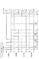
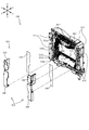
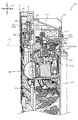
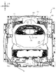
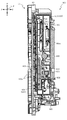
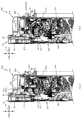
以下、本発明の第1実施形態について、添付図面を参照して説明する。図1は、第1実施形態におけるパチンコ機10の正面図であり、図2はパチンコ機10の遊技盤13の正面図であり、図3はパチンコ機10の背面図である。
<First Embodiment>
Hereinafter, the first embodiment of the present invention will be described with reference to the accompanying drawings. FIG. 1 is a front view of the
パチンコ機10は、図1に示すように、略矩形状に組み合わせた木枠により外殻が形成される外枠11と、その外枠11と略同一の外形形状に形成され外枠11に対して開閉可能に支持された内枠12とを備えている。外枠11には、内枠12を支持するために正面視(図1参照)左側の上下2カ所に金属製のヒンジ18が取り付けられ、そのヒンジ18が設けられた側を開閉の軸として内枠12が正面手前側へ開閉可能に支持されている。
As shown in FIG. 1, the
内枠12には、多数の釘や、入球口64,640,67等を有する遊技盤13(図2参照)が裏面側から着脱可能に装着される。この遊技盤13の前面を遊技球が流下することにより弾球遊技が行われる。なお、内枠12には、遊技球を遊技盤13の前面領域に発射する球発射ユニット112a(図8参照)やその球発射ユニット112aから発射された遊技球を遊技盤13の前面領域まで誘導する発射レール(図示せず)等が取り付けられている。
A game board 13 (see FIG. 2) having a large number of nails and
内枠12の前面側には、その前面上側を覆う前面枠14と、その下側を覆う下皿ユニット15とが設けられている。前面枠14及び下皿ユニット15を支持するために正面視(図1参照)左側の上下2カ所に金属製のヒンジ19が取り付けられ、そのヒンジ19が設けられた側を開閉の軸として前面枠14及び下皿ユニット15が正面手前側へ開閉可能に支持されている。なお、内枠12の施錠と前面枠14の施錠とは、シリンダ錠20の鍵穴21に専用の鍵を差し込んで所定の操作を行うことでそれぞれ解除される。
On the front side of the
前面枠14は、装飾用の樹脂部品や電気部品等を組み付けたものであり、その略中央部には略楕円形状に開口形成された窓部14cが設けられている。前面枠14の裏面側には2枚の板ガラスを有するガラスユニット16が配設され、そのガラスユニット16を介して遊技盤13の前面がパチンコ機10の正面側に視認可能となっている。
The
前面枠14には、遊技球を貯留する上皿17が前方へ張り出して上面を開放した略箱状に形成されており、この上皿17に賞球や貸出球などが排出される。上皿17の底面は正面視(図1参照)右側に下降傾斜して形成され、その傾斜により上皿17に投入された遊技球が球発射ユニット112aへと案内される。また、上皿17の上面には、枠ボタン22が設けられている。この枠ボタン22は、例えば、後述する第3図柄表示装置81で表示される演出や背景などを可変させる場合などに、遊技者により操作される。
On the
前面枠14には、その周囲(例えばコーナー部分)に各種ランプ等の発光手段が設けられている。これら発光手段は、大当たり時や所定のリーチ時等における遊技状態の変化に応じて、点灯または点滅することにより発光態様が変更制御され、遊技中の演出効果を高める役割を果たす。窓部14cの周縁には、LED等の発光手段を内蔵した電飾部29〜33が設けられている。パチンコ機10においては、これら電飾部29〜33が大当たりランプ等の演出ランプとして機能し、大当たり時やリーチ演出時等には内蔵するLEDの点灯や点滅によって各電飾部29〜33が点灯または点滅して、大当たり中である旨、或いは大当たり一歩手前のリーチ中である旨が報知される。また、前面枠14の正面視(図1参照)左上部には、LED等の発光手段が内蔵され賞球の払い出し中とエラー発生時とを表示可能な表示ランプ34が設けられている。
The
また、右側の電飾部32下側には、前面枠14の裏面側を視認できるように裏面側より透明樹脂を取り付けて小窓35が形成され、遊技盤13前面の貼着スペースK1(図2参照)に貼付される証紙等はパチンコ機10の前面から視認可能とされている。また、パチンコ機10においては、より煌びやかさを醸し出すために、電飾部29〜33の周りの領域にクロムメッキを施したABS樹脂製のメッキ部材36が取り付けられている。
Further, on the lower side of the illuminated
窓部14cの下方には、貸球操作部40が配設されている。貸球操作部40には、度数表示部41と、球貸しボタン42と、返却ボタン43とが設けられている。パチンコ機10の側方に配置されるカードユニット(球貸しユニット)(図示せず)に紙幣やカード等を投入した状態で貸球操作部40が操作されると、その操作に応じて遊技球の貸出が行われる。具体的には、度数表示部41はカード等の残額情報が表示される領域であり、内蔵されたLEDが点灯して残額情報として残額が数字で表示される。球貸しボタン42は、カード等(記録媒体)に記録された情報に基づいて貸出球を得るために操作されるものであり、カード等に残額が存在する限りにおいて貸出球が上皿17に供給される。返却ボタン43は、カードユニットに挿入されたカード等の返却を求める際に操作される。なお、カードユニットを介さずに球貸し装置等から上皿17に遊技球が直接貸し出されるパチンコ機、いわゆる現金機では貸球操作部40が不要となるが、この場合には、貸球操作部40の設置部分に飾りシール等を付加して部品構成は共通のものとしても良い。カードユニットを用いたパチンコ機と現金機との共通化を図ることができる。
A ball
上皿17の下側に位置する下皿ユニット15には、その中央部に上皿17に貯留しきれなかった遊技球を貯留するための下皿50が上面を開放した略箱状に形成されている。下皿50の右側には、遊技球を遊技盤13の前面へ打ち込むために遊技者によって操作される操作ハンドル51が配設され、かかる操作ハンドル51の内部には球発射ユニット112aの駆動を許可するためのタッチセンサ51aと、押下操作している期間中には遊技球の発射を停止する押しボタン式の打ち止めスイッチ51bと、操作ハンドル51の回動操作量を電気抵抗の変化により検出する可変抵抗器(図示せず)とが内蔵されている。操作ハンドル51が遊技者によって右回りに回転操作されると、タッチセンサ51aがオンされると共に可変抵抗器の抵抗値が操作量に対応して変化し、操作ハンドル51の回動操作量に応じて変化する可変抵抗器の抵抗値に対応した強さで遊技球が発射され、これにより遊技者の操作に対応した飛び量で遊技盤13の前面へ遊技球が打ち込まれる。また、操作ハンドル51が遊技者により操作されていない状態においては、タッチセンサ51aおよび打ち止めスイッチ51bがオフとなっている。
In the
なお、本実施形態では、上記した構成としたが、それに限らず、主制御装置110や他の制御装置が球発射ユニット112aにより発射された遊技球を検出する構成や、球発射ユニット112aのソレノイドが遊技球を発射したことを検出するように構成してもよい。また、検出した遊技球の数をカウントして、RAMクリア等の処理が実行されるまで記憶するように構成してもよい。
In the present embodiment, the configuration is not limited to the above, but the configuration is such that the
下皿50の正面下方部には、下皿50に貯留された遊技球を下方へ排出する際に操作するための球抜きレバー52が設けられている。この球抜きレバー52は、常時、右方向に付勢されており、その付勢に抗して左方向へスライドさせることにより、下皿50の底面に形成された底面口が開口して、その底面口から遊技球が自然落下して排出される。この球抜きレバー52の操作は、通常、下皿50の下方に下皿50から排出された遊技球を受け取る箱(一般に「ドル箱」と称される)を置いた状態で行われる。下皿50の右方には、上述したように操作ハンドル51が配設され、下皿50の左方には灰皿53が取り付けられている。
A
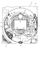
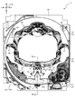
図2に示すように、遊技盤13は、正面視略正方形状に切削加工した木製のベース板60に、球案内用の多数の釘や風車、およびレール61,62、一般入賞口63、第1入球口64、第2入球口640、可変入賞装置65、作動入賞口660、可変表示装置ユニット80等を組み付けて構成され、その周縁部が内枠12の裏面側に取り付けられる。一般入賞口63、第1入球口64、第2入球口640、可変入賞装置65、作動入賞口660、可変表示装置ユニット80は、ルータ加工によってベース板60に形成された貫通穴に配設され、遊技盤13の前面側から木ネジ等により固定されている。また、遊技盤13の前面中央部分は、前面枠14の窓部14c(図1参照)を通じて内枠12の前面側から視認することができる。以下、主に図2を参照して、遊技盤13の構成について説明する。
As shown in FIG. 2, the
遊技盤13の前面には、帯状の金属板を略円弧状に屈曲加工して形成した外レール62が植立され、その外レール62の内側位置には外レール62と同様に帯状の金属板で形成した円弧状の内レール61が植立される。この内レール61と外レール62とにより遊技盤13の前面外周が囲まれ、遊技盤13とガラスユニット16(図1参照)とにより前後が囲まれることにより、遊技盤13の前面には、遊技球の挙動により遊技が行われる遊技領域が形成される。遊技領域は、遊技盤13の前面であって2本のレール61,62と円弧部材70とにより区画して形成される略円形状の領域(始動口等が配設され、発射された遊技球が流下する領域)である。また、遊技領域は、戻り球防止部材68を通過した遊技球がアウト口66や入賞口を通過するまでに流下する領域はすべて含まれる。
An
2本のレール61,62は、球発射ユニット112a(図8参照)から発射された遊技球を遊技盤13上部へ案内するために設けられたものである。外レール62の先端部分(図2の左上部)には、遊技球が入球可能な作動入賞口660が設けられている。この作動入賞口660は、遊技球が入球した場合に遊技者にとって有利な状態である大当たり状態(特別遊技状態)へと移行する。詳述すると、特別図柄(第1図柄)の抽選で大当たりと判定された場合に、この作動入賞口660への入球が有効とされる状態(大当たり待機状態)に設定される。なお、通常時は作動入賞口660へと遊技球が入球したとしても、何ら遊技に影響を与えることは無い。大当たり待機状態において、遊技者が遊技球を作動入賞口660に向けて発射することにより、遊技球が作動入賞口へと入球(入賞)して大当たりが開始される。なお、図2に示した通り、作動入賞口660の正面視左方向には、一定の回転速度で回転動作する回動部材670aが配設されている。この回動部材670aは、その回転位置に応じて作動入賞口660に向けて発射された遊技球が作動入賞口660の方向へ向かうのを妨げる配置と、妨げない配置とを取り得るため、回動部材670aが遊技球を妨げない配置となるタイミングを狙って遊技球を打ち出さなければ作動入賞口660へと遊技球を入球させること(大当たりを開始させること)ができない。よって、特別図柄の抽選で大当たりと判定された場合に、回動部材670aの配置を加味して遊技球を発射させることができるので、遊技者の遊技に対する興趣を向上させることができる。
The two
なお、作動入賞口660は、図2に示した通り、遊技球1個分よりも広く、2個分よりも狭い幅の流路(作動入賞口用流路)の終端に設けられている。この作動入賞口用流路は、少なくとも最大の勢い(発射強度)を含む所定範囲の発射強度(例えば、発射強度が95%〜100%の範囲)で発射された遊技球が届く(流入する)ように構成されている。このため、特別図柄の抽選で大当たりと判定され、大当たり待機状態になった場合には、作動入賞口660を狙う際に、単にハンドル51を可動し得る最大の範囲まで回転操作するだけで容易に作動入賞口660へと遊技球を入球させることができる。
As shown in FIG. 2, the
内レール61の先端部分には、返しゴム69が取り付けられている。所定の発射強度(例えば、発射強度が90%〜95%範囲)で発射された遊技球は、返しゴム69に当たって、勢いが減衰されつつ中央部側へ跳ね返される。また、内レール61の右下側の先端部と外レール62の右上側の先端部との間には、レール間を繋ぐ円弧を内面側に設けて形成された樹脂製の円弧部材70がベース板60に打ち込んで固定されている。
A
本パチンコ機10では、遊技球が第1入球口64、または第2入球口640のいずれかへ入球した場合に特別図柄(第1図柄)の抽選が行われ、遊技球が普通入球口67を通過した場合に普通図柄(第2図柄)の抽選が行われる。第1入球口64、または第2入球口640への入球に対して行われる特別図柄の抽選では、特別図柄の大当たりか否かの当否判定が行われると共に、特別図柄の大当たりと判定された場合にはその大当たり種別の判定も行われる。特別図柄の大当たりになると、パチンコ機10が特別遊技状態へ移行すると共に、通常時には閉鎖されている特定入賞口65aが所定時間(例えば、30秒経過するまで、或いは、遊技球が所定個数入賞するまで)開放され、その開放が大当たり種別に応じた回数(ラウンド数)繰り返される。その結果、その特定入賞口65aに多量の遊技球が入賞するので、通常時より多量の賞球の払い出しが行われる。特別図柄の大当たり種別としては、「大当たりA」〜「大当たりF」の6種類が設けられており、特別遊技状態の終了後には大当たり終了後の付加価値として、大当たり遊技の結果に応じた遊技上の価値(遊技価値)が遊技者に付与される。なお、「大当たりA〜C」の3種類は、遊技球が第1入球口64へと入球したことを契機として実行される特別図柄の抽選で大当たりとなった場合に決定され得る大当たり種別であり、「大当たりD〜F」の3種類は、遊技球が第2入球口640へと入球したことを契機として実行される特別図柄の抽選で大当たりとなった場合に決定され得る大当たり種別である。以降、説明の簡略化のため、遊技球が第1入球口64へと入球したことを契機として実行される特別図柄の抽選のことを第1特別図柄の抽選と称し、遊技球が第2入球口640へと入球したことを契機として実行される特別図柄の抽選のことを第2特別図柄の抽選と称する。
In this
特別図柄(第1図柄)の抽選が行われると、第1図柄表示装置37において特別図柄の変動表示が開始されて、所定時間(例えば、7秒〜90秒など)が経過した後に、抽選結果を示す特別図柄が停止表示される。第1図柄表示装置37において変動表示が行われている間に遊技球が第1入球口64、または第2入球口640へ入球すると、その入球回数は、入球口の種別毎にそれぞれ最大4回まで保留され、その保留球数が第1図柄表示装置37により示されると共に、第3図柄表示装置81においても示される。第1図柄表示装置37において変動表示が終了した場合に、第1入球口64、または第2入球口640についての保留球数が残っていれば、次の特別図柄の抽選が行われると共に、その抽選に応じた変動表示が開始される。
When the lottery of the special symbol (first symbol) is performed, the variable display of the special symbol is started on the first
一方、普通入球口67における遊技球の通過に対して行われる普通図柄の抽選では、普通図柄の当たりか否かの当否判定が行われる。普通図柄の当たりになると、所定時間(例えば、0.2秒または1秒)だけ第2入球口640に付随する電動役物640aが開放位置に可変されることで第2入球口640が開放される。なお、通常時は、電動役物640aが閉鎖位置に配設されているため、第2入球口640が閉鎖されている。よって、正面視上方から第2入球口640に向かって流下してきた球は、電動役物640aに阻まれることにより第2入球口640へと入球することが不可能(困難)となる。一方、普通図柄の当たりとなった場合は、電動役物640aが開放されることにより、第2入球口640に向かって流下してきた球が第2入球口640へ入球し易くなり、その結果、第2特別図柄の抽選が行われ易くなる。
On the other hand, in the lottery of the normal symbol performed for the passage of the game ball at the
また、普通図柄(第2図柄)の抽選が行われると、第2図柄表示装置83において普通図柄の変動表示が開始されて、所定時間(例えば、3秒や30秒など)が経過した後に、抽選結果を示す普通図柄が停止表示される。第2図柄表示装置83において変動表示が行われている間に遊技球が普通入球口67を通過すると、その通過回数は最大4回まで保留され、その保留球数が第1図柄表示装置37により表示されると共に、第2図柄保留ランプ84においても示される。第2図柄表示装置83において変動表示が終了した場合に、普通入球口67についての保留球数が残っていれば、次の普通図柄の抽選が行われると共に、その抽選に応じた変動表示が開始される。
Further, when the lottery of the normal symbol (second symbol) is performed, the variable display of the normal symbol is started on the second
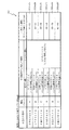
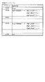
上述したように、特別図柄の大当たり種別としては、「大当たりA」〜「大当たりF」の6種類が設けられている。 As described above, as the jackpot type of the special symbol, six types of "big hit A" to "big hit F" are provided.
「大当たりA」になると、ラウンド数が8ラウンドの特別遊技状態(8ラウンド大当たり)となる。一方、「大当たりB」、または「大当たりC」になると、ラウンド数が5ラウンドの特別遊技状態(5ラウンド大当たり)となり、「大当たりD」になると、ラウンド数が16ラウンドの特別遊技状態(16ラウンド大当たり)となり、「大当たりE」、「大当たりF」になると、ラウンド数が10ラウンドの特別遊技状態(10ラウンド大当たり)となる。更に、「大当たりA」、「大当たりB」、「大当たりD」、「大当たりE」になった場合は、大当たり終了後に特別図柄の高確率状態(特別図柄の確変中)へ移行する。また、特別図柄の高確率状態が付与された場合には、普通図柄の当たり確率もアップする(普通図柄の時短状態が付与される)。特別図柄の高確率状態、および普通図柄の時短状態は、大当たり終了後から次に大当たりとなるまで継続する。一方、「大当たりC」、または「大当たりF」になると、大当たり終了後に普通図柄の時短状態が付与されるものの、特別図柄の高確率状態は付与されない。この「大当たりC」、または「大当たりF」の終了後に付与される普通図柄の時短状態は、特別図柄の抽選が100回実行されることにより終了する。 When it becomes "big hit A", it becomes a special game state (8 rounds big hit) with 8 rounds. On the other hand, when it becomes "big hit B" or "big hit C", the number of rounds becomes 5 rounds of special game state (5 rounds big hit), and when it becomes "big hit D", the number of rounds becomes 16 rounds of special game state (16 rounds). When it becomes "big hit E" and "big hit F", the number of rounds becomes a special game state of 10 rounds (10 round big hit). Further, when "Big hit A", "Big hit B", "Big hit D", and "Big hit E" are reached, the game shifts to a high probability state of the special symbol (during the probability change of the special symbol) after the big hit ends. In addition, when the high probability state of the special symbol is given, the hit probability of the normal symbol is also increased (the time saving state of the normal symbol is given). The high-probability state of the special symbol and the time-saving state of the normal symbol continue from the end of the big hit until the next big hit. On the other hand, when it becomes "big hit C" or "big hit F", the time saving state of the normal symbol is given after the big hit ends, but the high probability state of the special symbol is not given. The time saving state of the normal symbol given after the end of the "big hit C" or the "big hit F" ends when the special symbol lottery is executed 100 times.
ここで、「特別図柄の高確率状態」とは、特別図柄の大当たり確率がアップした状態、いわゆる「特別図柄の高確率状態」(特別図柄の確変状態)をいい、換言すれば、特別遊技状態(大当たり)へ移行し易い遊技の状態のことである。対して、「特別図柄の高確率状態」でない場合を「特別図柄の低確率状態」といい、これは特別図柄の確変状態よりも大当たり確率が低い状態、即ち、特別図柄の大当たり確率が通常の状態(特別図柄の低確率状態)のことを示す。また、「普通図柄の時短状態」(普通図柄の高確率状態)とは、普通図柄の当たり確率がアップして、第2入球口640へ遊技球が入球し易い遊技状態のことをいう。これ対して、「普通図柄の時短状態」でない時を「普通図柄の通常状態」(普通図柄の低確率状態)といい、これは普通図柄の当たり確率が通常の状態、即ち、時短中よりも当たり確率が低い状態のことを示す。
Here, the "high probability state of the special symbol" means a state in which the jackpot probability of the special symbol is increased, that is, a so-called "high probability state of the special symbol" (probability change state of the special symbol), in other words, a special gaming state. It is a state of the game in which it is easy to shift to (big hit). On the other hand, the case where it is not the "high probability state of the special symbol" is called the "low probability state of the special symbol", which means that the jackpot probability is lower than the probability variation state of the special symbol, that is, the jackpot probability of the special symbol is normal. Indicates a state (low probability state of a special symbol). In addition, the "time saving state of the normal symbol" (high probability state of the normal symbol) means a gaming state in which the hit probability of the normal symbol is increased and the game ball can easily enter the
上述したように、本実施形態における特別図柄の大当たりでは、大当たりの種別に応じて大当たり時のラウンド数を異ならせている。これに対して、全ての大当たり種別でラウンド数を共通(例えば、全て5ラウンド)としても良い。また、本実施形態では、大当たり後に付与された「特別図柄の確変状態」が、次に大当たりとなるまで継続する構成としたが、これに限られるものではない。例えば、「特別図柄の確変状態」が継続する期間を、特別図柄の抽選回数が所定回数(例えば、100回)実行されるまでの間に限定する構成としてもよい。この場合において、「特別図柄の確変状態」となる抽選回数と、「普通図柄の時短状態」となる抽選回数とを異ならせてもよい。また、大当たりの種別に応じて、抽選回数を可変させる構成としてもよい。 As described above, in the jackpot of the special symbol in the present embodiment, the number of rounds at the time of jackpot is different depending on the type of jackpot. On the other hand, the number of rounds may be the same for all jackpot types (for example, all 5 rounds). Further, in the present embodiment, the "probability change state of the special symbol" given after the big hit is continued until the next big hit, but the present invention is not limited to this. For example, the period in which the "probability change state of the special symbol" continues may be limited to the period until the number of lottery of the special symbol is executed a predetermined number of times (for example, 100 times). In this case, the number of lottery that is in the "probability change state of the special symbol" and the number of lottery that is in the "time saving state of the normal symbol" may be different. In addition, the number of lottery may be changed according to the type of jackpot.
本パチンコ機10では、電源などの投入等により初期設定が行われると、必ず「特別図柄の低確率状態」、および「普通図柄の通常状態」に設定される。そして、「大当たりA」、「大当たりB」、「大当たりD」、「大当たりE」の何れかになった場合は、「特別図柄の低確率状態」から「特別図柄の確変状態」へ移行すると共に、「普通図柄の通常状態」から「普通図柄の時短状態」へ移行する。この場合、設定された「特別図柄の確変状態」と、「普通図柄の時短状態」とは、次に大当たりとなるまで継続する。一方、「大当たりC」、または「大当たりF」になると、「特別図柄の低確率状態」、且つ「普通図柄の時短状態」に移行する。以降、説明の簡略化のため、大当たりの終了後に「特別図柄の確変状態」、且つ「普通図柄の時短状態」が付与される大当たり(「大当たりA」、「大当たりB」、「大当たりD」、「大当たりE」)のことを、「確変大当たり」と称する。一方、大当たりの終了後に100回の「普通図柄の時短状態」のみが付与される大当たり(「大当たりC」、「大当たりF」)のことを、「通常大当たり」と称する。
In the
遊技盤13の正面視左側下部(図2の左側下部)には、発光手段である複数の発光ダイオード(以下、「LED」と略す。)37aと7セグメント表示器37bとが設けられた第1図柄表示装置37が配設されている。第1図柄表示装置37は、後述する主制御装置110で行われる各制御に応じた表示がなされるものであり、主にパチンコ機10の遊技状態の表示が行われる。複数のLED37aは、第1入球口64への入球(始動入賞)に伴って行われる特別図柄の抽選が実行中であるか否かを点灯状態により示すことによって変動表示を行ったり、変動終了後の停止図柄として、その特別図柄の抽選結果に応じた特別図柄(第1図柄)を点灯状態により示したり、第1入球口64、または第2入球口640に入球された遊技球のうち変動が未実行である遊技球(保留球)の数である保留球数を点灯状態により示すものである。
A first unit is provided with a plurality of light emitting diodes (hereinafter abbreviated as "LED") 37a and a 7-
この第1図柄表示装置37において特別図柄(第1図柄)の変動表示が行われている間に遊技球が第1入球口64、または第2入球口640へ入球した場合、その入球回数は最大4回まで保留され、その保留球数は第1図柄表示装置37により示されると共に、第3図柄表示装置81においても示される。なお、本実施形態においては、第1入球口64、および第2入球口640への入球は、それぞれ最大4回まで保留されるように構成したが、最大保留回数は4回に限定されるものでなく、3回以下、又は、5回以上の回数(例えば、8回)に設定しても良い。
If the game ball enters the
7セグメント表示器37bは、大当たり中のラウンド数やエラー表示を行うものである。なお、LED37aは、それぞれのLEDの発光色(例えば、赤、緑、青)が異なるよう構成され、その発光色の組み合わせにより、少ないLEDでパチンコ機10の各種遊技状態(特別図柄の高確率状態や、普通図柄の時短中など)を表示することができる。また、LED37aには、変動終了後の停止図柄として特別図柄の抽選結果が大当たりであるか否かが示されるだけでなく、大当たりである場合はその大当たり種別(大当たりA〜Fに応じた特別図柄(第1図柄)が示される。
The 7-
また、遊技領域には、遊技球が入賞することにより5個から15個の遊技球が賞球として払い出される複数の一般入賞口63が配設されている。また、遊技領域の中央部分には、可変表示装置ユニット80が配設されている。可変表示装置ユニット80には、液晶ディスプレイ(以下単に「表示装置」と略す。)で構成された第3図柄表示装置81と、LEDで構成された第2図柄表示装置83とが設けられている。この可変表示装置ユニット80には、第3図柄表示装置81の外周を囲むようにして、センターフレーム86が配設されている。
Further, in the game area, a plurality of general winning
第3図柄表示装置81は、第1図柄表示装置37の表示に応じた装飾的な表示を行うものである。例えば、第1入球口64、または第2入球口640へ遊技球が入球(始動入賞)すると、それをトリガとして、第1図柄表示装置37において特別図柄(第1図柄)の変動表示が実行される。更に、第3図柄表示装置81では、その特別図柄の変動表示に同期して、その特別図柄の変動表示に対応する第3図柄の変動表示が行われる。
The third
第3図柄表示装置81は、8インチサイズの大型の液晶ディスプレイで構成されるものであり、後述する表示制御装置114によって表示内容が制御されることにより、例えば左、中及び右の3つの図柄列が表示される。各図柄列は複数の図柄によって構成され、これらの図柄が図柄列毎に縦スクロールして第3図柄表示装置81の表示画面上にて第3図柄が可変表示されるようになっている。本実施形態では、主制御装置110の制御に伴った遊技状態の表示が第1図柄表示装置37で行われるのに対して、第3図柄表示装置81はその第1図柄表示装置37の表示に応じた装飾的な表示が行われる。なお、表示装置に代えて、例えば、リール等を用いて第3図柄表示装置81を構成するようにしても良い。
The third
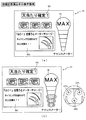
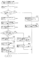
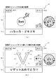
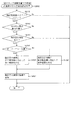
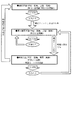
ここで、図6を参照して、第3図柄表示装置81の表示内容について説明する。図7は、第3図柄表示装置81の表示画面を説明するための図面であり、図6(a)は、表示画面の領域区分設定と有効ライン設定とを模式的に示した図であり、図6(b)は、実際の表示画面を例示した図である。
Here, the display contents of the third
第3図柄は、「1」から「9」の数字を付した9種類の主図柄により構成されている。各主図柄は、「1」から「9」の数字を模して構成されている。各主図柄は、木箱よりなる後方図柄の上に「1」から「9」の数字を付して構成され、そのうち奇数番号(1,3,5,7,9)を付した主図柄は、木箱の前面ほぼ一杯に大きな数字が付加されている。これに対し、偶数番号(2,4,6,8)を付した主図柄は、木箱の前面ほぼ一杯にかんな、風呂敷、ヘルメット等のキャラクタを模した付属図柄が付加されており、付属図柄の右下側に偶数の数字が緑色で小さく、且つ、付属図柄の前側に表示されるように付加されている。 The third symbol is composed of nine types of main symbols with numbers "1" to "9". Each main symbol is configured by imitating the numbers "1" to "9". Each main symbol is composed of a rear symbol consisting of a wooden box with numbers from "1" to "9", of which the main symbols with odd numbers (1, 3, 5, 7, 9) are , A large number is added to almost the front of the wooden box. On the other hand, the main symbols with even numbers (2, 4, 6, 8) have attached symbols that imitate characters such as furoshiki and helmets, which are almost full on the front of the wooden box. Even numbers are small in green on the lower right side of, and are added so that they are displayed on the front side of the attached symbol.
また、本実施形態のパチンコ機10においては、後述する主制御装置110(図8参照)により行われる特別図柄の抽選結果が大当たりであった場合に、同一の主図柄が揃う変動表示が行われ、その変動表示が終わった後に大当たりが発生するよう構成されている。一方、特別図柄の抽選結果が外れであった場合は、同一の主図柄が揃わない変動表示が行われる。
Further, in the
例えば、特別図柄の抽選結果が確変大当たり(「大当たりA」、「大当たりB」、「大当たりD」、「大当たりE」のいずれか)であれば、「1」〜「9」のいずれかが付加された主図柄が揃う変動表示が行われる。また、通常大当たり(「大当たりC」、または「大当たりF」)であれば、偶数番号である「0,2,4,6,8」が付加された主図柄が揃う変動表示が行われる。即ち、奇数番号である「1,3,5,7,9」が付加された主図柄が揃う変動表示は、確変大当たりでのみ実行される可能性がある。確変大当たりの場合でも、偶数の数字が付された主図柄が揃う変動表示が行われる可能性がある構成とすることにより、偶数の数字が付された主図柄が揃った場合にも、確変大当たりであることを期待して大当たり中の遊技を行わせることができる。一方、特別図柄の抽選結果が外れであれば、同一番号の主図柄が揃わない変動表示が行われる。なお、確変大当たりにおいて、偶数の数字が付された主図柄が揃う変動表示が行われる割合は、例えば、60%に設定される。また、偶数の数字が付された主図柄が揃う変動表示によって確変大当たりが開始された場合には、大当たりの所定期間(例えば、5ラウンドのラウンド期間中)において、確変大当たりであったことを報知する演出が実行される。 For example, if the lottery result of the special symbol is a probabilistic jackpot (one of "big hit A", "big hit B", "big hit D", and "big hit E"), one of "1" to "9" is added. A variable display is performed in which the main symbols are aligned. Further, in the case of a normal jackpot (“big hit C” or “big hit F”), a variable display is performed in which the main symbols to which the even numbers “0, 2, 4, 6, 8” are added are aligned. That is, the variable display in which the main symbols to which the odd numbers "1, 3, 5, 7, 9" are added may be executed only in the probability variation jackpot. Even in the case of a probabilistic jackpot, even if the main symbols with even numbers are aligned, the variable display may be performed so that the main symbols with even numbers are aligned. It is possible to play a game during a big hit with the expectation that it will be. On the other hand, if the lottery result of the special symbol is out of order, a variable display is performed in which the main symbols having the same number are not aligned. In addition, in the probability variation jackpot, the ratio of the variable display in which the main symbols with even numbers are aligned is set to, for example, 60%. In addition, when a probabilistic jackpot is started by a variable display in which the main symbols with even numbers are aligned, it is notified that the probabilistic jackpot was a probabilistic jackpot during a predetermined period of the jackpot (for example, during a round period of 5 rounds). The production to be performed is executed.
図6(a)に示すように、第3図柄表示装置81の表示画面は、大きくは上下に2分割され、下側の2/3が第3図柄を変動表示する主表示領域Dm、それ以外の上側の1/3が予告演出、キャラクタおよび保留球数などを表示する副表示領域Dsとなっている。
As shown in FIG. 6A, the display screen of the third
主表示領域Dmは、左・中・右の3つの表示領域Dm1〜Dm3に区分けされており、その3つの表示領域Dm1〜Dm3に、それぞれ3つの図柄列Z1,Z2,Z3が表示される。各図柄列Z1〜Z3には、上述した第3図柄が規定の順序で表示される。即ち、各図柄列Z1〜Z3には、数字の昇順または降順に主図柄が配列され、図柄列Z1〜Z3毎に周期性をもって上から下へとスクロールして変動表示が行われる。特に、左図柄列Z1においては主図柄の数字が降順に現れるように配列され、中図柄列Z2及び右図柄列Z3においては主図柄の数字が昇順に現れるように配列されている。 The main display area Dm is divided into three display areas Dm1 to Dm3 on the left, middle, and right, and three symbol columns Z1, Z2, and Z3 are displayed in the three display areas Dm1 to Dm3, respectively. In each of the symbol rows Z1 to Z3, the above-mentioned third symbols are displayed in a specified order. That is, the main symbols are arranged in the ascending or descending order of the numbers in the symbol rows Z1 to Z3, and the symbol rows Z1 to Z3 are periodically scrolled from top to bottom to perform variable display. In particular, in the left symbol row Z1, the numbers of the main symbols are arranged so as to appear in descending order, and in the middle symbol row Z2 and the right symbol row Z3, the numbers of the main symbols appear in ascending order.
また、主表示領域Dmには、図柄列Z1〜Z3毎に上・中・下の3段に第3図柄が表示される。この主表示領域Dmの中段部が有効ラインL1として設定されており、毎回の遊技に際して、左図柄列Z1→右図柄列Z3→中図柄列Z2の順に、有効ラインL1上に第3図柄が停止表示される。この停止表示状態は最低1秒間保持される。このように、停止した第3図柄を一定期間(1秒以上)表示させておくことで、遊技者が大当たりに対応する第3図柄の組み合わせであるか否か(特別図柄の抽選結果が大当たりであるか否か)を見落としてしまうことを抑制することができる。また、第3図柄の停止時に有効ラインL1上に大当たり図柄の組合せ(本実施形態では、同一の主図柄の組合せ)が揃えば、大当たりが確定し、大当たり待機状態を示す待機状態演出が表示される。この待機状態演出の詳細については、図7を参照して後述する。また、大当たり待機状態の間に遊技球を作動入賞口660に入球(入賞)させることにより、大当たりが開始され、大当たり動画(オープニング演出)が表示される。
Further, in the main display area Dm, the third symbol is displayed in the upper, middle, and lower three rows for each of the symbol rows Z1 to Z3. The middle part of this main display area Dm is set as the effective line L1, and the third symbol stops on the effective line L1 in the order of left symbol row Z1 → right symbol row Z3 → middle symbol row Z2 in each game. Is displayed. This stop display state is held for at least 1 second. By displaying the stopped 3rd symbol for a certain period of time (1 second or more) in this way, whether or not the player is a combination of the 3rd symbols corresponding to the jackpot (the lottery result of the special symbol is a jackpot). It is possible to prevent overlooking (whether or not there is). Further, if the combination of jackpot symbols (in the present embodiment, the same combination of main symbols) is aligned on the effective line L1 when the third symbol is stopped, the jackpot is confirmed and the standby state effect indicating the jackpot standby state is displayed. To. Details of this standby state effect will be described later with reference to FIG. 7. Further, by making the game ball enter (win) the
また、停止表示された第3図柄の組み合わせが外れに対応する組み合わせであって、保留球が存在する場合は、1秒間の停止表示後に、保留球に基づく抽選に対応する変動表示が開始される。なお、複数の保留球が存在する場合は、時間的に最も古い入球に対応する保留球に基づいて抽選が実行される。 Further, if the combination of the third symbols displayed as stopped is a combination corresponding to the detachment and there is a reserved ball, the variable display corresponding to the lottery based on the reserved ball is started after the stop display for 1 second. .. If there are a plurality of reserved balls, the lottery is executed based on the reserved balls corresponding to the oldest incoming balls in time.
一方、保留球が存在しない状態で、特別図柄の外れに対応する組み合わせの第3図柄が1秒間停止表示された場合は、その後も第3図柄が停止表示された状態が継続する。この状態は、所定時間(例えば、15秒)が経過するか、または、第1入球口64に対して新たに遊技球が入球するまで継続する。そして、第3図柄が停止表示されてから所定時間(例えば、15秒)が経過した場合は、遊技が実行されていないことを示すデモ演出が表示される。遊技者が遊技球を所定時間(例えば、15秒)連続して発射させているにも関わらず、第1入球口64への入球が無いという状況は稀であり、第3図柄が停止表示された状態が所定時間(例えば、15秒)継続する場合の多くは、遊技者が遊技を辞めたことで、パチンコ機10による遊技が全く行われていないことに起因する。よって、本実施形態のパチンコ機10では、第3図柄が停止表示されてから所定時間(例えば、15秒)が経過した時点で、遊技者が遊技を行っていないと判断し、デモ演出を開始する。これにより、遊技を開始するためにパチンコ機10を選択しようとしている遊技者が、デモ演出の表示の有無に基づいて遊技が行われているか否かを容易に判断することができる。一方、所定時間(例えば、15秒)が経過する前に第1入球口64に対して新たに遊技球が入球した場合は、その新たな入球に対応する第3図柄の変動表示が実行される。
On the other hand, when the third symbol of the combination corresponding to the deviation of the special symbol is stopped and displayed for 1 second in the state where the holding ball does not exist, the state in which the third symbol is stopped and displayed continues thereafter. This state continues until a predetermined time (for example, 15 seconds) elapses or a new game ball enters the first
副表示領域Dsは、主表示領域Dmよりも上方に横長に設けられており、さらに左右方向に3つの小領域Ds1〜Ds3に等区分されている。このうち、小領域Ds1は、第1入球口64、および第2入球口640に入球された遊技球のうち変動が未実行である遊技球(保留球)の数である保留球数を表示する領域であり、小領域Ds2およびDs3は、予告演出画像を表示する領域である。
The sub-display area Ds is provided horizontally above the main display area Dm, and is further divided into three small areas Ds1 to Ds3 in the left-right direction. Of these, the small area Ds1 is the number of reserved balls, which is the number of game balls (reserved balls) that have not been changed among the game balls entered in the
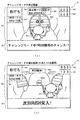
実際の表示画面では、図4(b)に示すように、主表示領域Dmに第3図柄の主図柄が合計9個表示される。副表示領域Dsにおいては、右の小領域Ds3に動画が表示され、通常より大当たりへ遷移し易い状態であることが遊技者に示唆される。中央の小領域Ds2では、通常は、所定のキャラクタ710(本実施形態ではハチマキを付けた少年)が所定動作をし、時として所定動作とは別の特別な動作をしたり、別のキャラクタが現出する等して予告演出が行われる。 On the actual display screen, as shown in FIG. 4B, a total of nine main symbols of the third symbol are displayed in the main display area Dm. In the sub-display area Ds, the moving image is displayed in the small area Ds3 on the right, suggesting to the player that the transition to the jackpot is easier than usual. In the central small area Ds2, a predetermined character 710 (a boy with a headband in this embodiment) usually performs a predetermined action, and sometimes a special action different from the predetermined action or another character performs a predetermined action. A notice production will be performed by appearing.
一方、第3図柄表示装置81(第1図柄表示装置37)にて変動表示が行われている間に遊技球が第1入球口64、または第2入球口640へ入球した場合、その入球回数は入球口の種別毎に、それぞれ最大4回まで保留され、その保留球数は第1図柄表示装置37により示されると共に、副表示領域Dsの小領域Ds1においても示される。小領域Ds1には、保留球数1球につき1つの保留球数図柄が表示され、その保留球数図柄の表示数に応じて、保留球数が表示される。即ち、小領域Ds1に1つの保留球数図柄が表示されている場合は、保留球数が1球であることを示し、4つの保留球数図柄が表示されている場合は、保留球数が4球であることを示す。また、小領域Ds1に保留球数図柄が表示されていない場合は、保留球数が0球である、即ち、保留球が存在しないことを示す。なお、小領域Ds1のうち、左半分には、第1入球口64への入球に基づく保留球数を示す保留球数図柄を表示し、小領域Ds2のうち、右半分には、第2入球口640への入球に基づく保留球数を示す保留球数図柄を表示する構成としている。図6(b)の例では、小領域Ds1の左半分に4つの保留球数図柄が表示されている一方で、右半分には保留球数図柄が1つも表示されていないので、第1特別図柄の保留球が4つ存在するが、第2特別図柄の保留球は0個となっている状態を示している。
On the other hand, when the game ball enters the first
なお、本実施形態においては、第1入球口64、および第2入球口640への入球は、それぞれ最大4回まで保留されるように構成したが、最大保留球数は4回に限定されるものでなく、3回以下、又は、5回以上の回数(例えば、8回)に設定しても良い。また、小領域Ds1における保留球数図柄の表示に代えて、保留球数を第3図柄表示装置81の一部に数字で、或いは、4つに区画された領域を保留球数分だけ異なる態様(例えば、色や点灯パターン)にして表示するようにしても良い。また、第1図柄表示装置37により保留球数が示されるので、第3図柄表示装置81に保留球数を表示させないものとしてもよい。更に、可変表示装置ユニット80に、保留球数を示す保留ランプを最大保留数分の4つ設け、点灯状態の保留ランプの数に応じて、保留球数を表示するものとしてもよい。
In the present embodiment, the first
第2図柄表示装置83は、遊技球が普通入球口67を通過することに伴って行われる普通図柄の抽選が実行中であるか否かを点灯状態により示すことによって変動表示を行ったり、変動終了後の停止図柄として、その普通図柄の抽選結果に応じた普通図柄(第2図柄)を点灯状態により示したりするものである。
The second
より具体的には、第2図柄表示装置83では、遊技球が左右いずれかの普通入球口67を通過する毎に、普通図柄(第2図柄)としての「○」の図柄と「×」の図柄とを交互に点灯させる変動表示が行われる。パチンコ機10は、第2図柄表示装置83における変動表示が所定図柄(本実施形態においては「○」の図柄)で停止すると、第2入球口640に付随する電動役物640aが所定時間だけ作動状態となり(開放される)、その結果、第2入球口640に遊技球が入り易い状態となるように構成されている。遊技球が普通入球口67を通過した通過回数は最大4回まで保留され、その保留球数が上述した第1図柄表示装置37により表示されると共に第2図柄保留ランプ84においても点灯表示される。第2図柄保留ランプ84は、最大保留数分の4つ設けられ、第3図柄表示装置81の下方に左右対称に配設されている。
More specifically, in the second
なお、普通図柄(第2図柄)の変動表示は、本実施形態のように、第2図柄表示装置83において複数のランプの点灯と非点灯を切り換えることにより行うものの他、第1図柄表示装置37及び第3図柄表示装置81の一部を使用して行うようにしても良い。同様に、第2図柄保留ランプ84の点灯を第3図柄表示装置81の一部で行うようにしても良い。また、普通入球口67における遊技球の通過は、第1入球口64や第2入球口640と同様に、最大保留球数は4回に限定されるものでなく、3回以下、又は、5回以上の回数(例えば、8回)に設定しても良い。また、第1図柄表示装置37により保留球数が示されるので、第2図柄保留ランプ84により点灯表示を行わないものとしても良い。
The variation display of the normal symbol (second symbol) is performed by switching the lighting and non-lighting of a plurality of lamps in the second
可変表示装置ユニット80の下方には、遊技球が入球し得る第1入球口64が配設されている。この第1入球口64へ遊技球が入球すると遊技盤13の裏面側に設けられる第1入球口スイッチ(図示せず)がオンとなり、その第1入球口スイッチのオンに起因して主制御装置110で第1特別図柄の抽選がなされ、その抽選結果に応じた表示が第1図柄表示装置37のLED37aで示される。また、第1入球口64は、遊技球が入球すると5個の賞球が払い出される入賞口の1つにもなっている。なお、この第1入球口64は、可変表示装置ユニット80の左側の流路を流下した遊技球(左打ちされた遊技球)の方が、可変表示装置ユニット80の右側の流路を流下した遊技球(右打ちされた遊技球)に比べて入球し易くなるように、釘等が配置されている。
Below the variable
可変表示装置ユニット80の正面視右下側には、遊技球が入球し得る第2入球口640が配設されている。この第2入球口640へ遊技球が入球すると遊技盤13の裏面側に設けられる第2入球口スイッチ(図示せず)がオンとなり、その第2入球口スイッチのオンに起因して主制御装置110で第2特別図柄の抽選がなされ、その抽選結果に応じた表示が第1図柄表示装置37のLED37aで示される。また、第2入球口640は、遊技球が入球すると5個の賞球が払い出される入賞口の1つにもなっている。図2に示した通り、第2入球口640は、遊技盤13の右側に設けられているため、基本的に可変表示装置ユニット80の右方向に設けられた流路を流下した遊技球のみが入球する。
On the lower right side of the variable
第2入球口640の正面視左下方向には、右可変入賞装置65が配設されており、その略中央部分に横長矩形状の右特定入賞口65aが設けられている。また、右可変入賞装置65の正面視左下方向には、左可変入賞装置650が配設されている。この左可変入賞装置650は、左特定入賞口650aを覆う横長矩形状の開閉板と、その開閉板の下辺を軸として前方側に開閉駆動するための大開放口ソレノイド(図示せず)とを備えている。開閉板は、通常時は、遊技球が入賞できない閉状態になっている。開閉板の閉状態においては、開閉板と遊技盤13とが同一平面上となるように閉鎖されるため、遊技球が開閉板の手前側を通過可能となる。また、開閉板が前面下側に傾倒することで、遊技球が左特定入賞口650aに入賞しやすい開状態を一時的に形成する。パチンコ機10においては、主制御装置110で行われる特別図柄の抽選が大当たりとなると、所定時間(変動時間)が経過した後に、大当たりの停止図柄となるよう第1図柄表示装置37のLED37aを点灯させると共に、その大当たりに対応した第3図柄の停止図柄を第3図柄表示装置81に表示させて、大当たりの確定(大当たりの権利を得たこと)が示される。そして、大当たりが確定したことで移行した大当たり待機状態において、遊技球を作動入賞口660へと入球させることで、通常時より多量の賞球の払い出しが行われる特別遊技状態に遊技状態が遷移する。この特別遊技状態として、通常時には閉鎖されている右特定入賞口65a、および左特定入賞口650aが、所定時間(例えば、30秒経過するまで、或いは、遊技球が所定個数入賞するまで)開放される。即ち、通常時は右特定入賞口65aを閉鎖している開閉扉65f1が、大当たり(特別遊技状態)の1ラウンド目となることにより開放され、右特定入賞口65aへと球が入球可能となる。右特定入賞口65aに遊技球が1個入球する毎に10個の賞球が付与される。加えて、大当たり(特別遊技状態)の2ラウンド目以降の各ラウンドでは、左特定入賞口650aが開放されて入球可能となる。左特定入賞口650aも、右特定入賞口65aと同様に、遊技球が1個入球する毎に10個の賞球が付与される。
A right variable winning
なお、右特定入賞口65a、左特定入賞口650a、および上述した第2入球口640は、可変表示装置ユニット80の右側の流路を流下した遊技球(右打ちされた遊技球)が入球可能(入球容易)となる位置に配置されている。言い換えれば、可変表示装置ユニット80の左側の流路を流下した遊技球が入球不可能(入球困難)となる位置に配置されている。よって、遊技者が大当たり中に賞球の払い出しを受ける(利益を得る)ためには、遊技球を右打ちすればよい。ここで、図2に示した通り、右可変入賞装置65は、正面視左下方向に下る向きに若干傾斜した状態で配設されている。これにより、開閉扉65f1が閉鎖された状態で遊技者が右打ちを行い、遊技球が右可変入賞装置65の上面に到達した場合に、その到達した遊技球を右可変入賞装置65の傾斜に沿って正面視左下方向へと流下させてアウト口66に入球させることができる。よって、右打ちにより発射された遊技球が右可変入賞装置65の上部(開閉扉65f1の上面)に滞留してしまうことを防止(抑制)することができる。なお、図2に示した通り、左可変入賞装置650は、右可変入賞装置65の左下に配設されているので、左特定入賞口650aが開放されている場合には、右可変入賞装置65の傾斜に沿って正面視左下方向へと流下した遊技球が左特定入賞口650aへと入球する。
The right specific winning
本第1実施形態におけるパチンコ機10では、大当たりの各ラウンドが終了する(開放された右特定入賞口65a、または左特定入賞口650aを、再度閉鎖する)条件を、大当たりのラウンド(開放される特定入賞口の種別)に応じて異ならせている。具体的には、1ラウンド目(右特定入賞口65aが開放されるラウンド)は、開閉扉65f1が開放されてから30秒間が経過するか、または、2個以上の遊技球が右特定入賞口65aに入賞(入球)した場合に開閉扉65f1が閉鎖されて1ラウンド目が終了される。一方、大当たりの2ラウンド目以降の各ラウンド(左特定入賞口650aが開放されるラウンド)においては、左特定入賞口650aが開放されてから30秒間が経過するか、または、10個以上の遊技球が左特定入賞口650aへと入賞した場合に左特定入賞口650aが閉鎖されてラウンドが終了される。
In the
なお、右可変入賞装置65において、右特定入賞口65aに対する遊技球の入球を検知するためのセンサは、右可変入賞装置65の内部に設けられている。よって、右特定入賞口65aへと遊技球が入賞(入球)してから、入球が検知されるまでにはタイムラグが生じる。より具体的には、遊技球が右特定入賞口65aへと入球してから、実際に入球数がカウントされるまでには約0.5秒間を要する。つまり、ラウンドの終了条件が成立する個数となる遊技球が右特定入賞口65aに入球してから開閉扉65f1が閉鎖されるまでには約0.5秒間を要する。よって、この0.5秒間の間に遊技球を追加で入球させることができれば、通常(ラウンドの終了上限が成立する個数のみが入賞した場合)よりも多くの賞球を獲得することができる。本第1実施形態では、1ラウンド(右特定入賞口65aが開放されるラウンド)において、ラウンドの終了条件となる個数以上の遊技球を遊技者が意図的に右特定入賞口65aに対して入球させることができる構成としている。以降、説明の簡略化のため、各ラウンドで規定されている上限の入賞個数(入球個数)を上回る個数の遊技球が特定入賞口65aに入賞(入球)することを、「オーバー入賞」と称する。
In the right variable winning
詳細については図4、および図5を参照して後述するが、本第1実施形態では、オーバー入賞を発生させ易くするために、遊技球が開閉扉65f1の上面に到達してから、開閉扉65f1の上面を通過しきるまでの期間が長くなるように開閉扉65f1の上面を構成している。このように構成することで、1の遊技球が開閉扉65f1の上面を流下している間に、複数の遊技球を追加して開閉扉65f1の上面に到達させ易くなる。よって、大当たり待機状態において、より多くの遊技球が開閉扉65f1の上面を流下しているタイミングで、作動入賞口660へと遊技球を入球させて大当たりを開始させる(開閉扉65f1を開放させる)ことにより、開閉扉65f1の上面を流下中の全ての遊技球を開放された右特定入賞口65aへと入球させることができる。上述した通り、大当たりの1ラウンド目では特定入賞口65aに対する2個以上の入賞(入球)を検出した場合に終了する。しかしながら、大当たりの開始前に3個以上の遊技球を開閉扉65f1の上面に到達させた状態で大当たりの1ラウンド目を開始させることができれば、3個以上の遊技球を右特定入賞口65aへと入賞(入球)させて、本来(2個分の入賞に対する賞球)よりも多くの賞球を獲得することができる。よって、作動入賞口660へと遊技球を入球させるタイミングに応じて、遊技者が大当たりの1ラウンド目に獲得可能な賞球数に影響を与える遊技性を提供することができるので、大当たり待機状態中における遊技をより楽しませることができる。なお、大当たり待機状態の間に、開閉扉65f1へと遊技球を到達させるには、作動入賞口660へと遊技球が入球しない(作動入賞口用流路(図2参照)へと遊技球が流入しない)程度の発射強度(95%未満の発射強度)で右打ちを行えばよい。
Details will be described later with reference to FIGS. 4 and 5, but in the first embodiment, in order to facilitate over-winning, the opening / closing door is opened and closed after the game ball reaches the upper surface of the opening / closing door 65f1. The upper surface of the opening / closing door 65f1 is configured so that the period until the door passes through the upper surface of the 65f1 is long. With this configuration, it becomes easy to add a plurality of game balls to reach the upper surface of the opening / closing door 65f1 while one game ball is flowing down the upper surface of the opening / closing door 65f1. Therefore, in the jackpot standby state, at the timing when more game balls are flowing down the upper surface of the opening / closing door 65f1, the game balls are entered into the
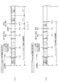
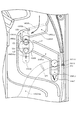
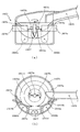
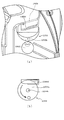
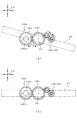
次に、図4、および図5を参照して、開閉扉65f1の上面の構造について説明する。まず、図4(a)は、開閉扉65f1が閉鎖された状態における可変入賞装置65の正面斜視図であり、図4(b)は、開閉扉65f1が開放された状態における可変入賞装置65の正面斜視図である。
Next, the structure of the upper surface of the opening / closing door 65f1 will be described with reference to FIGS. 4 and 5. First, FIG. 4A is a front perspective view of the variable winning
図4(a)に示した通り、開閉扉65f1の上面には、遊技球の流下を妨げるために設けられている凸部65f1a〜65f1cが設けられている。開閉扉65f1の上面を流下する遊技球は、各凸部65f1a〜65f1cによって流下を妨げられるので、各凸部65f1a〜65f1cの外周に沿って開閉扉65f1上を流下する。つまり開閉扉65f1上には、各凸部65f1a〜65f1cによってつづら折り状の流路が形成されることになる。このため、各凸部65f1a〜65f1cが設けられていない場合(即ち、遊技球が開閉扉65f1上を正面視右方向から左方向へと直線的に流下可能な場合)に比較して、開閉扉65f1の上面を流下しきるまでに要する期間を長くすることができる。これにより、1の遊技球が開閉扉65f1の上面を流下している間に、複数の遊技球を追加して開閉扉65f1の上面に到達させ易くなる。よって、大当たり待機状態において、より多くの遊技球が開閉扉65f1の上面を流下しているタイミングで、作動入賞口660へと遊技球を入球させて大当たりを開始させる(開閉扉65f1を開放させる)ことによって、より多くの遊技球をオーバー入賞させることができる。
As shown in FIG. 4A, convex portions 65f1a to 65f1c provided to prevent the flow of the game ball are provided on the upper surface of the opening / closing door 65f1. Since the game ball flowing down the upper surface of the opening / closing door 65f1 is prevented from flowing down by the convex portions 65f1a to 65f1c, it flows down on the opening / closing door 65f1 along the outer circumference of the convex portions 65f1a to 65f1c. That is, on the opening / closing door 65f1, a zigzag-shaped flow path is formed by the convex portions 65f1a to 65f1c. Therefore, as compared with the case where the convex portions 65f1a to 65f1c are not provided (that is, the game ball can flow linearly on the opening / closing door 65f1 from the right direction to the left direction in the front view), the opening / closing door The period required for the upper surface of 65f1 to flow down can be lengthened. As a result, it becomes easy to add a plurality of game balls to reach the upper surface of the opening / closing door 65f1 while one game ball is flowing down the upper surface of the opening / closing door 65f1. Therefore, in the jackpot standby state, at the timing when more game balls are flowing down the upper surface of the opening / closing door 65f1, the game balls are entered into the
図4(b)は、開閉扉65f1が開放された状態を示した図である。図4(b)に示した通り、開閉扉65f1は、正面視手前側から正面視奥側に向けてスライド動作し、遊技盤13に設けられている開口部を介して遊技盤13の内側に収納される。これにより、右特定入賞口65aが開放された状態となる。右特定入賞口65aが開放されると、右可変入賞装置65の右方向から流下してきた遊技球が右特定入賞口65aに入球可能となる。また、開閉扉65f1を収納するための開口部の高さは、遊技球の直径に対して十分に低いので、開閉扉65f1のスライド移動が開始される時点で開閉扉65f1の上面を流下中であった遊技球が開閉扉65f1と共に遊技盤13の内部に収納されてしまうことを抑制できる。よって、開閉扉65f1が遊技盤13の内部へとスライド移動した場合に、開閉扉65f1の上面に乗っていた遊技球を特定入賞口65aへと落下させることができる。
FIG. 4B is a diagram showing a state in which the opening / closing door 65f1 is opened. As shown in FIG. 4B, the opening / closing door 65f1 slides from the front side of the front view toward the back side of the front view, and enters the inside of the
ここで、本第1実施形態では、1の遊技球が開閉扉65f1を通過しきるまでに要する期間が約4秒間となるように構成している。そして、遊技球の発射間隔(1の遊技球を発射してから、次の遊技球を発射するまでの間隔)は最短で0.6秒となるように構成している。これにより1の遊技球が開閉扉65f1の上面を流下中に、追加で6個前後の遊技球を発射することができる。よって、大当たり待機状態において、7個前後の遊技球を可変入賞装置65に向けて連続して発射してから、作動入賞口660に対して遊技球を入球させることにより、7個前後の遊技球が開閉扉65f1の上面を流下中の状態で1ラウンド目を開始させることができる。即ち、開閉扉65f1を開放させて開閉扉65f1の上面を流下中の遊技球を全て特定入賞口65aに入賞させることができる。これにより、本来(2個分の入賞に対する賞球)よりも多い賞球を獲得することができるので、大当たり待機状態において、より多くの遊技球を開閉扉65f1に到達させた状態で作動入賞口660へ遊技球を入球させようと遊技者に工夫させることができる。従って、遊技者の大当たり待機状態における遊技に対する興趣を向上させることができる。これにより、大当たり待機状態において、遊技球が開閉扉65f1を流下している間に作動入賞口660へと遊技球を入球させることにより、オーバー入賞を意図的に発生させることができる遊技性を提供できる。
Here, in the first embodiment, the period required for one game ball to completely pass through the opening / closing door 65f1 is set to about 4 seconds. The firing interval of the game ball (the interval from the launch of one game ball to the launch of the next game ball) is configured to be 0.6 seconds at the shortest. As a result, about 6 additional game balls can be launched while one game ball is flowing down the upper surface of the opening / closing door 65f1. Therefore, in the jackpot standby state, about 7 game balls are continuously fired toward the variable winning
なお、本第1実施形態では、開閉扉65f1の上面に3つの凸部65f1a〜65f1cを設けることにより、凸部65f1a〜65f1cを遊技球が迂回する構成とし、遊技球が開閉扉65f1を通過する通過期間が長くなるように構成していたが、これに限られるものではない。例えば、凸部65f1a〜65f1cを設けるのに代えて、または加えて、開閉扉65f1の上面の材質を、他の部分(遊技盤13の表面や可変入賞装置65の内面等)よりも摩擦係数が大きい材質(例えば、弾性体等)で構成したり、遊技球が転動し難くなる加工を施したり(例えば、表面に凹凸を設ける等)してもよい。
In the first embodiment, by providing the three convex portions 65f1a to 65f1c on the upper surface of the opening / closing door 65f1, the game ball bypasses the convex portions 65f1a to 65f1c, and the game ball passes through the opening / closing door 65f1. It was configured to have a longer transit period, but it is not limited to this. For example, instead of or in addition to providing the convex portions 65f1a to 65f1c, the material of the upper surface of the opening / closing door 65f1 has a friction coefficient higher than that of other parts (the surface of the
本第1実施形態では、1ラウンドが開始されてから30秒間が経過するか、または30秒間が経過する前に特定入賞口65aに2個以上の遊技球が入球した場合に1ラウンド目を終了させる構成としていた。即ち、右打ちを行っていれば、ほぼ確実に上限個数(2個)の遊技球を特定入賞口65aに入球させて1ラウンド目が終了するように、終了条件を設定していたが、これに限られるものではない。例えば、1ラウンドが開始されてから右特定入賞口65aを狙って右打ちを行っても、遊技球を入球させることが困難となる長さの期間で1ラウンド目が終了する構成としてもよい。具体的には例えば、1ラウンドが開始されてから0.5秒間が経過するか、0.5秒間が経過する前に10個以上の遊技球が特定入賞口65aに入賞した場合に1ラウンド目を終了する構成としてもよい。このように構成した場合、作動入賞口660へと遊技球が入球したタイミングで開閉扉65f1の上面を遊技球が通過中でなければ、遊技球を1個も右特定入賞口65aへと入球させることなく1ラウンド目が終了してしまう可能性が高くなる遊技性を提供することができる。よって、1ラウンド目において賞球を獲得したいと考える遊技者に対して、大当たり待機状態において作動入賞口660へと遊技球を入球させる前に、遊技球を開閉扉65f1に向けて打ち出させた後で作動入賞口660を狙うという遊技性を楽しませることができる。よって、遊技者の大当たり待機状態における遊技に対する興趣を向上させることができる。
In the first embodiment, if 30 seconds have passed since the start of one round, or if two or more game balls enter the specific winning
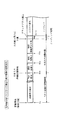
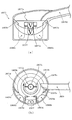
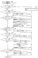
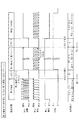
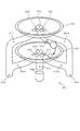
図5は、開閉扉65f1を鉛直上面側から見た上面図である。図5に示した通り、開閉扉65f1の上面のうち、遊技球が転動可能(容易)なつづら折り状の経路に、遊技球の通過を検出可能な通過検出センサ228a〜228fが埋め込まれている。これらの通過検出センサ228a〜228fは、開閉扉65f1の上面に形成されている経路において、互いに少なくとも遊技球の直径を超える距離を離して配置されている。これらの通過検出センサ228a〜228fは、その上方に遊技球が配置されている場合に出力がH(ハイ)となり、上方を妨げるものが何もない場合に出力がL(ロー)となる公知の光学センサで構成されている。本第1実施形態では、これらの通過検出センサ228a〜228fの出力の組み合わせを音声ランプ制御装置113側で監視する構成としている。そして、大当たり待機状態の間は、通過検出センサ228a〜228fの出力の組み合わせに応じて、開閉扉65f1の上面を流下中の遊技球の個数の目安を示唆する演出を実行可能に構成している。即ち、作動入賞口660に遊技球を入球させた場合の有利度合いを示唆する演出を実行可能に構成している。これにより、演出内容に応じてより多くの遊技球が開閉扉65f1上を流下中であることを示唆されたタイミングで作動入賞口660へと遊技球を入球させることにより、より多くの個数の遊技球をより容易にオーバー入賞させることができる。よって、遊技者がより気軽にオーバー入賞を狙うことができる。この大当たり待機状態中に実行される待機状態演出の詳細について、図7を参照して説明する。
FIG. 5 is a top view of the opening / closing door 65f1 as viewed from the vertical upper surface side. As shown in FIG. 5, on the upper surface of the opening / closing door 65f1,
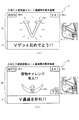
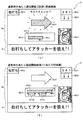
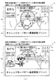
図7(a),(b)は、大当たり待機状態において実行される待機状態演出中の表示態様を示した図である。図7(a)に示した通り、大当たり待機状態になると、第3図柄表示装置81の表示画面における正面視上側に、「大当たり確定!」という文字が表示された表示領域HR1が形成される。この表示領域HR1の表示内容により、遊技者に対して大当たりが確定した(大当たりの権利を得た)ことを容易に認識させることができる。また、表示領域HR1の下方には、大当たり待機状態となる前に実行されていた変動表示演出において最終的に停止表示(確定表示)された第3図柄の組み合わせ(最終停止図柄)が表示される。大当たり待機状態の間も最終停止図柄を表示させておくことにより、今回の大当たりが確変大当たりであるか、通常大当たりであるかを遊技者が任意のタイミングで容易に確認することができる。
7 (a) and 7 (b) are views showing a display mode during the standby state effect executed in the jackpot standby state. As shown in FIG. 7A, in the jackpot standby state, a display area HR1 in which the characters "Big hit confirmed!" Is displayed is formed on the upper side of the front view on the display screen of the third
最終停止図柄に対して正面視右側には、縦長で、縦方向に6つの小領域に分割されているチャンスメーターCMが表示されている。このチャンスメーターCMを構成する各領域は、消灯した見た目となる態様と、発光した見た目となる態様とに可変可能に構成されており、発光した見た目となっている小領域の個数によって、作動入賞口660に遊技球を入球させた際の有利度合いを示唆する構成としている。より具体的には、小領域の個数は、通過検出センサ228a〜228fのうち、出力がH(ハイ)となっているセンサの個数に応じて、下側の小領域から順番(優先的)に発光した見た目(点灯態様)に設定される構成となっている。つまり、チャンスメーターCMのうち、発光した見た目(点灯態様)となっている小領域の個数分の遊技球が、少なくとも開閉扉65f1の上面を通過中である(開閉扉65f1が開放された場合に右特定入賞口65aへと入賞させることができる)ことが示唆される。以降、説明の簡略化のため、チャンスメーターCMのうち、発光した見た目の小領域のことを「ゲージ」と称し、発光した見た目の小領域の個数のことを「ゲージ数」と称し、小領域が発光した見た目に可変することを、「ゲージが貯まる」と称することにする。
On the right side of the front view with respect to the final stop symbol, a chance meter CM that is vertically long and is divided into six small areas in the vertical direction is displayed. Each region constituting the chance meter CM is variably configured to have a mode in which the light is turned off and a mode in which the light is emitted, and an operation prize is obtained depending on the number of small regions having the appearance of emitting light. The configuration suggests the degree of advantage when a game ball is inserted into the
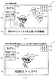
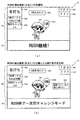
最終停止図柄の下方には、「「GO!」を狙うとメーターチャージ!!」との文字と、「タイミングを合わせて右上を狙え!!」との文字と、作動入賞口660を狙うように示唆する画像とが表示された表示領域HR2が形成される。この表示領域HR2の表示内容により、遊技者に対して「GO!」の文字が付された普通入球口(スルーゲート)67(図2参照)を狙うことにより、表示画面における正面視右側に表示されたチャンスメーターCMのゲージ数を増加させることができるということを容易に理解させることができる。なお、上述した通り、このチャンスメーターCMは、開閉扉65f1の上面に配設されている通過検出センサ228a〜228fの検出内容に連動してゲージ数が可変される。普通入球口(スルーゲート)67に入球する程度の発射強度(発射速度)で遊技球を発射することにより、その下流に配設されている可変入賞装置65に対しても遊技球を到達させることができる。よって、普通入球口(スルーゲート)67が配置されている方向に向けて連続して遊技球を発射することで、可変入賞装置65の開閉扉65f1の上面にも遊技球が連続して到達する。この状態で、表示領域HR2の表示内容に従って作動入賞口660を狙って(即ち、95%〜100%の発射強度で)遊技球を発射することにより、大当たりが開始されて開閉扉65f1が開放される。これにより、開閉扉65f1を流下中の遊技球をほぼ右特定入賞口65aに入賞(入球)させることができる。なお、上述した通り、作動入賞口660に対して正面視左方には、一定の回転速度で回転動作を行う回動部材670aが設けられている。この回動部材670aは、その回転位置に応じて、作動入賞口660へと遊技球が入球することを妨げ得るため、遊技者に対して、チャンスメーターCMのゲージ数だけでなく、回動部材670aの回転位置も加味した発射タイミングで遊技球を発射させることができる。よって、大当たり待機状態における遊技者の遊技に対する興趣をより向上させることができる。
Below the final stop symbol, "GO!" Is aimed at and the meter is charged! !! A display area HR2 is formed in which the characters "", the characters "Aim at the upper right at the same timing !!", and an image suggesting to aim at the
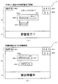
図7(b)は、チャンスメーターCMのゲージが3つ分貯まっている状態を示した図である。図7(b)に示した通り、通過検出センサ228c〜228eの3つのセンサの上側を遊技球が通過中となっている場合に、これら3つのセンサの出力がH(ハイ)となる。音声ランプ制御装置113は、H出力となっているセンサの個数を検出して、チャンスメーターCMの態様に反映させる。図7(b)の例では、3つのセンサ(通過検出センサ228c〜228e)の出力がHとなっているので、チャンスメーターCMのゲージが3つ貯まった状態の態様で表示される。このように、開閉扉65f1の上面を通過中の遊技球の個数を通過検出センサ228a〜228fによって検出し、検出結果に応じて、通過中の遊技球の個数の目安をチャンスメーターCMのゲージ数で表示させる構成とすることにより、遊技者に対して作動入賞口660を狙うべきタイミングをより分かり易くすることができる。よって、パチンコ機10での遊技を行った経験が浅い遊技者に対しても、作動入賞口660を狙うタイミングを直感的に理解させ易くすることができる。これにより、初めて遊技を行う遊技者に対しても、気軽に遊技を行わせることができるので、パチンコ機10の稼働率を向上させることができる。
FIG. 7B is a diagram showing a state in which three gauges of the chance meter CM are stored. As shown in FIG. 7B, when the game ball is passing above the three sensors of the
なお、本第1実施形態では、大当たり待機状態において、開閉扉65f1の上面を通過中の遊技球の個数の目安をチャンスメーターCMのゲージ数によって示唆することで、作動入賞口660へと遊技球を入球させた場合の有利度合いを示唆する構成としていたが、これに限られるものではない。例えば、チャンスメーターCMのゲージ数によって大当たりの有利度合いを示唆する構成としてもよい。具体的には例えば、チャンスメーターCMのゲージ数によって、大当たり種別を示唆することにより、作動入賞口660に遊技球を入球させた場合の有利度合いを遊技者に示唆する構成としてもよい。また、例えば、大当たりが確定した時点では大当たりのラウンド数が不定となるように構成し、作動入賞口660を通過させたタイミングで大当たりのラウンド数を抽選する構成としてもよい。そして、ゲージ数によって、作動入賞口660に遊技球を入球させた場合に実行される抽選で決定されるラウンド数を示唆することで、作動入賞口660に遊技球を入球させた場合の有利度合いを遊技者に示唆する構成としてもよい。
In the first embodiment, the number of game balls passing through the upper surface of the opening / closing door 65f1 in the jackpot standby state is suggested by the number of gauges of the chance meter CM, so that the game balls reach the
図2に戻って説明を続ける。遊技盤13の右下側の隅部には、証紙や識別ラベル等を貼着するための貼着スペースK1が設けられている。この、貼着スペースK1に貼られた証紙等は、前面枠14の小窓35(図1参照)を通じて視認することができる。
The explanation will be continued by returning to FIG. A sticking space K1 for sticking a certificate stamp, an identification label, or the like is provided in the lower right corner of the
更に、遊技盤13には、アウト口66が設けられている。いずれの入賞口にも入賞しなかった遊技球はアウト口66を通って図示しない球排出路へと案内される。遊技盤13には、遊技球の落下方向を適宜分散、調整等するために多数の釘が植設されているとともに、風車等の各種部材(役物)が配設されている。
Further, the
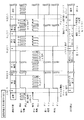
図3に示すように、パチンコ機10の背面側には、制御基板ユニット90、91と、裏パックユニット94とが主に備えられている。制御基板ユニット90は、主基板(主制御装置110)と音声ランプ制御基板(音声ランプ制御装置113)と表示制御基板(表示制御装置114)とが搭載されてユニット化されている。制御基板ユニット91は、払出制御基板(払出制御装置111)と発射制御基板(発射制御装置112)と電源基板(電源装置115)とカードユニット接続基板116とが搭載されてユニット化されている。
As shown in FIG. 3, the
裏パックユニット94は、保護カバー部を形成する裏パック92と払出ユニット93とがユニット化されている。また、各制御基板には、各制御を司る1チップマイコンとしてのMPU、各種機器との連絡をとるポート、各種抽選の際に用いられる乱数発生器、時間計数や同期を図る場合などに使用されるクロックパルス発生回路等が、必要に応じて搭載されている。
In the
なお、主制御装置110、音声ランプ制御装置113及び表示制御装置114、払出制御装置111及び発射制御装置112、電源装置115、カードユニット接続基板116は、それぞれ基板ボックス100〜104に収納されている。基板ボックス100〜104は、ボックスベースと該ボックスベースの開口部を覆うボックスカバーとを備えており、そのボックスベースとボックスカバーとが互いに連結されて、各制御装置や各基板が収納される。
The
また、基板ボックス100(主制御装置110)及び基板ボックス102(払出制御装置111及び発射制御装置112)は、ボックスベースとボックスカバーとを封印ユニット(図示せず)によって開封不能に連結(かしめ構造による連結)している。また、ボックスベースとボックスカバーとの連結部には、ボックスベースとボックスカバーとに亘って封印シール(図示せず)が貼着されている。この封印シールは、脆性な素材で構成されており、基板ボックス100,102を開封するために封印シールを剥がそうとしたり、基板ボックス100,102を無理に開封しようとすると、ボックスベース側とボックスカバー側とに切断される。よって、封印ユニット又は封印シールを確認することで、基板ボックス100,102が開封されたかどうかを知ることができる。
Further, in the board box 100 (main control device 110) and the board box 102 (
払出ユニット93は、裏パックユニット94の最上部に位置して上方に開口したタンク130と、タンク130の下方に連結され下流側に向けて緩やかに傾斜するタンクレール131と、タンクレール131の下流側に縦向きに連結されるケースレール132と、ケースレール132の最下流部に設けられ、払出モータ216(図8参照)の所定の電気的構成により遊技球の払出を行う払出装置133とを備えている。タンク130には、遊技ホールの島設備から供給される遊技球が逐次補給され、払出装置133により必要個数の遊技球の払い出しが適宜行われる。タンクレール131には、当該タンクレール131に振動を付加するためのバイブレータ134が取り付けられている。
The
また、払出制御装置111には状態復帰スイッチ120が設けられ、発射制御装置112には可変抵抗器の操作つまみ121が設けられ、電源装置115にはRAM消去スイッチ122(図3参照)が設けられている。状態復帰スイッチ120は、例えば、払出モータ216(図8参照)部の球詰まり等、払出エラーの発生時に球詰まりを解消(正常状態への復帰)するために操作される。操作つまみ121は、発射ソレノイドの発射力を調整するために操作される。RAM消去スイッチ122(図3参照)は、パチンコ機10を初期状態に戻したい場合に電源投入時に操作される。
Further, the
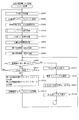
<第1実施形態における電気的構成について>
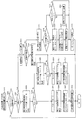
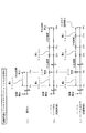
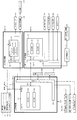
次に、図8を参照して、本パチンコ機10の電気的構成について説明する。図8は、パチンコ機10の電気的構成を示すブロック図である。
<About the electrical configuration in the first embodiment>
Next, the electrical configuration of the
主制御装置110には、演算装置である1チップマイコンとしてのMPU201が搭載されている。MPU201には、該MPU201により実行される各種の制御プログラムや固定値データを記憶したROM202と、そのROM202内に記憶される制御プログラムの実行に際して各種のデータ等を一時的に記憶するためのメモリであるRAM203と、そのほか、割込回路やタイマ回路、データ送受信回路などの各種回路が内蔵されている。なお、払出制御装置111や音声ランプ制御装置113などのサブ制御装置に対して動作を指示するために、主制御装置110から該サブ制御装置へ各種のコマンドがデータ送受信回路によって送信されるが、かかるコマンドは、主制御装置110からサブ制御装置へ一方向にのみ送信される。
The
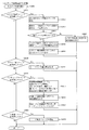
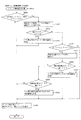
主制御装置110では、大当たり抽選や第1図柄表示装置37および第3図柄表示装置81における表示の設定、第2図柄表示装置83における表示結果の抽選といったパチンコ機10の主要な処理を実行する。RAM203には、これらの処理を制御するための各種カウンタを格納するカウンタ用バッファ(図12参照)が設けられている。
The
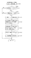
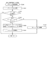
ここで、図12を参照して、主制御装置110のRAM203内に設けられるカウンタ等について説明する。これらのカウンタ等は、大当たり抽選や第1図柄表示装置37および第3図柄表示装置81の表示の設定、第2図柄表示装置83の表示結果の抽選などを行うために、主制御装置110のMPU201で使用される。
Here, with reference to FIG. 12, a counter and the like provided in the
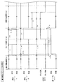
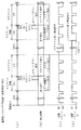
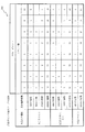
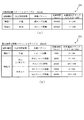
大当たり抽選や第1図柄表示装置37および第3図柄表示装置81の表示の設定には、大当たりの抽選に使用する第1当たり乱数カウンタC1と、大当たり図柄の選択に使用する第1当たり種別カウンタC2と、停止種別を選択するために使用する停止種別カウンタC3と、変動パターンの選択に使用する変動種別カウンタCS1と、第1当たり乱数カウンタC1の初期値設定に使用する第1初期値乱数カウンタCINI1とが用いられる。また、普通図柄(第2図柄表示装置83)の抽選には、第2当たり乱数カウンタC4が用いられ、第2当たり乱数カウンタC4の初期値設定には第2初期値乱数カウンタCINI2が用いられる。これら各カウンタは、更新の都度前回値に1が加算され、最大値に達した後0に戻るループカウンタとなっている。
The jackpot lottery and the display settings of the first
各カウンタは、例えば、タイマ割込処理(図21参照)の実行間隔である2ミリ秒間隔で更新され、また、一部のカウンタは、メイン処理(図30参照)の中で不定期に更新されて、その更新値がRAM203の所定領域に設定されたカウンタ用バッファに適宜格納される。RAM203には、4つの保留エリア(保留第1〜第4エリア)からなる第1特別図柄保留球格納エリア203aが設けられており、これらの各エリアには、第1入球口64への入球タイミングに合わせて、第1当たり乱数カウンタC1、第1当たり種別カウンタC2及び停止種別選択カウンタC3の各値がそれぞれ格納される。また、RAM203には、4つの保留エリア(保留第1〜第4エリア)からなる第2特別図柄保留球格納エリア203bが設けられており、これらの各エリアには、第2入球口640への入球タイミングに合わせて、第1当たり乱数カウンタC1、第1当たり種別カウンタC2及び停止種別選択カウンタC3の各値がそれぞれ格納される。また、RAM203には、実行エリア203cが設けられており、抽選を実行する対象となる第1当たり乱数カウンタC1、第1当たり種別カウンタC2及び停止種別選択カウンタC3の各値が格納される。更に、RAM203には、1つの実行エリアと4つの保留エリア(保留第1〜第4エリア)とからなる普通図柄保留球格納エリア203dが設けられており、これらの各エリアには、遊技球が普通入球口(スルーゲート)67を通過したタイミングに合わせて、第2当たり乱数カウンタC4の値が格納される。
Each counter is updated, for example, at intervals of 2 milliseconds, which is the execution interval of the timer interrupt process (see FIG. 21), and some counters are updated irregularly in the main process (see FIG. 30). Then, the updated value is appropriately stored in the counter buffer set in the predetermined area of the
各カウンタについて詳しく説明する。第1当たり乱数カウンタC1は、所定の範囲(例えば、0〜399)内で順に1ずつ加算され、最大値(例えば、0〜399の値を取り得るカウンタの場合は399)に達した後0に戻る構成となっている。特に、第1当たり乱数カウンタC1が1周した場合、その時点の第1初期値乱数カウンタCINI1の値が当該第1当たり乱数カウンタC1の初期値として読み込まれる。 Each counter will be described in detail. The first random number counter C1 is incremented by 1 in order within a predetermined range (for example, 0 to 399), and after reaching the maximum value (for example, 399 in the case of a counter capable of taking a value of 0 to 399), it is 0. It is configured to return to. In particular, when the first random number counter C1 makes one round, the value of the first initial value random number counter CINI1 at that time is read as the initial value of the first random number counter C1.
また、第1初期値乱数カウンタCINI1は、第1当たり乱数カウンタC1と同一範囲で更新されるループカウンタとして構成される。即ち、例えば、第1当たり乱数カウンタC1が0〜399の値を取り得るループカウンタである場合には、第1初期値乱数カウンタCINI1もまた、0〜399の範囲のループカウンタである。この第1初期値乱数カウンタCINI1は、タイマ割込処理(図21参照)の実行毎に1回更新されると共に、メイン処理(図30参照)の残余時間内で繰り返し更新される。 Further, the first initial value random number counter CINI1 is configured as a loop counter updated in the same range as the first random number counter C1. That is, for example, when the first random number counter C1 is a loop counter capable of taking a value of 0 to 399, the first initial value random number counter CINI1 is also a loop counter in the range of 0 to 399. The first initial value random number counter CINI1 is updated once for each execution of the timer interrupt process (see FIG. 21), and is repeatedly updated within the remaining time of the main process (see FIG. 30).
第1当たり乱数カウンタC1の値は、例えば定期的に(本実施形態ではタイマ割込処理毎に1回)更新され、遊技球が第1入球口64に入球した場合には、その値がRAM203の第1特別図柄保留球格納エリア203aに格納される。一方、遊技球が第2入球口640に入球した場合には、その値が第2特別図柄保留球格納エリア203bに格納される。
The value of the first random number counter C1 is updated periodically (once for each timer interrupt process in this embodiment), and when the game ball enters the
上述した通り、特別図柄の大当たりとなる乱数の値は、主制御装置110のROM202に格納される第1当たり乱数テーブル202a(図9(b)参照)によって設定されており、第1当たり乱数カウンタC1の値が、第1当たり乱数テーブルによって設定された大当たりとなる乱数の値と一致する場合に、特別図柄の大当たりと判定する。また、この第1当たり乱数テーブル202aは、特別図柄の低確率時(特別図柄の低確率状態である期間)用と、その低確率時より特別図柄の大当たりとなる確率の高い高確率時(特別図柄の確変状態である期間)用との2種類に分けられ、それぞれに含まれる大当たりとなる乱数の個数が異なって設定されている(図9(b)参照)。このように、大当たりとなる乱数の個数を異ならせることにより、特別図柄の低確率時と特別図柄の高確率時とで、大当たりとなる確率が変更される。
As described above, the value of the random number that becomes the jackpot of the special symbol is set by the first random number table 202a (see FIG. 9B) stored in the
第1当たり種別カウンタC2は、特別図柄の大当たりとなった場合に、第1図柄表示装置37の表示態様を決定するものであり、所定の範囲(例えば、0〜99)内で順に1ずつ加算され、最大値(例えば、0〜99の値を取り得るカウンタの場合は99)に達した後0に戻る構成となっている。第1当たり種別カウンタC2の値は、例えば、定期的に(本実施形態ではタイマ割込処理毎に1回)更新され、遊技球が第1入球口64に入球した場合には、その値がRAM203の第1特別図柄保留球格納エリア203a(特別図柄の抽選が実行中でない場合は実行エリア203c)に格納される。一方、遊技球が第2入球口640へと入球した場合には、その値がRAM203の第2特別図柄保留球格納エリア203b(特別図柄の抽選が実行中でない場合は実行エリア203c)に格納される。
The first hit type counter C2 determines the display mode of the first
ここで、実行エリア203cに格納された第1当たり乱数カウンタC1の値が、特別図柄の大当たりとなる乱数でなければ、即ち、特別図柄の外れとなる乱数であれば、第1図柄表示装置37に表示される停止図柄に対応した表示態様は、特別図柄の外れ時のものとなる。
Here, if the value of the first hit random number counter C1 stored in the
一方で、実行エリア203cに格納された第1当たり乱数カウンタC1の値が、特別図柄の大当たりとなる乱数であれば、第1図柄表示装置37に表示される停止図柄に対応した表示態様は、特別図柄の大当たり時のものとなる。この場合、その大当たり時の具体的な表示態様は、同じ第1特別図柄保留球格納エリア203a、または第2特別図柄保留球格納エリア203bに格納されている第1当たり種別カウンタC2の値が示す表示態様となる。
On the other hand, if the value of the first hit random number counter C1 stored in the
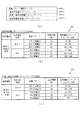
本実施形態のパチンコ機10における第1当たり乱数カウンタC1は、0〜399の範囲の2バイトのループカウンタとして構成されている。この第1当たり乱数カウンタC1において、特別図柄の低確率時に、特別図柄の大当たりとなる乱数値は2個あり、その乱数値である「0,1」は、低確率時用の第1当たり乱数テーブルに格納されている(図9(b)の202a1参照)。このように特別図柄の低確率時には、乱数値の総数が400ある中で、大当たりとなる乱数値の総数が2なので、特別図柄の大当たりとなる確率は、「1/200」となる。なお、大当たりとなる乱数値(カウンタ値)は、第1特別図柄の抽選と、第2特別図柄の抽選とで共通である。
The first random number counter C1 in the
一方で、特別図柄の高確率時に、特別図柄の大当たりとなる乱数値は20個あり、その値である「0〜19」は、高確率時用の第1当たり乱数テーブルに格納されている(図9(b)の202a2参照)。このように特別図柄の高確率時には、乱数値の総数が400ある中で、大当たりとなる乱数値の総数が20なので、特別図柄の大当たりとなる確率は、「1/20」となる。 On the other hand, when the special symbol has a high probability, there are 20 random number values that are big hits of the special symbol, and the values "0 to 19" are stored in the first random number table for the high probability ( See 202a2 in FIG. 9B). As described above, when the probability of the special symbol is high, the total number of random numbers that will be the jackpot is 20 while the total number of random numbers is 400, so the probability of the special symbol being the jackpot is "1/20".
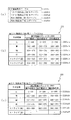
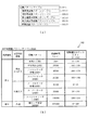
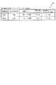
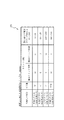
また、本実施形態のパチンコ機10における第1当たり種別カウンタC2の値は、0〜99の範囲のループカウンタとして構成されている。そして、図10(a)に示すように、第1特別図柄の抽選で大当たりとなり、第1当たり種別カウンタC2の値が「0〜4」であった場合の大当たり種別は、「大当たりA」(8ラウンド確変大当たり)となる。また、値が「5〜64」であった場合の大当たり種別は、「大当たりB」(5ラウンド確変大当たり)となり、値が「65〜99」であった場合の大当たり種別は、「大当たりC」(5ラウンド通常大当たり)となる。
Further, the value of the first type counter C2 in the
一方、第2特別図柄の抽選で大当たりとなり、第1当たり種別カウンタC2の値が「0〜4」であった場合の大当たり種別は、「大当たりD」(16ラウンド確変大当たり)となる。また、値が「5〜64」であった場合の大当たり種別は、「大当たりE」(10ラウンド確変大当たり)となり、値が「65〜99」であった場合の大当たり種別は、「大当たりF」(10ラウンド通常大当たり)となる。 On the other hand, when the lottery of the second special symbol is a big hit and the value of the first hit type counter C2 is "0-4", the big hit type is "big hit D" (16 round probability variation big hit). In addition, the jackpot type when the value is "5 to 64" is "big hit E" (10 round probability variation jackpot), and the jackpot type when the value is "65 to 99" is "big hit F". (10 rounds usually a big hit).
このように、本実施形態のパチンコ機10は、特別図柄の種類、および第1当たり種別カウンタC2が示す乱数の値によって、6種類の当たり種別(大当たりA〜F)が決定されるように構成されている。
As described above, the
停止種別選択カウンタC3は、例えば0〜99の範囲内で順に1ずつ加算され、最大値(つまり99)に達した後0に戻る構成となっている。本実施形態では、停止種別選択カウンタC3によって、第3図柄表示装置81で表示される外れ時の停止種別が選択され、リーチが発生した後、最終停止図柄がリーチ図柄の前後に1つだけずれて停止する「前後外れリーチ」(例えば98,99)と、同じくリーチ発生した後、最終停止図柄がリーチ図柄の前後以外で停止する「前後外れ以外リーチ」(例えば90〜97の範囲)と、リーチ発生しない「完全外れ」(例えば0〜89の範囲)との3つの停止(演出)パターンが選択される。停止種別選択カウンタC3の値は、例えば定期的に(本実施形態ではタイマ割込処理毎に1回)更新され、遊技球が第1入球口64に入球した場合は、その値がRAM203の第1特別図柄保留球格納エリア203a(特別図柄の抽選が実行中でない場合は実行エリア203c)に格納される。また、遊技球が第2入球口640に入球した場合は、その値がRAM203の第2特別図柄保留球格納エリア203b(特別図柄の抽選が実行中でない場合は実行エリア203c)に格納される。
The stop type selection counter C3 is configured to be incremented by 1 in order within the range of 0 to 99, and return to 0 after reaching the maximum value (that is, 99). In the present embodiment, the stop type selection counter C3 selects the stop type at the time of disconnection displayed by the third
なお、停止種別選択カウンタC3の値(乱数値)から、特別図柄の停止種別を決定するための乱数値は、停止種別選択テーブル(図示せず)により設定されており、このテーブルは、主制御装置110のROM202内に設けられている。また、本実施形態ではこのテーブルを、特別図柄の高確率時用と、特別図柄の低確率時用とに分けており、テーブルに応じて、外れの停止種別ごとに設定される乱数値の範囲を変えている。これは、パチンコ機10が特別図柄の高確率状態であるか、特別図柄の低確率状態であるか等に応じて、停止種別の選択比率を変更するためである。
From the value (random value) of the stop type selection counter C3, the random number value for determining the stop type of the special symbol is set by the stop type selection table (not shown), and this table is the main control. It is provided in the
例えば、高確率状態では、大当たりが発生し易いため必要以上にリーチ演出が選択されないように、「完全外れ」の停止種別に対応した乱数値の範囲が0〜89と広い高確率時用のテーブルが選択され、「完全外れ」が選択され易くなる。このテーブルは、「前後外れリーチ」が98,99と狭くなると共に「前後外れ以外リーチ」も90〜97と狭くなり、「前後外れリーチ」や「前後外れ以外リーチ」が選択され難くなる。また、低確率状態であれば、第1入球口64への遊技球の入球時間を確保するために「完全外れ」の停止種別に対応した乱数値の範囲が0〜79と狭い低確率時用のテーブルが選択され、「完全外れ」が選択され難くなる。
For example, in a high-probability state, a table for high-probability times has a wide range of random numbers from 0 to 89 corresponding to the stop type of "completely off" so that the reach effect is not selected more than necessary because a big hit is likely to occur. Is selected, and "completely off" is easily selected. In this table, the "reach outside the front and rear" is narrowed to 98,99 and the "reach other than the front and rear" is also narrowed to 90 to 97, making it difficult to select "reach outside the front and rear" and "reach other than the front and rear". Further, in the low probability state, the range of the random value corresponding to the stop type of "completely off" is narrow as 0 to 79 in order to secure the entry time of the game ball into the
この停止種別選択テーブルは、「前後外れ以外リーチ」の停止種別に対応した乱数値の範囲が80〜97と広くなり、「前後外れ以外リーチ」が選択され易くなっている。よって、低確率状態では、演出時間の長いリーチ表示を多く行うことできるので、第1入球口64への遊技球の入球時間を確保でき、第3図柄表示装置81による変動表示が継続して行われ易くなる。なお、後者のテーブルにおいても、「前後外れリーチ」の停止種別に対応した乱数値の範囲は98,99に設定される。
In this stop type selection table, the range of random value corresponding to the stop type of "reach other than front and rear deviation" is widened to 80 to 97, and "reach other than front and rear deviation" can be easily selected. Therefore, in the low probability state, it is possible to perform a lot of reach display with a long effect time, so that it is possible to secure the ball entry time of the game ball into the first
変動種別カウンタCS1は、例えば0〜198の範囲内で順に1ずつ加算され、最大値(つまり198)に達した後0に戻る構成となっている。変動種別カウンタCS1によって、いわゆるノーマルリーチ、スーパーリーチ等の大まかな表示態様が決定される。表示態様の決定は、具体的には、図柄変動の変動時間の決定である。変動種別カウンタCS1により決定された変動時間に基づいて、音声ランプ制御装置113や表示制御装置114により第3図柄表示装置81で表示される第3図柄のリーチ種別や細かな図柄変動態様が決定される。変動種別カウンタCS1の値は、後述するメイン処理(図30参照)が1回実行される毎に1回更新され、当該メイン処理内の残余時間内でも繰り返し更新される。なお、変動種別カウンタCS1の値(乱数値)から、図柄変動の変動時間を一つ決定する乱数値を格納した変動パターンテーブル202d(図11(a)参照)は、主制御装置110のROM202内に設けられている。
The variation type counter CS1 is configured to be incremented by 1 in order within the range of 0 to 198, and return to 0 after reaching the maximum value (that is, 198). The variable type counter CS1 determines a rough display mode such as so-called normal reach and super reach. Specifically, the determination of the display mode is the determination of the fluctuation time of the symbol variation. Based on the fluctuation time determined by the variation type counter CS1, the reach type and the detailed symbol variation mode of the third symbol displayed on the third
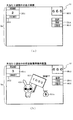
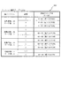
ここで、図11(a)〜(d)を参照して、変動パターンテーブル202dについて説明する。この変動パターンテーブル202dは、図11(a)に示すように、第1特別図柄の抽選に基づく変動パターンを選択するためのテーブルとして、大当たり用変動パターンテーブル202d1(図11(b)参照)と、外れ用(通常)変動パターンテーブル202d2(図11(c)参照)と、外れ用(確変)変動パターンテーブル202d3(図11(d)参照)とが少なくとも規定されている。 Here, the variation pattern table 202d will be described with reference to FIGS. 11A to 11D. As shown in FIG. 11A, the fluctuation pattern table 202d is referred to as a jackpot fluctuation pattern table 202d1 (see FIG. 11B) as a table for selecting a fluctuation pattern based on the lottery of the first special symbol. , The disengagement (normal) variation pattern table 202d2 (see FIG. 11C) and the disengagement (probability variation) variation pattern table 202d3 (see FIG. 11D) are at least specified.
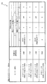
まず、図11(b)を参照して、大当たり用変動パターンテーブル202d1について説明する。図11(b)は、この大当たり用変動パターンテーブル202d1の内容を模式的に示した模式図である。大当たり用変動パターンテーブル202d1は、特別図柄の抽選結果が大当たりである場合に、選択される変動パターンの種別(変動時間)が規定されたデータテーブルである。大当たりの変動パターンとしては、ノーマルリーチ各種(30秒)、スーパーリーチ各種(60秒)、スペシャルリーチ(90秒)がそれぞれ規定されている。大当たり用変動パターンテーブル202d1には、変動種別カウンタCS1の値毎に、各変動パターンが対応付けられている。 First, the jackpot variation pattern table 202d1 will be described with reference to FIG. 11B. FIG. 11B is a schematic diagram schematically showing the contents of the jackpot variation pattern table 202d1. The jackpot variation pattern table 202d1 is a data table in which the type (variation time) of the variation pattern selected when the lottery result of the special symbol is a jackpot is defined. Various normal reach (30 seconds), various super reach (60 seconds), and special reach (90 seconds) are defined as the fluctuation patterns of the jackpot. In the jackpot fluctuation pattern table 202d1, each fluctuation pattern is associated with each value of the fluctuation type counter CS1.
具体的には、変動種別カウンタCS1の値の判定値として「0〜50」の範囲にはノーマルリーチ各種(30秒)の変動パターンが対応付けられ、「51〜179」の範囲にはスーパーリーチ各種(60秒)の変動パターンが対応付けられ、「180〜198」の範囲にはスペシャルリーチ各種(90秒)の変動パターンが対応付けられている。主制御装置110のMPU201は、特別図柄の抽選結果が大当たりとなる場合の変動パターンを選択する場合に、取得している変動種別カウンタCS1の値に対応する判定値が設定されている変動パターンを大当たり用変動パターンテーブル202d1より選択する。
Specifically, as a judgment value of the value of the fluctuation type counter CS1, various fluctuation patterns of normal reach (30 seconds) are associated with the range of "0 to 50", and various super reach are associated with the range of "51 to 179". Fluctuation patterns of (60 seconds) are associated, and variation patterns of various special reach (90 seconds) are associated with the range of "180 to 198". The
図11(c)は、外れ用(通常)変動パターンテーブル202d2の内容を模式的に示した模式図である。外れ用(通常)変動パターンテーブル202d2は、特別図柄の低確率状態において、特別図柄の抽選結果が外れであった場合に選択される変動パターンの種別(変動時間)が規定されたデータテーブルである。特別図柄の抽選結果が外れである場合には、上述したように、図示しない停止種別選択テーブルより停止種別が完全外れ(非リーチ)であるか、リーチ外れ(リーチ共通)であるかが停止種別選択カウンタC3の値によって決定される。具体的には、例えば、特別図柄の低確率状態において停止種別選択カウンタC3の値が「0〜79」の範囲にあれば完全外れを設定し、「80〜99」の範囲にあれば外れリーチ(前後外れリーチ、前後外れ以外リーチ)を設定する。 FIG. 11C is a schematic diagram schematically showing the contents of the deviation pattern table 202d2 for detachment (normal). The deviation pattern table 202d2 is a data table in which the type (variation time) of the variation pattern selected when the lottery result of the special symbol is out of order in the low probability state of the special symbol is defined. .. If the lottery result of the special symbol is out of order, as described above, the stop type is completely out of reach (non-reach) or out of reach (common to reach) from the stop type selection table (not shown). It is determined by the value of the selection counter C3. Specifically, for example, in a low probability state of a special symbol, if the value of the stop type selection counter C3 is in the range of "0 to 79", a complete deviation is set, and if it is in the range of "80 to 99", the deviation reach is set. Set (reach out of front and back, reach other than out of front and back).
ここで、変動パターン種別が、完全外れである場合には、変動時間が比較的短い短外れ(7秒)と、変動時間が比較的長い長外れ(10秒)のいずれかが設定される。短外れ(7秒)に対しては、「0〜98」が、長外れ(10秒)に対しては、「99〜198」が変動種別カウンタCS1の判定値として設定されている。 Here, when the fluctuation pattern type is a complete deviation, either a short deviation (7 seconds) in which the fluctuation time is relatively short or a long deviation (10 seconds) in which the fluctuation time is relatively long is set. For a short deviation (7 seconds), "0 to 98" is set as a determination value, and for a long deviation (10 seconds), "99 to 198" is set as a determination value of the variation type counter CS1.
また、外れリーチに対しては、変動種別カウンタCS1の判定値が「0〜149」の範囲には外れのノーマルリーチ各種(30秒)が、「150〜197」の範囲には外れのスーパーリーチ各種(60秒)が、「198」には外れのスペシャルリーチ各種(90秒)がそれぞれ設定されている。 For out-of-reach, various normal reach (30 seconds) out of the range of "0 to 149" for the judgment value of the fluctuation type counter CS1 and various super reach out of the range of "150 to 197". (60 seconds), but "198" is set with various special reach (90 seconds).
このように、主制御装置110のMPU201は、通常遊技状態時に特別図柄の抽選結果が外れである場合には、停止種別が決定され、外れ用(通常)変動パターンテーブル202d2より取得している変動種別カウンタCS1の値に基づいて、外れ用(通常)変動パターンテーブル202d2より変動パターンを選択する。
As described above, in the
図11(d)は、外れ用(確変)変動パターンテーブル202d3の内容を模式的に示した模式図である。この外れ用(確変)変動パターンテーブル202d3は、特別図柄の確変状態において、特別図柄の抽選が外れとなった場合に選択される変動パターンの種別(変動時間)が規定されたデータテーブルである。この外れ用(確変)変動パターンテーブル202d3では、設定されている変動種別カウンタCS1の値が、上述した外れ用(通常)変動パターンテーブル202d2とは異なっている。 FIG. 11D is a schematic diagram schematically showing the contents of the deviation pattern table 202d3 for deviation (probability variation). The deviation (probability variation) variation pattern table 202d3 is a data table in which the type (variation time) of the variation pattern selected when the lottery of the special symbol is missed in the probability variation state of the special symbol is defined. In this deviation (probability variation) fluctuation pattern table 202d3, the value of the variation type counter CS1 set is different from the deviation (normal) variation pattern table 202d2 described above.
なお、上述したように、遊技状態が確変遊技状態である場合には、図示しない停止種別選択テーブルにより停止種別選択カウンタC3の値が「0〜89」の範囲にあれば、完全外れが決定され、「90〜99」の範囲にあれば外れリーチ(前後外れリーチ、前後外れ以外リーチ)が決定される。 As described above, when the gaming state is the probabilistic gaming state, if the value of the stop type selection counter C3 is in the range of "0 to 89" by the stop type selection table (not shown), complete deviation is determined. , If it is in the range of "90 to 99", the out-of-reach (reach out of front and back, reach other than out of front and back) is determined.
このように、通常遊技状態よりも確変遊技状態である場合には、外れである場合にリーチとなる確率が低く設定されている。よって、確変時に外れの変動時間が長くなってしまい、大当たりとなるまでの期間が長くなってしまうことを抑制できる。よって、大当たりし易い確変遊技状態時に遊技が間延びしてしまい、遊技者が退屈に感じる不具合を抑制できる。 As described above, in the case of the probabilistic gaming state than in the normal gaming state, the probability of reaching is set lower when it is out of the game. Therefore, it is possible to prevent the fluctuation time of the deviation from becoming long at the time of the probability change and the period until the jackpot becomes long. Therefore, it is possible to suppress a problem that the player feels bored because the game is delayed in the probabilistic game state where it is easy to hit the jackpot.
図12に戻って説明を続ける。第2当たり乱数カウンタC4は、例えば0〜239の範囲内で順に1ずつ加算され、最大値(つまり239)に達した後0に戻るループカウンタとして構成されている。また、第2当たり乱数カウンタC4が1周した場合、その時点の第2初期値乱数カウンタCINI2の値が当該第2当たり乱数カウンタC4の初期値として読み込まれる。第2当たり乱数カウンタC4の値は、本実施形態ではタイマ割込処理毎に、例えば定期的に更新され、遊技球がスルーゲート67を通過したことが検知された時に取得され、RAM203の普通図柄保留球格納エリア203dに格納される。
The explanation will be continued by returning to FIG. The second random number counter C4 is configured as a loop counter in which, for example, 1 is added in order in the range of 0 to 239, the maximum value (that is, 239) is reached, and then the counter returns to 0. Further, when the second hit random number counter C4 makes one round, the value of the second initial value random number counter CINI2 at that time is read as the initial value of the second hit random number counter C4. In the present embodiment, the value of the second random number counter C4 is updated periodically, for example, for each timer interrupt process, and is acquired when it is detected that the game ball has passed through the through
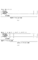
そして、普通図柄の当たりとなる乱数の値は、主制御装置のROM202に格納される第2当たり乱数テーブル202c(図10(b)参照)によって設定されており、第2当たり乱数カウンタC4の値が、第2当たり乱数テーブルによって設定された当たりとなる乱数の値と一致する場合に、普通図柄の当たりと判定する。また、この第2当たり乱数テーブルは、普通図柄の低確率時(普通図柄の通常状態である期間)用と、その低確率時より普通図柄の当たりとなる確率の高い高確率時(普通図柄の時短状態である期間)用との2種類に分けられ、それぞれに含まれる大当たりとなる乱数の個数が異なって設定されている(図10(b)参照)。このように、当たりとなる乱数の個数を異ならせることにより、普通図柄の低確率時と普通図柄の高確率時とで、当たりとなる確率が変更される。
The value of the random number that normally hits the symbol is set by the second hit random number table 202c (see FIG. 10B) stored in the
図10(b)に示すように、普通図柄の低確率時に、普通図柄の当たりとなる乱数値は24個あり、その値は「5〜28」である。このように、普通図柄の低確率時には、乱数値の総数が240ある中で、大当たりとなる乱数値の総数が24なので、特別図柄の大当たりとなる確率は、「1/10」となる。 As shown in FIG. 10B, when the probability of the normal symbol is low, there are 24 random numbers that hit the normal symbol, and the values are "5 to 28". As described above, when the probability of a normal symbol is low, the total number of random numbers that become a jackpot is 24 while the total number of random numbers is 240, so the probability of a jackpot of a special symbol is "1/10".
パチンコ機10が普通図柄の低確率時である場合に、遊技球が普通入球口(スルーゲート)67を通過すると、第2当たり乱数カウンタC4の値が取得されると共に、第2図柄表示装置83において普通図柄の変動表示が30秒間実行される。そして、取得された第2当たり乱数カウンタC4の値が「5〜28」の範囲内であれば当選と判定されて、第2図柄表示装置83における変動表示が終了した後に、停止図柄(第2図柄)として「○」の図柄が点灯表示されると共に、第2入球口640に付随する電動役物640aが「0.2秒間×1回」だけ開放される。なお、本実施形態では、パチンコ機10が普通図柄の低確率時である場合に、普通図柄の当たりとなったら電動役物640aが「0.2秒間×1回」だけ開放されるが、開放時間や回数は任意に設定すれば良い。例えば、「0.5秒間×2回」開放しても良い。
When the
一方で、普通図柄の高確率時に、普通図柄の大当たりとなる乱数値は200個あり、その範囲は「5〜204」となっている。これらの乱数値は、高確率時用の第2当たり乱数テーブルに格納されている。このように特別図柄の低確率時には、乱数値の総数が240ある中で、大当たりとなる乱数値の総数が200なので、特別図柄の大当たりとなる確率は、「1/1.2」となる。 On the other hand, when there is a high probability of a normal symbol, there are 200 random values that are big hits of the normal symbol, and the range is "5 to 204". These random number values are stored in the second random number table for high probability. As described above, when the probability of the special symbol is low, the total number of random numbers is 200 while the total number of random numbers is 240, so the probability of the special symbol being a jackpot is "1 / 1.2".
パチンコ機10が普通図柄の高確率時である場合に、遊技球が普通入球口(スルーゲート)67を通過すると、第2当たり乱数カウンタC4の値が取得されると共に、第2図柄表示装置83において普通図柄の変動表示が3秒間実行される。そして、取得された第2当たり乱数カウンタC4の値が「5〜204」の範囲であれば普通図柄の当たりと判定される。この場合、第2図柄表示装置83における変動表示が終了した後に、停止図柄(第2図柄)として「○」の図柄が点灯表示されると共に、電動役物640aが「1秒間×2回」開放される。このように、普通図柄の高確率時には、普通図柄の低確率時と比較して、変動表示の時間が「30秒→3秒」と非常に短くなり、更に、電動役物640aの開放期間が「0.2秒×1回→1秒間×2回」と非常に長くなるので、第2入球口640へ遊技球が入球し易い状態となる。なお、本実施形態では、パチンコ機10が普通図柄の高確率時である場合に、普通図柄の当たりとなったら電動役物64aが「1秒間×2回」だけ開放されるが、開放時間や回数は任意に設定すれば良い。例えば、「3秒間×2回」開放しても良い。
When the
第2初期値乱数カウンタCINI2は、第2当たり乱数カウンタC4と同一範囲で更新されるループカウンタとして構成され(値=0〜239)、タイマ割込処理(図21参照)毎に1回更新されると共に、メイン処理(図30参照)の残余時間内で繰り返し更新される。 The second initial value random number counter CINI2 is configured as a loop counter that is updated in the same range as the second random number counter C4 (value = 0 to 239), and is updated once for each timer interrupt process (see FIG. 21). At the same time, it is repeatedly updated within the remaining time of the main process (see FIG. 30).
このように、RAM203には種々のカウンタ等が設けられており、主制御装置110では、このカウンタ等の値に応じて大当たり抽選や第1図柄表示装置37および第3図柄表示装置81における表示の設定、第2図柄表示装置83における表示結果の抽選といったパチンコ機10の主要な処理を実行することができる。
As described above, the
図8に戻り、説明を続ける。RAM203は、図12に図示したカウンタ用バッファのほか、MPU201の内部レジスタの内容やMPU201により実行される制御プログラムの戻り先番地などが記憶されるスタックエリアと、各種のフラグおよびカウンタ、I/O等の値が記憶される作業エリア(作業領域)とを有している。なお、RAM203は、パチンコ機10の電源の遮断後においても電源装置115からバックアップ電圧が供給されてデータを保持(バックアップ)できる構成となっており、RAM203に記憶されるデータは、すべてバックアップされる。
Returning to FIG. 8, the description will be continued. In addition to the counter buffer shown in FIG. 12, the
停電などの発生により電源が遮断されると、その電源遮断時(停電発生時を含む。以下同様)のスタックポインタや、各レジスタの値がRAM203に記憶される。一方、電源投入時(停電解消による電源投入を含む。以下同様)には、RAM203に記憶される情報に基づいて、パチンコ機10の状態が電源遮断前の状態に復帰される。RAM203への書き込みはメイン処理(図30参照)によって電源遮断時に実行され、RAM203に書き込まれた各値の復帰は電源投入時の立ち上げ処理(図29参照)において実行される。なお、MPU201のNMI端子(ノンマスカブル割込端子)には、停電等の発生による電源遮断時に、停電監視回路252からの停電信号SG1が入力されるように構成されており、その停電信号SG1がMPU201へ入力されると、停電時処理としてのNMI割込処理(図28参照)が即座に実行される。
When the power supply is cut off due to the occurrence of a power failure or the like, the stack pointer at the time of the power failure (including the time when the power failure occurs; the same applies hereinafter) and the value of each register are stored in the
次に、ROM202の具体的な内容について、図9(a)を参照して説明する。図9(a)は、本実施形態における主制御装置110内に設けられたROM202の構成を示すブロック図である。主制御装置110のROM202には、上記した固定値データの一部として、第1当たり乱数テーブル202a、第1当たり種別選択テーブル202b、第2当たり乱数テーブル202c、変動パターン選択テーブル202dが少なくとも記憶されている。
Next, the specific contents of the
第1当たり乱数テーブル202a(図9(b)参照)は、第1当たり乱数カウンタC1の値と、抽選結果との対応関係が規定されているデータテーブルである。具体的には、特別図柄の低確率状態において、大当たりと判定される判定値の範囲として「0,1」が規定され(図9(b)の202a1参照)、特別図柄の高確率状態(確変状態)において、大当たりと判定される判定値の範囲として「0〜19」が規定されている(図9(b)の202a2参照)。始動入賞に基づいて取得した第1当たり乱数カウンタC1の値が、この第1当たり乱数テーブル202a(図9(b)参照)に規定されている大当たりに対応する判定値のいずれかと一致した場合に、特別図柄の大当たりであると判別される。 The first random number table 202a (see FIG. 9B) is a data table in which the correspondence between the value of the first random number counter C1 and the lottery result is defined. Specifically, in the low probability state of the special symbol, "0,1" is defined as the range of the judgment values determined to be a big hit (see 202a1 in FIG. 9B), and the high probability state of the special symbol (probability change) In the state), “0 to 19” is defined as the range of the determination value determined to be a big hit (see 202a2 in FIG. 9B). When the value of the first random number counter C1 acquired based on the starting prize matches any of the judgment values corresponding to the jackpot defined in the first random number table 202a (see FIG. 9B). , It is determined that it is a big hit of a special symbol.
第1当たり種別選択テーブル202b(図10(a)参照)は、大当たり種別を決定するための判定値が特別図柄の種別毎に記憶されているデータテーブルであり、第1当たり種別カウンタC2の判定値が、各大当たり種別に対応付けて規定されている。本実施形態のパチンコ機10では、特別図柄の大当たりと判定された場合に、始動入賞に基づいて取得した第1当たり種別カウンタC2の値と、第1当たり種別選択テーブル202bとが比較され、第1当たり種別カウンタC2の値に対応する大当たり種別が選択される。
The first hit type selection table 202b (see FIG. 10A) is a data table in which determination values for determining the jackpot type are stored for each type of special symbol, and the determination of the first hit type counter C2. The value is specified in association with each jackpot type. In the
図10(a)に示した通り、第1特別図柄に対して、第1当たり種別カウンタC2の値が「0〜4」の範囲には、「大当たりA」が対応付けられて規定されている(図10(a)の202b1参照)。この「大当たりA」は、ラウンド数が8ラウンドであり、大当たり終了後に、次に大当たりとなるまで継続する「特別図柄の確変状態」、および「普通図柄の時短状態」が付与される大当たりである。第1当たり種別カウンタC2の取り得る100個のカウンタ値のうち、「大当たりA」となるカウンタ値は5個なので、第1特別図柄の抽選で大当たりとなった場合に「大当たりA」が決定される割合は5%(5/100)である。この「大当たりA」は、第1特別図柄の大当たりの中で最もラウンド数が多く、且つ、大当たり終了後に有利な「特別図柄の確変状態」、および「普通図柄の時短状態」が付与されるので、第1特別図柄の大当たりの中で最も有利な大当たり種別である。 As shown in FIG. 10A, "big hit A" is associated with the first special symbol in the range where the value of the first hit type counter C2 is "0-4". (See 202b1 in FIG. 10A). This "big hit A" is a big hit in which the number of rounds is eight, and after the big hit is completed, a "probability change state of a special symbol" and a "time saving state of a normal symbol" that continue until the next big hit is given. .. Of the 100 counter values that the first hit type counter C2 can take, five counter values are "big hit A", so if a big hit is achieved in the first special symbol lottery, "big hit A" is determined. The ratio is 5% (5/100). This "big hit A" has the largest number of rounds among the jackpots of the first special symbol, and is given an advantageous "probability change state of special symbol" and "time saving state of normal symbol" after the end of the jackpot. , The most advantageous jackpot type among the jackpots of the first special symbol.
第1特別図柄に対して、第1当たり種別カウンタC2の値が「5〜64」の範囲には、「大当たりB」が対応付けられて規定されている(図10(a)の202b2参照)。この「大当たりB」は、ラウンド数が5ラウンドであり、大当たり終了後に、次に大当たりとなるまで継続する「特別図柄の確変状態」、および「普通図柄の時短状態」が付与される大当たりである。第1当たり種別カウンタC2の取り得る100個のカウンタ値のうち、「大当たりB」となるカウンタ値は60個なので、第1特別図柄の抽選で大当たりとなった場合に「大当たりB」が決定される割合は60%(60/100)である。この「大当たりB」は、ラウンド数が少ないものの、「大当たりA」と同様に、大当たりの終了後に有利な「特別図柄の確変状態」、および「普通図柄の時短状態」が付与されるので、遊技者にとって比較的有利な大当たり種別である。 With respect to the first special symbol, the value of the first hit type counter C2 is defined in the range of "5 to 64" in association with "big hit B" (see 202b2 in FIG. 10A). .. This "big hit B" is a big hit in which the number of rounds is 5, and after the big hit is completed, a "probability change state of a special symbol" and a "time saving state of a normal symbol" that continue until the next big hit is given. .. Of the 100 counter values that the first hit type counter C2 can take, 60 counter values are "big hit B", so if a big hit is achieved in the lottery of the first special symbol, "big hit B" is determined. The ratio is 60% (60/100). Although the number of rounds is small, this "big hit B" is given an advantageous "probability change state of special symbol" and "time saving state of normal symbol" after the end of the jackpot, so that the game is played. It is a jackpot type that is relatively advantageous for people.
第1特別図柄に対して、第1当たり種別カウンタC2の値が「65〜99」の範囲には、「大当たりC」が対応付けられて規定されている(図10(a)の202b3参照)。この「大当たりC」は、ラウンド数が5ラウンドであり、大当たり終了後に、特別図柄の抽選が100回終了するまでの間継続する「普通図柄の時短状態」が付与される大当たりである。第1当たり種別カウンタC2の取り得る100個のカウンタ値のうち、「大当たりC」となるカウンタ値は35個なので、第1特別図柄の抽選で大当たりとなった場合に「大当たりC」が決定される割合は35%(35/100)である。この「大当たりC」は、ラウンド数が少なく、且つ、大当たり終了後の遊技状態も、「大当たりA」や「大当たりB」に比較して不利となるため、遊技者にとって不利な大当たり種別となる。 A "big hit C" is associated with the first special symbol in the range where the value of the first hit type counter C2 is "65-99" (see 202b3 in FIG. 10A). .. This "big hit C" is a jackpot in which the number of rounds is 5, and after the jackpot is completed, a "normal symbol time saving state" that continues until the lottery of the special symbol is completed 100 times is given. Of the 100 counter values that the first hit type counter C2 can take, 35 counter values are "big hit C", so if a big hit is made in the lottery of the first special symbol, "big hit C" is determined. The ratio is 35% (35/100). This "big hit C" has a small number of rounds, and the game state after the big hit is also disadvantageous as compared with "big hit A" and "big hit B", so that it is a disadvantageous jackpot type for the player.
また、図10(a)に示した通り、第2特別図柄に対して、第1当たり種別カウンタC2の値が「0〜4」の範囲には、「大当たりD」が対応付けられて規定されている(図10(a)の202b4参照)。この「大当たりD」は、ラウンド数が16ラウンドであり、大当たり終了後に、次に大当たりとなるまで継続する「特別図柄の確変状態」、および「普通図柄の時短状態」が付与される大当たりである。第1当たり種別カウンタC2の取り得る100個のカウンタ値のうち、「大当たりD」となるカウンタ値は5個なので、第2特別図柄の抽選で大当たりとなった場合に「大当たりD」が決定される割合は5%(5/100)である。この「大当たりD」は、ラウンド数が最も多い上に、大当たり終了後の遊技状態も有利となるため、遊技者にとって最も有利な大当たり種別となる。 Further, as shown in FIG. 10A, "big hit D" is associated with the second special symbol in the range where the value of the first hit type counter C2 is "0-4". (See 202b4 in FIG. 10A). This "big hit D" has 16 rounds, and is a big hit that is given a "probability change state of a special symbol" and a "time saving state of a normal symbol" that continue until the next big hit after the end of the big hit. .. Of the 100 counter values that the first hit type counter C2 can take, five counter values are "big hit D", so if a big hit is achieved in the second special symbol lottery, "big hit D" is determined. The ratio is 5% (5/100). This "big hit D" is the most advantageous jackpot type for the player because the number of rounds is the largest and the gaming state after the jackpot is finished is also advantageous.
第2特別図柄に対して、第1当たり種別カウンタC2の値が「5〜64」の範囲には、「大当たりE」が対応付けられて規定されている(図10(a)の202b5参照)。この「大当たりE」は、ラウンド数が10ラウンドであり、大当たり終了後に、次に大当たりとなるまで継続する「特別図柄の確変状態」、および「普通図柄の時短状態」が付与される大当たりである。第1当たり種別カウンタC2の取り得る100個のカウンタ値のうち、「大当たりE」となるカウンタ値は60個なので、第1特別図柄の抽選で大当たりとなった場合に「大当たりE」が決定される割合は60%(60/100)である。この「大当たりE」は、「大当たりD」に比較してラウンド数が少ないものの、大当たり終了後の遊技状態は「大当たりA」、「大当たりB」、および「大当たりD」と同様に有利な遊技状態が設定されるので、遊技者にとって有利な大当たり種別の一種である。 With respect to the second special symbol, the value of the first hit type counter C2 is defined in the range of "5 to 64" in association with "big hit E" (see 202b5 in FIG. 10A). .. This "big hit E" is a big hit in which the number of rounds is 10 and a "probability change state of a special symbol" and a "time saving state of a normal symbol" that continue until the next big hit is given after the big hit is completed. .. Of the 100 counter values that the first hit type counter C2 can take, 60 counter values are "big hit E", so if a big hit is achieved in the lottery of the first special symbol, "big hit E" is determined. The ratio is 60% (60/100). Although the number of rounds of this "big hit E" is smaller than that of "big hit D", the gaming state after the big hit is as advantageous as "big hit A", "big hit B", and "big hit D". Is set, so it is a kind of jackpot type that is advantageous for the player.
第2特別図柄に対して、第1当たり種別カウンタC2の値が「65〜99」の範囲には、「大当たりF」が対応付けられて規定されている(図10(a)の202b6参照)。この「大当たりF」は、ラウンド数が10ラウンドであり、大当たり終了後に、特別図柄の抽選が100回終了するまで継続する「普通図柄の時短状態」が付与される大当たりである。第1当たり種別カウンタC2の取り得る100個のカウンタ値のうち、「大当たりF」となるカウンタ値は35個なので、第1特別図柄の抽選で大当たりとなった場合に「大当たりF」が決定される割合は35%(35/100)である。この「大当たりF」は、ラウンド数は第1特別図柄の大当たり(「大当たりA」〜「大当たりC」)に比較して多いものの、大当たり終了後の遊技状態が不利となるため、遊技者にとって不利な大当たり種別である。 With respect to the second special symbol, the value of the first hit type counter C2 is defined in the range of "65 to 99" in association with "big hit F" (see 202b6 in FIG. 10A). .. This "big hit F" has 10 rounds, and is a jackpot to which a "normal symbol time saving state" that continues until the lottery of special symbols is completed 100 times after the jackpot ends. Of the 100 counter values that the first hit type counter C2 can take, 35 counter values are "big hit F", so if a big hit is achieved in the lottery of the first special symbol, "big hit F" is determined. The ratio is 35% (35/100). Although the number of rounds of this "big hit F" is larger than that of the big hit of the first special symbol ("big hit A" to "big hit C"), the game state after the big hit is disadvantageous, which is disadvantageous for the player. It is a big hit type.
このように、第2特別図柄の抽選で大当たりになると、第1特別図柄の抽選よりもラウンド数が多い大当たり種別となるので、第1特別図柄の抽選よりも、第2特別図柄の抽選の方が遊技者にとって有利となる。なお、確変大当たりと通常大当たりとの比率は、第1特別図柄の抽選でも、第2特別図柄の抽選でも同一(確変大当たりが65%、通常大当たりが35%)となるように構成されている。 In this way, if a big hit is made in the lottery of the second special symbol, it will be a big hit type with more rounds than the lottery of the first special symbol, so the lottery of the second special symbol is better than the lottery of the first special symbol. Is advantageous for the player. The ratio of the probability variation jackpot to the normal jackpot is configured to be the same in both the lottery of the first special symbol and the lottery of the second special symbol (probability variation jackpot is 65%, normal jackpot is 35%).
第2当たり乱数テーブル202c(図10(b)参照)は、普通図柄の当たり判定値が規定(記憶)されているデータテーブルである。具体的には、普通図柄の通常状態において、普通図柄の当たりとなる判定値として、「5〜28」が規定されている(図10(b)の202c1参照)。また、普通図柄の高確率状態において、普通図柄の当たりとなる判定値として、「5〜204」が規定されている(図10(b)の202c2参照)。本実施形態のパチンコ機10では、普通入球口(スルーゲート)67を遊技球が通過することに基づいて取得される第2当たり乱数カウンタC4の値と、第2当たり乱数テーブル202cとを参照し、普通図柄の当たりであるか否かを判定している。
The second hit random number table 202c (see FIG. 10B) is a data table in which the hit determination value of the normal symbol is defined (stored). Specifically, in the normal state of the normal symbol, "5-28" is defined as a determination value for hitting the normal symbol (see 202c1 in FIG. 10B). Further, in the high probability state of the normal symbol, "5-204" is defined as a determination value that is a hit of the normal symbol (see 202c2 in FIG. 10B). In the
変動パターンテーブル202d(図11参照)は、変動パターンの表示態様を決定するための変動種別カウンタCS1の判定値が表示態様毎にそれぞれ規定されているデータテーブルである。なお、変動パターンテーブル202dの詳細については、変動種別カウンタCS1の説明において上述した通りであるので、ここではその詳細な説明について省略する。 The fluctuation pattern table 202d (see FIG. 11) is a data table in which the determination value of the fluctuation type counter CS1 for determining the display mode of the fluctuation pattern is defined for each display mode. Since the details of the fluctuation pattern table 202d are as described above in the description of the fluctuation type counter CS1, the detailed description thereof will be omitted here.
次に、RAM203の詳細について、図13を参照して説明する。図13は、主制御装置110のRAM203の構成を示すブロック図である。図13に示した通り、RAM203は、第1特別図柄保留球格納エリア203a、第2特別図柄保留球格納エリア203b、実行エリア203c、普通図柄保留球格納エリア203d、第1特別図柄保留球数カウンタ203e、第2特別図柄保留球数カウンタ203f、普通図柄保留球数カウンタ203g、確変フラグ203h、時短中カウンタ203i、入球待機フラグ203j、大当たり開始フラグ203k、大当たり中フラグ203m、その他メモリエリア203zを少なくとも有している。
Next, the details of the
第1特別図柄保留球格納エリア203aは、4つの保留エリア(保留第1エリア〜保留第4エリア)を有しており、これらの各エリアには、第1当たり乱数カウンタC1、第1当たり種別カウンタC2、及び停止種別選択カウンタC3の各値がそれぞれ格納される。
The first special symbol holding
より具体的には、遊技球が第1入球口64へ入賞(始動入賞)したタイミングで、各カウンタC1〜C3の各値が取得され、その取得されたデータが、4つの保留エリア(保留第1エリア〜保留第4エリア)の空いているエリアの中で、エリア番号(第1〜第4)の小さいエリアから順番に記憶される。つまり、エリア番号の小さいエリアほど、時間的に古い入賞に対応するデータが記憶され、保留第1エリアには、時間的に最も古い入賞に対応するデータが記憶される。なお、4つの保留エリアの全てにデータが記憶されている場合には、新たに何も記憶されない。 More specifically, each value of each counter C1 to C3 is acquired at the timing when the game ball wins the first ball opening 64 (starting winning), and the acquired data is stored in four holding areas (holding). Among the vacant areas (1st area to 4th reserved area), the areas with the smallest area numbers (1st to 4th) are stored in order. That is, the smaller the area number, the data corresponding to the time-old prize is stored, and the data corresponding to the time-oldest prize is stored in the reserved first area. If data is stored in all four holding areas, nothing is newly stored.
その後、主制御装置110において、特別図柄の抽選が行われる場合には、第1特別図柄保留球格納エリア203aの保留第1エリアに記憶されている各カウンタC1〜C3の値が、実行エリア203c(図12参照)へシフトされ(移動させられ)、その実行エリアに記憶された各カウンタC1〜C3の各値に基づいて、特別図柄の抽選などの判定が行われる。
After that, when the special symbol lottery is performed in the
なお、保留第1エリアから実行エリア203cへデータをシフトすると、保留第1エリアが空き状態となる。そこで、他の保留エリア(保留第2エリア〜保留第4エリア)に記憶されている入賞のデータを、エリア番号の1小さい保留エリア(保留第1エリア〜保留第3エリア)に詰めるシフト処理が行われる。本実施形態では、第1特別図柄保留球格納エリア203aにおいて、入賞のデータが記憶されている保留エリア(保留第2エリア〜保留第4エリア)についてのみデータのシフトが行われる。
When the data is shifted from the hold 1st area to the
第2特別図柄保留球格納エリア203bは、第1特別図柄保留球格納エリア203aと同様に、4つの保留エリアを有している。この第2特別図柄保留球格納エリア203bには、第2入球口640への始動入賞に基づいて取得される各カウンタ値が記憶される。カウンタ値の格納方法等については、第1特別図柄保留球格納エリア203aと同様であるため、その詳細な説明については省略する。
The second special symbol holding
実行エリア203cは、特別図柄の抽選を実行に用いるための各カウンタC1〜C3の値が格納される記憶領域である。この実行エリア203cに格納された各カウンタC1〜C3の値と、上述した第1当たり乱数テーブル202a、第1当たり種別選択テーブル202b等とが比較されて、特別図柄の抽選が実行される。
The
普通図柄保留球格納エリア203dは、1つの実行エリアと、4つの保留エリア(保留第1エリア〜保留第4エリア)とを有している。これらの各エリアには、第2当たり乱数カウンタC4が格納される。より具体的には、遊技球が普通入球口(スルーゲート)67を通過したタイミングで、カウンタC4の値が取得され、その取得されたデータが、4つの保留エリア(保留第1エリア〜保留第4エリア)の空いているエリアの中で、エリア番号(第1〜第4)の小さいエリアから順番に記憶される。つまり、第1特別図柄保留球格納エリア203aや、第2特別図柄保留球格納エリア203bと同様に、入賞した順序が保持されつつ、入賞に対応するデータが格納される。尚、4つの保留エリアの全てにデータが記憶されている場合には、新たに何も記憶されない。
The normal symbol holding
その後、主制御装置110において、普通図柄の当たりの抽選が行われる場合には、普通図柄保留球格納エリア203dの保留第1エリアに記憶されているカウンタC4の値が、実行エリアへシフトされ(移動させられ)、その実行エリアに記憶されたカウンタC4の値に基づいて、普通図柄の当たりの抽選などの判定が行われる。
After that, when the lottery for winning the normal symbol is performed in the
なお、保留第1エリアから実行エリアへデータをシフトすると、保留第1エリアが空き状態となるので、第1特別図柄保留球格納エリア203aや、第2特別図柄保留球格納エリア203bの場合と同様に、他の保留エリアに記憶されている入賞のデータを、エリア番号の1小さい保留エリアに詰めるシフト処理が行われる。また、データのシフトも、入賞のデータが記憶されている保留エリアについてのみ行われる。
When the data is shifted from the hold 1st area to the execution area, the hold 1st area becomes empty, so that the same applies to the case of the 1st special symbol hold
第1特別図柄保留球数カウンタ203eは、第1入球口64への入球(始動入賞)に基づいて第1図柄表示装置37で行われる特別図柄(第1図柄)の変動表示(第3図柄表示装置81で行われる変動表示)の保留球数(待機回数)を最大4回まで計数するカウンタである。この第1特別図柄保留球数カウンタ203eは、初期値がゼロに設定されており、第1入球口64へ遊技球が入球して変動表示の保留球数が増加する毎に、最大値4まで1ずつ加算される(図24のS404参照)。一方、第1特別図柄保留球数カウンタ203eは、新たに特別図柄の変動表示が実行される毎に、1減算される(図22のS210参照)。
The first special symbol reserved
この第1特別図柄保留球数カウンタ203eの値(第1特別図柄における変動表示の保留回数N1)は、保留球数コマンドによって音声ランプ制御装置113に通知される(図22のS211、図24のS405参照)。保留球数コマンドは、第1特別図柄保留球数カウンタ203eの値が変更される度に、主制御装置110から音声ランプ制御装置113に対して送信されるコマンドである。
The value of the first special symbol reserved
音声ランプ制御装置113は、第1特別図柄保留球数カウンタ203eの値が変更される度に、主制御装置110より送信される保留球数コマンドによって、主制御装置110に保留された変動表示の保留球数そのものの値を取得することができる。これにより、音声ランプ制御装置113の第1特別図柄保留球数カウンタ223bによって管理される変動表示の保留球数が、ノイズ等の影響によって、主制御装置110に保留された実際の変動表示の保留球数からずれてしまった場合であっても、次に受信する保留球数コマンドによって、そのずれを修正することができる。
The voice
なお、音声ランプ制御装置113は、保留球数コマンドに基づいて保留球数を管理し、保留球数が変化する度に表示制御装置114に対して、保留球数を通知するための表示用保留球数コマンドを送信する。表示制御装置114は、この表示用保留球数コマンドによって通知された保留球数を基に、第3図柄表示装置81に保留球数図柄を表示する。
The voice
第2特別図柄保留球数カウンタ203fは、第2入球口640への入球(始動入賞)に基づいて第1図柄表示装置37で行われる特別図柄(第1図柄)の変動表示(第3図柄表示装置81で行われる変動表示)の保留球数(待機回数)を最大4回まで計数するカウンタである。この第2特別図柄保留球数カウンタ203fは、初期値がゼロに設定されており、第2入球口640へ遊技球が入球して変動表示の保留球数が増加する毎に、最大値4まで1ずつ加算される(図24のS410参照)。一方、第2特別図柄保留球数カウンタ203fは、新たに特別図柄の変動表示が実行される毎に、1減算される(図22のS205参照)。この第2特別図柄保留球数カウンタ203fの値も、第1特別図柄保留球数カウンタ203eの値と同様に、保留球数コマンドによって音声ランプ制御装置113へと通知される。
The second special symbol reserved
普通図柄保留球数カウンタ203gは、普通入球口(スルーゲート)67における遊技球の通過に基づいて第2図柄表示装置83で行われる普通図柄(第2図柄)の変動表示の保留球数(待機回数)を最大4回まで計数するカウンタである。この普通図柄保留球数カウンタ203gは、初期値がゼロに設定されており、遊技球がスルーゲート67を通過して変動表示の保留球数が増加する毎に、最大値4まで1加算される(図27のS704参照)。一方、普通図柄保留球数カウンタ203gは、新たに普通図柄(第2図柄)の変動表示が実行される毎に、1減算される(図26のS605参照)。
The normal symbol reserved ball number counter 203 g is a reserved ball number (2) of the variable display of the normal symbol (second symbol) performed by the second
遊技球がスルーゲート67を通過した場合に、この普通図柄保留球数カウンタ203gの値(普通図柄における変動表示の保留回数M)が4未満であれば、第2当たり乱数カウンタC4の値が取得され、その取得されたデータが、普通図柄保留球格納エリア203dに記憶される(図27のS705)。一方、遊技球がスルーゲート67を通過した場合に、この普通図柄保留球数カウンタ203gの値が4であれば普通図柄保留球格納エリア203dには新たに何も記憶されない(図27のS703:No)。
When the game ball passes through the through
確変フラグ203hは、パチンコ機10が特別図柄の確変状態であるか否かを示すフラグであり、確変フラグ203hがオンであれば、パチンコ機10が特別図柄の確変状態であることを示し、確変フラグ203hがオフであれば、パチンコ機10が特別図柄の低確率状態であることを示す。また、上述した通り、特別図柄の確変状態の間は、普通図柄の時短状態となる。よって、確変フラグ203hがオンであれば、特別図柄の確変状態であると共に、普通図柄の時短状態であることも示している。
The
確変フラグ203hは、初期値がオフに設定されており、確変大当たり(「大当たりA」、「大当たりB」、「大当たりD」、「大当たりE」のいずれか)となった場合に、その大当たりの終了時にオンに設定される(図32のS1215参照)。また、確変フラグ203hは、大当たり遊技が開始される場合にオフにリセット設定される(図22のS219参照)。
The initial value of the
この確変フラグ203hは、特別図柄変動開始処理において遊技状態が確変状態であるか否かを判別するために参照される(図23のS302参照)。具体的には、特別図柄変動開始処理(図23、S213)が実行されると、特別図柄の抽選が行われる。特別図柄変動開始処理(図23、S213)では、確変フラグ203hが参照され、オンであれば、高確率時用の第1当たり乱数テーブル202a(図9(b)の202a2参照)に基づいて、特別図柄の抽選が行われる。一方、確変フラグ203hがオフであれば、低確率時用の第1当たり乱数テーブル202a(図9(b)の202a1参照)に基づいて、特別図柄の抽選が行われる。
The
また、確変フラグ203hは、普通図柄変動処理において遊技状態が時短状態であるか否かを判別するためにも参照される(図26のS608,S614,S620)。具体的には、普通図柄変動処理の中で確変フラグ203h、および後述する時短中カウンタ203iが参照され、確変フラグ203hがオンであるか、または時短中カウンタ203iの値が1以上であれば、普通図柄の時短状態中と判別されて、高確率時用の第2当たり乱数テーブル202c(図10(b)の202c2参照)に基づいて、普通図柄の抽選が行われる(図26のS609参照)。一方、確変フラグ203hがオフであり、且つ、時短中カウンタ203iの値が0であれば、普通図柄の通常状態中と判別されて、低確率時用の第2当たり乱数テーブル202c(図10(b)の202c1参照)に基づいて普通図柄の抽選が行われる(図26のS610参照)。また、普通図柄変動処理では、普通図柄の変動時間や、普通図柄の当たりとなった場合における電動役物640aの開放時間を決定する際にも確変フラグ203hが参照される(図26のS614,S620参照)。
The
時短中カウンタ203iは、パチンコ機10が普通図柄の時短状態であるか否かを示すカウンタであり、時短中カウンタ203iの値が1以上であれば、パチンコ機10が普通図柄の時短状態であることを示し、時短中カウンタ203iの値が0、且つ、確変フラグ203hがオフであれば、パチンコ機10が普通図柄の通常状態であることを示す。この時短中カウンタ203iは、初期値がゼロに設定されており、主制御装置110において特別図柄の抽選が行われ、通常大当たりとなる度に、その通常大当たりの終了時に値が100にセットされる(図32のS1214参照)。また、大当たり種別に関わらず、特別図柄の抽選により大当たりとなった場合は、その大当たりの開始を設定する中で値が0に設定される(図22のS219参照)。
The time saving
普通図柄の当たりの抽選が行われる場合には、時短中カウンタ203iの値、および確変フラグ203hの状態が参照され、時短中カウンタ203iの値が1以上であるか、確変フラグ203hがオンであれば、普通図柄の時短中と判別される。この場合、高確率時用の第2当たり乱数テーブルに基づいて、普通図柄の抽選が行われる(図26のS609参照)。一方、時短中カウンタ203iの値が0であり、且つ、確変フラグ203hがオフであれば、普通図柄の通常状態と判別されて、低確率時用の第2当たり乱数テーブルに基づいて、普通図柄の抽選が行われる(図26のS610参照)。
When a lottery for winning a normal symbol is performed, the value of the time saving /
入球待機フラグ203jは、作動入賞口660へと遊技球が入球するまで大当たりの開始が待機される大当たり待機状態であるか否かを示すフラグである。この入球待機フラグ203jがオンであれば、大当たり待機状態であることを意味し、オフであれば、大当たり待機状態ではないことを意味する。この入球待機フラグ203jは、特別図柄の抽選で大当たりとなり、当該大当たりに対応する変動パターンの変動時間が経過した際にオンに設定される(図22のS220参照)。また、入球待機フラグ203jは、大当たり待機状態中において、作動入賞口660へと遊技球が入球した場合にオフに設定される(図31のS1104参照)。この入球待機フラグ203jがオンの間は、作動入賞口660への入球が有効として扱われる(入球を検出した場合に大当たりが開始される)。
The ball
大当たり開始フラグ203kは、大当たりを開始させるか否かを示すフラグである。この大当たり開始フラグ203kがオンであれば、大当たりを開始させるタイミングである(作動入賞口660へと遊技球が入球して大当たり待機状態が終了した)ことを意味し、オフであれば、大当たりを開始させるタイミングではないことを意味する。この大当たり開始フラグ203kは、大当たり待機状態中に作動入賞口660へと遊技球が入球することでオンに設定される(図31のS1103参照)。また、大当たり開始フラグ203kは、大当たりの開始を設定した場合にオフに設定される(図32のS1203参照)。
The
大当たり中フラグ203mは、大当たり(特別遊技状態)中であるか否かを示すフラグである。この大当たり中フラグ203mがオンであれば、大当たり中であることを意味し、オフであれば大当たり中でないことを意味する。大当たり中フラグ203mは、特別図柄の抽選により大当たりとなり、大当たり(特別遊技状態)が開始されると共にオンに設定される(図32のS1203参照)。また、大当たり(特別遊技状態)の終了時にオフに設定される(図32のS1217参照)。特別図柄変動処理(図22参照)では、この大当たり中フラグ203mが参照されて、大当たり中であるか否かが判別される(図22のS201参照)。
The jackpot
その他メモリエリア203zは、主制御装置110のMPU201が使用するその他カウンタ値等を一時的に記憶しておくためのエリアである。
The
このように、主制御装置110のRAM203には、各種のカウンタやフラグが設けられている。
As described above, the
図8に戻って、説明を続ける。主制御装置110のMPU201には、アドレスバス及びデータバスで構成されるバスライン204を介して入出力ポート205が接続されている。入出力ポート205には、払出制御装置111、音声ランプ制御装置113、第1図柄表示装置37、第2図柄表示装置83、右特定入賞口65aおよび左特定入賞口650aを閉鎖または開放する開閉扉65f1を開閉駆動するための大開放口ソレノイドや電動役物を駆動するためのソレノイドなどからなるソレノイド209、回動部材670aを回転動作させるための回転体用モータ670cが接続され、MPU201は、入出力ポート205を介してこれらに対し各種コマンドや制御信号を送信する。
Returning to FIG. 8, the description will be continued. An input /
また、入出力ポート205には、図示しないスイッチ群やセンサ群などからなる各種スイッチ208や、電源装置115に設けられた後述のRAM消去スイッチ(図3、122)回路253が接続され、MPU201は各種スイッチ208から出力される信号や、RAM消去スイッチ(図3、122)回路253より出力されるRAM消去信号SG2に基づいて各種処理を実行する。
Further,
払出制御装置111は、払出モータ216を駆動させて賞球や貸出球の払出制御を行うものである。演算装置であるMPU211は、そのMPU211により実行される制御プログラムや固定値データ等を記憶したROM212と、ワークメモリ等として使用されるRAM213とを有している。
The
払出制御装置111のRAM213は、主制御装置110のRAM203と同様に、MPU211の内部レジスタの内容やMPU211により実行される制御プログラムの戻り先番地などが記憶されるスタックエリアと、各種のフラグおよびカウンタ、I/O等の値が記憶される作業エリア(作業領域)とを有している。RAM213は、パチンコ機10の電源の遮断後においても電源装置115からバックアップ電圧が供給されてデータを保持(バックアップ)できる構成となっており、RAM213に記憶されるデータは、すべてバックアップされる。なお、主制御装置110のMPU201と同様、MPU211のNMI端子にも、停電等の発生による電源遮断時に停電監視回路252から停電信号SG1が入力されるように構成されており、その停電信号SG1がMPU211へ入力されると、停電時処理としてのNMI割込処理(図28参照)が即座に実行される。
The
払出制御装置111のMPU211には、アドレスバス及びデータバスで構成されるバスライン214を介して入出力ポート215が接続されている。入出力ポート215には、主制御装置110や払出モータ216、発射制御装置112などがそれぞれ接続されている。また、図示はしないが、払出制御装置111には、払い出された賞球を検出するための賞球検出スイッチが接続されている。なお、該賞球検出スイッチは、払出制御装置111に接続されるが、主制御装置110には接続されていない。
An input /
発射制御装置112は、主制御装置110により遊技球の発射の指示がなされた場合に、操作ハンドル51の回転操作量に応じた遊技球の打ち出し強さとなるよう球発射ユニット112aを制御するものである。球発射ユニット112aは、図示しない発射ソレノイドおよび電磁石を備えており、その発射ソレノイドおよび電磁石は、所定条件が整っている場合に駆動が許可される。具体的には、遊技者が操作ハンドル51に触れていることをタッチセンサ51aにより検出し、遊技球の発射を停止させるための打ち止めスイッチ51bがオフ(操作されていないこと)を条件に、操作ハンドル51の回動量に対応して発射ソレノイドが励磁され、操作ハンドル51の操作量に応じた強さで遊技球が発射される。
The
音声ランプ制御装置113は、音声出力装置(図示しないスピーカなど)226における音声の出力、ランプ表示装置(電飾部29〜33、表示ランプ34など)227における点灯および消灯の出力、変動表示演出(変動表示)といった表示制御装置114で行われる第3図柄表示装置81の表示態様の設定などを制御するものである。演算装置であるMPU221は、そのMPU221により実行される制御プログラムや固定値データ等を記憶したROM222と、ワークメモリ等として使用されるRAM223と、を有している。
The audio
音声ランプ制御装置113のMPU221には、アドレスバス及びデータバスで構成されるバスライン224を介して入出力ポート225が接続されている。入出力ポート225には、主制御装置110、表示制御装置114、音声出力装置226、ランプ表示装置227、通過検出センサ228a〜228f、枠ボタン22などがそれぞれ接続されている。
An input /
音声ランプ制御装置113は、通過検出センサ228a〜228fの出力を監視し、出力がH(ハイ)となっているセンサの個数から、開閉扉65f1の上面を流下中の遊技球の大まかな個数を把握することが可能に構成されている。そして、大当たり待機状態では、センサの個数に応じて把握した遊技球の個数に対応させて、第3図柄表示装置81に表示させるチャンスメーターCMの態様(ゲージの量)を可変させる。これにより、遊技者に対して、作動入賞口660へと遊技球を入球させた場合に得られる賞球の量(開閉扉65f1が開放された場合に入球する遊技球の個数)を見た目で分かり易く理解させることができる。よって、大当たり待機状態の間に、より積極的に作動入賞口660に到達しない発射強度(95%未満の発射強度)で右打ちを行わせ、開閉扉65f1の上面により多くの遊技球を到達させようとさせることができる。よって、大当たり待機状態中の遊技に対する興趣を向上させることができる。
The voice
また、音声ランプ制御装置113は、枠ボタン22からの入力を監視し、遊技者によって枠ボタン22が操作された場合は、第3図柄表示装置81で表示されるステージを変更したり、スーパーリーチ時の演出内容を変更したりするように、音声出力装置226、ランプ表示装置227を制御し、また、表示制御装置114へ指示する。ステージが変更される場合は、変更後のステージに応じた背面画像を第3図柄表示装置81に表示させるべく、変更後のステージに関する情報を含めた背面画像変更コマンドを表示制御装置114へ送信する。ここで、背面画像とは、第3図柄表示装置81に表示させる主要な画像である第3図柄の背面側に表示される画像のことである。
Further, the voice
音声ランプ制御装置113は、主制御装置110からのコマンドや、音声ランプ制御装置113に接続された各種装置等の状況に応じてエラーを判定し、そのエラーの種別を含めてエラーコマンドを表示制御装置114へ送信する。表示制御装置114では、受信したエラーコマンドによって示されるエラー種別(例えば、振動エラー)に応じたエラーメッセージ画像を第3図柄表示装置81に遅滞無く表示させる制御が行われる。
The voice
次に、音声ランプ制御装置113の電気的構成の詳細について説明する。図14(a)は、音声ランプ制御装置113のMPU221のROM222の内容を模式的に示した模式図である。ROM222には、変動パターン選択テーブル222aを少なくとも有している。
Next, the details of the electrical configuration of the voice
変動パターン選択テーブル222aは、主制御装置110から出力された変動パターンコマンドに基づいて、その変動パターンコマンドが示す大まかな変動内容(変動時間、変動種別(リーチ、外れ等))から更に詳細な変動内容を決定するために用いられる。これにより、さらに多様な変動態様を決定することができる。ここでは、主制御装置110から指示された大まかな変動内容に対して、抽選により複数種類のうち1の変動態様が決定される。
The variation pattern selection table 222a is based on the variation pattern command output from the
次に、図14(b)を参照して、音声ランプ制御装置113のMPU221におけるRAM223について説明する。図14(b)は、RAM223の内容を示したブロック図である。RAM223には、入賞情報格納エリア223aと、第1特別図柄保留球数カウンタ223bと、第2特別図柄保留球数カウンタ223cと、変動開始フラグ223dと、停止種別選択フラグ223eと、変動時間カウンタ223fと、待機状態演出フラグ223gと、レベルカウンタ223hと、遊技状態格納エリア223iと、その他メモリエリア223zとが少なくとも設けられている。
Next, the
入賞情報格納エリア223aは、4つのエリア(第1エリア〜第4エリア)からなる記憶エリアを、第1特別図柄、および第2特別図柄のそれぞれに対して有している。加えて、1つの実行エリアを有している。各エリアには、入賞情報がそれぞれ格納される。本パチンコ機10では、主制御装置110において始動入賞が検出された場合に、その始動入賞に応じて取得された第1当たり乱数カウンタC1、第1当たり種別カウンタC2及び停止種別選択カウンタC3の各値から、その始動入賞に対応する特別図柄の抽選が行われた場合に得られる各種情報(当否、停止種別、変動パターン)が主制御装置110において予測(推定)され、その予測された各種情報が、主制御装置110から音声ランプ制御装置113へ入賞情報コマンドによって通知される。
The winning
音声ランプ制御装置113では、入賞情報コマンドが受信されると、その入賞情報コマンドにより通知された各種情報(当否、停止種別、変動パターン)が入賞情報として抽出されて、その入賞情報が、入賞情報格納エリア223aに記憶される。より具体的には、抽出された入賞情報が、4つのエリア(第1エリア〜第4エリア)の空いているエリアの中で、エリア番号(第1〜第4)の小さいエリアから順番に記憶される。つまり、エリア番号の小さいエリアほど、時間的に古い入賞に対応するデータが記憶され、第1エリアには、時間的に最も古い入賞に対応するデータが記憶される。
When the winning information command is received, the voice
第1特別図柄保留球数カウンタ223bは、主制御装置110において保留されている第1特別図柄の抽選に対応する保留球数(待機回数)を最大4回まで計数するカウンタであり、第2特別図柄保留球数カウンタ223cは、第2特別図柄の抽選に対応する保留球数を最大4回まで計数するカウンタである。
The first special symbol reserved
上述したように、音声ランプ制御装置113は、主制御装置110に直接アクセスして、主制御装置110のRAM203に格納されている第1特別図柄保留球数カウンタ203e、および第2特別図柄保留球数カウンタ203fの値を取得することができない。よって、音声ランプ制御装置113では、主制御装置110から送信される保留球数コマンドに基づいて保留球数をカウントし、第1特別図柄保留球数カウンタ223b、および第2特別図柄保留球数カウンタ223cにて、その保留球数を特別図柄の種別毎に管理するようになっている。
As described above, the voice
具体的には、主制御装置110では、第1入球口64、第2入球口640への入球によって変動表示の保留球数が加算された場合、又は、主制御装置110において特別図柄における変動表示が実行されて保留球数が減算された場合に、加算後または減算後の第1特別図柄保留球数カウンタ203eの値、または第2特別図柄保留球数カウンタ203fの値を示す保留球数コマンドを、音声ランプ制御装置113へ送信する。
Specifically, in the
音声ランプ制御装置113は、主制御装置110より送信される保留球数コマンドを受信すると、その保留球数コマンドから、主制御装置110の第1特別図柄保留球数カウンタ203e、または第2特別図柄保留球数カウンタ203fの値を取得して、第1特別図柄保留球数カウンタ223b、または第2特別図柄保留球数カウンタ223cに格納する(図36のS4308参照)。このように、音声ランプ制御装置113では、主制御装置110より送信される保留球数コマンドに従って、第1特別図柄保留球数カウンタ223b、および第2特別図柄保留球数カウンタ223cの値を更新するので、主制御装置110の第1特別図柄保留球数カウンタ203e、および第2特別図柄保留球数カウンタ203fの値と同期させながら、その値を更新することができる。
When the voice
第1特別図柄保留球数カウンタ223b、および第2特別図柄保留球数カウンタ223cの値は、第3図柄表示装置81における保留球数図柄の表示に用いられる。即ち、音声ランプ制御装置113は、保留球数コマンドの受信に応じて、そのコマンドにより示される保留球数を第1特別図柄保留球数カウンタ223b、および第2特別図柄保留球数カウンタ223cに格納すると共に、格納後の第1特別図柄保留球数カウンタ223b、および第2特別図柄保留球数カウンタ223cの値を表示制御装置114に通知するべく、表示用保留球数コマンドを表示制御装置114に対して送信する。
The values of the first special symbol reserved
表示制御装置114では、この表示用保留球数コマンドを受信すると、そのコマンドにより示される保留球数の値、即ち、音声ランプ制御装置113の第1特別図柄保留球数カウンタ223b、および第2特別図柄保留球数カウンタ223cの値分の保留球数図柄を第3図柄表示装置81の副表示領域Dsに表示するように、画像の描画を制御する。上述したように、第1特別図柄保留球数カウンタ223b、および第2特別図柄保留球数カウンタ223cは、主制御装置110の第1特別図柄保留球数カウンタ203e、第2特別図柄保留球数カウンタ203fと同期しながら、その値が変更される。従って、第3図柄表示装置81の小領域Ds1に表示される保留球数図柄の数も、主制御装置110の第1特別図柄保留球数カウンタ203e、第2特別図柄保留球数カウンタ203fの値に同期させながら、変化させることができる。よって、第3図柄表示装置81には、変動表示が保留されている保留球の数を正確に表示させることができる。
When the
変動開始フラグ223dは、主制御装置110から送信される変動パターンコマンドを受信した場合にオンされ(図36のS4302参照)、第3図柄表示装置81における変動表示の設定がなされるときにオフされる(図38のS4502参照)。変動開始フラグ223dがオンになると、受信した変動パターンコマンドから抽出された変動パターンに基づいて、表示用変動パターンコマンドが設定される。
The
ここで設定された表示用変動パターンコマンドは、RAM223に設けられたコマンド送信用のリングバッファに記憶され、MPU221により実行されるメイン処理(図34参照)のコマンド出力処理(S4102)の中で、表示制御装置114に向けて送信される。表示制御装置114では、この表示用変動パターンコマンドを受信することによって、この表示用変動パターンコマンドによって示される変動パターンで、第3図柄表示装置81において第3図柄の変動表示が行われるように、その変動演出の表示制御が開始される。
The display variation pattern command set here is stored in the command transmission ring buffer provided in the
停止種別選択フラグ223eは、主制御装置110から送信される停止種別コマンドを受信した場合にオンされ(図36のS4305参照)、第3図柄表示装置81における停止種別の設定がなされるときにオフされる(図38のS4507参照)。停止種別選択フラグ223eがオンになると、受信した停止種別コマンドから抽出された停止種別(大当たりの場合には大当たり種別)に基づいて、停止種別が決定される。
The stop
変動時間カウンタ223fは、特別図柄の変動表示の変動時間をカウントするカウンタである。主制御装置110から変動パターンコマンドを受信すると、その変動パターンコマンドにより通知された変動パターンに対応する変動時間が変動時間カウンタ223fに設定される。
The
待機状態演出フラグ223gは、待機状態演出(図7(a),(b)参照)の実行中であるか否かを示すフラグである。この待機状態演出フラグ223gがオンであれば、待機状態演出の実行中であることを意味し、オフであれば、待機状態演出の実行中ではないことを意味する。この待機状態演出フラグ223gは、大当たり待機状態となったことを示す待機状態コマンドを主制御装置110から受信して、待機状態演出の開始を設定したことを契機としてオンに設定される(図37のS4403参照)。また、この待機状態演出フラグ223gは、主制御装置110から大当たりの開始を示すオープニングコマンドを受信した場合にオフに設定される(図37のS4406参照)。
The standby
レベルカウンタ223hは、待機状態演出(図7(a),(b)参照)において第3図柄表示装置81の表示画面に表示されるチャンスメーターCMのゲージ数(レベル)を示すカウンタである。このレベルカウンタ223hの値は、通過検出センサ228a〜228fのうち、出力がH(ハイ)となっているセンサの個数に連動して更新される(図35のS4204参照)。即ち、出力がH(ハイ)となっているセンサの個数がカウンタ値として設定される。
The
遊技状態格納エリア223iは、パチンコ機10の遊技状態に応じたデータを格納しておくための記憶領域である。この遊技状態格納エリア223iは、主制御装置110から、パチンコ機10の遊技状態に変更が生じる毎に出力される状態コマンドを受信する毎に更新される(図36のS4310参照)。なお、遊技状態格納エリア223iは、例えば1バイトの記憶領域で構成され、下位2ビットの状態によって遊技状態を特定可能に構成されている。より具体的には、例えば、最下位のビットが普通図柄の時短状態であるか否かを示し、下位2ビット目のビットが特別図柄の確変状態であるか否かを示す。よって、「特別図柄の低確率状態」、且つ「普通図柄の通常状態」では、下位2ビットが「00B」となり、「特別図柄の低確率状態」、且つ「普通図柄の時短状態」では、下位2ビットが「01B」となり、「特別図柄の確変状態」、且つ「普通図柄の時短状態」では、下位2ビットが「11B」となる。音声ランプ制御装置113のMPU221は、この遊技状態格納エリア223iに格納されたデータに基づいて、音声ランプ制御装置113側でパチンコ機10の遊技状態を把握することができる。
The game
その他メモリエリア223zは上述したデータ以外のデータを格納する領域として設けられており、音声ランプ制御装置113のMPU221が使用するその他カウンタ値などを一時的に記憶しておくための領域である。
The
RAM223は、その他、主制御装置110より受信したコマンドを、そのコマンドに対応した処理が行われるまで一時的に記憶するコマンド記憶領域(図示せず)や、演出時間を計時する経時タイマなどを有している。なお、コマンド記憶領域はリングバッファで構成され、FIFO(First In First Out)方式によってデータの読み書きが行われる。音声ランプ制御装置113のコマンド判定処理(図36参照)が実行されると、コマンド記憶領域に記憶された未処理のコマンドのうち、最初に格納されたコマンドが読み出され、コマンド判定処理によって、そのコマンドが解析されて、そのコマンドに応じた処理が行われる。
The
表示制御装置114は、音声ランプ制御装置113及び第3図柄表示装置81が接続され、音声ランプ制御装置113より受信したコマンドに基づいて、第3図柄表示装置81における第3図柄の変動表示(変動演出)や連続予告演出を制御するものである。この表示制御装置114の詳細については、図15を参照して後述する。
The
電源装置115は、パチンコ機10の各部に電源を供給するための電源部251と、停電等による電源遮断を監視する停電監視回路252と、RAM消去スイッチ122(図3参照)が設けられたRAM消去スイッチ回路253とを有している。電源部251は、図示しない電源経路を通じて、各制御装置110〜114等に対して各々に必要な動作電圧を供給する装置である。その概要としては、電源部251は、外部より供給される交流24ボルトの電圧を取り込み、各種スイッチ208などの各種スイッチや、ソレノイド209などのソレノイド、モータ等を駆動するための12ボルトの電圧、ロジック用の5ボルトの電圧、RAMバックアップ用のバックアップ電圧などを生成し、これら12ボルトの電圧、5ボルトの電圧及びバックアップ電圧を各制御装置110〜114等に対して必要な電圧を供給する。
The
停電監視回路252は、停電等の発生による電源遮断時に、主制御装置110のMPU201及び払出制御装置111のMPU211の各NMI端子へ停電信号SG1を出力するための回路である。停電監視回路252は、電源部251から出力される最大電圧である直流安定24ボルトの電圧を監視し、この電圧が22ボルト未満になった場合に停電(電源断、電源遮断)の発生と判断して、停電信号SG1を主制御装置110及び払出制御装置111へ出力する。停電信号SG1の出力によって、主制御装置110及び払出制御装置111は、停電の発生を認識し、NMI割込処理を実行する。なお、電源部251は、直流安定24ボルトの電圧が22ボルト未満になった後においても、NMI割込処理の実行に充分な時間の間、制御系の駆動電圧である5ボルトの電圧の出力を正常値に維持するように構成されている。よって、主制御装置110及び払出制御装置111は、NMI割込処理(図28参照)を正常に実行し完了することができる。
The power
RAM消去スイッチ回路253は、RAM消去スイッチ122(図3参照)が押下された場合に、主制御装置110へ、バックアップデータをクリアさせるためのRAM消去信号SG2を出力するための回路である。主制御装置110は、パチンコ機10の電源投入時に、RAM消去信号SG2を入力した場合に、バックアップデータをクリアすると共に、払出制御装置111においてバックアップデータをクリアさせるための払出初期化コマンドを払出制御装置111に対して送信する。
The RAM erase
次に、図15を参照して、表示制御装置114の電気的構成について説明する。図15は、表示制御装置114の電気的構成を示すブロック図である。表示制御装置114は、MPU231と、ワークRAM233と、キャラクタROM234と、常駐用ビデオRAM235と、通常用ビデオRAM236と、画像コントローラ237と、入力ポート238と、出力ポート239と、バスライン240,241とを有している。
Next, the electrical configuration of the
入力ポート238の入力側には音声ランプ制御装置113の出力側が接続され、入力ポート238の出力側には、MPU231、ワークRAM233、キャラクタROM234、画像コントローラ237がバスライン240を介して接続されている。画像コントローラ237には、常駐用ビデオRAM235及び通常用ビデオRAM236が接続されると共に、バスライン241を介して出力ポート239が接続されている。また、出力ポート239の出力側には、第3図柄表示装置81が接続されている。
The output side of the voice
なお、パチンコ機10は、特別図柄の大当たりとなる抽選確率や、1回の特別図柄の大当たりで払い出される賞球数が異なる別機種であっても、第3図柄表示装置81で表示される図柄構成が全く同じ仕様の機種があるので、表示制御装置114は共通部品化されコスト低減が図られている。
The
以下では、先にMPU231、キャラクタROM234、画像コントローラ237、常駐用ビデオRAM235、通常用ビデオRAM236について説明し、次いで、ワークRAM233について説明する。
In the following, the
まず、MPU231は、主制御装置110の変動パターンコマンドに基づく音声ランプ制御装置113から出力された表示用変動パターンコマンドに基づいて、第3図柄表示装置81の表示内容を制御するものである。MPU231は、命令ポインタ231aを内蔵しており、命令ポインタ231aで示されるアドレスに格納された命令コードを読み出してフェッチし、その命令コードに従って各種処理を実行する。MPU231には、電源投入(停電からの復電を含む。以下、同じ。)直後に、電源装置115からシステムリセットがかけられるようになっており、そのシステムリセットが解除されると、命令ポインタ231aは、MPU231のハードウェアによって自動的に「0000H」に設定される。そして、命令コードがフェッチされる度に、命令ポインタ231aは、その値が1ずつ加算される。また、MPU231が命令ポインタの設定命令を実行した場合は、その設定命令により指示されたポインタの値が命令ポインタ231aにセットされる。
First, the
なお、詳細については後述するが、本実施形態において、MPU231によって実行される制御プログラムや、その制御プログラムで使用される各種の固定値データは、従来の遊技機のように専用のプログラムROMを設けて記憶させるのではなく、第3図柄表示装置81に表示させる画像のデータを記憶させるために設けられたキャラクタROM234に記憶させている。
Although the details will be described later, in the present embodiment, the control program executed by the
詳細については後述するが、キャラクタROM234は、小面積で大容量化を図ることが可能なNAND型フラッシュメモリ234aによって構成されている。これにより、画像データだけでなく制御プログラム等を十分に記憶させておくことができる。そして、キャラクタROM234に制御プログラム等を記憶させておけば、制御プログラム等を記憶する専用のプログラムROMを設ける必要がない。よって、表示制御装置114における部品点数を削減することができ、製造コストを削減できるほか、部品数増加による故障発生率の増加を抑制することができる。
Although the details will be described later, the
一方で、一般的にNAND型フラッシュメモリは、特にランダムアクセスを行う場合において読み出し速度が遅くなるという問題点がある。例えば、複数のページに連続して並んだデータの読み出しを行う場合において、2ページ目以降のデータは高速読み出しが可能であるが、最初の1ページ目のデータの読み出しには、アドレスが指定されてからデータが出力されるまでに大きな時間を要する。また、連続していないデータを読み出す場合は、そのデータを読み出す度に大きな時間を要する。このように、NAND型フラッシュメモリは、その読み出しに係る速度が遅いため、MPU231が直接キャラクタROM234から制御プログラムを読み出して各種処理を実行するように構成すると、制御プログラムを構成する命令の読み出しに時間がかかる場合が発生し、MPU231として高性能のプロセッサを用いても、表示制御装置114の処理性能を悪化させてしまうおそれがある。
On the other hand, in general, NAND flash memory has a problem that the read speed becomes slow especially when random access is performed. For example, when reading data arranged continuously on a plurality of pages, the data on the second and subsequent pages can be read at high speed, but an address is specified for reading the data on the first page. It takes a long time to output the data. Further, when reading non-continuous data, it takes a long time to read the data. As described above, since the speed of reading the NAND flash memory is slow, if the
そこで、本実施形態では、MPU231のシステムリセットが解除されると、まず、キャラクタROM234のNAND型フラッシュメモリ234aに記憶されている制御プログラムを、各種データの一時記憶用に設けたワークRAM233に転送して格納する。そして、MPU231はワークRAM233に格納された制御プログラムに従って、各種処理を実行する。ワークRAM233は、後述するようにDRAM(Dynamic RAM)によって構成され、高速でデータの読み書きが行われるので、MPU231は遅滞なく制御プログラムを構成する命令の読み出しを行うことができる。よって、表示制御装置114において高い処理性能を保つことができ、第3図柄表示装置81を用いて、多様化、複雑化させた演出を容易に実行することができる。
Therefore, in the present embodiment, when the system reset of the
キャラクタROM234は、MPU231において実行される制御プログラムや、第3図柄表示装置81に表示される画像のデータを記憶したメモリであり、MPU231とバスライン240を介して接続されている。MPU231は、バスライン240を介してシステムリセット解除後にキャラクタROM234に直接アクセスし、そのキャラクタROM234の後述する第2プログラム記憶エリア234a1に記憶された制御プログラムを、ワークRAM233のプログラム格納エリア233aへ転送する。また、バスライン240には画像コントローラ237も接続されており、画像コントローラ237はキャラクタROM234の後述するキャラクタ記憶エリア234a2に格納された画像データを、画像コントローラ237に接続されている常駐用ビデオRAM235や通常用ビデオRAM236へ転送する。
The
このキャラクタROM234は、NAND型フラッシュメモリ234a、ROMコントローラ234b、バッファRAM234c、NOR型ROM234dをモジュール化して構成されている。
The
NAND型フラッシュメモリ234aは、キャラクタROM234におけるメインの記憶部として設けられる不揮発性のメモリであり、MPU231によって実行される制御プログラムの大部分や第3図柄表示装置81を駆動させるための固定値データを記憶する第2プログラム記憶エリア234a1と、第3図柄表示装置81に表示させる画像(キャラクタ等)のデータを格納するキャラクタ記憶エリア234a2とを少なくとも有する。
The NAND
ここで、NAND型フラッシュメモリは、小さな面積で大きな記憶容量が得られる特徴を有しており、キャラクタROM234を容易に大容量化することができる。これにより、本パチンコ機において、例えば2ギガバイトの容量を持つNAND型フラッシュメモリ234aを用いることにより、第3図柄表示装置81に表示させる画像として、多くの画像をキャラクタ記憶エリア234a2に記憶させることができる。よって、遊技者の興趣をより高めるために、第3図柄表示装置81に表示される画像を多様化、複雑化することができる。
Here, the NAND flash memory has a feature that a large storage capacity can be obtained in a small area, and the
また、NAND型フラッシュメモリ234aは、多くの画像データをキャラクタ記憶エリア234a2に記憶させた状態で、更に、制御プログラムや固定値データも第2プログラム記憶エリア234a1に記憶させることができる。このように、制御プログラムや固定値データを、従来の遊技機のように専用のプログラムROMを設けて記憶させることなく、第3図柄表示装置81に表示させる画像のデータを記憶させるために設けられたキャラクタROM234に記憶させることができるので、表示制御装置114における部品点数を削減することができ、製造コストを削減できるほか、部品数増加による故障発生率の増加を抑制することができる。
Further, the
ROMコントローラ234bは、キャラクタROM234の動作を制御するためのコントローラであり、例えば、バスライン240を介してMPU231や画像コントローラ237から伝達されたアドレスに基づいて、NAND型フラッシュメモリ234a等から該当するデータを読み出し、バスライン240を介してMPU231又は画像コントローラ237へ出力する。
The
ここで、NAND型フラッシュメモリ234aは、その性質上、データの書き込み時にエラービット(誤ったデータが書き込まれたビット)が比較的多く発生したり、データを書き込むことができない不良データブロックが発生したりする。そこで、ROMコントローラ234bは、NAND型フラッシュメモリ234aから読み出したデータに対して公知の誤り訂正を施し、また、不良データブロックを避けてNAND型フラッシュメモリ234aへのデータの読み書きが行われるように公知のデータアドレスの変換を実行する。
Here, due to the nature of the
このROMコントローラ234bにより、エラービットを含むNAND型フラッシュメモリ234aから読み出されたデータに対して誤り訂正が行われるので、キャラクタROM234としてNAND型フラッシュメモリ234aを用いたとしても、誤ったデータに基づいてMPU231が処理を行ったり、画像コントローラ237が各種画像を生成したりすることを抑制することができる。
Since the
また、ROMコントローラ234bによってNAND型フラッシュメモリ234aの不良データブロックが解析され、その不良データブロックへのアクセスが回避されるので、MPU231や画像コントローラ237は、個々のNAND型フラッシュメモリ234aで異なる不良データブロックのアドレス位置を考慮することなく、キャラクタROM234へのアクセスを容易に行うことができる。よって、キャラクタROM234にNAND型フラッシュメモリ234aを用いても、キャラクタROM234へのアクセス制御が複雑化することを抑制することができる。
Further, since the defective data block of the
バッファRAM234cは、NAND型フラッシュメモリ234aから読み出したデータを一時的に記憶するバッファとして用いられるメモリである。MPU231や画像コントローラ237からバスライン240を介してキャラクタROM234に割り振られたアドレスが指定されると、ROMコントローラ234bは、その指定されたアドレスに対応するデータを含む1ページ分(例えば、2キロバイト)のデータがバッファRAM234cにセットされているか否かを判断する。そして、セットされていなければ、その指定されたアドレスに対応するデータを含む1ページ分(例えば、2キロバイト)のデータをNAND型フラッシュメモリ234a(またはNOR型ROM234d)より読み出してバッファRAM234cに一旦セットする。そして、ROMコントローラ234bは、公知の誤り訂正処理を施した上で、指定されたアドレスに対応するデータを、バスライン240を介してMPU231や画像コントローラ237に出力する。
The
このバッファRAM234cは、2バンクで構成されており、1バンク当たりNAND型フラッシュメモリ234aの1ページ分のデータがセットできるようになっている。これにより、ROMコントローラ234bは、例えば、一方のバンクにデータをセットした状態のまま他方のバンクを使用して、NAND型フラッシュメモリ234aのデータを外部に出力したり、MPU231や画像コントローラ237より指定されたアドレスに対応するデータを含む1ページ分のデータをNAND型フラッシュメモリ234aから一方のバンクに転送してセットする処理と、MPU231や画像コントローラ237によって指定されたアドレスに対応するデータを他方のバンクから読み出してMPU231や画像コントローラ237に対して出力する処理とを、並列して処理したりすることができる。よって、キャラクタROM234の読み出しにおける応答性を向上させることができる。
The
NOR型ROM234dは、キャラクタROM234におけるサブの記憶部として設けられる不揮発性のメモリであり、NAND型フラッシュメモリ234aを補完することを目的にそのNAND型フラッシュメモリ234aよりも極めて小容量(例えば、2キロバイト)に構成されている。このNOR型ROM234dには、キャラクタROM234に記憶される制御プログラムのうち、NAND型フラッシュメモリ234aの第2プログラム記憶エリア234a1に記憶されていないプログラム、具体的には、MPU231においてシステムリセット解除後に最初に実行されるブートプログラムの一部を格納する第1プログラム記憶エリア234d1が少なくとも設けられている。
The NOR
ブートプログラムは、第3図柄表示装置81に対する各種制御が実行可能となるように表示制御装置114を起動するための制御プログラムであり、システムリセット解除後にMPU231が先ずこのブートプログラムを実行する。これにより、表示制御装置114において各種制御が実行可能に状態とすることができる。第1プログラム記憶エリア234d1は、このブートプログラムのうち、バッファRAM234cの1バンク分(即ち、NAND型フラッシュメモリ234aの1ページ分)の容量の範囲で、システムリセット解除後にMPU231によって最初に処理すべき命令から所定数の命令(例えば、1ページの容量が2キロバイトであれば、1024ワード(1ワード=2バイト)分の命令)を格納する。なお、第1プログラム記憶エリア234d1に格納されるブートプログラムの命令数は、バッファRAM234cの1バンク分の容量以下に収まっていればよく、表示制御装置114の仕様に合わせて適宜設定されるものであってもよい。
The boot program is a control program for starting the
MPU231は、システムリセットが解除されると、ハードウェアによって命令ポインタ231aの値を「0000H」に設定すると共に、バスライン240に対して命令ポインタ231aにて示されるアドレス「0000H」を指定するように構成されている。一方、キャラクタROM234のROMコントローラ234bは、バスライン240にアドレス「0000H」が指定されたことを検知すると、NOR型ROM234dの第1プログラム記憶エリア234d1に記憶されたブートプログラムをバッファRAM234cの一方のバンクにセットして、対応するデータ(命令コード)をMPU231へ出力する。
When the system reset is released, the
MPU231は、キャラクタROM234から受け取った命令コードをフェッチすると、そのフェッチした命令コードに従って各種処理を実行するとともに、命令ポインタ231aを1だけ加算し、命令ポインタ231aにて示されるアドレスをバスライン240に対して指定する。そして、キャラクタROM234のROMコントローラ234bは、バスライン240によって指定されたアドレスがNOR型ROM234dに記憶されたプログラムを指し示すアドレスである間、先にNOR型ROM234dからバッファRAM234cにセットされたプログラムの中から、対応するアドレスの命令コードをバッファRAM234cより読み出して、MPU231に対して出力する。
When the
ここで、本実施形態において、制御プログラムを全てNAND型フラッシュメモリ234aに格納するのではなく、ブートプログラムのうち、システムリセット解除後にMPU231によって最初に処理すべき命令から所定数の命令をNOR型ROM234dに格納するのは、次の理由による。即ち、NAND型フラッシュメモリ234aは、上述したように、最初の1ページ目のデータの読み出しにおいて、アドレスを指定してからデータが出力されるまでに大きな時間を要する、というNAND型フラッシュメモリ特有の問題がある。
Here, in the present embodiment, instead of storing all the control programs in the
このようなNAND型フラッシュメモリ234aに対して制御プログラムを全て格納すると、システムリセット解除後にMPU231が最初に実行すべき命令コードをフェッチするためにMPU231からバスライン240を介してアドレス「0000H」が指定された場合、キャラクタROM234はアドレス「0000H」に対応するデータ(命令コード)を含む1ページ分のデータをNAND型フラッシュメモリ234aから読み出してバッファRAM234cにセットしなければならい。そして、NAND型フラッシュメモリ234aの性質上、その読み出しからバッファRAM234cへのセットに多大な時間を要することになるので、MPU231は、アドレス「0000H」を指定してからアドレス「0000H」に対応する命令コードを受け取るまでに多くの待ち時間を消費する。よって、MPU231の起動にかかる時間が長くなるので、結果として、表示制御装置114における第3図柄表示装置81の制御が即座に開始されないおそれがあるという問題点が生じる。
When all the control programs are stored in such a
これに対し、NOR型ROMは高速にデータを読み出すことが可能なメモリであるので、ブートプログラムのうち、システムリセット解除後にMPU231によって最初に処理すべき命令から所定数の命令をNOR型ROM234dに格納することによって、システムリセット解除後にMPU231からバスライン240を介してアドレス「0000H」が指定されると、キャラクタROM234は即座にNOR型ROM234dの第1プログラム記憶エリア234d1に記憶されたブートプログラムをバッファRAM234cにセットして、対応するデータ(命令コード)をMPU231へ出力することができる。よって、MPU231は、アドレス「0000H」を指定してから短い時間でアドレス「0000H」に対応する命令コードを受け取ることができ、MPU231の起動を短時間で行うことができる。従って、読み出し速度の遅いNAND型フラッシュメモリ234aで構成されたキャラクタROM234に制御プログラムを格納しても、表示制御装置114における第3図柄表示装置81の制御を即座に開始することができる。
On the other hand, since the NOR type ROM is a memory capable of reading data at high speed, a predetermined number of instructions from the instruction to be processed first by the
さて、ブートプログラムは、NAND型フラッシュメモリ234aの第2プログラム記憶エリア234a1に記憶されている制御プログラム、即ち、NOR型ROM234dの第1プログラム記憶エリア234d1に記憶されているブートプログラムを除く制御プログラムや、その制御プログラムで用いられる固定値データ(例えば、後述する表示データテーブル、転送データテーブルなど)を、所定量(例えば、NAND型フラッシュメモリ234aの1ページ分の容量)ずつワークRAM233のプログラム格納エリア233aやデータテーブル格納エリア233bへ転送するようにプログラミングされている。そして、MPU231は、まず、システムリセット解除後に第1プログラム記憶エリア234d1から読み出したブートプログラムに従って、第2プログラム記憶エリア234a1に記憶されている制御プログラムを、第1プログラム記憶エリア234d1のブートプログラムがセットされているバッファRAM234cのバンクとは異なるバンクを使用しながら、所定量だけプログラム格納エリア233aに転送し、格納する。
The boot program includes a control program stored in the second program storage area 234a1 of the
ここで、第1プログラム記憶エリア234d1に記憶されているブートプログラムは、上述したように、バッファRAM234cの1バンク分に相当する容量で構成されているので、内部バスのアドレスが「0000H」に指定されたことを受けて第1プログラム記憶エリア234d1のブートプログラムがバッファRAM234cにセットされる場合、そのブートプログラムはバッファRAM234cの一方のバンクにのみセットされる。よって、第1プログラム記憶エリア234d1のブートプログラムに従って、第2プログラム記憶エリア234a1に記憶されている制御プログラムをプログラム格納エリア233aに転送する場合は、バッファRAM234cの一方のバンクにセットされた第1プログラム記憶エリア234d1のブートプログラムを残したまま、他方のバンクを使用してその転送処理を実行することができる。従って、その転送処理後に、第1プログラム記憶エリア234d1のブートプログラムを再度バッファRAM234cにセットし直すといった処理が不要であるので、ブート処理に係る時間を短くすることができる。
Here, since the boot program stored in the first program storage area 234d1 is configured with a capacity corresponding to one bank of the
第1プログラム記憶エリア234d1に記憶されているブートプログラムは、第2プログラム記憶エリア234a1に記憶されている制御プログラムを所定量だけプログラム格納エリア233aに転送すると、命令ポインタ231aをプログラム格納エリア233a内の第1の所定番地に設定するようにプログラミングされている。これにより、システムリセット解除後、MPU231によって第2プログラム記憶エリア234a1に記憶されている制御プログラムが所定量だけプログラム格納エリア233aに転送されると、命令ポインタ231aがプログラム格納エリア233aの第1の所定番地に設定される。
When the boot program stored in the first program storage area 234d1 transfers the control program stored in the second program storage area 234a1 to the
よって、第2プログラム記憶エリア234a1に記憶されている制御プログラムのうち所定量のプログラムがプログラム格納エリア233aに格納されると、MPU231は、そのプログラム格納エリア233aに格納された制御プログラムを読み出して、各種処理を実行することができる。即ち、MPU231は、第2プログラム記憶エリア234a1を有するNAND型フラッシュメモリ234aから制御プログラムを読み出して命令フェッチするのではなく、プログラム格納エリア233aを有するワークRAM233に転送された制御プログラムを読み出して命令フェッチし、各種処理を実行することになる。後述するように、ワークRAM233はDRAMによって構成されるため、高速に読み出し動作が行われる。よって、制御プログラムの殆どを読み出し速度の遅いNAND型フラッシュメモリ234aに記憶させた場合であっても、MPU231は高速に命令をフェッチし、その命令に対する処理を実行することができる。
Therefore, when a predetermined amount of programs among the control programs stored in the second program storage area 234a1 are stored in the
ここで、第2プログラム記憶エリア234a1に記憶されている制御プログラムには、第1プログラム記憶エリア234d1に記憶されていない残りのブートプログラムが含まれている。一方、第1プログラム記憶エリア234d1に記憶されているブートプログラムは、ワークRAM233のプログラム格納エリア233aに所定量だけ第2プログラム記憶エリア234a1から転送される制御プログラムの中に、その残りのブートプログラムが含まれるようにプログラミングされていると共に、プログラム格納エリア233aに格納されたその残りのブートプログラムの先頭アドレスを第1の所定番地として命令ポインタ231aを設定するようにプログラミングされている。
Here, the control program stored in the second program storage area 234a1 includes the remaining boot programs that are not stored in the first program storage area 234d1. On the other hand, the boot program stored in the first program storage area 234d1 has the remaining boot programs in the control program transferred from the second program storage area 234a1 by a predetermined amount to the
これにより、MPU231は、第1プログラム記憶エリア234d1に記憶されているブートプログラムによって、第2プログラム記憶エリア234a1に記憶されている制御プログラムを所定量だけプログラム格納エリア233aに転送した後、その転送した制御プログラムに含まれる残りのブートプログラムを実行する。
As a result, the
この残りのブートプログラムでは、プログラム格納エリア233aに転送されていない残りの制御プログラムやその制御プログラムで用いられる固定値データ(例えば、後述する表示データテーブル、転送データテーブルなど)を全て第2プログラム記憶エリア234a1から所定量ずつプログラム格納エリア233a又はデータテーブル格納エリア233bに転送する処理を実行する。また、ブートプログラムの最後で、命令ポインタ231aをプログラム格納エリア233a内の第2の所定番地に設定する。具体的には、この第2の所定番地として、プログラム格納エリア233aに格納された、ブートプログラムによるブート処理(図39のS6001参照)の終了後に実行される初期設定処理(図39のS6002参照)に対応するプログラムの先頭アドレスを設定する。
In this remaining boot program, the remaining control program that has not been transferred to the
MPU231は、この残りのブートプログラムを実行することによって、第2プログラム記憶エリア234a1に記憶されている制御プログラムや固定値データが全てプログラム格納エリア233a又はデータテーブル格納エリア233bに転送される。そして、ブートプログラムがMPU231により最後まで実行されると、命令ポインタ231aが第2の所定番地に設定され、以後、MPU231は、NAND型フラッシュメモリ234aを参照することなく、プログラム格納エリア233aに転送された制御プログラムを用いて各種処理を実行する。
By executing the remaining boot program, the
よって、制御プログラムの殆どを読み出し速度の遅いNAND型フラッシュメモリ234aによって構成されるキャラクタROM234に記憶させた場合であっても、システムリセット解除後にその制御プログラムをワークRAM233のプログラム格納エリア233aに転送することで、MPU231は、読み出し速度が高速なDRAMによって構成されるワークRAMから制御プログラムを読み出して各種制御を行うことができる。従って、表示制御装置114において高い処理性能を保つことができ、第3図柄表示装置81を用いて、多様化、複雑化させた演出を容易に実行することができる。
Therefore, even when most of the control programs are stored in the
また、上述したように、NOR型ROM234dにブートプログラムを全て格納せずに、システムリセット解除後にMPU231によって最初に処理すべき命令から所定数の命令を格納しておき、残りのブートプログラムについては、NAND型フラッシュメモリ234aの第2プログラム記憶エリア234a1に記憶させても、第2プログラム記憶エリア234a1に記憶されている制御プログラムを確実にプログラム格納エリア233aに転送することができる。よって、キャラクタROM234は、極めて小容量のNOR型ROM234dを追加するだけで、MPU231の起動を短時間で行うことができるようになるので、その短時間化に伴うキャラクタROM234のコスト増加を抑制することができる。
Further, as described above, instead of storing all the boot programs in the NOR
画像コントローラ237は、画像を描画し、その描画した画像を所定のタイミングで第3図柄表示装置81に表示させるデジタル信号プロセッサ(DSP)である。画像コントローラ237は、MPU231から送信される後述の描画リスト(図20参照)に基づき1フレーム分の画像を描画して、後述する第1フレームバッファ236bおよび第2フレームバッファ236cのいずれか一方のフレームバッファに描画した画像を展開すると共に、他方のフレームバッファにおいて先に展開された1フレーム分の画像情報を第3図柄表示装置81へ出力することによって、第3図柄表示装置81に画像を表示させる。画像コントローラ237は、この1フレーム分の画像の描画処理と1フレーム分の画像の表示処理とを、第3図柄表示装置81における1フレーム分の画像表示時間(本実施形態では、20ミリ秒)の中で並列処理する。
The
画像コントローラ237は、1フレーム分の画像の描画処理が完了する20ミリ秒毎に、MPU231に対して垂直同期割込信号(以下、「V割込信号」と称す)を送信する。MPU231は、このV割込信号を検出する度に、V割込処理(図41(b)参照)を実行し、画像コントローラ237に対して、次の1フレーム分の画像の描画を指示する。この指示により、画像コントローラ237は、次の1フレーム分の画像の描画処理を実行すると共に、先に描画によって展開された画像を第3図柄表示装置81に表示させる処理を実行する。
The
このように、MPU231は、画像コントローラ237からのV割込信号に伴ってV割込処理を実行し、画像コントローラ237に対して描画指示を行うので、画像コントローラ237は、画像の描画処理および表示処理間隔(20ミリ秒)毎に、画像の描画指示をMPU231より受け取ることができる。よって、画像コントローラ237では、画像の描画処理や表示処理が終了していない段階で、次の画像の描画指示を受け取ることがないので、画像の描画途中で新たな画像の描画を開始したり、表示中の画像情報が格納されているフレームバッファに、新たな描画指示に伴って画像が展開されたりすることを防止することができる。
In this way, the
画像コントローラ237は、また、MPU231からの転送指示や、描画リストに含まれる転送データ情報に基づいて、画像データをキャラクタROM234から常駐用ビデオRAM235や通常用ビデオRAM236に転送する処理も実行する。
The
なお、画像の描画は、常駐用ビデオRAM235および通常用ビデオRAM236に格納された画像データを用いて行われる。即ち、描画の際に必要となる画像データは、その描画が行われる前に、MPU231からの指示に基づき、キャラクタROM234から常駐用ビデオRAM235または通常用ビデオRAM236へ転送される。
The drawing of the image is performed using the image data stored in the
ここで、一般的にNAND型フラッシュメモリは、ROMの大容量化を容易にする一方、読み出し速度がその他のROM(マスクROMやEEPROMなど)と比して遅い。これに対し、表示制御装置114では、MPU231が、キャラクタROM234に格納されている画像データのうち一部の画像データを電源投入後に常駐用ビデオRAM235に転送するように、画像コントローラ237に対して指示するよう構成されている。そして、後述するように、常駐用ビデオRAM235に格納された画像データは、上書きされることなく常駐されるように制御される。
Here, in general, the NAND flash memory facilitates a large capacity of the ROM, but the read speed is slower than that of other ROMs (mask ROM, EEPROM, etc.). On the other hand, in the
これにより、電源が投入されてから常駐用ビデオRAM235に常駐すべき画像データの転送が終了した後は、常駐用ビデオRAM235に常駐された画像データを使用しながら、画像コントローラ237にて画像の描画処理を行うことができる。よって、描画処理に使用する画像データが常駐用ビデオRAM235に常駐されていれば、画像描画時に読み出し速度の遅いNAND型フラッシュメモリ234aで構成されたキャラクタROM234から対応する画像データを読み出す必要がないため、その読み出しにかかる時間を省略でき、画像の描画を即座に行って第3図柄表示装置81に描画した画像を表示することができる。
As a result, after the transfer of the image data that should be resident in the
特に、常駐用ビデオRAM235には、頻繁に表示される画像の画像データや、主制御装置110または表示制御装置114によって表示が決定された後、即座に表示すべき画像の画像データを常駐させるので、キャラクタROM234をNAND型フラッシュメモリ234aで構成しても、第3図柄表示装置81に何らかの画像を表示させるまでの応答性を高く保つことができる。
In particular, since the
また、表示制御装置114は、常駐用ビデオRAM235に非常駐の画像データを用いて画像の描画を行う場合は、その描画が行われる前に、キャラクタROM234から通常用ビデオRAM236に対して描画に必要な画像データを転送するように、MPU231が画像コントローラ237に対して指示するよう構成されている。後述するように、通常用ビデオRAM236に転送された画像データは、画像の描画に用いられた後、上書きによって削除される可能性はあるものの、画像描画時には、読み出し速度の遅いNAND型フラッシュメモリ234aで構成されたキャラクタROM234から対応する画像データを読み出す必要がなく、その読み出しにかかる時間を省略できるので、画像の描画を即座に行って第3図柄表示装置81に描画した画像を表示することができる。
Further, when drawing an image using non-resident image data in the
また、通常用ビデオRAM236にも画像データを格納することによって、全ての画像データを常駐用ビデオRAM235に常駐させておく必要がないため、大容量の常駐用ビデオRAM235を用意する必要がない。よって、常駐用ビデオRAM235を設けたことによるコスト増大を抑えることができる。
Further, since it is not necessary to make all the image data resident in the
画像コントローラ237は、NAND型フラッシュメモリ234aの1ブロック分の容量である132キロバイトのSRAMによって構成されたバッファRAM237aを有している。
The
MPU231が、転送指示や描画リストの転送データ情報によって画像コントローラ237に対して行う画像データの転送指示には、転送すべき画像データが格納されているキャラクタROM234の先頭アドレス(格納元先頭アドレス)と最終アドレス(格納元最終アドレス)、転送先の情報(常駐用ビデオRAM235及び通常用ビデオRAM236のいずれに転送するかを示す情報)、及び転送先(常駐用ビデオRAM235又は通常用ビデオRAM236)の先頭アドレスが含まれる。なお、格納元最終アドレスに代えて、転送すべき画像データのデータサイズを含めてもよい。
The image data transfer instruction given by the
画像コントローラ237は、この転送指示の各種情報に従って、キャラクタROM234の所定アドレスから1ブロック分のデータを読み出して一旦バッファRAM237aに格納し、常駐用ビデオRAM235または通常用ビデオRAM236の未使用時に、バッファRAM237aに格納された画像データを常駐RAM235または通常用ビデオRAM236に転送する。そして、転送指示により示された格納元先頭アドレスから格納元最終アドレスに格納された画像データが全て転送されるまで、その処理を繰り返し実行する。
The
これにより、キャラクタROM234から時間をかけて読み出された画像データを一旦そのバッファRAM237aに格納し、その後、その画像データをバッファRAM237aから常駐用ビデオRAM235又は通常用ビデオRAM236へ短時間で転送することができる。よって、キャラクタROM234から画像データが常駐用ビデオRAM235又は通常用ビデオRAM236へ転送される間に、常駐用ビデオRAM235又は通常用ビデオRAM236が、その画像データの転送で長時間占有されるのを防止することができる。従って、画像データの転送により常駐用ビデオRAM235や通常用ビデオRAM236が占有されることで、画像の描画処理にそれらのビデオRAM235,236が使用できず、結果として必要な時間までに画像の描画や、第3図柄表示装置81への表示が間に合わないことを防止することができる。
As a result, the image data read from the
また、バッファRAM234cから常駐用ビデオRAM235又は通常用ビデオRAM236への画像データへの転送は、画像コントローラ237によって行われるので、常駐用ビデオRAM235及び通常用ビデオRAM236が画像の描画処理や第3図柄表示装置81への表示処理に未使用である期間を容易に判定することができ、処理の単純化を図ることができる。
Further, since the transfer of the image data from the
常駐用ビデオRAM235は、キャラクタROM234より転送された画像データが、電源投入中、上書きされることがなく保持され続けるように用いられ、電源投入時主画像エリア235a、背面画像エリア235c、キャラクタ図柄エリア235e、エラーメッセージ画像エリア235fが設けられているほか、電源投入時変動画像エリア235b、第3図柄エリア235dが少なくとも設けられている。
The
電源投入時主画像エリア235aは、電源が投入されてから常駐用ビデオRAM235に常駐すべき全ての画像データが格納されるまでの間に第3図柄表示装置81に表示する電源投入時主画像に対応するデータを格納する領域である。また、電源投入時変動画像エリア235bは、第3図柄表示装置81に電源投入時主画像が表示されている間に遊技者によって遊技が開始され、第1入球口64、または第2入球口640への入球が検出された場合に、主制御装置110において行われた抽選結果を変動演出によって表示する電源投入時変動画像に対応する画像データを格納する領域である。
The
MPU231は、電源部251から電源供給が開始されたときに、キャラクタROM234から電源投入時主画像および電源投入時変動画像に対応する画像データを電源投入時主画像エリア235aへ転送するように、画像コントローラ237へ転送指示を送信する(図39のS6003,S6004参照)。
When the power supply is started from the
ここで、図16を参照して、電源投入時変動画像について説明する。図16は、表示制御装置114が電源投入直後において、常駐用ビデオRAM235に対して格納すべき画像データをキャラクタROM234から転送している間に、第3図柄表示装置81にて表示される電源投入時画像を説明する説明図である。
Here, a variation image when the power is turned on will be described with reference to FIG. In FIG. 16, immediately after the power is turned on by the
表示制御装置114は、電源投入直後に、キャラクタROM234から電源投入時主画像および電源投入時変動画像に対応する画像データを、電源投入時主画像エリア235aおよび電源投入時変動画像エリア235bへ転送すると、続いて、常駐用ビデオRAM235に格納すべき残りの画像データを、キャラクタROM234から常駐用ビデオRAM235に対して転送する。この残りの画像データの転送が行われている間、表示制御装置114は、先に電源投入時主画像エリア235aに格納された画像データを用いて、図16(a)に示す電源投入時主画像を第3図柄表示装置81に表示させる。
Immediately after the power is turned on, the
このとき、変動開始の指示コマンドである主制御装置110からの変動パターンコマンドに基づき音声ランプ制御装置113から送信される表示用変動パターンコマンドを受信すると、表示制御装置114は、図16(b)に示すように、電源投入時主画像の表示画面上に、画面に向かって右下の位置に「○」図柄の電源投入時変動画像と、図16(c)に示すように、「○」図柄と同位置に「×」図柄の電源投入時変動画像とを、変動期間中、交互に繰り返して表示する。そして、主制御装置110からの変動パターンコマンドや停止種別コマンドに基づき音声ランプ制御装置113から送信される表示用変動パターンコマンドおよび表示用停止種別コマンドから、主制御装置110にて行われた抽選の結果を判断し、「特別図柄の大当たり」である場合は図16(b)に示す画像を変動演出の停止後に一定期間表示させ、「特別図柄の外れ」である場合は図16(c)に示す画像を変動演出の停止後に一定期間表示させる。
At this time, when the display fluctuation pattern command transmitted from the voice
MPU231は、常駐用ビデオRAM235に常駐すべき全ての画像データが常駐用ビデオRAM235に対して転送されるまで、画像コントローラ237に対し、電源投入時主画像エリア235aに格納された画像データを用いて電源投入時主画像の描画を行うよう指示する。これにより、残りの常駐すべき画像データが常駐用ビデオRAM235に転送されている間、遊技者やホール関係者は、第3図柄表示装置81に表示された電源投入時主画像を確認することができる。よって、表示制御装置114は、電源投入時主画像を第3図柄表示装置81に表示させている間に、時間をかけて残りの常駐すべき画像データをキャラクタROM234から常駐用ビデオRAM235に転送することができる。また、遊技者等は、電源投入時主画像が第3図柄表示装置81に表示されている間、何らかの処理が行われていることを認識できるので、残りの常駐用ビデオRAM235に常駐すべき画像データが、キャラクタROM234から常駐用ビデオRAM235に転送されるまでの間、動作が停止していないか、といった不安を持つことなく、常駐用ビデオRAM235への画像データの転送が完了するまで待機することができる。
The
また、製造時の工場等における動作チェックにおいても、電源投入時主画像がすぐに第3図柄表示装置81に表示されることによって、第3図柄表示装置81が電源投入によって問題なく動作が開始されていることをすぐに確認することができ、更に、キャラクタROM234に読み出し速度の遅いNAND型フラッシュメモリ234aを用いることにより動作チェックの効率が悪化することを抑制できる。
Further, even in the operation check in a factory or the like at the time of manufacturing, the main image at the time of turning on the power is immediately displayed on the third
また、電源投入時主画像が第3図柄表示装置81に表示されている間に遊技者が遊技を開始し、第1入球口64、または第2入球口640に入球が検出された場合は、電源投入時変動画像エリア235bに常駐された電源投入時変動画像に対応する画像データを用いて電源投入時変動画像が描画され、図16(b)及び(c)に示す画像が交互に第3図柄表示装置81に表示されるように、MPU231から画像コントローラ237に対して指示される。これにより、電源投入時変動画像を用いて簡単な変動演出を行うことができる。よって、遊技者は、電源投入時主画像が第3図柄表示装置81に表示されている間であっても、その簡単な変動演出によって確実に抽選が行われたことを確認することができる。
Further, when the power is turned on, the player starts the game while the main image is displayed on the third
また、電源投入時主画像が第3図柄表示装置81に表示される段階で、すでに電源投入時変動演出画像に対応する画像データが電源投入時変動画像エリア235bに常駐されているので、電源投入時主画像が第3図柄表示装置81に表示されている間に第1入球口64、または第2入球口640に入球が検出された場合は、対応する変動演出を第3図柄表示装置81に即座に表示させることができる。
Further, since the image data corresponding to the power-on fluctuation effect image is already resident in the power-on
図15に戻って、説明を続ける。背面画像エリア235cは、第3図柄表示装置81に表示される背面画像に対応する画像データを格納する領域である。ここで、図17を参照して、背面画像と、その背面画像のうち、背面画像エリア235cに格納される背面画像の範囲について説明する。図17は、4種類の背面画像と、各背面画像に対して常駐用ビデオRAM235の背面画像エリア235cに格納される背面画像の範囲を説明する説明図であり、図17(a)は、「砂浜ステージ」に対応する背面Aに対して、図17(b)は、「深海ステージ」に対応する背面Bに対してそれぞれ示したものである。
Returning to FIG. 15, the description continues. The
各背面A,Bに対応する背面画像は、図17に示すように、いずれも第3図柄表示装置81において表示される表示領域よりも水平方向に長い画像が、キャラクタROM234に用意されている。画像コントローラ237は、その画像を水平方向に左から右へスクロールさせながら背面画像が第3図柄表示装置81に表示されるように、画像の描画をおこなう。
As shown in FIG. 17, as the rear image corresponding to each of the rear surfaces A and B, an image longer in the horizontal direction than the display area displayed by the third
各背面A,Bに用意された画像(以下、「スクロール用画像」と称す。)は、いずれも位置aおよび位置cのところで背面画像が連続するように画像が構成されている。そして、位置cから位置dの間の画像および位置aから位置a’の間の画像は、表示領域の水平方向の幅分の画像によって構成されており、位置cから位置dの間にある画像が表示領域として第3図柄表示装置81に表示された後に、位置aから位置a’の間にある画像を表示領域として第3図柄表示装置81に表示させると、第3図柄表示装置81にスムーズなつながりで背面画像がスクロール表示されるようになっている。
The images prepared on the back surfaces A and B (hereinafter, referred to as "scrolling images") are configured so that the back image is continuous at the positions a and c. The image between the position c and the position d and the image between the position a and the position a'are composed of an image corresponding to the width of the display area in the horizontal direction, and the image between the position c and the position d Is displayed on the third
背面種別の変更が決定され、ステージが「砂浜ステージ」または「深海ステージ」に変更されると、MPU231は、対応する背面画像のまず位置aから位置a’の間を表示領域の初期位置として設定し、その初期位置の画像が第3図柄表示装置81に表示されるように、画像コントローラ237を制御する。そして、時間の経過とともに、表示領域をスクロール用画像に対して左から右に移動させ、順次その表示領域が第3図柄表示装置81に表示されるように画像コントローラ237を制御し、更に、表示領域が位置cから位置dの間の画像に到達した場合、再び表示領域を位置aから位置a’の画像として第3図柄表示装置81に表示されるように画像コントローラ237を制御する。よって、第3図柄表示装置81には、位置a〜位置cの間の画像を、左方向に向かって流れるように、スムーズなつながりで繰り返しスクロールされて表示させることができる。
When the change of the back type is decided and the stage is changed to "sandy beach stage" or "deep sea stage", the
次いで、各背面画像において、背面画像エリア235cに格納される背面画像の範囲について説明する。初期ステージである砂浜ステージに対応する背面Aは、図17(a)に示すように、その背面Aの全範囲、即ち、位置aから位置dに対応する画像データが全て常駐用ビデオRAM235の背面画像エリア235cに格納される。通常、初期ステージである「砂浜ステージ」を表示させたまま、ステージを変更せずに遊技が行われる場合が多いので、多頻度で表示される「砂浜ステージ」に対応する背面Aの画像データを全て背面画像エリア235cに常駐させておくことで、キャラクタROM234へのデータアクセス回数を減らすことができる。よって、表示制御装置114にかかる処理負荷を軽減することができる。
Next, in each back image, the range of the back image stored in the
一方、「深海ステージ」に対応する背面Bは、図17(b)に示すように、その背面の一部領域、即ち、位置aから位置bの間の画像に対応する画像データだけが常駐用ビデオRAM235の背面画像エリア235cに格納される。
On the other hand, as shown in FIG. 17B, the back surface B corresponding to the "deep sea stage" is resident only in a part of the back surface, that is, the image data corresponding to the image between the position a and the position b. It is stored in the
ここで、即座に背面画像を変更するためには、全ての背面画像について全範囲の画像データを常駐用ビデオRAM235に常駐させておくことが理想的であるが、そのようにすると常駐用ビデオRAM235として非常に大きな容量のRAMを用いなければならず、コストの増大につながるおそれがある。
Here, in order to change the rear image immediately, it is ideal to make the entire range of image data resident in the
これに対し、本パチンコ機10では、ステージが変更された場合に最初に表示される背面画像の初期位置を、位置aから位置a’の範囲(または図17(a)〜(b)の範囲)に固定し、その初期位置を含む位置aから位置bの間の画像(または図17(a)〜(b)の間の画像)に対応する画像データを常駐用ビデオRAM235の背面画像エリア235cに格納しておく構成としているので、キャラクタROM234を読み出し速度の遅いNAND型フラッシュメモリ234aで構成しても、変動開始時の抽選によりステージの変更が決定された場合に、常駐用ビデオRAM235の背面画像エリア235cに常駐されている画像データを用いることによって、即座にその背面Bの初期位置を第3図柄表示装置81に表示させることができ、また、時間経過とともにスクロール表示または色調を変化させながら表示させることができる。また、背面Bについては、一部範囲の画像に対応する画像データだけを格納するので、常駐用ビデオRAM235の記憶容量の増大を抑制でき、コストの増大を抑えることができる。
On the other hand, in the
また、背面Bは、初期位置の画像が表示された後、常駐用ビデオRAM235の背面画像エリア235cに常駐された画像データを用いて位置aから位置bの範囲を左から右に向けてスクロールさせている間に、位置b’から位置dの画像に対応する画像データをキャラクタROM234から通常用RAM236へ転送完了できるように、その位置aから位置bの範囲が設定されている。これにより、位置aから位置bの範囲をスクロールさせる間に位置b’から位置dの画像データを通常用ビデオRAM236へ転送できるので、常駐用ビデオRAM235の背面画像エリア235cに格納された画像データを用いて位置aから位置bの範囲をスクロールさせた後、遅滞なく通常用ビデオRAM236に格納された背面画像に対応する画像データを用いて、位置b’から位置dの範囲をスクロールさせて第3図柄表示装置81に表示させることができる。
Further, on the back surface B, after the image at the initial position is displayed, the range from the position a to the position b is scrolled from left to right using the image data resident in the
なお、背面Bにおいて、通常用ビデオRAM236に格納される画像データは、通常用ビデオRAM236の画像格納エリア236a(図15参照)に設けられた背面画像専用のサブエリアに格納される。これにより、背面画像専用のサブエリアに格納された背面画像データが、他の画像データによって上書きされることがないので、背面画像を確実に表示させることができる。
On the back surface B, the image data stored in the
また、背面Bにおいて、常駐用ビデオRAM235の背面画像エリア235cに格納される画像データと、通常用ビデオRAM236に格納される画像データとでは、位置b’から位置bの間の画像に対応する画像データが重複して格納される。そして、MPU231による画像コントローラ237の制御により、常駐用ビデオRAM235の背面画像エリア235cに格納された画像データを用いて位置bまでの画像を第3図柄表示装置81に表示させ、次いで、通常用ビデオRAM236に格納された画像データを用いて位置b’からの画像を第3図柄表示装置81に表示させることで、第3図柄表示装置81にスムーズなつながりで背面画像がスクロール表示されるようになっている。
Further, on the back surface B, the image data stored in the
更に、MPU231は、通常用ビデオRAM236の画像データを用いて、位置cから位置dの間の画像を表示領域として第3図柄表示装置81に表示されるように画像コントローラ237を制御すると、次いで、MPU231は、常駐用ビデオRAM235の背面画像エリア235cの画像データを用いて、位置aから位置a’の間の画像を表示領域として第3図柄表示装置81に表示されるように画像コントローラ237を制御する。これにより、第3図柄表示装置81には、位置a〜位置cの間の画像が、左方向に向かって流れるように、スムーズなつながりで繰り返しスクロールされて表示させることができる。
Further, the
図15に戻って、説明を続ける。第3図柄エリア235dは、第3図柄表示装置81に表示される変動演出において使用される第3図柄を常駐するためのエリアである。即ち、第3図柄エリア235dには、第3図柄である「1」から「9」の数字を付した上述の9種類の主図柄(図6(b)参照)に対応する画像データが常駐される。これにより、第3図柄表示装置81にて変動演出を行う場合、逐一キャラクタROM234から画像データを読み出す必要がないので、キャラクタROM234にNAND型フラッシュメモリ234aを用いても、第3図柄表示装置81において素早く変動演出を開始することができる。よって、第1入球口64、または第2入球口640への入球が発生してから、第1図柄表示装置37では変動演出が開始されているにも関わらず、第3図柄表示装置81において変動演出が即座に開始されないような状態が発生するのを抑制することができる。
Returning to FIG. 15, the description continues. The
また、第3図柄エリア235dには、「1」から「9」の数字が付されていない主図柄に対応する画像データも常駐される。これらの画像データは、一の変動演出が停止してから所定時間経過しても、始動入賞に伴う次の変動演出が開始されない場合に、第3図柄表示装置81に表示されるデモ演出に用いられる。これにより、デモ演出が第3図柄表示装置81に表示されると、そのデモ演出において、第3図柄として数字の付されていない主図柄が表示される。よって、遊技者は、数字の付されていない主図柄を第3図柄表示装置81の表示画像から視認することによって、当該パチンコ機10がデモ状態にあることを容易に認識することができる。
Further, in the
キャラクタ図柄エリア235eは、第3図柄表示装置81に表示される各種演出で使用されるキャラクタ図柄に対応する画像データを格納する領域である。本パチンコ機10では、「青年」や「女性」をはじめとする様々なキャラクタが各種演出にあわせて表示されるようになっており、これらに対応するデータがキャラクタ図柄エリア235eに常駐されることにより、表示制御装置114は、音声ランプ制御装置113より受信したコマンドの内容に基づいてキャラクタ図柄を変更する場合、キャラクタROM234から対応の画像データを新たに読み出すのではなく、常駐用ビデオRAM235のキャラクタ図柄エリア235eに予め常駐されている画像データを読み出すことによって、画像コントローラ237にて所定の画像を描画できるようになっている。これにより、キャラクタROM234から対応の画像データを読み出す必要がないので、キャラクタROM234に読み出し速度の遅いNAND型フラッシュメモリ234aを用いても、キャラクタ図柄を即座に変更することができる。
The
エラーメッセージ画像エリア235fは、パチンコ機10内にエラーが発生した場合に表示されるエラーメッセージに対応する画像データを格納する領域である。本パチンコ機10では、例えば、遊技盤13の裏面に取り付けられた振動センサ(図示せず)の出力から、音声ランプ制御装置113によって振動を検出すると、音声ランプ制御装置113は振動エラーの発生をエラーコマンドによって表示制御装置114に通知する。また、音声ランプ制御装置113により、その他のエラーの発生が検出された場合にも、音声ランプ制御装置113は、エラーコマンドによって、そのエラーの発生をそのエラー種別と共に表示制御装置114へ通知する。表示制御装置114では、エラーコマンドを受信すると、その受信したエラーに対応するエラーメッセージを第3図柄表示装置81に表示させるように構成されている。
The error
ここで、エラーメッセージは、遊技者の不正防止やエラーに対する遊技者の保護の観点から、エラーの発生とほぼ同時に表示されることが求められる。本パチンコ機10では、エラーメッセージ画像エリア235fに、各種エラーメッセージに対応する画像データが予め常駐されているので、表示制御装置114は、受信したエラーコマンドに基づいて、常駐用ビデオRAM235のエラーメッセージ画像エリア235fに予め常駐されている画像データを読み出すことによって、画像コントローラ237にて各エラーメッセージ画像を即座に描画できるようになっている。これにより、キャラクタROM234から逐次エラーメッセージに対応する画像データを読み出す必要がないので、キャラクタROM234に読み出し速度の遅いNAND型フラッシュメモリ234aを用いても、エラーコマンドを受信してから対応するエラーメッセージを即座に表示させることができる。
Here, the error message is required to be displayed almost at the same time as the occurrence of the error from the viewpoint of preventing fraud of the player and protecting the player against the error. In the
通常用ビデオRAM236は、データが随時上書きされ更新されるように用いられるもので、画像格納エリア236a、第1フレームバッファ236b、第2フレームバッファ236cが少なくとも設けられている。
The
画像格納エリア236aは、第3図柄表示装置81に表示させる画像の描画に必要な画像データのうち、常駐用ビデオRAM235に常駐されていない画像データを格納するためのエリアである。画像格納エリア236aは、複数のサブエリアに分割されており、サブエリア毎に、そのサブエリアに格納される画像データの種別が予め定められている。
The
MPU231は、常駐用ビデオRAM235に常駐されていない画像データのうち、その後の画像の描画で必要となる画像データを、キャラクタROM234から通常用ビデオRAM236の画像格納エリア236aに設けられたサブエリアのうち、その画像データの種別を格納すべき所定のサブエリアに転送するように、画像コントローラ237に対して指示をする。これにより画像コントローラ237は、MPU231により指示された画像データをキャラクタROM234から読み出し、バッファRAM237aを介して、画像格納エリア236aの指定された所定のサブエリアにその読み出した画像データを転送する。
Of the image data that is not resident in the
なお、画像データの転送指示は、MPU231が画像コントローラ237に対して画像の描画を指示する後述の描画リストの中に、転送データ情報を含めることによって行われる。これにより、MPU231は、画像の描画指示と、画像データの転送指示とを、描画リストを画像コントローラ237に送信するだけで行うことができるので、処理負荷を低減することができる。
The image data transfer instruction is given by including the transfer data information in the drawing list described later, in which the
第1フレームバッファ236bおよび第2フレームバッファ236cは、第3図柄表示装置81に表示すべき画像を展開するためのバッファである。画像コントローラ237は、MPU231からの指示に従って描画した1フレーム分の画像を、第1フレームバッファ236bおよび第2フレームバッファ236cのいずれか一方のフレームバッファに書き込むことによって、そのフレームバッファに1フレーム分の画像を展開すると共に、その一方のフレームバッファに画像を展開している間、他方のフレームバッファから先に展開された1フレーム分の画像情報を読み出し、駆動信号と共に第3図柄表示装置81に対してその画像情報を送信することによって、第3図柄表示装置81に、その1フレーム分の画像を表示させる処理を実行する。
The
このように、フレームバッファとして、第1フレームバッファ236bおよび第2フレームバッファ236cの2つを設けることによって、画像コントローラ237は、一方のフレームバッファに描画した1フレーム分の画像を展開しながら、同時に、他方のフレームバッファから先に展開された1フレーム分の画像を読み出して、第3図柄表示装置81にその読み出した1フレーム分の画像を表示させることができる。
In this way, by providing two frame buffers, the
そして、1フレーム分の画像を展開するフレームバッファと、第3図柄表示装置81に画像を表示させるために1フレーム分の画像情報が読み出されるフレームバッファとは、1フレーム分の画像の描画処理が完了する20ミリ秒毎に、MPU231によって、それぞれ第1フレームバッファ236bおよび第2フレームバッファ236cのいずれかが交互に入れ替えて指定される。
Then, the frame buffer that expands the image for one frame and the frame buffer for reading the image information for one frame in order to display the image on the third
即ち、あるタイミングで、1フレーム分の画像を展開するフレームバッファとして第1フレームバッファ236bが指定され、1フレーム分の画像情報が読み出されるフレームバッファとして第2フレームバッファ236cが指定されて、画像の描画処理および表示処理が実行されると、1フレーム分の画像の描画処理が完了する20ミリ秒後に、1フレーム分の画像を展開するフレームバッファとして第2フレームバッファ236cが指定され、1フレーム分の画像情報が読み出されるフレームバッファとして第1フレームバッファ236bが指定される。これにより、先に第1フレームバッファ236bに展開された画像の画像情報が読み出されて第3図柄表示装置81に表示させることができると同時に、第2フレームバッファ236cに新たな画像が展開される。
That is, at a certain timing, the
そして、更に次の20ミリ秒後には、1フレーム分の画像を展開するフレームバッファとして第1フレームバッファ236bが指定され、1フレーム分の画像情報が読み出されるフレームバッファとして第2フレームバッファ236cが指定される。これにより、先に第2フレームバッファ236cに展開された画像の画像情報が読み出されて第3図柄表示装置81に表示させることができると同時に、第1フレームバッファ236bに新たな画像が展開される。以後、1フレーム分の画像を展開するフレームバッファと、1フレーム分の画像情報が読み出されるフレームバッファとを、20ミリ秒毎に、それぞれ第1フレームバッファ236bおよび第2フレームバッファ236cのいずれかを交互に入れ替えて指定することによって、1フレーム分の画像の描画処理を行いながら、1フレーム分の画像の表示処理を20ミリ秒単位で連続的に行わせることができる。
Then, after the next 20 milliseconds, the
ワークRAM233は、キャラクタROM234に記憶された制御プログラムや固定値データを格納したり、MPU231による各種制御プログラムの実行時に使用されるワークデータやフラグを一時的に記憶するためのメモリであり、DRAMによって構成される。このワークRAM233は、プログラム格納エリア233a、データテーブル格納エリア233b、簡易画像表示フラグ233c、表示データテーブルバッファ233d、転送データテーブルバッファ233e、ポインタ233f、描画リストエリア233g、計時カウンタ233h、格納画像データ判別フラグ233i、描画対象バッファフラグ233jを少なくとも有している。
The
プログラム格納エリア233aは、MPU231によって実行される制御プログラムを格納するためのエリアである。MPU231は、システムリセットが解除されると、キャラクタROM234から制御プログラムを読み出してワークRAM233へ転送し、このプログラム格納エリア233aに格納する。そして、全ての制御プログラムをプログラム格納エリア233aに格納すると、以後、MPU231はプログラム格納エリア233aに格納された制御プログラムを用いて各種制御を実行する。上述したように、ワークRAM233はDRAMによって構成されるため、高速に読み出し動作が行われる。よって、制御プログラムを読み出し速度の遅いNAND型フラッシュメモリ234aによって構成されるキャラクタROM234に記憶させた場合であっても、表示制御装置114において高い処理性能を保つことができ、第3図柄表示装置81を用いて、多様化、複雑化させた演出を容易に実行することができる。
The
データテーブル格納エリア233bは、主制御装置110からのコマンドに基づき表示させる一の演出に対し、時間経過に伴い第3図柄表示装置81に表示すべき表示内容を記載した表示データテーブルと、表示データテーブルにより表示される一の演出において使用される画像データのうち常駐用ビデオRAM235に常駐されていない画像データの転送データ情報ならびに転送タイミングを規定した転送データテーブルとが格納される領域である。
The data
これらのデータテーブルは、通常、キャラクタROM234のNAND型フラッシュメモリ234aに設けられた第2プログラム記憶エリア234a1に固定値データの一種として記憶されており、システムリセット解除後にMPU231によって実行されるブートプログラムに従って、これらのデータテーブルがキャラクタROM234からワークRAM233へ転送され、このデータテーブル格納エリア233bに格納される。そして、全てのデータテーブルがデータテーブル格納エリア233bに格納されると、以後、MPU231は、データテーブル格納エリア233bに格納されたデータテーブルを用いて第3図柄表示装置81の表示を制御する。上述したように、ワークRAM233はDRAMによって構成されるため、高速に読み出し動作が行われる。よって、各種データテーブルを読み出し速度の遅いNAND型フラッシュメモリ234aによって構成されるキャラクタROM234に記憶させた場合であっても、表示制御装置114において高い処理性能を保つことができ、第3図柄表示装置81を用いて、多様化、複雑化させた演出を容易に実行することができる。
These data tables are usually stored as a kind of fixed value data in the second program storage area 234a1 provided in the
ここで、各種データテーブルの詳細について説明する。まず、表示データテーブルは、主制御装置110からのコマンドに基づいて第3図柄表示装置81に表示される各演出の演出態様毎に1つずつ用意されるもので、例えば、変動演出、オープニング演出、ラウンド演出、エンディング演出、デモ演出に対応する表示データテーブルが用意されている。
Here, the details of various data tables will be described. First, one display data table is prepared for each effect mode displayed on the third
変動演出は、音声ランプ制御装置113からの表示用変動パターンコマンドを受信した場合に、第3図柄表示装置81おいて開始される演出である。なお、表示用変動パターンコマンドが受信される場合には、変動演出の停止種別を示す表示用停止種別コマンドも受信される。例えば、変動演出が開始された場合に、その変動演出の停止種別が外れであれば、外れを示す停止図柄が最終的に停止表示される一方、その変動演出の停止種別が大当たりA〜Fのいずれかであれば、それぞれの大当たり種別を示す停止図柄が最終的に停止表示される。遊技者は、この変動演出における停止図柄を視認することで大当たり種別を認識でき、大当たり種別に応じて付与される遊技価値を容易に判断することができる。
The variation effect is an effect that is started by the third
オープニング演出は、これからパチンコ機10が特別遊技状態へ移行して、通常時には閉鎖されている右特定入賞口65a、および左特定入賞口650aが繰り返し開放されることを遊技者に報知するための演出であり、ラウンド演出は、これから開始されるラウンド数を遊技者に報知するための演出である。エンディング演出は、特別遊技状態の終了を遊技者に報知するための演出である。
The opening effect is an effect for notifying the player that the
なお、デモ演出は、上述したように、一の変動演出が停止してから所定時間経過しても、始動入賞に伴う次の変動演出が開始されない場合に、第3図柄表示装置81に表示される演出であり、「0」から「9」の数字が付されていない主図柄からなる第3図柄が停止表示されると共に、背面画像のみが変化する。第3図柄表示装置81にデモ演出が表示されていれば、遊技者やホール関係者が、当該パチンコ機10において遊技が行われていないことを認識することができる。
As described above, the demo effect is displayed on the third
データテーブル格納エリア233bには、オープニング演出、ラウンド演出、エンディング演出およびデモ演出に対応する表示データテーブルをそれぞれ1つずつ格納する。また、変動演出用の表示データテーブルである変動表示データテーブルは、設定される変動演出パターンが32パターンあれば、1変動演出パターンに1テーブル、合計で32テーブルが用意される。
In the data
ここで、図18を参照して、表示データテーブルの詳細について説明する。図18は、表示データテーブルのうち、変動表示データテーブルの一例を模式的に示した模式図である。表示データテーブルは、第3図柄表示装置81において1フレーム分の画像が表示される時間(本実施形態では、20ミリ秒)を1単位として表したアドレスに対応させて、その時間に表示すべき1フレーム分の画像の内容(描画内容)を詳細に規定したものである。
Here, the details of the display data table will be described with reference to FIG. FIG. 18 is a schematic diagram schematically showing an example of a variable display data table among the display data tables. The display data table should be displayed at the time corresponding to the address represented by the time (20 milliseconds in the present embodiment) in which the image for one frame is displayed on the third
描画内容には、1フレーム分の画像を構成する表示物であるスプライト毎に、そのスプライトの種別を規定すると共に、そのスプライトの種別に応じて、表示位置座標、拡大率、回転角度、半透明値、αブレンディング情報、色情報、フィルタ指定情報といった、スプライトを第3図柄表示装置81に描画させるための描画情報が規定されている。
In the drawing content, the type of sprite is specified for each sprite that is a display object that constitutes an image for one frame, and the display position coordinates, enlargement ratio, rotation angle, and translucency are specified according to the type of sprite. Drawing information for causing the third
スプライトの種別は、表示すべきスプライトを特定するための情報である。表示位置座標は、そのスプライトを表示すべき第3図柄表示装置81上の座標を特定するための情報である。拡大率は、そのスプライトに対して予め設定された標準的な表示サイズに対する拡大率を指定するための情報で、その拡大率に従って表示されるスプライトの大きさが特定される。なお、拡大率が100%より大きい場合は、そのスプライトが標準的な大きさよりも拡大されて表示され、拡大率が100%未満の場合は、そのスプライトが標準的な大きさもよりも縮小されて表示される。
The sprite type is information for identifying the sprite to be displayed. The display position coordinates are information for specifying the coordinates on the third
回転角度は、スプライトを回転させて表示させる場合の回転角度を特定するための情報である。半透明値は、スプライト全体の透明度を特定するためのものであり、半透明値が高いほど、スプライトの背面側に表示される画像が透けて見えるように画像が表示される。αブレンディング情報は、他のスプライトとの重ね合わせ処理を行う場合に用いられる既知のαブレンディング係数を特定するための情報である。色情報は、表示すべきスプライトの色調を指定するための情報である。そして、フィルタ指定情報は、指定されたスプライトを描画する場合に、そのスプライトに対して施すべき画像フィルタを指定するための情報である。 The rotation angle is information for specifying the rotation angle when the sprite is rotated and displayed. The translucent value is for specifying the transparency of the entire sprite, and the higher the translucent value, the more the image displayed on the back side of the sprite can be seen through. The α-blending information is information for identifying a known α-blending coefficient used when performing a superposition process with another sprite. The color information is information for designating the color tone of the sprite to be displayed. Then, the filter designation information is information for designating an image filter to be applied to the sprite when drawing the designated sprite.
変動表示データテーブルでは、各アドレスに対応して規定される1フレーム分の描画内容として、1つの背面画像、9個の第3図柄(図柄1,図柄2,・・・)、その画像において光の差し込みなどを表現するエフェクト、少年画像や文字などの各種演出に用いられるキャラクタといった各スプライトに対する描画情報が、アドレス毎に規定されている。なお、エフェクトやキャラクタに関する情報は、そのフレームに表示すべき内容に合わせて、1つ又は複数規定される。
In the variable display data table, one back image, nine third symbols (
ここで、背面画像は、表示位置は第3図柄表示装置81の画面全体に固定され、拡大率、回転角度、半透明値、αブレンディング情報、色情報およびフィルタ指定情報は、時間経過に対して一定とされるので、変動表示データテーブルでは、背面画像の種別を特定するための情報である背面種別のみが規定されている。この背面種別は、遊技者によって選択されているステージ(「砂浜ステージ」、「深海ステージ」のいずれか)に対応する背面A,Bのいずれかを表示させるか、背面A,Bとは異なる背面画像を表示させるかを特定する情報が記載されている。また、背面種別は、背面A,Bとは異なる背面画像を表示させることを特定する場合、どの背面画像を表示させるかを特定する情報も合わせて記載されている。
Here, the display position of the rear image is fixed to the entire screen of the third
MPU231は、この背面種別によって、背面A,Bのいずれかを表示させることが特定される場合は、背面A,Bのうち抽選により決定されたステージに対応する背面画像を描画対象として特定し、また、そのフレームに対して表示すべき背面画像の範囲を時間経過に合わせて特定する。一方、背面A,Bとは異なる背面画像を表示させることが特定される場合は、背面種別から表示させるべき背面画像を特定する。
When it is specified that either the back surface A or the back surface A or B is to be displayed by the back surface type, the
なお、本実施形態では、表示データテーブルにおいて、背面画像の描画内容として背面種別のみを規定する場合について説明するが、これに代えて、背面種別と、その背面種別に対応する背面画像のどの範囲を表示すべきかを示す位置情報とを規定するようにしてもよい。この位置情報は、例えば、初期位置に対応する範囲の背面画像が表示されてからの経過時間を示す情報であってもよい。この場合、MPU231は、そのフレームに対して表示すべき背面画像の範囲を、位置情報により示される初期位置に対応する範囲の背面画像が表示されてからの経過時間に基づいて特定する。
In the present embodiment, the case where only the back type is specified as the drawing content of the back image in the display data table will be described. Instead, the back type and the range of the back image corresponding to the back type are described. It may be specified as the position information indicating whether or not to be displayed. This position information may be, for example, information indicating the elapsed time since the back image of the range corresponding to the initial position is displayed. In this case, the
また、位置情報は、この表示データテーブルに基づく画像の描画(もしくは、第3図柄表示装置81の表示)が開始されてからの経過時間を示す情報であってもよい。この場合、MPU231は、そのフレームに対して表示すべき背面画像の範囲を、表示用データベースに基づき画像の描画(もしくは、第3図柄表示装置81の表示)が開始された段階で表示されていた背面画像の位置と、位置情報により示される該画像の描画(もしくは、第3図柄表示装置81の表示)が開始されてからの経過時間とに基づいて特定する。
Further, the position information may be information indicating the elapsed time from the start of drawing the image (or the display of the third symbol display device 81) based on the display data table. In this case, the
更に、位置情報は、背面種別に応じて、初期位置に対応する範囲の背面画像が表示されてからの経過時間を示す情報および表示データテーブルに基づく画像の描画(もしくは、第3図柄表示装置81の表示)が開始されてからの経過時間を示す情報のいずれかを示すものであってもよいし、背面種別および位置情報とともに、その位置情報の種別情報(例えば、初期位置に対応する範囲の背面画像が表示されてからの経過時間を示す情報であるか、表示用データベースに基づく画像の描画(もしくは、第3図柄表示装置81の表示)が開始されてからの経過時間を示す情報であるかを示す情報)を、背面画像の描画内容として規定してもよい。その他、位置情報は、経過時間を示す情報ではなく、表示すべき背面画像の範囲が格納されたアドレスを示す情報であってもよい。 Further, the position information is information indicating the elapsed time since the rear image of the range corresponding to the initial position is displayed and the drawing of the image based on the display data table (or the third symbol display device 81) according to the rear type. It may indicate any of the information indicating the elapsed time since the start of the display), and the type information of the position information (for example, the range corresponding to the initial position) together with the back type and the position information. It is information indicating the elapsed time since the back image is displayed, or information indicating the elapsed time since the drawing of the image based on the display database (or the display of the third symbol display device 81) is started. Information indicating the above) may be specified as the drawing content of the back image. In addition, the position information may not be information indicating the elapsed time, but may be information indicating an address in which the range of the rear image to be displayed is stored.
第3図柄(図柄1,図柄2,・・・)は、表示すべき第3図柄を特定するための図柄種別情報として、図柄種別オフセット情報が記載されている。このオフセット情報は、各第3図柄に付された数字の差分を表す情報である。第3図柄の種別を直接特定するのではなく、オフセット情報を特定するのは、変動演出における第3図柄の表示は、1つ前に行われた変動演出の停止図柄および今回行われる変動演出の停止図柄に応じて変わるためであり、変動が開始されてから所定時間経過するまでの図柄オフセット情報では、1つ前に行われた変動演出の停止図柄からのオフセット情報を記載する。これにより、1つ前の変動演出における停止図柄から変動演出が開始される。
In the third symbol (
一方、変動が開始されてから所定時間経過後は、音声ランプ制御装置113を介して主制御装置110より受信した停止種別コマンド(表示用停止種別コマンド)に応じて設定される停止図柄からのオフセット情報を記載する。これにより、変動演出を、主制御装置110より指定された停止種別に応じた停止図柄で停止させることができる。
On the other hand, after a predetermined time has elapsed from the start of the fluctuation, the offset from the stop symbol set according to the stop type command (display stop type command) received from the
なお、各第3図柄には固有の数字が付されているので、1つ前の変動演出における変動図柄や、主制御装置110より指定された停止種別に応じた停止図柄を、その第3図柄に付された数字で管理し、また、オフセット情報を、各第3図柄に付された数字の差分で表すことにより、そのオフセット情報から容易に表示すべき第3図柄を特定することができる。
Since each third symbol has a unique number, the fluctuation symbol in the previous variation effect and the stop symbol according to the stop type specified by the
また、図柄オフセット情報において、1つ前に行われた変動演出の停止図柄のオフセット情報から今回行われている変動演出の停止図柄のオフセット情報に切り替えられる所定時間は、第3図柄が高速に変動表示されている時間となるように設定されている。第3図柄が高速に変動表示されている間は、その第3図柄が遊技者に視認不能な状態であるので、その間に、図柄オフセット情報を1つ前に行われた変動演出の停止図柄のオフセット情報から今回行われている変動演出の停止図柄のオフセット情報に切り替えることによって、第3図柄の数字の連続性が途切れても、その数字の連続性の途切れを遊技者に認識させないようにすることができる。 Further, in the symbol offset information, the third symbol fluctuates at high speed for a predetermined time during which the offset information of the stop symbol of the fluctuation effect performed immediately before is switched to the offset information of the stop symbol of the fluctuation effect performed this time. It is set to be the displayed time. While the third symbol is fluctuating at high speed, the third symbol is invisible to the player. During that time, the stop symbol of the fluctuation effect performed immediately before the symbol offset information is displayed. By switching from the offset information to the offset information of the stop symbol of the fluctuation effect that is being performed this time, even if the continuity of the numbers of the third symbol is interrupted, the player is prevented from recognizing the interruption of the continuity of the numbers. be able to.
表示データテーブルの先頭アドレスである「0000H」には、データテーブルの開始を示す「Start」情報が記載され、表示データテーブルの最終アドレス(図18の例では、「02F0H」)には、データテーブルの終了を示す「End」情報が記載されている。そして、「Start」情報が記載されたアドレス「0000H」と「End」情報が記載されたアドレスとの間の各アドレスに対して、その表示データテーブルで規定すべき演出態様に対応させた描画内容が記載されている。 "Start" information indicating the start of the data table is described in "0000H" which is the start address of the display data table, and the data table is described in the final address of the display data table ("02F0H" in the example of FIG. 18). "End" information indicating the end of is described. Then, for each address between the address "0000H" in which the "Start" information is described and the address in which the "End" information is described, the drawing content corresponding to the effect mode to be specified in the display data table is obtained. Is described.
MPU231は、主制御装置110からのコマンド等に基づき音声ランプ制御装置113から送信されるコマンド(例えば、表示用変動パターンコマンド)等に応じて、使用する表示データテーブルを選定し、その選定した表示データテーブルをデータテーブル格納エリア233bから読み出して、表示データテーブルバッファ233dに格納すると共に、ポインタ233fを初期化する。そして、1フレーム分の描画処理が完了する度にポインタ233fを1加算し、表示データテーブルバッファ233dに格納された表示データテーブルにおいて、ポインタ233fが示すアドレスに規定された描画内容に基づき、次に描画すべき画像内容を特定して後述する描画リスト(図20参照)を作成する。この描画リストを画像コントローラ237に送信することで、その画像の描画指示を行う。これにより、ポインタ233fの更新に従って、表示データテーブルで規定された順に描画内容が特定されるので、その表示データテーブルで規定された通りの画像が第3図柄表示装置81に表示される。
The
このように、本パチンコ機10では、表示制御装置114において、主制御装置110からのコマンド等に基づき音声ランプ制御装置113から送信されるコマンド(例えば、表示用変動パターンコマンド)等に応じて、MPU231により実行すべきプログラムを変更するのではなく、表示データテーブルを表示データテーブルバッファ233dに適宜置き換えるという単純な操作だけで、第3図柄表示装置81に表示すべき演出画像を変更することができる。
As described above, in the
ここで、従来のパチンコ機のように、第3図柄表示装置81に表示させる演出画像を変更する度にMPU231で実行されるプログラムを起動するように構成した場合、演出画像の多種多様化に伴って複雑かつ膨大化するプログラムの起動や実行の処理に多大な負荷がかかるため、表示制御装置114における処理能力が制限となって、制御可能な演出画像の多様化に限界が生じてしまうおそれがあった。これに対し、本パチンコ機10では、表示データテーブルを表示データテーブルバッファ233dに適宜置き換えるという単純な操作だけで、第3図柄表示装置81に表示すべき演出画像を変更することができるので、表示制御装置114の処理能力に関係なく、多種多様な演出画像を第3図柄表示装置81に表示させることができる。
Here, when the program executed by the
また、このように各演出態様に対応して表示データテーブルを用意し、表示すべき演出態様に応じた表示データテーブルバッファを設定して、その設定されたデータテーブルに従い、1フレームずつ描画リストを作成することができるのは、パチンコ機10では、始動入賞に基づいて行われる抽選の結果に基づいて、予め第3図柄表示装置81に表示させる演出が決定されるためである。これに対し、パチンコ機といった遊技機を除くゲーム機などでは、ユーザの操作に基づいてその場その場で表示内容が変わるため、表示内容を予測することができず、よって、上述したような各演出態様に対応する表示データテーブルを持たせることはできない。このように、各演出態様に対応して表示データテーブルを用意し、表示すべき演出態様に応じた表示データテーブルバッファを設定して、その設定されたデータテーブルに従い、1フレームずつ描画リストを作成する構成は、パチンコ機10が、始動入賞に基づいて行われる抽選の結果に基づき予め第3図柄表示装置81に表示させる演出態様を決定する構成であることに基づいて初めて実現できるものである。
Further, in this way, a display data table is prepared corresponding to each effect mode, a display data table buffer is set according to the effect mode to be displayed, and a drawing list is drawn frame by frame according to the set data table. This can be created because, in the
次いで、図19を参照して、転送データテーブルの詳細について説明する。図19は、転送データテーブルの一例を模式的に示した模式図である。転送データテーブルは、演出毎に用意された表示データテーブルに対応して用意されるもので、上述したように、表示データテーブルで規定されている演出において使用されるスプライトの画像データのうち、常駐用ビデオRAM235に常駐されていない画像データをキャラクタROM234から通常用ビデオRAM236の画像格納エリア236aに転送するための転送データ情報ならびにその転送タイミングが規定されている。
Next, the details of the transfer data table will be described with reference to FIG. FIG. 19 is a schematic diagram schematically showing an example of a transfer data table. The transfer data table is prepared corresponding to the display data table prepared for each effect, and as described above, is resident among the sprite image data used in the effect specified by the display data table. The transfer data information for transferring the image data not resident in the
なお、表示データテーブルに規定された演出において使用されるスプライトの画像データが、全て常駐用ビデオRAM235に格納されていれば、その表示データテーブルに対応する転送データテーブルは用意されていない。これにより、データテーブル格納エリア233bの容量増大を抑制することができる。
If all the sprite image data used in the effect specified in the display data table is stored in the
転送データテーブルは、表示データテーブルにおいて規定されるアドレスに対応させて、そのアドレスで示される時間に転送を開始すべきスプライトの画像データ(以下、「転送対象画像データ」と称す)の転送データ情報が記載されている(図19のアドレス「0001H」及び「0097H」が該当)。ここで、表示データテーブルに従って所定のスプライトの描画が開始されるまでに、その所定のスプライトに対応する画像データが画像格納エリア236aに格納されるように、その転送対象画像データの転送開始タイミングが設定されており、転送データテーブルでは、その転送開始タイミングに対応するアドレスに対応させて、転送対象画像データの転送データ情報が規定される。
The transfer data table corresponds to the address specified in the display data table, and the transfer data information of the sprite image data (hereinafter referred to as "transfer target image data") for which transfer should be started at the time indicated by the address. Is described (corresponding to the addresses "0001H" and "097H" in FIG. 19). Here, the transfer start timing of the transfer target image data is set so that the image data corresponding to the predetermined sprite is stored in the
一方、表示データテーブルにおいて規定されるアドレスで示される時間に、転送を開始すべき転送対象画像データが存在しない場合は、そのアドレスに対応して転送を開始すべき転送対象画像データが存在しないことを意味するNullデータが規定される(図19のアドレス「0002H」が該当)。 On the other hand, if there is no transfer target image data to start transfer at the time indicated by the address specified in the display data table, there is no transfer target image data to start transfer corresponding to that address. Null data is defined (corresponding to the address "0002H" in FIG. 19).
転送データ情報としては、その転送対象画像データが格納されているキャラクタROM234の先頭アドレス(格納元先頭アドレス)と最終アドレス(格納元最終アドレス)、及び、転送先(通常用ビデオRAM236)の先頭アドレスが含まれる。
The transfer data information includes the start address (storage source start address) and end address (storage source final address) of the
なお、転送データテーブルの先頭アドレスである「0000H」には、表示データテーブルと同様に、データテーブルの開始を示す「Start」情報が記載され、転送データテーブルの最終アドレス(図19の例では、「02F0H」)には、データテーブルの終了を示す「End」情報が記載されている。そして、「Start」情報が記載されたアドレス「0000H」と「End」情報が記載されたアドレスとの間の各アドレスに対して、その転送データテーブルで規定すべき転送対象画像データの転送データ情報が記載されている。 In the "0000H" which is the start address of the transfer data table, "Start" information indicating the start of the data table is described as in the display data table, and the final address of the transfer data table (in the example of FIG. 19 in the example of FIG. 19). In "02F0H"), "End" information indicating the end of the data table is described. Then, for each address between the address "0000H" in which the "Start" information is described and the address in which the "End" information is described, the transfer data information of the image data to be transferred that should be specified in the transfer data table. Is described.
MPU231は、主制御装置110からのコマンド等に基づき音声ランプ制御装置113から送信されるコマンド(例えば、表示用変動パターンコマンド)等に応じて、使用する表示データテーブルを選定すると、その表示データテーブルに対応する転送データテーブルが存在する場合は、その転送データテーブルをデータテーブル格納エリア233bから読み出して、後述するワークRAM233の転送データテーブルバッファ233eに格納する。そして、ポインタ233fの更新毎に、表示データテーブルバッファ233dに格納された表示データテーブルから、ポインタ233fが示すアドレスに規定された描画内容を特定して、後述する描画リスト(図20参照)を作成すると共に、転送データテーブルバッファ233eに格納された転送データテーブルから、その時点において転送を開始すべき所定のスプライトの画像データの転送データ情報を取得して、その転送データ情報を作成した描画リストに追加する。
When the display data table to be used is selected by the
例えば、図19の例では、ポインタ233fが「0001H」や「0097H」となった場合に、MPU231は、転送データテーブルの当該アドレスに規定された転送データ情報を、表示データテーブルに基づいて作成した描画リストに追加して、その追加後の描画リストを画像コントローラ237へ送信する。一方、ポインタ233fが「0002H」である場合、転送データテーブルのアドレス「0002H」には、Nullデータが規定されているので、転送を開始すべき転送対象画像データが存在しないと判断し、生成した描画リストに転送データ情報を追加せずに、描画リストを画像コントローラ237へ送信する。
For example, in the example of FIG. 19, when the
そして、画像コントローラ237は、MPU231より受信した描画リストに転送データ情報が記載されていた場合、その転送データ情報に従って、転送対象画像データを、キャラクタROM234から画像格納エリア236aの所定のサブエリアに転送する処理を実行する。
Then, when the transfer data information is described in the drawing list received from the
ここで、上述したように、表示データテーブルに従って所定のスプライトの描画が開始されるまでに、その所定のスプライトに対応する画像データが画像格納エリア236aに格納されるように、転送データテーブルでは、転送対象画像データの転送データ情報が所定のアドレスに対して規定されているので、この転送データテーブルに規定された転送データ情報に従って、画像データをキャラクタROM234から画像格納エリア236aに転送することにより、表示データテーブルに従って所定のスプライトを描画する場合に、そのスプライトの描画に必要な常駐用ビデオRAM235に常駐されていない画像データを、必ず画像格納エリア236aに格納させておくことができる。そして、その画像格納エリア236aに格納された画像データを用いて、表示データテーブルに基づき、所定のスプライトの描画を行うことができる。
Here, as described above, in the transfer data table, the image data corresponding to the predetermined sprite is stored in the
これにより、読み出し速度の遅いNAND型フラッシュメモリ234aによってキャラクタROM234を構成しても、遅滞なく表示に必要な画像を予めキャラクタROM234から読み出し、通常用ビデオRAM236へ転送しておくことができるので、表示データテーブルで指定された各スプライトの画像を描画しながら、対応する演出を第3図柄表示装置81に表示させることができる。また、転送データテーブルの記載によって、常駐用ビデオRAM235に非常駐の画像データだけを容易に且つ確実にキャラクタROM234から通常用ビデオRAM236へ転送することができる。
As a result, even if the
また、本パチンコ機10では、表示制御装置114において、主制御装置110からのコマンド等に基づき音声ランプ制御装置113から送信されるコマンド(例えば、表示用変動パターンコマンド)等に応じて、表示データテーブルを表示データテーブルバッファ233dに設定するのに合わせて、その表示データテーブルに対応する転送データテーブルが転送データテーブルバッファ233eに設定されるので、その表示データテーブルで用いられるスプライトの画像データを、所望のタイミングで確実にキャラクタROM234から通常用ビデオRAM236へ転送することができる。
Further, in the
また、転送データテーブルでは、スプライトに対応する画像データ毎にキャラクタROM234から通常用ビデオRAM236へ画像データが転送されるように、その転送データ情報を規定する。これにより、その画像データの転送をスプライト毎に管理し、また、制御することができるので、その転送に係る処理を容易に行うことができる。そして、スプライト単位でキャラクタROM234から通常用ビデオRAM236への画像データの転送を制御することにより、その処理を容易にしつつ、詳細に画像データの転送を制御できる。よって、転送にかかる負荷の増大を効率よく抑制することができる。
Further, in the transfer data table, the transfer data information is defined so that the image data is transferred from the
また、転送データテーブルは、表示データテーブルと同様のデータ構造を有し、表示データテーブルにおいて規定されるアドレスに対応させて、そのアドレスで示される時間に転送を開始すべき転送対象画像データの転送データ情報が規定されているので、表示データテーブルバッファ233dに設定された表示データテーブルに基づいて所定のスプライトの画像データが用いられる前に、確実にその画像データが通常用ビデオRAM236へ格納されるように、転送開始のタイミングを指示することができるので、読み出し速度の遅いNAND型フラッシュメモリ234aによってキャラクタROM234を構成しても、多種多様な演出画像を容易に第3図柄表示装置81に表示させることができる。
Further, the transfer data table has the same data structure as the display data table, and is associated with the address specified in the display data table, and the transfer of the transfer target image data to be started at the time indicated by the address is transferred. Since the data information is specified, the image data of a predetermined sprite is surely stored in the
簡易画像表示フラグ233cは、第3図柄表示装置81に、図16(a)〜(c)に示す電源投入時画像(電源投入時主画像および電源投入時変動画像)を表示するか否かを示すフラグである。この簡易画像表示フラグ233cは、電源投入時主画像および電源投入時変動画像に対応する画像データが常駐用ビデオRAMの電源投入時主画像エリア235a又は電源投入時変動画像エリア235bに転送された後に、MPU231により実行されるメイン処理(図39参照)の中でオンに設定される(図39のS6005参照)。そして、画像転送処理の常駐画像転送処理によって、全ての常駐対象画像データが常駐用ビデオRAM235に格納された段階で、第3図柄表示装置81に電源投入時画像以外の画像を表示させるために、オフに設定される(図51(b)のS7705参照)。
The simple
この簡易画像表示フラグ233cは、画像コントローラ237から送信されるV割込信号を検出する毎にMPU231によって実行されるV割込処理の中で参照され(図41(b)のS6301参照)、簡易画像表示フラグ233cがオンである場合は、電源投入時画像が第3図柄表示装置81に表示されるように、簡易コマンド判定処理(図41(b)のS6308参照)および簡易表示設定処理(図41(b)のS6309参照)が実行される。一方、簡易画像表示フラグ233cがオフである場合は、主制御装置110からのコマンド等に基づき音声ランプ制御装置113から送信されるコマンドに応じて、種々の画像が表示されるように、コマンド判定処理(図42〜図47参照)および表示設定処理(図48〜図50参照)が実行される。
This simple
また、簡易画像表示フラグ233cは、V割込処理の中でMPU231により実行される転送設定処理の中で参照され(図51(a)のS7601参照)、簡易画像表示フラグ233cがオンである場合は、常駐用ビデオRAM235に格納されていない常駐対象画像データが存在するため、常駐対象画像データをキャラクタROM234から常駐用ビデオRAM235へ転送する常駐画像転送設定処理(図51(b)参照)を実行し、簡易画像表示フラグ233cがオフである場合は、描画処理に必要な画像データをキャラクタROM234から通常用ビデオRAM236へ転送する通常画像転送設定処理(図52参照)を実行する。
Further, the simple
表示データテーブルバッファ233dは、主制御装置110からのコマンド等に基づき音声ランプ制御装置113から送信されるコマンド等に応じて第3図柄表示装置81に表示させる演出態様に対応する表示データテーブルを格納するためのバッファである。MPU231は、その音声ランプ制御装置113から送信されるコマンド等に基づいて、第3図柄表示装置81に表示させる演出態様を判断し、その演出態様に対応する表示データテーブルをデータテーブル格納エリア233bから選定して、その選定された表示データテーブルを表示データテーブルバッファ233dに格納する。そして、MPU231は、ポインタ233fを1ずつ加算しながら、表示データテーブルバッファ233dに格納された表示データテーブルにおいてそのポインタ233fで示されるアドレスに規定された描画内容に基づき、1フレーム毎に画像コントローラ237に対する画像描画の指示内容を記載した後述の描画リスト(図20参照)を生成する。これにより、第3図柄表示装置81には、表示データテーブルバッファ233dに格納された表示データテーブルに対応する演出が表示される。
The display
MPU231は、ポインタ233fを1ずつ加算しながら、表示データテーブルバッファ233dに格納された表示データテーブルにおいてそのポインタ233fで示されるアドレスに規定された描画内容に基づき、1フレーム毎に画像コントローラ237に対する画像描画の指示内容を記載した後述の描画リスト(図20参照)を生成する。これにより、第3図柄表示装置81には、表示データテーブルに対応する演出が表示される。
The
転送データテーブルバッファ233eは、主制御装置110からのコマンド等に基づき音声ランプ制御装置113から送信されるコマンド等に応じて、表示データテーブルバッファ233dに格納された表示データテーブルに対応する転送データテーブルを格納するためのバッファである。MPU231は、表示データテーブルバッファ233dに表示データテーブルを格納するのに合わせて、その表示データテーブルに対応する転送データテーブルをデータテーブル格納エリア233bから選定して、その選定された転送データテーブルを転送データテーブルバッファ233eに格納する。なお、表示データテーブルバッファ233dに格納される表示データテーブルにおいて用いられるスプライトの画像データが全て常駐用ビデオRAM235に格納されている場合は、その表示データテーブルに対応する転送データテーブルが用意されていないので、MPU231は、転送データテーブルバッファ233eに転送対象画像データが存在しないことを意味するNullデータを書き込むことで、その内容をクリアする。
The transfer
そして、MPU231は、ポインタ233fを1ずつ加算しながら、転送データテーブルバッファ233eに格納された転送データテーブルにおいてそのポインタ233fで示されるアドレスに規定された転送対象画像データの転送データ情報が規定されていれば(即ち、Nullデータが記載されていなければ)、1フレーム毎に生成される画像コントローラ237に対する画像描画の指示内容を記載した後述の描画リスト(図20参照)に、その転送データ情報を追加する。
Then, the
これにより、画像コントローラ237は、MPU231より受信した描画リストに転送データ情報が記載されていた場合、その転送データ情報に従って、転送対象画像データを、キャラクタROM234から画像格納エリア236aの所定のサブエリアに転送する処理を実行する。ここで、上述したように、表示データテーブルに従って所定のスプライトの描画が開始されるまでに、その所定のスプライトに対応する画像データが画像格納エリア236aに格納されるように、転送データテーブルでは、転送対象画像データの転送データ情報が所定のアドレスに対して規定されている。よって、この転送データテーブルに規定された転送データ情報に従って、画像データをキャラクタROM234から画像格納エリア236aに転送することにより、表示データテーブルに従って所定のスプライトを描画する場合に、そのスプライトの描画に必要な常駐用ビデオRAM235に常駐されていない画像データを、必ず画像格納エリア236aに格納させておくことができる。
As a result, when the transfer data information is described in the drawing list received from the
これにより、読み出し速度の遅いNAND型フラッシュメモリ234aによってキャラクタROM234を構成しても、遅滞なく表示に必要な画像を予めキャラクタROM234から読み出し、通常用ビデオRAM236へ転送しておくことができるので、表示データテーブルで指定された各スプライトの画像を描画しながら、対応する演出を第3図柄表示装置81に表示させることができる。また、転送データテーブルの記載によって、常駐用ビデオRAM235に非常駐の画像データだけを容易に且つ確実にキャラクタROM234から通常用ビデオRAM236へ転送することができる。
As a result, even if the
ポインタ233fは、表示データテーブルバッファ233dおよび転送データテーブルバッファ233eの各バッファにそれぞれ格納された表示データテーブルおよび転送データテーブルから、対応する描画内容もしくは転送対象画像データの転送データ情報を取得すべきアドレスを指定するためのものである。MPU231は、表示データテーブルバッファ233dに表示データテーブルが格納されるのに合わせて、ポインタ233fを一旦0に初期化する。そして、画像コントローラ237から1フレーム分の画像の描画処理が完了する20ミリ秒ごとに送信されるV割込信号に基づいてMPU231により実行されるV割込処理の表示設定処理(図41(b)のS6303参照)の中で、ポインタ更新処理(図48のS7305参照)が実行され、ポインタ233fの値が1ずつ加算される。
The
MPU231は、このようなポインタ233fの更新が行われる毎に、表示データテーブルバッファ233dに格納された表示データテーブルから、ポインタ233fが示すアドレスに規定された描画内容を特定して、後述する描画リスト(図20参照)を作成すると共に、転送データテーブルバッファ233eに格納された転送データテーブルから、その時点において転送を開始すべき所定のスプライトの画像データの転送データ情報を取得して、その転送データ情報を作成した描画リストに追加する。
Each time the
これにより、表示データテーブルバッファ233dに格納された表示データテーブルに対応する演出が第3図柄表示装置81に表示される。よって、表示データテーブルバッファ233dに格納する表示データテーブルを変更するだけで、容易に第3図柄表示装置81に表示させる演出を変更することができる。従って、表示制御装置341の処理能力に関わらず、多種多様な演出を表示させることができる。
As a result, the effect corresponding to the display data table stored in the display
また、転送データテーブルバッファ233eに格納された転送データテーブルが格納されている場合は、その転送データテーブルに基づいて、対応する表示データテーブルによって所定のスプライトの描画が開始されるまでに、そのスプライトの描画で用いられる常駐用ビデオRAM235に常駐されていない画像データを、必ず画像格納エリア236aに格納させておくことができる。これにより、読み出し速度の遅いNAND型フラッシュメモリ234aによってキャラクタROM234を構成しても、遅滞なく表示に必要な画像を予めキャラクタROM234から読み出し、通常用ビデオRAM236へ転送しておくことができるので、表示データテーブルで指定された各スプライトの画像を描画しながら、対応する演出を第3図柄表示装置81に表示させることができる。また、転送データテーブルの記載によって、常駐用ビデオRAM235に非常駐の画像データだけを容易に且つ確実にキャラクタROM234から通常用ビデオRAM236へ転送することができる。
When the transfer data table stored in the transfer
描画リストエリア233gは、表示データテーブルバッファ233dに格納された表示データテーブル、及び、転送データテーブルバッファ233eに格納された転送データテーブルに基づいて生成される、1フレーム分の画像の描画を画像コントローラ237に指示する描画リストを格納するためのエリアである。
The
ここで、図20を参照して、描画リストの詳細について説明する。図20は、描画リストの内容を模式的に示した模式図である。描画リストは、画像コントローラ237に対して、1フレーム分の画像の描画を指示する指示表であり、図20に示すように、1フレームの画像で使用する背面画像、第3図柄(図柄1,図柄2,・・・)、エフェクト(エフェクト1,エフェクト2,・・・)、キャラクタ(キャラクタ1,キャラクタ2,・・・,保留球数図柄1,保留球数図柄2,・・・,エラー図柄)といったスプライト毎に、そのスプライトの詳細な描画情報(詳細情報)を記述したものである。また、描画リストには、画像コントローラ237に対して所定の画像データをキャラクタROM234から通常用ビデオRAM236へ転送させるための転送データ情報もあわせて記述される。
Here, the details of the drawing list will be described with reference to FIG. FIG. 20 is a schematic diagram schematically showing the contents of the drawing list. The drawing list is an instruction table for instructing the
各スプライトの詳細な描画情報(詳細情報)には、対応するスプライト(表示物)の画像データが格納されているRAM種別(常駐用ビデオRAM235か、通常用ビデオRAM236か)を示す情報と、そのアドレスとが記述されており、画像コントローラ237は、そのRAM種別およびアドレスによって指定されるメモリ領域から、当該スプライトの画像データを取得する。また、その詳細な描画情報(詳細情報)には、表示位置座標、拡大率、回転角度、半透明値、αブレンディング情報、色情報およびフィルタ指定情報が含まれており、画像コントローラ237は、各種ビデオRAMより読み出した当該スプライトの画像データにより生成される標準的な画像に対し、拡大率に応じて拡大縮小処理を施し、回転角度に応じて回転処理を施し、半透明値に応じて半透明化処理を施し、αブレンディング情報に応じて他のスプライトとの合成処理を施し、色情報に応じて色調補正処理を施し、フィルタ指定情報に応じてその情報により指定された方法でフィルタリング処理を施した上で、表示位置座標に示される表示位置に各種処理を施して得られた画像を描画する。そして、描画した画像は、画像コントローラ237によって、描画対象バッファフラグ233jで指定される第1フレームバッファ236b又は第2フレームバッファ236cのいずれかに展開される。
The detailed drawing information (detailed information) of each sprite includes information indicating the RAM type (
MPU231は、表示データテーブルバッファ233dに格納された表示データテーブルにおいて、ポインタ233fによって示されるアドレスに規定された描画内容と、その他の描画すべき画像の内容(例えば、保留球数図柄を表示する保留画像や、エラーの発生を通知する警告画像など)とに基づき、1フレーム分の画像の描画に用いられる全スプライトに対する詳細な描画情報(詳細情報)を生成すると共に、その詳細情報をスプライト毎に並び替えることによって描画リストを作成する。
In the display data table stored in the display
ここで、各スプライトの詳細情報のうち、スプライト(表示物)のデータの格納RAM種別とアドレスとは、表示データテーブルに規定されるスプライト種別や、その他の画像の内容から特定されるスプライト種別に応じて生成される。即ち、スプライト毎に、そのスプライトの画像データが格納される常駐用ビデオRAM235のエリア、又は、通常用ビデオRAM236の画像格納エリア236aのサブエリアが固定されているので、MPU231は、スプライト種別に応じて、そのスプライトの画像データが格納されている格納RAM種別とアドレスとを即座に特定し、それらの情報を描画リストの詳細情報に容易に含めることができる。
Here, among the detailed information of each sprite, the storage RAM type and address of the sprite (display object) data are the sprite type specified in the display data table and the sprite type specified from the contents of other images. Generated accordingly. That is, for each sprite, the area of the
また、MPU231は、各スプライトの詳細情報のうち、その他の情報(表示位置座標、拡大率、回転角度、半透明値、αブレンディング情報、色情報およびフィルタ指定情報)について、表示データテーブルに規定されるそれらの情報をそのままコピーする。
Further, the
また、MPU231は、描画リストを生成するにあたり、1フレーム分の画像の中で、最も背面側に配置すべきスプライトから前面側に配置すべきスプライト順に並び替えて、それぞれのスプライトに対する詳細な描画情報(詳細情報)を記述する。即ち、描画リストでは、最初に背面画像に対応する詳細情報が記述され、次いで、第3図柄(図柄1,図柄2,・・・)、エフェクト(エフェクト1,エフェクト2,・・・)、キャラクタ(キャラクタ1,キャラクタ2,・・・,保留球数図柄1,保留球数図柄2,・・・,エラー図柄)の順に、それぞれのスプライトに対応する詳細情報が記述される。
Further, when generating the drawing list, the
画像コントローラ237では、描画リストに記述された順番に従って、各スプライトの描画処理を実行し、フレームバッファにその描画されたスプライトを上書きによって展開していく。従って、描画リストによって生成した1フレーム分の画像において、最初に描画したスプライトが最も背面側に配置させ、最後に描画したスプライトが最も前面側に配置させることができるのである。
The
また、MPU231は、転送データテーブルバッファ233eに格納された転送データテーブルにおいて、ポインタ233fによって示されるアドレスに転送データ情報が記載されている場合、その転送データ情報(転送対象画像データが格納されたキャラクタROM234における格納元先頭アドレスおよび格納元最終アドレスと、その転送対象画像データを格納すべき画像格納エリア236aに設けられたサブエリアの格納先先頭アドレス)を、描画リストの最後に追加する。画像コントローラ237は、描画リストにこの転送データ情報が含まれていれば、その転送データ情報に基づいて、キャラクタROM234の所定の領域(格納元先頭アドレスおよび格納元最終アドレスによって示される領域)から画像データを読み出して、通常用ビデオRAM236の画像格納エリア236aに設けられた所定のサブエリア(格納先アドレス)に、転送対象となる画像データを転送する。
Further, when the transfer data information is described in the transfer data table stored in the transfer
計時カウンタ233hは、表示データテーブルバッファ233dに格納された表示データテーブルにより第3図柄表示装置81にて表示される演出の演出時間をカウントするカウンタである。MPU231は、表示データテーブルバッファ233dに一の表示データテーブルを格納するのに合わせて、その表示データテーブルに基づいて表示される演出の演出時間を示す時間データを設定する。この時間データは、演出時間を第3図柄表示装置81における1フレーム分の画像表示時間(本実施形態では、20ミリ秒)で割った値である。
The
そして、1フレーム分の画像の描画処理および表示処理が完了する20ミリ秒毎に画像コントローラ237から送信されるV割込信号に基づいて、MPU231により実行されるV割込処理(図41(b)参照)の表示設定処理が実行される度に、計時カウンタ233hが1ずつ減算される(図48のS7307参照)。その結果、計時カウンタ233hの値が0以下となった場合、MPU231は、表示データテーブルバッファ233dに格納された表示データテーブルにより表示される演出が終了したことを判断し、演出終了に合わせて行うべき種々の処理を実行する。
Then, the V interrupt process executed by the MPU 231 based on the V interrupt signal transmitted from the
格納画像データ判別フラグ233iは、対応する画像データが常駐用ビデオRAM235に常駐されない全てのスプライトに対して、それぞれ、そのスプライトに対応する画像データが通常用ビデオRAM236の画像格納エリア236aに格納されているか否かを表す格納状態を示すフラグである。
The stored image data determination flag 233i stores the image data corresponding to the sprite in the
この格納画像データ判別フラグ233iは、電源投入時にメイン処理の中でMPU231により実行される初期設定処理(図39のS6002参照)によって生成される。ここで生成される格納画像データ判別フラグ233iは、全てのスプライトに対する格納状態が、画像格納エリア236aに格納されていないことを示す「オフ」に設定される。
The stored image data discrimination flag 233i is generated by the initial setting process (see S6002 in FIG. 39) executed by the
そして、格納画像データ判別フラグ233iの更新は、MPU231により実行される通常画像転送設定処理(図52参照)の中で、一のスプライトに対応する転送対象画像データの転送指示を設定した場合に行われる。この更新では、転送指示が設定された一のスプライトに対応する格納状態を、対応する画像データが画像格納エリア236aに格納されていることを示す「オン」に設定する。また、その一のスプライトと同じ画像格納エリア236aのサブエリアに格納されることになっているその他のスプライトの画像データは、一のスプライトの画像データが格納されることによって必ず未格納状態となるので、その他のスプライトに対応する格納状態を「オフ」に設定する。
Then, the stored image data discrimination flag 233i is updated when a transfer instruction of the transfer target image data corresponding to one sprite is set in the normal image transfer setting process (see FIG. 52) executed by the
また、MPU231は、常駐用ビデオRAM235に画像データが常駐されていないスプライトの画像データをキャラクタROM234から通常用ビデオRAM236へ転送する際に、格納画像データ判別フラグ233iを参照し、転送対象のスプライトの画像データが、既に通常用ビデオRAM236の画像格納エリア236aに格納されているか否かを判断する(図52のS7813参照)。そして、転送対象のスプライトに対応する格納状態が「オフ」であり、対応する画像データが画像格納エリア236aに格納されていなければ、その画像データの転送指示を設定し(図52のS7814参照)、画像コントローラ237に対して、その画像データをキャラクタROM234から画像格納エリア236aの所定サブエリアに転送させる。一方、転送対象のスプライトに対応する格納状態が「オン」であれば、既に対応する画像データが画像格納エリア236aに格納されているので、その画像データの転送処理を中止する。これにより、無駄にキャラクタROM234から通常用ビデオRAM236に対して転送されるのを抑制することができ、表示制御装置114の各部における処理負担の軽減や、バスライン240におけるトラフィックの軽減を図ることができる。
Further, the
描画対象バッファフラグ233jは、2つのフレームバッファ(第1フレームバッファ236bおよび第2フレームバッファ236c)の中から、画像コントローラ237によって描画された画像を展開するフレームバッファ(以下、「描画対象バッファ」と称す)を指定するためのフラグで、描画対象バッファフラグ233jが0である場合は描画対象バッファとして第1フレームバッファ236bを指定し、1である場合は第2フレームバッファ236cを指定する。そして、この指定された描画対象バッファの情報は、描画リストと共に画像コントローラ237に送信される(図53のS7902参照)。
The drawing
これにより、画像コントローラ237は、描画リストに基づいて描画した画像を、指定された描画対象バッファ上に展開する描画処理を実行する。また、画像コントローラ237は、描画処理と同時並列的に、描画対象バッファとは異なるフレームバッファから先に展開済みの描画画像情報を読み出し、駆動信号と共に第3図柄表示装置81に対して、その画像情報を転送することで、第3図柄表示装置81に画像を表示させる表示処理を実行する。
As a result, the
描画対象バッファフラグ233jは、描画対象バッファ情報が描画リストと共に画像コントローラ237に対して送信されるのに合わせて、更新される。この更新は、描画対象バッファフラグ233jの値を反転させることにより、即ち、その値が「0」であった場合は「1」に、「1」であった場合は「0」に設定することによって行われる。これにより、描画対象バッファは、描画リストが送信される度に、第1フレームバッファ236bと第2フレームバッファ236cとの間で交互に設定される。また、描画リストの送信は、1フレーム分の画像の描画処理および表示処理が完了する20ミリ秒毎に画像コントローラ237から送信されるV割込信号に基づいて、MPU231により実行されるV割込処理の描画処理(図41(b)のS6306参照)が実行される度に行われる。
The drawing
即ち、あるタイミングで、1フレーム分の画像を展開するフレームバッファとして第1フレームバッファ236bが指定され、1フレーム分の画像情報が読み出されるフレームバッファとして第2フレームバッファ236cが指定されて、画像の描画処理および表示処理が実行されると、1フレーム分の画像の描画処理が完了する20ミリ秒後に、1フレーム分の画像を展開するフレームバッファとして第2フレームバッファ236cが指定され、1フレーム分の画像情報が読み出されるフレームバッファとして第1フレームバッファ236bが指定される。これにより、先に第1フレームバッファ236bに展開された画像の画像情報が読み出されて第3図柄表示装置81に表示させることができると同時に、第2フレームバッファ236cに新たな画像が展開される。
That is, at a certain timing, the
そして、更に次の20ミリ秒後には、1フレーム分の画像を展開するフレームバッファとして第1フレームバッファ236bが指定され、1フレーム分の画像情報が読み出されるフレームバッファとして第2フレームバッファ236cが指定される。これにより、先に第2フレームバッファ236cに展開された画像の画像情報が読み出されて第3図柄表示装置81に表示させることができると同時に、第1フレームバッファ236bに新たな画像が展開される。以後、1フレーム分の画像を展開するフレームバッファと、1フレーム分の画像情報が読み出されるフレームバッファとを、20ミリ秒毎に、それぞれ第1フレームバッファ236bおよび第2フレームバッファ236cのいずれかを交互に入れ替えて指定することによって、1フレーム分の画像の描画処理を行いながら、1フレーム分の画像の表示処理を20ミリ秒単位で連続的に行わせることができる。
Then, after the next 20 milliseconds, the
<第1実施形態における主制御装置の制御処理について>
次に、図21〜図32のフローチャートを参照して、主制御装置110内のMPU201により実行される各制御処理を説明する。かかるMPU201の処理としては大別して、電源投入に伴い起動される立ち上げ処理と、その立ち上げ処理後に実行されるメイン処理と、定期的に(本実施形態では2m秒間隔で)起動されるタイマ割込処理と、NMI端子への停電信号SG1の入力により起動されるNMI割込処理とがあり、説明の便宜上、はじめにタイマ割込処理とNMI割込処理とを説明し、その後、立ち上げ処理とメイン処理とを説明する。
<Regarding the control process of the main control device in the first embodiment>
Next, each control process executed by the
図21は、主制御装置110内のMPU201により実行されるタイマ割込処理を示すフローチャートである。タイマ割込処理は、例えば2ミリ秒毎に実行される定期処理である。タイマ割込処理では、まず各種入賞スイッチの読み込み処理を実行する(S101)。即ち、主制御装置110に接続されている各種スイッチの状態を読み込むと共に、当該スイッチの状態を判定して検出情報(入賞検知情報)を保存する。
FIG. 21 is a flowchart showing a timer interrupt process executed by the
次に、第1初期値乱数カウンタCINI1と第2初期値乱数カウンタCINI2の更新を実行する(S102)。具体的には、第1初期値乱数カウンタCINI1を1加算すると共に、そのカウンタ値が最大値(本実施形態では399)に達した際、0にクリアする。そして、第1初期値乱数カウンタCINI1の更新値を、RAM203の該当するバッファ領域に格納する。同様に、第2初期値乱数カウンタCINI2を1加算すると共に、そのカウンタ値が最大値(本実施形態では239)に達した際、0にクリアし、その第2初期値乱数カウンタCINI2の更新値をRAM203の該当するバッファ領域に格納する。
Next, the first initial value random number counter CINI1 and the second initial value random number counter CINI2 are updated (S102). Specifically, the first initial value random number counter CINI1 is added by 1, and when the counter value reaches the maximum value (399 in the present embodiment), it is cleared to 0. Then, the updated value of the first initial value random number counter CINI1 is stored in the corresponding buffer area of the
更に、第1当たり乱数カウンタC1、第1当たり種別カウンタC2、停止種別選択カウンタC3及び第2当たり乱数カウンタC4の更新を実行する(S103)。具体的には、第1当たり乱数カウンタC1、第1当たり種別カウンタC2、停止種別選択カウンタC3及び第2当たり乱数カウンタC4をそれぞれ1加算すると共に、それらのカウンタ値が最大値(本実施形態ではそれぞれ、399,99,99,239)に達した際、それぞれ0にクリアする。そして、各カウンタC1〜C4の更新値を、RAM203の該当するバッファ領域に格納する。
Further, the first hit random number counter C1, the first hit type counter C2, the stop type selection counter C3, and the second hit random number counter C4 are updated (S103). Specifically, the first per random number counter C1, the first per type counter C2, the stop type selection counter C3, and the second per random number counter C4 are each added by 1, and their counter values are the maximum values (in the present embodiment). When they reach 399, 99, 99, 239), they clear to 0, respectively. Then, the updated values of the counters C1 to C4 are stored in the corresponding buffer area of the
次に、第1図柄表示装置37において表示を行うための処理であると共に、第3図柄表示装置81による第3図柄の変動パターンなどを設定する特別図柄変動処理を実行し(S104)、次いで、第1入球口64、または第2入球口640への入賞(始動入賞)に伴う始動入賞処理を実行する(S105)。尚、特別図柄変動処理、及び、始動入賞処理の詳細については、図22〜図25を参照して後述する。
Next, a process for displaying on the first
始動入賞処理を実行した後は、第2図柄表示装置83において表示を行うための処理である普通図柄変動処理を実行し(S106)、スルーゲート67における遊技球の通過に伴うスルーゲート通過処理を実行する(S107)。尚、普通図柄変動処理、及び、スルーゲート通過処理の詳細は、図26および図27を参照して後述する。スルーゲート通過処理を実行した後は、発射制御処理を実行し(S108)、更に、定期的に実行すべきその他の処理を実行して(S109)、タイマ割込処理を終了する。なお、発射制御処理は、遊技者が操作ハンドル51に触れていることをタッチセンサ51aにより検出し、且つ、発射を停止させるための打ち止めスイッチ51bが操作されていないことを条件に、球の発射のオン/オフを決定する処理である。主制御装置110は、遊技球の発射がオンである場合に、発射制御装置112に対して遊技球の発射指示をする。
After executing the start winning process, the normal symbol variation process, which is a process for displaying on the second
次に、図22を参照して、主制御装置110内のMPU201により実行される特別図柄変動処理(S104)について説明する。図22は、この特別図柄変動処理(S104)を示すフローチャートである。この特別図柄変動処理(S104)は、タイマ割込処理(図21参照)の中で実行され、第1図柄表示装置37において行う特別図柄(第1図柄)の変動表示や、第3図柄表示装置81において行う第3図柄の変動表示などを制御するための処理である。
Next, the special symbol variation processing (S104) executed by the
この特別図柄変動処理では、まず、今現在が、大当たり待機状態中、または特別図柄の大当たり中の何れかであるかを判定する(S201)。具体的には、入球待機フラグ203j、および大当たり中フラグ203mの何れかがオンであるかを判定する。判定の結果、大当たり待機状態中、または特別図柄の大当たり中であれば(S201:Yes)、そのまま本処理を終了する。
In this special symbol variation processing, first, it is determined whether the current state is in the jackpot standby state or the jackpot of the special symbol (S201). Specifically, it is determined whether any of the ball
S201の処理において、大当たり待機状態中でも、特別図柄の大当たり中でもないと判定した場合は(S201:No)、第1図柄表示装置37の表示態様が変動中であるか否かを判定し(S202)、第1図柄表示装置37の表示態様が変動中でなければ(S202:No)、第2特別図柄保留球数カウンタ203fの値(第2特別図柄の抽選に基づく変動表示の保留回数N2)を取得する(S203)。次に、第2特別図柄保留球数カウンタ203fの値(N2)が0よりも大きいか否かを判別する(S204)。第2特別図柄保留球数カウンタ203fの値(N2)が0でなければ(S204:Yes)、第2特別図柄保留球数カウンタ203fの値(N2)を1減算し(S205)、演算により変更された第2特別図柄保留球数カウンタ203fの値を示す保留球数コマンドを設定する(S206)。ここで設定された保留球数コマンドは、RAM203に設けられたコマンド送信用のリングバッファに記憶され、MPU201により実行される後述のメイン処理(図30参照)の外部出力処理(S1001)の中で、音声ランプ制御装置113に向けて送信される。音声ランプ制御装置113は、保留球数コマンドを受信すると、その保留球数コマンドから第2特別図柄保留球数カウンタ203fの値を抽出し、抽出した値をRAM223の第2特別図柄保留球数カウンタ223cに格納する。
In the process of S201, when it is determined that neither the jackpot standby state nor the jackpot of the special symbol is in progress (S201: No), it is determined whether or not the display mode of the first
S206の処理により保留球数コマンドを設定した後は、第2特別図柄保留球格納エリア203bに格納されたデータをシフトする(S207)。S207の処理では、第2特別図柄保留球格納エリア203bの保留第1エリア〜保留第4エリアに格納されているデータを、実行エリア側に順にシフトさせる処理を行う。より具体的には、保留第1エリア→実行エリア、保留第2エリア→保留第1エリア、保留第3エリア→保留第2エリア、保留第4エリア→保留第3エリアといった具合に各エリア内のデータをシフトし、S213の処理へ移行する。
After setting the hold ball number command by the process of S206, the data stored in the second special symbol hold
一方、S204の処理において、第2特別図柄保留球数カウンタ203fの値(N2)が0であると判定した場合は(S204:No)、第1特別図柄保留球数カウンタ203eの値(第1特別図柄の抽選に基づく変動表示の保留回数N1)を取得し(S208)、取得した第1特別図柄保留球数カウンタ203eの値(N1)が0よりも大きいか否かを判別する(S209)。
On the other hand, in the processing of S204, when it is determined that the value (N2) of the second special symbol reserved
S209の処理において、第1特別図柄保留球数カウンタ203eの値(N1)が0であると判別した場合は(S209:No)、そのまま本処理を終了する。一方、S209の処理において、第1特別図柄保留球数カウンタ203eの値(N1)が0でない(即ち、1以上である)と判別した場合は(S209:Yes)、第1特別図柄保留球数カウンタ203eの値(N1)を1減算し(S210)、演算により変更された第1特別図柄保留球数カウンタ203eの値を示す保留球数コマンドを設定する(S211)。ここで設定された保留球数コマンドは、RAM203に設けられたコマンド送信用のリングバッファに記憶され、MPU201により実行される後述のメイン処理(図30参照)の外部出力処理(S1001)の中で、音声ランプ制御装置113に向けて送信される。音声ランプ制御装置113は、保留球数コマンドを受信すると、その保留球数コマンドから第1特別図柄保留球数カウンタ203eの値を抽出し、抽出した値をRAM223の第1特別図柄保留球数カウンタ223bに格納する。
If it is determined in the process of S209 that the value (N1) of the first special symbol reserved
S211の処理により保留球数コマンドを設定した後は、第1特別図柄保留球格納エリア203aに格納されたデータを、S207の処理と同一の手法によりシフトして(S212)、処理をS213へと移行する。S207、またはS212の処理後に実行されるS213の処理では、第1図柄表示装置37において変動表示を開始するための特別図柄変動開始処理を実行し(S213)、本処理を終了する。なお、この特別図柄変動開始処理の詳細については、図23を参照して後述する。
After setting the hold ball number command by the process of S211, the data stored in the first special symbol hold
S202の処理において、第1図柄表示装置37の表示態様が変動中であれば(S202:Yes)、変動時間を計測するための変動時間カウンタを更新し(S214)、更新後の変動時間カウンタの値に基づいて第1図柄表示装置37において実行している変動表示の変動時間が経過したか否かを判別する(S215)。第1図柄表示装置37において実行される変動表示の変動時間は、変動種別カウンタCS1により選択された変動パターンに応じて決められており(変動パターンコマンドに応じて決められており)、この変動時間が経過していなければ(S215:No)、第1図柄表示装置37の表示態様を更新し(S216)、本処理を終了する。
In the process of S202, if the display mode of the first
一方、S215の処理において、実行している変動表示の変動時間が経過していれば(S215:Yes)、第1図柄表示装置37の停止図柄に対応した表示態様を設定する(S217)。停止図柄の設定は、図23を参照して後述する特別図柄変動開始処理(S213)によって予め行われる。この特別図柄変動開始処理(S213)が実行されると、実行エリアに格納された各種カウンタの値に基づいて、特別図柄の抽選が行われる。より具体的には、第1当たり乱数カウンタC1の値に応じて特別図柄の大当たりか否かが決定されると共に、特別図柄の大当たりである場合には、第1当たり種別カウンタC2の値に応じて大当たりA〜Fのいずれかが決定される。
On the other hand, in the process of S215, if the fluctuation time of the variable display being executed has elapsed (S215: Yes), the display mode corresponding to the stop symbol of the first
尚、本実施形態では、大当たりAになる場合には、第1図柄表示装置37において青色のLEDを点灯させ、大当たりBになる場合には赤色のLEDを点灯させ、大当たりCとなる場合には、緑色のLEDを点灯させ、大当たりDとなる場合には、青色のLEDと緑色のLEDを点灯させ、大当たりEとなる場合には、赤色のLEDと緑色のLEDを点灯させ、大当たりFとなる場合には、青色のLEDと赤色のLEDと緑色のLEDを点灯させる。また、外れである場合には青色のLEDと赤色のLEDとを点灯させる。なお、各LEDの表示は、次の変動表示が開始される場合に点灯が解除されるが、変動の停止後数秒間のみ点灯させるものとしても良い。
In the present embodiment, when the jackpot A is reached, the blue LED is turned on in the first
S217の処理が終了した後は、第1図柄表示装置37において実行中の変動表示が開始されたときに、特別図柄変動開始処理によって行われた特別図柄の抽選結果(今回の抽選結果)が、特別図柄の大当たりであるかを判定する(S218)。今回の抽選結果が特別図柄の大当たりであれば(S218:Yes)、確変フラグ203hをオフに設定すると共に、時短中カウンタ203iの値を0にリセットする(S219)。そして、入球待機フラグ203jをオンに設定すると共に、大当たり待機状態の開始を示す待機状態コマンドを設定して(S220)、S223の処理へと移行する。ここで設定された待機状態コマンドは、RAM203に設けられたコマンド送信用のリングバッファに記憶され、MPU201により実行される後述のメイン処理(図30参照)の外部出力処理(S1001)の中で、音声ランプ制御装置113に向けて送信される。音声ランプ制御装置113は、待機状態コマンドを受信すると、第3図柄表示装置81の表示画面において待機状態演出(図7(a),(b)参照)を開始させるための表示用待機状態コマンドを表示制御装置114に出力するコマンドとして設定する。その結果、第3図柄表示装置81において、待機状態演出が開始される。
After the processing of S217 is completed, when the variation display being executed by the first
一方、S218の処理において、今回の抽選結果が特別図柄の外れであれば(S218:No)、時短中カウンタ203iの値が0より大きい値であるか(即ち、普通図柄の時短状態であるか)を判別し(S221)、時短中カウンタ203iの値が0より大きいと判別した場合は(S221:Yes)、時短中カウンタ203iの値を1減算して(S222)、処理をS223へと移行する。これに対し、S221の処理において、時短中カウンタ203iの値が0であると判別した場合は(S221:No)、S222の処理をスキップして、処理をS223に移行する。なお、図示については省略したが、S222の処理において減算後の時短中カウンタ203iの値が0になった場合には、普通図柄の時短状態から普通図柄の通常状態に遊技状態が変更されたことを示す状態コマンドが設定される。ここで設定された状態コマンドは、RAM203に設けられたコマンド送信用のリングバッファに記憶され、MPU201により実行される後述のメイン処理(図30参照)の外部出力処理(S1001)の中で、音声ランプ制御装置113に向けて送信される。音声ランプ制御装置113は、状態コマンドを受信すると、状態コマンドに含まれる遊技状態を取得する。これにより、音声ランプ制御装置113の把握する状態を、実際のパチンコ機10の状態に一致させることができる。
On the other hand, in the processing of S218, if the result of the lottery this time is out of the special symbol (S218: No), is the value of the time reduction /
S223の処理では、停止種別を示す停止コマンドを設定して、本処理を終了する。ここで設定された停止コマンドは、RAM203に設けられたコマンド送信用のリングバッファに記憶され、MPU201により実行される後述のメイン処理(図30参照)の外部出力処理(S1001)の中で、音声ランプ制御装置113に向けて送信される。音声ランプ制御装置113は、状態コマンドを受信すると、停止コマンドが示す停止種別に基づいて、第3図柄の停止図柄を設定する。
In the process of S223, a stop command indicating the stop type is set, and this process is terminated. The stop command set here is stored in the ring buffer for command transmission provided in the
次に、図23を参照して、主制御装置110内のMPU201により実行される特別図柄変動開始処理(S213)について説明する。図23は、特別図柄変動開始処理(S213)を示したフローチャートである。この特別図柄変動開始処理(S213)は、タイマ割込処理(図21参照)の特別図柄変動処理(図22参照)の中で実行される処理であり、第1特別図柄保留球格納エリア203aおよび第2特別図柄保留球格納エリア203bの実行エリアに格納された各種カウンタの値に基づいて、「特別図柄の大当たり」又は「特別図柄の外れ」の抽選(当否判定)を行うと共に、第1図柄表示装置37および第3図柄表示装置81で行われる変動演出の演出パターン(変動パターン)を決定するための処理である。
Next, with reference to FIG. 23, the special symbol variation start processing (S213) executed by the
特別図柄変動開始処理では、まず、実行エリア203cに格納されている第1当たり乱数カウンタC1、第1当たり種別カウンタC2、及び、停止種別選択カウンタC3の各値を取得する(S301)。
In the special symbol variation start process, first, each value of the first random number counter C1, the first hit type counter C2, and the stop type selection counter C3 stored in the
次に、確変フラグ203hを読み出して、パチンコ機10が特別図柄の確変状態であるかを判定する(S302)。このS302の処理では、確変フラグ203hがオンならば特別図柄の確変状態であると判定し、確変フラグ203hがオフであれば、特別図柄の低確率状態(確変状態でない)と判定する。S302の処理において、パチンコ機10が特別図柄の確変状態であると判定した場合は(S302:Yes)、S301の処理で取得した第1当たり乱数カウンタC1の値と、高確率時用の特別図柄大当たり乱数テーブルとに基づいて、特別図柄の大当たりか否かの抽選結果を取得する(S303)。具体的には、第1当たり乱数カウンタC1の値を、高確率時用の第1当たり乱数テーブル(図9(b)の202a2参照)と比較する。上述したように、特別図柄の大当たりとなる乱数値としては、「0〜19」の20個が設定されており、第1当たり乱数カウンタC1の値と、これらの当たりとなる乱数値とが一致する場合に、特別図柄の大当たりであると判定する。特別図柄の抽選結果を取得したら、S305の処理へ移行する。
Next, the
一方、S302の処理において、パチンコ機10が特別図柄の確変状態でない(特別図柄の低確率状態である)と判定した場合は(S302:No)、S301の処理で取得した第1当たり乱数カウンタC1の値と、低確率時用の第1当たり乱数テーブル(図9(b)の202a1参照)とに基づいて、特別図柄の大当たりか否かの抽選結果を取得する(S304)。具体的には、第1当たり乱数カウンタC1の値と、低確率時用の特別図柄大当たり乱数テーブルとを比較する。第1当たり乱数カウンタC1の値が、当たりとなる乱数値(即ち、「0,1」)と一致する場合に、特別図柄の大当たりであると判定する。特別図柄の抽選結果を取得したら、S305の処理へ移行する。
On the other hand, if it is determined in the processing of S302 that the
そして、S303またはS304の処理によって取得した特別図柄の抽選結果が、特別図柄の大当たりであるかを判定し(S305)、特別図柄の大当たりであると判定された場合には(S305:Yes)、S301の処理で取得した第1当たり種別カウンタC2の値に基づいて、大当たり時の表示態様を設定する(S306)。より具体的には、S301の処理で取得した第1当たり種別カウンタC2の値と、第1当たり種別選択テーブル202b(図10(a)参照)とを比較し、大当たり種別が何であるかを判定する。上述したように、第1特別図柄の抽選で大当たりとなった場合は、第1当たり種別カウンタC2の値が「0〜4」の範囲にあれば、大当たりA(8ラウンド確変大当たり)であると判定し、「5〜64」の範囲にあれば、大当たりB(5ラウンド確変大当たり)であると判定し、「65〜99」の範囲にあれば、大当たりC(5ラウンド通常大当たり)であると判定する(図10(a)参照)。一方、第2特別図柄の抽選で大当たりとなった場合は、第1当たり種別カウンタC2の値が「0〜4」の範囲にあれば、大当たりD(16ラウンド確変大当たり)であると判定し、「5〜64」の範囲にあれば、大当たりE(10ラウンド通常大当たり)であると判定し、「65〜99」の範囲にあれば、大当たりF(10ラウンド通常大当たり)であると判定する(図10(a)参照)。 Then, it is determined whether the lottery result of the special symbol acquired by the processing of S303 or S304 is a jackpot of the special symbol (S305), and if it is determined to be a jackpot of the special symbol (S305: Yes). Based on the value of the first hit type counter C2 acquired in the process of S301, the display mode at the time of big hit is set (S306). More specifically, the value of the first hit type counter C2 acquired in the process of S301 is compared with the first hit type selection table 202b (see FIG. 10A) to determine what the jackpot type is. To do. As described above, when a big hit is obtained in the lottery of the first special symbol, if the value of the first hit type counter C2 is in the range of "0-4", it is a big hit A (8 round probability variation big hit). Judging, if it is in the range of "5 to 64", it is judged to be a jackpot B (5 rounds probability variation jackpot), and if it is in the range of "65 to 99", it is a jackpot C (5 rounds normal jackpot). Judgment (see FIG. 10A). On the other hand, in the case of a big hit in the lottery of the second special symbol, if the value of the first hit type counter C2 is in the range of "0-4", it is determined that it is a big hit D (16 round probability variation big hit). If it is in the range of "5 to 64", it is determined to be a jackpot E (10 rounds normal jackpot), and if it is in the range of "65 to 99", it is determined to be a jackpot F (10 rounds normal jackpot) ( See FIG. 10 (a)).
このS306の処理では、判定された大当たり種別(大当たりA〜F)に応じて、第1図柄表示装置37の表示態様(LED37aの点灯状態)が設定される。また、大当たり種別に対応した停止図柄を、第3図柄表示装置81において停止表示させるべく、大当たり種別(大当たりA〜F)が停止種別として設定される。
In the process of S306, the display mode (lighting state of the
次に、大当たり時の変動パターンを決定する(S307)。S307の処理で変動パターンが設定されると、第1図柄表示装置37における変動演出の変動時間(表示時間)が設定されると共に、第3図柄表示装置81において大当たり図柄で停止するまでの第3図柄の変動時間が決定される。このとき、RAM203のカウンタ用バッファに格納されている変動種別カウンタCS1の値と、変動パターンテーブル202d(図11(a)参照)とを比較し、変動種別カウンタCS1の値に対応する変動パターン(変動時間)を決定する。
Next, the fluctuation pattern at the time of big hit is determined (S307). When the variation pattern is set in the process of S307, the variation time (display time) of the variation effect in the first
一方、S305の処理において、特別図柄の外れであると判定された場合には(S305:No)、外れ時の表示態様を設定する(S308)。S308の処理では、第1図柄表示装置37の表示態様を外れ図柄に対応した表示態様に設定すると共に、実行エリア203cに格納されている停止種別選択カウンタC3の値に基づいて、第3図柄表示装置81において表示させる停止種別として、前後外れリーチであるか、前後外れ以外リーチであるか、完全外れであるかを設定する。
On the other hand, in the process of S305, when it is determined that the special symbol is out of alignment (S305: No), the display mode at the time of deviation is set (S308). In the process of S308, the display mode of the first
ここでは、パチンコ機10が特別図柄の確変状態であれば、S301の処理で取得した停止種別選択カウンタC3の値と、高確率時用の停止種別選択テーブルに格納されている乱数値とを比較して、停止種別を設定する。具体的には、停止種別選択カウンタC3の値が「0〜89」の範囲にあれば、完全外れを設定し、「90〜97」の範囲にあれば前後外れ以外リーチを設定し、「98,99」であれば前後外れリーチを設定する。一方、パチンコ機10が特別図柄の通常状態であれば、停止種別選択カウンタC3の値と、低確率時用の停止種別選択テーブルに格納されている乱数値とを比較して、停止種別を設定する。具体的には、停止種別選択カウンタC3の値が「0〜79」の範囲にあれば、完全外れを設定し、「80〜97」の範囲にあれば前後外れ以外リーチを設定し、「98,99」であれば前後外れリーチを設定する。
Here, if the
次に、外れ時の変動パターンを決定する(S309)。ここでは、第1図柄表示装置37の表示時間が設定されると共に、第3図柄表示装置81において外れ図柄で停止するまでの第3図柄の変動時間が決定される。このとき、S307の処理と同様に、RAM203のカウンタ用バッファに格納されている変動種別カウンタCS1の値と、変動パターンテーブル202dとを比較し、変動種別カウンタCS1の値に対応する変動パターン(変動時間)を決定する。
Next, the fluctuation pattern at the time of disconnection is determined (S309). Here, the display time of the first
S307の処理またはS309の処理が終わると、次に、S307の処理またはS309の処理で決定した変動パターンを表示制御装置114へ通知するための変動パターンコマンドを設定する(S310)。次いで、今回の変動パターンの変動時間に対応するカウンタ値を、変動時間カウンタに設定する(S311)。そして、S306又はS308の処理で設定された停止種別を表示制御装置114へ通知するための停止種別コマンドを設定する(S312)。これらの変動パターンコマンドおよび停止種別コマンドは、RAM203に設けられたコマンド送信用のリングバッファに記憶され、メイン処理(図30参照)のS1001の処理で、音声ランプ制御装置113に送信される。S312の処理が終わると、特別図柄変動処理(図22参照)へ戻る。
When the process of S307 or the process of S309 is completed, next, a variation pattern command for notifying the
次に、図24のフローチャートを参照して、主制御装置110内のMPU201により実行される始動入賞処理(S105)を説明する。図24は、この始動入賞処理(S105)を示すフローチャートである。この始動入賞処理(S105)は、タイマ割込処理(図21参照)の中で実行され、第1入球口64、および第2入球口640への入賞(始動入賞)の有無を判断し、始動入賞があった場合に、各種カウンタが示す値の保留処理を実行するための処理である。
Next, the start winning process (S105) executed by the
始動入賞処理が実行されると、まず、遊技球が第1入球口64に入賞(始動入賞)したか否かを判定する(S401)。ここでは、第1入球口64への入球を3回のタイマ割込処理にわたって検出する。そして、遊技球が第1入球口64に入賞したと判別されると(S401:Yes)、第1特別図柄保留球数カウンタ203eの値(特別図柄における変動表示の保留回数N1)を取得する(S402)。そして、第1特別図柄保留球数カウンタ203eの値(N1)が上限値(本実施形態では4)未満であるか否かを判定する(S403)。
When the start winning process is executed, it is first determined whether or not the game ball has won a prize (starting prize) in the first ball opening 64 (S401). Here, the ball entering the first
そして、遊技球が第1入球口64への入賞がないか(S401:No)、或いは、遊技球が第1入球口64への入賞があっても第1特別図柄保留球数カウンタ203eの値(N1)が4未満でなければ(S403:No)、処理をS407へと移行する。一方、第1入球口64への入賞があり(S401:Yes)、且つ、第1特別図柄保留球数カウンタ203eの値(N1)が4未満であれば(S403:Yes)、第1特別図柄保留球数カウンタ203eの値(N1)を1加算する(S404)。そして、演算により変更された第1特別図柄保留球数カウンタ203eの値を示す保留球数コマンドを設定する(S405)。
Then, whether or not the game ball has won a prize in the first ball opening 64 (S401: No), or even if the game ball has won a prize in the first ball opening 64, the first special symbol reserved
ここで設定された保留球数コマンドは、RAM203に設けられたコマンド送信用のリングバッファに記憶され、MPU201により実行される後述のメイン処理(図30参照)の外部出力処理(S1001)の中で、音声ランプ制御装置113に向けて送信される。音声ランプ制御装置113は、保留球数コマンドを受信すると、その保留球数コマンドから第1特別図柄保留球数カウンタ203eの値を抽出し、抽出した値をRAM223の第1特別図柄保留球数カウンタ223bに格納する。
The reserved ball count command set here is stored in the ring buffer for command transmission provided in the
S405の処理により保留球数コマンドを設定した後は、上述したタイマ割込処理のS103で更新した第1当たり乱数カウンタC1、第1当たり種別カウンタC2及び変動種別カウンタCS1の各値を、RAM203の第1特別図柄保留球格納エリア203aの空き保留エリア(保留第1エリア〜保留第4エリア)のうち最初のエリアに格納して(S406)、処理をS407へと移行する。尚、S406の処理では、第1特別図柄保留球数カウンタ203eの値を参照し、その値が0であれば、保留第1エリアを最初のエリアとする。同様に、その値が1であれば保留第2エリアを、その値が2であれば保留第3エリアを、その値が3であれば保留第4エリアを、それぞれ最初のエリアとする。
After setting the hold ball number command by the processing of S405, the values of the first random number counter C1, the first hit type counter C2, and the variable type counter CS1 updated in S103 of the timer interrupt processing described above are set in the
S407の処理では、遊技球が第2入球口640に入賞(始動入賞)したか否かを判定する(S407)。本処理でも、S401の処理と同様に、第2入球口640への入球を3回のタイマ割込処理にわたって検出する。そして、遊技球が第2入球口640に入賞したと判別されると(S407:Yes)、第2特別図柄保留球数カウンタ203fの値(特別図柄における変動表示の保留回数N2)を取得し(S408)、第2特別図柄保留球数カウンタ203fの値(N2)が上限値(本実施形態では4)未満であるか否かを判定する(S409)。
In the process of S407, it is determined whether or not the game ball has won a prize (starting prize) in the second entrance 640 (S407). In this process as well, as in the process of S401, the ball entering the second
そして、第2入球口640への入賞がないか(S407:No)、或いは、第2入球口640への入賞があっても第2特別図柄保留球数カウンタ203fの値(N2)が4未満でない(即ち、4である)と判定した場合は(S409:No)、処理をS413へと移行する。一方、第2入球口640への入賞があり(S407:Yes)、且つ、第2特別図柄保留球数カウンタ203fの値(N2)が4未満であれば(S409:Yes)、第2特別図柄保留球数カウンタ203fの値(N2)に1を加算する(S410)。そして、演算により変更された第2特別図柄保留球数カウンタ203fの値を示す保留球数コマンドを設定する(S411)。
Then, whether or not there is a prize in the second entrance 640 (S407: No), or even if there is a prize in the
ここで設定された保留球数コマンドは、RAM203に設けられたコマンド送信用のリングバッファに記憶され、MPU201により実行される後述のメイン処理(図30参照)の外部出力処理(S1001)の中で、音声ランプ制御装置113に向けて送信される。音声ランプ制御装置113は、保留球数コマンドを受信すると、その保留球数コマンドから第2特別図柄保留球数カウンタ203fの値を抽出し、抽出した値をRAM223の第2特別図柄保留球数カウンタ223cに格納する。
The reserved ball count command set here is stored in the ring buffer for command transmission provided in the
S411の処理により保留球数コマンドを設定した後は、上述したタイマ割込処理のS103の処理で更新した第1当たり乱数カウンタC1、第1当たり種別カウンタC2及び変動種別カウンタCS1の各値を、RAM203の第2特別図柄保留球格納エリア203bの空き保留エリア(保留第1エリア〜保留第4エリア)のうち最初のエリアに格納し(S412)、S413の処理へ移行する。尚、S412の処理では、S406の処理と同様に、第2特別図柄保留球数カウンタ203fの値を参照し、その値が0であれば、保留第1エリアを最初のエリアとする。同様に、その値が1であれば保留第2エリアを、その値が2であれば保留第3エリアを、その値が3であれば保留第4エリアを、それぞれ最初のエリアとする。
After setting the hold ball number command by the processing of S411, each value of the first random number counter C1, the first hit type counter C2, and the variable type counter CS1 updated in the processing of S103 of the timer interrupt processing described above is changed. The second special symbol holding
S413の処理では、始動入賞に基づいて取得した各種カウンタ値から当否を先読みするための先読み処理を実行して(S413)、本処理を終了する。この先読み処理の詳細について、図25を参照して説明する。 In the process of S413, a pre-reading process for pre-reading whether or not the result is obtained from various counter values acquired based on the start winning is executed (S413), and this process is terminated. The details of this look-ahead process will be described with reference to FIG.
図25は、先読み処理(S413)を示すフローチャートである。この先読み処理(S413)では、まず、今回の始動入賞処理(図24参照)において第1入球口64、または第2入球口640に対する新たな入球を検出していたか否かを判別し(S501)、新たな入球を検出していなければ(S501:No)、そのまま本処理を終了する。 FIG. 25 is a flowchart showing the look-ahead process (S413). In this look-ahead processing (S413), first, it is determined whether or not a new ball has been detected for the first ball opening 64 or the second ball opening 640 in the starting winning process (see FIG. 24). If (S501) does not detect a new ball entry (S501: No), this process ends as it is.
一方、S501の処理において、新たな入球を検出していたと判別した場合は(S501:Yes)、次に、検出した入球に対応する保留球数が上限値(即ち、4)であるか否かを判別し(S502)、上限値であると判別した場合は(S502:Yes)、そのまま本処理を終了する。これに対し、S502の処理において、保留球数が上限値未満であると判別した場合は(S502:No)、当該入球に基づく変動表示を開始するタイミングが特別図柄の確変状態であるか否かを判別する(S503)。このS503の処理では、現在の遊技状態と、今回の入球以前に保留された保留球の先読み結果とに応じて、確変状態であるか否かを判別している。具体的には、保留球の中に大当たりが含まれていなければ、現在の遊技状態と、今回検出した入球に基づく変動表示を開始するタイミングとが一致するので、現在の遊技状態が確変状態であると判別する。また、保留球の中に大当たりが含まれている場合は、大当たりの種別に応じて遊技状態が変更される可能性がある。具体的には、確変大当たりが保留されている場合は当該大当たり後に確変状態へと移行し、通常大当たりが保留されている場合は、当該大当たり後に通常状態へと移行する。これらを加味して、今回検出した入球に基づく変動表示の開始タイミングが確変状態であるか否かを判別する。 On the other hand, if it is determined that a new ball has been detected in the process of S501 (S501: Yes), then whether the number of reserved balls corresponding to the detected ball is the upper limit value (that is, 4). Whether or not it is determined (S502), and if it is determined that it is the upper limit value (S502: Yes), the present process is terminated as it is. On the other hand, in the processing of S502, when it is determined that the number of reserved balls is less than the upper limit value (S502: No), whether or not the timing of starting the variation display based on the incoming ball is the probable change state of the special symbol. (S503). In the process of S503, it is determined whether or not the game is in the probabilistic state according to the current gaming state and the look-ahead result of the reserved ball held before the current entry. Specifically, if the reserved ball does not include a jackpot, the current game state and the timing of starting the variation display based on the ball input detected this time match, so that the current game state is a probable change state. It is determined that. In addition, if a jackpot is included in the reserved ball, the game state may be changed according to the type of jackpot. Specifically, when the probabilistic jackpot is suspended, it shifts to the probabilistic state after the jackpot, and when the normal jackpot is suspended, it shifts to the normal state after the jackpot. Taking these factors into consideration, it is determined whether or not the start timing of the variation display based on the ball input detected this time is in the probabilistic state.
S503の処理において、今回検出した入球に基づく変動の開始時が特別図柄の確変状態であると判別した場合は(S503:Yes)、入球を検出した入球口の種別と、高確率時用の第1当たり乱数テーブル(図9(b)の202a2参照)とに基づいて、今回の入球に基づく抽選結果を取得し(S504)、処理をS506へと移行する。一方、変動開始時が特別図柄の低確率状態であると判別した場合は(S503:No)、入球を検出した入球口の種別と、低確率時用の第1当たり乱数テーブル(図9(b)の202a1参照)とに基づいて、今回の入球に基づく抽選結果を取得し(S505)、処理をS506へと移行する。 In the processing of S503, if it is determined that the start time of the fluctuation based on the ball entry detected this time is the probabilistic state of the special symbol (S503: Yes), the type of the ball entry port that detected the ball entry and the high probability time Based on the first random number table (see 202a2 in FIG. 9B), the lottery result based on the current entry is acquired (S504), and the process is shifted to S506. On the other hand, when it is determined that the start of fluctuation is in the low probability state of the special symbol (S503: No), the type of the entry port where the entry is detected and the first random number table for the low probability (FIG. 9). Based on (see 202a1 of (b)), the lottery result based on the current entry is acquired (S505), and the process is shifted to S506.
S504、またはS505の処理後に実行されるS506の処理では、今回の入球を検出した入球口の種別と、S504、またはS505の処理で取得した抽選結果とに基づいて入賞情報コマンドを設定し(S506)、本処理を終了する。ここで設定された入賞情報コマンドは、RAM203に設けられたコマンド送信用のリングバッファに記憶され、MPU201により実行される後述のメイン処理(図30参照)の外部出力処理(S1001)の中で、音声ランプ制御装置113に向けて送信される。音声ランプ制御装置113は、入賞情報コマンドを受信すると、その入賞情報コマンドにより通知された入球口の種別、および抽選結果を入賞情報格納エリア223aに格納する。
In the process of S506 executed after the process of S504 or S505, the winning information command is set based on the type of the ball entry port that detected the current ball entry and the lottery result acquired in the process of S504 or S505. (S506), this process is terminated. The winning information command set here is stored in the ring buffer for command transmission provided in the
次に、図26を参照して、主制御装置110内のMPU201により実行される普通図柄変動処理(S106)について説明する。図26は、この普通図柄変動処理(S106)を示すフローチャートである。この普通図柄変動処理(S106)は、タイマ割込処理(図21参照)の中で実行され、第2図柄表示装置83において行う普通図柄(第2図柄)の変動表示や、第2入球口640に付随する電動役物640aの開放時間などを制御するための処理である。
Next, the normal symbol variation processing (S106) executed by the
この普通図柄変動処理(S106)では、まず、今現在が、普通図柄(第2図柄)の当たり中であるか否かを判定する(S601)。普通図柄(第2図柄)の当たり中としては、第2図柄表示装置83において当たりを示す表示がなされている最中と、第2入球口640に付随する電動役物640aの開閉制御がなされている最中とが含まれる。判定の結果、普通図柄(第2図柄)の当たり中であれば(S601:Yes)、そのまま本処理を終了する。
In this normal symbol variation processing (S106), first, it is determined whether or not the normal symbol (second symbol) is currently being hit (S601). As for the hitting of the normal symbol (second symbol), the opening / closing control of the
一方、普通図柄(第2図柄)の当たり中でなければ(S601:No)、第2図柄表示装置83の表示態様が変動中であるか否かを判定し(S602)、第2図柄表示装置83の表示態様が変動中でなければ(S602:No)、普通図柄保留球数カウンタ203gの値(普通図柄における変動表示の保留回数M)を取得する(S603)。次に、普通図柄保留球数カウンタ203gの値(M)が0よりも大きいか否かを判別し(S604)、普通図柄保留球数カウンタ203gの値(M)が0であれば(S604:No)、そのまま本処理を終了する。一方、普通図柄保留球数カウンタ203gの値(M)が0でなければ(S604:Yes)、普通図柄保留球数カウンタ203gの値(M)を1減算する(S605)。
On the other hand, if the normal symbol (second symbol) is not hit (S601: No), it is determined whether or not the display mode of the second
次に、普通図柄保留球格納エリア203dに格納されたデータをシフトする(S606)。S606の処理では、普通図柄保留球格納エリア203dの保留第1エリア〜保留第4エリアに格納されているデータを、実行エリア側に順にシフトさせる処理を行う。より具体的には、保留第1エリア→実行エリア、保留第2エリア→保留第1エリア、保留第3エリア→保留第2エリア、保留第4エリア→保留第3エリアといった具合に各エリア内のデータをシフトする。データをシフトした後は、普通図柄保留球格納エリア203dの実行エリアに格納されている第2当たり乱数カウンタC4の値を取得する(S607)。
Next, the data stored in the normal symbol holding
次に、普通図柄の時短状態であるか否かを判定する(S608)。なお、上述した通り、本実施形態におけるパチンコ機10では、確変フラグ203hがオンであるか、または、時短中カウンタ203iの値が1以上であれば、普通図柄の時短状態であると判定する一方で、確変フラグ203hがオフで、且つ、時短中カウンタ203iの値が0であれば、普通図柄の通常状態であると判定する。
Next, it is determined whether or not the normal symbol is in the time saving state (S608). As described above, in the
S608の処理において、普通図柄の時短状態であると判定した場合は(S608:Yes)、S607の処理で取得した第2当たり乱数カウンタC4の値と、高確率時用の普通図柄当たり乱数テーブルと基づいて、普通図柄の当たりか否かの抽選結果を取得する(S609)。具体的には、第2当たり乱数カウンタC4の値と、高確率時用の普通図柄当たり乱数テーブルに格納されている乱数値と比較する。上述したように、第2当たり種別カウンタC4の値が「5〜204」の範囲にあれば、普通図柄の当たりであると判定し、「0〜4,205〜239」の範囲にあれば、普通図柄の外れであると判定する(図10(b)の202c2参照)。 In the processing of S608, when it is determined that the time saving state of the normal symbol is (S608: Yes), the value of the second random number counter C4 acquired in the processing of S607 and the random number table per normal symbol for high probability Based on this, the lottery result of whether or not the normal symbol is a hit is acquired (S609). Specifically, the value of the second random number counter C4 is compared with the random number value stored in the random number table per ordinary symbol for high probability. As described above, if the value of the second hit type counter C4 is in the range of "5-204", it is determined that the hit is a normal symbol, and if it is in the range of "0-4,205-239", it is determined. It is determined that the normal symbol is out of alignment (see 202c2 in FIG. 10B).
S608の処理において、普通図柄の時短状態でないと判定した場合は(S608:No)、S610の処理へ移行する。S610の処理では、パチンコ機10が特別図柄の大当たり中であるか、又は、パチンコ機10が普通図柄の通常状態であるので、S607の処理で取得した第2当たり乱数カウンタC4の値と、低確率時用の普通図柄当たり乱数テーブルとに基づいて、普通図柄の当たりか否かの抽選結果を取得する(S610)。具体的には、第2当たり乱数カウンタC4の値と、低確率時用の普通図柄当たり乱数テーブルに格納されている乱数値と比較する。上述したように、第2当たり種別カウンタC4の値が「5〜28」の範囲にあれば、普通図柄の当たりであると判定し、0〜4,29〜239」の範囲にあれば、普通図柄の外れであると判定する(図10(b)の202c1参照)。
In the process of S608, when it is determined that the time saving state of the normal symbol is not (S608: No), the process proceeds to the process of S610. In the processing of S610, since the
次に、S609またはS610の処理によって取得した普通図柄の抽選結果が、普通図柄の当たりであるかを判定し(S611)、普通図柄の当たりであると判定した場合には(S611:Yes)、当たり時の表示態様を設定する(S612)。このS612の処理では、第2図柄表示装置83における変動表示が終了した後に、停止図柄(第2図柄)として「○」の図柄が点灯表示されるように設定し、処理をS614へと移行する。一方、S611の処理において、普通図柄の当たりではない(普通図柄の外れである)と判定した場合には(S611:No)、外れ時の表示態様を設定する(S613)。このS613の処理では、第2図柄表示装置83における変動表示が終了した後に、停止図柄(第2図柄)として「×」の図柄が点灯表示されるように設定し、処理をS614へと移行する。
Next, it is determined whether the lottery result of the ordinary symbol acquired by the processing of S609 or S610 is a hit of the ordinary symbol (S611), and if it is determined to be a hit of the ordinary symbol (S611: Yes), The display mode at the time of hit is set (S612). In the process of S612, after the variation display in the second
S612、またはS613の処理後に実行されるS614の処理では、普通図柄の時短状態であるか(確変フラグ203hがオン、または時短中カウンタ203iが1以上であるか)を判定し(S614)、普通図柄の時短状態であれば(S614:Yes)、第2図柄表示装置83における変動表示の変動時間を3秒間に設定して(S615)、本処理を終了する。一方、普通図柄の時短状態でない(即ち、確変フラグ203hがオフであり、且つ、時短中カウンタ203iの値が0である)と判定した場合は(S614:No)、第2図柄表示装置83における変動表示の変動時間を30秒間に設定して(S616)、本処理を終了する。
In the process of S614 executed after the process of S612 or S613, it is determined whether the normal symbol is in the time saving state (whether the
また、S602の処理において、第2図柄表示装置83の表示態様が変動中であれば(S602:Yes)、第2図柄表示装置83において実行している変動表示の変動時間が経過したか否かを判別する(S617)。尚、ここでの変動時間は、第2図柄表示装置83において変動表示が開始される前に、S615の処理またはS616の処理によって予め設定された時間である。
Further, in the process of S602, if the display mode of the second
S617の処理において、変動時間が経過していないと判別した場合は(S617:No)、そのまま本処理を終了する。一方、S617の処理において、実行している変動表示の変動時間が経過していれば(S617:Yes)、第2図柄表示装置83の停止表示を設定する(S618)。S618の処理では、普通図柄の抽選が当たりとなって、S612の処理により表示態様が設定されていれば、第2図柄としての「○」図柄が、第2図柄表示装置83において停止表示(点灯表示)されるように設定される。一方、普通図柄の抽選が外れとなって、S613の処理により表示態様が設定されていれば、第2図柄としての「×」図柄が、第2図柄表示装置83において停止表示(点灯表示)されるように設定される。S618の処理により、停止表示が設定されると、次にメイン処理(図30参照)の第2図柄表示更新処理(S1008参照)が実行された場合に、第2図柄表示装置83における変動表示が終了し、S612の処理またはS613の処理で設定された表示態様で、停止図柄(第2図柄)が第2図柄表示装置83に停止表示(点灯表示)される。
If it is determined in the process of S617 that the fluctuation time has not elapsed (S617: No), the present process is terminated as it is. On the other hand, in the process of S617, if the fluctuation time of the fluctuation display being executed has elapsed (S617: Yes), the stop display of the second
次に、第2図柄表示装置83において実行中の変動表示が開始されたときに、普通図柄変動処理によって行われた普通図柄の抽選結果(今回の抽選結果)が、普通図柄の当たりであるかを判定する(S619)。今回の抽選結果が普通図柄の当たりであれば(S619:Yes)、次いで、普通図柄の時短状態中であるか(即ち、確変フラグ203hがオン、または時短中カウンタ203iが1以上であるか)を判別し(S620)、時短状態中でなければ(S620:No)、第2入球口640に付随する電動役物640aの開放時間、および開放回数を「0.2秒間×1回」に設定して(S621)、処理をS623へと移行する。一方、S620の処理において、普通図柄の時短中ではあると判別した場合は(S620:Yes)、第2入球口640に付随する電動役物640aの開放時間、および開放回数を「1秒間×2回」に設定して(S622)、処理をS623へと移行する。
Next, when the variable display being executed by the second
S623の処理では、S621、またはS622の処理で決定された開放時間、および開放回数の開閉制御開始を設定し(S623)、本処理を終了する。S623の処理によって、電動役物640aの開閉制御開始が設定されると、次にメイン処理(図30参照)の電動役物開閉処理(S1006参照)が実行された場合に、電動役物640aの開閉制御が開始され、S621の処理またはS622の処理で設定された開放時間および開放回数が終了するまで電動役物640aの開閉制御が継続される。一方、S619の処理において、今回の抽選結果が普通図柄の外れであれば(S619:No)、S620〜S623の各処理をスキップして、本処理を終了する。
In the process of S623, the opening time determined in the process of S621 or S622 and the opening / closing control start of the number of times of opening are set (S623), and this process is terminated. When the opening / closing control start of the
次に、図27のフローチャートを参照して、主制御装置110内のMPU201により実行されるスルーゲート通過処理(S107)を説明する。図27は、このスルーゲート通過処理(S107)を示すフローチャートである。このスルーゲート通過処理(S107)は、タイマ割込処理(図21参照)の中で実行され、普通入球口(スルーゲート)67における遊技球の通過の有無を判断し、遊技球の通過があった場合に、第2当たり乱数カウンタC4が示す値を取得し保留するための処理である。
Next, the through-gate passage process (S107) executed by the
スルーゲート通過処理では、まず、遊技球が普通入球口67を通過したか否かを判定する(S701)。ここでは、普通入球口67における遊技球の通過を3回のタイマ割込処理にわたって検出する。そして、遊技球が普通入球口67を通過したと判定されると(S701:Yes)、普通図柄保留球数カウンタ203gの値(普通図柄における変動表示の保留回数M)を取得する(S702)。そして、普通図柄保留球数カウンタ203gの値(M)が上限値(本実施形態では4)未満であるか否かを判定する(S703)。
In the through gate passing process, first, it is determined whether or not the game ball has passed through the normal entry port 67 (S701). Here, the passage of the game ball at the
遊技球が普通入球口67を通過していないか(S701:No)、或いは、遊技球が普通入球口67を通過していても普通図柄保留球数カウンタ203gの値(M)が4未満でなければ(S703:No)、本処理を終了する。一方、遊技球が普通入球口67を通過し(S701:Yes)、且つ、普通図柄保留球数カウンタ203gの値(M)が4未満であれば(S703:Yes)、普通図柄保留球数カウンタ203gの値(M)を1加算する(S704)。そして、上述したタイマ割込処理のS103で更新した第2当たり乱数カウンタC4の値を、RAM203の普通図柄保留球格納エリア203dの空き保留エリア(保留第1エリア〜保留第4エリア)のうち最初のエリアに格納して(S705)、本処理を終了する。尚、S705の処理では、普通図柄保留球数カウンタ203gの値を参照し、その値が0であれば、保留第1エリアを最初のエリアとする。同様に、その値が1であれば保留第2エリアを、その値が2であれば保留第3エリアを、その値が3であれば保留第4エリアを、それぞれ最初のエリアとする。
Whether the game ball has passed through the normal entry port 67 (S701: No), or even if the game ball has passed through the
図28は、主制御装置110内のMPU201により実行されるNMI割込処理を示すフローチャートである。NMI割込処理は、停電の発生等によるパチンコ機10の電源遮断時に、主制御装置110のMPU201により実行される処理である。このNMI割込処理により、電源断の発生情報がRAM203に記憶される。即ち、停電の発生等によりパチンコ機10の電源が遮断されると、停電信号SG1が停電監視回路252から主制御装置110内のMPU201のNMI端子に出力される。すると、MPU201は、実行中の制御を中断してNMI割込処理を開始し、電源断の発生情報の設定として、電源断の発生情報をRAM203に記憶し(S801)、NMI割込処理を終了する。
FIG. 28 is a flowchart showing an NMI interrupt process executed by the
なお、上記のNMI割込処理は、払出発射制御装置111でも同様に実行され、かかるNMI割込処理により、電源断の発生情報がRAM213に記憶される。即ち、停電の発生等によりパチンコ機10の電源が遮断されると、停電信号SG1が停電監視回路252から払出制御装置111内のMPU211のNMI端子に出力され、MPU211は実行中の制御を中断して、NMI割込処理を開始するのである。
The above NMI interrupt process is also executed in the payout
次に、図29を参照して、主制御装置110に電源が投入された場合に主制御装置110内のMPU201により実行される立ち上げ処理について説明する。図29は、この立ち上げ処理を示すフローチャートである。この立ち上げ処理は電源投入時のリセットにより起動される。立ち上げ処理では、まず、電源投入に伴う初期設定処理を実行する(S901)。例えば、スタックポインタに予め決められた所定値を設定する。次いで、サブ側の制御装置(音声ランプ制御装置113、払出制御装置111等の周辺制御装置)が動作可能な状態になるのを待つために、ウエイト処理(本実施形態では1秒)を実行する(S902)。そして、RAM203のアクセスを許可する(S903)。
Next, with reference to FIG. 29, a start-up process executed by the
その後は、電源装置115に設けたRAM消去スイッチ122(図3参照)がオンされているか否かを判別し(S904)、オンされていれば(S904:Yes)、処理をS915へ移行する。一方、RAM消去スイッチ122がオンされていなければ(S904:No)、更にRAM203に電源断の発生情報が記憶されているか否かを判別し(S905)、記憶されていなければ(S905:No)、前回の電源遮断時の処理が正常に終了しなかった可能性があるので、この場合も、処理をS915へ移行する。
After that, it is determined whether or not the RAM erase switch 122 (see FIG. 3) provided in the
RAM203に電源断の発生情報が記憶されていれば(S905:Yes)、RAM判定値を算出し(S906)、算出したRAM判定値が正常でなければ(S907:No)、即ち、算出したRAM判定値が電源遮断時に保存したRAM判定値と一致しなければ、バックアップされたデータは破壊されているので、かかる場合にも処理をS915へ移行する。なお、図30のS1015の処理で後述する通り、RAM判定値は、例えばRAM203の作業領域アドレスにおけるチェックサム値である。このRAM判定値に代えて、RAM203の所定のエリアに書き込まれたキーワードが正しく保存されているか否かによりバックアップの有効性を判断するようにしても良い。
If the power outage occurrence information is stored in the RAM 203 (S905: Yes), the RAM determination value is calculated (S906), and if the calculated RAM determination value is not normal (S907: No), that is, the calculated RAM If the determination value does not match the RAM determination value saved when the power is cut off, the backed up data has been destroyed, and the process is shifted to S915 even in such a case. As will be described later in the process of S1015 in FIG. 30, the RAM determination value is, for example, a checksum value at the work area address of the
S915の処理では、サブ側の制御装置(周辺制御装置)となる払出制御装置111を初期化するために払出初期化コマンドを送信する(S915)。払出制御装置111は、この払出初期化コマンドを受信すると、RAM213のスタックエリア以外のエリア(作業領域)をクリアし、初期値を設定して、遊技球の払い出し制御を開始可能な状態となる。主制御装置110は、払出初期化コマンドの送信後は、RAM203の初期化処理(S916,S917)を実行する。
In the process of S915, a payout initialization command is transmitted in order to initialize the
上述したように、本パチンコ機10では、例えばホールの営業開始時など、電源投入時にRAMデータを初期化する場合にはRAM消去スイッチ122を押しながら電源が投入される。従って、立ち上げ処理の実行時にRAM消去スイッチ122が押されていれば、RAMの初期化処理(S916,S917)を実行する。また、電源断の発生情報が設定されていない場合や、RAM判定値(チェックサム値等)によりバックアップの異常が確認された場合も同様に、RAM203の初期化処理(S916,S917)を実行する。RAMの初期化処理(S916,S917)では、RAM203の使用領域を0クリアし(S916)、その後、RAM203の初期値を設定する(S917)。S917の処理が終了した後は、処理をS910へと移行する。
As described above, in the
一方、RAM消去スイッチ122がオンされておらず(S904:No)、電源断の発生情報が記憶されており(S905:Yes)、更にRAM判定値(チェックサム値等)が正常であれば(S907:Yes)、RAM203にバックアップされたデータを保持したまま、電源断の発生情報をクリアする(S908)。次に、サブ側の制御装置(周辺制御装置)を駆動電源遮断時の遊技状態に復帰させるための復電時の払出復帰コマンドを送信し(S909)、S910の処理へ移行する。払出制御装置111は、この払出復帰コマンドを受信すると、RAM213に記憶されたデータを保持したまま、遊技球の払い出し制御を開始可能な状態となる。
On the other hand, if the RAM erase
S910の処理では、演出許可コマンドを音声ランプ制御装置113へ送信し、音声ランプ制御装置113および表示制御装置114に対して各種演出の実行を許可する。S910の処理が終了した後は、確変フラグ203h、時短中カウンタ203i、入球待機フラグ203j、大当たり中フラグ203mを読み出して(S911)、読み出した確変フラグ203h、時短中カウンタ203i、入球待機フラグ203j、大当たり中フラグ203mが示す遊技状態を通知するための状態コマンドを設定する(S912)。S912の処理が終了した後は、回転体用モータ670cの駆動開始を設定し(S913)、割込みを許可して(S914)、後述するメイン処理に移行する。S913の処理により設定された回転体用モータ670cの駆動の設定は、電源が遮断されるまで変更されない。これにより、遊技機に対して電源が投入されている間は、回動部材670aを常に等速で回転動作させ続けることができる。よって、大当たり待機状態において、遊技者に対して回動部材670aの回転位置が、作動入賞口660方向への遊技球の流下(飛翔)を妨げない配置となっているタイミングを狙って遊技球を発射させることができるので、遊技者に対してタイミング良く遊技球を発射する楽しみを与えることができる。よって、遊技者の遊技に対する興趣を向上させることができる。
In the process of S910, the effect permission command is transmitted to the voice
なお、本第1実施形態では、遊技機に対して電源が投入されている間、回動部材670aを等速で回転動作させ続けるように構成したが、これに限られるものではない。大当たり待機状態において、回動部材670aの回転位置が、作動入賞口660への入球を妨げる配置と、妨げない配置とに可変される構成となっていればよく、例えば、大当たり待機状態の間のみ回動部材670aを等速で回転動作させ、その他の状態では動作を停止させる構成としてもよい。
In the first embodiment, the rotating
また、本第1実施形態では、回動部材670aの回転速度が等速となるように構成していたが、これに限られるものではなく、ランダムに、または規則的に回転速度や回転方向が可変する構成としてもよい。このように構成することで、作動入賞口660へと遊技球を入球させる難易度がより高くなるため、作動入賞口660へと狙い通りに遊技球が入球した場合に、遊技者をより喜ばせることができる。
Further, in the first embodiment, the rotation speed of the rotating
次に、図30を参照して、上記した立ち上げ処理後に主制御装置110内のMPU201により実行されるメイン処理について説明する。図30は、このメイン処理を示すフローチャートである。このメイン処理では遊技の主要な処理が実行される。その概要として、4m秒周期の定期処理としてS1001〜S1008の各処理が実行され、その残余時間でS1011,S1012のカウンタ更新処理が実行される構成となっている。
Next, with reference to FIG. 30, the main process executed by the
メイン処理においては、まず、タイマ割込処理(図21参照)の実行中に、RAM203に設けられたコマンド送信用のリングバッファに記憶されたコマンド等の出力データをサブ側の各制御装置(周辺制御装置)に送信する外部出力処理を実行する(S1001)。具体的には、タイマ割込処理(図21参照)におけるS101のスイッチ読み込み処理で検出した入賞検知情報の有無を判別し、入賞検知情報があれば払出制御装置111に対して獲得球数に対応する賞球コマンドを送信する。また、特別図柄変動処理(図22参照)や始動入賞処理(図24参照)で設定された保留球数コマンドを音声ランプ制御装置113に送信する。また、始動入賞処理で設定された入賞情報コマンドを音声ランプ制御装置113に送信する。また、遊技状態が変更された場合に、その遊技状態の変更を通知するための状態コマンドを音声ランプ制御装置113に送信する。更に、この外部出力処理により、第3図柄表示装置81による第3図柄の変動表示に必要な変動パターンコマンド、停止種別コマンド等を音声ランプ制御装置113に送信する。また、大当たり制御処理(図32参照)で設定されたオープニングコマンド、ラウンド数コマンド、エンディングコマンドを音声ランプ制御装置113へ送信する。加えて、遊技球の発射を行う場合には、発射制御装置112へ球発射信号を送信する。
In the main process, first, during the execution of the timer interrupt process (see FIG. 21), the output data such as commands stored in the ring buffer for command transmission provided in the
次に、変動種別カウンタCS1の値を更新する(S1002)。具体的には、変動種別カウンタCS1を1加算すると共に、そのカウンタ値が最大値(本実施形態では198)に達した際、0にクリアする。そして、変動種別カウンタCS1の更新値を、RAM203の該当するバッファ領域に格納する。
Next, the value of the fluctuation type counter CS1 is updated (S1002). Specifically, the variation type counter CS1 is added by 1, and when the counter value reaches the maximum value (198 in the present embodiment), it is cleared to 0. Then, the update value of the variation type counter CS1 is stored in the corresponding buffer area of the
変動種別カウンタCS1の更新が終わると、払出制御装置111より受信した賞球計数信号や払出異常信号を読み込み(S1003)、次いで、大当たり待機状態において、作動入賞口660への入球を監視し、作動入賞口660への入球が検出された場合に大当たりを開始するための大当たり開始処理を実行する(S1004)。この大当たり開始処理(S1004)の詳細については、図31を参照して後述する。S1004の処理が終了すると、次いで、特別図柄の大当たり状態である場合に、大当たり演出の実行や、可変入賞装置65の右特定入賞口65aおよび左特定入賞口650aを開放又は閉鎖するための大当たり制御処理を実行する(S1005)。大当たり制御処理では、大当たりのラウンド毎に右特定入賞口65a(開閉扉65f1)、または左特定入賞口650aを開放し、最大開放時間が経過したか、又は遊技球が規定数入賞したかを判定する。そして、これら何れかの条件が成立すると右特定入賞口65a(開閉扉65f1)、または左特定入賞口650aを閉鎖する。ここで、本実施形態では、大当たり制御処理(S1005)をメイン処理において実行しているが、タイマ割込処理において実行しても良い。この大当たり制御処理(S1005)の詳細については、図32を参照して後述する。
When the update of the variation type counter CS1 is completed, the prize ball counting signal and the payout abnormality signal received from the
S1005の処理が終了すると、次に、第2入球口640に付随する電動役物640aの開閉制御を行う電動役物開閉処理を実行する(S1006)。電動役物開閉処理では、普通図柄変動処理(図26参照)のS623の処理によって電動役物640aの開閉制御開始が設定された場合に、電動役物640aの開閉制御を開始する。尚、この電動役物640aの開閉制御は、普通図柄変動処理(図26参照)におけるS621の処理またはS622の処理で設定された開放時間および開放回数が終了するまで継続される。
When the process of S1005 is completed, next, the electric accessory opening / closing process for controlling the opening / closing of the
次に、第1図柄表示装置37の表示を更新する第1図柄表示更新処理を実行する(S1007)。第1図柄表示更新処理では、特別図柄変動開始処理(図23参照)のS307の処理またはS309の処理によって変動パターンが設定された場合に、その変動パターンに応じた変動表示を、第1図柄表示装置37において開始する。本実施形態では、第1図柄表示装置37のLED37aの内、変動が開始されてから変動時間が経過するまでは、例えば、現在点灯しているLEDが赤であれば、その赤のLEDを消灯すると共に緑のLEDを点灯させ、緑のLEDが点灯していれば、その緑のLEDを消灯すると共に青のLEDを点灯させ、青のLEDが点灯していれば、その青のLEDを消灯すると共に赤のLEDを点灯させる。
Next, the first symbol display update process for updating the display of the first
なお、メイン処理は4ミリ秒毎に実行されるが、そのメイン処理の実行毎にLEDの点灯色を変更すると、LEDの点灯色の変化を遊技者が確認することができない。そこで、遊技者がLEDの点灯色の変化を確認することができるように、メイン処理が実行される毎にカウンタ(図示せず)を1カウントし、そのカウンタが100に達した場合に、LEDの点灯色の変更を行う。即ち、0.4s毎にLEDの点灯色の変更を行う。尚、カウンタの値は、LEDの点灯色が変更されたら、0にリセットされる。 The main process is executed every 4 milliseconds, but if the LED lighting color is changed each time the main process is executed, the player cannot confirm the change in the LED lighting color. Therefore, a counter (not shown) is counted by 1 each time the main process is executed so that the player can confirm the change in the lighting color of the LED, and when the counter reaches 100, the LED is displayed. Change the lighting color of. That is, the lighting color of the LED is changed every 0.4 s. The value of the counter is reset to 0 when the lighting color of the LED is changed.
また、第1図柄表示更新処理では、特別図柄変動開始処理(図23参照)のS307の処理またはS309の処理によって設定された変動パターンに対応する変動時間が終了した場合に、第1図柄表示装置37において実行されている変動表示を終了し、特別図柄変動開始処理(図23参照)のS306の処理またはS308の処理によって設定された表示態様で、停止図柄(第1図柄)を第1図柄表示装置37に停止表示(点灯表示)する。
Further, in the first symbol display update process, when the variation time corresponding to the variation pattern set by the process of S307 or the process of S309 of the special symbol variation start process (see FIG. 23) ends, the first symbol display device The stop symbol (first symbol) is displayed as the first symbol in the display mode set by the processing of S306 or the processing of S308 of the special symbol variation start processing (see FIG. 23) after ending the variation display executed in 37. A stop display (lighting display) is displayed on the
次に、第2図柄表示装置83の表示を更新する第2図柄表示更新処理を実行する(S1008)。第2図柄表示更新処理では、普通図柄変動開始処理(図26参照)のS615の処理またはS616の処理によって普通図柄(第2図柄)の変動時間が設定された場合に、第2図柄表示装置83において変動表示を開始する。これにより、第2図柄表示装置83では、普通図柄(第2図柄)としての「○」の図柄と「×」の図柄とを交互に点灯させる変動表示が行われる。また、第2図柄表示更新処理では、普通図柄変動処理(図26参照)のS618の処理によって第2図柄表示装置83の停止表示が設定された場合に、第2図柄表示装置83において実行されている変動表示を終了し、普通図柄変動開始処理(図26参照)のS612の処理またはS613の処理によって設定された表示態様で、停止図柄(第2図柄)を第2図柄表示装置83に停止表示(点灯表示)する。
Next, the second symbol display update process for updating the display of the second
その後は、RAM203に電源断の発生情報が記憶されているか否かを判別し(S1009)、RAM203に電源断の発生情報が記憶されていなければ(S1009:No)、停電監視回路252から停電信号SG1は出力されておらず、電源は遮断されていない。よって、かかる場合には、次のメイン処理の実行タイミングに至ったか否か、即ち今回のメイン処理の開始から所定時間(本実施形態では4ミリ秒)が経過したか否かを判別し(S1010)、既に所定時間が経過していれば(S1010:Yes)、処理をS1001へ移行し、上述したS1001以降の各処理を繰り返し実行する。
After that, it is determined whether or not the power outage occurrence information is stored in the RAM 203 (S1009), and if the power outage occurrence information is not stored in the RAM 203 (S1009: No), the power failure signal from the power
一方、今回のメイン処理の開始から未だ所定時間(4ミリ秒)が経過していなければ(S1010:No)、所定時間に至るまでの間、即ち、次のメイン処理の実行タイミングに至るまでの残余時間内において、第1初期値乱数カウンタCINI1、第2初期値乱数カウンタCINI2及び変動種別カウンタCS1の更新を繰り返し実行する(S1011,S1012)。 On the other hand, if a predetermined time (4 milliseconds) has not yet elapsed from the start of the main process this time (S1010: No), until the predetermined time is reached, that is, until the execution timing of the next main process is reached. Within the remaining time, the first initial value random number counter CINI1, the second initial value random number counter CINI2, and the variation type counter CS1 are repeatedly updated (S1011, S1012).
まず、第1初期値乱数カウンタCINI1と第2初期値乱数カウンタCINI2との更新を実行する(S1011)。具体的には、第1初期値乱数カウンタCINI1と第2初期値乱数カウンタCINI2を1加算すると共に、そのカウンタ値が最大値(本実施形態では共に399)に達した際、0にクリアする。そして、第1初期値乱数カウンタCINI1と第2初期値乱数カウンタCINI2の更新値を、RAM203の該当するバッファ領域にそれぞれ格納する。次に、変動種別カウンタCS1の更新を、S1002の処理と同一の方法によって実行する(S1012)。
First, the first initial value random number counter CINI1 and the second initial value random number counter CINI2 are updated (S1011). Specifically, the first initial value random number counter CINI1 and the second initial value random number counter CINI2 are added by 1, and when the counter value reaches the maximum value (399 in the present embodiment), the counter value is cleared to 0. Then, the updated values of the first initial value random number counter CINI1 and the second initial value random number counter CINI2 are stored in the corresponding buffer areas of the
ここで、S1001〜S1008の各処理の実行時間は遊技の状態に応じて変化するため、次のメイン処理の実行タイミングに至るまでの残余時間は一定でなく変動する。故に、かかる残余時間を使用して第1初期値乱数カウンタCINI1と第2初期値乱数カウンタCINI2の更新を繰り返し実行することにより、第1初期値乱数カウンタCINI1と第2初期値乱数カウンタCINI2(即ち、第1当たり乱数カウンタC1の初期値、第2当たり乱数カウンタC4の初期値)をランダムに更新することができ、同様に変動種別カウンタCS1についてもランダムに更新することができる。 Here, since the execution time of each process of S1001 to S1008 changes according to the state of the game, the remaining time until the execution timing of the next main process is not constant and fluctuates. Therefore, by repeatedly updating the first initial value random number counter CINI1 and the second initial value random number counter CINI2 using the remaining time, the first initial value random number counter CINI1 and the second initial value random number counter CINI2 (that is, , The initial value of the first random number counter C1 and the initial value of the second random number counter C4) can be randomly updated, and similarly, the variable type counter CS1 can also be updated randomly.
また、S1009の処理において、RAM203に電源断の発生情報が記憶されていれば(S1009:Yes)、停電の発生または電源のオフにより電源が遮断され、停電監視回路252から停電信号SG1が出力された結果、図28のNMI割込処理が実行されたということなので、S1013以降の電源遮断時の処理が実行される。まず、各割込処理の発生を禁止し(S1013)、電源が遮断されたことを示す電源断コマンドを他の制御装置(払出制御装置111や音声ランプ制御装置113等の周辺制御装置)に対して送信する(S1014)。そして、RAM判定値を算出して、その値を保存し(S1015)、RAM203のアクセスを禁止して(S1016)、電源が完全に遮断して処理が実行できなくなるまで無限ループを継続する。ここで、RAM判定値は、例えば、RAM203のバックアップされるスタックエリア及び作業エリアにおけるチェックサム値である。
Further, in the processing of S1009, if the power cutoff occurrence information is stored in the RAM 203 (S1009: Yes), the power supply is cut off due to the occurrence of a power failure or the power off, and the power failure signal SG1 is output from the power
なお、S1009の処理は、S1001〜S1008で行われる遊技の状態変化に対応した一連の処理の終了時、又は、残余時間内に行われるS1011とS1012の処理の1サイクルの終了時となるタイミングで実行されている。よって、主制御装置110のメイン処理において、各設定が終わったタイミングで電源断の発生情報を確認しているので、電源遮断の状態から復帰する場合には、立ち上げ処理の終了後、処理をS1001の処理から開始することができる。即ち、立ち上げ処理において初期化された場合と同様に、処理をS1001の処理から開始することができる。よって、電源遮断時の処理において、MPU201が使用している各レジスタの内容をスタックエリアへ退避したり、スタックポインタの値を保存しなくても、初期設定の処理(図29のS901参照)において、スタックポインタが所定値(初期値)に設定されることで、S1001の処理から開始することができる。従って、主制御装置110の制御負担を軽減することができると共に、主制御装置110が誤動作したり暴走することなく正確な制御を行うことができる。
The processing of S1009 is performed at the end of a series of processing corresponding to the state change of the game performed in S1001 to S1008, or at the end of one cycle of the processing of S1011 and S1012 performed within the remaining time. It is running. Therefore, in the main process of the
次に、図31のフローチャートを参照して、大当たり開始処理(S1004)の詳細について説明する。この大当たり開始処理(S1004)は、上述した通り、作動入賞口660への入球を監視し、入球が検出された場合に大当たりを開始するための処理である。
Next, the details of the jackpot start processing (S1004) will be described with reference to the flowchart of FIG. As described above, this jackpot start process (S1004) is a process for monitoring the entry of the ball into the
この大当たり開始処理(図31参照)では、まず、入球待機フラグ203jがオンであるかを判別し(S1101)、入球待機フラグ203jがオフであると判別した場合は(S1101:No)、現在が大当たり待機状態ではないことを意味するため、そのまま本処理を終了する。
In this jackpot start process (see FIG. 31), first, it is determined whether the ball
一方、S1101の処理において、入球待機フラグ203jがオンであると判別した場合は(S1101:Yes)、現在が大当たり待機状態中であることを意味するので、次に、作動入賞口660への入球を検出したか否かを判別する(S1102)。S1102の処理において、作動入賞口660への入球を検出していないと判別した場合は(S1102:No)、大当たりの開始タイミングではないため、そのまま本処理を終了する。これに対し、S1102の処理において、作動入賞口660への入球を検出したと判別した場合は(S1102:Yes)、大当たりの開始を設定すると共に、大当たり開始フラグ203kをオンに設定する(S1103)。そして、入球待機フラグ203jをオフに設定することで、大当たり待機状態を終了させ(S1104)、本処理を終了する。
On the other hand, in the process of S1101, when it is determined that the ball
次に、図32のフローチャートを参照して、主制御装置110内のMPU201により実行される大当たり制御処理(S1005)を説明する。図32は、この大当たり制御処理(S1005)を示すフローチャートである。この大当たり制御処理(S1005)は、メイン処理(図30参照)の中で実行され、パチンコ機10が特別図柄の大当たり状態である場合に、大当たりに応じた各種演出の実行や、右特定入賞口65a、および左特定入賞口650aを開放又は閉鎖するための処理である。
Next, the jackpot control process (S1005) executed by the
大当たり制御処理(図32参照)では、まず、大当たり開始フラグ203kがオンであるか(即ち、大当たりの開始が設定されたか)を判定する(S1201)。S1201の処理において、大当たり開始フラグ203kがオンであると判別した場合には(S1201:Yes)、大当たりのオープニング期間の開始を通知するためのオープニングコマンドを設定する(S1202)。ここで設定されたオープニングコマンドは、RAM203に設けられたコマンド送信用のリングバッファに記憶され、MPU201により実行されるメイン処理(図30参照)の外部出力処理(S1001)の中で、音声ランプ制御装置113に向けて送信される。音声ランプ制御装置113は、オープニングコマンドを受信すると、表示用オープニングコマンドを表示制御装置114へ送信する。表示制御装置114によって表示用オープニングコマンドが受信されると、第3図柄表示装置81においてオープニング演出が開始される。なお、本第1実施形態では、オープニング期間を0.1秒とし、作動入賞口660に対する遊技球の入球を検出してから、ほとんど時間差無く1ラウンドが開始される(開閉扉65f1が開放される)構成としている。このように構成することで、作動入賞口660へと入球した時点で開閉扉65f1の上面を流下中の遊技球をほぼ右特定入賞口65aに入球させることができる。よって、遊技者が作動入賞口660へと遊技球を入球させるタイミングを図り易くすることができる。S1202の処理後は、大当たり中フラグ203mをオンに設定すると共に、大当たり開始フラグ203kをオフに設定して(S1203)、本処理を終了する。
In the jackpot control process (see FIG. 32), first, it is determined whether the
一方、S1201の処理において、大当たりフラグ203jがオフであると判定した場合は(S1201:No)、大当たり中フラグ203mがオンであるか(特別図柄の大当たり中であるか)を判別する(S1204)。S1204の処理において、大当たりフラグ203mがオフである(特別図柄の大当たり中ではない)と判別した場合は(S1204:No)、本処理を終了する。
On the other hand, in the process of S1201, when it is determined that the
一方、S1204の処理において、大当たり中フラグ203mがオンであると判別した場合は(S1204:Yes)、新たなラウンドの開始タイミングであるかを判定し(S1205)、新たなラウンドの開始タイミングであれば(S1205:Yes)、ラウンド数に対応する特定入賞口の開放を設定する(S1206)。より具体的には、今回が1ラウンド目の開始タイミングであれば、開閉扉65f1を開放することで右特定入賞口65aを開放状態に設定し、1ラウンド目以外であれば左特定入賞口650aを開放状態に設定する。S1206の処理が終了すると、次いで、新たに開始するラウンド数を示すラウンド数コマンドを設定して(S1207)、本処理を終了する。ここで設定されたラウンド数コマンドは、RAM203に設けられたコマンド送信用のリングバッファに記憶され、MPU201により実行されるメイン処理(図30参照)の外部出力処理(S1001)の中で、音声ランプ制御装置113に向けて送信される。音声ランプ制御装置113は、ラウンド数コマンドを受信すると、そのラウンド数コマンドからラウンド数を抽出する。そして、抽出したラウンド数に応じた表示用ラウンド数コマンドを表示制御装置114へ送信する。表示制御装置114によって表示用ラウンド数コマンドが受信されると、第3図柄表示装置81において新たなラウンド演出が開始される。
On the other hand, in the processing of S1204, if it is determined that the jackpot
一方、S1205の処理において、新たなラウンドの開始タイミングでないと判定した場合は(S1205:No)、特定入賞口(右特定入賞口65a、または左特定入賞口650a)の閉鎖条件が成立したかを判定する(S1208)。具体的には、現在が1ラウンドのラウンド期間であれば、右特定入賞口65aを開放した後に所定時間(例えば、30秒)が経過したか、または、右特定入賞口65aを開放した後に遊技球が右特定入賞口65aに2個以上入賞したことを検出した場合に、閉鎖条件が成立したと判別する。また、現在が1ラウンド目以外のラウンドのラウンド期間であれば、左特定入賞口650aを開放した後に所定時間(例えば、30秒)が経過したか、または、左特定入賞口650aを開放した後に遊技球が左特定入賞口650aに10個以上入賞したことを検出した場合に、閉鎖条件が成立したと判別する。
On the other hand, if it is determined in the process of S1205 that it is not the start timing of a new round (S1205: No), it is determined whether the closing condition of the specific winning opening (right specific winning
S1208の処理において、特定入賞口(右特定入賞口65a、または左特定入賞口650a)の閉鎖条件が成立したと判別した場合には(S1208:Yes)、開放状態に設定されている特定入賞口(右特定入賞口65a、または左特定入賞口650a)の閉鎖を設定して(S1209)、本処理を終了する。一方、S1208の処理において、特定入賞口の閉鎖条件が成立していないと判定した場合には(S1208:No)、エンディング演出の開始タイミングであるかを判定する(S1210)。具体的には、通常時より多量の賞球の払い出しが行われる特別遊技状態の全ラウンドが終了した場合に、エンディング演出の開始タイミングであると判定する。
In the process of S1208, when it is determined that the closing condition of the specific winning opening (right specific winning
S1210の処理において、エンディング演出の開始タイミングであると判定した場合には(S1210:Yes)、エンディングコマンドを設定し(S1211)、本処理を終了する。ここで設定されたエンディングコマンドは、RAM203に設けられたコマンド送信用のリングバッファに記憶され、MPU201により実行されるメイン処理(図30参照)の外部出力処理(S1001)の中で、音声ランプ制御装置113に向けて送信される。音声ランプ制御装置113は、エンディングコマンドを受信すると表示用エンディングコマンドを表示制御装置114へ送信する。表示制御装置114によって表示用エンディングコマンドが受信されると、第3図柄表示装置81においてエンディング演出が開始される。
In the process of S1210, when it is determined that it is the start timing of the ending effect (S1210: Yes), the ending command is set (S1211), and this process ends. The ending command set here is stored in the ring buffer for command transmission provided in the
S1210の処理において、エンディングの演出の開始タイミングでないと判定した場合は(S1210:No)、次いで、エンディング演出の終了タイミングであるか否かを判別し(S1212)、エンディング演出の終了タイミングでないと判別した場合は(S1212:No)、そのまま本処理を終了する。一方、S1212の処理において、エンディング演出の終了タイミングであると判別した場合は(S1212:Yes)、今回の大当たりが確変大当たり(大当たりA,B,D,Eの何れか)であるか否かを判別する(S1213)。 In the process of S1210, if it is determined that it is not the start timing of the ending effect (S1210: No), then it is determined whether or not it is the end timing of the ending effect (S1212), and it is determined that it is not the end timing of the ending effect. If this is the case (S1212: No), the present process is terminated as it is. On the other hand, in the processing of S1212, when it is determined that it is the end timing of the ending effect (S1212: Yes), whether or not the current jackpot is a probabilistic jackpot (any of jackpot A, B, D, E) is determined. Determine (S1213).
S1213の処理において、確変大当たりでない(即ち、通常大当たりである)と判別した場合は(S1213:No)、時短中カウンタ203iの値に100を上書きすることにより、大当たり終了後に100回の普通図柄の時短期間が付与されるように設定して(S1214)、処理をS1216へと移行する。一方、S1213の処理において、今回の大当たりが確変大当たりであると判別した場合は(S1213:Yes)、確変フラグ203hをオンとすることで、大当たりの終了後に特別図柄の確変状態が付与されるように設定し(S1215)、処理をS1216へと移行する。
In the processing of S1213, when it is determined that the hit is not a probabilistic jackpot (that is, it is a normal jackpot) (S1213: No), 100 is overwritten on the value of the time reduction /
S1214の処理、又はS1215の処理後に実行されるS1216の処理では、大当たりが終了した後の遊技状態(特別図柄の確変状態、且つ、普通図柄の時短状態であるか、特別図柄の低確率状態、且つ、普通図柄の時短状態であるか)を音声ランプ制御装置113に対して通知するための状態コマンドを設定し(S1216)、大当たりの終了を設定して(S1217)、本処理を終了する。 In the processing of S1214 or the processing of S1216 executed after the processing of S1215, the game state after the jackpot is completed (probability change state of special symbol and time saving state of normal symbol, low probability state of special symbol, In addition, a status command for notifying the voice lamp control device 113 (whether it is a normal symbol time saving state) is set (S1216), a jackpot end is set (S1217), and this process is terminated.
<第1実施形態における音声ランプ制御装置の制御処理について>
次に、図33〜図38を参照して、音声ランプ制御装置113内のMPU221により実行される各制御処理を説明する。かかるMPU221の処理としては大別して、電源投入に伴い起動される立ち上げ処理と、その立ち上げ処理後に実行されるメイン処理とがある。
<Regarding the control process of the audio lamp control device in the first embodiment>
Next, with reference to FIGS. 33 to 38, each control process executed by the
まず、図33を参照して、音声ランプ制御装置113内のMPU221により実行される立ち上げ処理を説明する。図33は、この立ち上げ処理を示したフローチャートである。この立ち上げ処理は電源投入時に起動される。
First, the start-up process executed by the
立ち上げ処理が実行されると、まず、電源投入に伴う初期設定処理を実行する(S4001)。具体的には、スタックポインタに予め決められた所定値を設定する。その後、電源断処理中フラグがオンしているか否かによって、今回の立ち上げ処理が瞬間的な電圧降下(瞬間的な停電、所謂「瞬停」)によって、S4117の電源断処理(図34参照)の実行途中に開始されたものであるか否かが判断される(S4002)。図34を参照して後述する通り、音声ランプ制御装置113は、主制御装置110から電源断コマンドを受信すると(図34のS4114参照)、S4117の電源断処理を実行する。かかる電源断処理の実行前に、電源断処理中フラグがオンされ、該電源断処理の終了後に、電源断処理中フラグはオフされる。よって、S4117の電源断処理が実行途中であるか否かは、電源断処理中フラグの状態によって判断できる。
When the start-up process is executed, first, the initial setting process associated with the power-on is executed (S4001). Specifically, a predetermined value is set in the stack pointer. After that, depending on whether or not the power-off processing flag is turned on, the power-off processing of S4117 (see FIG. 34) is caused by a momentary voltage drop (momentary power failure, so-called "instantaneous power failure") in this startup processing. ) Is started in the middle of execution (S4002). As will be described later with reference to FIG. 34, when the voice
電源断処理中フラグがオフであれば(S4002:No)、今回の立ち上げ処理は、電源が完全に遮断された後に開始されたか、瞬間的な停電が生じた後であってS4117の電源断処理の実行を完了した後に開始されたか、或いは、ノイズなどによって音声ランプ制御装置113のMPU221にのみリセットがかかって(主制御装置110からの電源断コマンドを受信することなく)開始されたものである。よって、これらの場合には、RAM223のデータが破壊されているか否かを確認する(S4003)。
If the power off processing flag is off (S4002: No), the start-up process this time is started after the power is completely cut off, or after a momentary power failure occurs and the power of S4117 is turned off. It was started after the execution of the process was completed, or it was started by resetting only the
RAM223のデータ破壊の確認は、次のように行われる。即ち、RAM223の特定の領域には、S4006の処理によって「55AAh」のキーワードとしてのデータが書き込まれている。よって、その特定領域に記憶されるデータをチェックし、該データが「55AAh」であればRAM223のデータ破壊は無く、逆に「55AAh」でなければRAM223のデータ破壊を確認することができる。RAM223のデータ破壊が確認されれば(S4003:Yes)、S4004へ移行して、RAM223の初期化を開始する。一方、RAM223のデータ破壊が確認されなければ(S4003:No)、S4008へ移行する。
Confirmation of data corruption in
なお、今回の立ち上げ処理が、電源が完全に遮断された後に開始された場合には、RAM223の特定領域に「55AAh」のキーワードは記憶されていないので(電源断によってRAM223の記憶は喪失するから)、RAM223のデータ破壊と判断され(S4003:Yes)、S4004へ移行する。一方、今回の立ち上げ処理が、瞬間的な停電が生じた後であってS4117の電源断処理の実行を完了した後に開始されたか、或いは、ノイズなどによって音声ランプ制御装置113のMPU221にのみリセットがかかって開始された場合には、RAM223の特定領域には「55AAh」のキーワードが記憶されているので、RAM223のデータは正常と判断されて(S4003:No)、S4008の処理へと移行する。
If the start-up process is started after the power is completely cut off, the keyword "55AAh" is not stored in the specific area of the RAM 223 (the memory of the
S4002の処理において、電源断処理中フラグがオンであれば(S4002:Yes)、今回の立ち上げ処理は、瞬間的な停電が生じた後であって、S4117の電源断処理の実行途中に、音声ランプ制御装置113のMPU221にリセットがかかって開始されたものである。かかる場合は電源断処理の実行途中なので、RAM223の記憶状態は必ずしも正しくない。よって、かかる場合には制御を継続することはできないので、処理をS4004へ移行して、RAM223の初期化を開始する。
If the power-off processing flag is on in the processing of S4002 (S4002: Yes), the startup processing this time is after a momentary power failure and during the execution of the power-off processing of S4117. The
S4004の処理では、RAM223の全範囲の記憶領域をチェックして(S4004)、次いで、RAM223の各記憶領域が正常であるか否かを判別する(S4005)。チェック方法としては、まず、1バイト毎に「0FFh」を書き込み、それを1バイト毎に読み出して「0FFh」であるか否かを確認し、「0FFh」であれば正常と判別する。かかる1バイト毎の書き込み及び確認を、「0FFh」に次いで、「55h」、「0AAh」、「00h」の順に行う。このRAM223の読み書きチェックにより、RAM223のすべての記憶領域が0クリアされる。
In the process of S4004, the storage area of the entire range of the
S4005の処理において、RAM223のすべての記憶領域について、読み書きチェックが正常と判別されれば(S4005:Yes)、RAM223の特定領域に「55AAh」のキーワードを書き込んで、RAM破壊チェックデータを設定し(S4006)、処理をS4008へと移行する。この特定領域に書き込まれた「55AAh」のキーワードを確認することにより、RAM223にデータ破壊があるか否かがチェックされる。
In the process of S4005, if the read / write check is determined to be normal for all the storage areas of the RAM 223 (S4005: Yes), the keyword "55AAh" is written in the specific area of the
一方、S4005の処理において、RAM223のいずれかの記憶領域で読み書きチェックの異常が検出されれば(S4005:No)、RAM223の異常を報知して(S4007)、電源が遮断されるまで無限ループする。RAM223の異常は、表示ランプ34により報知される。なお、音声出力装置226により音声を出力してRAM223の異常報知を行うようにしても良いし、表示制御装置114にエラーコマンドを送信して、第3図柄表示装置81にエラーメッセージを表示させるようにしてもよい。
On the other hand, in the process of S4005, if an abnormality of the read / write check is detected in any storage area of the RAM 223 (S4005: No), the abnormality of the
S4008の処理では、電源断フラグがオンされているか否かを判別する(S4008)。電源断フラグはS4117の電源断処理の実行時にオンされる(図34のS4117参照)。つまり、電源断フラグは、S4117の電源断処理が実行される前にオンされるので、電源断フラグがオンされた状態でS4008の処理に至るのは、今回の立ち上げ処理が、瞬間的な停電が生じた後であって、S4117の電源断処理の実行を完了した状態で開始された場合である。従って、かかる場合には(S4008:Yes)、音声ランプ制御装置113の各処理を初期化するためにRAMの作業エリアをクリアし(S4009)、RAM223の初期値の設定を行う(S4010)。なお、RAM223の作業エリアとしては、主制御装置110から受信したコマンド等を記憶する領域以外の領域をいう。
In the process of S4008, it is determined whether or not the power off flag is turned on (S4008). The power-off flag is turned on when the power-off process of S4117 is executed (see S4117 in FIG. 34). That is, since the power-off flag is turned on before the power-off process of S4117 is executed, the process of S4008 is reached with the power-off flag turned on because the start-up process is instantaneous. This is a case where the power is started after the power failure occurs and the execution of the power cutoff process of S4117 is completed. Therefore, in such a case (S4008: Yes), the work area of the RAM is cleared (S4009) in order to initialize each process of the voice
S4010の処理後は、主制御装置110のMPU201によって立ち上げ処理(図29参照)の中で設定された状態コマンドの通知内容を解析して(S4011)、解析結果に応じて遊技状態格納エリア223iのデータを更新する(S4012)。これにより、電源投入時からパチンコ機10の遊技状態を正確に把握することができる。S4012の処理後は、割込み許可を設定して(S4013)、メイン処理へ移行する。
After the processing of S4010, the notification content of the state command set in the start-up process (see FIG. 29) by the
一方、電源断フラグがオフされた状態でS4008の処理に至るのは、今回の立ち上げ処理が、例えば電源が完全に遮断された後に開始されたためにS4004からS4006の処理を経由してS4008の処理へ至ったか、或いは、ノイズなどによって音声ランプ制御装置113のMPU221にのみリセットがかかって(主制御装置110からの電源断コマンドを受信することなく)開始された場合である。よって、かかる場合には(S4008:No)、RAM223の作業領域のクリア処理であるS4009をスキップして、S4010〜S4013の処理を実行し、メイン処理へ移行する。
On the other hand, the reason why the processing of S4008 is reached with the power off flag turned off is that the startup processing of this time is started after the power is completely cut off, for example, so that the processing of S4008 is performed via the processing of S4004 to S4006. This is a case where the processing is reached, or only the
なお、S4009のクリア処理をスキップするのは、S4004からS4006の処理を経由してS4008の処理へ至った場合には、S4004の処理によって、既にRAM223のすべての記憶領域はクリアされているし、ノイズなどによって音声ランプ制御装置113のMPU221にのみリセットがかかって、立ち上げ処理が開始された場合には、RAM223の作業領域のデータをクリアせず保存しておくことにより、音声ランプ制御装置113の制御を継続できるからである。
The reason for skipping the clearing process of S4009 is that when the processing of S4008 is reached via the processing of S4004 to S4006, the processing of S4004 has already cleared all the storage areas of the
次に、図34を参照して、音声ランプ制御装置113の立ち上げ処理後に音声ランプ制御装置113内のMPU221により実行されるメイン処理について説明する。図34は、このメイン処理を示したフローチャートである。メイン処理が実行されると、まず、メイン処理が開始されてから、又は、前回のS4101の処理が実行されてから1m秒以上が経過したか否かが判別され(S4101)、1m秒以上経過していなければ(S4101:No)、S4102〜S4111の処理を行わずにS4112の処理へ移行する。S4101の処理で、1m秒経過したか否かを判別するのは、S4102〜S4111が主に表示(演出)に関する処理であり、短い周期(1ミリ秒以内)で編集する必要がないのに対して、S4112のコマンド判定処理や、S4113の変動表示設定処理を短い周期で実行する方が好ましいからである。S4112の処理が短い周期で実行されることにより、主制御装置110から送信されるコマンドの受信洩れを防止でき、S4113の処理が短い周期で実行されることにより、コマンド判定処理によって受信されたコマンドに基づき、変動演出に関する設定を遅滞なく行うことができる。
Next, with reference to FIG. 34, the main process executed by the
S4101の処理で1ミリ秒以上経過していれば(S4101:Yes)、まず、S4103〜S4113の処理によって設定された、表示制御装置114に対する各種コマンドを、表示制御装置114に対して送信する(S4102)。次いで、表示ランプ34の点灯態様の設定や後述するS4108の処理で編集されるランプの点灯態様となるよう各ランプの出力を設定し(S4103)、その後電源投入報知処理を実行する(S4104)。電源投入報知処理は、電源が投入された場合に所定の時間(例えば30秒)電源が投入されたことを知らせる報知を行うものであり、その報知は音声出力装置226やランプ表示装置227により行われる。また、第3図柄表示装置81の画面において電源が供給されたことを報知するようコマンドを表示制御装置114に送信するものとしても良い。なお、電源投入時でなければ、電源投入報知処理による報知は行わずにS4105の処理へ移行する。
If 1 millisecond or more has passed in the process of S4101 (S4101: Yes), first, various commands for the
S4105の処理では客待ち演出処理が実行され、その後、保留個数表示更新処理が実行される(S4106)。客待ち演出処理では、パチンコ機10が遊技者により遊技されない時間が所定時間経過した場合に、第3図柄表示装置81の表示をタイトル画面に切り替える設定などが行われ、その設定がコマンドとして表示制御装置114に送信される。保留個数表示更新処理では、第1特別図柄保留球数カウンタ223b、および第2特別図柄保留球数カウンタ223cの値に応じて保留ランプ(図示せず)を点灯させる処理が行われる。
In the process of S4105, the customer waiting effect process is executed, and then the hold quantity display update process is executed (S4106). In the customer waiting effect processing, when a predetermined time elapses when the
その後、枠ボタン入力監視・演出処理が実行される(S4107)。この枠ボタン入力監視・演出処理では、演出効果を高めるために遊技者に操作される枠ボタン22が押されたか否かの入力を監視し、枠ボタン22の入力が確認された場合に対応した演出を行うよう設定する処理である。この処理では、枠ボタン22の遊技者による操作が検出されると、表示制御装置114に対して枠ボタン22が操作されたことを通知する枠ボタン操作コマンドを設定する。
After that, the frame button input monitoring / effect processing is executed (S4107). In this frame button input monitoring / effect processing, the input of whether or not the
また、変動演出が未実行の期間や、高速変動期間中に枠ボタン22が押された場合は、ステージを変更する処理を行い、表示制御装置114に対する背面画像変更コマンドを設定する。この背面画像変更コマンドに、変更後のステージに対応する背面画像の種別に関する情報を含めることにより、表示制御装置114において、第3図柄表示装置81に表示される背面画像を、ステージに応じた画像に変更する処理が行われる。また、変動表示開始時に予告キャラが出現した場合に枠ボタン22を押すことで今回の変動による大当たりの期待値を表示したり、リーチ演出中に枠ボタン22を押すことで大当たりへの期待感を持てる演出に変更したり、枠ボタン22を複数のリーチ演出のうち1のリーチ演出を選択するための決定ボタンとしても良い。なお、枠ボタン22が配設されていない場合には、S4107の処理は省略される。
Further, when the
枠ボタン入力監視・演出処理が終わると、ランプ編集処理を実行し(S4108)、その後、音編集・出力処理を実行する(S4109)。ランプ編集処理では、第3図柄表示装置81で行われる表示に対応するよう電飾部29〜33の点灯パターンなどが設定される。音編集・出力処理では、第3図柄表示装置81で行われる表示に対応するよう音声出力装置226の出力パターンなどが設定され、その設定に応じて音声出力装置226から音が出力される。
When the frame button input monitoring / effect processing is completed, the lamp editing process is executed (S4108), and then the sound editing / output processing is executed (S4109). In the lamp editing process, the lighting patterns of the
S4109の処理が終了すると、液晶演出実行管理処理が実行される(S4110)。液晶演出実行管理処理では、主制御装置110から送信される変動パターンコマンドに基づいて第3図柄表示装置81で行われる変動表示に要する時間と同期した時間が設定される。この液晶演出実行監視処理で設定された時間に基づいてS4108のランプ編集処理が実行される。なお、S4109の音編集・出力処理も第3図柄表示装置81で行われる変動表示に要する時間と同期した時間で実行される。
When the process of S4109 is completed, the liquid crystal effect execution management process is executed (S4110). In the liquid crystal effect execution management process, a time synchronized with the time required for the fluctuation display performed by the third
S4110の処理が終了すると、次に、演出更新処理を実行して(S4111)、処理をS4112に移行する。演出更新処理(S4111)では、大当たり待機状態において実行される待機状態中演出の演出態様(チャンスメーターCM(図7(a),(b)参照)のゲージ数)を、通過検出センサ228a〜228fの検出結果に応じて可変させる制御が実行される。この演出更新処理の詳細については、図35を参照して後述する。
When the process of S4110 is completed, next, the effect update process is executed (S4111), and the process shifts to S4112. In the effect update process (S4111), the
S4112の処理では、主制御装置110より受信したコマンドに応じた処理を行うコマンド判定処理を行う(S4112)。このコマンド判定処理の詳細については、図36、および図37を参照して後述する。そして、コマンド判定処理の後、変動表示設定処理が実行される(S4113)。変動表示設定処理では、第3図柄表示装置81において変動演出を実行させるために、主制御装置110より受信した変動パターンコマンドに基づいて表示用変動パターンコマンドが生成されて設定される。その結果、そのコマンドが表示制御装置114に送信される。なお、この変動表示設定処理の詳細については、図38を参照して後述する。
In the process of S4112, a command determination process for performing a process according to a command received from the
S4113の処理が終了すると、ワークRAM233に電源断の発生情報が記憶されているか否かを判別する(S4114)。電源断の発生情報は、主制御装置110から電源断コマンドを受信した場合に記憶される。S4114の処理において、電源断の発生情報が記憶されていると判別された場合は(S4114:Yes)、電源断フラグ、及び電源断処理中フラグを共にオンに設定して(S4116)、電源断処理を実行する(S4117)。電源断処理の実行後は、電源断処理中フラグをオフし(S4118)、その後、処理を無限ループする。電源断処理では、割込処理の発生を禁止すると共に、各出力ポートをオフして、音声出力装置226およびランプ表示装置227からの出力をオフする。また、電源断の発生情報の記憶も消去する。
When the processing of S4113 is completed, it is determined whether or not the power failure occurrence information is stored in the work RAM 233 (S4114). The power-off occurrence information is stored when a power-off command is received from the
一方、S4114の処理で電源断の発生情報が記憶されていなければ(S4114:No)、RAM223に記憶されるキーワードに基づき、RAM223が破壊されているか否かが判別され(S4115)、RAM223が破壊されていなければ(S4115:No)、S4101の処理へ戻り、繰り返しメイン処理が実行される。一方、RAM223が破壊されていれば(S4115:Yes)、以降の処理の実行を停止させるために、処理を無限ループする。ここで、RAM破壊と判別されて無限ループするとメイン処理が実行されないので、その後、第3図柄表示装置81による表示が変化しない。よって、遊技者は、異常が発生したことを知ることができるので、ホールの店員などを呼びパチンコ機10の修復などを頼むことができる。また、RAM223が破壊されていると確認された場合に、音声出力装置226やランプ表示装置227によりRAM破壊の報知を行うものとしても良い。
On the other hand, if the power failure occurrence information is not stored in the process of S4114 (S4114: No), it is determined whether or not the
次に、図35を参照して、音声ランプ制御装置113のMPU221により実行される演出更新処理(S4111)の詳細について説明する。図35は、この演出更新処理(S4111)を示したフローチャートである。この演出更新処理(S4111)は、上述した通り、待機状態演出における演出態様を更新するための処理である。
Next, with reference to FIG. 35, the details of the effect update process (S4111) executed by the
演出更新処理(図35参照)では、まず、待機状態演出フラグ223gがオンであるかを判別し(S4201)、オフであると判別した場合は(S4201:No)、現在が待機状態演出の実行中ではない(演出態様を更新する可能性が無い)ため、そのまま本処理を終了する。一方で、S4201の処理において、待機状態演出フラグ223gがオンであると判別した場合は(S4201:Yes)、通過検出センサ228a〜228fのうち、出力がH(ハイ)のセンサの数をカウント(計数)する(S4202)。
In the effect update process (see FIG. 35), first, it is determined whether the standby
S4202の処理が終了すると、S4202の処理によるカウント値(計数値)と、レベルカウンタ223hのカウンタ値とが一致するかを判別する(S4203)。上述した通り、このレベルカウンタ223hは、第3図柄表示装置81において表示されるチャンスメーターCMのゲージ数を示すカウンタである。チャンスメーターCMのゲージ数は、通過検出センサ228a〜228fのうち、出力がH(ハイ)となっているセンサの数に連動して可変される。よって、S4203の処理において、レベルカウンタ223hのカウント値と、S4202の処理におけるカウント値とが異なっていると判別した場合は(S4203:No)、開閉扉65f1の上面における遊技球の個数が変化した等により、チャンスメーターCMの表示態様と出力がH(ハイ)のセンサの数とがずれていることを意味するので、S4202の処理におけるカウント値(計数値)を、レベルカウンタ223gの値に上書きすることで更新する(S4204)。そして、チャンスメーターCMの態様を、S4204の処理で更新したレベルカウンタ223gの値に対応するゲージ数の態様に更新して(S4205)、本処理を終了する。
When the processing of S4202 is completed, it is determined whether the count value (counting value) obtained by the processing of S4202 and the counter value of the
一方、S4203の処理において、S4202の処理によるカウント値(計数値)と、レベルカウンタ223gの値とが一致していると判別した場合は(S4203:Yes)、現状の通過検出センサ228a〜228fの出力と、チャンスメーターCMのゲージ数とが一致しており、チャンスメーターCMの表示態様(待機状態演出の演出態様)を更新する必要がないので、S4204,S4205の各処理をスキップして、そのまま本処理を終了する。
On the other hand, in the processing of S4203, when it is determined that the count value (counting value) obtained by the processing of S4202 and the value of the
この演出更新処理(図35参照)を実行することで、チャンスメーターCMの態様を、開閉扉65f1の上面を流下中の遊技球の個数に対応させて更新することができる。よって、チャンスメーターCMの態様を参照して、よりゲージ数が多い態様となっている間に作動入賞口660へと遊技球が入球することを狙って遊技を行わせることができる。つまり、遊技者に対して作動入賞口660を狙うべきタイミングをより分かり易くすることができる。よって、パチンコ機10での遊技を行った経験が浅い遊技者に対しても、作動入賞口660を狙うタイミングを直感的に理解させ易くすることができる。これにより、初めて遊技を行う遊技者に対しても、気軽に遊技を行わせることができるので、パチンコ機10の稼働率を向上させることができる。
By executing this effect update process (see FIG. 35), the mode of the chance meter CM can be updated according to the number of game balls flowing down the upper surface of the opening / closing door 65f1. Therefore, with reference to the aspect of the chance meter CM, the game can be performed with the aim of allowing the game ball to enter the
なお、本第1実施形態では、待機状態演出の実行中において、演出更新処理(図35参照)が実行される毎にS4203の処理によって通過検出センサ228a〜228fの出力状況と、チャンスメーターCMのゲージ数との齟齬が生じていないか(チャンスメーターCMの態様を更新すべきか)を判別する構成としていたが、チャンスメーターCMの態様を更新する頻度を少なくしてもよい。具体的には、例えば、待機状態演出の実行中は、0.5秒に1回のみS4203の処理を実行する構成としてもよい。このように構成することで、音声ランプ制御装置113のMPU221の処理負荷を軽減することができる。
In the first embodiment, the output status of the
次に、図36を参照して、音声ランプ制御装置113内のMPU221により実行されるコマンド判定処理(S4112)について説明する。図36は、このコマンド判定処理(S4112)を示したフローチャートである。このコマンド判定処理(S4112)は、音声ランプ制御装置113内のMPU221により実行されるメイン処理(図34参照)の中で実行され、上述したように、主制御装置110から受信したコマンドを判定するための処理である。
Next, the command determination process (S4112) executed by the
コマンド判定処理では、まず、RAM223に設けられたコマンド記憶領域から、未処理のコマンドのうち主制御装置110より受信した最初のコマンドを読み出し、解析して、主制御装置110より変動パターンコマンドを受信したか否かを判定する(S4301)。S4301の処理において、変動パターンコマンドを受信したと判定した場合には(S4301:Yes)、RAM223に設けられた変動開始フラグ223dをオンし(S4302)、また、受信した変動パターンコマンドから変動パターン種別を抽出して(S4303)、本処理を終了する。ここで抽出された変動パターン種別は、RAM223に記憶され、後述の変動表示設定処理(図38参照)が実行される場合に参照される。そして、表示制御装置114に対して変動演出の開始とその変動パターン種別を通知する表示用変動パターンコマンドを設定するために用いられる。
In the command determination process, first, the first unprocessed command received from the
一方、S4301の処理において、変動パターンコマンドを受信していないと判定した場合には(S4301:No)、次いで、主制御装置110より停止種別コマンドを受信したか否かを判定する(S4304)。そして、停止種別コマンドを受信した場合には(S4304:Yes)、RAM223の停止種別選択フラグ223eをオンに設定し(S4305)、受信した停止種別コマンドから停止種別を抽出して(S4306)、本処理を終了する。ここで抽出された停止種別は、RAM223に記憶され、後述の変動表示設定処理(図38参照)が実行される場合に参照される。そして、表示制御装置114に対して変動演出の停止種別を通知する表示用停止種別コマンドを設定するために用いられる。
On the other hand, in the process of S4301, when it is determined that the variation pattern command has not been received (S4301: No), then it is determined whether or not the stop type command has been received from the main controller 110 (S4304). Then, when the stop type command is received (S4304: Yes), the stop
一方、S4304の処理において、停止種別コマンドを受信していないと判定した場合には(S4304:No)、次いで、主制御装置110より保留球数コマンドを受信したか否かを判定する(S4307)。そして、保留球数コマンドを受信したと判定した場合には(S4307:Yes)、受信した保留球数コマンドに含まれている値、即ち、主制御装置110の第1特別図柄保留球数カウンタ203eの値(第1特別図柄の抽選に基づく変動表示の保留回数N1)、または第2特別図柄保留球数カウンタ203fの値(第2特別図柄に基づく変動表示の保留回数N2)を抽出し、これを音声ランプ制御装置113の第1特別図柄保留球数カウンタ223b、または第2特別図柄保留球数カウンタ223cに格納する(S4308)。また、S4308の処理では、更新された第1特別図柄保留球数カウンタ223b、第2特別図柄保留球数カウンタ223cの値を表示制御装置114へ通知するための表示用保留球数コマンドを設定する。S4308の処理の終了後は、本処理を終了する。
On the other hand, in the process of S4304, when it is determined that the stop type command has not been received (S4304: No), then it is determined whether or not the hold ball number command has been received from the main controller 110 (S4307). .. Then, when it is determined that the hold ball number command has been received (S4307: Yes), the value included in the received hold ball number command, that is, the first special symbol hold
ここで、保留球数コマンドは、遊技球が第1入球口64、若しくは第2入球口640に入賞(始動入賞)したとき、または特別図柄の抽選が行われたときに主制御装置110から送信されるので、始動入賞が検出される毎に、又は、特別図柄の抽選が行われる毎に、S4308の処理によって音声ランプ制御装置113の第1特別図柄保留球数カウンタ223b、および第2特別図柄保留球数カウンタ223cの値を主制御装置110の第1特別図柄保留球数カウンタ203eの値、および第2特別図柄保留球数カウンタ203fの値に合わせることができる。よって、ノイズなどの影響により、音声ランプ制御装置113の第1特別図柄保留球数カウンタ223b、および第2特別図柄保留球数カウンタ223cの値が主制御装置110の第1特別図柄保留球数カウンタ203e、および第2特別図柄保留球数カウンタ203fの値とずれても、始動入賞の検出時や特別図柄の抽選時に、音声ランプ制御装置113の第1特別図柄保留球数カウンタ223b、および第2特別図柄保留球数カウンタ223cの値を修正し、主制御装置110の第1特別図柄保留球数カウンタ203e、および第2特別図柄保留球数カウンタ203fの値に合わせることができる。尚、S4308の処理が実行されると、更新された第1特別図柄保留球数カウンタ223b、および第2特別図柄保留球数カウンタ223cの値を表示制御装置114へ通知するための表示用保留球数コマンドが設定される。これにより、表示制御装置114では、保留球数に応じた保留球数図柄が第3図柄表示装置81に表示される。
Here, the reserved ball number command is used when the game ball wins a prize (starting prize) in the first ball opening 64 or the second ball opening 640, or when a special symbol lottery is performed, the
S4307の処理において、保留球数コマンドを受信していないと判定した場合には(S4307:No)、次いで、主制御装置110より状態コマンドを受信したか否かを判定する(S4309)。そして、状態コマンドを受信したと判定した場合には(S4309:Yes)、受信したコマンドに応じて遊技状態格納エリア223iのデータを更新する(S4310)。即ち、状態コマンドにより通知された遊技状態に応じた情報に基づき、特別図柄の確変状態、且つ普通図柄の時短状態が通知された場合には、遊技状態格納エリア223iの下位2ビットを「11B」に設定し、特別図柄の低確率状態、且つ普通図柄の時短状態が通知された場合には、遊技状態格納エリア223iの下位2ビットを「01B」に設定し、特別図柄の低確率状態、且つ普通図柄の通常状態が通知された場合には、遊技状態格納エリア223iの下位2ビットを「00B」に設定する。これにより、パチンコ機10の遊技状態が変更された場合に、その変更を音声ランプ制御装置113が容易に把握することができる。
In the process of S4307, when it is determined that the hold ball number command has not been received (S4307: No), then it is determined whether or not the state command has been received from the main control device 110 (S4309). Then, when it is determined that the state command has been received (S4309: Yes), the data in the game
一方、S4309の処理において、状態コマンドを受信していないと判定した場合には(S4309:No)、次いで、入賞情報コマンドを受信したか否かを判別する(S4311)。S4311の処理において、入賞情報コマンドを受信したと判別した場合は(S4311:Yes)、受信した入賞情報コマンドにより通知された情報(新たな始動入賞を検出した入球口の種別、および抽選結果を示す情報)を、入賞情報格納エリア223aの対応する記憶領域に格納して(S4312)、本処理を終了する。
On the other hand, in the process of S4309, when it is determined that the status command has not been received (S4309: No), then it is determined whether or not the winning information command has been received (S4311). When it is determined that the winning information command has been received in the processing of S4311 (S4311: Yes), the information notified by the received winning information command (the type of the entry slot that detected the new start winning, and the lottery result are displayed. The information shown) is stored in the corresponding storage area of the winning
S4311の処理において、入賞情報コマンドを受信していないと判別した場合は(S4311:No)、次いで、当たりに関連するコマンド(待機状態コマンド、オープニングコマンド、ラウンド数コマンド、エンディングコマンドのいずれか)を受信したか否かを判定する(S4313)。そして、当たりに関連するコマンドを受信したと判定した場合には(S4313:Yes)、当たりに関連するコマンドの種別に対応する制御を実行するための当たり関連処理を実行して(S4314)、本処理を終了する。この当たり関連処理(S4314)の詳細については、図37を参照して後述する。 If it is determined that the winning information command has not been received in the processing of S4311 (S4311: No), then the command related to the hit (either the standby state command, the opening command, the round number command, or the ending command) is executed. It is determined whether or not the command has been received (S4313). Then, when it is determined that the command related to the hit has been received (S4313: Yes), the hit-related process for executing the control corresponding to the type of the command related to the hit is executed (S4314), and the present End the process. The details of this hit-related process (S4314) will be described later with reference to FIG. 37.
一方、S4313の処理において、大当たりに関連するコマンドを受信していないと判定した場合には(S4313:No)、その他のコマンドに応じた処理を実行し(S4315)、本処理を終了する。S4315の処理では、その他のコマンドが、音声ランプ制御装置113で用いるコマンドであればそのコマンドに対応した処理を行い、処理結果をRAM223に記憶し、表示制御装置114で用いるコマンドであればそのコマンドを表示制御装置114に送信するように、コマンドの設定を行うものである。
On the other hand, in the process of S4313, if it is determined that the command related to the jackpot has not been received (S4313: No), the process corresponding to the other command is executed (S4315), and this process is terminated. In the processing of S4315, if the other command is a command used by the voice
次に、図37を参照して、音声ランプ制御装置113内のMPU221により実行される当たり関連処理(S4314)について説明する。図37は、この当たり関連処理(S4314)を示したフローチャートである。
Next, the hit-related process (S4314) executed by the
当たり関連処理では、まず、待機状態コマンドを受信したか否かを判定し(S4401)、待機状態コマンドを受信していれば(S4401:Yes)、待機状態演出を開始させるための表示用待機状態コマンドを設定する(S4402)。ここで設定された表示用待機状態コマンドは、RAM223に設けられたコマンド送信用のリングバッファに記憶され、MPU221により実行されるメイン処理(図34参照)のコマンド出力処理(S4102)の中で、表示制御装置114に向けて送信される。表示制御装置114は、表示用待機状態コマンドを受信すると、第3図柄表示装置81において大当たり待機状態であることを報知するための待機状態演出を開始する。S4402の処理が終了すると、次に、待機状態演出フラグ223gをオンに設定することで待機状態演出の実行中であることを示し(S4403)、本処理を終了する。
In the hit-related processing, first, it is determined whether or not the standby state command has been received (S4401), and if the standby state command has been received (S4401: Yes), the display standby state for starting the standby state effect is started. Set the command (S4402). The display standby state command set here is stored in the command transmission ring buffer provided in the
一方、S4401の処理において、待機状態コマンドを受信していないと判別した場合は(S4401:No)、次いで、オープニングコマンドを受信したか否かを判定し(S4404)、オープニングコマンドを受信していれば(S4404:Yes)、オープニング演出を開始させるための表示用オープニングコマンドを設定し(S4405)、待機状態演出フラグ223gをオフにすることで待機状態演出の終了を設定して(S4406)、本処理を終了する。S4405の処理で設定された表示用オープニングコマンドは、RAM223に設けられたコマンド送信用のリングバッファに記憶され、MPU221により実行されるメイン処理(図34参照)のコマンド出力処理(S4102)の中で、表示制御装置114に向けて送信される。表示制御装置114は、表示用オープニングコマンドを受信すると、第3図柄表示装置81において大当たりの開始を報知するためのオープニング演出を開始する。
On the other hand, in the process of S4401, if it is determined that the standby state command has not been received (S4401: No), then it is determined whether or not the opening command has been received (S4404), and the opening command has been received. For example (S4404: Yes), the display opening command for starting the opening effect is set (S4405), and the end of the standby state effect is set by turning off the standby
一方、S4404の処理において、オープニングコマンドを受信していないと判定した場合には(S4404:No)、次いで、主制御装置110よりラウンド数コマンドを受信したか否かを判定する(S4407)。そして、ラウンド数コマンドを受信したと判定した場合には(S4407:Yes)、受信したラウンド数コマンドからラウンド数を抽出し、その抽出したラウンド数に応じた表示用ラウンド数コマンドを設定する(S4408)。ここで設定された表示用ラウンド数コマンドは、RAM223に設けられたコマンド送信用のリングバッファに記憶され、MPU221により実行されるメイン処理(図34参照)のコマンド出力処理(S4102)の中で、表示制御装置114に向けて送信される。表示制御装置114は、表示用ラウンド数コマンドを受信すると、第3図柄表示装置81において新たなラウンド演出を開始する。S4408の処理後は、本処理を終了する。
On the other hand, in the process of S4404, when it is determined that the opening command has not been received (S4404: No), then it is determined whether or not the round number command has been received from the main controller 110 (S4407). Then, when it is determined that the round number command has been received (S4407: Yes), the number of rounds is extracted from the received round number command, and the display round number command is set according to the extracted round number command (S4408). ). The display round number command set here is stored in the command transmission ring buffer provided in the
一方、S4407の処理において、ラウンド数コマンドを受信していないと判定した場合には(S4407:No)、次いで、主制御装置110よりエンディングコマンドを受信したか否かを判定する(S4409)。そして、エンディングコマンドを受信したと判定した場合には(S4409:Yes)、エンディング演出を開始させるための表示用エンディングコマンドを設定し(S4410)、本処理を終了する。S4410の処理で設定された表示用オープニングコマンドは、RAM223に設けられたコマンド送信用のリングバッファに記憶され、MPU221により実行されるメイン処理(図34参照)のコマンド出力処理(S4102)の中で、表示制御装置114に向けて送信される。表示制御装置114は、表示用オープニングコマンドを受信すると、第3図柄表示装置81において大当たりの終了を報知するためのエンディング演出を開始する。
On the other hand, in the process of S4407, when it is determined that the round number command has not been received (S4407: No), then it is determined whether or not the ending command has been received from the main controller 110 (S4409). Then, when it is determined that the ending command has been received (S4409: Yes), the display ending command for starting the ending effect is set (S4410), and this process is terminated. The display opening command set in the process of S4410 is stored in the ring buffer for command transmission provided in the
一方、S4409の処理において、エンディングコマンドを受信していないと判定した場合には(S4409:No)、そのまま本処理を終了する。この当たり関連処理(図37参照)を実行することにより、当たりに関連する各種のコマンドに応じて適切な制御を実行することができる。 On the other hand, in the process of S4409, if it is determined that the ending command has not been received (S4409: No), this process ends as it is. By executing this hit-related process (see FIG. 37), appropriate control can be executed according to various commands related to the hit.
次に、図38を参照して、音声ランプ制御装置113内のMPU221により実行される変動表示設定処理(S4113)について説明する。図38は、この変動表示設定処理(S4113)を示したフローチャートである。この変動表示設定処理(S4113)は、音声ランプ制御装置113内のMPU221により実行されるメイン処理(図34参照)の中で実行され、第3図柄表示装置81において変動演出を実行させるために、主制御装置110より受信した変動パターンコマンドに基づいて表示用変動パターンコマンドを生成し設定する。
Next, the variation display setting process (S4113) executed by the
変動表示設定処理では、まず、RAM223に設けられた変動開始フラグ223dがオンか否かを判別する(S4501)。そして、変動開始フラグ223dがオンではない(即ち、オフである)と判別した場合は(S4501:No)、主制御装置110より変動パターンコマンドを受信していない状態であるので、S4506の処理へ移行する。一方、S4501の処理において、変動開始フラグ223dがオンであると判別された場合は(S4501:Yes)、変動開始フラグ223dをオフし(S4502)、次いで、コマンド判定処理(図36参照)のS4303の処理において、変動パターンコマンドから抽出した変動演出における変動パターン種別を、RAM223より取得する(S4503)。
In the variation display setting process, first, it is determined whether or not the
そして、取得した変動パターン種別に基づいて、表示制御装置114へ通知するための表示用変動パターンコマンドを生成して、そのコマンドを表示制御装置114へ送信するために設定する(S4504)。表示制御装置114では、この表示用変動パターンコマンドを受信することによって、この表示用変動パターンコマンドによって示される変動パターンで、第3図柄表示装置81において第3図柄の変動表示が行われるように、その変動演出の表示制御が開始される。
Then, based on the acquired variation pattern type, a display variation pattern command for notifying the
次いで、入賞情報格納エリア223aに格納されたデータをシフトして(S4505)、処理をS4506へと移行する。S4505の処理では、入賞情報格納エリア223aの第1エリア〜第4エリアに格納されているデータを、実行エリア側に順にシフトさせる処理を行う。より具体的には、第1エリア→実行エリア、第2エリア→第1エリア、第3エリア→第2エリア、第4エリア→第3エリアといった具合に各エリア内のデータをシフトする。
Next, the data stored in the winning
S4506の処理では、RAM233に設けられた停止種別選択フラグ223eがオンか否かを判別する(S4506)。そして、停止種別選択フラグ223eがオンではない(即ち、オフである)と判別された場合(S4506:No)、主制御装置110より停止種別コマンドを受信していない状態であるので、この変動表示設定処理(図38参照)を終了し、メイン処理に戻る。
In the process of S4506, it is determined whether or not the stop
一方、停止種別選択フラグ223eがオンであると判別された場合(S4506:Yes)、停止種別選択フラグ223eをオフに設定し(S4507)、次いで、コマンド判定処理(図36参照)のS4306の処理において、停止種別コマンドから抽出された変動演出における停止種別を、RAM223より取得する(S4508)。次に、S4508の処理で取得した停止種別に基づいて、表示用停止種別コマンドを設定し(S4509)、本処理を終了する。表示制御装置114では、この表示用停止種別コマンドを受信することによって、この表示用停止種別コマンドによって示される停止種別で、第3図柄表示装置81において第3図柄の停止表示が行われるように制御される。
On the other hand, when it is determined that the stop
<第1実施形態における表示制御装置の制御処理について>
次に、図39から図53を参照して、表示制御装置114のMPU231により実行される各制御について説明する。かかるMPU231の処理としては大別して、電源投入後から繰り返し実行されるメイン処理と、音声ランプ制御装置113よりコマンドを受信した場合に実行されるコマンド割込処理と、画像コントローラ237より1フレーム分の画像の描画処理が完了する20ミリ秒毎に送信されるV割込信号をMPU231が検出した場合に実行されるV割込処理とがある。MPU231は、通常、メイン処理を実行し、コマンドの受信やV割込信号の検出に合わせて、コマンド割込処理やV割込処理を実行する。なお、コマンドの受信とV割込信号の検出とが同時に行われた場合は、コマンド受信処理を優先的に実行する。これにより、音声ランプ制御装置113より受信したコマンドの内容を素早く反映して、V割込処理を実行させることができる。
<Regarding the control process of the display control device in the first embodiment>
Next, with reference to FIGS. 39 to 53, each control executed by the
まず、図39を参照して、表示制御装置114内のMPU231により実行されるメイン処理について説明する。図39は、このメイン処理を示したフローチャートである。メイン処理は、電源投入時の初期化処理を実行するものである。
First, the main process executed by the
このメイン処理の起動は、具体的には、以下の流れに従って行われる。電源装置115から表示制御装置114に対して電源が投入され、システムリセットが解除されると、MPU231は、そのハードウェア構成によって、MPU231内に設けられた命令ポインタ231aを「0000H」に設定すると共に、命令ポインタ231aにて示されるアドレス「0000H」をバスライン240に対して指定する。キャラクタROM234のROMコントローラ234bは、バスライン240に指定されたアドレスが「0000H」であることを検知すると、NOR型フラッシュメモリ234dの第1プログラム記憶エリア234d1に記憶されたブートプログラムをバッファRAM234cにセットして、対応するデータ(命令コード)をMPU231へ出力する。そして、MPU231は、キャラクタROM234から受け取った命令コードをフェッチし、そのフェッチした命令に応じた処理の実行を開始することで、メイン処理を起動する。
Specifically, the activation of this main process is performed according to the following flow. When the power is turned on from the
ここで、仮にシステムリセット解除後にMPU231によって最初に処理されるブートプログラムを全てNAND型フラッシュメモリ234aに記憶させた場合、キャラクタROM234は、バスライン240に指定されたアドレスが「0000H」であることを検知すると、アドレス「0000H」に対応するデータ(命令コード)を含む1ページ分のデータをNAND型フラッシュメモリ234aから読み出してバッファRAM234cにセットしなければならない。そして、NAND型フラッシュメモリ234aの性質上、その読み出しからバッファRAM234cへのセットに多大な時間を要するので、MPU231は、アドレス「0000H」を指定してからアドレス「0000H」に対応する命令コードを受け取るまでに多くの待ち時間を消費することとなる。よって、MPU231の起動にかかる時間が長くなるので、結果として、表示制御装置114における第3図柄表示装置81の制御が即座に開始されないおそれがあるという問題点が生じる。
Here, if all the boot programs first processed by the
これに対し、本実施形態のように、ブートプログラムのうち、システムリセット解除後にMPU231によって最初に処理すべき命令から所定数の命令がNOR型フラッシュメモリ234dに格納されることにより、NOR型フラッシュメモリは高速にデータを読み出すことが可能なメモリであるため、システムリセット解除後にMPU231からバスライン240を介してアドレス「0000H」が指定されると、キャラクタROM234は即座にNOR型フラッシュメモリ234dの第1プログラム記憶エリア234d1に記憶されたブートプログラムをバッファRAM234cにセットして、対応するデータ(命令コード)をMPU231へ出力することができる。よって、MPU231は、アドレス「0000H」を指定してから短い時間でアドレス「0000H」に対応する命令コードを受け取ることができるので、MPU231においてメイン処理の起動を短時間で行うことができる。従って、読み出し速度の遅いNAND型フラッシュメモリ234aで構成されたキャラクタROM234に制御プログラムを格納しても、表示制御装置114における第3図柄表示装置81の制御を即座に開始することができる。
On the other hand, as in the present embodiment, in the boot program, a predetermined number of instructions from the instruction to be processed first by the
以上のようにしてメイン処理が実行されると、まず、ブートプログラムによって実行されるブート処理を実行し(S6001)、第3図柄表示装置81に対する各種制御が実行可能となるように表示制御装置114を起動する。
When the main process is executed as described above, first, the boot process executed by the boot program is executed (S6001), and the
ここで、図40を参照して、ブート処理(S6001)について説明する。図40は、表示制御装置114のMPU231において、メイン処理の中で実行されるブート処理(S6001)を示すフローチャートである。
Here, the boot process (S6001) will be described with reference to FIG. 40. FIG. 40 is a flowchart showing a boot process (S6001) executed in the main process in the
上述したように、本実施形態では、MPU231によって実行される制御プログラムや固定値データは、従来の遊技機のように専用のプログラムROMを設けて記憶させるのではなく、第3図柄表示装置81に表示させる画像のデータを記憶させるために設けられたキャラクタROM234に記憶させている。そしてキャラクタROM234は、小面積で大容量化を図ることが可能なNAND型フラッシュメモリ234aによって構成されているため、画像データだけでなく制御プログラム等を十分に記憶させておくことができる一方、制御プログラム等を記憶する専用のプログラムROMを設ける必要がない。よって、表示制御装置114における部品点数を削減することができ、製造コストを削減できるほか、部品数増加による故障発生率の増加を抑制することができる。
As described above, in the present embodiment, the control program and the fixed value data executed by the
一方、NAND型フラッシュメモリ234aは、特にランダムアクセスを行う場合において読み出し速度が遅いため、MPU231がNAND型フラッシュメモリ234aに格納された制御プログラムや固定値データを直接読み出して処理していては、MPU231として高性能のプロセッサを用いても、表示制御装置114の処理性能を悪化させてしまうおそれがある。そこで、本ブート処理では、NAND型フラッシュメモリ234aの第2プログラム記憶エリア234a1に記憶されている制御プログラム及び固定値データを、DRAMによって構成されるワークRAM233に設けられたプログラム格納エリア233aやデータテーブル格納エリア233bへ転送し格納する処理を実行する。
On the other hand, since the
具体的には、まず、上述のMPU231及びキャラクタROM234のハードウェアによる動作に基づき、システムリセット解除後にNOR型フラッシュメモリ234dの第1プログラム記憶エリア234d1より読み出されバッファRAM234cにセットされたブートプログラムに従って、第2プログラム記憶エリア234a1に記憶されている制御プログラムのうち、所定量だけプログラム格納エリア233aへ転送する(S6101)。ここで転送される所定量の制御プログラムには、第1プログラム記憶エリア234d1に記憶されていない残りのブートプログラムが含まれる。
Specifically, first, based on the above-mentioned operation by the hardware of the
そして、命令ポインタ231aをプログラム格納エリア233aの第1の所定番地、即ち、プログラム格納エリア233aに格納されたその残りのブートプログラムの先頭アドレスを設定する(S6102)。これにより、MPU231は、S6101の処理によってプログラム格納エリア233aに転送され格納された制御プログラムに含まれる残りのブートプログラムの実行を開始する。
Then, the
また、S6102の処理により命令ポインタ231aをプログラム格納エリア233aの所定番地に設定することで、MPU231は、そのワークRAM233のプログラム格納エリア233aに格納された制御プログラムを読み出しながら、各種処理を実行することになる。即ち、MPU231は、第2プログラム記憶エリア234a1を有するNAND型フラッシュメモリ234aから制御プログラムを読み出して命令フェッチするのではなく、プログラム格納エリア233aを有するワークRAM233に転送された制御プログラムを読み出して命令フェッチし、各種処理を実行する。上述したように、ワークRAM233はDRAMによって構成されるため、高速に読み出し動作が行われる。よって、制御プログラムを読み出し速度の遅いNAND型フラッシュメモリ234aによって構成されるキャラクタROM234に記憶させた場合であっても、MPU231は高速に命令をフェッチし、その命令に対する処理を実行することができる。
Further, by setting the
S6102の処理により命令ポインタ231aが設定されると、続いて、その設定された命令ポインタ231aによって実行が開始される残りのブートプログラムに従って、NAND型フラッシュメモリ234aの第2プログラム記憶エリア234a1に記憶されている制御プログラムのうちプログラム格納エリア233aに未転送である残りの制御プログラムと固定値データとを、所定量ずつプログラム格納エリア233a又はデータテーブル格納エリア233bへ転送する(S6103)。具体的には、制御プログラムおよび一部の固定データを、ワークRAM233のプログラム格納エリア233aに格納し、また、固定値データのうち上述の各種データテーブル(表示データテーブル、転送データテーブル)をデータテーブル格納エリア233bに転送する。
When the
そして、ブート処理に必要なその他の処理を実行(S6104)した後、命令ポインタ231aをプログラム格納エリア233aの第2の所定番地、即ち、このブート処理(図39のS6001参照)の終了後に実行すべき初期化処理(図39のS6002参照)に対応するプログラムの先頭アドレスを設定することで(S6105)、ブートプログラムの実行を終え、本ブート処理を終了する。
Then, after executing other processing necessary for the boot processing (S6104), the
このように、ブート処理(S6001)が実行されることによって、NAND型フラッシュメモリ234aの第2プログラム記憶エリア234a1に記憶されている制御プログラム及び固定値データは、全てDRAMによって構成されたワークRAM233のプログラム格納エリア233a及びデータテーブル格納エリア233bに転送され、格納される。そして、ブート処理の終了時に、命令ポインタ231aが上述の第2の所定番地に設定され、以後、MPU231は、NAND型フラッシュメモリ234aを参照することなく、プログラム格納エリア233aに転送された制御プログラムを用いて各種処理を実行する。
By executing the boot process (S6001) in this way, the control program and the fixed value data stored in the second program storage area 234a1 of the
よって、制御プログラムを読み出し速度の遅いNAND型フラッシュメモリ234aによって構成されるキャラクタROM234に記憶させた場合であっても、システムリセット解除後にその制御プログラムや固定値データをワークRAM233のプログラム格納エリア233a及びデータテーブル格納エリア233bに転送することで、MPU231は、読み出し速度が高速なDRAMによって構成されるワークRAMから制御プログラムや固定値データを読み出して各種制御を行うことができるので、表示制御装置114において高い処理性能を保つことができ、補助演出部を用いて多様化、複雑化させた演出を容易に実行することができる。
Therefore, even when the control program is stored in the
一方、NOR型フラッシュメモリ234dにブートプログラムを全て格納せずに、システムリセット解除後にMPU231によって最初に処理すべき命令から所定数の命令を格納しておき、残りのブートプログラムについては、NAND型フラッシュメモリ234aの第2プログラム記憶エリア234a1に記憶させても、第2プログラム記憶エリア234a1に記憶されている制御プログラムを確実にプログラム格納エリア233aに転送することができる。よって、キャラクタROM234は、極めて小容量のNOR型フラッシュメモリ234dを追加するだけで、MPU231の起動を短時間で行うことができるようになるので、その短時間化に伴うキャラクタROM234のコスト増加を抑制することができる。
On the other hand, instead of storing all the boot programs in the NOR
なお、図40に示すブート処理では、S6101の処理によってプログラム格納エリア233aに転送される所定量の制御プログラムに、第1プログラム記憶エリア234d1に記憶されていない残りのブートプログラムが全て含まれるように構成されているが、必ずしもこれに限られるものではなく、S6101の処理によってプログラム格納エリア233aに転送される所定量の制御プログラムは、S6102の処理に続いて処理すべきブート処理を実行するブートプログラムの一部としてもよい。ここで転送されるブートプログラムは、残りのブートプログラムを全て含む制御プログラムを所定量だけプログラム格納エリア233aに転送し、更に、これによりプログラム格納エリア233aに格納されたブートプログラムの先頭アドレスを命令ポインタ231aに設定する処理を実行するものであってもよい。そして、プログラム格納エリア233aに格納された残り全てのブートプログラムによって、S6103〜S6105の処理を実行するようにしてもよい。
In the boot process shown in FIG. 40, the predetermined amount of control programs transferred to the
また、S6101の処理によって転送されるブートプログラムは、残りのブートプログラムの一部を更に所定量だけプログラム格納エリア233aに転送し、続いて、これによりプログラム格納エリア233aに格納されたブートプログラムの先頭アドレスを命令ポインタ231aに設定する処理を実行するものであってもよい。また、この処理によってプログラム格納エリア233aに格納された一部のブートプログラムは、更に残りのブートプログラムの一部を所定量だけプログラム格納エリア233aに転送し、続いて、これによりプログラム格納エリア233aに格納されたブートプログラムの先頭アドレスを命令ポインタ231aに設定する処理を実行するものであってもよい。そして、残りのブートプログラムの一部を所定量だけプログラム格納エリア233aに転送し、続いて、これによりプログラム格納エリア233aに格納されたブートプログラムの先頭アドレスを命令ポインタ231aに設定する処理を、S6101及びS6102の処理を含めて複数回繰り返した後、S6103〜S6105の処理を実行するようにしてもよい。
Further, the boot program transferred by the process of S6101 further transfers a part of the remaining boot program to the
これにより、ブートプログラムのプログラムサイズが大きく、第1プログラム記憶エリア234d1に記憶されていない残りのブートプログラムが一度にプログラム格納エリア233aへ転送できなくても、MPU231はプログラム格納エリア233aに既に格納されたブートプログラムを使用して、所定量ずつプログラム格納エリア233aに転送することができる。
As a result, even if the program size of the boot program is large and the remaining boot programs that are not stored in the first program storage area 234d1 cannot be transferred to the
また、本実施形態では、第1プログラム記憶エリア234d1に、ブートプログラムのうち、システムリセット解除時にまずMPU231によって実行されるブートプログラムの一部を記憶させる場合について説明したが、全てのブートプログラムを第1プログラム記憶エリア234d1に記憶させてもよい。この場合、MPU231は、ブート処理を開始すると、S6101及びS6102の処理を行わずに、S6103〜S6105の処理を実行してもよい。これにより、ブートプログラムをプログラム格納エリア233aへ転送する処理が不要となるので、キャラクタROM234かプログラム格納エリア233aへのプログラムの転送処理回数が減るため、ブート処理の処理時間を減らすことができる。よって、ブート処理後に可能となるMPU231における補助演出部の制御の開始をより早く行うことができる。
Further, in the present embodiment, the case where a part of the boot program executed by the
ここで、図39の説明に戻る。ブート処理を終了すると、次いで、ワークRAM233のプログラム格納エリア233aに転送され格納された制御プログラムに従って、初期設定処理を実行する(S6002)。具体的には、スタックポインタの値をMPU231内に設定すると共に、MPU231内のレジスタ群や、I/O装置等に対する各種の設定などを行う。また、ワークRAM233、常駐用ビデオRAM235、通常用ビデオRAM236の記憶をクリアする処理などが行われる。更に、ワークRAM233に各種フラグを設け、それぞれのフラグに初期値を設定する。なお、各フラグの初期値として、特に明示した場合を除き、「オフ」又は「0」が設定される。
Here, the description returns to FIG. 39. When the boot process is completed, the initial setting process is then executed according to the control program transferred and stored in the
更に、初期設定処理では、画像コントローラ237の初期設定を行った後、第3図柄表示装置81に特定の色の画像が画面全体に表示されるように、画像コントローラ237に対して、画像の描画および表示処理の実行を指示する。これにより、電源投入直後において、第3図柄表示装置81には、まず、特定の色の画像が画面全体に表示される。ここで、電源投入直後に第3図柄表示装置81の画面全体に表示される画像の色が、パチンコ機の機種に応じて異なる色となるように設定されている。これにより、製造時の工場等における動作チェックにおいて、電源投入直後に、その機種に応じた色の画像が第3図柄表示装置81に表示されるか否かを検査することで、パチンコ機10が正常に起動開始できるか否かを簡易かつ即座に判断することができる。
Further, in the initial setting process, after the initial setting of the
次いで、電源投入時主画像に対応する画像データを常駐用ビデオRAM235の電源投入時主画像エリア235aへ転送するように、画像コントローラ237に対して転送指示を送信する(S6003)。この転送指示には、電源投入時主画像に対応する画像データが格納されているキャラクタROM234の先頭アドレスおよび最終アドレスと、転送先の情報(ここでは、常駐用ビデオRAM235)と、転送先である電源投入時主画像エリア235aの先頭アドレスとが含まれており、画像コントローラ237は、この転送指示に従って、電源投入時主画像に対応する画像データがキャラクタROM234から常駐用ビデオRAM235の電源投入時主画像エリア235aに転送される。
Next, a transfer instruction is transmitted to the
そして、転送指示により示された画像データの転送が全て完了すると、画像コントローラ237は、MPU231に対して転送終了を示す転送終了信号を送信する。MPU231はこの転送終了信号を受信することにより、転送指示で指定した画像データの転送が終了したことを把握することができる。なお、画像コントローラ237は、転送指示により示された画像データの転送を全て完了した場合、画像コントローラ237の内部に設けられたレジスタまたは内蔵メモリの一部領域に、転送終了を示す転送終了情報を書き込むようにしてもよい。そして、MPU231は随時このレジスタまたは内蔵メモリの一部領域の情報を読み出し、画像コントローラ237による転送終了情報の書き込みを検出することによって、転送指示で指定した画像データの転送が終了したことを把握するようにしてもよい。
Then, when all the transfer of the image data indicated by the transfer instruction is completed, the
電源投入時主画像エリア235aに転送された画像データは、電源が遮断されるまで上書きされないように保持される。S6003の処理により画像コントローラ237に対して送信された転送指示に基づき、電源投入時主画像に対応する画像データの電源投入時主画像エリア235aへの転送が終了すると、次いで、電源投入時変動画像に対応する画像データを常駐用ビデオRAM235の電源投入時変動画像エリア235bへ転送するように、画像コントローラに対して転送指示を送信する(S6004)。この転送指示には、電源投入時変動画像に対応する画像データが格納されているキャラクタROM234の先頭アドレスと、その画像データのデータサイズと、転送先の情報(ここでは、常駐用ビデオRAM235)と、転送先である電源投入時変動画像エリア235bの先頭アドレスとが含まれており、画像コントローラは、この転送指示に従って、電源投入時変動画像に対応する画像データがキャラクタROM234から常駐用ビデオRAM235の電源投入時変動画像エリア235bに転送される。そして、電源投入時変動画像エリア235bに転送された画像データは、電源が遮断されるまで上書きされないように保持される。
The image data transferred to the
S6004の処理により画像コントローラ237に対して送信された転送指示に基づき、電源投入時変動画像に対応する画像データの電源投入時変動画像エリア235bへの転送が終了すると、次いで、簡易画像表示フラグ233cをオンする(S6005)。これにより、簡易画像表示フラグ233cがオンの間は、後述する転送設定処理(図51(a)参照)において、常駐用ビデオRAM235に常駐すべき全ての画像データをキャラクタROM234から常駐用ビデオRAM235へ転送するように画像コントローラ237へ転送を指示する常駐画像転送設定処理が実行される(図51(a)のS7602参照)。
When the transfer of the image data corresponding to the power-on variable image to the power-on
また、簡易画像表示フラグ233cは、この常駐画像転送設定処理による画像コントローラ237への転送指示に基づき、常駐用ビデオRAM235に常駐すべき全ての画像データのキャラクタROM234から常駐用ビデオRAM235への転送が終了するまでの間、オンに維持される。これにより、その間は、V割込処理(図41(b)参照)において、図16に示す電源投入時画像(電源投入時主画像や電源投入時変動画像)が描画されるように、簡易コマンド判定処理(図41(b)のS6308参照)および簡易表示設定処理(図41(b)のS6309参照)が実行される。
Further, the simple
上述したように、本パチンコ機10では、キャラクタROM234にNAND型フラッシュメモリ234aを用いているため、その読み出し速度が遅いことに起因して、常駐用ビデオRAM235に格納すべき全ての画像データが、キャラクタROM234から常駐用ビデオRAM235に転送されるまでに多くの時間を要する。そこで、本メイン処理のように、電源が投入された後、まず先に電源投入時主画像および電源投入時変動画像をキャラクタROM234から常駐用ビデオRAM235へ転送し、電源投入時主画像を第3図柄表示装置81に表示することで、残りの常駐すべき画像データが常駐用ビデオRAM235に転送されている間、遊技者やホール関係者は、第3図柄表示装置81に表示された電源投入時主画像を確認することができる。よって、表示制御装置114は、電源投入時主画像を第3図柄表示装置81に表示させている間に、時間をかけて残りの常駐すべき画像データをキャラクタROM234から常駐用ビデオRAM235に転送することができる。一方、遊技者等は、電源投入時主画像が第3図柄表示装置81に表示されている間、何らかの初期化処理が行われていることを認識できるので、残りの常駐用ビデオRAM235に常駐すべき画像データがキャラクタROM234から常駐用ビデオRAM235に転送されるまでの間、動作が停止していないか、といった不安を持つことなく、初期化が完了するまで待機することができる。
As described above, in the
また、製造時の工場等における動作チェックにおいても、電源投入時主画像がすぐに第3図柄表示装置81に表示されることによって、第3図柄表示装置81が電源投入によって問題なく動作が開始されていることをすぐに確認することができ、キャラクタROM234に読み出し速度の遅いNAND型フラッシュメモリ234aを用いることにより動作チェックの効率が悪化することを抑制できる。
Further, even in the operation check in a factory or the like at the time of manufacturing, the main image at the time of turning on the power is immediately displayed on the third
また、パチンコ機10の表示制御装置114では、電源投入後に電源投入時主画像とあわせて電源投入時変動画像もキャラクタROM234から常駐用ビデオRAM235へ転送するので、電源投入時主画像が第3図柄表示装置81に表示されている間に遊技者が遊技を開始したことにより、第1入球口64、または第2入球口640へ入球(始動入賞)があり、変動演出の開始指示が主制御装置110より音声ランプ制御装置113を介してあった場合、即ち、表示用変動パターンコマンドを受信した場合は、電源投入時変動画像をその変動演出期間中に即座に表示させ、簡単な変動演出を行うことができる。よって、遊技者は、電源投入時主画像が第3図柄表示装置81に表示されている間であっても、その簡単な変動演出によって確実に抽選が行われたことを確認することができる。
Further, in the
また、上述したように、残りの常駐すべき画像データがキャラクタROM234から常駐用ビデオRAM235に転送されている間は、第3図柄表示装置81に電源投入時主画像が表示され続けるが、キャラクタROM234は読み出し速度の遅いNAND型フラッシュメモリ234aによって構成されており、その転送に時間がかかるので、電源投入後、電源投入時主画像が表示され続ける時間も長くなる。しかしながら、本パチンコ機10では、電源投入後に常駐用ビデオRAM235に転送された電源投入時変動画像を用いて簡易的な変動演出を行うことができるので、電源が投入された直後、例えば、停電復帰直後などにおいて、電源投入時主画像が表示されている間であっても、遊技者に安心して遊技を行わせることができる。
Further, as described above, while the remaining image data to be resident is transferred from the
S6005の処理の後、割込許可を設定し(S6006)、以後、メイン処理は電源が切断されるまで、無限ループ処理を実行する。これにより、S6006の処理によって割込許可が設定されて以降、コマンドの受信およびV割込信号の検出に従って、コマンド割込処理およびV割込処理を実行する。 After the process of S6005, the interrupt permission is set (S6006), and thereafter, the main process executes an infinite loop process until the power is turned off. As a result, after the interrupt permission is set by the process of S6006, the command interrupt process and the V interrupt process are executed according to the reception of the command and the detection of the V interrupt signal.
次いで、図41(a)を参照して、表示制御装置114のMPU231で実行されるコマンド割込処理について説明する。図41(a)は、そのコマンド割込処理を示すフローチャートである。上述したように、音声ランプ制御装置113からコマンドを受信すると、MPU231によってコマンド割込処理が実行される。
Next, the command interrupt process executed by the
このコマンド割込処理では、受信したコマンドデータを抽出し、ワークRAM233に設けられたコマンドバッファ領域に、その抽出したコマンドデータを順次格納して(S6201)、終了する。このコマンド割込処理によってコマンドバッファ領域に格納された各種コマンドは、後述するV割込処理のコマンド判定処理または簡易コマンド判定処理によって読み出され、そのコマンドに応じた処理が行われる。 In this command interrupt process, the received command data is extracted, the extracted command data is sequentially stored in the command buffer area provided in the work RAM 233 (S6201), and the process ends. Various commands stored in the command buffer area by this command interrupt processing are read by the command determination processing or the simple command determination processing of the V interrupt processing described later, and the processing corresponding to the command is performed.
次いで、図41(b)を参照して、表示制御装置114のMPU231で実行されるV割込処理について説明する。図41(b)は、そのV割込処理を示すフローチャートである。このV割込処理では、コマンド割込処理によってコマンドバッファ領域に格納されたコマンドに対応する各種処理を実行すると共に、第3図柄表示装置81に表示させる画像を特定した上で、その画像の描画リストを作成し、その描画リストを画像コントローラ237に送信することで、画像コントローラ237に対し、その画像の描画処理および表示処理の実行を指示するものである。
Next, the V interrupt process executed by the
上述したように、このV割込処理は、画像コントローラ237からのV割込信号が検出されることによって実行が開始される。このV割込信号は、画像コントローラ237において、1フレーム分の画像の描画処理が完了する20ミリ秒毎に生成され、MPU231に対して送信される信号である。よって、このV割込信号に同期させてV割込処理を実行することにより、画像コントローラ237に対して描画指示が、1フレーム分の画像の描画処理が完了する20ミリ秒毎に行われることになる。よって、画像コントローラ237では、画像の描画処理や表示処理が終了していない段階で、次の画像の描画指示を受け取ることがないので、画像の描画途中で新たな画像の描画を開始したり、表示中の画像情報が格納されているフレームバッファに、新たな描画指示に伴って画像が展開されたりすることを防止することができる。
As described above, the execution of this V interrupt process is started when the V interrupt signal from the
ここでは、まず、V割込処理のフローの概略について説明し、次いで、各処理の詳細について他の図面を参照して説明する。このV割込処理では、図41(b)に示すように、まず、簡易画像表示フラグ233cがオンであるか否かを判別し(S6301)、簡易画像表示フラグ233cがオンではない、即ち、オフであれば(S6301:No)、常駐用ビデオRAM235に常駐すべき全ての画像データの転送が完了していることを意味するので、電源投入時画像ではなく、通常の演出画像を第3図柄表示装置81に表示させるべく、コマンド判定処理(S6302)を実行し、次いで、表示設定処理(S6303)を実行する。
Here, first, the outline of the flow of the V interrupt processing will be described, and then the details of each processing will be described with reference to other drawings. In this V interrupt process, as shown in FIG. 41 (b), first, it is determined whether or not the simple
コマンド判定処理(S6302)では、コマンド割込処理によってコマンドバッファ領域に格納された音声ランプ制御装置113からのコマンドの内容を解析し、そのコマンドに応じた処理を実行すると共に、表示用デモコマンドや表示用変動パターンコマンドが格納されていた場合は、デモ用表示データテーブル又は変動パターン種別に応じた変動表示データテーブルを表示データテーブルバッファ233dに設定すると共に、設定された表示データテーブルに対応する転送データテーブルを転送データテーブルバッファ233eに設定する。
In the command determination process (S6302), the content of the command from the voice
このコマンド判定処理では、その時点でコマンドバッファ領域に格納されている全てのコマンドを解析して、処理を実行する。これは、コマンド判定処理が、V割込処理の実行される20ミリ秒間隔で行われるため、その20ミリ秒の間に複数のコマンドがコマンドバッファ領域に格納されている可能性が高いためである。特に、主制御装置110において、変動演出の開始が決定された場合、表示用変動パターンコマンドや表示用停止種別コマンドなどが同時にコマンドバッファ領域に格納されている可能性が高い。従って、これらのコマンドを一度に解析して実行することによって、主制御装置110や音声ランプ制御装置113によって選定された変動演出の態様や停止種別を素早く把握し、その態様に応じた演出画像を第3図柄表示装置81に表示させるように、画像の描画を制御することができる。なお、このコマンド判定処理の詳細については、図42〜図47を参照して後述する。
In this command determination process, all commands stored in the command buffer area at that time are analyzed and the process is executed. This is because the command determination process is performed at intervals of 20 milliseconds when the V interrupt process is executed, so there is a high possibility that multiple commands are stored in the command buffer area during that 20 milliseconds. is there. In particular, when the start of the variation effect is determined in the
表示設定処理(S6303)では、コマンド判定処理(S6302)などによって表示データテーブルバッファ233dに設定された表示データテーブルの内容に基づき、第3図柄表示装置81において次に表示すべき1フレーム分の画像の内容を具体的に特定する。また、処理の状況などに応じて、第3図柄表示装置81に表示すべき演出態様を決定し、その決定した演出態様に対応する表示データテーブルを表示データテーブルバッファ233dに設定する。なお、この表示設定処理の詳細については、図48〜図50を参照して後述する。
In the display setting process (S6303), an image for one frame to be displayed next on the third
表示設定処理が実行された後、次いで、タスク処理を実行する(S6304)。このタスク処理では、表示設定処理(S6303)もしくは簡易表示設定処理(S6309)によって特定された、第3図柄表示装置81に表示すべき次の1フレーム分の画像の内容に基づき、その画像を構成するスプライト(表示物)の種別を特定すると共に、スプライト毎に、表示座標位置や拡大率、回転角度といった描画に必要な各種パラメータを決定する。
After the display setting process is executed, the task process is then executed (S6304). In this task process, the image is configured based on the content of the image for the next frame to be displayed on the third
次に、転送設定処理を実行する(S6305)。この転送設定処理では、簡易画像表示フラグ233cがオンである間は、画像コントローラ237に対して、常駐用ビデオRAM235に常駐すべき画像データをキャラクタROM234から常駐用ビデオRAM235の所定エリアへ転送させる転送指示を設定する。また、簡易画像表示フラグ233cがオフである間は、転送データテーブルバッファ233eに設定される転送データテーブルの転送データ情報に基づき、画像コントローラ237に対して、所定の画像データをキャラクタROM234から通常用ビデオRAM236の画像格納エリア236aの所定サブエリアへ転送させる転送指示を設定すると共に、音声ランプ制御装置113から背面画像変更コマンドを受信した場合にも、画像コントローラ237に対して、変更後の背面画像の画像データをキャラクタROM234から通常用ビデオRAM236の画像格納エリア236aの所定サブエリアへ転送させる転送指示を設定する。なお、転送設定処理の詳細については、図51および図52を参照して後述する。
Next, the transfer setting process is executed (S6305). In this transfer setting process, while the simple
次いで、描画処理を実行する(S6306)。この描画処理では、タスク処理(S6304)で決定された、1フレームを構成する各種スプライトの種別やそれぞれのスプライトの描画に必要なパラメータと、転送設定処理(S6305)により設定された転送指示とから、図20に示す描画リストを生成し、描画対象バッファ情報と共に、その描画リストを画像コントローラ237に対して送信する。これにより、画像コントローラ237では、描画リストに従って、画像の描画処理を実行する(S6306)。なお、描画処理の詳細については、図53を参照して後述する。
Next, the drawing process is executed (S6306). In this drawing process, the types of various sprites constituting one frame, the parameters required for drawing each sprite, and the transfer instruction set by the transfer setting process (S6305), which are determined in the task process (S6304), are used. , The drawing list shown in FIG. 20 is generated, and the drawing list is transmitted to the
次いで、表示制御装置114に設けられた各種カウンタの更新処理を実行する(S6307)。そして、V割込処理を終了する。S6307の処理によって更新されるカウンタとしては、例えば、停止図柄を決定するための停止図柄カウンタ(図示せず)がある。この停止図柄カウンタの値は、ワークRAM233に格納され、V割込処理が実行される度に、更新処理が行われる。そして、コマンド判定処理において、表示用停止種別コマンドの受信が検出されると、表示用停止種別コマンドにより示される停止種別(大当たりA〜F、前後外れリーチ、前後外れ以外リーチ、完全外れ)に対応する停止種別テーブルと停止種別カウンタとが比較され、第3図柄表示装置81に表示される変動演出後の停止図柄が最終的に設定される。
Next, update processing of various counters provided in the
一方、S6301の処理において、簡易画像表示フラグ233cがオンであると判別されると(S6301:Yes)、常駐用ビデオRAM235に常駐すべき全ての画像データの転送が完了していないことを意味するので、電源投入時画像を第3図柄表示装置81に表示させるべく、簡易コマンド判定処理(S6308)を実行し、次いで、簡易表示設定処理(S6309)を実行して、S6304の処理へ移行する。
On the other hand, if it is determined in the process of S6301 that the simple
次いで、図42〜図47を参照して、表示制御装置114のMPU231で実行されるV割込処理の一処理である上述のコマンド判定処理(S6302)の詳細について説明する。まず、図42は、このコマンド判定処理を示すフローチャートである。
Next, with reference to FIGS. 42 to 47, the details of the above-mentioned command determination process (S6302), which is one process of the V interrupt process executed by the
このコマンド判定処理では、図42に示すように、まず、コマンドバッファ領域に未処理の新規コマンドがあるか否かを判別し(S6401)、未処理の新規コマンドがなければ(S6401:No)、コマンド判定処理を終了してV割込処理に戻る。一方、未処理の新規コマンドがあれば(S6401:Yes)、オン状態で新規コマンドを処理したことを表示設定処理(S6303)に通知する新規コマンドフラグをオンに設定し(S6402)、次いで、コマンドバッファ領域に格納されている未処理のコマンドすべてについて、そのコマンドの種別を解析する(S6403)。 In this command determination process, as shown in FIG. 42, first, it is determined whether or not there is an unprocessed new command in the command buffer area (S6401), and if there is no unprocessed new command (S6401: No), The command judgment process is terminated and the process returns to the V interrupt process. On the other hand, if there is an unprocessed new command (S6401: Yes), the new command flag that notifies the display setting process (S6303) that the new command has been processed in the ON state is set to ON (S6402), and then the command For all the unprocessed commands stored in the buffer area, the command type is analyzed (S6403).
そして、未処理のコマンドの中に、表示用変動パターンコマンドがあるか否かを判別する(S6404)。そして、表示用変動パターンコマンドがあれば(S6404:Yes)、変動パターンコマンド処理を実行して(S6405)、S6401の処理へ戻る。 Then, it is determined whether or not there is a display variation pattern command among the unprocessed commands (S6404). Then, if there is a display variation pattern command (S6404: Yes), the variation pattern command process is executed (S6405), and the process returns to the process of S6401.
ここで、図43(a)を参照して、変動パターンコマンド処理(S6405)の詳細について説明する。図43(a)は、変動パターンコマンド処理(S6405)を示すフローチャートである。この変動パターンコマンド処理(S6405)は、音声ランプ制御装置113より受信した表示用変動パターンコマンドに対応する処理を実行するものである。
Here, the details of the variation pattern command processing (S6405) will be described with reference to FIG. 43A. FIG. 43A is a flowchart showing the variation pattern command processing (S6405). This fluctuation pattern command processing (S6405) executes the processing corresponding to the display fluctuation pattern command received from the voice
変動パターンコマンド処理では、まず、表示用変動パターンコマンドによって示される変動演出パターンに対応した変動表示データテーブルを決定し、その決定した変動表示データテーブルをデータテーブル格納エリア233bから読み出して、表示データテーブルバッファ233dに設定する(S6501)。
In the variation pattern command processing, first, a variation display data table corresponding to the variation effect pattern indicated by the display variation pattern command is determined, and the determined variation display data table is read from the data
ここで、主制御装置110において変動の開始の判断は、必ず数秒以上離れて行われるので、20ミリ秒以内に2以上の表示用変動パターンコマンドを受信することはなく、したがって、コマンド判定処理を実行する場合に、コマンドバッファ領域に2以上の表示用変動パターンコマンドが格納されている場合はあり得ないが、ノイズ等の影響によってコマンドの一部が変化し、別のコマンドが誤って表示用変動パターンコマンドとして解釈されるおそれもあり得る。S6501の処理では、このような場合に備え、2以上の表示用変動パターンコマンドがコマンドバッファ領域に格納されていると判断される場合は、変動時間が最も短い変動パターンに対応する変動表示データテーブルを表示データテーブルバッファ233dに設定する。
Here, since the determination of the start of fluctuation is always made at a distance of several seconds or more in the
仮に、変動時間の長い変動パターンに対応する変動表示データテーブルを表示データテーブルバッファ233dに設定してしまうと、実際には、設定した表示データテーブルよりも短い変動時間を有する変動演出が主制御装置110によって指示されていた場合に、設定された変動表示データテーブルに従った変動演出を第3図柄表示装置81に表示させている最中に主制御装置110から次の表示用変動パターンコマンドを受信することとなり、別の変動表示が急に開始されてしまうので、遊技者に対して違和感を持たせるおそれがあった。
If a variation display data table corresponding to a variation pattern having a long variation time is set in the display
これに対し、本実施形態のように、変動時間が最も短い変動パターンに対応する変動表示データテーブルを表示データテーブルバッファ233dに設定することで、実際には、設定した表示データテーブルよりも長い変動時間を有する変動演出が主制御装置110によって指示されていた場合であっても、後述するように、表示データテーブルバッファ233dに従った変動演出が終了したのち、主制御装置110から次の表示用パターンコマンドを受信するまでの間、デモ演出が表示されるように、表示設定処理によって、第3図柄表示装置81の表示が制御されるので、遊技者は違和感なく第3図柄表示装置81における第3図柄の変動を見続けることができる。
On the other hand, as in the present embodiment, by setting the variation display data table corresponding to the variation pattern having the shortest variation time in the display
次いで、S6501で設定された表示データテーブルに対応する転送データテーブルを決定してデータテーブル格納エリア233bから読み出し、それを転送データテーブルバッファ233eに設定する(S6502)。そして、S6501の処理によって表示データテーブルバッファ233dに設定された変動表示データテーブルに対応する変動パターンの変動時間を基に、その変動時間を表す時間データを計時カウンタ233hに設定し(S6503)、ポインタ233fを0に初期化する(S6504)。そして、デモ表示フラグおよび確定表示フラグをいずれもオフに設定して(S6505)、変動パターンコマンドを終了し、コマンド判定処理に戻る。
Next, the transfer data table corresponding to the display data table set in S6501 is determined, read from the data
この変動パターンコマンド処理が実行されることにより、表示設定処理では、S6504の処理によって初期化されたポインタ233fを更新しながら、S6501の処理によって表示データテーブルバッファ233dに設定された変動表示データテーブルから、ポインタ233fに示されるアドレスに規定された描画内容を抽出し、第3図柄表示装置81において次に表示すべき1フレーム分の画像の内容を特定すると同時に、S6502の処理によって転送データテーブルバッファ233eに設定された転送データテーブルから、ポインタ233fに示されるアドレスに規定された転送データ情報を抽出し、設定された変動表示データテーブルにおいて必要なスプライトの画像データが、予めキャラクタROM234から通常用ビデオRAM236の画像格納エリア236aに転送されるように、画像コントローラ237を制御する。
By executing this variation pattern command process, in the display setting process, while updating the
また、表示設定処理では、S6503の処理によって時間データが設定された計時カウンタ233hを用いて、変動表示データテーブルで規定された変動演出の時間を計時し、変動表示データテーブルにおける変動演出が終了すると判断された場合、主制御装置110からの表示用停止種別コマンドに応じた停止図柄を第3図柄表示装置81に表示するように、その停止表示の設定を制御する。
Further, in the display setting process, when the time of the variation effect defined in the variation display data table is measured by using the
ここで、図42の説明に戻る。S6404の処理において、表示用変動パターンコマンドがないと判別されると(S6404:No)、次いで、未処理のコマンドの中に、表示用停止種別コマンドがあるか否かを判別し(S6406)、表示用停止種別コマンドがあれば(S6406:Yes)、停止種別コマンド処理を実行して(S6407)、S6401の処理へ戻る。 Here, the description returns to FIG. 42. In the processing of S6404, if it is determined that there is no display variation pattern command (S6404: No), then it is determined whether or not there is a display stop type command among the unprocessed commands (S6406). If there is a stop type command for display (S6406: Yes), the stop type command process is executed (S6407), and the process returns to the process of S6401.
ここで、図43(b)を参照して、停止種別コマンド処理(S6407)の詳細について説明する。図43(b)は、停止種別コマンド処理を示すフローチャートである。この停止種別コマンド処理は、音声ランプ制御装置113より受信した表示用変動種別コマンドに対応する処理を実行するものである。
Here, the details of the stop type command processing (S6407) will be described with reference to FIG. 43 (b). FIG. 43B is a flowchart showing the stop type command processing. This stop type command processing executes the processing corresponding to the display variation type command received from the voice
停止種別コマンド処理(S6407)では、まず、表示用停止種別コマンドによって示される停止種別情報(大当たりA〜F、前後外れリーチ、前後外れ以外リーチ、完全外れ、のいずれか)に対応する停止種別テーブルを決定し(S6601)、その停止種別テーブルと、V割込処理(図41(b)参照)が実行されるたびに更新される停止種別カウンタの値とを比較して、第3図柄表示装置81に表示される変動演出後の停止図柄を最終的に設定する(S6602)。 In the stop type command processing (S6407), first, the stop type table corresponding to the stop type information (big hit A to F, front / rear out reach, non-front / back out reach, complete out) indicated by the display stop type command. (S6601), and the stop type table is compared with the value of the stop type counter that is updated every time the V interrupt process (see FIG. 41 (b)) is executed, and the third symbol display device is used. The stop symbol after the variation effect displayed on 81 is finally set (S6602).
そして、停止図柄毎に設けられた停止図柄判別フラグのうち、S6602の処理によって設定された停止図柄に対応する停止図柄判別フラグをオンすると共に、その他の停止図柄に対応する停止図柄判別フラグをオンに設定し(S6603)、コマンド判定処理に戻る。 Then, among the stop symbol discrimination flags provided for each stop symbol, the stop symbol discrimination flag corresponding to the stop symbol set by the process of S6602 is turned on, and the stop symbol discrimination flag corresponding to other stop symbols is turned on. Is set to (S6603), and the process returns to the command determination process.
ここで、上述したように、変動表示データテーブルでは、そのデータテーブルに基づく変動が開始されてから所定時間経過後において、第3図柄表示装置81に表示すべき第3図柄を特定する種別情報として、S6602の処理によって設定された停止図柄からのオフセット情報(図柄オフセット情報)が記載されている。上述のタスク処理(S6304)では、変動が開始されてから所定時間が経過した後、S6603によって設定された停止図柄判別フラグからS6602の処理によって設定された停止図柄を特定すると共に、その特定した停止図柄に対して表示設定処理により取得された図柄オフセット情報を加算することによって、実際に表示すべき第3図柄を特定する。そして、この特定された第3図柄に対応する画像データが格納されたアドレスを特定する。第3図柄に対応する画像データは、上述したように、常駐用ビデオRAM235の第3図柄エリア235dに格納されている。
Here, as described above, in the variation display data table, as the type information for specifying the third symbol to be displayed on the third
なお、主制御装置110において変動の開始の判断は、必ず数秒以上離れて行われるので、20ミリ秒以内に2以上の表示用停止種別コマンドを受信することはなく、したがって、コマンド判定処理を実行する場合に、コマンドバッファ領域に2以上の表示用停止種別コマンドが格納されている場合はあり得ないが、ノイズ等の影響によってコマンドの一部が変化し、別のコマンドが誤って表示用停止種別コマンドとして解釈されるおそれもあり得る。S6601の処理では、このような場合に備え、2以上の表示用停止種別コマンドがコマンドバッファ領域に格納されていると判断される場合は、停止種別が完全外れであると仮定して、停止種別テーブルを決定する。これにより、完全外れに対応する停止図柄がS6602の処理によって設定される。
Since the determination of the start of fluctuation is always made at a distance of several seconds or more in the
仮に、「特別図柄の大当たり」に対応する停止図柄が設定されてしまうと、実際には、「特別図柄の外れ」であった場合であっても、第3図柄表示装置81には「特別図柄の大当たり」に対応する停止図柄が表示されることとなり、遊技者にパチンコ機10が「特別図柄の大当たり」となったと勘違いさせてしまい、パチンコ機10の信頼性を低下させるおそれがあった。これに対し、本実施形態のように、完全外れに対応する停止図柄が設定されることで、実際には、「特別図柄の大当たり」であれば、第3図柄表示装置81に完全外れの停止図柄が表示されても、パチンコ機10が「特別図柄の大当たり」になるので、遊技者を喜ばせることができる。
If a stop symbol corresponding to the "big hit of the special symbol" is set, the third
図42に戻り、説明を続ける。S6406の処理において、表示用停止種別コマンドがないと判別されると(S6406:No)、次いで、未処理のコマンドの中に、表示用待機状態コマンドがあるか否かを判別し(S6408)、表示用待機状態コマンドがあれば(S6408:Yes)、待機状態コマンド処理を実行して(S6409)、S6401の処理へ戻る。 Returning to FIG. 42, the description will be continued. In the processing of S6406, if it is determined that there is no display stop type command (S6406: No), then it is determined whether or not there is a display standby state command among the unprocessed commands (S6408). If there is a display standby state command (S6408: Yes), the standby state command process is executed (S6409), and the process returns to the process of S6401.
ここで、図44を参照して、待機状態コマンド処理(S6409)の詳細について説明する。図44は、待機状態コマンド処理を示すフローチャートである。この待機状態コマンド処理は、音声ランプ制御装置113より受信した待機状態コマンドに対応する処理を実行するものである。
Here, the details of the standby state command processing (S6409) will be described with reference to FIG. 44. FIG. 44 is a flowchart showing the standby state command processing. This standby state command process executes the process corresponding to the standby state command received from the voice
待機状態コマンド処理では、まず、待機状態演出用表示データテーブルを表示データテーブルバッファ233dに設定する(S6701)。その後、待機状態演出用表示データテーブルに対応する転送データテーブルを転送データテーブルバッファ233eに設定し(S6702)、設定した待機状態演出用表示データテーブルを基に、時間データを計時カウンタ233hに設定する(S6703)。その後、ポインタ233fを0に初期化する(S6704)。そして、デモ表示フラグ、および確定表示フラグをいずれもオフに設定して(S6705)、待機状態コマンドを終了し、コマンド判定処理に戻る。
In the standby state command processing, first, the display data table for the standby state effect is set in the display
図42に戻り、説明を続ける。S6408の処理において、待機状態コマンドがないと判別されると(S6408:No)、次いで、未処理のコマンドの中に、表示用オープニングコマンドがあるか否かを判別し(S6410)、表示用オープニングコマンドがあれば(S6410:Yes)、オープニングコマンド処理を実行して(S6411)、S6401の処理へ戻る。 Returning to FIG. 42, the description will be continued. In the processing of S6408, if it is determined that there is no standby state command (S6408: No), then it is determined whether or not there is a display opening command among the unprocessed commands (S6410), and the display opening is determined. If there is a command (S6410: Yes), the opening command process is executed (S6411), and the process returns to the process of S6401.
ここで、図45(a)を参照して、オープニングコマンド処理(S6411)の詳細について説明する。図45(a)は、オープニングコマンド処理を示すフローチャートである。このオープニングコマンド処理は、音声ランプ制御装置113より受信したオープニングコマンドに対応する処理を実行するものである。
Here, the details of the opening command processing (S6411) will be described with reference to FIG. 45A. FIG. 45A is a flowchart showing the opening command processing. This opening command process executes the process corresponding to the opening command received from the voice
オープニングコマンド処理では、まず、オープニング表示データテーブルを表示データテーブルバッファ233dに設定する(S6801)。その後、オープニング表示データテーブルに対応する転送データテーブルを転送データテーブルバッファ233eに設定し(S6802)、設定したオープニング表示データテーブルを基に、時間データを計時カウンタ233hに設定する(S6803)。その後、ポインタ233fを0に初期化する(S6804)。そして、デモ表示フラグ、および確定表示フラグをいずれもオフに設定して(S6805)、オープニングコマンドを終了し、コマンド判定処理に戻る。
In the opening command processing, first, the opening display data table is set in the display
図42に戻り、説明を続ける。S6410の処理において、表示用オープニングコマンドがないと判別されると(S6410:No)、次いで、未処理のコマンドの中に、表示用ラウンド数コマンドがあるか否かを判別し(S6412)、表示用ラウンド数コマンドがあれば(S6412:Yes)、ラウンド数コマンド処理を実行して(S6413)、S6401の処理へ戻る。 Returning to FIG. 42, the description will be continued. In the processing of S6410, if it is determined that there is no display opening command (S6410: No), then it is determined whether or not there is a display round number command among the unprocessed commands (S6412), and the display is performed. If there is a round number command (S6412: Yes), the round number command process is executed (S6413), and the process returns to the process of S6401.
ここで、図45(b)を参照して、ラウンド数コマンド処理(S6413)の詳細について説明する。図45(b)は、ラウンド数コマンド処理を示すフローチャートである。このラウンド数コマンド処理は、音声ランプ制御装置113より受信した表示用ラウンド数コマンドに対応する処理を実行するものである。
Here, the details of the round number command processing (S6413) will be described with reference to FIG. 45 (b). FIG. 45B is a flowchart showing the round number command processing. This round number command process executes the process corresponding to the display round number command received from the voice
ラウンド数コマンド処理では、まず、表示用ラウンド数コマンドによって示されるラウンド数に対応したラウンド数表示データテーブルを決定し、その決定したラウンド数表示データテーブルをデータテーブル格納エリア233bから読み出して、表示データテーブルバッファ233dに設定する(S6901)。次いで、転送データテーブルバッファ233eにNullデータを書き込むことで、その内容をクリアする(S6902)。
In the round number command processing, first, the round number display data table corresponding to the round number indicated by the display round number command is determined, and the determined round number display data table is read from the data
そして、S6901の処理によって表示データテーブルバッファ233dに設定されたラウンド数表示データテーブルを基に、その演出時間を表す時間データを計時カウンタ233hに設定し(S6903)、ポインタ233fを0に初期化する(S6904)。そして、デモ表示フラグ、および確定表示フラグをいずれもオフに設定して(S6905)、ラウンド数コマンド処理を終了し、コマンド判定処理に戻る。
Then, based on the round number display data table set in the display
図42に戻って説明を続ける。S6412の処理において、表示用ラウンド数コマンドがないと判別されると(S6412:No)、次いで、未処理のコマンドの中に、表示用エンディングコマンドがあるか否かを判別し(S6414)、表示用エンディングコマンドがあれば(S6414:Yes)、エンディングコマンド処理を実行して(S6415)、S6401の処理へ戻る。 Returning to FIG. 42, the description will be continued. In the processing of S6412, if it is determined that there is no display round number command (S6412: No), then it is determined whether or not there is a display ending command among the unprocessed commands (S6414), and the display is performed. If there is an ending command for (S6414: Yes), the ending command process is executed (S6415), and the process returns to the process of S6401.
ここで、図46を参照して、エンディングコマンド処理(S6415)の詳細について説明する。図46は、エンディングコマンド処理を示すフローチャートである。このエンディングコマンド処理は、音声ランプ制御装置113より受信した表示用エンディングコマンドに対応する処理を実行するものである。
Here, the details of the ending command processing (S6415) will be described with reference to FIG. 46. FIG. 46 is a flowchart showing the ending command processing. This ending command process executes the process corresponding to the display ending command received from the voice
エンディングコマンド処理では、まず、表示用エンディングコマンドによって示されるエンディング演出の表示態様に対応したエンディング表示データテーブルを決定し、その決定したエンディング表示データテーブルをデータテーブル格納エリア233bから読み出して、表示データテーブルバッファ233dに設定する(S7001)。次いで、転送データテーブルバッファ233eにNullデータを書き込むことで、その内容をクリアする(S7002)。
In the ending command processing, first, an ending display data table corresponding to the display mode of the ending effect indicated by the display ending command is determined, and the determined ending display data table is read from the data
次いで、S7001の処理によって表示データテーブルバッファ233dに設定されたエンディング表示データテーブルを基に、その演出時間を表す時間データを計時カウンタ233hに設定し(S7003)、ポインタ233fを0に初期化する(S7004)。そして、デモ表示フラグ、および確定表示フラグをいずれもオフに設定して(S7005)、エンディングコマンド処理を終了し、コマンド判定処理に戻る。
Next, based on the ending display data table set in the display
図42に戻り、説明を続ける。S6414の処理において、表示用エンディングコマンドがないと判別されると(S6414:No)、次いで、未処理のコマンドの中に、背面画像変更コマンドがあるか否かを判別し(S6416)、背面画像変更コマンドがあれば(S6416:Yes)、背面画像変更コマンド処理を実行して(S6417)、S6401の処理へ戻る。 Returning to FIG. 42, the description will be continued. In the processing of S6414, if it is determined that there is no display ending command (S6414: No), then it is determined whether or not there is a rear image change command among the unprocessed commands (S6416), and the rear image is determined. If there is a change command (S6416: Yes), the rear image change command process is executed (S6417), and the process returns to the process of S6401.
ここで、図47(a)を参照して、背面画像変更コマンド処理(S6417)の詳細について説明する。図47(a)は、背面画像変更コマンド処理を示すフローチャートである。この背面画像変更コマンド処理は、音声ランプ制御装置113より受信した背面画像変更コマンドに対応する処理を実行するものである。
Here, the details of the rear image change command processing (S6417) will be described with reference to FIG. 47 (a). FIG. 47A is a flowchart showing the rear image change command processing. This rear image change command process executes the process corresponding to the rear image change command received from the voice
背面画像変更コマンド処理では、まず、オン状態で背面画像変更コマンドを受信したことに伴う背面画像の変更を通常画像転送設定処理(S7603)に通知する背面画像変更フラグをオンに設定する(S7101)。そして、背面画像種別(背面A,B)毎に設けられた背面画像判別フラグの各ビットのうち、背面画像変更コマンドによって示された背面画像種別に対応するビットをオンに設定すると共に、その他の背面画像種別に対応するビットをオフに設定して(S7102)、この背面画像変更コマンド処理を終了し、コマンド判定処理に戻る。 In the rear image change command process, first, the rear image change flag for notifying the normal image transfer setting process (S7603) of the change of the rear image due to the reception of the rear image change command in the on state is set to on (S7101). .. Then, among the bits of the back image discrimination flag provided for each back image type (back A, B), the bit corresponding to the back image type indicated by the back image change command is set to on, and the other bits are set to on. The bit corresponding to the rear image type is set to off (S7102), the rear image change command process is terminated, and the process returns to the command determination process.
通常画像転送設定処理では、S7101の処理により設定される背面画像変更フラグがオンされていることを検出すると、S7102の処理によって設定される背面画像判別フラグから、変更後の背面画像種別を特定する。 In the normal image transfer setting process, when it is detected that the rear image change flag set by the process of S7101 is turned on, the rear image type after the change is specified from the rear image discrimination flag set by the process of S7102. ..
また、タスク処理(S6304)では、表示データテーブルに規定された背面画像の背面種別によって、背面A,Bのいずれかを表示させることが規定されていた場合、S7102によって設定された背面画像判別フラグから、その時点において表示すべき背面画像種別を特定し、更に、表示すべき背面画像の範囲を時間経過に合わせて特定して、その背面画像の範囲に対応する画像データが格納されているRAM種別(常駐用ビデオRAM235か、通常用ビデオRAM236か)と、そのRAMのアドレスを特定する。
Further, in the task process (S6304), when it is specified to display either the back surface A or B according to the back surface type of the back image defined in the display data table, the back image discrimination flag set by S7102 is specified. From, the back image type to be displayed at that time is specified, the range of the back image to be displayed is specified according to the passage of time, and the RAM corresponding to the range of the back image is stored in the RAM. The type (
なお、遊技者が枠ボタン22を20ミリ秒以下で連続して操作することはないので、20ミリ秒以内に2以上の背面画像変更コマンドを受信することはなく、したがって、コマンド判定処理を実行する場合に、コマンドバッファ領域に2以上の背面画像変更コマンドが格納されている場合はないはずであるが、ノイズ等の影響によってコマンドの一部が変化し、別のコマンドが誤って背面画像変更コマンドとして解釈されるおそれもあり得る。S7102の処理では、2以上の背面画像コマンドがコマンドバッファ領域に格納されていると判断される場合、先に受信した背面画像コマンドによって示される背面画像種別に対応する背面画像判別フラグをオンしてもよいし、後に受信した背面画像コマンドによって示される背面画像種別に対応する背面画像判別フラグをオンしてもよい。また、任意の1の背面画像変更コマンドを抽出し、そのコマンドによって示される背面画像種別に対応する背面画像判別フラグをオンしてもよい。この背面画像の変更は、パチンコ機10における遊技価値の直接影響を与えるものではないので、パチンコ機10の特性や操作性に応じて、適宜設定するのが好ましい。
Since the player does not continuously operate the
ここで、図42の説明に戻る。S6416の処理において、背面画像変更コマンドがないと判別されると(S6416:No)、次いで、未処理のコマンドの中に、エラーコマンドがあるか否かを判別し(S6418)、エラーコマンドがあれば(S6418:Yes)、エラーコマンド処理を実行して(S6419)、S6401の処理へ戻る。 Here, the description returns to FIG. 42. In the processing of S6416, if it is determined that there is no rear image change command (S6416: No), then it is determined whether or not there is an error command among the unprocessed commands (S6418), and there is an error command. If (S6418: Yes), the error command processing is executed (S6419), and the process returns to the processing of S6401.
ここで、図47(b)を参照して、エラーコマンド処理(S6419)の詳細について説明する。図47(b)は、エラーコマンド処理を示すフローチャートである。このエラーコマンド処理は、音声ランプ制御装置113より受信したエラーコマンドに対応する処理を実行するものである。
Here, the details of the error command processing (S6419) will be described with reference to FIG. 47 (b). FIG. 47B is a flowchart showing error command processing. This error command processing executes the processing corresponding to the error command received from the voice
エラーコマンド処理では、まず、オン状態でエラーが発生していることを示すエラー発生フラグをオンに設定する(S7201)。そして、エラー種別毎に設けられたエラー判別フラグのうち、エラーコマンドによって示されるエラー種別に対応するエラー判別フラグをオンすると共に、その他のエラー判別フラグをオフに設定して(S7202)、エラーコマンド処理を終了し、コマンド判定処理に戻る。 In the error command processing, first, the error occurrence flag indicating that an error has occurred in the ON state is set to ON (S7201). Then, among the error discrimination flags provided for each error type, the error discrimination flag corresponding to the error type indicated by the error command is turned on, and the other error discrimination flags are set to off (S7202). The process ends and the process returns to the command judgment process.
表示設定処理(S6303)では、S7201の処理によって設定されたエラー発生フラグに基づいて、エラーの発生を検出すると、S7202の処理によって設定されたエラー判別フラグから発生したエラー種別を判断し、そのエラー種別に対応する警告画像を第3図柄表示装置81に表示させるように処理を実行する。
In the display setting process (S6303), when the occurrence of an error is detected based on the error occurrence flag set by the process of S7201, the error type generated from the error determination flag set by the process of S7202 is determined, and the error is determined. The process is executed so that the warning image corresponding to the type is displayed on the third
なお、2以上のエラーコマンドがコマンドバッファ領域に格納されていると判断される場合、S7202に処理では、それぞれのエラーコマンドによって示される全てのエラー種別に対応するエラー判別フラグをオンに設定する。これにより、全てのエラー種別に対応する警告画像が第3図柄表示装置81に表示されるので、遊技者やホール関係者が、エラーの発生状況を正しく把握することができる。
When it is determined that two or more error commands are stored in the command buffer area, the processing in S7202 sets the error discrimination flags corresponding to all the error types indicated by the respective error commands to ON. As a result, warning images corresponding to all error types are displayed on the third
ここで、図42の説明に戻る。S6418の処理において、エラーコマンドがないと判別されると(S6418:No)、次いで、その他の未処理のコマンドに対応する処理を実行し(S6420)、S6401の処理へ戻る。 Here, the description returns to FIG. 42. If it is determined that there is no error command in the process of S6418 (S6418: No), then the process corresponding to the other unprocessed command is executed (S6420), and the process returns to the process of S6401.
各コマンドの処理が実行された後に再び実行されるS6401の処理では、再度、コマンドバッファ領域に未処理の新規コマンドがあるか否かを判別し、未処理の新規コマンドがあれば(S6401:Yes)、再びS6402〜S6420の処理を実行する。そして、コマンドバッファ領域に未処理の新規コマンドがなくなるまで、S6401〜S6420の処理が繰り返し実行され、S6401の処理で、コマンドバッファ領域に未処理の新規コマンドがないと判別されると、このコマンド判定処理を終了する。 In the processing of S6401 that is executed again after the processing of each command is executed, it is determined again whether or not there is an unprocessed new command in the command buffer area, and if there is an unprocessed new command (S6401: Yes). ), The processing of S6402 to S6420 is executed again. Then, the processes of S6401 to S6420 are repeatedly executed until there are no unprocessed new commands in the command buffer area, and when it is determined in the process of S6401 that there are no unprocessed new commands in the command buffer area, this command determination is made. End the process.
なお、V割込処理(図41(b)参照)において簡易画像表示フラグ233cがオンの場合に実行される簡易コマンド判定処理(S6308)も、コマンド判定処理と同様の処理が行われる。ただし、簡易コマンド判定処理では、コマンドバッファ領域に格納されている未処理のコマンドから、電源投入時画像を表示するのに必要なコマンド、即ち、表示用変動パターンコマンドおよび表示用停止種別コマンドだけを抽出して、それぞれのコマンドに対応する処理である、変動パターンコマンド処理(図43(a)参照)および停止種別コマンド処理(図43(b)参照)を実行すると共に、その他のコマンドについては、そのコマンドに対応する処理を実行せずに破棄する処理を行う。
The simple command determination process (S6308) executed when the simple
ここで、この場合に実行される、変動パターンコマンド処理(図43(a)参照)では、S6501の処理で、電源投入時変動画像の表示に対応した表示データテーブルバッファが表示データテーブルバッファ233dに設定され、また、その場合に必要となる電源投入時主画像および電源投入時変動画像の画像データは常駐用ビデオRAM235の電源投入時主画像エリア235aおよび電源投入時変動画像エリア235bに格納されているので、S6502の処理では、転送データテーブルバッファ233eにはNullデータを書き込み、その内容をクリアする処理が行われる。
Here, in the variation pattern command processing (see FIG. 43A) executed in this case, the display data table buffer corresponding to the display of the variation image at power-on is changed to the display
次いで、図48〜図50を参照して、表示制御装置114のMPU231で実行されるV割込処理の一処理である上述の表示設定処理(S6303)の詳細について説明する。図48は、この表示設定処理を示すフローチャートである。
Next, with reference to FIGS. 48 to 50, the details of the above-mentioned display setting process (S6303), which is one process of the V interrupt process executed by the
この表示設定処理では、図48に示すように、まず、新規コマンドフラグがオンであるか否かを判別し(S7301)、新規コマンドフラグがオンではない、即ち、オフであれば(S7301:No)、先に実行されるコマンド判定処理において新規コマンドが処理されていないと判断して、S7302〜S7304の処理をスキップし、S7305の処理へ移行する。一方、新規コマンドフラグがオンであれば(S7301:Yes)、先に実行されるコマンド判定処理において新規コマンドが処理されたと判断し、新規コマンドフラグをオフに設定した後(S7302)、S7303〜S7304の処理によって、新規コマンドに対応する処理を実行する。 In this display setting process, as shown in FIG. 48, first, it is determined whether or not the new command flag is on (S7301), and if the new command flag is not on, that is, it is off (S7301: No). ), It is determined that the new command has not been processed in the command determination process executed earlier, the processes of S7302 to S7304 are skipped, and the process proceeds to the process of S7305. On the other hand, if the new command flag is on (S7301: Yes), it is determined that the new command has been processed in the command determination process executed first, and after the new command flag is set to off (S7302), S7303 to S7304 Executes the process corresponding to the new command by the process of.
S7303の処理では、エラー発生フラグがオンであるか否かを判別する(S7303)。そして、エラー発生フラグがオンであれば(S7303:Yes)、警告画像設定処理を実行する(S7304)。 In the process of S7303, it is determined whether or not the error occurrence flag is on (S7303). Then, if the error occurrence flag is on (S7303: Yes), the warning image setting process is executed (S7304).
ここで、図49を参照して、警告画像設定処理の詳細について説明する。図49は、警告画像設定処理を示すフローチャートである。この処理は、発生したエラーに対応する警告画像を第3図柄表示装置81に表示させる画像データを展開するための処理で、まず、エラー判別フラグを参照し、オンが設定された全てのエラー判別フラグに対応したエラーの警告画像を第3図柄表示装置81に表示させる警告画像データを展開する(S7401)。
Here, the details of the warning image setting process will be described with reference to FIG. 49. FIG. 49 is a flowchart showing the warning image setting process. This process is a process for expanding the image data for displaying the warning image corresponding to the generated error on the third
タスク処理(S6304)では、この展開された警告画像データを元に、その警告画像を構成するスプライト(表示物)の種別を特定すると共に、スプライト毎に、表示座標位置や拡大率、回転角度といった描画に必要な各種パラメータを決定する。 In the task processing (S6304), based on the expanded warning image data, the type of sprite (display object) constituting the warning image is specified, and the display coordinate position, enlargement ratio, rotation angle, etc. are obtained for each sprite. Determine various parameters required for drawing.
そして、警告画像設定処理では、S7401の処理の後、エラー発生フラグをオフに設定して(S7402)、表示設定処理に戻る。 Then, in the warning image setting process, after the process of S7401, the error occurrence flag is set to off (S7402), and the process returns to the display setting process.
ここで、図48の説明に戻る。警告画像設定処理(S7304)の後、又は、S7303の処理において、エラー発生フラグがオンではない、即ち、オフであると判別されると(S7303:No)、次いで、S7305の処理へ移行する。 Here, the description returns to FIG. 48. After the warning image setting process (S7304) or in the process of S7303, when it is determined that the error occurrence flag is not on, that is, it is off (S7303: No), the process proceeds to the process of S7305.
S7305では、ポインタ更新処理を実行する(S7305)。ここで、図50を参照して、ポインタ更新処理の詳細について説明する。図50は、ポインタ更新処理を示すフローチャートである。このポインタ更新処理は、表示データテーブルバッファ233dおよび転送データテーブルバッファ233eの各バッファにそれぞれ格納された表示データテーブルおよび転送データテーブルから、対応する描画内容もしくは転送対象画像データの転送データ情報を取得すべきアドレスを指定するポインタ233fの更新を行う処理である。
In S7305, the pointer update process is executed (S7305). Here, the details of the pointer update process will be described with reference to FIG. 50. FIG. 50 is a flowchart showing the pointer update process. This pointer update process acquires the transfer data information of the corresponding drawing contents or transfer target image data from the display data table and transfer data table stored in the display
このポインタ更新処理では、まず、ポインタ233fに1を加算する(S7501)。即ち、ポインタ233fは、原則、V割込処理が実行される度に1だけ加算されるように更新処理が行われる。また、上述したように、各種データテーブルは、アドレス「0000H」には、Start情報が記載されており、それぞれのデータの実体はアドレス「0001H」以降に規定されているところ、表示データテーブルが表示データテーブルバッファ233dに格納されるのに合わせてポインタ233fの値が0に初期化された場合は、このポインタ更新処理によってその値が1に更新されるので、アドレス「0001H」から順に、それぞれのデータテーブルから実体的なデータを読み出すことができる。
In this pointer update process, first, 1 is added to the
S7501の処理によって、ポインタ233fの値を更新した後、次いで、表示データテーブルバッファ233dに設定された表示データテーブルにおいて、その更新後のポインタ233fで示されるアドレスのデータがEnd情報であるか否かを判別する(S7502)。その結果、End情報であれば(S7502:Yes)、表示データテーブルバッファ233dに設定された表示データテーブルにおいて、その実体データが記載されたアドレスを過ぎてポインタ233fが更新されたことを意味する。
After updating the value of the
そこで、表示データテーブルバッファ233dに格納されている表示データテーブルがデモ用表示データテーブルであるか否かを判別して(S7503)、デモ用表示データテーブルであれば(S7503:Yes)、表示データテーブルバッファ233dに設定されているデモ用表示データテーブルの演出時間に対応する時間データを計時カウンタ233hに設定し(S7504)、S7507の処理へ移行する。
Therefore, it is determined whether or not the display data table stored in the display
一方、S7503の処理において、表示データテーブルバッファ233dに格納されている表示データテーブルがデモ用表示データテーブルでないと判別された場合は(S7503:No)、表示データテーブルが待機状態演出用表示データテーブルであるか否かを判別して(S7505)、待機状態演出用表示データテーブルであれば(S7505:Yes)、表示データテーブルバッファ233dに設定されている待機状態演出用表示データテーブルの演出時間に対応する時間データを計時カウンタ233hに設定し(S7506)、S7507の処理へ移行する。
On the other hand, in the processing of S7503, when it is determined that the display data table stored in the display
S7507の処理では、ポインタ233fを1に設定して初期化し(S7507)、本処理を終了して、表示設定処理に戻る。これにより、表示設定処理では、デモ用表示データテーブルの先頭から順に描画内容を展開することができるので、第3図柄表示装置81には、デモ演出を繰り返し表示させることができる。
In the process of S7507, the
一方、S7505の処理において、表示データテーブルバッファ233dに格納されている表示データテーブルが待機状態演出用表示データテーブルでないと判別された場合は(S7505:No)、ポインタ233fの値を1だけ減算して(S7508)、本処理を終了し、表示設定処理に戻る。これにより、表示設定処理では、表示データテーブルバッファ233dにデモ用表示データテーブル以外の表示データテーブル、例えば、変動表示データテーブルが設定されている場合は、End情報が記載された1つ前のアドレスの描画内容が常に展開されるので、第3図柄表示装置81には、その表示データテーブルで規定される最後の画像を停止させた状態で表示させることができる。一方、S7502の処理において、更新後のポインタ233fで示されるアドレスのデータがEnd情報でなければ(S7502:No)、本処理を終了し、表示設定処理に戻る。
On the other hand, in the process of S7505, when it is determined that the display data table stored in the display
ここで、図48に戻り説明を続ける。ポインタ更新処理の後、表示データテーブルバッファ233dに設定されている表示データテーブルから、ポインタ更新処理によって更新されたポインタ233fで示されるアドレスの描画内容を取得する(S7306)。タスク処理(S6304)では、先に展開された警告画像などと共に、S7306の処理で展開された描画内容を元に、画像を構成するスプライト(表示物)の種別を特定すると共に、スプライト毎に、表示座標位置や拡大率、回転角度といった描画に必要な各種パラメータを決定する。
Here, the process returns to FIG. 48 to continue the description. After the pointer update process, the drawing contents of the address indicated by the
次いで、計時カウンタ233hの値を1だけ減算し(S7307)、減算後の計時カウンタ233hの値が0以下であるか否かを判別する(S7308)。そして、計時カウンタ233hの値が1以上である場合は(S7308:No)、そのまま表示設定処理を終了してV割込処理に戻る。一方、計時カウンタ233hの値が0以下である場合は(S7308:Yes)、表示データテーブルバッファ233dに設定されている表示データテーブルに対応する演出の演出時間が経過したことを意味する。このとき、表示データテーブルバッファ233dに変動表示データテーブルが設定されている場合は、その変動表示を終了すると共に停止表示を行うタイミングであるので、確定表示フラグがオンであるか否かを確認する(S7309)。
Next, the value of the
その結果、確定表示フラグがオフであれば(S7309:No)、まだ確定表示の演出を行っておらず、確定表示の演出を行うタイミングなので、まず、確定表示データテーブルを表示データテーブルバッファ233dに設定し(S7310)、次いで、転送データテーブルバッファ233eにNullデータを書き込むことで、その内容をクリアする(S7311)。そして、確定表示データテーブルの演出時間に対応する時間データを計時カウンタ233hに設定し(S7312)、更に、ポインタ233fの値を0に初期化する(S7313)。そして、オン状態で確定表示演出中であることを示す確定表示フラグをオンに設定した後(S7314)、停止図柄判別フラグの内容をそのままワークRAM233に設けられた前回停止図柄判別フラグにコピーして(S7315)、V割込処理に戻る。
As a result, if the confirmation display flag is off (S7309: No), the confirmation display has not been produced yet, and it is time to produce the confirmation display. Therefore, first, the confirmation display data table is set in the display
これにより、表示データテーブルバッファ233dに変動表示データテーブルが設定されている場合などにおいて、その演出の終了に合わせて、変動演出における停止図柄の確定表示演出が第3図柄表示装置81に表示されるように、その描画内容を設定することができる。また、表示データテーブルバッファ233dに設定される表示データテーブルを確定表示データテーブルに変更するだけで、容易に、第3図柄表示装置81に表示させる演出を確定表示演出に変更することができる。そして、従来のように、別のプログラムを起動させることによって表示内容を変更する場合と比較して、プログラムが複雑かつ肥大化することなく、よって、MPU231に多大な負荷がかかることがないので、表示制御装置114の処理能力に関係なく、多種多様な演出画像を第3図柄表示装置81に表示させることができる。
As a result, when the variable display data table is set in the display
なお、S7315の処理によって設定された前回停止図柄判別フラグは、次に行われる変動演出において第3図柄表示装置81に表示すべき第3図柄を特定するために用いられる。即ち、上述したように、変動演出における第3図柄の表示は、1つ前に行われた変動演出の停止図柄に応じて変わるためであり、変動表示データテーブルでは、そのデータテーブルに基づく変動が開始されてから所定時間経過するまでは、1つ前に行われた変動演出の停止図柄からの図柄オフセット情報が記載されている。タスク処理(S6304)では、変動が開始されてから所定時間が経過するまで、S7315によって設定された前回停止図柄判別フラグから、1つ前に行われた変動演出の停止図柄を特定すると共に、その特定した停止図柄に対して表示設定処理により取得された図柄オフセット情報を加算することによって、実際に表示すべき第3図柄を特定する。これにより、1つ前の変動演出における停止図柄から変動演出が開始される。
The previous stop symbol determination flag set by the process of S7315 is used to specify the third symbol to be displayed on the third
一方、S7309の処理において、確定表示フラグがオンであれば(S7309:Yes)、デモ表示フラグがオンであるか否かを判別する(S7316)。そして、デモ表示フラグがオフであれば(S7316:No)、確定表示演出の終了に伴って計時カウンタ233hの値が0以下になったことを意味するので、確定表示演出の終了から一定時間経過後に、第3図柄表示装置81にデモ演出を表示させるための処理を行う。
On the other hand, in the process of S7309, if the confirmation display flag is on (S7309: Yes), it is determined whether or not the demo display flag is on (S7316). If the demo display flag is off (S7316: No), it means that the value of the
まず、デモ用表示データテーブルを取得して表示データテーブルバッファ233dへ設定し(S7317)、転送データテーブルバッファ233eにNullデータを書き込むことで、その内容をクリアする(S7318)。そして、デモ用表示データテーブルの演出時間に対応する時間データを計時カウンタ233hに設定する(S7319)。そして、ポインタ233fを0に初期化し(S7320)、オン状態でデモ演出中であることを示すデモ表示フラグをオンに設定して(S7321)、本処理を終了し、V割込処理に戻る。
First, the demo display data table is acquired and set in the display
これにより、確定表示演出が終了した後に、次の変動演出開始を示す表示用変動パターンコマンドを受信しなかった場合には、自動的に、第3図柄表示装置81にデモ演出が表示されるように、その描画内容を設定することができる。
As a result, if the display variation pattern command indicating the start of the next variation effect is not received after the final display effect is completed, the demo effect is automatically displayed on the third
S7316の処理において、デモ表示フラグがオンであれば(S7316:Yes)、確定表示演出が終了した後にデモ演出が行われ、そのデモ演出が終了したことを意味するので、そのまま表示設定処理を終了し、V割込処理に戻る。そして、この場合、次回のV割込処理の中で実行されるポインタ更新処理によって、上述したように、再びデモ演出が開始されるように、各種設定が行われるので、音声ランプ制御装置113より新たな表示用変動パターンコマンドを受信するまでは、デモ演出を繰り返し第3図柄表示装置81に表示させることができる。
In the process of S7316, if the demo display flag is on (S7316: Yes), it means that the demo effect is performed after the final display effect is completed, and the demo effect is completed. Therefore, the display setting process is terminated as it is. Then, the process returns to the V interrupt process. Then, in this case, various settings are made so that the demo effect is started again as described above by the pointer update process executed in the next V interrupt process, so that the voice
なお、V割込処理(図41(b)参照)において簡易画像表示フラグ233cがオンの場合に実行される簡易表示設定処理(S6309)でも、表示設定処理と同様の処理が行われる。ただし、簡易表示設定処理では、電源投入時変動画像による変動演出の演出時間が終了した後、所定時間、表示用停止種別コマンドに基づいて設定された停止図柄に応じた電源投入時変動画像の一方の画像を停止表示させることを規定した表示データテーブルを、表示データテーブルバッファ233dに設定する処理が行われる。
The simple display setting process (S6309), which is executed when the simple
次いで、図51及び図52を参照して、表示制御装置114のMPU231で実行されるV割込処理の一処理である上述の転送設定処理(S6305)の詳細について説明する。まず、図51(a)は、この転送設定処理を示すフローチャートである。
Next, with reference to FIGS. 51 and 52, details of the above-mentioned transfer setting process (S6305), which is one process of the V interrupt process executed by the
この転送設定処理では、まず、簡易画像表示フラグ233cがオンか否かを判別する(S7601)。そして、簡易画像表示フラグ233cがオンであれば、(S7601:Yes)、常駐用ビデオRAM235に常駐すべき全ての画像データがキャラクタROM234から常駐用ビデオRAM235に転送されていないので、常駐画像転送設定処理を実行して(S7602)、転送設定処理を終了し、V割込処理へ戻る。これにより、画像コントローラ237に対して、常駐用ビデオRAM235に常駐すべき画像データをキャラクタROM234から常駐用ビデオRAM235へ転送させるための転送指示が設定される。なお、常駐画像転送設定処理の詳細については、図51(b)を参照して後述する。
In this transfer setting process, first, it is determined whether or not the simple
一方、S7601の処理の結果、簡易画像表示フラグ233cがオンではない、即ち、オフであれば、(S7601:No)、常駐用ビデオRAM235に常駐すべき全ての画像データがキャラクタROM234から常駐用ビデオRAM235に転送されている。この場合は、通常画像転送設定処理を実行し(S7603)、転送設定処理を終了して、V割込処理へ戻る。これにより、以後のキャラクタROM234からの画像データの転送は、通常用ビデオRAM236に対して行われるように転送指示が設定される。なお、通常画像転送設定処理の詳細については、図52を参照して後述する。
On the other hand, if the simple
次いで、図51(b)を参照して、表示制御装置114のMPU231で実行される転送設定処理(S6305)の一処理である常駐画像転送設定処理(S7602)について説明する。図51(b)は、この常駐画像転送設定処理(S7602)を示すフローチャートである。
Next, the resident image transfer setting process (S7602), which is one of the transfer setting processes (S6305) executed by the
この常駐画像転送設定処理では、まず、画像コントローラ237に対して、未転送の画像データの転送指示をしているか否かを判別し(S7701)、転送指示を送信していれば(S7701:Yes)、更に、その転送指示に基づき画像コントローラ237により行われる画像データの転送処理が終了したか否かを判別する(S7702)。このS7702の処理では、画像コントローラ237に対して画像データの転送指示を行った後、画像コントローラ237から、転送処理の終了を示す転送終了信号を受信した場合に、転送処理が終了したと判断する。そして、S7702の処理により、転送処理が終了していないと判別される場合(S7702:No)、画像コントローラ237において画像の転送処理が継続して行われているので、この常駐画像転送設定処理を終了する。一方、転送処理が終了したと判別される場合(S7702:Yes)、S7703の処理へ移行する。また、S7701の処理の結果、画像コントローラ237に対して、未転送の画像データの転送指示を送信していない場合も(S7701:No)、S7703の処理へ移行する。
In this resident image transfer setting process, first, it is determined whether or not the
S7703の処理では、常駐用ビデオRAM235に常駐すべき全ての常駐対象画像データを転送したか否かを判別し(S7703)、未転送の常駐対象画像データがあれば(S7703:No)、その未転送の常駐対象画像データをキャラクタROM234から常駐用ビデオRAM235へ転送するように、画像コントローラ237に対する転送指示を設定し(S7704)、本処理を終了する。
In the process of S7703, it is determined whether or not all the resident target image data to be resident in the
これにより、描画処理において画像コントローラ237に対して送信される描画リストに、未転送の常駐対象画像データに関する転送データ情報が含められることになり、画像コントローラ237は、その描画リストに記載された転送データ情報を基に、常駐対象画像データをキャラクタROM234から常駐用ビデオRAM235へ転送することができる。なお、転送データ情報には、常駐対象画像データが格納されているキャラクタROM234の先頭アドレスと最終アドレス、転送先の情報(この場合は、常駐用ビデオRAM235)、及び転送先(ここで転送される常駐対象画像データを格納すべき常駐用ビデオRAM235に設けられたエリア)の先頭アドレスが含められる。画像コントローラ237は、この転送データ情報に基づいて画像転送処理を実行し、転送処理で指定された画像データをキャラクタROM234から読み出して一旦バッファRAM237aに格納した後、常駐用ビデオRAM235の未使用期間中に、常駐用ビデオRAM235の指定されたアドレスに転送する。そして、転送が完了すると、MPU231に対して、転送終了信号を送信する。
As a result, the drawing list transmitted to the
S7703の処理の結果、全ての常駐対象画像データが転送されていれば(S7703:Yes)、簡易画像表示フラグ233cをオフに設定して(S7705)、本処理を終了する。これにより、V割込処理(図41(b)参照)において、簡易コマンド判定処理(図41(b)のS6308参照)および簡易表示設定処理(図41(b)のS6309参照)ではなく、コマンド判定処理(図42〜図47参照)および表示設定処理(図48〜図50参照)が実行されるので、通常時の画像の描画が設定されることになり、第3図柄表示装置81には通常時の画像が表示される。また、以後のキャラクタROM234からの画像データの転送は、通常画像転送設定処理(図52参照)により、通常用ビデオRAM236に対して行われる(図51(a)のS7601:No参照)。
If all the resident target image data has been transferred as a result of the process of S7703 (S7703: Yes), the simple
MPU231は、この常駐画像転送設定処理を実行することにより、既にメイン処理の中で転送されている電源投入時主画像および電源投入時変動画像を除く、常駐用ビデオRAM235に常駐すべき全ての常駐対象画像データをキャラクタROM234から常駐用ビデオRAM235に対して転送することができる。そして、MPU231は、常駐用ビデオRAM235に転送された画像データを、電源投入中、上書きすることなく保持され続けるよう制御する。これにより、常駐画像転送設定処理によって常駐用ビデオRAM235に転送された画像データは、電源投入中、常駐用ビデオRAM235に常駐されることになる。
By executing this resident image transfer setting process, the
よって、常駐用ビデオRAM235に常駐すべき全ての画像データが常駐用ビデオRAM235に転送された後、表示制御装置114は、この常駐用ビデオRAM235に常駐された画像データを使用しながら、画像コントローラ237にて画像の描画処理を行うことができる。これにより、描画処理に使用する画像データが常駐用ビデオRAM235に常駐されていれば、画像描画時に読み出し速度の遅いNAND型フラッシュメモリ234aで構成されたキャラクタROM234から対応する画像データを読み出す必要がないため、その読み出しにかかる時間を省略でき、画像の描画を即座に行って第3図柄表示装置81に描画した画像を表示することができる。
Therefore, after all the image data that should be resident in the
特に、常駐用ビデオRAM235には、背面画像や、第3図柄、キャラクタ図柄、エラーメッセージといった、頻繁に表示される画像の画像データや、主制御装置110、音声ランプ制御装置113や表示制御装置114などによって表示が決定された後、即座に表示すべき画像の画像データを常駐させるので、キャラクタROM234をNAND型フラッシュメモリ234aで構成しても、遊技者によって任意のタイミングで行われる種々の操作から、第3図柄表示装置81に何らかの画像を表示させるまでの応答性を高く保つことができる。
In particular, the
次いで、図52を参照して、表示制御装置114のMPU231で実行される転送設定処理(図51(a)、S6305参照)の一処理である通常画像転送設定処理(S7603)について説明する。図52は、この通常画像転送設定処理(S7603)を示すフローチャートである。
Next, with reference to FIG. 52, a normal image transfer setting process (S7603), which is one process of the transfer setting process (see FIGS. 51 (a) and S6305) executed by the
この通常画像転送設定処理では、まず、転送データテーブルバッファ233eに設定されている転送データテーブルから、先に実行された表示設定処理(図48、S6303参照)のポインタ更新処理(S7305)によって更新されたポインタ233fで示されるアドレスに記載された情報を取得する(S7801)。そして、取得した情報が転送データ情報であるか否かを判別し(S7802)、転送データ情報であれば(S7802:Yes)、その転送データ情報から、転送対象画像データが格納されているキャラクタROM234の先頭アドレス(格納元先頭アドレス)と最終アドレス(格納元最終アドレス)、及び、転送先(通常用ビデオRAM236)の先頭アドレスを抽出して、ワークRAM233に設けられた転送データバッファに格納し(S7803)、更に、ワークRAM233に設けられ、オン状態で転送開始すべき画像データが存在することを示す転送開始フラグをオンに設定して(S7804)、S7805の処理へ移行する。
In this normal image transfer setting process, first, the transfer data table set in the transfer
また、S7802の処理において、取得した情報が転送データ情報ではなく、Nullデータであれば(S7802:No)、S7803及びS7804の処理をスキップして、S7805の処理へ移行する。S7805の処理では、画像コントローラ237に対して、前回行われた画像データの転送が終了した後に、新たに画像データの転送指示を設定したか否かを判別し(S7805)、転送指示を設定していれば(S7805:Yes)、更に、その転送指示に基づき画像コントローラ237により行われる画像データの転送が終了したか否かを判別する(S7806)。
Further, in the process of S7802, if the acquired information is not the transfer data information but the Null data (S7802: No), the processes of S7803 and S7804 are skipped and the process proceeds to the process of S7805. In the process of S7805, it is determined whether or not a new image data transfer instruction has been set for the
このS7806の処理では、画像コントローラ237に対して画像データの転送指示を設定した後、画像コントローラ237から、転送処理の終了を示す転送終了信号を受信した場合に、転送処理が終了したと判断する。そして、S7806の処理により、転送処理が終了していないと判別される場合(S7806:No)、画像コントローラ237において画像の転送処理が継続して行われているので、この通常画像転送設定処理を終了する。一方、転送処理が終了したと判別される場合(S7806:Yes)、S7807の処理へ移行する。また、S7805の処理の結果、前回の転送処理の終了後に、画像コントローラ237に対して画像データの転送指示を設定していない場合も(S7805:No)、S7807の処理へ移行する。
In the process of S7806, after setting the image data transfer instruction to the
S7807の処理では、転送開始フラグがオンか否かを判別し(S7807)、転送開始フラグがオンであれば(S7807:Yes)、転送開始すべき画像データが存在しているので、転送開始フラグをオフにし(S7808)、S7803の処理によって転送データバッファに格納した各種情報によって示されるスプライトの画像データを転送対象画像データに設定した上で、S7813の処理へ移行する。一方、転送開始フラグがオンではなく、オフであれば(S7807:No)、次いで、背面画像変更フラグはオンか否かを判別する(S7809)。そして、背面画像変更フラグがオンではなく、オフであれば(S7809:No)、転送開始すべき画像データが存在していないので、そのまま通常画像転送設定処理を終了する。 In the process of S7807, it is determined whether or not the transfer start flag is on (S7807), and if the transfer start flag is on (S7807: Yes), the image data to be transferred exists, so the transfer start flag Is turned off (S7808), the image data of the sprite indicated by various information stored in the transfer data buffer by the process of S7803 is set as the image data to be transferred, and then the process proceeds to the process of S7813. On the other hand, if the transfer start flag is not on but off (S7807: No), then it is determined whether or not the rear image change flag is on (S7809). If the rear image change flag is not on but off (S7809: No), the image data to be transferred does not exist, so the normal image transfer setting process is terminated as it is.
一方、背面画像変更フラグがオンであれば(S7809:Yes)、背面画像の変更を意味するので、背面画像変更フラグをオフに設定した後(S7810)、背面画像種別毎に設けられた背面画像判別フラグのうち、オン状態にある背面画像判別フラグに対応する背面画像の画像データを特定し、その画像データを転送対象画像データに設定する(S7811)。更に、オン状態にある背面画像判別フラグに対応する背面画像の画像データが格納されているキャラクタROM234の先頭アドレス(格納元先頭アドレス)と最終アドレス(格納元最終アドレス)、及び、転送先(通常用ビデオRAM236)の先頭アドレスを取得し(S7812)、S7813の処理へ移行する。
On the other hand, if the rear image change flag is on (S7809: Yes), it means that the rear image is changed. Therefore, after the rear image change flag is set to off (S7810), the rear image provided for each rear image type is provided. Among the discrimination flags, the image data of the back image corresponding to the back image discrimination flag in the on state is specified, and the image data is set as the transfer target image data (S7811). Further, the start address (storage source start address) and end address (storage source final address) of the
S7813の処理では、転送対象画像データが通常用ビデオRAM236に既に格納されているか否かを判別する(S7813)。このS7813の処理における判別では、格納画像データ判別フラグ233iを参照することによって行われる。即ち、転送対象画像データとされたスプライトに対応する格納状態を格納画像データ判別フラグ233iより読み出して、その格納状態が「オン」であれば、転送対象となったスプライトの画像データが通常用ビデオRAM236に格納されていると判断し、格納状態が「オフ」であれば、転送対象となったスプライトの画像データが通常用ビデオRAM236に格納されていないと判断する。
In the process of S7813, it is determined whether or not the image data to be transferred is already stored in the normal video RAM 236 (S7813). The discrimination in the process of S7813 is performed by referring to the stored image data discrimination flag 233i. That is, the storage state corresponding to the sprite as the transfer target image data is read from the stored image data discrimination flag 233i, and if the storage state is "on", the image data of the transfer target sprite is the normal video. It is determined that the data is stored in the
そして、S7813の処理の結果、転送対象画像データが通常用ビデオRAM236に格納されていれば(S7813:Yes)、キャラクタROM234から通常用ビデオRAM236に対して、その画像データを転送する必要がないので、そのまま通常画像転送設定処理を終了する。これにより、無駄に画像データがキャラクタROM234から通常用ビデオRAM236に対して転送されるのを抑制することができ、表示制御装置114の各部における処理負担の軽減や、バスライン240におけるトラフィックの軽減を図ることができる。
Then, as a result of the processing of S7813, if the image data to be transferred is stored in the normal video RAM 236 (S7813: Yes), it is not necessary to transfer the image data from the
一方、S7813の処理の結果、転送対象画像データが通常用ビデオRAM236に格納されていなければ(S7813:No)、その転送対象画像データの転送指示を設定する(S7814)。これにより、描画処理において画像コントローラ237に対して送信される描画リストに、転送対象画像データの転送データ情報が含められることになり、画像コントローラ237は、その描画リストに記載された転送データ情報を基に、転送対象画像の画像データをキャラクタROM234から通常用ビデオRAM236へ転送することができる。なお、転送データ情報には、転送対象画像の画像データが格納されているキャラクタROM234の先頭アドレスと最終アドレス、転送先の情報(この場合は、通常用ビデオRAM236)、及び転送先(ここで転送される転送対象画像の画像データを格納すべき通常用ビデオRAM236の画像格納エリア236aに設けられたサブエリア)の先頭アドレスが含められる。画像コントローラ237は、この転送データ情報に基づいて画像転送処理を実行し、転送処理で指定された画像データをキャラクタROM234から読み出して、指定されたビデオRAM(ここでは、通常用ビデオRAM236)の指定されたアドレスに転送する。そして、転送が完了すると、MPU231に対して、転送終了信号を送信する。
On the other hand, if the transfer target image data is not stored in the
S7814の処理の後、格納画像データ判別フラグ233iを更新し(S7815)、この通常画像転送設定処理を終了する。格納画像データ判別フラグ233iの更新は、上述したように、転送対象画像データとなったスプライトに対応する格納状態を「オン」に設定し、また、その一のスプライトと同じ画像格納エリア236aのサブエリアに格納されることになっているその他のスプライトに対応する格納状態を「オフ」に設定することによって行われる。
After the process of S7814, the stored image data determination flag 233i is updated (S7815), and this normal image transfer setting process is terminated. To update the stored image data discrimination flag 233i, as described above, the storage state corresponding to the sprite that is the transfer target image data is set to "on", and the sub of the same
このように、この通常画像転送処理を実行することによって、先に実行されたコマンド判定処理の中で、表示用停止種別コマンドに対応する処理が実行され、その結果、表示用停止種別コマンドによって示される停止種別情報が大当たりの停止種別であると判別された場合は、オープニング演出において使用する画像データを遅滞なくキャラクタROM234から通常用ビデオRAM236に転送させることができる。また、先に実行されたコマンド判定処理の中で背面画像変更コマンドの受信に基づいて背面画像の変更が行われた場合は、その背面画像で用いられる画像データのうち、常駐用ビデオRAM235の背面画像エリア235cに格納されていない画像データを、遅滞なく、キャラクタROM234から通常用ビデオRAM236に転送させることができる。
In this way, by executing this normal image transfer process, the process corresponding to the display stop type command is executed in the command determination process executed earlier, and as a result, it is indicated by the display stop type command. When it is determined that the stop type information is the stop type of the jackpot, the image data used in the opening effect can be transferred from the
また、本実施形態では、主制御装置110からのコマンド等に基づき音声ランプ制御装置113から送信されるコマンド(例えば、表示用変動パターンコマンド)等に応じて、表示データテーブルが表示データテーブルバッファ233dに設定されるのに合わせて、その表示データテーブルに対応する転送データテーブルが転送データテーブルバッファ233eに設定される。そして、MPU231は、通常画像転送設定処理を実行することにより、転送データテーブルバッファ233eに設定された転送データテーブルのポインタ233fで示されるエリアに記載されている転送データ情報に従って、画像コントローラ237に対し転送対象画像データの転送指示を設定するので、表示データテーブルバッファ233dに設定された表示データテーブルで用いられるスプライトの画像データを、所望のタイミングで確実にキャラクタROM234から通常用ビデオRAM236へ転送することができる。
Further, in the present embodiment, the display data table is displayed as the display
ここで、表示データテーブルに従って所定のスプライトの描画が開始されるまでに、その所定のスプライトに対応する画像データが画像格納エリア236aに格納されるように、転送データテーブルでは、転送対象画像データの転送データ情報が所定のアドレスに対して規定されているので、この転送データテーブルに規定された転送データ情報に従って、画像データをキャラクタROM234から画像格納エリア236aに転送することにより、表示データテーブルに従って所定のスプライトを描画する場合に、そのスプライトの描画に必要な常駐用ビデオRAM235に常駐されていない画像データを、必ず画像格納エリア236aに格納させておくことができる。
Here, in the transfer data table, the transfer target image data is stored so that the image data corresponding to the predetermined sprite is stored in the
これにより、読み出し速度の遅いNAND型フラッシュメモリ234aによってキャラクタROM234を構成しても、遅滞なく表示に必要な画像を予めキャラクタROM234から読み出し、通常用ビデオRAM236へ転送しておくことができるので、表示データテーブルで指定された各スプライトの画像を描画しながら、対応する演出を第3図柄表示装置81に表示させることができる。また、転送データテーブルの記載によって、常駐用ビデオRAM235に非常駐の画像データだけを容易に且つ確実にキャラクタROM234から通常用ビデオRAM236へ転送することができる。
As a result, even if the
また、転送データテーブルでは、スプライトに対応する画像データ毎にキャラクタROM234から通常用ビデオRAM236へ画像データが転送されるように、その転送データ情報を規定する。これにより、その画像データの転送をスプライト毎に管理し、また、制御することができるので、その転送に係る処理を容易に行うことができる。そして、スプライト単位でキャラクタROM234から通常用ビデオRAM236への画像データの転送を制御することにより、その処理を容易にしつつ、詳細に画像データの転送を制御できる。よって、転送にかかる負荷の増大を効率よく抑制することができる。
Further, in the transfer data table, the transfer data information is defined so that the image data is transferred from the
次いで、図53を参照して、表示制御装置114のMPU231で実行されるV割込処理の一処理である上述の描画処理(S6306)の詳細について説明する。図53は、この描画処理を示すフローチャートである。
Next, with reference to FIG. 53, the details of the above-mentioned drawing process (S6306), which is one process of the V interrupt process executed by the
描画処理では、タスク処理(S6304)で決定された1フレームを構成する各種スプライトの種別ならびにそれぞれのスプライトの描画に必要なパラメータ(表示位置座標、拡大率、回転角度、半透明値、αブレンディング情報、色情報、フィルタ指定情報)、及び、転送設定処理(S6305)により設定された転送指示から、描画リスト(図20参照)を生成する(S7901)。即ち、S7901の処理では、タスク処理(S6304)で決定された1フレームを構成する各種スプライトの種別から、スプライト毎に、そのスプライトの画像データが格納されている格納RAM種別とアドレスとを特定し、その特定された格納RAM種別とアドレスとに対して、タスク処理で決定されたそのスプライトに必要なパラメータを対応付ける。そして、各スプライトを、1フレーム分の画像の中で最も背面側に配置すべきスプライトから前面側に配置すべきスプライト順に並び替えた上で、その並び替え後のスプライト順に、それぞれのスプライトに対する詳細な描画情報(詳細情報)として、スプライトの画像データが格納されている格納RAM種別ならびにアドレスおよびそのスプライトの描画に必要なパラメータを記述することで、描画リストを生成する。また、転送設定処理(S6305)により転送指示が設定された場合は、その描画リストの末尾に、転送データ情報として、転送対象画像データが格納されているキャラクタROM234の先頭アドレス(格納元先頭アドレス)と最終アドレス(格納元最終アドレス)、及び、転送先(通常用ビデオRAM236)の先頭アドレスを追記する。
In the drawing process, the types of various sprites constituting one frame determined in the task process (S6304) and the parameters required for drawing each sprite (display position coordinates, enlargement ratio, rotation angle, translucent value, α blending information). , Color information, filter designation information), and a drawing list (see FIG. 20) is generated from the transfer instruction set by the transfer setting process (S6305) (S7901). That is, in the processing of S7901, the storage RAM type and address in which the image data of the sprite is stored are specified for each sprite from the types of various sprites constituting one frame determined in the task processing (S6304). , The specified storage RAM type and address are associated with the parameters required for the sprite determined by the task processing. Then, each sprite is rearranged in the order of the sprites to be arranged on the front side from the sprites to be arranged on the back side in the image for one frame, and the details for each sprite are arranged in the order of the sprites after the rearrangement. As various drawing information (detailed information), a drawing list is generated by describing the storage RAM type and address in which the image data of the sprite is stored, the address, and the parameters necessary for drawing the sprite. When a transfer instruction is set by the transfer setting process (S6305), the start address (storage source start address) of the
なお、上述したように、スプライト毎に、そのスプライトの画像データが格納される常駐用ビデオRAM235のエリア、又は、通常用ビデオRAM236の画像格納エリア236aのサブエリアが固定されているので、MPU231は、スプライト種別に応じて、そのスプライトの画像データが格納されている格納RAM種別とアドレスとを即座に特定し、それらの情報を描画リストの詳細情報に容易に含めることができる。
As described above, for each sprite, the area of the
描画リストを生成すると、その生成した描画リストと、描画対象バッファフラグ233jによって特定される描画対象バッファ情報とを画像コントローラへ送信する(S7902)。ここでは、描画対象バッファフラグ233jが0である場合は、描画対象バッファ情報として第1フレームバッファ236bに描画された画像を展開するよう指示する情報を含め、描画対象バッファフラグ233jが1である場合は、描画対象バッファ情報として第2フレームバッファ236cに描画された画像を展開するよう指示する情報を含める。
When the drawing list is generated, the generated drawing list and the drawing target buffer information specified by the drawing
画像コントローラ237は、MPU231より受信した描画リストに基づいて、その描画リストの先頭に記述されたスプライトから順に画像を描画し、それを描画対象バッファ情報によって指示されたフレームバッファに上書きによって展開する。これにより、描画リストによって生成された1フレーム分の画像において、最初に描画したスプライトが最も背面側に配置させ、最後に描画したスプライトが最も前面側に配置させることができる。
Based on the drawing list received from the
また、描画リストに転送データ情報が含まれている場合は、その転送データ情報から、転送対象画像データが格納されているキャラクタROM234の先頭アドレス(格納元先頭アドレス)と最終アドレス(格納元最終アドレス)、及び、転送先(通常用ビデオRAM236)の先頭アドレスを抽出し、その格納元先頭アドレスから格納元最終アドレスまでに格納された画像データを順にキャラクタROM234から読み出してバッファRAM237aに一時的に格納した後、通常用ビデオRAM236が未使用状態にあるときを見計らって、バッファRAM237aに格納した画像データを通常用ビデオRAM236の転送先先頭アドレスによって示されるエリアに順次転送する。そして、この通常用ビデオRAM236に格納された画像データは、その後にMPU231より送信される描画リストに基づいて使用され、描画リストに従った画像の描画が行われる。
If the drawing list contains transfer data information, the transfer data information includes the start address (storage source start address) and the final address (storage source final address) of the
なお、画像コントローラ237は、描画対象バッファ情報によって指示されたフレームバッファとは異なるフレームバッファから、先に展開された画像の画像情報を読み出して、駆動信号と共にその画像情報を第3図柄表示装置81に送信する。これにより、第3図柄表示装置81に対して、フレームバッファに展開した画像を表示させることができる。また、一方のフレームバッファに描画した画像を展開しながら、一方のフレームバッファから展開した画像を第3図柄表示装置81に表示させることができ、描画処理と表示処理とを同時並列的に処理することができる。
The
描画処理は、S7902の処理の後、描画対象バッファフラグ233jを更新する(S7903)。そして、描画処理を終了して、V割込処理に戻る。描画対象バッファフラグ233jの更新は、その値を反転させることにより、即ち、値が「0」であった場合は「1」に、「1」であった場合は「0」に設定することによって行われる。これにより、描画対象バッファは、描画リストが送信される度に、第1フレームバッファ236bと第2フレームバッファ236cとの間で交互に設定される。
The drawing process updates the drawing
ここで、描画リストの送信は、1フレーム分の画像の描画処理および表示処理が完了する20ミリ秒毎に画像コントローラ237から送信されるV割込信号に基づいて、MPU231により実行されるV割込処理(図41(b)参照)の描画処理が実行される度に、行われることになる。これにより、あるタイミングで、1フレーム分の画像を展開するフレームバッファとして第1フレームバッファ236bが指定され、1フレーム分の画像情報が読み出されるフレームバッファとして第2フレームバッファ236cが指定されて、画像の描画処理および表示処理が実行されると、1フレーム分の画像の描画処理が完了する20ミリ秒後に、1フレーム分の画像を展開するフレームバッファとして第2フレームバッファ236cが指定され、1フレーム分の画像情報が読み出されるフレームバッファとして第1フレームバッファ236bが指定される。よって、先に第1フレームバッファ236bに展開された画像の画像情報が読み出されて第3図柄表示装置81に表示させることができると同時に、第2フレームバッファ236cに新たな画像が展開される。
Here, the drawing list is transmitted by the
そして、更に次の20ミリ秒後には、1フレーム分の画像を展開するフレームバッファとして第1フレームバッファ236bが指定され、1フレーム分の画像情報が読み出されるフレームバッファとして第2フレームバッファ236cが指定される。よって、先に第2フレームバッファ236cに展開された画像の画像情報が読み出されて第3図柄表示装置81に表示させることができると同時に、第1フレームバッファ236bに新たな画像が展開される。以後、1フレーム分の画像を展開するフレームバッファと、1フレーム分の画像情報が読み出されるフレームバッファとを、20ミリ秒毎に、それぞれ第1フレームバッファ236bおよび第2フレームバッファ236cのいずれかを交互に指定することによって、1フレーム分の画像の描画処理を行いながら、1フレーム分の画像の表示処理を20ミリ秒単位で連続的に行わせることができる。
Then, after the next 20 milliseconds, the
以上説明した通り、本第1実施形態におけるパチンコ機10では、大当たり中に遊技球が入球することで賞球が払い出される可変入賞装置65の開閉扉65f1が閉鎖され、右特定入賞口65aに遊技球を入球させることが不可能な状態において、開閉扉65f1の上面を遊技球が流下可能となるように構成している。そして、開閉扉65f1の上面は、1ラウンド目の終了条件となる入球個数(即ち、2個)を上回る個数の遊技球を同時に流下させることが可能に構成している。言い換えれば、1の遊技球が開閉扉65f1の上面に到達してから、開閉扉65f1の上面を通過するまでの間に、1ラウンド目の終了条件となる入球個数(即ち、2個)を上回る個数の遊技球を開閉扉65f1の上面に到達させることが可能となるように構成している。これにより、1ラウンド目が開始される(開閉扉65f1が開放される)タイミングで、開閉扉65f1の上面を流下している遊技球が多くなるほど、開閉扉65f1上を流下していた遊技球を、開放された開閉扉65f1から右特定入賞口65aへと入球させて、より多くの賞球を獲得することができる。よって、大当たりの1ラウンドの開始タイミングにおいて、開閉扉65f1の上面を流下中の遊技球の個数に注目して遊技を行わせることができるので、1ラウンド目の開始時における遊技者の興趣を向上させることができる。
As described above, in the
また、本第1実施形態におけるパチンコ機10では、特別図柄の抽選で大当たりとなった場合に、作動入賞口660へと遊技球が入球したことを契機として大当たりが開始される構成としている。これにより、作動入賞口660へ向けて遊技球を発射するタイミングを調節することにより、大当たりの1ラウンド目が開始されるタイミングを遊技者が調節することができるので、遊技者にとってより有利となるタイミング(つまり、開閉扉65f1の上面をより多くの遊技球が通過しているタイミング)を狙って作動入賞口660へと遊技球を入球させる遊技性を実現することができる。よって、遊技者の技量(作動入賞口660を狙うタイミング)に応じて、大当たりの所定期間(1ラウンド終了まで)に遊技者が獲得できる賞球(特典)の量を異ならせることができるので、作動入賞口660へと遊技球を入球させるタイミングをより真剣に図らせることができる。よって、遊技者の遊技に対する興趣をより向上させることができる。
Further, in the
更に、本第1実施形態では、大当たりが確定してから大当たりが開始されるまでの間の大当たり待機状態において、作動入賞口660へと遊技球を入球させた場合に遊技者が受けることができる恩恵(賞球数)の目安を、演出態様(チャンスメーターCMのゲージ数)によって遊技者に示唆する構成としている。このように構成することで、作動入賞口660を狙うべきタイミングを、より分かり易くすることができる。よって、パチンコ機10で遊技を行った経験が浅い遊技者であっても、分かり易い遊技性を実現することができるので、遊技者に敬遠され難い遊技機を提供できる。よって、パチンコ機10の稼働率を向上させることができる。
Further, in the first embodiment, the player receives the game ball when the game ball is inserted into the
なお、本第1実施形態におけるパチンコ機10では、開閉扉65f1の上面に3つの凸部65f1a〜65f1cを設けることにより、凸部65f1a〜65f1cを遊技球が迂回する構成とし、遊技球が開閉扉65f1を通過する通過期間が長くなるように構成していたが、これに限られるものではない。例えば、凸部65f1a〜65f1cを設けるのに代えて、または加えて、開閉扉65f1の上面の材質を、他の部分(遊技盤13の表面や右可変入賞装置65の内面等)よりも摩擦係数が大きい材質(例えば、弾性体等)で構成したり、遊技球が転動し難くなる加工を施したり(例えば、表面に凹凸を設ける等)してもよい。
In the
本第1実施形態では、1ラウンドが開始されてから30秒間が経過するか、または30秒間が経過する前に右特定入賞口65aに2個以上の遊技球が入球した場合に1ラウンド目を終了させる構成としていた。即ち、右打ちを行っていれば、ほぼ確実に上限個数(2個)の遊技球を右特定入賞口65aに入球させて1ラウンド目が終了するように、終了条件を設定していたが、これに限られるものではない。例えば、1ラウンドが開始されてから右特定入賞口65aを狙って右打ちを行っても、遊技球を入球させることが困難となる長さの期間で1ラウンド目が終了する構成としてもよい。具体的には例えば、1ラウンドが開始されてから0.5秒間が経過するか、0.5秒間が経過する前に10個以上の遊技球が右特定入賞口65aに入賞した場合に1ラウンド目を終了する構成としてもよい。このように構成した場合、作動入賞口660へと遊技球が入球したタイミングで開閉扉65f1の上面を遊技球が通過中でなければ、遊技球を1個も右特定入賞口65aへと入球させることなく1ラウンド目が終了してしまう可能性が高くなる遊技性を提供することができる。よって、1ラウンド目において賞球を獲得したいと考える遊技者に対して、大当たり待機状態において作動入賞口660へと遊技球を入球させる前に、遊技球を開閉扉65f1に向けて打ち出させた後で作動入賞口660を狙うという遊技性を楽しませることができる。よって、遊技者の大当たり待機状態における遊技に対する興趣を向上させることができる。
In the first embodiment, if 30 seconds have passed since the start of one round, or if two or more game balls have entered the right specific winning
本第1実施形態では、大当たり待機状態において、開閉扉65f1の上面を通過中の遊技球の個数の目安をチャンスメーターCMのゲージ数によって示唆することで、作動入賞口660へと遊技球を入球させた場合の有利度合いを示唆する構成としていたが、これに限られるものではない。例えば、チャンスメーターCMのゲージ数によって大当たりの有利度合いを示唆する構成としてもよい。具体的には例えば、チャンスメーターCMのゲージ数によって、大当たり種別を示唆することにより、作動入賞口660に遊技球を入球させた場合の有利度合いを遊技者に示唆する構成としてもよい。また、例えば、大当たりが確定した時点では大当たりのラウンド数が不定となるように構成し、作動入賞口660を通過させたタイミングで大当たりのラウンド数を抽選する構成としてもよい。そして、ゲージ数によって、作動入賞口660に遊技球を入球させた場合に実行される抽選で決定されるラウンド数を示唆することで、作動入賞口660に遊技球を入球させた場合の有利度合いを遊技者に示唆する構成としてもよい。
In the first embodiment, the game balls are inserted into the
本第1実施形態では、遊技機に対して電源が投入されている間、回動部材670aを等速で回転動作させ続けるように構成したが、これに限られるものではない。大当たり待機状態において、回動部材670aの回転位置が、作動入賞口660への入球を妨げる配置と、妨げない配置とに可変される構成となっていればよく、例えば、大当たり待機状態の間のみ回動部材670aを等速で回転動作させ、その他の状態では動作を停止させる構成としてもよい。
In the first embodiment, the rotating
本第1実施形態では、回動部材670aの回転速度が等速となるように構成していたが、これに限られるものではなく、ランダムに、または規則的に回転速度や回転方向が可変する構成としてもよい。このように構成することで、作動入賞口660へと遊技球を入球させる難易度がより高くなるため、作動入賞口660へと狙い通りに遊技球が入球した場合に、遊技者をより喜ばせることができる。
In the first embodiment, the rotation speed of the rotating
本第1実施形態では、待機状態演出により、大当たりが開始された場合の有利度合い(1ラウンド目に獲得できる賞球数)を示唆する構成としていたが、これに限られるものではない。例えば、大当たりが開始された場合の有利度合いに代えて、又は加えて、待機状態演出により大当たり自体の有利度合いを示唆する演出を実行する構成としてもよい。具体的には、例えば、大当たり後の遊技状態(確変大当たりであるか否か)や、ラウンド数等を示唆する演出を実行する構成としてもよい。また、大当たり自体の有利度合いを示唆する演出を実行する場合には、大当たり待機状態中に実行しなくても良い。例えば、第3図柄の停止表示時に、第3図柄の種別によって実行中に大当たり自体の有利度合いを示唆してもよい。また、オープニング期間やラウンド期間、エンディング期間等において大当たり自体の有利度合いを示唆してもよい。 In the first embodiment, the standby state effect suggests the degree of advantage (the number of prize balls that can be obtained in the first round) when the big hit is started, but the present invention is not limited to this. For example, instead of or in addition to the degree of advantage when the big hit is started, an effect suggesting the degree of advantage of the big hit itself may be executed by the standby state effect. Specifically, for example, it may be configured to execute an effect that suggests the game state after the big hit (whether or not it is a probabilistic big hit), the number of rounds, and the like. Further, when executing an effect suggesting the degree of advantage of the jackpot itself, it is not necessary to execute it during the jackpot standby state. For example, when the stop display of the third symbol is displayed, the degree of advantage of the jackpot itself may be suggested during execution depending on the type of the third symbol. In addition, the degree of advantage of the jackpot itself may be suggested in the opening period, the round period, the ending period, and the like.
本第1実施形態では、特別図柄の抽選で大当たりとなり、作動入賞口660へと遊技球が入球した場合に大当たりが開始されるタイプのパチンコ機10を例に取って説明したが、異なる仕様のパチンコ機10に適用してもよい。例えば、遊技盤13における特定領域に遊技球が入球した場合に大当たりが開始されるパチンコ機10に対して適用してもよい。即ち、特別図柄の抽選を行う機能自体が搭載されていないタイプのパチンコ機10(所謂、2種タイプ)や、特別図柄の抽選を行う機能は搭載されているものの、特別図柄の抽選結果とは無関係に、特定領域に遊技球が入球すると大当たりが開始されるタイプのパチンコ機10(所謂、1種2種混合タイプ)に適用してもよい。このように構成することで、特定領域へと遊技球を入球させる時点における開閉扉65f1の上面の遊技球個数に応じて大当たりの1ラウンド目の有利度合いを可変させることができる。
In the first embodiment, a
<第2実施形態>
次に、図54から図62を参照して、第2実施形態におけるパチンコ機10について説明する。上述した第1実施形態におけるパチンコ機10では、特別図柄の抽選で大当たりとなった場合に、大当たり待機状態に移行し、その大当たり待機状態の間に作動入賞口660へと遊技球を入球させた場合に大当たりが開始される構成としていた。また、作動入賞口660は遊技盤13の右上側に1箇所のみ設ける構成としていた。即ち、大当たり待機状態となった場合には、大当たり種別によらず、遊技盤13の右上側に向かって遊技球を発射して作動入賞口660へと遊技球を入球させない限り、大当たりが開始されない構成としていた。
<Second Embodiment>
Next, the
これに対して本第2実施形態におけるパチンコ機10では、遊技盤13の右上側と、左下側とにそれぞれ大当たり開始の契機となる作動入賞口(右作動入賞口661、左作動入賞口662)を設け、大当たり種別に応じて、大当たりの開始の契機となる作動入賞口を異ならせる構成としている。また、左作動入賞口662は、大当たり待機状態となった場合に、比較的短い時間(約0.5秒間)で、ほぼ自動的に遊技球が入球する構成としている。つまり、左作動入賞口662が大当たりの開始の契機となる大当たり種別の場合には、開閉扉65f1の上面に遊技球を到達させるよりも前に、大当たりの1ラウンド目が開始される構成としている。つまり、遊技者が1ラウンド目にオーバー入賞を狙うことが不可能な大当たり種別を設ける構成としている。これにより、オーバー入賞を狙うことができる大当たり種別と、オーバー入賞を狙うことができない大当たり種別とを設けることができるので、ラウンド数や大当たり後の遊技状態以外にも、大当たり種別毎の有利度合いに差を設けることができる。
On the other hand, in the
この第2実施形態におけるパチンコ機10が、第1実施形態におけるパチンコ機10と構成上において相違する点は、遊技盤13の盤面構成が一部変更となっている点、主制御装置110におけるROM202、およびRAM203の構成が一部変更となっている点、主制御装置110のMPU201により実行される制御処理が一部変更となっている点、および音声ランプ制御装置113のMPU221により実行される制御処理が一部変更となっている点である。その他の構成や、主制御装置110のMPU201によって実行されるその他の処理、音声ランプ制御装置113のMPU221によって実行されるその他の処理、表示制御装置114のMPU231によって実行される各種処理については、第1実施形態におけるパチンコ機10と同一である。以下、第1実施形態と同一の要素には同一の符号を付し、その図示と説明とを省略する。
The difference in configuration between the
まず、図54を参照して、第2実施形態における遊技盤13の盤面構成について説明する。図54に示した通り、遊技盤13の正面視右上側には、第1実施形態における作動入賞口660に代えて、遊技球が入球可能な右作動入賞口661が設けられている。この右作動入賞口661は、本第2実施形態における8種類の大当たり(大当たりA2〜H2)のうち、大当たりA2,B2,D2,F2〜H2の6種類の大当たりの開始の契機となる作動入賞口である。この右作動入賞口661は、特別図柄の抽選で上記6種類の大当たり(大当たりA2,B2,D2,F2〜H2)のいずれかとなった場合に移行される大当たり待機状態の間のみ、入球が有効と判定されるように構成されている。
First, the board surface configuration of the
また、図54に示した通り、第1入球口64に対して正面視左下側には、遊技球が入球可能な左作動入賞口662が設けられている。この左作動入賞口662は、本第2実施形態における8種類の大当たり(大当たりA2〜H2)のうち、大当たりC2,E2の2種類の大当たりの開始の契機となる作動入賞口である。即ち、特別図柄の抽選で大当たりC2,E2のどちらかとなったことを契機として移行する大当たり待機状態において、遊技球の入球が有効と判定される作動入賞口である。この左作動入賞口662に対して正面視上方には、図54に示した通り、貯留装置675が設けられている。この貯留装置675は、鉛直上方から流下してきた遊技球を1個のみ貯留することが可能に構成されている。この貯留装置675は、1個の遊技球が流下可能な幅で構成された流路の下端に、貯留装置675に入球した遊技球を受け止めて貯留する(遊技球の流下を妨げる)ことが可能な閉鎖位置と、貯留装置675へと入球した遊技球の流下を妨げることなく、遊技球をそのまま貯留装置675の下方へと排出する開放位置とに可変可能な貯留弁675aが設けられている。
Further, as shown in FIG. 54, a left-acting winning
この貯留装置675の貯留弁675aは、大当たり待機状態が設定された場合に開放位置に可変され、大当たりの終了時に閉鎖位置に可変される。図54に示した通り、貯留装置675の直下には左作動入賞口662が配設されているので、貯留装置675に遊技球が貯留されている状態で大当たり待機状態になると、貯留弁675aが開放されることで貯留されていた遊技球が下方へと流下する結果、大当たり待機状態となった直後(約0.5秒後)に左作動入賞口662へと遊技球が入球する。ここで、通常時(特別図柄の低確率状態、且つ、普通図柄の通常状態)においては、第2入球口640へと遊技球が入球し難い(電動役物640aが開放され難い)ので、左打ちにより第1入球口64を狙って遊技を行うのが遊技者にとって最も損の少ない遊技方法となる。第1入球口64を狙って遊技球を発射すると、第1入球口64の左下側に配設されている貯留装置675の方向へも遊技球が流下する。これにより、通常時においては、大当たりとなるまでの間に、ほぼ、貯留装置675に遊技球が貯留された状態となる。よって、通常時に大当たりC2,E2のいずれかになった場合は、ほぼ、大当たり待機状態となった直後に大当たりが開始されることとなる。このため、大当たりC2,E2になると、大当たり待機状態となる期間が短すぎて、大当たり待機状態の間に開閉扉65f1の上面に遊技球を到達させることがほぼ不可能となるため、オーバー入賞を狙うことができなくなる。このため、大当たりの1ラウンド目における入賞個数が最低限(2個)となる可能性が極めて高くなる結果、他の大当たりの1ラウンド目に比較して、獲得できる賞球数の面で不利となる。
The
このように、本第1実施形態では、右作動入賞口661が大当たり開始の契機となる大当たり種別(大当たりA2,B2,D2,F2〜H2)では、第1実施形態と同様に1ラウンド目にオーバー入賞を狙って賞球をより多く獲得する遊技性で遊技を行うことができる一方で、左作動入賞口662が大当たり開始の契機となる大当たり種別(大当たりC2,E2)では、ほぼ、オーバー入賞を狙う間もなく大当たりが開始される構成とした。これにより、大当たり種別に応じて大当たりの1ラウンド目における有利度合いに差をつけることができるので、大当たりとなった場合に、遊技者に対して大当たり種別により注目させることができる。よって、遊技者の興趣をより向上させることができる。なお、以降では、説明の簡略化のために、右作動入賞口661への入球を契機として開始される大当たり種別のことを、「右契機大当たり」と称し、左作動入賞口662への入球を契機として開始される大当たり種別のことを、「左契機大当たり」と称する。
As described above, in the first embodiment, in the jackpot type (big hit A2, B2, D2, F2 to H2) in which the right-acting winning
<第2実施形態における電気的構成>
次に、図55、および図56を参照して、本第2実施形態における主制御装置110のROM202、RAM203について説明する。なお、本第2実施形態のROM202は、上述した第1実施形態のROM202に対して、第1当たり種別選択テーブル202bの規定内容が一部変更となっているのみであり、その他の構成については、上述した第1実施形態と同一である。よって、第2実施形態におけるROM202の説明としては、第1当たり種別選択テーブル202bの詳細のみを説明する。
<Electrical configuration in the second embodiment>
Next, the
図55は、本第2実施形態におけるROM202に規定されている第1当たり種別選択テーブル202bの規定内容を示した図である。図55に示した通り、本第2実施形態における第1当たり種別選択テーブル202bには、第1特別図柄の抽選で大当たりとなった場合に決定され得る5種類の大当たり種別(大当たりA2〜E2)と、第2特別図柄の抽選で大当たりとなった場合に決定され得る3種類の大当たり種別(大当たりF2〜H2)とが規定されている。
FIG. 55 is a diagram showing the specified contents of the first type selection table 202b defined in the
第1特別図柄の大当たりとして、第1当たり種別カウンタC2の値が「0〜4」の範囲に対しては、「大当たりA2」が対応付けて規定されている(図55の202b1参照)。第1当たり種別カウンタC2の取り得る100個のカウンタ値のうち、「大当たりA2」となるカウンタ値は5個なので、第1特別図柄の抽選で大当たりとなった場合に「大当たりA2」が決定される割合は5%(5/100)である。この「大当たりA2」は、第1実施形態における「大当たりA」と同様にラウンド数が8ラウンドであり、大当たり終了後に「特別図柄の確変状態」、且つ、「普通図柄の時短状態」が付与される大当たり種別である。また、この「大当たりA2」は、右作動入賞口661への入球を契機として開始される右契機大当たりの一種である。このため、大当たり待機状態の間に遊技球をより多く開閉扉65f1の上面に到達させた状態で右作動入賞口660へと遊技球を入球させることができれば、通常(1ラウンドが開始されてから遊技球を右打ちした場合)よりも多くの賞球を獲得できるので、左契機大当たりに比べて1ラウンド目に獲得できる賞球数が有利となり易い。
As the jackpot of the first special symbol, "big hit A2" is defined in association with the range in which the value of the first hit type counter C2 is "0 to 4" (see 202b1 in FIG. 55). Of the 100 counter values that the first hit type counter C2 can take, five counter values are "big hit A2", so if a big hit is achieved in the lottery of the first special symbol, "big hit A2" is determined. The ratio is 5% (5/100). This "big hit A2" has eight rounds like the "big hit A" in the first embodiment, and after the big hit is completed, a "probability change state of a special symbol" and a "time saving state of a normal symbol" are given. It is a big hit type. In addition, this "big hit A2" is a kind of right-triggered jackpot that is started when the ball enters the right-acting winning
第1特別図柄の大当たりとして、第1当たり種別カウンタC2の値が「5〜14」の範囲に対しては、「大当たりB2」が対応付けて規定されている(図55の202b2参照)。第1当たり種別カウンタC2の取り得る100個のカウンタ値のうち、「大当たりB2」となるカウンタ値は10個なので、第1特別図柄の抽選で大当たりとなった場合に「大当たりB2」が決定される割合は10%(10/100)である。この「大当たりB2」は、第1実施形態における「大当たりB」と同様にラウンド数が5ラウンドであり、大当たり終了後に「特別図柄の確変状態」、且つ、「普通図柄の時短状態」が付与される大当たり種別である。また、この「大当たりB2」は、「大当たりA2」と同様に、右作動入賞口661への入球を契機として開始される右契機大当たりの一種である。このため、左契機大当たりに比べて1ラウンド目に獲得できる賞球数が有利となり易い。
As the jackpot of the first special symbol, the jackpot B2 is defined in association with the range in which the value of the first hit type counter C2 is "5 to 14" (see 202b2 in FIG. 55). Of the 100 counter values that the first hit type counter C2 can take, 10 counter values are "big hit B2", so if a big hit is achieved in the lottery of the first special symbol, "big hit B2" is determined. The ratio is 10% (10/100). This "big hit B2" has 5 rounds like the "big hit B" in the first embodiment, and after the big hit is completed, a "probability change state of a special symbol" and a "time saving state of a normal symbol" are given. It is a big hit type. Further, this "big hit B2" is a kind of right-triggered jackpot that is started when the ball enters the right-acting winning
第1特別図柄の大当たりとして、第1当たり種別カウンタC2の値が「15〜64」の範囲に対しては、「大当たりC2」が対応付けて規定されている(図55の202b3参照)。第1当たり種別カウンタC2の取り得る100個のカウンタ値のうち、「大当たりC2」となるカウンタ値は50個なので、第1特別図柄の抽選で大当たりとなった場合に「大当たりC2」が決定される割合は50%(50/100)である。この「大当たりC2」は、第1実施形態における「大当たりB」と同様にラウンド数が5ラウンドであり、大当たり終了後に「特別図柄の確変状態」、且つ、「普通図柄の時短状態」が付与される大当たり種別である。また、この「大当たりC2」は、左作動入賞口662への入球を契機として開始される左契機大当たりの一種である。このため、右契機大当たりに比べて1ラウンド目に獲得できる賞球数が不利となり易い。
As the jackpot of the first special symbol, "big hit C2" is defined in association with the value of the first hit type counter C2 in the range of "15 to 64" (see 202b3 in FIG. 55). Of the 100 counter values that the first hit type counter C2 can take, 50 counter values are "big hit C2", so if a big hit is made in the lottery of the first special symbol, "big hit C2" is determined. The ratio is 50% (50/100). This "big hit C2" has 5 rounds as in the "big hit B" in the first embodiment, and after the big hit is completed, a "probability change state of a special symbol" and a "time saving state of a normal symbol" are given. It is a big hit type. Further, this "big hit C2" is a kind of left-triggered jackpot that is started when the ball enters the left-acting winning
第1特別図柄の大当たりとして、第1当たり種別カウンタC2の値が「65〜74」の範囲に対しては、「大当たりD2」が対応付けて規定されている(図55の202b4参照)。第1当たり種別カウンタC2の取り得る100個のカウンタ値のうち、「大当たりD2」となるカウンタ値は10個なので、第1特別図柄の抽選で大当たりとなった場合に「大当たりD2」が決定される割合は10%(10/100)である。この「大当たりD2」は、第1実施形態における「大当たりC」と同様にラウンド数が5ラウンドであり、大当たり終了後に「特別図柄の低確率状態」、且つ、「普通図柄の時短状態」が付与される大当たり種別である。また、この「大当たりD2」は、右作動入賞口661への入球を契機として開始される右契機大当たりの一種である。このため、左契機大当たりに比べて1ラウンド目に獲得できる賞球数が有利となり易い。
As the jackpot of the first special symbol, "big hit D2" is defined in association with the range in which the value of the first hit type counter C2 is "65-74" (see 202b4 in FIG. 55). Of the 100 counter values that the first hit type counter C2 can take, 10 are counter values that become "big hit D2", so if a big hit is achieved in the lottery of the first special symbol, "big hit D2" is determined. The ratio is 10% (10/100). This "big hit D2" has 5 rounds like the "big hit C" in the first embodiment, and after the big hit is completed, a "low probability state of a special symbol" and a "time saving state of a normal symbol" are given. It is a jackpot type to be played. Further, this "big hit D2" is a kind of right-triggered jackpot that is started when the ball enters the right-acting winning
第1特別図柄の大当たりとして、第1当たり種別カウンタC2の値が「75〜99」の範囲に対しては、「大当たりE2」が対応付けて規定されている(図55の202b5参照)。第1当たり種別カウンタC2の取り得る100個のカウンタ値のうち、「大当たりE2」となるカウンタ値は25個なので、第1特別図柄の抽選で大当たりとなった場合に「大当たりE2」が決定される割合は25%(25/100)である。この「大当たりE2」は、第1実施形態における「大当たりC」と同様にラウンド数が5ラウンドであり、大当たり終了後に「特別図柄の低確率状態」、且つ、「普通図柄の時短状態」が付与される大当たり種別である。また、この「大当たりE2」は、左作動入賞口662への入球を契機として開始される左契機大当たりの一種である。このため、右契機大当たりに比べて1ラウンド目に獲得できる賞球数が不利となり易い。
As the jackpot of the first special symbol, "big hit E2" is defined in association with the value of the first hit type counter C2 in the range of "75 to 99" (see 202b5 in FIG. 55). Of the 100 counter values that the first hit type counter C2 can take, 25 counter values are "big hit E2", so if a big hit is achieved in the lottery of the first special symbol, "big hit E2" is determined. The ratio is 25% (25/100). This "big hit E2" has 5 rounds like the "big hit C" in the first embodiment, and after the big hit is completed, a "low probability state of a special symbol" and a "time saving state of a normal symbol" are given. It is a jackpot type to be played. Further, this "big hit E2" is a kind of left-triggered jackpot that is started when the ball enters the left-acting winning
このように、本第2実施形態では、第1特別図柄の抽選で大当たりとなった場合に、25%の割合で右契機大当たり(大当たりA2,B2,D2の何れか)となり、75%の割合で左契機大当たり(大当たりC2,E2の何れか)となるように構成している。即ち、大当たり待機状態の間に遊技球をより多く開閉扉65f1の上面に到達させた後でタイミング良く右作動入賞口661を狙う遊技性で遊技を行うことができるのは、第1特別図柄の抽選で大当たりとなった場合の25%である。大半(75%の割合)は、大当たり待機状態となってから、即座に(約0.5秒間で)大当たりが開始されてしまう大当たりであるので、右契機大当たりとなった場合に、遊技者をより喜ばせることができる。
As described above, in the second embodiment, when a big hit is obtained in the lottery of the first special symbol, a right-handed big hit (either big hit A2, B2, D2) is obtained at a rate of 25%, and a rate of 75% It is configured to be a left-handed jackpot (either jackpot C2 or E2). That is, it is the first special symbol that the game can be played with the game property of aiming at the right-acting winning
また、図55に示した通り第2特別図柄の大当たりは、右契機大当たりのみで構成されている。よって、第2特別図柄の抽選で大当たりになった場合は、必ず右作動入賞口661へと遊技球が入球したことを契機として大当たりが開始される。このように構成しているのは、第2特別図柄の抽選が実行されるのは、基本的に「普通図柄の時短状態」の間であり、遊技者が遊技球を連続して右打ちにより発射している間となるため、大当たり待機状態の開始時に貯留装置675に対して遊技球が貯留されていない可能性が高いからである。つまり、第2特別図柄の大当たりの中に左契機大当たりを設ける構成にしたとしても、大当たり待機状態の直後に大当たりを開始させることができない可能性が高いので、無駄に左契機大当たりを設けず、右契機大当たりのみを設ける構成としている。これにより、大当たり種別を削減することができるので、大当たり種別毎のデータを格納しておくための記憶領域の記憶容量を削減することができる。
Further, as shown in FIG. 55, the jackpot of the second special symbol is composed of only the right-triggered jackpot. Therefore, when a big hit is obtained in the lottery of the second special symbol, the big hit is always started when the game ball enters the right-acting winning
第2実施形態における第2特別図柄の各大当たり(大当たりF2〜H2)は、それぞれ第1実施形態における第2特別図柄の各大当たり(大当たりD〜F)と、ラウンド数や大当たり後の遊技状態が全く同一である。よって、その詳細な説明については省略する。 Each jackpot of the second special symbol (big hit F2 to H2) in the second embodiment has each jackpot (big hit D to F) of the second special symbol in the first embodiment, and the number of rounds and the game state after the jackpot. It is exactly the same. Therefore, the detailed description thereof will be omitted.
なお、本第2実施形態では、第2特別図柄の大当たりとなった場合に必ず右契機大当たりとなるように構成していたが、これに限られるものではない。第2特別図柄の大当たりとなった場合にも、所定の割合(例えば、10%)で左契機大当たりとなるように構成してもよい。上述した通り、第2特別図柄の抽選で大当たりとなった場合に、貯留装置675に遊技球が貯留されている可能性は低いので、左契機大当たりとなった場合にも、大当たり待機状態となった場合に即座に遊技球が左作動入賞口662へと入球することはない。よって、左契機大当たりとなった場合には、左作動入賞口662へと遊技球を入球させるタイミングを計る遊技性を提供することができる。即ち、右契機大当たりとなるか、左契機大当たりとなるかによって大当たり待機状態の間に狙う作動入賞口を異ならせることができる。よって、大当たり待機状態の間の遊技のバリエーションを多様化することができる。
In the second embodiment, when the jackpot of the second special symbol is hit, the jackpot is always right-triggered, but the present invention is not limited to this. Even when the jackpot of the second special symbol is obtained, the jackpot may be configured to be a left-triggered jackpot at a predetermined ratio (for example, 10%). As described above, if a big hit is made in the lottery of the second special symbol, it is unlikely that the game balls are stored in the
次に、図56を参照して、本第2実施形態における主制御装置110のRAM203について説明する。図56は、RAM203の構成を示したブロック図である。図56に示した通り、本第2実施形態におけるRAM203は、上述した第1実施形態におけるRAM203の構成(図13参照)に対して、開始契機格納エリア203nが追加されている点で相違している。その他の構成については、第1実施形態におけるRAM203と同一であるので、その詳細な説明については省略する。
Next, the
開始契機格納エリア203nは、大当たりの開始契機となる作動入賞口の種別を示すデータが格納される記憶領域である。より具体的には、この開始契機格納エリア203nにデータとして「01H」が格納されている場合には、大当たりの開始契機が右作動入賞口661である(今回の大当たりが右契機大当たりである)ことを意味し、「02H」が格納されている場合には、大当たりの開始契機が左作動入賞口662である(今回の大当たりが左契機大当たりである)ことを意味する。この開始契機格納エリア203nは、初期値が「00H」に設定されており、特別図柄の抽選で大当たりとなり、大当たり待機状態に移行する際に、今回の大当たり種別に応じたデータが上書きされる(図57のS232参照)。大当たり待機状態の間は、この開始契機格納エリア203nに格納されているデータに対応する作動入賞口に対する入球を監視して、当該監視している作動入賞口に対する入球を検出した場合に、大当たりの開始を設定する構成としている(図59のS1113,S1114参照)。これにより、大当たり種別に応じて、異なる作動入賞口への入球を契機として大当たりを開始させることができるので、右契機大当たりとなった場合には、第1実施形態と同様の、タイミング良く作動入賞口を狙う遊技性を実現できる一方で、左契機大当たりとなった場合には、作動入賞口を狙わなくても大当たりが開始される遊技性を実現することができる。よって、大当たり待機状態における遊技性を多様化させることができる。
The start
<第2実施形態における主制御装置の制御処理について>
次に、図57から図60を参照して、本第2実施形態における主制御装置110のMPU201により実行される各種制御処理について説明する。まず、図57を参照して、特別図柄変動処理2(S111)について説明する。この特別図柄変動処理2(S111)は、第1実施形態における特別図柄変動処理(図22参照)に代えて実行される処理であり、特別図柄変動処理(図22参照)と同様に、第1図柄表示装置37における表示の設定や、第3図柄表示装置81による第3図柄の変動パターンなどを設定するための処理である。
<Regarding the control process of the main control device in the second embodiment>
Next, various control processes executed by the
この第2実施形態における特別図柄変動処理2(図57参照)のうち、S201〜S23の各処理では、それぞれ第1実施形態における特別図柄変動処理(図22参照)のS201〜S223の各処理と同一の処理が実行される。 Of the special symbol variation processing 2 (see FIG. 57) in the second embodiment, each of the processes S201 to S23 is the same as the special symbol variation processing (see FIG. 22) S201 to S223 in the first embodiment. The same process is executed.
また、本第2実施形態における特別図柄変動処理2(図57参照)では、S220の処理が終了すると、貯留弁675aの開放を設定する(S231)。貯留弁675aを開放することで、貯留装置675に対して遊技球が貯留されている場合に、大当たり待機状態の開始直後に左作動入賞口662に対して遊技球を入球させることができる。これにより、左契機大当たりとなった場合に、開放扉65f1の上面に対して遊技球を到達させる間もなく大当たりを開始させることができる。
Further, in the special symbol variation processing 2 (see FIG. 57) in the second embodiment, when the processing of S220 is completed, the
S231の処理が終了すると、次に、開始契機格納エリア203nに格納されているデータを、今回の大当たり種別に応じたデータに更新して(S232)、処理をS223へと移行する。S232の処理では、今回の大当たりが右契機大当たり(大当たりA2,B2,D2,F2〜H2の何れか)である場合に、データとして「01H」を格納し、左契機大当たり(大当たりC2,E2の何れか)である場合に、データとして「02H」を格納する。
When the processing of S231 is completed, next, the data stored in the start
次に、図58を参照して、本第2実施形態における立ち上げ処理2について説明する。この立ち上げ処理2は、第1実施形態における立ち上げ処理(図29参照)に代えて実行される処理であり、電源投入に伴って起動される処理である。
Next, the start-up
この第2実施形態における立ち上げ処理2(図58参照)のうち、S901〜S914の各処理では、それぞれ第1実施形態における立ち上げ処理(図29参照)のS901〜S914の各処理と同一の処理が実行される。 Of the start-up processes 2 (see FIG. 58) in the second embodiment, each process of S901 to S914 is the same as each process of S901 to S914 of the start-up process (see FIG. 29) in the first embodiment. The process is executed.
また、第2実施形態における立ち上げ処理2(図58参照)では、S911の処理が終了すると、次に、入球待機フラグ203jと、大当たり中フラグ203mのどちらかがオンであるか判別し(S921)、いずれかのフラグがオンであると判別した場合は(S921:Yes)、貯留装置675の貯留状態が解除されているべき期間(大当たり待機状態中、または大当たり中)であることを意味するので、貯留弁675aの開放を設定して(S922)、処理をS912へ移行する。これに対し、S921の処理において、入球待機フラグ203jと、大当たり中フラグ203mのどちらもオフであると判別した場合は(S921:No)、貯留装置675が貯留状態に設定されているべき期間(通常遊技中)であることを意味するので、貯留弁675aの閉鎖を設定して(S923)、処理をS912へと移行する。
Further, in the start-up process 2 (see FIG. 58) in the second embodiment, when the process of S911 is completed, it is next determined whether either the ball
次に、図59を参照して、本第2実施形態における大当たり開始処理2(S1021)について説明する。この大当たり開始処理2(S1021)は、メイン処理(図30参照)の中で、第1実施形態における大当たり開始処理(図31参照)に代えて実行される処理であり、大当たり種別に対応する作動入賞口(右作動入賞口661、または左作動入賞口662)への入球を監視し、作動入賞口への入球が検出された場合に大当たりを開始するための処理である。
Next, the jackpot start processing 2 (S1021) in the second embodiment will be described with reference to FIG. 59. The jackpot start process 2 (S1021) is a process executed in place of the jackpot start process (see FIG. 31) in the first embodiment in the main process (see FIG. 30), and is an operation corresponding to the jackpot type. This is a process for monitoring the entry of a ball into the winning opening (right-acting winning
この第2実施形態における大当たり開始処理2(図59参照)のうち、S1101,S1103、およびS1104の各処理では、それぞれ第1実施形態における大当たり開始処理(図31参照)のS1101,S1103、およびS1104の各処理と同一の処理が実行される。 Of the jackpot start processing 2 (see FIG. 59) in the second embodiment, in each of the processes S1101, S1103, and S1104, the jackpot start processing (see FIG. 31) S1101, S1103, and S1104 in the first embodiment, respectively, The same process as each process of is executed.
また、本第2実施形態における大当たり開始処理2(図59参照)では、S1101の処理において入球待機フラグ203jがオンである(即ち、大当たり待機状態である)と判別した場合に(S1101:Yes)、次いで、開始契機格納エリア203nのデータを読み出して(S1111)、読み出したデータが右作動入賞口661を示すデータ(即ち、「01H」)であるかを判別する(S1112)。S1112の処理において、右作動入賞口661に対応するデータ(即ち、「01H」)が格納されていると判別した場合は(S1112:Yes)、次いで、右作動入賞口661への入球を検出したか判別し(S1113)、入球を検出していない場合は(S1113:No)、大当たり待機状態を継続させるために、そのまま本処理を終了する。一方、S1113の処理において、右作動入賞口661への入球を検出したと判別した場合は(S1113:Yes)、大当たり待機状態を終了して大当たりを開始させるために、処理をS1103へと移行する。
Further, in the jackpot start processing 2 (see FIG. 59) in the second embodiment, when it is determined that the ball
これに対して、S1112の処理において、開始契機格納エリア203nに格納されているデータが、左作動入賞口662を示すデータ(即ち、「02H」)であると判別した場合は(S1112:No)、左作動入賞口662への入球を検出したか判別し(S1114)、左作動入賞口662への入球を検出していない場合は(S1114:No)、そのまま本処理を終了する。一方、S1114の処理において、左作動入賞口662への入球を検出したと判別した場合は(S1114:Yes)、大当たり待機状態を終了して大当たりを開始させるために、処理をS1103へと移行する。
On the other hand, in the process of S1112, when it is determined that the data stored in the start
この大当たり開始処理2(図59参照)を実行することにより、大当たり種別(右契機大当たりであるか、左契機大当たりであるか)に応じて、大当たりの契機となる作動入賞口の種別を切り替えることができる。よって、右契機大当たりとなった場合は、右作動入賞口661を狙うタイミングに応じて大当たりの1ラウンドに遊技者が享受できる利益(賞球数)が可変する遊技性と、大当たり待機状態中の遊技方法が利益(賞球数)に影響しない遊技性とを切り替えることができる。
By executing this jackpot start processing 2 (see FIG. 59), the type of the operation winning opening that triggers the jackpot can be switched according to the jackpot type (whether it is a right-triggered jackpot or a left-triggered jackpot). Can be done. Therefore, in the case of a right-triggered jackpot, the profit (number of prize balls) that the player can enjoy in one round of the jackpot varies according to the timing of aiming at the right-acting winning
次に、図60を参照して、本第2実施形態における大当たり制御処理2(S1022)について説明する。この大当たり制御処理2(S1022)は、メイン処理(図30参照)の中で第1実施形態における大当たり制御処理(図32参照)に代えて実行される処理であり、大当たり制御処理(図32参照)と同様に、大当たり演出の実行や、可変入賞装置65の特定入賞口65aを開放又は閉鎖するための処理である。
Next, the jackpot control process 2 (S1022) in the second embodiment will be described with reference to FIG. 60. The jackpot control process 2 (S1022) is a process executed in place of the jackpot control process (see FIG. 32) in the first embodiment in the main process (see FIG. 30), and is a jackpot control process (see FIG. 32). ), It is a process for executing the jackpot effect and opening or closing the specific winning
この第2実施形態における大当たり制御処理2(図60参照)のうち、S1201〜S1217の各処理では、それぞれ第1実施形態における大当たり制御処理(図32参照)のS1201〜S1217の各処理と同一の処理が実行される。また、本第2実施形態における大当たり制御処理2(図60参照)では、S1214、またはS1215の処理が終了した後で、貯留装置675の貯留弁675aの閉鎖を設定して(S1221)、処理をS1216へと移行する。これにより、貯留装置675の貯留状態が解除される期間を、大当たり待機状態中、および大当たり中に限ることができる。
Of the jackpot control processes 2 (see FIG. 60) in the second embodiment, each of the processes S1201 to S1217 is the same as each process of the jackpot control processes (see FIG. 32) S1201 to S1217 in the first embodiment. The process is executed. Further, in the jackpot control process 2 (see FIG. 60) in the second embodiment, after the process of S1214 or S1215 is completed, the
<第2実施形態における音声ランプ制御装置の制御処理について>
次に、図61、および図62を参照して、本第2実施形態における音声ランプ制御装置113のMPU221により実行される制御処理について説明する。まず、図61を参照して、本第2実施形態における当たり関連処理2(S4321)について説明する。この当たり関連処理2(S4321)は、第1実施形態における当たり関連処理(図37参照)に代えて実行される処理であり、当たり関連処理(図37参照)と同様に、当たりに関連するコマンドの種別に対応する制御を実行するための処理である。
<Regarding the control process of the audio lamp control device in the second embodiment>
Next, with reference to FIGS. 61 and 62, the control process executed by the
この第2実施形態における当たり関連処理(図61参照)のうち、S4401、およびS4404〜S4410の各処理では、それぞれ第1実施形態における当たり関連処理(図37参照)のS4401、およびS4404〜S4410の各処理と同一の処理が実行される。また、第2実施形態における当たり関連処理2(図61参照)では、S4401の処理において、主制御装置110から受信したコマンドの中に待機状態コマンドがあると判別した場合に(S4401:Yes)、受信した待機状態コマンドに応じて待機状態演出の内容を決定するための待機状態コマンド処理を実行し(S4421)、本処理を終了する。この待機状態コマンド処理(S4421)の詳細について、図62を参照して説明する。
Of the hit-related processes (see FIG. 61) in the second embodiment, in each of the processes S4401 and S4404 to S4410, the hit-related processes (see FIG. 37) S4401 and S4404 to S4410 in the first embodiment, respectively. The same process as each process is executed. Further, in the hit-related process 2 (see FIG. 61) in the second embodiment, when it is determined in the process of S4401 that the command received from the
図62は、待機状態コマンド処理(S4421)を示すフローチャートである。待機状態コマンド処理(S4421)では、まず、今回の大当たりが、右契機大当たりであるかを判別し(S4601)、右契機大当たりであると判別した場合は(S4601:Yes)、第1実施形態と同様に待機状態演出(図7参照)を実行させるための表示用待機状態コマンドを設定し(S4602)、待機状態演出フラグ223gをオンに設定して(S4603)、本処理を終了する。
FIG. 62 is a flowchart showing the standby state command processing (S4421). In the standby state command processing (S4421), first, it is determined whether or not the current jackpot is a right-triggered jackpot (S4601), and if it is determined that the jackpot is a right-triggered jackpot (S4601: Yes), the first embodiment Similarly, a display standby state command for executing the standby state effect (see FIG. 7) is set (S4602), the standby
一方、S4601の処理において、今回の大当たりが右契機大当たりでない(左契機大当たりである)と判別した場合は(S4601:No)、待機状態演出を実行する代わりに、変動表示演出において確定表示された第3図柄をそのまま確定表示させ続ける(確定表示を延長させる)態様の待機状態演出を実行させるための表示用待機状態コマンドを設定して(S4604)、本処理を終了する。左契機大当たりの場合に、単に第3図柄の確定表示を延長させる態様の待機状態演出としているのは、左契機大当たりとなった場合の大当たり待機状態が、極めて短期間(0.5秒程度)で終了して大当たりが開始されるためである。よって、左契機大当たりとなった場合に、右契機大当たりと同様の待機状態演出(図7参照)を実行する構成にすると、一瞬(約0.5秒間)だけ待機状態演出が表示された後で大当たりが開始されるので、遊技者が表示内容に違和感を抱かせてしまったり、遊技者を混乱させてしまう虞がある。そこで、本第2実施形態では、左契機大当たりとなったことに基づいて設定された大当たり待機状態において、変動表示演出の終了時の表示態様(第3図柄の確定表示)を大当たりが開始されるまでそのまま表示させ続ける構成としている。このように構成することで、変動表示が終了してからそのまま大当たりが開始されたかのように遊技者に感じさせることができるので、遊技者に対して違和感を抱かせてしまったり、遊技者を混乱させてしまうことを防止(抑制)することができる。 On the other hand, in the processing of S4601, when it is determined that the current jackpot is not a right-triggered jackpot (a left-triggered jackpot) (S4601: No), instead of executing the standby state effect, a definite display is displayed in the variable display effect. The display standby state command for executing the standby state effect in the mode of continuing to confirm and display the third symbol as it is (extending the confirmed display) is set (S4604), and this process is terminated. In the case of a left-triggered jackpot, the standby state effect in which the confirmation display of the third symbol is simply extended is that the jackpot waiting state in the case of a left-triggered jackpot is an extremely short period (about 0.5 seconds). This is because it ends with and the jackpot starts. Therefore, in the case of a left-triggered jackpot, if the same standby state effect (see FIG. 7) as the right-triggered jackpot is executed, the standby state effect is displayed for a moment (about 0.5 seconds). Since the jackpot is started, there is a risk that the player may feel uncomfortable with the displayed contents or the player may be confused. Therefore, in the second embodiment, in the jackpot standby state set based on the left-triggered jackpot, the jackpot is started in the display mode (confirmed display of the third symbol) at the end of the variable display effect. It is configured to continue to display until. By configuring in this way, it is possible to make the player feel as if the jackpot has started as it is after the variable display ends, which may make the player feel uncomfortable or confuse the player. It is possible to prevent (suppress) the cause.
以上説明した通り、本第2実施形態におけるパチンコ機10では、遊技盤13の右上側と、左下側とに、2種類の作動入賞口を配設し、大当たり種別に応じて大当たりの開始契機となる作動入賞口を異ならせる構成としている。遊技盤13の右上側に設けられた右作動入賞口661は、右打ちにより遊技球を発射した場合に入球し得る位置に設けられている一方で、遊技盤13の左下側に設けられた左作動入賞口662は、左打ちにより遊技球を発射した場合に入球し得る位置に設けられている。また、左作動入賞口662の上方には、遊技球を1個のみ貯留しておくことができる貯留装置675が配設されており、左打ちを行う遊技状態(特別図柄の低確率状態、且つ、普通図柄の通常状態)において、遊技者が第1入球口64を狙って遊技球を発射する遊技を行うと、第1特別図柄の大当たりとなるまでの間に、ほぼ、貯留装置675に対して遊技球が貯留された状態となるように構成している。この貯留装置675の貯留状態は、大当たり待機状態となったことを契機に解除されるので、左作動入賞口662へと入球したことを契機に開始される大当たり種別(左契機大当たり)となった場合には、貯留装置675に貯留されていた遊技球が下方へと流下して左作動入賞口662へと入球するため、大当たり待機状態となった直後に大当たりが開始される。これにより、左契機大当たりは、大当たりの1ラウンド目において、開閉扉65f1の上面に遊技球が到達していない状態で大当たりが開始される可能性が高くなるので、遊技者の技量によらず、得られる賞球数が毎回ほぼ同一となる。これに対して右契機大当たりになると、右作動入賞口661を狙って遊技球を発射しない限り大当たりが開始されないので、第1実施形態と同様に、右作動入賞口661へと遊技球を入球させるタイミングに応じて、大当たりの1ラウンド目に遊技者が得られる賞球数を異ならせることができる遊技性を実現することができる。よって、本第2実施形態では、左契機大当たりとなるか、右契機大当たりとなるかに応じて、大当たり待機状態、および大当たりの1ラウンド目における遊技性を異ならせることができるので、大当たり種別により注目して遊技を行わせることができる。
As described above, in the
なお、本第2実施形態では、大当たり種別に応じて、大当たりの開始の契機となる作動入賞口を異ならせる構成としていたが、これに限られるものではない。例えば、全ての大当たり種別で、左右のどちらの作動入賞口へ遊技球が入球した場合にも大当たりが開始されるように構成した上で、貯留弁675aが開放される大当たり種別と、開放されない大当たり種別とを設ける構成としてもよい。即ち、左契機大当たりの場合には、大当たり待機状態が開始されてから大当たりが終了するまでの間、貯留弁675aが開放される一方で、右契機大当たりの場合には、大当たり待機状態が開始されてから大当たりが終了するまでの間、貯留弁675aが閉鎖されたままの状態となるように構成としてもよい。このように構成することで、左契機大当たりの場合は、大当たりが確定表示された直後に、貯留弁675aが解除されて貯留されていた遊技球が左作動入賞口662へと入球(入賞)するので、上述した第2実施形態と同様に、開閉扉65f1の上面に遊技球を貯める間もなく(大当たり待機状態となってから約0.5秒間で)大当たりを開始させることができる。一方、右契機大当たりとなった場合には、貯留弁675aが開放されないため、大当たりが確定表示されたとしても、即座に左作動入賞口662へと遊技球が入球する可能性が低くなる。よって、大当たりの確定表示後、即座に大当たりが開始される可能性も低くなるので、上述した第1実施形態、および第2実施形態と同様に、遊技球の発射速度(発射強度)を異ならせることで、遊技球が開閉扉65f1の上面により多く到達している(乗っている)状態で右作動入賞口661へと入球させることにより、1ラウンド目の終了条件となる入賞個数(即ち、2個)を上回る個数の遊技球が右特定入賞口65aに入賞し得る画期的な遊技性を提供することができる。これらにより、第2実施形態と同様に、大当たり種別に応じて、1ラウンド目が予め定められた入賞個数で終了する遊技性と、遊技者の技量次第で予め定められた入賞個数を上回る個数の遊技球を入賞させることができる遊技性とを切り替えることができるので、遊技者の遊技に対する興趣をより向上させることができる。
In the second embodiment, the operation winning opening that triggers the start of the jackpot is different depending on the jackpot type, but the present invention is not limited to this. For example, in all jackpot types, the jackpot is configured so that the jackpot starts when the game ball enters either the left or right operating winning opening, and the jackpot type in which the
本第2実施形態では、2つの作動入賞口(右作動入賞口661、左作動入賞口662)を設ける構成とし、大当たり種別に応じて大当たりの開始契機となる作動入賞口を異ならせる構成としていた。即ち、大当たりを示す第3図柄の組み合わせ(即ち、ぞろ目)が確定表示されてから、即座に遊技球が入球する可能性が高い左作動入賞口662に遊技球が入球(入賞)することで開始される大当たり種別と、大当たりを示す第3図柄の組み合わせが確定表示されてから、遊技者が狙わなければ遊技球が入球する可能性が低い右作動入賞口661に遊技球が入球(入賞)することで開始される大当たり種別とを設ける構成としていた。これに対して、単に右作動入賞口661のみを設ける構成とし、右作動入賞口661に遊技球が入球(入賞)しなくても(即ち、大当たりを示す第3図柄の組み合わせが確定表示されただけで)開始される大当たり種別と、右作動入賞口661に遊技球が入球(入賞)しなければ大当たりが開始されない大当たり種別とを設ける構成としてもよい。このように構成することで、左作動入賞口662、および貯留装置670を設ける必要がなくなるので、パチンコ機10の部品点数を削減することができる。よって、パチンコ機10の原価率を低減させることができる。
In the second embodiment, two operating winning openings (right
本第2実施形態では、第1入球口64に対する遊技球の入球し易さが、貯留装置675の状態とは無関係に一定であったが、第1入球口64に対する入球し易さを、貯留装置675の状態(遊技球が貯留されているか否か)に応じて可変させる構成としてもよい。具体的には、例えば、貯留装置675を第1入球口64の左上側に設ける構成とし、貯留装置675に対して遊技球が貯留されている場合には、その貯留されている遊技球の上面が貯留装置675の上面から一部はみ出すように貯留装置675の高さを設定する。そして、左打ちにより発射された遊技球が、貯留装置675に貯留されている遊技球に衝突した場合には、第1入球口64が配置されている方向へはじき返され易くなるように、貯留装置675の位置を設定する。このように構成することで、貯留装置675に遊技球が貯留されている場合に、第1入球口64へと遊技球が入球し易くなるので、第1特別図柄の抽選が実行され易くなる。つまり、貯留装置675に遊技球が貯留されている方が、遊技者にとって有利となるので、遊技者に対して通常時に積極的に遊技球を貯留させることができる。よって、より確実に貯留装置675に遊技球が貯留された状態で大当たり待機状態を開始させることができるので、左契機大当たりとなった場合に、貯留装置675に貯留されていた遊技球を即座に左作動入賞口662へと入球させて、左契機大当たりを開始させることができる。
In the second embodiment, the ease of entering the game ball into the
本第2実施形態では、大当たり種別に応じて大当たりの開始契機となる作動入賞口を切り替えることにより、大当たり待機状態となってから大当たりが開始されるまでの期間を異ならせる構成としていたが、これに限られるものではない。例えば、作動入賞口自体を削除して(つまり、大当たり待機状態を介さずに大当たりが開始される構成とし)、単に大当たり種別に応じてオープニング期間を異ならせるのみとしてもよい。このように構成することで、オープニングが長い大当たりではオープニングの間に右打ちを行うことでより多くの遊技球を開閉扉65f1の上面に到達させることができるのに対し、オープニング期間が短い大当たりでは、遊技球を開閉扉65f1の上面に到達させ難くなるので、作動入賞口を用いること無く、1ラウンド目の有利度合いを大当たり種別に応じて可変させることができる。 In the second embodiment, the period from the jackpot standby state to the start of the jackpot is different by switching the operation winning opening that triggers the start of the jackpot according to the jackpot type. It is not limited to. For example, the operation winning opening itself may be deleted (that is, the jackpot is started without going through the jackpot standby state), and the opening period may be simply different depending on the jackpot type. With this configuration, in a jackpot with a long opening, more game balls can be reached on the upper surface of the opening / closing door 65f1 by hitting right during the opening, whereas in a jackpot with a short opening period. Since it becomes difficult for the game ball to reach the upper surface of the opening / closing door 65f1, the degree of advantage in the first round can be changed according to the jackpot type without using the operation winning opening.
本第2実施形態では、大当たり種別に応じて大当たりの開始契機となる作動入賞口を切り替える構成としていたが、これに限られるものではない。例えば、大当たり待機状態において、どちらの作動入賞口へと遊技球が入球したとしても、大当たりが開始される構成としてもよい。そして、入賞した作動入賞口の種別に応じて、大当たりの有利度合いを異ならせる構成としてもよい。より具体的には、例えば、左作動入賞口662に入賞して大当たりが開始されるよりも、右作動入賞口661に入賞して大当たりが開始された方が、大当たりのラウンド数が多くなり易くなる構成としてもよい。このように構成することで、大当たり待機状態となった場合に即座に右作動入賞口661へと遊技球を入賞(入球)させることができれば、遊技者にとって有利な結果となるので、大当たりとなるか否かを変動表示の実行中から予測して、大当たり待機状態となってから即座に(遊技球が左作動入賞口662に入賞するまでの約0.5秒間の間に)遊技球が右作動入賞口661へと入球するように工夫して遊技を行わせることができる。また、この場合において、有利度合いを作動入賞口の種別に応じて切り替えるのに代えて、遊技性を切り替える構成としてもよい。具体的には、例えば、左作動入賞口662へと入球して大当たりが開始された場合には、必ず10ラウンドの大当たりが開始される構成とする一方で、右作動入賞口661へと入球して大当たりが開始された場合には、4ラウンド、又は16ラウンドの大当たりのどちらかが抽選で選択される構成としてもよい。このように構成することで、安定して10ラウンドの大当たりが付与される遊技性と、多いラウンド数にも少ないラウンド数にもなり得る不安定な(ギャンブル性が高い)遊技性とを切り替えることができるので、遊技者の遊技に対する興趣を向上させることができる。
In the second embodiment, the operation winning opening that triggers the start of the jackpot is switched according to the jackpot type, but the present invention is not limited to this. For example, in the jackpot standby state, the jackpot may be started regardless of which operating winning opening the game ball enters. Then, the degree of advantage of the jackpot may be different depending on the type of the winning operation winning opening. More specifically, for example, the number of rounds of the jackpot is likely to increase when the jackpot is started by winning the right-acting winning
本第2実施形態では、特別図柄の抽選で大当たりとなった後で大当たり種別に対応する作動入賞口へと遊技球が入球した場合に大当たりが開始される構成としていたが、これに限られるものではない。例えば、作動入賞口を構成に含まず、特別図柄の抽選で大当たりとなった場合に即座に開始される大当たり(所謂、1種当たり)と、遊技盤13に設けられた特定領域に遊技球が入球した場合に開始される大当たり(所謂、2種当たり)とが存在するタイプのパチンコ機10(所謂、1種2種混合機)に対して本実施形態の右可変入賞装置65を適用しても、同様の動作を実現し得る。即ち、1種当たりとなった場合には、右可変入賞装置65に向けて遊技球を発射する間もなく大当たりが開始されるので、オーバー入賞を狙うことができなくなる一方で、特定領域が入球可能な状態(2種当たりを狙える状態)となった場合には、先に開閉扉65f1の上面に遊技球を発射してから特定領域を狙って遊技球を発射することにより、オーバー入賞を意図的に発生させることができる。
In the second embodiment, the jackpot is started when the game ball enters the operating winning opening corresponding to the jackpot type after the jackpot is won by the lottery of the special symbol, but this is limited to this. It's not a thing. For example, a jackpot (so-called per type) that starts immediately when a jackpot is won in a special symbol lottery without including the operating winning opening, and a game ball is placed in a specific area provided on the
<第3実施形態>
次に、図63から図68を参照して、第3実施形態におけるパチンコ機10について説明する。上述した第1実施形態におけるパチンコ機10では、特別図柄の抽選で大当たりとなり、大当たり待機状態に移行した場合に、作動入賞口660へと遊技球が入球したタイミングで開閉扉65f1の上面を通過中の遊技球が多い程、遊技者に有利となる(1ラウンド目に獲得できる賞球数が多くなる)構成としていた。
<Third Embodiment>
Next, the
これに対して第3実施形態では、大当たりとなった場合以外でも、開閉扉65f1の上面を通過する遊技球の数に応じて遊技者の有利度合いを異ならせる場面を設ける構成とした。より具体的には、特別図柄の抽選が外れとなった場合の一部で、右特定入賞口65aが所定期間(例えば、0.2秒間)開放される抽選結果(小当たり)を設けている。これにより、小当たりが開始されたタイミングで開閉扉65f1の上面を通過中の遊技球が多いほど、小当たりにおいて獲得できる賞球数が多くなるので、小当たりの度に開閉扉65f1の上面に注目して遊技を行わせることができる。
On the other hand, in the third embodiment, a scene is provided in which the degree of advantage of the player varies depending on the number of game balls passing through the upper surface of the opening / closing door 65f1 even in the case of a big hit. More specifically, a lottery result (small hit) is provided in which the right specific winning
この第3実施形態におけるパチンコ機10が、第1実施形態におけるパチンコ機10と構成上において相違する点は、遊技盤13の盤面構成が一部変更となっている点、主制御装置110におけるROM202、およびRAM203の構成が一部変更となっている点、主制御装置110のMPU201により実行される制御処理が一部変更となっている点、および音声ランプ制御装置113のMPU221により実行される制御処理が一部変更となっている点である。その他の構成や、主制御装置110のMPU201によって実行されるその他の処理、音声ランプ制御装置113のMPU221によって実行されるその他の処理、表示制御装置114のMPU231によって実行される各種処理については、第1実施形態におけるパチンコ機10と同一である。以下、第1実施形態と同一の要素には同一の符号を付し、その図示と説明とを省略する。
The
まず、図63を参照して、本第3実施形態における遊技盤13の盤面構成について説明する。図63に示した通り、本第3実施形態では、普通入球口(スルーゲート)67と、第2入球口640とを、可変表示装置ユニット80の左側に設けられた流路に配設する構成としている。また、これにより、遊技球を左打ちにより発射することで、普通入球口(スルーゲート)67、第1入球口64、および第2入球口640の何れに対しても遊技球を入球させることができる。このため、大当たり待機状態中、および大当たり中以外では、遊技状態によらず、遊技者に対して左打ちによって遊技を行わせることができる。そして、大当たり、または小当たりとなった場合には、右打ちにより開閉扉65f1の上面に遊技球を発射することで、開閉扉65f1が開放されるタイミングにより多くの遊技球を右特定入賞口65aに入賞させる遊技性を楽しませることができる。
First, with reference to FIG. 63, the board surface configuration of the
なお、本第3実施形態では、第2特別図柄の抽選で外れとなった場合の一部で小当たりとなって開閉扉65f1が所定期間(0.2秒間)開放されるが、第1特別図柄の抽選では小当たりに当選しない構成としている。このように構成することで、普通図柄の時短状態が設定されている間における有利度合いをより高めることができる。よって、普通図柄の時短状態における遊技者の興趣をより向上させることができる。 In the third embodiment, the opening / closing door 65f1 is opened for a predetermined period (0.2 seconds) as a small hit in a part of the case where the second special symbol is missed in the lottery, but the first special In the lottery of symbols, small hits are not won. With such a configuration, it is possible to further increase the degree of advantage while the time saving state of the normal symbol is set. Therefore, it is possible to further improve the interest of the player in the time-saving state of the normal symbol.
次に、図64を参照して、本第3実施形態におけるパチンコ機10の第3図柄表示装置81において実行される表示演出について説明する。まず、図64(a)は、確変状態(特別図柄の確変状態、且つ、普通図柄の時短状態)において第2特別図柄の抽選で小当たりとなった場合における表示態様の一例を示した図である。本実施形態では、小当たりとなった場合に、第3図柄表示装置81において、小当たりを示す第3図柄の組み合わせ(所謂、チャンス目)として、「3」、「4」、「1」の数字が付された第3図柄の組み合わせが表示される。図64(a)は、小当たりとなって、全ての図柄列が停止表示された瞬間を示している。
Next, with reference to FIG. 64, a display effect executed by the third
図64(a)に示した通り、確変状態において、小当たりに対応する図柄の組み合わせが確定表示されるまでの間は、小領域Ds3において左打ちを遊技者に促す画像が表示される。これにより、確変状態において、遊技盤13の左側に設けられた第2入球口640を狙って左打ちを行わせることができる。
As shown in FIG. 64 (a), in the probabilistic state, an image prompting the player to hit left is displayed in the small area Ds3 until the combination of the symbols corresponding to the small hits is confirmed and displayed. As a result, in the probabilistic state, it is possible to make a left strike aiming at the
図64(b)は、小当たりの確定表示中における表示態様を示した図である。小当たりの確定表示中は、第3図柄表示装置81における小領域Ds3に対して、「右からだよ!」という文字と、右向きの矢印の図形とが表示された吹き出しが形成される。この表示内容によって、右打ちを行うことにより、開閉扉65f1の上面に遊技球を到達させることができる。よって、小当たりの開放期間が開始された場合に、開閉扉65f1の上面に配置されていた遊技球を右特定入賞口65aへと入球させることができる。この小当たりの確定表示(図64(b)参照)は、小当たりに対応する変動表示の変動期間が経過してから、小当たりが終了するまでの間に渡って表示され続ける。以降、説明の簡略化のため、小当たりの間に表示される、右打ちを促す画像(図64(b)参照)のことを、「右打ち報知画像」と称する。
FIG. 64 (b) is a diagram showing a display mode during the fixed display of small hits. During the small hit confirmation display, a balloon is formed in which the characters "From the right!" And the figure of the arrow pointing to the right are displayed for the small area Ds3 in the third
なお、本第3実施形態における小当たりは、4秒間のオープニング期間が設定される構成となっている。即ち、表示画面に右打ち報知画像(図64(b)参照)が表示開始されてから4秒間が経過した後で、開閉扉65f1が所定期間(0.2秒間)開放される構成となっている。これにより、4秒間のオープニング期間の間に遊技球をより多く開閉扉65f1の上面に到達させることで、小当たりの開放期間となり、開閉扉65f1が開放された場合に、より多くの遊技球を右特定入賞口65aへと入球させることができる。
The small hit in the third embodiment has a configuration in which an opening period of 4 seconds is set. That is, the opening / closing door 65f1 is opened for a predetermined period (0.2 seconds) after 4 seconds have passed from the start of displaying the right-handed notification image (see FIG. 64B) on the display screen. There is. As a result, more game balls reach the upper surface of the opening / closing door 65f1 during the opening period of 4 seconds, so that a small hit opening period is reached, and when the opening / closing door 65f1 is opened, more game balls are released. The ball can be entered into the right specific winning
また、上述した通り、開閉扉65f1の上面は、遊技球が約4秒で通過可能に構成されている。即ち、開閉扉65f1の上面に到達した遊技球は、小当たりのオープニング期間とほぼ同一の期間開閉扉65f1の上面を転動する。よって、右打ち報知画像(図64(b)参照)が表示されてから右打ちを開始した場合に、オープニング期間が経過するよりも前に遊技球が開閉扉65f1の上面を通過してしまうことを抑制できる。また、小当たりが確定表示された後、より早く遊技球の右打ちを開始する程、より多くの遊技球を開閉扉65f1の上面に到達させることができるので、確変状態(特別図柄の確変状態、且つ、普通図柄の時短状態)、および時短状態(特別図柄の低確率状態、且つ、普通図柄の時短状態)において、第3図柄表示装置81の表示内容により注目して遊技を行わせることができる。
Further, as described above, the upper surface of the opening / closing door 65f1 is configured so that the game ball can pass through in about 4 seconds. That is, the game ball that has reached the upper surface of the opening / closing door 65f1 rolls on the upper surface of the opening / closing door 65f1 for a period substantially the same as the opening period of the small hit. Therefore, when the right-handed hitting notification image (see FIG. 64B) is displayed and then the right-handed hitting is started, the game ball passes over the upper surface of the opening / closing door 65f1 before the opening period elapses. Can be suppressed. In addition, after the small hit is confirmed and displayed, the earlier the right-handed game ball is started, the more game balls can reach the upper surface of the opening / closing door 65f1, so that the probability change state (probability change state of the special symbol) In addition, in the time saving state of the normal symbol (the time saving state of the normal symbol) and the time saving state (the low probability state of the special symbol and the time saving state of the normal symbol), the game can be played by paying more attention to the display contents of the third
<第3実施形態における電気的構成>
次に、図65を参照して、本第3実施形態における主制御装置110のROM202、RAM203について説明する。なお、本第3実施形態のROM202は、上述した第1実施形態のROM202に対して、第1当たり乱数テーブル202aの規定内容が一部変更となっているのみであり、その他の構成については、上述した第1実施形態と同一である。よって、第3実施形態におけるROM202の説明としては、第1当たり乱数テーブル202aの詳細のみを説明する。
<Electrical configuration in the third embodiment>
Next, the
図65(a)は、本第3実施形態における第1当たり乱数テーブル202aの規定内容を示した図である。図65(a)に示した通り、第3実施形態における第1当たり乱数テーブル202aには、大当たりと判定される乱数値(カウンタ値)に加えて、小当たりと判定される乱数値(カウンタ値)が規定されている。 FIG. 65A is a diagram showing the specified contents of the first random number table 202a in the third embodiment. As shown in FIG. 65 (a), in the first hit random number table 202a in the third embodiment, in addition to the random number value (counter value) determined to be a big hit, the random number value (counter value) determined to be a small hit is displayed. ) Is stipulated.
より具体的には、特別図柄の低確率状態であるか、特別図柄の高確率状態であるかによらず、第2特別図柄の抽選に対して、第1当たり乱数カウンタC1の値が「360〜399」の範囲に対して、小当たりが対応付けて規定されている(図65(a)の202a2、202a4参照)。一方で、第1特別図柄の抽選に対しては、小当たりに対応する第1当たり乱数カウンタC1の値が1つも対応付けられていない(図65(a)の202a2、202a4参照)。このため、第1特別図柄の抽選が実行された場合、小当たりになる可能性は無いが、第2特別図柄の抽選が実行されると、1/10(40/400)の確率で小当たりとなる。よって、確変状態や時短状態では、普通図柄の当たり確率が高くなることで第2入球口640へと遊技球が入球し易くなる上に、比較的高確率で小当たりとなって賞球を獲得するチャンスが得られるので、遊技者にとって極めて有利な遊技状態となる。また、小当たりとなった場合に特定入賞口65aを狙って遊技を行うか否かによって、遊技者の有利度合いに大きな差を設けることができる。即ち、本実施形態では、小当たりが報知された後、4秒間のオープニング期間の間に遊技球を右打ちすることにより、開閉扉65f1の上面に多量(6個前後)の遊技球を到達させることができる。言い換えれば、小当たりの開放期間が開始される時点で、6個前後の遊技球が開閉扉65f1の上面を通過中の状態とすることができる。特定入賞口65aに対して遊技球が1個入賞する毎に、10個の賞球が付与されるので、小領域Ds3に表示される右打ち報知(図64(b)参照)に従って右打ちを行うことにより、小当たりとなる毎に60個前後の賞球を獲得することができる。よって、小当たりとなった場合に第3図柄表示装置81の表示内容(右打ち報知画像)に従って右打ちを行うか否かで、確変状態および時短状態の間の有利度合いを大きく異ならせることができる。従って、第3図柄表示装置81の表示内容により注目して遊技を行わせることができる。
More specifically, the value of the random number counter C1 per first is "360" for the lottery of the second special symbol regardless of whether the special symbol is in the low probability state or the special symbol is in the high probability state. Small hits are defined in association with the range of "~ 399" (see 202a2 and 202a4 in FIG. 65 (a)). On the other hand, the lottery of the first special symbol is not associated with any value of the first random number counter C1 corresponding to the small hit (see 202a2 and 202a4 in FIG. 65A). Therefore, when the lottery of the first special symbol is executed, there is no possibility of a small hit, but when the lottery of the second special symbol is executed, there is a 1/10 (40/400) probability of a small hit. It becomes. Therefore, in the probabilistic state or the time saving state, the probability of hitting the normal symbol is high, which makes it easier for the game ball to enter the
次に、図65(b)を参照して、本第3実施形態における主制御装置110に設けられているRAM203について説明する。図65(b)は、RAM203の構成を示したブロック図である。この第3実施形態におけるRAM203は、第1実施形態におけるRAM203の構成(図13参照)に対して、小当たり中フラグ203pが追加されている点で相違している。その他の構成については、第1実施形態におけるRAM203と同一であるので、その詳細な説明については省略する。
Next, the
小当たり中フラグ203pは、小当たり中であるか否かを示すフラグであり、オンであれば小当たり中であることを意味する。一方、オフであれば、小当たり中ではないことを意味する。ここで、小当たり中とは、小当たりのオープニング期間が開始されてから、小当たりのエンディング期間が終了するまでの間を示している。この小当たり中フラグ203pは、小当たりのオープニング期間の開始時にオンに設定され(図67のS1303参照)、小当たりの終了時にオフに設定される(図67のS1311参照)。
The small hit
<第3実施形態における主制御装置の制御処理について>
次に、図66、および図67を参照して、本第3実施形態における主制御装置110のMPU201により実行される各種制御処理について説明する。まず、図66のフローチャートを参照して、本第3実施形態におけるメイン処理3について説明する。このメイン処理3は、第1実施形態におけるメイン処理(図30参照)に代えて実行される処理であり、メイン処理(図30参照)と同様に、遊技の主要な制御を行うための処理である。
<Regarding the control process of the main control device in the third embodiment>
Next, with reference to FIGS. 66 and 67, various control processes executed by the
この第3実施形態におけるメイン処理3(図66参照)のうち、S1001〜S1005、およびS1006〜S1016の各処理では、それぞれ第1実施形態におけるメイン処理(図30参照)のS1001〜S1005、およびS1006〜S1016の各処理と同一の処理が実行される。また、本第3実施形態におけるメイン処理3(図66参照)では、S1005の処理が終了すると、次に、小当たりの実行中における特定入賞口65aの開閉動作を制御するための小当たり制御処理を実行して(S1021)、処理をS1006へと移行する。この小当たり制御処理(S1021)の詳細について、図67を参照して説明する。
Of the main processes 3 (see FIG. 66) in the third embodiment, in each of the processes S1001 to S1005 and S1006 to S1016, S1001 to S1005 and S1006 of the main processes (see FIG. 30) in the first embodiment, respectively. The same process as each process of ~ S1016 is executed. Further, in the main process 3 (see FIG. 66) in the third embodiment, when the process of S1005 is completed, the small hit control process for controlling the opening / closing operation of the specific winning
図67は、小当たり制御処理(S1021)を示すフローチャートである。この小当たり制御処理(S1021)では、まず、小当たりの開始タイミングであるか否かを判別する(S1301)。なお、S1301の処理では、特別図柄変動開始処理(図23参照)において特別図柄の抽選結果が小当たりと判定されたことに基づいて変動パターンが実行され、当該小当たりに対応する変動パターンの終了タイミングとなった場合に、小当たりの開始タイミングであると判別する。 FIG. 67 is a flowchart showing the small hit control process (S1021). In this small hit control process (S1021), first, it is determined whether or not it is the start timing of the small hit (S1301). In the process of S1301, the variation pattern is executed based on the fact that the lottery result of the special symbol is determined to be a small hit in the special symbol variation start process (see FIG. 23), and the variation pattern corresponding to the small hit ends. When the timing comes, it is determined that it is the start timing of the small hit.
S1301の処理において、小当たりの開始タイミングであると判別した場合は(S1301:Yes)、小当たりのオープニング期間の開始を示す小当たり用オープニングコマンドを設定し(S1302)、小当たり中フラグ203pをオンに設定して(S1303)、本処理を終了する。
In the process of S1301, when it is determined that it is the start timing of the small hit (S1301: Yes), the small hit opening command indicating the start of the small hit opening period is set (S1302), and the small hit
一方、S1301の処理において、小当たりの開始タイミングではないと判別した場合は(S1301:No)、次いで、小当たり中フラグ203pがオンであるか(つまり、小当たり中であるか)を判別し(S1304)、小当たり中フラグ203pがオフであると判別した場合は(S1304:No)、そのまま本処理を終了する。これに対し、小当たり中フラグ203pがオンであると判別した場合は(S1304:Yes)、次に、右特定入賞口65aの開放タイミングになったか否かを判別する(S1305)。即ち、オープニング期間(3秒間)の終了タイミングであるかを判別する。
On the other hand, in the process of S1301, when it is determined that it is not the start timing of the small hit (S1301: No), then it is determined whether the small hit
S1305の処理において、右特定入賞口65aの開放タイミングであると判別した場合は(S1305:Yes)、右特定入賞口65aの開放を設定して(S1306)、本処理を終了する。S1306の処理によって右特定入賞口65aの開放が設定されることにより、開閉扉65f1が開放されて開閉扉65f1の上面を通過中の遊技球が右特定入賞口65aへと入賞(入球)する。これにより、開閉扉65f1の上面に多くの遊技球が到達しているほど、多量の賞球を遊技者に獲得させることができる。よって、小当たりのオープニング期間の間に、より多くの遊技球を遊技者に発射させることができるので、遊技者の遊技に対する参加意欲を向上させることができる。
If it is determined in the process of S1305 that it is the opening timing of the right specific winning
S1305の処理において、右特定入賞口65aの開放タイミングではない(即ち、オープニング期間の終了タイミングではない)と判別した場合は(S1305:No)、次いで、右特定入賞口65aの閉鎖条件が成立したか否かを判別する(S1307)。なお、本第3実施形態では、右特定入賞口65aが開放されてから0.2秒間が経過するか、或いは、遊技球が2個入賞した場合に、閉鎖条件が成立したと判別する。
In the process of S1305, if it is determined that it is not the opening timing of the right specific winning
S1307の処理において、右特定入賞口65aの閉鎖条件が成立したと判別した場合は(S1307:Yes)、右特定入賞口65aの閉鎖を設定し(S1308)、小当たりのエンディング期間の開始を示す小当たり用エンディングコマンドを設定して(S1309)、本処理を終了する。なお、小当たりのエンディング期間は、右特定入賞口65aへと入球した全ての遊技球を排出するのに十分な期間(例えば、0.5秒間)が設定される。
In the process of S1307, when it is determined that the closing condition of the right specific winning
一方、S1307の処理において、右特定入賞口65aの閉鎖条件が成立したタイミングではないと判別した場合は(S1307:No)、次いで、小当たりの終了タイミングであるか(即ち、エンディング期間の終了タイミングであるか)を判別し(S1310)、小当たりの終了タイミングであると判別した場合は(S1310:Yes)、小当たり中フラグ203pをオフにすることで小当たりの終了を設定して(S1311)、本処理を終了する。また、S1310の処理において、小当たりの終了タイミングでないと判別した場合は(S1310:No)、そのまま本処理を終了する。
On the other hand, in the processing of S1307, if it is determined that the closing condition of the right specific winning
この小当たり制御処理(図66参照)を実行することで、毎回の小当たりで同一の右特定入賞口65aの開閉動作を実現することができる。
By executing this small hit control process (see FIG. 66), it is possible to realize the same opening / closing operation of the right specific winning
<第3実施形態における音声ランプ制御装置の制御処理について>
次に、図68を参照して、本第3実施形態における音声ランプ制御装置113のMPU221により実行される制御処理について説明する。図68は、本第3実施形態における音声ランプ制御装置113のMPU221により実行される当たり関連処理3(S4331)を示すフローチャートである。この第3実施形態における当たり関連処理3(S4331)は、コマンド判定処理(図36参照)の中で、第1実施形態における当たり関連処理(図37参照)に代えて実行される処理であり、当たり関連処理(図37参照)と同様に、当たりに関連するコマンドの種別に対応する制御を実行するための処理である。
<Regarding the control process of the audio lamp control device in the third embodiment>
Next, with reference to FIG. 68, the control process executed by the
この第3実施形態における当たり関連処理3(図68参照)のうち、S4401〜S4410の各処理では、それぞれ第1実施形態における当たり関連処理(図37参照)のS4401〜S4410の各処理と同一の処理が実行される。 Of the hit-related processes 3 (see FIG. 68) in the third embodiment, the processes S4401 to S4410 are the same as the processes S4401 to S4410 of the hit-related processes (see FIG. 37) in the first embodiment, respectively. The process is executed.
また、本第3実施形態における当たり関連処理3(図68参照)では、S4409の処理において、エンディングコマンドを受信していないと判別した場合は(S4409:No)、次に、主制御装置110から小当たり用オープニングコマンドを受信したかを判別し(S4431)、小当たり用オープニングコマンドを受信したと判別した場合は(S4431:Yes)、右打ち報知画像(図64(b)参照)を表示させるための表示用コマンドを表示制御装置114に対して設定して(S4432)、本処理を終了する。
Further, in the hit-related process 3 (see FIG. 68) in the third embodiment, when it is determined that the ending command has not been received in the process of S4409 (S4409: No), then from the
一方、S4431の処理において、小当たり用オープニングコマンドを受信していないと判別した場合は(S4431:No)、次いで、主制御装置110から小当たり用エンディングコマンドを受信しているかを判別し(S4433)、小当たり用エンディングコマンドを受信したと判別した場合は(S4433:Yes)、右打ち報知画像を解除して通常の左打ちを報知する画像(図64(a)参照)に戻すための表示用コマンドを設定して(S4434)、本処理を終了する。小当たりの終了タイミングではなく、小当たりのエンディング期間の開始時に右打ち報知画像を解除することにより、右特定入賞口65aが閉鎖されて、遊技球が右特定入賞口65aへと入球する可能性がないにも拘わらず遊技者が遊技球を右打ちにより発射示続けてしまうことを防止(抑制)することができる。よって、遊技者にとって損となることを防止できる。これに対し、S4433の処理において、小当たり用エンディングコマンドを受信していないと判別した場合は(S4433:No)、そのまま本処理を終了する。
On the other hand, in the process of S4431, when it is determined that the small hit opening command has not been received (S4431: No), then it is determined whether the small hit ending command has been received from the main controller 110 (S4433). ), When it is determined that the small hit ending command has been received (S4433: Yes), the display for canceling the right-handed notification image and returning to the normal left-handed notification image (see FIG. 64 (a)). Set the command (S4434) to end this process. By canceling the right-handed notification image at the start of the ending period of the small hit instead of the end timing of the small hit, the right specific winning
この第3実施形態における当たり関連処理3(図68参照)におけるS4431〜S4434の処理により、小当たりのオープニング期間の開始時から小当たり終了までの間に渡って、右打ち報知画像の表示を設定することができる。よって、小当たりの開放期間が開始されるよりも前(4秒間のオープニング期間の間)に遊技者に右打ちを行わせることができるので、右打ち報知画像に従って右打ちを行うことにより、小当たりの開放期間の開始時に開閉扉65f1の上面に複数の遊技球を到達した状態とすることができる。従って、小当たりの開放期間は自体は短い(最大0.2秒間)にも拘わらず、複数の遊技球を特定入賞口65aへと入球させることができるので、右打ち報知画像に従って遊技を行った場合の有利度合いをより大きくすることができる。これにより、遊技者に対してより真剣に第3図柄表示装置81の表示内容を確認させることができるので、遊技者の遊技に対する参加意欲を向上させることができる。
By the processing of S4431 to S4434 in the hit-related processing 3 (see FIG. 68) in the third embodiment, the display of the right-handed notification image is set from the start of the small hit opening period to the end of the small hit. can do. Therefore, the player can be made to hit right before the opening period of the small hit is started (during the opening period of 4 seconds). Therefore, by hitting right according to the right-handed notification image, the player can make a small hit. It is possible to set a state in which a plurality of game balls have reached the upper surface of the opening / closing door 65f1 at the start of the hit opening period. Therefore, although the opening period of the small hit is short (maximum 0.2 seconds), a plurality of game balls can be entered into the specific winning
以上説明した通り、第3実施形態におけるパチンコ機10では、特別図柄の抽選で外れとなった場合の一部で、右特定入賞口65aが最大0.2秒間だけ開放される抽選結果(小当たり)を設ける構成としている。この小当たりになると、4秒間のオープニング期間が設定された後で、右特定入賞口65aが0.2秒間開放される。よって、4秒間のオープニング期間の間に開閉扉65f1の上面に向けて遊技球を連続して発射することにより、開放期間の開始時に複数の遊技球が開閉扉65f1の上面を通過中の状態とすることができるので、その複数の遊技球を開放された右特定入賞口65aへと入球させることができる。また、特別図柄の抽選で小当たりとなった場合には、小当たりのオープニング期間の開始から開放期間の終了までに渡って右打ち報知画像を表示させる構成としている。このように構成することで、第3図柄表示装置81の表示内容に従って右打ち報知画像が表示されている間のみ右打ちを行うことで、毎回の小当たりで容易に複数の遊技球を0.2秒間の開放期間の間に右特定入賞口65aへと入賞させることができる。よって、第3図柄表示装置81の表示内容により注目して遊技を行わせることができる。更に、本第3実施形態では、右打ちが有利となるのが大当たり、または小当たりの場合のみであり、通常時は左打ちによって遊技を行う構成としている。このように構成することで、時短状態中や確変状態中は、右打ちと、左打ちとを頻繁に切り替えさせることができるので、遊技者に対して遊技球を発射する方向を切り替える楽しみを抱かせることができる。また、右打ちが報知されれば賞球を獲得できるチャンスであるので、右打ちが報知された場合に遊技者を喜ばせることができる。
As described above, in the
なお、本第3実施形態では、通常時に小当たりとなった場合は右打ちを報知する演出を実行し、それ以外では左打ちを報知する演出を実行する構成としていたが、これに限られるものではない。例えば、小当たりとなった場合に、即座に(例えば、変動終了後、0.1秒間で)開放期間が設定される構成とする。即ち、変動表示の実行中に右打ちを開始していなければ小当たりの開放期間中に遊技球を入球させることが困難となるように構成する。そして、第2特別図柄の変動表示中に小当たりとなる期待度を示唆する演出を実行する構成としてもよい。具体的には例えば、第3図柄の変動表示の実行中に、小領域Ds3に対して、「10%」との文字と、「30%」との文字と、「60%」との文字と、「100%」との文字との中から何れかの文字を選択して表示させる構成としてもよい。選択する際には、第2特別図柄の抽選結果に応じた選択確率で表示させる文字を決定する構成としてもよい。より具体的には、「100%」との文字は、小当たりの場合にしか選択されないが、選択される確率が他の文字に比べて低確率となるように構成する。また、「10%」との文字は、第2特別図柄の抽選結果が小当たりの場合に「30%」や「60%」よりも選択され難く、且つ、外れの場合に最も選択され易くなるように構成する。また、「30%」との文字は、小当たりの場合に選択される確率が「10%」よりは高く、且つ、「60%」よりも低くなるように構成する一方、外れの場合に選択される確率が「10%」よりは低く、且つ、「60%」よりも高くなるように構成する。また、「60%」との文字は、小当たりの場合に選択される確率が「30%」よりも高くなるように構成する一方、外れの場合に選択される確率が「30%」よりも低くなるように構成する。このように構成することで、小当たりとなった場合に表示される文字の多くは、外れの場合にも表示され得る「30%」や「60%」となるので、表示された文字から、小当たりとなるか否かを遊技者に予測させることができる。そして、小当たりになると予測した遊技者に対して、変動表示の実行中から(小当たりが開始される前から)右打ちにより開閉扉65f1の上面に向けて遊技球を発射させることができる。これにより、遊技者の予測通りに小当たりとなれば、開閉扉65f1が開放されて賞球を獲得できる一方、予測が外れた場合には無駄に右打ちを行ってしまっただけとなるので、遊技者に小当たりであるか否かをより真剣に予測させることができる。また、「100%」との文字が表示された場合は、必ず小当たりとなるので、遊技者に対して安心して変動表示の実行中から右打ちを行わせることができる。よって、確変状態、および時短状態における遊技者の遊技に対する興趣をより向上させることができる。 In the third embodiment, the effect of notifying the right-handed hit is executed when a small hit occurs in the normal state, and the effect of notifying the left-handed hit is executed in other cases, but this is limited to this. is not it. For example, in the case of a small hit, the opening period is set immediately (for example, 0.1 seconds after the end of the fluctuation). That is, if the right-handed hit is not started during the execution of the variable display, it is difficult to insert the game ball during the opening period of the small hit. Then, the effect suggesting the degree of expectation to be a small hit may be executed during the variable display of the second special symbol. Specifically, for example, during the execution of the variable display of the third symbol, the characters "10%", the characters "30%", and the characters "60%" are used for the small area Ds3. , One of the characters "100%" may be selected and displayed. When selecting, the characters to be displayed may be determined with a selection probability according to the lottery result of the second special symbol. More specifically, the character "100%" is selected only in the case of a small hit, but the probability of being selected is set to be lower than that of other characters. Further, the character "10%" is more difficult to be selected than "30%" or "60%" when the lottery result of the second special symbol is a small hit, and is most likely to be selected when the lottery result is off. It is configured as follows. In addition, the character "30%" is configured so that the probability of being selected in the case of a small hit is higher than "10%" and lower than "60%", while it is selected in the case of a miss. It is configured so that the probability of being performed is lower than "10%" and higher than "60%". In addition, the character "60%" is configured so that the probability of being selected in the case of a small hit is higher than "30%", while the probability of being selected in the case of a miss is higher than "30%". Configure to be low. With this configuration, most of the characters displayed in the case of a small hit will be "30%" or "60%" that can be displayed even in the case of a miss, so from the displayed characters, It is possible to make the player predict whether or not it will be a small hit. Then, the player who predicts that the small hit will be hit can be fired at the upper surface of the opening / closing door 65f1 by right-handed while the variable display is being executed (before the small hit is started). As a result, if the player makes a small hit as predicted, the opening / closing door 65f1 can be opened to win the prize ball, but if the prediction is not correct, the player just hits right in vain. It is possible to make the player more seriously predict whether or not it is a small hit. Further, when the character "100%" is displayed, it is always a small hit, so that the player can safely make a right-handed hit while the variable display is being executed. Therefore, it is possible to further improve the interest of the player in the game in the probabilistic state and the time saving state.
本第3実施形態では、小当たり種別として、オープニング期間が4秒間の小当たりのみを設ける構成としていたが、これに限られるものではない。例えば、オープニング期間が異なる複数の種別を設ける構成としてもよい。具体的には、例えば、オープニング期間が1秒間の種別と、2秒間の種別と、4秒間の種別と、8秒間の種別とを設ける構成としてもよい。このように構成することで、オープニング期間が短い(1秒間や2秒間)種別の小当たりとなった場合には、小当たりのオープニング期間が開始されてから右打ちを行った場合に、小当たりの開放期間が開始されるまでの間に開閉扉65f1に到達する遊技球の個数が少なくなるので、オープニング期間が4秒間の小当たり種別に比べて賞球数が少なくなり易い。一方、オープニング期間が、開閉扉65f1の上面を遊技球が通過するのに要する期間よりも長い(8秒間)種別の小当たりとなった場合には、小当たりのオープニング期間が開始されてから右打ちをし続けると、オープニング期間の前半で発射された遊技球が、開放期間の開始よりも前に開閉扉65f1を通過してしまう。よって、無駄球が発生しやすくなるため、オープニング期間が4秒間の小当たり種別よりも、持ち球が減り易くなってしまう。これにより、小当たり種別によって遊技者の有利度合いが可変されるので、小当たりが報知された(右打ち報知画像が表示された)場合に、有利な小当たりであることを願いながら右打ちを行わせることができる。 In the third embodiment, as the small hit type, only the small hit with an opening period of 4 seconds is provided, but the present invention is not limited to this. For example, a plurality of types having different opening periods may be provided. Specifically, for example, a type having an opening period of 1 second, a type having an opening period of 2 seconds, a type having an opening period of 4 seconds, and a type having an opening period of 8 seconds may be provided. With this configuration, if the opening period is short (1 second or 2 seconds), the small hit will be a small hit, and if the right hit is made after the opening period of the small hit is started, the small hit will be made. Since the number of game balls that reach the opening / closing door 65f1 before the opening period is started is reduced, the number of prize balls is likely to be smaller than that of the small hit type having an opening period of 4 seconds. On the other hand, if the opening period is a type of small hit that is longer (8 seconds) than the period required for the game ball to pass through the upper surface of the opening / closing door 65f1, it is right after the opening period of the small hit is started. If you continue to hit, the game ball launched in the first half of the opening period will pass through the opening / closing door 65f1 before the start of the opening period. Therefore, since waste balls are likely to occur, the number of balls held is likely to decrease as compared with the small hit type with an opening period of 4 seconds. As a result, the degree of advantage of the player is changed depending on the type of small hit, so when the small hit is notified (the right-handed notification image is displayed), right-handed while hoping that the small hit is advantageous. Can be done.
本第3実施形態では、小当たりとなった場合に右打ち報知画像を表示させる構成としていたが、右打ち報知画像を表示させるのは、小当たりの間に限られるものではない。例えば、大当たりの実行中の表示(例えば、オープニング期間の表示)にも右打ち報知画像を転用してもよい。このように構成することで、大当たり中と小当たり中とで別々の演出を用意する必要がなくなるので、表示データテーブルのデータ数を削減することができる。 In the third embodiment, the right-handed notification image is displayed when a small hit occurs, but the display of the right-handed notification image is not limited to the small hit. For example, the right-handed notification image may be diverted to the display during execution of the jackpot (for example, the display of the opening period). With this configuration, it is not necessary to prepare separate effects for the big hit and the small hit, so that the number of data in the display data table can be reduced.
本第3実施形態では、第2特別図柄の抽選で小当たりに当選する可能性がある構成としたが、これに限られるものではない。第2特別図柄の抽選に代えて、または加えて、第1特別図柄の抽選が実行された場合に所定確率(例えば、1/50の確率)で小当たりに当選する構成としてもよい。このように構成することで、遊技者にとって最も不利な特別図柄の低確率状態、且つ、普通図柄の通常状態において、小当たりとなった場合にある程度まとまった出球を得ることが可能となるので、遊技が単調となってしまうことを抑制することができる。よって、最も不利な状態が長く続いた(所謂、ハマりが発生した)としても、遊技者が遊技に飽き難くすることができる。この場合において、小当たりに当選した場合における右打ち報知画像を表示する割合(右打ちナビの発生率)を、外れが連続した回数によって可変させる構成としてもよい。即ち、第1特別図柄の抽選で大当たりとならずに特定回数、外れとなるまでは、小当たりとなっても右打ちナビがほとんど発生しない構成とし、特定回数を超えた場合に右打ちナビの発生率が高確率(例えば、50%)となる構成としてもよい。これにより、特定回数を超えると持ち球が減り難くなるので、遊技者に対してより長く遊技を継続させることができる。よって、パチンコ機10の稼働率を向上させることができる。
In the third embodiment, there is a possibility of winning a small hit in the lottery of the second special symbol, but the present invention is not limited to this. Instead of or in addition to the lottery of the second special symbol, a small hit may be won with a predetermined probability (for example, a probability of 1/50) when the lottery of the first special symbol is executed. With this configuration, it is possible to obtain a certain amount of balls in the case of a small hit in the low probability state of the special symbol, which is the most disadvantageous to the player, and in the normal state of the normal symbol. , It is possible to prevent the game from becoming monotonous. Therefore, even if the most disadvantageous state continues for a long time (so-called addiction occurs), the player can hardly get tired of the game. In this case, the ratio of displaying the right-handed notification image (occurrence rate of right-handed navigation) when a small hit is won may be changed according to the number of consecutive misses. That is, in the lottery of the first special symbol, right-handed navigation hardly occurs even if it becomes a small hit until it is a specific number of times without a big hit, and when it exceeds the specified number of times, the right-handed navigation The configuration may be such that the occurrence rate has a high probability (for example, 50%). As a result, when the number of times exceeds a specific number, it becomes difficult to reduce the number of balls held, so that the player can continue the game for a longer period of time. Therefore, the operating rate of the
本第3実施形態では、第1実施形態と同様に、作動入賞口660へと遊技球が入球した場合に大当たりが開始される構成としていたが、作動入賞口660を削除して、小当たりとなった場合にのみ、オーバー入賞が発生し得る構成としてもよい。
In the third embodiment, as in the first embodiment, the jackpot is started when the game ball enters the
本第3実施形態では、特別図柄の抽選で大当たりとなった場合に大当たりが開始される構成としていたが、これに限られるものではない。これに代えて、または加えて、右可変入賞装置65の内部の特定領域に遊技球が入球した場合に大当たりが開始される構成としてもよい。即ち、小当たりに当選したことに基づく右特定入賞口65aの開放期間の間に、右特定入賞口65aへと遊技球を入球させることで、特定領域へと遊技球が入球して大当たりが開始される可能性がある構成としてもよい。このように構成することで、小当たりにおいて右特定入賞口65aへと入球させるメリットをより大きくすることができるので、右打ちナビが発生するかどうかにより注目して遊技を行わせることができる。この場合において、第1特別図柄の抽選でも小当たりに当選するように構成した上で、遊技状態毎に小当たりとなった場合の右打ちナビの発生率を可変させる構成としてもよい。即ち、普通図柄の低確率状態では、ナビ発生率を低くし、普通図柄の時短状態ではナビ発生率を高くする構成としてもよい。このように構成することで、普通図柄の時短状態における有利度合いをより高めることができる。また、逆に、普通図柄の低確率状態の方がナビ発生率を高くしてもよい。これにより、特別図柄の抽選で大当たりになった場合に加え、小当たりとなった場合にも特定領域に入球させて大当たりになるチャンスが与えられるので、長い間大当たりに当選しないという状況を発生し難くすることができる。よって、遊技者に対してより長く遊技を継続させることができる。更に、普通図柄の低確率状態において、特別図柄の抽選で外れとなった回数が特定回数以上となった場合に、小当たりとなった場合における右打ちナビの発生率を高くする構成としてもよい。このように構成することで、特定回数を超えた場合に、超える前よりも大当たりに当選し易い(特定領域に遊技球を入球させ易い)状況を形成することができるので、長い間特別図柄の外れが連続するという状況が発生し難くなるように構成できる。よって、パチンコ機10の稼働率を向上させることができる。
In the third embodiment, the jackpot is started when the jackpot is won in the lottery of the special symbol, but the present invention is not limited to this. Alternatively or in addition to this, a jackpot may be started when a game ball enters a specific area inside the right variable winning
<第4実施形態>
次に、図69から図74を参照して、第4実施形態におけるパチンコ機10について説明する。上述した第1実施形態におけるパチンコ機10では、開閉扉65f1の上面を遊技球が通過している間に作動入賞口660へと遊技球を入球させることで、大当たりが開始されて開閉扉65f1の上面を通過中の遊技球が右特定入賞口65aへと入球する構成としていた。つまり、大当たり待機状態になった場合には、必ず大当たりを開始させる(作動入賞口660へと入球させる)タイミングに応じて1ラウンド目の有利度合い(1ラウンド目に右特定入賞口65aへと入球させる遊技球の個数)が可変する遊技性になる構成としていた。
<Fourth Embodiment>
Next, the
これに対して第4実施形態におけるパチンコ機10では、大当たりを開始させるタイミングに応じて1ラウンド目の有利度合い(獲得できる賞球数)が可変する遊技性と、大当たりを開始させるタイミングと1ラウンド目の有利度合い(獲得できる賞球数)とが無関係になる遊技性とを遊技者が選択することができる構成としている。より具体的には、本第4実施形態では、大当たり待機状態における遊技者の選択により、大当たりの1ラウンド目に、右可変入賞装置65の右特定入賞口65aを開放させるか、左可変入賞装置650の左特定入賞口650aを開放させるかを可変させる構成としている。これにより、遊技者に対して好みの遊技性を選択させることができるので、遊技者毎の趣向に合わせた遊技性を提供することができる。
On the other hand, in the
この第4実施形態におけるパチンコ機10が、第1実施形態におけるパチンコ機10と構成上において相違する点は、遊技盤13の盤面構成が一部変更となっている点、大当たりの各ラウンドにおいて左特定入賞口650aを閉鎖すると判定される条件を、「30秒が経過したか、或いは4個以上の遊技球が入賞した場合」とした点、主制御装置110におけるRAM203の構成が一部変更となっている点、主制御装置110のMPU201により実行される制御処理が一部変更となっている点、音声ランプ制御装置113のMPU221により実行される制御処理が一部変更となっている点、および主制御装置110におけるROM202の構成が一部変更となっている点、である。その他の構成や、主制御装置110のMPU201によって実行されるその他の処理、音声ランプ制御装置113のMPU221によって実行されるその他の処理、表示制御装置114のMPU231によって実行される各種処理については、第1実施形態におけるパチンコ機10と同一である。以下、第1実施形態と同一の要素には同一の符号を付し、その図示と説明とを省略する。
The difference in configuration between the
まず、図69を参照して、本第4実施形態における遊技盤13の盤面構成について説明する。図69に示した通り、本第4実施形態では、遊技盤13における正面視右上側には、第1実施形態における作動入賞口660に代えて、振り分け装置680が配設されている。振り分け装置680の内部には、遊技球が入球可能な2つの作動入賞口(右作動入賞口681、左作動入賞口682)が設けられている。これら2つの作動入賞口は、いずれも第1実施形態における作動入賞口660と同様に、大当たり待機状態の間のみ、遊技球の入球が有効と判定される。大当たり待機状態において、右作動入賞口681へと遊技球が入球した場合には、大当たりの1ラウンドにおいて右特定入賞口65aが開放される大当たりが開始され、左作動入賞口682へと遊技球が入球した場合は、大当たりの1ラウンドにおいて左特定入賞口650aが開放される大当たりが開始される。
First, with reference to FIG. 69, the board surface configuration of the
また、2つの作動入賞口(右作動入賞口681、左作動入賞口682)の上方には、振り分け装置680へと入球した遊技球を、どちらかの作動入賞口へと振り分けるための振り分け部材683が設けられている。この振り分け部材683は、軸683aを回転軸として回動可能に構成されており、経過時間に応じて(2秒毎に)右側に傾倒した配置(図69の実線参照)と、左側に傾倒した配置(図69の破線参照)とに交互に可変される。振り分け部材683が右側に傾倒した配置になると、右作動入賞口681の上方が振り分け部材683によって塞がれると共に、左作動入賞口682の上方が開放される。このため、振り分け部材683が右側に傾倒した配置となっている間に振り分け装置680へと入球した遊技球は、振り分け部材683が形成する、正面視右上方向から正面視左下方向に向かう傾斜に沿って左下方向へと流下して、左作動入賞口682へと入球する。
Further, above the two operating winning openings (right
大当たり待機状態において左作動入賞口682へと遊技球が入球すると、大当たりの全ラウンドで左特定入賞口650aが開放される大当たりが開始される。左可変入賞装置650は、右可変入賞装置65と異なり、左特定入賞口650aが閉鎖されている間に、左特定入賞口650aへと遊技球が入球可能な位置に遊技球を留めておくことが不可能となるように構成されている。よって、大当たりの1ラウンド目において、遊技球の入球数がバラつき難く、毎回ほぼ同一の個数の賞球を安定して払い出させることができる。よって、タイミングを合わせて遊技球を打ち出す遊技に自信が無い遊技者等に対しては、左特定入賞口650aが開放される大当たりを選択させることができる。
When a game ball enters the left-acting winning
なお、上述した通り、左作動入賞口682へと遊技球が入球した場合に開始される大当たりは、各ラウンドの開始から30秒が経過するか、或いは遊技球が左特定入賞口650aに4個以上入球した場合にラウンドが終了する。よって、左作動入賞口682へと遊技球が入球して開始された大当たり(左契機大当たり)の1ラウンド目では、ほぼ、遊技球が左特定入賞口650aに4個入賞して大当たりが終了する。
As described above, the jackpot that starts when the game ball enters the left-acting winning
一方、振り分け部材683が左側に傾倒した配置になった場合は、右作動入賞口681の上方が開放されると共に、左作動入賞口682の上方が振り分け部材683によって塞がれる。このため、振り分け部材683が左側に傾倒した配置となっている間に振り分け装置680へと入球した遊技球は、振り分け部材683が形成する、正面視左上方向から正面視右下方向に向かう傾斜に沿って右下方向へと流下して、右作動入賞口681へと入球する。右作動入賞口681へと遊技球が入球した場合には、大当たりの1ラウンド目に右特定入賞口65aが開放され、2ラウンド目以降に左特定入賞口650aが開放される大当たり(右契機大当たり)が開始される。この右契機大当たりの1ラウンド目は、右特定入賞口65aが開放されてから30秒が経過するか、或いは遊技球が右特定入賞口65aに2個以上入球した場合に終了する。しかしながら、上述した通り、右特定入賞口65aへの入賞個数は、右特定入賞口65aの開放時点で開閉扉65f1の上面を通過中の遊技球の個数に応じて、おおよそ2個〜6個の範囲で上下する。よって、大当たり待機状態において右作動入賞口681へと遊技球が入球した場合は、その入球のタイミングに応じて獲得できる賞球数が可変する遊技性となる。
On the other hand, when the
このように、本第4実施形態では、大当たり待機状態になると、2秒毎に振り分け部材683の配置が切り替わるので、遊技者に対して、振り分け部材683の配置を確認して、好みの遊技性に対応する作動入賞口へと入球可能となるタイミングで遊技球を入球させることにより、各遊技者の趣向に合った遊技性を提供することができる。
As described above, in the fourth embodiment, the arrangement of the
右作動入賞口681と、左作動入賞口682との間には、振り分け装置680へと入球した遊技球がいずれの作動入賞口へも入球しなかった場合に、当該遊技球を振り分け装置680の外部へと排出するためのアウト口が設けられている。このアウト口を設けておくことで、振り分け装置680の内部において球詰まり等の不具合が生じることを防止(抑制)することができる。
Between the right-acting winning
次に、図70を参照して、本第4実施形態における表示演出について説明する。図70(a),(b)は、本第4実施形態における大当たり待機状態において実行される待機状態演出中の表示態様の一例を示した図である。図70(a)は、大当たり待機状態において、振り分け部材683が右側に傾倒した状態となっている間の表示態様を示している。
Next, the display effect in the fourth embodiment will be described with reference to FIG. 70. 70 (a) and 70 (b) are views showing an example of a display mode during the standby state effect executed in the jackpot standby state in the fourth embodiment. FIG. 70A shows a display mode while the sorting
図70(a)に示した通り、本第4実施形態における大当たり待機状態では、第1実施形態と同様に、表示画面における正面視上部に「大当たり確定!」との文字が表示された表示領域HR1と、大当たり待機状態となる前に実行されていた変動表示演出において最終的に停止表示(確定表示)された第3図柄の組み合わせ(最終停止図柄)とが表示される。また、図70(a)に示した通り、振り分け部材683が右側に傾倒した状態となっている間は、表示画面に形成される表示領域HR2に対して、「今打つと安心モード!?」との文字と、「賞球を安定して獲得できるよ!」との文字と、振り分け装置680へと入球した遊技球が流下する方向(左作動入賞口682が配置されている方向)を示す画像とが表示される。また、第1実施形態とは異なり、チャンスメーターCMは表示されず、表示画面の右側が空いた状態となる。これらの表示内容により、振り分け装置680へ向けて遊技球を発射すると、左作動入賞口682へと入球する可能性が高いことを遊技者に認識させることができる。即ち、左作動入賞口682へと遊技球を入球させるタイミングとは無関係に、1ラウンド目において安定して5個の遊技球を左特定入賞口650aに入球させることができる遊技性の大当たりが開始されると認識させることができる。
As shown in FIG. 70A, in the jackpot standby state in the fourth embodiment, as in the first embodiment, the display area in which the characters “Big hit confirmed!” Are displayed on the upper part of the front view on the display screen. The combination of the HR1 and the third symbol (final stop symbol) that is finally stopped (confirmed) in the variable display effect that was executed before the jackpot standby state is displayed. Further, as shown in FIG. 70 (a), while the
図70(b)に示した通り、振り分け部材683が左側に傾倒した状態となっている間は、第1実施形態と同様に、表示画面における正面視上部に「大当たり確定!」との文字が表示された表示領域HR1と、大当たり待機状態となる前に実行されていた変動表示演出において最終的に停止表示(確定表示)された第3図柄の組み合わせ(最終停止図柄)とが表示される。加えて、表示画面の右側に、第1実施形態と同様にチャンスメーターCMが表示される。そして、表示画面に形成される表示領域HR2に対して、「今打つと不安定モード!?」との文字と、「運が良ければ大量獲得!!運が悪ければ、、、」との文字と、振り分け装置680へと入球した遊技球が流下する方向(右作動入賞口681が配置されている方向)を示す画像とが表示される。これらの表示内容により、振り分け装置680へ向けて遊技球を発射すると、右作動入賞口681へと入球する可能性が高いことを遊技球に認識させることができる。即ち、開閉扉65f1に到達している遊技球の個数をチャンスメーターCMのゲージ数から判別して、タイミング良く(ゲージ数がより多いタイミングで)右作動入賞口681へと遊技球を入球させることでより多くの賞球を獲得できる遊技性の大当たりが開始されると認識させることができる。
As shown in FIG. 70 (b), while the sorting
このように、本第4実施形態では、大当たり待機状態において、振り分け装置680を狙って遊技球を発射した場合に入球する作動入賞口の種別と、入球により開始される大当たりの概要(遊技性)とを第3図柄表示装置81において表示させる構成としている。このように構成することで、遊技者に対して自己の趣向に合った遊技性の大当たりを選択させることができる。よって、遊技者毎の好みに合わせて遊技性を切り替えることができる遊技機を提供することができる。
As described above, in the fourth embodiment, the type of the operating winning opening that is entered when the game ball is launched aiming at the
<第4実施形態における電気的構成>
次に、図71を参照して、第4実施形態における主制御装置110に設けられているRAM203の構成について説明する。図71は、RAM203の構成を示したブロック図である。この第4実施形態におけるRAM203は、上述した第1実施形態におけるRAM203の構成(図13参照)に対して、特定入賞口種別格納エリア203qと、振分状態格納エリア203rと、振分状態タイマ203sと、が追加されている点で相違している。その他の構成については、第1実施形態におけるRAM203と同一であるので、その詳細な説明については省略する。
<Electrical configuration in the fourth embodiment>
Next, the configuration of the
特定入賞口種別格納エリア203qは、大当たりの1ラウンド目において開放される特定入賞口の種別を示すデータが格納される記憶領域である。具体的には、特定入賞口種別格納エリア203qに「01H」が格納されている場合は、大当たりの1ラウンド目に右特定入賞口65aが開放され、2ラウンド目以降は左特定入賞口650aが開放される大当たり種別であることを意味する。一方、「02H」が格納されている場合は、大当たりの各ラウンドで左特定入賞口650aが開放される大当たり種別であることを意味する。この特定入賞口種別格納エリア203qは、初期値が「00H」に設定されており、大当たり待機状態において右作動入賞口681へと遊技球が入球することで「01H」が格納される一方、左作動入賞口682へと遊技球が入球することで「02H」が格納される(図72のS1131,S1133参照)。大当たりの1ラウンド目の開始条件が成立すると、この特定入賞口種別格納エリア203qのデータに基づいて開放させる特定入賞口の種別を判別する(図73のS1232)。
The specific winning opening type storage area 203q is a storage area for storing data indicating the type of the specific winning opening that is opened in the first round of the jackpot. Specifically, when "01H" is stored in the specific winning opening type storage area 203q, the right specific winning
振分状態格納エリア203rは、振り分け部材683の向きを示すデータが格納される記憶領域である。具体的には、振分状態格納エリア203rに「00H」が格納されている場合は、振り分け部材683が左側に傾倒した状態(右作動入賞口681に遊技球が入球可能となる状態)となっていることを意味し、「01H」が格納されている場合は、振り分け部材683が右側に傾倒した状態(左作動入賞口682に遊技球が入球可能となる状態)となっていることを意味する。この振分状態格納エリア203rのデータは、大当たり待機状態において、振り分け部材683の配置が切り替わる毎に、切り替わり後の配置に対応したデータに更新される(図72のS1125,S1127参照)。なお、振り分け部材683の初期の配置は、左側に傾倒した状態となる。これに合わせて、振分状態格納エリア203rの初期値も「00H」となる。大当たり待機状態においては、振分状態格納エリア203rのデータが更新される毎に、更新後のデータに対応する振り分け部材683の配置を音声ランプ制御装置113に通知するためのコマンド(振分状態コマンド)が設定される。この振分状態コマンドにより、振り分け部材683の配置が切り替わったと判別して、待機状態演出の表示態様を切り替わり後の配置に対応する表示態様に更新する。
The distribution
振分状態タイマ203sは、振り分け部材683の状態を切り替えるまでの残り時間をカウントするためのタイマである。この振分状態タイマ203sは、大当たり待機状態において振り分け部材683の状態が切り替えられる毎にタイマ値が「0」にリセットされ、後述する大当たり開始処理4(図72参照)が実行される毎に1ずつ加算される(図72のS1121)。即ち、メイン処理の実行間隔である2ミリ秒間隔で更新される。そして、タイマ値が500以上となった場合に振り分け部材683の状態が切り替えられる(図72のSS1124,S1126参照)。
The
<第4実施形態における主制御装置の制御処理について>
次に、図72、および図73を参照して、第4実施形態における主制御装置110のMPU201により実行される制御処理について説明する。まず、図72を参照して、本第4実施形態における大当たり開始処理4(S1041)について説明する。この大当たり開始処理4(S1041)は、第1実施形態における大当たり開始処理(図31参照)に代えて実行される処理であり、作動入賞口(右作動入賞口681、および左作動入賞口682)への入球を監視し、作動入賞口への入球が検出された場合に、作動入賞口の種別に対応する大当たりを開始するための処理である。
<Regarding the control process of the main control device in the fourth embodiment>
Next, the control process executed by the
この第4実施形態における大当たり開始処理4(図72参照)のうち、S1101,S1103、およびS1104の各処理では、それぞれ第1実施形態における大当たり開始処理(図31参照)のS1101,S1103、およびS1104の各処理と同一の処理が実行される。 Of the jackpot start processing 4 (see FIG. 72) in the fourth embodiment, in each of the processes S1101, S1103, and S1104, the jackpot start processing (see FIG. 31) S1101, S1103, and S1104 in the first embodiment, respectively, The same process as each process of is executed.
また、本第4実施形態における大当たり開始処理4(図72参照)では、S1101の処理において入球待機フラグ203jがオンである(即ち、大当たり待機状態中である)と判別した場合は(S1101:Yes)、次いで、振分状態タイマ203sの値に1を加算し(S1121)、加算後のタイマ値が500以上であるかを判別する(S1122)。S1122の処理において、加算後の振分状態タイマ203sのタイマ値が500以上であると判別した場合は(S1122:Yes)、振り分け部材683の状態を切り替えるタイミングになったことを意味するため、振り分け部材683の状態を切り替えるためのS1123〜S1129の各処理を実行する。
Further, in the jackpot start processing 4 (see FIG. 72) in the fourth embodiment, when it is determined that the ball
具体的には、振分状態格納エリア203rに格納されたデータが「00H」であるか(振り分け部材683が左側に傾倒した状態であるか)否かを判別する(S1123)。S1123の処理において、「00H」が格納されていると判別した場合は(S1123:Yes)、左側に傾倒した状態の振り分け部材683を、右側に傾倒した状態に可変させ(S1124)、振分状態格納エリア203rに「01H」を格納して(S1125)、処理をS1128へと移行する。
Specifically, it is determined whether or not the data stored in the distribution
一方、S1123の処理において、振分状態格納エリア203rに格納されたデータが「01H」であると判別した場合は(S1123:No)、右側に傾倒した状態の振り分け部材683を、左側に傾倒した状態に可変させ(S1126)、振分状態格納エリア203rに「00H」を格納して(S1127)、処理をS1128へと移行する。
On the other hand, in the process of S1123, when it is determined that the data stored in the distribution
S1125、またはS1127の処理後に実行されるS1128の処理では、切り替え後の振り分け部材683の配置を示す振分状態コマンドを設定し(S1128)、振分状態タイマ203sの値を0にリセットして(S1129)、処理をS1130へと移行する。
In the process of S1128 executed after the process of S1125 or S1127, a distribution state command indicating the arrangement of the
これに対して、S1122の処理において、更新後の振分状態タイマ203sの値が500未満であると判別した場合は(S1122:No)、振り分け部材683の状態を切り替えるタイミングではないことを意味するので、S1123〜S1129の各処理をスキップして、処理をS1130へと移行する。S1130の処理では、右作動入賞口681への入球を検出したかを判別し(S1130)、入球を検出したと判別した場合は(S1130:Yes)、特定入賞口種別格納エリア203qに対して右特定入賞口650aを示すデータである「01H」を格納して(S1131)、処理をS1103へと移行する。これにより、大当たりの1ラウンド目に右特定入賞口65aが開放される大当たりの開始を設定することができる。
On the other hand, when it is determined in the process of S1122 that the value of the
一方、S1130の処理において、右作動入賞口681への入球を検出していないと判別した場合は(S1130:No)、次に、左作動入賞口682への入球を検出したか判別する(S1132)。S1132の処理において、左作動入賞口682への入球を検出したと判別した場合は(S1132:Yes)、特定入賞口種別格納エリア203qに対して左特定入賞口650aを示すデータである「02H」を格納して(S1133)、処理をS1103へと移行する。これに対し、S1132の処理において、左作動入賞口682への入球を検出していないと判別した場合は(S1132:No)、大当たり待機状態の終了タイミングではないことを意味するので、そのまま本処理を終了する。
On the other hand, if it is determined in the process of S1130 that the ball has not been detected in the right-acting winning opening 681 (S1130: No), then it is determined whether or not the ball has been detected in the left-acting winning
また、本第4実施形態における大当たり開始処理4(S1041)では、S1104の処理が終了すると、次に、振分状態タイマ203sを0にリセットして(S1134)、本処理を終了する。このS1134の処理において、大当たり待機状態の終了時に振分状態タイマ203sをリセットしておくことにより、次の大当たり待機状態において、振分状態タイマ203sがリセットされた状態からタイマ値の更新を開始できる。
Further, in the jackpot start process 4 (S1041) in the fourth embodiment, when the process of S1104 is completed, the
次に、図73を参照して、本第4実施形態における大当たり制御処理4(S1042)について説明する。図73は、大当たり制御処理4(S1042)を示したフローチャートである。この大当たり制御処理4(S1042)は、第1実施形態における大当たり制御処理(図32参照)に代えてメイン処理(図30参照)の中で実行される処理であり、大当たり制御処理(図32参照)と同様に、右特定入賞口65a、および左特定入賞口650aの開閉動作を制御するための処理である。
Next, the jackpot control process 4 (S1042) in the fourth embodiment will be described with reference to FIG. 73. FIG. 73 is a flowchart showing the jackpot control process 4 (S1042). The jackpot control process 4 (S1042) is a process executed in the main process (see FIG. 30) instead of the jackpot control process (see FIG. 32) in the first embodiment, and is a jackpot control process (see FIG. 32). ), This is a process for controlling the opening / closing operation of the right specific winning
この第4実施形態における大当たり制御処理4(図73参照)のうち、S1201〜S1205、およびS1207〜S1217の各処理では、それぞれ第1実施形態における大当たり制御処理(図32参照)のS1201〜S1205、およびS1207〜S1217の各処理と同一の処理が実行される。また、本第4実施形態における大当たり制御処理4(図73参照)では、S1205の処理において新たなラウンドの開始タイミングであると判別した場合に(S1205:Yes)、今回開始されるラウンドが1ラウンドであるかを判別する(S1231)。 Of the jackpot control processes 4 (see FIG. 73) in the fourth embodiment, in each of the processes S1201 to S1205 and S1207 to S1217, the jackpot control processes (see FIG. 32) S1201 to S1205 in the first embodiment, respectively, And the same processing as each processing of S1207 to S1217 is executed. Further, in the jackpot control process 4 (see FIG. 73) in the fourth embodiment, when it is determined in the process of S1205 that it is the start timing of a new round (S1205: Yes), the round to be started this time is one round. (S1231).
S1231の処理において、1ラウンドであると判別した場合は(S1231:Yes)、特定入賞口種別格納エリア203qに格納されているデータに対応する特定入賞口の開放を設定して(S1232)、処理をS1207へと移行する。より具体的には、特定入賞口種別格納エリア203qに格納されているデータが「01H」であれば、右特定入賞口65aの開放を設定する一方で、格納されているデータが「02H」であれば、左特定入賞口650aの開放を設定する。
In the process of S1231, if it is determined that it is one round (S1231: Yes), the opening of the specific winning opening corresponding to the data stored in the specific winning opening type storage area 203q is set (S1232), and the processing is performed. To S1207. More specifically, if the data stored in the specific winning opening type storage area 203q is "01H", the opening of the right specific winning
一方、S1231の処理において、今回開始されるラウンドが1ラウンド目ではないと判別した場合は(S1232:No)、左特定入賞口650aの開放を設定して(S1233)、処理をS1207へと移行する。
On the other hand, in the processing of S1231, if it is determined that the round to be started this time is not the first round (S1232: No), the opening of the left specific winning
この大当たり制御処理4(図73参照)を実行することで、大当たりの1ラウンド目において、遊技者が大当たり待機状態において通過させた(選択した)作動入賞口の種別に応じた特定入賞口を開放させることができる。よって、大当たりの1ラウンド目において、遊技者が選択した作動入賞口の種別に応じた遊技性を提供することができる。 By executing this jackpot control process 4 (see FIG. 73), in the first round of the jackpot, the specific winning openings according to the type of the (selected) operating winning openings passed by the player in the jackpot standby state are opened. Can be made to. Therefore, in the first round of the jackpot, it is possible to provide the playability according to the type of the operating winning opening selected by the player.
<第4実施形態における音声ランプ制御装置の制御処理について>
次に、図74を参照して、本第4実施形態における音声ランプ制御装置113のMPU221により実行される制御処理について説明する。図74は、本第4実施形態における当たり関連処理4(S4341)を示すフローチャートである。この当たり関連処理4(S4341)は、第1実施形態における当たり関連処理(図37参照)に代えて実行される処理であり、当たり関連処理(図37参照)と同様に、当たりに関連するコマンドの種別に対応する制御を実行するための処理である。
<Regarding the control process of the audio lamp control device in the fourth embodiment>
Next, with reference to FIG. 74, the control process executed by the
この第4実施形態における当たり関連処理4(図74参照)のうち、S4401〜S4410の各処理では、それぞれ第1実施形態における当たり関連処理(図37参照)のS4401〜S4410の各処理と同一の処理が実行される。また、本第4実施形態における当たり関連処理4(図74参照)では、S4409の処理において、主制御装置110から受信したコマンドの中にエンディングコマンドが含まれていないと判別した場合は(S4409:No)、次に、振分状態コマンドが含まれているか判別する(S4441)。
Of the hit-related processes 4 (see FIG. 74) in the fourth embodiment, the processes S4401 to S4410 are the same as the processes S4401 to S4410 of the hit-related processes (see FIG. 37) in the first embodiment, respectively. The process is executed. Further, in the hit-related process 4 (see FIG. 74) in the fourth embodiment, when it is determined that the ending command is not included in the command received from the
S4441の処理において、主制御装置110から受信したコマンドの中に振分状態コマンドが含まれていると判別した場合は(S4441:Yes)、受信した振分状態コマンドが示す振分状態に対応する待機状態演出の態様に更新するための表示用コマンドを設定して(S4442)、本処理を終了する。一方、S4441の処理において、主制御装置110から受信したコマンドの中に振分状態コマンドが含まれていないと判別した場合は(S4441:No)、そのまま本処理を終了する。 In the process of S4441, when it is determined that the distribution status command is included in the command received from the main controller 110 (S4441: Yes), it corresponds to the distribution status indicated by the received distribution status command. A display command for updating to the standby state effect mode is set (S4442), and this process ends. On the other hand, in the process of S4441, if it is determined that the distribution state command is not included in the command received from the main control device 110 (S4441: No), this process is terminated as it is.
この当たり関連処理4(図74参照)により、振り分け部材683の状態が切り替わる毎に、切り替わり後の状態に応じた表示態様(図70(a),(b)参照)を設定することができる。よって、大当たり待機状態となった場合に、遊技者は、第3図柄表示装置81の表示内容を確認するだけで、現在の振り分け装置680の状態が、遊技球を入球させた場合に自己の趣向に合った遊技性の大当たりが開始される状態であるか否かを容易に判別することができる。
By this hit-related process 4 (see FIG. 74), each time the state of the
以上説明した通り、本第4実施形態におけるパチンコ機10では、大当たりとなった場合に遊技球が入球可能となる2種類の特定入賞口(右特定入賞口65a、左特定入賞口650a)を設ける構成としている。より具体的には、右特定入賞口65aは、閉鎖されている間に、右特定入賞口65aが開放されると入球可能となる位置(開閉扉65f1の上面)に遊技球を比較的長い時間滞在させることが可能となる構成となっている一方で、左特定入賞口650aは、閉鎖されている間に、左特定入賞口650aへと遊技球が入球可能な位置に遊技球を留めておくことが不可能となるように構成されている。加えて、本第4実施形態では、大当たりの開始契機となる2種類の作動入賞口(右作動入賞口681、左作動入賞口682)を設け、大当たり待機状態において入球させる作動入賞口を遊技者に選択させる構成としている。右作動入賞口681へと遊技球が入球すれば、大当たりの毎ラウンドで右特定入賞口65aが開放される右契機大当たりが開始され、左作動入賞口682へと遊技球が入球すれば、大当たりの毎ラウンドで左特定入賞口650aが開放される左契機大当たりが開始される。これにより、右作動入賞口681へと遊技球を入球させるタイミングで開閉扉65f1の上面を通過中の遊技球の個数が、1ラウンド目に獲得できる賞球数に大きく影響を及ぼす遊技性と、大当たり待機状態中の状況が獲得賞球数に影響しない遊技性とを、遊技者に対して選択させることができる。よって、遊技者毎の趣向に沿った遊技性を提供することができる。
As described above, in the
なお、本第4実施形態では、左契機大当たりとなった場合には、大当たり待機状態において左特定入賞口650aへと入球可能な位置に遊技球を滞在させておくことが不可能となるように構成していたが、これに限られるものではない。例えば、開閉扉65f1の上面よりも少ない範囲で、所定数(例えば、1個)まで遊技球を左特定入賞口650aに入球可能な位置に滞在させることが可能に構成してもよい。このように構成することで、左作動入賞口682を遊技者が選択した場合にも、遊技球を入球させるタイミングに応じて有利度合いが可変する遊技性を提供することができる。
In the fourth embodiment, in the case of a left-triggered jackpot, it is impossible to keep the game ball at a position where the ball can enter the left specific winning
本第4実施形態では、右契機大当たりとなった場合に、大当たりの全ラウンドで右特定入賞口65aを開放させる一方で、左契機大当たりとなった場合には、全ラウンドで左特定入賞口650aを開放させる構成としていたが、これに限られるものではない。例えば、1ラウンド目のみ作動入賞口に対応する特定入賞口を開放させる構成とし、2ラウンド目以降は共通の特定入賞口を開放させる構成としてもよい。このように構成したとしても、1ラウンド目における遊技性を、遊技球が入球した作動入賞口の種別に応じて切り替えることができる。
In the fourth embodiment, in the case of a right-triggered jackpot, the right specific winning
本第4実施形態では、入球した作動入賞口の種別に応じて右契機大当たりと、左契機大当たりとのどちらを開始させるかを異ならせていた。即ち、大当たりにおいて開放させる特定入賞口の種別を、作動入賞口の種別に応じて異ならせていたが、作動入賞口の種別に応じて異ならせるのはこれに限られるものではない。例えば、作動入賞口の種別に応じて、大当たりのラウンド数を異ならせる構成としてもよい。より具体的には、例えば、右作動入賞口681へと遊技球が入球した場合は、ラウンド数が16ラウンド、又は4ラウンドの大当たりが半々で抽選されるのに対し、左作動入賞口682へと遊技球が入球した場合は、ラウンド数が10ラウンドの大当たりが必ず選択される構成としてもよい。また、大当たり中に特定領域に遊技球が入球した場合に、大当たり後に確変状態が付与される遊技機(所謂、V確機)において、作動入賞口の種別に応じて、特定領域への入球率を異ならせる構成としてもよい。より具体的には、例えば、右作動入賞口681へと遊技球が入球した場合は、特定領域への入球率が20%の大当たりと100%の大当たりとが半々で抽選されるのに対し、左作動入賞口682へと遊技球が入球した場合は、特定領域への入球率が60%の大当たりが必ず選択される構成としてもよい。
In the fourth embodiment, it is different whether to start the right-triggered jackpot or the left-triggered jackpot depending on the type of the operating winning opening that has entered the ball. That is, the type of the specific winning opening to be opened in the big hit is different depending on the type of the operating winning opening, but it is not limited to this depending on the type of the operating winning opening. For example, the number of jackpot rounds may be different depending on the type of operation winning opening. More specifically, for example, when a game ball enters the right-acting winning
<第5実施形態>
次に、図75から図79を参照して、第5実施形態におけるパチンコ機10について説明する。上述した第1実施形態では、大当たり待機状態において開閉扉65f1の上面に向けて発射した遊技球の個数に応じて、大当たりが開始された場合の有利度合い(1ラウンド目に獲得できる賞球数)が可変する構成としていた。
<Fifth Embodiment>
Next, the
これに対して本第5実施形態では、大当たりに対応する変動表示が終了すると、大当たり待機状態を介さずに大当たりが開始される構成とした。そして、大当たりのオープニング期間やインターバル期間を大当たり種別に応じて異ならせることにより、オープニング期間や、インターバル期間において開閉扉65f1の上面に到達させることができる遊技球の個数を異ならせ、大当たり種別毎に有利度合いを可変させる構成とした。 On the other hand, in the fifth embodiment, when the variation display corresponding to the big hit is completed, the big hit is started without going through the big hit standby state. Then, by making the opening period and the interval period of the big hit different according to the big hit type, the number of game balls that can reach the upper surface of the opening / closing door 65f1 in the opening period and the interval period is made different, and each big hit type. The configuration is such that the degree of advantage is variable.
この第5実施形態におけるパチンコ機10が、第1実施形態におけるパチンコ機10と構成上において相違する点は、遊技盤13の盤面構成が一部変更となっている点、大当たりの各ラウンドの終了条件を、「30秒が経過したか、或いは2個以上の遊技球が入賞した場合」に統一した点、主制御装置110におけるROM202の構成が一部変更となっている点、および主制御装置110のMPU201により実行される制御処理が一部変更となっている点である。その他の構成や、主制御装置110のMPU201によって実行されるその他の処理、音声ランプ制御装置113のMPU221によって実行される各種処理、表示制御装置114のMPU231によって実行される各種処理については、第1実施形態におけるパチンコ機10と同一である。以下、第1実施形態と同一の要素には同一の符号を付し、その図示と説明とを省略する。
The difference in configuration between the
まず、図75を参照して、第5実施形態におけるパチンコ機10の遊技盤13の盤面構成について説明する。図75に示した通り、本第5実施形態における遊技盤13は、第1実施形態における遊技盤13(図2参照)の正面視右上側に設けられていた作動入賞口660が削除されている。このため、本第5実施形態では、大当たりに対応する変動表示が終了すると、即座に(大当たり待機状態を介さずに)大当たりのオープニング期間が開始される。
First, with reference to FIG. 75, the board surface configuration of the
また、図75に示した通り、本第5実施形態では、左可変入賞装置650aが削除されている。このため、本第5実施形態では、大当たりの全てのラウンドで、ラウンドが開始してから30秒が経過するか、或いは、遊技球が2個以上入球することで閉鎖される右特定入賞口65aが開放される。
Further, as shown in FIG. 75, in the fifth embodiment, the left variable winning
<第5実施形態の電気的構成>
次に、図76を参照して、本第5実施形態における主制御装置110のROM202について説明する。図76(a)は、ROM202の構成を示したブロック図である。図76(a)に示した通り、本第5実施形態におけるROM202は、第1実施形態におけるRM202の構成に対して、期間長選択テーブル202eが追加されている点と、第1当たり種別選択テーブル202bの規定内容が一部変更となっている点とが相違している。その他の構成については、第1実施形態におけるROM202と同一であるので、その詳細な説明については省略する。
<Electrical configuration of the fifth embodiment>
Next, the
期間長選択テーブル202eは、大当たりのオープニング期間、およびインターバル期間を大当たりの種別毎に規定したデータテーブルである。大当たりのオープニング期間の開始タイミング、およびインターバル期間の開始タイミングとなった場合は、この期間量選択テーブル202eが参照されて、大当たり種別に応じたオープニング期間、およびインターバル期間が設定される。詳細については図70(c)を参照して後述するが、この期間長選択テーブル202eには、オープニング期間として比較的長い期間(5秒間)と、比較的短い期間(1秒間)との2種類が規定されている。また、インターバル期間も同様に、比較的長い期間(3秒間)と、比較的短い期間(0.5秒間)との2種類が規定されている。これらによって、大当たりが開始されてから1ラウンド目が開始するまでの閉鎖期間(オープニング期間)、および2ラウンド目以降の各ラウンド間の閉鎖期間(インターバル期間)が長い大当たりと、短い大当たりとを設けることができる。 The period length selection table 202e is a data table in which the opening period of the jackpot and the interval period are defined for each type of jackpot. When the start timing of the jackpot opening period and the start timing of the interval period are reached, the period amount selection table 202e is referred to, and the opening period and the interval period according to the jackpot type are set. Details will be described later with reference to FIG. 70 (c), but in this period length selection table 202e, there are two types of opening periods, a relatively long period (5 seconds) and a relatively short period (1 second). Is stipulated. Similarly, two types of interval periods are defined: a relatively long period (3 seconds) and a relatively short period (0.5 seconds). As a result, a jackpot with a long closing period (opening period) from the start of the jackpot to the start of the first round, and a jackpot with a long closing period (interval period) between the second and subsequent rounds is provided. be able to.
次に、図76(b)を参照して、本第5実施形態における第1当たり種別選択テーブル202bについて説明する。図76(b)は、第1当たり種別選択テーブル202bの規定内容を示した図である。図76(b)に示した通り、本第5実施形態における第1当たり種別選択テーブル202bには、第1特別図柄の大当たり種別として「大当たりA5」〜「大当たりE5」の5種類の大当たり種別が規定され、第2特別図柄の大当たり種別として「大当たりF5」〜「大当たりH5」の3種類の大当たり種別が規定されている。 Next, the first type selection table 202b in the fifth embodiment will be described with reference to FIG. 76 (b). FIG. 76B is a diagram showing the specified contents of the first type selection table 202b. As shown in FIG. 76 (b), in the first hit type selection table 202b in the fifth embodiment, there are five types of jackpots of "big hit A5" to "big hit E5" as the jackpot types of the first special symbol. Three types of jackpots, "big hit F5" to "big hit H5", are defined as the jackpot types of the second special symbol.
図76(b)に示した通り、第1特別図柄の大当たりとして、第1当たり種別カウンタC2の値が「0〜4」の範囲に対しては、「大当たりA5」が対応付けて規定されている(図76の202b1参照)。第1当たり種別カウンタC2の取り得る100個のカウンタ値のうち、「大当たりA5」となるカウンタ値は5個なので、第1特別図柄の抽選で大当たりとなった場合に「大当たりA5」が決定される割合は5%(5/100)である。この「大当たりA2」は、第1実施形態における「大当たりA」と同様にラウンド数が8ラウンドであり、大当たり終了後に「特別図柄の確変状態」、且つ、「普通図柄の時短状態」が付与される大当たり種別である。また、この「大当たりA5」は、オープニング期間、およびエンディング期間として、比較的長い期間が設定される大当たり種別の1種である。上述した通り、本第5実施形態では、大当たりの全てのラウンドにおいて、30秒が経過するか、或いは、2個以上の遊技球が右特定入賞口65aに入球することで右特定入賞口65aが閉鎖されてラウンドが終了する。このため、オープニング期間、およびインターバル期間が長ければ、閉鎖期間の間により多くの遊技球を開閉扉65f1の上面に到達させることができるので、次のラウンドの開始時に、より多くの遊技球が開閉扉65f1に乗っている状態とすることができる。つまり、新たなラウンドが開始されて開閉扉65f1が開放された場合に、より多くの遊技球を開閉扉65f1から落下させて右特定入賞口65aに入球させることができる。これにより、各ラウンドで規定されている上限の入球個数(2個)を超える個数の遊技球が右特定入賞口65aに入球する(オーバー入賞する)可能性が高くなるので、遊技者にとって賞球数の面で有利となり易くなる。一方、オープニング期間、およびインターバル期間が短ければ、これらの閉鎖期間の間に開閉扉65f1の上面に遊技球を到達させることが困難になるので、大当たりの各ラウンドにおいて、上限(規定)個数(即ち、2個)の遊技球が入球してラウンドが終了する可能性が高くなる(オーバー入賞する可能性が低くなる)。つまり、賞球数の面で不利となり易くなる。以降の説明では、オープニング期間、およびインターバル期間が長い大当たり(各ラウンドで獲得する賞球が多くなり易い大当たり)のことを「長間隔大当たり」と称し、オープニング期間、およびインターバル期間が短い大当たり(各ラウンドで獲得する賞球が多くなり難い大当たり)のことを「短間隔大当たり」と称する。
As shown in FIG. 76 (b), as the jackpot of the first special symbol, "big hit A5" is defined in association with the range where the value of the first hit type counter C2 is "0-4". (See 202b1 in FIG. 76). Of the 100 counter values that the first hit type counter C2 can take, five counter values are "big hit A5", so if a big hit is made in the lottery of the first special symbol, "big hit A5" is determined. The ratio is 5% (5/100). This "big hit A2" has eight rounds like the "big hit A" in the first embodiment, and after the big hit is completed, a "probability change state of a special symbol" and a "time saving state of a normal symbol" are given. It is a big hit type. Further, this "big hit A5" is one of the big hit types in which a relatively long period is set as the opening period and the ending period. As described above, in the fifth embodiment, 30 seconds have passed in all the rounds of the jackpot, or two or more game balls enter the right specific winning
第1特別図柄の大当たりとして、第1当たり種別カウンタC2の値が「5〜14」の範囲に対しては、「大当たりB5」が対応付けて規定されている(図76の202b2参照)。第1当たり種別カウンタC2の取り得る100個のカウンタ値のうち、「大当たりB2」となるカウンタ値は10個なので、第1特別図柄の抽選で大当たりとなった場合に「大当たりB5」が決定される割合は10%(10/100)である。この「大当たりB5」は、第1実施形態における「大当たりB」と同様にラウンド数が5ラウンドであり、大当たり終了後に「特別図柄の確変状態」、且つ、「普通図柄の時短状態」が付与される大当たり種別である。また、この「大当たりB5」は、「大当たりA5」と同様に、長間隔大当たりの一種である。このため、短間隔大当たりに比べて各ラウンドで獲得する賞球数が多くなり易い。 As the jackpot of the first special symbol, the jackpot B5 is defined in association with the range in which the value of the first hit type counter C2 is "5 to 14" (see 202b2 in FIG. 76). Of the 100 counter values that the first hit type counter C2 can take, 10 counter values are "big hit B2", so if a big hit is made in the lottery of the first special symbol, "big hit B5" is determined. The ratio is 10% (10/100). This "big hit B5" has 5 rounds as in the "big hit B" in the first embodiment, and after the big hit is completed, a "probability change state of a special symbol" and a "time saving state of a normal symbol" are given. It is a big hit type. Further, this "big hit B5" is a kind of long-interval jackpot like "big hit A5". For this reason, the number of prize balls to be acquired in each round tends to be larger than that of the short-interval jackpot.
第1特別図柄の大当たりとして、第1当たり種別カウンタC2の値が「15〜64」の範囲に対しては、「大当たりC5」が対応付けて規定されている(図76の202b3参照)。第1当たり種別カウンタC2の取り得る100個のカウンタ値のうち、「大当たりC2」となるカウンタ値は50個なので、第1特別図柄の抽選で大当たりとなった場合に「大当たりC5」が決定される割合は50%(50/100)である。この「大当たりC5」は、第1実施形態における「大当たりB」と同様にラウンド数が5ラウンドであり、大当たり終了後に「特別図柄の確変状態」、且つ、「普通図柄の時短状態」が付与される大当たり種別である。また、この「大当たりC5」は、短間隔大当たりの一種である。このため、長間隔大当たりに比べて各ラウンドで獲得する賞球数が多くなり難い。 As the jackpot of the first special symbol, "big hit C5" is defined in association with the value of the first hit type counter C2 in the range of "15 to 64" (see 202b3 in FIG. 76). Of the 100 counter values that the first hit type counter C2 can take, 50 counter values are "big hit C2", so if a big hit is made in the lottery of the first special symbol, "big hit C5" is determined. The ratio is 50% (50/100). This "big hit C5" has 5 rounds as in the "big hit B" in the first embodiment, and after the big hit is completed, a "probability change state of a special symbol" and a "time saving state of a normal symbol" are given. It is a big hit type. Moreover, this "big hit C5" is a kind of short-interval jackpot. For this reason, it is difficult for the number of prize balls to be acquired in each round to increase compared to the long-interval jackpot.
第1特別図柄の大当たりとして、第1当たり種別カウンタC2の値が「65〜74」の範囲に対しては、「大当たりD5」が対応付けて規定されている(図76の202b4参照)。第1当たり種別カウンタC2の取り得る100個のカウンタ値のうち、「大当たりD5」となるカウンタ値は10個なので、第1特別図柄の抽選で大当たりとなった場合に「大当たりD5」が決定される割合は10%(10/100)である。この「大当たりD5」は、第1実施形態における「大当たりC」と同様にラウンド数が5ラウンドであり、大当たり終了後に「特別図柄の低確率状態」、且つ、「普通図柄の時短状態」が付与される大当たり種別である。また、この「大当たりD5」は、長間隔大当たりの一種である。このため、短間隔大当たりに比べて各ラウンドで獲得する賞球数が多くなり易い。 As the jackpot of the first special symbol, "big hit D5" is defined in association with the range in which the value of the first hit type counter C2 is "65-74" (see 202b4 in FIG. 76). Of the 100 counter values that the first hit type counter C2 can take, 10 are counter values that become "big hit D5", so if a big hit is achieved in the lottery of the first special symbol, "big hit D5" is determined. The ratio is 10% (10/100). This "big hit D5" has 5 rounds like the "big hit C" in the first embodiment, and after the big hit is completed, a "low probability state of a special symbol" and a "time saving state of a normal symbol" are given. It is a jackpot type to be played. Further, this "big hit D5" is a kind of long-interval jackpot. For this reason, the number of prize balls to be acquired in each round tends to be larger than that of the short-interval jackpot.
第1特別図柄の大当たりとして、第1当たり種別カウンタC2の値が「75〜99」の範囲に対しては、「大当たりE5」が対応付けて規定されている(図76の202b5参照)。第1当たり種別カウンタC2の取り得る100個のカウンタ値のうち、「大当たりE5」となるカウンタ値は25個なので、第1特別図柄の抽選で大当たりとなった場合に「大当たりE5」が決定される割合は25%(25/100)である。この「大当たりE5」は、第1実施形態における「大当たりC」と同様にラウンド数が5ラウンドであり、大当たり終了後に「特別図柄の低確率状態」、且つ、「普通図柄の時短状態」が付与される大当たり種別である。また、この「大当たりE5」は、短間隔大当たりの一種である。このため、長間隔大当たりに比べて各ラウンドで獲得する賞球数が多くなり難い。 As the jackpot of the first special symbol, "big hit E5" is defined in association with the value of the first hit type counter C2 in the range of "75 to 99" (see 202b5 in FIG. 76). Of the 100 counter values that the first hit type counter C2 can take, 25 counter values are "big hit E5", so if a big hit is achieved in the lottery of the first special symbol, "big hit E5" is determined. The ratio is 25% (25/100). This "big hit E5" has 5 rounds like the "big hit C" in the first embodiment, and after the big hit is completed, a "low probability state of a special symbol" and a "time saving state of a normal symbol" are given. It is a jackpot type to be played. In addition, this "big hit E5" is a kind of short-interval jackpot. For this reason, it is difficult for the number of prize balls to be acquired in each round to increase compared to the long-interval jackpot.
また、第2特別図柄の大当たりとして、第1当たり種別カウンタC2の値が「0〜4」の範囲に対しては、「大当たりF5」が対応付けて規定されている(図76の202b6参照)。第1当たり種別カウンタC2の取り得る100個のカウンタ値のうち、「大当たりF5」となるカウンタ値は5個なので、第1特別図柄の抽選で大当たりとなった場合に「大当たりF5」が決定される割合は5%(5/100)である。この「大当たりF5」は、第1実施形態における「大当たりD」と同様にラウンド数が16ラウンドであり、大当たり終了後に「特別図柄の確変状態」、且つ、「普通図柄の時短状態」が付与される大当たり種別である。また、この「大当たりF5」は、長間隔大当たりの一種である。このため、短間隔大当たりに比べて各ラウンドで獲得する賞球数が多くなり易い。 Further, as a jackpot of the second special symbol, "big hit F5" is defined in association with the range in which the value of the first hit type counter C2 is "0 to 4" (see 202b6 in FIG. 76). .. Of the 100 counter values that the first hit type counter C2 can take, five counter values are "big hit F5", so if a big hit is achieved in the lottery of the first special symbol, "big hit F5" is determined. The ratio is 5% (5/100). This "big hit F5" has 16 rounds like the "big hit D" in the first embodiment, and after the big hit is completed, a "probability change state of a special symbol" and a "time saving state of a normal symbol" are given. It is a big hit type. Moreover, this "big hit F5" is a kind of long-interval jackpot. For this reason, the number of prize balls to be acquired in each round tends to be larger than that of the short-interval jackpot.
第2特別図柄の大当たりとして、第1当たり種別カウンタC2の値が「5〜64」の範囲に対しては、「大当たりG5」が対応付けて規定されている(図76の202b7参照)。第1当たり種別カウンタC2の取り得る100個のカウンタ値のうち、「大当たりG5」となるカウンタ値は60個なので、第1特別図柄の抽選で大当たりとなった場合に「大当たりG5」が決定される割合は60%(60/100)である。この「大当たりG5」は、第1実施形態における「大当たりE」と同様にラウンド数が10ラウンドであり、大当たり終了後に「特別図柄の確変状態」、且つ、「普通図柄の時短状態」が付与される大当たり種別である。また、この「大当たりG5」は、長間隔大当たりの一種である。このため、短間隔大当たりに比べて各ラウンドで獲得する賞球数が多くなり易い。 As the jackpot of the second special symbol, "big hit G5" is defined in association with the range in which the value of the first hit type counter C2 is "5 to 64" (see 202b7 in FIG. 76). Of the 100 counter values that the first hit type counter C2 can take, 60 counter values are "big hit G5", so if a big hit is achieved in the lottery of the first special symbol, "big hit G5" is determined. The ratio is 60% (60/100). This "big hit G5" has 10 rounds like the "big hit E" in the first embodiment, and after the big hit is completed, a "probability change state of a special symbol" and a "time saving state of a normal symbol" are given. It is a big hit type. Moreover, this "big hit G5" is a kind of long-interval jackpot. For this reason, the number of prize balls to be acquired in each round tends to be larger than that of the short-interval jackpot.
第2特別図柄の大当たりとして、第1当たり種別カウンタC2の値が「65〜99」の範囲に対しては、「大当たりH5」が対応付けて規定されている(図76の202b8参照)。第1当たり種別カウンタC2の取り得る100個のカウンタ値のうち、「大当たりH5」となるカウンタ値は35個なので、第1特別図柄の抽選で大当たりとなった場合に「大当たりH5」が決定される割合は35%(35/100)である。この「大当たりH5」は、第1実施形態における「大当たりD」と同様にラウンド数が10ラウンドであり、大当たり終了後に「特別図柄の低確率状態」、且つ、「普通図柄の時短状態」が付与される大当たり種別である。また、この「大当たりH5」は、長間隔大当たりの一種である。このため、短間隔大当たりに比べて各ラウンドで獲得する賞球数が多くなり易い。 As the jackpot of the second special symbol, "big hit H5" is defined in association with the range in which the value of the first hit type counter C2 is "65-99" (see 202b8 in FIG. 76). Of the 100 counter values that the first hit type counter C2 can take, 35 counter values are "big hit H5", so if a big hit is achieved in the lottery of the first special symbol, "big hit H5" is determined. The ratio is 35% (35/100). This "big hit H5" has 10 rounds like the "big hit D" in the first embodiment, and after the big hit is completed, a "low probability state of a special symbol" and a "time saving state of a normal symbol" are given. It is a jackpot type to be played. Moreover, this "big hit H5" is a kind of long-interval jackpot. For this reason, the number of prize balls to be acquired in each round tends to be larger than that of the short-interval jackpot.
このように、本第5実施形態では、長間隔大当たりと、短間隔大当たりとを設ける構成としている。長間隔大当たりでは、ラウンド間の右特定入賞口65aの閉鎖期間が長くなるため、その長い閉鎖期間の間に右打ちにより開閉扉65f1の上面により多くの遊技球を到達させることができる。よって、閉鎖期間が終了し、新たなラウンドが開始されることで、開閉扉65f1の上面を通過中の遊技球を右特定入賞口65aに入球させることができるため、より多くの賞球を獲得することができる。一方、短間隔大当たりでは、右特定入賞口65aが閉鎖されてから、次に開放されるまでの間の期間が短く、閉鎖期間の間に開閉扉65f1の上面に遊技球を到達させることがほとんどできないので、次のラウンドでオーバー入賞が発生する可能性も低くなる。よって、各ラウンドで獲得できる賞球が長間隔大当たりに比べて少なくなり易い。よって、本第5実施形態では、ラウンド数や、大当たり後の遊技状態とは別に、オーバー入賞する可能性を大当たり種別毎に異ならせることで大当たり毎の有利度合いを可変させることができるので、大当たり種別により注目して遊技を行わせることができる。
As described above, in the fifth embodiment, the long-interval jackpot and the short-interval jackpot are provided. In the long-interval jackpot, the closing period of the right specific winning
次に、図76(c)を参照して、期間長選択テーブル202eの詳細について説明を行う。図76(c)は、期間長選択テーブル202eの規定内容を示した図である。図76(c)に示した通り、この期間長選択テーブル202eには、大当たりの種別毎に、オープニング期間、およびインターバル期間として設定すべき期間の長さが規定されている。 Next, the details of the period length selection table 202e will be described with reference to FIG. 76 (c). FIG. 76 (c) is a diagram showing the specified contents of the period length selection table 202e. As shown in FIG. 76 (c), the period length selection table 202e defines the length of the opening period and the period to be set as the interval period for each type of jackpot.
具体的には、大当たり種別が「大当たりA5」,「大当たりB5」,「大当たりD5」,「大当たりF5」〜「大当たりH5」(長間隔大当たり)に対しては、オープニング期間として「5秒間」が対応付けて規定されていると共に、インターバル期間として「3秒間」が対応付けて規定されている(図76(c)の202e1参照)。また、大当たり種別が「大当たりC5」,「大当たりE5」(短間隔大当たり)に対しては、オープニング期間として「1秒間」が対応付けて規定されていると共に、インターバル期間として「0.5秒間」が対応付けて規定されている(図76(c)の202e2参照)。これらの規定内容を参照してオープニング期間、およびインターバル期間を選択することにより、長間隔大当たりでは、各閉鎖期間(オープニング期間、インターバル期間)が比較的長くなるので、閉鎖期間の間に遊技球を比較的多く開閉扉65f1の上面に到達させることができる。一方、短間隔大当たりでは、各閉鎖期間が、閉鎖期間が開始されてから右打ちしても1個の遊技球が開閉扉65f1の上面にとどくかどうかという程度の短い長さに設定されるので、大当たりの各ラウンドでオーバー入賞が発生し難くなる。よって、この期間長選択テーブル202eを参照して閉鎖期間を設定することにより、大当たり種別に応じてオーバー入賞が発生する可能性を異ならせることができる。従って、大当たり種別により注目して遊技を行わせることができる。 Specifically, for the jackpot types "Big hit A5", "Big hit B5", "Big hit D5", "Big hit F5" to "Big hit H5" (long-interval jackpot), "5 seconds" is set as the opening period. In addition to being specified in association with each other, "3 seconds" is specified in association with the interval period (see 202e1 in FIG. 76 (c)). In addition, for the jackpot types "big hit C5" and "big hit E5" (short interval jackpot), "1 second" is specified in association with the opening period, and "0.5 seconds" is defined as the interval period. Are associated with each other (see 202e2 in FIG. 76 (c)). By selecting the opening period and the interval period with reference to these provisions, each closing period (opening period, interval period) becomes relatively long in the long-interval jackpot, so the game ball can be played during the closing period. A relatively large number can reach the upper surface of the opening / closing door 65f1. On the other hand, in the short-interval jackpot, each closing period is set to a short length such as whether or not one game ball reaches the upper surface of the opening / closing door 65f1 even if it hits right after the closing period starts. , Over-winning is less likely to occur in each round of jackpots. Therefore, by setting the closing period with reference to the period length selection table 202e, it is possible to make the possibility of over-winning different depending on the jackpot type. Therefore, it is possible to pay attention to the jackpot type and perform the game.
<第5実施形態における主制御装置の制御処理について>
次に、図77から図79を参照して、第5実施形態における主制御装置110のMPU201により実行される制御処理について説明する。まず、図77を参照して、本第5実施形態における特別図柄変動処理5(S121)について説明する。この特別図柄変動処理5(S121)は、第1実施形態における特別図柄変動処理(図22参照)に代えてタイマ割込み処理(図21参照)の中で実行される処理であり、特別図柄変動処理(図22参照)と同様に、第1図柄表示装置37における表示の設定や、第3図柄表示装置81による第3図柄の変動パターンなどを設定するための処理である。
<Regarding the control process of the main control device in the fifth embodiment>
Next, the control process executed by the
この第5実施形態における特別図柄変動処理5(図77参照)のうち、S202〜S219、およびS222〜S224の各処理では、それぞれ第1実施形態における特別図柄変動処理(図22参照)のS202〜S219、およびS222〜S224の各処理と同一の処理が実行される。 Of the special symbol variation processing 5 (see FIG. 77) in the fifth embodiment, in each of the processes S202 to S219 and S222 to S224, S202 to S202 to the special symbol variation processing (see FIG. 22) in the first embodiment, respectively. The same processing as each processing of S219 and S222 to S224 is executed.
また、本第5実施形態における特別図柄変動処理5(図77参照)が開始されると、大当たり中であるか否かを判別して(S241)、大当たり中であれば(S241:Yes)、処理をそのまま終了する。一方、S241の処理において、大当たり中ではないと判別した場合は(S241:No)、処理をS202へと移行する。 Further, when the special symbol variation processing 5 (see FIG. 77) in the fifth embodiment is started, it is determined whether or not the jackpot is being hit (S241), and if the jackpot is being hit (S241: Yes), The process ends as it is. On the other hand, in the process of S241, if it is determined that the jackpot is not hit (S241: No), the process shifts to S202.
また、本第5実施形態における特別図柄変動処理5(図77参照)では、S219の処理が終了すると、大当たり開始フラグ203kをオンに設定して(S242)、処理をS224へ移行する。
Further, in the special symbol variation processing 5 (see FIG. 77) in the fifth embodiment, when the processing of S219 is completed, the
次に、図78のフローチャートを参照して、本第5実施形態における大当たり制御処理5(S1052)について説明する。この大当たり制御処理5(S1052)は、第1実施形態における大当たり制御処理(図32参照)に代えてメイン処理(図30参照)の中で実行される処理であり、右特定入賞口65aの開閉動作を制御するための処理である。
Next, the jackpot control process 5 (S1052) in the fifth embodiment will be described with reference to the flowchart of FIG. 78. The jackpot control process 5 (S1052) is a process executed in the main process (see FIG. 30) instead of the jackpot control process (see FIG. 32) in the first embodiment, and opens and closes the right specific winning
この大当たり制御処理5(図78参照)のうち、S1201,S1203〜S1209、およびS1210〜S1217の各処理では、それぞれ第1実施形態における大当たり制御処理(図32参照)のS1201,S1203〜S1209、およびS1210〜S1217の各処理と同一の処理が実行される。 Of the jackpot control processes 5 (see FIG. 78), in each of the processes S1201, S1203 to S1209, and S121-10 to S1217, the jackpot control processes (see FIG. 32) S1201, S1203 to S1209, respectively, in the first embodiment, and The same process as each process of S121 to S1217 is executed.
また、本第5実施形態における大当たり制御処理5(図78参照)では、S1201の処理において大当たり開始フラグ203kがオンであると判別した場合は(S1201:Yes)、期間長選択テーブル202e(図76(c)参照)を読み出して(S1241)、読み出した期間長選択テーブル202eから今回の大当たり種別に対応する長さのオープニング期間を特定し、その特定した期間を示すオープニングコマンドを設定する(S1242)。S1242の処理では、長間隔大当たりの場合には5秒間のオープニング期間を示すオープニングコマンドを設定し、短間隔大当たりの場合には1秒間のオープニング期間を示すオープニングコマンドを設定する。S1242の処理が終了すると、処理をS1203に移行する。
Further, in the jackpot control process 5 (see FIG. 78) in the fifth embodiment, when it is determined that the
また、本第5実施形態における大当たり制御処理5(図78参照)では、S1208の処理において右特定入賞口65aの閉鎖条件が成立したと判別した場合に(S1208:Yes)、大当たり種別に応じたインターバル期間を設定するためのインターバル設定処理を実行して(S1243)、本処理を終了する。このインターバル設定処理(S1243)の詳細について、図79を参照して説明する。
Further, in the jackpot control process 5 (see FIG. 78) in the fifth embodiment, when it is determined that the closing condition of the right specific winning
図79は、インターバル設定処理(S1243)を示すフローチャートである。このインターバル設定処理(S1243)では、まず、今回成立した閉鎖条件が、最終ラウンドの終了に伴う閉鎖であったかを判別し(S1401)、最終ラウンドの終了に伴う閉鎖であると判別した場合は(S1401:Yes)、インターバル期間を設定する必要が無いため、そのまま本処理を終了する。 FIG. 79 is a flowchart showing the interval setting process (S1243). In this interval setting process (S1243), first, it is determined whether the closing condition established this time is the closing due to the end of the final round (S1401), and if it is determined that the closing condition is due to the end of the final round (S1401). : Yes), since it is not necessary to set the interval period, this process ends as it is.
一方、S1401の処理において、最終ラウンド以外のラウンドの終了に伴う閉鎖条件が成立したと判別した場合は(S1401:No)、期間長選択テーブル202eを読み出して(S1402)、今回の大当たり種別に対応するインターバル期間の長さを、読み出した期間長選択テーブル202eから選択(特定)する(S1403)。そして、S1403の処理で特定した長さのインターバル期間の開始を設定して(S1404)、本処理を終了する。 On the other hand, in the processing of S1401, when it is determined that the closing condition associated with the end of a round other than the final round is satisfied (S1401: No), the period length selection table 202e is read out (S1402) to correspond to the current jackpot type. The length of the interval period to be performed is selected (specified) from the read period length selection table 202e (S1403). Then, the start of the interval period of the length specified in the process of S1403 is set (S1404), and the present process is ended.
このインターバル設定処理(図79参照)を実行することで、長間隔大当たりであるか、短間隔大当たりであるかに応じてインターバル期間の長さを可変させることができる。これにより、長間隔大当たりでは、インターバル期間毎に閉鎖中の開閉扉65f1の上面に多量の遊技球を到達させることができるので、次のラウンドの開始時に右特定入賞口65aへと多量の遊技球をオーバー入賞させることができる。これに対して、短間隔大当たりとなった場合には、インターバル期間として極めて短い期間(0.5秒間)が設定されるので、インターバル期間中に開閉扉65f1の上面に遊技球を到達させることが困難となる。よって、各ラウンドでオーバー入賞が発生し難くなるので、各ラウンドで獲得できる賞球数が少なくなる。よって、大当たり種別として長間隔大当たりが選択されることを期待して遊技を行わせることができる。
By executing this interval setting process (see FIG. 79), the length of the interval period can be changed depending on whether it is a long-interval jackpot or a short-interval jackpot. As a result, in a long-interval jackpot, a large amount of game balls can reach the upper surface of the opening / closing door 65f1 that is closed every interval period, so that a large amount of game balls reach the right specific winning
以上説明した通り、第5実施形態におけるパチンコ機10では、大当たりのオープニング期間、およびインターバル期間が比較的長い長間隔大当たりと、大当たりのオープニング期間、およびインターバル期間が比較的短い短間隔大当たりとを設ける構成としている。長間隔大当たりとなった場合には、大当たりが報知されてから1ラウンド目が開始されるまでの間の閉鎖期間(オープニング期間)、および1のラウンドが終了してから次のラウンドが開始されるまでの間の閉鎖期間(インターバル期間)において、右打ちを行うことで多量の賞球を開閉扉65f1の上面に到達させることができる。よって、閉鎖期間が経過して右特定入賞口65aが開放される際に、開閉扉65f1の上面の遊技球を一気に右特定入賞口65aへと入球させることができるので、大当たりの各ラウンドでオーバー入賞が発生する割合を高くすることができる。一方、短間隔大当たりの場合には、閉鎖期間の間に右打ちを行っていても、閉鎖期間が短すぎて開閉扉65f1の上面に遊技球がほとんど到達しないまま次のラウンドが開始されてしまう。よって、オーバー入賞が発生し難くなるので、長間隔大当たりよりも賞球数の面で不利となる。これらにより、大当たりのラウンド数や、大当たり終了後の遊技状態の他に、オーバー入賞の発生し易さも大当たり種別に応じて異ならせることができるので、大当たり種別毎の有利度合いの差をより大きくすることができる。よって、大当たりとなった場合に、大当たりの種別により注目して遊技を行わせることができる。
As described above, in the
なお、本第5実施形態では、全ての閉鎖期間が長い長間隔大当たりと、全ての閉鎖期間が短い短間隔大当たりとの2種類のみを設ける構成としていたが、これに限られるものではない。より多くの種類を設ける構成としても良い。具体的には、例えば、長間隔大当たり、および短間隔大当たりに加えて、大当たりの所定ラウンド(例えば、3ラウンド目)までは閉鎖期間として長間隔(例えば、3秒間)が設定され、以降のラウンドでは短間隔(例えば、0.5秒間)が設定される大当たり種別や、逆に、所定のラウンド(例えば、3ラウンド目)までは閉鎖期間として短間隔(例えば、0.5秒間)が設定され、以降のラウンドでは長間隔(例えば、3秒間)が設定される大当たり種別を設ける構成としても良い。また、例えば、短間隔と長間隔とが交互に繰り返される大当たり種別を設ける構成としても良い。このように構成することで、オープニング期間が短間隔であったとしても、所定のラウンドを経過したら長間隔になる大当たり、または短間隔と長間隔が交互に繰り返される大当たりになることを遊技者に期待させることができる。また、オープニング期間が長間隔であった場合には、全ての閉鎖期間に長間隔が設定される大当たりであることを期待させることができる。これにより、大当たり種別を予測させる楽しみを遊技者に与えることができる。 In the fifth embodiment, only two types, a long-interval jackpot with a long closing period and a short-interval jackpot with a short closing period, are provided, but the present invention is not limited to this. A configuration in which more types are provided may be provided. Specifically, for example, in addition to the long-interval jackpot and the short-interval jackpot, a long interval (for example, 3 seconds) is set as a closing period until a predetermined round of jackpot (for example, the third round), and subsequent rounds. In, a short interval (for example, 0.5 seconds) is set as a jackpot type, and conversely, a short interval (for example, 0.5 seconds) is set as a closing period until a predetermined round (for example, the third round). , In the subsequent rounds, a jackpot type in which a long interval (for example, 3 seconds) is set may be provided. Further, for example, a configuration may be provided in which a jackpot type in which short intervals and long intervals are alternately repeated is provided. With this configuration, even if the opening period is short, the player will be informed that the jackpot will be a long interval after a predetermined round, or that the short interval and the long interval will be repeated alternately. You can expect it. In addition, when the opening period is a long interval, it can be expected that the long interval is set for all the closing periods. As a result, it is possible to give the player the pleasure of predicting the jackpot type.
本第5実施形態では、長間隔大当たりとなった場合に、オープニング期間と、インターバル期間とをどちらも長間隔とし、短間隔大当たりとなった場合に、オープニング期間と、インターバル期間とをどちらも短間隔とするこうせいとしていたが、これに限られるものではない。例えば、一方は共通の長さの期間とし、他方の期間の長さのみを大当たり種別に応じて異ならせる構成としてもよい。これにより、制御を簡素化することができるので、主制御装置110のMPU201の処理負荷を軽減することができる。
In the fifth embodiment, in the case of a long-interval jackpot, both the opening period and the interval period are set to long intervals, and in the case of a short-interval jackpot, both the opening period and the interval period are short. It was supposed to be an interval, but it is not limited to this. For example, one may have a common length period, and only the length of the other period may be different depending on the jackpot type. As a result, the control can be simplified, so that the processing load of the
本第5実施形態では、大当たり種別に応じてオープニング期間とインターバル期間との長さを異ならせる構成としていたが、これに限られるものではない。これに代えて、又は加えて、大当たりに当選した時点の遊技状態に応じて、オープニング期間とインターバル期間とのうち少なくとも一方を異ならせる構成としてもよい。具体的には、例えば、遊技者に不利な特別図柄の低確率状態、且つ、普通図柄の通常状態では、短いオープニング期間(例えば、1秒間)、およびインターバル期間(例えば、0.5秒間)が設定される一方で、普通図柄の時短状態が設定されている遊技状態(確変状態、時短状態)では、長いオープニング期間(例えば、5秒間)、およびインターバル期間(例えば、3秒間)が設定される大当たり種別を設ける構成としてもよい。これにより、遊技者に有利な確変状態、および時短状態の有利度合いを更に向上させることができる。また、逆に、遊技者に不利な遊技状態において、長い閉鎖期間が設定され、有利な遊技状態では短い閉鎖期間が設定される構成としてもよい。これにより、遊技者に不利な状態で大当たりとなった場合に、より多くの賞球を獲得できるので、不利な状態になった場合に遊技を辞めてしまうことを抑制できる。よって、パチンコ機10の稼働率を向上させることができる。また、遊技状態、若しくは大当たり種別に応じて閉鎖期間の長さを可変させる制御は、必ずしも本実施形態における右可変入賞装置65と組み合わせる必要はない。オーバー入賞を意図的に発生させることができない構造の可変入賞装置(例えば、上記各実施形態における左可変入賞装置650)のみが設けられているパチンコ機10に適用してもよい。これにより、閉鎖期間を状況(当選した大当たり種別、当選した時点の遊技状態等)に応じて可変させることができるので、閉鎖期間で実行する演出を異ならせることができる。よって、演出態様を多様化させることができる。
In the fifth embodiment, the lengths of the opening period and the interval period are different depending on the jackpot type, but the present invention is not limited to this. Instead of or in addition to this, at least one of the opening period and the interval period may be different depending on the gaming state at the time of winning the jackpot. Specifically, for example, in the low probability state of the special symbol which is disadvantageous to the player and the normal state of the normal symbol, a short opening period (for example, 1 second) and an interval period (for example, 0.5 second) are set. On the other hand, in the gaming state (probability variation state, time saving state) in which the time saving state of the normal symbol is set, a long opening period (for example, 5 seconds) and an interval period (for example, 3 seconds) are set. The jackpot type may be provided. As a result, it is possible to further improve the degree of advantage of the probabilistic state and the time saving state, which are advantageous to the player. On the contrary, a long closing period may be set in a gaming state that is disadvantageous to the player, and a short closing period may be set in an advantageous gaming state. As a result, if a big hit is made in a disadvantageous state to the player, more prize balls can be obtained, so that it is possible to prevent the player from quitting the game in the case of a disadvantageous state. Therefore, the operating rate of the
<第5実施形態の変形例>
次に、図80を参照して、上述した第5実施形態の変形例について説明する、上述した第5実施形態では、1の可変入賞装置65を用いて、オーバー入賞し易い大当たり種別と、オーバー入賞し難い大当たり種別とを設ける技術について説明した。これに対して本変形例では、2種類の可変入賞装置(下可変入賞装置65、上可変入賞装置650)を用いて、閉鎖期間を変えずにオーバー入賞が発生する可能性を異ならせる技術について説明する。
<Modified example of the fifth embodiment>
Next, with reference to FIG. 80, a modified example of the fifth embodiment described above will be described. In the fifth embodiment described above, the jackpot type that is easy to over-win and the over-winning type using the variable winning
図80は、第5実施形態の変形例におけるパチンコ機10の遊技盤13を示した図である。図80に示した通り、本変形例では、上記各実施形態における右可変入賞装置65と同一の構造の下可変入賞装置65が、上記各実施形態における右可変入賞装置65と同一の位置に配置されている。また、下可変入賞装置65の上方には、上記第1〜第4実施形態における左可変入賞装置650と同一の構造の上可変入賞装置650が配設されている。本変形例では、大当たり種別に応じて、上可変入賞装置650の上特定入賞口650aと、可変入賞装置65の下特定入賞口65aとが1ラウンド毎に交互に開放される大当たり種別(交互大当たり)と、大当たりの毎ラウンドで下特定入賞口65aが開放される大当たり種別(片方大当たり)とが少なくとも設けられている。また、各閉鎖期間(オープニング期間、インターバル期間)は、上述した第5実施形態における短間隔大当たりと同一の期間が設定される。このように構成した場合、片方大当たりでは、上述した第5実施形態における短間隔大当たりと同一の動作となるので、ほとんどオーバー入賞が発生せず、賞球数の面で不利となる。
FIG. 80 is a diagram showing a
一方で、交互大当たりとなった場合には、上特定入賞口650aが開放されているラウンドにおいて右打ちを行うと、一部の遊技球が上特定入賞口650aの右側を抜けて(上特定入賞口650aに入賞せずに)下方へと流下し、開閉扉65f1の上面に到達する場合がある。つまり、次のラウンド(下特定入賞口65aが開放されるラウンド)の開始時に、開閉扉65f1の上面に遊技球が1又は複数配置されている状態となる可能性がある。これにより、開閉扉65f1の上面に到達した遊技球が多いほど、次のラウンド(下特定入賞口65aが開放されるラウンド)におけるオーバー入賞の発生割合が高くなる。よって、交互大当たりとなった場合に、遊技者に対して、上特定入賞口650aの右側を抜けて開閉扉65f1の上面に到達し易くなる発射強度となるように工夫して遊技を行わせることができる。つまり、上特定入賞口650aが開放されている最大30秒間の間に、より多くの遊技球を開閉扉65f1の上面へ到達させてから上特定入賞口650aに上限個数(2個)以上の遊技球を入球させることを狙って遊技を行わせることができる。これにより、交互大当たりとなった場合には、遊技者の遊技方法に応じて獲得できる賞球が異なってくるので、技術に自信のある遊技者に対して、積極的にパチンコ機10で遊技を行わせることができる。よって、パチンコ機10の稼働率を向上させることができる。
On the other hand, in the case of alternating jackpots, if a right-handed hit is made in a round in which the upper specific winning
<第6実施形態>
次に、図81から図90を参照して、第6実施形態におけるパチンコ機10について説明する。上述した第5実施形態では、大当たり種別に応じてオープニング期間、およびエンディング期間の長さ(閉鎖期間の長さ)を異ならせることにより、各閉鎖期間において右可変入賞装置65の開閉扉65f1に到達させることが可能な遊技球の数を異ならせる構成とした。これにより、各ラウンドの開始時に開閉扉65f1上面を通過中の遊技球(即ち、右特定入賞口65aが開放された場合に、右特定入賞口65aの内部へと誘導される位置に配置されている遊技球)の数を異ならせることが可能となるように構成した。2個を上回る遊技球を開閉扉65f1の上面に到達させることが可能な長さの閉鎖期間が設定される長間隔大当たりでは、閉鎖期間中に連続して遊技球を開閉扉65f1に向けて発射し続けるだけで、次のラウンドの開始時に開閉扉65f1上を通過中の遊技球を全て、開放された右特定入賞口65aへと入賞させることができる。よって、遊技球が2個以上入賞することで終了する大当たりの各ラウンドにおいて、閉鎖期間中に連続して右打ちを行うだけで、規定個数(2個)を上回る個数の遊技球を入球させることができる。一方、2個以下の遊技球のみを開閉扉65f1の上面に到達させることが可能な長さの閉鎖期間が設定される短間隔大当たりでは、大当たりの各ラウンドの開始時に開閉扉65f1の上面を通過中の遊技球の個数がほぼ2個以下になる。これにより、大当たりの各ラウンドにおいて、ほぼ、規定個数(2個)の遊技球のみが入球してラウンドが終了する。これらによって、大当たり種別に応じて大当たりの各ラウンドで獲得可能となる賞球数を異ならせることができるので、大当たり種別毎の有利度合いの差をより大きくすることができる。
<Sixth Embodiment>
Next, the
これに対して本第6実施形態では、オープニング期間の長さが大当たり種別によらず0.5秒間で固定となるように構成している。つまり、オープニング期間が開始されてから右打ちを行ったとしても、遊技球が開閉扉65f1に到達するよりも前にオープニング期間が終了して右特定入賞口65aが開放されてしまう構成としている。そして、変動表示演出の実行中における示唆内容により、変動表示中から遊技球を発射した方がよいかどうか(開閉扉65f1の上面に遊技球が複数到達した状態で開閉扉65f1が開放されるかどうか)を遊技者に判断させる構成としている。即ち、変動表示の実行中に、右打ちを行った場合に有利となる可能性を遊技者に報知する演出を実行可能に構成している。これにより、遊技者に対して演出の内容から右打ちを行った方がよいかどうかを予測させて、右打ちを行った方がよいと判断した場合に、変動が終了するよりも前に右打ちを開始させることができる。よって、予測通りに開閉扉65f1が開放された場合には、遊技者に対して自力でオーバー入賞を発生させたことに対する幸福感を抱かせることができる。
On the other hand, in the sixth embodiment, the length of the opening period is fixed at 0.5 seconds regardless of the jackpot type. That is, even if a right-handed hit is made after the opening period is started, the opening period ends before the game ball reaches the opening / closing door 65f1, and the right specific winning
この第6実施形態におけるパチンコ機10が、第5実施形態におけるパチンコ機10と構成上において相違する点は、右可変入賞装置65に設けられている通過検出センサ228の配置および個数を変更した点、主制御装置110におけるROM202、およびRAM203の構成が一部変更となっている点、音声ランプ制御装置113におけるROM222、およびRAM223の構成が一部変更となっている点、および音声ランプ制御装置113のMPU221により実行される制御処理が一部変更となっている点である。その他の構成や、主制御装置110のMPU201によって実行される各種処理、音声ランプ制御装置113のMPU221によって実行されるその他の処理、表示制御装置114のMPU231によって実行される各種処理については、第5実施形態におけるパチンコ機10と同一である。以下、第1実施形態と同一の要素には同一の符号を付し、その図示と説明とを省略する。
The difference in configuration between the
まず、図81を参照して、本第6実施形態における右可変入賞装置65に設けられている通過検出センサ228の配置について説明する。図81は、本第6実施形態における右可変入賞装置65の上面図である。図81に示した通り、本第6実施形態における右可変入賞装置65は、開閉扉65f1の上面に設けられている流路の入口側(正面視右側)、および出口側(正面視左側)に、それぞれ遊技球の通過を検出可能な通過検出センサ228g1,228g2が設けられている。通過検出センサ228g1により開閉扉65f1の上面に設けられている流路へと流入する遊技球を検出することができる。また、通過検出センサ228g2により、開閉扉65f1の上面に設けられている流路を通過しきって開閉扉65f1の左側へと排出された遊技球を検出することができる。本第6実施形態では、開閉扉65f1の上面に設けられている流路へと流入する遊技球の個数(通過検出センサ228g1によって検出された遊技球の個数)と、開閉扉65f1の上面に設けられている流路から排出された遊技球の個数(通過検出センサ228g2によって検出された遊技球の個数)との差分を算出することにより、開閉扉65f1の上面を通過中の遊技球の個数を、より正確に把握することが可能に構成している。
First, with reference to FIG. 81, the arrangement of the
また、図81に示した通り、本第6実施形態における右可変入賞装置65では、遊技球の流下を妨げる(遊技球を減速させて開閉扉65f1の上面を遊技球が通過するのに要する期間を長くする)ための構成として、開閉扉65f1の上面の凸部65f1a〜65f1cに加えて、開閉扉65f1の左右にも、遊技球の流下を妨げることが可能な凸部65f1d,65f1eが設けられている。凸部65f1dにより、右可変入賞装置65の右側から流下してきた遊技球を、右可変入賞装置65の上面における正面視手前側から、開閉扉65f1の上面の流路に流入させることができる。また、凸部65f1eにより、開閉扉65f1の上面に設けられている流路から排出される際に、排出位置を右可変入賞装置65における正面視手前側に限ることができる。これらの開閉扉65f1の上面の流路の入口側(正面視右側)、および出口側(正面視左側)の遊技球が通過可能な流路(凸部65f1d,65f1eで妨げられていない範囲)は、遊技球が1個のみ通過可能な幅(遊技球1.5個分の幅)で構成されており、その中央にそれぞれ通過検出センサ228g1,228g2が配設されている。入口側、および出口側の流路を上記各実施形態よりも狭くする(遊技球1.5個分の幅にする)ことにより、1個の入口側、および出口側に設けられている通過検出センサ228g1,228g2によって、開閉扉65f1の上面の流路へと流入する遊技球と、流路から流出する遊技球とをより確実に検出することができる。よって、開閉扉65f1の上面を通過中の遊技球の個数をより正確に把握することができる。
Further, as shown in FIG. 81, in the right variable winning
次に、図82〜図84を参照して、本第6実施形態における変動表示演出の実行中に、第3図柄表示装置81に表示される可能性がある右打ち期待度示唆演出について説明を行う。この右打ち期待度示唆演出は、スーパーリーチまたはスペシャルリーチに発展する変動表示演出の一部で実行される可能性がある演出であり、開閉扉65f1の上面に向けて遊技球を発射した場合に遊技者に有利となるかどうかの期待度を示唆するための演出である。即ち、変動表示中に開閉扉65f1の上面の流路に遊技球をより多く到達させた場合に、右特定入賞口65aが開放されてオーバー入賞が発生するかどうかの期待度を示唆するための演出である。
Next, with reference to FIGS. 82 to 84, a right-handed expectation suggestion effect that may be displayed on the third
図82(a)は、右打ち期待度示唆演出が設定されたスーパーリーチ中の表示態様を示した図である。上述した通り、本第6実施形態では、スーパーリーチ、又はスペシャルリーチ演出に発展した場合の一部で、右打ち期待度示唆演出が実行される。この右打ち期待度示唆演出では、図82(a)に示した通り、剣と盾とを所持した冒険者のキャラクタと、敵である怪獣とが睨み合っている画像が第3図柄表示装置81の表示画面上に表示される。また、表示画面の上側には、「敵を倒せ!!」という文字が表示された表示領域HR4が形成されると共に、表示領域HR4の右側に、リーチ状態で変動中の第3図柄が縮小表示される。これらの表示内容により、冒険者が敵である怪獣を倒すことができれば大当たりになるということを遊技者に理解させることができる。
FIG. 82 (a) is a diagram showing a display mode during super reach in which a right-handed expectation suggestion effect is set. As described above, in the sixth embodiment, the right-handed expectation suggestion effect is executed in a part of the case where the super reach or the special reach effect is developed. In this right-handed expectation suggestion effect, as shown in FIG. 82 (a), the image of the adventurer's character possessing the sword and the shield and the enemy monster glaring at each other is the image of the third
なお、図82(a)に示した通り、怪獣の胴体には十文字に交差した傷が付いている。更に、本第6実施形態における右可変入賞装置65の正面視手前側には、怪獣の胴体に付いている傷を模した装飾が施されている。これにより、怪獣の傷と右可変入賞装置65とが関連しているかのような印象を遊技者に抱かせることができる。なお、詳細については後述するが、本第6実施形態では、冒険者が怪獣の傷を狙って攻撃を行う演出が実行される。そして、これに合わせて、遊技者参加型の演出として、怪獣の傷を模した装飾が施された右可変入賞装置65を狙って遊技球を発射させる演出が実行される。
As shown in FIG. 82 (a), the body of the monster has scratches crossing the cross. Further, the front side of the right variable winning
図82(b)に示した通り、右打ち期待度示唆演出において、冒険者と怪獣とが睨み合う画像が表示された後、怪獣の腹部から上側がズームアップされて表示されると共に、怪獣の画像の右側に、怪獣の残りの体力を示す体力ゲージLGが表示された表示領域HR5が形成される。これらの表示内容により、怪獣の残り体力を遊技者に視覚的に分かり易く理解させることができる。 As shown in FIG. 82 (b), in the right-handed expectation suggestion effect, after the image of the adventurer and the monster glaring at each other is displayed, the upper side is zoomed up from the abdomen of the monster and displayed, and the image of the monster is displayed. On the right side of the monster, a display area HR5 on which a physical strength gauge LG indicating the remaining physical strength of the monster is displayed is formed. With these display contents, the player can visually understand the remaining physical strength of the monster in an easy-to-understand manner.
また、怪獣の左側には、怪獣の傷を指し示す矢印の画像が表示されると共に、表示領域HR4に対して、「傷を狙うんだ!!」との文字と、傷を模した画像とが表示される。更に、右可変入賞装置65における傷を模した装飾の箇所付近が、今回の演出の期待度に応じた色に発光する。これらの演出内容により、傷を模した装飾が施された右可変入賞装置65を狙って遊技球を発射することで、オーバー入賞が発生する可能性があることを遊技者に対して示唆することができる。
In addition, on the left side of the monster, an image of an arrow pointing to the monster's wound is displayed, and in the display area HR4, the characters "Aim for the wound !!" and an image imitating the wound are displayed. Is displayed. Further, the vicinity of the decorative portion imitating a scratch on the right variable winning
なお、本第6実施形態における右可変入賞装置65は、傷を模した装飾の箇所付近を発光させるために、複数種類の発光色の発光ダイオード(LED)が内蔵されている。即ち、白色LEDと、青色LEDと、緑色LEDと、赤色LEDとが内蔵されている。詳細については後述するが、本第6実施形態では、白色の発光色が最も期待度が低く、青色が白色よりも期待度が高く、緑色が青色よりも期待度が高く、赤色が最も期待度が高くなるように構成されている。これにより、右可変入賞装置65の発光色を手掛かりとして、開閉扉65f1の上面へと遊技球を発射した場合に有利となるか(右特定入賞口65aが開放されてオーバー入賞が発生するか)どうかを推測させることができる。よって、右打ち期待度示唆演出の内容により注目して遊技を行わせることができる。
The right variable winning
図83(a)は、右打ち期待度示唆演出において、遊技者が右打ちにより開閉扉65f1の上面を狙って遊技球を発射した場合の表示態様である。図83(a)に示した通り、右打ち期待度示唆演出において、怪獣の傷を狙って攻撃を行うように示唆する表示内容(図82(b)参照)が表示された後は、遊技球が通過検出センサ228g1を通過する毎に、冒険者が怪獣の傷に攻撃を加えることで怪獣の体力ゲージLGが1ゲージずつ減少する演出が実行される。このゲージが減少する演出を実行することにより、右打ちを行った方が怪獣を倒しやすくなるかのように遊技者に思わせることができるので、遊技球を積極的に右打ちさせることができる。よって、遊技者の右打ち期待度示唆演出に対する参加意欲を向上させることができる。 FIG. 83A is a display mode in which the player shoots the game ball aiming at the upper surface of the opening / closing door 65f1 by right-handing in the right-handed expectation suggestion effect. As shown in FIG. 83 (a), after the display content (see FIG. 82 (b)) suggesting to attack the monster's wound is displayed in the right-handed expectation suggestion effect, the game ball. Every time the player passes the passage detection sensor 228g1, the adventurer attacks the monster's wound, and the monster's physical strength gauge LG is reduced by 1 gauge. By executing the effect of reducing this gauge, it is possible to make the player think that it is easier to defeat the monster by hitting right, so that the game ball can be positively hit right. .. Therefore, it is possible to improve the player's willingness to participate in the right-handed expectation suggestion effect.
なお、本第6実施形態における右打ち期待度示唆演出では、特別図柄の抽選結果が大当たりの場合に、体力ゲージLGのゲージ数が0まで減少し得る一方で、特別図柄の抽選結果が外れの場合には、残り1ゲージまでしか減少しない(ゲージ数が0になることはない)構成としている。これにより、特別図柄の抽選結果を第3図柄が停止表示されるよりも前に知りたいと考える遊技者に対して、より積極的に遊技球を開閉扉65f1の上面へ向けてと発射させることができる。これにより、遊技者の右打ち期待度示唆演出に対する参加意欲をより向上させることができる。 In the right-handed expectation suggestion effect in the sixth embodiment, when the lottery result of the special symbol is a big hit, the number of gauges of the physical strength gauge LG can be reduced to 0, but the lottery result of the special symbol is out of order. In this case, the configuration is such that only the remaining 1 gauge is reduced (the number of gauges never becomes 0). As a result, the player who wants to know the lottery result of the special symbol before the third symbol is stopped and displayed is more actively fired at the upper surface of the opening / closing door 65f1. Can be done. As a result, the player's willingness to participate in the right-handed expectation suggestion effect can be further improved.
図83(b)は、特別図柄の抽選で大当たりとなり、右打ち期待度示唆演出が設定された変動表示が実行された場合における変動停止時の表示態様の一例を示した図である。図83(b)に示した通り、大当たりを報知する場合には、表示領域HR3において第3図柄が同一の数字が揃った状態で停止表示される。これに加えて、冒険者の攻撃によって怪獣が倒れると共に、体力ゲージのゲージ数が0に減少する演出が実行される。また、表示領域HR4に対して「勝利」という文字が表示される。これらの表示内容により、大当たりになったことを遊技者に対して容易に理解させることができる。 FIG. 83 (b) is a diagram showing an example of a display mode when the fluctuation is stopped when a fluctuation display in which a right-handed expectation suggestion effect is set is executed after a big hit in a special symbol lottery. As shown in FIG. 83 (b), when the jackpot is notified, the third symbol is stopped and displayed in the display area HR3 with the same numbers. In addition to this, the monster collapses due to the attack of the adventurer, and the number of gauges of the physical strength gauge is reduced to 0. In addition, the characters "victory" are displayed for the display area HR4. With these display contents, the player can easily understand that the jackpot has been achieved.
また、これらの表示内容はオープニング期間中も表示され続ける。上述した通り、本第6実施形態では、オープニング期間が0.5秒間と極めて短くなるように構成している。よって、右打ち期待度示唆演出を、オープニング期間まで用いて実行することにより、0.5秒間だけ演出を行うことで演出が不自然となってしまうことを防止する構成としている。オープニング期間の終了時には、右特定入賞口65aが開放されるので、右打ち期待度示唆演出の実行中に遊技者が右打ちを行って開閉扉65f1の上面に遊技球を到達させていた場合には、遊技球が開放された右特定入賞口65aへと入球する。
In addition, these displayed contents will continue to be displayed even during the opening period. As described above, in the sixth embodiment, the opening period is set to be extremely short, 0.5 seconds. Therefore, the right-handed expectation suggestion effect is executed until the opening period, so that the effect is prevented from becoming unnatural by performing the effect for only 0.5 seconds. At the end of the opening period, the right specific winning
次に、図84を参照して、本第6実施形態において右打ち期待度示唆演出が設定された変動表示演出の前後における表示態様の経時変化について説明する。図84(a)は、特別図柄の抽選で大当たりとなった場合の変動表示演出で右打ち期待度示唆演出が実行された場合における表示態様の経時変化を示した図である。図84(a)では、変動時間が60秒間のスーパーリーチが変動種別として選択された場合を例にとって説明する。図84(a)に示した通り、大当たりに対応する変動表示が開始されると、まず、通常の変動表示が開始され、各図柄列を構成する第3図柄の変動表示が開始される。そして、第3図柄の変動表示が開始されてから10秒間が経過すると、リーチ状態が発生する。即ち、左図柄列Z1と右図柄列Z3とが同一の数字を付した第3図柄で停止表示され、中図柄列Z2のみが変動表示されている状態となる。 Next, with reference to FIG. 84, the time-dependent change of the display mode before and after the variable display effect in which the right-handed expectation suggestion effect is set in the sixth embodiment will be described. FIG. 84 (a) is a diagram showing a change over time in the display mode when the right-handed expectation suggestion effect is executed in the variable display effect when a big hit is obtained in the special symbol lottery. In FIG. 84 (a), a case where a super reach with a fluctuation time of 60 seconds is selected as a fluctuation type will be described as an example. As shown in FIG. 84A, when the variation display corresponding to the jackpot is started, the normal variation display is first started, and the variation display of the third symbol constituting each symbol sequence is started. Then, when 10 seconds have passed from the start of the variable display of the third symbol, the reach state occurs. That is, the left symbol row Z1 and the right symbol row Z3 are stopped and displayed at the third symbol with the same number, and only the middle symbol row Z2 is variablely displayed.
リーチ状態が発生してから20秒間が経過すると、スーパーリーチに発展すると共に、右打ち期待度示唆演出(図82(a)参照)が開始される。そして、この右打ち期待度示唆演出が開始されてから26秒間が経過すると(即ち、変動終了まで残り4秒間になると)、表示領域HR4に「傷を狙うんだ!!」との文字が表示される演出(図82(b)参照)が実行される。この演出では、上述した通り、右可変入賞装置65の発光色によって、右打ちを行った場合に有利となるかどうかの期待度を示唆する構成としている。変動時間が終了するまでの間の残りの4秒間と、大当たりのオープニング期間の0.5秒間との4.5秒間に渡って右打ちを行うことで、7個前後の遊技球を発射することができるので、1ラウンドの開始時に7個前後の遊技球をほぼ同時に入球させることができる。以降の説明では、右可変入賞装置65の発光色によって右打ちを行った場合に有利となるか否かの期待度を報知する演出(表示画面に「傷を狙うんだ!!」との文字が表示される演出)のことを、「期待度報知演出」と称する。
When 20 seconds have passed since the reach state was generated, the super reach is developed and the right-handed expectation suggestion effect (see FIG. 82 (a)) is started. Then, when 26 seconds have passed since the right-handed expectation suggestion effect was started (that is, when there are 4 seconds remaining until the end of the fluctuation), the characters "Aim for scratches !!" are displayed in the display area HR4. The effect to be performed (see FIG. 82 (b)) is executed. In this production, as described above, the emission color of the right variable winning
なお、実際には、発光色を確認して、開閉扉65f1が開放されるかどうかを判断してから発射を開始する場合が大半となるので、発射までに要する期間が長くなるほど、オーバー入賞の個数が少なくなる。外れの場合に遊技球を発射してしまうと、発射した全ての遊技球が無駄となる(ほぼ全ての遊技球がアウト口66から排出されてしまう)ため、演出発生時に毎回即座に右打ちを行う遊技方法で遊技を行うと、却って損になってしまうためである。よって、遊技者に対して、「傷を狙うんだ!!」との文字が表示される演出(期待度報知演出)が発生する毎に、右特定入賞口65aが開放されるかどうかを正確に判断して、開放されると判断した場合に、迅速に右打ちを開始しようとして遊技を行わせることができる。よって、遊技者の右打ち期待度示唆演出に対する参加意欲を向上させることができるので、遊技者の遊技に対する興趣を向上させることができる。
In most cases, the emission color is checked to determine whether the opening / closing door 65f1 is opened before launching is started. Therefore, the longer the period required for launching, the more the over-winning prize will be awarded. The number is reduced. If the game balls are fired in the case of off, all the fired game balls are wasted (almost all the game balls are discharged from the out port 66), so each time the production occurs, immediately hit right. This is because if the game is played by the method of the game to be performed, it will be a loss. Therefore, it is accurate whether or not the right specific winning
大当たりにおけるオープニング期間の0.5秒間が経過すると、大当たりの1ラウンド目が開始されて右特定入賞口65aが開放されると共に、大当たりが開始されたことを示す演出(オープニング演出に相当する演出)が1ラウンドのラウンド期間、および1ラウンドが終了した後のインターバル期間に渡って実行される。そして、大当たりの2ラウンド目が開始されると、通常の態様の大当たり演出が実行される。大当たりの2ラウンド目が開始されるまでの期間に渡ってオープニング演出に相当する演出を実行する構成にすることで、実際のオープニング期間の0.5秒間の間にオープニング演出を実行する場合に比較して、十分長い時間に渡って大当たりが開始されたことを演出により報知することができる。よって、遊技者に対して大当たりが開始されたことをより確実に認識させることができる。
When 0.5 seconds of the opening period of the jackpot has passed, the first round of the jackpot is started, the right specific winning
図84(b)は、変動時間が60.5秒間のスーパーリーチ外れの変動種別が変動パターンとして決定され、右打ち期待度示唆演出が設定された場合における表示態様の経時変化を示した図である。図84(b)に示した通り、外れの場合における演出態様の経時変化は、少なくとも期待度報知演出が発生するまでの間、大当たりの場合と全く同一となる。一方、上述した通り、右可変入賞装置65の装飾部分の発光色の選択率が大当たりの場合とは異なっている。よって、期待度報知演出が発生した場合には、大当たりにおいて選択される割合が高い発光色であるか、外れにおいて選択される割合が高い発光色であるかによって、右打ちを開始させるかどうかを遊技者に判断させることができる。
FIG. 84B is a diagram showing the time-dependent change of the display mode when the fluctuation type of the super reach deviation of 60.5 seconds is determined as the fluctuation pattern and the right-handed expectation suggestion effect is set. is there. As shown in FIG. 84 (b), the change over time in the effect mode in the case of deviation is exactly the same as in the case of the jackpot, at least until the expectation level notification effect occurs. On the other hand, as described above, the selectivity of the emission color of the decorative portion of the right variable winning
図84(b)に示した通り、変動開始から60秒が経過すると、冒険者の攻撃で怪獣を倒すことができなかったことが報知されると共に、外れに対応する第3図柄の組み合わせが停止表示されて、外れとなったことが報知される。これにより、遊技者に対して今回の特別図柄の抽選結果が外れだったことを容易に理解させることができる。この外れとなったことの報知(外れに対応する第3図柄の組み合わせの停止表示)は、0.5秒間継続する。なお、外れの方が、変動時間が0.5秒間長くなっているのは、大当たりとなる場合には、上述した通り、大当たりのオープニング期間である0.5秒間も用いて右打ち期待度示唆演出を実行するためである。つまり、外れの場合も、大当たりの場合と同一の演出時間とすることで、最終結果が報知される60秒経過時までの演出態様を共通化することができる。よって、共通のデータを用いて演出を実行することができるので、右打ち期待度示唆演出を実行するためのデータ量を削減することができる。 As shown in FIG. 84 (b), 60 seconds after the start of the fluctuation, it is notified that the monster could not be defeated by the attack of the adventurer, and the combination of the third symbols corresponding to the deviation is stopped. It is displayed to notify that it has come off. As a result, the player can easily understand that the lottery result of this special symbol was out of order. The notification of the deviation (stop display of the combination of the third symbols corresponding to the deviation) continues for 0.5 seconds. In addition, the fact that the fluctuation time is longer by 0.5 seconds for the off is that when it becomes a big hit, as described above, the right-handed expectation is suggested by using 0.5 seconds, which is the opening period of the big hit. This is to execute the production. That is, even in the case of a deviation, by setting the same production time as in the case of a big hit, it is possible to standardize the production mode until the lapse of 60 seconds when the final result is notified. Therefore, since the effect can be executed using the common data, the amount of data for executing the right-handed expectation suggestion effect can be reduced.
このように、本第6実施形態では、右打ち期待度示唆演出が設定された場合に、右可変入賞装置65の装飾部分の発光色の選択率以外は態様が共通する演出が、演出終了の0.5秒前まで継続する。これにより、遊技者に対して右可変入賞装置65の発光色を手掛かりに、右打ちを行った方が良いか否かを判断させることができる。
As described above, in the sixth embodiment, when the right-handed expectation suggestion effect is set, the effect having the same mode except for the selection rate of the emission color of the decorative portion of the right variable winning
なお、上述した通り、本第6実施形態では、期待度報知演出が発生した後で、遊技球が通過検出センサ228g1を通過する毎に、怪獣の体力を示す体力ゲージLGのゲージ数が1ずつ減少して表示される。そして、大当たりとなる(右特定入賞口65aが開放される)場合には、体力ゲージLGが0まで減少する一方で、外れの場合には体力ゲージLGが1までしか減少しない。よって、遊技者が右打ちをし続けた場合には、大当たりとなるかどうかを若干早く察知できる場合がある。体力ゲージLGは、ゲージ数の初期値が5となるので、5個の遊技球を通過検出センサ228g1に到達させることにより、大当たりか否かを察知することができる。即ち、ゲージ数が0まで減少すれば大当たりであると判断することができる一方、ゲージ数が1から減少しなかった場合は、外れであると判断することができる。しかしながら、5個の遊技球を発射するには、最低でも3秒間を要する。そして、発射された遊技球が通過検出センサ228g1に到達するまでには、1秒前後の時間を要する。よって、右可変入賞装置65の発光色を確認した後で遊技球を発射したとしても、5個の遊技球を通過検出センサ228g1に通過させることは困難となる。このため、大当たりを少しでも早く察知したいと考える遊技者に対して、期待度報知演出が発生するよりも前に遊技球を発射させることができる。つまり、遊技者毎の趣向に応じて、少しでも早く大当たりか否かを知ることができる遊技性と、大当たりかどうかを右可変入賞装置65の発光色から推測して右打ちを行うかどうかを判断する遊技性とを遊技者に選択させることができる。よって、遊技者毎の趣向に合わせた遊技性を提供することができるので、遊技者の遊技に対する興趣をより向上させることができる。
As described above, in the sixth embodiment, the number of gauges of the physical strength gauge LG indicating the physical strength of the monster is one each time the game ball passes through the passage detection sensor 228g1 after the expectation level notification effect is generated. It is displayed reduced. Then, in the case of a big hit (the right specific winning
なお、本第6実施形態では、大当たりに対応する変動表示演出において右打ち期待度示唆演出が設定された場合には、通過検出センサ228g1を5個以上の遊技球が通過した場合は体力ゲージLGのゲージ数が必ず0まで減少する構成としたが、これに限られるものではない。例えば、大当たりとなる場合に所定の割合(例えば、50%の割合)で体力ゲージLGのゲージ数を0まで減少可能に構成し、その他の場合にはゲージ数が1となるまでしか減少しないように構成してもよい。このように構成することで、ゲージ数が1までしか減少しなくても、大当たりに対する期待感を持続させることができる。 In the sixth embodiment, when the right-handed expectation suggestion effect is set in the variable display effect corresponding to the jackpot, the physical strength gauge LG is used when five or more game balls pass through the passage detection sensor 228g1. The number of gauges is always reduced to 0, but it is not limited to this. For example, in the case of a big hit, the number of gauges of the physical strength gauge LG can be reduced to 0 at a predetermined ratio (for example, 50%), and in other cases, the number of gauges can be reduced only until the number of gauges becomes 1. It may be configured as. With this configuration, even if the number of gauges is reduced to only 1, the expectation for the jackpot can be maintained.
<第6実施形態における電気的構成>
次に、図85、および図86を参照して、本第6実施形態における音声ランプ制御装置113に設けられているROM222、およびRAM223について説明する。図85(a)は、ROM222の構成を示したブロック図である。図85(a)に示した通り、本第6実施形態におけるROM222は、第5実施形態(および第1実施形態)におけるROM222の構成(図14(a)参照)に対して、演出態様選択テーブル222bが追加されている点で相違している。その他の構成については、上述した第5実施形態と同一であるので、その詳細については省略する。
<Electrical configuration in the sixth embodiment>
Next, the
演出態様選択テーブル222bは、変動表示演出において実行する演出態様を選択する際に参照するデータテーブルである。この演出態様選択テーブル222bには、上述した右打ち期待度示唆演出を含む複数の演出態様が規定されており、変動表示演出の開始時に、後述する演出抽選カウンタ223jの値に対応する態様が決定される。この演出態様選択テーブル222bの詳細について、図86を参照して説明する。
The effect mode selection table 222b is a data table to be referred to when selecting an effect mode to be executed in the variable display effect. The effect mode selection table 222b defines a plurality of effect modes including the above-mentioned right-handed expectation suggestion effect, and at the start of the variable display effect, the mode corresponding to the value of the
図86は、演出態様選択テーブル222bの規定内容を示した図である。図86に示した通り、演出態様選択テーブル222bは、変動種別毎に、選択され得る演出態様と、演出抽選カウンタ223jの値の範囲とが対応付けて規定されている。具体的には、変動種別「当たりスペシャルリーチ」に対しては、演出抽選カウンタ223jの値の範囲「0〜39」に、演出種別として通常演出が対応付けて規定されている(図86の222b1参照)。この通常演出とは、右打ちを行った場合に有利となるか否かが、変動停止の直前まで分かり難くなる演出態様の総称である。より具体的には、大当たりの場合と、外れの場合とで、変動終了時に同一の数字が付された第3図柄が揃うか否か以外は、演出態様から大当たりとなるか否かを見分けることが困難となる態様の演出である。この通常演出が実行された場合には、大当たりであるかどうかを、第3図柄の停止時まで判断できない。よって、遊技者が大当たりを察知して右打ちを開始したとしても、2個を上回る遊技球を開閉扉65f1の上面に到達させるよりも前に1ラウンド目が開始されてしまう。よって、通常演出が選択された場合には、1ラウンド目にオーバー入賞させることが困難になる。
FIG. 86 is a diagram showing the specified contents of the effect mode selection table 222b. As shown in FIG. 86, in the effect mode selection table 222b, the effect mode that can be selected and the value range of the
演出抽選カウンタ223jの値が取り得る「0〜99」の100個の値のうち、「通常演出」に対応付けられているカウンタ値は40個なので、当たりスペシャルリーチの変動種別が決定された場合に、演出態様として通常演出が決定される割合は40%(40/100)である。
Of the 100 values of "0 to 99" that the value of the
一方、演出抽選カウンタ223jの値の範囲「40〜99」に対しては、演出態様として右打ち期待度示唆演出が対応付けて規定されている(図86の222b2〜222b5参照)。このうち、「40〜49」の範囲には、右可変入賞装置65の発光色として「白色」が設定される態様の期待度報知演出が発生する右打ち期待度示唆演出が対応付けて規定され(図86の222b2参照)、「50〜74」の範囲には、発光色として「青色」が設定される態様が対応付けて規定され(図86の222b3参照)、「75〜90」の範囲には、発光色として「緑色」が設定される態様が対応付けて規定され(図86の222b4参照)、「90〜99」の範囲には、発光色として「赤色」が設定される態様が対応付けて規定されている(図86の222b5参照)。
On the other hand, for the value range "40 to 99" of the
演出抽選カウンタ223jの値が取り得る100個の値のうち、発光色が「白色」、「青色」、「緑色」、「赤色」に対応付けられているカウンタ値はそれぞれ10個、25個、15個、10個なので、各発光色が決定される割合は、それぞれ10%(10/100)、25%(25/100)、15%(15/100)、10%(10/100)である。
Of the 100 possible values of the
また、変動種別「当たりスーパーリーチ」に対しては、演出抽選カウンタ223jの値の範囲「0〜74」に、演出種別として通常演出が対応付けて規定されている(図86の222b6参照)。演出抽選カウンタ223jの値が取り得る100個の値のうち、「通常演出」に対応付けられているカウンタ値は75個なので、当たりスーパーリーチの変動種別が決定された場合に、演出態様として通常演出が決定される割合は75%(75/100)である。
Further, for the variable type "win super reach", the normal effect is defined as the effect type in association with the value range "0 to 74" of the
一方、演出抽選カウンタ223jの値の範囲「75〜99」に対しては、演出態様として右打ち期待度示唆演出が対応付けて規定されている(図86の222b7,222b8参照)。このうち、「75〜94」の範囲には、期待度報知演出における右可変入賞装置65の発光色として「白色」が対応付けて規定され(図86の222b7参照)、「95〜99」の範囲には、発光色として「赤色」が設定される態様が対応付けて規定されている(図86の222b8参照)。演出抽選カウンタ223jの値が取り得る100個の値のうち、発光色が「白色」、「赤色」に対応付けられているカウンタ値はそれぞれ20個、5個なので、各発光色が決定される割合は、それぞれ20%(20/100)、5%(5/100)である。
On the other hand, for the value range "75 to 99" of the
また、変動種別「外れスペシャルリーチ」に対しては、演出抽選カウンタ223jの値の範囲「0〜89」に、演出種別として通常演出が対応付けて規定されている(図86の222b9参照)。演出抽選カウンタ223jの値が取り得る100個の値のうち、「通常演出」に対応付けられているカウンタ値は90個なので、外れスペシャルリーチの変動種別が決定された場合に、演出態様として通常演出が決定される割合は90%(90/100)である。
Further, for the variable type "outside special reach", the normal effect is defined as the effect type in association with the value range "0 to 89" of the
一方、演出抽選カウンタ223jの値の範囲「90〜99」に対しては、演出態様として右打ち期待度示唆演出が対応付けて規定されている(図86の222b10〜222b12参照)。このうち、「90〜96」の範囲には、期待度報知演出における右可変入賞装置65の発光色として「白色」が対応付けて規定され(図86の222b10参照)、「97,98」の範囲には、発光色として「青色」が設定される態様が対応付けて規定され(図86の222b11参照)、「99」に対しては、発光色として「緑色」が設定される態様が対応付けて規定されている(図86の222b12参照)。演出抽選カウンタ223jの値が取り得る100個の値のうち、発光色が「白色」、「青色」、「緑色」に対応付けられているカウンタ値はそれぞれ7個、2個、1個なので、各発光色が決定される割合は、それぞれ7%(7/100)、2%(2/100)、1%(1/100)である。
On the other hand, for the value range "90 to 99" of the
即ち、当たりスペシャルリーチと、外れスペシャルリーチとを比較すると、当たりスペシャルリーチの方が右打ち期待度示唆演出が選択される割合が高くなる(通常演出が選択される割合が低くなる)。よって、右打ち期待度示唆演出が実行された時点で、大当たりに対する期待感を抱かせることができる。また、当たりスペシャルリーチでは、外れスペシャルリーチに比べて、右打ち期待度示唆演出が決定される場合における、「白色」および「青色」の発光色の決定割合が低くなる一方で、「緑色」の発光色の決定割合が高くなる。また、当たりスペシャルリーチの場合にのみ、「赤色」の発光色が決定される可能性がある。よって、発光色が「緑色」となった場合には、右打ちをした方が有利になる可能性が高いと遊技者に思わせることができる。また、「赤色」となった場合には、右特定入賞口65aが開放されることを遊技者に察知させることができる。
That is, when the hit special reach and the missed special reach are compared, the right-handed expectation suggestion effect is selected more frequently in the hit special reach (the normal effect is selected less). Therefore, when the right-handed expectation suggestion effect is executed, it is possible to have a sense of expectation for the big hit. In addition, in the hit special reach, the determination ratio of the emission colors of "white" and "blue" is lower when the right-handed expectation suggestion effect is determined than in the missed special reach, while the "green" The determination rate of the emission color is high. In addition, the emission color of "red" may be determined only in the case of hit special reach. Therefore, when the emission color becomes "green", it is possible to make the player think that it is more likely to be advantageous to hit right. Further, when the color becomes "red", the player can be made aware that the right specific winning
また、変動種別「外れスーパーリーチ」に対しては、演出抽選カウンタ223jの値の範囲「0〜94」に、演出種別として通常演出が対応付けて規定されている(図86の222b13参照)。演出抽選カウンタ223jの値が取り得る100個の値のうち、「通常演出」に対応付けられているカウンタ値は95個なので、外れスーパーリーチの変動種別が決定された場合に、演出態様として通常演出が決定される割合は95%(95/100)である。
Further, for the variable type "outside super reach", the normal effect is defined as the effect type in association with the value range "0 to 94" of the
一方、演出抽選カウンタ223jの値の範囲「95〜99」に対しては、演出態様として、「白色」の発光色に対応する期待度報知演出が対応付けて規定されている(図86の222b14参照)。演出抽選カウンタ223jの値が取り得る100個の値のうち、発光色が「白色」の期待度報知演出に対応付けられているカウンタ値は5個なので、発光色が「白色」の期待度報知演出が決定される割合は5%(5/100)である。
On the other hand, with respect to the value range "95 to 99" of the
即ち、当たりスーパーリーチと、外れスーパーリーチとを比較すると、当たりスーパーリーチの方が右打ち期待度示唆演出が選択される割合が高くなる(通常演出が選択される割合が低くなる)。よって、右打ち期待度示唆演出が実行された時点で、大当たりに対する期待感を抱かせることができる。また、当たりスーパーリーチでは、外れスーパーリーチに比べて、右打ち期待度示唆演出が決定される場合における、「白色」の発光色の決定割合が低くなる。また、当たりスペシャルリーチの場合にのみ、「赤色」の発光色が決定される可能性がある。よって、発光色が「白色」となった場合には、右打ちをした方が有利となるのか、ならないのかを遊技者に推測させることができる。また、「赤色」となった場合には、右特定入賞口65aが開放されることを遊技者に察知させることができる。
That is, when the hit super reach and the off super reach are compared, the right-handed expectation suggestion effect is selected at a higher rate (the normal effect is selected at a lower rate) in the hit super reach. Therefore, when the right-handed expectation suggestion effect is executed, it is possible to have a sense of expectation for the big hit. Further, in the hit super reach, the determination ratio of the "white" emission color is lower when the right-handed expectation suggestion effect is determined, as compared with the out-of-order super reach. In addition, the emission color of "red" may be determined only in the case of hit special reach. Therefore, when the emission color becomes "white", it is possible to make the player guess whether it is advantageous to hit right or not. Further, when the color becomes "red", the player can be made aware that the right specific winning
また、変動種別「当たりスペシャルリーチ」、「当たりスーパーリーチ」、「外れスペシャルリーチ」、「外れスーパーリーチ」以外の変動種別(「当たりノーマルリーチ」、「外れノーマルリーチ」、「長外れ」、「短外れ」)に対しては、演出抽選カウンタ223jが取り得る全ての値の範囲に対して、「通常演出」が対応付けて規定されている(図86の222b15参照)。このため、変動種別が「当たりノーマルリーチ」、「外れノーマルリーチ」、「長外れ」、「短外れ」となった場合には、右打ち期待度示唆演出が実行されることはない。
In addition, the fluctuation types other than the fluctuation types "Hit Special Reach", "Hit Super Reach", "Loss Special Reach", and "Loss Super Reach" ("Hit Normal Reach", "Loss Normal Reach", "Long Loss", "Short Miss" ”),“ Normal effect ”is defined in association with the range of all values that the
このように、本第6実施形態では、右打ち期待度示唆演出を決定する割合や、右打ち期待度示唆演出の中の期待度報知演出で各発光色を選択する割合を、変動種別に応じて異ならせる構成としている。これにより、期待度報知演出が実行された場合における右可変入賞装置65の発光色から、右打ちを行った方が良いかどうかを遊技者に判断させることができる。よって、遊技者の遊技に対する興趣を向上させることができる。
As described above, in the sixth embodiment, the ratio of determining the right-handed expectation suggestion effect and the ratio of selecting each emission color in the expectation notification effect in the right-handed expectation suggestion effect are determined according to the variation type. It is configured to be different. As a result, the player can be made to judge whether or not it is better to perform a right-handed hit from the emission color of the right variable winning
次に、図85(b)を参照して、本第6実施形態におけるRAM223の構成について説明する。図85(b)に示した通り、本第6実施形態におけるRAM223は、第1実施形態におけるRAM223の構成(図14(b)参照)に対して、演出抽選カウンタ223jと、通過個数カウンタ223kと、報知演出中フラグ223mと、体力ゲージカウンタ223nと、報知待機フラグ223pと、報知種別格納エリア223qとが追加されている点で相違している。
Next, the configuration of the
演出抽選カウンタ223jは、上述した演出態様選択テーブル222b(図86参照)から、変動表示演出の態様を選択するために用いるカウンタであり、「0〜99」の範囲で値が更新される。変動開始時には、この演出抽選カウンタ223jの値に対応する演出態様が演出態様選択テーブル222bから選択される。
The
通過個数カウンタ223kは、開閉扉65f1の上面を通過中の遊技球の個数をカウントするためのカウンタである。この通過個数カウンタ223kの値は、通過検出センサ228g1,228g2のうち、上流側に設けられている通過検出センサ228g1によって遊技球の通過が検出される(出力がHになる)毎に値に1ずつ加算される。即ち、開閉扉65f1の上面に遊技球が流入する毎に1ずつ加算される。また、通過個数カウンタ223kの値は、下流側に設けられている通過検出センサ228g2によって遊技球の通過が検出される(出力がHになる)毎に1ずつ加算される。即ち、開閉扉65f1の上面の流路から遊技球が流出する毎に1ずつ減算される。
The passing
報知演出中フラグ223mは、期待度報知演出(右可変入賞装置65の発光色により右打ちを行った場合に有利となるか否かの期待度を報知する演出)の実行中であるか否かを示すフラグである。この報知演出中フラグ223mがオンであれば、期待度報知演出の実行中であることを示し、オフであれば、期待度報知演出の実行中ではないことを示す。この報知演出中フラグ223mは、期待度報知演出の開始を設定した場合にオンに設定され(図88のS4708参照)、大当たりが開始された場合にオフに設定される。
Whether or not the
体力ゲージカウンタ223nは、期待度報知演出の実行中に第3図柄表示装置81に表示される体力ゲージLGのゲージ数を示すカウンタである。この体力ゲージカウンタ223nのカウンタ値は、期待度報知演出の開始時に、初期値として体力ゲージ数の最大値である「5」から通過個数カウンタ223kの値を減算した値が設定される(図88のS4706参照)。これにより、期待度報知演出が開始されるよりも前から遊技球を右打ちし、期待度報知演出の開始時に複数の遊技球が開閉扉65f1の上面を通過中の状態にしておけば、期待度報知演出の実行中に体力ゲージカウンタLGのゲージ数を減らし切るまでに要する期間を短くすることができる。よって、大当たりとなるか否かを少しでも早く知りたいと考える遊技者に対して、期待度報知演出が開始されるよりも前から遊技球を右打ちさせることができる。なお、期待度報知演出の開始時に、通過個数カウンタ223kの値が4以上の場合には、通過個数カウンタ223kの値によらず、体力ゲージカウンタ223nの値を一律で1に設定する(図88のS4705参照)。即ち、大当たりの場合でも、期待度報知演出の開始直後に体力ゲージLGのゲージ数が0となることはない。よって、右可変入賞装置65の発光色を手掛かりに右打ちを開始した方が良いかどうかを遊技者に判断させることができる。この体力ゲージカウンタ223nは、特別図柄の抽選結果毎に設定された下限値(大当たりの場合は0、外れの場合は1)となるまで、上流側の通過検出センサ228g1によって遊技球の通過が検出される毎に、値が1ずつ減算して更新される(図87のS4217参照)。
The physical
報知待機フラグ223pは、右打ち期待度示唆演出が設定された変動表示演出の実行中であり、且つ、期待度報知演出の開始タイミングに達していない状態であるか否かを示すフラグである。この報知待機フラグ223pは、右打ち期待度示唆演出の実行が決定された場合にオンに設定され(図90のS4805参照)、期待度報知演出の開始が設定された場合にオフに設定される(図88のS4708参照)。
The
報知種別格納エリア223qは、右打ち期待度示唆演出において実行される期待度報知演出の種別(右可変入賞装置65の発光色)を示すデータが格納される記憶領域である。変動開始時に演出態様選択テーブル222bを参照して期待度報知演出の種別が決定されると、この報知種別格納エリア223qに対して、決定された種別に対応するデータが格納される(図90のS4804参照)。なお、報知種別格納エリア223qは、例えば、1バイトの記憶領域で構成され、「01H」が格納されていれば発光色「白色」が設定される期待度報知演出を示し、「02H」が格納されていれば発光色「青色」が設定される期待度報知演出を示し、「03H」が格納されていれば発光色「緑色」が設定される期待度報知演出を示し、「04H」が格納されていれば発光色「赤色」が設定される期待度報知演出を示す。一方、「00H」が格納されている場合は、右打ち期待度示唆演出が設定されていないことを示す。
The notification
<第6実施形態における音声ランプ制御装置の制御処理>
次に、図87から図90を参照して、本第6実施形態における音声ランプ制御装置113のMPU221により実行される各種制御処理について説明する。まず、図87のフローチャートを参照して、本第6実施形態における演出更新処理6(S4121)について説明する。この演出更新処理6(S4121)は、演出更新処理(図35参照)に代えてメイン処理(図34参照)の中で実行される処理であり、遊技の状況に応じて演出態様を更新するための処理である。
<Control processing of the audio lamp control device in the sixth embodiment>
Next, with reference to FIGS. 87 to 90, various control processes executed by the
この演出更新処理6(図87参照)では、まず、右可変入賞装置65の上面における上流側(開閉扉65f1の上面の流路の入口側)に配置されている通過検出センサ228g1の出力がH(ハイ)であるかを判別して(S4211)、出力がHであると判別した場合は(S4211:Yes)、通過個数カウンタ223kの値に1を加算して更新する(S4212)。次に、報知演出中フラグ223mがオンであるか否かを判別して(S4213)、報知演出中フラグ223mがオンであると判別した場合は(S4213:Yes)、体力ゲージLGの態様を更新するための処理(S4214〜S4218)を実行した後で、処理をS4219へと移行する。一方、S4211の処理において通過検出センサ228g1の出力がLであると判別した場合(S4211:No)、およびS4213の処理において報知演出中フラグ223mがオフであると判別した場合は(S4213:No)、体力ゲージLGの表示態様を変更する可能性が無いため、体力ゲージLGの態様を更新するためのS4214〜S4218の各処理をスキップして、処理をS4219へと移行する。
In this effect update process 6 (see FIG. 87), first, the output of the passage detection sensor 228g1 arranged on the upstream side (the inlet side of the flow path on the upper surface of the opening / closing door 65f1) on the upper surface of the right variable winning
ここで、体力ゲージLGの態様を更新するための処理について詳しく説明する。体力ゲージLGを更新するための処理では、まず、今回の特別図柄の抽選が大当たりであったか否かを判別し(S4214)、今回の特別図柄の抽選の結果が大当たりであると判別した場合は(S4214:Yes)、次いで、体力ゲージカウンタ223nの値が1以上であるか否かを判別する(S4215)。即ち、体力ゲージLGのゲージ数が当たりの場合の下限(0)に達しているか否かを判別して、体力ゲージカウンタ223nの値が1以上である(ゲージ数が下限に達していない)と判別した場合は(S4215:Yes)、体力ゲージカウンタ223nの値を1減算して更新すると共に(S4217)、体力ゲージLGの表示態様を、更新後の体力ゲージカウンタ223nの値に対応するゲージ数の態様に更新して(S4218)、処理をS4219へと移行する。一方、S4215の処理において体力ゲージカウンタ223nの値が0である(ゲージ数が下限に達している)と判別した場合は(S4215:No)、体力ゲージLGの表示態様を更新する必要が無いため、S4217,S4218の各処理をスキップして、処理をS4219へと移行する。
Here, the process for updating the aspect of the physical strength gauge LG will be described in detail. In the process for updating the physical strength gauge LG, first, it is determined whether or not the lottery of this special symbol was a big hit (S4214), and when it is determined that the result of the lottery of this special symbol is a big hit ( S4214: Yes), then it is determined whether or not the value of the physical
これに対して、S4214の処理において、今回の特別図柄の抽選結果が外れである(大当たりではない)と判別した場合は(S4214:No)、次いで、体力ゲージカウンタ223nの値が2以上であるか否かを判別する(S4216)。即ち、外れの場合における体力ゲージLGのゲージ数の下限値(1)に達しているかを判別して(S4216)、体力ゲージカウンタ223nの値が2以上である(ゲージ数が下限値に達していない)と判別した場合は(S4216:Yes)、体力ゲージカウンタ223nの値、および体力ゲージLGの表示態様を更新するためのS4217,S4218の各処理を実行して、処理をS4219へと移行する。一方、S4216の処理において、体力ゲージカウンタ223nの値が1である(外れの場合におけるゲージ数の下限値である)と判別した場合は(S4216:No)、体力ゲージLGの表示態様を更新する必要が無いため、S4217,S4218の各処理をスキップして、処理をS4219へと移行する。
On the other hand, in the processing of S4214, when it is determined that the lottery result of this special symbol is out of order (not a big hit) (S4214: No), then the value of the physical
S4219の処理では、右可変入賞装置65の上面における下流側(開閉扉65f1の上面の流路の出口側)に設けられている通過検出センサ228g2の出力がH(ハイ)であるかを判別して(S4219)、出力がHである(遊技球が通過した)と判別した場合は(S4219:Yes)、通過個数カウンタ223kの値を1減算して更新し(S4220)、処理をS4221へと移行する。一方、S4219の処理において、通過検出センサ228g2の出力がLである(遊技球の通過を検出していない)と判別した場合は(S4219:No)、S4220の処理をスキップして、処理をS4221へと移行する。
In the process of S4219, it is determined whether the output of the passage detection sensor 228g2 provided on the downstream side (the outlet side of the flow path on the upper surface of the opening / closing door 65f1) on the upper surface of the right variable winning
S4221の処理では、期待度報知演出の開始タイミングであるかを判別して、開始タイミングとなった場合に期待度報知演出を実行するための報知開始判別処理を実行して(S4221)、本処理を終了する。この報知開始判別処理(S4221)の詳細について、図88を参照して説明する。 In the process of S4221, it is determined whether or not it is the start timing of the expected degree notification effect, and when the start timing is reached, the notification start determination process for executing the expected degree notification effect is executed (S4221), and this process is performed. To finish. The details of this notification start determination process (S4221) will be described with reference to FIG. 88.
図88は、上述した報知開始判別処理(S4221)を示したフローチャートである。この報知開始判別処理(S4221)では、まず、報知待機フラグ223pがオンであるかを判別し(S4701)、オフであると判別した場合は(S4701:No)、右打ち期待度示唆演出の実行中でないか、或いは、右打ち期待度示唆演出の実行中であるが、既に期待度報知演出を開始済みであることを意味し、期待度報知演出の実行を開始する可能性が無いため、そのまま本処理を終了する。
FIG. 88 is a flowchart showing the above-mentioned notification start determination process (S4221). In this notification start determination process (S4221), first, it is determined whether the
一方、S4701の処理において、報知待機フラグ223pがオンであると判別した場合は(S4701:Yes)、次いで、期待度報知演出の開始タイミングであるかを判別し(S4702)、期待度報知演出の開始タイミングではないと判別した場合は(S4702:No)、そのまま本処理を終了する。これに対し、S4702の処理において期待度報知演出の開始タイミングになったと判別した場合は(S4702:Yes)、通過個数カウンタ223kの値を読み出して(S4703)、読み出したカウンタ値が4以上であるか否かを判別する(S4704)。
On the other hand, in the process of S4701, when it is determined that the
S4704の処理において、通過個数カウンタ223kの値が4以上であると判別した場合は、体力ゲージカウンタ223nの値に1を設定して(S4705)、処理をS4707へと移行する。一方、S4704の処理において、通過個数カウンタ223kの値が4未満であると判別した場合は、ゲージ数の最大値である5から通過個数カウンタ223kの値を減じた値を体力ゲージカウンタ223nの値に設定して(S4706)、処理をS4707へと移行する。このように、本第6実施形態では、期待度報知演出の開始時における体力ゲージLGのゲージ数の初期値を、通過個数カウンタ223kの値(開閉扉65f1の上面を通過中の遊技球の個数)に応じて異ならせる構成としている。これにより、少しでも早く大当たりとなるか否かを知りたいと考える遊技者に対して、期待度報知演出が開始されるよりも前から、右打ちにより開閉扉65f1の上面に遊技球をより多く到達させようと思わせることができる。
When it is determined that the value of the passing
S4707の処理では、報知種別格納エリア223qに格納されているデータと、S4705、またはS4706の処理で設定された体力ゲージカウンタ223nの値と、に応じた態様で、期待度報知演出の開始を設定する(S4707)。具体的には、報知種別格納エリア223qに格納されているデータに対応する発光色で右可変入賞装置65を発光させると共に、体力ゲージカウンタ223nのカウンタ値に応じたゲージ数を、体力ゲージLGの表示態様として設定する。次いで、報知待機フラグ223pをオフに設定すると共に、報知演出中フラグ223mをオンに設定して(S4708)、本処理を終了する。
In the processing of S4707, the start of the expectation notification effect is set in a manner corresponding to the data stored in the notification
この報知開始判別処理(図88参照)を実行することにより、演出態様選択テーブル222bから選択された態様の期待度報知演出を正確に実行することができる。 By executing this notification start determination process (see FIG. 88), the expected degree notification effect of the mode selected from the effect mode selection table 222b can be accurately executed.
次に、図89を参照して、本第6実施形態における変動表示設定処理6(S4122)について説明する。この変動表示設定処理6(S4122)は、変動表示設定処理(図38参照)に代えて実行される処理である。この第6実施形態における変動表示設定処理6(S4122)のうち、S4501〜S4509の各処理では、それぞれ変動表示設定処理(図38参照)におけるS4501〜S4509の各処理と同一の処理が実行される。 Next, the variation display setting process 6 (S4122) in the sixth embodiment will be described with reference to FIG. 89. The variation display setting process 6 (S4122) is a process executed in place of the variation display setting process (see FIG. 38). Of the variation display setting process 6 (S4122) in the sixth embodiment, each process of S4501 to S4509 executes the same process as each process of S4501 to S4509 in the variation display setting process (see FIG. 38). ..
また、本第6実施形態における変動表示設定処理6(図89参照)では、S4503の処理が終了すると、S4503の処理で抽出した変動パターン(変動種別)に応じた態様の演出態様を演出態様選択テーブル222bから決定するための演出態様選択処理を実行して(S4511)、処理をS4504へと移行する。この演出態様選択処理(S4511)の詳細について、図90を参照して説明する。 Further, in the variation display setting process 6 (see FIG. 89) in the sixth embodiment, when the process of S4503 is completed, the effect mode is selected according to the variation pattern (variation type) extracted by the process of S4503. The effect mode selection process for determining from the table 222b is executed (S4511), and the process shifts to S4504. The details of this effect mode selection process (S4511) will be described with reference to FIG. 90.
図90は、演出態様選択処理(S4511)を示したフローチャートである。この演出態様選択処理(S4511)では、まず、演出態様選択テーブル222bと、演出抽選カウンタ223jの値とを読み出して(S4801)、読み出した演出態様選択テーブル222bから、変動パターンコマンドによって主制御装置110から通知された変動種別と、演出抽選カウンタ223jの値とに対応する演出態様を特定する(S4802)。
FIG. 90 is a flowchart showing the effect mode selection process (S4511). In this effect mode selection process (S4511), first, the effect mode selection table 222b and the value of the
次いで、特定した演出態様が、右打ち期待度示唆演出に対応する演出態様であるかを判別して(S4803)、右打ち期待度示唆演出が実行されない演出態様であると判別した場合は(S4803:No)、そのまま本処理を終了する。一方、S4803の処理において、右打ち期待度示唆演出を伴う態様が特定された場合には、今回の演出態様(右可変入賞装置65の発光色)に対応するデータを報知種別格納エリア223qに格納し(S4804)、報知待機フラグ223pをオンに設定して(S4805)、本処理を終了する。
Next, when it is determined whether the specified effect mode is an effect mode corresponding to the right-handed expectation suggestion effect (S4803), and it is determined that the right-handed expectation suggestion effect is not executed (S4803). : No), this process ends as it is. On the other hand, in the process of S4803, when the mode accompanied by the right-handed expectation suggestion effect is specified, the data corresponding to the current effect mode (emission color of the right variable winning device 65) is stored in the notification
この演出態様選択処理(図89参照)を実行することにより、演出態様選択テーブル222bから、変動種別に応じた割合で、期待度報知演出の演出態様を選択することができるので、期待度報知演出が実行された場合に、右可変入賞装置65の発光色から右打ちを行うと有利となるか否かを推測して、右打ちを開始するかどうかを遊技者に判断させることができる。
By executing this effect mode selection process (see FIG. 89), the effect mode of the expectation notification effect can be selected from the effect mode selection table 222b at a ratio according to the variation type. Is executed, it is possible to infer from the emission color of the right variable winning
以上説明した通り、第6実施形態におけるパチンコ機10では、大当たり種別によらず、大当たりのオープニング期間として0.5秒間が設定される構成としている。即ち、大当たりが開始されるよりも前から右可変入賞装置65へ向けて遊技球を発射していない限り、大当たりの1ラウンド目の開始時に、規定個数(2個)を上回る個数の遊技球が開閉扉65f1の上面の流路を通過中の状態にすることが不可能に構成としている。そして、大当たりを報知するための変動表示演出の一部、および外れを報知するための変動表示演出の一部で、右特定入賞口65aが開放される期待度を報知するための期待度報知演出を実行可能に構成している。これにより、期待度報知演出の内容から、変動表示演出の実行中(特別図柄の抽選結果が報知されるよりも前)に、右打ちを開始するかどうかを遊技者に判断させることができる。変動表示の実行中に右打ちを開始し、遊技者の狙い通り右特定入賞口65aが開放されれば、オーバー入賞を発生させることができるので遊技者を満足させることができる。また、変動表示の実行中に右打ちを行わず、遊技者の狙い通り右特定入賞口65aが閉鎖されたままになった(特別図柄の抽選で外れになった)場合には、無駄に右打ちをして持ち球を消費することを回避できたことに対する安堵感を抱かせることができる。一方、遊技者の狙いに反する結果となった場合(右打ちを行ったのに右特定入賞口65aが開放されなかった場合、および右打ちを行わなかったのに右特定入賞口65aが開放された場合)には、次回の期待度報知演出では、右打ちをした方が良いかどうかの予測を当てたいという目的意識を抱かせることができる。よって、遊技者の遊技に対する興趣を向上させることができる。
As described above, the
また、本第6実施形態では、オープニング期間を大当たり種別によらず共通とし、音声ランプ制御装置113側の制御により、変動表示の実行中から右打ちを行った方が良いかどうかを遊技者に判断させる構成とすることで、大当たり毎に1ラウンド目の有利度合い(右特定入賞口65aへと入賞する遊技球の個数)を異ならせている。これにより、上述した第5実施形態とは異なり、主制御装置110において、大当たり種別と閉鎖期間との対応関係を規定した期間長選択テーブル202e(図76(c)参照)を設ける必要が無いため、ROM202の容量を削減することができる。また、オープニング期間を選択する際の制御処理も、単に共通の期間を設定する処理となるため、主制御装置110のMPU201の処理負荷を軽減することができる。主制御装置110のMPU201は、大当たりの抽選や第1図柄の変動表示等の、遊技に関する主要な制御を行う必要があるものであるので、処理負荷を軽減することにより各種の主要な制御をより確実に実行することができる。
Further, in the sixth embodiment, the opening period is the same regardless of the jackpot type, and the player is informed whether or not it is better to hit right while the variable display is being executed by controlling the voice
なお、本第6実施形態では、期待度報知演出として、右可変入賞装置65の発光色により右打ちを行った方が有利となるか否かの期待度を示す構成としていたが、これに限られるものではない。これに代えて、又は加えて、例えば、第3図柄表示装置81に表示される怪獣の色や態様を異ならせることで期待度を示す構成としてもよいし、冒険者の攻撃の内容によって期待度を報知する構成としてもよい。また、右可変入賞装置65の発光色や第3図柄表示装置81の表示態様に代えて、又は加えて、楽曲や効果音を異ならせることにより期待度を報知する構成としてもよい。
In the sixth embodiment, as the expectation degree notification effect, the degree of expectation of whether or not it is advantageous to perform right-handed hitting with the emission color of the right variable winning
本第6実施形態では、全ての大当たり種別のオープニング期間を0.5秒間に統一したが、これに限られるものではない。例えば、上述した第5実施形態と同様に、大当たり種別に応じてオープニング期間を異ならせる構成とし、オープニング期間が短い大当たりとなった場合(および特別図柄の抽選で外れとなった場合)の一部で、変動表示の実行中に期待度報知演出を実行する構成としてもよい。これにより、オープニング期間が長い大当たり種別になった場合は、大当たりが報知された後で安心して右打ちを行わせることができる。また、期待度報知演出が実行された場合には、報知内容(右可変入賞装置65の発光色)に基づいて変動表示の実行中から右打ちを開始した方が良いかどうかを遊技者に判断させる遊技性を提供することができる。 In the sixth embodiment, the opening period of all jackpot types is unified to 0.5 seconds, but the present invention is not limited to this. For example, as in the fifth embodiment described above, the opening period is different depending on the jackpot type, and a part of the case where the opening period is short and the jackpot is missed (and the special symbol is drawn out). Therefore, the expected degree notification effect may be executed during the execution of the variable display. As a result, when the jackpot type has a long opening period, it is possible to make a right-handed hit with confidence after the jackpot is notified. In addition, when the expectation level notification effect is executed, the player determines whether it is better to start right-handed while the variable display is being executed based on the notification content (emission color of the right variable winning device 65). It is possible to provide playability to be made.
本第6実施形態では、期待度報知演出において、傷を模した装飾を右可変入賞装置65に施した上で、第3図柄表示装置81において、傷を狙うように促す表示を行うことで、間接的に右打ちを遊技者に示唆する構成としていたが、これに限られるものではない。例えば、期待度報知演出において、右打ちを明確に報知する構成としてもよい。このように構成することで、遊技者に対して右打ちを行うことで有利になる(オーバー入賞が発生する)可能性があることを容易に理解させることができる。
In the sixth embodiment, in the expectation level notification effect, a decoration imitating a scratch is applied to the right variable winning
本第6実施形態では、右打ちを行った場合に遊技者に有利となるか否かの期待度を報知する期待度報知演出を実行することにより、変動表示の実行中に右打ちを行った方が良いかどうかを判断させる構成としていたが、期待度報知演出は、必ずしも本実施形態における右可変入賞装置65(右特定入賞口65aが開放された場合に入賞可能となる位置に複数の遊技球を留めることができる構造の可変入賞装置)と組み合わせる必要はない。例えば、期待度報知演出を、左可変入賞装置650のように、開放された後で打ち出した遊技球のみを入賞させることが可能な可変入賞装置のみが設けられているパチンコ機10に適用してもよい。即ち、期待度報知演出を、単に変動終了後に大当たりとなるかどうかの期待度を報知する演出として実行する構成としてもよい。
In the sixth embodiment, the right-handed hit is performed during the execution of the variable display by executing the expectation degree notification effect that notifies the expected degree of whether or not the player is advantageous when the right-handed hit is performed. Although it was configured to determine whether or not it is better, the expectation level notification effect does not necessarily mean that the right variable winning
本第6実施形態では、特別図柄の抽選が外れとなった場合も、期待度報知演出を実行可能に構成していたが、特別図柄の抽選で大当たりとなった場合にのみ、期待度報知演出を実行する構成としてもよい。この場合において、期待度報知演出を開始するタイミングを可変させる構成としてもよい。即ち、第6実施形態では、変動時間が終了する4秒前に期待度報知演出が発生する構成としていたが、例えば、抽選により4秒前、2秒前、1秒前のいずれかのタイミングで期待度報知演出が発生する構成としてもよい。更に、この場合において、例えば、外れに対応する変動表示の連続回数が多くなるほど、4秒前や2秒前に期待度報知演出が発生する割合が高くなるように構成してもよい。即ち、外れの連続回数が多くなる程、大当たりとなって右打ち期待度示唆演出が選択された場合に、変動表示の実行中に、右打ちをより長い期間実行できるように構成してもよい。このように構成することで、前回大当たりとなってからの変動表示の実行回数が多くなる程、大当たりに当選した場合における1ラウンド目の賞球数が多くなり易くなるので、外れが連続した場合に、遊技者に対して大当たりとなるまで遊技を継続しようと思わせることができる。よって、パチンコ機10の稼働率を向上させることができる。また、例えば、RTC(Real−Time−Clock)等の時刻を計時可能な装置を設ける構成とし、時間帯に応じて期待度報知演出が発生し易いタイミングを異ならせる構成としてもよい。このように構成することで、変動終了の4秒前や2秒前に期待度報知演出が発生し易い時間帯に遊技を行いたいと遊技者に思わせることができる。
In the sixth embodiment, even if the lottery of the special symbol is missed, the expectation notification effect can be executed. However, the expectation notification effect is produced only when the lottery of the special symbol is a big hit. May be configured to execute. In this case, the timing for starting the expectation notification effect may be changed. That is, in the sixth embodiment, the expectation degree notification effect is generated 4 seconds before the end of the fluctuation time, but for example, at any timing of 4 seconds, 2 seconds, or 1 second before the lottery. The configuration may be such that the expectation degree notification effect is generated. Further, in this case, for example, as the number of continuous fluctuation displays corresponding to the deviation increases, the rate at which the expectation notification effect occurs 4 seconds or 2 seconds before may increase. That is, when the number of consecutive deviations increases and the right-handed expectation suggestion effect is selected as a big hit, the right-handed player may be executed for a longer period during the execution of the variable display. .. With this configuration, the more times the variable display is executed since the last big hit, the more likely it is that the number of prize balls in the first round will increase when the big hit is won. In addition, it is possible to make the player want to continue the game until it becomes a big hit. Therefore, the operating rate of the
<第7実施形態>
次に、図91から図99を参照して、第7実施形態におけるパチンコ機10について説明する。上述した第2実施形態では、遊技盤13の右上側と、左下側とにそれぞれ大当たり開始の契機となる作動入賞口(右作動入賞口661、左作動入賞口662)を設け、大当たり種別に応じて、大当たりの開始の契機となる作動入賞口を異ならせる構成としていた。また、左作動入賞口662には、大当たり待機状態となった場合に、比較的短い時間(約0.5秒間)で、ほぼ自動的に遊技球が入球する構成としていた。つまり、左作動入賞口662が大当たりの開始の契機となる左契機大当たりとなった場合には、開閉扉65f1の上面に遊技球を到達させるよりも前に、大当たりの1ラウンド目が開始される一方で、右作動入賞口661が大当たりの開始の契機となる右契機大当たりとなった場合には、大当たり待機状態の間に開閉扉65f1の上面の流路に遊技球を複数到達させてから右作動入賞口661へと遊技球を入球させることで遊技者がオーバー入賞を狙うことが可能に構成していた。
<7th Embodiment>
Next, the
これに対して、本第7実施形態におけるパチンコ機10では、左契機大当たりに当選した場合も、大当たり待機状態となってから遊技者が左打ちを行わなければ遊技球が左作動入賞口662へと入球する可能性が無いように構成している。そして、大当たり待機状態において、第3図柄表示装置81において実行される演出として、通常の遊技状態であるかのような演出を行う構成としている。即ち、大当たり待機状態の間も、疑似的に第3図柄の変動表示演出等を実行し、遊技者に対して大当たり待機状態に移行していないかのように(通常の遊技状態であるかのように)誤認させて左打ちを継続させることが可能に構成している。つまり、左契機大当たりとなった場合には、大当たり待機状態となったことを遊技者に認識され難い演出を実行することで、遊技者に対して左打ちを継続させ、開閉扉65f1の上面に遊技球を到達させようと遊技者が意識する間もなく、左作動入賞口662へと遊技球を入球させてしまう構成としている。これにより、左契機大当たりとなった場合には、開閉扉65f1の上面に規定個数(1ラウンド目の上限個数である2個)を上回る個数の遊技球を到達させてから大当たりを開始させることが困難となる一方で、右契機大当たりとなった場合には開閉扉65f1の上面により多くの遊技球が到達しているタイミングで右作動入賞口661へと遊技球を入球させることにより、容易にオーバー入賞を発生させることができる。よって、上述した第2実施形態と同様に、左契機大当たりと右契機大当たりとで1ラウンド目の有利度合い(獲得できる賞球数)を異ならせることができるので、大当たり種別により注目して遊技を行わせることができる。
On the other hand, in the
この第7実施形態におけるパチンコ機10が、第2実施形態におけるパチンコ機10と構成上において相違する点は、遊技盤13の盤面構成が一部変更となっている点、音声ランプ制御装置113のRAM223の構成が一部変更となっている点、および音声ランプ制御装置113のMPU221により実行される制御処理が一部変更となっている点である。その他の構成や、主制御装置110のMPU201によって実行される各種処理、音声ランプ制御装置113のMPU221によって実行されるその他の処理、表示制御装置114のMPU231によって実行される各種処理については、第2実施形態におけるパチンコ機10と同一である。以下、第2実施形態と同一の要素には同一の符号を付し、その図示と説明とを省略する。
The difference in configuration between the
まず、図91を参照して、本第7実施形態における遊技盤13の盤面構成について説明する。図91に示した通り、本第7実施形態における遊技盤13の盤面構成は、第2実施形態における遊技盤13(図54参照)に対して、貯留装置675が削除されている点で相違している。貯留装置675が削除されたことにより、左契機大当たりに当選し、大当たり待機状態になった場合も、上述した第2実施形態のように、即座に左作動入賞口662へと遊技球が入球することはない。つまり、左契機大当たりの場合でも、大当たり待機状態において左打ちにより作動入賞口662へと遊技球を入球させなければ、大当たりが開始されることがない。なお、本第7実施形態では、左契機大当たりとなった場合に、第3図柄表示装置81において外れの組み合わせの第3図柄を停止表示させ、大当たり待機状態に移行した後も、通常の遊技状態と同様に変動表示を実行する構成としている。これにより、遊技者が大当たり待機状態となったことを認識し難くなるように構成し、大当たり待機状態となった後も左打ちを継続して左作動入賞口662へと遊技球が入球するように構成している。よって、第2実施形態と同様に、右契機大当たりではオーバー入賞を狙って発生させることが可能な一方で、左契機大当たりとなった場合にはオーバー入賞を狙う間もなく大当たりが開始されてしまう遊技性を提供することができる。また、左打ちによって発射された遊技球のうち、左作動入賞口662へと入賞する遊技球の割合は、第1入球口64へと入球する割合よりも高くなるように構成されている。これにより、左契機大当たりの大当たり待機状態となった場合に、より短期間で左作動入賞口662へと遊技球を入球(入賞)させることができる。なお、図示については省略したが、貯留装置675が削除されたことにより、貯留装置675の貯留弁675aを開閉する制御処理も削除されている。
First, with reference to FIG. 91, the board surface configuration of the
次に、図92を参照して、左契機大当たりとなった場合において、変動表示が開始されてから大当たりが開始されるまでの間の演出態様の経時変化について説明する。図92は、変動開始時に保留球数が2個貯まっている状態で、左契機大当たりに対応する変動表示演出(変動時間が60秒間の当たりスーパーリーチ)が実行された場合を例示した図である。図92に示した通り、左契機大当たりに対応する変動表示が実行されると、変動終了時に外れとなったことが疑似的に報知される。即ち、第3図柄表示装置81において、第3図柄が外れの組み合わせで停止表示される。なお、このとき第1図柄表示装置37では、大当たりに対応する停止図柄が停止表示される。しかしながら、第3図柄表示装置81は、第1図柄表示装置37に比べて大きく、且つ、見易い位置に配置されている。よって、ほとんどの遊技者は、第1図柄表示装置37において当たりとなる停止図柄となっていることに気付かないので、第3図柄表示装置81の表示内容を確認した遊技者に対して特別図柄の抽選結果が外れになった(大当たり待機状態に移行していない)と思わせることができる。
Next, with reference to FIG. 92, in the case of a left-triggered jackpot, the time-dependent change of the effect mode from the start of the variable display to the start of the jackpot will be described. FIG. 92 is a diagram illustrating a case where a fluctuation display effect (a hit super reach with a fluctuation time of 60 seconds) corresponding to a left-triggered jackpot is executed while two reserved balls are accumulated at the start of fluctuation. .. As shown in FIG. 92, when the fluctuation display corresponding to the left-triggered jackpot is executed, it is pseudo-notified that the deviation has occurred at the end of the fluctuation. That is, in the third
図92に示した通り、左契機大当たりに対応する変動表示が終了すると、大当たり待機状態が開始されると共に、第3図柄表示装置81において、疑似的な変動表示が開始される。即ち、左契機大当たりに対応する変動表示の実行中に保留されていた2個の保留球に対応する変動表示を疑似的に実行する。この疑似的な変動表示は、それぞれ2秒間の変動時間が設定され、変動終了時に完全外れに対応する停止図柄が停止表示される。なお、この疑似的な変動表示を実行するために、表示制御装置114において、疑似的な変動表示用の表示データテーブルが用意されている。また、大当たり待機状態において疑似的な変動表示が実行されると、第3図柄表示装置81の小領域Ds1に表示されている保留球数図柄の数も疑似的に減らされる。これにより、2秒毎に保留球が減っていくかのように遊技者に思わせることができるので、追加で第1入球口64へと遊技球を入球させて特別図柄の抽選を実行させようと思わせることができる。疑似的な変動表示が終了し、疑似的な保留球も無くなると、疑似的な変動停止状態が設定される。この疑似的な変動停止状態は、通常の遊技状態において保留球の数が0になった場合と全く同一の表示態様となる。よって、遊技者に対して第1入球口64へと遊技球を入球させなければ特別図柄の抽選が実行されないと思わせることができるので、より積極的に左打ちを行わせることができる。
As shown in FIG. 92, when the variation display corresponding to the left-triggered jackpot ends, the jackpot standby state is started, and the pseudo variation display is started on the third
なお、本実施形態では、上述した第2実施形態と同様に、第1特別図柄の抽選でのみ、左契機大当たりに当選する構成としている。即ち、左契機大当たりに当選する状況を、第1入球口64を狙って遊技を行う遊技状態(特別図柄の低確率状態、且つ、普通図柄の通常状態)に限定する構成としている。これにより、疑似的な変動表示演出や疑似的な変動停止状態となった場合に、遊技を継続する(特別図柄の抽選を行わせる)ために遊技者が遊技球を発射する方向を、遊技盤13の左側に限定することができる。よって、疑似的な通常状態において、遊技を継続しようとした遊技者に対して、より確実に、左作動入賞口662へと遊技球を入球させることができる。
In this embodiment, as in the second embodiment described above, only in the lottery of the first special symbol, the left-triggered jackpot is won. That is, the situation in which the left-triggered jackpot is won is limited to the game state (low probability state of the special symbol and normal state of the normal symbol) in which the game is performed aiming at the
大当たり待機状態において遊技者が左打ちを継続して行うことにより、左作動入賞口662へと遊技球が入球すると、特殊な態様の演出(ブラックアウト演出)が実行される。詳細については後述するが、この、通常の遊技状態中には発生しないブラックアウト演出が実行されることで、大当たり待機状態だったこと、および大当たりが開始されることを遊技者に即座に理解させることができる。このブラックアウト演出は、オープニング期間の0.1秒間の間実行され、演出終了後は通常の大当たり演出が開始される。
When the player continuously hits the left side in the jackpot standby state and the game ball enters the left-acting winning
なお、疑似的な変動停止状態において、3秒間が経過しても左作動入賞口662への入賞が検知されなかった場合は、疑似的な変動停止状態を終了して、待機状態演出(図7参照)を実行する。3秒間で疑似的な変動停止状態を終了する構成としているのは、変動停止状態となったタイミングで、遊技者が遊技を辞めようと思った場合に、遊技者が台を離れるよりも前に、実は大当たり待機状態となっていたことを遊技者に気づかせるためである。即ち、大当たりが確定している状態で遊技者が離席してしまい、他の遊技者に大当たり待機状態から遊技を開始されることを抑制するためである。これにより、大当たりに当選していたにも拘わらず、気づかずに遊技を辞めてしまい、遊技者に遊技に対する不満を抱かせてしまうことを防止できる。
If no prize is detected in the left operating winning
次に、図93を参照して、本第7実施形態における左契機大当たり中の演出態様について説明する。図93(a)は、左契機大当たりのオープニング期間において実行されるブラックアウト演出を示した図である。上述した通り、本第7実施形態では、左契機大当たりに当選して大当たり待機状態へと移行した場合に、疑似的な変動表示、および疑似的な変動停止状態演出を実行することにより、大当たり待機状態となったことを遊技者に認識され難くしている。これらの疑似的な演出の実行中に左作動入賞口662へと遊技球が入賞し、大当たりを開始させる場合にはオープニング期間が極めて短い(0.1秒間)ため、第3図柄を当たりの組み合わせで停止表示させる等の演出により大当たりを報知するだけの期間が無い。そこで本第7実施形態では、遊技者に特別な演出が実行されたことを一見して理解させることができ、演出時間も短くて済む態様として、図93(a)に示したブラックアウト演出を実行する構成としている。即ち、左作動入賞口662へと遊技球が入賞して、左契機大当たりのオープニング期間となった場合に、突如として第3図柄表示装置81の表示画面全体が暗転する(ブラックアウトする)演出が実行される構成としている。それまで実行されていた疑似的な変動表示、または疑似的な変動停止状態演出とは大きく異なる見た目になることで、遊技者に対して瞬時に特別な演出が実行されたことを理解させることができる。
Next, with reference to FIG. 93, the production mode during the left-triggered jackpot in the seventh embodiment will be described. FIG. 93 (a) is a diagram showing a blackout effect executed during the opening period of the left-triggered jackpot. As described above, in the seventh embodiment, when the player wins the left-triggered jackpot and shifts to the jackpot standby state, the jackpot standby is performed by executing the pseudo fluctuation display and the pseudo fluctuation stop state effect. It makes it difficult for the player to recognize that the state has been reached. When the game ball wins the left-acting winning
ブラックアウト演出が終了した後は、図93(b)に示した、大当たりが開始されたことを示す演出が実行される。即ち、主表示領域Dmにおいて、「大当たり確定!」という文字が表示されると共に、同一の数字が付された第3図柄が3つ揃った状態で停止表示される。更に、小領域Ds1において、ラウンド数を示す表示(「1ラウンド」との文字)、および払い出された賞球数を示す表示(「0000GET」との文字)が表示される。また、小領域Ds3には、右特定入賞口65aに向けて遊技球を発射させるための、「右打ち!!」との文字と、右向きの矢印の図形とが表示される。これらの表示内容により、大当たりが既に開始されていることを、遊技者に対して即座に理解させることができる。
After the blackout effect is completed, the effect shown in FIG. 93 (b) indicating that the jackpot has started is executed. That is, in the main display area Dm, the characters "Big hit confirmed!" Are displayed, and the stop display is performed with three third symbols having the same number attached. Further, in the small area Ds1, a display indicating the number of rounds (character "1 round") and a display indicating the number of prize balls paid out (character "0000 GET") are displayed. Further, in the small area Ds3, the characters "Right-handed !!" and the figure of the arrow pointing to the right are displayed for firing the game ball toward the right specific winning
<第7実施形態における電気的構成>
次に、図94を参照して、本第7実施形態における音声ランプ制御装置113に設けられているRAM223について説明する。図94は、RAM223の構成を示したブロック図である。図94に示した通り、本第7実施形態におけるRAM223は、第2実施形態(および第1実施形態)におけるRAM223の構成(図14(b)参照)に対して、疑似保留球数カウンタ223rと、疑似通常状態フラグ223sと、疑似変動中タイマ223tと、疑似変動停止状態タイマ223uとが追加されている。
<Electrical configuration in the seventh embodiment>
Next, the
疑似保留球数カウンタ223rは、左契機大当たりに当選し、大当たり待機状態となった後における疑似的な変動表示の保留数を示すカウンタである。大当たり待機状態において、この疑似保留球数カウンタ223rの値が1以上の間は疑似的な変動表示が繰り返し実行され(図96のS4907参照)、疑似保留球数カウンタ223rの値が0となった状態で疑似的な変動表示が終了した場合は、疑似的な変動停止状態が設定される(図96のS4906参照)。この疑似保留球数カウンタ223rは、左契機大当たりに対応する大当たり待機状態への移行時に、第1特別図柄保留球数カウンタ223b、および第2特別図柄保留球数カウンタ223cの値が設定される(図98のS4614参照)。つまり、疑似保留球数カウンタ223rは、疑似的な第1特別図柄の保留球数をカウントするためのカウンタと、疑似的な第2特別図柄の保留球数をカウントするためのカウンタとで少なくとも構成されている。また、この疑似保留球数カウンタ223rは、疑似的な変動表示の開始を設定する毎に値が1ずつ減算される(図96のS4908参照)。
The pseudo-holding
疑似通常状態フラグ223sは、大当たり待機状態において、疑似的に通常の遊技状態であるかのような態様の演出(疑似通常状態演出)を実行しているか(左契機大当たりに当選した場合に設定される大当たり待機状態であるか)否かを示すフラグである。この疑似通常状態フラグ223sがオンであれば、疑似通常状態演出の実行中であることを示し、オフであれば疑似通常状態演出を実行していないことを示す。この疑似通常状態フラグ223sは、左契機大当たりに当選し、大当たり待機状態が開始された場合にオンに設定される(図98のS4617参照)。一方、この疑似通常状態フラグ223sは、疑似通常状態演出が終了した際(左作動入賞口662へと遊技球が入球して大当たりのオープニング期間に移行した場合、または疑似的な変動停止状態が3秒継続して待機状態演出が開始された場合)にオフに設定される(図96のS4912,図98のS4617参照)。
The pseudo
疑似変動中タイマ223tは、疑似的な変動表示の変動時間を計時するタイマである。この疑似変動中タイマ223tには、疑似的な変動表示の開始を設定する毎に、2秒に対応するタイマ値(即ち、2000)が設定される(図96のS4907参照)。この疑似変動中タイマ223tの値が0であるかいなかによって、疑似的な変動表示の実行中であるか否かを判別する。
The
疑似変動停止状態タイマ223uは、疑似的な変動停止状態の継続時間を計時するタイマである。この疑似変動停止状態タイマ223uには、疑似的な変動停止状態が設定されたタイミングで、3秒に対応するタイマ値(即ち、3000)が設定される(図96のS4906参照)。この疑似変動停止状態タイマ223uが0になった場合は、疑似的な変動停止状態が開始されてから3秒間が経過したことを意味するので、待機状態演出の開始を設定する。3秒間で疑似的な変動停止状態を終了する構成とすることにより、仮に遊技者が遊技を辞めようと思ったとしても、遊技者が台を離れるよりも前に、大当たり待機状態となっていたことを遊技者に気づかせることができる。これにより、左契機大当たりに当選していたにも拘わらず、気づかずに遊技を辞めてしまい、遊技者に遊技に対する不満を抱かせてしまうことを防止できる。
The pseudo-variable
<第7実施形態における音声ランプ制御装置の制御処理について>
次に、図95から図99を参照して、本第7実施形態における音声ランプ制御装置113のMPU221により実行される各種制御処理について説明する。まず、図95を参照して、本第7実施形態における音声ランプ制御装置113のメイン処理7について説明を行う。このメイン処理7は、第2実施形態(および第1実施形態)におけるメイン処理(図34参照)に代えて実行される処理である。
<Regarding the control process of the audio lamp control device in the seventh embodiment>
Next, various control processes executed by the
この第7実施形態におけるメイン処理7(図95参照)のうち、S4101〜S4118の各処理では、それぞれ第2実施形態におけるメイン処理(図34参照)のS4101〜S4118の各処理と同一の処理が実行される。また、本第7実施形態におけるメイン処理7(図95参照)では、演出更新処理(S4111)が終了した後で、疑似的な通常状態が設定されている間の演出態様を設定するための疑似通常状態演出処理を実行して(S4131)、処理をS4112へと移行する。この疑似通常状態演出処理(S4131)の詳細について、図96を参照して説明する。 Of the main processes 7 (see FIG. 95) in the seventh embodiment, each process of S4101 to S4118 is the same as each process of S4101 to S4118 of the main process (see FIG. 34) in the second embodiment. Will be executed. Further, in the main process 7 (see FIG. 95) in the seventh embodiment, after the effect update process (S4111) is completed, a pseudo effect mode for setting the effect mode while the pseudo normal state is set is set. The normal state effect processing is executed (S4131), and the processing shifts to S4112. The details of this pseudo-normal state effect processing (S4131) will be described with reference to FIG. 96.
図96は、上述した疑似通常状態演出処理(S4131)を示したフローチャートである。この疑似通常状態演出処理(S4131)では、まず、疑似通常状態フラグ223sがオンであるかを判別し(S4901)、疑似通常状態フラグ223sがオフであると判別した場合は(S4901:No)、疑似的な通常の遊技状態が設定されていない(左契機大当たりに基づく大当たり待機状態ではない)ことを意味するので、そのまま本処理を終了する。
FIG. 96 is a flowchart showing the above-mentioned pseudo-normal state effect processing (S4131). In this pseudo-normal state effect processing (S4131), first, it is determined whether the
一方、S4901の処理において、疑似通常状態フラグ223sがオンであると判別した場合は(S4901:Yes)、次に、疑似的な変動表示演出の実行中であるか否かを判別する(S4902)。より具体的には、疑似変動中タイマ223tの値が1以上であるかを判別する。S4902の処理において、疑似的な変動表示演出の実行中である(疑似変動中タイマ223tの値が1以上である)と判別した場合は(S4902:Yes)、疑似変動中タイマ223tの値を1減算することで更新し(S4903)、減算後の疑似変動中タイマ223tの値が0になったかを判別する(S4904)。即ち、疑似的な変動表示の変動時間が終了したかを判別する。
On the other hand, in the process of S4901 when it is determined that the pseudo
S4904の処理において、疑似変動中タイマ223tの値が0になっていないと判別した場合は(S4904:No)、疑似的な変動表示を継続させるために、そのまま本処理を終了する。一方、疑似変動中タイマ223tの値が0になったと判別した場合は(S4904:Yes)、次いで、疑似保留球数カウンタ223rの値が0であるか(第1特別図柄に対応する疑似的な保留球数と第2特別図柄に対応する疑似的な保留球数とが共に0であるか)を判別し(S4905)、疑似保留球数カウンタ223rの値が0であると判別した場合は(S4905:Yes)、疑似的な変動表示を開始させることができないので、疑似的な変動停止状態に移行させるために、疑似変動停止状態タイマ223uの値に3000を設定して(S4906)、本処理を終了する。なお、疑似通常状態演出処理(図96参照)は、メイン処理7(図95参照)の中で1ミリ秒毎に実行される処理であるので、疑似変動停止状態タイマ223uのタイマ値として3000を設定することで、3秒(3000ミリ秒)経過時にタイマ値が0となる。これにより、疑似的な変動停止状態となってから3秒間を正確に計ることができる。
If it is determined in the process of S4904 that the value of the
一方、S4905の処理において、疑似保留球数カウンタ223rの値が0になっていないと判別した場合は(S4905:No)、疑似的な変動表示の開始を新たに設定すると共に、疑似変動中タイマ223tの値に2000(2秒間に対応するタイマ値)を設定する(S4907)。次いで、疑似保留球数カウンタ223rの値を1減算すると共に、減算後の疑似的な保留球数に応じた表示態様に更新して(S4908)、本処理を終了する。
On the other hand, in the processing of S4905, when it is determined that the value of the pseudo-held
また、S4902の処理において、疑似的な変動表示の実行中ではないと判別した場合は(S4902:No)、現在が疑似的な変動停止状態であることを意味するので、疑似変動停止状態タイマ223uの値を1減算し(S4909)、減算後の疑似変動停止状態タイマ223uの値が0になったかを判別する(S4910)。S4910の処理において、疑似変動停止状態タイマ223uの値が0になっていない(1以上の値である)と判別した場合は(S4910:No)、疑似的な変動停止状態を継続させるために、そのまま本処理を終了する。
Further, in the process of S4902, when it is determined that the pseudo fluctuation display is not being executed (S4902: No), it means that the current state is the pseudo fluctuation stop state. Therefore, the pseudo fluctuation
一方、S4910の処理において、減算後の疑似変動停止状態タイマ223uの値が0になったと判別した場合は(S4910:Yes)、表示用待機状態コマンドを設定することで、待機状態演出(図7参照)の実行を設定する(S4911)。次いで、待機状態演出フラグ223gをオンに設定すると共に、疑似通常状態フラグ223sをオフに設定して(S4912)、本処理を終了する。
On the other hand, in the process of S4910, when it is determined that the value of the pseudo-variation
この疑似通常状態演出処理(図96参照)を実行することにより、左契機大当たりに当選したことに基づいて移行した大当たり待機状態において、遊技者に対して通常の遊技状態が継続しているかのように思わせる態様の演出を実行することができる。これにより、左契機大当たりとなって大当たり待機状態に移行した場合に、遊技者に対して左打ちを継続させることができるので、開閉扉65f1の上面に遊技球を到達させようと思う間もなく左契機大当たりの1ラウンド目を開始させることができる。 By executing this pseudo-normal state effect processing (see FIG. 96), it is as if the normal gaming state continues for the player in the jackpot standby state shifted based on the winning of the left trigger jackpot. It is possible to perform an effect that reminds us of. As a result, when the player shifts to the jackpot standby state due to the left-triggered jackpot, the player can continue to hit the left-handed hit. You can start the first round of jackpot.
なお、本第7実施形態では、疑似的な変動表示を、大当たり待機状態の開始時(変動終了時)において保留されている保留球数の分だけ実行する構成とし、大当たり待機状態となった後で第1入球口64への入球を検出した場合には、その入球に対応する疑似的な保留球数を増加させない構成としている。これは、上述した通り、左打ちを行った場合に、第1入球口64よりも、左作動入賞口662へと遊技球が入球し易くなるように遊技盤13が構成されているため、大当たり待機状態の間に連続して左打ちを行った場合に、左作動入賞口662へと遊技球が入賞せずに連続して第1入球口64へと入球する可能性が極めて低いためである。よって、疑似的な保留球数を増加させるための処理を省略することができるので、音声ランプ制御装置113のMPU221の処理負荷を軽減することができる。また、仮に、保留球数を増加させる処理も行う構成とした場合、主制御装置110において、大当たり待機状態の間に第1入球口64への入球を検出した場合に、既に保留球数が上限に達していたとしても、入球したことを音声ランプ制御装置113に対して通知しなければならなくなる。保留球数が上限に達している状態で大当たり待機状態に移行し、1回以上疑似的な変動表示演出が実行された後で第1入球口64に対する入球を検出した場合は、疑似的に保留球数を増加させる必要があるからである。このため、主制御装置110において出力すべきコマンドが増加するので、主制御装置110の処理負荷も増加することとなる。これに対して本第7実施形態では、疑似的な保留球数を増加させない構成としているので、主制御装置110においてコマンドを新たに増加させる必要が無く、主制御装置110の処理負荷を軽減させることができる。更に、運良く先に第1入球口64へと入球し、保留球数図柄が増加しないことを遊技者が認識した場合には、実は大当たり待機状態になっていたということを遊技者に理解させることができる。よって、運良く大当たり待機状態を察知できた遊技者に対して、開閉扉65f1の上面に遊技球を到達させてから左作動入賞口662へと入球させようと工夫して遊技を行わせることができる。これにより、通常の遊技状態であるか、大当たり待機状態であるかを見極めるために、より積極的に左打ちを行わせることができる。
In the seventh embodiment, the pseudo fluctuation display is executed for the number of reserved balls held at the start of the jackpot standby state (at the end of the fluctuation), and after the jackpot standby state is reached. When a ball entering the first
次に、図97を参照して、本第7実施形態における当たり関連処理7(S4341)について説明する。この当たり関連処理7(S4341)は、第2実施形態における当たり関連処理2(図61参照)に代えて実行される処理であり、当たり関連処理2(図61参照)と同様に、当たりに関連するコマンドを受信した場合に、コマンドに応じた制御を行うための処理である。 Next, the hit-related process 7 (S4341) in the seventh embodiment will be described with reference to FIG. 97. The hit-related process 7 (S4341) is a process executed in place of the hit-related process 2 (see FIG. 61) in the second embodiment, and is related to the hit as in the hit-related process 2 (see FIG. 61). This is a process for performing control according to a command when a command to be executed is received.
この第7実施形態における当たり関連処理7(図97参照)のうち、S4401,S4404、およびS4407〜S4410の各処理では、それぞれ第2実施形態における当たり関連処理2(図61参照)のS4401,S4404、およびS4407〜S4410の各処理と同一の処理が実行される。また、本第7実施形態における当たり関連処理7(図97参照)では、S4401の処理において、主制御装置110から待機状態コマンドを受信したと判別した場合に(S4401:Yes)、待機状態コマンド処理(図62参照)に代えて、待機状態コマンド処理7を実行し(S4441)、本処理を終了する。詳細については図98を参照して後述するが、この待機状態コマンド処理7(S4441)は、大当たり待機状態として、大当たり種別に応じた演出態様を設定するための処理である。
Of the hit-related processes 7 (see FIG. 97) in the seventh embodiment, in each of the processes S4401, S4404, and S4407 to S4410, S4401 and S4404 of the hit-related process 2 (see FIG. 61) in the second embodiment, respectively. , And the same processing as each processing of S4407 to S4410 is executed. Further, in the hit-related process 7 (see FIG. 97) in the seventh embodiment, when it is determined that the standby state command has been received from the
また、本第7実施形態における当たり関連処理7(図97参照)では、S4404の処理において、主制御装置110からオープニングコマンドを受信したと判別した場合に(S4404:Yes)、大当たりが開始された状況に応じた態様のオープニング演出を実行するためのオープニングコマンド処理を実行して(S4442)、本処理を終了する。このオープニングコマンド処理(S4442)の詳細については、図99を参照して後述する。
Further, in the hit-related process 7 (see FIG. 97) in the seventh embodiment, when it is determined that the opening command has been received from the
次いで、図98を参照して、上述した待機状態コマンド処理7(S4441)の詳細について説明する。図98は、待機状態コマンド処理7(S4441)を示したフローチャートである。この待機状態コマンド処理7(S4441)のうち、S4601〜S4603の各処理では、それぞれ第2実施形態における待機状態コマンド処理(図62参照)のS4601〜S4603の各処理と同一の処理が実行される。 Next, with reference to FIG. 98, the details of the above-described standby state command process 7 (S4441) will be described. FIG. 98 is a flowchart showing the standby state command process 7 (S4441). In each of the standby state command processes 7 (S4441), S4601 to S4603, the same processes as those of S4601 to S4603 of the standby state command process (see FIG. 62) in the second embodiment are executed. ..
また、本第7実施形態における待機状態コマンド処理7(図98参照)では、S4601の処理において、今回の大当たりが右契機大当たりではない(左契機大当たりである)と判別した場合に(S4601:No)、第1特別図柄保留球数カウンタ223b、および第2特別図柄保留球数カウンタ223cの値を読み出して(S4611)、読み出した各カウンタ値が共に0であるか否かを判別する(S4612)。
Further, in the standby state command process 7 (see FIG. 98) in the seventh embodiment, when it is determined in the process of S4601 that the current jackpot is not a right-triggered jackpot (a left-triggered jackpot) (S4601: No. ), The values of the first special symbol reserved
S4612の処理において、第1特別図柄保留球数カウンタ223b、および第2特別図柄保留球数カウンタ223cの値が共に0であると判別した場合は(S4612:Yes)、特別図柄の保留球数が0であり、疑似的な変動表示を開始させてしまうと遊技者に対して違和感を抱かせてしまうことになるので、疑似的な変動停止状態を設定する。即ち、疑似変動停止状態タイマ223uの値に3000(3秒間に対応するタイマ値)を設定して(S4613)、処理をS4617へと移行する。
In the process of S4612, when it is determined that the values of the first special symbol reserved
一方、S4612の処理において、第1特別図柄保留球数カウンタ223b、および第2特別図柄保留球数カウンタ223cの値のうち、少なくとも一方が0ではないと判別した場合は(S4612:No)、読み出した第1特別図柄保留球数カウンタ223b、および第2特別図柄保留球数カウンタ223cの値を疑似保留球数カウンタ223rの値として格納し(S4614)、疑似的な変動表示の開始を設定すると共に、疑似変動中タイマ223tの値に2000(2秒間に対応するタイマ値)を設定する(S4615)。そして、疑似保留球数カウンタ223rの値を1減算して更新すると共に、保留球数図柄を疑似的に1個減少して表示させ(S4616)、処理をS4617へと移行する。S4617の処理では、疑似通常状態フラグ223sをオンに設定して(S4617)、本処理を終了する。
On the other hand, in the process of S4612, when it is determined that at least one of the values of the first special symbol reserved
この待機状態コマンド処理7(図98参照)を実行することにより、左契機大当たりの大当たり待機状態では、通常の遊技状態が継続しているかのような演出を疑似的に実行することができる一方で、右契機大当たりとなった場合には、待機状態演出を実行することができる。これにより、左契機大当たりとなった場合は、遊技者に対して大当たり待機状態となったことを気づかせずに左打ちを継続させることができるので、開閉扉65f1の上面に遊技球を到達させる間もなく左作動入賞口662へと入賞させて大当たりを開始させることができる。一方、右契機大当たりとなった場合には、大当たり待機状態となったことを遊技者に容易に理解させることができるので、遊技球を右作動口661へと入賞させるタイミングに応じて1ラウンド目の有利度合い(右特定入賞口65aへと入球させることができる遊技球の個数)が可変する遊技性を提供することができる。よって、遊技者に対してタイミング良く遊技球を発射する楽しみを与えることができる。
By executing this standby state command process 7 (see FIG. 98), in the jackpot standby state of the left-triggered jackpot, it is possible to pseudo-execute an effect as if the normal gaming state is continuing. , If the right trigger is a big hit, the standby state effect can be executed. As a result, in the case of a left-triggered jackpot, the left-handed strike can be continued without notifying the player that the jackpot is in a standby state, so that the game ball reaches the upper surface of the opening / closing door 65f1. Soon, it is possible to start a big hit by winning a prize in the left-acting winning
次に、図99を参照して、上述したオープニングコマンド処理(S4442)の詳細について説明する。このオープニングコマンド処理(S4442)では、まず、疑似通常状態フラグ223sがオンであるかを判別する(S5001)。S5001の処理において、疑似通常状態フラグ223sがオンであると判別した場合は(S5001:Yes)、疑似的な変動表示演出、または疑似的な変動停止状態が表示されている間に左作動入賞口662へと入球して大当たりのオープニング期間が開始されたことを意味するので、ブラックアウト演出(図93(a)参照)に対応する表示用オープニングコマンドを設定する(S5002)。
Next, the details of the above-mentioned opening command processing (S4442) will be described with reference to FIG. 99. In this opening command processing (S4442), first, it is determined whether or not the pseudo
次いで、疑似保留球数カウンタ223rの値と、疑似変動中タイマ223tの値と、疑似変動停止状態タイマ223uの値とを全て0にリセットし(S5003)、疑似通常状態フラグ223sをオフに設定して(S5004)、本処理を終了する。
Next, the value of the pseudo-held
一方、S5001の処理において、疑似通常状態フラグ223sがオフであると判別した場合は(S5001:No)、通常のオープニング演出に対応する表示用オープニングコマンドを設定し(S5005)、待機状態演出フラグ223gをオフに設定して(S5006)、本処理を終了する。
On the other hand, in the process of S5001, when it is determined that the pseudo
このオープニングコマンド処理(図99参照)を実行することにより、左契機大当たりに当選して移行した大当たり待機状態で、左作動入賞口662へと遊技球が入賞してオープニング期間が開始された場合に、突如として第3図柄表示装置81の表示画面全体が暗転する(ブラックアウトする)ブラックアウト演出を実行することができる。即ち、それまで実行されていた疑似的な変動表示、または疑似的な変動停止状態演出とは大きく異なる態様に設定することができる。これにより、遊技者に対して瞬時に特別な演出が実行されたことを理解させることができる。
By executing this opening command process (see FIG. 99), when the game ball wins a prize in the left
以上説明した通り、第7実施形態におけるパチンコ機10では、第1入球口64を狙って発射された遊技球の一部が入球可能となる位置に、左契機大当たりの開始契機となる左作動入賞口662を配置する構成とした。そして、左契機大当たりとなった場合には、特別図柄の変動表示中における第3図柄表示装置81の演出として、外れの組み合わせの第3図柄が停止表示される演出が実行される構成とした。更に、変動終了後に移行する大当たり待機状態では、通常の遊技状態が継続しているかのような態様の演出が実行される構成としている。即ち、大当たり待機状態の間も、疑似的な変動表示演出等の疑似通常状態演出を実行し、遊技者に対して通常の遊技状態中であるかのように誤認させて左打ちを継続させることが可能に構成している。これにより、左契機大当たりに当選して大当たり待機状態となった場合に、遊技者に対して左打ちを継続させることができる(遊技者が右打ちを行うことを抑制できる)ので、開閉扉65f1の上面に遊技球を到達させようと遊技者が意識する間もなく、左作動入賞口662へと遊技球を入球さることができる。よって、左契機大当たりとなった場合には、開閉扉65f1の上面に規定個数(1ラウンド目の上限個数である2個)を上回る個数の遊技球を到達させてから大当たりを開始させることが困難となる一方で、右契機大当たりとなった場合には開閉扉65f1の上面により多くの遊技球が到達しているタイミングで右作動入賞口661へと遊技球を入球させることにより、容易にオーバー入賞を発生させることができる。よって、左契機大当たりと右契機大当たりとで1ラウンド目の有利度合い(獲得できる賞球数)を異ならせることができるので、大当たり種別により注目して遊技を行わせることができる。
As described above, in the
なお、本第7実施形態では、左契機大当たりの大当たり待機状態となった場合に必ず疑似通常状態演出を実行する構成としていたが、これに限られるものではない。例えば、左契機大当たりとなった場合に、疑似通常状態演出を実行するか、待機状態演出を実行するかを抽選により決定する構成としてもよい。 In the seventh embodiment, the pseudo-normal state effect is always executed when the jackpot standby state of the left-triggered jackpot is entered, but the present invention is not limited to this. For example, in the case of a left-handed jackpot, it may be configured to determine by lottery whether to execute the pseudo normal state effect or the standby state effect.
本第7実施形態では、疑似的な変動表示を、大当たり待機状態の開始時(変動終了時)において保留されている保留球数の分だけ実行する構成とし、大当たり待機状態となった後で第1入球口64への入球を検出した場合には、その入球に対応する疑似的な保留球数を増加させない構成としていたが、これに限られるものではない。例えば、始動入賞が検出される毎に、疑似的に保留球数図柄を増加させる構成としても良い。これにより、疑似通常状態演出が実行されているのか否かをより遊技者に認識され難くできる。
In the seventh embodiment, the pseudo fluctuation display is executed for the number of reserved balls held at the start of the jackpot standby state (at the end of the fluctuation), and after the jackpot standby state is reached, the seventh embodiment is executed. 1 When a ball entering the
本第7実施形態では、期待度報知演出の実行開始タイミングを、変動種別毎に固定としていた。即ち、当たり又は外れスペシャルリーチの場合には、変動開始から86秒が経過したタイミングで期待度報知演出を実行開始させ、当たり又は外れスーパーリーチの場合には、変動開始から56秒が経過したタイミングで期待度報知演出を実行開始させる構成としていたが、これに限られるものではない。例えば、同一の変動種別であっても、抽選等により、期待度報知演出の実行開始タイミングを異ならせる構成としてもよい。 In the seventh embodiment, the execution start timing of the expectation level notification effect is fixed for each variation type. That is, in the case of hit or miss special reach, the expectation notification effect is started at the timing when 86 seconds have passed from the start of fluctuation, and in the case of hit or miss super reach, the timing when 56 seconds have passed from the start of fluctuation. The configuration was such that the expected degree notification effect was started to be executed, but the present invention is not limited to this. For example, even if the variable types are the same, the execution start timing of the expectation notification effect may be different by lottery or the like.
本第7実施形態では、疑似的な変動表示として、通常とは異なる2秒間の専用の演出を実行する構成としたが、これに限られるものではない。例えば、通常の変動表示と同一の変動時間、および表示態様の変動表示演出を疑似的に実行する構成としてもよい。より具体的には、例えば、大当たり待機状態となる直前に実行されていた変動表示を繰り返す構成としてもよい。このように構成することで、直前に使用していた変動表示のデータをそのまま転用すれば良いので、疑似的な変動表示を実行する際の処理負荷を軽減させることができる。 In the seventh embodiment, as a pseudo fluctuation display, a special effect for 2 seconds different from the usual one is executed, but the present invention is not limited to this. For example, it may be configured to pseudo-execute the variation display effect having the same variation time as the normal variation display and the display mode. More specifically, for example, the variation display that was executed immediately before the jackpot standby state may be repeated. With this configuration, the data of the variable display used immediately before can be used as it is, so that the processing load when executing the pseudo variable display can be reduced.
本第7実施形態では、左契機大当たりとなって大当たり待機状態に移行した場合、その時点の保留球数に応じた回数の疑似的な変動表示を実行してから、疑似的な停止表示状態に移行させる構成としていたが、これに限られるものではない。例えば、大当たり待機状態に移行した場合に、保留球数とは無関係に、即座に停止表示状態に移行させる構成としてもよい。この場合において、保留球数図柄を、大当たり待機状態に移行した際、又は変動表示中から疑似的に0個にする構成としてもよい。このように構成することで、大当たり待機状態に移行した場合に保留球が0個になったかのような印象を遊技者に抱かせることができるので、大当たり待機状態の開始時から、特別図柄の抽選を実行させようとして遊技者に左打ちを行わせることができる。 In the seventh embodiment, when the player shifts to the jackpot standby state due to a left-triggered jackpot, the pseudo-variable display of the number of times according to the number of reserved balls at that time is executed, and then the pseudo stop display state is entered. It was configured to be migrated, but it is not limited to this. For example, when the player shifts to the jackpot standby state, the player may immediately shift to the stop display state regardless of the number of reserved balls. In this case, the number of reserved balls may be set to 0 in a pseudo manner when the player shifts to the jackpot standby state or during the variable display. By configuring in this way, it is possible to give the player the impression that the number of reserved balls has become 0 when the jackpot standby state is entered. Therefore, a special symbol lottery is performed from the start of the jackpot standby state. You can have the player make a left-handed strike in an attempt to execute.
本第7実施形態では、疑似的な変動表示を実行する場合に、通常の変動表示と同一の大3図柄の画像を用いて変動表示を実行する構成としていたが、これに限られるものではない。例えば、通常の第3図柄とは態様が異なる図柄を、疑似的な変動表示に専用の図柄として用意する構成としてもよい。 In the seventh embodiment, when the pseudo variation display is executed, the variation display is executed using the same large three-symbol image as the normal variation display, but the present invention is not limited to this. .. For example, a symbol having a mode different from that of the normal third symbol may be prepared as a symbol dedicated to the pseudo variable display.
<第1制御例>
次に、図100から図117を参照して、上記各実施形態におけるパチンコ機10に対して適用し得る第1の制御例について説明する。この第1の制御例では、興趣演出の一環として、通常遊技中における所定期間(例えば、確変状態が設定されている期間)において出力(再生)される楽曲(音声演出)を、遊技者が選択可能に構成している。より具体的には、所定期間(確変状態が設定されている期間)において、前面枠14に設けられている操作ボタン230に対する操作を検出した場合に、第3図柄表示装置81において、選曲(選択)可能な楽曲のリスト(選曲メニュー画面)を表示する構成としている。そして、選曲メニュー画面が表示された状態で遊技者が任意の楽曲(音声演出)を選択し、決定操作(操作ボタン230の中央ボタンCBに対する押下操作)を行うことにより、当該選択された楽曲(音声演出)の出力(再生)が開始される構成としている。なお、本第1制御例では、所定期間が開始された(確変状態に移行した)タイミングで、まず1の楽曲(演出態様)をランダムに選択して再生する構成としている。このランダムに選択された楽曲の再生は、遊技者により選択された楽曲の再生が開始されるか、確変状態(所定期間)が終了するまで継続する。これにより、確変状態に移行してから遊技者によって楽曲が選択されるまでの間(楽曲が選択されていない状態の間)も、楽曲を再生しておくことができるので、遊技者に有利な確変状態となったことに対する遊技者の満足感をより大きくすることができる。
<First control example>
Next, with reference to FIGS. 100 to 117, a first control example applicable to the
また、本第1制御例では、選曲メニュー画面の初期配置として、確変状態の開始時にランダムに選択された楽曲(演出態様)の種別とは無関係に、それまでの遊技において遊技者により選択された頻度の高い(回数が多い)楽曲程、選択し易いメニュー位置に配置されるように構成している。ここで、「選択し易いメニュー位置」とは、楽曲を選択するまでの間に操作ボタン230に対して実行される操作の回数が少ない(3回以内の操作で選択可能な)メニュー位置を意味する。
Further, in the first control example, as the initial arrangement of the music selection menu screen, the music is selected by the player in the previous game regardless of the type of the music (directing mode) randomly selected at the start of the probability change state. The more frequently (more frequently) songs are arranged in a menu position that is easy to select. Here, the "easy-to-select menu position" means a menu position in which the number of operations executed for the
まず、図100を参照して、本第1制御例におけるパチンコ機10の外観について説明する。図100は、本第1制御例におけるパチンコ機10の正面図である。図100に示した通り、本第1制御例におけるパチンコ機10では、貸球操作部40に対して正面視左側に、操作ボタン230が配設されている。この操作ボタン230は、正面視上側に配置された上ボタンUB、正面視下側に配置された下ボタンDB、正面視右側に配置された右ボタンRB、正面視左側に配置された左ボタンLB、および操作ボタン230の中央部分に配置された中央ボタンCBの5つのボタンで構成されている。詳細については図101、および図102を参照して後述するが、この操作ボタン230は、上述した通り、確変状態が設定されている期間において、パチンコ機10に予め設定され、選曲メニュー画面に表示されている複数の楽曲(楽曲A〜楽曲Zの26曲)の中から、任意の楽曲を遊技者に対して選択させるために設けられている。
First, the appearance of the
次に、図101、および図102を参照して、本第1制御例における確変状態中の表示態様について説明する。図101(a)は、確変状態中における第3図柄表示装置81の表示内容の一例を示した図である。図101(a)に示した通り、確変状態では、主表示領域Dmにおける正面視左側(変動表示されている第3図柄の左側)に、再生中の楽曲の情報を表示させるための楽曲用領域MRが形成される。より具体的には、図101(a)に示した通り、現在再生中(出力中)の楽曲(図101(a)の例では楽曲A)を示す「楽曲A」という文字と、「ボタン操作で曲を選択できるよ!」という文字とが楽曲用領域MRに対して表示される。これらの表示内容により、現在再生されている楽曲が何であるかを遊技者に対して容易に理解させることができる。また、操作ボタン230を操作することにより、任意の楽曲を選択できるということを遊技者に対して容易に理解させることができる。
Next, with reference to FIGS. 101 and 102, the display mode in the probabilistic state in the first control example will be described. FIG. 101A is a diagram showing an example of the display contents of the third
図101(b)は、図101(a)に示した画像が表示されている状態において、操作ボタン230を遊技者が操作した(各ボタンUB,DB,RB,LB,CBの何れかを押下した)場合に切り替わる表示内容を示した図である。図101(b)は、遊技者が下ボタンDBを押下したことに基づいて(連動して)表示内容(表示態様)が切り替わった場合を例示している。図101(b)に示した通り、操作ボタン230が操作(押下)されると、楽曲用領域MRの内部に、楽曲のタイトル(楽曲名)が付された横長略長方形形状の表示領域が複数表示される。また、複数の表示領域の下方には、「上下ボタンで選択」という文字と、「中央ボタンで決定」という文字とが表示される。これらの表示内容(選曲メニュー画面)により、操作ボタン230を操作することにより、任意の楽曲を選択して再生させることができることを遊技者に対して容易に理解させることができる。以降、説明の簡略化のため、この選曲メニュー画面が表示されている状態(操作ボタン230の操作内容に応じて任意の楽曲を選択できる状態)のことを「楽曲選択モード」と称する。この楽曲選択モード中の表示内容について、図102を参照してより詳細な説明を行う。
In FIG. 101 (b), the player operates the
図102(a)は、楽曲選択モードに移行した場合に最初に表示される選曲メニュー画面における各項目(楽曲の種別(楽曲名)を示す画像)の配置を示した図である。図102(a)に示した通り、選曲メニュー画面には、互いに異なる項目(楽曲の種別を示す画像)が配置された少なくとも5つの表示領域(全楽曲数である26曲よりも少ない数の表示領域)が表示される。選曲メニュー画面が表示された状態で中央ボタンCBが押下されると、5つの表示領域のうち、中央に表示されている表示領域に配置されている項目(楽曲)の再生が決定される。 FIG. 102A is a diagram showing the arrangement of each item (image showing the type of music (music name)) on the music selection menu screen that is first displayed when the music selection mode is entered. As shown in FIG. 102 (a), the song selection menu screen displays at least five display areas (displaying a number smaller than the total number of songs, 26 songs) in which different items (images showing the types of songs) are arranged. Area) is displayed. When the center button CB is pressed while the music selection menu screen is displayed, the playback of the item (music) arranged in the display area displayed in the center among the five display areas is determined.
選曲メニュー画面に表示される5つの表示領域のうち、上側2つの表示領域には、遊技者がこれまでの確変状態において選択した回数が多い楽曲の種別(遊技者の選択頻度が高い楽曲)に対応する項目PA1,PA2(楽曲Y、および楽曲Zを示す画像)が配置される。なお、中央の表示領域に対して相対的に近い位置に配置されている項目PA1(楽曲Zを示す画像)の方が、中央の表示領域に対して相対的に遠い項目P2(楽曲Yを示す画像)よりも、遊技者の選択頻度がより高くなっている。 Of the five display areas displayed on the song selection menu screen, the upper two display areas are for the types of songs that the player has selected most often in the probabilistic state (music that the player frequently selects). Corresponding items PA1 and PA2 (images showing music Y and music Z) are arranged. The item PA1 (image showing the music Z) arranged at a position relatively close to the central display area is the item P2 (showing the music Y) relatively far from the center display area. The player's selection frequency is higher than that of the image).
選曲メニュー画面において中央に表示された項目RA1(楽曲Aを示す画像)には、ランダムに選択された楽曲(確変状態に移行後、最初に再生された楽曲)を示す項目が配置される。そして、中央よりも下側には、最初に選択された楽曲を基準として、予め定められた順番(本第1制御例では、アルファベット順)で2つの項目が並べて表示される。即ち、中央に表示された項目RA1(楽曲A)を基準として、アルファベット順となる「楽曲B」、および「楽曲C」との項目RA2,RA3が、項目RA1の下方に並べて表示される。以降の説明では、説明の簡略化のため、選曲メニュー画面における最初の配置において、中央の項目RA1よりも上側に表示される2つの項目PA1,PA2(遊技者がこれまでに選択した頻度が高い項目)が配置される表示領域のことを「履歴エリア」と称する。また、履歴エリアよりも下側に表示される3つの項目が表示される表示領域(ランダムに選択された項目が配置される表示領域)のことを「ランダム選択エリア」と称する。また、遊技者が中央ボタンCBを押下した場合に再生される項目が配置される表示領域のことを「選曲エリア」と称する。 In the item RA1 (image showing the music A) displayed in the center on the music selection menu screen, an item indicating a randomly selected music (the music first played after shifting to the probabilistic state) is arranged. Then, on the lower side of the center, two items are displayed side by side in a predetermined order (alphabetical order in the first control example) based on the first selected song. That is, with reference to the item RA1 (music A) displayed in the center, the items RA2 and RA3 of "music B" and "music C" in alphabetical order are displayed side by side below the item RA1. In the following description, for the sake of simplification of the explanation, in the initial arrangement on the song selection menu screen, the two items PA1 and PA2 displayed above the central item RA1 (the frequency of selection by the player so far is high). The display area in which the item) is arranged is referred to as a "history area". Further, a display area in which three items displayed below the history area are displayed (a display area in which randomly selected items are arranged) is referred to as a "random selection area". Further, the display area in which the item to be played when the player presses the center button CB is arranged is referred to as a "music selection area".
図102(a)に示した通り、選曲エリア(選曲メニュー画面における中央)に配置されている項目PA1は、点灯した状態で表示され、他の項目PA1,PA2,RA2,RA3は消灯した状態で表示される。これにより、中央ボタンCBを押下した場合に他の項目(楽曲の種別を示す画像)とは異なる態様(点灯した見た目の態様)で表示されている項目が、今回再生される楽曲として決定されることを、遊技者に対してより容易に理解させることができる。また、選曲エリアの上側、且つ、項目PA1の右側には、上向きの略三角形形状の上画像UGが表示されると共に、選曲エリアの下側、且つ、項目RA2の右側には、下向きの略三角形形状の下画像DGが表示される。これらの表示内容により、上ボタンUBを押下すると、押下に連動して、選曲エリアに表示される表示内容(楽曲)を現状よりも1つ上側の表示内容(図102(a)の例では、楽曲Zを示す画像)にずらすことが可能であること、および下ボタンDBを押下すると、押下に連動して、選曲エリアに表示される表示内容(楽曲)を現状よりも1つ下側の表示内容(図102(a)の例では、楽曲Bを示す画像)にずらすことが可能であることを遊技者に対して直観的に理解させることができる。 As shown in FIG. 102 (a), the item PA1 arranged in the song selection area (center on the song selection menu screen) is displayed in a lit state, and the other items PA1, PA2, RA2, RA3 are turned off. Is displayed. As a result, when the center button CB is pressed, the item displayed in a mode (lighted appearance mode) different from other items (image showing the type of music) is determined as the music to be played this time. This can be made easier for the player to understand. Further, an upward substantially triangular upper image UG is displayed on the upper side of the music selection area and on the right side of the item PA1, and a downward substantially triangular shape is displayed on the lower side of the music selection area and on the right side of the item RA2. The lower image DG of the shape is displayed. When the upper button UB is pressed according to these display contents, the display content (music) displayed in the music selection area is displayed one higher than the current display content (in the example of FIG. 102 (a)). It is possible to shift to the image showing the music Z), and when the lower button DB is pressed, the display content (music) displayed in the music selection area is displayed one level lower than the current state in conjunction with the pressing. It is possible to intuitively make the player understand that it is possible to shift to the content (in the example of FIG. 102 (a), the image showing the music B).
図102(b)は、図101(a)に示した選曲メニュー画面が表示されている状態において、遊技者が操作ボタン230における上ボタンUBを押下(操作)した場合の表示態様の一例を示した図である。図102(b)に示した通り、上ボタンUBを遊技者が押下すると、当該押下に連動して、全ての表示内容が、表示領域1つ分ずつ下方向に移動された見た目の表示態様に可変される。これにより、図102(a)において選曲エリアの1つ上に配置されていた項目PA1(楽曲Z)が、上ボタンUBに対する押下に連動して、選曲エリアに移動された見た目の表示態様に可変される。選曲エリアに移動された項目PA1は、点灯した見た目の態様に設定され、他の項目は消灯した見た目の態様に設定される。また、項目PA2の1つ上側に、「楽曲X」を示す項目PA3が表示される。この項目PA3は、遊技者がこれまでに選択した回数として、項目PA2(楽曲Y)の次に多い項目(図102(b)の例では、「楽曲X」)が表示される。また、各項目が表示領域1つ分ずつ下方向にシフトすることに伴って、上ボタンUBに対応する画像である上画像が点灯した見た目になる。これにより、上ボタンUBを押下したことに連動して、選曲メニュー画面の項目の配置が変更された(選曲エリアの1つ上に配置されていた項目PA1を選曲エリアに移動させることができた)ことを遊技者に対して容易に理解させることができる。
FIG. 102 (b) shows an example of a display mode when the player presses (operates) the upper button UB on the
また、上ボタンUBが複数回押下された場合は、その押下回数に応じて項目が下方向にシフトされる。例えば、図102(a)に示した選曲メニュー画面の配置において、上ボタンDBを遊技者が3回押下した場合には、各項目が表示領域3つ分ずつ下方向にシフトされることで、選曲エリアに対して、項目PA3(楽曲Xを示す画像)が配置される。なお、メニュー項目の配置はループ状になっており、上ボタンを押下し続けることで全ての楽曲を順番に選曲エリアにシフトさせることが可能となっている。また、末尾の楽曲に対応する項目が選曲エリアに配置された状態で、更に上ボタンUBが押下された場合には、先頭の楽曲(図102(a)の例では、楽曲A)を示す項目が選曲エリアに戻ってくる構成となっている。 When the upper button UB is pressed a plurality of times, the item is shifted downward according to the number of times the upper button UB is pressed. For example, in the arrangement of the music selection menu screen shown in FIG. 102 (a), when the player presses the upper button DB three times, each item is shifted downward by three display areas. Item PA3 (an image showing music X) is arranged with respect to the music selection area. The arrangement of menu items is in a loop, and it is possible to shift all songs in order to the song selection area by pressing and holding the upper button. Further, when the item corresponding to the last song is arranged in the song selection area and the upper button UB is further pressed, the item indicating the first song (in the example of FIG. 102 (a), the song A). Is configured to return to the music selection area.
なお、図示については省略したが、下ボタンDBを遊技者が操作(押下)した場合は、上ボタンUBを押下した場合とは反対の動作が行われる。即ち、各項目表示領域1つ分ずつ上方向にシフトすることにより、操作の時点で選曲エリアの1つ下の表示領域に配置されていた項目が選曲エリアへと移動された見た目の表示態様に可変される。例えば、図102(a)に示した配置において下ボタンDBが押下された場合には、当該押下に連動して、項目RA2が選曲エリアに移動された見た目の表示態様に可変される。また、下ボタンDBに対応する下画像DGが点灯した見た目の態様に設定される。これにより、遊技者が下ボタンDBを押下した場合にも、押下に連動して項目がシフトされたことを遊技者に容易に理解させることができる。 Although not shown, when the player operates (presses) the lower button DB, the operation opposite to the case where the upper button UB is pressed is performed. That is, by shifting upward by one for each item display area, the items arranged in the display area one below the music selection area at the time of the operation are moved to the music selection area. It is variable. For example, when the lower button DB is pressed in the arrangement shown in FIG. 102 (a), the item RA2 is changed to the appearance display mode in which the item RA2 is moved to the music selection area in conjunction with the pressing. Further, the lower image DG corresponding to the lower button DB is set to the lit appearance mode. As a result, even when the player presses the lower button DB, the player can easily understand that the items are shifted in conjunction with the pressing.
なお、本第1制御例では、選曲メニュー画面の初期配置において選曲エリアの上側に対して、遊技者がこれまでに選択した回数が多い順に3つの項目(項目PA1〜PA3)を配置する構成としている。即ち、上ボタンUBに対する押下回数が3回以内の範囲で選択可能(選曲エリアにシフトさせることが可能)な位置に、遊技者の選択頻度が高い項目(楽曲)を配置する構成としている。これは、これまでに選択された頻度が高い項目ほど、今回の確変状態においても遊技者が選択する可能性が高いと考えられるからである。仮に、選曲メニュー画面の初期配置を決定するにあたって、ランダムに選択された項目(楽曲)に対応する項目を選曲エリアに配置し、その他の項目を、選曲エリアに配置された項目を基準として、単純にアルファベット順(予め定められた順番)に配置する構成にすると、遊技者が好みの楽曲を選択し難くなってしまう可能性がある。即ち、遊技者が選択したい項目(楽曲)と、ランダムに選択された項目(楽曲)とが順番として離れている場合に、選択したい項目を選曲エリアまでシフトさせるための操作ボタン230に対する操作の回数が多くなってしまい、遊技者に対して煩わしさを感じさせてしまう虞がある。また、煩わしさを感じさせ難くするための方法として、確変状態となった場合に最初に選曲エリアに配置される項目を、遊技者の選択頻度が高い項目に設定する方法も考えられるが、この方法では、そもそも確変状態において最初に再生(出力)された楽曲に対して遊技者が満足してしまい、楽曲を変更しようと思わない(選曲メニュー画面を表示させない)可能性が高くなる。遊技者が選曲メニュー画面を表示させる機会が少なくなる程、パチンコ機10に設定されている他の楽曲の種別を知る機会も少なくなってしまう。このため、遊技者が、他の楽曲を選択しようと考える可能性が低くなってしまう。よって、例えパチンコ機10に対して、多数の楽曲が選択可能に設定されていたとしても、その大半が選択されずに無駄となってしまう場合がある。
In this first control example, three items (items PA1 to PA3) are arranged in descending order of the number of times the player has selected so far on the upper side of the music selection area in the initial arrangement of the music selection menu screen. There is. That is, the item (musical piece) that is frequently selected by the player is arranged at a position where the number of times the upper button UB is pressed can be selected within a range of 3 times (the music can be shifted to the music selection area). This is because it is considered that the more frequently the items are selected so far, the more likely the player is to select them even in the current probabilistic state. Temporarily, in determining the initial arrangement of the song selection menu screen, the items corresponding to the randomly selected items (musical pieces) are arranged in the music selection area, and the other items are simply arranged based on the items arranged in the music selection area. If the music is arranged in alphabetical order (predetermined order), it may be difficult for the player to select a favorite music. That is, when the item (song) that the player wants to select and the item (song) that is randomly selected are separated in order, the number of operations on the
更に、遊技者が好みの楽曲を選択し易くする方法として、全ての項目を第3図柄表示装置81の表示画面に一括して表示させる(項目をマトリクス状に配置させる)ことにより、どの楽曲(項目)がどの位置に配置されているかを一目で理解できるようにする方法も考えられる。しかしながら、この方法では、項目を表示させるための表示領域(選曲メニュー画面の面積)が広くなってしまい、他の表示内容(第3図柄や、保留球数図柄等)を表示させるための表示領域が狭くなりすぎてしまう可能性がある。 Further, as a method of making it easier for the player to select a favorite music, by displaying all the items collectively on the display screen of the third symbol display device 81 (arranging the items in a matrix), which music (the items are arranged in a matrix). A method is also conceivable so that the position of the item) can be understood at a glance. However, in this method, the display area for displaying items (area of the music selection menu screen) becomes wide, and the display area for displaying other display contents (third symbol, reserved ball number symbol, etc.) May become too narrow.
これらに対して本第1制御例では、遊技者が選択する可能性が高い項目(これまでの遊技において選択した頻度が高い項目)を選択し易くなるように、選曲メニュー画面に表示される項目の初期配置を設定している。より具体的には、遊技者がこれまでの遊技で選択した頻度が高い(選択した回数が多い)3つの項目(楽曲)を示す画像を、少ない操作回数(操作ボタン230に対する押下回数)で選択可能となる位置(選曲エリアの上側3つ分の表示領域)に配置させる構成としている。このように構成することで、選曲メニュー画面の選曲エリアに最初に配置される項目(楽曲名を示す画像)がいずれになったとしても、少ない操作回数(3回以内の操作)で選択可能な位置に、遊技者の選択頻度が高い項目を配置させることができる。よって、毎回の確変状態において、遊技者がこれまでに繰り返し選択してきた項目(即ち、遊技者が今回の確変状態でも選択する可能性が高い項目)を、少ない手間で選択させることができるので、遊技者に対して楽曲(項目)を選択する際に煩わしさを感じさせ難くすることができる。なお、1回以上選択された項目(再生された楽曲)が3つに満たない(即ち、遊技者の選択頻度が高い項目が3つに満たない)場合には、1回以上選択された項目(3つ未満の項目)のみが履歴エリアに配置され、その他の項目が、選曲エリアに配置されている項目を基準として、予め定められた順序(楽曲アルファベット順)で配置される。このため、パチンコ機10に対する電源投入の直後等、遊技者が1回も楽曲を選択していない状態の場合には、単純に、ランダムな抽選により選曲エリアに配置することが決定された項目を基準として、全ての項目が予め定められた順序(楽曲のアルファベット順)で配置される。
On the other hand, in the first control example, the items displayed on the song selection menu screen are displayed so that the player can easily select the items that are likely to be selected (the items that are frequently selected in the previous games). The initial placement of is set. More specifically, an image showing three items (musical pieces) that the player has frequently selected (many times selected) in the previous game is selected with a small number of operations (number of times the
また、本第1制御例では、確変状態へ移行した後、最初に表示される選曲メニュー画面において、選曲エリアに対して、ランダムに選択した1の楽曲の楽曲名を示す画像を配置し、選曲エリアの上側に履歴エリアを配置する構成としている。このように構成することで、少なくとも確変状態に移行した直後は、ランダムに選択した楽曲を再生させることができるので、選択する頻度が高い楽曲以外の楽曲を聴く機会を遊技者に与えることができる。よって、パチンコ機10に設定されている複数の楽曲を無駄なく再生することができる。また、ランダムに選択された楽曲を聴くうちに、当該楽曲を遊技者が気に入り、次回以降の確変状態でも再生させたいと考える可能性がある。よって、遊技者の好みの楽曲を増加させることができるので、確変状態における遊技の興趣を向上させることができる。また、同じ楽曲ばかりを選択し続けることで、遊技が単調となってしまうことを抑制(防止)できる。
Further, in the first control example, an image showing the music name of one randomly selected music is arranged in the music selection area on the music selection menu screen that is displayed first after the transition to the probability change state, and the music is selected. The history area is arranged above the area. With this configuration, at least immediately after the transition to the probabilistic state, randomly selected songs can be played, so that the player can be given an opportunity to listen to songs other than the songs that are frequently selected. .. Therefore, it is possible to reproduce a plurality of songs set in the
更に、本第1制御例では、選曲メニュー画面に表示させる項目(楽曲名を示す画像)の数を5個(全楽曲数である26よりも少ない個数)に限る構成とし、操作ボタン230に対する操作内容に応じて、選曲メニュー画面に表示される項目の種別を可変させることにより、パチンコ機10に設定されている全ての項目を選択することができる構成としている。このように構成することで、全ての項目を一括して表示させる場合に比較して、選曲メニュー画面の表示面積を小さくすることができる。よって、第3図柄や、保留球数図柄等の、選曲メニュー画面以外の表示内容をより大きな表示面積で表示させることができる。
Further, in the first control example, the number of items (images showing the music name) displayed on the music selection menu screen is limited to 5 (the number is smaller than the total number of music 26), and the
なお、本第1制御例では、選曲エリアの上側3つ分の表示領域に対して、遊技者がこれまでの遊技において選択した頻度(回数)が多い楽曲(項目)に対応する表示領域を配置する構成とし、残りの表示領域はランダムに選択された1の表示領域を基準として、予め定められた順番(アルファベット順)で配置する構成としていたが、これに限られるものではない。遊技者がこれまでの遊技において選択した頻度(回数)が多い項目の個数は、3つより少なく設定しても良いし、多く設定してもよい。 In this first control example, a display area corresponding to a music (item) having a high frequency (number of times) selected by the player in the previous game is arranged with respect to the display area for the upper three of the music selection area. The remaining display area is arranged in a predetermined order (alphabetical order) based on one randomly selected display area, but the present invention is not limited to this. The number of items with a high frequency (number of times) selected by the player in the previous games may be set to be less than 3, or may be set to be large.
本第1制御例では、選曲メニュー画面の初期配置において、履歴エリアに配置させる項目として、これまでの遊技において遊技者が選択した頻度が高い項目を配置させる構成としていたが、これに限られるものではない。例えば、今回の確変状態よりも前に設定された確変状態において遊技者が選択した項目を、選択されたタイミングが新しい(近い)順に履歴エリアに配置する構成としてもよい。このように構成することにより、気に入った楽曲を連続して選択する傾向がある遊技者が選択する可能性の高い楽曲を示す画像(項目)を履歴エリアに配置しておくことができるので、遊技者の利便性を高めることができる。 In this first control example, in the initial arrangement of the music selection menu screen, as the items to be arranged in the history area, the items frequently selected by the player in the previous games are arranged, but the present invention is limited to this. is not it. For example, the items selected by the player in the probabilistic state set before the current probabilistic state may be arranged in the history area in the order of newest (closest) selection timing. With this configuration, images (items) showing songs that are likely to be selected by a player who tends to continuously select favorite songs can be arranged in the history area, so that the game can be played. It is possible to improve the convenience of the person.
本第1制御例では、確変状態になった後で、操作ボタン230を操作しなければ選曲メニュー画面が表示されない構成としていたが、これに限られるものではなく、確変状態中は常時、選曲メニュー画面を表示させておく構成としてもよい。このように構成することで、楽曲を選択したいと考える遊技者の手間を軽減することができるので、遊技者の利便性を高めることができる。
In this first control example, the music selection menu screen is not displayed unless the
本第1制御例では、選曲エリアに対して最初に表示される項目を、ランダムな抽選によって選択する構成としていたが、これに限られるものではない。例えば、選曲メニュー画面における選曲エリアに最初に表示される項目として、今回の確変状態よりも前に設定された確変状態において、遊技者が最後に選択した項目を配置させる構成としてもよい。 In the first control example, the item displayed first in the music selection area is selected by a random lottery, but the present invention is not limited to this. For example, as the item first displayed in the song selection area on the song selection menu screen, the item last selected by the player may be arranged in the probability change state set before the current probability change state.
本第1制御例では、これまでの遊技において遊技者が選択した回数が多い順に最大3つの項目を、選曲メニュー画面における初期配置において、比較的少ない操作回数で選択する(選曲エリアにシフトさせる)ことが可能な位置に配置させる構成としていたが、これに限られるものではない。遊技者が選択する可能性が高い楽曲(これまでに選択された回数が多い楽曲)が選曲メニュー画面のどこに配置されているのかを遊技者が容易に理解できればよく、例えば、選曲メニュー画面における初期配置として、楽曲用領域MRのどこかに表示されるように構成してもよい。このように構成することで、例えば、楽曲用領域MRに表示させる項目数を5個よりも増加させた場合であっても、遊技者が選択しようとしている可能性が高い項目を最初から表示しておくことができる。よって、遊技者が項目を選択し易くなるので、遊技者の利便性を高めることができる。 In this first control example, a maximum of three items are selected in the order of the number of times the player has selected in the previous game with a relatively small number of operations in the initial arrangement on the music selection menu screen (shift to the music selection area). It was configured to be placed in a position where it is possible, but it is not limited to this. It suffices if the player can easily understand where the music that is likely to be selected by the player (the music that has been selected many times so far) is arranged on the music selection menu screen. For example, the initial stage on the music selection menu screen. As an arrangement, it may be configured to be displayed somewhere in the music area MR. With this configuration, for example, even when the number of items to be displayed in the music area MR is increased to more than 5, the items that are likely to be selected by the player are displayed from the beginning. Can be kept. Therefore, it becomes easier for the player to select an item, and the convenience of the player can be enhanced.
本第1制御例では、選曲エリアに表示されている項目と、その他の表示領域に表示されている項目とで、表示態様を異ならせる構成としていたが、これに加えて、遊技者が選択する可能性が高い楽曲(選曲メニュー画面の初期配置において履歴エリアに配置させた項目)であるか否かによって表示態様を可変させる構成としてもよい。このように構成することで、遊技者が選択する可能性が高い項目を遊技者がより容易に発見できるので、遊技者の利便性を高めることができる。 In the first control example, the display mode is different between the items displayed in the music selection area and the items displayed in the other display areas, but in addition to this, the player selects. The display mode may be changed depending on whether or not the music has a high possibility (an item arranged in the history area in the initial arrangement of the music selection menu screen). With such a configuration, the player can more easily discover the items that the player is likely to select, so that the convenience of the player can be enhanced.
<第1制御例における電気的構成>
次に、図103から図108を参照して、本第1制御例における電気的構成について説明する。図103は、パチンコ機10の電気的構成を示すブロック図である。この第1制御例におけるパチンコ機10では、音声ランプ制御装置113の入出力ポート225に対して操作ボタン230が電気的に接続されている点で、上記各実施形態におけるパチンコ機10の電気的構成(図8参照)と相違している。また、音声ランプ制御装置113に設けられているROM222、およびRAM223の構成が一部変更となっている。その他の構成については、上記各実施形態と同一であるため、その詳細については省略する。なお、以降の第1制御例の説明では、第1実施形態を比較対象として、第1実施形態との相違点を中心に説明を行う。
<Electrical configuration in the first control example>
Next, the electrical configuration in the first control example will be described with reference to FIGS. 103 to 108. FIG. 103 is a block diagram showing an electrical configuration of the
操作ボタン230を構成するいずれかのボタン(UB,DB,RB,LB,CB)が押下(操作)されると、操作されたボタンに対応する信号線に対してオン信号(出力がHの信号)が出力される。音声ランプ制御装置113は、操作ボタン230からの出力を監視して、いずれかのボタンに対応する信号の出力がHとなっている場合には、ボタンの種別に応じた制御を実行する。具体的には、例えば、確変状態において選曲メニュー画面が表示されていない状態でいずれかのボタンに対応する信号の出力がHになったことを検出した場合は、選曲メニュー画面を表示させるための制御を行う。また、選曲メニュー画面が表示された状態において、上ボタンUBに対応する信号の出力がHとなったことを検出した場合は、選曲メニュー画面における各項目を1つ分ずつ下方向にシフトさせるための制御を行う。
When any of the buttons (UB, DB, RB, LB, CB) constituting the
次に、図104(a)を参照して、本第1制御例における音声ランプ制御装置113のROM222の構成について説明する。図104(a)は、本第1制御例におけるROM222の構成を示したブロック図である。図104(a)に示した通り、本第1制御例におけるROM222は、第1実施形態におけるROM222の構成(図14(a)参照)に対して、項目順記憶エリア222aaが追加されている点で相違している。その他の構成については、上述した第1実施形態と同一であるため、その詳細については省略する。
Next, the configuration of the
項目順記憶エリア222aaは、選曲メニュー画面における項目の並び順が規定されているデータテーブルであり、選曲メニュー画面の初期配置を設定する際に参照される。より具体的には、確変状態に移行した際に、選曲メニュー画面の初期配置が決定される。この初期配置の決定時には、まず、履歴エリアに配置する3つの項目(楽曲)を決定し、次に、履歴エリアに配置されていない他の項目の中から、選曲エリアに配置する1の項目をランダムに(例えば、乱数を用いた抽選等により)決定する。そして、選曲エリアに配置した項目を基準として、この項目順記憶エリア222aaに規定されている並び順で、他の項目(選曲エリア、および履歴エリアのいずれにも配置されなかった項目)の配置を設定する。なお、上述した通り、本第1制御例では、項目の並び順が、楽曲のアルファベット順になるように項目順記憶エリア222aaが設定されている。 The item order storage area 222aa is a data table in which the order of arrangement of items on the song selection menu screen is defined, and is referred to when setting the initial arrangement of the song selection menu screen. More specifically, the initial arrangement of the song selection menu screen is determined when the state changes to the probability change state. At the time of determining this initial arrangement, first, three items (musical pieces) to be arranged in the history area are determined, and then one item to be arranged in the song selection area from other items not arranged in the history area Randomly (for example, by lottery using random numbers). Then, based on the items arranged in the song selection area, the other items (items not arranged in either the song selection area or the history area) are arranged in the order specified in the item order storage area 222aa. Set. As described above, in the first control example, the item order storage area 222aa is set so that the order of the items is in the alphabetical order of the music.
次に、図104(b)を参照して、本第1制御例における音声ランプ制御装置113のRAM223の構成について説明する。図104(b)は、RAM223の構成を示したブロック図である。図104(b)に示した通り、本第1制御例におけるRAM223は、第1実施形態におけるRAM223の構成(図14(b)参照)に対して、項目配置格納エリア223aaと、メニュー位置ポインタ223abと、選曲回数格納エリア223acと、選曲許可フラグ223adと、メニュー表示フラグ223aeとが追加されている点で相違している。その他の構成については、上述した第1実施形態と同一であるため、その詳細については省略する。
Next, the configuration of the
項目配置格納エリア223aaは、選曲メニュー画面における各項目(各楽曲の種別を示す画像)の配置を記憶しておくための記憶領域である。確変状態に移行した場合は、この項目配置格納エリア223aaに対して、各項目の初期配置が設定され(図113のS5204,S5208,S5212参照)、選曲メニュー画面が表示された場合には、項目配置格納エリア223aaに設定されている配置で、選曲メニュー画面が表示される。この項目配置格納エリア223aaの詳細について、図105(a)を参照して説明する。 The item arrangement storage area 223aa is a storage area for storing the arrangement of each item (image showing the type of each music) on the music selection menu screen. When the transition to the probabilistic state is entered, the initial arrangement of each item is set for this item arrangement storage area 223aa (see S5204, S5208, S5212 in FIG. 113), and when the song selection menu screen is displayed, the item The music selection menu screen is displayed in the arrangement set in the arrangement storage area 223aa. The details of the item arrangement storage area 223aa will be described with reference to FIG. 105 (a).
図105(a)は、項目配置格納エリア223aaの内容の一例を示した図である。図105(a)では、履歴エリアに対して「楽曲N」、「楽曲O」、および「楽曲P」が配置され、選曲エリアに対して「楽曲A」が配置されるように設定された場合における項目配置格納エリア223aaの内容を例示している。図105(a)に示した通り、この項目配置格納エリア223aaには、メニュー位置ポインタ223abが取り得る各値(「00H」〜「19H」)に対応させて、メニュー項目を示すデータを格納するための記憶領域が設けられている。図105(a)の例では、メニュー位置ポインタ223abの値「00H」に対応する記憶領域に対して、メニュー項目「楽曲A」に対応するデータが記憶され、メニュー位置ポインタ223abの値「01H」に対応する記憶領域に対して、メニュー項目「楽曲B」に対応するデータが記憶されている。以降も、メニュー位置ポインタ223abの値「0BH」までは、楽曲のアルファベット順にデータが格納されている。また、「0BH」の次の「0CH」に対応する記憶領域には、「楽曲Q」に対応するデータが格納されている。つまり、既に履歴エリアに格納されている「楽曲N」、「楽曲O」、および「楽曲P」に対応するデータがランダム選択エリアに対して重複して格納されることが回避される。 FIG. 105 (a) is a diagram showing an example of the contents of the item arrangement storage area 223aa. In FIG. 105 (a), when "music N", "music O", and "music P" are arranged in the history area, and "music A" is arranged in the music selection area. The contents of the item arrangement storage area 223aa in the above are illustrated. As shown in FIG. 105 (a), in this item arrangement storage area 223aa, data indicating a menu item is stored corresponding to each value (“00H” to “19H”) that the menu position pointer 223ab can take. A storage area is provided for this. In the example of FIG. 105 (a), the data corresponding to the menu item "music A" is stored in the storage area corresponding to the value "00H" of the menu position pointer 223ab, and the value "01H" of the menu position pointer 223ab is stored. The data corresponding to the menu item "music B" is stored in the storage area corresponding to. Even after that, the data is stored in the alphabetical order of the music up to the value "0BH" of the menu position pointer 223ab. Further, the data corresponding to the "musical piece Q" is stored in the storage area corresponding to the "0CH" next to the "0BH". That is, the data corresponding to the "music N", the "music O", and the "music P" already stored in the history area is prevented from being duplicately stored in the random selection area.
メニュー位置ポインタ223abの値「0CH」に対応する記憶領域から、「16H」に対応する記憶領域までは、「00H」〜「0BH」の範囲と同様に、楽曲のアルファベット順でデータが格納される。また、メニュー位置ポインタ223abの値が「17H」〜「19H」の範囲は、履歴エリアに対応しており、図105(a)の例では、「楽曲N」、「楽曲O」、および「楽曲P」に対応するデータがそれぞれ格納される。なお、メニュー位置ポインタ223abの値「19H」に対応する記憶領域に対して、最も選択頻度が高い楽曲に対応するデータが格納され、「18H」に対応する記憶領域に対して、2番目に選択頻度が高い楽曲に対応するデータが格納され、「17H」に対応する記憶領域に対して、3番目に選択頻度が高い楽曲に対応するデータが格納される。 From the storage area corresponding to the value "0CH" of the menu position pointer 223ab to the storage area corresponding to "16H", data is stored in alphabetical order of the music as in the range of "00H" to "0BH". .. Further, the range in which the value of the menu position pointer 223ab is "17H" to "19H" corresponds to the history area, and in the example of FIG. 105 (a), "music N", "music O", and "music". The data corresponding to "P" is stored respectively. The data corresponding to the music having the highest selection frequency is stored in the storage area corresponding to the value "19H" of the menu position pointer 223ab, and the data corresponding to the storage area corresponding to "18H" is selected second. The data corresponding to the music having a high frequency is stored, and the data corresponding to the music having the third highest selection frequency is stored in the storage area corresponding to "17H".
本第1制御例では、選曲メニュー画面を表示させる場合に、この項目配置格納エリア223aaに記憶されたデータ(メニュー位置ポインタ223abの値と、メニュー項目との対応関係)と、メニュー位置ポインタ223abの現在値とを比較して、メニュー位置ポインタ223abの現在値に対応する記憶領域に格納されているメニュー項目を、選曲エリアに配置する構成としている。また、メニュー位置ポインタ223abの値の前後2つ分の値に対応する記憶領域に格納されているメニュー項目を、選曲エリアの上下にそれぞれ配置させる構成としている。例えば、図105(a)の例において、メニュー位置ポインタ223abの値が「19H」であれば、選曲エリアに対して「楽曲P」を示す項目が表示される。また、選曲エリアの1つ上には、メニュー位置ポインタ223abの値「19H」よりも1つ上の値(即ち、「18H」)に対応する記憶領域に格納されている「楽曲O」が配置される。同様に、選曲エリアの2つ上側には、メニュー位置ポインタ223abの値「17H」に対応する「楽曲N」が配置される。逆に、選曲エリアの1つ下には、メニュー位置ポインタ223abの値「19H」よりも1つ下の値に対応する項目が配置される。ここで、本制御例では、メニュー位置ポインタ223abの最大値である「19H」の次の値は「00H」と判定されるように設定されている(同様に、最小値である「00H」の次(1つ下)の値は「19H」と判定される)このため、選曲エリアの1つ下側、および2つ下側には、それぞれ「00H」、および「01H」に対応する記憶領域に格納されている「楽曲A」、および「楽曲B」がそれぞれ配置される。 In this first control example, when the music selection menu screen is displayed, the data stored in the item arrangement storage area 223aa (correspondence between the value of the menu position pointer 223ab and the menu item) and the menu position pointer 223ab The menu items stored in the storage area corresponding to the current value of the menu position pointer 223ab are arranged in the music selection area by comparing with the current value. Further, the menu items stored in the storage area corresponding to the two values before and after the value of the menu position pointer 223ab are arranged above and below the music selection area, respectively. For example, in the example of FIG. 105A, if the value of the menu position pointer 223ab is "19H", an item indicating "music P" is displayed for the music selection area. Further, above the music selection area, "music O" stored in the storage area corresponding to the value one above the value "19H" of the menu position pointer 223ab (that is, "18H") is arranged. Will be done. Similarly, "music N" corresponding to the value "17H" of the menu position pointer 223ab is arranged two above the music selection area. On the contrary, an item corresponding to a value one lower than the value "19H" of the menu position pointer 223ab is arranged one below the music selection area. Here, in this control example, the value next to the maximum value "19H" of the menu position pointer 223ab is set to be determined as "00H" (similarly, the minimum value "00H" is set. The next (one below) value is determined to be "19H") Therefore, the storage areas corresponding to "00H" and "01H" are located one below and two below the music selection area, respectively. "Music A" and "Music B" stored in are arranged respectively.
図104(b)に戻って説明を続ける。メニュー位置ポインタ223abは、上述した項目配置格納エリア223aaのうち、選曲メニュー画面に表示させる項目の範囲を判別するために用いられるポインタである。上述した通り、選曲メニュー画面を表示させる場合は、メニュー位置ポインタ223abの値に対応する記憶領域を中心として、5つの記憶領域に格納されているデータを読み出して、各データに対応する5つの項目を選曲メニュー画面に配置する構成としている。このメニュー位置ポインタ223abは、初期値が「00H」に設定されており、選曲メニュー画面の表示中に上ボタンUBに対する押下を検出する毎に、値が1ずつ減らされる。なお、「00H」の状態で上ボタンUBの押下を検出した場合は、最大値である「19H」に更新される。また、選曲メニュー画面の表示中に下ボタンDBに対する押下を検出する毎に、値が1ずつ増やされる。なお、値が最大値である「19H」となっている状態でさらに下ボタンUBに対する押下を検出した場合は、値が最小値である「00H」に更新される(図111のS5110参照)。また、メニュー位置ポインタ223abの値は、大当たりとなる毎に初期値である「00H」にリセットされる(図114のS4452参照)。確変状態は、必ず大当たりの終了後に移行するため、大当たりとなった場合に初期値にリセットしておくことで、確変状態の開始時にメニュー位置ポインタ223abの値を必ず「00H」に設定しておくことができる。 The explanation will be continued by returning to FIG. 104 (b). The menu position pointer 223ab is a pointer used to determine the range of items to be displayed on the music selection menu screen in the item arrangement storage area 223aa described above. As described above, when displaying the music selection menu screen, the data stored in the five storage areas is read out centering on the storage area corresponding to the value of the menu position pointer 223ab, and the five items corresponding to each data are read. Is arranged on the song selection menu screen. The initial value of the menu position pointer 223ab is set to "00H", and the value is decremented by 1 each time a press on the upper button UB is detected while the music selection menu screen is displayed. When the pressing of the upper button UB is detected in the state of "00H", the maximum value is updated to "19H". In addition, the value is incremented by 1 each time a press on the lower button DB is detected while the music selection menu screen is displayed. If the lower button UB is further pressed while the value is the maximum value "19H", the value is updated to the minimum value "00H" (see S5110 in FIG. 111). Further, the value of the menu position pointer 223ab is reset to the initial value "00H" every time a big hit is made (see S4452 in FIG. 114). Since the probability change state always shifts after the end of the jackpot, by resetting to the initial value when the jackpot hits, the value of the menu position pointer 223ab must be set to "00H" at the start of the probability change state. be able to.
選曲回数格納エリア223acは、各楽曲(項目)の選択回数を記憶しておくための記憶領域である。項目配置格納エリア223aaに対してメニュー項目の配置を設定する場合には、この選曲回数格納エリア223acが参照されて、選択された回数が多い楽曲から順番に、メニュー位置ポインタ223abの値「19H」,「18H」,「17H」に対応する記憶領域(即ち、履歴エリア)にデータが格納される。この選曲回数格納エリア223acの詳細について、図105(b)を参照して説明する。 The music selection number storage area 223ac is a storage area for storing the selection number of each music (item). When the arrangement of menu items is set for the item arrangement storage area 223aa, the music selection count storage area 223ac is referred to, and the value "19H" of the menu position pointer 223ab is referred to in order from the music having the largest number of selections. , "18H", "17H", data is stored in the storage area (that is, the history area) corresponding to. The details of the music selection number storage area 223ac will be described with reference to FIG. 105 (b).
図105(b)は、選曲回数格納エリア223acの内容の一例を示した図である。図105(b)に示した通り、選曲回数格納エリア223acは、楽曲の種別と、これまでに選択(選曲)された回数とを対応付けて記憶することが可能に構成されている。例えば、図105(b)の例では、「楽曲A」に対して選択回数として0回が対応付けて記憶され、楽曲Bに対して選択回数として1回が対応付けて記憶され、楽曲Cに対して選択回数として0回が対応付けて記憶されている。他の楽曲種別についても同様に、選択回数が対応付けて記憶されている。この選曲回数格納エリア223acは、選曲メニュー画面の表示中に、遊技者が中央ボタンCBを押下することで1の楽曲の再生を決定する毎に、当該決定された楽曲に対応する選択回数に対して1が加算されて更新される(図111のS5108参照)。なお、音声ランプ制御装置113のRAM223はバックアップされていないので、パチンコ機10の電源がオフになると、各楽曲の選択回数を示すデータはすべてクリアされる。
FIG. 105B is a diagram showing an example of the contents of the music selection number storage area 223ac. As shown in FIG. 105 (b), the music selection number storage area 223ac is configured to be able to store the type of music and the number of times selected (music selection) so far in association with each other. For example, in the example of FIG. 105 (b), "music A" is stored in association with 0 times as the number of selections, and music B is stored in association with 1 time as the number of selections in music C. On the other hand, 0 times are stored in association with each other as the number of selections. Similarly, for other music types, the number of selections is stored in association with each other. The music selection number storage area 223ac is used for the number of selections corresponding to the determined music each time the player decides to play one music by pressing the center button CB while the music selection menu screen is displayed. 1 is added and updated (see S5108 in FIG. 111). Since the
図104(b)に戻って説明を続ける。選曲許可フラグ223adは、楽曲を遊技者が選択可能な状態であるか否かを示すフラグである。この選曲許可フラグ223adがオンであれば、任意の楽曲を選択可能な状態であることを示し、オフであれば、楽曲を選択することが不可能な状態であることを示す。この選曲許可フラグ223adは、初期値がオフに設定されており、主制御装置110から出力される状態コマンドによって、確変状態へ移行したことが通知された場合にオンに設定される(図113のS5213参照)。また、大当たりの開始を示すオープニングコマンドを受信する毎に、オフにリセットされる(図114のS4451参照)。選曲許可フラグ223adがオンの間は、楽曲の選択が可能な期間であると判別されて、操作ボタン230に対する押下が有効として扱われる。
The explanation will be continued by returning to FIG. 104 (b). The music selection permission flag 223ad is a flag indicating whether or not the music can be selected by the player. When the music selection permission flag 223ad is on, it indicates that an arbitrary music can be selected, and when it is off, it indicates that it is impossible to select a music. The initial value of the music selection permission flag 223ad is set to off, and is set to on when the state command output from the
メニュー表示フラグ223aeは、選曲メニュー画面(図102(a)参照)が表示されているか否かを示すフラグである。このメニュー表示フラグ223aeがオンであれば、選曲メニュー画面が表示されていることを示し、オフであれば、選曲メニュー画面が表示されていないことを示す。このメニュー表示フラグ223aeは、初期値がオフに設定されており、選曲メニュー画面の表示が設定された場合にオンに設定される(図111のS5105参照)。また、選曲メニュー画面が表示された状態で中央ボタンCBに対する押下を検出すると、選曲メニュー画面が閉じられると共に、このメニュー表示フラグ223aeがオフに設定される(図111のS5109参照)。また、大当たりの開始を示すオープニングコマンドを受信した場合にもオフにリセットされる(図114のS4451参照)。メニュー表示フラグ223aeがオンの間は、上ボタンUB、または下ボタンDBに対する押下を検出する度に、対応する方向に選曲メニュー画面の各項目がシフトされる。また、中央ボタンCBに対する押下を検出することで、選曲エリアに配置されている項目の再生が設定されると共に、選曲メニュー画面が閉じられる。 The menu display flag 223ae is a flag indicating whether or not the music selection menu screen (see FIG. 102A) is displayed. When the menu display flag 223ae is on, it indicates that the song selection menu screen is displayed, and when it is off, it indicates that the song selection menu screen is not displayed. The initial value of the menu display flag 223ae is set to off, and the menu display flag 223ae is set to on when the display of the music selection menu screen is set (see S5105 in FIG. 111). When a press on the center button CB is detected while the music selection menu screen is displayed, the music selection menu screen is closed and the menu display flag 223ae is set to off (see S5109 in FIG. 111). It is also reset to off when an opening command indicating the start of a jackpot is received (see S4451 in FIG. 114). While the menu display flag 223ae is on, each item on the music selection menu screen is shifted in the corresponding direction each time a press on the upper button UB or the lower button DB is detected. Further, by detecting the pressing of the center button CB, the playback of the items arranged in the music selection area is set, and the music selection menu screen is closed.
次に、図106から図108を参照して、音声出力装置226の電気的構成について説明する。図106は、音声出力装置226の電気的構成を示したブロック図である。図106に示した通り、音声出力装置226は、音声ランプ制御装置113から出力されるデータを受信可能に接続されている。
Next, the electrical configuration of the
図106に示した通り、音声出力装置226は、演算装置である1チップマイコンとしてのMPU301が搭載されている。MPU301には、当該MPU301により実行される各種の制御プログラムや固定値データを記憶したROM302と、そのROM302内に記憶される制御プログラムの実行に際して各種のデータ等を一時的に記憶するためのメモリであるRAM303とが内蔵されている。
As shown in FIG. 106, the
音声出力装置226のMPU301は、入力ポート305、および音声合成部306と電気的に接続されている。音声ランプ制御装置113から音声出力装置226に対して、音声データを指定するコマンドを受信した場合には、そのコマンドが入力ポート305、およびバスライン304を介してMPU301へ入力される。また、音声ランプ制御装置113によって指定された音声データは、ROM302から読み出されて、音声合成部306の、音声種別に対応するチャンネルに対して出力される。例えば、楽曲に対応する音声データは、CN1に対して出力され、効果音に対応する音声データは、CN2に対して出力され、警告音に対応する音声データは、CN3に対して出力される。
The
音声合成部306は、各チャンネルに入力された音声データを合成して、合成音声データとしてアンプ部307へと出力する公知の音声合成LSIで構成されている。合成音声データは、アンプ部307によって増幅され、スピーカー部308に入力される。これにより、スピーカー部308から、音声ランプ制御装置113によって指定された各種音声を出力することができる。
The voice synthesis unit 306 is composed of a known voice synthesis LSI that synthesizes the voice data input to each channel and outputs the synthesized voice data to the
次に、図107(a)を参照して、音声出力装置226のMPU301に設けられているROM302の構成について説明する。図107(a)に示した通り、ROM302には、音声ファイル記憶エリア302aが少なくとも設けられている。
Next, the configuration of the
音声ファイル記憶エリア302aには、楽曲や効果音等を出力するために用いる音声ファイル(音声データ)が記憶されている記憶領域である。確変状態において、遊技者が選択可能な楽曲(楽曲A〜楽曲Z)を再生するための音声ファイルも、この音声ファイル記憶エリア302aに格納されている。各種音声データの出力が音声ランプ制御装置113により指示された場合には、この音声ファイル記憶エリア302aから演出に対応する音声ファイルが読み出され、音声合成部306の対応するチャンネルに出力される。
The audio
この音声ファイル記憶エリア302aの詳細について、図108を参照して説明する。図108は、音声ファイル記憶エリア302aの構成を示したブロック図である。図108に示した通り、音声ファイル記憶エリア302aには、各楽曲を再生するために用いられる複数のデータで構成された楽曲用データ群(楽曲A用データ群302a1〜楽曲Z用データ群302a26)や、各効果音を出力するために用いられるデータ(例えば、効果音A用データ302a27)等、音声出力装置226によって再生可能な全ての音声ファイル(音声データ)が格納されている。
The details of the audio
なお、上述した通り、確変状態中に再生可能な各楽曲(楽曲A〜楽曲Z)に対応する音声ファイル(楽曲A用データ群302a1〜楽曲Z用データ群302a26)は、それぞれ複数のデータで構成されている。これらの楽曲用データ群302a1〜302a26の構成について、図109を参照して説明する。 As described above, the audio files (music A data group 302a1 to music Z data group 302a26) corresponding to each music (music A to music Z) that can be played in the probabilistic state are each composed of a plurality of data. Has been done. The configuration of these music data groups 302a1 to 302a26 will be described with reference to FIG. 109.
図109は、楽曲用データ群の構成の一例を示した図である。図109に示した通り、楽曲用データ群は、楽曲のパート(区切り)単位の複数のデータで構成されている。より具体的には、図109に例示した通り、例えば、楽曲の前奏(所謂、イントロ)部分に対応するイントロ用データと、楽曲の最初のメロディ(所謂、Aメロ部分)に対応するAメロ1用データと、楽曲の2番目(Aメロの次)のメロディ(所謂、Bメロ部分)に対応するBメロ1用データと、楽曲において最も盛り上がる部分(所謂、サビ部分)に対応するサビ1用データと、楽曲の間奏部分に対応する間奏用データと、楽曲の2番のAメロ部分に対応するAメロ2用データと、楽曲の2番のBメロ部分に対応するBメロ2用データと、楽曲の2番のサビ部分に対応するサビ2用データと、楽曲のアウトロ部分に対応するアウトロ用データとで構成されている。これらのパート単位の音声データを、楽曲毎に定められている順番で再生(出力)することにより、1の楽曲が再生されるように構成している。このように構成することで、他の演出等で楽曲の一部分を使用する際(例えば、変動表示演出中に所定の楽曲のサビ部分を再生する場合等)に、音声データを転用することができる。言い換えれば、楽曲1曲分の音声データと、楽曲の一部分の音声データとを別々に記憶しておく必要が無いため、音声ファイル記憶エリア302aの記憶容量を削減することができる。また、楽曲用データ群を構成する各データには、RAM303に設定された後述する楽曲用ポインタ303bのポインタ値に対応するデータと、各データを再生した場合の再生時間とが対応付けて規定されている。本第1制御例では、楽曲用ポインタ303bの値の順番に再生を行う構成としている。即ち、再生中の楽曲用データの再生時間が経過した場合に、楽曲用ポインタ303bの値を1更新して、更新後のポインタ値に対応する楽曲用データを再生する構成としている。これにより、各楽曲用データを、毎回同じ順番で再生することができる。
FIG. 109 is a diagram showing an example of the configuration of the music data group. As shown in FIG. 109, the music data group is composed of a plurality of data in units of music parts (separations). More specifically, as illustrated in FIG. 109, for example, the intro data corresponding to the prelude (so-called intro) part of the music and the
次に、図107(b)を参照して、音声出力装置226のMPU301に設けられているRAM303の構成について説明する。図107(b)は、RAM303の構成を示したブロック図である。図107(b)に示した通り、RAM303は、楽曲用データ群格納エリア303aと、楽曲用ポインタ303bと、最大値格納エリア303cと、楽曲用タイマ303dとが少なくとも設けられている。
Next, the configuration of the
楽曲用データ群格納エリア303aは、確変状態中に再生する楽曲に対応する音声ファイル(楽曲用データ群)を格納しておくための記憶領域である。確変状態中は、この楽曲用データ群格納エリア303aに格納されている楽曲用データ群を楽曲用ポインタ303bの値の順番に再生していくことにより、1の楽曲を再生する構成となっている。この楽曲用データ群格納エリア303aには、音声ランプ制御装置113より、確変状態の開始時に抽選で決定された楽曲の再生を指示するために出力されたコマンド(音声用抽選楽曲コマンド)、または遊技者が選択した楽曲の再生を指示するために出力されたコマンド(音声用選択楽曲コマンド)を受信した場合に、コマンドにより指示された楽曲に対応する楽曲用データ群が音声ファイル記憶エリア302aから読み出されて格納される(図116のS9205,S9210参照)。
The music data
なお、本第1制御例では、楽曲用データ群格納エリア303aに格納された楽曲用データ群に基づいて楽曲の再生を開始する際に、楽曲が決定された経緯によって、再生位置を異ならせる構成としている。具体的には、確変状態の開始時に抽選で決定された楽曲の再生を開始する際は、サビ部分から再生を開始する(サビ1用データの再生を設定する)一方で、遊技者の選択によって決定された楽曲の再生を開始する場合には、楽曲の最初(イントロ部分)から再生を開始する(イントロ用データの再生を設定する)構成としている。遊技者が選択した楽曲については、遊技者が楽曲の最初からじっくりと聴きたいと考えている可能性が高いのに対して、ランダムに選択された楽曲については、少しでも気に入らなければ遊技者が即座に楽曲を変更してしまう可能性があるためである。よって、ランダムに選択された楽曲については、楽曲の中で最も盛り上がる部分であるサビ部分から再生を開始させることにより、少なくとも楽曲の最も特徴的な部分を遊技者に聴かせた上で、楽曲を変更するかどうかの判断を行わせることができる。これにより、ランダムに選曲された楽曲の良さ(特徴)を最大限、遊技者に伝達する(理解させる)ことができるので、遊技者の好みの楽曲を増加させ易くする(ランダムに選曲された楽曲の中から新たに気に入る楽曲を発見し易くする)ことができる。従って、確変状態における遊技の興趣を向上させることができる。
In this first control example, when the music is started to be played based on the music data group stored in the music data
楽曲用ポインタ303bは、楽曲用データ群格納エリア303aに格納された楽曲用データ群のうち、いずれのデータを再生中であるかを示すためのポインタである。この楽曲用ポインタ303bは、遊技者が選択した楽曲の再生が指示された(音声用選択楽曲コマンドにより楽曲が通知された)場合に、値が「00H」に設定される(図116のS9206参照)。また、これに伴って、ポインタ値「00H」に対応するイントロ用データの再生が設定される。一方、確変状態の開始時にランダムに選択された楽曲の再生が指示された(音声用抽選楽曲コマンドにより楽曲が通知された)場合に、サビ1部分に対応する値が設定される(図116のS9211参照)。この楽曲用ポインタ303bの値は、楽曲用データ群格納エリア303aに設定されている1の楽曲用データの再生が終了する毎に、値が1ずつ更新される。また、楽曲用ポインタ303bの値が、楽曲の種別毎に設定されている最大値(本第1制御例では、アウトロ部分の1つ前に対応するポインタ値)となっている状態で、更にポインタ値が更新される際には、値が「01H」に更新される。
The
ここで、アウトロ部分の1つ前まで再生を終了した場合に、アウトロ部分、およびイントロ部分を再生させずに、楽曲用ポインタ303bの値を、Aメロ1部分に対応する「01H」に更新しているのは、楽曲が繰り返し再生された場合に、楽曲の切れ目を遊技者に対して認識させ難くするためである。仮に、楽曲のアウトロ部分まで再生した後、再度、イントロ部分から再生させることで楽曲を繰り返し再生させる構成にすると、楽曲の切れ目を遊技者が容易に認識できてしまう。この場合、楽曲の切れ目が気になってしまい、確変状態中における遊技に集中し難くなってしまう可能性がある。これに対して本制御例では、楽曲を繰り返し再生する場合に、楽曲におけるアウトロ部分、およびイントロ部分を飛ばしてAメロ1部分に戻る構成としているので、より自然な繋がりで楽曲をループさせることができる。よって、楽曲の切れ目に遊技者が気付き難くなるため、遊技者に対してより集中して確変状態中における遊技を行わせることができる。
Here, when the playback is completed up to one before the outro part, the value of the
最大値格納エリア303cは、楽曲用ポインタ303bの最大値を一時的に記憶しておくための記憶領域である。上述した通り、本第1制御例では、Aメロ1部分から、アウトロ部分の1つ手前の部分までを繰り返し再生する構成としているが、アウトロ部分の1つ手前の部分に対応するポインタ値は、楽曲によって異なる可能性がある。楽曲によっては、Bメロの次にCメロが設定されていたり、サビが複数種類設定されていたり、間奏が設定されていなかったりする場合があり、図109に示したデータ構成とは異なっている場合がある。よって、楽曲用データ群を楽曲用データ群格納エリア303aに格納して楽曲の再生を設定する場合には、この最大値格納エリア303cに対して、再生しようとしている楽曲に対応する楽曲用ポインタ303bの最大値を予め設定しておく構成としている(図116のS9207,S9212参照)。そして、楽曲用データ群格納エリア303aに設定した1の楽曲用データの再生が終了する毎に、楽曲用ポインタ303bの値と、最大値格納エリア303cに格納されている最大値とを比較して、アウトロ部分の1つ手前の部分までの再生が終了したか(楽曲用ポインタ303bを「01H」に戻すべきタイミングか)どうかを判別可能に構成している。これにより、楽曲毎にデータ構成が異なっていたとしても、イントロ部分とアウトロ部分とを確実にスキップしてループ再生させることができる。
The maximum
楽曲用タイマ303dは、再生中の楽曲用データの再生時間を計時するタイマである。この楽曲用タイマ303dには、新たな楽曲用データの再生を設定する度に、当該楽曲用データの再生時間に対応するタイマ値が設定される。なお、各楽曲用データの再生時間は、楽曲用データ群格納エリア303aにおいて、楽曲用データの種別に対応付けて規定される。楽曲の再生中は、この楽曲用タイマ303dの値に基づいて、再生時間が経過したかどうかを判別する。なお、図示については省略したが、この楽曲用タイマ303dは、定期的(例えば、1ミリ秒毎)に更新される。
The
<第1制御例における音声ランプ制御装置の制御処理について>
次に、図110から図114を参照して、本第1制御例における音声ランプ制御装置113のMPU221により実行される各種制御処理について説明する。まず、図110は、本第1制御例における音声ランプ制御装置113のメイン処理8を示したフローチャートである。
<Regarding the control processing of the audio lamp control device in the first control example>
Next, various control processes executed by the
この第1制御例におけるメイン処理8(図110参照)のうち、S4101〜S4111、およびS4113〜S4118の各処理では、それぞれ第1実施形態におけるメイン処理(図34参照)のS4101〜S4111、およびS4113〜S4118の各処理と同一の処理が実行される。また、本第1制御例におけるメイン処理8(図110参照)では、S4111の演出更新処理が終了した後で、操作ボタン230に対する操作(押下)を監視して、操作を検出した場合に対応する制御を実行するための操作検出処理を実行し(S4141)、処理をS4142へと移行する。この操作検出処理(S4141)の詳細については、図111を参照して後述する。
Of the main processes 8 (see FIG. 110) in the first control example, in each of the processes S4101 to S4111 and S4113 to S4118, S4101 to S4111 and S4113 of the main processes (see FIG. 34) in the first embodiment, respectively. The same process as each process of ~ S4118 is executed. Further, in the main process 8 (see FIG. 110) in the first control example, after the effect update process of S4111 is completed, the operation (pressing) of the
また、S4141の処理が終了するか、または、S4101の処理において、前回の処理から1ミリ秒が経過していないと判別した場合は(S4101:No)、第1実施形態におけるコマンド判定処理(図36参照)に代えて、コマンド判定処理8を実行し(S4142)、処理をS4113へと移行する。このコマンド判定処理8(S4142)の詳細については、図112を参照して後述する。
If it is determined that the processing of S4141 is completed or that 1 millisecond has not elapsed from the previous processing in the processing of S4101 (S4101: No), the command determination processing in the first embodiment (FIG. Instead of (see 36), the
次に、図111を参照して、上述した操作検出処理(S4141)の詳細について説明する。図111は、この操作検出処理(S4141)を示すフローチャートである。操作検出処理(S4141)では、まず、操作ボタン230に対する操作(押下)を検出したかを判別する(S5101)。このS5101の処理では、操作ボタン230の各ボタンに接続された信号線の出力を検出して、何れかの出力がHとなっていれば、操作ボタン230に対する操作を検出したと判別する。
Next, the details of the above-described operation detection process (S4141) will be described with reference to FIG. 111. FIG. 111 is a flowchart showing this operation detection process (S4141). In the operation detection process (S4141), first, it is determined whether or not an operation (pressing) on the
S5101の処理において、操作ボタン230に対する操作を検出していない(即ち、全てのボタンに対応する信号の出力がLである)と判別した場合は(S5101:No)、そのまま処理を終了する。一方、操作ボタン230に対する操作を検出した(即ち、何れかのボタンに対応する信号の出力がHである)と判別した場合は(S5101:Yes)、次に、選曲許可フラグ223adがオンであるかを判別し(S5102)、選曲許可フラグ223adがオフであれば(S5102:No)、楽曲を選択することができない期間であることを意味し、操作ボタン230に対する操作が無効とされるので、そのまま本処理を終了する。
If it is determined in the process of S5101 that the operation for the
一方、S5102の処理において、選曲許可フラグ223adがオンであると判別した場合は(S5102:Yes)、次に、メニュー表示フラグ223aeがオンであるか否かを判別する(S5103)。S5103の処理において、メニュー表示フラグ223aeがオフであると判別した場合は(S5103:No)、選曲メニュー画面の表示を設定し(S5104)、メニュー表示フラグ223aeをオンに設定して(S5105)、本処理を終了する。これらの処理により、確変状態中で、且つ、選曲メニュー画面が表示されていない場合には、押下されたボタンの種別によらず、選曲メニュー画面を表示させることができる。 On the other hand, in the process of S5102, when it is determined that the music selection permission flag 223ad is on (S5102: Yes), then it is determined whether or not the menu display flag 223ae is on (S5103). If it is determined in the process of S5103 that the menu display flag 223ae is off (S5103: No), the display of the music selection menu screen is set (S5104), and the menu display flag 223ae is set to on (S5105). This process ends. By these processes, the music selection menu screen can be displayed regardless of the type of the pressed button when the music selection menu screen is not displayed in the probabilistic state.
これに対し、S5103の処理においてメニュー表示フラグ223aeがオンであると判別した場合は(S5103:Yes)、遊技者によって操作(押下)されたボタンの種別に応じて異なる制御を実行する。具体的には、まず、S5101の処理により検出されたのが、中央ボタンCBに対する操作であるかを判別し(S5106)、今回検出された操作が、中央ボタンCBに対する操作であると判別した場合は(S5106:Yes)、現在のメニュー位置ポインタ223abの値に対応する楽曲の再生を音声出力装置226に対して通知するための音声用選択楽曲コマンドを設定する(S5107)。
On the other hand, when it is determined that the menu display flag 223ae is on in the process of S5103 (S5103: Yes), different control is executed according to the type of the button operated (pressed) by the player. Specifically, first, it is determined whether the operation detected by the process of S5101 is the operation for the center button CB (S5106), and it is determined that the operation detected this time is the operation for the center button CB. (S5106: Yes) sets an audio selection music command for notifying the
S5107の処理が終了すると、次いで、選曲回数格納エリア223acに設定されている各記憶領域のうち、S5107の処理によって再生が設定された(選択された)楽曲の選曲回数に1を加算して更新し(S5108)、選曲メニュー画面を閉じると共にメニュー表示フラグ223aeをオフに設定して(S5109)、本処理を終了する。 When the processing of S5107 is completed, then, among the storage areas set in the music selection count storage area 223ac, 1 is added to the number of music selections (selected) of the music set to be played by the processing of S5107 to update. (S5108), the music selection menu screen is closed, and the menu display flag 223ae is set to off (S5109) to end this process.
一方、S5106の処理において、中央ボタンCBに対する操作を検出していないと判別した場合は(S5106:No)、操作を検出したボタンの種別に応じて、メニュー位置ポインタ223abの値を更新する(S5110)。このS5110の処理では、上ボタンUBの押下を検出していた場合に、メニュー位置ポインタ223abの値から1を減算する一方で、下ボタンDBの押下を検出していた場合に、メニュー位置ポインタ223abの値に1を加算する。なお、メニュー位置ポインタ223abが「00H」の状態で上ボタンUBの押下を検出した場合には、ポインタ値が最大値である「19H」に更新される。また、メニュー位置ポインタ223abが最大値である「19H」となっている状態で下ボタンDBの押下を検出した場合には、ポインタ値が「00H」に更新される。 On the other hand, when it is determined in the process of S5106 that the operation for the center button CB is not detected (S5106: No), the value of the menu position pointer 223ab is updated according to the type of the button for which the operation is detected (S5110). ). In the process of S5110, when the press of the upper button UB is detected, 1 is subtracted from the value of the menu position pointer 223ab, while when the press of the lower button DB is detected, the menu position pointer 223ab is detected. Add 1 to the value of. When the pressing of the upper button UB is detected while the menu position pointer 223ab is "00H", the pointer value is updated to the maximum value "19H". Further, when the pressing of the lower button DB is detected in the state where the menu position pointer 223ab is the maximum value "19H", the pointer value is updated to "00H".
S5110の処理が終了すると、次に、S5110の処理により更新された後のメニュー位置ポインタ223abの値に応じて選曲メニュー画面の表示態様を更新し(S5111)、本処理を終了する。このS5111の処理では、メニュー位置ポインタ223abの値に対応する項目(楽曲の種別を示す画像)を選曲エリアに配置すると共に、メニュー位置ポインタ223abの現在値の前後2つの値に対応する項目(楽曲の種別を示す画像)を、それぞれ選曲エリアの上下に配置する。 When the processing of S5110 is completed, the display mode of the music selection menu screen is updated according to the value of the menu position pointer 223ab after being updated by the processing of S5110 (S5111), and this processing is completed. In the processing of S5111, the item corresponding to the value of the menu position pointer 223ab (image showing the type of music) is arranged in the music selection area, and the item corresponding to the two values before and after the current value of the menu position pointer 223ab (music). (Images showing the types of) are arranged above and below the music selection area, respectively.
この操作検出処理(図111参照)を実行することで、操作ボタン230に対する操作内容(押下を検出したボタンの種別)に応じて選曲メニュー画面の更新や、楽曲の決定等を、遊技者の思い通りに実行することができる。
By executing this operation detection process (see FIG. 111), the player can update the music selection menu screen, determine the music, etc. according to the operation content (type of the button that detected the press) for the
次に、図112を参照して、本第1制御例における音声ランプ制御装置113のコマンド判定処理8(S4142)について説明する。このコマンド判定処理8(S4142)は、上述した通り、第1実施形態におけるコマンド判定処理(図36参照)に代えて実行される処理である。
Next, the command determination process 8 (S4142) of the voice
このコマンド判定処理8(図112参照)のうち、S4301〜S4309,S4311〜S4313、およびS4315の各処理では、それぞれ第1実施形態におけるコマンド判定処理(図36参照)のS4301〜S4309,S4311〜S4313、およびS4315の各処理と同一の処理が実行される。また、本第1制御例におけるコマンド判定処理8(図112参照)では、S4309の処理において、状態コマンドを受信したと判別した場合は(S4309:Yes)、次いで、受信した状態コマンドにより通知された遊技状態に応じた制御を実行するための状態コマンド処理を実行して(S4351)、本処理を終了する。この状態コマンド処理(S4351)の詳細については、図113を参照して後述する。 In each of the command determination processes 8 (see FIG. 112), S4301 to S4309, S4311 to S4313, and S4315, the command determination processes (see FIG. 36) in the first embodiment, S4301 to S4309, and S4311 to S4313, respectively. , And the same processing as each processing of S4315 is executed. Further, in the command determination process 8 (see FIG. 112) in the first control example, if it is determined that the status command has been received in the process of S4309 (S4309: Yes), then the received status command is notified. A state command process for executing control according to the game state is executed (S4351), and this process is terminated. The details of this state command processing (S4351) will be described later with reference to FIG. 113.
また、本第1制御例におけるコマンド判定処理8(図112参照)では、S4313の処理において、当たり関連のコマンドを受信したと判別した場合に(S4313:Yes)、第1実施形態における当たり関連処理(図37参照)に代えて、当たり関連処理8を実行して(S4352)、本処理を終了する。この当たり関連処理8(S4352)の詳細については、図114を参照して後述する。
Further, in the command determination process 8 (see FIG. 112) in the first control example, when it is determined that a hit-related command has been received in the process of S4313 (S4313: Yes), the hit-related process in the first embodiment Instead of (see FIG. 37), the hit-related
次に、図113を参照して、上述した状態コマンド処理(S4351)の詳細について説明する。図113は、この状態コマンド処理(S4351)を示したフローチャートである。この状態コマンド処理(S4351)は、上述した通り、状態コマンドにより通知された遊技状態に応じた制御を行うための処理である。 Next, the details of the above-mentioned state command processing (S4351) will be described with reference to FIG. 113. FIG. 113 is a flowchart showing this state command processing (S4351). As described above, this state command process (S4351) is a process for performing control according to the game state notified by the state command.
この状態コマンド処理(図113参照)では、まず、主制御装置110から受信した状態コマンドにより通知された遊技状態に応じて、遊技状態格納エリア223iのデータを更新する(S5201)。即ち、状態コマンドにより通知された遊技状態に応じた情報に基づき、特別図柄の確変状態、且つ普通図柄の時短状態が通知された場合には、遊技状態格納エリア223iの下位2ビットを「11B」に設定し、特別図柄の低確率状態、且つ普通図柄の時短状態が通知された場合には、遊技状態格納エリア223iの下位2ビットを「01B」に設定し、特別図柄の低確率状態、且つ普通図柄の通常状態が通知された場合には、遊技状態格納エリア223iの下位2ビットを「00B」に設定する。これにより、パチンコ機10の遊技状態が変更された場合に、その変更を音声ランプ制御装置113が容易に把握することができる。
In this state command processing (see FIG. 113), first, the data of the game
S5201の処理が終了すると、次いで、確変状態(特別図柄の確変状態、且つ普通図柄の時短状態)への移行を示す状態コマンドであるか否かを判別して(S5202)、確変状態への移行を示す状態コマンドではないと判別した場合は(S5202:No)、そのまま本処理を終了する。一方、S5202の処理において、確変状態への移行を示す状態コマンドを受信したと判別した場合は(S5202:Yes)、次いで、選曲回数格納エリア223ac(図105(b)参照)から、再生回数が多い順に最大3つのデータを読み出す(S5203)。なお、電源投入後、遊技者が選択した楽曲の数が3つに満たない場合は、選択した楽曲のみ(即ち、3つ未満のデータ)を読み出す。また、電源投入後、1回も楽曲を選択していない(即ち、選曲回数格納エリア223acの全ての楽曲種別に対応する選曲回数が0である)場合には、S5203の処理ではデータが読み出されることはない。 When the processing of S5201 is completed, it is next determined whether or not it is a state command indicating the transition to the probabilistic state (probability change state of the special symbol and the time saving state of the normal symbol) (S5202), and the transition to the probabilistic state is performed. If it is determined that the command does not indicate (S5202: No), this process is terminated as it is. On the other hand, in the process of S5202, when it is determined that the state command indicating the transition to the probabilistic state has been received (S5202: Yes), then the number of playbacks is increased from the music selection count storage area 223ac (see FIG. 105 (b)). A maximum of three data are read in descending order (S5203). If the number of songs selected by the player is less than three after the power is turned on, only the selected songs (that is, data of less than three) are read out. Further, if no music has been selected even once after the power is turned on (that is, the number of music selections corresponding to all music types in the music selection number storage area 223ac is 0), data is read out in the process of S5203. There is no such thing.
S5203の処理が終了すると、次いで、S5203の処理で読み出した最大3つのデータを、項目配置格納エリア223aaにおける履歴エリア(メニュー位置ポインタ223abの値「17H」〜「19H」に対応する記憶領域)に格納し(S5204)、選曲メニュー画面における選曲エリアに配置する項目(楽曲)を抽選により決定する(S5205)。なお、S5204の処理において、S5203の処理によって読み出されたデータが3つ未満だった場合には、履歴エリアの全て(3つ)の記憶領域にデータを格納することができないため、履歴エリアのうち、1又は複数の記憶領域が空きエリアとなる。S5205の処理が終了すると、次に、S5205の処理による抽選で決定した項目が、既に履歴エリアに格納済みの項目(楽曲)であるかを判別し(S5206)、履歴エリアに格納済みの項目であれば(S5206:Yes)、選曲エリアと履歴エリアとに同一の項目(楽曲)が重複して配置されることを防止するために、再度、S5205の処理に戻って抽選をやり直す。 When the processing of S5203 is completed, the maximum three data read in the processing of S5203 are then stored in the history area (storage area corresponding to the values "17H" to "19H" of the menu position pointer 223ab) in the item arrangement storage area 223aa. Items (musics) to be stored (S5204) and arranged in the music selection area on the music selection menu screen are determined by lottery (S5205). If the number of data read by the process of S5203 is less than three in the process of S5204, the data cannot be stored in all (three) storage areas of the history area. Of these, one or more storage areas are free areas. When the processing of S5205 is completed, next, it is determined whether the item determined by the lottery by the processing of S5205 is an item (musical piece) already stored in the history area (S5206), and the item stored in the history area is used. If there is (S5206: Yes), in order to prevent the same item (music) from being duplicated in the music selection area and the history area, the process returns to S5205 and the lottery is repeated.
一方、S5206の処理において、S5205の処理による抽選で決定した項目(楽曲)が履歴エリアに格納済みの項目ではないと判別した場合は(S5206:No)、S5205の処理による抽選で決定した項目に対応する楽曲の再生を通知するための音声用抽選楽曲コマンドを設定する(S5207)。ここで設定された音声用抽選楽曲コマンドは、メイン処理8(図110参照)のコマンド出力処理(S4102)によって、音声出力装置226に対して出力される。音声出力装置226は、音声用抽選楽曲コマンドを受信すると、コマンドにより指定された楽曲がサビ1部分から再生されるように設定する。ここで、ランダムな抽選で選択された楽曲を、サビ1部分から再生するのは、少しでも気に入らなければ遊技者が即座に楽曲を変更してしまう可能性があるためである。よって、ランダムに選択された楽曲については、楽曲の中で最も盛り上がる部分であるサビ部分から再生を開始させることにより、少なくとも楽曲の最も特徴的な部分を遊技者に聴かせた上で、楽曲を変更するかどうかの判断を行わせることができる。これにより、ランダムに選曲された楽曲の良さを最大限、遊技者に伝達することができるので、遊技者の好みの楽曲を増加させ易くする(ランダムに選曲された楽曲の中から新たに気に入る楽曲を発見し易くする)ことができる。従って、確変状態における遊技の興趣を向上させることができる。
On the other hand, in the process of S5206, if it is determined that the item (music) determined by the lottery by the process of S5205 is not an item stored in the history area (S5206: No), the item determined by the lottery by the process of S5205 is selected. A voice lottery music command for notifying the playback of the corresponding music is set (S5207). The voice lottery music command set here is output to the
S5207の処理が終了すると、次いで、S5205の処理による抽選で決定した項目を、項目配置格納エリア223aaにおけるメニュー位置ポインタ223abの値「00H」に対応する記憶領域に格納し(S5208)、直前に格納した項目に続けて配置するべき順番の項目を、項目順記憶エリア222aaに規定されている並び順(即ち、楽曲のアルファベット順)を参照して特定する(S5209)。そして、S5209の処理で特定した項目(楽曲)が、項目配置格納エリア223aaにおけるメニュー位置ポインタ223abの値「00H」に対応する記憶領域に格納したデータ(項目)であるかを判別し(S5210)、項目配置格納エリア223aaにおけるメニュー位置ポインタ223abの値「00H」に対応する記憶領域に格納した項目以外の項目を特定したと判別した場合には(S5210:No)、履歴エリアに既に格納済みの項目を特定したか否かを判別する(S5211)。 When the processing of S5207 is completed, the items determined by the lottery by the processing of S5205 are then stored in the storage area corresponding to the value "00H" of the menu position pointer 223ab in the item arrangement storage area 223aa (S5208) and stored immediately before. The items in the order to be arranged following the items are specified by referring to the order (that is, the alphabetical order of the music) defined in the item order storage area 222aa (S5209). Then, it is determined whether the item (musical piece) specified in the process of S5209 is the data (item) stored in the storage area corresponding to the value "00H" of the menu position pointer 223ab in the item arrangement storage area 223aa (S5210). If it is determined that an item other than the item stored in the storage area corresponding to the value "00H" of the menu position pointer 223ab in the item arrangement storage area 223aa is specified (S5210: No), the item has already been stored in the history area. It is determined whether or not the item has been specified (S5211).
S5211の処理において、履歴エリアに格納していないデータをS5209の処理で特定したと判別した場合は(S5211:No)、S5209の処理で特定した項目を、S5208の処理、または前回のS5212の処理において格納した記憶領域の次の記憶領域に格納し(S5212)、処理をS5209に戻す。これに対し、S5211の処理において、S5209の処理で特定した項目が、既に履歴エリアに格納済みの項目であると判別した場合は(S5211:Yes)、特定した項目を項目配置格納エリア223aaに格納せずに(S5212の処理をスキップして)、処理をS5209へと戻す。移行は、S5210の処理において、「00H」に対応する記憶領域に格納した項目を特定するまで、項目順記憶エリア222aaに規定されている順番で項目を特定するS5209の処理と、特定した項目を項目配置格納エリア223aaに格納するS5212の処理とを繰り返す。 In the process of S5211, when it is determined that the data not stored in the history area is specified by the process of S5209 (S5211: No), the item specified by the process of S5209 is the process of S5208 or the previous process of S5212. It is stored in the storage area next to the storage area stored in (S5212), and the process is returned to S5209. On the other hand, in the process of S5211 when it is determined that the item specified in the process of S5209 is an item already stored in the history area (S5211: Yes), the specified item is stored in the item arrangement storage area 223aa. Without doing so (skipping the process of S5212), the process returns to S5209. In the process of S5210, the process of S5209 for specifying the items in the order specified in the item order storage area 222aa and the specified items until the items stored in the storage area corresponding to "00H" are specified in the process of S5210. The process of S5212 stored in the item arrangement storage area 223aa is repeated.
また、S5210の処理において、S5209の処理により特定した項目が、項目配置格納エリア223aaにおけるメニュー位置ポインタ223abの値「00H」に対応する記憶領域に格納した項目であると判別した場合は(S5210:Yes)、項目配置格納エリア223aaにおけるメニュー位置ポインタ223abの値「00H」〜「19H」の全てに対応する記憶領域に項目を格納し、一周して「00H」に戻ってきたことを意味するので、S5209〜S5212の各処理のループを終了し、処理をS5213へと移行する。S5213の処理では、選曲許可フラグ223adをオンに設定して(S5213)、本処理を終了する。S5209〜S5212の処理を繰り返すことにより、S5204の処理において履歴エリアに格納されたデータの個数に関係なく、S5204,S5205の処理によりデータが格納された領域以外の全ての記憶領域に対して、重複無く確実にデータを格納することができる。 Further, in the processing of S5210, when it is determined that the item specified by the processing of S5209 is an item stored in the storage area corresponding to the value "00H" of the menu position pointer 223ab in the item arrangement storage area 223aa (S5210: Yes), because it means that the item is stored in the storage area corresponding to all the values "00H" to "19H" of the menu position pointer 223ab in the item arrangement storage area 223aa, and the item is returned to "00H" after going around. , The loop of each process of S5209 to S5212 is terminated, and the process shifts to S5213. In the process of S5213, the music selection permission flag 223ad is set to ON (S5213), and this process is terminated. By repeating the processes of S5209 to S5212, all the storage areas other than the area where the data is stored by the processes of S5204 and S5205 are duplicated regardless of the number of data stored in the history area in the process of S5204. Data can be stored reliably without any problems.
この状態コマンド処理(図113参照)を実行することにより、選曲メニュー画面の構成の初期配置を設定することができる。また、遊技者が選択した回数が多い順に最大3つの項目(楽曲)を、選曲メニュー画面における履歴エリアに配置させることができる。即ち、選曲エリアの上側3つ分の配置に対して、これまでの遊技において遊技者が選択した回数が多い項目(遊技者が選択する可能性が高い項目)を配置させることができる。よって、毎回の確変状態において、遊技者がこれまでに繰り返し選択してきた項目(即ち、遊技者が今回の確変状態でも選択する可能性が高い項目)を、少ない手間で選択させることができるので、遊技者に対して楽曲(項目)を選択する際に煩わしさを感じさせ難くすることができる。 By executing this state command process (see FIG. 113), the initial arrangement of the configuration of the music selection menu screen can be set. In addition, up to three items (musical pieces) can be arranged in the history area on the music selection menu screen in descending order of the number of times the player has selected. That is, it is possible to arrange items (items that are likely to be selected by the player) that are frequently selected by the player in the previous games with respect to the arrangement of the upper three parts of the music selection area. Therefore, in each probabilistic state, the items that the player has repeatedly selected so far (that is, the items that the player is likely to select even in the probabilistic state this time) can be selected with less effort. It is possible to make it difficult for the player to feel annoyed when selecting a song (item).
また、確変状態となる毎に、最初に再生される楽曲をランダムな抽選により決定することができる。これにより、少なくとも確変状態に移行した直後は、ランダムに選択した楽曲を再生させることができるので、選択する頻度が高い楽曲以外の楽曲を聴く機会を遊技者に与えることができる。よって、パチンコ機10に設定されている複数の楽曲を無駄なく再生することができる。また、ランダムに選択された楽曲を聴くうちに、当該楽曲を遊技者が気に入り、次回以降の確変状態でも再生させたいと考える可能性がある。よって、遊技者の好みの楽曲を増加させることができるので、確変状態における遊技の興趣を向上させることができる。また、同じ楽曲ばかりを選択し続けることで、遊技が単調となってしまうことを抑制(防止)できる。
In addition, each time the probability change state is reached, the first song to be played can be determined by a random lottery. As a result, at least immediately after the transition to the probabilistic state, the randomly selected music can be played, so that the player can be given an opportunity to listen to music other than the music that is frequently selected. Therefore, it is possible to reproduce a plurality of songs set in the
次に、図114を参照して、上述した当たり関連処理8(S4352)の詳細について説明する。図114は、この当たり関連処理8(S4352)を示したフローチャートである。この第1制御例における当たり関連処理8(S4352)のうち、S4401〜S4410の各処理では、それぞれ第1実施形態における当たり関連処理(図37参照)と同一の処理が実行される。 Next, the details of the hit-related process 8 (S4352) described above will be described with reference to FIG. 114. FIG. 114 is a flowchart showing the hit-related process 8 (S4352). In each of the hit-related processes 8 (S4352) in the first control example, S4401 to S4410, the same processes as the hit-related processes (see FIG. 37) in the first embodiment are executed.
また、本第1制御例における当たり関連処理8(図114参照)では、S4406の処理が終了すると、選曲許可フラグ223adと、メニュー表示フラグ223aeとをいずれもオフにリセットし(S4451)、メニュー位置ポインタ223abの値を「00H」にリセットして(S4452)、本処理を終了する。S4451,S4452の各処理を実行することで、選曲メニュー画面に関連するフラグやポインタを、オープニングコマンドを受信する毎(即ち、大当たりに当選する毎)にリセットすることができる。 Further, in the hit-related process 8 (see FIG. 114) in the first control example, when the process of S4406 is completed, both the music selection permission flag 223ad and the menu display flag 223ae are reset to off (S4451), and the menu position is set. The value of the pointer 223ab is reset to "00H" (S4452), and this process ends. By executing each of the processes of S4451 and S4452, the flags and pointers related to the song selection menu screen can be reset every time an opening command is received (that is, every time a big hit is won).
なお、本第1制御例では、選曲メニュー画面に関連するフラグやポインタのリセットを、大当たりに当選する毎にリセットする構成としていたが、これに限られるものではない。例えば、確変状態において大当たりに当選した場合にのみ、リセット処理を実行する構成としてもよい。また、確変状態の開始時にリセット処理を実行する構成としてもよい。 In the first control example, the reset of the flag and the pointer related to the music selection menu screen is reset every time the jackpot is won, but the present invention is not limited to this. For example, the reset process may be executed only when a big hit is won in the probability change state. Further, the reset process may be executed at the start of the probability change state.
<第1制御例における音声出力装置の制御処理について>
次に、図115から図117を参照して、本第1制御例における音声出力装置226のMPU301によって実行される各種制御処理について説明する。まず、図115(a)を参照して、音声出力装置226のMPU301により実行されるメイン処理について説明する。図115(a)は、このメイン処理の内容を示したフローチャートである。
<Regarding the control processing of the audio output device in the first control example>
Next, various control processes executed by the
この音声出力装置226のメイン処理が実行されると、まず、音声ランプ制御装置113から受信したコマンドに応じた処理を行うコマンド判定処理を実行する(S9001)。このコマンド判定処理(S9001)の詳細については、図116を参照して後述する。S9001の処理後は、音声データの再生およびデータの切り替えを設定するための音声設定処理を実行する(S9002)。この音声設定処理(S9002)の詳細については、図117を参照して後述する。
When the main process of the
S9002の処理が終了すると、ワークRAM303に電源断の発生情報が記憶されているか否かを判別する(S9003)。S9003の処理で電源断の発生情報が記憶されていれば(S9003:Yes)、電源断フラグ及び電源断処理中フラグを共にオンして(S9005)、電源断処理を実行する(S9006)。電源断処理の実行後は、電源断処理中フラグをオフし(S9007)、その後、処理を無限ループする。 When the processing of S9002 is completed, it is determined whether or not the power failure occurrence information is stored in the work RAM 303 (S9003). If the power-off occurrence information is stored in the process of S9003 (S9003: Yes), both the power-off flag and the power-off processing in-progress flag are turned on (S9005), and the power-off process is executed (S9006). After executing the power off processing, the power off processing flag is turned off (S9007), and then the processing is looped infinitely.
一方、S9003の処理で電源断の発生情報が記憶されていなければ(S9003:No)、RAM303に記憶されるキーワードに基づき、RAM303が破壊されているか否かが判別され(S9004)、RAM303が破壊されていなければ(S9004:No)、S9001の処理へ戻り、繰り返しメイン処理が実行される。一方、RAM303が破壊されていれば(S9004:Yes)、以降の処理の実行を停止させるために、処理を無限ループする。
On the other hand, if the power failure occurrence information is not stored in the process of S9003 (S9003: No), it is determined whether or not the
次に、図115(b)を参照して、音声出力装置226のMPU301により実行されるコマンド割込処理について説明する。図115(b)は、このコマンド割込処理の内容を示したフローチャートである。
Next, the command interrupt process executed by the
このコマンド割込処理(図115(b)参照)は、音声ランプ制御装置113からコマンドを受信する毎に実行する処理である。
This command interrupt process (see FIG. 115 (b)) is a process executed every time a command is received from the voice
このコマンド割込処理では、受信したコマンドデータを抽出し、RAM303に設けられたコマンドバッファ領域に、その抽出したコマンドデータを順次格納して(S9101)、終了する。このコマンド割込処理によってコマンドバッファ領域に格納された各種コマンドは、後述するコマンド判定処理によって読み出され、そのコマンドに応じた処理が行われる。 In this command interrupt process, the received command data is extracted, the extracted command data is sequentially stored in the command buffer area provided in the RAM 303 (S9101), and the process ends. Various commands stored in the command buffer area by this command interrupt processing are read by the command determination processing described later, and processing according to the command is performed.
次に、図116を参照して、音声出力装置226のMPU301により実行されるメイン処理(図115(a)参照)内の一処理であるコマンド判定処理(S9001)について説明する。このコマンド判定処理(S9001)では、音声ランプ制御装置113から受信した各種コマンドの種別に応じた制御を実行する。図116は、このコマンド判定処理(S9001)の内容を示したフローチャートである。
Next, the command determination process (S9001), which is one of the main processes (see FIG. 115 (a)) executed by the
コマンド判定処理(図116参照)では、まず、コマンドバッファ領域に未処理の新規コマンドがあるか否かを判別し(S9201)、未処理の新規コマンドがなければ(S9201:No)、コマンド判定処理を終了してメイン処理に戻る。一方、未処理の新規コマンドがあれば(S9201:Yes)、オン状態で新規コマンドを処理したことを示す新規コマンドフラグをオンに設定し(S9202)、次いで、コマンドバッファ領域に格納されている未処理のコマンドすべてについて、そのコマンドの種別を解析する(S9203)。 In the command determination process (see FIG. 116), first, it is determined whether or not there is an unprocessed new command in the command buffer area (S9201), and if there is no unprocessed new command (S9201: No), the command determination process is performed. And return to the main process. On the other hand, if there is an unprocessed new command (S9201: Yes), the new command flag indicating that the new command has been processed in the on state is set to on (S9202), and then the unprocessed new command stored in the command buffer area is set. For all the processing commands, the type of the command is analyzed (S9203).
そして、未処理のコマンドの中に、まず、遊技者が操作ボタン230に対する操作によって選択した楽曲を通知するための音声用選択楽曲コマンドがあるか否かを判別して(S9204)、音声用選択楽曲コマンドがあると判別した場合には(S9204:Yes)、コマンドにより通知された楽曲に対応する音声ファイル(楽曲用データ群)を、ROM302の音声ファイル記憶エリア302aから読み出して、読み出した楽曲用データ群を楽曲用データ群格納エリア303aに格納する(S9205)。次に、楽曲用ポインタ303bの値に「00H」を設定し、イントロ用データの再生時間に対応するタイマ値を楽曲用タイマ303dに設定する(S9206)。これにより、遊技者が操作ボタン230を操作して選択した楽曲を、先頭から再生することができるので、遊技者が選択した楽曲を遊技者に対してじっくりと(楽曲の先頭から完全な形で)聴かせることができる。
Then, among the unprocessed commands, first, it is determined whether or not there is an audio selection music command for notifying the music selected by the player by operating the operation button 230 (S9204), and the audio selection is performed. When it is determined that there is a music command (S9204: Yes), the audio file (music data group) corresponding to the music notified by the command is read from the audio
S9206の処理が終了すると、次いで、今回楽曲用データ群格納エリア303aに格納した楽曲用データ群に対応する楽曲用ポインタ303bの最大値を、最大値格納エリア303cに格納し(S9207)、イントロ用データの再生を設定して(S9208)、本処理を終了する。
When the processing of S9206 is completed, the maximum value of the
一方、S9204の処理において、音声ランプ制御装置113から受信したコマンドの中に、音声用選択楽曲コマンドが含まれていないと判別した場合は(S9204:No)、次いで、音声ランプ制御装置113から受信したコマンドの中に、確変状態となったことに基づいてランダムに選択された楽曲を通知するための音声用抽選楽曲コマンドがあるか否かを判別する(S9209)。S9209の処理において、音声用抽選楽曲コマンドがあると判別した場合は(S9209:Yes)、受信した音声用抽選楽曲コマンドが示す楽曲に対応する音声ファイル(楽曲用データ群)を音声ファイル記憶エリア302aから読出して、読み出した楽曲用データ群を、楽曲用データ群格納エリア303aに格納する(S9210)。
On the other hand, in the process of S9204, when it is determined that the selected music command for voice is not included in the command received from the voice lamp control device 113 (S9204: No), then received from the voice
S9210の処理が終了すると、次いで、楽曲用ポインタ303bの値に対して、サビ1部分に対応するポインタ値を設定すると共に、サビ1用データの再生時間に対応するタイマ値を楽曲用タイマ303dに設定する(S9211)。そして、今回楽曲用データ群格納エリア303aに格納した楽曲用データ群に対応する楽曲用ポインタ303bの最大値を、最大値格納エリア303cに格納し(S9212)、サビ1用データの再生を設定して(S9213)、本処理を終了する。
When the processing of S9210 is completed, the pointer value corresponding to the
これに対し、S9209の処理において、音声ランプ制御装置113から音声用選択楽曲コマンドを受信していないと判別した場合は(S9209:No)、音声ランプ制御装置113から受信したその他のコマンドに応じた処理を実行して(S9214)、処理をS9201へと戻す。このS9214の処理では、音声ランプ制御装置113から受信したコマンドが、例えば、効果音の再生を指示するコマンドであれば、コマンドによって指定された種別の効果音の再生を設定する。また、警告音の再生を指示するコマンドであれば、コマンドによって指定された種別の警告音の再生を設定する。
On the other hand, in the process of S9209, when it is determined that the selected music command for voice is not received from the voice lamp control device 113 (S9209: No), it corresponds to the other command received from the voice
次に、図117を参照して、音声出力装置226のMPU301により、メイン処理(図115(a)参照)の中で実行される音声設定処理(S9002)の詳細について説明する。図117は、この音声設定処理(S9002)を示したフローチャートである。
Next, with reference to FIG. 117, the details of the audio setting process (S9002) executed in the main process (see FIG. 115 (a)) by the
この音声設定処理(図117参照)では、まず、確変状態中の楽曲を再生中であるか否かを判別し(S9301)、確変状態中の楽曲の再生中ではないと判別した場合は(S9301:No)、単発の効果音や警告音等を再生しているか、音声が出力されていないことを意味し、音声の再生中に他の音声データへの切り替えを行う可能性が無いので、そのまま本処理を終了する。 In this audio setting process (see FIG. 117), first, it is determined whether or not the music in the probabilistic state is being played (S9301), and when it is determined that the music in the probabilistic state is not being played (S9301). : No), it means that a single sound effect, warning sound, etc. is being played, or no sound is output, and there is no possibility of switching to other sound data during sound playback, so it is as it is. This process ends.
一方、S9301の処理において、確変状態中の楽曲を再生中であると判別した場合は(S9301:Yes)、次に、再生中の楽曲用データの終了タイミングであるかを判別する(S9302)。即ち、楽曲用タイマ303dの値が0になったかを判別し、楽曲用データの再生終了タイミングではない(即ち、楽曲用タイマ303dの値が0になっていない)と判別した場合は(S9302:No)、そのまま本処理を終了する。
On the other hand, in the process of S9301 when it is determined that the music in the probabilistic state is being reproduced (S9301: Yes), then it is determined whether it is the end timing of the music data being reproduced (S9302). That is, when it is determined whether or not the value of the
これに対して、S9302の処理において、再生中の楽曲用データの終了タイミングになった(即ち、楽曲用タイマ303dの値が0になった)と判別した場合は(S9302:Yes)、楽曲用データ群格納エリア303aのうち、今回再生が終了した楽曲用データの次の楽曲用データの再生を設定するための処理を実行する。具体的には、まず、最大値格納エリア303cに格納されているデータ(今回再生中の楽曲用データ群に対応する最大値)と、楽曲用ポインタ303bの現在の値とを比較して(S9303)、楽曲用ポインタ303bの値が今回の楽曲用データ群に対応する最大値(最大値格納エリア303cに格納されているデータ)に一致したか否かを判別する(S9304)。
On the other hand, in the processing of S9302, when it is determined that the end timing of the music data being played has come (that is, the value of the
S9304の処理において、楽曲用ポインタ303bの値が、今回の楽曲用データ群に対応する最大値に一致していないと判別した場合は(S9304:No)、楽曲用ポインタ303bの値に1を加算して更新し(S9305)、処理をS9307へと移行する。これに対し、S9304の処理において、楽曲用ポインタ303bの値が、今回の楽曲用データ群に対応する最大値に一致したと判別した場合は(S9304:Yes)、楽曲用ポインタ303bの値を「01H」に更新し(S9306)、処理をS9307へと移行する。このS9306の処理により、楽曲用ポインタ303bの値を「01H」に更新しておくことで、設定されている楽曲のAメロ1部分に戻ってループ再生を行うことができる。即ち、イントロ部分とアウトロ部分とをスキップしてループ再生を行うことができる。
In the processing of S9304, if it is determined that the value of the
ここで、仮に、楽曲のループ再生を行う場合において、楽曲のアウトロ部分まで再生した後、再度、イントロ部分から再生させることでループ再生する構成にすると、楽曲の切れ目を遊技者が容易に認識できてしまう。この場合、楽曲の切れ目が気になってしまい、確変状態中における遊技に遊技者が集中し難くなってしまう可能性がある。これに対して本第1制御例では、楽曲を繰り返し再生する場合に、楽曲におけるアウトロ部分、およびイントロ部分を飛ばしてAメロ1部分に戻る構成としているので、より自然な繋がりで楽曲をループさせることができる。よって、楽曲の切れ目に遊技者が気付き難くなるため、遊技者に対してより集中して確変状態中における遊技を行わせることができる。
Here, if the loop playback of the music is performed, the player can easily recognize the break of the music if the loop playback is configured by playing the music up to the outro part and then playing it again from the intro part. I will end up. In this case, the breaks in the music become anxious, and it may be difficult for the player to concentrate on the game in the probabilistic state. On the other hand, in this first control example, when the music is repeatedly played, the outro part and the intro part of the music are skipped and the music is returned to the
S9305、またはS9306の処理が終了した後で実行されるS9307の処理では、更新後の楽曲用ポインタ303bの値に対応する1の楽曲用データを、楽曲用データ群格納エリア303aから読み出し(S9307)、読み出した楽曲用データの再生を設定して(S9308)、本処理を終了する。
In the processing of S9307 executed after the processing of S9305 or S9306 is completed, the music data of 1 corresponding to the value of the updated
この音声設定処理(図117参照)を実行することにより、確変状態中において、設定されている楽曲のイントロ部分とアウトロ部分とをスキップしてループ再生を行うことができる。 By executing this voice setting process (see FIG. 117), it is possible to skip the intro part and the outro part of the set music and perform loop playback in the probabilistic state.
以上説明した通り、本第1制御例におけるパチンコ機10では、通常遊技中における所定期間(例えば、確変状態が設定されている期間)において、第3図柄表示装置81に対して、遊技者の操作ボタン230に対する操作に連動して表示態様(選曲エリアに点灯した見た目の態様で表示される項目)が可変する選曲メニュー画面を表示させる構成とし、当該選曲メニュー画面が表示された状態で遊技者によって中央ボタン230が押下された場合に、選曲メニュー画面の表示態様(選曲エリアに表示されている項目)に応じた楽曲(音声演出)を再生する(実行する)構成とした。また、所定期間となった後で、最初に表示される選曲メニュー画面の構成を、遊技者がこれまで(少なくとも前回)に選択した楽曲の種別(音声演出の種別)に基づいて可変させる構成としている。
As described above, in the
より具体的には、確変状態へと移行した場合に、まず、複数の楽曲(楽曲A〜Z)の中からランダムに1曲(1の音声演出の種別)を選択して選曲エリアに配置する項目として決定すると共に、当該選択した楽曲の再生を開始させる構成としている。また、確変状態の間に、遊技者が操作ボタン230を操作することで、遊技者の任意の楽曲(任意の演出)を選択することができるように構成している。確変状態への移行時に、1の楽曲をランダムに選択して再生する構成とすることで、遊技者によって楽曲が選択されるまでの間(楽曲が選択されていない状態の間)も、楽曲を再生しておくことができるので、遊技者に有利な確変状態となったことに対する遊技者の満足感をより大きくすることができる。また、操作ボタン230に対する操作によって楽曲を選曲するための画面(選曲メニュー画面)の初期配置として、確変状態の開始時にランダムに選択された楽曲の種別とは無関係に、遊技者が選択する可能性が高いと考えられる楽曲(これまでの遊技において遊技者によって選択された回数が多い楽曲)を、操作ボタン230に対する少ない操作回数(3回以内の操作回数)で選択可能な位置に配置する構成としている。ここで、仮に、選曲メニュー画面の初期配置を決定するにあたって、ランダムに選択された項目(楽曲)を選曲エリアに配置し、その他の項目を、選曲エリアに配置された項目を基準として、単純にアルファベット順(予め定められた順番)で配置する構成にすると、遊技者が好みの楽曲を選択し難くなってしまう可能性がある。即ち、遊技者が選択したい項目(楽曲)と、ランダムに選択された項目(楽曲)とが順番として離れている場合に、選択したい項目(選択したい楽曲の種別を示す画像)を選曲エリアまでシフトさせるための操作ボタン230に対する操作の回数が多くなってしまい、遊技者に対して煩わしさを感じさせてしまう虞がある。また、煩わしさを感じさせ難くするための方法として、確変状態となった場合に最初に選曲エリアに配置される項目を、遊技者が選択した頻度が高い項目としておく方法も考えられるが、この方法では、そもそも確変状態において最初に再生(出力)された楽曲に対して遊技者が満足してしまい、楽曲を変更しようと思わない(選曲メニュー画面を表示させない)可能性が高くなる。遊技者が楽曲選択メニューを表示させる機会が少なくなる程、パチンコ機10に設定されている楽曲の種別を知る機会も少なくなってしまう。このため、遊技者が、他の楽曲を選択しようと考える可能性が低くなってしまう。よって、例えパチンコ機10に対して、多数の楽曲が選択可能に設定されていたとしても、その大半が選択されずに無駄となってしまう場合がある。従って、遊技者が、他の楽曲を選択しようと考える可能性が低くなってしまうので、例えパチンコ機10に対して、多数の楽曲が選択可能に設定されていたとしても、その大半が選択されずに無駄となってしまう場合がある。
More specifically, when the state shifts to the probabilistic state, first, one song (one type of sound production) is randomly selected from a plurality of songs (songs A to Z) and arranged in the song selection area. It is determined as an item and is configured to start playing the selected song. Further, it is configured so that the player can select any music (arbitrary effect) of the player by operating the
これに対して本第1制御例では、遊技者が選択する可能性が高い項目(これまでの遊技において選択した頻度が高い項目)を選択し易くなるように、選曲メニュー画面の初期配置を設定している。より具体的には、遊技者がこれまでの遊技で選択した頻度が高い(選択した回数が多い)3つの項目(楽曲)を、少ない操作回数(操作ボタン230に対する押下回数)で選択可能となる位置(選曲エリアの上側3つ分の表示領域)に配置させる構成としている。このように構成することで、選曲メニュー画面の選曲エリアに最初に配置される項目(楽曲の種別を示す画像)が、いずれの楽曲に対応する項目になったとしても、少ない操作回数(上ボタンUBの押下回数が3回以内)で選択可能な位置に、遊技者の選択頻度が高い項目を配置させることができる。よって、毎回の確変状態において、遊技者がこれまでに繰り返し選択してきた項目(即ち、遊技者が今回の確変状態でも選択する可能性が高い項目)を、少ない手間で選択させることができるので、遊技者に対して楽曲(項目)を選択する際に煩わしさを感じさせ難くすることができる。
On the other hand, in the first control example, the initial arrangement of the music selection menu screen is set so that the player can easily select the item that is likely to be selected (the item that is frequently selected in the previous game). doing. More specifically, it becomes possible to select three items (musical pieces) that the player has frequently selected in the previous game (the number of times of selection is large) with a small number of operations (the number of times the
また、本第1制御例では、楽曲(音声演出)の再生が設定された経緯に応じて、楽曲(音声演出)の再生位置(実行開始位置)を可変させる構成としている。より具体的には、遊技者が操作ボタン230を操作することによって選択した楽曲については、楽曲の先頭(即ち、イントロ部分)から(第2の開始位置から)再生を開始する構成としているのに対して、確変状態の開始時に、ランダムな抽選によって決定(選択)された楽曲については、楽曲のサビ1部分から(第2の開始位置から)再生を開始する構成としている。これにより、遊技者が自らの意思で選択した楽曲については、楽曲の最初から完全な形で聴かせることができる。一方、ランダムな抽選により選択された楽曲を、サビ1部分から再生するのは、少しでも気に入らなければ遊技者が即座に楽曲を変更してしまう可能性があるためである。よって、ランダムに選択された楽曲については、楽曲の中で最も盛り上がる部分であるサビ部分から再生を開始させることにより、少なくとも楽曲の最も特徴的な部分を遊技者に聴かせた上で、楽曲を変更するかどうかの判断を行わせることができる。これにより、ランダムに選曲された楽曲の良さを最大限、遊技者に伝達することができるので、遊技者の好みの楽曲を増加させ易くする(ランダムに選曲された楽曲の中から新たに気に入る楽曲を発見し易くする)ことができる。従って、確変状態における遊技の興趣を向上させることができる。
Further, in the first control example, the reproduction position (execution start position) of the music (sound effect) is changed according to the background in which the reproduction of the music (sound effect) is set. More specifically, for a song selected by the player by operating the
また、本第1制御例では、選曲メニュー画面に表示させる項目を5個(項目の全数よりも少ない数)に限り、操作ボタン230を操作することにより、選曲メニュー画面に表示される項目を可変させることで、遊技者の操作に連動させて全ての項目を選択可能に構成している。ここで、選曲メニュー画面において、遊技者が好みの楽曲を選択し易くする方法として、全ての項目を第3図柄表示装置81の表示画面に一括して表示させる(項目をマトリクス状に配置させる)ことにより、どの楽曲(項目)がどの位置に配置されているかを一目で理解できるようにする方法も考えられる。しかしながら、この方法では、各項目を表示させるための表示領域(選曲メニュー画面の面積)が広くなってしまい、他の表示内容(第3図柄や、保留球数図柄等)を表示させるための表示領域が狭くなりすぎてしまう可能性がある。これに対して本第1制御例では、選曲メニュー画面に表示させる項目の数を5個(項目の全数よりも少ない数)に限る構成としている。このように構成することで、全ての項目を一括して表示させる場合に比較して、選曲メニュー画面の表示面積を小さくすることができる。よって、第3図柄や、保留球数図柄等の、選曲メニュー画面以外の表示内容をより大きな表示面積で表示させることができる。
Further, in the first control example, the number of items displayed on the song selection menu screen is limited to five (the number is less than the total number of items), and the items displayed on the song selection menu screen can be changed by operating the
なお、本第1制御例では、確変状態の開始時にランダムな抽選によって決定された楽曲については、サビ1部分からの再生を設定する一方で、確変状態中に操作ボタン230に対する操作を行って選択した楽曲については、イントロ部分から再生する構成としていたが、これに限られるものではない。逆に、ランダムな抽選によって決定された楽曲については、イントロ部分からの再生を設定する一方で、遊技者が操作ボタン230を操作することで自発的に選択した楽曲については、サビ1部分から再生する構成としてもよい。自発的に楽曲を選択した遊技者の多くが最も聴きたいのは、当該選択した楽曲のサビ部分であるので、自発的に選択された楽曲をサビ部分から再生させることにより、遊技者の要望を即座に叶えることができる。また、確変状態の開始(移行)時にランダムな抽選によって再生が決定された楽曲を、イントロ部分から再生させることにより、遊技者に対して楽曲を落ち着いて選択させることができる。詳述すると、楽曲のイントロ部分は比較的落ち着いたメロディーとなるのに対して、楽曲のサビ部分は比較的激しいメロディーとなるのが一般的である。よって、イントロ部分からの再生を設定することにより、比較的落ち着いたメロディーが最初に流れるように設定できる。従って、比較的落ち着いたメロディーが流れている間に、遊技者に対して落ち着いた気分で楽曲を選択させることができる。また、必ずしも再生を設定された経緯に応じて再生位置を異ならせる必要はない。例えば、経緯によらず、サビ1部分から(即ち、楽曲における最も盛り上がる部分から)再生を開始する構成としてもよいし、イントロ部分から再生を開始する構成としてもよい。このように構成することで、経緯を判別して再生位置を可変させる制御を省略することができるので、処理負荷を軽減させることができる。
In this first control example, for the music determined by the random lottery at the start of the probability change state, the playback from the
本第1制御例では、選曲メニュー画面において、履歴エリアを選曲エリアの上側に配置する構成としていたが、これに限られるものではなく、任意の配置に設定してもよい。例えば、選曲エリアの下側に履歴エリアを配置する構成としてもよい。即ち、遊技者がこれまでの遊技において選択した頻度が高い項目(楽曲)を、選曲エリアの下側に3つ配置する構成としてもよい。 In the first control example, the history area is arranged above the music selection area on the music selection menu screen, but the present invention is not limited to this, and any arrangement may be set. For example, the history area may be arranged below the music selection area. That is, three items (musical pieces) that are frequently selected by the player in the previous games may be arranged below the music selection area.
本第1制御例では、履歴エリアとして、遊技者が選択した回数が多い(頻度が高い)項目が配置されるエリアを設ける構成としていたが、履歴エリアの構成はこれに限られるものではない。例えば、第1制御例の構成に代えて、または加えて、第2の履歴エリアとして、遊技者の過去の傾向から、遊技者が選択する可能性の低い項目を配置しておくエリアを、遊技者が選択し難い(楽曲を選択するための操作ボタン230に対する操作回数が比較的多い)範囲に設ける構成としてもよい。より具体的には、例えば、ランダムに選択された楽曲が再生されている状態で、所定期間が経過するよりも前に(例えば、5秒以内に)他の楽曲に変更された場合には、当該楽曲を、次回以降、遊技者が選択する可能性が低い項目として、遊技者が比較的選択し難い範囲(例えば、少なくとも10回以上の操作を行わなければ選択することができない範囲)に配置させる構成としてもよい。所定期間内に楽曲が変更されたということは、遊技者が聴きたくない楽曲が再生されたため、遊技者が急いで楽曲を変更したという可能性があるため、次回以降も遊技者が当該楽曲を聴きたくないと考えている可能性(再生された場合に、即座に楽曲を変更される可能性)が高くなる。即ち、再生されることで、遊技者に不快感を抱かせてしまう可能性がある。よって、再生中の比較的早い段階(所定期間内)で変更された楽曲を、第2の履歴エリアに配置することにより、次回以降の確変状態においてランダムな抽選時に選択される可能性を排除できると共に、他の項目(第2の履歴エリアに配置した項目に比較して、遊技者により選択される可能性が高い項目)を、相対的に選択し易い(比較的少ない操作回数で選択可能な)位置に配置させることができる。よって、確変状態の開始時に再生される楽曲によって遊技者に対して不快感を抱かせてしまう可能性を低くすることができる。
In the first control example, the history area is configured to provide an area in which items that are frequently selected by the player (frequently) are arranged, but the structure of the history area is not limited to this. For example, instead of or in addition to the configuration of the first control example, as a second history area, an area in which items unlikely to be selected by the player from the past tendency of the player are arranged is set as a game. The configuration may be provided in a range that is difficult for a person to select (the number of operations for the
本第1制御例では、パチンコ機10に対する電源投入が行われた後における各楽曲の選択回数を楽曲別にカウントしておき、回数が多い順に3つの項目(楽曲)を履歴エリアに配置する構成としていたが、遊技者が選択する可能性が高い楽曲を推定する方法はこれに限られるものではない。例えば、パチンコ機10を開発したメーカーが所有している外部サーバーに対して、遊技者毎の選曲の傾向を蓄積可能に構成してもよい。より具体的には、パチンコ機10の第3図柄表示装置81において、外部サーバーへ接続するためのURLの情報を、携帯端末で読み取り可能な形式(例えば、二次元バーコード形式)により表示可能に構成する。当該URL情報を携帯端末で読み取って、携帯端末から外部サーバーへアクセスし、事前に登録しておいた、または今回新規に登録するID、およびパスワードを入力することで、遊技者の個人データ(パチンコ機10で大当たりに当選した回数や、特別図柄の抽選回数等)を確認可能に構成する。この項目の中に、選択した楽曲の履歴および回数も設定しておく。そして、サーバーへログインした状態でパチンコ機10による遊技を開始した場合には、サーバーに記憶されている選択履歴をパチンコ機10に反映させて、当該選択履歴に基づいて選択エリアに格納する項目を決定する構成としてもよい。なお、サーバーのデータをパチンコ機10に反映させる方法としては、例えば、サーバーに設定されているデータをパスワード化(符号化)して遊技者の携帯端末に表示させ、当該パスワードを携帯端末の操作者によってパチンコ機10側に入力させる方法が挙げられる。即ち、パチンコ機10側で、パスワードと履歴との対応関係を予め規定しておき、パスワードが入力された場合には、当該パスワードに対応する履歴(楽曲毎の選択回数)を選曲回数格納エリア223acに設定しておく構成としてもよい。このように構成することで、遊技者毎の傾向に即した選曲メニュー画面を表示させることができるので、遊技者が自己の好きな楽曲をより容易に選択することができるパチンコ機10を提供することができる。
In this first control example, the number of times each song is selected after the
本第1制御例では、選曲メニュー画面の項目の初期配置を、これまでに遊技者が選択した楽曲の種別や回数等(遊技者の選択履歴)に応じて可変させる構成としていたが、これに限られるものではない。所定の操作ボタンに対する操作を促す演出等の、遊技者参加型の演出を実行する場合において、遊技者の参加状況に応じて演出の初期態様を可変させる構成としてもよい。例えば、積極的に参加する傾向の遊技者に対しては、より多い回数の操作を促す演出態様が選択され易くなるように制御する一方で、演出に参加する頻度が低い遊技者の場合には、比較的少ない操作回数の操作を促す演出態様が選択され易くなるように制御する構成としてもよい。また、例えば、演出に参加する頻度が低い遊技者の場合には、押下することで遊技者にとって有利な結果が報知される期待度が高い態様の演出が実行され易くなる構成としてもよい。このように構成することで、参加頻度が低い遊技者が、押下演出に参加しようと思う可能性が高くなるので、遊技者の傾向に応じて適切な態様を設定できる。また、この場合において、遊技者の参加状況(履歴)に応じて演出態様を決定するのに代えて、操作回数等の演出態様を抽選でランダムに決定してもよい。このように構成することで、遊技者の参加状況を記憶しておく必要がなくなるため、制御を単純化することができる。 In this first control example, the initial arrangement of the items on the music selection menu screen has been changed according to the type and number of times of the music selected by the player (player's selection history). It is not limited. In the case of executing a player-participation-type effect such as an effect that prompts an operation on a predetermined operation button, the initial mode of the effect may be changed according to the participation status of the player. For example, for a player who tends to actively participate, control is performed so that a production mode that encourages a larger number of operations can be easily selected, while a player who participates in the production less frequently is controlled. The configuration may be such that the effect mode for promoting the operation with a relatively small number of operations can be easily selected. Further, for example, in the case of a player who rarely participates in the effect, the effect may be configured so that the effect in which the player is likely to be notified of an advantageous result by pressing the effect is easily executed. With this configuration, a player who participates less frequently is more likely to want to participate in the pressing effect, so that an appropriate mode can be set according to the tendency of the player. Further, in this case, instead of determining the effect mode according to the participation status (history) of the player, the effect mode such as the number of operations may be randomly determined by lottery. With such a configuration, it is not necessary to memorize the participation status of the player, so that the control can be simplified.
本第1制御例では、遊技者が選曲メニュー画面から1の楽曲を決定した場合に、状況によらず、楽曲の先頭部分から再生を開始させる構成としていたが、これに限られるものではない。例えば、確変状態が終了するまでの残りの時間が短い場合(例えば、実行中の変動表示が終了すると大当たりが開始される場合)には、サビ部分から再生を開始させる構成としてもよい。 In the first control example, when the player decides one song from the song selection menu screen, the playback is started from the beginning of the song regardless of the situation, but the present invention is not limited to this. For example, when the remaining time until the probability change state ends is short (for example, when the jackpot starts when the variable display during execution ends), the reproduction may be started from the rust portion.
本第1制御例では、確変状態の開始時にランダムに選択された楽曲については、楽曲のサビ部分から再生を開始させる一方で、選曲メニュー画面から遊技者が選択した楽曲については、楽曲の先頭から再生させるように構成していたが、楽曲の再生が決定された経緯に応じて楽曲の再生位置(最初に用いる楽曲用データの種別)を可変させる制御は、これに限られるものではない。例えば、大当たり中に再生される楽曲として、大当たりの1ラウンド目が開始されたことに基づいて楽曲の再生を設定する場合は、楽曲の先頭(イントロ部分)から再生を開始させる一方、大当たりのエンディング期間が開始されたことに基づいて楽曲の再生を設定する場合には、楽曲のアウトロ部分から再生を開始させる構成としてもよい。 In this first control example, the music randomly selected at the start of the probabilistic state is started to be played from the chorus part of the music, while the music selected by the player from the music selection menu screen is from the beginning of the music. Although it was configured to be reproduced, the control for changing the reproduction position of the music (the type of data for the music to be used first) according to the circumstances in which the reproduction of the music was decided is not limited to this. For example, when setting the playback of a song based on the start of the first round of the jackpot as the song to be played during the jackpot, the playback is started from the beginning (intro part) of the song, while the ending of the jackpot. When the playback of the music is set based on the start of the period, the playback may be started from the outro portion of the music.
本第1制御例では、楽曲(音声演出)の種別が決定された経緯(ランダムな抽選で選択されたのか、遊技者により自発的に選択されたのか)に応じて、楽曲の再生位置(音声演出の実行開始位置)を可変させる構成としていたが、本制御は、音声による演出に限られるものではない。例えば、第3図柄表示装置81において実行する表示演出について、本制御を適用しても良い。また、演出の種別が決定された経緯についても、本第1制御例において例示したもの(ランダムな抽選で選択されたのか、遊技者により自発的に選択されたのか)に限られるものではない。例えば、外れに対応する変動表示の実行中という状況下において特定の演出の実行が決定された場合には、当該特定の演出を最初から実行するように構成する一方で、大当たりに対応する変動表示の実行中という状況下において特定の演出の実行が決定された場合には、特定の演出の途中から実行を開始する構成としてもよい。このように構成することで、演出の内容により注目して遊技を行わせることができる。
In this first control example, the reproduction position (sound) of the music is determined according to the background of the determination of the type of the music (sound production) (whether it is selected by a random lottery or voluntarily selected by the player). Although it was configured to change the execution start position of the effect), this control is not limited to the effect by voice. For example, this control may be applied to the display effect executed by the third
本第1制御例では、遊技者が楽曲を選択した履歴(各楽曲の選択回数)に応じて、選曲メニュー画面の初期配置を可変させ、遊技者が選択する可能性が高い項目ほど、少ない操作回数で選択可能な位置に配置する構成としていたが、本制御は、楽曲を選択する場合に限られるものではない。例えば、音声出力装置226から出力される音声の音量に対応する項目や、第3図柄表示装置81に表示される画像の明るさに対応する項目、遊技履歴に対応する項目等で構成された遊技メニュー画面を、操作ボタン230に対する操作によって表示可能に構成する。そして、過去に遊技者が選択した項目の履歴に応じて、遊技者が選択する可能性が高い項目ほど、少ない操作回数で選択可能な位置に配置させるように構成してもよい。
In this first control example, the initial arrangement of the music selection menu screen is changed according to the history of music selection by the player (the number of times each music is selected), and the more items the player is likely to select, the fewer operations are performed. Although it was configured to be arranged at a position that can be selected by the number of times, this control is not limited to the case of selecting a musical piece. For example, a game composed of items corresponding to the volume of the sound output from the
本第1制御例では、確変状態になった後で、操作ボタン230を操作しなければ選曲メニュー画面が表示されない構成としていたが、これに限られるものではなく、確変状態中は常時、選曲メニュー画面を表示させておく構成としてもよい。このように構成することで、楽曲を選択したいと考える遊技者の手間を軽減することができるので、遊技者の利便性を高めることができる。
In this first control example, the music selection menu screen is not displayed unless the
本第1制御例では、選曲エリアに対して最初に表示される項目を、ランダムな抽選によって選択する構成としていたが、これに限られるものではない。例えば、選曲メニュー画面における選曲エリアに最初に表示される項目として、今回の確変状態よりも前に設定された確変状態において、遊技者が最後に選択した項目を配置させる構成としてもよい。 In the first control example, the item displayed first in the music selection area is selected by a random lottery, but the present invention is not limited to this. For example, as the item first displayed in the song selection area on the song selection menu screen, the item last selected by the player may be arranged in the probability change state set before the current probability change state.
本第1制御例では、これまでの遊技において遊技者が選択した回数が多い順に最大3つの項目を、選曲メニュー画面における初期配置において、比較的少ない操作回数で選択する(選曲エリアにシフトさせる)ことが可能な位置に配置させる構成としていたが、これに限られるものではない。遊技者が選択する可能性が高い楽曲(これまでに選択された回数が多い楽曲)が選曲メニュー画面のどこに配置されているのかを遊技者が容易に理解できればよく、例えば、選曲メニュー画面における初期配置として、楽曲用領域MRのどこかに表示されるように構成してもよい。このように構成することで、例えば、楽曲用領域MRに表示させる項目数を5個よりも増加させた場合であっても、遊技者が選択しようとしている可能性が高い項目を最初から表示しておくことができる。よって、遊技者が項目を選択し易くなるので、遊技者の利便性を高めることができる。 In this first control example, a maximum of three items are selected in the order of the number of times the player has selected in the previous game with a relatively small number of operations in the initial arrangement on the music selection menu screen (shift to the music selection area). It was configured to be placed in a position where it is possible, but it is not limited to this. It suffices if the player can easily understand where the music that is likely to be selected by the player (the music that has been selected many times so far) is arranged on the music selection menu screen. For example, the initial stage on the music selection menu screen. As an arrangement, it may be configured to be displayed somewhere in the music area MR. With this configuration, for example, even when the number of items to be displayed in the music area MR is increased to more than 5, the items that are likely to be selected by the player are displayed from the beginning. Can be kept. Therefore, it becomes easier for the player to select an item, and the convenience of the player can be enhanced.
本第1制御例では、選曲エリアに表示されている項目と、その他の表示領域に表示されている項目とで、表示態様を異ならせる構成としていたが、これに加えて、遊技者が選択する可能性が高い楽曲(選曲メニュー画面の初期配置において履歴エリアに配置させた項目)であるか否かによって表示態様を可変させる構成としてもよい。このように構成することで、遊技者が選択する可能性が高い項目を遊技者がより容易に発見できるので、遊技者の利便性を高めることができる。 In the first control example, the display mode is different between the items displayed in the music selection area and the items displayed in the other display areas, but in addition to this, the player selects. The display mode may be changed depending on whether or not the music has a high possibility (an item arranged in the history area in the initial arrangement of the music selection menu screen). With such a configuration, the player can more easily discover the items that the player is likely to select, so that the convenience of the player can be enhanced.
本第1制御例では、確変状態の開始時においてランダムな抽選により決定された楽曲を再生させる場合に、楽曲における最も特徴的な部分であるサビ部分から再生を開始させる構成としていたが、これに限られるものではなく、遊技者の注意が向き易い(ランダムに選択された楽曲を聴こうと遊技者が思い易い)再生位置であればよい。例えば、他の演出(例えば、変動表示演出等)に一部が流用されている楽曲(例えば、スーパーリーチリーチ演出の開始時に、演出のバックミュージックとしてAメロ部分から再生が開始される楽曲等)については、演出で設定されている再生開始位置と同一の再生開始位置から楽曲の再生を開始させる構成としてもよい。このように構成することで、通常遊技中にも再生されていた再生位置(即ち、遊技者にとって比較的馴染み深い再生位置)から再生を開始させることができる。よって、通常遊技中に再生され得るメロディー(遊技者が既に聴いたことがある可能性が高いメロディー)から再生させることにより、遊技者の注意を引くことができるので、当該楽曲をよりじっくりと聴かせることができる。 In the first control example, when a musical piece determined by a random lottery is played at the start of the probability variation state, the playback is started from the chorus part, which is the most characteristic part of the musical piece. It is not limited, and any playback position may be used as long as it is easy for the player to pay attention to (it is easy for the player to think about listening to a randomly selected song). For example, a piece of music that is partially diverted to another effect (for example, a variable display effect) (for example, a piece of music that starts playing from the verse part as the back music of the effect at the start of the super reach reach effect). May be configured to start the reproduction of the music from the same reproduction start position as the reproduction start position set in the effect. With this configuration, playback can be started from a playback position that was normally played during the game (that is, a playback position that is relatively familiar to the player). Therefore, by playing from a melody that can be played during a normal game (a melody that the player is likely to have already heard), the player's attention can be drawn, and the music can be listened to more carefully. Can be made.
本第1制御例では、確変状態において選曲メニュー画面を表示可能に構成していたが、これに限られるものではない。例えば、大当たり中に選曲メニュー画面を表示させることが可能に構成してもよいし、時短状態の間に表示させる構成としてもよい。また、例えば、変動表示の実行中の演出態様として、特定の演出態様(例えば、スーパーリーチ演出)が選択された場合に、当該特定の演出態様の実行中に選曲メニュー画面を表示させて、変動表示の実行中における楽曲を遊技者が自由に選択できるように構成してもよい。 In the first control example, the music selection menu screen can be displayed in the probabilistic state, but the present invention is not limited to this. For example, the music selection menu screen may be displayed during the jackpot, or may be displayed during the time saving state. Further, for example, when a specific effect mode (for example, super reach effect) is selected as the effect mode during execution of the variable display, the music selection menu screen is displayed during the execution of the specific effect mode to change. It may be configured so that the player can freely select the music during the execution of the display.
<第2制御例>
次に、図118から図139を参照して、第2制御例におけるパチンコ機10について説明する。上述した第1制御例におけるパチンコ機10では、確変状態の開始時に、ランダムに選択した楽曲(音声演出)の再生を開始させる構成にすると共に、操作ボタン230を操作することで、任意の楽曲(音声演出)に変更可能に構成していた。また、ランダムに選択した楽曲については、楽曲におけるサビ部分(楽曲における最も盛り上がる部分)から再生を開始するのに対して、遊技者が自発的に選択した楽曲については、楽曲の最初(イントロ部分)から再生を開始する構成としていた。
<Second control example>
Next, the
これに対して第2制御例では、大当たり中の楽曲(音声演出の種別)を遊技者が選択可能に構成した。そして、最終ラウンドが終了するまでの間に、なるべくサビ部分が再生されるように、大当たりの進行状況に応じて、動的に楽曲用データの再生順を組み替える構成とした。即ち、大当たりの実行中における所定のタイミング(例えば、最終ラウンドの直前のインターバル期間の開始時や、最終ラウンドの開始時)で、現在再生が設定されている楽曲用データの種別(Aメロ1、Bメロ1、サビ1等)を判別して、サビ部分から遠いパートが再生されている場合には、楽曲用データ群を構成する各楽曲用データの再生順を組み替えて、次に再生されるパートがサビ部分に近いパートとなるように変更する構成としている。これにより、大当たりの終了までに、より確実に楽曲における最も盛り上がる(最も特徴的な)部分であるサビ部分を遊技者に聞かせることができる。
On the other hand, in the second control example, the player can select the music (type of sound production) that is being hit. Then, the playback order of the music data is dynamically rearranged according to the progress of the jackpot so that the chorus part is reproduced as much as possible by the end of the final round. That is, at a predetermined timing during the execution of the jackpot (for example, at the start of the interval period immediately before the final round or at the start of the final round), the type of music data currently set to be played (A
また、本第2制御例では、大当たりの最終ラウンドの終了時において、サビ部分(特定の範囲)を再生中である場合にはエンディング演出の開始タイミングを遅延させて、より長くサビ部分の再生を継続させる構成としている。このように構成することで、楽曲において最も盛り上がる(最も特徴的な)サビ部分が、大当たりの終了により強制的に終了されてしまうことをなるべく防止することができる。これにより、サビ部分を遊技者に対してより楽しませることができるので、大当たり中における遊技者の遊技に対する興趣を向上させることができる。 Further, in the second control example, at the end of the final round of the jackpot, if the chorus portion (specific range) is being reproduced, the start timing of the ending effect is delayed to reproduce the chorus portion for a longer time. It is configured to continue. With this configuration, it is possible to prevent the most exciting (most characteristic) chorus part in the music from being forcibly ended by the end of the jackpot. As a result, the chorus portion can be more entertained by the player, so that the player's interest in the game during the jackpot can be improved.
この第2制御例におけるパチンコ機10が、第1制御例におけるパチンコ機10と構成上において相違する点は、音声出力装置226の構成が一部変更となっている点、音声ランプ制御装置113におけるROM222、およびRAM223の構成が一部変更となっている点、音声出力装置226のRAM303の構成が一部変更となっている点、音声ランプ制御装置113のMPU221により実行される制御処理が一部変更となっている点、および音声出力装置226のMPU301により実行される制御処理が一部変更となっている点である。その他の構成や、主制御装置110のMPU201によって実行される各種処理、音声ランプ制御装置113のMPU221によって実行されるその他の処理、表示制御装置114のMPU231によって実行される各種処理、音声出力装置226によって実行されるその他の処理については、第1制御例におけるパチンコ機10と同一である。以下、第1制御例と同一の要素には同一の符号を付し、その図示と説明とを省略する。
The difference in configuration between the
まず、図118を参照して、本第2制御例におけるパチンコ機10の大当たりの構成について説明する。図118に示した通り、大当たりのオープニング期間が開始されると、オープニング期間専用の楽曲(オープニング用楽曲)が再生される。オープニング期間が終了して、1ラウンド目が開始されると、楽曲の選択が可能な期間(選曲期間)が設定される。この選曲期間では、第1制御例における確変状態と同様に、第3図柄表示装置81の左側に、楽曲用領域MR(図101(a),(b)参照)が形成される。この楽曲用領域MRに対する表示内容は、上述した第1制御例と同一であるため、その詳細な説明については省略する。
First, the jackpot configuration of the
なお、本第2制御例では、選曲期間の間に遊技者が選曲メニュー画面(図101(b)参照)を表示させて楽曲を選択したとしても、即座に再生が開始されず(再生が遅延され)、1ラウンド目が終了したタイミングで楽曲の再生が設定される。また、選曲期間が設定されている1ラウンド目の間は、選曲期間専用の楽曲(選曲用楽曲)が再生される。このように構成することで、1ラウンドのラウンド期間の間であれば、遊技者が即座に楽曲を選択した場合も、1ラウンドの終了間際に楽曲を選択した場合も、楽曲の再生開始タイミングを同一にすることができるので、選曲期間の間に好みの楽曲をじっくりと選択させることができる。なお、選曲メニュー画面の項目の初期配置は、上述した第1制御例と同様の制御により設定される。即ち、選曲エリアには、ランダムな抽選により選択された楽曲(項目)が配置されると共に、選曲エリアの上側3つの表示領域に、これまでの遊技において遊技者が選択した回数が多い楽曲(項目)が配置される。 In this second control example, even if the player displays the music selection menu screen (see FIG. 101 (b)) and selects a music during the music selection period, the playback is not started immediately (playback is delayed). ), The playback of the music is set at the timing when the first round is completed. In addition, during the first round in which the song selection period is set, a song dedicated to the song selection period (song for song selection) is played. With this configuration, the playback start timing of the music can be set regardless of whether the player immediately selects the music or the music is selected just before the end of the one round during the round period of one round. Since they can be the same, it is possible to carefully select a favorite song during the song selection period. The initial arrangement of the items on the music selection menu screen is set by the same control as in the first control example described above. That is, in the song selection area, songs (items) selected by random lottery are arranged, and in the upper three display areas of the song selection area, songs (items) that the player has selected many times in the previous games. ) Is placed.
図118に示した通り、1ラウンドが終了してインターバル期間が開始されると、遊技者が選択した楽曲(遊技者が選曲メニュー画面において楽曲の選択を行わなかった場合は、大当たり開始時の抽選で選曲エリアに配置された楽曲)の再生が開始される。この楽曲の再生は、大当たりの最終ラウンドが終了するまで少なくとも継続する。そして、最終ラウンドが終了して、エンディング期間の開始タイミングになると、基本的にエンディング演出が開始されると共に、エンディング演出用の楽曲が再生される。なお、上述した通り、最終ラウンドの終了タイミングで、サビ部分を再生中の場合には、エンディング演出の開始タイミングを遅延させることで、より長く楽曲のサビ部分の再生を継続する。楽曲のうち最も盛り上がる部分であるサビ部分をより長く遊技者に聴かせることができるので、大当たり中の遊技に対する興趣を向上させることができる。 As shown in FIG. 118, when one round ends and the interval period starts, the music selected by the player (if the player does not select the music on the music selection menu screen, the lottery at the start of the jackpot) Playback of the song (the song placed in the song selection area) is started. Playback of this song will continue at least until the end of the final round of jackpots. Then, when the final round ends and the ending period starts, the ending effect is basically started and the music for the ending effect is played. As described above, when the chorus portion is being played at the end timing of the final round, the chorus portion of the music is continued to be played for a longer time by delaying the start timing of the ending effect. Since the chorus part, which is the most exciting part of the music, can be heard by the player for a longer period of time, it is possible to improve the interest in the game during the big hit.
更に、図118に示した通り、本第2制御例における大当たりには、楽曲用データ群の再生順を組み替えるかを判別するための組み替え判別タイミングが二箇所(大当たりにおける最終ラウンドの直前のインターバル期間の開始時、および大当たりの最終ラウンドの開始時)に設定されている。これらの組み替え判別タイミングになると、楽曲の再生位置(現在再生している楽曲用データの種別)に基づいて、次に再生する楽曲用データを組み替えるか(通常の再生順から可変させるか)否かを判別する。この判別において、楽曲を組み替えると判別した場合には、次のサビが再生されるまでのパート数(再生される楽曲用データの数)が少なくなるように(現在再生が設定されている楽曲用データ群の次にサビ部分の再生が設定されるように)、楽曲用データの再生順を組み替える。これにより、次にサビが再生されるまでの時間を短くすることができるので、大当たりが終了するまでの間に、より確実にサビ部分を再生することができる。なお、楽曲の再生順を組み替えると判別される種別の楽曲用データであるか否かは、後述する組み替え判別テーブル222bb(図123参照)に対して予め設定(規定)されている。 Further, as shown in FIG. 118, in the jackpot in the second control example, there are two rearrangement determination timings for determining whether to rearrange the playback order of the music data group (interval period immediately before the final round in the jackpot). At the start of and at the start of the final round of jackpots) At these rearrangement determination timings, whether or not to rearrange the music data to be played next (change from the normal playback order) based on the music playback position (type of music data currently being played). To determine. In this determination, if it is determined that the music is rearranged, the number of parts (the number of music data to be played) until the next chorus is played is reduced (for the music currently set to be played). (So that the playback of the chorus part is set next to the data group), rearrange the playback order of the music data. As a result, the time until the next rust is regenerated can be shortened, so that the rust portion can be regenerated more reliably before the jackpot ends. It should be noted that whether or not the data is of a type of music that is determined to be rearranged in the playback order of the music is preset (specified) in the rearrangement determination table 222bb (see FIG. 123) described later.
次に、図119、および図120を参照して、楽曲の再生順を組み替える場合の具体例について説明する。図119は、楽曲Aの再生中に組み替え判別タイミング1(最終ラウンドの直前のインターバル期間の開始時)となり、再生順を組み替えると判別された場合の、大当たりの状態の推移と、楽曲のパートの推移との対応関係の一例を示している。 Next, a specific example of rearranging the playback order of the music will be described with reference to FIGS. 119 and 120. FIG. 119 shows the transition of the jackpot state and the transition of the music part when it is determined that the playback order is rearranged at the rearrangement determination timing 1 (at the start of the interval period immediately before the final round) during the playback of the music A. An example of the correspondence with the transition is shown.
図119に示した通り、大当たりの1ラウンドの間は、楽曲として、選曲期間専用の選曲用楽曲が再生される。この間に遊技者によって楽曲Aが選択されると、大当たりの1ラウンドが終了したことを契機として、楽曲Aの先頭から(即ち、楽曲Aのイントロ部分から)再生が開始される。これ以降は、楽曲Aに対応する楽曲用データ群の並び順(各データに対応付けられている楽曲用ポインタ303bの値の順番)で、Aメロ1部分からアウトロ部分の1つ手前のパートまでの間がループ再生される。
As shown in FIG. 119, during one round of the jackpot, a music selection song dedicated to the music selection period is played as a music composition. If music A is selected by the player during this period, playback is started from the beginning of music A (that is, from the intro portion of music A), triggered by the end of one round of jackpot. From this point onward, in the order of the music data groups corresponding to the music A (the order of the values of the
ループ再生が継続している間に、組み替え判別タイミング1になると、楽曲用データの再生順を組み替えるか否かが判別される。図119では、組み替え判別タイミング1となった時点で、Aメロ1部分が再生中となっている場合を例示している。図119の中段(組み替え前の楽曲の推移)に示した通り、組み替え判別タイミング1においてAメロ1部分の再生中である場合には、大当たりの最終ラウンドが終了するまでに、Bメロ1部分を再生中に最終ラウンドが終了する可能性が高い。即ち、遊技者が最も聴きたい可能性が高い部分(パート)である、サビ1部分に到達するよりも前に、楽曲Aの再生が終了してしまう可能性が高い。よって、この場合は、組み替え判別タイミング1になった場合に、楽曲用データ群の再生順を組み替えて、最終ラウンドの終了までに、サビ1部分が再生されやすくなるように再生順を設定する。
When the
より具体的には、図119の下段(組み替え後の楽曲の推移)に示した通り、組み替えが決定された時点で再生中であったAメロ1部分の再生が終了すると、本来(図119の中段に示した組み替え前の推移)の順番であるBメロ1部分を飛ばして、サビ1部分が再生されるように制御される。より具体的には、楽曲用ポインタ303bのポインタ値を、楽曲Aのサビ1部分(サビ1用データ)に対応する値に更新すると共に、サビ1用データの再生を設定する。これにより、最終ラウンドにおいて、楽曲において最も盛り上がる部分であるサビ1部分を遊技者に聴かせることができるので、遊技者の気分を高揚させることで、大当たりに対してより大きな満足感を抱かせることができる。
More specifically, as shown in the lower part of FIG. 119 (transition of the music after the rearrangement), when the reproduction of the
再生順を組み替えて、サビ1の再生を設定した後は、楽曲用ポインタ303bの値の順番で再生を継続する。即ち、図119の下段に示した通り、サビ1部分の再生中に大当たりの終了タイミングとならなかった場合は、通常通り、間奏部分(間奏用データ)が再生される。
After rearranging the playback order and setting the playback of the
次に、図120を参照して、組み替え判別タイミング2(即ち、大当たりの最終ラウンドの開始タイミング)において、楽曲の再生順を組み替えると判別した場合の具体例について説明する。図120の例では、組み替え判別タイミング1になった時点でBメロ1部分を再生中であり、且つ、組み替え判別タイミング2に到達するまでにBメロ1部分の再生が終了してサビ1部分の再生に移行する場合を例示している。
Next, with reference to FIG. 120, a specific example will be described in the case where it is determined that the playback order of the music is rearranged at the rearrangement determination timing 2 (that is, the start timing of the final round of the jackpot). In the example of FIG. 120, the
図120の例では、組み替え判別タイミング1において、Bメロ1部分を再生中であり、次に再生されるのがサビ1部分であるので、再生順を組み替えなくても、最終ラウンドの間にサビ1部分が再生された状態になる可能性が高い。よって、組み替え判別タイミング1では、再生順の組み替えが回避される。また、図120の例では、組み替え判別タイミング2において、サビ1部分を再生中の状態となる。この場合、図120の中段に示した通り、再生順を組み替えずにそのまま再生を継続すると、最終ラウンドの途中でサビ1部分の再生が終了し、比較的長い期間、サビ1部分の次のパートである間奏部分の再生が実行される。間奏部分は、比較的穏やかなメロディーとなるので、最終ラウンドにおいて間奏部分が長く再生されることにより、遊技者の大当たり遊技に対する興趣を損ねてしまう可能性がある。そこで、組み替え判別タイミング2においてサビ1部分が既に再生中である場合は、楽曲の再生順を組み替えて、図120の下段に示した通り、サビ1部分の再生後に、サビ2部分(サビ1部分の次のサビ)が再生されるように設定する。このように構成することで、大当たりにおける最終ラウンドにおいて、より長い期間、楽曲の最も盛り上がる部分であるサビ部分を再生し続けることができる。よって、大当たりの最終ラウンドにおける遊技者の遊技に対する興趣を向上させることができる。
In the example of FIG. 120, at the
このように、本第2制御例では、大当たりにおける所定のタイミング(最終ラウンドの直前のインターバル期間の開始時、および最終ラウンドの開始時)において、楽曲の進行状況(楽曲における現在の再生位置)に応じて、楽曲の再生順を組み替えるか否かの判別を実行する構成としている。そして、大当たりの最終ラウンドにおいて、サビ部分が全く再生されないか、または再生時間が短くなる可能性がある場合には、最終ラウンド中により長くサビ部分(サビ1部分、サビ2部分等)が再生されるように、楽曲用データの再生順を組み替える(少なくとも次に再生する楽曲用データを、予め定められた順番(楽曲用ポインタ303bの値の順)から可変させる)構成としている。言い換えれば、大当たりの進行状況と、楽曲の再生位置とに基づいて、大当たりの所定期間(最終ラウンド)の間により長くサビ部分が再生されるように、動的に楽曲用データの再生順を可変させる構成としている。このように構成することで、大当たりの最終ラウンドにおいて、楽曲における最も盛り上がるサビ部分をより長く遊技者に聴かせることができる。よって、遊技者に対して、大当たりの終了間際により大きな高揚感を抱かせることができるので、遊技者の遊技に対するモチベーションを高めることができる。
As described above, in the second control example, at a predetermined timing in the jackpot (at the start of the interval period immediately before the final round and at the start of the final round), the progress of the music (current playback position in the music) is set. Correspondingly, it is configured to determine whether or not to rearrange the playback order of the music. Then, in the final round of the jackpot, if the rust part is not reproduced at all or the reproduction time may be shortened, the rust part (
また、ラウンド数が比較的少ない大当たり(例えば、ラウンド数が5ラウンドの大当たりB等)になった場合は、そもそもサビ部分に到達せずに全てのラウンドが終了してしまう可能性がある。特に、遊技者が選曲メニュー画面を表示させて自発的に選択した楽曲の再生中にも拘わらず、サビ部分(サビ1部分、サビ2部分等)を聴けずに大当たりが終了してしまうと、遊技者を大きく落胆させてしまう可能性がある。遊技者が自発的に楽曲を選択した場合には、当該選択した楽曲のサビ部分を聴くことを楽しみにしている可能性が高いためである。これに対して本第2制御例では、大当たりの最終ラウンドが終了するまでにおいて、より確実にサビ部分を少なくとも1回再生することができる。よって、楽曲を選択した遊技者を満足させることができる。
Further, in the case of a jackpot with a relatively small number of rounds (for example, jackpot B with 5 rounds), there is a possibility that all rounds will end without reaching the rust portion in the first place. In particular, if the player finishes the jackpot without listening to the chorus part (
ここで、大当たりの最終ラウンドにおいて、サビ部分を再生させるための方法として、楽曲の進行状況とは無関係に、最終ラウンドの開始時にサビ部分に対応する楽曲用データの再生を設定する方法も考えられる。しかしながら、この方法では、最終ラウンドの開始前後(つまり、サビ部分の再生に切り替わる前後)において、楽曲の繋がりが不自然になってしまう虞がある。即ち、他のパートの途中から唐突にサビ部分の再生が開始されしまう可能性が高くなってしまう。よって、この方法では、遊技者が再生されている楽曲に違和感を抱いてしまい、パチンコ機10の故障等を疑わせてしまう可能性がある。即ち、パチンコ機10が正常に動作しているのかどうかが疑わしくなり、遊技に対して不安感を抱かせてしまう可能性がある。これに対して本第2制御例では、パート単位(メロディー(曲調)の区切り単位)で楽曲用データの再生順を組み替える(可変させる)構成としているので、再生順を組み替えた場合に、違和感の少ない音声態様で楽曲を再生することができる。よって、遊技者に対して、大当たり中の遊技を安心して行わせることができる。
Here, as a method for playing the chorus part in the final round of the jackpot, a method of setting the playback of the music data corresponding to the chorus part at the start of the final round can be considered regardless of the progress of the music. .. However, in this method, there is a risk that the connection of the music becomes unnatural before and after the start of the final round (that is, before and after switching to the reproduction of the chorus portion). That is, there is a high possibility that the reproduction of the rust portion will suddenly start from the middle of the other part. Therefore, in this method, the player may feel uncomfortable with the music being played, and may suspect that the
なお、本第2制御例では、大当たりにおける最終ラウンドの直前のインターバル期間の開始時、および最終ラウンドの開始時に、楽曲用データの再生順を組み替えるか否かの判別を実行する構成としていたが、これに限られるものではない。再生順を組み替えるか否かの判別の回数、およびタイミングは、任意に定めることができる。 In the second control example, it is configured to determine whether or not to rearrange the playback order of the music data at the start of the interval period immediately before the final round of the jackpot and at the start of the final round. It is not limited to this. The number and timing of determination as to whether or not to rearrange the playback order can be arbitrarily determined.
また、本第2制御例では、最終ラウンドの間にサビ部分がより長く再生されるように楽曲用データの再生順を組み替える構成としていたが、これに限られるものではなく、サビ部分を再生させるラウンドは任意に設定することができる。 Further, in this second control example, the playback order of the music data is rearranged so that the chorus part is played longer during the final round, but the playback order is not limited to this, and the chorus part is played. The round can be set arbitrarily.
次に、図121を参照して、エンディング演出の開始タイミングを遅延させる場合における、大当たり状態の推移と、楽曲のパートの推移との対応関係について説明する。図121は、楽曲用データの再生順を組み替えられた結果、最終ラウンドの終了時にサビ2部分の再生途中になる場合を例示した図である。
Next, with reference to FIG. 121, the correspondence between the transition of the jackpot state and the transition of the music part when the start timing of the ending effect is delayed will be described. FIG. 121 is a diagram illustrating a case where, as a result of rearranging the reproduction order of the music data, the
図121の最上段は、大当たりにおける状態の推移を示し、上から2段目は、エンディング演出の開始を遅延させなかったと仮定した場合における楽曲の推移を示し、下から2段目は、サビ部分をより長く再生するためにエンディング演出の開始タイミングを遅延させた場合における楽曲の推移を示し、最下段は、大当たり中に第3図柄表示装置81に対して表示される演出態様の推移を示している。
The top row of FIG. 121 shows the transition of the state at the jackpot, the second row from the top shows the transition of the music when it is assumed that the start of the ending effect is not delayed, and the second row from the bottom shows the chorus part. The transition of the music when the start timing of the ending effect is delayed in order to reproduce the song for a longer time is shown, and the lowermost row shows the transition of the effect mode displayed on the third
図121の上から2段目の図に示した通り、エンディング演出の遅延制御を行わなければ、サビ2部分の再生中に、楽曲の再生が打ち切られ、エンディング用の楽曲が再生される。この場合、遊技者に対して、折角最も盛り上がる部分を聴いていたのに、唐突に異なるメロディーが開始されたかのような印象を抱かせてしまい、遊技者が不満に思ってしまう可能性がある。そこで、本第2制御例では、大当たりの最終ラウンドの終了タイミングにおいて、サビ部分(サビ1部分、サビ2部分等)の再生中である場合は、図121の下から2段目の図に示すように、エンディング用の楽曲が再生されるタイミングを遅延させて、より長くサビ部分の再生を行い続ける構成としている。これに伴って、演出態様も、大当たり中に表示される演出態様がそのまま継続される。即ち、実際にはエンディング期間が開始されているにも拘わらず、最終ラウンドが終了してから所定期間(例えば、最大4秒間)が経過するまでの間、大当たりが継続しているかのような演出態様(表示態様、音声態様)に設定する構成としている。
As shown in the second row from the top of FIG. 121, if the delay control of the ending effect is not performed, the reproduction of the music is stopped and the music for the ending is reproduced during the reproduction of the
このように構成することで、サビ部分の再生途中で楽曲が終了されてしまう可能性を低くし、大当たりのエンディング演出が開始されるまでの間に、より長く、楽曲における最も盛り上がる部分であるサビ部分を遊技者に聴かせることができる。よって、楽曲を選択した遊技者に対して、より大きな満足感を抱かせることができる。 With this configuration, the possibility that the song will end in the middle of playing the chorus part is reduced, and the chorus, which is the most exciting part of the song, is longer until the ending effect of the jackpot is started. The part can be heard by the player. Therefore, it is possible to give a greater sense of satisfaction to the player who has selected the music.
<第2制御例における電気的構成>
次に、図122から図126を参照して、本第2制御例における電気的構成について説明する。まず、図122(a)を参照して、本第2制御例における音声ランプ制御装置113に設けられているROM222の構成について説明する。図122(a)は、本第2実施形態におけるROM222の構成を示したブロック図である。
<Electrical configuration in the second control example>
Next, the electrical configuration in the second control example will be described with reference to FIGS. 122 to 126. First, the configuration of the
図122(a)に示した通り、本第2制御例におけるROM222の構成は、上述した第1制御例におけるROM222の構成(図104(a)参照)に対して、楽曲用データ群種別格納エリア222baと、組み替え判別テーブル222bbと、エンディング演出選択テーブル222bcとが追加されている点で相違している。
As shown in FIG. 122 (a), the configuration of
楽曲用データ群種別格納エリア222baは、各楽曲に対応する楽曲用データ群の構成を記憶したデータテーブルである。この楽曲用データ群種別格納エリア222baには、楽曲の種別毎に、楽曲用データ群を構成する各楽曲用データの再生順、および再生時間を示す情報が少なくとも規定されている。上述した第1制御例では、音声ランプ制御装置113において、再生する楽曲の種別、および楽曲が決定された経緯(ランダムな抽選で選択された楽曲であるか、遊技者が選択した楽曲であるか)を音声出力装置226に通知すると、その後は音声出力装置226において楽曲用データを予め定められた順番でループ再生する構成だった。即ち、音声ランプ制御装置113側では、再生中の楽曲の進行状況を把握する必要が無かった。これに対して本第2制御例では、大当たりの進行状況と、楽曲の再生位置(再生中の楽曲用データの種別)とに応じて楽曲用データの再生順を組み替えたり、エンディング演出の開始タイミングの遅延制御を実行する必要がある。このため、音声ランプ制御装置113側でも、楽曲の再生位置(現在再生中の楽曲用データの種別)等を把握する必要がある。よって、本第2制御例では、この楽曲用データ群格納エリア222baを規定しておく構成とし、音声出力装置226において設定されている楽曲用データ群の構成や、使用(再生)中の楽曲用データの種別、次に再生される楽曲用データの種別等を把握可能に構成している。
The music data group type storage area 222ba is a data table that stores the configuration of the music data group corresponding to each music. In the music data group type storage area 222ba, at least information indicating the reproduction order and the reproduction time of each music data constituting the music data group is defined for each music type. In the first control example described above, in the voice
組み替え判別テーブル222bbは、大当たりにおける組み替え判別タイミング1,2のいずれかとなった場合に、楽曲用データの再生順を組み替えるか否かを判別するために参照されるデータテーブルである。この組み替え判別テーブル222bbには、現在再生が設定されている楽曲用データの種別に応じて、組み替えるか否かの判別結果と、組み替えると判別する場合における、次に再生を設定する楽曲用データの種別とが規定されている。この組み替え判別テーブル222bbの詳細について、図123を参照して説明する。
The rearrangement determination table 222bb is a data table that is referred to for determining whether or not to rearrange the reproduction order of the music data when any of the
図123は、組み替え判別テーブル222bbの規定内容を示した図である。図123に示した通り、この組み替え判別テーブル222bbには、楽曲の種別毎に、組み替え判別タイミングとなった時点で再生中の状態となっている楽曲用データの種別と、判別結果(再生順を組み替えると判別するか否か)とが対応付けて規定されている。 FIG. 123 is a diagram showing the specified contents of the rearrangement determination table 222bb. As shown in FIG. 123, in the rearrangement determination table 222bb, for each type of music, the type of music data that is in the state of being played at the time when the rearrangement determination timing is reached, and the determination result (playback order). Whether or not it is determined to be rearranged) is specified in association with it.
より具体的には、例えば、楽曲AにおけるAメロ1部分に対しては、判別結果として、「可」が対応付けて規定されていると共に、次に再生する楽曲用データの種別として、「サビ1」が対応付けて規定されている。このため、Aメロ1部分を再生中に組み替え判別タイミングになった場合は、Aメロ1部分の再生が終了した後で、サビ1部分が再生される(Bメロ1部分の再生をスキップする)ように、楽曲用データの再生順が組み替えられる。また、Bメロ1部分に対しては、判別結果として「不可」が対応付けて規定されている。このため、Bメロ部分を再生中に組み替え判別タイミングになったとしても、楽曲用データの再生順は組み替えられない。よって、Bメロ1部分の再生が終了した後は、通常通りサビ1部分が再生される。
More specifically, for example, for the
同様にして、図123に示した通り、楽曲Aにおけるサビ1部分、間奏部分、およびAメロ2部分に対しては、判別結果として、「可」が対応付けて規定されていると共に、次に再生する楽曲用データの種別として、「サビ2」が対応付けて規定されている。このため、サビ1部分、間奏部分、またはAメロ2部分を再生中に組み替え判別タイミングになった場合は、サビ1部分、間奏部分、またはAメロ2部分の再生が終了した後で、サビ2部分が再生されるように、楽曲用データの再生順が組み替えられる。また、楽曲AにおけるBメロ2部分に対しては、判別結果として、「不可」が対応付けて規定されている。このため、Bメロ2部分の再生が終了した後は、通常通りサビ2部分が再生される。更に、楽曲Aにおけるサビ2部分に対しては、判別結果として、「可」が対応付けて規定されていると共に、次に再生する楽曲用データの種別として、「サビ1」が対応付けて規定されている。このため、サビ2部分を再生中に組み替え判別タイミングになった場合は、サビ2部分の再生が終了した後で、サビ2部分が再生されるように、楽曲用データの再生順が組み替えられる。
Similarly, as shown in FIG. 123, for the
楽曲B以降についても同様に、楽曲において複数回設定されているサビ部分に対して、比較的遠い再生位置(1つ分以上のパートが離れている再生位置)を再生中の状態で、組み替え判別タイミングとなった場合には、現在再生中のパートが終了した後で、直近のサビ部分が再生されるように、組み替え判別テーブル222bbのデータが規定されている。このように構成することで、最終ラウンドにおいて、より確実にサビ部分を再生させることができるので、楽曲の最も盛り上がる部分を再生した上で、大当たりを終了させることができる。よって、遊技者の大当たり遊技に対する興趣を向上させることができる。 Similarly for music B and later, the rearrangement is determined while the playback position relatively far (the playback position where one or more parts are separated) is being played with respect to the chorus part set multiple times in the music. When the timing comes, the data of the rearrangement determination table 222bb is defined so that the latest chorus portion is reproduced after the part currently being reproduced is completed. With this configuration, the chorus portion can be reproduced more reliably in the final round, so that the jackpot can be ended after reproducing the most exciting portion of the music. Therefore, it is possible to improve the interest of the player in the jackpot game.
図122(a)に戻って説明を続ける。エンディング演出選択テーブル222bcは、エンディング演出が開始されたタイミング毎にエンディング演出の態様を規定したデータテーブルである。上述した通り、本第2制御例では、サビ部分(サビ1部分、サビ2部分等)の再生中に最終ラウンドの終了タイミングとなった場合は、サビ部分の再生を続行すると共に、エンディング演出の開始を遅延させる構成としている。ここで、エンディング演出の開始タイミングを遅延させたとしても、大当たりのエンディング期間は一定であるため、遅延させた分だけエンディング演出の実行期間が短くなる。本第2制御例では、このエンディング演出選択テーブル222bcに対して、エンディング演出の実行期間に応じて選択し得る複数のエンディング演出を規定している。このエンディング演出選択テーブル222bcの詳細について、図124を参照して説明する。
The explanation will be continued by returning to FIG. 122 (a). The ending effect selection table 222bc is a data table that defines the mode of the ending effect for each timing when the ending effect is started. As described above, in the second control example, when the end timing of the final round is reached during the reproduction of the rust portion (
図124は、エンディング演出選択テーブル222bcの規定内容を示した図である。図124に示した通り、エンディング演出選択テーブル222bcには、大当たりの最終ラウンドの終了時点における、サビ部分の再生が終了するまでの残り時間(残再生時間タイマ223bbの値)の範囲毎に、選択されるエンディング演出の種別が対応付けて規定されている。なお、残再生時間タイマ223bbは、楽曲用データの再生を設定されるタイミングで、当該データの再生時間に対応するタイマ値が設定され、定期的に(1ミリ秒毎に)値が1ずつ減算される構成となっている。 FIG. 124 is a diagram showing the specified contents of the ending effect selection table 222bc. As shown in FIG. 124, in the ending effect selection table 222bc, selection is made for each range of the remaining time (value of the remaining playback time timer 223bb) until the reproduction of the rust portion is completed at the end of the final round of the jackpot. The types of ending effects to be performed are specified in association with each other. In the remaining playback time timer 223bb, a timer value corresponding to the playback time of the data is set at the timing when the playback of the music data is set, and the value is periodically (every 1 millisecond) subtracted by 1. It is configured to be.
図124に示した通り、残再生時間タイマ223bbの値(T)が1000以下(即ち、最終ラウンドの終了時点におけるサビ部分の残りの再生時間が1秒以下)の範囲に対しては、通常の態様のエンディング演出(通常エンディング)が対応付けて規定されている。この通常エンディング演出は、演出時間が4秒間で構成されている。即ち、エンディング期間が開始されてからエンディング演出が終了するまでの期間(サビ部分の残りの再生時間と、通常エンディングの演出期間との和)が、4秒よりも長く、且つ、5秒以下となるように設定される。これに対し、大当たりのエンディング期間は5秒間が設定される。即ち、通常エンディング演出が終了してからエンディング期間が終了までの間には、最大で約1秒間の間が空く構成となっている。本制御例では、エンディング演出中に、遊技者が大当たり中に獲得した賞球の個数を報知する画像(リザルト画像)を表示させる構成とし、エンディング演出の終了から、エンディング期間が終了するまでの差分の期間は、リザルト画像を静止画として表示させ続ける構成としている。これにより、エンディング演出の終了から、実際にエンディング期間が終了するまでの間の期間において、演出が途切れてしまったかのような印象を遊技者に抱かせてしまうことを防止(抑制)することができる。 As shown in FIG. 124, for a range in which the value (T) of the remaining playback time timer 223bb is 1000 or less (that is, the remaining playback time of the rust portion at the end of the final round is 1 second or less), it is normal. The ending effect (normal ending) of the mode is defined in association with each other. This normal ending effect has an effect time of 4 seconds. That is, the period from the start of the ending period to the end of the ending effect (the sum of the remaining playback time of the chorus portion and the normal ending effect period) is longer than 4 seconds and 5 seconds or less. Is set to be. On the other hand, the ending period of the jackpot is set to 5 seconds. That is, there is a maximum of about 1 second between the end of the normal ending effect and the end of the ending period. In this control example, an image (result image) for notifying the number of prize balls acquired by the player during the jackpot is displayed during the ending effect, and the difference from the end of the ending effect to the end of the ending period. During the period of, the result image is continuously displayed as a still image. As a result, it is possible to prevent (suppress) the player from giving the impression that the production has been interrupted during the period from the end of the ending effect to the actual end of the ending period. ..
残再生時間タイマ223bbの値(T)が1000より大きく、且つ、2000以下(即ち、最終ラウンドの終了時点におけるサビ部分の残りの再生時間が1秒より長く、且つ、2秒以下)の範囲に対しては、エンディング演出の種別として、演出時間が3秒間の短縮エンディング1が対応付けて規定されている。即ち、サビ部分の残りの再生時間と、エンディング演出の演出時間との和が4秒よりも長く、且つ、5秒以下となるように設定される。よって、この場合にも、エンディング演出の終了から、実際にエンディング期間が終了するまでの間の期間を1秒以下にすることができる。よって、リザルト画像が静止画として表示され続ける期間を短く限ることができるので、遊技者に対して第3図柄表示装置81の表示内容に違和感を抱かせてしまうことを防止できる。
Remaining playback time The value (T) of the timer 223bb is in the range of more than 1000 and 2000 or less (that is, the remaining playback time of the rust portion at the end of the final round is longer than 1 second and 2 seconds or less). On the other hand, as a type of ending effect, a shortened ending 1 with an effect time of 3 seconds is defined in association with each other. That is, the sum of the remaining reproduction time of the rust portion and the effect time of the ending effect is set to be longer than 4 seconds and 5 seconds or less. Therefore, even in this case, the period from the end of the ending effect to the actual end of the ending period can be set to 1 second or less. Therefore, since the period during which the result image continues to be displayed as a still image can be limited to a short period of time, it is possible to prevent the player from feeling uncomfortable with the display content of the third
また、残再生時間タイマ223bbの値(T)が2000より大きく、且つ、3000以下(即ち、最終ラウンドの終了時点におけるサビ部分の残りの再生時間が2秒より長く、且つ、3秒以下)の範囲に対しては、エンディング演出の種別として、演出時間が2秒間の短縮エンディング2が対応付けて規定されている。即ち、通常エンディングや短縮エンディング1が設定される場合と同様に、サビ部分の残りの再生時間と、エンディング演出の演出時間との和が4秒よりも長く、且つ、5秒以下となるように設定される。また、残再生時間タイマ223bbの値(T)が3000より大きい範囲に対しては、エンディング演出の種別として、演出時間が1秒間の短縮エンディング3が対応付けて規定されている。ここで、本第2制御例では、エンディング演出の演出時間を確保するために、エンディング演出の開始タイミングを4秒以上遅延させないように構成としている。即ち、エンディング期間が開始されてから4秒間が経過しても、サビ部分が再生され続けている場合には、楽曲の再生(大当たり演出)を打ち切って、エンディング演出を実行する構成としている。このため、短縮エンディング3が設定される場合には、サビ部分の再生時間を3秒と4秒との間に限ることができる。よって、通常エンディングや短縮エンディング1,2が設定される場合と同様に、サビ部分の再生時間と、エンディング演出の演出時間との和が4秒よりも長く、且つ、5秒以下となるように設定される。
Further, the value (T) of the remaining playback time timer 223bb is larger than 2000 and 3000 or less (that is, the remaining playback time of the rust portion at the end of the final round is longer than 2 seconds and 3 seconds or less). With respect to the range, as a type of ending effect, a shortened ending 2 with an effect time of 2 seconds is defined in association with the range. That is, the sum of the remaining playback time of the chorus portion and the production time of the ending effect is longer than 4 seconds and 5 seconds or less, as in the case where the normal ending or the shortened ending 1 is set. Set. Further, for a range in which the value (T) of the remaining playback time timer 223bb is larger than 3000, a shortened ending 3 having an effect time of 1 second is defined as a type of ending effect. Here, in the second control example, in order to secure the effect time of the ending effect, the start timing of the ending effect is not delayed by 4 seconds or more. That is, if the chorus portion continues to be reproduced even after 4 seconds have passed from the start of the ending period, the reproduction of the music (big hit effect) is stopped and the ending effect is executed. Therefore, when the shortened ending 3 is set, the reproduction time of the rust portion can be limited to between 3 seconds and 4 seconds. Therefore, the sum of the playback time of the chorus portion and the production time of the ending effect is longer than 4 seconds and 5 seconds or less, as in the case where the normal ending or shortened
このように、本第2制御例では、最終ラウンドの終了タイミングとなった時点で、サビ部分の再生中である場合には、エンディング演出の開始タイミングを遅延させる構成としている。そして、エンディング期間が開始してから、サビ部分の再生を終了する(または再生を打ち切る)までの間の期間の長さに応じて、エンディング演出の態様を異ならせる構成とし、サビ部分の残り時間によらず、エンディング期間が終了するまでの間にエンディング演出を終了させることが可能に構成している。このように構成することで、楽曲における最も盛り上がる部分であるサビ部分をより長く遊技者に聴かせることができつつ、違和感の無いエンディング演出を実行することができる。 As described above, in the second control example, when the end timing of the final round is reached, if the chorus portion is being reproduced, the start timing of the ending effect is delayed. Then, the mode of the ending effect is changed according to the length of the period from the start of the ending period to the end of the reproduction of the rust portion (or the reproduction is stopped), and the remaining time of the rust portion. Regardless of this, the ending effect can be completed before the ending period ends. With this configuration, the player can listen to the chorus part, which is the most exciting part of the music, for a longer period of time, and the ending effect can be performed without any discomfort.
次に、図122(b)を参照して、本第2制御例における音声ランプ制御装置113のRAM223の構成について説明する。図122(b)は、RAM223の構成を示したブロック図である。図122(b)に示した通り、本第2制御例におけるRAM223の構成は、第1制御例におけるRAM223の構成(図104(b)参照)に対して、再生データ種別格納エリア223baと、残再生時間タイマ223bbと、エンディング遅延フラグ223bcと、楽曲種別格納エリア223bdと、エンディング種別格納エリア223beと、遅延期間タイマ223bfとが追加されている点で相違している。その他の構成については、上述した第1制御例におけるRAM223と同一であるため、その詳細な説明については省略する。
Next, the configuration of the
再生データ種別格納エリア223baは、音声出力装置226によって再生中の楽曲用データの種別を示すデータを格納しておくための記憶領域である。大当たりにおける楽曲再生期間の間は、この再生データ種別格納エリア223baに格納されているデータに基づいて、楽曲の再生位置を特定し、組み替え判別タイミングとなった場合に、楽曲用データの再生順を組み替えるかどうか判断することができる。この再生データ種別格納エリア223baは、音声出力装置226から楽曲コマンドを受信する毎に、コマンドが示す種別の楽曲用データに対応する値に更新される(図135のS5701参照)。ここで、楽曲コマンドは、音声出力装置226において、1の楽曲用データの再生時間が終了し、次の楽曲用データの再生を設定する際に、設定する楽曲用データの種別を音声ランプ制御装置113に対して通知するためのコマンドである。この楽曲用コマンドにより、音声出力装置113が再生している楽曲用データの種別を、音声ランプ制御装置113側で正確に把握することができる。
The reproduction data type storage area 223ba is a storage area for storing data indicating the type of music data being reproduced by the
残再生時間タイマ223bbは、楽曲用データの残りの再生時間を計時するためのタイマである。この残再生時間タイマ223bbは、定期的に(例えば、1ミリ秒毎に)更新される。大当たりの最終ラウンドの終了タイミングにおいて、サビ部分を再生中の場合は、この残再生時間タイマ223bbのタイマ値が参照されて、サビ部分の残りの再生時間が特定される。この残りの再生時間と、上述したエンディング演出選択テーブル222bcの規定内容とに応じて、エンディング演出の演出種別が決定される(図134のS5603参照)。 The remaining playback time timer 223bb is a timer for measuring the remaining playback time of the music data. The remaining playback time timer 223bb is updated periodically (for example, every 1 millisecond). When the chorus portion is being regenerated at the end timing of the final round of the jackpot, the timer value of the remaining regeneration time timer 223bb is referred to to specify the remaining regeneration time of the chorus portion. The effect type of the ending effect is determined according to the remaining playback time and the specified content of the ending effect selection table 222bc described above (see S5603 in FIG. 134).
エンディング遅延フラグ223bcは、エンディング演出の実行開始を遅延させている間の期間であるか否かを示すフラグである。このエンディング遅延フラグ223bcがオンであれば、エンディング演出の開始の遅延が決定されてから、エンディング演出が開始されるまでの間の期間(エンディング遅延期間)であることを示す。一方、エンディング遅延フラグ223bcがオフであれば、エンディング遅延期間ではないことを示す。このエンディング遅延フラグ223bcは、エンディングコマンドを受信した時点でサビ部分を再生中である場合に、オンに設定される(図134のS5605)。また、エンディング遅延期間が経過して、エンディング演出の開始を設定した場合にオフに設定される(図129のS5306参照)。 The ending delay flag 223bc is a flag indicating whether or not it is a period during which the execution start of the ending effect is delayed. When the ending delay flag 223bc is on, it indicates that it is a period (ending delay period) from the determination of the delay of the start of the ending effect to the start of the ending effect. On the other hand, if the ending delay flag 223bc is off, it indicates that the ending delay period is not reached. This ending delay flag 223bc is set to on when the chorus portion is being played back when the ending command is received (S5605 in FIG. 134). Further, when the ending delay period elapses and the start of the ending effect is set, it is set to off (see S5306 in FIG. 129).
楽曲種別格納エリア223bdは、大当たりの1ラウンド目に設定される選曲期間の間に遊技者によって選択された楽曲の種別に応じたデータを格納しておくための記憶領域である。この楽曲種別格納エリア223bdには、選曲期間(即ち、大当たりの1ラウンド目)の開始時に、ランダムな抽選により決定された1の楽曲(項目)に対応するデータが格納される(図132のS5221参照)。また、選曲期間の間に遊技者によって楽曲が選択された場合には、当該選択された楽曲に対応するデータが上書きされる(図128のS5121参照)。選曲期間(大当たりの1ラウンド目)の終了時には、この楽曲種別格納エリア223bdに格納されているデータに応じた楽曲の再生を通知するための音声用選択楽曲コマンドが設定される(図133のS5507参照)。 The music type storage area 223bd is a storage area for storing data according to the type of music selected by the player during the music selection period set in the first round of the jackpot. In the music type storage area 223db, data corresponding to one music (item) determined by a random lottery at the start of the music selection period (that is, the first round of the jackpot) is stored (S5221 in FIG. 132). reference). When a song is selected by the player during the song selection period, the data corresponding to the selected song is overwritten (see S5121 in FIG. 128). At the end of the music selection period (first round of the jackpot), a voice selection music command for notifying the playback of the music according to the data stored in the music type storage area 223bd is set (S5507 in FIG. 133). reference).
エンディング種別格納エリア223beは、エンディング演出の開始タイミングを遅延させた場合に、エンディング演出選択テーブル222bcと、残再生時間タイマ223bbのタイマ値とに応じて決定されたエンディング演出の演出種別を、エンディング遅延期間の間、記憶しておくための記憶領域である。このエンディング種別格納エリア223beには、エンディングコマンドを受信した時点でサビ部分を再生中であり、エンディング演出の開始の遅延が決定されると共に、エンディング演出の演出種別が決定された場合に、当該決定された演出種別に対応するデータが格納される(図134のS5604参照)。エンディング遅延期間の経過時には、このエンディング種別格納エリア223beに格納されているデータに対応するエンディング演出の開始を設定する(図129のS5305参照)。 When the start timing of the ending effect is delayed, the ending type storage area 223be delays the ending effect effect type determined according to the ending effect selection table 222bc and the timer value of the remaining playback time timer 223bb. A storage area for storage during a period. In the ending type storage area 223be, the chorus part is being played when the ending command is received, the delay of the start of the ending effect is determined, and the effect type of the ending effect is determined. Data corresponding to the produced effect type is stored (see S5604 in FIG. 134). When the ending delay period elapses, the start of the ending effect corresponding to the data stored in the ending type storage area 223be is set (see S5305 in FIG. 129).
遅延期間タイマ223bfは、エンディング演出の開始の遅延が決定されてからの経過時間(エンディング遅延期間の長さ)を計時するためのタイマである。この遅延期間タイマ223bfは、エンディング遅延期間の間、定期的に(例えば、1ミリ秒毎に)更新される。この遅延期間タイマ223bfの値に基づいて、サビ部分の再生が終了するよりも前に、エンディング遅延期間の長さが4秒に達したと判別された場合には、エンディング遅延期間が打ち切られてエンディング演出が開始される(図129のS5303参照)。 The delay period timer 223bf is a timer for measuring the elapsed time (the length of the ending delay period) after the delay of the start of the ending effect is determined. The delay period timer 223bf is updated periodically (eg, every millisecond) during the ending delay period. If it is determined that the length of the ending delay period has reached 4 seconds before the reproduction of the rust portion is completed based on the value of the delay period timer 223bf, the ending delay period is terminated. The ending effect is started (see S5303 in FIG. 129).
次に、図125、および図126を参照して、本第2制御例における音声出力装置226の構成について説明する。まず、図125は、本第2制御例における音声出力装置226の電気的構成を示したブロック図である。図125に示した通り、本第2制御例における音声出力装置226の構成は、第1制御例における音声出力装置226の構成(図106参照)に対して、入力ポート305に代えて入出力ポート311が設けられている点、およびバスライン304に代えてバスライン312が設けられている点、RAM303の構成が一部変更となっている点で相違している。
Next, the configuration of the
入出力ポート311、およびバスライン312に変更したのは、音声出力装置226のMPU301から音声ランプ制御装置113に対して、コマンドを出力可能に構成するためである。即ち、入出力ポート311、およびバスライン312は、音声ランプ制御装置113からMPU301へ向かう方向と、MPU301から音声ランプ制御装置113へ向かう向きとの双方向に通信可能に構成されている。
The input /
次に、図126を参照して、本第2制御例における音声出力装置226のRAM303の構成について説明する。図126は、RAM303の構成を示したブロック図である。図126に示した通り、本第2制御例におけるRAM303は、第1制御例におけるRAM303の構成(図107(b)参照)に対して、組み替え待機フラグ303eと、組み替え種別格納エリア303fとが追加されている点で相違している。その他の構成については、上述した第1制御例と同一であるため、その詳細な説明については省略する。
Next, the configuration of the
組み替え待機フラグ303eは、音声ランプ制御装置113より、楽曲用データの再生順の組み替えが通知されてから、順番の組み替えを実際に設定するまでの間の期間であることを示すフラグであり、組み替え種別格納エリア303fは、再生順の組み替え後に、最初に再生を設定するべき楽曲用データの種別として音声ランプ制御装置113から通知された種別に対応するデータを格納しておくための記憶領域である。音声ランプ制御装置113より、楽曲用データの再生順の組み替えを通知するための音声用組み替えコマンドを受信した場合は、コマンドにより通知された楽曲用データの種別に対応するデータが組み替え種別格納エリア303fに格納されると共に、組み替え待機フラグ303eがオンに設定される(図138のS9402,S9403参照)。組み替え待機フラグ303eがオンの状態で、再生中の楽曲用データの再生時間が経過すると、次に再生する楽曲用データとして、組み替え種別格納エリア303fに格納されているデータに対応する楽曲用データが設定される(図139のS9313参照)。
The
<第2制御例における音声ランプ制御装置の制御処理について>
次に、図127から図135を参照して、本第2制御例における音声ランプ制御装置113のMPU221により実行される各種制御処理について説明する。まず、図127を参照して、本第2制御例における音声ランプ制御装置113のMPU221により実行されるメイン処理9について説明する。このメイン処理9は、第1制御例におけるメイン処理8(図110参照)に代えて実行される処理である。
<Regarding the control processing of the audio lamp control device in the second control example>
Next, various control processes executed by the
この第2制御例におけるメイン処理9(図127参照)のうち、S4101〜S4111、およびS4113〜S4118の各処理では、それぞれ第1制御例におけるメイン処理8(図110参照)のS4101〜S4111、およびS4113〜S4118の各処理と同一の処理が実行される。 Of the main processes 9 (see FIG. 127) in the second control example, in each of the processes S4101 to S4111 and S4113 to S4118, S4101 to S4111 and S411 to S4111 of the main process 8 (see FIG. 110) in the first control example, respectively. The same processing as each processing of S4113 to S4118 is executed.
また、本第2制御例におけるメイン処理9(図127参照)では、S4111の演出更新処理が終了すると、第1制御例における操作検出処理(図111参照)に代えて、操作検出処理9を実行する(S4151)。この操作検出処理9(S4151)は、第1制御例における操作検出処理(図111参照)と同様に、操作ボタン230に対する操作(押下)を監視して、操作を検出した場合に対応する制御を実行するための処理である。この操作検出処理9(S4151)については、図128を参照して後述する。
Further, in the main process 9 (see FIG. 127) in the second control example, when the effect update process of S4111 is completed, the
操作検出処理9(S4151)が終了すると、次に、エンディング演出の開始の遅延が設定されている間の期間(エンディング遅延期間)において、エンディング演出を開始させるか否かを判定するためのエンディング演出開始判定処理を実行する(S4152)。このエンディング演出開始判定処理(S4152)の詳細については、図129を参照して後述する。 When the operation detection process 9 (S4151) is completed, the ending effect for determining whether or not to start the ending effect is next during the period during which the delay for starting the ending effect is set (ending delay period). The start determination process is executed (S4152). The details of the ending effect start determination process (S4152) will be described later with reference to FIG. 129.
エンディング演出開始判定処理(S4152)が終了すると、第1制御例におけるコマンド判定処理8(図112参照)に代えて、コマンド判定処理9を実行し(S4153)、処理をS4113へと移行する。このコマンド判定処理9(S4153)では、第1制御例におけるコマンド判定処理8(図112参照)に対して、当たり関連処理8(図114参照)に代えて当たり関連処理9(S4361)が実行される点以外は同一であるため、その図示については省略している。
When the ending effect start determination process (S4152) is completed, the
次に、図128を参照して、上述した操作検出処理9(S4151)の詳細について説明する。図128は、本第2制御例における操作検出処理9(S4151)を示したフローチャートである。この操作検出処理9(S4151)は、上述した通り、第1制御例における操作検出処理(図111参照)に代えて実行される処理であり、操作検出処理(図111参照)と同様に、操作ボタン230に対する操作(押下)を監視して、操作を検出した場合に対応する制御を実行するための処理である。
Next, the details of the operation detection process 9 (S4151) described above will be described with reference to FIG. 128. FIG. 128 is a flowchart showing the operation detection process 9 (S4151) in the second control example. As described above, the operation detection process 9 (S4151) is a process executed in place of the operation detection process (see FIG. 111) in the first control example, and is an operation similar to the operation detection process (see FIG. 111). This is a process for monitoring the operation (pressing) of the
この第2制御例における操作検出処理9(図128参照)のうち、S5101〜S5106、およびS5109〜S5111の各処理では、それぞれ第1制御例における操作検出処理(図111参照)のS5101〜S5106、およびS5109〜S5111の各処理と同一の処理が実行される。また、本第2制御例における操作検出処理9では、S5106の処理において、中央ボタンCBに対する操作を検出したと判別した場合に(S5106:Yes)、メニュー位置ポインタ223abの現在の値に対応する楽曲(現在、選曲メニュー画面の選曲エリアに配置されている項目)を示すデータを楽曲種別格納エリア223bdに格納して(S5121)、処理をS5109へと移行する。
Of the operation detection processes 9 (see FIG. 128) in the second control example, in each of the processes S5101 to S5106 and S5109 to S5111, the operation detection processes (see FIG. 111) S5101 to S5106 in the first control example, respectively And the same processing as each processing of S5109 to S5111 is executed. Further, in the
この操作検出処理9(図128参照)により、選曲メニュー画面における項目の配置を、遊技者の操作ボタン230に対する操作内容に応じて可変させることができると共に、選曲期間の間に遊技者によって決定操作(選曲メニュー画面が表示された状態で中央ボタンCBを押下する操作)が行われた場合に、選曲エリアに配置されている楽曲(楽曲)が楽曲再生期間の間にループ再生するように設定することができる。
By this operation detection process 9 (see FIG. 128), the arrangement of items on the music selection menu screen can be changed according to the operation content of the
次に、図129のフローチャートを参照して、上述したエンディング演出開始判定処理(S4152)の詳細について説明する。このエンディング演出開始判定処理(S4152)は、上述した通り、エンディング遅延期間において、エンディング演出を開始させるか否かを判定するための処理である。 Next, the details of the ending effect start determination process (S4152) described above will be described with reference to the flowchart of FIG. 129. As described above, the ending effect start determination process (S4152) is a process for determining whether or not to start the ending effect during the ending delay period.
エンディング演出開始判定処理(図129参照)では、まず、エンディング遅延フラグ223bcがオンであるかを判別し(S5301)、エンディング遅延フラグ223bcがオフであると判別した場合は(S5301:No)、エンディング遅延期間ではないことを意味し、エンディング演出の開始を設定する可能性が無いため、そのまま本処理を終了する。一方、S5301の処理において、エンディング遅延フラグ223bcがオンであると判別した場合は(S5301:Yes)、エンディング遅延期間であることを意味するので、エンディング遅延期間を終了してエンディング演出を開始させるか否かを判定するための処理を実行する。 In the ending effect start determination process (see FIG. 129), first, it is determined whether the ending delay flag 223bc is on (S5301), and if it is determined that the ending delay flag 223bc is off (S5301: No), the ending This means that it is not a delay period, and there is no possibility of setting the start of the ending effect, so this process ends as it is. On the other hand, when it is determined that the ending delay flag 223bc is on in the processing of S5301 (S5301: Yes), it means that the ending delay period is reached. Therefore, whether to end the ending delay period and start the ending effect. Execute the process for determining whether or not.
具体的には、まず、残再生時間タイマ223bbの値が0であるかを判別する(S5302)。S5302の処理において、残再生時間タイマ223bbの値が0ではない(即ち、1以上である)と判別した場合は(S5302:No)、楽曲のサビ部分の再生が終了していないことを意味するので、次に、遅延期間タイマ223bfの値が4000以上であるかを判別する(S5303)。即ち、エンディング演出の開始を遅延させてから、4秒以上が経過したか否かを判別する。S5303の処理において、遅延期間タイマ223bfの値が4000以上ではない(4000未満である)と判別した場合は(S5303:No)、エンディング遅延期間を継続させる(楽曲のサビ部分の再生を継続させる)ために、そのまま本処理を終了する。 Specifically, first, it is determined whether or not the value of the remaining playback time timer 223bb is 0 (S5302). When it is determined that the value of the remaining playback time timer 223bb is not 0 (that is, 1 or more) in the processing of S5302 (S5302: No), it means that the reproduction of the chorus portion of the music is not completed. Therefore, next, it is determined whether the value of the delay period timer 223bf is 4000 or more (S5303). That is, it is determined whether or not 4 seconds or more have elapsed since the start of the ending effect was delayed. If it is determined in the processing of S5303 that the value of the delay period timer 223bf is not 4000 or more (less than 4000) (S5303: No), the ending delay period is continued (playback of the chorus part of the music is continued). Therefore, this process is terminated as it is.
一方、S5303の処理において、遅延期間タイマ223bfの値が4000以上であると判別した場合は(S5303:Yes)、エンディング演出の開始を設定するためのS5304〜S5306の処理を実行する。また、S5302の処理において、残再生時間タイマ223bbの値が0である(即ち、サビ部分の再生時間が終了した)と判別した場合も(S5302:Yes)、処理をS5304に移行してエンディング演出の開始を設定する。
On the other hand, in the process of S5303, when it is determined that the value of the
S5304の処理では、エンディング種別格納エリア223beに格納されているデータに対応するエンディング演出の演出種別(通常エンディング、短縮エンディング1〜3のいずれか)を特定し(S5304)、その特定した演出種別のエンディング演出を実行させるための、表示用エンディングコマンド、および音声用エンディングコマンドを設定する(S5305)。そして、エンディング遅延フラグ223bcをオフに設定することでエンディング遅延期間の終了を設定し(S5306)、本処理を終了する。
In the process of S5304, the effect type (either normal ending or shortened
このエンディング演出開始判定処理(図129参照)により、エンディング遅延期間が設定されている間に、楽曲の再生状況(サビ部分の再生が終了したか否か)、およびエンディング遅延期間の長さを判別し、適切なタイミングでエンディング演出の開始を設定することができる。 By this ending effect start determination process (see FIG. 129), while the ending delay period is set, the playback status of the music (whether or not the chorus portion has finished playing) and the length of the ending delay period are determined. However, the start of the ending effect can be set at an appropriate timing.
次に、図130を参照して、当たり関連処理9(S4361)の詳細について説明する。この当たり関連処理9(S4361)は、第1制御例における当たり関連処理8(図114参照)に代えて実行される処理であり、当たり関連処理8(図114参照)と同様に、主制御装置110より受信した当たりに関連するコマンドの種別に対応する制御を実行するための処理である。 Next, the details of the hit-related process 9 (S4361) will be described with reference to FIG. 130. The hit-related process 9 (S4361) is a process executed in place of the hit-related process 8 (see FIG. 114) in the first control example, and is the same as the hit-related process 8 (see FIG. 114). This is a process for executing the control corresponding to the type of the command related to the hit received from 110.
この当たり関連処理9(S4361)のうち、S4401〜S4407、およびS4409の各処理では、それぞれ第1制御例における当たり関連処理8(図114参照)のS4401〜S4407、およびS4409の各処理と同一の処理が実行される。また、本第2制御例における当たり関連処理9(S4361)では、S4407の処理において、主制御装置110から受信したコマンドの中にラウンド数コマンドが含まれていると判別した場合は(S4407:Yes)、ラウンド数コマンドが示すラウンド数に応じた制御を行うためのラウンド数コマンド処理を実行して(S4461)、本処理を終了する。このラウンド数コマンド処理(S4461)の詳細については、図131を参照して後述する。
Of the hit-related processes 9 (S4361), the processes S4401 to S4407 and S4409 are the same as the processes S4401 to S4407 and S4409 of the hit-related process 8 (see FIG. 114) in the first control example, respectively. The process is executed. Further, in the hit-related process 9 (S4361) in the second control example, when it is determined in the process of S4407 that the command received from the
また、本第2制御例における当たり関連処理9(図130参照)では、S4407の処理において、主制御装置110から受信したコマンドの中に、ラウンド数コマンドが含まれていないと判別した場合は(S4407:No)、次に、インターバル期間の開始を意味するインターバルコマンドを主制御装置110から受信したか否かを判別する(S4462)。S4462の処理において、インターバルコマンドを受信したと判別した場合は(S4462:Yes)、インターバルの種別(何ラウンド目のインターバルであるか)に応じた制御を行うためのインターバルコマンド処理を実行して(S4463)、本処理を終了する。このインターバルコマンド処理(S4463)の詳細については、図133を参照して後述する。一方、S4462の処理において、主制御装置110から受信したコマンドの中にインターバルコマンドが含まれていないと判別した場合は(S4462:No)、処理をS4409へと移行する。
Further, in the hit-related process 9 (see FIG. 130) in the second control example, when it is determined in the process of S4407 that the command received from the
また、本第2制御例における当たり関連処理9(図130参照)では、S4409の処理において、主制御装置110から受信したコマンドの中にエンディングコマンドが含まれていると判別した場合は(S4409:Yes)、楽曲の再生状況に応じて、エンディング演出の開始を遅延させるか否か判別するためのエンディングコマンド処理を実行して(S4464)、本処理を終了する。このエンディングコマンド処理(S4464)の詳細については、図134を参照して後述する。
Further, in the hit-related process 9 (see FIG. 130) in the second control example, when it is determined that the ending command is included in the command received from the
一方、S4409の処理において、主制御装置110から受信したコマンドの中にエンディングコマンドが含まれていないと判別した場合は(S4409:No)、次いで、音声制御装置226から出力される楽曲コマンドを受信しているかを判別し(S4465)、楽曲コマンドを受信していると判別した場合は(S4465:Yes)、楽曲コマンドが示す楽曲用データの種別に応じて、再生データ種別格納エリア223ba、再生時間タイマ223bbを更新するための楽曲コマンド処理を実行して(S4466)、本処理を終了する。この楽曲コマンド処理(S4466)の詳細については、図135を参照して後述する。また、S4465の処理において、楽曲コマンドを受信していないと判別した場合は(S4465:No)、そのまま本処理を終了する。
On the other hand, in the process of S4409, if it is determined that the ending command is not included in the command received from the main control device 110 (S4409: No), then the music command output from the
次に、図131を参照して、上述したラウンド数コマンド処理(S4461)の詳細について説明する。ラウンド数コマンド処理(S4461)では、まず、ラウンド数コマンドが示すラウンド数を表示制御装置114に対して通知するための表示用ラウンド数コマンドを設定し(S5401)、次いで、ラウンド数コマンドが示すラウンド数が、今回の大当たりにおける最終ラウンドに対応するラウンド数であるかを判別する(S5402)。
Next, with reference to FIG. 131, the details of the above-mentioned round number command processing (S4461) will be described. In the round number command processing (S4461), first, a display round number command for notifying the
S5402の処理において、今回開始されるラウンドが最終ラウンドであると判別した場合は(S5402:Yes)、組み替え判別タイミング2(楽曲の再生順を組み替えるか否かを判別するタイミング)になったことを意味するので、再生順を組み替えるか否かを判別するためのS5403〜S5405の各処理を実行する。具体的には、組み替え判別テーブル222bbの規定内容と、再生データ種別格納エリア223baに格納されているデータとを比較し(S5403)、現在再生中の楽曲用データの種別(再生中のパート)が、再生順を組み替えるべき種別であるかを判別する(S5404)。 In the process of S5402, when it is determined that the round started this time is the final round (S5402: Yes), it is determined that the rearrangement determination timing 2 (timing for determining whether or not to rearrange the playback order of the music) has been reached. Since it means, each process of S5403 to S5405 for determining whether or not to rearrange the reproduction order is executed. Specifically, the specified content of the rearrangement determination table 222bb is compared with the data stored in the playback data type storage area 223ba (S5403), and the type of music data currently being played (playing part) is determined. , It is determined whether the playback order should be rearranged (S5404).
S5404の処理において、再生中の楽曲用データの種別が、再生順を組み替えるべき種別であると判別した場合は(S5404:Yes)、再生順の組み替えを行った結果(現在再生している楽曲用データの次に再生を設定すべき楽曲用データの種別)を通知するための音声用組み替えコマンドを設定して(S5405)、本処理を終了する。ここで設定された音声用組み替えコマンドは、メイン処理9のコマンド出力処理(図127のS4102参照)において、音声出力装置226に対して出力される。音声出力装置226のMPU301は、音声用組み替えコマンドを受信すると、コマンドにより通知された組み替え結果(次に再生すべき音声用データの種別)を示すデータを組み替え種別格納エリア303fに格納しておく。そして、現在再生中の楽曲用データの再生期間が経過した場合に、組み替え後の楽曲用データの再生を開始させる。これにより、最終ラウンドが終了するまでの間に、より確実に、楽曲における最も盛り上がるサビ部分を再生させることができる。
In the processing of S5404, if it is determined that the type of music data being played is the type for which the playback order should be rearranged (S5404: Yes), the result of rearranging the playback order (for the currently playing music). A voice recombination command for notifying the type of music data to be set to be played next to the data) is set (S5405), and this process is terminated. The voice rearrangement command set here is output to the
一方、S5404の処理において、データの再生順を組み替えるべき種別ではないと判別した場合は(S5404:No)、再生順の組み替えを行わなくとも、最終ラウンドが終了するまでにサビ部分が再生される可能性が高いため、S5405の処理をスキップして、そのまま本処理を終了する。 On the other hand, in the processing of S5404, if it is determined that the data reproduction order is not a type to be rearranged (S5404: No), the rust portion is reproduced by the end of the final round without rearranging the reproduction order. Since there is a high possibility, the process of S5405 is skipped and the main process is terminated as it is.
また、S5402の処理において、ラウンド数コマンドにより通知されたラウンド数が、最終ラウンドではないと判別した場合は(S5402:No)、次いで、通知されたラウンド数が1ラウンド目であるか否かを判別する(S5406)。S5406の処理において、通知されたラウンド数が1ラウンド目であると判別した場合は(S5406:Yes)、選曲期間の開始を設定するための選曲期間設定処理を実行して(S5407)、本処理を終了する。この選曲期間設定処理(S5407)の詳細については、図132を参照して後述する。これに対し、S5406の処理において、通知されたのが1ラウンド目ではないと判別した場合は(S5406:No)、S5407の処理をスキップして、そのまま本処理を終了する。 Further, in the processing of S5402, if it is determined that the number of rounds notified by the round number command is not the final round (S5402: No), then whether or not the notified number of rounds is the first round is determined. Determine (S5406). In the process of S5406, if it is determined that the number of notified rounds is the first round (S5406: Yes), the song selection period setting process for setting the start of the song selection period is executed (S5407), and this process is performed. To finish. The details of this music selection period setting process (S5407) will be described later with reference to FIG. 132. On the other hand, in the processing of S5406, if it is determined that the notification is not the first round (S5406: No), the processing of S5407 is skipped and the main processing is terminated as it is.
次に、図132を参照して、上述した選曲期間設定処理(S5407)の詳細について説明する。この選曲期間設定処理は、遊技者が楽曲を選択することが可能となる(選曲メニュー画面を表示することが可能となる)選曲期間を設定するために、選曲メニュー画面の初期配置を決定するための処理である。即ち、第1制御例における状態コマンド処理(図113参照)に対応する処理である。この選曲期間設定処理(S5407)と、第1制御例における状態コマンド処理(図113参照)とは、処理内容の共通点が多いため、第1制御例における状態コマンド処理(図113参照)との相違点を中心に説明を行う。 Next, with reference to FIG. 132, the details of the above-mentioned music selection period setting process (S5407) will be described. This music selection period setting process is for determining the initial arrangement of the music selection menu screen in order to set the music selection period that allows the player to select a music (the music selection menu screen can be displayed). It is a process of. That is, it is a process corresponding to the state command process (see FIG. 113) in the first control example. Since the music selection period setting process (S5407) and the state command process (see FIG. 113) in the first control example have much in common in the processing contents, the state command process (see FIG. 113) in the first control example is used. The explanation will focus on the differences.
この選曲期間設定処理(図132参照)におけるS5203〜S5206、およびS5208〜S5213の各処理では、それぞれ第1制御例における状態コマンド処理(図113参照)のS5203〜S5206、およびS5208〜S5213の各処理と同一の処理が実行される。 In each of the processes S5203 to S5206 and S5208 to S5213 in the music selection period setting process (see FIG. 132), the processes S5203 to S5206 and S5208 to S5213 of the state command process (see FIG. 113) in the first control example, respectively. The same process as is executed.
また、本第2制御例における選曲期間設定処理(図132参照)では、S5208の処理が終了すると、次いで、S5205の処理によるランダムな抽選で決定された項目(楽曲)に対応するデータを楽曲種別格納エリア223bdに格納して(S5221)、処理をS5209へと移行する。なお、上述した通り、本第2制御例では、選曲期間(即ち、大当たりの1ラウンド目)の開始時には、ランダムな抽選により決定された楽曲を再生せず、選曲期間用の専用楽曲を再生する構成としているので、第1制御例における状態コマンド処理のように、抽選により決定された楽曲を即座に再生させる処理(S5207の処理)は行われない。 Further, in the music selection period setting process (see FIG. 132) in the second control example, when the process of S5208 is completed, the data corresponding to the item (music) determined by the random lottery by the process of S5205 is next to the music type. It is stored in the storage area 223bad (S5221), and the process shifts to S5209. As described above, in the second control example, at the start of the music selection period (that is, the first round of the jackpot), the music determined by the random lottery is not played, but the dedicated music for the music selection period is played. Since it is configured, the process of immediately playing back the music determined by the lottery (the process of S5207) is not performed as in the state command process in the first control example.
また、本第2制御例における選曲期間設定処理(図132参照)では、S5210の処理において、項目配置格納エリア223aaのうち、メニュー位置ポインタ223abの値「00H」に対応する記憶領域に既に格納済みの項目が再度特定されたと判別した場合は(S5210:Yes)、選曲期間用の楽曲の再生を音声出力装置226に対して指示(通知)するための音声用コマンドを設定して(S5222)、処理をS5213へと移行する。
Further, in the music selection period setting process (see FIG. 132) in the second control example, in the process of S5210, it has already been stored in the storage area corresponding to the value "00H" of the menu position pointer 223ab in the item arrangement storage area 223aa. When it is determined that the item of (S5210: Yes) is specified again, a voice command for instructing (notifying) the
次に、図133を参照して、上述したインターバルコマンド処理(S4463)の詳細について説明する。図133は、このインターバルコマンド処理(S4463)を示すフローチャートである。インターバルコマンド処理(S4463)では、まず、終了したラウンドに応じた態様のインターバル演出を設定するための表示用インターバルコマンドを設定し(S5501)、次いで、主制御装置110より受信したインターバルコマンドが、最終ラウンドの直前のインターバルを示すコマンドであるか否かを判別する(S5502)。
Next, the details of the above-mentioned interval command processing (S4463) will be described with reference to FIG. 133. FIG. 133 is a flowchart showing this interval command processing (S4463). In the interval command processing (S4463), first, a display interval command for setting an interval effect according to the completed round is set (S5501), and then the interval command received from the
S5502の処理において、最終ラウンドの直前のインターバルを示すコマンドであると判別した場合は(S5502:Yes)、組み替え判別タイミング1(楽曲の再生順を組み替えるか否かを判別するタイミング)になったことを意味するので、楽曲用データの再生順を組み替えるか否かを判別するためのS5503〜S5505の各処理を実行する。具体的には、組み替え判別テーブル222bbの規定内容と、再生データ種別格納エリア223baに格納されているデータとを比較し(S5503)、現在再生中の楽曲用データの種別(再生中のパート)が、再生順を組み替えるべき種別であるかを判別する(S5504)。 In the processing of S5502, when it is determined that the command indicates the interval immediately before the final round (S5502: Yes), the rearrangement determination timing 1 (timing for determining whether or not to rearrange the playback order of the music) has been reached. Therefore, each process of S5503 to S5505 for determining whether or not to rearrange the playback order of the music data is executed. Specifically, the specified content of the rearrangement determination table 222bb is compared with the data stored in the playback data type storage area 223ba (S5503), and the type of music data currently being played (playing part) is determined. , It is determined whether the playback order should be rearranged (S5504).
S5504の処理において、再生中の楽曲用データの種別が、再生順を組み替えるべき種別であると判別した場合は(S5504:Yes)、再生順の組み替えを行った結果(現在再生している楽曲用データの次に再生を設定すべき楽曲用データの種別)を通知するための音声用組み替えコマンドを設定して(S5505)、本処理を終了する。ここで設定された音声用組み替えコマンドは、メイン処理9のコマンド出力処理(図127のS4102参照)において、音声出力装置226に対して出力される。音声出力装置226のMPU301は、音声用組み替えコマンドを受信すると、コマンドにより通知された組み替え結果(次に再生すべき音声用データの種別)を示すデータを組み替え種別格納エリア303fに格納しておく。そして、現在再生中の楽曲用データの再生期間が経過した場合に、組み替え後の楽曲用データの再生を開始させる。これにより、最終ラウンドが終了するまでの間に、より確実に、楽曲における最も盛り上がるサビ部分を再生させることができる。
If it is determined in the processing of S5504 that the type of data for the music being played is the type for which the playback order should be rearranged (S5504: Yes), the result of rearranging the playback order (for the music currently being played). A voice recombination command for notifying (the type of music data for which playback should be set next to the data) is set (S5505), and this process ends. The voice rearrangement command set here is output to the
一方、S5504の処理において、データの再生順を組み替えるべき種別ではないと判別した場合は(S5504:No)、再生順の組み替えを行わなくとも、最終ラウンドが終了するまでにサビ部分が再生される可能性が高いため、S5505の処理をスキップして、そのまま本処理を終了する。 On the other hand, in the processing of S5504, if it is determined that the data reproduction order is not the type to be rearranged (S5504: No), the rust portion is reproduced by the end of the final round without rearranging the reproduction order. Since there is a high possibility, the process of S5505 is skipped and the main process is terminated as it is.
また、S5502の処理において、今回のインターバルコマンドが、最終ラウンドの直前のインターバルを示すコマンドではないと判別した場合は(S5502:No)、次いで、1ラウンドの終了後に設定されるインターバルを示すコマンドであるかを判別する(S5506)。S5506の処理において、1ラウンドの終了後のインターバルを示すコマンドであると判別した場合は(S5506:Yes)、楽曲種別格納エリア223bdに格納されているデータに対応する楽曲の再生を指示(通知)するための音声用選択楽曲コマンドを設定し(S5507)、選曲回数格納エリア223acの各データのうち、今回再生を設定した楽曲の選曲回数に対応するデータに対して1を加算する(S5508)。そして、選曲メニュー画面の非表示を設定すると共に、メニュー表示フラグ223ae、および選曲許可フラグ223adを共にオフに設定して(S5509)、本処理を終了する。これに対し、S5506の処理において、今回のインターバルコマンドが、1ラウンド目の終了後のインターバルを示すコマンドではないと判別した場合は(S5506:No)、S5507〜S5509の各処理をスキップして、そのまま本処理を終了する。 Further, in the processing of S5502, if it is determined that the current interval command is not a command indicating the interval immediately before the final round (S5502: No), then a command indicating the interval set after the end of one round is used. It is determined whether or not there is (S5506). If it is determined in the processing of S5506 that the command indicates the interval after the end of one round (S5506: Yes), the music corresponding to the data stored in the music type storage area 223bad is instructed (notification) to be played. A selected music command for audio is set (S5507), and 1 is added to each data in the music selection number storage area 223ac corresponding to the music selection number of the music set to be played this time (S5508). Then, the non-display of the music selection menu screen is set, and both the menu display flag 223ae and the music selection permission flag 223ad are set to off (S5509) to end this process. On the other hand, in the processing of S5506, if it is determined that the current interval command is not a command indicating the interval after the end of the first round (S5506: No), each processing of S5507 to S5509 is skipped. This process ends as it is.
次に、図134を参照して、上述したエンディングコマンド処理(S4464)の詳細について説明する。このエンディングコマンド処理(S4464)は、上述した通り、楽曲の再生状況に応じて、エンディング演出の開始を遅延させるか否か判別するための処理である。 Next, the details of the ending command processing (S4464) described above will be described with reference to FIG. 134. As described above, this ending command process (S4464) is a process for determining whether or not to delay the start of the ending effect according to the playback status of the music.
エンディングコマンド処理(図134参照)では、まず、再生データ種別格納エリア223baに格納されているデータ(即ち、現在再生中の楽曲用データの種別に応じたデータ)を読み出して(S5601)、読み出したデータが、サビ部分に対応するデータであるか(即ち、サビ部分を再生中であるか)を判別する(S5602)。S5602の処理において、サビ部分に対応するデータを読み出したと判別した場合は(S5602:Yes)、エンディング演出の開始を遅延させて、サビ部分の再生時間をより長くするためのS5603〜S5605の各処理を実行する。具体的には、エンディング演出選択テーブル222bc(図124参照)から、残再生時間タイマ223bbの値が属する範囲に対応するエンディング演出の演出種別を選択する(S5603)。 In the ending command processing (see FIG. 134), first, the data stored in the playback data type storage area 223ba (that is, the data corresponding to the type of music data currently being played) was read (S5601) and read. It is determined whether the data corresponds to the rust portion (that is, whether the rust portion is being reproduced) (S5602). In the process of S5602, when it is determined that the data corresponding to the rust portion has been read (S5602: Yes), each process of S5603 to S5605 for delaying the start of the ending effect and lengthening the reproduction time of the rust portion. To execute. Specifically, from the ending effect selection table 222bc (see FIG. 124), the effect type of the ending effect corresponding to the range to which the value of the remaining playback time timer 223bb belongs is selected (S5603).
具体的には、図124に示した通り、残再生時間タイマ223bbの値が、1000以下(即ち、最終ラウンドの終了時点におけるサビ部分の残りの再生時間が1秒以下)の範囲にある場合は、エンディング演出の種別として、演出時間が4秒間の通常エンディングを選択し、残再生時間タイマ223bbの値が1000より大きく、且つ、2000以下(即ち、最終ラウンドの終了時点におけるサビ部分の残りの再生時間が1秒より長く、且つ、2秒以下)の範囲にある場合は、エンディング演出の種別として、演出時間が3秒間の短縮エンディング1を選択し、残再生時間タイマ223bbの値が2000より大きく、且つ、3000以下(即ち、最終ラウンドの終了時点におけるサビ部分の残りの再生時間が2秒より長く、且つ、3秒以下)の範囲にある場合は、エンディング演出の種別として、演出時間が2秒間の短縮エンディング2を選択し、残再生時間タイマ223bbの値が3000より大きい(即ち、最終ラウンドの終了時点におけるサビ部分の残りの再生時間が3秒より長い)範囲にある場合は、エンディング演出の種別として、演出時間が1秒間の短縮エンディング3を選択する(図124参照)。 Specifically, as shown in FIG. 124, when the value of the remaining playback time timer 223bb is in the range of 1000 or less (that is, the remaining playback time of the rust portion at the end of the final round is 1 second or less). As the type of ending effect, a normal ending with an effect time of 4 seconds is selected, and the value of the remaining playback time timer 223bb is greater than 1000 and 2000 or less (that is, the remaining reproduction of the rust portion at the end of the final round). If the time is longer than 1 second and is within the range of 2 seconds or less), select the shortened ending 1 with an effect time of 3 seconds as the type of ending effect, and the value of the remaining playback time timer 223bb is larger than 2000. And, if it is in the range of 3000 or less (that is, the remaining playback time of the rust portion at the end of the final round is longer than 2 seconds and 3 seconds or less), the production time is 2 as the type of ending effect. If the shortened ending 2 per second is selected and the value of the remaining playback time timer 223bb is in the range greater than 3000 (that is, the remaining playback time of the rust portion at the end of the final round is longer than 3 seconds), the ending effect is produced. As the type of, the shortened ending 3 with an effect time of 1 second is selected (see FIG. 124).
S5603の処理が終了すると、次いで、S5603の処理で選択したエンディング演出に対応するデータを、エンディング種別格納エリア223beに格納し(S5604)、エンディング遅延フラグ223bcをオンに設定して(S5605)、本処理を終了する。 When the processing of S5603 is completed, the data corresponding to the ending effect selected in the processing of S5603 is stored in the ending type storage area 223be (S5604), the ending delay flag 223bc is set to ON (S5605), and the present End the process.
これらのS5603〜S5605の各処理を実行することにより、エンディング演出の開始タイミングを遅延させることができると共に、エンディング遅延期間後に実行するエンディング演出の種別を予めエンディング種別格納エリア223beに設定しておくことができる。これにより、エンディング期間が開始してから、サビ部分の再生を終了する(または再生を打ち切る)までの間の期間の長さに応じて、適切な演出時間(演出態様)のエンディング演出を設定することができる。また、楽曲における最も盛り上がる部分であるサビ部分をより長く遊技者に聴かせることができる。 By executing each of the processes S5603 to S5605, the start timing of the ending effect can be delayed, and the type of the ending effect to be executed after the ending delay period is set in the ending type storage area 223be in advance. Can be done. As a result, the ending effect of an appropriate effect time (effect mode) is set according to the length of the period from the start of the ending period to the end of the reproduction (or the termination of the reproduction) of the rust portion. be able to. In addition, the chorus part, which is the most exciting part of the music, can be heard by the player for a longer period of time.
S5602の処理において、再生データ種別格納エリア223baから読み出したデータがサビ部分以外のパートに対応するデータであると判別した場合は(S5602:No)、エンディング演出の開始タイミングを遅延させる必要が無いため、通常エンディング演出に対応する表示用エンディングコマンドを設定すると共に(S5606)、通常エンディング演出に対応する楽曲を示す音声用エンディングコマンドを設定して(S5607)、本処理を終了する。これにより、エンディング期間の開始時(最終ラウンドの終了時)に、サビ部分以外のパートが再生されている場合には、エンディング期間の開始と同時に、通常のエンディング演出を実行することができる。 In the process of S5602, if it is determined that the data read from the reproduction data type storage area 223ba is the data corresponding to the part other than the chorus part (S5602: No), it is not necessary to delay the start timing of the ending effect. , The display ending command corresponding to the normal ending effect is set (S5606), and the audio ending command indicating the music corresponding to the normal ending effect is set (S5607), and this process is terminated. As a result, if a part other than the chorus part is being played at the start of the ending period (at the end of the final round), the normal ending effect can be executed at the same time as the start of the ending period.
次に、図135を参照して、上述した楽曲コマンド処理(S4466)の詳細について説明する。この楽曲コマンド処理(S4466)では、まず、音声出力装置226から出力された楽曲コマンドが示す楽曲用データ(音声出力装置226において再生を設定する楽曲用データ)の種別を示すデータを、再生データ種別格納エリア223baに格納する(S5701)。そして、通知された楽曲用データの種別に対応するタイマ値を、残再生時間タイマ223bbに設定して(S5702)、本処理を終了する。
Next, the details of the above-mentioned music command processing (S4466) will be described with reference to FIG. 135. In this music command processing (S4466), first, data indicating the type of music data (music data for which playback is set in the music output device 226) indicated by the music command output from the
この楽曲コマンド処理(S4466)を実行することにより、音声出力装置226が再生している楽曲用データ(再生中のパート)の種別、および再生時間を、音声ランプ制御装置113側で容易に把握することができる。
By executing this music command processing (S4466), the type of music data (playing part) being played by the
<第2制御例における音声出力装置の制御処理について>
次に、図136から図139を参照して、本第2制御例における音声出力装置226のMPU301によって実行される各種制御処理について説明する。まず、図136を参照して、本第2制御例において、第1制御例におけるメイン処理(図115(a)参照)に代えて実行されるメイン処理9について説明する。図136は、このメイン処理9を示したフローチャートである。
<Regarding the control processing of the audio output device in the second control example>
Next, various control processes executed by the
この第2制御例におけるメイン処理9(図136参照)のうち、9003〜S9007の各処理では、第1制御例におけるメイン処理(図115(a)参照)のS9003〜S9007の各処理と同一の処理が実行される。また、本第2制御例におけるメイン処理9(図136参照)では、処理が開始されると、まず、S9012、およびS9013の各処理によって設定された、音声ランプ制御装置113に対する各種コマンドを、音声ランプ制御装置113に対して送信するためのコマンド出力処理を実行する(S9011)。
Of the main processes 9 (see FIG. 136) in the second control example, each process of 9003 to S9007 is the same as each process of S9003 to S9007 of the main process (see FIG. 115 (a)) in the first control example. The process is executed. Further, in the main process 9 (see FIG. 136) in the second control example, when the process is started, first, various commands for the sound
次いで、第1制御例におけるコマンド判定処理(図116参照)に代えて、コマンド判定処理9を実行する(S9012)。このコマンド判定処理9(S9012)は、第1制御例におけるコマンド判定処理(図116参照)と同様に、音声ランプ制御装置113から受信した各種コマンドの種別に応じた制御を実行するための処理である。このコマンド判定処理9(S9012)の詳細については、図137を参照して後述する。
Next, the
S9012の処理が終了すると、第1制御例における音声設定処理(図117参照)に代えて、音声設定処理9を実行し(S9013)、処理をS9003へと移行する。詳細については図139を参照して後述するが、この音声設定処理9(S9013)は、第1制御例における音声設定処理(図117参照)と同様に、楽曲用データ等の音声データの再生、および楽曲用データの切り替えを設定するための処理である。
When the process of S9012 is completed, the
次に、図137を参照して、上述したコマンド判定処理9(S9012)の詳細について説明する。このコマンド判定処理9(S9012)は、上述した通り、第1制御例におけるコマンド判定処理(図116参照)に代えて実行される処理である。 Next, the details of the command determination process 9 (S9012) described above will be described with reference to FIG. 137. As described above, the command determination process 9 (S9012) is a process executed in place of the command determination process (see FIG. 116) in the first control example.
この第2制御例におけるコマンド判定処理9(図137参照)のうち、S9201〜SS9214の各処理では、それぞれ第1制御例におけるコマンド判定処理(図116参照)のS9201〜SS9214の各処理と同一の処理が実行される。また、本第2制御例におけるコマンド判定処理9(図137参照)では、S9209の処理において、音声ランプ制御装置113から受信したコマンドの中に、音声用抽選楽曲コマンドが含まれていないと判別した場合は(S9209:No)、次いで、音声ランプ制御装置113から受信したコマンドの中に、大当たり中の楽曲に関連するコマンドが含まれているか否かを判別する(S9221)。
Of the command determination processes 9 (see FIG. 137) in the second control example, each process of S9201 to SS9214 is the same as each process of S9201 to SS9214 of the command determination process (see FIG. 116) in the first control example. The process is executed. Further, in the command determination process 9 (see FIG. 137) in the second control example, it is determined that the voice lottery music command is not included in the commands received from the voice
S9221の処理において、大当たり中の楽曲に関連するコマンドが含まれていると判別した場合は(S9221:Yes)、コマンドの種別に応じた制御を実行するための大当たり楽曲関連処理を実行して(S9222)、本処理を終了する。この大当たり楽曲関連処理(S9222)の詳細については、図138を参照して後述する。また、S9221の処理において、音声ランプ制御装置113から受信したコマンドの中に、大当たり中の楽曲に関連するコマンドが含まれていないと判別した場合は(S9221:No)、処理をS9214に移行する。
If it is determined in the processing of S9221 that a command related to the music being hit is included (S9221: Yes), the jackpot music-related processing for executing the control according to the command type is executed (S9221: Yes). S9222), this process is terminated. Details of this jackpot music-related process (S9222) will be described later with reference to FIG. 138. Further, in the process of S9221, if it is determined that the command received from the voice
次に、図138を参照して、上述した大当たり楽曲関連処理(S9222)の詳細について説明する。この大当たり楽曲関連処理(S9222)では、まず、音声ランプ制御装置113から受信したコマンドの中に、音声用組み替えコマンドが含まれているかを判別し(S9401)、音声用組み替えコマンドが含まれていると判別した場合は(S9401:Yes)、コマンドにより通知された組み替え内容(次に再生を設定すべき楽曲用データの種別)に応じて、組み替え種別格納エリア303fのデータを更新する(S9402)。次いで、組み替え待機フラグ303eをオンに設定することにより、現在再生中の楽曲用データの次に再生する楽曲用データを組み替える(楽曲用ポインタ303bの値順の再生順から可変させる)ことを示して(S9403)、本処理を終了する。
Next, with reference to FIG. 138, the details of the above-mentioned jackpot music-related processing (S9222) will be described. In this jackpot music-related process (S9222), first, it is determined whether or not the command received from the voice
一方、S9401の処理において、音声ランプ制御装置113から受信したコマンドの中に、音声用組み替えコマンドが含まれていないと判別した場合は(S9401:No)、次いで、音声ランプ制御装置113から受信したコマンドの中に、音声用エンディングコマンドが含まれているかを判別する(S9404)。
On the other hand, in the processing of S9401, when it is determined that the command received from the voice
S9404の処理において、音声用エンディングコマンドが含まれていると判別した場合は(S9404:Yes)、現在再生中の楽曲の再生を打ち切って(S9405)、音声用エンディングコマンドにより通知された種別のエンディング用楽曲の再生を設定し(S9406)、本処理を終了する。一方、S9404の処理において、音声ランプ制御装置113から受信したコマンドの中に、音声用エンディングコマンドが含まれていないと判別した場合は(S9404:No)、そのまま本処理を終了する。
If it is determined in the processing of S9404 that the ending command for voice is included (S9404: Yes), the playback of the currently playing song is stopped (S9405), and the ending of the type notified by the ending command for voice Set the playback of the music for use (S9406), and end this process. On the other hand, in the process of S9404, if it is determined that the command received from the voice
次に、図139を参照して、上述した音声設定処理9(S9013)の詳細について説明する。図139は、音声設定処理9(S9013)を示したフローチャートである。この音声設定処理9(S9013)は、上述した通り、第1制御例における音声設定処理(図117参照)に代えて実行される処理である。 Next, the details of the above-mentioned voice setting process 9 (S9013) will be described with reference to FIG. 139. FIG. 139 is a flowchart showing the voice setting process 9 (S9013). As described above, the voice setting process 9 (S9013) is a process executed in place of the voice setting process (see FIG. 117) in the first control example.
この第2制御例における音声設定処理9(図139参照)のうち、S9302〜S9308の各処理では、それぞれ第1制御例における音声設定処理(図117参照)のS9302〜S9308の各処理と同一の処理が実行される。また、本第2制御例における音声設定処理9(図139参照)が開始されると、まず、大当たり中の楽曲(楽曲A〜楽曲Zのいずれか)を再生中であるか否かを判別して(S9311)、大当たり中の楽曲を再生中であれば(S9311:Yes)、処理をS9302へと移行する。一方、S9311の処理において、大当たり中の楽曲の再生中ではないと判別した場合は(S9311:No)、そのまま本処理を終了する。 Of the voice setting processes 9 (see FIG. 139) in the second control example, each process of S9302 to S9308 is the same as each process of S9302 to S9308 of the voice setting process (see FIG. 117) in the first control example. The process is executed. Further, when the voice setting process 9 (see FIG. 139) in the second control example is started, it is first determined whether or not the music (any of music A to Z) in the jackpot is being played. (S9311), if the music being hit is being played (S9311: Yes), the process shifts to S9302. On the other hand, in the process of S9311, if it is determined that the music being hit is not being played (S9311: No), this process is terminated as it is.
また、本第2制御例における音声設定処理9(図139参照)では、S9302の処理において、再生中の楽曲用データの再生終了タイミングであると判別した場合に(S9302:Yes)、次いで、組み替え待機フラグ303eがオンであるか否かを判別する(S9312)。S9312の処理において、組み替え待機フラグ303eがオンであると判別した場合は(S9312:Yes)、楽曲毎に予め定められている再生順とは異なる再生順(音声ランプ制御装置113によって指定された順)で楽曲用データの再生を設定する必要があるので、組み替え種別格納エリア303fに格納されているデータに対応する値を、楽曲用ポインタ303bの値に上書きすることで更新し(S9313)、処理をS9307へと移行する。これにより、組み替え後の楽曲用データの再生を設定することができる。
Further, in the audio setting process 9 (see FIG. 139) in the second control example, when it is determined in the process of S9302 that it is the reproduction end timing of the music data being reproduced (S9302: Yes), then the rearrangement is performed. It is determined whether or not the
一方、S9312の処理において、組み替え待機フラグ303eがオフであると判別した場合は(S9312:No)、処理をS9303へと移行し、楽曲用ポインタ303bの値順の再生を設定する。
On the other hand, in the process of S9312, when it is determined that the
以上説明した通り、第2制御例におけるパチンコ機10では、大当たり中の楽曲を遊技者が選択可能に構成した。そして、最終ラウンドが終了するまでの間に、なるべくサビ部分が再生されるように、大当たりの進行状況に応じて、動的に楽曲用データの再生順を組み替える構成としている。即ち、大当たりの実行中における所定のタイミング(例えば、最終ラウンドの直前のインターバル期間の開始時や、最終ラウンドの開始時)で、現在再生が設定されている楽曲用データの種別(Aメロ1、Bメロ1、サビ1等)を判別して、サビ部分から遠いパートが再生されている場合には、楽曲用データ群を構成する各楽曲用データの再生順を組み替えて、次に再生されるパートがサビ部分に近いパートとなるように変更する構成としている。これにより、大当たりの終了までに、より確実に楽曲における最も盛り上がる部分であるサビ部分を遊技者に聞かせることができる。
As described above, in the
ここで、大当たりの最終ラウンドにおいて、サビ部分を再生させるための方法として、楽曲の進行状況とは無関係に、最終ラウンドの開始時にサビ部分に対応する楽曲用データの再生を設定する方法も考えられる。しかしながら、この方法では、最終ラウンドの開始前後(つまり、サビ部分の再生に切り替わる前後)において、楽曲の繋がりが不自然になってしまう虞がある。即ち、他のパートの途中から唐突にサビ部分の再生が開始されしまう可能性が高くなってしまう。よって、この方法では、遊技者が再生されている楽曲に違和感を抱いてしまい、パチンコ機10の故障等を疑わせてしまう可能性がある。即ち、パチンコ機10が正常に動作しているのかどうかが疑わしくなり、遊技に対して不安感を抱かせてしまう可能性がある。これに対して本第2制御例では、パート単位(メロディー(曲調)の区切り単位)で楽曲用データの再生順を組み替える(可変させる)構成としているので、再生順を組み替えた場合に、違和感の少ない音声態様で楽曲を再生することができる。よって、遊技者に対して、大当たり中の遊技を安心して行わせることができる。
Here, as a method for playing the chorus part in the final round of the jackpot, a method of setting the playback of the music data corresponding to the chorus part at the start of the final round can be considered regardless of the progress of the music. .. However, in this method, there is a risk that the connection of the music becomes unnatural before and after the start of the final round (that is, before and after switching to the reproduction of the chorus portion). That is, there is a high possibility that the reproduction of the rust portion will suddenly start from the middle of the other part. Therefore, in this method, the player may feel uncomfortable with the music being played, and may suspect that the
また、本第2制御例では、大当たりの最終ラウンドの終了時において、サビ部分(サビ1、サビ2等)を再生中である場合にはエンディング演出の開始タイミングを遅延させて、より長くサビ部分の再生を継続させる構成としている。このように構成することで、楽曲において最も盛り上がるサビ部分が、大当たりの終了により強制的に終了されてしまうことをなるべく防止することができる。これにより、サビ部分を遊技者に対してより楽しませることができるので、大当たり中における遊技者の遊技に対する興趣を向上させることができる。
Further, in the second control example, when the chorus portion (
なお、本第2制御例では、大当たりの最終ラウンドの途中でサビ部分が終了した場合には、再生順を組み替えずに、楽曲用データの順番で楽曲を再生させる構成としているが、これに限られるものではない。例えば、最終ラウンドにおいてサビ部分の再生が終了した場合には、再度、楽曲用データの再生順を組み替えて、サビ部分が繰り返し再生されるように構成してもよい。この場合において、再生が終了した楽曲用データを再度再生する構成としても良いし、再生が終了したサビ部分とは異なるサビ部分を再生する(例えば、サビ1部分の再生が終了した場合には、続けてサビ2部分の再生を設定し、サビ2部分の再生が終了した場合には、サビ1部分の再生を設定する)構成としてもよい。このように構成することで、最終ラウンドにおいて、より長く、楽曲における最も盛り上がるサビ部分を、より長く再生することができるので、最終ラウンドにおける遊技者の興趣をより向上させることができる。また、単純にサビ部分を繰り返し再生するのではなく、サビ部分の再生を繰り返した場合における、当該サビ部分の終了タイミングを最終ラウンドの進行状況等から予め予測し、最終ラウンドのラウンド期間内に収まる可能性が高いという予測結果になった場合にのみ、サビ部分を繰り返す構成としてもよい。このように構成することで、サビ部分の繰り返しを設定した直後にエンディング期間が開始され、サビ部分を十分に聴くことができずにサビ部分の再生が打ち切られてしまうことを抑制できる。
In this second control example, when the chorus part ends in the middle of the final round of the jackpot, the music is played in the order of the music data without rearranging the playback order, but this is limited to this. It is not something that can be done. For example, when the reproduction of the chorus portion is completed in the final round, the reproduction order of the music data may be rearranged so that the chorus portion is repeatedly reproduced. In this case, the music data for which playback has been completed may be replayed, or a chorus portion different from the chorus portion whose playback has been completed may be reproduced (for example, when the reproduction of one chorus portion is completed, the playback is completed. The reproduction of the
本第2制御例では、大当たりにおける最終ラウンドの直前のインターバル期間の開始時、および最終ラウンドの開始時に、楽曲用データの再生順を組み替えるか否かの判別を実行する構成としていたが、これに限られるものではない。再生順を組み替えるか否かの判別の回数、およびタイミングは、任意に定めることができる。 In this second control example, at the start of the interval period immediately before the final round of the jackpot and at the start of the final round, it is configured to determine whether or not to rearrange the playback order of the music data. It is not limited. The number and timing of determination as to whether or not to rearrange the playback order can be arbitrarily determined.
本第2制御例では、最終ラウンドの間にサビ部分がより長く再生されるように楽曲用データの再生順を組み替える構成としていたが、これに限られるものではなく、サビ部分を再生させるラウンドは任意に設定することができる。 In this second control example, the playback order of the music data is rearranged so that the chorus part is played longer during the final round, but the playback order is not limited to this, and the round in which the chorus part is played is not limited to this. It can be set arbitrarily.
本第2制御例では、楽曲用データの再生順の組み替えを、パート単位で行う構成としていたが、これに限られるものではなく、任意の単位で組み替えを行って良い。パート単位よりも細かい単位で組み替えを行うことにより、組み替えをより細かく設定することができる。また、パート単位よりも荒い単位で組み替える構成とすることで、楽曲用データ群の構成を単純化することができる。 In the second control example, the playback order of the music data is rearranged in part units, but the present invention is not limited to this, and the rearrangement may be performed in any unit. By rearranging in smaller units than in parts, the rearrangement can be set more finely. In addition, the structure of the music data group can be simplified by rearranging the data in units that are rougher than the parts.
本第2制御例では、楽曲用データの組み替えを決定した場合に、再生中のパート(楽曲用データ)の再生時間が経過してから、本来の再生順とは異なる順序のパートを再生させる構成としていたが、これに限られるものではない。例えば、組み替えを決定した場合に、即座に組み替え後の楽曲用データを再生させる構成としてもよい。このように構成することで、音声出力装置226において、組み替えのタイミングとなるまで、組み替え後の楽曲用データの種別を保持しておくための構成(即ち、組み替え種別格納エリア303f)を設ける必要がなくなるので、記憶容量を削減することができる。また、より単純に、大当たりの最終ラウンドの開始時に、楽曲の再生位置によらず、サビ部分の再生を開始させる構成としてもよい。このように構成することで、処理をより単純化させることができるので、音声ランプ制御装置113、および音声出力装置226の処理負荷を軽減することができる。
In this second control example, when it is decided to rearrange the music data, the parts in an order different from the original playback order are played after the playback time of the part being played (music data) has elapsed. However, it is not limited to this. For example, when the rearrangement is decided, the music data for the rearranged music may be immediately reproduced. With this configuration, it is necessary to provide the
本第2制御例では、楽曲用データの組み替え可否を音声ランプ制御装置113のMPU221が行う構成としていたが、これに限られるものではなく、音声出力装置226のMPU301が実行する構成としてもよい。この場合、音声ランプ制御装置113側では、組み替え判別タイミングとなったことのみを音声出力装置226に対して通知する構成とすれば良い。そして、音声ランプ制御装置113のROM222に設けていた組み替え判別テーブル222bbを音声出力装置226に移設し、組み替え判別タイミングとなったことが音声ランプ制御装置113から音声出力装置226に対して通知されたことに基づいて、音声出力装置226のMPU301によって、楽曲用データの再生順を組み替えるか否かの判別を実行する構成とすればよい。
In the second control example, the
本第2制御例では、大当たり遊技の進行状況と、楽曲の再生位置とに応じて、楽曲用データの再生順を組み替えることが可能に構成していたが、最終ラウンドの間にサビ部分が再生される可能性を高めるための方法は、これに限られるものではない。例えば、遊技の進行状況と、楽曲の再生位置とに応じて、楽曲の再生速度を可変させる構成としてもよい。即ち、例えば、組み替え判別タイミング1において、現在の再生位置と、サビ部分とが遠い(2パート以上離れている)場合は、サビ部分が再生されるまで楽曲を通常よりも速い再生速度(例えば、1.5倍速)で再生させ、近い場合(1パート以下の場合)には、サビ部分が再生されるまで楽曲を通常よりも遅い再生速度(例えば、0.5倍速)で再生させる構成としてもよい。
In this second control example, the playback order of the music data can be rearranged according to the progress of the jackpot game and the playback position of the music, but the chorus part is played during the final round. The method for increasing the possibility of being done is not limited to this. For example, the playback speed of the music may be changed according to the progress of the game and the playback position of the music. That is, for example, at the
本第2制御例では、大当たりの進行状況と、楽曲の進行状況の両方を判別して、楽曲用データの再生順を可変させる(組み替える)か否か判別する構成としていたが、単純に、大当たりの進行状況(最終ラウンドの開始タイミングになったか否か)のみを判別して、特定のパート(サビ部分)に対応する楽曲用データの再生を開始させるか否かを判別する構成としてもよい。また、この制御は、最終ラウンドに限られるものではない。例えば、1の楽曲を大当たり中にループ再生し、エンディング期間には楽曲のアウトロ部分をエンディング演出用の音声として再生する構成のパチンコ機10において、大当たりの1ラウンド目の開始タイミングか否かを判別し、1ラウンド目の開始タイミングであれば、楽曲の状況によらず、イントロ部分に対応するデータを再生させる(楽曲の先頭から再生させる)構成としてもよい。また、エンディング期間の開始タイミングか否かを判別し、エンディング期間の開始タイミングであれば、楽曲の状況によらず、再生するデータをアウトロ部分に対応する楽曲用データに可変させる構成としてもよい。このように構成することで、エンディング演出中の楽曲を、大当たり中に流れていた楽曲に対応するアウトロ部分の楽曲に設定できるので、大当たり中と、エンディング演出中とで、再生される楽曲に統一感を持たせることができる。また、この制御は、エンディング専用の楽曲が設けられている場合にも適用し得る。即ち、大当たりにおいて、エンディング期間の開始タイミングか否かを判別し、エンディング期間の開始タイミングであれば、楽曲の状況によらず、エンディング演出のための専用の楽曲に対応する楽曲用データの再生を開始させる構成としてもよい。
In this second control example, both the progress status of the jackpot and the progress status of the music are discriminated, and whether or not the playback order of the music data is changed (recombined) is determined, but simply, the jackpot It may be configured to determine only the progress status (whether or not the start timing of the final round has been reached) and determine whether or not to start the reproduction of the music data corresponding to the specific part (chorus part). Also, this control is not limited to the final round. For example, in a
本第2制御例では、エンディング期間の開始タイミングにおいて、楽曲の進行状況(再生位置)を判別し、特定の再生範囲(サビ部分)を再生中である場合には、エンディング演出の開始を遅延させて、特定の再生範囲をより長く再生可能に構成していたが、当該制御を適用できるのは、エンディング期間の開始時に限られるものではない。楽曲を再生中に、他の楽曲を再生させる条件が成立した場合であれば適用することができ、例えば、上述した確変状態の間に楽曲をループ再生させる構成とし、確変状態の終了タイミングとなった場合にサビ部分を再生中であれば、確変状態が終了したことを示す演出の開始を遅延させて、より長くサビ部分を再生させる構成としても良い。また、RTC(Real Time Clock)等の公知の計時装置を構成に含み、計時装置の計時する時刻が所定時刻になった場合に、通常とは異なる特定演出(所謂、島連動演出)を実行可能な仕様の遊技機において、島連動演出の開始時に第2制御例における制御を適用してもよい。具体的には、特定演出の開始タイミングで、楽曲のサビ部分(特定の再生範囲)を再生中の場合には、特定演出の開始タイミングを遅延させることにより、サビ部分(特定の再生範囲)をより長く再生させる構成としてもよい。また、本制御を適用可能な対象は、音声を伴う演出(楽曲を再生する演出)に限られるものではない。第3図柄表示装置81に表示される表示演出に適用することもできる。具体的には、例えば、変動表示の実行中に、計時装置の計時する時刻が所定時刻になった場合に、実行中の変動演出の進行状況(演出態様)に応じて、島連動演出の開始を遅延させるか否か判別する構成としてもよい。具体的には、例えば、比較的大当たりの期待度が高いスーパーリーチ演出の実行中は、当該スーパーリーチ演出が終了するまで、島連動演出が実行されることを抑制する(遅延させる)構成としてもよい。このように構成することで、変動表示演出の結果を遊技者に適切に報知することができる。また、例えば、変動表示演出や、大当たり中の演出として、所定の操作ボタンを操作することを促す演出を実行し、操作を検出するか、操作有効期間が経過することで異なる演出態様に切り替わる押下演出を実行可能な遊技機に適用しても良い。即ち、操作有効期間の間は、操作ボタンに対する操作を検出したとしても、操作有効期間の間の演出が終了するまでは、演出態様が切り替わることを遅延させる(操作有効期間が終了するまで演出態様が可変することを抑制する)構成としてもよい。
In the second control example, the progress status (playback position) of the music is determined at the start timing of the ending period, and when a specific playback range (rust portion) is being played, the start of the ending effect is delayed. Therefore, a specific reproduction range has been configured to be reproducible for a longer period of time, but the control can be applied not only at the start of the ending period. It can be applied if the condition for playing another song is satisfied during the playback of the music. For example, the music is loop-played during the above-mentioned probability change state, and the end timing of the probability change state is set. In this case, if the rust portion is being reproduced, the start of the effect indicating that the probability change state has ended may be delayed so that the rust portion is reproduced for a longer period of time. Further, a known time measuring device such as RTC (Real Time Clock) is included in the configuration, and when the time measured by the time measuring device reaches a predetermined time, a specific effect different from the usual one (so-called island interlocking effect) can be executed. The control in the second control example may be applied at the start of the island interlocking effect in a game machine having various specifications. Specifically, when the chorus part (specific playback range) of the music is being played at the start timing of the specific effect, the chorus part (specific playback range) is delayed by delaying the start timing of the specific effect. It may be configured to be played for a longer time. Further, the target to which this control can be applied is not limited to the production accompanied by sound (the production of playing music). It can also be applied to the display effect displayed on the third
本第2制御例では、エンディング期間の開始時にサビ部分を再生中であれば、エンディング演出の開始タイミングを遅延させてサビ部分をより長く再生させる構成としていたが、これに限られるものではない。例えば、エンディング期間の開始タイミングでサビ部分を再生中の場合には、表示態様としてエンディング演出用の表示態様を開始させておきつつ、サビ部分の再生を継続する構成としてもよい。このように構成することで、エンディング演出として、残りのエンディング期間に応じた複数の表示態様を用意しておく必要がなくなるので、エンディング演出を実行するための表示用データテーブルの数を削減することができる。よって、表示制御装置114の記憶容量を削減することができる。
In the second control example, if the chorus portion is being reproduced at the start of the ending period, the start timing of the ending effect is delayed so that the chorus portion is reproduced for a longer time, but the present invention is not limited to this. For example, when the rust portion is being reproduced at the start timing of the ending period, the display mode for the ending effect may be started as the display mode, and the rust portion may be continuously reproduced. With this configuration, it is not necessary to prepare a plurality of display modes according to the remaining ending period as the ending effect, so that the number of display data tables for executing the ending effect can be reduced. Can be done. Therefore, the storage capacity of the
本第2制御例では、エンディング期間の開始時にサビ部分を再生中である場合に、最大で4秒間、エンディング演出の開始を遅延させ、遅延期間が経過後に、残りのエンディング期間の範囲内で終了する長さのエンディング演出を実行する構成としていたが、これに限られるものではない。例えば、遅延期間が経過した後で開始させるエンディング演出を、遅延させずに開始されるエンディング演出と同一の内容(通常用エンディング演出)にしてもよい。即ち、エンディング期間が終了するまでの長さを、遅延期間に応じて延長する構成としてもよい。このように構成することで、エンディング演出の演出態様として、演出期間が異なる複数の種別を設ける必要がないので、エンディング演出を実行するための表示用データテーブルの数を削減することができる。よって、表示制御装置114の記憶容量を削減することができる。また、エンディング期間を延長するのに代えて、エンディング演出のみを、エンディング期間が終了しても継続させる構成としてもよい。この場合、大当たりの終了時点において保留されていた保留球に基づく変動表示を、エンディング演出に比較して目立ち難い態様で(例えば、第3図柄表示装置81の右下に縮小して)実行する構成としてもよい。このように構成した場合も、エンディング演出を実行するための表示用データテーブルの数を削減することができるので、表示制御装置114の記憶容量を削減することができる。
In this second control example, when the chorus part is being reproduced at the start of the ending period, the start of the ending effect is delayed for a maximum of 4 seconds, and after the delay period elapses, it ends within the range of the remaining ending period. It was configured to execute the ending effect of the length to be performed, but it is not limited to this. For example, the ending effect that is started after the delay period has elapsed may have the same content as the ending effect that is started without delay (normal ending effect). That is, the length until the end of the ending period may be extended according to the delay period. With this configuration, it is not necessary to provide a plurality of types having different effect periods as the effect mode of the ending effect, so that the number of display data tables for executing the ending effect can be reduced. Therefore, the storage capacity of the
<第3制御例>
次に、図140から図150を参照して、第3制御例におけるパチンコ機10について説明する。上述した第2制御例におけるパチンコ機10では、大当たり中に再生(実行)する楽曲(音声演出の種別)として、遊技者が任意の楽曲(音声態様)を選択可能に構成した。そして、大当たりの最終ラウンドにおいて、サビ部分が再生される可能性が高くなるように、大当たりにおける所定のタイミングで、楽曲の再生位置を切り替える(楽曲用データの再生順を組み替える)か否かの判別を実行する構成としていた。
<Third control example>
Next, the
これに対して第3制御例におけるパチンコ機10では、選曲メニュー画面において、楽曲(音声演出の態様)がランダムに選択される「ランダム選曲」というメニュー項目を追加し、「ランダム選曲」が遊技者によって決定された場合には、1ラウンド目(選曲期間)の終了後に再生させる楽曲を所定の抽選により決定する構成としている。また、「ランダム選曲」では、選曲メニュー画面には項目として表示されない楽曲(音声演出)が決定され得る構成とした。より具体的には、確変大当たりにおいて「ランダム選曲」が決定されると、選曲メニュー画面に表示される「楽曲A」〜「楽曲Z」に対して、「楽曲a」を加えた中から抽選により大当たり中に再生する楽曲を決定する構成としている。これにより、通常は聴くことができない「楽曲a」が決定されることを期待して、「ランダム選曲」を選択させることができる。
On the other hand, in the
また、本第3制御例では、大当たり中に実行される演出の一種として、大当たりが開始されてから所定期間(例えば、5ラウンド目や10ラウンド目が終了するまで)の間、大当たりのラウンド数を、本来のラウンド数よりも少なく報知しておき、所定期間の経過時に、本来のラウンド数を報知する演出を選択可能に構成している。このラウンド数を疑似的に本来のラウンド数よりも少なく報知する演出(疑似少ラウンド演出)を実行可能に構成することで、大当たりの開始時に比較的少ないラウンド数が報知された場合(即ち、第1特別図柄の大当たりで5ラウンドが報知された場合や、第2特別図柄の大当たりで10ラウンドが報知された場合、図10(a)参照)に、所定期間が経過した後で、より多いラウンド数(8ラウンドや、16ラウンド)が報知されることを期待して、所定期間が経過するまでの間の遊技を行わせることができる。また、これに伴って、本第3制御例では、疑似少ラウンド演出の実行中における疑似的な最終ラウンドにおいても、本来の最終ラウンドと同様に、楽曲の再生順を組み替えてサビ部分が再生されるように構成している。これにより、疑似的な最終ラウンドの間に再生される楽曲のパートから、疑似的な最終ラウンドであるのか、本来の最終ラウンドであるのかを識別困難にすることができる。よって、疑似少ラウンド演出が終了するまで(所定期間が経過するまで)の間、より多いラウンド数が報知されることに対する期待感を抱かせ続けることができる。 Further, in the third control example, as a kind of effect executed during the jackpot, the number of jackpot rounds is performed during a predetermined period (for example, from the start of the jackpot to the end of the 5th or 10th round). Is notified less than the original number of rounds, and when a predetermined period elapses, an effect of notifying the original number of rounds can be selected. When a relatively small number of rounds is notified at the start of a big hit (that is, the first When 5 rounds are notified by the jackpot of 1 special symbol, or 10 rounds are notified by the jackpot of the 2nd special symbol, see FIG. 10 (a)), more rounds after a predetermined period has passed. Expecting that the number (8 rounds or 16 rounds) is notified, the game can be played until a predetermined period elapses. Along with this, in the third control example, even in the pseudo final round during the execution of the pseudo small round effect, the chorus part is reproduced by rearranging the playback order of the music as in the original final round. It is configured to. As a result, it is possible to make it difficult to distinguish between the pseudo final round and the original final round from the parts of the music played during the pseudo final round. Therefore, until the pseudo small round effect is completed (until the predetermined period elapses), it is possible to continue to have a sense of expectation that a larger number of rounds will be notified.
この第3制御例におけるパチンコ機10が、第2制御例におけるパチンコ機10と構成上において相違する点は、音声ランプ制御装置113におけるROM222、およびRAM223の構成が一部変更となっている点、および音声ランプ制御装置113のMPU221により実行される制御処理が一部変更となっている点である。その他の構成や、主制御装置110のMPU201によって実行される各種処理、音声ランプ制御装置113のMPU221によって実行されるその他の処理、表示制御装置114のMPU231によって実行される各種処理、音声出力装置226によって実行される各種処理については、第2制御例におけるパチンコ機10と同一である。以下、第2制御例と同一の要素には同一の符号を付し、その図示と説明とを省略する。
The configuration of the
まず、図140(a),(b)を参照して、本第3制御例における選曲メニュー画面の構成について説明する。図140(a)は、大当たりの選曲期間が開始されてから、最初に選曲メニュー画面が表示された場合における楽曲用領域MRの表示態様の一例を示した図である。図140(a)に示した通り、本第3制御例における選曲メニュー画面には、遊技者が選択可能な楽曲名が表示された複数の表示領域(項目RA1〜RA3,PA1,PA2が配置された表示領域)に加えて、「ランダム選曲」という項目OAが表示された表示領域が、楽曲名が表示された複数の画像に対して正面視右側に表示される。この「ランダム選曲」という項目OAは、パチンコ機10に設定されている楽曲(楽曲A〜Z、および楽曲a)の中から、抽選によりランダムに1の楽曲が選択される項目である。
First, the configuration of the music selection menu screen in the third control example will be described with reference to FIGS. 140 (a) and 140 (b). FIG. 140 (a) is a diagram showing an example of a display mode of the music area MR when the music selection menu screen is first displayed after the jackpot music selection period is started. As shown in FIG. 140 (a), on the music selection menu screen in the third control example, a plurality of display areas (items RA1 to RA3, PA1, PA2) on which music names that can be selected by the player are displayed are arranged. In addition to the display area), a display area in which the item OA "random music selection" is displayed is displayed on the right side of the front view with respect to a plurality of images in which the music name is displayed. The item OA "random music selection" is an item in which one music is randomly selected by lottery from the music (musics A to Z and music a) set in the
「ランダム選曲」という項目OAは、最初に選曲メニュー画面を表示させた時点では、消灯した見た目の態様(選曲エリア以外の表示領域に配置された項目と同様の態様)に設定される。また、楽曲名が表示された複数の画像と、項目OAとの間には、右向きの略三角形形状の右画像RGが表示される。これらの表示内容により、操作ボタン230における右ボタンRBを押下(操作)すれば、「ランダム選曲」を選択できることを、遊技者に対して容易に理解させることができる。
The item OA of "random song selection" is set to the appearance mode (similar to the item arranged in the display area other than the song selection area) when the song selection menu screen is first displayed. Further, a right image RG having a substantially triangular shape pointing to the right is displayed between the plurality of images on which the music name is displayed and the item OA. Based on these display contents, the player can easily understand that "random music selection" can be selected by pressing (operating) the right button RB on the
図140(b)は、選曲メニュー画面が表示されている状態で、遊技者が右ボタンRBを操作(押下)した場合の楽曲用領域MRの表示態様を示した図である。図140(b)に示した通り、遊技者が右ボタンRBを押下すると(右ボタンRBに対応する信号の出力がHになったことを検出すると)、選曲エリアに配置されている項目RA1(「楽曲A」との文字が表示された画像)が、消灯した見た目の態様に切り替わると共に、項目OAが点灯した見た目の態様に切り替わる。即ち、選曲エリアに配置されている項目PA1の見た目の態様と、項目OAの見た目の態様とが入れ替わる。また、右画像RGが、発光した見た目の態様となる。これらの表示内容により、中央ボタンCBを押下した場合に、「ランダム選曲」が決定される状態になったということを、遊技者に対して容易に理解させることができる。 FIG. 140 (b) is a diagram showing a display mode of the music area MR when the player operates (presses) the right button RB while the music selection menu screen is displayed. As shown in FIG. 140 (b), when the player presses the right button RB (when it is detected that the output of the signal corresponding to the right button RB becomes H), the item RA1 arranged in the music selection area ( The image) in which the characters “music A” are displayed is switched to the appearance mode in which the light is turned off, and the item OA is switched to the appearance mode in which the item OA is lit. That is, the appearance mode of the item PA1 arranged in the music selection area and the appearance mode of the item OA are interchanged. In addition, the right image RG is an aspect of the appearance of light emission. From these display contents, it is possible to easily make the player understand that the "random song selection" is determined when the center button CB is pressed.
また、「ランダム選曲」が決定された場合には、1バイト(8ビット)で構成されたメニュー位置ポインタ223abの最上位ビットがオン(1)に設定される。上述した通り、上記第1制御例や第2制御例では、メニューの初期配置を決定する際に、メニュー位置ポインタ223abの値の範囲「00H」(00000000B)〜「19H」(00011001B)に対して「楽曲A」〜「楽曲Z」が1つずつ対応付けられて、その対応関係が項目配置格納エリア223aaに格納される。言い換えれば、メニュー位置ポインタ223abの下位5ビットによって選曲エリアに配置されている項目を特定可能に構成しており、上位3ビットは空きビットとなっている。本第3制御例では、空きビットのうち1のビット(例えば、最上位ビット)を「ランダム選曲」に対応するビットとして規定している。このように構成することで、「ランダム選曲」が選択された状態になったとしても、「ランダム選曲」が選択される直前に選曲エリアに配置されていた項目(楽曲)を、メニュー位置ポインタ223abの下位5ビットから容易に判別することができる。即ち、遊技者が右ボタンRBを押下して「ランダム選曲」を選択してから、再度、左ボタンLBを押下したとしても、「ランダム選曲」を選択する直前の状態(選曲メニュー画面の表示態様)に容易に戻すことができる。また、選曲メニュー画面が表示された状態(メニュー表示フラグ223aeがオンの状態)において遊技者により中央ボタンCBが押下された場合には、最上位ビットの状態を確認するだけで、容易に「ランダム選曲」が決定されたか否かを識別することができる。 When "random song selection" is determined, the most significant bit of the menu position pointer 223ab composed of 1 byte (8 bits) is set to on (1). As described above, in the first control example and the second control example, when the initial arrangement of the menu is determined, the value range of the menu position pointer 223ab is set to "00H" (00000000000B) to "19H" (00011001B). "Music A" to "Music Z" are associated one by one, and the correspondence is stored in the item arrangement storage area 223aa. In other words, the lower 5 bits of the menu position pointer 223ab make it possible to identify the item arranged in the music selection area, and the upper 3 bits are empty bits. In the third control example, one of the free bits (for example, the most significant bit) is defined as a bit corresponding to "random music selection". With this configuration, even if "random song selection" is selected, the items (music) that were placed in the song selection area immediately before "random song selection" is selected can be displayed on the menu position pointer 223ab. It can be easily discriminated from the lower 5 bits of. That is, even if the player presses the right button RB to select "random song selection" and then presses the left button LB again, the state immediately before selecting "random song selection" (display mode of the song selection menu screen). ) Can be easily returned. In addition, when the center button CB is pressed by the player while the song selection menu screen is displayed (the menu display flag 223ae is on), the state of the most significant bit can be easily confirmed as "random". It is possible to identify whether or not "selection of music" has been decided.
なお、詳細については後述するが、本第3制御例では、「ランダム選曲」を遊技者が選択した(項目OAが点灯した見た目の態様となっている状態で中央ボタンCBに対する操作を検出した)場合に、特定条件が成立していれば(例えば、実行中の大当たりが確変大当たりであれば)、選曲メニュー画面の中には項目として表示されない(遊技者が選択することができない)特別な楽曲(即ち、楽曲a)を含めた複数の楽曲(楽曲A〜楽曲Z、および楽曲a)の中から1の楽曲を抽選によって決定する構成としている。これにより、特別な楽曲を聴きたいと考える遊技者に対して、積極的に「ランダム選曲」を選択させることができる。 Although details will be described later, in this third control example, the player selects "random music selection" (the operation on the center button CB is detected while the item OA is in the lit appearance). In this case, if a specific condition is met (for example, if the jackpot being executed is a probabilistic jackpot), a special song that is not displayed as an item in the song selection menu screen (cannot be selected by the player). (That is, one song is determined by lottery from a plurality of songs (songs A to Z, and song a) including the song a). As a result, the player who wants to listen to a special music can be made to positively select "random music selection".
次に、図141(a),(b)を参照して、上述した疑似少ラウンド演出(大当たり種別に対応する実際のラウンド数よりも少ないラウンド数かのように見せる演出)が設定された大当たりにおける第3図柄表示装置81の表示態様の一例について説明する。図141(a),(b)では、ラウンド数が8ラウンドの大当たりAに当選し、且つ、疑似少ラウンド演出が設定されたことにより実際よりも少ないラウンド数(5ラウンド)が報知された場合を例にとって説明する。
Next, with reference to FIGS. 141 (a) and 141 (b), a jackpot in which the above-mentioned pseudo small round effect (an effect that makes the number of rounds appear to be smaller than the actual number of rounds corresponding to the jackpot type) is set. An example of the display mode of the third
図141(a)は、疑似少ラウンド演出の実行中における、疑似的な最終ラウンドの表示態様(5ラウンド目)の表示態様を示した図である。図141(a)に示した通り、本第3制御例では、大当たり中に、第3図柄表示装置81における小領域Ds1に対して、大当たりの進行状況(現在のラウンド数と、最大ラウンド数との対比)を示す文字(「5/5ラウンド」という文字)が表示される。また、大当たりの進行状況を示す文字の下方には、賞球の獲得状況(現在までに払い出された賞球数と、今回の大当たりにおいて払い出される最大の賞球数との対比)を示す文字(即ち、「500/500 GET」という文字)が表示される。図141(a)は、疑似的な最終ラウンド(5ラウンド目)において、規定個数(即ち、10個)の遊技球が左特定入賞口650に対して入球したことを検出した時点(即ち、払い出された賞球数が500個になった時点)の表示態様の例を示しており、小領域Ds1における賞球数の表示が「490/500 GET」から「500/500 GET」に更新された瞬間を示している。
FIG. 141 (a) is a diagram showing a display mode of a pseudo final round display mode (fifth round) during execution of the pseudo small round effect. As shown in FIG. 141 (a), in the third control example, during the jackpot, the progress of the jackpot (the current number of rounds and the maximum number of rounds) with respect to the small area Ds1 in the third
また、図141(a)に示した通り、主表示領域Dmには、宝箱を模した画像が表示される。これにより、遊技者が多量の賞球(利益)を得ることができる状態であることを示唆している。また、楽曲用領域MRには、選曲期間の間に遊技者が選択し、現在再生されている楽曲の楽曲名を示す画像が表示される。図141(a)では、遊技者が選曲期間の間に「楽曲Z」を選択した場合を例示しており、楽曲用領域MRには、「楽曲Z」という文字が付された項目(画像)が表示される。 Further, as shown in FIG. 141 (a), an image imitating a treasure box is displayed in the main display area Dm. This suggests that the player can obtain a large amount of prize balls (profit). Further, in the music area MR, an image showing the music name of the music selected by the player during the music selection period and currently being played is displayed. FIG. 141 (a) illustrates a case where the player selects "musical piece Z" during the music selection period, and the item (image) with the character "musical piece Z" in the music area MR. Is displayed.
図141(b)は、疑似少ラウンド演出が設定された大当たりにおいて、疑似的な最終ラウンドが終了した直後(即ち、図141(a)の表示態様となった直後)の表示態様を示した図である。疑似少ラウンド演出における疑似的な最終ラウンドが終了すると、本来のラウンド数を報知する演出が実行される。より具体的には、図141(b)に示した通り、小領域Ds1に表示されていた文字が、本来の最大ラウンド数、および本来の最大の賞球数を示す文字に更新される。即ち、小領域Ds1における上側に表示されていた「5/5ラウンド」という文字が、「5/8ラウンド」という文字に更新されると共に、小領域Ds1における下側に表示されていた「500/500 GET」という文字が、「500/800 GET」という文字に更新される。また、小領域Ds2に表示されていた少年のキャラクタ710が、「まだまだー!!」という台詞を発する演出が実行される。これらの演出態様によって、遊技者に対して、大当たりが5ラウンドで終了せず、8ラウンドまで継続するということ(疑似少ラウンド演出が実行されていたこと)を容易に認識させることができる。よって、より多くの賞球を獲得することができるということを遊技者に認識させることができるので、遊技者の興趣を向上させることができる。以降、説明の簡略化のため、疑似少ラウンドにおける疑似的な最終ラウンドが終了したことに基づいて実行される、大当たりが終了せずに継続することを報知する演出(図141(b)参照)のことを、「継続演出」と称する。
FIG. 141 (b) is a diagram showing a display mode immediately after the pseudo final round is completed (that is, immediately after the display mode of FIG. 141 (a) is set) in the jackpot in which the pseudo small round effect is set. Is. When the pseudo final round in the pseudo small round effect is completed, the effect of notifying the original number of rounds is executed. More specifically, as shown in FIG. 141 (b), the characters displayed in the small area Ds1 are updated to the characters indicating the original maximum number of rounds and the original maximum number of prize balls. That is, the character "5/5 round" displayed on the upper side in the small area Ds1 is updated to the character "5/8 round", and "500 /" displayed on the lower side in the small area Ds1. The characters "500 GET" are updated to the characters "500/800 GET". In addition, the effect that the
なお、詳細については後述するが、本第3制御例では、第2制御例と同様に、大当たりの最終ラウンドにおいて、楽曲のサビ部分が再生される可能性が高くなるように、大当たり中の所定タイミング(最終ラウンドの直前のインターバル開始時、および最終ラウンドの開始時)で、楽曲用データの再生順を組み替えるか否かの判別を実行する構成としている。加えて、本第3制御例では、疑似少ラウンド演出の実行中における疑似的な最終ラウンドにおいても、本来の最終ラウンドと同様に、楽曲の再生順を組み替えてサビ部分が再生される可能性が高くなるように制御する構成としている。これにより、疑似的な最終ラウンドの間に再生される楽曲のパートから、疑似的な最終ラウンドであるのか、本来の最終ラウンドであるのかを識別困難にすることができる。よって、疑似少ラウンド演出が終了するまで(所定期間が経過するまで)の間、より多いラウンド数が報知されることに対する期待感を抱かせ続けることができる。 Although details will be described later, in the third control example, as in the second control example, a predetermined value during the jackpot is set so that the chorus part of the music is more likely to be reproduced in the final round of the jackpot. It is configured to determine whether or not to rearrange the playback order of the music data at the timing (at the start of the interval immediately before the final round and at the start of the final round). In addition, in this third control example, even in the pseudo final round during the execution of the pseudo small round effect, there is a possibility that the chorus part is reproduced by rearranging the playback order of the music as in the original final round. It is configured to be controlled so that it is high. As a result, it is possible to make it difficult to distinguish between the pseudo final round and the original final round from the parts of the music played during the pseudo final round. Therefore, until the pseudo small round effect is completed (until the predetermined period elapses), it is possible to continue to have a sense of expectation that a larger number of rounds will be notified.
<第3制御例における電気的構成>
次に、図142(a)を参照して、本第3制御例における音声ランプ制御装置113のROM222の構成について説明する。図142(a)は、ROM222の構成を示したブロック図である。図142(a)に示した通り、本第3実施形態におけるROM222は、第2制御例におけるROM222の構成(図122(a)参照)に対して、ランダム選曲テーブル222caと、疑似少ラウンド抽選テーブル222cbとが追加されている点で相違している。その他の構成については、上述した第2制御例と同一であるので、その詳細な説明については省略する。
<Electrical configuration in the third control example>
Next, the configuration of the
ランダム選曲テーブル222caは、遊技者が「ランダム選曲」を選択した場合において、1の楽曲を決定するために参照されるデータテーブルである。このランダム選曲テーブル222caの詳細について、図143を参照して説明する。 The random music selection table 222ca is a data table that is referred to for determining one music when the player selects "random music selection". The details of the random music selection table 222ca will be described with reference to FIG. 143.
図143は、ランダム選曲テーブル222caの規定内容を示した図である。図143に示した通り、このランダム選曲テーブル222caは、楽曲の種別と、楽曲抽選カウンタ223caの値との対応関係が、抽選を実行する際の状況(当選した大当たりの種別、および大当たりを報知した図柄の種別)毎に規定されている。ここで、楽曲抽選カウンタ223caは、ランダム選曲テーブル222caから1の楽曲を選択するために設けられており、「0〜259」の範囲で値が更新される乱数カウンタである。 FIG. 143 is a diagram showing the specified contents of the random music selection table 222ca. As shown in FIG. 143, in the random music selection table 222ca, the correspondence between the music type and the value of the music lottery counter 223ca informs the situation when the lottery is executed (the type of the winning jackpot and the jackpot). It is specified for each type of symbol). Here, the music lottery counter 223ca is provided for selecting one music from the random music selection table 222ca, and is a random number counter whose value is updated in the range of "0 to 259".
図143に示した通り、変動パターン演出において、奇数の数字が付された第3図柄が揃う演出態様(即ち、確変大当たりの場合にのみ、40%の割合で選択される演出態様)によって報知された確変大当たり(奇数図柄報知の確変大当たり)の場合には、楽曲抽選カウンタ223caの値が「0〜8」の範囲(楽曲抽選カウンタ223caの値9個分の範囲)に対して「楽曲A」が対応付けて規定されている(図143の222ca1参照)。また、楽曲抽選カウンタ223caの値が「9〜17」の範囲に対して「楽曲B」が対応付けて規定され(図143の222ca2参照)、楽曲抽選カウンタ223caの値が「18〜26」の範囲に対して「楽曲C」が対応付けて規定されている(図143の222ca3参照)。図示については省略したが、以降も、楽曲抽選カウンタ223caの値9個分の範囲に対して、「楽曲D」〜「楽曲Z」の各楽曲種別が対応付けて規定されている。楽曲抽選カウンタ223caが取り得る260個の値のうち、「楽曲A」〜「楽曲Z」の各楽曲種別に対して、それぞれ9個の楽曲抽選カウンタ223caの値が対応付けて規定されているので、奇数図柄報知の確変大当たりとなり、選曲期間中に「ランダム選曲」が選択された場合において、「楽曲A」〜「楽曲Z」が決定される割合は、それぞれ約3.5%(9/260)である。 As shown in FIG. 143, in the variation pattern effect, the notification is provided by an effect mode in which the third symbols with odd numbers are aligned (that is, an effect mode selected at a rate of 40% only in the case of a probability variation jackpot). In the case of a probable change jackpot (probability change jackpot of odd number symbol notification), the value of the music lottery counter 223ca is in the range of "0 to 8" (the range of 9 values of the music lottery counter 223ca) and "music A". Are associated with each other (see 222ca1 in FIG. 143). Further, the value of the music lottery counter 223ca is defined by associating "music B" with the range of "9 to 17" (see 222ca2 in FIG. 143), and the value of the music lottery counter 223ca is "18 to 26". "Music C" is defined in association with the range (see 222ca3 in FIG. 143). Although not shown, the music types of "music D" to "music Z" are defined in association with the range of nine values of the music lottery counter 223ca. Of the 260 values that the music lottery counter 223ca can take, the values of nine music lottery counters 223ca are defined in association with each music type of "music A" to "music Z". , It becomes a probability change jackpot of odd number symbol notification, and when "random music selection" is selected during the music selection period, the ratio of "music A" to "music Z" being determined is about 3.5% (9/260), respectively. ).
また、図143に示した通り、確変図柄報知の確変大当たりとなった状況において、楽曲抽選カウンタ223caの値が「234〜259」の範囲に対しては、選曲メニュー画面には表示されない特別な楽曲である「楽曲a」が対応付けて規定されている。楽曲抽選カウンタ223caが取り得る260個の値のうち、「楽曲a」に対応付けられている値が「234〜259」の26個であるので、奇数図柄報知の確変大当たりの選曲期間において、遊技者により「ランダム選曲」が選択された場合に、「楽曲a」が決定される割合(確率)は、10%(26/260)である(図143の222ca27参照)。 Further, as shown in FIG. 143, in the situation where the probability variation symbol notification is a probability variation jackpot, a special song that is not displayed on the music selection menu screen for the range of the music lottery counter 223ca of "234 to 259" "Music a" is defined in association with each other. Of the 260 values that can be taken by the music lottery counter 223ca, the value associated with "music a" is 26 of "234 to 259". When "random music selection" is selected by a person, the ratio (probability) of determining "music a" is 10% (26/260) (see 222ca27 in FIG. 143).
これに対し、変動パターン演出において、偶数の数字が付された第3図柄が揃う演出態様(即ち、確変大当たりの場合に60%の割合で選択される一方で、通常大当たりの場合に100%の割合で選択される演出態様)によって報知された確変大当たり(偶数図柄報知の確変大当たり)の場合には、図143に示した通り、楽曲抽選カウンタ223caの値が「0〜6」の範囲(楽曲抽選カウンタ223caの値7個分の範囲)に対して「楽曲A」が対応付けて規定されている(図143の222ca1参照)。また、楽曲抽選カウンタ223caの値が「7〜13」の範囲に対して「楽曲B」が対応付けて規定され(図143の222ca2参照)、楽曲抽選カウンタ223caの値が「14〜20」の範囲に対して「楽曲C」が対応付けて規定されている(図143の222ca3参照)。図示については省略したが、以降も、楽曲抽選カウンタ223caの値7個分の範囲に対して、「楽曲D」〜「楽曲Z」の各楽曲種別が対応付けて規定されている。楽曲抽選カウンタ223caが取り得る260個の値のうち、「楽曲A」〜「楽曲Z」の各楽曲種別に対して、それぞれ7個の楽曲抽選カウンタ223caの値が対応付けて規定されているので、偶数図柄報知の確変大当たりとなり、選曲期間中に「ランダム選曲」が選択された場合において、「楽曲A」〜「楽曲Z」が決定される割合は、それぞれ約2.7%(7/260)である。 On the other hand, in the variation pattern production, the production mode in which the third symbols with even numbers are aligned (that is, the probability variation jackpot is selected at a rate of 60%, while the normal jackpot is 100%. In the case of the probability variation jackpot (probability variation jackpot of even number symbol notification) notified by the effect mode selected by the ratio), as shown in FIG. 143, the value of the music lottery counter 223ca is in the range of "0 to 6" (music). "Music A" is defined in association with the lottery counter (range of 7 values of 223ca) (see 222ca1 in FIG. 143). Further, the value of the music lottery counter 223ca is defined in association with the range of "7 to 13" with "music B" (see 222ca2 in FIG. 143), and the value of the music lottery counter 223ca is "14 to 20". "Music C" is defined in association with the range (see 222ca3 in FIG. 143). Although not shown, the music types of "music D" to "music Z" are defined in association with the range of seven values of the music lottery counter 223ca. Of the 260 values that the music lottery counter 223ca can take, the values of the seven music lottery counters 223ca are defined in association with each music type of "music A" to "music Z". , It becomes a probable change jackpot of even number symbol notification, and when "random music selection" is selected during the music selection period, the ratio of "music A" to "music Z" being determined is about 2.7% (7/260), respectively. ).
また、図143に示した通り、偶数図柄報知の確変大当たりとなった状況において、楽曲抽選カウンタ223caの値が「182〜259」の範囲に対しては、選曲メニュー画面には表示されない特別な楽曲である「楽曲a」が対応付けて規定されている。楽曲抽選カウンタ223caが取り得る260個の値のうち、「楽曲a」に対応付けられている値が「182〜259」の78個であるので、奇数図柄報知の確変大当たりの選曲期間において、遊技者により「ランダム選曲」が選択された場合に、「楽曲a」が決定される割合(確率)は、30%(78/260)である(図143の222ca27参照)。即ち、奇数図柄報知の確変大当たりよりも、偶数図柄報知の確変大当たりの方が、「ランダム選曲」を選択した場合に「楽曲a」が選択される割合が高くなっている。よって、「楽曲a」を聴きたい(再生させたい)と考える遊技者に対して、偶数の数字が付された第3図柄が揃う変動表示が実行されて大当たりが報知された場合に、より積極的に「ランダム選曲」を選択させることができる。 Further, as shown in FIG. 143, in the situation where the even-numbered symbol notification is a probable change jackpot, a special song that is not displayed on the song selection menu screen for the range where the value of the song lottery counter 223ca is "182 to 259". "Music a" is defined in association with each other. Of the 260 values that can be taken by the music lottery counter 223ca, the value associated with "music a" is 78 of "182-259", so that the game is played during the song selection period of the odd-numbered symbol notification probability variation jackpot. When "random music selection" is selected by a person, the ratio (probability) of determining "music a" is 30% (78/260) (see 222ca27 in FIG. 143). That is, the ratio of "music a" selected when "random song selection" is selected is higher in the even-numbered symbol notification probability variation jackpot than in the odd-numbered symbol notification probability variation jackpot. Therefore, for a player who wants to listen to (play) "music a", when a variable display in which the third symbols with even numbers are aligned is executed and a big hit is notified, the player is more positive. "Random song selection" can be selected.
図143に示した通り、通常大当たりに対しては、楽曲抽選カウンタ223caの値が「0〜9」の範囲(楽曲抽選カウンタ223caの値10個分の範囲)に対して「楽曲A」が対応付けて規定されている(図143の222ca1参照)。また、楽曲抽選カウンタ223caの値が「10〜19」の範囲に対して「楽曲B」が対応付けて規定され(図143の222ca2参照)、楽曲抽選カウンタ223caの値が「20〜29」の範囲に対して「楽曲C」が対応付けて規定されている(図143の222ca3参照)。図示については省略したが、以降も、楽曲抽選カウンタ223caの値10個分の範囲に対して、「楽曲D」〜「楽曲Z」の各楽曲種別が対応付けて規定されている。楽曲抽選カウンタ223caが取り得る260個の値のうち、「楽曲A」〜「楽曲Z」の各楽曲種別に対して、それぞれ10個の楽曲抽選カウンタ223caの値が対応付けて規定されているので、通常大当たりとなり、選曲期間中に「ランダム選曲」が選択された場合において、「楽曲A」〜「楽曲Z」が決定される割合は、それぞれ約3.8%(10/260)である。一方、通常大当たりの場合には、特別な楽曲である「楽曲a」に対して楽曲抽選カウンタ223caの値は対応付けられていない(図143の222ca27参照)。即ち、通常大当たりとなった場合には、「ランダム選曲」を選択したとしても、「楽曲a」が決定される(再生される)可能性は無い。言い換えれば、「ランダム選曲」を選択して、「楽曲a」が再生された場合には、確変大当たりが確定する。よって、特に、偶数の数字が付された第3図柄が揃う変動表示(変動演出)によって大当たりとなった場合(確変大当たりであるか、通常大当たりであるかが不明である場合)に、少しでも早く(即ち、確変状態に移行するか否かを報知する演出の結果を確認するよりも前に)確変状態に移行するか否かを知りたいと考える遊技者に対して積極的に「ランダム選曲」を選択させることができる。また、遊技者の期待通りに「楽曲a」が再生された場合に、遊技者を喜ばせることができる。更に、「楽曲a」が再生されなかった場合であっても、大当たり中に確変状態に移行するか否かを報知する演出が実行されるまでは、確変状態に対する期待感を抱かせ続けることができる。 As shown in FIG. 143, for a normal jackpot, "music A" corresponds to a range in which the value of the music lottery counter 223ca is "0 to 9" (a range of 10 values of the music lottery counter 223ca). It is attached and specified (see 222ca1 in FIG. 143). Further, "music B" is defined in association with the range of "10 to 19" in the value of the music lottery counter 223ca (see 222ca2 in FIG. 143), and the value of the music lottery counter 223ca is "20 to 29". "Music C" is defined in association with the range (see 222ca3 in FIG. 143). Although not shown, the music types of "music D" to "music Z" are defined in association with the range of 10 values of the music lottery counter 223ca. Of the 260 values that the music lottery counter 223ca can take, the values of 10 music lottery counters 223ca are defined in association with each music type of "music A" to "music Z". , Usually, it is a big hit, and when "random music selection" is selected during the music selection period, the ratio of "music A" to "music Z" determined is about 3.8% (10/260), respectively. On the other hand, in the case of a normal jackpot, the value of the music lottery counter 223ca is not associated with the special music "music a" (see 222ca27 in FIG. 143). That is, in the case of a normal jackpot, there is no possibility that "music a" is determined (reproduced) even if "random music selection" is selected. In other words, when "random music selection" is selected and "music a" is played, the probability variation jackpot is confirmed. Therefore, especially when a big hit is made by the variable display (variable effect) in which the third symbols with even numbers are aligned (whether it is a probabilistic big hit or a normal big hit), even a little Actively "random song selection" for players who want to know whether or not to shift to the probabilistic state quickly (that is, before confirming the result of the effect of notifying whether or not to shift to the probabilistic state). Can be selected. Further, when the "musical piece a" is played as expected by the player, the player can be pleased. Furthermore, even if "music a" is not played, it is possible to continue to have a sense of expectation for the probabilistic state until the effect of notifying whether or not to shift to the probable change state is executed during the jackpot. it can.
図142(a)に戻って説明を続ける。疑似少ラウンド抽選テーブル222cbは、疑似少ラウンド演出を実行するか否かを判別(抽選)するために参照されるデータテーブルである。この疑似少ラウンド抽選テーブル222cbを用いた疑似少ラウンド演出を実行するか否かの抽選は、大当たりA、又は大当たりDに対応するオープニングコマンドを受信した場合に実行される(図147のS5833参照)。図示については省略したが、この疑似少ラウンド抽選テーブル222cbは、大当たりA、又は大当たりDとなった場合に、50%の割合で疑似少ラウンド演出の実行が決定されるように設定されている。 The explanation will be continued by returning to FIG. 142 (a). The pseudo small round lottery table 222cc is a data table referred to for determining (lottery) whether or not to execute the pseudo small round effect. The lottery for whether or not to execute the pseudo small round effect using the pseudo small round lottery table 222cc is executed when the opening command corresponding to the jackpot A or the jackpot D is received (see S5833 in FIG. 147). .. Although not shown, the pseudo small round lottery table 222cc is set so that when the jackpot A or the jackpot D is reached, the execution of the pseudo small round effect is determined at a rate of 50%.
次に、図142(b)を参照して、本第3制御例における音声ランプ制御装置113のRAM223の構成について説明する。図142(b)は、RAM223の構成を示したブロック図である。図142(b)に示した通り、本第3制御例におけるRAM223は、上述した第2制御例におけるRAM223の構成(図122(b)参照)に対して、楽曲抽選カウンタ223caと、大当たり状況格納エリア223cbと、疑似最終R格納エリア223ccとが追加されている点で相違している。
Next, the configuration of the
楽曲抽選カウンタ223caは、上述したランダム選曲テーブル222caから1の楽曲を選択(決定)するために用いられるカウンタであり、「0〜259」の範囲で値が更新される。選曲期間中に遊技者によって「ランダム選曲」が決定された場合には、この楽曲抽選カウンタ223caの値に対応する楽曲がランダム選曲テーブル222caから選択される。 The music lottery counter 223ca is a counter used for selecting (determining) one music from the above-mentioned random music selection table 222ca, and the value is updated in the range of "0 to 259". If "random music selection" is determined by the player during the music selection period, the music corresponding to the value of the music lottery counter 223ca is selected from the random music selection table 222ca.
大当たり状況格納エリア223cbは、大当たりの種別、および大当たりに当選した際に実行された変動演出で揃った図柄に対応するデータが格納される記憶領域である。この大当たり状況格納エリア223cbは、例えば1バイトの記憶領域で構成され、データとして「01H」が格納されていれば、奇数図柄報知の確変大当たりであることを示す。また、「02H」が格納されていれば、偶数図柄報知の確変大当たりであることを示し、「03H」が格納されていれば、偶数図柄報知の通常大当たりであることを示す。一方、「00H」が格納されていれば、大当たりに当選していないことを示す。この大当たり状況格納エリア223cbは、大当たりを報知する変動演出の実行が設定された場合に、当選した大当たりの種別と、大当たりを報知する図柄の種別(奇数の数字が付された第3図柄が揃うか、偶数の数字が付された第3図柄が揃うか)とに応じて、対応するデータが格納される(図150のS4522参照)。選曲期間において、遊技者が「ランダム選曲」を選択(決定)した場合には、ランダム選曲テーブル222caのうち、大当たり状況格納エリア223cbに格納されているデータに対応する規定内容と、楽曲抽選カウンタ223caとが比較されて、大当たり中に再生する1の楽曲が決定される。 The jackpot status storage area 223cc is a storage area in which data corresponding to the types of jackpots and the symbols aligned by the variation effect executed when the jackpot is won is stored. The jackpot status storage area 223cc is composed of, for example, a 1-byte storage area, and if "01H" is stored as data, it indicates that it is a probability variation jackpot for odd number symbol notification. Further, if "02H" is stored, it indicates that it is a probabilistic jackpot for even-numbered symbol notification, and if "03H" is stored, it indicates that it is a normal jackpot for even-numbered symbol notification. On the other hand, if "00H" is stored, it indicates that the jackpot has not been won. In this jackpot status storage area 223cc, when the execution of the variable effect for notifying the jackpot is set, the type of the winning jackpot and the type of the symbol for notifying the jackpot (the third symbol with an odd number are aligned). Or, depending on whether the third symbols with even numbers are aligned), the corresponding data is stored (see S4522 in FIG. 150). When the player selects (determines) "random music selection" during the music selection period, the regulation contents corresponding to the data stored in the jackpot status storage area 223cc in the random music selection table 222ca and the music lottery counter 223ca Is compared with and one song to be played during the jackpot is determined.
疑似最終R格納エリア223ccは、疑似少ラウンド演出が決定された場合において、疑似的な最終ラウンドを示すデータが格納される記憶領域である。この疑似最終R格納エリア223ccには、8ラウンド大当たり(大当たりA)となって疑似少ラウンド演出が決定された場合に、5ラウンド(即ち、第1特別図柄の大当たりのうち、比較的ラウンド数が少ない大当たりB,Cのラウンド数)に対応するデータが設定される一方で(図147のS5836参照)、16ラウンド大当たり(大当たりD)となって疑似少ラウンド演出が決定された場合に、10ラウンド(即ち、第2特別図柄の大当たりのうち、比較的ラウンド数が少ない大当たりE,Fのラウンド数)に対応するデータが設定される(図147のS5837参照)。大当たりにおいて、新たなインターバル期間の開始時や、新たなラウンドの開始時には、この疑似最終R格納エリア223ccに格納されたデータに応じて、疑似的な最終ラウンドの直前のインターバル期間の開始タイミングであるか、および疑似的な最終ラウンドの開始タイミングであるかが判別される。即ち、楽曲の組み替え判別タイミングであるかが判別される。 The pseudo final R storage area 223cc is a storage area in which data indicating a pseudo final round is stored when a pseudo small round effect is determined. In this pseudo final R storage area 223cc, when a pseudo small round effect is determined as an 8 round jackpot (big hit A), the number of rounds is relatively large among the jackpots of the first special symbol. While data corresponding to (the number of rounds of small jackpots B and C) is set (see S5836 in FIG. 147), when the jackpot is 16 rounds (big hit D) and a pseudo small round effect is decided, 10 rounds (That is, among the jackpots of the second special symbol, the number of rounds of jackpots E and F, which has a relatively small number of rounds), the data corresponding to (see S5837 in FIG. 147) is set. In the jackpot, at the start of a new interval period or the start of a new round, it is the start timing of the interval period immediately before the pseudo final round according to the data stored in the pseudo final R storage area 223cc. It is determined whether it is the start timing of the pseudo final round. That is, it is determined whether or not it is the timing for determining the rearrangement of the music.
<第3制御例における音声ランプ制御装置の制御処理について>
次に、図144から図150を参照して、本第3制御例における音声ランプ制御装置113のMPU221によって実行される各種制御処理について説明する。図示については省略したが、本第3制御例では、第2制御例におけるメイン処理9(図127参照)に代えて、メイン処理10が実行される。このメイン処理10は、第2制御例におけるメイン処理9(図127参照)に対して、操作検出処理9(S4151、図128参照)に代えて操作検出処理10(S4161)が実行される点、コマンド判定処理9(S4153)に代えてコマンド判定処理10(S4165)が実行される点、変動表示設定処理(図38参照)に代えて変動表示設定処理10(S4162)が実行される点のみが相違している。
<Regarding the control processing of the audio lamp control device in the third control example>
Next, various control processes executed by the
まず、図144を参照して、本第3制御例における操作検出処理10(S4161)の詳細について説明する。この操作検出処理10(S4161)は、第2制御例における操作検出処理9(図128参照)に代えて実行される処理であり、上述した操作検出処理9(図128参照)と同様に、操作ボタン230に対する操作(押下)を監視して、操作を検出した場合に操作内容に応じた制御を実行するための処理である。
First, the details of the operation detection process 10 (S4161) in the third control example will be described with reference to FIG. 144. The operation detection process 10 (S4161) is a process executed in place of the operation detection process 9 (see FIG. 128) in the second control example, and is an operation similar to the operation detection process 9 (see FIG. 128) described above. This is a process for monitoring the operation (pressing) of the
この第3制御例における操作検出処理10(図144参照)のうち、S5101〜S5106,S5109、およびS5110の各処理では、それぞれ第2制御例における操作検出処理9(図128参照)のS5101〜S5106,S5109、およびS5110の各処理と同一の処理が実行される。また、本第3制御例における操作検出処理10(図144参照)では、S5106の処理において、中央ボタンCBに対する操作(押下)を検出したと判別した場合に(S5106:Yes)、選択した項目の種別に応じて選曲期間の終了後に再生する楽曲を決定するための楽曲決定処理を実行して(S5121)、本処理を終了する。この楽曲決定処理(S5121)の詳細について、図145を参照して説明する。 Of the operation detection processes 10 (see FIG. 144) in the third control example, in each of the processes S5101 to S5106, S5109, and S5110, S5101 to S5106 of the operation detection process 9 (see FIG. 128) in the second control example, respectively. , S5109, and S5110 are the same processes as each process. Further, in the operation detection process 10 (see FIG. 144) in the third control example, when it is determined that the operation (press) for the center button CB is detected in the process of S5106 (S5106: Yes), the selected item is selected. A music determination process for determining a music to be played after the end of the music selection period according to the type is executed (S5121), and this process ends. The details of this music determination process (S5121) will be described with reference to FIG. 145.
図145は、上述した楽曲決定処理(S5121)の詳細を示したフローチャートである。この楽曲決定処理(S5121)では、まず、遊技者によってランダム選曲が決定されたか(メニュー位置ポインタ223abの最上位ビットがオン(1)であるか)否かを判別する(S5801)。S5801の処理において、ランダム選曲以外の項目が決定された(中央ボタンCBの押下を検出した時点でメニュー位置ポインタ223abの最上位ビットがオフ(0)である)と判別した場合は(S5801:No)、メニュー位置ポインタ223abの下位5ビットの値に対応する楽曲を示すデータを項目配置格納エリア223aaから特定し、楽曲種別格納エリア223bdに格納して(S5802)、処理をS5806に移行する。 FIG. 145 is a flowchart showing the details of the music determination process (S5121) described above. In this music determination process (S5121), first, it is determined whether or not the random music selection is determined by the player (whether the most significant bit of the menu position pointer 223ab is on (1)) (S5801). When it is determined in the process of S5801 that an item other than the random music selection is determined (the most significant bit of the menu position pointer 223ab is off (0) when the pressing of the center button CB is detected), (S5801: No. ), The data indicating the music corresponding to the value of the lower 5 bits of the menu position pointer 223ab is specified from the item arrangement storage area 223aa, stored in the music type storage area 223bad (S5802), and the process shifts to S5806.
一方、S5801の処理において、ランダム選曲が決定された(メニュー位置ポインタ223abの最上位ビットがオン(1)である)と判別した場合は(S5801:Yes)、ランダム選曲テーブル222ca(図143参照)を読み出して(S5803)、読み出したテーブルのうち、大当たり状況格納エリア223cbに格納されているデータに対応する規定内容と、楽曲抽選カウンタ223caの値とを比較することで、楽曲抽選カウンタ223caの値に対応する1の楽曲を決定する(S5804)。そして、S5804の処理において決定した楽曲に対応するデータを楽曲種別格納エリア223bdに格納して(S5805)、処理をS5806に移行する。 On the other hand, when it is determined in the process of S5801 that the random music selection is determined (the most significant bit of the menu position pointer 223ab is on (1)) (S5801: Yes), the random music selection table 222ca (see FIG. 143). (S5803), and by comparing the specified content corresponding to the data stored in the jackpot status storage area 223cc in the read table with the value of the music lottery counter 223ca, the value of the music lottery counter 223ca. 1 song corresponding to (S5804) is determined. Then, the data corresponding to the music determined in the processing of S5804 is stored in the music type storage area 223db (S5805), and the processing is shifted to S5806.
S5802、またはS5805の処理後に実行されるS5806の処理では、選曲メニュー画面を閉じると共に、メニュー表示フラグ223aeをオフに設定して(S5806)、本処理を終了する。この楽曲決定処理(図145参照)を実行することにより、ランダム選曲が決定された場合には、複数の楽曲の中から1の楽曲をランダムに選択することができる。 In the process of S5806 executed after the process of S5802 or S5805, the music selection menu screen is closed, the menu display flag 223ae is set to off (S5806), and the present process is terminated. By executing this music determination process (see FIG. 145), when random music selection is determined, one music can be randomly selected from a plurality of music.
なお、上述した通り、ランダム選曲が決定された場合には、選曲メニュー画面に項目として表示されない楽曲(即ち、「楽曲a」)が決定される可能性がある。この「楽曲a」は、確変大当たりの場合にのみ決定される可能性がある上に、偶数図柄報知の確変大当たりとなった場合(確変大当たりであるか、通常大当たりであるかが不明である場合)の方が、奇数図柄報知の確変大当たりとなった場合(確変大当たりであることが確定する場合)よりも高い割合で決定される構成としている。このように構成することで、偶数図柄報知の大当たりとなった場合に、少しでも早く(即ち、確変状態に移行するか否かを報知する演出の結果を確認するよりも前に)確変状態に移行するか否かを知りたいと考える遊技者に対して積極的に「ランダム選曲」を選択させることができる。また、遊技者の期待通りに「楽曲a」が再生された場合に、遊技者を喜ばせることができる。更に、「楽曲a」が再生されなかった場合であっても、大当たり中に確変状態に移行するか否かを報知する演出が実行されるまでは、確変状態に対する期待感を抱かせ続けることができる。 As described above, when the random music selection is determined, there is a possibility that a music (that is, "music a") that is not displayed as an item on the music selection menu screen is determined. This "music a" may be determined only in the case of a probability variation jackpot, and when it becomes a probability variation jackpot of even-numbered symbol notification (when it is unknown whether it is a probability variation jackpot or a normal jackpot). ) Is determined at a higher rate than when it becomes a probabilistic jackpot for odd-numbered symbol notification (when it is determined that it is a probabilistic jackpot). With this configuration, when the jackpot of even-numbered symbol notification is reached, the probability change state is set as soon as possible (that is, before confirming the result of the effect of notifying whether or not to shift to the probability change state). Players who want to know whether or not to make a transition can be made to positively select "random song selection". Further, when the "musical piece a" is played as expected by the player, the player can be pleased. Furthermore, even if "music a" is not played, it is possible to continue to have a sense of expectation for the probabilistic state until the effect of notifying whether or not to shift to the probable change state is executed during the jackpot. it can.
次に、図146を参照して、本第3制御例における当たり関連処理10(S4371)の詳細について説明する。この当たり関連処理10(S4371)は、第2制御例における当たり関連処理9(図130参照)に代えて実行される処理である。この第3制御例における当たり関連処理10(S4371)のうち、S4401〜S4404,S4406,S4407,S4409,S4462、およびS4464〜S4466の各処理では、それぞれ第2制御例における当たり関連処理9(図130参照)のS4401〜S4404,S4406,S4407,S4409,S4462、およびS4464〜S4466の各処理と同一の処理が実行される。 Next, the details of the hit-related process 10 (S4371) in the third control example will be described with reference to FIG. 146. The hit-related process 10 (S4371) is a process executed in place of the hit-related process 9 (see FIG. 130) in the second control example. Of the hit-related processes 10 (S4371) in the third control example, the hit-related processes 9 (FIG. 130) in the second control example in each of the processes S4401 to S4404, S4406, S4407, S4409, S4462, and S4464 to S4466, respectively. The same processes as those of S4401 to S4404, S4406, S4407, S4409, S4462, and S4464 to S4466 of (see) are executed.
また、本第3制御例における当たり関連処理10(図146参照)では、S4404の処理において、主制御装置110から受信したコマンドの中にオープニングコマンドが含まれていると判別した場合に(S4404:Yes)、次いで、本来のラウンド数よりも少ないラウンド数であるかのように見せる演出である疑似少ラウンド演出の実行可否を抽選(判定)するための疑似少ラウンド抽選処理を実行して(S4471)、処理をS4406へと移行する。この疑似少ラウンド抽選処理(S4471)の詳細については、図147を参照して後述する。
Further, in the hit-related process 10 (see FIG. 146) in the third control example, when it is determined in the process of S4404 that the command received from the
また、本第3制御例における当たり関連処理10(図146参照)では、S4407の処理において、主制御装置110から受信したコマンドの中にラウンド数コマンドが含まれていると判別した場合に(S4407:Yes)、次いで、第2制御例におけるラウンド数コマンド処理(図131参照)に代えて、ラウンド数コマンド処理10を実行し(S4472)、本処理を終了する。このラウンド数コマンド処理10(S4472)の詳細については、図148を参照して後述する。
Further, in the hit-related process 10 (see FIG. 146) in the third control example, when it is determined in the process of S4407 that the command received from the
また、本第3制御例における当たり関連処理10(図146参照)では、S4462の処理において、主制御装置110から受信したコマンドの中にインターバルコマンドが含まれていると判別した場合に(S4462:Yes)、次いで、第2制御例におけるインターバルコマンド処理(図133参照)に代えて、インターバルコマンド処理10を実行して(S4473)、本処理を終了する。このインターバルコマンド処理10(S4473)の詳細については、図149を参照して後述する。
Further, in the hit-related process 10 (see FIG. 146) in the third control example, when it is determined in the process of S4462 that the command received from the
次に、図147を参照して、本第3制御例における当たり関連処理10(図146参照)の中の1処理である、上述した疑似少ラウンド抽選処理(S4471)の詳細について説明する。この疑似少ラウンド抽選処理(S4471)は、上述した通り、疑似少ラウンド演出の実行を設定するか否かを抽選するための処理である。 Next, with reference to FIG. 147, the details of the above-described pseudo small round lottery process (S4471), which is one of the hit-related processes 10 (see FIG. 146) in the third control example, will be described. As described above, this pseudo small round lottery process (S4471) is a process for drawing whether or not to set the execution of the pseudo small round effect.
疑似少ラウンド抽選処理(図147参照)では、まず、今回のオープニングコマンドによりオープニング期間の開始が通知された大当たりの種別が大当たりA(第1特別図柄の大当たりのうち、比較的ラウンド数が多い8ラウンド大当たり)、または大当たりD(第2特別図柄の大当たりのうち、比較的ラウンド数が多い16ラウンド大当たり)のどちらかであるか否かを判別する(S5831)。S5831の処理において、今回の大当たりが大当たりA、および大当たりDのどちらでもないと判別した場合は(S5831:No)、今回の大当たりが大当たりB,C(第1特別図柄の大当たりのうち、比較的ラウンド数が少ない5ラウンド大当たり)、およびE,F(第2特別図柄の大当たりのうち、比較的ラウンド数が少ない10ラウンド大当たり)の何れかであることを意味する。よって、この場合は、元々のラウンド数が少なく、疑似少ラウンド演出を実行する可能性が無いため、疑似少ラウンド演出の実行可否を抽選(判定)するためのS5832〜S5837の各処理をスキップして、処理をS5838へと移行する。 In the pseudo small round lottery process (see FIG. 147), first, the type of jackpot notified by the opening command this time is jackpot A (the number of rounds is relatively large among the jackpots of the first special symbol). It is determined whether it is either a jackpot (round jackpot) or a jackpot D (a 16-round jackpot with a relatively large number of rounds among the jackpots of the second special symbol) (S5831). In the processing of S5831, if it is determined that the current jackpot is neither jackpot A nor jackpot D (S5831: No), the jackpot this time is relatively jackpots B and C (among the jackpots of the first special symbol). It means that it is either 5 round jackpot with a small number of rounds) or E, F (10 round jackpot with a relatively small number of rounds among the jackpots of the second special symbol). Therefore, in this case, since the original number of rounds is small and there is no possibility of executing the pseudo small round effect, each process of S5832 to S5837 for drawing (determining) whether or not the pseudo small round effect can be executed is skipped. Then, the process shifts to S5838.
これに対し、S5831の処理において、今回の大当たりが大当たりA、または大当たりDのどちらかであると判別した場合には(S5831:Yes)、疑似少ラウンド演出の実行可否を抽選(判定)するためのS5832〜S5837の各処理を実行する。具体的には、疑似少ラウンド抽選テーブル222cbを読み出して(S5832)、疑似少ラウンド演出の実行可否を抽選(判定)する(S5833)。なお、上述した通り、疑似少ラウンド抽選テーブル222cbは、50%の割合で疑似少ラウンド演出の実行に対応する抽選結果となるように設定されている。 On the other hand, in the processing of S5831 when it is determined that the current jackpot is either jackpot A or jackpot D (S5831: Yes), in order to draw (determine) whether or not the pseudo small round effect can be executed. Each process of S5832 to S5837 is executed. Specifically, the pseudo small round lottery table 222cc is read out (S5832), and whether or not the pseudo small round effect can be executed is drawn (determined) (S5833). As described above, the pseudo small round lottery table 222cc is set so that the lottery result corresponding to the execution of the pseudo small round effect is obtained at a rate of 50%.
S5833の処理が終了すると、次いで、S5833の処理による抽選(判定)結果が、疑似少ラウンド演出の実行に対応する抽選結果であるか否かを判別し(S5834)、疑似少ラウンド演出の実行に対応する抽選結果ではないと判別した場合は(S5834:No)、疑似少ラウンド演出の実行を設定するためのS5835〜S5837の各処理をスキップして、処理をS5838に移行する。 When the processing of S5833 is completed, it is then determined whether or not the lottery (determination) result by the processing of S5833 is the lottery result corresponding to the execution of the pseudo small round effect (S5834), and the pseudo small round effect is executed. If it is determined that the result is not the corresponding lottery result (S5834: No), each process of S5835 to S5837 for setting the execution of the pseudo small round effect is skipped, and the process shifts to S5838.
一方、S5834の処理において、疑似少ラウンド演出の実行に対応する抽選結果であると判別した場合は(S5834:Yes)、次いで、今回の大当たりが大当たりAであるか否かを判別する(S5835)。S5835の処理において、今回の大当たりが大当たりA(第1特別図柄の8ラウンド大当たり)であると判別した場合は(S5835:Yes)、今回の大当たりを、第1特別図柄の大当たりのうち、ラウンド数が比較的少ない大当たり(5ラウンド大当たり)かのように見せるために、疑似最終R格納エリア223ccに対して5ラウンドに対応する値(データ)を格納して(S5836)、処理をS5838へと移行する。 On the other hand, in the process of S5834, when it is determined that the lottery result corresponds to the execution of the pseudo small round effect (S5834: Yes), then it is determined whether or not the current jackpot is jackpot A (S5835). .. In the processing of S5835, if it is determined that the jackpot this time is jackpot A (8 round jackpot of the first special symbol) (S5835: Yes), the jackpot this time is the number of rounds among the jackpots of the first special symbol. In order to make it look like a relatively small jackpot (5 round jackpot), the value (data) corresponding to 5 rounds is stored in the pseudo final R storage area 223cc (S5836), and the processing is shifted to S5838. To do.
これに対し、S5835の処理において、今回の大当たりが大当たりAではない(即ち、大当たりDである)と判別した場合は(S5835:No)、今回の大当たりを、第2特別図柄の大当たりのうち、ラウンド数が比較的少ない大当たり(10ラウンド大当たり)かのように見せるために、疑似最終R格納エリア223ccに対して10ラウンドに対応する値(データ)を格納して(S5837)、処理をS5838に移行する。 On the other hand, in the processing of S5835, when it is determined that the current jackpot is not the jackpot A (that is, the jackpot D) (S5835: No), the current jackpot is selected from the jackpots of the second special symbol. In order to make it look like a jackpot with a relatively small number of rounds (10 round jackpot), the value (data) corresponding to 10 rounds is stored in the pseudo final R storage area 223cc (S5837), and the processing is performed in S5838. Transition.
S5838の処理では、実行するオープニング演出に対応する表示用オープニングコマンドを設定して、本処理を終了する。この疑似少ラウンド抽選処理を実行することにより、大当たりの開始時に比較的少ないラウンド数が報知された場合(即ち、第1特別図柄の大当たりで5ラウンドが報知された場合や、第2特別図柄の大当たりで10ラウンドが報知された場合)であっても、より多いラウンド数が報知されること(疑似少ラウンド演出が実行されていること)を期待して、大当たり中における遊技を行わせることができる。よって、遊技者の遊技に対する興趣を向上させることができる。 In the process of S5838, the display opening command corresponding to the opening effect to be executed is set, and this process is terminated. By executing this pseudo small round lottery process, when a relatively small number of rounds is notified at the start of the jackpot (that is, when 5 rounds are notified by the jackpot of the first special symbol, or when the second special symbol is notified. Even if 10 rounds are notified by the jackpot), it is possible to play the game during the jackpot in the expectation that a larger number of rounds will be notified (a pseudo small round effect is being executed). it can. Therefore, it is possible to improve the interest of the player in the game.
次に、図148を参照して、本第3制御例における当たり関連処理10(図146参照)の中の1処理であり、第2制御例におけるラウンド数コマンド処理(図131参照)に代えて実行されるラウンド数コマンド処理10(S4472)の詳細について説明する。図148は、このラウンド数コマンド処理10(S4472)を示したフローチャートである。 Next, with reference to FIG. 148, it is one of the hit-related processes 10 (see FIG. 146) in the third control example, instead of the round number command process (see FIG. 131) in the second control example. The details of the number of rounds command processing 10 (S4472) to be executed will be described. FIG. 148 is a flowchart showing the round number command process 10 (S4472).
この第3制御例におけるラウンド数コマンド処理10(図148参照)のうち、S5401〜S5407の各処理では、それぞれ第2制御例におけるラウンド数コマンド処理(図131参照)のS5401〜S5407の各処理と同一の処理が実行される。また、本第3制御例におけるラウンド数コマンド処理10では、S5401の処理が終了すると、次いで、今回のラウンド数コマンドによって通知されたラウンドが、疑似最終R格納エリア223ccに設定されている疑似的な最終ラウンドに一致するかを判別し(S5411)、今回のラウンドが疑似的な最終ラウンドであると判別した場合は(S5411:Yes)、処理をS5403に移行して、楽曲用データ種別の再生順を組み替えるか否かの判別を行う。一方、S5411の処理において、今回のラウンドが疑似的な最終ラウンドではないと判別した場合は(S5411:No)、処理をS5402へと移行する。
Of the round number command processes 10 (see FIG. 148) in the third control example, each process of S5401 to S5407 is a process of S5401 to S5407 of the round number command process (see FIG. 131) in the second control example, respectively. The same process is executed. Further, in the round
このラウンド数コマンド処理10(図148参照)を実行することにより、疑似少ラウンド演出が実行されている場合における疑似的な最終ラウンドの開始時(大当たりAにおける5ラウンド開始時、および大当たりDにおける10ラウンドの開始時)に、本来の最終ラウンドと同様に、楽曲用データの再生順の組み替えを判別して、疑似的な最終ラウンドの間に楽曲のサビ部分が再生される可能性が高くなるように構成することができる。即ち、疑似的な最終ラウンドにおける音声態様と、本来の最終ラウンドにおける音声対用途を同等にすることができるので、楽曲の音声態様から、疑似的な最終ラウンドであるか、本来の最終ラウンドであるかを、継続演出(図141(b)参照)が実行されるよりも前に遊技者に察知されてしまうことを防止(抑制)できる。よって、疑似少ラウンド演出が設定された場合に、継続演出(図141(b)参照)の開始タイミング(即ち、疑似的な最終ラウンドの終了タイミング)となるまで、継続演出が実行されるのか、そのまま大当たりが終了してしまうのかを識別困難にできるので、疑似的な最終ラウンドの間における遊技者の期待感を高めることができる。 By executing this round number command process 10 (see FIG. 148), at the start of a pseudo final round (at the start of 5 rounds in jackpot A and 10 in jackpot D) when a pseudo small round effect is executed. At the start of the round), as in the original final round, the rearrangement of the playback order of the music data is determined so that the chorus part of the music is more likely to be played during the pseudo final round. Can be configured in. That is, since the voice mode in the pseudo final round and the voice vs. use in the original final round can be made equivalent, it is a pseudo final round or the original final round from the voice mode of the music. It is possible to prevent (suppress) the player from being detected before the continuous effect (see FIG. 141 (b)) is executed. Therefore, when the pseudo small round effect is set, is the continuous effect executed until the start timing of the continuous effect (see FIG. 141 (b)) (that is, the end timing of the pseudo final round)? Since it is possible to make it difficult to identify whether the jackpot ends as it is, it is possible to increase the expectation of the player during the pseudo final round.
次に、図149を参照して、本第3制御例における当たり関連処理10(図146参照)の中の1処理であり、第2制御例におけるインターバルコマンド処理(図133参照)に代えて実行されるインターバル数コマンド処理10(S4473)の詳細について説明する。図149は、このインターバル数コマンド処理10(S4473)を示したフローチャートである。 Next, with reference to FIG. 149, it is one of the hit-related processes 10 (see FIG. 146) in the third control example, and is executed instead of the interval command process (see FIG. 133) in the second control example. The details of the interval number command processing 10 (S4473) to be performed will be described. FIG. 149 is a flowchart showing the interval number command process 10 (S4473).
この第3制御例におけるインターバルコマンド処理10(図149参照)のうち、S5501〜S5509の各処理では、それぞれ第2制御例におけるインターバルコマンド処理(図133参照)のS5501〜S5509の各処理と同一の処理が実行される。また、第3制御例におけるインターバルコマンド処理10(図149参照)では、S5501の処理が終了すると、次いで、今回のインターバルコマンドによって通知されたインターバル期間が、疑似的な最終ラウンド(疑似最終R格納エリア223ccに設定されているラウンド)の直前に設定されるインターバル期間であるかを判別し(S5511)、今回のインターバル期間が疑似的な最終ラウンドの直前のインターバル期間であると判別した場合は(S5511:Yes)、処理をS5503に移行して、楽曲用データ種別の再生順を組み替えるか否かの判別を行う。一方、S5511の処理において、今回のラウンドが疑似的な最終ラウンドではないと判別した場合は(S5511:No)、処理をS5502へと移行する。 Of the interval command processes 10 (see FIG. 149) in the third control example, each process of S5501 to S5509 is the same as each process of S5501 to S5509 of the interval command process (see FIG. 133) in the second control example, respectively. The process is executed. Further, in the interval command processing 10 (see FIG. 149) in the third control example, when the processing of S5501 is completed, the interval period notified by the current interval command is set to a pseudo final round (pseudo final R storage area). When it is determined whether the interval period is set immediately before the round set to 223cc (S5511) and the interval period this time is the interval period immediately before the pseudo final round (S5511). : Yes), the process is shifted to S5503, and it is determined whether or not to rearrange the playback order of the music data type. On the other hand, in the process of S5511, if it is determined that this round is not a pseudo final round (S5511: No), the process is shifted to S5502.
このS5511の処理を実行することにより、疑似少ラウンド演出が実行されている場合における疑似的な最終ラウンドの直前のインターバル期間の開始時に、本来の最終ラウンドの直前のインターバル期間の開始時と同様に、楽曲用データの再生順の組み替えを判別して、疑似的な最終ラウンドの間に楽曲のサビ部分が再生される可能性が高くなるように構成することができる。即ち、疑似的な最終ラウンドにおける音声態様と、本来の最終ラウンドにおける音声対用途を同等にすることができるので、楽曲の音声態様から、疑似的な最終ラウンドであるか、本来の最終ラウンドであるかを、継続演出(図141(b)参照)が実行されるよりも前に遊技者に察知されてしまうことを防止(抑制)できる。よって、疑似少ラウンド演出が設定された場合に、継続演出(図141(b)参照)の開始タイミング(即ち、疑似的な最終ラウンドの終了タイミング)となるまで、継続演出が実行されるのか、そのまま大当たりが終了してしまうのかを識別困難にできるので、疑似的な最終ラウンドの間における遊技者の期待感を高めることができる。 By executing the process of S5511, at the start of the interval period immediately before the pseudo final round in the case where the pseudo small round effect is executed, the same as at the start of the interval period immediately before the original final round. , It is possible to determine the rearrangement of the playback order of the music data so that the chorus portion of the music is more likely to be played during the pseudo final round. That is, since the voice mode in the pseudo final round and the voice vs. use in the original final round can be made equivalent, it is a pseudo final round or the original final round from the voice mode of the music. It is possible to prevent (suppress) the player from being detected before the continuous effect (see FIG. 141 (b)) is executed. Therefore, when the pseudo small round effect is set, is the continuous effect executed until the start timing of the continuous effect (see FIG. 141 (b)) (that is, the end timing of the pseudo final round)? Since it is possible to make it difficult to identify whether the jackpot ends as it is, it is possible to increase the expectation of the player during the pseudo final round.
また、本第3制御例におけるインターバルコマンド処理10(図149参照)では、S5506の処理において、今回のインターバルコマンドにより通知されたインターバル期間が、大当たりの1ラウンド目の終了後のインターバル期間ではないと判別した場合に(S5506:No)、次いで、今回のインターバルが、疑似的な最終ラウンド(疑似最終R格納エリア223ccに設定されているラウンド)が終了した後のインターバル期間であるかを判別する(S5512)。そして、S5512の処理において、疑似的な最終ラウンドが終了した後のインターバル期間であると判別した場合は(S5512:Yes)、継続演出(図141(b)参照)の実行を設定し(S5513)、疑似最終R格納エリア223ccに格納されているデータをリセットして(S5514)、本処理を終了する。
Further, in the interval command processing 10 (see FIG. 149) in the third control example, in the processing of S5506, the interval period notified by the current interval command is not the interval period after the end of the first round of the jackpot. When it is determined (S5506: No), then it is determined whether or not the current interval is the interval period after the pseudo final round (the round set in the pseudo final
次に、図150を参照して、本第3制御例における変動表示設定処理10(S4162)の詳細について説明する。図150は、この変動表示設定処理10(S4162)を示したフローチャートである。この第3制御例における変動表示設定処理10(S4162)は、第2制御例(および第1実施形態)における変動表示設定処理(図38参照)と同様に、第3図柄表示装置81において変動演出を実行させるために、主制御装置110より受信した変動パターンコマンドに基づいて表示用変動パターンコマンドを生成し設定するための処理である。
Next, with reference to FIG. 150, the details of the variation display setting process 10 (S4162) in the third control example will be described. FIG. 150 is a flowchart showing the variable display setting process 10 (S4162). The variation display setting process 10 (S4162) in the third control example is the variation effect in the third
この第3制御例における変動表示設定処理10(図150参照)のうち、S4501〜S4509の各処理では、それぞれ第2制御例(第1実施形態)における変動表示設定処理(図38参照)のS4501〜S4509の各処理と同一の処理が実行される。また、本第3制御例における変動表示設定処理10(図150参照)では、S4504の処理が終了すると、次に、今回の変動パターンが、大当たりを報知するための変動パターンであるかを判別し(S4521)、大当たりを報知するための変動パターンであると判別した場合は(S4521:Yes)、大当たりの種別と、今回設定した変動パターンにおいて揃う第3図柄の種別(奇数図柄であるか、偶数図柄であるか)とに応じたデータを、大当たり状況格納エリア223cbに格納して(S4522)、処理をS4505に移行する。このS4522の処理では、奇数図柄報知の確変大当たりである場合に、大当たり状況格納エリア223cbに対して「01H」を格納し、偶数図柄報知の確変大当たりである場合に、「02H」を格納し、偶数図柄報知の通常大当たりである場合に、「03H」を格納する。 Of the variation display setting processes 10 (see FIG. 150) in the third control example, in each of the processes S4501 to S4509, S4501 of the variation display setting process (see FIG. 38) in the second control example (first embodiment), respectively. The same process as each process of ~ S4509 is executed. Further, in the variation display setting process 10 (see FIG. 150) in the third control example, when the process of S4504 is completed, it is next determined whether or not the variation pattern of this time is a variation pattern for notifying a jackpot. In (S4521), when it is determined that the fluctuation pattern is for notifying the jackpot (S4521: Yes), the jackpot type and the third symbol type (odd symbol or even number) aligned in the fluctuation pattern set this time. The data according to (whether it is a symbol) is stored in the jackpot status storage area 223cc (S4522), and the processing is shifted to S4505. In the processing of S4522, "01H" is stored in the jackpot status storage area 223cc when the odd-numbered symbol notification is a probability variation jackpot, and "02H" is stored when the even-numbered symbol notification is a probability variation jackpot. Stores "03H" when it is a normal jackpot for even-numbered symbol notification.
S4522の処理によって大当たり状況格納エリア223cbに格納されたデータは、選曲期間において、遊技者が「ランダム選曲」を選択(決定)した場合に参照され、ランダム選曲テーブル222caのうち、大当たり状況格納エリア223cbに格納されているデータに対応する規定内容と、楽曲抽選カウンタ223caとが比較されて、大当たり中に再生する1の楽曲が決定される。 The data stored in the jackpot status storage area 223cc by the processing of S4522 is referred to when the player selects (determines) "random music selection" during the music selection period, and is referred to in the random music selection table 222ca, in the jackpot status storage area 223cc. The specified content corresponding to the data stored in is compared with the music lottery counter 223ca, and one music to be played during the jackpot is determined.
一方、S4521の処理において、今回設定した変動パターンが、大当たりに対応する変動パターンではない(即ち、外れに対応する変動パターンである)と判別した場合は(S4521:No)、S4522の処理をスキップして、処理をS4505に移行する。 On the other hand, in the processing of S4521, if it is determined that the fluctuation pattern set this time is not the fluctuation pattern corresponding to the jackpot (that is, the fluctuation pattern corresponding to the deviation) (S4521: No), the processing of S4522 is skipped. Then, the process shifts to S4505.
以上説明した通り、本第3制御例では、選曲メニュー画面において、「ランダム選曲」が遊技者によって決定された場合には、1ラウンド目(選曲期間)の終了後に再生させる楽曲をランダムな抽選により決定する構成としている。また、「ランダム選曲」が決定された際に、特定の条件が成立していれば(即ち、今回の大当たりが確変大当たりであれば)、選曲メニュー画面には項目として表示されない特別な楽曲(即ち、「楽曲a」)が選択され得る構成としている。これにより、通常は聴くことができない「楽曲a」が決定されることを期待して、「ランダム選曲」を選択させることができる。特に、偶数の数字が付された第3図柄が揃う変動表示(変動演出)によって大当たりとなった場合(確変大当たりであるか、通常大当たりであるかが不明である場合)に、少しでも早く(即ち、確変状態に移行するか否かを報知する演出の結果を確認するよりも前に)確変状態に移行するか否かを知りたいと考える遊技者に対して積極的に「ランダム選曲」を選択させることができる。更に、「楽曲a」が抽選により決定される割合は、奇数図柄報知の確変大当たりよりも、偶数図柄報知の確変大当たりの方が高くなるように構成されている。これにより、偶数図柄報知の大当たりに当選した場合に、より積極的に「ランダム選曲」を選択させることができる。なお、遊技者によって「ランダム選曲」が決定される可能性を高めることにより、パチンコ機10に設定されている複数の楽曲(楽曲A〜楽曲Z)をまんべんなく再生させることができる。これにより、複数の楽曲を無駄なく聴かせることができる。
As described above, in the third control example, when "random music selection" is determined by the player on the music selection menu screen, the music to be played after the end of the first round (music selection period) is randomly drawn. It is configured to be decided. Also, when "random song selection" is decided, if certain conditions are met (that is, if this jackpot is a probabilistic jackpot), a special song that is not displayed as an item on the song selection menu screen (that is, that is). , "Music a") can be selected. As a result, it is possible to select "random music selection" in the hope that "music a", which cannot be normally listened to, is determined. In particular, when a big hit is made by a variable display (variable effect) in which the third symbols with even numbers are aligned (whether it is a probabilistic big hit or a normal big hit), as soon as possible (when it is unknown) That is, the player who wants to know whether or not to shift to the probabilistic state (before confirming the result of the effect of notifying whether or not to shift to the probabilistic state) is actively "randomly selected". You can choose. Further, the ratio of "music a" determined by lottery is configured so that the probability variation jackpot of even-numbered symbol notification is higher than the probability variation jackpot of odd-numbered symbol notification. As a result, when the jackpot of even-numbered symbol notification is won, "random song selection" can be selected more positively. By increasing the possibility that the "random song selection" is determined by the player, it is possible to evenly reproduce a plurality of songs (songs A to Z) set in the
また、本第3制御例では、大当たり中に実行される演出の一種として、大当たりが開始されてから所定期間(例えば、5ラウンド目や10ラウンド目が終了するまで)の間、大当たりのラウンド数を、本来のラウンド数よりも少なく報知しておき、所定期間の経過時に、本来のラウンド数を報知する疑似少ラウンド演出を選択可能に構成している。この疑似少ラウンド演出を実行可能に構成することで、大当たりの開始時に比較的少ないラウンド数が報知された場合に、所定期間が経過した後で、より多いラウンド数(8ラウンドや、16ラウンド)が報知されることを期待して、所定期間が経過するまでの間の遊技を行わせることができる。また、これに伴って、本第3制御例では、疑似少ラウンド演出の実行中における疑似的な最終ラウンドにおいても、本来の最終ラウンドと同様に、楽曲の再生順を組み替えてサビ部分が再生されるように構成している。これにより、疑似的な最終ラウンドの間に再生される楽曲のパートから、疑似的な最終ラウンドであるのか、本来の最終ラウンドであるのかを識別困難にすることができる。よって、疑似少ラウンド演出が終了するまで(所定期間が経過するまで)の間、より多いラウンド数が報知されることに対する期待感を抱かせ続けることができる。 Further, in the third control example, as a kind of effect executed during the jackpot, the number of jackpot rounds is performed during a predetermined period (for example, from the start of the jackpot to the end of the 5th or 10th round). Is notified less than the original number of rounds, and when a predetermined period elapses, a pseudo small round effect for notifying the original number of rounds can be selected. By configuring this pseudo-small round effect to be executable, if a relatively small number of rounds is notified at the start of the jackpot, a larger number of rounds (8 rounds or 16 rounds) will be available after a predetermined period has elapsed. It is possible to play the game until the predetermined period elapses in the expectation that the game will be notified. Along with this, in the third control example, even in the pseudo final round during the execution of the pseudo small round effect, the chorus part is reproduced by rearranging the playback order of the music as in the original final round. It is configured to. As a result, it is possible to make it difficult to distinguish between the pseudo final round and the original final round from the parts of the music played during the pseudo final round. Therefore, until the pseudo small round effect is completed (until the predetermined period elapses), it is possible to continue to have a sense of expectation that a larger number of rounds will be notified.
なお、本第3制御例では、確変大当たりの場合にのみ、遊技者が「ランダム選曲」を決定すると、「楽曲a」が再生される可能性がある構成とし、且つ、奇数図柄報知の確変大当たりよりも、偶数図柄報知の確変大当たりの方が、「楽曲a」が選択される割合が高くなるように構成していたが、「ランダム選曲」を決定した場合において各楽曲が決定される割合は、任意に定めることができる。具体的には、例えば、通常大当たりになった場合も、低確率(例えば、0.1%の割合)で「楽曲a」が決定される構成としてもよい。即ち、確変大当たりの実行中に「ランダム選曲」を選択した場合の方が、通常大当たりの実行中に「ランダム選曲」を選択した場合よりも「楽曲a」が選択される割合が高くなるように構成してもよい。このように構成することで、「楽曲a」が再生されたとしても、確変大当たりが確定する訳ではなくなるので、確変状態が報知されるまでは、緊張感を持って遊技を行わせることができる。また、「楽曲a」が決定される割合を、偶数図柄報知の確変の大当たりよりも、奇数図柄報知の確変大当たりの方が高くなるように構成してもよい。 In the third control example, if the player decides "random music selection" only in the case of the probability variation jackpot, the "music a" may be played, and the odd number symbol notification probability variation jackpot. The probability variation jackpot of even-numbered symbol notification was configured so that the ratio of selecting "music a" was higher than that of the even-numbered symbol notification, but when "random music selection" was decided, the ratio of each song being determined was , Can be determined arbitrarily. Specifically, for example, even in the case of a normal jackpot, the "music a" may be determined with a low probability (for example, a ratio of 0.1%). That is, when "random song selection" is selected during the execution of the probability variation jackpot, the ratio of "music a" selected is higher than when "random song selection" is selected during the execution of the normal jackpot. It may be configured. With this configuration, even if "music a" is played, the probability change jackpot is not fixed, so the game can be played with a sense of tension until the probability change state is notified. .. Further, the rate at which "music a" is determined may be set so that the odd-numbered symbol notification probability variation jackpot is higher than the even-numbered symbol notification probability variation jackpot.
本第3制御例では、大当たり(所定期間)の間に実行される興趣演出のうち、音声による興趣演出の演出態様(再生される楽曲の種別)を、遊技者の操作ボタン230に対する操作内容(選曲メニュー画面における選択結果)に応じて決定する構成としていたが、これに限られるものではない。例えば、所定期間の間に第3図柄表示装置81において、表示される表示演出の演出態様を、遊技者の選択結果(操作ボタン230に対する操作内容)に応じて可変させる構成としてもよい。より具体的には、特定の演出実行条件が成立した場合に、複数の演出態様に対応する複数の項目(第3制御例における「楽曲A」〜「楽曲Z」のそれぞれに対応する項目に相当)と、演出態様がランダムに選択される項目(第3制御例における「ランダム選曲」に対応する項目に相当)とを第3図柄表示装置81に対して表示可能に構成する。そして、遊技者が操作ボタン230を操作することによって選択した項目に応じて、実行する演出の演出態様を決定する。即ち、演出態様に対応する項目が選択された場合は、選択した項目に対応する演出態様で演出を実行する一方で、ランダムに選択される項目が選択された場合には、所定のタイミングで選択し得る複数の演出態様の中から1の演出態様が決定される構成としてもよい。このように構成することで、遊技者の好みの演出態様を選択する遊技性と、演出態様をランダムに選択させ、いずれの演出態様が選択されるかに注目させる遊技性とを遊技者に選択させることができる。また、この場合において、上記第3制御例と同様に、演出態様がランダムに選択される項目を遊技者が選択した場合にのみ決定され得る特別な演出(上記第3制御例における特別な楽曲である「楽曲a」に相当する表示演出)を設定しておいてもよい。このように構成することで、特別な演出が実行されたか否かを視覚によって判別することができるので、特別な演出であるか否か(即ち、大当たり後に確変状態に移行するか否か)をより容易に理解させることができる。
In this third control example, among the entertainment effects executed during the jackpot (predetermined period), the production mode (type of music to be played) of the entertainment effects by voice is set to the operation content (operation content) for the player's
本第3制御例では、遊技者が選曲メニュー画面において「ランダム選曲」を選択した場合にのみ、特別な楽曲である「楽曲a」が選択され得る構成としていたが、これに限られるものではない。例えば、確変大当たりが確定している場合(即ち、奇数図柄報知の確変大当たりとなり、遊技者が既に確変大当たりであることを確信している場合)には、選曲メニュー画面に対して「楽曲a」という項目が表示されるように構成してもよい。このように構成することで、確変状態が確定している状況においては、「楽曲a」を聴きたいと考える遊技者に対して、他の楽曲が選択される可能性の方が高い「ランダム選曲」を選択するのでなく、「楽曲a」という項目を選択させることができる。よって、遊技者の利便性を向上させることができる。また、この場合において、偶数図柄報知の確変大当たり(遊技者が確変状態となるか否かを知ることができない状況)において表示される選曲メニュー画面に対して、所定の割合で、「楽曲a」という項目が表示されるように構成してもよい。このように構成することで、確変状態となるか否かを早期に察知する方法にバリエーション(項目の中に「楽曲a」が含まれるか否か、および「ランダム選曲」を選択した場合に「楽曲a」が再生されるか否か)を設けることができるので、偶数図柄報知の大当たりの選曲期間において、遊技者の興趣をより向上させることができる。 In the third control example, the special music "music a" can be selected only when the player selects "random music selection" on the music selection menu screen, but the present invention is not limited to this. .. For example, when the probability variation jackpot is confirmed (that is, the odd number symbol notification probability variation jackpot and the player is confident that the probability variation jackpot is already), "music a" is displayed on the song selection menu screen. May be configured to display the item. With this configuration, in a situation where the probability change state is fixed, it is more likely that another song will be selected for the player who wants to listen to "song a", "random song selection". "" Can be selected, but the item "music a" can be selected. Therefore, the convenience of the player can be improved. Further, in this case, "music a" is displayed at a predetermined ratio with respect to the music selection menu screen displayed in the even-numbered symbol notification probability change jackpot (a situation in which the player cannot know whether or not the player is in the probability change state). May be configured to display the item. By configuring in this way, there are variations in the method of early detection of whether or not a probable change state occurs (whether or not "music a" is included in the items, and when "random song selection" is selected, " Since it is possible to provide whether or not the music a ”is played, it is possible to further improve the interest of the player during the song selection period of the jackpot of even-numbered symbol notification.
本第3制御例では、遊技者が選曲メニュー画面において「ランダム選曲」を選択した場合にのみ、特別な楽曲である「楽曲a」が選択され得る構成としていたが、必ずしも遊技者が楽曲を選択することができるように構成しなくても良い。例えば、操作ボタン230を廃止し、大当たりの実行中に再生される楽曲を、毎回、ランダム選曲テーブル222caを参照してランダムに選択する構成としてもよい。即ち、大当たり終了後に確変状態となる場合には、「楽曲a」が再生され得るが、大当たり終了後が低確率状態の場合は、「楽曲a」が再生される可能性が無いように構成してもよい。このように構成した場合にも、偶数図柄報知の大当たりとなった場合に、「楽曲a」が再生されるか否かに注目して大当たり中の遊技を行わせることができる。また、確変状態であるか否かを示唆するために「楽曲a」を用いる場合に限定されることはない。遊技中の所定期間において、所定期間が経過した後の状態が遊技者にとって有利な状態(例えば、大当たりや時短状態、小当たりRUSH、スロットのBIG BONUS、ART、AT等)となるか、その有利な状態よりも不利な状態になるかを判別し、有利な状態となる場合には、特別な楽曲が再生され得る構成とする一方で、不利な状態となる場合には、特別な楽曲が再生される可能性が無いように構成すれば良い。
In this third control example, the special music "music a" can be selected only when the player selects "random music selection" on the music selection menu screen, but the player does not necessarily select the music. It does not have to be configured so that it can be done. For example, the
本第3制御例では、確変大当たりであるか否かに応じて、「ランダム選曲」を選択した場合に選択され得る楽曲を異ならせる構成としていたが、これに限られるものではない。例えば、疑似少ラウンド演出の実行中であるか否かに応じて、「ランダム選曲」を選択した場合に選択され得る楽曲を異ならせる構成としてもよい。具体的には、疑似少ラウンド演出の実行中に「ランダム選曲」が決定されると、「楽曲a」を含む複数の楽曲の中から1の楽曲を選択し、疑似少ラウンド演出が実行されていない場合には、複数の楽曲のうち、「楽曲a」を除外した中から1の楽曲を選択する構成としてもよい。 In the third control example, the music that can be selected when "random music selection" is selected is configured to be different depending on whether or not it is a probability variation jackpot, but the present invention is not limited to this. For example, the music that can be selected when "random music selection" is selected may be different depending on whether or not the pseudo-small round effect is being executed. Specifically, when "random song selection" is determined during the execution of the pseudo small round production, one song is selected from a plurality of songs including the "music a", and the pseudo small round production is executed. If not, one song may be selected from the plurality of songs excluding "music a".
本第3制御例では、大当たり中の楽曲を設定する際の制御を例にとって説明したが、本制御は大当たり中に限られるものではない。所定の楽曲再生期間の終了後に、遊技者にとって比較的有利な状態となる場合には、「ランダム選曲」を選択した場合に特別な楽曲(即ち、「楽曲a」)が選択され得る構成とする一方で、再生期間の終了後に比較的不利な状態となる場合には、特別な楽曲(即ち、「楽曲a」)を少なくとも除外した中(即ち、「楽曲A」〜「楽曲Z」の中)から1の楽曲を選択する構成にできる状況であれば、何でもよい。例えば、第1制御例と同様に、確変状態中の楽曲を選択するための制御に用いる構成としてもよい。この場合において、保留球の中に大当たりが含まれている状態で「ランダム選曲」が選択された場合には、特別な楽曲が選択され得る構成とする一方で、保留球の中に大当たりが含まれていない場合には、特別な楽曲を除外した中から1の楽曲を選択する構成としてもよい。また、変動表示演出の実行中に、選曲メニュー画面を表示させることが可能に構成し、大当たりに対応する変動表示の実行中に「ランダム選曲」が選択(決定)された場合には、特別な楽曲が選択され得る構成とする一方で、外れに対応する変動表示の実行中に「ランダム選曲」が選択(決定)された場合には、特別な楽曲を除外した中から1の楽曲を選択する構成としてもよい。 In this third control example, the control at the time of setting the music in the jackpot has been described as an example, but the control is not limited to the jackpot. If the player is in a relatively advantageous state after the end of the predetermined music playback period, a special music (that is, "music a") can be selected when "random music selection" is selected. On the other hand, when it becomes a relatively disadvantageous state after the end of the playback period, at least the special music (that is, "music a") is excluded (that is, in "music A" to "music Z"). Any situation can be used as long as it can be configured to select one song from. For example, as in the first control example, the configuration may be used for control for selecting a musical piece in a probabilistic state. In this case, if "random song selection" is selected with the jackpot included in the reserved ball, a special song can be selected, while the jackpot is included in the reserved ball. If not, one song may be selected from the ones excluding special songs. In addition, it is configured so that the song selection menu screen can be displayed during the execution of the variable display effect, and when "random music selection" is selected (determined) during the execution of the variable display corresponding to the jackpot, it is special. If "random song selection" is selected (determined) during the execution of the variable display corresponding to the deviation, one song is selected from the ones excluding special songs. It may be configured.
本第3制御例では、「ランダム選曲」を選択した場合に、「楽曲a」が選択されれば確変状態が確定する構成としていたが、遊技者が選曲メニュー画面において「ランダム選曲」以外の項目を選択した場合についても、所定の割合で確変状態が確定する場合を設けてもよい。具体的には、例えば、確変大当たりの実行中に遊技者が1の楽曲を選択した場合に、所定の確率で、当該楽曲の再生位置を通常とは異なる再生位置から再生する(例えば、サビ部分から再生したり、曲の2番から再生したりする、等)構成としてもよい。また、これに代えて、または加えて、所定の確率で、選択した楽曲とは異なる楽曲(例えば、「楽曲a」)が再生されたり、曲調を通常とは異ならせたり、バージョンを通常とは異ならせる構成としてもよい。このように構成することで、自分の好みの楽曲を選択したいという考えと、確変状態となるかどうか早期に察知したいという考えとの両方を抱く遊技者の欲求に応じることができる。また、この場合において、所定回数の大当たりに渡って同一の楽曲を選択し続けている場合にのみ、通常とは異なる音声態様で、遊技者に選択された楽曲を再生する構成としてもよい。 In this third control example, when "random music selection" is selected, the probability change state is determined if "music a" is selected, but the player has an item other than "random music selection" on the music selection menu screen. Even when is selected, a case may be provided in which the probability change state is determined at a predetermined ratio. Specifically, for example, when the player selects one song during the execution of the probability variation jackpot, the playback position of the song is reproduced from a playback position different from the normal one with a predetermined probability (for example, the chorus portion). It may be played from, or played from the second song, etc.). In addition, instead of or in addition to this, a music different from the selected music (for example, "music a") is played with a predetermined probability, the music tone is different from the normal one, or the version is different from the normal one. It may be configured to be different. With this configuration, it is possible to meet the desires of a player who has both the desire to select his / her favorite music and the desire to detect at an early stage whether or not a probabilistic state will occur. Further, in this case, the music selected by the player may be reproduced in a voice mode different from the usual one only when the same music is continuously selected for a predetermined number of jackpots.
本第3制御例では、大当たりのラウンド数によらず、大当たりの1ラウンド目が終了した時点で、選曲期間中に選択された楽曲を先頭(イントロ部分)から再生する構成としていたが、これに限られるものではない。例えば、ラウンド数が多い大当たり(例えば、8ラウンド大当たりや16ラウンド大当たり)については、楽曲の先頭から再生を開始する一方で、ラウンド数が少ない(例えば、5ラウンドの)大当たり、および疑似少ラウンド演出が設定された大当たりについては、楽曲のサビ部分から再生を開始する構成としてもよい。このように構成することで、ラウンド数が少ない大当たり種別であっても、1の大当たりにおいて、楽曲のサビ部分をより確実に遊技者に聴かせることができる。また、この場合において、疑似少ラウンド演出が設定されている場合には、楽曲のサビ部分から再生を開始するか、楽曲のイントロ部分から再生を開始するかを抽選により決定してもよい。具体的には、例えば、疑似少ラウンド演出が設定された場合には、90%の割合で楽曲のサビ部分から再生を開始し、10%の割合で楽曲の先頭部分から再生を開始する構成としてもよい。このように構成することで、少ないラウンド数(例えば、5ラウンド)が報知されたにも拘わらず、楽曲の先頭部分から再生が開始されれば、その時点で疑似少ラウンド演出が実行されているということを遊技者に理解させることができるので、継続演出を確認するよりも前に、ラウンド数が多い大当たりであることに対する満足感を抱かせることができる。 In this third control example, regardless of the number of rounds of the jackpot, when the first round of the jackpot is completed, the music selected during the music selection period is played from the beginning (intro part). It is not limited. For example, for a jackpot with a large number of rounds (for example, an 8-round jackpot or a 16-round jackpot), playback starts from the beginning of the song, while a jackpot with a small number of rounds (for example, 5 rounds) and a pseudo-small round effect. For the jackpot for which is set, the playback may be started from the chorus part of the music. With this configuration, even if the jackpot type has a small number of rounds, the player can more reliably hear the chorus part of the music in one jackpot. Further, in this case, when the pseudo-small round effect is set, it may be decided by lottery whether to start the reproduction from the chorus portion of the music or the intro portion of the music. Specifically, for example, when a pseudo-small round effect is set, playback is started from the chorus part of the music at a rate of 90%, and playback is started from the beginning part of the music at a rate of 10%. May be good. With this configuration, if playback starts from the beginning of the song even though a small number of rounds (for example, 5 rounds) has been notified, a pseudo small round effect is being executed at that point. Since the player can understand that, before confirming the continuous production, it is possible to have a feeling of satisfaction that the jackpot has a large number of rounds.
<第4制御例>
次に、図151から図169を参照して、第4制御例におけるパチンコ機10について説明を行う。上述した第1〜第3制御例におけるパチンコ機10では、選曲メニュー画面における項目の初期配置を決定する際に、上ボタンUBに対する3回以内の操作で選択可能な範囲(履歴エリア)に、遊技者の選択頻度が高い最大3個の項目を配置させる構成としている。また、選択回数が1回以上の項目が3個未満の場合には、3個未満の項目を履歴エリアに配置させ、残りのエリアにはランダムな抽選により決定した項目を配置する(選曲エリアに抽選により決定した1の項目を配置し、当該1の項目を基準にアルファベット順で他の項目を配置する)構成としている。このように構成することで、電源投入直後等、楽曲を選択した回数が少ない場合であっても、全ての楽曲を選曲メニュー画面に重複無く配置させることができる。
<Fourth control example>
Next, the
これに対して本第4制御例では、履歴エリアに対して設定する項目が少ない(3個未満の)場合に、履歴エリアの空きエリア(選択頻度が高い項目が配置されなかったエリア)に対して配置させる項目の優先順位を規定しておく構成としている。この優先順位は、より多くの遊技者が知っている可能性が高い楽曲(例えば、パチンコ機10のモチーフとなった作品のテーマ曲や、リーチ演出等の通常遊技時に再生される楽曲等)ほど高くなるように設定されている。このように構成することで、楽曲の選択回数が少ない場合であっても、遊技者が選択する可能性の高い楽曲を履歴エリアに配置させることができるので、遊技者の利便性を高めることができる。
On the other hand, in the fourth control example, when there are few items (less than 3) to be set for the history area, the empty area of the history area (the area where the items with high selection frequency are not arranged) The structure is such that the priority of the items to be arranged is specified. This priority is higher for songs that are more likely to be known by more players (for example, the theme song of the work that became the motif of the
また、上述した第2、および第3制御例におけるパチンコ機10では、大当たり中の最終ラウンドにおいて、サビ部分が再生中の状態となる可能性が高くなるように、大当たり中の所定タイミングで楽曲用データの再生順を組み替え可能に構成していた。これにより、楽曲において最も盛り上がる部分(特徴的な部分)であるサビ部分を、最終ラウンドにおいてより確実に遊技者に聴かせることができるように構成していた。
Further, in the
これに加えて本第4制御例では、最終ラウンドの間にサビ部分の再生が終了した場合に、最終ラウンドの進行状況に応じてサビ部分を繰り返して再生させるか否か判別する構成としている。より具体的には、サビ部分の再生が終了してから最終ラウンドが終了するまでの間(若しくはエンディング演出を遅延させることが可能な期間が終了するまでの間)にサビ部分を終了させることができる可能性が高ければ、サビ部分を繰り返して再生させ、サビ部分が途中で終了してしまう(サビ部分の再生途中でエンディング演出が開始されてしまう)可能性が高ければ、サビ部分を繰り返さずに楽曲用データの再生順に従って再生を設定する構成としている。このように構成することで、最終ラウンドにおいてサビ部分が途中で打ち切られずに、完全な形で再生できる可能性を高くすることができる。 In addition to this, in the fourth control example, when the reproduction of the rust portion is completed during the final round, it is determined whether or not the rust portion is repeatedly reproduced according to the progress of the final round. More specifically, it is possible to end the chorus part between the end of the reproduction of the chorus part and the end of the final round (or the end of the period during which the ending effect can be delayed). If there is a high possibility that the chorus part will be played repeatedly, and if there is a high possibility that the chorus part will end in the middle (the ending effect will start in the middle of playing the chorus part), the chorus part will not be repeated. The playback is set according to the playback order of the music data. With this configuration, it is possible to increase the possibility that the rust portion will not be cut off in the middle of the final round and can be reproduced in a complete form.
また、上述した第3制御例では、大当たりの1ラウンド目を選曲期間とし、遊技者に対して楽曲を選択させる構成としていた。この選曲期間の間は、再生させる楽曲が決定された(中央ボタンCBが押下された)か否かに拘わらず、選曲期間に専用の楽曲が再生され続ける構成とし、選曲期間が経過(1ラウンド目が終了)したタイミングで楽曲の先頭(イントロ部分)から再生を開始させる構成としていた。 Further, in the third control example described above, the first round of the jackpot is set as the music selection period, and the player is made to select the music. During this song selection period, regardless of whether or not the song to be played is decided (the center button CB is pressed), the dedicated song is continuously played during the song selection period, and the song selection period has elapsed (1 round). The composition was such that playback was started from the beginning (intro part) of the song at the timing when the eyes were closed.
これに対して本第4制御例では、選曲期間において遊技者が操作ボタン230を操作することで選曲エリアに異なる項目を配置させる毎に、配置させた項目に対応する楽曲のサビ部分を再生させる構成としている。これにより、選曲メニュー画面に表示された楽曲名だけでなく、楽曲における最も特徴的なサビ部分のメロディーを加味して楽曲を選択させることができる。また、本第4制御例では、選曲期間において楽曲が決定された場合に、大当たりのラウンド数に応じて、楽曲の再生開始位置や再生開始タイミングを可変させる構成としている。具体的には、ラウンド数が多い(16ラウンドの)大当たりの場合には、選曲期間が終了した時点で、楽曲の先頭から(イントロ部分)から再生を開始させ、10ラウンド、および8ラウンドの大当たりの場合には、選曲期間が終了した時点で、楽曲のAメロ部分から(即ち、イントロ部分をスキップして)再生を開始させる構成としている。一方で、ラウンド数が少ない(5ラウンドの)大当たりの場合には、遊技者が楽曲を決定した時点で、既に再生中のサビ部分の続きからそのまま楽曲の再生を継続させる(選曲期間が終了する前から楽曲を再生させる)構成としている。このように構成することで、少ないラウンド数の場合でも、サビ部分をより長い時間、遊技者に聴かせることができる。
On the other hand, in the fourth control example, every time the player operates the
この第4制御例におけるパチンコ機10が、第3制御例におけるパチンコ機10と構成上において相違する点は、音声ランプ制御装置113におけるROM222、およびRAM223の構成が一部変更となっている点、音声出力装置226におけるRAM303の構成が一部変更となっている点、音声ランプ制御装置113のMPU221により実行される制御処理が一部変更となっている点、音声出力装置226のMPU301により実行される制御処理が一部変更となっている点である。その他の構成や、主制御装置110のMPU201によって実行される各種処理、音声ランプ制御装置113のMPU221によって実行されるその他の処理、表示制御装置114のMPU231によって実行される各種処理、音声出力装置226によって実行されるその他の処理については、第3制御例におけるパチンコ機10と同一である。以下、第3制御例と同一の要素には同一の符号を付し、その図示と説明とを省略する。
The difference in configuration between the
まず、図151(a)を参照して、本第4制御例における音声ランプ制御装置113のROM222の構成について説明する。図151(a)は、ROM222の構成を示したブロック図である。図151(a)に示した通り、本第4制御例におけるROM222は、第3制御例におけるROM222の構成(図142(a)参照)に対して、疑似少ラウンド抽選テーブル222cbの規定内容が一部変更となっている点、および優先度規定テーブル222daと、サビループ判別テーブル222dbとが追加されている点で相違している。
First, the configuration of
優先度規定テーブル222daは、履歴エリアに配置させる項目の優先順位を定めたテーブルである。選曲メニュー画面における項目の初期配置を決定する際に、1回以上選択された楽曲の個数が3個未満であれば、履歴エリアの空きエリアに対して、この優先度規定テーブル222daに規定された優先度が高い項目から順番に項目を配置させる構成としている(図163のS5275参照)。この優先度規定テーブル222daの詳細について、図152(b)を参照して後述する。 The priority specification table 222da is a table in which the priority of items to be arranged in the history area is determined. When determining the initial arrangement of items on the song selection menu screen, if the number of songs selected at least once is less than 3, it is specified in this priority setting table 222da for the empty area of the history area. The items are arranged in order from the item having the highest priority (see S5275 in FIG. 163). The details of the priority specification table 222da will be described later with reference to FIG. 152 (b).
サビループ判別テーブル222dbは、最終ラウンドにおいて、サビ部分に対応する楽曲用データの再生終了タイミングとなった場合に、サビ部分を繰り返し再生させる(ループ再生させる)か否かを判別するために参照されるデータテーブルである(図158のS5905参照)。このサビループ判別テーブル222dbの詳細については、図153を参照して後述する。 The chorus loop determination table 222db is referred to in order to determine whether or not the chorus portion is repeatedly reproduced (loop reproduction) when the reproduction end timing of the music data corresponding to the chorus portion is reached in the final round. It is a data table (see S5905 in FIG. 158). The details of the rust loop discrimination table 222db will be described later with reference to FIG. 153.
次に、図152(a)を参照して、本第4制御例における疑似少ラウンド抽選テーブル222cbの詳細について説明する。この疑似少ラウンド抽選テーブル222cbは、上述した第3制御例と同様に、疑似少ラウンド演出を実行するか否かを判別(抽選)するために参照されるデータテーブルである。 Next, with reference to FIG. 152 (a), the details of the pseudo small round lottery table 222cc in the fourth control example will be described. The pseudo small round lottery table 222cc is a data table referred to for determining (lottery) whether or not to execute the pseudo small round effect, as in the third control example described above.
図152(a)に示した通り、本第4制御例における疑似少ラウンド抽選テーブル222cbは、演出態様を抽選するための演出抽選カウンタの値の範囲に対応付けて、疑似少ラウンド演出の実行可否(通常演出を実行するか、疑似少ラウンド演出を実行するか)が対応付けて規定されている。加えて、本第4制御例における疑似少ラウンド抽選テーブル222cbは、楽曲を再生する際の音声態様(再生態様)を疑似少ラウンド演出によって疑似的に報知されるラウンド数に合わせるか、本来のラウンド数に合わせるかについても、演出抽選カウンタの値に対応付けて規定されている。即ち、本第4制御例では、疑似少ラウンド演出の表示態様と、楽曲の再生態様とを一致させるか否かについても、この疑似少ラウンド抽選テーブル222cbによって抽選する構成としている。楽曲の再生態様が疑似少ラウンド演出によって報知されたラウンド数と一致しないことを遊技者が認識した場合には、疑似少ラウンド演出が実行されていることを理解させることができる。よって、継続演出(図141(b)参照)が実行されるよりも前に、疑似少ラウンド演出が実行されたことを理解した遊技者に対して満足感を抱かせることができる。 As shown in FIG. 152 (a), the pseudo small round lottery table 222cc in the fourth control example corresponds to the value range of the effect lottery counter for drawing the effect mode, and whether or not the pseudo small round effect can be executed. (Whether to execute a normal effect or a pseudo small round effect) is specified in association with each other. In addition, in the pseudo small round lottery table 222cc in the fourth control example, the voice mode (playback mode) when playing the music is matched with the number of rounds pseudo-notified by the pseudo small round effect, or the original round. Whether to match the number is also specified in association with the value of the production lottery counter. That is, in the fourth control example, whether or not the display mode of the pseudo-small round effect and the reproduction mode of the music match is also determined by lottery using the pseudo-small round lottery table 222 kb. When the player recognizes that the reproduction mode of the music does not match the number of rounds notified by the pseudo small round effect, it can be understood that the pseudo small round effect is being executed. Therefore, it is possible to give satisfaction to the player who understands that the pseudo-small round effect is executed before the continuous effect (see FIG. 141B) is executed.
図152(a)に示した通り、大当たりAにおいて、演出抽選カウンタの値が「0〜49」の範囲に対しては、表示態様として「通常演出」が対応付けて規定され、楽曲の再生態様として「8R・10R用」が対応付けて規定されている。このため、大当たりAに当選し、演出抽選カウンタの値が「0〜49」の範囲にある場合は、疑似少ラウンド演出が実行されず、大当たりの最初から8ラウンドの大当たりであることが報知される(通常演出が実行される)。また、楽曲の再生態様として、選曲期間の終了時に楽曲がAメロ1部分から再生される再生態様(8R・10R用の再生態様)が設定される。このため、遊技者に対して第1特別図柄の大当たりの中では比較的ラウンド数が多い8ラウンドの大当たりであることを大当たりの開始時から遊技者に認識させることができる。よって、大当たりの開始時から大当たり中の遊技を安心して行わせることができる。演出抽選カウンタの値が取り得る「0〜99」の100個のカウンタ値(乱数値)のうち、表示態様「通常演出」、且つ、再生態様「8R・10R用」に対応付けられているカウンタ値(乱数値)は「0〜49」の50個であるので、表示態様「通常演出」、且つ、再生態様「8R・10R用」が決定される割合は50%(50/100)である。
As shown in FIG. 152 (a), in the jackpot A, for the range of the effect lottery counter value of "0 to 49", "normal effect" is defined in association with the display mode, and the music reproduction mode. "For 8R / 10R" is specified in association with each other. Therefore, if the jackpot A is won and the value of the production lottery counter is in the range of "0 to 49", the pseudo small round production is not executed, and it is notified that the jackpot is a jackpot of 8 rounds from the beginning. (Normal production is performed). Further, as the reproduction mode of the music, a reproduction mode (reproduction mode for 8R / 10R) in which the music is reproduced from the
図152(a)に示した通り、大当たりAにおいて、演出抽選カウンタの値が「50〜94」の範囲に対しては、表示態様として「疑似少ラウンド演出」が対応付けて規定され、楽曲の再生態様として「5R用」が対応付けて規定されている。このため、大当たりAに当選し、演出抽選カウンタの値が「50〜94」の範囲にある場合は、疑似少ラウンド演出が実行され、8ラウンドの大当たりであるにも拘わらず、所定期間の間(5ラウンド目が終了するまでの間)、5ラウンド大当たりかのような表示演出(疑似少ラウンド演出)が実行される。加えて、楽曲の再生態様として、遊技者が楽曲を決定した時点で再生されている再生位置からそのまま楽曲の再生が継続される再生態様(5R用の再生態様)が設定される。これにより、継続演出が実行されるまでは、表示態様としても、音声の再生態様としても、5ラウンド大当たり(大当たりB、および大当たりC)と同一になるので、所定期間が経過するまでの間、疑似少ラウンド演出が実行されているのか、5ラウンドの大当たりが実行されているのかを識別することを困難にすることができる。よって、継続演出が実行された場合に、遊技者に対してより大きな喜びを与えることができる。演出抽選カウンタの値が取り得る「0〜99」の100個のカウンタ値(乱数値)のうち、表示態様「疑似少ラウンド演出」、且つ、再生態様「5R用」に対応付けられているカウンタ値(乱数値)は「50〜94」の45個なので、表示態様「疑似少ラウンド演出」、且つ、再生態様「5R用」が決定される割合は45%(45/100)である。 As shown in FIG. 152 (a), in the jackpot A, for the range of the effect lottery counter value of "50 to 94", "pseudo small round effect" is defined as a display mode in association with the music. As a reproduction mode, "for 5R" is defined in association with each other. Therefore, if the jackpot A is won and the value of the production lottery counter is in the range of "50 to 94", the pseudo small round production is executed, and the jackpot of 8 rounds is performed for a predetermined period. (Until the end of the 5th round) A display effect (pseudo small round effect) that looks like a big hit in the 5th round is executed. In addition, as the reproduction mode of the music, a reproduction mode (reproduction mode for 5R) in which the reproduction of the music is continued as it is from the reproduction position where the music is being reproduced when the player determines the music is set. As a result, until the continuous effect is executed, both the display mode and the audio reproduction mode are the same as the 5-round jackpot (big hit B and jackpot C), so that the predetermined period elapses. It can be difficult to identify whether a pseudo-small round effect is being performed or a five-round jackpot is being performed. Therefore, when the continuous production is executed, the player can be given greater joy. Of the 100 counter values (random values) of "0 to 99" that can be obtained by the effect lottery counter, the counters associated with the display mode "pseudo-small round effect" and the reproduction mode "for 5R". Since there are 45 values (random values) of "50 to 94", the ratio at which the display mode "pseudo-small round effect" and the reproduction mode "for 5R" are determined is 45% (45/100).
図152(a)に示した通り、大当たりAにおいて、演出抽選カウンタの値が「95〜99」の範囲に対しては、表示態様として「疑似少ラウンド演出」が対応付けて規定され、楽曲の再生態様として「8R・10R用」が対応付けて規定されている。このため、大当たりAに当選し、演出抽選カウンタの値が「95〜99」の範囲にある場合は、疑似少ラウンド演出が実行され、8ラウンドの大当たりであるにも拘わらず、所定期間の間(5ラウンド目が終了するまでの間)、5ラウンド大当たりかのような表示演出(疑似少ラウンド演出)が実行される。加えて、楽曲の再生態様として、選曲期間の終了時に楽曲がAメロ1部分から再生される再生態様(8R・10R用の再生態様)が設定される。これにより、少なくとも選曲期間において遊技者が楽曲を決定するまでの間は、表示態様としても、音声の再生態様としても、5ラウンド大当たり(大当たりB、および大当たりC)と同一になるが、楽曲を決定した後の音声の再生態様は5ラウンド大当たりとは異なる態様に設定される。よって、遊技者に対して音声の再生態様と表示態様とが合っていないことに対する違和感を抱かせることができるので、疑似少ラウンド演出が実行されていることを遊技者に容易に理解させることができる。これにより、継続演出が実行されるよりも前に疑似少ラウンド演出が実行されたことを見抜くことができた遊技者に対して、優越感を抱かせることができる。演出抽選カウンタの値が取り得る「0〜99」の100個のカウンタ値(乱数値)のうち、表示態様「疑似少ラウンド演出」、且つ、再生態様「8R・10R用」に対応付けられているカウンタ値(乱数値)は「95〜99」の5個なので、表示態様「疑似少ラウンド演出」、且つ、再生態様「8R・10R用」が決定される割合は5%(5/100)である。
As shown in FIG. 152 (a), in the jackpot A, for the range of the effect lottery counter value of "95 to 99", "pseudo small round effect" is defined as a display mode in association with the music. As a reproduction mode, "for 8R / 10R" is defined in association with each other. Therefore, if the jackpot A is won and the value of the production lottery counter is in the range of "95 to 99", the pseudo small round production is executed, and the jackpot of 8 rounds is performed for a predetermined period. (Until the end of the 5th round) A display effect (pseudo small round effect) that looks like a big hit in the 5th round is executed. In addition, as a reproduction mode of the music, a reproduction mode (reproduction mode for 8R / 10R) in which the music is reproduced from the
また、図152(a)に示した通り、大当たりDにおいて、演出抽選カウンタの値が「0〜49」の範囲に対しては、表示態様として「通常演出」が対応付けて規定され、楽曲の再生態様として「16R用」が対応付けて規定されている。このため、大当たりDに当選し、演出抽選カウンタの値が「0〜49」の範囲にある場合は、疑似少ラウンド演出が実行されず、大当たりの最初から16ラウンドの大当たりであることが報知される(通常演出が実行される)。また、楽曲の再生態様として、選曲期間の終了時に楽曲がイントロ部分から再生される再生態様(16R用の再生態様)が設定される。このため、遊技者に対して第2特別図柄の大当たりの中では比較的ラウンド数が多い16ラウンドの大当たりであることを大当たりの開始時から遊技者に認識させることができる。演出抽選カウンタの値が取り得る「0〜99」の100個のカウンタ値(乱数値)のうち、表示態様「通常演出」、且つ、再生態様「16R用」に対応付けられているカウンタ値(乱数値)は「0〜49」の50個であるので、表示態様「通常演出」、且つ、再生態様「16R用」が決定される割合は50%(50/100)である。 Further, as shown in FIG. 152 (a), in the jackpot D, for the range of the effect lottery counter value of "0 to 49", "normal effect" is defined as a display mode in association with the music. As a reproduction mode, "for 16R" is defined in association with each other. Therefore, if the jackpot D is won and the value of the production lottery counter is in the range of "0 to 49", the pseudo small round production is not executed, and it is notified that the jackpot is a jackpot of 16 rounds from the beginning. (Normal production is performed). Further, as the reproduction mode of the music, a reproduction mode (reproduction mode for 16R) in which the music is reproduced from the intro portion at the end of the music selection period is set. Therefore, it is possible to make the player recognize that the jackpot is 16 rounds, which has a relatively large number of rounds among the jackpots of the second special symbol, from the start of the jackpot. Of the 100 counter values (random values) of "0 to 99" that can be taken by the effect lottery counter, the counter values associated with the display mode "normal effect" and the reproduction mode "for 16R" ( Since the number of random values) is 50 of "0 to 49", the ratio of the display mode "normal effect" and the reproduction mode "for 16R" is determined to be 50% (50/100).
図152(a)に示した通り、大当たりDにおいて、演出抽選カウンタの値が「50〜94」の範囲に対しては、表示態様として「疑似少ラウンド演出」が対応付けて規定され、楽曲の再生態様として「8R・10用」が対応付けて規定されている。このため、大当たりDに当選し、演出抽選カウンタの値が「50〜94」の範囲にある場合は、疑似少ラウンド演出が実行され、16ラウンドの大当たりであるにも拘わらず、所定期間の間(5ラウンド目が終了するまでの間)、10ラウンド大当たりであるかのような表示演出(疑似少ラウンド演出)が実行される。加えて、楽曲の再生態様として、選曲期間の終了時に楽曲がAメロ1部分から再生される再生態様(8R・10R用の再生態様)が設定される。これにより、継続演出が実行されるまでは、表示態様としても、音声の再生態様としても、10ラウンド大当たり(大当たりE、および大当たりF)と同一になるので、所定期間が経過するまでの間、疑似少ラウンド演出が実行されているのか、10ラウンドの大当たりが実行されているのかを識別することを困難にすることができる。よって、継続演出が実行された場合に、遊技者に対してより大きな喜びを与えることができる。演出抽選カウンタの値が取り得る「0〜99」の100個のカウンタ値(乱数値)のうち、表示態様「疑似少ラウンド演出」、且つ、再生態様「5R用」に対応付けられているカウンタ値(乱数値)は「50〜94」の45個なので、表示態様「疑似少ラウンド演出」、且つ、再生態様「8R・10R用」が決定される割合は45%(45/100)である。
As shown in FIG. 152 (a), in the jackpot D, for the range of the effect lottery counter value of "50 to 94", "pseudo small round effect" is defined as a display mode in association with the music. As a reproduction mode, "for 8R / 10" is defined in association with each other. Therefore, if the jackpot D is won and the value of the effect lottery counter is in the range of "50 to 94", the pseudo small round effect is executed, and the jackpot is 16 rounds, but for a predetermined period of time. (Until the end of the 5th round) A display effect (pseudo small round effect) as if it is a big hit for 10 rounds is executed. In addition, as a reproduction mode of the music, a reproduction mode (reproduction mode for 8R / 10R) in which the music is reproduced from the
図152(a)に示した通り、大当たりDにおいて、演出抽選カウンタの値が「95〜99」の範囲に対しては、表示態様として「疑似少ラウンド演出」が対応付けて規定され、楽曲の再生態様として「16R用」が対応付けて規定されている。このため、大当たりDに当選し、演出抽選カウンタの値が「95〜99」の範囲にある場合は、疑似少ラウンド演出が実行され、16ラウンドの大当たりであるにも拘わらず、所定期間の間(5ラウンド目が終了するまでの間)、10ラウンド大当たりかのような表示演出(疑似少ラウンド演出)が実行される。加えて、楽曲の再生態様として、選曲期間の終了時に楽曲がイントロ部分から再生される再生態様(16R用の再生態様)が設定される。これにより、少なくとも選曲期間が終了するまでの間は、表示態様としても、音声の再生態様としても、10ラウンド大当たり(大当たりE、および大当たりF)と同一になるが、選曲期間が終了した後の音声の再生態様は10ラウンド大当たりとは異なる態様に設定される。よって、遊技者に対して音声の再生態様と表示態様とが合っていないことに対する違和感を抱かせることができるので、疑似少ラウンド演出が実行されていることを遊技者に容易に理解させることができる。これにより、継続演出が実行されるよりも前に疑似少ラウンド演出が実行されたことを見抜くことができた遊技者に対して、優越感を抱かせることができる。演出抽選カウンタの値が取り得る「0〜99」の100個のカウンタ値(乱数値)のうち、表示態様「疑似少ラウンド演出」、且つ、再生態様「16R用」に対応付けられているカウンタ値(乱数値)は「95〜99」の5個なので、表示態様「疑似少ラウンド演出」、且つ、再生態様「16R用」が決定される割合は5%(5/100)である。 As shown in FIG. 152 (a), in the jackpot D, for the range of the effect lottery counter value of "95 to 99", "pseudo small round effect" is defined as a display mode in association with the music. As a reproduction mode, "for 16R" is defined in association with each other. Therefore, if the jackpot D is won and the value of the effect lottery counter is in the range of "95 to 99", the pseudo small round effect is executed, and the jackpot is 16 rounds, but for a predetermined period of time. (Until the end of the 5th round) A display effect (pseudo small round effect) as if a 10-round jackpot is executed. In addition, as a reproduction mode of the music, a reproduction mode (reproduction mode for 16R) in which the music is reproduced from the intro portion at the end of the music selection period is set. As a result, at least until the end of the song selection period, both the display mode and the audio reproduction mode are the same as the 10-round jackpot (big hit E and jackpot F), but after the song selection period ends. The audio reproduction mode is set to a mode different from the 10-round jackpot. Therefore, it is possible to make the player feel uncomfortable that the playback mode and the display mode of the sound do not match, so that the player can easily understand that the pseudo-small round effect is being executed. it can. As a result, it is possible to give a sense of superiority to the player who was able to detect that the pseudo-small round effect was executed before the continuous effect was executed. Of the 100 counter values (random values) of "0 to 99" that the value of the effect lottery counter can take, the counter associated with the display mode "pseudo small round effect" and the reproduction mode "for 16R". Since there are five values (random values) of "95 to 99", the ratio at which the display mode "pseudo-small round effect" and the reproduction mode "for 16R" are determined is 5% (5/100).
このように、本第4制御例では、大当たりのラウンド数に応じて、楽曲の再生態様(楽曲の再生が開始されるタイミング、および楽曲の再生位置)を異ならせる構成としている。そして、疑似少ラウンド演出(実際のラウンド数よりも少ないラウンド数の(不利な)大当たりであるかのような演出)が実行される場合の一部(所定の割合)で、音声態様のみが実際の大当たりのラウンド数に対応する再生態様に設定される構成としている。このように構成することで、音声態様から、継続演出が実行されるよりも前に疑似少ラウンド演出が実行されたことを遊技者に察知させることが可能となる。よって、早めに疑似少ラウンド演出の実行中であることを察知できた遊技者に対して優越感を抱かせることができる。 As described above, in the fourth control example, the reproduction mode of the music (the timing at which the reproduction of the music is started and the reproduction position of the music) is different depending on the number of rounds of the jackpot. Then, in a part (predetermined ratio) of the case where the pseudo small round effect (the effect as if the number of rounds is smaller than the actual number of rounds (unfavorable) jackpot) is executed, only the audio mode is actually The configuration is set to the playback mode corresponding to the number of rounds of the jackpot. With this configuration, it is possible for the player to detect from the audio mode that the pseudo-small round effect is executed before the continuous effect is executed. Therefore, it is possible to give a sense of superiority to the player who can detect that the pseudo-small round production is being executed early.
次に、図152(b)を参照して、優先度規定テーブル222daの規定内容について説明する。この優先度規定テーブル222daは、上述した通り、履歴エリアに対して配置する項目の優先度(優先順位)を定めたデータテーブルである。選曲メニュー画面における項目の初期配置を決定する際に、1回以上選択された楽曲の個数が3個未満であれば、履歴エリアの空きエリアに対して、この優先度規定テーブル222daに規定された優先度が高い項目から順番に項目が配置される。 Next, with reference to FIG. 152 (b), the specified contents of the priority specification table 222da will be described. As described above, the priority setting table 222da is a data table that defines the priority (priority) of the items to be arranged with respect to the history area. When determining the initial arrangement of items on the song selection menu screen, if the number of songs selected at least once is less than 3, it is specified in this priority setting table 222da for the empty area of the history area. Items are arranged in order from the item with the highest priority.
図152(b)に示した通り、優先度規定テーブル222daには、履歴エリアに配置させる優先度と、メニュー項目とが対応付けて規定されている。より具体的には、優先度規定テーブル222daにおいて、優先度「高」に対しては、メニュー項目として「楽曲A」が対応付けて規定され、優先度「中」に対しては、メニュー項目として「楽曲J」が対応付けて規定され、優先度「低」に対しては、メニュー項目として「楽曲E」が対応付けて規定されている。これらの項目は、より多くの遊技者に知られている可能性が高い楽曲ほど、高い優先度となるように設定されている。具体的には、例えば、優先度「高」に対応する「楽曲A」として、パチンコ機10のモチーフとなった作品のオープニング曲(テーマ曲)が規定され、優先度「中」に対応する「楽曲J」として、モチーフとなった作品のエンディング曲が規定され、優先度「低」に対応する「楽曲E」として、モチーフとなった作品の挿入歌が規定されている。
As shown in FIG. 152 (b), in the priority specification table 222da, the priority to be arranged in the history area and the menu item are defined in association with each other. More specifically, in the priority setting table 222da, "music A" is defined as a menu item for the priority "high", and "music A" is defined as a menu item for the priority "medium". "Music J" is associated and defined, and "Music E" is associated and defined as a menu item for the priority "low". These items are set so that the music that is more likely to be known to more players has a higher priority. Specifically, for example, the opening song (theme song) of the work that became the motif of the
優先度規定テーブル222daを参照して履歴エリアに配置させる項目を決定することにより、例えば、1回以上選択された楽曲の個数が2個の状態で確変状態に移行した場合は、選曲メニュー画面の初期配置として、まず、遊技者によって1回以上選択されている2個の楽曲(項目)が履歴エリアに配置される。そして、項目1個分の空きエリアに対して、優先度「高」に対応する項目である「楽曲A」が配置される。また、1回以上選択された楽曲の個数が1個の状態で確変状態に移行した場合は、遊技者によって1回以上選択されている1個の項目を履歴エリアに配置させ、項目2個分の空きエリアに対して、優先度が「高」に対応する「楽曲A」と、優先度が「中」に対応する「楽曲J」とが格納される。更に、楽曲が1回も選択されていない場合には、優先度規定テーブル222daに規定されている3つの項目が全て履歴エリアに格納される。 By deciding the items to be placed in the history area by referring to the priority specification table 222da, for example, when the number of songs selected once or more shifts to the probabilistic state with two songs, the song selection menu screen is displayed. As an initial arrangement, first, two songs (items) selected once or more by the player are arranged in the history area. Then, the item "music A" corresponding to the priority "high" is arranged in the empty area for one item. In addition, when the number of songs selected once or more shifts to the probabilistic state with one piece, one item selected once or more by the player is placed in the history area for two items. The "music A" corresponding to the priority "high" and the "music J" corresponding to the priority "medium" are stored in the empty area of. Further, when the music is not selected even once, all three items specified in the priority specification table 222da are stored in the history area.
このように、本第4制御例では、楽曲の選択回数が少ない(1回以上選択された楽曲が3個未満の)場合において、履歴エリアの空きエリアに配置させる項目の優先度を、優先度規定テーブル222daによって予め規定しておく構成としている。この優先度規定テーブル222daは、より多くの遊技者に知られている可能性が高い楽曲ほど優先度が高くなるように構成されている。このように構成することで、楽曲の選択回数が少ない場合であっても、履歴エリアに対して遊技者が選択する可能性が高い楽曲を配置させることができる。よって、楽曲を選択する際における遊技者の利便性を高めることができる。 As described above, in the fourth control example, when the number of times of music selection is small (the number of music selected once or more is less than 3), the priority of the items to be arranged in the empty area of the history area is set to the priority. The configuration is defined in advance by the specification table 222da. The priority setting table 222da is configured so that the higher the priority is, the higher the possibility that the music is known to more players. With this configuration, even when the number of times the music is selected is small, the music that is likely to be selected by the player can be arranged in the history area. Therefore, it is possible to enhance the convenience of the player when selecting a musical piece.
次に、図153を参照して、上述したサビループ判別テーブル222dbの詳細について説明する。図153は、サビループ判別テーブル222dbの規定内容を示した図である。このサビループ判別テーブル222dbは、上述した通り、最終ラウンドの間にサビ部分に対応する楽曲用データの再生が終了した場合に、再生が終了したサビ部分を再度ループ再生させるか否かを判別するために参照されるデータテーブルである。 Next, the details of the above-mentioned rust loop discrimination table 222db will be described with reference to FIG. 153. FIG. 153 is a diagram showing the specified contents of the sabi loop determination table 222db. As described above, the chorus loop determination table 222db determines whether or not to loop-reproduce the chorus portion for which the reproduction has been completed when the reproduction of the music data corresponding to the chorus portion is completed during the final round. It is a data table referred to in.
図153に示した通り、このサビループ判別テーブル222dbは、現在再生中の楽曲におけるサビ部分の再生時間の範囲と、ループ再生が可能と判定される入賞個数(最終ラウンドにおいて左特定入賞口650aに入球した遊技球の個数)とが対応付けて規定されている。ここで、上述した通り、パチンコ機10における遊技球の発射間隔(1の遊技球を発射してから、次の遊技球を発射するまでの間隔)は最短で0.6秒となるように構成している。大当たりの間は、多くの場合、遊技者が最短の発射間隔で遊技球を発射するのが通常であると考えられるため、最終ラウンドにおいて遊技球は約0.6秒間隔で左特定入賞口650aに入球(入賞)する。これにより、最終ラウンドにおける入賞個数によって、エンディング演出が開始されるまでの大まかな時間を予測することができる。サビループ判別テーブル222dbは、最終ラウンドにおける入賞個数から予測されるエンディング演出が開始されるまでの残り時間がサビ部分の再生時間以上となる場合に、サビ部分のループ再生を許容し、サビ部分の再生時間未満となる場合にはサビ部分のループ再生が制限されるように対応関係が規定されている。なお、楽曲A〜楽曲Z、および楽曲aの中で最もサビ部分が短い楽曲のサビ部分の長さは7秒間である。よって、図153に示した通り、サビループ判別テーブル222dbには、サビ部分の再生時間(L)が7秒以上の範囲についてのみ規定されている。
As shown in FIG. 153, the chorus loop determination table 222db has a range of playback time of the chorus portion in the currently playing song and the number of winnings determined to be capable of loop playback (entering the left specific winning
より具体的には、図153に示した通り、サビ部分の再生時間(L)が7秒以上、且つ、7.6秒未満の範囲に対しては、サビ部分のループ再生を許容する入賞個数として、「0〜3」が対応付けて規定されている。入賞個数が3個以下の状態であれば、サビ部分の再生が終了した直後に4個目の入賞が検出されたとしても、最終ラウンドが終了するまでに5個目〜10個目の6個分の入賞を検出するまでの時間である約3.6秒間(0.6秒間隔×6個)が確保できる。加えて、上述した通り、エンディング演出の開始タイミングは、大当たりの最終ラウンドが終了してから最大で4秒間遅延させることができる。よって、エンディング演出が開始されるまでの間には、7.6秒以上の時間が経過する可能性が高いため、7.6秒未満の再生時間のサビ部分であれば、ループ再生させてもエンディング演出の開始までにサビ部分の再生が終了する可能性が高くなる。従って、サビ部分の再生時間(L)が7.6秒未満の範囲の場合には、入賞個数が3個以下の範囲に対して、サビ部分のループ再生を許容するようにサビループ判別テーブル222dbが規定されている。 More specifically, as shown in FIG. 153, the number of winnings that allows loop reproduction of the rust portion in the range where the reproduction time (L) of the rust portion is 7 seconds or more and less than 7.6 seconds. , "0 to 3" are specified in association with each other. If the number of winnings is 3 or less, even if the 4th prize is detected immediately after the reproduction of the rust part is completed, the 5th to 10th 6 pieces will be completed by the end of the final round. It is possible to secure about 3.6 seconds (0.6 second interval x 6 pieces), which is the time until the winning of the minute is detected. In addition, as described above, the start timing of the ending effect can be delayed by up to 4 seconds after the end of the final round of the jackpot. Therefore, there is a high possibility that 7.6 seconds or more will elapse before the ending effect is started, so if the chorus part has a playback time of less than 7.6 seconds, loop playback can be performed. There is a high possibility that the reproduction of the chorus part will be completed by the start of the ending effect. Therefore, when the reproduction time (L) of the rust portion is in the range of less than 7.6 seconds, the rust loop determination table 222db allows the loop reproduction of the rust portion in the range in which the number of winnings is 3 or less. It is stipulated.
また、図153に示した通り、サビ部分の再生時間(L)が7.6秒以上、且つ、8.2秒未満の範囲に対しては、サビ部分のループ再生を許容する入賞個数として、「0〜2」が対応付けて規定されている。入賞個数が2個以下の状態であれば、サビ部分の再生が終了した直後に3個目の入賞が検出されたとしても、最終ラウンドが終了するまでに4個目〜10個目の7個分の入賞を検出するまでの約4.2秒間(0.6秒間隔×7個)と、エンディング演出の開始を遅延させることができる4秒間とを加算した8.2秒間を、サビ部分のループ再生を行うための時間として確保することができる。よって、8.2秒未満の再生時間のサビ部分であれば、ループ再生させてもエンディング演出の開始までにサビ部分の再生が終了する可能性が高くなるので、サビ部分の再生時間(L)が7.6秒以上、且つ、8.2秒未満の範囲の場合には、入賞個数が2個以下の範囲に対して、サビ部分のループ再生を許容するようにサビループ判別テーブル222dbが規定されている。 Further, as shown in FIG. 153, in the range where the reproduction time (L) of the rust portion is 7.6 seconds or more and less than 8.2 seconds, the number of winnings that allows the loop reproduction of the rust portion is set. "0 to 2" are specified in association with each other. If the number of winnings is 2 or less, even if the 3rd prize is detected immediately after the reproduction of the rust part is completed, the 4th to 10th 7 pieces will be completed by the end of the final round. 8.2 seconds, which is the sum of about 4.2 seconds (0.6 second interval x 7) until the winning of the minute is detected and 4 seconds that can delay the start of the ending effect, is the chorus part. It can be secured as a time for performing loop playback. Therefore, if the chorus portion has a playback time of less than 8.2 seconds, there is a high possibility that the chorus portion will be played back by the start of the ending effect even if the loop playback is performed. Therefore, the chorus portion playback time (L) When is in the range of 7.6 seconds or more and less than 8.2 seconds, the rust loop determination table 222db is defined so as to allow loop reproduction of the rust portion in the range where the number of winnings is 2 or less. ing.
また、図153に示した通り、サビ部分の再生時間(L)が8.2秒以上、且つ、8.8秒未満の範囲に対しては、サビ部分のループ再生を許容する入賞個数として、「0,1」が対応付けて規定されている。入賞個数が1個以下の状態であれば、サビ部分の再生が終了した直後に2個目の入賞が検出されたとしても、最終ラウンドが終了するまでに3個目〜10個目の8個分の入賞を検出するまでの約4.8秒間(0.6秒間隔×8個)と、エンディング演出の開始を遅延させることができる4秒間とを加算した8.8秒間を、サビ部分のループ再生を行うための時間として確保することができる。よって、8.8秒未満の再生時間のサビ部分であれば、ループ再生させてもエンディング演出の開始までにサビ部分の再生が終了する可能性が高くなるので、サビ部分の再生時間(L)が8.2秒以上、且つ、8.8秒未満の範囲の場合には、入賞個数が1個以下の範囲に対して、サビ部分のループ再生を許容するようにサビループ判別テーブル222dbが規定されている。 Further, as shown in FIG. 153, in the range where the reproduction time (L) of the rust portion is 8.2 seconds or more and less than 8.8 seconds, the number of winnings that allows the loop reproduction of the rust portion is set. "0,1" is specified in association with each other. If the number of winnings is 1 or less, even if the 2nd prize is detected immediately after the reproduction of the rust part is completed, the 3rd to 10th 8 pieces will be completed by the end of the final round. 8.8 seconds, which is the sum of about 4.8 seconds (0.6 second interval x 8 pieces) until the winning of the minute is detected and 4 seconds that can delay the start of the ending effect, is the chorus part. It can be secured as a time for performing loop playback. Therefore, if the chorus portion has a playback time of less than 8.8 seconds, there is a high possibility that the chorus portion will be played back by the start of the ending effect even if the loop playback is performed. Therefore, the chorus portion playback time (L) When is in the range of 8.2 seconds or more and less than 8.8 seconds, the rust loop determination table 222db is defined so as to allow loop reproduction of the rust portion in the range where the number of winnings is 1 or less. ing.
また、図153に示した通り、サビ部分の再生時間(L)が8.8秒以上、且つ、9.4秒未満の範囲に対しては、サビ部分のループ再生を許容する入賞個数として、「0」のみが対応付けて規定されている。入賞個数が0個の状態であれば、サビ部分の再生が終了した直後に1個目の入賞が検出されたとしても、最終ラウンドが終了するまでに2個目〜10個目の9個分の入賞を検出するまでの約5.4秒間(0.6秒間隔×9個)と、エンディング演出の開始を遅延させることができる4秒間とを加算した9.4秒間を、サビ部分のループ再生を行うための時間として確保することができる。よって、9.4秒未満の再生時間のサビ部分であれば、ループ再生させてもエンディング演出の開始までにサビ部分の再生が終了する可能性が高くなるので、サビ部分の再生時間(L)が8.8秒以上、且つ、9.4秒未満の範囲の場合には、入賞個数が0個以下の範囲に対して、サビ部分のループ再生を許容するようにサビループ判別テーブル222dbが規定されている。 Further, as shown in FIG. 153, in the range where the reproduction time (L) of the rust portion is 8.8 seconds or more and less than 9.4 seconds, the number of winnings that allows the loop reproduction of the rust portion is set. Only "0" is associated and specified. If the number of winnings is 0, even if the first winning is detected immediately after the reproduction of the rust part is completed, the second to tenth nines will be received by the end of the final round. 9.4 seconds, which is the sum of about 5.4 seconds (0.6 second interval x 9 pieces) until the winning of the prize is detected and 4 seconds that can delay the start of the ending effect, is the loop of the chorus part. It can be secured as time for reproduction. Therefore, if the chorus portion has a playback time of less than 9.4 seconds, there is a high possibility that the chorus portion will be played back by the start of the ending effect even if the loop playback is performed. Therefore, the chorus portion playback time (L) When is in the range of 8.8 seconds or more and less than 9.4 seconds, the rust loop determination table 222db is defined so as to allow loop reproduction of the rust portion in the range where the number of winnings is 0 or less. ing.
これらに対して、図153に示した通り、サビ部分の再生時間(L)が9.4秒以上の範囲の場合には、ループ再生が許容されることは無い。これは、入賞個数に拘わらず、サビ部分の再生中にエンディング演出の開始タイミングとなってしまう可能性が高いからである。 On the other hand, as shown in FIG. 153, when the reproduction time (L) of the rust portion is in the range of 9.4 seconds or more, loop reproduction is not allowed. This is because there is a high possibility that the ending effect will start during the reproduction of the chorus portion regardless of the number of winnings.
このように、本第4制御例では、最終ラウンドにおいてサビ部分の再生が終了した場合に、このサビループ判別テーブル222dbによってサビ部分をループ再生させるか否か判別する構成としている。このように構成することで、エンディング演出が開始されるまでの間にサビ部分をループ再生させることができるかどうか(サビ部分の再生途中にエンディング演出が開始されてしまう可能性が低いかどうか)を正確に判別することができる。よって、サビ部分の再生途中でエンディング演出が開始される可能性を低減することができるので、大当たりの最終ラウンド(およびエンディング遅延期間)の間に、サビ部分を完全な形で再生することができる。 As described above, in the fourth control example, when the reproduction of the rust portion is completed in the final round, the rust loop determination table 222db is configured to determine whether or not to reproduce the rust portion in a loop. With this configuration, whether the chorus part can be played back in a loop before the ending effect is started (whether the ending effect is unlikely to be started during the playback of the chorus part). Can be accurately determined. Therefore, it is possible to reduce the possibility that the ending effect is started during the reproduction of the chorus portion, so that the chorus portion can be reproduced in a complete form during the final round (and the ending delay period) of the jackpot. ..
次に、図151(b)を参照して、本第4制御例における音声ランプ制御装置113のRAM223の構成について説明する。図151(b)は、RAM223の構成を示したブロック図である。図151(b)に示した通り、本第4制御例におけるRAM223は、第3制御例におけるRAM223の構成(図142(b)参照)に対して、ループ判別フラグ223daと、再生態様格納エリア223dbと、入賞個数カウンタ223dcとが追加されている点で相違している。
Next, the configuration of the
ループ判別フラグ223daは、サビ部分のループ再生の可否を判別する期間であるか否かを示すフラグである。このループ判別フラグ223daがオンであればループ再生の可否を判別する期間(即ち、大当たりの最終ラウンド)であることを示し、オフであれば、ループ再生の可否を判別する期間ではないことを示す。このループ判別フラグ223daは、大当たりの最終ラウンドの開始時にオンに設定され(図161のS5421参照)、大当たりのエンディング期間の開始時にオフに設定される(図159のS4484参照)。 The loop determination flag 223da is a flag indicating whether or not it is a period for determining whether or not the loop reproduction of the rust portion is possible. If this loop determination flag 223da is on, it indicates that it is a period for determining whether or not loop reproduction is possible (that is, the final round of the jackpot), and if it is off, it indicates that it is not a period for determining whether or not loop reproduction is possible. .. The loop determination flag 223da is set on at the start of the final round of jackpot (see S5421 in FIG. 161) and off at the start of the ending period of the jackpot (see S4484 in FIG. 159).
再生態様格納エリア223dbは、楽曲の再生態様(5R用、8R・10R用、16R用のいずれであるか)を示すデータを格納するための記憶領域である。この再生態様格納エリア223dbには、大当たりのラウンド数、および疑似少ラウンド演出の実行可否の抽選結果に応じた再生態様を示すデータが格納される(図160のS5841,S5842参照)。この再生態様格納エリア223dbに格納されたデータに基づいて、楽曲が決定された場合における再生態様が設定される。 The reproduction mode storage area 223db is a storage area for storing data indicating the reproduction mode of the music (whether it is for 5R, 8R / 10R, or 16R). In the reproduction mode storage area 223db, data indicating the reproduction mode according to the number of big hit rounds and the lottery result of whether or not the pseudo small round effect can be executed is stored (see S5841 and S5842 in FIG. 160). Based on the data stored in the reproduction mode storage area 223db, the reproduction mode when the music is determined is set.
入賞個数カウンタ223dcは、大当たりの各ラウンドにおいて右特定入賞口65a、または左特定入賞口650aに対して入賞した遊技球の個数をカウントするためのカウンタである。この入賞個数カウンタ223dcは、初期値が0に設定されており、主制御装置110において右特定入賞口65a、または左特定入賞口650aに対する入賞を検出した場合に出力される入賞コマンドを受信する毎に値が1ずつ加算される(図159のS4486参照)。また、各ラウンドが終了した場合に値が0にリセットされる(図159のS4484、図164のS5521参照)。大当たりの最終ラウンド(ループ判別フラグ223daがオンの間)においてサビ部分の再生が終了した場合には、この入賞個数カウンタ223dcの値と、上述したサビループ判別テーブル222dbとが参照されて、サビ部分をループ再生するか否かが判別される(図158のS5905参照)。
The winning number counter 223dc is a counter for counting the number of game balls that have won a prize for the right specific winning
次いで、図154を参照して、本第4制御例における音声出力装置226のRAM303の構成について説明する。図154は、本第4制御例におけるRAM303の構成を示したブロック図である。図154に示した通り、本第4制御例におけるRAM303は、第3制御例(および第2制御例)におけるRAM303の構成(図126参照)に対して、仮選曲フラグ303gが追加されている点で相違している。その他の構成については、上述した第3制御例と同一であるので、その詳細な説明については省略する。
Next, the configuration of the
仮選曲フラグ303gは、選曲期間において、遊技者の操作ボタン230に対する操作によって選曲エリアに配置された(仮選曲された)楽曲のサビ部分をループ再生させるべき状態であるか否かを示すフラグである。この仮選曲フラグ303gがオンであれば、サビ部分のループ再生を行うべき状態であることを示し、オフであれば、サビ部分のループ再生を行うべき状態ではないことを示す。この仮選曲フラグ303gは、選曲メニュー画面が表示された状態において、遊技者により操作ボタン230が操作され、選曲エリアに対して新たな項目が配置される毎にオンに設定される(図168のS9507参照)。また、5ラウンド大当たりにおいて選曲期間中に楽曲を遊技者が決定した(中央ボタンCBを遊技者が押下した)場合、若しくは5ラウンド以外の大当たりにおいて選曲期間が終了した場合にオフに設定される(図167のS9233,S9239参照)。この仮選曲フラグ303gがオンの間は、サビ部分をループ再生するように制御される(図169のS9603参照)。
The provisional
<第4制御例における音声ランプ制御装置の制御処理について>
次に、図155から図165を参照して、本第4制御例における音声ランプ制御装置113のMPU221により実行される各種制御処理について説明する。まず、図155を参照して、本第4制御例における音声ランプ制御装置113のメイン処理11について説明する。図155は、メイン処理11を示したフローチャートである。
<Regarding the control processing of the audio lamp control device in the fourth control example>
Next, various control processes executed by the
このメイン処理11(図155参照)のうち、S4101〜S4111,S4114〜S4118、およびS4152の各処理では、それぞれ第3制御例におけるメイン処理10(図示せず)のS4101〜S4111,S4113〜S4118、およびS4152の各処理と同一の処理が実行される。また、本第4制御例におけるメイン処理11(図155参照)では、S4111の処理が終了すると、第3制御例における操作検出処理10(図144参照)に代えて、操作検出処理11を実行する(S4171)。詳細については図156を参照して後述するが、この操作検出処理11(S4171)は、操作検出処理10(図144参照)と同様に、操作ボタン230に対する操作(押下)を監視して、操作を検出した場合に操作内容に応じた制御を実行するための処理である。
In each of the main processes 11 (see FIG. 155), S4101 to S4111, S4114 to S4118, and S4152, S4101 to S4111, S4113 to S4118, respectively, of the main process 10 (not shown) in the third control example. And the same process as each process of S4152 is executed. Further, in the main process 11 (see FIG. 155) in the fourth control example, when the process of S4111 is completed, the
操作検出処理11(S4171)が終了すると、次に、大当たりの最終ラウンドにおいて、サビ部分の再生が終了した場合に、サビ部分をループ再生するか否かを判別するためのサビ部分ループ処理を実行する(S4172)。このサビ部分ループ処理(S4172)の詳細については、図158を参照して後述する。また、サビ部分ループ処理(S4172)が終了すると、主制御装置110から受信したコマンドの種別に応じた制御を行うためのコマンド判定処理11を実行して(S4173)、処理をS4162へと移行する。
When the operation detection process 11 (S4171) is completed, next, when the reproduction of the rust portion is completed in the final round of the jackpot, the rust partial loop process for determining whether or not to loop the rust portion is executed. (S4172). The details of this rust partial loop processing (S4172) will be described later with reference to FIG. 158. Further, when the chorus partial loop process (S4172) is completed, the
次に、図156のフローチャートを参照して、上述した操作検出処理11(S4171)の詳細について説明する。この操作検出処理11(S4171)は、上述した通り、第3制御例における操作検出処理10(図144参照)に代えて実行される処理である。この操作検出処理11(S4171)のうち、S5101〜S5106,S5109、およびS5110の各処理では、それぞれ第3制御例における操作検出処理10(図144参照)のS5101〜S5106,S5109、およびS5110の各処理と同一の処理が実行される。 Next, the details of the operation detection process 11 (S4171) described above will be described with reference to the flowchart of FIG. 156. As described above, the operation detection process 11 (S4171) is a process executed in place of the operation detection process 10 (see FIG. 144) in the third control example. In each of the operation detection processes 11 (S4171), S5101 to S5106, S5109, and S5110, each of S5101 to S5106, S5109, and S5110 of the operation detection process 10 (see FIG. 144) in the third control example, respectively. The same process as the process is executed.
また、本第4制御例における操作検出処理11(図156参照)では、S5106の処理において、中央ボタンCBに対する操作を検出したと判別した場合は(S5106:Yes)、第3制御例における楽曲決定処理(図145参照)に代えて、楽曲決定処理11を実行して(S5131)、本処理を終了する。この楽曲決定処理11(S5131)は、選択した項目の種別と、大当たりのラウンド数とに応じて選曲期間の終了後、若しくは選択した直後から再生する楽曲を決定するための処理である。この楽曲決定処理11(S5131)の詳細については、図157を参照して後述する。
Further, in the operation detection process 11 (see FIG. 156) in the fourth control example, if it is determined that the operation for the center button CB is detected in the process of S5106 (S5106: Yes), the music is determined in the third control example. Instead of the process (see FIG. 145), the
また、本第4制御例における操作検出処理11(図156参照)では、S5110の処理が終了すると、S5109の処理によって更新されたメニュー位置ポインタ223abの値に対応する楽曲のサビ部分をループ再生させるための音声用仮選曲コマンドを設定して(S5132)、本処理を終了する。ここで設定された音声用仮選曲コマンドは、メイン処理11(図155参照)のコマンド出力処理(S4102)において音声出力装置226に対して出力される。音声出力装置226は、音声用仮選曲コマンドを受信すると、受信したコマンドが示す楽曲のサビ部分から再生の開始を設定する。これにより、遊技者が操作ボタン230を操作して、新たな項目が選曲エリアに配置される毎に、当該配置された項目に対応するサビ部分を再生させることができる。よって、楽曲名だけでなく、サビ部分のメロディーも加味して楽曲を選択させることができるので、より正確に好みの楽曲を選択させることができる。従って、遊技者の利便性をより高めることができる。
Further, in the operation detection process 11 (see FIG. 156) in the fourth control example, when the process of S5110 is completed, the chorus portion of the music corresponding to the value of the menu position pointer 223ab updated by the process of S5109 is played back in a loop. A temporary music selection command for voice is set (S5132), and this process ends. The audio temporary music selection command set here is output to the
次に、図157を参照して、上述した楽曲決定処理11(S5131)の詳細について説明する。この楽曲決定処理11(S5131)は、上述した通り、第3制御例における楽曲決定処理(図145参照)に代えて実行される処理である。 Next, the details of the music determination process 11 (S5131) described above will be described with reference to FIG. 157. As described above, the music determination process 11 (S5131) is a process executed in place of the music determination process (see FIG. 145) in the third control example.
この第4制御例における楽曲決定処理11(図157参照)のうち、S5801〜S5806の各処理では、それぞれ第3制御例における楽曲決定処理(図145参照)のS5801〜S5806の各処理と同一の処理が実行される。また、本第4制御例における楽曲決定処理11(図157参照)では、S5801の処理において遊技者によってランダム選曲が決定されていない(メニュー位置ポインタ223abの最上位ビットがオン(1)でない)と判別した場合に(S5801:No)、次いで、再生態様格納エリア223dbに格納されているデータを読み出して(S5811)、読み出したデータが5R用の再生態様に対応するデータであるかを判別する(S5812)。 Of the music determination processes 11 (see FIG. 157) in the fourth control example, each process of S5801 to S5806 is the same as each process of S5801 to S5806 of the music determination process (see FIG. 145) in the third control example, respectively. The process is executed. Further, in the music determination process 11 (see FIG. 157) in the fourth control example, it is determined that the random music selection is not determined by the player in the process of S5801 (the most significant bit of the menu position pointer 223ab is not on (1)). When the determination is made (S5801: No), then the data stored in the reproduction mode storage area 223db is read (S5811), and it is determined whether the read data is the data corresponding to the reproduction mode for 5R (S5801: No). S5812).
S5812の処理において、5R用の再生態様に対応するデータが再生態様格納エリア223dbに格納されていない(即ち、8R・10R用、または16R用の再生態様に対応するデータが格納されている)と判別した場合は(S5812:No)、処理をS5802へと移行する。一方、S5812の処理において、5R用の再生態様に対応するデータが再生態様格納エリア223dbに格納されていたと判別した場合は(S5812:Yes)、サビ部分のループ再生の解除を通知するための音声用ループ解除コマンドを設定して(S5813)、本処理を終了する。ここで設定された音声用ループ解除コマンドは、メイン処理11(図155参照)のコマンド出力処理(S4102)において音声出力装置226に対して出力される。音声出力装置226は、音声用ループ解除コマンドを受信すると、サビ部分のループ再生を解除する(即ち、仮選曲フラグ303gをオフに設定する)。これにより、現在再生中のサビ部分の再生時間が終了すると、サビ部分がループ再生されずに、サビ部分の次の再生順に規定されているパート(楽曲用データ)の再生が設定される。以降は、楽曲用データの再生順に従って、各楽曲用データが順番に再生される。これにより、ラウンド数が少なく、大当たりが終了するまでの期間(即ち、楽曲を再生可能な期間)が短くなり易い5ラウンド大当たりにおいて、楽曲を決定した時点から(即ち、選曲期間の終了を待たずに)楽曲を再生させることができる。よって、ラウンド数が少ない5ラウンド大当たりにおいて、大当たり終了までの比較的短い期間を有効利用して楽曲を再生させることができる。
In the process of S5812, if the data corresponding to the reproduction mode for 5R is not stored in the reproduction mode storage area 223db (that is, the data corresponding to the reproduction mode for 8R / 10R or 16R is stored). If it is determined (S5812: No), the process shifts to S5802. On the other hand, in the process of S5812, when it is determined that the data corresponding to the reproduction mode for 5R is stored in the reproduction mode storage area 223db (S5812: Yes), a voice for notifying the cancellation of the loop reproduction of the rust portion Set the loop release command (S5813), and end this process. The voice loop release command set here is output to the
また、本第4制御例における楽曲決定処理11(図157参照)では、S5805の処理が終了すると、選曲期間用の楽曲の再生を設定して(S5814)、処理をS5806に移行する。ランダム選曲が決定された場合(S5801:Yes)に、ランダム選曲テーブル222caを用いた抽選により決定された楽曲のサビ部分を再生させずに、選曲期間用の楽曲の再生を設定するのは、選曲期間中にランダム選曲を何度も決定することにより、「楽曲a」のサビ部分が再生されるかどうかを何度も判別する変則的な選択方法を防止し、1の大当たりにつき、「楽曲a」が再生されるかどうかを1回のみ確認可能に構成するためである。 Further, in the music determination process 11 (see FIG. 157) in the fourth control example, when the process of S5805 is completed, the reproduction of the music for the music selection period is set (S5814), and the process shifts to S5806. When random song selection is decided (S5801: Yes), it is the song selection that sets the playback of the song for the song selection period without playing the chorus part of the song decided by the lottery using the random song selection table 222ca. By determining the random song selection many times during the period, it is possible to prevent an irregular selection method of repeatedly determining whether or not the chorus part of "song a" is played, and for each jackpot, "song a". This is because it is possible to confirm whether or not "" is reproduced only once.
次に、図158を参照して、上述したサビ部分ループ処理(S4172)について説明する。図158は、このサビ部分ループ処理(S4172)を示したフローチャートである。このサビ部分ループ処理(S4172)は、上述した通り、大当たりの最終ラウンドにおいて、サビ部分の再生が終了した場合に、サビ部分をループ再生するか否かを判別するための処理である。 Next, the above-mentioned rust partial loop processing (S4172) will be described with reference to FIG. 158. FIG. 158 is a flowchart showing this rust partial loop processing (S4172). As described above, this rust partial loop process (S4172) is a process for determining whether or not to loop regenerate the rust portion when the reproduction of the rust portion is completed in the final round of the jackpot.
サビ部分ループ処理(図158参照)では、まず、ループ判別フラグ223daがオンであるか否かを判別し(S5901)、ループ判別フラグ223daがオフであると判別した場合は(S5901:No)、サビ部分をループ再生させる可能性が無いため、そのまま本処理を終了する。一方、S5901の処理において、ループ判別フラグ223daがオンであると判別した場合は(S5901:Yes)、次いで、現在再生中のパートがサビ部分であるか否かを判別し(S5902)、サビ部分を再生中でないと判別した場合は(S5902:No)、サビ部分をループ再生させる可能性が無いため、そのまま本処理を終了する。 In the chorus partial loop processing (see FIG. 158), first, it is determined whether or not the loop discrimination flag 223da is on (S5901), and when it is determined that the loop discrimination flag 223da is off (S5901: No), Since there is no possibility of loop playback of the rust part, this process ends as it is. On the other hand, in the process of S5901 when it is determined that the loop determination flag 223da is on (S5901: Yes), then it is determined whether or not the part currently being played is a rust portion (S5902), and the rust portion is determined. If it is determined that is not being reproduced (S5902: No), there is no possibility that the rust portion is reproduced in a loop, so this process is terminated as it is.
一方、S5902の処理において、再生中のパートがサビ部分であると判別した場合は(S5902:Yes)、次に、サビ部分の残りの再生時間(残再生時間タイマ223bbの値)が0であるかを判別し(S5903)、サビ部分の残りの再生時間(残再生時間タイマ223bbの値)が0でないと判別した場合は(S5903:No)、サビ部分の再生を継続させるために、そのまま本処理を終了する。これに対し、S5903の処理において、サビ部分の残りの再生時間(残再生時間タイマ223bbの値)が0になったと判別した場合は(S5903:Yes)、サビ部分のループ再生の実行可否を判別するためのS5904〜S5907の処理を実行する。 On the other hand, in the process of S5902, when it is determined that the part being reproduced is the rust portion (S5902: Yes), then the remaining reproduction time of the rust portion (value of the remaining reproduction time timer 223bb) is 0. If it is determined (S5903) and the remaining reproduction time of the rust portion (value of the remaining reproduction time timer 223bb) is not 0 (S5903: No), the book is used as it is in order to continue the reproduction of the rust portion. End the process. On the other hand, in the process of S5903, when it is determined that the remaining reproduction time of the rust portion (value of the remaining reproduction time timer 223bb) becomes 0 (S5903: Yes), it is determined whether or not the loop reproduction of the rust portion can be executed. The processing of S5904 to S5907 is executed.
より具体的には、まず、サビループ判別テーブル222db(図153参照)を読み出して(S5904)、読み出したサビループ判別テーブル222dbの規定内容と、今回再生中の楽曲のサビ部分の再生時間(L)と、入賞個数カウンタ223dcの値とに基づいて、サビ部分のループ再生の実行可否を判定する(S5905)。なお、上述した通り、サビループ判別テーブル222db(図153参照)は、エンディング演出が開始されるよりも前にサビ部分が終了する可能性が高い場合に、サビ部分のループ再生を許容するように設定されている。 More specifically, first, the chorus loop discrimination table 222db (see FIG. 153) is read out (S5904), the specified contents of the read chorus loop discrimination table 222db, and the playback time (L) of the chorus portion of the music being played this time. , It is determined whether or not the loop reproduction of the rust portion can be executed based on the value of the winning number counter 223dc (S5905). As described above, the chorus loop determination table 222db (see FIG. 153) is set to allow loop reproduction of the chorus portion when there is a high possibility that the chorus portion will end before the ending effect is started. Has been done.
次に、S5905の処理による判定結果が、ループ再生の実行に対応する判定結果であるかを判別して(S5906)、ループ再生の実行に対応する判定結果でないと判別した場合は(S5906:No)、そのまま本処理を終了する。これに対し、S5906の処理において、ループ再生の実行に対応する判定結果であると判別した場合は(S5906:Yes)、サビ部分のループ再生を示す音声用ループ再生コマンドを設定して(S5907)、本処理を終了する。ここで設定された音声用ループ再生コマンドは、メイン処理11(図155参照)のコマンド出力処理(S4102)において音声出力装置226に対して出力される。音声出力装置226は、音声用ループ再生コマンドを受信すると、再生を終了したサビ部分を再度先頭から再生させる。これにより、エンディング演出が開始されるまでの間に、より多くの回数、楽曲において最も盛り上がる部分であるサビ部分を遊技者に聴かせることができる。よって、遊技者に対してより大きな満足感を抱かせることができる。
Next, when it is determined whether the determination result by the process of S5905 is the determination result corresponding to the execution of the loop reproduction (S5906) and it is determined that the determination result is not the determination result corresponding to the execution of the loop reproduction (S5906: No. ), This process ends as it is. On the other hand, in the process of S5906, when it is determined that the determination result corresponds to the execution of the loop reproduction (S5906: Yes), a loop reproduction command for voice indicating the loop reproduction of the chorus portion is set (S5907). , End this process. The voice loop reproduction command set here is output to the
次に、図159を参照して、本第4制御例における当たり関連処理11(S4381)について説明する。この当たり関連処理11(S4381)は、第3制御例における当たり関連処理10(図146参照)に代えて実行される処理である。この第4制御例における当たり関連処理11(S4381)のうち、S4401〜S4404,S4406,S4407,S4409,S4462、およびS4464〜S4466の各処理では、それぞれ第3制御例における当たり関連処理10(図146参照)のS4401〜S4404,S4406,S4407,S4409,S4462、およびS4464〜S4466の各処理と同一の処理が実行される。 Next, the hit-related process 11 (S4381) in the fourth control example will be described with reference to FIG. 159. The hit-related process 11 (S4381) is a process executed in place of the hit-related process 10 (see FIG. 146) in the third control example. Of the hit-related processes 11 (S4381) in the fourth control example, in each of the processes S4401 to S4404, S4406, S4407, S4409, S4462, and S4464 to S4466, the hit-related processes 10 (FIG. 146) in the third control example, respectively. The same processes as those of S4401 to S4404, S4406, S4407, S4409, S4462, and S4464 to S4466 of (see) are executed.
また、本第4制御例における当たり関連処理11(図159参照)では、S4404の処理において、主制御装置110から受信したコマンドの中にオープニングコマンドが含まれていると判別した場合に(S4404:Yes)、第3制御例における疑似少ラウンド抽選処理(図147参照)に代えて、疑似少ラウンド抽選処理11を実行し(S4481)、処理をS4406に移行する。詳細については図160を参照して後述するが、この疑似少ラウンド抽選処理11(S4481)は、第3制御例における疑似少ラウンド抽選処理(図147参照)と同様に、疑似少ラウンド演出の実行可否を判別するための処理である。
Further, in the hit-related process 11 (see FIG. 159) in the fourth control example, when it is determined that the opening command is included in the command received from the
また、本第4制御例における当たり関連処理11(図159参照)では、S4407の処理において、主制御装置110から受信したコマンドの中にラウンド数コマンドが含まれていると判別した場合に(S4407:Yes)、第3制御例におけるラウンド数コマンド処理10(図148参照)に代えて、ラウンド数コマンド処理11を実行し(S4482)、本処理を終了する。詳細については図161を参照して後述するが、このラウンド数コマンド処理11(S4482)は、ラウンド数コマンドが示すラウンド数に応じた制御を行うための処理である。
Further, in the hit-related process 11 (see FIG. 159) in the fourth control example, when it is determined in the process of S4407 that the command received from the
また、本第4制御例における当たり関連処理11(図159参照)では、S4462の処理において、主制御装置110から受信したコマンドの中にインターバルコマンドが含まれていると判別した場合に(S4462:Yes)、第3制御例におけるインターバルコマンド処理10(図149参照)に代えて、インターバルコマンド11を実行し(S4483)、本処理を終了する。詳細については図164を参照して後述するが、このインターバルコマンド処理11(S4483)は、インターバルの種別(何ラウンド目のインターバルであるか)に応じた制御を行うための処理である。
Further, in the hit-related process 11 (see FIG. 159) in the fourth control example, when it is determined that the command received from the
また、本第4制御例における当たり関連処理11(図159参照)では、S4409の処理において、主制御装置110から受信したコマンドの中にエンディングコマンドが含まれていると判別した場合に(S4409:Yes)、ループ判別フラグ223daをオフに設定すると共に、入賞個数カウンタ223dcを0にリセットして(S4484)、処理をS4464に移行する。このS4484の処理により、サビ部分のループ再生を判別する期間を終了させることができる。
Further, in the hit-related process 11 (see FIG. 159) in the fourth control example, when it is determined that the ending command is included in the command received from the
また、本第4制御例における当たり関連処理11(図159参照)では、S4465の処理において、主制御装置110から受信したコマンドの中に楽曲コマンドが含まれていないと判別した場合に(S4465:No)、次いで、主制御装置110から受信したコマンドの中に入賞コマンドが含まれているか否かを判別し(S4485)、入賞コマンドが含まれていると判別した場合は(S4485:Yes)、入賞個数カウンタ223dcの値に1を加算して(S4486)、本処理を終了する。入賞個数カウンタ223dcの値を入賞コマンドに応じて更新することにより、大当たりの各ラウンドの進行状況(ラウンドが終了するまでの大まかな残り時間)を把握することができる。よって、最終ラウンドにおいて、サビ部分を最後まで再生しきることができるだけの期間が残されているかどうかを、この入賞個数カウンタ223dcのカウンタ値を加味して正確に判断することができる。一方、S4485の処理において、主制御装置110から受信したコマンドの中に入賞コマンドが含まれていないと判別した場合は(S4485:No)、そのまま本処理を終了する。
Further, in the hit-related process 11 (see FIG. 159) in the fourth control example, when it is determined in the process of S4465 that the command received from the
次に、図160を参照して、上述した疑似少ラウンド抽選処理11(S4481)の詳細について説明する。図160は、疑似少ラウンド抽選処理11(S4481)を示したフローチャートである。この疑似少ラウンド抽選処理11(S4481)は、上述した通り、第3制御例における疑似少ラウンド抽選処理(図147参照)に代えて実行される処理である。この第4制御例における疑似少ラウンド抽選処理11(S4481)のうち、S5831〜S5838の各処理では、それぞれ第3制御例における疑似少ラウンド抽選処理(図147参照)のS5831〜S5838の各処理と同一の処理が実行される。 Next, with reference to FIG. 160, the details of the above-described pseudo small round lottery process 11 (S4481) will be described. FIG. 160 is a flowchart showing a pseudo small round lottery process 11 (S4481). As described above, the pseudo small round lottery process 11 (S4481) is a process executed in place of the pseudo small round lottery process (see FIG. 147) in the third control example. Of the pseudo small round lottery processes 11 (S4481) in the fourth control example, each process of S5831 to S5838 is the same as each process of S5831 to S5838 of the pseudo small round lottery process (see FIG. 147) in the third control example. The same process is executed.
また、本第4制御例における疑似少ラウンド抽選処理11(図160参照)では、S5834の処理において、疑似少ラウンド演出を実行すると判別した場合に(S5834:Yes)、疑似少ラウンド演出の実行可否の抽選と同時に、疑似少ラウンド抽選テーブル222cb(図152(a)参照)を用いた抽選で決定された楽曲の再生態様を示すデータを再生態様格納エリア223dbに格納して(S5841)、処理をS5835に移行する。S5841の処理によって格納されたデータに基づいて、選曲期間中に楽曲が決定された場合に、当該決定された楽曲の再生態様を適切に設定することができる。これにより、疑似少ラウンド演出(実際のラウンド数よりも少ないラウンド数の(不利な)大当たりであるかのような演出)が実行される場合の一部(所定の割合)で、音声態様のみを実際の大当たりのラウンド数に対応する再生態様に設定することができる。このように構成することで、音声態様から、継続演出が実行されるよりも前に疑似少ラウンド演出が実行されたことを遊技者に察知させることが可能となる。よって、早めに疑似少ラウンド演出の実行中であることを察知できた遊技者に対して優越感を抱かせることができる。 Further, in the pseudo small round lottery process 11 (see FIG. 160) in the fourth control example, when it is determined that the pseudo small round effect is to be executed in the process of S5834 (S5834: Yes), whether or not the pseudo small round effect can be executed. At the same time as the lottery, data indicating the reproduction mode of the music determined by the lottery using the pseudo small round lottery table 222cc (see FIG. 152 (a)) is stored in the reproduction mode storage area 223db (S5841), and the processing is performed. Move to S5835. When a song is determined during the song selection period based on the data stored by the process of S5841, the reproduction mode of the determined song can be appropriately set. As a result, in a part (predetermined ratio) of the case where the pseudo small round effect (the effect as if the number of rounds is smaller than the actual number of rounds (unfavorable) jackpot) is executed, only the audio mode is displayed. It is possible to set the reproduction mode corresponding to the actual number of jackpot rounds. With this configuration, it is possible for the player to detect from the audio mode that the pseudo-small round effect is executed before the continuous effect is executed. Therefore, it is possible to give a sense of superiority to the player who can detect that the pseudo-small round production is being executed early.
また、本第4制御例における疑似少ラウンド抽選処理11(図160参照)では、S5831の処理において、今回当選した大当たりが大当たりAでも大当たりDでもない(即ち、大当たりB,C,E,Fのいずれかである)と判別した場合(S5831:No)、および、S5834の処理において、疑似少ラウンド演出を実行しないと判別した場合には(S5834:No)、大当たりのラウンド数に対応する楽曲の再生態様を示すデータを再生態様格納エリア223dbに格納して(S5842)、本処理を終了する。具体的には、今回の大当たりが大当たりB,Cのいずれか(5ラウンド大当たり)であれば、「5R用」の再生態様に対応するデータを格納する一方で、大当たりE,Fのいずれか(10ラウンド大当たり)であれば、「8R・10R用」の再生態様に対応するデータを格納する。また、今回の大当たりが大当たりA(8ラウンド大当たり)であり、且つ、疑似少ラウンド演出を実行しない場合には、「8R・10R用」の再生態様に対応するデータを再生態様格納エリア223dbに格納する一方で、大当たりD(16ラウンド大当たり)であり、且つ、疑似少ラウンド演出を実行しない場合には、「16R用」の再生態様に対応するデータを格納する。 Further, in the pseudo small round lottery process 11 (see FIG. 160) in the fourth control example, in the process of S5831, the jackpot won this time is neither jackpot A nor jackpot D (that is, jackpots B, C, E, F). If it is determined that (S5831: No), or if it is determined that the pseudo-small round effect is not executed in the processing of S5834 (S5834: No), the music corresponding to the number of jackpot rounds The data indicating the reproduction mode is stored in the reproduction mode storage area 223db (S5842), and the present process is terminated. Specifically, if the jackpot this time is either jackpot B or C (5 round jackpot), data corresponding to the reproduction mode of "for 5R" is stored, while jackpot E or F (5 round jackpot). If it is a 10-round jackpot), the data corresponding to the reproduction mode of "for 8R / 10R" is stored. Further, when the jackpot this time is jackpot A (8 round jackpot) and the pseudo small round effect is not executed, the data corresponding to the reproduction mode of "for 8R / 10R" is stored in the reproduction mode storage area 223db. On the other hand, when the jackpot D (16 round jackpot) and the pseudo small round effect is not executed, the data corresponding to the reproduction mode of "for 16R" is stored.
この疑似少ラウンド抽選処理11(図160参照)を実行することにより、大当たりのラウンド数に応じて、楽曲の再生態様(楽曲の再生が開始されるタイミング、および楽曲の再生位置)を異ならせることができる。そして、疑似少ラウンド演出が実行される場合の一部(所定の割合)で、音声態様のみが実際の大当たりのラウンド数に対応する再生態様を設定することができる。これにより、音声態様から、継続演出が実行されるよりも前に疑似少ラウンド演出が実行されたことを遊技者に察知させることが可能となる。よって、早めに疑似少ラウンド演出の実行中であることを察知できた遊技者に対して優越感を抱かせることができる。 By executing this pseudo small round lottery process 11 (see FIG. 160), the reproduction mode of the music (timing at which the reproduction of the music is started and the reproduction position of the music) is changed according to the number of rounds of the jackpot. Can be done. Then, in a part (predetermined ratio) when the pseudo small round effect is executed, it is possible to set the reproduction mode in which only the voice mode corresponds to the actual number of jackpot rounds. This makes it possible for the player to detect from the audio aspect that the pseudo-small round effect has been executed before the continuous effect is executed. Therefore, it is possible to give a sense of superiority to the player who can detect that the pseudo-small round production is being executed early.
次に、図161のフローチャートを参照して、上述したラウンド数コマンド処理11(S4482)の詳細について説明する。このラウンド数コマンド処理11(S4482)は、上述した通り、第3制御例におけるラウンド数コマンド処理10(図148参照)に代えて実行される処理である。 Next, the details of the round number command process 11 (S4482) described above will be described with reference to the flowchart of FIG. 161. As described above, the round number command process 11 (S4482) is a process executed in place of the round number command process 10 (see FIG. 148) in the third control example.
この第4制御例におけるラウンド数コマンド処理11(図161参照)のうち、S5401〜S5406、およびS5411の各処理では、それぞれ第3制御例におけるラウンド数コマンド処理10(図148参照)のS5401〜S5406、およびS5411の各処理と同一の処理が実行される。また、本第4制御例におけるラウンド数コマンド処理11(図161参照)では、S5402の処理において、今回のラウンド数コマンドにより通知されたラウンド数が最終ラウンドであると判別した場合に(S5402:Yes)、ループ判別フラグ223daをオンに設定して(S5421)、処理をS5403に移行する。このS5421の処理でループ判別フラグ223daをオンに設定しておくことにより、最終ラウンド中にサビ部分の再生時間が経過したタイミングで、サビ部分をループ再生させるか否かを判別することができる。これにより、1の大当たりの実行中にサビ部分が再生される機会をより多くすることができる。 Of the round number command processes 11 (see FIG. 161) in the fourth control example, in each of the processes S5401 to S5406 and S5411, S5401 to S5406 of the round number command process 10 (see FIG. 148) in the third control example, respectively. , And the same processing as each processing of S5411 is executed. Further, in the round number command process 11 (see FIG. 161) in the fourth control example, when it is determined in the process of S5402 that the number of rounds notified by the current round number command is the final round (S5402: Yes). ), The loop determination flag 223da is set to ON (S5421), and the process shifts to S5403. By setting the loop determination flag 223da to ON in the process of S5421, it is possible to determine whether or not to reproduce the rust portion in a loop at the timing when the reproduction time of the rust portion elapses during the final round. This makes it possible to increase the chances that the rust portion will be regenerated during the execution of one jackpot.
また、本第4制御例におけるラウンド数コマンド処理11(図161参照)では、S5406の処理において、今回のラウンド数コマンドにより通知されたラウンド数が1ラウンド目であると判別した場合に(S5406:Yes)、第3制御例(および第2制御例)における選曲期間設定処理(図132参照)に代えて、選曲期間設定処理11を実行し(S5422)、本処理を終了する。この選曲期間設定処理11(S5422)の詳細について、図162を参照して説明する。
Further, in the round number command processing 11 (see FIG. 161) in the fourth control example, when it is determined in the processing of S5406 that the number of rounds notified by the current round number command is the first round (S5406: Yes), instead of the song selection period setting process (see FIG. 132) in the third control example (and the second control example), the song selection
図162は、選曲期間設定処理11(S5422)を示したフローチャートである。この選曲期間設定処理11(S5422)のうち、S5205,S5206,S5208〜S5213,S5221、およびS5222の各処理では、それぞれ第3制御例(および第2制御例)における選曲期間設定処理(図132参照)のS5205,S5206,S5208〜S5213,S5221、およびS5222の各処理と同一の処理が実行される。 FIG. 162 is a flowchart showing the music selection period setting process 11 (S5422). In each of the processes S5205, S5206, S5208 to S5213, S5221, and S5222 in the music selection period setting process 11 (S5422), the song selection period setting process in the third control example (and the second control example) (see FIG. 132). ), The same processes as those of S5205, S5206, S5208 to S5213, S5221, and S5222 are executed.
また、第4制御例における選曲期間設定処理11(図162参照)では、まず、履歴エリアに配置する項目を設定するための履歴エリア設定処理を実行して(S5231)、処理をS5205へと移行する。この履歴エリア設定処理(S5231)の詳細について、図163を参照して説明する。 Further, in the music selection period setting process 11 (see FIG. 162) in the fourth control example, first, the history area setting process for setting the items to be arranged in the history area is executed (S5231), and the process shifts to S5205. To do. The details of this history area setting process (S5231) will be described with reference to FIG. 163.
図163は、履歴エリア設定処理(S5231)を示すフローチャートである。この履歴エリア設定処理(S5231)は、上述した通り、履歴エリアに配置する項目を設定するための処理である。この履歴エリア設定処理(S5231)では、まず、選曲回数格納エリア223ac(図105(b)参照)に格納されているデータを読み出して(S5271)、再生回数が1以上の楽曲が3つ以上あるか否かを判別する(S5272)。S5272の処理において、再生回数が1以上の楽曲が3つ未満であると判別した場合は(S5272:No)、選曲回数格納エリア223acに規定されているデータのうち、再生回数が1以上のデータを全て読み出して(S5273)、読み出したデータを項目配置格納エリア223aa(図105(a)参照)の履歴エリア(メニュー位置ポインタ223abの値の範囲「17H」〜「19H」に対応する記憶領域)に対して、再生回数が多い順に格納する(S5274)。次いで、履歴エリアのうち、S5274の処理においてデータが格納されなかった残りのエリア(空きエリア)に対して、優先度規定テーブル222da(図152(b)参照)に規定されている優先順位が高い項目から順番にデータを格納して(S5275)、本処理を終了する。 FIG. 163 is a flowchart showing the history area setting process (S5231). As described above, this history area setting process (S5231) is a process for setting items to be arranged in the history area. In this history area setting process (S5231), first, the data stored in the music selection count storage area 223ac (see FIG. 105 (b)) is read (S5271), and there are three or more songs having a playback count of 1 or more. Whether or not it is determined (S5272). When it is determined in the processing of S5272 that the number of songs having a playback count of 1 or more is less than 3 (S5272: No), among the data defined in the song selection count storage area 223ac, the data having a playback count of 1 or more. (S5273), and the read data is stored in the history area of the item arrangement storage area 223aa (see FIG. 105A) (storage area corresponding to the value range "17H" to "19H" of the menu position pointer 223ab). On the other hand, the data is stored in descending order of the number of reproductions (S5274). Next, among the history areas, the priority specified in the priority specification table 222da (see FIG. 152 (b)) is higher than the remaining area (vacant area) in which data was not stored in the processing of S5274. Data is stored in order from the item (S5275), and this process ends.
一方、S5272の処理において、再生回数が1以上の楽曲の個数が3つ以上であると判別した場合は(S5272:Yes)、選曲回数格納エリア223acから、再生回数が多い順に3つのデータを読み出して(S5276)、読み出した3つのデータを、再生回数が多い順に項目配置格納エリア223aaの履歴エリアに格納して(S5277)、本処理を終了する。 On the other hand, in the process of S5272, when it is determined that the number of songs having a playback count of 1 or more is 3 or more (S5272: Yes), 3 data are read from the song selection count storage area 223ac in descending order of the number of playbacks. (S5276), the three read data are stored in the history area of the item arrangement storage area 223aa in descending order of the number of reproductions (S5277), and the present process is terminated.
この履歴エリア設定処理(図163参照)を実行することにより、楽曲の選択回数が少ない(1回以上選択された楽曲が3個未満の)場合であっても、履歴エリアの空きエリアに対して遊技者が選択する可能性が高い項目(優先度規定テーブル222daに規定されている優先度が高い項目)を配置させることができる。より具体的には、パチンコ機10のモチーフとなった作品のオープニング曲(テーマ曲)やエンディング曲、挿入歌等の、過去にモチーフとなった作品を見たことがある遊技者であればほぼ確実に聴いたことがある楽曲を優先度が高い項目として規定している。このように構成することで、楽曲の選択回数が少ない場合であっても、履歴エリアに対し、より多くの遊技者が知っている可能性が高い項目を配置させることができる。即ち、楽曲の選択回数に拘わらず、遊技者が選択する可能性が高い楽曲を履歴エリアに配置させることができるので、楽曲を選択する際における遊技者の利便性を高めることができる。
By executing this history area setting process (see FIG. 163), even when the number of times of music selection is small (the number of music selected once or more is less than 3), the empty area of the history area is covered. Items that are likely to be selected by the player (items with high priority specified in the priority specification table 222da) can be arranged. More specifically, if you are a player who has seen works that have become motifs in the past, such as opening songs (theme songs), ending songs, and insert songs of works that have become motifs for
次に、図164を参照して、上述したインターバルコマンド処理11(S4483)の詳細について説明する。この第4制御例におけるインターバルコマンド処理11(S4483)のうち、S5501〜S5506、およびS5511〜S5514の各処理では、それぞれ第3制御例におけるインターバルコマンド処理10(図149参照)のS5501〜S5506、およびS5511〜S5514の各処理と同一の処理が実行される。 Next, the details of the above-described interval command process 11 (S4483) will be described with reference to FIG. 164. Of the interval command processes 11 (S4483) in the fourth control example, in each of the processes S5501 to S5506 and S551 to S5514, S5501 to S5506 and S5501 to S5506 of the interval command process 10 (see FIG. 149) in the third control example, respectively. The same processing as each processing of S5511 to S5514 is executed.
また、本第4制御例におけるインターバルコマンド処理11(図164参照)では、S5501の処理が終了すると、次いで、入賞個数カウンタ223dcを0にリセットして(S5521)、処理をS5511に移行する。インターバルコマンドを受信する毎に入賞個数カウンタ223dcをリセットする構成とすることにより、大当たりの各ラウンドにおいて、特定入賞口(右特定入賞口65a、または左特定入賞口650a)に入賞した遊技球の個数を、音声ランプ制御装置113側において正確に把握することができる。
Further, in the interval command processing 11 (see FIG. 164) in the fourth control example, when the processing of S5501 is completed, the winning number counter 223dc is reset to 0 (S5521), and the processing is shifted to S5511. By resetting the winning number counter 223dc each time an interval command is received, the number of game balls that have won in the specific winning opening (right specific winning
また、本第4制御例におけるインターバルコマンド処理11(図164参照)では、S5506処理において、今回のインターバルコマンドにより開始が通知されたインターバル期間が、1ラウンド目が終了した後のインターバル期間であると判別した場合は(S5506:Yes)、選曲期間(即ち、1ラウンド目)において遊技者に選択(決定)された楽曲の再生を設定するための、選択楽曲設定処理を実行して(S5522)、本処理を終了する。この選択楽曲設定処理(S5522)の詳細について、図165を参照して説明する。 Further, in the interval command processing 11 (see FIG. 164) in the fourth control example, in the S5506 processing, the interval period notified of the start by the current interval command is the interval period after the first round is completed. If it is determined (S5506: Yes), the selected music setting process for setting the playback of the music selected (determined) by the player during the music selection period (that is, the first round) is executed (S5522). This process ends. The details of this selected music setting process (S5522) will be described with reference to FIG. 165.
図165は、選択楽曲設定処理(S5522)を示したフローチャートである。この選択楽曲設定処理(S5522)では、まず、楽曲種別格納エリア223bdに格納されているデータに対応する楽曲を特定し(S5551)、次いで、再生態様格納エリア223dbに格納されているデータに対応する再生態様を特定する(S5552)。そして、S5552の処理において特定した再生態様が、5R用の再生態様であるか否かを判別し(S5553)、5R用の再生態様であると判別した場合は(S5553:Yes)、次に、選曲期間中の楽曲を再生中であるか否か判別する(S5554)。S5554の処理において、選曲期間中の楽曲を再生中であると判別された場合は(S5554:Yes)、選曲期間において、選曲メニュー画面を一度も表示させていないか、遊技者がランダム選曲を決定したことを意味し、楽曲種別格納エリア223bdに格納されているデータに対応する楽曲の再生が設定されていないことを意味するので、S5551の処理により特定した楽曲をサビ部分から再生させるための音声用選択楽曲コマンドを設定して(S5555)、処理をS5559に移行する。 FIG. 165 is a flowchart showing the selected music setting process (S5522). In this selected music setting process (S5522), first, the music corresponding to the data stored in the music type storage area 223db is specified (S5551), and then the data stored in the playback mode storage area 223db is supported. The reproduction mode is specified (S5552). Then, it is determined whether or not the reproduction mode specified in the process of S5552 is the reproduction mode for 5R (S5553), and if it is determined that the reproduction mode is for 5R (S5553: Yes), then, It is determined whether or not the music during the music selection period is being played (S5554). If it is determined in the process of S5554 that the music during the music selection period is being played (S5554: Yes), the player decides whether or not the music selection menu screen is displayed even once during the music selection period. This means that the playback of the music corresponding to the data stored in the music type storage area 223bd is not set. Therefore, the sound for reproducing the music specified by the processing of S5551 from the chorus part. The selected music command is set (S5555), and the process shifts to S5559.
一方、S5554の処理において、選曲期間用の楽曲を再生中ではないと判別した場合は(S5554:No)、選曲期間中に遊技者が選曲メニュー画面を表示させて、「ランダム選曲」以外(即ち、楽曲A〜楽曲Zのいずれか)を選択したことを意味する。上述した通り、5R用の再生態様が設定さている状態で楽曲を決定すると、その時点で当該楽曲のサビ部分のループ再生が解除されて、決定時点で再生されていた再生位置から楽曲用データの再生順に従って楽曲の再生が開始されるように設定される。即ち、選曲期間の終了時に楽曲の再生を新たに設定する必要は無いため、S5555の処理をスキップして、処理をS5559に移行する。 On the other hand, in the process of S5554, when it is determined that the music for the music selection period is not being played (S5554: No), the player displays the music selection menu screen during the music selection period and other than "random music selection" (that is, , Any of music A to music Z) is selected. As described above, when the music is determined with the reproduction mode for 5R set, the loop reproduction of the chorus part of the music is canceled at that time, and the music data is transferred from the reproduction position that was being reproduced at the time of determination. The music is set to start playing according to the playback order. That is, since it is not necessary to newly set the reproduction of the music at the end of the music selection period, the processing of S5555 is skipped and the processing shifts to S5559.
また、S5553の処理において、S5552の処理で特定した再生態様が5R用の再生態様ではないと判別した場合には(S5553:No)、次いで、S5552の処理で特定した再生態様が16R用の再生態様であるかを判別する(S5556)。S5556の処理において、16R用の再生態様を特定していない(8R・10R用の再生態様を特定した)と判別した場合は(S5556:No)、S5551の処理により特定した楽曲をAメロ1部分から再生させるための音声用選択楽曲コマンドを設定して(S5557)、処理をS5559に移行する。一方、S5556の処理において、特定した再生態様が16R用の再生態様であると判別した場合は(S5556:Yes)、S5551の処理により特定した楽曲をイントロ部分から再生させるための音声用選択楽曲コマンドを設定して(S5558)、処理をS5559に移行する。
Further, in the process of S5553, when it is determined that the reproduction mode specified in the process of S5552 is not the reproduction mode for 5R (S5553: No), then the reproduction mode specified in the process of S5552 is the reproduction mode for 16R. It is determined whether it is an aspect (S5556). If it is determined in the processing of S5556 that the reproduction mode for 16R is not specified (the reproduction mode for 8R / 10R is specified) (S5556: No), the music specified by the processing of S5551 is the
S5559の処理では、選曲回数格納エリア223acのうち、今回再生した楽曲の選曲回数に対応するデータに1を加算し(S5559)、選曲メニュー画面を閉じると共に、メニュー表示フラグ223aeと、選曲許可フラグ223adとをオフに設定して(S5560)、本処理を終了する。 In the process of S5559, 1 is added to the data corresponding to the number of times of music selection of the music played this time in the music selection number storage area 223ac (S5559), the music selection menu screen is closed, and the menu display flag 223ae and the music selection permission flag 223ad are closed. And is set to off (S5560) to end this process.
この選択楽曲設定処理(図165参照)を実行することにより、選曲期間の終了時に、再生態様格納エリア223dbに格納されているデータに応じた再生態様で、遊技者が選択した楽曲の再生を設定することができる。 By executing this selected music setting process (see FIG. 165), at the end of the music selection period, the playback of the music selected by the player is set in the playback mode according to the data stored in the playback mode storage area 223db. can do.
<第4制御例における音声出力装置の制御処理について>
次に、図166から図169を参照して、本第4制御例における音声出力装置226のMPU301により実行される各種制御処理について説明する。まず、図166を参照して、本第4制御例における音声出力装置226のMPU301により実行されるメイン処理11について説明する。このメイン処理11は、第3制御例(および第2制御例)におけるメイン処理9(図136参照)に代えて実行される処理である。
<Regarding the control processing of the audio output device in the fourth control example>
Next, various control processes executed by the
このメイン処理11(図166参照)のうち、S9003〜S9007,S9011,S9013の各処理では、それぞれ第3制御例(および第2制御例)におけるメイン処理9(図136参照)のS9003〜S9007,S9011,S9013の各処理と同一の処理が実行される。また、本第4制御例におけるメイン処理11(図166参照)では、S9011の処理が終了すると、次いで、第3制御例(および第2制御例)におけるコマンド判定処理9(図137参照)に代えて、コマンド判定処理11を実行し(S9021)、処理をS9013に移行する。詳細については図167を参照して後述するが、このコマンド判定処理11(S9021)は、第3制御例におけるコマンド判定処理9(図137参照)と同様に、音声ランプ制御装置113から受信したコマンドの種別に応じた制御を実行するための処理である。
Of the main processes 11 (see FIG. 166), in each of the processes S9003 to S9007, S9011, and S9013, S9003 to S9007 of the main process 9 (see FIG. 136) in the third control example (and the second control example), respectively. The same processing as each processing of S9011 and S9013 is executed. Further, in the main process 11 (see FIG. 166) in the fourth control example, when the process of S9011 is completed, the command determination process 9 (see FIG. 137) in the third control example (and the second control example) is replaced. Then, the
また、本第4制御例におけるメイン処理11(図166参照)では、S9013の処理が終了すると、次いで、選曲期間において遊技者が選曲エリアに配置した(仮選曲した)項目(楽曲)のサビ部分をループ再生させるための仮選曲期間中処理を実行して(S9022)、処理をS9003に移行する。この仮選曲期間中処理(S9022)の詳細については、図169を参照して後述する。 Further, in the main process 11 (see FIG. 166) in the fourth control example, after the process of S9013 is completed, the chorus portion of the item (song) arranged (provisionally selected) by the player in the song selection period is then completed. Is executed during the provisional music selection period for loop playback (S9022), and the process shifts to S9003. The details of the process during the provisional song selection period (S9022) will be described later with reference to FIG. 169.
次いで、図167を参照して、上述したコマンド判定処理11(S9021)の詳細について説明する。図167は、コマンド判定処理11(S9021)を示したフローチャートである。このコマンド判定処理11(S9021)は、上述した通り、第3制御例におけるコマンド判定処理9(図137参照)に代えて実行される処理である。このコマンド判定処理11(図167参照)のうち、S9201〜S9205,S9207,S9214,S9221、およびS9222の各処理では、それぞれ第3制御例におけるコマンド判定処理9(図137参照)のS9201〜S9205,S9207,S9214,S9221、およびS9222の各処理と同一の処理が実行される。 Next, the details of the command determination process 11 (S9021) described above will be described with reference to FIG. 167. FIG. 167 is a flowchart showing the command determination process 11 (S9021). As described above, the command determination process 11 (S9021) is a process executed in place of the command determination process 9 (see FIG. 137) in the third control example. In each of the command determination processes 11 (see FIG. 167), S9201 to S9205, S9207, S9214, S9221, and S9222, S9201 to S9205 of the command determination process 9 (see FIG. 137) in the third control example, respectively. The same processing as each processing of S9207, S9214, S9221 and S9222 is executed.
また、本第4制御例におけるコマンド判定処理11(図167参照)では、S9205の処理が終了すると、次いで、音声ランプ制御装置113から受信した音声用選択楽曲コマンドが示すパートに対応するポインタ値を楽曲用ポインタ303bに設定すると共に、再生を設定するパートの再生時間に対応するタイマ値を楽曲用タイマ303dに設定して(S9231)、処理をS9207に移行する。また、S9207の処理が終了すると、音声ランプ制御装置113から受信した音声用選択楽曲コマンドが示すパートに対応する楽曲用データからの再生を設定し(S9232)、仮選曲フラグ303gをオフに設定して(S9233)、本処理を終了する。
Further, in the command determination process 11 (see FIG. 167) in the fourth control example, when the process of S9205 is completed, the pointer value corresponding to the part indicated by the selected music command for voice received from the voice
また、本第4制御例におけるコマンド判定処理11(図167参照)では、S9204の処理において、未処理のコマンドの中に音声用選択楽曲コマンドが含まれていないと判別した場合は(S9204:No)、次いで、未処理のコマンドの中に音声用ループ再生コマンド(即ち、最終ラウンドにおいてサビ部分のループ再生を指示するためのコマンド)が含まれるか否かを判別する(S9234)。S9234の処理において、未処理のコマンドの中に音声用ループ再生コマンドが含まれると判別した場合は(S9234:Yes)、再生が終了するサビ部分の再生時間に対応するタイマ値を楽曲用タイマ303dに再設定すると共に、再生が終了するサビ部分の再生を再設定して(S9235)、本処理を終了する。このS9235の処理を実行することで、大当たりの最終ラウンドにおいて、サビ部分をループ再生させることができる。よって、1の大当たりの間により多くの回数、サビ部分を再生することができるので、遊技者の興趣を向上させることができる。
Further, in the command determination process 11 (see FIG. 167) in the fourth control example, when it is determined in the process of S9204 that the selected music command for voice is not included in the unprocessed commands (S9204: No. ), Then, it is determined whether or not the voice loop reproduction command (that is, the command for instructing the loop reproduction of the chorus portion in the final round) is included in the unprocessed command (S9234). In the processing of S9234, if it is determined that the unprocessed command includes the audio loop playback command (S9234: Yes), the timer value corresponding to the playback time of the chorus portion at which playback ends is set to the
一方、S9234の処理において、未処理のコマンドの中に音声用ループ再生コマンドが含まれていないと判別した場合は、次に、未処理のコマンドの中に音声用仮選曲コマンド(選曲エリアに新たに配置された楽曲のサビ部分のループ再生を指示するコマンド)が含まれているか否かを判別する(S9236)。S9236の処理において、未処理のコマンドの中に音声用仮選曲コマンドが含まれていると判別した場合は(S9236:Yes)、選曲エリアに新たに配置された(仮選曲された)項目(楽曲)のサビ部分をループ再生させるための仮選曲コマンド処理を実行して(S9237)、本処理を終了する。この仮選曲コマンド処理(S9237)の詳細については、図168を参照して後述する。 On the other hand, in the processing of S9234, if it is determined that the unprocessed command does not include the audio loop playback command, then the audio temporary music selection command (new in the music selection area) is included in the unprocessed command. It is determined whether or not a command) for instructing loop playback of the chorus portion of the music arranged in is included (S9236). In the processing of S9236, if it is determined that the provisional music selection command for audio is included in the unprocessed commands (S9236: Yes), the item (temporarily selected) newly placed in the music selection area (music). ) Is executed for loop playback of the chorus portion (S9237), and this process is terminated. The details of this provisional song selection command processing (S9237) will be described later with reference to FIG. 168.
また、S9236の処理において、未処理のコマンドの中に音声用仮選曲コマンドが含まれていないと判別した場合は(S9236:No)、次いで、未処理のコマンドの中に音声用ループ解除コマンドが含まれているか否かを判別する(S9238)。S9238の処理において、未処理のコマンドの中に音声用ループ解除コマンド(5ラウンド大当たりにおいて、仮選曲された楽曲のサビ部分のループ再生の解除を指示するコマンド)が含まれていると判別した場合は(S9238:Yes)、仮選曲フラグ303gをオフにすることで、仮選曲された楽曲のサビ部分のループ再生の解除を設定して(S9239)、本処理を終了する。このS9239の処理においてサビ部分のループ再生を解除しておくことにより、サビ部分の再生時間が経過して以降は、楽曲用データの再生順に従って楽曲用データを順番に再生させることができる。これにより、ラウンド数が少なく、大当たりが終了するまでの期間(即ち、楽曲を再生可能な期間)が短くなり易い5ラウンド大当たりにおいて、楽曲を決定した時点から(即ち、選曲期間の終了を待たずに)楽曲を再生させることができる。よって、ラウンド数が少ない5ラウンド大当たりにおいて、大当たり終了までの比較的短い期間を有効利用して楽曲を再生させることができる。
Further, in the processing of S9236, when it is determined that the voice provisional song selection command is not included in the unprocessed commands (S9236: No), then the voice loop release command is included in the unprocessed commands. It is determined whether or not it is contained (S9238). In the process of S9238, when it is determined that the unprocessed command includes a voice loop release command (a command instructing to release the loop playback of the chorus part of the provisionally selected song in the 5-round jackpot). (S9238: Yes), by turning off the provisional
一方、S9238の処理において、未処理のコマンドの中に音声用ループ再生コマンドが含まれていないと判別した場合は、処理をS9221へと移行する。 On the other hand, in the processing of S9238, when it is determined that the voice loop reproduction command is not included in the unprocessed commands, the processing is shifted to S9221.
次に、図168を参照して、上述した仮選曲コマンド処理(S9237)の詳細について説明する。この仮選曲コマンド処理(S9237)は、上述した通り、選曲エリアに新たに配置された(仮選曲された)項目(楽曲)のサビ部分をループ再生させるための処理である。 Next, with reference to FIG. 168, the details of the above-mentioned provisional song selection command processing (S9237) will be described. As described above, this provisional music selection command process (S9237) is a process for loop-playing the chorus portion of the item (musical piece) newly arranged (temporarily selected) in the music selection area.
仮選曲コマンド処理(図168参照)では、まず、ランダム選曲を示す仮選曲コマンドであるか否かを判別し(S9501)、ランダム選曲を示す仮選曲コマンドであると判別した場合は(S9501:Yes)、選曲期間用楽曲の再生を設定して(S9502)、本処理を終了する。一方、S9501の処理において、受信した仮選曲コマンドが、ランダム選曲を示す仮選曲コマンドではないと判別した場合は(S9501:No)、コマンドが示す楽曲に対応する音声ファイル(楽曲用データ群)を音声ファイル記憶エリア302aから読み出して、読み出した音声ファイルを楽曲用データ群格納エリア303aに格納する(S9503)。
In the tentative music selection command processing (see FIG. 168), first, it is determined whether or not the tentative music selection command indicates random music selection (S9501), and if it is determined that the tentative music selection command indicates random music selection (S9501: Yes). ), Set the playback of the music for the music selection period (S9502), and end this process. On the other hand, if it is determined in the processing of S9501 that the received temporary music selection command is not a temporary music selection command indicating random music selection (S9501: No), an audio file (music data group) corresponding to the music indicated by the command is input. It is read from the audio
S9503の処理が終了すると、次いで、楽曲用ポインタ303bに対して、コマンドにより通知された楽曲のサビ1部分に対応するポインタ値を設定すると共に、サビ1部分の再生時間に対応するタイマ値を楽曲用タイマ303dに設定する(S9504)。次に、楽曲用ポインタ303bの最大値を最大値格納エリア303cに格納し(S9505)、サビ1部分に対応する楽曲用データの再生を設定する(S9506)。そして、仮選曲フラグ303gをオンに設定して(S9507)、本処理を終了する。
When the processing of S9503 is completed, the pointer value corresponding to the
この仮選曲コマンド処理(図168参照)を実行することにより、仮選曲された楽曲のサビ1部分のループ再生を開始させることができる。これにより、遊技者に対して、選曲メニュー画面に表示される楽曲名だけでなく、楽曲のサビ部分のメロディーも加味して好みの楽曲を選択させることができる。よって、楽曲を選択する際の遊技者の利便性を高めることができる。
By executing this provisional music selection command processing (see FIG. 168), the loop reproduction of the
次に、図169のフローチャートを参照して、上述したメイン処理11(図166参照)の中で実行される仮選曲期間中処理(S9022)の詳細について説明する。この仮選曲期間中処理(S9022)は、上述した通り、楽曲が仮選曲されている(選曲エリアに配置されている)場合において、楽曲のサビ部分をループ再生させるための処理である。 Next, with reference to the flowchart of FIG. 169, the details of the provisional music selection period processing (S9022) executed in the above-mentioned main processing 11 (see FIG. 166) will be described. As described above, the process during the provisional music selection period (S9022) is a process for loop-playing the chorus portion of the music when the music is temporarily selected (arranged in the music selection area).
この仮選曲期間中処理(図169参照)では、まず、仮選曲フラグ303gがオンであるか否かを判別して(S9601)、仮選曲フラグ303gがオフであると判別した場合は(S9601:No)、楽曲が仮選曲されていないことを意味するため、そのまま本処理を終了する。一方、S9601の処理において、仮選曲フラグ303gがオンであると判別した場合は(S9601:Yes)、再生中の楽曲用データの再生終了タイミングであるか否かを判別し(S9602)、再生終了タイミングではないと判別した場合は(S9602:No)、そのまま本処理を終了する。
In this process during the provisional music selection period (see FIG. 169), first, it is determined whether or not the provisional
一方で、S9602の処理において、再生中の楽曲用データの再生終了タイミングである(楽曲用タイマ303dの値が0である)と判別した場合は(S9602:Yes)、サビ1部分の再生開始を再設定し(S9603)、楽曲用タイマ303dに対してサビ1部分に対応する再生時間を再設定して(S9604)、本処理を終了する。
On the other hand, in the process of S9602, when it is determined that it is the playback end timing of the music data being played (the value of the
この仮選曲期間中処理(図169参照)を実行することにより、仮選曲された(選曲エリアに配置された)楽曲のサビ1部分を繰り返し再生させることができる。よって、好みの楽曲をより容易に選択させることができるので、遊技者の利便性を高めることができる。 By executing this process during the provisional music selection period (see FIG. 169), one chorus portion of the provisionally selected music (arranged in the music selection area) can be repeatedly reproduced. Therefore, the favorite music can be selected more easily, and the convenience of the player can be enhanced.
以上説明した通り、本第4制御例におけるパチンコ機10では、履歴エリアに対して設定する項目が少ない(3個未満の)場合に、履歴エリアの空きエリア(選択頻度が高い項目が配置されなかったエリア)に対して配置させる項目の優先順位(優先度)を規定しておく構成としている。この優先順位は、より多くの遊技者が知っている可能性が高い楽曲(例えば、パチンコ機10のモチーフとなった作品のテーマ曲(オープニング曲)や、エンディング曲、挿入歌等)ほど高くなるように設定されている。このように構成することで、楽曲の選択回数が少ない場合であっても、遊技者が選択する可能性の高い楽曲を履歴エリアに配置させることができるので、遊技者の利便性を高めることができる。
As described above, in the
また、本第4制御例では、最終ラウンドの間にサビ部分の再生が終了した場合に、最終ラウンドの進行状況に応じてサビ部分を繰り返して再生させるか否か判別する構成としている。より具体的には、サビ部分の再生が終了してから最終ラウンドが終了するまでの間(若しくはエンディング演出を遅延させることが可能な期間が終了するまでの間)にサビ部分を終了させることができる可能性が高ければ、サビ部分を繰り返して再生させ、サビ部分が途中で終了してしまう(サビ部分の再生途中でエンディング演出が開始されてしまう)可能性が高ければ、サビ部分を繰り返さずに楽曲用データの再生順に従って再生を設定する構成としている。このように構成することで、最終ラウンドにおいてサビ部分が途中で打ち切られずに、完全な形で再生できる可能性を高くすることができる。 Further, in the fourth control example, when the reproduction of the rust portion is completed during the final round, it is determined whether or not the rust portion is repeatedly reproduced according to the progress of the final round. More specifically, it is possible to end the chorus part between the end of the reproduction of the chorus part and the end of the final round (or the end of the period during which the ending effect can be delayed). If there is a high possibility that the chorus part will be played repeatedly, and if there is a high possibility that the chorus part will end in the middle (the ending effect will start in the middle of playing the chorus part), the chorus part will not be repeated. The playback is set according to the playback order of the music data. With this configuration, it is possible to increase the possibility that the rust portion will not be cut off in the middle of the final round and can be reproduced in a complete form.
更に、本第4制御例では、選曲期間において遊技者が操作ボタン230を操作することで選曲エリアに異なる項目を配置させる(仮選曲する)毎に、配置させた項目に対応する楽曲のサビ部分を再生させる構成としている。これにより、選曲メニュー画面に表示された楽曲名だけでなく、楽曲における最も特徴的なサビ部分のメロディーを加味して楽曲を選択させることができる。また、本第4制御例では、選曲期間において楽曲が決定された場合に、大当たりのラウンド数に応じて、楽曲の再生開始位置や再生開始タイミングを可変させる構成としている。具体的には、ラウンド数が多い(16ラウンドの)大当たりの場合には、選曲期間が終了した時点で、楽曲の先頭から(イントロ部分)から再生を開始させ、10ラウンド、および8ラウンドの大当たりの場合には、選曲期間が終了した時点で、楽曲のAメロ部分から(即ち、イントロ部分をスキップして)再生を開始させる構成としている。一方で、ラウンド数が少ない(5ラウンドの)大当たりの場合には、遊技者が楽曲を決定した時点で、既に再生中のサビ部分の続きからそのまま楽曲の再生を継続させる(選曲期間が終了する前から楽曲を再生させる)構成としている。このように構成することで、少ないラウンド数の場合でも、サビ部分をより長い時間、遊技者に聴かせることができる。
Further, in the fourth control example, each time the player operates the
なお、本第4制御例では、履歴エリアに配置させる項目が少ない場合(遊技者が1回以上選択した楽曲が3個未満の場合)に、履歴エリアの空きエリアに対して、優先度規定テーブル222daに規定されている優先度が高い楽曲を示すデータから順に格納する構成としていたが、これに限られるものではない。例えば、履歴エリアの空きエリアの個数とは無関係に、履歴エリアに配置した項目に続けて、優先度が高い楽曲を示すデータから順に項目配置格納エリア223aaに格納する構成としてもよい。このように構成することで、遊技者が多くの楽曲を選択している場合であっても、遊技者が選択する可能性が比較的高い(優先度が高い)楽曲を、比較的少ない操作回数で選曲エリアに移動させることができる配置に設定することができる。 In this fourth control example, when there are few items to be arranged in the history area (when the number of songs selected by the player at least once is less than three), the priority setting table is set for the empty area of the history area. The configuration is such that the data indicating the music having the highest priority specified in 222da is stored in order, but the present invention is not limited to this. For example, regardless of the number of empty areas in the history area, the items arranged in the history area may be stored in the item arrangement storage area 223aa in order from the data indicating the music having the highest priority. With this configuration, even if the player selects many songs, the songs that the player is likely to select (high priority) can be operated with a relatively small number of operations. It can be set to an arrangement that can be moved to the music selection area with.
本第4制御例では、選曲メニュー画面の初期配置を決定する際に、項目配置格納エリア223aaの各記憶領域のうち、少ない操作回数で選択可能な範囲(項目配置格納エリア223aaにおける履歴エリア)に対して、選択回数が1個以上の項目のうち、選択回数が多い順に最大3つの項目を格納する構成としていた。そして、履歴エリアに配置した項目が3つ未満であれば、選択回数が0個の項目の中から履歴エリアの空きエリアに配置させる項目を追加して設定する構成としていたが、本制御は、選曲メニュー画面の初期配置を決定する際の制御に限られるものではない。RAM等の記憶手段における特定範囲の記憶領域に対し、予め定められている個数のデータを設定する制御であれば転用することができる。言い換えれば、記憶手段のうち、第1の記憶領域と、第2の記憶領域とに対して予め定められている個数のデータを設定する場合であり、且つ、第1の記憶領域には特定条件を満たしているデータを格納し、第2の記憶領域にはそれ以外のデータを配置させる制御を行うものであれば転用可能である。具体的には、例えば、複数の項目の中から1の項目を選択する所定のメニュー画面(例えば、遊技メニュー画面や、リーチ演出における演出態様を選択するためのメニュー画面)において、遊技者が選択可能な項目と、選択不可能な項目とを含む複数の項目を同時に表示させる場合(例えば、遊技者が予め設定されている所定のミッション(課題)を達成する毎に、選択可能な項目が増えていく仕様のメニューを表示させる場合)に転用してもよい。つまり、特定の表示範囲に対しては、遊技者が選択可能な項目を優先的に配置させ、他の表示範囲に残りの項目を配置させるためのデータ設定を行う際の制御に転用してもよい。この場合は、まず、特定の表示範囲に表示させる項目に対応するデータを設定する。そして、特定の表示範囲に表示させるために十分な個数の項目を設定することができた場合は、続けて残りのデータを他の表示範囲に表示させる項目として設定する。一方、特定の表示範囲に表示させることができる項目数未満の個数の項目が遊技者に選択可能な状態の場合には、特定の表示範囲に表示させる項目として、遊技者が選択不可能な項目の中から優先度が高い項目の順に特定の表示範囲に表示されるようにデータを設定する構成としても良い。この場合の優先度の設定方法としては、例えば、選択可能な状態に切り替わり易い項目(難易度が比較的容易なミッションを達成することで選択可能な状態に切り替わる項目)ほど、優先度が高くなるように設定してもよい。 In the fourth control example, when the initial arrangement of the music selection menu screen is determined, the storage area of the item arrangement storage area 223aa can be selected with a small number of operations (history area in the item arrangement storage area 223aa). On the other hand, among the items having one or more selections, a maximum of three items are stored in descending order of the number of selections. Then, if the number of items arranged in the history area is less than 3, the item to be arranged in the empty area of the history area is added and set from the items whose selection count is 0, but this control is set. It is not limited to the control when determining the initial arrangement of the song selection menu screen. A control that sets a predetermined number of data for a specific range of storage areas in a storage means such as a RAM can be diverted. In other words, in the storage means, a predetermined number of data are set for the first storage area and the second storage area, and the first storage area has a specific condition. It can be diverted as long as it controls to store the data satisfying the above conditions and to arrange the other data in the second storage area. Specifically, for example, a player selects a predetermined menu screen (for example, a game menu screen or a menu screen for selecting an effect mode in a reach effect) for selecting one item from a plurality of items. When displaying a plurality of items including possible items and non-selectable items at the same time (for example, each time the player achieves a predetermined preset mission (task), the selectable items increase. It may be diverted to (when displaying a menu with specifications to be used). That is, even if the items that can be selected by the player are preferentially arranged for a specific display range and the data is set for arranging the remaining items in another display range, the control is diverted. Good. In this case, first, the data corresponding to the item to be displayed in the specific display range is set. Then, when a sufficient number of items can be set to be displayed in a specific display range, the remaining data is continuously set as items to be displayed in another display range. On the other hand, when the number of items less than the number of items that can be displayed in a specific display range can be selected by the player, the items that the player cannot select as the items to be displayed in the specific display range. The data may be set so that the items are displayed in a specific display range in the order of priority from the items. As a method of setting the priority in this case, for example, the higher the priority is, the easier it is to switch to the selectable state (the item that switches to the selectable state by completing a mission with a relatively easy difficulty level). It may be set as.
本第4制御例では、履歴エリアに配置させる項目(選択回数が1回以上の項目)が3個に満たない場合に、履歴エリアに追加して配置させる項目の優先度(優先順位)として、パチンコ機10のモチーフとなった作品で使用された頻度が高い楽曲(オープニング曲(テーマ曲)、エンディング曲、挿入歌等)ほど優先度が高くなる構成としていたが、これに限られるものではない。優先度は任意に設定して良く、例えば、パチンコ機10における遊技の中で使用される頻度が高い楽曲(例えば、リーチ演出中に再生される楽曲等)ほど優先度が高くなるように構成してもよい。また、例えば、通常遊技中に遊技者が優先度を設定することが可能に構成してもよい。
In this fourth control example, when the number of items to be placed in the history area (items selected once or more) is less than three, the priority (priority) of the items to be additionally placed in the history area is set. The song (opening song (theme song), ending song, insert song, etc.) that was frequently used in the work that became the motif of the
本第4制御例では、選択回数が1以上の楽曲が少ない(3個未満)場合に、優先度規定テーブル222daに規定されている優先度が高い楽曲を優先して履歴エリアに配置させる構成としていたが、これに限られるものではない。例えば、大当たりの選曲期間において遊技者により選択された回数を、選曲回数格納エリア223acにおいてカウントしておくのに加え、通常遊技中に再生された楽曲(例えば、スーパーリーチ演出に発展することにより再生された楽曲)の再生回数をカウントしておく構成としてもよい。そして、遊技者の選択回数が少ない間は、通常遊技中に再生された回数が多い楽曲を履歴エリアの空きエリア(遊技者の選択回数が1以上の楽曲を格納した後の残りの記憶領域)に対して格納する構成としてもよい。このように構成することで、遊技者が遊技中に聴いたことがある楽曲を履歴エリアに配置することができる。遊技者が自発的に楽曲を選択する場合のほとんどは、自己が聴いたことがある楽曲を選択するので、確実に聴いたことがある楽曲(通常遊技中に再生済みの楽曲)を履歴エリアに配置させる構成とすることで、遊技者が選択する可能性が高い楽曲(メニュー項目)を、操作ボタン230に対する少ない操作回数(3回以内)で選択可能な範囲に配置させることができる。よって、遊技者の利便性をより高めることができる。この変形例について、図170から図172を参照して、より詳細に説明を行う。
In this fourth control example, when there are few songs (less than 3) whose number of selections is 1 or more, the songs with high priority specified in the priority specification table 222da are preferentially arranged in the history area. There was, but it is not limited to this. For example, in addition to counting the number of times selected by the player during the jackpot song selection period in the song selection number storage area 223ac, the music played during the normal game (for example, played by developing into a super reach effect). It may be configured to count the number of times the played music is played. Then, while the number of selections by the player is small, the music that has been played many times during the normal game is stored in an empty area of the history area (the remaining storage area after storing the music that the player has selected one or more times). It may be configured to be stored in. With this configuration, the music that the player has listened to during the game can be arranged in the history area. In most cases where the player voluntarily selects a song, the song that he / she has listened to is selected, so the song that he / she has definitely listened to (the song that has been played during the normal game) is set in the history area. By arranging the music (menu item) that is likely to be selected by the player, the music (menu item) that is likely to be selected can be arranged in a selectable range with a small number of operations (within 3 times) for the
<第4制御例の変形例>
図170は、第4制御例の変形例における音声ランプ制御装置113のRAM223に追加された演出中再生回数格納エリア223ddを示した図である。この演出中再生回数格納エリア223ddは、通常遊技中に実行される変動表示演出において楽曲が再生(使用)された回数を、楽曲の種別毎に記憶しておくための記憶領域である。図170に示した通り、演出中再生回数格納エリア223ddは、楽曲の種別(楽曲A〜楽曲Z)毎に、通常遊技中に再生(使用)された回数を示すデータが対応付けて記憶されるように構成されている。即ち、選曲回数格納エリア223ac(図105(b)参照)と同様の構成となっている。図170の例では、楽曲C、および楽曲Zが通常遊技中にそれぞれ1回ずつ再生され、他の楽曲が再生されていない場合を例示している。
<Modified example of the fourth control example>
FIG. 170 is a diagram showing a reproduction number storage area 223dd during production added to the
この演出中再生回数格納エリア223ddに記憶されている各楽曲の再生回数は、本変形例における変動表示設定処理12(図172参照)の中で、変動パターン演出の詳細な態様を決定し、表示用変動パターンコマンドを設定した後で、当該決定された変動パターン演出において再生される楽曲が存在する場合に、当該楽曲の再生回数に1が加算される(図172のS4532参照)。また、この演出中再生回数格納エリア223ddに記憶されている各楽曲の再生回数(使用回数)は、選曲メニュー画面の初期配置において、履歴エリアに配置させる項目を設定する際に参照される(図171のS5281)。 The number of times of reproduction of each music stored in the number of times of reproduction storage area 223dd during the production is determined and displayed in the variation display setting process 12 (see FIG. 172) in the present modification. After setting the variable pattern command for use, if there is a musical piece to be played in the determined variable pattern effect, 1 is added to the number of times the musical piece is played (see S4532 in FIG. 172). Further, the number of times of reproduction (number of times of use) of each song stored in the number of times of reproduction storage area 223dd during the production is referred to when setting an item to be arranged in the history area in the initial arrangement of the music selection menu screen (FIG. 171 S5281).
<第4制御例の変形例における音声ランプ制御装置の制御処理について>
次に、図171、および図172を参照して、本変形例における音声ランプ制御装置113のMPU221によって実行される各種制御処理について説明する。まず、図171を参照して、本変形例における履歴エリア設定処理12(S5241)の詳細について説明する。図171は、履歴エリア設定処理12(S5241)を示したフローチャートである。この履歴エリア設定処理12(S5241)は、第4制御例における履歴エリア設定処理(図163参照)に代えて実行され、履歴エリア設定処理(図163参照)と同様に、選曲メニュー画面における履歴エリアに配置させる項目(楽曲)を決定するための処理である。
<Regarding the control processing of the audio lamp control device in the modified example of the fourth control example>
Next, with reference to FIGS. 171 and 172, various control processes executed by the
この第4制御例の変形例における履歴エリア設定処理12(図171参照)のうち、S5271〜S5277の各処理では、それぞれ第4制御例における履歴エリア設定処理(図163参照)のS5271〜S5277の各処理と同一の処理が実行される。また、本変形例における履歴エリア設定処理12(図171参照)では、S5274の処理が終了すると、次いで、演出中再生回数格納エリア223ddのデータ(通常遊技中に各楽曲が再生された回数に対応するデータ)を読み出して(S5281)、通常遊技中に1回以上再生された楽曲の数が、S5274の処理において履歴エリアにデータが格納されなかった空きエリアのエリア数以上であるか否かを判別する(S5282)。 Of the history area setting processes 12 (see FIG. 171) in the modified example of the fourth control example, in each of the processes S5271 to S5277, the history area setting processes (see FIG. 163) S5271 to S5277 in the fourth control example, respectively. The same process as each process is executed. Further, in the history area setting process 12 (see FIG. 171) in this modification, when the process of S5274 is completed, the data of the playback number storage area 223dd during the production (corresponding to the number of times each song is played during the normal game). (S5281), and whether or not the number of songs played once or more during the normal game is equal to or greater than the number of empty areas where data was not stored in the history area in the processing of S5274. Determine (S5282).
S5282の処理において、通常遊技中に1回以上再生された楽曲の数が、履歴エリアの空きエリアのエリア数以上であると判別した場合は(S5282:Yes)、演出中再生回数格納エリア223ddに格納されている再生回数が多い順に、履歴エリアの空きエリアのエリア数分の楽曲に対応するデータを読み出し(S5283)、読出したデータを履歴エリアの空きエリアに対して再生回数が多い順に格納して(S5284)、本処理を終了する。 In the process of S5282, if it is determined that the number of songs played once or more during the normal game is equal to or greater than the number of empty areas in the history area (S5282: Yes), the playback number storage area 223dd during production is set. Data corresponding to the number of songs in the empty area of the history area is read out in descending order of the number of stored playbacks (S5283), and the read data is stored in the order of the number of playbacks in the empty area of the history area. (S5284), this process is terminated.
一方、S5282の処理において、通常遊技中に1回以上再生された楽曲の数が、履歴エリアの空きエリアのエリア数未満であると判別した場合は(S5282:No)、通常遊技中の再生回数が1以上となっている楽曲を読み出し(S5285)、読み出した全ての楽曲を履歴エリアの空きエリアに格納して(S5286)、処理をS5275に移行する。 On the other hand, in the process of S5282, if it is determined that the number of songs played once or more during the normal game is less than the number of empty areas in the history area (S5282: No), the number of times played during the normal game. The music having a value of 1 or more is read (S5285), all the read music is stored in an empty area of the history area (S5286), and the process shifts to S5275.
この履歴エリア設定処理12(図171参照)を実行することで、遊技者によって楽曲が選択された回数が少ない場合において、遊技者が通常遊技中に聴いたことがある楽曲を履歴エリアに配置することができる。よって、遊技者が選択する可能性が高い楽曲(項目)を履歴エリアに優先的に配置させることができるので、遊技者の利便性を高めることができる。 By executing this history area setting process 12 (see FIG. 171), when the number of times the music is selected by the player is small, the music that the player has heard during the normal game is arranged in the history area. be able to. Therefore, the music (item) that is likely to be selected by the player can be preferentially arranged in the history area, so that the convenience of the player can be improved.
次に、図172を参照して、第4制御例の変形例における変動表示設定処理12(S4182)の詳細について説明する。図172は、変動表示設定処理12(S4182)を示したフローチャートである。この変動表示設定処理12(S4182)は、第4制御例(および第3制御例)における変動表示設定処理10(図150参照)に代えて実行される処理であり、変動表示設定処理10(図150参照)と同様に、第3図柄表示装置81において変動演出(変動表示演出)を実行させるために、主制御装置110より受信した変動パターンコマンドに基づいて表示用変動パターンコマンドを生成し設定するための処理である。
Next, with reference to FIG. 172, the details of the variation display setting process 12 (S4182) in the modified example of the fourth control example will be described. FIG. 172 is a flowchart showing the variable display setting process 12 (S4182). The variation display setting process 12 (S4182) is a process executed in place of the variation display setting process 10 (see FIG. 150) in the fourth control example (and the third control example), and the variation display setting process 10 (FIG. 150). (Refer to 150), in order to execute the variation effect (variation display effect) in the third
この第4制御例の変形例における変動表示設定処理12(図172参照)のうち、S4501〜S4509,S4521、およびS4522の各処理では、それぞれ第4制御例(および第3制御例)における変動表示設定処理10(図150参照)のS4501〜S4509,S4521、およびS4522の各処理と同一の処理が実行される。また、本第4制御例の変形例における変動表示設定処理12(図172参照)では、S4504の処理が終了すると、次いで、S4504の処理で設定した表示用変動パターンコマンドによって実行される変動表示演出が、楽曲の再生を伴う演出内容であるか否かを判別する(S4531)。なお、本変形例では、スーパーリーチ演出やスペシャルリーチ演出が実行される場合に、リーチの種別に対応する楽曲の一部が再生されるように構成されている。 Of the variation display setting process 12 (see FIG. 172) in the modified example of the fourth control example, in each process of S4501 to S4509, S4521, and S4522, the variation display in the fourth control example (and the third control example), respectively. The same processes as those of S4501 to S4509, S4521, and S4522 of the setting process 10 (see FIG. 150) are executed. Further, in the variation display setting process 12 (see FIG. 172) in the modified example of the fourth control example, when the process of S4504 is completed, the variation display effect is executed by the display variation pattern command set in the process of S4504. However, it is determined whether or not the production content involves the reproduction of the music (S4531). In this modified example, when a super reach effect or a special reach effect is executed, a part of the music corresponding to the type of reach is played.
S4531の処理において、今回の変動表示演出が、楽曲の再生を伴う演出内容であると判別した場合は(S4531:Yes)、次いで、演出中再生回数格納エリア223ddのうち、今回の変動表示演出の実行中に再生される楽曲に対応する再生回数に1を加算して(S4532)、処理をS4521に移行する。一方、S4531の処理において、今回の変動表示演出が、楽曲の再生を伴わない演出内容(例えば、完全外れの変動パターンに対応する変動表示演出)であると判別した場合は(S4531:No)、S4532の処理をスキップして、処理をS4521に移行する。
In the processing of S4531, when it is determined that the current variable display effect is the effect content accompanied by the reproduction of the music (S4531: Yes), then, among the 223dd of the playback count storage area during the effect, the current
以上説明した通り、第4制御例の変形例では、遊技者により選択されたことがある楽曲が少ない(3個未満)場合に、通常遊技中において、変動表示演出の実行中に再生(実行)された楽曲(音声演出)に対応する画像を優先的に履歴エリア(少ない操作回数で選択可能なメニュー位置)に配置させる構成としている。このように構成することで、遊技者により選択されたことがある楽曲が少ない(3個未満)場合であっても、遊技者が聴いたことがある楽曲を履歴エリアに配置することができる。よって、楽曲の選択回数に拘わらず、遊技者が選択する可能性が高い楽曲(メニュー項目)を、操作ボタン230に対する少ない操作回数(3回以内)で選択可能な範囲に配置させることができるので、遊技者の利便性をより高めることができる。
As described above, in the modified example of the fourth control example, when the number of songs selected by the player is small (less than 3), the music is played (executed) during the execution of the variable display effect during the normal game. The image corresponding to the performed music (sound effect) is preferentially arranged in the history area (menu position that can be selected with a small number of operations). With this configuration, even if there are few songs (less than 3) that have been selected by the player, the songs that the player has listened to can be arranged in the history area. Therefore, regardless of the number of times the music is selected, the music (menu item) that the player is likely to select can be arranged in a selectable range with a small number of operations (within 3 times) for the
なお、本変形例では、楽曲の選択回数が少ない(1回以上選択された楽曲が3個未満の)場合に、履歴エリアの空きエリアに対して通常遊技中に再生されたことがある楽曲に対応する画像(項目)を優先的に配置させる構成としていたが、これに限られるものではない。例えば、履歴エリアに配置させる項目として、まず、通常遊技中に再生された回数が多い楽曲を優先的に配置させる構成とし、履歴エリアに空きエリアが生じている場合には、遊技者が選曲期間において選択(決定)した回数が多い楽曲に対応する画像を空きエリアに配置させる構成としてもよい。また、例えば、遊技者が選択した回数が多い楽曲を履歴エリアに配置させた後で、履歴エリアに対して空きエリアが生じているか否かに拘わらず、選択回数が多い楽曲に対応する画像に続けて、通常遊技中に再生された回数が多い順に最大3個(所定の上限数)の楽曲に対応する画像を配置させる構成としてもよい。 In this modified example, when the number of times the music is selected is small (the number of music selected once or more is less than 3), the music that has been played during the normal game with respect to the empty area of the history area is used. The configuration was such that the corresponding images (items) were preferentially arranged, but the present invention is not limited to this. For example, as an item to be arranged in the history area, first, the music that has been played many times during the normal game is preferentially arranged, and if there is an empty area in the history area, the player selects the music period. The image corresponding to the music that has been selected (determined) many times in the above may be arranged in the empty area. Further, for example, after arranging a music having a large number of selections by the player in the history area, an image corresponding to the music having a large number of selections can be obtained regardless of whether or not there is an empty area in the history area. Subsequently, images corresponding to a maximum of three (predetermined upper limit) songs may be arranged in descending order of the number of times played during the normal game.
上記第4制御例、およびその変形例では、ランダム選曲を遊技者が仮選曲した場合、およびランダム選曲を遊技者が決定した場合に、選曲期間用の楽曲が再生される構成とし、ランダムな抽選により決定された楽曲が何であるのかを、選曲期間が経過するまで識別不可能に構成していたが、これに限られるものではない。例えば、ランダム選曲を遊技者が決定した時点で、ランダムな抽選により決定された楽曲のサビ部分の再生を開始させる構成としてもよい。また、例えば、ランダム選曲を遊技者が仮選曲した時点で再生させる楽曲を抽選により決定し、他の項目と同様にサビ部分のループ再生を開始させる構成としてもよい。このように構成することで、抽選により決定された楽曲を選曲期間中に遊技者が識別可能となるので、抽選により決定された楽曲が気に入らなかった場合に、他の項目を選択し直す機会を与えることができる。よって、遊技者の利便性をより高めることができる。なお、これらの場合において、1の選曲期間において遊技者がランダム選曲を仮選曲、または決定する毎に、ランダムな抽選による楽曲の決定をやり直す構成としてもよいし、ランダム選曲が決定された場合に再生される楽曲を、1の選曲期間において最初に抽選により決定された楽曲に固定する構成としてもよい。ランダム選曲を仮選曲、または決定する毎に、ランダムな抽選による楽曲の決定をやり直す構成にすることで、選曲期間の間に、好みの楽曲が再生されるまでランダム選曲の仮選曲、または決定を繰り返すという選択肢を遊技者に与えることができる。よって、ランダム選曲により好みの楽曲を再生させることができるか否かを選曲期間中における1つの楽しみとして大当たり中の遊技を行わせることができるので、遊技者の遊技に対する興趣を向上させることができる。これに対して、ランダム選曲が決定された場合に再生される楽曲を、1の選曲期間において最初に抽選により決定された楽曲に固定する構成とした場合には、再生された時点で確変大当たりが確定する「楽曲a」が抽選で決定されるかどうかの機会を、1の大当たりにおいて1回に限ることができる。よって、ランダム選曲を仮選曲、または決定した場合に「楽曲a」が再生されなかったとしても、たまたま抽選に外れただけだと思わせることができるので、遊技者の確変大当たりに対する期待感を維持させることができる。 In the fourth control example and its modified example, when the player temporarily selects a random song and when the player decides the random song selection, the song for the song selection period is played, and a random lottery is performed. The composition of what the song was determined by was indistinguishable until the song selection period had elapsed, but it is not limited to this. For example, when the player decides the random song selection, the chorus portion of the song decided by the random lottery may be started to be played. Further, for example, a song to be played at the time when the player provisionally selects a random song may be determined by lottery, and loop playback of the chorus portion may be started in the same manner as other items. With this configuration, the player can identify the music determined by the lottery during the song selection period, so if the music determined by the lottery does not like it, there is an opportunity to reselect other items. Can be given. Therefore, the convenience of the player can be further enhanced. In these cases, every time the player temporarily selects or decides a random song during one song selection period, the song may be re-determined by a random lottery, or when the random song selection is decided. The music to be played may be fixed to the music first determined by lottery in one music selection period. By configuring the random lottery to redo the decision of the song each time the random song is tentatively selected or decided, the tentative song selection or decision of the random song is made until the favorite song is played during the song selection period. The player can be given the option of repeating. Therefore, it is possible to play the game during the big hit as one of the pleasures during the song selection period, whether or not the favorite song can be played by the random song selection, so that the player's interest in the game can be improved. .. On the other hand, if the music to be played when the random music selection is decided is fixed to the music first determined by the lottery in one song selection period, the probability change jackpot will be obtained at the time of playback. The opportunity to decide whether or not the finalized "music a" is decided by lottery can be limited to once in one jackpot. Therefore, even if "song a" is not played when the random song is tentatively selected or decided, it can be made to think that it just happened to be out of the lottery, so that the player's expectation for the probability change jackpot is maintained. Can be made to.
上記第4制御例、およびその変形例では、選曲期間中に仮選曲された楽曲のサビ部分をループ再生させる構成としているが、これに限られるものではなく、仮選曲された楽曲の再生位置は任意に定めることができる。また、仮選曲されたことに基づいて再生する楽曲と、選曲期間が経過した後に再生する楽曲とで、音量を異ならせる構成としてもよい。例えば、仮選曲された楽曲の音量を小さくし、選曲期間が経過した後に再生する楽曲の音量を大きくすることにより、遊技者が選択した楽曲をより大きな音量で遊技者に聴かせることができる。よって、楽曲を聴いた遊技者に対してより大きな満足感を抱かせることができる。また、仮選曲した楽曲の音量を大きくすることで、選曲期間中に仮選曲された楽曲のサビ部分のメロディーをより明快に遊技者に認識させることができる。よって、好みの楽曲であるか否かをより容易に判断することができるので、遊技者の楽曲選択時における利便性を向上させることができる。 In the above-mentioned fourth control example and its modification, the chorus part of the tentatively selected song is played back in a loop during the song selection period, but the present invention is not limited to this, and the playback position of the tentatively selected song is It can be determined arbitrarily. Further, the volume may be different between the music to be played based on the provisionally selected music and the music to be played after the music selection period has elapsed. For example, by lowering the volume of the tentatively selected song and increasing the volume of the song to be played after the song selection period has elapsed, the player can listen to the song selected by the player at a louder volume. Therefore, it is possible to give a greater sense of satisfaction to the player who listens to the music. Further, by increasing the volume of the tentatively selected song, the player can more clearly recognize the melody of the chorus part of the tentatively selected song during the song selection period. Therefore, it is possible to more easily determine whether or not the song is a favorite song, and it is possible to improve the convenience of the player when selecting a song.
上記第4制御例、およびその変形例では、疑似少ラウンド演出が決定された場合の一部において、疑似少ラウンド演出により報知されたラウンド数に対応する楽曲の再生態様とは異なる再生態様で楽曲を再生することにより、疑似少ラウンド演出が実行されているか否かを事前に察知させることができる構成としていたが、これに限られるものではない。例えば、再生態様に代えて、表示態様の一部を疑似少ラウンド演出によって報知されたラウンド数とは異なるラウンド数に対応する態様に設定することで、疑似少ラウンド演出が実行されているのか否かを疑似少ラウンド演出が終了する前(継続演出が実行される前)に遊技者が察知可能な場合を設ける構成としてもよい。具体的には、例えば、第3図柄表示装置81における小領域Ds2に表示されるキャラクタをラウンド数に応じて異ならせる構成とし、疑似少ラウンド演出が決定された場合は基本的に疑似少ラウンド演出により報知されたラウンド数に対応するキャラクタが表示されるが、所定の割合(例えば、10%の割合)で、小領域Ds2に表示されるキャラクタを実際のラウンド数に対応するキャラクタを表示させる構成としてもよい。このように構成することで、第3図柄表示装置81により注目して大当たり中の遊技を行わせることができる。
In the fourth control example and its modified example, in a part of the case where the pseudo small round effect is determined, the music is played in a playback mode different from the playback mode of the music corresponding to the number of rounds notified by the pseudo small round effect. By playing back, it was possible to detect in advance whether or not a pseudo-small round effect is being executed, but the configuration is not limited to this. For example, whether or not the pseudo small round effect is executed by setting a part of the display mode to a mode corresponding to a number of rounds different from the number of rounds notified by the pseudo small round effect instead of the reproduction mode. It may be configured to provide a case where the player can detect the value before the pseudo small round effect is completed (before the continuous effect is executed). Specifically, for example, the characters displayed in the small area Ds2 in the third
上記第4制御例、およびその変形例では、疑似少ラウンド演出が実行される場合に、疑似少ラウンド演出により報知されたラウンド数に対応する楽曲の再生態様に設定するか、実際のラウンド数に対応する楽曲の再生態様に設定するかを抽選により決定する構成としていたが、本制御は、疑似少ラウンド演出が実行される場合に限定されるものではない。有利な状態に移行した(または今後移行することが決定している)場合において、一時的に、不利な状態に移行した(または今後移行することが決定している)場合に実行される演出と区別し難い態様の演出を実行するものであれば適用することができる。具体的には、例えば、偶数図柄報知の確変大当たりと、偶数図柄報知の通常大当たりとでは、大当たりのオープニング演出やオープニング用の楽曲として基本的に同一の表示態様および音声態様となるように設定する。一方、奇数図柄報知の確変大当たりの場合には、大当たりのオープニング演出やオープニング用の楽曲として、偶数図柄報知の通常大当たり等におけるオープニングの表示態様および音声態様とは異なる態様を設定する構成とする。この場合において、偶数図柄報知の確変大当たりとなった場合の一部(例えば、10%の割合)で、オープニング用の楽曲として、奇数図柄報知の確変大当たりとなった場合と同一の楽曲を再生する構成としてもよい。このように構成することで、偶数図柄で大当たりが報知されたが、実は確変大当たりであったということを、遊技者に対して察知させることができる。よって、オープニング期間中の音声態様をより集中して聴かせることができるので、遊技者の遊技に対する興趣を向上させることができる。また、オープニング用の楽曲を可変させるのに代えて、又は加えて、オープニング演出の表示態様を、偶数図柄報知の確変大当たりとなった場合の一部(例えば、10%の割合)で、奇数図柄報知の確変大当たりになった場合と同一の表示態様に設定する構成としてもよい。このように構成することで、オープニング期間中の表示態様により注目して遊技を行わせることができる。また、これらの変形例は、オープニング期間中の表示態様および音声態様に限られるものではない。大当たり中における所定のラウンドにおける表示態様、または音声態様に対して本制御を適用してもよいし、所定のインターバル期間における表示態様、または音声態様に対して本制御を適用してもよいし、エンディング期間における表示態様、または音声態様に対して本制御を適用してもよい。 In the fourth control example and its modification, when the pseudo small round effect is executed, the music reproduction mode corresponding to the number of rounds notified by the pseudo small round effect is set, or the actual number of rounds is set. Although it was configured to determine whether to set the playback mode of the corresponding music by lottery, this control is not limited to the case where the pseudo small round effect is executed. With the effect that is executed when a transition to an advantageous state (or a decision to shift in the future) occurs, and a temporary transition to a disadvantageous state (or a decision to shift in the future) occurs It can be applied as long as it performs an effect that is difficult to distinguish. Specifically, for example, the probabilistic jackpot of even-numbered symbol notification and the normal jackpot of even-numbered symbol notification are set so as to have basically the same display mode and voice mode as the opening effect of the jackpot and the music for the opening. .. On the other hand, in the case of a probability variation jackpot of odd-numbered symbol notification, a configuration different from the display mode and voice mode of the opening in the normal jackpot of even-numbered symbol notification is set as the opening effect of the jackpot or the opening music. In this case, in a part of the case where the even-numbered symbol notification is a probabilistic jackpot (for example, at a rate of 10%), the same song as the odd-numbered symbol notification probabilistic jackpot is played as the opening song. It may be configured. With this configuration, the jackpot was notified with even-numbered symbols, but the player can be made aware that it was actually a probabilistic jackpot. Therefore, since the audio mode during the opening period can be heard more intensively, it is possible to improve the player's interest in the game. In addition, instead of changing the opening music, or in addition, the display mode of the opening effect is an odd numbered symbol in a part (for example, a ratio of 10%) when the even numbered symbol notification is a probable change jackpot. The display mode may be set to the same as that in the case of a probability change jackpot of notification. With this configuration, it is possible to pay attention to the display mode during the opening period and perform the game. Further, these modifications are not limited to the display mode and the voice mode during the opening period. This control may be applied to a display mode or a voice mode in a predetermined round during a jackpot, or may be applied to a display mode or a voice mode in a predetermined interval period. This control may be applied to the display mode or the voice mode during the ending period.
上記第4制御例、およびその変形例では、疑似少ラウンド抽選テーブル222cbを用いて、疑似少ラウンド演出の実行可否と、楽曲の再生態様の抽選態様との両方を同時に抽選可能に構成していたが、これに限られるものではない。例えば、疑似少ラウンド演出が決定された場合に、楽曲の再生態様として疑似少ラウンド演出により報知されるラウンド数に対応する再生態様を設定するか、本来のラウンド数に対応する再生態様を設定するか抽選するための専用のデータテーブルを別個に設ける構成としてもよい。 In the fourth control example and its modification, the pseudo-small round lottery table 222 kb is used to configure both the feasibility of executing the pseudo-small round effect and the lottery mode of the musical composition reproduction mode at the same time. However, it is not limited to this. For example, when the pseudo small round effect is determined, the reproduction mode corresponding to the number of rounds notified by the pseudo small round effect is set as the reproduction mode of the music, or the reproduction mode corresponding to the original number of rounds is set. Alternatively, a dedicated data table for drawing lots may be provided separately.
上記第4制御例、およびその変形例では、疑似少ラウンド演出が実行される場合に、疑似少ラウンド演出で報知されるラウンド数に対応する再生態様を設定するか、本来のラウンド数に対応する再生態様を設定するかを抽選により選択する構成としていたが、これに限られるものではない。例えば、疑似少ラウンド演出が実行される場合には、必ず本来のラウンド数に対応する再生態様を設定する構成としてもよい。このように構成することで、楽曲の再生態様をより注意深く確認させることができる。 In the fourth control example and its modification, when the pseudo small round effect is executed, the reproduction mode corresponding to the number of rounds notified by the pseudo small round effect is set, or the reproduction mode corresponds to the original number of rounds. It was configured to select whether to set the reproduction mode by lottery, but the present invention is not limited to this. For example, when the pseudo-small round effect is executed, the reproduction mode corresponding to the original number of rounds may be set without fail. With such a configuration, it is possible to confirm the reproduction mode of the music more carefully.
上記第3、第4制御例、および第4制御例の変形例では、ランダム選曲を遊技者が決定したことにより実行されるランダムな抽選で決定された楽曲が再生された場合についても、選曲回数格納エリア223acに記憶されている再生回数に対して1を加算する構成としていたが、これに限られるものではない。例えば、ランダム選曲を決定したことにより再生された楽曲については、再生回数のカウントの対象から除外する構成としてもよい。このように構成することで、遊技者が自発的に選択した楽曲の選択回数のみをカウントすることができるので、履歴エリアに配置させる項目として、より遊技者が選択する可能性が高い項目を配置させることができる。 In the third and fourth control examples and the modified examples of the fourth control example, the number of times of music selection is also performed even when the music determined by the random lottery executed by the player determining the random music selection is played. The configuration is such that 1 is added to the number of playbacks stored in the storage area 223ac, but the present invention is not limited to this. For example, a song played by determining a random song selection may be excluded from the target of counting the number of times played. With this configuration, only the number of times the player has voluntarily selected a song can be counted, so items that are more likely to be selected by the player are placed in the history area. Can be made to.
上記第2、および第3制御例では、選曲期間(1ラウンド目)において、選曲期間専用の楽曲を再生し、1ラウンド目の終了時から、遊技者が選択した楽曲を再生する構成としていたが、これに限られるものではない。例えば、選曲メニュー画面において遊技者が上ボタンUBや下ボタンDBを操作(押下)する毎(点灯した見た目の表示態様となる項目が切り替わる毎)に、選曲エリアに新たに配置された項目のサビ部分を再生する構成としてもよい。このように構成することで、楽曲のタイトル(楽曲名)だけでなく、楽曲における最も特徴的なサビ部分の音声態様も加味して、大当たりの間に再生する楽曲を決定させることができるので、楽曲をより選択し易くすることができる。また、この場合において、今回の大当たりがラウンド数の少ない大当たり(例えば、5ラウンド大当たり)である場合に、遊技者が中央ボタンCBを押下して選択した際の再生位置の続きからそのまま楽曲の再生を継続させる構成としてもよい。このように構成することで、ラウンド数が少ない大当たりの残りの期間を用いて、より効果的に楽曲を再生することができる。 In the above-mentioned second and third control examples, in the music selection period (first round), the music dedicated to the music selection period is played, and from the end of the first round, the music selected by the player is played. , Not limited to this. For example, every time the player operates (presses) the upper button UB or the lower button DB on the song selection menu screen (every time the item that becomes the lit appearance display mode is switched), the chorus of the item newly placed in the song selection area It may be configured to reproduce a part. With this configuration, not only the title (song name) of the song but also the voice mode of the most characteristic chorus part of the song can be taken into consideration to determine the song to be played during the jackpot. It is possible to make it easier to select a song. Further, in this case, when the jackpot this time is a jackpot with a small number of rounds (for example, a jackpot of 5 rounds), the music is played as it is from the continuation of the playback position when the player presses the center button CB to select it. May be configured to continue. With this configuration, the music can be played more effectively using the remaining period of the jackpot with a small number of rounds.
上記各制御例では、所定期間(確変状態中や、大当たり中)において実行される興趣演出のうち、音声による演出の演出態様(再生される楽曲の種別)を遊技者が選択することができる構成としていたが、これに限られるものではない。例えば、第3図柄表示装置81において表示される表示演出の演出態様を選択することが可能に構成してもよい。
In each of the above control examples, the player can select the production mode (type of music to be played) of the production by voice among the entertainment effects executed in the predetermined period (during the probability change state or during the jackpot). However, it is not limited to this. For example, it may be configured so that the effect mode of the display effect displayed on the third
上記各制御例では、再生する楽曲の種別毎に、楽曲用データ群を設け、予め定めた順番で楽曲用データ群を構成する各データを再生することにより1の楽曲を再生する構成としていたが、これに限られるものではない。1の楽曲を開始から終了まで再生することができる1のデータのみを、楽曲の数だけ設ける構成としてもよい。この場合において、再生位置を識別可能な形式のデータ構成としておき、再生位置を、少なくともパート単位で可変させることが可能に構成してもよい。このように構成することで、上述した第1制御例のように、楽曲が選択された経緯に応じて、異なる再生位置から楽曲の再生を開始させることができる。また、上述した第2制御例のように、大当たりの最終ラウンドのラウンド期間中にサビ部分が再生される可能性が高くなるように、再生位置を可変させることができる。 In each of the above control examples, a music data group is provided for each type of music to be played, and one music is played by playing each data constituting the music data group in a predetermined order. , Not limited to this. A configuration may be configured in which only one piece of data capable of playing one piece of music from the start to the end is provided for the number of pieces of music. In this case, the reproduction position may be set as a data structure in an identifiable format, and the reproduction position may be changed at least in parts. With this configuration, as in the first control example described above, it is possible to start playing the music from different playback positions according to the background in which the music is selected. Further, as in the second control example described above, the reproduction position can be changed so that the rust portion is more likely to be reproduced during the round period of the final round of the jackpot.
上記各制御例では、選曲エリアに配置する項目のみをランダムな抽選により決定し、他の項目(履歴エリア以外のメニュー位置に配置させる項目)については、選曲エリアに配置する項目を基準として予め定められた順序(アルファベット順)で配置させる構成としていたが、これに限られるものではない。例えば、他の項目についても、ランダムな抽選により決定する構成としてもよい。 In each of the above control examples, only the items to be placed in the song selection area are determined by a random lottery, and the other items (items to be placed in the menu position other than the history area) are predetermined based on the items to be placed in the song selection area. It was configured to be arranged in the order (alphabetical order), but it is not limited to this. For example, other items may also be determined by a random lottery.
上記各制御例では、選曲メニュー画面の初期配置において、少ない操作回数で選択できる範囲に、遊技者の選択頻度が高い項目を配置させ、選曲エリアに対してランダムな抽選により選択した1の項目を配置させ、これら以外の項目を、選曲エリアに配置させた項目を基準として予め定めた順序で配置させる構成としていたが、これに限られるものではない。例えば、遊技者が選曲メニュー画面における項目の配置を操作ボタン230に対する操作等によって自由にカスタムできるように構成してもよい。このように構成することで、遊技者が選択したいと考える楽曲を、予め操作回数が少ない範囲で選択可能な位置に配置させておくことができるので、遊技者の利便性を高めることができる。
In each of the above control examples, in the initial arrangement of the music selection menu screen, items with a high selection frequency of the player are arranged in a range that can be selected with a small number of operations, and one item selected by a random lottery for the music selection area is selected. Items other than these are arranged in a predetermined order based on the items arranged in the music selection area, but the present invention is not limited to this. For example, the player may be configured to freely customize the arrangement of items on the music selection menu screen by operating the
以上、上記実施形態に基づき本発明を説明したが、本発明は上記形態に何ら限定されるものではなく、本発明の趣旨を逸脱しない範囲で種々の変形改良が可能であることは容易に推察できるものである。 Although the present invention has been described above based on the above-described embodiment, the present invention is not limited to the above-described embodiment, and it can be easily inferred that various modifications and improvements can be made without departing from the spirit of the present invention. It can be done.
例えば、上記第1〜第4実施形態、および第7実施形態では、遊技球が入球することで大当たりの開始契機となる作動入賞口を1又は複数設ける構成としていたが、大当たりの開始契機はこれに限られるものではない。例えば、遊技者の手が届く範囲にスイッチ等の操作手段を設ける構成とし、特別図柄の抽選で大当たりとなってから当該操作手段に対して特定の操作を行った場合に大当たりが開始される構成としてもよい。このように構成することで、簡単に大当たりを開始させることができるので、作動入賞口を狙って遊技球を発射したにも拘わらず作動入賞口に入球しなかった等により遊技者を落胆させてしまうことを防止できる。 For example, in the first to fourth embodiments and the seventh embodiment, one or a plurality of operation winning openings that trigger the start of a jackpot when a game ball enters are provided, but the trigger for the start of the jackpot is It is not limited to this. For example, a configuration in which an operating means such as a switch is provided within the reach of the player, and a jackpot is started when a specific operation is performed on the operating means after a big hit in a special symbol lottery. May be. With this configuration, the jackpot can be easily started, so the player is disappointed because he did not enter the operating winning opening even though he fired the game ball aiming at the operating winning opening. It can be prevented from being lost.
<第8実施形態>
次に、図173から図185を参照して、第8実施形態におけるパチンコ機10について説明する。上述した第1実施形態におけるパチンコ機10では、特別図柄の抽選で大当たりとなった場合に、大当たり待機状態に移行し、その大当たり待機状態の間に作動入賞口660へと遊技球を入球させた場合に大当たりが開始される構成としていた。また、作動入賞口660は遊技盤13の右上側に1箇所のみ設ける構成としていた。即ち、大当たり待機状態となった場合には、大当たり種別によらず、遊技盤13の右上側に向かって遊技球を発射して作動入賞口660へと遊技球を入球させない限り、大当たりが開始されない構成としていた。
<8th Embodiment>
Next, the
これに対して本第8実施形態におけるパチンコ機10では、複数の作動入賞口を設ける構成とし、大当たり待機状態において入賞した作動入賞口の種別に応じて開始される大当たりの種別(有利度合い)を異ならせる構成とした。より具体的には、MAX用作動入賞口6710a、通常作動入賞口6710b,6710c、および特殊MAX用作動入賞口6720の4つの作動入賞口を設ける構成とし、大当たり待機状態においてMAX用作動入賞口6710a、および特殊MAX用作動入賞口6720のどちらかへと遊技球が入球した場合には、ラウンド数が16ラウンドの大当たりが開始される一方で、通常作動入賞口6710b,6710cのどちらかへと遊技球が入球した場合には、ラウンド数が4ラウンドの大当たりが開始される構成としている。この第8実施形態におけるパチンコ機10では、MAX用作動入賞口6710aへと遊技球を入球させることにより大当たりを開始させることができれば、特殊MAX用作動入賞口6720へと遊技球が入球し易い状態を形成することができるので、次回の大当たり待機状態において特殊MAX用作動入賞口6720へと遊技球を入球させ易くすることができる。よって、2回の大当たりにおいて連続してラウンド数が多い(即ち、遊技者に有利な)16ラウンド大当たりとなるので、遊技者の遊技に対する興趣を向上させることができる。
On the other hand, the
この第8実施形態におけるパチンコ機10が、第1実施形態におけるパチンコ機10と構成上において相違する点は、遊技盤13の盤面構成が一部変更となっている点、主制御装置110のROM202の構成が一部変更となっている点、音声ランプ制御装置113のRAM223の構成が一部変更となっている点、主制御装置110のMPU201により実行される制御処理が一部変更となっている点、および音声ランプ制御装置113のMPU221により実行される制御処理が一部変更となっている点である。その他の構成や、主制御装置110のMPU201によって実行されるその他の処理、音声ランプ制御装置113のMPU221によって実行されるその他の処理、表示制御装置114のMPU231によって実行される各種処理については、第1実施形態におけるパチンコ機10と同一である。以下、第1実施形態と同一の要素には同一の符号を付し、その図示と説明とを省略する。
The difference in configuration between the
まず、図173を参照して、本第8実施形態における遊技盤13の盤面構成について説明する。図173は、本第8実施形態における遊技盤13の正面図である。図173に示した通り、本第8実施形態における遊技盤13では、可変表示装置ユニット80の下方に、遊技球をMAX用作動入賞口6710a、通常作動入賞口6710b,6710cのいずれかに振り分けるための振分装置6700が設けられている。この振分装置6700は、正面視右方に遊技球が内部へと入球可能となる開口部と、その開口部を開閉するための作動ゲート6700aとが設けられている。この作動ゲート6700aは、通常時においては遊技球が振分装置6700の内部へと入球不可能な閉鎖状態(閉鎖位置)となり、大当たり待機状態の間のみ、振分装置6700の内部へと入球可能となる開放状態(開放位置)となる。
First, with reference to FIG. 173, the board surface configuration of the
図173に示した通り、振分装置6700の内部には、開口部から入球した遊技球が流下可能な誘導流路6700bと、その誘導流路6700bを流下した遊技球を、3つの作動入賞口(MAX用作動入賞口6710a、通常作動入賞口6710b,6710c)のいずれかへとランダムに振り分けるための3穴クルーン6710とが設けられている。大当たり待機状態においてMAX用作動入賞口6710aへと入球すると、ラウンド数が16ラウンドの大当たりが開始される一方で、大当たり待機状態において通常作動入賞口6710b,6710cのいずれかへと入球すると、ラウンド数が4ラウンドの大当たりが開始される。
As shown in FIG. 173, inside the
3穴クルーン6710は、公知のクルーン手段で構成されており、すり鉢形状の内壁の底面部分に3つの作動入賞口が設けられている。誘導流路6700bを流下して3穴クルーン6710へと流入した遊技球は、すり鉢状の内壁を所定期間転動した後、いずれかの作動入賞口へと入球する。なお、3穴クルーン6710へと流入した遊技球が各作動入賞口へと入球する割合は均等となっている。即ち、振分装置6700へと入球した遊技球がMAX用作動入賞口6710a、通常作動入賞口6710b,6710cへと入球する確率(割合)は、各1/3である。言い換えれば、特別図柄の抽選で大当たりとなった場合に16ラウンド大当たりとなる確率(MAX用作動入賞口6710aへと振り分けられる確率)は1/3であり、4ラウンド大当たりとなる確率(通常作動入賞口6710b,6710cのどちらかに振り分けられる確率)は2/3である。
The 3-
図173に示した通り、本第8実施形態における遊技盤13では、振分装置6700に対して正面視左下方向に、特殊MAX用作動入賞口6720が設けられている。この特殊MAX用作動入賞口6720は、大当たり待機状態において遊技球が入球することで、16ラウンド大当たりの開始が設定される作動入賞口の一種である。即ち、特殊MAX用作動入賞口6720は、MAX用作動入賞口6710aと同一の機能を有する作動入賞口である。この特殊MAX用作動入賞口6720には、図173に示した通り、特殊MAX用作動入賞口6720を開放、および閉鎖させることが可能な非電動役物6720aが付随して設けられている。
As shown in FIG. 173, in the
非電動役物6720aは、MAX用作動入賞口6710aの内部に設けられている図示しない開放機構と接続されており、非電動役物6720aが閉鎖されている間にMAX用作動入賞口6710aへと遊技球が入球する(遊技球が開放機構を通過する)ことにより、非電動役物6720aが機械的に(電気的な制御を用いずに)開放されるように構成されている。なお、開放機構は、非電動役物6720aを開放する機能のみを有しており、非電動役物6720aが開放されている状態において、更にMAX用作動入賞口6710aへと遊技球が入球した(遊技球が開放機構を通過した)としても、非電動役物6720aの状態が変わる(非電動役物6720aが閉鎖される)ことはない。
The
また、非電動役物6720aは、開放状態の間に、特殊MAX用作動入賞口6720の内部に設けられている図示しない閉鎖機構を遊技球が通過することで、非電動役物6720aが機械的に(電気的な制御を用いずに)閉鎖される。なお、特殊MAX用作動入賞口6720は、他の作動入賞口とは異なり、可変表示装置ユニット80に対して正面視左側の流路を流下した遊技球が入球可能となる位置に設けられている。即ち、他の作動入賞口(MAX用作動入賞口6710a、通常作動入賞口6710b,6710c)に対して遊技球を入球させるためには、作動ゲート6700aが開放されている間に右打ちを行えば良いのに対して、特殊MAX用作動入賞口6720に対して遊技球を入球させるためには、非電動役物6720aが開放されている間に左打ちを行えば良い。
Further, in the
なお、上述した通り、非電動役物6720aは、通常時は閉鎖されており、MAX用作動入賞口6710aへと遊技球が入球した場合にのみ開放される。つまり、非電動役物6720aが閉鎖されている状態で大当たりになり、大当たり待機状態においてMAX用作動入賞口6710aへと遊技球が入球すると、ラウンド数が最も多い16ラウンドの大当たり遊技(遊技者にとって有利な種別の大当たり)が実行される上に、特殊MAX用作動入賞口6720が開放された状態にすることができる。よって、次に大当たりとなるまでの間に特殊MAX用作動入賞口6720へと遊技球が入球しなければ(遊技球が閉鎖機構を通過しなければ)、次回の大当たり待機状態において左打ちを行うだけで、容易に、特殊MAX用作動入賞口6720へと遊技球を入球させて16ラウンド大当たり(遊技者にとって有利な種別の大当たり)を開始させることができる。なお、本第8実施形態では、大当たり終了後の遊技状態として、次回の大当たりまで継続する確変状態、または時短回数が100回の時短状態のうち、どちらかが大当たり種別(確変大当たりであるか、通常大当たりであるか)に応じて設定される。即ち、特別図柄の抽選で外れ続けたとしても、最低でも特別図柄の抽選が100回終了するまでの間、普通図柄の時短状態が継続するので、第2入球口640に付随する電動役物640aが開放され易くなる。このため、少なくとも特別図柄の抽選が100回終了するまでは、右打ちにより第2入球口640を狙って遊技を行うことになる(遊技者が左打ちを行うことがない)ため、大当たり終了後、即座に特殊MAX用作動入賞口6720へと遊技球が入球してしまい、非電動役物6720aが閉鎖されてしまうことを抑制(防止)することができる。これにより、MAX用作動入賞口6710aへと遊技球が入球して大当たりが開始された場合に、遊技者にとって最も有利な16ラウンドの大当たりに連続して当選し易くなる状態を形成することができるので、遊技者の遊技に対する興趣を向上させることができる。
As described above, the
また、図173に示した通り、作動ゲート6700aの上方には、振分装置6700に対する遊技球の到達間隔を長くするための整流装置6800が設けられている。詳細については後述するが、この整流装置6800は、到達した遊技球を装置内に停留させる停留状態と、停留していた遊技球を振分装置6700に向けて流下させる流下状態とに周期的に切り替わる。この切り替わりの周期は、5秒間に1個の遊技球を流下させることが可能となる期間となるように設定されているので、振分装置6700の作動ゲート6700aが開放された場合に、1の遊技球が開口部を介して振分装置6700へと入球してから、次の遊技球が振分装置6700へと到達するまでの間に5秒の間隔を空けることができる。一方で、振分装置6700は、いずれかの作動入賞口へと遊技球が入球した時点で作動ゲート6700aが閉鎖されるように制御される。加えて、振分装置6700の内部へと入球した遊技球がいずれかの作動入賞口へと入球するまでの期間は、4秒前後となるように振分装置6700の内部構造が構成されている。つまり、1の遊技球が振分装置6700へと入球してから作動ゲート6700aが閉鎖されるまでの期間が5秒未満となるように構成しているので、整流装置6800によって振分装置6700に対する遊技球の最短の到達間隔を5秒間にすることにより、1の大当たり待機状態の間に2個以上の遊技球が振分装置6700へと入球してしまうことを抑制することができる。
Further, as shown in FIG. 173, a
ここで、仮に整流装置6800を設けずに振分装置6700に遊技球が複数入球し得る構成とした場合、1の大当たり待機状態において異なる複数の作動入賞口へと遊技球が入球する可能性がある。つまり、1の遊技球が通常作動入賞口6710b,6710cのどちらかへと入球した後で、他の遊技球がMAX用作動入賞口6710aへと入球してしまう可能性がある。この場合、通常作動入賞口に対応する4ラウンド大当たりが実行されるにもかかわらず、非電動役物6720aが開放されてしまう(特殊MAX用作動入賞口6720へと入球可能な状態となってしまう)ので、特殊MAX用作動入賞口6720へと入球可能な状態となるケースが増加してしまい、遊技者にとって過剰に有利となってしまう可能性がある。
Here, if a configuration is such that a plurality of game balls can enter the
これに対して本第8実施形態では、振分装置6700の開口部の上流側に、整流装置6800を設けることにより、1の大当たり待機状態において振分装置6700へと入球可能な遊技球を1個に限る(1の遊技球が振分装置6700へと入球してからいずれかの作動入賞口へと入球して作動ゲート6700aが閉鎖されるまでの間に振分装置6700に対して次の遊技球が到達することを防止する)構成としているので、非電動役物6720aが閉鎖された状態で大当たりに当選した場合(振分装置6700へと遊技球を入球させて大当たりを開始させる場合)に、毎回、1/3の確率(割合)で非電動役物6720aを開放させることができる。よって、非電動役物6720aの開放頻度が高くなり、遊技者にとって過剰に有利となってしまうことを抑制できるので、ホールに対して不測の不利益を生じさせてしまうことを防止することができる。
On the other hand, in the eighth embodiment, by providing the
次に、図174を参照して、整流装置6800の動作の詳細について説明する。図174(a)は、振分装置6700の作動ゲート6700aが開放されている状態において、停留状態の整流装置6800へと遊技球が到達した場合を示した図である。図174(a)に示した通り、整流装置6800は、遊技球を振分装置6700へと流下させることが可能な縦方向の流路と、その流路の途中に設けられ、流路を閉鎖および開放させることが可能なゲート誘導弁6800aとで構成されている。整流装置6800の停留状態においては、ゲート誘導弁6800aが閉鎖された状態となるので、遊技球が整流装置6800を通過することが不可能(困難)となる。よって、整流装置6800へと到達した遊技球は、図174(a)に示した通り、ゲート誘導弁6800aによって流下を阻まれるので、ゲート誘導弁6800aの上方に停留される。なお、ゲート誘導弁6800aの上方は、遊技球が1個のみ停留可能となる幅で構成されているため、1の遊技球が停留された状態で他の遊技球が整流装置6800に到達したとしても、ゲート誘導弁6800aの上方に停留されることはなく、整流装置6800の右方の流路を介して遊技盤13の下方へと流下する。これにより、ゲート誘導弁6800aが開放された場合に2個以上の遊技球が同時に振分装置6700へと向かって流下することを抑制できるので、1の大当たり待機状態において複数の遊技球が振分装置6700の内部に入球することをより確実に防止することができる。
Next, the details of the operation of the
図174(b)は、ゲート誘導弁6800aの上方に遊技球が停留された状態でゲート誘導弁6800aが開放された場合を示した図である。図174(b)に示した通り、ゲート誘導弁6800aが開放されると、ゲート誘導弁6800aの上方に停留されていた遊技球が下方へと落下する。これにより、作動ゲート6700aが開放されている場合には、遊技球が振分装置6700へと入球する。なお、図174(c)に示した通り、ゲート誘導弁6800aは、遊技球がゲート誘導弁6800aを通過した直後に閉まるように、ゲート誘導弁6800aの開閉の周期が設定されている。より具体的には、ゲート誘導弁6800aは、4.9秒間の閉鎖状態と、0.1秒間の開放状態とを周期的に繰り返すように構成されている。これにより、5秒間あたり、最大1個の遊技球のみを振分装置6700に向けて流下させることができるので、1の遊技球が振分装置6700へと入球してから振分装置6700の作動ゲート6700aが閉鎖されるまでの間の約4秒の間に他の遊技球が振分装置6700へと入球してしまうことをより確実に防止することができる。
FIG. 174 (b) is a diagram showing a case where the
次に、図175を参照して、各作動入賞口の詳細について説明する。図175(a)は、遊技球が3穴クルーン6710の内壁を転動中の状態を示した図である。図175(a)に示した通り、振分装置6700の内部に設けられている3穴クルーン6710には、その略中央部分に、MAX用作動入賞口6710a、通常作動入賞口6710b,6710cの3つの作動入賞口が設けられている。MAX用作動入賞口6710aへと遊技球が入球すると、大当たりのラウンド数が16ラウンドに設定される一方で、通常作動入賞口6710b,6710cのいずれかへと入球した場合は、大当たりのラウンド数が4ラウンドに設定される。よって、大当たり待機状態において振分装置6700へと遊技球が入球した場合には、3穴クルーン6710に設けられている3つの作動入賞口のうち、有利な16ラウンド大当たりの契機となるMAX用作動入賞口6710aへと入球することを期待させる遊技性を実現することができる。
Next, the details of each operating winning opening will be described with reference to FIG. 175. FIG. 175 (a) is a diagram showing a state in which the game ball is rolling on the inner wall of the 3-
また、図175(a)に示した通り、MAX用作動入賞口6710aと、特殊MAX用作動入賞口6720とは機械的に接続されている。より具体的には、図175(b)に示した通り、遊技球がMAX用作動入賞口6710aへと入球して、MAX用作動入賞口6710aの内部に設けられている図示しない開放機構を通過すると、遊技球の通過に連動して、特殊MAX用作動入賞口6720に付随する非電動役物6720aが開放する。これにより、特殊MAX用作動入賞口6720へと遊技球が入球するまでの間、特殊MAX用作動入賞口6720が開放された状態に維持される。よって、特殊MAX用作動入賞口6720へと遊技球が入球するよりも前に大当たりに当選し、大当たり待機状態に移行すれば、左打ちにより特殊MAX用作動入賞口6720を狙うだけで、容易にラウンド数が多い(即ち、遊技者にとって有利な)16ラウンド大当たりを開始させることができる。よって、有利な大当たり種別に連続して当選する可能性が高い極めて有利な状態を形成することができるので、遊技者の遊技に対する興趣をより向上させることができる。
Further, as shown in FIG. 175 (a), the MAX
また、本第8実施形態では、大当たりのラウンド数のみを大当たり待機状態の間に遊技球が入球した作動入賞口の種別に応じて決定する構成とし、大当たり終了後の遊技状態に関しては、大当たり種別に応じて予め定められている(確変大当たりとなるか、通常大当たりとなるかが特別図柄の抽選を実行した時点で決定されている)構成としている。このため、MAX用作動入賞口6710aへと入球して(即ち、非電動役物6720aが開放された状態で)実行された16ラウンド大当たりの終了後の遊技状態は、確変状態、および時短状態のどちらの可能性もある。言い換えれば、比較的不利な通常大当たりに当選した場合でも、MAX用作動入賞口6710aへと遊技球を入球させることができれば、時短状態が経過するまでの間、大当たりに当選した場合にラウンド数が16ラウンドに設定される有利な状態が継続するので、時短大当たりとなって通常作動入賞口6710b,6710cのどちらかへと入球した場合(非電動役物6720aが開放されなかった場合)に比較して、時短状態における抽選結果が大当たりとなることをより強く期待して遊技を行わせることができる。即ち、同じ時短状態であっても、非電動役物6720aの状態に応じて、大当たりに当選することに対する期待感を異ならせることができるので、遊技者の遊技に対する興趣を向上させることができる。
Further, in the eighth embodiment, only the number of rounds of the jackpot is determined according to the type of the operating winning opening in which the game ball enters during the jackpot standby state, and the game state after the jackpot ends is the jackpot. It has a configuration that is predetermined according to the type (whether it is a probabilistic jackpot or a normal jackpot is determined when a special symbol lottery is executed). Therefore, the gaming state after the end of the 16-round jackpot executed by entering the MAX
なお、本第8実施形態では、遊技球がMAX用作動入賞口6710aへと1個入球することにより、特殊MAX用作動入賞口6720が開放される機構を採用していたが、これに限られるものではなく、特殊MAX用作動入賞口6720が開放されるまでに要するMAX用作動入賞口6710aへの入賞個数は任意に定めることができる。また、同様にして、開放された状態の特殊MAX用作動入賞口6720が閉鎖されるまでに要する特殊MAX用作動入賞口6720に対する入賞個数も任意に定めることができる。
In the eighth embodiment, a mechanism is adopted in which the special MAX operating winning
次に、図176、および図177を参照して、本第8実施形態における第3図柄表示装置81に表示される特徴的な表示演出について説明する。図176(a)は、特殊MAX用作動入賞口6720が開放された状態で大当たりが終了した場合における大当たりのエンディング演出の表示態様の一例を示した図である。なお、特殊MAX用作動入賞口6720が開放された状態で大当たりが終了する場合とは、基本的に、大当たり待機状態においてMAX用作動入賞口6710aへと遊技球が入球したことにより実行された16ラウンド大当たりが終了した場合である。なお、特殊MAX用作動入賞口6720が開放された状態において大当たりになったにもかかわらず、遊技者が発射方向を誤った等により、大当たり待機状態において右打ちを行って振分装置6700へと入球させ、3穴クルーン6710に設けられているいずれかの作動入賞口へと入球した場合にも、大当たりの終了時に特殊MAX用作動入賞口6720が開放された状態になる。この場合にも同様のエンディング演出が実行される。
Next, with reference to FIGS. 176 and 177, a characteristic display effect displayed on the third
特殊MAX用作動入賞口6720が開放された状態におけるエンディング演出では、第3図柄表示装置81の表示画面に対して、「MAXゾーン突入!!」という文字と、「右打ち中に当たればMAX確定!?」という文字とが表示される。これらの表示内容により、遊技者に対して、右打ちを行っている間に大当たりに当選することで、特殊MAX用作動入賞口6720へと遊技球を入球させて16ラウンド大当たり(MAX大当たり)を開始させることができるということを容易に理解させることができる。以降は、説明の便宜上、特殊MAX用作動入賞口6720が開放された状態のことを、「MAXゾーン」と称する。
In the ending effect when the special MAX
次に、図176(b)を参照して、MAXゾーンの間に大当たりに当選した場合における、大当たり待機状態中の表示態様(待機状態演出)について説明する。図176(b)に示した通り、MAXゾーンにおいて大当たりに当選すると、第3図柄表示装置81の表示画面の上方に、「左打ちでMAXを狙え!!」という文字が表示された表示領域HR5が形成されると共に、表示領域HR5の下方に、特殊MAX用作動入賞口6720を模した画像に対して矢印の画像が向けられている表示内容が表示された表示領域HR6が形成される。これらの表示内容により、今回の大当たり待機状態においては、右打ちにより振分装置6700を狙うのではなく、左打ちにより特殊MAX用作動入賞口6720を狙えば良いということを遊技者に対して容易に理解させることができる。
Next, with reference to FIG. 176 (b), a display mode (standby state effect) in the jackpot standby state when a jackpot is won during the MAX zone will be described. As shown in FIG. 176 (b), when a big hit is won in the MAX zone, the display area HR5 in which the characters "Aim for MAX by left-handed !!" are displayed above the display screen of the third
次に、図177(a)を参照して、MAXゾーン中に時短回数が終了した(時短期間が経過した)場合における第3図柄表示装置81の表示態様について説明する。図177(a)に示した通り、MAXゾーンにおいて時短回数が経過すると、第3図柄表示装置81の表示画面における下方に、「MAXゾーン転落のピンチ!!」という文字と、「転落する前に当たればMAX確定!?」という文字とが表示された表示領域HR7が形成される。この表示内容により、遊技者に対してMAXゾーンが終了する可能性があることを容易に理解させることができる。逆に言えば、時短期間が経過し、左打ちにより遊技を行う必要がある比較的不利な遊技状態(通常遊技状態)に移行したとしても、特殊MAX用作動入賞口6720へと遊技球が入球するよりも前に第1入球口64へと遊技球を入球して大当たりに当選することができれば、特殊MAX用作動入賞口6720へと入球させるだけで有利な16ラウンド大当たりが実行されるというMAXゾーンの恩恵がそのまま受けられるので、時短状態が終了した場合に、即座に遊技を辞めてしまうことを防止することができる。即ち、少なくとも特殊MAX用作動入賞口6720へと遊技球が入球して、MAXゾーンが終了してしまうまでは遊技を継続しようと遊技者に思わせることができるので、パチンコ機10の稼働率を向上させることができる。なお、本第8実施形態では、非電動役物6720aが開放されている状態において左打ちを行った場合に、遊技球約5個に1個の割合で非電動役物6720aへと遊技球を入球させることが可能に構成されている。これに対し、第1入球口64に対しては遊技球約10個に1個の割合でしか入球しないため、非電動役物6720aが開放されている状態で左打ちを行った場合に、第1特別図柄の抽選が実行される回数はほぼ、1回以下となる。よって、非電動役物6720aが開放されている状態で先に第1入球口64へと入球して、且つ、入球に基づく抽選で大当たりになる可能性は非常に低いため、この状況が生じた場合に、遊技者に対してより大きな達成感と満足感とを抱かせることができる。よって、遊技者の遊技に対する興趣を向上させることができる。
Next, with reference to FIG. 177 (a), a display mode of the third
図177(b)は、MAXゾーンにおいて特殊MAX用作動入賞口6720へと入球したことによりMAXゾーンが終了した場合(非電動役物6720aが閉鎖した場合)を示した図である。図177(b)に示した通り、MAXゾーンにおいて時短期間が経過し、特別図柄の抽選を実行させるために左打ちを行ったことにより、遊技球が特殊MAX用作動入賞口6720へと入球すると、表示領域HR7の表示内容が「転落!!」という文字に変更されると共に、非電動役物6720aが閉鎖される。この表示内容により、遊技者に対してMAXゾーンが終了してしまったことを容易に理解させることができる。
FIG. 177 (b) is a diagram showing a case where the MAX zone is terminated (when the
なお、本第8実施形態では、非電動役物6720aが開放されている状態において左打ちを行った場合に、発射された遊技球が約5個に1個の割合で入球する構成としていたが、遊技球が入球する割合は任意に定めてもよい。遊技球が入球する割合を高くする(例えば、1/3の割合)ことにより、非電動役物6720aが開放された状態で大当たりとなった場合に、より少ない発射個数で特殊MAX用作動入賞口6720へと入球させることができるので、効率良く遊技を行わせることができる。これに対して、遊技球が入球する割合を低くする(例えば、1/20の割合)ことにより、非電動役物6720が開放された状態で時短回数が経過した場合に、特殊MAX用作動入賞口6720へと入球するよりも前に第1入球口64へと入球して特別図柄の抽選を実行させることができる可能性が高まるため、非電動役物6720aが開放された状態で大当たりとなる可能性を高くすることができる。更に、左打ちを行った場合に特殊MAX用作動入賞口6720へと入球する割合を、ホールの店員等が可変させることが可能となるように構成してもよい。即ち、効率良く遊技を行うことができるように設定するか、特殊MAX用作動入賞口6720aが開放された状態で大当たりとなる可能性を高めるかを選択することができるように構成してもよい。このように構成することで、ホール毎の経営方針等に合わせたスペックを実現することができる。
In the eighth embodiment, when the
<第8実施形態における電気的構成>
次に、図178、および図179を参照して、本第8実施形態におけるパチンコ機10の電気的構成について説明する。本第8実施形態におけるパチンコ機10では、主制御装置110に設けられているROM202の構成、および音声ランプ制御装置113に設けられているRAM223の構成が、第1実施形態から一部変更となっている。まず、図178を参照して、本第8実施形態におけるROM202に設けられている第1当たり種別選択テーブル202bについて説明する。なお、第1当たり種別選択テーブル202bの規定内容以外については、第1実施形態におけるROM202と同一であるため、ここではその詳細な説明については省略する。
<Electrical configuration in the eighth embodiment>
Next, the electrical configuration of the
図178に示した通り、本第8実施形態における第1当たり種別選択テーブル202bには、大当たり種別として、「大当たりA12」と、「大当たりB12」との2種類の大当たり種別が規定されている。なお、本第8実施形態では、第1特別図柄の抽選であるか、第2特別図柄の抽選であるかによらず、共通の大当たり種別が選択される。より具体的には、第1特別図柄、または第2特別図柄の抽選で大当たりとなった場合に、第1当たり種別カウンタC2の値が「0〜64」の範囲内であれば、大当たり種別として「大当たりA12」が決定される(図178の202b1参照)。この「大当たりA12」は、大当たり終了後の遊技状態が確変状態に設定される大当たり種別である。なお、ラウンド数に関しては、上述した通り、大当たり待機状態において入賞した作動入賞口の種別に応じて可変する。より具体的には、通常作動入賞口6710b,6710cへと入球した場合に、4ラウンドの大当たりになる一方で、MAX用作動入賞口6710a、または特殊MAX用作動入賞口6720へと入球した場合に、16ラウンドの大当たりとなる。
As shown in FIG. 178, in the first hit type selection table 202b in the eighth embodiment, two types of jackpot types, "big hit A12" and "big hit B12", are defined as jackpot types. In the eighth embodiment, a common jackpot type is selected regardless of whether the lottery is for the first special symbol or the second special symbol. More specifically, when a big hit is obtained in the lottery of the first special symbol or the second special symbol, if the value of the first hit type counter C2 is within the range of "0 to 64", the jackpot type is set. The "big hit A12" is determined (see 202b1 in FIG. 178). This "big hit A12" is a big hit type in which the gaming state after the end of the big hit is set to the probable change state. As described above, the number of rounds varies depending on the type of operating winning opening that has won a prize in the jackpot standby state. More specifically, when the ball is entered into the normal
第1当たり種別カウンタC2の取り得る100個のカウンタ値(乱数値)のうち、「大当たりA12」に対応付けられているのは「0〜64」の65個のカウンタ値なので、特別図柄の抽選で大当たりとなった場合に「大当たりA12」が決定される割合は65%(65/100)である。 Of the 100 counter values (random values) that can be taken by the first hit type counter C2, 65 counter values of "0 to 64" are associated with "big hit A12", so a special symbol lottery The rate at which "big hit A12" is determined when a big hit is made is 65% (65/100).
これに対して、第1特別図柄、または第2特別図柄の抽選で大当たりとなった場合に、第1当たり種別カウンタC2の値が「65〜99」の範囲内であれば、大当たり種別として「大当たりB12」が決定される(図178の202b2参照)。この「大当たりB12」は、大当たり終了後の遊技状態として、時短回数が100回の時短状態に設定される大当たり種別である。よって、確変状態よりも不利な遊技状態となるので、「大当たりB12」は、「大当たりA12」よりも遊技者にとって不利となる。なお、ラウンド数に関しては、「大当たりA12」と同様に、入賞した作動入賞口の種別に応じて可変する。 On the other hand, when a big hit is obtained in the lottery of the first special symbol or the second special symbol, if the value of the first hit type counter C2 is within the range of "65-99", the jackpot type is " The jackpot B12 ”is determined (see 202b2 in FIG. 178). This "big hit B12" is a big hit type in which the number of time reductions is set to 100 times as the game state after the end of the big hit. Therefore, since the gaming state is more disadvantageous than the probabilistic state, the "big hit B12" is more disadvantageous to the player than the "big hit A12". The number of rounds is variable according to the type of winning operation winning opening, as in the case of "big hit A12".
第1当たり種別カウンタC2の取り得る100個のカウンタ値(乱数値)のうち、「大当たりB12」に対応付けられているのは「65〜99」の35個のカウンタ値なので、特別図柄の抽選で大当たりとなった場合に「大当たりB12」が決定される割合は35%(35/100)である。 Of the 100 counter values (random values) that the first hit type counter C2 can take, 35 counter values of "65-99" are associated with "big hit B12", so a special symbol lottery The rate at which "big hit B12" is determined when a big hit is made is 35% (35/100).
このように、本第8実施形態では、大当たり種別に応じて、大当たり終了後に設定される遊技状態のみが予め定められており、ラウンド数については、大当たり待機状態において遊技球が(最初に)入球した作動入賞口の種別に応じて決定されるように構成している。即ち、大当たり遊技の有利度合いが、大当たり待機状態において遊技球が入球した作動入賞口の種別に応じて可変する構成としている。これにより、大当たり待機状態となった場合に、遊技球が入球する作動入賞口の種別に注目して遊技を行わせることができるので、遊技者の遊技に対する興趣を向上させることができる。 As described above, in the eighth embodiment, only the game state set after the end of the jackpot is predetermined according to the jackpot type, and the number of rounds is the game ball (first) entered in the jackpot standby state. It is configured to be determined according to the type of the ball-operated winning opening. That is, the degree of advantage of the jackpot game is changed according to the type of the operating winning opening in which the game ball enters in the jackpot standby state. As a result, when the jackpot standby state is reached, the game can be performed by paying attention to the type of the operating winning opening into which the game ball enters, so that the player's interest in the game can be improved.
次に、図179を参照して、本第8実施形態における音声ランプ制御装置113内に設けられているRAM223の構成について説明する。図179は、RAM223の構成を示したブロック図である。図179に示した通り、第8実施形態におけるRAM223の構成は、第1実施形態におけるRAM223の構成(図14(b)参照)に対して、MAXゾーン中フラグ223daが追加されている点、およびレベルカウンタ223hが削除されている点で相違する。
Next, the configuration of the
MAXゾーン中フラグ223daは、MAXゾーン中であるか(即ち、非電動役物6720aが開放されているか)否かを示すためのフラグである。このMAXゾーン中フラグ223daがオンであれば、MAXゾーン中である(非電動役物6720aが開放されている)ことを示し、オフであれば、MAXゾーン中ではない(非電動役物6720aが閉鎖されている)ことを示す。このMAXゾーン中フラグ223daは、大当たり待機状態においてMAX用作動入賞口6710aへの入賞を検出した場合にオンに設定され(図185のS40003参照)、特殊MAX用作動入賞口6720への入賞を検出した場合にオフに設定される(図185のS40005,40009参照)。大当たりのエンディング期間となり、主制御装置110からエンディングコマンドを受信した場合には、このMAXゾーン中フラグ223daの状態を参照して、通常のエンディング演出を実行するか、MAXゾーンを示すエンディング演出を実行するかが決定される(図184のS4493〜S4495参照)。
The MAX zone in flag 223da is a flag for indicating whether or not the MAX zone is in (that is, whether the
<第8実施形態における主制御装置の制御処理について>
次に、図180から図183を参照して、主制御装置110のMPU201により実行される各種制御処理について説明する。まず、図180のフローチャートを参照して、本第8実施形態における特別図柄変動処理12(S131)について説明する。この特別図柄変動処理12(S131)は、第1実施形態における特別図柄変動処理(図22参照)に代えて実行される処理であり、第1実施形態における特別図柄変動処理(図22参照)と同様に、第1図柄表示装置37における表示態様の設定、および第3図柄表示装置81による第3図柄の変動パターン等を設定するための処理である。
<Regarding the control process of the main control device in the eighth embodiment>
Next, various control processes executed by the
この第8実施形態における特別図柄変動処理12(図180参照)のうち、S201〜S223の各処理では、それぞれ第1実施形態における特別図柄変動処理(図22参照)のS201〜S223の各処理と同一の処理が実行される。また、本第8実施形態における特別図柄変動処理12(図180参照)では、S220の処理が終了すると、次いで、作動ゲート6700aの開放を設定して(S251)、処理をS223へと移行する。作動ゲート6700aの開放を設定することにより、大当たり待機状態において右打ちを行うことで振分装置6700の内部へと容易に遊技球を入球させることができるようになる。
Of the special symbol variation processing 12 (see FIG. 180) in the eighth embodiment, each of the processes S201 to S223 is the same as each process of the special symbol variation processing (see FIG. 22) S201 to S223 in the first embodiment. The same process is executed. Further, in the special symbol variation processing 12 (see FIG. 180) in the eighth embodiment, when the processing of S220 is completed, the opening of the
次に、図181を参照して、本第8実施形態における立ち上げ処理12について説明する。この立ち上げ処理12は、第1実施形態における立ち上げ処理(図29参照)に代えて実行される処理であり、第1実施形態における立ち上げ処理(図29参照)と同様に、電源投入に伴い起動される処理である。この第8実施形態における立ち上げ処理12(図181参照)のうち、S901〜S912、およびS914〜S917の各処理では、それぞれ第1実施形態における立ち上げ処理(図29参照)のS901〜S912、およびS914〜S917の各処理と同一の処理が実行される。また、本第8実施形態における立ち上げ処理12(図181参照)では、S912の処理が終了すると、ゲート誘導弁6800aの駆動開始を設定して(S931)、処理をS914へと移行する。ゲート誘導弁6800aの駆動が開始されると、ゲート誘導弁6800aは、4.9秒間の閉鎖状態と、0.1秒間の開放状態とを電源が遮断されるまで周期的に繰り返す。これにより、整流装置6800へと到達した遊技球が振分装置6700へと到達する間隔を5秒間隔以上とすることができるので、1の大当たり待機状態において1の遊技球が振分装置6700へと入球してから当該遊技球がいずれかの作動ゲートへと入球する(作動ゲート6700aが閉鎖される)までの約4秒間の間に他の遊技球が振分装置6700の内部に入球することを防止することができる。よって、非電動役物6720aが閉鎖された状態において大当たりとなった場合に、MAX用作動入賞口6710aへの入球に基づいてMAXゾーンに移行する(非電動役物6720aが開放される)割合を1/3に維持することができる。よって、MAXゾーンに過剰に移行してしまい、ホールに対して不測の不利益を与えてしまうことを抑制できる。
Next, the start-up
次に、図182を参照して、本第8実施形態におけるメイン処理12について説明する。このメイン処理12は、第1実施形態におけるメイン処理(図30参照)に代えて実行される処理であり、第1実施形態におけるメイン処理(図30参照)と同様に、遊技の主要な制御を実行するための処理である。
Next, the
この第8実施形態におけるメイン処理12(図182参照)のうち、S1001〜S1003、およびS1005〜S1016の各処理では、それぞれ第1実施形態におけるメイン処理(図30参照)のS1001〜S1003、およびS1005〜S1016の各処理と同一の処理が実行される。また、本第8実施形態におけるメイン処理12(図182参照)では、S1003の処理が終了すると、第1実施形態における大当たり開始処理(図31、S1004参照)に代えて、大当たり開始処理12を実行して(S1061)、処理をS1005へと移行する。この大当たり開始処理12(S1061)の詳細について、図183を参照して説明する。
Of the main processes 12 (see FIG. 182) in the eighth embodiment, in each of the processes S1001 to S1003 and S1005 to S1016, S1001 to S1003 and S1005 of the main processes (see FIG. 30) in the first embodiment, respectively. The same process as each process of ~ S1016 is executed. Further, in the main process 12 (see FIG. 182) in the eighth embodiment, when the process of S1003 is completed, the
図183は、大当たり開始処理12(S1061)を示すフローチャートである。この大当たり開始処理12(S1061)は、第1実施形態における大当たり開始処理(図31参照)に代えて実行される処理であり、作動入賞口への入球に基づいて大当たりを開始するための処理である。この第8実施形態における大当たり開始処理12(S1061)のうち、S1101,S1102、およびS1104の各処理では、それぞれ第1実施形態における大当たり開始処理(図31参照)のS1101,S1102、およびS1104の各処理と同一の処理が実行される。 FIG. 183 is a flowchart showing the jackpot start process 12 (S1061). The jackpot start process 12 (S1061) is a process executed in place of the jackpot start process (see FIG. 31) in the first embodiment, and is a process for starting a jackpot based on a ball entering the operating winning opening. Is. Of the jackpot start processing 12 (S1061) in the eighth embodiment, in each of the processes S1101, S1102, and S1104, each of the jackpot start processing (see FIG. 31) S1101, S1102, and S1104 in the first embodiment, respectively. The same process as the process is executed.
また、第8実施形態における大当たり開始処理12(図183参照)では、S1102の処理が終了すると(S1102:Yes)、次に、作動ゲート6700aの閉鎖を設定し(S1121)、入賞を検出した作動入賞口の種別を音声ランプ制御装置113に通知するための入賞口種別コマンドを設定する(S1122)。ここで設定された入賞口種別コマンドは、RAM203に設けられたコマンド送信用のリングバッファに記憶され、MPU201により実行されるメイン処理12(図182参照)の外部出力処理(S1001)の中で、音声ランプ制御装置113に向けて送信される。音声ランプ制御装置113は、入賞口種別コマンドを受信すると、コマンドにより通知された作動入賞口の種別に応じてMAXゾーン中フラグ223daを更新する。これにより、大当たり終了時に実行されるエンディング演出の態様を、特殊MAX用作動入賞口6720の状態(MAXゾーンであるか否か)に応じて設定することができる。
Further, in the jackpot start processing 12 (see FIG. 183) in the eighth embodiment, when the processing of S1102 is completed (S1102: Yes), the closing of the
また、S1122の処理が終了すると、次いで、入賞を検出した作動入賞口の種別に応じたラウンド数の大当たりの開始を設定する(S1123)。より具体的には、通常作動入賞口6710b,6710cのどちらかへの入賞を検出した場合に、4ラウンド大当たりの開始を実行する一方で、MAX用作動入賞口6710a、または特殊MAX用作動入賞口6720のどちらかへの入賞を検出した場合に、16ラウンド大当たりの開始を設定する。S1123の処理が終了すると、大当たり開始フラグ203kをオンに設定して(S1124)、処理をS1104へと移行する。
Further, when the processing of S1122 is completed, the start of the jackpot of the number of rounds according to the type of the operating winning opening for which the winning is detected is set (S1123). More specifically, when a prize is detected in either the normal operation winning opening 6710b or 6710c, the start of the 4-round jackpot is executed, while the MAX operating winning opening 6710a or the special MAX operating winning opening. When a prize in either of the 6720s is detected, the start of a 16-round jackpot is set. When the processing of S1123 is completed, the
<第8実施形態における音声ランプ制御装置の制御処理について>
次に、図184および図185を参照して、本第8実施形態における音声ランプ制御装置113のMPU221により実行される各種制御処理について説明する。まず、図184を参照して、本第8実施形態における当たり関連処理12(S4391)について説明する。この当たり関連処理12(S4391)は、コマンド判定処理(図36参照)において、第1実施形態における当たり関連処理(図37参照)に代えて実行される処理であり、第1実施形態における当たり関連処理(図37参照)と同様に、当たりに関連するコマンドの種別に対応する制御を実行するための処理である。
<Regarding the control process of the audio lamp control device in the eighth embodiment>
Next, various control processes executed by the MPU 221 of the voice
この第8実施形態における当たり関連処理12(図184参照)のうち、S4401〜S4409の各処理では、それぞれ第1実施形態における当たり関連処理(図37参照)のS4401〜S4409の各処理と同一の処理が実行される。また、本第8実施形態における当たり関連処理12(図184参照)では、S4407の処理において、主制御装置110から受信した未処理のコマンドの中にラウンド数コマンドが含まれていないと判別した場合に(S4407:No)、次いで、未処理のコマンドの中に入賞口種別コマンドが含まれているか否かを判別し(S4491)、入賞口種別コマンドが含まれていると判別した場合は(S4491:Yes)、コマンドにより通知された作動入賞口の種別に応じた制御を実行するための入賞口種別コマンド処理を実行して(S4492)、本処理を終了する。この入賞口種別コマンド処理(S4492)の詳細については、図185を参照して後述する。
Of the hit-related processes 12 (see FIG. 184) in the eighth embodiment, the processes S4401 to S4409 are the same as the processes S4401 to S4409 of the hit-related processes (see FIG. 37) in the first embodiment, respectively. The process is executed. Further, in the hit-related process 12 (see FIG. 184) in the eighth embodiment, when it is determined in the process of S4407 that the unprocessed command received from the
一方、S4491の処理において、主制御装置110から受信した未処理のコマンドの中に入賞口種別コマンドが含まれていないと判別した場合は(S4491:No)、処理をS4409へと移行する。S4409の処理において、主制御装置110から受信した未処理のコマンドの中にエンディングコマンドが含まれていると判別した場合は(S4409:Yes)、次いで、MAXゾーン中フラグ223daがオンであるか否かを判別し(S4493)、MAXゾーン中フラグ223daがオンであると判別した場合は(S4493:Yes)、非電動役物6720aが開放されていることを意味し、大当たり終了後に設定される確変状態、または時短状態の間に再度大当たりに当選することにより、特殊MAX用作動入賞口6720へと入球させて有利な16ラウンド大当たりを開始させることが可能であることを意味するので、MAXゾーンへの突入を示す態様のエンディング演出(図176(a)参照)の実行を設定して(S4494)、本処理を終了する。一方で、S4493の処理において、MAXゾーン中フラグ223daがオフであると判別した場合は(S4493:No)、通常のエンディング演出を設定して(S4495)、本処理を終了する。
On the other hand, in the process of S4491, if it is determined that the winning opening type command is not included in the unprocessed commands received from the main control device 110 (S4491: No), the process shifts to S4409. In the processing of S4409, if it is determined that the ending command is included in the unprocessed commands received from the main controller 110 (S4409: Yes), then whether or not the MAX zone flag 223da is turned on. If it is determined (S4493) and the flag 223da in the MAX zone is determined to be on (S4493: Yes), it means that the
次に、図185を参照して、上述した入賞口種別コマンド処理(S4492)の詳細について説明する。この入賞口種別コマンド処理(S4492)は、上述した通り、主制御装置110から受信した入賞口種別コマンドによって通知された作動入賞口の種別に応じた制御を実行するための処理である。
Next, with reference to FIG. 185, the details of the above-mentioned winning opening type command processing (S4492) will be described. As described above, the winning opening type command processing (S4492) is a process for executing the control according to the type of the operating winning opening notified by the winning opening type command received from the
この入賞口種別コマンド処理(図185参照)では、まず、待機状態演出フラグ223gがオンであるか否かを判別し(S40001)、待機状態演出フラグ223gがオンであると判別した場合は(S40001:Yes)、次いで、今回受信した入賞口種別コマンドが、MAX用作動入賞口6710aを示すコマンドであるか否かを判別する(S40002)。S40002の処理において、MAX用作動入賞口6710aを示すコマンドであると判別した場合は(S40002:Yes)、大当たり待機状態においてMAX用作動入賞口6710aへと遊技球が入球したことを意味し、非電動役物6720aを開放させるための開放機構を遊技球が通過した(非電動役物6720aが開放された)ことを意味するので、MAXゾーン中フラグ223daをオンに設定して(S40003)、本処理を終了する。
In this winning opening type command processing (see FIG. 185), first, it is determined whether or not the standby
一方で、S40002の処理において、今回受信した入賞口種別コマンドが、MAX用作動入賞口6710aを示すコマンドではないと判別した場合は(S40002:No)、次いで、特殊MAX用作動入賞口6720を示すコマンドであるか否かを判別し(S40004)、特殊MAX用作動入賞口6720を示す入賞口種別コマンドであると判別した場合は(S40004:Yes)、特殊MAX用作動入賞口6720へと入球して閉鎖機構を遊技球が通過する(非電動役物6720aが閉鎖される)ことを意味するので、MAXゾーン中フラグ223daをオフに設定して(S40005)、本処理を終了する。これに対し、S40004の処理において、特殊MAX用作動入賞口6720を示す入賞口種別コマンドではないと判別した場合は(S40004:No)、非電動役物6720aの状態が切り替わることがないので、そのまま本処理を終了する。
On the other hand, in the processing of S40002, if it is determined that the command for the winning opening type received this time is not the command indicating the operating winning
一方、S40001の処理において、待機状態演出フラグ223gがオフであると判別した場合は(S40001:No)、次に、特殊MAX用作動入賞口6720を示す入賞口種別コマンドを受信したか否かを判別し(S40006)、特殊MAX用作動入賞口6720を示す入賞口種別コマンドであると判別した場合は(S40006:Yes)、MAXゾーン中フラグ223daがオンであるか否かを判別する(S40007)。S40007の処理において、MAXゾーン中フラグ223daがオンであると判別した場合は(S40007:Yes)、大当たり待機状態以外の状態において、開放された状態の特殊MAX用作動入賞口6720へと入球して非電動役物6720aが閉鎖されたことを意味するので、転落演出(図177(b)参照)の実行を設定する(S40008)。次いで、MAXゾーン中フラグ223daをオフに設定して(S40009)、本処理を終了する。これにより、遊技者に対してMAXゾーンが終了したことを容易に理解させることができる。
On the other hand, if it is determined in the processing of S40001 that the standby
一方、S40006の処理において、特殊MAX用作動入賞口6720を示す入賞口種別コマンドではない(MAX用作動入賞口6710a、通常作動入賞口6710b,6710cのいずれかを示す入賞口種別コマンドである)と判別した場合は(S40006:No)、大当たり待機状態ではない(作動ゲート6700aが閉鎖され、振分装置6700の内部に遊技球が入球不可能である)にもかかわらず、振分装置6700の内部に遊技球が入球したことを意味し、作動ゲート6700aの故障や何らかの不正行為が行われた可能性があるので、表示用エラーコマンドを設定することによりエラーを報知して(S40010)、本処理を終了する。また、S40007の処理において、MAXゾーン中フラグ223daがオフであると判別した場合は(S40007:No)、非電動役物6720aが閉鎖されているはずであるのにもかかわらず、遊技球が特殊MAX用作動入賞口6720へと入球したことを意味し、非電動役物6720aの故障等の不具合が発生している可能性があるため、処理をS40010へと移行してエラーの報知を設定し、本処理を終了する。
On the other hand, in the processing of S40006, it is not a winning opening type command indicating the special MAX operating winning opening 6720 (it is a winning opening type command indicating either the
この入賞口種別コマンド処理(図185参照)を実行することにより、入賞を検出した作動入賞口の種別に応じて好適にMAXゾーン中フラグ223daを更新することができる。 By executing this winning slot type command process (see FIG. 185), the MAX zone middle flag 223da can be suitably updated according to the type of operating winning slot in which winning is detected.
以上説明した通り、本第8実施形態におけるパチンコ機10では、大当たり待機状態において入球した作動入賞口の種別に応じて、実行(決定)される大当たり遊技の有利度合い(大当たり種別)が可変する構成としている。即ち、大当たり待機状態においてMAX用作動入賞口6710a、または特殊MAX用作動入賞口6720へと遊技球が入球すると、比較的有利な16ラウンド大当たりが実行される一方で、通常作動入賞口6710b,6710cへと入球すると、比較的不利な4ラウンド大当たりが実行される。4つの作動入賞口のうち、MAX用作動入賞口6710a、通常作動入賞口6710b,6710cの3つの作動入賞口は、振分装置6700の内部に設けられており、振分装置6700の内部に入球した遊技球が各1/3の確率(割合)で均等に振り分けられる構成としている。つまり、大当たり待機状態において振分装置6700へと遊技球が入球すると、1/3の割合で16ラウンド大当たりとなり(即ち、MAX用作動入賞口6710aへと入球し)、2/3の割合で4ラウンド大当たりとなる(即ち、通常作動入賞口6710b,6710cのいずれかへと入球する)。これにより、MAX用作動入賞口6710aへと振り分けられることを期待させる遊技性を実現することができるので、大当たり待機状態における遊技者の遊技に対する興趣を向上させることができる。
As described above, in the
また、本第8実施形態におけるパチンコ機10では、MAX用作動入賞口6710aへと遊技球が入球することにより、通常時は閉鎖されている特殊MAX用作動入賞口6720が開放されるように構成している。この特殊MAX用作動入賞口6720の開放状態は、次に特殊MAX用作動入賞口6720へと遊技球が入球するまで維持される。ここで、特殊MAX用作動入賞口6720は遊技盤13における左側の流路に配置されているので、普通図柄の時短状態が設定される確変状態、および時短状態の間(即ち、右打ちにより遊技を進行する遊技状態の間)は、遊技球が特殊MAX用作動入賞口6720へと入球して非電動役物6720aが閉鎖されることはない。よって、確変大当たり(大当たりA12)に当選して、大当たり待機状態でMAX用作動入賞口6710aへと入球した場合は、16ラウンド大当たりが実行される上に、次に大当たりとなった場合に特殊MAX用作動入賞口6720へと入球させることができるので、2回の大当たりで連続して、遊技者にとって有利な種別の大当たりが実行されることが確定するという遊技性を提供することができる。一方で、通常大当たり(大当たりB12)に当選してMAX用作動入賞口6710aへと入球した場合には、時短状態が継続している間に大当たりとなることにより、次の大当たりも16ラウンド大当たりとなるため、時短状態の間に再度大当たりになることを強く願って遊技を行うという遊技性を実現することができる。このように、MAX用作動入賞口6710aへと入球したのが確変大当たりの大当たり待機状態であるか、通常大当たりの大当たり待機状態であるかに応じて、大当たり終了後の遊技性を異ならせることができるので、遊技者の遊技に対する興趣を向上させることができる。
Further, in the
なお、本第8実施形態では、振分装置6700の内部に3穴クルーン6710を設けることにより、3つの作動入賞口に対してランダムに遊技球を振り分ける構成としていたが、遊技球をランダムに振り分けるための構成はこれに限られるものではない。複数の作動入賞口に対してランダムに遊技球を振り分けることができる構成であれば、任意の構成を採用することができる。
In the eighth embodiment, the game balls are randomly distributed to the three operating winning openings by providing the 3-
本第8実施形態では、1の大当たり待機状態において1の遊技球のみが振分装置6700の内部へと入球可能となるように制御していたが、条件(例えば、大当たり種別や大当たり待機状態に移行した時点の遊技状態、大当たり当選時の特別図柄の抽選回数等)に応じて、振分装置6700の内部へと入球可能となる遊技球の個数を可変させてもよい。より多くの遊技球が入球可能となる場合の方がMAX用作動入賞口6710aへと入球して特殊MAX用作動入賞口6720が開放される可能性も高くなるため、遊技者に対してMAXゾーンへの移行をより強く期待させることができるので、遊技者の遊技に対する興趣を向上させることができる。
In the eighth embodiment, control is performed so that only one game ball can enter the inside of the
本第8実施形態では、振分装置6700へと入球した遊技球を3つの作動入賞口のいずれかへとランダムに振り分ける構成としていたが、必ずしもランダムに振り分ける必要はない。例えば、大当たり待機状態となる毎に、遊技球が振り分けられる作動入賞口が予め定められた順序で切り替わるように構成してもよい。このように構成することで、次回に振り分けられる作動入賞口がMAX用作動入賞口6710aである場合に、大当たりとなるまで遊技を継続しようと遊技者に思わせることができる。よって、パチンコ機10の稼働率を向上させることができる。
In the eighth embodiment, the game ball that has entered the
本第8実施形態では、MAX用作動入賞口6710aが、大当たりの開始契機となる作動入賞口としての役割と、特殊MAX用作動入賞口6720を開放させる役割とを兼任していたが、これに限られるものではない。例えば、通常用作動入賞口6710bに対して特殊MAX用作動入賞口6720を開放させるための開放機構を設ける構成としてもよい。このように構成することで、比較的不利な大当たり(4ラウンドの大当たり)が実行された場合に、特殊MAX用作動入賞口6720が開放した有利な状態となるので、不利な大当たりとなったとしても、遊技者の遊技に対するモチベーションを維持させることができる。更に、大当たりが通常大当たりであった場合に、特殊MAX用作動入賞口6720が開放されたままに維持される100回の時短回数の中で再度大当たりとなって16ラウンド大当たりに当選させたいと強く願って遊技を行わせることができる。よって、遊技者の遊技に対するモチベーションを向上させることができる。また、作動入賞口とは別に、特殊MAX用作動入賞口6720を開放させるための専用の入球口を設ける構成としてもよい。この場合において、特殊MAX用作動入賞口6720を開放させるための専用の入球口は、必ずしも振分装置6700の内部に設ける必要はなく、例えば、特定入賞口65aの内部に設ける構成としてもよい。
In the eighth embodiment, the MAX
本第8実施形態では、大当たり待機状態においてMAX用作動入賞口6710aに遊技球が入球すると必ず16ラウンド大当たりとなる一方で、通常作動入賞口6710b,6710cに遊技球が入球すると必ず4ラウンド大当たりになる構成としていたが、これに限られるものではない。例えば、大当たり種別に応じて、ラウンド数が16ラウンドに設定される作動入賞口と、4ラウンドが設定される作動入賞口との配分を異ならせる構成としてもよい。即ち、MAX用作動入賞口6710aへと入球した場合に加え、通常作動入賞口6710bへと入球した場合にも16ラウンド大当たりが設定される大当たり種別や、振分装置6700の内部のいずれの作動入賞口へと振り分けられたとしてもラウンド数が16ラウンドに設定される大当たり種別や、振分装置6700の内部のいずれの作動入賞口へと振り分けられたとしてもラウンド数が4ラウンドに設定される大当たり種別を設ける構成としてもよい。
In the eighth embodiment, when a game ball enters the MAX operating winning
本第8実施形態では、大当たり終了後の遊技状態は大当たり種別に応じて予め定められており、大当たりのラウンド数のみを、遊技球が入球した作動入賞口の種別に応じて設定する構成としていたが、作動入賞口の種別によって可変させるのは、大当たりのラウンド数に限られるものではなく、ラウンド数に代えて、又は加えて、大当たりの有利度合いに関する他の要素を作動入賞口の種別に応じて設定する構成としてもよい。具体的には、例えば、MAX用作動入賞口6710a、または特殊MAX用作動入賞口6720へと入球した場合には、大当たりのラウンド数が16ラウンドに設定されるのに代えて、または加えて、大当たり終了後の遊技状態が確変状態に設定されるように構成してもよい。また、通常作動入賞口6710bへと入球した場合には、大当たりのラウンド数が4ラウンドに設定されるのに代えて、または加えて、大当たり終了後の遊技状態が確変状態に設定されるように構成してもよい。また、通常作動入賞口6710bへと入球した場合には、大当たりのラウンド数が4ラウンドに設定されるのに代えて、または加えて、大当たり終了後の遊技状態が時短状態に設定されるように構成してもよい。このように構成することで、遊技球が作動入賞口の種別に応じて設定される有利度合いの差をより大きくすることができるので、遊技球が入球する作動入賞口の種別により注目して遊技を行わせることができる。よって、遊技者の遊技に対する興趣を向上させることができる。
In the eighth embodiment, the game state after the end of the jackpot is predetermined according to the jackpot type, and only the number of rounds of the jackpot is set according to the type of the operating winning opening in which the game ball enters. However, it is not limited to the number of rounds of the jackpot that can be changed depending on the type of the operating winning opening, and instead of or in addition to the number of rounds, other factors related to the degree of advantage of the jackpot are changed to the type of the operating winning opening. The configuration may be set accordingly. Specifically, for example, when the ball is entered into the MAX
本第8実施形態では、非電動役物6720aが開放された状態において、特殊MAX用作動入賞口6720へと遊技球が1個入球することにより非電動役物6720aが閉鎖される構成としていたが、開放状態の特殊MAX用作動入賞口6720が閉鎖状態に切り替わる条件(遊技球の入球個数)は、これに限られるものではない。例えば、遊技球が2個入球するまで特殊MAX用作動入賞口6720が開放状態に保たれる構成としてもよい。このように構成した場合、MAX用作動入賞口6710aへと遊技球を入球させることができれば、右打ち遊技中に大当たりに当選した場合に16ラウンド大当たりが確定する有利な状態(MAXゾーン)を最大2回の大当たりに渡って継続させることができる。よって、MAX用作動入賞口6710aへと遊技球が入球した場合における恩恵をより大きくすることができるので、振分装置6700へと入球した遊技球が振り分けられる作動入賞口の種別により注目して遊技を行わせることができる。
In the eighth embodiment, when the
本第8実施形態では、非電動役物6720aが開放された状態においてMAX用作動入賞口6710aへと遊技球が入球したとしても、非電動役物6720aの状態に何ら影響を及ぼすことがない構成としていた(単に閉鎖状態の非電動役物6720aを開放させるのみであった)が、これに限られるものではなく、非電動役物6720aが開放されている状態でMAX用作動入賞口6710aへと入球させた場合に、非電動役物6720aの状態が更に遊技者に有利になるように構成してもよい。具体的には、例えば、非電動役物6720aが開放されている状態でMAX用作動入賞口6710aへと遊技球が入球する毎に、非電動役物6720aが閉鎖されるまでの特殊MAX用作動入賞口6720に対する入球個数が1ずつ増加していくように構成してもよい。このように構成することで、非電動役物6720aが開放されている状態において大当たりになった場合であっても、大当たり待機状態において振分装置6700を狙って遊技球を発射させるという選択肢を遊技者に与えることができる。即ち、MAX用作動入賞口6710aへと遊技球を入球させることにより非電動役物6720aが閉鎖されるまでの入球個数を上乗せさせようと考えさせることができる。よって、非電動役物6720aが開放されている状態において、発射方向を選択させる遊技性を実現することができるので、遊技者の遊技に対する興趣を向上させることができる。
In the eighth embodiment, even if the game ball enters the MAX
本第8実施形態では、確変大当たりになると、次に大当たりとなるまで確変状態、および時短状態が継続する構成とし、通常大当たりになると、特別図柄の抽選が100回実行されるまで時短状態が継続する構成としていたが、これに限られるものではなく、時短回数を多様化させてもよい。具体的には、例えば、次に大当たりとなるまで時短状態が継続する確変大当たり(大当たりa)と、時短回数が10回に設定される確変大当たり(大当たりb)と、時短回数が100回に設定される通常大当たり(大当たりc)と、時短回数が10回に設定される通常大当たり(大当たりd)と、を少なくとも設ける構成としてもよい。このように構成することで、特殊MAX用作動入賞口6720が開放された状態において大当たりとなった場合に、大当たり種別を加味して、大当たり待機状態において特殊MAX用作動入賞口6720へと遊技球を入球させるか、振分装置6700へと遊技球を入球させるかを選択させる遊技性を実現することができる。即ち、大当たりaや大当たりc(時短状態の間に再度大当たりに当選する可能性が比較的高い大当たり種別)となった場合には、特殊MAX用作動入賞口6720が開放された状態を次の大当たりまで持ち越すために、振分装置6700を狙って遊技球を発射するという選択肢を遊技者に与えることができる。一方で、大当たりbや大当たりd(時短状態が10回しかなく、時短回数内に大当たりに当選する可能性が比較的低い大当たり種別)となった場合は、特殊MAX用作動入賞口6720へと遊技球を入球させないと、時短状態が経過して左打ち遊技に戻ってしまい、特殊MAX用作動入賞口6720へと遊技球が入球する可能性が高くなる(特殊MAX用作動入賞口6720が閉鎖されて16ラウンド大当たりの権利を失ってしまう可能性が高くなる)ので、特殊MAX用作動入賞口6720へと遊技球を入球させて16ラウンド大当たりを実行させるという選択肢を遊技者に与えることができる。なお、この場合において、MAX用作動入賞口6710aへと遊技球が入球する毎に特殊MAX用作動入賞口6720の閉鎖条件となる入球個数に1が加算されていく仕様を組み合わせると、より効果的である。即ち、特殊MAX用作動入賞口6720が開放された状態で振分装置6700へと遊技球を入球させ、MAX用作動入賞口6710aへと入球した場合に、16ラウンド大当たりとなるだけでなく、特殊MAX用作動入賞口6720の閉鎖条件が1加算されるので、特殊MAX用作動入賞口6720が閉鎖されているか、開放されているかによらず、MAX用作動入賞口6710aへと遊技球が入球することで遊技者にメリットを生じさせることができる。よって、遊技者の遊技に対する興趣を向上させることができる。
In the eighth embodiment, when the probability change jackpot is reached, the probability variation state and the time saving state are continued until the next big hit, and when the normal jackpot is reached, the time saving state is continued until the lottery of the special symbol is executed 100 times. However, the configuration is not limited to this, and the number of time reductions may be diversified. Specifically, for example, a probabilistic jackpot (big hit a) in which the time saving state continues until the next big hit, a probabilistic jackpot (big hit b) in which the number of time saving times is set to 10 times, and a time saving number of times are set to 100 times. A normal jackpot (big hit c) to be performed and a normal jackpot (big hit d) in which the number of time reductions is set to 10 may be provided at least. With this configuration, if a big hit occurs when the special MAX operating winning
<第9実施形態>
次いで、図186から図208を参照して、第9実施形態におけるパチンコ機10について説明する。上述した第8実施形態におけるパチンコ機10では、大当たり待機状態においてMAX用作動入賞口6710aへと入球した場合に、有利な16ラウンド大当たりが開始される上に、特殊MAX用作動入賞口6720へと入球可能となるMAXゾーンが付与される構成とすることにより、有利な種別の大当たりが連続して実行され易くなる構成とし、遊技者の遊技に対する興趣向上を図っていた。
<9th embodiment>
Next, the
これに対して本第9実施形態におけるパチンコ機10では、特別図柄の抽選で大当たりになった場合に加え、特別図柄の抽選で外れの一種である小当たりとなって、当該小当たり遊技の間に遊技領域に設けられているV入賞口(特定領域)に遊技球が入球することによっても大当たりに当選する仕様を採用している。また、本第9実施形態において、小当たりは第2特別図柄の抽選(第2入球口640への入球に基づく特別図柄の抽選)でのみ高確率で(例えば、9/10で)当選し得る(第1特別図柄の抽選よりも第2特別図柄の抽選の方が小当たりとなり易くなる)構成とし、且つ、遊技状態に応じて第2入球口640への入球し易さを可変させる構成としている。即ち、本第9実施形態では、特別図柄の抽選で大当たりになる確率は遊技状態によらず一定としておき、第2入球口640に付随する電動役物640aの開放確率(普通図柄の当たりとなる確率)や、普通図柄の変動時間、開放時間等を遊技状態に応じて異ならせることにより、遊技状態に応じて小当たりに当選する可能性を異ならせ、結果的に大当たりに当選する可能性を異ならせる構成(所謂、1種2種混合機の仕様)としている。
On the other hand, in the
また、本第9実施形態では、小当たりに当選した場合に入球すると大当たりに当選するV入賞口の種別として、16ラウンド大当たりが実行される契機となるMAX用V入賞口と、小当たり種別に対応するラウンド数の大当たりが実行される契機となる通常V入賞口との2種類を設ける構成としている。また、上述した第8実施形態と同様に、16ラウンド大当たりが付与される1のMAX用V入賞口(特殊MAX用V入賞口6752)に対して非電動役物6752aを付随して設ける構成とし、16ラウンド大当たりが付与される1のV入賞口(MAX用V入賞口6750f1)へと遊技球が入球したことに連動して、非電動役物6752aが開放される構成としている。これにより、普通図柄の時短状態が継続している間に小当たりとなった場合は、小当たりが終了するよりも前に左打ちにより特殊MAX用V入賞口6752へと遊技球を入球させるだけで、容易に16ラウンドの大当たりを確定させることができる。
Further, in the ninth embodiment, as the types of V winning openings that win the jackpot when the ball is won when the small hit is won, the V winning opening for MAX that triggers the execution of the 16-round jackpot and the small hit type. It is configured to provide two types, a normal V winning opening, which triggers the execution of a jackpot of the number of rounds corresponding to. Further, as in the eighth embodiment described above, the
この第9実施形態におけるパチンコ機10が、第8実施形態におけるパチンコ機10と構成上において相違する点は、遊技盤13の盤面構成が一部変更となっている点、主制御装置110のROM202およびRAM203の構成が一部変更となっている点、音声ランプ制御装置113のROM222およびRAM223の構成が一部変更となっている点、主制御装置110のMPU201により実行される制御処理が一部変更となっている点、および音声ランプ制御装置113のMPU221により実行される制御処理が一部変更となっている点である。その他の構成や、主制御装置110のMPU201によって実行されるその他の処理、音声ランプ制御装置113のMPU221によって実行されるその他の処理、表示制御装置114のMPU231によって実行される各種処理については、第8実施形態におけるパチンコ機10と同一である。以下、第8実施形態と同一の要素には同一の符号を付し、その図示と説明とを省略する。
The difference in configuration between the
まず、図186を参照して、本第9実施形態における遊技盤13の盤面構成について説明する。図186は、本第9実施形態における遊技盤13の正面図である。図186に示した通り、本第9実施形態における遊技盤13は、第8実施形態における遊技盤13の盤面構成(図173参照)に対して、振分装置6700に代えて抽選装置6750が設けられている点、特殊MAX用作動入賞口6720に代えて、特殊MAX用V入賞口6752が設けられている点で相違している。
First, the board surface configuration of the
抽選装置6750は、特別図柄の抽選で小当たりとなった場合に、所定期間、遊技球が入球可能な状態となり(即ち、小当たり用アタッカー6750aが開放され)、抽選装置6750の内部に設けられている3つのV入賞口(MAX用V入賞口6750f1、通常V入賞口6750f3,6750f5)のうちいずれかへと遊技球が入球することにより、大当たりに当選する。なお、抽選装置6750の内部には、V入賞口の個数(3個)と同数のアウト口(アウト口6750f2,6750f4,6750f6)が設けられている。抽選装置6750の内部に入球した遊技球は、いずれかのV入賞口、若しくはいずれかのアウト口へと必ず入球するので、抽選装置6750へと入球した遊技球がいずれかのV入賞口へと入球する(V入賞が発生する)割合(確率)は1/2(3/6)である。
The
小当たり遊技の実行中(小当たり有効期間中)に通常V入賞口6750f3,6750f5のいずれかへと遊技球が入球すると、実行された小当たりの種別に対応するラウンド数の大当たりが実行される一方で、MAX用V入賞口6750f1へと遊技球が入球すると、小当たり種別によらず、16ラウンドの大当たりが実行される。また、MAX用V入賞口6750f1の内部には、特殊MAX用V入賞口6752に付随して設けられている非電動役物6752aを開放させるための開放機構が設けられている。このため、小当たり有効期間の間にMAX用V入賞口6750f1へと遊技球が入球すると、ラウンド数が最も多い(遊技者に有利な)16ラウンドの大当たりが実行される上に、左打ちを行うだけで、特殊MAX用V入賞口6752へと遊技球を容易に入球させることが可能な状態となる。小当たり有効期間において特殊MAX用V入賞口6752へと遊技球が入球した場合についても、MAX用V入賞口6750f1へと入球した場合と同様に、小当たり種別によらず、ラウンド数が最も多い16ラウンドの大当たりに当選するので、有利な大当たりに連続して当選するチャンスが付与される。よって、遊技者の遊技に対する興趣を向上させることができる。
When a game ball enters one of the normal V winning openings 6750f3 and 6750f5 during the execution of the small hit game (during the small hit valid period), the jackpot of the number of rounds corresponding to the type of the executed small hit is executed. On the other hand, when the game ball enters the MAX V winning opening 6750f1, 16 rounds of big hits are executed regardless of the small hit type. Further, inside the MAX V winning opening 6750f1, an opening mechanism for opening the
なお、本第9実施形態では、第1特別図柄の抽選が実行された場合、小当たりに当選する可能性は0であるが、第2特別図柄の抽選が実行された場合、高確率(例えば、9/10)で小当たりに当選する構成としている。よって、第2入球口640へと遊技球が入球し易くなる普通図柄の時短状態では、右打ちをし続けることにより、高確率で小当たりとなって小当たり用アタッカー6750aが開放されるので、V入賞口に入球し易い状態となる。一方で、普通図柄の通常状態では、右打ちを行っても第2入球口640へと遊技球を入球させることが困難となるので、左打ちによって遊技を進行させる必要がある。左打ちされた遊技球は、第1入球口64に入球可能であるが、第2入球口640に入球不可能であるので、普通図柄の通常状態では、小当たりに当選することがない。よって、MAX用V入賞口6750f1へと遊技球が入球した(特殊MAX用V入賞口6752が開放された)ことに基づいて実行された大当たりの終了後の遊技状態が普通図柄の通常状態となった場合は、小当たりになるよりも前に左打ちされた遊技球が特殊MAX用V入賞口6752へと入球することで、非電動役物6752aが閉鎖されてしまう。これに対し、MAX用V入賞口6750f1へと遊技球が入球した(特殊MAX用V入賞口6752が開放された)ことに基づいて実行された大当たりの終了後の遊技状態が普通図柄の時短状態であれば、高確率で小当たりに当選するので、小当たりに当選した時点で左打ちを行うことで、小当たり有効期間の間に容易に特殊MAX用V入賞口6752へと遊技球を入球させることができる。よって、2回の大当たりで連続して有利な大当たり種別の大当たりを実行させることができる。
In the ninth embodiment, when the lottery of the first special symbol is executed, the possibility of winning a small hit is 0, but when the lottery of the second special symbol is executed, there is a high probability (for example). , 9/10) to win a small hit. Therefore, in the time-saving state of the normal symbol that makes it easier for the game ball to enter the
次に、図187を参照して、本第9実施形態における抽選装置6750の詳細について説明する。図187は、抽選装置6750の内部構造を示した図である。図187に示した通り、抽選装置6750の内部には、3つのV入賞口(MAX用V入賞口6750f1、通常V入賞口6750f3,6750f5)と、3つのアウト口(アウト口6750f2,6750f4,6750f6)とが設けられ、常時一定速度で回転動作を行う振分回転体6750fが設けられている。振分回転体6750fに到達した遊技球は、3つのV入賞口と3つのアウト口のうち、いずれかに入球する。振分回転体6750fは、パチンコ機10に対して電源が投入されてから電源が遮断されるまでの間、常に、等速で回転動作を行うため、小当たりに当選するタイミングや抽選装置6750内における遊技球の転動速度等によって、振分回転体6750fに設けられているいずれの入球口(3つのV入賞口、および3つのアウト口)へと振り分けられるかが可変する。即ち、小当たりとなって遊技球が抽選装置6750の内部へと入球する毎に、いずれかの入球口へと遊技球をランダムに振り分けることができる。
Next, the details of the
また、図187に示した通り、抽選装置6750における正面視右側には、抽選装置6750の入り口部分を開閉するための小当たり用アタッカー6750aが設けられている。この小当たり用アタッカー6750aは、小当たりに当選した場合に、所定期間(例えば、0.5秒間)開放される。この開放期間の間に上方から小当たり用アタッカー6750aへと到達した遊技球は、抽選装置6750の内部へと流入する。抽選装置6750の内部には、図187に示した通り、遊技球を振分回転体6750fへ向けて流下させるための誘導流路6750bが設けられており、その誘導流路6750bの床面の一部には、床面を開閉させる球排出扉6750cが設けられている。球排出扉6750cが閉鎖されている場合は、誘導流路6750bの床面と、球排出扉6750cの上面とで1の流路を形成するので、遊技球を球排出扉6750cよりも下流側へと流下させることができる。一方、球排出扉6750cが開放されている状態では、遊技球が球排出扉6750cの下方に形成されている排出領域6750dへと落下して、パチンコ機10の外部へと排出される。即ち、振分回転体6750fへと到達することなく、外部へと排出される。また、図187に示した通り、球排出扉6750cの下端よりも、遊技球1個分程度下流側には、流下してきた遊技球を誘導流路6750b内で一時的に停止させる(誘導流路6750bの特定位置を閉鎖する)ことが可能な球止め部6750eが設けられている。
Further, as shown in FIG. 187, a
球排出扉6750c、排出領域6750d、および球止め部6750eは、1の小当たりにおいて振分回転体6750fへと到達する遊技球を最大1個に限るために設けられている。この振分回転体6750fへと到達する遊技球を1個に限定するための制御方法について、図188を参照して説明する。図188(a)は、球排出扉6750c、および球止め部6750eがどちらも閉鎖されている状態で複数の遊技球が抽選装置6750の内部に入球した場合を示した図である。図188(a)に示した通り、球排出扉6750c、および球止め部6750eが閉鎖されている状態においては、抽選装置6750の内部へと流入した遊技球が球排出扉6750cの上面を通過して、球止め部6750eにより流下が妨げられ、球止め部6750eの右方に停留される。なお、1の遊技球が停留されている状態で更に遊技球が誘導流路6750bを流下した場合は、既に停留されている遊技球によって流下が妨げられ、停留されている遊技球の右方に停留される。なお、上述した通り、球止め部6750eは、球排出扉6750cの下端に対して遊技球1個分程度の距離を空けて配設されているので、2個目以降に抽選装置6750へと入球した遊技球は、球排出扉6750cの上面に停留される。
The ball discharge
図188(b)は、遊技球が停留されている状態で球排出扉6750cが開放された状態を示した図である。図188(b)に示した通り、球排出扉6750cが開放されると、球止め部6750eの右方に停留されている遊技球以外の遊技球が、排出領域6750dへと落下することによりパチンコ機10の外部へと落下する。これにより、抽選装置6750の内部に1の遊技球のみが停留された状態を形成することができる。球止め部6750eは、球排出扉6750cが開放されてから0.5秒間が経過した後で、正面視左方向へと傾倒することにより誘導流路6750bを通過可能な状態となる。これにより、抽選装置6750内に残存する1の遊技球を振分回転体6750fへ向けて流下させることができる。このように制御することにより、1の小当たりにおいて振分回転体6750fへと到達可能となる遊技球を最大1個に限ることができるので、抽選装置6750を用いた大当たり抽選の確率(振分回転体6750fによりV入賞口に振り分けられる割合)を一定にすることができる。
FIG. 188 (b) is a diagram showing a state in which the
次に、図189を参照して、振分回転体6750fの詳細について説明する。図189(a)は、振分回転体6750fの上面図である。図189(a)に示した通り、振分回転体6750fは、上面視略円形で構成されており、その外縁部分に6つの入球口が配置されている。振分回転体6750fは、その中心から外縁方向に向かって下る向きの傾斜が設けられているので、振分回転体6750fの中心付近に対して上方から到達した遊技球は、外縁方向に向かう傾斜に沿って、外縁部分に設けられている何れかの入球口へと振り分けられる。
Next, the details of the
図189(a)に示した通り、振分回転体6750fには、上面視略台形形状の3つのV入賞口と、上面視略台形形状の3つのアウト口とが交互に配置されている。即ち、MAX用V入賞口6750f1と、アウト口6750f2と、通常V入賞口6750f3と、アウト口6750f4と、通常V入賞口6750f5と、アウト口6750f6とが順番に配置されている。なお、図189(a)に示した通り、振分回転体6750fは、パチンコ機10に電源が投入されている間、常に、軸6750fzを回転軸として、上面視時計回り方向に等速(例えば、5秒間で1回転する回転速度)で回転動作を行い続けるように構成されている。
As shown in FIG. 189 (a), in the
図189(b)に示した通り、振分回転体6750fに到達した遊技球がMAX用V入賞口6750f1へと入球すると、遊技球がMAX用V入賞口6750f1の内部に設けられている開放機構を通過するため、この開放機構の通過に連動して、非電動役物6752aが開放される。これにより、特殊MAX用V入賞口6752へと遊技球が入球可能となる開状態を形成する。この開状態は、特殊MAX用V入賞口6752へと遊技球が入球し、内部に設けられている閉鎖機構を通過するまでの間継続する。なお、特殊MAX用V入賞口6752へは、遊技球を右打ちしている限り入球することがないため、特殊MAX用V入賞口6752が開状態に切り替わる契機となる大当たり(MAX用V入賞口6750f1への入球に基づいて当選した大当たり)が時短大当たりであれば、大当たり終了後の時短状態を右打ちで第2特別図柄の抽選を実行させることにより遊技を進行させることができ、左打ちをせずに小当たりに当選させることができる。よって、小当たりに当選した際に、小当たり有効期間の間左打ちを行うだけで、容易に特殊MAX用V入賞口6752へと遊技球を入球させて有利な種別の大当たり(16ラウンド大当たり)を実行させることができる。これに対し、MAX用V入賞口6750f1へと入球することで当選した大当たりが通常大当たりである場合は、大当たり終了後に普通図柄の通常状態となってしまい、右打ちしても第2特別図柄の抽選を実行させることが困難となってしまうので、左打ちにより第1入球口64へと遊技球を入球させることで遊技を進行する必要がある。よって、特殊MAX用V入賞口6752へと遊技球が入り易くなるので、比較的早い段階で非電動役物6752aが閉鎖されてしまう。このため、ほとんどの場合、特殊MAX用V入賞口6752が開放されたことによる恩恵を受けることはできない。
As shown in FIG. 189 (b), when the game ball that has reached the
このように、本第9実施形態では、小当たりにおいてMAX用V入賞口6750f1へと振り分けられて実行された大当たりが時短大当たりであるか、通常大当たりであるかによって、特殊MAX用V入賞口6752が開放されたことによる恩恵(次に小当たりとなった場合に16ラウンド大当たりに容易に当選させることができること)を受けられるか否かが可変する構成となっている。よって、MAX用V入賞口6750f1へと遊技球が入球して大当たりが実行された場合に、遊技者に対して、大当たり終了後の遊技状態が普通図柄の時短状態となることをより期待して遊技を行わせることができる。よって、遊技者の遊技に対する興趣を向上させることができる。
As described above, in the ninth embodiment, the special MAX
次に、図190を参照して、本第9実施形態における第2特別図柄の抽選で小当たりとなった場合における、抽選装置6750の各部(小当たり用アタッカー6750a、球止め部6750e、および球排出扉6750c)の作動パターン(開放パターン)について説明する。図190は、小当たり当選時における各部の状態の経時変化を示した図である。
Next, with reference to FIG. 190, each part of the lottery device 6750 (
図190に示した通り、第2特別図柄の抽選で小当たりに当選すると、小当たりの開始(小当たり有効期間の開始)と共に、小当たり用アタッカー6750aが開放される。図190に示した通り、この小当たり用アタッカー6750aの開放状態は0.5秒間継続し、0.5秒経過時に閉鎖される。以降は、小当たりが終了するまでの間、小当たり用アタッカー6750aが閉鎖状態に維持される。0.5秒間の開放期間の間に遊技球を小当たりアタッカー6750aへと入球させることができれば、小当たり有効期間の間に振分回転体6750fへと遊技球を到達させて、いずれかの入球口へと遊技球を入球させることができる。
As shown in FIG. 190, when a small hit is won in the lottery of the second special symbol, the
また、図190に示した通り、球止め部6750eは、小当たりの開始から2秒が経過するまでの間、閉鎖状態(図188(a)参照)に維持され、2秒経過時点(小当たり用アタッカー6750aの閉鎖後1.5秒経過時点)から小当たり終了までの間、開放状態(誘導流路6750bを流下可能となる状態)に切り替えられ、小当たり終了時に再度、閉鎖状態に切り替えられる。これに対して球排出扉6750cは、小当たりの開始から1.5秒が経過するまでの間、閉鎖状態(図188(a)参照)に維持され、1.5秒経過時点(小当たり用アタッカー6750aの閉鎖後1秒経過時点)から小当たり終了までの間、開放状態(図188(b)参照)に切り替えられ、小当たり終了時に再度、閉鎖状態に切り替えられる。即ち、小当たりが開始されてから1.5秒の間は、球止め部6750eも球排出扉6750cも閉鎖された状態となるので、抽選装置6750の内部へと入球した遊技球は全て、球止め部6750eによって誘導流路6750b内に停留される。
Further, as shown in FIG. 190, the ball stop
また、小当たりの開始から1.5秒が経過すると、球止め部6750eが閉鎖された状態で球排出扉6750cが開放されるので、球止め部6750eの右側に直接接触することにより停留されている1の遊技球以外の遊技球が、全て球排出扉6750cの開口部から排出領域6750dへと落下して外部へと排出される。即ち、抽選装置6750の内部に停留されている遊技球が1個のみの状態となる。そして、球排出扉6750cが開放されてから0.5秒後に球止め部6750eが開放されるので、抽選装置6750の内部に残存している1個の遊技球が振分回転体6750fに向けて流下する。このように、先に球排出扉6750cを開放させてから球止め部6750eを開放させる構成とすることにより、小当たり用アタッカー6750aの開放期間中に抽選装置6750の内部に2個以上の遊技球が入球したとしても、球止め部6750eが開放されるまでの間に、2個目以降の遊技球を排出領域6750dから外部に排出しておくことができる。よって、1の小当たりにおいて振分回転体6750fへと到達する遊技球を、毎回1個に限ることができるので、小当たりにおける大当たりの当選確率(V入賞口へと遊技球が入球する確率)を常時一定(50%)とすることができる。
Further, when 1.5 seconds have passed from the start of the small hit, the
次に、図191を参照して、本第9実施形態における第3図柄表示装置81において実行される特徴的な表示演出について説明する。本第9実施形態では、小当たり有効期間の間に遊技球が入球することにより大当たりが付与されるV入賞口として、右打ちされた遊技球が入球可能となる抽選装置6750の内部に設けられている3つのV入賞口(MAX用V入賞口6750f1、通常V入賞口6750f3,6750f5)に加えて、左打ちにより発射された遊技球が入球可能となる位置に特殊MAX用V入賞口6752が設けられている。本第9実施形態では、特殊MAX用V入賞口6752が開放されている状態で小当たりとなった場合に、小当たり有効期間内に、抽選装置6750ではなく、特殊MAX用V入賞口6752を狙うように促す演出(特殊小当たり演出)が実行される。この特殊小当たり演出の表示態様には、特殊MAX用V入賞口6752へと遊技球を入球させた場合に時短大当たりとなる期待度を示唆可能な3種類の表示態様が設けられている。
Next, with reference to FIG. 191, a characteristic display effect executed by the third
図191(a)は、時短大当たりの期待度が低いことを示唆する特殊小当たり演出(低期待度用の特殊小当たり演出)が実行された場合における第3図柄表示装置81の表示態様の一例を示した図である。図191(a)に示した通り、低期待度用の特殊小当たり演出が実行されると、第3図柄表示装置81の表示画面における左上に、小当たり有効期間が終了するまでの残り時間(特殊MAX用V入賞口6752へと遊技球が入球した場合に、当該入球が有効として扱われ、16ラウンドの大当たりに当選する期間)を表示するための表示領域HR8が形成される。この表示領域HR8の内部には、図191(a)に示した通り、「MAX有効タイマー」という文字が表示され、その「MAX有効タイマー」という文字の下方に、小当たりの有効期間が経過するまでの残り時間に応じた秒数が表示される。この表示領域HR8の表示内容を確認することにより、特殊MAX用V入賞口6752への入球が無効になるまでの残り時間を遊技者が容易に理解することができる。
FIG. 191 (a) shows an example of the display mode of the third
また、図191(a)に示した通り、表示画面における略中央部分には、「タイマーが0になる前にMAXに入ればMAX大当たり確定!!」という文字と、「時短モードにも突入するかも・・・?」という文字とが表示された表示領域HR9が形成される。更に、表示領域HR9の下方には、特殊MAX用V入賞口6752を模した画像と、その特殊MAX用V入賞口6752を模した画像の方向を向き、「左打ち」という文字が表示された矢印を模した画像とが表示された表示領域HR10が形成される。これらの表示領域HR9,HR10の表示内容により、左打ちにより特殊MAX用V入賞口6752を狙って遊技球を発射することにより、少なくとも16ラウンド大当たりに当選するということを遊技者に対して容易に理解させることができる。また、表示領域HR9に対して、「時短モードにも突入するかも・・・?」という比較的弱気な表現の文字が表示されることにより、遊技球を入球させても時短モード(普通図柄の時短状態)に移行する可能性が低いということを遊技者に対して認識させることができる。よって、小当たり期間の間に左打ちを行って16ラウンド大当たりに当選させるか、遊技球の打ち出しを止めて次の小当たりまで待つ(今回の小当たりでのV入賞を回避する)かを遊技者に選択させるという遊技性を実現することができるので、遊技者の遊技に対する興趣を向上させることができる。なお、低期待度用の特殊小当たり演出は、時短大当たりに対応する小当たり有効期間中に選択され難く、且つ、通常大当たりに対応する小当たり有効期間中に選択され易くなるように構成されている。
In addition, as shown in FIG. 191 (a), in the substantially central part of the display screen, the characters "If you enter MAX before the timer reaches 0, the MAX jackpot is confirmed !!" and "Enter the time saving mode. A display area HR9 is formed in which the characters "may ...?" Are displayed. Further, below the display area HR9, the characters "left-handed" are displayed facing the direction of the image imitating the special MAX
図191(b)は、時短大当たりの期待度が高いことを示唆する特殊小当たり演出(高期待度用の特殊小当たり演出)が実行された場合における第3図柄表示装置81の表示態様の一例を示した図である。図191(b)に示した通り、高期待度用の特殊小当たり演出の表示態様は、低期待度用の特殊小当たり演出の表示態様に対して、表示領域HR9の表示態様のみが異なって構成されている。具体的には、表示領域HR9の内部における下段に表示される文字が、「時短モードの期待大!!」という文字となる。この表示態様により、遊技者に対して今回の小当たり有効期間の間に特殊MAX用V入賞口6752へと遊技球を入球させることにより、時短大当たりに当選する可能性が極めて高いということを容易に理解させることができる。詳細については図195(b)を参照して後述するが、この高期待度用の特殊小当たり演出は、時短大当たりに対応する小当たり有効期間中に選択され易く、且つ、通常大当たりに対応する小当たり有効期間中に選択され難くなるように構成されている。
FIG. 191 (b) shows an example of the display mode of the third
なお、図示については省略したが、本第9実施形態における特殊小当たり演出には、低期待度用、および高期待度用に加えて、中期待度用が設けられている。特殊MAX用V入賞口6752が開放されている状態で小当たりに当選した場合には、これらの3つの期待度のうち、小当たり種別に応じて1の期待度用の特殊小当たり演出が決定される。これにより、遊技者に対して特殊小当たり演出により示唆される期待度を加味して、左打ちにより特殊MAX用V入賞口6752への入賞を狙うのか、V入賞を回避するのかを選択させる遊技性を実現することができるので、遊技者の遊技に対する興趣を向上させることができる。
Although not shown, the special small hit effect in the ninth embodiment is provided for medium expectation in addition to low expectation and high expectation. If a small hit is won with the special MAX
<第9実施形態における電気的構成>
次に、図192(a)を参照して、本第9実施形態における主制御装置110内に設けられているROM202の構成について説明する。図192(a)は、本第9実施形態におけるROM202の構成を示したブロック図である。図192(a)に示した通り、本第9実施形態におけるROM202の構成は、第8実施形態(および第1実施形態)におけるROM202の構成(図9(a)参照)に対して、小当たり種別選択テーブル202eaが追加されている点、第1当たり乱数テーブル202a、第1当たり種別選択テーブル202bの規定内容が一部変更されている点で相違している。
<Electrical configuration in the ninth embodiment>
Next, the configuration of the
小当たり種別選択テーブル202eaは、特別図柄の抽選で小当たりとなった場合に、その小当たり種別を決定するために参照されるデータテーブルである。詳細については図193(b)を参照して後述するが、特別図柄の抽選で小当たりとなった場合には、この小当たり種別選択テーブル202eaが参照されて、小当たり種別カウンタC5の値に対応する小当たり種別が決定される。 The small hit type selection table 202ea is a data table that is referred to for determining the small hit type when a small hit is obtained in a lottery of a special symbol. The details will be described later with reference to FIG. 193 (b), but when a small hit is obtained in the special symbol lottery, the small hit type selection table 202ea is referred to and the value of the small hit type counter C5 is set. The corresponding small hit type is determined.
次に、図192(b)を参照して、本第9実施形態における第1当たり乱数テーブル202aについて説明する。図192(b)は、本第9実施形態における第1当たり乱数テーブル202aの規定内容を示した図である。図192(b)に示した通り、本第9実施形態における第1当たり乱数テーブル202aには、大当たりと判定される判定値として、「0,1」の2つの乱数値(カウンタ値)が規定されている(図192(b)の202a1参照)。なお、大当たりとなる判定値は、第1特別図柄の抽選と、第2特別図柄の抽選とで共通である。第1当たり乱数カウンタC1の取り得る400個の乱数値(カウンタ値)のうち、大当たりと判定される判定値(カウンタ値)の個数が2個なので、特別図柄の抽選で大当たりと判定される確率は1/200(2/400)である。 Next, the first random number table 202a in the ninth embodiment will be described with reference to FIG. 192 (b). FIG. 192 (b) is a diagram showing the specified contents of the first random number table 202a in the ninth embodiment. As shown in FIG. 192 (b), in the first hit random number table 202a in the ninth embodiment, two random number values (counter values) of "0, 1" are defined as judgment values determined to be big hits. (See 202a1 in FIG. 192 (b)). The determination value that becomes a big hit is common to the lottery of the first special symbol and the lottery of the second special symbol. Of the 400 random number values (counter values) that the first random number counter C1 can take, the number of judgment values (counter values) that are determined to be jackpots is 2, so the probability that a jackpot will be determined by a special symbol lottery. Is 1/200 (2/400).
また、第1特別図柄の抽選で外れと判定される判定値の範囲として「2〜399」が規定され(図192(b)の202a2参照)、第1特別図柄の小当たりと判定される判定値は規定されていない(図192(b)の202a3参照)。また、第2特別図柄の外れと判定される判定値の範囲として「2〜39」が規定され(図192(b)の202a2参照)、第2特別図柄の小当たりと判定される判定値の範囲として「40〜399」が規定されている(図192(b)の202a3参照)。第1当たり乱数カウンタC1の取り得る400個の乱数値(カウンタ値)のうち、小当たりと判定される判定値(カウンタ値)の個数が360個なので、特別図柄の抽選で大当たりと判定される確率は9/10(360/400)である。 In addition, "2-399" is defined as the range of judgment values determined to be out of the lottery for the first special symbol (see 202a2 in FIG. 192 (b)), and the determination is determined to be a small hit of the first special symbol. The value is not specified (see 202a3 in FIG. 192 (b)). Further, "2 to 39" is defined as a range of judgment values determined to be out of the second special symbol (see 202a2 in FIG. 192 (b)), and the judgment value determined to be a small hit of the second special symbol. The range is defined as "40 to 399" (see 202a3 in FIG. 192 (b)). Of the 400 random numbers (counter values) that the first random number counter C1 can take, the number of judgment values (counter values) that are determined to be small hits is 360, so it is determined to be a big hit by lottery of special symbols. The probability is 9/10 (360/400).
このように、本第9実施形態では、第2特別図柄の抽選でのみ、小当たりに当選し得る構成としている。これにより、第2特別図柄の抽選が実行され易くなる普通図柄の時短状態において、V入賞口へと遊技球が入球し易くなるので、短い期間で再度大当たりが発生し易くなる。これにより、時短状態における有利度合いをより高めることができるので、時短状態となった場合に、遊技者に対して大きな喜びを与えることができる。 As described above, in the ninth embodiment, the small hit can be won only by the lottery of the second special symbol. As a result, the game ball is likely to enter the V winning opening in the time-saving state of the normal symbol, which facilitates the lottery of the second special symbol, so that a big hit is likely to occur again in a short period of time. As a result, the degree of advantage in the time saving state can be further increased, so that the player can be greatly delighted in the time saving state.
次に、図193(a)を参照して、本第9実施形態における第1当たり種別選択テーブル202bについて説明する。図193(a)は、本第9実施形態における第1当たり種別選択テーブル202bの規定内容を示した図である。図193(a)に示した通り、本第9実施形態における第1当たり種別選択テーブル202bには、第1特別図柄の大当たり種別として、大当たりA13,B13の2種類が設けられており、第2特別図柄の大当たり種別として、大当たりC13,D13の2種類が設けられている。 Next, the first type selection table 202b in the ninth embodiment will be described with reference to FIG. 193 (a). FIG. 193 (a) is a diagram showing the specified contents of the first type selection table 202b in the ninth embodiment. As shown in FIG. 193 (a), the first hit type selection table 202b in the ninth embodiment is provided with two types of jackpots A13 and B13 as the jackpot types of the first special symbol, and the second There are two types of jackpots, C13 and D13, as jackpot types of special symbols.
図193(a)に示した通り、第1特別図柄に対して、第1当たり種別カウンタC2の値が「0〜49」の範囲には、「大当たりA13」が対応付けられて規定されている(図193(a)の202b1参照)。この「大当たりA13」は、ラウンド数が4ラウンドであり、大当たり後の遊技状態が普通図柄の時短状態に設定される大当たり種別(4ラウンド時短大当たり)である。第1当たり種別カウンタC2の取り得る100個のカウンタ値のうち、「大当たりA13」となるカウンタ値は50個なので、第1特別図柄の抽選で大当たりとなった場合に「大当たりA13」が決定される割合は50%(50/100)である。 As shown in FIG. 193 (a), "big hit A13" is associated with the first special symbol in the range where the value of the first hit type counter C2 is "0 to 49". (See 202b1 in FIG. 193 (a)). This "big hit A13" is a big hit type (4 rounds time saving big hit) in which the number of rounds is 4 and the game state after the big hit is set to the time saving state of the normal symbol. Of the 100 counter values that the first hit type counter C2 can take, 50 counter values are "big hit A13", so if a big hit is achieved in the lottery of the first special symbol, "big hit A13" is determined. The ratio is 50% (50/100).
図193(a)に示した通り、第1特別図柄に対して、第1当たり種別カウンタC2の値が「50〜99」の範囲には、「大当たりB13」が対応付けられて規定されている(図193(a)の202b2参照)。この「大当たりB13」は、ラウンド数が4ラウンドであり、大当たり後の遊技状態が普通図柄の通常状態に設定される大当たり種別(4ラウンド通常大当たり)である。第1当たり種別カウンタC2の取り得る100個のカウンタ値のうち、「大当たりB13」となるカウンタ値は50個なので、第1特別図柄の抽選で大当たりとなった場合に「大当たりB13」が決定される割合は50%(50/100)である。 As shown in FIG. 193 (a), "big hit B13" is associated with the first special symbol in the range where the value of the first hit type counter C2 is "50 to 99". (See 202b2 in FIG. 193 (a)). This "big hit B13" is a jackpot type (4 rounds normal jackpot) in which the number of rounds is 4 and the gaming state after the jackpot is set to the normal state of the normal symbol. Of the 100 counter values that the first hit type counter C2 can take, 50 counter values are "big hit B13", so if a big hit is made in the lottery of the first special symbol, "big hit B13" is determined. The ratio is 50% (50/100).
また、図193(a)に示した通り、第2特別図柄に対して、第1当たり種別カウンタC2の値が「0〜79」の範囲に対して「大当たりC13」が対応付けて規定されている(図193(a)の202b3参照)。この「大当たりC13」は、ラウンド数が16ラウンドであり、大当たり終了後の遊技状態が普通図柄の時短状態に設定される大当たり種別(16ラウンド時短大当たり)である。第1当たり種別カウンタC2の取り得る100個のカウンタ値のうち、「大当たりC13」となるカウンタ値は80個なので、第2特別図柄の抽選で大当たりとなった場合に「大当たりC13」が決定される割合は80%(80/100)である。 Further, as shown in FIG. 193 (a), "big hit C13" is defined in association with the range of "0 to 79" in the value of the first hit type counter C2 for the second special symbol. (See 202b3 in FIG. 193 (a)). This "big hit C13" is a jackpot type (16 rounds time-saving jackpot) in which the number of rounds is 16 and the game state after the jackpot ends is set to the time-saving state of the normal symbol. Of the 100 counter values that the first hit type counter C2 can take, 80 counter values are "big hit C13", so if a big hit is achieved in the second special symbol lottery, "big hit C13" is determined. The ratio is 80% (80/100).
また、図193(a)に示した通り、第2特別図柄に対して、第1当たり種別カウンタC2の値が「80〜99」の範囲に対して「大当たりD13」が対応付けて規定されている(図193(a)の202b4参照)。この「大当たりD13」は、ラウンド数が4ラウンドであり、大当たり終了後の遊技状態が普通図柄の通常状態に設定される大当たり種別(4ラウンド通常大当たり)である。第1当たり種別カウンタC2の取り得る100個のカウンタ値のうち、「大当たりD13」となるカウンタ値は20個なので、第2特別図柄の抽選で大当たりとなった場合に「大当たりD13」が決定される割合は20%(20/100)である。 Further, as shown in FIG. 193 (a), the value of the first hit type counter C2 is defined in association with the range of "80 to 99" with respect to the second special symbol. (See 202b4 in FIG. 193 (a)). This "big hit D13" is a jackpot type (4 rounds normal jackpot) in which the number of rounds is 4 and the game state after the jackpot ends is set to the normal state of the normal symbol. Of the 100 counter values that the first hit type counter C2 can take, 20 are counter values that become "big hit D13", so if a big hit is achieved in the second special symbol lottery, "big hit D13" is determined. The ratio is 20% (20/100).
このように、本第9実施形態では、第1特別図柄の抽選で大当たりとなった場合には、必ずラウンド数が少ない4ラウンドの大当たりが実行される一方で、第2特別図柄の抽選で大当たりとなった場合には、80%の割合でラウンド数が最も多い16ラウンドの大当たりが実行され、20%の割合でラウンド数が少ない4ラウンドの大当たりが実行される構成としている。また、第1特別図柄の抽選で大当たりとなった場合には、大当たり終了後に有利な時短状態が設定される割合が50%であるのに対して、第2特別図柄の抽選で大当たりとなった場合には、時短状態が設定される割合が80%となる。よって、第1特別図柄の抽選で大当たりになるよりも、第2特別図柄の抽選で大当たりになった方が、遊技者にとって有利となり易くなるように構成されている。 As described above, in the ninth embodiment, when a big hit is obtained in the lottery of the first special symbol, a big hit of four rounds with a small number of rounds is always executed, while a big hit is made in the lottery of the second special symbol. In the case of, the jackpot of 16 rounds with the largest number of rounds is executed at a rate of 80%, and the jackpot of 4 rounds with a small number of rounds is executed at a rate of 20%. In addition, when a big hit is obtained in the lottery of the first special symbol, the ratio of setting an advantageous time saving state after the end of the big hit is 50%, whereas the lottery of the second special symbol is a big hit. In that case, the rate at which the time saving state is set is 80%. Therefore, it is configured so that it is easier for the player to win the jackpot in the lottery of the second special symbol than to win the jackpot in the lottery of the first special symbol.
次に、図193(b)を参照して、小当たり種別選択テーブル202eaの詳細について説明する。図193(b)は、小当たり種別選択テーブル202eaの規定内容を示した図である。この小当たり種別選択テーブル202eaは、特別図柄の抽選で小当たりとなった場合に、小当たり種別を決定するための判定値が規定されているデータテーブルであり、小当たり種別カウンタC5の判定値が、各小当たり種別に対応付けて規定されている。 Next, the details of the small hit type selection table 202ea will be described with reference to FIG. 193 (b). FIG. 193 (b) is a diagram showing the specified contents of the small hit type selection table 202ea. The small hit type selection table 202ea is a data table in which a determination value for determining the small hit type is defined when a small hit is obtained in a special symbol lottery, and the determination value of the small hit type counter C5. However, it is defined in association with each small hit type.
具体的には、図193(b)に示した通り、小当たり種別カウンタC5の値が「0〜4」の範囲に対しては、小当たり種別として「小当たりA13」が対応付けて規定されている(図193(b)の202ea1参照)。この「小当たりA13」は、小当たり有効期間の間にいずれかのV入賞口へと遊技球が入球した場合に、「大当たりE13」(16ラウンド時短大当たり)に当選する小当たり種別である。即ち、通常V入賞口6750f3,6750f5へと遊技球が入球した場合にも、MAX用V入賞口6750f1、および特殊MAX用V入賞口6752へと遊技球が入球した場合と同様に、ラウンド数が最も多い(遊技者に有利な)16ラウンド大当たりが実行される上に、大当たり終了後の遊技状態として時短状態が設定される最も有利な大当たり種別である。小当たり種別カウンタC5の値が取り得る100個のカウンタ値のうち、「小当たりA13」となるカウンタ値は5個なので、特別図柄の抽選で小当たりとなった場合に「小当たりA13」が決定される割合は5%(5/100)である。
Specifically, as shown in FIG. 193 (b), "small hit A13" is associated with the small hit type counter C5 in the range of "0 to 4". (See 202ea1 in FIG. 193 (b)). This "small hit A13" is a small hit type that wins "big hit E13" (16 rounds of short-time big hit) when a game ball enters any V winning opening during the small hit validity period. .. That is, even when the game ball enters the normal V winning openings 6750f3 and 6750f5, the round is the same as when the game ball enters the MAX V winning opening 6750f1 and the special MAX
また、図193(b)に示した通り、小当たり種別カウンタC5の値が「5〜54」の範囲に対しては、小当たり種別として「小当たりB13」が対応付けて規定されている(図193(b)の202ea2参照)。この「小当たりB13」は、小当たり有効期間の間にいずれかのV入賞口へと遊技球が入球した場合に、「大当たりF13」(特殊時短大当たり)に当選する小当たり種別である。この「大当たりF13」は、小当たり有効期間の間に通常V入賞口6750f3,6750f5のどちらかへと遊技球が入球した場合に、大当たりのラウンド数が4ラウンドに設定される一方で、MAX用V入賞口6750f1、または特殊MAX用V入賞口6752へと遊技球が入球した場合に、大当たりのラウンド数が16ラウンドに設定される。つまり、「小当たりB13」は、大当たりのラウンド数(有利度合い)が入賞したV入賞口の種別に応じて可変するので、通常V入賞口へと遊技球が入球した場合には、遊技者にとって不利となる。また、大当たり後の遊技状態が時短状態に設定されるので、大当たり終了後の遊技状態の面で遊技者に有利となる大当たり種別である。小当たり種別カウンタC5の値が取り得る100個のカウンタ値のうち、「小当たりB13」となるカウンタ値は50個なので、特別図柄の抽選で小当たりとなった場合に「小当たりB13」が決定される割合は50%(50/100)である。
Further, as shown in FIG. 193 (b), "small hit B13" is defined as a small hit type in association with the range in which the value of the small hit type counter C5 is "5 to 54" ( See 202ea2 in FIG. 193 (b)). This "small hit B13" is a small hit type that wins "big hit F13" (special time-saving big hit) when a game ball enters any V winning opening during the small hit valid period. In this "big hit F13", when a game ball enters either of the normal V winning openings 6750f3 and 6750f5 during the small hit validity period, the number of jackpot rounds is set to 4 while MAX. When a game ball enters the V winning opening 6750f1 for special MAX or the
また、図193(b)に示した通り、小当たり種別カウンタC5の値が「55〜99」の範囲に対しては、小当たり種別として「小当たりC13」が対応付けて規定されている(図193(b)の202ea3参照)。この「小当たりC13」は、小当たり有効期間の間にいずれかのV入賞口へと遊技球が入球した場合に、「大当たりG13」(特殊通常大当たり)に当選する小当たり種別である。この「大当たりG13」は、小当たり有効期間の間に通常V入賞口6750f3,6750f5のどちらかへと遊技球が入球した場合に、大当たりのラウンド数が4ラウンドに設定される一方で、MAX用V入賞口6750f1、または特殊MAX用V入賞口6752へと遊技球が入球した場合に、大当たりのラウンド数が16ラウンドに設定される。つまり、「小当たりC13」は、大当たりのラウンド数(有利度合い)が入賞したV入賞口の種別に応じて可変するので、通常V入賞口へと遊技球が入球した場合には、遊技者にとって不利となる。また、大当たり後の遊技状態が普通図柄の通常状態に設定されるので、大当たり終了後の遊技状態の面で遊技者に不利となる大当たり種別である。小当たり種別カウンタC5の値が取り得る100個のカウンタ値のうち、「小当たりC13」となるカウンタ値は45個なので、特別図柄の抽選で小当たりとなった場合に「小当たりC13」が決定される割合は45%(45/100)である。
Further, as shown in FIG. 193 (b), "small hit C13" is defined as a small hit type in association with the range in which the value of the small hit type counter C5 is "55-99" ( See 202ea3 in FIG. 193 (b)). This "small hit C13" is a small hit type that wins "big hit G13" (special normal big hit) when a game ball enters any V winning opening during the small hit valid period. In this "big hit G13", when a game ball enters either of the normal V winning openings 6750f3 and 6750f5 during the small hit validity period, the number of jackpot rounds is set to 4 while MAX. When a game ball enters the V winning opening 6750f1 for special MAX or the
このように、第2特別図柄の抽選で小当たりとなった場合に、時短大当たりに対応する小当たり種別(小当たりA13,B13)が決定される割合は55%(5%+50%)に設定されている一方で、通常大当たりに対応する小当たり種別(小当たりC13)が決定される割合は45%に設定されている。上述した通り、普通図柄の時短状態においては、第2特別図柄の抽選で小当たりとなる確率が9/10となるので、普通図柄の時短状態において大当たりに当選するのは、ほぼ、小当たりとなってV入賞が発生した場合である。よって、普通図柄の時短状態において大当たりとなった場合に、大当たり後に再度、有利な普通図柄の時短状態となる割合は45%である。また、第2特別図柄の抽選で小当たりとなり、V入賞が発生した場合に当選する大当たりのラウンド数については、特殊MAX用V入賞口6752の状態に応じて可変するように構成されている。即ち、特殊MAX用V入賞口6752が閉鎖されていれば、小当たり有効期間中にV入賞を発生させるためには抽選装置6750へと遊技球を入球させる必要があるため、V入賞が発生する場合の1/3は、MAX用V入賞口6750f1に対するV入賞であるのに対し、V入賞が発生する場合の2/3は、通常V入賞口6750f3,6750f5のどちらかに対するV入賞である。そして、上述した通り、小当たりとなった場合の50%の割合で決定される小当たりB13、および45%の割合で決定される小当たりC13は、通常V入賞口6750f3,6750f5のどちらかに遊技球が入球すると、大当たりのラウンド数が4ラウンドに設定される。即ち、MAX用V入賞口6750f1に対するV入賞が発生した場合には100%の割合で16ラウンド大当たりが設定される一方で、通常V入賞口6750f3,6750f5のどちらかに対するV入賞が発生した場合には、5%の割合(小当たりA13)で16ラウンド大当たりが設定される一方で、95%の割合(小当たりB13,C13のいずれか)で4ラウンド大当たりが設定される。このため、特殊MAX用V入賞口6752が閉鎖された状態においては、V入賞が発生した場合の約36.7%の割合(1/3+2/3×5%)で16ラウンド大当たりとなる一方で、約63.3%の割合(2/3×95%)で4ラウンド大当たりとなる。これに対して、上述した通り、第2特別図柄の抽選で大当たりになった場合は、80%の割合で16ラウンド大当たりとなるので、特殊MAX用V入賞口6752が閉鎖されている状態において、有利な16ラウンド大当たりとなる割合としては、第2特別図柄の抽選で小当たりとなり、当該小当たり遊技の実行中(小当たり有効期間中)にV入賞が発生して大当たりとなった場合(約36.7%)よりも、第2特別図柄の抽選で大当たりとなった場合(80%)の方が高くなる。
In this way, when a small hit is obtained in the lottery of the second special symbol, the ratio of the small hit type (small hit A13, B13) corresponding to the time saving big hit is set to 55% (5% + 50%). On the other hand, the ratio of the small hit type (small hit C13) corresponding to the normal big hit is set to 45%. As mentioned above, in the time saving state of the normal symbol, the probability of winning a small hit in the lottery of the second special symbol is 9/10, so it is almost a small hit to win the big hit in the time saving state of the normal symbol. This is the case when a V prize is generated. Therefore, when a big hit occurs in the time saving state of the normal symbol, the ratio of the advantageous normal symbol to the time saving state again after the big hit is 45%. In addition, the number of rounds of the big hit that is won when a small hit is obtained in the lottery of the second special symbol and a V prize is generated is configured to be variable according to the state of the special MAX
これに対して、時短状態で、且つ、特殊MAX用V入賞口6752が開放されている状態においては、小当たり種別が何であっても、左打ちを行って、開放された状態の特殊MAX用V入賞口6752へと遊技球を入球させるだけで、必ず最もラウンド数の多い16ラウンド大当たりが設定されるので、第2特別図柄の抽選で大当たりになった場合よりも、ラウンド数の面では有利となる。言い換えれば、本第9実施形態では、同一の遊技状態(普通図柄の時短状態)であっても、特殊MAX用V入賞口6752が開放されているか否かに応じて、第2特別図柄の抽選で小当たりとなり、当該小当たり遊技の実行中にV入賞が発生して大当たりとなった場合と、第2特別図柄の抽選で大当たりとなった場合との有利度合いが切り替わる構成となっている。このように構成することで、特殊MAX用V入賞口6752の状態に応じて、大当たりの当選契機(V入賞、および第2特別図柄の抽選)として、異なる契機を遊技者に願わせることができる。よって、遊技者の遊技に対する興趣を向上させることができる。
On the other hand, in the state where the time is shortened and the
次に、図194を参照して、本第9実施形態における主制御装置110内に設けられているRAM203の構成について説明する。図194は、本第9実施形態におけるRAM203の構成を示したブロック図である。図194に示した通り、本第9実施形態におけるRAM203の構成は、上述した第8実施形態(および第1実施形態)におけるRAM203の構成(図13参照)に対して、小当たり中フラグ203eaと、大当たり種別格納エリア203ebと、V通過フラグ203ecとが追加されている点、確変フラグ203hと、入球待機フラグ203jとが削除されている点で相違している。その他の構成については上述した第8実施形態(および第1実施形態)におけるRAM203の構成と同一であるため、ここではその詳細な説明については省略する。
Next, the configuration of the
小当たり中フラグ203eaは、小当たり中であるか否かを示すフラグである。この小当たり中フラグ203eaがオンであれば、小当たり中であることを意味し、オフであれば小当たり中でないことを意味する。小当たり中フラグ203eaは、特別図柄の抽選で小当たりとなり、小当たりが開始される際にオンに設定される。また、小当たりの終了時にオフに設定される(図203のS1311参照)。特別図柄変動処理13(図197参照)では、この小当たり中フラグ203eaが参照されて、小当たり中であるか否かが判別される(図197のS261参照)。 The small hit medium flag 203ea is a flag indicating whether or not the small hit is in progress. If the small hit medium flag 203ea is on, it means that the small hit is in progress, and if it is off, it means that the small hit is not in progress. The small hit medium flag 203ea becomes a small hit in a special symbol lottery, and is set to on when the small hit starts. Further, it is set to off at the end of the small hit (see S1311 in FIG. 203). In the special symbol variation processing 13 (see FIG. 197), the small hit middle flag 203ea is referred to to determine whether or not the small hit is in progress (see S261 in FIG. 197).
大当たり種別格納エリア203ebは、大当たりに当選した場合に、当該当選した大当たりの種別を示すデータを一時的に格納しておくための記憶領域である。この大当たり種別格納エリア203ebには、特別図柄の抽選で大当たりとなった場合に、大当たり種別に対応するデータが格納される(図198のS321参照)。また、特別図柄の抽選で小当たりとなり、当該小当たりにおいてV入賞口へと遊技球が入球した場合に、小当たり種別に対応する大当たり種別を示すデータが格納される(図199のS1502参照)。この大当たり種別格納エリア203ebに格納されたデータは、当選した大当たりの終了タイミングまで保持され、大当たり終了後の遊技状態を、大当たり種別に応じて設定するために用いられる。 The jackpot type storage area 203eb is a storage area for temporarily storing data indicating the winning jackpot type when a jackpot is won. In the jackpot type storage area 203eb, data corresponding to the jackpot type is stored when a jackpot is obtained by lottery of a special symbol (see S321 in FIG. 198). Further, when a small hit is obtained by a lottery of a special symbol and a game ball enters the V winning opening in the small hit, data indicating the big hit type corresponding to the small hit type is stored (see S1502 in FIG. 199). ). The data stored in the jackpot type storage area 203eb is held until the end timing of the winning jackpot, and is used to set the gaming state after the jackpot ends according to the jackpot type.
V通過フラグ203ecは、小当たり遊技の実行中に、V入賞口へと遊技球が入球済みであるか否か(小当たり終了後に大当たりとなることが確定しているか否か)を示すためのフラグである。小当たりの終了時に、このV通過フラグ203ecがオンであれば、小当たり終了時に大当たりの開始が設定される一方で、V通過フラグ203ecがオフであれば、大当たりが開始されずに小当たりが終了される。このV通過フラグ203ecは、初期値がオフに設定されており、小当たり遊技の実行中に遊技球がV入賞口に入賞した場合にオンに設定される(図204のS1608参照)。また、V入賞口へと遊技球が入球したことに基づく大当たりの開始を設定した後でオフに設定される(図203のS1325参照)。
The V-passing flag 203ec indicates whether or not the game ball has already entered the V winning opening during the execution of the small hit game (whether or not it is confirmed that the big hit will be achieved after the small hit). Is the flag of. If this V-pass flag 203ec is on at the end of the small hit, the start of the big hit is set at the end of the small hit, while if the V-pass flag 203ec is off, the big hit is not started and the small hit is set. It will be terminated. The initial value of the
次に、図195(a)を参照して、本第9実施形態における音声ランプ制御装置113内に設けられているROM222の構成について説明する。図195(a)は、本第9実施形態におけるROM222の構成を示したブロック図である。図195(a)に示した通り、本第9実施形態におけるROM222の構成は、第8実施形態(および第1実施形態)におけるROM222の構成(図14(a)参照)に対して、期待度選択テーブル222eaが追加されている点でのみ相違している。この期待度選択テーブル222eaは、特殊MAX用V入賞口6752が開放されている状態で小当たりに当選した場合に実行される特殊小当たり演出の演出態様(演出により示唆される期待度)を決定するために参照されるデータテーブルである。ここで、上述した通り、本第9実施形態では、小当たり有効期間の間にいずれかのV入賞口へと入球することにより大当たりに当選する構成としている。また、V入賞口へと入球した場合に当選する大当たりの種別(大当たり図柄)は、小当たり種別毎に予め定められている(図193(b)参照)。即ち、V入賞口へと遊技球を入球させて大当たりに当選した場合に、当該大当たりの終了後に時短状態が付与されるか否かは、小当たり種別が決定された時点(特別図柄の変動開始時点)で決定されている。本第9実施形態では、特殊MAX用V入賞口6752が開放されている間に小当たりに当選した場合は、小当たり有効期間の間に、V入賞させることにより時短状態が付与される期待度を示唆する特殊小当たり演出を期待度選択テーブル222eaから選択して実行する構成としている。このように構成することで、特殊MAX用V入賞口6752が開放された状態で小当たりとなった場合に、小当たり有効期間内に遊技球を特殊MAX用V入賞口6752に入球させて大当たりを開始させるか否かを、特殊小当たり演出により示唆される期待度に応じて決定させることができる。よって、遊技者の遊技に対する興趣を向上させることができる。この期待度選択テーブル222eaの詳細について、図195(b)を参照して説明する。
Next, the configuration of the
図195(b)は、期待度選択テーブル222eaの規定内容を示した図である。図195(b)に示した通り、この期待度選択テーブル222eaは、小当たり種別毎に、期待度の種別(特殊小当たり演出で示唆される期待度)と、演出抽選カウンタ223eaの値の範囲とが対応付けて規定されている。具体的には、図195(b)に示した通り、小当たりA13、および小当たりB13(V入賞が発生すると時短大当たりに当選する小当たり種別)に対しては、演出抽選カウンタ223eaの値が「0〜19」の範囲に高期待度用の演出態様(図191(b)参照)が対応付けて規定され、「20〜89」の範囲に中期待度用の演出態様(図示せず)が対応付けて規定され、「90〜99」の範囲に低期待度用の演出態様(図191(a)参照)が対応付けて規定されている。 FIG. 195 (b) is a diagram showing the specified contents of the expectation degree selection table 222ea. As shown in FIG. 195 (b), the expectation degree selection table 222ea has a range of the expected degree type (expectation degree suggested by the special small hit effect) and the effect lottery counter 223ea for each small hit type. Is specified in association with. Specifically, as shown in FIG. 195 (b), the value of the effect lottery counter 223ea is set for the small hit A13 and the small hit B13 (the small hit type that wins the time saving big hit when the V prize occurs). The production mode for high expectation (see FIG. 191 (b)) is defined in association with the range of "0 to 19", and the production mode for medium expectation (not shown) is defined in the range of "20 to 89". Is specified in association with each other, and an effect mode for low expectation (see FIG. 191 (a)) is associated with the range of "90 to 99".
演出抽選カウンタ223eaは、「0〜99」の100個の値を取り得るので、小当たりA13、またはB13となった場合に高期待度用、中期待度用、および低期待度用の演出態様が決定される割合は、それぞれ20%(20/100)、70%(70/100)、および10%(10/100)である。 Since the production lottery counter 223ea can take 100 values of "0 to 99", the production mode for high expectation, medium expectation, and low expectation when the small hit is A13 or B13. The percentages for which are determined are 20% (20/100), 70% (70/100), and 10% (10/100), respectively.
また、図195(b)に示した通り、小当たりC13(V入賞が発生すると通常大当たりに当選する小当たり種別)に対しては、演出抽選カウンタ223eaの値が「0〜4」の範囲に高期待度用の演出態様(図191(b)参照)が対応付けて規定され、「5〜49」の範囲に中期待度用の演出態様(図示せず)が対応付けて規定され、「50〜99」の範囲に低期待度用の演出態様(図191(a)参照)が対応付けて規定されている。 Further, as shown in FIG. 195 (b), the value of the effect lottery counter 223ea is in the range of "0 to 4" for the small hit C13 (the small hit type that normally wins the big hit when a V prize occurs). The effect mode for high expectation (see FIG. 191 (b)) is defined in association with each other, and the effect mode for medium expectation (not shown) is associated with the range of "5 to 49". An effect mode for low expectations (see FIG. 191 (a)) is associated with the range of "50 to 99".
演出抽選カウンタ223ekaは、「0〜99」の100個の値を取り得るので、小当たりC13となった場合に高期待度用、中期待度用、および低期待度用の演出態様が決定される割合は、それぞれ5%(5/100)、45%(45/100)、および50%(50/100)である。これらの規定内容から、高期待度用の演出態様は、小当たりA13、および小当たりB13に当選した場合に選択され易くなる一方で、小当たりC13に当選した場合に選択し難くなると言える。また、中期待度用の演出態様は、小当たりA13、および小当たりB13に当選した場合にも、小当たりC13に当選した場合にも比較的高い割合で選択され、低期待度用の演出態様は、小当たりA13、および小当たりB13に当選した場合に選択され難く、小当たりC13に当選した場合に選択され易くなる。よって、高期待度用の演出態様が実行された場合には、実行中の小当たりが小当たりA13、または小当たりB13である可能性が高いということを示唆することが可能となる一方で、低期待度用の演出態様が実行された場合には、実行中の小当たりが小当たりC13である可能性が高いということを示唆することが可能となる。また、中期待度用の演出態様が実行された場合には、小当たりA13、および小当たりB13の可能性も、小当たりC13の可能性もあるということを示唆することが可能となる。これにより、演出態様により示唆された期待度に応じて、遊技者に対して特殊MAX用V入賞口6752へと遊技球を入球させるか否かを選択させる遊技性を提供することができるので、遊技者の遊技に対する興趣を向上させることができる。
Since the production lottery counter 223eka can take 100 values of "0 to 99", the production modes for high expectation, medium expectation, and low expectation are determined when the small hit is C13. The percentages are 5% (5/100), 45% (45/100), and 50% (50/100), respectively. From these provisions, it can be said that the effect mode for high expectation is easy to be selected when the small hit A13 and the small hit B13 are won, but is difficult to be selected when the small hit C13 is won. In addition, the production mode for medium expectation is selected at a relatively high rate regardless of whether the small hit A13 and the small hit B13 are won or the small hit C13 is won, and the production mode for low expectation is selected. Is difficult to be selected when the small hit A13 and the small hit B13 are won, and is easily selected when the small hit C13 is won. Therefore, it is possible to suggest that there is a high possibility that the small hit being executed is the small hit A13 or the small hit B13 when the effect mode for high expectation is executed. When the effect mode for low expectation is executed, it is possible to suggest that the small hit being executed is likely to be the small hit C13. Further, when the effect mode for the medium expectation is executed, it is possible to suggest that there is a possibility of a small hit A13 and a small hit B13, and a possibility of a small hit C13. As a result, it is possible to provide a game property that allows the player to select whether or not to insert the game ball into the special MAX
なお、本第9実施形態では、特殊MAX用V入賞口6752が開放されている状態で小当たりに当選した場合に、特殊小当たり演出を実行する構成としていたが、これに限られるものではない。例えば、特殊MAX用V入賞口6752が閉鎖された状態において小当たりとなった場合においても、特殊小当たり演出を実行可能に構成してもよい。この場合において、例えば、小当たりに当選する毎に、特殊小当たり演出が実行されるか、通常の小当たり演出(V入賞させた場合に時短大当たりとなる期待度が示唆されない態様の演出)が実行されるかを抽選により決定してもよい。また、抽選確率を状況に応じて可変させてもよい。より具体的には、通常大当たりに連続して当選しているほど、時短大当たりに当選して時短状態へと移行した場合に、特殊小当たり演出が実行される確率が高くなるように構成してもよい。このように構成することで、通常大当たりに連続して当選するという遊技者にとって比較的不利な状況が発生した場合における救済を図ることができるので、不利な状況が発生したとしても、遊技者の遊技に対するモチベーションを維持させることができる。よって、パチンコ機10の稼働率を向上させることができる。
In the ninth embodiment, when a small hit is won with the special MAX
次に、図196を参照して、本第9実施形態における音声ランプ制御装置113内に設けられているRAM223の構成について説明する。図196は、RAM223の構成を示したブロック図である。図196に示した通り、本第9実施形態におけるRAM223は、第8実施形態におけるRAM223の構成(図179参照)に対して、演出抽選カウンタ223eaが追加されている点、および待機状態演出フラグ223gが削除されている点で相違している。
Next, the configuration of the
演出抽選カウンタ223eaは、上述した期待度選択テーブル222eaから1の演出態様(期待度種別)を選択するために用いるカウンタである。この演出抽選カウンタ223eaは、「0〜99」の範囲で値が更新される。特殊小当たり演出の演出態様(期待度種別)を選択する場合は、期待度選択テーブル222eaに規定された乱数値(カウンタ値)と、この演出抽選カウンタ223eaの値と比較されて、対応する1の演出態様(期待度種別)が選択される。この演出抽選カウンタ223eaは、例えばメイン処理13(図201参照)の中で1ms毎に更新される。 The effect lottery counter 223ea is a counter used to select the effect mode (expectation type) of 1 from the expectation degree selection table 222ea described above. The value of the effect lottery counter 223ea is updated in the range of "0 to 99". When selecting the effect mode (expectation type) of the special small hit effect, the random value (counter value) specified in the expectation degree selection table 222ea is compared with the value of the effect lottery counter 223ea, and the corresponding 1 The production mode (expectation type) of is selected. The effect lottery counter 223ea is updated every 1 ms in, for example, the main process 13 (see FIG. 201).
<第9実施形態における主制御装置の制御処理について>
次に、図197から図204を参照して、本第9実施形態における主制御装置110のMPU201により実行される各種制御処理について説明する。まず、図197を参照して、本第9実施形態における特別図柄変動処理13(S141)について説明する。この特別図柄変動処理13(S141)は、第8実施形態における特別図柄変動処理12(図180参照)に代えて実行される処理であり、第8実施形態における特別図柄変動処理12(図180参照)と同様に、第1図柄表示装置37における表示態様の設定、および第3図柄表示装置81による第3図柄の変動パターン等を設定するための処理である。
<Regarding the control process of the main control device in the ninth embodiment>
Next, various control processes executed by the
この第9実施形態における特別図柄変動処理13(図197参照)のうち、S202〜S212,S214〜S218、およびS221〜S223の各処理では、それぞれ第8実施形態における特別図柄変動処理13(図197参照)のS202〜S212,S214〜S218、およびS221〜S223の各処理と同一の処理が実行される。また、本第9実施形態における特別図柄変動処理13(図197参照)が実行されると、まず、大当たり遊技、または小当たり遊技の実行中であるか否かを判別し(S261)、大当たり遊技、または小当たり遊技の実行中であると判別した場合は(S261:Yes)、そのまま本処理を終了する。一方で、S261の処理において、大当たり遊技、または小当たり遊技のいずれも実行されていないと判別した場合は(S261:No)、処理をS202へと移行する。なお、S261の処理では、大当たり中フラグ203mがオンであれば大当たり遊技の実行中であると判別され、小当たり中フラグ203eaがオンであれば小当たり遊技の実行中であると判別され、大当たり中フラグ203m、および小当たり中フラグ203eaが共にオフであると判別した場合は、大当たり中でも小当たり中でもないと判別する。
Of the special symbol variation processing 13 (see FIG. 197) in the ninth embodiment, in each of the processes S202 to S212, S214 to S218, and S221 to S223, the special symbol variation processing 13 (FIG. 197) in the eighth embodiment, respectively. The same processes as those of S202 to S212, S214 to S218, and S221 to S223 of (see) are executed. Further, when the special symbol variation process 13 (see FIG. 197) in the ninth embodiment is executed, it is first determined whether or not the big hit game or the small hit game is being executed (S261), and the big hit game is executed. , Or if it is determined that the small hit game is being executed (S261: Yes), this process is terminated as it is. On the other hand, if it is determined that neither the big hit game nor the small hit game is being executed in the process of S261 (S261: No), the process shifts to S202. In the processing of S261, if the jackpot
また、本第9実施形態における特別図柄変動処理13(図197参照)では、S207、またはS212の処理が終了すると、第8実施形態(および第1実施形態)における特別図柄変動処理(S213、図23参照)に代えて、特別図柄変動処理13を実行して(S262)、本処理を終了する。この特別図柄変動処理13(S262)の詳細については、図198を参照して後述する。また、本第9実施形態における特別図柄変動処理13(図197参照)では、S218の処理において、今回の特別図柄の抽選結果が大当たりであると判別した場合は(S218:Yes)、時短中カウンタ203iを0にリセットし(S263)、大当たりの開始を設定すると共に大当たり開始フラグ203kをオンに設定して(S264)、処理をS223へと移行する。
Further, in the special symbol variation processing 13 (see FIG. 197) in the ninth embodiment, when the processing of S207 or S212 is completed, the special symbol variation processing (S213, FIG. Instead of (see 23), the special
また、本第9実施形態における特別図柄変動処理13(図197参照)では、S222の処理が終了すると、次いで、今回の特別図柄の抽選結果が小当たりであるか否かを判別し(S265)、抽選結果が小当たりであると判別した場合は(S265:Yes)、小当たりの開始を設定するための小当たり開始処理を実行して(S266)、本処理を終了する。この小当たり開始処理(S266)の詳細については、図199を参照して後述する。一方、S265の処理において、今回の特別図柄の抽選結果が小当たりではない(即ち、外れである)と判別した場合は(S265:No)、小当たり開始処理(S266)をスキップして、そのまま本処理を終了する。 Further, in the special symbol variation processing 13 (see FIG. 197) in the ninth embodiment, when the processing of S222 is completed, it is then determined whether or not the lottery result of the special symbol this time is a small hit (S265). If it is determined that the lottery result is a small hit (S265: Yes), the small hit start process for setting the start of the small hit is executed (S266), and this process ends. The details of this small hit start processing (S266) will be described later with reference to FIG. 199. On the other hand, in the processing of S265, if it is determined that the lottery result of this special symbol is not a small hit (that is, it is a miss) (S265: No), the small hit start processing (S266) is skipped and the result is as it is. This process ends.
次いで、図198を参照して、本第9実施形態における特別図柄変動開始処理13(S262)の詳細について説明する。この特別図柄変動開始処理13(S262)は、第8実施形態(および第1実施形態)における特別図柄変動開始処理(図23参照)に代えて実行される処理であり、第8実施形態(および第1実施形態)における特別図柄変動開始処理(図23参照)と同様に、第1特別図柄保留球格納エリア203aおよび第2特別図柄保留球格納エリア203bの実行エリアに格納された各種カウンタの値に基づいて、「特別図柄の大当たり」、「特別図柄の外れ」、又は「特別図柄の小当たり」の抽選(当否判定)を行うと共に、第1図柄表示装置37および第3図柄表示装置81で行われる変動演出の演出パターン(変動パターン)を決定するための処理である。
Next, with reference to FIG. 198, the details of the special symbol variation start processing 13 (S262) in the ninth embodiment will be described. This special symbol variation start process 13 (S262) is a process executed in place of the special symbol variation start process (see FIG. 23) in the eighth embodiment (and the first embodiment), and is a process executed in place of the eighth embodiment (and the eighth embodiment). Similar to the special symbol change start processing (see FIG. 23) in the first embodiment), the values of various counters stored in the execution areas of the first special symbol holding
この第9実施形態における特別図柄変動開始処理13(図198参照)のうち、S301〜S312の各処理では、それぞれ第8実施形態(および第1実施形態)における特別図柄変動開始処理(図23参照)のS301〜S312の各処理と同一の処理が実行される。また、本第9実施形態における特別図柄変動開始処理13(図198参照)では、S305の処理において、今回の特別図柄の抽選結果が大当たりであると判別した場合に(S305:Yes)、大当たり種別格納エリア203ebに対して今回の抽選により当選した大当たり種別を示すデータを格納して(S321)、処理をS306へと移行する。 Of the special symbol variation start processing 13 (see FIG. 198) in the ninth embodiment, in each of the processes S301 to S312, the special symbol variation start processing (see FIG. 23) in the eighth embodiment (and the first embodiment), respectively. ), The same processes as those of S301 to S312 are executed. Further, in the special symbol variation start processing 13 (see FIG. 198) in the ninth embodiment, when it is determined in the processing of S305 that the lottery result of the special symbol this time is a jackpot (S305: Yes), the jackpot type Data indicating the jackpot type won by this lottery is stored in the storage area 203eb (S321), and the process shifts to S306.
一方、S305の処理において、今回の特別図柄の抽選が大当たりではないと判別した場合に(S305:No)、次いで、今回の特別図柄の抽選が小当たりであるか否かを判別して(S322)、抽選結果が小当たりであると判別した場合は(S322:Yes)、S301の処理で取得した小当たり種別カウンタC5の値に基づいて、小当たり時の表示態様を設定する(S323)。より具体的には、S301の処理で取得した小当たり種別カウンタC5の値と、小当たり種別選択テーブル202ea(図193(b)参照)とを比較し、小当たり種別が何であるかを判定する。上述したように、小当たり種別カウンタC5の値が「0〜4」の範囲にあれば、小当たりA13であると判定し、「5〜54」の範囲にあれば、小当たりB13であると判定し、「55〜99」の範囲にあれば、小当たりC13であると判定する(図193(b)参照)。 On the other hand, in the processing of S305, when it is determined that the lottery of the special symbol this time is not a big hit (S305: No), then it is determined whether or not the lottery of the special symbol this time is a small hit (S322). ), When it is determined that the lottery result is a small hit (S322: Yes), the display mode at the time of a small hit is set based on the value of the small hit type counter C5 acquired in the process of S301 (S323). More specifically, the value of the small hit type counter C5 acquired in the process of S301 is compared with the small hit type selection table 202ea (see FIG. 193 (b)) to determine what the small hit type is. .. As described above, if the value of the small hit type counter C5 is in the range of "0-4", it is determined to be the small hit A13, and if it is in the range of "5 to 54", it is determined to be the small hit B13. If it is in the range of "55-99", it is determined that it is a small hit C13 (see FIG. 193 (b)).
S323の処理が終了すると、小当たり時の変動パターンを決定する(S324)。S324の処理で変動パターンが設定されると、第1図柄表示装置37における変動演出の変動時間(表示時間)が設定されると共に、第3図柄表示装置81において小当たりを示す図柄の組み合わせで停止するまでの第3図柄の変動時間が決定される。このとき、RAM203のカウンタ用バッファに格納されている変動種別カウンタCS1の値と、変動パターン選択テーブル202d(図11(a)参照)とを比較し、変動種別カウンタCS1の値に対応する変動パターン(変動時間)を決定する。S324の処理が終了すると、本処理を終了する。
When the processing of S323 is completed, the fluctuation pattern at the time of small hit is determined (S324). When the variation pattern is set in the process of S324, the variation time (display time) of the variation effect in the first
次いで、図199を参照して、上述した小当たり開始処理(S266)の詳細について説明する。この小当たり開始処理(S266)は、上述した通り、特別図柄の抽選で小当たりとなった場合に、小当たりの開始を設定するための処理である。この小当たり開始処理が実行されると、まず、小当たり種別に対応する抽選装置6750の動作シナリオを読み出す(S1501)。この動作シナリオには、小当たり用アタッカー6750a、球止め部6750e、および球排出扉6750cに対して図190に示した動作を設定するためのデータが規定されている。
Next, with reference to FIG. 199, the details of the above-mentioned small hit start processing (S266) will be described. As described above, this small hit start process (S266) is a process for setting the start of a small hit when a small hit is obtained in a special symbol lottery. When this small hit start process is executed, first, the operation scenario of the
S1501の処理が終了すると、次に、大当たり種別格納エリア203ebに対して、今回の小当たり種別に対応する大当たり種別を示すデータを格納する(S1502)。このS1502の処理では、今回の小当たり種別が小当たりA13であれば、大当たりE13(16ラウンド時短大当たり)を示すデータを大当たり種別格納エリア203ebに格納し、今回の小当たり種別が小当たりB13であれば、大当たりF13(特殊時短大当たり)を示すデータを大当たり種別格納エリア203ebに格納し、今回の小当たり種別が小当たりC13であれば、大当たりG13(特殊通常大当たり)を示すデータを大当たり種別格納エリア203ebに格納する。S1502の処理が終了すると、小当たりの開始を設定して(S1503)、本処理を終了する。 When the processing of S1501 is completed, next, data indicating the jackpot type corresponding to the current small hit type is stored in the jackpot type storage area 203eb (S1502). In the processing of S1502, if the small hit type this time is the small hit A13, the data indicating the big hit E13 (16 round time reduction big hit) is stored in the big hit type storage area 203eb, and the current small hit type is the small hit B13. If there is, the data indicating the jackpot F13 (special time saving jackpot) is stored in the jackpot type storage area 203eb, and if the small hit type this time is the small hit C13, the data indicating the jackpot G13 (special normal jackpot) is stored in the jackpot type storage area. Store in area 203eb. When the processing of S1502 is completed, the start of the small hit is set (S1503), and the main processing is completed.
次に、図200を参照して、本第9実施形態における立ち上げ処理13について説明する。この立ち上げ処理13は、第8実施形態における立ち上げ処理12(図181参照)に代えて実行される処理であり、第8実施形態における立ち上げ処理12(図181参照)と同様に、電源投入に伴い起動される処理である。この第9実施形態における立ち上げ処理13(図200参照)のうち、S901〜S910,S912、およびS914〜917の各処理では、それぞれ第1実施形態における立ち上げ処理(図29参照)のS901〜S910、およびS914〜S917の各処理と同一の処理が実行される。
Next, the start-up
また、本第9実施形態における立ち上げ処理13(図200参照)では、S910の処理が終了すると、時短中カウンタ203i、大当たり中フラグ203m、および小当たり中フラグ203eaを読み出して(S941)、処理をS912へと移行する。
Further, in the start-up process 13 (see FIG. 200) in the ninth embodiment, when the process of S910 is completed, the time saving
また、本第9実施形態における立ち上げ処理13(図200参照)では、抽選装置6750の内部に設けられている振分回転体6750fの回転動作の開始を設定して(S942)、処理をS914へと移行する。このS942の処理を実行することにより、パチンコ機10の電源が遮断されるまでの間、振分回転体6750fが一定の回転速度(例えば、5秒間で1回転する回転速度)で回転動作を行い続ける。よって、小当たりに当選したタイミング等に応じて、抽選装置6750へと入球した遊技球が振り分けられる入球口をランダムに可変させることができる。
Further, in the start-up process 13 (see FIG. 200) in the ninth embodiment, the start of the rotation operation of the
次に、図201を参照して、本第9実施形態におけるメイン処理13の詳細について説明する。このメイン処理13は、第8実施形態におけるメイン処理12(図182参照)に代えて実行される処理であり、第8実施形態におけるメイン処理12(図182参照)と同様に、遊技の主要な制御を実行するための処理である。
Next, the details of the
この第9実施形態におけるメイン処理13(図201参照)のうち、S1001〜S1003、およびS1006〜S1016の各処理では、それぞれ第1実施形態におけるメイン処理(図30参照)のS1001〜S1003、およびS1006〜S1016の各処理と同一の処理が実行される。また、本第9実施形態におけるメイン処理13(図201参照)では、S1003の処理が終了すると、第8実施形態(および第1実施形態)における大当たり制御処理(S1005、図30参照)に代えて、大当たり制御処理13を実行し(S1071)、次いで、小当たり遊技中の各種制御を実行するための小当たり制御処理13を実行して(S1072)、処理をS1006へと移行する。これらの大当たり制御処理13(S1071)、および小当たり制御処理13(S1072)の詳細については、それぞれ図202、および図203を参照して後述する。
Of the main processes 13 (see FIG. 201) in the ninth embodiment, in each of the processes S1001 to S1003 and S1006 to S1016, S1001 to S1003 and S1006 of the main processes (see FIG. 30) in the first embodiment, respectively. The same process as each process of ~ S1016 is executed. Further, in the main process 13 (see FIG. 201) in the ninth embodiment, when the process of S1003 is completed, the jackpot control process (see S1005 and FIG. 30) in the eighth embodiment (and the first embodiment) is replaced. , The big
まず、図202を参照して、上述した大当たり制御処理13(S1071)の詳細について説明する。この大当たり制御処理13は、上述した通り、第8実施形態(および第1実施形態)における大当たり制御処理(図32参照)に代えて実行される処理であり、特定入賞口65aの開閉制御を行うための処理である。
First, the details of the jackpot control process 13 (S1071) described above will be described with reference to FIG. 202. As described above, the
この第9実施形態における大当たり制御処理13(S1071)のうち、S1201〜S1212,S1214,S1216、およびS1217の各処理では、それぞれ第8実施形態(および第1実施形態)における大当たり制御処理(図32参照)のS1201〜S1212,S1214,S1216、およびS1217の各処理と同一の処理が実行される。 Of the jackpot control processes 13 (S1071) in the ninth embodiment, in each of the processes S1201 to S121, S124, S1216, and S1217, the jackpot control process (FIG. 32) in the eighth embodiment (and the first embodiment), respectively. The same processes as those of S1201 to S121, S124, S1216, and S1217 of (see) are executed.
また、本第9実施形態における大当たり制御処理13(図202参照)では、S1212の処理において、エンディング演出の終了タイミングになったと判別した場合に(S1212:Yes)、今回の大当たりが時短大当たりであるか否かを判別して(S1251)、時短大当たりであると判別した場合は、処理をS1214へと移行する。これに対し、S1251の処理において、時短大当たりではないと判別した場合は(S1251:No)、処理をS1216へと移行する。 Further, in the jackpot control process 13 (see FIG. 202) in the ninth embodiment, when it is determined in the process of S1212 that the end timing of the ending effect has come (S1212: Yes), the jackpot this time is a time-saving jackpot. If it is determined whether or not it is (S1251) and it is determined that it is a time saving jackpot, the process shifts to S1214. On the other hand, in the process of S1251, when it is determined that the time saving jackpot is not (S1251: No), the process is shifted to S1216.
次に、図203を参照して、上述した小当たり制御処理13(S1072)の詳細について説明する。この小当たり制御処理13(S1072)は、上述した通り、小当たり遊技中の各種制御を実行するための処理である。言い換えれば、上述した第3実施形態における小当たり制御処理(図67参照)と同様の制御を行うための処理である。 Next, with reference to FIG. 203, the details of the small hit control process 13 (S1072) described above will be described. As described above, the small hit control process 13 (S1072) is a process for executing various controls during the small hit game. In other words, it is a process for performing the same control as the small hit control process (see FIG. 67) in the third embodiment described above.
この小当たり制御処理13(図203参照)のうち、S1301〜S1304,S1310、およびS1311の各処理では、それぞれ第3実施形態における小当たり制御処理(図67参照)のS1301〜S1304,S1310、およびS1311の各処理と同一の処理が実行される。また、本第9実施形態における小当たり制御処理13(図203参照)では、S1303の処理が終了すると、次いで、小当たり用の動作シナリオの開始を設定して(S1321)、本処理を終了する。 Of the small hit control processes 13 (see FIG. 203), in each of the processes S1301 to S1304, S1310, and S1311, the small hit control processes (see FIG. 67) S1301 to S1304, S1310 in the third embodiment, respectively, and The same process as each process of S1311 is executed. Further, in the small hit control process 13 (see FIG. 203) in the ninth embodiment, when the process of S1303 is completed, the start of the operation scenario for the small hit is set (S1321), and the present process is ended. ..
また、本第9実施形態における小当たり制御処理13(図203参照)では、S1311の処理が終了すると、次に、V通過フラグ203ecがオンであるか否かを判別し(S1322)、V通過フラグ203ecがオンであると判別した場合は(S1322:Yes)、時短中カウンタ203iの値を0にリセットし(S1323)、大当たり種別格納エリア203ebに格納されているデータに対応する種別の大当たりの開始を設定し(S1324)、V通過フラグ203ecをオフに設定して(S1325)、本処理を終了する。一方、S1322の処理において、V通過フラグ203ecがオフであると判別した場合は(S1322:No)、S1323〜S1325の各処理をスキップして、そのまま本処理を終了する。
Further, in the small hit control process 13 (see FIG. 203) in the ninth embodiment, when the process of S1311 is completed, it is next determined whether or not the
また、本第9実施形態における小当たり制御処理13(図203参照)では、S1310の処理において、小当たりの終了タイミングではないと判別した場合に(S1310:No)、V入賞口への入球を監視して、入球を検出した場合に、V入賞口の種別に対応する制御を行うためのV通過検出処理を実行して(S1326)、本処理を終了する。このV通過検出処理(S1326)の詳細について、図204を参照して説明する。 Further, in the small hit control process 13 (see FIG. 203) in the ninth embodiment, when it is determined in the process of S1310 that it is not the end timing of the small hit (S1310: No), the ball enters the V winning opening. When a ball is detected, a V passage detection process for performing control corresponding to the type of the V winning opening is executed (S1326), and this process is terminated. The details of this V passage detection process (S1326) will be described with reference to FIG. 204.
図204は、V通過検出処理(S1625)を示したフローチャートである。このV通過検出処理(S1625)は、上述した通り、V入賞口への入球を監視して、入球を検出した場合に、V入賞口の種別に対応する制御を行うための処理である。このV通過検出処理(S1625)が実行されると、まず、V通過フラグ203ecがオンであるか否かを判別し(S1601)、V通過フラグ203ecがオンであると判別した場合は(S1601:Yes)、既にいずれかのV入賞口への入球(通過)を検出済みであり、新たな設定の必要がないことを意味するので、そのまま本処理を終了する。 FIG. 204 is a flowchart showing the V passage detection process (S1625). As described above, this V-passing detection process (S1625) is a process for monitoring the entry of a ball into the V winning opening and, when the entry is detected, performing control corresponding to the type of the V winning opening. .. When this V-passing detection process (S1625) is executed, first, it is determined whether or not the V-passing flag 203ec is on (S1601), and if it is determined that the V-passing flag 203ec is on (S1601:). Yes), it means that the entry (passage) to any V winning opening has already been detected and there is no need for a new setting, so this process is terminated as it is.
これに対して、V通過フラグ203ecがオフであると判別した場合は(S1601:No)、いずれかのV入賞口に対する入球(通過)を検出したか否かを判別して(S1602)、V入賞口に対する入球(通過)を検出していないと判別した場合は(S1602:No)、そのまま本処理を終了する。一方、S1602の処理において、V入賞口に対する入球を検出したと判別した場合は(S1602:Yes)、次いで、V入賞の有効期間中であるか否かを判別し(S1603)、有効期間外である場合は(S1603:No)、不正行為等により遊技球がV入賞口へと入球した(通過した)可能性があるため、エラーコマンドを設定して(S1604)、本処理を終了する。 On the other hand, when it is determined that the V passing flag 203ec is off (S1601: No), it is determined whether or not a ball (passing) for any V winning opening is detected (S1602). If it is determined that the ball (passing) to the V winning opening has not been detected (S1602: No), this process is terminated as it is. On the other hand, in the process of S1602, when it is determined that a winning ball for the V winning opening is detected (S1602: Yes), then it is determined whether or not the V winning is in the valid period (S1603), and the valid period is out of the valid period. If (S1603: No), there is a possibility that the game ball has entered (passed) into the V winning opening due to cheating or the like, so an error command is set (S1604) and this process is terminated. ..
これに対し、S1603の処理において、V有効期間内であると判別した場合は(S1603:Yes)、次に、S1602の処理で入球を検出したV入賞口の種別が、通常V入賞口6750f3,6750f5のいずれかであるか否かを判別し(S1605)、今回の入球(通過)が通常V入賞口6750f3,6750f5のどちらでもない(MAX用V入賞口6750f1、または特殊MAX用V入賞口6752のいずれかである)と判別した場合は(S1605:No)、大当たり種別格納エリア203ebに格納されているデータを、16ラウンド大当たりに対応するデータに書き換えて(S1606)、処理をS1607へと移行する。 On the other hand, if it is determined in the processing of S1603 that it is within the V valid period (S1603: Yes), then the type of the V winning opening that detected the winning ball in the processing of S1602 is the normal V winning opening 6750f3. , 6750f5 (S1605), and this time the ball (passing) is neither the normal V winning opening 6750f3, 6750f5 (MAX V winning opening 6750f1 or special MAX V winning). If it is determined (S1605: No), the data stored in the jackpot type storage area 203eb is rewritten to the data corresponding to the 16-round jackpot (S1606), and the process proceeds to S1607. And migrate.
これに対して、S1605の処理において、通常V入賞口6750f3,6750f5のどちらかに対する入球を検出したと判別した場合は(S1605:Yes)、S1606の処理をスキップして、処理をS1607へと移行する。S1607の処理では、V通過コマンドを設定し(S1607)、次いで、V通過フラグ203ecをオンに設定する(S1608)。次に、通過を検出したV入賞口の種別を音声ランプ制御装置113に通知するためのV入賞口コマンドを設定して(S1609)、本処理を終了する。
On the other hand, in the processing of S1605, if it is determined that a ball has been detected for either of the normal V winning openings 6750f3 and 6750f5 (S1605: Yes), the processing of S1606 is skipped and the processing proceeds to S1607. Transition. In the process of S1607, the V-pass command is set (S1607), and then the V-pass flag 203ec is set to ON (S1608). Next, a V winning opening command for notifying the voice
このV通過検出処理により、小当たり有効期間の間にMAX用V入賞口6750f1、および特殊MAXV入賞口6752への入球を検出した場合に、小当たり種別とは無関係に16ラウンドの大当たりを実行することができる。これにより、小当たり有効期間の間に入球するV入賞口の種別に注目して遊技を行わせることができるので、遊技者の遊技に対する興趣を向上させることができる。
By this V passage detection process, when a ball is detected in the MAX V winning opening 6750f1 and the special MAX
<第9実施形態における音声ランプ制御装置の制御処理について>
次に、図205から図207を参照して、本第9実施形態における音声ランプ制御装置113のMPU221により実行される各種制御処理について説明する。まず、図205を参照して、本第9実施形態における当たり関連処理13(S43001)について説明する。この当たり関連処理13(S43001)は、コマンド判定処理(図36参照)において、第8実施形態における当たり関連処理12(図184参照)に代えて実行される処理であり、第8実施形態における当たり関連処理12(図184参照)と同様に、当たりに関連するコマンドの種別に対応する制御を実行するための処理である。
<Regarding the control process of the audio lamp control device in the ninth embodiment>
Next, with reference to FIGS. 205 to 207, various control processes executed by the
この第9実施形態における当たり関連処理13(図205参照)のうち、S4404,S4405,S4407、およびS4408の各処理では、それぞれ第8実施形態における当たり関連処理12(図184参照)のS4404,S4405,S4407、およびS4408の各処理と同一の処理が実行される。また、本第9実施形態における当たり関連処理13(図205参照)では、S4407の処理において、主制御装置110から受信した未処理のコマンドの中に、ラウンド数コマンドが含まれていないと判別した場合は(S4407:No)、次に、主制御装置110から受信した未処理のコマンドの中に小当たり用オープニングコマンドが含まれているか否かを判別し(S44001)、小当たり用オープニングコマンドが含まれていると判別した場合は(S44001:Yes)、小当たり中の演出態様を設定するための期待度示唆設定処理を実行して(S44002)、本処理を終了する。この期待度示唆設定処理(S44002)の詳細については、図206を参照して後述する。
Of the hit-related processes 13 (see FIG. 205) in the ninth embodiment, in each of the processes S4404, S4405, S4407, and S4408, the hit-related processes 12 (see FIG. 184) S4404 and S4405 in the eighth embodiment, respectively. , S4407, and S4408, and the same processing is executed. Further, in the hit-related process 13 (see FIG. 205) in the ninth embodiment, it is determined that the round number command is not included in the unprocessed commands received from the
また、本第9実施形態における当たり関連処理13(図205参照)では、S44001の処理において、小当たり用オープニングコマンドを受信していないと判別した場合に(S44001:No)、次いで、主制御装置110から受信した未処理のコマンドの中にV入賞口コマンドが含まれているか否かを判別し(S44003)、V入賞口コマンドが含まれていると判別した場合は(S44003:Yes)、入球を検出したV入賞口の種別、および状態に応じた制御を実行するためのV入賞口コマンド処理を実行して(S44004)、本処理を終了する。一方、S44003の処理において、V入賞口コマンドが含まれていないと判別した場合は(S44003:No)、処理をS4409へと移行する。なお、V入賞口コマンド処理(S44004)の詳細については、図207を参照して後述する。 Further, in the hit-related process 13 (see FIG. 205) in the ninth embodiment, when it is determined that the small hit opening command has not been received in the process of S44001 (S4401: No), then the main control device If it is determined whether or not the V winning opening command is included in the unprocessed command received from 110 (S44003), and if it is determined that the V winning opening command is included (S44003: Yes), the entry is entered. The V winning opening command process for executing control according to the type and state of the V winning opening that detected the ball is executed (S44004), and this processing is terminated. On the other hand, if it is determined that the V winning opening command is not included in the processing of S44003 (S44003: No), the processing shifts to S4409. The details of the V winning opening command processing (S44004) will be described later with reference to FIG. 207.
次に、図206を参照して、上述した期待度示唆設定処理(S44002)の詳細について説明する。この期待度示唆設定処理(S44002)は、上述した通り、小当たり中の演出態様を設定するための処理である。この期待度示唆設定処理(S44002)では、まず、MAXゾーン中フラグ223daがオンであるか否かを判別し(S40101)、MAXゾーン中フラグ223daがオンであると判別した場合は(S40101:Yes)、特殊MAX用V入賞口6752が開放されている状態で小当たりが実行されたことを意味するので、特殊小当たり演出の演出態様を決定するためのS40103〜S40105の各処理を実行する。より具体的には、期待度選択テーブル222eaを読み出して(S40103)、読み出した期待度選択テーブル222eaから、今回の小当たり種別、および演出抽選カウンタ223eaのカウンタ値に対応する期待度種別を特定し(S40104)、特定した期待度種別の特殊小当たり演出の実行を設定して(S40105)、本処理を終了する。
Next, with reference to FIG. 206, the details of the above-mentioned expectation degree suggestion setting process (S44002) will be described. As described above, this expectation degree suggestion setting process (S44002) is a process for setting the effect mode during the small hit. In this expectation degree suggestion setting process (S44002), first, it is determined whether or not the MAX zone flag 223da is on (S40101), and when it is determined that the MAX zone flag 223da is on (S40101: Yes). ), Since it means that the small hit was executed with the special MAX
これに対して、S40101の処理において、MAXゾーン中フラグ223daがオフであると判別した場合は(S40101:No)、特殊MAX用V入賞口6752が閉鎖されていることを意味するので、通常の小当たり演出の実行を設定して(S40102)、本処理を終了する。この期待度示唆設定処理(図206参照)により、特殊MAX用V入賞口6752が開放されている場合に、特殊小当たり演出の演出態様によってV入賞させた場合に時短大当たりが実行される期待度を遊技者に示唆することができる。よって、特殊小当たり演出の示唆内容を加味して、特殊MAX用V入賞口6752へと遊技球を入球させるか否かを選択させるという遊技性を実現することができる。従って、遊技者の遊技に対する興趣を向上させることができる。
On the other hand, in the processing of S40101, when it is determined that the flag 223da in the MAX zone is off (S40101: No), it means that the special MAX
次に、図207を参照して、上述したV入賞口コマンド処理(S44004)の詳細について説明する。このV入賞口コマンド処理(S44004)は、上述した通り、入球を検出したV入賞口の種別、および状態に応じた制御を実行するための処理である。このV入賞口コマンド処理(S44004)では、まず、今回受信したV入賞口コマンドが、MAX用V入賞口6750f1への入球を示すコマンドであるか否かを判別し(S40201)、MAX用V入賞口6750f1を示すコマンドであると判別した場合は(S40201:Yes)、MAXゾーン中フラグ223daをオンに設定し(S40202)、小当たり有効期間中にV入賞口へと入賞したことを示すV入賞演出を設定して(S40203)、本処理を終了する。 Next, with reference to FIG. 207, the details of the above-mentioned V winning opening command processing (S44004) will be described. As described above, this V winning opening command process (S44004) is a process for executing control according to the type and state of the V winning opening that detected the winning ball. In this V winning opening command processing (S44004), first, it is determined whether or not the V winning opening command received this time is a command indicating entry into the V winning opening 6750f1 for MAX (S40201), and V for MAX. If it is determined that the command indicates the winning opening 6750f1 (S40201: Yes), the MAX zone flag 223da is set to ON (S40202), and V indicating that the winning opening is won during the small hit valid period. The winning effect is set (S40203), and this process ends.
一方、S40201の処理において、MAX用V入賞口6750f1への入球を示すコマンドではないと判別した場合は(S40201:No)、次に、特殊MAX用V入賞口6752への入球を示すV入賞口コマンドであるか否かを判別する(S40204)。S40204の処理において、今回のV入賞口コマンドが特殊MAX用V入賞口6752を示すコマンドであると判別した場合は(S40204:Yes)、次に、MAXゾーン中フラグ223daをオフに設定し(S40205)、次いで、現在が小当たり遊技の実行中であるか否かを判別する(S40206)。S40206の処理において、現在が小当たり遊技の実行中であると判別した場合は(S40206:Yes)、小当たり有効期間中に、開放状態の特殊MAX用V入賞口6752へと遊技球が入球したことを意味するので、V入賞演出の実行を設定して(S40207)、本処理を終了する。一方、S40206の処理において、小当たり遊技の実行中ではない(通常遊技中である)と判別した場合は(S40206:No)、小当たり有効期間外において左打ちを行ったことにより、開放されていた特殊MAX用V入賞口6752へと遊技球が入球して特殊MAX用V入賞口6752が閉鎖されたことを意味するので、転落演出の実行を設定して(S40208)、本処理を終了する。
On the other hand, in the process of S4021, if it is determined that the command is not a command indicating a ball entering the MAX V winning opening 6750f1 (S40201: No), then a V indicating a ball entering the special MAX
これに対し、S40204の処理において、今回受信したV入賞口コマンドが、特殊MAX用V入賞口6752への入賞を示すコマンドではないと判別した場合は(S40204:No)、通常V入賞口6750f3,6750f5のいずれかを示すコマンドであることを意味するので、V入賞演出の実行を設定して(S40209)、本処理を終了する。このV入賞口コマンド処理(図207参照)を実行することにより、入賞を検出したV入賞口の種別、および特殊MAX用V入賞口6752の状態等に応じて、好適な制御を実行することができる。
On the other hand, in the processing of S40204, if it is determined that the V winning opening command received this time is not a command indicating winning the special MAX V winning opening 6752 (S40204: No), the normal V winning opening 6750f3 Since it means that the command indicates any of 6750f5, the execution of the V winning effect is set (S40209), and this process is terminated. By executing this V winning opening command process (see FIG. 207), it is possible to execute appropriate control according to the type of the V winning opening that detected the winning, the state of the
以上説明した通り、本第9実施形態におけるパチンコ機10では、小当たりに当選した場合に入球すると大当たりに当選するV入賞口の種別として、16ラウンド大当たりが実行される契機となるMAX用V入賞口と、小当たり種別に対応するラウンド数の大当たりが実行される契機となる通常V入賞口との2種類を設ける構成としている。また、16ラウンド大当たりが付与されるMAX用V入賞口として、MAX用V入賞口6750f1と、特殊MAX用V入賞口6752との2つを設ける構成とし、特殊MAX用V入賞口6752に対しては非電動役物6752aを付随して設ける構成としている。この非電動役物6752aは、MAX用V入賞口6750f1へと遊技球が入球したことに連動して開放される構成としている。この開放状態は、次に特殊MAX用V入賞口6752へと遊技球が入球するまでの間継続するので、小当たり中にMAX用V入賞口6750f1へと遊技球を入球させることができれば、小当たりとなった場合に、小当たりが終了するよりも前に左打ちにより特殊MAX用V入賞口6752へと遊技球を入球させるだけで、容易に16ラウンドの大当たりを確定させることができる非常に有利な状態を形成することができる。つまり、連続して最も有利な種別の大当たりに当選する可能性が高い、極めて有利な状態を形成することができるので、遊技者に対してより大きな満足感を抱かせることができる。
As described above, in the
また、本第9実施形態では、時短状態において第2特別図柄の抽選で大当たりとなった場合には、特殊MAX用V入賞口6752の状態によらず、80%の割合で16ラウンド大当たりとなるように構成されている。これに対し、特殊MAX用V入賞口6752が閉鎖されている状態においてV入賞が発生した場合には、約36.7%の割合(MAX用V入賞口6750f1に入球した場合、および小当たりA13の小当たり有効期間中にV入賞が発生した場合)でしか16ラウンド大当たりに当選しない一方で、特殊MAX用V入賞口6752が開放されている状態においては、小当たり有効期間中に特殊MAX用V入賞口6752を狙って遊技球を発射するだけで必ず16ラウンド大当たりに当選する構成となっている。言い換えれば、普通図柄の時短状態において特殊MAX用V入賞口6752が閉鎖されている場合には、小当たり有効期間中にV入賞が発生した場合よりも、第2特別図柄の抽選で大当たりになった方が有利な16ラウンド大当たりとなる割合が高くなる一方で、特殊MAX用V入賞口6752が開放されている場合には、小当たり有効期間中にV入賞が発生した場合の方が、第2特別図柄の抽選で大当たりになった場合よりも16ラウンド大当たりとなる割合が高くなる。よって、同一の遊技状態であるにもかかわらず、特殊MAX用V入賞口6752が開放されているか否かに応じて、第2特別図柄の抽選で小当たりとなり、当該小当たり遊技の実行中にV入賞が発生して大当たりとなった場合と、第2特別図柄の抽選で大当たりとなった場合との有利度合いを切り替えることができる。よって、普通図柄の時短状態において、特殊MAX用V入賞口6752の状態に応じて、大当たりの当選契機(V入賞、および第2特別図柄の抽選)として、異なる契機を遊技者に願わせることができるので、遊技者の遊技に対する興趣を向上させることができる。
Further, in the ninth embodiment, when a big hit is obtained in the lottery of the second special symbol in the time saving state, the big hit is 16 rounds at a rate of 80% regardless of the state of the special MAX
<第9実施形態の変形例>
次に、図208を参照して、上述した第9実施形態の変形例について説明する。上述した第9実施形態では、小当たり遊技の実行中(小当たり有効期間の間)に遊技球をいずれかのV入賞口へと入球(通過)させることにより、V入賞口の種別に対応するラウンド数の大当たりが開始される構成としていた。即ち、小当たり種別に応じて、V入賞した場合に時短大当たりとなるか、通常大当たりとなるかのみが予め定められており、大当たりのラウンド数についてはV入賞が発生するまで不定となる構成としていた。
<Modified example of the ninth embodiment>
Next, a modification of the ninth embodiment described above will be described with reference to FIG. 208. In the ninth embodiment described above, the type of V winning opening is supported by allowing the game ball to enter (pass) into any V winning opening during the execution of the small hit game (during the small hit valid period). The jackpot for the number of rounds to be played was set to start. That is, depending on the type of small hit, only whether it will be a short-time big hit or a normal big hit when a V prize is won is predetermined, and the number of rounds of the big hit is indefinite until the V prize occurs. There was.
これに対して第9実施形態の変形例では、大当たりのラウンド数に加えて、大当たり終了後の遊技状態についても、小当たり有効期間の間に入球したV入賞口の種別に応じて可変し得る構成としている。より具体的には、大当たりG13(特殊通常大当たり)に対応する小当たりC13に当選したとしても、当該小当たり有効期間においてMAX用V入賞口6750f1、または特殊MAX用V入賞口6752へと入球すれば、16ラウンド時短大当たりが付与される(大当たりG13が16ラウンド時短大当たりに書き換えられる)構成としている。このように構成することで、MAX用V入賞口6750f1、および特殊MAX用V入賞口6752へと遊技球が入球した場合における恩恵をより大きくすることができるので、抽選装置6750へと遊技球が入球した場合には、入球するV入賞口の種別に対してより注目して遊技を行わせることができる。また、特殊MAX用V入賞口6752が開放された状態で時短状態に移行した場合には、9/10で当選する小当たりの小当たり有効期間内に左打ちを行うだけで、容易に16ラウンド時短大当たりに当選させることができる極めて有利な状態を形成することができるので、遊技者の遊技に対する興趣を向上させることができる。
On the other hand, in the modified example of the ninth embodiment, in addition to the number of rounds of the big hit, the game state after the big hit is also changed according to the type of the V winning opening that was entered during the small hit valid period. It is configured to obtain. More specifically, even if the small hit C13 corresponding to the big hit G13 (special normal big hit) is won, the ball enters the MAX V winning opening 6750f1 or the special MAX
この第9実施形態の変形例におけるパチンコ機10が、上述した第9実施形態におけるパチンコ機10と構成上において相違する点は、主制御装置110のMPU201により実行される制御処理が一部変更となっている点である。その他の構成や、主制御装置110のMPU201によって実行されるその他の処理、音声ランプ制御装置113のMPU221によって実行される各種処理、表示制御装置114のMPU231によって実行される各種処理については、第9実施形態におけるパチンコ機10と同一である。以下、第9実施形態と同一の要素には同一の符号を付し、その図示と説明とを省略する。
The difference in configuration between the
<第9実施形態の変形例における主制御装置の制御処理について>
次に、図208を参照して、本変形例における主制御装置110のMPU201により実行されるV通過検出処理(S1625)について説明する。このV通過検出処理(S1625)は、上述した第9実施形態におけるV通過検出処理(図204参照)と同様に、V入賞口への入球を監視して、入球を検出した場合に、V入賞口の種別に対応する制御を行うための処理である。
<Regarding the control process of the main control device in the modified example of the ninth embodiment>
Next, the V-passage detection process (S1625) executed by the
この第9実施形態の変形例におけるV通過検出処理(図208参照)のうち、S1601〜S1605、およびS1607〜S1609の各処理では、それぞれ第9実施形態におけるV通過検出処理(図204参照)のS1601〜S1605、およびS1607〜S1609の各処理と同一の処理が実行される。 Among the V-passage detection processes (see FIG. 208) in the modified example of the ninth embodiment, in each of the processes S1601 to S1605 and S1607 to S1609, the V-passage detection process (see FIG. 204) in the ninth embodiment, respectively. The same processes as those of S1601 to S1605 and S1607 to S1609 are executed.
また、本変形例におけるV通過検出処理(図208参照)では、S1605の処理において、今回通過を検出したV入賞口が、通常V入賞口6750f3,6750f5のどちらでもない(即ち、MAX用V入賞口6750f1、特殊MAX用V入賞口6752のいずれかである)と判別した場合に(S1605:No)、大当たり種別格納エリア203ebに格納されているデータを、16ラウンド時短大当たりを示すデータに書き換えて(S1611)、処理をS1607へと移行する。 Further, in the V passage detection process (see FIG. 208) in the present modification, in the process of S1605, the V winning opening that detected the passage this time is neither the normal V winning opening 6750f3, 6750f5 (that is, the V winning opening for MAX). When it is determined (S1605: No), the data stored in the jackpot type storage area 203eb is rewritten into the data indicating the 16-round time-saving jackpot when it is determined (either the mouth 6750f1 or the special MAX V winning mouth 6752). (S1611), the process shifts to S1607.
このように、本変形例におけるV通過検出処理(図208参照)では、小当たり有効期間の間にMAX用V入賞口6750f1、または特殊MAX用V入賞口6752への入球を検出した場合に、小当たり種別によらず(即ち、小当たり種別に対応する大当たり種別によらず)、16ラウンド時短大当たりが設定されるように構成している。このように構成することで、MAX用V入賞口6750f1、または特殊MAX用V入賞口6752へと遊技球が入球した場合における遊技者の有利度合いをより高めることができるので、遊技者の遊技に対する興趣を向上させることができる。
As described above, in the V passage detection process (see FIG. 208) in the present modification, when the ball is detected in the V winning opening 6750f1 for MAX or the
以上説明した通り、第9実施形態の変形例におけるパチンコ機10では、小当たり有効期間の間にMAX用V入賞口6750f1へと遊技球が入球した場合に、特殊MAX用V入賞口6752が開放される上に、16ラウンド時短大当たりに当選するように構成している。このように構成することで、MAX用V入賞口6750f1へと入球させると、必ず、右打ちにより遊技を行う遊技状態へと移行することになるので、特殊MAX用V入賞口6752が開放された後、小当たりに1度も当選せずに特殊MAX用V入賞口6752が閉鎖されるという自体が生じることを抑制することができる。また、小当たり有効期間の間に特殊MAX用V入賞口6752へと遊技球が入球した場合にも、16ラウンド時短大当たりに当選する構成としているので、MAX用V入賞口6750f1へと遊技球を入球させることで、短い間隔で少なくとも2回、16ラウンド時短大当たりに当選することがほぼ確定する極めて有利な状態を形成することができる。よって、小当たり有効期間中に抽選装置6750の内部へと遊技球が入球した場合に、MAX用V入賞口6750f1へと遊技球が入球することをより強く期待させることができる。よって、遊技者の遊技に対する興趣を向上させることができる。
As described above, in the
また、本変形例では、MAX用V入賞口6750f1、および特殊MAX用V入賞口6752へと遊技球が入球した場合に、大当たり終了後の遊技状態が時短状態に設定される構成としているので、時短状態への移行し易さを、遊技状態、および特殊MAX用V入賞口6752の状態に応じて可変させることができる。より具体的には、普通図柄の通常状態においては、第1特別図柄の抽選で大当たりとなった場合に50%の割合で時短大当たりとなるのに対し、普通図柄の時短状態において第2特別図柄の抽選で大当たりになると、80%の割合で時短大当たりとなるように構成されている(図193(a)参照)。一方、時短状態において小当たり中のV入賞により大当たりに当選する場合に時短状態となる割合は、特殊MAX用V入賞口6752が開放されているか否かに応じて可変する。即ち、特殊MAX用V入賞口6752が閉鎖されている状態においてV入賞が発生した場合には、小当たりA13,B13(時短大当たりに対応する小当たり)のどちらかにおける小当たり有効期間の間にV入賞が発生した場合(55%)と、小当たりC13の小当たり有効期間の間にMAX用V入賞口6750f1へと入球した場合(45%×1/3)とに、時短大当たりに当選する。つまり、70%の割合で時短大当たりとなる。これに対し、特殊MAX用V入賞口6752が開放されている状態においては、小当たり有効期間中に左打ちを行うだけで、特殊MAX用V入賞口6752へと入球させて時短大当たりを実行させることができる。このため、時短状態において特殊MAX用V入賞口6752が閉鎖されている場合には、第2特別図柄の抽選で大当たりになった場合の方が、小当たり有効期間中にV入賞が発生する場合よりも時短状態に移行し易くなるのに対し、特殊MAX用V入賞口6752が開放されている場合には、第2特別図柄の抽選で大当たりになるよりも、小当たり有効期間中にV入賞が発生した方が時短状態に移行し易くなる。よって、普通図柄の時短状態において、特殊MAX用V入賞口6752の状態に応じて、大当たりの当選契機(V入賞、および第2特別図柄の抽選)として、異なる契機を遊技者に願わせることができるので、遊技者の遊技に対する興趣を向上させることができる。
Further, in this modification, when a game ball enters the MAX V winning opening 6750f1 and the special MAX
なお、第9実施形態、およびその変形例では、小当たり種別毎に、小当たり有効期間中にV入賞が発生した場合に当選する大当たりの種別を対応付けて規定しておき、MAX用V入賞口6750f1、または特殊MAX用V入賞口6752へと遊技球が入球した場合には、大当たり種別を16ラウンド大当たり、または16ラウンド時短大当たりに書き換える構成としていたが、必ずしも小当たり種別毎に大当たり種別を予め規定しておく必要はない。大当たり種別は、V入賞が発生した時点で抽選により決定する構成としてもよい。より具体的には、例えば、小当たり有効期間の間に通常V入賞口6750f3,6750f5へと遊技球が入球した場合には、5%の割合で16ラウンド時短大当たり、50%の割合で4ラウンド時短大当たり、45%の割合で4ラウンド通常大当たりが決定されるように抽選を行う構成としてもよい。また、MAX用V入賞口6750f1、特殊MAX用V入賞口6752への入球を検出した場合には、必ず16ラウンド時短大当たりが決定されるように抽選を行う構成としてもよい。このように構成することで、小当たり種別と大当たり種別とを対応付けて規定しておく必要がなくなるので、小当たり種別選択テーブル202eaを省略することができる。
In the ninth embodiment and its modified example, the type of big hit that is won when a V prize occurs during the small hit valid period is defined in association with each small hit type, and the V prize for MAX is specified. When a game ball enters the mouth 6750f1 or the special MAX
<第10実施形態>
次に、図209から図220を参照して、第10実施形態におけるパチンコ機10について説明する。上述した第9実施形態におけるパチンコ機10では、時短状態の間に実行され易くなる第2特別図柄の抽選において、高確率で小当たりに当選する一方で、第1特別図柄の抽選では小当たりに当選し得ない構成としていた。そして、小当たり有効期間の間にV入賞口へと遊技球が入球することにより、大当たりに当選する構成としていた。
<10th Embodiment>
Next, the
これに対して本第10実施形態におけるパチンコ機10では、第1特別図柄の抽選が実行された場合にも、所定確率(例えば、1/100)で小当たりに当選する構成とし、且つ、第1特別図柄の小当たりの一部でV入賞し得る開放パターンが設定される構成としている。即ち、左打ちにより第1入球口64を狙って遊技球を発射することにより遊技を進行すべき通常状態においても、V入賞による大当たり当選が発生し得る構成としている。また、V入賞が発生し得る第1特別図柄の小当たりとして、V入賞率が異なる複数の小当たり種別(50%、75%、および100%のV入賞率)を設ける構成としている。これにより、第1特別図柄の抽選で小当たりとなった場合に、V入賞が可能となる開放パターンの小当たりとなることを期待させることができる上に、より高いV入賞率の小当たりとなることを期待して遊技を行わせることができるので、遊技者の遊技に対する興趣を向上させることができる。
On the other hand, in the
この第10実施形態におけるパチンコ機10が、第9実施形態におけるパチンコ機10と構成上において相違する点は、遊技盤13の盤面構成が一部変更となっている点、主制御装置110のROM202の構成が一部変更となっている点である。その他の構成や、主制御装置110のMPU201によって実行される各種処理、音声ランプ制御装置113のMPU221によって実行される各種処理、表示制御装置114のMPU231によって実行される各種処理については、第9実施形態におけるパチンコ機10と同一である。以下、第9実施形態と同一の要素には同一の符号を付し、その図示と説明とを省略する。
The difference in configuration between the
まず、図209を参照して、本第10実施形態における遊技盤13の盤面構成について説明する。図209は、本第10実施形態における遊技盤13の正面図である。図209に示した通り、本第10実施形態では、可変表示装置ユニット80の下方に、第9実施形態における抽選装置6750に代えて、抽選装置6755が設けられていると共に、第9実施形態における特殊MAX用V入賞口6752が削除されている点で相違している。この抽選装置6755の詳細について、図210から図212を参照して説明する。
First, the board surface configuration of the
図210は、本第10実施形態の遊技盤13における抽選装置6755周辺の拡大正面図である。図210に示した通り、本第10実施形態における抽選装置6755の内部には、第9実施形態における振分回転体6750fに代えて、振分回転体6755fが設けられている。この振分回転体6755fには、3つのV入賞口(中央V入賞口6755fv1〜6755fv3)と、3つのアウト口(中央アウト口6755fo1〜6755fo3)とが設けられており、第9実施形態における振分回転体6750fと同様に、常時一定速度で回転動作を行うように構成されている。小当たりに当選するタイミング等によって振分回転体6755fに到達した遊技球が6つの入球口のいずれかへとランダムに振り分けられるので、振分回転体6755fに到達した遊技球がV入賞口に振り分けられる確率(割合)は1/2(3/6)となる。
FIG. 210 is an enlarged front view of the area around the
また、図210に示した通り、抽選装置6755には、抽選装置6755を開閉可能な小当たり用アタッカー6755aと、遊技球を外部へと排出させるための排出領域6755dと、排出領域6755を開閉するための球排出扉6755cと、球排出扉6755cの上面を通過した遊技球を一時的に誘導流路6755b内に停留させるための球止め部6755eとが設けられている。これらの小当たり用アタッカー6755a、排出領域6755d、球排出扉6755c、および球止め部6755eは、それぞれ第9実施形態における抽選装置6750に設けられていた小当たり用アタッカー6750a、排出領域6750d、球排出扉6750c、および球止め部6750eと同一の機能を有して構成されているので、ここではその詳細な説明については省略する。
Further, as shown in FIG. 210, the
また、図210に示した通り、抽選装置6755の内部における小当たり用アタッカー6755aと、排出領域6755dとの間の所定位置には、遊技球を振分回転体6755fとは異なる方向(下方)へと流下させることが可能な誘導流路6755b2と、その誘導流路6755b2を流下した遊技球が入球可能な位置に設けられている2つの入球口(右V入賞口6755bV、および右アウト口6755bO)と、誘導流路6755b2の上端を開閉させることが可能な上開閉扉6755bUと、右V入賞口6755bVの上方を開閉することが可能な下開閉扉6755bDと、が設けられている。この誘導流路6755b2の周辺構造について、図211を参照して詳細に説明する。
Further, as shown in FIG. 210, the game ball is placed in a predetermined position between the
図211(a)は、上開閉扉6755bUと、下開閉扉6755bDとの両方が閉鎖された状態における誘導流路6755b2周辺の拡大正面図であり、図211(b)は、上開閉扉6755bUが開放され、下開閉扉6755bDが閉鎖された状態における誘導流路6755b2周辺の拡大正面図であり、図211(c)は、上開閉扉6755bUと、下開閉扉6755bDとの両方が開放された状態における誘導流路6755b2周辺の拡大正面図である。 FIG. 211 (a) is an enlarged front view of the vicinity of the guide flow path 6755b2 in a state where both the upper opening / closing door 6755bU and the lower opening / closing door 6755bD are closed, and FIG. 211 (b) shows the upper opening / closing door 6755bU. It is an enlarged front view around the guide flow path 6755b2 in a state where the lower opening / closing door 6755bD is opened, and FIG. 211 (c) shows a state where both the upper opening / closing door 6755bU and the lower opening / closing door 6755bD are opened. It is an enlarged front view around the induction flow path 6755b2 in.
図211(a)に示した通り、上開閉扉6755bUと、下開閉扉6755bDとの両方が閉鎖された状態になると、上開閉扉6755bUの上面を遊技球が転動することにより通過可能となる。これにより、抽選装置6755の内部へと入球した遊技球は、上開閉扉6755bUの上を通過して、振分回転体6755fへ向けて流下する。また、図211(b)に示した通り、上開閉扉6755bUが開放され、下開閉扉6755bDが閉鎖された状態になると、遊技球が誘導流路6755b2へと流入可能となり、且つ、流入した遊技球が右V入賞口6755bVへと入球不可能(困難)となる。また、図210(b)に示した通り、下開閉扉6755bDは、閉鎖状態において、右アウト口6755bOへと向けて下る向きの傾斜を形成する。これにより、上開閉扉6755bUが開放され、下開閉扉6755bDが閉鎖された状態で抽選装置6755の内部へと流入した遊技球は、上端が開放されている誘導流路6755b2へと流入し、閉鎖されている下開閉扉6755bDの上面が成す傾斜により右アウト口6755bOの方向へと誘導される結果、右アウト口6755bOへと入球する。
As shown in FIG. 211 (a), when both the upper opening / closing door 6755bU and the lower opening / closing door 6755bD are closed, the game ball rolls on the upper surface of the upper opening / closing door 6755bU to allow passage. .. As a result, the game ball that has entered the inside of the
また、図210(c)に示した通り、右V入賞口6755bVは、誘導流路6755b2の直下に配置されている一方で、右アウト口6755bOは、誘導流路6755b2の流下方向に対して左側に分岐した位置に設けられている。よって、上開閉扉6755bUと、下開閉扉6755bDとの両方が開放された状態において抽選装置6755の内部へと入球した遊技球は、誘導流路6755b2の流下方向に沿って流下し、右V入賞口6755bVへと入球する。
Further, as shown in FIG. 210 (c), the right V winning opening 6755bV is arranged directly under the induction flow path 6755b2, while the right out opening 6755bO is on the left side with respect to the flow direction of the induction flow path 6755b2. It is provided at a branching position. Therefore, the game ball that has entered the inside of the
このように、本第10実施形態の抽選装置6755は、上開閉扉6755bUと、下開閉扉6755bDの開閉の組み合わせに応じて、抽選装置6755の内部へと流入した遊技球を振分回転体6755f側へと流下させる状態(図211(a)参照)と、右アウト口6755bOへと流下させる状態(図211(b)参照)と、右V入賞口6755bVへと流下させる状態とに切り替えることができる。つまり、1/2の割合でV入賞が発生する流下方向(振分回転体6755fが設けられている方向)と、V入賞不可能(困難)な流下方向(右アウト口6755bOの方向)と、V入賞が確定する(容易となる)流下方向(右V入賞口6755bVの方向)とを切り替えることができる。よって、抽選装置6755へと入球した遊技球の流下方向により注目して遊技を行わせることができるので、遊技者の遊技に対する興趣を向上させることができる。
As described above, the
なお、詳細については後述するが、本第10実施形態では、第2特別図柄の抽選で小当たりとなった場合に、中央V入賞口6755fv1〜6755fv3のいずれかへと入球することによりV入賞が発生した場合の方が、右V入賞口6755bVへと入球することによりV入賞が発生した場合よりも時短大当たりとなる可能性が高くなるように構成している。より具体的には、第2特別図柄の小当たり遊技中に中央V入賞口6755fv1〜6755fv3へと遊技球が入球すると、100%の割合で16ラウンド時短大当たりに当選する一方で、右V入賞口6755bVへと入球した場合には、4割弱でしか時短大当たりとならないように構成している。このように構成することで、第2特別図柄の小当たりとなった場合に、右V入賞口6755bVへと入球するよりも、中央V入賞口6755fv1〜6755fv3のいずれかへと入球することをより強く期待して遊技を行わせることができる。よって、特に、第2特別図柄の小当たり遊技の実行中に、振分回転体6755fへと向けて遊技球が流下した場合(即ち、中央V入賞口6755fv1〜6755fv3、または中央アウト口6755fo1〜6755fo3のいずれかへと遊技球が振り分けられることが確定した場合)に、V入賞することを強く願わせることができる。よって、遊技者の遊技に対する興趣をより向上させることができる。
Although details will be described later, in the tenth embodiment, when a small hit is obtained in the lottery of the second special symbol, a V prize is won by entering one of the central V winning openings 6755fv1 to 6755fv3. Is configured so that when a V-winning occurs, there is a higher possibility of a time-saving jackpot than when a V-winning occurs by entering the right V winning opening 6755bV. More specifically, when a game ball enters the central V winning openings 6755fv1 to 6755fv3 during the small hit game of the second special symbol, the right V prize is won while the 16 round time saving jackpot is won at a rate of 100%. When the ball enters the mouth 6755bV, it is configured so that only a little less than 40% will be a time-saving jackpot. With this configuration, when it becomes a small hit of the second special symbol, it is possible to enter one of the central V winning openings 6755fv1 to 6755fv3 rather than entering the right V winning opening 6755bV. You can play the game with a stronger expectation. Therefore, in particular, when the game ball flows down toward the
次に、図212を参照して、本第10実施形態における振分回転体6755fの構成について説明する。図212は、本第10実施形態における振分回転体6755fの上面図である。図212に示した通り、本第10実施形態における振分回転体6755fには、第9実施形態における振分回転体6750(図189(a)参照)と同様に、外周部分に沿って6つの入球口が配置されている。具体的には、図212に示した通り、中央V入賞口6755fv1〜6755fv3と、中央アウト口6755fo1〜6755fo3とが、V入賞口とアウト口とが交互に隣接するように配置されている。振分回転体6755fは、軸6755fzを回転軸として、一定方向に一定速度で回転動作を行い続けるので、振分回転体6755fへと到達した遊技球は、各入球口へと均等な割合で振り分けられる。即ち、V入賞口へと遊技球が入球する割合(確率)は1/2(3/6)である。
Next, the configuration of the
次に、図213を参照して、特別図柄の抽選で小当たりとなった場合における、上開閉扉6755bU、下開閉扉6755bD、球止め部6755e、および球排出扉6755cの作動パターンについて説明する。ここで、本第10実施形態では、小当たりに当選した場合に、小当たり用アタッカー6755aの開閉動作の態様(開放パターン)のみを小当たり種別に応じて異ならせ、その他の作動態様(上開閉扉6755bU、下開閉扉6755bD、球止め部6755e、および球排出扉6755cの作動パターン)については小当たり種別によらず共通となるように構成している。図213では、小当たり種別によらず共通となる、小当たり用アタッカー6755a以外の部分の作動態様について説明する。なお、小当たり種別毎の小当たり用アタッカー6755aの開放パターンについては、図214、および図215を参照して後述する。
Next, with reference to FIG. 213, the operation patterns of the upper opening / closing door 6755bU, the lower opening / closing door 6755bD, the
図213は、小当たり遊技の実行中における上開閉扉6755bU、下開閉扉6755bD、球止め部6755e、および球排出扉6755cの開閉状態の経時変化(作動パターン)を示した図である。図213に示した通り、上開閉扉6755bUは、開放状態が初期状態として設定されており、小当たりが開始されてから0.2秒間が経過した時点で閉鎖状態に切り替わる。即ち、振分回転体6755fの方向へと遊技球を流下させることが可能となる状態に切り替わる。この閉鎖状態は、0.2秒間継続し(即ち、小当たりの開始から0.4秒が経過するまで継続し)、閉鎖状態に切り替わってから0.2秒経過時に開放状態に切り替わる。その後、小当たりの開始から2秒間経過時点まで上開閉扉6755bUは開放状態に維持され、2秒経過時点から3秒経過時点までの間、再び閉鎖状態に切り替わる。そして、小当たりの開始から3秒が経過した時点で、再度、開放状態に切り替わり、以降は小当たり終了まで開放状態が維持される。即ち、小当たり開始後0.2秒経過時点から0.4秒経過時点までの間、および2秒経過時点から3秒経過時点までの間に抽選装置6755の内部に入球した遊技球は、閉鎖されている上開閉扉6755bUの上面を転動して振分回転体6755f側へと流下し(図211(a)参照)、その他の期間において抽選装置6755の内部に入球した遊技球は誘導流路6755b2へと流入して、右V入賞口6755bV、または右アウト口6755bOへと誘導される(図211(b),(c)参照)。
FIG. 213 is a diagram showing changes over time (operation patterns) of the open / closed state of the upper opening / closing door 6755bU, the lower opening / closing door 6755bD, the
また、図213に示した通り、下開閉扉6755bDは、閉鎖状態が初期状態として設定されており、小当たりの開始から0.6秒間が経過するまでの間、閉鎖状態が維持される。そして、小当たりの開始から0.6秒間が経過した時点で、開放状態に切り替わる。これにより、誘導流路6755b2へと流入した遊技球が右V入賞口6755bVへと入球可能な状態となる。この下開閉扉6755bDの開放状態は、0.2秒間の間継続し、小当たり開始から0.8秒経過時に閉鎖状態に切り替わる。その後は、小当たり開始から3秒間が経過するまでの間、下開閉扉6755bDが閉鎖状態に保たれ、3秒経過時点で再度、開放状態に切り替わる。この開放状態は、1秒間の間継続する。即ち、小当たりの開始から4秒間が経過する時点まで、開放状態が継続し、小当たりの開始から4秒経過時点で閉鎖状態に切り替わる。そして、以降は小当たりが終了するまでの間、閉鎖状態が維持される。 Further, as shown in FIG. 213, the lower opening / closing door 6755bD is set in the closed state as the initial state, and the closed state is maintained until 0.6 seconds have elapsed from the start of the small hit. Then, when 0.6 seconds have passed from the start of the small hit, the open state is switched. As a result, the game ball that has flowed into the induction flow path 6755b2 can enter the right V winning opening 6755bV. The open state of the lower opening / closing door 6755bD continues for 0.2 seconds, and switches to the closed state 0.8 seconds after the start of the small hit. After that, the lower opening / closing door 6755bD is kept in the closed state until 3 seconds have passed from the start of the small hit, and after 3 seconds have passed, the lower opening / closing door is switched to the open state again. This open state lasts for 1 second. That is, the open state continues until 4 seconds have passed from the start of the small hit, and the closed state is switched to the closed state when 4 seconds have passed from the start of the small hit. After that, the closed state is maintained until the small hit is completed.
これらの上開閉扉6755bU、および下開閉扉6755bDの作動パターンの組み合わせにより、大当たりの開始から0.2秒間の間は遊技球を右アウト口6755bOへと誘導する状態(図211(b)参照)となる。即ち、小当たりの開始から0.2秒間の間は、遊技球が抽選装置6755へと入球したとしても、V入賞口へと入球することが不可能(困難)な期間(V不可期間)となる。そして、小当たりの開始から0.2秒間が経過して上開放扉6755bUが閉鎖状態に切り替わると、遊技球を振分回転体6755fへと誘導する状態(図211(a)参照)となる。上述した通り、振分回転体6755fに到達した遊技球は、1/2の割合でいずれかのV入賞口へと振り分けられるので、小当たり開始から0.2秒間が経過することで、抽選装置6755へと入球した遊技球が1/2の割合でV入賞する期間(V入賞率50%期間)となる。このV入賞率50%期間は、小当たり開始から0.4秒経過時点まで継続して0.4秒経過時に、V不可期間に切り替わる。
By combining the operation patterns of the upper opening / closing door 6755bU and the lower opening / closing door 6755bD, the game ball is guided to the right out opening 6755bO for 0.2 seconds from the start of the jackpot (see FIG. 211 (b)). It becomes. That is, for 0.2 seconds from the start of the small hit, even if the game ball enters the
V不可期間は、小当たり開始から0.6秒経過時まで継続し、小当たり開始から0.6秒間が経過した時点で、上開閉扉6755bUが開放状態に維持されたまま、下開閉扉6755bDが開放される。これにより、抽選装置6755へと入球した遊技球を右V入賞口6755bVへと誘導する状態(図211(c)参照)となる。つまり、抽選装置6755へと入球した遊技球がほぼ100%の割合でV入賞する期間(V入賞率100%期間)となる。このV入賞率100%期間は、0.2秒間継続し、小当たりの開始から0.8秒間が経過した時点で下開閉扉6755bDが閉鎖されることにより、再びV不可期間に切り替わる。このV不可期間は、小当たり開始から2秒間経過時点まで継続し、小当たり開始から2秒経過時点で上開閉扉6755bUが閉鎖されることにより、小当たり開始後3秒経過時までの1秒間の間、V入賞率50%期間に切り替わる。そして、小当たり開始後3秒経過時点で、上開閉扉6755bUが開放されると共に、下開閉扉6755bDが開放されることにより、V入賞率100%期間に切り替わる。このV入賞率100%期間は、小当たり開始後4秒経過時点までの間(即ち、1秒間)継続し、1秒間が経過すると、下開閉扉6755bDが閉鎖されることによりV不可期間へと切り替わる。そして、以降は、小当たりが終了するまでの間、V不可期間が維持される。
The V-impossible period continues until 0.6 seconds have passed from the start of the small hit, and when 0.6 seconds have passed from the start of the small hit, the upper opening / closing door 6755bU is maintained in the open state and the lower opening / closing door 6755bD. Is released. As a result, the game ball that has entered the
このように、小当たり遊技の実行中は、V不可期間、V入賞率50%期間、およびV入賞率100%期間が切り替わるので、抽選装置6755へと遊技球が入球したタイミングに応じて、V入賞率を可変させることができる。よって、抽選装置6755へと遊技球が入球するタイミングに注目して遊技を行わせることができるので、遊技者の遊技に対する興趣を向上させることができる。
In this way, during the execution of the small hit game, the V impossible period, the
また、図213に示した通り、球止め部6755eは、小当たりの開始から5秒が経過するまでの間、閉鎖状態に維持され、5秒経過時点(2回目のV入賞率50%期間が経過した後、2秒経過時点)から小当たり終了までの間、開放状態(誘導流路6755bを流下可能となる状態)に切り替えられ、小当たり終了時に再度、閉鎖状態に切り替えられる。これに対して球排出扉6755cは、小当たりの開始から4.5秒が経過するまでの間、閉鎖状態に維持され、4.5秒経過時点(2回目のV入賞率50%期間が経過した後、1.5秒経過時点)から小当たり終了までの間、開放状態に切り替えられ、小当たり終了時に再度、閉鎖状態に切り替えられる。即ち、小当たりが開始されてから4.5秒の間は、球止め部6755eも球排出扉6755cも閉鎖された状態となるので、V入賞率50%期間の間に抽選装置6755の内部へと入球し、閉鎖された状態の上開閉扉6755bUの上面を通過した遊技球は、全て、球止め部6755eによって誘導流路6755b内に停留される。
Further, as shown in FIG. 213, the ball stop
また、小当たりの開始から4.5秒が経過すると、球止め部6755eが閉鎖された状態で球排出扉6755cが開放されるので、球止め部6755eの右側に直接接触することにより停留されている1の遊技球以外の遊技球が、全て球排出扉6755cの開口部から排出領域6755dへと落下して外部へと排出される。即ち、V入賞率50%期間の間に複数の遊技球が抽選装置6755の内部へと流入したとしても、球排出扉6755eが開放されて以降は、抽選装置6755の内部に停留されている遊技球が最大で1個のみの状態とすることができる。そして、球排出扉6755cが開放されてから0.5秒後に球止め部6755eが開放されるので、抽選装置6755の内部に残存している1個の遊技球が振分回転体6755fに向けて流下する。先に球排出扉6755cを開放させてから球止め部6755eを開放させる構成とすることにより、V入賞率50%期間の間に抽選装置6755の内部に2個以上の遊技球が入球したとしても、球止め部6755eが開放されるまでの間に、2個目以降の遊技球を排出領域6755dから外部に排出しておくことができる。よって、1の小当たりにおいて振分回転体6755fへと到達する遊技球を、最大1個に限ることができるので、V入賞率50%期間の間に遊技球が抽選装置6755へと入球した場合におけるV入賞率を、毎回一定(50%)とすることができる。
Further, when 4.5 seconds have passed from the start of the small hit, the
このように、本第10実施形態では、小当たりに当選した場合における上開閉扉6755bU、下開閉扉6755bD、球止め部6755e、および球排出扉6755cの動作を、小当たりの種別によらず、共通としている。これにより、小当たり種別に応じて小当たり用アタッカー6755aの動作のみを異ならせればよいので、小当たり当選時における処理負荷を軽減することができる。
As described above, in the tenth embodiment, the operation of the upper opening / closing door 6755bU, the lower opening / closing door 6755bD, the
次に、図214を参照して、本第10実施形態において第1特別図柄の抽選で小当たりとなった場合に小当たり用アタッカー6755aに対して設定される開放パターンについて説明する。本第10実施形態では、第1特別図柄の小当たりにおける小当たり用アタッカー6755aの開放パターンとして、4種類の異なる開放パターンが設けられている。具体的には、図214に示した通り、V入賞確定パターン(図214(a)参照)と、V入賞率50%パターン(図214(b)参照)と、V入賞率75%パターン(図214(c)参照)と、通常小当たり用パターン(図214(d)参照)との4種類が設けられている。
Next, with reference to FIG. 214, an opening pattern set for the
図214(a)に示した通り、小当たり用アタッカー6755aの開放パターンとして、V入賞確定パターンが設定されると、小当たりの開始から1秒間が経過するまでの間、小当たり用アタッカー6755aが閉鎖状態に保たれる。この間は、右打ちにより発射された遊技球が閉鎖されている小当たり用アタッカー6755aに阻まれて、抽選装置6755内に入球することが不可能となる。そして、小当たりの開始から1秒間が経過した時点で、0.1秒間の間、小当たり用アタッカー6755aが開放される。0.1秒間が経過すると、小当たり用アタッカー6755aが閉鎖される。この0.1秒間の間は、V不可期間に相当するため、抽選装置6755へと遊技球を入球させることができたとしても、単に入球に対する賞球(例えば、10個の賞球)を得ることができるのみであり、V入賞口へと入球させることはできない。
As shown in FIG. 214 (a), when the V winning confirmation pattern is set as the opening pattern of the
0.1秒間の開放期間経過後の閉鎖状態は、小当たり開始後3秒間が経過するまで継続する。そして、小当たり開始後3秒間が経過すると、1秒間の間(即ち、小当たり開始後4秒間経過時点まで)小当たり用アタッカー6755aが開放状態に設定される。図213を参照して上述した通り、小当たり開始後3秒間から4秒間の間は、V入賞率100%期間となる。即ち、上開閉扉6755bUと、下開閉扉6755bDとの両方が開放された状態(図211(c)参照)となるので、開放期間の間に遊技球を抽選装置6755へと入球させることにより、ほぼ確実に右V入賞口6755bVへと遊技球が入球して、大当たりに当選する。小当たりの間に右打ちを行い続けていれば、1秒間の開放期間の間に容易に遊技球を抽選装置6755へと入球させることができるので、開放パターンとしてV入賞確定パターンが設定されると、ほぼ、V入賞が確定する。
The closed state after the opening period of 0.1 seconds elapses continues until 3 seconds have elapsed after the start of the small hit. Then, when 3 seconds have passed since the start of the small hit, the
一方、図214(b)に示した通り、小当たり用アタッカー6755aの開放パターンとして、V入賞率50%パターンが設定された場合、2秒経過時点までの開閉動作はV入賞確定パターンと同一となる。即ち、小当たり開始後1秒経過時点から0.1秒間のみ小当たり用アタッカー6755aが開放される。そして、V入賞率50%パターンでは、小当たり開始後2秒間が経過した時点で、小当たり用アタッカー6755aが開放され、この開放状態が1秒間の間継続する。即ち、小当たり開始後2秒経過時点から3秒経過時点まで開放状態が維持され、3秒経過時点で小当たり用アタッカー6755aが閉鎖される。この1秒間は、最短の発射間隔(即ち、0.6秒間隔)で遊技球を右打ちし続けることにより、1以上の遊技球を容易に抽選装置6755へと入球させることが可能となる期間として設定されている。小当たり用アタッカー6755aが閉鎖されて以降は、小当たり終了まで、小当たりアタッカー6755aが閉鎖状態に維持される。図213を参照して上述した通り、小当たり開始後2秒間から3秒間の間は、V入賞率50%期間となる。即ち、上開閉扉6755bUと、下開閉扉6755bDとの両方が閉鎖された状態(図211(a)参照)となるので、開放期間の間に遊技球を抽選装置6755へと入球させることにより、1の遊技球を振分回転体6755fへと流下させることができる。上述した通り、振分回転体6755fへと遊技球が到達すると、1/2の割合でV入賞口へと振り分けられるので、開放パターンとしてV入賞率50%パターンが設定された場合にV入賞が発生する割合は50%である。
On the other hand, as shown in FIG. 214 (b), when the
また、図214(c)に示した通り、小当たり用アタッカー6755aの開放パターンとして、V入賞率75%パターンが設定された場合、2秒経過時点までの開閉動作はV入賞確定パターンや、V入賞率50%パターンと同一となる。即ち、小当たり開始後1秒経過時点から0.1秒間のみ小当たり用アタッカー6755aが開放される。そして、V入賞率75%パターンでは、小当たり開始後2.5秒間が経過した時点で、小当たり用アタッカー6755aが開放され、この開放状態が1秒間の間継続する。即ち、小当たり開始後2.5秒経過時点から3.5秒経過時点まで開放状態が維持され、3.5秒経過時点で小当たり用アタッカー6755aが閉鎖される。以降は、小当たり終了まで、小当たりアタッカー6755aが閉鎖状態に維持される。図213を参照して上述した通り、小当たり開始後2秒間から3秒間の間は、V入賞率50%期間となり、3秒間から4秒間の間は、V入賞率100%期間となる。即ち、V入賞率75%パターンが設定された場合は、開放期間の前半0.5秒間がV入賞率50%期間になると共に、開放期間の後半0.5秒間がV入賞率100%期間になる。よって、1秒間の開放期間の前半に抽選装置6755へと遊技球が入球すると、V入賞率が50%となる一方で、後半で抽選装置6755へと入球すると、V入賞率が100%となる。よって、V入賞率75%パターンが設定された場合におけるV入賞率は、平均75%(50%×1/2+100%×1/2)となる。
Further, as shown in FIG. 214 (c), when the
これらに対し、図214(c)に示した通り、通常小当たり用パターンが設定された場合には、2秒経過時点までの開閉動作はV入賞確定パターンや、V入賞率50%パターンや、V入賞率75%パターンと同一になるものの、0.1秒間の開放期間が終了した後は、小当たりが終了するまでの間、小当たり用アタッカー6755aが開放されることはない。よって、通常小当たり用パターンが設定されると、小当たり有効期間の間に0.1秒間という極めて短い期間しか小当たり用アタッカー6755aが開放されない上に、開放期間の間に運良く遊技球を抽選装置6755の内部へと入球させることができたとしても、右アウト口6755bOへと入球する。即ち、V入賞が発生することはない。よって、通常小当たり用パターンは、遊技者にとって最も不利となる(恩恵が少ない)開放パターンである。
On the other hand, as shown in FIG. 214 (c), when the normal small hit pattern is set, the opening / closing operation up to the lapse of 2 seconds is a V winning confirmation pattern, a
このように、本第10実施形態では、第1特別図柄の抽選で小当たりとなった場合に、V入賞率の異なる4種類の開放パターンのうちいずれかが小当たり用アタッカー6755aの開放パターンとして設定される構成としている。また、少なくとも小当たりが開始されてから2秒間が経過するまでは、小当たり用アタッカー6755aに対して設定された開放パターンによらず、共通の開閉動作(1秒経過時に0.1秒間のみ開放される動作)が実行される構成としている。このように構成することで、小当たりが開始されてから少なくとも2秒間が経過するまでの間は、いずれの開放パターンが設定されたのかを遊技者が認識困難になるように構成できるので、全ての小当たり種別において、V入賞を期待させることができる。よって、遊技者の遊技に対する興趣を向上させることができる。
As described above, in the tenth embodiment, when a small hit is obtained in the lottery of the first special symbol, one of the four types of opening patterns having different V winning rates is used as the opening pattern of the
なお、本第10実施形態においては、1の小当たりにおける遊技球の上限の入球個数を1個に設定し、1個の遊技球の入球を検出したことに基づいて、小当たりの終了が設定されるように構成していた。即ち、小当たり用アタッカー6755aの閉鎖が設定されると共に、小当たり用アタッカー6755aが完全に閉鎖されるまでの間に抽選装置6755内に入球した全ての遊技球がいずれかの抽選装置6755内のいずれかの入球口へと入球して排出されることにより、小当たりが開始されてからの経過時間によらず、小当たりが終了される構成としている。よって、例えば、右打ちした遊技球が、0.1秒間の開放期間の間に抽選装置6755の内部へと入球してしまった場合には、小当たり用アタッカー6755aが閉鎖されると共に、入球した遊技球が右アウト口6755bOへと入球した時点で小当たりが終了されてしまう構成となっている。言い換えれば、V入賞可能な開放パターン(図214(a)〜(c)参照)が設定されていたとしても、小当たり開始後1秒経過時点で設定される0.1秒間の開放期間の間に遊技球を入球させてしまうと、V入賞可能な期間(V入賞率50%期間、およびV入賞率100%期間)に到達するよりも前に小当たりが終了されてしまうという極めて不利な状況が生じ得る。一方で、通常小当たり用パターン(図214(d)参照)が設定された場合には、0.1秒間の開放期間の間に遊技球を入球させなければ、その後に小当たり用アタッカー6755aが開放されることはなく、賞球を得る機会もないため、0.1秒間の開放期間にあわせて右打ちを行わないと、遊技者にとって損になる可能性がある。このため、V入賞可能な開放パターンが設定された場合には、0.1秒間の開放期間の間に遊技球を入球させない方が遊技者にとって有利になる可能性が高いのに対して、V入賞が不可能な通常小当たり用パターンが設定された場合には、0.1秒間の開放期間の間に遊技球を入球させた方が遊技者に有利となるので、小当たり種別(設定される開放パターン)を予測して0.1秒間の開放期間の間に抽選装置6755へと入球させるか否かを選択させる遊技性を実現することができる。即ち、V入賞可能な開放パターンであると予測した遊技者に対して、0.1秒間の開放期間において遊技球が抽選装置6755へと入球しないように待機若しくは左打ちを行うという選択をさせる一方で、通常小当たり用パターンであると予測した遊技者に対して、0.1秒間の開放期間を狙って右打ちを行わせることができる。よって、遊技者の遊技に対する興趣を向上させることができる。
In the tenth embodiment, the maximum number of balls that can be entered in one small hit is set to one, and the end of the small hit is based on the detection of the entry of one game ball. Was configured to be set. That is, the
なお、本第10実施形態では、全ての小当たり種別において、小当たりの開始から2秒間の動作を共通化していたが、これに限られるものではない。一部のV入賞可能な小当たりにおいては、通常小当たり用パターンと同一の動作態様が含まれない小当たり用アタッカー6755aの開放パターンが設定される構成としてもよい。このように構成することで、V入賞可能となる小当たりをいち早く察知できるケースを設けることができるので、小当たり用アタッカー6755aの開放パターンに注目して遊技を行わせることができる。
In the tenth embodiment, all the small hit types have a common operation for two seconds from the start of the small hit, but the present invention is not limited to this. In some small hits that can win a V prize, an open pattern of the
次に、図215を参照して、本第10実施形態において第2特別図柄の抽選で小当たりとなった場合に小当たり用アタッカー6755aに対して設定される開放パターンについて説明する。本第10実施形態では、第2特別図柄の小当たりにおける小当たり用アタッカー6755aの開放パターンとして、3種類の異なる開放パターン(開放パターンA〜C)が設けられている。
Next, with reference to FIG. 215, an opening pattern set for the
本第10実施形態では、小当たり中に遊技球1個以上の遊技球が入球した場合に、当該入球した遊技球が排出された時点で小当たりが終了される一方で、遊技球が入球しなかった場合には、8秒が経過するまで小当たりが終了しない構成としていたが、これに限られるものではない。例えば、1の小当たりにおける小当たり用アタッカー6755aの開放期間が全て終了した時点で遊技球の入球を検出していなければ、その時点で小当たりを打ち切る構成としてもよい。このように構成することで、遊技球が抽選装置6755へと入球しなかった(即ち、V入賞が発生する可能性が無い)にもかかわらず、小当たり開始から8秒経過するまで小当たりが終了されないという事象が生じることを抑制できるので、遊技の効率化を図ることができる。
In the tenth embodiment, when one or more game balls enter during a small hit, the small hit ends when the entered game ball is discharged, while the game ball is played. If the ball is not entered, the small hit does not end until 8 seconds have passed, but the present invention is not limited to this. For example, if the entry of the game ball is not detected at the time when all the opening periods of the
また、逆に、小当たり用アタッカー6755aの開放期間が全て終了した時点からの経過時間によって小当たりの終了を設定する構成としてもよい。より具体的には、例えば、小当たり用アタッカー6755aの開放期間が終了してから所定期間(例えば、5秒間)が経過した時点で小当たりが強制的に(抽選装置6755内に遊技球が残存していても)終了する構成としても良い。この場合において、小当たりを終了させるまでの期間は、V入賞率50%期間の間に抽選装置6755へと入球した遊技球が、振分回転体6755fによっていずれかの入球口へと振り分けられる(入球を検出する)よりも少なくとも長い期間で、且つ、磁石等により無理矢理振分回転体6755f側の流路(中央ルート)へと遊技球を誘導することが困難となる長さの期間に設定すればよい。このように構成することで、磁石等を用いて無理矢理遊技球を振分回転体6755fへと誘導する不正行為に対する抑制を図ることができる。ここで、遊技球は磁性体(金属)で構成されているのが通常であるため、遊技領域を流下している遊技球に対して磁石等を近接させることにより、遊技球の流下方向を可変させることが可能となる。この性質を利用することで、例えば、抽選装置6755に入球した遊技球を磁石によって引きつけ、上開閉扉6755bUが閉鎖されているか開放されているかに関係なく、磁石の磁力によって遊技球を誘導することにより、上開閉扉6755bUや球排出扉6755cを通過させて振分回転体6755fへと誘導する不正行為を行われる可能性がある。特に、普通図柄の時短状態においては、振分回転体6755fへと到達した遊技球がV入賞口へと入球することで、最も有利な16ラウンド時短大当たりとなる。つまり、磁石等によって毎回の小当たりで振分回転体6755fへと遊技球を誘導する不正行為が行われてしまうと、小当たりに当選する確率が高い(9/10)時短状態と、最も有利な16ラウンド時短大当たりとが延々と繰り返されてしまい、不正行為者にとって極めて有利な状況となってしまう。言い換えれば、ホールに対して不測の不利益を被らせてしまう可能性がある。これに対して本変形例では、磁石等によって無理矢理振分回転体6755fへと遊技球を誘導しようとしても、遊技球がいずれかの入球口へと入球する前に小当たりが終了されてしまうように構成している。つまり、上開閉扉6755bUが開放されている状態で、遊技盤13の手前側から磁石によって遊技球を引きつけることにより、誘導流路6755bに対して遊技球を浮かせて、開放状態の上開閉扉6755bUや球排出扉6755cの上方を無理矢理通過させるという一連の不正行為を行った場合、通常(V入賞率50%期間の間に抽選装置6755へと遊技球が入球して振分回転体6755fへと遊技球が流下した場合)よりも振分回転体6755fへと流下するまでの期間が長くなるため、不正行為により振分回転体6755fへと到達した遊技球がいずれかの入球口へと振り分けられるよりも前に小当たりを終了させることができる。よって、不正行為に対する抑制を図ることができる。
On the contrary, the end of the small hit may be set according to the elapsed time from the time when all the opening periods of the
また、小当たり用アタッカー6755aの閉鎖タイミングから所定期間(例えば、5秒間)経過後に小当たりを終了させるのではなく、小当たりにおける最後のV入賞率50%期間が経過してから所定期間経過後に小当たりを終了させる構成とした上で(即ち、小当たりの種別によらず、小当たり開始からの小当たりが打ち切られるまでの期間を共通化した上で)、V入賞率50%期間やV入賞率100%期間の順序を異ならせることにより、磁石等により振分回転体6755fの側へと誘導する不正行為を防止する構成としてもよい。このように構成することで、小当たりの終了条件を単純化することができるので、処理負荷を軽減することができる。
Further, instead of ending the small hit after a predetermined period (for example, 5 seconds) has elapsed from the closing timing of the
図215(a)に示した通り、開放パターンAが設定されると、小当たりの開始と共に、小当たり用アタッカー6755aが開放される。この開放状態は、0.6秒間の間継続し、小当たり開始後0.6秒が経過した時点で小当たり用アタッカー6755aが閉鎖される。以降は、小当たりが終了するまでの間、小当たり用アタッカー6755aが閉鎖状態に維持される。開放時間が0.6秒間と比較的短いため、最短の発射間隔(即ち、0.6秒間隔)で右打ちを実行していたとしても、遊技球が入球する割合は7割程度である。また、開放期間の間に2個以上の遊技球を入球させることは極めて困難となる。
As shown in FIG. 215 (a), when the opening pattern A is set, the
図213を参照して上述した通り、小当たりの開始から0.2秒間が経過するまでの間、および0.4秒経過時点から0.6秒経過時点までは、V不可期間に設定される一方で、0.2秒経過時点から0.4秒経過時点までは、V入賞率50%期間に設定される。このため、開放パターンAが設定されて抽選装置6755へと入球した場合の1/3(0.2s/0.6s)はV入賞率50%期間の間における入球となる。即ち、1/3の割合で、抽選装置6755へと入球した遊技球が振分回転体6755fへと振り分けられ、その1/2の割合でV入賞が発生する。
As described above with reference to FIG. 213, the period from the start of the small hit until 0.2 seconds have elapsed, and from the time when 0.4 seconds have passed to the time when 0.6 seconds have passed is set as the V-impossible period. On the other hand, from the time when 0.2 seconds have passed to the time when 0.4 seconds have passed, the V winning rate is set to 50%. Therefore, 1/3 (0.2s / 0.6s) when the opening pattern A is set and the ball enters the
また、図215(b)に示した通り、開放パターンBが設定されると、小当たりの開始後0.4秒間の間は、小当たり用アタッカー6755aが閉鎖状態に維持され、0.4秒経過時から1秒経過時までの0.6秒間の間、開放状態に切り替わり、1秒経過以降は小当たり終了まで閉鎖状態に維持される。上述した通り、小当たりの開始後0.4秒経過時点から0.6秒経過時点まで、および0.8秒経過時点から1秒経過時点までは、V不可期間に設定される一方で、0.6秒経過時点から0.8秒経過時点までは、V入賞率100%期間に設定される。このため、開放パターンBが設定されて抽選装置6755へと入球した場合の1/3(0.2s/0.6s)はV入賞率100%期間の間における入球となる。即ち、1/3の割合で、抽選装置6755へと入球した遊技球が右V入賞口6755bVへと入球することによりV入賞が発生する。なお、上述した通り、第2特別図柄の小当たりとなった場合に右V入賞口6755bVへと入球すると、時短状態となる可能性が比較的低くなる(4割弱になる)ように構成されている。一方、上述した通り、中央V入賞口6755fv1〜6755fv3へと入球した場合は、遊技者にとって最も有利な16ラウンド時短大当たりが確定する。このため、右V入賞口6755bVへしか入球し得ない開放パターンBは、開放パターンAよりも不利な開放パターンであるといえる。
Further, as shown in FIG. 215 (b), when the opening pattern B is set, the
また、図215(c)に示した通り、開放パターンCが設定されると、小当たりの開始後0.2秒間の間は、小当たり用アタッカー6755aが閉鎖状態に維持され、0.2秒経過時から0.8秒経過時までの0.6秒間の間、開放状態に切り替わり、0.8秒経過以降は小当たり終了まで閉鎖状態に維持される。上述した通り、小当たりの開始後0.2秒経過時点から0.4秒経過時点までは、V入賞率50%期間に設定され、0.4秒経過時点から0.6秒経過時点までは、V不可期間に設定され、0.6秒経過時点から0.8秒経過時点までは、V入賞率100%期間に設定される。このため、開放パターンCが設定されて抽選装置6755へと入球した場合の1/3(0.2s/0.6s)は、V入賞率50%期間の間における入球となり、1/3(0.2s/0.6s)は、V入賞率100%期間の間における入球となる。即ち、開放パターンCは、抽選装置6755へと入球した場合の2/3でV入賞が発生する開放パターンとなるので、他の開放パターンよりもV入賞率が高い有利な開放パターンとなる。
Further, as shown in FIG. 215 (c), when the opening pattern C is set, the
このように、本第10実施形態では、第2特別図柄の抽選で小当たりになった場合に、3種類の開放パターンのいずれかが設定される構成とし、開放パターンに応じて、V入賞率や、入球し得るV入賞口の種別を異ならせる構成としている。このように構成することで、小当たり時に小当たり用アタッカー6755aに設定される開放パターン(開放期間中における上開閉扉6755bU、下開閉扉6755bDの動作)により注目して遊技を行わせることができるので、遊技者の遊技に対する興趣を向上させることができる。
As described above, in the tenth embodiment, when a small hit is made in the lottery of the second special symbol, one of three types of open patterns is set, and the V winning rate is set according to the open pattern. Also, the types of V winning openings that can be entered are different. With this configuration, it is possible to pay attention to the opening pattern (operation of the upper opening / closing door 6755bU and the lower opening / closing door 6755bD during the opening period) set in the
次に、図216を参照して、本第10実施形態における第3図柄表示装置81において実行される特徴的な演出について説明する。図216は、本第10実施形態において、第1特別図柄の抽選で小当たりとなった場合に実行される選択演出の表示態様の一例を示した図である。上述した通り、本第10実施形態では、第1特別図柄の小当たりとして、V入賞可能な開放パターン(図214(a)〜(c)参照)が設定される小当たりと、V入賞不可能(困難)な開放パターン(図214(d)参照)が設定される小当たりとが設けられているが、少なくとも2秒間が経過するまでは、小当たり用アタッカー6755aの開放パターン(小当たり用アタッカー6755aの動作態様)が共通となるため、見た目からV入賞可能な開放パターンが設定されているのか否かを区別することが困難となる。よって、共通の開放パターンで動作している間に設定される0.1秒間の開放期間の間に遊技球を入球させると、遊技者にとって特になるのか損になるのかも、不明となる。つまり、V入賞可能な開放パターンが設定されている場合には、V不可期間において設定される0.1秒間の開放期間の間に遊技球を入球させると、賞球は付与されるものの、小当たりが終了されてしまうため損になるが、通常小当たり用パターンが設定されている場合には、0.1秒間の開放期間の間に遊技球を入球させると、賞球が付与されるため遊技者にとって得になる。選択演出は、共通の開放パターン(動作態様)が実行されている間に設定される0.1秒間の開放期間を狙って遊技球を発射すべきかどうかを遊技者に選択させるための演出である。
Next, with reference to FIG. 216, a characteristic effect executed in the third
図216に示した通り、選択演出が実行されると、第3図柄表示装置81の表示画面における中央上部に対して、「選べ!!」という文字が表示された表示領域HR8が形成される。また、表示画面における中央左側には、「賞球ゲットの期待度低」という文字と、「Vチャレンジ期待度中」という文字とが表示された横長略長方形形状の表示領域HR9が形成される。また、表示領域HR9の下方には、「左打ち」という文字が表示された、左向きの矢印を模した形状の矢印画像YG1が表示される。一方、表示画面における中央右側には、「賞球ゲットの期待度中」という文字と、「Vチャレンジ期待度低」という文字とが表示された横長略長方形形状の表示領域HR10が形成される。また、表示領域HR10の下方には、「右打ち」という文字が表示された、右向きの矢印を模した形状の矢印画像YG2が表示される。これらの表示内容により、左打ちを行った場合のメリット、デメリットと、右打ちを行った場合のメリット、デメリットを遊技者に把握させることができる。即ち、左打ちを行うと、0.1秒間の開放期間の間に遊技球を入球させて賞球を得ることはできないが、V入賞可能となる期間において小当たり用アタッカー6755aが開放される(Vチャレンジが実行される)可能性があるということを遊技者に理解させることができる。また、右打ちを行うと、0.1秒間の開放期間の間に遊技球が入球することで賞球を獲得できる可能性があるが、V入賞可能な開放パターンが設定されていた場合には、Vチャレンジ(V入賞可能な期間における小当たり用アタッカー6755aの開放)が実行されずに小当たりが終了されてしまう可能性があるということを遊技者に理解させることができる。
As shown in FIG. 216, when the selection effect is executed, a display area HR8 in which the characters "Select !!" is displayed is formed on the upper center of the display screen of the third
なお、選択演出の態様には、V入賞可能な開放パターンが設定されている期待度が異なる複数の種類が設けられている。即ち、V入賞可能な開放パターンが設定された場合に選択される割合、および通常小当たり用の開放パターンが設定された場合に選択される割合が異なる複数の種類が設けられている(図示せず)。これにより、選択演出により示唆されるV入賞可能な開放パターンの期待度も加味して、右打ちを行うか左打ちを行うかを遊技者に決断させることができる。よって、遊技者の遊技に対する興趣を向上させることができる。 It should be noted that, as the mode of the selection effect, a plurality of types having different expectations in which an opening pattern capable of winning a V prize is set are provided. That is, a plurality of types are provided in which the ratio selected when the opening pattern for V winning is set and the ratio selected when the opening pattern for normal small hits is set are different (shown). Z). As a result, the player can be made to decide whether to hit right or left, taking into consideration the expectation of the open pattern that can win V, which is suggested by the selection effect. Therefore, it is possible to improve the interest of the player in the game.
次に、図217を参照して、第1特別図柄の抽選で小当たりとなった場合における第3図柄表示装置81の表示態様の経時変化について説明する。図217(a)は、V入賞可能な開放パターンが設定される小当たり(Vチャレンジ小当たり)に当選した場合における表示態様の経時変化を示した図である。図217(a)では、Vチャレンジ小当たりとして、V入賞率50%パターンが設定される小当たりに当選した場合を例にとって説明する。
Next, with reference to FIG. 217, a change over time in the display mode of the third
図217(a)に示した通り、V入賞率50%パターンが設定される小当たりに当選すると、まず、小当たりに対応する変動表示が開始される。この変動表示は60秒間継続した後、小当たりの当選が報知されると共に、選択演出(図216参照)が開始される。即ち、小当たりに対応する図柄が確定表示される期間となった時点で、選択演出が開始される。この選択演出は、最大で3秒間の間継続する。即ち、小当たりが開始されてから2秒間が経過するまで(共通の動作態様が終了するまで)の間継続する。
As shown in FIG. 217 (a), when the small hit in which the
小当たり開始後1秒経過時に設定される0.1秒間の開放期間の間に遊技球が抽選装置6755内に入球しなければ(即ち、小当たりの終了条件が成立していなければ)、V入賞可能な期間において小当たり用アタッカー6755aが開放されると共に、Vチャレンジ演出が実行されたことを示すVチャレンジ演出が実行される。図示については省略するが、このVチャレンジ演出は、右打ちを行って遊技球を抽選装置6755へと入球させることにより、振分回転体6755f、または右V入賞口6755bVのどちらかへと遊技球を到達させることができるということを報知する演出である。つまり、最低でも50%の割合でV入賞が発生するということを報知するための演出である。このVチャレンジ演出において遊技球を抽選装置6755へと入球させ、V入賞が発生すると、大当たりが実行される。
If the game ball does not enter the
なお、選択演出の実行中に右打ちを行って、0.1秒間の開放期間の間に遊技球が抽選装置6755へと入球した場合には、賞球を獲得したことを祝福する演出が実行されて、選択演出が終了される。即ち、Vチャレンジ小当たりにおいて、0.1秒間の開放期間の間に遊技球を入球させたことにより、Vチャレンジの実行がキャンセルされてしまったとしても、通常小当たり用パターンが設定されて遊技球が入球した場合と区別することが不可能(困難)に構成できる。よって、Vチャレンジの実行がキャンセルされたとしても、遊技者に対して、通常小当たり用パターンが設定されたと予測して右打ちを行い、狙い通りに遊技球を入球させることができたと思わせることができる。従って、Vチャレンジがキャンセルされたとしても、遊技者の遊技に対するモチベーションが低下してしまうことを抑制できる。
If a right-handed ball is hit during the execution of the selection effect and the game ball enters the
図217(b)は、通常小当たり用パターンが設定される通常小当たりに当選した場合における演出態様の経時変化を示した図である。図217(b)に示した通り、通常小当たりに当選した場合、通常小当たりに対応する変動表示が開始されてから、小当たり開始後2秒間が経過するまでの間の演出態様の経時変化は、Vチャレンジ小当たりに当選した場合と同一となる。即ち、60秒間の変動表示演出の実行後に、選択演出が実行される。選択演出は、0.1秒間の開放期間の間に遊技球の入球が検出されなかったこと(即ち、小当たりの終了条件が成立しなかったこと)を条件に、4秒間の間継続する。即ち、Vチャレンジ小当たりのうち、小当たり用アタッカー6755aが開放されるまでの期間が最も長いV入賞確定パターン(図214(a)参照)が設定される小当たりのVチャレンジの開始タイミングと同一のタイミング(小当たり開始から4秒間経過時点)まで、選択演出が実行され続ける。そして、小当たり開始後4秒が経過した時点で、Vチャレンジが実行されないこと(Vチャレンジに非当選であったこと)を報知するための演出を実行する。これにより、Vチャレンジ小当たりであると予測して選択演出の間、左打ちを行うという選択を行った遊技者に対して、より長く、Vチャレンジに対する期待感を抱かせ続けることができる。よって、遊技者の遊技に対する興趣を向上させることができる。
FIG. 217 (b) is a diagram showing a change over time in the effect mode when a normal small hit in which a normal small hit pattern is set is won. As shown in FIG. 217 (b), when a normal small hit is won, the change over time in the production mode from the start of the variation display corresponding to the normal small hit to the lapse of 2 seconds after the start of the small hit. Is the same as when the V Challenge small hit is won. That is, the selection effect is executed after the variable display effect is executed for 60 seconds. The selection effect continues for 4 seconds on condition that the entry of the game ball is not detected during the opening period of 0.1 seconds (that is, the end condition of the small hit is not satisfied). .. That is, it is the same as the start timing of the small hit V challenge in which the V winning confirmation pattern (see FIG. 214 (a)), which has the longest period until the
なお、本第10実施形態では、小当たり変動の終了時に選択演出を開始させる構成とし、選択演出の開始から2秒経過時に0.1秒間の開放期間が設定される構成としていたが、これに限られるものではない。選択演出のタイミング、および開放期間はより早いタイミングで設定してもよい。具体的には、変動中(第1図柄表示装置37において第1図柄が停止表示されるよりも前)から選択演出を実行すると共に、小当たり開始直後に解放期間が設定されるように構成してもよい。このように構成することで、第1図柄表示装置37に表示される第1図柄を識別することにより小当たり種別を特定して、開放期間に遊技球が入球するように遊技球を発射するか否かを決定しても、開放期間に間に合わないようにすることができるので、より真剣に、右打ちするか、左打ちするかを予め選択させることができる。よって、遊技者の遊技に対する興趣を向上させることができる。
In the tenth embodiment, the selection effect is started at the end of the small hit variation, and the opening period of 0.1 seconds is set when 2 seconds have passed from the start of the selection effect. It is not limited. The timing of the selection effect and the opening period may be set at an earlier timing. Specifically, the selection effect is executed during the fluctuation (before the first symbol is stopped and displayed on the first symbol display device 37), and the release period is set immediately after the start of the small hit. You may. With this configuration, the small hit type is specified by identifying the first symbol displayed on the first
<第10実施形態における電気的構成>
次に、図218から図220を参照して、本第10実施形態における主制御装置110のROM202について説明する。ここで、本第10実施形態では、上述した第9実施形態におけるROM202の構成(図192(a)参照)に対して、第1当たり乱数テーブル202a、および小当たり種別選択テーブル202eaの規定内容が一部変更となっている点でのみ相違する。その他の構成については、上述した第9実施形態におけるROM202の構成と同一であるため、ここではその詳細な説明については省略する。
<Electrical configuration in the tenth embodiment>
Next, the
まず、図218を参照して、本第10実施形態における第1当たり乱数テーブル202aについて説明する。図218(a)は、本第10実施形態における第1当たり乱数テーブル202aの規定内容を示した図である。図218(a)に示した通り、本第10実施形態における第1当たり乱数テーブル202aには、大当たりと判定される判定値として、「0,1」の2つの乱数値(カウンタ値)が規定されている(図218(a)の202a1参照)。なお、大当たりとなる判定値は、第9実施形態と同様に、第1特別図柄の抽選と、第2特別図柄の抽選とで共通である。第1当たり乱数カウンタC1の取り得る400個の乱数値のうち、大当たりと判定される乱数値(カウンタ値)は2個であるので、特別図柄の抽選で大当たりとなる確率は1/200(2/400)である。また、第1特別図柄の抽選で外れと判定される判定値の範囲として「2〜395」が規定され(図218(a)の202a2参照)、第1特別図柄の小当たりと判定される判定値の範囲として、「396〜399」が規定されている(図218(a)の202a3参照)。 First, the first random number table 202a in the tenth embodiment will be described with reference to FIG. 218. FIG. 218 (a) is a diagram showing the specified contents of the first random number table 202a in the tenth embodiment. As shown in FIG. 218 (a), in the first random number table 202a in the tenth embodiment, two random number values (counter values) of "0, 1" are defined as determination values to be determined as big hits. (See 202a1 in FIG. 218 (a)). The determination value that becomes a big hit is common to the lottery of the first special symbol and the lottery of the second special symbol, as in the ninth embodiment. Of the 400 random numbers that the first random number counter C1 can take, two are determined to be jackpots (counter values), so the probability of winning a jackpot in a special symbol lottery is 1/200 (2). / 400). In addition, "2-395" is defined as the range of judgment values determined to be out of the lottery for the first special symbol (see 202a2 in FIG. 218 (a)), and the determination is determined to be a small hit of the first special symbol. As the range of values, "396 to 399" is specified (see 202a3 in FIG. 218 (a)).
第1当たり乱数カウンタC1の取り得る400個の乱数値のうち、小当たりと判定される乱数値(カウンタ値)は4個であるので、第1特別図柄の抽選で小当たりとなる確率は1/100(4/400)である。なお、詳細については後述するが、第1特別図柄の小当たりのうち6割は開放パターンとして通常小当たり用パターン(即ち、抽選装置6755に遊技球を入球させてもV入賞が発生し得ない開放パターン)が設定される。つまり、Vチャレンジ小当たりは第1特別図柄の小当たりのうち4割である。即ち、1/100の割合で、Vチャレンジ小当たりを遊技者に期待させることが可能となる小当たり用アタッカー6755aの0.1秒間の開放動作が実行され、そのうち4割でVチャレンジが実行される(即ち、V入賞可能となるタイミングで小当たり用アタッカー6755aが開放される)。よって、第1特別図柄の抽選でVチャレンジ小当たりとなる確率は1/250(1/100×4/10)である。
Of the 400 random numbers that can be taken by the first random number counter C1, the number of random numbers (counter values) that are determined to be small hits is 4, so the probability of winning a small hit in the lottery of the first special symbol is 1. It is / 100 (4/400). Although details will be described later, 60% of the small hits of the first special symbol are open patterns for normal small hits (that is, even if a game ball is inserted into the
また、図218(a)に示した通り、第2特別図柄の外れと判定される判定値の範囲として「2〜39」が規定され(図218(a)の202a2参照)、第2特別図柄の小当たりと判定される判定値の範囲として「40〜399」が規定されている(図218(a)の202a3参照)。よって、第2特別図柄の抽選で小当たりとなる確率は、上述した第9実施形態と同様に、9/10(360/400)である。なお、第2特別図柄の小当たりに関しては、全ての小当たり種別において、小当たり用アタッカー6755aの開放期間の間にV入賞可能な期間が含まれるように構成している。
Further, as shown in FIG. 218 (a), "2 to 39" is defined as a range of judgment values determined to be out of the second special symbol (see 202a2 in FIG. 218 (a)), and the second special symbol is specified. "40 to 399" is defined as a range of determination values determined to be small hits (see 202a3 in FIG. 218 (a)). Therefore, the probability of winning a small hit in the lottery of the second special symbol is 9/10 (360/400) as in the ninth embodiment described above. Regarding the small hit of the second special symbol, in all the small hit types, the period during which the
このように、本第10実施形態では、第9実施形態と同様に、第2特別図柄の抽選が実行された場合に高確率(9/10)で小当たりに当選する構成としているのに加え、第1特別図柄の抽選が実行された場合にも、低確率(1/100)で小当たりに当選する構成としている。即ち、不利な通常状態において主として実行される第1特別図柄の抽選でも、V入賞に基づく大当たりの当選を期待させることができる。また、本第10実施形態では、第1特別図柄の小当たりとして、V入賞が可能となる期間(V入賞率50%期間、V入賞率100%期間のうち一方又は両方)に小当たり用アタッカー6755aが開放されるVチャレンジ小当たりと、V入賞が不可能(困難)となる期間(V不可期間)にのみ小当たり用アタッカー6755aが開放される通常小当たりとを設ける構成としている。これにより、小当たりに当選した場合に、Vチャレンジ小当たりに当選していることを期待させることができるので、遊技者の遊技に対する興趣を向上させることができる。なお、上述した通り、本第10実施形態では、通常小当たりと、Vチャレンジ小当たりとで、小当たり開始後2秒間における小当たり用アタッカー6755aの開閉動作の動作態様を共通としている。即ち、小当たり開始後1秒経過時点で、0.1秒間のみ小当たり用アタッカー6755aが開放される動作態様が実行される。このため、小当たりの当選が報知された後も、少なくとも2秒間の間は、通常小当たりであるかVチャレンジ小当たりであるかを遊技者が認識困難に構成することができる。よって、通常小当たりに当選したとしても、小当たりの開始から所定期間(2秒間)の間は、Vチャレンジ小当たりに対する期待感を持続して抱かせ続けることができる。よって、小当たりに当選する毎に、遊技者の遊技に対する興趣を向上させることができる。
As described above, in the tenth embodiment, as in the ninth embodiment, when the lottery of the second special symbol is executed, the small hit is won with a high probability (9/10). Even when the lottery of the first special symbol is executed, the small hit is won with a low probability (1/100). That is, even in the lottery of the first special symbol, which is mainly executed in a disadvantageous normal state, it is possible to expect a big hit based on the V prize. Further, in the tenth embodiment, as a small hit of the first special symbol, a small hit attacker during a period during which V winning is possible (one or both of a
次に、図218(b)を参照して、本第10実施形態における小当たり種別選択テーブル202eaの詳細について説明する。図218(b)は、本第10実施形態における小当たり種別選択テーブル202eaの構成を示した図である。図218(b)に示した通り、本第10実施形態における小当たり種別選択テーブル202eaには、第1特別図柄の抽選で小当たりとなった場合に小当たり種別を決定するために参照される特図1小当たり用テーブル202ea1と、第2特別図柄の抽選で小当たりとなった場合に小当たり種別を決定するために参照される特図2小当たり用テーブル202ea2とが設けられている。まず、図219を参照して、特図1小当たり用テーブル202ea1の詳細について説明する。 Next, the details of the small hit type selection table 202ea in the tenth embodiment will be described with reference to FIG. 218 (b). FIG. 218 (b) is a diagram showing the configuration of the small hit type selection table 202ea in the tenth embodiment. As shown in FIG. 218 (b), the small hit type selection table 202ea in the tenth embodiment is referred to in order to determine the small hit type when a small hit is obtained in the lottery of the first special symbol. The special figure 1 small hit table 202ea1 and the special figure 2 small hit table 202ea2 which are referred to for determining the small hit type when a small hit is obtained in the lottery of the second special symbol are provided. First, the details of the special figure 1 small hit table 202ea1 will be described with reference to FIG. 219.
図219は、上述した特図1小当たり用テーブル202ea1の規定内容を示した図である。図219に示した通り、特図1小当たり用テーブル202ea1には、小当たり種別カウンタC5の値の範囲に対応付けて、決定される小当たり種別が規定されている。より具体的には、図219に示した通り、小当たり種別カウンタC5の値が「0,1」の範囲に対しては、小当たり種別として「小当たりA14」が対応付けて規定されている(図219の202ea1a参照)。この「小当たりA14」は、小当たり用アタッカー6755aの開放パターンとして、V入賞確定パターン(図214(a)参照)が設定される小当たり種別である。また、この「小当たりA14」においてV入賞が発生すると、「大当たりE14」に当選する。「大当たりE14」は、ラウンド数が5ラウンドであり、大当たり終了後の遊技状態が時短状態に設定される大当たり種別である。よって、「小当たりA14」は、小当たり用アタッカー6755aの開放期間中に右打ちして抽選装置6755へと遊技球を入球させるだけで、ほぼ確実にV入賞を発生させることができる上に、V入賞が発生することにより大当たり後に有利な時短状態が付与される小当たり種別である。
FIG. 219 is a diagram showing the specified contents of the above-mentioned special figure 1 small hit table 202ea1. As shown in FIG. 219, in the special figure 1 small hit table 202ea1, the small hit type to be determined is defined in association with the value range of the small hit type counter C5. More specifically, as shown in FIG. 219, "small hit A14" is associated with the range where the value of the small hit type counter C5 is "0, 1" as the small hit type. (See 202ea1a in FIG. 219). This "small hit A14" is a small hit type in which a V winning confirmation pattern (see FIG. 214 (a)) is set as an opening pattern of the
小当たり種別カウンタC5の取り得る100個の乱数値(カウンタ値)のうち、「小当たりA14」に対応付けられている乱数値(カウンタ値)は2個なので、第1特別図柄の抽選で小当たりとなった場合に「小当たりA14」が決定される割合は2%(2/100)である。 Of the 100 possible random numbers (counter values) of the small hit type counter C5, 2 are the random values (counter values) associated with the "small hit A14", so the lottery for the first special symbol is small. The rate at which "small hit A14" is determined in the case of a hit is 2% (2/100).
また、図219に示した通り、小当たり種別カウンタC5の値が「2,3」の範囲に対しては、小当たり種別として「小当たりB14」が対応付けて規定されている(図219の202ea1b参照)。この「小当たりB14」は、「小当たりA14」と同様に、小当たり用アタッカー6755aの開放パターンとして、V入賞確定パターン(図214(a)参照)が設定される小当たり種別である。また、この「小当たりB14」においてV入賞が発生すると、「大当たりF14」に当選する。「大当たりF14」は、ラウンド数が5ラウンドであり、大当たり終了後の遊技状態が不利な普通図柄の通常状態に設定される大当たり種別である。よって、「小当たりB14」は、小当たり用アタッカー6755aの開放期間中に右打ちして抽選装置6755へと遊技球を入球させるだけで、ほぼ確実にV入賞を発生させることができるものの、V入賞が発生した場合は、大当たり後に不利な通常状態が付与される小当たり種別である。よって、「小当たりB14」は、「小当たりA14」よりも不利な小当たり種別である。
Further, as shown in FIG. 219, "small hit B14" is defined as a small hit type in association with the range in which the value of the small hit type counter C5 is "2, 3" (FIG. 219). See 202ea1b). Similar to the "small hit A14", this "small hit B14" is a small hit type in which a V winning confirmation pattern (see FIG. 214 (a)) is set as an opening pattern of the
小当たり種別カウンタC5の取り得る100個の乱数値(カウンタ値)のうち、「小当たりB14」に対応付けられている乱数値(カウンタ値)は2個なので、第1特別図柄の抽選で小当たりとなった場合に「小当たりB14」が決定される割合は2%(2/100)である。 Of the 100 possible random numbers (counter values) of the small hit type counter C5, 2 are the random values (counter values) associated with the "small hit B14", so the lottery for the first special symbol is small. The rate at which "small hit B14" is determined in the case of a hit is 2% (2/100).
また、図219に示した通り、小当たり種別カウンタC5の値が「4〜9」の範囲に対しては、小当たり種別として「小当たりC14」が対応付けて規定されている(図219の202ea1c参照)。この「小当たりC14」は、小当たり用アタッカー6755aの開放パターンとして、V入賞率75%パターン(図214(c)参照)が設定される小当たり種別である。また、この「小当たりC14」においてV入賞が発生すると、「大当たりE14」(5ラウンド時短大当たり)に当選する。よって、「小当たりC14」は、V入賞確定パターンが設定される「小当たりA14」や、「小当たりB14」よりもV入賞が発生し難い開放パターンが設定されるものの、V入賞が発生した場合は、大当たり後に有利な時短状態が付与される小当たり種別である。よって、「小当たりC14」は、小当たり用アタッカー6755aの開放パターンとしては「小当たりA14」や「小当たりB14」よりも不利となる(V入賞し難くなる)。また、V入賞が発生した場合に大当たり後に設定される遊技状態の面では、「小当たりB14」よりも有利となる。
Further, as shown in FIG. 219, "small hit C14" is defined as a small hit type in association with the range in which the value of the small hit type counter C5 is "4 to 9" (FIG. 219). See 202ea1c). This "small hit C14" is a small hit type in which a
小当たり種別カウンタC5の取り得る100個の乱数値(カウンタ値)のうち、「小当たりC14」に対応付けられている乱数値(カウンタ値)は6個なので、第1特別図柄の抽選で小当たりとなった場合に「小当たりC14」が決定される割合は6%(6/100)である。 Of the 100 possible random numbers (counter values) of the small hit type counter C5, 6 are the random values (counter values) associated with the "small hit C14", so the first special symbol lottery is small. The rate at which "small hit C14" is determined in the case of a hit is 6% (6/100).
また、図219に示した通り、小当たり種別カウンタC5の値が「10〜15」の範囲に対しては、小当たり種別として「小当たりD14」が対応付けて規定されている(図219の202ea1d参照)。この「小当たりD14」は、小当たり用アタッカー6755aの開放パターンとして、V入賞率75%パターン(図214(c)参照)が設定される小当たり種別である。また、この「小当たりD14」においてV入賞が発生すると、「大当たりF14」(5ラウンド通常大当たり)に当選する。よって、「小当たりD14」は、V入賞確定パターンが設定される「小当たりA14」や、「小当たりB14」よりもV入賞が発生し難い開放パターンが設定される上に、V入賞が発生した場合は、大当たり後に不利な通常状態が付与される小当たり種別である。よって、「小当たりD14」は、小当たり用アタッカー6755aの開放パターンとしては「小当たりA14」や「小当たりB14」よりも不利となる(V入賞し難くなる)。また、V入賞が発生した場合に大当たり後に設定される遊技状態の面も、最も不利となる。
Further, as shown in FIG. 219, "small hit D14" is defined as a small hit type in association with the range in which the value of the small hit type counter C5 is "10 to 15" (FIG. 219). See 202ea1d). This "small hit D14" is a small hit type in which a
小当たり種別カウンタC5の取り得る100個の乱数値(カウンタ値)のうち、「小当たりD14」に対応付けられている乱数値(カウンタ値)は6個なので、第1特別図柄の抽選で小当たりとなった場合に「小当たりD14」が決定される割合は6%(6/100)である。 Of the 100 possible random numbers (counter values) of the small hit type counter C5, 6 are the random values (counter values) associated with the "small hit D14", so the lottery for the first special symbol is small. The rate at which "small hit D14" is determined in the case of a hit is 6% (6/100).
また、図219に示した通り、小当たり種別カウンタC5の値が「16〜27」の範囲に対しては、小当たり種別として「小当たりE14」が対応付けて規定されている(図219の202ea1e参照)。この「小当たりE14」は、小当たり用アタッカー6755aの開放パターンとして、V入賞率50%パターン(図214(b)参照)が設定される小当たり種別である。また、この「小当たりE14」においてV入賞が発生すると、「大当たりE14」(5ラウンド時短大当たり)に当選する。よって、「小当たりE14」は、V入賞確定パターンが設定される「小当たりA14」や、「小当たりB14」、およびV入賞率75%パターンが設定される「小当たりC14」や、「小当たりD14」よりもV入賞が発生し難い開放パターンが設定されるものの、V入賞が発生した場合は、大当たり後に有利な時短状態が付与される小当たり種別である。よって、「小当たりE14」は、小当たり用アタッカー6755aの開放パターンとしては「小当たりA14」〜「小当たりD14」よりも不利となる(V入賞し難くなる)。一方で、V入賞が発生した場合に大当たり後に設定される遊技状態の面では、最も有利となる。
Further, as shown in FIG. 219, "small hit E14" is defined as a small hit type in association with the range in which the value of the small hit type counter C5 is "16 to 27" (FIG. 219). See 202ea1e). This "small hit E14" is a small hit type in which a
小当たり種別カウンタC5の取り得る100個の乱数値(カウンタ値)のうち、「小当たりE14」に対応付けられている乱数値(カウンタ値)は12個なので、第1特別図柄の抽選で小当たりとなった場合に「小当たりE14」が決定される割合は12%(12/100)である。 Of the 100 possible random numbers (counter values) of the small hit type counter C5, 12 are the random values (counter values) associated with the "small hit E14", so the lottery for the first special symbol is small. The rate at which "small hit E14" is determined in the case of a hit is 12% (12/100).
また、図219に示した通り、小当たり種別カウンタC5の値が「28〜39」の範囲に対しては、小当たり種別として「小当たりF14」が対応付けて規定されている(図219の202ea1f参照)。この「小当たりF14」は、小当たり用アタッカー6755aの開放パターンとして、V入賞率50%パターン(図214(b)参照)が設定される小当たり種別である。また、この「小当たりF14」においてV入賞が発生すると、「大当たりF14」(5ラウンド通常大当たり)に当選する。よって、「小当たりF14」は、V入賞確定パターンが設定される「小当たりA14」や、「小当たりB14」、およびV入賞率75%パターンが設定される「小当たりC14」や、「小当たりD14」よりもV入賞が発生し難い開放パターンが設定される上に、V入賞が発生した場合に、大当たり後に不利な時短状態が付与される小当たり種別である。よって、「小当たりF14」は、小当たり用アタッカー6755aの開放パターンとして「小当たりA14」〜「小当たりD14」よりも不利となる(V入賞し難くなる)。また、V入賞が発生した場合に大当たり後に設定される遊技状態の面でも、最も不利となる。つまり、「小当たりF14」は、Vチャレンジ小当たりの中で、小当たり用アタッカー6755aに設定される開放パターンの面でも、V入賞が発生した場合における大当たり終了後の遊技状態の面でも最も不利となる小当たり種別である。
Further, as shown in FIG. 219, for the value of the small hit type counter C5 in the range of "28 to 39", "small hit F14" is associated with the small hit type (FIG. 219). See 202ea1f). This "small hit F14" is a small hit type in which a
小当たり種別カウンタC5の取り得る100個の乱数値(カウンタ値)のうち、「小当たりF14」に対応付けられている乱数値(カウンタ値)は12個なので、第1特別図柄の抽選で小当たりとなった場合に「小当たりF14」が決定される割合は12%(12/100)である。 Of the 100 possible random numbers (counter values) of the small hit type counter C5, 12 are the random values (counter values) associated with the "small hit F14", so the lottery for the first special symbol is small. The rate at which "small hit F14" is determined in the case of a hit is 12% (12/100).
また、図219に示した通り、小当たり種別カウンタC5の値が「40〜99」の範囲に対しては、小当たり種別として「小当たりG14」が対応付けて規定されている(図219の202ea1g参照)。この「小当たりG14」は、小当たり用アタッカー6755aの開放パターンとして、通常小当たり用パターン(図214(d)参照)が設定される小当たり種別である。このため、小当たり有効期間中にV入賞させることはほぼ不可能となる。なお、V入賞が発生することは極めて困難ではあるが、「小当たりG14」の小当たり有効期間中にV入賞が発生した場合は、「大当たりE14」(5ラウンド時短大当たり)となる。
Further, as shown in FIG. 219, for the value of the small hit type counter C5 in the range of "40 to 99", "small hit G14" is associated with the small hit type (FIG. 219). See 202ea1g). This "small hit G14" is a small hit type in which a normal small hit pattern (see FIG. 214 (d)) is set as an opening pattern of the
小当たり種別カウンタC5の取り得る100個の乱数値(カウンタ値)のうち、「小当たりG14」に対応付けられている乱数値(カウンタ値)は60個なので、第1特別図柄の抽選で小当たりとなった場合に「小当たりG14」が決定される割合は60%(60/100)である。 Of the 100 possible random numbers (counter values) of the small hit type counter C5, 60 are the random values (counter values) associated with the "small hit G14", so the lottery for the first special symbol is small. The ratio at which "small hit G14" is determined in the case of a hit is 60% (60/100).
このように、本第10実施形態では、第1特別図柄のVチャレンジ小当たりとして、V入賞率が異なる複数種類の小当たり種別を設ける構成としている。即ち、V入賞率が100%となる「小当たりA14」、「小当たりB14」と、V入賞率が75%となる「小当たりC14」、「小当たりD14」と、V入賞率が50%となる「小当たりE14」、「小当たりF14」とが設けられている。このように構成することで、遊技者に対して、より高いV入賞率の小当たりに当選することを期待させることができるので、遊技者の遊技に対する興趣を向上させることができる。また、本第10実施形態では、Vチャレンジ小当たりに加え、V入賞が不可能(困難)となる期間(V不可期間)にのみ小当たり用アタッカー6755aが開放される「小当たりG14」(通常小当たり)を設ける構成としている。これにより、小当たりに当選した場合に、Vチャレンジ小当たりに当選していることを期待させることができるので、遊技者の遊技に対する興趣を向上させることができる。なお、本第10実施形態では、通常小当たりと、Vチャレンジ小当たりとで、小当たり開始後2秒間における小当たり用アタッカー6755aの開閉動作の動作態様を共通としている。即ち、小当たり開始後1秒経過時点で、0.1秒間のみ小当たり用アタッカー6755aが開放される動作態様が実行される。このため、小当たりの当選が報知された後も、少なくとも2秒間の間は、通常小当たりであるかVチャレンジ小当たりであるかを遊技者が認識困難に構成することができる。よって、通常小当たりに当選したとしても、小当たりの開始から所定期間(2秒間)の間は、Vチャレンジ小当たりに対する期待感を持続して抱かせ続けることができる。よって、小当たりに当選する毎に、遊技者の遊技に対する興趣を向上させることができる。
As described above, in the tenth embodiment, as the V challenge small hit of the first special symbol, a plurality of types of small hit types having different V winning rates are provided. That is, "small hit A14" and "small hit B14" where the V winning rate is 100%, "small hit C14" and "small hit D14" where the V winning rate is 75%, and the V winning rate is 50%. "Small hit E14" and "small hit F14" are provided. With this configuration, it is possible to expect the player to win a small hit with a higher V winning rate, so that the player's interest in the game can be improved. Further, in the tenth embodiment, in addition to the V challenge small hit, the small hit G14 (normally) in which the
次に、図220を参照して、上述した特図2小当たり用テーブル202ea2の詳細について説明する。図220は、この特図2小当たり用テーブル202ea2の規定内容を示した図である。図220に示した通り、この特図2小当たり用テーブル202ea2には、「小当たりH14」〜「小当たりM14」の6種類の小当たり種別が規定されている。
Next, with reference to FIG. 220, the details of the special figure 2 small hit table 202ea2 described above will be described. FIG. 220 is a diagram showing the specified contents of the
図220に示した通り、小当たり種別カウンタC5の値が「0〜12」の範囲に対しては、「小当たりH14」が対応付けて規定されている(図220の202ea2a参照)。この「小当たりH14」は、小当たり用アタッカー6755aの開放パターンとして、開放パターンA(図215(a)参照)が設定される小当たり種別である。即ち、小当たり用アタッカー6755aの開放期間中に遊技球が抽選装置6755へと入球した場合に、右アウト口6755bOへと入球するか、若しくは振分回転体6755fへと到達する可能性がある開放パターンが設定される。「小当たりH14」においてV入賞が発生した場合、入球したV入賞口の種別に応じて異なる大当たり種別に当選する。より具体的には、右V入賞口6755bVへと入球することによりV入賞が発生した場合には、「大当たりG14」に当選する。この「大当たりG14」は、ラウンド数が10ラウンドであり、大当たり終了後の遊技状態が遊技者に有利な時短状態に設定される大当たり種別である。一方、中央V入賞口6755fv1〜6755fv3のいずれかへと遊技球が入球する(即ち、振分回転体6755fに設けられているV入賞口に入球する)ことによりV入賞が発生した場合には、「大当たりI14」に当選する。この「大当たりI14」は、ラウンド数が16ラウンドであり、大当たり終了後の遊技状態が有利な時短状態に設定される大当たり種別である。即ち、ラウンド数が最も多い上に、大当たり終了後の遊技状態も有利となるため、最も有利な大当たり種別である。なお、図220に示した通り、第2特別図柄の小当たりとなって、当該小当たりの有効期間中に中央V入賞口6755fv1〜6755fv3のいずれかへと遊技球が入球した場合には、小当たり種別とは無関係に「大当たりI14」に当選するように構成されている。よって、振分回転体6755fへと遊技球が流下した場合には、50%の割合で最も有利な大当たりに当選するので、遊技者の期待感を高めることができる。よって、遊技者の遊技に対する興趣を向上させることができる。なお、開放パターンAでは、右V入賞口6755bVへと遊技球が入球可能となるタイミングで小当たり用アタッカー6755aが開放されることはないため、基本的に「小当たりH14」でV入賞が発生した場合には、中央V入賞口6755fv1〜6755fv3のいずれかに対するV入賞である。即ち、「小当たりH14」の小当たり有効期間中にV入賞が発生した場合は、基本的に最も有利な「大当たりI14」に当選する。
As shown in FIG. 220, “small hit H14” is associated with the range in which the value of the small hit type counter C5 is “0 to 12” (see 202ea2a in FIG. 220). This "small hit H14" is a small hit type in which an opening pattern A (see FIG. 215 (a)) is set as an opening pattern of the
小当たり種別カウンタC5の取り得る100個の乱数値(カウンタ値)のうち、「小当たりH14」に対応付けられているカウンタ値の個数は13個であるので、第2特別図柄の抽選で小当たりになった場合に「小当たりH14」に当選する割合は13%(13/100)である。 Of the 100 possible random values (counter values) of the small hit type counter C5, the number of counter values associated with the "small hit H14" is 13, so the second special symbol lottery is small. The rate of winning the "small hit H14" when it hits is 13% (13/100).
また、図220に示した通り、小当たり種別カウンタC5の値が「13〜25」の範囲に対しては、「小当たりI14」が対応付けて規定されている(図220の202ea2b参照)。この「小当たりI14」は、小当たり用アタッカー6755aの開放パターンとして、開放パターンB(図215(b)参照)が設定される小当たり種別である。即ち、小当たり用アタッカー6755aの開放期間中に遊技球が抽選装置6755へと入球した場合に、右アウト口6755bOへと入球するか、若しくは右V入賞口6755bVへと入球する可能性がある開放パターンが設定される。「小当たりI14」において右V入賞口6755bVに対するV入賞が発生した場合、「小当たりH14」と同様に、「大当たりG14」(10ラウンド時短大当たり)に当選する。なお、開放パターンBでは、振分回転体6755fへと遊技球が到達可能となるタイミングで小当たり用アタッカー6755aが開放されることはないため、基本的に「小当たりI14」でV入賞が発生した場合には、右V入賞口6755bVに対するV入賞である。即ち、「小当たりI14」の小当たり有効期間中にV入賞が発生した場合は、基本的に「大当たりG14」(10ラウンド時短大当たり)に当選する。
Further, as shown in FIG. 220, “small hit I14” is associated with the value of the small hit type counter C5 in the range of “13 to 25” (see 202ea2b in FIG. 220). This "small hit I14" is a small hit type in which an opening pattern B (see FIG. 215 (b)) is set as an opening pattern of the
小当たり種別カウンタC5の取り得る100個の乱数値(カウンタ値)のうち、「小当たりI14」に対応付けられているカウンタ値の個数は13個であるので、第2特別図柄の抽選で小当たりになった場合に「小当たりI14」に当選する割合は13%(13/100)である。 Of the 100 possible random values (counter values) of the small hit type counter C5, the number of counter values associated with "small hit I14" is 13, so it is small in the second special symbol lottery. The percentage of winning "small hit I14" is 13% (13/100).
また、図220に示した通り、小当たり種別カウンタC5の値が「26〜38」の範囲に対しては、「小当たりJ14」が対応付けて規定されている(図220の202ea2c参照)。この「小当たりJ14」は、小当たり用アタッカー6755aの開放パターンとして、開放パターンC(図215(c)参照)が設定される小当たり種別である。即ち、小当たり用アタッカー6755aの開放期間中に遊技球が抽選装置6755へと入球した場合に、右アウト口6755bOへと入球するか、右V入賞口6755bVへと入球するか、若しくは振分回転体6755fに到達する可能性がある開放パターンが設定される。「小当たりJ14」において右V入賞口6755bVに対するV入賞が発生した場合、「小当たりH14」、「小当たりI14」と同様に、「大当たりG14」(10ラウンド時短大当たり)に当選する。なお、開放パターンCでは、振分回転体6755fへと遊技球が到達可能となるタイミングでも、右V入賞口6755bVへと遊技球が入球可能となるタイミングでも小当たり用アタッカー6755aが開放される。即ち、「小当たりJ14」の小当たり有効期間中にV入賞が発生した場合は、「大当たりG14」となる可能性も、「大当たりI14」となる可能性もある。
Further, as shown in FIG. 220, "small hit J14" is associated with the value of the small hit type counter C5 in the range of "26 to 38" (see 202ea2c in FIG. 220). This "small hit J14" is a small hit type in which an opening pattern C (see FIG. 215 (c)) is set as an opening pattern of the
小当たり種別カウンタC5の取り得る100個の乱数値(カウンタ値)のうち、「小当たりJ14」に対応付けられているカウンタ値の個数は13個であるので、第2特別図柄の抽選で小当たりになった場合に「小当たりJ14」に当選する割合は13%(13/100)である。 Of the 100 possible random values (counter values) of the small hit type counter C5, the number of counter values associated with "small hit J14" is 13, so the second special symbol lottery is small. The percentage of winning "small hit J14" is 13% (13/100).
また、図220に示した通り、小当たり種別カウンタC5の値が「39〜58」の範囲に対しては、「小当たりK14」が対応付けて規定されている(図220の202ea2d参照)。この「小当たりK14」は、小当たり用アタッカー6755aの開放パターンとして、開放パターンA(図215(a)参照)が設定される小当たり種別である。即ち、小当たり用アタッカー6755aの開放期間中に遊技球が抽選装置6755へと入球した場合に、右アウト口6755bOへと入球するか、若しくは振分回転体6755fへと到達する可能性がある開放パターンが設定される。「小当たりK14」において右V入賞口6755bVに対するV入賞が発生した場合、「大当たりH14」に当選する。この「大当たりH14」は、ラウンド数が10ラウンドであり、大当たり終了後に不利な普通図柄の通常状態が設定される大当たり種別である。なお、開放パターンAでは、右V入賞口6755bVへと入球可能となるタイミングで小当たり用アタッカー6755aが開放されることはないため、基本的に「小当たりK14」でV入賞が発生した場合には、中央V入賞口6755fv1〜6755fv3のいずれかに対するV入賞である。即ち、「小当たりK14」の小当たり有効期間中にV入賞が発生した場合は、基本的に「大当たりI14」(16ラウンド時短大当たり)に当選する。
Further, as shown in FIG. 220, "small hit K14" is associated with the value of the small hit type counter C5 in the range of "39 to 58" (see 202ea2d in FIG. 220). This "small hit K14" is a small hit type in which an opening pattern A (see FIG. 215 (a)) is set as an opening pattern of the
小当たり種別カウンタC5の取り得る100個の乱数値(カウンタ値)のうち、「小当たりK14」に対応付けられているカウンタ値の個数は20個であるので、第2特別図柄の抽選で小当たりになった場合に「小当たりK14」に当選する割合は20%(20/100)である。 Of the 100 possible random values (counter values) of the small hit type counter C5, the number of counter values associated with the "small hit K14" is 20, so the second special symbol is drawn for small The percentage of winning "small hit K14" is 20% (20/100).
また、図220に示した通り、小当たり種別カウンタC5の値が「59〜79」の範囲に対しては、「小当たりL14」が対応付けて規定されている(図220の202ea2e参照)。この「小当たりL14」は、小当たり用アタッカー6755aの開放パターンとして、開放パターンB(図215(b)参照)が設定される小当たり種別である。即ち、小当たり用アタッカー6755aの開放期間中に遊技球が抽選装置6755へと入球した場合に、右アウト口6755bOへと入球するか、若しくは右V入賞口6755bVへと入球する可能性がある開放パターンが設定される。「小当たりL14」において右V入賞口6755bVに対するV入賞が発生した場合、「小当たりK14」と同様に、「大当たりH14」(10ラウンド通常大当たり)に当選する。なお、開放パターンBでは、振分回転体6755fへと遊技球が到達可能となるタイミングで小当たり用アタッカー6755aが開放されることはないため、基本的に「小当たりL14」でV入賞が発生した場合には、右V入賞口6755bVに対するV入賞である。即ち、「小当たりL14」の小当たり有効期間中にV入賞が発生した場合は、基本的に「大当たりH14」(10ラウンド通常大当たり)に当選する。よって、「小当たりL14」は、V入賞が発生すると遊技者に不利になる(時短状態が終了してしまう)小当たり種別である。
Further, as shown in FIG. 220, “small hit L14” is associated with the value of the small hit type counter C5 in the range of “59 to 79” (see 202ea2e in FIG. 220). This "small hit L14" is a small hit type in which an opening pattern B (see FIG. 215 (b)) is set as an opening pattern of the
小当たり種別カウンタC5の取り得る100個の乱数値(カウンタ値)のうち、「小当たりL14」に対応付けられているカウンタ値の個数は21個であるので、第2特別図柄の抽選で小当たりになった場合に「小当たりL14」に当選する割合は21%(21/100)である。 Of the 100 possible random values (counter values) of the small hit type counter C5, the number of counter values associated with the "small hit L14" is 21, so it is small in the second special symbol lottery. The rate of winning the "small hit L14" when it hits is 21% (21/100).
また、図220に示した通り、小当たり種別カウンタC5の値が「80〜99」の範囲に対しては、「小当たりM14」が対応付けて規定されている(図220の202ea2f参照)。この「小当たりM14」は、小当たり用アタッカー6755aの開放パターンとして、開放パターンC(図215(c)参照)が設定される小当たり種別である。即ち、小当たり用アタッカー6755aの開放期間中に遊技球が抽選装置6755へと入球した場合に、右アウト口6755bOへと入球するか、右V入賞口6755bVへと入球するか、若しくは振分回転体6755fに到達する可能性がある開放パターンが設定される。「小当たりM14」において右V入賞口6755bVに対するV入賞が発生した場合、「小当たりK14」、「小当たりL14」と同様に、「大当たりH14」(10ラウンド通常大当たり)に当選する。なお、開放パターンCでは、振分回転体6755fへと遊技球が到達可能となるタイミングでも、右V入賞口6755bVへと遊技球が入球可能となるタイミングでも小当たり用アタッカー6755aが開放される。即ち、「小当たりM14」の小当たり有効期間中にV入賞が発生した場合は、「大当たりH14」となる可能性も、「大当たりI14」となる可能性もある。
Further, as shown in FIG. 220, “small hit M14” is associated with the value of the small hit type counter C5 in the range of “80 to 99” (see 202ea2f in FIG. 220). This "small hit M14" is a small hit type in which an opening pattern C (see FIG. 215 (c)) is set as an opening pattern of the
小当たり種別カウンタC5の取り得る100個の乱数値(カウンタ値)のうち、「小当たりM14」に対応付けられているカウンタ値の個数は20個であるので、第2特別図柄の抽選で小当たりになった場合に「小当たりM14」に当選する割合は20%(20/100)である。 Of the 100 possible random values (counter values) of the small hit type counter C5, the number of counter values associated with the "small hit M14" is 20, so the second special symbol lottery is small. The rate of winning the "small hit M14" when it hits is 20% (20/100).
このように、本第10実施形態では、第2特別図柄の抽選で小当たりとなった場合に、遊技球が入球したV入賞口の種別に応じて異なる大当たり種別に当選する構成としている。即ち、中央V入賞口6755fv1〜6755fv3のいずれかへと遊技球が入球した場合には、最も有利な「大当たりI14」が確定する一方で、右V入賞口6755bVへと入球した場合には、比較的有利な「大当たりG14」と、不利な「大当たりH14」とのいずれかとなる。また、「大当たりG14」となる割合(即ち、「小当たりH14」〜「小当たりJ14」のいずれかに当選する割合)よりも、「大当たりH14」となる割合(即ち、「小当たりK14」〜「小当たりM14」のいずれかに当選する割合)の方が高くなるように構成している。これにより、第2特別図柄の抽選で小当たりとなった場合に、遊技者に対して、右V入賞口6755bVへと入球するよりも、50%の割合でしかV入賞が発生しない振分回転体6755fへと遊技球が到達することを期待させるという斬新な遊技性を提供することができる。よって、抽選装置6755へと遊技球が入球する毎に、遊技球の流下方向に注目して遊技を行わせることができるので、遊技者の遊技に対する興趣を向上させることができる。
As described above, in the tenth embodiment, when a small hit is obtained in the lottery of the second special symbol, a different big hit type is won according to the type of the V winning opening in which the game ball is entered. That is, when the game ball enters any of the central V winning openings 6755fv1 to 6755fv3, the most advantageous "big hit I14" is determined, while when the ball enters the right V winning opening 6755bV. , It is either a relatively advantageous "big hit G14" or a disadvantageous "big hit H14". In addition, the ratio of "big hit H14" (that is, the ratio of "small hit K14" to "winning") rather than the ratio of "big hit G14" (that is, the ratio of winning any of "small hit H14" to "small hit J14"). The rate of winning any of the "small hits M14") is set to be higher. As a result, when a small hit is made in the lottery of the second special symbol, the player is given a V prize only at a rate of 50% rather than entering the right V winning opening 6755bV. It is possible to provide a novel game property in which the game ball is expected to reach the
以上説明した通り、第10実施形態におけるパチンコ機10では、第1特別図柄の抽選が実行された場合に、所定確率(例えば、1/100)で小当たりに当選する構成としている。これにより、左打ちによって遊技を進行する必要がある普通図柄の通常状態においても、特別図柄の抽選で小当たりになることを期待して遊技を行わせることができる。また、本第10実施形態では、第1特別図柄の小当たりとして、V入賞率が異なる複数の種別が設けられている。即ち、V入賞率が100%、75%、および50%のVチャレンジ小当たりと、V入賞が不可能(困難)になる通常小当たりとが設けられている。これにより、小当たりに当選した場合に、より高いV入賞率に対応する小当たり種別が決定されることを期待して遊技を行わせることができるので、遊技者の遊技に対する興趣を向上させることができる。更に、本第10実施形態では、第1特別図柄の小当たりとなった場合に、小当たり種別によらず、小当たり開始から2秒間の間における小当たり用アタッカー6755aの開閉動作の態様を共通化している。このように構成することで、少なくとも小当たり開始から2秒間が経過するまでは、いずれの小当たり種別の小当たりが実行されているのかを遊技者に認識困難にすることができるので、通常小当たりが実行されている場合においても、Vチャレンジ小当たりに対する期待感をより長く抱かせ続けることができる。
As described above, the
また、本第10実施形態では、第1特別図柄の抽選で小当たりに当選した場合に、Vチャレンジ小当たりであるか否かを予測して、その予測結果に応じて遊技球の発射方向を遊技者に可変させる選択演出を実行する構成としている。即ち、今回の小当たりが通常小当たりだった場合には、小当たりの開始後2秒間の、共通の動作態様が実行されている間に右打ちを行うことにより、遊技球を抽選装置6755へと入球させて賞球を獲得することが可能となる一方で、左打ちを行うと賞球を獲得することができない。一方で、今回の小当たりがVチャレンジ小当たりであった場合は、共通の動作態様が実行されている間に右打ちを行って遊技球が抽選装置6755へと入球してしまうと、その時点で小当たりの終了条件(1個以上の遊技球が入球すること)が成立してしまい、Vチャレンジが実行されずに小当たりが終了されてしまう。これに対し、Vチャレンジ小当たりにおいて共通の動作態様が実行されている間(即ち、選択演出の実行中に)、左打ちを行った場合、Vチャレンジが開始されるまで小当たりが終了されることはない。よって、通常小当たりでは、選択演出の間に右打ちを行うことで賞球を獲得可能になるというメリットが生じるのに対し、Vチャレンジ小当たりでは、選択演出の間に左打ちを行うことにより、確実にVチャレンジを実行させることができるというメリットがある。よって、遊技者に対して、小当たり種別を予測させて、予測に応じた方向へと遊技球を発射させるという斬新な遊技性を提供することができる。
Further, in the tenth embodiment, when a small hit is won in the lottery of the first special symbol, it is predicted whether or not it is a V challenge small hit, and the launch direction of the game ball is determined according to the prediction result. It is configured to execute a selection effect that is variable to the player. That is, when the small hit this time is a normal small hit, the game ball is sent to the
なお、本第10実施形態では、通常小当たりとVチャレンジ小当たりとで、小当たり用アタッカー6755aの開放動作が共通となる小当たり開始後2秒間の間において、0.1秒間のみ小当たり用アタッカー6755aを開放する構成としていたが、これに限られるものではなく、V入賞が不可能(困難)な期間の間に小当たり用アタッカー6755aが開放されるのであれば、共通の動作態様として任意の動作態様を設定してもよい。例えば、共通の動作態様として、小当たり開始後0.8秒経過時点から0.5秒間の開放動作を設定する構成としても良い。このように構成することで、共通の動作態様の実行中に遊技球を抽選装置6755の内部へと入球させ易くなるので、通常小当たりと予測した遊技者に対して、右打ちによってより容易に賞球を獲得させることができる。
In the tenth embodiment, the small hit is for only 0.1 seconds during the two seconds after the start of the small hit, in which the opening operation of the
本第10実施形態では、抽選装置6755において、小当たり用アタッカー6755a以外の各部の作動パターンを、小当たり種別とは無関係に共通としたが、これに限られるものではなく、小当たり種別に応じて、各部の作動パターンを異ならせてもよい。これにより、小当たり種別毎の動作を多様化させることができるので、小当たり当選時における動作の自由度を向上させることができる。
In the tenth embodiment, in the
本第10実施形態では、小当たり中に遊技球1個以上の遊技球が入球した場合に、当該入球した遊技球が排出された時点で小当たりが終了される一方で、遊技球が入球しなかった場合には、8秒が経過するまで小当たりが終了しない構成としていたが、これに限られるものではない。例えば、1の小当たりにおける小当たり用アタッカー6755aの開放期間が全て終了した時点で遊技球の入球を検出していなければ、その時点で小当たりを打ち切る構成としてもよい。このように構成することで、遊技球が抽選装置6755へと入球しなかった(即ち、V入賞が発生する可能性が無い)にもかかわらず、小当たり開始から8秒経過するまで小当たりが終了されないという事象が生じることを抑制できるので、遊技の効率化を図ることができる。
In the tenth embodiment, when one or more game balls enter during a small hit, the small hit ends when the entered game ball is discharged, while the game ball is played. If the ball is not entered, the small hit does not end until 8 seconds have passed, but the present invention is not limited to this. For example, if the entry of the game ball is not detected at the time when all the opening periods of the
<第10実施形態の第1の変形例>
次に、図221から図223を参照して、上述した第10実施形態の第1の変形例におけるパチンコ機10について説明する。上述した第10実施形態におけるパチンコ機10では、特別図柄の抽選で小当たりとなった場合に、抽選装置6755の内部に設けられているいずれかのV入賞口へと遊技球が入球することにより大当たりに当選する構成としていた。また、第2特別図柄の小当たりでは、遊技球が入球したV入賞口の種別によって、大当たり終了後に時短状態となる期待度が異なるように構成していた。即ち、第2特別図柄の小当たりとなって中央V入賞口6755fv1〜6755fv3のいずれかに遊技球が入球して大当たりに当選した場合は、小当たり種別とは無関係に、必ず大当たり終了後に時短状態が設定されるのに対し、右V入賞口6755bVに入球して大当たりに当選した場合は、39%の割合(即ち、小当たりH14〜J14であった場合)でしか時短状態が設定されない構成となっていた。即ち、第2特別図柄の小当たりにおいては、右V入賞口6755bVへと入球するよりも、振分回転体6755fへと遊技球が到達した方が遊技者にとって喜ばしい構成としている。また、第2特別図柄の小当たりの開放期間は0.6秒と短いため、1の遊技球を入球させるのがせいぜいとなるように構成していた。
<First modification of the tenth embodiment>
Next, the
これに対して本変形例では、第2特別図柄の小当たりの一部において、右V入賞口6755bVへと遊技球が振り分けられる期間の間に小当たり用アタッカー6755aが開放された後で、振分回転体6755fへと遊技球が誘導される期間においても再度、小当たり用アタッカー6755aが開放される特殊開放パターンが設定される構成とした。また、右V入賞口6755bVへと続く流路の途上に、遊技球の流下速度を遅延させるための遅延装置6755b3を設ける構成とし、特殊開放パターンにおいて右V入賞口6755bVへと遊技球が誘導される期間と、振分回転体6755fへと遊技球が誘導される期間との両方で遊技球を入球させた場合に、振分回転体6755fによって遊技球がいずれかの入球口へと振り分けられた後で右V入賞口6755bVへと遊技球が流下するように、遅延装置6755b3による遅延期間を設定している。これにより、遊技者に対して、振分回転体6755fによって中央V入賞口6755fv1〜6755fv3の何れかへと振り分けられなければ(即ち、中央アウト口6755fo1〜6755fo3の何れかへと振り分けられてしまうと)、時短状態の期待度が低い右V入賞口6755bVへと遊技球が入球してしまうことを認識させることができるので、振分回転体6755fにより振り分けられる入球口の種別により注目して遊技を行わせることができる。よって、遊技者の遊技に対する興趣を向上させることができる。
On the other hand, in this modified example, in a part of the small hit of the second special symbol, after the
まず、第10実施形態の第1の変形例におけるパチンコ機10の抽選装置6755の構成について、図221を参照して説明する。図221は、第1の変形例における抽選装置6755の誘導流路6755b2周辺における拡大正面図である。図221に示した通り、本第1の変形例における誘導流路6755b2は下開閉扉6755bDと、右V入賞口6755bVとの間に、下開閉扉6755bDを通過した遊技球(即ち、V入賞100%期間の間に抽選装置6755へと入球した遊技球)が右V入賞口6755bVへと到達するまでの期間を長くする(遅延させる)ための遅延装置6755b3が設けられている。この遅延装置6755b3は、公知のクルーン手段で構成されている。つまり、下開閉扉6755bDを通過して遅延装置6755b3の左側から入射した遊技球が、内壁部分を約8秒間の間周回し続けた後に、中央に設けられている通過口を介して右V入賞口6755bVへ向けて落下するように構成されている。なお、図221に示した通り、誘導流路6755b2における上部右側は、遅延装置6755b3の左側に向かって下る向きの傾斜を形成している。これにより、V入賞率100%期間において抽選装置6755へと入球し、下開閉扉6755bDを通過した遊技球を、確実に遅延装置6755b3の左方へと落下させることができる。つまり、下開閉扉6755bDを通過した遊技球が、遅延装置6755b3の開口部を直接通過してしまう(遊技球の流下を遅延させることができなくなってしまう)ことを抑制することができる。これにより、特殊開放パターン(V入賞率100%期間と、V入賞率50%期間とで小当たりアタッカー6755aが開放される開放パターン)が設定される小当たりが実行され、且つ、V入賞率100%期間と、V入賞率50%期間との両方で遊技者が遊技球を抽選装置6755へと入球させた場合に、確実に、振分回転体6755fによる遊技球の振り分けが終了した後で、右V入賞口6755bVへと遊技球を入球させることができる。このため、特殊開放パターンが設定された場合に、振分回転体6755fによっていずれかのV入賞口へと遊技球が振り分けられることをより強く期待させる遊技性を提供することができる。即ち、時短大当たりに当選する期待度が低い右V入賞口6755bVへと入球するよりも前に、入球した時点で16ラウンド時短大当たり(大当たりI14)の当選が確定する中央V入賞口6755fv1〜6755fv3のいずれかへと遊技球を入球させたいと強く願わせる遊技性を実現することができる。よって、特殊開放パターンが設定された場合における遊技者の遊技に対する興趣をより向上させることができる。
First, the configuration of the
なお、誘導流路6755b2以外の盤面構成については、上述した第10実施形態における遊技盤13の盤面構成と同一であるため、その詳細な説明については省略する。
Since the board surface configuration other than the induction flow path 6755b2 is the same as the board surface configuration of the
次に、図222を参照して、第10実施形態の第1の変形例における特殊開放パターンの詳細について説明する。この特殊開放パターンは、第2特別図柄の小当たりのうち、所定割合(例えば、第2特別図柄の小当たりの1%の割合)で選択される特殊小当たりとなった場合に、小当たり用アタッカー6755aの開放パターンとして設定される。図222に示した通り、特殊開放パターンが設定されると、小当たりの開始から0.4秒間が経過するまでの間、小当たり用アタッカー6755aが閉鎖状態に維持され、小当たりの開始から0.4秒間が経過した時点で小当たり用アタッカー6755aが開放される。この開放状態は、0.6秒間の間継続し、小当たり開始後1秒が経過した時点で小当たり用アタッカー6755aが閉鎖される。この閉鎖状態は、小当たり開始後2秒経過時点まで継続する。即ち、特殊開放パターンは、小当たり開始後2秒間の間、上述した開放パターンB(図215(b)参照)と全く同一の動作となる。つまり、小当たり開始後0.4秒間〜1秒間の間に抽選装置6755へと入球した遊技球が、1/3の割合で右V入賞口6755bVへと流下する。
Next, with reference to FIG. 222, the details of the special opening pattern in the first modification of the tenth embodiment will be described. This special open pattern is used for small hits when the special small hits are selected at a predetermined ratio (for example, 1% of the small hits of the second special symbol) among the small hits of the second special symbol. It is set as the open pattern of the
また、図222に示した通り、特殊開放パターンでは、小当たり開始後2秒間が経過すると、0.5秒間の間、小当たり用アタッカー6755aが開放され、小当たり開始後2.5秒が経過した時点で再度、小当たり用アタッカー6755aが閉鎖される。そして、以降は小当たりが終了するまで小当たり用アタッカー6755aが閉鎖状態に維持される。図213を参照して上述した通り、小当たり開始後2秒〜2.5秒の間は、V入賞率50%期間に設定されるので、この0.5秒間の開放期間の間に抽選装置6755へと入球した遊技球は、閉鎖状態の上開閉扉6755bUの上面を通過して、振分回転体6755fへと誘導される。即ち、50%の割合で、いずれかの中央V入賞口へと振り分けられて最も有利な16ラウンド時短大当たりに当選する。なお、上述した通り、V入賞率100%期間の間に遊技球が抽選装置6755へと入球していた場合、遅延装置6755b3によって右V入賞口6755bVへの到達が遅延される。よって、V入賞率100%期間と、V入賞率50%期間との両方で抽選装置6755へと遊技球を入球させたとしても、先に振分回転体6755fによる遊技球の振り分けが完了してから右V入賞口6755bVへと遊技球が入球する。よって、振分回転体6755fにより中央V入賞口へと遊技球が振り分けられた場合には、最も有利な16ラウンド時短大当たりに当選する一方で、振分回転体6755fにより中央アウト口へと振り分けられた場合には、時短状態が付与される期待度が低い右V入賞口6755bVへの入球に基づく大当たりに当選する。このため、振分回転体6755fにより振り分けられる入球口の種別により注目して遊技を行わせることができるので、遊技者の遊技に対する興趣を向上させることができる。
Further, as shown in FIG. 222, in the special opening pattern, when 2 seconds have passed since the start of the small hit, the
このように、本第1の変形例では、第2特別図柄の小当たりの一部において、V入賞率100%期間と、V入賞率50%期間とで小当たり用アタッカー6755aが開放される特殊開放パターンが設定される構成とし、且つ、V入賞率100%期間の間に抽選装置6755へと入球した遊技球が右V入賞口6755bVへと到達するよりも先に、V入賞率50%期間の間に入球した遊技球がいずれかの入球口に振り分けられる構成とした。つまり、V入賞率100%期間と、V入賞率50%期間との両方において遊技球が入球した場合に、まず、振分回転体6755fによる遊技球の振り分けが完了してから、右V入賞口6755bVへと遊技球が入球する構成とした。言い換えれば、最も有利な16ラウンド時短大当たりに当選する(振分回転体6755fにより中央V入賞口へと振り分けられる)か否かの結果が出てから、右V入賞口6755bVへと入球するように構成している。右V入賞口6755bVへの入球に基づく大当たりは、時短状態が付与される期待度が低い(例えば、39%の割合)ので、遊技者に対して、振分回転体6755fによって中央V入賞口へと振り分けられることを強く願って遊技を行わせる斬新な遊技性を提供することができる。よって、遊技者の遊技に対する興趣を向上させることができる。
As described above, in the first modification, in a part of the small hit of the second special symbol, the
なお、本第1の変形例では、1の小当たりにおいてV入賞率100%期間と、V入賞率50%期間とに遊技球が抽選装置6755へと入球した場合に、先に振分回転体6755fによる遊技球の振り分けが終了してから右V入賞口6755bVへと遊技球が到達するように、右V入賞口6755bVへと向かう遊技球の流下速度を遅延させる構成としていたが、必ずしも1の小当たりでなくてもよい。遅延装置6755b3によって遊技球が遅延されている間に、小当たりを終了させて次の変動および小当たりを開始可能に構成することにより、複数の小当たりをまたいで右V入賞口6755bVへと到達するよりも前に振分回転体6755fによる振り分けが終了する動作を実現してもよい。このように構成することで、特殊開放パターンが設定される小当たりを設ける必要がなくなる(開放パターンBが設定される小当たりの後で開放パターンAが設定される小当たりに当選することで同様の動作を実現できる)ので、ROM202の記憶容量を削減することができる。
In this first modification, when the game ball enters the
本第1の変形例では、小当たり有効期間において最初に遊技球が入球したV入賞口の種別に基づいて大当たり種別を決定する構成としていたが、これに限られるものではない。例えば、1の小当たり有効期間において最後に遊技球が入球したV入賞口の種別に基づいて大当たり種別を決定する構成としてもよい。このように構成することで、1の小当たり有効期間中に先に右V入賞口6755bVへと入球した後で遊技球が振分回転体6755fへと誘導されたとしても、振分回転体6755fによって中央V入賞口へと振り分けられることにより最も有利な16ラウンド時短大当たりに当選するように構成できる。言い換えれば、遅延装置6755b3を設けることなく、上述した第1の変形例と同一の遊技性を実現することができる。これにより、遊技盤13の盤面構成を簡素化することができるので、パチンコ機10の原価率を低減することができる。
In the first modification, the jackpot type is determined based on the type of the V winning opening in which the game ball first enters during the small hit validity period, but the present invention is not limited to this. For example, the jackpot type may be determined based on the type of the V winning opening to which the game ball last entered in the small hit valid period of 1. With this configuration, even if the game ball is guided to the
<第10実施形態の第2の変形例>
次に、図223を参照して、第10実施形態の第2の変形例におけるパチンコ機10について説明する。上述した第10実施形態におけるパチンコ機10では、V入賞率50%期間の間に抽選装置6755へと入球した遊技球が、振分回転体6755fによって中央アウト口へと振り分けられた場合は、大当たりに当選する可能性が無かった。
<Second modification of the tenth embodiment>
Next, the
これに対して第2の変形例では、振分回転体6755fによって遊技球が中央アウト口へと振り分けられた場合にも、大当たりに当選し得る構成としている。
On the other hand, in the second modification, even when the game ball is distributed to the central out port by the
この第10実施形態の第2の変形例について、図223を参照して説明する。図223(a)は、抽選装置6755の誘導流路6755bにおける球排出扉6755cよりも右側の部分を示した上面図である。図223(a)に示した通り、本第2の変形例における誘導流路6755bは、球排出扉6755cと、上開閉扉6755bUとの間の部分が正面視手前側と奥側とに分岐している。また、分岐点には、遊技球を正面視手前側の流路、または奥側の流路のどちらかへと振り分けるための振分部材6755gが設けられている。この振分部材6755gは、通常時は遊技球を正面視手前側に誘導する状態(図223(b)参照)に配置されており、V入賞率50%期間の間に、所定期間の間(例えば、0.1秒間)のみ、遊技球を奥側の流路へと振り分け可能な配置(図223(a)参照)に可変するように構成されている。
A second modification of the tenth embodiment will be described with reference to FIG. 223. FIG. 223 (a) is a top view showing a portion of the
更に、図223(a)に示した通り、誘導流路6755bにおける正面視奥側の流路には、遊技球が通過可能なV通過口6755hが設けられている。このV通過口6755hは、抽選装置6755内に設けられている各種V入賞口と同様の機能を有して構成されている。即ち、小当たり有効期間の間に遊技球がV通過口6755hを通過することによって、大当たりに当選する。
Further, as shown in FIG. 223 (a), the flow path on the back side of the front view of the
このように、V入賞率50%期間の間における所定期間、V通過口6755hが設けられている側の流路を遊技球が通過可能となるように構成することで、V通過口6755hを通過後に振分回転体6755fへと到達し、中央アウト口へと振り分けられたとしても、小当たり終了後に、先にV通過口6755hを通過していたことにより既に当選していた大当たりを開始させることができる。即ち、中央アウト口へと振り分けられた時点で、遊技者に対して大当たりに当選しなかったと一旦思わせておいて、大当たりを開始させることができるので、遊技者に対して大きな驚きと喜びとを抱かせることができる。よって、遊技者の遊技に対する興趣を向上させることができる。
In this way, by configuring the game ball to pass through the flow path on the side where the
なお、分岐している流路のいずれを遊技球が通過したのかについては、装飾等によって視認困難となるように構成されている。このように構成することで、V通過口6755hを通過することにより既に大当たりに当選しているのか否かを遊技者に認識困難とすることができるので、中央アウト口へと振り分けられたにもかかわらず大当たりの当選が報知された場合に、遊技者をより確実に驚かせることができる。よって、遊技者の遊技に対する興趣をより向上させることができる。
It should be noted that which of the branched flow paths the game ball has passed through is configured to be difficult to see due to decoration or the like. With this configuration, it is difficult for the player to recognize whether or not the jackpot has already been won by passing through the
なお、図示については省略したが、V通過口6755hを通過した後で、遊技球が中央アウト口に振り分けられた場合には、一旦、アウト口へと振り分けられたために大当たりに当選しなかったということを報知する演出が実行される。そして、その後に所謂復活演出によって大当たりの当選が報知されて大当たりが開始される。これにより、中央アウト口へと遊技球が振り分けられて大当たりに当選しなかったことが報知される毎に、復活演出が発生することを期待させることができる。よって、遊技者に対して大当たりへの期待感をより長く抱かせ続けることができるので、遊技者の遊技に対する興趣を向上させることができる。
Although not shown, if the game ball is distributed to the central out port after passing through the
なお、第10実施形態、およびその各種変形例では、複数のV入賞口を別々に設ける構成とし、各V入賞口へと遊技球が入球した時点で大当たりに当選する構成としていたが、これに限られるものではない。例えば、遊技球が入球することによって大当たりに当選する特定領域を1つのみ設ける構成とし、各V入賞口へと入球した遊技球は、最終的に1の特定領域へと流下される構成としてもよい。このように構成することで、各V入賞口に対して入球を検出するセンサ等の検出手段を設ける必要がなくなるので、パチンコ機10の原価率を低減することができる。
In the tenth embodiment and various modifications thereof, a plurality of V winning openings are separately provided, and a jackpot is won when a game ball enters each V winning opening. It is not limited to. For example, a configuration is provided in which only one specific area is provided to win a jackpot when a game ball enters, and the game ball that has entered each V winning opening is finally flowed down to one specific area. May be. With such a configuration, it is not necessary to provide a detection means such as a sensor for detecting a winning ball in each V winning opening, so that the cost rate of the
第10実施形態、およびその各種変形例では、V入賞率100%期間における入球し易さを小当たり種別に応じて異ならせることにより、小当たり種別に応じてV入賞が発生する期待度を異ならせる構成としていたが、これに限られるものではない。これに代えて、又は加えて、振分回転体6755fへと到達可能な遊技球の個数を小当たり種別に応じて異ならせることにより、V入賞が発生する期待度を異ならせる構成としてもよい。具体的には、例えば、小当たり用アタッカー6755aの開放期間の間に右打ちを行うことで、振分回転体6755fへと最大1個の遊技球が到達可能となる小当たり種別と、振分回転体6755fへと最大2個の遊技球が到達可能となる小当たり種別とを設ける構成としてもよい。2個の遊技球を振分回転体6755fへと到達させることができた場合、V入賞が発生する割合は75%(2個の遊技球が共にV入賞できない確率が50%×50%=25%)であるので、振分回転体6755へと到達する遊技球が多くなるほど、V入賞に対する遊技者の期待感を高めることができる。よって、遊技者の遊技に対する興趣を向上させることができる。
In the tenth embodiment and various modifications thereof, the degree of expectation that V prize will be generated according to the small hit type is determined by making the ease of entering the ball in the period of 100% V prize rate different according to the small hit type. It was designed to be different, but it is not limited to this. Instead of or in addition to this, the number of game balls that can reach the
<第11実施形態>
次に、図224から図256を参照して、第11実施形態におけるパチンコ機10について説明する。上述した第10実施形態におけるパチンコ機10では、特別図柄の抽選で大当たりとなった場合に加え、特別図柄の抽選で小当たりになって、その小当たりの有効期間の間にいずれかのV入賞口へと遊技球が入球した場合にも、大当たり遊技が実行される構成としていた。また、第1特別図柄の抽選と、第2特別図柄の抽選とで、小当たりとなる確率を可変させる構成とし、第2特別図柄の抽選では、高確率(9/10)で小当たりになる一方で、第1特別図柄の抽選では比較的低確率(1/100)でしか小当たりに当選しない構成とした。これにより、第2特別図柄の抽選が実行され易い(普通図柄の当たりとなる確率が高い)普通図柄の時短状態においては、相対的に小当たりに当選し易くなる(V入賞が発生し易くなる)ので遊技者に有利となる一方で、第1特別図柄の抽選により遊技を進行する必要がある普通図柄の通常状態では、相対的に小当たりに当選し難くなる(V入賞が発生し難くなる)ので遊技者に不利となる。
<11th Embodiment>
Next, the
これに加えて第11実施形態におけるパチンコ機10では、第10実施形態の仕様(スペック)のパチンコ機10において実行することで遊技者の興趣をより向上させることが可能となる各種興趣演出を追加している。より具体的には、特別図柄の変動表示の実行中に、大当たりや小当たりとなる期待度を示唆するために実行される興趣演出や、時短状態における小当たり遊技の実行中に、振り分け回転体6755fへと遊技球が振り分けられ易い入球タイミングを示唆するために実行される興趣演出等が追加されている。
In addition to this, in the
この第11実施形態におけるパチンコ機10が、第10実施形態におけるパチンコ機10と構成上において相違する点は、前面枠14に対して、上述した第1制御例と同様に、操作ボタン230(図100参照)が設けられている点、音声ランプ制御装置113のROM222およびRAM223の構成が一部変更となっている点、主制御装置110のMPU201により実行される制御処理が一部変更となっている点、音声ランプ制御装置113のMPU221により実行される制御処理が一部変更となっている点、および表示制御装置114のMPU231により実行される制御処理が一部変更となっている点である。その他の構成や、主制御装置110のMPU201によって実行されるその他の処理、音声ランプ制御装置113のMPU221によって実行されるその他の処理、表示制御装置114のMPU231によって実行されるその他の処理については、第10実施形態におけるパチンコ機10と同一である。以下、第10実施形態と同一の要素には同一の符号を付し、その図示と説明とを省略する。
The difference in configuration between the
まず、本第11実施形態における操作ボタン230の構成について説明する。なお、本第11実施形態における操作ボタン230の形状は、上述した第1制御例における操作ボタン230の形状と同一であるため、ここでは、第1制御例における説明で参照した図100を再度参照して説明を行う。図100に示した通り、操作ボタン230は、貸球操作部40に対して正面視左側に配設されている。この操作ボタン230は、正面視上側に配置された上ボタンUB、正面視下側に配置された下ボタンDB、正面視右側に配置された右ボタンRB、正面視左側に配置された左ボタンLB、および操作ボタン230の中央部分に配置された中央ボタンCBの5つのボタンで構成されている。本第11実施形態では、上ボタンUBおよび下ボタンDBは、パチンコ機10における各種発光部材の輝度(電飾部29〜33の発光輝度や、第3図柄表示装置81の表示画面の輝度等)を調節するためのボタンとして用いられ、右ボタンRBおよび左ボタンLBは、パチンコ機10における各種音声の音量を調節するためのボタンとして用いられる。より具体的には、操作ボタン230を操作することによって、輝度および音量を、それぞれ5段階のいずれかの段階に設定することができる。即ち、上ボタンUBを操作(押下)する毎に、各種発光部材の輝度を1段階増加させるように設定することが可能となる一方で、下ボタンDBを操作(押下)する毎に、各種発光部材の輝度を1段階減少させるように設定することが可能となる。また、右ボタンRBを操作(押下)する毎に、音量を1段階増加させるように設定することが可能となる一方で、左ボタンLBを押下する毎に、音量を1段階減少させるように設定することが可能となる。また、中央ボタンCBは、変動表示演出の実行中に設定され得る所定の演出(例えば、後述する操作応援演出等のボタン操作演出)において操作が促される。詳細については図224等を参照して後述するが、操作応援演出では、演出の実行中に中央ボタンCBを押下する毎に、大当たり等の期待度を示す表示態様が表示される。これにより、遊技者に対して積極的に中央ボタンCBを押下させることができるので、遊技者の遊技に対する興趣を向上させることができる。
First, the configuration of the
なお、本第11実施形態では、輝度の設定変更、および音量の設定変更は基本的に常時可能となるように構成されている。即ち、変動表示演出の実行中や、大当たり遊技の実行中でも、操作ボタン230を押下することにより遊技者の好みの設定に変更することができる。よって、遊技者の利便性をより向上させることができる。なお、本第11実施形態では、中央ボタンCBの周辺に輝度の設定変更を行うための上ボタンUB、下ボタンDBと、音量の設定変更を行うための右ボタンRB、左ボタンLBとが設けられている。即ち、中央ボタンCBに対する操作が促される演出(例えば、後述する操作応援演出等のボタン操作演出)が実行されている間、中央ボタンCBを押下しようとした遊技者が、誤って異なるボタンを押下してしまう可能性が比較的高いボタン配置となっている。言い換えれば、ボタン操作演出に参加しようとした遊技者が中央ボタンCBを押下しようとしたにもかかわらず、輝度の設定が変更されてしまったり、音量の設定が変更されてしまったりする可能性がある。
In the eleventh embodiment, it is basically configured so that the brightness setting and the volume setting can be changed at all times. That is, it is possible to change the setting to the player's preference by pressing the
そこで、本第11実施形態では、ボタン操作演出が設定されている変動表示演出の実行期間のうち、少なくとも中央ボタンCBに対する操作が有効として扱われる操作有効期間の間は、輝度または音量の設定変更が制限されるように構成されている。より具体的には、中央ボタンCBの操作有効期間が開始される1秒前から、操作有効期間の終了後1秒経過するまでの期間に渡って、各種設定(輝度の設定、および音量の設定)を変更するために要する各種ボタン(非演出用ボタン)の操作回数を通常よりも増加させる構成としている。より具体的には、通常時においては、各種ボタン(非演出用ボタン)を1回操作する毎に設定が1段階変更される(例えば、右ボタンRBを1回押下する毎に、音量が1段階大きい設定となる)ように構成する一方で、操作有効期間の開始1秒前から終了後1秒経過時までの間は、各種ボタンを2回操作しなければ設定が変更されないように構成している。このように構成することで、ボタン操作演出の実行中に中央ボタンCBを操作しようとした遊技者が誤って非演出用ボタンを押下してしまった場合に、遊技者の意に反して各種設定が変更されてしまうことを抑制することができると共に、操作に対応する演出態様が表示されなかったことにより、遊技者に対して操作の誤り(押下するボタンの種別を誤ったこと)を認識させることができる。よって、ボタン操作演出をより好適に実行することができる。ここで、操作有効期間の間だけでなく、操作有効期間の前後1秒間も非演出用ボタンに対する操作に基づく設定変更が制限されるように構成したのは、ボタン操作演出が開始されることを察知して操作有効期間が始まる前からボタン操作を開始する遊技者や、操作有効期間が終了したことに気付かずに操作を継続し続ける遊技者が誤操作を行ってしまった場合にも対応するためである。これにより、遊技者の意に反する設定変更が行われてしまう可能性をより低減することができる。以降は、説明の簡略化のため、操作有効期間の開始1秒前から終了後1秒経過時までの間の期間のことを、非演出用ボタン制限期間と称する。 Therefore, in the eleventh embodiment, among the execution periods of the variable display effect in which the button operation effect is set, the brightness or volume setting is changed at least during the operation valid period in which the operation for the center button CB is treated as valid. Is configured to be restricted. More specifically, various settings (brightness setting and volume setting) are set from 1 second before the operation valid period of the center button CB starts to 1 second after the end of the operation valid period. The number of operations of various buttons (non-effect buttons) required to change) is increased more than usual. More specifically, in the normal state, the setting is changed by one step each time the various buttons (non-effect buttons) are operated (for example, the volume is set to 1 each time the right button RB is pressed once. On the other hand, from 1 second before the start of the operation validity period to 1 second after the end of the operation validity period, the setting is not changed unless the various buttons are operated twice. ing. With this configuration, if the player who tried to operate the center button CB accidentally presses the non-effect button during the execution of the button operation effect, various settings are made against the player's intention. Can be suppressed from being changed, and the player is made to recognize an operation error (the type of the button to be pressed is incorrect) because the effect mode corresponding to the operation is not displayed. be able to. Therefore, the button operation effect can be more preferably executed. Here, the reason why the setting change based on the operation for the non-effect button is restricted not only during the operation valid period but also for 1 second before and after the operation valid period is that the button operation effect is started. In order to deal with cases where a player who detects and starts a button operation before the operation valid period starts, or a player who continues the operation without noticing that the operation valid period has expired makes an erroneous operation. Is. As a result, it is possible to further reduce the possibility that the setting change is made against the player's will. Hereinafter, for the sake of simplification of the explanation, the period from 1 second before the start of the operation valid period to 1 second after the end is referred to as a non-effect button restriction period.
なお、本第11実施形態では、非演出用ボタン制限期間において非演出用ボタンを2回押下することにより各種設定を1段階変更することが可能となるように構成したが、設定変更を行うための規定の操作回数(押下回数)は2回に限られるものではなく、任意の回数を設定することができる。また、例えば、規定の操作回数に渡って連続して同一の非演出用ボタンを操作しなければ、設定が変更されないように構成してもよい。即ち、異なるボタンを操作する毎に、規定の操作回数がリセットされるように構成してもよい。このように構成することで、非演出用ボタン制限期間において敢えて設定を変更しようと考えて非演出用ボタンを操作した場合以外(例えば、中央ボタンCBを大まかに操作することにより、数回に1度程度他のボタンが操作されてしまう場合等)に、設定が変更されてしまうことを抑制することができるので、遊技者の意に反して設定が変更されてしまうことを、より確実に抑制することができる。 In the eleventh embodiment, various settings can be changed by one step by pressing the non-effect button twice during the non-effect button restriction period, but the settings are changed. The specified number of operations (number of presses) is not limited to two, and any number can be set. Further, for example, the setting may not be changed unless the same non-effect button is continuously operated over a specified number of operations. That is, it may be configured so that the specified number of operations is reset each time a different button is operated. With this configuration, except when the non-production button is operated with the intention of changing the setting during the non-production button restriction period (for example, by roughly operating the center button CB, 1 in several times. Since it is possible to prevent the setting from being changed when other buttons are operated about once, it is possible to more reliably prevent the setting from being changed against the player's will. can do.
本第11実施形態では、中央ボタンCBの操作有効期間、および操作有効期間の前後1秒間を非演出用ボタン制限期間として設定する構成としていたが、非演出用ボタン制限期間は任意に定めることができる。例えば、ボタン操作演出が設定されている変動表示演出の変動期間の間は常に非演出用ボタン制限期間に設定してもよい。このように構成することで、遊技者が誤操作を行った場合に、遊技者の意に反して設定が変更されてしまうことを抑制することができる。また、例えば、操作有効期間の間のみを非演出用ボタン制限期間に設定する構成としてもよい。このように構成することで、操作有効期間の直前若しくは直後に設定変更を行おうとした遊技者に対して、何らの制限も課さずに設定変更を行わせることができるので、遊技者の利便性を向上させることができる。また、本第11実施形態では、操作応援演出においてのみ、非演出用ボタン制限期間を設定する構成としていたが、これに限られるものではなく、他のボタン操作演出でも非演出用ボタン制限期間を設定する構成としてもよい。このように構成することで、他のボタン操作演出でも、遊技者の意に反して設定が変更されてしまうことを抑制することができる。また、他のボタン操作演出において非演出用ボタン制限期間を設定することで、例えば、出現した時点で大当たり期待度が大きく跳ね上がるボタン操作演出が実行されるか否かを、非演出用ボタンを操作することにより予め知ることができる遊技性を実現することができる。より具体的には、例えば、大当たりとなる場合の一部で、一旦外れの図柄で停止表示された後、ボタン操作演出が発生し、当該ボタン操作演出の演出期間の間に中央ボタンCBに対する操作が行われた(または所定の演出期間が経過した)ことに基づいて大当たり図柄に変更される演出に対して非演出用ボタン制限期間を設定される構成とする。そして、例えば、有効期間の1秒前(例えば、外れ図柄が停止した時点)に非演出用ボタン制限期間を開始する構成とする。このように構成することで、外れ図柄が停止した際に非演出用ボタンを操作することで、ボタン操作演出が実行されるよりも前に、ボタン操作演出の実行を遊技者に察知させることができる。よって、ボタン操作演出が開始されるよりも前に大当たりとなることを遊技者に理解させることができるので、遊技者の遊技に対する興趣を向上させることができる。また、中央ボタンCBとは異なる他の操作手段に対しても、非演出用ボタンを隣接して配置しておき、当該操作手段に対する操作を促す演出が実行される変動表示演出においても、非演出用ボタン制限期間を設定する構成としてもよい。特に、期待度が高い演出でのみ、操作が促される操作手段の近傍に非演出用ボタンを配置させる構成とすることにより、期待度の高い操作手段に対する操作を促す演出の実行を、非演出用ボタン制限期間において非演出用ボタンを操作することにより、早期に察知することができるので、非演出用ボタン制限期間となっている可能性がある場合に、積極的に非演出用ボタンを押下する遊技性を実現することができる。よって、遊技者の遊技に対する興趣を向上させることができる。 In the eleventh embodiment, the operation valid period of the center button CB and one second before and after the operation valid period are set as the non-effect button limit period, but the non-effect button limit period can be arbitrarily determined. it can. For example, during the variable period of the variable display effect in which the button operation effect is set, the non-effect button restriction period may be set at all times. With such a configuration, it is possible to prevent the setting from being changed against the intention of the player when the player makes an erroneous operation. Further, for example, the non-effect button restriction period may be set only during the operation valid period. With this configuration, it is possible for a player who tries to change the setting immediately before or after the operation validity period to change the setting without imposing any restrictions, which is convenient for the player. Can be improved. Further, in the eleventh embodiment, the non-effect button restriction period is set only in the operation support effect, but the present invention is not limited to this, and the non-effect button restriction period is also set in other button operation effects. It may be configured to be set. With this configuration, it is possible to prevent the setting from being changed against the intention of the player even in other button operation effects. In addition, by setting the non-effect button restriction period in other button operation effects, for example, the non-effect button is operated to determine whether or not the button operation effect in which the jackpot expectation level jumps up when it appears is executed. By doing so, it is possible to realize playability that can be known in advance. More specifically, for example, in a part of a big hit, a button operation effect is generated after the stop display is once displayed with a symbol that is off, and an operation on the center button CB is performed during the effect period of the button operation effect. The non-effect button restriction period is set for the effect that is changed to the jackpot symbol based on the fact that (or the predetermined effect period has elapsed). Then, for example, the non-effect button restriction period is started one second before the valid period (for example, when the detached symbol is stopped). With this configuration, by operating the non-effect button when the detached symbol is stopped, the player can be made to detect the execution of the button operation effect before the button operation effect is executed. it can. Therefore, it is possible to make the player understand that the jackpot will be a big hit before the button operation effect is started, so that the player's interest in the game can be improved. Further, even in the variable display effect in which the non-effect button is arranged adjacent to the other operation means different from the center button CB and the effect for prompting the operation for the operation means is executed, the non-effect The button may be configured to set a limited period. In particular, by arranging the non-effect button in the vicinity of the operation means for which the operation is promoted only in the production with a high degree of expectation, the execution of the effect for prompting the operation for the operation means with a high degree of expectation can be performed for the non-effect. By operating the non-directing button during the button restriction period, it can be detected at an early stage. Therefore, when there is a possibility that the non-production button restriction period has expired, the non-production button is positively pressed. It is possible to realize playability. Therefore, it is possible to improve the interest of the player in the game.
次に、図224から図226を参照して、本第11実施形態におけるボタン操作演出の1種である操作応援演出について説明する。この操作応援演出は、演出期間の間に遊技者が中央ボタンCBを操作する毎に、実行中の変動表示において大当たりが報知されることに対する期待度や、実行中の変動表示においてより期待度の高い変動表示態様へと発展することに対する期待度(リーチに発展する期待度や、ノーマルリーチからスーパーリーチに発展することに対する期待度等)を遊技者に示唆するための演出である。以下の説明では、スーパーリーチ演出として、冒険者を模したキャラクタ811と、怪獣を模したキャラクタ812とが対決する演出が実行されている間に操作応援演出が実行された場合を例にとって説明を行う。
Next, with reference to FIGS. 224 to 226, an operation support effect, which is one type of button operation effect in the eleventh embodiment, will be described. In this operation support effect, each time the player operates the center button CB during the effect period, the degree of expectation that a jackpot will be notified in the variable display during execution and the degree of expectation in the variable display during execution are higher. This is an effect for suggesting to the player the degree of expectation for developing into a high variable display mode (the degree of expectation for developing into reach, the degree of expectation for developing from normal reach to super reach, etc.). In the following explanation, as an example of the super reach effect, the operation support effect is executed while the
図224(a)に示した通り、操作応援演出が実行されると、第3図柄表示装置81の主表示領域Dmにおける左上部分に対して、横長略長方形形状の表示領域HR11が形成される。また、表示領域HR11以外の箇所では、スーパーリーチ演出として、冒険者を模したキャラクタ811と、怪獣を模したキャラクタ812とが対決する演出が実行される。図224(a)に示した通り、表示領域HR11には、鳥を模したキャラクタ813が表示されると共に、キャラクタ813の下方に、「ボタンPUSHで応援だ!!」という文字が表示される。これらの表示内容により、操作ボタン230を操作することにより、キャラクタ813が応援する演出が実行されるということを遊技者に対して容易に理解させることができる。
As shown in FIG. 224 (a), when the operation support effect is executed, a horizontally long substantially rectangular display area HR11 is formed with respect to the upper left portion in the main display area Dm of the third
図224(b)に示した通り、操作応援演出の実行中に操作ボタン230の中央ボタンCBが操作(押下)されると、表示領域HR11に、「ガンバレー」という文字を模した文字画像814が表示される。なお、図225(a)に示した通り、表示領域HR11には、複数の文字画像が表示され得る構成となっている。即ち、表示領域HR11が表示されている間(中央ボタンCBの操作有効期間の間)に遊技者が中央ボタンCBを押下する毎に、文字画像が表示される。図225(a)は、2つの文字画像814a,814bが、通常(デフォルト)の表示態様(白文字の表示態様)で表示されている場合を例示した図である。
As shown in FIG. 224 (b), when the center button CB of the
図225(b)は、表示領域HR11に対して表示されている2つの文字画像のうち、1の文字画像が、より期待度の高いリーチ演出に発展する期待度が高い表示態様(文字態様)に設定された場合を示した図である。図225(b)に示した通り、本第11実施形態では、発展する期待度が高い文字態様として、ストライプ柄の文字態様(文字画像814c)が設けられている。このストライプ柄の文字態様が表示されることにより、期待度が高いリーチ演出に発展することを遊技者に期待させることができるので、遊技者の遊技に対する興趣を向上させることができる。
FIG. 225 (b) shows a display mode (character mode) in which one of the two character images displayed with respect to the display area HR11 is expected to develop into a reach effect with a higher degree of expectation. It is a figure which showed the case which was set to. As shown in FIG. 225 (b), in the eleventh embodiment, a striped character mode (
なお、本第11実施形態では、文字画像814の文字態様として6種類が設けられている。具体的には、上述したストライプ柄の文字態様に加え、例えば、外れの変動表示の実行中よりも、大当たりの変動表示の実行中に表示され易くなる(即ち、大当たりの期待度が高くなる)赤文字の表示態様(文字態様)等が設けられている。操作応援演出の実行中は、中央ボタンCBが押下される毎に、6種類の文字態様の中から1の文字態様が抽選により決定されて、その決定された文字態様の文字画像が表示される。よって、大当たりとなる期待度が高くなる文字態様や、発展する期待度が高くなる文字態様が表示されることを期待して、操作応援演出の実行中に積極的に中央ボタンCBを操作させることができるので、遊技者の操作応援演出に対する参加意欲を向上させることができる。従って、遊技者の遊技に対する興趣を向上させることができる。
In the eleventh embodiment, six types of character modes of the
なお、本第11実施形態では、遊技者の操作状況(操作の傾向)に応じて、各文字態様の選択率を可変させる構成としている。即ち、操作応援演出の実行中に積極的に中央ボタンCBに対する操作を行う傾向の遊技者であるかを判別して、その判別結果に応じて各文字態様の選択率を異ならせることが可能に構成している。より具体的には、操作応援演出の実行中に積極的に中央ボタンCBを押下する傾向の遊技者が遊技を行っていると判別した場合は、期待度が高い文字態様(大当たりの期待度が高い赤文字の文字態様や、発展の期待度が高いストライプ柄の文字態様)が決定される割合が比較的低くなる一方で、操作応援演出の実行中に中央ボタンCBを押下する頻度が低い傾向の遊技者が遊技を行っていると判別した場合は、期待度が高い文字態様の決定割合が比較的高くなるように構成している。 In the eleventh embodiment, the selection rate of each character mode is changed according to the operation status (operation tendency) of the player. That is, it is possible to determine whether the player has a tendency to actively operate the center button CB during the execution of the operation support effect, and to make the selection rate of each character mode different according to the determination result. It is configured. More specifically, when it is determined that the player who tends to actively press the center button CB during the operation support effect is playing the game, the character mode with high expectation (the expectation of the jackpot is high). While the ratio of determining the high red character mode and the striped character mode with high expectations for development) is relatively low, the frequency of pressing the center button CB during the operation support effect tends to be low. When it is determined that the player in the game is playing a game, the rate of determining the character mode with high expectation is relatively high.
ここで、操作応援演出において、遊技者の押下の傾向によらず、実行中の変動表示演出の当否および発展状況のみによって各文字態様の決定割合を設定する構成とした場合、積極的に押下を行う(即ち、1の操作応援演出における押下回数が多い)遊技者の方が、文字態様を抽選する回数が多くなり易いため、相対的に期待度が高い文字態様の表示割合が高くなってしまう。つまり、遊技者の傾向に応じて、操作応援演出により示される期待度が変わってしまうという問題点がある。 Here, in the operation support effect, if the determination ratio of each character mode is set only by the propriety of the variable display effect being executed and the development status regardless of the tendency of the player to press the character, the character mode is positively pressed. Since the player who performs (that is, the number of times of pressing in the operation support effect of 1 is large) tends to increase the number of times of drawing the character mode, the display ratio of the character mode having a relatively high expectation becomes high. .. That is, there is a problem that the degree of expectation indicated by the operation support effect changes according to the tendency of the player.
これに対して本第11実施形態では、操作応援演出の実行中における遊技者毎の押下の傾向に応じて、各文字態様の決定割合を可変させ、積極的に押下を行う遊技者と、比較的押下回数が少ない遊技者とで、操作応援演出の実行中に示唆される期待度の信頼度の差が少なくなるように構成している。これにより、遊技者の押下の傾向によらず、文字態様の期待度をより適切に提供することができる。 On the other hand, in the eleventh embodiment, the determination ratio of each character mode is changed according to the tendency of each player to press the character during the execution of the operation support effect, and the comparison is made with the player who positively presses the character. It is configured so that the difference in reliability of the degree of expectation suggested during the execution of the operation support effect is small between the player who presses the target less frequently. As a result, it is possible to more appropriately provide the degree of expectation of the character mode regardless of the tendency of the player to press the character.
次に、図226を参照して、操作応援演出が設定された変動表示演出が実行された場合における、操作応援演出の実行期間について説明する。なお、図226では、スーパーリーチの変動パターン(即ち、60秒間の変動時間の変動パターン、図11(b)〜(d)参照)に対して操作応援演出が設定された場合を例にとって説明を行う。図226に示した通り、スーパーリーチの変動パターンに対して操作応援演出の実行が決定されると、1の変動期間の間に3回の操作応援演出が設定される。具体的には、図226に示した通り、変動開始から5秒経過時点から9秒経過時点までの4秒間(第1演出期間)と、変動開始から25秒経過時点から29秒経過時点までの4秒間(第2演出期間)と、変動開始から55秒経過時点から59秒経過時点までの4秒間(第3演出期間)とで操作応援演出が実行される。即ち、リーチ演出に発展する(リーチが発生する)タイミング(変動開始から10秒経過時)の5秒前から1秒前までの間の4秒間(第1演出期間)と、スーパーリーチに発展するタイミング(変動開始から30秒経過時)の5秒前から1秒前までの間の4秒間(第2演出期間)と、変動停止タイミング(変動開始から60秒経過時)の5秒前から1秒前までの間の4秒間(第3演出期間)とで操作応援演出が実行される。即ち、より期待度の高いリーチ演出へと発展する5秒前、および変動停止の5秒前となる毎に操作応援演出が実行される。 Next, with reference to FIG. 226, the execution period of the operation support effect when the variable display effect in which the operation support effect is set is executed will be described. In addition, in FIG. 226, the case where the operation support effect is set for the fluctuation pattern of the super reach (that is, the fluctuation pattern of the fluctuation time of 60 seconds, see FIGS. 11B to 11D) will be described as an example. Do. As shown in FIG. 226, when the execution of the operation support effect is determined for the fluctuation pattern of the super reach, the operation support effect is set three times during one variation period. Specifically, as shown in FIG. 226, 4 seconds (first production period) from the time when 5 seconds have passed since the start of fluctuation to the time when 9 seconds have passed, and from the time when 25 seconds have passed since the start of fluctuation to the time when 29 seconds have passed. The operation support effect is executed in 4 seconds (second effect period) and 4 seconds from the time when 55 seconds have elapsed from the start of fluctuation to the time when 59 seconds have elapsed (third effect period). That is, it develops into a super reach with 4 seconds (first production period) from 5 seconds to 1 second before the timing (when 10 seconds have passed from the start of fluctuation) that develops into reach production (reach occurs). 4 seconds (second production period) from 5 seconds to 1 second before the timing (30 seconds after the start of fluctuation) and 5 seconds to 1 before the stop timing of fluctuation (60 seconds after the start of fluctuation) The operation support effect is executed in 4 seconds (third effect period) up to the second before. That is, the operation support effect is executed every 5 seconds before the reach effect with higher expectation is developed and 5 seconds before the fluctuation stop.
また、図226に示した通り、各演出期間の開始前1秒間から、終了後1秒経過時までの間の6秒間は、非演出用ボタン(輝度の設定変更を行うための上ボタンUBおよび下ボタンDBと、音量の設定変更を行うための右ボタンRBおよび左ボタンLB)に対する操作に基づく設定変更が制限される非演出用ボタン制限期間に設定される。即ち、各種設定(輝度の設定、および音量の設定)を変更するために要する各種ボタン(非演出用ボタン)の操作(押下)回数を通常よりも増加させる(1回から2回に変更する)構成としている。このように構成することで、ボタン操作演出の実行中に中央ボタンCBを操作しようとした遊技者が誤って非演出用ボタンを押下してしまった場合に、遊技者の意に反して各種設定が変更されてしまうことを抑制することができると共に、操作に対応する演出態様が表示されなかったことにより、遊技者に対して操作の誤り(押下するボタンの種別を誤ったこと)を認識させることができる。よって、ボタン操作演出をより好適に実行することができる。また、操作有効期間の前後1秒間も非演出用ボタン制限期間とすることにより、ボタン操作演出が開始されることを察知して操作有効期間が始まる前からボタン操作を開始する遊技者や、操作有効期間が終了したことに気付かずに操作を継続し続ける遊技者が誤操作を行ってしまった場合にも、遊技者の意に反する設定変更が行われてしまうことを防止することができる。 Further, as shown in FIG. 226, for 6 seconds from 1 second before the start of each effect period to 1 second after the end, the non-effect button (upper button UB for changing the brightness setting) and It is set to the non-directing button restriction period in which the setting change based on the operation for the lower button DB and the right button RB and the left button LB for changing the volume setting is restricted. That is, the number of operations (presses) of various buttons (non-effect buttons) required to change various settings (brightness setting and volume setting) is increased more than usual (changed from 1 time to 2 times). It has a structure. With this configuration, if the player who tried to operate the center button CB accidentally presses the non-effect button during the execution of the button operation effect, various settings are made against the player's intention. Can be suppressed from being changed, and the player is made to recognize an operation error (the type of the button to be pressed is incorrect) because the effect mode corresponding to the operation is not displayed. be able to. Therefore, the button operation effect can be more preferably executed. In addition, by setting the non-effect button restriction period for 1 second before and after the operation valid period, the player who detects that the button operation effect is started and starts the button operation before the operation valid period starts, and the operation Even if a player who continues the operation without noticing that the validity period has expired makes an erroneous operation, it is possible to prevent the setting change against the intention of the player.
なお、本実施形態では、全ての発展が完了する前か後か(スーパーリーチの変動パターンの場合は、スーパーリーチ演出まで発展する前後)で、各文字態様の選択比率が可変するように構成している。即ち、図226に示した例において、スーパーリーチに発展する前(第1演出期間、および第2演出期間において実行される操作応援演出)では、発展の期待度が高い文字態様(例えば、ストライプ柄の文字態様)の選択割合が比較的高くなる一方で、大当たりの当否を示唆する文字態様(青文字、緑文字、赤文字等)の選択割合が比較的低くなる。これに対し、スーパーリーチに発展した後(第3演出期間において実行される操作応援演出)では、発展の期待度を示す文字態様の選択割合が低くなる一方で、大当たりの当否を示唆する文字態様の選択割合が比較的高くなる。これにより、変動表示における発展の段階毎に、遊技者が表示されることを期待する文字態様の種別を異ならせることができる。即ち、基本的には期待度の高いリーチ演出に発展する程、大当たりの期待度が高くなるので、リーチ演出の発展前や、ノーマルリーチ演出の実行中など、少ない発展の段階(期待度が低い段階)においては、発展の期待度が高くなる文字態様が表示されることを遊技者に期待させることができる。一方、大当たりの期待度が高まる段階(例えば、スーパーリーチ)まで発展した後は、大当たりの期待度が高くなる文字態様が表示されることを遊技者に期待させることができる。よって、操作応援演出という同一の表示態様の演出が実行されているにもかかわらず、リーチ演出の発展の段階に応じて表示されることを期待する文字態様の種別を異ならせることができるという、斬新な演出を実現することができる。 In this embodiment, the selection ratio of each character mode is configured to be variable before or after all the development is completed (in the case of the fluctuation pattern of the super reach, before and after the development to the super reach effect). ing. That is, in the example shown in FIG. 226, before the development into super reach (operation support production executed in the first production period and the second production period), the character mode (for example, the stripe pattern) with high expectation of development is high. The selection rate of the character mode (blue character, green character, red character, etc.) that suggests the success or failure of the jackpot is relatively low. On the other hand, after developing into super reach (operation support production performed in the third production period), the selection ratio of the character mode indicating the degree of expectation of development decreases, while the character mode suggesting the success or failure of the jackpot. The selection rate of is relatively high. As a result, the type of character mode that the player expects to be displayed can be different for each stage of development in the variable display. That is, basically, the higher the expectation of the reach production, the higher the expectation of the jackpot. Therefore, there are few stages of development (low expectations) such as before the development of the reach production and during the execution of the normal reach production. In), the player can be expected to display a character mode in which the degree of expectation for development is high. On the other hand, after developing to the stage where the expectation of the jackpot is high (for example, super reach), the player can be expected to display the character mode in which the expectation of the jackpot is high. Therefore, it is possible to make different types of character modes that are expected to be displayed according to the stage of development of the reach effect, even though the effect of the same display mode called the operation support effect is executed. It is possible to realize a novel production.
なお、図226では、スーパーリーチの変動パターンに対して操作応援演出が設定された場合を例示して説明したが、その他の変動パターンにおける操作応援演出の実行タイミングについても簡単に説明すると、完全外れの変動パターンでは、変動停止の5秒前にのみ操作応援演出が実行される。即ち、リーチ演出に発展するか否かに遊技者が注目する期間においてのみ、操作応援演出が実行される。また、ノーマルリーチの変動パターンに対して操作応援演出が設定された場合には、リーチ演出に発展する5秒前、および変動停止の5秒前にそれぞれ操作応援演出が実行される。即ち、リーチ演出に発展するか否かに遊技者が注目する期間と、スーパーリーチ演出に発展するか否かに注目する期間とに操作応援演出が実行される。更に、スペシャルリーチの変動パターンに対して操作応援演出が設定された場合には、リーチ演出に発展する5秒前、スーパーリーチ演出に発展する5秒前、スペシャルリーチ演出に発展する5秒前、および変動停止の5秒前にそれぞれ操作応援演出が実行される。 In addition, in FIG. 226, the case where the operation support effect is set for the fluctuation pattern of the super reach has been described as an example, but if the execution timing of the operation support effect in the other fluctuation patterns is also briefly explained, it is completely off. In the fluctuation pattern of, the operation support effect is executed only 5 seconds before the fluctuation stops. That is, the operation support effect is executed only during the period in which the player pays attention to whether or not the reach effect is developed. When the operation support effect is set for the fluctuation pattern of the normal reach, the operation support effect is executed 5 seconds before the reach effect develops and 5 seconds before the fluctuation stops. That is, the operation support effect is executed during the period in which the player pays attention to whether or not it develops into the reach effect and the period in which the player pays attention to whether or not it develops into the super reach effect. Furthermore, when the operation support effect is set for the fluctuation pattern of the special reach, 5 seconds before the reach effect develops, 5 seconds before the super reach effect develops, and 5 seconds before the special reach effect develops. And 5 seconds before the fluctuation stop, the operation support effect is executed respectively.
このように、本第11実施形態では、操作応援演出が設定されると、第3図柄が停止表示される可能性があるタイミング(より期待度の高いリーチ演出に発展する可能性があるタイミング)の5秒前となる毎に、4秒間の操作応援演出が実行される構成としている。この操作応援演出では、4秒間の演出期間の間に、遊技者が中央ボタンCBを押下する毎に、当該変動表示の終了時に大当たりが報知されることに対する期待度や、操作応援演出の終了後により期待度の高いリーチ演出に発展することに対する期待度を文字画像814の文字態様によって示唆する構成としている。このため、なるべく多くの示唆を確認することにより、大当たりとなるか否か、および発展するか否かについてより正確に予測したいと考える遊技者に対して、4秒間の演出期間の間に積極的に中央ボタンCBを操作させることができる。よって、遊技者の操作応援演出に対する参加意欲を向上させることができるので、遊技者の遊技に対する興趣を向上させることができる。
As described above, in the eleventh embodiment, when the operation support effect is set, the timing at which the third symbol may be stopped and displayed (the timing at which the reach effect with higher expectation may be developed). The operation support effect for 4 seconds is executed every 5 seconds before. In this operation support effect, each time the player presses the center button CB during the 4-second effect period, the degree of expectation that a jackpot will be notified at the end of the variation display and after the end of the operation support effect. The character mode of the
なお、本第11実施形態では、遊技者の操作状況(操作の傾向)に応じて、各文字態様の選択率を可変させる構成としている。即ち、操作応援演出の実行中に積極的に中央ボタンCBに対する操作を行う傾向の遊技者であるかを判別して、その判別結果に応じて各文字態様の選択率を異ならせることが可能に構成している。これにより、積極的に押下を行う遊技者と、比較的押下回数が少ない遊技者とで、操作応援演出の実行中に示唆される期待度の差を少なくすることができるので、遊技者の押下の傾向によらず、文字態様の期待度をより適切に提供することができる。 In the eleventh embodiment, the selection rate of each character mode is changed according to the operation status (operation tendency) of the player. That is, it is possible to determine whether the player has a tendency to actively operate the center button CB during the execution of the operation support effect, and to make the selection rate of each character mode different according to the determination result. It is configured. As a result, it is possible to reduce the difference in the degree of expectation suggested during the execution of the operation support effect between the player who actively presses and the player who presses relatively few times, so that the player presses. It is possible to more appropriately provide the degree of expectation of the character aspect regardless of the tendency of.
なお、本第11実施形態では、第3図柄が停止表示される可能性があるタイミング(変動開始後10秒経過時、30秒経過時、60秒経過時、および90秒経過時)の5秒前から、操作応援演出を4秒間に渡って実行する構成としていたが、操作応援演出の実行タイミングは、これに限られるものではない。例えば、1の変動表示演出の演出期間の中で、擬似的に複数回の変動表示を実行する演出(所謂、擬似連演出)を実行することが可能なタイプのパチンコ機10においては、次の擬似的な変動が実行され得るタイミングとなる所定期間(例えば、5秒)前から操作応援演出を実行する構成としてもよい。このように構成することで、擬似連の回数毎に、遊技者に対して異なる種別の文字態様が表示されることを期待させることができる。即ち、擬似連の回数が少ない(1回や2回)うちは、次の擬似連に発展する期待度が高くなる文字態様が表示されることを期待させることができる一方で、擬似連の回数が多くなり、大当たりか否かの報知が行われうる段階まで発展した後は、大当たりの期待度が高くなる文字態様が表示されることを期待させることができる。よって、操作応援演出の実行中に表示される文字画像814の文字態様により注目して遊技を行わせることができるので、遊技者の遊技に対する興趣を向上させることができる。
In the eleventh embodiment, 5 seconds at the timing when the third symbol may be stopped and displayed (10 seconds, 30 seconds, 60 seconds, and 90 seconds after the start of fluctuation). For some time, the operation support effect has been executed for 4 seconds, but the execution timing of the operation support effect is not limited to this. For example, in the
本第11実施形態では、操作応援演出が設定されると、第3図柄が停止表示される可能性があるタイミング(変動開始後10秒経過時、30秒経過時、60秒経過時、および90秒経過時)の5秒前となる毎に、操作応援演出を実行する構成としていたが、各タイミングにおいて必ず操作応援演出を実行する必要はなく、例えば、実行タイミングとなる毎に、抽選により操作応援演出を実行するか否かを決定する構成としてもよい。この場合において、大当たりとなるか否かや、発展するか否か等に応じて抽選確率を可変させる構成としてもよい。このように構成することで、操作応援演出が実行されるか否かについても注目して遊技を行わせることができるので、遊技者の遊技に対する興趣をより向上させることができる。 In the eleventh embodiment, when the operation support effect is set, the timing at which the third symbol may be stopped and displayed (10 seconds after the start of fluctuation, 30 seconds, 60 seconds, and 90). It was configured to execute the operation support effect every 5 seconds before (when the seconds have passed), but it is not always necessary to execute the operation support effect at each timing. It may be configured to decide whether or not to execute the cheering effect. In this case, the lottery probability may be changed according to whether or not it is a big hit, whether or not it develops, and the like. With this configuration, it is possible to play the game while paying attention to whether or not the operation support effect is executed, so that the player's interest in the game can be further improved.
次に、図227から図232を参照して、本第11実施形態における変動表示演出の変動期間中に実行され得るミニキャラ予告演出について説明する。このミニキャラ予告演出は、第3図柄表示装置81に表示されるキャラクタ(ミニキャラ)が所定の動作(アクション)を行う演出であり、普通図柄の通常状態において、Vチャレンジ小当たり(図214(a)〜(c)参照)となることを示唆するために実行される。即ち、変動期間中にミニキャラが最大で3段階のアクションを行う演出が実行され、3段階目のアクションまで実行されることによりVチャレンジ小当たりが確定するという内容の演出が実行される。
Next, with reference to FIGS. 227 to 232, a mini character notice effect that can be executed during the variable period of the variable display effect in the eleventh embodiment will be described. This mini character notice effect is an effect in which the character (mini character) displayed on the third
まず、図227(a),(b)を参照して、ミニキャラ予告演出における1段階目のアクション(第1アクション)について説明する。変動表示の実行中にミニキャラ予告演出における1段階目のアクションが開始されると、まず、図227(a)に示した通り、ロボットを模したキャラクタ(ミニキャラ)MCが第3図柄表示装置81の表示画面における中央下方に出現する。第3図柄表示装置81の表示画面の下方に出現したミニキャラMCは、その後、図227(b)に示した通り、正面視右方向へと移動していき、そのまま表示画面外へとフェードアウトする。
First, with reference to FIGS. 227 (a) and 227 (b), the first stage action (first action) in the mini character notice production will be described. When the first-stage action in the mini-character notice effect is started during the execution of the variable display, first, as shown in FIG. 227 (a), the character (mini-character) MC imitating the robot is displayed on the third
また、1段階目のアクションが終了して、ミニキャラMCが画面外へとフェードアウトしてから所定期間が経過した後で実行される2段階目のアクション(第2アクション)では、図228(a)に示した通り、ミニキャラMCが表示画面の右方向から表示画面に対してフェードインし、画面の右方向から左上方向へと飛び上がる態様のアクションが実行される。この2段階目のアクションでは、左上方向へと飛び上がったミニキャラが、表示画面の上方へとそのままフェードアウトしていく。 Further, in the second stage action (second action) executed after a predetermined period has elapsed after the first stage action is completed and the mini character MC fades out of the screen, FIG. 228 (a) is shown. As shown in the above, the mini character MC fades in from the right direction of the display screen to the display screen, and the action of jumping from the right direction of the screen to the upper left direction is executed. In this second stage action, the mini character that jumped up to the upper left fades out to the upper part of the display screen as it is.
更に、2段階目のアクションが終了してから所定期間が経過した後で実行される3段階目のアクション(第3アクション)では、図228(b)に示した通り、表示画面の上方へとフェードアウトしていたミニキャラMCが、「Vチャレンジ」という文字が表示された看板を模した画像(Vチャレンジシンボル)と共に上方から表示画面内へとフェードインしてくる演出が実行される。この3段階目のアクションが実行されて、Vチャレンジシンボルが表示されることにより、遊技者に対してVチャレンジ小当たりに当選したことを容易に理解させることができる。なお、この3段階目のアクション(第3アクション)が実行されると共に、第3図柄がVチャレンジ小当たりを示す図柄の組合せ(図228(b)の例では、「3」、「V」、「3」の組合せ)で停止表示される。 Further, in the third stage action (third action) executed after a predetermined period has elapsed from the end of the second stage action, as shown in FIG. 228 (b), the action is moved to the upper part of the display screen. The effect that the mini character MC that had faded out fades in from above into the display screen is executed together with an image (V challenge symbol) that imitates a signboard with the characters "V challenge" displayed. By executing this third stage action and displaying the V challenge symbol, it is possible to easily make the player understand that the V challenge small hit has been won. It should be noted that this third stage action (third action) is executed, and the combination of symbols in which the third symbol indicates a V challenge small hit (in the example of FIG. 228 (b), "3", "V", Stop display is displayed by the combination of "3").
次に、図229を参照して、ミニキャラ予告演出が実行された場合における第3図柄表示装置81の表示態様の経時変化について説明する。図229は、ミニキャラ予告演出においてミニキャラMCが第3アクションまで実行する場合における、ミニキャラ予告演出の開始時を起点としたミニキャラMCの表示態様の経時変化を示した図である。図229に示した通り、ミニキャラ予告演出が開始されると、まず、ミニキャラMCが表示画面の中央下部に出現して右方向へと移動する第1アクション(図227(a),(b)参照)を行う。この第1アクションは、5秒間継続し、5秒が経過した時点でミニキャラMCが画面外へとフェードアウトした状態となる。このミニキャラMCが画面外へとフェードアウトした状態の期間(ミニキャラ不在期間)は、5秒間〜10秒間の間継続する。不在期間の長さは、変動種別(特別図柄の抽選結果、および変動期間の長さ等)に応じて抽選により決定される。
Next, with reference to FIG. 229, the time-dependent change of the display mode of the third
また、図229に示した通り、設定されたミニキャラ不在期間が経過すると、ミニキャラMCが表示画面の右方向から左上方向へと飛び上がる第2アクションが実行される。この第2アクションは3秒間継続し、3秒間が経過した時点でミニキャラMCが画面外へとフェードアウトした状態となる。ミニキャラがフェードアウトした後のミニキャラ不在期間は4秒間〜9秒間の間継続し、設定されたミニキャラ不在期間が経過すると、ミニキャラMCがVチャレンジシンボルと共に表示画面内に落下する第3アクションが実行される。第3アクションが実行されることにより、Vチャレンジ小当たりの当選が確定するため、ミニキャラ予告演出が開始される毎に、第3アクションまで予告演出が継続することを遊技者に期待させることができる。よって、遊技者の遊技に対する興趣を向上させることができる。 Further, as shown in FIG. 229, when the set mini character absence period elapses, the second action in which the mini character MC jumps from the right direction to the upper left direction of the display screen is executed. This second action continues for 3 seconds, and when 3 seconds have passed, the mini character MC fades out of the screen. The mini character absence period after the mini character fades out lasts for 4 to 9 seconds, and when the set mini character absence period elapses, the third action is executed in which the mini character MC falls into the display screen together with the V challenge symbol. .. By executing the third action, the winning of the V challenge small hit is confirmed, so that the player can expect the advance notice effect to continue until the third action every time the mini character advance notice effect is started. .. Therefore, it is possible to improve the interest of the player in the game.
なお、本第11実施形態では、ミニキャラ不在期間の長さを可変させることにより、ミニキャラMCが行う各種アクション(第1〜第3アクション)の実行タイミングを異ならせる構成としている。また、ミニキャラ予告演出が設定された変動表示において、第3アクションまで発展することなく変動表示が終了する場合には、必ず、変動停止のタイミングがミニキャラ不在期間となるように設定する構成としている。これにより、ミニキャラMCが表示画面内においてアクションを行っている途中で変動表示が終了されてしまうことを防止(抑制)することができる。よって、より好適な表示演出を提供することができる。また、ミニキャラMCがアクションを行っている途中で変動表示が終了されることを抑制する構成とすることにより、ミニキャラMCのアクション開始のタイミングによっては、より期待度の高いリーチ演出に発展することを、発展に係る演出が実行されるよりも前に予め知ることができる遊技性を提供することができる。即ち、リーチ演出に発展する可能性がある変動開始から10秒経過時の直前(例えば、2秒前)にミニキャラMCがアクションを開始した場合には、ミニキャラMCのアクションが変動開始後10秒経過時をまたいで実行されそうだと遊技者に対して認識させることができる。10秒をまたぐということは、10秒経過時点において図柄が停止されて変動表示が終了されることがないということを意味するため、ミニキャラMCのアクションが発生した段階で、リーチ演出に発展することを遊技者に間接的に理解させることができる。よって、ミニキャラMC自体のアクションの内容だけでなく、ミニキャラMCがアクションを開始する際の第3図柄の変動表示の状況にも注目して遊技を行わせることができるので、遊技者の遊技に対する興趣をより向上させることができる。
In the eleventh embodiment, the execution timings of various actions (first to third actions) performed by the mini character MC are different by changing the length of the mini character absence period. Further, in the variable display in which the mini character notice effect is set, when the variable display ends without developing to the third action, the timing of stopping the fluctuation is always set to be the mini character absent period. As a result, it is possible to prevent (suppress) the variable display from ending while the mini character MC is performing an action on the display screen. Therefore, it is possible to provide a more suitable display effect. In addition, by configuring the configuration to prevent the variable display from ending while the mini character MC is performing an action, it will develop into a reach production with higher expectations depending on the timing of the action start of the mini character MC. , It is possible to provide a playability that can be known in advance before the production related to the development is executed. That is, if the mini character MC starts the
次に、図230から図231を参照して、第3図柄の変動表示の状況と、ミニキャラMCのアクションの状況との対応関係について説明する。本第11実施形態では、ミニキャラ予告演出における各アクションの実行期間として、低期待度、中期待度、および高期待度の3種類の実行期間が設定されている。即ち、ミニキャラMCのアクション自体は共通としておき、ミニキャラMCがアクションを行う期間のみを異ならせることでVチャレンジ小当たりとなることに対する期待度を示唆する構成としている。このように構成することで、ミニキャラ予告演出に要する画像データを最低限にすることができるので、表示制御装置114の記憶容量を削減することができる。
Next, with reference to FIGS. 230 to 231 the correspondence relationship between the state of the variable display of the third symbol and the state of the action of the mini character MC will be described. In the eleventh embodiment, three types of execution periods of low expectation, medium expectation, and high expectation are set as the execution period of each action in the mini character notice production. That is, the action itself of the mini character MC is set to be common, and the degree of expectation that the mini character MC will be a V challenge small hit is suggested by making only the period during which the mini character MC performs the action different. With this configuration, the image data required for the mini character notice effect can be minimized, so that the storage capacity of the
まず、図230(a)を参照して、長外れの変動パターンに対してミニキャラ予告演出が設定された場合における、ミニキャラMCのアクションの期間と、第3図柄の変動時間(変動期間)との対応関係について説明する。図230(a)に示した通り、長外れの変動パターンに対してミニキャラ予告演出が設定された場合には、必ず、変動開始から5秒経過時点で第1アクションが開始され、外れ図柄停止時に第1アクションが終了される。長外れの変動パターンにおいて第1アクションが実行され得る構成とすることにより、長外れの変動パターンにおいてもVチャレンジ小当たりとなることに対する期待感を遊技者に抱かせることができる。 First, with reference to FIG. 230 (a), the action period of the mini character MC and the fluctuation time (variation period) of the third symbol when the mini character notice effect is set for the fluctuation pattern of the long deviation. The correspondence relationship will be described. As shown in FIG. 230 (a), when the mini character notice effect is set for the long deviation variation pattern, the first action is always started 5 seconds after the fluctuation start, and when the deviation symbol is stopped. The first action is completed. By configuring the first action to be executed in the variation pattern of the long deviation, the player can have a feeling of expectation that the V challenge will be a small hit even in the variation pattern of the long deviation.
次に、図230(b)〜図231を参照して、ノーマルリーチの変動パターンに対してミニキャラ予告演出が設定された場合における変動時間とミニキャラMCのアクションの期間との対応関係について説明する。図230(b)は、ノーマルリーチ外れ(通常小当たり含む)の変動パターンに対して、低期待度のアクションタイミングのミニキャラ予告演出が設定された場合を示した図である。図230(b)に示した通り、低期待度のミニキャラ予告演出が設定された場合、変動開始から5秒経過時に第1アクションが実行される。即ち、第1アクションの実行期間として、長外れの変動パターンと同一の実行期間が設定される。よって、第1アクションが実行された段階では、遊技者の期待感をさほど向上させることはない。また、図230(b)に示した通り、変動開始から20秒が経過すると、第2アクションが実行される。この第2アクションは、上述した通り、3秒間の間継続する。第2アクションが終了すると、外れ図柄が停止する(変動期間が終了する)までの間、ミニキャラ不在期間に設定される。この低期待度のアクションタイミングは、Vチャレンジ小当たりとは異なる抽選結果となった場合に、他の期待度(中期待度、および高期待度)のアクションタイミングよりも高い割合で選択される。よって、アクションのタイミングを確認した遊技者に対して、Vチャレンジの期待度がさほど高くないということを認識させることができるので、期待度を適切に認識させることができる。 Next, with reference to FIGS. 230 (b) to 231 the correspondence relationship between the fluctuation time and the action period of the mini character MC when the mini character notice effect is set for the fluctuation pattern of the normal reach will be described. FIG. 230 (b) is a diagram showing a case where a mini-character notice effect of a low expectation degree action timing is set for a fluctuation pattern of out of normal reach (including a normal small hit). As shown in FIG. 230B, when a low-expectation mini-character notice effect is set, the first action is executed 5 seconds after the start of the fluctuation. That is, as the execution period of the first action, the same execution period as the variation pattern of the long deviation is set. Therefore, at the stage when the first action is executed, the expectation of the player is not improved so much. Further, as shown in FIG. 230 (b), the second action is executed when 20 seconds have passed from the start of the fluctuation. This second action continues for 3 seconds, as described above. When the second action is completed, the mini character absent period is set until the out-of-order symbol stops (the variable period ends). This low expectation action timing is selected at a higher rate than the action timings of other expectations (medium expectation and high expectation) when the lottery result is different from the V challenge small hit. Therefore, it is possible to make the player who has confirmed the timing of the action recognize that the expectation of the V challenge is not so high, so that the expectation can be appropriately recognized.
また、図230(c)は、ノーマルリーチ小当たり(Vチャレンジ小当たり)の変動パターンに対して低期待度のアクションタイミングのミニキャラ予告演出が設定された場合を示した図である。図230(c)に示した通り、Vチャレンジ小当たりの抽選結果に対応するノーマルリーチの変動パターンに対して低期待度のアクションタイミングのミニキャラ予告演出が設定されると、第1アクション、および第2アクションが、ノーマルリーチ外れの場合(図230(b)参照)と同一の期間で実行される。即ち、変動開始後5秒経過時に第1アクションが実行され、20秒経過時に第2アクションが実行される。そして、図230(c)に示した通り、ノーマルリーチ小当たりの変動パターンの開始から27秒間が経過すると、第3アクションが実行されてVチャレンジ小当たりの当選が報知される。即ち、変動開始後27秒が経過するまでの間は、少なくともミニキャラMCのアクションタイミングが全く同一となるように構成されている。よって、ミニキャラMCのアクションの内容から、低期待度用のミニキャラ予告演出が設定されたノーマルリーチ外れの変動パターンであるか、ノーマルリーチ小当たりの変動パターンであるのかを見分けることが困難(不可能)となるので、第3アクションによってVチャレンジ小当たりが報知された場合に、遊技者に対してより大きな喜びや驚きを与えることができる。 Further, FIG. 230C is a diagram showing a case where a mini-character notice effect of a low expectation degree action timing is set for a fluctuation pattern of a normal reach small hit (V challenge small hit). As shown in FIG. 230 (c), when the mini character notice effect of the action timing with low expectation is set for the fluctuation pattern of the normal reach corresponding to the lottery result of the V challenge small hit, the first action and the second action and the second The action is executed in the same period as when the action is out of normal reach (see FIG. 230 (b)). That is, the first action is executed 5 seconds after the start of the fluctuation, and the second action is executed 20 seconds later. Then, as shown in FIG. 230 (c), when 27 seconds have passed from the start of the fluctuation pattern of the normal reach small hit, the third action is executed and the winning of the V challenge small hit is notified. That is, the action timings of the mini character MC are configured to be exactly the same until 27 seconds have passed since the start of the fluctuation. Therefore, it is difficult (impossible) to distinguish from the action content of the mini character MC whether it is a fluctuation pattern that is out of normal reach or a fluctuation pattern of normal reach small hits for which a mini character notice effect for low expectations is set. Therefore, when the V-challenge small hit is notified by the third action, it is possible to give greater joy and surprise to the player.
図231(a)は、ノーマルリーチ外れ(通常小当たり含む)の変動パターンに対して中期待度のアクションタイミングのミニキャラ予告演出が設定された場合を示した図である。図231(a)に示した通り、中期待度のミニキャラ予告演出が設定された場合、変動開始から10秒経過時に第1アクションが実行される。即ち、リーチ演出に発展した直後に第1アクションが実行される。この第1アクションは、変動開始後15秒経過時まで継続し、15秒経過後はミニキャラ不在期間となる。そして、図231(a)に示した通り、変動開始から20秒間が経過した時点で第2アクションが実行される。第2アクションは変動開始後23秒経過時まで実行され、その後は変動終了までミニキャラ不在期間に設定される。 FIG. 231 (a) is a diagram showing a case where a mini-character notice effect of action timing of medium expectation is set for a fluctuation pattern of out of normal reach (including normal small hit). As shown in FIG. 231 (a), when the mini character notice effect of the medium expectation degree is set, the first action is executed 10 seconds after the start of the fluctuation. That is, the first action is executed immediately after developing into a reach effect. This first action continues until 15 seconds have passed since the start of the fluctuation, after which the mini character is absent. Then, as shown in FIG. 231 (a), the second action is executed when 20 seconds have elapsed from the start of the fluctuation. The second action is executed until 23 seconds have passed since the start of the fluctuation, after which the mini character is set to the absence period until the end of the fluctuation.
図231(b)は、ノーマルリーチ小当たり(Vチャレンジ小当たりに限る)の変動パターンに対して中期待度のアクションタイミングが設定された場合を示した図である。図231(b)に示した通り、ノーマルリーチ小当たりの変動パターンに対して中期待度のアクションタイミングが設定された場合には、第1アクション、および第2アクションが、ノーマルリーチ外れの場合(図231(a)参照)と同一の期間で実行される。即ち、変動開始後10秒経過時に第1アクションが実行され、20秒経過時に第2アクションが実行される。そして、図231(b)に示した通り、ノーマルリーチ小当たりの変動パターンの開始から27秒間が経過すると、第3アクションが実行されてVチャレンジ小当たりの当選が報知される。即ち、低期待度のアクションタイミングと同様に、変動開始後27秒が経過するまでの間は、少なくともミニキャラMCのアクションタイミングが全く同一となるように構成されている。よって、ミニキャラMCのアクションの内容から、中期待度用のミニキャラ予告演出が設定されたノーマルリーチ外れの変動パターンであるか、ノーマルリーチ小当たりの変動パターンであるのかを見分けることが困難(不可能)となるので、第3アクションによってVチャレンジ小当たりが報知された場合に、遊技者に対してより大きな喜びや驚きを与えることができる。 FIG. 231 (b) is a diagram showing a case where the action timing of the medium expectation degree is set for the fluctuation pattern of the normal reach small hit (limited to the V challenge small hit). As shown in FIG. 231 (b), when the action timing of the medium expectation is set for the fluctuation pattern of the normal reach small hit, the first action and the second action are out of the normal reach (FIG. 231). It is executed in the same period as (see (a)). That is, the first action is executed 10 seconds after the start of the fluctuation, and the second action is executed 20 seconds later. Then, as shown in FIG. 231 (b), when 27 seconds have passed from the start of the fluctuation pattern of the normal reach small hit, the third action is executed and the winning of the V challenge small hit is notified. That is, as with the action timing with a low expectation, at least the action timing of the mini character MC is configured to be exactly the same until 27 seconds have passed after the start of the fluctuation. Therefore, it is difficult (impossible) to distinguish from the action content of the mini character MC whether it is a fluctuation pattern that is out of the normal reach or a fluctuation pattern that is out of the normal reach for which the mini character notice effect for the medium expectation is set. Therefore, when the V-challenge small hit is notified by the third action, it is possible to give greater joy and surprise to the player.
また、中期待度のアクションタイミングが設定された場合、長外れの変動パターンにミニキャラ予告演出が設定される場合(図230(a)参照)とは明らかに異なるタイミング(リーチ演出に発展した後)で第1アクションが実行されるので、遊技者に対してより期待度の高い変動表示演出であることを期待させることができる。よって、遊技者の遊技に対する興趣を向上させることができる。 In addition, when the action timing of medium expectation is set, the timing is clearly different from the case where the mini character notice effect is set for the long-distance fluctuation pattern (see FIG. 230 (a)) (after developing into reach effect). Since the first action is executed at, the player can expect the variable display effect to have a higher degree of expectation. Therefore, it is possible to improve the interest of the player in the game.
図231(c)は、ノーマルリーチ外れ(通常小当たり含む)の変動パターンに対して高期待度用のアクションタイミングが設定された場合を示した図である。図231(c)に示した通り、高期待度用のアクションタイミングが設定されると、変動開始から8秒経過時に第1アクションが開始される。即ち、リーチ演出に発展する前で、且つ、低期待度用の第1アクションのタイミングよりも遅いタイミングで第1アクションが開始される。これにより、通常時に比較的発生し易い低期待度用の第1アクションとは異なるアクションタイミングが設定されたことを遊技者に対して実感させることができる。よって、Vチャレンジ小当たりに対する期待感を高めることができる。また、上述した通り、第1アクションは5秒間継続するので、リーチ演出に発展するタイミングをまたいで第1アクションが実行されることになる。よって、第1アクションの進行状況と、第3図柄の変動表示の態様とを比較して確認した遊技者に対して、リーチ演出が発生するか否かが確定するタイミングよりも第1アクションの終了タイミングの方が後になりそうだと感じさせることができる。ここで、上述した通り、本第11実施形態では、ミニキャラMCのアクションの途中で変動表示が終了することはない。よって、この仕様を理解して遊技を行っている遊技者に対して、リーチ演出の発生タイミングになるよりも前に、リーチ演出が発生することを察知させることができる。従って、変動表示の進行状況と、ミニキャラMCのアクションの進行状況とを比較しながら遊技を行うという斬新な楽しみ方を遊技者に対して提供することができる。 FIG. 231 (c) is a diagram showing a case where an action timing for high expectation is set for a fluctuation pattern of out of normal reach (including normal small hit). As shown in FIG. 231 (c), when the action timing for high expectation is set, the first action is started 8 seconds after the start of fluctuation. That is, the first action is started before the development of the reach effect and at a timing later than the timing of the first action for low expectation. This makes it possible for the player to realize that an action timing different from the first action for low expectation, which is relatively likely to occur in normal times, is set. Therefore, the expectation for the V-challenge small hit can be increased. Further, as described above, since the first action continues for 5 seconds, the first action is executed across the timing of developing the reach effect. Therefore, for the player who has confirmed by comparing the progress of the first action with the mode of the variable display of the third symbol, the end of the first action is more than the timing when it is determined whether or not the reach effect is generated. It can make you feel that the timing is likely to come later. Here, as described above, in the eleventh embodiment, the variable display does not end in the middle of the action of the mini character MC. Therefore, it is possible to make the player who understands this specification and plays the game detect that the reach effect is generated before the time when the reach effect is generated. Therefore, it is possible to provide the player with a novel way of enjoying the game while comparing the progress of the variable display with the progress of the action of the mini character MC.
また、図231(c)に示した通り、第1アクションが終了する変動開始後13秒経過時点から、変動開始後20秒経過時点までの間の7秒間は、ミニキャラ不在期間に設定される。そして、変動開始後20秒経過時点で3秒間の第2アクションが実行され、以降は変動終了までミニキャラ不在期間に設定される。 Further, as shown in FIG. 231 (c), the 7 seconds from the time when 13 seconds after the start of the fluctuation when the first action ends to the time when 20 seconds have passed after the start of the fluctuation is set as the mini character absence period. Then, 20 seconds after the start of the fluctuation, the second action for 3 seconds is executed, and thereafter, the mini character is absent until the end of the fluctuation.
また、図231(d)に示した通り、ノーマルリーチ小当たり(Vチャレンジ小当たり)の変動パターンに対して高期待度用のアクションタイミングのミニキャラ予告演出が設定されると、第1アクション、および第2アクションがノーマルリーチ外れの場合と同一の期間で実行される。即ち、変動開始後27秒が経過するまでの間は、少なくともミニキャラMCのアクションタイミングが全く同一となるように構成されている。よって、ミニキャラMCのアクションの内容から、低期待度用のミニキャラ予告演出が設定されたノーマルリーチ外れの変動パターンであるか、ノーマルリーチ小当たりの変動パターンであるのかを見分けることが困難(不可能)となるので、第3アクションによってVチャレンジ小当たりが報知された場合に、遊技者に対してより大きな喜びや驚きを与えることができる。 Further, as shown in FIG. 231 (d), when the mini character notice effect of the action timing for high expectation is set for the fluctuation pattern of the normal reach small hit (V challenge small hit), the first action and the first action and the first 2 Actions are executed in the same period as when the normal reach is off. That is, the action timings of the mini character MC are configured to be exactly the same until 27 seconds have passed since the start of the fluctuation. Therefore, it is difficult (impossible) to distinguish from the action content of the mini character MC whether it is a fluctuation pattern that is out of normal reach or a fluctuation pattern of normal reach small hits for which a mini character notice effect for low expectations is set. Therefore, when the V-challenge small hit is notified by the third action, it is possible to give greater joy and surprise to the player.
高期待度用のアクションタイミングは、特別図柄の抽選でVチャレンジ小当たりとなった場合に設定される割合が比較的高く、且つ、外れの場合に設定される割合が極めて低くなるため、ミニキャラMCのアクションのタイミングから高期待度用のアクションであると判断した遊技者に対して、Vチャレンジ小当たりとなることに対する大きな期待感を抱かせることができる。よって、ミニキャラMCのアクションの内容だけでなく、アクションが開始されるタイミングにも注目して遊技を行わせることができるので、遊技者の遊技に対する興趣を向上させることができる。 The action timing for high expectation is relatively high when the V challenge small hit is made in the special symbol lottery, and the ratio set when it is off is extremely low, so the mini character MC It is possible to give a player who is judged to be an action for high expectation from the timing of the action of the above to have a great expectation for becoming a V-challenge small hit. Therefore, it is possible to play the game by paying attention not only to the content of the action of the mini character MC but also to the timing when the action is started, so that the player's interest in the game can be improved.
なお、図示については省略したが、変動時間が60秒間のスーパーリーチの変動パターンや、変動時間が90秒間のスペシャルリーチの変動パターンについても、低期待度用、中期待度用、および高期待度用のアクションタイミングが規定されている。スーパーリーチおよびスペシャルリーチの場合にも、基本的にはノーマルリーチの場合と同様であり、低期待度のアクションタイミングでは、第1アクションがリーチ演出における最後の発展タイミングの直前にアクションが終了するように構成されている。即ち、スーパーリーチの変動パターンであれば、スーパーリーチに発展する直前(即ち、変動開始後30秒経過時)に第1アクションが終了するように第1アクションが実行され、スペシャルリーチの変動パターンであれば、スペシャルリーチに発展する直前(即ち、変動開始後60秒経過時)に第1アクションが終了するように第1アクションが実行される。また、中期待度用のアクションタイミングでは、リーチ演出における最後の発展タイミングの直後に第1アクションが開始されるように構成されており、高期待度用のアクションタイミングでは、リーチ演出における最後の発展タイミングをまたいで第1アクションが実行されるように構成されている。 Although not shown, the fluctuation pattern of the super reach with a fluctuation time of 60 seconds and the fluctuation pattern of the special reach with a fluctuation time of 90 seconds are also for low expectation, medium expectation, and high expectation. The action timing for is specified. In the case of super reach and special reach, it is basically the same as in the case of normal reach, and in the action timing of low expectation, the first action ends just before the final development timing in the reach production. It is configured. That is, in the case of the fluctuation pattern of super reach, the first action is executed so that the first action ends immediately before the development of super reach (that is, 30 seconds after the start of fluctuation), and the fluctuation pattern of special reach If so, the first action is executed so that the first action ends immediately before the development of the special reach (that is, 60 seconds after the start of the fluctuation). In addition, the action timing for medium expectation is configured so that the first action is started immediately after the final development timing in the reach production, and the action timing for high expectation is the final development in the reach production. It is configured so that the first action is executed across the timing.
このように、本第11実施形態では、Vチャレンジの実行を示唆する演出の一種として、ミニキャラ予告演出を実行可能に構成している。このミニキャラ予告演出では、ミニキャラMCが第1から第3の全てのアクションを完了することによりVチャレンジが実行されることを遊技者に報知する演出態様となっている。また、ミニキャラ予告演出には、Vチャレンジが実行される期待度が異なる複数の種別(低期待度、中期待度、および高期待度)が設けられており、ミニキャラMCのアクションの内容自体は同一であるが、アクションが実行されるタイミングが期待度毎に異なって構成されている。これにより、ミニキャラMCのアクションを表示させるために用いる画像データ自体は共通化することができるので、表示制御装置114のキャラクタROM234の記憶容量を削減することができる。更に、ミニキャラ予告演出が設定された変動表示において、高期待度用のアクションタイミングが設定された場合、より期待度の高いリーチ演出に発展するタイミングをまたいで第1アクションが実行される。よって、第1アクションの進行状況と、第3図柄の変動表示の態様とを比較して確認した遊技者に対して、より期待度の高いリーチ演出に発展するか否かが確定するタイミングよりも第1アクションの終了タイミングの方が後になりそうだと感じさせることができる。ここで、上述した通り、本第11実施形態では、ミニキャラMCのアクションの途中で変動表示が終了することはない。よって、この仕様を理解して遊技を行っている遊技者に対して、実際に演出が発展するタイミングになるよりも前に、発展することを察知させることができる。従って、変動表示の進行状況と、ミニキャラMCのアクションの進行状況とを比較しながら遊技を行うという斬新な楽しみ方を遊技者に対して提供することができる。
As described above, in the eleventh embodiment, the mini character notice effect is executably configured as a kind of effect suggesting the execution of the V challenge. In this mini character advance notice production, the effect mode is to notify the player that the V challenge is executed when the mini character MC completes all the first to third actions. In addition, the mini character notice production is provided with multiple types (low expectation, medium expectation, and high expectation) with different expectations for the V challenge to be executed, and the action content of the mini character MC itself is the same. However, the timing at which the action is executed is configured differently for each expectation. As a result, the image data itself used for displaying the action of the mini character MC can be shared, so that the storage capacity of the
次に、図232を参照して、本第11実施形態における普通図柄の時短状態において実行される中央ルート示唆演出について説明する。この中央ルート示唆演出は、基本的に、遊技球が抽選装置6755へと入球した場合に振分回転体6755fへと振り分けられる(中央ルートを遊技球が流下する)可能性が高い(振分回転体6755fへと振り分けられ易くなる)期間(図215参照)を示唆する演出である。上述した通り、振分回転体6755fへと到達した遊技球は、振分回転体6755fに設けられている6つの入球口(中央V入賞口6755fv1〜6755fv3、中央アウト口6755fo1〜6755fo3のいずれか)へと入球する(図212参照)。これら6つの入球口のうち、中央V入賞口6755fv1〜6755fv3のいずれかへと遊技球が入球した場合は、最も有利な「大当たりI14」に当選する。即ち、ラウンド数が多く、且つ、大当たり終了後に再度普通図柄の時短状態が設定されるので、中央V入賞口6755fv1〜6755fv3へと遊技球が入球した場合に、遊技者に対して大きな満足感を抱かせることができる。一方、上述した通り、中央アウト口6755fo1〜6755fo3へと入球した場合には、遊技者に対して何らの特典も付与されない状態となる。よって、振分回転体6755fへと遊技球が振り分けられてからいずれかの入球口へと振り分けられるまでの間は、遊技者にとって最も期待感が高まる期間の一種である。従って、中央ルート示唆演出により振分回転体6755へと遊技球が振り分けられ易い(中央ルートを流下し易い)タイミングを示唆する構成とすることにより、中央ルート示唆演出が実行されている間に遊技球を抽選装置6755へと入球させたいと遊技者に願わせる遊技性を実現することができる。よって、遊技者の遊技に対する興趣を向上させることができる。
Next, with reference to FIG. 232, the central route suggestion effect executed in the time saving state of the normal symbol in the eleventh embodiment will be described. This central route suggestion effect is basically likely to be distributed to the
図232(a),(b)は、時短状態において小当たりが実行された場合における、第3図柄表示装置81の表示態様の一例を示した図である。図232(a)は、上開閉扉6755bUが開放されている間(V不可期間やV入賞率100%期間)における表示態様の一例を示しており、図232(b)は、上開閉扉6755bUが閉鎖されている間(V入賞50%期間)における表示態様の一例を示している。図232(a)に示した通り、時短状態における小当たり遊技の実行中は、小領域Ds2に対して少年のキャラクタ710が表示されると共に、小領域Ds3において、「右打ち!」という文字と、右側を向いた矢印を模した画像とが表示される。これらの表示内容により、小当たり遊技の実行中に右打ちを行うことで小当たり用アタッカー6755aへと遊技球を入球させ、V入賞を狙うことができるということを遊技者に対して容易に理解させることができる。また、主表示領域Dmにおいて、小当たりを示す停止図柄が表示され続ける。これにより、小当たり遊技の実行中であることを遊技者に対して容易に理解させることができる。なお、小領域Ds1の表示内容については、通常時と同一である。即ち、保留図柄が表示されるのみであるため、ここではその詳細な説明については省略する。
232 (a) and 232 (b) are diagrams showing an example of the display mode of the third
図232(b)は、上開放扉6755bUが閉鎖されている間(V入賞率50%期間)における表示態様の一例を示している。図232(b)に示した通り、小領域Ds2に表示されている少年のキャラクタ710の周囲が発光した(オーラを纏った)見た目の態様に変更される。この小領域Ds2の表示態様の変更により、遊技球が抽選装置6755へと入球することで中央ルートへと振り分けられる(1/2の割合で最も有利な大当たりI14に当選する状況となる)ということを容易に認識させることができる。よって、時短状態において小当たりとなった場合には、少年のキャラクタ710がオーラを纏った(発光した)表示態様となっている間に遊技球が抽選装置6755へと入球するか否かについて、より注目して遊技を行わせることができるので、遊技者の遊技に対する興趣を向上させることができる。
FIG. 232 (b) shows an example of the display mode while the upper opening door 6755bU is closed (
なお、本第11実施形態では、中央ルートへと振り分けられることが無い期間においても、中央ルート示唆演出を実行される可能性がある。具体的には、小当たりH14〜J14のいずれか(即ち、V入賞が発生した場合に10ラウンド時短大当たりとなる小当たり種別)となった場合におけるV入賞率100%期間においても、所定の割合(例えば、40%の割合)で中央ルート示唆演出を実行する構成としている。これにより、中央ルート示唆演出が発生している間に遊技球を抽選装置6755へと入球させたにもかかわらず、右V入賞口6755bVへと遊技球が誘導されて、且つ、大当たり後に時短状態に継続するという、通常とは異なる挙動(振分回転体6755fへと振り分けられる挙動)を実現することができる。よって、遊技者に対して大きな驚きと、喜びとを与えることができるので、遊技者の遊技に対する興趣を向上させることができる。
In the eleventh embodiment, there is a possibility that the central route suggestion effect is executed even during the period when the route is not distributed to the central route. Specifically, even in the case of any of the small hits H14 to J14 (that is, the small hit type that becomes a 10-round time saving big hit when a V prize occurs), the predetermined ratio is also in the
ここで、上述した通り、中央ルート示唆演出は、小当たり開始後1秒以内に設定されるV入賞率50%期間、若しくはV入賞率100%期間に同期して実行される演出であるため、演出時間は0.2秒間となる(図215参照)。よって、中央ルート示唆演出が発生したことを視認してから遊技球を発射したとしても、演出が終了するまでの間に抽選装置6755へと遊技球を到達させることは不可能(困難)となる。これにより、普通図柄の時短状態において、中央ルート示唆演出が発生している間に抽選装置6755へと遊技球を入球させることを狙う変則的な遊技方法を成り立たなくすることができるので、ホールに対して不測の不利益を与えてしまうことを抑制することができる。また、中央ルート示唆演出を視認してから遊技球を発射しても、演出の実行期間中に抽選装置6755へと遊技球を入球させることが不可能な仕様とすることにより、既に発射した遊技球が抽選装置6755に入球するタイミングで、中央ルート示唆演出が発生することを期待させる遊技性を実現することができる。つまり、抽選装置6755へと入球した遊技球の流下経路だけでなく、抽選装置6755へと入球する時点の演出状況にも注目して遊技を行わせることができる。言い換えれば、中央ルート示唆演出の発生状況と、抽選装置6755に対する遊技球の入球タイミングとを比較して、遊技球の流下経路を予め遊技者に把握させる斬新な遊技性を実現することができるので、遊技者の遊技に対する興趣を向上させることができる。
Here, as described above, the central route suggestion effect is an effect that is executed in synchronization with the
このように、本第11実施形態では、普通図柄の時短状態において小当たりに当選した場合に、V入賞率50%期間(振分回転体6755fへと遊技球が誘導され易い期間)であることを遊技者に示唆するための中央ルート示唆演出を実行する構成としている。このように構成することで、遊技球が抽選装置6755の内部へと入球した遊技球がいずれかの入球口へと入球するまでの間の流下経路だけでなく、遊技球が抽選装置6755へと入球する際の演出状況にも注目して遊技を行わせることができる。即ち、抽選装置6755へと遊技球が入球するタイミングと、小領域Ds2において実行される中央ルート示唆演出の状況とを比較して中央ルートを流下する(振分回転体6755fへと遊技球が振り分けられる)期待度を遊技者に予測させるという斬新な遊技性を実現することができる。よって、遊技者の遊技に対する興趣を向上させることができる。この挙動から、中央ルート示唆演出は、演出発生中に抽選装置6755へと入球した遊技球によってV入賞が発生した場合に、大当たり終了後の時短状態が確定する(演出が発生していない状況で入球した遊技球によりV入賞が発生した場合よりも時短状態が設定され易くなる)演出とも言える。
As described above, in the eleventh embodiment, when a small hit is won in the time saving state of the normal symbol, the V winning rate is 50% period (the period during which the game ball is easily guided to the
なお、本第11実施形態では、中央ルート示唆演出によって中央ルートに振り分けられる可能性が高い入球タイミングを報知する構成としていたが、これに限られるものではない。例えば、中央ルート示唆演出の表示態様に複数の種別を設ける構成とし、表示態様に応じて中央ルートに振り分けられる期待度を異ならせるように構成してもよい。このように構成することで、中央ルート示唆演出が実行されている期間だけでなく、中央ルート示唆演出の表示態様にも注目して遊技を行わせることができるので、遊技者の遊技に対する興趣を向上させることができる。 In the eleventh embodiment, the ball entry timing that is likely to be distributed to the central route is notified by the central route suggestion effect, but the present invention is not limited to this. For example, a plurality of types may be provided in the display mode of the central route suggestion effect, and the degree of expectation distributed to the central route may be different depending on the display mode. With this configuration, it is possible to play the game by paying attention not only to the period during which the central route suggestion effect is being executed but also to the display mode of the central route suggestion effect, so that the player can enjoy the game. Can be improved.
本第11実施形態では、中央ルート示唆演出を、V入賞率50%期間、若しくはV入賞率100%期間に同期して実行する構成としたが、これに限られるものではない。例えば、抽選装置6755へと入球してから上開閉扉6755bU(下開閉扉6755bD)へと遊技球が到達するまでの間のタイムラグを加味して中央ルート示唆演出の実行タイミングを設定する(例えば、期間が開始される0.1秒前から、期間が終了する0.1秒前までの間を実行期間に設定する)構成としてもよい。このように構成することで、中央ルート示唆演出が実行されている間に抽選装置6755へと遊技球が入球したにもかかわらず、振分回転体6755f(若しくは右V入賞口6755bV)へと遊技球が流下しない状況が発生し、遊技者に不満感を抱かせてしまったり、中央ルート示唆演出の意味が理解し難くなってしまったりすることを防止(抑制)することができる。
In the eleventh embodiment, the central route suggestion effect is executed in synchronization with the
<第11実施形態の電気的構成>
次に、図233(a)を参照して、本第11実施形態における音声ランプ制御装置113内に設けられているROM222の構成について説明する。図233(a)は、本第11実施形態におけるROM222の構成を示したブロック図である。図233(a)に示した通り、本第11実施形態におけるROM222の構成は、第10実施形態(および第8実施形態)におけるROM222の構成(図195(a)参照)に対して、文字態様選択テーブル222faと、ミニキャラ演出選択テーブル222fbと、小当たり時演出選択テーブル222fcとが追加されている点で相違している。
<Electrical configuration of the eleventh embodiment>
Next, the configuration of the
文字態様選択テーブル222faは、操作応援演出(図224(b)参照)の実行中において、中央ボタンCBを遊技者が押下(操作)した場合に表示される文字画像814の文字態様を決定するためのデータが規定されているデータテーブルである。詳細については、図234および図235を参照して後述するが、この文字態様選択テーブル222faは、操作応援演出の実行中において中央ボタンCBが操作された場合に、特別図柄の抽選結果や遊技者の中央ボタンCBに対する操作状況等に応じた文字態様を選択するために参照される(図245のS40609参照)。
The character mode selection table 222fa is used to determine the character mode of the
ミニキャラ演出選択テーブル222fbは、ミニキャラ予告演出(図227および図228参照)においてミニキャラMCにより実行されるアクションのタイミングを決定するためのデータが規定されているデータテーブルである。詳細については図236および図237を参照して後述するが、このミニキャラ演出選択テーブル222fbは、主制御装置110から受信した変動パターンコマンドに基づく変動表示の実行を設定する際に参照され、ミニキャラ予告演出の有無、および予告演出により示唆する期待度(ミニキャラMCのアクションのタイミング)を決定するために参照される(図254のS41307参照)。
The mini character effect selection table 222fb is a data table in which data for determining the timing of an action executed by the mini character MC in the mini character advance notice effect (see FIGS. 227 and 228) is defined. The details will be described later with reference to FIGS. 236 and 237, but the mini character effect selection table 222fb is referred to when setting the execution of the variation display based on the variation pattern command received from the
小当たり時演出選択テーブル222fcは、普通図柄の時短状態において小当たりとなった場合に、中央ルート示唆演出(図232(b)参照)の実行有無、および実行タイミングを決定するためのデータが規定されているデータテーブルである。詳細については図238を参照して後述するが、この小当たり時演出選択テーブル222fcは、小当たりの開始時(主制御装置110から、小当たり種別を示す小当たり種別コマンドを受信した場合)に参照されて、小当たり種別に応じて中央ルート示唆演出の実行有無、および実行タイミングが決定される(図250のS41004,S41005参照)。 The small hit effect selection table 222fc defines data for determining whether or not to execute the central route suggestion effect (see FIG. 232 (b)) and the execution timing when a small hit occurs in the time saving state of the normal symbol. It is a data table that has been created. The details will be described later with reference to FIG. 238, but the small hit effect selection table 222fc is displayed at the start of the small hit (when a small hit type command indicating the small hit type is received from the main control device 110). With reference to it, whether or not the central route suggestion effect is executed and the execution timing are determined according to the small hit type (see S41004 and S41005 in FIG. 250).
次に、図234および図235を参照して、文字態様選択テーブル222faの詳細について説明する。この文字態様選択テーブル222faは、上述した通り、操作応援演出(図224(b)参照)の実行中において、中央ボタンCBを遊技者が押下(操作)した場合に表示される文字画像814の文字態様を決定するために参照されるデータテーブルである。
Next, the details of the character mode selection table 222fa will be described with reference to FIGS. 234 and 235. As described above, the character mode selection table 222fa is the character of the
図234(a)は、文字態様選択テーブル222faの規定内容を示したブロック図である。図234(a)に示した通り、文字態様選択テーブル222faは、大当たりに対応する変動表示(変動演出)の実行中であり、且つ、リーチ演出における最後の発展タイミングよりも前に実行された操作応援演出において文字態様を選択するために参照される当たり(発展完了前)用テーブル222fa1と、大当たりに対応する変動表示(変動演出)の実行中であり、且つ、リーチ演出における最後の発展タイミングよりも後に実行された操作応援演出において文字態様を選択するために参照される当たり(発展完了後)用テーブル222fa2と、外れに対応する変動表示(変動演出)の実行中であり、且つ、リーチ演出における最後の発展タイミングよりも前に実行された操作応援演出において文字態様を選択するために参照される外れ(発展完了前)用テーブル222fa3と、外れに対応する変動表示(変動演出)の実行中であり、且つ、リーチ演出における最後の発展タイミングよりも後に実行された操作応援演出において文字態様を選択するために参照される外れ(発展完了後)用テーブル222fa4と、で構成されている。 FIG. 234 (a) is a block diagram showing the specified contents of the character mode selection table 222fa. As shown in FIG. 234 (a), the character mode selection table 222fa is an operation in which the variation display (variation effect) corresponding to the jackpot is being executed and is executed before the final development timing in the reach effect. From the hit (before the completion of development) table 222fa1 referred to for selecting the character mode in the cheering production and the variable display (variable production) corresponding to the big hit, and the final development timing in the reach production. The hit table 222fa2, which is referred to for selecting the character mode in the operation support effect that was executed later, and the variation display (variation effect) corresponding to the deviation are being executed, and the reach effect In the operation support effect executed before the final development timing in, the table 222fa3 for deviation (before the development is completed), which is referred to for selecting the character mode, and the variation display (variation effect) corresponding to the deviation are being executed. It is composed of a table 222fa4 for deviation (after the development is completed), which is referred to for selecting a character mode in the operation support effect executed after the final development timing in the reach effect.
まず、図234(b)を参照して、当たり(発展完了前)用テーブル222fa1の詳細について説明する。図234(b)は、当たり(発展完了前)用テーブル222fa1の規定内容を示した図である。図234(b)に示した通り、演出抽選カウンタ223eaの値の範囲毎に、当たり(発展完了前)用テーブル222fa1には、操作応援演出において文字画像814に設定され得る6種類の文字態様がそれぞれ対応付けて規定されている。また、演出抽選カウンタ223eaの値は、遊技者の操作状況(操作応援演出に対する参加状況)に応じて異なる範囲が規定されている。操作頻度が少ない遊技者が遊技を行っている場合(操作応援演出が設定された前回の変動表示における各操作応援演出の操作回数の平均が5回以下である場合)には、図234(b)における「操作頻度少」に対応する規定内容が参照され、操作頻度が中程度の遊技者が遊技を行っている場合(操作応援演出が設定された前回の変動表示における各操作応援演出の操作回数の平均が6回以上、9回以下である場合)には、図234(b)における「操作頻度中」に対応する規定内容が参照され、操作頻度が高い遊技者が遊技を行っている場合(操作応援演出が設定された前回の変動表示における各操作応援演出の操作回数の平均が10回以上である場合)には、図234(b)における「操作頻度多」に対応する規定内容が参照される。
First, the details of the winning table 222fa1 (before the completion of development) will be described with reference to FIG. 234 (b). FIG. 234 (b) is a diagram showing the specified contents of the hit table 222fa1 (before the completion of development). As shown in FIG. 234 (b), for each range of values of the effect lottery counter 223ea, the hit (before completion of development) table 222fa1 has six types of character modes that can be set in the
図234(b)に示した通り、操作頻度が少ない遊技者に対応する規定内容として、演出抽選カウンタ223eaの値が「0〜199」の範囲に対して、文字態様として「白」が対応付けて規定されている(図234(b)の222fa1a)。演出抽選カウンタ223eaは、「0〜999」の1000個の値を取り得るので、大当たりに対応する変動演出における最後の発展が終了するよりも前に実行された操作応援演出において、中央ボタンCBを遊技者が操作した場合、20%(200/1000)の割合で白文字の文字画像814が表示される。
As shown in FIG. 234 (b), "white" is associated with the range in which the value of the effect lottery counter 223ea is "0 to 199" as a regulation content corresponding to a player who operates infrequently. (222fa1a in FIG. 234 (b)). Since the production lottery counter 223ea can take 1000 values of "0 to 999", the center button CB is pressed in the operation support production executed before the final development in the fluctuation production corresponding to the jackpot is completed. When operated by the player, the
また、図234(b)に示した通り、演出抽選カウンタ223eaの値が「200〜449」の範囲に対して、文字態様として「青」が対応付けて規定されている(図234(b)の222fa1b)。よって、大当たりに対応する変動演出における最後の発展が終了するよりも前に実行された操作応援演出において、中央ボタンCBを遊技者が操作した場合、25%(250/1000)の割合で青文字の文字画像814が表示される。また、演出抽選カウンタ223eaの値が「450〜479」の範囲に対して、文字態様として「緑」が対応付けて規定されている(図234(b)の222fa1c)。よって、大当たりに対応する変動演出における最後の発展が終了するよりも前に実行された操作応援演出において、中央ボタンCBを遊技者が操作した場合、3%(30/1000)の割合で緑文字の文字画像814が表示される。また、演出抽選カウンタ223eaの値が「480〜499」の範囲に対して、文字態様として「赤」が対応付けて規定されている(図234(b)の222fa1d)。よって、大当たりに対応する変動演出における最後の発展が終了するよりも前に実行された操作応援演出において、中央ボタンCBを遊技者が操作した場合、2%(20/1000)の割合で赤文字の文字画像814が表示される。
Further, as shown in FIG. 234 (b), the value of the effect lottery counter 223ea is defined in association with "blue" as the character mode with respect to the range of "200 to 449" (FIG. 234 (b)). 222fa1b). Therefore, in the operation support effect executed before the end of the final development in the variable effect corresponding to the jackpot, when the player operates the center button CB, the blue character is 25% (250/1000).
また、図234(b)に示した通り、演出抽選カウンタ223eaの値が「500〜949」の範囲に対して、文字態様として「ストライプ(黒)」が対応付けて規定されている(図234(b)の222fa1e)。よって、大当たりに対応する変動演出における最後の発展が終了するよりも前に実行された操作応援演出において、中央ボタンCBを遊技者が操作した場合、45%(450/1000)の割合で黒のストライプ柄の文字画像814が表示される。また、演出抽選カウンタ223eaの値が「950〜999」の範囲に対して、文字態様として「ストライプ(赤)」が対応付けて規定されている(図234(b)の222fa1f)。よって、大当たりに対応する変動演出における最後の発展が終了するよりも前に実行された操作応援演出において、中央ボタンCBを遊技者が操作した場合、5%(50/1000)の割合で赤のストライプ柄の文字画像814が表示される。
Further, as shown in FIG. 234 (b), the value of the effect lottery counter 223ea is defined in association with the range of "500 to 949" with "stripe (black)" as the character mode (FIG. 234). 222fa1e of (b)). Therefore, when the player operates the center button CB in the operation support effect executed before the end of the final development in the variable effect corresponding to the jackpot, the ratio of black is 45% (450/1000). A
このように、大当たりに対応する変動演出における最後の発展が終了するよりも前に実行された操作応援演出において、操作頻度が少ない(1の操作応援演出における平均の操作回数が5回以下)遊技者が中央ボタンCBを操作した場合、1/2の割合で、発展の期待度が高くなる黒若しくは赤のストライプ柄の文字態様が設定される。また、詳細については後述するが、当たりとなる期待度が高くなる種別の文字態様(緑文字や赤文字)が、外れの場合よりも高い割合で設定される。よって、発展する期待度が高い文字態様(黒のストライプ柄や赤のストライプ柄)が選択された場合に、遊技者に対してより期待度の高いリーチ演出に発展することを期待させることができる。また、当たりとなる期待度が高くなる種別の文字態様(緑文字や赤文字)が選択された場合に、大当たりとなることに対する期待感を高めることができる。なお、赤ストライプ柄に関しては、リーチ演出における最後の発展が完了した後に実行される操作応援演出においては表示され得ないように構成している。つまり、赤ストライプ柄の文字画像814が表示された時点で、現状のリーチ演出の段階よりも期待度の高い演出に発展することが確定する。
In this way, in the operation support effect executed before the final development of the variable effect corresponding to the jackpot is completed, the operation frequency is low (the average number of operations in one operation support effect is 5 times or less). When a person operates the center button CB, the character mode of the black or red striped pattern, which is expected to develop at a rate of 1/2, is set. Further, as will be described in detail later, the character mode (green character or red character) of the type that has a high expectation of winning is set at a higher rate than in the case of a miss. Therefore, when a character mode (black stripe pattern or red stripe pattern) with high expectation for development is selected, it is possible to expect the player to develop a reach production with higher expectation. .. In addition, when a character mode (green character or red character) having a high expectation of winning is selected, the expectation of becoming a big hit can be increased. The red stripe pattern is configured so that it cannot be displayed in the operation support effect executed after the final development in the reach effect is completed. That is, when the
一方、操作頻度が中程度の遊技者(1の操作応援演出における平均の操作回数が6回以上、9回以下)に対応する規定内容として、演出抽選カウンタ223eaの値が「0〜579」の範囲に対して、文字態様として「白」が対応付けて規定されている(図234(b)の222fa1a)。よって、大当たりに対応する変動演出における最後の発展が終了するよりも前に実行された操作応援演出において、中央ボタンCBを遊技者が操作した場合58%(580/1000)の割合で白文字の文字画像814が表示される。また、演出抽選カウンタ223eaの値が「580〜779」の範囲に対して、文字態様として「青」が対応付けて規定されている(図234(b)の222fa1b)。よって、大当たりに対応する変動演出における最後の発展が終了するよりも前に実行された操作応援演出において、中央ボタンCBを遊技者が操作した場合、20%(200/1000)の割合で青文字の文字画像814が表示される。また、演出抽選カウンタ223eaの値が「780〜791」の範囲に対して、文字態様として「緑」が対応付けて規定されている(図234(b)の222fa1c)。よって、大当たりに対応する変動演出における最後の発展が終了するよりも前に実行された操作応援演出において、中央ボタンCBを遊技者が操作した場合、1.2%(12/1000)の割合で緑文字の文字画像814が表示される。また、演出抽選カウンタ223eaの値が「792〜799」の範囲に対して、文字態様として「赤」が対応付けて規定されている(図234(b)の222fa1d)。よって、大当たりに対応する変動演出における最後の発展が終了するよりも前に実行された操作応援演出において、中央ボタンCBを遊技者が操作した場合、0.8%(8/1000)の割合で赤文字の文字画像814が表示される。
On the other hand, the value of the production lottery counter 223ea is "0 to 579" as a regulation content corresponding to a player with a medium operation frequency (the average number of operations in one operation support production is 6 times or more and 9 times or less). “White” is associated with the range as a character mode (222fa1a in FIG. 234 (b)). Therefore, in the operation support effect executed before the end of the final development in the variable effect corresponding to the jackpot, when the player operates the center button CB, the rate of white characters is 58% (580/1000). The
また、図234(b)に示した通り、演出抽選カウンタ223eaの値が「800〜979」の範囲に対して、文字態様として「ストライプ(黒)」が対応付けて規定されている(図234(b)の222fa1e)。よって、大当たりに対応する変動演出における最後の発展が終了するよりも前に実行された操作応援演出において、中央ボタンCBを遊技者が操作した場合、18%(180/1000)の割合で黒のストライプ柄の文字画像814が表示される。また、演出抽選カウンタ223eaの値が「980〜999」の範囲に対して、文字態様として「ストライプ(赤)」が対応付けて規定されている(図234(b)の222fa1f)。よって、大当たりに対応する変動演出における最後の発展が終了するよりも前に実行された操作応援演出において、中央ボタンCBを遊技者が操作した場合、2%(20/1000)の割合で赤のストライプ柄の文字画像814が表示される。
Further, as shown in FIG. 234 (b), the value of the effect lottery counter 223ea is defined in association with the range of "800 to 979" with "stripe (black)" as the character mode (FIG. 234). 222fa1e of (b)). Therefore, in the operation support effect executed before the end of the final development in the variable effect corresponding to the jackpot, when the player operates the center button CB, the ratio of black is 18% (180/1000). A
このように、操作頻度が中程度(平均の操作回数が6回以上、9回以下)の場合は、操作頻度が少ない(平均の操作回数が5回以下)場合に比較して、大当たりの期待度が高い文字態様(緑文字、赤文字)や、発展に対する期待度が高い文字態様(黒のストライプ柄や赤のストライプ柄)の選択割合が低くなっている。このように構成することで、操作の傾向によらず各文字態様の選択割合を共通とした場合に比べて、操作回数の傾向が異なる遊技者が遊技を行った場合でも、1の操作応援演出において大当たりおよび発展の期待度が高い文字態様が表示される回数の差を少なくすることができる。よって、操作の傾向によらず、好適に演出を設定することができる。 In this way, when the operation frequency is medium (the average number of operations is 6 or more and 9 or less), the jackpot expectation is higher than when the operation frequency is low (the average number of operations is 5 or less). The selection ratio of high-degree character modes (green characters, red characters) and high-expectation character modes (black stripe pattern and red stripe pattern) is low. With this configuration, even when players who have different tendencies in the number of operations play the game, compared to the case where the selection ratio of each character mode is common regardless of the tendency of operations, one operation support effect is produced. It is possible to reduce the difference in the number of times that the character mode with high expectation of big hit and development is displayed. Therefore, the effect can be preferably set regardless of the tendency of the operation.
一方、操作頻度が多い遊技者(1の操作応援演出における平均の操作回数が10回以上)に対応する規定内容として、演出抽選カウンタ223eaの値が「0〜799」の範囲に対して、文字態様として「白」が対応付けて規定されている(図234(b)の222fa1a)。よって、大当たりに対応する変動演出における最後の発展が終了するよりも前に実行された操作応援演出において、中央ボタンCBを遊技者が操作した場合80%(800/1000)の割合で白文字の文字画像814が表示される。また、演出抽選カウンタ223eaの値が「800〜889」の範囲に対して、文字態様として「青」が対応付けて規定されている(図234(b)の222fa1b)。よって、大当たりに対応する変動演出における最後の発展が終了するよりも前に実行された操作応援演出において、中央ボタンCBを遊技者が操作した場合、9%(90/1000)の割合で青文字の文字画像814が表示される。また、演出抽選カウンタ223eaの値が「890〜895」の範囲に対して、文字態様として「緑」が対応付けて規定されている(図234(b)の222fa1c)。よって、大当たりに対応する変動演出における最後の発展が終了するよりも前に実行された操作応援演出において、中央ボタンCBを遊技者が操作した場合、0.6%(6/1000)の割合で緑文字の文字画像814が表示される。また、演出抽選カウンタ223eaの値が「896〜899」の範囲に対して、文字態様として「赤」が対応付けて規定されている(図234(b)の222fa1d)。よって、大当たりに対応する変動演出における最後の発展が終了するよりも前に実行された操作応援演出において、中央ボタンCBを遊技者が操作した場合、0.4%(4/1000)の割合で赤文字の文字画像814が表示される。
On the other hand, as a rule content corresponding to a player who frequently operates (the average number of operations in one operation support production is 10 times or more), characters are used for the range of the production lottery counter 223ea of "0 to 799". As an embodiment, "white" is defined in association with each other (222fa1a in FIG. 234 (b)). Therefore, in the operation support effect executed before the end of the final development in the variable effect corresponding to the jackpot, when the player operates the center button CB, the ratio of white characters is 80% (800/1000). The
また、図234(b)に示した通り、演出抽選カウンタ223eaの値が「900〜989」の範囲に対して、文字態様として「ストライプ(黒)」が対応付けて規定されている(図234(b)の222fa1e)。よって、大当たりに対応する変動演出における最後の発展が終了するよりも前に実行された操作応援演出において、中央ボタンCBを遊技者が操作した場合、9%(90/1000)の割合で黒のストライプ柄の文字画像814が表示される。また、演出抽選カウンタ223eaの値が「990〜999」の範囲に対して、文字態様として「ストライプ(赤)」が対応付けて規定されている(図234(b)の222fa1f)。よって、大当たりに対応する変動演出における最後の発展が終了するよりも前に実行された操作応援演出において、中央ボタンCBを遊技者が操作した場合、1%(10/1000)の割合で赤のストライプ柄の文字画像814が表示される。
Further, as shown in FIG. 234 (b), the value of the effect lottery counter 223ea is defined in association with the range of "900 to 989" with "stripe (black)" as the character mode (FIG. 234). 222fa1e of (b)). Therefore, when the player operates the center button CB in the operation support effect executed before the end of the final development in the variable effect corresponding to the jackpot, the ratio of black is 9% (90/1000). A
このように、操作頻度が多い(平均の操作回数が10回以上)場合は、操作頻度が少ない(平均の操作回数が5回以下)場合や中程度(平均の操作回数が6回以上、9回以下)の場合に比較して、大当たりの期待度が高い文字態様(緑文字、赤文字)や、発展に対する期待度が高い文字態様(黒のストライプ柄や赤のストライプ柄)の選択割合が更に低くなっている。このように構成することで、操作の傾向によらず各文字態様の選択割合を共通とした場合に比べて、操作回数の傾向が異なる遊技者が遊技を行った場合でも、1の操作応援演出において大当たりおよび発展の期待度が高い文字態様が表示される回数の差を少なくすることができる。よって、操作の傾向によらず、好適に演出を設定することができる。 In this way, when the operation frequency is high (the average number of operations is 10 or more), the operation frequency is low (the average number of operations is 5 or less) or medium (the average number of operations is 6 or more, 9). Compared to the case of (less than once), the selection ratio of the character mode with high expectation of big hit (green character, red character) and the character mode with high expectation for development (black stripe pattern or red stripe pattern) It is even lower. With this configuration, even when players who have different tendencies in the number of operations play the game, compared to the case where the selection ratio of each character mode is common regardless of the tendency of operations, one operation support effect is produced. It is possible to reduce the difference in the number of times that the character mode with high expectation of big hit and development is displayed. Therefore, the effect can be preferably set regardless of the tendency of the operation.
次に、図234(c)を参照して、上述した当たり(発展完了後)用テーブル222fa2の詳細について説明する。この当たり(発展完了後)用テーブル222fa2は、上述した通り、大当たりに対応する変動表示(変動演出)の実行中であり、且つ、リーチ演出における最後の発展タイミングよりも後に実行された操作応援演出において文字態様を選択する場合に参照されるデータテーブルである。 Next, with reference to FIG. 234 (c), the details of the above-mentioned hit (after completion of development) table 222fa2 will be described. As described above, the hit (after the development is completed) table 222fa2 is executing the fluctuation display (variation effect) corresponding to the jackpot, and the operation support effect executed after the final development timing in the reach effect. It is a data table referred to when selecting a character mode in.
図234(c)に示した通り、操作頻度が少ない遊技者に対応する規定内容として、演出抽選カウンタ223eaの値が「0〜99」の範囲に対して文字態様として「白」が対応付けて規定され(図234(c)の222fa2a参照)、「100〜199」の範囲に対して文字態様として「青」が対応付けて規定され(図234(c)の222fa2b参照)、「200〜699」の範囲に対して文字態様として「緑」が対応付けて規定され(図234(c)の222fa2c参照)、「700〜949」の範囲に対して文字態様として「赤」が対応付けて規定されている(図234(c)の222fa2d参照)、「950〜999」の範囲に対して文字態様として「ストライプ(黒)」が対応付けて規定されている(図234(c)の222fa2e参照)。また、「ストライプ(赤)」については演出抽選カウンタ223eaの値が対応付けられていない(図234(c)の222fa2f参照)。よって、中央ボタンCBを押下しても赤のストライプ柄が設定されることはない。 As shown in FIG. 234 (c), as a regulation content corresponding to a player who operates infrequently, "white" is associated with a range in which the value of the effect lottery counter 223ea is "0 to 99" as a character mode. It is defined (see 222fa2a in FIG. 234 (c)), and "blue" is associated with the range of "100 to 199" as a character mode (see 222fa2b in FIG. 234 (c)), and "200 to 699". "Green" is associated with the range of "" (see 222fa2c in FIG. 234 (c)), and "red" is associated with the range of "700 to 949". (Refer to 222fa2d in FIG. 234 (c)), "stripe (black)" is specified as a character mode in association with the range of "950 to 999" (see 222fa2e in FIG. 234 (c)). ). Further, the value of the effect lottery counter 223ea is not associated with "stripe (red)" (see 222fa2f in FIG. 234 (c)). Therefore, even if the center button CB is pressed, the red stripe pattern is not set.
このように、リーチ演出における最後の発展が完了した後に実行される操作応援演出では、最後の発展が完了するよりも前に実行される操作応援演出に比較して、大当たりの期待度が高いことを示す文字態様の選択比率が増加する(緑文字の選択比率が3%→50%、赤文字の選択比率が2%→25%に増加する)。よって、大当たりの期待度が高いことを示す文字態様が表示されることにより、現在の発展段階で大当たりが報知されることをより強く期待させることができる。一方で、リーチ演出における最後の発展が完了した後は、発展の期待度が高いことを示す文字態様の選択比率が大幅に低下する(黒のストライプ柄の選択比率が45%→5%、赤のストライプ柄の選択比率が5%→0%に低下する)ので、発展の期待度が高いことを示す文字態様が表示されない程、現在の発展段階で抽選結果が報知される可能性が高いということを遊技者に認識させることができる。よって、遊技者の遊技に対する興趣を向上させることができる。 In this way, the operation support effect executed after the final development in the reach effect is completed has a higher expectation of a big hit than the operation support effect executed before the final development is completed. The selection ratio of the character mode indicating the above increases (the selection ratio of green characters increases from 3% to 50%, and the selection ratio of red characters increases from 2% to 25%). Therefore, by displaying the character mode indicating that the expectation of the jackpot is high, it is possible to make it more strongly expected that the jackpot will be notified at the current development stage. On the other hand, after the final development in the reach production is completed, the selection ratio of the character pattern indicating that the expectation of development is high is greatly reduced (the selection ratio of the black stripe pattern is 45% → 5%, red. Since the selection ratio of the stripe pattern is reduced from 5% to 0%), it is highly likely that the lottery result will be notified at the current development stage so that the character mode indicating that the degree of expectation for development is high is not displayed. It is possible to make the player recognize that. Therefore, it is possible to improve the interest of the player in the game.
また、図234(c)に示した通り、操作頻度が中程度の遊技者に対応する規定内容として、演出抽選カウンタ223eaの値が「0〜399」の範囲に対して文字態様として「白」が対応付けて規定され(図234(c)の222fa2a参照)、「400〜679」の範囲に対して文字態様として「青」が対応付けて規定され(図234(c)の222fa2b参照)、「680〜879」の範囲に対して文字態様として「緑」が対応付けて規定され(図234(c)の222fa2c参照)、「880〜979」の範囲に対して文字態様として「赤」が対応付けて規定されている(図234(c)の222fa2d参照)、「980〜999」の範囲に対して文字態様として「ストライプ(黒)」が対応付けて規定されている。また、「ストライプ(赤)」については演出抽選カウンタ223eaの値が対応付けられていない(中央ボタンCBを押下しても赤のストライプ柄が設定されることはない)。 Further, as shown in FIG. 234 (c), as a regulation content corresponding to a player with a medium operation frequency, the value of the effect lottery counter 223ea is "white" as a character mode with respect to the range of "0 to 399". (See 222fa2a in FIG. 234 (c)), and "blue" is associated with the range of "400 to 679" as the character mode (see 222fa2b in FIG. 234 (c)). "Green" is defined as the character mode in association with the range of "680 to 879" (see 222fa2c in FIG. 234 (c)), and "red" is defined as the character mode for the range of "880 to 979". It is defined in association with each other (see 222fa2d in FIG. 234 (c)), and "stripe (black)" is associated with the range of "980 to 999" as a character mode. Further, the value of the effect lottery counter 223ea is not associated with "stripe (red)" (the red stripe pattern is not set even if the center button CB is pressed).
即ち、操作頻度が中程度の遊技者が遊技を行っている場合においても、リーチ演出における最後の発展が完了した後に実行される操作応援演出では、最後の発展が完了するよりも前に実行される操作応援演出に比較して、大当たりの期待度が高いことを示す文字態様の選択比率が増加する(緑文字の選択比率が1.2%→20%、赤文字の選択比率が0.8%→10%に増加する)と共に、発展の期待度が高いことを示す文字態様の選択比率が大幅に低下する(黒のストライプ柄の選択比率が18%→2%、赤のストライプ柄の選択比率が2%→0%に低下する)。発展の期待度が高いことを示す文字態様が出難くなることで、現在の発展段階で特別図柄の抽選結果が報知される可能性が高いことを遊技者に認識させることができる。また、大当たりの期待度が高いことを示す文字態様が出易くなることで、現在の発展段階で大当たりとなることに対する期待感を向上させることができる。 That is, even when a player with a medium operation frequency is playing a game, the operation support effect executed after the final development in the reach effect is completed is executed before the final development is completed. Compared to the operation support effect, the selection ratio of the character mode indicating that the expectation of the jackpot is high increases (the selection ratio of green characters is 1.2% → 20%, the selection ratio of red characters is 0.8). Along with (increase from% to 10%), the selection ratio of the character pattern indicating that the degree of expectation for development is high is greatly reduced (the selection ratio of the black stripe pattern is 18% → 2%, the selection of the red stripe pattern The ratio decreases from 2% to 0%). It is possible to make the player recognize that there is a high possibility that the lottery result of the special symbol will be notified at the current development stage by making it difficult for the character mode indicating that the degree of expectation for development is high to appear. In addition, it is possible to improve the expectation that the jackpot will be a big hit at the current stage of development by making it easier to generate a character mode indicating that the expectation of the jackpot is high.
また、図234(c)に示した通り、操作頻度が多い遊技者に対応する規定内容として、演出抽選カウンタ223eaの値が「0〜699」の範囲に対して文字態様として「白」が対応付けて規定され(図234(c)の222fa2a参照)、「700〜839」の範囲に対して文字態様として「青」が対応付けて規定され(図234(c)の222fa2b参照)、「840〜939」の範囲に対して文字態様として「緑」が対応付けて規定され(図234(c)の222fa2c参照)、「940〜989」の範囲に対して文字態様として「赤」が対応付けて規定されている(図234(c)の222fa2d参照)、「990〜999」の範囲に対して文字態様として「ストライプ(黒)」が対応付けて規定されている。また、「ストライプ(赤)」については演出抽選カウンタ223eaの値が対応付けられていない(中央ボタンCBを押下しても赤のストライプ柄が設定されることはない)。 Further, as shown in FIG. 234 (c), as a regulation content corresponding to a player who frequently operates, "white" corresponds to the character mode for the value of the effect lottery counter 223ea in the range of "0 to 699". It is specified with the addition (see 222fa2a in FIG. 234 (c)), and "blue" is associated with the range of "700 to 839" as a character mode (see 222fa2b in FIG. 234 (c)), and "840". "Green" is associated with the range of "~ 939" (see 222fa2c in FIG. 234 (c)), and "red" is associated with the range of "940-989". (See 222fa2d in FIG. 234 (c)), "stripe (black)" is specified as a character mode in association with the range of "990 to 999". Further, the value of the effect lottery counter 223ea is not associated with "stripe (red)" (the red stripe pattern is not set even if the center button CB is pressed).
即ち、操作頻度が多い遊技者が遊技を行っている場合においても、リーチ演出における最後の発展が完了した後に実行される操作応援演出では、最後の発展が完了するよりも前に実行される操作応援演出に比較して、大当たりの期待度が高いことを示す文字態様の選択比率が増加する(緑文字の選択比率が0.6%→20%、赤文字の選択比率が0.4%→5%に増加する)と共に、発展の期待度が高いことを示す文字態様の選択比率が大幅に低下する(黒のストライプ柄の選択比率が9%→1%、赤のストライプ柄の選択比率が1%→0%に低下する)。発展の期待度が高いことを示す文字態様が出難くなることで、現在の発展段階で特別図柄の抽選結果が報知される可能性が高いことを遊技者に認識させることができる。また、大当たりの期待度が高いことを示す文字態様が出易くなることで、現在の発展段階で大当たりとなることに対する期待感を向上させることができる。 That is, even when a player who frequently operates is playing a game, in the operation support effect executed after the final development in the reach effect is completed, the operation is executed before the final development is completed. Compared to the cheering production, the selection ratio of the character mode indicating that the expectation of the jackpot is high increases (green character selection ratio is 0.6% → 20%, red character selection ratio is 0.4% → (Increases to 5%), the selection ratio of the character pattern indicating that the degree of expectation for development is high is greatly reduced (the selection ratio of the black stripe pattern is 9% → 1%, and the selection ratio of the red stripe pattern is It decreases from 1% to 0%). It is possible to make the player recognize that there is a high possibility that the lottery result of the special symbol will be notified at the current development stage by making it difficult for the character mode indicating that the degree of expectation for development is high to appear. In addition, it is possible to improve the expectation that the jackpot will be a big hit at the current stage of development by making it easier to generate a character mode indicating that the expectation of the jackpot is high.
次に、図235(a)を参照して、上述した外れ(発展完了前)用テーブル222fa3の詳細について説明する。この外れ(発展完了前)用テーブル222fa3は、上述した通り、外れに対応する変動表示(変動演出)の実行中であり、且つ、リーチ演出における最後の発展タイミングよりも前に実行された操作応援演出において文字態様を選択する場合に参照されるデータテーブルである。 Next, with reference to FIG. 235 (a), the details of the above-mentioned disengagement (before completion of development) table 222fa3 will be described. As described above, the disengagement (before the completion of development) table 222fa3 is in the process of executing the variation display (variation effect) corresponding to the disengagement, and the operation support executed before the final development timing in the reach effect. This is a data table that is referred to when selecting a character mode in the production.
図235(a)に示した通り、操作頻度が少ない遊技者に対応する規定内容として、演出抽選カウンタ223eaの値が「0〜99」の範囲に対して文字態様として「白」が対応付けて規定され(図235(a)の222fa3a参照)、「100〜479」の範囲に対して文字態様として「青」が対応付けて規定され(図235(a)の222fa3b参照)、「480〜494」の範囲に対して文字態様として「緑」が対応付けて規定され(図235(a)の222fa3c参照)、「495〜499」の範囲に対して文字態様として「赤」が対応付けて規定され(図235(a)の222fa3d参照)、「500〜949」の範囲に対して文字態様として「ストライプ(黒)」が対応付けて規定され(図235(a)の222fa3e参照)、「950〜999」の範囲に対して文字態様として「ストライプ(赤)」が対応付けて規定されている(図235(a)の222fa3f参照)。 As shown in FIG. 235 (a), as a regulation content corresponding to a player who operates infrequently, "white" is associated with a range in which the value of the effect lottery counter 223ea is "0 to 99" as a character mode. It is defined (see 222fa3a in FIG. 235 (a)), and "blue" is associated with the range of "100 to 479" as a character mode (see 222fa3b in FIG. 235 (a)), and "480-494". "Green" is associated with the range of "" (see 222fa3c in FIG. 235 (a)), and "red" is associated with the range of "495-499". (Refer to 222fa3d in FIG. 235 (a)), "stripe (black)" is defined as a character mode in association with the range of "500 to 949" (see 222fa3e in FIG. 235 (a)), and "950". "Stripes (red)" are defined in association with the range of "~ 999" as a character mode (see 222fa3f in FIG. 235 (a)).
このように、外れに対応する変動演出において、最後の発展が完了する前に操作応援演出が実行された場合は、当たり(発展完了前)用テーブル222fa1(図234(b)参照)が参照された場合よりも、大当たりの期待度が高いことを示す文字態様の選択比率が低くなる(緑文字の選択比率が3%→1.5%、赤文字の選択比率が2%→0.5%に減少する)。これに対し、発展する期待度が高いことを示す文字態様の選択比率は、当たり(発展完了前)用テーブル222fa1(図234(b)参照)が参照された場合と同一である。最後の発展が完了する前において、大当たりの場合も外れの場合も発展する期待度が高いことを示す文字態様の選択比率を共通とすることにより、各文字態様の選択比率をほぼ共通とすることができる。よって、外れの場合でも当たりの場合でも、最後の発展が完了するまでは、当たりとなる期待度が高いことを示す文字態様が選択され難くなる結果、最後の発展が完了するまでの間、大当たりに対する期待感を持続して抱かせ続けることができる。 In this way, in the variable effect corresponding to the deviation, if the operation support effect is executed before the final development is completed, the hit (before the development is completed) table 222fa1 (see FIG. 234 (b)) is referred to. The selection ratio of the character mode indicating that the expectation of the jackpot is high is lower than in the case of (green character selection ratio is 3% → 1.5%, red character selection ratio is 2% → 0.5%). Decreases to). On the other hand, the selection ratio of the character mode indicating that the degree of expectation for development is high is the same as the case where the hit (before completion of development) table 222fa1 (see FIG. 234 (b)) is referred to. Before the final development is completed, the selection ratio of each character mode should be almost the same by making the selection ratio of the character mode indicating that the expectation of development is high in both the big hit and the miss. Can be done. Therefore, regardless of whether it is a hit or a miss, until the final development is completed, it becomes difficult to select a character mode that indicates that the expectation of winning is high, and as a result, a big hit until the final development is completed. You can continue to have a sense of expectation for.
また、図235(a)に示した通り、操作頻度が中程度の遊技者に対応する規定内容として、演出抽選カウンタ223eaの値が「0〜599」の範囲に対して文字態様として「白」が対応付けて規定され(図235(a)の222fa3a参照)、「600〜791」の範囲に対して文字態様として「青」が対応付けて規定され(図235(a)の222fa3b参照)、「792〜797」の範囲に対して文字態様として「緑」が対応付けて規定され(図235(a)の222fa3c参照)、「798,799」の範囲に対して文字態様として「赤」が対応付けて規定され(図235(a)の222fa3d参照)、「800〜979」の範囲に対して文字態様として「ストライプ(黒)」が対応付けて規定され(図235(a)の222fa3e参照)、「980〜999」の範囲に対して文字態様として「ストライプ(赤)」が対応付けて規定されている(図235(a)の222fa3f参照)。 Further, as shown in FIG. 235 (a), as a regulation content corresponding to a player with a medium operation frequency, the value of the effect lottery counter 223ea is "white" as a character mode with respect to the range of "0 to 599". (See 222fa3a in FIG. 235 (a)), and "blue" is associated with the range of "600 to 791" as a character mode (see 222fa3b in FIG. 235 (a)). "Green" is defined as the character mode in association with the range of "792 to 797" (see 222fa3c in FIG. 235 (a)), and "red" is defined as the character mode for the range of "798,799". It is defined in association with each other (see 222fa3d in FIG. 235 (a)), and "stripe (black)" is associated with the range of "800 to 979" as a character mode (see 222fa3e in FIG. 235 (a)). ), “Stripes (red)” are defined as the character mode in association with the range of “980 to 999” (see 222fa3f in FIG. 235 (a)).
更に、図235(a)に示した通り、操作頻度が多い遊技者に対応する規定内容として、演出抽選カウンタ223eaの値が「0〜799」の範囲に対して文字態様として「白」が対応付けて規定され(図235(a)の222fa3a参照)、「800〜895」の範囲に対して文字態様として「青」が対応付けて規定され(図235(a)の222fa3b参照)、「896〜898」の範囲に対して文字態様として「緑」が対応付けて規定され(図235(a)の222fa3c参照)、「899」に対して文字態様として「赤」が対応付けて規定され(図235(a)の222fa3d参照)、「900〜989」の範囲に対して文字態様として「ストライプ(黒)」が対応付けて規定され(図235(a)の222fa3e参照)、「990〜999」の範囲に対して文字態様として「ストライプ(赤)」が対応付けて規定されている(図235(a)の222fa3f参照)。 Further, as shown in FIG. 235 (a), as a regulation content corresponding to a player who frequently operates, "white" corresponds to the character mode for the value of the effect lottery counter 223ea in the range of "0 to 799". It is specified with the addition (see 222fa3a in FIG. 235 (a)), and "blue" is associated with the range of "800 to 895" as a character mode (see 222fa3b in FIG. 235 (a)), and "896". "Green" is associated with the range of "~ 898" as a character aspect (see 222fa3c in FIG. 235 (a)), and "red" is associated with "899" as a character aspect (see FIG. 235 (a)). (See 222fa3d in FIG. 235 (a)), “stripes (black)” are defined as the character mode in association with the range “900 to 989” (see 222fa3e in FIG. 235 (a)), “990 to 999”. "Stripes (red)" are defined in association with the range of "" (see 222fa3f in FIG. 235 (a)).
このように、外れ(発展完了前)用テーブル222fa3においても、操作頻度が多い遊技者が遊技を行っているほど、大当たりの期待度が高いことを示す文字態様や、発展する期待度が高いことを示す文字態様の選択割合が低くなる。これにより、1の操作応援演出における各文字態様の出現回数が大きく異なってしまい、遊技方法に応じて期待度が可変してしまうことを抑制することができる。よって、より好適な演出態様を実現することができる。 In this way, even on the detachment table 222fa3 (before the completion of development), the more frequently the player plays the game, the higher the expectation of the jackpot is, and the higher the expectation of development. The selection ratio of the character mode indicating is low. As a result, the number of appearances of each character mode in the operation support effect of 1 is greatly different, and it is possible to suppress that the degree of expectation is changed according to the game method. Therefore, a more suitable production mode can be realized.
次に、図235(b)を参照して、上述した外れ(発展完了後)用テーブル222fa4の詳細について説明する。この外れ(発展完了後)用テーブル222fa4は、上述した通り、外れに対応する変動表示(変動演出)の実行中であり、且つ、リーチ演出における最後の発展タイミングよりも後に実行された操作応援演出において文字態様を選択する場合に参照されるデータテーブルである。 Next, with reference to FIG. 235 (b), the details of the above-mentioned disengagement (after completion of development) table 222fa4 will be described. As described above, the disengagement (after the development is completed) table 222fa4 is in the process of executing the variation display (variation effect) corresponding to the disengagement, and the operation support effect executed after the final development timing in the reach effect. It is a data table referred to when selecting a character mode in.
図235(b)に示した通り、操作頻度が少ない遊技者に対応する規定内容として、演出抽選カウンタ223eaの値が「0〜254」の範囲に対して文字態様として「白」が対応付けて規定され(図235(b)の222fa4a参照)、「255〜754」の範囲に対して文字態様として「青」が対応付けて規定され(図235(b)の222fa4b参照)、「755〜944」の範囲に対して文字態様として「緑」が対応付けて規定され(図235(b)の222fa4c参照)、「945〜949」の範囲に対して文字態様として「赤」が対応付けて規定され(図235(b)の222fa4d参照)、「950〜999」の範囲に対して文字態様として「ストライプ(黒)」が対応付けて規定されている(図235(b)の222fa4e参照)。一方、「ストライプ(赤)」の文字態様に対しては、演出抽選カウンタ223eaの値が対応付けられていない(図235(b)の222f4f参照)。 As shown in FIG. 235 (b), as a regulation content corresponding to a player who operates infrequently, "white" is associated with a range in which the value of the effect lottery counter 223ea is "0 to 254" as a character mode. It is defined (see 222fa4a in FIG. 235 (b)), and "blue" is associated with the range of "255-754" as a character mode (see 222fa4b in FIG. 235 (b)), and "755-944". "Green" is associated with the range of "" (see 222fa4c in FIG. 235 (b)), and "red" is associated with the range of "945-949". (See 222fa4d in FIG. 235 (b)), and "stripe (black)" is specified as a character mode in association with the range of "950-999" (see 222fa4e in FIG. 235 (b)). On the other hand, the value of the effect lottery counter 223ea is not associated with the character mode of "stripe (red)" (see 222f4f in FIG. 235 (b)).
このように、外れに対応する変動演出において、最後の発展が完了した後に操作応援演出が実行された場合は、当たり(発展完了後)用テーブル222fa2(図234(c)参照)が参照された場合よりも、大当たりの期待度が高いことを示す文字態様の選択比率が低くなる(緑文字の選択比率が50%→19%、赤文字の選択比率が25%→0.5%に減少する)。これに対し、発展する期待度が高いことを示す文字態様の選択比率は、当たり(発展完了後)用テーブル222fa2(図234(c)参照)が参照された場合と同一であり、黒のストライプ柄の文字態様が5%の割合で選択され、赤のストライプ柄の文字態様は選択されない。即ち、発展の期待度が高い文字態様がほとんど選択されない。最後の発展が完了した後において、大当たりの場合も外れの場合も発展する期待度が高いことを示す文字態様の選択比率を共通の低確率(5%の割合)とすることにより、演出がこれ以上発展しないということ(即ち、現状の発展段階で特別図柄の抽選結果が報知されること)を遊技者に認識させることができる。よって、停止表示される第3図柄の組合せに対してより注目して遊技を行わせることができる。 In this way, when the operation support effect is executed after the final development is completed in the variable effect corresponding to the deviation, the hit (after the development is completed) table 222fa2 (see FIG. 234 (c)) is referred to. The selection ratio of the character mode indicating that the expectation of the jackpot is high is lower than in the case (the selection ratio of the green character is reduced from 50% to 19%, and the selection ratio of the red character is reduced from 25% to 0.5%. ). On the other hand, the selection ratio of the character mode indicating that the degree of expectation for development is high is the same as when the hit (after completion of development) table 222fa2 (see FIG. 234 (c)) is referred to, and the black stripe. The character mode of the pattern is selected at a rate of 5%, and the character mode of the red striped pattern is not selected. That is, character modes with high expectations for development are rarely selected. After the final development is completed, the effect is achieved by setting the selection ratio of the character mode, which indicates that the expectation of development is high in both big hits and misses, to a common low probability (5% ratio). It is possible to make the player recognize that it will not develop any more (that is, the lottery result of the special symbol will be notified at the current development stage). Therefore, it is possible to play the game with more attention to the combination of the third symbols that are stopped and displayed.
また、図235(b)に示した通り、操作頻度が中程度の遊技者に対応する規定内容として、演出抽選カウンタ223eaの値が「0〜699」の範囲に対して文字態様として「白」が対応付けて規定され(図235(b)の222fa4a参照)、「700〜899」の範囲に対して文字態様として「青」が対応付けて規定され(図235(b)の222fa4b参照)、「900〜977」の範囲に対して文字態様として「緑」が対応付けて規定され(図235(b)の222fa4c参照)、「978,979」の範囲に対して文字態様として「赤」が対応付けて規定され(図235(b)の222fa4d参照)、「980〜999」の範囲に対して文字態様として「ストライプ(黒)」が対応付けて規定されている(図235(b)の222fa4e参照)。一方、「ストライプ(赤)」の文字態様に対しては、演出抽選カウンタ223eaの値が対応付けられていない(図235(b)の222fa4f参照)。 Further, as shown in FIG. 235 (b), as a regulation content corresponding to a player with a medium operation frequency, the value of the effect lottery counter 223ea is "white" as a character mode with respect to the range of "0 to 699". (See 222fa4a in FIG. 235 (b)), and "blue" is associated with the range of "700 to 899" as a character mode (see 222fa4b in FIG. 235 (b)). "Green" is defined as the character mode in association with the range of "900 to 977" (see 222fa4c in FIG. 235 (b)), and "red" is defined as the character mode for the range of "978,979". It is defined in association with each other (see 222fa4d in FIG. 235 (b)), and "stripe (black)" is associated with the range of "980-999" as a character mode (see FIG. 235 (b)). See 222fa4e). On the other hand, the value of the effect lottery counter 223ea is not associated with the character mode of "stripe (red)" (see 222fa4f in FIG. 235 (b)).
更に、図235(b)に示した通り、操作頻度が多い遊技者に対応する規定内容として、演出抽選カウンタ223eaの値が「0〜849」の範囲に対して文字態様として「白」が対応付けて規定され(図235(b)の222fa4a参照)、「850〜949」の範囲に対して文字態様として「青」が対応付けて規定され(図235(b)の222fa4b参照)、「950〜988」の範囲に対して文字態様として「緑」が対応付けて規定され(図235(b)の222fa4c参照)、「989」に対して文字態様として「赤」が対応付けて規定され(図235(b)の222fa4d参照)、「990〜999」の範囲に対して文字態様として「ストライプ(黒)」が対応付けて規定されている(図235(b)の222fa4e参照)。一方、「ストライプ(赤)」の文字態様に対しては、演出抽選カウンタ223eaの値が対応付けられていない(図235(b)の222fa4f参照)。 Further, as shown in FIG. 235 (b), as a regulation content corresponding to a player who frequently operates, "white" corresponds to a character mode in which the value of the effect lottery counter 223ea is in the range of "0 to 849". It is specified with the addition (see 222fa4a in FIG. 235 (b)), and "blue" is associated with the range of "850 to 949" as a character mode (see 222fa4b in FIG. 235 (b)), and "950". "Green" is associated with the range of "~ 988" as a character aspect (see 222fa4c in FIG. 235 (b)), and "red" is associated with "989" as a character aspect (see FIG. 235 (b)). (See 222fa4d in FIG. 235 (b)), “stripes (black)” are defined as the character mode in association with the range “990 to 999” (see 222fa4e in FIG. 235 (b)). On the other hand, the value of the effect lottery counter 223ea is not associated with the character mode of "stripe (red)" (see 222fa4f in FIG. 235 (b)).
よって、外れ(発展完了後)用テーブル222fa4においても、操作頻度が多い遊技者が遊技を行っているほど、大当たりの期待度が高いことを示す文字態様や、発展する期待度が高いことを示す文字態様の選択割合が低くなる。これにより、1の操作応援演出における各文字態様の出現回数が大きく異なってしまい、遊技方法に応じて期待度が可変してしまうことを抑制することができる。よって、より好適な演出態様を実現することができる。 Therefore, even in the disengagement table 222fa4 (after the development is completed), it is shown that the more frequently the player plays the game, the higher the expectation of the jackpot is, and the higher the expectation of the development. The selection rate of the character mode is low. As a result, the number of appearances of each character mode in the operation support effect of 1 is greatly different, and it is possible to suppress that the degree of expectation is changed according to the game method. Therefore, a more suitable production mode can be realized.
このように、本第11実施形態では、同一の変動演出(変動表示)に対して操作応援演出が複数回実行されるように構成し、操作応援演出が実行されるタイミング(全ての発展が完了する前であるか、後であるか)に応じて、中央ボタンCBを遊技者が押下した際に表示される文字態様の選択比率が可変するように構成した。より具体的には、全ての発展が完了する前に実行された操作応援演出においては、特別図柄の抽選結果によらず、発展の期待度が高くなる文字態様(黒のストライプ柄や赤のストライプ柄)に設定される割合が高くなる一方で、大当たりとなる期待度が高くなる文字態様に設定される割合が極めて低くなる。これにより、最後の発展が完了するよりも前に実行される操作応援演出においては、大当たりの場合も外れの場合も表示される文字態様に差がほぼ生じないので、少なくとも最後の発展が完了するまでは遊技者に対して大当たりに対する期待感を損ねずに遊技を行わせることができる。また、大当たりとなる期待度が高くなる文字態様の選択率は低いものの、選択された場合には大当たりとなる期待度が高まるため、毎回の操作応援演出において、大当たりとなる期待度が高まる文字態様が表示されることを期待して中央ボタンCBを押下させることができる。よって、遊技者の操作応援演出に対する参加意欲を向上させることができる。また、本第11実施形態では、操作応援演出において遊技者が中央ボタンCBを押下した回数をカウントし、1の操作応援演出における平均の操作回数を算出する構成としている。そして、平均の操作回数に応じて、中央ボタンCBに対する押下1回当たりの各文字態様の選択比率を異ならせる構成としている。即ち、押下の頻度が少ない遊技者が遊技を行っている場合は、大当たりの期待度が高いことを示す文字態様や、発展の期待度が高いことを示す文字態様の選択比率を高くする一方で、押下の頻度が多い遊技者が遊技を行っている場合は、大当たりの期待度が高いことを示す文字態様や、発展の期待度が高いことを示す文字態様の選択比率を低くする構成とした。このように構成することで、遊技者の操作の傾向によらず、操作応援演出において期待度が高いことを示す文字態様の表示回数を同等にすることができるので、より好適な演出を実現することができる。 As described above, in the eleventh embodiment, the operation support effect is configured to be executed a plurality of times for the same variation effect (variation display), and the timing when the operation support effect is executed (all developments are completed). It is configured so that the selection ratio of the character mode displayed when the player presses the center button CB is variable depending on whether it is before or after the operation. More specifically, in the operation support production performed before all the development is completed, the character mode (black stripe pattern or red stripe) that is expected to develop is high regardless of the lottery result of the special symbol. While the ratio set for the pattern) is high, the ratio set for the character mode in which the expectation of a big hit is high is extremely low. As a result, in the operation support effect executed before the final development is completed, there is almost no difference in the displayed character mode regardless of whether it is a big hit or a miss, so at least the final development is completed. Up to this point, the player can be made to play the game without losing the expectation for the big hit. In addition, although the selection rate of the character mode in which the expectation of a big hit is high is low, the expectation of a big hit increases when selected, so that the character mode in which the expectation of a big hit increases in each operation support production. Can be pressed with the expectation that is displayed. Therefore, it is possible to improve the player's willingness to participate in the operation support production. Further, in the eleventh embodiment, the number of times the player presses the center button CB in the operation support effect is counted, and the average number of operations in one operation support effect is calculated. Then, the selection ratio of each character mode for each pressing of the center button CB is made different according to the average number of operations. That is, when a player who presses less frequently is playing a game, the selection ratio of the character mode indicating that the expectation of the jackpot is high and the character mode indicating that the expectation of development is high is increased. , When a player who frequently presses the game is playing a game, the selection ratio of the character mode indicating that the jackpot expectation is high and the character mode indicating that the development expectation is high is set to be low. .. With such a configuration, it is possible to equalize the number of times the character mode indicating that the expectation is high in the operation support effect is the same regardless of the player's operation tendency, so that a more suitable effect is realized. be able to.
次に、図236および図237を参照して、上述したミニキャラ演出選択テーブル222fbの詳細について説明する。図236(a)は、ミニキャラ演出選択テーブル222fbの規定内容を示した図である。図236(a)に示した通り、ミニキャラ演出選択テーブル222fbは、Vチャレンジ小当たりに対応する変動表示においてミニキャラ予告演出の実行可否、およびアクションタイミングを決定するために参照されるVチャレンジ小当たり用テーブル222fb1と、通常小当たりに対応する変動表示においてミニキャラ予告演出の実行可否、およびアクションタイミングを決定するために参照される通常小当たり用テーブル222fb2と、小当たり以外の抽選結果に対応する変動表示においてミニキャラ予告演出の実行可否、およびアクションタイミングを決定するために参照される非小当たり用テーブル222fb3と、の3つのデータテーブルで少なくとも構成されている。 Next, the details of the mini character effect selection table 222fb described above will be described with reference to FIGS. 236 and 237. FIG. 236 (a) is a diagram showing the specified contents of the mini character effect selection table 222fb. As shown in FIG. 236 (a), the mini character effect selection table 222fb is used for the V challenge small hit, which is referred to for determining whether or not the mini character advance notice effect can be executed and the action timing in the variable display corresponding to the V challenge small hit. Table 222fb1 and the normal small hit table 222fb2 which is referred to for determining whether or not the mini character notice effect can be executed and the action timing in the variable display corresponding to the normal small hit, and the variable display corresponding to the lottery result other than the small hit. It is composed of at least three data tables, that is, a non-small hit table 222fb3 that is referred to for determining whether or not the mini character notice effect can be executed and the action timing.
まず、図236(b)を参照して、Vチャレンジ小当たり用テーブル222fb1の詳細について説明する。このVチャレンジ小当たり用テーブル222fb1は、上述した通り、Vチャレンジ小当たりに対応する変動表示においてミニキャラ予告演出の実行可否、およびアクションタイミングを決定するためのデータが規定されているデータテーブルである。図236(b)に示した通り、Vチャレンジ小当たり用テーブル222fb1は、変動種別毎に、演出抽選カウンタ223eaの値の範囲と、ミニキャラ予告演出の演出態様とが対応付けて規定されている。 First, the details of the V-challenge small hit table 222fb1 will be described with reference to FIG. 236 (b). As described above, the V-challenge small hit table 222fb1 is a data table in which data for determining whether or not the mini character notice effect can be executed and the action timing in the variable display corresponding to the V-challenge small hit are defined. As shown in FIG. 236 (b), in the V-challenge small hit table 222fb1, the range of the value of the effect lottery counter 223ea and the effect mode of the mini character notice effect are defined for each variation type.
具体的には、図236(b)に示した通り、ノーマルリーチの変動種別(変動パターン)に対しては、演出抽選カウンタ223eaの値が「0〜99」の範囲に対してミニキャラ予告演出無しが対応付けて規定され(図236(b)の222fb1a参照)、「100〜399」の範囲に対して低期待度のミニキャラ予告演出(図230(c)参照)が対応付けて規定され(図236(b)の222fb1b参照)、「400〜699」の範囲に対して中期待度のミニキャラ予告演出(図231(b)参照)が対応付けて規定され(図236(b)の222fb1c参照)、「700〜999」の範囲に対して高期待度のミニキャラ予告演出(図231(d)参照)が対応付けて規定されている(図236(b)の222fb1d参照)。 Specifically, as shown in FIG. 236 (b), for the fluctuation type (variation pattern) of the normal reach, there is no mini character notice production for the range where the value of the production lottery counter 223ea is "0 to 99". It is defined in association with each other (see 222fb1a in FIG. 236 (b)), and a mini character notice effect with a low expectation (see FIG. 230 (c)) is associated with the range of "100 to 399" (see FIG. 236). (See 222fb1b in FIG. 236), a mini-character notice effect with a medium expectation (see FIG. 231 (b)) is defined in association with the range of “400 to 699” (see 222fb1c in FIG. 236 (b)). A high-expected mini-character notice effect (see FIG. 231 (d)) is defined in association with the range of “700 to 999” (see 222fb1d in FIG. 236 (b)).
また、図236(b)に示した通り、スーパーリーチ、およびスペシャルリーチの変動種別(変動パターン)に対しては、演出抽選カウンタ223eaの値が「0〜99」の範囲に対してミニキャラ予告演出無しが対応付けて規定され(図236(b)の222fb1e参照)、「100〜149」の範囲に対して低期待度のミニキャラ予告演出(図230(c)参照)が対応付けて規定され(図236(b)の222fb1f参照)、「150〜649」の範囲に対して中期待度のミニキャラ予告演出(図231(b)参照)が対応付けて規定され(図236(b)の222fb1g参照)、「650〜999」の範囲に対して高期待度のミニキャラ予告演出(図231(d)参照)が対応付けて規定されている(図236(b)の222fb1h参照)。 Further, as shown in FIG. 236 (b), for the fluctuation type (variation pattern) of the super reach and the special reach, the mini character notice effect is produced for the range where the value of the effect lottery counter 223ea is "0 to 99". None is specified in association with each other (see 222fb1e in FIG. 236 (b)), and a low-expectation mini-character notice effect (see FIG. 230 (c)) is associated with the range of "100 to 149" (see FIG. 230 (c)). (Refer to 222fb1f in FIG. 236 (b)), a mini character notice effect with a medium expectation degree (see FIG. 231 (b)) is defined in association with the range of “150 to 649” (see 222fb1g in FIG. 236 (b)). ), A high-expected mini-character notice effect (see FIG. 231 (d)) is defined in association with the range of "650 to 999" (see 222fb1h in FIG. 236 (b)).
即ち、より期待度の高いリーチに発展する変動種別の方が、期待度が高いミニキャラ予告演出が選択され易くなるように構成している。特に、高期待度のミニキャラ予告演出の選択比率を、期待度の高いリーチ演出において高める構成とすることによって、より期待度の高い発展段階において、高期待度のアクションタイミングが設定される可能性を高くすることができる。上述した通り、高期待度の第1アクションが設定されると、より期待度の高いリーチ演出へと発展するタイミングをまたいでミニキャラMCが第1アクションを行う。そして、ミニキャラMCの各アクションは、途中で打ち切られることが無いように構成されている(即ち、ミニキャラMCのアクションの途中で変動時間が経過することが無いようにアクションが設定される)。よって、当該仕様を理解して遊技を行う遊技者に対して、期待度の高いリーチ演出へと発展するよりも前に、発展することを察知させることができる。しかしながら、比較的期待度の低い発展段階において高期待度の第1アクションが実行され、発展を察知することができたとしても、期待度が低い発展段階で特別図柄の抽選結果が報知される可能性が高くなるため、Vチャレンジ小当たりに対する期待感をさほど高めることができない。そこで、本第11実施形態では、期待度が高い変動種別の方が、高期待度のアクションが実行される割合を高める構成としている。これにより、期待度の高い発展段階までリーチ演出が発展した状態で、更に期待度の高い演出に発展することを遊技者に事前に察知させることができる。よって、遊技者の遊技に対する興趣を向上させることができる。 That is, the variable type that develops into a reach with a higher degree of expectation is configured so that the mini character notice effect with a higher degree of expectation is more easily selected. In particular, by increasing the selection ratio of the high-expectation mini-character notice production in the high-expectation reach production, there is a possibility that the high-expectation action timing will be set in the development stage with higher expectation. Can be high. As described above, when the first action with a high degree of expectation is set, the mini character MC performs the first action across the timing of developing the reach production with a higher degree of expectation. Then, each action of the mini character MC is configured so as not to be terminated in the middle (that is, the action is set so that the fluctuation time does not elapse in the middle of the action of the mini character MC). Therefore, it is possible to make the player who understands the specification and plays the game sense that the reach production with high expectation will be developed before the development. However, even if the first action with high expectation is executed at the development stage with relatively low expectation and the development can be detected, the lottery result of the special symbol can be notified at the development stage with low expectation. Since the character is high, the expectation for the V-challenge small hit cannot be raised so much. Therefore, in the eleventh embodiment, the variable type having a high degree of expectation has a configuration in which the rate of execution of the action with a high degree of expectation is increased. As a result, it is possible to make the player know in advance that the reach production has been developed to the development stage with a high degree of expectation and the production will be further developed with a high degree of expectation. Therefore, it is possible to improve the interest of the player in the game.
次に、図237(a)を参照して、上述した通常小当たり用テーブル222fb2の詳細について説明する。図237(a)は、この通常小当たり用テーブル222fb2の規定内容を示した図である。この通常小当たり用テーブル222fb2は、上述した通り、通常小当たりに対応する変動表示においてミニキャラ予告演出の実行可否、およびアクションタイミングを決定するためのデータが規定されているデータテーブルである。 Next, with reference to FIG. 237 (a), the details of the above-mentioned normal small hit table 222fb2 will be described. FIG. 237 (a) is a diagram showing the specified contents of the normal small hit table 222fb2. As described above, the normal small hit table 222fb2 is a data table in which data for determining whether or not the mini character notice effect can be executed and the action timing in the variable display corresponding to the normal small hit are defined.
図237(a)に示した通り、ノーマルリーチの変動種別(変動パターン)に対しては、演出抽選カウンタ223eaの値が「0〜499」の範囲に対してミニキャラ予告演出無しが対応付けて規定され(図237(a)の222fb2a参照)、「500〜899」の範囲に対して低期待度のミニキャラ予告演出(図230(b)参照)が対応付けて規定され(図237(a)の222fb2b参照)、「900〜989」の範囲に対して中期待度のミニキャラ予告演出(図231(a)参照)が対応付けて規定され(図237(a)の222fb2c参照)、「990〜999」の範囲に対して高期待度のミニキャラ予告演出(図231(c)参照)が対応付けて規定されている(図237(a)の222fb2d参照)。 As shown in FIG. 237 (a), for the fluctuation type (variation pattern) of the normal reach, the value of the effect lottery counter 223ea is defined in association with the range of "0 to 499" without the mini character notice effect. (Refer to 222fb2a in FIG. 237 (a)), a mini character notice effect with a low expectation (see FIG. 230 (b)) is defined in association with the range of “500 to 899” (222fb2b in FIG. 237 (a)). (See), a mini-character notice effect of medium expectation (see FIG. 231 (a)) is defined in association with the range of “900 to 989” (see 222fb2c in FIG. 237 (a)), “990 to 999”. A high-expected mini-character notice effect (see FIG. 231 (c)) is defined in association with the range of (see 222fb2d in FIG. 237 (a)).
また、図237(a)に示した通り、スーパーリーチ、およびスペシャルリーチの変動種別(変動パターン)に対しては、演出抽選カウンタ223eaの値が「0〜99」の範囲に対してミニキャラ予告演出無しが対応付けて規定され(図237(a)の222fb2e参照)、「100〜799」の範囲に対して低期待度のミニキャラ予告演出(図230(b)参照)が対応付けて規定され(図237(a)の222fb2f参照)、「800〜949」の範囲に対して中期待度のミニキャラ予告演出(図231(a)参照)が対応付けて規定され(図237(a)の222fb2g参照)、「950〜999」の範囲に対して高期待度のミニキャラ予告演出(図231(c)参照)が対応付けて規定されている(図237(a)の222fb2h参照)。 Further, as shown in FIG. 237 (a), for the fluctuation type (variation pattern) of the super reach and the special reach, the mini character notice effect is produced for the range where the value of the effect lottery counter 223ea is "0 to 99". None is specified in association with each other (see 222fb2e in FIG. 237 (a)), and a low-expectation mini-character notice effect (see FIG. 230 (b)) is associated with the range of “100 to 799” (see FIG. 230 (b)). (See 222fb2f in FIG. 237 (a)), a mini-character notice effect with a medium expectation degree (see FIG. 231 (a)) is defined in association with the range of “800 to 949” (see 222fb2g in FIG. 237 (a)). ), A high-expected mini-character notice effect (see FIG. 231 (c)) is defined in association with the range of “950 to 999” (see 222fb2h in FIG. 237 (a)).
よって、通常小当たりとなってノーマルリーチの変動種別が選択されると、Vチャレンジ小当たりの場合に比較して、ミニキャラ予告演出の実行割合が低くなり(90%→50%)、更に、実行されたとしても、ほぼ、低期待度のミニキャラ予告演出が決定される。よって、ノーマルリーチの変動パターンにおいて中期待度や高期待度のミニキャラ予告演出が実行された場合に、遊技者のVチャレンジ小当たりに対する期待感を向上させることができる。また、通常小当たりとなってスーパーリーチ、若しくはスペシャルリーチの変動種別が選択されると、ミニキャラ予告演出自体の実行割合は同等となるが、中期待度や高期待度のミニキャラ予告演出の選択割合が低くなる。よって、中期待度や高期待度のミニキャラ予告演出が実行された場合に、遊技者のVチャレンジ小当たりに対する期待感を向上させることができる。 Therefore, when the normal reach is a normal small hit and the variation type of the normal reach is selected, the execution rate of the mini character notice effect is lower (90% → 50%) than in the case of the V challenge small hit, and further, it is executed. Even if it is, the mini character notice production with low expectation is almost decided. Therefore, it is possible to improve the player's expectation for the V-challenge small hit when the mini-character notice effect of medium expectation or high expectation is executed in the fluctuation pattern of normal reach. In addition, when the variable type of super reach or special reach is selected as a normal small hit, the execution rate of the mini character notice effect itself becomes the same, but the selection rate of the mini character notice effect with medium expectation and high expectation. Will be low. Therefore, it is possible to improve the player's expectation for the V-challenge small hit when the mini-character notice effect of medium expectation or high expectation is executed.
次に、図237(b)を参照して、上述した非小当たり用テーブル222fb3の詳細について説明する。図237(b)は、この非小当たり用テーブル222fb3の規定内容を示した図である。この非小当たり用テーブル222fb3は、上述した通り、小当たり以外の抽選結果に対応する変動表示においてミニキャラ予告演出の実行可否、およびアクションタイミングを決定するためのデータが規定されているデータテーブルである。 Next, the details of the non-small hit table 222fb3 described above will be described with reference to FIG. 237 (b). FIG. 237 (b) is a diagram showing the specified contents of the non-small hit table 222fb3. As described above, the non-small hit table 222fb3 is a data table in which data for determining whether or not to execute the mini character notice effect and the action timing in the variable display corresponding to the lottery result other than the small hit is defined. ..
図237(b)に示した通り、長外れの変動種別(変動パターン)に対しては、演出抽選カウンタ223eaの値が「0〜949」の範囲に対してミニキャラ予告演出無しが対応付けて規定され(図237(b)の222fb3a参照)、「950〜999」の範囲に対して低期待度のミニキャラ予告演出(図230(b)参照)が対応付けて規定されている(図237(b)の222fb3b参照)。 As shown in FIG. 237 (b), for the variation type (variation pattern) of the long deviation, the value of the effect lottery counter 223ea is defined in association with the range of "0 to 949" without the mini character notice effect. (See 222fb3a in FIG. 237 (b)), and a low-expectation mini-character notice effect (see FIG. 230 (b)) is associated with the range of "950-999" (see FIG. 237 (b)). ) 222fb3b).
また、図237(b)に示した通り、ノーマルリーチの変動種別(変動パターン)に対しては、演出抽選カウンタ223eaの値が「0〜599」の範囲に対してミニキャラ予告演出無しが対応付けて規定され(図237(b)の222fb3c参照)、「600〜949」の範囲に対して低期待度のミニキャラ予告演出(図230(b)参照)が対応付けて規定され(図237(b)の222fb3d参照)、「950〜998」の範囲に対して中期待度のミニキャラ予告演出(図231(a)参照)が対応付けて規定され(図237(b)の222fb3e参照)、「999」に対して高期待度のミニキャラ予告演出(図231(c)参照)が対応付けて規定されている(図237(b)の222fb3f参照)。 Further, as shown in FIG. 237 (b), for the fluctuation type (variation pattern) of the normal reach, the value of the effect lottery counter 223ea is associated with the range of "0 to 599" without the mini character notice effect. It is defined (see 222fb3c in FIG. 237 (b)), and a low-expectation mini-character notice effect (see FIG. 230 (b)) is associated with the range of "600 to 949" (see FIG. 237 (b)). (Refer to 222fb3d) and “950 to 998”, a mini character notice effect with a medium expectation (see FIG. 231 (a)) is defined in association with the range (see 222fb3e in FIG. 237 (b)), “999”. A high-expected mini-character notice effect (see FIG. 231 (c)) is defined in association with the above (see 222fb3f in FIG. 237 (b)).
また、図237(b)に示した通り、スーパーリーチ、およびスペシャルリーチの変動種別(変動パターン)に対しては、演出抽選カウンタ223eaの値が「0〜399」の範囲に対してミニキャラ予告演出無しが対応付けて規定され(図237(b)の222fb3g参照)、「400〜899」の範囲に対して低期待度のミニキャラ予告演出(図230(b)参照)が対応付けて規定され(図237(b)の222fb3h参照)、「900〜979」の範囲に対して中期待度のミニキャラ予告演出(図231(a)参照)が対応付けて規定され(図237(b)の222fb3i参照)、「980〜999」の範囲に対して高期待度のミニキャラ予告演出(図231(c)参照)が対応付けて規定されている(図237(b)の222fb3j参照)。 Further, as shown in FIG. 237 (b), for the fluctuation type (variation pattern) of the super reach and the special reach, the mini character notice effect is produced for the range where the value of the effect lottery counter 223ea is "0 to 399". None is specified in association with (see 222fb3g in FIG. 237 (b)), and a low-expectation mini-character notice effect (see FIG. 230 (b)) is associated with the range of "400 to 899" (see FIG. 230 (b)). (See 222fb3h in FIG. 237 (b)), a mini-character notice effect with a medium expectation (see FIG. 231 (a)) is defined in association with the range of “900 to 979” (see 222fb3i in FIG. ), A high-expected mini-character notice effect (see FIG. 231 (c)) is defined in association with the range of “980 to 999” (see 222fb3j in FIG. 237 (b)).
よって、小当たり以外の抽選結果になると、通常小当たりの場合よりも、ミニキャラ予告演出の実行割合が低下する上に、中期待度用や高期待度用のミニキャラ予告演出が選択される割合もより低くなる。これにより、ミニキャラ予告演出が実行された時点で、少なくとも小当たり(Vチャレンジ小当たり、または通常小当たり)の抽選結果となっている、可能性が高くなるので、ミニキャラ予告演出が実行されることにより、遊技者の小当たり遊技に対する期待感を向上させることができる。 Therefore, when the lottery result is other than the small hit, the execution rate of the mini character notice effect is lower than that in the case of the normal small hit, and the ratio of the mini character notice effect for medium expectation and high expectation is also selected. It will be lower. As a result, when the mini character notice effect is executed, there is a high possibility that the lottery result is at least a small hit (V challenge small hit or normal small hit), so that the mini character notice effect is executed. Therefore, it is possible to improve the player's expectation for the small hit game.
なお、本第11実施形態では、Vチャレンジ小当たりの場合にのみ、ミニキャラ予告演出で第3アクション(図228(b)参照)まで実行される構成としたが、これに限られるものではない。例えば、第3アクションを、通常小当たりでも実行する構成にするとともに、第3図柄表示装置81の表示内容として、小当たりのみが確定する表示態様(例えば、「小当たり」という文字が表示されたシンボルと共にミニキャラMCが落下するアクション)を設定してもよい。このように構成することで、ミニキャラMCが第3アクションまで実行した場合に、アクションの内容からVチャレンジ小当たりであるか、通常小当たりであるかを予測する遊技性を実現することができる。即ち、上述した第10実施形態における選択演出(図216参照)と同様に、小当たり種別を予測させ、予測結果に応じて発射方向を切り替える斬新な遊技性を実現することができる。よって、遊技者の遊技に対する興趣を向上させることができる。
In the eleventh embodiment, only in the case of the V challenge small hit, the third action (see FIG. 228 (b)) is executed by the mini character notice effect, but the present invention is not limited to this. For example, the third action is configured to be executed even with a normal small hit, and as the display content of the third
次に、図238を参照して、上述した小当たり時演出選択テーブル222fcの詳細について説明する。図238(a)は、小当たり時演出選択テーブル222fcの構成を示したブロック図である。図238に示した通り、小当たり時演出選択テーブル222fcは、普通図柄の時短状態において小当たりH14〜J14のいずれかとなった場合に、中央ルート示唆演出(図232(b)参照)の実行可否、および実行タイミングを選択するための小当たりH14〜J14用テーブル222fc1と、普通図柄の時短状態において小当たりK14〜M14のいずれかとなった場合に、中央ルート示唆演出(図232(b)参照)の実行可否、および実行タイミングを選択するための小当たりK14〜M14用テーブル222fc2と、で構成されている。 Next, with reference to FIG. 238, the details of the above-mentioned small hit effect selection table 222fc will be described. FIG. 238 (a) is a block diagram showing the configuration of the small hit effect selection table 222fc. As shown in FIG. 238, the small hit time effect selection table 222fc shows whether or not the central route suggestion effect (see FIG. 232 (b)) can be executed when any of the small hits H14 to J14 is obtained in the time saving state of the normal symbol. , And the table 222fc1 for small hits H14 to J14 for selecting the execution timing, and the small hit K14 to M14 in the time saving state of the normal symbol, the central route suggestion effect (see FIG. 232 (b)). It is composed of a small hit K14 to M14 table 222fc2 for selecting whether or not to execute the above and the execution timing.
まず、図238(b)を参照して、小当たりH14〜J14用テーブル222fc1の詳細について説明する。図238(b)は、小当たりH14〜J14用テーブル222fc1の規定内容を示した図である。図238(b)に示した通り、小当たりH14〜J14用テーブル222fc1には、中央ルート示唆演出の実行タイミング毎に、演出抽選カウンタ223eaの値の範囲が対応付けて規定されている。 First, with reference to FIG. 238 (b), the details of the small hit H14 to J14 tables 222fc1 will be described. FIG. 238 (b) is a diagram showing the specified contents of the small hit H14 to J14 tables 222fc1. As shown in FIG. 238 (b), in the small hit H14 to J14 tables 222fc1, the value range of the effect lottery counter 223ea is defined in association with each execution timing of the central route suggestion effect.
図238(b)に示した通り、演出抽選カウンタ223eaの値が「0〜599」の範囲に対しては、中央ルート示唆演出の実行タイミングとして、「V入賞率50%期間」が対応付けて規定されている(図238(b)の222fc1a参照)。演出抽選カウンタ223eaは、「0〜999」の1000個の値を取り得るので、小当たりH14〜J14のいずれかとなった場合に、V入賞率50%期間の間(即ち、抽選装置6755へと入球した遊技球が振分回転体6755fに振り分けられ易くなる期間)にのみ中央ルート示唆演出が実行される割合(確率)は60%(600/1000)である。
As shown in FIG. 238 (b), for the range where the value of the effect lottery counter 223ea is "0 to 599", "
また、図238(b)に示した通り、演出抽選カウンタ223eaの値が「600〜749」の範囲に対しては、中央ルート示唆演出の実行タイミングとして「V入賞率100%期間」が対応付けて規定されている(図238(b)の222fc1b参照)。よって、小当たりH14〜J14のいずれかとなった場合に、V入賞率100%期間の間(即ち、抽選装置6755へと入球した遊技球が右V入賞口6755bVに振り分けられ易くなる期間)にのみ中央ルート示唆演出が実行される割合(確率)は15%(150/1000)である。つまり、小当たりH14〜J14に当選した場合は、基本的に振分回転体6755fへと遊技球が流下し易くなる(中央ルートを流下し易くなる)タイミングを示唆する中央ルート示唆演出を、中央ルートを流下し得ないタイミングにも実行し得る構成としている。これは、小当たりH14〜J14になると、中央V入賞口6755fv1〜6755fv3へと入球した場合も、右V入賞口6755bVへと入球した場合も、時短大当たりとなるためである。つまり、中央ルート示唆演出の実行中に抽選装置6755へと入球したにもかかわらず、振分回転体6755fへと遊技球が振り分けられるという基本的な演出法則から外れ、時短状態となる期待度が低い(39%の割合でしか時短状態にならない)右V入賞口6755bVへと遊技球が入球した場合に、逆に、大当たり終了後の時短状態が確定するという斬新な挙動を実現することができる。よって、中央ルート示唆演出の実行中に抽選装置6755へと入球した遊技球が右V入賞口6755bVへと入球した場合(即ち、中央ルート示唆演出の基本的な演出法則に外れた挙動が発生した場合)に、遊技者に対して時短状態が付与されることを確信させることができるので、遊技者の遊技に対する興趣をより向上させることができる。
Further, as shown in FIG. 238 (b), the "
また、図238(b)に示した通り、演出抽選カウンタ223eaの値が「750〜799」の範囲に対しては、中央ルート示唆演出の実行タイミングとして「両期間」(V入賞率50%期間、およびV入賞率100%期間の両方の期間)が対応付けて規定されている(図238(b)の222fc1c参照)。よって、小当たりH14〜J14のいずれかとなった場合に、V入賞率50%期間と、V入賞率100%期間との両方の期間で中央ルート示唆演出が実行される割合(確率)は5%(50/1000)である。両方の期間で中央ルート示唆演出を実行することにより、通常よりも時短状態となるチャンスが増加しているかのように遊技者に思わせることができる。よって、遊技者の遊技に対する興趣を向上させることができる。
Further, as shown in FIG. 238 (b), for the range where the value of the effect lottery counter 223ea is "750 to 799", the execution timing of the central route suggestion effect is "both periods" (
更に、図238(b)に示した通り、演出抽選カウンタ223eaの値が「800〜999」の範囲に対しては、「非実行」が対応付けて規定されている。よって、小当たりH14〜J14のいずれかとなった場合に、中央ルート示唆演出が実行されない割合(確率)は20%(200/1000)である。小当たりに当選しても、中央ルート示唆演出が実行されない場合を設ける構成とすることにより、中央ルート示唆演出が実行されていない間に抽選装置6755へと遊技球が入球したとしても、振分回転体6755fへと遊技球が流下したり、右V入賞口6755bVへと入球して時短状態が付与されたりする事象が生じ得る構成とすることができる。よって、中央ルート示唆演出が実行されていない状態で抽選装置6755へと遊技球が入球した場合にも、時短状態を期待させることができるので、遊技者の遊技に対する興趣を向上させることができる。
Further, as shown in FIG. 238 (b), "non-execution" is defined in association with the value of the effect lottery counter 223ea in the range of "800 to 999". Therefore, when any of the small hits H14 to J14 is obtained, the ratio (probability) that the central route suggestion effect is not executed is 20% (200/1000). Even if a small hit is won, the central route suggestion effect is not executed. Therefore, even if the game ball enters the
次に、図238(c)を参照して、上述した小当たりK14〜M14用テーブル222fc2の詳細について説明する。図238(c)は、小当たりK14〜M14用テーブル222fc2の規定内容を示した図である。図238(c)に示した通り、小当たりK14〜M14用テーブル222fc2において、演出抽選カウンタ223eaの値が「0〜949」の範囲に対しては、中央ルート示唆演出の実行タイミングとして、「V入賞率50%期間」が対応付けて規定されている(図238(c)の222fc2a参照)。演出抽選カウンタ223eaは、「0〜999」の1000個の値を取り得るので、小当たりK14〜M14のいずれかとなった場合に、V入賞率50%期間の間(即ち、抽選装置6755へと入球した遊技球が振分回転体6755fに振り分けられ易くなる期間)にのみ中央ルート示唆演出が実行される割合(確率)は95%(950/1000)である。
Next, the details of the small hit K14 to M14 tables 222fc2 described above will be described with reference to FIG. 238 (c). FIG. 238 (c) is a diagram showing the specified contents of the small hit K14 to M14 tables 222fc2. As shown in FIG. 238 (c), in the table 222fc2 for small hits K14 to M14, for the range where the value of the effect lottery counter 223ea is "0 to 949", the execution timing of the central route suggestion effect is "V". The winning rate of 50% period ”is defined in association with each other (see 222fc2a in FIG. 238 (c)). Since the production lottery counter 223ea can take 1000 values of "0 to 999", when any of the small hits K14 to M14 is obtained, the V winning rate is 50% during the period (that is, to the lottery device 6755). The ratio (probability) that the central route suggestion effect is executed only during the period during which the entered game ball is easily distributed to the
図238(c)に示した通り、演出抽選カウンタ223eaの値が「950〜999」の範囲に対しては、「非実行」が対応付けて規定されている。よって、小当たりK14〜M14のいずれかとなった場合に、中央ルート示唆演出が実行されない割合(確率)は5%(50/1000)である。小当たりに当選しても、中央ルート示唆演出が実行されない場合を設ける構成とすることにより、中央ルート示唆演出が実行されていない間に抽選装置6755へと遊技球が入球したとしても、振分回転体6755fへと遊技球が流下したり、右V入賞口6755bVへと入球して時短状態が付与されたりする事象が生じ得る構成とすることができる。よって、中央ルート示唆演出が実行されていない状態で抽選装置6755へと遊技球が入球した場合にも、時短状態を期待させることができるので、遊技者の遊技に対する興趣を向上させることができる。
As shown in FIG. 238 (c), "non-execution" is defined in association with the range in which the value of the effect lottery counter 223ea is "950-999". Therefore, when any of the small hits K14 to M14 is obtained, the ratio (probability) that the central route suggestion effect is not executed is 5% (50/1000). Even if a small hit is won, the central route suggestion effect is not executed. Therefore, even if the game ball enters the
このように、本第11実施形態では、V入賞率50%期間、若しくはV入賞が発生することで時短大当たりとなる種別の小当たりにおけるV入賞率100%期間に同期させて、中央ルート示唆演出を実行する構成とした。このように構成することで、中央ルート示唆演出の実行中に遊技球が抽選装置6755へと入球すれば、振分回転体6755fに振り分けられて1/2の割合で16ラウンド時短大当たりとなるか、右V入賞口6755bVに入球して時短大当たりになるので、中央ルート示唆演出の実行中に抽選装置6755へと遊技球を入球させたいと強く期待して遊技を行わせることができる。よって、抽選装置6755に対する遊技球の入球タイミングと、中央ルート示唆演出の実行状況(第3図柄表示装置81の表示態様)とを比較して時短状態となるか否かを予測する遊技性を実現することができるので、遊技者の遊技に対する興趣を向上させることができる。
As described above, in the eleventh embodiment, the central route suggestion effect is synchronized with the
次に、図233(b)を参照して、本第11実施形態における音声ランプ制御装置113内に設けられているRAM223の詳細について説明する。図233(b)は、本第11実施形態におけるRAM223の構成を示したブロック図である。図233(b)に示した通り、本第11実施形態におけるRAM223の構成は、第10実施形態におけるRAM223の構成(図196参照)に対して、演出タイミング格納エリア223faと、操作有効期間中フラグ223fbと、応援演出フラグ223fcと、発展完了フラグ223fdと、押下回数カウンタ223feと、操作頻度フラグ223ffと、ミニキャラフラグ223fgと、アクションタイミング格納エリア223fhと、アクションカウンタ223fiと、制限期間中フラグ223fjと、制限期間中カウンタ223fkと、が追加されている点で相違している。
Next, the details of the
演出タイミング格納エリア223faは、普通図柄の時短状態における小当たり開始時に決定された中央ルート示唆演出の実行タイミングを示すデータを、少なくとも実際に中央ルート示唆演出を開始させるまでの間一時的に記憶しておくための記憶領域である。この演出タイミング格納エリア223faは、例えば、1バイトの記憶領域が割り当てられており、データとして「00H」が格納されている場合に中央ルート示唆演出を実行しないことを示し、「01H」が格納されている場合にV入賞率50%期間でのみ中央ルート示唆演出を実行することを示し、「02H」が格納されている場合にV入賞率100%期間でのみ中央ルート示唆演出を実行することを示し、「03H」が格納されている場合にV入賞率50%期間とV入賞率100%期間との両方で中央ルート示唆演出を実行することを示す。この演出タイミング格納エリア223faは、初期値が「00H」に設定されており、小当たり開始時(小当たり種別コマンドを受信した際)に、小当たり種別に応じた演出タイミングを小当たり時演出選択テーブル222fcより決定したことに基づいて、その決定された演出タイミングに対応するデータが格納される(図250のS41006参照)。また、小当たり終了時に「00H」にリセットされる。
The effect timing storage area 223fa temporarily stores data indicating the execution timing of the central route suggestion effect determined at the start of the small hit in the time saving state of the normal symbol, at least until the central route suggestion effect is actually started. It is a storage area for storing. This effect timing storage area 223fa indicates that the central route suggestion effect is not executed when, for example, a 1-byte storage area is allocated and "00H" is stored as data, and "01H" is stored. If this is the case, the central route suggestion effect is executed only during the V winning rate of 50%, and if "02H" is stored, the central route suggestion effect is executed only during the V winning rate of 100%. It is shown that when "03H" is stored, the central route suggestion effect is executed in both the
操作有効期間中フラグ223fbは、中央ボタンCBの操作有効期間中であるか否かを示すフラグである。この操作有効期間中フラグ223fbがオンであれば、操作有効期間中であることを意味する。即ち、遊技者が中央ボタンCBを押下することにより、文字態様選択テーブル222faを用いて文字態様が抽選され、抽選により決定された文字態様の文字画像814が表示される。この操作有効期間中フラグ223fbは、初期値がオフに設定されており、操作応援演出が設定された変動演出(変動表示)における各操作応援演出の実行期間の開始時にオンに設定される(図243のS40405参照)。また、操作応援演出の終了タイミングでオフに設定される(図243のS40408参照)。
The operation valid period flag 223fb is a flag indicating whether or not the operation valid period of the center button CB is in progress. If the flag 223fb is on during the operation valid period, it means that the operation is valid. That is, when the player presses the center button CB, the character mode is drawn by using the character mode selection table 222fa, and the
応援演出フラグ223fcは、操作応援演出が設定されている変動演出(変動表示)の実行中であるか否かを示すフラグであり、オンであれば操作応援演出の設定された変動演出の実行中であることを示す。この応援演出フラグ223fcは、操作応援演出を伴う変動表示演出が決定された場合にオンに設定される(図253のS41201参照)。また、変動停止時にオフに設定される。 The support effect flag 223fc is a flag indicating whether or not the variable effect (variable display) in which the operation support effect is set is being executed. If it is on, the variable effect in which the operation support effect is set is being executed. Indicates that. This support effect flag 223fc is set to on when a variable display effect accompanied by an operation support effect is determined (see S4201 in FIG. 253). It is also set to off when the fluctuation stops.
発展完了フラグ223fdは、変動表示における発展の最終段階までが完了しているか否かを示すフラグである。即ち、ノーマルリーチの変動パターンであれば、ノーマルリーチまで発展しているか否かを示し、スーパーリーチの変動パターンであれば、スーパーリーチまで発展しているか否かを示し、スペシャルリーチの変動パターンであれば、スペシャルリーチまで発展しているか否かを示す。この発展完了フラグ223fdがオンであれば、変動表示における最終段階までの発展が完了済みであることを意味し、オフであれば、変動表示における最終段階までの発展が未完了であることを意味する。この発展完了フラグ223fdは、初期値がオフに設定されており、各変動演出における最終段階の発展が行われるタイミングでオンに設定される(図244のS40504,S40508参照)。また、変動停止時にオフに設定される。操作応援演出の実行中に中央ボタンCBが押下された場合には、この発展完了フラグ223fdが参照されて発展が完了したか否か判別され、判別結果に応じて文字態様選択テーブル222faに規定されている4つのデータテーブルのうちいずれか1のデータテーブルが、文字態様を選択するためのテーブルとして決定される(図245のS40604,S40605、S40607,S40608参照)。 The development completion flag 223fd is a flag indicating whether or not the final stage of development in the variable display has been completed. That is, if it is a fluctuation pattern of normal reach, it indicates whether or not it has developed to normal reach, if it is a fluctuation pattern of super reach, it indicates whether or not it has developed to super reach, and if it is a fluctuation pattern of special reach. , Indicates whether or not it has developed to special reach. If this development completion flag 223fd is on, it means that the development to the final stage in the variable display has been completed, and if it is off, it means that the development to the final stage in the variable display has not been completed. To do. The initial value of the development completion flag 223fd is set to off, and is set to on at the timing when the final stage of development in each variation effect is performed (see S40504 and S40508 in FIG. 244). It is also set to off when the fluctuation stops. When the center button CB is pressed during the execution of the operation support effect, the development completion flag 223fd is referred to to determine whether or not the development is completed, and it is defined in the character mode selection table 222fa according to the determination result. The data table of any one of the four data tables is determined as a table for selecting the character mode (see S40604, S40605, S40607, and S40608 in FIG. 245).
押下回数カウンタ223feは、操作応援演出が設定された1の変動表示演出における中央ボタンCBの押下回数をカウントするカウンタである。この押下回数カウンタ223feは、初期値が0に設定されており、操作応援演出の操作有効期間の間に中央ボタンCBが押下される(押下を検出する)毎に、値が1ずつ加算して更新される(図245のS40601参照)。この押下回数カウンタ223feの値は、次に操作応援演出が設定された変動表示演出の実行が設定されるまで保持され、保持されたカウンタ値に基づいて、前回の遊技者の操作の傾向(1の操作応援演出における平均の操作回数)を判別した後に、値が0にリセットされる(図253のS41209参照)。なお、押下回数カウンタ223feに基づいて判別された遊技者の操作の傾向は、後述する操作頻度フラグ223ffの状態(「00H」〜「02H」のいずれか)として設定される。操作応援演出において遊技者の中央ボタンCBに対する操作に基づいて文字態様を決定する際は、操作頻度フラグ223ffの状態が示す遊技者の操作頻度に対応するデータテーブルが文字態様選択テーブル222faから選択されて、その選択されたテーブルを用いて文字態様が決定される(図245のS40609参照)。 The press count counter 223fe is a counter that counts the number of presses of the center button CB in the variable display effect of 1 for which the operation support effect is set. The initial value of the press count counter 223fe is set to 0, and the value is incremented by 1 each time the center button CB is pressed (presses are detected) during the operation valid period of the operation support effect. It is updated (see S40601 in FIG. 245). The value of the press count counter 223fe is held until the next execution of the variable display effect in which the operation support effect is set is set, and based on the held counter value, the tendency of the previous player's operation (1). After determining (the average number of operations in the operation support effect of), the value is reset to 0 (see S41209 in FIG. 253). The tendency of the player's operation determined based on the press count counter 223fe is set as the state of the operation frequency flag 223ff (any of "00H" to "02H") described later. When the character mode is determined based on the operation of the player's center button CB in the operation support effect, the data table corresponding to the player's operation frequency indicated by the state of the operation frequency flag 223ff is selected from the character mode selection table 222fa. Then, the character aspect is determined using the selected table (see S40609 in FIG. 245).
操作頻度フラグ223ffは、遊技者の操作の傾向(操作頻度)を示すデータが設定されるフラグである。この操作頻度フラグ223ffは、1バイトで構成され、「00H」であれば、操作頻度が多い遊技者が遊技を行っていることを示し、「01H」であれば、操作頻度が中程度の遊技者が遊技を行っていることを示し、「02H」であれば、操作頻度が低い遊技者が遊技を行っていることを示す。この操作頻度フラグ223ffは、初期設定が「00H」に設定されており、操作応援演出が設定された変動表示の開始時に、押下回数カウンタ223feに基づいて判別される遊技者の押下の傾向(平均の操作回数)に応じて、状態が設定される(図253のS41205,S41207,S41208参照)。 The operation frequency flag 223ff is a flag in which data indicating the tendency (operation frequency) of the player's operation is set. This operation frequency flag 223ff is composed of 1 byte, and if it is "00H", it means that a player with a high operation frequency is playing a game, and if it is "01H", a game with a medium operation frequency. It indicates that the player is playing the game, and if it is "02H", it means that the player who operates less frequently is playing the game. The initial setting of this operation frequency flag 223ff is set to "00H", and the tendency of the player to press (average) determined based on the press count counter 223fe at the start of the variation display in which the operation support effect is set. The state is set according to the number of operations of (see S41205, S41207, and S41208 in FIG. 253).
ミニキャラフラグ223fgは、ミニキャラ予告演出が設定された変動表示演出の実行中であるか否かを示すフラグであり、オンであればミニキャラ予告演出が設定された変動表示の実行中であることを示す一方で、オフであればミニキャラ予告演出が設定されていないことを示す。このミニキャラフラグ223fgは、変動表示演出の開始時に、ミニキャラ演出選択テーブル222fb(図236(a)参照)を用いた抽選によりミニキャラ予告演出の実行が決定された場合にオンに設定される(図254のS41309)。また、ミニキャラ予告演出が設定された変動表示の終了時にオフに設定される。 The mini character flag 223fg is a flag indicating whether or not the variable display effect in which the mini character advance notice effect is set is being executed, and if it is on, it indicates that the variable display in which the mini character advance notice effect is set is being executed. On the other hand, if it is off, it indicates that the mini character notice effect is not set. This mini character flag 223fg is set to on when the execution of the mini character notice effect is determined by a lottery using the mini character effect selection table 222fb (see FIG. 236 (a)) at the start of the variable display effect (FIG. 254). S41309). In addition, it is set to off at the end of the variable display in which the mini character notice effect is set.
アクションタイミング格納エリア223fhは、ミニキャラ予告演出における各アクションの実行タイミングを示すデータが格納される記憶領域である。このアクションタイミング格納エリア223fhには、ミニキャラ演出選択テーブル222fb(図236(a)参照)に基づいてミニキャラ予告演出の実行が決定された場合に、決定されたミニキャラ予告演出の種別(期待度)に対応する実行タイミングを示すデータが格納される(図254のS41310参照)。ミニキャラ予告演出が設定された変動表示演出の実行中は、このアクションタイミング格納エリア223fhに格納されているデータに基づいて各アクションの実行タイミングが判別されて、各アクションの実行が設定される(図246のS40705参照)。 The action timing storage area 223fh is a storage area for storing data indicating the execution timing of each action in the mini character notice effect. In this action timing storage area 223fh, when the execution of the mini character advance notice effect is decided based on the mini character effect selection table 222fb (see FIG. 236 (a)), the type (expectation degree) of the determined mini character advance notice effect is set. Data indicating the corresponding execution timing is stored (see S41310 in FIG. 254). During the execution of the variable display effect in which the mini character notice effect is set, the execution timing of each action is determined based on the data stored in the action timing storage area 223fh, and the execution of each action is set (Fig.). See S40705 of 246).
アクションカウンタ223fiは、ミニキャラ予告演出のアクションの段階を示す値が設定されるカウンタである。このアクションカウンタ223fiは、ミニキャラ予告演出において、アクションの段階が1段階進む毎に、値に1が加算される(図246のS40704参照)。ミニキャラ予告演出における新たなアクションの開始タイミングとなった場合は、このアクションカウンタ223fiのカウンタ値に応じたアクションが設定される(図246のS40705参照)。 The action counter 223fi is a counter in which a value indicating the stage of the action of the mini character notice effect is set. The action counter 223fi adds 1 to the value each time the action stage advances by one stage in the mini character notice effect (see S40704 in FIG. 246). When it is the start timing of a new action in the mini character notice effect, an action is set according to the counter value of the action counter 223fi (see S40705 in FIG. 246).
制限期間中フラグ223fjは、非演出用ボタン制限期間(操作有効期間の開始1秒前から終了後1秒経過時までの間の期間)であるか否かを示すフラグであり、オンであれば非演出用ボタン制限期間であることを示す一方、オフであれば非演出用ボタン制限期間ではないことを示す。この制限期間中フラグ223fjは、操作応援演出が設定された変動表示において、各操作応援演出(操作有効期間)が開始される1秒前となったタイミングでオンに設定され(図248のS40905参照)、操作応援演出の終了後1秒が経過したタイミングでオフに設定される(図248のS40903参照)。この制限期間中フラグ223fjがオンの間は、非演出用ボタンが操作されても、操作されたボタンに対応する設定の変更が制限される。これにより、操作応援演出の実行中に中央ボタンCBを操作しようとした遊技者が誤って非演出用ボタンを押下してしまった場合に、遊技者の意に反して各種設定が変更されてしまうことを抑制することができると共に、操作に対応する演出態様が表示されなかったことにより、遊技者に対して操作の誤り(押下するボタンの種別を誤ったこと)を認識させることができる。よって、操作応援演出をより好適に実行することができる。ここで、操作有効期間の間だけでなく、操作有効期間の前後1秒間も非演出用ボタンに対する操作に基づく設定変更が制限されるように構成したのは、操作有効期間が開始されることを察知して、操作有効期間が始まるよりも前からボタン操作を開始する遊技者や、操作有効期間が終了したことに気付かずに操作を継続し続ける遊技者が誤操作を行ってしまった場合にも対応するためである。これにより、遊技者の意に反する設定変更が行われてしまう可能性をより低減することができる。 The limited period flag 223fj is a flag indicating whether or not the non-effect button limiting period (the period from 1 second before the start of the operation valid period to 1 second after the end) is on, and if it is on. It indicates that it is a non-effect button restriction period, while it indicates that it is not a non-effect button restriction period if it is off. During this limited period, the flag 223fj is set to be turned on at a timing one second before each operation support effect (operation valid period) is started in the variable display in which the operation support effect is set (see S40905 in FIG. 248). ), It is set to off at the timing when 1 second has elapsed after the end of the operation support effect (see S40903 in FIG. 248). While the flag 223fj is on during this restriction period, even if the non-effect button is operated, the change of the setting corresponding to the operated button is restricted. As a result, if the player who tries to operate the center button CB accidentally presses the non-directing button during the operation support effect, various settings are changed against the player's intention. In addition to being able to suppress this, it is possible to make the player recognize an error in the operation (the type of the button to be pressed is incorrect) because the effect mode corresponding to the operation is not displayed. Therefore, the operation support effect can be more preferably executed. Here, the reason why the setting change based on the operation for the non-effect button is restricted not only during the operation valid period but also for 1 second before and after the operation valid period is that the operation valid period is started. Even if a player who detects and starts the button operation before the operation validity period starts or a player who continues the operation without noticing that the operation validity period has expired makes an erroneous operation. This is to correspond. As a result, it is possible to further reduce the possibility that the setting change is made against the player's will.
制限期間中カウンタ223fkは、1の非演出用ボタン制限期間において非演出用ボタンが押下(操作)された回数をカウントするためのカウンタである。本第11実施形態では、非演出用ボタン制限期間の間に2回以上非演出用ボタンが操作されない限り、押下されたボタンの種別に対応する設定変更を行わない構成としている。つまり、この制限期間中カウンタ223fkの値が1以下の状態においては、パチンコ機10の光量若しくは音量の設定変更が回避(制限)される構成としている。このように構成することで、操作有効期間、およびその前後の1秒間の期間において、中央ボタンCBを押下することで操作応援演出に参加しようとした遊技者が、中央ボタンCBの近傍(所定距離以内の範囲)に配設されている非演出用ボタンを誤って押下してしまった場合に、パチンコ機10の設定が遊技者の意に反して変更されてしまうことを抑制することができる。よって、遊技者を操作応援演出に対してより集中させることができるので、好適な演出態様を実現することができる。
The counter 223fk during the limited period is a counter for counting the number of times the non-effect button is pressed (operated) in the non-effect button limited period of 1. In the eleventh embodiment, the setting corresponding to the type of the pressed button is not changed unless the non-effect button is operated twice or more during the non-effect button restriction period. That is, in the state where the value of the counter 223fk is 1 or less during this limited period, the setting change of the light amount or the volume of the
<第11実施形態における主制御装置の制御処理について>
次に、図239、および図240を参照して、本第11実施形態における主制御装置110のMPU201により実行される各種制御処理について説明する。まず、図239を参照して、本第11実施形態における小当たり開始処理14(S271)について説明する。この小当たり開始処理14(S271)は、第10実施形態における小当たり開始処理(図199参照)に代えて実行される処理であり、第10実施形態における小当たり開始処理(図199参照)と同様に、特別図柄の抽選で小当たりとなった場合に、小当たりの開始を設定するための処理である。
<Regarding the control process of the main control device in the eleventh embodiment>
Next, various control processes executed by the
この第11実施形態における小当たり開始処理14(図239参照)のうち、S1501〜S1503の各処理では、それぞれ第10実施形態における小当たり開始処理(図199参照)のS1501〜S1503の各処理と同一の処理が実行される。また、第11実施形態における小当たり開始処理14(図239参照)では、S1503の処理が終了すると、今回開始させる小当たりの種別を示す小当たり種別コマンドを設定して(S1511)、本処理を終了する。ここで設定された小当たり種別コマンドは、RAM203に設けられたコマンド送信用のリングバッファに記憶され、MPU201により実行されるメイン処理13(図201参照)の外部出力処理(S1001)の中で、音声ランプ制御装置113に向けて送信される。音声ランプ制御装置113は、普通図柄の時短状態において小当たり種別コマンドを受信すると、コマンドにより通知された小当たり種別に応じて、中央ルート示唆演出の実行可否および実行タイミングを決定する。
Of the small hit start processes 14 (see FIG. 239) in the eleventh embodiment, the processes S1501 to S1503 are the same as the small hit start processes (see FIG. 199) S1501 to S1503 in the tenth embodiment. The same process is executed. Further, in the small hit start process 14 (see FIG. 239) in the eleventh embodiment, when the process of S1503 is completed, a small hit type command indicating the type of the small hit to be started this time is set (S1511), and this process is performed. finish. The small hit type command set here is stored in the ring buffer for command transmission provided in the
次に、図240を参照して、本第11実施形態における小当たり制御処理14(S1081)について説明する。この小当たり制御処理14(S1081)は、第10実施形態における小当たり制御処理13(図203参照)に代えて実行される処理であり、第10実施形態における小当たり制御処理13(図203参照)と同様に、小当たり遊技中の各種制御を実行するための処理である。 Next, the small hit control process 14 (S1081) in the eleventh embodiment will be described with reference to FIG. 240. The small hit control process 14 (S1081) is a process executed in place of the small hit control process 13 (see FIG. 203) in the tenth embodiment, and the small hit control process 13 (see FIG. 203) in the tenth embodiment. ), It is a process for executing various controls during the small hit game.
この第11実施形態における小当たり制御処理14(図240参照)のうち、S1301〜S1304,S1310,S1311,およびS1321〜S1326の各処理では、それぞれ第10実施形態における小当たり制御処理13(図203参照)のS1301〜S1304,S1310,S1311,およびS1321〜S1326の各処理と同一の処理が実行される。 Among the small hit control processes 14 (see FIG. 240) in the eleventh embodiment, in each of the processes S1301 to S1304, S1310, S1311, and S1321 to S1326, the small hit control process 13 (FIG. 203) in the tenth embodiment, respectively. The same processing as each processing of S1301 to S1304, S1310, S1311, and S1321 to S1326 of (see) is executed.
また、本第11実施形態における小当たり制御処理14(図240参照)では、S1304の処理において、小当たり中フラグ203eaがオンであると判別した場合に(S1304:Yes)、次いで、抽選装置6755の各作動部材(小当たり用アタッカー6755a、上開閉扉6755bU、下開閉扉6755bD)の作動タイミングであるか否かを判別し(S1331)、いずれかの作動部材の作動タイミングであると判別した場合は(S1331:Yes)、作動する作動部材の種別や可動位置(作動内容)を示す作動内容コマンドを設定して(S1332)、本処理を終了する。ここで設定された作動内容コマンドは、RAM203に設けられたコマンド送信用のリングバッファに記憶され、MPU201により実行されるメイン処理13(図201参照)の外部出力処理(S1001)の中で、音声ランプ制御装置113に向けて送信される。音声ランプ制御装置113は、中央ルート示唆演出の実行が決定された状態で作動内容コマンドを受信すると、作動内容と、決定された中央ルート示唆演出の実行タイミングとを比較して、中央ルート示唆演出を開始させるか否かを判別する。
Further, in the small hit control process 14 (see FIG. 240) in the eleventh embodiment, when it is determined in the process of S1304 that the small hit medium flag 203ea is on (S1304: Yes), then the
この小当たり制御処理14(図240参照)を実行することにより、各作動部材の作動タイミングを正確に把握することができるので、上開閉扉6755bUの閉鎖タイミング(V入賞率50%期間の開始タイミング)や、下開閉扉6755bDの開放タイミング(V入賞率100%期間の開始タイミング)に正確に同期させて、中央ルート示唆演出を実行することができる。
By executing this small hit control process 14 (see FIG. 240), the operation timing of each operating member can be accurately grasped, so that the closing timing of the upper opening / closing door 6755bU (the start timing of the
<第11実施形態における音声ランプ制御装置の制御処理について>
次に、図241〜図254を参照して、本第11実施形態における音声ランプ制御装置113内のMPU221により実行される各制御処理について説明する。まず、図241を参照して、本第11実施形態におけるメイン処理14について説明する。このメイン処理14は、第10実施形態(および第1実施形態)におけるメイン処理(図34参照)に代えて実行される処理である。
<Regarding the control process of the audio lamp control device in the eleventh embodiment>
Next, with reference to FIGS. 241 to 254, each control process executed by the
この第11実施形態におけるメイン処理14(図241参照)のうち、S4101〜S4110、およびS4114〜S4118の各処理では、それぞれ第10実施形態(および第1実施形態)におけるメイン処理(図34参照)のS4101〜S4110、およびS4114〜S4118の各処理と同一の処理が実行される。また、本第11実施形態におけるメイン処理14(図241参照)では、S4110の処理が終了すると、第10実施形態(および第1実施形態)における演出更新処理(図35参照)に代えて、演出更新処理14を実行する(S4191)。詳細については図242を参照して後述するが、この演出更新処理14は、第11実施形態におけるパチンコ機10で実行される各種演出の演出態様を更新するための処理である。
Of the main processes 14 (see FIG. 241) in the eleventh embodiment, in each of the processes S4101 to S4110 and S4114 to S4118, the main processes (see FIG. 34) in the tenth embodiment (and the first embodiment), respectively). The same processes as those of S4101 to S4110 and S4114 to S4118 are executed. Further, in the main process 14 (see FIG. 241) in the eleventh embodiment, when the process of S4110 is completed, the effect is replaced with the effect update process (see FIG. 35) in the tenth embodiment (and the first embodiment). The
また、第11実施形態におけるメイン処理14(図241参照)では、演出更新処理14(S4191)が終了すると、次いで、非演出用ボタン(音量や光量の設定変更を行うためのボタン)に対する操作(押下)を監視して、操作を検出した場合に、操作が行われたボタンの種別に応じて設定変更を行うための各種設定ボタン入力監視処理を実行する(S4192)。この各種設定ボタン入力監視処理(S4192)の詳細については、図243を参照して後述する。 Further, in the main process 14 (see FIG. 241) in the eleventh embodiment, after the effect update process 14 (S4191) is completed, the operation for the non-effect button (button for changing the volume and light amount settings) ( (Press) is monitored, and when an operation is detected, various setting button input monitoring processes for changing the setting according to the type of the button on which the operation is performed are executed (S4192). Details of the various setting button input monitoring processes (S4192) will be described later with reference to FIG. 243.
また、各種設定ボタン入力監視処理(S4192)が終了すると、次いで、第10実施形態(および第1実施形態)におけるコマンド判定処理(図36参照)に代えて、コマンド判定処理14を実行し(S4193)、その後、第10実施形態(および第1実施形態)における変動表示設定処理(図38参照)に代えて、変動表示設定処理14を実行して(S4194)、処理をS4114へと移行する。なお、変動表示設定処理14の詳細については、図252を参照して後述する。
Further, when the various setting button input monitoring processes (S4192) are completed, the
次に、図242を参照して、上述した演出更新処理14(S4191)の詳細について説明する。図242は、演出更新処理14(S4191)を示すフローチャートである。この演出更新処理14は、上述した通り、各種演出の演出態様を更新するための処理である。図242に示した通り、演出更新処理14(S4191)が実行されると、操作応援演出が設定された変動表示における演出態様を更新するための操作応援演出処理を実行し(S40301)、次いで、ミニキャラ予告演出が設定された変動表示における演出態様を更新するためのミニキャラ設定処理を実行して(S40302)、本処理を終了する。これらの操作応援演出処理(S40301)、およびミニキャラ設定処理(S40302)の詳細については、それぞれ図243〜図245、および図246を参照して後述する。
Next, the details of the above-mentioned effect update process 14 (S4191) will be described with reference to FIG. 242. FIG. 242 is a flowchart showing the effect update process 14 (S4191). As described above, the
次に、図243を参照して、上述した操作応援演出処理(S40301)の詳細について説明する。図243は、操作応援演出処理を示したフローチャートである。この操作応援演出処理(S40301)は、上述した通り、操作応援演出が設定された変動表示における演出態様を更新するための処理である。 Next, with reference to FIG. 243, the details of the operation support effect processing (S40301) described above will be described. FIG. 243 is a flowchart showing the operation support effect processing. As described above, this operation support effect processing (S40301) is a process for updating the effect mode in the variable display in which the operation support effect is set.
操作応援演出処理(図243参照)が実行されると、まず、応援演出フラグ223fcがオンであるか否かを判別し(S40401)、オフであると判別した場合は(S40401:No)、操作応援演出が設定されている変動表示の実行中ではないため、そのまま本処理を終了する。一方、S40401の処理において、応援演出フラグ223fcがオンであると判別した場合は(S40401:Yes)、次いで、実行中の変動演出の発展状況を判別するための発展判別処理を実行する(S40402)。この発展判別処理(S40402)の詳細については、図244を参照して後述する。S40402の処理が終了すると、次に、操作有効期間中フラグ223fbがオンであるか否かを判別し(S40403)、操作有効期間中フラグ223fbがオンではない(オフである)と判別した場合は(S40403:No)、操作有効期間の開始タイミングであるかを判別する(S40404)。S40404の処理において、操作有効期間の開始タイミング(即ち、操作応援演出の開始タイミング)であると判別した場合は(S40404:Yes)、操作有効期間中フラグ223fbをオンに設定し(S40405)、操作応援演出(図224参照)の開始を設定して(S40406)、本処理を終了する。一方、S40404の処理において、操作有効期間の開始タイミング(操作応援演出の開始タイミング)ではないと判別した場合は(S40404:No)、S40405,S40406の各処理をスキップして、そのまま本処理を終了する。 When the operation support effect processing (see FIG. 243) is executed, first, it is determined whether or not the support effect flag 223fc is on (S40401), and if it is determined to be off (S40401: No), the operation is performed. Since the variable display for which the cheering effect is set is not being executed, this process is terminated as it is. On the other hand, in the process of S40401, when it is determined that the support effect flag 223fc is on (S40401: Yes), then the development determination process for determining the development status of the variable effect being executed is executed (S40402). .. The details of this development determination process (S40402) will be described later with reference to FIG. 244. When the processing of S40402 is completed, it is next determined whether or not the flag 223fb during the operation valid period is on (S40403), and when it is determined that the flag 223fb during the operation valid period is not on (off). (S40403: No), it is determined whether it is the start timing of the operation valid period (S40404). In the process of S40404, if it is determined that it is the start timing of the operation valid period (that is, the start timing of the operation support effect) (S40404: Yes), the flag 223fb during the operation valid period is set to ON (S40405), and the operation is performed. The start of the cheering effect (see FIG. 224) is set (S40406), and this process ends. On the other hand, in the process of S40404, if it is determined that it is not the start timing of the operation valid period (start timing of the operation support effect) (S40404: No), each process of S40405 and S40406 is skipped and the main process is terminated as it is. To do.
これに対し、S40403の処理において、操作有効期間中フラグ223fbがオンである(即ち、操作応援演出の実行期間中である)と判別した場合は(S40403:Yes)、操作有効期間の終了タイミング(即ち、操作応援演出の終了タイミング)であるか否かを判別する(S40407)。S40407の処理において、操作有効期間の終了タイミングであると判別した場合は(S40407:Yes)、操作有効期間中フラグ223fbをオフに設定し(S40408)、操作応援演出の終了を設定して(S40409)、本処理を終了する。 On the other hand, in the process of S40403, when it is determined that the flag 223fb during the operation valid period is on (that is, during the execution period of the operation support effect) (S40403: Yes), the end timing of the operation valid period (S40403: Yes) That is, it is determined whether or not it is the end timing of the operation support effect (S40407). In the process of S40407, if it is determined that it is the end timing of the operation valid period (S40407: Yes), the flag 223fb during the operation valid period is set to off (S40408), and the end of the operation support effect is set (S40409). ), End this process.
一方、S40407の処理において、操作有効期間の終了タイミングではないと判別した場合は(S40407:No)、中央ボタンCBに対する押下(操作)を検出したか否かを判別し(S40410)、中央ボタンCBに対する押下を検出したと判別した場合は(S40410:Yes)、特別図柄の当否および遊技者の操作状況に応じて、第3図柄表示装置81に表示させる文字画像814の文字態様を決定するための文字態様設定処理を実行し(S40411)、本処理を終了する。この文字態様設定処理(S40411)の詳細については、図245を参照して後述する。これに対し、S40410の処理において、中央ボタンCBに対する押下を検出していないと判別した場合は(S40410:No)、そのまま本処理を終了する。
On the other hand, in the process of S40407, when it is determined that it is not the end timing of the operation valid period (S40407: No), it is determined whether or not the press (operation) for the center button CB is detected (S40410), and the center button CB is determined. When it is determined that the pressing of the
次に、図244を参照して、上述した発展判別処理(S40402)の詳細について説明する。この発展判別処理(S40402)は、上述した通り、実行中の変動演出の発展状況を判別するための処理である。この発展判別処理(S40402)が実行されると、まず、発展完了フラグ223fdがオンであるか否かを判別し(S40501)、発展完了フラグ223fdがオンであると判別した場合は(S40501:Yes)、現在実行中の変動演出において、これ以上リーチ演出の段階が発展することは無いため、そのまま本処理を終了する。 Next, the details of the development determination process (S40402) described above will be described with reference to FIG. 244. As described above, this development determination process (S40402) is a process for determining the development status of the variation effect being executed. When this development determination process (S40402) is executed, first, it is determined whether or not the development completion flag 223fd is on (S40501), and if it is determined that the development completion flag 223fd is on (S40501: Yes). ), Since the stage of reach production does not develop any more in the variable production currently being executed, this process is terminated as it is.
一方、S40501の処理において、発展完了フラグ223fdがオフであると判別した場合は(S40501:No)、次いで、リーチが発生する(ノーマルリーチ演出に発展する)タイミング(即ち、変動開始後10秒経過のタイミング)であるか否かを判別し(S40502)、リーチ発生のタイミングであると判別した場合は(S40502:Yes)、次に、実行中の変動種別がノーマルリーチの変動種別(変動パターン)であるか否かを判別する(S40503)。S40503の処理において、ノーマルリーチの変動種別(変動パターン)であると判別した場合は(S40503:Yes)、ノーマルリーチへの発展が変動表示における最後の発展であることを意味するため、発展完了フラグ223fdをオンに設定して(S40504)、本処理を終了する。一方、S40503の処理において、ノーマルリーチの変動種別ではないと判別した場合は(S40503:No)、ノーマルリーチへの発展が最後の発展ではない(スーパーリーチやスペシャルリーチへの発展が残っている)ことを意味するので、そのまま本処理を終了する。 On the other hand, in the processing of S40501, when it is determined that the development completion flag 223fd is off (S40501: No), then the timing at which the reach occurs (develops into the normal reach effect) (that is, 10 seconds after the start of the fluctuation) It is determined whether or not it is (timing) (S40502), and if it is determined that it is the timing of reach occurrence (S40502: Yes), then the fluctuation type being executed is the fluctuation type (variation pattern) of normal reach. Whether or not it is determined (S40503). In the processing of S40503, when it is determined that the variation type (variation pattern) of the normal reach is (S40503: Yes), it means that the development to the normal reach is the last development in the variation display, so the development completion flag 223fd is set. Set it to ON (S40504) to end this process. On the other hand, if it is determined in the processing of S40503 that it is not a variable type of normal reach (S40503: No), it means that the development to normal reach is not the last development (development to super reach or special reach remains). Since it means, this process is terminated as it is.
これに対して、S40502の処理において、リーチが発生する(ノーマルリーチ演出に発展する)タイミングではないと判別した場合は(S40502:No)、次に、スーパーリーチ演出に発展するタイミング(即ち、変動開始後30秒経過のタイミング)であるか否かを判別し(S40505)、スーパーリーチ演出に発展するタイミングであると判別した場合は(S40505:Yes)、現在実行中の変動種別がスーパーリーチの変動種別であるか否かを判別する(S40506)。S40506の処理において、スーパーリーチの変動種別であると判別した場合は(S40506:Yes)、スーパーリーチへの発展が変動表示における最後の発展であることを意味するため、発展完了フラグ223fdをオンに設定して(S40508)、本処理を終了する。一方、S40506の処理において、スーパーリーチの変動種別ではないと判別した場合は(S40506:No)、スーパーリーチへの発展が最後の発展ではない(スペシャルリーチへの発展が残っている)ことを意味するので、そのまま本処理を終了する。 On the other hand, in the processing of S40502, if it is determined that it is not the timing when the reach occurs (develops to the normal reach effect) (S40502: No), then the timing to develop the super reach effect (that is, the fluctuation start). If it is determined whether or not it is the timing when 30 seconds have passed (S40505), and if it is determined that it is the timing to develop into the super reach effect (S40505: Yes), the fluctuation type currently being executed is the fluctuation of the super reach. It is determined whether or not it is a type (S40506). In the processing of S40506, when it is determined that the variation type of the super reach is (S40506: Yes), it means that the development to the super reach is the last development in the variation display, so the development completion flag 223fd is turned on. After setting (S40508), this process ends. On the other hand, in the processing of S40506, when it is determined that it is not a variable type of super reach (S40506: No), it means that the development to super reach is not the last development (development to special reach remains). Therefore, this process ends as it is.
一方、S40505の処理において、スーパーリーチ演出への発展タイミングではないと判別した場合は(S40505:No)、次に、スペシャルリーチ演出への発展タイミング(即ち、変動開始後60秒が経過したタイミング)であるか否かを判別し(S40507)、スペシャルリーチ演出に発展するタイミングであると判別した場合は(S40507:Yes)、発展完了フラグ223fdをオンに設定して(S40508)、本処理を終了する。これに対し、S40507の処理において、スペシャルリーチに発展するタイミングではないと判別した場合は(S40507:No)、そのまま本処理を終了する。 On the other hand, if it is determined in the processing of S40505 that it is not the development timing to the super reach effect (S40505: No), then the development timing to the special reach effect (that is, the timing when 60 seconds have passed since the start of the fluctuation). (S40507), and if it is determined that it is time to develop into a special reach effect (S40507: Yes), the development completion flag 223fd is set to ON (S40508), and this process ends. To do. On the other hand, in the process of S40507, if it is determined that it is not the timing to develop into the special reach (S40507: No), the present process is terminated as it is.
この発展判別処理を実行することにより、リーチ演出の発展状況に応じて、発展完了フラグ223fdを好適に更新することができる。よって、操作応援演出において、発展完了フラグ223fdが示す発展状況を用いて、好適に文字態様を設定することができる。 By executing this development determination process, the development completion flag 223fd can be suitably updated according to the development status of the reach effect. Therefore, in the operation support effect, the character mode can be preferably set by using the development status indicated by the development completion flag 223fd.
次に、図245を参照して、上述した文字態様設定処理(S40411)の詳細について説明する。この文字態様設定処理(S40411)は、上述した通り、操作応援演出において中央ボタンCBが押下された場合に、特別図柄の当否および遊技者の操作状況に応じて、第3図柄表示装置81に表示させる文字画像814の文字態様を決定するための処理である。
Next, the details of the character mode setting process (S40411) described above will be described with reference to FIG. 245. As described above, this character mode setting process (S40411) is displayed on the third
文字態様設定処理(S40411)が実行されると、まず、押下回数カウンタ223feの値に1を加算して更新し(S40601)、次に、発展完了フラグ223fdがオンであるか否かを判別する(S40602)。S40602の処理において、発展完了フラグ223fdがオフであると判別した場合は(S40602:No)、次に、大当たりに対応する変動表示の実行中であるかを判別し(S40603)、大当たりに対応する変動表示の実行中であると判別した場合は(S40603:Yes)、文字態様選択テーブル222faの当たり(発展完了前)用テーブル222fa1(図234(b)参照)を、文字態様を決定(抽選)するためのデータテーブルとして読み出して(S40604)、処理をS40609へと移行する。一方、S40603の処理において、大当たりに対応する変動表示の実行中ではない(即ち、外れに対応する変動表示の実行中である)と判別した場合は(S40603:No)、文字態様選択テーブル222faの外れ(発展完了前)用テーブル222fa3(図235(a)参照)を、文字態様を決定(抽選)するためのデータテーブルとして読み出して(S40605)、処理をS40609へと移行する。 When the character mode setting process (S40411) is executed, first, 1 is added to the value of the press count counter 223fe to update (S40601), and then it is determined whether or not the development completion flag 223fd is on. (S40602). In the process of S40602, if it is determined that the development completion flag 223fd is off (S40602: No), then it is determined whether or not the variation display corresponding to the jackpot is being executed (S40603), and the jackpot corresponds to the jackpot. When it is determined that the variable display is being executed (S40603: Yes), the character mode is determined (lottery) in the character mode selection table 222fa hit (before the completion of development) table 222fa1 (see FIG. 234 (b)). It is read out as a data table for the operation (S40604), and the processing is shifted to S40609. On the other hand, in the processing of S40603, when it is determined that the variation display corresponding to the jackpot is not being executed (that is, the variation display corresponding to the deviation is being executed) (S40603: No), the character mode selection table 222fa The out-of-order (before completion of development) table 222fa3 (see FIG. 235 (a)) is read out as a data table for determining (lottery) the character mode (S40605), and the process shifts to S40609.
これに対し、S40602の処理において、発展完了フラグ223fdがオンであると判別した場合は(S40602:Yes)、次に、大当たりに対応する変動表示の実行中であるかを判別し(S40606)、大当たりに対応する変動表示の実行中であると判別した場合は(S40606:Yes)、文字態様選択テーブル222faの当たり(発展完了後)用テーブル222fa2(図234(c)参照)を、文字態様を決定(抽選)するためのデータテーブルとして読み出して(S40607、処理をS40609へと移行する。一方、S40606処理において、大当たりに対応する変動表示の実行中ではない(即ち、外れに対応する変動表示の実行中である)と判別した場合は(S40606:No)、文字態様選択テーブル222faの外れ(発展完了後)用テーブル222fa4(図235(b)参照)を、文字態様を決定(抽選)するためのデータテーブルとして読み出して(S40608)、処理をS40609へと移行する。 On the other hand, in the process of S40602, when it is determined that the development completion flag 223fd is on (S40602: Yes), then it is determined whether the variation display corresponding to the jackpot is being executed (S40606). When it is determined that the variable display corresponding to the jackpot is being executed (S40606: Yes), the character mode is changed to the character mode selection table 222fa hit (after the development is completed) table 222fa2 (see FIG. 234 (c)). Read as a data table for determination (lottery) (S40607, process shifts to S40609. On the other hand, in S40606 processing, the variation display corresponding to the jackpot is not being executed (that is, the variation display corresponding to the deviation). When it is determined (S40606: No), the character mode selection table 222fa is removed (after the development is completed) from the table 222fa4 (see FIG. 235 (b)) to determine the character mode (lottery). (S40608), and the process shifts to S40609.
S40604,S40605,S40607,S40608の各処理が終了した後で実行されるS40609の処理では、直前の処理において読み出されたデータテーブルから、演出抽選カウンタ223eaの値と、操作頻度フラグ223ffの状態に対応する操作頻度と、に応じて文字態様を特定し(S40609)、特定した文字態様の台詞(文字画像814)の表示を設定して(S40610)、本処理を終了する。 In the processing of S40609, which is executed after each processing of S40604, S40605, S40607, and S40608 is completed, the value of the effect lottery counter 223ea and the operation frequency flag 223ff are changed from the data table read in the immediately preceding processing. The character mode is specified according to the corresponding operation frequency (S40609), the display of the dialogue (character image 814) of the specified character mode is set (S40610), and the present process is terminated.
操作応援演出が実行されている間に中央ボタンCBが押下される毎に、この文字態様設定処理(図245参照)を実行することにより、特別図柄の抽選結果、変動表示の発展状況、および遊技者の操作頻度に応じて適切な文字態様を設定することができる。 By executing this character mode setting process (see FIG. 245) each time the center button CB is pressed while the operation support effect is being executed, the lottery result of the special symbol, the development status of the variable display, and the game An appropriate character mode can be set according to the operation frequency of the person.
次に、図246を参照して、上述したミニキャラ設定処理(S40302)の詳細について説明する。このミニキャラ設定処理(S40302)は、上述した通り、ミニキャラ予告演出が設定された変動表示における演出態様を更新するための処理である。このミニキャラ設定処理(S40302)が実行されると、まず、ミニキャラフラグ223fgがオンであるか否かを判別し(S40701)、ミニキャラフラグ223fgがオンではない(オフである)と判別した場合は(S40701:No)、ミニキャラ予告演出が設定されている変動表示の実行中ではないことを意味し、ミニキャラ予告演出に関する演出態様の更新を行う可能性がないため、そのまま本処理を終了する。
Next, with reference to FIG. 246, the details of the above-mentioned mini character setting process (S40302) will be described. As described above, this mini character setting process (S40302) is a process for updating the effect mode in the variable display in which the mini character notice effect is set. When this mini character setting process (S40302) is executed, first, it is determined whether or not the
一方、S40701の処理において、ミニキャラフラグ223fgがオンであると判別した場合は(S40701:Yes)、アクションタイミング格納エリア223fhのデータを読み出して(S40702)、読み出したデータに基づいて特定されるアクションタイミングとなったか否かを判別する(S40703)。より具体的には、変動開始からの経過時間(変動時間カウンタ223fの値)が、S40702の処理において読み出されたデータに対応するアクションタイミングに一致するか否かを判別する。
On the other hand, in the process of S40701, when it is determined that the mini character flag 223fg is on (S40701: Yes), the data in the action timing storage area 223fh is read (S40702), and the action timing specified based on the read data is read. It is determined whether or not the result is (S40703). More specifically, it is determined whether or not the elapsed time from the start of fluctuation (value of the
S40703の処理において、ミニキャラMCのアクションの開始タイミングではないと判別した場合は(S40703:No)、そのまま本処理を終了する。一方、S40703の処理において、ミニキャラMCの新たなアクションの開始タイミングであると判別した場合は(S40703:Yes)、アクションカウンタ223fiの値に1を加算して更新し(S40704)、加算後のアクションカウンタ223fiの値に対応するアクションを示す表示用アクションコマンドを設定して(S40705)、本処理を終了する。 If it is determined in the process of S40703 that it is not the start timing of the action of the mini character MC (S40703: No), this process ends as it is. On the other hand, in the process of S40703, when it is determined that it is the start timing of a new action of the mini character MC (S40703: Yes), 1 is added to the value of the action counter 223fi to update (S40704), and the action after the addition is performed. A display action command indicating an action corresponding to the value of the counter 223fi is set (S40705), and this process ends.
ここで設定された表示用アクションコマンドは、RAM223に設けられたコマンド送信用のリングバッファに記憶され、MPU221により実行されるメイン処理14(図241参照)のコマンド出力処理(S4102)の中で、表示制御装置114に向けて送信される。表示制御装置114では、この表示用アクションコマンドを受信すると、ミニキャラMCがコマンドに対応するアクションを実行するように表示制御を実行する。
The display action command set here is stored in the command transmission ring buffer provided in the
このミニキャラ設定処理(図246参照)を実行することで、変動表示の開始時に決定されたミニキャラ予告演出の各アクションタイミングで、正確に各アクションを開始させることができる。よって、毎回のミニキャラ予告演出で、Vチャレンジ小当たりとなる期待度を正確に示唆することができる。 By executing this mini-character setting process (see FIG. 246), each action can be accurately started at each action timing of the mini-character notice effect determined at the start of the variable display. Therefore, it is possible to accurately suggest the degree of expectation of a V-challenge small hit in each mini-character notice production.
次に、図247を参照して、上述した各種設定ボタン入力監視処理(S4192)の詳細について説明する。上述した通り、この各種設定ボタン入力監視処理(S4192)は、メイン処理14(図241参照)の中の1処理であり、非演出用ボタン(音量や光量の設定変更を行うためのボタン)に対する操作(押下)を監視して、操作を検出した場合に、操作が行われたボタンの種別に応じて設定変更を行うための処理である。 Next, with reference to FIG. 247, the details of the various setting button input monitoring processes (S4192) described above will be described. As described above, the various setting button input monitoring processes (S4192) are one of the main processes 14 (see FIG. 241), and are for non-directing buttons (buttons for changing the volume and light intensity settings). This is a process for monitoring an operation (pressing) and changing the setting according to the type of the button on which the operation is performed when the operation is detected.
各種設定ボタン入力監視処理(図247参照)では、まず、いずれかの非演出用ボタン(上ボタンUB、下ボタンDB、右ボタンRB、左ボタンLBのいずれか)に対する押下(操作)を検出したか否かを判別し(S40801)、非演出用ボタンに対する押下(操作)を検出していないと判別した場合は(S40801:No)、次に、応援演出フラグ223fcがオンであるか否かを判別する(S40802)。S40802の処理において、応援演出フラグ223fcがオンであると判別した場合は(S40802:Yes)、操作応援演出が設定されている変動表示の実行中であることを意味するので、変動開始後の経過時間に応じて非演出用ボタン制限期間を設定するための制限期間設定処理を実行して(S40803)、本処理を終了する。この制限期間設定処理(S40803)の詳細については、図248を参照して後述する。一方、S40802の処理において、応援演出フラグ223fcがオンではない(オフである)と判別した場合は(S40802:No)、操作応援演出が設定されている変動表示の実行中ではないことを意味し、非演出用ボタン制限期間を設定および終了する可能性がないため、そのまま本処理を終了する。 In the various setting button input monitoring processes (see FIG. 247), first, the pressing (operation) of any of the non-directing buttons (upper button UB, lower button DB, right button RB, left button LB) was detected. If it is determined whether or not (S40801) and it is determined that the press (operation) for the non-effect button is not detected (S40801: No), then whether or not the support effect flag 223fc is turned on is determined. Discriminate (S40802). If it is determined that the support effect flag 223fc is on in the process of S40802 (S40802: Yes), it means that the variation display in which the operation support effect is set is being executed. The limit period setting process for setting the non-effect button limit period according to the time is executed (S40803), and this process ends. The details of this time limit setting process (S40803) will be described later with reference to FIG. 248. On the other hand, when it is determined in the processing of S40802 that the support effect flag 223fc is not on (off) (S40802: No), it means that the variable display in which the operation support effect is set is not being executed. , Non-effect button Since there is no possibility of setting and ending the restriction period, this process ends as it is.
また、S40801の処理において、いずれかの非演出用ボタンに対する押下を検出したと判別した場合は(S40801:Yes)、次に、制限期間中フラグ223fjがオンであるか否かを判別し(S40804)、制限期間中フラグ223fjがオフであると判別した場合は(S40804:No)、処理をS40808へと移行する。一方、S40804の処理において、制限期間中フラグ223fjがオンであると判別した場合は(S40804:Yes)、制限期間中カウンタ223fkの値に1を加算して更新する(S40805)。次に、更新後の制限期間中カウンタ223fkの値が2になったか(即ち、非演出用ボタン制限期間の間に非演出用ボタンを遊技者が2回以上押下したか)否かを判別し(S40806)、更新後のカウンタ値が2になっていない(即ち、1である)と判別した場合は(S40806:No)、そのまま本処理を終了する。 Further, when it is determined that the pressing of any of the non-effect buttons is detected in the process of S40801 (S40801: Yes), then it is determined whether or not the flag 223fj is on during the restriction period (S40804). ), If it is determined that the flag 223fj is off during the restriction period (S40804: No), the process shifts to S40808. On the other hand, in the process of S40804, when it is determined that the flag 223fj is on during the restriction period (S40804: Yes), 1 is added to the value of the counter 223fk during the restriction period to update (S40805). Next, it is determined whether or not the value of the counter 223fk during the updated restriction period has become 2 (that is, whether the player has pressed the non-effect button twice or more during the non-effect button restriction period). (S40806), if it is determined that the updated counter value is not 2 (that is, 1) (S40806: No), the present process is terminated as it is.
一方、S40806の処理において、更新後の制限期間中カウンタ223fkの値が2である(即ち、非演出用ボタン制限期間の間に非演出用ボタンが2回以上押下された)と判別した場合は(S40806:Yes)、制限期間中カウンタ223fkの値を0にリセットし(S40807)、処理をS40808へと移行する。S40808の処理では、操作を検出した非演出用ボタンの種別に応じてパチンコ機10の設定を更新して(S40808)、本処理を終了する。具体的には、上ボタンUBが押下された場合に光量(輝度)の設定を1段階上昇させる一方で、下ボタンDBが押下された場合に光量の設定を1段階減少させる。また、右ボタンRBが押下された場合に音量の設定を1段階上昇させる一方で、左ボタンLBが押下された場合に音量の設定を1段階減少させる。
On the other hand, in the process of S40806, when it is determined that the value of the counter 223fk during the restricted period after the update is 2 (that is, the non-effect button is pressed twice or more during the non-effect button restriction period). (S40806: Yes), the value of the counter 223fk is reset to 0 during the limited period (S40807), and the process shifts to S40808. In the process of S40808, the setting of the
このように、本第11実施形態では、非演出用ボタン制限期間において、非演出用ボタンを2回以上押下しなければ、パチンコ機10の各種設定(音量、および光量の設定)が変更されないように構成している。これにより、操作応援操作演出の実行中に中央ボタンCBを操作しようとした遊技者が誤って非演出用ボタンを押下してしまったとしても、遊技者の意に反して各種設定が変更されてしまうことを抑制することができると共に、操作に対応する演出態様が表示されなかったことにより、遊技者に対して操作の誤り(押下するボタンの種別を誤ったこと)を認識させることができる。よって、操作応援演出をより好適に実行することができる。また、非演出用ボタン制限期間において、非演出用ボタンを2回押下することにより設定を変更可能に構成したことで、操作応援演出の実行中にパチンコ機10の設定を変更したいと考える遊技者の要望に添うことができる。よって、多様な遊技者のニーズに応えることができるので、遊技者の利便性をより向上させることができる。
As described above, in the eleventh embodiment, various settings (volume and light amount settings) of the
次に、図248を参照して、上述した制限期間設定処理(S40803)の詳細について説明する。この制限期間設定処理(S40803)は、上述した通り、変動開始後の経過時間に応じて非演出用ボタン制限期間を設定するための処理である。この制限期間設定処理(S40803)では、まず、制限期間中フラグ223fjがオンであるか否かを判別し(S40901)、制限期間中フラグ223fjがオンであると判別した場合は(S40901:Yes)、次いで、非演出用ボタン制限期間の終了タイミング(即ち、操作応援演出の終了後1秒間が経過したタイミング)であるか否かを判別する(S40902)。 Next, with reference to FIG. 248, the details of the above-mentioned time limit setting process (S40803) will be described. As described above, this limit period setting process (S40803) is a process for setting the non-effect button limit period according to the elapsed time after the start of fluctuation. In this limit period setting process (S40803), first, it is determined whether or not the flag 223fj is on during the limit period (S40901), and when it is determined that the flag 223fj is on during the limit period (S40901: Yes). Then, it is determined whether or not it is the end timing of the non-effect button restriction period (that is, the timing when one second has elapsed after the end of the operation support effect) (S40902).
S40902の処理において、非演出用ボタン制限期間の終了タイミングであると判別した場合は(S40902:Yes)、制限期間中カウンタ223fkの値を0にリセットし(S40903)、制限期間中フラグ223fjをオフに設定して(S40904)、本処理を終了する。一方、S40902の処理において、非演出用ボタン制限期間の終了タイミング(操作応援演出の終了後1秒間が経過したタイミング)ではないと判別した場合は(S40902:No)、S40903,S40904の各処理をスキップして、そのまま本処理を終了する。 In the process of S40902, when it is determined that it is the end timing of the non-effect button restriction period (S40902: Yes), the value of the counter 223fk during the restriction period is reset to 0 (S40903), and the flag 223fj during the restriction period is turned off. Set to (S40904) to end this process. On the other hand, in the process of S40902, when it is determined that it is not the end timing of the non-effect button restriction period (the timing when one second has elapsed after the end of the operation support effect) (S40902: No), each process of S40903 and S40904 is performed. Skip and end this process as it is.
これに対し、S40901の処理において、制限期間中フラグ223fjがオンではない(即ち、オフである)と判別した場合は(S40901:No)、非演出用ボタン制限期間の開始タイミング(即ち、操作応援演出が開始される1秒前のタイミング)であるか否かを判別し(S40905)、非演出用ボタン制限期間の開始タイミング(即ち、操作応援演出が開始される1秒前のタイミング)であると判別した場合は(S40905:Yes)、制限期間中フラグ223fjをオンに設定して(S40906)、本処理を終了する。一方、S40905の処理において、非演出用ボタン制限期間の開始タイミング(即ち、操作応援演出が開始される1秒前のタイミング)ではないと判別した場合は(S40905)、S40906の処理をスキップして、そのまま本処理を終了する。
On the other hand, in the process of S40901, when it is determined that the flag 223fj is not on (that is, is off) during the restriction period (S40901: No), the start timing of the non-directing button restriction period (that is, operation support). It is determined whether or not it is the
この制限期間設定処理(図248参照)を実行することにより、操作応援演出が開始される1秒前から、操作応援演出の終了後1秒経過時までの間を、正確に非演出用ボタン制限期間に設定することができる。よって、操作応援操作演出の実行中に中央ボタンCBを操作しようとした遊技者が誤って非演出用ボタンを押下してしまったとしても、遊技者の意に反して各種設定が変更されてしまうことを抑制することができる。 By executing this restriction period setting process (see FIG. 248), the non-effect button restriction is performed accurately from 1 second before the operation support effect is started to 1 second after the end of the operation support effect. Can be set to a period. Therefore, even if the player who tries to operate the center button CB accidentally presses the non-directing button during the operation support operation effect, various settings are changed against the player's intention. Can be suppressed.
次に、図249を参照して、本第11実施形態における当たり関連処理14(S43011)の詳細について説明する。この当たり関連処理14(S43011)は、本第11実施形態におけるコマンド判定処理14(S4193)の中で、第10実施形態における当たり関連処理13(図205参照)に代えて実行される処理であり、第10実施形態における当たり関連処理13(図205参照)と同様に、当たりに関連するコマンドの種別に対応する制御を実行するための処理である。なお、本第11実施形態におけるコマンド判定処理14は、第10実施形態における当たり関連処理13(図205参照)に代えて当たり関連処理14(S43011)が実行される点以外、変更がないため、その詳細な説明については省略する。
Next, the details of the hit-related process 14 (S43011) in the eleventh embodiment will be described with reference to FIG. 249. The hit-related process 14 (S43011) is a process executed in place of the hit-related process 13 (see FIG. 205) in the tenth embodiment in the command determination process 14 (S4193) in the eleventh embodiment. , This is a process for executing the control corresponding to the type of the command related to the hit, similarly to the hit-related process 13 (see FIG. 205) in the tenth embodiment. Note that the
この第11実施形態における当たり関連処理14(図249参照)のうち、S4404,S4405,S4407〜S4410、およびS44001〜S44004の各処理では、それぞれ第10実施形態における当たり関連処理13(図205参照)のS4404,S4405,S4407〜S4410、およびS44001〜S44004の各処理と同一の処理が実行される。
Of the hit-related processes 14 (see FIG. 249) in the eleventh embodiment, in each of the processes S4404, S4405, S4407 to S4410, and S44001 to S44004, the hit-related
また、本第11実施形態における当たり関連処理14(図249参照)では、S44001の処理において、主制御装置110から受信した未処理のコマンドの中に小当たり用オープニングコマンドが含まれていないと判別した場合に(S44001:No)、次いで、主制御装置110から受信した未処理のコマンドの中に小当たり種別コマンドが含まれているか否かを判別する(S44011)。S44011の処理において、未処理のコマンドの中に小当たり種別コマンドが含まれていると判別した場合は(S44011:Yes)、コマンドにより通知された小当たり種別に応じた制御を実行するための小当たり種別コマンド処理を実行して(S44012)、本処理を終了する。この小当たり種別コマンド処理(S44012)の詳細については、図250を参照して後述する。
Further, in the hit-related process 14 (see FIG. 249) in the eleventh embodiment, it is determined that the small hit opening command is not included in the unprocessed commands received from the
一方、S44011の処理において、未処理のコマンドの中に小当たり種別コマンドが含まれていないと判別した場合は(S44011:No)、次いで、主制御装置110から受信した未処理のコマンドの中に作動内容コマンドが含まれているか否かを判別し(S44013)、作動内容コマンドが含まれていると判別した場合は(S44013:Yes)、受信したコマンドが示す作動内容に応じた制御を実行するための作動内容コマンド処理を実行して(S44014)、本処理を終了する。この作動内容コマンド処理(S44014)の詳細については、図251を参照して後述する。これに対し、S44013の処理において、未処理のコマンドの中に作動内容コマンドが含まれていないと判別した場合は(S44013:No)、処理をS44003へと移行する。
On the other hand, in the processing of S44011, when it is determined that the small hit type command is not included in the unprocessed commands (S44011: No), then, in the unprocessed commands received from the
次いで、図250を参照して、上述した小当たり種別コマンド処理(S44012)の詳細について説明する。図250は、この小当たり種別コマンド処理(S44012)を示したフローチャートである。この小当たり種別コマンド処理(S44012)は、当たり関連処理14(図249参照)の中の1処理であり、上述した通り、コマンドにより通知された小当たり種別に応じた制御を実行するための処理である。 Next, with reference to FIG. 250, the details of the above-mentioned small hit type command processing (S44012) will be described. FIG. 250 is a flowchart showing this small hit type command process (S44012). This small hit type command process (S44012) is one process in the hit related process 14 (see FIG. 249), and as described above, is a process for executing control according to the small hit type notified by the command. Is.
小当たり種別コマンド処理(図250参照)では、まず、遊技状態格納エリア223iに格納されているデータを読み出して(S41001)、読み出したデータが普通図柄の時短状態を示すデータであるか否かを判別する(S41002)。S41002の処理において、時短状態とは異なる遊技状態(即ち、普通図柄の通常状態)を示すデータを読み出したと判別した場合は(S41002:No)、中央ルート示唆演出(図232(b)参照)を実行する可能性がないため、そのまま本処理を終了する。一方、S41002の処理において、時短状態を示すデータが読み出されたと判別した場合は(S41002:Yes)、次に、小当たり種別コマンドによって通知された小当たり種別が、小当たりH14〜J14のいずれかであるか否かを判別し(S41003)、小当たりH14〜J14のいずれかであると判別した場合は(S41003:Yes)、小当たりH14〜J14用テーブル222fc1を参照して中央ルート示唆演出(図232(b)参照)の実行可否、および実行タイミングを決定して(S41004)、処理をS41006へと移行する。
In the small hit type command processing (see FIG. 250), first, the data stored in the game
一方、S41003の処理において、コマンドにより通知された小当たり種別が小当たりH14〜J14ではない(小当たりK14〜M14のいずれかである)と判別した場合は(S41003:No)、小当たりK14〜M14用テーブル222fc2を参照して中央ルート示唆演出(図232(b)参照)の実行可否、および実行タイミングを決定して(S41005)、処理をS41006へと移行する。 On the other hand, in the processing of S41003, when it is determined that the small hit type notified by the command is not the small hits H14 to J14 (any of the small hits K14 to M14) (S41003: No), the small hits K14 to With reference to the table 222fc2 for M14, whether or not the central route suggestion effect (see FIG. 232 (b)) can be executed and the execution timing are determined (S41005), and the process shifts to S41006.
S41004、またはS41005のいずれかの処理後に実行されるS41006の処理では、S41004、またはS41005の処理によって決定された演出タイミングを示すデータを演出タイミング格納エリア223faに格納して(S41006)、本処理を終了する。 In the process of S41006 executed after the process of either S41004 or S41005, the data indicating the effect timing determined by the process of S41004 or S41005 is stored in the effect timing storage area 223fa (S41006), and this process is performed. finish.
次に、図251を参照して、上述した作動内容コマンド処理(S44014)の詳細について説明する。この作動内容コマンド処理(S44014)は、当たり関連処理14(図249参照)の中の1処理であり、上述した通り、受信したコマンドが示す作動内容に応じた制御を実行するための処理である。この作動内容コマンド処理(S44014)では、まず、演出タイミング格納エリア223faのデータを読み出して(S41101)、読み出したデータに対応する示唆演出の開始タイミングが、今回の作動内容コマンドにより通知された作動部材の作動タイミングに一致するか否かを判別する(S41102)。このS41102の処理では、演出タイミングとしてV入賞率50%期間が設定されている状態で、上開閉扉6755bUの閉鎖を示す作動内容コマンドを受信した場合、および演出タイミングとしてV入賞率100%期間が設定されている状態で、下開閉扉6755bDの開放を示す作動内容コマンドを受信した場合に、演出タイミングに一致したと判別する。
Next, with reference to FIG. 251, the details of the operation content command processing (S44014) described above will be described. This operation content command process (S44014) is one process in the hit-related process 14 (see FIG. 249), and as described above, is a process for executing control according to the operation content indicated by the received command. .. In this operation content command processing (S44014), first, the data in the effect timing storage area 223fa is read (S41101), and the start timing of the suggestion effect corresponding to the read data is notified by the operation content command this time. It is determined whether or not it matches the operation timing of (S41102). In the process of S41102, when the operation content command indicating the closure of the upper opening / closing door 6755bU is received in the state where the
S41102の処理において、コマンドにより通知された作動内容の作動タイミングと、示唆演出の開始タイミングとが一致したと判別した場合は(S41102:Yes)、示唆演出の実行を設定して(S41103)、本処理を終了する。これに対し、S41102の処理において、コマンドにより通知された作動内容の作動タイミングと、示唆演出の開始タイミングとが一致していないと判別した場合は(S41102:No)、そのまま本処理を終了する。 In the process of S41102, if it is determined that the operation timing of the operation content notified by the command and the start timing of the suggestion effect match (S41102: Yes), the execution of the suggestion effect is set (S41103). End the process. On the other hand, in the process of S41102, if it is determined that the operation timing of the operation content notified by the command and the start timing of the suggestion effect do not match (S41102: No), this process ends as it is.
次に、図252を参照して、本第11実施形態における変動表示設定処理14(S4194)の詳細について説明する。この変動表示設定処理14(S4194)は、メイン処理14(図241参照)の中の1処理であり、上述した通り、第10実施形態(および第1実施形態)における変動表示設定処理(図38参照)に代えて実行される処理である。この第11実施形態における変動表示設定処理14(S4194)のうち、S4501〜S4509の各処理では、それぞれ第10実施形態(および第1実施形態)における変動表示設定処理(図38参照)のS4501〜S4509の各処理と同一の処理が実行される。 Next, the details of the variation display setting process 14 (S4194) in the eleventh embodiment will be described with reference to FIG. 252. This variation display setting process 14 (S4194) is one process in the main process 14 (see FIG. 241), and as described above, the variation display setting process (FIG. 38) in the tenth embodiment (and the first embodiment). This is a process that is executed instead of (see). Of the variation display setting process 14 (S4194) in the eleventh embodiment, in each process of S4501 to S4509, S4501 to S4501 of the variation display setting process (see FIG. 38) in the tenth embodiment (and the first embodiment), respectively. The same process as each process of S4509 is executed.
また、本第11実施形態における変動表示設定処理14(図252参照)では、S4504の処理が終了すると、次に、S4504の処理において設定した変動パターン(変動表示演出)が、操作応援演出を伴う変動パターンであるか否かを判別し(S4541)、操作応援演出を伴う変動パターンであると判別した場合は(S4541:Yes)、操作応援演出の設定を行うための応援演出設定処理を実行して(S4542)、処理をS4543へと移行する。応援演出設定処理(S4542)の詳細については、図253を参照して後述する。一方、S4541の処理において、操作応援演出を伴う変動パターンではないと判別した場合は(S4541:No)、S4542の処理をスキップして、処理をS4543へと移行する。 Further, in the variation display setting process 14 (see FIG. 252) in the eleventh embodiment, when the process of S4504 is completed, the variation pattern (variation display effect) set in the process of S4504 is accompanied by the operation support effect. When it is determined whether or not the pattern is a fluctuation pattern (S4541) and it is determined that the pattern is a fluctuation pattern accompanied by an operation support effect (S4541: Yes), a support effect setting process for setting the operation support effect is executed. (S4542), the process shifts to S4543. The details of the support effect setting process (S4542) will be described later with reference to FIG. 253. On the other hand, in the process of S4541 when it is determined that the variation pattern is not accompanied by the operation support effect (S4541: No), the process of S4542 is skipped and the process shifts to S4543.
S4543の処理では、ミニキャラ予告演出の実行可否、および実行タイミングを抽選するためのアクションタイミング決定処理を実行して(S4543)、処理をS4505へと移行する。このアクションタイミング決定処理(S4543)の詳細については、図254を参照して後述する。 In the process of S4543, the execution possibility / non-execution of the mini character notice effect and the action timing determination process for drawing the execution timing are executed (S4543), and the process shifts to S4505. Details of this action timing determination process (S4543) will be described later with reference to FIG. 254.
次に、図253を参照して、上述した応援演出設定処理(S4542)の詳細について説明する。この応援演出設定処理(S4542)は、上述した通り、操作応援演出の設定を行うための処理である。この応援演出設定処理(S4542)では、まず、応援演出フラグ223fcをオンに設定し(S41201)、次に、押下回数カウンタ223feの値を読み出す(S41202)。そして、読み出した押下回数カウンタ223feの値から、前回の操作応援演出が設定された変動表示における1の操作応援演出の平均の押下回数(A)を算出する(S41203)。ここで、操作応援演出は、変動種別に応じて、1の変動期間の間に2〜4回実行される。具体的には、ノーマルリーチの変動パターンでは、ノーマルリーチに発展する前、およびノーマルリーチに発展した後の2回実行され、スーパーリーチの変動パターンでは、ノーマルリーチに発展する前、ノーマルリーチに発展した後、およびスーパーリーチに発展した後の3回実行され、スペシャルリーチの変動パターンでは、ノーマルリーチに発展する前、ノーマルリーチに発展した後、スーパーリーチに発展した後、およびスペシャルリーチに発展した後の4回実行される。S41203の処理では、前回実行された操作応援演出を伴う変動表示の変動種別がノーマルリーチであれば、押下回数カウンタ223feの値を2で割った値を平均の操作回数(A)として算出し、スーパーリーチであれば、3で割った値を平均の操作回数(A)として算出し、スペシャルリーチであれば、押下回数カウンタ223feの値を4で割った値を平均の操作回数(A)として算出する。 Next, with reference to FIG. 253, the details of the above-mentioned cheering effect setting process (S4542) will be described. As described above, this support effect setting process (S4542) is a process for setting the operation support effect. In this support effect setting process (S4542), first, the support effect flag 223fc is set to ON (S41201), and then the value of the press count counter 223fe is read out (S41202). Then, from the value of the read press count counter 223fe, the average press count (A) of 1 operation support effect in the variable display in which the previous operation support effect is set is calculated (S41203). Here, the operation support effect is executed 2 to 4 times during one fluctuation period according to the fluctuation type. Specifically, in the normal reach variation pattern, it is executed twice before developing into normal reach and after developing into normal reach, and in the super reach variation pattern, it is executed before developing into normal reach, after developing into normal reach, and super. It is executed 3 times after developing into reach, and in the variation pattern of special reach, it is executed 4 times before developing into normal reach, after developing into normal reach, after developing into super reach, and after developing into special reach. .. In the processing of S41203, if the variation type of the variation display accompanied by the operation support effect executed last time is normal reach, the value obtained by dividing the value of the press count counter 223fe by 2 is calculated as the average number of operations (A), and the super is calculated. In the case of reach, the value divided by 3 is calculated as the average number of operations (A), and in the case of special reach, the value obtained by dividing the value of the press counter 223fe by 4 is calculated as the average number of operations (A). To do.
S41203の処理が終了すると、次に、S41203の処理で算出した平均の操作回数(A)が5以下の値である(即ち、前回の操作応援演出における遊技者の平均の操作回数が5回以下である)か否かを判別し(S41204)、5以下であると判別した場合は(S41204:Yes)、操作頻度フラグ223ffに「操作頻度少」を示す「02H」を設定して(S41205)、処理をS41209へと移行する。一方、S41204の処理において、平均の操作回数(A)が5よりも大きい値であると判別した場合は(S41204:No)、次に、平均の操作回数(A)が9以下の値であるか否かを判別する(S41206)。 When the processing of S41203 is completed, the average number of operations (A) calculated in the processing of S41203 is next to a value of 5 or less (that is, the average number of operations of the player in the previous operation support effect is 5 or less). (S41204), and if it is determined to be 5 or less (S41204: Yes), the operation frequency flag 223ff is set to "02H" indicating "low operation frequency" (S41205). , The process shifts to S41209. On the other hand, in the processing of S41204, when it is determined that the average number of operations (A) is larger than 5 (S41204: No), then the average number of operations (A) is 9 or less. Whether or not it is determined (S41206).
S41206の処理において、平均の操作回数(A)が9以下の値であると判別した場合は(S41206:Yes)、操作頻度フラグ223ffに「操作頻度中」を示す「01H」を設定して(S41207)、処理をS41209へと移行する。一方、S41206の処理において、平均の操作回数(A)が10以上の値であると判別した場合は(S41206:No)、操作頻度フラグ223ffに「操作頻度多」を示す「00H」を設定して(S41208)、処理をS41209へと移行する。S41209の処理では、押下回数カウンタ223feの値を0にリセットして(S41209)、本処理を終了する。 When it is determined that the average number of operations (A) is 9 or less in the processing of S41206 (S41206: Yes), the operation frequency flag 223ff is set to "01H" indicating "in operation frequency" (S41206: Yes). S41207), the process shifts to S41209. On the other hand, in the processing of S41206, when it is determined that the average number of operations (A) is 10 or more (S41206: No), the operation frequency flag 223ff is set to "00H" indicating "frequent operation". (S41208), the process shifts to S41209. In the process of S41209, the value of the press count counter 223fe is reset to 0 (S41209), and this process ends.
この応援演出設定処理(図253参照)を実行することにより、前回の操作応援演出を伴う変動表示における遊技者の押下の傾向を元に、操作頻度フラグ223ffを更新することができる。よって、実際に操作応援演出が開始されて中央ボタンCBが押下された場合に、操作の傾向に応じて適切に文字態様を設定することができる。 By executing this support effect setting process (see FIG. 253), the operation frequency flag 223ff can be updated based on the tendency of the player to press the variable display accompanied by the previous operation support effect. Therefore, when the operation support effect is actually started and the center button CB is pressed, the character mode can be appropriately set according to the tendency of the operation.
なお、本第11実施形態では、押下回数カウンタ223feの値を次に操作応援演出が実行される変動表示の開始タイミングとなるまで保持しておき、その保持しておいた押下回数カウンタ223feの値に応じて、操作応援演出が設定された変動表示の開始時に操作頻度フラグ223ffの状態を設定する構成としていたが、これに限られるものではない。例えば、操作応援演出が設定された変動表示の終了時に、押下回数カウンタ223feの値に基づいて操作頻度フラグ223ffの状態を設定しておき、操作頻度フラグ223ffの状態のみを、次回に操作応援演出が設定された変動表示が実行されるまで保持しておく構成としてもよい。このように構成することで、変動開始時における処理負荷を軽減することができる。また、本第11実施形態では、単純に操作有効期間の間に中央ボタンCBを押下した回数をカウントして、遊技者の操作回数の傾向を判別する構成としていたが、遊技者の押下の傾向の判別方法はこれに限られるものではない。これに代えて、または加えて、例えば、操作有効期間における前半で中央ボタンCBを押下する傾向が高いか、後半で中央ボタンCBを押下する傾向が高いか、まんべんなく押下する傾向かを判別して、遊技者が押下する傾向が高いと判別される期間と、そうでない期間とで発展若しくは大当たりの期待度が高い文字態様の決定割合を切り替える構成としてもよい。押下の傾向が高い期間に期待度が高い文字態様の決定割合を高くすることで、遊技者毎の傾向に応じた適切な表示態様を設定することができる。また、逆に、遊技者が押下する傾向が低い期間に期待度が高い文字態様の決定割合を高くすることにより、通常とは異なる押下方法を試してみようと遊技者に思わせることができる。よって、遊技者の遊技に対する興趣を向上させることができる。 In the eleventh embodiment, the value of the press count counter 223fe is held until the start timing of the variable display in which the operation support effect is executed next, and the held value of the press count counter 223fe is held. The operation frequency flag 223ff is set at the start of the variable display in which the operation support effect is set, but the present invention is not limited to this. For example, at the end of the variable display in which the operation support effect is set, the state of the operation frequency flag 223ff is set based on the value of the press count counter 223fe, and only the state of the operation frequency flag 223ff is displayed next time. It may be configured to hold until the variable display in which is set is executed. With this configuration, the processing load at the start of fluctuation can be reduced. Further, in the eleventh embodiment, the number of times the center button CB is pressed during the operation valid period is simply counted to determine the tendency of the number of times the player operates, but the tendency of the player to press the button. The method of determining is not limited to this. Instead of or in addition to this, for example, it is determined whether the center button CB tends to be pressed in the first half of the operation validity period, the center button CB tends to be pressed in the second half, or the center button CB tends to be pressed evenly. The character mode with high expectation of development or jackpot may be switched between a period in which it is determined that the player has a high tendency to press the button and a period in which the player does not. By increasing the determination rate of the character mode with high expectation during the period when the tendency of pressing is high, it is possible to set an appropriate display mode according to the tendency of each player. On the contrary, by increasing the determination ratio of the character mode having a high expectation during the period when the player has a low tendency to press, the player can be made to think to try a different pressing method. Therefore, it is possible to improve the interest of the player in the game.
次に、図254を参照して、上述したアクションタイミング決定処理(S4543)について説明する。このアクションタイミング決定処理は、上述した通り、ミニキャラ予告演出の実行可否、および実行タイミングを抽選するための処理である。このアクションタイミング決定処理(S4543)では、まず、今回の変動パターンが小当たりの変動パターンであるか否かを判別し(S41301)、小当たりの変動パターンではないと判別した場合は(S41301:No)、次いで、短外れの変動パターンであるか否かを判別する(S41302)。S41302の処理において、短外れの変動パターンであると判別した場合は(S41302:Yes)、ミニキャラ予告演出を実行する可能性が無い変動パターンであるため、そのまま本処理を終了する。 Next, the above-described action timing determination process (S4543) will be described with reference to FIG. 254. As described above, this action timing determination process is a process for drawing the execution feasibility and execution timing of the mini character notice effect. In this action timing determination process (S4543), first, it is determined whether or not the current fluctuation pattern is a small hit fluctuation pattern (S41301), and when it is determined that it is not a small hit fluctuation pattern (S41301: No). ), Then, it is determined whether or not the fluctuation pattern is a short deviation (S41302). If it is determined in the process of S41302 that the variation pattern is short (S41302: Yes), the variation pattern is such that there is no possibility of executing the mini character notice effect, so this process is terminated as it is.
一方、S41302の処理において、短外れの変動パターンではないと判別した場合は(S41302:No)、ミニキャラ予告演出の演出態様(アクションタイミング)を決定するためのデータテーブルとして、非小当たり用テーブル222fb3(図237(b)参照)を読み出して(S41303)、処理をS41307へと移行する。 On the other hand, in the processing of S41302, when it is determined that the fluctuation pattern is not a short deviation (S41302: No), the non-small hit table 222fb3 is used as a data table for determining the production mode (action timing) of the mini character notice effect. (See FIG. 237 (b)) is read out (S41303), and the process shifts to S41307.
これに対し、S41301の処理において、今回実行する変動パターンが小当たりの変動パターンであると判別した場合は(S41301:Yes)、Vチャレンジ小当たりに対応する変動パターンであるか否かを判別し(S41304)、Vチャレンジ小当たりに対応する変動パターンであると判別した場合は(S41304:Yes)、ミニキャラ予告演出の演出態様(アクションタイミング)を決定するためのデータテーブルとして、Vチャレンジ小当たり用テーブル222fb1(図236(b)参照)を読み出して(S41305)、本処理を終了する。 On the other hand, in the processing of S43011, when it is determined that the fluctuation pattern to be executed this time is the fluctuation pattern of the small hit (S41301: Yes), it is determined whether or not the fluctuation pattern corresponds to the V challenge small hit. (S41304), when it is determined that the fluctuation pattern corresponds to the V challenge small hit (S41304: Yes), the data table for determining the production mode (action timing) of the mini character notice effect is for the V challenge small hit. Table 222fb1 (see FIG. 236 (b)) is read out (S41305), and this process ends.
一方、S41304の処理において、今回の変動パターンがVチャレンジ小当たりに対応する変動パターンではないと判別した場合は(S41304:No)、ミニキャラ予告演出の演出態様(アクションタイミング)を決定するためのデータテーブルとして、通常小当たり用テーブル222fb2(図237(a)参照)を読み出して(S41306)、処理をS41307へと移行する。 On the other hand, in the processing of S41304, when it is determined that the current fluctuation pattern is not the fluctuation pattern corresponding to the V challenge small hit (S41304: No), the data for determining the production mode (action timing) of the mini character notice effect. As a table, the normal small hit table 222fb2 (see FIG. 237 (a)) is read out (S41306), and the process shifts to S41307.
S41307の処理では、S41303,S41305、またはS41306のいずれかの処理により読み出されたテーブルから、演出抽選カウンタ223eaの値に対応する演出態様(ミニキャラ予告演出の実行可否、および実行する場合のアクションタイミング)を特定し(S41307)、次いで、S41307の処理においてミニキャラ予告演出の実行が特定されたかを判別する(S41308)。S41308の処理において、ミニキャラ予告演出の実行が特定されたと判別した場合は(S41308:Yes)、ミニキャラフラグ223fgをオンに設定し(S41309)、S41307の処理で特定した演出態様に対応するアクションタイミングを示すデータをアクションタイミング格納エリア223fhに格納して(S41310)、本処理を終了する。これに対し、S41308の処理において、ミニキャラ予告演出の実行が特定されていない(ミニキャラ予告演出を実行しない)と判別した場合は(S41308:No)、S41309,S41310の各処理をスキップして、そのまま本処理を終了する。このアクションタイミング決定処理(図254参照)を実行することにより、特別図柄の抽選結果に応じて適切な演出態様を設定することができる。 In the process of S41307, the effect mode (whether or not the mini character notice effect can be executed and the action timing when the effect timing is executed) corresponding to the value of the effect lottery counter 223ea from the table read by any of the processes of S41303, S41305, or S41306. ) Is specified (S41307), and then it is determined whether the execution of the mini character notice effect is specified in the process of S41307 (S41308). When it is determined that the execution of the mini character notice effect is specified in the process of S41308 (S41308: Yes), the mini character flag 223fg is set to on (S41309), and the action timing corresponding to the effect mode specified in the process of S41307 is set. The indicated data is stored in the action timing storage area 223fh (S41310), and this process ends. On the other hand, in the process of S41308, when it is determined that the execution of the mini character advance notice effect is not specified (the mini character advance notice effect is not executed) (S41308: No), each process of S41309 and S41310 is skipped and is as it is. This process ends. By executing this action timing determination process (see FIG. 254), it is possible to set an appropriate effect mode according to the lottery result of the special symbol.
<第11実施形態における表示制御装置の制御処理について>
次に、図255、および図256を参照して、本第11実施形態における表示制御装置114のMPU231により実行される各種制御処理について説明する。まず、図255を参照して、本第11実施形態における表示制御装置114のコマンド判定処理14(S6311)について説明する。このコマンド判定処理14(S6311)は、第10実施形態(および第1実施形態)におけるコマンド判定処理(図42参照)に代えて実行される処理であり、第10実施形態(および第1実施形態)におけるコマンド判定処理(図42参照)と同様に、音声ランプ制御装置113から受信したコマンドの種別に応じた制御を実行するための処理である。
<Regarding the control process of the display control device in the eleventh embodiment>
Next, various control processes executed by the
この第11実施形態におけるコマンド判定処理14(S6311)のうち、S6401〜S6420の各処理では、それぞれ第10実施形態(および第1実施形態)におけるコマンド判定処理(図42参照)のS6401〜S6420の各処理と同一の処理が実行される。また、本第11実施形態におけるコマンド判定処理14(S6311)では、S6418の処理において、音声ランプ制御装置113から受信した未処理のコマンドの中に、エラーコマンドが含まれていないと判別した場合に(S6418:No)、次いで、未処理のコマンドの中に表示用アクションコマンドが含まれているか否かを判別する(S6431)。S6431の処理において、未処理のコマンドの中に表示用アクションコマンドが含まれていると判別した場合は(S6431:Yes)、表示用アクションコマンドが示すミニキャラMCのアクションを表示させるためのアクションコマンド処理を実行して(S6432)、本処理を終了する。一方、S6431の処理において、未処理のコマンドの中に表示用アクションコマンドが含まれていないと判別した場合は(S6431:No)、処理をS6420へと移行する。このアクションコマンド処理(S6432)の詳細について、図256を参照して説明する。
Of the command determination processes 14 (S6311) in the eleventh embodiment, in each of the processes S6401 to S6420, S6401 to S6420 of the command determination process (see FIG. 42) in the tenth embodiment (and the first embodiment), respectively. The same process as each process is executed. Further, in the command determination process 14 (S6311) in the eleventh embodiment, when it is determined in the process of S6418 that the unprocessed command received from the voice
図256は、アクションコマンド処理(S6432)を示すフローチャートである。このアクションコマンド処理(S6432)では、まず、音声ランプ制御装置113から受信した表示用アクションコマンドによって通知されたアクションに対応するアクションデータをアクションデータテーブルから読み出して(S8001)、その読み出したアクションデータを、表示データテーブルバッファ233dに既に格納されているデータに対して、現状のポインタ233fの値を起点として追加する(S8002)。
FIG. 256 is a flowchart showing the action command processing (S6432). In this action command processing (S6432), first, the action data corresponding to the action notified by the display action command received from the voice
S8002の処理が終了すると、設定したアクションデータ(表示データテーブル)に対応する転送用アクションデータテーブルを決定して、その決定した転送用アクションデータテーブルに規定された内容を、転送データテーブルバッファ233eに対して、現在のポインタ233fの値を起点として追加し(S8003)、本処理を終了する。
When the processing of S8002 is completed, the transfer action data table corresponding to the set action data (display data table) is determined, and the contents specified in the determined transfer action data table are stored in the transfer
このアクションコマンド処理(図256参照)を実行することにより。表示用アクションコマンドにより通知された内容のアクションを表示させるための表示データを、表示データテーブルバッファ233dや転送データテーブルバッファ233eに対して正確に追加することができるので、既に設定されている変動表示演出の表示態様に影響を与えずに、好適にミニキャラ予告演出を実行することができる。
By executing this action command processing (see FIG. 256). Since the display data for displaying the action of the content notified by the display action command can be accurately added to the display
以上説明した通り、第11実施形態におけるパチンコ機10では、操作応援演出やミニキャラ予告演出、中央ルート示唆演出等の、多様な興趣演出を実行可能に構成している。操作応援演出は、演出期間の間に特定条件が成立する(遊技者が中央ボタンCBを押下する)毎に、表示態様により各種期待度を示唆する文字画像が表示される演出である。この操作応援演出を実行することにより、実行中の変動演出における各種期待度を知りたいと考える遊技者に対して、特定条件が成立し易くなるように遊技を行わせる(積極的に中央ボタンCBを押下(操作)させる)ことができるので、遊技者の遊技に対する参加意欲を向上させることができる。また、操作応援演出は、同一の変動演出(変動表示)に対して複数回実行されるように構成し、操作応援演出が実行されるタイミング(全ての発展が完了する前であるか、後であるか)に応じて、中央ボタンCBを遊技者が押下した際に表示される文字態様の選択比率が可変するように構成した。より具体的には、全ての発展が完了する前に実行された操作応援演出においては、特別図柄の抽選結果によらず、発展の期待度が高くなる文字態様(黒のストライプ柄や赤のストライプ柄)に設定される割合が高くなる一方で、大当たりとなる期待度が高くなる文字態様に設定される割合が極めて低くなる。これにより、最後の発展が完了するよりも前に実行される操作応援演出においては、大当たりの場合も外れの場合も表示される文字態様に差がほぼ生じないので、少なくとも最後の発展が完了するまでは遊技者に対して大当たりに対する期待感を損ねずに遊技を行わせることができる。また、大当たりとなる期待度が高くなる文字態様の選択率は低いものの、選択された場合には大当たりとなる期待度が高まるため、毎回の操作応援演出において、大当たりとなる期待度が高まる文字態様が表示されることを期待して中央ボタンCBを押下させることができる。よって、遊技者の操作応援演出に対する参加意欲を向上させることができる。また、本第11実施形態では、操作応援演出において遊技者が中央ボタンCBを押下した回数をカウントし、1の操作応援演出における平均の操作回数を算出する構成としている。そして、平均の操作回数に応じて、中央ボタンCBに対する押下1回当たりの各文字態様の選択比率を異ならせる構成としている。即ち、押下の頻度が少ない遊技者が遊技を行っている場合は、大当たりの期待度が高いことを示す文字態様や、発展の期待度が高いことを示す文字態様の選択比率を高くする一方で、押下の頻度が多い遊技者が遊技を行っている場合は、大当たりの期待度が高いことを示す文字態様や、発展の期待度が高いことを示す文字態様の選択比率を低くする構成とした。このように構成することで、遊技者の操作の傾向によらず、操作応援演出において期待度が高いことを示す文字態様の表示回数を同等にすることができるので、より好適な演出を実現することができる。更に、変動表示毎に遊技者が故意に操作の傾向を異ならせる遊技方法を行うことにより、独特の遊技性を実現することができる。即ち、操作応援演出が実行されるまでの間における変動表示演出の態様から、大当たりの期待度が低いと判断した場合に、操作応援演出に参加しないという遊技方法を選択する一方で、大当たりの期待度が高そうだと判断した場合にのみ操作応援演出に対して参加するという遊技方法を選択することで、遊技者が操作応援演出に参加する際に、操作頻度が少ない遊技者であると判別されて文字態様が抽選される可能性が高くなる。つまり、遊技者が操作応援演出に参加する際は、高い確率で、大当たりの場合に期待度の高い文字態様が選択され易くなる状態を形成することができるので、操作応援演出に対してまんべんなく参加した場合よりも、期待度が高い文字態様の表示確率を高めることができる。よって、大当たりとなるか否かをより正確に予測することができる遊技性を提供することができる。
As described above, the
また、ミニキャラ予告演出は、Vチャレンジの実行を示唆する演出の一種である。このミニキャラ予告演出では、ミニキャラMCが第1から第3の全てのアクションを完了することによりVチャレンジが実行されることを遊技者に報知する演出態様となっている。また、ミニキャラ予告演出には、Vチャレンジが実行される期待度が異なる複数の種別(低期待度、中期待度、および高期待度)が設けられており、ミニキャラMCのアクションの内容自体は同一であるが、アクションが実行されるタイミングが期待度毎に異なって構成されている。これにより、ミニキャラMCのアクションを表示させるために用いる画像データ自体は共通化することができるので、表示制御装置114のキャラクタROM234の記憶容量を削減することができる。更に、ミニキャラ予告演出が設定された変動表示において、高期待度用のアクションタイミングが設定された場合、より期待度の高いリーチ演出に発展するタイミングをまたいで第1アクションが実行される。よって、第1アクションの進行状況と、第3図柄の変動表示の態様とを比較して確認した遊技者に対して、より期待度の高いリーチ演出に発展するか否かが確定するタイミングよりも第1アクションの終了タイミングの方が後になりそうだと感じさせることができる。ここで、本第11実施形態では、ミニキャラMCのアクションの途中で変動表示が終了することはないようにアクションタイミングが設定される。よって、この仕様を理解して遊技を行っている遊技者に対して、実際に演出が発展するタイミングになるよりも前に、発展することを察知させることができる。従って、変動表示の進行状況と、ミニキャラMCのアクションの進行状況とを比較しながら遊技を行うという斬新な楽しみ方を遊技者に対して提供することができる。よって、遊技者の遊技に対する興趣を向上させることができる。
In addition, the mini character notice production is a kind of production that suggests the execution of the V challenge. In this mini character advance notice production, the effect mode is to notify the player that the V challenge is executed when the mini character MC completes all the first to third actions. In addition, the mini character notice production is provided with multiple types (low expectation, medium expectation, and high expectation) with different expectations for the V challenge to be executed, and the action content of the mini character MC itself is the same. However, the timing at which the action is executed is configured differently for each expectation. As a result, the image data itself used for displaying the action of the mini character MC can be shared, so that the storage capacity of the
更に、中央ルート示唆演出は、V入賞率50%期間、若しくはV入賞が発生することで時短大当たりとなる種別の小当たりにおけるV入賞率100%期間に同期して実行される演出である。つまり、遊技球が抽選装置6755へと入球することにより、振分回転体6755fへと流下し易くなる期間、若しくは右V入賞口6755bVへと振り分けられ、且つ、時短状態が付与され易くなる期間を示唆する演出である。この中央ルート示唆演出を実行することで、中央ルート示唆演出の実行中に抽選装置6755へと遊技球を入球させたいと強く期待して遊技を行わせることができる。よって、抽選装置6755に対する遊技球の入球タイミングと、中央ルート示唆演出の実行状況(第3図柄表示装置81の表示態様)とを比較して時短状態となるか否かを予測する遊技性を実現することができるので、遊技者の遊技に対する興趣を向上させることができる。
Further, the central route suggestion effect is an effect that is executed in synchronization with the period of 50% of the V winning rate or the period of 100% of the V winning rate in the type of small hit that becomes a time saving big hit when the V winning occurs. That is, a period in which the game ball easily flows down to the
本第11実施形態では、変動表示単位で中央ボタンCBに対する操作の頻度を判別して操作頻度フラグ223ffの状態を更新する構成としていたが、これに限られるものではない。例えば、操作応援演出単位で操作の頻度を判別して操作頻度フラグ223ffの状態を更新する構成としてもよい。これにより、遊技者の押下の傾向をより正確に判断することができるので、各文字態様の選択割合をより好適に設定することができる。 In the eleventh embodiment, the frequency of operations for the center button CB is determined in the variable display unit to update the state of the operation frequency flag 223ff, but the present invention is not limited to this. For example, the operation frequency may be determined for each operation support effect unit and the state of the operation frequency flag 223ff may be updated. As a result, the tendency of the player to press the character can be determined more accurately, so that the selection ratio of each character mode can be set more preferably.
本第11実施形態では、特別図柄の抽選結果(大当たりであるか否か)、および発展完了フラグ223fdの状態が同一であれば、文字態様選択テーブル222faから毎回同一のデータテーブルが読み出される構成としていたが、これに限られるものではない。例えば、特別図柄の抽選結果と、発展完了フラグ223fdの状態との組合せ毎に複数のテーブルを規定しておき、抽選により1のテーブルが選択されるように構成してもよい。即ち、当たりであるにもかかわらず、文字態様として緑文字や赤文字が選択され難いテーブルが選択されたり、外れであるにもかかわらず、緑文字や赤文字が比較的選択され易いテーブルが選択され得る構成としても良い。このように構成することで、演出態様をより多様化させることができる。また、特別図柄の抽選結果と、発展完了フラグ223fdの状態との組合せのみに応じてテーブルを可変させるのではなく、例えば、変動パターンや選択された変動表示演出の態様に応じて異なるテーブルを参照して文字態様を決定する構成としてもよい。更に、本第11実施形態では、発展完了フラグ223fdの状態として、全ての発展が完了しているか否かの2つの状態のみを取り得る構成としていたが、それぞれの発展段階で参照されるテーブルを切り替える構成としてもよい。 In the eleventh embodiment, if the lottery result (whether or not it is a big hit) of the special symbol and the state of the development completion flag 223fd are the same, the same data table is read from the character mode selection table 222fa every time. There was, but it is not limited to this. For example, a plurality of tables may be defined for each combination of the lottery result of the special symbol and the state of the development completion flag 223fd, and one table may be selected by the lottery. That is, a table in which it is difficult to select green characters or red characters as a character mode is selected even though it is a hit, or a table in which green characters or red characters are relatively easy to be selected is selected even though it is out of order. It may be a possible configuration. With such a configuration, the production mode can be further diversified. Further, instead of changing the table only according to the combination of the lottery result of the special symbol and the state of the development completion flag 223fd, for example, refer to a different table according to the fluctuation pattern and the mode of the selected fluctuation display effect. It may be configured to determine the character mode. Further, in the eleventh embodiment, as the state of the development completion flag 223fd, only two states of whether or not all the developments are completed can be taken, but the table referred to in each development stage is used. It may be configured to switch.
本第11実施形態では、当たりか外れかによって文字態様選択テーブル222faから選択されるテーブルを異ならせる構成としていたが、当たり、Vチャレンジ小当たり、および外れ(通常小当たり含む)の3パターンでそれぞれ選択されるテーブルを異ならせる構成としても良い。この場合において、当たりや外れの場合よりも、Vチャレンジ小当たりの場合に設定され易い文字態様(例えば、黄文字)を設ける構成としても良い。このように構成することで、特別図柄の抽選結果が大当たりであるか、小当たりであるか、外れであるかを遊技者に予測させる遊技性を実現することができるので、遊技者の遊技に対する興趣を向上させることができる。また、Vチャレンジ小当たりとなった場合におけるV入賞率に応じて、文字態様の選択比率を可変させる構成としてもよい。 In the eleventh embodiment, the table selected from the character mode selection table 222fa is different depending on whether it is a hit or a miss, but there are three patterns of hit, V challenge small hit, and miss (including normal small hit), respectively. The selected tables may be different. In this case, a character mode (for example, yellow character) that is easier to set in the case of a V-challenge small hit may be provided than in the case of a hit or a miss. With this configuration, it is possible to realize a game property that allows the player to predict whether the lottery result of the special symbol is a big hit, a small hit, or a miss, so that the player can play the game. You can improve your interest. In addition, the selection ratio of the character mode may be changed according to the V winning rate in the case of a V challenge small hit.
本第11実施形態では、Vチャレンジ小当たりである場合には、小当たり種別によらず、ミニキャラ予告演出のアクションタイミングを共通のテーブルを参照して決定する構成としていたが、これに限られるものではない。例えば、Vチャレンジ小当たりに当選するか否かだけで無く、Vチャレンジ小当たりの小当たり種別(V入賞率)も加味してアクションタイミングを選択するように構成してもよい。このように構成することで、ミニキャラMCのアクションのタイミングからVチャレンジ小当たりの種別まで予測可能な遊技性を実現することができるので、遊技者の遊技に対する興趣を向上させることができる。 In the eleventh embodiment, in the case of a V-challenge small hit, the action timing of the mini character notice production is determined by referring to a common table regardless of the small hit type, but this is limited to this. is not it. For example, the action timing may be selected in consideration of not only whether or not the V challenge small hit is won, but also the small hit type (V winning rate) of the V challenge small hit. With this configuration, it is possible to realize predictable playability from the timing of the action of the mini character MC to the type of V challenge small hit, so that the player's interest in the game can be improved.
本第11実施形態では、操作応援演出の実行期間(操作応援演出が終了されるまでの残り時間)を遊技者に対して示唆(報知)していなかったが、操作応援演出の実行期間をタイマ表示やインジケータ表示等によって遊技者に示唆(報知)する構成としてもよい。このように構成することで、遊技者に対して容易に操作応援演出の実行期間を把握させることができるので、遊技者の利便性を向上させることができる。この場合において、操作応援演出の実行期間を、文字画像814によって表示させる構成としてもよい。具体的には、例えば、中央ボタンCBに対する押下が検出された時点における操作応援演出の残りの演出期間を判別して、残りの演出期間に応じた文字を模した文字画像814を表示させる構成としてもよい。即ち、残り1.2秒の段階で中央ボタンCBが押下された場合に、「1.2」という文字を模した文字画像を、押下時の抽選により決定された文字態様で表示させる構成としてもよい。また、例えば、残り時間が少なくなる程、鳥を模したキャラクタ813が透過した見た目の態様となっていき、操作応援演出の実行期間が経過した時点でキャラクタ813が完全に透過して見えなくなるように構成してもよい。このように構成することで、遊技者に対して操作応援演出の残り時間を容易に理解させることができる。よって、遊技者の利便性をより向上させることができる。
In the eleventh embodiment, the execution period of the operation support effect (the remaining time until the operation support effect is completed) is not suggested (notified) to the player, but the execution period of the operation support effect is set as a timer. It may be configured to suggest (notify) to the player by a display, an indicator display, or the like. With such a configuration, the player can easily grasp the execution period of the operation support effect, so that the convenience of the player can be improved. In this case, the execution period of the operation support effect may be displayed by the
<第12実施形態>
次に、図257から図267を参照して、第12実施形態におけるパチンコ機10について説明する。上述した第11実施形態におけるパチンコ機10では、操作応援演出において、遊技者が中央ボタンCBを押下する毎に、大当たりとなる期待度や発展することに対する期待度を示唆する文字画像814の文字態様を表示させる構成としていた。そして、操作応援演出の実行期間の開始1秒前から、終了1秒後までの間の期間は、中央ボタンCBの周囲に配設されている非演出用ボタンに対する操作が制限される(2回以上押下しなければ押下を検出したボタンに対応する設定変更が行われない)ように構成した。
<12th Embodiment>
Next, the
これに対して第12実施形態におけるパチンコ機10では、操作応援演出の実行期間において、操作応援演出に参加するか、パチンコ機10の設定を変更するかを、操作ボタン230に対する操作によって遊技者に選択させることが可能に構成した。これにより、操作応援演出に参加しようとした遊技者が操作を誤ってしまい、意に反してパチンコ機10の設定が変更されてしまうことをより確実に防止(抑制)することができる。
On the other hand, in the
また、上述した第9〜第11実施形態におけるパチンコ機10では、小当たりにおいて、1球以上の遊技球が抽選装置6755へと入球した後で入球した全ての遊技球が排出されるか、または、小当たりの開始から8秒間が経過した場合に小当たり遊技の終了条件が成立したとして、小当たりを終了させる構成としていた。しかしながら、この構成では、例えば、抽選装置6755へと入球した遊技球を、磁石等を用いて有利な流路(中央ルート)へと強制的に誘導させる不正行為が可能となってしまう虞がある。即ち、抽選装置6755へと入球した遊技球を遊技盤13の手前側(ガラスユニット16の手前側)から磁石の引力によって引き寄せることで、遊技球を誘導流路6755bに対して浮かせ、上開閉扉6755bUや球排出扉6755cの開閉状況とは無関係にこれらの上方を通過させて振分回転体6755fへと誘導する不正行為が行われる可能性があった。
Further, in the
これに対して第12実施形態におけるパチンコ機10では、磁石等を用いて遊技盤13の手前側から遊技球を引き寄せる不正行為に対する抑制を図るために、上開閉扉6755bUや球排出扉6755cを、ガラスユニット16の手前側から発せられる磁力による引力の影響を受け難い配置とした。また、抽選装置6755へと入球した遊技球を、磁石等を用いて強制的に振分回転体6755f側の流路へと誘導された遊技球が振分回転体6755fによっていずれかの入球口へと入球するよりも前に小当たりが終了されるように小当たり有効期間を設定する構成とした。つまり、抽選装置6755に入球した全ての遊技球がいずれかの入球口まで到達していなかった(抽選装置6755内に残存していた)としても、小当たりの開始から特定期間(例えば、6.5秒間)が経過した時点で小当たりを終了させる構成とした。言い換えれば、磁力等の外力を介さずに(重力や誘導流路6755bの傾斜のみによって)抽選装置6755内を流下した遊技球がいずれかの入球口へと容易に入球可能となる一方で、磁石等により流下方向を強制的に(無理矢理)可変させて本来とは異なる方向に誘導された遊技球がいずれかの入球口へと到達することが困難となる有効期間を設定する構成とした。
On the other hand, in the
この第12実施形態におけるパチンコ機10が、第11実施形態におけるパチンコ機10と構成上において相違する点は、抽選装置6755の内部構造が一部変更となっている点、音声ランプ制御装置113のROM222およびRAM223の構成が一部変更となっている点、および音声ランプ制御装置114のMPU231により実行される制御処理が一部変更となっている点である。その他の構成や、主制御装置110のMPU201によって実行される各種処理、音声ランプ制御装置113のMPU221によって実行されるその他の処理、表示制御装置114のMPU231によって実行される各種処理については、第11実施形態におけるパチンコ機10と同一である。以下、第11実施形態と同一の要素には同一の符号を付し、その図示と説明とを省略する。
The difference in configuration between the
まず、図257を参照して、第12実施形態におけるパチンコ機10の抽選装置6755の内部構造について説明する。図257は、抽選装置6755の誘導流路6755bの上面図である。図257に示した通り、本第12実施形態における誘導流路6755bのうち、開閉扉6755bUや、球排出扉6755c(およびその下方に設けられている排出領域6755d)、および球止め部6755eは、誘導流路6755bにおける他の部分に比較して正面視奥側に設けられている。このため、遊技盤13におけるガラスユニット16よりも手前側から磁石等によって遊技球を振分回転体6755fへと誘導しようとした場合に、上開閉扉6755bUや球排出扉6755cへと遊技球が到達する前後でガラスユニット16に対する距離を長くすることができる。即ち、磁石等により上開閉扉6755bUや球排出扉6755cが開放されている状態(正規の遊技方法では振分回転体6755fに到達し得ない状態)において遊技球を振分回転体6755fへと誘導しようとした場合に、開放状態の上開閉扉6755bUや球排出扉6755cに到達した段階で磁石と遊技球との距離が最も離れるように構成することができる。つまり、開放状態の上開閉扉6755bUや球排出扉6755cに遊技球を到達させた段階で、遊技球に作用する磁力を最も弱めることができるので、開放状態の上開閉扉6755bUや球排出扉6755cを介して右アウト口6755bOや排出領域6755dへと遊技球が落下し易くなるように構成できる。これにより、磁石等を用いて振分回転体6755fへと不正に遊技球を到達させる不正行為を成功し難くすることができるので、不正行為に対する抑制を図ることができる。よって、不正行為によりホールに対して不測の不利益を与えてしまうことを抑制することができる。また、誘導流路6755bが直線ではなく、蛇行した形状となっていることにより、遊技球を磁石等により誘導しようとした場合に、振分回転体6755fまで誘導するのに要する期間をより長くすることができる。よって、不正行為により振分回転体6755fへと誘導された遊技球がいずれかの入球口へと誘導されるよりも前に、小当たり遊技を終了させることができる。従って、不正行為に対する抑止効果をより高めることができる。
First, with reference to FIG. 257, the internal structure of the
次に、図258、および図259を参照して、本第12実施形態における操作応援演出の表示態様について説明する。まず、図258(a)は、本第12実施形態における操作応援演出の開始時における第3図柄表示装置81の表示態様の一例を示した図である。図258(a)に示した通り、本第12実施形態における操作応援演出が実行されると、鳥を模したキャラクタ813の下方に、「応援」という文字が表示された応援ボタン画像815aと、その応援ボタン画像815aの下方に表示され、「音量設定」という文字が表示された音量設定ボタン画像815bと、応援ボタン画像815aと音量設定ボタン画像815bとの間に表示され、上向き略正三角形形状の上ボタン画像815cと、その上ボタン画像815cの下方に表示され、下向き略正三角形形状の下ボタン画像815dと、が表示される。また、応援ボタン画像815aが発光した見た目となるように設定される。これらの表示内容により、上ボタンUBを押下することにより「応援」という項目を選択することができること(即ち、操作応援演出に参加するという選択を行うことができること)、および下ボタンDBを押下することにより「音量設定」という項目を選択することができること(即ち、音量設定の変更を行うことができること)を遊技者に対して直感的に理解させることができる。また、応援ボタン画像815aが光った見た目の表示態様に設定されることにより、「応援」という項目が選択されていることを遊技者に対して直感的に理解させることができる。
Next, with reference to FIGS. 258 and 259, a display mode of the operation support effect in the twelfth embodiment will be described. First, FIG. 258 (a) is a diagram showing an example of a display mode of the third
なお、本第12実施形態では、表示領域HR11において表示される文字画像814の文字態様だけでなく、応援ボタン画像815aの表示態様(発光色)によっても、大当たりとなる期待度を示唆することが可能に構成されている。詳細については後述するが、この応援ボタン画像815aの表示態様による大当たり期待度の示唆は、操作を全く行わない遊技者が遊技を行っている場合の方が発生し易くなる(大当たりの場合に期待度の高い発光色に設定される割合が高くなる)ように構成している。これにより、操作応援演出に参加しない遊技者に対しても、大当たり期待度を示唆することができるので、遊技が単調となってしまうことを抑制することができる。よって、遊技者の遊技に対する興趣を向上させることができる。
In the twelfth embodiment, not only the character mode of the
図258(b)は、「応援」という項目が選択された状態(応援ボタン画像815aが光った見た目に設定されている状態)において更に遊技者が上ボタンUBを押下した場合における第3図柄表示装置81の表示態様を示した図である。図258(b)に示した通り、「応援」という項目が選択された状態で遊技者が上ボタンUBを押下すると、文字態様選択テーブル222faを用いた抽選により文字態様が決定されて、その決定された文字態様の文字画像814が表示される。即ち、「応援」という項目が選択された状態で遊技者が上ボタンUBを押下する毎に、上述した第11実施形態において中央ボタンCBを押下した場合と同様、大当たりや発展に対する期待度を示唆する文字画像を表示させることができる。操作応援演出の開始時の設定を「応援」という項目が選択された状態にしておくことにより、上述した第11実施形態と同様の操作性(操作応援演出の開始時の状態において特定のボタン(上ボタンUB)を押下する毎に文字画像を表示させることが可能となる操作性)を実現することができる。よって、遊技者の利便性を向上させることができる。
FIG. 258 (b) shows the third symbol display when the player further presses the upper button UB in the state where the item “support” is selected (the state in which the
一方、図259(a)に示した通り、「応援」という項目が選択された状態において遊技者が下ボタンDBを押下すると、応援ボタン画像815aが光った見た目から消灯した見た目に変更されると共に、音量設定ボタン画像815bが消灯した見た目から発光した見た目に変更される。即ち、「音量設定」という項目が選択された状態に変更される。更に、表示領域HR11における正面視右方向に、横長略長方形形状の表示領域816が形成される。この表示領域816には、図259(a)に示した通り、現在の音量の設定を示す画像が表示される。即ち、スピーカーを模した画像が表示されると共に、そのスピーカーを模した画像の下方に、現在の音量設定をバーの長さに応じて5段階で表示する音量バーSBが表示される。音量バーSBは、大きい音量の設定になるほど斜線を付されたバーの個数が増加していき、小さい音量の設定になるほど斜線を付されたバーの個数が減少していく。なお、図259(a)では、音量バーSBを構成する5個のバーのうち、左から3つのバーが斜線を付された表示態様に設定されているので、音量設定が5段階中3段階に設定された状態を示している。音量バーSBの示す音量設定(斜線が付されたバーの個数)が左詰で表示されることにより、左ボタンLBを押下することで斜線を付されたバーの個数を減少させることができること、および右ボタンRBを押下することで斜線を付されたバーの個数を増加させることができることを遊技者に対して容易に理解させることができる。よって、音量設定の変更方法を遊技者に対して容易に理解させることができる。
On the other hand, as shown in FIG. 259 (a), when the player presses the lower button DB while the item "support" is selected, the
図259(b)は、「音量設定」の項目が選択された状態において遊技者が右ボタンRBを押下した場合の表示態様を示した図である。図259(b)に示した通り、「音量設定」の項目が選択された状態において遊技者が右ボタンRBを押下すると、斜線を付されて表示されたバーの個数が1個増加する。即ち、押下の直前まで表示されていた3つの斜線を付されたバーの右側に、追加で1個、斜線を付されたバーが表示される。この表示態様の変化により、音量設定の変更が正常に実行されたということを遊技者に対して容易に理解させることができる。 FIG. 259 (b) is a diagram showing a display mode when the player presses the right button RB while the item of “volume setting” is selected. As shown in FIG. 259 (b), when the player presses the right button RB while the "volume setting" item is selected, the number of shaded bars is increased by one. That is, one additional shaded bar is displayed on the right side of the three shaded bars that were displayed until just before pressing. By this change in the display mode, the player can easily understand that the change in the volume setting has been executed normally.
このように、本第11実施形態における操作応援演出では、上ボタンUBおよび下ボタンDBに対する操作(押下)に応じて、「応援」という項目と、「音量設定」という項目とを遊技者に選択させることが可能に構成している。そして、「応援」という項目が選択された状態においては、「応援」に対応する上ボタンUBを押下する毎に文字画像814の表示が設定される一方で、「音量設定」に対応する右ボタンRBや左ボタンLBを押下したとしても、何らの設定変更も行われないように構成した。一方、「音量設定」という項目が選択された状態においては、右ボタンRBや左ボタンLBを押下することにより音量設定を変更することが可能となる一方で、上ボタンUBを押下したとしても文字画像814が表示されないように構成した。このように構成することで、操作応援演出に参加しようとした遊技者が誤って右ボタンRBや左ボタンLBを押下してしまったとしても、遊技者の意に反する設定変更が実行されてしまうことを抑制することができる。また、音量設定を行おうとした遊技者が誤って上ボタンUBや下ボタンDBを押下してしまったとしても、遊技者の意に反して文字画像814が表示されてしまうことを防止することができる。よって、遊技者の利便性をより向上させることができる。
As described above, in the operation support effect in the eleventh embodiment, the player selects the item "support" and the item "volume setting" according to the operation (pressing) of the upper button UB and the lower button DB. It is configured so that it can be made. Then, in the state where the item "support" is selected, the display of the
なお、本第12実施形態では、「音量設定」の項目が選択された状態において下ボタンDBを押下したとしても、何らの表示態様および設定の変更も行われないように構成していたが、これに限られるものではない。例えば、特定の条件下においては、下ボタンDBに対する押下を検出した場合にも文字画像814の文字態様の抽選および表示が行われるように構成してもよい。より具体的には、例えば、「音量設定」の項目が選択された状態において下ボタンDBが所定回数(例えば、5回)以上押下された場合には、遊技者が操作応援演出に対する参加方法を誤って認識している(下ボタンDBを押下することで文字画像814が表示されると勘違いしている)と判断して、文字画像814の文字態様の抽選および表示を設定する構成としてもよい。このように構成することで、勘違い等により下ボタンDBを連続して押下してしまった遊技者に対しても、操作応援演出に参加させることができるので、遊技者の利便性をより向上させることができる。なお、この場合において、下ボタンDBに対する所定回数以上の押下を検出した後は、音量設定ボタン画像815bの表示態様を、応援ボタン画像815aと同一の見た目に変更する構成としてもよい。このように構成することで、「音量設定」が選択されているにもかかわらず文字画像814が表示されるという不自然な見た目となることを防止(抑制)できるので、表示態様をより好適に設定することができる。
In the twelfth embodiment, even if the lower button DB is pressed while the "volume setting" item is selected, no display mode or setting is changed. It is not limited to this. For example, under a specific condition, the character mode of the
次に、図260を参照して、本第12実施形態において特別図柄の抽選で小当たりとなった場合における、上開閉扉6755bU、下開閉扉6755bD、球止め部6755e、および球排出扉6755cの作動パターンについて説明する。ここで、本第12実施形態では、上述した第11実施形態と同様に、小当たりに当選した場合に、小当たり用アタッカー6755aの開閉動作の態様(開放パターン)のみを小当たり種別に応じて異ならせ、その他の作動態様(上開閉扉6755bU、下開閉扉6755bD、球止め部6755e、および球排出扉6755cの作動パターン)については小当たり種別によらず共通となるように構成している。図260では、小当たり種別によらず共通となる、小当たり用アタッカー6755a以外の部分の作動態様について説明する。
Next, with reference to FIG. 260, the upper opening / closing door 6755bU, the lower opening / closing door 6755bD, the
図260は、本第12実施形態の小当たり遊技の実行中における上開閉扉6755bU、下開閉扉6755bD、球止め部6755e、および球排出扉6755cの開閉状態の経時変化(作動パターン)を示した図である。図260に示した通り、上開閉扉6755bUは、開放状態が初期状態として設定されており、小当たりの開始と同時に閉鎖状態に切り替わる。この閉鎖状態(V入賞率50%期間)は、1秒間継続し(即ち、小当たりの開始から1秒が経過するまで継続し)、閉鎖状態に切り替わってから1秒経過時に開放状態に切り替わる。その後、小当たりの開始から1.2秒間経過時点まで上開閉扉6755bUは開放状態に維持され、1.2秒経過時点から1.4秒経過時点までの間、再び閉鎖状態(V入賞率50%期間)に切り替わる。そして、小当たりの開始から1.4秒が経過した時点で、再度、開放状態に切り替わり、以降は小当たり終了まで開放状態が維持される。即ち、小当たり開始直後から1秒経過時点までの間、および1.2秒経過時点から1.4秒経過時点までの間に抽選装置6755の内部に入球した遊技球は、閉鎖されている上開閉扉6755bUの上面を転動して振分回転体6755f側へと流下し(図211(a)参照)、その他の期間において抽選装置6755の内部に入球した遊技球は誘導流路6755b2へと流入して、右V入賞口6755bV、または右アウト口6755bOへと誘導される(図211(b),(c)参照)。即ち、本第12実施形態では、第11実施形態に比較して、V入賞率50%期間が早期に終了するように構成している。なお、本第12実施形態では、小当たりの開始から6.5秒間が経過した時点で、抽選装置6755内に遊技球が残存していたとしても、小当たりを強制的に終了させる構成としている。これにより、磁石等により無理矢理に遊技球の進行経路を代えて、振分回転体6755fへと遊技球を誘導させるという、比較的時間を要する不正行為が行われた場合等に、振分回転体6755fによって遊技球がいずれかの入球口へと振り分けられるよりも前に小当たりを強制終了させることができる。よって、不正行為に対する抑制を図ることができる。
FIG. 260 shows the time course (operation pattern) of the open / closed state of the upper opening / closing door 6755bU, the lower opening / closing door 6755bD, the
また、図260に示した通り、下開閉扉6755bDは、閉鎖状態が初期状態として設定されており、小当たりの開始から1.6秒間が経過するまでの間、閉鎖状態が維持される。そして、小当たりの開始から1.6秒間が経過した時点で、開放状態(V入賞率100%期間)に切り替わる。これにより、誘導流路6755b2へと流入した遊技球が右V入賞口6755bVへと入球可能な状態となる。この下開閉扉6755bDの開放状態は、0.2秒間の間継続し、小当たり開始から1.8秒経過時に閉鎖状態に切り替わる。その後は、小当たり開始から2秒間が経過するまでの間、下開閉扉6755bDが閉鎖状態に保たれ、2秒経過時点で再度、開放状態(V入賞率100%期間)に切り替わる。この開放状態は、1秒間の間継続する。即ち、小当たりの開始から3秒間が経過する時点まで、開放状態が継続し、小当たりの開始から3秒経過時点で閉鎖状態に切り替わる。そして、以降は小当たりが終了するまでの間、閉鎖状態が維持される。
Further, as shown in FIG. 260, the lower opening / closing door 6755bD is set in the closed state as the initial state, and the closed state is maintained until 1.6 seconds elapse from the start of the small hit. Then, when 1.6 seconds have passed from the start of the small hit, the state is switched to the open state (
また、図260に示した通り、球止め部6755eは、小当たりの開始から2.9秒が経過するまでの間、閉鎖状態に維持され、2.9秒経過時点(2回目のV入賞率50%期間が経過した後、1.5秒経過時点)から小当たり終了までの間、開放状態(誘導流路6755bを流下可能となる状態)に切り替えられ、小当たり終了時に再度、閉鎖状態に切り替えられる。これに対して球排出扉6755cは、小当たりの開始から2.4秒が経過するまでの間、閉鎖状態に維持され、2.4秒経過時点(2回目のV入賞率50%期間が経過した後、1秒経過時点)から小当たり終了までの間、開放状態に切り替えられ、小当たり終了時に再度、閉鎖状態に切り替えられる。即ち、小当たりが開始されてから2.4秒の間は、球止め部6755eも球排出扉6755cも閉鎖された状態となるので、V入賞率50%期間の間に抽選装置6755の内部へと入球し、閉鎖された状態の上開閉扉6755bUの上面を通過した遊技球は、全て、球止め部6755eによって誘導流路6755b内に停留される。
Further, as shown in FIG. 260, the ball stop
また、小当たりの開始から2.4秒が経過すると、球止め部6755eが閉鎖された状態で球排出扉6755cが開放されるので、球止め部6755eの右側に直接接触することにより停留されている1の遊技球以外の遊技球が、全て球排出扉6755cの開口部から排出領域6755dへと落下して外部へと排出される。即ち、V入賞率50%期間の間に複数の遊技球が抽選装置6755の内部へと流入したとしても、球排出扉6755eが開放されて以降は、抽選装置6755の内部に停留されている遊技球が最大で1個のみの状態とすることができる。そして、球排出扉6755cが開放されてから0.5秒後に球止め部6755eが開放されるので、抽選装置6755の内部に残存している1個の遊技球が振分回転体6755fに向けて流下する。先に球排出扉6755cを開放させてから球止め部6755eを開放させる構成とすることにより、V入賞率50%期間の間に抽選装置6755の内部に2個以上の遊技球が入球したとしても、球止め部6755eが開放されるまでの間に、2個目以降の遊技球を排出領域6755dから外部に排出しておくことができる。よって、1の小当たりにおいて振分回転体6755fへと到達する遊技球を、最大1個に限ることができるので、V入賞率50%期間の間に遊技球が抽選装置6755へと入球した場合におけるV入賞率を、毎回一定(50%)とすることができる。
Further, when 2.4 seconds have passed from the start of the small hit, the
このように、本第12実施形態では、第10および第11実施形態に対して、V入賞率50%期間の設定タイミングを早める構成とした。これにより、球排出扉6755cや球止め部6755eの作動のタイミングを第10実施形態および第11実施形態よりも早めることができるため、小当たりの終了タイミングを早めることができる。よって、V入賞率50%期間よりも後に設定されるV不可期間、およびV入賞率100%期間に抽選装置6755内に入球した遊技球を、磁石等により不正に振分回転体6755fへと誘導しようとしても、誘導した遊技球が振分回転体6755fによりいずれかの入球口へと振り分けられるよりも前に小当たりを終了させることができる。つまり、不正によりV入賞口へと遊技球を入球させたとしても、大当たりが実行され難くなるように構成している。よって、不正行為に対する抑止効果を高めることができる。更に、本第12実施形態では、小当たりの開始から6.5秒間が経過したタイミング(V入賞率50%期間の間に抽選装置6755へと入球して振分回転体6755fへと流下した遊技球がいずれかの入球口へと振り分けられることが十分に可能となる長さの期間)で、小当たり遊技を強制的に修了させる構成としている。このように構成することで、正規の遊技方法で遊技を行う遊技者には影響を与えることなく、磁石等を用いた不正行為に対する抑制を図ることができる。即ち、磁石等によって遊技球を引き寄せて流下経路を強制的に変更させることにより振分回転体6755fへと到達させようとすると、遊技球が通常の動作(傾斜や重力の作用のみによって流下する動作)で振分回転体6755fまで到達する場合に比較して、振分回転体6755fへと到達するまでの期間が長くなる。小当たり開始後6.5秒間という期間は、通常の動作で振分回転体6755fまで到達した遊技球が問題無くいずれかの入球口へと振り分けられることが可能となり、且つ、磁石等による不正行為によって振分回転体6755fへと誘導された遊技球がいずれかの入球口に振り分けられることが困難(不可能)となる期間で構成されている。これにより、磁石等を用いて抽選装置6755内に流入した遊技球を振分回転体6755fへと強制的に誘導する不正行為を行ったとしても、遊技球が何れかの入球口へと振り分けられる前に小当たりを終了させることができるので、当該不正行為が成立しないように構成することができる。よって、不正行為によりホールに対して不測の不利益を与えてしまうことを抑制することができる。
As described above, in the twelfth embodiment, the setting timing of the
<第12実施形態における電気的構成>
次に、図261(a)を参照して、本第12実施形態における音声ランプ制御装置113内に設けられているROM222の構成について説明する。図261(a)は、本第12実施形態におけるROM222の構成を示したブロック図である。図261(a)に示した通り、本第12実施形態におけるROM222の構成は、第11実施形態におけるROM222の構成(図233参照)に対して、ボタン態様選択テーブル222gaが追加されている点で相違している。その他の構成については、上述した第11実施形態におけるROM222の構成(図233参照)と同一であるため、ここではその詳細な説明については省略する。
<Electrical configuration in the twelfth embodiment>
Next, the configuration of the
ボタン態様選択テーブル222gaは、操作応援演出において表示される応援ボタン画像815a(図258(a)参照)の表示態様(発光色)を選択する際に参照されるデータテーブルである。操作応援演出の開始時には、このボタン態様選択テーブル222gaが参照されて、特別図柄の抽選結果や遊技者の操作状況等に応じて1の表示態様が決定される。このボタン態様選択テーブル222gaの詳細について、図262、および図263を参照して説明する。
The button mode selection table 222ga is a data table that is referred to when selecting the display mode (emission color) of the
図262(a)は、ボタン態様選択テーブル222gaの構成を示すブロック図である。図262(a)に示した通り、本第12実施形態におけるボタン態様選択テーブル222gaは、操作応援演出において全く操作を行わない傾向の遊技者が遊技を行っている状況において、大当たりに対応する変動表示に対して設定する操作応援演出における応援ボタン画像815aの発光色(ボタン色)を選択するための当たり(非操作)用テーブル222ga1と、操作応援演出において操作を行う傾向の遊技者が遊技を行っている状況において、大当たりに対応する変動表示に対して設定する操作応援演出における応援ボタン画像815aの発光色(ボタン色)を選択するための当たり(操作)用テーブル222ga2と、操作応援演出において全く操作を行わない傾向の遊技者が遊技を行っている状況において、外れに対応する変動表示に対して設定する操作応援演出における応援ボタン画像815aの発光色(ボタン色)を選択するための外れ(非操作)用テーブル222ga3と、操作応援演出において操作を行う傾向の遊技者が遊技を行っている状況において、外れに対応する変動表示に対して設定する操作応援演出における応援ボタン画像815aの発光色(ボタン色)を選択するための外れ(操作)用テーブル222ga4と、で少なくとも構成されている。
FIG. 262 (a) is a block diagram showing the configuration of the button mode selection table 222ga. As shown in FIG. 262 (a), the button mode selection table 222ga in the twelfth embodiment corresponds to a jackpot in a situation where a player who tends not to perform any operation in the operation support effect is playing a game. A hit (non-operation) table 222ga1 for selecting the emission color (button color) of the
まず、図262(b)を参照して、当たり(非操作)用テーブル222ga1の詳細について説明する。図262(b)は、当たり(非操作)用テーブル222ga1の規定内容を示した図である。図262(b)に示した通り、当たり(非操作)用テーブル222ga1には、演出抽選カウンタ223eaの値の範囲毎に、ボタン色が対応付けて規定されている。具体的には、図262(b)に示した通り、演出抽選カウンタ223eaの値が「0〜199」の範囲に対しては、ボタン色(応援ボタン画像815aの表示態様)として「白」が対応付けて規定されている(図262(b)の222ga1a参照)。演出抽選カウンタ223eaの取り得る1000個の乱数値(カウンタ値)のうち、ボタン色「白」に対応付けられている乱数値(カウンタ値)が200個なので、操作応援演出において操作を全く行わない傾向の遊技者が遊技を行っている状態において、特別図柄の抽選で大当たりとなり、操作応援演出を実行する場合にボタン色として「白色」が設定される割合(確率)は20%(200/1000)である。
First, the details of the hit (non-operation) table 222ga1 will be described with reference to FIG. 262 (b). FIG. 262 (b) is a diagram showing the specified contents of the hit (non-operation) table 222ga1. As shown in FIG. 262 (b), the winning (non-operation) table 222ga1 is defined with button colors associated with each value range of the effect lottery counter 223ea. Specifically, as shown in FIG. 262 (b), "white" is used as the button color (display mode of the
また、図262(b)に示した通り、演出抽選カウンタ223eaの値が「200〜599」の範囲に対しては、ボタン色(応援ボタン画像815aの表示態様)として「青」が対応付けて規定されている(図262(b)の222ga1b参照)。演出抽選カウンタ223eaの取り得る1000個の乱数値(カウンタ値)のうち、ボタン色「青」に対応付けられている乱数値(カウンタ値)が400個なので、操作応援演出において操作を全く行わない傾向の遊技者が遊技を行っている状態において、特別図柄の抽選で大当たりとなり、操作応援演出を実行する場合にボタン色として「青色」が設定される割合(確率)は40%(400/1000)である。
Further, as shown in FIG. 262 (b), "blue" is associated with the button color (display mode of the
また、図262(b)に示した通り、演出抽選カウンタ223eaの値が「600〜899」の範囲に対しては、ボタン色(応援ボタン画像815aの表示態様)として「緑」が対応付けて規定されている(図262(b)の222ga1c参照)。演出抽選カウンタ223eaの取り得る1000個の乱数値(カウンタ値)のうち、ボタン色「緑」に対応付けられている乱数値(カウンタ値)が300個なので、操作応援演出において操作を全く行わない傾向の遊技者が遊技を行っている状態において、特別図柄の抽選で大当たりとなり、操作応援演出を実行する場合にボタン色として「緑色」が設定される割合(確率)は30%(300/1000)である。
Further, as shown in FIG. 262 (b), "green" is associated with the button color (display mode of the
更に、図262(b)に示した通り、演出抽選カウンタ223eaの値が「900〜999」の範囲に対しては、ボタン色(応援ボタン画像815aの表示態様)として「赤」が対応付けて規定されている(図262(b)の222ga1d参照)。演出抽選カウンタ223eaの取り得る1000個の乱数値(カウンタ値)のうち、ボタン色「赤」に対応付けられている乱数値(カウンタ値)が100個なので、操作応援演出において操作を全く行わない傾向の遊技者が遊技を行っている状態において、特別図柄の抽選で大当たりとなり、操作応援演出を実行する場合にボタン色として「赤色」が設定される割合(確率)は10%(100/1000)である。
Further, as shown in FIG. 262 (b), "red" is associated with the button color (display mode of the
このように、全く操作を行わない傾向の遊技者が遊技を行っている状況下において、大当たり変動中に操作応援演出が実行される場合には、80%の割合で大当たり期待度が低い「白色」以外のボタン色に設定される上に、40%の割合で大当たり期待度が高い「緑色」や「赤色」のボタン色が設定される。即ち、全く操作を行わない傾向の遊技者が遊技を行っている場合には、大当たりとなった場合に大当たり期待度が高いボタン色を選択する割合が比較的高くなる。このように構成することで、操作応援演出に参加しない遊技者に対しても、大当たりとなる期待度を適切に示唆することができるので、操作を行わない(操作応援演出に参加しない)傾向の遊技者に対しても、操作応援演出を楽しませることができる。よって、遊技者の遊技に対する興趣を向上させることができる。 In this way, in a situation where a player who tends not to perform any operation is playing a game, when the operation support effect is executed during the jackpot fluctuation, the jackpot expectation is low at a rate of 80% "white". In addition to being set to a button color other than "", a button color of "green" or "red", which has a high expectation of a big hit, is set at a rate of 40%. That is, when a player who tends not to perform any operation is playing a game, the ratio of selecting a button color having a high expectation of a big hit is relatively high in the case of a big hit. With this configuration, it is possible to appropriately suggest the degree of expectation that will be a big hit even for players who do not participate in the operation support production, so there is a tendency not to perform operations (do not participate in the operation support production). It is possible to entertain the operation support production even for the player. Therefore, it is possible to improve the interest of the player in the game.
次に、図262(c)を参照して、ボタン態様選択テーブル222gaを構成するデータテーブルの一種である当たり(操作)用テーブル222ga2の詳細について説明する。図262(c)は、当たり(操作)用テーブル222ga2の規定内容を示した図である。図262(c)に示した通り、演出抽選カウンタ223eaの値が「0〜499」の範囲に対しては、ボタン色(応援ボタン画像815aの表示態様)として「白」が対応付けて規定されている(図262(c)の222ga2a参照)。演出抽選カウンタ223eaの取り得る1000個の乱数値(カウンタ値)のうち、ボタン色「白」に対応付けられている乱数値(カウンタ値)が500個なので、操作応援演出において操作を行う傾向の遊技者が遊技を行っている状態において、特別図柄の抽選で大当たりとなり、操作応援演出を実行する場合にボタン色として「白色」が設定される割合(確率)は50%(500/1000)である。
Next, with reference to FIG. 262 (c), the details of the hit (operation) table 222ga2, which is a kind of data table constituting the button mode selection table 222ga, will be described. FIG. 262 (c) is a diagram showing the specified contents of the hit (operation) table 222ga2. As shown in FIG. 262 (c), "white" is associated with the button color (display mode of the
また、図262(c)に示した通り、演出抽選カウンタ223eaの値が「500〜899」の範囲に対しては、ボタン色(応援ボタン画像815aの表示態様)として「青」が対応付けて規定されている(図262(c)の222ga2b参照)。演出抽選カウンタ223eaの取り得る1000個の乱数値(カウンタ値)のうち、ボタン色「青」に対応付けられている乱数値(カウンタ値)が400個なので、操作応援演出において操作を行う傾向の遊技者が遊技を行っている状態において、特別図柄の抽選で大当たりとなり、操作応援演出を実行する場合にボタン色として「青色」が設定される割合(確率)は40%(400/1000)である。
Further, as shown in FIG. 262 (c), "blue" is associated with the button color (display mode of the
また、図262(c)に示した通り、演出抽選カウンタ223eaの値が「900〜979」の範囲に対しては、ボタン色(応援ボタン画像815aの表示態様)として「緑」が対応付けて規定されている(図262(c)の222ga2c参照)。演出抽選カウンタ223eaの取り得る1000個の乱数値(カウンタ値)のうち、ボタン色「緑」に対応付けられている乱数値(カウンタ値)が80個なので、操作応援演出において操作を行う傾向の遊技者が遊技を行っている状態において、特別図柄の抽選で大当たりとなり、操作応援演出を実行する場合にボタン色として「緑色」が設定される割合(確率)は8%(80/1000)である。
Further, as shown in FIG. 262 (c), "green" is associated as the button color (display mode of the
更に、図262(c)に示した通り、演出抽選カウンタ223eaの値が「980〜999」の範囲に対しては、ボタン色(応援ボタン画像815aの表示態様)として「赤」が対応付けて規定されている(図262(c)の222ga2d参照)。演出抽選カウンタ223eaの取り得る1000個の乱数値(カウンタ値)のうち、ボタン色「赤」に対応付けられている乱数値(カウンタ値)が20個なので、操作応援演出において操作を行う傾向の遊技者が遊技を行っている状態において、特別図柄の抽選で大当たりとなり、操作応援演出を実行する場合にボタン色として「赤色」が設定される割合(確率)は2%(20/1000)である。
Further, as shown in FIG. 262 (c), "red" is associated with the button color (display mode of the
このように、操作応援演出の実行中に操作を行う傾向の遊技者が遊技を行っている場合には、全く操作を行わない遊技者が遊技を行っている場合に比較して、大当たり変動の実行中でも最も期待度の低い「白色」が選択される割合が高くなる上に、期待度の高いボタン色の選択割合が10%と大幅に低くなる。よって、ボタン色から大当たりとなる期待度を予測することが困難になるので、操作応援演出において積極的に押下を行うことで、表示される文字画像814の文字態様から大当たり期待度を予測しようと考えさせることができる。従って、遊技者の操作応援演出に対する参加意欲を向上させることができる。
In this way, when the player who tends to perform the operation during the operation support effect is playing the game, the jackpot fluctuation is different from the case where the player who does not perform the operation is playing the game. The ratio of selecting "white" with the lowest expectation is high even during execution, and the selection ratio of the button color with high expectation is significantly low at 10%. Therefore, it is difficult to predict the expected degree of jackpot from the button color. Therefore, by actively pressing the button in the operation support effect, the expected degree of jackpot is predicted from the character mode of the displayed
次に、図263(a)を参照して、外れ(非操作)用テーブル222ga3の詳細について説明する。図263(a)は、外れ(非操作)用テーブル222ga3の規定内容を示した図である。図263(a)に示した通り、演出抽選カウンタ223eaの値が「0〜799」の範囲に対しては、ボタン色(応援ボタン画像815aの表示態様)として「白」が対応付けて規定されている(図263(a)の222ga3a参照)。演出抽選カウンタ223eaの取り得る1000個の乱数値(カウンタ値)のうち、ボタン色「白」に対応付けられている乱数値(カウンタ値)が800個なので、操作応援演出において操作を全く行わない傾向の遊技者が遊技を行っている状態において、特別図柄の抽選で外れとなり、操作応援演出を実行する場合にボタン色として「白色」が設定される割合(確率)は80%(800/1000)である。
Next, the details of the detachment (non-operation) table 222ga3 will be described with reference to FIG. 263 (a). FIG. 263 (a) is a diagram showing the specified contents of the detachment (non-operation) table 222ga3. As shown in FIG. 263 (a), "white" is associated and defined as the button color (display mode of the
また、図263(a)に示した通り、演出抽選カウンタ223eaの値が「800〜949」の範囲に対しては、ボタン色(応援ボタン画像815aの表示態様)として「青」が対応付けて規定されている(図263(a)の222ga3b参照)。演出抽選カウンタ223eaの取り得る1000個の乱数値(カウンタ値)のうち、ボタン色「青」に対応付けられている乱数値(カウンタ値)が150個なので、操作応援演出において操作を全く行わない傾向の遊技者が遊技を行っている状態において、特別図柄の抽選で外れとなり、操作応援演出を実行する場合にボタン色として「青色」が設定される割合(確率)は15%(150/1000)である。
Further, as shown in FIG. 263 (a), "blue" is associated with the button color (display mode of the
また、図263(a)に示した通り、演出抽選カウンタ223eaの値が「950〜998」の範囲に対しては、ボタン色(応援ボタン画像815aの表示態様)として「緑」が対応付けて規定されている(図263(a)の222ga3c参照)。演出抽選カウンタ223eaの取り得る1000個の乱数値(カウンタ値)のうち、ボタン色「緑」に対応付けられている乱数値(カウンタ値)が49個なので、操作応援演出において操作を全く行わない傾向の遊技者が遊技を行っている状態において、特別図柄の抽選で外れとなり、操作応援演出を実行する場合にボタン色として「緑色」が設定される割合(確率)は4.9%(49/1000)である。
Further, as shown in FIG. 263 (a), "green" is associated with the button color (display mode of the
更に、図263(a)に示した通り、演出抽選カウンタ223eaの値が「999」に対しては、ボタン色(応援ボタン画像815aの表示態様)として「赤」が対応付けて規定されている(図263(a)の222ga3d参照)。演出抽選カウンタ223eaの取り得る1000個の乱数値(カウンタ値)のうち、ボタン色「赤」に対応付けられている乱数値(カウンタ値)が1個なので、操作応援演出において操作を全く行わない傾向の遊技者が遊技を行っている状態において、特別図柄の抽選で外れとなり、操作応援演出を実行する場合にボタン色として「赤色」が設定される割合(確率)は0.1%(1/1000)である。
Further, as shown in FIG. 263 (a), when the value of the effect lottery counter 223ea is "999", "red" is associated with the button color (display mode of the
このように、操作応援演出に参加しない(ボタンを操作しない)遊技者が遊技を行っている状況下において特別図柄の抽選で外れとなった場合には、ボタン色「白色」の選択割合が高くなる一方で、期待度の高い「緑色」や「赤色」の選択割合が大幅に低くなる。よって、ボタン色から大当たり期待度を予測する遊技性を提供することができる。 In this way, if a player who does not participate in the operation support effect (does not operate the button) is playing a game and is out of the lottery for a special symbol, the selection rate of the button color "white" is high. On the other hand, the selection ratio of "green" and "red", which are highly expected, is significantly reduced. Therefore, it is possible to provide playability in which the expected degree of jackpot is predicted from the button color.
次に、図263(b)を参照して、外れ(操作)用テーブル222ga4の詳細について説明する。図263(b)は、外れ(操作)用テーブル222ga4の規定内容を示した図である。図263(b)に示した通り、演出抽選カウンタ223eaの値が「0〜599」の範囲に対しては、ボタン色(応援ボタン画像815aの表示態様)として「白」が対応付けて規定されている(図263(b)の222ga4a参照)。演出抽選カウンタ223eaの取り得る1000個の乱数値(カウンタ値)のうち、ボタン色「白」に対応付けられている乱数値(カウンタ値)が600個なので、操作応援演出において操作を行う傾向の遊技者が遊技を行っている状態において、特別図柄の抽選で外れとなり、操作応援演出を実行する場合にボタン色として「白色」が設定される割合(確率)は60%(600/1000)である。
Next, the details of the detachment (operation) table 222ga4 will be described with reference to FIG. 263 (b). FIG. 263 (b) is a diagram showing the specified contents of the detachment (operation) table 222ga4. As shown in FIG. 263 (b), "white" is associated and defined as the button color (display mode of the
また、図263(b)に示した通り、演出抽選カウンタ223eaの値が「600〜949」の範囲に対しては、ボタン色(応援ボタン画像815aの表示態様)として「青」が対応付けて規定されている(図263(b)の222ga4b参照)。演出抽選カウンタ223eaの取り得る1000個の乱数値(カウンタ値)のうち、ボタン色「青」に対応付けられている乱数値(カウンタ値)が350個なので、操作応援演出において操作を行う傾向の遊技者が遊技を行っている状態において、特別図柄の抽選で外れとなり、操作応援演出を実行する場合にボタン色として「青色」が設定される割合(確率)は35%(350/1000)である。
Further, as shown in FIG. 263 (b), "blue" is associated with the button color (display mode of the
また、図263(b)に示した通り、演出抽選カウンタ223eaの値が「950〜997」の範囲に対しては、ボタン色(応援ボタン画像815aの表示態様)として「緑」が対応付けて規定されている(図263(b)の222ga4c参照)。演出抽選カウンタ223eaの取り得る1000個の乱数値(カウンタ値)のうち、ボタン色「緑」に対応付けられている乱数値(カウンタ値)が48個なので、操作応援演出において操作を行う傾向の遊技者が遊技を行っている状態において、特別図柄の抽選で外れとなり、操作応援演出を実行する場合にボタン色として「緑色」が設定される割合(確率)は4.8%(48/1000)である。
Further, as shown in FIG. 263 (b), "green" is associated with the button color (display mode of the
更に、図263(b)に示した通り、演出抽選カウンタ223eaの値が「998,999」の範囲に対しては、ボタン色(応援ボタン画像815aの表示態様)として「赤」が対応付けて規定されている(図263(b)の222ga4d参照)。演出抽選カウンタ223eaの取り得る1000個の乱数値(カウンタ値)のうち、ボタン色「赤」に対応付けられている乱数値(カウンタ値)が2個なので、操作応援演出において操作を行う傾向の遊技者が遊技を行っている状態において、特別図柄の抽選で大当たりとなり、操作応援演出を実行する場合にボタン色として「赤色」が設定される割合(確率)は0.2%(2/1000)である。
Further, as shown in FIG. 263 (b), "red" is associated with the button color (display mode of the
このように、操作応援演出に参加する(ボタンを操作する)遊技者が遊技を行っている状況下においても、特別図柄の抽選で外れとなった場合の方が、ボタン色「白色」の選択割合が高くなる一方で、期待度の高い「緑色」や「赤色」の選択割合が低くなる。よって、全く操作を行わない遊技者が遊技を行っている場合よりも大当たりとなった場合との差が少なくなるものの、ボタン色から大当たり期待度を予測する遊技性を提供することができる。 In this way, even in the situation where the player who participates in the operation support production (operates the button) is playing the game, the button color "white" is selected when the player loses the lottery of the special symbol. While the ratio is high, the selection ratio of "green" and "red", which are highly expected, is low. Therefore, although the difference between the case where the player who does not perform any operation is playing the game and the case where the big hit is obtained is smaller, it is possible to provide the game property in which the expected degree of big hit is predicted from the button color.
次に、図261(b)を参照して、本第12実施形態における音声ランプ制御装置113内に設けられているRAM223の構成について説明する。図261(b)は、本第12実施形態におけるRAM223の構成を示したブロック図である。図261(b)に示した通り、本第12実施形態におけるRAM223の構成は、第11実施形態におけるRAM223の構成(図233(b)参照)に対して、カーソル位置格納エリア223gaが追加されている点で相違している。その他の構成については、上述した第11実施形態におけるRAM223の構成と同一であるので、その詳細な説明については省略する。
Next, the configuration of the
カーソル位置格納エリア223gaは、操作応援演出の実行中において、遊技者が選択している項目(カーソル位置)を示す情報を格納するための記憶領域である。このカーソル位置格納エリア223gaに「00H」が格納されている場合は、「応援」という項目が選択されている状態を示し、「01H」が格納されている場合は、「音量設定」という項目が選択されている状態を示す。このカーソル位置格納エリア223gaは、操作応援演出の実行中において遊技者が異なる項目を選択する毎に、項目に応じたデータに更新される。 The cursor position storage area 223ga is a storage area for storing information indicating an item (cursor position) selected by the player during execution of the operation support effect. When "00H" is stored in the cursor position storage area 223ga, it indicates that the item "support" is selected, and when "01H" is stored, the item "volume setting" is displayed. Indicates the selected state. The cursor position storage area 223ga is updated with data corresponding to each item each time the player selects a different item during the execution of the operation support effect.
<第12実施形態における音声ランプ制御装置の制御処理について>
次に、図264から図267を参照して、本第12実施形態における音声ランプ制御装置113内のMPU221により実行される各制御処理について説明する。まず、図264を参照して、本第12実施形態における操作応援演出処理15(S40301)について説明する。この操作応援演出処理15(S40301)は、第11実施形態における操作応援演出処理(図243参照)に代えて実行される処理であり、第11実施形態における操作応援演出処理(図243参照)と同様に、操作応援演出が設定された変動表示における演出態様を更新するための処理である。
<Regarding the control process of the audio lamp control device in the twelfth embodiment>
Next, with reference to FIGS. 264 to 267, each control process executed by the
この第12実施形態における操作応援演出処理15(図264参照)のうち、S40401〜S40409の各処理では、それぞれ第11実施形態における操作応援演出処理(図243参照)のS40401〜S40409の各処理と同一の処理が実行される。また、本第12実施形態における操作応援演出処理15(図264参照)では、S40405の処理が終了すると、次いで、ボタン態様選択テーブル222gaのうち、今回の特別図柄の抽選結果、および遊技者の操作状況(操作頻度フラグ223ffの状態)に対応するテーブルを読み出して(S40421)、その読み出したテーブルから、演出抽選カウンタ223eaの値に対応するボタン色を特定する(S40422)。S40422の処理が終了すると、処理をS40406に移行する。なお、本第12実施形態では、操作頻度フラグ223ffの状態として、全く操作を行っていないことを示す状態(「03H」)が追加されている。S40421の処理では、操作頻度フラグ223ffの状態が「03H」であるか否かによって、非操作用のテーブル(当たり(非操作)用テーブル222ga1や外れ(非操作)用テーブル222ga3)を選択するか否かが可変する。 Of the operation support effect processing 15 (see FIG. 264) in the twelfth embodiment, each process of S40401 to S40409 is a process of S40401 to S40409 of the operation support effect process (see FIG. 243) in the eleventh embodiment, respectively. The same process is executed. Further, in the operation support effect processing 15 (see FIG. 264) in the twelfth embodiment, when the processing of S40405 is completed, the lottery result of this special symbol in the button mode selection table 222ga and the operation of the player are then performed. A table corresponding to the situation (state of operation frequency flag 223ff) is read (S40421), and a button color corresponding to the value of the effect lottery counter 223ea is specified from the read table (S40422). When the processing of S40422 is completed, the processing shifts to S40406. In the twelfth embodiment, a state (“03H”) indicating that no operation is performed is added as a state of the operation frequency flag 223ff. In the process of S40421, whether to select a non-operation table (a hit (non-operation) table 222ga1 or a loss (non-operation) table 222ga3) depending on whether or not the operation frequency flag 223ff is "03H". Whether or not it is variable.
次に、図265を参照して、本第12実施形態における各種設定ボタン入力監視処理15(S4195)の詳細について説明する。この第12実施形態における各種設定ボタン入力監視処理15(S4195)は、第11実施形態における各種設定ボタン入力監視処理(図247参照)に代えて実行される処理であり、第11実施形態における各種設定ボタン入力監視処理(図247参照)と同様に、非演出用ボタン(音量や光量の設定変更を行うためのボタン)に対する操作(押下)を監視して、操作を検出した場合に、操作が行われたボタンの種別に応じて設定変更を行うための処理である。 Next, with reference to FIG. 265, the details of the various setting button input monitoring processes 15 (S4195) in the twelfth embodiment will be described. The various setting button input monitoring processes 15 (S4195) in the twelfth embodiment are processes executed in place of the various setting button input monitoring processes (see FIG. 247) in the eleventh embodiment, and are various in the eleventh embodiment. Similar to the setting button input monitoring process (see FIG. 247), when the operation (pressing) of the non-directing button (button for changing the volume and light amount settings) is monitored and the operation is detected, the operation is performed. This is a process for changing the settings according to the type of button performed.
この第12実施形態における各種設定ボタン入力監視処理15(図265参照)のうち、S40801,およびS40808の各処理では、それぞれ第11実施形態における各種設定ボタン入力監視処理(図247参照)のS40801,およびS40808の各処理と同一の処理が実行される。また、本第12実施形態における各種設定ボタン入力監視処理15(図265参照)では、S40801の処理において、いずれかの非演出用ボタンに対する押下を検出したと判別した場合に(S40801:Yes)、次いで、操作有効期間中フラグ223fbがオンであるか否かを判別する(S40811)。S40811の処理において操作有効期間中フラグ223fbがオフであると判別した場合は(S40811:No)、処理をS40808へと移行する。一方、S40811の処理において、有効期間中フラグ223fbがオンであると判別した場合は、次いで、S40801の処理で検出されたのが上ボタンUBまたは下ボタンDBに対する押下であったのか否かを判別する(S40812)。 Of the various setting button input monitoring processes 15 (see FIG. 265) in the twelfth embodiment, in each of the processes S40801 and S40808, S40801 of the various setting button input monitoring processes (see FIG. 247) in the eleventh embodiment, respectively. And the same process as each process of S40808 is executed. Further, in the various setting button input monitoring processes 15 (see FIG. 265) in the twelfth embodiment, when it is determined that the pressing of any of the non-directing buttons is detected in the process of S40801 (S40801: Yes), Next, it is determined whether or not the flag 223fb is on during the operation valid period (S40811). If it is determined in the process of S40811 that the flag 223fb is off during the operation valid period (S40811: No), the process shifts to S40808. On the other hand, if it is determined in the process of S40811 that the flag 223fb is on during the valid period, then it is determined whether or not the press on the upper button UB or the lower button DB was detected in the process of S40801. (S40812).
S40812の処理において、上ボタンUBまたは下ボタンDBに対する押下を検出したと判別した場合は(S40812:Yes)、ボタン押下時のカーソル位置(選択されている項目)、および押下を検出したボタンの種別に応じた制御を実行するための上下ボタン押下時処理を実行して(S40813)、本処理を終了する。この上下ボタン押下時処理(S40813)の詳細については、図266を参照して後述する。一方、S40812の処理において、今回押下を検出したのは上ボタンUBでも下ボタンDBでもないと判別した場合は(S40812:No)、次いで、右ボタンRBまた左ボタンLBに対する押下を検出したかを判別する(S40814)。 When it is determined that the press on the upper button UB or the lower button DB is detected in the process of S40812 (S40812: Yes), the cursor position (selected item) when the button is pressed, and the type of the button on which the press is detected. The process of pressing the up / down buttons for executing the control according to the above is executed (S40813), and the present process is terminated. The details of the up / down button pressing process (S40813) will be described later with reference to FIG. 266. On the other hand, in the process of S40812, when it is determined that the press is not detected in the upper button UB or the lower button DB (S40812: No), then it is determined whether the press on the right button RB or the left button LB is detected. Discriminate (S40814).
S40814の処理において、右ボタンRBまたは左ボタンLBに対する押下を検出したと判別した場合は(S40814:Yes)、ボタン押下時のカーソル位置(選択されている項目)、および押下を検出したボタンの種別に応じた制御を実行するための左右ボタン押下時処理を実行して(S40815)、本処理を終了する。この左右ボタン押下時処理(S40815)の詳細については、図267を参照して後述する。これに対し、S40814の処理において、今回押下を検出したのが右ボタンRBでも左ボタンLBでもないと判別した場合は(S40814:No)、そのまま本処理を終了する。 When it is determined that the press on the right button RB or the left button LB is detected in the processing of S40814 (S40814: Yes), the cursor position at the time of pressing the button (selected item), and the type of the button on which the press is detected. The left / right button pressing process for executing the control according to the above is executed (S40815), and this process is terminated. The details of the left / right button pressing process (S40815) will be described later with reference to FIG. 267. On the other hand, in the process of S40814, if it is determined that the pressing is not detected by the right button RB or the left button LB (S40814: No), the present process is terminated as it is.
次に、図266を参照して、上述した上下ボタン押下時処理(S40813)の詳細について説明する。図266は、この上下ボタン押下時処理(S40813)を示したフローチャートである。この上下ボタン押下時処理(S40813)は、上述した通り、操作応援演出において上ボタンUB、または下ボタンDBのいずれかが押下された場合に、ボタン押下時のカーソル位置(選択されている項目)、および押下を検出したボタンの種別に応じた制御を実行するための処理である。 Next, with reference to FIG. 266, the details of the above-described up / down button pressing process (S40813) will be described. FIG. 266 is a flowchart showing the process when the up and down buttons are pressed (S40813). As described above, this up / down button pressing process (S40813) is the cursor position (selected item) when the button is pressed when either the upper button UB or the lower button DB is pressed in the operation support effect. , And is a process for executing control according to the type of the button that detected the press.
上下ボタン押下時処理(図266参照)では、まず、カーソル位置格納エリア223gaのデータを読み出して(S41401)、読み出したデータが上側のカーソル位置(「応援」の項目を選択した状態)を示すデータ(即ち、「00H」)であるか否かを判別する(S41402)。S41402の処理において、カーソル位置格納エリア223gaに格納されているデータが上側のカーソル位置を示すデータであると判別した場合は(S41402:Yes)、次いで、上ボタンUBに対する押下を検出したか否かを判別する(S41403)。 In the processing when the up and down buttons are pressed (see FIG. 266), first, the data in the cursor position storage area 223ga is read (S41401), and the read data indicates the upper cursor position (the state in which the "support" item is selected). (That is, it is determined whether or not it is "00H") (S41402). In the process of S41402, if it is determined that the data stored in the cursor position storage area 223ga is the data indicating the upper cursor position (S41402: Yes), then whether or not the press on the upper button UB is detected. Is determined (S41403).
S41403の処理において、上ボタンUBに対する押下を検出したと判別した場合は(S41403:Yes)、次に、文字態様設定処理(図245参照)を実行することで、押下に対応する文字態様を抽選すると共に抽選により決定された文字態様の文字画像814の表示を設定して(S41404)、本処理を終了する。一方、S41403の処理において、上ボタンUBに対する押下ではない(即ち、下ボタンDBに対する押下である)と判別した場合は(S41403:No)、音量設定ボタン画像815bを発光態様に設定し(S41405)、カーソル位置格納エリア223gaのデータを「01H」に更新して(S41406)、本処理を終了する。
If it is determined that the press on the upper button UB is detected in the process of S41403 (S41403: Yes), then the character mode setting process (see FIG. 245) is executed to draw a lottery for the character mode corresponding to the press. At the same time, the display of the
これに対し、S41402の処理において、カーソル位置格納エリア223gaに格納されているデータが上側のカーソル位置を示すデータではない(下側のカーソル位置を示すデータである)と判別した場合は(S41402:No)、次に、上ボタンUBに対する押下を検出したか否かを判別する(S41407)。S41407の処理において、上ボタンUBに対する押下を検出したと判別した場合は(S41407:Yes)、次に、応援ボタン画像815aを発光態様に設定し(S41408)、カーソル位置格納エリア223gaのデータを「00H」に更新して(S41409)、本処理を終了する。一方、S41407の処理において、上ボタンUBに対する押下を検出していない(即ち、下ボタンDBに対する押下である)と判別した場合は(S41407:No)、そのまま本処理を終了する。
On the other hand, in the process of S41402, when it is determined that the data stored in the cursor position storage area 223ga is not the data indicating the upper cursor position (the data indicating the lower cursor position) (S41402: No), then it is determined whether or not the pressing of the upper button UB is detected (S41407). When it is determined that the pressing of the upper button UB is detected in the processing of S41407 (S41407: Yes), then the
次に、図267を参照して、上述した左右ボタン押下時処理(S40815)の詳細について説明する。この左右ボタン押下時処理(S40815)は、上述した通り、操作応援演出において左ボタンLB、または右ボタンRBのいずれかが押下された場合に、ボタン押下時のカーソル位置(選択されている項目)、および押下を検出したボタンの種別に応じた制御を実行するための処理である。 Next, with reference to FIG. 267, the details of the above-mentioned left / right button pressing process (S40815) will be described. As described above, this left / right button pressing process (S40815) is the cursor position (selected item) when the button is pressed when either the left button LB or the right button RB is pressed in the operation support effect. , And is a process for executing control according to the type of the button that detected the press.
この左右ボタン押下時処理(図267参照)では、まず、カーソル位置格納エリア223gaに格納されているデータを読み出して(S41501)、読み出したデータが下側のカーソル位置(「音量設定」の項目を選択した状態)を示すデータ(即ち、「01H」)であるか否かを判別する(S41502)。S41502の処理において、下側のカーソル位置を示すデータ(「01H」)が読み出されたと判別した場合は(S41502:Yes)、次いで、右ボタンRBに対する押下を検出したか否かを判別する(S41503)。 In this left / right button pressing process (see FIG. 267), first, the data stored in the cursor position storage area 223ga is read (S41501), and the read data is the lower cursor position (“volume setting” item). It is determined whether or not the data indicates (that is, "01H") indicating the selected state (S41502). In the process of S41502, if it is determined that the data indicating the lower cursor position (“01H”) has been read (S41502: Yes), then it is determined whether or not the press on the right button RB is detected ( S41503).
S41503の処理において、右ボタンRBに対する押下を検出したと判別した場合は(S41503:Yes)、パチンコ機10の音量設定を1段階増加させると共に、第3図柄表示装置81に表示される音量バーの個数(斜線が付されたバーの個数)を1つ増加させて(S41504)、本処理を終了する。なお、右ボタンRBに対する押下の時点で音量設定が最大値(5段階)である場合は、音量設定をこれ以上増加させることができないため、S41504の処理をスキップする。一方、S41503の処理において、左ボタンLBに対する押下を検出したと判別した場合は(S41503:No)、パチンコ機10の音量設定を1段階減少させると共に、第3図柄表示装置81に表示される音量バーの個数を1つ減少させて(S41505)、本処理を終了する。なお、左ボタンLBに対する押下の時点で音量設定が最小値(1段階)である場合は、音量設定をこれ以上減少させることができないため、S41505の処理をスキップする。
When it is determined that the pressing of the right button RB is detected in the processing of S41503 (S41503: Yes), the volume setting of the
これに対し、S41502の処理において、上側のカーソル位置を示すデータ(「00H」)が読み出されたと判別した場合は(S41502:No)、「応援」の項目が選択されているにもかかわらず右ボタンRB、若しくは左ボタンLBを押下した(音量の設定変更ができない状態で音量の設定変更に対応する操作が行われた)ことを意味するので、S41503〜S41505の各処理をスキップして、そのまま本処理を終了する。 On the other hand, in the process of S41502, when it is determined that the data indicating the upper cursor position (“00H”) has been read (S41502: No), even though the item of “support” is selected. Since it means that the right button RB or the left button LB was pressed (the operation corresponding to the volume setting change was performed while the volume setting could not be changed), each process of S41503 to S41505 was skipped. This process ends as it is.
以上説明した通り、本第12実施形態におけるパチンコ機10では、操作応援演出の実行期間において、操作応援演出に参加するか、パチンコ機10の設定を変更するかを、操作ボタン230に対する操作によって遊技者に選択させることが可能に構成した。具体的には、操作応援演出の実行中に、第3図柄表示装置81に対して、「応援」という項目(応援ボタン画像815a)と、「音量設定」という項目(音量設定ボタン画像815b)とを表示させる構成とし、上ボタンUBおよび下ボタンDBを操作することにより遊技者の任意の項目を選択することが可能に構成した。そして、より具体的には、「応援」という項目が選択された状態で上ボタンUBを押下する毎に、大当たりや発展に対する期待度を示唆する文字画像814が表示される一方で、「音量設定」という項目が選択された状態で右ボタンRBまたは左ボタンLBを押下することで、パチンコ機10の音量設定を変更することが可能に構成している。また、本第12実施形態におけるパチンコ機10では、1の項目が選択されている状態において、他の項目に対応する操作を行ったとしても、他の項目に対応する制御が回避されるように構成している。即ち、「応援」の項目が選択された状態で右ボタンRBや左ボタンLBが押下されたとしても、音量設定を変更する制御が回避(制限)される。また、「音量設定」の項目が選択された状態で上ボタンUBが押下されたとしても、単に「応援」の項目が選択されるに過ぎない。即ち、文字画像814を表示させる制御が回避(制限)される。これにより、操作応援演出に参加しようとした遊技者が操作を誤ってしまい、意に反してパチンコ機10の設定が変更されてしまうことをより確実に防止(抑制)することができる。
As described above, in the
また、本第12実施形態におけるパチンコ機10では、操作応援演出の実行中に表示領域HR11において表示される文字画像814の文字態様に加えて、応援ボタン画像815aの表示態様(発光色)によっても、大当たりとなる期待度を示唆することが可能に構成した。また、応援ボタン画像815aの表示態様による大当たり期待度の示唆は、操作を全く行わない遊技者が遊技を行っている場合の方が発生し易くなる(大当たりの場合に期待度の高い発光色に設定される割合が高くなる)ように構成した。これにより、操作応援演出に参加しない遊技者に対しても、大当たり期待度を示唆することができるので、遊技が単調となってしまうことを抑制することができる。よって、遊技者の遊技に対する興趣を向上させることができる。
Further, in the
また、第12実施形態におけるパチンコ機10では、磁石等を用いて遊技盤13の手前側から遊技球を引き寄せる不正行為に対する抑制を図るために、上開閉扉6755bUや球排出扉6755cを、ガラスユニット16の手前側から発せられる磁力による引力の影響を受け難い配置(誘導流路6755bの他の部分よりも正面視奥側の配置)とした。これにより、磁石等によって遊技球を振分回転体6755fへと誘導しようとする不正行為が行われたとしても、上開閉扉6755bUや球排出扉6755cの直上で磁力の影響を弱めることができるので、上開閉扉6755bUの直下の誘導流路6755b2や、球排出扉6755cの直下の排出領域6755dへと遊技球が流下し易くなる。即ち、振分回転体6755f側へと遊技球を誘導することが困難となるので、磁石等を用いた不正行為に対する抑制を図ることができる。加えて、本第12実施形態では、抽選装置6755へと入球した遊技球を、磁石等を用いて強制的に振分回転体6755f側の流路へと誘導された遊技球が振分回転体6755fによっていずれかの入球口へと入球するよりも前に小当たりが終了されるように小当たり有効期間を設定する構成とした。つまり、抽選装置6755に入球した全ての遊技球がいずれかの入球口まで到達していなかった(抽選装置6755内に残存していた)としても、小当たりの開始から特定期間(例えば、6.5秒間)が経過した時点で小当たりを終了させる構成とした。言い換えれば、磁力等の外力を介さずに(重力や誘導流路6755bの傾斜のみによって)抽選装置6755内を流下した遊技球がいずれかの入球口へと容易に入球可能となる一方で、磁石等により流下方向を強制的に(無理矢理)可変させて本来とは異なる方向に誘導された遊技球がいずれかの入球口へと到達することが困難となる有効期間を設定する構成とした。このように構成することで、不正行為者が磁石等を用いて抽選装置6755内に流入した遊技球を振分回転体6755fへと誘導しようとしたとしても、振分回転体6755fによって遊技球がいずれかの入球口へと振り分けられるよりも前に小当たり有効期間を終了させることができる(たとえV入賞口に入球しても大当たりが開始されない)ので、不正行為を行うメリットを無くすことができる。よって、不正行為に対する抑止効果を更に高めることができる。
Further, in the
なお、本第12実施形態では、操作応援演出の実行中に表示される応援ボタン画像815aの発光色によって、大当たりとなる期待度を示唆する構成としていたが、発光色によって示唆する対象は大当たりの期待度に限られるものではない。大当たりの期待度に代えて、または加えて、発展に対する期待度や、Vチャレンジ小当たりとなる期待度を示唆する構成としてもよい。このように構成することで、応援ボタン画像815aの発光色(表示態様)に対してより注目させることができるので、遊技者の遊技に対する興趣を向上させることができる。
In the twelfth embodiment, the emission color of the
本第12実施形態では、応援ボタン画像815aの発光色を、文字態様選択テーブル222faから選択されるデータテーブルとは無関係に設定する構成としていたが、これに限られるものではない。例えば、応援ボタン画像815aの発光色によって、文字態様選択テーブル222faのうちいずれのテーブルが文字態様を抽選するために用いられるのかを示唆するように構成してもよい。即ち、期待度の高い文字態様が選択される割合が高いテーブルが設定される場合に、応援ボタン画像815aに対して期待度の高い発光色が設定される構成としても良い。このように構成することで、期待度の高い発光色が設定された場合に、より積極的に操作応援演出に参加させることができる。
In the twelfth embodiment, the emission color of the
本第12実施形態では、小当たり遊技の開始から6.5秒間が経過した時点で強制的に小当たりを終了させることにより、磁石等を用いた不正行為が成立不可能(困難)になるように構成していたが、磁石等を用いた不正行為を抑止する方法は、これに限られるものではない。例えば、誘導流路6755bの所定範囲(例えば、上開閉扉6755bUや球排出扉6755cが設けられている範囲)における天井部分に遊技球が接触しているか否かを検出することが可能な公知のセンサ手段を設ける構成とし、センサ手段に接触している期間が所定期間(例えば、1秒間)以上となった場合にエラーを報知する構成としてもよい。磁石等を用いて遊技球を振分回転体6755fへと誘導しようとした場合、少なくとも上開閉扉6755bUや球排出扉6755cを通過させる際に遊技球を誘導流路6755bに対して浮かせる必要がある。つまり、これらが配置されている範囲における天井部分に遊技球が接触し易くなる。よって、所定期間(例えば、1秒間)以上天井部分に接触していることを検出した場合には、ほぼ、磁石等を用いた不正行為が行われていることを意味するため、この場合にエラーを報知する構成とすることで、磁石等を用いた不正行為に対する抑制を図ることができる。
In the twelfth embodiment, by forcibly ending the small hit when 6.5 seconds have passed from the start of the small hit game, it becomes impossible (difficult) to establish a fraudulent act using a magnet or the like. However, the method of deterring fraudulent activities using magnets and the like is not limited to this. For example, it is known that it is possible to detect whether or not the game ball is in contact with the ceiling portion in a predetermined range of the
<第12実施形態の変形例>
次に、図268を参照して、上述した第12実施形態の変形例について説明する。上述した第12実施形態では、操作応援演出の実行中に、第3図柄表示装置81に対して「応援」の項目を示す応援ボタン画像815aと、「音量設定」の項目を示す音量設定ボタン画像815bとを表示させ、遊技者の操作によって項目(操作応援演出に参加するか、音量設定を変更するか)を選択することが可能に構成していた。しかしながら、第12実施形態では、操作応援演出の実行中に光量の設定変更を行うことができない構成となっていた。
<Modified example of the twelfth embodiment>
Next, a modified example of the twelfth embodiment described above will be described with reference to FIG. 268. In the twelfth embodiment described above, the
これに対して本変形例では、第3図柄表示装置81に対して「光量設定」の項目(光量設定ボタン815g)も表示させる構成とした。即ち、遊技者の操作ボタン230に対する操作に応じて、「応援」という項目と、「音量設定」という項目と、「光量設定」という項目とを選択することが可能に構成した。これにより、操作応援演出の実行中に音量設定を変更したいと考える遊技者の要望だけでなく、光量設定を変更したいと考える遊技者の要望も叶えることができる。よって、遊技者の利便性をより向上させることができる。
On the other hand, in this modified example, the third
図268は、この第12実施形態の変形例における操作応援演出の実行中の表示態様の一例を示した図である。図268に示した通り、本変形例では、応援ボタン画像815aと、音量設定ボタン画像815bと、上ボタン画像815cと、下ボタン画像815dと、に加えて、音量設定ボタン画像815bの右側に表示された左向き略正三角形形状の左ボタン画像815eと、その左ボタン画像815eの右側に表示された右向き略正三角形形状の右ボタン画像815fと、その右ボタン画像815fの右側に表示された横長略長方形形状の光量設定ボタン画像815gとが表示される。この光量設定ボタン815gは、「音量設定」の項目が選択された状態(音量設定画像815bが発光した表示態様となった状態)において、右ボタンRBを押下することにより、「光量設定」の項目を選択することができる。即ち、音量設定画像815bが消灯した見た目になると共に、光量設定画像815gが発光した見た目になる(図268参照)。また、「光量設定」の項目が選択された状態で左ボタンLBが押下されると、「音量設定」の項目が選択される。一方で、「応援」の項目が選択された状態で左ボタンLBや右ボタンRBが押下された場合には、「応援」の項目が選択されたままとなる(「光量設定」の項目が選択されることはない)。
FIG. 268 is a diagram showing an example of a display mode during execution of the operation support effect in the modified example of the twelfth embodiment. As shown in FIG. 268, in this modification, in addition to the
このように、操作応援演出の実行中に、音量設定だけでなく、光量設定も変更可能に構成することで、操作応援演出の実行中に設定変更を行いたいと考える遊技者の要望を叶えることができる。よって、遊技者の利便性をより向上させることができる。 In this way, by configuring not only the volume setting but also the light amount setting to be changeable during the operation support effect, it is possible to fulfill the request of the player who wants to change the setting during the operation support effect. Can be done. Therefore, the convenience of the player can be further improved.
なお、本変形例では、「音量設定」の項目を選択した状態で右ボタンRBを押下することにより「光量設定」の項目を選択することが可能に構成したが、各ボタンに対する操作内容と選択される項目との対応関係は、任意に定めることができる。具体的には、例えば、「応援」の項目が選択された状態で右ボタンRBを押下すると、「光量設定」の項目が選択される一方で、「光量設定」の項目が選択された状態で左ボタンLBを押下すると、「応援」の項目が選択されるように構成してもよい。このように構成することで、「音量設定」の項目を選択する場合も、「光量設定」の項目を選択する場合も、「応援」の項目が選択された状態(即ち、操作応援演出における初期状態)において1のボタンを押下するだけで選択を行うことができるので、遊技者の利便性をより向上させることができる。
In this modified example, the item of "light intensity setting" can be selected by pressing the right button RB with the item of "volume setting" selected, but the operation content and selection for each button are configured. Correspondence relationship with the item to be done can be arbitrarily determined. Specifically, for example, when the right button RB is pressed with the "support" item selected, the "light intensity setting" item is selected while the "light intensity setting" item is selected. When the left button LB is pressed, the item of "support" may be selected. With this configuration, the "support" item is selected regardless of whether the "volume setting" item or the "light intensity setting" item is selected (that is, the initial stage in the operation support effect). Since the selection can be made only by pressing the
上記第12実施形態、およびその変形例では、操作応援演出の実行中に、いずれかの項目が選択された状態で選択項目に対応する操作を行うことにより、選択項目に応じた制御が実行される構成としていたが、これに限られるものではない。例えば、いずれかの項目を選択した状態で所定の決定操作(例えば、中央ボタンCBを押下する操作)を行うことにより、対応する項目の選択が確定する構成としてもよい。この場合において、決定操作の後は他の項目を選択することが不可能(困難)となるように構成してもよい。このように構成することで、遊技者が選択した項目に対して集中させることができる。 In the twelfth embodiment and its modified example, control according to the selected item is executed by performing an operation corresponding to the selected item while any item is selected during the execution of the operation support effect. However, it is not limited to this. For example, the selection of the corresponding item may be confirmed by performing a predetermined determination operation (for example, an operation of pressing the center button CB) with any item selected. In this case, it may be configured so that it becomes impossible (difficult) to select another item after the determination operation. With this configuration, it is possible to concentrate on the items selected by the player.
上記第11実施形態、および第12実施形態では、操作応援演出の実行中において、文字画像814の表示条件が成立する毎に、抽選により文字態様を決定する構成としていたが、これに限られるものではない。例えば、遊技者の操作回数に応じて、文字態様がステップアップする(白→青→緑→赤と昇格していく)構成を採用してもよい。この場合において、例えば、大当たりの場合は赤までステップアップし得るが、外れの場合には赤までステップアップすることが不可能(困難)となるように構成してもよい。そして、各色においてステップアップが発生する規定の操作回数を、特別図柄の抽選結果、および遊技者の操作の傾向(操作応援演出に対する参加状況)に応じて異ならせる構成としてもよい。本構成を採用することにより、ある程度の回数(例えば、2回)以上の操作を行わなければ必ず最も期待度の低い文字態様が表示されるので、文字態様から期待度を予測したいと考える遊技者に対して、より積極的に操作を行わせることができる。なお、ステップアップする条件は、操作回数に限られるものではなく、例えば、特別図柄の抽選結果、および遊技者の操作の傾向に応じた確率で、ステップアップするか否かを抽選する構成としてもよい。このように構成した場合も、遊技者に対して積極的に操作応援演出に対して参加させることができる。更に、この場合において、ステップアップの発生し易さを、予め示唆する構成としてもよい。具体的には、例えば、鳥を模したキャラクタ813の色によって示唆する構成としてもよい。このように構成することで、操作を行わない傾向の遊技者に対しても、ステップアップの発生期待度が高い態様のキャラクタ813が表示された場合には、操作応援演出に参加してみようと思わせることができるので、遊技者の操作応援演出に対する参加意欲をより向上させることができる。
In the eleventh embodiment and the twelfth embodiment, the character mode is determined by lottery every time the display condition of the
上記各実施形態では、大当たり、又は小当たりとなった場合に、遊技球を入球させることで賞球を付与するための構成として右可変入賞装置65を設ける構成としていたが、これに限られるものではない。例えば、右可変入賞装置65の内部の特定領域に遊技球が入球した場合に大当たりが開始されるタイプの遊技機(所謂、二種、および一種二種タイプ)に用いる構成としてもよい。このように構成することで、開閉扉65f1の上面を通過中の遊技球が多いほど、右特定入賞口65aへと入球する遊技球も多くなるので、特定領域へと遊技球が入球し易いと思わせることができる。よって、開閉扉65f1の上面の遊技球の個数から大当たりとなる期待度を遊技者に判断させることができる。
In each of the above embodiments, the right variable winning
上記第1〜第4実施形態、および第7実施形態では、閉鎖条件が異なる2種類の特定入賞口(右特定入賞口65a、左特定入賞口650a)を設ける構成とし、ラウンド数等に応じて開放させる特定入賞口の種別を切り替える構成としていたが、これに限られるものではない。右特定入賞口65aのみを設ける構成とし、ラウンド数を判別して閉鎖条件(最大の入賞個数)を切り替える構成としてもよい。このように構成することで、左可変入賞装置650を削除することができるので、部品点数の削減によりパチンコ機10の原価率を低減することができる。
In the first to fourth embodiments and the seventh embodiment, two types of specific winning openings (right specific winning
上記第1〜第4実施形態、および第7実施形態では、最大の発射強度(発射速度)で遊技球を発射させることで、作動入賞口(第1〜第3実施形態における作動入賞口660、第4実施形態における右作動入賞口661、左作動入賞口662)へと常時遊技球が入球可能となるように構成し、大当たり待機状態の間のみ作動入賞口への入球を有効と判定する構成としていたが、これに限られるものではない。例えば、大当たり待機状態以外の状態では、物理的に作動入賞口へと入球不可能となるように構成してもよい。具体的には、例えば、作動入賞口用流路を閉鎖可能な電動役物を設ける構成とし、大当たり待機状態となってから作動入賞口へと遊技球が入球するまでの間のみ、電動役物を開放する構成としてもよい。このように構成した場合も、大当たり待機状態において作動入賞口への入球を検出したことに基づいて大当たりを開始させることができる。
In the first to fourth embodiments and the seventh embodiment, the operating winning opening (the
上記各実施形態では、待機状態演出や右打ち期待度示唆演出等の演出態様の開始タイミングや態様の更新処理等を音声ランプ制御装置113側で制御する構成としていたが、これに限られるものではない。例えば、主制御装置110や、表示制御装置114において演出態様に関する制御を行う構成としてもよい。これにより、音声ランプ制御装置113の処理負荷を軽減させることができる。なお、この場合は、通過検出センサ228を主制御装置110、または表示制御装置114に電気的に接続すればよい。これにより、演出態様に関する制御を他の制御装置に移植したとしても、チャンスメーターCMの態様の更新や、体力ゲージLGの態様の更新等を正確に実行できる。
In each of the above embodiments, the start timing of the effect mode such as the standby state effect and the right-handed expectation suggestion effect, the update process of the mode, and the like are controlled by the voice
上記第1〜第4実施形態、および第7実施形態では、待機状態演出の実行中に開閉扉65f1の上面を通過中の遊技球の個数を検出するための通過検出センサ228を設け、センサの検出結果に応じてチャンスメーターCMの態様を可変させることにより遊技者に対して開閉扉65f1の上面の遊技球数を把握させる構成としていたが、これに限られるものではない。例えば、開閉扉65f1の上面を撮影するための公知の撮影手段(例えば、ビデオカメラ等)を設ける構成とし、大当たり待機状態の間は、第3図柄表示装置81の表示画面の少なくとも一部に撮影手段により撮影した画像または映像を表示させる構成としてもよい。これにより、開閉扉65f1の上面における状況をより正確に遊技者に把握させることができる。
In the first to fourth embodiments and the seventh embodiment, a
上記各実施形態では、開閉扉65f1の上面に、遊技球の進行方向が複数回可変されるつづら折り状の流路を形成することで、遊技球を連続して右打ちした場合に、大当たりの1ラウンド目における上限の入賞個数を上回る個数の遊技球が開閉扉65f1の上面を同時に流下可能となるように構成していたが、これに限られるものではない。例えば、開閉扉65f1の上面につづら折り状の流路を形成するのに代えて、単に開閉扉65f1(および右特定入賞口65a)の幅を広げて遊技球が開閉扉65f1上を通過する際の距離を長くすることにより、1ラウンド目における上限の入賞個数を上回る個数の遊技球が同時に流下可能となる構成としてもよい。また、この場合において、連続して右打ちをし続けた場合に同時に開閉扉65f1の上面を流下する遊技球の個数が、1ラウンド目における上限の入賞個数を上回る構成としなくてもよい。例えば、開閉扉65f1の上面の幅(経路長)が、遊技球の直径に対して1ラウンド目における上限の入賞個数を乗じた長さを上回る長さとなるように構成してもよい。このように構成することで、例えば球詰まり等が生じて、開閉扉65f1の上面の遊技球が遊技盤13の下方に流下できなくなった場合に、右打ちにより開閉扉65f1の上面に1ラウンド目の上限個数以上の遊技球を予め到達させておくだけで、次に大当たりとなった場合に、1ラウンド目に上限個数以上の遊技球を同時に入球させることができる。なお、通常時に、開閉扉65f1の上面に到達した遊技球が遊技盤13の下方に流下することを防止する遮蔽部材等を設ける構成としてもよい。即ち、開閉扉65f1の上面に到達した遊技球は、大当たりとなるまで開閉扉65f1の上面に停留する構成としてもよい。このように構成した場合、大当たりとなる前に遊技球を右打ちしておくだけで、次に大当たりとなった場合に容易にオーバー入賞させることができる。
In each of the above embodiments, by forming a zigzag-shaped flow path in which the traveling direction of the game ball is changed a plurality of times on the upper surface of the opening / closing door 65f1, a
<第13実施形態>
上述した第9実施形態におけるパチンコ機10では、特別図柄の抽選で大当たりになった場合に加え、特別図柄の抽選で外れの一種である小当たりとなって、当該小当たり遊技の間に遊技領域に設けられているV入賞口(特定領域)に遊技球が入球することによっても大当たりに当選する仕様を採用していた。また、上述した第9実施形態において、小当たりは第2特別図柄の抽選(第2入球口640への入球に基づく特別図柄の抽選)でのみ高確率で(例えば、9/10で)当選し得る(第1特別図柄の抽選よりも第2特別図柄の抽選の方が小当たりとなり易くなる)構成とし、且つ、遊技状態に応じて第2入球口640への入球し易さを可変させる構成としている。即ち、上述した第9実施形態では、特別図柄の抽選で大当たりになる確率は遊技状態によらず一定としておき、第2入球口640に付随する電動役物640aの開放確率(普通図柄の当たりとなる確率)や、普通図柄の変動時間、開放時間等を遊技状態に応じて異ならせることにより、遊技状態に応じて小当たりに当選する可能性を異ならせ、結果的に大当たりに当選する可能性を異ならせる構成(所謂、1種2種混合機の仕様)としていた。
<13th Embodiment>
In the
これに対して、本第13実施形態では、第1特別図柄の抽選においても小当たりに当選し得る(第2特別図柄の抽選のほうが第1特別図柄の抽選よりも小当たりに当選し易いが、第1特別図柄の抽選で大当たり当選する確率よりも高い確率で小当たりに当選し得る)構成としている。 On the other hand, in the thirteenth embodiment, a small hit can be won even in the lottery of the first special symbol (although the lottery of the second special symbol is easier to win the small hit than the lottery of the first special symbol). , It is possible to win a small hit with a higher probability than the probability of winning a big hit in the lottery of the first special symbol).
即ち、本第13実施形態では、遊技状態として通常状態(特別図柄の低確率状態、普通図柄の低確率状態)が設定されている場合においても入球可能(設定される遊技状態に応じて入球のし易さが可変しない)な第1入球口64に球が入球したことに基づいて実行条件が成立する抽選(第1特別図柄の抽選)にて、小当たりに当選させ、当該小当たり遊技の間に遊技領域(小当たり遊技中に遊技球が入球可能となる可変入賞装置内)に設けられているV入賞口(特定領域)に遊技球が入球することによっても大当たりに当選(大当たり遊技の実行条件が成立)する仕様を採用している。即ち、本第13実施形態では、上述した第9実施形態に対して、第1特別図柄の抽選が主に実行される遊技状態である通常状態が設定されている状況においても複数の契機で大当たり遊技を実行させることが可能としている点で相違している。これにより、遊技者に対して、常時特別図柄の大当たり当選、或いは小当たり当選を期待させた状態で遊技を行わせることができるため、遊技の興趣を向上させることができる。
That is, in the thirteenth embodiment, the ball can be entered even when the normal state (low probability state of the special symbol, low probability state of the normal symbol) is set as the game state (enter according to the set game state). In a lottery (lottery of the first special symbol) in which the execution condition is satisfied based on the ball entering the
さらに、本第13実施形態では、小当たり遊技中に可変動作される可変入賞装置の内部領域に、複数のV入賞口(特定領域)を設け、小当たり遊技期間中に球をV入賞口(特定領域)へと通過させるための遊技内容として、球がV入賞口(特定領域)へと到達し易い流路と、到達し難い流路と、を設けるように構成している。そして、設定されている遊技状態や、当選した小当たりの種別に応じて、小当たり遊技中におけるV入賞口(特定領域)への球の到達のし易さを異ならせるように構成している。 Further, in the thirteenth embodiment, a plurality of V winning openings (specific areas) are provided in the internal area of the variable winning device that is variably operated during the small hit game, and the ball is inserted into the V winning opening (specific area) during the small hit game period. As a game content for passing the ball to the specific area), a flow path in which the ball easily reaches the V winning opening (specific area) and a flow path in which the ball is difficult to reach are provided. Then, the ease of reaching the V winning opening (specific area) during the small hit game is configured to be different depending on the set game state and the type of the winning small hit. ..
加えて、本第13実施形態では、1回の小当たり遊技中にV入賞口(特定領域)へと到達し得る球の数が必ず1個となるように構成している。これにより、小当たり遊技中に球がV入賞口(特定領域)を通過し大当たり遊技が実行される頻度を抑制することが可能となる。よって、遊技者に対して大当たり遊技を過剰に実行してしまう事態の発生を抑制することができる。また、一度の小当たり遊技中に複数の球がV入賞口(特定領域)へと到達し得るルートに誘導されないように構成しているため、V入賞口(特定領域)へと到達し得るルートを流下する球1個当たりにおけるV入賞口(特定領域)への入賞率を高めることができる。 In addition, in the thirteenth embodiment, the number of balls that can reach the V winning opening (specific area) during one small hit game is always one. As a result, it is possible to suppress the frequency with which the ball passes through the V winning opening (specific area) during the small hit game and the big hit game is executed. Therefore, it is possible to suppress the occurrence of a situation in which the jackpot game is excessively executed for the player. In addition, since a plurality of balls are not guided to a route that can reach the V winning opening (specific area) during one small hit game, a route that can reach the V winning opening (specific area). It is possible to increase the winning rate to the V winning opening (specific area) per ball flowing down the ball.
さらに、本第13実施形態では、第1特別図柄の抽選で大当たりに当選した場合に実行される大当たり遊技と、第1特別図柄の抽選で小当たりに当選したことに基づいて実行される大当たり遊技とで、その大当たり遊技に基づいて遊技者に付与される特典量を異ならせるように構成している。具体的には、本実施形態では、特図1抽選において大当たりに当選した場合よりも、小当たりに当選した場合のほうが、実行される大当たり遊技に基づいて遊技者に付与される特典(大当たり遊技中に付与される賞球数、大当たり遊技終了後に設定される遊技状態)が多くなる(遊技者に有利になる)ように構成している。 Further, in the thirteenth embodiment, a jackpot game executed when a jackpot is won in the lottery of the first special symbol and a jackpot game executed based on winning a small hit in the lottery of the first special symbol. Therefore, the amount of benefits given to the player based on the jackpot game is configured to be different. Specifically, in the present embodiment, a privilege (big hit game) given to the player based on the big hit game to be executed when the small hit is won than when the big hit is won in the special figure 1 lottery. The number of prize balls given to the player and the game state set after the jackpot game is completed are increased (advantageous to the player).
これにより、小当たり遊技中に球がV入賞口(特定領域)を通過するか否かについて遊技者により興味を持たせることができる。また、本実施形態では、小当たり遊技中に球が入賞可能となる可変入賞装置内に複数(2つ)のV入賞口(特定領域)を配設し、可変入賞装置内に入賞した球を複数の流路に振り分け可能な振分手段を有している。そして、振分手段によって振り分けられた流路に応じて異なるV入賞口(特定領域)へと球が誘導されるように構成している。 As a result, the player can be more interested in whether or not the ball passes through the V winning opening (specific area) during the small hit game. Further, in the present embodiment, a plurality of (two) V winning openings (specific areas) are arranged in the variable winning device in which the ball can be won during the small hit game, and the winning ball is placed in the variable winning device. It has a distribution means that can be distributed to a plurality of flow paths. Then, the sphere is configured to be guided to a different V winning opening (specific area) according to the flow path distributed by the distribution means.
さらに、可変入賞装置に入賞した球が各V入賞口(特定領域)に到達するまでに要する時間(流下時間)を異ならせるように各V入賞口(特定領域)へと誘導される各流路を形成している。これにより、小当たり遊技中に可変入賞装置に入賞した球を様々なタイミングでV入賞口(特定領域)に到達させることが可能となる。よって、小当たり遊技が終了するまで継続してV入賞に対する期待感を遊技者に抱かせることができる。 Further, each flow path is guided to each V winning opening (specific area) so that the time (flowing time) required for the ball winning the variable winning device to reach each V winning opening (specific area) is different. Is forming. As a result, the ball that has won the variable winning device during the small hit game can reach the V winning opening (specific area) at various timings. Therefore, it is possible to give the player a sense of expectation for the V prize continuously until the small hit game is completed.
また、本第13実施形態では、可変入賞装置に入賞した球が流下する複数の流路の一つとして、球の流下時間を不定にする(遅らせる)ための遅延流路を設けている。そして、遅延流路を流下している球を遊技者が視認可能となるように構成している。また、遅延流路に複数の流出口を設け、その複数の流出口の一部にV入賞口(特定領域)を設けるように構成している。 Further, in the thirteenth embodiment, a delay flow path for making (delaying) the flow time of the ball is provided as one of a plurality of flow paths through which the ball winning the variable winning device flows down. Then, the ball flowing down the delay flow path is configured to be visible to the player. Further, a plurality of outlets are provided in the delay flow path, and a V winning port (specific area) is provided in a part of the plurality of outlets.
これにより、遅延流路を流下している球がV入賞口(特定領域)を通過するか否かを遊技者に注視させることができる。また、遅延流路を設けることで、球が複数の流出口の何れかから流出するまでの期間を確保することができる。 As a result, the player can be made to pay attention to whether or not the ball flowing down the delay flow path passes through the V winning opening (specific area). Further, by providing the delayed flow path, it is possible to secure a period until the sphere flows out from any of the plurality of outlets.
本第13実施形態では、遊技状態として時短状態が設定されると、高確率(約1/2の確率)で小当たり当選する第2特別図柄の抽選が実行され易く(通常状態よりも実行され易く)なり、且つ、時短状態中に第2特別図柄の抽選で小当たりに当選した場合には、可変入賞装置に入賞した球が高確率(ほぼ100%)でV入賞口(特定領域)を通過するように構成している。そして、時短状態中に実行された大当たり遊技の終了後には通常状態が設定されるように構成している。さらに、第2特別図柄の抽選権利を記憶(保留記憶)可能に構成している。 In the thirteenth embodiment, when the time saving state is set as the game state, the lottery of the second special symbol that wins a small hit with a high probability (probability of about 1/2) is easily executed (executed more than the normal state). If you win a small hit in the lottery of the second special symbol during the time saving state, the ball that won the variable winning device will have a high probability (almost 100%) of the V winning opening (specific area). It is configured to pass through. Then, the normal state is set after the end of the jackpot game executed during the time saving state. Further, the lottery right of the second special symbol can be stored (held storage).
つまり、本第13実施形態におけるパチンコ機10では、時短状態が設定される大当たり遊技が実行された場合には、その後もう1回大当たり遊技が実行され易くなるように構成している。このように構成することで、遊技者にとって有利な大当たり遊技(大当たり遊技終了後に時短状態が設定される大当たり遊技)が実行されたにも関わらず、その後、大当たり遊技が実行されること無く、遊技状態が時短状態から通常状態へと移行してしまう事態が発生することを抑制することができる。また、時短状態中に大当たり条件(特別図柄抽選で大当たりに当選、或いは、小当たり遊技中にV入賞口(特定領域)を球が通過)が成立した場合は、その大当たり遊技の終了後に通常状態が設定されるように構成している。よって、遊技者に有利な遊技状態(時短状態)が大当たり遊技を跨いで連続して設定されてしまい遊技者に過剰に有利な遊技が行われてしまうことを抑制することができる。加えて、遊技者に有利な遊技状態(時短状態)が連続して設定されることが無いため、1回の大当たり遊技において遊技者に付与される特典(大当たり遊技中に付与可能な賞球数)の量を多くすることができる。
That is, the
加えて、本第13実施形態では、第2特別図柄の抽選権利を保留記憶可能に構成しているため、時短状態中に大当たり条件が成立し、大当たり遊技が実行された後の通常状態にて、保留記憶されている数だけ第2特別図柄の抽選を実行することができるように構成している。よって、通常状態が設定された後も第2特別図柄の抽選で大当たり、又は小当たりに当選し、再度大当たり遊技が実行されることを期待しながら遊技を行わせることができる。さらに、第2特別図柄にて小当たり当選した場合は、V入賞口(特定領域)に球を通過させ易い小当たり遊技が実行され、且つ、V入賞口(特定領域)を球が通過したことに基づいて実行される大当たり遊技の後には、時短状態が設定される(設定し易くなる)ように構成している。 In addition, in the thirteenth embodiment, since the lottery right of the second special symbol is configured to be pending and memorable, the jackpot condition is satisfied during the time saving state, and the jackpot game is executed in the normal state. , It is configured so that the lottery of the second special symbol can be executed as many as the number stored on hold. Therefore, even after the normal state is set, the big hit or the small hit can be won by the lottery of the second special symbol, and the game can be played while expecting that the big hit game is executed again. Further, when the small hit is won in the second special symbol, the small hit game in which the ball easily passes through the V winning opening (specific area) is executed, and the ball has passed through the V winning opening (specific area). After the jackpot game executed based on the above, the time saving state is set (easily set).
これにより、通常状態中の大当たりと時短状態中の大当たりと、を1つのセットとして遊技者に提供可能な遊技性を構成することができ、遊技者に対して所定条件(時短状態が設定される大当たり条件)が成立した場合に、複数回の大当たり遊技を提供し易くすることができる。 As a result, it is possible to configure the playability that can be provided to the player as one set of the jackpot in the normal state and the jackpot in the time saving state, and a predetermined condition (time saving state is set for the player When the jackpot condition) is satisfied, it is possible to easily provide a plurality of jackpot games.
<第13実施形態におけるパチンコ機10の盤面構成について>
次に、図269から図277を参照して、本第13実施形態におけるパチンコ機10の盤面構成について説明をする。本第13実施形態におけるパチンコ機10の盤面構成は、上述した第9実施形態におけるパチンコ機10の盤面構成に対して、遊技盤13上の遊技領域のうち、可変表示装置ユニット80の右側に形成される右側領域に設けられる装置を変更した点で大きく相違している。それ以外の構成(可変表示装置ユニット80の左側に形成される左側領域に設けられる装置など)については同一であり、同一の構成については同一の符号を付してその詳細な説明を省略する。
<About the board configuration of the
Next, the board surface configuration of the
なお、本第13実施形態では、遊技盤13上の遊技領域について、可変表示装置ユニット80の右側に形成される右側領域(可変表示装置ユニット80の上側の遊技領域を越えるように発射された球が流下可能な領域)と、可変表示装置ユニット80の左側に形成される左側領域(可変表示装置ユニット80の上側の遊技領域を越えないように発射された球が流下可能な領域)と、右側領域を流下した球と、左側領域を流下した球と、が共に流下可能な下側領域(アウト口66の上方付近の領域)と、に区分けして説明をする。また、右側領域を狙う遊技を右打ち遊技と称し、左側領域を狙う遊技を左打ち遊技と称して説明をする。
In the thirteenth embodiment, with respect to the game area on the
まず、図269を参照して、本第13実施形態におけるパチンコ機10の遊技盤13の全体構成について説明をする。図269は、第13実施形態におけるパチンコ機10の遊技盤13を示す正面図である。図269に示した通り、本第13実施形態におけるパチンコ機10の遊技盤13は、上述した第9実施形態における遊技盤13の盤面構成(図186参照)に対して、抽選装置6750に替えて小当たり用入賞装置(可変入賞装置)10650が設けられている点、電動役物640aが付随する第2入球口640の構成に替えてゲート式電動役物10640aが付随する第2入球口10640が設けられている点、特殊MAX用V入賞口6752を削除した点で相違している。
First, with reference to FIG. 269, the overall configuration of the
小当たり用入賞装置10650は、上述した第9実施形態の抽選装置6750と同様に、特別図柄の抽選で小当たりとなった場合に、遊技球が入球可能な状態となる(即ち、開閉扉10650bが開放される)可変入賞装置として構成されている。詳細な説明は後述するが、本実施形態では、1回の小当たり遊技にてラウンド遊技が1回実行されるように構成しており、1回のラウンド遊技にて開閉扉10650bが複数回開閉するように構成している。なお、本実施形態の構成とは異なり、1回のラウンド遊技にて開閉扉10650bを1回だけ開状態にするように構成しても良い。
Similar to the
さらに、小当たり用入賞装置10650は、上述した小当たり遊技中に入賞した球が通過し得るように、その内部に複数のV入賞口(特定領域)を有している。つまり、小当たり用入賞装置10650は、可変入賞装置の機能に加え、大当たり条件を成立させるための機能を有している装置となる。詳細な説明は、図270以降を参照して後述するが、この小当たり用入賞装置10650に入賞した球は、2つのV入賞口(直V入賞口10657、役物ルートV入賞口10677)、又は、3つのアウト口(アウト口10654,10680a,10680b)の何れかに入球し、遊技盤13の外部へと排出されるように構成している。
Further, the small
なお、本第13実施形態では、小当たり遊技中に球が小当たり用入賞装置10650に入賞した場合には、その入賞した球が何れのV入賞口(特定領域)、或いは、アウト口に入球したとしても同一価値の賞球(3個)を付与するように構成している。よって、小当たり遊技が実行された場合には、その小当たり遊技中に遊技者に付与される賞球数を、その小当たり遊技結果に関わらず一定にすることができるため、遊技者は、小当たり遊技中に獲得する賞球数の大小を気にすること無く、入賞した球がV入賞口(特定領域)に通過するか否かに注視して遊技を行わせることができる。
In the thirteenth embodiment, when a ball wins the small
上述した第13実施形態の構成とは異ならせて、例えば、小当たり用入賞装置10650に入賞した球が入球する入球口の種別(V入賞口、アウト口)に応じて遊技者に付与される賞球数の数を異ならせるように構成しても良く、例えば、V入賞口に入球した場合に、アウト口に入球するよりも多くの賞球が遊技者に付与されるように構成しても良い。このように構成することで、小当たり遊技中にV入賞口(特定領域)に球を入球させた場合には、V入賞口(特定領域)に球を入球させることが出来なかった場合に比べて、大当たり遊技の実行の有無に加え、小当たり遊技中に付与される賞球の数までも遊技者に有利な状態となるようにすることができる。このように、小当たり遊技の遊技結果に応じて遊技者に付与される特典(大当たり遊技、小当たり遊技中の賞球)の差が大きくなるように構成することにより、より多くの特典を得ようと遊技者に意欲的に遊技を行わせることができる。
Different from the configuration of the thirteenth embodiment described above, for example, it is given to the player according to the type of the entry port (V winning opening, out opening) into which the ball winning the small
また、上述した構成とは異なり、アウト口に入球した場合にV入賞口に入球した場合よりも、多くの賞球が遊技者に付与されるように構成しても良い。このように構成することにより、小当たり遊技中に球がV入賞口(特定領域)に入球しなかった場合においても、所定数の賞球(V入賞口に入球した場合よりも多くの賞球)を遊技者に付与することが可能となるため、V入賞口(特定領域)に球を入球させることができなかった小当たり遊技が連続した場合であっても、遊技者の遊技意欲が著しく低下してしまうことを抑制することができる。 Further, unlike the above-described configuration, the player may be configured to receive more prize balls when he / she enters the out opening than when he / she enters the V winning opening. With this configuration, even if the ball does not enter the V winning opening (specific area) during the small hit game, the number of winning balls is larger than that when the ball enters the V winning opening (V winning opening). Since it is possible to give the player a prize ball), even if the small hit game in which the ball could not be entered into the V winning opening (specific area) continues, the player's game It is possible to prevent a significant decrease in motivation.
本第13実施形態における小当たり用入賞装置10650の内部には、回転体10652が設けられており、小当たり用入賞装置10650に入賞し、第1流路10651aを流下した球が受け入れられるように構成している。この回転体10652は、小当たり用入賞装置10650に入賞した球のうち、V入賞口(特定領域)へと入球し得る流路(第2流路10652)に流下させる球数を制限するための制限手段の機能を有しており、小当たり遊技の開始を契機に予め定められた規則に従って回転駆動するように構成している。なお、回転体10652の詳細な説明は、図270以降を参照して後述する。
A
そして、第2流路10651bを流下する球は、可動片10653の開閉状況に応じて直V入賞口10657に入球可能な流路、或いは、役物ルートV入賞口10677に入球可能な流路の何れかに振り分けられる。ここで、直V入賞口10657に入球可能な流路には、直V入賞口10657以外に球が入球可能な入球口が設けられていない。つまり、球が直V入賞口10657に入球可能な流路に振分られた時点で、球がV入賞口(特定領域)に入球することが確定するように構成している。なお、本第13実施形態では、上述した回転体10652の作動により第2流路10651bに到達した球が直V入賞口10657へと入球するのに要する期間が約1秒となるように構成している。
Then, the ball flowing down the
一方、役物ルートV入賞口10677に入球可能な流路に振り分けられた球は、役物ルート10670を流下し、可変表示装置ユニット80の下側に設けられた役物装置10675へと誘導される。この役物装置10675の具体的な構成については図275を参照して後述するが、役物装置10675には、転動する球の挙動を不規則にするための転動装置と、その転動装置から排出された球が入球可能な1つのV入賞口(役物ルートV入賞口10677)と、2つのアウト口(10680a,10680b)とが設けられている。
On the other hand, the ball distributed to the flow path that can enter the accessory route
転動装置は、すり鉢状に形成された転動体と、その転動体上に設けられた転動面を転動する球と衝突可能に形成された羽根部材を有する常時回転体10675aと、から構成されており、転動面を転動している球が常時回転体10675aと衝突し、球に対して不規則な力が付与されることにより、球の挙動を可変させながら転動面を転動している球が1つのV入賞口(役物ルートV入賞口10677)、或いは、2つのアウト口(10680a,10680b)の何れかに入球するように構成している。なお、本第13実施形態では、役物装置10675に到達した球の1/4がV入賞口へ、残りの3/4がアウト口(10680a,10680b)へ入球するように入球割合が設定されている。なお、本第13実施形態では、上述した回転体10652の作動により第2流路10651bに到達した球が役物装置10675へと到達するのに要する期間が約2秒となるように構成している。そして、役物装置10675内の転動体上の転動面を転動した後に役物ルートV入賞口10677に入球するまでの期間は不定(約1秒〜約100秒)となるように構成している。
The rolling device is composed of a rolling body formed in a mortar shape and a constantly rotating
つまり、本第13実施形態では、小当たり用入賞装置10650内に2つのV入賞口(直V入賞口10657、役物ルートV入賞口10677)のそれぞれに入賞し得る流路を構成し、直V入賞口10657に入賞し得る流路を流下した球は確実にV入賞口(特定領域)に入球し、役物ルートV入賞口10677に入賞し得る流路を流下した球は約1/4の割合でV入賞口(特定領域)に入球するように構成されている。そして、直V入賞口10657に球が入球するまでの期間よりも、役物ルートV入賞口10677に球が入球するまでの期間のほうが長くなるように構成している。
That is, in the thirteenth embodiment, a flow path capable of winning a prize in each of the two V winning openings (direct
このように構成することで、確実に球がV入賞口(特定領域)に入球する場合には、その結果を短時間で遊技者に報知可能とすると共に、約1/4の確率でV入賞口(特定領域)に入球する場合には、球がV入賞口(特定領域)に入球するか否かについて時間を掛けて楽しませることができる。さらに、役物装置10675内では、転動装置によって球の挙動が不規則となるように構成し、且つ、球が転動装置から排出されるまでの期間が不定となるように構成している。そして、役物ルートV入賞口10677に球が入球するか否かが転動装置の転動面上を転動する球の挙動によって決定するように構成している。
With this configuration, when the ball surely enters the V winning opening (specific area), the result can be notified to the player in a short time, and V has a probability of about 1/4. When entering the winning opening (specific area), it is possible to take time to entertain whether or not the ball enters the V winning opening (specific area). Further, in the
よって、球がどのような挙動でどれくらいの期間転動するのかを遊技者に注視させながら、遊技を行わせることができ、遊技者が遊技に早期に飽きてしまうことを抑制することができる。 Therefore, it is possible to allow the player to play the game while paying attention to how the ball behaves and how long it rolls, and it is possible to prevent the player from getting bored with the game at an early stage.
なお、詳細な構成についての説明は後述するが、本第13実施形態では、小当たり当選した特別図柄の種別(第1特別図柄、第2特別図柄)、及び、小当たり当選時の遊技状態(通常状態、時短状態)に応じて、小当たり遊技中に球が直V入賞口10657に入賞可能な流路に振り分けられるか、役物ルートV入賞口10677に入賞可能な流路に振り分けられるかを可変設定するように構成している。具体的には、時短状態中に実行される第2特別図柄の抽選で小当たり当選した場合に、その小当たり遊技にて小当たり用入賞装置10650に入賞した球が直V入賞口10657に入賞可能な流路へ振り分けられ易く(他の条件で小当たり当選した場合よりも振り分けられ易く)なるように構成している。
Although the detailed configuration will be described later, in the thirteenth embodiment, the types of special symbols won by the small hit (first special symbol, second special symbol) and the gaming state at the time of winning the small hit ( Depending on the normal state and the time saving state), whether the ball is distributed to the flow path that can win the direct
即ち、上述した通り、本実施形態は時短状態中に第2特別図柄の抽選が実行され易くなるように構成しており、第2特別図柄の抽選では第1特別図柄の抽選よりも小当たりに当選する確率が高くなる(約1/2の確率で小当たり当選する)ように構成している。そして、時短状態が特別図柄の抽選(変動)が100回実行されるまで継続するように構成している。よって、時短状態が設定された場合の殆どが、その時短状態が終了するまでに次の大当たり遊技が実行される。このように、次回の大当たり遊技が約束されている時短状態においては、効率良く大当たり遊技が実行させるために、小当たり遊技中に球が役物ルートV入賞口10677に入賞可能な流路に振り分けられ難く構成しているため、遊技をスムーズに行わせることができる。
That is, as described above, the present embodiment is configured so that the lottery of the second special symbol can be easily executed during the time saving state, and the lottery of the second special symbol is a smaller hit than the lottery of the first special symbol. It is configured so that the probability of winning is high (the probability of winning a small hit is about 1/2). Then, the time saving state is configured to continue until the lottery (variation) of the special symbol is executed 100 times. Therefore, in most cases where the time saving state is set, the next jackpot game is executed by the end of the time saving state. In this way, in the time-saving state in which the next big hit game is promised, in order to efficiently execute the big hit game, the ball is distributed to the flow path that can win the character route
遊技盤13の右側領域に発射された球は、右側流路10600を流下し、S字状に形成された蛇行流路10600aを流下する。この蛇行流路10600aの最上流部に小当たり用入賞装置10650の開閉扉10650bが配設され、小当たり遊技によって開閉扉10650bが開状態である場合には、右打ち遊技によって右側領域に発射された球が小当たり用入賞装置10650に入賞する。一方、開閉扉10650bが閉状態である場合は、開閉扉10650bの上面が蛇行流路10600aの一部となり、球が開閉扉10650bの上面を転動して蛇行流路10600aを流下する。
The ball launched into the right region of the
蛇行流路10600aの流出口10600bから流出した球は、遊技盤13に植設された釘によって約1/2の球が普図入賞口10067に入球し、残りの1/2の球が、ゲート式電動役物10640aが配設されている領域へと流下するように構成している。普図入賞口10067は、普通図柄の抽選契機となる入賞口であって、球が入球した場合に、普通図柄の抽選条件が成立すると共に、1個の賞球が遊技者に払い出されるように構成している。このように、普通図柄の抽選契機となる構成を、球が通過可能なゲート形状では無く、球が入球する形状にすることにより、普通図柄の抽選契機を成立させた球によって、他の特典が付与されることを抑制することができる。
About 1/2 of the balls that flowed out from the
ゲート式電動役物10640aは、普通図柄の抽選で当たりに当選した場合に作動する電動役物であって、通常は遊技盤13に埋設された待機状態に位置し、普通図柄の抽選で当たり当選(普図当たりに当選)した場合に、遊技盤13から突出した誘導状態へと作動する。誘導状態へと作動したゲート式電動役物10640aは遊技領域を流下する球を受け止め可能となり、ゲート式電動役物10640aの上面で受け止めた球を第2入球口10640に向けて誘導するように流下させるべく、その上面が第2入球口10640側の一端側に向けて下り傾斜するように構成している。
The gate-type
詳細な構成については、図277を参照して後述するが、通常状態において普図当たりに当選した場合には、通常普図当たり遊技としてゲート式電動役物10640aを短時間(0.2秒)作動させ、時短状態において普図当たりに当選した場合には、時短普図当たり遊技としてゲート式電動役物10640aを長時間(2秒)作動させるように構成しており、ゲート式電動役物10640aは、その上面を球が通過するのに約0.8秒要するように構成している。よって、通常状態中に普図当たりに当選したとしても球が第2入賞口10640に入球することが無い。
The detailed configuration will be described later with reference to FIG. 277, but when the player wins the game in the normal state, the gate-type
待機状態のゲート式電動役物10640aを通過した球、或いは、誘導状態中のゲート式電動役物10640aの上面を流下し、第2入賞口10640に到達する前にゲート式電動役物10640aが待機状態となり、下方に落下した球は、大当たり用可変入賞装置10065に向けて流下するように構成している。そして、大当たり用可変入賞装置10065に入賞しなかった球はアウト口66に流入し、排出口(図示せず)からパチンコ機10の外部へと排出される。
The ball that has passed through the gate-type
次に、本実施形態における遊技盤13の右側領域の詳細な構成について、図270から図277を参照して説明をする。まずは、小当たり用入賞装置10650近傍の構成について、図270〜図274を参照して説明をする。図270は、遊技盤13の右側領域のうち小当たり用入賞装置10650近傍を拡大した拡大図であり、図271は小当たり遊技中に球が回転体10652の貯留部に貯留されている状態における球の挙動を示した図であり、図272は、回転体10652が作動し、球が役物ルートV入賞口10677に入賞可能な流路へと振り分けられた状態における球の挙動を示した図であり、図273は、回転体10652が作動し、球が直V入賞口10657に入賞可能な流路へと振り分けられた状態における球の挙動を示した図である。そして、図274は、回転体10652の構造を詳細に示すための部分断面図である。
Next, the detailed configuration of the right side region of the
図270に示した通り、開閉扉10650bの下方には、開閉扉10650bと転動壁10650fとの間に第1流路10651aが形成されている。転動壁10650fは、開状態となった開閉扉10650bから流入した球が回転体10652に向けて流下するように、回転体10652方向(図270の視点で左下方向)に向けて下り傾斜するように構成されている。そして、転動壁10650fの下流端が回転体10652の上方に臨む位置となるように構成されており、転動壁11650fの下流端部から排出された球は、球の半径(5.5ミリ)よりも高い15ミリの落差を回転体10652に向けて流下するように構成しており、開状態である開閉扉10650bから流入した球が第1流路10651aを流下して、回転体10652に到達するまでの期間が0.5秒となるように構成している。
As shown in FIG. 270, a
第1流路10651aは、球が1個流下可能な程度の空間(図270視点で奥行き方向が約15ミリ、高さ方向が約15ミリ)を有した状態で開閉扉10650bと略平行に形成されており、開閉扉10650bから流入した球が1列に整列した状態で第1流路10651aを流下するように構成している。
The
転動壁10650fの下流端位置は、開閉扉10650bの下流端位置よりも回転体10652方向に延設されており、転動壁10650f下流端部の上方(垂直方向の上側)にリブ10650cが設けられている。このように構成することで、小当たり遊技となり、開状態となった開閉扉10650bに入賞した球が転動壁10650f上を転動すること無く直接回転体10652に到達することを抑制している。よって、球が勢いよく回転体10652に衝突することにより回転体10652が破損してしまう事態が発生してしまうことを抑制することができる。また、詳細な説明は後述するが、本実施形態では、小当たり遊技中に開閉扉10650bが短い期間(例えば、0.2秒)の開放動作を繰り返し実行するように構成しており、1回の開放動作中に複数の球(3つ以上の球)が小当たり用入賞装置10650に入賞し難くなるように構成している。これにより、大量の球が一度に入賞してしまい、第1流路10651aにて球詰まりが発生することを抑制することができる。
The downstream end position of the rolling
なお、図示は省略しているが、開閉扉10650bの上面には流下遅延部材が設けられており、球が開閉扉10650bの上面を通過するのに要する時間が、小当たり遊技中に複数回開閉される開閉扉10650bにおける1回の閉状態期間(例えば、0.3秒)よりも長くなるように構成している。これにより、小当たり遊技中に右打ち遊技によって発射された球を高確率で小当たり用入賞装置10650に入賞させることができる。よって、短い間隔で開閉扉10650bを開閉動作する小当たり遊技を設定したとしても、遊技者に不利な状態(小当たり遊技中に球が入賞しない状態)が発生し難く、且つ、入賞した球を円滑に処理することができる。
Although not shown, a flow delay member is provided on the upper surface of the opening /
回転体10652は、第1流路10651aを流下した球が到達可能な位置に配設されており、図示しない電気的駆動源(モータ等)の駆動力によって予め定められた規則に従って初期位置と作動位置とに回動可能に構成している。図270では、初期位置に位置している回転体10652が示されており、所定の作動条件が成立した場合に、図271を参照して示すように左方向に90度回転した作動位置へと回動するように構成している。本実施形態では、回転体10652が一方の位置(例えば、初期位置)から他方の位置(例えば、作動位置)へと可変される場合の作動時間が0.1秒となるように構成しており、何れの回動方向に対しても同一の速度で回動するように構成している。
The
なお、回転体10652の可変内容(回動内容)については、本実施形態で用いた構成以外を用いても良く、例えば、回転体10652が初期位置から作動位置へと可変する際の可変期間(作動期間)と、作動位置から初期位置へと可変する際の可変期間を異ならせても良い。この場合、初期位置から作動位置へと回転体10652を可変させる場合よりも、作動位置から初期位置へと回転体10652を可変させる場合のほうが、可変期間(作動時間)が長くなるように構成しても良い。
As the variable content (rotation content) of the
回転体10652の貯留部10652aに球が貯留されていない(されている可能性が低い)場合には、可変期間(作動時間)を短くし、回転体10652の貯留部10652aに球が貯留されている(貯留している可能性が高い)場合には、貯留部10652aに貯留されている球が飛び出ないように可変期間(作動時間)が長くなるように構成しても良い。
When the sphere is not stored in the
回転体10652には、球を1個貯留可能な貯留部10652aが形成されており、回転体10652が作動位置に位置している場合には、第1流路10651aから流出した球を1個貯留可能に構成している。一方、図270に示した通り、回転体10652が初期位置に位置している状態では、第1流路10651aから流出した球が貯留部10652aに貯留されること無く、回転体10652の上方に形成された第1流入口10651bに流入し、アウト流路10651baを流下(流下時間0.5秒)し、アウト口10654に入球する。
The
このアウト口10654に球が入球すると、小当たり用入賞装置10650内に設けられた他の入賞口と同一の賞球(3個)が払い出されると共に、入球した球がパチンコ機10の外部へと排出されるように構成している。また、アウト流路10651ba内にはアウト流路10651baを通過した球を検知するためのアウトセンサSZaが設けられており、小当たり用入賞装置10650に入賞した全ての球数を計測可能な入賞センサSZ0により計測された球の入賞数に対応した球数が小当たり用入賞装置10650から排出されたかを判別する際に参照される。また、アウトセンサSZaは、上述した各実施形態で用いられる近接センサと同一の仕様で構成されており、球が近接センサの検知範囲を通過するのに十分な所定期間(例えば、1秒)以上連続して球を検知しているか否かを判別することにより球アウト流路10651ba内の球詰まりを監視可能に構成している。
When a ball enters the
図270に示した通り、回転体10652が初期位置に位置している場合には、小当たり用入賞装置10650に入賞した球が、全て第1流入口に流入し、アウト口10654に入球するように構成しているため、例えば、不正に開閉扉10650bを開放させ球を入賞させる遊技が行われたとしても、入賞した球がV入賞口(特定領域)へ入賞し得る流路を流下することが無い。よって、パチンコ機10に対して不正行為が実行されることを抑制することができる。
As shown in FIG. 270, when the
回転体10652の右下方向には第2流路10651c(流下期間1秒)が形成されており、その下流端部には可動片10653が配設されている。この可動片10653は、図示しない電気的駆動源(ソレノイド等)の駆動力によって小当たり遊技の開始を契機に予め定められた規則に従って閉鎖位置と、開放位置とに可変可能に構成されている。可動片10653は、電気的駆動源(ソレノイド等)の駆動力を受けていない状態(初期状態)では、遊技盤13から突出した閉鎖位置に位置するように構成しており、電気的駆動源(ソレノイド等)の駆動力を受けることにより遊技盤13に埋没する解除位置へと可変するように構成されている。
A
そして、図270に示した通り、可動片10653が閉鎖位置に位置している場合は、第2流路10651cを流下した球が閉鎖位置に位置する可動片10653に衝突し、第2流入口10651dに流入するように構成している。第2流入口10651dに流入した球は役物ルート用流路10651daを流下して、役物装置10675(図269参照)に向けて誘導される。この役物ルート用流路10651da内には役物ルート用流路10651daを通過した球を検知するための役物ルートセンサSZ2が設けられており、上述したアウトセンサSZaと同様に、通過した球の数、及び、流路内の球詰まり状況を判別する際に用いられる。この役物ルートセンサSZ2は、第2流入口10651dに入球した球が役物ルート用流路10651daを0.7秒流下した際に通過する位置に配設されている。
Then, as shown in FIG. 270, when the
詳細な説明は省略するが、第2流路10651cを流下した球は可動片10653の可動状況に応じて異なる流路(直V流路10651e、役物ルート用流路10651da)に振り分けられるように構成しており、球が開放状態である可動片10653を通過し、直V入賞口10657に入賞するまでに要する期間が0.5秒、閉鎖状態である可動片10653に衝突し、役物ルートセンサSZ2を通過するまでに要する期間が0.7秒となるように構成している。そして、球が直V入賞口10657に入賞した場合、または、球が役物ルートセンサSZ2を通過した場合には、第3図柄表示装置81の表示画面に専用の画面が表示されるように構成している(図283参照)。
Although detailed description will be omitted, the sphere flowing down the
つまり、小当たり用入賞装置10650に入賞にした球が回転体10675aの作動によって第2流路10651cを流下した場合において、直V入賞口10657に入賞したことを報知するための表示画面(図283(a)参照)が表示されるタイミングよりも、役物ルートセンサSZ2が球の通過を検知したことを報知するための表示画面(図283(b)参照)が表示されるタイミングのほうが遅くなるように構成している。このように構成することにより、小当たり用入賞装置10650に入賞した球がどの流路を流下したのか、具体的には、球が直V入賞口10657に入球することを期待しながら第3図柄表示装置81の表示画面に表示される表示態様を注視する遊技者に対して、直V入賞口10657に球が入賞したことを報知するための表示画面が表示され得るタイミングが到来するまでに、球が役物ルートセンサSZ2を通過したことを、即ち、球が直V入賞口10657に入賞しなかったことを報知するための表示画面が表示されてしまうことを抑制することができる。よって、遊技者に対して、直V入賞口10657に球が入賞し得るタイミングが到来するまでの間、期待感を抱かせながら第3図柄表示装置81の表示態様に対して興味を持たせることができる。
That is, when the ball that has won the small
以上、説明をした通り、本第13実施形態の小当たり用入賞装置10650は、その内部に、小当たり遊技の開始(小当たり遊技のオープニング期間の開始)を契機に予め定められた規則に従って可変する複数の可変手段(回転体10652、可動片10653)を設け、小当たり用入賞装置10650に球が入賞したタイミングに応じて、入賞した球を異なる流路(アウト流路10651ba、役物ルート用流路10651da、直V流路)へと振り分けるように構成している。
As described above, the small
そして、小当たり遊技が実行されていない期間は、小当たり用入賞装置10650内の複数の可変手段が遊技者に不利となる流路へ球が振り分けられる位置に位置するように構成しているため、小当たり遊技中で無いにも関わらず、小当たり用入賞装置10650に球を入賞させる不正行為を抑制することができる。
Then, during the period when the small hit game is not executed, the plurality of variable means in the small
なお、本実施形態では、上述した複数の可変手段が、何れも2つの位置の間を可変可能な構成としているが、これに限ること無く、3つ以上の位置に可変可能な構成を用いても良い。例えば、可動片10653を、役物ルート用流路10651daに球を振り分ける第1位置と、直V流路10651eに球を振り分ける第2位置と、パチンコ機10の外部に球を排出するためのアウト口に球を振り分ける第3位置とに可変可能に構成し、可動片10653に対して電気的駆動源(ソレノイド等)が駆動力を付与していない場合には、第2流路10651cを流下した球がアウト口へと振り分けられる第3位置に位置するように構成すると良い。この場合、アウト口に球が入球した場合には、賞球が付与されないように構成すると良い。これにより、小当たり遊技中以外に球を小当たり用入賞装置10650に入賞させる不正行為が行われることをより抑制することができる。また、このように小当たり遊技中以外に球が小当たり用入賞装置10650に入賞した場合のみ球が流下可能となる流路を設けた場合には、その流路に球を検知するための検知手段(近接センサ)を設け、その検知手段が球を検知した場合に異常報知を行う異常報知手段を設けると良い。
In the present embodiment, the plurality of variable means described above all have a configuration that can be changed between two positions, but the present invention is not limited to this, and a configuration that can be changed to three or more positions is used. Is also good. For example, the
次に、小当たり遊技中における小当たり用入賞装置10650内の球流れについて、図271から図273を参照して説明をする。まず小当たり遊技が開始されると、所定のオープニング期間(0.5秒、又は5秒)が経過した後に、開閉扉10650bが開状態(図271では点線状態)へと可変制御されるラウンド遊技期間が設定される。このラウンド遊技期間中は、開閉扉10650bが開状態と閉状態とを予め定められた規則に従って可変するように構成しており、ラウンド遊技期間中に右打ち遊技で右側領域に発射された球が開状態である開閉扉10650bから小当たり用入賞装置10650内へと入賞する。
Next, the ball flow in the small
図271に示すように、小当たり用入賞装置10650内の第1流路10651aを流下(流下時間0.5秒)した球ta1は、作動位置に位置している回転体10652の貯留部10652aに受け入れられ、回転体10652が初期位置(図272参照)へと回動されるまで貯留される。この状態において次に入賞した球ta2は、貯留部10652aに貯留されている球ta1に衝突した後に、第1流入口10651bに流入し、アウト流路10651baを流下(流下時間0.5秒)してアウト口10654に入球する。
As shown in FIG. 271, the ball ta1 flowing down the
ここで、図274を参照して、回転体10652と、第1流入口10651bとの関係について説明をする。図274(a)は、回転体10652が作動位置に位置している状態における断面図であり、図274(b)は、回転体10652が初期位置に位置している状態における断面図である。図274(a)に示した通り、回転体10652は遊技盤13の表面よりも突出して設けられており、遊技盤13側(図271の視点で奥側)の後面部10652cと、ガラスユニット16側(図271の視点で手前側)の前面部10652dとの間を切り欠くように貯留部10652aが形成されている。
Here, the relationship between the
この貯留部10652aは、球を1個貯留可能な程度の空間を有しており、貯留部10652aの入口側(前面部10652dの上端部と、後面部10652cの上端部との間の領域)よりも、底面10652bがガラスユニット16側(図271の視点で手前側、図274の視点で左側)に位置するように直方体状に形成されている。
The
このように構成することで、第1流路10651aから流入した球をスムーズに貯留部10652aで貯留させることができる。また、貯留された球ta1は底面10652aの傾斜に沿って貯留部10652aの後面部10652cと当接する位置に維持され、球ta1と、前面部10652dの内側面との間に隙間SK1が形成される状態となる。
With this configuration, the spheres that have flowed in from the
この状態に維持される球ta1に対して、第1流路10651aから流出した球ta4が衝突すると、後面部10652cの厚み分遊技盤13から離間した位置に維持される球ta1の中心位置よりも、球ta2の中心位置が遊技盤13側にずれた状態(間隔SK2が生じた状態)で球ta1と球ta2とが衝突することになる。そして、球ta1は中心位置よりも遊技盤13側(図274の視点で右側)に衝突した球ta2から受ける力によって、前面部10652d側へと移動する(矢印Y1方向に移動する)。このように、貯留部10652aを隙間SK1が形成される程度の大きさに構成することにより、球ta1に対して球ta2が衝突した際に、球ta1を前面部10652d側へと移動させることができるので、球ta1と球ta2とが衝突した際に生じる力を分散することができ、衝突後の球ta2に加わる力を弱めることが可能となる。よって、球ta2が大きく跳ね返ってしまい、第1流路10651a近傍で球詰まりが生じてしまう事態が発生することを抑制することができる。
When the ball ta4 flowing out of the
また、球ta1が前面部10652d側(矢印Y1方向)に移動することにより、球ta1の中心位置と、球ta2の中心位置との距離が、間隔SK2よりも広がるため、球ta2が第1流入口10651bにより流入し易くすることが可能となる。加えて、本第13実施形態では、回転体10652の貯留部10652aを構成する前面部10652dの上端位置が、後面部10652cの上端位置よりも高くなるように構成している。これにより、球ta1が球ta2との衝突により矢印Y1方向に移動したとしても球ta1が貯留部10652aから溢れてしまうことを抑制している。また、後面部10652cの上端位置が貯留部10652aに貯留されている球ta1の上端位置よりも低くなるように構成し、球ta1に衝突した球ta2が矢印Y2方向に向けて流下する際に後面部10652cの上端と接触しないように構成している。これにより、第1流入口10651bへと球を円滑に流入させることができる。
Further, since the sphere ta1 moves to the
次に、図274(b)を参照して、回転体10652が初期位置に位置している場合の構成について説明をする。図274(b)に示した通り、回転体10652は、断面視で遊技盤13側(後面部10652c)のほうが、ガラスユニット16側(前面部10652d)よりも狭い台形状に形成されており、初期位置に位置している回転体10652に対して第1流路10651aから流出した球が衝突した場合には、回転体10652の外壁面に形成された傾斜に沿って球が第1流入口10651bに向けて流下するように構成している。上述した通り、本第13実施形態における回転体10652は、作動位置に位置し貯留部10652aに球を貯留している場合も、初期位置に位置している場合も、次に到達する球を円滑に第1流入口10651bへと誘導することが可能となるため、小当たり用入賞装置10650内の球流れを円滑にすることができる。よって、小当たり遊技中に球詰まりが発生してしまい遊技者に不快感を与えてしまうことを抑制することができる。
Next, the configuration when the
図271に戻り説明を続ける。回転体10652は、小当たり遊技中以外は、初期位置(図270参照)に位置し、小当たり遊技が開始(小当たり遊技のオープニング期間が開始)してから、0.5秒後に作動位置(図271参照)へと可変し、作動位置を3秒間維持(第1作動)するように規定されている。そして第1作動の終了後には初期位置で2秒間待機し、その後、作動位置を5秒間維持(第2作動)し、第2作動後に初期位置へと移動するように構成している。そして、作動位置を維持する期間が経過すると、図271に示した状態(作動位置)から図272に示した状態(初期位置)へと移行する。
The explanation will be continued by returning to FIG. 271. The
図272に示した通り、回転体10652が作動位置から初期位置へと可変されると、貯留部10652aに貯留されていた1個の球ta1が第2流路10651cを流下(流下時間1秒)し、第2流路10651cの下流端側に配設された可動片10653に到達する。図272では、球ta1が可動片10653に到達した状態において、可動片10653が閉鎖位置(閉状態)であるため、可動片10653の上方に設けられた第2流入口10651dに球が流入し、役物ルート用流路10651daを役物装置10675に向けて流下する。なお、詳細な説明は省略するが、可動片10653の構成も、上述した回転体10652と同様に第2流入口10651dに球が振り分けられ易い構成を用いており、球が可動片10653上方で詰まることが無いように構成している。
As shown in FIG. 272, when the
一方、第2流路10651cを流下した球が可動片10653に到達した状態において、可動片10653が解除位置に位置している場合には、図273に示した通り、解除位置に位置する可動片10653を通過し、直V流路10651eを流下(流下時間0.5秒)し、直V入賞口10657に入賞することになる。
On the other hand, when the sphere flowing down the
次に、図275、及び図276を参照して、小当たり用入賞装置10650に入賞した球が役物ルート用流路10651daを流下した場合に誘導される役物装置10675の詳細な構成について説明をする。図275(a)は、役物装置10675を正面視した拡大図であり、図275(b)は、役物装置10675を平面視した拡大図である。そして、図276(a)、及び図276(b)は、役物装置10675内の転動面を球が転動している場合における球の挙動を模式的に示した模式図である。
Next, with reference to FIGS. 275 and 276, a detailed configuration of the
図275(a)に示した通り、小当たり用入賞装置10650の役物ルート用流路10651daを流下した球は、役物ルート10670を流下し、転動装置10675cの転動面10675dに排出される。この転動装置10675cは、すり鉢形状に形成されており、その中心部(最も窪んだ箇所)に常時回転体10675aが設けられている。
As shown in FIG. 275 (a), the ball flowing down the accessory route flow path 10651da of the small
役物ルート10670の下流側は、転動面10675dに沿って流出口10670aから球を排出させるために、屈曲形成されており、図275(b)に示した通り、転動装置10675cの奥行き方向(図275(b)視点で上側方向)に向けて流出口10670aが形成される。これにより、役物ルート10670から勢い良く排出された球は、転動面10675d上で左回りの弧を描くように転動し、徐々に転動面10675dの中心側に向かって渦巻き状に転動する。
The downstream side of the
そして、中心部の近傍に到達した球は、常時回転体10675aの羽根部材10675bと衝突し、転動装置10675cの外周壁方向に向かって弾かれる。本実施形態では、常時回転体10675aが右回りに回転し、役物ルート10670から排出された球が左回りに転動するように構成している。これにより、球が常時回転体10675aの羽根部材10675bに衝突した際に大きな力が掛かるため、衝突後の球を勢いよく転動装置10675cの外周壁方向に向けて弾かせることが可能となる。この常時回転体10675aの羽根部材は、耐久性に優れた樹脂(例えば、ABS)で構成されており、球との衝突により係る衝撃に耐える強度を備えている。
Then, the sphere that has reached the vicinity of the central portion always collides with the
また、転動面10675dには、円弧状の溝が複数形成されており、転動面10675dに存在する球が外周壁側から中心側に向けて直線状に流下し難くなるように構成している。これにより、球の挙動をより不規則にすると共に、転動面10675d上を円弧状に転動する球の勢いを維持し易くすることができる。さらに、転動面10675dの手前側(図275(b)の視点では下側)には、球が入球可能な入球口として、アウト口10680a,10680bと、役物ルートV入賞口10677とが設けられており、転動面10675dを転動する球が各入球口に入球し難くするために第1規制壁10670b、第2規制壁10670c、第3規制壁10675e、第4規制壁10675fが設けられている。
Further, a plurality of arcuate grooves are formed on the rolling
第1規制壁10670b、第2規制壁10670cは、転動面10675dのうち、上流側(外周壁側)を転動する球の挙動を規制するものであって、第2規制壁10670cに沿って転動した球は、その転動方向が転動面10675dの中心側に向けて規制され、第1規制壁10670bに向けて転動することになる。このように、転動装置10675c自体は、平面視で略正円形状(図275(b)参照)であって、その中心位置に常時回転体10675aを備えたすり鉢形状(図275(a)参照)に構成されているが、その中で球が転動可能な範囲が第1規制壁10670b、第2規制壁10670cによって規制され、転動装置10675cの中心位置に対して偏心楕円形状となるように構成している。このように構成することで、球が転動装置10675cの中心位置に対して正円弧状に転動可能となるように転動面10675dを設けた場合に比べて、球が常時回転体10675aの羽根部材10675bと接触するタイミングや、接触時の球の勢いにばらつきを持たせることが可能となるため、転動面10675dを転動する球の挙動に幅を持たせ易くすることができる。よって、転動面10675d上の球の挙動に注視している遊技者に対して予測困難な球の挙動を提供することが可能となり、どの入球口に球が入球するのかを分かり難くすることができる。
The
第3規制壁10675e、及び第4規制壁10675fは、常時回転体10675aの羽根部材10675bによって弾かれた球がいずれかの入球口に入球し難くするための規制壁であって、各アウト口と役物ルートV入賞口10677との間に設けられている。本実施形態では、転動面10675dを転動する球のうち、約1/4が役物ルートV入賞口10677に入球し、残りの3/4が左右のアウト口(アウト口10680a、アウト口10680b)に入球するように構成している。
The
さらに、本実施形態では、転動面10675dのうち、最も低い位置(最も窪んだ位置)に常時回転体10675aを設け、転動面10675dのうち、最も高い位置(外周壁側)に各入球口を設けるように構成している。よって、最終的に何れかの入球口に入球する球は、転動面10675dを上るように転動することになる。よって、常時回転体10675aが設けられている位置と同じ高さ位置に入球口を設ける構成に比べて、球が入球する際の転動速度を弱めることが可能となる。これにより、遊技者が認識不可能な速度で球が入球口に入球してしまうことで遊技者に分かり難い遊技を提供してしまうことを抑制すると共に各入球口が破損することを抑制することができる。
Further, in the present embodiment, the
加えて、転動面10675dのうち、最も低い位置(最も窪んだ位置)に常時回転体10675aを設け、転動面10675dのうち、最も高い位置(外周壁側)に各入球口を設けるように構成しているため、故障により常時回転体10675aが回転しなくなった場合には、球が転動装置10675cの中央位置に滞留し、各入球口に入球することが無いように構成している。
In addition, the
このように構成することで、例えば、パチンコ機10に電源が投入されている間、常時回転している常時回転体10675aが、故障して停止している場合といった正常では無い状態において、役物ルート10670から排出された球が転動装置10675cから排出されてしまう(何れかの入球口に入球してしまう)ことを抑制することができる。また、転動装置10675c内を球が転動している際中に停電が発生し、常時回転体10675aの駆動が停止した場合において、その停電中に球が入賞口に入賞してしまうことを抑制することができる。
With this configuration, for example, in an abnormal state such as when the constantly rotating
次に、図276を参照して、転動装置10675cの転動面10675dを転動する球の挙動について説明をする。図276(a)は、転動面10675dを転動した球が役物ルートV入賞口10677へと入球する場合の球の挙動を模式的に示した模式図であって、図276(b)は、転動面10675dを転動した球がアウト口10680aに入球した場合の球の挙動を模式的に示した模式図である。
Next, with reference to FIG. 276, the behavior of the sphere rolling on the rolling
図276(a)に示した通り、役物ルート10670の排出口10670aから転動面10675dに向けて排出された球は、転動面10675d上を円弧状に転動(水平転動)し、第2規制壁10670cに衝突し、転動面10675dの中心部に向けて転動(下降転動)する。そして、回動している常時回転体10675aの羽根部材10675bと衝突し、その衝撃で第4規制壁10675fに向かって転動(上昇転動)し、第4規制壁10675fと衝突した後に、再度転動面10675dの中心部に向けて転動(下降転動)する。そして、1回目の羽根部材10675bと衝突した地点とは異なる地点で、常時回転体10675aの羽根部材10675bと再度衝突し、その衝撃で第3規制壁10675eと第4規制壁10675fとの間に形成されたV入賞口10677の開口部に向かって転動(上昇転動)し、V入賞口10657に入賞する。
As shown in FIG. 276 (a), the ball discharged from the
上述した通り、本実施形態では、転動装置10675cの転動面10675dに球が排出される際に、排出された球がすり鉢状に形成された転動面10675dのうち、常時回転体10675aと接触することの無い高さ位置で水平方向に転動するように排出口10670aが形成されている。これにより、転動面10675dに排出された球が常時回転体10675aに最初に衝突するまでの期間を長くすることができる。また、本実施形態では、転動面10700a上に水平方向に溝が設けており、その溝上を球が転動することにより、球が水平方向に転動し易くなるように構成している。なお、この溝は、常時回転体10675aの羽根部材10675bと衝突した球が上昇転動する際に、転動している球に対して不規則に摩擦力を付与する構成にもなる。つまり、水平転動している球に対しては現状の転動を維持させ易くし、上昇転動している球に対しては、現状の転動を維持し難く(転動速度を落とす、転動方向を可変させる)することが可能な機能を有している。
As described above, in the present embodiment, when a sphere is discharged to the rolling
さらに、本実施形態では、正円形状で形成された転動面10700aの内壁から中心方向に突出する複数の規制壁10675b〜10675fが形成されており、常時回転体10675aの羽根部材10675bと衝突した球の転動方向(上昇転動方向)によって、次に衝突する壁(転動装置10675cの内壁、規制壁10675b〜10675f)までの距離が異なるように構成している。このように構成することで、羽根部材10675bと衝突した後の転動方向(羽根部材10675bと衝突する位置)に応じて、球の挙動を異ならせ易くすることができる。
Further, in the present embodiment, a plurality of regulating
加えて、本実施形態では、転動面10700aのうち、各入球口が設けられている側(図276の視点で下半分側)の斜面を上昇転動している球が衝突し得る規制壁10675b〜10675fの球衝突面形状が、各入球口が設けられていない側(図276の視点で上半分側)に向かって衝突した後の球が転動するように形成されている。これにより、転動面10700aを転動している球が各入球口に入球し難くなるため、転動装置10675c内の球転動時間を長くすることができる。なお、本実施形態の構成に限ること無く、転動装置10675c内に設けられた規制壁の形状を、衝突した後の球が各入賞口に向かって転動し得るようにする誘導機能を有した形状としても良い。このように構成することで、各入球口に入球可能な球の転動経緯として、常時回転体10675aの羽根部材10675bに衝突した後の上昇転動に加え、規制壁に衝突した後の誘導転動を加えることが可能となるため、転動経緯を増加させることにより遊技興趣を向上させることができる。
In addition, in the present embodiment, among the rolling
次に、図276(b)に示した通り、役物ルート10670の排出口10670aから転動面10675dに向けて排出された球が、転動面10675d上を円弧状に転動(水平転動)し、第2規制壁10670cに衝突し、転動面10675dの中心部に向けて転動(下降転動)する。そして、回動している常時回転体10675aの羽根部材10675bと衝突し、その衝撃で第4規制壁10675fに向かって転動(上昇転動)し、上述した図276(a)よりも若干浅い角度(約30°)で第4規制壁10675fと衝突すると、衝突後の球が転動装置10675cの内壁に向かって上昇転動し、転動装置10675c内壁に衝突した球が円弧状に下降転動しながらアウト口10680aへ入球する。
Next, as shown in FIG. 276 (b), the ball discharged from the
以上、説明をした通り、本実施形態の転動装置10675cでは、転動面10700aを転動している球が各規制壁10675に衝突する角度や速度によって、衝突後の転動方向が可変するため、遊技者が予測し難い球の挙動を提供することができる。なお、本実施形態では、各入球口の開口部が形成される高さ位置が同一となるように構成しているが、これに限ること無く、各入球口の開口部が形成される高さ位置を異ならせても良い。例えば、アウト口10680aのみ開口部の高さ位置を低くし、球の自重による転動によっても入球可能に構成しても良い。さらに、本実施形態では、転動面10700aの一方向側(図276(a)の視点で下方向側)の端面に各入球口の開口部を形成しているが、これに限ること無く、転動面10700aの端面の全方向に渡って開口部を配設しても良い。また、本実施形態では、球が転動可能な転動面10700aが一面の一層構造を用いているが、これに限ること無く、例えば、転動面10700aを多層式に形成し、転動面10700aの一部に設けられた通過穴を通過した球が下層の転動面10700aへと侵入し、再度、各入球口に向かって転動するように構成しても良い。
As described above, in the rolling
この場合、上層の転動面10700aからも、下層の転動面からも役物ルートV入賞口10677に球が入賞可能に構成し、さらに、下層の転動面のほうが、上層の転動面よりも転動中の球が役物ルートV入賞口10677に入賞し易くなるように構成すると良く、例えば、上層の転動面は、1/4で役物ルートV入賞口10677に入賞し、1/4で通過穴(下層の転動面へ連通する穴)を通過し、1/2でアウト口に入賞するように構成し、下層の転動面は、1/2で役物ルートV入賞口10677に入賞し、1/2でアウト口に入賞するように構成すると良い。このように構成することで、球が役物ルートV入賞口10677に入賞する期待度を段階的に高めていくことができる。
In this case, a ball can be won in the accessory route
次に、図277を参照して、遊技盤13の右側領域下方に設けられた第2入球口10640、及び電動役物10640a近傍の構成について説明をする。図277は、遊技盤13の右側領域の一部を模式的に示した拡大図である。本実施形態は、第2特別図柄の抽選において高確率(約1/2)で小当たり当選するように構成しており、時短状態中に獲得した第2特別図柄の保留記憶を用いた抽選が通常状態中に実行されることにより、再度時短状態が設定され易くなるように構成している。
Next, with reference to FIG. 277, a configuration in the vicinity of the second
このように構成された本パチンコ機10では、通常状態が設定されている状態で右打ち遊技を行い、第2特別図柄の抽選契機となる第2入球口10640に球が入球されてしまうと、通常状態における適正な遊技(左打ち遊技を行い、第1特別図柄抽選を実行することにより大当たり遊技を狙う遊技)よりも、容易に大当たり遊技を実行されてしまうことになるため、通常状態中に第2入球口10640に球が入球しない(し難い)構成を用いている。
In the
具体的には、右側領域を流下し、隔壁10700aの下方に形成された流路を流下した球は、ゲート式電動役物10640aを臨む位置に排出される。ここで、ゲート式電動役物10640aが誘導状態(突出状態)である場合には、ゲート式電動役物10640aの上面を第2入球口10640方向に向けて流下する。一方、ゲート式電動役物10640aが開放状態(埋没状態)である場合には、ゲート式電動役物10640aを通過して大当たり用可変入賞装置10065に向けて流下する。
Specifically, the sphere that flows down the right side region and flows down the flow path formed below the
次に、球がゲート式電動役物10640a上を流下する場合について詳細に説明をする。上述した通り、ゲート式電動役物10640aは隔壁10700aの下方に形成された流路から排出された球を、一端側(上流側)で受け入れて、他端側(下流が)に向けて流下可能に構成している。ゲート式電動役物10640aの上方には釘K1が植設されており、隔壁10700aの下方に形成された流路から排出された球がゲート式電動役物10640aの上流側に落下するように釘K1の位置を調整可能に構成している。
Next, the case where the sphere flows down on the gate type
ゲート式電動役物10640aは、普通図柄の抽選で当たりに当選した場合に開放状態(埋没状態)から所定期間、誘導状態(突出状態)へと可変する可変動作を実行する可変手段であり、可変動作の開始時点における遊技状態に応じて可変動作の動作時間を異ならせるように構成している。具体的には、可変動作の開始時点における遊技状態が通常状態である場合には、誘導状態(突出状態)を0.2秒維持する可変動作を実行し、時短状態である場合には、誘導状態(突出状態)を2秒維持する可変動作を実行するように構成している。
The gate-type
そして、ゲート式電動役物10640aは、球の流下期間tz1が0.8秒となるように構成されている。よって、通常状態中に右打ち遊技を行い、普図入賞口10067に球を入球させることで普通図柄の抽選を実行し、その普通図柄の抽選にて当たり当選したとしても、その当たり当選に基づいて実行されるゲート式電動役物10640aの可変動作によって第2入球口10640に入球可能な位置まで球を流下すること無く、流下時間0.3の範囲を示すtz2の何れかの位置まで流下した後に、釘群K3の左側の領域に落下することになる。
The gate-type
一方、ゲート式電動役物10640aの可変動作タイミングが時短状態である場合には、2秒間の可変動作が実行されるため、誘導状態(突出状態)中のゲート式電動役物10640a上を流下した球がゲート式電動役物10640aの下流端まで到達することから、第2入球口10640に球を入球可能となる。なお、本実施形態では、1分間に100発の球を発射可能にパチンコ機10が構成されているため、球の流下間隔は0.6秒となる。そして、図269を参照して上述した通り、右打ち遊技によって発射された球の約1/2がゲート式電動役物10640aに到達するように構成している。よって、少なくとも、1.2秒に1回は球がゲート式電動役物10640aに到達することになる。
On the other hand, when the variable operation timing of the gate type
本実施形態では、時短状態中のゲート式電動役物10640aの可変動作期間(ゲート式電動役物10640aを誘導状態(突出状態)に維持させる期間)を2秒に設定していることから、継続して右打ち遊技を行うことにより、ゲート式電動役物10640aが可変動作されているどのタイミングで球がゲート式電動役物10640a上に落下したとしても、ゲート式電動役物10640a上に落下した球を確実に第2入球口10640に入賞させることができる。また、第2入球口10640の上方には釘群K2が植設されており、ゲート式電動役物10640aを流下した球がtz2の範囲を超えた状態でゲート式電動役物10640aから落下した場合に、球の慣性力によって第2入球口10640へと入球することを防止するようにしている。
In the present embodiment, since the variable operation period of the gate-type
以上、説明をしたとおり、本実施形態では、球が流下可能な流下状態と、流下困難な非流下状態とに可変可能な可変手段を設け、流下状態である可変手段によって所定領域まで球が流下した場合に、第2特別図柄の抽選条件が成立するように構成している。そして、遊技状態に応じて、可変手段が流下状態である場合に、球を所定領域まで流下させ易い状態と、流下させ難い状態と、を設定可能に構成している。このように構成することで、第2特別図柄の抽選条件が成立し易い状態と、し難い状態とを設定することが可能となり、遊技者に対して第2特別図柄の抽選条件が成立し易い遊技状態が設定されることを期待しながら遊技を行わせることができる。 As described above, in the present embodiment, a variable means that can be changed between a flow-down state in which the ball can flow down and a non-flow-down state in which the ball can flow down is provided, and the ball flows down to a predetermined region by the variable means in the flow-down state. If this is the case, the lottery conditions for the second special symbol are satisfied. Then, depending on the game state, when the variable means is in the flow-down state, a state in which the ball can easily flow down to a predetermined region and a state in which it is difficult to flow down can be set. With this configuration, it is possible to set a state in which the lottery condition for the second special symbol is easy to be established and a state in which it is difficult to be satisfied, and it is easy for the player to establish the lottery condition for the second special symbol. The game can be played while expecting that the game state is set.
<第13実施形態における遊技の流れについて>
次に、図278から図280を参照して、本第13実施形態のパチンコ機10における特徴的な遊技の流れについて説明をする。上述した通り、本第13実施形態では遊技盤13に形成される遊技領域の右側領域に小当たり用入賞装置10650を設け、小当たり遊技中に入賞した球を複数の流路へと振り分け可能に構成している。そして、振り分けられた流路に応じてV入賞口(特定領域)への球の通過し易さを可変可能に構成している。
<About the flow of the game in the thirteenth embodiment>
Next, with reference to FIGS. 278 to 280, a characteristic game flow in the
さらに、本実施形態では、小当たり当選時の遊技状態、及び、小当たり当選した特別図柄の種別に応じて、小当たり遊技中に球がV入賞口(特定領域)を通過し易い状態と、し難い状態とを設定可能に構成している。このように構成することにより、小当たり遊技経由で実行される大当たり遊技の実行確率を予め定められた規定範囲内に納めることができるため、遊技者に過剰に有利な遊技や、過剰に不利な遊技を行わせてしまうことを抑制することができる。 Further, in the present embodiment, the ball easily passes through the V winning opening (specific area) during the small hit game, depending on the game state at the time of the small hit winning and the type of the special symbol for which the small hit is won. It is configured so that it can be set to a difficult state. With this configuration, the execution probability of the big hit game executed via the small hit game can be kept within a predetermined predetermined range, so that the game is excessively advantageous to the player or excessively disadvantageous. It is possible to prevent the game from being played.
上述したように、小当たり当選時の遊技状態、及び、小当たり当選した特別図柄の種別に応じて、小当たり遊技中に球がV入賞口(特定領域)を通過し易い状態と、し難い状態とを設定可能にする場合には、例えば、小当たり遊技中に作動する複数の装置(開閉扉10650b、回転体10652、可動片10653)のそれぞれに対して、小当たり用入賞装置10650に入賞した球が、高確率(約100%)でV入賞口(特定領域)に入賞し得る有利流路(直V流路10651e)へ振り分けられる有利動作パターン(動作シナリオ)と、有利流路を流下するよりも低確率(約25%)でV入賞口(特定領域)に入賞し得る不利流路(役物ルート用流路10651da)へ振り分けられる不利動作パターン(動作シナリオ)と、を設定可能に構成することが考えられるが、上述したような構成を用いた場合には、複数の装置に対して異なる動作パターン(動作シナリオ)に基づく動作制御を実行しなければならず、各種装置に対する動作制御プログラム量が増大してしまうという問題があった。
As described above, it is difficult for the ball to easily pass through the V winning opening (specific area) during the small hit game, depending on the game state at the time of the small hit winning and the type of the special symbol for which the small hit is won. When the state can be set, for example, the small
また、上述した複数の装置は、動作異常が生じてしまうと遊技結果に大きく影響を与えることになるため、正常な動作をしているか否かを監視するための監視処理の精度を高めて実行する必要があることから、異なる動作パターン(動作シナリオ)に基づく動作制御を実行可能に構成した場合には、各動作パターン(動作シナリオ)に対して精度の高い監視処理を行う必要があり、監視処理の処理負荷が増大してしまうという問題もあった。 Further, since the above-mentioned plurality of devices have a great influence on the game result when an operation abnormality occurs, the accuracy of the monitoring process for monitoring whether or not the device is operating normally is improved. Therefore, when operation control based on different operation patterns (operation scenarios) is configured to be executable, it is necessary to perform highly accurate monitoring processing for each operation pattern (operation scenario), and monitoring is performed. There is also a problem that the processing load of processing increases.
これに対して、本実施形態では、小当たり状態中に作動する複数の装置(開閉扉10650b、回転体10652、可動片10653)の動作内容を変えること無く、各種装置の動作開始タイミングを変更する処理を実行するだけで、小当たり当選時の遊技状態、及び、小当たり当選した特別図柄の種別に応じて、小当たり遊技中に球がV入賞口(特定領域)を通過させ易い状態と、させ難い状態とを設定可能に構成している。このように構成することで、各種装置に対する動作制御プログラム量が増大したり、各種装置に対する監視処理の処理負荷が増大したりしてしまうことを抑制することができる。
On the other hand, in the present embodiment, the operation start timings of the various devices are changed without changing the operation contents of the plurality of devices (opening /
ここで、図278、及び、図279を参照して小当たり遊技中における各種装置の動作の流れについて説明をする。図278は、球が有利流路(直V流路10651e)へと振り分けられ易い小当たり遊技における各種装置の動作パターンを示したタイミングチャートであり、図279は、球が不利流路(役物ルート用流路10651da)へと振り分けられ易い小当たり遊技における各種装置の動作パターンを示したタイミングチャートである。
Here, the flow of operations of various devices during the small hit game will be described with reference to FIGS. 278 and 279. FIG. 278 is a timing chart showing operation patterns of various devices in a small hit game in which the ball is easily distributed to an advantageous flow path (straight
図278、及び図279に示した通り、本実施形態では、小当たり遊技が開始された(オープニング期間が設定された)ことを契機に、回転体10652、及び、可動片10653が予め定められた一定の規則に従って作動するように構成しており、小当たり遊技のラウンド遊技が開始されたことを契機に、開閉扉10650bが予め定められた一定の規則に従って作動するように構成している。そして、小当たり遊技のオープニング期間の長さを可変可能に構成している。これにより、オープニング期間が開始されたことを契機に作動する回転体10652、及び、可動片10653の作動状況と、ラウンド遊技が開始されたことを契機に作動する開閉扉10650bの作動状況との関係を、オープニング期間の長さに応じて異ならせることが可能となる。
As shown in FIGS. 278 and 279, in the present embodiment, the
本実施形態では、オープニング期間の長さを可変し、回転体10652、可動片10653の作動状況と、開閉扉10650bの作動状況との関係を異ならせることにより、ラウンド遊技中に入賞した球の振分先を可変させるように構成している。なお、本実施形態では、回転体10652と可動片10653とが同一の作動契機(オープニング期間の開始)に基づいて予め定められた一定の規則に従って作動するように構成しているため、回転体10652の作動状況と、可動片10653の作動状況との関係は常に一定とすることができる。よって、小当たり用入賞装置10650に入賞した球を複数の流路へと振り分けるための装置(回転体10652、可動片10653)を、常に一定の関係性を持たせた状態で動作させることになるため、各装置の制御異常を監視するための監視処理内容を簡素化することができる。
In the present embodiment, the length of the opening period is changed, and the relationship between the operating status of the
次に、図278を参照し、球が有利流路(直V流路10651e)へと振り分けられ易い小当たり遊技における各構成の動作内容(小当たり開放パターンA)について具体的に説明をする。本実施形態における小当たり遊技は、オープニング期間、ラウンド期間、エンディング期間の3つの期間が設定される当たり遊技であって、ラウンド遊技中には1回のラウンド遊技が実行されるように構成している。
Next, with reference to FIG. 278, the operation content (small hit opening pattern A) of each configuration in the small hit game in which the ball is easily distributed to the advantageous flow path (straight
オープニング期間が開始(設定)されると、オープニング期間の開始を契機に作動を始める回転体10652、及び、可動片10653のそれぞれに対して一定の動作シナリオがセットされる。まず、回転体10652は、オープニング期間が開始されてから0.5秒間、初期位置(小当たり用入賞装置10650に入賞した球を貯留部10652aで受け入れ困難な位置)を維持した後に、作動位置(小当たり用入賞装置10650に入賞した球を貯留部10652aで受け入れ可能な位置)を3秒間維持する第1作動が実行される。
When the opening period is started (set), a certain operation scenario is set for each of the
そして、第1作動(3秒)が経過すると、初期位置で2秒間待機し、その後、作動位置を5秒間維持する第2作動が実行される。第2作動(5秒)が経過すると、初期位置が設定され、1回の小当たり遊技の開始に基づいて実行される回転体の動作シナリオを完了する。つまり、本実施形態では、1回の小当たり遊技中(オープニング期間からエンディング期間までの間)に、回転体10652の貯留部10652aに球を貯留可能な作動位置へと回転体10652を2回作動させるように構成し、貯留部10652aに貯留された球をV入賞口(特定領域)に到達し得る第2流路10651cへと排出可能な動作(作動位置から初期位置へと移動するための動作)を2回実行するように構成している。
Then, when the first operation (3 seconds) elapses, the second operation is executed, which waits for 2 seconds at the initial position and then maintains the operation position for 5 seconds. When the second operation (5 seconds) elapses, the initial position is set, and the operation scenario of the rotating body executed based on the start of one small hit game is completed. That is, in the present embodiment, during one small hit game (between the opening period and the ending period), the
次に、可動片10653の動作内容について説明をする。可動片10653は、上述した回転体10652と同様に、小当たり遊技のオープニング期間が開始された(設定された)ことを契機に一定の動作シナリオがセットされる。可動片10653は、小当たり遊技が実行されている期間以外は常に閉状態(図272参照)となるように構成しており、小当たり遊技中以外に球が小当たり用入賞装置10650に入賞(異常入賞)した場合において、入賞した球が遊技者に有利な有利流路を流下し得ないように構成している。
Next, the operation content of the
可動片10653に動作シナリオがセットされると、オープニング期間が開始されてから1秒間、閉状態(図272参照)を維持した後に、4秒間の開状態(図273参照)が設定される。そして、4秒間の開状態が経過すると、1回の小当たり遊技の開始に基づいて実行される可動片10653の動作シナリオが完了し、初期状態である閉状態が設定される。
When the operation scenario is set in the
遊技者に有利な小当たり遊技(球が有利流路(直V流路10651e)へと振り分けられ易い小当たり遊技)では、オープニング期間の長さが0.5秒に設定されており、大当たり遊技が開始されてから0.5秒後にラウンド期間が設定(ラウンド遊技が開始)されるように構成している。そして、ラウンド期間の設定(ラウンド遊技の開始)を契機として開閉扉10650bの動作シナリオが設定される。開閉扉10650bの動作シナリオが設定されると、第1動作として開状態(球が入球可能な状態)が0.2秒間設定された後に、閉状態(球が入球困難な状態)が0.3秒間設定される動作を5回繰り返し、その後、第2動作として開状態が0.5秒間設定され、その後、閉状態が1.9秒間設定された後に、再度開状態が0.1秒間設定されるように開閉扉10650bが作動する。
In the small hit game that is advantageous to the player (the small hit game in which the ball is easily distributed to the advantageous flow path (straight
なお、詳細な説明は後述するが、上述した各種装置(開閉扉10650b、回転体10652、可動片10653)に設定される動作シナリオは、主制御装置110のROM202が有する小当たりシナリオテーブル202mf(図288参照)に予め規定されている。
Although detailed description will be described later, the operation scenario set in the various devices (opening /
上述したように、小当たり遊技として小当たり開放パターンA(遊技者に有利な小当たり遊技に対応する開放パターン)が設定された場合には、ラウンド遊技中に小当たり用入賞装置10650に入賞した球が第1作動期間中である回転体10652の貯留部10652aに貯留されることになる。そして、図273に示したように、回転体10652が第1作動期間の経過後に初期位置へと回動することにより、貯留部10652aに貯留されていた球が第2流路10651cへと流下し、開状態中の可動片10653を通過して直V流路10651eを通過するため、V入賞口(特定領域)に球を入球させ易い小当たり遊技が実行される。ここで、回転体10652が作動位置から初期位置へと可変し、球が第2流路10651cを流下し、可動片10653に到達するまでの期間が1秒に設計しており、可動片10653は、その球流下時間よりも0.5秒遅くまで開状態を継続するように構成している。よって、第2流路10651c内で球の流下速度が低下したとしも十分に球を直V入賞口10657に入球可能な状態を維持することができる。加えて、可動片10653が開状態を維持する期間は、回転体10652の第2作動が終了するよりも前の期間となるように設定しているため、回転体10652の他の作動によって第2流路10651cを流下した球が直V入賞口10657に入賞することを禁止することができる。
As described above, when the small hit opening pattern A (opening pattern corresponding to the small hit game advantageous to the player) is set as the small hit game, the small
さらに、小当たり開放パターンAでは、小当たり遊技のエンディング期間が0.6秒となるように構成している。この0.6秒は、小当たり遊技のラウンド期間中に小当たり用入賞装置10650に入賞にした球がV入賞するまでの最短期間を確保するための時間である。つまり、本実施形態では1分間に100発の球を発射可能に構成しており、小当たり遊技のラウンド終了条件として、5秒経過、或いは、10球の入賞が規定されている。そして、小当たり用入賞装置10650に入賞した球がV入賞するまでに要する期間が最短で5秒となるように構成している。
Further, in the small hit opening pattern A, the ending period of the small hit game is configured to be 0.6 seconds. This 0.6 seconds is a time for securing the shortest period until the ball that has won the small
よって、エンディング期間を0.6秒設定することにより、最短で球がV入賞した場合にエンディング期間中に球をV入賞させることが可能となる。一方、これ以上短い期間をエンディング期間として設定してしまうと、常に、V入賞するタイミングがエンディング期間を超えたタイミングとなってしまう。本実施形態では、上述した各実施形態と同様に、小当たり遊技として予め設定されている小当たり遊技期間の終了タイミング(エンディング期間の終了タイミング)にて小当たり用入賞装置10650に入賞した球が小当たり用入賞装置10650内に残存しているかを判別し、球が残存していると判別した場合には、小当たり遊技の終了タイミングを、残存球が無くなるまで延期するように構成している。
Therefore, by setting the ending period to 0.6 seconds, it is possible to make the ball V-win during the ending period when the ball wins V at the shortest. On the other hand, if a shorter period is set as the ending period, the timing of winning the V will always exceed the ending period. In the present embodiment, similarly to each of the above-described embodiments, the ball that has won the small
図278に示したエンディング期間よりも短い期間をエンディング期間として設定してしまうと、正常に遊技をしている場合であっても、常に、小当たり遊技の終了タイミングを延期する処理を実行する必要があり、処理負荷を増大させてしまうという問題が生じる。 If a period shorter than the ending period shown in FIG. 278 is set as the ending period, it is necessary to always postpone the end timing of the small hit game even when the game is played normally. There is a problem that the processing load is increased.
これに対して、本実施形態の小当たり開放パターンAでは、小当たり遊技の遊技期間を短くすると共に、小当たり遊技中の処理負荷を軽減するためのエンディング期間を設定しているため、上述した問題を解決することができる。なお、エンディング期間の長さはこれに限ること無く、小当たり遊技の実行期間を短くするために、より短いエンディング期間を設定しても良いし、小当たり遊技中の処理負荷を軽減させるために長いエンディング期間を設定するように構成しても良い。 On the other hand, in the small hit opening pattern A of the present embodiment, the game period of the small hit game is shortened and the ending period for reducing the processing load during the small hit game is set. You can solve the problem. The length of the ending period is not limited to this, and a shorter ending period may be set in order to shorten the execution period of the small hit game, or in order to reduce the processing load during the small hit game. It may be configured to set a long ending period.
また、本実施形態では、予め定められた小当たり遊技期間の終了タイミング(エンディング期間の終了タイミング)が経過するまでは、小当たり遊技が終了しないように構成しているが、これに限ること無く、例えば、小当たり遊技中に球がV入賞口(特定領域)に入球したことを強制終了条件として設定しておき、その強制終了条件が成立した場合に、予め定められている小当たり遊技期間の終了タイミング(エンディング期間の終了タイミング)が経過しなくとも、小当たり遊技を終了させる強制終了処理を実行するように構成しても良い。 Further, in the present embodiment, the small hit game is configured not to end until the predetermined end timing of the small hit game period (end timing of the ending period) elapses, but the present invention is not limited to this. For example, if a ball enters the V winning opening (specific area) during a small hit game is set as a forced end condition, and the forced end condition is satisfied, a predetermined small hit game is performed. Even if the end timing of the period (end timing of the ending period) does not elapse, the forced end process for ending the small hit game may be executed.
一方、小当たり遊技として小当たり開放パターンB(球が不利流路(役物ルート用流路10651da)へと振り分けられ易い小当たり遊技)が設定された場合には、図279に示した通り、上述した小当たり開放パターンAに対して、小当たり遊技のオープニング期間の長さを5秒に変更した点と、エンディング期間の長さを5秒に変更した点でのみ相違した小当たり遊技が実行される。このようにオープニング期間の長さを長くすることにより、球を直V流路10651eに振分可能な回転体10652の第1作動期間をオープニング期間中(ラウンド遊技が開始されるよりも前の期間中)に経過させることができる。そして、回転体10652の第2作動期間中にラウンド期間が設定(ラウンド遊技が実行)されるため、ラウンド遊技中に球を小当たり用入賞装置10650に入賞させ、回転体10652の貯留部10652aに球を貯留させたとしても、その貯留された球が役物ルート用流路10651daへと振り分けられることになる。
On the other hand, when the small hit opening pattern B (small hit game in which the ball is easily distributed to the disadvantageous flow path (flow path 10651da for the accessory route)) is set as the small hit game, as shown in FIG. 279. For the small hit opening pattern A described above, the small hit game is executed only in that the length of the opening period of the small hit game is changed to 5 seconds and the length of the ending period is changed to 5 seconds. Will be done. By increasing the length of the opening period in this way, the first operating period of the
なお、本実施形態では、オープニング期間を5秒間に設定することにより、開閉扉10650bが開状態となるタイミングを、可動片10653の開状態が終了した後とすることで、小当たり用入賞装置10650に入賞した球が直V入賞口10657に入賞することを確実に抑制するように構成しているが、これに限ること無く、例えば、回転体10652の第1作動が終了した後、即ち、小当たり遊技の開始から3.5秒が経過した状態で開閉扉10650bが開状態となるように、オープニング期間を3.5秒に構成しても良い。このように構成した場合は、可動片10653が開状態のタイミングで小当たり用入賞装置10650に球を入賞させることになるが、回転体10652が初期位置に位置しているため、小当たり用入賞装置10650に入賞した球が第2流路へと流下されず、アウト口10654に入球することになるため、小当たり用入賞装置10650に入賞した球が直V入賞口10657に入賞することを抑制することができる。また、本実施形態では、小当たり用入賞装置10650に入賞した球が直V入賞口10657へと誘導される小当たり遊技(小当たり開放パターンAで開放動作が実行される小当たり遊技)と、小当たり用入賞装置10650に入賞した球が役物ルートV入賞口10677へと誘導される小当たり遊技(小当たり開放パターンBで開放動作が実行される小当たり遊技)と、を実行可能に構成しているが、これに限ること無く、小当たり用入賞装置10650に入賞した球を直V入賞口10657と役物ルートV入賞口10677との何れにも誘導可能なタイミングで開閉扉10650bを開放させる小当たり遊技を実行可能に構成しても良い。
In the present embodiment, by setting the opening period to 5 seconds, the opening /
また、エンディング期間を5秒にすることで、例えば、小当たり遊技中に球が役物ルート用流路10651daを流下しない限り、小当たり遊技期間を延長すること無く小当たり遊技を終了させることができるため、小当たり遊技中の処理負荷を軽減することができる。 Further, by setting the ending period to 5 seconds, for example, unless the ball flows down the accessory route flow path 10651da during the small hit game, the small hit game can be ended without extending the small hit game period. Therefore, the processing load during the small hit game can be reduced.
なお、本実施形態では、図278を参照して上述した通り、小当たり遊技中に各種装置に設定される動作シナリオが完了するまでの期間が小当たり遊技期間となるように構成しているが、これに限ること無く、例えば、小当たり遊技期間中に所定の終了条件が成立し、且つ、小当たり用入賞装置10650内に球が存在していないと判別した場合には、各種装置に設定される動作シナリオを強制終了するように構成しても良い。このように構成することにより、例えば、図278に示した小当たり開放パターンが設定された小当たり遊技において、回転体10652の動作シナリオが完了する(第2作動期間が経過する)前に小当たり遊技を終了させることができる。このように構成することで、小当たり遊技の期間を短くすることができるため、遊技効率を高めることができる。
In the present embodiment, as described above with reference to FIG. 278, the period until the operation scenarios set in the various devices during the small hit game is completed is configured to be the small hit game period. Not limited to this, for example, when it is determined that a predetermined end condition is satisfied during the small hit game period and the ball does not exist in the small
さらに、本実施形態では、上述した通り、小当たり遊技のオープニング期間を短くすることで、遊技者に有利な小当たり遊技(小当たり開放パターンA)を実行可能に構成している。つまり、小当たり遊技中の各種装置の動作パターンとして、直V入賞口10657に入賞可能な動作パターンを、役物ルートV入賞口10677に入賞可能な動作パターンよりも先に実行するように構成している。
Further, in the present embodiment, as described above, by shortening the opening period of the small hit game, the small hit game (small hit opening pattern A) which is advantageous to the player can be executed. That is, as the operation pattern of various devices during the small hit game, the operation pattern that can win the direct
このように構成することで、例えば、遊技者に不利な小当たり遊技(小当たり開放パターンB)の実行中に小当たり用入賞装置10650に入賞させた球を、磁石等を用いて小当たり用入賞装置10650内に不正に滞留させたとしても、その後、直V入賞口10657に入賞可能な状態(可動片10653が開放する状態)が設定されることが無くなるため、遊技者が不正に直V入賞口10657に球を入球させる行為を行われ難くすることができる。また、大当たり遊技が実行される確率が高い小当たり遊技(小当たり開放パターンA)に対する各種装置の動作パターンを先に実行するため、次の大当たり遊技が実行され易い時短状態中の小当たり遊技の遊技時間を短くすることができる。
With this configuration, for example, a ball that has been won by the small
なお、本実施形態では、小当たり遊技の動作シナリオとして、小当たり用入賞装置10650に入賞した球が直V入賞口10657に入賞し得る小当たり開放パターンAと、役物ルートV入賞口10677に入賞し得る小当たり開放パターンBと、を小当たり遊技のオープニング期間を可変設定することで設定可能に構成しているが、これに限ること無く、例えば、何れのV入賞口にも球が入賞し得ない小当たり開放パターンや、両方のV入賞口に球を入賞可能な小当たり開放パターンを、小当たり遊技のオープニング期間を可変設定することで設定しても良い。これにより、実行される小当たり遊技の種別に応じて遊技者に付与可能な特典(大当たり遊技の実行の可能性)の大きさに幅を持たせることができるため、より遊技の興趣を向上させることができる。
In the present embodiment, as the operation scenario of the small hit game, the small hit opening pattern A in which the ball winning the small
さらに、本実施形態では、小当たり遊技のオープニング期間の長さのみを可変させることで小当たり遊技中の遊技内容(V入賞口のし易さ、入賞し得るV入賞の種別)を可変させるように構成しているが、これに限ること無く、その他の装置(回転体10652、可動片10653)の動作パターンを可変させたり、動作開始タイミングを異ならせたりすることで、小当たり遊技中の遊技内容(V入賞口のし易さ、入賞し得るV入賞の種別)を可変させるように構成しても良い。
Further, in the present embodiment, the game content during the small hit game (easiness of V winning opening, type of V winning that can be won) is changed by changing only the length of the opening period of the small hit game. However, the game is not limited to this, and the game during the small hit game can be played by changing the operation pattern of other devices (rotating
また、本実施形態では、当選した小当たり種別に対応した動作パターンで各種装置を動作させるように構成しているが、異常状態(例えば、小当たり遊技中に停電し電源が遮断された状態や不正行為が行われていると判別された状態)では、当選した小当たり種別に関わらず、予め定められた異常時用の動作パターンで各種装置を動作させるように構成しても良い。この場合、各小当たり種別に対応して設定される動作パターンよりも遊技者に不利となる動作パターンを異常時用の動作パターンとして設定すると良い。これにより、不正に異常状態を発生させる行為を抑制することができる。 Further, in the present embodiment, various devices are configured to operate in an operation pattern corresponding to the winning small hit type, but an abnormal state (for example, a state in which a power failure occurs during a small hit game and the power is cut off) In a state where it is determined that fraudulent activity has been performed), various devices may be operated according to a predetermined operation pattern for abnormal situations regardless of the winning small hit type. In this case, it is preferable to set an operation pattern that is more disadvantageous to the player than the operation pattern set corresponding to each small hit type as an operation pattern for abnormal situations. As a result, it is possible to suppress an act that illegally causes an abnormal state.
次に、本第13実施形態における遊技状態の遷移について図280を参照して説明をする。図280は、本第13実施形態の遊技状態の遷移状況を模式的に示したゲームフローである。図280に示した通り、本実施形態では、遊技状態として通常状態(特別図柄の低確率状態、普通図柄の低確率状態)と、時短状態(特別図柄の低確率状態、普通図柄の高確率状態)と、を設定可能に構成している。 Next, the transition of the gaming state in the thirteenth embodiment will be described with reference to FIG. 280. FIG. 280 is a game flow schematically showing the transition state of the gaming state of the thirteenth embodiment. As shown in FIG. 280, in the present embodiment, the game state is a normal state (low probability state of special symbol, low probability state of normal symbol) and time saving state (low probability state of special symbol, high probability state of normal symbol). ) And can be set.
そして、通常状態中は図277を参照して説明をした通り、第2入球口10640に球が入球することが無い(し難い)ため、左打ち遊技によって第1入球口64に球を入球させる遊技(特1遊技)が行われる。この特1遊技にて実行される第1特別図柄の抽選では、1/300の確率で大当たりに当選し、1/70の確率で小当たりに当選する特別図柄抽選が実行される。特1遊技で大当たりに当選した場合には、95%の割合で大当たりBが実行される。この大当たりBは、大当たり遊技として2ラウンド分のラウンド遊技が実行され、その大当たり遊技の終了後に通常状態(不利状態)が設定される大当たり遊技である(図287(a)参照)。残りの5%の割合で大当たりAが実行される。この大当たりAは、大当たり遊技として10ラウンド分のラウンド遊技が実行され、その大当たり遊技の終了後に時短状態(有利状態)が設定される大当たり遊技である(図287(a)参照)。
Then, in the normal state, as explained with reference to FIG. 277, since the ball does not (difficultly) enter the
また、特1遊技にて小当たりに当選した場合は、1/4の確率でV入賞口(特定領域)に球が入球可能な小当たり遊技が実行される。この小当たり遊技中に球がV入賞口(特定領域)に入球した場合には、当選した小当たり種別に応じた大当たり遊技が実行され、当選した小当たり種別が小当たりA、B(小当たり当選の50%)である場合には、大当たり遊技終了後に時短状態が設定され、小当たりC(小当たり当選の50%)である場合には、大当たり遊技終了後に通常状態が設定される。また、小当たり遊技中に球がV入賞口(特定領域)に入球しなかった場合(非V入賞の場合)には、その小当たり遊技終了は、そのまま通常状態となる。 In addition, when a small hit is won in the special 1 game, a small hit game in which a ball can enter the V winning opening (specific area) is executed with a probability of 1/4. When a ball enters the V winning opening (specific area) during this small hit game, a big hit game is executed according to the winning small hit type, and the winning small hit types are small hits A and B (small hits). In the case of winning 50%), the time saving state is set after the big hit game ends, and in the case of small hit C (50% of the small hit winning), the normal state is set after the big hit game ends. Further, when the ball does not enter the V winning opening (specific area) during the small hit game (in the case of non-V winning), the end of the small hit game is in the normal state as it is.
次に、時短状態中の遊技の流れについて説明をする。この時短状態は、特別図柄が低確率状態、普通図柄が高確率状態に設定される遊技状態であって、通常状態(特別図柄の低確率状態、普通図柄の低確率状態)に比べて、普通図柄抽選で当たり当選した場合に実行される普図当たり遊技によって遊技球が第2入球口10640に入球し易くなる遊技状態である。なお、本実施形態では、時短状態が設定された場合において、通常状態が設定されている場合よりも普図当たり遊技によって遊技球が第2入球口10640に入球し易くするために、時短状態が設定されている場合のほうが、通常状態が設定されている場合よりも普通図柄の変動時間が短くなるように構成することで単位時間当たりにおける普通図柄抽選の実行回数を増加させると共に、普通図柄抽選で当たり当選する確率が通常状態よりも時短状態のほうが高くなるように構成し、さらに、普図当たり当選した場合に実行される普図当たり遊技の開放パターン(ゲート式電動役物10640aの動作パターン)として、通常状態(普通図柄の低確率状態)中に実行される普図当たり遊技よりも、時短状態(普通図柄の高確率状態)中に実行される普図当たり遊技のほうが、遊技球を第2入球口10640へと誘導させ易くなるように構成しているが、通常状態よりも時短状態のほうが、普図当たり遊技によって遊技球が第2入球口10640に入球し易く、且つ、時短状態中において、第1入球口64を狙う左打ち遊技を行うよりも、第2入球口10640を狙う右打ち遊技を行ったほうが特別図柄の抽選を実行し易くなるように構成していれば良く、本実施形態で用いた構成以外を用いても良い。例えば、通常状態よりも時短状態のほうが第2入球口10640に遊技球を入球させ易くするために本実施形態にて用いられる上記各構成のうち、いずれかの構成のみを用いたり、各構成を適宜選択して用いたりする構成でも良い。時短状態が設定されると、ゲート式電動役物10640aがロング可変(2秒)するため、第2入球口10640に球が入球し易い状態となる。第1入球口64に対する球の入球割合は、通常状態と、時短状態とで変化しないが、通常状態では第1特別図柄の抽選契機となる第1入球口64のほうが、第2特別図柄の抽選契機となる第2入球口10640よりも球を入球させ易くなるように構成しているのに対して、時短状態では、第2特別図柄の抽選契機となる第2入球口10640のほうが、第1特別図柄の抽選契機となる第1入球口64よりも球を入球させ易くなるように構成しているため、時短状態が設定されている間は第2入球口10640に球を入球させるための特2遊技(右打ち遊技)が行われる。
Next, the flow of the game during the time saving state will be described. This time saving state is a gaming state in which the special symbol is set to the low probability state and the normal symbol is set to the high probability state, and is normal as compared with the normal state (low probability state of the special symbol, low probability state of the normal symbol). This is a game state in which a game ball is easily entered into the
なお、本実施形態では、第1特別図柄の抽選権利を最大で4つ記憶(保留記憶)可能に構成し、第2特別図柄の抽選権利を最大で1つ記憶(保留記憶)可能に構成している。よって、第1特別図柄の抽選権利を所定数(例えば、3つ)保留記憶している状態で大当たりに当選(大当たり遊技を実行)し、その大当たり遊技の終了後に時短状態が設定された場合には、保留記憶されている第1特別図柄の抽選が実行され得るように構成している。本実施形態では、第1特別図柄の保留記憶と、第2特別図柄の保留記憶とを共に有している場合には、第2特別図柄の保留記憶に基づく抽選(遊技者に有利となる抽選)が先に実行されるように構成しているが、例えば、通常状態で第1特別図柄の抽選で大当たりに当選し、その大当たり遊技の終了後に時短状態が設定される場合には、その時点で第2特別図柄の保留記憶が存在していないため、時短状態中に第1特別図柄の抽選が実行されることになる。 In the present embodiment, the lottery right of the first special symbol can be stored up to four (holding storage), and the lottery right of the second special symbol can be stored up to one (holding storage). ing. Therefore, when a jackpot is won (a jackpot game is executed) while a predetermined number (for example, three) of lottery rights for the first special symbol are held and stored, and a time saving state is set after the jackpot game is completed. Is configured so that the lottery of the first special symbol stored on hold can be executed. In the present embodiment, when both the reserved memory of the first special symbol and the reserved memory of the second special symbol are held, a lottery based on the reserved memory of the second special symbol (lottery advantageous to the player). ) Is executed first, but for example, if a jackpot is won in the lottery of the first special symbol in the normal state and the time saving state is set after the jackpot game is completed, that time point Since the hold memory of the second special symbol does not exist, the lottery of the first special symbol is executed during the time saving state.
時短状態中に第1特別図柄の抽選が実行されると、通常状態と同一の確率で大当たり抽選(1/300)、小当たり抽選(1/70)が実行され、大当たりに当選した場合、小当たり当選後の小当たり遊技中に球がV入賞口に入球し大当たり遊技が実行された場合、の何れにおいても大当たり遊技終了後に通常状態が設定される。 If the lottery of the first special symbol is executed during the time saving state, the big hit lottery (1/300) and the small hit lottery (1/70) are executed with the same probability as in the normal state, and if the big hit is won, the small hit lottery is executed. When the ball enters the V winning opening and the big hit game is executed during the small hit game after the winning, the normal state is set after the big hit game is completed.
一方、時短状態中における特2遊技にて実行される第2特別図柄の抽選では、1/300の確率で大当たりに当選し、1/2の確率で小当たりに当選する特別図柄抽選が実行される。特2遊技で大当たりに当選した場合は、100%の割合で大当たりCが実行される。この大当たりCは、大当たり遊技として15ラウンド分のラウンド遊技が実行され、その大当たり遊技の終了後に通常状態(不利状態)が設定される大当たり遊技である(図287(a)参照)。 On the other hand, in the lottery of the second special symbol executed in the special 2 game in the time saving state, the special symbol lottery in which the big hit is won with a probability of 1/300 and the small hit is won with a probability of 1/2 is executed. To. If the jackpot is won in the special 2 game, the jackpot C is executed at a rate of 100%. This jackpot C is a jackpot game in which a round game for 15 rounds is executed as a jackpot game, and a normal state (disadvantageous state) is set after the end of the jackpot game (see FIG. 287 (a)).
また、特2遊技にて小当たりに当選した場合は、ほぼ100%の確率でV入賞口(特定領域)に球が入球可能な小当たり遊技が実行される。この小当たり遊技中に球がV入賞口(特定領域)に入球した場合には、当選した小当たり種別に応じた大当たり遊技が実行され、大当たり遊技終了後に通常状態が設定される。また、小当たり遊技中に球がV入賞口(特定領域)に入球しなかった場合には、その小当たり遊技終了は、そのまま時短状態となる。 In addition, when a small hit is won in the special 2 game, a small hit game in which a ball can enter the V winning opening (specific area) is executed with a probability of almost 100%. When the ball enters the V winning opening (specific area) during this small hit game, the big hit game according to the winning small hit type is executed, and the normal state is set after the big hit game is completed. Further, if the ball does not enter the V winning opening (specific area) during the small hit game, the end of the small hit game is shortened as it is.
さらに、本実施形態では、大当たり遊技を介すること無く、遊技状態を時短状態から通常状態へと移行させる移行条件(時短終了条件)が設定されている。具体的には、時短状態中に特別図柄抽選(変動)の実行回数が99回に到達した場合に成立する第1時短終了条件と、時短状態中に実行された小当たり遊技の回数が2回に到達した場合に成立する第2時短終了条件と、が設定されている。このように、遊技者に有利な遊技状態を、大当たり遊技を介すること無く終了させることが可能となるように構成することで、遊技者に対して過剰な特典が付与されてしまうことを抑制することができる。また、本実施形態では、時短状態中に実行される第2特別図柄抽選にて高確率(1/2)で小当たりに当選するように構成している。よって、例えば、時短状態中に当選した小当たりの種別を判別し、遊技者に有利な小当たりに当選するまで、その小当たり遊技中に球をV入賞口(特定領域)に入球させない遊技を実行することが可能となる。 Further, in the present embodiment, a transition condition (time reduction end condition) for shifting the game state from the time saving state to the normal state is set without going through the jackpot game. Specifically, the first time saving end condition that is satisfied when the number of executions of the special symbol lottery (variation) reaches 99 times during the time saving state, and the number of small hit games executed during the time saving state are twice. The second time-saving end condition, which is satisfied when the above is reached, is set. In this way, by configuring the game state that is advantageous to the player to be able to be terminated without going through the jackpot game, it is possible to prevent the player from being given an excessive privilege. be able to. Further, in the present embodiment, a small hit is won with a high probability (1/2) in the second special symbol lottery executed during the time saving state. Therefore, for example, a game in which the type of the small hit that is won during the time saving state is determined, and the ball is not allowed to enter the V winning opening (specific area) during the small hit game until the small hit that is advantageous to the player is won. Can be executed.
このような遊技が実行されることを抑制するために、本実施形態では上述した第2時短終了条件(小当たり遊技の実行回数に基づいて時短状態を終了させるための条件)を設定している。これにより、時短状態中において、所望の小当たり種別が設定される小当たりに当選するまで繰り返し小当たり遊技を実行する遊技を抑制し適正な遊技を提供することができる。なお、上述した第2時短終了条件を設ける場合には、例えば、主制御装置110の制御処理にて、時短状態中に実行される小当たり遊技の実行回数をカウントするカウント手段を設け、そのカウント手段のカウント結果に基づいて時短状態を終了させる条件が成立したかを判別するように構成すると良い。この場合、時短終了条件の成立の有無を判別するタイミングは適宜設定すれば良く、例えば、特別図柄の抽選結果が小当たりであると判別されたタイミング、小当たり当選した特別図柄変動が開始されたタイミング、小当たり当選を示す特別図柄が停止表示、確定表示されたタイミング、小当たり遊技の実行中、大当たり遊技の実行中のタイミングの何れにおいて判別しても良い。また、時短終了条件が成立したことに基づいて時短状態を終了させるタイミングについても上述したタイミングに基づいて適宜設定すれば良い。これにより、様々なタイミングで時短状態を終了させることができるため、時短状態中の遊技に対して遊技者に興味を持たせることができる。
In order to suppress the execution of such a game, in the present embodiment, the above-mentioned second time saving end condition (condition for ending the time saving state based on the number of executions of the small hit game) is set. .. Thereby, in the time saving state, it is possible to suppress the game of repeatedly executing the small hit game until the small hit in which the desired small hit type is set is won, and to provide an appropriate game. When the above-mentioned second time saving end condition is provided, for example, in the control process of the
次に、通常状態中における特2遊技について説明をする。上述した通り、本実施形態では第2特別図柄の抽選権利を1つ保留記憶可能に構成しており、時短状態から通常状態へと移行した場合に、保留記憶されている数に対応した回数、第2特別図柄抽選が実行されるように構成している。そして、通常状態が設定されている状態で第2特別図柄抽選が実行されると、時短状態と同様に1/300の確率で大当たりに当選し、1/2の確率で小当たりに当選する。ここで、大当たりに当選した場合は、100%の割合で大当たり遊技終了後に時短状態が設定され、小当たりに当選した場合も、その小当たり遊技中に球をV入賞口(特定領域)に入球させることにより100%の割合で時短状態が設定されるように構成している。つまり、通常状態において第1特別図柄抽選で大当たり、或いは小当たりに当選するよりも、第2特別図柄で大当たり、小当たりに当選する場合のほうが、大当たり遊技の終了後に、遊技者に有利な遊技状態(時短状態)が設定され易くなるように構成している。 Next, the special 2 game in the normal state will be described. As described above, in the present embodiment, one lottery right of the second special symbol is configured to be hold-stored, and the number of times corresponding to the number held-stored when the time saving state is changed to the normal state. It is configured so that the second special symbol lottery is executed. Then, when the second special symbol lottery is executed in the state where the normal state is set, the big hit is won with a probability of 1/300 and the small hit is won with a probability of 1/2 as in the time saving state. Here, if a big hit is won, a time saving state is set after the big hit game ends at a rate of 100%, and even if a small hit is won, the ball enters the V winning opening (specific area) during the small hit game. It is configured so that the time saving state is set at a rate of 100% by making the ball. That is, in the normal state, it is more advantageous for the player to win the big hit or the small hit in the second special symbol than to win the big hit or the small hit in the first special symbol lottery after the big hit game is completed. It is configured so that the state (time saving state) can be easily set.
以上、説明をした通り、本実施形態では、通常状態が設定されている特1遊技中は、第1特別図柄の抽選で大当たりに当選したとしても、その大当たり遊技の終了後に時短状態が設定される可能性が低く(大当たり当選の5%)、且つ、ラウンド数の少ない大当たり遊技が実行され易い大当たり遊技が実行されるため、実質、小当たり遊技経由で大当たり遊技を狙うことを主とした遊技が実行される。そして、第1特別図柄の抽選で小当たり当選(1/70)した場合に実行される小当たり遊技は、転動装置10675c(図275参照)が用いられる役物ルートV入賞口10677を狙う小当たり遊技となる。この役物ルートV入賞口10677を狙う小当たり遊技では、約1/4の確率で球が役物ルートV入賞口10677に入賞するように設計されているため、通常状態における特1遊技では、小当たり当選(1/70)後に役物ルートV入賞口10677へ球を入賞させる(約1/4)ことで大当たり遊技(約1/280)を狙う遊技が行われることになる。以降、小当たり遊技のうち、役物ルートV入賞口10677を狙う小当たり遊技のことを役物チャレンジと称し、説明をする。
As described above, in the present embodiment, during the special 1 game in which the normal state is set, even if the big hit is won in the lottery of the first special symbol, the time saving state is set after the end of the big hit game. Since the jackpot game is executed, which is unlikely to be played (5% of the jackpot wins) and the jackpot game with a small number of rounds is easily executed, the game is mainly aimed at the jackpot game via the small hit game. Is executed. Then, the small hit game executed when the small hit is won (1/70) in the lottery of the first special symbol is a small aiming at the accessory route
このように、通常状態が設定されている状態おいて特別図柄の抽選結果(小当たり当選)と、球の転動結果(役物ルートV入賞口10677へと入球)と、に基づいて実行され得る大当たり遊技を狙う遊技を実行可能にすることで、遊技者に斬新な遊技を行わせることができ、遊技に早期に飽きてしまうことを抑制することができる。 In this way, the execution is performed based on the lottery result (small hit winning) of the special symbol and the rolling result of the ball (ball entering the character route V winning opening 10677) in the state where the normal state is set. By making it possible to execute a game aiming at a possible jackpot game, it is possible to make the player perform a novel game, and it is possible to prevent the player from getting bored with the game at an early stage.
また、本実施形態では、時短状態が設定された状態で大当たり遊技が実行された場合には、その大当たり遊技の終了後に必ず通常状態が設定されるように構成している。このように構成することで、大当たり遊技を跨いで遊技者に有利な遊技状態が連続して設定され難くする(されないようにする)ことが可能となるため、遊技者に過剰に有利な遊技が行われてしまうことを抑制することができる。さらに、遊技者に有利な遊技状態が連続して設定され難くする(されないようにする)ことにより、1回の大当たり遊技によって遊技者に付与される特典(賞球数)を高め易くすることができる。 Further, in the present embodiment, when the jackpot game is executed in the state where the time saving state is set, the normal state is always set after the jackpot game is completed. With this configuration, it is possible to make it difficult (or prevent) to continuously set a game state that is advantageous to the player across the jackpot game, so that the game that is excessively advantageous to the player can be achieved. It can be suppressed that it is done. Furthermore, by making it difficult (or preventing) the game state that is advantageous to the player to be continuously set, it is possible to easily increase the privilege (number of prize balls) given to the player by one big hit game. it can.
なお、本実施形態では、時短状態が設定された状態で大当たり遊技が実行された場合には、その大当たり遊技の終了後に必ず通常状態が設定されるように構成しているが、これに限ること無く、例えば、大当たり遊技の終了を契機に通常状態(大当たり遊技前の遊技状態)から時短状態(大当たり遊技後の遊技状態)へと移行する割合(確率)よりも、大当たり遊技の終了を契機に時短状態(大当たり遊技前の遊技状態)から時短状態(大当たり遊技後の遊技状態)へと移行する割合(確率)が低くなるように構成しても良い。 In the present embodiment, when the jackpot game is executed in the state where the time saving state is set, the normal state is always set after the end of the jackpot game, but the present embodiment is limited to this. No, for example, the rate (probability) of shifting from the normal state (game state before the jackpot game) to the time saving state (game state after the jackpot game) when the jackpot game ends, but when the jackpot game ends. It may be configured so that the ratio (probability) of transitioning from the time saving state (game state before the big hit game) to the time saving state (game state after the big hit game) is low.
さらに、本実施形態では、第2特別図柄の抽選権利を1つ保留記憶可能に構成しているが、これに限ること無く、2つ以上の抽選権利を保留記憶可能に構成しても良い。また、本実施形態では、遊技状態として通常状態と、時短状態とを設定可能に構成しているが、これに限ること無く、例えば、確変状態(特別図柄の高確率状態、普通図柄の高確率状態)や、潜確状態(特別図柄の高確率状態、普通図柄の低確率状態)を設定可能に構成しても良い。 Further, in the present embodiment, one lottery right of the second special symbol is configured to be hold-stored, but the present invention is not limited to this, and two or more lottery rights may be configured to be hold-stored. Further, in the present embodiment, a normal state and a time saving state can be set as the game state, but the present invention is not limited to this, and for example, a probabilistic state (high probability state of special symbol, high probability of normal symbol). A state) or a latent state (a high-probability state of a special symbol, a low-probability state of a normal symbol) may be configured to be settable.
<第13実施形態における演出内容について>
次に、図281から図285を参照して、本第13実施形態におけるパチンコ機10にて実行される特徴的な演出の内容について説明をする。本実施形態では、遊技状態として通常状態が設定されている場合には左打ち遊技(左側領域に球を流下させるための遊技)を行わせ、時短状態が設定されている場合、小当たり遊技中、及び、大当たり遊技中は右打ち遊技(右側領域に球を流下させるための遊技)を行わせるように構成している。
<About the production contents in the 13th embodiment>
Next, with reference to FIGS. 281 to 285, the content of the characteristic effect executed by the
そして、遊技者に対して遊技方法を可変させる場合、例えば、通常状態が設定されている状態で小当たり当選し、小当たり遊技が実行される場合には、小当たり遊技のラウンド期間が設定されるまでに(ラウンド遊技が実行されるまでに)、右打ち遊技を促すための準備演出を所定期間(例えば5秒間)実行するように構成している。このように実際にラウンド遊技が実行されるまでに遊技者に対して右打ち遊技を促すことにより、ラウンド遊技が開始される時点において右打ち遊技を行わせ易くなり、遊技者に不利な遊技(小当たり遊技中にも関わらず、左打ち遊技を継続して実行してしまい、小当たり用入賞装置10650に球を入賞させることができない遊技)が行われてしまうことを抑制することができる。 Then, when the game method is changed for the player, for example, when the small hit is won in the state where the normal state is set and the small hit game is executed, the round period of the small hit game is set. By the time (by the time the round game is executed), the preparatory effect for encouraging the right-handed game is executed for a predetermined period (for example, 5 seconds). By encouraging the player to perform a right-handed game before the round game is actually executed in this way, it becomes easier to perform the right-handed game at the time when the round game is started, which is disadvantageous to the player. It is possible to prevent a left-handed game from being continuously executed even during the small hit game, and a game in which the ball cannot be won by the small hit winning device 10650).
また、本実施形態では、上述した通り、小当たり遊技中に設定されるオープニング期間の長さを小当たり遊技の開放パターンに応じて可変させるように構成している。 Further, in the present embodiment, as described above, the length of the opening period set during the small hit game is configured to be variable according to the opening pattern of the small hit game.
このように構成されたパチンコ機10では、オープニング期間の長さが長い開放パターンB(オープニング期間の長さが5秒)が設定される場合には、オープニング期間を用いて準備演出を実行すれば良いが、オープニング期間の長さが短い開放パターンA(オープニング期間が0.5秒)が設定される場合には、オープニング期間のみで5秒間の準備演出を実行することが出来ず、小当たり当選した特別図柄変動が停止表示されるよりも前のタイミングから準備演出を実行させる必要があった。
In the
このように構成することで、オープニング期間の長さが異なる小当たり遊技が実行される場合において、一定の準備演出期間を確保することは可能であるが、準備演出が実行された時点における特別図柄の変動状況(特別図柄変動中、或いは、特別図柄変動停止中)を判別することにより、今回の準備演出が特別図柄の変動期間中(小当たり当選した特別図柄の変動期間中)に実行されたものなのか、小当たり遊技のオープニング期間中に実行されたものなのかを遊技者に識別されてしまい、小当たり遊技が開始される前に、今回当選した小当たりの種別が判別されてしまうという問題があった。 With this configuration, it is possible to secure a certain preparatory effect period when small hit games with different lengths of the opening period are executed, but a special symbol at the time when the preparatory effect is executed. This preparatory effect was executed during the fluctuation period of the special symbol (during the fluctuation period of the special symbol that won the small hit) by determining the fluctuation status of the special symbol (during the fluctuation of the special symbol or while the fluctuation of the special symbol is stopped). It is said that the player will identify whether it is a thing or one that was executed during the opening period of the small hit game, and the type of small hit won this time will be determined before the small hit game starts. There was a problem.
上述した問題を解決するために、本実施形態では、図281に示した通り、特別図柄変動を確定表示するための確定期間の長さを当選した小当たりの種別に応じて異ならせ、特別図柄の確定期間と、小当たり遊技のオープニング期間と、を合算させた期間が同一となるように構成している。具体的には、小当たり遊技の開放パターンとして開放パターンAが設定される小当たりに当選したことを示す特別図柄変動に対しては、図281(a)に示した通り、特別図柄の確定期間として5秒が設定される。これにより、特別図柄変動が停止表示されてから小当たり遊技のラウンド期間が設定されるまでの間に、5.5秒の期間(確定期間とオープニング期間とを合算した期間)を設定することができ、一定期間(5秒)の準備演出を実行する期間を確保することが可能となる。 In order to solve the above-mentioned problem, in the present embodiment, as shown in FIG. 281, the length of the confirmation period for confirming and displaying the special symbol variation is made different according to the type of the winning small hit, and the special symbol is changed. The fixed period of the game and the opening period of the small hit game are combined so that they are the same. Specifically, as shown in FIG. 281 (a), for the special symbol variation indicating that the small hit in which the opening pattern A is set as the opening pattern of the small hit game is won, the determination period of the special symbol is set. 5 seconds is set as. As a result, it is possible to set a period of 5.5 seconds (the total period of the fixed period and the opening period) between the time when the special symbol fluctuation is stopped and displayed until the round period of the small hit game is set. It is possible to secure a period for executing the preparatory effect for a certain period (5 seconds).
一方、小当たり遊技の開放パターンとして開放パターンBが設定される小当たりに当選したことを示す特別図柄変動に対しては、図281(b)に示した通り、特別図柄の確定期間として0.5秒が設定される。これにより、特別図柄変動が停止表示されてから小当たり遊技のラウンド期間が設定されるまでの間に、5.5秒の期間(確定期間とオープニング期間とを合算した期間)を設定することができ、一定期間(5秒)の準備演出を実行する期間を確保することが可能となる。 On the other hand, with respect to the special symbol variation indicating that the small hit in which the opening pattern B is set as the opening pattern of the small hit game is won, as shown in FIG. 281 (b), the special symbol is set to 0. 5 seconds is set. As a result, it is possible to set a period of 5.5 seconds (the total period of the fixed period and the opening period) between the time when the special symbol fluctuation is stopped and displayed until the round period of the small hit game is set. It is possible to secure a period for executing the preparatory effect for a certain period (5 seconds).
以上、説明をした通り、本実施形態では、小当たり遊技として設定されるオープニング期間の長さに応じて異なる長さの確定期間が設定されるように構成し、何れの小当たり遊技が実行される場合にも、特別図柄変動が停止表示されてから一定期間の準備演出を実行することが可能となるため、準備演出の実行タイミングに基づいて、後に実行される小当たり遊技の種別を遊技者に把握されてしまうことを抑制することができる。なお、本実施形態では、何れの小当たり遊技が実行される場合であっても(異なるオープニング期間が設定される小当たり遊技が実行される場合であっても)、小当たり当選した特別図柄が停止表示されてから小当たり遊技におけるラウンド遊技が開始されるまでの準備期間(特別図柄の確定表示期間と、小当たり遊技のオープニング期間と、を合算させた期間)が同一となるように構成し、その準備期間中に一定期間(5秒)の準備演出を実行することで準備演出の実行タイミングから今回実行される小当たり遊技の内容(小当たり種別)を分かり難くしているが、実行される準備演出に基づいて後に実行される小当たり遊技の内容(小当たり種別)が遊技者に判別されてしまうことを抑制できるものであれば、それ以外の構成を用いても良く、例えば、準備期間として第1準備期間(例えば、5.5秒)と、その第1準備期間(例えば、10秒)と、を設定可能に構成し、実行される小当たり遊技の種別に応じて異なる準備期間を設定するように構成しても良い。この場合、第1準備期間が設定される小当たり種別と、第2準備期間が設定される小当たり種別とを、少なくともそれぞれ2以上設けることにより、第1準備期間、第2準備期間の何れが設定された場合であっても、後に実行される小当たり遊技の内容(小当たり種別)を遊技者に予測させ難くすることができる。また、本実施形態では、準備期間(特別図柄の確定表示期間と、当たり遊技にてラウンド期間が設定されるまでの期間(オープニング期間))内で準備演出を実行するように構成しているが、これに限ること無く、例えば、準備期間が設定されるよりも前、即ち、特別図柄の変動期間を用いて準備演出を実行するように構成しても良い。この場合は、設定される小当たり遊技の内容(小当たり種別)に関わらず、必ず準備期間が設定される所定期間前(変動停止タイミングの所定秒数前)が準備演出の実行タイミングとなるように構成すると良い。このように構成することにより、何れの小当たり遊技に当選した場合であっても、特別図柄が変動停止される所定時間前から準備演出を実行させることができるため、当選した小当たり種別に関わらず準備期間の長さを同一とするための処理を実行するだけで、準備演出の演出期間を長くすることが可能となる。 As described above, in the present embodiment, a fixed period having a different length is set according to the length of the opening period set as the small hit game, and any small hit game is executed. Even in this case, since it is possible to execute the preparatory effect for a certain period of time after the special symbol change is stopped and displayed, the player selects the type of small hit game to be executed later based on the execution timing of the preparatory effect. It is possible to prevent the user from being grasped. In addition, in this embodiment, regardless of which small hit game is executed (even if the small hit game in which a different opening period is set is executed), the special symbol that won the small hit is displayed. The preparation period (the period obtained by adding the fixed display period of the special symbol and the opening period of the small hit game) from the stop display to the start of the round game in the small hit game is configured to be the same. , By executing the preparation effect for a certain period (5 seconds) during the preparation period, it is difficult to understand the content (small hit type) of the small hit game to be executed this time from the execution timing of the preparation effect, but it is executed. As long as it is possible to prevent the player from discriminating the content (small hit type) of the small hit game to be executed later based on the preparation effect, other configurations may be used, for example, preparation. The first preparation period (for example, 5.5 seconds) and the first preparation period (for example, 10 seconds) can be set as a period, and the preparation period differs depending on the type of small hit game to be executed. May be configured to set. In this case, by providing at least two small hit types for which the first preparation period is set and two or more small hit types for which the second preparation period is set, either the first preparation period or the second preparation period can be set. Even if it is set, it is possible to make it difficult for the player to predict the content (small hit type) of the small hit game to be executed later. Further, in the present embodiment, the preparation effect is executed within the preparation period (the fixed display period of the special symbol and the period until the round period is set in the winning game (opening period)). The preparation effect is not limited to this, and may be configured to execute the preparation effect before the preparation period is set, that is, using the fluctuation period of the special symbol. In this case, regardless of the content of the small hit game (small hit type) that is set, the execution timing of the preparation effect is always before the predetermined period for which the preparation period is set (the predetermined number of seconds before the fluctuation stop timing). It is good to configure to. With this configuration, regardless of which small hit game is won, the preparatory effect can be executed from a predetermined time before the special symbol is stopped fluctuating, regardless of the winning small hit type. It is possible to lengthen the production period of the preparation effect simply by executing the process for making the length of the preparation period the same.
次に、図282を参照して、準備演出期間中に実行される準備演出の演出態様について説明をする。図282(a)は、小当たり当選した特別図柄が停止表示された場合に表示される表示内容を模式的に示した模式図であって、図282(b)は、準備演出が実行されてから3秒経過時点に表示される表示内容を模式的に示した模式図である。 Next, with reference to FIG. 282, an effect mode of the preparatory effect executed during the preparatory effect period will be described. FIG. 282 (a) is a schematic diagram schematically showing the display contents displayed when the special symbol won by the small hit is stopped and displayed, and FIG. 282 (b) shows the preparatory effect being executed. It is a schematic diagram which shows typically the display content which is displayed when 3 seconds have passed since.
図282(a)に示した通り、小当たり当選した特別図柄変動が停止表示されると、表示領域HR21にて特別図柄の抽選結果を示すための第3図柄が小当たり当選を示す表示態様「341」で停止表示され、表示領域HR22にて遊技者に右打ち遊技を案内するための案内表示態様として「右打ち」が表示される。そして、主表示領域Dmには、キャラクタ1800が、小当たり遊技が実行されることを報知する報知態様として「Vゲーム」の文字が付されたカード1800aが表示される。なお、図282(a)の表示画面は、小当たり遊技の開放パターンとして開放パターンAが設定される小当たりに当選した場合は、確定期間(5秒)のうち、最初の2秒間で表示され、開放パターンBが設定される小当たりに当選した場合は、確定期間(0.5秒)が設定されてから小当たり遊技のオープニング期間が1.5秒経過するまでの2秒間で表示される。
As shown in FIG. 282 (a), when the small hit winning special symbol fluctuation is stopped and displayed, the display mode "3rd symbol for showing the lottery result of the special symbol in the display area HR21 indicates the small hit winning" It is stopped and displayed at "341", and "right-handed" is displayed as a guidance display mode for guiding the right-handed game to the player in the display area HR22. Then, in the main display area Dm, the card 1800a with the characters "V game" is displayed as a notification mode in which the
このように、何れの開放パターンが設定される小当たりに当選した場合であっても、既に特別図柄変動が停止している状態であるため、表示領域HR21には同一の表示態様が表示される。よって、第3図柄表示装置81の表示画面の表示内容に基づいて今回の小当たり種別を遊技者に判別され難くすることができる。
In this way, even if any of the open patterns is set as a small hit, the same display mode is displayed in the display area HR21 because the special symbol fluctuation has already stopped. .. Therefore, it is possible to make it difficult for the player to determine the current small hit type based on the display content of the display screen of the third
次いで、準備演出が実行されてから3秒が経過すると、図282(b)に示した通り、表示領域HR22が拡大表示され、準備演出の開始時の表示画面(図282(a)参照)よりも強調して右打ち遊技を促す画面が表示されると共に、表示領域HR23に、実際に遊技者が右打ち遊技によって狙う箇所を示す画像が表示される。さらに、副表示領域Dsには、右打ち遊技によって狙う箇所を示す「右のアタッカーを狙え!!」のコメントが表示される。 Next, when 3 seconds have passed since the preparation effect was executed, the display area HR22 was enlarged and displayed as shown in FIG. 282 (b), and from the display screen at the start of the preparation effect (see FIG. 282 (a)). A screen prompting the right-handed game is displayed, and an image showing a portion actually aimed by the player by the right-handed game is displayed in the display area HR23. Further, in the sub-display area Ds, a comment "Aim at the right attacker !!" indicating the target location by the right-handed game is displayed.
本実施形態では、右打ち遊技によって発射された球が小当たり用入賞装置10650に到達するまでに要する期間が約1.5秒となるように構成しており、図282(b)に示した表示画面が表示されてから右打ち遊技を開始することで、小当たり遊技のラウンド遊技中に球を小当たり用入賞装置10650に入賞させることができるように構成している。
In the present embodiment, the time required for the ball launched by the right-handed game to reach the small
次に、図283から図285(a)を参照して、小当たり遊技中に第3図柄表示装置81の表示画面に表示される表示内容の一例について説明をする。まず、小当たり遊技中に球が直V入賞口10657に入賞する場合について説明をする。図283(a)は、小当たり遊技中に球が直V入賞口10657に入賞した場合に表示される表示内容の一例を模式的に示した模式図である。
Next, an example of the display content displayed on the display screen of the third
図283(a)に示した通り、球が直V入賞口10657に入賞した場合には、主表示領域Dmにて、小当たり遊技中に球がV入賞口(特定領域)を通過(入球)したことを報知する報知態様1801として「V」を模した画像が表示され、副表示領域Dsには「Vゲットおめでとう!!」のコメントが表示される。本実施形態では、時短状態中の特図2変動にて小当たりに当選した場合にのみ、小当たり遊技中に球が直V入賞口10657に入賞し易い開放パターン(開放パターンA)が設定されるように構成している。
As shown in FIG. 283 (a), when the ball wins the direct
そして、時短状態が設定された状態は、正常に遊技を行っていれば次の大当たり遊技が実行される確率が高い(ほぼ100%)状態となるように構成している。 The state in which the time saving state is set is configured so that the probability that the next jackpot game will be executed is high (almost 100%) if the game is played normally.
よって、小当たり遊技中に球が直V入賞口10657に入賞する場合には、小当たり遊技中に球がV入賞口(特定領域)を通過するか否かを煽る演出を実行すること無く、図283(a)に示した表示画面が表示される。
Therefore, when the ball wins the direct
一方で、小当たり遊技中に球が役物ルート用流路10651daへ振り分けられ易い開放パターン(開放パターンB)が設定された場合には、図283(b)に示す表示画面が表示される。図283(b)は、小当たり遊技中に球が役物ルート用流路10651daを通過した場合に表示される役物チャレンジ演出の一例を模式的に示した模式図である。小当たり用入賞装置10650に入賞した球が役物ルート用流路10651daに振り分けられ、役物ルートセンサSZ2が球の通過を検知すると、図283(b)に示した表示画面が表示される。この表示画面では、主表示領域Dmに転動装置10675cを用いた小当たり遊技(小当たり用入賞装置10650に入賞した球を用いた遊技)が実行されることを示す「役物チャレンジ突入」の文字が表示されると共に、転動装置10675cを模した役物画像1802が表示されると共に、副表示領域Dsには「V通過を祈れ」の文字が表示される。
On the other hand, when an opening pattern (opening pattern B) in which the ball is easily distributed to the accessory route flow path 10651da is set during the small hit game, the display screen shown in FIG. 283 (b) is displayed. FIG. 283 (b) is a schematic diagram schematically showing an example of a bonus challenge effect displayed when a ball passes through the bonus route flow path 10651da during a small hit game. When the ball winning in the small
さらに、主表示領域DmのHR24には、今回の役物チャレンジ演出の経過期間を示すための経過期間表示態様として、役物チャレンジ演出が開始された状態(役物チャレンジ演出開始後、0秒経過した状態)であることを示す「0:00」が表示される。この役物チャレンジの経過期間は、小当たり遊技が開始されてからの経過時間を計測する経過カウンタ203mgの値を用いて算出されるように構成しており、具体的には、球が役物ルートセンサSZ2を通過した時点における経過期間カウンタ223maの値(役物チャレンジ演出開始時間)を記憶し、時間の経過に合わせて更新される経過期間カウンタ223maの値と、記憶されている役物ルートセンサSZ2を通過した時点における経過期間カウンタ223maの値との差分値に対応する秒数を算出し、その算出結果を経過時間として表示するように構成している。これにより、様々な用途で用いられる経過期間カウンタ223maの値を用いて、役物チャレンジ演出の経過期間を算出することが可能となるため、経過期間を計測するためのカウンタを共通化することができる。 Further, in the HR24 of the main display area Dm, as an elapsed period display mode for indicating the elapsed period of the present character challenge effect, a state in which the character challenge effect is started (0 seconds have passed since the start of the character challenge effect). "0:00" is displayed to indicate that the status is the same. The elapsed period of this accessory challenge is configured to be calculated using the value of the progress counter 203 mg that measures the elapsed time from the start of the small hit game. Specifically, the ball is the accessory. The value of the elapsed period counter 223ma (the start time of the character challenge effect) at the time of passing through the route sensor SZ2 is stored, and the value of the elapsed period counter 223ma updated according to the passage of time and the stored character route. The number of seconds corresponding to the difference value from the value of the elapsed period counter 223ma at the time of passing through the sensor SZ2 is calculated, and the calculated result is displayed as the elapsed time. As a result, it is possible to calculate the elapsed period of the character challenge effect using the value of the elapsed period counter 223ma used for various purposes. Therefore, it is possible to standardize the counter for measuring the elapsed period. it can.
なお、詳細な説明は省略するが、本実施形態では、役物チャレンジ演出が開始されてからの経過時間が所定単位分経過した場合に表示領域HR24の表示態様を可変表示するように構成しており、具体的には1/100秒単位で表示可能に構成している。そして、役物チャレンジ演出が開始されると、図284に示した表示画面が表示される。図284(a)は、役物チャレンジ演出が開始されてから15秒が経過した時点における表示画面の一例を示した模式図である。図284(a)に示した通り、役物チャレンジ演出中は、主表示領域Dmに爆弾を模した画像が表示される。この爆弾は、球が転動装置10675cから排出(アウト口10680a,1060b、或いは、役物ルートV入賞口10677に球が入球)したことに基づいて爆弾し、遊技結果を示す表示態様が表示される演出が実行される。
Although detailed description is omitted, in the present embodiment, the display mode of the display area HR24 is variably displayed when a predetermined unit of elapsed time has elapsed since the start of the character challenge effect. Specifically, it is configured so that it can be displayed in 1/100 second units. Then, when the character challenge effect is started, the display screen shown in FIG. 284 is displayed. FIG. 284 (a) is a schematic view showing an example of a display screen when 15 seconds have passed since the start of the accessory challenge effect. As shown in FIG. 284 (a), an image imitating a bomb is displayed in the main display area Dm during the character challenge production. This bomb is bombed based on the fact that the ball is ejected from the rolling
図284(a)に示した時点では、球が転動装置10675cの転動面10675dを流下している状態(図284(a)の点線囲み図参照)であるため、爆弾の導火線が徐々に短くなる演出が実行される。なお、この爆弾の表示態様を、例えば、役物チャレンジ演出の経過期間や、転動装置10675c内を転動する球の数や、転動位置に応じて可変させても良いし、実行中の小当たり遊技に対応する大当たり種別に応じて可変させても良い。また、本実施形態では役物チャレンジ演出として第3図柄表示装置81の表示画面に表示される表示演出のみを説明しているが、第3図柄表示装置81以外の構成を用いて役物チャレンジ演出を実行しても良く、例えば、役物装置10675近傍に発光手段(フルカラーLED等)を複数設け、球の転動状況に応じて、発光手段を発光制御するように構成しても良い。
At the time shown in FIG. 284 (a), since the sphere is flowing down the rolling
図284(a)に示した状態から小当たり遊技が経過し、球が役物ルートV入賞口10677に入賞した場合に表示される表示内容の一例を、図284(b)を参照して説明をする。図284(b)は、役物チャレンジ演出が実行されてから41秒が経過し、V入賞口10677に球が入球した時点で表示される表示内容の一例を示した模式図である。図284(b)に示した通り、球がV入賞口10677に入賞すると、主表示領域Dmに、小当たり遊技中に球がV入賞口(特定領域)を通過(入球)したことを報知する報知態様1801として「V」を模した画像が表示される。そして、副表示領域Dsには「Vゲットおめでとう!!」の文字が表示される。また、表示領域HR25には、実行される大当たり遊技の種別を遊技者に示唆するための示唆コメントとして「激アツ」の文字が表示され、表示領域HR24には、今回の役物チャレンジ演出の経過期間(転動装置10675c内を球が転動していた時間)が41秒であったことを示す「41:00」が表示される。
An example of the display content displayed when the small hit game elapses from the state shown in FIG. 284 (a) and the ball wins the accessory route
ここで、表示領域HR25には、後述する表示コメント選択テーブル222ma(図291(b)参照)を参照して、役物チャレンジ演出の終了時(転動装置10675cから球が排出時)の経過期間と、今回の大当たり種別と、球が入球した入球口の種別(アウト口10680a,10680b、役物ルートV入賞口10677)に応じたコメントが表示されるように構成している。
Here, in the display area HR25, the elapsed period at the end of the character challenge effect (when the ball is ejected from the rolling
一方、転動装置10675c内を転動していた球が、アウト口10680aに入球した場合には、図285(a)に示した表示画面が表示される。図285(a)は、役物チャレンジ演出が開始されてから51秒が経過した時点における表示画面の一例を示した模式図である。図285(a)に示した通り、転動装置10675c内を転動していた球が、アウト口10680aに入球した場合は、主表示領域Dmに今回の小当たり遊技にて球がV入賞口に入球しなかったことを示す演出結果態様1802として「残念」の文字が表示され、表示領域HR25には「残念、当たっても通常だったよ」のコメントが表示される。また、表示領域HR24には、今回のチャレンジ演出の経過期間が51秒であったことを示す「51:00」が表示される。そして、副表示領域Dsには「次こそ頑張れ」の文字が表示される。
On the other hand, when the ball rolling in the rolling
詳細な説明は図291(b)を参照して後述するが、本実施形態では、チャレンジ演出の経過期間が所定期間(40秒)を経過した状態で、球がアウト口10680aに入球した場合には、実際に設定され得る大当たり種別が遊技者に有利な大当たり種別(時短大当たり)であったとしても、遊技者に不利な大当たり種別(通常大当たり)であったことを示唆する表示コメントが表示されるように構成している。これにより、長時間の小当たり遊技の結果、大当たり遊技が実行されなかった場合において、遊技者の遊技意欲がより低下してしまうことを抑制することができる。
A detailed description will be described later with reference to FIG. 291 (b), but in the present embodiment, when the ball enters the
次に、図285(b)を参照して、パチンコ機10に電源を投入した際に表示される表示画面のうち、特徴的な表示内容について説明をする。本実施形態では、小当たり遊技中の一部状態(球が転動装置10675c内に残存し得る状態)において電源が遮断された場合、再度電源を投入した後に、通常とは異なる電源復帰処理が実行されるように構成している。具体的には、通常であれば、電源投入時に実行される電源復帰処理(立ち上げ処理)にて駆動が開始される常時回転体10675aを駆動させない処理を実行する(常時回転体10675aを駆動させるための処理をスキップする処理を実行する)ように構成している。図285(b)は、常時回転体10675aの駆動処理をスキップする電源復帰処理(立ち上げ処理)の実行中に表示される表示画面の一例を示した模式図である。図285(b)に示した通り、主表示領域Dmに「電源投入中しばらくお待ち下さい」の共通コメントが表示され、その下に、今回の電源投入処理が異常処理であることを示す「小当たり遊技中に電断したためエラー状態で復帰します係員をお呼び下さい」のコメントが表示される。
Next, with reference to FIG. 285 (b), the characteristic display contents of the display screens displayed when the
このように構成することで、正常に電源投入されなかったことを遊技者に報知することができる。なお、この状態で電源が復帰したパチンコ機10は、主制御装置110のバックアップ用RAMに記憶されている情報に基づいて、電断前の遊技状態が設定される。つまり、小当たり遊技中であって、小当たり用入賞装置10650内に球が存在している状態として復帰する。本実施形態では、予め定められている小当たり遊技期間が経過した場合であっても、小当たり用入賞装置10650に球が残存している間は小当たり遊技期間(V入賞を有効に判別可能な期間)を延長するように構成している。よって、エラー状態で電源復帰した場合は、転動装置10675c内の球が排出されるまで小当たり遊技期間(V入賞を有効に判別可能な期間)が継続することになる。
With this configuration, it is possible to notify the player that the power has not been turned on normally. In the
これにより、表示画面を見た遊技者が係員を呼んでいる間に小当たり遊技が終了してしまうことが無い。また、常時回転体10675aが駆動停止している状態であるため、店員を呼んでいる間に球が転動装置10675cから排出されることも無い。
As a result, the small hit game does not end while the player who sees the display screen is calling the staff. Further, since the
<第13実施形態における電気的構成について>
次に、図286から図289を参照して、本第13実施形態における主制御装置110のROM202について説明をする。図286(a)は、本第13実施形態における主制御装置110のROM202の内容を模式的に示した模式図である。本第13実施形態では、上述した第9実施形態のROM202(図192(a)参照)に対して、第1当たり乱数テーブル202aに替えて第1当たり乱数14テーブル202maを、第1当たり種別選択テーブル202bに替えて第1当たり種別選択14テーブル202mbを、変動パターン選択テーブル202dに替えて変動パターン選択14テーブル202mdを、小当たり種別選択テーブル202eaに替えて小当たり種別選択14テーブル202meを設けた点、及び、新たに小当たりシナリオテーブル202mfを追加した点で相違している。その他の構成については、上述した第9実施形態と同一である。よって、第13実施形態におけるROM202の説明としては、上述した変更点のみを説明し、第9実施形態と同一の要素については、その説明を省略する。
<About the electrical configuration in the 13th embodiment>
Next, the
第1当たり乱数14テーブル202maは、上述した第9実施形態の第1当たり乱数テーブル202a(図192(b)参照)に対して、第1特別図柄の抽選でも小当たり当選し得るように構成した点と、第2特別図柄の抽選で小当たり当選する確率を変更した点とで相違し、それ以外は同一である。
The first
ここで、図286(b)を参照して、第1当たり乱数14テーブル202maの内容について説明をする。図286(b)は、第1当たり乱数14テーブル202maに規定されている内容を模式的に示した模式図である。図286(b)に示した通り、第1当たり乱数14テーブル202maでは、第1特別図柄の抽選で外れと判定される判定値(第1当たり乱数カウンタC1の値)の範囲として「2〜590」が、第1特別図柄の抽選で小当たりと判定される判定値の範囲として「591〜599」が規定され、第2特別図柄の抽選で外れと判定される判定値(第1当たり乱数カウンタC1の値)の範囲として「2〜300」が、第2特別図柄の抽選で小当たりと判定される判定値の範囲として「301〜599」がそれぞれ規定されている。
Here, the contents of the first
つまり、本第13実施形態では、第1特別図柄の抽選において、1/300(2/600)の割合で大当たりとなり、589/600の割合で外れとなり、3/200(9/600)の割合で小当たりとなるように構成している。また、第2特別図柄の抽選において、1/300(2/600)の割合で大当たりとなり、299/600の割合で外れとなり、299/600(約1/2)の割合で小当たりとなるように構成している。 That is, in the thirteenth embodiment, in the lottery of the first special symbol, the jackpot is 1/300 (2/600), the jackpot is 589/600, and the lottery is 3/200 (9/600). It is configured to be a small hit. Also, in the second special symbol lottery, the jackpot will be 1/300 (2/600), the hit will be 299/600, and the small hit will be 299/600 (about 1/2). It is configured in.
これにより、第1特別図柄の抽選が実行される通常状態においても小当たり遊技を実行し、小当たり遊技経由で大当たり遊技を実行させることが可能となる。 As a result, it is possible to execute the small hit game even in the normal state in which the lottery of the first special symbol is executed, and to execute the big hit game via the small hit game.
第1当たり種別選択14テーブル202mbは、上述した第9実施形態の第1当たり種別選択テーブル202b(図193(a)参照)に対して、大当たり遊技の種別、及び、大当たり種別を判定するための判定値(第1当たり種別カウンタC2)の規定範囲を変更している点で相違している。
The first
図287(a)を参照して、第1当たり種別選択14テーブル202mbの内容について説明をする。図287(a)は、第1当たり種別選択14テーブル202mbに規定されている内容を模式的に示した模式図である。図287(a)に示した通り、第1当たり種別選択14テーブル202mbには、大当たり遊技の種別として、第1特別図柄の抽選で大当たりに当選した場合に選択される「大当たりA14」,「大当たりB14」と、第2特別図柄の抽選で大当たりに当選した場合に選択される「大当たりC14」と、小当たり遊技中に球がV入賞口(特定領域)を通過したことに基づいて選択される「大当たりD14」と、がそれぞれ規定されている。
The contents of the
「大当たりA14」は、大当たり遊技として、10ラウンド(R)のラウンド遊技が実行され、当選時の遊技状態が通常状態である場合には、その大当たり遊技終了後に時短状態(特別図柄の低確率状態、普通図柄の高確率状態)が100回(特別図柄の抽選が100回実行されるまで継続する時短状態)が設定され、当選時の遊技状態が時短状態である場合には、その大当たり遊技終了後に通常状態(特別図柄の低確率状態、普通図柄の高確率状態)が設定されるように規定されている大当たり種別である。 In the "big hit A14", when a round game of 10 rounds (R) is executed as a big hit game and the game state at the time of winning is the normal state, the time is shortened after the big hit game is completed (low probability state of special symbol) , Normal symbol high probability state) is set to 100 times (time saving state that continues until the special symbol lottery is executed 100 times), and if the game state at the time of winning is the time saving state, the jackpot game ends. It is a jackpot type that is specified so that a normal state (low probability state of a special symbol, high probability state of a normal symbol) is set later.
「大当たりB14」は、大当たり遊技として、2ラウンド(R)のラウンド遊技が実行され、当選時の遊技状態に関わらず、その大当たり遊技終了後に通常状態(特別図柄の低確率状態、普通図柄の高確率状態)が設定されるように規定されている大当たり種別である。 In "Big hit B14", a round game of 2 rounds (R) is executed as a big hit game, and regardless of the game state at the time of winning, the normal state (low probability state of special symbol, high normal symbol) after the end of the big hit game. It is a jackpot type that is specified so that the probability state) is set.
「大当たりC14」は、大当たり遊技として、15ラウンド(R)のラウンド遊技が実行され、当選時の遊技状態が通常状態である場合には、その大当たり遊技終了後に時短状態(特別図柄の低確率状態、普通図柄の高確率状態)が100回(特別図柄の抽選が100回実行されるまで継続する時短状態)が設定され、当選時の遊技状態が時短状態である場合には、その大当たり遊技終了後に通常状態(特別図柄の低確率状態、普通図柄の高確率状態)が設定されるように規定されている大当たり種別である。 In the "big hit C14", a round game of 15 rounds (R) is executed as a big hit game, and if the game state at the time of winning is the normal state, the time is shortened after the big hit game ends (low probability state of the special symbol). , Normal symbol high probability state) is set to 100 times (time saving state that continues until the special symbol lottery is executed 100 times), and if the game state at the time of winning is the time saving state, the jackpot game ends. It is a jackpot type that is specified so that a normal state (low probability state of a special symbol, high probability state of a normal symbol) is set later.
「大当たりD14」は、大当たり遊技として、10ラウンド(R)のラウンド遊技が実行され、当選時の遊技状態に関わらず、その大当たり遊技終了後に通常状態(特別図柄の低確率状態、普通図柄の高確率状態)が設定されるように規定されている大当たり種別である。この「大当たりD14」は、第1特別図柄の抽選で小当たり当選し、その小当たり遊技中に球がV入賞口(特定領域)を通過した場合において選択され得る大当たり種別である。 In "Big hit D14", a round game of 10 rounds (R) is executed as a big hit game, and regardless of the game state at the time of winning, the normal state (low probability state of special symbol, high normal symbol) after the big hit game is completed. It is a jackpot type that is specified so that the probability state) is set. This "big hit D14" is a big hit type that can be selected when a small hit is won in the lottery of the first special symbol and the ball passes through the V winning opening (specific area) during the small hit game.
変動パターン選択14テーブル202mdは、上述した第9実施形態の変動パターン選択テーブル202d(図11((a)参照)に対して、特別図柄の変動時間に加えて特別図柄の停止時間(確定時間)を規定している点で相違している。つまり、本第13実施形態では、変動パターン選択14テーブル202mdによって、特別図柄の変動時間と確定時間を選択可能に構成している点で上述した第9実施形態と相違している。なお、設定されている遊技状態に応じて異なるデータテーブルを参照し、取得した変動種別カウンタCS1の値に基づいて変動パターン(変動時間)を選択する構成については、上述した第9実施形態と同一であるため、その詳細な説明を省略する。
The
ここで、変動パターン選択14テーブル202mdの内容について、図289を参照して説明をする。図289(a)は、変動パターン選択14テーブル202mdに規定されている内容を模式的に示した模式図であって、図289(b)は、変動パターン選択14テーブル202mdに規定されている通常用変動パターン14テーブル202md1の内容を示した模式図であって、図289(c)は、変動パターン選択14テーブル202mdに規定されている時短用変動パターン14テーブル202md2の内容を示した模式図である。
Here, the contents of the
図289(a)に示した通り、変動パターン選択14テーブル202mdには、遊技状態として通常状態が設定されている場合に参照される通常用変動パターン14テーブル202md1と、時短状態が設定されている場合に時短用変動パターン14テーブル202md2とが規定されている。
As shown in FIG. 289 (a), the
通常用変動パターン14テーブル202md1には、図289(b)に示した通り、特別図柄の抽選結果と、取得した変動種別カウンタCS1の値に応じて様々な変動パターン(30秒〜90秒)が規定されている。なお、図289(b)では、その説明を省略している。そして、特別図柄の抽選結果に応じて、異なる確定時間(特別図柄を停止表示する時間)が設定されるように構成している。
As shown in FIG. 289 (b), the
具体的には、取得した変動種別カウンタCS1の値に関わらず、特別図柄の抽選結果が当たりである場合には確定時間として1秒が設定され、小当たりAである場合には確定時間として5秒が設定され、小当たりB,Cである場合には確定時間として0.5秒が設定され、外れである場合には0.5秒が設定されるように規定している。 Specifically, regardless of the value of the acquired fluctuation type counter CS1, 1 second is set as the fixed time when the lottery result of the special symbol is a hit, and 5 as the fixed time when the small hit is A. It is stipulated that seconds are set, and 0.5 seconds is set as a fixed time when the small hits are B and C, and 0.5 seconds is set when the hits are off.
そして、時短用変動パターン14テーブル202md2には、図289(c)に示した通り、特別図柄の抽選結果と、取得した変動種別カウンタCS1の値に応じて様々な変動パターン(5秒〜10秒)が規定されている。なお、図289(c)では、その説明を省略している。そして、特別図柄の抽選結果に関わらず、確定時間として0.5秒が設定されるように規定している。
Then, in the time saving
これにより、遊技状態および特別図柄の抽選結果に応じて、特別図柄の確定時間を異ならせることができるため、図281を参照して上述した通り、小当たり遊技のオープニング期間の長さを可変させることにより、小当たり遊技中における入賞球の挙動を異ならせる構成を用いた場合において、小当たり当選した特別図柄の変動が停止してから、小当たり遊技のラウンド期間が開始されるまでの間に一定期間(特別図柄の確定期間と、小当たり遊技のオープニング期間を合算した期間)を確保することが可能となる。 As a result, the determination time of the special symbol can be changed according to the game state and the lottery result of the special symbol. Therefore, as described above with reference to FIG. 281, the length of the opening period of the small hit game is changed. As a result, when a configuration in which the behavior of the winning ball is different during the small hit game is used, between the time when the fluctuation of the special symbol won by the small hit is stopped and the time when the round period of the small hit game is started. It is possible to secure a certain period (the period obtained by adding the fixed period of the special symbol and the opening period of the small hit game).
よって、図282を参照して説明をした準備演出の実行タイミングに基づいて、遊技者に対して今回実行される小当たり遊技の種別(遊技者に有利な小当たり遊技、不利な小当たり遊技)が事前に(小当たり遊技が実行されるよりも前に)判別されてしまうことを抑制することができる。 Therefore, based on the execution timing of the preparatory effect described with reference to FIG. 282, the type of small hit game executed this time for the player (small hit game advantageous to the player, small hit game disadvantageous to the player). Can be prevented from being determined in advance (before the small hit game is executed).
小当たり種別選択14テーブル202meは、当選した小当たりに対して小当たり種別を設定する場合に参照されるデータテーブルである。なお、特別図柄の抽選を実行してから小当たり種別が設定されるまでの制御処理内容については、上述した第9実施形態と同一であり、本実施形態では、選択される小当たり種別の内容を上述した第9実施形態から変更している点で相違している。よって、小当たり種別選択14テーブル202meに規定されている内容についてのみ説明をし、それ以外は省略する。
The small
ここで、図287(b)を参照して、小当たり種別選択14テーブル202meの内容について説明をする。図287(b)は、小当たり種別選択14テーブル202meに規定されている内容を模式的に示した模式図である。図287(b)に示した通り、小当たり種別選択14テーブル202meには、第1特別図柄で小当たりに当選した場合に選択される小当たり種別と、第2特別図柄で小当たりに当選した場合に選択される小当たり種別と、がそれぞれ規定されている。
Here, the contents of the small
具体的には、小当たりに当選した特別図柄が第1特別図柄の場合は、取得した小当たり種別カウンタC5の値が「0」に「小当たりA14」、「1〜49」の範囲に「小当たりB14」、「50〜99」の範囲に「小当たりC14」が規定されており、小当たりに当選した特別図柄が第2特別図柄の場合は、取得した小当たり種別カウンタC5の値が「0〜49」の範囲に「小当たりA15」、「50〜99」の範囲に「小当たりB15」が規定されている。 Specifically, when the special symbol won in the small hit is the first special symbol, the value of the acquired small hit type counter C5 is "0", "small hit A14", and "1 to 49". "Small hit C14" is specified in the range of "small hit B14" and "50 to 99", and when the special symbol won in the small hit is the second special symbol, the value of the acquired small hit type counter C5 is "Small hit A15" is defined in the range of "0 to 49", and "small hit B15" is defined in the range of "50 to 99".
選択された小当たり種別に応じて、小当たり遊技中における動作シナリオとして異なる動作シナリオが選択されると共に、小当たり遊技中に球がV入賞口(特定領域)を通過した場合に実行される大当たり遊技として異なる大当たり種別が設定されるように構成している。 Depending on the selected small hit type, a different operation scenario is selected as the operation scenario during the small hit game, and the big hit is executed when the ball passes through the V winning opening (specific area) during the small hit game. It is configured so that different jackpot types are set as games.
具体的には、小当たり種別として「小当たりA14、小当たりA15」が選択されると、V通過時(V入賞口に球が入球した場合)に実行される大当たり遊技の種別として「小当たりA14」では「大当たりA14(10R時短大当たり)」が、「小当たりA15」では「大当たりC14(15R時短大当たり)」が設定され、小当たり遊技の動作シナリオとして、小当たり用入賞装置10650に入賞した球が直V入賞口10657に入賞し易い動作シナリオ(小当たり遊技中にV入賞口する確率が高い(ほぼ100%))が設定される。
Specifically, when "small hit A14, small hit A15" is selected as the small hit type, "small hit game" is executed as the type of the big hit game that is executed when the ball passes through V (when the ball enters the V winning opening). "Big hit A14 (10R time saving big hit)" is set for "Hit A14", and "Big hit C14 (15R time saving big hit)" is set for "Small hit A15", and the small
「小当たりB14、小当たりB15」が選択されると、V通過時(V入賞口に球が入球した場合)に実行される大当たり遊技の種別として「小当たりB14」では「大当たりA14(10R時短大当たり)」が、「小当たりB15」では「大当たりC14(15R時短大当たり)」が設定され、小当たり遊技の動作シナリオとして、遊技状態が通常状態の場合は、小当たり用入賞装置10650に入賞した球が役物ルートV入賞口10677に入賞し易い(小当たり遊技中にV入賞口する確率が低い(約25%))動作シナリオが設定され、時短状態の場合は、小当たり用入賞装置10650に入賞した球が直V入賞口10657に入賞し易い動作シナリオ(小当たり遊技中にV入賞口する確率が高い(ほぼ100%))が設定される。つまり、遊技状態に応じて異なる動作シナリオが設定されるように構成している。これにより、同一の小当たり種別に当選した場合であっても、当選した遊技状態に応じて小当たり遊技の遊技内容(V入賞のし易さ)を異ならせることができるために、遊技者に対して、特別図柄抽選の抽選結果に加え、小当たり当選した時点における遊技状態にまで興味を持たせることができる。
When "small hit B14, small hit B15" is selected, "big hit A14 (10R)" is selected as the type of big hit game to be executed when the ball passes through V (when a ball enters the V winning opening). "Time saving jackpot)" is set for "small hit B15", and "big hit C14 (15R time saving jackpot)" is set, and as an operation scenario of the small hit game, when the game state is the normal state, the small
「小当たりC14」が選択されると、V通過時(V入賞口に球が入球した場合)に実行される大当たり遊技の種別として「大当たりD14(10R時短大当たり)」が設定され、小当たり遊技の動作シナリオとして、小当たり用入賞装置10650に入賞した球が役物ルートV入賞口10677に入賞し易い(小当たり遊技中にV入賞口する確率が低い(約25%))動作シナリオが設定される。
When "small hit C14" is selected, "big hit D14 (10R time saving big hit)" is set as the type of big hit game to be executed when passing V (when a ball enters the V winning opening), and small hit As an operation scenario of the game, a ball that has won the small
小当たりシナリオテーブル202mfは、小当たり遊技中に実行される各種装置(開閉扉10650b、回転体10652、可動片10653)に対する動作内容を、設定されている小当たり種別に対応させて規定しているデータテーブルであって、小当たり遊技が実行される場合に読み出されるものである。そして、小当たり遊技の開始に合わせて読み出されたシナリオがセットされ、経過時間や経過条件に基づいてシナリオ情報が更新され、更新後のシナリオ情報に対応した動作制御が各装置に対して実行される。
The small hit scenario table 202mf defines the operation contents for various devices (opening /
ここで、図288を参照して、小当たりシナリオテーブル202mfに規定されている内容について説明をする。図288は小当たりシナリオテーブル202mfの内容を模式的に示した模式図である。なお、図288では、小当たりシナリオテーブル202mfに規定されている内容(各種装置の動作内容)を分かり易く説明するために、動作の流れを時間経過に合わせて示しているが、実際は、主制御装置110のメイン処理にて定期的に実行されるカウンタ更新処理にて更新されるカウンタ値に対応させて、各種装置の動作内容が規定されているものである。
Here, with reference to FIG. 288, the contents specified in the small hit scenario table 202mf will be described. FIG. 288 is a schematic diagram schematically showing the contents of the small hit scenario table 202mf. In addition, in FIG. 288, in order to explain the contents (operation contents of various devices) specified in the small hit scenario table 202mf in an easy-to-understand manner, the flow of the operation is shown according to the passage of time, but in reality, the main control The operation contents of various devices are defined in correspondence with the counter values updated in the counter update process periodically executed in the main process of the
次に、図290を参照して、本第13実施形態における主制御装置110のRAM203の内容について説明をする。図290は、本実施形態における主制御装置110のRAM203の内容を模式的に示した模式図である。図290に示した通り、本実施形態では、上述した第9実施形態における主制御装置110のRAM203(図194参照)に対して、第2特別図柄保留球格納エリア203bに替えて第2特別図柄保留球格納エリア203maを、第2特別図柄保留球数カウンタ203fに替えて第2特別図柄保留球数カウンタ203mbを設けた点、及び、入球フラグ203mc、貯留フラグ203md、Vルート通過フラグ203me、役物ルート通過フラグ203mf、経過カウンタ203mg、遊技状況格納エリア203miを設けた点で相違し、それ以外は同一である。同一の内容については、同一の符号を付して、その詳細な説明を省略する。
Next, the contents of the
本第13実施形態では、上述した第9実施形態に対して、記憶可能な第2特別図柄の保留数(保留記憶数)を、4個から1個に減少されている点で相違しており、この相違点に対応させるように、第2特別図柄保留球格納エリア203ma、及び、第2特別図柄保留球数カウンタ203mbの構成を、上述した第9実施形態の第2特別図柄保留球格納エリア203b、及び、第2特別図柄保留球数カウンタ203fに対して異ならせている。
The thirteenth embodiment is different from the ninth embodiment described above in that the number of memorable second special symbols on hold (number of held memorized symbols) is reduced from four to one. In order to correspond to this difference, the configuration of the second special symbol holding ball storage area 203ma and the second special symbol holding ball number counter 203mb is configured in the second special symbol holding ball storage area of the ninth embodiment described above. It is different from 203b and the second special symbol reserved
つまり、4つの保留エリア(保留第1〜第4エリア)からなる第2特別図柄保留球格納エリア203bを、1つの保留エリア(保留第1エリア)のみからなる第2特別図柄保留球格納エリア203maに替えている。また、第2入球口10640への入球(始動入賞)に基づいて第1図柄表示装置37で行われる特別図柄(第1図柄)の変動表示(第3図柄表示装置81で行われる変動表示)の保留球数(待機回数)を最大4回まで計数可能な第2特別図柄保留球数カウンタ203fに対して、最大1回まで計数可能な第2特別図柄保留球数カウンタ203mbに替えている。それ以外の内容は同一であるため、詳細な説明及び、本要素が用いられる制御処理の内容については省略する。
That is, the second special symbol holding
入球フラグ203mcは、図270を参照して上述した小当たり用入賞装置10650に球が入賞したことを示すためのフラグであって、小当たり用入賞装置10650に入賞した球が入球センサSZ0を通過した場合にオンに設定される。そして、小当たり遊技中における遊技状況を判別する場合に参照される。そして、小当たり遊技の終了と共にオフに設定されるものである。
The
貯留フラグ203mdは、当たり用入賞装置10650に入賞した球が回転体10652の貯留部10652aに貯留された(図271参照)ことを示すためのフラグであって、貯留部10652aに球が貯留された場合にオンに設定されるものである。この貯留フラグ203mdは、遊技状況判別処理(図300のS3201参照)において、貯留部10652aに設けられた貯留センサSZ1が球を検知していると判別し、且つ、そのタイミングが貯留可能期間であると判別した場合にオンに設定され(S3208参照)、遊技状況設定処理(図299のS1394参照)において、小当たり遊技における現在の遊技状況を判別する際に参照される(図299のS3202参照)。また、小当たり中監視処理(図301のS1395参照)において、小当たり遊技中の異常状態を判別する際にも参照される(図301のS3303参照)。そして、遊技状況設定処理(図299のS1394参照)において、小当たり遊技における現在の遊技状況が進行した場合にオフに設定される。
The storage flag 203md is a flag for indicating that the spheres that have won the winning
Vルート通過フラグ203meは、小当たり用入賞装置10650に入賞した球が直V流路10651eを通過したことを示すためのフラグであって、球が直V流路10651eを通過した場合にオンに設定されるものである。
The V route passing flag 203me is a flag for indicating that the ball winning the small
このVルート通過フラグ203meは、遊技状況判別処理(図300のS3201参照)において、直VルートセンサSZ3が球を検知している状態が、直V流路10651eを球が通過可能な期間であると判別した場合に、オンに設定される(図300のS3212参照)。そして、遊技状況設定処理(図299のS1394参照)において、小当たり遊技中の遊技状況を設定するために、Vルート通過フラグ203meの設定状況が参照される(図299のS3210)。
The V route passage flag 203me is a period during which the ball can pass through the straight
Vルート通過フラグ203meは、小当たり用入賞装置10650に入賞した球が直V流路10651eを通過したことを示すためのフラグであって、球が直V流路10651eを通過した場合にオンに設定されるものである。このVルート通過フラグ203meは、遊技状況判別処理(図300のS3201参照)において、直VルートセンサSZ3が球を検知している状態が、直V流路10651eを球が通過可能な期間であると判別した場合に、オンに設定される(図300のS3212参照)。そして、遊技状況設定処理(図299のS1394参照)において、小当たり遊技中の遊技状況を設定するために、Vルート通過フラグ203meの設定状況が参照される(図299のS3210)。そして、小当たり遊技が終了した場合にオフに設定される。
The V route passing flag 203me is a flag for indicating that the ball winning the small
役物ルート通過フラグ203mfは、小当たり用入賞装置10650に入賞した球が役物ルート用流路10651daを通過したことを示すためのフラグであって、球が役物ルート用流路10651daを通過した場合にオンに設定されるものである。この役物ルート通過フラグ203mfは、遊技状況判別処理(図300のS3201参照)において、役物ルートセンサSZ2が球を検知している状態が、役物ルート用流路10651daを球が通過可能な期間であると判別した場合に、オンに設定される(図300のS3216参照)。そして、遊技状況設定処理(図299のS1394参照)において、小当たり遊技中の遊技状況を設定するために、役物ルート通過フラグ203mfの設定状況が参照される(図299のS3207)。そして、小当たり遊技が終了した場合にオフに設定される。
The accessory route passage flag 203mf is a flag for indicating that the ball winning the small
経過カウンタ203mgは、小当たり遊技が開始されてからの経過時間を計測するためのカウンタであって、小当たり制御処理15(図297のS1092参照)において、小当たり遊技が開始された場合にカウンタの値に1がセットされ(図297のS1391参照)、小当たり中フラグ203eaがオンに設定されている間、その値が更新される(図297のS1392参照)。そして、小当たり終了のタイミングであると判別した場合に(図297のS1310:Yes)、カウンタの値がリセットされる(図297のS1396参照)。 The progress counter 203 mg is a counter for measuring the elapsed time from the start of the small hit game, and is a counter when the small hit game is started in the small hit control process 15 (see S1092 in FIG. 297). The value of is set to 1 (see S1391 in FIG. 297), and the value is updated while the small hit medium flag 203ea is set to on (see S1392 in FIG. 297). Then, when it is determined that it is the timing of the end of the small hit (S1310: Yes in FIG. 297), the value of the counter is reset (see S1396 in FIG. 297).
この経過カウンタ203mgの値は、異なる流下期間が設定される複数のV入賞口(特定領域)への球の入球が正常であるか否かを判別する際に参照される(図298参照)。また、小当たり中監視処理(図301のS1395参照)において、小当たり遊技中に異常が発生しているかを判別する際に参照される(図301のS3305)。つまり、異なる流下期間が設定される複数のV入賞口(特定領域)を小当たり遊技中に球が入球可能となる可変入球装置(小当たり用入賞装置10650)内に設けた場合には、一方のV入賞口と、他方のV入賞口とで、球が入球するタイミングが異なることになる。そこで、V入賞口への球の入球タイミングが正常であると判別可能な期間(V入賞有効期間)として、何れのV入賞口に対しても共通の期間を設定してしまうと、個々のV入賞口に対する実際のV入賞有効期間よりも長い期間のV入賞有効期間を設定しまうことになり、異常(不正)に球をV入賞口に入賞させたことを監視し難くなるという問題が発生した。 The value of the progress counter 203 mg is referred to when determining whether or not the ball is normally entered into a plurality of V winning openings (specific regions) in which different flow periods are set (see FIG. 298). .. Further, in the small hit medium monitoring process (see S1395 in FIG. 301), it is referred to when determining whether or not an abnormality has occurred during the small hit game (S3305 in FIG. 301). That is, when a plurality of V winning openings (specific areas) in which different flow periods are set are provided in a variable ball entering device (small hit winning device 10650) in which a ball can enter during a small hit game. , One V winning opening and the other V winning opening have different timings for the ball to enter. Therefore, if a common period is set for any V winning opening as a period (V winning valid period) in which it can be determined that the timing of entering the ball into the V winning opening is normal, each individual V winning opening is set. Since the V prize validity period is set for a period longer than the actual V prize validity period for the V prize opening, there is a problem that it becomes difficult to monitor that the ball is abnormally (illegal) won in the V prize opening. did.
これに対し、本実施形態では、各V入賞口に対して、V入賞有効期間を設定し、経過カウンタ203mgの値と、球が入賞したV入賞口の種別とに基づいて、今回の入賞が有効であるか否かを判別するように構成している。これにより、不正なV入賞を監視し易くすることができる。 On the other hand, in the present embodiment, the V winning validity period is set for each V winning opening, and the current winning is based on the value of the progress counter 203 mg and the type of the V winning opening in which the ball has won. It is configured to determine whether it is valid or not. This makes it easier to monitor fraudulent V prizes.
遊技状況格納エリア203miは、小当たり遊技中における遊技状況を一時的に記憶するための格納エリアであって、遊技状況設定処理(図299のS1394参照)において、設定される各種遊技状況を記憶するための記憶領域である。この遊技状況格納エリア203miは、現在設定されている遊技状況を記憶するための現在記憶エリアと、過去に設定された遊技状況を最大で4つ記憶可能な過去記憶エリアと、を有している。 The game status storage area 203mi is a storage area for temporarily storing the game status during the small hit game, and stores various game situations set in the game status setting process (see S1394 in FIG. 299). Storage area for. The game status storage area 203mi has a current storage area for storing the currently set game status and a past storage area that can store up to four previously set game statuses. ..
本制御例では、小当たり遊技中の遊技状況として、小当たり遊技の進行度合いに合わせて、貯留待ち状況(回転体10652の貯留部10652aに球が一度も貯留されていない状況)、待機状況(回転体10652の貯留部10652aに球が貯留されている状況)、役物通過状況(球が役物ルート用流路10651daを通過した状況)、直V通過状況(球が直V流路10651eを通過した状況)と、を設定可能に構成しており、現在設定されている遊技状況に応じて、小当たり遊技中における異常の有無判別や、小当たり遊技中に発生した電断状態(停電等)から復帰した場合に実行される小当たり中復帰処理(図296のS992参照)にて実行される復帰処理内容を異ならせるように構成している。
In this control example, as the game status during the small hit game, the storage waiting status (the situation where the ball is never stored in the
次に、図291を参照して、本第13実施形態における音声ランプ制御装置113のROM222の内容について説明をする。図291(a)は、第13実施形態における音声ランプ制御装置113のROM222の内容を模式的に示した模式図である。本実施形態では、上述した第9実施形態のROM222に対して、表示コメント選択テーブル222maを追加した点で相違している。なお、詳細な説明は省略するが、変動パターン選択テーブル222aの内容を、主制御装置110のROM202が有する変動パターン選択14テーブル202mdの内容や、第3図柄表示装置81の表示画面にて表示する表示内容に対応させて変更させている。
Next, the contents of
表示コメント選択テーブル222maは、小当たり遊技中において小当たり用入賞装置10650に入賞した球が役物ルート用流路10651daを流下し、転動装置10675cを転動した後、アウト口10680a,10680b或いは、役物ルートV入賞口10677に入球したタイミングで第3図柄表示装置81の表示画面に表示されるコメント(図284(b),図285(a)参照)の種別を選択する際に参照されるデータテーブルである。
In the display comment selection table 222ma, after the ball winning the small
ここで、表示コメント選択テーブル222maの内容について、図291(b)を参照して説明する。図291(b)は、表示コメント選択テーブル222maの内容を模式的に示した模式図である。図291(b)に示した通り、表示コメント選択テーブル222maには、大当たりが開始されてからの経過期間を計測する経過期間カウンタ223maの値と、今回の小当たり遊技にて設定されている大当たり種別(V入賞した場合に実行される大当たり種別)と、球が入球した入球口(アウト口、V入賞口)の種別と、に応じて異なる表示コメントが選択されるように構成している。 Here, the contents of the display comment selection table 222ma will be described with reference to FIG. 291 (b). FIG. 291 (b) is a schematic diagram schematically showing the contents of the display comment selection table 222ma. As shown in FIG. 291 (b), in the display comment selection table 222ma, the value of the elapsed period counter 223ma that measures the elapsed period from the start of the jackpot and the jackpot set in this small hit game It is configured so that different display comments are selected according to the type (the jackpot type executed when a V prize is won) and the type of the ball entry port (out port, V winning port) into which the ball has entered. There is.
具体的には、経過期間カウンタ223maの値が、転動装置10675cに球が流入してからの経過時間として「0〜2秒」を示す値であって、今回の小当たり遊技にて設定されている大当たり種別(抽選結果)が「時短当たり」であり、球が入球した入球口(入賞結果)が「V入賞」である場合には、表示コメントとして「激アツ」が選択され、球が入球した入球口(入賞結果)が「外れ(アウト口)」である場合には、表示コメントとして「残念、アツかったのに」が選択される。また、今回の小当たり遊技にて設定されている大当たり種別(抽選結果)が「通常当たり」であり、球が入球した入球口(入賞結果)が「V入賞」である場合には、表示コメントとして「おめでとう」が選択され、球が入球した入球口(入賞結果)が「外れ(アウト口)」である場合には、表示コメントとして「残念」が選択される。
Specifically, the value of the elapsed period counter 223ma is a value indicating "0 to 2 seconds" as the elapsed time since the ball flows into the rolling
つまり、転動装置10675cに球が流入してからの経過時間が短い場合(第1期間内である場合)は、入賞結果が何れであっても、今回当選した小当たりに対して設定された大当たり種別(抽選結果)を、遊技者が判別し易い内容の表示コメントが表示され易くなるように構成している。このように構成することで、小当たり遊技にてV入賞した場合には、実際に大当たり遊技が実行されるよりも前に、その大当たり遊技の種別(大当たり種別)を予測することができると共に、小当たり遊技にてV入賞しなかった場合であっても、今回の小当たり遊技にてV入賞した場合に付与される大当たり遊技の種別を予測することが可能となる。
That is, when the elapsed time from the ball flowing into the rolling
経過期間カウンタ223maの値が、転動装置10675cに球が流入してからの経過時間として「2〜20秒」である場合には、抽選結果に関わらず、球が入球した入球口(入賞結果)が「V入賞」である場合には、表示コメントとして「おめでとう」が選択され、球が入球した入球口(入賞結果)が「外れ(アウト口)」である場合には、表示コメントとして「残念」が選択される。このように、転動装置10675cに球が流入してからの経過時間が特定の範囲(第2期間である場合)には、第3図柄表示装置81の表示画面に表示されるコメントからは、今回の抽選結果を遊技者が予測することが出来ないように構成している。よって、小当たり遊技にてV入賞した場合には、実際に実行される大当たり遊技を注視させることができると共に、小当たり遊技にてV入賞しなかった場合に今回の抽選結果を遊技者が予測することができないため、今回の小当たり遊技の遊技結果を気にすること無く、次の小当たり当選に向けて遊技を行わせることができる。
When the value of the elapsed period counter 223ma is "2 to 20 seconds" as the elapsed time from the ball flowing into the rolling
次に、経過期間カウンタ223maの値が、転動装置10675cに球が流入してからの経過時間として「20〜40秒」を示す値であって、今回の小当たり遊技にて設定されている大当たり種別(抽選結果)が「時短当たり」であり、球が入球した入球口(入賞結果)が「V入賞」である場合には、表示コメントとして「おめでとう」が選択され、球が入球した入球口(入賞結果)が「外れ(アウト口)」である場合には、表示コメントとして「残念、アツかったのに」が選択される。また、今回の小当たり遊技にて設定されている大当たり種別(抽選結果)が「通常当たり」であり、球が入球した入球口(入賞結果)が「V入賞」である場合には、表示コメントとして「おめでとう」が選択され、球が入球した入球口(入賞結果)が「外れ(アウト口)」である場合には、表示コメントとして「残念」が選択される。
Next, the value of the elapsed period counter 223ma is a value indicating "20 to 40 seconds" as the elapsed time since the ball flows into the rolling
つまり、転動装置10675cに球が流入してからの経過時間が特定期間(第3期間)の範囲内である場合は、入賞結果が「V入賞」である場合にのみ、今回当選した小当たりに対して設定された大当たり種別(抽選結果)を、遊技者が判別し易い内容の表示コメントが表示され易くなるように構成している。このように、入賞結果が何れか一方の場合にのみ、今回の抽選結果を遊技者に判別し易くすることで、全ての抽選結果を遊技者に判別され難くすることができる。なお、本実施形態では、入賞結果が「V入賞」である場合に、今回の抽選結果を遊技者が判別し易い内容のコメントを表示するように構成しているが、これに限ること無く、例えば、入賞結果が「外れ(アウト口)」である場合に、今回の抽選結果を遊技者が判別し易い内容のコメントを表示するように構成しても良いし、所定の抽選を実行可能とし、その抽選結果が所定の抽選結果である場合に、今回の抽選結果を遊技者が判別し易い内容のコメントを表示するように構成しても良い。
That is, when the elapsed time from the inflow of the ball into the rolling
最後に経過期間カウンタ223maの値が、転動装置10675cに球が流入してからの経過時間として「40秒以上」を示す値であって、今回の小当たり遊技にて設定されている大当たり種別(抽選結果)が「時短当たり」であり、球が入球した入球口(入賞結果)が「V入賞」である場合には、表示コメントとして「激アツ」が選択され、球が入球した入球口(入賞結果)が「外れ(アウト口)」である場合には、表示コメントとして「残念、当たっても通常だったよ」が選択される。また、今回の小当たり遊技にて設定されている大当たり種別(抽選結果)が「通常当たり」であり、球が入球した入球口(入賞結果)が「V入賞」である場合には、表示コメントとして「おめでとう」が選択され、球が入球した入球口(入賞結果)が「外れ(アウト口)」である場合には、表示コメントとして「残念、当たっても通常だったよ」が選択される。
Finally, the value of the elapsed period counter 223ma is a value indicating "40 seconds or more" as the elapsed time since the ball flows into the rolling
つまり、転動装置10675cに球が流入してからの経過時間が長い場合は、入賞結果が「V入賞」である場合は、今回当選した小当たりに対して設定された大当たり種別(抽選結果)を、遊技者が判別し易い内容の表示コメントが表示され易くなるように構成し、入賞結果が「外れ(アウト口)」である場合は、何れの抽選結果であっても、遊技者に不利となる抽選結果(通常当たり)であったことを示す表示コメントが表示される。このように構成することで、小当たり遊技にてV入賞した場合には、実際に大当たり遊技が実行されるよりも前に、その大当たり遊技の種別を予測することができると共に、小当たり遊技にてV入賞しなかった場合には、実際の抽選結果とは異なる内容を示す表示コメントを表示させることで、遊技者の遊技意欲が低下してしまうことを抑制することができる。
That is, if the elapsed time from the ball flowing into the rolling
なお、本実施形態では、上述した内容で表示コメントを選択するように構成しているが、これに限ること無く、例えば、経過時間と表示内容の関係性を異ならせても良い。また、本実施形態では、抽選結果を判別可能な表示内容と、判別困難な表示内容と、の2種類を選択可能に構成しているが、これに限ること無く、抽選結果の判別のし易さを異ならせた3種類以上の表示内容から一の表示内容を選択可能に構成しても良い。 In the present embodiment, the display comment is selected according to the above-mentioned contents, but the present invention is not limited to this, and for example, the relationship between the elapsed time and the displayed contents may be different. Further, in the present embodiment, two types of display contents, one in which the lottery result can be discriminated and the other in which the lottery result is difficult to discriminate, can be selected, but the lottery result can be easily discriminated without limitation. One display content may be selectable from three or more types of display contents having different appearances.
さらに、本実施形態では、実際に転動装置10675cから球が排出されたタイミング(アウト口、V入賞口の何れかの入球口に球が入球したタイミング)で、遊技者が抽選結果を予測可能な表示コメントを表示するように構成しているが、別のタイミングで抽選結果を予測可能な表示コメントを表示するように構成しても良く、例えば、転動装置10675cの転動面10675d上を球が転動している期間が所定期間に到達した場合に、今回の抽選結果を遊技者が予測可能な表示コメントを表示するように構成しても良い。このように構成することで、表示コメントの内容に基づいて、今回の小当たり遊技の遊技結果をより強く注視させることができ、遊技の興趣を向上させることができる。
Further, in the present embodiment, the player draws the lottery result at the timing when the ball is actually ejected from the rolling
加えて、小当たり用入賞装置10650に入賞した球数に応じて選択される表示コメントの内容を可変させるように構成しても良く、例えば、小当たり用入賞装置10650に入賞させた球の数が多いほど、遊技者に有利な表示内容が選択されるように構成しても良い。このように構成することで、小当たり遊技中に多くの球を小当たり用入賞装置10650に入賞させようと意欲的に遊技を行わせることができる。
In addition, the content of the display comment selected according to the number of balls won in the small
また、本実施形態では、第3図柄表示装置81の表示画面に今回の抽選結果を予測可能な表示コメントを表示するように構成しているが、遊技者が今回の抽選結果を予測可能な態様で報知できれば良く、例えば、パチンコ機10に設けられている発光手段による発光色を可変させることで抽選結果を予測可能に構成しても良いし、パチンコ機10から出力される音声の種別によって抽選結果を予測可能に構成しても良い。
Further, in the present embodiment, the display comment of the third
次に、図292を参照して、本第13実施形態における音声ランプ制御装置113のRAM223の内容について説明をする。図292は、本第13実施形態における音声ランプ制御装置113のRAM223の内容を模式的に示した模式図である。図292に示した通り、本実施形態では、上述した第9実施形態のRAM223に対して、経過期間カウンタ223maを追加した点で相違し、それ以外は同一である。同一の要素については、同一の符号を付して、その詳細な説明を省略する。
Next, the contents of the
経過期間カウンタ223maは、小当たり遊技が開始されてからの経過時間を計測するためのカウンタであって、当たり関連処理15(図303のS43071参照)において、小当たり用オープニングコマンドを受信した場合に、カウンタの値として1がセットされる(図303のS44051)。そして、演出更新処理15(図302のS4191参照)において、その値が1更新される。この演出更新処理15は、1ミリ秒毎に実行される音声ランプ制御装置113のメイン処理(図34参照)にて実行されるものであり、経過期間カウンタ223maの値が1加算されると、1ミリ秒経過したことになる。よって、例えば、「1秒の経過」を判別する場合には、経過期間カウンタ223maの値が1秒に対応する「1000」であるかを判別している。なお、本実施形態では、説明の便宜上、経過時間の判別内容を説明する際に、経過期間カウンタ223maの値では無く秒数を用いているが、実際の制御処理としては経過期間カウンタ223maの値に基づいて判別するものである。
The elapsed period counter 223ma is a counter for measuring the elapsed time from the start of the small hit game, and when the small hit opening command is received in the hit related process 15 (see S43071 in FIG. 303). , 1 is set as the value of the counter (S44051 in FIG. 303). Then, in the effect update process 15 (see S4191 in FIG. 302), the value is updated by 1. This
<第13実施形態における主制御装置の制御処理について>
次に、図293から図301を参照して、主制御装置110の制御処理内容について説明をする。本実施形態では、上述した第9実施形態に対して、特別図柄変動処理13(図197のS141参照)に替えて特別図柄変動処理15(図293参照)を、小当たり開始処理(図199のS266参照)に替えて小当たり開始処理15(図294参照)を、立ち上げ処理13(図200参照)に替えて立ち上げ処理15(図295参照)を、小当たり制御処理13(図203のS1072参照)に替えて小当たり制御処理15(図297参照)を、V通過検出処理(図204のS1625参照)に替えてV通過検出処理15(図298参照)を、設けた点で相違し、それ以外は同一である。同一の制御内容についてはその詳細な説明を省略する。
<Regarding the control process of the main control device in the thirteenth embodiment>
Next, the control processing contents of the
まず、図293を参照して特別図柄変動処理15(S141)の内容について説明をする。図293は、特別図柄変動処理15(S141)の内容を示したフローチャートである。図293に示した通り、特別図柄変動処理15(S141)は、上述した特別図柄変動処理13(図197のS141参照)に対して、S221の処理において時短カウンタ203iの値が0よりも大きく無い(0である)と判別した場合(S221:No)も、S265の処理へ移行する点と、S265の処理において、今回の抽選結果が小当たりであると判別した場合に(S265:Yes)、実行される処理を、小当たり開始処理15(S266)に変更した点で相違し、それ以外は同一である。
First, the contents of the special symbol variation processing 15 (S141) will be described with reference to FIG. 293. FIG. 293 is a flowchart showing the contents of the special symbol variation processing 15 (S141). As shown in FIG. 293, in the special symbol variation processing 15 (S141), the value of the
次に、図294を参照して、小当たり開始処理15(S266)の内容について説明をする。図294は、小当たり開始処理15(S266)の内容を示したフローチャートである。図294に示した通り、小当たり開始処理15(S266)が実行されると、まず、今回当選した小当たり種別に対応する小当たりシナリオを小当たりシナリオテーブル202mfから読み出し(S1591)、その後、上述した小当たり開始処理(図199のS266参照)と同一のS1502,S1503の処理を実行し、本処理を終了する。 Next, the contents of the small hit start process 15 (S266) will be described with reference to FIG. 294. FIG. 294 is a flowchart showing the contents of the small hit start processing 15 (S266). As shown in FIG. 294, when the small hit start process 15 (S266) is executed, first, the small hit scenario corresponding to the small hit type won this time is read from the small hit scenario table 202mf (S1591), and then the above-mentioned The same processing of S1502 and S1503 as the small hit start processing (see S266 in FIG. 199) is executed, and this processing is terminated.
次いで、図295を参照して、立ち上げ処理15の内容について説明をする。図295は、立ち上げ処理15の内容を示したフローチャートである。本実施形態では、小当たり遊技の一部として転動装置10675cを用いて球を転動させ、転動装置10675cから排出された球が入球した入球口の種別(アウト口、V入賞口)に応じて、小当たり遊技の遊技結果を異ならせるように構成している。そして、転動装置10675cには常時回転体10675aが設けられており、その常時回転体10675aと、転動装置10675cの転動面10675dを転動する球が衝突することにより、球の挙動を不規則にし、遊技者に対して予測し難い挙動で球を転動させることで遊技者が早期に飽きることの無い小当たり遊技を提供可能に構成している。
Next, the contents of the start-up
さらに、転動装置10675cは図275を参照して上述した通り、すり鉢形状に形成され、常時回転体10675aと衝突することにより球が受ける力を用いて転動装置10675c外へと排出されるように構成している。このように構成することで、転動装置10675cを転動する球が、常時回転体10675aと衝突すること無く(球の挙動を不規則にすることなく)、転動装置10675c外へ排出されてしまうことを抑制している。
Further, the rolling
このような装置を用いている本実施形態におけるパチンコ機10では、小当たり遊技のうち転動装置10675cを球が転動している状態において、停電等の電断状態が発生した場合には、転動装置10675c内に球が残留した状態となる。
In the
この場合において、電源が復帰し、常時回転体10675aの駆動が開始されてしまうと、球が転動装置10675c内で停止している状態(すり鉢状の転動装置10675cの底面に停止している状態)で、常時回転体10675aと衝突することになり、球が規則的な挙動で転動してしまう虞があった。また、その規則性が、役物ルートV入賞口10677に向けて転動し易い規則性である場合には、小当たり遊技中であって、転動装置10675c内に球が存在する状態で意図的にパチンコ機10の電源を遮断させる不正行為が行われてしまう虞があった。
In this case, when the power is restored and the driving of the
これに対して、本実施形態では、停電等の電断状態が発生し、転動装置10675c内に球が残留した状態で電源が復帰した場合には、常時回転体10675aを駆動させること無く、エラー状態として電源を復帰するように立ち上げ処理15を実行するように構成している。これにより、転動装置10675c内に球が存在する状態で意図的にパチンコ機10の電源を遮断させる不正行為が行われてしまうことを抑制することができる。また、電断状態時の状況を維持したままエラー状態として電源を復帰することができるため、電源復帰後における対応を店員に委ねることが可能となる。
On the other hand, in the present embodiment, when an electric power failure state such as a power failure occurs and the power is restored with the ball remaining in the rolling
立ち上げ処理15が実行されると、まず、上述した立ち上げ処理13(図200参照)と同一のS901〜S910の処理を実行し、その後、RAM203に記憶されている時短中カウンタ203i、大当たり中フラグ203m、小当たり中フラグ203ea、役物ルート通過フラグ203meの設定状況を読み出す(S991)。なお、本実施形態においても、上述した各実施形態と同様に、RAM203に記憶されている情報は、パチンコ機10への電源が遮断された状態でも保持可能に構成されている。具体的な構成については、上述した各実施形態と同一であるため、その説明は省略する。
When the start-up
S991の処理を終えると、S912の処理を実行し、その後、小当たり中復帰処理を実行し(S992)、S914の処理を実行し、メイン処理15へ移行する。なお、メイン処理15は、上述したメイン処理13(図201参照)に対して、小当たり制御処理13(図203のS1072参照)に替えて小当たり制御処理15(図297のS1092参照)を実行する点で相違し、それ以外は同一である。よって、メイン処理15の内容について、図示、及び内容の説明を省略する。
When the processing of S991 is completed, the processing of S912 is executed, then the small hit medium return processing is executed (S992), the processing of S914 is executed, and the process proceeds to the
次に、図296を参照して、立ち上げ処理15(図295参照)にて実行される小当たり中復帰処理(S992)の内容について説明をする。図296は、小当たり中復帰処理(S992)の内容を示したフローチャートである。この小当たり中復帰処理(S992)は、電源を投入した状態が小当たり遊技中である場合において、その小当たり遊技の遊技状況に応じて異なる電源復帰処理を実行するためのものである。 Next, with reference to FIG. 296, the contents of the small hit medium return process (S992) executed in the start-up process 15 (see FIG. 295) will be described. FIG. 296 is a flowchart showing the contents of the small hit medium return process (S992). This small hit medium return process (S992) is for executing a different power return process according to the game status of the small hit game when the power is turned on during the small hit game.
小当たり中復帰処理(S992)が実行されると、まず、小当たり中フラグ203eaがオンに設定されているかを判別し(S3001)、オンに設定されていない、即ち、現在が小当たり遊技中では無いと判別した場合は(S3001:No)、加速回転体(常時回転体)10675aの回動開始を設定し(S3009)、本処理を終了する。一方、S3001の処理において、小当たり中フラグ203eaがオンに設定されていると判別した場合は(S3001:Yes)、次に、Vフラグ(V通過フラグ)203ecがオンに設定されているかを判別し(S3002)、Vフラグ(V通過フラグ)203ecがオンに設定されていると判別した場合は(S3002:Yes)、既に、小当たり遊技の遊技結果が確定している状態であるため、実行中の小当たりシナリオの進行内容を、電断時処理にて一時的に退避記憶させておいた記憶エリア(バックアップエリア)から読み出し(S3007)、読み出した進行内容に対応させた情報をRAM203に設定し(S3008)、S3009の処理へ移行し、その後本処理を終了する。
When the small hit medium return process (S992) is executed, first, it is determined whether the small hit medium flag 203ea is set to ON (S3001), and it is not set to ON, that is, the small hit game is currently in progress. If it is determined that this is not the case (S3001: No), the start of rotation of the accelerated rotating body (constant rotating body) 10675a is set (S3009), and this process ends. On the other hand, in the process of S3001, when it is determined that the small hit medium flag 203ea is set to ON (S3001: Yes), then it is determined whether the V flag (V passage flag) 203ec is set to ON. If it is determined that the V flag (V passage flag) 203 ec is set to ON (S3002) (S3002: Yes), the game result of the small hit game has already been confirmed, so the game is executed. The progress content of the small hit scenario in the middle is read from the storage area (backup area) temporarily saved and stored by the power failure processing (S3007), and the information corresponding to the read progress content is set in the
S3002の処理において、Vフラグ(V通過フラグ)203ecがオンに設定されていないと判別した場合(S3002:No)、即ち、現在が小当たり遊技中であって、且つ、V入賞口に球が入球していない状態である場合は、遊技状況格納エリア203miに格納されている現在の遊技状況を読み出し(S3003)、現在の遊技状況が、貯留待ち状況、又は、待機状況であるかを判別する(S3004)。ここで、現在の遊技状況が、貯留待ち状況、又は、待機状況であると判別した場合は(S3004:Yes)、小当たり用入賞装置10650内において、球が回転体10652よりも下流側に到達していない状態であり、正常に電源復帰しても問題がないため、S3007の処理へ移行する。
In the process of S3002, when it is determined that the V flag (V passage flag) 203 ec is not set to ON (S3002: No), that is, the ball is currently in the small hit game and the ball is in the V winning opening. If the ball is not in the ball, the current game status stored in the game status storage area 203mi is read (S3003), and it is determined whether the current game status is the storage waiting status or the waiting status. (S3004). Here, when it is determined that the current game status is the storage waiting status or the standby status (S3004: Yes), the ball reaches the downstream side of the
一方、S3004の処理において、現在の遊技状況が、貯留待ち状況、又は、待機状況では無い、即ち、現在の遊技状況が役物通過状況、或いは、直V通過状況であると判別した場合は(S3004:No)、小当たり遊技中のエラーを示すエラーコマンドを設定する(S3005)。このS3005の処理において設定されるエラーコマンドとしては、現在の遊技状況が直V通過状況である場合には、直V流路10651eを球が通過した状態にも関わらず、Vフラグ(V通過フラグ)203ecがオンに設定されていない状態、即ち、直V流路10651e内に設けられた直VルートセンサSZ3が球を検知してから球が直V入賞口10657に入球するまでの間に、電断状態が発生した状態では、電断状態中に球が直V入賞口10657を入球したことを示すエラーコマンドが設定され、現在の遊技状況が役物通過状況である場合には、転動装置10675c内に球が存在している状態である可能性が高いことを示すエラーコマンドが設定される。
On the other hand, in the process of S3004, when it is determined that the current game status is not the storage waiting status or the standby status, that is, the current game status is the accessory passing status or the direct V passing status ( S3004: No), an error command indicating an error during the small hit game is set (S3005). As an error command set in the process of S3005, when the current game situation is a straight V passing situation, the V flag (V passing flag) is used even though the ball has passed through the straight V flow path 10651e. ) 203ec is not set on, that is, between the time when the straight V route sensor SZ3 provided in the straight
S3005の処理において設定されたエラーコマンドは、他のコマンドと同様に主制御装置110のメイン処理にて音声ランプ制御装置113等の外部装置へと出力される。音声ランプ制御装置113が上述したエラーコマンドを受信した場合には、受信したエラーコマンドの内容を判別し、その判別結果に基づくエラー表示を第3図柄表示装置81の表示画面に表示させるための表示用コマンドを設定し、表示制御装置114へと出力し、表示制御装置114によって、第3図柄表示装置81の表示画面にエラー表示が表示される(図285(b)参照)。
The error command set in the process of S3005 is output to an external device such as the voice
S3005の処理を終えると、次に、現在の遊技状況が役物通過状況であるかを判別し(S3006)、役物通過状況では無い(直V通過状況である)と判別した場合は(S3006:No)、転動装置10675c内に球が存在していることが無いため、S3009の処理へ移行する。S3006の処理において、役物通過状況であると判別した場合は(S3006:Yes)、加速回転体(常時回転体)10675aの回動開始を設定するためのS3009の処理をスキップして本処理を終了する。
After the processing of S3005 is completed, next, it is determined whether the current game status is the accessory passing status (S3006), and if it is determined that the current game status is not the accessory passing status (direct V passing status) (S3006). : No) Since there is no sphere in the rolling
このように構成することにより、転動装置10675c内に球が存在する状態(存在している可能性が高い状態)では、その旨を示すエラーコマンドを設定すると共に、加速回転体(常時回転体)10675aを回動させること無く立ち上げ処理15を終了させることができるため、転動装置10675c内に球が存在する状態で意図的にパチンコ機10の電源を遮断させる不正行為が行われてしまうことを抑制することができる。また、電断状態時の状況を維持したままエラー状態として電源を復帰することができるため、電源復帰後における対応を店員に委ねることが可能となる。
With this configuration, in the state where the sphere exists in the rolling
なお、本処理において加速回転体(常時回転体)10675aの回動を開始させること無くエラー状態で電源を復帰した場合には、図示しないエラー解除ボタンを店員が操作することにより、エラー状態を解除した後に、加速回転体(常時回転体)10675aの回動を開始するように構成しているが、これに限ること無く、RAM203に記憶されている情報の全て、或いは一部を消去するためのボタン(RAM消去スイッチ)を操作した状態で電源を再度立ち上げるように構成しても良い。
If the power is restored in an error state without starting the rotation of the accelerating rotating body (constant rotating body) 10675a in this process, the clerk operates an error canceling button (not shown) to cancel the error state. After that, it is configured to start the rotation of the accelerating rotating body (constant rotating body) 10675a, but the present invention is not limited to this, and all or part of the information stored in the
次に、図297を参照して、小当たり制御処理15(S1092)の内容について説明をする。図297は、小当たり制御処理15(S1092)の内容を示したフローチャートである。図297に示した通り、小当たり制御処理15(S1092)は、上述した小当たり制御処理13(図203のS1072参照)に対して、小当たり遊技中の経過時間を計測するための経過カウンタ203mgの値を更新するための処理と、小当たり遊技中有に実行する処理を追加した点で相違し、それ以外は同一である。同一の制御内容については、同一の符号を付してその詳細な説明を省略する。 Next, the contents of the small hit control process 15 (S1092) will be described with reference to FIG. 297. FIG. 297 is a flowchart showing the contents of the small hit control process 15 (S1092). As shown in FIG. 297, the small hit control process 15 (S1092) has a progress counter 203 mg for measuring the elapsed time during the small hit game with respect to the above-mentioned small hit control process 13 (see S1072 in FIG. 203). The difference is that the process for updating the value of and the process to be executed during the small hit game are added, and the other points are the same. The same control contents are designated by the same reference numerals and detailed description thereof will be omitted.
小当たり制御処理15が実行されると、まず、上述した小当たり制御処理13(図203のS1072参照)と同一のS1301〜S1321の処理を実行し、その後、経過カウンタ203mgの値に1をセットし(S1391)、本処理を終了する。また、S1301,S1304の順で処理を実行し、S1304の処理で小当たり中フラグ203eaがオンに設定されていると判別した場合は(S1304:Yes)、次いで、小当たり動作シナリオの内容、及び、経過カウンタ203mgの値を更新し(S1392)、S1310の処理へ移行する。S1310の処理において、小当たり終了タイミングでは無いと判別した場合、即ち、現在が小当たり遊技中であると判別した場合(S1310:No)は、V通過検出処理15を実行し(S1393)、遊技状況設定処理を実行し(S1394)、小当たり中監視処理を実行し(S1395)、その後、本処理を終了する。
When the small
S1393の処理において実行されるV通過検出処理15(S1393)は、上述した第9実施形態のV通過検出処理13(図204のS1625)に替えて実行されるものであり、その詳細な説明は、図298を参照して後述する。また、S1394の処理において実行される遊技状況設定処理(S1394)の詳細な内容については、図299を参照して説明し、S1395の処理において実行される小当たり中監視処理(S1395)の詳細な内容については、図301を参照して説明をする。 The V-passage detection process 15 (S1393) executed in the process of S1393 is executed in place of the V-passage detection process 13 (S1625 in FIG. 204) of the ninth embodiment described above, and the detailed description thereof will be described. , 298, which will be described later. Further, the detailed contents of the game status setting process (S1394) executed in the process of S1394 will be described with reference to FIG. 299, and the detailed contents of the small hit medium monitoring process (S1395) executed in the process of S1395 will be described. The contents will be described with reference to FIG. 301.
図297に戻り説明を続ける。S1310の処理において、小当たり終了のタイミングであると判別した場合は(S1310:Yes)、S1311の処理を実行し、経過カウンタ203mgの値をリセットし(S1396)、その後、小当たり制御処理13(図203のS1072参照)と同一のS1322〜S1325の処理を実行し、本処理を終了する。 The explanation will be continued by returning to FIG. 297. In the process of S1310, when it is determined that it is the timing of the end of the small hit (S1310: Yes), the process of S1311 is executed, the value of the progress counter 203 mg is reset (S1396), and then the small hit control process 13 (S1396). The same process of S1322 to S1325 as in S1072 of FIG. 203) is executed, and this process is terminated.
次に、図298を参照して、小当たり制御処理15(図297のS1092参照)にて実行されるV通過検出処理15(S1393)の内容について説明をする。図298は、V通過検出処理15(S1393)の内容を模式的に示したフローチャートである。このV通過検出処理15(S1393)は、上述したV通過検出処理(図204のS1625参照)に対して、球が通過したV入賞口の種別に応じてV通過時の処理内容を異ならせている点で相違している。なお、V通過検出処理15(S1393)では、説明の便宜上、上述した第9実施形態のV通過検出処理13(図204のS1625)と異なる符号を付しているが、実質同一の処理内容がある。その場合、対応関係のみを説明し、その詳細な内容の説明を省略する。 Next, with reference to FIG. 298, the contents of the V passage detection process 15 (S1393) executed in the small hit control process 15 (see S1092 in FIG. 297) will be described. FIG. 298 is a flowchart schematically showing the contents of the V passage detection process 15 (S1393). The V-passing detection process 15 (S1393) is different from the above-mentioned V-passing detection process (see S1625 in FIG. 204) in that the processing content at the time of passing V is different depending on the type of V winning opening through which the ball has passed. It differs in that it is. The V-passage detection process 15 (S1393) has a different reference numeral from the V-passage detection process 13 (S1625 in FIG. 204) of the ninth embodiment described above for convenience of explanation, but the processing contents are substantially the same. is there. In that case, only the correspondence relationship will be described, and the detailed description thereof will be omitted.
V通過検出処理15(S1393)が実行されると、まず、V通過検出処理13(図204のS1625)のS1601,S1602と同一のS3101,S3102の処理を実行する。そして、S3102の処理においてV通過あり(V入賞口に球が入球した)と判別した場合は(S3102:Yes)、次に、今回球が入球したV入賞口が直V入賞口10657であるかを判別し(S3103)、直V入賞口10657であると判別した場合は(S3103:Yes)、経過カウンタ203mgの値を読み出し(S3104)、読み出した値が直V入賞の有効期間内であるかを判別する(S3105)。
When the V-passage detection process 15 (S1393) is executed, first, the same processes of S3101 and S3102 as S1601 and S1602 of the V-passage detection process 13 (S1625 in FIG. 204) are executed. Then, when it is determined in the processing of S3102 that V has passed (the ball has entered the V winning opening) (S3102: Yes), then the V winning opening where the ball has entered this time is the direct
ここで、本実施形態では、図288に示した通り、小当たり遊技中に動作制御される各種装置(回転体10652、可動片10653、開閉扉10650b)の動作内容が小当たりシナリオテーブル202mfに規定されているため、常に各種装置が規則的に作動するように構成している。これにより、今回の小当たり遊技において球が各V入賞口(直V入賞口10657、役物ルートV入賞口10677)に入球し得る期間(V入賞有効期間)をRAM202の記憶領域に予め設定している。よって、小当たり遊技が開始されてからの経過時間を経過カウンタ203mgの値で判別し、その判別結果と、予め設定しているV入賞有効期間とに基づいてS3105の判別が実行される。
Here, in the present embodiment, as shown in FIG. 288, the operation contents of various devices (rotating
S3105の処理において、現在が直V入賞有効期間内では無いと判別した場合は(S3105:No)、エラーコマンドを設定し(S3109)、本処理を終了し、現在が直V入賞有効期間内であると判別した場合は(S3105:Yes)、上述したV通過検出処理13(図204のS1625)のS1607,S1608,S1609と同一の処理であるS3106,S3107,S3108の処理を実行し、本処理を終了する。 In the processing of S3105, if it is determined that the current is not within the direct V winning valid period (S3105: No), an error command is set (S3109), this processing is terminated, and the current is within the direct V winning valid period. If it is determined to be present (S3105: Yes), the process of S3106, S3107, S3108, which is the same process as S1607, S1608, and S1609 of the V passage detection process 13 (S1625 in FIG. 204) described above, is executed, and this process is performed. To finish.
一方、S3103の処理において、今回球が入球したV入賞口が直V入賞口10657では無い(役物ルートV入賞口10677である)と判別した場合は(S3103:No)、経過カウンタ203mgの値を読み出し(S3110)、読み出した値が役物ルートV入賞口10677のV入賞有効期間内であるかを判別する(S3111)。なお、本実施形態では、役物ルートV入賞口10677に球が入球するまでに転動装置10675cによる球の転動動作が実行されるため、役物ルートV入賞口10677のV入賞有効期間は、最短期間、即ち、小当たり遊技が開始されてから、球が転動装置10675cへと流入し得る最短の時間(10秒)のみが設定されている。
On the other hand, in the processing of S3103, when it is determined that the V winning opening that the ball has entered this time is not the direct V winning opening 10657 (the accessory route V winning opening 10677) (S3103: No), the progress counter 203 mg. The value is read (S3110), and it is determined whether or not the read value is within the V winning valid period of the accessory route V winning opening 10677 (S3111). In this embodiment, since the rolling operation of the ball by the rolling
S3111の処理においてV入賞有効期間では無いと判別した場合は(S3111:No)、エラーコマンドを設定し(S3112)、本処理を終了する。一方、V入賞有効期間であると判別した場合は(S3111:Yes)、S3106の処理へ移行する。なお、S3109、及びS3112の処理でエラーコマンドが設定された場合は、上述したV通過検出処理13(図204のS1625)のS1604の処理と同一の処理が実行される。 If it is determined in the process of S3111 that the V winning valid period is not valid (S3111: No), an error command is set (S3112), and this process ends. On the other hand, if it is determined that the V winning valid period is (S3111: Yes), the process proceeds to S3106. When an error command is set in the processes of S3109 and S3112, the same process as the process of S1604 of the V-passage detection process 13 (S1625 of FIG. 204) described above is executed.
以上、説明をした通り、本実施形態では、複数のV入賞口(直V入賞口10657、役物ルートV入賞口10677)のそれぞれに対してV入賞有効期間を設定し、小当たり遊技が開始されてからの経過期間と、球が入球したV入賞口の種別とに応じて正常なV入賞であるか否かを判別するように構成している。これにより、球が到達するまでに要する期間(小当たり遊技が開始されてからの期間)が異なる経路を経由してV入賞口に到達するように構成されたパチンコ機10において、今回のV入賞が正常であるか否か精度を高めて判別することができる。
As described above, in the present embodiment, the V winning validity period is set for each of the plurality of V winning openings (direct
なお、本実施形態は、複数のV入賞口を設け、各V入賞口に球が到達するまでの期間を異ならせているが、これに限ること無く、例えば、一のV入賞口に対して球を到達させることが可能な経路(流路)を複数設ける構成であれば、球が流下した流路毎にV入賞有効期間を予め設定しておき、球が通過した経路(流路)を判別する判別手段と、球がV入賞口に到達するまでに要した期間と、に基づいて、今回のV入賞が正常であるか否かを判別するように構成しても良い。 In this embodiment, a plurality of V winning openings are provided, and the period until the ball reaches each V winning opening is different, but the period is not limited to this, and for example, for one V winning opening. If a configuration is provided in which a plurality of paths (flow paths) capable of reaching the sphere are provided, the V winning validity period is set in advance for each flow path through which the sphere flows, and the path (flow path) through which the sphere has passed is set. Based on the discriminating means for discriminating and the period required for the ball to reach the V winning opening, it may be configured to discriminate whether or not the current V winning is normal.
また、本実施形態では、主制御装置110のデータ容量を削減するために、他の用途でも用いられる値(経過カウンタ203mgの値)に基づいてV入賞有効期間の判別を実行するように構成しているが、これに限ること無く、V入賞有効期間を判別するための専用のカウンタ(計測手段)を設けても良く、例えば、回転体10652が初期位置に作動する時点からの経過期間を計測するカウンタ(計測手段)を設け、その計測手段の計測結果に基づいてV入賞有効期間を判別可能に構成しても良い。このように構成した場合には、計測手段の計測範囲を、小当たり遊技開始からの経過期間を計測する場合に比べて短くすることができ、考慮すべき誤差範囲を狭くすることができるため、より精度の高い判別を実行することが可能となる。また、回転体10652は、直V入賞口10657に入球し得る球も、役物ルートV入賞口10677に入球し得る球も通過する装置であるため、上述した計測手段を用いた場合であっても、各V入賞口に対するV入賞有効期間を判別する際に用いる計測手段を共通化することが可能となる。それ以外にも、例えば、役物ルート用流路10651daを球が通過した場合や、転動装置10675cに球が流入した場合に計測を開始する計測手段を設け、その計測手段の計測結果に基づいてV入賞有効期間を判別可能に構成しても良い。
Further, in the present embodiment, in order to reduce the data capacity of the
次に、図299を参照して、遊技状況設定処理(S1394)の内容について説明をする。図299は、遊技状況設定処理(S1394)の内容を示したフローチャートである。この遊技状況設定処理(S1394)は、小当たり遊技中における遊技状況を設定し、遊技状況格納エリア203miに格納するための処理が実行される。 Next, the contents of the game status setting process (S1394) will be described with reference to FIG. 299. FIG. 299 is a flowchart showing the contents of the game status setting process (S1394). In this game status setting process (S1394), a process for setting a game status during a small hit game and storing it in the game status storage area 203mi is executed.
遊技状況設定処理(S1394)が実行されると、まず、遊技状況判別処理を実行する(S3201)。この遊技状況判別処理(S3201)は、遊技状況を設定するために用いる各種フラグに対して、小当たり用入賞装置10650内に設けられた複数の検知手段(センサ)の検知結果(球の検知結果)に基づいた内容を設定するための処理が実行される。
When the game status setting process (S1394) is executed, first, the game status determination process is executed (S3201). The game status determination process (S3201) is a detection result (ball detection result) of a plurality of detection means (sensors) provided in the small
ここで、図300を参照して遊技状況判別処理(S3201)の内容について説明をする。図300は、遊技状況判別処理(S3201)の内容を示したフローチャートである。遊技状況判別処理(S3201)が実行されると、まず、入球フラグ203mcがオンであるか判別する(S3202)。入球フラグ203mcがオンではないと判別した場合には(S3202:No)、入球センサSZ0がオンであるか判別する(S3203)。入球センサSZ0がオンであると判別した場合には(S3203:Yes)、入球フラグ203mcをオンに設定し(S3204)、S3205の処理に移行する。一方、S3202の処理において入球フラグ203mcがオンであると判別した場合(S3202:Yes)、或いは、S3203の処理において入球センサSZ0がオンではない(即ち、オフである)と判別した場合には、S3204の処理をスキップし、S3205の処理に移行する。
Here, the contents of the game situation determination process (S3201) will be described with reference to FIG. 300. FIG. 300 is a flowchart showing the contents of the game situation determination process (S3201). When the game status determination process (S3201) is executed, first, it is determined whether the
次に、貯留フラグ203mdがオンであるか判別する(S3205)。貯留フラグ203mdがオンではないと判別した場合には(S3205:No)、貯留センサSZ1が遊技球を検知したか判別する(S3206)。貯留センサSZ1が遊技球を検知したと判別した場合には(S3206:Yes)、遊技球の貯留可能期間であるか判別する(S3207)。遊技球の貯留可能期間であると判別した場合には(S3207:Yes)、貯留フラグ203mdをオンに設定し(S3208)、S3209の処理に移行する。一方、S3207の処理において、遊技球の貯留期間ではないと判別した場合には(S3207:No)、エラーコマンドを設定し(S3217)、そのまま本処理を終了する。 Next, it is determined whether the storage flag 203md is on (S3205). When it is determined that the storage flag 203md is not on (S3205: No), it is determined whether the storage sensor SZ1 has detected the game ball (S3206). When it is determined that the storage sensor SZ1 has detected the game ball (S3206: Yes), it is determined whether the game ball can be stored (S3207). When it is determined that the storage period of the game ball is possible (S3207: Yes), the storage flag 203md is set to ON (S3208), and the process proceeds to S3209. On the other hand, in the process of S3207, when it is determined that the storage period of the game ball is not (S3207: No), an error command is set (S3217), and this process is terminated as it is.
一方、S3205の処理において貯留フラグ203mdがオンであると判別した場合(S3205:Yes)、或いは、S3206の処理において貯留センサSZ1が遊技球を検知していないと判別した場合には(S3206:No)、S3207〜S3208の処理をスキップし、S3209の処理に移行する。 On the other hand, when it is determined that the storage flag 203md is on in the processing of S3205 (S3205: Yes), or when it is determined that the storage sensor SZ1 does not detect the game ball in the processing of S3206 (S3206: No). ), The processing of S3207 to S3208 is skipped, and the process proceeds to the processing of S3209.
S3209の処理では、Vルート通過フラグ203meがオンか判別する(S3209)。Vルート通過フラグ203meがオンではないと判別した場合には(S3209:No)、直VルートセンサSZ3がオンであるか判別する(S3210)。直VルートセンサSZ3がオンであると判別した場合には(S3210:Yes)、次に、通過可能期間か判別する(S3211)。通過可能期間であると判別した場合には(S3211:Yes)、Vルート通過フラグ203meをオンに設定し(S3212)、S3213の処理に移行する。一方、S3211の処理において、通過可能期間ではないと判別した場合には(S3211:No)、エラーコマンドを設定し(S3217)、本処理を終了する。 In the process of S3209, it is determined whether the V route passage flag 203me is on (S3209). When it is determined that the V route passage flag 203me is not on (S3209: No), it is determined whether the direct V route sensor SZ3 is on (S3210). When it is determined that the direct V route sensor SZ3 is on (S3210: Yes), then it is determined whether it is a passable period (S3211). When it is determined that the passable period is reached (S3211: Yes), the V route pass flag 203me is set to ON (S3212), and the process proceeds to S3213. On the other hand, in the process of S3211, if it is determined that the passable period is not reached (S3211: No), an error command is set (S3217), and this process is terminated.
一方、S3209の処理においてVルート通過フラグ203meがオンであると判別した場合(S3209:Yes)、或いは、S3210の処理において、直VルートセンサSZ3がオンではないと判別した場合には(S3210:No)、S3211〜S3212の処理をスキップし、S3213の処理に移行する。 On the other hand, when it is determined that the V route passage flag 203me is on in the processing of S3209 (S3209: Yes), or when it is determined that the direct V route sensor SZ3 is not on in the processing of S3210 (S3210: Yes). No), the processing of S3211 to S3212 is skipped, and the process proceeds to the processing of S3213.
S3213の処理では、役物ルート通過フラグ203mfがオンであるか判別する(S3213)。役物ルート通過フラグ203mfがオンではないと判別した場合には(S3213:No)、役物ルートセンサSZ2がオンであるか判別する(S3214)。役物ルートセンサSZ2がオンであると判別した場合には(S3214:Yes)、通過可能期間であるか判別する(S3215)。通過可能期間ではないと判別した場合には(S3215:No)、エラーコマンドを設定し(S3217)、そのまま本処理を終了する。一方、通過可能期間であると判別した場合には(S3215:Yes)、役物ルート通過フラグ203mfをオンに設定し(S3216)、本処理を終了する。一方、S3213の処理において、役物ルート通過フラグ203mfがオンであると判別した場合(S3213:Yes)、或いは、S3214の処理において、役物ルートセンサSZ2がオンではないと判別した場合には(S3214:No)、S3215〜S3216の処理をスキップし、そのまま本処理を終了する。 In the process of S3213, it is determined whether or not the accessory route passage flag 203mf is on (S3213). When it is determined that the accessory route passage flag 203mf is not on (S3213: No), it is determined whether the accessory route sensor SZ2 is on (S3214). When it is determined that the accessory route sensor SZ2 is on (S3214: Yes), it is determined whether it is a passable period (S3215). If it is determined that the passable period is not reached (S3215: No), an error command is set (S3217), and this process is terminated as it is. On the other hand, when it is determined that the passable period is reached (S3215: Yes), the accessory route passing flag 203mf is set to ON (S3216), and this process is terminated. On the other hand, in the processing of S3213, when it is determined that the accessory route passage flag 203mf is on (S3213: Yes), or in the processing of S3214, when it is determined that the accessory route sensor SZ2 is not on (S3213: Yes). S3214: No), the processing of S3215 to S3216 is skipped, and the main processing is terminated as it is.
図299に戻り、遊技状況設定処理(S1394)の説明を続ける。図300を参照して説明をした遊技状況判別処理(S3201)を終えると、次に貯留フラグ203mdがオンに設定されているかを判別し(S3202)、貯留フラグ203mdがオンに設定されていないと判別した場合は(S3202:No)、球が回転体10652の貯留部10652aに貯留されていない状態であるため、現在の遊技状況として貯留待ち状況を設定し(S3203)、S3213の処理へ移行する。
Returning to FIG. 299, the description of the game status setting process (S1394) will be continued. After completing the game status determination process (S3201) described with reference to FIG. 300, it is next determined whether the storage flag 203md is set to ON (S3202), and the storage flag 203md is not set to ON. If it is determined (S3202: No), since the sphere is not stored in the
一方、S3202の処理において貯留フラグ203mdがオンに設定されていると判別した場合は(S3202:Yes)、次に、入球フラグ203mcがオンに設定されているかを判別し(S3204)、入球フラグ203mcがオンに設定されていないと判別した場合(S3204:No)、即ち、入球センサSZ0が球を検知していないにも関わらず、貯留フラグ203mdがオンに設定されている状態であると判別した場合は、正常ルート以外を用いて球を貯留部10652aに貯留させた場合、或いは、センサの故障が考えられるため、エラーコマンドを設定し(S3205)、本処理を終了する。
On the other hand, if it is determined in the processing of S3202 that the storage flag 203md is set to ON (S3202: Yes), then it is determined whether the entry flag 203mc is set to ON (S3204), and the entry ball is entered. When it is determined that the
S3204の処理において、入球フラグ203mcがオンに設定されていると判別した場合は(S3204:Yes)、現在の遊技状況として、正常に球が回転体10652の貯留部10652aに貯留されている状態であることを示す待機状態を設定する(S3206)。次に、役物ルート通過フラグ203mfがオンに設定されているかを判別し(S3207)、オンに設定されている場合は(S3207:Yes)、貯留フラグ203mdをオフに設定し(S3208)、現在の遊技状況を役物通過状況に設定し(S3209)、S3210の処理へ移行する。一方、S3207の処理において、役物ルート通過フラグ203mfがオンに設定されていないと判別した場合は(S3207:No)、S3208、及びS3209の処理をスキップしてS3210の処理へ移行する。
In the process of S3204, when it is determined that the
S3210の処理では、Vルート通過フラグ203meがオンに設定されているかを判別し(S3210)、オンに設定されていると判別した場合は(S3210:Yes)、貯留フラグ203mdをオフに設定し(S3211)、現在の遊技状況を直V通過状況に設定し(S3212)、S3213の処理へ移行する。一方、S3210の処理において、Vルート通過フラグ203meがオンに設定されていないと判別した場合は(S3210:No)、S3211、及びS3212の処理をスキップしてS3213の処理へ移行する。 In the processing of S3210, it is determined whether the V route passage flag 203me is set to on (S3210), and if it is determined that it is set to on (S3210: Yes), the storage flag 203md is set to off (S3210). S3211), the current game status is set to the direct V passage status (S3212), and the process proceeds to S3213. On the other hand, when it is determined that the V route passage flag 203me is not set to ON in the processing of S3210 (S3210: No), the processing of S3211 and S3212 is skipped and the process proceeds to the processing of S3213.
S3203の処理を実行した後、S3212の処理を実行した後、或いは、S3210の処理にてVルート通過フラグ203meがオンに設定されていないと判別した後に実行するS3213の処理では、現時点で遊技状況格納エリア203miに格納されている遊技状況を読み出す(S3213)。そして、読み出した遊技状況と、今回の処理で設定した遊技状況と、を比較し(S3214)、遊技状況の推移が正常であるか否かを判別する(S3215)。ここで、遊技状況格納エリア203miに格納される遊技状況の種別は、小当たり遊技の進行状況に応じて設定されるものであり、貯留待ち状況が設定された後に、待機状況が設定され、その後、小当たり用入賞装置10650に入賞した球が流下する流路に応じて、役物通過状況、或いは直V通過状況が設定されるものである。
In the processing of S3213, which is executed after executing the processing of S3203, executing the processing of S3212, or after determining that the V route passing flag 203me is not set to ON in the processing of S3210, the game status at the present time. The game status stored in the storage area 203mi is read out (S3213). Then, the read game status is compared with the game status set in this process (S3214), and it is determined whether or not the transition of the game status is normal (S3215). Here, the type of the game status stored in the game status storage area 203mi is set according to the progress status of the small hit game, and after the storage wait status is set, the standby status is set, and then Depending on the flow path through which the ball that has won the prize in the small
S3215の処理では、上述した小当たり遊技の進行状況に対応した順序で遊技状況が設定されているか否かの判別が実行される。これにより、小当たり遊技中に不正に球を小当たり用入賞装置10650内に侵入させる行為、例えば、回転体10652の貯留部10652aに球を貯留させること無く、ガラスユニット16に穴を開けて第2流路10651c(図270参照)に直接球を入れる行為が行われたことを判別することが可能となる。S3215の処理において、遊技状況の移行内容(推移)が正常であると判別した場合は(S3215:Yes)、今回の処理で設定した遊技状況を遊技状況格納エリア203miに格納し(S3216)、本処理を終了する。なお、本実施形態では、遊技状況格納エリア203mi内に現在の遊技状況を記憶する記憶エリア(現在記憶エリア)と、過去の遊技状況を記憶する記憶エリア(過去記憶エリア)と、を設けており、新たな遊技状況が設定されると、以前設定していた遊技状況を示す情報が、過去記憶エリアへとシフトされるように構成している。そして、過去記憶エリアのうち、最も古い遊技状況が消去されるように構成している。
In the process of S3215, it is determined whether or not the game status is set in the order corresponding to the progress status of the small hit game described above. As a result, an act of illegally invading the ball into the small
S3215の処理において、遊技状況の移行内容(推移)が正常ではないと判別した場合は(S3215:No)、エラーコマンドを設定し(S3205)、本処理を終了する。 If it is determined in the process of S3215 that the transition content (transition) of the game status is not normal (S3215: No), an error command is set (S3205), and this process is terminated.
次に、図301を参照して、小当たり中監視処理(S1395)の内容について説明をする。図301は、小当たり中監視処理(S1395)の内容を示したフローチャートである。この小当たり中監視処理(S1395)は、小当たり遊技中において発生し得る異常状態を監視するための処理である。 Next, the contents of the small hit medium monitoring process (S1395) will be described with reference to FIG. 301. FIG. 301 is a flowchart showing the contents of the small hit medium monitoring process (S1395). This small hit medium monitoring process (S1395) is a process for monitoring an abnormal state that may occur during the small hit game.
小当たり中監視処理(S1395)を実行すると、まず、溢れセンサ(アウトセンサ)SZa(図270参照)がオンであるかを判別する。この溢れセンサ(アウトセンサ)SZaは、小当たり用入賞装置10650に入賞した球が第1流入口からアウト流路10651baへと流入した球を検知するためのセンサである。
When the small hit medium monitoring process (S1395) is executed, it is first determined whether the overflow sensor (out sensor) SZa (see FIG. 270) is on. The overflow sensor (out sensor) SZa is a sensor for detecting a ball that has won a prize in the small
次いで、回転体10675aが作動位置に位置させているかを判別し(S3302)、次に、貯留センサSZ1が球を検知しているか(貯留センサSZ1がオンであるか)を判別する(S3303)。S3303の処理において、貯留センサSZ1がオン状態であると判別した場合は(S3303:Yes)、次にS3304の処理へと移行する。一方、S3303の処理で貯留センサSZ1がオンに設定されていないと判別した場合は(S3303:No)、エラーコマンドを設定し(S3309)、本処理を終了する。
Next, it is determined whether the
<第13実施形態における音声ランプ制御装置113の制御処理について>
次に、図302から図304を参照して、本第13実施形態における音声ランプ制御装置113の制御内容について説明をする。本第13実施形態では、上述した第9実施形態にて実行される音声ランプ制御装置113の制御処理内容に対して、演出更新処理15(図302参照)と、当たり関連処理15(図303参照)と、を変更した点で相違する。それ以外は同一であるため、同一の制御内容に対してはその詳細な説明を省略する。
<Regarding the control process of the voice
Next, the control contents of the voice
まず、図302を参照して、演出更新処理15(S4191)の内容について説明をする。図302は、演出更新処理15(S4191)の内容を示したフローチャートである。演出更新処理15(S4191)が実行されると、まず、経過期間カウンタ223maの値が1以上であるかを判別し(S45001)、1以上であると判別した場合は(S45001;Yes)、経過期間カウンタ223maの値に1を加算する(S45002)。そして、経過期間カウンタ223maの値が40秒に対応する値であるかを判別するS45003。 First, the contents of the effect update process 15 (S4191) will be described with reference to FIG. 302. FIG. 302 is a flowchart showing the contents of the effect update process 15 (S4191). When the effect update process 15 (S4191) is executed, first, it is determined whether the value of the elapsed period counter 223ma is 1 or more (S45001), and if it is determined to be 1 or more (S45001; Yes), the elapsed period. 1 is added to the value of the period counter 223ma (S4502). Then, S45003 determines whether the value of the elapsed period counter 223ma is a value corresponding to 40 seconds.
S45003の処理にて、経過期間カウンタ223maの値に基づいて現在が40秒経過に対応するタイミングであると判別した場合は(S45003:Yes)、大当たり種別格納エリアに格納されている大当たり種別、即ち、今回の小当たり当選の際に設定された大当たり種別を示唆するための示唆演出を示す表示用コマンドを設定し(S45004)、その他、実行中の演出内容を更新するための処理を実行し(S45005)、本処理を終了する。 If it is determined in the processing of S4503 that the current timing corresponds to the elapse of 40 seconds based on the value of the elapsed period counter 223ma (S45003: Yes), the jackpot type stored in the jackpot type storage area, that is, , Set a display command indicating a suggestion effect to suggest the jackpot type set at the time of winning the small hit this time (S45004), and execute other processing for updating the content of the effect being executed (S4504). S45005), this process is terminated.
このように構成することで、小当たり遊技が開始されてからの経過期間が所定期間に到達した場合には、今回の小当たり遊技でV入賞した場合に実行される大当たり遊技に対応する大当たり種別を小当たり遊技中に示唆することができる。なお、本実施形態では、小当たり遊技が開始されてから40秒が経過したタイミングで示唆演出を実行するように構成しているが、示唆演出が実行されるタイミングはこれに限ることは無く、転動装置10675cを球が転動する場合にのみ経過し得る長さの経過期間であれば、その値を適宜設定しても良い。
With this configuration, when the elapsed period from the start of the small hit game reaches a predetermined period, the big hit type corresponding to the big hit game executed when the V prize is won in this small hit game. Can be suggested during the small hit game. In the present embodiment, the suggestion effect is executed at the timing when 40 seconds have passed since the start of the small hit game, but the timing at which the suggestion effect is executed is not limited to this. The value may be appropriately set as long as the elapsed period has a length that can be elapsed only when the ball rolls on the rolling
例えば、後述する当たり関連処理15(図303のS43071参照)において、役物通過状況を示す小当たり用遊技状況コマンドを受信した場合に、オンに設定されるフラグ(役物通過中フラグ)を設け、その役物通過中フラグがオンに設定されており、且つ、経過期間カウンタ223maの値が所定期間以上(例えば、40秒)となった場合に、示唆演出を実行するように構成しても良い。 For example, in the hit-related process 15 (see S43071 in FIG. 303), which will be described later, a flag (a flag passing the accessory) that is set to be turned on when a small hit game status command indicating the passing status of the accessory is received is provided. , Even if the suggestion effect is executed when the passing flag of the accessory is set to ON and the value of the elapsed period counter 223ma becomes equal to or longer than a predetermined period (for example, 40 seconds). good.
また、本実施形態では、設定されている大当たり種別に関わらず、特定の経過期間(40秒)が経過した場合に示唆演出を実行するように構成しているが、例えば、設定されている大当たり種別に応じて示唆演出を実行するための実行条件(経過期間)を異ならせても良く、この場合、設定されている大当たり種別が遊技者に有利な大当たり種別(例えば、大当たり遊技終了後に時短状態が設定される大当たり種別や、大当たり遊技として実行されるラウンド遊技数が多い大当たり種別)に対応して設定される実行条件を、遊技者に不利な大当たり種別(例えば、大当たり遊技終了後に通常状態が設定される大当たり種別や、大当たり遊技として実行されるラウンド遊技数が少ない大当たり種別)に対応して設定される実行条件よりも成立し易くするように構成すると良い。これにより、遊技者に有利な大当たり種別であることを示唆する示唆演出を、遊技者に不利な大当たり種別であることを示唆する示唆演出よりも実行し易くすることができるため、実行される示唆演出に対して遊技者に興味を持たせることができる。 Further, in the present embodiment, regardless of the set jackpot type, the suggestion effect is executed when a specific elapsed period (40 seconds) has elapsed. For example, the set jackpot is executed. The execution conditions (elapsed period) for executing the suggestion effect may be different depending on the type. In this case, the set jackpot type is a jackpot type that is advantageous to the player (for example, a time saving state after the jackpot game ends). The execution condition set corresponding to the jackpot type for which is set or the jackpot type with a large number of round games executed as a jackpot game is set to the normal state after the jackpot game is completed, which is disadvantageous to the player. It is preferable to configure it so that it is easier to satisfy than the execution conditions set corresponding to the set jackpot type and the jackpot type in which the number of round games executed as the jackpot game is small). As a result, the suggestion effect suggesting that the jackpot type is advantageous to the player can be made easier to execute than the suggestion effect suggesting that the jackpot type is disadvantageous to the player. It is possible to make the player interested in the production.
一方、設定されている大当たり種別が遊技者に有利な大当たり種別(例えば、大当たり遊技終了後に時短状態が設定される大当たり種別や、大当たり遊技として実行されるラウンド遊技数が多い大当たり種別)に対応して設定される実行条件を、遊技者に不利な大当たり種別(例えば、大当たり遊技終了後に通常状態が設定される大当たり種別や、大当たり遊技として実行されるラウンド遊技数が少ない大当たり種別)に対応して設定される実行条件よりも成立し難くするように構成しても良い。これにより、遊技者に有利な大当たり種別であることを示唆する示唆演出を実行させ難くすることができるため、遊技者に有利な大当たり種別であることを示唆する示唆演出が実行された場合に遊技者に特別な満足感を与えることができる。 On the other hand, the set jackpot type corresponds to the jackpot type that is advantageous to the player (for example, the jackpot type in which the time saving state is set after the jackpot game ends, or the jackpot type in which the number of round games executed as the jackpot game is large). Corresponds to the jackpot type that is disadvantageous to the player (for example, the jackpot type in which the normal state is set after the jackpot game ends, or the jackpot type in which the number of round games executed as the jackpot game is small). It may be configured to be more difficult to satisfy than the set execution conditions. As a result, it is possible to make it difficult to execute a suggestion effect suggesting that the jackpot type is advantageous to the player. Therefore, when the suggestion effect suggesting that the jackpot type is advantageous to the player is executed, the game is played. It can give a person a special feeling of satisfaction.
さらに、本実施形態では、大当たり種別格納エリアに格納されている大当たり種別を読み出して示唆演出の演出態様を設定するように構成しているが、小当たり遊技の終了後に実行され得る大当たり遊技に対応する大当たり種別を示唆可能な情報であれば良く、例えば、小当たり種別と大当たり種別とが対応付けて設定されるパチンコ機10であれば、今回当選した小当たりの小当たり種別に応じて示唆演出の演出態様を設定するように構成しても良い。
Further, in the present embodiment, the jackpot type stored in the jackpot type storage area is read out to set the effect mode of the suggestion effect, but it corresponds to the jackpot game that can be executed after the end of the small hit game. Any information that can suggest the type of big hit to be played is sufficient. For example, in the case of the
次に、図303を参照して、当たり関連処理15(S43071)の内容について説明をする。図303は、当たり関連処理15(S43071)の内容を示したフローチャートである。この当たり関連処理15(S43071)では、主制御装置110側で設定される小当たりに関連したコマンドを受信した場合の処理内容を上述した第9実施形態にて実行される当たり関連処理13(図205のS43001参照)に対して異ならせた点で相違し、それ以外は同一である。同一の内容については同一の符号を付して、その詳細な説明を省略する。
Next, the contents of the hit-related process 15 (S43071) will be described with reference to FIG. 303. FIG. 303 is a flowchart showing the contents of the hit-related process 15 (S43071). In the hit-related process 15 (S43071), the process content when a command related to the small hit set on the
当たり関連処理15(S43071)が実行されると、まず、上述した当たり関連処理13(図205のS43001参照)と同一のS4404〜S4408、及びS44001の処理を実行する。そして、S44001の処理において、小当たり用オープニングコマンドを受信したと判別した場合は(S44001:Yes)、経過期間カウンタ223maの値に1をセットし(S44051)、次いで、小当たり遊技開始を示すための表示用オープニングコマンドを設定し(S44052)、本処理を終了する。 When the hit-related process 15 (S43071) is executed, first, the same processes of S4404 to S4408 and S44001 as the above-mentioned hit-related process 13 (see S43001 in FIG. 205) are executed. Then, in the process of S4401, when it is determined that the small hit opening command has been received (S4401: Yes), 1 is set to the value of the elapsed period counter 223ma (S44051), and then the small hit game is started. Set the opening command for display (S44052), and end this process.
一方、小当たり用オープニングコマンドを受信していないと判別した場合は(S44001:No)、次に、小当たり用遊技状況コマンドを受信したかを判別する(S44053)。この小当たり用遊技状況コマンドは、上述した遊技状況設定処理(図299のS1394参照)にて、新たな遊技状況を遊技状況格納エリア203miに格納した場合に設定されるコマンドであって、新たに格納した遊技状況を示すための情報を有するコマンドである。 On the other hand, if it is determined that the small hit opening command has not been received (S4401: No), then it is determined whether or not the small hit game status command has been received (S44053). This small hit game status command is a command that is newly set when a new game status is stored in the game status storage area 203mi in the above-mentioned game status setting process (see S1394 in FIG. 299). This command has information for indicating the stored game status.
S44053の処理において、小当たり用遊技状況コマンドを受信したと判別した場合は(S44053:Yes)、受信したコマンドに応じた表示用コマンドを設定し(S44054)、本処理を終了する。S44054の処理は、第3図柄表示装置81の表示画面に小当たり遊技の進行状況を示すための表示態様を表示するための表示用コマンドを設定するための処理であり、例えば、図284を参照して上述した各遊技状況に応じた表示態様を示す表示用コマンドが設定される。
If it is determined that the small hit game status command has been received in the process of S44053 (S44053: Yes), a display command corresponding to the received command is set (S44054), and this process ends. The process of S44054 is a process for setting a display command for displaying a display mode for indicating the progress of the small hit game on the display screen of the third
小当たり用遊技状況コマンドを受信していないと判別した場合は(S44053:No)、次に、小当たり入賞コマンドを受信したかを判別し(S44055)、受信したと判別した場合は(S44055:Yes)、小当たり入賞コマンド処理を実行し(S44056)、本処理を終了する。この小当たり入賞コマンド処理(S44056)の内容については、図304を参照して後述する。S44055の処理において、小当たり入賞コマンドを受信していないと判別した場合は(S44055:No)、次いで、エンディングコマンドを受信したかを判別する(S4409)。 If it is determined that the small hit game status command has not been received (S44053: No), then it is determined whether the small hit winning command has been received (S44055), and if it is determined that it has been received (S44055: Yes), the small hit winning command process is executed (S44056), and this process is terminated. The contents of this small hit winning command processing (S44056) will be described later with reference to FIG. 304. In the process of S44055, when it is determined that the small hit winning command has not been received (S44055: No), then it is determined whether or not the ending command has been received (S4409).
S4409の処理において、エンディングコマンドを受信したと判別した場合は(S4409:Yes)、表示用エンディングコマンドを設定し(S4410)、次いで、経過期間カウンタ223maの値が1以上であるかを判別し(S44057)、1以上であると判別した場合は(S44057:Yes)、経過期間カウンタ223maの値をリセットし(S44058)、本処理を終了する。一方、S44057の処理にて、1以上では無いと判別した場合、即ち、今回のエンディングコマンドが大当たり遊技の終了を示すコマンドであると判別した場合は(S44057:No)、S44058の処理をスキップして本処理を終了する。 In the process of S4409, if it is determined that the ending command has been received (S4409: Yes), the ending command for display is set (S4410), and then it is determined whether the value of the elapsed period counter 223ma is 1 or more (S4409: Yes). S44057), if it is determined that the value is 1 or more (S44057: Yes), the value of the elapsed period counter 223ma is reset (S44058), and this process ends. On the other hand, if it is determined that the number is not 1 or more in the processing of S44057, that is, if it is determined that the ending command this time is a command indicating the end of the jackpot game (S44057: No), the processing of S44058 is skipped. This process ends.
S4409の処理で、エンディングコマンドを受信していないと判別した場合は(S4409:No)、エラーコマンドを受信したかを判別し(S44059)、受信したと判別した場合は、受信したエラーコマンドに含まれる情報に応じた表示用コマンドを設定し(S44060)、本処理を終了し、エラーコマンドを受信していないと判別した場合は(S44059:No)、そのまま本処理を終了する。 In the process of S4409, if it is determined that the ending command has not been received (S4409: No), it is determined whether the error command has been received (S44059), and if it is determined that the ending command has been received, it is included in the received error command. When it is determined that the error command has not been received (S44059: No), the present process is terminated as it is by setting the display command according to the information to be displayed (S44060) and ending the present process.
次に、当たり関連処理15(図303のS43071参照)において実行される小当たり入賞コマンド処理(S44055)の内容について、図304を参照して説明をする。図304は、小当たり入賞コマンド処理(S44055)の内容を示したフローチャートである。この小当たり入賞コマンド処理(S44055)は、小当たり遊技中に遊技球が入球した入球口の種別に応じて異なる表示態様の表示コメントを選択するための処理が実行される。 Next, the contents of the small hit winning command process (S44055) executed in the hit-related process 15 (see S43071 in FIG. 303) will be described with reference to FIG. 304. FIG. 304 is a flowchart showing the contents of the small hit winning command processing (S44055). In this small hit winning command process (S44055), a process for selecting a display comment having a different display mode is executed according to the type of the entry slot into which the game ball has entered during the small hit game.
まず、小当たり入賞コマンド処理(S44055)が実行されると、今回受信したコマンドが、役物ルートV入賞口10677への入賞を示すコマンドであるかを判別し(S44101)、役物ルートV入賞口10677への入賞を示すコマンドであると判別した場合は(S44101:Yes)、役物ルートV入賞口10677への入賞を示す表示用コマンドを設定し(S44102)、S44107の処理へ移行する。
First, when the small hit winning command processing (S44055) is executed, it is determined whether the command received this time is a command indicating winning the character route V winning opening 10677 (S44101), and the character route V winning. If it is determined that the command indicates the winning of the mouth 10677 (S44101: Yes), the display command indicating the winning of the accessory route
S44101の処理で、今回受信したコマンドが、役物ルートV入賞口10677への入賞を示すコマンドでは無いと判別した場合は(S44101:No)、次に、今回受信したコマンドが、直VルートV入賞口(直V入賞口)10657への入賞を示すコマンドであるかを判別し(S44103)、直VルートV入賞口(直V入賞口)10657への入賞を示すコマンドであると判別した場合は(S44103:Yes)、直VルートV入賞口(直V入賞口)10657への入賞を示す表示用コマンドを設定し(S44104)、S44107の処理へ移行する。 If it is determined in the process of S44101 that the command received this time is not a command indicating winning of the accessory route V winning opening 10677 (S44101: No), then the command received this time is the direct V route V. When it is determined whether the command indicates a prize to the winning opening (straight V winning opening) 10657 (S44103), and it is determined to be a command indicating winning to the direct V route V winning opening (direct V winning opening) 10657. (S44103: Yes) sets a display command indicating winning to the direct V route V winning opening (straight V winning opening) 10657 (S44104), and proceeds to the process of S44107.
S44103の処理で、今回受信したコマンドが、直VルートV入賞口(直V入賞口)10657への入賞を示すコマンドでは無いと判別した場合は(S44103:No)、次に、今回受信したコマンドが、役物ルート用のアウト口10680a,10680bへの入賞を示すコマンドであるかを判別し(S44105)、役物ルート用のアウト口10680a,10680bへの入賞を示すコマンドであると判別した場合は(S44105:Yes)、役物ルート用のアウト口10680a,10680bへの入賞を示す表示用コマンドを設定し(S44106)、S44107の処理へ移行する。
If it is determined in the processing of S44103 that the command received this time is not a command indicating winning the direct V route V winning opening (direct V winning opening) 10657 (S44103: No), then the command received this time Is a command indicating winning of the
S44105の処理で、今回受信したコマンドが、役物ルート用のアウト口10680a,10680bへの入賞を示すコマンドでは無いと判別した場合は(S44105:No)、そのままS44107の処理へ移行する。S44107の処理では、大当たり種別格納エリアに格納されている大当たり種別を読み出し(S44107)、読み出した大当たり種別と、入賞結果と、に基づいて、表示用コメント選択テーブル222maを参照して表示コメントを決定し(S44108)、決定した表示コメントを示す表示用コマンドを設定し(S44109)、本処理を終了する。
If it is determined in the process of S44105 that the command received this time is not a command indicating winning of the
なお、上述した小当たり入賞コマンド処理(S44055)のS44108の処理において設定される表示コメントについても、上述した演出更新処理15(図302のS4191参照)において実行される示唆演出を設定する技術思想と同一の技術思想に基づいて設定しても良い。 The display comment set in the process of S44108 of the small hit winning command process (S44055) described above also has a technical idea of setting a suggestion effect executed in the above-mentioned effect update process 15 (see S4191 of FIG. 302). It may be set based on the same technical idea.
<第14実施形態>
次に、図305〜図308を参照して、第14実施形態について説明をする。上述した第13実施形態では、小当たり遊技の種別と、遊技状態とに応じて、小当たり用入賞装置10650に入賞した球が直V入賞口10657に入賞し得る小当たり遊技と、役物ルートV入賞口10677に入賞し得る小当たり遊技と、を実行可能に構成し、次の大当たり遊技が実行される可能性が高い(ほぼ次回大当たりが確定している)遊技状態(時短状態)が設定されている場合は、小当たり遊技を短時間で終了させるために、直V入賞口10657に入賞し得る小当たり遊技が実行され易くし、時短状態よりも不利な遊技状態である通常状態においては、小当たり遊技を長時間楽しませるために、役物ルートV入賞口10677に入賞し得る小当たり遊技を実行させ易くするように構成していた。
<14th Embodiment>
Next, the 14th embodiment will be described with reference to FIGS. 305 to 308. In the thirteenth embodiment described above, a small hit game in which a ball winning the small
そして、役物ルートV入賞口10677に入賞し得る小当たり遊技では、転動装置10675c内を球が転動することにより、球の挙動を不規則にすることで、球が役物ルートV入賞口10677へ入球するか否か、及び、どのタイミングで役物ルートV入賞口10677に入球するのかを遊技者に予測させ難くすることで、遊技者に対して小当たり遊技の遊技内容に長時間興味を持たせることができるものであった。
Then, in the small hit game in which the character route
しかしながら、上述した第13実施形態のパチンコ機10では、球の挙動を不規則にすることで、球が役物ルートV入賞口10677へ入球するか否か、及び、どのタイミングで役物ルートV入賞口10677に入球するのかを遊技者に予測させ難くすることは可能だが、転動装置10675c内で球が転動する期間に関わらず、球が役物ルートV入賞口10677に入球する割合が常に一定の割合(1/4)であるため、長時間遊技を行っている遊技者に対して徐々に遊技に飽きられてしまうという問題があった。
However, in the
また、転動装置10675c内を転動する球の挙動が不規則になることから、短時間で球が転動装置10675c外へ排出(アウト口10680a,10680b、或いは、役物ルートV入賞口10677の何れかに入球)されてしまう場合もあり、転動装置10675cに球が流入したことに基づいて実行される演出(図283(b)〜図284参照)の実行期間が短くなってしまい、演出効果が低下してしまうと共に、遊技者に分かり難い遊技を提供してしまうという問題があった。
Further, since the behavior of the ball rolling in the rolling
これに対して、本第14実施形態では、転動装置10675c内を転動している球が、アウト口10680a,10680bに入球し易い状態(上述した第13実施形態と同一の割合で入球し得る状態)と、入球し難い状態(上述した第13実施形態よりも入球し難くなる状態)と、を設定可能にしている。さらに、その状態が小当たり遊技の経過期間に応じて可変するように構成している。
On the other hand, in the 14th embodiment, the ball rolling in the rolling
このように構成することで、小当たり遊技の経過期間に基づいて、転動装置10675c内を転動している球が、アウト口10680a,10680bに入球し易い状態(上述した第13実施形態と同一の割合で入球し得る状態)と、入球し難い状態(上述した第13実施形態よりも入球し難くなる状態)と、設定する。即ち、役物ルートV入賞口10677に入球可能な状態と、その状態よりも入球し易い(他の入球口に入球し難い状態)と、を設定することが可能になる。よって、遊技者に対して、小当たり遊技の遊技内容に長時間興味を持たせることができる。
With this configuration, a ball rolling in the rolling
さらに、本第14実施形態では、転動装置10675cに球が流入し得る期間が設定されてから所定期間(2秒間)の間、転動装置10675c内を転動している球が、アウト口10680a,10680bに入球し難い状態を設定するように構成している。これにより、転動装置10675cに流入した球が、短時間でアウト口10680a,10680bに入球してしまうことを抑制することができる。
Further, in the 14th embodiment, the ball rolling in the rolling
加えて、本第14実施形態では、転動装置10675cに球が流入し得る期間が設定されてから一定期間(40秒間)が経過した場合にも、アウト口10680a,10680bに入球し難い状態を設定するように構成している。これにより、転動装置10675c内で球が長時間(40秒以上)転動することにより、役物ルートV入賞口10677への入球割合を高めることが可能となる。よって、小当たり遊技の実行期間が長くなることを期待しながら遊技者に遊技を行わせることができるため、小当たり遊技中における遊技について遊技者が飽きてしまう事態を抑制することができる。
In addition, in the 14th embodiment, even when a certain period (40 seconds) has elapsed since the period during which the ball can flow into the rolling
また、本第14実施形態では、転動装置10675c内を転動している球が、アウト口10680a,10680bに入球し難い状態が設定されるまでの期間(残時間)を遊技者に報知可能に構成している。これにより、あとどれくらいの期間、転動装置10675c内で球が転動すると有利な状態が設定されるかを事前に判別することが可能となる。
Further, in the 14th embodiment, the player is notified of the period (remaining time) until a state in which it is difficult for the ball rolling in the rolling
まず、図305を参照して、本第14実施形態における役物装置10675の構成について説明をする。本実施形態における役物装置10675は、上述した第13実施形態の役物装置10675に対して、アウト口10680a,10680bへの球の入球を規制するための規制片10678a,10678bを追加した点で相違し、それ以外は同一である。同一の構成については、同一の符号を付してその説明を省略する。
First, the configuration of the
図305(a)は、規制片10678a,10678bが突出した状態を示す役物装置10675を模式的に示した正面図であって、図305(b)は、規制片10678a,10678bが突出した状態を示す役物装置10675を模式的に示した平面図である。図305(a)に示した通り、本実施形態では、アウト口10680a,10680bへの球の入球を規制するための規制片10678a,10678bが設けられている。具体的には、左アウト口10680aへの球の入球を規制するための左規制片10678aと、右アウト口10680bへの球の入球を規制するための右規制片10678bと、が配設されており、各規制片10678が、所定の規則に従ってアウト口10680の開口部を塞ぐ規制位置(図306(a)参照)と、その規制位置よりもアウト口10680の開口部を塞がない開放位置(図306(b)参照)と、に可変可能に構成している。
FIG. 305 (a) is a front view schematically showing the
次に、図306を参照して、本実施形態における転動装置10675c内の球の挙動について説明をする。図306(a)は、規制片10678a,10678bが規制位置に位置している場合における球の挙動を模式的に示した模式図であって、図306(b)は、規制片10678a,10678bが開放位置に位置している場合における球の挙動を模式的に示した模式図である。
Next, with reference to FIG. 306, the behavior of the sphere in the rolling
規制片10678a,10678bがアウト口10680a,10680bへの球の入球を規制している状態では、図306(a)に示した通り、転動装置10675c内を転動する球が規制片10678a,10678bに衝突することで、アウト口10680a,10680bへ入球され難くなるため、結果として、役物ルートV入賞口10677への入球割合を高めることができる。
In a state where the
一方、規制片10678a,10678bが開放位置に位置している場合は、図306(b)に示した通り、上述した第13実施形態と同一の割合で球を各入球口へと振り分けることができる。このように、規制片10678a,10678bを可変させることにより、アウト口10680a,10680bへの球の入球のし易さを可変することができ、結果として役物ルートV入賞口10677への球の入球のし易さを可変することが可能となる。
On the other hand, when the
なお、本第14実施形態では、規制片10678a,10678bが規制位置(図306参照)に位置している状態で、球が規制片10678a,10678bに衝突した場合に、転動装置10675cの中央部に向けて球が跳ね返るように規制片10678a,10678bを構成しているが、これに限ること無く、例えば、規制片10678a,10678bが規制位置(図306参照)に位置している状態で、球が規制片10678a,10678bに衝突した場合に、衝突した球の一部、或いは全部が役物ルートV入賞口10677に向かって跳ね返るような形状で規制片10678a,10678bを構成しても良い。このように構成することで、規制片10678a,10678bがアウト口10680a,10680bへの球の入球を制限する制限手段としての役割と、役物ルートV入賞口10677へ球を誘導する誘導手段としての役割を担うことになり、より積極的に球を役物ルートV入賞口10677へ入球させ易い状態を設定することが可能となる。
In the 14th embodiment, when the ball collides with the
また、本第14実施形態では、規制片10678a,10678bが共に連動して可変するように構成しているが、何れか一方のみ(例えば、規制片10678a)が規制位置に位置するような動作を実行可能に構成しても良い。このように構成することで、アウト口10680a,10680bに球が入球し難い状態を段階的に設定することが可能となり、小当たり遊技中の遊技を興趣の富んだ遊技とすることが可能となる。
Further, in the 14th embodiment, the
次に、図307を参照して、本実施形態における小当たり遊技の流れと、規制片10678a,10678bの動作内容と、の関係について説明をする。図307は、本実施形態における小当たり遊技の流れを模式的に示したタイミングチャートである。図307に示した通り、本実施形態は、上述した第13実施形態に対して、規制片10678a,10678bの作動が追加された点で相違し、それ以外は同一である。同一の内容については、その詳細な説明を省略する。
Next, with reference to FIG. 307, the relationship between the flow of the small hit game in the present embodiment and the operation contents of the
図307に示した通り、規制片10678a,10678bは、小当たり遊技の開始(オープニング期間の開始)を契機に予め定められた規則に従って動作制御される装置である。なお、図示は省略するが、この規制片10678a,10678bの動作パターン(シナリオ)は、他の装置(回転体10652、可動片10653、開閉扉10650b)と同様に、小当たりシナリオテーブル202mf(図288参照)に規定されている。
As shown in FIG. 307, the
具体的には、小当たり遊技が開始されてから、9秒(第1期間)が経過するまでは、初期位置(規制位置)を維持し、その後、初期位置(規制位置)から作動位置(開放位置)へと3秒(第2期間)かけて作動する。そして、作動位置(開放位置)を38秒間(第3期間)維持した後、2秒(第4期間)かけて作動位置(開放位置)から初期位置(規制位置)へと作動し、動作シナリオが完了するように構成している。 Specifically, the initial position (regulated position) is maintained until 9 seconds (first period) elapses from the start of the small hit game, and then the operating position (opening) is maintained from the initial position (regulated position). It takes 3 seconds (second period) to operate to the position). Then, after maintaining the operating position (open position) for 38 seconds (third period), it operates from the operating position (open position) to the initial position (regulated position) over 2 seconds (fourth period), and the operation scenario is set. It is configured to complete.
図307によれば、小当たり用入賞装置10650に入賞した球が役物装置10675の転動装置10675cへ流入するタイミングが最短で規制片10678a,10678bが第2期間中であるため、最短で転動装置10675cに球が流入した場合は、その時点で球がアウト口10680a,10680bに入球し難い状態となる。よって、転動装置10675cに球が流入して直ぐにアウト口10680a,10680bに入球してしまう事態が発生してしまうことを抑制することができる。
According to FIG. 307, the timing at which the ball winning the small
また、本実施形態では、役物ルートセンサSZ2が球の通過を検知した時点における経過期間カウンタ223maの値を基準に、転動装置10675cで球が転動している期間を計測し、第3図柄表示装置81の表示画面に表示するように構成している。そして、その経過時間の表示に加え、規制片10678a,10678bが第4期間に到達するまでの残期間を遊技者に報知可能に構成している。
Further, in the present embodiment, the period during which the ball is rolling is measured by the rolling
図307に示した例によれば、回転体10652が初期位置に作動し、役物ルートセンサSZ2が球の通過を検知したタイミングで経過表示として基準である0秒を示す「00:00」が表示され、その後、経過期間カウンタ223maの値の加算状況に合わせ、第3期間到達時には2秒経過を示す「02:00」、第4期間到達時には40秒経過を示す「40:00」、第5期間到達時には42秒経過を示す「42:00」が表示されるように構成している。
According to the example shown in FIG. 307, at the timing when the
ここで、図308を参照して、本実施形態において表示される特徴的な表示内容について説明をする。図308(a)は、役物ルートに球が到達(役物ルートセンサSZ2が球の通過を検知してから)35秒経過した時点における表示内容の一例を示した図であって、図308(b)は、役物ルートに球が到達(役物ルートセンサSZ2が球の通過を検知してから)40秒経過した時点における表示内容の一例を示した図である。 Here, with reference to FIG. 308, the characteristic display contents displayed in the present embodiment will be described. FIG. 308 (a) is a diagram showing an example of the display contents when the ball reaches the accessory route (after the accessory route sensor SZ2 detects the passage of the ball) 35 seconds later. FIG. (B) is a diagram showing an example of the display contents when the ball reaches the accessory route (after the accessory route sensor SZ2 detects the passage of the ball) 40 seconds later.
図307を参照して上述した通り、規制片10678a,10678bに対する動作シナリオが第4期間に到達すると、規制片10678a,10678bが作動位置(開放位置)から初期位置(規制位置)へと可変し、徐々に転動装置10675c内を転動している球がアウト口10680a,10680bに入球し難くなるように構成している。そして、規制片10678a,10678bに対する動作シナリオが第4期間に到達するまでの残期間が5秒となった時点で(第3期間が設定されてから33秒が経過した時点で)、図308(a)に示した通り、第3図柄表示装置81の表示画面の表示領域HR25にて、第4期間に到達するまでの残期間を示す表示態様として「残り5秒」のコメントが表示される。また、扉1804が表示され、扉1804から何かが出てくることを遊技者に予測させる演出が実行されることで、表示画面で実行されている役物チャレンジ演出の演出態様が可変されることを示唆する示唆演出を実行する。さらに、副表示領域Dsには「もう少しガンバレ!!」の文字が表示される。なお、表示領域HR25に表示される第4期間に到達するまでの残期間を示す表示態様は、経過期間カウンタ223maの値の更新に伴って、1秒単位で減算表示されるように構成しており、「5秒」、「4秒」とカウントダウン表示されるように構成している。
As described above with reference to FIG. 307, when the operation scenario for the
そして、図308(a)に示した表示画面が表示されてから、5秒が経過すると、図308(b)に示した通り、表示領域HR24には、経過期間が40秒となったことを示す「40:00」が表示され、扉1804から天使を模したキャラクタ1805a,1805bが登場し、役物チャレンジ演出で用いている爆弾1803の表示態様を星柄の表示態様に可変させる演出が実行される。これにより、遊技者に対して有利な遊技状態、即ち、アウト口10680a,10680bに球が入球し難い遊技状態(規制片10678a,10678bがアウト口10680a,10680bを塞いだ状態(図306(a)参照))になったことが報知される。そして、副表示領域Dsには、遊技者を祝福するための「よくがんばったね!!」のコメントが表示される。
Then, when 5 seconds have passed since the display screen shown in FIG. 308 (a) was displayed, as shown in FIG. 308 (b), the elapsed period was 40 seconds in the display area HR24. "40:00" is displayed, and
以上、説明をした通り、本実施形態では、規制片10678a,10678bの動作内容に基づいて役物チャレンジ演出の演出態様を可変させることにより、遊技者に分かり易い遊技を提供することができると共に、表示領域HR25にて遊技者が有利な遊技状態が設定されるまでの残期間を遊技者に報知することで、転動装置10675c内を転動する球の挙動に遊技者をより注視させることができる。
As described above, in the present embodiment, by changing the production mode of the character challenge effect based on the operation contents of the
また、本実施形態では、小当たり遊技が開始されてからの経過時間に基づいて第3図柄表示装置81の表示画面に経過期間を表示するのでは無く、役物ルートセンサSZ2が球を検知したタイミングに基づいて第3図柄表示装置81の表示画面に経過期間(表示領域HR24に表示される経過期間)を表示し、小当たり遊技が開始されてからの経過時間に基づいて規制片10678a,10678bが第4期間に到達するまでの残期間(表示領域HR25に表示される残期間)を表示するように構成しているため、小当たり用入賞装置10650を流下する球の挙動によって役物ルートセンサSZ2が球の通過を検知するタイミングが若干異なった場合であっても、表示領域HR24に表示される経過期間を実際の球の挙動に対応させて表示することができるため、遊技者に違和感を与え難くすることができる。
Further, in the present embodiment, the accessory route sensor SZ2 detects the ball instead of displaying the elapsed period on the display screen of the third
さらに、小当たり用入賞装置10650を流下する球の挙動によって役物ルートセンサSZ2が球の通過を検知するタイミングが異なることにより、表示領域HR24に表示される経過期間の表示態様と、表示領域HR25に表示される残期間の表示態様との関係性を異ならせることができる。具体的には、図307に示した例によれば、表示領域HR24に経過期間0秒を示す「00:00」が表示されるタイミングにおいて、規制片10678a,10678bの第4期間が設定されるまでの残期間は40秒であるため、図308(a)に示した通り、表示領域HR24に経過期間35秒を示す「35:00」が表示された時点で表示領域HR25に残期間が5秒であることを示す表示態様が表示されるが、例えば、回転体10652が作動してから、役物ルートセンサSZ2が球を検知するまでの期間が、図307に示した例よりも2秒遅れた場合には、表示領域HR24に経過期間0秒を示す「00:00」が表示されるタイミングにおいて、規制片10678a,10678bの第4期間が設定されるまでの残期間は38秒となるため、表示領域HR24に経過期間33秒を示す「33:00」が表示された時点で表示領域HR25に残期間が5秒であることを示す表示態様が表示されることになる。
Further, the timing of detecting the passage of the ball by the accessory route sensor SZ2 differs depending on the behavior of the ball flowing down the small
このように、経過期間を算出する契機(役物ルートセンサSZ2の球検知)と、残期間を算出する契機(小当たり遊技の開始)とを異ならせることにより、経過期間と残期間との対応関係をランダムにすることができ、残期間が表示される前の時点から表示される経過期間に基づいて遊技者に第4期間が到達するまでの残期間を容易に判別されてしまうことを抑制することができる。 In this way, by making the trigger for calculating the elapsed period (ball detection of the accessory route sensor SZ2) different from the trigger for calculating the remaining period (start of the small hit game), the correspondence between the elapsed period and the remaining period Relationships can be randomized to prevent the player from easily determining the remaining period until the fourth period is reached by the player based on the elapsed period displayed from the point before the remaining period is displayed. can do.
なお、本実施形態では、図307に示した通り、規制片10678a,10678bに対して他の装置よりも長い期間の動作シナリオが設定されるように構成しているが、規制片10678a,10678bに対して設定される動作シナリオが完了するまでに、小当たり遊技の終了条件(予め定められている小当たり遊技期間が終了し、且つ、小当たり用入賞装置10650内に球が残存していない状態)が成立した場合には、動作シナリオを途中で強制的に終了させ、初期位置へと移動させるように構成すると良い。このように構成することで、小当たり遊技の遊技期間が無用に長くなってしまうことを抑制することができる。
In the present embodiment, as shown in FIG. 307, the
以上、説明をした第14実施形態では、転動装置10675c内を転動する球の転動期間が長くなると球が役物ルートV入賞口10677に入球し易くなるように、可変手段(規制片)を駆動させるように構成しているが、同様の技術思想であれば良く、例えば、図175に上述した様な3穴クルーン6710を用いる場合には、遊技者に有利な入賞口(例えば、V入賞口)と、遊技者に不利な入賞口(例えば、アウト入賞口)と、を設け、時間経過に基づいて遊技者に不利な入賞口への球の入賞が規制されるように可変手段を構成しても良いし、可変手段が可変動作することにより、3穴クルーン6710を転動する球が遊技者に不利な入賞口よりも遊技者に有利な入賞口に入賞し易くなるように誘導する構成としても良い。
In the 14th embodiment described above, the variable means (regulation) is made so that the ball can easily enter the accessory route
さらに、図189に示したような振分回転体6750fを転動装置10675cに替えて設ける場合には、振分回転体6750fを流下した球が入球可能な入球口のうち、遊技者に有利な入賞口に球が入賞し易くなるように可変手段を可変制御可能に構成すれば良い。
Further, when the
<第14実施形態の第1変形例>
次に、図309から図311を参照して、第14実施形態の第1変形例について説明をする。上述した第14実施形態では、小当たり遊技の遊技期間、即ち、転動装置10675c内の球の転動期間が長くなるほど球がV入賞口に入球し易くなるように構成していた。これに対し、本第1変形例では、小当たり遊技の遊技期間、即ち、転動装置10675c内の球の転動期間が長くなるほど転動装置10675c内に複数の球を存在させ易くし、転動装置10675c内に複数の球が存在した状態のほうが、転動装置10675c内に1個の球が存在した状態よりもV入賞口に入球し易くなるように構成している点で相違している。
<First modification of the 14th embodiment>
Next, a first modification of the 14th embodiment will be described with reference to FIGS. 309 to 311. In the 14th embodiment described above, the longer the game period of the small hit game, that is, the rolling period of the ball in the rolling
つまり、本第1変形例は、上述した第14実施形態と同様の技術思想、即ち、転動装置10675c内の球の転動期間が長くなるほど球がV入賞口に入球し易くなるという技術思想を別の具体例で具現化したものである。
That is, this first modification has the same technical idea as that of the 14th embodiment described above, that is, the longer the rolling period of the ball in the rolling
まず、図309、及び図310を参照して、本第1変形例の役物装置10675の構成について説明をする。なお、上述した第14実施形態と同一の構成については、同一の符号を付してその詳細な説明を省略する。
First, the configuration of the
図309(a)は、本変形例における役物装置10675の構成を模式的に示した正面図であって、図309(b)は、本変形例における役物装置10675の構成を模式的に示した平面図である。本変形例では、上述した第14実施形態の役物装置10675の構成(図305参照)に対して、規制片10678a,10678bの構成を削除し、常時回転体10675aの構成を変更した点で相違し、それ以外は同一である。
FIG. 309 (a) is a front view schematically showing the configuration of the
図309(a),(b)に示した通り、本変形例では、常時回転体10675aの中心部に第2役物ルートV入賞口10677aを配設している。この第2役物ルートV入賞口10677aは、1個の球が転動装置10675c内を転動している限り、球が入球し得ないように、常時回転体10675aの上方に開口部が設けられている。
As shown in FIGS. 309 (a) and 309 (b), in this modified example, the second accessory route
次に、図310を参照して、本変形例における転動装置10675c内に複数(2個)の球が転動した場合における球の挙動について説明する。図310(a)は、複数の球が転動装置10675c内を転動している状態を示した模式図で、図310(b)は、複数の球が衝突した際の球の挙動を示した模式図である。
Next, with reference to FIG. 310, the behavior of the spheres when a plurality of (two) spheres roll in the rolling
図310(a)に示した通り、転動装置10675c内に複数の球が転動している場合は、それぞれの球が異なるタイミングで常時回転体10675aに衝突するため、それぞれが独立した球の挙動を示す。また、定期的に球と常時回転体10675aとが衝突するため、複数の球が異なるタイミングで転動装置10675c内に流入したとしても、個々の球の勢い(転動速度)は、ほぼ一定となる。この状態にて球と常時回転体10675aとの衝突が何回も繰り返されると、球同士が衝突する機会が発生する。
As shown in FIG. 310 (a), when a plurality of spheres are rolling in the rolling
転動装置10675c内で転動している球同士が衝突すると、衝突した際の角度や場所によって、衝突後の球の挙動は不規則であるが、例えば、転動装置10675cの転動面10675dの上流側付近で、球同士が衝突した場合において、図310(b)に示したように、一方の球(球Ta2)が浮き上がり、第2役物ルートV入賞口10677aに入賞する。
When spheres rolling in the rolling
このように、1個の球だけでは入賞し得ない(困難)なV入賞口を設けることにより、複数の球が転動装置10675c内に流入した場合に球がV入賞口に入球し易くすることができる。なお、本実施形態では球同士が衝突し浮き上がった球が入賞し得る位置にV入賞口を配設するように構成しているが、複数の球が転動装置10675c内に流入した場合に球がV入賞口に入球し易く箇所にV入賞口を追加すれば良く、例えば、第1規制壁10670bや第2規制壁10670cによって常時回転体10675aに衝突して跳ね返った球が侵入し得ない領域にV入賞口を追加し、球同士が衝突した場合に入球し得るように構成しても良い。
In this way, by providing the V winning opening that cannot be won by only one ball (difficult), it is easy for the ball to enter the V winning opening when a plurality of balls flow into the rolling
次に、図311を参照して、本変形例において、転動装置10675c内に複数の球を流入させるための動作内容について説明をする。図311は、本変形例における小当たり遊技中の各種装置(開閉扉10650b、回転体10652、可動片10653)の動作内容を示したタイミングチャートである。図311に示した通り、本変形例では、上述した第14実施形態(図307参照)に対して、規制片10678a,10678bに関する動作内容が削除され、回転体10652の動作内容を可変した点で相違している。
Next, with reference to FIG. 311, in this modified example, the operation content for flowing a plurality of balls into the rolling
具体的には、1回の小当たり遊技中に、回転体10652が3回作動するようにし、第2作動(2秒)と、第3作動(3秒)の何れにも球を回転体10652の貯留部10652aに貯留させることが可能に構成している。このように構成することで、回転体10652の第2作動中に貯留部10652aに貯留された球が先に、転動装置10675cに流入し、その後、第3作動中に貯留部10652aに貯留された球が転動装置10675cに流入することが可能となる。
Specifically, the
つまり、回転体10652の第2作動に基づいて転動装置10675cに流入した球が転動し続けている状態で、第3作動に基づいて転動装置10675cに球が流入した場合に、転動装置10675c内に複数の球を存在させることができるように構成している。このように構成することで、最初に転動装置10675cに流入した球が長い期間転動することを願いながら小当たり遊技を行わせることができる。
That is, when the ball that has flowed into the rolling
加えて、ラウンド期間中において、回転体10652が作動位置に位置している状態と、初期位置に位置している状態とが設定されるため、タイミング良く球を小当たり用入賞装置10650に入賞させなければ、2個の球を転動装置10675c内に流入させることができないように構成している。これにより、遊技者に対して、タイミングを計って小当たり用入賞装置10650に球を入賞させる楽しみを提供することができ、遊技者に意欲的に遊技を行わせることができる。
In addition, during the round period, the state where the
なお、本変形例では、上述した通り、小当たり用入賞装置10650に球を入賞させるタイミングによって、遊技者に有利な場合と不利な場合とが発生してしまうため、パチンコ機10の遊技をあまり行ったことのない初心者に対して不利な遊技を提供し易くなるという問題があった。
In this modified example, as described above, depending on the timing at which the ball is won by the small
この問題を解決するためには、小当たり用入賞装置10650に入賞した球が回転体10652に到達するまでの期間を異ならせる(不規則に遅らせる)ための遅延手段を設けると良い。このように遅延手段を設けることにより、小当たり用入賞装置10650に球を入賞させるタイミングを計ったとしても遅延手段により回転体10652へ球が到達するタイミングをランダムにすることができるため、上述した問題を解決することができる。ここで、図312を参照して、遅延手段の構成例について説明をする。図312(a)は、小当たり用入賞装置10650の開閉扉10650bと、回転体10652との間に設けられた遅延手段である遅延装置11700の構成を模式的に示した正面図であり、図312(b)は、小当たり用入賞装置10650の開閉扉10650bと、回転体10652との間に設けられた遅延手段である遅延装置11700の構成を模式的に示した平面図である。
In order to solve this problem, it is preferable to provide a delay means for differentiating (irregularly delaying) the period until the ball winning the small
図312(a)に示した通り、開状態の開閉扉10650bから小当たり用入賞装置10650に入賞した、転動壁11650fを流下した球を受け入れるように遅延装置11700が設けられている。この遅延装置11700はすり鉢形状を為したものであって、その球転動面10700aの底部に球を回転体10652へと誘導する排出口10700bが形成されている。図312(b)に示した通り、転動壁11650fを流下した球が、遅延装置11700の球転動面10700aを円弧状に転動するように転動壁11650fと、遅延装置11700とが配設されており、球転動面10700aを転動する球の勢いが弱まるにつれて排出口10700bに向かって球が流下するように構成している。ここで、図312(b)に示した通り、転動壁11650fの上流側(図312(b)の視点で右側)には球が転動壁11650fから落下することを防止する防止壁が形成されているのに対して、下流側(図312(b)の視点で左側)には、防止壁が形成されておらず、転動壁11650fの下流側からランダムに球が遅延装置11700へと落下するように構成している。このように構成することで、遅延装置11700へと落下する球の勢いや落下位置を不定にすることができるため、球が遅延装置11700の排出口10700bから排出されるまでの期間をよりランダムにすることができる。よって、遊技者に技量に関わらず、転動装置10675c内に複数の球を入球させ得る状態と、入球させ得ない状態と、を発生させることができる。
As shown in FIG. 312 (a), a
なお、図312(a)に示した遅延装置11700は、遅延手段の一例であり、上述した各実施形態に用いられる遅延手段の構成を適用しても勿論良い。
The
また、図312(a)に示した遅延装置11700の構成を用いて、以下の技術思想の基、パチンコ機10を構成しても良い。例えば、図311に示した小当たり遊技中の各種装置の動作内容に対し、例えば、回転体10652の第3作動(3秒)が終了してから、3秒後に第4作動(2秒)が実行され、その第4作動が終了してから2秒後に第5作動(2秒)が実行されるように構成し、さらに、可動片10653に対して、小当たり遊技が開始されてから17秒後からの4秒間の間、開状態となるように各種装置の動作パターン(動作シナリオ)を設定するように構成しても良い。このように構成することで、遅延装置11700によって遅延された球が第4作動中の回転体10652の貯留部10652aに貯留された場合に、第4作動の終了に伴って流下した遊技球が開状態中の可動片10653を通過し、直V入賞口10657へと入賞することになる。このように、1回の小当たり遊技中において、役物ルートV入賞口10677へ入球し得る流路と、直V入賞口10657へ入球し得る流路と、のそれぞれに球を振り分け可能とすることで、1回の小当たり遊技中にV入賞口へ球を入球させる機会を複数回提供することができるため、遊技の興趣を向上させることができる。
Further, the
さらに、遅延装置11700から回転体10652へと球を誘導するための排出口を複数設け、その一つを、上述した第10実施形態の第2の変形例(図223参照)のように、球が通過可能なV入賞口(Vゲート)として構成しても良い。これにより、遅延手段である遅延装置11700が、V入賞口へ球を入球(通過)させるか否かを振り分ける振分手段の機能を有することになる。よって、小当たり用入賞装置10650に入賞した1個の球に対して複数回のV入賞機会を提供することができる。この場合、上述した第10実施形態の第2の変形例と同様に、V入賞口(Vゲート)を通過した時点ではその旨を遊技者に報知せず、小当たり遊技の終了条件(予め定められた小当たり遊技期間が終了し、且つ、小当たり用入賞装置10650内に球が残存していない状態)が成立した場合に、V入賞の有無を報知するように構成すると良い。このように構成することで、小当たり遊技が終了するまでV入賞したか否かを遊技者に気付かせ難くすることができるため、1回の小当たり遊技中に実行される複数回のV入賞機会のそれぞれに対して遊技者を注視させることができる。
Further, a plurality of outlets for guiding the sphere from the
また、図312に示したパチンコ機10のように、小当たり用入賞装置10650に入賞した球が回転体10652に到達するまでの時間を遅延(不定に)する遅延装置11700を有している場合には、図313に示したように、小当たり遊技のラウンド期間が経過した後に実行される回転体10652、可動片10653の動作パターンに、遊技者に有利となる動作パターンを設定し、小当たり用入賞装置10650に入賞した球が所定タイミングで回転体10652に到達するように遅延装置11700にて球の流下を遅延させた場合に遊技者に有利となるように(V入賞口に球が入球し易くなるように)構成しても良い。
Further, when the
ここで、図313を参照して、小当たり遊技中の各種装置に対する動作パターン(動作シナリオ)の変形例について説明をする。図313は小当たりシナリオテーブル202mfに規定される小当たりシナリオ(小当たり開放パターン)の変形例(小当たり開放パターンD)を用いた場合における小当たり遊技中の流れを模式的に示したタイミングチャートである。なお、詳細な説明は省略するが、本変形例に用いられる小当たり開放パターンDも、対応する小当たりシナリオが小当たりシナリオテーブル202mfに規定されており、特定の小当たり種別に対応して選択されるように構成している。 Here, with reference to FIG. 313, a modified example of the operation pattern (operation scenario) for various devices during the small hit game will be described. FIG. 313 is a timing chart schematically showing the flow during the small hit game when a modified example (small hit opening pattern D) of the small hit scenario (small hit opening pattern) defined in the small hit scenario table 202mf is used. Is. Although detailed description is omitted, the small hit opening pattern D used in this modification is also selected according to a specific small hit type because the corresponding small hit scenario is defined in the small hit scenario table 202mf. It is configured to be done.
図313に示した通り、小当たり開放パターンDは、上述した小当たり開放パターンBに対して、回転体10652の動作シナリオと、可動片10653の動作シナリオと、を変更し、さらに、図312に示した遅延装置11700によって、小当たり用入賞装置10650に球が入賞したタイミングと、球が回転体10652に到達するタイミングとが、一定では無く不定となっている点で相違し、それ以外は同一である。同一の内容についてはその詳細な説明を省略する。
As shown in FIG. 313, the small hit opening pattern D changes the operation scenario of the
本変形例では、1回の小当たり遊技において、回転体10652が球を受け入れ可能な状態(作動位置に可変される状態)が4回設定されるように動作シナリオが設定されており、第2作動の終了後、4秒経過した場合に第3作動(1秒)を実行し、その第3作動が終了してから1秒後に第4作動(1秒)が実行されるように設定している。また、可動片10653が開状態(球を直V入賞口10657に入賞させることが可能な状態)となる回数が2回となるように動作シナリオが設定されており、1回目の開状態が終了してから9秒後に2回目の開状態が2.5秒間設定されるように構成している。
In this modification, the operation scenario is set so that the state in which the
ここで、回転体10652の第3作動、第4作動が実行される期間、及び、可動片10653の2回目の開状態が設定される期間は、小当たり遊技のラウンド期間として予め定められている5秒間よりも後に設定されている。即ち、ラウンド期間中に小当たり用入賞装置10650に入賞した球が所定期間以上、遅延装置11700にて遅延した球のみが到達可能な期間に設定されている。
Here, the period during which the third operation and the fourth operation of the
そして、図313に示した通り、回転体10652の第3作動期間中に球が回転体10652の貯留部10652aに貯留された場合は、その球が可動片10653に到達する時点では、可動片10653が閉状態であるため、球が役物装置10675へと振り分けられ、第4作動期間中に球が回転体10652の貯留部10652aに貯留された場合は、その球が可動片10653に到達する時点で、可動片10653が開状態(2回目の開状態)となるため、球が直V入賞口10657に入賞し得る流路(第2流路10651c)へと振り分けられることになる。また、回転体が作動位置に位置している状態において、球が直V入賞口10657に入賞した場合であっても、遅延装置11700により球の流下が遅延されることから、遅延期間の長さに応じて回転体10652の貯留部10652aにて球を貯留することができないように構成している。
Then, as shown in FIG. 313, when the sphere is stored in the
このように構成することで、遅延装置11700によって、球を遅延させたほうが遊技者に有利な状態と、球を遅延させないほうが遊技者に有利な状態と、を設けることができるため、小当たり遊技中における球の挙動に対して遊技者に興味を持たせることができ、遊技の興趣を向上させることができる。さらに、小当たり用入賞装置10650に球を入賞させることが可能な期間(ラウンド期間)を経過した後に、遊技者に有利な状態を設定することができるように構成しているため、その有利な状態を狙って球を小当たり用入賞装置10650に入賞させる行為を完全に防止することができ、適正な遊技を提供し易くすることができる。
With this configuration, the
以上、説明をした通り、上述した各実施形態では、小当たり用入賞装置10650に入賞した球をV入賞口に入賞させるための経路を複数設けることで小当たり遊技中の遊技内容(小当たり用入賞装置10650に入賞した球を用いた遊技の内容)を多様化するように構成していた。具体的には、V入賞口を複数設け(直V入賞口10657、役物ルートV入賞口10677)、各V入賞口に対して球を入球させるための経路を設け、小当たり用入賞装置10650に入賞した球が何れの経路に振り分けられるかを遊技者に楽しませる遊技を行うように構成していた。なお、上述した各実施形態と同様に、小当たり遊技中の遊技内容を多様化するものとして、例えば、1つのV入賞口(特定領域)に球を入球させることが可能な経路(流路)を複数設け、流下する流路によってV入賞口(特定領域)に球が入球する割合や、時間を異ならせるように構成しても良い。
As described above, in each of the above-described embodiments, the game content during the small hit game (for small hits) is provided by providing a plurality of routes for winning the ball winning the small
例えば、図270を参照して説明をすると、第2流路10651c内に新たに振分手段を設け、その振分手段を、小当たり遊技の開始を契機に所定パターンで第1状態と第2状態とに可変可能に構成する。そして、振分手段が第1状態である場合には、球を可動片10653に向けて流下可能に構成し、第2状態である場合には、特殊ルートへ球を振り分けるように構成する。特殊ルートを、役物装置10675を介すること無く役物ルートV入賞口10677に連通するように構成する。
For example, to explain with reference to FIG. 270, a new distribution means is provided in the
このように構成することにより、1つのV入賞口(役物ルートV入賞口10677)に入球可能な経路を複数設けることができ、さらに、各経路を流下する球のV入賞口への入球確率を異ならせることができる。なお、上述した例では、特殊ルートを流下した球が役物ルートV入賞口10677に確実に入球する構成であるが、これに限ること無く、役物装置10675を介して役物ルートV入賞口10677に向けて流下する球のV入賞確率(1/4)よりも高いV入賞確率が設定されれば良く、V入賞確率が1/2となるように構成しても良い。また、同一のV入賞確率を設定しても良いし、役物装置10675を介して役物ルートV入賞口10677に向けて流下する球のV入賞確率(1/4)よりも低いV入賞確率となるように構成しても良い。
With this configuration, it is possible to provide a plurality of routes that can be entered in one V winning opening (role route V winning opening 10677), and further, entry of a ball flowing down each route into the V winning opening. The ball probabilities can be different. In the above-mentioned example, the ball flowing down the special route is configured to surely enter the character route
加えて、特殊ルートを流下した球が、可動片10653を介さずに直V入賞口10657に入賞可能な構成としても良いし、特殊ルートへの分岐部を第2流路10651cでは無く、第1流路10651aや、役物ルート用流路10651daに設けても良い。さらに、図312に示した遅延装置11700を設けた場合には、遅延装置11700に通過穴を複数設け、その一部を特殊ルートへの振分手段として用いても良い。
In addition, the ball flowing down the special route may be configured to be able to win a prize in the direct
また、上述した第13実施形態、第14実施形態では、図270に示した通り、小当たり用入賞装置10650に入賞した球の全てを第2流路10651cへと誘導可能な回転体10652へと誘導可能な構成を用いているが、これに限ること無く、小当たり用入賞装置10650に入賞した球の一部のみが回転体10652に向けて流下するように構成しても良い。これにより、回転体10652の貯留部10652aに球が貯留されるか否かについても遊技者に興味を持たせることができる。
Further, in the thirteenth embodiment and the fourteenth embodiment described above, as shown in FIG. 270, all the spheres that have won the small
<第15実施形態>
次に、図314から図341を参照して、第15実施形態について説明をする。上述した第9実施形態から第14実施形態におけるパチンコ機10では、特別図柄の抽選で大当たりになった場合に加え、特別図柄の抽選で外れの一種である小当たりとなって、当該小当たり遊技の間に遊技領域に設けられているV入賞口(特定領域)に遊技球が入球することによっても大当たりに当選(大当たり遊技を実行)する仕様を採用していた。また、上述した第9実施形態では、小当たりは第2特別図柄の抽選(第2入球口640への入球に基づく特別図柄の抽選)でのみ高確率で(例えば、9/10で)当選し得る(第1特別図柄の抽選よりも第2特別図柄の抽選の方が小当たりとなり易くなる)構成とし、且つ、遊技状態に応じて第2入球口640への入球し易さを可変させる構成としていた。即ち、上述した第9実施形態では、特別図柄の抽選で大当たりになる確率は遊技状態によらず一定としておき、第2入球口640に付随する電動役物640aの開放確率(普通図柄の当たりとなる確率)や、普通図柄の変動時間、開放時間等を遊技状態に応じて異ならせることにより、遊技状態に応じて小当たりに当選する可能性を異ならせ、結果的に大当たりに当選する可能性を異ならせる構成(所謂、1種2種混合機の仕様)としていた。
<15th Embodiment>
Next, the fifteenth embodiment will be described with reference to FIGS. 314 to 341. In the
また、上述した第13実施形態では、第1特別図柄の抽選においても小当たりに当選し得る(第2特別図柄の抽選のほうが第1特別図柄の抽選よりも小当たりに当選し易いが、第1特別図柄の抽選で大当たり当選する確率よりも高い確率で小当たりに当選し得る)構成とし、第1特別図柄の抽選が実行される遊技状態である通常状態(特別図柄の低確率状態、普通図柄の低確率状態)が設定されている状態でも、小当たり当選に基づいた大当たり遊技を実行可能な構成としていた。 Further, in the thirteenth embodiment described above, a small hit can be won even in the lottery of the first special symbol (the lottery of the second special symbol is easier to win the small hit than the lottery of the first special symbol, but the first 1 A small hit can be won with a higher probability than the probability of winning a big hit in a special symbol lottery), and a normal state (low probability state of a special symbol, normal) in which the lottery of the first special symbol is executed. Even when the low-probability state of the symbol is set, the jackpot game based on the small hit winning can be executed.
さらに、上述した第13実施形態では、小当たりに当選した特別図柄の種別に応じて小当たり遊技中に実行される遊技内容を異ならせるように構成しており、第1特別図柄の抽選で小当たりに当選(当選確率1/70)した場合は、その小当たり遊技としてパチンコ機10の中央部に設けられた転動装置10675内の役物ルートV入賞口10677(図269参照)への球の入賞を期待させる小当たり遊技(役物チャレンジ、V入賞確率:約1/4)が、第2特別図柄の抽選で小当たりに当選した場合は、その小当たり遊技としてパチンコ機10の右側領域に設けられた直V入賞口10657(図269参照)への球の入賞を期待させる小当たり遊技(直Vチャレンジ、V入賞確率:約1/1)が、それぞれ実行され易くなるように構成していた。
Further, in the thirteenth embodiment described above, the game content executed during the small hit game is configured to be different depending on the type of the special symbol won in the small hit, and the small hit is drawn in the first special symbol. If the player wins the game (winning
このように、小当たり当選した特別図柄の種別に応じて異なる遊技性の小当たり遊技を実行可能に構成することにより、遊技者が早期に飽きてしまうことの無いパチンコ機10を提供することができるという効果を奏するものであった。
In this way, it is possible to provide the
しかしながら、上述した第13実施形態のパチンコ機10では、時短状態が設定されることにより、通常状態よりも抽選が実行され易くなる特別図柄の種別が固定されていたため(時短状態が設定されると第2特別図柄の抽選のみが実行され易くなるように構成していたため)、役物ルートV入賞口10677(図269参照)への球の入賞を期待させる小当たり遊技(役物チャレンジ)が実行され易い遊技状態を設定することができず、遊技者の遊技意欲が低下してしまうという問題があった。
However, in the
これに対して、本第15実施形態では、通常状態よりも特別図柄の抽選が実行され易い遊技状態として、通常状態よりも第1特別図柄の抽選が実行され易い遊技状態(時短B状態)と、通常状態よりも第2特別図柄の抽選が実行され易い遊技状態(時短A状態)と、を設定可能に構成している。このように構成することで、通常状態よりも特別図柄の抽選が実行され易い有利遊技状態中に、役物チャレンジを実行させ易くする遊技状態(時短B状態)と、直Vチャレンジを実行させ易くする遊技状態(時短A状態)と、を遊技者に提供することができ、有利遊技状態中の遊技に対して遊技者に興味を持たせることができる。 On the other hand, in the fifteenth embodiment, as a gaming state in which the lottery of the special symbol is more easily executed than in the normal state, a gaming state (time saving B state) in which the lottery of the first special symbol is more easily executed than in the normal state. , A game state (time saving A state) in which the lottery of the second special symbol is more likely to be executed than in the normal state can be set. With this configuration, it is easier to execute the character challenge (time saving B state) and the direct V challenge during the advantageous game state in which the lottery of the special symbol is more likely to be executed than in the normal state. The game state (time saving A state) to be played can be provided to the player, and the player can be interested in the game in the advantageous game state.
また、上述した第13実施形態では、第2特別図柄の保留記憶数の上限を1個とし、且つ、時短状態中に第2特別図柄の抽選を契機に大当たり遊技が実行された場合には、その大当たり遊技の終了後に必ず通常状態が設定されるように構成していた。そして、時短状態中に獲得した第2特別図柄の保留記憶(1個)に基づく第2特別図柄の抽選が通常状態中に実行され、その第2特別図柄の抽選で小当たりに当選(小当たり確率1/2)し、大当たり遊技が実行された場合には、再度、時短状態が設定されるように構成していた。 Further, in the thirteenth embodiment described above, when the upper limit of the number of reserved memories of the second special symbol is set to one and the jackpot game is executed triggered by the lottery of the second special symbol during the time saving state, the jackpot game is executed. It was configured so that the normal state was always set after the jackpot game was completed. Then, a lottery of the second special symbol based on the reserved memory (1 piece) of the second special symbol acquired during the time saving state is executed during the normal state, and a small hit is won by the lottery of the second special symbol (small hit). The probability is 1/2), and when the jackpot game is executed, the time saving state is set again.
つまり、上述した第13実施形態は、一旦時短状態が設定されると、次回の大当たり遊技がほぼ確定する代わりに、時短状態が連続して設定されることが無いように構成することで、遊技者に有利な有利遊技状態(時短状態)が設定されたにも関わらず、大当たりに当選すること無く(大当たり遊技が実行されること無く)、有利遊技状態が終了してしまい遊技意欲が低下してしまうことを抑制しながら、遊技者に過剰な特典(賞球)が付与されてしまうことを抑制することができるものであった。 That is, in the thirteenth embodiment described above, once the time saving state is set, the next jackpot game is almost fixed, but the time saving state is not continuously set. Even though the advantageous gaming state (time saving state) that is advantageous to the player is set, the advantageous gaming state ends without winning the jackpot (the jackpot game is not executed), and the motivation for playing is reduced. It was possible to prevent the player from being given an excessive privilege (prize ball) while suppressing the loss.
しかしながら、上述した第13実施形態のパチンコ機10では、遊技者に有利となる有利遊技状態(時短状態)が連続して設定されることが無く、大当たり遊技が実行される毎に、大当たり遊技終了後に実行される1回目の特別図柄抽選(時短状態中に保留記憶された第2特別図柄抽選)にて小当たり当選するか否かを注視する必要があることから、遊技者に安心して遊技を行わせることが出来ないという問題があった。
However, in the
これに対して、本第15実施形態では、上述した第13実施形態の時短状態と同様の遊技が実行される時短A状態(時短状態中に第2特別図柄の抽選が実行され易くなる遊技状態)に加え、第1特別図柄の抽選が実行され易くなる有利遊技状態(時短B状態)を設定可能に構成し、その時短B状態において第1特別図柄の抽選で小当たり当選した場合には、当選した小当たり遊技に基づいて実行される大当たり遊技の終了後に再度時短B状態が設定されるように構成している。つまり、本第15実施形態では、時短状態中に大当たり遊技が実行され易く、且つ、時短状態が連続して設定され難い有利遊技状態(時短A状態)と、時短状態中に大当たり遊技が実行され難く、且つ、時短状態が連続して設定され易い有利遊技状態(時短B状態)と、を遊技者に提供することが可能となるように構成されている。 On the other hand, in the fifteenth embodiment, the time saving A state in which the same game as the time saving state of the thirteenth embodiment described above is executed (a gaming state in which the lottery of the second special symbol is easily executed during the time saving state). ), An advantageous game state (time saving B state) that facilitates execution of the lottery of the first special symbol can be set, and if a small hit is won in the lottery of the first special symbol in the time saving B state, It is configured so that the time saving B state is set again after the end of the big hit game executed based on the winning small hit game. That is, in the fifteenth embodiment, the jackpot game is executed during the time saving state, and the advantageous gaming state (time saving A state) in which the time saving state is difficult to be continuously set and the jackpot game is executed during the time saving state. It is configured so that it is possible to provide the player with an advantageous gaming state (time saving B state), which is difficult and the time saving state is easily set continuously.
さらに、本第15実施形態では、上述した時短A状態が設定される第1条件と、時短B状態が設定される第2条件と、を異ならせており、通常状態が設定されている場合には、第1条件が成立し易くし、時短A状態が設定されている場合のほうが、通常状態が設定されている場合よりも第2条件が成立し易くなるように構成している。加えて、時短A状態が設定されている場合よりも、時短B状態が設定されている場合のほうが、第2条件が成立し易くなるように構成している。 Further, in the fifteenth embodiment, the first condition in which the time saving A state is set and the second condition in which the time saving B state is set are different from each other, and the normal state is set. Is configured so that the first condition is easily satisfied, and the second condition is more likely to be satisfied when the time saving A state is set than when the normal state is set. In addition, the second condition is more likely to be satisfied when the time saving B state is set than when the time saving A state is set.
つまり、本第15実施形態では、通常状態、時短A状態、時短B状態の順で段階的に遊技状態が設定されるように構成し、一度時短B状態が設定されると、時短B状態が高確率で繰り返し設定されるように構成している。そして、時短B状態が設定されている状態において、何れの契機で大当たり遊技が実行されたとしても、その大当たり遊技の終了後に通常状態が設定されることが無いように構成している。 That is, in the fifteenth embodiment, the game state is set stepwise in the order of the normal state, the time saving A state, and the time saving B state, and once the time saving B state is set, the time saving B state is changed. It is configured to be set repeatedly with a high probability. Then, in the state where the time saving B state is set, the normal state is not set after the end of the big hit game regardless of the trigger of the big hit game.
つまり、遊技者に有利な遊技状態である有利遊技状態のうち、時短A状態が設定されている間は、大当たり遊技が実行された後に遊技者に不利な遊技状態である通常状態が設定され易く、時短B状態が設定されている間は、大当たり遊技が実行された後に遊技者に不利な遊技状態である通常状態が設定され難くなるように構成している。これにより、有利遊技状態として時短B状態が設定されている間は、安心して大当たり遊技が実行させることができるため、遊技の興趣を向上させることができる。 That is, among the advantageous gaming states that are advantageous to the player, while the time saving A state is set, it is easy to set the normal state that is disadvantageous to the player after the jackpot game is executed. While the time saving B state is set, it is difficult to set the normal state, which is a disadvantageous game state for the player, after the jackpot game is executed. As a result, while the time saving B state is set as the advantageous game state, the jackpot game can be executed with peace of mind, so that the interest of the game can be improved.
次に、図314を参照して、本第15実施形態におけるパチンコ機10の遊技盤13の構成について説明をする。図314は、本第15実施形態におけるパチンコ機10の正面図である。本実施形態では、上述した第13実施形態のパチンコ機10に対して、遊技盤13の右側領域の構成を変更している点で相違し、それ以外は同一である。なお、同一の構成については、同一の符号を付して、その詳細な説明を省略する。
Next, the configuration of the
図314に示した通り、本第15実施形態のパチンコ機10は、上述した第13実施形態のパチンコ機10に対して、蛇行流路10600aを流下する球が入球し得る第1作動用入球口20064bと、第2作動用入球口20064aと、を設けた点と、ゲート式電動役物20640aの下流端側(図314の視点で右下側)に、上述した第1作動用入球口20064b、第2作動用入球口20064aを球が入球可能な状態へと作動させるための振分入賞装置20070(図315参照)を設けた点と、で相違している。
As shown in FIG. 314, the
そして、右打ち遊技によって遊技領域へと発射された球は、遊技盤13の右側領域を流下し、閉状態の開閉扉10650b上を流下した後に、蛇行流路10600aに流入する。蛇行流路10600aの流出口10600bから排出された球は、遊技盤13に植設された釘と衝突することにより様々な方向へと振り分けられ、流出口10600bから排出された球の約1/3が普図入賞口10067(賞球1個)に入球し、それ以外の球(2/3)が転動面20700b(図315参照)上を転動し、ゲート式電動役物20640aを臨むように形成される開口部から大当たり用入賞装置10065に向けて排出される。
Then, the ball launched into the game area by the right-handed game flows down the right side area of the
ここで、図315及び図316を参照して、振分入賞装置20070の構成について説明をする。図315は、第15実施形態のパチンコ機10の遊技盤13の右下側領域を拡大した部分拡大図であり、図316は、第15実施形態の振分入賞装置20070の作動の流れを示した部分拡大図である。
Here, the configuration of the
図315に示した通り、振分入賞装置20070の上流側にはゲート式電動役物20640aが設けられている。このゲート式電動役物20640aは、上述した第13実施形態のゲート式電動役物10640aと同一に構成されており、普通図柄の抽選で当たりに当選した場合に作動する電動役物である。通常は遊技盤13に埋設された待機状態に位置し、普通図柄の抽選で当たり当選(普図当たりに当選)した場合に、遊技盤13から突出した誘導状態へと予め定められた作動パターンに従って作動するように構成している。誘導状態へと作動したゲート式電動役物20640aは隔壁20700aにより遊技盤13上に形成された流路20700bを流下する球を受け止め可能となり、ゲート式電動役物20640aの上面で受け止めた球を振分入賞装置20070に向けて誘導するように流下させるべく、その上面が振分入賞装置20070の一端側に向けて下り傾斜するように構成している。
As shown in FIG. 315, a gate type
なお、本第15実施形態では、上述した第13実施形態と同様に、通常状態が設定されている場合において普通図柄抽選で当たりに当選し、普図当たり遊技が実行されたとしても振分入賞装置20070に球が流入し得ないように、ゲート式電動役物20640aの開放パターンおよび、ゲート式電動役物20640aの流下長(ゲート式電動役物20640aの上流端から下流端までの長さ)が設定されているが、具体的構成が上述した第13実施形態と同一であるため、その詳細な説明を省略する。
In the fifteenth embodiment, as in the thirteenth embodiment described above, when the normal state is set, a winning prize is won by a normal symbol lottery, and even if a game per normal symbol is executed, a distribution prize is won. The opening pattern of the gate-type
振分入賞装置20070の内部には、第1流路20075a、および第2流路20075bの2つの流路が形成されており、第1流路20075aを流下した球は第1作動口20073aに入球し、第2流路20075bを流下した球は第2作動口20073bに入球するように構成している。さらに、第1流路20075aと第2流路20075bとが分岐する位置には、切換弁(可変流路)20072が設けられている。
Two flow paths, a
この切換弁(可変流路)20072は、振分入賞装置20070に流入した球を第1流路20075aへと流下させる第1切換状態(図315にて実線で示した状態)と、第2流路20075bへと流下させる第2切換状態(図315にて点線で示した状態)とに切り換え(スライド変位させる)可能に構成されており、普通図柄抽選で当たりに当選し、当たり遊技が実行されることに基づいて、予め定められた作動パターンで作動されるように構成している。切換弁20072が第1切換状態に位置すると、第2流路20075bの上流側が塞がれ、第1流路20075aのみが開放された状態となる。そして、振分入賞装置20070内に流入した球が、切換弁20072の傾斜面を流下し、第1流路20075aへと進行する。
The switching valve (variable flow path) 20072 is a first switching state (state shown by a solid line in FIG. 315) in which a ball flowing into the
一方、切換弁20072が第2切換状態に位置すると、第1流路20075aの上流側が塞がれ、第2流路20075bのみが開放された状態となる。そして、振分入賞装置20070内に流入した球が、隔壁20070aと、切換弁20072の垂直面との間に形成される領域を流下し、第2流路20075bへと進行する。
On the other hand, when the switching
ここで、切換弁20072は、通常では(当たり遊技が実行されていない状態では)、第1切換状態を維持するように構成している。本実施形態では、上述した通り、通常状態中の普図当たり遊技によって、球が振分入賞装置20070へと流入し得ないようにゲート式電動役物20640aを作動させるように構成しているが、通常状態における普図当たり遊技中に流路20700bから勢いよく球が排出され、瞬間的に誘導状態となったゲート式電動役物20640aと衝突し、その跳ね返りによって球が振分入賞装置20070へと流入する虞もある。
Here, the switching
しかしながら、本実施形態では、通常状態中に普図当たり遊技(ゲート式電動役物20640aの開閉動作)が実行される期間(0.5秒間)中には、切換弁20072が第1切換状態を維持するように構成しているため、たとえ、通常状態中に右打ち遊技を実行し、球が振分入賞装置20070に流入したとしても、第1作動口20073aに入球することになる。そして、第1作動口20073aに球が入球すると第1作動役物20064b1が作動し、第1作動用入球口20064bに球が入球可能な状態となる。
However, in the present embodiment, during the period (0.5 seconds) in which the game per game (opening / closing operation of the gate-type
さらに、右打ち遊技を継続して実行することにより、第1作動用入球口20064bに球を入球させることで、第1入球口64に球を入球させた場合と同様に第1特別図柄の抽選を実行するための処理が行われる。このように、通常状態中に右打ち遊技を行い、球の跳ね返りによって振分入賞装置20070に球を流入させる遊技を行ったとしても、通常状態中に左打ち遊技を行い第1入球口64に球を入球させる遊技と同一の処理が実行されるだけであり、さらに、左打ち遊技を実行することにより遊技盤13の左側領域を流下させた球が第1入球口64に入球する割合(約15球に1球の割合)よりも、右打ち遊技を実行することにより遊技盤13の右側領域を流下させた球が短時間開放されるゲート式電動役物20640aと衝突し、振分入賞装置20070へと流入する割合のほうが格段に低くなるため、通常状態中に右打ち遊技を行うメリットが無いことから、遊技者は通常状態中は左打ち遊技を実行することになる。
Further, by continuously executing the right-handed game, the ball is inserted into the first operating
なお、本実施形態では、切換弁20072を2つの状態(第1切換状態、第2切換状態)に切り換え可能に構成し、切換弁20072が何れの状態であっても、振分入賞装置20070に球が流入すること抑制すること無く、且つ、第1作動口20073a、或いは、第2作動口20073bの何れかに球が入球するように構成しているが、これに限ること無く、例えば、切換弁20072を3つ以上の状態に切り換え可能に構成し、振分入賞装置20070に流入した球を第1作動口20073aに向けて流下させる状態と、第2作動口20073bに向けて流下させる状態と、アウト口に向けて流下させる状態と、に切り換え可能に構成しても良い。
In the present embodiment, the switching
また、切換弁20072とは別に、振分入賞装置20070に球が流入することを防ぐ遮蔽部材を設け、普図当たり遊技が実行されることに基づいて、切換弁20072に合わせて遮蔽部材も作動させるように構成し、その作動パターンとして、時短状態中に普図当たり遊技が実行される場合は、遮蔽部材を、球が振分入賞装置20070に流入困難な遮蔽状態から、その遮蔽状態よりも流入し易い許容状態へと作動し、通常状態中に普図当たり遊技が実行される場合は、その普図当たり遊技中において、遮蔽部材が遮蔽状態を維持するように構成しても良い。
Further, apart from the switching
このように構成することで、通常状態中に普図当たり遊技が実行された場合において、球が振分入賞装置20070へと流入することを確実に防止することができる。
With such a configuration, it is possible to reliably prevent the ball from flowing into the
次に、図316を参照して、各作動口(第1作動口20073a、第2作動口20073b)に球が入賞した場合における作動内容について説明をする。第1作動口20073aの内部には、第1作動機構20074aが設けられており、第1作動口20073aに球が入賞した場合に、第1作動機構20074aが作動し、第1作動役物20064b1が開放状態となるよう公知の非電動役物で構成されている。 Next, with reference to FIG. 316, the operation contents when the ball wins a prize in each operating port (first operating port 200373a, second operating port 20037b) will be described. A first actuating mechanism 200647a is provided inside the first actuating port 20037a, and when a ball wins in the first actuating port 20037a, the first actuating mechanism 200647a is actuated and the first actuating accessory 20064b1 is activated. It is composed of a known non-electric accessory so as to be in an open state.
即ち、第1作動機構20074aの一端側が第1作動口20073aに入賞した球と接触するように構成されており、第1作動機構20074aの他端側が第1作動役物20064b1と連結するように構成されている。そして、第1作動口20073aへと入球した球の重みによって、第1作動機構20074aが作動し、第1作動役物20064b1を開放状態に切り替えるように構成している。また、第1作動役物20064b1が開放状態において、第1作動用入球口20064bに球が所定個数(2個)入球した場合に第1作動役物20064b1が閉鎖状態に切り替わるように構成している。第1作動用入球口20064bは、第1特別図柄の抽選契機となる始動口であって、球が入球した場合には、第1入球口64に球が入球した場合と同一の制御処理が実行される。
That is, one end side of the first actuating mechanism 200647a is configured to come into contact with the winning ball in the first actuating port 20037a, and the other end side of the first actuating mechanism 200647a is configured to be connected to the first actuating accessory 20064b1. Has been done. Then, the weight of the ball that has entered the first operating port 20037a activates the
同様に、第2作動口20073bの内部には、第2作動機構20074bが設けられており、第2作動口20073bに球が入賞した場合に、第2作動機構20074bが作動し、第2作動役物20064a1が開放状態となるよう公知の非電動役物で構成されている。
Similarly, a
即ち、第2作動機構20074bの一端側が第2作動口20073bに入賞した球と接触するように構成されており、第2作動機構20074bの他端側が第2作動役物20064a1と連結するように構成されている。そして、第2作動口20073bへと入球した球の重みによって、第2作動機構20074bが作動し、第2作動役物20064a1を開放状態に切り替えるように構成している。また、第2作動役物20064a1が開放状態において、第2作動用入球口20064aに球が所定個数(2個)入球した場合に第2作動役物20064a1が閉鎖状態に切り替わるように構成している。第2作動用入球口20064aは、第2特別図柄の抽選契機となる始動口であって、球が入球した場合には、第2入球口640に球が入球した場合と同一の制御処理が実行される。
That is, one end side of the
このように、本実施形態では、ゲート式電動役物20640a上を流下する球が振分入賞装置20070へと流入可能な遊技状態(時短状態(普通図柄の高確率状態))において、切換弁20072の状態に応じて、球が入球する作動口(第1作動口20073a、第2作動口20073b)を異ならせるように構成している。
As described above, in the present embodiment, in the gaming state (time saving state (high probability state of the normal symbol)) in which the ball flowing down on the gate type
そして、球が入球した作動口(第1作動口20073a、第2作動口20073b)に対応する作動役物(第1作動役物20064b1、第2作動役物20064a1)が開放状態となり、開放状態となった作動役物(第1作動役物20064b1、第2作動役物20064a1)が付設されている作動用入球口(第1作動用入球口20064b、第2作動用入球口20064a)に球が入球可能な状態を提供することができる。よって、通常状態が設定されている場合よりも、特別図柄の抽選が実行され易い(遊技者に有利となる普図当たり遊技が実行され易い)時短状態中において、抽選が実行される特別図柄の種別を適宜変更することができ、遊技の興趣を向上させることができる。
Then, the operating accessories (first operating accessory 20064b1, second operating accessory 2006ra1) corresponding to the operating ports (first operating port 20037a, second operating port 20037b) into which the ball has entered are in the open state, and are in the open state. Activating ball inlets (first actuating
さらに、本実施形態では、特別図柄の抽選に基づいて大当たり遊技が実行される場合において、その大当たり種別に応じて異なる種別の時短状態(時短A状態、時短B状態)を設定可能に構成しており、設定された時短状態の種別によって、振分入賞装置20070に流入した球が第1作動口20073aに入賞し易い時短状態(時短B状態)と、第2作動口20073bに入賞し易い時短状態(時短A状態)と、を設定可能に構成している。具体的には、普通図柄の当たり当選を契機に実行される普図当たり遊技におけるゲート式電動役物20640aの開放動作パターンを設定されている時短種別に応じて異ならせることにより、球が振分入賞装置20070に流入した際の切換弁20072の状態を異ならせるように構成している。
Further, in the present embodiment, when the jackpot game is executed based on the lottery of the special symbol, different types of time saving states (time saving A state, time saving B state) can be set according to the jackpot type. Depending on the type of the set time saving state, the time saving state (time saving B state) in which the ball flowing into the
ここで、図317を参照して、普図当たり遊技中に実行されるゲート式電動役物20640aの動作(開放パターン)と、切換弁(可変流路)20072の切換動作との対応関係について説明する。図317は、時短状態が設定されている場合におけるゲート式電動役物20640aの動作と、切換弁20072の切換動作との対応関係を示したタイミングチャートである。図317に示した通り、ゲート式電動役物20640aは、設定されている時短種別に対応させた2種類の開放パターン(開放パターンA、および開放パターンB)で作動可能に構成されており、時短種別として時短A状態が設定されている場合には開放パターンBが、時短B状態が設定されている場合には開放パターンAが設定されるように予め規定されている。なお、この開放パターンは、主制御装置110のROM202の普電動作シナリオ16テーブル202ngに規定されており、普通図柄抽選にて当たり当選した場合に、現在設定されている遊技状態、及び時短種別に対応する普電動作シナリオ(開放パターン)が読み出されるように構成している。
Here, with reference to FIG. 317, the correspondence between the operation (opening pattern) of the gate-type
振分入賞装置20070内の切換弁20072は、普図当たり遊技の開始タイミングを契機に予め定められた動作パターンで第1切換状態(第1流路20075aに球を流下させることが可能な状態)と、第2切換状態(第2流路20075bに球を流下させることが可能な状態)とに切り換わる(スライド変位する)ように構成されており、具体的には、図317に示した通り、普図当たり遊技が開始されてから第1切換状態を1.5秒間維持した後に、第2切換状態へとスライド変位し、第2切換状態を3秒間維持する。そして、第2切換状態を3秒間維持した後に、初期状態である第1切換状態へとスライド変位する動作パターンが規定されている。
The switching valve 20077 in the
なお、本実施形態では、普図当たり遊技が実行される場合の遊技状態に関わらず、切換弁20072を予め定められた一定パターンで動作させるように構成しており、上述した普図当たり遊技の開放パターンを可変させることにより球が入球可能な作動口を異ならせるように構成している。このように構成することで、遊技状態に応じて普図当たり遊技の開放パターンを可変させるという他でも用いられる制御(例えば、通常状態と時短状態とで普図当たり遊技の開放パターンを可変させる制御)を利用して球が入球可能な作動口を異ならせことができるため、振分入賞装置20070へと流入した球が入球する作動口を可変させるための制御処理を、専用の制御処理を用いる場合よりも簡略化することができる。
In this embodiment, the switching
開放パターンAが設定されると、普通図柄の当たり遊技が開始された直後に比較的長い時間(即ち、1秒間)ゲート式電動役物20640aが誘導状態(球を振分入賞装置20070に向けて流下させることが可能な突出状態)となり、その後1.4秒間の開放状態(球を振分入賞装置20070に向けて流下させることが困難な埋没状態)を経て、0.1秒間の誘導状態が設定される普図当たり遊技が実行される。なお、本実施形態では、振分入賞装置20070に球を流入させるために必要なゲート式電動役物20640aの動作期間(継続して誘導状態が設定される期間)が0.5秒となるように、ゲート式電動役物20640aの下流長tz1(図315参照)が設定されているため、0.1秒間の誘導状態が設定される普図当たり遊技の後半期間においては、球が振分入賞装置20070に流入し得ないように構成されている。
When the opening pattern A is set, the gate-type
つまり、開放パターンAが設定される普図当たり遊技では、普図当たり遊技が開始された直後に設定される誘導状態(1秒間の誘導状態)によって球が振分入賞装置20070に流入する。また、本実施形態では、ゲート式電動役物20640aの下流端から排出された球が第1流路20075a、或いは、第2流路20075bに到達するまでに要する期間が約0.3秒となるように設計されている。
That is, in the game per game in which the opening pattern A is set, the ball flows into the
そして、上述した通り、切換弁20072は普図当たり遊技が開始されてから1.5秒間、第1流路20075aへと球を流下させることが可能な第1切換状態に位置するように構成しているため、開放パターンAが設定される普図当たり遊技において振分入賞装置20070に流入した球は、第1流路20075aを流下し、第1作動口20073aに入賞することになる。
Then, as described above, the switching
一方、開放パターンBが設定されると、普通図柄の当たり遊技が開始された直後に極めて短い時間(0.1秒間)ゲート式電動役物20640aが誘導状態(球を振分入賞装置20070に向けて流下させることが可能な突出状態)となり、その後1.4秒間の開放状態(球を振分入賞装置20070に向けて流下させることが困難な埋没状態)を経て、1秒間の誘導状態が設定される普図当たり遊技が実行される。なお、本実施形態では、振分入賞装置20070に球を流入させるために必要なゲート式電動役物20640aの動作期間(継続して誘導状態が設定される期間)が0.5秒となるように、ゲート式電動役物20640aの下流長tz1(図315参照)が設定されているため、0.1秒間の誘導状態が設定される普図当たり遊技の後半期間においては、球が振分入賞装置20070に流入し得ないように構成されている。
On the other hand, when the open pattern B is set, the gate-type
つまり、開放パターンBが設定される普図当たり遊技では、普図当たり遊技が開始された直後に設定される誘導状態(0.1秒間の誘導状態)によって球が振分入賞装置20070に流入することは無く、普図当たり遊技の後半期間において設定される誘導常態(1秒間の誘導状態)によって球が振分入賞装置20070に流入するように構成している。
That is, in the game per game in which the opening pattern B is set, the ball flows into the
そして、上述した通り、切換弁20072は普図当たり遊技が開始されてから1.5秒経過後に、第2流路20075bへと球を流下させることが可能な第2切換状態を3秒間設定するように構成しているため、開放パターンBが設定される普図当たり遊技において振分入賞装置20070に流入した球は、第2流路20075bを流下し、第2作動口20073bに入賞することになる。
Then, as described above, the switching
このように構成することで、設定される時短種別に応じて異なる開放パターンでゲート式電動役物20640aを作動させることにより、抽選が実行される特別図柄の種別を異ならせることができるため、時短遊技中に実行される特別図柄の抽選遊技を多様化させることが可能となり、時短状態中に実行される遊技の興趣を向上させることができる。
With this configuration, by operating the gate type
また、例えば、時短状態中に実行される第1特別図柄抽選よりも、第2特別図柄抽選のほうが遊技者に有利な特別図柄抽選が実行されるように構成している場合であれば、時短状態中に何れの特別図柄抽選が実行されるのかに対して遊技者に興味を抱かせることができる。 Further, for example, if the second special symbol lottery is configured to execute the special symbol lottery that is more advantageous to the player than the first special symbol lottery that is executed during the time saving state, the time is shortened. It is possible to make the player interested in which special symbol lottery is executed during the state.
本実施形態では、上述した通り、時短種別に応じて異なる開放パターンで普図当たり遊技が実行されるように構成し、時短種別として時短A状態が設定された場合は、開放パターンBで普図当たり遊技が実行されることにより第2特別図柄の抽選が実行され、時短種別として時短B状態が設定された場合は、開放パターンAで普図当たり遊技が実行されることにより第1特別図柄の抽選が実行されるように構成しているが、これに限ること無く、例えば、何れの時短種別が設定された場合であっても、開放パターンAの普図当たり遊技と、開放パターンBの普図当たり遊技とが実行され得るように構成し、設定された時短種別に応じて各開放パターンの選択割合を異ならせるように構成しても良い。このように構成することにより、設定されている時短種別が遊技者に把握されたとしても、次に実行される普図当たり遊技が何れの開放パターンで実行されるのかを遊技者に分かり難くすることができる。 In the present embodiment, as described above, the game is configured to execute the game per normal figure with different opening patterns according to the time saving type, and when the time saving A state is set as the time saving type, the opening pattern B is used for the normal drawing. When the winning game is executed, the lottery of the second special symbol is executed, and when the time saving B state is set as the time saving type, the normal symbol winning game is executed in the open pattern A to execute the first special symbol. The lottery is configured to be executed, but the lottery is not limited to this, and for example, regardless of which time reduction type is set, the game per game of the open pattern A and the game of the open pattern B are set. It may be configured so that the game per figure can be executed, and the selection ratio of each opening pattern may be different according to the set time saving type. By configuring in this way, even if the set time saving type is grasped by the player, it is difficult for the player to understand which open pattern the next game per game is executed. be able to.
また、時短状態中に実行される特別図柄の変動回数(抽選回数)や、普通図柄の変動回数(抽選回数)に対応させて普図当たり遊技の開放パターンを規定したシナリオデータを設け、そのシナリオデータに規定されている開放パターンで普図当たり遊技が実行されるように構成しても良い。これにより、時短状態中に実行される遊技(特別図柄抽選、普通図柄抽選)の進行状況に応じて普図当たり遊技の開放パターンを可変させることが可能となる。 In addition, scenario data is provided that defines the opening pattern of the game per normal symbol in correspondence with the number of changes in the special symbol (number of lottery) executed during the time saving state and the number of changes in the normal symbol (number of lottery). It may be configured so that the game per game is executed in the open pattern specified in the data. As a result, it is possible to change the opening pattern of the game per normal figure according to the progress of the game (special symbol lottery, normal symbol lottery) executed during the time saving state.
なお、この場合、大当たり遊技の終了後に設定される時短状態(特図変動100回)に対して、最初の所定期間(例えば、特図変動10回分)は、開放パターンBで普図当たり遊技が実行され、残りの期間(例えば、特図変動90回分)は、開放パターンAで普図当たり遊技が実行されるようにシナリオデータを設定すると良く、さらに、開放パターンBの普図当たり遊技のほうが、開放パターンAの普図当たり遊技よりも遊技者に有利となる普図当たり遊技となるように構成すると良い。このように構成することで、大当たり遊技の終了後に設定される有利遊技状態(時短状態)の中でも、遊技者に有利な有利時短状態と、その有利時短状態よりも遊技者に不利となる不利時短状態と、を遊技者に順に提供することができる。また、シナリオデータには上述した規定内容以外の内容を規定しても良く、開放パターンAの普図当たり遊技と、開放パターンBの普図当たり遊技とが交互に実行されるように規定しても良いし、遊技者に不利となる不利時短状態が先に遊技者に提供されるように構成しても良い。 In this case, with respect to the time saving state (100 special figure fluctuations) set after the end of the big hit game, during the first predetermined period (for example, 10 special figure fluctuations), the game per normal figure is performed in the open pattern B. For the remaining period (for example, 90 special figure fluctuations), it is better to set the scenario data so that the game per normal figure is executed in the open pattern A, and further, the game per normal figure in the open pattern B is better. , It is preferable to configure the game so that the game is more advantageous to the player than the game per game of the open pattern A. With this configuration, among the advantageous gaming states (time saving states) set after the end of the jackpot game, the advantageous time saving state that is advantageous to the player and the disadvantageous time saving that is more disadvantageous to the player than the advantageous time saving state. The state and the state can be provided to the player in order. Further, the scenario data may specify contents other than the above-mentioned specified contents, and it is specified that the game per normal figure of the open pattern A and the game per normal figure of the open pattern B are alternately executed. Alternatively, the player may be configured to be provided with a disadvantageous time saving state that is disadvantageous to the player first.
さらに、本実施形態では、切換弁20072が遊技状態に関わらず常に一定の作動パターンで作動するように構成し、ゲート式電動役物20640aの開放パターンを遊技状態(時短種別)に応じて異ならせることにより、時短状態中の普図当たり遊技において、球が入球可能な作動口の種別を異ならせるように構成しているが、これに限ること無く、例えば、ゲート式電動役物20640aが遊技状態に関わらず常に一定の開放パターンで作動させ、切換弁20072の作動パターンを遊技状態(時短種別)に応じて異ならせるように構成しても良い。このように構成した場合でも、時短状態中の普図当たり遊技において、球が入球可能な作動口の種別を異ならせることが可能となる。また、切換弁20072の作動パターンと、ゲート式電動役物20640aの開放パターンの両方を遊技状態(時短種別)に応じて異ならせるように構成しても良い。このように構成することで、複数の装置(切換弁20072、ゲート式電動役物20640a)の動作内容を組み合わせることで球が入球可能な作動口の種別を異ならせることが可能となるため、入球可能な作動口の種別をより複雑に設定することが可能となる。
Further, in the present embodiment, the switching valve 20027 is configured to always operate in a constant operation pattern regardless of the gaming state, and the opening pattern of the gate type
さらに、本実施形態では、第1作動口20073aと、第2作動口20073bとをそれぞれ1つずつ設けているが、各作動口の個数はこれに限ること無く、2個以上設けても良い。また、各作動口の個数を異ならせても良い。このように各作動口を複数設けることにより、振分入賞装置20070へと流入した球がどの作動口に入球するのかを分かり難くすることができるため、遊技者に予測され難い遊技を提供することができる。
Further, in the present embodiment, the first operating port 200373a and the second operating port 20037b are provided one by one, but the number of each operating port is not limited to this, and two or more may be provided. Further, the number of each operating port may be different. By providing a plurality of each operating port in this way, it is possible to make it difficult to understand which operating port the ball flowing into the
次に、図318を参照して、本第15実施形態におけるパチンコ機10における遊技状態移行の流れについて説明をする。図318は、本第15実施形態におけるパチンコ機10のゲームフローを模式的に示した模式図である。本第15実施形態では、上述した第13実施形態のパチンコ機10のゲームフロー(図280参照)に対して、時短状態を2つの時短状態(時短A状態、時短B状態)に分けた点と、時短状態中における遊技状態の移行内容を変更した点と、各移行契機における移行割合の一部を変更した点とで相違し、それ以外は同一である。同一の内容については、その詳細な説明を省略する。
Next, with reference to FIG. 318, the flow of the game state transition in the
本第15実施形態では、図314に示した通り、通常状態が設定されている間は、第2特別図柄の抽選契機となる始動口(第2作動用入球口20064a1)に球が入球することが無い(し難い)ため、左打ち遊技によって第1入球口64に球を入球させ、第1特別図柄の抽選が実行されることを狙う遊技(特1遊技)が行われる。この特1遊技中に実行される第1特別図柄の抽選では、1/300の確率で大当たりに当選し、1/20の確率で小当たりに当選する特別図柄抽選が実行される。特1遊技で大当たりに当選した場合には、95%の割合で大当たりBが実行される。この大当たりBは、大当たり遊技として10ラウンド分のラウンド遊技が実行され、その大当たり遊技の終了後に通常状態(不利状態)が設定される大当たり遊技である(図325(a)参照)。一方、残りの5%の割合では大当たりAが実行される。この大当たりAは、大当たり遊技として10ラウンド分のラウンド遊技が実行され、その大当たり遊技の終了後に時短状態(時短A状態)が設定される大当たり遊技である(図325(a)参照)。 In the fifteenth embodiment, as shown in FIG. 314, while the normal state is set, the ball enters the starting port (second operating ball entry port 2006ra1) that triggers the lottery of the second special symbol. Since there is nothing (difficult to do), a game (special 1 game) is performed in which a ball is inserted into the first ball opening 64 by a left-handed game and a lottery for the first special symbol is executed. In the first special symbol lottery executed during this special 1 game, a special symbol lottery is executed in which a jackpot is won with a probability of 1/300 and a small hit is won with a probability of 1/20. If the jackpot is won in the special 1 game, the jackpot B is executed at a rate of 95%. The jackpot B is a jackpot game in which a round game for 10 rounds is executed as a jackpot game, and a normal state (disadvantageous state) is set after the end of the jackpot game (see FIG. 325 (a)). On the other hand, the jackpot A is executed at the remaining 5% rate. The jackpot A is a jackpot game in which a round game for 10 rounds is executed as a jackpot game, and a time saving state (time saving A state) is set after the jackpot game is completed (see FIG. 325 (a)).
また、特1遊技にて小当たり(当選確率1/20)に当選した場合は、70%の割合で小当たり用入賞装置10650が開放される小当たり遊技として、小当たり用入賞装置10650に入賞した球が小当たり用入賞装置10650内に設けられたV入賞口(直V入賞口10657、役物ルートV入賞口10677)に入賞し難い小当たり遊技が実行される小当たりCが選択される(図325(b)参照)。詳細な説明は後述するが、この小当たりCに対応する小当たり遊技が実行されると、回転体10652が初期位置(横向き)に位置する期間中のみ球が小当たり用入賞装置10650に入賞するように小当たり遊技が実行されるため、小当たり用入賞装置10650に入賞した球が全てアウト口10654に入球することになる。よって、通常状態中に実行される小当たりCに対応した小当たり遊技は遊技者に最も不利な小当たり遊技となる。
In addition, when a small hit (winning
残りの30%の割合で実行される小当たり遊技(小当たりA,B)では、小当たり用入賞装置10650に入賞した球が役物ルートV入賞口10677に入賞し得る流路へと誘導される小当たり遊技(役物チャレンジ)が実行される。この役物チャレンジは、上述した第13実施形態と同様に、転動装置10675内に球を流下させる小当たり遊技であって、1/4の確率で役物ルートV入賞口10677(特定領域)に球が入球可能な小当たり遊技となる。なお、この役物チャレンジの詳細な内容は上述した第13実施形態と同一であるため、その詳細な説明を省略する。
In the small hit game (small hits A and B) executed at the remaining 30% rate, the ball that has won the small
そして、通常状態中に第1特別図柄の抽選で小当たり当選し、その小当たり遊技中に球が役物ルートV入賞口10677(特定領域)に入球すると、大当たり遊技が実行され、大当たり遊技終了後に時短状態(時短A状態)が設定される。つまり、本第15実施形態のパチンコ機10では、小当たり当選確率が1/20で、そのうち、70%の割合でV入賞し得ない小当たり遊技が実行され、30%の割合でV入賞率25%の小当たり遊技が実行されるため、通常状態中における第1特別図柄抽選において、小当たり当選を契機に大当たり遊技が実行される確率は、約1/280となる。よって、第1特別図柄の抽選にて、大当たりに当選(1/300)し、その大当たり遊技終了後に時短状態が設定される確率(大当たり当選(1/300)の5%)よりも、小当たり当選(1/20)に基づく大当たり遊技終了後に時短状態が設定される確率(小当たり当選(1/20)の約8%)のほうが高くなるため、第1特別図柄の抽選が主に実行される通常状態では、小当たり当選を契機に時短状態が設定されることを狙う遊技が行われる。
Then, during the normal state, a small hit is won by the lottery of the first special symbol, and when the ball enters the character route V winning opening 10677 (specific area) during the small hit game, the big hit game is executed and the big hit game is executed. After the end, the time saving state (time saving A state) is set. That is, in the
次に、時短状態中の遊技の流れについて説明をする。本実施形態では、時短状態の種別として、第2特別図柄の抽選が実行され易くなる時短A状態と、第1特別図柄の抽選が実行され易くなる時短B状態と、を設定可能に構成しており、通常状態における第1特別図柄抽選に基づいて実行される大当たり遊技の終了後には、時短A状態が設定されるように構成している。つまり、本実施形態のパチンコ機10は、通常状態中の遊技において、設定され易い時短種別(時短A状態)と、設定され難い時短種別(時短B状態)と、を有している。このように設定され易い時短種別と、設定され難い時短種別と、を設けることにより、遊技者に対してどの時短種別が設定されるのかを楽しませながら遊技を行わせることができる。
Next, the flow of the game during the time saving state will be described. In the present embodiment, as the type of the time saving state, a time saving A state in which the lottery of the second special symbol is easily executed and a time saving B state in which the lottery of the first special symbol is easily executed can be set. Therefore, after the jackpot game executed based on the first special symbol lottery in the normal state is completed, the time saving A state is set. That is, the
まず、通常状態から移行し易い(設定され易い)時短種別である時短A状態中の遊技の流れについて説明をする。なお、本実施形態における時短A状態中の遊技の流れは、上述した第13実施形態における時短状態の遊技の流れに対して、第2特別図柄の抽選で大当たりに当選した場合における遊技状態の移行先を異ならせた点と、時短状態から通常状態へと遊技状態を移行させるための時短終了条件の内容を異ならせた点で相違し、それ以外は同一である。同一の内容についてはその詳細な説明を省略する。 First, the flow of the game in the time saving A state, which is a time saving type that is easy to shift from the normal state (easily set), will be described. In addition, the flow of the game in the time saving A state in the present embodiment is a transition of the game state in the case where a big hit is won in the lottery of the second special symbol with respect to the flow of the game in the time saving state in the thirteenth embodiment described above. The difference is that the tip is different and the content of the time saving end condition for shifting the game state from the time saving state to the normal state is different, and the other points are the same. Detailed explanation of the same contents will be omitted.
時短A状態が設定されると、ゲート式電動役物20640aがロング可変(1秒)するため、振分入賞装置20070へと球が流入し易くなり、さらに、普図当たり遊技において、開放パターンBの開放動作が実行されるため(実行され易くなるため)、第2作動口20073bに球が入球し易くなる。第2作動口20073bに球が入球すると、蛇行流路10600aに設けられた第2作動役物20064a1が開状態(開放状態)となり、第2作動用入球口20064a1に球が入球し易い状態となる。よって、時短A状態が設定されている期間中は、右打ち遊技を継続して行うだけで第2特別図柄の抽選を容易に行うことができる期間となる。
When the time saving A state is set, the gate type
また、時短A状態が設定されている場合は、左打ち遊技による第1入球口64へ球を入球させるよりも高確率で右打ち遊技による第2作動用入球口20064a1への球の入球が実行されるように構成しているため、時短A状態が設定されている間は遊技者が右打ち遊技を行うことになる。なお、本実施形態では、時短A状態が設定されている間は、普図当たり遊技において第1作動口20073aに球が入球することが無いように構成しているため、時短A状態中に行われる右打ち遊技によって第1作動用入球口20064bに球が入球することが無い。
In addition, when the time saving A state is set, the ball is more likely to enter the second operating ball entry port 2006ra1 by the right-handed game than when the ball is inserted into the first
なお、本実施形態のように、特定の時短種別(時短A状態)が設定された場合において、一方の特別図柄抽選のみが行われる構成に限定すること無く、一方の特別図柄抽選のほうが他方の特別図柄抽選よりも実行され易く(優先して実行される)なるように構成しても良い。 It should be noted that, as in the present embodiment, when a specific time saving type (time saving A state) is set, one special symbol lottery is not limited to the configuration in which only one special symbol lottery is performed, and one special symbol lottery is the other. It may be configured so that it is easier to be executed (priority is executed) than the special symbol lottery.
時短A状態中に第2特別図柄抽選が実行されると、1/300の確率で大当たりに当選し、1/2の確率で小当たりに当選する当たり抽選が実行される。なお、時短状態中に実行される第2特別図柄の各当たり抽選確率、及び、小当たり当選時における遊技の流れについては、上述した第13実施形態と同一であるためその詳細な説明を省略する。 If the second special symbol lottery is executed during the time saving A state, the big hit is won with a probability of 1/300, and the winning lottery for winning a small hit is executed with a probability of 1/2. The lottery probability for each of the second special symbols executed during the time saving state and the flow of the game at the time of winning the small hit are the same as those in the thirteenth embodiment described above, so detailed description thereof will be omitted. ..
一方、時短A状態中に第2特別図柄抽選にて大当たりに当選した場合は、その大当たり終了後に、時短B状態が設定される。つまり、時短A状態中において、1/2の確率で当選する小当たり遊技に基づいて大当たりが実行されるよりも前に、大当たり当選(1/300)した場合にのみ時短B状態が設定されるように構成している。なお、本実施形態では、上述した第13実施形態と同じく、第2特別図柄の抽選権利を1個保留記憶させることが可能に構成している。よって、第2特別図柄の抽選で大当たり当選し、時短B状態が設定されたとしても、時短B状態が設定されている状態で保留記憶されていた第2特別図柄の抽選が実行される場合がある。 On the other hand, if a jackpot is won in the second special symbol lottery during the time saving A state, the time saving B state is set after the jackpot ends. That is, in the time saving A state, the time saving B state is set only when the big hit is won (1/300) before the big hit is executed based on the small hit game which is won with a probability of 1/2. It is configured as follows. In the present embodiment, as in the thirteenth embodiment described above, one lottery right for the second special symbol can be reserved and stored. Therefore, even if a big hit is won in the lottery of the second special symbol and the time saving B state is set, the lottery of the second special symbol that has been held and stored in the state where the time saving B state is set may be executed. is there.
さらに、本実施形態では、図314を参照して上述した通り、大当たり遊技中に開放動作される大当たり用入賞装置10065に球を入賞させるための右打ち遊技によって発射された球が流下する蛇行流路10600aに第2作動役物20064a1、および第2作動用入球口20064aを設けているため、時短B状態が設定されてから第2特別図柄の抽選が実行されないように開状態中の第2作動用入球口20064aに球を入球させることなく大当たり遊技を実行することが困難となるように構成している。
Further, in the present embodiment, as described above with reference to FIG. 314, a meandering flow in which the ball launched by the right-handed game for winning the ball in the
このように構成することで、時短B状態において第1特別図柄の抽選を実行させる時短遊技(役物ラッシュ)が実行される確率を、時短A状態において第2特別図柄抽選で大当たりに当選する確率(1/300)よりも低くすることができるため、具体的には、時短A状態において第2特別図柄抽選で大当たりに当選し(1/300)、その大当たり遊技の終了後に設定される時短B状態において実行される第2特別図柄の抽選(保留記憶されていた第2特別図柄)に基づいて大当たり遊技が実行されない(大当たり当選しない(299/300)、小当たり当選しない(1/2))場合に、時短B状態において第1特別図柄の抽選を実行させる時短遊技(役物ラッシュ)が実行可能となるため、役物ラッシュをより実行され難くすることができる。よって、実行され難い遊技を行おうと遊技者に意欲的に遊技を行わせることができる。 With this configuration, the probability that the time-saving game (feature rush) that executes the lottery of the first special symbol in the time-saving B state will be executed, and the probability that the jackpot will be won in the second special symbol lottery in the time-saving A state. Since it can be made lower than (1/300), specifically, in the time saving A state, the jackpot is won in the second special symbol lottery (1/300), and the time saving B set after the jackpot game is completed. The jackpot game is not executed based on the lottery of the second special symbol executed in the state (the second special symbol held and stored) (the jackpot is not won (299/300), the small hit is not won (1/2)). In this case, since the time-saving game (character rush) for executing the lottery of the first special symbol in the time-saving B state can be executed, the character rush can be made more difficult to be executed. Therefore, it is possible to make the player enthusiastically play a game that is difficult to perform.
なお、本実施形態の構成に限ること無く、例えば、第2特別図柄の抽選権利を保留記憶するための機能を排除した構成を用いても良い。この場合、時短B状態が設定された後に、第2特別図柄の抽選が実行され難くすることができるため、時短A状態において大当たりに当選した場合の付加価値を高めることができる。 The configuration is not limited to the present embodiment, and for example, a configuration excluding the function for holding and storing the lottery right of the second special symbol may be used. In this case, since the lottery of the second special symbol can be made difficult to be executed after the time saving B state is set, the added value when the big hit is won in the time saving A state can be increased.
また、上述した通り、第2作動用入球口20064aが球を入球し易い開放状態のまま大当たり遊技が実行されたとしても、その大当たり遊技中に球が第2作動用入球口20064aに入球し、第2作動役物20064a1が閉鎖するため、大当たり遊技終了後、即ち、時短B状態が設定される際に、第2作動用入球口20064aが開放状態となることを抑制することができる。よって、時短B状態が設定されている間に第2特別図柄の抽選が実行されることをより抑制することができる。
Further, as described above, even if the jackpot game is executed while the second actuating
上述した第13実施形態は、時短状態が設定されている状態で小当たり当選(1/2)し、その小当たり当選に基づく大当たり遊技が実行された場合も、大当たり当選(1/300)したことにより大当たり遊技が実行された場合も、その大当たり遊技の終了後に通常状態が設定されるものであった。つまり、大当たり遊技の実行契機として、成立し易い実行契機(小当たり遊技中のV入賞)と、成立し難い実行契機(特別図柄抽選における大当たり当選)と、で、大当たり遊技終了後に設定される遊技状態が同一であるため、成立し難い側の実行契機が成立し、大当たり遊技が実行された場合において、遊技者の遊技意欲が低下してしまうという問題があった。 In the thirteenth embodiment described above, a small hit is won (1/2) in a state where a time saving state is set, and even when a big hit game based on the small hit is executed, a big hit is won (1/300). As a result, even when the jackpot game is executed, the normal state is set after the jackpot game is completed. In other words, as the execution trigger of the jackpot game, the execution trigger that is easy to be established (V prize during the small hit game) and the execution trigger that is difficult to be established (big hit winning in the special symbol lottery) are set after the jackpot game is completed. Since the states are the same, there is a problem that when the execution opportunity on the side that is difficult to be established is established and the jackpot game is executed, the player's willingness to play is reduced.
これに対して、本第15実施形態では、時短A状態が設定されている場合に成立し易い大当たり遊技の実行条件(小当たり当選)が成立した場合には、上述した第13実施形態と同様に、大当たり遊技の終了後に通常状態が設定され、時短A状態が設定されている場合に成立し難い大当たり遊技の実行条件(大当たり当選)が成立した場合には、その大当たり遊技の終了後に時短B状態が設定されるように構成している。 On the other hand, in the fifteenth embodiment, when the execution condition (small hit winning) of the big hit game that is easily established when the time saving A state is set is satisfied, the same as the thirteenth embodiment described above. In addition, when the normal state is set after the end of the jackpot game and the execution condition (big hit winning) of the jackpot game that is difficult to be established when the time saving A state is set is satisfied, the time saving B is set after the end of the jackpot game. It is configured so that the state is set.
このように構成することで、時短A状態中に成立し得る複数の大当たり条件に基づいて、大当たり遊技の終了後に設定される遊技状態を可変させることが可能となるため、時短状態(時短A状態)中に実行される遊技に対して遊技者に興味を持たせることができる。 With this configuration, it is possible to change the game state set after the end of the jackpot game based on a plurality of jackpot conditions that can be established during the time saving A state, so that the time saving state (time saving A state) ) It is possible to make the player interested in the game performed during.
次に、時短A状態において第2特別図柄の大当たりに当選したことに基づいて設定される時短B状態の遊技の流れについて説明をする。この時短B状態は、上述した時短A状態と同様に、大当たり遊技が実行されることなく特別図柄の抽選が99回実行されるまで継続するように構成している。時短B状態が設定されると、ゲート式電動役物10640aがロング可変(1秒)するため、振分入賞装置20070へと球が流入し易くなり、さらに、普図当たり遊技において、開放パターンAの開放動作が実行されるため(実行され易くなるため)、第1作動口20073aに球が入球し易くなる。第1作動口20073aに球が入球すると、蛇行流路10600aに設けられた第1作動役物20064b1が開状態となり、第1作動用入球口20064bに球が入球し易い状態となる。よって、時短B状態が設定されている期間中は、右打ち遊技を継続して行うだけで第1特別図柄の抽選を容易に行うことができる。また、時短B状態が設定されている場合は、左打ち遊技による第1入球口64へ球を入球させるよりも高確率で右打ち遊技による第1作動用入球口20064bへの球の入球が実行されるように構成しているため、時短B状態が設定されている間は遊技者が右打ち遊技を行うことになる。なお、本実施形態では、時短B状態が設定されている間は、普図当たり遊技において第2作動口20073bに球が入球することが無いように構成しているため、時短B状態中に行われる右打ち遊技によって第2作動用入球口20064aに球が入球することが無い。
Next, the flow of the game in the time saving B state, which is set based on winning the jackpot of the second special symbol in the time saving A state, will be described. This time saving B state is configured to continue until the special symbol lottery is executed 99 times without executing the jackpot game, as in the time saving A state described above. When the time saving B state is set, the gate type
なお、本実施形態のように、特定の時短種別(時短A状態)が設定された場合において、一方の特別図柄抽選のみが行われる構成に限定すること無く、一方の特別図柄抽選のほうが他方の特別図柄抽選よりも実行され易く(優先して実行される)なるように構成しても良い。 It should be noted that, as in the present embodiment, when a specific time saving type (time saving A state) is set, one special symbol lottery is not limited to the configuration in which only one special symbol lottery is performed, and one special symbol lottery is the other. It may be configured so that it is easier to be executed (priority is executed) than the special symbol lottery.
時短B状態中に第1特別図柄の抽選が実行されると、通常状態における第1特別図柄の抽選と同一の当選確率で大当たり当選(1/300)、小当たり当選(1/20)が判別される。そして、小当たり当選した場合は、その100%の割合で転動装置10675cに球を流下させる小当たり遊技(役物チャレンジ)が実行される。このように、本第15実施形態では、遊技状態に応じて、第1特別図柄の抽選により小当たり当選した場合において、役物チャレンジが実行される確率を異ならせており、通常状態中は小当たり当選の30%の確率で役物チャレンジが実行されるのに対して、時短B状態中は小当たり当選の100%の確率で役物チャレンジが実行されるように構成している。
When the lottery of the first special symbol is executed during the time saving B state, the big hit winning (1/300) and the small winning winning (1/20) are determined with the same winning probability as the lottery of the first special symbol in the normal state. Will be done. Then, when the small hit is won, a small hit game (role challenge) is executed in which the ball is made to flow down to the rolling
このように構成することで、通常状態と、時短状態とで第1特別図柄抽選の実行のされ易さ(第1特別図柄の抽選契機となる始動口への球の入賞のし易さ)だけでは無く、第1特別図柄抽選に基づく大当たり遊技の実行のされ易さも異ならせることができ、時短状態(時短B状態)を、より有利な遊技状態とすることができる。また、球の挙動を楽しむことができる役物チャレンジを実行し易い遊技状態とすることで、遊技者が早期に飽きてしまうことの無い遊技状態を設定することができる。 With this configuration, only the ease of executing the first special symbol lottery in the normal state and the time saving state (the ease of winning a ball at the starting port that triggers the lottery of the first special symbol). Instead, the ease of executing the jackpot game based on the first special symbol lottery can be made different, and the time saving state (time saving B state) can be made into a more advantageous game state. In addition, by setting the game state in which it is easy to execute the character challenge in which the behavior of the ball can be enjoyed, it is possible to set the game state in which the player does not get bored at an early stage.
なお、本実施形態では、通常状態に対して、時短B状態を、第1特別図柄の抽選が行われ易く、且つ、役物チャレンジが実行され易い遊技状態としているが、時短B状態が、通常状態よりも遊技者に有利な遊技状態となるように構成していれば良く、例えば、第1特別図柄の抽選が行われ易く、役物チャレンジの実行確率は変わらない遊技状態となるように構成しても良いし、第1特別図柄の抽選のし易さを変えること無く、役物チャレンジが実行され易くなる遊技状態となるように構成しても良い。 In the present embodiment, the time saving B state is set to the gaming state in which the lottery of the first special symbol is easy to be performed and the character challenge is easily executed, but the time saving B state is the normal state. It suffices to configure the game state to be more favorable to the player than the state. For example, the first special symbol is easily drawn, and the execution probability of the character challenge does not change. Alternatively, the game state may be set so that the character challenge can be easily executed without changing the ease of drawing the first special symbol.
そして、役物チャレンジにて球が役物ルートV入賞口10677に入賞し、大当たり遊技が実行されると、その大当たり遊技終了後に、再度、時短B状態が設定される。つまり、時短終了条件が成立するまでに(特別図柄の抽選が99回行われるまでに)、小当たりに当選(確率1/20)し、その小当たり遊技においてV入賞口(役物ルートV入賞口10677)に球を入賞させる(確率1/4)ことで、時短B状態をループ可能に構成している(ループ率約70%)。
Then, when the ball wins the character route
このように構成することで、時短状態(特別図柄の低確率状態、普通図柄の高確率状態)が連続して設定され難い時短A状態と、連続して設定され易い時短B状態とを設定することが可能となるため、時短状態中にバリエーションの富んだ遊技を提供することができる。 With this configuration, it is possible to set a time saving A state in which it is difficult to continuously set a time saving state (low probability state of a special symbol, a high probability state of a normal symbol) and a time saving B state in which it is easy to set continuously. Therefore, it is possible to provide a wide variety of games during the time saving state.
一方、時短B状態中に実行される第1特別図柄の抽選で大当たり当選(1/300)した場合は、設定される大当たり種別に応じて大当たり遊技終了後に設定される遊技状態が異なるように構成しており、大当たり種別が大当たりA(5%の割合で)の場合は、大当たり遊技終了後に、再度、時短B状態が設定され、大当たり種別が大当たりB(95%の割合)の場合は、大当たり遊技終了後に、時短A状態が設定されるように構成している。 On the other hand, when the jackpot is won (1/300) in the lottery of the first special symbol executed during the time saving B state, the gaming state set after the jackpot game ends differs depending on the set jackpot type. If the jackpot type is jackpot A (at a rate of 5%), the time saving B state is set again after the jackpot game ends, and if the jackpot type is jackpot B (at a rate of 95%), the jackpot is hit. It is configured so that the time saving A state is set after the game is completed.
このように、一度、時短B状態が設定されると、時短B状態中に大当たり遊技が実行された場合において、その大当たり遊技終了後に通常状態が設定されることが無いように構成しているため、時短状態中に実行される大当たり遊技を安心して実行させることができる。 In this way, once the time saving B state is set, when the jackpot game is executed during the time saving B state, the normal state is not set after the jackpot game ends. , The jackpot game that is executed during the time saving state can be executed with confidence.
以上、説明をしたとおり、本第15実施形態では、時短状態の時短種別として時短A状態と時短B状態とを設定可能に構成し、設定される時短種別に応じて実行され易くなる特別図柄抽選の種別を異ならせるように構成している。これにより、時短状態中に様々な遊技性を持たせることができ、遊技の興趣を向上させることができる。また、設定される時短種別によって、時短状態中における大当たり遊技の実行確率と、時短状態が継続して設定される時短状態継続率と、が異なるように構成している。 As described above, in the fifteenth embodiment, the time saving A state and the time saving B state can be set as the time saving type of the time saving state, and the special symbol lottery that can be easily executed according to the set time saving type is easily executed. It is configured so that the types of are different. As a result, it is possible to provide various playability during the time saving state, and it is possible to improve the interest of the game. Further, depending on the time saving type to be set, the execution probability of the jackpot game in the time saving state and the time saving state continuation rate in which the time saving state is continuously set are configured to be different.
これにより、設定されている時短種別によって、大当たり遊技が実行されることを期待する遊技性と、大当たり遊技終了後に再度時短状態が設定されることを期待する遊技性と、を時短状態中に遊技に持たせることができるため、遊技者が遊技に早期に飽きてしまうことを抑制することができる。 As a result, depending on the set time saving type, the game property in which the jackpot game is expected to be executed and the game property in which the time saving state is expected to be set again after the jackpot game is completed can be played during the time saving state. Since it can be held by the player, it is possible to prevent the player from getting bored with the game at an early stage.
さらに、時短B状態において役物チャレンジが実行される確率と、通常状態において役物チャレンジが実行される確率と、を異ならせるように構成しているため、通常状態と、時短B状態と、で同一の第1特別図柄抽選を実行する場合であっても、時短B状態を、通常状態よりもより有利な遊技状態とすることができる。なお、本実施形態では、役物チャレンジの実行確率を、通常状態と、時短B状態とで異ならせるように構成しているが、通常状態よりも時短B状態のほうが遊技者に有利となるように構成していれば良く、例えば、役物チャレンジの実行確率を変えること無く、役物チャレンジが実行された場合におけるV入賞口(役物ルートV入賞口10677)へと球の入賞率を異ならせるように構成しても良い。 Further, since the probability that the character challenge is executed in the time saving B state and the probability that the character challenge is executed in the normal state are configured to be different, the normal state and the time saving B state can be used. Even when the same first special symbol lottery is executed, the time saving B state can be set to a more advantageous gaming state than the normal state. In this embodiment, the execution probability of the character challenge is configured to be different between the normal state and the time saving B state, but the time saving B state is more advantageous to the player than the normal state. For example, if the winning rate of the ball is different to the V winning opening (character route V winning opening 10677) when the character challenge is executed without changing the execution probability of the character challenge. It may be configured to allow.
なお、本実施形態では、時短A状態と時短B状態とで同一の時短終了条件(特図変動99回)を設定しているが、これに限ること無く、時短A状態の時短終了条件と、時短B状態の時短終了条件と、を異ならせて設定しても良い。また、時短A状態と時短B状態とで共通の時短終了条件を設定する場合には、設定される時短終了条件として、第1特別図柄の抽選によって成立し得る時短終了条件と、第2特別図柄の抽選によって成立し得る時短終了条件を設定するように構成すると良い。このように構成することで、設定される時短状態の種別に応じて時短終了条件を可変設定する必要が無くなるため、パチンコ機10の処理負荷を軽減することができる。
In this embodiment, the same time saving end condition (99 special figure fluctuations) is set for the time saving A state and the time saving B state, but the time saving ending condition and the time saving ending condition of the time saving A state are not limited to this. The time saving end condition in the time saving B state may be set differently. In addition, when setting a time saving end condition common to the time saving A state and the time saving B state, the time saving end condition that can be satisfied by the lottery of the first special symbol and the second special symbol are set as the time saving end condition. It is preferable to set the time saving end condition that can be satisfied by the lottery. With such a configuration, it is not necessary to variably set the time saving end condition according to the type of the time saving state to be set, so that the processing load of the
次に、図319を参照して、本実施形態における小当たり遊技中の各種装置の動作内容について説明をする。図319は、小当たり遊技中の各種装置の動作内容を示したタイミングチャートである。図319に示した通り、本第15実施形態では、上述した第13実施形態のパチンコ機10に対して、小当たり遊技として実行される小当たり用入賞装置10650の開閉扉10650bの開放動作の内容を異ならせた点で相違しており、それ以外は同一である。同一の動作内容についてはその詳細な説明を省略する。
Next, with reference to FIG. 319, the operation contents of various devices during the small hit game in the present embodiment will be described. FIG. 319 is a timing chart showing the operation contents of various devices during the small hit game. As shown in FIG. 319, in the fifteenth embodiment, the content of the opening operation of the opening /
本第15実施形態では、実行される小当たり遊技の種類として、役物ルートV入賞口10677に球を入賞させることを狙う小当たり遊技(役物チャレンジ)と、直V入賞口10657に球を入賞させることを狙う小当たり遊技(直Vチャレンジ)と、何れのV入賞口(役物ルートV入賞口10677、直V入賞口10657)にも球を入賞させることができない(入賞させ難い)小当たり遊技(ガセ小当たり)を設定可能に構成しており、通常状態中に第1特別図柄の抽選で小当たり当選し、小当たり種別として小当たりCが設定された場合(小当たり当選の70%)に実行される小当たり遊技が上述したガセ小当たりとなるように構成している。
In the fifteenth embodiment, as the types of small hit games to be executed, a small hit game (role challenge) aiming to win a ball in the character route
なお、小当たり種別として小当たりCが設定された場合に実行される小当たり遊技の遊技内容は、小当たり当選時の遊技状態に応じて可変するように構成しており、通常状態が設定されている場合には、上述したガセ小当たりを実行し、時短状態(時短B状態)が設定されている場合には、役物チャレンジが実行されるように構成している。このように、同一の小当たり種別に対応して実行させる小当たり遊技の内容を遊技状態に応じて異ならせることにより、遊技状態に応じて小当たり遊技中におけるV入賞口(特定領域)への球の入賞のし易さを容易に可変設定させることが可能となる。 In addition, the game content of the small hit game executed when the small hit C is set as the small hit type is configured to be variable according to the game state at the time of winning the small hit, and the normal state is set. If this is the case, the above-mentioned small hit is executed, and if the time saving state (time saving B state) is set, the character challenge is executed. In this way, by making the contents of the small hit game to be executed corresponding to the same small hit type different according to the game state, the V winning opening (specific area) during the small hit game can be obtained according to the game state. It is possible to easily change the ease of winning a ball.
図319に示した通り、本第15実施形態では、上述した第13実施形態に対して、小当たり遊技の開始を契機に実行される回転体10652、及び可動片10653の動作パターンを異ならせている。具体的には、小当たり遊技が開始されてから回転体10652が作動するまでの期間を、第13実施形態の0.5秒(図278参照)から5.5秒に変更し、小当たり遊技が開始されてから可動片10653を開状態へと可変させるまでの期間を、第13実施形態の1秒(図278参照)から6秒に変更している。
As shown in FIG. 319, in the fifteenth embodiment, the operation patterns of the
つまり、本第15実施形態では、小当たり遊技が実行されてから回転体10652、及び可動片10653が作動するまでの期間(非作動期間)が、上述した第13実施形態よりも5秒長くなるように構成している。そして、この非作動期間を用いて、上述したガセ小当たりに対応する小当たり遊技を実行するように構成している。
That is, in the fifteenth embodiment, the period (non-operating period) from the execution of the small hit game to the operation of the
具体的には、通常状態において第1特別図柄の抽選で小当たり当選し、小当たりCの小当たり遊技(特1小当たりC)が実行されると、オープニング期間(1秒)、ラウンド期間(1.5秒)、エンディング期間(2.5秒)の動作シナリオで小当たり遊技が実行される。このように小当たり遊技を実行することで、ガセ小当たり中に小当たり用入賞装置10650に入賞した球がV入賞口(役物ルートV入賞口10677、直V入賞口10657)に入賞することを確実に抑制している。また、本第15実施形態では、小当たり遊技のラウンド期間を1.5秒とし、ラウンド期間の経過、或いは、小当たり用入賞装置10650に球が10個入賞した場合に、小当たり遊技(ラウンド期間)が終了するように構成している。
Specifically, when a small hit is won in the lottery of the first special symbol in the normal state and the small hit game of small hit C (special 1 small hit C) is executed, the opening period (1 second) and the round period ( A small hit game is executed in an operation scenario of 1.5 seconds) and an ending period (2.5 seconds). By executing the small hit game in this way, the ball that has won the small
上述した各実施形態と同様に、本第15実施形態でも、球の発射は1分間に100個が上限となるように構成しているため、小当たり遊技のラウンド期間(1.5秒)中に小当たり用入賞装置10650に球が10個入賞することは殆ど無く、1.5秒が経過したタイミングでラウンド期間が終了するように構成している。そして、ラウンド期間の終了間際に小当たり用入賞装置10650に入賞した球が第1流入口10651bに流入し、アウト口10654に到達するまでに要する期間(0.5秒)よりも長いエンディング期間(2.5秒)を経て、小当たり遊技が終了するように構成している。
Similar to each of the above-described embodiments, in the fifteenth embodiment as well, since the maximum number of balls to be launched is 100 per minute, during the round period (1.5 seconds) of the small hit game. In addition, 10 balls are rarely won in the small
このように構成することで、特1小当たりCの終了タイミングを、小当たり遊技開始から5秒後に固定することができる。この小当たり遊技開始から5秒後のタイミングは、図319に示した通り、回転体10652、可動片10653が作動していないタイミングとなるため、小当たり用入賞装置10650に入賞した球がV入賞口(役物ルートV入賞口10677、直V入賞口10657)に入賞することが無いガセ小当たりを実行する際に、回転体10652、及び可動片10653が作動することを抑制することができる。よって、不必要に回転体10652、及び可動片10653を作動させてしまい、回転体10652、及び可動片10653を劣化させてしまうことを防止することができる。
With this configuration, the end timing of the special 1 small hit C can be fixed 5 seconds after the start of the small hit game. As shown in FIG. 319, the
また、小当たり遊技開始から5秒後のタイミングは、正常であれば、小当たり用入賞装置10650に入賞した球が全て小当たり用入賞装置10650の外部へと排出されているタイミングとなるため、本第15実施形態では、このタイミングで入賞装置10650内に球が残存しているかの判別(第1判別)を実行し、小当たり遊技中に異常な状態が発生したか否かの判定を行うように構成している。具体的には、小当たり用入賞装置10650に入賞した球の数を、入球センサSZ0(図270参照)の検知結果に基づいて算出し、小当たり用入賞装置10650から排出された球の数を、溢れセンサ(アウトセンサ)SZa(図270参照)の検知結果に基づいて算出し、その差分値に基づいて、現在、小当たり用入賞装置10650内に球が残存しているかを判別し、球が残存していると判別した場合に、遊技異常であると判定するように構成している。
In addition, the
ここで遊技異常であると判定された場合は、小当たり遊技中に異常(エラー)が発生したことを示すエラーコマンドを設定し、設定されたエラーコマンドを外部に出力する処理が実行される。これにより、例えば、ガセ小当たり中に小当たり用入賞装置10650に入賞させた球を、磁石等を用いて小当たり用入賞装置10650内に残存させておき、回転体10652、可動片10653が作動するタイミングに合わせて残存球を流下させる不正行為が実行されることを抑制することができる。
If it is determined that the game is abnormal here, an error command indicating that an error has occurred during the small hit game is set, and a process of outputting the set error command to the outside is executed. As a result, for example, the ball that was won by the small
さらに、本第15実施形態では、小当たり遊技中に異常(エラー)が発生した場合には、その小当たり遊技が終了しないように構成しているため、小当たり遊技中に異常(エラー)が発生したまま遊技が進行されてしまうことを抑制することができる。なお、本第15実施形態のように、小当たり遊技中に異常(エラー)が発生した場合には、その小当たり遊技が終了しないように構成する場合は、小当たり遊技が異常状態のまま延長していることを示す異常延長状態を設定可能に構成し、この異常延長状態である場合には、回転体10652、可動片10653を正常の動作パターンで作動させない(遊技者に最も不利となる作動位置に作動させる)異常用動作パターンを設定するように構成すると良い。このように構成することで、磁石等を用いて小当たり用入賞装置10650内に残存させておき、回転体10652、可動片10653が作動するタイミングに合わせて残存球を流下させる不正行為が実行されることをより確実に抑制することができる。
Further, in the fifteenth embodiment, if an abnormality (error) occurs during the small hit game, the small hit game is configured so as not to end, so that the abnormality (error) occurs during the small hit game. It is possible to prevent the game from proceeding as it occurs. If an abnormality (error) occurs during the small hit game as in the fifteenth embodiment, the small hit game is extended in an abnormal state if the small hit game is configured so as not to end. An abnormal extension state indicating that the game is being extended is configured to be configurable, and in this abnormal extension state, the
一方、通常状態が設定されている状態において、第1特別図柄の抽選で小当たりに当選し、小当たり種別として小当たりAが設定される小当たり遊技(特1小当たりA)や、小当たり種別として小当たりBが設定される小当たり遊技(特1小当たりB)が実行される場合、或いは、時短状態(時短B状態)が設定されている状態において、上述した特1小当たりA〜特1小当たりCが実行される場合には、上述した第13実施形態にて、第1特別図柄で小当たり当選した場合と同様に、小当たり用入賞装置10650に入賞した球を役物ルートV入賞口10677に向けて流下させる役物チャレンジが実行されるように開閉扉10650bが動作制御される。
On the other hand, in a state where the normal state is set, a small hit game (special 1 small hit A) in which a small hit is won by a lottery of the first special symbol and a small hit A is set as a small hit type, or a small hit When the small hit game (special 1 small hit B) in which the small hit B is set as the type is executed, or in the state where the time saving state (time saving B state) is set, the above-mentioned special 1 small hit A to When the special 1 small hit C is executed, in the 13th embodiment described above, the ball that has won the small
なお、本実施形態では、上述した通り、小当たり遊技が開始されてから回転体10652、及び可動片10653が作動を開始するまでの期間を、上述した第13実施形態に対して5秒遅らせているため、役物チャレンジが実行されるように設定される開閉扉10650bの動作パターンも、上述した第13実施形態に対して5秒遅らせている点で相違し、それ以外は同一である。同一の内容については、上述した第13実施形態を参考にし、その詳細な説明を省略する。
In the present embodiment, as described above, the period from the start of the small hit game to the start of the operation of the
図319に示した通り、役物チャレンジが実行される小当たり遊技では、小当たり遊技が開始されてから開閉扉10650bを開放させるまでの期間(オープニング)として12秒が設定され、その後、ラウンド期間(1.5秒)、エンディング期間(3.5秒)が設定される。このラウンド期間中に入賞した球は、上向き位置(作動位置)に位置している回転体10652の貯留部に貯留され、その後、回転体10652、及び可動片10653の作動に応じて、役物ルートセンサSZ2を通過し、転動装置10675に向けて流下するように構成している。
As shown in FIG. 319, in the small hit game in which the character challenge is executed, 12 seconds is set as the period (opening) from the start of the small hit game to the opening of the opening /
エンディング期間の3.5秒は、回転体10652の作動が完了し、球が役物ルートセンサSZ2を通過するのに十分な時間として設定しているものである。つまり、このエンディング期間が経過したタイミングは、回転体10652、及び可動片10653が作動中では無いタイミングとなるため、エンディング期間の経過に基づいて小当たり遊技を終了させたとしても、動作中の回転体10652、及び可動片10653を強制的に終了させる必要が無くなる。よって、小当たり遊技を終了させるための処理として、回転体10652、及び可動片10653の作動を異ならせた動作パターンを設ける必要が無く、制御処理を簡素化することができる。
The ending period of 3.5 seconds is set as a time sufficient for the operation of the
また、エンディング期間の経過タイミングを、小当たり用入賞装置10650に入賞した球が役物ルートセンサSZ2を通過するのに十分な時間で設定しているため、エンディング期間の経過タイミングにおいて、今回の小当たり遊技において、役物チャレンジが実行されたか否かを確実に判別可能に構成している。そして、エンディング期間の経過タイミングにおいて、役物ルートセンサSZ2を球が通過していないと判別された場合は、小当たり遊技を終了させるための処理として、小当たり用入賞装置10650に入賞した球が残存している遊技異常を判定する処理を実行し、役物ルートセンサSZ2を球が通過していると判別された場合は、小当たり遊技の期間を延長する延長処理を実行するように構成している。
Further, since the elapsed timing of the ending period is set to a sufficient time for the ball winning the small
このように構成することで、役物チャレンジを実行可能な小当たり遊技が実行された場合において、小当たり用入賞装置10650に球を入賞させることができなかった場合(小当たり遊技のエンディング期間経過時に、役物ルートセンサSZ2を球が通過しなかった場合)と、小当たり用入賞装置10650に球を入賞させることができた場合(小当たり遊技のエンディング期間経過時に、役物ルートセンサSZ2を球が通過した場合)とで、小当たり遊技の終了タイミングを異ならせることが可能となる。よって、役物チャレンジが実行されない小当たり遊技において、その小当たり遊技を、役物チャレンジが終了し得るまでの期間待機させてから終了させる構成に比べて、小当たり遊技を効率良く消化させることができるという効果がある。 With this configuration, when a small hit game that can execute a character challenge is executed, and the ball cannot be won by the small hit winning device 10650 (the ending period of the small hit game has elapsed). Occasionally, when the ball does not pass through the accessory route sensor SZ2) and when the ball can be won by the small hit winning device 10650 (when the ending period of the small hit game elapses, the accessory route sensor SZ2 is used. It is possible to make the end timing of the small hit game different depending on (when the ball passes). Therefore, in the small hit game in which the character challenge is not executed, the small hit game can be efficiently digested as compared with the configuration in which the small hit game is stopped after waiting for a period until the character challenge can be completed. It has the effect of being able to do it.
また、上述した第13実施形態と同様に、小当たり遊技として、役物チャレンジを実行し、延長処理が実行された場合は、役物チャレンジが十分に終了し得る期間(例えば、120秒)の経過後に、小当たり遊技を終了させるための処理を実行するように構成している。これにより、同一の小当たり種別が設定される小当たり遊技(例えば、特1小当たりA)において、その小当たり遊技における遊技内容に応じて、小当たり遊技の終了タイミング、及び、小当たり用入賞装置10650に入賞した球が残存している状態である遊技異常状態を判定するタイミングを異ならせることができる。
Further, as in the thirteenth embodiment described above, when the character challenge is executed as a small hit game and the extension process is executed, the character challenge can be sufficiently completed (for example, 120 seconds). After the lapse of time, it is configured to execute a process for ending the small hit game. As a result, in the small hit game (for example, special 1 small hit A) in which the same small hit type is set, the end timing of the small hit game and the prize for the small hit are obtained according to the game content in the small hit game. It is possible to make the timing of determining the game abnormal state, which is the state in which the winning ball remains in the
なお、役物チャレンジが実行される小当たり遊技、即ち、正常な遊技が行われている場合であっても、その小当たり遊技の終了タイミングが球の挙動によって不定となる小当たり遊技が実行されている場合には、小当たり遊技の終了タイミングとして、タイミングを異ならせた複数のタイミングを設定し、各タイミングが経過した場合に対応する終了処理を実行するように構成すると良い。具体的には、例えば、役物チャレンジが実行されてから120秒経過したタイミングを第1タイミングとし、180秒経過したタイミングを第2タイミングとして予め設定しておき、第1タイミング経過時に球が転動装置10675内に残存しているかを判定し、残存していると判定された場合には、役物チャレンジが長時間実行されていることを示す長期実行コマンドを設定し、設定されたコマンドに対応させた演出表示(例えば、第3図柄表示装置81の表示面に「ロングチャレンジ中」の文字を表示)を実行すると共に、外部にも長期実行コマンドを出力し、遊技場の店員に対して役物チャレンジが長時間実行されていることを報知する。そして、第1タイミングよりも長い期間として設定されている第2タイミング(180秒)が経過した場合に、遊技異常状態であるかの判定を行うように構成すると良い。
In addition, a small hit game in which a character challenge is executed, that is, a small hit game in which the end timing of the small hit game is indefinite depending on the behavior of the ball is executed even when a normal game is performed. If so, it is preferable to set a plurality of timings having different timings as the end timings of the small hit game, and to execute the corresponding end processing when each timing elapses. Specifically, for example, the timing 120 seconds after the character challenge is executed is set as the first timing, and the
このように構成することにより、第1タイミング経過時点では、役物チャレンジ中の球の挙動により役物チャレンジが長時間実行されている状態なのか、小当たり遊技中に遊技異常が発生した状態なのかが不明な状態を店員に報知し、店員に直接パチンコ機10を確認させるための報知(事前報知)を行うことができるため、役物チャレンジ中の球の挙動によって役物チャレンジが長時間継続して実行されている遊技者に対して、遊技異常状態を設定してしまい、不快感を与えてしまうことを抑制することができる。また、実際に遊技異常状態が発生している場合であっても、第1タイミングの経過に基づいて、その状態を遊技場の店員に視認させることができるため、遊技者が不必要に長い時間(第2タイミングが経過するまでの時間)、遊技異常状態が発生したまま待機させられてしまうことを抑制することができる。 With this configuration, at the time when the first timing elapses, it is in a state where the character challenge is being executed for a long time due to the behavior of the ball during the character challenge, or a game abnormality has occurred during the small hit game. Since it is possible to notify the clerk of the unknown state and notify the clerk to directly confirm the pachinko machine 10 (advance notification), the character challenge continues for a long time depending on the behavior of the ball during the character challenge. It is possible to prevent the player who is being executed from being discomforted by setting a game abnormal state. Further, even when a game abnormal state actually occurs, the state can be visually recognized by a clerk at the game hall based on the passage of the first timing, so that the player can use it for an unnecessarily long time. (Time until the second timing elapses), it is possible to prevent the player from being kept waiting while the game abnormal state occurs.
図319に戻り、説明を続ける。第2特別図柄の小当たりに当選した場合は、上述した第13実施形態にて、第2特別図柄で小当たり当選した場合と同様に、小当たり用入賞装置10650に入賞した球を直V入賞口10657に向けて流下させる直Vチャレンジが実行されるように開閉扉10650bが動作制御される。
Returning to FIG. 319, the description will be continued. When the small hit of the second special symbol is won, in the thirteenth embodiment described above, the ball which has won the small
なお、本実施形態では、上述した通り、小当たり遊技が開始されてから回転体10652、及び可動片10653が作動を開始するまでの期間を、上述した第13実施形態に対して5秒遅らせているため、直Vチャレンジが実行されるように設定される開閉扉10650bの動作パターンも、上述した第13実施形態に対して5秒遅らせている点で相違し、それ以外は同一である。同一の内容については、上述した第13実施形態を参考にし、その詳細な説明を省略する。
In the present embodiment, as described above, the period from the start of the small hit game to the start of the operation of the
図319に示した通り、直Vチャレンジが実行される小当たり遊技では、小当たり遊技が開始されてから開閉扉10650bを開放させるまでの期間(オープニング)として5.5秒が設定され、その後、ラウンド期間(1.5秒)、エンディング期間(3.5秒)が設定される。このラウンド期間中に入賞した球は、上向き位置(作動位置)に位置している回転体10652の貯留部に貯留され、その後、回転体10652、及び可動片10653の作動に応じて、直VルートセンサSZ3を通過し、直V入賞口10657に向けて流下するように構成している。
As shown in FIG. 319, in the small hit game in which the direct V challenge is executed, 5.5 seconds is set as the period (opening) from the start of the small hit game to the opening of the opening /
エンディング期間の3.5秒は、回転体10652の作動、及び、可動片10653の作動が完了し、球が直V入賞口10657に入賞するのに十分な時間として設定しているものである。つまり、このエンディング期間が経過したタイミングは、回転体10652、及び可動片10653が作動中では無いタイミングとなるため、エンディング期間の経過に基づいて小当たり遊技を終了させたとしても、動作中の回転体10652、及び可動片10653を強制的に終了させる必要が無くなる。よって、小当たり遊技を終了させるための処理として、回転体10652、及び可動片10653の作動を異ならせた動作パターンを設ける必要が無く、制御処理を簡素化することができる。
The ending period of 3.5 seconds is set as a sufficient time for the ball to win the straight
また、通常に遊技が行われている場合であれば、小当たり用入賞装置10650に入賞した球が全て小当たり用入賞装置10650の外部に排出されているタイミングとなるため、小当たり用入賞装置10650内に球が残存していないタイミングとなる。よって、本第15実施形態では、このタイミングで入賞装置10650内に球が残存しているかの判別(第2判別)を実行し、小当たり遊技中に異常な状態が発生したか否かの判定(遊技異常状態であるかの判定)を行うように構成している。そして、遊技異常状態であると判定された場合は遊技異常状態に対応した処理を実行し、遊技異常状態では無いと判定された場合は小当たり遊技を終了させるための処理を実行する。
Further, if the game is normally performed, it is the timing when all the balls winning in the small
<第15実施形態における演出内容について>
次に、図320から図323を参照して、本第15実施形態のパチンコ機10において実行される各種演出のうち、特徴的な内容について説明をする。本第15実施形態では、上述した第13実施形態に対して、第2特別図柄の抽選が実行され易くなる時短状態(時短A状態)が設定されている場合に、第2特別図柄抽選で大当たりに当選すると(特定条件の成立に基づいて大当たり遊技が実行されると)、その大当たり遊技の終了後に、第1特別図柄の抽選が実行され易くなる時短状態(時短B状態)が設定される遊技性を設けた点で大きく相違している。
<About the production contents in the 15th embodiment>
Next, with reference to FIGS. 320 to 323, characteristic contents of various effects performed in the
よって、本第15実施形態では、上述した遊技性に対応させた各種演出を、特徴的な演出として実行するように構成している。そこで、図320から図322を参照して、本第15実施形態の特徴的な遊技性に対応させた演出内容について説明をする。なお、以下に示す演出内容のうち、上述した第13実施形態と同一内容を示す演出内容については、同一の符号を付してその詳細な説明を省略する。 Therefore, in the fifteenth embodiment, various effects corresponding to the above-mentioned playability are configured to be executed as characteristic effects. Therefore, with reference to FIGS. 320 to 322, the content of the effect corresponding to the characteristic playability of the fifteenth embodiment will be described. In addition, among the effect contents shown below, the effect contents showing the same contents as the above-mentioned thirteenth embodiment are designated by the same reference numerals and detailed description thereof will be omitted.
まず、図320を参照して、時短A状態中の演出内容について説明をする。図320(a)は、時短A状態中に実行される演出内容を模式的に示した模式図であり、図320(b)は、時短A状態中に第2特別図柄で大当たり当選した場合の大当たり遊技終了時の演出内容を模式的に示した模式図である。図320(a)に示した通り、時短A状態で第2特別図柄の抽選が実行されると、第3図柄表示装置81の表示面の主表示領域Dmにて、キャラクタ1800が走り、アイコン1810a〜1810dの何れかを獲得する演出が実行される。
First, with reference to FIG. 320, the content of the effect during the time saving A state will be described. FIG. 320 (a) is a schematic diagram schematically showing the content of the effect executed during the time saving A state, and FIG. 320 (b) shows the case where the jackpot is won by the second special symbol during the time saving A state. It is a schematic diagram which shows typically the production content at the end of a big hit game. As shown in FIG. 320 (a), when the lottery of the second special symbol is executed in the time saving A state, the
アイコン1810a〜1810dは、実行中の第2特別図柄の抽選結果を示唆するための表示態様であり、キャラクタ1800が「?」を模したアイコン1810aを獲得した場合は、第2特別図柄変動が停止するまで(演出実行後、所定期間が経過するまで)、今回の第2特別図柄の抽選結果が分からない演出が実行される。詳細な演出内容についての図示は省略したが、このアイコン1810aは、キャラクタ1800がアイコン1810aを獲得してから表示態様が可変するように構成しており、「?」を示す表示態様が、その他の「V,7,×」の表示態様へと可変されるように構成している。これにより、キャラクタ1800がアイコン1810aを獲得する獲得演出が実行された場合には、その獲得演出が実行されてからも、第2特別図柄の抽選結果を事前に把握するために、実行される演出に対して遊技者に注視させることができる。また、このように、獲得演出の内容に応じて、第2特別図柄の抽選結果を示唆報知するタイミングを異ならせることにより、第2特別図柄の変動期間中に実行される演出に対して継続させて興味を持たせることができる。
The
次に、「V」を模したアイコン1810bは、第2特別図柄の抽選結果が「小当たり」であることを示唆する示唆態様である。キャラクタ1800がアイコン1810bを獲得する獲得演出を実行した場合には、今回の第2特別図柄の抽選結果が小当たりであることが示唆報知される。そして、「×」を模したアイコン1810cは、第2特別図柄の抽選結果が「外れ」であることを示唆する示唆態様である。キャラクタ1800がアイコン1810cを獲得する獲得演出を実行した場合には、今回の第2特別図柄の抽選結果が外れであることが示唆報知される。最後に、「7」を模したアイコン1810dは、第2特別図柄の抽選結果が「大当たり」であることを示唆する示唆態様である。キャラクタ1800がアイコン1810dを獲得する獲得演出を実行した場合には、今回の第2特別図柄の抽選結果が大当たりであることが示唆報知される。
Next, the
本第15実施形態では、上述した第13実施形態とは異なり、第2特別図柄の抽選に基づいて実行される大当たり遊技の実行契機によって、大当たり遊技終了後に設定される遊技状態を異ならせるように構成している。よって、遊技者は、時短A状態が設定されている場合における第2特別図柄の抽選結果(成立し得る大当たり遊技の実行契機)を把握するために、実行される演出を注視することになる。よって、演出効果を高めることができる。 In the fifteenth embodiment, unlike the thirteenth embodiment described above, the game state set after the jackpot game ends differs depending on the execution trigger of the jackpot game executed based on the lottery of the second special symbol. It is configured. Therefore, the player pays close attention to the effect to be executed in order to grasp the lottery result of the second special symbol (the execution opportunity of the jackpot game that can be established) when the time saving A state is set. Therefore, the effect of production can be enhanced.
そして、時短A状態中に実行される第2特別図柄の抽選で大当たりに当選したことに基づいて大当たり遊技が実行されると、図320(b)に示した通り、大当たり遊技終了時に、時短B状態が設定されることを示すための表示態様として「役物ラッシュ突入」の文字表示と、キャラクタ1800が大当たり遊技終了後に設定される遊技状態を示唆するための案内ボード1800bを掲げる演出表示と、が実行され、副表示領域Dsには、「役物ラッシュ」中の遊技内容を説明するための「役物ルートに球が入り易くなるよ」のコメントが表示される。
Then, when the jackpot game is executed based on the winning of the jackpot in the lottery of the second special symbol executed during the time saving A state, as shown in FIG. 320 (b), at the end of the jackpot game, the time saving B As a display mode for indicating that the state is set, a character display of "Character rush rush", an effect display in which the
また、主表示領域Dmの左下側には、表示領域HR30に、大当たり遊技中に獲得した球数を示すための獲得情報「600P」が表示され、表示領域HR31に、所定期間内に実行された大当たり遊技の回数を示すための回数情報として、2回の大当たり遊技が実行されたことを示す「V×2」が表示されている。ここで、本実施形態では、上述した第13実施形態と同様に、第2特別図柄の保留記憶数の上限が1個であり、時短状態(時短A状態)中に第2特別図柄抽選で小当たり当選したことに基づいて実行される大当たり遊技(小当たり遊技中に球が特定領域(直V入賞口10657)に入球したことに基づいて実行される大当たり遊技)の終了後に通常状態が設定されるように構成している。 Further, on the lower left side of the main display area Dm, the acquisition information "600P" for indicating the number of balls acquired during the jackpot game is displayed in the display area HR30, and is executed in the display area HR31 within a predetermined period. As the number of times information for indicating the number of jackpot games, "V × 2" indicating that two jackpot games have been executed is displayed. Here, in the present embodiment, as in the thirteenth embodiment described above, the upper limit of the number of reserved storage of the second special symbol is one, and the second special symbol lottery is performed during the time saving state (time saving A state). The normal state is set after the end of the big hit game (big hit game executed based on the ball entering a specific area (direct V winning opening 10657) during the small hit game) that is executed based on the winning. It is configured to be done.
そして、時短A状態中から通常状態へと遊技状態が移行し、その後、保留記憶されている第2特別図柄抽選(抽選回数1回)で小当たり当選し、大当たり遊技が実行されると、その大当たり遊技の終了後に再度、時短状態(時短A状態)が設定されるように構成している。本第15実施形態では、一度、時短状態が設定されてから、通常状態において第1特別図柄抽選が実行されるまでの期間を所定期間とし、その所定期間中に実行される大当たり遊技の回数や、その所定期間中に獲得した球数に関する情報を、第3図柄表示装置81の表示面に表示するように構成している。これにより、遊技者に対して、過去の遊技内容を分かり易く報知することができる。なお、本実施形態では、第2特別図柄の抽選権利を1つ保留可能に構成しているため、時短A状態中に第2特別図柄の抽選で大当たりに当選し、時短B状態へ移行したとしても、最大で1回の第2特別図柄抽選が実行されることになる。本実施形態では、第2特別図柄の抽選で大当たりに当選した場合の大当たり遊技中に保留記憶されている第2特別図柄に対応している入賞情報を先読みし、小当たりに当選していない場合にのみ図320(b)に示した表示画面を表示するように構成している。さらに、本実施形態では、大当たり遊技中に開放動作される大当たり用可変入賞装置10065に球を入賞させる右打ち遊技によって開放状態中の第2作動用入球口20064aに球が入球するように構成しているため、大当たり遊技終了後に第2特別図柄の保留が記憶されている状態となり易いように構成している。これにより、時短B状態が設定されている状態で実行される役物ラッシュ遊技を実行可能な確率を実質1/600程度にすることができる。
Then, when the game state shifts from the time saving A state to the normal state, and then a small hit is won in the second special symbol lottery (the number of lottery times is once) stored in hold, and the big hit game is executed, that After the jackpot game is completed, the time saving state (time saving A state) is set again. In the fifteenth embodiment, the period from once the time saving state is set to the execution of the first special symbol lottery in the normal state is set as a predetermined period, and the number of jackpot games executed during the predetermined period is determined. , Information on the number of balls acquired during the predetermined period is displayed on the display surface of the third
なお、このような構成を用いること無く、例えば、第2特別図柄の保留記憶機能を有さないように構成しても良い。これにより、時短A状態中に第2特別図柄の抽選で大当たりに当選した場合に、確実に役物ラッシュ遊技を実行させることができる。また、上述した通り、大当たり遊技中に開放動作される大当たり用可変入賞装置10065に球を入賞させる右打ち遊技によって開放状態中の第2作動用入球口20064aに球が入球するように構成しているため、大当たり遊技終了後に第2作動用入球口20064aが開放状態となり難くすることができる。さらに、本実施形態の構成を用いた場合において、時短B状態中に実行される第2特別図柄変動の変動時間、及び、第2特別図柄抽選で小当たり当選した場合に実行される小当たり遊技期間中に右打ち遊技を実行させないようにする報知手段を設けても良い。これにより、時短B状態中に実行される第2特別図柄抽選で小当たり当選した場合に実行される小当たり遊技に基づいて大当たり遊技が実行されることを抑制することができる。
It should be noted that, without using such a configuration, for example, it may be configured so as not to have the hold storage function of the second special symbol. As a result, when a big hit is won in the lottery of the second special symbol during the time saving A state, the character rush game can be surely executed. Further, as described above, the ball is configured to enter the second operating
時短A状態にて第2特別図柄で大当たり当選し、その大当たり遊技終了後に時短B状態が設定されると、図321(a)に示した演出が実行される。次に、図321を参照して、時短B状態(役物ラッシュ)が設定されている間に実行される演出内容について説明をする。図321(a)は、役物ラッシュが開始された直後の演出内容を示すための模式図であって、図321(b)は、役物ラッシュ終了画面を模式的に示した模式図である。 When the big hit is won by the second special symbol in the time saving A state and the time saving B state is set after the big hit game is completed, the effect shown in FIG. 321 (a) is executed. Next, with reference to FIG. 321, the content of the effect executed while the time saving B state (role rush) is set will be described. FIG. 321 (a) is a schematic diagram for showing the effect content immediately after the bonus rush is started, and FIG. 321 (b) is a schematic diagram schematically showing the bonus rush end screen. ..
上述した通り、本第15実施形態では、時短B状態が設定されると、第1特別図柄の抽選が実行され易く(第1作動用入球口20064bに球が入球し易く)なる時短状態が設定される。そして、時短B状態中に実行される第1特別図柄の抽選で小当たりに当選した場合は、設定される小当たり種別に関わらず、役物チャレンジを実行し得る小当たり遊技が実行されるように構成している。そして、時短B状態が設定されると、図321(a)に示した通り、表示領域HR31に時短B状態が終了するまでの特別図柄変動回数が表示され(図321(a)の例では「残り90回」)、表示領域HR32には、時短B状態が設定されている間に実行された役物チャレンジ回数と、その役物チャレンジによって球が役物ルートV入賞口10677に入賞した回数と、が表示され、表示領域HR33には、時短B状態が設定されている間に実行された役物チャレンジ中の経過時間の累積秒数が表示される。
As described above, in the fifteenth embodiment, when the time saving B state is set, the lottery of the first special symbol is easily executed (the ball is easily entered into the first operating
本第15実施形態では、時短B状態が設定されている間に大当たり遊技が実行されると、その大当たり遊技の終了後に高確率で再度時短B状態が設定されるように構成している。具体的には、第1特別図柄の小当たり当選(当選確率1/20)を契機に大当たり遊技が実行された場合には、100%の割合で時短B状態が設定され、第1特別図柄の大当たり当選(当選確率1/300)を契機に大当たり遊技が実行された場合には、5%の割合で時短B状態が設定されるように構成している。
In the fifteenth embodiment, if the jackpot game is executed while the time saving B state is set, the time saving B state is set again with a high probability after the end of the jackpot game. Specifically, when the big hit game is executed with the small hit winning of the first special symbol (winning
表示領域HR32、及び表示領域HR33に表示される回数、及び秒数は、一度時短B状態が設定されてから、時短B状態以外の遊技状態が設定されるまでの期間を対象とした累積値が表示されるように構成している。よって、時短B状態が繰り返し設定される回数が増加するほど、表示領域HR32、及び表示領域HR33に表示される回数、及び秒数が増加し易くなる。 The number of times and the number of seconds displayed in the display area HR32 and the display area HR33 are cumulative values for the period from once the time reduction B state is set until the game state other than the time reduction B state is set. It is configured to be displayed. Therefore, as the number of times the time saving B state is repeatedly set increases, the number of times and the number of seconds displayed in the display area HR32 and the display area HR33 tend to increase.
なお、本実施形態では、上述した通り、一度時短B状態が設定されてから、時短B状態以外の遊技状態が設定されるまでの期間を対象として表示領域HR32、及び表示領域HR33の表示内容を決定するように構成しているが、これに限ること無く、時短B状態が設定されてから大当たり遊技が実行されるまで、或いは、大当たり遊技が実行されること無く時短B状態が終了するまでの単位期間を対象にして、表示領域HR32、及び表示領域HR33の表示内容を決定するように構成しても良い。 In the present embodiment, as described above, the display contents of the display area HR32 and the display area HR33 are set for the period from once the time saving B state is set until the game state other than the time saving B state is set. It is configured to determine, but is not limited to this, from the time saving B state is set until the jackpot game is executed, or until the time saving B state ends without executing the jackpot game. The display contents of the display area HR32 and the display area HR33 may be determined for the unit period.
次に、表示領域HR32に表示される表示内容について説明をする。本第15実施形態では、時短B状態が設定されている間に、第1特別図柄の抽選で小当たりに当選した場合に、役物チャレンジを実行し得る小当たり遊技が実行されるように構成している。そして、その小当たり遊技中に、小当たり用入賞装置10650に入賞した球が役物ルートセンサSZ2を通過した場合、即ち、小当たり遊技中に役物チャレンジが実行されることが確定した場合に、役物チャレンジ回数が1加算されるように構成している。つまり、表示領域HR32に表示される役物チャレンジ回数(表示領域HR32の表示のうち、分母側の回数)は、時短B状態中における小当たり遊技回数(役物チャレンジを実行し得る小当たり遊技の実行回数)では無く、実際に役物チャレンジが実行される回数が表示されるように構成している。
Next, the display contents displayed in the display area HR32 will be described. In the fifteenth embodiment, when the small hit is won in the lottery of the first special symbol while the time saving B state is set, the small hit game capable of executing the character challenge is executed. doing. Then, when the ball winning the small
このように構成することにより、小当たり遊技が実行されたにも関わらず、球を小当たり用入賞装置10650に入賞させることができなかった場合に、役物チャレンジ回数が加算表示されないため、役物チャレンジ回数に対する役物ルートV入賞口10677への球入賞回数(表示領域HR32の表示のうち、分子側の回数)の割合(設計値では1/4)を精度良く遊技者に把握させることができる。よって、表示領域HR32に表示される表示内容に基づいて、今回実行される役物チャレンジにて球が特定領域(役物ルートV入賞口10677)に入賞するか否かを予測しながら遊技を楽しませることができる。
With this configuration, if the ball cannot be won by the small
なお、表示領域HR32に表示される表示内容について、上述した方法以外の方法で表示内容を決定しても良く、例えば、第1特別図柄の小当たり当選に基づく小当たり遊技が実行されていることを判別し、第1特別図柄の小当たり当選に基づく小当たり遊技が実行された回数を役物チャレンジ回数として表示するように構成しても良い。また、役物チャレンジを実行可能な小当たり遊技が実行されたにも関わらず、役物チャレンジが実行されなかった回数(小当たり用入賞装置10650に球を入賞させることができなかった回数)を遊技者が把握できるような表示内容を表示しても良いし、役物チャレンジにて球が役物ルートV入賞口10677以外の入賞口に入賞した回数を遊技者が把握できるような表示内容を表示しても良い。
Regarding the display content displayed in the display area HR32, the display content may be determined by a method other than the above-mentioned method. For example, the small hit game based on the small hit winning of the first special symbol is executed. Is determined, and the number of times the small hit game based on the small hit winning of the first special symbol is executed may be displayed as the number of bonus challenges. In addition, the number of times the character challenge was not executed (the number of times the ball could not be won by the small hit winning device 10650) even though the small hit game capable of executing the character challenge was executed. The display content may be displayed so that the player can grasp it, or the display content can be displayed so that the player can grasp the number of times the ball has won a prize in a prize opening other than the character route
また、役物チャレンジが実際に実行された回数を判別するために、本第15実施形態では、転動装置10675に球を流入させるための役物ルート10670に球が流入したことを、役物ルートセンサSZ2を用いて検知し、その検知結果に基づいて役物チャレンジの実行回数を判別しているが、これに限ること無く、例えば、実際に転動装置10675内に球が流入したことを検知する検知手段を設け、その検知手段の検知結果に基づいて役物チャレンジの実行回数を計測するように構成しても良い。
Further, in order to determine the number of times the bonus challenge is actually executed, in the fifteenth embodiment, the ball has flowed into the
また、本実施形態では、1回の小当たり遊技中に複数の球が転動装置10675内に流入した場合には、転動装置10675内に流入した球数に応じて役物チャレンジ回数を更新するように構成しているが、これに限ること無く、1回の小当たり遊技中に実行される役物チャレンジの回数の上限を1回に規定し役物チャレンジ回数を更新するように構成しても良い。このように構成することにより、例えば、1回の小当たり遊技中に複数個の球を転動装置10675内に流入させることが可能な小当たり遊技が実行されるパチンコ機10では、1回の小当たり遊技中に複数個の球を用いて役物チャレンジを実行した方が、役物チャレンジ回数に対する役物ルートV入賞口10677への入賞割合を高めた表示内容を表示領域HR32に表示させることができ、遊技者の満足度を高めることができる。よって、1回の小当たり遊技中に多くの球を転動装置10675内へと流入させるために、小当たり遊技中に意欲的に遊技を行わせることができる。
Further, in the present embodiment, when a plurality of balls flow into the rolling
次いで、時短B状態が終了する場合、即ち、時短B状態中に大当たり遊技が実行されること無く、時短終了条件(特図変動回数99回)が成立した場合、或いは、大当たり遊技終了後に時短B状態以外の遊技状態が設定される大当たり遊技が終了した場合には、図321(b)に示した通り、時短B状態が終了することを示す終了表示が表示される。この終了表示では、時短B状態中に実行した役物チャレンジ回数(5回)と、役物ルートV入賞口10677への入賞回数(0回)と、が表示領域HR32に表示されると共に、表示領域HR33に、今回実行された役物チャレンジ(5回)における役物チャレンジ継続時間の累積値(120秒)が表示される。 Next, when the time saving B state ends, that is, when the time saving end condition (the number of special figure fluctuations is 99 times) is satisfied without executing the jackpot game during the time saving B state, or when the time saving B after the jackpot game ends. When the jackpot game in which the game state other than the state is set ends, the end display indicating that the time saving B state ends is displayed as shown in FIG. 321 (b). In this end display, the number of bonus challenges (5 times) executed during the time saving B state and the number of winnings to the bonus route V winning opening 10677 (0 times) are displayed and displayed in the display area HR32. In the area HR33, the cumulative value (120 seconds) of the character challenge duration in the character challenge (5 times) executed this time is displayed.
さらに、主表示領域Dmの中央部には、今回の時短B状態にて実行された小当たり遊技の内容に応じた称号が表示される。この称号の内容についての詳細は後述するが、時短B状態中に実行された小当たり遊技回数(役物チャレンジ回数)と、時短B状態中に実行された役物チャレンジの経過期間と、に基づいて段階的に設定された称号のうち、対応する称号が選択され、表示画面に表示されるように構成している。このように時短B状態が終了するタイミングにて、今回の時短B状態の内容に基づく称号を遊技者に報知することにより、今回実行した遊技(時短B状態中の遊技)の遊技内容が優秀であったか否かを遊技者に分かりやすく報知することができる。 Further, in the central portion of the main display area Dm, a title corresponding to the content of the small hit game executed in the time saving B state of this time is displayed. The details of the content of this title will be described later, but it is based on the number of small hit games executed during the time saving B state (the number of character challenges) and the elapsed period of the character challenge executed during the time saving B state. Among the titles set in stages, the corresponding title is selected and displayed on the display screen. By notifying the player of the title based on the content of the time saving B state at the timing when the time saving B state ends in this way, the game content of the game executed this time (the game in the time saving B state) is excellent. It is possible to inform the player in an easy-to-understand manner whether or not there was a problem.
次に、図322を参照して、時短B状態が設定されている場合に、第1特別図柄の抽選で大当たりに当選した場合の大当たり遊技中の演出内容について説明をする。本実施形態では、上述した通り、時短B状態が設定されている間に、第1特別図柄の抽選で大当たりに当選してしまうと、小当たり当選に基づく大当たり遊技が実行された場合よりも高確率で、その大当たり遊技の終了後に時短B状態以外の遊技(例えば、時短A状態)が実行されるように構成している。よって、時短B状態が設定されている状態では、第1特別図柄の抽選で小当たりに当選したほうが、大当たりに当選するよりも遊技者に有利な遊技結果とすることができる。 Next, with reference to FIG. 322, when the time saving B state is set, the effect content during the jackpot game when the jackpot is won in the lottery of the first special symbol will be described. In the present embodiment, as described above, if a big hit is won in the lottery of the first special symbol while the time saving B state is set, it is higher than the case where the big hit game based on the small hit winning is executed. It is configured so that a game other than the time saving B state (for example, the time saving A state) is executed after the end of the jackpot game with a probability. Therefore, in the state where the time saving B state is set, it is possible to obtain a game result that is more advantageous to the player if the small hit is won in the lottery of the first special symbol than if the big hit is won.
図322は(a)は、役物ラッシュ中(時短B状態設定中)に、第1特別図柄の抽選で大当たりに当選したことを示す表示画面を模式的に示した模式図であり、図322(b)は、大当たり遊技中に表示される表示内容を模式的に示した模式図である。図322(a)に示した通り、役物ラッシュ中に第1特別図柄の抽選で大当たりに当選すると、特別図柄の大当たりに当選したことを示す「V」のアイコン1811が、宝箱2801を付設した表示態様で表示される。これにより、大当たり遊技中に宝箱2801を開放させるための演出が実行されることを遊技者に事前報知することができる。
FIG. 322 is a schematic view schematically showing a display screen showing that a big hit was won in the lottery of the first special symbol during the accessory rush (time saving B state is being set). (B) is a schematic diagram schematically showing the display contents displayed during the jackpot game. As shown in FIG. 322 (a), when the jackpot was won in the lottery of the first special symbol during the character rush, the "V"
そして、大当たり遊技中に所定期間が経過すると、図322(b)に示した通り、宝箱2801が開放し、その中から、大当たり遊技の終了後に設定される遊技状態を示唆するための示唆態様2801aが登場する演出が実行される。図322(b)に示した例によれば、大当たり遊技終了後に通常状態が設定されることを示す「残念」の文字が表示される。
Then, when a predetermined period elapses during the jackpot game, as shown in FIG. 322 (b), the
次に、小当たり遊技中のエラー状態を報知するための表示画面について、図323を参照して説明をする。図323は、小当たり遊技中に発生したエラー情報を模式的に示した模式図である。このエラー情報は、小当たり遊技中において、実行されている小当たり遊技の種別(遊技内容)に応じて異なるタイミングで実行される遊技異常状態判別処理において、パチンコ機10に遊技異常状態(球詰まり)が発生したことに基づいて表示されるものである。
Next, a display screen for notifying an error state during the small hit game will be described with reference to FIG. 323. FIG. 323 is a schematic diagram schematically showing error information generated during the small hit game. This error information is transmitted to the
<第15実施形態における電気的構成について>
次に、図324から図327を参照して、本第15実施形態における主制御装置110のROM202について説明をする。図324(a)は、本第15実施形態における主制御装置110のROM202の内容を模式的に示した模式図である。本第15実施形態では、上述した第9実施形態のROM202(図192(a)参照)に対して、第1当たり乱数テーブル202aに替えて第1当たり乱数16テーブル202naを、第1当たり種別選択テーブル202bに替えて第1当たり種別選択16テーブル202nbを、変動パターン選択テーブル202dに替えて変動パターン選択14テーブル202mdを、小当たり種別選択テーブル202eaに替えて小当たり種別選択16テーブル202neを設けた点、及び、新たに小当たりシナリオ16テーブル202nf、普電動作シナリオ16テーブル202ngを追加した点で相違している。その他の構成については、上述した第9実施形態と同一である。よって、第15実施形態におけるROM202の説明としては、上述した変更点のみを説明し、第9実施形態と同一の要素については、その説明を省略する。また、変動パターン選択14テーブル202mdの内容については、上述した第14実施形態と同一であるためその詳細な説明を省略する。
<About the electrical configuration in the 15th embodiment>
Next, the
第1当たり乱数16テーブル202naは、上述した第9実施形態の第1当たり乱数テーブル202a(図192(b)参照)に対して、第1特別図柄の抽選でも小当たり当選し得るように構成した点と、第2特別図柄の抽選で小当たり当選する確率を変更した点とで相違し、それ以外は同一である。
The first
ここで、図324(b)を参照して、第1当たり乱数16テーブル202naの内容について説明をする。図324(b)は、第1当たり乱数16テーブル202naに規定されている内容を模式的に示した模式図である。この第1当たり乱数16テーブルnaは、第15実施形態における特別図柄の大当たり判定を実行するために使用するテーブルであり、第1入球口64、第1作動用入球口20064b、第2作動用入球口20064aのいずれかに遊技球が入球したことに基づいて取得された第1当たり乱数カウンタの値に対して、第1当たり乱数16テーブル202naに規定されている判定値とを照合することによって、大当たり、外れ、小当たりの判定が実行できるように構成されている。
Here, the contents of the
図324(b)に示した通り、第1当たり乱数16テーブル202naでは、第1特別図柄の抽選において、大当たり(当たり)と判定される判定値(第1当たり乱数カウンタC1の値)として、「0,1」が、第1特別図柄の抽選で外れと判定される判定値(第1当たり乱数カウンタC1の値)の範囲として「2〜569」が、第1特別図柄の抽選で小当たりと判定される判定値の範囲として「570〜599」が規定され、第2特別図柄の抽選で大当たり(当たり)と判定される判定値(第1当たり乱数カウンタC1の値)の範囲として「0,1」が、第2特別図柄の抽選で外れと判定される判定値(第1当たり乱数カウンタC1の値)の範囲として「2〜300」が、第1特別図柄の抽選で小当たりと判定される判定値の範囲として「301〜599」がそれぞれ規定されている。
As shown in FIG. 324 (b), in the first
つまり、本第15実施形態では、第1特別図柄の抽選において、1/300(2/600)の割合(確率)で大当たりとなり、568/600の割合で外れとなり、1/20(30/600)の割合で小当たりとなるように構成している。また、第2特別図柄の抽選において、1/300(2/600)の割合で大当たりとなり、299/600の割合で外れとなり、299/600(約1/2)の割合で小当たりとなるように構成している。 That is, in the fifteenth embodiment, in the lottery of the first special symbol, a jackpot is obtained at a ratio (probability) of 1/300 (2/600), and a big hit is made at a ratio of 568/600, which is 1/20 (30/600). ) Is configured to be a small hit. Also, in the second special symbol lottery, the jackpot will be 1/300 (2/600), the hit will be 299/600, and the small hit will be 299/600 (about 1/2). It is configured in.
これにより、第1特別図柄の抽選が実行される通常状態においても小当たり遊技を実行し、小当たり遊技経由でV入賞させることにより大当たり遊技を実行させることが可能となる。 As a result, it is possible to execute the small hit game even in the normal state in which the lottery of the first special symbol is executed, and to execute the big hit game by winning a V prize via the small hit game.
第1当たり種別選択16テーブル202nbは、上述した第9実施形態の第1当たり種別選択テーブル202b(図193(a)参照)に対して、大当たり遊技の種別、及び、大当たり種別を判定するための判定値(第1当たり種別カウンタC2)の規定範囲を変更している点で相違している。
The first
図325(a)を参照して、第1当たり種別選択16テーブル202nbの内容について説明をする。図325(a)は、第1当たり種別選択16テーブル202nbに規定されている内容を模式的に示した模式図である。図325(a)に示した通り、第1当たり種別選択16テーブル202nbには、大当たり遊技の種別として、第1特別図柄の抽選で大当たりに当選した場合に選択される「大当たりA16」,「大当たりB16」と、第2特別図柄の抽選で大当たりに当選した場合に選択される「大当たりC16」と、小当たり遊技中に球がV入賞口(特定領域)を通過したことに基づいて選択される「大当たりD16」,「大当たりE16」と、がそれぞれ規定されている。
The contents of the
「大当たりA16」は、取得されている第1当たり種別カウンタ値C2の値が「0〜4」である場合に実行(決定)され、「大当たりB16」は、取得されている第1当たり種別カウンタ値C2の値が「5〜99」である場合に実行(決定)され、「大当たりC16」は、取得されている第1当たり種別カウンタ値C2の値が「0〜99」である場合に実行(決定)され、「大当たりD16」は、取得されている第1当たり種別カウンタ値C2の値が「0〜49」である場合に実行(決定)され、「大当たりE16」は、取得されている第1当たり種別カウンタ値C2の値が「50〜99」である場合に実行(決定)されるように、第1当たり種別選択16テーブル202nbには、それぞれ判定値が設定されている。
The "big hit A16" is executed (determined) when the acquired first hit type counter value C2 is "0 to 4", and the "big hit B16" is the acquired first hit type counter. It is executed (determined) when the value of the value C2 is "5 to 99", and the "big hit C16" is executed when the value of the acquired first hit type counter value C2 is "0 to 99". (Determined), "Big hit D16" is executed (determined) when the value of the acquired first hit type counter value C2 is "0 to 49", and "Big hit E16" is acquired. Judgment values are set in the first
「大当たりA16」は、大当たり遊技として、10ラウンド(R)のラウンド遊技が実行され、当選時の遊技状態が通常状態である場合には、その大当たり遊技終了後に時短状態A(特別図柄の低確率状態、普通図柄の高確率状態)が100回(特別図柄の抽選が100回実行されるまで継続する時短状態)が設定され、当選時の遊技状態が時短状態AまたはBである場合には、その大当たり遊技終了後に時短状態B(特別図柄の低確率状態、普通図柄の高確率状態)が100回(特別図柄の抽選が100回実行されるまで継続する時短状態)が設定される。 In "Big hit A16", when a round game of 10 rounds (R) is executed as a big hit game and the game state at the time of winning is the normal state, the time saving state A (low probability of the special symbol) after the end of the big hit game When the state (high probability state of normal symbol) is set to 100 times (time saving state that continues until the lottery of special symbol is executed 100 times) and the gaming state at the time of winning is the time saving state A or B, After the jackpot game is completed, the time saving state B (low probability state of the special symbol, high probability state of the normal symbol) is set 100 times (time saving state that continues until the lottery of the special symbol is executed 100 times).
「大当たりB16」は、大当たり遊技として、10ラウンド(R)のラウンド遊技が実行され、当選時の遊技状態が通常状態である場合には、通常遊技状態が大当たり遊技の実行後にも設定され、当選時の遊技状態が時短状態Aまたは時短状態Bである場合には、その大当たり遊技終了後に時短状態A(特別図柄の低確率状態、普通図柄の高確率状態)が100回(特別図柄の抽選が100回実行されるまで継続する時短状態)が設定される。 In the "big hit B16", when a round game of 10 rounds (R) is executed as a big hit game and the game state at the time of winning is the normal state, the normal game state is set even after the big hit game is executed and the winning is won. When the game state of the time is the time saving state A or the time saving state B, the time saving state A (low probability state of the special symbol, high probability state of the normal symbol) is 100 times (the lottery of the special symbol is performed) after the jackpot game is completed. A time saving state that continues until it is executed 100 times) is set.
「大当たりC16」は、大当たり遊技として、15ラウンド(R)のラウンド遊技が実行され、当選時の遊技状態が通常状態である場合には、その大当たり遊技終了後に時短状態B(特別図柄の低確率状態、普通図柄の高確率状態)が100回(特別図柄の抽選が100回実行されるまで継続する時短状態)が設定され、当選時の遊技状態が時短状態AまたはBである場合には、その大当たり遊技終了後に時短状態B(特別図柄の低確率状態、普通図柄の高確率状態)が100回(特別図柄の抽選が100回実行されるまで継続する時短状態)が設定される。 In the "big hit C16", a round game of 15 rounds (R) is executed as a big hit game, and if the game state at the time of winning is the normal state, the time saving state B (low probability of the special symbol) after the big hit game is completed. When the state (high probability state of normal symbol) is set to 100 times (time saving state that continues until the lottery of special symbol is executed 100 times) and the gaming state at the time of winning is time saving state A or B, After the jackpot game is completed, the time saving state B (low probability state of the special symbol, high probability state of the normal symbol) is set 100 times (time saving state that continues until the lottery of the special symbol is executed 100 times).
「大当たりD16」は、大当たり遊技として、10ラウンド(R)のラウンド遊技が実行され、当選時の遊技状態が通常状態である場合には、その大当たり遊技終了後に時短状態A(特別図柄の低確率状態、普通図柄の高確率状態)が100回(特別図柄の抽選が100回実行されるまで継続する時短状態)が設定され、当選時の遊技状態が時短状態Aである場合には、通常遊技状態が大当たり遊技の実行後にも設定され、当選時の遊技状態が時短状態Bである場合には、その大当たり遊技終了後に時短状態B(特別図柄の低確率状態、普通図柄の高確率状態)が100回(特別図柄の抽選が100回実行されるまで継続する時短状態)が設定される。 In the "big hit D16", when a round game of 10 rounds (R) is executed as a big hit game and the game state at the time of winning is the normal state, the time saving state A (low probability of the special symbol) after the big hit game is completed. When the state (high probability state of the normal symbol) is set to 100 times (the time saving state that continues until the lottery of the special symbol is executed 100 times) and the gaming state at the time of winning is the time saving state A, the normal game If the state is set even after the jackpot game is executed and the game state at the time of winning is the time saving state B, the time saving state B (low probability state of the special symbol, high probability state of the normal symbol) is set after the jackpot game is completed. 100 times (a time saving state that continues until the special symbol lottery is executed 100 times) is set.
「大当たりE16」は、大当たり遊技として、10ラウンド(R)のラウンド遊技が実行され、当選時の遊技状態が通常状態である場合には、通常遊技状態が大当たり遊技の実行後にも設定され、当選時の遊技状態が時短状態Aである場合には、通常遊技状態が大当たり遊技の実行後に設定され、当選時の遊技状態が時短状態Bである場合には、その大当たり遊技終了後に時短状態B(特別図柄の低確率状態、普通図柄の高確率状態)が100回(特別図柄の抽選が100回実行されるまで継続する時短状態)が設定される。 In the "big hit E16", when a round game of 10 rounds (R) is executed as a big hit game and the game state at the time of winning is the normal state, the normal game state is set even after the big hit game is executed and the game is won. When the game state at the time is the time saving state A, the normal game state is set after the execution of the jackpot game, and when the gaming state at the time of winning is the time saving state B, the time saving state B (after the jackpot game ends) A low probability state of the special symbol, a high probability state of the normal symbol) is set 100 times (a time saving state that continues until the lottery of the special symbol is executed 100 times).
このように、本第15実施形態における第1当たり種別選択16テーブルnbでは、時短遊技状態が設定されている場合にも、その設定されている時短遊技状態の種別(時短状態Aまたは時短状態B)によって、小当たりした場合に設定される遊技状態が異なるように設定されている。このように構成することで、遊技者が遊技を行う上では、時短状態Aであっても、時短状態Bであっても、特別図柄の変動時間や、普通図柄の当たり確率、普通電動役物の作動時間(開放時間)や開放回数等の見た目による遊技の状態は変わりないことから、現在設定されている遊技状態が時短状態Aであるか、時短状態Bであるかを判別することができないように構成されている。このような遊技構成であっても、大当たり遊技に当選した時点の遊技状態が時短状態Aであれば、大当たり遊技後には、通常遊技状態が設定され、時短状態Bであれば、時短状態Bが設定されるので、時短状態Bであれば、大当たり遊技が実行された後にも、継続して遊技者に有利となる時短状態Bが設定されることとなり、時短状態Bが設定されることは、時短状態Aが設定されるよりも遊技者にとって有利な遊技状態が設定されることになるように構成されている。
As described above, in the
なお、本実施形態では、時短状態Aである場合には、大当たり遊技後に通常遊技状態が設定されるように構成したが、時短状態Aで時短回数を少なく(例えば、10回等)に設定するように構成してもよい。このように構成することで、大当たり遊技後にも継続して時短状態が設定され、時短回数が何回であるかに興味を持たせて遊技を行わせることができる。 In the present embodiment, in the case of the time saving state A, the normal game state is set after the big hit game, but in the time saving state A, the number of time saving is set to be small (for example, 10 times). It may be configured as follows. With this configuration, the time saving state is continuously set even after the big hit game, and the game can be performed with an interest in how many times the time saving is.
次に、図325(b)を参照して、小当たり種別選択16テーブル202neについて説明する。図325(b)は、この小当たり種別選択16テーブル202neの内容を模式的に示した模式図である。小当たり種別選択16テーブル202neは、小当たりに当選した場合に、実行される小当たり遊技の種別を取得している小当たり種別カウンタ値C5の値に基づいて決定するための選択テーブルである。
Next, the small
小当たり種別選択16テーブル202neには、第1特別図柄の抽選により小当たりと判定された場合に決定される小当たり種別として「小当たりA16」、「小当たりB16」、「小当たりC16」が設定され、第2特別図柄の抽選により小当たりと判定された場合に決定される小当たり種別として「小当たりA17」、「小当たりB17」が設定されている。
In the small
「小当たりA16」は、小当たりに当選した場合に、小当たり種別選択カウンタ値C5の値として「0」が取得されている場合に決定される小当たり種別であり、小当たりA16における小当たり遊技の実行中にV入賞した場合には、「大当たりC16」が実行される。 "Small hit A16" is a small hit type determined when "0" is acquired as the value of the small hit type selection counter value C5 when a small hit is won, and is a small hit in the small hit A16. If a V prize is won during the execution of the game, "big hit C16" is executed.
「小当たりB16」は、小当たりに当選した場合に、小当たり種別選択カウンタ値C5の値として「1〜29」が取得されている場合に決定される小当たり種別であり、小当たりB16における小当たり遊技の実行中にV入賞した場合には、「大当たりA16」が実行される。 The "small hit B16" is a small hit type determined when "1 to 29" is acquired as the value of the small hit type selection counter value C5 when the small hit is won, and is defined in the small hit B16. If a V prize is won during the execution of the small hit game, the "big hit A16" is executed.
「小当たりC16」は、小当たりに当選した場合に、小当たり種別選択カウンタ値C5の値として「30〜99」が取得されている場合に決定される小当たり種別であり、小当たりC16における小当たり遊技の実行中にV入賞した場合には、「大当たりE16」が実行される。 The "small hit C16" is a small hit type determined when "30 to 99" is acquired as the value of the small hit type selection counter value C5 when the small hit is won, and is defined in the small hit C16. If a V prize is won during the execution of the small hit game, the "big hit E16" is executed.
「小当たりA17」は、小当たりに当選した場合に、小当たり種別選択カウンタ値C5の値として「0〜49」が取得されている場合に決定される小当たり種別であり、小当たりA17における小当たり遊技の実行中にV入賞した場合には、「大当たりD16」が実行される。 The "small hit A17" is a small hit type determined when "0 to 49" is acquired as the value of the small hit type selection counter value C5 when the small hit is won, and is defined in the small hit A17. If a V prize is won during the execution of the small hit game, the "big hit D16" is executed.
「小当たりB17」は、小当たりに当選した場合に、小当たり種別選択カウンタ値C5の値として「50〜99」が取得されている場合に決定される小当たり種別であり、小当たりB17における小当たり遊技の実行中にV入賞した場合には、「大当たりE16」が実行される。 The "small hit B17" is a small hit type determined when "50 to 99" is acquired as the value of the small hit type selection counter value C5 when the small hit is won, and is defined in the small hit B17. If a V prize is won during the execution of the small hit game, the "big hit E16" is executed.
このように、小当たり種別選択16テーブル202neでは、第1特別図柄と第2特別図柄とで、実行される小当たり種別が異なり、その小当たり遊技では、小当たり種別に対応した大当たり種別の大当たり遊技がV入賞時には実行されるように構成されているので、第1特別図柄で小当たりした場合と、第2特別図柄で小当たりした場合とで、遊技者に付与される有利な状態の程度を異ならせることができる。また、本第15実施形態では、時短状態では、時短状態Aと時短状態Bとで、第1作動口20073a(遊技球が入球することで第1特別図柄の抽選が実行可能)と第2作動口20073b(遊技球が入球することで第2特別図柄の抽選が実行可能)とへの入球を切り替えるように構成されているので、設定される時短状態の種別により入球する作動口の種別を制御することができ、遊技者がより有利となる作動口へ振り分けられる時短状態(本実施形態では、時短状態B)が設定されることを期待して遊技を行うことができる。
In this way, in the small
また、本実施形態では、時短状態では遊技者に不利となる時短状態Aが設定されて、第2作動口20073bに遊技球が入球するように切替られ、第2特別図柄の抽選が実行される場合であっても、通常状態中に第1特別図柄の保留記憶を獲得していた場合には、獲得していた第1特別図柄の保留記憶に基づいた第1特別図柄の抽選が実行されることになる。そしてその変動で小当たり当選した場合し、小当たりA16または小当たりB16が実行されることでV入賞した場合には、そのV入賞することで実行された大当たり遊技の後に時短状態Bが設定されることとなるので(大当たりA16または大当たりC16が実行される為)、遊技者の有利な時短状態へとランクアップして移行させることができる。その確率は、小当たり種別選択16テーブル202neに示した通り、第1特別図柄で小当たりした場合に3/10の確率で設定されている。よって、通常状態において第1特別図柄の保留記憶をより多く獲得した状態で時短A状態へと移行することを期待させながら遊技を行わせることができるため、遊技の稼働を高めることができる。
Further, in the present embodiment, the time saving state A, which is disadvantageous to the player in the time saving state, is set, the game ball is switched so as to enter the
次に、図326を参照して、小当たりシナリオテーブル202nfについて説明する。図326は、この小当たりシナリオテーブル202nfの内容を模式的に示した模式図である。この小当たりシナリオテーブル202nfは、小当たり遊技が実行される場合における小当たり入賞装置10650の動作内容(動作タイミングを含む)を設定するためのシナリオデータが設定されているテーブルである。
Next, the small hit scenario table 202nf will be described with reference to FIG. 326. FIG. 326 is a schematic diagram schematically showing the contents of the small hit scenario table 202nf. The small hit scenario table 202nf is a table in which scenario data for setting the operation content (including the operation timing) of the small
小当たりシナリオテーブル202nfには、小当たり種別に対応してそれぞれ、動作シナリオが設定されている。小当たりA16および小当たりB16は、小当たり遊技が実行される際に設定されている遊技状態が通常遊技状態である場合と、時短遊技状態(時短状態Aまたは時短状態B)である場合とでそれぞれ専用の動作シナリオが設定されている。小当たりC16、小当たりA17、小当たりB17では、設定されている遊技状態に関わらず対応する動作シナリオが設定(選択)されるように構成されている。 In the small hit scenario table 202nf, operation scenarios are set corresponding to the small hit types. The small hit A16 and the small hit B16 are classified into a case where the gaming state set when the small hit game is executed is a normal gaming state and a case where the time saving game state (time saving state A or time saving state B). Dedicated operation scenarios are set for each. The small hit C16, the small hit A17, and the small hit B17 are configured so that the corresponding operation scenario is set (selected) regardless of the set gaming state.
小当たりA16または小当たりB16が実行される場合には、通常遊技状態であれば、オープニング期間として1s(秒)、開閉扉10650bのラウンド期間(開放期間)として1.5s、エンディング期間として3sが設定されるように構成されている。ここで、オープニング期間とは、小当たりA16または小当たりB16と判定された特別図柄の変動表示期間(動的表示期間)が終了(経過)してから開閉扉10650bが開放状態とされるまでの期間であり、小当たり遊技が実行されている期間の一部である。その後、開放期間の動作データが設定され、開閉扉10650bが開放状態(開閉扉10650bが遊技機10の背面側方向へ移動(可動)された状態)に1.5s間可動される。開放期間の1.5秒が経過した場合または小当たり入賞装置10650へ所定数(本実施形態では10球)の遊技球が入球した場合に閉鎖状態へと開閉扉10650bが可動されて、エンディング期間の3秒間が経過した後に、新たに特別図柄の変動が開始されたり、V入賞した場合には、大当たり遊技の開始が実行される。
When the small hit A16 or the small hit B16 is executed, in the normal gaming state, the opening period is 1s (seconds), the opening /
なお、本実施形態では、小当たり遊技において小当たり入賞装置10650へ入賞した遊技球は、回転体10652の貯留部10652aに貯留されること無く小当たり用入賞装置10650の外部へと排出されるアウト口10654(図270参照)、直V入賞口10657または役物ルートV入賞口10677が配置された転動装置10675へと誘導されるように構成されている。直V入賞口10657へと誘導された場合には、直V入賞口10657に遊技球が入球することで、実行されている小当たり種別に対応する大当たり遊技の実行がエンディング期間の経過後に実行される。転動装置10675へと案内された場合には、常時回転体10675aの回転動作によって振り分けられ、役物ルートV入賞口10677へと入球した場合には小当たり遊技の実行後(エンディング期間の経過後)に大当たり遊技が実行されるように構成されている。
In the present embodiment, the game balls that have won the small
また、小当たりA16または小当たりB16が時短遊技状態(時短状態AまたはB)である場合に実行される場合には、オープニング期間として12s(秒)、開閉扉10650bのラウンド期間(開放期間)として1.5s、エンディング期間として3.5sが設定されるように構成されている。この場合、図319を参照して上述した通り、小当たり用入賞装置10650に入賞した球が役物ルートV入賞口10677に向けて流下する小当たり遊技(役物チャレンジ)が実行される。
Further, when the small hit A16 or the small hit B16 is executed in the time saving game state (time saving state A or B), the opening period is 12 s (seconds) and the opening /
同様に、小当たりC16が実行される場合には、オープニング期間として12s(秒)、開閉扉10650bのラウンド期間(開放期間)として1.5s、エンディング期間として3.5sが設定されるように構成されている。この場合、図319を参照して上述した通り、小当たり用入賞装置10650に入賞した球が役物ルートV入賞口10677に向けて流下する小当たり遊技(役物チャレンジ)が実行される。
Similarly, when the small hit C16 is executed, the opening period is set to 12 s (seconds), the opening /
小当たりA17または小当たりB17が実行される場合には、オープニング期間として5.5s(秒)、開閉扉10650bのラウンド期間(開放期間)として1.5s、エンディング期間として3.5sが設定されるように構成されている。この場合、図319を参照して上述した通り、小当たり用入賞装置10650に入賞した球が直V入賞口11657に向けて流下する小当たり遊技(直Vチャレンジ)が実行される。
When the small hit A17 or the small hit B17 is executed, the opening period is set to 5.5 s (seconds), the opening / closing
以上、説明をした通り、本第15実施形態では、小当たりA16、及び小当たりB16が設定された場合、即ち、第1特別図柄抽選で小当たりに当選した場合において70%の割合で選択される小当たりが設定された場合に、通常状態では、オープニング期間が1秒に設定されガセ小当たり遊技が実行されるのに対して、時短状態では、オープニング期間が12秒に設定され役物チャレンジ小当たり遊技が実行されるように構成している。 As described above, in the fifteenth embodiment, when the small hit A16 and the small hit B16 are set, that is, when the small hit is won in the first special symbol lottery, it is selected at a rate of 70%. When a small hit is set, in the normal state, the opening period is set to 1 second and the Gase small hit game is executed, whereas in the short time state, the opening period is set to 12 seconds and the character challenge It is configured so that a small hit game is executed.
このように、同一の小当たり種別が設定された場合であっても、遊技状態に応じて特定領域への球の入球期待度を異ならせた小当たり遊技を実行可能とすることで、遊技状態に応じて、小当たり当選時における大当たり期待度を可変させることができる。よって、遊技者に対して複雑な遊技性を提供することができ、遊技者が遊技に早期に飽きてしまうことを抑制することができる。 In this way, even when the same small hit type is set, it is possible to execute a small hit game in which the expected degree of ball entry into a specific area is different according to the game state. The degree of expectation of a big hit at the time of winning a small hit can be changed according to the state. Therefore, it is possible to provide the player with complicated playability, and it is possible to prevent the player from getting bored with the game at an early stage.
次に、図327を参照して、本第15実施形態における主制御装置110のRAM203について説明する。図327は、本第15実施形態における主制御装置110のRAM203の内容を模式的に示した模式図である。本第15実施形態における主制御装置110のRAM203は、第9実施形態における主制御装置110のRAM203に対して、時短種別格納エリア203na、緊急停止フラグ203nb、小当たり種別格納エリア203nc、入賞異常フラグ203nd、延長フラグ203neがそれぞれ追加されている点で相違する。その他の構成については、第9実施形態で説明した内容と同一であるのでその説明を省略する。
Next, the
時短種別格納エリア203naは、時短遊技状態において設定される時短状態の種別に対応したデータが格納される記憶エリアである。本実施形態では、時短遊技状態としては、時短状態Aと時短状態Bの2種類の時短種別が設定されており、大当たり遊技後に実行された大当たり種別に対応した時短状態種別に対応したデータが設定される。また、時短遊技状態以外である場合には、通常遊技状態であることを示すデータが設定される。これにより、時短回数(例えば、100回)等が経過して通常遊技状態が設定されることに基づいて、通常遊技状態であることを示すデータに上書きされて設定される。なお、主制御装置110のRAM203のデータは電源断が発生して、遊技機に外部より電力が供給されない状態であっても、バックアップ電源によってデータの内容が保持されるように構成されている。また、バックアップされた状態で再度電源が投入される場合にもRAMクリアスイッチがオンされた状態で電源スイッチがオンにされることによりRAM203の内容が初期化されて遊技機が立ち上がる構成となっている。なお、時短種別格納エリア203naは、初期化(RAMクリア等)されて電源投入された状態では、通常遊技状態であることを示すデータが保存された状態で立ち上がる構成となっている。
The time saving type storage area 203na is a storage area for storing data corresponding to the time saving state type set in the time saving game state. In the present embodiment, two types of time saving states, time saving state A and time saving state B, are set as the time saving game state, and data corresponding to the time saving state type corresponding to the jackpot type executed after the jackpot game is set. Will be done. In addition, when it is not in the time-saving gaming state, data indicating that it is in the normal gaming state is set. As a result, based on the fact that the normal game state is set after the time reduction number of times (for example, 100 times) has elapsed, the data indicating the normal game state is overwritten and set. The data in the
緊急停止フラグ203nbは、小当たり遊技中に電源断が発生(遊技機10に供給されている電力(電力基板に供給されている電力(20A)))が所定値以下(例えば、12.4V以下)となった場合)に常時回転体10675aを停止させたことを示すフラグである。小当たり遊技中に電源断が発生した場合には、常時回転体10675aを停止する処理をすることで、設計上V入賞しないはずのタイミングであるのに、常時回転体10675aの回転速度が低下したり、途中で止まる等の通常時とは異なる動作がされることでV入賞してしまったり、逆に、V入賞するはずのタイミングであるのに、V入賞しない等の不具合が発生することを抑制するために常時回転体10675aを停止させる処理が実行される。なお、この緊急停止フラグ203nbは、主制御装置110のMPU201により実行される電源断時処理(S1002)内のS1804の処理によりオンに設定され、図331における小当たり中復帰処理16(S995)内のフラグがオンと判別された後に実行されるS3052の処理によりフラグがオフに設定される。S3052の処理が実行された後に、エラーコマンドが設定されることで、エラーの報知が遊技者に実行され、小当たり遊技中に回転体10675aが停止しても遊技者が異常により停止したことを識別でき、安心して遊技を行うことができるように構成されている。
In the emergency stop flag 203nb, the power supply is cut off during the small hit game (the power supplied to the game machine 10 (the power supplied to the power board (20A))) is equal to or less than a predetermined value (for example, 12.4V or less). ) Is a flag indicating that the rotating
小当たり種別格納エリア203ncは、小当たりに当選した場合に実行される小当たり遊技の種別を示すデータ格納されるエリアである。この小当たり種別格納エリア203ncには、主制御装置110により大当たり判定が実行され、小当たりであると判別された場合に、取得している小当たり種別選択カウンタC5の値に基づいて小当たり種別が決定されて、その決定された小当たり種別に対応したデータが記憶されるように構成されている。そして、小当たり遊技が実行されるタイミングで、小当たりシナリオテーブル202nfより小当たり種別格納エリア203ncに格納されているデータに対応する小当たり動作シナリオが設定されて、小当たり遊技が実行される。
The small hit type storage area 203nc is an area in which data indicating the type of the small hit game executed when a small hit is won is stored. In the small hit
入賞異常フラグ203ndは、小当たり遊技が実行され、所定の経過期間が経過しても残存球が小当たり入賞装置10650内にあることを示すためのフラグである。経過期間は、実行されている小当たり種別に対応して設定されており、通常遊技状態において実行されている小当たりA16または小当たりB16である場合には5秒に設定されている。この入賞異常フラグ203ndがオンに設定されることにより、主制御装置110にて小当たり遊技中の球詰まり判別を容易に判別することができる。
The winning abnormality flag 203nd is a flag for indicating that the small hit game is executed and the remaining balls are still in the small
延長フラグ203neは、時短遊技状態において、小当たりA16または小当たりB16が実行される場合または遊技状態に関わらず小当たりC16が実行される場合に、小当たり遊技の開始から17秒が経過したにも関わらず残存球があることを示すフラグである。この延長フラグ203neがオンに設定されることにより役物ルートV入賞有効期間内(役物ルートV入賞口10677に遊技球が入球した場合に、入球が有効として処理されて対応する大当たり遊技が実行される期間)であっても小当たりの終了が設定される。 The extension flag 203ne sets 17 seconds from the start of the small hit game when the small hit A16 or the small hit B16 is executed in the time-saving game state or when the small hit C16 is executed regardless of the game state. Despite this, it is a flag indicating that there are remaining spheres. By setting this extension flag 203ne to ON, the winning ball is processed as valid and the corresponding jackpot game is performed within the valid period of the winning character route V winning (when the game ball enters the character route V winning opening 10677). The end of the small hit is set even during the period during which is executed.
この延長フラグ203neは、主制御装置110のMPU201が実行する小当たり終了タイミング判別処理(S1381)内のS1721の処理によりオンに設定される。一方、図335に示すV通過検出処理16(S1382)内のS3131の処理において、延長フラグ203neがオンであるか判別されて、オンであれば、小当たりの終了が設定されて、S3133の処理により延長フラグ203neがオフに設定される。
This extension flag 203ne is set to ON by the process of S1721 in the small hit end timing determination process (S1381) executed by the
次に、図328を参照して、本第15実施形態における音声ランプ制御装置113のROM222について説明する。図328(a)は、本第15実施形態におけるROM222の内容示した模式図である。本第15実施形態では、第9実施形態に対して、称号選択テーブル222naが追加されている点で相違する。その他の構成については、第9実施形態と同一であるので、その詳細な説明は省略する。
Next, the
次に、称号選択テーブル222naについて、図328(b)を参照して説明する。図328(b)は、この称号選択テーブル222naの内容を模式的に示した模式図である。称号選択テーブル222naは、時短状態Bの終了時に実行される称号演出において実行される称号の演出内容(演出態様)を選択するためのテーブルである。 Next, the title selection table 222na will be described with reference to FIG. 328 (b). FIG. 328 (b) is a schematic diagram schematically showing the contents of the title selection table 222na. The title selection table 222na is a table for selecting the effect content (effect mode) of the title to be executed in the title effect executed at the end of the time saving state B.
この称号選択テーブル222naは、後述する時間累積カウンタ223nbと、チャレンジ回数カウンタ223naとの値に対してそれぞれ選択される称号演出内容が設定されている。時間累積カウンタ223nbおよびチャレンジ回数カウンタ223naについて説明する。 In this title selection table 222na, title effect contents selected for the values of the time accumulation counter 223nb and the challenge number counter 223na, which will be described later, are set. The time accumulation counter 223nb and the challenge number counter 223na will be described.
図329は、本第15実施形態において音声ランプ制御装置113のRAM223の内容を示した模式図である。本第15実施形態におけるRAM223は、第9実施形態におけるRAM223に対して、チャレンジ回数カウンタ223naと時間累積カウンタ223nbとがそれぞれ追加されている点で第9実施形態と相違する。その他の構成は、第9実施形態と同一であるので、その詳細な説明は省略する。
FIG. 329 is a schematic diagram showing the contents of the
チャレンジ回数カウンタ223naは、時短状態B(時短B状態)である場合に小当たり入賞装置10650に入賞することが可能な小当たり遊技(役物チャレンジ小当たり)が実行された回数をカウントするためのカウンタである。このチャレンジ回数カウンタ223naは、電源が投入された初期状態では、初期値である0が設定される。また、時短状態Bが設定された場合には、主制御装置110のMPU201が実行する状態コマンド処理16(S4350:図338)内のS41603の処理で初期値である0に設定される。また、図339に示す当たり関連処理16内のS44072の処理において、役物チャレンジ小当たりと判定されることに基づいてチャレンジ回数カウンタ223naの値が1加算されて更新される。
The challenge number counter 223na is for counting the number of times the small hit game (character challenge small hit) that can win the small
時間累積カウンタ223nbは、時短状態中に実行される役物チャレンジ小当たりの実行期間を累積するためのカウンタである。この役物チャレンジ小当たりの経過期間は、小当たり遊技が開始されてからの経過時間を計測する経過カウンタ203mgの値を用いて算出されるように構成しており、具体的には、球が役物ルートセンサSZ2(図270参照)を通過した時点における経過期間カウンタ223maの値(役物チャレンジ演出開始時間)を記憶し、時間の経過に合わせて更新される経過期間カウンタ223maの値と、記憶されている役物ルートセンサSZ2を通過した時点における経過期間カウンタ223maの値との差分値に対応する秒数を算出し、その算出結果を経過時間として表示するように構成している。この時間累積カウンタ223nbは、電源が投入された初期状態では、初期値である0が設定され、さらに、状態コマンド処理16(S4350:図338)内のS41603の処理において、時短B状態への移行を示すコマンドを受信した場合に初期値である0に設定される。また、図339に示す当たり関連処理16内のS44073の処理において、今回実行された小当たり遊技が役物チャレンジ小当たり(通常状態中に当選した小当たりA16,B16、或いは、時短状態中に当選した小当たりA16,B16,C16)と判定されることに基づいて、今回の役物チャレンジ小当たりにて実行された小当たりチャレンジ期間(転動装置10675を用いた球の転動期間)に対応する秒数を示す値を、時間累積カウンタ223nbに加算することで更新される。
The time accumulation counter 223nb is a counter for accumulating the execution period of the bonus challenge small hit executed during the time saving state. The elapsed period of this accessory challenge small hit is configured to be calculated using the value of the
図328(b)に戻って、称号選択テーブル222naについて説明する。この称号選択テーブル222naは、音声ランプ制御装置113のMPU222により実行される最終変動演出設定処理(S4552:図341)内のS4552の処理において、チャレンジ回数カウンタ223na、時間累積カウンタ223nbの値とが参照されて、対応する称号演出の内容が決定されるのに用いられる。最終変動演出設定処理(S4552)は、時短状態Bが終了する最終1変動(特別図柄の最終1変動)にて実行される処理であるので、時短状態Bにおいて実行された役物チャレンジ小当たりの実行回数と、その累積時間とに基づいた称号内容が決定されて遊技者に報知される。これにより、時短状態Bが設定された場合における遊技の評価を遊技者が行うことができ、同じ時短状態Bが設定された遊技と比較した遊技を行わせることができ、時短状態Bを実行することに遊技者が飽きてしまう不具合を抑制できる。
Returning to FIG. 328 (b), the title selection table 222na will be described. In the title selection table 222na, the values of the challenge count counter 223na and the time accumulation counter 223nb are referred to in the processing of S4552 in the final variation effect setting process (S4552: FIG. 341) executed by the
具体的には、チャレンジ回数カウンタ223naの値が「0〜2」であって、時間累積カウンタ223nbの値が「0〜140秒」の範囲を示す値である場合は、ランク1である「平凡」が選択され、「140秒」を超える範囲を示す値である場合は、ランク3である「逆神」が選択される。また、チャレンジ回数カウンタ223naの値が「3〜7」であって、時間累積カウンタ223nbの値が「0〜140秒」の範囲を示す値である場合は、ランク2である「一般」が選択され、「140秒」を超える範囲を示す値である場合は、ランク4である「上級」が選択される。最後に、チャレンジ回数カウンタ223naの値が「8〜」であって、時間累積カウンタ223nbの値が「0〜40秒」の範囲を示す値である場合は、ランク3である「逆神」が選択され、「40秒〜140秒」の範囲を示す値である場合は、ランク4である「上級」が選択され、「140秒」を超える範囲を示す値である場合は、ランク5である「達人」が選択される。
Specifically, when the value of the challenge count counter 223na is "0 to 2" and the value of the time accumulation counter 223nb is a value indicating the range of "0 to 140 seconds", it is
そして、称号選択テーブル222naを参照して選択された称号は、時短B状態の最終変動中に表示される。なお、この称号が表示される期間は、時短B状態が終了し、通常状態へと移行した後に、所定期間(例えば、1秒)が経過するまで表示されるように構成してもよい。これにより、遊技者に対して前回の時短B状態の遊技結果を分かり易く報知することができる。 Then, the title selected with reference to the title selection table 222na is displayed during the final fluctuation of the time saving B state. The period in which this title is displayed may be configured to be displayed until a predetermined period (for example, 1 second) elapses after the time saving B state ends and the normal state is entered. As a result, it is possible to inform the player of the game result of the previous time saving B state in an easy-to-understand manner.
<第15実施形態における主制御装置の制御処理について>
次に、図330から図336を参照して、本第15実施形態における主制御装置110のMPU201により実行される各種制御処理について説明する。まず、図330を参照して、本第15実施形態における普通図柄変動処理16(S136)について説明する。この普通図柄変動処理16(S136)は、第13実施形態(および第1実施形態)における普通図柄変動処理(S106)に代えて実行される処理であり、第13実施形態(および第1実施形態)における普通図柄変動処理(S106)と同様に、普通図柄の抽選を設定するための処理と抽選結果に応じて電動役物の開閉制御処理を実行する。
<Regarding the control process of the main control device in the 15th embodiment>
Next, various control processes executed by the
この第15実施形態における普通図柄変動処理16(S136)のうち、S601〜S621,S623の各処理では、それぞれ第13実施形態(および第1実施形態)における普通図柄変動処理(S106)のS601〜S621,S623の各処理と同一の処理が実行されるが、本第15実施形態における普通図柄変動処理16(S136)では、遊技状態が時短中である場合における電動役物の開放制御、また可変流路の動作制御の開始を設定する点で相違する。その他の処理については、同一であるためその詳細な説明を省略する。 Of the ordinary symbol variation processing 16 (S136) in the fifteenth embodiment, in each of the processes S601 to S621 and S623, S601 to the ordinary symbol variation processing (S106) in the thirteenth embodiment (and the first embodiment), respectively. The same processing as each processing of S621 and S623 is executed, but in the normal symbol variation processing 16 (S136) in the fifteenth embodiment, the opening control of the electric accessory and the variable when the gaming state is shortened. The difference is that it sets the start of flow control operation. Since the other processes are the same, detailed description thereof will be omitted.
普通図柄変動処理16(S136)では、今回の普通図柄の抽選結果が当たりであり(S619:Yes)、当選時の遊技状態が時短中であると判別した場合には(S620:Yes)、設定されている時短種別に対応した開放パターンを設定する(S631)。具体的には、図317を参照して、上述したように、普通図柄の抽選の当選時に設定されている時短種別に応じて、開放パターンA、或いは、開放パターンBを設定する。そして、S631の処理において設定した開放パターンに応じて電動役物の開閉制御を設定し(S623)、次に、可変流路の動作制御の開始を設定し(S632)、本処理を終了する。 In the normal symbol variation processing 16 (S136), the lottery result of the normal symbol this time is a win (S619: Yes), and when it is determined that the gaming state at the time of winning is in a short time (S620: Yes), the setting is made. An opening pattern corresponding to the set time saving type is set (S631). Specifically, with reference to FIG. 317, as described above, the opening pattern A or the opening pattern B is set according to the time saving type set at the time of winning the lottery of the ordinary symbol. Then, the opening / closing control of the electric accessory is set according to the opening pattern set in the process of S631 (S623), then the start of the operation control of the variable flow path is set (S632), and this process is terminated.
なお、本実施形態では、時短中の電動役物の開放パターンを2種類に設定したがこれに限ることなく2種類以上としてもよい。このように構成することで、遊技者は、今回どの開放パターンが設定されるのかをより期待して待つことができ、遊技の興趣が向上する。また、切換弁20072の動作制御の内容を時短種別に応じて切り替えるように設定しても良い。このように構成することで、同じ時短状態においても、複数の遊技状態を設定することが可能であり、より遊技の興趣を向上させることができる。
In the present embodiment, the opening patterns of the electric accessory during the time reduction are set to two types, but the opening pattern is not limited to this, and may be two or more types. With such a configuration, the player can wait more expecting which opening pattern will be set this time, and the interest of the game will be improved. Further, the content of the operation control of the switching
次に、図331を参照して、本第15実施形態における小当たり中復帰処理16(S995)について説明する。本第15実施形態における小当たり中復帰処理16(S995)は、上述した第13実施形態における小当たり中復帰処理(図296のS992参照)に対して、小当たり遊技中に、転動装置10675に遊技球が残存したまま電源断が実行されてしまった場合にエラーコマンドを設定する処理が追加されている点で相違する。その他の点については、同一であるため、その詳細な説明は省略する。
Next, the small hit medium return process 16 (S995) in the fifteenth embodiment will be described with reference to FIG. 331. The small hit medium return process 16 (S995) in the fifteenth embodiment is the rolling
小当たり中復帰処理16(S995)では、まず、小当たり中フラグ203eaがオンであるか判別する(S3001)。小当たり中フラグ203eaがオンであると判別した場合には(S3001:Yes)、小当たり遊技中に電源断が発生した状態であるため、役物ルートV入賞口10677を遊技球が通過せず電源断があったことを示す緊急停止フラグ203nbがオンであるか判別する(S3051)。緊急停止フラグ203nbがオンである(S3051:Yes)、即ち、小当たり遊技中に役物ルートV入賞口10677を通過せずに電源断があったと判別した場合には、緊急停止フラグ203nbをオフに設定し(S3052)、小当たり遊技中のエラーを示すエラーコマンドを設定し(S3005)、本処理を終了する。
In the small hit medium return process 16 (S995), first, it is determined whether or not the small hit medium flag 203ea is on (S3001). When it is determined that the small hit middle flag 203ea is on (S3001: Yes), the game ball does not pass through the accessory route
ここで、エラーコマンドを設定した場合には、上述した図285(b)に示したようなエラー画面を第3図柄表示装置81に表示する。このように構成することで、小当たり遊技が終了する前に電源断が発生したことを遊技者に分かり易く報知することができ、速やかに遊技を再開することができる。また、電源復帰時に加速回転体10675aの回動を設定し、突然遊技球が弾かれ、役物ルートV入賞口10677に入賞せずに小当たり遊技が終了してしまう等の不透明な遊技を提供してしまう恐れをなくすことが出来る。一方、S3051の処理において、緊急停止フラグ203nbがオンではない、即ち、オフであると判別した場合には(S3051:No)、上述した第14実施形態における小当たり中復帰処理(図296のS992参照)のS3007〜S3009と同一の処理を実行し本処理を終了する。
Here, when an error command is set, an error screen as shown in FIG. 285 (b) described above is displayed on the third
なお、本実施形態では、上述したように小当たり遊技中に電源断があり、遊技球が転動装置10675に残留したまま電源復帰する場合には、加速回転体10675aの回動の開始を設定せずにエラーコマンドを設定するよう構成したが、これに限るものではなく、例えば、電源復帰から加速回転体10675aが動き出すことを報知する演出(カウントダウンなど)を実行してもよい。このように構成することで、急に加速回転体10675aが動き出すなどの不透明な遊技を提供してしまう恐れを防ぐことができ、また加速回転体10675aが動き出すことを事前に報知することで、遊技者は加速回転体10675aが動き出すことを容易に理解することができ、注意して加速回転体10675aが動き出す様子を確認することができるため、透明性のある遊技を提供することができる。
In the present embodiment, as described above, when the power is cut off during the small hit game and the power is restored while the game ball remains in the rolling
また、小当たり遊技中に電源断が発生し、転動装置10675に遊技球が残留している場合には、電源復帰時に第3図柄表示装置81に、加速回転体10675aを動かす、或いは、エラーとして係員を呼ぶかどうかを選択する演出を表示し、遊技者が操作可能な操作手段で遊技者自身に選択させるようにしてもよい。このように構成することで、小当たり遊技中に電源断が発生してしまった場合にも、遊技者自身がその後の対応を選択することができるため、納得がいく遊技を遊技者に提供することができる。また、そのどちらかがランダムに設定される構成にしても良い。
Further, when the power is cut off during the small hit game and the game ball remains in the rolling
なお、このように構成した場合、悪意のある遊技者が、小当たり遊技中に故意に本パチンコ機10の電源を落とし、更には、役物ルートV入賞口10677に入賞し易い位置で電源復帰するよう不正を働く恐れがある。このような不正を防ぐため、電源断の回数をカウントし、1時間に複数回などの不審な電源断が実行されている場合には、強制的にエラーコマンドを設定し、係員に知らせるよう構成しても良い。このように構成することで、不正を防止することができる。
In addition, in this configuration, a malicious player intentionally turns off the power of the
また、立ち上げ処理が全て終了してから、最後に加速回転体10675aを回転させるよう構成しても良い。このように構成した場合、上述したカウントダウン演出を実行するようにしてもよい。このように構成することで、遊技者は加速回転体10675aが回動することを理解することが容易となり、遊技者が目視していない間に回動し遊技球が入賞してしまうことを防ぐことができ、透明性のある遊技を提供できる。
Further, the
次に、図332を参照して、本第15実施形態におけるメイン処理16(図332参照)について説明する。本第15実施形態におけるメイン処理16(図332参照)は、第13実施形態におけるメイン処理13(図201参照)に替えて実行される処理であり、小当たり制御処理13(図203のS1072参照)に替えて小当たり制御処理16(S10001)を実行する点、電源断時処理(S10002)を追加する点で相違する。その他の処理については同一であるため、その詳細な説明は省略する。 Next, the main process 16 (see FIG. 332) in the fifteenth embodiment will be described with reference to FIG. 332. The main process 16 (see FIG. 332) in the fifteenth embodiment is a process executed in place of the main process 13 (see FIG. 201) in the thirteenth embodiment, and the small hit control process 13 (see S1072 in FIG. 203). ) Is replaced with the small hit control process 16 (S10001), and the power cutoff process (S10002) is added. Since the other processes are the same, detailed description thereof will be omitted.
メイン処理16(図332参照)では、まず、第13実施形態のメイン処理(図201参照)と同一の処理であるS1001〜S1003、及びS1071の処理を実行し、次に、小当たり制御処理16(S10001)を実行する。この小当たり制御処理16(S10001)では、小当たりの開始や終了タイミングを設定する処理が実行される。この小当たり制御処理16(S10001)の詳細な説明については、図333を参照して後述する。 In the main process 16 (see FIG. 332), first, the processes S1001 to S1003 and S1071, which are the same processes as the main process (see FIG. 201) of the thirteenth embodiment, are executed, and then the small hit control process 16 (S10001) is executed. In the small hit control process 16 (S10001), a process of setting the start and end timings of the small hit is executed. A detailed description of the small hit control process 16 (S10001) will be described later with reference to FIG. 333.
そして、小当たり制御処理16(S10001)を実行した後、次に、上述したS1006〜S1009の処理を実行し、S1009の処理おいて、電源断の発生情報があると判別した場合には(S1009:Yes)、上述したS1013の処理を実行し、電源断時処理(S10002)を実行し、S1014の処理に移行する。 Then, after the small hit control process 16 (S10001) is executed, the above-described processes S1006 to S1009 are executed, and when it is determined in the process of S1009 that there is information on the occurrence of a power failure (S1009). : Yes), the processing of S1013 described above is executed, the power off processing (S10002) is executed, and the process proceeds to the processing of S1014.
ここで、図333を参照して、本第15実施形態におけるメイン処理16(図332参照)の一処理である小当たり制御処理16(S10001)について説明する。図333は、小当たり制御処理16(S10001)の内容を示したフローチャートである。本第15実施形態における小当たり制御処理16(S10001)は、第13実施形態における小当たり制御処理15(図297のS1092)に替えて実行される処理であり、V通過検出処理15(S1393)に替えてV通過検出処理16(S1382)を実行する点と、小当たり終了タイミング判別処理(S1381)を追加する点で相違する。その他の処理については同一であるため、その詳細な説明は省略する。 Here, the small hit control process 16 (S10001), which is one process of the main process 16 (see FIG. 332) in the fifteenth embodiment, will be described with reference to FIG. 333. FIG. 333 is a flowchart showing the contents of the small hit control process 16 (S10001). The small hit control process 16 (S10001) in the fifteenth embodiment is a process executed in place of the small hit control process 15 (S1092 in FIG. 297) in the thirteenth embodiment, and is a V pass detection process 15 (S1393). The difference is that the V passage detection process 16 (S1382) is executed instead of the above, and the small hit end timing determination process (S1381) is added. Since the other processes are the same, detailed description thereof will be omitted.
小当たり制御処理16(S10001)では、まず小当たり開始のタイミングか判別し(S1301)、小当たり開始のタイミングであると判別した場合には(S1301:Yes)、上述した第13実施形態における小当たり制御処理15(図297のS1092)のS1302〜S1303,S1321、及びS1391の処理と同一の処理を実行し、本処理を終了する。一方、小当たり開始のタイミングではないと判別した場合には(S1301:No)、小当たり中フラグ203eaがオンであるか判別する(S1304)。小当たり中フラグ203eaがオンではない、即ち、オフである場合には(S1304:No)、そのまま本処理を終了する。一方、小当たり中フラグ203eaがオンである、即ち、小当たり中であると判別した場合には(S1304:Yes)、小当たり動作シナリオ経過カウンタの値を更新し(S1392)、小当たり終了タイミング判別処理を実行し(S1381)、S1310の処理に移行する。 In the small hit control process 16 (S10001), first, it is determined whether the timing is the start of the small hit (S1301), and when it is determined that the timing is the start of the small hit (S1301: Yes), the small hit in the thirteenth embodiment described above is performed. The same process as the processes of S1302 to S1303, S1321 and S1391 of the hit control process 15 (S1092 of FIG. 297) is executed, and this process is terminated. On the other hand, when it is determined that it is not the timing to start the small hit (S1301: No), it is determined whether the small hit medium flag 203ea is on (S1304). If the small hit medium flag 203ea is not on, that is, is off (S1304: No), the present process is terminated as it is. On the other hand, when it is determined that the small hit medium flag 203ea is on, that is, it is determined that the small hit is in progress (S1304: Yes), the value of the small hit operation scenario progress counter is updated (S1392), and the small hit end timing The discrimination process is executed (S1381), and the process proceeds to the process of S1310.
ここで、図334を参照して、本第15実施形態における小当たり制御処理16(S10001)の一処理である小当たり終了タイミング判別処理(S1381)について説明する。図334は、小当たり終了タイミング判別処理(S1381)の内容を示したフローチャートである。この小当たり終了タイミング判別処理(S1381)では、当選した小当たり種別と小当たりの開始時間から計測しているかカウンタとの値に応じて、小当たりの終了のタイミングを決定し、また、小当たり遊技の終了タイミングに転動装置10675に遊技球が残っている場合には、エラーコマンドを設定する処理を実行する。
Here, with reference to FIG. 334, the small hit end timing determination process (S1381), which is one process of the small hit control process 16 (S10001) in the fifteenth embodiment, will be described. FIG. 334 is a flowchart showing the contents of the small hit end timing determination process (S1381). In this small hit end timing determination process (S1381), the end timing of the small hit is determined according to the value of the winning small hit type and the start time of the small hit or the counter, and the small hit ends. If a game ball remains in the rolling
小当たり終了タイミング判別処理(S1381)では、まず、経過カウンタ203mgの値の読み出しを実行する(S1701)。次に、S1701の処理において読み出した経過カウンタ203mgの示す値が5秒であるか判別する(S1702)。この5秒は、遊技状態が通常状態である場合の、小当たりAと小当たりBの終了タイミングである(図319の判別1参照)。経過時間が5秒であると判別した場合には(S1702:Yes)、小当たり種別格納エリア203ncの情報の読み出しを実行する(S1703)。
In the small hit end timing determination process (S1381), first, the value of the progress counter 203 mg is read out (S1701). Next, it is determined whether the value indicated by the progress counter 203 mg read in the process of S1701 is 5 seconds (S1702). This 5 seconds is the end timing of the small hit A and the small hit B when the game state is the normal state (see
そして、S1703の処理において読み出した小当たり種別が、通常状態の小当たりA16、或いは、小当たりB16であるか判別する(S1704)。小当たりA16、或いは、小当たりB16ではないと判別した場合には(S1704:No)、小当たりの終了タイミングではないため、そのまま本処理を終了する。一方、読み出した小当たり種別が通常状態の小当たりA、或いは、小当たりBであると判別した場合には(S1704:Yes)、転動装置10675に遊技球が残存していないか判別する(S1705)。この遊技球が残存しているかどうかの判別は、転動装置10675に設けられているセンサなどで判別を実行する。
Then, it is determined whether the small hit type read in the process of S1703 is the small hit A16 in the normal state or the small hit B16 (S1704). If it is determined that it is not the small hit A16 or the small hit B16 (S1704: No), it is not the end timing of the small hit, so the present process is terminated as it is. On the other hand, when it is determined that the read small hit type is the small hit A in the normal state or the small hit B (S1704: Yes), it is determined whether or not the game ball remains in the rolling device 10675 (S1704: Yes). S1705). Whether or not the game ball remains is determined by a sensor or the like provided in the rolling
S1705の処理において遊技球が転動装置10675に残存していないと判別した場合には(S1705:Yes)、小当たり終了タイミングを設定し(S1706)、本処理を終了する。一方、S1705の処理において、遊技球が転動装置10675内に残存していると判別した場合には(S1705)、残存エラーコマンドを設定し(S1707)、入賞異常フラグ203ndをオンに設定し(S1708)、そのまま本処理を終了する。 If it is determined in the process of S1705 that the game ball does not remain in the rolling device 10675 (S1705: Yes), the small hit end timing is set (S1706), and this process is terminated. On the other hand, in the process of S1705, when it is determined that the game ball remains in the rolling device 10675 (S1705), the remaining error command is set (S1707), and the winning abnormality flag 203nd is set to ON (S1705). S1708), this process is terminated as it is.
一方、S1702の処理において、経過時間は5秒ではないと判別した場合には(S1702:No)、経過時間は10.5秒であるか判別する。経過時間は10.5秒であると判別した場合には(S1709:Yes)、小当たり種別格納エリア203ncの情報の読み出しを実行する(S1710)。S1710の処理において読み出した小当たり種別が小当たりA17、或いは、小当たりB17でないと判別した場合には(S1711:No)、小当たり終了のタイミングではないためそのまま本処理を終了する。一方、S1711の処理において小当たり種別が小当たりA17、或いは、小当たりB17であると判別した場合には(S1711:Yes)、転動装置10675内に残存球があるか判別する(S1712)。残存球がないと判別した場合には(S1712:No)、小当たり終了タイミングを設定し(S1713)、本処理を終了する。一方、転動装置10675内に残存球があると判別した場合には(S1712:Yes)、残存エラーコマンドを設定し(S1714)、入賞異常フラグ203ndをオンに設定し(S1715)、本処理を終了する。
On the other hand, in the process of S1702, when it is determined that the elapsed time is not 5 seconds (S1702: No), it is determined whether the elapsed time is 10.5 seconds. When it is determined that the elapsed time is 10.5 seconds (S1709: Yes), the information of the small hit
一方、S1709の処理において、経過時間は10.5秒ではないと判別した場合には(S1709:No)、経過時間は17秒であるか判別する(S1716)。経過時間が17秒ではないと判別した場合には(S1716:No)、そのまま本処理を終了する。一方、経過時間が17秒であると判別した場合には(S1716:Yes)、小当たり種別格納エリア203ncの情報の読み出しを実行し(S1717)、その読み出した小当たり種別が時短状態の小当たりA16,小当たりB16、或いは、小当たりC16であるか判別する(S1718)。その読み出した小当たり種別が時短状態の小当たりA16,小当たりB16、或いは、小当たりC16ではないと判別した場合には(S1718:No)、小当たり終了のタイミングではないため、そのまま本処理を終了する。一方、その読み出した小当たり種別が時短状態の小当たりA16,小当たりB16、或いは、小当たりC16であると判別した場合には(S1718:Yes)、転動装置10675内に残存球があるか判別する(S1719)。
On the other hand, in the process of S1709, when it is determined that the elapsed time is not 10.5 seconds (S1709: No), it is determined whether the elapsed time is 17 seconds (S1716). If it is determined that the elapsed time is not 17 seconds (S1716: No), this process is terminated as it is. On the other hand, when it is determined that the elapsed time is 17 seconds (S1716: Yes), the information in the small hit
S1719の処理において、転動装置10675内に残存球がないと判別した場合には(S1719:No)、小当たり終了のタイミングを設定し(S1720)、本処理を終了する。一方、転動装置10675内に残存球がある場合には(S1719:Yes)、延長フラグ203neをオンに設定し(S1721)、本処理を終了する。 In the process of S1719, when it is determined that there is no remaining ball in the rolling device 10675 (S1719: No), the timing of the end of the small hit is set (S1720), and this process is terminated. On the other hand, when there is a remaining ball in the rolling device 10675 (S1719: Yes), the extension flag 203ne is set to ON (S1721), and this process is terminated.
図333に戻り説明を続ける。小当たり終了タイミング判別処理(S1381)を実行した後、次に小当たり終了のタイミングであるか判別する(S1310)。S1310の処理において小当たり終了のタイミングではないと判別した場合には(S1310:No)、V通過検出処理16を実行し(S1382)、上述した第13実施形態の小当たり制御処理15のS1394〜S1395の処理を実行し本処理を終了する。
The explanation will be continued by returning to FIG. 333. After executing the small hit end timing determination process (S1381), it is next determined whether or not it is the small hit end timing (S1310). When it is determined in the process of S1310 that it is not the timing of the end of the small hit (S1310: No), the V
次に、図335を参照して、本第15実施形態における小当たり制御処理16(図333のS10001参照)内の一処理であるV通過検出処理16(S1382)について説明する。図335は、V通過検出処理16(S1382)の内容を示したフローチャートである。本第15実施形態におけるV通過検出処理16(S1382)は、上述した第13実施形態におけるV通過検出処理15(S1393)に対して、当選した小当たり種別が、時短状態の小当たりA16,小当たりB16、或いは、小当たりC16である場合に、役物ルートV入賞口に入賞が検知され、小当たり期間が延長されていることを示す延長フラグ203neがオンではある場合に小当たりの終了タイミングを設定する処理が追加されている点で相違する。その他の点については、同一であるため、その詳細な説明を省略する。 Next, with reference to FIG. 335, the V passage detection process 16 (S1382), which is one of the small hit control processes 16 (see S10001 in FIG. 333) in the fifteenth embodiment, will be described. FIG. 335 is a flowchart showing the contents of the V passage detection process 16 (S1382). In the V-passage detection process 16 (S1382) in the fifteenth embodiment, the winning small hit type is the small hit A16, small hit in a time-saving state with respect to the V-passage detection process 15 (S1393) in the thirteenth embodiment described above. When the hit is B16 or the small hit is C16, the winning is detected in the accessory route V winning opening, and the end timing of the small hit is turned on when the extension flag 203ne indicating that the small hit period is extended is on. The difference is that the process of setting is added. Since the other points are the same, detailed description thereof will be omitted.
V通過検出処理16(S1382)では、まず、上述した第13実施形態におけるV通過検出処理15(S1393)のS3101〜S3103と同一の処理を実行し、S3103の処理において、直V入賞口を遊技球が通過していないと判別した場合には(S3103:No)次に経過カウンタ203mgの値の読み出しを実行し(S3110)、次に読み出した経過カウンタ203mgの値が役物ルートV入賞有効期間内であるか判別する(S3111)。役物ルートV入賞有効期間内であると判別した場合には(S3111:Yes)、延長フラグ203neがオンであるか判別する(S3131)。 In the V-passage detection process 16 (S1382), first, the same processes as those of S3101 to S3103 of the V-passage detection process 15 (S1393) in the above-described thirteenth embodiment are executed, and in the process of S3103, the direct V winning opening is played. When it is determined that the ball has not passed (S3103: No), the value of the progress counter 203 mg is read next (S3110), and the value of the progress counter 203 mg read next is the character route V winning validity period. It is determined whether it is within (S3111). When it is determined that the accessory route V winning is within the valid period (S3111: Yes), it is determined whether the extension flag 203ne is on (S3131).
S3131の処理において延長フラグ203neがオンであると判別した場合には(S3131:Yes)、小当たり終了タイミングを設定し(S3132)、延長フラグ203neをオフに設定し(S3133)、上述したS3106の処理に移行する。一方、S3131の処理において延長フラグ203neがオンではないと判別した場合には(S3131:No)、S3132〜S3133の処理をスキップし、上述したS3106の処理へ移行する。 When it is determined that the extension flag 203ne is on in the processing of S3131 (S3131: Yes), the small hit end timing is set (S3132), the extension flag 203ne is set to off (S3133), and the above-mentioned S3106 Move to processing. On the other hand, when it is determined that the extension flag 203ne is not on in the process of S3131 (S3131: No), the processes of S3132 to S3133 are skipped, and the process proceeds to the process of S3106 described above.
次に、図336を参照して、本第15実施形態におけるメイン処理(図332参照)内の一処理である電源断時処理(S10002)について説明する。図336は電源断時処理(S10002)の内容を示したフローチャートである。この電源断時処理(S10002)は、小当たり遊技中に電源断があり、役物ルートV入賞口10677に入球がない場合に加速回転体10675aの停止を実行するための処理である。
Next, with reference to FIG. 336, a power cutoff process (S10002), which is one process in the main process (see FIG. 332) in the fifteenth embodiment, will be described. FIG. 336 is a flowchart showing the contents of the power cutoff process (S10002). This power off processing (S10002) is a process for executing the stop of the
電源断時処理(S10002)では、まず、小当たり中フラグ203eaがオンであるか判別する(S1801)。小当たり中フラグ203eaがオンではないと判別した場合、即ち、小当たり中ではないと判別した場合には(S1801:No)、そのまま本処理を終了する。一方、小当たり中フラグ203eaがオンであると判別した場合には(S1801:Yes)、次に、V通過フラグ203ecがオンであるか判別する(S1802)。即ち、今回の電源断の発生の前に役物ルートV入賞口10677に入球があったことを判別する。V通過フラグ203ecがオンであると判別した場合には(S1802:Yes)、V入賞してからの電源断であるため、そのまま本処理を終了する。一方、V通過フラグ203eaがオンではない、即ち、オフであると判別した場合には(S1802:No)、加速回転体10675aの回動を停止し(S1803)、緊急停止フラグ203nbをオンに設定し(S1804)、本処理を終了する。
In the power off processing (S10002), first, it is determined whether the small hit medium flag 203ea is on (S1801). When it is determined that the small hit middle flag 203ea is not on, that is, when it is determined that the small hit middle flag 203ea is not on (S1801: No), this process is terminated as it is. On the other hand, when it is determined that the small hit medium flag 203ea is on (S1801: Yes), then it is determined whether the V passage flag 203ec is on (S1802). That is, it is determined that the ball has entered the accessory route
上述したように、本実施形態では、小当たり遊技中に電源断があった場合には、加速回転体10675aの駆動を停止してから電源断の処理を実行するよう構成している。このように、小当たり遊技中にV通過フラグ203ecがオンに設定されていない場合にのみ加速回転体10675aの回動をまず止めることで、電源断時の処理負荷を軽減することが出来る。また、加速回転体10675aの回動をまず止めることで、転動装置10675に遊技球が残存している状態で電源断があり、V入賞の有効期間が経過してから加速回転体10675aに弾かれた遊技球が役物ルートV入賞口10677に入賞してしまい、遊技者が損をした気分になることを抑制することができる。
As described above, in the present embodiment, when the power is cut off during the small hit game, the drive of the accelerating
なお、これに限ることなく、電源断時もバックアップ電源などにより役物ルートV入賞口10677に入賞したことを検知するセンサなどを設け、そのセンサが遊技球を感知した場合に、立ち上げ処理が実行されてから、大当たり遊技を実行するよう構成しても良い。このように構成することで、急な電源断中に、役物ルートV入賞口10677に入球があり大当たりが付与されないという不具合を防止することができる。また、本実施形態では、小当たり遊技中に電源断があった場合に、まず回転役物10675aを停止するよう構成したが、これに限ることなく、電源断が発生した場合には、遊技状態に関わらず、まず回転役物10675aを停止するよう構成しても良い。このように構成することで電源断処理において回転役物10675aの停止を制御することが可能となり、処理負荷を軽減することができる。
Not limited to this, a sensor or the like that detects that a prize has been won in the accessory route
さらに、電源断が発生した場合に用いられるバックアップ用電源からの電力供給によって、役物ルートV入賞口10677への球の入球を電源断中の検知可能に構成し、その検知結果を一時的に記憶する記憶手段を設け、電源断状態が復帰した場合に、記憶手段に記憶されている検知結果に基づいて小当たり遊技を継続させるように構成しても良い。このように構成した場合でも、役物ルートV入賞口10677に球が入球したにも関わらず、大当たり遊技が実行されない事態が発生することを抑制することができる。
Furthermore, by supplying power from the backup power supply used when the power is cut off, the ball entering the accessory route
また、電源断時には役物ルートV入賞口10677に入球する球を、役物ルートV入賞口10677への球の入球を検知する検知手段の直前で保持する保持手段を設けても良い。これにより、電断中に球が役物ルートV入賞口10677に入球することを確実に防止することができる。この場合、保持手段の解除は電源投入されて、パチンコ機10の制御処理が完全に復帰した後に実行すると良く。例えば、第3図柄表示装置81の表示面にて保持部材を解除する旨の報知演出を実行した後に解除処理を実行するように構成しても良い。
Further, when the power is turned off, a holding means may be provided to hold the ball entering the accessory route
<第15実施形態における音声ランプ制御装置の制御処理について>
次に、図337から図341を参照して、本第15実施形態における音声ランプ制御装置113内のMPU221により実行される各制御処理について説明する。まず、図337を参照して、本第15実施形態におけるコマンド判定処理16(S41012)について説明する。このコマンド判定処理16(S41012)は、第13実施形態(および第1実施形態)におけるコマンド判定処理(S4112)に代えて実行される処理であり、第13実施形態におけるコマンド判定処理(S4112)に対して、状態コマンド処理(S4310)に替えて状態コマンド処理16(S4350)を実行する点と、当たり関連処理15(S43071)に替えて当たり関連処理16(S4354)を実行する点とで相違する。その他の処理については、同一の処理を実行するためその詳細な説明を省略する。
<Regarding the control process of the audio lamp control device in the 15th embodiment>
Next, with reference to FIGS. 337 to 341, each control process executed by the
コマンド判定処理16(S41012)では、まず、上述したS4301〜S4308の処理を実行し、次に、主制御装置110より状態コマンドを受信したか判別する(S4309)。状態コマンドを受信したと判別した場合には(S4309:Yes)、状態コマンド処理16(S4350)を実行し、本処理を終了する。この状態コマンド処理16(S4350)については、図338を参照して後述する。一方、状態コマンドを受信していないと判別した場合には(S4309:No)、上述したS4311〜S4312の処理を実行し、次に当たり関連コマンドを受信したか判別する(S4313)。当たり関連コマンドを受信したと判別した場合には(S4313:Yes)、当たり関連処理16(S4354)を実行し、本処理を終了する。この当たり関連処理16(S4354)の詳細な説明については、図339を参照して後述する。一方、当たり関連のコマンドを受信していないと判別した場合には(S4313:No)、上述したS4315の処理を実行し、本処理を終了する。 In the command determination process 16 (S41012), first, the processes of S4301 to S4308 described above are executed, and then it is determined whether or not a status command has been received from the main control device 110 (S4309). If it is determined that the status command has been received (S4309: Yes), the status command process 16 (S4350) is executed to end this process. This state command process 16 (S4350) will be described later with reference to FIG. 338. On the other hand, when it is determined that the status command has not been received (S4309: No), the above-described processes S4311 to S4312 are executed, and then it is determined whether or not the related command has been received (S4313). When it is determined that the hit-related command has been received (S4313: Yes), the hit-related process 16 (S4354) is executed, and this process is terminated. A detailed description of the hit-related process 16 (S4354) will be described later with reference to FIG. 339. On the other hand, when it is determined that the hit-related command has not been received (S4313: No), the above-mentioned process of S4315 is executed, and this process is terminated.
次に、図338を参照して、本第15実施形態におけるコマンド判定処理(図337のS41012参照)内の一処理である状態コマンド処理16(S4350)について説明する。図338は、状態コマンド処理16(S4350)の内容を示したフローチャートである。本第15実施形態における状態コマンド処理16(S4350)では、遊技状態が時短B状態に移行した場合に、チャレンジ回数カウンタ223naと時間累積カウンタ223nbとをリセットする処理が実行される。 Next, the state command process 16 (S4350), which is one of the command determination processes (see S41012 in FIG. 337) in the fifteenth embodiment, will be described with reference to FIG. 338. FIG. 338 is a flowchart showing the contents of the state command process 16 (S4350). In the state command process 16 (S4350) in the fifteenth embodiment, when the game state shifts to the time saving B state, a process of resetting the challenge count counter 223na and the time accumulation counter 223nb is executed.
状態コマンド処理16(S4350)では、まず、今回受信したコマンドに応じて遊技状態格納エリアのデータを更新する(S41601)。次に、今回受信したコマンドが時短B状態への移行を示すコマンドか判別する(S41602)。受信した状態コマンドが時短B状態への移行を示すコマンドではないと判別した場合には(S41602:No)、そのまま本処理を終了する。一方、時短B状態への移行を示すコマンドであると判別した場合には、チャレンジ回数カウンタ223naと時短累積カウンタ223nbとの値を初期値に設定し(S41603)、本処理を終了する。 In the state command processing 16 (S4350), first, the data in the game state storage area is updated according to the command received this time (S41601). Next, it is determined whether the command received this time is a command indicating the transition to the time saving B state (S41602). If it is determined that the received state command is not a command indicating the transition to the time saving B state (S41602: No), this process is terminated as it is. On the other hand, when it is determined that the command indicates the transition to the time saving B state, the values of the challenge count counter 223na and the time saving cumulative counter 223nb are set as initial values (S41603), and this process is terminated.
なお、上述したように本実施形態では、チャレンジ回数カウンタ203naと時間累積カウンタ223nbとの値を初期値に設定する処理を遊技状態が時短B状態に移行する場合に実行されるよう構成したが、これに限ることなく、遊技状態が時短B状態から他の遊技状態に移行する際に、チャレンジ回数カウンタ203naと時間累積カウンタ223nbとの値を初期値に設定する処理を実行しても良い。このように構成することで、再度時短B状態が設定されるまでカウンタの値を保持する必要がなくなり処理負荷を軽減することができる。 As described above, in the present embodiment, the process of setting the values of the challenge count counter 203na and the time accumulation counter 223nb to the initial values is executed when the gaming state shifts to the time saving B state. Not limited to this, when the gaming state shifts from the time saving B state to another gaming state, a process of setting the values of the challenge count counter 203na and the time accumulation counter 223nb to the initial values may be executed. With this configuration, it is not necessary to hold the counter value until the time saving B state is set again, and the processing load can be reduced.
次に、図339を参照して、本第15実施形態におけるコマンド判定処理(図337のS41012参照)内の一処理である当たり関連処理16(S4354)について説明する。図339は当たり関連処理16(S4354)の詳細な内容を示したフローチャートである。本第15実施形態における当たり関連処理16(S4354)は、第13実施形態における当たり関連処理15(図303のS43071参照)に対して、遊技状態が時短状態Bであり役物チャレンジ小当たりに当選した場合に、チャレンジ回数カウンタ223naと時短累積カウンタ223nbとの値を更新する処理を追加する点で相違する。その他の処理については、同一であるためその詳細な説明は省略する。 Next, the hit-related process 16 (S4354), which is one of the command determination processes (see S41012 in FIG. 337) in the fifteenth embodiment, will be described with reference to FIG. 339. FIG. 339 is a flowchart showing the detailed contents of the hit-related process 16 (S4354). The hit-related process 16 (S4354) in the fifteenth embodiment has a game state of time saving state B and wins a bonus challenge small hit with respect to the hit-related process 15 (see S43071 in FIG. 303) in the thirteenth embodiment. If so, the difference is that a process of updating the values of the challenge count counter 223na and the time saving cumulative counter 223nb is added. Since the other processes are the same, detailed description thereof will be omitted.
当たり関連処理16(S4354)では、まず、S4404〜S4408,S44401,S44051〜S44056の処理を実行し、エンディングコマンドを受信したか判別する(S4409)。エンディングコマンドを受信したと判別した場合には(S4409:Yes)、表示用エンディングコマンドを設定し(S4410)、次に、今回の当たり関連コマンドが役物チャレンジ小当たりであるか判別する(S44071)。役物チャレンジ小当たりであると判別した場合には(S44071:Yes)、チャレンジ回数カウンタ223naの値を1加算し(S44072)、次に、時間累積カウンタ223nbの値を更新し(S44073)、上述したS44058の処理を実行し、本処理を終了する。 In the hit-related process 16 (S4354), first, the processes S4404 to S4408, S44401, S44051 to S44056 are executed, and it is determined whether or not the ending command has been received (S4409). If it is determined that the ending command has been received (S4409: Yes), the display ending command is set (S4410), and then it is determined whether the hit-related command this time is a bonus challenge small hit (S44071). .. When it is determined that the character challenge is a small hit (S44071: Yes), the value of the challenge count counter 223na is added by 1 (S44072), and then the value of the time accumulation counter 223nb is updated (S44073). The process of S44058 is executed, and this process is terminated.
次に、図340を参照して、本第15実施形態における変動表示設定処理16(S44194)について説明する。図340は、変動表示設定処理16(S44194)の内容を示すフローチャートである。本第15実施形態における変動表示設定処理16(S44194)は、第13実施形態(および第1実施形態)における変動表示設定処理(S4113)に対して、時短B状態の最終変動演出を設定する処理が追加されている点で相違する。その他の点については、同一であるためその詳細な説明は省略する。 Next, the variation display setting process 16 (S44194) in the fifteenth embodiment will be described with reference to FIG. 340. FIG. 340 is a flowchart showing the contents of the variable display setting process 16 (S44194). The variation display setting process 16 (S44194) in the fifteenth embodiment is a process for setting the final variation effect in the time saving B state with respect to the variation display setting process (S4113) in the thirteenth embodiment (and the first embodiment). The difference is that is added. Since the other points are the same, detailed description thereof will be omitted.
変動表示設定処理16(S44194)では、まず、上述したS4501〜S4504の処理を実行し、次に、今回の変動が、時短B状態の最終変動であるか判別する(S4551)。今回の変動が時短B状態の最終変動であると判別した場合には(S4551:Yes)、最終変動演出設定処理(S4552)を実行し、その他演出設定処理実行する(S4553)。そして上述したS4505〜S4509の処理を実行し、本処理を終了する。この最終変動演出設定処理(S4552)の詳細については、図341を参照して後述する。一方、S4551の処理において、今回の変動が時短B状態の最終変動ではないと判別した場合には(S4551:No)、最終変動演出設定処理(S4552)をスキップし、S4553の処理に移行する。 In the variation display setting process 16 (S44194), first, the processes of S4501 to S4504 described above are executed, and then it is determined whether the variation this time is the final variation of the time saving B state (S4551). When it is determined that the current variation is the final variation in the time saving B state (S4551: Yes), the final variation effect setting process (S4552) is executed, and the other effect setting process is executed (S4553). Then, the above-mentioned processes of S4505 to S4509 are executed, and this process is completed. Details of this final variation effect setting process (S4552) will be described later with reference to FIG. 341. On the other hand, in the process of S4551 when it is determined that the current variation is not the final variation of the time saving B state (S4551: No), the final variation effect setting process (S4552) is skipped and the process proceeds to the process of S4553.
次に、図341を参照して、本第15実施形態における変動表示設定処理16(S44194)内の一処理である最終変動演出設定処理(S4552)について説明する。図341は、この最終変動演出設定処理(S4552)の内容を示したフローチャートである。最終変動演出設定処理(S4552)では、遊技状態が時短B状態である場合の最終変動において、チャレンジ回数カウンタ223naと時間累積カウンタ223nbとの値に基づいて、遊技者に称号を与える演出を設定する処理が実行される。 Next, with reference to FIG. 341, the final variation effect setting process (S4552), which is one of the variation display setting processes 16 (S44194) in the fifteenth embodiment, will be described. FIG. 341 is a flowchart showing the contents of the final variation effect setting process (S4552). In the final variation effect setting process (S4552), in the final variation when the game state is the time saving B state, an effect of giving a title to the player is set based on the values of the challenge count counter 223na and the time accumulation counter 223nb. The process is executed.
最終変動演出設定処理(S4552)では、チャレンジ回数カウンタ223naと時間累積カウンタ223nbの値に基づいて、称号選択テーブル222naを参照して遊技者に付与する称号を選択する(S4571)。次に、今回の変動で大当たりに当選したか判別する(S4572)。今回の変動で大当たりに当選していないと判別した場合には(S4572:No)、選択された称号をそのまま設定し(S4573)、S4575の処理に移行する。一方、S4572の処理において、大当たりに当選したと判別した場合には(S4572:Yes)、S4571の処理において選択された称号より、2ランク高い称号を設定し(S4574)、S4575の処理へ移行する。S4575の処理では、設定した称号を示すための表示用コマンドを設定し(S4575)、本処理を終了する。ここで設定された表示用コマンドは、表示制御装置113に送られ、この表示用コマンドに基づいて、図321(b)に示した様な称号を付与する画面を第3図柄表示装置81に表示する。
In the final variation effect setting process (S4552), the title to be given to the player is selected with reference to the title selection table 222na based on the values of the challenge number counter 223na and the time accumulation counter 223nb (S4571). Next, it is determined whether or not the jackpot was won by this change (S4572). If it is determined that the jackpot has not been won due to this fluctuation (S4572: No), the selected title is set as it is (S4573), and the process proceeds to S4575. On the other hand, in the processing of S4572, if it is determined that the jackpot has been won (S4572: Yes), a title two ranks higher than the title selected in the processing of S4571 is set (S4574), and the process proceeds to S4575. .. In the process of S4575, a display command for indicating the set title is set (S4575), and this process is terminated. The display command set here is sent to the
このように構成することで、実際の遊技結果(時短B状態中に、実行された役物チャレンジ回数と、役物チャレンジの累計遊技期間)に対して、表示された称号のランクが高い場合には、時短B状態の最終変動で大当たりに当選したのではと遊技者に思わせることができる。 By configuring in this way, when the rank of the displayed title is higher than the actual game result (the number of character challenges executed during the time saving B state and the cumulative game period of the character challenge). Can make the player think that he won the jackpot in the final fluctuation of the time saving B state.
なお、本実施形態では、時短Bの最終変動が設定される際に、遊技者に称号を付与する演出を実行するよう構成したが、これに限ることなく、時短遊技の変動回数が予め定められた規定回数に到達するごとに、その時点での称号を遊技者に報知するよう構成しても良い。このように構成することで、遊技者は、遊技者自身の称号が変化していくことを楽しむことができ、遊技の興趣が向上する。また、遊技者が操作可能な操作手段により遊技者が現在の称号を確認することができるよう構成しても良い。遊技者自身が確認したいタイミングで称号を確認できるよう構成することで、分かり易い遊技を提供することができる。 In the present embodiment, when the final variation of the time saving B is set, the effect of giving the title to the player is executed, but the number of fluctuations of the time saving game is predetermined. Each time the specified number of times is reached, the title at that time may be notified to the player. With this configuration, the player can enjoy changing the title of the player himself, and the interest of the game is improved. Further, it may be configured so that the player can confirm the current title by an operation means that can be operated by the player. By configuring the title so that the player can confirm the title at the timing he / she wants to confirm, it is possible to provide an easy-to-understand game.
<第15実施形態の変形例1>
次に、図342から図344を参照して、上述した第15実施形態の変形例1について説明をする。上述した第15実施形態では、遊技状態として、通常状態(特別図柄の低確率状態、普通図柄の低確率状態)と、時短状態(特別図柄の低確率状態、普通図柄の高確率状態)と、を設定可能に構成し、さらに、時短状態として、第2特別図柄の抽選が実行され易い時短A状態と、第2特別図柄の抽選が実行され易い時短B状態と、を設定可能に構成していた。そして、時短A状態が設定されている場合に、第2特別図柄の抽選で大当たりに当選した場合に、時短B状態が設定されるように構成することで、段階的に複数の時短状態が設定されるように構成していた。さらに、時短A状態よりも時短B状態のほうが遊技者に有利な遊技状態とすることで、遊技者に対して、より有利な遊技状態が設定されるように意欲的に遊技を行わせることができるように構成していた。
<
Next, a
加えて、上述した第15実施形態では、時短A状態が設定されている場合に、第2特別図柄の抽選で小当たり当選し、その小当たり当選に基づいて大当たり遊技が実行された場合は、大当たり遊技終了後に通常状態が設定されるように構成し、時短A状態中に実行される大当たり遊技の実行契機によって、後の遊技内容を大きく異ならせるように構成することで、遊技の興趣を向上させていた。 In addition, in the fifteenth embodiment described above, when the time saving A state is set, a small hit is won by the lottery of the second special symbol, and the big hit game is executed based on the small hit winning. By configuring the normal state to be set after the end of the jackpot game and configuring the subsequent game content to differ greatly depending on the execution trigger of the jackpot game executed during the time saving A state, the interest of the game is improved. I was letting you.
これに対して、本第15実施形態の変形例1では、時短A状態が設定されている場合に、大当たり遊技が実行されると、その大当たり遊技終了後に時短B状態が設定されるように構成し、その時短B状態中に大当たり遊技が実行されると、その大当たり遊技終了後に時短A状態が設定されるように構成している。そして、時短B状態を終了させる条件を、上述した第15実施形態よりも成立し易くすることで、時短A状態のほうが、時短B状態よりも有利な遊技状態としている点で上述した第15実施形態と相違している。 On the other hand, in the first modification of the fifteenth embodiment, when the time saving A state is set and the jackpot game is executed, the time saving B state is set after the jackpot game is completed. However, if the jackpot game is executed during the time saving B state, the time saving A state is set after the jackpot game is completed. Then, by making the condition for terminating the time saving B state easier to be satisfied than in the above-mentioned 15th embodiment, the time saving A state is a more advantageous gaming state than the time saving B state. It is different from the form.
一方、時短B状態は、上述した第15実施形態と同様に、第1特別図柄の抽選を、通常状態よりも実行され易くしているため、時短B状態は、通常状態よりも遊技者に有利な遊技状態としている。つまり、本変形例のパチンコ機10は、上述した第15実施形態と同様の構成を用いて、時短A状態と、時短B状態と、を設定可能に構成し、時短A状態中に大当たり遊技が実行された場合に、所定期間の引き戻しゾーンとして時短B状態を設定可能に構成している。
On the other hand, the time saving B state makes it easier for the lottery of the first special symbol to be executed than the normal state, as in the fifteenth embodiment described above, so that the time saving B state is more advantageous to the player than the normal state. It is in a game state. That is, the
このように構成することで、時短A状態が設定されている状態で大当たり遊技が実行された場合に、その大当たり遊技終了後に遊技者に最も不利な遊技状態(通常状態)が設定されるのでは無く、時短A状態よりも不利ではあるが、通常状態よりは有利な時短B状態を設定することが可能となる。よって、時短B状態が設定されている間に大当たり遊技を実行し、再度時短A状態が設定されることを期待しながら継続的に遊技を行わせることができる。なお、本変形例では、上述した第15実施形態に対して、大当たり遊技終了後に設定される遊技状態に対する規定内容と、時短B状態の終了条件を変更した点と、その変更点に応じた演出を実行する点で相違し、それ以外は同一である。同一の内容については上述した第15実施形態の内容を参考にし、その詳細な説明を省略する。 With this configuration, if the jackpot game is executed while the time saving A state is set, the game state (normal state) that is most disadvantageous to the player may be set after the jackpot game ends. There is no such thing, and it is possible to set the time saving B state, which is more disadvantageous than the time saving A state but more advantageous than the normal state. Therefore, the jackpot game can be executed while the time saving B state is set, and the game can be continuously played while expecting that the time saving A state is set again. In this modified example, with respect to the fifteenth embodiment described above, the specified contents for the game state set after the end of the jackpot game, the change of the end condition of the time saving B state, and the effect according to the change. It differs in that it executes, and is otherwise the same. For the same contents, the contents of the fifteenth embodiment described above will be referred to, and detailed description thereof will be omitted.
<第15実施形態の変形例1の演出内容について>
次に、図342を参照して、本変形例のパチンコ機10にて実行される各種演出内容のうち、特徴的な演出内容について説明をする。図342(a)は、時短A状態(通常ラッシュ)中に実行された大当たり遊技終了時の表示画面を模式的に示した模式図であり、図342(b)は、時短B状態(復活チャンス)中の表示画面を模式的に示した模式図である。
<About the production contents of the modified example 1 of the 15th embodiment>
Next, with reference to FIG. 342, a characteristic effect content among various effect contents executed by the
図342(a)に示した通り、通常ラッシュ中に大当たり遊技が実行されると、その大当たり遊技終了後には時短B状態(復活チャンス)が設定されることを報知するためのコメントが主表示領域Dmの中央部に表示される。そして、時短B状態(復活チャンス)の特別図柄変動(第1特別図柄変動)が開始されると、図342(b)に示した通り、時短B状態(復活チャンス)が終了するまでの特別図柄変動回数として「残り19回」が表示領域HR31に表示され、表示領域HR35には「役物チャレンジ高確中」の文字が表示され、副表示領域Dsには、「残り回数中に、役物チャレンジをゲットしろ」のコメントが表示される。 As shown in FIG. 342 (a), when the jackpot game is executed during the normal rush, a comment for notifying that the time saving B state (revival chance) is set after the jackpot game ends is the main display area. It is displayed in the center of Dm. Then, when the special symbol variation (first special symbol variation) in the time saving B state (revival chance) is started, as shown in FIG. 342 (b), the special symbol until the time saving B state (revival chance) ends. As the number of fluctuations, "19 times remaining" is displayed in the display area HR31, the characters "Character challenge high accuracy in progress" are displayed in the display area HR35, and "Characters during the remaining number of times" are displayed in the sub-display area Ds. "Get the challenge" is displayed.
時短B状態が設定されると、上述した第15実施形態のパチンコ機10における時短B状態と同一の遊技が実行されるため、通常状態の第1特別図柄の抽選で小当たり当選した場合は、役物チャレンジの実行確率が30%であるのに対して、時短B状態の第1特別図柄の抽選で小当たり当選した場合は、役物チャレンジの実行確率が100%となるため、通常状態に対して、役物チャレンジの実行確率が高確率となる。よって、図342(b)に示した通り、時短B状態が設定された場合には、役物チャレンジの実行確率が高まっている状態であることを遊技者に報知するための演出が実行される。
When the time saving B state is set, the same game as the time saving B state in the
なお、本変形例では、上述した第15実施形態と同様に、時短B状態が設定されると、通常状態に対して、第1特別図柄の抽選が実行され易くなり、且つ、役物チャレンジが実行され易くなるように構成しているが、これに限ること無く、例えば、第1特別図柄抽選の実行のされ易さを通常状態と変えること無く(同程度となるように構成し)、役物チャレンジの実行確率のみ高めるように構成しても良い。 In this modified example, as in the fifteenth embodiment described above, when the time saving B state is set, the lottery of the first special symbol is easily executed with respect to the normal state, and the character challenge is performed. It is configured to be easy to execute, but it is not limited to this, for example, the ease of executing the first special symbol lottery is not changed from the normal state (configured to be about the same), and the combination It may be configured to increase only the execution probability of the object challenge.
次に、図343を参照して、本変形例における遊技状態の遷移状況について説明をする。図343は、本変形例におけるパチンコ機10の遊技状況が遷移する流れを模式的に示したゲームフローである。本変形例のパチンコ機10は、上述した第15実施形態のパチンコ機10のゲームフロー(図318参照)に対して、通常状態にて大当たり遊技が実行された場合には、大当たり遊技終了後に、必ず時短A状態が設定されるように構成し、時短A状態にて大当たり遊技が実行された場合には、大当たり遊技終了後に、必ず時短B状態が設定されるように構成し、時短B状態にて大当たり遊技が実行された場合は、大当たり遊技終了後に、必ず時短A状態が設定されるように構成している点で上述した第15実施形態と相違している。
Next, with reference to FIG. 343, the transition state of the gaming state in this modified example will be described. FIG. 343 is a game flow schematically showing a flow in which the gaming status of the
さらに、時短B状態を終了させるための条件(時短終了条件)を、上述した第15実施形態では、特別図柄変動(抽選)が99回変動(実行)した場合を時短終了条件として設定していたのに対して、本変形例では、特別図柄変動(抽選)が20回変動(実行)した場合を時短終了条件として設定し、時短B状態の終了条件を成立し易くしている点で相違している。それ以外の内容は、上述した第15実施形態と同一であり、同一の内容についてはその詳細な説明を省略する。 Further, in the fifteenth embodiment described above, the condition for ending the time saving B state (time saving ending condition) is set as the time saving ending condition when the special symbol variation (lottery) fluctuates (executes) 99 times. On the other hand, in this modification, the case where the special symbol fluctuation (lottery) fluctuates (executes) 20 times is set as the time saving end condition, and the difference is that the end condition of the time saving B state is easily satisfied. ing. The other contents are the same as those of the fifteenth embodiment described above, and detailed description of the same contents will be omitted.
このように構成することで、本変形例では、大当たり遊技が実行される毎に、規則性を持たせて遊技状態を遷移させていくことが可能となり、分かり易い遊技性を遊技者に提供することができる。また、第1特別図柄の抽選が実行され易くなる時短B状態を、通常状態よりも時短A状態が設定され易くなる引き戻しゾーン(復活チャンス)として用いているため、時短A状態での大当たり遊技終了後に通常状態が設定されてしまう遊技性に比べて、時短A状態が終了した直後に遊技者が遊技を止めてしまうことを抑制することができる。 With this configuration, in this modified example, it is possible to change the game state with regularity each time the jackpot game is executed, and the player is provided with easy-to-understand game characteristics. be able to. In addition, since the time saving B state in which the lottery of the first special symbol is easily executed is used as a pullback zone (revival chance) in which the time saving A state is more easily set than in the normal state, the jackpot game ends in the time saving A state. Compared to the game property in which the normal state is set later, it is possible to prevent the player from stopping the game immediately after the time saving A state ends.
<第15実施形態の変形例1の電気的構成について>
次に、図344を参照して、本変形例における電気的構成について説明をする。本変形例では、上述した第15実施形態のパチンコ機10の電気的構成に対して、主制御装置110のROM202が有する第1当たり種別選択16テーブル202nbに代えて第1当たり種別選択17テーブル202pbを設けた点で相違し、それ以外は同一である。同一の要素については、同一の符号を付して、その詳細な説明を省略する。なお、上述した相違点に基づく演出を、第3図柄表示装置81の表示面にて表示する場合において、新たな電気的構成を用いるが、音声ランプ制御装置113にて演出設定をする際に用いられる情報の有無判別を実行し、その有無判別の判別結果に基づいて演出内容を設定するための電気的構成については、上述した何れか各実施形態に記載されている技術思想と同一であるため、具体手な表示内容が異なったとしても、その説明を省略する。
<About the electrical configuration of the first modification of the 15th embodiment>
Next, the electrical configuration in this modification will be described with reference to FIG. 344. In this modification, with respect to the electrical configuration of the
図344(a)は、本変形例におけるパチンコ機10の主制御装置110のROM202に規定されている内容を模式的に示した模式図である。図344(a)に示した通り、本変形例では、第1当たり種別選択16テーブル202nbに代えて第1当たり種別選択17テーブル202pbを設けることで、大当たり遊技終了後に設定される遊技状態の種別を上述した第15実施形態と異ならせている。
FIG. 344 (a) is a schematic view schematically showing the contents specified in the
ここで、図344(b)を参照して、第1当たり種別選択17テーブル202pbの内容について説明をする。図344(b)は、第1当たり種別選択17テーブル202pbの内容を模式的に示した模式図である。図344(a)に示した通り、上述した第15実施形態の第1当たり種別選択16テーブル202nbに対して、大当たり遊技終了後に設定される遊技状態の種別および終了条件を異ならせている点で相違し、それ以外は同一である。同一の内容については、その詳細な説明を省略する。
Here, the contents of the
具体的には、第1特別図柄の大当たり当選時に設定される大当たり種別であって、その大当たり種別が大当たりA16(10R(ラウンド)大当たり)である場合は、当選時の遊技状態に関わらず、大当たり遊技終了後に「時短A状態」が設定され、大当たりB16(10R(ラウンド)大当たり)である場合は、当選時の遊技状態が通常状態であれば、大当たり遊技終了後に「通常状態」が設定され、時短A状態、時短B状態であれば「時短A状態」が設定される。 Specifically, if the jackpot type is set when the jackpot of the first special symbol is won and the jackpot type is jackpot A16 (10R (round) jackpot), the jackpot is irrespective of the gaming state at the time of winning. When the "time saving A state" is set after the game ends and the jackpot is B16 (10R (round) jackpot), if the game state at the time of winning is the normal state, the "normal state" is set after the jackpot game ends. If the time saving A state and the time saving B state, the "time saving A state" is set.
また、第2特別図柄の大当たり当選時に設定される大当たり種別であって、その大当たり種別が大当たりC16(15R(ラウンド)大当たり)である場合は、当選時の遊技状態が通常状態、或いは、時短B状態であれば「時短A状態」が設定され、時短A状態であれば「時短B状態」が設定される。 Further, if the jackpot type is set at the time of winning the jackpot of the second special symbol and the jackpot type is jackpot C16 (15R (round) jackpot), the gaming state at the time of winning is the normal state or the time saving B. If it is a state, the "time saving A state" is set, and if it is the time saving A state, the "time saving B state" is set.
さらに、小当たり当選した場合に設定され得る大当たり種別であって、その大当たり種別が大当たりD16(10R(ラウンド)大当たり)である場合は、当選時の遊技状態が通常状態、或いは、時短B状態であれば「時短A状態」が設定され、時短A状態であれば「時短B状態」が設定される。また、大当たり種別が大当たりE16(10R(ラウンド)大当たり)である場合は、当選時の遊技状態が通常状態であれば「通常状態」が設定され、時短A状態であれば、「時短B状態」が設定され、時短B状態であれば「時短A状態」が設定される。 Further, if the jackpot type can be set when the small hit is won and the jackpot type is the jackpot D16 (10R (round) jackpot), the gaming state at the time of winning is the normal state or the time saving B state. If there is, the "time saving A state" is set, and if there is, the "time saving B state" is set. If the jackpot type is jackpot E16 (10R (round) jackpot), the "normal state" is set if the game state at the time of winning is the normal state, and the "time saving B state" is set if the time saving A state. Is set, and if the time saving B state is set, the "time saving A state" is set.
なお、本変形例では、時短A状態が設定される場合には、その時短終了条件として、大当たり遊技が実行されること無く、特別図柄変動が100回実行された場合に成立する時短終了条件(特図変動100回)が設定され、時短B状態が設定される場合には、その時短終了条件として、大当たり遊技が実行されること無く、特別図柄変動が20回実行された場合に成立する時短終了条件(特図変動20回)が設定される。 In this modified example, when the time saving A state is set, as the time saving end condition, the time saving end condition that is satisfied when the special symbol variation is executed 100 times without executing the jackpot game ( When the special symbol variation (100 times) is set and the time reduction B state is set, the time reduction that is established when the special symbol variation is executed 20 times without executing the jackpot game as the time reduction end condition. The end condition (20 special figure fluctuations) is set.
時短A状態が設定されている場合は、1/2の確率で小当たりに当選する第2特別図柄の抽選が実行され易くなり、第2特別図柄の抽選で小当たりに当選した場合は、高確率(ほぼ100%)で小当たり入賞装置10650に入賞した球が直V入賞口10657に入賞する小当たり遊技(直Vチャレンジ)が実行されるため、通常の遊技を行っている場合には、時短終了条件が成立すること無く、大当たり遊技が実行される。一方で、時短B状態では、1/20の確率で小当たりに当選する第1特別図柄の抽選が実行され易くなる遊技状態である。時短B状態中は、第1特別図柄の小当たり当選にて必ず役物チャレンジを実行し得る小当たり遊技が実行されるが、役物チャレンジにて球が役物ルートV入賞口10677に入賞する確率は1/4であるため、時短B状態は、時短終了条件が時短A状態よりも時短終了条件が成立し易い時短状態となる。しかしながら、時短B状態は、通常状態よりも大当たり遊技が実行され易い状態であるため、通常状態よりも遊技者に有利な遊技状態となる。
When the time saving A state is set, the lottery of the second special symbol that wins the small hit with a probability of 1/2 becomes easy to be executed, and if the small hit is won in the lottery of the second special symbol, it is high. Since the small hit game (direct V challenge) in which the ball that wins the small
<第15実施形態における変形例2>
次に、図345を参照して、第15実施形態における変形例2について説明をする。上述した第15実施形態では、特別図柄の抽選結果に基づいて、大当たり種別が設定されるように構成していた。具体的には、特別図柄の抽選で大当たりに当選した場合、或いは小当たりに当選した場合に、第1当たり種別選択16テーブル202nbを参照して大当たり種別を選択し、大当たり遊技を実行する場合に、選択された大当たり種別に対応した大当たり遊技を実行し、大当たり遊技の終了後に、選択された大当たり種別に対応した遊技状態を設定するように構成していた。
<
Next, a
しかしながら、特別図柄の抽選結果を第1図柄表示装置37にて表示する場合において、今回の特別図柄の抽選結果に加え、選択された大当たり種別も識別可能に表示するように構成していたため、例えば、時短状態が設定されている場合に、小当たり当選した際に第1図柄表示装置37に表示される内容を識別することにより、今回の小当たり遊技中に球をV入賞口(特定領域)に入球させることで実行される大当たり遊技が遊技者に有利な大当たり遊技であるか、不利な大当たり遊技であるかを事前に把握されてしまうという問題があった。
However, when the lottery result of the special symbol is displayed on the first
この問題を解決するために、例えば、第1図柄表示装置37に特別図柄の抽選結果が停止表示されてから球を発射した場合には、小当たり遊技中にV入賞口(特定領域)へ球を入球させることができないように遊技盤13の構造を構成することが考えられるが、このような構成を用いることにより、限られたスペースである遊技盤13に対して遊技性を向上させるための構成を設ける自由度に制限が掛けられてしまうという問題が生じてしまう。
In order to solve this problem, for example, when the ball is fired after the lottery result of the special symbol is stopped and displayed on the first
そこで、本変形例2では、小当たり遊技中に球が入球し得る複数の特定領域(V入賞口)を設け、球が入球した特定領域(V入賞口)に対応させて大当たり遊技終了後に設定される遊技状態を異ならせるように構成している。
Therefore, in the
さらに、上述した遊技状態を設定するための複数の特定領域(V入賞口)を、転動装置10675に流入した遊技球が入球し得る領域に配設している。このように構成することで、小当たり遊技中に球が入球した特定領域に対応させた遊技状態を設定する構成を用いた場合に、遊技者が意図的に特定の遊技状態が設定されることを狙って遊技を行うことを抑制することが可能となる。
Further, a plurality of specific regions (V winning openings) for setting the above-mentioned gaming state are arranged in regions where the gaming balls flowing into the rolling
ここで、図345を参照して、本変形例2で用いられる転動装置10675の構成について説明をする。図345(a)は、本変形例2における転動装置10675を正面視した拡大図であり、図345(b)は、本変形例2における転動装置10675を平面視した拡大図である。図345に示した通り、本変形例2では、上述した第15実施形態の転動装置10675に対して、アウト口10680a,10680bの位置と、役物ルートV入賞口10677の位置を変更している点と、特定領域である役物ルートV入賞口10677の数を増加している点で相違しており、それ以外は同一である。同一の構成については同一の符号を付して、その詳細な説明を省略する。
Here, the configuration of the rolling
図345(a)、及び図345(b)に示した通り、本変形例2では、転動装置10675から排出された球が入球可能な特定領域として第1役物ルートV入賞口10677aと、第2役物ルートV入賞口10677bと、を設けており、小当たり遊技の有効期間中に何れかの入賞口に球が入球することで、大当たり遊技が実行されるように構成している。つまり、上述した第15実施形態に対して、転動装置10675に流入した球が入球可能な特定領域の数を増加させている。そして、球が第1役物ルートV入賞口10677aに入球した場合と、第2役物ルートV入賞口10677bに入球した場合とで、実行される大当たり遊技の遊技内容は同一だが、大当たり遊技終了後に設定される遊技状態を異ならせるように構成している。
As shown in FIGS. 345 (a) and 345 (b), in the second modification, the first accessory route
具体的には、第1役物ルートV入賞口10677aに球が入球した場合は、大当たり遊技終了後に時短A状態が設定され、第2役物ルートV入賞口10677bに球が入球した場合は、大当たり遊技終了後に時短B状態が設定されるように構成している。つまり、特別図柄の抽選で小当たりに当選した場合に、大当たり遊技の内容のみ大当たり種別として選択し、大当たり遊技終了後に設定される遊技状態を小当たり遊技中に球が入球した特定領域(V入賞口)の種類に応じて設定するように構成している。
Specifically, when a ball enters the first accessory route
このように構成することで、特別図柄の抽選で小当たりに当選した場合において、第1図柄表示装置37に表示される表示内容によって、特別図柄の抽選結果(小当たり当選)と大当たり種別(大当たり遊技内容)を識別されたとしても、大当たり遊技終了後に設定される遊技状態を事前に識別されることが無いため、意図的に特定の大当たり遊技(遊技者に有利な遊技状態が設定される大当たり遊技)を狙った遊技を遊技者に行われてしまうことを確実に防止することができる。
With this configuration, when a small hit is won in the special symbol lottery, the special symbol lottery result (small hit winning) and the big hit type (big hit) are determined according to the display contents displayed on the first
なお、本変形例2では、入球する特定領域(V入賞口)に応じて、時短状態の種別を異ならせる例について説明をしたが、これに限ること無く、入球する特定領域(V入賞口)に応じて、大当たり遊技終了後に通常状態が設定される特定領域を設けても良い。また、本変形例2では、何れの特定領域に球が入球するかを視認可能とするために、転動装置10675内に複数の特定領域を設けているが、これに限ること無く、遊技者が視認困難な部位に複数の特定領域を設けても良く、例えば、上述した第15実施形態の構成(図275参照)のように転動装置10675に1つの役物ルートV入賞口10677(疑似V入賞口)を設け、その疑似V入賞口に入球した球を第1流路と第2流路とに振り分ける振分手段を設け、振分手段により第1流路に振り分けられた球が、時短A状態が設定される特定領域に入球し、第2流路に振り分けられた球が、時短B状態が設定される特定領域に入球するように構成しても良い。これにより、疑似V入賞口に球が入球することにより、大当たり遊技が実行されることが確定し、最終的に球が入球した特定領域に応じて、大当たり遊技終了の遊技状態が設定されることになる。この場合、疑似V入賞口に球が入球したことを検知する検知手段を設け、その検知手段が球を検知した場合に、大当たり遊技の実行条件が成立したことを示す演出として、上述した第15実施形態のパチンコ機10にて、役物ルートV入賞口10677に球が入球したことを示す演出を実行するように構成すると良い。
In addition, in this
このように構成することで、遊技者に対して、疑似V入賞口に球が入球したことに基づいて大当たり遊技が実行されたと思わせることができるため、どのタイミングで大当たり遊技終了後の遊技状態が決定されたのかを分かり難くすることができる。よって、大当たり遊技終了後にどの遊技状態が設定されるのかを予測する楽しみを提供することができる。加えて、大当たり遊技が終了するまで、大当たり遊技終了後に設定される遊技状態を遊技者が容易に識別出来ない構成を用いる場合は、大当たり遊技終了後に設定される遊技状態が設定されてから、大当たり遊技が終了するまでの間(例えば、大当たり遊技中)に、設定される遊技状態を示唆する示唆演出を実行するように構成すると良い。これにより、いち早く大当たり遊技終了後に設定される遊技状態を把握しようとする遊技者が実行される示唆演出を意欲的に見ることになるため、演出効果を高めることができる。 With this configuration, it is possible to make the player think that the jackpot game has been executed based on the ball entering the pseudo V winning opening, so at what timing the game after the jackpot game ends. It can be difficult to tell if the state has been determined. Therefore, it is possible to provide the enjoyment of predicting which game state will be set after the jackpot game ends. In addition, if a configuration is used in which the player cannot easily identify the game state set after the jackpot game ends until the jackpot game ends, the game state set after the jackpot game ends is set and then the jackpot is set. It is preferable to execute the suggestion effect suggesting the set game state until the game is finished (for example, during the big hit game). As a result, the player who tries to grasp the game state set after the jackpot game is completed will enthusiastically see the suggestion effect to be executed, so that the effect of the effect can be enhanced.
なお、本変形例2では、図345に示した通り、異なる遊技状態が設定される割合が均等となるように各特定領域を設けているが、これに限ること無く、特定の遊技状態が設定される割合を、他の遊技状態が設定される割合よりも高く(或いは、低く)なるように、特定領域の個数や、配設位置を設定しても良い。これにより、大当たり遊技終了後に設定され易い遊技状態と、設定され難い遊技状態と、を容易に設定することができる。
In addition, in this
さらに、上述した第14制御例のように、役物チャレンジが実行されてからの経過時間に応じて、球が入球し易い入賞口(アウト口)が可変するような構成を用いても良い。このように構成することで、役物チャレンジが実行されてからの経過時間に応じて、大当たり遊技終了後に設定される遊技状態として、特定の遊技状態が設定され易い期間と、設定され難い期間と、を設けることができる。よって、役物チャレンジ中の球の挙動に対してより遊技者に興味を持たせることができる。 Further, as in the 14th control example described above, a configuration may be used in which the winning opening (out opening) in which the ball can easily enter is variable according to the elapsed time from the execution of the accessory challenge. .. With this configuration, a period in which a specific game state is likely to be set and a period in which it is difficult to set as a game state to be set after the end of the jackpot game are set according to the elapsed time from the execution of the character challenge. , Can be provided. Therefore, it is possible to make the player more interested in the behavior of the ball during the character challenge.
<第15実施形態の変形例3について>
次に、図346、及び図347を参照して、上述した第15実施形態の変形例3について説明をする。上述した第15実施形態では、上述した第15実施形態では、遊技状態として、通常状態(特別図柄の低確率状態、普通図柄の低確率状態)と、時短状態(特別図柄の低確率状態、普通図柄の高確率状態)と、を設定可能に構成し、さらに、時短状態として、第2特別図柄の抽選が実行され易い時短A状態と、第2特別図柄の抽選が実行され易い時短B状態と、を設定可能に構成していた。そして、時短A状態が設定されている場合に、第2特別図柄の抽選で大当たりに当選した場合に、時短B状態が設定されるように構成することで、段階的に複数の時短状態が設定されるように構成していた。さらに、時短A状態よりも時短B状態のほうが遊技者に有利な遊技状態とすることで、遊技者に対して、より有利な遊技状態が設定されるように意欲的に遊技を行わせることができるように構成していた。
<About
Next, a
加えて、上述した第15実施形態では、時短A状態が設定されている場合に、第2特別図柄の抽選で小当たり当選し、その小当たり当選に基づいて大当たり遊技が実行された場合は、大当たり遊技終了後に通常状態が設定されるように構成し、時短A状態中に実行される大当たり遊技の実行契機によって、後の遊技内容を大きく異ならせるように構成することで、遊技の興趣を向上させていた。 In addition, in the fifteenth embodiment described above, when the time saving A state is set, a small hit is won by the lottery of the second special symbol, and the big hit game is executed based on the small hit winning. By configuring the normal state to be set after the end of the jackpot game and configuring the subsequent game content to differ greatly depending on the execution trigger of the jackpot game executed during the time saving A state, the interest of the game is improved. I was letting you.
しかしながら、上述した第15実施形態では、時短A状態が設定されている遊技状態において、第2特別図柄の抽選で小当たりに当選した場合は、小当たり種別に関わらず、小当たり入賞装置10650に入賞した球が直V入賞口10657に入球するように構成しているため、例え、設定された小当たり種別に応じて大当たり遊技終了後に設定される遊技状態が異なるように構成したとしても、大当たり遊技終了後に設定される遊技状態を任意に選択することができなかった。
However, in the fifteenth embodiment described above, in the gaming state in which the time saving A state is set, when a small hit is won in the lottery of the second special symbol, the small
これに対して、本変形例3では、小当たり遊技中の遊技方法によって、特定の小当たり種別が設定されている小当たり当選時のみ、小当たり遊技中に球を特定領域(V入賞口)に入球させることができるように構成している点で上述した第15実施形態と相違している。このように構成することで、遊技者が任意に大当たり遊技終了後の遊技状態を選択することができるため、遊技者の所望する遊技を行わせることにより遊技の興趣を向上させることができる。
On the other hand, in the
ここで、図346を参照して、本変形例3におけるパチンコ機10の構成について説明をする。図346は、本変形例3におけるパチンコ機10の遊技盤13を模式的に示した正面図である。本変形例3のパチンコ機10の遊技盤13は、上述した第15実施形態のパチンコ機10の遊技盤13に対して、遊技盤13の左側領域に、第2小当たり用入賞装置11650を設けている点で相違し、それ以外は同一である。なお、同一の構成には同一の符号を付してその詳細な説明を省略する。
Here, the configuration of the
第2小当たり用入賞装置11650は、小当たり遊技が実行される場合に球が入球可能な開放状態と、その開放状態よりも球が入球し難い閉鎖状態と、に予め定められた可変パターンで移行する入賞装置であって、第2開閉扉11650bが遊技盤13側に埋没することで開放状態となり、遊技盤13側から突出することで閉鎖状態となるように構成している。
The second small hit winning device 11650 is a predetermined variable state in which the ball can enter when the small hit game is executed and the closed state in which the ball is harder to enter than the open state. It is a winning device that shifts in a pattern, and is configured so that the second opening /
この第2小当たり用入賞装置11650は、小当たり遊技が実行されていない状態では閉鎖状態となり、球が入賞し得ないように構成されている。第2開閉扉11650bは、小当たり用入賞装置10650に設けられている開閉扉10650bと同一の駆動源によって、同一タイミングで可変制御される部材であって、駆動源からの駆動力に応じて作動する作動部材(図示せず)によって、開閉扉10650bと連結している連結部材である。つまり、小当たり遊技が実行されると、小当たり遊技の動作シナリオに基づいて、開閉扉10650bと第2開閉扉11650bとが、同一タイミングで開閉されるため、小当たり用入賞装置10650と、第2小当たり用入賞装置11650と、は、同一タイミングで開放状態と閉鎖状態とに可変される入賞装置となる。
The second small hit winning device 11650 is closed when the small hit game is not executed, and is configured so that the ball cannot win a prize. The second opening /
第2小当たり用入賞装置11650の内部には、球が入球することにより大当たり遊技の実行契機となる第2直V入賞口11657と、球を第2小当たり用入賞装置11650の外部へと排出する第2アウト口11654と、が設けられており、さらに、第2小当たり用入賞装置11650に入賞した球が第2直V入賞口11657に入球可能な開状態と、第2直V入賞口11657に入球すること無く、第2アウト口11654に入球可能な閉状態とに可変動作される第2可動片11653と、が設けられており、第2可動片11653は、小当たり遊技の開始を契機に予め定められた動作パターンで作動するように構成されている。
Inside the second small hit winning device 11650, the second straight
詳細な動作パターンについては、図347を参照して後述するが、本変形例3では、小当たり種別が小当たりAである場合に実行される小当たり遊技では、第2小当たり用入賞装置11650に入賞した球が第2直V入賞口11657に入球することが無く、小当たり種別が小当たりBである場合に実行される小当たり遊技では、第2小当たり用入賞装置11650に入賞した球が第2直V入賞口11657に入球し得るように、開閉扉10650b、第2開閉扉11650bの動作パターン、及び、第2可動片11653の動作パターンが規定されている。また、上述した第15実施形態と同様に、小当たり用入賞装置10650に入賞した球は、小当たり種別に関わらず、直V入賞口10657に入球し得るように構成されている。
The detailed operation pattern will be described later with reference to FIG. 347, but in the
このように構成することで、大当たり遊技終了後に、時短B状態が設定されることを所望する遊技者は、時短A状態が設定されている状態で小当たり当選した場合(第2特別図柄の抽選で小当たり当選した場合)に、遊技方法を、右打ち遊技から左打ち遊技へと切り替えて、第2小当たり用入賞装置11650に球を入賞させるための小当たり遊技を実行するだけで、大当たり遊技の終了後に時短B状態が設定される小当たりBに対応する小当たり遊技のみ球を特定領域である第2直V入賞口11657に入球させることが可能となる。
With this configuration, a player who desires to set the time saving B state after the big hit game ends will win a small hit while the time saving A state is set (lottery of the second special symbol). (If you win a small hit in), just switch the game method from a right-handed game to a left-handed game and execute a small hit game to make the second small hit winning device 11650 win a ball. Only the small hit game corresponding to the small hit B in which the time saving B state is set after the end of the game can be entered into the second straight
これにより、遊技者が所望する遊技状態が設定される小当たり遊技が実行されている場合のみ、大当たり遊技を実行することができるため、遊技者が所望する遊技状態を遊技者が任意に選択して設定することができる。よって、遊技者が積極的に遊技に参加することによる遊技の興趣向上を図ることができる。 As a result, the big hit game can be executed only when the small hit game in which the game state desired by the player is set is executed. Therefore, the player arbitrarily selects the game state desired by the player. Can be set. Therefore, it is possible to improve the interest of the game by having the player actively participate in the game.
また、小当たり用入賞装置10650の開閉扉10650bと、第2小当たり用入賞装置11650の第2開閉扉10650bと、を同一の駆動源を用いて同一タイミングで可変させるように構成しているため、新たな入賞装置を設けたとしても、パチンコ機10に新たな駆動源を設ける必要が無く、コスト削減を図ることができる。また、小当たり用入賞装置10650と、第2小当たり用入賞装置11650とで、開放状態となる期間が同一であることから、小当たり遊技中に何れの入賞装置を狙う遊技を行ったとしても、小当たり遊技中に入賞させることができる球数を同一にすることができるため、賞球の払出数において遊技者に有利不利が発生することが無い。
Further, since the opening /
なお、詳細な説明は省略するが、本変形例3では、1回の小当たり遊技が実行された場合に、小当たり用入賞装置10650と、第2小当たり用入賞装置11650とが共に開放状態となるように構成しているため、何れの入賞装置にも球を入賞させることが可能となるため、各入賞装置に入賞した球数を累積した累積値を用いて、小当たり遊技の終了条件の成立の有無を判別するように構成している。よって、例えば、小当たり遊技の終了条件として、小当たり遊技中の入賞数が10個に到達した場合に成立する終了条件を設定した場合において、小当たり遊技が開始された直後は右打ち遊技によって小当たり用入賞装置10650に球を入賞させ、入賞した球数が所定個数(例えば、8個)に到達した場合に、遊技方法を左打ち遊技へと切り替え、第2小当たり用入賞装置11650に球を入賞させる遊技を行ったとしても、1回の小当たり遊技中に過剰に球が入賞装置に入賞してしまう事態を抑制することができる。
Although detailed description is omitted, in the
なお、詳細な図示は省略しているが、第2小当たり用入賞装置11650の内部にも、小当たり用入賞装置10650と同様に、球の通過を検知する検知手段としての検知センサが複数設けられており、例えば、第2小当たり用入賞装置11650に球が入賞したことを検知するための第2入球センサ、球が閉状態の第2可動片11653を通過したことを検知するための第2通過センサ、球が閉状態の第2可動片11653によってアウト口11654に向けて流下したことを検知する第2排出センサが設けられている。このように、第2小当たり用入賞装置11650内の球の挙動も、上述した第15実施形態の小当たり用入賞装置10650と同様に判別可能に構成することで、第2小当たり用入賞装置11650内で発生する遊技異常状態を確実に判別することができる。
Although detailed illustration is omitted, a plurality of detection sensors as detection means for detecting the passage of the ball are provided inside the second small hit winning device 11650 as well as the small
次に、図347を参照して、本変形例3における第2特別図柄の小当たり当選に基づいて実行される小当たり遊技(特2小当たり遊技)中の回転体10652、可動片10653、第2可動片11653、開閉扉10650b,11650bの動作内容について説明をする。図347は、特2小当たり遊技中の各種装置の動作内容を模式的に示したタイミングチャートである。図347に示した通り、特2小当たり遊技として小当たりA(特2小当たりA)が設定された場合と、小当たりB(特2小当たりB)が設定された場合とでは、開閉扉10651a,10651bが開状態となるタイミングを異ならせており、特2小当たりAが設定される小当たり遊技では、オープニング期間(5.5秒)、ラウンド期間(1秒)、エンディング期間(4.5秒)が小当たりシナリオとして規定されており、特2小当たりBが設定される小当たり遊技では、オープニング期間(6.5秒)、ラウンド期間(1秒)、エンディング期間(3.5秒)が小当たりシナリオとして規定されている。
Next, with reference to FIG. 347, the
そして、回転体10652は、小当たり種別に関わらず、小当たり遊技が開始されてから、5.5秒経過後に初期状態(横向き状態)から作動し、作動状態(上向き状態)を3.5秒間維持(第1作動)し、その後、初期状態(横向き状態)が2.5秒間維持するように作動し、再度、作動状態(上向き状態)を5秒間維持(第2作動)するように動作制御される。また、可動片10653は、小当たり遊技が開始されてから、6秒経過後に、閉状態から開状態へと作動し、開状態を4.5秒間維持し、その後、閉状態となるように動作制御され、第2可動片11653は、小当たり遊技が開始されてから、6.7秒経過後に閉状態から開状態へと1秒間作動し、その後、閉状態となるように動作制御される。
Then, regardless of the small hit type, the
このように小当たり遊技中の各種装置の動作パターンが設定されている本変形例3では、例えば、特2小当たり遊技中に小当たり用入賞装置10650を狙う右打ち遊技が行われると、特2小当たりAの小当たり遊技が実行された場合も、特2小当たりBの小当たり遊技が実行された場合も、小当たり用入賞装置10650に入賞した球が上向き状態(第1作動中)の回転体10652の貯留部10652aに貯留され、第1作動が終了したタイミングで第2流路10651b(図346参照)へ排出され、開状態である可動片10653を通過し、直V入賞口11657に入球する。なお、具体的な時間経過については、上述した第13実施形態と同一であるため、その詳細な説明を省略する。
In the
つまり、本変形例3では、特2小当たり遊技中に小当たり用入賞装置10650を狙う右打ち遊技を行った場合には、設定されている小当たり種別に関わらず、小当たり用入賞装置10650に入賞した球が直V入賞口10657に入球するため、小当たり当選した場合に確実に大当たり遊技を実行させることが可能となるように構成している。よって、大当たり遊技の終了後に設定される遊技状態に関わらず、いち早く大当たり遊技を実行させたいと考えている遊技者は、特2小当たり遊技中に右打ち遊技を行うことになる。
That is, in the
一方、特2小当たり遊技中に第2小当たり用入賞装置11650を狙う左打ち遊技が行われると、特2小当たりAの小当たり遊技、即ち、特定領域に球を入球させることで、大当たり遊技終了後に時短A状態が設定される大当たり遊技の実行契機となる小当たり遊技が実行された場合には、第2小当たり用入賞装置11650内に入球した球が、閉状態中の第2可動片11653によって第2アウト口11654へと誘導される。つまり、特2小当たりAの小当たり遊技は、第2小当たり用入賞装置11650を狙う左打ち遊技によって、球を第2小当たり用入賞装置11650内に入賞させることができるが、小当たり遊技中に球を特定領域である第2直V入賞口11657に入球させることができないように構成している。
On the other hand, when a left-handed game aiming at the second small hit winning device 11650 is performed during the special 2 small hit game, the small hit game of the special 2 small hit A, that is, by inserting the ball into a specific area, When the small hit game that triggers the execution of the big hit game in which the time saving A state is set after the big hit game is executed, the ball that has entered the second small hit winning device 11650 is in the closed state. It is guided to the second
これに対して、特2小当たりBの小当たり遊技、即ち、特定領域に球を入球させることで、大当たり遊技終了後に時短B状態が設定される大当たり遊技の実行契機となる小当たり遊技が実行された場合には、第2小当たり用入賞装置11650内に入球した球が開状態中の第2可動片11653を通過し、第2直V入賞口11657に入球するように構成している。つまり、特2小当たりBの小当たり遊技は、第2小当たり用入賞装置11650を狙う左打ち遊技によって、球を第2小当たり用入賞装置11650内に入賞させることができ、さらに、小当たり遊技中に球を特定領域である第2直V入賞口11657に入球させることができるように構成している。
On the other hand, a small hit game of special 2 small hit B, that is, a small hit game that triggers the execution of a big hit game in which a time saving B state is set after the end of the big hit game by putting a ball in a specific area. When executed, the ball entered in the second small hit winning device 11650 is configured to pass through the second
このように構成することで、時短B状態が設定されることを所望する遊技者は、時短A状態中に小当たり当選した場合、小当たり遊技を左打ち遊技で行うことで、確実に時短B状態を設定させることができる。なお、本変形例3では、時短A状態が設定される大当たり遊技が実行され得る特2小当たりA、時短B状態が設定される大当たり遊技が実行され得る特2小当たりBの何れにおいても、小当たり遊技中に球を特定領域に入球させることが可能な小当たり用入賞装置10650と、時短B状態が設定される大当たり遊技が実行され得る特2小当たりBのみ、小当たり遊技中に球を特定領域に入球させることが可能な第2小当たり用入賞装置11650と、を設け、遊技者が大当たり遊技終了後に設定される遊技状態を選択可能に構成しているが、遊技者が遊技状態を選択し得る構成であれば、これ以外の構成を用いても良く、例えば、時短A状態が設定される大当たり遊技が実行され得る特2小当たりAのみ、小当たり遊技中に球を特定領域に入球させることが可能な第3小当たり用入賞装置を設けても良い。
With this configuration, a player who desires to set the time saving B state can surely perform the small hit game in the left-handed game when the small hit is won during the time saving A state. The state can be set. In addition, in this
さらに、本変形例3では、遊技方法を右打ちから左打ちへと変更することにより、遊技者に大当たり遊技終了後に設定される遊技状態を選択可能に構成しているが、遊技方法の変更内容はこれに限ること無く、例えば、遊技盤13の右側領域に、強右打ち領域と、弱右打ち領域との2つの遊技領域を形成し、一方の領域を流下した球が他方の領域を流下することが無いように構成し、各領域に異なる入賞装置を設けるように構成しても良い。このように構成することで、各入賞装置を近傍に配設することが可能となるため、同一の駆動源によって駆動される各入賞装置の開閉扉を容易に連結させることができる。
Further, in the
また、本変形例3では、小当たり遊技中に球を入賞させる入賞装置を異ならせることにより任意の遊技状態が大当たり遊技終了後に設定される構成を用いているが、これに限ること無く、一の入賞装置のみで、遊技者が大当たり遊技終了後に設定される遊技状態を任意に選択できるように構成しても良い。この場合、例えば、1回の小当たり遊技を前半期間と、後半期間に分け、各期間にて球が入賞装置に入賞し得るように開閉扉を開閉制御する。そして、入賞装置内に設けられた可動片の動作タイミングに対応させて、各小当たり種別に対応させた開閉扉の開放タイミングを設定することにより、時短A状態が設定される大当たり遊技が実行され得る特2小当たりAが実行された場合は、小当たり遊技の前半期間に入賞装置に入賞した球が特定領域に入球し得るように構成し、時短B状態が設定される大当たり遊技が実行され得る特2小当たりBが実行された場合は、小当たり遊技の後半期間に入賞した球が特定領域に入球し得るように構成すると良い。
Further, in the
このように構成することで、一の入賞装置に対して、球を入賞させるタイミングを異ならせるだけで、遊技者が所望する遊技状態を大当たり遊技終了後に設定させることが可能となる。よって、遊技者に遊技方法を選択させること無く、球の発射タイミングを異ならせるだけで所望の遊技状態を選択させることができるため、遊技方法を変更するという煩わしさを遊技者に与えることを無くすことができる。 With this configuration, it is possible to set the game state desired by the player after the jackpot game is completed, simply by changing the timing of winning the ball for one winning device. Therefore, it is possible to select the desired gaming state simply by changing the firing timing of the ball without having the player select the gaming method, so that the player is not bothered to change the gaming method. be able to.
次に、図348を参照して、本変形例3の演出内容について説明をする。図348は、本変形例3において、時短A状態中に小当たり当選し、小当たり遊技が実行される場合に第3図柄表示装置81の表示面に表示される表示内容の一例を模式的に示した模式図である。
Next, with reference to FIG. 348, the effect contents of the
図348に示した通り、時短A状態中に小当たりに当選すると、小当たり遊技の遊技方法を遊技者に選択させるための選択画面が表示される。具体的には、主表示領域Dmが中央部分で左右に区画され、主表示領域Dmの右側には右打ち遊技を示す矢印画像YG2が表示され、主表示領域Dmの左側には左打ち遊技を示す矢印画像YG1が表示される。 As shown in FIG. 348, when a small hit is won during the time saving A state, a selection screen for allowing the player to select the game method of the small hit game is displayed. Specifically, the main display area Dm is divided into left and right in the central portion, an arrow image YG2 indicating a right-handed game is displayed on the right side of the main display area Dm, and a left-handed game is displayed on the left side of the main display area Dm. The arrow image YG1 is displayed.
そして、左打ち遊技を行った場合の遊技内容として表示領域HR9に、大当たり期待度が右打ち遊技よりも低く、大当たり遊技が実行された場合における時短状態の継続期待度が高いことを示すコメントが表示される。 Then, as a game content when the left-handed game is performed, there is a comment in the display area HR9 indicating that the jackpot expectation is lower than that of the right-handed game and the continuation expectation of the time saving state is high when the jackpot game is executed. Is displayed.
このように選択画面を表示することにより、小当たり遊技中に実行する遊技方法に応じてどのような遊技結果が提供されるのかを遊技者が事前に把握することができるため、遊技者に分かり易い遊技を提供することができる。 By displaying the selection screen in this way, the player can grasp in advance what kind of game result will be provided according to the game method to be executed during the small hit game, so that the player can understand. Easy games can be provided.
また、主表示領域Dmの右側には、右打ち遊技によって球がV入賞し得る開放期間、即ち、小当たりAの開放期間と小当たりBの開放期間とを合算した期間に対応したタイムゲージ2811が表示領域HR40に表示され、時間経過に応じて残期間表示態様2811aが減少するように表示されている。
Further, on the right side of the main display area Dm, a
一方、主表示領域Dmの左側には、左打ち遊技によって球がV入賞し得る開放期間、即ち、小当たりBの開放期間に対応したタイムゲージ2811Zが表示領域HR40Zに表示され、時間経過に応じて残期間表示態様2811zaが減少するように表示される。 On the other hand, on the left side of the main display area Dm, an opening period in which the ball can win a V prize by a left-handed game, that is, a time gauge 2811Z corresponding to the opening period of the small hit B is displayed in the display area HR40Z, and according to the passage of time. The remaining period display mode 2811za is displayed so as to decrease.
このように、V入賞し得る開放期間を遊技者に報知することで、遊技者により分かり易い遊技を実行させることができる。 In this way, by notifying the player of the opening period in which the V prize can be won, the player can execute the game in an easy-to-understand manner.
<第16実施形態>
次に、図349から図354を参照して、第16実施形態について説明をする。上述した第13実施形態から15実施形態では、通常状態で小当たり当選し、小当たり遊技が実行される場合において、遊技盤13の右側領域に設けられた小当たり用入賞装置10650に球を入賞させる遊技を行わせるための右打ち遊技案内表示(図282(b)参照)を行うことで、遊技者に分かり易い遊技を提供するものであった。
<16th Embodiment>
Next, the 16th embodiment will be described with reference to FIGS. 349 to 354. In the thirteenth to fifteenth embodiments described above, when a small hit is won in a normal state and a small hit game is executed, a ball is won in a small
しかしながら、上述した右打ち遊技案内表示は、小当たり遊技が実行されることを遊技者に把握させることは可能だが、どのタイミングで小当たり用入賞装置10650が球を入球させ易い開放状態となるのかを遊技者に把握させることができないという問題があった。また、小当たり用入賞装置10650に球を入賞させることができる期間の残期間を遊技者に把握させることができないため、確実に球を小当たり用入賞装置10650に入賞させるために、遊技者が不必要に右打ち遊技を行ってしまうという問題があった。
However, although the above-mentioned right-handed game guidance display can make the player know that the small hit game is executed, at what timing the small
これに対して、本第16実施形態では、小当たり遊技が実行される場合において、小当たり用入賞装置10650が開放状態となる期間を遊技者に報知することができるように構成している。このように構成することで、効率良く球を小当たり用入賞装置10650に入賞させることができる。
On the other hand, in the 16th embodiment, when the small hit game is executed, the player can be notified of the period during which the small
また、上述した第13実施形態のように、1回の小当たり遊技として、小当たり用入賞装置10650を、一旦開放状態(連続して開放させる状態)とした後に、所定期間の閉鎖状態とし、その後再度開放状態(連続して開放させる状態)とする小当たり遊技、即ち、1回の小当たり遊技中に、開放前半期間と、開放後半期間と、が設定された小当たり遊技を実行する場合には、小当たり遊技中に、小当たり用入賞装置10650が球を入賞させ難い閉鎖状態となる期間が発生してしまうため、図282(b)に示した右打ち遊技案内表示では、遊技者がより不必要に球を発射させてしまうという問題があった。
Further, as in the thirteenth embodiment described above, as one small hit game, the small
これに対して、本第16実施形態では、実行される小当たり遊技の種別に基づいて、前半期間における開放状態の残期間と、後半期間における開放状態の残期間と、を分けて遊技者に報知するように構成している。このように構成することで、小当たり遊技が実行されると、まず、前半期間に設定される開放状態の期間(残期間)が報知され、その前半期間中に球が小当たり用入賞装置10650に入賞しなかった場合は、後半期間の開始に基づいて、後半期間に設定される開放状態の期間(残期間)が報知される。これにより、小当たり用入賞装置10650の動作パターンとして、小当たり遊技中に所定期間の閉鎖状態が設定される動作パターンが設定される場合であってとしても、遊技者に小当たり用入賞装置10650が開放状態となる期間(残期間)を、確実に報知することができる。
On the other hand, in the 16th embodiment, based on the type of small hit game to be executed, the remaining period of the open state in the first half period and the remaining period of the open state in the second half period are divided into the players. It is configured to notify. With this configuration, when the small hit game is executed, the open state period (remaining period) set in the first half period is first notified, and the ball is a small
さらに、上述した第13実施形態から第15実施形態では、小当たり用入賞装置10650に入賞した球を回転体10652の貯留部10652aに貯留可能に構成しており、小当たり遊技が開始されてから所定期間経過後(例えば、3.5秒後)に、貯留部10652aに貯留していた球を下流側へと排出させる動作を実行するように構成している。このように、小当たり用入賞装置10650に入賞させた球が所定期間貯留させる構成を用いたパチンコ機10では、回転体10652の貯留部10652aに球を貯留させることができれば良く、どのタイミングで貯留部10652aに球を貯留させたとしても、遊技者に何ら影響が無いため、いち早く球を貯留部10652aに貯留させようとする意欲が低下するものであった。
Further, in the thirteenth to fifteenth embodiments described above, the balls winning in the small
これに対して、本第16実施形態では、球が貯留部10652aに貯留されたことが判別されたタイミングにおける小当たり用入賞装置10650の開放状態の残期間に基づいて演出態様を異ならせるように構成し、いち早く球を貯留部10652aに貯留させたほうが遊技者に有利となる演出態様が設定され易くなるように構成している。これにより、遊技者に対して、いち早く球を貯留部10652aに貯留させようと意欲的に遊技を行わせることができる。
On the other hand, in the 16th embodiment, the effect mode is changed based on the remaining period of the open state of the small
加えて、本第16実施形態では、球が貯留部10652aに貯留された後、所定期間経過後(1秒後)に、貯留された球が下流側に排出されるまでの残期間を遊技者に報知するための第2残期間報知を実行するように構成している。これにより、貯留部10652aに貯留された球が下流側に排出される過程を遊技者に分かり易く報知することができる。さらに、上述した第2残期間報知の報知態様は、球が貯留部10652aに貯留されたタイミングに応じて可変設定されるように構成しており、いち早く球が貯留部10652aに貯留された場合に、遊技者に有利となる情報を示す報知態様が設定されるように構成している。これにより、遊技者に対して、いち早く球を貯留部10652aに貯留させようと意欲的に遊技を行わせることができる。
In addition, in the 16th embodiment, after the balls are stored in the
また、本第16実施形態では、小当たり種別に応じて、小当たり用入賞装置10650の動作パターン(開閉扉10650bの動作シナリオ)が異なる小当たり遊技を実行可能に構成しており、例えば、上述した第13実施形態のように、前半期間の開放状態期間が終了した後、所定期間(例えば、1.9秒)の閉鎖状態期間を経て、後半期間の開放状態期間が設定される小当たり種別と、小当たり遊技中に所定期間(例えば、1.9秒)よりも短い期間の閉鎖状態期間が設定される小当たり種別と、を有している。
Further, in the 16th embodiment, the small hit game in which the operation pattern of the small hit winning device 10650 (the operation scenario of the opening /
このように複数の動作パターンで小当たり遊技が実行される場合において、小当たり遊技中に所定期間(例えば、1.9秒)以上の閉鎖状態期間が設定される小当たり遊技に対しては、その閉鎖状態期間が設定されるよりも前の開放状態期間(第1開放期間)と、閉鎖状態期間が設定された後の開放状態期間(第2開放期間)と、に分けて、遊技者の開放期間を報知するための案内表示を実行し、小当たり遊技中に所定期間(例えば、1.9秒)未満の閉鎖状態期間が設定される小当たり遊技に対しては、閉鎖状態期間の前後に設定される開放状態期間(全開放期間)を報知するための案内表示を実行するように構成している。 In the case where the small hit game is executed in a plurality of operation patterns in this way, the small hit game in which a closed state period of a predetermined period (for example, 1.9 seconds) or more is set during the small hit game The player's is divided into an open state period (first open period) before the closed state period is set and an open state period (second open period) after the closed state period is set. For small hit games in which a guidance display for notifying the opening period is executed and a closed state period of less than a predetermined period (for example, 1.9 seconds) is set during the small hit game, before and after the closed state period. It is configured to execute a guidance display for notifying the open state period (fully open period) set in.
このように構成することで、短い間隔で複数回の開放状態が設定される小当たり遊技が実行された場合において、開放状態が終了する毎に案内表示が期間の終了を表示してしまい、遊技者に分かり難い表示が実行されてしまうことを抑制することができる。また、上述した全開放期間を報知するための案内表示を実行する場合には、小当たり遊技期間の全期間を示すタイムゲージを表示し、そのタイムゲージの更新状況に応じて、小当たり用入賞装置10650が開放状態である期間を遊技者に視認させることができるように構成している。これにより、短い間隔で複数回の開放状態が設定される小当たり遊技が実行された場合であっても、今回の小当たり遊技期間中に、どの程度の開放期間が設定されるのかを遊技者に分かり易く報知することができる。
With this configuration, when a small hit game in which the open state is set multiple times at short intervals is executed, the guidance display displays the end of the period each time the open state ends, and the game It is possible to prevent a display that is difficult for a person to understand to be executed. In addition, when executing the guidance display for notifying the full opening period described above, a time gauge indicating the entire period of the small hit game period is displayed, and a prize for small hits is awarded according to the update status of the time gauge. It is configured so that the player can visually recognize the period during which the
<第16実施形態における演出内容について>
次に、図349から図351を参照して、本第16実施形態のパチンコ機10で実行される特徴的な演出内容について説明をする。図349(a)は、通常状態中に小当たり遊技が実行されている場合に表示される表示内容の一例を示した模式図であって、図349(b)は、小当たり遊技における第1開放期間が終了した場合に表示される表示内容の一例を示した模式図であって、図350(a)は、小当たり遊技における第2開放期間が開始された場合に表示される表示内容の一例を示した模式図である。また、図350(b)は、短い間隔で開放状態が設定される第2小当たり遊技が実行されている場合に表示される表示内容の一例を示した模式図である。
<About the production contents in the 16th embodiment>
Next, with reference to FIGS. 349 to 351, the characteristic effect contents executed by the
図349(a)に示した通り、小当たり遊技が実行されると、第3図柄表示装置81の表示面の主表示領域Dmに右打ち遊技を案内する矢印アイコン2810が表示され、その下の表示領域HR40にて、第1開放期間(小当たり遊技の前半期間に設定される球が入賞し易い状態が設定される期間)を示すタイムゲージ2811と、第1開放期間の残期間を示す残期間表示態様2811aと、が表示される。
As shown in FIG. 349 (a), when the small hit game is executed, an
残期間表示態様2811aは、タイムゲージ2811上を右端から左端側へと減少表示するように構成しており、第1開放期間が設定された直後は、タイムゲージ2811の全てが残期間表示態様2811a(図349(a)では塗りつぶし)で表示され、第1開放期間が終了する際には、タイムゲージ2811の左端まで移動した残期間表示態様2811aが非表示となるように構成している。つまり、タイムゲージ2811上において残期間表示態様2811aで示されている期間が、第1開放期間の残期間を示すための表示態様となり、タイムゲージ2811上において残期間表示態様2811aで示されていない期間が、第1開放期間の経過期間を示すための表示態様となる。
The remaining
このように構成することにより、小当たり遊技中に小当たり用入賞装置10650が球を入賞可能な開放状態となる期間を遊技者に分かり易く報知することができる。
With this configuration, it is possible to inform the player in an easy-to-understand manner of the period during which the small
次に、第1開放期間中に球を小当たり用入賞装置10650に入賞させなかった場合は、図349(b)に示した通り、表示領域HR40には、第1開放期間が終了したことを示す表示態様が表示され、矢印アイコン2810が消去される。そして、小当たり遊技中の遊技方法が正常では無いことを遊技者に報知するための注意表示が表示領域HR41に表示される。
Next, when the ball is not made to win the small
なお、図349(b)の表示が実行される期間は、小当たり遊技中における閉鎖状態期間であり、後に、第2開放期間が設定される状態であることから、表示領域HR22には、小当たり遊技中であることを示す右打ちの案内表示が継続して実行され、副表示領域Dsには小当たり遊技を案内するための「右打ちしてアタッカーを狙え」のコメントが継続表示される。また、表示領域HR22に表示される案内表示の表示態様が強調表示されて実行される。 Since the period in which the display of FIG. 349 (b) is executed is the closed state period during the small hit game and the second open period is set later, the display area HR22 is small. The right-handed guidance display indicating that the hit game is in progress is continuously executed, and the comment "Right-handed and aim at the attacker" for guiding the small hit game is continuously displayed in the sub-display area Ds. .. In addition, the display mode of the guidance display displayed in the display area HR22 is highlighted and executed.
次に、小当たり遊技中に第2開放期間が設定されると、図350(a)に示した通り、小当たり遊技で、球を小当たり用入賞装置10650に入賞させることが可能な開放状態が再度設定されたこと(第2開放期間が設定されたこと)を、示すための表示が実行される。この第2開放期間は、小当たり遊技中に設定される最後の開放状態であるため、主表示領域Dmに「ラストチャンス」のコメントが表示され、矢印アイコン2810が第1開放期間よりも強調された表示態様(図350(a)では、塗りつぶし)で表示される。そして、表示領域HR40には、第2開放期間を示すタイムゲージ2811と、その残期間表示態様2811aが表示される。
Next, when the second opening period is set during the small hit game, as shown in FIG. 350 (a), the open state in which the ball can be won by the small
このように、小当たり遊技中に実行される小当たり用入賞装置10650の開放動作として、所定期間(例えば、1.9秒)の間隔を空けて複数回の開放状態が設定されるように小当たり用入賞装置10650の開放動作が設定される小当たり遊技が実行される場合において、各開放状態(開放期間)に対応させて開放期間および、その開放期間の残期間を表示するように構成することで、遊技者に対して、右打ち遊技によって発射された球が小当たり用入賞装置10650に入賞するタイミングを分かり易く報知することができる。
In this way, as the opening operation of the small
さらに、現在設定されている開放期間が、今回の小当たり遊技における最後の開放期間であることを、遊技者に報知することで、小当たり遊技中に球を小当たり用入賞装置10650に入賞させるように意欲的に遊技を行わせることができる。また、1回目の開放期間を報知する報知態様(図349(a)参照)よりも、2回目(最後)の開放期間を報知する報知態様(図350(a)参照)のほうが、強調した態様で報知されるため、遊技者に対して危機感を持たせて右打ち遊技を行わせることができる。
Further, by notifying the player that the currently set opening period is the last opening period in the small hit game, the ball is awarded to the small
次に、小当たり遊技中に実行される小当たり用入賞装置10650の開放動作として、複数回の開放状態が設定される間隔が所定期間(例えば、1.9秒)未満となるように小当たり用入賞装置10650の開放動作が設定される小当たり遊技(第2小当たり遊技)が実行される場合には、図350(b)に示した報知態様が表示される。図350(b)に示した通り、第2小当たり遊技が実行される場合には、開放期間を報知するための開放期間表示態様として、第2小当たり遊技中に設定される全ての開放期間を対象とした開放期間表示態様が表示領域HR40に表示される。
Next, as the opening operation of the small
具体的には、小当たり遊技の全期間の長さに対応したタイムゲージ2811が表示され、残期間表示態様2811aが、小当たり遊技の進行に応じて右端から左端側へと減少表示される。そして、タイムゲージ2811の下方に開放状態が設定される開放期間を示す表示態様として、第1開放期間表示2812aと、第2開放期間表示2812bとが「チャンス」の文字と共に表示される。
Specifically, the
このように、第1開放期間と第2開放期間とが短い間隔で設定される小当たり遊技(第2小当たり遊技)が実行される場合には、上述した図349(a)から図350(a)に示した期間表示、即ち、各開放期間に対応させた期間表示を実行してしまうと、期間終了表示(図349(b)参照)と、期間開始表示(図350(a)参照)とが頻繁に切り替え表示されてしまい、遊技者に分かり難い表示が実行されてしまい遊技意欲が低下してしまうという問題が発生する虞があるため、本実施形態では、図350(b)に示した通り、小当たり遊技の全期間を示す期間表示を実行し、その期間表示を用いて開放期間が設定される期間を遊技者に報知するように構成している。これにより、遊技者に対して、開放期間が設定される期間を分かり易く報知することが可能となる。 In this way, when the small hit game (second small hit game) in which the first opening period and the second opening period are set at short intervals is executed, FIGS. 349 (a) to 350 (a) described above are executed. When the period display shown in a), that is, the period display corresponding to each opening period is executed, the period end display (see FIG. 349 (b)) and the period start display (see FIG. 350 (a)) are executed. Is frequently switched and displayed, which may cause a problem that the player may execute a display that is difficult to understand and reduce the motivation to play. Therefore, in the present embodiment, FIG. 350 (b) is shown. As described above, the period display indicating the entire period of the small hit game is executed, and the period display is used to notify the player of the period for which the opening period is set. This makes it possible to inform the player of the period in which the opening period is set in an easy-to-understand manner.
次に、図351を参照して、小当たり用入賞装置10650に入賞した球が回転体10652の貯留部10652aに貯留された場合に実行される表示内容について説明をする。図351(a)は、小当たり遊技中において貯留部10652aに球が貯留されたことを示す表示内容の一例を示した模式図であって、図351(b)は、貯留部10652aに球が貯留された後であって、貯留部10652aに貯留された球が第2流路10651bへと排出されるまでの残期間を示すための第2残期間表示の一例を示した模式図である。
Next, with reference to FIG. 351, the display content executed when the ball winning the small
図351(a)に示した通り、小当たり遊技の開放期間中に球を小当たり用入賞装置10650に入賞させ、その入賞した球が回転体10652の貯留部10652aに貯留されると、第3図柄表示装置81の主表示領域Dmに、球が貯留されたことを示す「スタンバイOK」の文字が表示され、副表示領域Dsに、「貯留完了」のコメントが表示される。そして、表示領域HR40では、タイムゲージ2811の残期間表示態様2811aの更新が停止し、その下方に、残期間表示態様2811aの領域の大きさ(長さ)に対応した領域を用いた予告表示態様2815として「チャンス」の文字が表示される。
As shown in FIG. 351 (a), when a ball is made to win a prize in the small
このように、本実施形態では、球が回転体10652の貯留部10652aに貯留されたと判別した時点における開放期間の残期間に応じて予告表示態様2815の表示態様(表示領域、及び、表示内容)を異ならせるように構成している。このように構成することで、小当たり遊技中に球を小当たり用入賞装置10650に入賞させるタイミングによって、予告表示態様2815の表示態様を可変させることができるため、小当たり遊技中における小当たり用入賞装置10650への球の入賞タイミングを可変させる楽しみを遊技者に提供することができる。
As described above, in the present embodiment, the display mode (display area and display content) of the
さらに、本実施形態では、小当たり遊技が開始されてからなるべく早いタイミングで球を回転体10652の貯留部10652aに貯留させたほうが、貯留部10652aに球が貯留した時点における開放期間の残期間が長くなり、予告表示態様2815の表示領域が大きくなるように構成し、予告表示態様2815の表示領域が大きくなるほど、予告表示態様の表示内容として遊技者に有利となる情報が表示され易くなるように構成している。これにより、遊技者に対して、小当たり遊技中にいち早く球を小当たり用入賞装置10650に入賞させるよう意欲的に遊技を行わせることができる。
Further, in the present embodiment, if the balls are stored in the
図351(a)の表示が実行されてから所定期間(1秒)が経過すると、小当たり遊技の開放期間の残期間表示が、回転体10652の貯留部10652aに貯留された球が第2流路10651bへと排出されるまでの残期間を示す第2残期間表示へと切り替えて表示される。具体的には、第3図柄表示装置81の主表示領域Dmの表示領域HR41に、回転体10652の貯留部10652aに貯留された球が第2流路10651bへと排出されるまでの残期間を示すタイムゲージ2821が表示され、時間経過に応じて残期間表示態様2821aが更新表示される。そして、副表示領域Dsには、現在の小当たり遊技の状況が、貯留部10652aに貯留された球が排出されることを待機する「排出待機中」のコメントが表示される。
When a predetermined period (1 second) elapses after the display of FIG. 351 (a) is executed, the remaining period display of the opening period of the small hit game is displayed, and the ball stored in the
そして、タイムゲージ2821の表示領域の大きさに対応させた第2予告表示態様2825が表示される。この第2予告表示態様2825は、今回の小当たり遊技において実行される大当たり遊技の内容を示唆する予告内容が設定されるものであり、タイムゲージ2821の表示領域の大きさ(長さ)に対応した予告内容が設定されるように構成しており、図351(b)に示した例によれば、第2予告表示態様2825として「大チャンス」の文字が表示される。上述した通り、タイムゲージ2821の表示領域の大きさ(長さ)は、小当たり遊技中に球をいち早く回転体10652の貯留部10652aに貯留させたほうが、球が貯留部10652aに貯留されてから排出されるまでの期間(待機期間)が長くなり、タイムゲージ2821の表示領域の大きさ(長さ)も長くなるように構成している。よって、遊技者に対して、小当たり遊技中にいち早く球を小当たり用入賞装置10650に入賞させるよう意欲的に遊技を行わせることができる。
Then, the second notice display mode 2825 corresponding to the size of the display area of the
<第16実施形態における音声ランプ制御装置の制御処理について>
次に、図352から図354を参照して、本第16実施形態における音声ランプ制御装置113内のMPU221により実行される各制御処理について説明する。まず、図352を参照して、本第16実施形態における演出更新処理17(S20091)について説明する。図352は、演出更新処理17(S20091)の内容を示したフローチャートである。演出更新処理17(S20091)は、上述した第13実施形態における演出更新処理15(図302のS4191参照)に代えて実行される処理であり、演出更新処理15(図302のS4191参照)に対して、案内期間表示の更新コマンドを設定する処理を追加する点で相違する。その他の処理については、同一であるため、その詳細な説明は省略する。
<Regarding the control process of the audio lamp control device in the 16th embodiment>
Next, with reference to FIGS. 352 to 354, each control process executed by the
演出更新処理17(S20091)では、まず、上述した第13実施形態における演出更新処理15(図302のS4191参照)のS45001〜S45004と同一の処理を実行し、次に、案内表示期間の更新コマンドを設定する(S45101)。そして、上述した第13実施形態における演出更新処理15(図302のS4191参照)S45005の処理を実行し、本処理を終了する。 In the effect update process 17 (S20091), first, the same process as S4551 to S45004 of the effect update process 15 (see S4191 in FIG. 302) in the above-described thirteenth embodiment is executed, and then the guidance display period update command is executed. Is set (S45101). Then, the process of the effect update process 15 (see S4191 of FIG. 302) S45005 in the thirteenth embodiment described above is executed, and this process is terminated.
次に、図353を参照して、本第16実施形態における当たり関連処理17(S43171)について説明する。図353は、当たり関連処理17(S43171)の内容を示したフローチャートである。当たり関連処理17(S43171)は、上述した第13実施形態における当たり関連処理15(図303のS43071参照)に代えて実行する処理であり、当たり関連処理15(図303のS43071参照)に対して、案内期間表示コマンドを設定する処理と状況コマンド処理(S44152)とを追加する点で相違する。その他の処理については同一であるため、その詳細な説明は省略する。 Next, the hit-related process 17 (S43171) in the 16th embodiment will be described with reference to FIG. 353. FIG. 353 is a flowchart showing the contents of the hit-related process 17 (S43171). The hit-related process 17 (S43171) is a process to be executed in place of the hit-related process 15 (see S43071 in FIG. 303) in the above-described thirteenth embodiment, and is a process to be executed with respect to the hit-related process 15 (see S43071 in FIG. 303). , The difference is that the process of setting the guidance period display command and the status command process (S44152) are added. Since the other processes are the same, detailed description thereof will be omitted.
当たり関連処理17(S43171)では、まず、上述した第13実施形態におけるS4404〜S4408と同一の処理を実行し、次に、小当たり用オープニングコマンドを受信したか判別する(S44001)。小当たり用オープニングコマンドを受信したと判別した場合には(S44001:Yes)経過期間カウンタ223maの値を1にセットし、小当たり遊技開始を示すための表示用オープニングコマンドを設定する(S44052)。次に、当選した小当たり種別に対応する案内期間表示コマンドを設定し(S44151)、本処理を終了する。 In the hit-related process 17 (S43171), first, the same process as in S4404 to S4408 in the thirteenth embodiment described above is executed, and then it is determined whether or not the small hit opening command has been received (S44001). When it is determined that the small hit opening command has been received (S4401: Yes), the value of the elapsed period counter 223ma is set to 1, and the display opening command for indicating the start of the small hit game is set (S44052). Next, the guidance period display command corresponding to the winning small hit type is set (S44151), and this process is terminated.
一方、S44001の処理において、小当たり用オープニングコマンドを受信していないと判別した場合には(S44001:No)、小当たり用遊技状況コマンドを受信したか判別する(S44053)。小当たり用遊技状況コマンドを受信したと判別した場合には(S44053:Yes)、状況コマンド処理を実行し(S44152)、本処理を終了する。 On the other hand, in the process of S44401, when it is determined that the small hit opening command has not been received (S44001: No), it is determined whether or not the small hit game status command has been received (S44053). When it is determined that the small hit game status command has been received (S44053: Yes), the status command process is executed (S44152), and this process is terminated.
次に、図354を参照して、本第16実施形態における当たり関連処理17(図353S43171参照)の一処理である状況コマンド処理(S44152)について説明する。図354は、状況コマンド処理(S44152)の内容を示したフローチャートである。 Next, the situation command process (S44152), which is one process of the hit-related process 17 (see FIG. 353S43171) in the 16th embodiment, will be described with reference to FIG. 354. FIG. 354 is a flowchart showing the contents of the status command processing (S44152).
状況コマンド処理(44152)では、まず、貯留を示すコマンドを受信したか判別する(S20101)。貯留を示すコマンドを受信したと判別した場合には(S20101:Yes)、貯留完了を示す表示用コマンドを設定し(S20102)、案内期間表示の残期間を算出する(S20103)。次に、S20103の処理において算出した残期間と小当たり種別とに基づいた予告表示態様を設定する(S20104)。そして、S20104の処理において設定した予告表示態様を示す表示用コマンドを設定し(S20105)、経過期間カウンタ223maの値の読み出しを実行する(S20106)。 In the status command processing (44152), first, it is determined whether or not a command indicating storage has been received (S20101). When it is determined that the command indicating storage has been received (S20101: Yes), a display command indicating storage completion is set (S20102), and the remaining period of the guidance period display is calculated (S20103). Next, the notice display mode based on the remaining period calculated in the process of S20103 and the small hit type is set (S20104). Then, a display command indicating the notice display mode set in the process of S20104 is set (S20105), and the value of the elapsed period counter 223ma is read out (S20106).
次に、S20106の処理において読み出した経過期間カウンタ223maの値に基づいて、球排出期間までの残期間を算出する(S20107)。そして、算出した残期間に対応する第2案内期間表示態様を設定し(S20108)、S20108の処理において設定した第2案内期間表示態様を1秒後に示す表示用コマンドを設定し(S20109)、その他受信したコマンドに応じ表示用コマンドを設定し(S20110)、本処理を終了する。一方、S20101の処理において、貯留を示すコマンドを受信していないと判別した場合には(S20101:No)、S20102〜S20109の処理をスキップし、上述したS20110の処理を実行し、そのまま本処理を終了する。 Next, the remaining period until the ball discharge period is calculated based on the value of the elapsed period counter 223ma read in the process of S20106 (S20107). Then, the second guidance period display mode corresponding to the calculated remaining period is set (S20108), the display command indicating the second guidance period display mode set in the process of S20108 after 1 second is set (S20109), and the like. A display command is set according to the received command (S20110), and this process is terminated. On the other hand, in the process of S20101, if it is determined that the command indicating storage has not been received (S20101: No), the processes of S20102 to S20109 are skipped, the above-mentioned process of S20101 is executed, and the main process is performed as it is. finish.
以上、説明をした通り、本第16実施形態では、判別手段(特別図柄抽選)の判別結果(抽選結果)が特定の判別結果(小当たり当選)であることに基づいて、可変入球手段(小当たり用入賞装置10650)を、球が入賞し難い閉状態(開閉扉10650bが閉鎖している状態)と、入賞し易い開状態(開閉扉10650bが開放している状態)とに所定の可変パターンで可変制御させる特典遊技(小当たり遊技)が実行される場合において、球を可変入球手段へと入球させるための遊技方法(右打ち遊技)を案内するための案内表示(右打ち報知)に加え、可変入球手段が開状態となる期間(開放期間)を遊技者に報知可能に構成している。これにより、小当たり遊技中において、右打ち遊技を行うタイミングを遊技者に把握させることが可能となるため、小当たり遊技中に効率の良い右打ち遊技を実行させることができる。
As described above, in the 16th embodiment, the variable ball entry means (small hit winning) is based on the discrimination result (lottery result) of the discrimination means (special symbol lottery) being a specific discrimination result (small hit winning). The small hit winning device 10650) is variable to a closed state in which the ball is difficult to win (a state in which the opening /
なお、上述した可変入球手段が開状態となる開放期間とは、実際に、可変入球手段が開状態となる期間に対応させて設定しても良いし、短期間(例えば、0.2秒)の閉状態を挟んで、可変入球手段の開状態が複数回設定される場合において、連続して設定される複数回の開状態に対応させて1つの開放期間を設定しても良い。つまり、小当たり遊技中において、遊技者が右打ち遊技によって発射した球が、小当たり用入賞装置10650に入賞し難い状態と、入賞し易い状態と、を判別し、入賞し易い状態に対応する期間を開放期間として設定するように構成すれば良い。
The open period in which the variable ball entry means is in the open state may be set corresponding to the period in which the variable ball entry means is actually in the open state, or may be set for a short period (for example, 0.2). When the open state of the variable ball entry means is set a plurality of times with the closed state of (seconds) in between, one open period may be set corresponding to the multiple open states set continuously. .. That is, during the small hit game, the ball launched by the player in the right-handed game distinguishes between a state in which it is difficult to win the small
また、実際に可変入球手段が開状態となる期間に対して、右打ち遊技によって発射された球が小当たり用入賞装置10650に到達するまでの時間を考慮した開放期間を設定するように構成しても良く、例えば、右打ち遊技によって発射された球が小当たり用入賞装置10650に到達するまでに要する期間が、1秒である場合には、可変入球手段が開状態となる期間よりも1秒早いタイミングを開放期間と設定するように構成すると良い。これにより、第3図柄表示装置81に表示された開放期間表示に基づいて右打ち遊技を実行した場合に、右打ち遊技によって発射された球を、開状態中の小当たり用入賞装置10650へと到達させ易くすることができる。
Further, it is configured to set an opening period in consideration of the time until the ball launched by the right-handed game reaches the small
本実施形態では、可変入球手段が開状態となる全ての期間を対象として、開放期間を設定し、設定された開放期間、及び、開放期間の残期間を遊技者に報知するように構成しているが、これに限ること無く、例えば、開放期間として球を小当たり用入賞装置10650に入賞させることが困難な短時間(例えば、0.3秒)が設定される開放期間については、遊技者に報知しないように構成しても良い。これにより、球が小当たり用入賞装置10650に入賞し難い状況(短時間の開状態設定)となる開放期間に対して右打ち遊技を行わせることを抑制することができる。よって、第3図柄表示装置81に表示された開放期間表示に基づいて右打ち遊技を実行した場合に、右打ち遊技によって発射された球を、小当たり用入賞装置10650に入賞させ易くすることができる。
In the present embodiment, the opening period is set for all the periods during which the variable ball entry means is in the open state, and the set opening period and the remaining period of the opening period are notified to the player. However, the game is not limited to this, for example, for an opening period in which a short time (for example, 0.3 seconds) is set in which it is difficult to make the ball win the small
また、本実施形態では、可変入球手段が開状態となった場合に、開放期間表示を実行するように構成しているが、これに限ること無く、可変入球手段が開状態となるよりも前に、後に実行される開状態に対応させた開放期間表示を実行するように構成しても良い。これにより、実際の可変入球手段が開状態となるよりも前に、開放期間表示を実行することができるため、遊技者に余裕を持たせて右打ち遊技を行わせることができる。 Further, in the present embodiment, the open period display is executed when the variable ball entry means is in the open state, but the present invention is not limited to this, and the variable ball entry means is in the open state. It may be configured to execute the open period display corresponding to the open state executed before or after. As a result, the opening period display can be executed before the actual variable ball entry means is opened, so that the player can play the right-handed game with a margin.
さらに、本第16実施形態では、可変入球手段が開状態となる期間(開放期間)を遊技者に報知する場合において、開放期間が設定される残期間も合わせて遊技者に報知するように構成している。これにより、報知される開放期間の残期間に合わせて、右打ち遊技の実行の可否を判別しながら遊技者に遊技を行わせることができる。よって、遊技者に技量に合わせた遊技を行わせることができ、遊技の興趣を向上させることができる。 Further, in the 16th embodiment, when notifying the player of the period (opening period) in which the variable ball entering means is in the open state, the player is also notified of the remaining period in which the opening period is set. It is configured. As a result, the player can be made to play the game while determining whether or not the right-handed game can be executed according to the remaining period of the notified open period. Therefore, the player can be made to play the game according to the skill, and the interest of the game can be improved.
また、本第16実施形態では、1回の小当たり遊技中に、可変入球手段が開状態となり易い期間が2回到来する小当たり遊技を少なくとも実行可能に構成している。そして、小当たり遊技が実行されてから最初に到来する可変入球手段が開状態となり易い期間(第1開放期間)と、次に到来する可変入球手段が開状態となり易い期間(第2開放期間)と、のそれぞれに対応させて開放期間表示を実行するように構成している。 Further, in the 16th embodiment, during one small hit game, the small hit game in which the period in which the variable ball entry means is likely to be in the open state comes twice is configured to be feasible at least. Then, the period during which the first variable entry means that arrives after the small hit game is executed is likely to be in the open state (first open period) and the period during which the next variable entry means is likely to be in the open state (second open period). Period) and, respectively, are configured to execute the open period display.
このように構成することで、1回の小当たり遊技中に、球を可変入球手段に入球させ易い期間と、入球させ難い期間とが繰り返し設定される場合において、球を可変入球手段に入球させ易い期間のみを確実に報知することができ、小当たり用入賞装置10650に入賞させるための右打ち遊技を効率良く実行させることができる。なお、本実施形態では、1回の小当たり遊技中に可変入球手段が開状態となり易い期間が2回到来する小当たり遊技の動作パターンを用いているが、可変入球手段が開状態となり易い期間が3回以上到来するような小当たり遊技の動作パターンを設定しても良い。
With this configuration, the ball can be variablely entered during one small hit game when a period during which the ball is easily entered into the variable entry means and a period during which it is difficult to enter the ball are repeatedly set. It is possible to reliably notify only the period during which it is easy for the means to enter the ball, and it is possible to efficiently execute the right-handed game for making the small
さらに、本実施形態では、複数回の開放期間の間に設定される可変入球手段に球を入球させ難い閉状態の期間の長さに応じて、開放期間表示の表示態様を異ならせる様に構成しており、閉状態の期間が所定期間(例えば、1.9秒)よりも短い場合は、その閉状態の前に設定される開放期間と、後に設定される開放期間とを含めた期間を開放期間として設定し、開放期間表示を実行するように構成している。このように構成することで、開放期間表示の終了と、開始とが煩雑になり遊技者に分かり難い演出が実行されることを抑制することができる。 Further, in the present embodiment, the display mode of the opening period display is changed according to the length of the closed state in which it is difficult for the ball to enter the variable ball entering means set during the plurality of opening periods. When the closed period is shorter than the predetermined period (for example, 1.9 seconds), the open period set before the closed state and the open period set after the closed state are included. The period is set as the open period, and the open period display is executed. With this configuration, it is possible to prevent the player from performing an effect that is difficult for the player to understand because the end and start of the open period display become complicated.
本第16実施形態では、小当たり遊技中に可変入球手段(小当たり用入賞装置10650)に入賞した球を所定期間(最大3秒)貯留可能な貯留手段(回転体10652)を有しており、貯留手段が貯留可能な状態(回転体10652が作動し上向きの状態)にて小当たり用入賞装置10650に入賞した球を貯留可能に構成している。そして、球が貯留手段に貯留されると、貯留期間が経過し、貯留状態が解除されるまでの残期間を遊技者に報知可能に構成している。
In the 16th embodiment, there is a storage means (rotating body 10652) capable of storing balls that have won a prize in the variable ball winning means (small hit winning device 10650) during a small hit game for a predetermined period (up to 3 seconds). The balls that have won the small
このように構成することで、小当たり遊技中の遊技の進行状況を遊技者に容易に把握させることが可能となる。よって、小当たり遊技の貯留期間が設定されている場合に、遊技が進行しなくても安心しながら小当たり遊技を実行することができる。 With this configuration, it is possible for the player to easily grasp the progress of the game during the small hit game. Therefore, when the storage period of the small hit game is set, the small hit game can be executed with peace of mind even if the game does not progress.
<第15実施形態の構造変形例>
次に、図355から図357を参照して、第15実施形態の構造変形例について説明をする。図314から図317を参照して上述した通り、第15実施形態では、時短状態(特別図柄の低確率状態、普通図柄の高確率状態)において、第1特別図柄の抽選が実行され易い状態(時短B状態)と、第2特別図柄の抽選が実行され易い状態(時短A状態)と、を設定するために、振分入賞装置20070(第1作動口20073a、第2作動口20073b)、及び、作動役物(第1作動役物20064b1、第2作動役物20064a1)を設けていた。
<Example of structural modification of the 15th embodiment>
Next, a structural modification example of the fifteenth embodiment will be described with reference to FIGS. 355 to 357. As described above with reference to FIGS. 314 to 317, in the fifteenth embodiment, the lottery of the first special symbol is likely to be executed in the time saving state (low probability state of the special symbol, high probability state of the normal symbol) ( In order to set the time saving B state) and the state in which the lottery of the second special symbol is easily executed (time saving A state), the distribution winning device 20070 (first operating port 200373a,
図316を参照して上述した通り、第15実施形態のパチンコ機10で用いられる振分入賞装置20070の構成では、切換弁20072が何れの状態(第1切換状態、第2切換状態)に位置している場合であっても、何れかの作動口(第1作動口20073a、第2作動口20073b)に球が入球し得る状態となるため、通常状態が設定されている場合において、右打ち遊技を行い、振分入賞装置20070へと球を流入させる遊技が行われる虞があった。
As described above with reference to FIG. 316, in the configuration of the
上述した第15実施形態のパチンコ機10では、通常状態中、即ち、普通図柄の低確率状態が設定されている間に右打ち遊技を行ったとしても、球が振分入賞装置20070へと流入し難くなるようにゲート式電動役物20640a(図316参照)を構成し、さらに、万が一、通常状態中に球が振分入賞装置20070へと流入したとしても、通常時に左打ち遊技が行われる場合よりも遊技者に有利な特典(例えば、通常状態中の左打ち遊技によって実行される第1特別図柄抽選よりも遊技者に有利となる第2特別図柄抽選の実行)が付与されることが無いように構成しているため、上述した切換弁20072を用いたとしても通常状態中に左打ち遊技を行わせることができるものであった。
In the
しかしながら、上述した第15実施形態では、通常状態中に右打ち遊技が行われたとしても、振分入賞装置20070へと球を流入させないようにしたり、振分入賞装置20070に球が流入した場合に遊技者に有利な特典が付与されないようにするために、特殊な構造を用いる必要があり、遊技盤13という限られたスペースの中において演出効果を高めるためのその他の構造物や、遊技性を高めるためのその他の構造物を配設する自由度が低下してしまうという問題があった。
However, in the fifteenth embodiment described above, even if the right-handed game is performed in the normal state, the ball is prevented from flowing into the
また、図316に示した通り、上述した第15実施形態で用いた切換弁20072の構成では、切換弁20072がスライド変位する場合、具体的には、第1流路20075aを塞ぐ第2切換状態から、第2流路20075bを塞ぐ第1切換状態へと切換弁20072がスライド変位する場合において、隔壁20070aと、切換弁20072のうち隔壁20070aと対向する対向面との間に形成されたスペース(球流路)が隔壁20070aと切換弁20072の対向面との平行状態を維持したまま狭くなるため、振分入賞装置20070内を流下する球の流下状況と、切換弁20072のスライド変位状況によっては、上述したスペースにて球が詰まる虞があった。
Further, as shown in FIG. 316, in the configuration of the switching
これに対して、本構造変形例では、上述した切換弁20072に代えて、上述した通常状態中において球が振分入賞装置20070へと流入することを防止(抑制)するための部材(遮蔽部材20173(図356参照))と、切換弁20072とは異なる構造で形成された切換弁20172(図356参照)と、を設け、普通図柄の当たり当選に基づいて実行される当たり遊技(普図当たり遊技)にて遮蔽部材と、切換弁20172上述した第15実施形態のパチンコ機10にて発生し得る問題を解決するように構成している。なお、それ以外の構成は上述した第15実施形態と同一であるため、同一の符号を付してその詳細な説明を省略する。
On the other hand, in this structural modification, instead of the switching
次に、図356を参照して、本構造変形例の具体的な内容について説明をする。図356は、本構造変形例におけるパチンコ機10の遊技盤13のうち、振分入賞装置20070の近傍を拡大した模式図である。
Next, the specific contents of this structural modification will be described with reference to FIG. 356. FIG. 356 is an enlarged schematic view of the vicinity of the
図356に示した通り、本構造変形例では、上述した第15実施形態に対して、遮蔽部材20173を追加した点と、切換弁20072に代えて切換弁20172を設けた点とで相違し、それ以外は同一である。遮蔽部材20173は、通常時、即ち、普図当たり遊技による動作制御が実行されていない状態では、振分入賞装置20070に向けて形成される流入経路内に突出した状態(規制状態)となり、球が振分入賞装置20070へと流入し得ないように構成している。また、遮蔽部材20173によって流下が阻害された球が釘K3と隔壁20070aとの間の領域を流下し得る位置に設けられている。
As shown in FIG. 356, in the present structural modification, the difference is that the shielding
そして、普図当たり遊技が開始されると、所定の動作パターンに基づいて、振分入賞装置20070に向けて形成される流入経路から退避した状態(退避状態)となり、球が振分入賞装置20070へと流入可能な状態となるように可変可能に構成されている。また、詳細な説明は図357を参照して後述するが、この遮蔽部材20173は、通常状態中に実行される普図当たり遊技にてゲート式電動役物20640aが誘導状態(球がゲート式電動役物20640aの上面を転動可能な状態)となる期間(普図当たり遊技の開始から0.1秒間)は規制状態を位置するように動作制御される。
Then, when the game per game is started, the ball is evacuated from the inflow path formed toward the distribution winning device 20070 (evacuation state) based on a predetermined operation pattern, and the ball is evacuated from the
このように構成することにより、通常時、即ち、普図当たり遊技による動作制御が実行されていない状態では、球が振分入賞装置20070へと流入することを確実に防止することができる。さらに、通常状態中に普図当たり遊技が実行されたとしても、誘導状態に位置するゲート式電動役物20640aに衝突し、その跳ね返りによって振分入賞装置20070に向けて移動する球が振分入賞装置20070へと流入することを確実に防止することができる。
With such a configuration, it is possible to reliably prevent the ball from flowing into the
次に、切換弁20172は、第1流路20075aと、第2流路20075bとを隔てる隔壁の頂点部を中心軸として回動可能に構成される可変部材であって、普図当たり遊技の開始に基づいて、球が第1流路20075aを流下可能な第1状態(図356にて実線で示した状態)と、第2流路20075bを流下可能な第2状態(図356にて破線で示した状態)と、に切り換わるように動作制御されるものである。
Next, the switching
この切換弁20172は、第1流路20075aと、第2流路20075bとを隔てる隔壁の頂点部を中心軸として回動するように構成しているため、第1状態と第2状態とに切り換え動作される場合において、隔壁20072aと切換弁20172との間のスペース(流下領域)が平行状態を維持すること無く狭くなる。よって、上述した第15実施形態にて用いられた切換弁20072のスライド変位動作に対して、振分入賞装置20070内で球詰まりが発生し難くすることができる。
Since this switching
次に、図357を参照して、本構造変形例における時短状態中の普図当たり遊技にて実行される各種装置の動作内容について説明をする。図357は、時短状態中の普図当たり遊技にて実行される各種装置の動作内容を模式的に示したタイミングチャートである。なお、本構造変形例は、上述した第15実施形態に対して、切換弁20072に代えて切換弁200172を動作させる点と、遮蔽板20173に対する動作制御を追加した点で相違しており、それ以外は同一である。同一の内容についてはその詳細な説明を省略する。
Next, with reference to FIG. 357, the operation contents of various devices executed in the normal drawing per game in the time saving state in this structural modification will be described. FIG. 357 is a timing chart schematically showing the operation contents of various devices executed in the game per game in the time saving state. It should be noted that this structural modification differs from the above-mentioned 15th embodiment in that the switching valve 200172 is operated instead of the switching
切換弁20172は、第15実施形態の切換弁20072と同一の内容で動作制御されるものであって、普図当たり遊技が開始されてから1.5秒間、第1流路20075aに球が流下可能な第1状態を維持し、その後、第2流路20075bに球が流下可能な第2状態へと切り換えられ、その第2状態を3秒間継続した後に、第1状態へと切り換えられる動作制御が実行される。
The operation of the switching
遮蔽板20173は、普図当たり遊技が開始されてから0.1秒間閉鎖状態(規制状態)を維持し、その後、開放状態(退避状態)へと可変し、その開放状態(退避状態)を1.5秒間維持した後に、閉鎖状態(規制状態)へと可変する動作制御が実行される。
The shielding
図示は省略するが、本構造変形例では、通常状態中に普図当たり遊技が実行された場合には、普図当たり遊技が開始されてから0.1秒間の開放状態が設定される開放パターンでゲート式電動役物20640aが動作制御されるように構成している。よって、通常状態中に普図当たり遊技が実行され、ゲート式電動役物20640aが誘導状態となる0.1秒間の間に球が振分入賞装置20070へと流入し得る状況が発生した場合であっても、遮蔽板20173が閉鎖状態(規制状態)を維持しているため、球が振分入賞装置20070へと流入することを確実に防止することができる。
Although not shown, in this structural modification, when a game per game is executed during the normal state, an open pattern is set for 0.1 seconds after the game per game is started. The gate type
なお、本構造変形例では、遮蔽板20173の動作パターンとして、普図当たり遊技が開始されてから0.1秒間、即ち、通常状態中の普図当たり遊技においてゲート式電動役物20640aが誘導状態となっている間、規制状態を維持する動作パターンを用いているが、通常状態中に実行される普図当たり遊技によって誘導状態となるゲート式電動役物20640aと衝突した球が振分入賞装置20070へと流入し得る期間が経過するまで(例えば、普図当たり遊技が開始されてから0.3秒が経過するまで)、規制状態を維持するように構成しても良い。これにより、通常状態中に球が振分入賞装置20070へと流入する事態をより確実に防止することができる。
In this structural modification, as the operation pattern of the
この場合、普図当たり遊技が開始されてから遮蔽板20173が開放状態(退避状態)となるまでの期間を必要以上に長く設定してしまうと、時短状態中に実行される普図当たり遊技における振分入賞装置20070への球の流入が阻害されてしまうため、遮蔽板20173が規制状態を維持する期間を、ゲート式電動役物20640aの上面を転動した球が振分入賞装置20070へと流入するのに要する期間(図315のtz1に相当)よりも短くなるように設定すると良い。このように構成することで、通常状態中に球が振分入賞装置20070へと流入することを防止しながら、時短状態中に球を振分入賞装置20070へと効率良く流入させることができる。
In this case, if the period from the start of the per-figure game to the opening state (evacuated state) of the
なお、上述した第15実施形態、及び本構造変形例では、振分入賞装置20070へと流入した球が入球可能な作動口(第1作動口20073a、第2作動口20073b)を切り換えるための切換弁20072、200172を常時一定の動作パターンで動作させる例について示したが、これに限ること無く、例えば、設定されている遊技状態(時短種別)に応じて異なる動作パターンで切換弁20072,200172を作動させる動作パターンを設定可能に構成しても良い。このように構成することで、時短種別に応じて普図当たり遊技の動作パターン(ゲート式電動役物20640aの開放パターン)を異ならせること無く、時短種別に応じて球が入球可能な作動口(第1作動口20073a、第2作動口20073b)を容易に切り換えることが可能となる。また、ゲート式電動役物20640aの開放パターンによって、現在設定されている時短種別が遊技者に把握されてしまうことを抑制することができる。
In the fifteenth embodiment described above and the modified example of the present structure, the operating ports (first operating port 200373a, second operating port 200373b) through which the ball flowing into the
さらに、上述した第15実施形態、及び本構造変形例では、異なる時短種別が設定されている場合であっても、普図当たり遊技においてゲート式電動役物20640aが誘導状態となる期間の合計が1.5秒となるように各開放パターンを設定しているが、時短種別に応じてゲート式電動役物20640aが誘導状態となる合計期間の長さを異ならせても良いし、誘導状態へと可変される回数を異ならせても良い。
Further, in the fifteenth embodiment and the present structural modification described above, even when different time saving types are set, the total period during which the gate-type
<第16実施形態の演出変形例について>
次に、図358を参照して、上述した第16実施形態の演出変形例について説明をする。上述した第16実施形態では、小当たり遊技が実行される場合に実行される案内報知として、小当たり遊技中に遊技者が球を発射させるべき遊技領域を遊技者に案内するための右打ち報知に加え、小当たり遊技が実行されることにより球が入球し難い閉鎖状態から球が入球し易い開放状態へと可変制御される可変入球手段(小当たり用入賞装置10650)が開放状態となる期間(残期間)を遊技者に示唆する開放期間報知を実行するように構成していた。
<About the production modification example of the 16th embodiment>
Next, with reference to FIG. 358, an example of the effect modification of the 16th embodiment described above will be described. In the 16th embodiment described above, as the guidance notification executed when the small hit game is executed, the right-handed notification for guiding the player to the game area in which the player should launch the ball during the small hit game is performed. In addition, the variable ball entry means (small hit winning device 10650) that is variably controlled from the closed state in which the ball is difficult to enter to the open state in which the ball is easy to enter by executing the small hit game is in the open state. It was configured to execute the open period notification that suggests the period (remaining period) to the player.
さらに、1回の小当たり遊技中に小当たり用入賞装置10650が複数回開放状態となる開放パターンで小当たり遊技が実行される場合には、その複数回の開放状態が設定される間隔(インターバル期間)に基づいて、開放期間報知の対象を異ならせるように構成しいていた。具体的には、上述したインターバル期間の長さが1.9秒よりも長い場合は、インターバル期間の前に設定される第1開放状態の期間(第1開放期間)と、インターバル期間経過後に設定される第2開放状態の期間(第2開放期間)と、で別々の開放期間報知を実行するように構成し、インターバル期間の長さが1.9秒以下である場合は、上述した第1開放状態の期間と、第2開放状態の期間と、を1の開放期間として開放期間報知を実行するように構成していた。
Further, when the small hit game is executed in the opening pattern in which the small
上述した第16実施形態では、小当たり遊技中に遊技者が右打ち遊技を行わなかった場合における救済措置として第2開放期間を設定しているため、第1開放期間に対応する開放期間報知が実行されている場合(図349(a)参照)には、次いで、第2開放期間が設定されることを遊技者に事前に報知するものではなかった。 In the 16th embodiment described above, since the second opening period is set as a relief measure when the player does not play the right-handed game during the small hit game, the opening period notification corresponding to the first opening period is notified. When it was executed (see FIG. 349 (a)), it did not notify the player in advance that the second opening period would then be set.
これに対して、例えば、図311や図313を参照して上述したように、1回の小当たり遊技中において、小当たり用入賞装置10650が複数回開放状態となる開放パターンが設定され、第1開放期間中に球を小当たり用入賞装置10650に入賞させる場合と、第2開放期間中に球を小当たり用入賞装置10650に入賞させる場合とで、小当たり遊技における遊技内容を異ならせることが可能なパチンコ機10では、上述した第16実施形態で用いた開放期間報知を用いたとしても、今回の小当たり遊技にて小当たり用入賞装置10650が何回開放状態となるのかを遊技者に事前に報知することができず、小当たり遊技を遊技者に十分に楽しませることができないものであった。
On the other hand, for example, as described above with reference to FIGS. 311 and 313, an opening pattern is set in which the small
これに対して、本演出変形例では、第1開放期間に対応する開放期間報知の実行中に、第1開放期間よりも後に設定される第2開放期間の存在を遊技者に事前に報知可能な事前報知演出を実行するように構成している。このように構成することで、今回実行されている小当たり遊技の遊技内容をいち早く認識することができる。 On the other hand, in this effect modification example, it is possible to notify the player in advance of the existence of the second opening period set after the first opening period during the execution of the opening period notification corresponding to the first opening period. It is configured to execute a pre-notification effect. With this configuration, it is possible to quickly recognize the game content of the small hit game being executed this time.
また、例えば、第1開放期間中に球を小当たり用入賞装置10650に入賞させる場合と、第2開放期間中に球を小当たり用入賞装置10650に入賞させる場合とで、異なる内容の小当たり遊技(例えば、直Vチャレンジと役物チャレンジ)が実行されるように構成しているパチンコ機10であれば、第1開放期間が終了するよりも前に、今回の小当たり遊技において第2開放期間が設定されることを把握することができるため、遊技者に小当たり遊技の内容を選択させ易くすることができる。
Further, for example, a small hit with different contents differs depending on whether the ball is won by the small
ここで、本演出変形例では、小当たり遊技中に実行される小当たり用入賞装置10650の第1開放期間中に球を入賞させた場合に第1小当たり遊技(直Vチャレンジ)が実行され、第2開放期間中に球を入賞させた場合に第2小当たり遊技(役物チャレンジ)が実行される小当たり遊技(特定小当たり遊技)が実行される場合における演出内容について説明をする。なお、本演出変形例では、特定小当たり遊技にて実行される演出内容についてのみ説明をし、それ以外の内容(遊技盤13の構成、各主制御装置の制御内容)については、上述した各実施形態に用いられる内容を適宜選択して用いているため、その詳細な内容の説明を省略する。
Here, in this effect modification example, the first small hit game (direct V challenge) is executed when the ball is won during the first opening period of the small
まず、図358を参照して、本演出変形例において実行される演出表示のうち、特徴的な表示内容について説明をする。図358(a)では、第1開放期間、及び第2開放期間が設定される小当たり遊技中であって、第1開放期間中に表示される表示内容の一例を示した模式図である。なお、第3図柄表示装置81の表示面に表示される表示内容のうち、上述した第15実施形態と同一の要素については同一の符号を付してその詳細な説明を省略する。
First, with reference to FIG. 358, the characteristic display contents of the effect displays executed in the present effect modification will be described. FIG. 358 (a) is a schematic diagram showing an example of display contents displayed during the small hit game in which the first opening period and the second opening period are set. Of the display contents displayed on the display surface of the third
図358(a)に示した通り、本演出変形例では、小当たり遊技の第1開放期間中に、右打ち遊技を案内するための矢印アイコン2810が表示される。本演出変形例では、第1開放期間中に球を入賞させた場合に第1小当たり遊技として直Vチャレンジが実行されるため、矢印アイコン2810に、入賞時に実行される小当たり遊技の種別を示す「直」のマークが付されている。これにより、第1開放期間中に球を入賞させた場合に直Vチャレンジが実行されることを遊技者に分かり易く報知することができる。
As shown in FIG. 358 (a), in this effect modification example, the
さらに、残期間表示態様2811aが所定の残期間を示すと、主表示領域Dmの下方側から表示領域HR45が徐々に範囲を広げるように表示される。この表示領域HR45は、次に実行される第2開放期間に関する情報が表示されるものであり、図358(a)に示した状態では、今回の小当たり遊技にて第2開放期間が設定されることを示す情報として矢印アイコンの一部のみが表示されている。また、第2開放期間が後に設定されることを遊技者に報知するために「待機中」の文字が表示領域HR45に表示される。
Further, when the remaining
なお、図358(a)に示した状態において、球を小当たり用入賞装置10650に入賞させると、球が回転体10652の貯留部10652a(図270参照)に貯留され、図351(a)に示した表示画面が表示される。この場合、第1開放期間における球の入賞により第1小当たり遊技(直Vチャレンジ)が実行されることが確定するため、第2開放期間に対して表示される表示領域HR45の表示内容が消去される。
In the state shown in FIG. 358 (a), when the ball is won by the small
一方、図358(a)に示した状態から球を入賞させること無く、所定時間経過すると、図358(b)に示した表示内容が表示される。図358(b)は、第1開放期間の終了直前において表示される表示内容の一例を示した模式図である。図358(b)に示した通り、残期間表示態様2811aが示す第1開放期間の残期間が減少すると、第1開放期間に対応して表示される矢印アイコン2810、タイムゲージ2811が徐々に縮小表示され、次に設定される第2開放期間に対応した情報が表示される表示領域HR45が徐々に拡大表示される。
On the other hand, when a predetermined time elapses without winning the ball from the state shown in FIG. 358 (a), the display content shown in FIG. 358 (b) is displayed. FIG. 358 (b) is a schematic view showing an example of the display contents displayed immediately before the end of the first opening period. As shown in FIG. 358 (b), when the remaining period of the first opening period shown in the remaining
図358(b)に示した状態では、矢印アイコン2815の全体が表示され、第2開放期間中に球を入賞させた場合に第2小当たり遊技(役物チャレンジ)が実行されることを示すための「役」のマークが表示される。さらに、第2開放期間に対応するタイムゲージ2815aも表示される。
In the state shown in FIG. 358 (b), the
このように、第1開放期間が終了するよりも前に、次に設定される第2開放期間の情報を表示することにより、遊技者に対して第1開放期間中に球を入賞させるのか、第2開放期間中に球を入賞させるのかを選択させ易くすることができるため、遊技者に分かり易い遊技を行わせることができる。 In this way, by displaying the information of the second opening period set next before the end of the first opening period, the player is allowed to win the ball during the first opening period. Since it is possible to easily select whether to win the ball during the second opening period, it is possible to make the player play an easy-to-understand game.
また、第1開放期間の残期間が減少するほど、次に設定される第2開放期間に対する情報量を増加させることにより、第1開放期間中のどのタイミングで球を入賞させるのかを遊技者に考えさせることができるため、遊技の興趣を向上させることができる。なお、このような演出表示を用いる場合には、例えば、小当たり遊技が開始されてから第1期間(例えば、2秒)経過後に第1開放期間(例えば、3秒)が設定され、その後、第2開放期間が設定される第1小当たり動作パターンと、小当たり遊技が開始されてから第1期間(例えば、2秒)経過後に第1開放期間(例えば、3秒)が設定され、その後、第2開放期間が設定されない第2小当たり動作パターンと、を実行可能に構成すると良く、上述した第1小当たり動作パターンに基づく小当たり遊技が実行される場合も、第2小当たり動作パターンに基づく小当たり遊技が実行される場合も、第1開放期間中の演出表示として図358(a)に示した演出表示を実行するように構成すると良い。 In addition, as the remaining period of the first opening period decreases, the amount of information for the second opening period set next is increased, so that the player is informed at what timing during the first opening period the ball is won. Because it makes you think, you can improve the interest of the game. When such an effect display is used, for example, the first opening period (for example, 3 seconds) is set after the lapse of the first period (for example, 2 seconds) from the start of the small hit game, and then, after that, The first small hit operation pattern in which the second opening period is set, and the first opening period (for example, 3 seconds) are set after the first period (for example, 2 seconds) has elapsed since the small hit game was started, and then , The second small hit operation pattern in which the second opening period is not set should be configured to be feasible, and even when the small hit game based on the above-mentioned first small hit operation pattern is executed, the second small hit operation pattern Even when the small hit game based on the above is executed, it is preferable to execute the effect display shown in FIG. 358 (a) as the effect display during the first opening period.
つまり、第1開放期間中の表示演出として、表示領域HR45に表示される内容が、次に第2開放期間が設定されることを報知するものでは無く、第2開放期間が設定されない場合も含むように構成すると良い。この場合、第1開放期間の残期間が所定期間未満(例えば、2秒未満)となった場合に、第2開放期間が設定されないことを遊技者に報知するように構成すると良い。 That is, as a display effect during the first opening period, the content displayed in the display area HR45 does not notify that the second opening period is set next, and includes the case where the second opening period is not set. It is good to configure it like this. In this case, when the remaining period of the first opening period is less than a predetermined period (for example, less than 2 seconds), it is preferable to notify the player that the second opening period is not set.
また、本演出変形例では、第2開放期間中に球を入賞させた場合に第2小当たり遊技(役物チャレンジ)が実行される場合、即ち、各開放期間に対して実行され得る小当たり遊技内容が固定されている場合を示したが、これに限ること無く、第2開放期間中に球を入賞させた場合に、第1小当たり遊技(直Vチャレンジ)が実行される小当たりと、第2小当たり遊技(役物チャレンジ)が実行される小当たりと、何れの遊技も実行されない小当たりと、を設けても良い。 Further, in this effect modification example, when the second small hit game (role challenge) is executed when the ball is won during the second opening period, that is, the small hit that can be executed for each opening period. The case where the game content is fixed is shown, but not limited to this, when the ball is won during the second opening period, the first small hit game (direct V challenge) is executed as a small hit. , A small hit in which the second small hit game (role challenge) is executed and a small hit in which none of the games are executed may be provided.
上述した第16実施形態、及び演出変形例では、小当たり遊技中に設定される開放期間として第1開放期間と第2開放期間の2つの開放期間が設定される場合について説明をしたが、小当たり遊技中に設定される開放期間の数を3以上に設定しても良い。また、上述した第16実施形態、及び演出変形例では、小当たり遊技中に小当たり用入賞装置10650が開放状態となる開放期間を遊技者に報知する演出表示について説明をしたが、これに限ること無く、小当たり用入賞装置10650が閉鎖状態となる閉鎖期間を遊技者に報知する演出表示として、上述した各内容を用いても良い。
In the 16th embodiment and the modified example of the effect described above, the case where two opening periods, the first opening period and the second opening period, are set as the opening period set during the small hit game has been described. The number of open periods set during the winning game may be set to 3 or more. Further, in the above-described 16th embodiment and the effect modification example, the effect display for notifying the player of the opening period in which the small
また、上述した第16実施形態、及び演出変形例では、小当たり用入賞装置10650の開放状態に対応する期間を開放期間として設定し、設定された開放期間に対応する開放期間報知を実行するように構成しているが、実行されている開放期間報知の報知態様に基づいて、遊技者が開放期間を予測可能なものであれば良く、例えば、実際に開放状態となる期間よりも、開放期間を長く設定したり、短く設定したりしても良い。加えて、開放期間報知の実行タイミングは、小当たり用入賞装置10650が開放状態となったタイミングでも良いし、小当たり遊技が開始されたタイミングでも良い。また、小当たり遊技が開始されてから所定期間経過後に実行するように構成しても良い。
Further, in the above-described 16th embodiment and the modified production example, the period corresponding to the open state of the small
さらに、上述した第16実施形態、及び演出変形例では、小当たり遊技中に設定される開放期間に基づく演出について説明をしたが、これに限ること無く、例えば、特別図柄の抽選にて大当たりに当選した場合に実行される大当たり遊技中に設定される開放期間に対して上述した案内報知を実行しても良いし、普通図柄の抽選にて当たりに当選した場合に実行される普図当たり遊技中に設定される開放期間に対して上述した案内報知を実行しても良い。 Further, in the above-described 16th embodiment and the modified example of the effect, the effect based on the open period set during the small hit game has been described, but the effect is not limited to this, and for example, a big hit can be obtained by drawing a special symbol. The above-mentioned guidance notification may be executed for the opening period set during the jackpot game executed when the player wins, or the game per game executed when the player wins the game by drawing a normal symbol. The above-mentioned guidance notification may be executed for the opening period set during.
<第15実施形態の制御変形例>
次に、図359から図363を参照して、第15実施形態の制御変形例について説明をする。本制御変形例では、上述した第15実施形態の制御内容のうち、電断時、及び立ち上げ時に実行される制御処理の内容を変更した点で相違し、それ以外は同一である。同一の内容については同一の符号を付して、その詳細な説明を省略する。
<Example of control modification of the 15th embodiment>
Next, a control modification example of the fifteenth embodiment will be described with reference to FIGS. 359 to 363. In this control modification, among the control contents of the fifteenth embodiment described above, the contents of the control processing executed at the time of power failure and the start-up are changed, and the other points are the same. The same contents are designated by the same reference numerals, and detailed description thereof will be omitted.
上述した第15実施形態では、小当たり遊技中に停電が発生し主制御装置110の制御処理を正常に継続することが出来ない場合に、小当たり用入賞装置10650に入賞した球の状況(小当たり遊技の遊技状況)に応じて、電源断時処理(図336参照)や小当たり中復帰処理16(図331参照)の制御内容を異ならせることで、遊技の不具合、即ち、小当たり遊技中に小当たり用入賞装置10650に入賞した球が、電源断中に特定領域(V入賞口)に入球してしまう事態を抑制するように構成している。
In the fifteenth embodiment described above, when a power failure occurs during the small hit game and the control process of the
これに対して、本制御変形例では、上述した制御内容としてより詳細な制御を実行するように構成した点で相違している。具体的には、停電時(電断時)における小当たり用入賞装置10650に入球した球の状況と、復電時(立ち上げ時)における球の状況と、を比較し、比較した結果が正常状態であるかエラー状態であるかを判別し、その判別結果に基づいた処理を実行するように構成している。これにより、より詳細な処理を実行することができる。
On the other hand, this control modification differs in that it is configured to execute more detailed control as the control content described above. Specifically, the situation of the ball that entered the small
また、本制御変形例のパチンコ機10は、上述した内容の制御処理を実行するために、停電等により外部装置からの電源供給が遮断された(電断状態になった)と判別した場合に、一時的にパチンコ機10の各種制御処理のうち、一部の処理のみを電断状態中も継続して実行可能とするための内部電源(バックアップ電源)を、電源装置115(図8参照)に設けており、電源断時処理において、所定条件が成立したと判別された場合に、内部電源を用いた電断中制御を実行可能に構成している。そして、電断中制御として、小当たり用入賞装置10650内に設けられ、球の通過を検知可能な各種検知手段の検知動作と、その検知手段の検知結果を記憶する記憶処理と、を電断中制御として実行可能に構成している。
Further, when it is determined that the
このように、電断中においても球の流下状況(通過状況)を検知可能に構成することにより、電断時の状況と、復電時の状況とを容易に比較することが可能となる。なお、本制御変形例では、上述した構成を用いて、電断中における球の移動(流下)を検知することにより復電時の状況を判別可能に構成しているが、これに限ること無く、例えば、復電後に小当たり用入賞装置10650内の球の状況を検知可能に構成し、その検知結果に基づいて復電時の状況を判別するように構成しても良い。この場合、電断時と復電時とで球が移動していない(小当たり用入賞装置10650内の所定位置に位置している球が、電断時と復電時とで移動していない)場合においても、復電時における球の状況を判別する必要があるため、球の通過を検知するための検知手段(例えば、近接センサ)以外に、球の存在を検知するための検知手段(例えば、重量検出手段)を設け、球の重みを検知可能に構成すると良い。
In this way, by configuring the ball to be able to detect the flow state (passing state) of the ball even during power failure, it is possible to easily compare the situation at the time of power failure and the situation at the time of power recovery. In this control modification, the above-described configuration is used to detect the movement (flow) of the sphere during power interruption so that the situation at the time of power recovery can be determined, but the present invention is not limited to this. For example, the state of the ball in the small
次に、図359を参照して、本制御変形例において第3図柄表示装置81の表示面に表示される表示内容について説明をする。図359(a)は、小当たり遊技中に電断状態となった後に、電源投入された場合のエラー状態を示すための表示画面であって、図359(b)は、小当たり遊技中に電断状態となった後に、電源投入された場合の正常状態を示すための表示画面である。なお、図359に示した表示画面を表示するための詳細な表示制御内容については、上述した図16に示した表示画面を表示するための制御と同一であるため、その詳細な説明を省略する。
Next, with reference to FIG. 359, the display contents displayed on the display surface of the third
図359(a)に示した通り、電源投入時(復電時)にエラー状態であると判別されると、その旨を示す表示態様として「エラーが発生しました係員をお呼び下さい」のコメントが電源投入画面の主表示領域Dmに表示され、副表示領域Dsには、現在の状況を示す「復帰時エラー発生」のコメントが表示される。これにより、エラーが発生したことを遊技者に分かり易く報知することができる。 As shown in FIG. 359 (a), when it is determined that an error state occurs when the power is turned on (when the power is restored), a comment "Call the person in charge who has an error" is displayed as a display mode to that effect. It is displayed in the main display area Dm of the power-on screen, and the comment "Error occurred at recovery" indicating the current status is displayed in the sub display area Ds. As a result, it is possible to inform the player that an error has occurred in an easy-to-understand manner.
また、図359(b)に示した通り、電源投入時(復電時)が正常状態であると判別されると、その旨を示す表示態様として「小当たり遊技が再開されますご注意下さい」のコメントが電源投入画面の主表示領域Dmに表示され、副表示領域Dsには、現在の状況を示す「正常復帰中」のコメントが表示される。これにより、途中で中断された小当たり遊技が正常に復帰することを遊技者に分かり易く報知することができる。 In addition, as shown in FIG. 359 (b), when it is determined that the power is turned on (when the power is restored), the display mode indicating that is "Please note that the small hit game will be restarted." Is displayed in the main display area Dm of the power-on screen, and the comment "Returning to normal" indicating the current status is displayed in the sub-display area Ds. As a result, it is possible to inform the player in an easy-to-understand manner that the small hit game interrupted on the way returns to normal.
なお、図359に示した表示例では、電源投入画面において、エラー復帰、及び正常復帰を示す表示態様を表示するように構成しているが、これに限ること無く、電源投入画面の表示期間を経過した後に、表示するように構成しても良い。また、表示期間を長く設定するために、正常状態で復帰した場合であっても、小当たり遊技の再開タイミングを遅延させるための遅延処理を実行し、小当たり遊技が復帰することを遊技者に認識させてから小当たり遊技が再開させるように構成しても良い。 In the display example shown in FIG. 359, the power-on screen is configured to display a display mode indicating error recovery and normal recovery, but the display period of the power-on screen is not limited to this. It may be configured to be displayed after the lapse of time. In addition, in order to set a long display period, even if the player returns to the normal state, a delay process for delaying the restart timing of the small hit game is executed, and the player is informed that the small hit game is returned. It may be configured so that the small hit game is restarted after being recognized.
<第15実施形態の制御変形例の電気的構成について>
次に、図360及び図361を参照して、本制御変形例における電気的構成について説明をする。本制御変形例では、上述した第15実施形態に対して、主制御装置110のMPU201が有するROM202の一部構成、及びRAM203の一部構成を異ならせた点で相違し、それ以外は同一である。同一の要素については同一の符号を付してその詳細な説明を省略する。
<About the electrical configuration of the control modification example of the 15th embodiment>
Next, the electrical configuration in this control modification will be described with reference to FIGS. 360 and 361. The control modification differs from the above-described 15th embodiment in that the partial configuration of the
図360(a)は、本制御変形例における主制御装置110のMPU201が有するROM202の内容を模式的に示した模式図である。図360(a)に示した通り、本制御変形例では、第15実施形態に対して復電時状況選択テーブル202nnを設けた点で相違しており、それ以外は同一である。同一の内容についてはその詳細な説明を省略する。
FIG. 360 (a) is a schematic diagram schematically showing the contents of the
ここで、復電時状況選択テーブル202nnの内容について、図360(b)を参照して説明をする。図360(b)は、復電時状況選択テーブル202nnに規定されている内容を模式的に示した模式図である。この復電時状況選択テーブル202nnは、電断時の球の状況と、復電時の球の状況と、を比較して現在の状況(復電時の状況)が正常状態であるかエラー状態であるかを選択(判別)するためのデータテーブルであって、後述する小当たり中復帰処理A(図363のS19051参照)が実行される場合に参照される。 Here, the contents of the power recovery status selection table 202nn will be described with reference to FIG. 360 (b). FIG. 360 (b) is a schematic diagram schematically showing the contents specified in the power recovery status selection table 202nn. The power recovery status selection table 202nn compares the ball status at the time of power failure with the ball status at the time of power recovery, and whether the current status (status at the time of power recovery) is the normal state or the error state. It is a data table for selecting (determining) whether or not, and is referred to when the small hit medium return process A (see S19051 in FIG. 363) described later is executed.
この復電時状況選択テーブル202nnでは、後述する電断時状況格納エリア203nnに格納されている電断時状況と、内部電源を用いて実行される電断中制御によってRAM203のその他メモリエリアが有する記憶手段(電断中記憶エリア)に記憶された情報に基づいて判別される復電時状況と、が参照される。
In the power recovery status selection table 202nn, the other memory areas of the
このように構成することで、小当たり遊技中に電断状態が発生した場合における様々な状況と、復電時における様々な状況との組合せによって復電時の状況が正常であるか異常であるかを選択することができるため、より精度の高い異常判別を行うことができる。 With this configuration, the situation at the time of power recovery is normal or abnormal depending on the combination of various situations when a power failure state occurs during the small hit game and various situations at the time of power recovery. Since it is possible to select whether or not, more accurate abnormality discrimination can be performed.
この復電時状況選択テーブル202nnに規定されている内容について具体的に説明をすると、まず、電断状態が発生すると、上述した遊技状況設定処理(図299)により、設定された遊技状況(球の状況)を遊技状況格納エリア203miから読み出し、読み出した情報に基づいて、小当たり用入賞装置10650に球が入賞している状態として、球が転動装置10675(図314参照)に球が入賞していない未進入状態、転動装置10675(図314参照)に存在している(存在し得る)進入状態、それ以外の状態の3つの状態に判別し、その判別結果を電断時状況格納エリア203nnに格納する。
To specifically explain the contents defined in the power recovery status selection table 202nn, first, when a power failure state occurs, the game status (ball) set by the game status setting process (FIG. 299) described above occurs. (Situation) is read from the game status storage area 203mi, and based on the read information, the ball wins the rolling device 10675 (see FIG. 314), assuming that the ball has won the small
電断状態中は、内部電源を用いた電断中制御が実行され、電断中に小当たり用入賞装置10650内に設けられた各検知手段(検知センサ)が球の通過を検知し、その検知結果が電断中記憶エリアに記憶される。そして、復電時において、電断中記憶エリアに記憶された情報(各検知手段の検知結果)と、電断時状況格納エリア203nnに格納された情報とに基づいて現在の状況(未進入、進入、V通過、アウト通過)を判定(判別)する。
During the power outage state, the power outage control using the internal power supply is executed, and each detection means (detection sensor) provided in the small
そして、電断時状況が「未進入」で、復電時状況が「未進入」、或いは「進入」である場合は「正常」が選択され、「V通過」、或いは「アウト通過」である場合は「エラー(異常)」が選択される。また、電断時状況が「進入」である場合は、復電時状況が何れの状況であっても「正常」が選択される。また、電断時状況が「その他」で、復電時状況が「未進入」、或いは「進入」である場合は「エラー」が選択され、「V通過」、或いは「アウト通過」である場合は、状況判別が行われない。 Then, when the power failure status is "not entered" and the power recovery status is "not entered" or "entered", "normal" is selected, and "V passage" or "out passage" is performed. In that case, "Error (abnormal)" is selected. If the power failure status is "entry", "normal" is selected regardless of the power recovery status. If the power failure status is "Other" and the power recovery status is "No entry" or "Enter", "Error" is selected and "V pass" or "Out pass". Does not determine the situation.
次に、図361を参照して、本制御変形例の主制御装置110のMPU201が有するRAM203の電気的構成について説明をする。図361は、本制御変形例の主制御装置110のMPU201が有するRAM203の構成を模式的に示した模式図である。図361に示した通り、本制御変形例では、上述した第15実施形態に対して、電断時状況格納エリア203nnを追加した点で相違し、それ以外は同一である。同一の内容についてはその詳細な説明を省略する。
Next, with reference to FIG. 361, the electrical configuration of the
電断時状況格納エリア203nnは、小当たり遊技中に電断状態が発生した場合において、小当たり用入賞装置10650に入賞した球の状況(流下状況)を記憶しておくための記憶エリアであって、後述する電源断時処理A(S19002)にて設定された電断時の状況が記憶されるものである。
The power interruption status storage area 203nn is a storage area for storing the status (flow status) of the balls that have won the small
<第15実施形態の制御変形例における主制御装置の制御処理について>
次に、図362、及び図363を参照して、主制御装置110の制御処理内容について説明をする。本制御変形例では、上述した第15実施形態に対して、電源断時に実行される処理(電源断時処理)の内容と、小当たり中復帰処理16(図331参照)の内容を変更した点で相違し、それ以外は同一である。同一の内容については、その詳細な説明を省略する。
<Regarding the control process of the main control device in the control modification example of the 15th embodiment>
Next, the control processing contents of the
まず、図362を参照して、電源断時処理A(S19002)の内容について説明をする。この電源断時処理A(S19002)は、上述した第15実施形態にて実行される電源断時処理(図336のS10002参照)に対して、電源断時における小当たり用入賞装置10650内の球の状況を記憶するための処理を実行する点で相違している。
First, with reference to FIG. 362, the contents of the power cutoff process A (S19002) will be described. This power off processing A (S1902) is a ball in the small
電源断時処理A(S19002)が実行されると、まず、上述した電源断時処理(図336のS10002参照)と同一のS1801〜S1803の処理を実行し、その後、遊技状態格納エリア203miから現在の小当たり遊技状況を読み出す(S19011)。そして、読み出した小当たり遊技状況が「待機状況」、或いは「貯留待ち状況」であるかを判別し(S19012)、「待機状況」、或いは「貯留待ち状況」であると判別した場合は(S19012:Yes)、回転体10652を上向き(回転体10652の貯留部10652aに球を貯留することができない状態)で停止し(S19013)、電断時状況を「未進入」に設定し、電断時状況格納エリア203nnに格納する(S19014)。
When the power-off processing A (S19002) is executed, first, the same processing of S1801 to S1803 as the power-off processing described above (see S10002 in FIG. 336) is executed, and then the game state storage area 203mi is used to present the current state. Read out the small hit game status of (S19011). Then, it is determined whether the read small hit game status is the "standby status" or the "storage waiting status" (S19012), and when it is determined to be the "waiting status" or the "storage waiting status" (S19012). : Yes), the
つまり、電源断時処理A(S19002)が実行されるタイミングが、小当たり遊技中であって、球が小当たり用入賞装置10650に入賞していない状態、球が小当たり入賞装置10650に入賞したが回転体10652の貯留部10652aに到達していない状態、回転体10652の貯留部10652aに貯留されている状態では、回転体10652の作動を停止し、即ち、回転体10652の貯留部10652aに貯留されている球が小当たり用入賞装置10650の下流側へと排出されることを停止したうえで、球が転動装置10675に流入し得ない「未進入」状態として電断時の状況を設定する。
That is, the timing at which the power off processing A (S19002) is executed is during the small hit game, and the ball has not won the small
次に、S19014の処理を終えた場合、或いは、19012の処理において、読み出した小当たり遊技状況が「待機状況」、或いは「貯留待ち状況」では無いと判別した場合(S19012:No)は、次に、S19015の処理へ移行する。 Next, when the processing of S19014 is completed, or when it is determined in the processing of 19012 that the read small hit game status is not the "standby status" or the "storage waiting status" (S19012: No), the following Then, the process proceeds to S19015.
S19015の処理では、読み出した小当たり遊技状況が「役物通過状況」、即ち、転動装置10675に球が流入した状態であるかを判別し(S19015)、「役物通過状況」であると判別した場合は(S19015:Yes)、電断時状況を「進入」に設定し、電断時状況格納エリア203nnに格納する(S19016)。そして、電断状態となった場合でも、小当たり用入賞装置10650内の各検知センサによる球の通過検知と、その通過検知結果を電断中記憶エリアに記憶するための処理と、を実行するために内部電源供給の開始を設定し(S19017)、本処理を終了する。
In the process of S19015, it is determined whether the read small hit game status is the "accessory passing status", that is, whether the ball has flowed into the rolling device 10675 (S19015), and is determined to be the "accessory passing status". If it is determined (S19015: Yes), the power failure status is set to "entry" and stored in the power failure status storage area 203nn (S19016). Then, even when the power is cut off, the passing detection of the ball by each detection sensor in the small
一方、S19015の処理において、「役物通過状況」では無いと判別した場合、例えば、球が直V入賞口11657に向けて流下している「直V通過状況」である場合には(S19015:No)、電断時状況を「その他」に設定し、電断時状況格納エリア203nnに格納し(S19018)、S19017の処理へ移行する。なお、S19018の処理では、S19014の処理において既に電断時状況格納エリア203nnに電断時状況が格納されている場合には、新たな電断時状況を設定すること無く処理を終了するように構成している。
On the other hand, in the processing of S19015, when it is determined that the ball is not in the "passing condition of the accessory", for example, when the ball is flowing down toward the straight
また、S1801の処理で小当たり中フラグ203eaがオンでは無い(S1801:No)、即ち、現在が小当たり遊技中では無い。或いは、S1802の処理でV通過フラグ203ecがオンである(S1802:Yes)、即ち、小当たり遊技にて球が特定領域(V入賞口)に入球した後であると判別した場合は、電断中に球の通過を監視する必要が無いため、S19017の処理をスキップして本処理を終了する。 Further, the small hit medium flag 203ea is not turned on in the process of S1801 (S1801: No), that is, the small hit game is not currently in progress. Alternatively, if it is determined in the processing of S1802 that the V passage flag 203ec is on (S1802: Yes), that is, after the ball has entered the specific area (V winning opening) in the small hit game, the electric power is transmitted. Since it is not necessary to monitor the passage of the ball during the interruption, the process of S19017 is skipped and the present process is terminated.
以上、説明をした通り、電源断時処理A(S19002)では、電断中に発生し得る状況に応じて、4段階以上に細分化されていた小当たり遊技状況を3段階に区分けした状況で記憶するように構成している。これにより、処理負荷や、電断時状況格納エリア203nnに格納される情報量を抑えながらも、異常判別を精度良く実行することができる。 As described above, in the power-off processing A (S19002), the small hit game situation, which has been subdivided into four or more stages, is divided into three stages according to the situations that may occur during the power cut. It is configured to be remembered. As a result, it is possible to accurately execute the abnormality determination while suppressing the processing load and the amount of information stored in the power failure status storage area 203nn.
次に、図363を参照して、小当たり中復帰処理A(S19051)の内容について説明をする。図363は小当たり中復帰処理A(S19051)の内容を模式的に示したフローチャートである。この小当たり中復帰処理A(S19051)では、小当たり遊技中に電断状態が発生した場合において、電断時状況格納エリア203nnに格納された電源断時における球状況と、電源投入時(復帰時)における球状況とに基づいて、電源投入時(復帰時)の状況が正常であるか否かを判別するための処理が実行される。 Next, with reference to FIG. 363, the contents of the small hit medium return process A (S19051) will be described. FIG. 363 is a flowchart schematically showing the contents of the small hit medium return process A (S19051). In this small hit middle return process A (S19051), when a power interruption state occurs during the small hit game, the ball condition at the time of power off and the ball condition at the time of power on (return) stored in the power interruption status storage area 203nn. Based on the ball condition at the time), a process for determining whether or not the condition at the time of power-on (returning) is normal is executed.
小当たり中復帰処理A(S19051)が実行されると、まず、小当たり中フラグ203eaがオンである、即ち、現在が小当たり遊技中であるかを判別する(S3001)。そして、小当たり中フラグ203eaがオンに設定されていないと判別した場合は(S3001:No)、正常な復帰動作を行うために加速回転体10675aの回動開始を設定し(S3009)、本処理を終了する。
When the small hit medium return process A (S19051) is executed, first, it is determined whether the small hit medium flag 203ea is on, that is, whether or not the small hit medium flag game is currently in progress (S3001). Then, when it is determined that the small hit medium flag 203ea is not set to ON (S3001: No), the rotation start of the
一方、S3001の処理において、小当たり中フラグ203eaがオンに設定されていると判別した場合は(S3001:Yes)、次に、遊技状況格納エリア203miに格納されている小当たり遊技状況を読み出す(S19071)。ここで、本制御変形例では、電断中であっても内部電源を用いて電断中制御を実行可能に構成しており、この電断中制御によって、電断中における小当たり用入賞装置10650内の球の移動を検知、及び記憶することができるように構成している。S19071の処理では、電断中制御によって更新された内容を反映させた現在の小当たり遊技状況が読み出される。 On the other hand, if it is determined in the process of S3001 that the small hit medium flag 203ea is set to ON (S3001: Yes), then the small hit game status stored in the game status storage area 203mi is read out (S3001: Yes). S19071). Here, in this control modification, the control during power failure can be executed by using the internal power supply even during power failure, and the control during power failure enables the winning device for small hits during power failure. It is configured so that the movement of the sphere in 10650 can be detected and stored. In the process of S19071, the current small hit game status reflecting the content updated by the power interruption control is read out.
次に、S19071の処理で読み出した情報(現在の状況)と、電断時状況格納エリア203nnに格納された情報(電断時の状況)とに基づいて復電時状況選択テーブル202nnを参照してエラー状態の有無(正常状態の有無)を選択(判別)し(S19072)、選択結果に基づく表示コマンドを設定する(S19073)。 Next, the power recovery status selection table 202nn is referred to based on the information read in the process of S19071 (current status) and the information stored in the power interruption status storage area 203nn (status at the time of power interruption). Then, the presence / absence of an error state (presence / absence of a normal state) is selected (determined) (S19072), and a display command based on the selection result is set (S19073).
このS19073の処理において、エラー状態を示す表示用コマンドが設定された場合には、図359(a)に示した表示画面が表示され、正常状態を示す表示用コマンドが設定された場合には、図359(b)に示した表示画面が表示される。そして、今回の復帰処理が正常状態であるかを判別し(S19074)、正常であれば(S19074:Yes)、上述した第15実施形態の小当たり中復帰処理16(図331参照)と同一のS3007〜S3009の処理を実行し、本処理を終了する。また、S19074の処理にて正常では無いと判別した場合は(S19074:No)、正常な復帰動作(S3007〜S3009の処理)を実行すること無く、本処理を終了する。 In the process of S19073, when the display command indicating the error state is set, the display screen shown in FIG. 359 (a) is displayed, and when the display command indicating the normal state is set, The display screen shown in FIG. 359 (b) is displayed. Then, it is determined whether or not the return process this time is in a normal state (S19074), and if it is normal (S19074: Yes), it is the same as the small hit medium return process 16 (see FIG. 331) of the 15th embodiment described above. The processes of S3007 to S3009 are executed, and this process is terminated. If it is determined that the process is not normal in the process of S1907 (S19074: No), the process ends without executing the normal return operation (processes S3007 to S3009).
また、上述した各実施形態では、小当たり遊技中に小当たり用入賞装置10650に入賞した球を用いて、V入賞口(特定領域)に球が入球するか否かを決定するV入賞遊技が複数種類実行可能に構成しているが、このV入賞遊技の種別を遊技者に報知するタイミングが適宜設定すれば良く、例えば、小当たり遊技の開始に基づいて、今回実行され得るV入賞遊技の種別を予め遊技者に報知しても良いし、V入賞遊技が実行されたとしても遊技者に報知しないように構成しても良い。さらに、1回の小当たり遊技内の異なるタイミングで複数回V入賞遊技を実行可能に構成する場合には、実行され得るV入賞遊技が複数存在する旨のみを遊技者に示唆する演出を所定のタイミング(小当たり遊技の開始タイミングや、小当たり当選した特別図柄の変動中等)で実行するように構成しても良い。
Further, in each of the above-described embodiments, the ball that has won the small
また、上述した各実施形態では、様々な機構(振分手段)を用いて、球を複数の流路へと振り分けるように構成し、特定領域への球の入球割合を異ならせるように構成しているが、各実施形態に用いられた様々な振分手段を適宜組合せた振分手段を各実施形態に転用しても勿論良いし、一の実施形態にて用いる振分手段の配設位置や個数について、上述した各実施形態に記載の各種発明における技術思想を逸脱しない範囲であれば適宜決定しても良い。 Further, in each of the above-described embodiments, various mechanisms (sorting means) are used to distribute the spheres to a plurality of flow paths, and the spheres enter a specific region at different ratios. However, of course, the sorting means in which various sorting means used in each embodiment are appropriately combined may be diverted to each embodiment, or the sorting means used in one embodiment may be arranged. The positions and the number may be appropriately determined as long as they do not deviate from the technical ideas in the various inventions described in the above-described embodiments.
さらに、上述した各実施形態における球を振り分けるための振分手段は、振分手段に到達した球を複数の経路に振り分けるものであるが、条件に応じて異なる経路に球を誘導可能な構成であれば良く、球を所定の経路に誘導可能な誘導手段を振分手段に替えて設けても良い。この場合、例えば、所定の経路内に球を滞留させ、その滞留した球の影響で後続の球が異なる流路へと誘導される構成も含まれる。 Further, the sorting means for sorting the spheres in each of the above-described embodiments is to sort the spheres that have reached the sorting means into a plurality of paths, but the spheres can be guided to different paths depending on the conditions. Anyway, a guiding means capable of guiding the sphere to a predetermined path may be provided instead of the sorting means. In this case, for example, a configuration in which a sphere is retained in a predetermined path and a subsequent sphere is guided to a different flow path due to the influence of the retained sphere is also included.
また、上述した各実施形態では、球が自重により進行することを示す流下の文言を用いて発明の内容を説明しているが、上述した流下を用いた説明は、発明を実施するための一例であり、例えば、球を可動式の磁石に吸着させることで移動させたり、球を載置した状態で可動可能な可動手段を設け、可動手段を可動させることにより球を移動させるといった技術思想も勿論含まれるものである。この場合、全ての概念を含む文言として球の移動や、球の誘導、球の通過等の文言を用いれば良い。 Further, in each of the above-described embodiments, the content of the invention is described by using the wording of the flow-down indicating that the sphere advances by its own weight, but the above-mentioned explanation using the flow-down is an example for carrying out the invention. For example, there is also a technical idea that a sphere is moved by attracting it to a movable magnet, or a movable means that can be moved while the sphere is placed is provided and the sphere is moved by moving the movable means. Of course, it is included. In this case, words such as movement of a sphere, guidance of a sphere, and passage of a sphere may be used as words including all the concepts.
上述した各実施形態において実行される小当たり遊技は、オープニング期間と、ラウンド期間と、エンディング期間とを予め定めるように構成しているが、例えば、エンディング期間を設けずに、オープニング期間とラウンド期間のみを設定するように構成しても良い。また、小当たり遊技の終了条件として、球が所定個数(10個)入球した場合、或いは、小当たり遊技が開始されてからの経過時間が所定期間(例えば、5秒)に到達した場合に、ラウンド期間終了条件を成立させ、その後、小当たり遊技にて可変制御される入賞装置(小当たり用入賞装置10650)に入賞した球が全て排出されたと判別した場合に、小当たり遊技終了条件が成立するように構成しているが、これに限ること無く、例えば、球がV入賞口に入球したことに基づいてラウンド期間終了条件を成立させるように構成しても良く。この場合、V入賞口に入球した球が小当たり遊技にて可変制御される入賞装置(小当たり用入賞装置10650)から排出された場合に、他の球の残存状況に関わらず、小当たり遊技の終了条件が成立するように構成しても良い。 The small hit game executed in each of the above-described embodiments is configured so that the opening period, the round period, and the ending period are predetermined. For example, the opening period and the round period are not provided. It may be configured to set only. Further, as a condition for ending the small hit game, when a predetermined number (10 balls) of balls have entered, or when the elapsed time from the start of the small hit game reaches a predetermined period (for example, 5 seconds). , When it is determined that all the winning balls have been discharged to the winning device (small hit winning device 10650) that is variably controlled in the small hit game after the round period end condition is satisfied, the small hit game end condition is set. Although it is configured to be satisfied, the present invention is not limited to this, and for example, it may be configured to satisfy the round period end condition based on the ball entering the V winning opening. In this case, when the ball that has entered the V winning opening is discharged from the winning device (small hit winning device 10650) that is variably controlled in the small hit game, the small hit is regardless of the remaining status of other balls. It may be configured so that the end condition of the game is satisfied.
つまり、小当たり遊技中に成立する大当たり遊技の実行条件が成立した場合には、その大当たり遊技の実行条件を成立させた球が正常に処理されたことに基づいて、大当たり遊技が開始されるように構成しても良い。このように構成することで、大当たり遊技の実行条件の成立に関わらなかった球の流下状況に応じて、大当たり遊技の実行タイミングが遅れてしまい、小当たり遊技と大当たり遊技との関連性が弱くなってしまうことを抑制することができる。 That is, when the execution condition of the big hit game that is satisfied during the small hit game is satisfied, the big hit game is started based on the fact that the ball that satisfies the execution condition of the big hit game is normally processed. It may be configured as. With this configuration, the execution timing of the big hit game is delayed according to the flow situation of the ball that was not related to the establishment of the execution condition of the big hit game, and the relationship between the small hit game and the big hit game is weakened. It can be suppressed that it ends up.
なお、この場合、例えば、小当たり遊技中にV入賞口に入賞し得る球が、最後に小当たり用入賞装置10650から排出されるように構成することで、遊技者に違和感を与えること無く、小当たり遊技から大当たり遊技へと移行することができる。また、小当たり遊技中に可変制御される入賞装置と、大当たり遊技中に可変制御される入賞装置とを異ならせることにより、小当たり遊技中に小当たり用入賞装置10650に入賞した球が残存している状態で大当たり遊技後を実行させても、大当たり遊技の遊技内容に支障を与え難くすることができる。
In this case, for example, by configuring the ball that can win the V winning opening during the small hit game to be finally discharged from the small
以上、説明をした通り、上記各実施形態では、大当たりと、小当たりと、外れと、を少なくとも含む複数の抽選結果から1の抽選結果が選択される特別図柄抽選において、小当たりに当選した場合に、小当たり遊技が実行され、その小当たり遊技中に球が入球し難い状態(開状態)と入球し易い状態(閉状態)とを所定の可変パターンで可変制御される可変入球手段を設け、可変入球手段に入球した球が、可変入球手段内に設けられた特定領域(V入賞口)を通過(入球)したことに基づいて、大当たり遊技が実行されるように構成している。 As described above, in each of the above embodiments, when a small hit is won in a special symbol lottery in which one lottery result is selected from a plurality of lottery results including at least a big hit, a small hit, and a miss. In addition, a small hit game is executed, and a variable ball entry state in which the ball is difficult to enter (open state) and a state in which the ball is easy to enter (closed state) is variably controlled by a predetermined variable pattern during the small hit game. A means is provided so that the jackpot game is executed based on the fact that the ball that has entered the variable entry means has passed (entered) a specific area (V winning opening) provided in the variable entry means. It is configured in.
このように、特別図柄抽選で小当たりに当選し、その小当たり当選を契機に大当たり遊技が実行される構成における各要素の関係性を以下に定義する。 In this way, the relationship between each element in the configuration in which a small hit is won in a special symbol lottery and the big hit game is executed when the small hit is won is defined below.
<パターン1>
特別図柄の抽選で小当たりに当選した場合に、予め記憶されている複数の小当たり種別から1の小当たり種別が小当たり種別決定手段により決定される。各小当たり種別には、後に実行され得る大当たり遊技の種別を示すための情報(大当たり種別情報)が対応付けられている。そして、大当たり遊技の一部(1ラウンド目)として、小当たり遊技を実行し、その小当たり遊技中に球が特定領域(V入賞口)に入球した場合に、決定した小当たり種別に対応付けられている大当たり種別情報に基づいて大当たり遊技(2ラウンド目以降)が実行されるように構成されたパターン1。
<
When a small hit is won in a special symbol lottery, one small hit type is determined by the small hit type determining means from a plurality of small hit types stored in advance. Information (big hit type information) for indicating the type of the big hit game that can be executed later is associated with each small hit type. Then, as a part of the big hit game (first round), when the small hit game is executed and the ball enters a specific area (V winning opening) during the small hit game, it corresponds to the determined small hit type.
上述したパターン1の構成によれば、小当たり当選した場合に、大当たり種別情報が決定するため、小当たり当選した時点における遊技状態に応じて小当たり遊技後に実行され得る大当たり遊技種別(大当たり遊技中のラウンド数、大当たり遊技終了後に設定される遊技状態)を予め設定することが可能となる。このように、小当たり当選した時点で後に実行され得る大当たり遊技を示すための大当たり種別情報を決定可能にすることで、小当たり当選した特別図柄の変動開始タイミングから大当たり遊技が実行されるまでの長期間を用いて、実行され得る大当たり遊技に対応する大当たり遊技種別を遊技者に示唆するための演出を実行することができ、演出効果を高めることができる。
According to the configuration of
また、小当たり当選した時点で後に実行され得る大当たり遊技を示すための大当たり種別情報を決定可能にすることで、小当たり遊技中に球が特定領域を通過(入球)しなかった場合において、特定領域を通過した際に実行された大当たり遊技に対応する大当たり種別を報知する演出を実行することができる。 In addition, by making it possible to determine the jackpot type information for indicating the jackpot game that can be executed later when the small hit is won, when the ball does not pass (enter) a specific area during the small hit game, It is possible to execute an effect of notifying the jackpot type corresponding to the jackpot game executed when passing through a specific area.
一方、本パターン1の構成では、大当たり遊技の一部として小当たり遊技を実行するように定義しているため、小当たり遊技中に球が特定領域に入球した場合であっても、小当たり遊技(大当たり遊技の1ラウンド目)の遊技期間(小当たり遊技のオープニング期間、ラウンド期間、エンディング期間)が終了した後に、大当たり遊技(大当たり遊技の2ラウンド目以降)が実行される。つまり、小当たり遊技中に特定領域に球が入球することで、大当たり遊技(2ラウンド目以降)を実行する権利を獲得することになる。
On the other hand, in the configuration of this
よって、小当たり遊技中に球が特定領域に入球した時点で小当たり遊技の遊技期間が残っている場合には、特定領域に球が入球した直後から大当たり遊技(2ラウンド目)を実行させることが出来ない。また、見た目上の大当たり遊技は、実質2ラウンド目からの開始となるため、大当たり遊技の最大ラウンド数が1少なくなる。 Therefore, if the game period of the small hit game remains when the ball enters the specific area during the small hit game, the big hit game (second round) is executed immediately after the ball enters the specific area. I can't let you. Further, since the apparent jackpot game starts from the second round, the maximum number of rounds of the jackpot game is reduced by one.
なお、本パターン1の構成によれば、特別図柄抽選の抽選で大当たりに当選した場合は、特別図柄の抽選によって、大当たりに当選した権利(第1権利)、大当たり内容を決定する権利(第2権利)、大当たり内容に基づく大当たり遊技を全て実行する権利(第3権利)の全てを含む大当たり権利を獲得したことになり、特別図柄の抽選で小当たりに当選した場合は、特別図柄の抽選によって、上記第1権利、第2権利に加え、大当たり内容に基づく大当たり遊技の一部(1ラウンド分)のみ実行する権利(第4権利)を含む小当たり権利を獲得したことになる。
According to the configuration of this
次に、特別図柄の抽選で小当たりに当選した場合に、予め記憶されている複数の小当たり種別から1の小当たり種別が小当たり種別決定手段により決定される。そして、小当たり遊技を実行し、その小当たり遊技中に球が特定領域(V入賞口)に入球した場合に、入球したV入賞口に対応した大当たり遊技種別を決定し、大当たり遊技の実行条件が成立するパターン2。
Next, when a small hit is won in a special symbol lottery, one small hit type is determined by the small hit type determining means from a plurality of small hit types stored in advance. Then, when the small hit game is executed and the ball enters a specific area (V winning opening) during the small hit game, the big hit game type corresponding to the entered V winning opening is determined, and the big
パターン2の構成によれば、特別図柄抽選の抽選で大当たりに当選した場合は、特別図柄の抽選によって、大当たりに当選した権利(第1権利)、大当たり内容を決定する権利(第2権利)、大当たり内容に基づく大当たり遊技を全て実行する権利(第3権利)の全てを含む大当たり権利を獲得したことになり、特別図柄の抽選で小当たりに当選した場合は、大当たり権利がいずれも成立すること無く、小当たり遊技中に球が特定領域(V入賞口)に入球した場合に、上述した第1権利〜第3権利が全て成立する。
According to the configuration of
上述したパターン2の構成によれば、小当たり当選した場合には、大当たりに関する情報が決定されず、小当たり遊技中に球が特定領域(V入賞口)に入球した場合に、大当たり種別情報が決定されるため、小当たり当選した時点における遊技状態に応じて小当たり遊技後に実行され得る大当たり遊技種別(大当たり遊技中のラウンド数、大当たり遊技終了後に設定される遊技状態)を、V入賞時に設定することが可能となる。このように構成することで、例えば、複数のV入賞口を設け、各V入賞口に対して異なる大当たり遊技種別を規定しておくことで、球が入賞したV入賞口に応じて異なる大当たり遊技を実行させることが可能となる。よって、球がどのV入賞口に入球するかについて遊技者により興味を持たせることができる。
According to the configuration of the above-mentioned
次に、特別図柄の抽選で小当たりに当選した場合に、予め記憶されている複数の小当たり種別から1の小当たり種別が小当たり種別決定手段により決定される。各小当たり種別には、後に実行され得る大当たり遊技の種別を示すための情報(大当たり種別情報)の一部(小当たり当選時の遊技状態を示す情報)が対応付けられている。そして、小当たり遊技を実行し、その小当たり遊技中に球が特定領域(V入賞口)に入球した場合に、入球したV入賞口に対応した大当たり遊技種別を決定し、当選した小当たり種別に対応した大当たり種別情報の一部と、入球したV入賞口に対応した大当たり遊技種別とに基づいて大当たり遊技の実行条件が成立するパターン3。
Next, when a small hit is won in a special symbol lottery, one small hit type is determined by the small hit type determining means from a plurality of small hit types stored in advance. Each small hit type is associated with a part of information (big hit type information) for indicating a type of big hit game that can be executed later (information indicating a game state at the time of winning a small hit). Then, when the small hit game is executed and the ball enters a specific area (V winning opening) during the small hit game, the big hit game type corresponding to the entered V winning opening is determined, and the winning
パターン3の構成によれば、特別図柄抽選の抽選で大当たりに当選した場合は、特別図柄の抽選によって、大当たりに当選した権利(第1権利)、大当たり内容を決定する権利(第2権利)、大当たり内容に基づく大当たり遊技を全て実行する権利(第3権利)の全てを含む大当たり権利を獲得したことになり、特別図柄の抽選で小当たりに当選した場合は、小当たり当選時の遊技状態を用いてV入賞時に選択される大当たり種別の選択範囲を特定するための情報(大当たり種別選択条件情報)が設定され、小当たり遊技中に球が特定領域(V入賞口)に入球した場合に、入球したV入賞口に対応して規定されている大当たり遊技情報のうち、小当たり当選に基づいて設定された大当たり種別選択条件情報に対応した大当たり遊技情報が設定される。
According to the configuration of
つまり、上記パターン3の構成によれば、特別図柄抽選に基づいて設定される第1情報と、V入賞時に取得される第2情報との両方に基づいて、実行される大当たり種別が決定されるため、遊技者に対して提供される大当たり遊技の種別をより複雑に設定することが可能となり、遊技の興趣を向上させることができる。
That is, according to the configuration of the
なお、上述した各パターンのうち、パターン2、及びパターン3は、小当たり遊技を大当たり遊技の一部として実行していないため、例えば、大当たり遊技の実行条件が成立した場合(V入賞口に球が入球した場合)に、実行中の小当たり遊技を強制的に終了させ、大当たり遊技を実行することが可能となる。
Of the above-mentioned patterns,
上記各実施形態において用いた小当たり遊技と、大当たり遊技との関係性を、上述したパターン1からパターン3のいずれかの定義が成立するように構成しても良い。
The relationship between the small hit game used in each of the above embodiments and the big hit game may be configured so that any of the definitions of
上記した各実施形態、および各制御例について、その全部またはその一部を組み合わせて構成してもよい。例えば、上記第6実施形態における右可変入賞装置65の通過検出センサ228の構成を、他の実施形態に適用してもよい。例えば、上記第1実施形態に適用することで、待機状態演出の実行中におけるチャンスメーターCMのゲージ数を、開閉扉65f1の上面を流下中の遊技球の個数により正確にリンクさせることができる。より具体的には、第6実施形態における通過個数カウンタ223kを第1実施形態におけるRAM223にも設ける構成とし、第4実施形態と同一の方法で通過個数カウンタ223kの値を更新する(図87のS4211,S4212,S4219,S4220参照)。そして、待機状態演出の実行中は、通過個数カウンタ223kの値が更新される毎に、更新後のカウンタ値に対応するゲージ数になるようにチャンスメーターCMの態様を更新する。これにより、チャンスメーターCMの態様を、実際の開閉扉65f1の上面の状況に即した態様とすることができる。他の実施形態についても、同様の方法により第6実施形態の構成を転用することができる。
Each of the above-described embodiments and each control example may be configured by combining all or a part thereof. For example, the configuration of the
<第1実施形態>
以下、本発明の実施形態について、添付図面を参照して説明する。まず、図364から図537を参照し、第1実施形態として、本発明をパチンコ遊技機(以下、単に「パチンコ機」という)10に適用した場合の一実施形態について説明する。図364は、第1実施形態におけるパチンコ機10の正面図であり、図365はパチンコ機10の遊技盤13の正面図であり、図366はパチンコ機10の背面図である。
<First Embodiment>
Hereinafter, embodiments of the present invention will be described with reference to the accompanying drawings. First, with reference to FIGS. 364 to 537, as a first embodiment, an embodiment when the present invention is applied to a pachinko gaming machine (hereinafter, simply referred to as “pachinko machine”) 10 will be described. FIG. 364 is a front view of the
なお、以下の説明では、図364に示す状態のパチンコ機10に対して、紙面手前側を前方(正面)側として、紙面奥側を後方(背面)側として説明する。また、図364に示す状態のパチンコ機10に対して、上側を上方(上)側として、下側を下方(下)側として、右側を右方(右)側として、左側を左方(左)側としてそれぞれ説明する。さらに、図中(例えば、図365参照)の矢印U−D,L−R,F−Bは、パチンコ機10の上下方向,左右方向,前後方向をそれぞれ示している。
In the following description, the
図364に示すように、パチンコ機10は、略矩形状に組み合わせた木枠により外殻が形成される外枠11と、その外枠11と略同一の外形形状に形成され外枠11に対して開閉可能に支持された内枠12とを備えている。外枠11には、内枠12を支持するために正面視(図364参照)左側の上下2カ所に金属製のヒンジ18が取り付けられ、そのヒンジ18が設けられた側を開閉の軸として内枠12が正面手前側へ開閉可能に支持されている。
As shown in FIG. 364, the
内枠12には、多数の釘や入賞口63,64等を有する遊技盤13(図365参照)が裏面側から着脱可能に装着される。この遊技盤13の正面を球(遊技球)が流下することにより弾球遊技が行われる。なお、内枠12には、球を遊技盤13の正面領域に発射する球発射ユニット112a(図367参照)やその球発射ユニット112aから発射された球を遊技盤13の正面領域まで誘導する発射レール(図示せず)等が取り付けられている。
A game board 13 (see FIG. 365) having a large number of nails, winning
内枠12の正面側には、その正面上側を覆う正面枠14と、その下側を覆う下皿ユニット15とが設けられている。正面枠14及び下皿ユニット15を支持するために正面視(図364参照)左側の上下2カ所に金属製のヒンジ19が取り付けられ、そのヒンジ19が設けられた側を開閉の軸として正面枠14及び下皿ユニット15が正面手前側へ開閉可能に支持されている。なお、内枠12の施錠と正面枠14の施錠とは、シリンダ錠20の鍵穴21に専用の鍵を差し込んで所定の操作を行うことでそれぞれ解除される。
On the front side of the
正面枠14は、装飾用の樹脂部品や電気部品等を組み付けたものであり、その略中央部には略楕円形状に開口形成された窓部14cが設けられている。正面枠14の裏面側には2枚の板ガラスを有するガラスユニット16が配設され、そのガラスユニット16を介して遊技盤13の正面がパチンコ機10の正面側に視認可能となっている。
The
正面枠14には、球を貯留する上皿17が正面側へ張り出して上面を開放した略箱状に形成されており、この上皿17に賞球や貸出球などが排出される。上皿17の底面は正面視(図364参照)右側に下降傾斜して形成され、その傾斜により上皿17に投入された球が球発射ユニット112a(図367参照)へと案内される。また、上皿17の上面には、枠ボタン22が設けられている。この枠ボタン22は、例えば、第3図柄表示装置81(図365参照)で表示される演出のステージを変更したり、スーパーリーチの演出内容を変更したりする場合などに、遊技者により操作される。
In the
正面枠14には、その周囲(例えばコーナー部分)に各種ランプ等の発光手段が設けられている。これら発光手段は、大当たり時や所定のリーチ時等における遊技状態の変化に応じて、点灯又は点滅することにより発光態様が変更制御され、遊技中の演出効果を高める役割を果たす。窓部14cの周縁には、LED等の発光手段を内蔵した電飾部29〜33が設けられている。パチンコ機10においては、これら電飾部29〜33が大当たりランプ等の演出ランプとして機能し、大当たり時やリーチ演出時等には内蔵するLEDの点灯や点滅によって各電飾部29〜33が点灯または点滅して、大当たり中である旨、或いは大当たり一歩手前のリーチ中である旨が報知される。また、正面枠14の正面視(図364参照)左上部には、LED等の発光手段が内蔵され賞球の払い出し中とエラー発生時とを表示可能な表示ランプ34が設けられている。
The
また、右側の電飾部32下側には、正面枠14の裏面側を視認できるように裏面側より透明樹脂を取り付けて小窓35が形成され、遊技盤13正面の貼着スペースK1(図365参照)に貼付される証紙等がパチンコ機10の正面から視認可能とされている。また、パチンコ機10においては、より煌びやかさを醸し出すために、電飾部29〜33の周りの領域にクロムメッキを施したABS樹脂製のメッキ部材36が取り付けられている。
Further, on the lower side of the illuminated
窓部14cの下方には、貸球操作部40が配設されている。貸球操作部40には、度数表示部41と、球貸しボタン42と、返却ボタン43とが設けられている。パチンコ機10の側方に配置されるカードユニット(球貸しユニット)(図示せず)に紙幣やカード等を投入した状態で貸球操作部40が操作されると、その操作に応じて球の貸出が行われる。具体的には、度数表示部41はカード等の残額情報が表示される領域であり、内蔵されたLEDが点灯して残額情報として残額が数字で表示される。球貸しボタン42は、カード等(記録媒体)に記録された情報に基づいて貸出球を得るために操作されるものであり、カード等に残額が存在する限りにおいて貸出球が上皿17に供給される。返却ボタン43は、カードユニットに挿入されたカード等の返却を求める際に操作される。なお、カードユニットを介さずに球貸し装置等から上皿17に球が直接貸し出されるパチンコ機、いわゆる現金機では貸球操作部40が不要となるが、この場合には、貸球操作部40の設置部分に飾りシール等を付加して部品構成は共通のものとしても良い。カードユニットを用いたパチンコ機と現金機との共通化を図ることができる。
A ball
上皿17の下側に位置する下皿ユニット15には、その左側部に上皿17に貯留しきれなかった球を貯留するための下皿50が上面を開放した略箱状に形成されている。下皿50の右側には、球を遊技盤13の正面へ打ち込むために遊技者によって操作される操作ハンドル51が配設される。
In the
操作ハンドル51の内部には、球発射ユニット112aの駆動を許可するためのタッチセンサ51aと、押下操作している期間中には球の発射を停止する発射停止スイッチ51bと、操作ハンドル51の回動操作量(回動位置)を電気抵抗の変化により検出する可変抵抗器(図示せず)などが内蔵されている。操作ハンドル51が遊技者によって右回りに回動操作されると、タッチセンサ51aがオンされると共に可変抵抗器の抵抗値が回動操作量に対応して変化し、その可変抵抗器の抵抗値に対応した強さ(発射強度)で球が発射され、これにより遊技者の操作に対応した飛び量で遊技盤13の正面へ球が打ち込まれる。また、操作ハンドル51が遊技者により操作されていない状態においては、タッチセンサ51aおよび発射停止スイッチ51bがオフとなっている。
Inside the
下皿50の正面下方部には、下皿50に貯留された球を下方へ排出する際に操作するための球抜きレバー52が設けられている。この球抜きレバー52は、常時、右方向に付勢されており、その付勢に抗して左方向へスライドさせることにより、下皿50の底面に形成された底面口が開口して、その底面口から球が自然落下して排出される。この球抜きレバー52の操作は、通常、下皿50の下方に下皿50から排出された球を受け取る箱(一般に「千両箱」と称される)を置いた状態で行われる。下皿50の右方には、上述したように操作ハンドル51が配設され、下皿50の左方には灰皿(図示せず)が取り付けられている。
A
図365に示すように、遊技盤13は、正面視略正方形状に切削加工したベース板60に、球案内用の多数の釘(センターフレーム86の下方において図示し、遊技領域の上半部においては図示せず)や風車(図示せず)の他、レール61,62、一般入賞口63、第1入賞口64、第2入賞口140、可変入賞装置65、スルーゲート67、可変表示装置ユニット80等を組み付けて構成され、その周縁部が内枠12(図364参照)の裏面側に取り付けられる。
As shown in FIG. 365, the
ベース板60は、光透過性の樹脂材料から形成されており、その正面側からベース板60の背面側に配設された各種構造体を遊技者に視認させることが可能となっている。一般入賞口63、第1入賞口64、第2入賞口140及び可変入賞装置65は、ルータ加工によってベース板60に形成された貫通穴に配設され、遊技盤13の正面側からタッピングネジ等により固定されている。
The
なお、ベース板60を木製の板部材から形成しても良い。この場合、センターフレーム86の外側において、その正面側からベース板60の背面側に配設された各種構造体を遊技者に視認不能に遮蔽することが可能となる。
The
遊技盤13の正面中央部分は、正面枠14の窓部14c(図364参照)を通じて内枠12の正面側から視認することができる。以下に、主に図365を参照して、遊技盤13の構成について説明する。
The front central portion of the
遊技盤13の正面には、帯状の金属板を略円弧状に屈曲加工して形成した外レール62が植立され、その外レール62の内側位置には外レール62と同様に帯状の金属板で形成した円弧状の内レール61が植立される。この内レール61と外レール62とにより遊技盤13の正面外周が囲まれ、遊技盤13とガラスユニット16(図364参照)とにより前後が囲まれることにより、遊技盤13の正面には、球の挙動により遊技が行われる遊技領域が形成される。遊技領域は、遊技盤13の正面であって2本のレール61,62とレール間を繋ぐ樹脂製の外縁部材73とにより区画して形成される領域(入賞口等が配設され、発射された球が流下する領域)である。
An
2本のレール61,62は、球発射ユニット112a(図367参照)から発射された球を遊技盤13上部へ案内するために設けられたものである。内レール61の先端部分(図365の左上部)には戻り球防止部材68が取り付けられ、一旦、遊技盤13の上部へ案内された球が再度球案内通路内に戻ってしまうといった事態が防止される。外レール62の先端部(図365の右上部)には、球の最大飛翔部分に対応する位置に返しゴム69が取り付けられ、所定以上の勢いで発射された球は、返しゴム69に当たって、勢いが減衰されつつ中央部側へ跳ね返される。
The two
遊技領域の正面視左側下部(図365の左側下部)には、発光手段である複数のLED及び7セグメント表示器を備える第1図柄表示装置37A,37Bが配設されている。第1図柄表示装置37A,37Bは、主制御装置110(図367参照)で行われる各制御に応じた表示がなされるものであり、主にパチンコ機10の遊技状態の表示が行われる。本実施形態では、第1図柄表示装置37A,37Bは、球が、第1入賞口64へ入賞したか、第2入賞口140へ入賞したかに応じて使い分けられるように構成されている。具体的には、球が、第1入賞口64へ入賞した場合には、第1図柄表示装置37Aが作動し、一方で、球が、第2入賞口140へ入賞した場合には、第1図柄表示装置37Bが作動するように構成されている。
In the lower left side of the front view (lower left side of FIG. 365) of the game area, first
また、第1図柄表示装置37A,37Bは、LEDにより、パチンコ機10が確変中か時短中か通常中であるかを点灯状態により示したり、変動中であるか否かを点灯状態により示したり、停止図柄が確変大当たりに対応した図柄か普通大当たりに対応した図柄か外れ図柄であるかを点灯状態により示したり、保留球数を点灯状態により示すと共に、7セグメント表示装置により、大当たり中のラウンド数やエラー表示を行う。なお、複数のLEDは、それぞれのLEDの発光色(例えば、赤、緑、青)が異なるよう構成され、その発光色の組み合わせにより、少ないLEDでパチンコ機10の各種遊技状態を示唆することができる。
In addition, the first
尚、本パチンコ機10では、第1入賞口64及び第2入賞口140へ入賞があったことを契機として抽選が行われる。パチンコ機10は、その抽選において、大当たりか否かの当否判定(大当たり抽選)を行うと共に、大当たりと判定した場合はその大当たり種別の判定も行う。ここで判定される大当たり種別としては、15R確変大当たり、4R確変大当たり、4R通常大当たりが用意されている。第1図柄表示装置37A,37Bには、変動終了後の停止図柄として抽選の結果が大当たりであるか否かが示されるだけでなく、大当たりである場合はその大当たり種別に応じた図柄が示される。
In the
ここで、「15R確変大当たり」とは、最大ラウンド数が15ラウンドの大当たりの後に高確率状態へ移行する確変大当たりのことであり、「4R確変大当たり」とは、最大ラウンド数が4ラウンドの大当たりの後に高確率状態へ移行する確変大当たりのことである。また、「4R通常大当たり」は、最大ラウンド数が4ラウンドの大当たりの後に、低確率状態へ移行すると共に、所定の変動回数の間(例えば、100変動回数)は時短状態となる大当たりのことである。 Here, the "15R probability variation jackpot" is a probability variation jackpot in which the maximum number of rounds shifts to a high probability state after the jackpot of 15 rounds, and the "4R probability variation jackpot" is a jackpot with a maximum number of rounds of 4 rounds. It is a probabilistic jackpot that shifts to a high probability state after. In addition, "4R normal jackpot" is a jackpot in which the maximum number of rounds is 4 rounds, and then the probability shifts to a low probability state, and the time is shortened during a predetermined number of fluctuations (for example, 100 fluctuations). is there.
また、「高確率状態」とは、大当たり終了後に付加価値としてその後の大当たり確率がアップした状態、いわゆる確率変動中(確変中)の時をいい、換言すれば、特別遊技状態へ移行し易い遊技の状態のことである。本実施形態における高確率状態(確変中)は、所定の変動回数の間(本実施形態では、100変動回数)、大当たり確率がアップし、後述する第2図柄の当たり確率がアップして第2入賞口140へ球が入賞し易い遊技の状態を含む。「低確率状態」とは、確変中でない時をいい、大当たり確率が通常の状態、即ち、確変の時より大当たり確率が低い状態をいう。また、「低確率状態」のうちの時短状態(時短中)とは、大当たり確率が通常の状態であると共に、大当たり確率がそのままで第2図柄の当たり確率のみがアップして第2入賞口140へ球が入賞し易い遊技の状態のことをいう。一方、パチンコ機10が通常中とは、確変中でも時短中でもない遊技の状態(大当たり確率も第2図柄の当たり確率もアップしていない状態)である。
In addition, the "high probability state" refers to a state in which the subsequent jackpot probability increases as an added value after the end of the jackpot, that is, during so-called probability fluctuation (probability change), in other words, a game in which it is easy to shift to a special gaming state. It is the state of. In the high probability state (during probabilistic change) in the present embodiment, the jackpot probability increases during a predetermined number of fluctuations (100 fluctuations in the present embodiment), and the hit probability of the second symbol described later increases and the second Includes a game state in which a ball can easily win a prize in the winning
本実施形態では、後述する振分装置300の確変検出センサSE11の貫通孔を、大当たり遊技の1ラウンド目に遊技球が通過したと判定された時に、その大当たり遊技終了後の遊技状態が100変動回数の間、高確率状態となる。なお、確変検出センサSE11の貫通孔に遊技球が通過したと判定されなかったら大当たり遊技終了後の遊技状態が100変動回数の間、時短状態となる。
In the present embodiment, when it is determined that the game ball has passed through the through hole of the probability variation detection sensor SE11 of the
確変中や時短中は、第2図柄の当たり確率がアップするだけではなく、第2入賞口140に付随する電動役物140a(電動役物)が開放される時間も変更され、通常中と比して長い時間が設定される。電動役物140aが開放された状態(開放状態)にある場合は、その電動役物140aが閉鎖された状態(閉鎖状態)にある場合と比して、第2入賞口140へ球が入賞しやすい状態となる。よって、確変中や時短中は、第2入賞口140へ球が入賞し易い状態となり、大当たり抽選が行われる回数を増やすことができる。
During the probability change and the time reduction, not only the hit probability of the second symbol increases, but also the time when the
なお、確変中や時短中において、第2入賞口140に付随する電動役物140aの開放時間を変更するのではなく、または、その開放時間を変更することに加えて、1回の当たりで電動役物140aが開放する回数を通常中よりも増やす変更を行うものとしてもよい。また、確変中や時短中において、第2図柄の当たり確率は変更せず、第2入賞口140に付随する電動役物140aが開放される時間および1回の当たりで電動役物140aが開放する回数の少なくとも一方を変更するものとしてもよい。また、確変中や時短中において、第2入賞口140に付随する電動役物140aが開放される時間や、1回の当たりで電動役物140aを開放する回数はせず、第2図柄の当たり確率だけを、通常中と比してアップするよう変更するものであってもよい。
In addition, during the probability change or the time reduction, the opening time of the
遊技領域には、球が入賞することにより5個から15個の球が賞球として払い出される複数の一般入賞口63が配設されている。また、遊技領域の中央部分には、可変表示装置ユニット80が配設されている。可変表示装置ユニット80には、第1入賞口64及び第2入賞口140への入賞(始動入賞)をトリガとして、第1図柄表示装置37A,37Bにおける変動表示と同期させながら、第3図柄の変動表示を行う液晶ディスプレイ(以下単に「表示装置」と略す)で構成された第3図柄表示装置81と、スルーゲート67の球の通過をトリガとして第2図柄を変動表示するLEDで構成される第2図柄表示装置(図示せず)とが設けられている。また、正面視において可変表示装置ユニット80の第3図柄表示装置81の外周を囲むようにして、センターフレーム86が配設されている。
In the game area, a plurality of general winning
なお、本実施形態では、第3図柄表示装置81は遊技盤13の背面に固定される背面ケースに締結固定され、センターフレーム86はベース板60の窓部(中央開口60b)を縁取るように配設されている。即ち、正面視では第3図柄表示装置81の外周を囲むようにセンターフレーム86が配設されているように見えるが、実際は、第3図柄表示装置81とセンターフレーム86とは前後に離れて配置されている。
In the present embodiment, the third
第3図柄表示装置81は、例えば9インチサイズの大型の液晶ディスプレイで構成されるものであり、表示制御装置114(図367参照)によって表示内容が制御されることにより、例えば上、中及び下の3つの図柄列が表示される。各図柄列は複数の図柄(第3図柄)によって構成され、これらの第3図柄が図柄列毎に横スクロールして第3図柄表示装置81の表示画面上にて第3図柄が可変表示されるようになっている。本実施形態の第3図柄表示装置81は、主制御装置110(図367参照)の制御に伴った遊技状態の表示が第1図柄表示装置37A,37Bで行われるのに対して、その第1図柄表示装置37A,37Bの表示に応じた装飾的な表示を行うものである。なお、表示装置に代えて、例えばリール等を用いて第3図柄表示装置81を構成するようにしても良い。
The third
第2図柄表示装置は、球がスルーゲート67を通過する毎に表示図柄(第2図柄(図示せず))としての「○」の図柄と「×」の図柄とを所定時間交互に点灯させる変動表示を行うものである。パチンコ機10では、球がスルーゲート67を通過したことが検出されると、当たり抽選が行われる。その当たり抽選の結果、当たりであれば、第2図柄表示装置において、第2図柄の変動表示後に「○」の図柄が停止表示される。また、当たり抽選の結果、外れであれば、第2図柄表示装置において、第3図柄の変動表示後に「×」の図柄が停止表示される。
The second symbol display device alternately lights the “○” symbol and the “×” symbol as the display symbol (second symbol (not shown)) each time the sphere passes through the through
パチンコ機10は、第2図柄表示装置における変動表示が所定図柄(本実施形態においては「○」の図柄)で停止した場合に、第2入賞口140に付随された電動役物140aが所定時間だけ作動状態となる(開放される)よう構成されている。
In the
第2図柄の変動表示にかかる時間は、遊技状態が通常中の場合よりも、確変中または時短中の方が短くなるように設定される。これにより、確変中および時短中は、第2図柄の変動表示が短い時間で行われるので、当たり抽選を通常中よりも多く行うことができる。
よって、当たり抽選において当たりとなる機会が増えるので、第2入賞口140の電動役物140aが開放状態となる機会を遊技者に多く与えることができる。よって、確変中および時短中は、第2入賞口140へ球が入賞しやすい状態とすることができる。
The time required for the variation display of the second symbol is set to be shorter during the probability change or the time reduction than when the game state is normal. As a result, during the probability change and the time reduction, the variation display of the second symbol is performed in a short time, so that the winning lottery can be performed more than during the normal time.
Therefore, since the chances of winning in the winning lottery increase, it is possible to give the player many opportunities to open the
なお、確変中または時短中において、当たり確率を高める、1回に当たりに対する電動役物140aの開放時間や開放回数を増やすなど、その他の方法によっても、確変中または時短中に第2入賞口140へ球が入賞しやすい状態としている場合は、第2図柄の変動表示にかかる時間を遊技状態にかかわらず一定としてもよい。一方、第2図柄の変動表示にかかる時間を、確変中または時短中において通常中よりも短く設定する場合は、当たり確率を遊技状態にかかわらず一定にしてもよいし、また、1回の当たりに対する電動役物140aの開放時間や開放回数を遊技状態にかかわらず一定にしてもよい。
In addition, during the probability change or the time reduction, the second winning
スルーゲート67は、可変表示装置ユニット80の左右の領域において遊技盤13に組み付けられ、遊技盤13に発射された球の一部が通過可能に構成されている。スルーゲート67を球が通過すると、第2図柄の当たり抽選が行われる。当たり抽選の後、第2図柄表示装置にて変動表示を行い、当たり抽選の結果が当たりであれば、変動表示の停止図柄として「○」の図柄を表示し、当たり抽選の結果が外れであれば、変動表示の停止図柄として「×」の図柄を表示する。
The through
球のスルーゲート67の通過回数は、合計で最大4回まで保留され、その保留球数が上述した第1図柄表示装置37A,37Bにより表示されると共に第2図柄保留ランプ(図示せず)においても点灯表示される。第2図柄保留ランプは、最大保留数分の4つ設けられ、第3図柄表示装置81の下方に左右対称に配設されている。
The number of times the ball has passed through the through
なお、第2図柄の変動表示は、本実施形態のように、第2図柄表示装置において複数のランプの点灯と非点灯を切り換えることにより行うものの他、第1図柄表示装置37A,37B及び第3図柄表示装置81の一部を使用して行うようにしても良い。同様に、第2図柄保留ランプの点灯を第3図柄表示装置81の一部で行うようにしても良い。また、スルーゲート67の球の通過に対する最大保留球数は4回に限定されるものでなく、3回以下、又は、5回以上の回数(例えば、8回)に設定しても良い。また、スルーゲート67の組み付け数は2つに限定されるものではなく、例えば1つであっても良い。また、スルーゲート67の組み付け位置は可変表示装置ユニット80の左右に限定されるものではなく、例えば、可変表示装置ユニット80の下方でも良い。また、第1図柄表示装置37A,37Bにより保留球数が示されるので、第2図柄保留ランプにより点灯表示を行わないものとしてもよい。
The variation display of the second symbol is performed by switching the lighting and non-lighting of a plurality of lamps in the second symbol display device as in the present embodiment, as well as the first
可変表示装置ユニット80の下方には、球が入賞し得る第1入賞口64が配設されている。この第1入賞口64へ球が入賞すると遊技盤13の裏面側に設けられる第1入賞口スイッチ(図示せず)がオンとなり、その第1入賞口スイッチのオンに起因して主制御装置110(図367参照)で大当たりの抽選がなされ、その抽選結果に応じた表示が第1図柄表示装置37Aで示される。
Below the variable
一方、第1入賞口64の正面視下方には、球が入賞し得る第2入賞口140が配設されている。この第2入賞口140へ球が入賞すると遊技盤13の裏面側に設けられる第2入賞口スイッチ(図示せず)がオンとなり、その第2入賞口スイッチのオンに起因して主制御装置110(図367参照)で大当たりの抽選がなされ、その抽選結果に応じた表示が第1図柄表示装置37Bで示される。
On the other hand, below the front view of the first winning
また、第1入賞口64および第2入賞口140は、それぞれ、球が入賞すると5個の球が賞球として払い出される入賞口の1つにもなっている。なお、本実施形態においては、第1入賞口64へ球が入賞した場合に払い出される賞球数と第2入賞口140へ球が入賞した場合に払い出される賞球数とを同じに構成したが、第1入賞口64へ球が入賞した場合に払い出される賞球数と第2入賞口140へ球が入賞した場合に払い出される賞球数とを異なる数、例えば、第1入賞口64へ球が入賞した場合に払い出される賞球数を3個とし、第2入賞口140へ球が入賞した場合に払い出される賞球数を5個として構成してもよい。
Further, each of the first winning
第2入賞口140には電動役物140aが付随されている。この電動役物140aは開閉可能に構成されており、通常は電動役物140aが閉鎖状態(縮小状態)となって、球が第2入賞口140へ入賞しにくい状態となっている。一方、スルーゲート67への球の通過を契機として行われる第2図柄の変動表示の結果、「○」の図柄が第2図柄表示装置に表示された場合、電動役物140aが開放状態(拡大状態)となり、球が第2入賞口140へ入賞しやすい状態となる。
An
上述した通り、確変中および時短中は、通常中と比して第2図柄の当たり確率が高く、また、第2図柄の変動表示にかかる時間も短いので、第2図柄の変動表示において「○」の図柄が表示され易くなって、電動役物140aが開放状態(拡大状態)となる回数が増える。更に、確変中および時短中は、電動役物140aが開放される時間も、通常中より長くなる。よって、確変中および時短中は、通常時と比して、第2入賞口140へ球が入賞しやすい状態を作ることができる。
As described above, during the probability change and the time reduction, the probability of hitting the second symbol is higher than during the normal time, and the time required for the variation display of the second symbol is short. Therefore, in the variation display of the second symbol, "○" The symbol “” is easily displayed, and the number of times the
ここで、第1入賞口64に球が入賞した場合と第2入賞口140へ球が入賞した場合とで、大当たりとなる確率は、低確率状態であっても高確率状態でも同一である。しかしながら、大当たりとなった場合に選定される大当たりの種別として15R確変大当たりとなる確率は、第2入賞口140へ球が入賞した場合のほうが第1入賞口64へ球が入賞した場合よりも高く設定されている。一方、第1入賞口64は、第2入賞口140にあるような電動役物は有しておらず、球が常時入賞可能な状態となっている。
Here, the probability of winning a jackpot is the same in both the low probability state and the high probability state when the ball wins in the first winning
よって、通常中においては、第2入賞口140に付随する電動役物が閉鎖状態にある場合が多く、第2入賞口140に入賞しづらいので、電動役物のない第1入賞口64へ向けて、可変表示装置ユニット80の左方を球が通過するように球を発射し(所謂「左打ち」)、第1入賞口64への入賞によって大当たり抽選の機会を多く得て、大当たりとなることを狙った方が、遊技者にとって有利となる。
Therefore, in normal times, the electric accessory attached to the second winning
一方、確変中や時短中は、スルーゲート67に球を通過させることで、第2入賞口140に付随する電動役物140aが開放状態となりやすく、第2入賞口140に入賞しやすい状態であるので、第2入賞口140へ向けて、可変表示装置80の右方を球が通過するように球を発射し(所謂「右打ち」)、スルーゲート67を通過させて電動役物を開放状態にすると共に、第2入賞口140への入賞によって15R確変大当たりとなることを狙った方が、遊技者にとって有利となる。
On the other hand, during the probability change or the time reduction, by passing the ball through the through
なお、本実施形態におけるパチンコ機10は、遊技盤13の構成が左右対称とされるため、「右打ち」で第1入賞口64を狙うことも、「左打ち」で第2入賞口140を狙うこともできる。そのため、本実施形態のパチンコ機10は、パチンコ機10の遊技状態(確変中であるか、時短中であるか、通常中であるか)に応じて、遊技者に対し、球の発射の仕方を「左打ち」と「右打ち」とに変えさせることを不要にできる。よって、球の打ち方を変化させる煩わしさを解消することができる。
Since the
第1入賞口64の下方には可変入賞装置65(図365参照)が配設されており、その略中央部分に特定入賞口65aが設けられている。パチンコ機10においては、第1入賞口64又は第2入賞口140への入賞に起因して行われた大当たり抽選が大当たりとなると、所定時間(変動時間)が経過した後に、大当たりの停止図柄となるよう第1図柄表示装置37A又は第1図柄表示装置37Bを点灯させると共に、その大当たりに対応した停止図柄を第3図柄表示装置81に表示させて、大当たりの発生が示される。その後、球が入賞し易い特別遊技状態(大当たり)に遊技状態が遷移する。この特別遊技状態として、通常時には閉鎖されている特定入賞口65aが、所定時間(例えば、30秒経過するまで、或いは、球が10個入賞するまで)開放される。
A variable winning device 65 (see FIG. 365) is arranged below the first winning
この特定入賞口65aは、所定時間が経過すると閉鎖され、その閉鎖後、再度、その特定入賞口65aが所定時間開放される。この特定入賞口65aの開閉動作は、最高で例えば15回(15ラウンド)繰り返し可能にされている。この開閉動作が行われている状態が、遊技者にとって有利な特別遊技状態の一形態であり、遊技者には、遊技上の価値(遊技価値)の付与として通常時より多量の賞球の払い出しが行われる。
The
なお、上記した形態に特別遊技状態は限定されるものではない。特定入賞口65aとは別に開閉される大開放口を遊技領域に設け、第1図柄表示装置37A,37Bにおいて大当たりに対応したLEDが点灯した場合に、特定入賞口65aが所定時間開放され、その特定入賞口65aの開放中に、球が特定入賞口65a内へ入賞することを契機として特定入賞口65aとは別に設けられた大開放口が所定時間、所定回数開放される遊技状態を特別遊技状態として形成するようにしても良い。また、特定入賞口65aは1つに限るものではなく、1つ若しくは2以上の複数(例えば3つ)を配置しても良く、また配置位置も第1入賞口64の下方右側や、第1入賞口64の下方左側に限らず、例えば、可変表示装置ユニット80の左方でも良い。
The special gaming state is not limited to the above-described form. A large opening that opens and closes separately from the specific winning
遊技盤13の下側における右隅部には、証紙や識別ラベル等を貼着するための貼着スペースK1が設けられ、貼着スペースK1に貼られた証紙等は、正面枠14の小窓35(図364参照)を通じて視認することができる。
A sticking space K1 for sticking a certificate stamp, an identification label, or the like is provided in the right corner on the lower side of the
遊技盤13には、アウト口71が設けられている。遊技領域を流下する球であって、いずれの入賞口63,64,65a,140にも入賞しなかった球は、アウト口71を通って図示しない球排出路へと案内される。
The
遊技盤13には、球の落下方向を適宜分散、調整等するために多数の釘が植設されているとともに、風車等の各種部材(役物)とが配設されている(図365では不図示)。
A large number of nails are planted on the
図366に示すように、パチンコ機10の背面側には、制御基板ユニット90,91と、裏パックユニット94とが主に備えられている。制御基板ユニット90は、主基板(主制御装置110)と音声ランプ制御基板(音声ランプ制御装置113)と表示制御基板(表示制御装置114)とが搭載されてユニット化されている。制御基板ユニット91は、払出制御基板(払出制御装置111)と発射制御基板(発射制御装置112)と電源基板(電源装置115)とカードユニット接続基板116とが搭載されてユニット化されている。
As shown in FIG. 366, the
裏パックユニット94は、保護カバー部を形成する裏パック92と払出ユニット93とがユニット化されている。また、各制御基板には、各制御を司る1チップマイコンとしてのMPU、各種機器との連絡をとるポート、各種抽選の際に用いられる乱数発生器、時間計数や同期を図る場合などに使用されるクロックパルス発生回路等が、必要に応じて搭載されている。
In the
なお、主制御装置110、音声ランプ制御装置113及び表示制御装置114、払出制御装置111及び発射制御装置112、電源装置115、カードユニット接続基板116は、それぞれ基板ボックス100〜104に収納されている。基板ボックス100〜104は、ボックスベースと該ボックスベースの開口部を覆うボックスカバーとを備えており、そのボックスベースとボックスカバーとが互いに連結されて、各制御装置や各基板が収納される。
The
また、基板ボックス100(主制御装置110)及び基板ボックス102(払出制御装置111及び発射制御装置112)は、ボックスベースとボックスカバーとを封印ユニット(図示せず)によって開封不能に連結(かしめ構造による連結)している。また、ボックスベースとボックスカバーとの連結部には、ボックスベースとボックスカバーとに亘って封印シール(図示せず)が貼着されている。この封印シールは、脆性な素材で構成されており、基板ボックス100,102を開封するために封印シールを剥がそうとしたり、基板ボックス100,102を無理に開封しようとすると、ボックスベース側とボックスカバー側とに切断される。よって、封印ユニット又は封印シールを確認することで、基板ボックス100,102が開封されたかどうかを知ることができる。
Further, in the board box 100 (main control device 110) and the board box 102 (
払出ユニット93は、裏パックユニット94の最上部に位置して上方に開口したタンク130と、タンク130の下方に連結され下流側に向けて緩やかに傾斜するタンクレール131と、タンクレール131の下流側に縦向きに連結されるケースレール132と、ケースレール132の最下流部に設けられ、払出モータ216(図367参照)の所定の電気的構成により球の払出を行う払出装置133とを備えている。タンク130には、遊技ホールの島設備から供給される球が逐次補給され、払出装置133により必要個数の球の払い出しが適宜行われる。タンクレール131には、当該タンクレール131に振動を付加するためのバイブレータ134が取り付けられている。
The
また、払出制御装置111には状態復帰スイッチ120が設けられ、発射制御装置112には可変抵抗器の操作つまみ121が設けられ、電源装置115にはRAM消去スイッチ122が設けられている。状態復帰スイッチ120は、例えば、払出モータ216(図367参照)部の球詰まり等、払出エラーの発生時に球詰まりを解消(正常状態への復帰)するために操作される。操作つまみ121は、発射ソレノイドの発射力を調整するために操作される。RAM消去スイッチ122は、パチンコ機10を初期状態に戻したい場合に電源投入時に操作される。
Further, the
次に、図367を参照して、本パチンコ機10の電気的構成について説明する。図367は、パチンコ機10の電気的構成を示すブロック図である。
Next, the electrical configuration of the
主制御装置110には、演算装置である1チップマイコンとしてのMPU201が搭載されている。MPU201には、該MPU201により実行される各種の制御プログラムや固定値データを記憶したROM202と、そのROM202内に記憶される制御プログラムの実行に際して各種のデータ等を一時的に記憶するためのメモリであるRAM203と、そのほか、割込回路やタイマ回路、データ送受信回路などの各種回路が内蔵されている。主制御装置110では、MPU201によって、大当たり抽選や第1図柄表示装置37A,37B及び第3図柄表示装置81における表示の設定、第2図柄表示装置における表示結果の抽選といったパチンコ機10の主要な処理を実行する。
The
なお、払出制御装置111や音声ランプ制御装置113などのサブ制御装置に対して動作を指示するために、主制御装置110から該サブ制御装置へ各種のコマンドがデータ送受信回路によって送信されるが、かかるコマンドは、主制御装置110からサブ制御装置へ一方向にのみ送信される。
In order to instruct the operation of the sub control device such as the
RAM203は、各種エリア、カウンタ、フラグのほか、MPU201の内部レジスタの内容やMPU201により実行される制御プログラムの戻り先番地などが記憶されるスタックエリアと、各種のフラグおよびカウンタ、I/O等の値が記憶される作業エリア(作業領域)とを有している。なお、RAM203は、パチンコ機10の電源の遮断後においても電源装置115からバックアップ電圧が供給されてデータを保持(バックアップ)できる構成となっており、RAM203に記憶されるデータは、すべてバックアップされる。
The
停電などの発生により電源が遮断されると、その電源遮断時(停電発生時を含む。以下同様)のスタックポインタや、各レジスタの値がRAM203に記憶される。一方、電源投入時(停電解消による電源投入を含む。以下同様)には、RAM203に記憶される情報に基づいて、パチンコ機10の状態が電源遮断前の状態に復帰される。RAM203への書き込みはメイン処理(図示せず)によって電源遮断時に実行され、RAM203に書き込まれた各値の復帰は電源投入時の立ち上げ処理(図示せず)において実行される。なお、MPU201のNMI端子(ノンマスカブル割込端子)には、停電等の発生による電源遮断時に、停電監視回路252からの停電信号SG1が入力されるように構成されており、その停電信号SG1がMPU201へ入力されると、停電時処理としてのNMI割込処理(図示せず)が即座に実行される。
When the power supply is cut off due to the occurrence of a power failure or the like, the stack pointer at the time of the power failure (including the time when the power failure occurs; the same applies hereinafter) and the value of each register are stored in the
主制御装置110のMPU201には、アドレスバス及びデータバスで構成されるバスライン204を介して入出力ポート205が接続されている。入出力ポート205には、払出制御装置111、音声ランプ制御装置113、第1図柄表示装置37A,37B、第2図柄表示装置、第2図柄保留ランプ、特定入賞口65aの開閉板65b(図365参照)の下辺を軸として正面側に開閉駆動するための大開放口ソレノイドや電動役物を駆動するためのソレノイドなどからなるソレノイド209が接続され、MPU201は、入出力ポート205を介してこれらに対し各種コマンドや制御信号を送信する。
An input /
また、入出力ポート205には、図示しないスイッチ群およびスライド位置検出センサSや回転位置検出センサRを含むセンサ群などからなる各種スイッチ208、電源装置115に設けられた後述のRAM消去スイッチ回路253が接続され、MPU201は各種スイッチ208から出力される信号や、RAM消去スイッチ回路253より出力されるRAM消去信号SG2に基づいて各種処理を実行する。
Further, the input /
払出制御装置111は、払出モータ216を駆動させて賞球や貸出球の払出制御を行うものである。演算装置であるMPU211は、そのMPU211により実行される制御プログラムや固定値データ等を記憶したROM212と、ワークメモリ等として使用されるRAM213とを有している。
The
払出制御装置111のRAM213は、主制御装置110のRAM203と同様に、MPU211の内部レジスタの内容やMPU211により実行される制御プログラムの戻り先番地などが記憶されるスタックエリアと、各種のフラグおよびカウンタ、I/O等の値が記憶される作業エリア(作業領域)とを有している。RAM213は、パチンコ機10の電源の遮断後においても電源装置115からバックアップ電圧が供給されてデータを保持(バックアップ)できる構成となっており、RAM213に記憶されるデータは、すべてバックアップされる。なお、主制御装置110のMPU201と同様、MPU211のNMI端子にも、停電等の発生による電源遮断時に停電監視回路252から停電信号SG1が入力されるように構成されており、その停電信号SG1がMPU211へ入力されると、停電時処理としてのNMI割込処理(図示せず)が即座に実行される。
The
払出制御装置111のMPU211には、アドレスバス及びデータバスで構成されるバスライン214を介して入出力ポート215が接続されている。入出力ポート215には、主制御装置110や払出モータ216、発射制御装置112などがそれぞれ接続されている。また、図示はしないが、払出制御装置111には、払い出された賞球を検出するための賞球検出スイッチが接続されている。なお、該賞球検出スイッチは、払出制御装置111に接続されるが、主制御装置110には接続されていない。
An input /
発射制御装置112は、主制御装置110により球の発射の指示がなされた場合に、操作ハンドル51の回動操作量に応じた球の打ち出し強さとなるよう球発射ユニット112aを制御するものである。球発射ユニット112aは、図示しない発射ソレノイドおよび電磁石を備えており、その発射ソレノイドおよび電磁石は、所定条件が整っている場合に駆動が許可される。具体的には、遊技者が操作ハンドル51に触れていることをタッチセンサ51aにより検出し、球の発射を停止させるための発射停止スイッチ51bがオフ(操作されていないこと)を条件に、操作ハンドル51の回動操作量(回動位置)に対応して発射ソレノイドが励磁され、操作ハンドル51の操作量に応じた強さで球が発射される。
The
音声ランプ制御装置113は、音声出力装置(図示しないスピーカなど)226における音声の出力、ランプ表示装置(電飾部29〜33、表示ランプ34など)227における点灯および消灯の出力、変動演出(変動表示)や予告演出といった表示制御装置114で行われる第3図柄表示装置81の表示態様の設定などを制御するものである。演算装置であるMPU221は、そのMPU221により実行される制御プログラムや固定値データ等を記憶したROM222と、ワークメモリ等として使用されるRAM223とを有している。
The audio
音声ランプ制御装置113のMPU221には、アドレスバス及びデータバスで構成されるバスライン224を介して入出力ポート225が接続されている。入出力ポート225には、主制御装置110、表示制御装置114、音声出力装置226、ランプ表示装置227、その他装置228、枠ボタン22などがそれぞれ接続されている。その他装置228には駆動モータ648,820、ソレノイド651等が含まれる。
An input /
音声ランプ制御装置113は、主制御装置110から受信した各種のコマンド(変動パターンコマンド、停止種別コマンド等)に基づいて、第3図柄表示装置81の表示態様を決定し、決定した表示態様をコマンド(表示用変動パターンコマンド、表示用停止種別コマンド等)によって表示制御装置114へ通知する。また、音声ランプ制御装置113は、枠ボタン22からの入力を監視し、遊技者によって枠ボタン22が操作された場合は、第3図柄表示装置81で表示されるステージを変更したり、スーパーリーチ時の演出内容を変更したりするように、表示制御装置114へ指示する。ステージが変更される場合は、変更後のステージに応じた背面画像を第3図柄表示装置81に表示させるべく、変更後のステージに関する情報を含めた背面画像変更コマンドを表示制御装置114へ送信する。ここで、背面画像とは、第3図柄表示装置81に表示させる主要な画像である第3図柄の背面側に表示される画像のことである。表示制御装置114は、この音声ランプ制御装置113から送信されるコマンドに従って、第3図柄表示装置81に各種の画像を表示する。
The voice
また、音声ランプ制御装置113は、表示制御装置114から第3図柄表示装置81の表示内容を表すコマンド(表示コマンド)を受信する。音声ランプ制御装置113では、表示制御装置114から受信した表示コマンドに基づき、第3図柄表示装置81の表示内容に合わせて、その表示内容に対応する音声を音声出力装置226から出力し、また、その表示内容に対応させてランプ表示装置227の点灯および消灯を制御する。
Further, the voice
表示制御装置114は、音声ランプ制御装置113及び第3図柄表示装置81が接続され、音声ランプ制御装置113より受信したコマンドに基づいて、第3図柄表示装置81における第3図柄の変動演出などの表示を制御するものである。また、表示制御装置114は、第3図柄表示装置81の表示内容を通知する表示コマンドを適宜音声ランプ制御装置113へ送信する。音声ランプ制御装置113は、この表示コマンドによって示される表示内容にあわせて音声出力装置226から音声を出力することで、第3図柄表示装置81の表示と音声出力装置226からの音声出力とをあわせることができる。
In the
電源装置115は、パチンコ機10の各部に電源を供給するための電源部251と、停電等による電源遮断を監視する停電監視回路252と、RAM消去スイッチ122(図366参照)が設けられたRAM消去スイッチ回路253とを有している。電源部251は、図示しない電源経路を通じて、各制御装置110〜114等に対して各々に必要な動作電圧を供給する装置である。その概要としては、電源部251は、外部より供給される交流24ボルトの電圧を取り込み、各種スイッチ208などの各種スイッチや、ソレノイド209などのソレノイド、モータ等を駆動するための12ボルトの電圧、ロジック用の5ボルトの電圧、RAMバックアップ用のバックアップ電圧などを生成し、これら12ボルトの電圧、5ボルトの電圧及びバックアップ電圧を各制御装置110〜114等に対して必要な電圧を供給する。
The
停電監視回路252は、停電等の発生による電源遮断時に、主制御装置110のMPU201及び払出制御装置111のMPU211の各NMI端子へ停電信号SG1を出力するための回路である。停電監視回路252は、電源部251から出力される最大電圧である直流安定24ボルトの電圧を監視し、この電圧が22ボルト未満になった場合に停電(電源断、電源遮断)の発生と判断して、停電信号SG1を主制御装置110及び払出制御装置111へ出力する。停電信号SG1の出力によって、主制御装置110及び払出制御装置111は、停電の発生を認識し、NMI割込処理を実行する。なお、電源部251は、直流安定24ボルトの電圧が22ボルト未満になった後においても、NMI割込処理の実行に充分な時間の間、制御系の駆動電圧である5ボルトの電圧の出力を正常値に維持するように構成されている。よって、主制御装置110及び払出制御装置111は、NMI割込処理(図示せず)を正常に実行し完了することができる。
The power
RAM消去スイッチ回路253は、RAM消去スイッチ122(図366参照)が押下された場合に、主制御装置110へ、バックアップデータをクリアさせるためのRAM消去信号SG2を出力するための回路である。主制御装置110は、パチンコ機10の電源投入時に、RAM消去信号SG2を入力した場合に、バックアップデータをクリアすると共に、払出制御装置111においてバックアップデータをクリアさせるための払出初期化コマンドを払出制御装置111に対して送信する。
The RAM erase
図368及び図369を参照して、第1実施形態における遊技盤13のベース板に配設される入賞口ユニット930及び送球ユニット970について説明する。なお、図368及び図369の説明では図365を適宜参照する。
The winning
図368は、遊技盤13の分解斜視正面図である。なお、図368では、ベース板60に配設される入賞口ユニット930及び送球ユニット970以外のユニット(例えば、センターフレーム86(図365参照)など)の図示が省略される。
FIG. 368 is an exploded perspective front view of the
図368に示すように、ベース板60には、センターフレーム86(図365参照)が取り付けられる中央開口の重力方向下側(図368下側)にベース板60の厚み方向に貫通する貫通孔60aがルータ加工によって形成される。
As shown in FIG. 368, the
貫通孔60aは、後述する正面ユニット940の正面視における外形よりも若干小さく形成され、内側に正面ユニット940に配設される駆動ユニット960及び特定入賞口ユニット950が挿入される。
The through
ベース板60には、遊技領域(正面)側から入賞口ユニット930が配設され、遊技領域と反対(背面)側から送球ユニット970が配設され、それぞれタッピングネジ等により締結固定される。なお、入賞口ユニット930及び送球ユニット970の詳細な構成については後述する。
The winning
図369は、図365のVI−VI線における遊技盤13の断面図である。図369では、組立状態における入賞口ユニット930及び送球ユニット970の配置について図示される。
FIG. 369 is a cross-sectional view of the
図369に示すように、正面ユニット940及び送球ユニット970の各通路の連結は、前後方向(図369左右方向)に当接した状態とされると共に、送球ユニット970に形成される凸部が、正面ユニット940に形成される突部に挿入される。
As shown in FIG. 369, the passages of the
詳しく説明すると、第1送球部942gと流入口982dとは、第1送球部942gに形成される第1凹欠部942g1の内側に流入口982dに形成される第2突起982d1が配置される。また、第2送球部942cと側壁部981bとは、第2送球部942cに形成される第2凹欠部942c1の内側に、側壁部981bに形成される突起981b1が配置される。これにより、ベース板60に組み付ける際の正面ユニット940及び送球ユニット970の位置合わせを容易に行うことができる。
More specifically, the
次いで、図370及び図371を参照して、送球ユニット970の全体構成について説明する。
図370(a)は、送球ユニット970の正面図であり、図370(b)は、送球ユニット970の側面図である。図371(a)は、送球ユニット970の分解斜視正面図であり、図371(b)は、送球ユニット970の分解斜視背面図である。
Next, the overall configuration of the throwing
FIG. 370 (a) is a front view of the throwing
図370及び図371に示すように、送球ユニット970は、遊技者側(遊技領域側)に配設され内部に遊技球を挿通可能な空間を備える振分けユニット980と、その振分けユニット980の遊技領域と反対側に配設される通路ユニット990とを備えて形成される。
As shown in FIGS. 370 and 371, the
振分けユニット980は、上述した入賞口ユニット930の第1入賞口64及び第2入賞口140と連なる開口(流入口982d及び側壁部981b)を備えており、その開口(流入口982d及び側壁部981b)から第1入賞口64及び第2入賞口140の介して遊技領域と反対側に送球される遊技球を内部に受け入れることができる。なお、振分けユニット980についての詳しい説明は後述する。
The
通路ユニット990は、振分けユニット980の重力方向一側(重力方向下側)に配設される。通路ユニット990は、振分けユニット980との対向面に複数の開口(第1挿通孔991a〜第2挿通孔991dを備えており、振分けユニット980の内部を送球される遊技球をその開口から受け入れることができる。なお、通路ユニット990についての詳しい説明は後述する。
The
次いで、図372から図375を参照して、振分けユニット980の構成について詳細な説明をする。図372(a)は、振分けユニット980の正面図であり、図372(b)は、振分けユニット980の側面図である。図373は、振分けユニット980の分解斜視正面図であり、図374は、振分けユニット980の分解斜視背面図である。図375(a)は、図372(a)のXIIa−XIIa線における振分けユニット980の断面図であり、図375(b)は、図375(a)のXIIb−XIIbにおける振分けユニット980の断面図である。
Next, the configuration of the
図372から図375に示すように、振分けユニット980は、背面ベース985と、その背面ベース985の遊技者側に配設される正面ベース981と、その正面ベース981と背面ベースとの間に回転可能な状態で配設される振分け部983と、背面ベース985の背面側に振分け部983と対応する位置に配設されるカバー部材987とを主に備えて形成される。
As shown in FIGS. 372 to 375, the
背面ベース985は、有色半透明(本実施形態では、青色)の樹脂材料から形成され、板状体に形成されるベース部985aと、そのベース部985aの厚み方向に貫通する複数の開口(開口985b〜985g)と、その複数の開口の重力方向他側(重力方向上側)に凹設される凹部985hと、その凹部985hの反対面から突出する収容部986b及び突設部986eとを主に備えて形成される。
The
ベース部985aは、正面視縦長矩形に形成され、その外縁部に円形状に貫通する複数の締結孔986c及び986dと、正面ベース981側と反対側に重力方向一側に向かって傾斜する傾斜面986aとを備えて形成される。締結孔986cは、後述する正面ベース981を挿通したネジを螺合する孔である。これにより、正面ベース981及び背面ベース985を締結固定することができる。また、締結孔986dは、後述する通路ユニット990を挿通するネジを螺合する孔である。これにより、背面ベース985(振分けユニット980)及び通路ユニット990を締結固定することができる。
The
傾斜面986aは、後述する開口985b〜985fの重力方向他側の一部と重なる位置に形成される。また、傾斜面986aは、正面ベース981及び背面ベース985が組み合わされた状態において、正面ベース981の傾斜部982bと対向する位置に形成される。これにより、重力方向に流下する遊技球の流下方向を開口985b〜985f側に案内することができる。その結果、遊技球を開口985b〜985fに流入させやすくできる。
The
凹部985hは、正面ベース981と反対側(図372(b)紙面手前側)に向かって凹設されると共に、ベース部985aの短手方向(図372(b)左右方向)略中央位置に形成される。また、凹部985hは、内側に後述する振分け部983の一部を収容可能な大きさに形成されると共に、底面に円環状に突出する軸受部985jを備える。軸受部985jは、振分け部983を軸支する軸部材988aの一端が挿入される孔であり、軸部材988aの外径よりも大きい内径に形成される。
The
開口985b及び開口985cは、それぞれベース部985aの短手方向両端部に形成されるとともに、内縁の寸法が遊技球の直径よりも大きく設定される。また、開口985b及び開口985cは、重力方向一側(重力方向下側)の内面が正面ベース981側と反対側に向かうにつれて下降傾斜して形成される。これにより、正面ベース981側から流入する遊技球を正面ベース981側と反対側に転動させることができる。
The
開口985dは、ベース部985aの短手方向(図372(b)左右方向)略中央位置に形成され、重力方向(図372(b)上下方向)における位置が開口985b及び開口985cと略同一の位置に設定される。また、開口985dは、開口985b及び開口985cと同様に、重力方向一側(重力方向下側)の内面が正面ベース981側と反対側に向かうにつれて下降傾斜して形成される。これにより、正面ベース981側から流入する遊技球を正面ベース981側と反対側に転動させることができる。
The
開口985eは、開口985b及び開口985dの間に形成され、開口985fは、開口985c及び開口985dの間に形成される。また、開口985e,985fは、正面ベース981側に開口する空間の流入通路985e1,985f1と、正面ベース981側と反対側に開口する空間の排出通路985e3,985f3と、重力方向に延設され流入通路985e1,985f1及び排出通路985e3,985f3を連通する中間通路985e2,985f2と,を主に備えて形成される。
The
流入通路985e1,985f1は、後述する正面ベース981と背面ベース985との対向間に形成される第1通路TR1及び第2通路TR2に連結されると共に、遊技球が通過可能な大きさに形成される。これにより、第1通路TR1及び第2通路を流下する遊技球を流入通路985e1,985f1に流入させることができる。
The inflow passages 985e1 and 985f1 are connected to the first passage TR1 and the second passage TR2 formed between the
中間通路985e2,985f2は、重力方向に延設して形成され、重力方向他側(重力方向上側)が流入通路985e1,985f1に連通されると共に、遊技球が通過可能な大きさに形成される。これにより、流入通路985e1,985f1を通過する遊技球を中間通路985e2,985f2に流入させることができる。 The intermediate passages 985e2 and 985f2 are formed so as to extend in the gravity direction, and the other side in the gravity direction (upper side in the gravity direction) is communicated with the inflow passage 985e1,985f1 and is formed in a size that allows the game ball to pass through. .. As a result, the game ball passing through the inflow passage 985e1,985f1 can flow into the intermediate passage 985e2,985f2.
また、中間通路985e2,985f2には、遊技球の送球方向(重力方向)と略直交する方向に凹設される凹設部985f4が形成される。凹設部985f4は、その内側に後述する検出装置SE3を配設するための切り欠きであり、背面視において検出装置SE3の外形と略同一に設定される。これにより、検出装置SE3をベース部985aの背面側(正面ベース981と反対側)から挿入して配設することができる。
Further, in the intermediate passages 985e2 and 985f2, recessed portions 985f4 are formed which are recessed in a direction substantially orthogonal to the throwing direction (gravity direction) of the game ball. The recessed portion 985f4 is a notch for disposing the detection device SE3 described later inside the recessed portion 985f4, and is set substantially the same as the outer shape of the detection device SE3 in rear view. As a result, the detection device SE3 can be inserted and arranged from the back side (opposite side to the front base 981) of the
検出装置SE3は、遊技球の通過を検知する装置であり、その厚み方向に遊技球よりも若干大きい内径の検出孔SE1aが貫通形成される。検出孔SE1aは、背面視横長矩形の状態で配設される検出装置SE3の長手方向のどちらか一方または他方に偏って形成されており、検出孔SE1aが形成されていない長手方向のどちらか他方または一方に検出装置SE3を制御する検出基板SE1bが配設される。 The detection device SE3 is a device that detects the passage of the game ball, and a detection hole SE1a having an inner diameter slightly larger than that of the game ball is formed through the detection device SE1a in the thickness direction thereof. The detection hole SE1a is formed unevenly in either one or the other of the longitudinal direction of the detection device SE3 arranged in a horizontally long rectangular shape in the rear view, and the detection hole SE1a is not formed in either of the longitudinal directions. Alternatively, a detection board SE1b that controls the detection device SE3 is arranged on one side.
本実施形態では、検出装置SE3により遊技球の通過が検知されると、5個の賞球が払い出されると共に、第1図柄の抽選が実行される。この抽選に対応して、第3図柄表示装置81で第3図柄の変動表示が実行される。
In the present embodiment, when the detection device SE3 detects the passage of the game ball, five prize balls are paid out and the lottery of the first symbol is executed. In response to this lottery, the third
また、検出装置SE3は、検出孔SE1aの軸方向が中間通路985e2,985f2の延設方向に平行に設定されると共に、検出孔SE1aの内部空間と中間通路985e2,985f2の空間とが略一致する位置に配置される。これにより、遊技球が中間通路985e2,985f2の重力方向他側(重力方向上側)から重力方向一側(重力方向下側)に流下する場合に、検出装置SE3の検出孔SE1aを通過させることができる。これにより、第1通路TR1及び第2通路TR2を通過する遊技球を検出することができる。 Further, in the detection device SE3, the axial direction of the detection hole SE1a is set parallel to the extension direction of the intermediate passage 985e2, 985f2, and the internal space of the detection hole SE1a and the space of the intermediate passage 985e2, 985f2 substantially coincide with each other. Placed in position. As a result, when the game ball flows down from the other side in the gravity direction (upper side in the gravity direction) to the one side in the gravity direction (lower side in the gravity direction) in the intermediate passages 985e2 and 985f2, it can pass through the detection hole SE1a of the detection device SE3. it can. Thereby, the game ball passing through the first passage TR1 and the second passage TR2 can be detected.
また、検出装置SE3は、検出孔SE1aの軸方向が重力方向と平行に形成されるので、遊技球を検出孔SE1aに送球する際に、遊技球の自重を利用しやすくできる。その結果、遊技球が中間通路985e2,985f2及び検出孔SE1aとの連結部分に引っ掛ることを抑制できる。 Further, since the detection device SE3 is formed so that the axial direction of the detection hole SE1a is parallel to the direction of gravity, the weight of the game ball can be easily used when the game ball is sent to the detection hole SE1a. As a result, it is possible to prevent the game ball from being caught in the connecting portion between the intermediate passages 985e2 and 985f2 and the detection hole SE1a.
凹設部985e4,985f4は、流入通路985e1,985f1及び排出通路985e3,985f3の空間と連なって形成される。即ち、中間通路985e2,985f2は、検出装置SE3を利用して形成される。これにより、中間通路985e2,985f2の重力方向の長さ寸法が大きくなることを抑制できる。その結果、背面ベース985が重力方向に大型化することを抑制できる。
The recessed portions 985e4, 985f4 are formed so as to be connected to the spaces of the inflow passage 985e1,985f1 and the discharge passage 985e3,985f3. That is, the intermediate passages 985e2 and 985f2 are formed by using the detection device SE3. As a result, it is possible to prevent the intermediate passages 985e2 and 985f2 from increasing in length in the gravity direction. As a result, it is possible to prevent the
排出通路985e3,985f3は、中間通路985e2,985f2の重力方向一側(重力方向下側)に連結されると共に、遊技球が通過可能な大きさに形成される。また、排出通路985e3,985f3は、振分けユニット980及び通路ユニット990が組み合わされた状態において、後述する通路ユニット990の第3挿通孔991c及び第4挿通孔991dに連結される。これにより、中間通路985e2,985f2を通過する遊技球を、排出通路985e3,985f3に流入させることができると共に、その空間を通過させて通路ユニット990に送球できる。
The discharge passages 985e3 and 985f3 are connected to one side in the gravity direction (lower side in the gravity direction) of the intermediate passages 985e2 and 985f2, and are formed in a size that allows the game ball to pass through. Further, the discharge passages 985e3 and 985f3 are connected to the
開口985gは、開口985dの重力方向一側(重力方向下側)に形成される。また、開口985gは、開口985dと同様に、重力方向一側(重力方向下側)の内面が正面ベース981側と反対側に向かうにつてれて下降傾斜して形成される。これにより、正面ベース981側から流入する遊技球を正面ベース981と反対側に転動させることができる。
The
流入通路985e1,985f1は、後述する正面ベース981と背面ベース985との対向間に形成される第1通路TR1及び第2通路TR2に連結されると共に、遊技球が通過可能な大きさに形成される。これにより、第1通路TR1及び第2通路TR2を流下する遊技球を流入通路985e1,985f1に流入させることができる。
The inflow passages 985e1 and 985f1 are connected to the first passage TR1 and the second passage TR2 formed between the
収容部986bは、一対の半円環体から形成される。また、収容部986bは、後述する磁性体988bを内側に収容する部分であり、その内径が、円柱体に形成される磁性体988bの外径と略同一に設定される。また、収容部986bの突設寸法は、磁性体988bの軸方向寸法よりも大きく設定される。これにより、収容部986bの内側に磁性体988bを収容できる。また、収容部986bは、一対の半円環体から形成されるので、磁性体988bの外径が製造の誤差により微小に大きく形成された場合でも、一対の半円環体を弾性変形させて磁性体988bを配設できる。
The
突設部986eは、上述した軸受部985jとベース部985aを挟んで反対側の位置から円柱状に突設される。また、突設部986eは、その軸に円形状に凹設される締結孔を備える。締結孔は、後述するカバー部材987を挿通するネジの先端を螺合させる孔であり、カバー部材987を当接させた状態でネジを螺合することで、カバー部材987を背面ベース985に締結固定できる。
The projecting
磁性体988bは、磁石から形成されており、収容部986bに配設されることで、ベース部985aを介して正面ベース981側に磁界を発生させることができる。これにより、後述する振分け部983に配設される磁性体988cを反発させて振分け部983を変位させやすくできる。
The
正面ベース981は、有色半透明(本実施形態では、青色)の樹脂材料から形成される。また、正面ベース981は、正面視において背面ベース985よりも大きい略矩形状に形成されると共に、ベース板981aとそのベース板981aから遊技者側(背面ベース986と反対側)に膨出する膨出部982とを主に備えて形成される。
The
ベース板981aは、正面視略矩形状の板部材に形成され、その外周縁部に板厚方向に貫通する複数の挿通孔981gと、背面ベース985側に向けて突設される第1ガイド壁981f及び第2ガイド壁981dと、その第1ガイド壁981f及び第2ガイド壁981dの近傍に貫通する第2挿通孔981eと、膨出部982の重力方向一側(重力方向下側)に板厚方向に貫通する貫通孔981cとを主に備えて形成される。
The
挿通孔981gは、組み立て状態の送球ユニット970をベース板60(図368参照)に締結するネジ(図示しない)を挿通する孔であり、ネジの先端部分の外径よりも大きい内径に設定される。
The
第1ガイド壁981fは、半円の円環形状に形成されると共に、後述する膨出部982を間に挟む状態で短手方向に一対形成される。また、第1ガイド壁981fは、半円の開放部分をベース板981aの短手方向略中央側に向けて形成される。
The
第2ガイド壁981dは、円環形状に形成されると共に、ベース板981aの短手方向に2箇所形成される。また、第2ガイド壁981dは、後述する膨出部982の重力方向下側に形成されると共に、2箇所の間に貫通孔981cが形成される。
The
第1ガイド壁981f及び第2ガイド壁981dは、その内縁形状が上述した背面ベース985の締結孔986cの周囲の外形形状と略同一に形成される。これにより、正面ベース981及び背面ベース985を組み合わせた場合に、第1ガイド壁981f及び第2ガイド壁981dの内側に締結孔986cの周囲の壁部を挿入でき、第1ガイド壁981f及び第2ガイド壁981dを位置決めすることができる。
The inner edge shape of the
第2挿通孔981eは、第1ガイド壁981fの半円の中心および第2ガイド壁981dの中心に形成される。第2挿通孔981eは、正面ベース981及び背面ベース985が組み立られた状態において、締結孔986cと同軸上に形成されており、正面ベース981側からネジを挿通して締結孔986dに螺合させることで、正面ベース981と背面ベース985とを締結できる。
The
貫通孔981cは、一辺が遊技球の直径よりも大きい正方形に貫通形成される。また、貫通孔981cは、その縁部に沿って背面ベース985側と反対側(図372(a)紙面手前側)に立設される側壁部981bを備えて形成される。また、貫通孔981cは、上述した入賞口ユニット930の第2入賞口140に連通する部分であり、入賞口ユニット930及び送球ユニット970がベース板60に装着された状態において、第2入賞口140に流入した遊技球の転動方向と重なる位置に形成される。
The through
側壁部981bは、入賞口ユニット930及び送球ユニット970がベース板60に装着された状態において、立設先端面が入賞口ユニット930の第2送球部942cと当接する寸法に形成される。また、側壁部981bは、重力方向一側(重力方向下側)の内面の転動面981c1が、転動部943aの端面943a1よりも重力方向一側に位置されると共に、背面ベース985側に向かって下降傾斜して形成される(図369参照)。
The
さらに、側壁部981bは、立設先端面から突設される突起981b1を備える。突起981b1は、転動面981c1から重力方向へ遊技球の半径分離間した位置に形成される。これにより、転動部943aの端面943a1から貫通孔981cの転動面981c1に遊技球が送球される場合に、遊技球が転動部943aと貫通孔981cとの間に挟まりにくくできる。なお、転動部943aの端面943a1から貫通孔981cの転動面981c1に遊技球が送球される場合についての詳しい説明は後述する。
Further, the
膨出部982は、ベース板981aから膨出するドーム状に形成されると共に、その内側に遊技球を挿通可能な大きさに設定され、その内側に流入口982dから流入される遊技球が通過する送球通路TR0と、その送球通路TR0から分岐する第1通路TR1及び第2通路TR2とを備えて形成される。膨出部982は、正面視縦長矩形に形成されると共に、重力方向上端部を切り欠いて形成される流入口982dと、正面視略中間位置に背面ベース985側に向かって屈曲して立設する立設壁982aと、重力方向他側の複数箇所に凹設される凹部982e〜982jとを主に備えて形成される。
The bulging
流入口982dは、正面視略U字状に切り欠き形成される。また、流入口982dは、入賞口ユニット930及び送球ユニット970がベース板60に装着された状態において、内縁部分が、入賞口ユニット930の第1入賞口64に流入した遊技球の転動方向と重なる位置に形成される。
The
また、流入口982dは、重力方向他側(重力方向上側)の縁部に背面ベース985側と反対側に突出する第2突起982d1を備える。第2突起982d1は、上述した入賞口ユニット930の第1凹欠部942g1の内縁形状に形成されており、入賞口ユニット930及び送球ユニット970がベース板60に配設された場合に、第1凹欠部942g1の内縁に第2突起982d1が当接される。
Further, the
また、第2突起982d1から流入口982dの重力方向一側(重力方向下側)の端面までの距離寸法L14(図372(a)参照)は、第1凹欠部942g1の内縁から第1送球部942gの重力方向一側の内縁までの距離寸法L35(図450(b)参照)までの距離寸法よりも大きく設定される。これにより、第1入賞口64を介して第1送球部942gに送球された遊技球が、流入口982dに流入する際に、流入口982d(膨出部982)と第1送球部942gとの間に挟まりにくくできる。
Further, the distance dimension L14 (see FIG. 372 (a)) from the second protrusion 982d1 to the end face of the
立設壁982aは、正面視において膨出部982の外縁形状と所定の間隔を隔てる矩形状に形成される。また、立設壁982aは、流入口982dの重力方向下側に形成されると共に、重力方向上側に立設方向視三角形状に形成される当接部982a1を備えて形成される。
The
立設壁982aは、膨出部982の外周部分の内縁と水平方向における離間距離L16(図375(b)参照)が、遊技球の直径よりも大きく設定されており、その対向間に遊技球が通過可能な空間の第1通路TR1及び第2通路TR2が形成される。
In the
第1通路TR1及び第2通路TR2は、後述する振分け部983の下流側に形成されており、振分け部983を通過する遊技球がどちらかに送球される。振分け部983は、流入口982dに流入する遊技球を、第1通路TR1及び第2通路TR2に交互に送球可能に設定される。これにより、第1入賞口64に流入する遊技球の送球が単調になることを抑制できる。その結果、遊技者の興趣が損なわれることを抑制できる。
The first passage TR1 and the second passage TR2 are formed on the downstream side of the
立設壁982aの重力方向他側(重力方向上側)には、膨出部982の内側面から背面ベース985側に円環状に突出する軸受部982cが形成される。軸受部982cは、後述する振分け部983を軸支する軸部材988aの他端側を支持する部分であり、内径が軸部材988aの外径と略同一に設定される。よって、軸部材988aを軸受部982cに挿入することで、軸部材988aの他端側を支持できる。
On the other side of the
また、上述したように、軸部材988aの一端側は、背面ベース985の軸受部985jに挿入されるので、正面ベース981及び背面ベース985を組み合わせる際に、軸部材988aの一端を軸受部985jに挿入すると共に、軸部材988aの他端側を軸受部982cに挿入することで、軸部材988aを正面ベース981及び背面ベース985の間に支持できる。
Further, as described above, since one end side of the
当接部982a1は、後述する振分け部983の回転軌跡上に形成されており、振分け部983の作用部983aが当接することで、振分け部983の回転変位量が規制される。なお、当接部982a1と振分け部983との当接状態についての詳しい説明は後述する。
The contact portion 982a1 is formed on the rotation locus of the
凹部982e及び凹部982fは、膨出部982の重力方向一側(重力方向下側)の内側面から第1通路TR1及び第2通路TR2の延設方向と略直交する方向に凹設される。
また、凹部982e及び凹部982fの内側には、第1通路TR1又は第2通路TR2と連通する空間の第1分岐通路BK1又は第2分岐通路BK2が形成される。
The
Further, inside the
第1分岐通路BK1は、正面ベース981及び背面ベース985が組み合わされた状態において背面ベース985の開口985bと連通される。従って、第1分岐通路BK1は、第1通路TR1を流下する遊技球を受け入れ可能に形成されると共に、その受け入れた遊技球を背面ベース985の開口985bに流入可能とされる。
The first branch passage BK1 communicates with the
第2分岐通路BK2は、正面ベース981及び背面ベース985が組み合わされた状態において背面ベース985の開口985cと連通される。従って、第2分岐通路BK2は、第2通路TR2を流下する遊技球を受け入れ可能に形成されると共に、その受け入れた遊技球を背面ベース985の開口985cに流入可能とされる。
The second branch passage BK2 communicates with the
凹部982h及び凹部982jは、膨出部982の重力方向一側(重力方向下側)の内側面から第1通路TR1及び第2通路TR2の延設方向に凹設される。即ち、第1通路TR1及び第2通路TR2は、凹部982h及び凹部982jの分、重力方向一側に延設される。
The
第1通路TR1は、正面ベース981及び背面ベース985が組み合わされた状態において背面ベース985の開口985eと連通される。従って、第1通路TR1は、流入口982dに流入した遊技球が流入されると共に、その流入された遊技球を背面ベース985の開口985eに流入可能とされる。
The first passage TR1 communicates with the
第2通路TR2は、正面ベース981及び背面ベース985が組み合わされた状態において背面ベース985の開口985fと連通される。従って、第2通路TR2は、流入口982dに流入した遊技球が流入されると共に、その流入された遊技球を背面ベース985の開口985fに流入可能とされる。
The second passage TR2 communicates with the
凹部982gは、凹部982h及び凹部982jの間に形成されると共に、凹設方向が第1通路TR1及び第2通路TR2の延設方向と平行に設定される。また、凹部982gの内側には、第1通路TR1及び第2通路TR2と連通する空間の第3分岐通路BK3が形成される。よって、第1通路TR1及び第2通路TR2に連通する第3分岐通路BK3が、第1通路TR1及び第2通路TR2との間に形成されるので、振分けユニット980の小型化を図ることができる。
The
第3分岐通路BK3は、正面ベース981及び背面ベース985が組み合わされた状態において背面ベース985の開口985dと連通される。従って、第3分岐通路BK3は、第1通路TR1又は第2通路TR2を流下する遊技球を受け入れ可能に形成されると共に、その受け入れた遊技球を背面ベース985の開口985dに流入可能とされる。
The third branch passage BK3 communicates with the
傾斜部982bは、膨出部982の重力方向一側(重力方向下側)に形成されると共に、重力方向一側に向かって背面ベース985側に傾斜して延設される。また、傾斜部982bは、正面ベース981及び背面ベース985を組み合わせた状態において、開口985bから開口985fと対向する位置に形成される。これにより、第1通路TR1、第2通路TR2、第1分岐通路BK1、第2分岐通路BK2及び第3分岐通路BK3を流下する遊技球を傾斜部982bに当接させることで、流下する遊技球を開口985b〜985f側に案内して開口985b〜985fに流入させ易くできる。
The
案内部982h1,982j1は、凹部982h及び凹部982jと傾斜部982bとに連結されると共に、立設先端面が背面ベース985側(図372(b)紙面手前側)に向かって下降傾斜される。これにより、第1通路TR1及び第2通路TR2を流下する遊技球を、案内部982h1,982j1の立設先端面に当接させて、開口985e及び開口985f側に案内して、開口985e及び開口985fに流入しやすくできる。
The guide portions 982h1 and 982j1 are connected to the
また、案内部982h1,982j1は、傾斜部982bと連結して形成される。これにより、第1通路TR1及び第2通路TR2を流下する遊技球を傾斜部982bに当接させて背面ベース985側に案内しつつ案内部982h1,982j1に衝突させることで、遊技球を開口985e及び開口985fに流入させすくできる。さらに、傾斜部982bの傾斜の分、案内部982h1,982j1の立設距離を小さくすることができるので、案内部982h1,982j1の剛性を高めて耐久性の向上を図ることができる。
Further, the guide portions 982h1 and 982j1 are formed in connection with the
ここで、上述したように、振分けユニット980(送球ユニット970)は、遊技者側に配設される正面ユニット940(入賞口ユニット930)を介して遊技者から視認可能とされる。そのため、正面ユニット940を介す分、第1通路TR1及び第2通路TR2を流下する遊技球は、遊技者側から視認し難くなる。さらに、開口985e及び開口985fの正面側に案内部982h1,982j1が立設されると、その案内部982h1,982j1の厚みの分、第1通路TR1及び第2通路TR2を流下する遊技球が遊技者から視認し難くなるという問題点があった。
Here, as described above, the distribution unit 980 (ball throwing unit 970) is visible to the player via the front unit 940 (winning opening unit 930) arranged on the player side. Therefore, the game ball flowing down the first passage TR1 and the second passage TR2 through the
これに対し、本実施形態では、案内部982h1,982j1は、傾斜部982bと連結して形成されるので、傾斜部982bの立設寸法を小さくできる。従って、開口985e及び開口985fに送球される遊技球(第1通路TR1及び第2通路TR2を流下する遊技球)を、正面ユニット940を介した状態であっても視認させやすくすることができる。即ち、本実施形態では、傾斜部982bが、遊技球の流下方向へ向かうに従って背面ベース985側に位置するように傾斜されることで、剛性の確保と遊技球の案内とを可能としつつ、案内部982h1,982j1の前後方向の厚みを薄くすることができるので、遊技球の視認性を確保できる。
On the other hand, in the present embodiment, since the guide portions 982h1 and 982j1 are formed in connection with the
振分け部983は、正面ベース981及び背面ベース985の対向間の寸法よりも若干小さい厚みに設定されると共に、正面視略T字状に形成される。また、振分け部983は、T字状の一辺側の作用部983aと、その作用部983aの延設方向略中央位置から突出する中間板983bと、作用部983a及び中間板983bの連結部分に貫通される貫通孔983cと、その貫通孔983cの軸を中心に円形状に膨出する当接部983dと、作用部983a及び中間板983bの背面ベース985側に連結して形成される壁部983eとを主に備えて形成される。
The
貫通孔983cは、正面ベース981及び背面ベース985の対向間に支持される軸部材988aが挿入される孔であり、軸部材988aの外径よりも若干大きく形成される。
これにより、正面ベース981及び背面ベース985を組み上げる場合に、軸部材988aを振分け部983の貫通孔983cに挿入した状態とすることで、振分け部983が回転可能な状態で正面ベース981及び背面ベース985の対向間に配設される。
The through
As a result, when assembling the
中間板983bは、貫通孔983cの径方向外側に向かって延設して形成されると共に、振分け部983の変位が一方または他方に回転して規制された状態において、その先端から中間板983bの内側までの離間距離L17(図375(b)参照)が遊技球の直径よりも小さい寸法とされる。これにより、遊技球の送球が第1通路TR1又は第2通路TR2の一方または他方のどちらかに規制される。また、中間板983bは、振分け部983が貫通孔983cを中心に回転されることで、第1通路TR1の一方に遊技球の送球を規制した状態から第2通路TR2の他方に遊技球の送球を規制した状態に切り換えられる。
The
作用部983aは、正面視において中間板983bの延設方向と略直交する方向に延設して形成される。また、作用部983aは、当接部983dとの連結位置が、中間板983bの当接部983dとの連結位置よりも重力方向一側(重力方向下側)に設定される。
これにより、流入口982dを介して振分け部983に送球される遊技球は、作用部983a側に荷重をかけた状態とされる。その結果、振分け部983は、貫通孔983cを中心に回転変位される。
The working
As a result, the game ball sent to the
壁部983eは、作用部983a及び中間板983bに連結されると共に、貫通孔983cの軸方向視において略半円状の板状に形成される。壁部983eは、貫通孔983cの軸と直交する方向において作用部983a及び中間板983bよりも外側に突出して形成されると共に、厚み寸法が上述した背面ベース985の凹部985hの凹設寸法よりも小さく設定される。よって、背面ベース985及び正面ベース981の対向間に振分け部983を配設した状態において、凹部985hの内部に壁部983eを配置できる。これにより、流入口982dから振分けユニット980の内部に送球される遊技球が、凹部985hの内部に引っ掛ることで、その遊技球の流下が阻害されることを抑制できる。
The
また、壁部983eは、中間板983bの背面側であって、貫通孔983cから径方向外側端部に、中間板983b側に向かって凹設される収容部983e1を備える。収容部983e1は、円柱状体に形成される磁性体988cを内側に収容する部分であり、磁性体988cの外径と略同一の内径の円形に凹設される。また、収容部983e1は、背面ベース985側から正面ベース981側に向かって凹設されており、磁性体988cが背面ベース985側から内部に収容される。
Further, the
磁性体988cは、磁石から形成されており、背面ベース985に配設される磁性体988bと反発する状態で配設される。これにより、振分け部983は、磁性体988cが背面ベース985に配設される磁性体988bから磁力が作用されて、貫通孔983cを軸に回転して作用部983aの延設方向を一方または他方に傾いた状態にできる。
The
また、磁性体988cと磁性体988bとが反発される状態に配設されると共に、収容部983e1が正面側に向かって凹設されるので、収容部983e1に挿入する磁性体988cが収容部983e1から抜け出ることを抑制できる。即ち、収容部983e1に挿入される磁性体988cを係止する部分を必要としないので、振分け部983の構造を簡易にできると共に、振分け部983への磁性体988cの配設を簡易にできる。
Further, since the
なお、磁性体988b及び磁性体988cの磁力は、遊技球の荷重よりも小さい磁着力に設定される。これにより、振分けユニット980の内側を送球される遊技球が磁性体988b及び磁性体988cに磁着して、振分けユニット980の内側に停滞することを抑制できる。
The magnetic force of the
カバー部材987は、上面視縦長矩形に形成されると共に、背面ベース985の凹部985hの正面ベース981側と反対側に配設される。また、カバー部材987は、正面視円形状に重力方向に並んで凹設される2つの第1凹部987a及び第2凹部987bを備えて形成される。
The
第1凹部987aは、内側に上述した背面ベース985の収容部986bを収容する部分であり、収容部986bの外径と略同一の内径に設定される。よって、上述したように収容部986bの内部に磁性体988bを収容した状態で、第1凹部987aに収容部986bの先端を収容することで、収容部986bの内側に収容した磁性体988bが収容部986bから抜け出ることを抑制できる。
The
第2凹部987bは、その凹設底面に背面ベース985に締結固定するための貫通孔987b1を備える。また、第2凹部987bは、凹設部分の内形が、上述した背面ベース985の突設部986eの外径と略同一の内径に形成される。これにより、カバー部材987は、背面ベース985の突設部986eに第2凹部987bを収容して位置決め配置できると共に、位置決めした状態で貫通孔987b1を介してネジを突設部986eの締結孔に締結できる。
The
次いで、図376を参照して、流入口982dから遊技球が振分けユニット980に流入した場合の振り分け部983の動作について説明する。図376(a)及び図376(b)は、図375(b)の範囲XIIIaにおける振分けユニット980の部分拡大断面図である。なお、以下では、振分け部983の作用部983aが第1通路TR1の一方へ遊技球の送球を規制する状態から、第2通路TR2の他方への遊技球の送球を規制する状態へ変位される場合のみを説明し、第2通路TR2の他方への遊技球の送球を規制する状態から、第1通路TR1の一方への遊技球の送球を規制する場合の説明は省略する。
Next, with reference to FIG. 376, the operation of the
図376(a)及び図376(b)に示すように、振分け部983に遊技球が送球される前(作用部983aに遊技球が当接する前)では、上述したように、振分け983に配設される磁性体988cが磁性体988b(図373参照)と反発することで、貫通孔983cから径方向外側の中間板983bが、第2通路TR2側へ傾いた状態とされる。なお、第2通路TR2側の作用部983aが正面ベース981の当接部982a1に当接することで、その回転量が規制される(図376(a)参照)。
As shown in FIGS. 376 (a) and 376 (b), before the game ball is thrown to the distribution unit 983 (before the game ball comes into contact with the
この状態で遊技球が振分け部983に送球されると、遊技球は、中間板983b及び第1通路TR1側の作用部983aとの間に送球される。上述したように、作用部983aは、当接部983dとの連結位置が、中間板983bの当接部983dとの連結位置よりも重力方向一側(重力方向下側)に設定されるので、遊技球の荷重を第1通路TR1側の作用部983aに作用させることができる。
When the game ball is thrown to the
これにより、振分け部983は、図376(b)に示すように、貫通孔983cを軸に回転変位され、貫通孔983cから径方向外側の中間板983bが、第1通路TR1側へ傾いた状態とされる。なお、第1通路TR1側の作用部983aが正面ベース981の当接部982a1に当接することで、その回転量が規制される。また、この場合、磁性体988cの反発方向が、貫通孔983cから径方向外側の中間板983bを第2通路TR2側へ作用する状態から第1通路TR1側へ作用する状態に切り換えられる。
As a result, as shown in FIG. 376 (b), the
従って、振分け部983は、遊技球の荷重および磁性体988cの反発力を利用して、貫通孔983cを軸に回転変位させることができる。また、磁性体988cの反発力の方向が切り替わるので、振分け部983が回転した状態を維持させることができる。従って、振分け部983は、遊技球が送球される都度、中間板983bの傾き方向を変位させて、遊技球を第1通路TR1及び第2通路TR2に一球ずつ送球できる。
Therefore, the
次いで、図377から図379を参照して、通路ユニット990の構成について説明する。
図377(a)は、通路ユニット990の正面図であり、図377(b)は、通路ユニット990の側面図である。図378は、通路ユニット990の分解斜視正面図であり、図379は、通路ユニット990の分解斜視背面図である。
Next, the configuration of the
FIG. 377 (a) is a front view of the
図377から図379に示すように、通路ユニット990は、振分けユニット980側が開口する複数の開口を備える第1通路部材991と、その第1通路部材991に配設される第1通路部材991を通過する遊技球を送球する第2通路部材992と、第2通路部材992に配設され第2通路部材992を通過した遊技球を送球する第3通路部材993と、第2通路部材992及び第3通路部材993の間に配設される検出装置SE4とを主に備えて形成される。
As shown in FIGS. 377 to 379, the
第1通路部材991は、正面視横長矩形に形成されると共に第2通路部材992側に所定の幅を備えて形成される。また、第1通路部材991は、振分けユニット980側の重力方向他側(重力方向上側)に貫通形成される第1挿通孔991aと、その第1挿通孔991aの重力方向一側(重力方向下側)に貫通形成される第2挿通孔991bと、その第2挿通孔991bの水平方向両隣に形成される貫通形成される第3挿通孔991c及び第4挿通孔991dと、正面視における外側周囲に円形状に複数個貫通形成される貫通孔991fとを主に備えて形成される。
The
第1挿通孔991aは、正面視において一辺が遊技球の直径よりも大きい正方形に形成される。また、第1挿通孔991aは、振分けユニット980及び通路ユニット990を組み合わせた状態において、振分けユニット980の開口985dと内部空間が連なる位置に形成される。これにより、振分けユニット980の内部を流下して開口985dを通過する遊技球を第1挿通孔991aに受け入れることができる。
The
また、第1挿通孔991aは、重力方向一側(重力方向下側)の内面が第2通路部材992側に向かって下降傾斜して形成される。これにより、第1挿通孔991aに送球される遊技球を第2通路部材992側に転動させることができる。
Further, the
さらに、第1挿通孔991aには、第2通路部材992を挿通するネジを螺合する締結孔991g1を備える円環状の円環突起991gが外周部分に連結して形成される。これにより、第1通路部材991及び第2通路部材992を締結固定することができる。
Further, the
第2挿通孔991bは、正面視において縦長矩形に形成され、短手方向の幅寸法が遊技球の直径よりも大きく設定される。また、第2挿通孔991bは、振分けユニット980及び通路ユニット990が組み合わされた状態において、振分けユニット980の開口985gと内部空間が連なる位置に形成される。これにより、振分けユニット980の内部を流下して開口985gを通過する遊技球を第2挿通孔991bに受け入れることができる。
The
また、第2挿通孔991bは、重力方向一側(重力方向下側)の内面が第2通路部材992側に向かって下降傾斜して形成される。これにより、第2挿通孔991bに送球される遊技球を第2通路部材992側に転動させることができる。
Further, the
第3挿通孔991cは、正面視において縦長矩形に形成され、短手方向の幅寸法が遊技球の直径よりも大きく設定される。また、第3挿通孔991cは、振分けユニット980及び通路ユニット990が組み合わされた状態において、振分けユニット980の開口985eの内部空間が連なる位置に形成される。これにより、振分けユニット980の内部(第1通路TR1)を流下して開口985eを通過する遊技球を第3挿通孔991cに受け入れることができる。
The
また、第3挿通孔991cは、重力方向他側(重力方向上側)に水平方向両側に凹設される凹設部991c1を備える。凹設部991c1は、振分けユニット980に配設される検出装置SE3の検出基板SE1bを内部に収容する部分であり、検出装置SE3の外形と略同一の寸法に形成される。これにより、検出装置SE3の検出基板SE1b側を凹設部991c1により保護することができると共に、検出装置SE3が振分けユニット980及び通路ユニット990を組み合わせた状態で外部から不正に操作されることを抑制できる。
Further, the
さらに、振分けユニット980と通路ユニット990とを組み合わせる場合に、振分けユニット980に配設する検出装置SE3の検出基板SE1bを通路ユニット990の凹設部991c1の内部に受け入れることができるので、振分けユニット980と通路ユニット990との位置決めとすることができる。これにより、検出装置SE3の一部が外部に張り出すことを抑制して、送球ユニット970の全体としての小型化を図ることができる。
Further, when the
第3挿通孔991cは、第2通路部材992側の内縁に第2挿通孔991b側から突出する突設部991c2を備えると共に、重力方向一側(重力方向下側)の内面が水平方向に隣り合う第2挿通孔991bから離間する方向に下降傾斜して形成される。これにより、第3挿通孔991cに流入した遊技球を突設部991c2に衝突させると共に、第2挿通孔991bから離間する方向(図377(a)左方向)に転動させることができる。
The
第4挿通孔991dは、正面視において縦長矩形に形成され、短手方向の幅寸法が遊技球の直径よりも大きく設定される。また、第4挿通孔991dは、振分けユニット980及び通路ユニット990が組み合わされた状態において、振分けユニット980の開口985fの内部空間が連なる位置に形成される。これにより、振分けユニット980の内部(第2通路TR2)を流下して開口985fを通過する遊技球を第4挿通孔991dに受け入れることができる。
The
また、第4挿通孔991dは、重力方向他側(重力方向上側)に水平方向両側に凹設される凹設部991d1を備える。凹設部991d1は、振分けユニット980に配設される検出装置SE3の検出基板SE1bを内部に収容する部分であり、検出装置SE3の外形と略同一の寸法に形成される。これにより、検出装置SE3の検出基板SE1b側を凹設部991d1により保護することができると共に、検出装置SE3が振分けユニット980及び通路ユニット990を組み合わせた状態で外部から不正に操作されることを抑制できる。
Further, the
さらに、第4挿通孔991dは、第2通路部材992側の内縁に第2挿通孔991b側から突出する突設部991d2を備えると共に、重力方向一側(重力方向下側)の内面が水平方向に隣り合う第2挿通孔991bから離間する方向に下降傾斜して形成される。これにより、第4挿通孔991dに流入した遊技球を突設部991d2に衝突させると共に、第2挿通孔991bから離間する方向(図377(a)右方向)に転動させることができる。
Further, the
第2通路部材992は、正面視において上下反対の略T字状の板状に形成されると共に、重力方向他側(重力方向上側)に貫通する第5挿通孔992bと、その第5挿通孔992bの重力方向一側(重力方向下側)に貫通する第6挿通孔992cと、第5挿通孔992bの内周縁に立設される立設壁992aとを主に備えて形成される。
The
第5挿通孔992bは、正面視において縦長矩形に形成され、短手方向の幅寸法が遊技球の直径よりも大きく設定される。また、第5挿通孔992bは、第1通路部材991及び第2通路部材992が組み合わされた状態において、第1通路部材991の第1挿通孔991aの内部空間が連なる位置に形成される。これにより、第1通路部材991の第1挿通孔991aを通過する遊技球を第5挿通孔992bに受け入れることができる。
The
立設壁992aは、第5挿通孔992bの縁部全域から第3通路部材993側に向かって立設される。また、立設壁992aは、重力方向一側(重力方向下側)の内面が第3通路部材993側に向かって下降傾斜して形成される。これにより、第5挿通孔992bに送球された遊技球を第3通路部材993側(図377(b)右側)に転動させることができる。
The
立設壁992aの外周面には、水平方向に突出する係合部992dと、第1通路部材991側の端部から水平方向に突出する突設壁992eとを備えて形成される。係合部992dは、水平方向に突出すると共に、その先端が第3通路部材993側に屈曲するL字状に形成される。係合部992dは、立設壁992aとの対向間に後述する検出装置SE4及び振分けユニット980に配設される検出装置SE3の配線が挿入される。これにより、検出装置SE3及び検出装置SE4の配線を係止することができるので、検出装置SE3及び検出装置SE4が振分けユニット980及び通路ユニット990から抜け出ることを抑制できる。
The outer peripheral surface of the
突設壁992eは、立設壁992aの水平方向両側に正面視半円状に突出して形成され、その半円の軸に貫通する貫通孔992e1を備える。また、突設壁992eは、第1通路部材991及び第2通路部材992が組み合わされた状態において、第1通路部材991の円環突起991gと対向する位置に形成されると共に、貫通孔992e1が締結孔991g1と同軸上に位置される。これにより、第2通路部材992側から貫通孔992e1にネジを挿通すると共に、そのネジを締結孔991g1に螺合することで、第1通路部材991及び第2通路部材992を締結固定できる。
The projecting
第6挿通孔992cは、正面視において一辺が遊技球の直径よりも大きい正方形に形成される。また、第6挿通孔992cは、第1通路部材991及び第2通路部材992を組み合わせた状態において、その内部空間が第1通路部材991の第2挿通孔991bの内部空間と連なる位置に形成される。これにより、第1通路部材991の第2挿通孔991bを通過する遊技球を第6挿通孔992cに受け入れることができる。
The
また、第6挿通孔992cの周囲には、第3通路部材993側に向かって立設されるガイド壁992c1が形成される。ガイド壁992c1は、第6挿通孔992cの重力方向一側(重力方向下側)に立設される第1壁部992c2と、その第1壁部992c2の延設方向の端部と連なると共に重力方向に延設される第2壁部992c3とから形成される。
Further, around the
第1壁部992c2及び第2壁部992c3は、検出装置SE4を配設する位置決めとなる壁面であり、第3通路部材993に形成される立設壁993e及び係合部993dとの対向間における寸法が検出装置SE4の対向における寸法と略同一に設定される。
The first wall portion 992c2 and the second wall portion 992c3 are positioning wall surfaces for arranging the detection device SE4, and are located between the standing
また、検出装置SE4は、検出孔SE1aの内部空間が第6挿通孔992cの内部空間と連なる位置に配置される。これにより、第6挿通孔992cを通過する遊技球は、検出孔SE1aを通過して検出装置SE4に検出されると共に、第3通路部材993側に送球される。
Further, the detection device SE4 is arranged at a position where the internal space of the detection hole SE1a is connected to the internal space of the
また、第2通路部材992は、第6挿通孔992cから水平方向(図377(a)左右方向)に離間した位置に、第3通路部材993側に突設される円環突起992fを備える。
円環突起992fは、その軸に円形状の孔の締結孔992f1を備える。締結孔992f1は、第3通路部材993を挿通したネジを螺合する孔であり、これにより、第2通路部材992及び第3通路部材993を締結固定できる。
Further, the
The
第1挿通孔991aは、正面視において一辺が遊技球の直径よりも大きい正方形に形成される。また、第1挿通孔991aは、振分けユニット980及び通路ユニット990を組み合わせた状態において、振分けユニット980の開口985dと内部空間が連なる位置に形成される。これにより、振分けユニット980の内部を流下して開口985dを通過する遊技球を第1挿通孔991aに受け入れることができる。
The
また、第1挿通孔991aは、重力方向一側(重力方向下側)の内面が第2通路部材992側に向かって下降傾斜して形成される。これにより、第1挿通孔991aに送球される遊技球を第2通路部材992側に転動させることができる。
Further, the
さらに、第1挿通孔991aには、第2通路部材992を挿通するネジを螺合する締結孔991g1を備える円環状の円環突起991gが外周部分に連結して形成される。これにより、第1通路部材991及び第2通路部材992を締結固定することができる。
Further, the
第2挿通孔991bは、正面視において縦長矩形に形成され、短手方向の幅寸法が遊技球の直径よりも大きく設定される。また、第2挿通孔991bは、振分けユニット980及び通路ユニット990が組み合わされた状態において、振分けユニット980の開口985gと内部空間が連なる位置に形成される。これにより、振分けユニット980の内部を流下して開口985gを通過する遊技球を第2挿通孔991bに受け入れることができる。
The
また、第2挿通孔991bは、重力方向一側(重力方向下側)の内面が第2通路部材992側に向かって下降傾斜して形成される。これにより、第2挿通孔991bに送球される遊技球を第2通路部材992側に転動させることができる。
Further, the
第3通路部材993は、正面視横長矩形の板状に形成される。第3通路部材993は、長手方向略中間位置に貫通形成される第7挿通孔993aと、その第7挿通孔993aの縁部から立設される案内壁993bと、重力方向他側の縁部から第2通路部材992側に立設される立設壁993eと、長手方向に突出する係合部993dと、第2通路部材992側の側面に凹設される凹部993cとを主に備えて形成される。
The
第7挿通孔993aは、正面視において一辺が遊技球の直径よりも多きい正方形に形成される。また、第7挿通孔993aは、第2通路部材992及び第3通路部材993を組み合わせた状態において、第2通路部材992に配設される検出装置SE4の内部空間と連なる位置に形成される。これにより、第2通路部材992の第7挿通孔993a及び検出装置SE4の検出孔SE1aを通過した遊技球を第7挿通孔993aに受け入れることができる。
The
案内壁993bは、第7挿通孔993aの重力方向他側(重力方向上側)を除く3方向の縁部から第2通路部材992側と反対側に向かって立設される。また、案内壁993bは、重力方向一側(重力方向下側)の内面が第2通路部材992側に向かって上方傾斜(第2通路部材992側と反対側に向かって下降傾斜)して形成される。これにより、第7挿通孔993aに送球された遊技球を第2通路部材992側と反対側(図377(b)右側)に転動させることができる。
The
また、第3通路部材993は、図377(b)に示すように、第2通路部材992の立設壁992aの重力方向一側(図377(b)下側)に配設される。上述したように、第3通路部材993は、重力方向他側(図377(b)上側)が開放されるので、その分、第3通路部材993を立設壁992aに近づけて配設できる。その結果、上述した振分けユニット980の開口985dと開口985gとを近づけることができ、振分けユニット980及び通路ユニット990の重力方向における外形を小型化することができる。
Further, as shown in FIG. 377 (b), the
立設壁993eは、第2通路部材992及び第3通路部材993が組み合わされた状態において、第2通路部材992の第1壁部992c2との対向間の距離寸法が、検出装置SE4の検出孔SE1aの軸と直交する方向における短手側の距離寸法と略同一に設定される。これにより、検出装置SE4の重力方向における位置決めをすることができる。
In the standing
また、遊技球が送球される上流側(第2通路部材992側)に、検出装置SE4の重力方向下側の位置決めをする第1壁部992c2が形成される。これにより、第6挿通孔992cを通過する遊技球を検出装置SE4の検出孔SE1aに挿通させやすくできる。
Further, on the upstream side (
即ち、検出孔SE1aは、遊技者の不正を防止する目的で、遊技球の直径よりも若干大きい寸法に形成されるため、遊技球の転動面の高さの微小な位置ずれにより、その内部に遊技球が挿通できなくなるところ、本実施形態では、遊技球が送球される上流側(第2通路部材992側)に、検出装置SE4の重力方向下側の位置決めをする第1壁部992c2が形成されるので、第6挿通孔992cと検出孔SE1aと転動面の高さが位置ずれすることを抑制できる。その結果、第6挿通孔992cを挿通する遊技球を検出孔SE1aに挿通させやすくできる。
That is, since the detection hole SE1a is formed to have a size slightly larger than the diameter of the game ball for the purpose of preventing the player from cheating, the inside thereof is caused by a slight misalignment of the height of the rolling surface of the game ball. In the present embodiment, the first wall portion 992c2 for positioning the lower side of the detection device SE4 in the direction of gravity is located on the upstream side (
係合部993dは、第3通路部材993の長手方向に突出して形成されると共に、その突出先端に第2通路部材992側に屈曲する屈曲部993d1を備える。屈曲部993d1は、第2通路部材992及び第3通路部材993が組み合わされた状態において、第2通路部材992の第2壁部992c3との対向間の距離寸法が、検出装置SE4の検出孔SE1aの軸と直交する方向における長手側の距離寸法と略同一に設定される。これにより、検出装置SE4の水平方向における位置決めをすることができる。
The engaging
凹部993cは、第2通路部材992と第3通路部材993とが組み合わされた状態において、第2通路部材992の円環突起992fと対向する位置に形成されると共に、円環突起992fの外径よりも大きい内縁形状に形成される。また、凹部993cは、その凹設底面に円環突起992fの締結孔992f1と同軸上に貫通形成される貫通孔993c1を備える。これにより、凹部993cに第2通路部材992の円環突起992fを挿入すると共に、ネジを第3通路部材993側から貫通孔993c1を挿通させて締結孔992f1に螺合させることで、第2通路部材992及び第3通路部材993を締結固定できる。
The
以上のように構成される送球ユニット970によれば、送球ユニット970が、第1入賞口64及び第2入賞口140と異なるユニットから形成されると共に、第1入賞口64及び第2入賞口140を備える正面ユニット940の背面側(遊技領域と反対側)に配設されるので、送球ユニット970(振分けユニット980)を交換して別のユニットを配設することで、遊技領域を流下する遊技球の流下に影響することなく、別の遊技形態とできる。
According to the
次いで、図380から図432を参照して、第2実施形態について説明する。第1実施形態では、振分ユニット980の第1通路TR1及び第2通路TR2が球を前戻りさせずに後方へ案内する通路として形成される場合を説明したが、第2実施形態の振分ユニット300では、球の前戻りを許容するように構成される。なお、上述した各実施形態と同一の部分には同一の符号を付して、その説明は省略する。
Next, a second embodiment will be described with reference to FIGS. 380 to 432. In the first embodiment, the case where the first passage TR1 and the second passage TR2 of the
まず、図380から図398を参照して遊技盤13の構成の詳細を説明し、その後で、図399から図432を参照して動作ユニット500の構成の詳細を説明する。
First, the details of the configuration of the
図380は、第2実施形態における遊技盤13及び動作ユニット500の正面分解斜視図である。図380に示すように、遊技盤13の内部に配設されるセンターフレーム86には内部開口が形成されており、遊技者は、このセンターフレーム86の内部開口を通して動作ユニット500を視認可能となる。
FIG. 380 is a front exploded perspective view of the
これに加えて、本実施形態では、遊技盤13のベース板60が光透過性の樹脂材料から形成されているので、センターフレーム86の内部開口を通した視認態様に限定されず、センターフレーム86の外側に位置するベース板60を介して動作ユニット500を視認可能となる。
In addition to this, in the present embodiment, since the
図381は、遊技盤13の正面図であり、図382は、遊技盤13の背面図であり、図383は、遊技盤13の正面斜視図であり、図384は、遊技盤13の背面斜視図である。図381では、図365においては図示を省略していた風車FS1や釘KG1についても図示されている。
381 is a front view of the
本実施形態では、後述するように、球の流下経路を振り分けるという釘の機能を代替する上部連結部材270を備えており、上部連結部材270が配設される範囲では、釘KG1が配置されていない。
In the present embodiment, as will be described later, an upper connecting
これにより、釘KG1の非透過性が欠点として作用することを回避することができる。
換言すれば、上部連結部材270が配設されるセンターフレーム86の上方位置(センターフレーム86の上方かつ外レール62の下方である位置)から釘KG1を排除することで、センターフレーム86の上方位置を通過する光が釘KG1により様々な方向に反射したり、遮られたりすることを回避することができるので、センターフレーム86の上方位置における光演出の視認性を向上することができる。なお、センターフレーム86の上方位置における光演出の態様については後述する。
This makes it possible to avoid the impermeable nature of the nail KG1 acting as a drawback.
In other words, the position above the
図382では、ベース板60の中央開口60bの形状が、左右中央位置において上方に凹設される形状から形成されることや、その凹設部分に配置される電飾基板251に接続される電気配線DH1を保持するためにも利用されるセンサカバー254が図示されている。
In FIG. 382, the shape of the
図382に示すように、センターフレーム86の下方位置において、ベース板60の背面側には、一般入賞口63に入球した球の流下経路を構成する集合樋480と、その集合樋480の上方に配設されると共に第1入賞口64の後側を跨ぐような形状で形成される幅広装飾部材490と、が締結固定される。
As shown in FIG. 382, at the lower position of the
集合樋480は、無色透明の樹脂材料から形成される。これにより、集合樋480が背面側からの光の入射を遮ることを防止することができる。また、正面視で、一般入賞口63に入球して集合樋480を流下する球の視認性を向上することができる。
The
幅広装飾部材490は、有色透明(本実施形態では青色)の樹脂材料から形成される。
これにより、遊技領域を正面視で視認する遊技者に対して、幅広装飾部材490を目立たせることができる。
The wide
As a result, the wide
幅広装飾部材490は、左右端部に締結ネジの挿通孔491を備える。その挿通孔491には、集合樋480に螺入される締結ネジが挿通され、その締結ネジにより幅広装飾部材490が集合樋480に締結固定される。これにより、幅広装飾部材490に対する注目力を、集合樋480を流下する球に対する注目力に繋げることができる。
The wide
幅広装飾部材490は、一般入賞口63の上方において球を転動させる板状部(天井板部455)の背後において、その板状部と同様の傾斜角度で形成される左右一対の傾斜形成部492と、その傾斜形成部492の左右内側において左右方向に延設される中央形成部493と、を備える。
The wide
傾斜形成部492は、部材の上面が、正面視において、一般入賞口63の上方において球を転動させる板状部(天井板部455)に沿うように配置される。そのため、球を転動させる板状部が無色透明の樹脂材料から形成される場合であっても、正面視において、あたかも球が傾斜形成部492を転がっているように見せることができ、球の流下経路の把握をさせ易くすることができる。
The
中央形成部493は、第1入賞口64に入球した球の流下経路(後述する傾斜延設部315)の天井部を構成する。これにより、球が流下経路から脱落することを防止することができると共に、第1入賞口64に入球した球の流下経路が無色透明の樹脂材料から形成される場合であっても、有色透明の樹脂材料から形成される中央形成部493により球の流下経路を正面視で把握し易くすることができる。
The central forming
図383では、センターフレーム86の上方および下方において、遊技領域に張り出す部分を有し光透過性の樹脂材料から形成される上部連結部材270や、入賞口構成部材400等の樹脂部材が図示されている。これらの樹脂部材により、球の流下態様を安定的に維持する効果を生じさせることができるが、詳細は後述する。なお、図383では、釘KG1および風車FS1の図示は省略されている。
In FIG. 383, a resin member such as an upper connecting
先に概要を説明すると、上部連結部材270や入賞口構成部材400等の樹脂部材の共通の効果として、割れたり欠けたりした時の修理が容易であることが挙げられる。この効果は、通常用いられる金属製の釘を利用する場合には奏しない効果である。
To explain the outline first, one of the common effects of the resin members such as the upper connecting
ベース板60に植設される釘の場合、球が衝突したり、作業者が釘に誤って過負荷をかけたりした場合等に、釘が曲がったり折れたりする可能性がある。曲がった場合には同じだけ逆側に曲げれば元通りにできる可能性があるが、折れた場合には元通りにすることは困難である。
In the case of nails planted on the
そもそも、ベース板60への釘の打ち込みは自動機で行うものであり、一本ずつ単独で打ち込むものではなく、遊技盤全体にまとめて打ち込む方法が一般的である。そのため、一本の釘が欠損しただけであっても、他の釘が植設されている状態で欠損した単独の釘を新たに打ち直すことは困難であり、ベース板60ごと交換する必要が生じる可能性がある。
In the first place, the nails are driven into the
この際、ベース板60には、レール61,62や外縁部材73等が組み付けられているので、これらの組み付けられていた部材を、交換先のベース板60に組み付け直すか、又は、これらの部材ごと交換する必要があり、いずれにせよ、修理費用が嵩み易い。
At this time, since the
これに対し、上部連結部材270や入賞口構成部材400等の樹脂部材の一部が割れたり欠けたりした場合、新たな部材と交換することにより修理を完了することができ、ベース板60を交換する必要がない。また、樹脂部材は、レール61,62や外縁部材73等とは独立しているので、樹脂部材の交換の際にレール61,62や外縁部材73等に関連する費用は生じないので、修理費用を抑制することができる。
On the other hand, if a part of the resin member such as the upper connecting
図384では、センターフレーム86の上部に配置される電飾基板251及び基板保持板252について、基板保持板252がベース板60の板厚寸法内に入り込むように配置されており、基板保持板252の前側に配置される電飾基板251に至ってはベース板60の厚み寸法の内側位置に収まるように配置されることが図示されているが、詳細は後述する。
In FIG. 384, with respect to the illuminated
図384に示すように、ベース板60の板背面から背面側へ向けて外形部が先細りする円筒状に突設形成される複数の嵌合部60cを備える。嵌合部60cは、内径側に雌ネジが形成されており、動作ユニット500をベース板60に締結固定する際に締結ネジが螺入される部分として機能する。
As shown in FIG. 384, the
図385は、遊技盤13の分解正面斜視図であり、図386は、遊技盤13の分解背面斜視図である。図385及び図386に示すように、遊技盤13は、ベース板60と、そのベース板60の内側に配置されると共にセンターフレーム86を有する中央構成ユニット240と、その中央構成ユニット240の上部とベース板60とを連結すると共に遊技領域を流下する球の流下方向を制限する上部連結部材270と、その上部連結部材270と中央構成ユニット240との間に配置される薄板部材290と、を備える。
FIG. 385 is an exploded front perspective view of the
中央構成ユニット240の詳細については後述するが、図385で拡大図として示すように、中央構成ユニット240には、薄板部材290の位置決め及び固定に利用される固定用部244が形成される。
The details of the
図387は、中央構成ユニット240の分解正面斜視図であり、図388は、中央構成ユニット240の分解背面斜視図である。中央構成ユニット240は、ベース板60の中央開口60bに配設される際に環状に組み立てられるユニットであって、センターフレーム86を有しており、球の流下を案内する。
FIG. 387 is an exploded front perspective view of the
中央構成ユニット240は、センターフレーム86の上側部を構成する上側構成部材241と、センターフレーム86の下側部を構成する下側構成部材261と、を備える。上側構成部材241及び下側構成部材261が、光透過性の樹脂材料から、それぞれ環形状の上下半分を構成することで、組立状態(図381参照)において正面視で第3図柄表示装置を囲むセンターフレーム86を構成する。
The central
このように、センターフレーム86を単品で環状に構成するのではなく、複数部材を組み合わせて環状に構成することにより、樹脂部材の成形に必要となる樹脂金型の大きさを小さくすることができる。これにより、樹脂金型の製造コストを抑えることができる。
In this way, the size of the resin mold required for molding the resin member can be reduced by forming the
例えば、ベース板60の中央開口60bの上縁部の形状が、本実施形態のように左右中央部において薄板部242の形状に対応して上向きに凹設される形状ではなく、略円弧形状で形成されるようにベース板60の設計変更を行う場合、上半分(上側構成部材241)のみ対応して設計変更すればベース板60にセンターフレーム86を組み付けることができることから、下半分(下側構成部材261)については本実施形態に対応させて設計した部材を流用することができる。
For example, the shape of the upper edge portion of the
これにより、ベース板60の設計変更や、センターフレーム86の形状を変えて見映えを変えることにより行うマイナーチェンジのために、センターフレーム86の全体を包含するような大きな金型を新たに製造する必要がないので、金型費用の削減を図ることができる。
As a result, it is necessary to newly manufacture a large mold that covers the
上側構成部材241は、組立状態(図381参照)においてベース板60の板正面と面一で配置される薄板部242と、その薄板部242の正面側に帯状に延設され、遊技中においてガラスユニット16(図364参照)との間に球を通さない寸法で形成されると共に球の流下を案内可能に形成される帯状フレーム部245と、その帯状フレーム部245の下側および左右内側に配設され略円弧形状を形成する装飾部247と、を備える。
The
薄板部242は、左右および上側の縁部において補強のために背面側に延設される延設部243と、上部連結部材270(図385及び図386参照)との位置決め及び固定に利用される固定用部244と、を備える。
The
延設部243は、前後幅がベース板60の板厚と同程度の長さとなるように設計される。即ち、延設部243よりも前後幅が短い薄板部242の前後厚みは、ベース板60の板厚よりも薄く設計されている。これにより、薄板部242の背面側にスペースを確保し易くすることができる。
The
固定用部244は、上部連結部材270(図385及び図386参照)との位置決めのために凹設される凹設部244aと、その凹設部244aに近接配置され正面側に突設される突設部244bと、上部連結部材271に正面側から挿通される締結ネジが螺入される締結部244cと、を左右対称位置に備えている。
The fixing
薄板部242はベース板60と面一で配置され、突設部244bを正面側の任意の位置から形成することができる。そのため、上部連結部材270(図385及び図386参照)との位置決めの設計自由度を向上することができる。なお、固定用部244を利用した上部連結部材270の組み付けについては後述する。
The
装飾部247は、複数の立体的な模様や図形が形成されており、薄板部242に比較して光透過性が低くなるように形成されている。これにより、装飾部247を、光透過性を若干残しながら、視界を分断する部分として利用することができる。
A plurality of three-dimensional patterns and figures are formed in the
ここまでは、上側構成部材241の正面側の構成を主に説明した。次に、上側構成部材241の背面側に配設される構成について説明する。上側構成部材241は、薄板部242の背面側に形成される締結部に締結固定される電飾基板251と、その電飾基板251を締結固定する締結ネジで共締めされる基板保持板252と、電飾基板251と薄板部242とに挟持されると共に正面側に末広がりとなる皿形状に形成される皿状部材253と、上側構成部材241の左右片側(本実施形態では右側)において装飾部247の背面側となる位置に締結固定されるセンサカバー254と、を備える。
Up to this point, the configuration on the front side of the
基板保持板252は、左右対称形状ではなく、左側部と比較して右下部の形成が省略されている。これにより、センサカバー254側から通される電気配線DH1(図382参照)の接続を容易にすることができる。即ち、電飾基板251の接続端子251aは、基板の右下側部の板背面に配置されており、この位置への電気配線DH1の接続が容易となるように基板保持板252の形状が設計されている。
The
更に、基板保持板252は、左右中央位置において上に凸の湾曲形状で凹設形成される凹設部252aを備える。凹設部252aは、動作ユニット500の配置の自由度を向上させる目的で形成される部分であるが、詳細は後述する。
Further, the
センサカバー254は、内部に静電容量センサ(例えば、遊技者がガラスユニット16の正面側に手をかざしたことを検知可能なセンサ)を配置し、その静電容量センサを固定するための固定部材である。本実施形態では、静電容量センサの固定だけではなく、電飾基板251に接続される電気配線DH1の中継部分としても兼用されている。
The
即ち、電飾基板251に形成される鉤形状部に結束バンド等で電気配線DH1を固定することで、電気配線DH1を装飾部247の背面位置に保持することができる。これにより、電気配線DH1を遊技者の視界に入り難いように隠すことができる。このように、センサカバー254を利用して電気配線DH1の配置を保持することで、電気配線DH1の配置を保持するための専用部材を用意する場合に比較して、組み付け工数を削減したり、材料コストを低減したりすることができる。
That is, by fixing the electric wiring DH1 to the hook-shaped portion formed on the illuminated
下側構成部材261は、組立状態(図381参照)においてベース板60の板正面に締結固定される薄板部262と、その薄板部262から背面側へ帯状に延設される帯状延設部263と、その帯状延設部263の延設端部に形成される締結部に締結固定されると共に帯状延設部263の背面側を塞ぐように覆う背面覆設部264と、薄板部262の左右下端部の正面側に締結固定され薄板部262との間で球を背面側へ流すための流下経路を構成する左右一対の流路前構成部265と、薄板部262の左右下端部の背面側に締結固定され流路前構成部265の薄板部262から左右内側にはみ出した半構成部と合体することで球を帯状延設部263の上面に案内する流下経路を構成する左右一対の流路後構成部266と、を備える。
The
帯状延設部263は、左右中央部へ向けて下降傾斜する上面部を備えており、転動した球をベース板60の正面側へ戻すように機能する。帯状延設部263の左右中央部には、左右方向の速度が収まった球を背面側へ流し易いよう背面側へ下降傾斜する中央後傾斜部263aと、その中央後傾斜部263aの左右両側において中央後傾斜部263aよりも若干下側に配置され左右方向の速度が収まった球を正面側へ流し易いよう正面側へ下降傾斜する一対の左右前傾斜部263bと、中央後傾斜部263aにより背面側へ流され流下した後で背面覆設部264に正面側へ案内された球をベース板60の正面側へ排出可能に貫通形成される球排出孔263cと、を備える。
The strip-shaped extending
帯状延設部263との関係において、背面覆設部264は基本的には帯状延設部263の背面側端部からの球の脱落を防止するように塞ぐが、中央後傾斜部263aの後方に限っては、帯状延設部263との間で球を下方に流下させることができる隙間を形成する。
この隙間を通り正面側へ案内された球が球排出孔263cから排出される。
In relation to the strip-shaped
A ball guided to the front side through this gap is discharged from the
球排出孔263cは左右中央位置に配置され、その下方には第1入賞口64が配設されているので(図381参照)、球排出孔263cから排出された球は、高確率で(釘KG1に弾かれながら第1入賞口64に近づく球よりも高確率で)第1入賞口64に入球する。
そのため、帯状延設部263に球が案内された場合に、その球に対する注目力を向上させることができる。
Since the
Therefore, when the ball is guided to the strip-shaped
流路前構成部265は、薄板部262の正面側を流下する球を背面側に案内する案内経路を形成し、流路後構成部266は、その案内経路の後端面を形成することで球を帯状延設部263の上面に案内する。換言すれば、流路前構成部265及び流路後構成部266によって、ベース板60の正面側から流入した球を、帯状延設部263の上面に排出するトンネル状部が形成される。
The flow path
図385及び図386に戻って説明する。上部連結部材270は、光透過性の樹脂材料から形成される部材であって、薄肉の板状部271と、その板状部271を基端として背面側から正面側に押し出されるように張り出す張出部272〜277と、板状部271の背面側において部分的に肉薄に形成される肉薄部278と、その肉薄部278において背面側に突設するように形成される突設部279と、を備える。
It will be described back to FIG. 385 and FIG. 386. The upper connecting
板状部271は、正面視で左右に長い左右対称の弓形状に形成され、下縁部の形状がセンターフレーム86の上縁部の形状に沿う形状とされる。また、板状部271は、上縁部が湾曲形状とされており、詳細には、板状部271の上縁部の特定の点における接線が、その特定の点に近接配置される外レール62の対応する点の接線と平行となる形状とされる。
The plate-shaped
外レール62と板状部271とは、球(遊技球)の直径程度の間隔が空けられている(図381参照)。これにより、外レール62に沿って転動する球が板状部271と衝突して勢いが減衰される事態の発生を回避し易くすることができる。
The
即ち、遊技領域に導入された球が板状部271に衝突する前に、球は外レール62から離れるよう構成される。換言すれば、外レール62に接触している限り、球が板状部271と衝突することは無いので、最大の発射強度で発射させる球(例えば、返しゴム69に衝突するまで外レール62に接触して転動する球)が板状部271に衝突して勢いが減衰されることを回避することができる。
That is, the ball is configured to separate from the
これにより、球の不要な減衰を避けることができると共に、最大の発射強度の球が板状部271と衝突することで板状部271が割れたり欠けたりすることを回避することができる。
As a result, unnecessary attenuation of the sphere can be avoided, and the plate-shaped
なお、外レール62と板状部271との間隔については、球の直径程度の間隔に限られるものではなく、種々の態様が例示される。例えば、球の形状を考慮して、球と板状部271との衝突を避けられるように、前後方向で間隔を変化させる(ベース板60から離れるほど間隔が広くなる)ようにしても良い。この場合において、ベース板60に近い側における板状部271と外レール62との間隔を狭めることができるので、板状部271に装飾を施す場合に、その装飾の形成面積を広げることができる。
The distance between the
張出部272〜277は、板状部271の左右中心を基準として左右対称となる位置から、板状部271の左右中心を基準とする左右対称形状で、板状部271の背面側から正面側へ向けて張り出される部分であり、それぞれが、釘の機能を代替する。
The overhanging
左右中央側から、第1張出部272、第2張出部273、第3張出部274、第4張出部275、第5張出部276、第6張出部277と称して説明する。
From the left and right center side, it is described as the first overhanging
第1張出部272及び第2張出部273は、薄板部材290を介して中央構成ユニット240の正面に配置される。第3張出部274は、中央構成ユニット240とベース板60とを跨ぐように配置される。第4張出部275、第5張出部276及び第6張出部277は、ベース板60の正面に配置される。
The
このように、各張出部272〜277は、どの部材の正面側に配置されるかが異なるので、その機能や、設計思想に違いが生じ得るが、詳細は後述する。
As described above, since each of the overhanging
肉薄部278は、薄板部材290を配置するために、板背面が薄板部材290の厚み寸法分または厚み寸法を若干超えた寸法分だけ正面側にずれることで、肉薄に形成される部分である。本実施形態では、肉薄部278から薄板部材290に押圧力が負荷されることで薄板部材290を保持する態様ではなく、固定用部244(図385参照)によって薄板部材290を保持する態様を採用している。
The
なお、肉薄部278における板背面の正面側へのずれ寸法は、薄板部材290の厚み寸法以上で形成される場合に限られるものではなく、種々の態様が例示される。例えば、板背面の正面側へのずれが、薄板部材290の厚み寸法未満の寸法で設計されても良い。この場合、薄板部材290が厚み方向に伸縮可能(圧縮可能)に形成されることで、薄板部材290に過度な圧力が加えられることを回避しながら、薄板部材290の配置を固定し易くすることができる。
The deviation dimension of the
また、例えば、薄板部材290の縁部に対応する部分だけ、肉薄部278の板背面の正面側へのずれを小さくするようにしても良い。この場合、薄板部材290に圧力が加えられる範囲を薄板部材290の縁部に限定することができる。
Further, for example, the deviation of the
突設部279は、薄板部材290に穿設される位置決め孔291に挿通される部分であって、薄板部材290を位置決めするための突状部分である。肉薄部278における第1張出部272又は第2張出部273の配置位置の裏側には、張出部272,273の形状に対応した凹部(窪み)が形成されることから、この位置から突設部279を突設させることはできない。即ち、突設部279は、肉薄部278の内、第1張出部272や、第2張出部273の配置を避けた位置から突設される。
The projecting
薄板部材290は、光透過性の樹脂材料から薄板状(シート状)に形成される部材であって、組み付け時の位置決め用に穿設される複数の位置決め孔291と、上部連結部材270を中央構成ユニット240に締結固定する締結ネジを挿通させるための孔として穿設される複数の挿通孔292と、を備える。
The
位置決め孔291は、左右外側に穿設され中央構成ユニット240の突設部244bが挿通される孔291aと、左右内側に穿設され上部連結部材270の突設部279が挿通される孔291bと、を備える。即ち、薄板部材290は、中央構成ユニット240及び上部連結部材270の双方との位置決めに利用される。
The positioning holes 291 are
なお、本実施形態において、左右外側とは、正面視における遊技盤13又は動作ユニット500の左右縁側を意味し、左右内側とは、正面視における遊技盤13又は動作ユニット500の左右中央部側を意味する。
In the present embodiment, the left and right outside means the left and right edge sides of the
図385及び図386に示すように、突設部244bは、第2張出部273の背面側の凹設部と対向配置される位置に形成される。そのため、正面視において、突設部244bは第2張出部273に目隠しされる。これにより、突設部244bの視認性は低下させながら、突設部244bによる薄板部材290の位置決め(位置安定)作用を生じさせることができる。
As shown in FIGS. 385 and 386, the projecting
図385及び図386に示すように、上部連結部材270に形成する部分を孔部ではなく突設部279とすることで、張出部272,273の境界位置という狭い範囲においても問題なく位置決め用の部分を構成することができる。換言すれば、狭い範囲において貫通孔や凹部を形成する際には、部材肉厚が過度に薄くなり強度が不足する事態となる可能性があるが、その事態を回避することができる。
As shown in FIGS. 385 and 386, by forming the portion formed in the upper connecting
換言すれば、薄板部材290の位置決め用の部分のために、張出部272,273の配置が制限されたり、強度が低下したりすることを回避し易くすることができる。即ち、張出部272,273の境界位置に位置決め用の孔部を形成する場合には、張出部272,273の境界位置の幅長さを孔部の幅長さ以上(孔部が円形状であれば直径以上)にする必要が生じるし、孔部により材料が削られる分、張出部272,273の強度低下が生じる可能性があるところ、本実施形態によれば、これらの問題点を解消し易くすることができる。
In other words, it is possible to easily avoid that the arrangement of the overhanging
一方で、上述のように、張出部272,273の背面は窪んでいるので突設部279を形成することができないところ、この位置については、図385に示すように、中央構成ユニット240から突設部244bを突設させることで対応できるので、張出部272,273の配置に制限されることなく薄板部材290の位置決め用の部分(突設部244b,279)を配置することができる。
On the other hand, as described above, since the back surfaces of the overhanging
このように、本実施形態によれば、薄板部材290の位置決め用の突設部244b,279を、中央構成ユニット240及び上部連結部材270の双方に形成させることにより、上部連結部材270の設計自由度や強度を高く維持しながら、薄板部材290の位置決め用部分の配置が制限されることを回避することができるので、薄板部材290の位置を安定させることができる。
As described above, according to the present embodiment, the projecting
更に、薄板部材290に挿通した突設部279が中央構成ユニット240の凹設部244aに挿通可能となるように設計されることで、中央構成ユニット240及び上部連結部材270に対して薄板部材290を位置決めするのと同時に、中央構成ユニット240に対する上部連結部材270の位置決めを行うことができる。
Further, the protruding
薄板部材290は、上部連結部材270を介して遊技者が視認可能となる部材である。
敢えて図示はしないが、本実施形態では、薄板部材290の板正面に模様、図形、文字またはキャラクターが色彩豊かに描かれており、中央構成ユニット240の電飾基板251に配置されるLEDから照射される光の発光態様の違い(色味や明暗の態様の違い)に応じて、薄板部材290を通して視認される色彩や明暗の態様が様々に変化する。
The
Although not shown, in the present embodiment, patterns, figures, characters or characters are colorfully drawn on the front surface of the
模様、図形、文字またはキャラクターをベース板60に直接描く場合と異なり、本実施形態によれば、薄板部材290を取り外せば薄板部材290に描かれた模様、図形、文字またはキャラクターを遊技盤13から取り去ることができるので、遊技盤13の見映えを容易に異ならせることができる。
Unlike the case where the pattern, graphic, character or character is drawn directly on the
例えば、遊技盤13の形状は同じものを流用しながら、遊技性を変える場合に(所謂、スペック違い)、遊技盤13に描かれる模様、図形、文字またはキャラクターや、色彩等を異ならせて、遊技者が遊技性を把握し易いようにする場合がある。
For example, when the
模様、図形、文字またはキャラクターがベース板60に直接描かれている場合には、ベース板60ごと取り替える必要が生じるので、実質、遊技盤13全体を取り替えることになり易く、遊技性変更にあたりコストが嵩み易い。
When a pattern, figure, character or character is drawn directly on the
一方、本実施形態によれば、薄板部材290を、描かれる模様、図形、文字またはキャラクターや、色彩等が異なる別の薄板部材290と交換することで足りるので、遊技盤13全体を取り替える必要は無い。従って、遊技性変更のためのコストを抑制し易くすることができる。
On the other hand, according to the present embodiment, it is sufficient to replace the
図389は、図381の範囲XXVIにおける遊技盤13の拡大正面図であり、図390は、図389のXXVII−XXVII線における遊技盤13の部分断面図であり、図391は、図389のXXVIII−XXVIII線における遊技盤13の部分断面図である。
389 is an enlarged front view of the
図389に図示されるように、張出部272〜277は、それぞれ個別の形状で形成される一方で、遊技領域に導入された球が衝突した場合には、その球の勢いを落としながら、その球をセンターフレーム86の左右側へ流下させるという共通の目的を有する。
As shown in FIG. 389, the overhanging
従来から、同様の配置で植設されることのあった釘の代替品として張出部272〜277を形成している。即ち、植設される複数の釘を正面視で囲むような形状から各張出部272〜277が設計されている。
Conventionally, overhanging
第1張出部272、第2張出部273及び第3張出部274で共通してみられるように、上側面が他の側面に比較して広く形成されている。これにより、上側面のどの位置に乗るかに寄らず、乗った球を上側面の傾斜に沿って同一の方向に流すよう構成することができる。これにより、発射力の調整が多少ずれても、球を類似の流下経路で流下させ易くなるので、同様の経路で球を流下させたい遊技者の遊技中のストレスを緩和することができる。
As can be seen in common with the first overhanging
第3張出部274と第4張出部275は、隣り合って配設されているため、球の発射力調整が少しずれるだけでどちらに球が到達するかが変化することになるが、上側面の傾斜が大きく異なる。即ち、第3張出部274の上側面は、左右内側に向かって緩く傾斜する下降傾斜面であるのに対し、第4張出部275の上側面は、左右内側に向かって急激に傾斜する下降傾斜面として形成される。
Since the third overhanging
そのため、第4張出部275の上側面に到達して流下する球は、センターフレーム86との衝突時に上向きに大きく跳ね返ることになり、勢いが失われ易い。そのため、遊技領域の下流側において第1入賞口64まで到達せずに、アウト口71へ向かって流下したり、一般入賞口63へ向かって流下したり、しやすい。
Therefore, the ball that reaches the upper side surface of the fourth overhanging
一方で、第3張出部274の上側面に到達して流下する球は、センターフレーム86と左右方向で衝突し、跳ね返り方向の負荷も流下の勢いとして利用できるので、遊技領域の下流側において第1入賞口64まで到達し易い。
On the other hand, the ball that reaches the upper side surface of the third overhanging
即ち、どの張出部272〜276に球が到達するかによって、遊技領域の下流側における球の流下態様が変化するように張出部272〜276の形状を設計している。これにより、遊技者に球の発射力の調整を意欲的に行わせることができる。
That is, the shape of the overhanging
図390及び図391に図示されるように、ベース板60と中央構成ユニット240の延設部243とは、上下間に中央構成ユニット240の薄板部242の板厚程度の隙間CL1,CL2を空けて配置されるよう設計される。
As shown in FIGS. 390 and 391, a gap CL1 and CL2 of about the thickness of the
即ち、ベース板60の中央開口60bに中央構成ユニット240が位置決めされる設計思想ではなく、ベース板60の中央開口60bと中央構成ユニット240との間には隙間を空けておき、上部連結部材270による締結固定(連結)の際にベース板60に対する中央構成ユニット240の位置合わせを同時に行うという設計思想から設計される。
That is, it is not a design concept in which the central
図390及び図391に図示されるように、第1張出部272の背面には薄板部材290及び中央構成ユニット240が配置される一方で、第3張出部274の背面にはベース板60が配置される。このように、張出部272〜277の背面に配置される部材は全て同じでは無く、異なる場合がある。
As shown in FIGS. 390 and 391, the
図390に示すように、中央構成ユニット240の薄板部242が薄肉で形成されることから、例えば、第1張出部272に負荷が与えられることで第1張出部272に撓み変形が生じる場合、中央構成ユニット240の薄板部242も撓み変形することができるので、第1張出部272に加えられる負荷を吸収することができる。これにより、第1張出部272が割れたり欠けたりする可能性を低くすることができる。
As shown in FIG. 390, since the
そのため、例えば、第1張出部272に球が衝突する際に、その球の勢いが非常に大きかったとしても、第1張出部272の撓み変形や、その撓み変形の影響で生じる薄板部242の撓み変形によって、球の勢いを十分に低下させることができるので、第1張出部272に衝突した後の球の流下を落ち着かせることができる。
Therefore, for example, when a sphere collides with the first overhanging
薄板部242の撓み変形は、上述のように、薄板部242とベース板60とが嵌合される構成ではなく、間に隙間CL1,CL2が設けられる構成を採用したことによって生じ易くなっている。即ち、本実施形態では、薄板部242とベース板60との間に隙間CL1,CL2を設けることにより、中央構成ユニット240を撓み変形させることによって、第1張出部272に与えられる負荷を逃がすことができる。
The bending deformation of the
同様の作用が、第2張出部273にも期待できる。なお、第1張出部272に与えられる負荷としては、遊技球の衝突による負荷や、遊技領域における球詰まりを解消する際に遊技機店の店員から加えられる負荷や、メンテナンス作業を行う作業者から加えられる負荷等が想定される。
A similar effect can be expected for the second overhanging
一方、図391に示すように、ベース板60は、撓みが生じない程度に厚肉で形成されるので、例えば、第3張出部274に負荷が与えられた場合に、ベース板60の撓み変形により負荷を逃がす作用を期待することはできないが、第3張出部274の高さ位置は、張出部272,273よりも低い位置にあるので、衝突する球の勢いは比較的小さい。そのため、第3張出部274をベース板60の正面に配置する構成でも、第3張出部274が割れたり欠けたりする可能性を低くすることができる。
On the other hand, as shown in FIG. 391, the
更に、衝突する球の勢いが比較的小さい箇所で、第3張出部274に衝突した球の勢いを過度に低下させると、球の流下が停止する可能性があることを考慮して、本実施形態では、第3張出部274をベース板60の正面に配置する構成を採用している。
Furthermore, in consideration of the fact that if the momentum of the ball colliding with the third overhanging
また、第3張出部274の撓みは抑えられ、状態が安定していることから、センターフレーム86の左右側に振り分けられて、釘が植設されている遊技領域としての、センターフレーム86の左右側領域や下側領域に近い配置において、球の案内を安定化させることができるので、球の発射強度と、球の流下態様との対応を安定させることができる。
Further, since the bending of the third overhanging
なお、第3張出部274が割れたり欠けたりすることを確実に避けるためには、球との衝突角度や、第3張出部274の形状等を、第3張出部274に与えられる負荷が小さくなるように(負荷が逃げやすくなるように)設計することが好ましい。第4張出部275〜第6張出部277についても、同様の設計思想を採用することが好ましい。
In order to prevent the third overhanging
張出部272〜277を、ベース板60に植設される釘KG1の代替品として利用することの利点について説明する。特に、演出効果の向上を図ることができる。即ち、光透過性の樹脂材料から形成される張出部272〜277の場合、金属製の釘KG1に比較して、遊技者にとって目隠しとなる部分が少ない。
The advantages of using the overhanging
例えば、本実施形態のように、張出部272,273の背面側に電飾基板251や薄板部材290を配置する構成であっても(図390参照)、張出部272,273が光を透過させるので、電飾基板251に配設されるLED等の発光手段から照射される光や、薄板部材290に描かれた模様、図形、文字またはキャラクターを遊技者が視認し易いようにすることができる。
For example, even in the configuration in which the
電飾基板251は、下側部中央位置に配置される4個のLEDから構成される中央発光手段251bと、その中央発光手段251bの左右側および上側を囲むように配設される7個のLEDから構成される周囲発光手段251cと、左右両端部付近に2個ずつ配設されるLEDから構成される遠方発光手段251dと、を備えており、図389において本実施形態における配置が隠れ線で図示される。各発光手段251b,251c,251dは、光の照射方向が必ずしも統一されておらず、光らせようとする対象がそれぞれ異なる。
The
中央発光手段251bは、光の照射方向が前方向(光軸が前後方向)であり、中央構成ユニット240の装飾部247の左右中央部におけるシンボルマーク(図389において白塗で図示)を照らす。そのシンボルマークの全体を淡く発光させるために、中央発光手段251bから照射される光の光軸を基準とした照射方向の幅角度が大きくなるように設計される。
The central
周囲発光手段251cは、光の照射方向が前方向(光軸が前後方向)であり、帯状フレーム部245や、張出部272,273の縁部等、前後方向に幅を持つ部分に光を導入させるように配置されている。前後方向の幅が長い部分を通過した後において遊技者に視認される光が弱弱しくならないように、光のエネルギーを光軸に集めるために、周囲発光手段251cから照射される光の光軸を基準とした照射方向の幅角度は小さくなるように設計される。
The ambient
これにより、光の明暗の付け方や、色の変化により、光の経路(帯状フレーム部245や張出部272,273を通過する光の経路)を直接的に目立たせ、その目立たせ方に差をつける演出を行うことができる。例えば、左右で光の明暗に差をつけることで、球を発射する方向を暗に示唆する発光演出を実行することができる。
As a result, the path of light (the path of light passing through the strip-shaped
例えば、第1張出部272の下縁部272aの後方に配置されている周囲発光手段251cのLEDは、第1張出部272の下縁部272aから、左右外側縁部272bに光を導光させるように配置されている。これにより、遊技者は、第1張出部272の光を目印に球を発射することで、第1張出部272の左右外側縁部272bに球を到達させ易くなる。光の光軸は第1張出部272の前後幅が長い位置を通過しており、第1張出部272の内部で光を全反射させ易くすることができる。
For example, the LED of the ambient light emitting means 251c arranged behind the
また、第1張出部272の内部形状は、後方が内側に突設されるように湾曲形成されているので、第1張出部272の内側に進行した光を第1張出部272の内部で繰り返し反射させ、第1張出部272の内側に光を集め易くすることができる。これにより、正面視において第1張出部272を周囲に比較して明るく発光させることができる。
Further, since the internal shape of the first overhanging
図390に図示されるように、中央構成ユニット240の薄板部242の背面側に電飾基板251が配置される。本実施形態では、正面側で球が案内される範囲における上部連結部材270の背面において、ベース板60の肉厚部分(釘KG1を打ち込むために必要となる厚み部分)の厚み寸法内(前後方向寸法内)に電飾基板251を配置している。即ち、ベース板60の肉厚部分の背側面の前後位置よりも、電飾基板251の前後位置の方が正面側に設定される。
As shown in FIG. 390, the
これは、球を案内するための部品としての釘KG1をベース板60に打ち込んでいる範囲においては、不可能な基板配置である。換言すれば、釘KG1が打ち込まれる範囲においては、ベース板60を十分に肉厚に形成せざるを得ないので、ベース板60の厚み寸法内(ベース板60の肉厚部分の背側面の前後位置よりも正面側)に電飾基板251を配置するスペースを確保することができない。
This is an impossible substrate arrangement in the range where the nail KG1 as a component for guiding the ball is driven into the
これに対し、本実施形態では、球を案内するための部品として、釘KG1ではなく薄肉の上部連結部材270を採用し、その背面にベース板60の中央開口60bを配置してベース板60の代わりに中央構成ユニット240の薄板部242を配置することで、球が案内される範囲の背面側において電飾基板251を配置するためのスペースを確保するようにしている。
On the other hand, in the present embodiment, as a part for guiding the sphere, a thin-walled
これにより、電飾基板251をベース板60の背面側に配置せざるを得ない場合に比較して、電飾基板251の配置の設計自由度を向上することができると共に、電飾基板251の配置を前側に寄せることができる。
As a result, the degree of freedom in designing the arrangement of the
電飾基板251の配置を前側に寄せることで、遊技盤13の背面側に配置される動作ユニット500の回転演出装置800(図380参照)の配置を前側に寄せ易くすることができると共に、電飾基板251に配設される中央発光手段251bや周囲発光手段251cや、回転演出装置800に配設される光源が、前側に配置されることになるので、遊技者に視認させる光をより明るくすることができる。
By moving the
遠方発光手段251dは、光の照射方向(光軸方向)が前後方向と交差する方向(図389において矢印で図示される方向)であり、左右外側に配設される張出部274〜276や、帯状フレーム部245や、外レール62等に光を照射するように配置されている。
The distant
これにより、強度確保のためにベース板60の板厚部分を形成し、その板厚部分の正面に張出部274〜276を配設する本実施形態のような構成であっても、遠方発光手段251dからの光照射を利用して張出部274〜276を十分に照らすことができる。
As a result, even in the configuration as in this embodiment in which a plate-thick portion of the
特に、本実施形態では、電飾基板251がベース板60の板厚後端よりも前端側に寄せられている(板厚寸法内に配設されている)ことから、遠方発光手段251dから前後方向と交差する方向に照射される光を、左右外側に離れた第5張出部276まで到達させ易くすることができる。
In particular, in the present embodiment, since the illuminated
遠方発光手段251dからの光を受ける張出部274〜276の形状は、光量を確保し易くなるように形状が工夫されている。即ち、例えば、第3張出部274において、遠方発光手段251d側の側面274a(左右内側かつ上側の側面)が広く形成され、遠方発光手段251dからの光を面で受けるように形成されている。
The shapes of the overhanging
また、遠方発光手段251dの反対側(左右外側かつ下側)においては、面と面との連結位置に角部274bが形成され、張出部274に形成されるカットをこの角部274bに光を集中させるような形状から形成している。これにより、遠方発光手段251dから離れた角部274bにおいても、発光強度を確保することができる。
Further, on the opposite side (left and right outer side and lower side) of the distant light emitting means 251d, a
なお、第6張出部277への光照射については、電飾基板251からの光照射ではなく、第6張出部277の正面視左右内側に配置される薄板部242(左右中央ではなく左右外側の薄板部242)を正面側へ透過する光により行っている。
Regarding the light irradiation to the 6th overhanging
また、第6張出部277の発光演出は、後述する回転演出装置800の回転部材810から照射される光によっても実行されるが、回転部材810から照射される光が正面側へ向かうための構成や、その強弱の設定については、後述する。
Further, the light emitting effect of the sixth overhanging
図383に戻って説明する。図383に示すように、センターフレーム86の下方に配設される入賞口63,64等は、光透過性の樹脂材料から形成される入賞口構成部材400の一部として形成される。
It will be described back to FIG. 383. As shown in FIG. 383, the winning
図392は、遊技盤13の分解正面斜視図であり、図393は、遊技盤13の分解背面斜視図である。図392及び図393では、入賞口構成部材400が分解された状態が図示される。
FIG. 392 is an exploded front perspective view of the
入賞口構成部材400は、遊技盤13の左右中央部においてベース板60に締結固定される中央構成部材410と、その中央構成部材410の下部を正面側から覆う形状で構成される覆設部材430と、中央構成部材410の左側に配置されベース板60に締結固定される左部構成部材450と、中央構成部材410の右側に配置されベース板60に締結固定される右部構成部材470と、を備える。なお、右部構成部材470は、左部構成部材450と概略左右対称形状で形成される。
The winning
中央構成部材410は、ベース板60に面で接触した状態で締結固定される平板状の本体板部411と、特定入賞口65aを構成する開口部として形成される横長開口412と、その横長開口412の左右側部に上方において球の流下経路を振分可能に張出形成される左右一対の振分部413と、その振分部413の上方において上側面が湾曲板状に形成されると共に球の流下経路を振分可能に正面側に突設される左右一対の湾曲状突設部414と、横長開口412の左右端部から左右外側に離れた位置に球を排出可能な大きさで穿設される左右一対のアウト口415と、を備える。
The central
本体板部411は、左右両側において背面側から板厚を薄くするように凹設されるシート配設用凹部411aを備える。シート配設用凹部411aは、演出用のシート部材(薄板部材380)の外形に応じた形状で凹設され、そのシート部材の厚みと略同等の凹設深さで形成される。
The main
振分部413と湾曲状突設部414との間の隙間は、球の直径よりも大きく形成される。これにより、振分部413と湾曲状突設部414との間の隙間を通して球を流下させることができるので、球の流下のランダム性を高めることができ、球への注目力を向上させることができる。
The gap between the
振分部413は、左右内側(第2入賞口140側)の側面から突設される複数の突条部413aを備える。突条部413aは、流下する球に当接することで球の流下速度を減速させるために設けられる形状部であり、突条部413aによる減速効果によって、特定入賞口65aの開閉板65bに球から与えられる衝突力を低減することができる。これにより、開閉板65bの破損を防止することができる。
The
湾曲状突設部414の湾曲面の下端部を通る湾曲面の接線HL1(図394参照)は、振分部413の左右内側側面(第1入賞口64側の側面)を通るように設計されている。そのため、湾曲状突設部414の湾曲面を下端部まで転動した球が、振分部413の左右内側側面に到達する事態が生じやすい。
The tangent line HL1 (see FIG. 394) of the curved surface passing through the lower end of the curved surface of the curved projecting
覆設部材430は、光透過性の樹脂材料から形成され、薄板状に形成される本体板部431と、その本体板部431の左右側端部から左右内側部へ向けて延びる帯形状で背面側へ延設される左右一対の帯状部432と、その帯状部432の左右内側端部と連結されると共に鉛直方向に長尺の板形状で背面側へ延設される左右一対の鉛直板部433と、その鉛直板部433の上端部から左右内側へ向かう程に上昇傾斜する姿勢の長尺板形状で背面側へ延設される左右一対の傾斜板部434と、電動役物140aの回転角度を規制するように電動役物140aの下側において本体板部431から背面側に立設形成される立設部435と、を備える。
The lining
帯状部432、鉛直板部433、傾斜板部434及び立設部435は、覆設部材430が中央構成部材410に締結固定された状態において、その先端部が中央構成部材410の本体板部411に当接可能な長さで形成される。即ち、帯状部432、鉛直板部433、傾斜板部434及び立設部435により球の流下経路が変化されると共に、球の流下経路が振り分けられる。
The strip-shaped
帯状部432は、アウト口415の左右外側および下側に沿うように配設され、帯状部432に転動して流下する球は、アウト口415に案内され、遊技領域から排出される。
The band-shaped
傾斜板部434は、アウト口415よりも特定入賞口65a側に配置されているが、上側面の傾斜方向がアウト口415側へ下降傾斜する方向なので、傾斜板部434に転動した流下する球も、アウト口415に案内され、遊技領域から排出される。
The
立設部435は、中央構成部材410と覆設部材430との組立状態(図380参照)において中央構成部材410の振分部413の左右内側に、球の直径以上の隙間を空けて配置される。これにより、振分部413と立設部435との間を球が流下可能となっている。
The
左部構成部材450は、無色透明の樹脂材料から形成され、ベース板60に面で接触した状態で締結固定される平板状の本体板部451と、その本体板部451の左部広範囲で正面側に張出形成される張出部453と、その張出部453との間に球が通過可能な大きさの隙間を空けて左端部が配置される板状部であり、右側へ向かうほど下降傾斜する形状から形成される天井板部455と、その天井板部455よりも下側において一般入賞口63へ球を案内可能な形状で形成される複数の球案内部457,459と、を備える。
The
天井板部455は、張出部453と天井板部455との間の隙間を通過した球のみが球案内部457,459を流下可能となるようにするために、途中で分断されることない板状に形成される。
The
左部構成部材450の背面側および右部構成部材470の背面側には、背面側から板厚を薄くするように凹設されるシート配設用凹部451b,471bが形成される。シート配設用凹部451b,471bは、演出用のシート部材(図示せず)の外形に応じた形状で凹設され、そのシート部材の厚みと略同等の凹設深さで形成される。なお、このシート部材の装飾の例は、薄板部材380における説明で代用する。
図394は、図381の範囲XXXIにおける遊技盤13の拡大正面図である。張出部453と天井板部455との間の隙間を通過せず、天井板部455の上面を転動して流下する球は、案内部457,459へ案内されることはなく、中央構成部材410側へ案内されるように流下する。左部構成部材450や中央構成部材410の上流側からの球の流下経路について説明する。
FIG. 394 is an enlarged front view of the
図394に示すように、ベース板60に植設される複数の釘KG1は、左右方向内側へ向かう程に下降傾斜する直線に沿って球の直径未満の隙間を空けて並べられることで、左右中央側へ向かって流下する球の道筋(主経路FL1)が形成される一方、所々で球の直径を超える隙間を空けていることで、その隙間を通過して主経路から外れる球の脱落経路FL2,FL3が形成される。
As shown in FIG. 394, the plurality of nails KG1 planted on the
天井板部455は、球が上面を転動可能となるように形成されるが、天井板部455を転動する球の転動速度は、主経路FL1から下方へ脱落するタイミングにより異なる。詳述すると、主経路FL1から脱落経路FL2に球の経路が変化する場合、球の流下速度は、主に左右方向を向く状態から、主に上下方向を向く状態に切り替えられる。
The
そして、天井板部455に到達してから再び速度が左右方向を向く状態に切り替えられるので、天井板部455に球が到達するタイミングが早いほど(流下経路の上流側であるほど)、天井板部455を流下する際の球の転動速度(勢い)が大きくなり、遊技領域の左右内側(特定入賞口65a側)に到達し易い。
Then, after reaching the
また、天井板部455の上面の左右内側端部(下端部)は、隣り合う湾曲状突設部414の上端部よりも上方に配置されていることから、天井板部455を転動し左右内側に過ぎる球が湾曲状突設部414の左右外側側面にせき止められることを回避し易い。
Further, since the left and right inner end portions (lower end portions) of the upper surface of the
天井板部455を流下する際の球の転動速度を大きくし、その速度のまま特定入賞口65aに到達すると、球から開閉板65bに大きな衝撃力が伝えられることによる開閉板65bの破損が危惧されるが、本実施形態では、開閉板65bまでの球の流下経路に突条部413aが配設されており、球の流下速度を減速させている。
When the rolling speed of the ball when flowing down the
加えて、突条部413aの左右内側には立設部435が対向配置されており、複数の球が横並びで流下することを防止している。これにより、突条部413aと立設部435との間で球詰まりが生じることを回避することができる(整流作用)と共に、球が開閉板65bに同時に着地する事態の発生を回避し易くすることができることから開閉板65bの破損を防止し易くすることができる(耐久性向上)。
In addition, standing
このように、球の流下速度が落とされつつ、球の流下経路が制限されている。これにより、開閉板65bに球が衝突する際に生じる衝突力を低減することができるので、開閉板65bが破損する不具合の発生を抑制することができる。
In this way, the flow path of the ball is restricted while the flow speed of the ball is reduced. As a result, the collision force generated when the ball collides with the opening /
なお、本実施形態では、突条部413aは立設部435を基準として左右対称位置に配置されるので、左右一対の突条部413aと立設部435とにより形成される一対の流下経路において、球が同時に流下した場合には、開閉板65bに複数の球が同時に着地することは生じ得る。
In the present embodiment, since the
そのため、特別遊技状態において、球を左右に打ち分けることにより、特定入賞口65aに複数の球を同時に入球させ易くすることができる。これにより、特別遊技状態の進行が遅くなりすぎる事態を回避し易くすることができる。
Therefore, in the special game state, by striking the balls to the left and right, it is possible to facilitate the simultaneous entry of a plurality of balls into the specific winning
天井板部455の上面は左右に幅広の傾斜面として形成されているので、天井板部455で複数の球を同時に受け入れることができ、それらの球を整列させた状態で勢いよく左右内側(特定入賞口65a側)に流すことができる。
Since the upper surface of the
そして、左右内側に流された球は振分部413の左右内側(突条部413aが形成される側)を順番に通り、開放状態の開閉板65bに順番に到達する。このように、本実施形態によれば、開閉板65bに到達する球の道筋が振分部413の左右内側を通る道筋にまとめられているので、開閉板65bの上流側において球同士が衝突して、球が特定入賞口65aから逸れてしまう事態の発生を抑制することができる。
Then, the spheres flowed inwardly pass through the left and right inside of the distribution portion 413 (the side on which the
更に、振分部413の突条部413aに当接しながら流下し開閉板65bに到達する位置よりも、特定入賞口65a及び開閉板65bの左右端が左右外側に位置するように設計することで、開閉板65bの上で球同士が衝突して左右に跳ねた場合であっても、球が開閉板65bの上面に乗っている状態を依然として維持することができる。従って、開閉板65bから球が零れる事態の発生を抑制することができる。
Furthermore, the position where it reaches the
なお、球が開閉板65bの左右端部から密に複数個滞留した場合であっても、本実施形態では傾斜板部434の下方に空間が形成されており、球を開閉板65bの左右外側に流せるようになっているので、振分部413の左右内側を通る球の経路が詰まる事態は回避することができる。
Even when a plurality of balls are densely retained from the left and right ends of the opening /
本実施形態では、天井板部455と湾曲状突設部414との間に球の直径を超える隙間を配置することで、この隙間を通る球の流下を許容している。例えば、天井板部455を転動し流下する球が、内側脱落経路FL3を通り流下する球に衝突すると、天井板部455を転動してきた球が左右方向速度を低下され、天井板部455と湾曲状突設部414との間の隙間に入り込み易い。
In the present embodiment, by arranging a gap exceeding the diameter of the sphere between the
主経路FL1を流下する球が、外側脱落経路FL2で流下する頻度や、内側脱落経路FL3で流下する頻度は、釘KG1の状態(汚れの付着、生産ロット)により変わり得る。
そのため、対策なしでは、釘KG1の状態により遊技効率や遊技利益が左右され、平等な条件での遊技を提供することができない。
The frequency with which the sphere flowing down the main path FL1 flows down with the outer dropout path FL2 and the frequency with which it flows down with the inner dropout path FL3 may change depending on the state of the nail KG1 (dirt adhesion, production lot).
Therefore, without countermeasures, the game efficiency and game profit are affected by the state of the nail KG1, and it is not possible to provide the game under equal conditions.
これに対し、本実施形態では、外側脱落経路FL2を通り天井板部455を転動する球の方が、内側脱落経路FL3で流下する球よりも高頻度で生じる場合、第1入賞口64まで到達する球が少なくなるので、抽選を受けて大当たりを目指す遊技状態(通常状態、時短状態、高確率状態など)の場合には不利だが、特定入賞口65aが開閉する大当たり遊技状態では、天井板部455と湾曲状突設部414との間の隙間に球が入り込む可能性を少なくでき、天井板部455に到達したほとんどの球を特定入賞口65aへ案内することができるので、遊技効率を向上させることができる(例えば、大当たり遊技に要する時間を短縮できる)。
On the other hand, in the present embodiment, when a ball that rolls on the
一方、内側脱落経路FL3を流下する球の方が、外側脱落経路FL2を通り天井板部455を転動する球よりも高頻度で生じる場合、第1入賞口64まで到達する球は多くなるので、抽選を受けて大当たりを目指す遊技状態(通常状態、時短状態、高確率状態など)の場合には有利だが、特定入賞口65aが開閉する大当たり遊技状態では、天井板部455を転動して流下する球の経路に内側脱落経路FL3から下方へ流下した球が衝突し、天井板部455と湾曲状突設部414との間の隙間に落下する球や、振分部413と湾曲状突設部414との間の隙間を通過してアウト口415側へ流れる球が頻発する。これにより、特定入賞口65aから逸れる球が増えるので、大当たり遊技の遊技効率は低下することになる。
On the other hand, if the spheres flowing down the inner dropout path FL3 occur more frequently than the spheres rolling down the
このように、本実施形態では、外側脱落経路FL2を通り天井板部455を転動する球の発生頻度と内側脱落経路FL3を流下する球の発生頻度との大小関係が切り替わると、遊技状態として有利な状態と不利な状態とが切り替わるのであって、遊技者が一方的に有利になったり、一方的に不利になったりするものではなくなるように設計されている。
As described above, in the present embodiment, when the magnitude relationship between the frequency of occurrence of balls rolling down the
即ち、釘KG1の状態が異なることは許容しながら、どのような釘KG1の状態であったとしても、ある状態では遊技者に有利となり、他のある状態では遊技者に不利となる関係を保つようにすることで、平等な条件での遊技の提供を図っている。 That is, while allowing the state of the nail KG1 to be different, regardless of the state of the nail KG1, the relationship is maintained to be advantageous to the player in a certain state and disadvantageous to the player in another state. By doing so, we are trying to provide games under equal conditions.
外側脱落経路FL2で流下して、天井板部455の左端部において上方向に延設される延設板部455aと、その延設板部455aと対向配置される張出部453の左右内側において左右外側下方へ向けて湾曲形成される側壁部453aとの間を流下する球の流下経路について説明する。
On the left and right inside of the
この流下経路へ球が案内される割合は、近接する釘KG2の状態(球が流下する位置における間隔)により、変動する。釘KG2は、球の衝突や、遊技機店の店員が触れること等により、状態が変動する場合がある。 The rate at which the ball is guided to this flow path varies depending on the state of the adjacent nails KG2 (interval at the position where the ball flows down). The state of the nail KG2 may change due to a collision of a ball, a clerk of a game machine store, or the like.
また、釘KG2の直前まで球が到達するか割合は、球が側壁部453の上面を転動するかによって変動する。球が側壁部453の上面に到達するかどうかは、側壁部453の上方に配置される風車FS1の状態によって変動する。風車FS1も、回転軸が釘KG2と同様にベース板60に打ち込まれているので、球の衝突や、遊技機店の店員が触れること等により、状態が変動する場合がある。
Further, the ratio of whether the ball reaches immediately before the nail KG2 varies depending on whether the ball rolls on the upper surface of the
延設板部455aと側壁部453aとの間の流下経路の真下には第1球案内部457が配設されているので、通常は、流下した球は第1球案内部457を通り遊技領域から排出される。第1球案内部457は一般入賞口63を構成しており、第1球案内部457に球が案内されると、遊技者に対して賞球の払い出しが実行される。
Since the first
本実施形態では、延設板部455aと側壁部453aとの間を球が真下に流下する場合、その球は、8割の確率で第1球案内部457に入球し、1割の確率で左に逸れ、1割の確率で右に逸れるように構成されている。なお、この割合は、延設板部455a及び側壁部453aの形状(傾斜や間隔等)や、第1球案内部457の配置により、異なるように設計することが可能である。
In the present embodiment, when a ball flows directly below between the
これに対し、例えば、第1球案内部457に到達した球が未だ第1球案内部457に留まっている間に、次の球が第1球案内部457に到達した場合には、次の球は第1球案内部457の左右に逸れて流下し易くなる。また、例えば、第1球案内部457へ向けて複数の球が集まった状態で流れると、その複数の球の内の数個は第1球案内部457の左右に逸れて流下し易くなる。
On the other hand, for example, when the next ball reaches the first
第1球案内部457から左右外側に逸れると、その下流側には入賞口は配設されておらず、アウト口415から排出される。一方、第1球案内部457から左右内側に逸れると、第1球案内部457から左右内側へ突設される傾斜案内部458を転動して第2球案内部459に到達し得る。第2球案内部459は一般入賞口63を構成しており、第2球案内部459に球が案内されると、遊技者に対して賞球の払い出しが実行される。
When the
第1球案内部457に球が案内されることに伴って払い出される賞球個数と、第2球案内部459に球が案内されることに伴って払い出される賞球個数とは、任意に設定可能であるが、本実施形態では、下流側に球が案内された方が払い出される賞球個数が多くなるように設定している。
The number of prize balls paid out when the ball is guided to the first
即ち、第2球案内部459に球が案内されることに伴って払い出される賞球個数の方が、第1球案内部457に球が案内されることに伴って払い出される賞球個数よりも多くなるように設定されている。
That is, the number of prize balls paid out when the ball is guided to the second
これにより、天井坂部455の左端よりも左側に球が流下した場合に、その球が第1球案内部457には入らずに、右側(第2球案内部459側)に逸れることを、遊技者が望むような遊技性を作ることができ、左部構成部材450への注目力を向上させることができる。
As a result, when a ball flows down to the left side of the left end of the
例えば、第1球案内部457に球が案内されることに伴い、賞球が1個払い出されるよう設定される場合には、第1案内部457へ向かう球が、左右外側(図394左側)に逸れると遊技者の手持ちの球数が減り、第1案内部457に案内されると球数は現状維持(発射1個に対して賞球1個)、左右内側(図394右側)に逸れると第2球案内部459に球が案内されて賞球(1個よりも多い個数、一般的に、2個〜15個)が払い出されることにより、手持ちの球数が増える可能性があるという遊技性を構成することができる。
For example, when one prize ball is set to be paid out as the ball is guided to the
これにより、第1案内部457付近の球の流れと遊技者が得られる利益の大小とを分かり易く対応づけることができるので、第1案内部457付近の球の流れに対する注目力を向上させることができる。
As a result, the flow of the ball near the
第1案内部457の右方に延びる傾斜案内部458は、樹脂材料から形成されているので、曲げなどが生じた場合には容易に折れ損する。そのため、釘KG1と異なり状態の変化が把握し易い。折れ損した状態を把握できれば、部材を交換するまでパチンコ機10を稼働停止することで、遊技者が不測の不利益を被ることを回避することができる。
Since the
本実施形態では、傾斜案内部458を転動した球が第2球案内部459に高確率で案内されるように、種々の形状的工夫がされている。第1に、第2球案内部459の左上位置において天井板部455の下面側に膨らむ膨出部456が形成される。
In the present embodiment, various shapes have been devised so that the ball that has rolled the
傾斜案内部458の上面を転動開始し、上下への跳ねが十分には収まっていない球は膨出部456に左右方向で当接することになり、球の速度方向が下方に向き変えられる。これにより、傾斜案内部458の上面を転動した球が、勢いのままに第2球案内部459の右側へ逸れることを防止することができる。
The ball that starts rolling on the upper surface of the
第2に、傾斜案内部458が、第2球案内部459との間の左右方向間隔が球の半径よりも短い間隔となると共に、第2球案内部459との間の上下方向間隔が球の直径よりも短い間隔となる位置まで第2球案内部459側へ張り出している(傾斜案内部458と第2球案内部459との間の球の通過を許容しない寸法関係で形成されている)ので、傾斜案内部458により、第2球案内部459の左側へ球が逸れることを防止し易くすることができる。
Secondly, the horizontal distance between the
入賞口構成部材400は、樹脂成形部材であり、ベース板60への組み付けは締結ネジによる締結固定なので、不良が生じた場合の交換は、釘KG1を交換(打ち直し)する場合に比較して容易である。
Since the winning
例えば、釘KG1が折れた場合には長期間に亘り遊技機の稼働を停止することになる可能性が高いところ、通常、釘KG1の打ち込みは一本ごとに打ち込むのではなく、多数の釘KG1を自動機で打ち込むことから、一部の釘KG1が折れたからといって釘KG1を打ち込み直すことは容易では無い。 For example, if the nail KG1 is broken, there is a high possibility that the operation of the game machine will be stopped for a long period of time. Normally, the nail KG1 is not driven one by one, but a large number of nails KG1. It is not easy to re-drive the nail KG1 just because a part of the nail KG1 is broken because the nail KG1 is driven by an automatic machine.
そのため、修復のためには、遊技盤全体の取り換えが必要になることが多いが、取り替え費用を賄えないと判断した場合には、釘KG1の他に故障している箇所が無いにも関わらず、再稼働することなく倉庫にしまわれる可能性がある。即ち、メンテナンス性および遊技機の稼働期間向上の観点から改良の余地があった。 Therefore, it is often necessary to replace the entire game board for repair, but if it is judged that the replacement cost cannot be covered, even though there is no faulty part other than the nail KG1. There is a possibility that it will be stored in the warehouse without restarting. That is, there was room for improvement from the viewpoint of maintainability and improvement of the operating period of the game machine.
本実施形態では、釘KG1の不良が極力生じないようにするために、上下方向に落下してくる球の受け止めを左部構成部材450の張出部453で行い、受け止めた球を張出部453の上面で左右に転動させることで上下方向の勢いを低減してから、その下流側の釘KG1に当接させるようにしている。これにより、球から釘KG1へ与えられる負荷を低減することができ、釘KG1の不良の発生を抑制することができる。
In the present embodiment, in order to prevent the nail KG1 from being defective as much as possible, the ball falling in the vertical direction is received by the overhanging
また、外側脱落経路FL2の左右外側に配置される釘KG1に着目すると、その左右外側は張出部453に覆われているので、これらの釘KG1に球が左右外側から衝突することはない。そのため、釘KG1がランダムな方向から負荷を受ける場合に比較して、釘KG1が折れるまでの期間を長くすることができる。
Further, paying attention to the nails KG1 arranged on the left and right outer sides of the outer dropout path FL2, since the left and right outer sides are covered with the overhanging
左部構成部材450の正面側を流下した球はアウト口415を通りベース板60の背面側に排出される。この時、鉛直板部433により左右内側(開閉板65bに近接する側)への球の通過が規制されていることから、アウト口415を通らずに、開閉板65b側へ球が流れることを防止することができる。
The ball that has flowed down the front side of the
そのため、開閉板65bの回動軸は左部構成部材450側から球が流れ込むことを防止することができるので、球詰まりに対する対策として開閉板65bと内レール61との間を常に球が通過可能に空けておく必要が無く、内レール61と開閉板65bの回動軸(下縁部)との上下間隔を球の直径未満に設定することができる。
Therefore, the rotation shaft of the opening /
また、そのように構成したとしても、開閉板65bに乗っていた球が左右に零れた場合には、鉛直板部433と開閉板65bとの間に仮置きすることができ、開閉板65bが閉鎖状態となれば、球の流下経路を遮っていた開閉板65bが球の流下経路から退避するので、仮置きされていた球はアウト口71へ向けて流下することになる。従って、球詰まりが生じる可能性を低くすることができる。
Even with such a configuration, if the ball on the opening /
図395は、図394のXXXII−XXXII線における遊技盤13の部分断面図である。左部構成部材450の本体板部451は、左右内側縁部からベース板60の前面に沿って薄肉板状(本体板部451の厚みよりも薄い板状)で延設される延設部451aを備え、中央構成部材410の本体板部411は、左右外側縁部から正面側側面に沿って延設される覆設延設部411bを備える。
FIG. 395 is a partial cross-sectional view of the
本実施形態では、覆設延設部411bとベース板60とにより延設部451aが挟持される。これにより、挟持される側である左部構成部材450の左右内側端部から固定用の締結ネジを取り払うことができるので、その分、左部構成部材450に装飾を施す場合に締結ネジの存在が目立ってしまうことで演出効果を低下させるという不具合を生じさせないようにし易くすることができる。加えて、部材を締結固定するための締結ネジの本数を削減することができるので、組立の工数や、材料コストを削減することができる。
In the present embodiment, the
延設部451aをベース板60との間で挟持している状態における覆設延設部411bの前端部の前後位置は、本体板部451の前端部の前後位置よりも背面側に位置している。これにより、本体板部451の前面側を流下する球が本体板部411の前面側へ向けて流れる際に、覆設延設部411bの前端部と球とが衝突して、球が左右外側に跳ね返される事態の発生を防止することができる。
The front-rear position of the front end portion of the overturned
図396は、振分ユニット300の分解正面斜視図であり、図397は、振分ユニット300の分解背面斜視図である。図396及び図397に図示されるように、振分ユニット300の内部には上述した振分け部983が回転可能な状態で配設されており、第1入賞口64を通り振分ユニット300の内部に案内された球が交互に左右に振り分けられるように構成される。
FIG. 396 is an exploded front perspective view of the
振分ユニット300は、背面側から振分け部983が回転可能な状態で配設される部材であって第1入賞口64を通過した球を左右に振分けて流下させる流下経路を構成する第1構成部材310と、第1入賞口64を通過した球が後方に流下する経路の天井を構成する天井構成部材330と、第1構成部材310と共に振分け部983の軸部材988aを両持ちで支持すると共に振分け部983に当接して流れる球の背面側への脱落を規制する第1補助部材340と、第1構成部材310の下流側から後方に排出された球の排出経路を構成する第2構成部材350と、その第2構成部材350が締結固定される部材であって第2構成部材350により構成される排出経路の後方および上方を覆うように配設され第1構成部材310に締結固定される左右一対の第2補助部材370と、第1構成部材310の正面側に配置され第1構成部材310と中央構成部材410の本体板部411との間に左右一対で配設される薄板部材380と、を備える。
The
第1構成部材310は、無色半透明の樹脂材料から形成され、前後方向と直交する面に沿って形成される板状の中央板部311と、その中央板部311の上端から正面側に延設される延設板部313と、中央板部311の背面側に延設され左右外側へ向けて下降傾斜する方向に帯状に延びる一対の傾斜延設部315と、その傾斜延設部315の左右外側端部に連接され球の流下方向を切り替える(本実施形態では左右方向から前後方向に90度切り替える)一対の方向切替部317と、中央板部311の正面側において球が通過可能な大きさの開口が左右に複数並べられる左右一対の開口形成部320と、を備える。
The
中央板部311は、延設板部313の後端部の真下において、振分け部983を軸支する軸部材988aの一端が挿入される略円筒状の軸受部312を備える。軸受部312は軸部材988aの外径よりも大きい内径に形成される。
The
延設板部313は、左右中央部に沿って上端面が後方へ向かうほど下降傾斜する突条として形成され球の転動路を形成する突条部313aと、左右縁部から立設され球を後方に案内する左右一対の壁状部314と、を備える。
The
傾斜延設部315を流下する球は、第2補助部材370の前板部371に背面側への脱落を規制されながら、左右外側に流下する。なお、第2補助部材370は、検出装置SE3の抜け止め用の部材としても利用される。
The ball that flows down the
方向切替部317は、傾斜延設部315の左右端部の左右外側において傾斜延設部315よりも一段下がった位置で球が転動可能な板面として形成され正面側へ向けて下降傾斜する傾斜面部318と、その傾斜面部318の後側縁部および左右外側縁部から立設され球を正面側に案内可能な形状で正面側へ向けて湾曲形成される立設湾曲部319と、を備える。
The
開口形成部320は、検出装置SE3が背面側から挿通されるセンサ配置用開口321と、そのセンサ配置用開口321の左右側面に沿って正面側に延設され検出センサSE3の左右端部を支持する左右一対の支持延設部322と、その支持延設部322の間において球が通過可能に開口形成される入賞用開口部323と、支持延設部322を基準とした入賞用開口部323の左右反対側において球が通過可能に開口形成される一対の排出用開口部325と、入賞用開口部323及び排出用開口部325を通過した球を受け止めて背面側へ案内可能な形状で底面部が後方へ向けて湾曲形成される底面構成部327と、その底面構成部327の上面側を仕切るように支持延設部322の下縁から底面構成部327に向けて延設される一対の仕切り壁部328と、を備える。
The
センサ配置用開口321に検出装置SE3を挿通する際に、検出孔SE1aが入賞用開口部323の内側に配置されるように設計されている。支持延設部322の前縁部から突設される位置決め突部322aと検出装置SE3の前端部とが当接することで検出装置SE3の前後位置を容易に位置決めすることができる。
When the detection device SE3 is inserted into the sensor arrangement opening 321, the detection hole SE1a is designed to be arranged inside the winning
方向切替部317を通過し開口形成部320に到達した球は、入賞用開口部323又は排出用開口部325のいずれかを通過して、底面構成部327の上面を転動して背面側へ案内される。各転動経路は仕切り壁部328によって分断されているので、底面構成部327の上面で球が交差したり、衝突したりする可能性を低くすることができる。これにより、球の流れを整流化することができるので、球詰まりや、球が停滞することを防止することができる。
The ball that has passed through the
底面構成部327の上面を転動する球の内、入賞用開口部323を通過した球は検出装置SE3に通過を検知される。一方、排出用開口部325を通過した球は検出装置SE3には通過を検知されない。なお、いずれにしても、底面構成部327の上面を転動した球は、球の排出を検知する検出装置(図示せず)に検知された後、図示しない球排出路へと案内される。
Among the spheres that roll on the upper surface of the
図示しない球排出路へは、球は第2補助部材370に背面側への脱落を規制されながら、第2構成部材350の転動面351を左右内側へ向けて転動し、左右それぞれに配設される共通落下流路352を流れて案内される。
To the ball discharge path (not shown), the ball rolls the rolling
第2補助部材370は、傾斜延設部315の背面側に開いている空間に蓋をして球の脱落を防止する前板部371と、第2構成部材350の転動面351及び共通落下流路352に沿って流下する球の流下経路の上面側および背面側を塞いで球の脱落を防止する後板部372と、第1構成部材310の締結部329に螺入される締結ネジを挿通可能に前板部371に穿設される挿通孔373と、第2構成部材350の締結部353に螺入される締結ネジを挿通可能に後板部372に穿設される挿通孔374と、を備える。
The second
なお、第2構成部材350及び第2補助部材370を形成する材料は任意に設定可能であるが、本実施形態では、第2構成部材350を有色不透明の樹脂材料から形成し、第2補助部材370を無色透明の樹脂材料から形成している。
The material forming the second
これにより、共通落下流路352を流れる球の視認性を落とし排出された球に対する注目力を下げることができると共に、第2補助部材370の背面側から光を取り入れることができるので、取り入れられる光によって手前側に配設される第1構成部材310を明るく照らすことができ、第1構成部材310を流下する球の視認性を向上することができる。
As a result, the visibility of the sphere flowing through the common
薄板部材380は、本体板部411のシート配設用凹部411a(図393参照)に収容されることで位置決めされる。このように位置決めされた状態で、遊技盤13の組立が行われ、薄板部材380は本体板部411と第1構成部材310とに前後方向で挟持される。
The
第1入賞口64に入球した球の流下の過程における前後左右の変位(配置変化)について説明する。まず、第1入賞口64に入球した球は、延設板部313に沿って後方に変位する。その後、第1実施形態で説明した振分け部983の回転変位によって左右に振り分けられ、傾斜延設部315に沿って左右外側へ変位する。
The front-back and left-right displacements (arrangement changes) in the process of flowing down the ball that has entered the first winning
その後、方向切替部317によって流下方向を正面側へ切り替えられ、前方に変位する。球の流下方向を切り替えるための湾曲面が形成される案内部が流下する球の正面側に配置される場合には、その案内部が球への視線を遮り易く、視認性が低下する可能性があるが、本実施形態では、案内部としての立設湾曲部319は球の背面側に配置されるので、立設湾曲部319が球への視線を遮る可能性は低い。これにより、球の視認性を確保し易くすることができる。
After that, the flow direction is switched to the front side by the
その後、入賞用開口部323を真下に流下する球は、検出装置SE3に検知された後で、底面構成部327に沿って後方へ変位する。また、入賞用開口部323の上方において左右いずれかに変位し、排出用開口部325の真上に到達した球は、排出用開口部325を通過して底面構成部327に沿って後方へ変位する。
After that, the ball flowing directly below the winning
このように、本実施形態では、第1入賞口64に入球した球の配置を、入球当初は後側に寄せ、左右に流し、検出装置SE3を通過する直前で手前側に寄せるようにしている。
これにより、第1実施形態の構成に比較して、振分け部983の配置を後方に寄せることができると共に、延設板部313の下側にスペースを空けることができる。
As described above, in the present embodiment, the arrangement of the balls that have entered the first winning
As a result, as compared with the configuration of the first embodiment, the arrangement of the
この空いたスペースは、第2入賞口140の電動役物140aを動作させるための駆動機構を配置するためのスペースとして利用することができる。これにより、本実施形態では、第1実施形態に比較して、第2入賞口140の配置を第1入賞口64に近づけることができる。
This vacant space can be used as a space for arranging a drive mechanism for operating the
また、振り分けられた後の球が流下する経路を、前後方向へ経路を切り替えるようにして構成することで、流路を一貫して上下方向に並べて構成する場合(例えば、振分ユニット980で上述した構成の場合)に比較して、流路の正面視における上下幅を短縮することができる。これにより、第1入賞口64に対する検出装置SE3の相対的な上下配置の設計自由度を向上することができる。
Further, when the path through which the sorted spheres flow down is configured so as to switch the path in the front-rear direction so that the paths are consistently arranged in the vertical direction (for example, the
図398は、図381の範囲XXXVにおける遊技盤13の部分拡大正面図である。図398では、中央構成部材410及び薄板部材380が半透明に図示され、振分ユニット300が視認可能とされる。また、図398では、説明の便宜のために、電動役物140aの閉鎖状態および開放状態における外形が共に図示されている。なお、図398の説明では、図396及び図397を適宜参照する。
FIG. 398 is a partially enlarged front view of the
薄板部材380は、光透過性の樹脂材料から薄板状(シート状)に形成される部材であって、中央構成部材410を介して遊技者が視認可能となる部材である。敢えて図示はしないが、本実施形態では、薄板部材380の板正面に模様、図形、文字またはキャラクターが色彩豊かに描かれており、照射される光の態様の違い(色味や明暗の態様の違い)に応じて、薄板部材380を通して視認される色彩や明暗の態様が様々に変化する。
The
模様、図形、文字またはキャラクターをベース板60に直接描く場合と異なり、本実施形態によれば、薄板部材380を取り外せば薄板部材380に描かれた模様、図形、文字またはキャラクターを遊技盤13から取り去ることができるので、遊技盤13の見映えを容易に異ならせることができる。
Unlike the case where the pattern, graphic, character or character is drawn directly on the
例えば、遊技盤13の形状は同じものを流用しながら、遊技性を変える場合に(所謂、スペック違い)、遊技盤13に描かれる模様、図形、文字またはキャラクターや、色彩等を異ならせて、遊技者が遊技性を把握し易いようにする場合がある。
For example, when the
模様、図形、文字またはキャラクターがベース板60に直接描かれている場合には、ベース板60ごと取り替える必要が生じるので、実質、遊技盤13全体を取り替えることになり易く、遊技性変更にあたりコストが嵩み易い。
When a pattern, figure, character or character is drawn directly on the
一方、本実施形態によれば、薄板部材380を、描かれる模様、図形、文字またはキャラクターや、色彩等が異なる別の薄板部材380と交換することで足りるので、遊技盤13全体を取り替える必要は無い。従って、遊技性変更のためのコストを抑制し易くすることができる。
On the other hand, according to the present embodiment, it is sufficient to replace the
薄板部材380に施す装飾の態様は何ら限定されるものではなく、種々の態様が例示される。例えば、検出装置SE3の上方において無色透明な範囲を形成することで傾斜面部318を転動する球の視認性を向上させ、その他の部分においては図形や模様を密に描画して装飾性を向上させるようにしても良い。また、例えば、正面視で入賞用開口部323や、排出用開口部325に対応する箇所に数字等で目印をそれぞれ描き、どの目印に近接して球が流下したかによって遊技者が得られる利益を把握し易くするようにしても良い。
The mode of decoration applied to the
薄板部材380は、貫通孔60aよりも左右外側に張り出すように大きな形状で設計されており、ベース板60と中央構成部材410の本体板部411との間に挟まれるようにして配設される。
The
本実施形態では、薄板部材380の後端面と、第1構成部材310の前端部(例えば、支持延設部322の前端部)とが当接するように配置される。即ち、検出装置SE3が薄板部材380と近接配置されるので、検出装置SE3の検出孔SE1aを遊技者側に寄せることができる。これにより、検出装置SE3を通過する球の視認性を向上することができ、検出装置SE3を通過する球を見逃す事態が発生することを回避し易くすることができる。
In the present embodiment, the rear end surface of the
また、検出装置SE3は、正面視において電動役物140aよりも左右外側に配置されており、電動役物140aに隠されることが無い。これにより、球の流下経路が電動役物140aに隠される場合(図368参照)に比較して、電動役物140aの状態(開放状態、閉鎖状態)に関わらず、検出装置SE3を通過する球の視認性を向上させることができる。
Further, the detection device SE3 is arranged on the left and right outside of the
また、検出装置SE3は、中央構成部材410の本体板部411よりも後方に配置されているので、本体板部411の正面側における球の流下態様に影響を与えるものではない。即ち、検出装置SE3が本体板部411よりも前側(ベース板60の前端面よりも前側)に張り出して配置される場合に比較して、遊技領域の設計自由度を向上させることができる。
Further, since the detection device SE3 is arranged behind the main
強度の関係で、本体板部411に釘を配設することはされないが、本実施形態では、釘の代替品として振分部413や湾曲状突設部414により球の経路を振り分けるよう構成されている。これにより、本体板部411の正面側における球の流下経路が単調となることを回避することができる。
Due to the strength, the nail is not arranged on the main
検出装置SE3の検出孔SE1aを通って検出装置SE3に検知される球(入賞用開口部323を通過する球)と、排出用開口部325を通過する球とは、双方共に、傾斜面部318を転動して正面側へ変位する経路を通る。そのため、傾斜面部318に到達した球の個数と、検出装置SE3に検知される球の個数とには、差異が生じる場合がある。
The sphere detected by the detection device SE3 through the detection hole SE1a of the detection device SE3 (the sphere passing through the winning opening 323) and the sphere passing through the
傾斜面部318により球が手前側に変位することで球の視認性を向上することができるものの、入賞用開口部323を通ったのか、排出用開口部325を通ったのかの識別がし難い構成では、球が検出装置SE3を本当に通っていないのか、検出装置SE3を通っているのに検知不良が生じているのかの判別ができず、遊技者が不満を感じる可能性があった。
Although the visibility of the ball can be improved by displacing the ball toward the front side by the
これに対し、本実施形態では、傾斜面部318から入賞用開口部323を通過する球は、入賞時流下経路FL31に沿って、正面視で下方へ流下するように視認されるのに対し、傾斜面部318から排出用開口部325を通過する球は、非入賞時流下経路FL32に沿って、正面視における流下方向が下向きから左右向きに90度切り替えられる。
On the other hand, in the present embodiment, the ball passing through the winning
即ち、球の流下方向に左右方向成分があるか、否かで、球が検出装置SE3を通過するか、否かの判別を行うことができるので、球の通過箇所を見間違う可能性を低くすることができる。これにより、検出装置SE3の検出孔SE1aを球が通過したか否かの判別を容易とすることができる。 That is, it is possible to determine whether or not the sphere passes through the detection device SE3 depending on whether or not there is a left-right component in the flow direction of the sphere, so that the possibility of mistaking the passing location of the sphere is low. can do. This makes it easy to determine whether or not the sphere has passed through the detection hole SE1a of the detection device SE3.
入賞時流下経路FL31に沿って流下する遊技球も、非入賞時流下経路FL32に沿って流下する遊技球も、正面視において振分部413や湾曲状突設部414の付近を流下することから、その流下経路は特定入賞口65aへ向けて流下する遊技球の流下経路と重なるように視認される。
Because both the game ball that flows down along the flow-down path FL31 at the time of winning and the game ball that flows down along the flow-down path FL32 at the time of non-winning flow down in the vicinity of the
そのため、傾斜面部318を経て流下する遊技球が、あたかも特定入賞口65aへ向けて流下しているように遊技者に見せることができる。遊技者は、発射した遊技球の内、開閉板65bの上方までは到達したが特定入賞口65aに入らなかった遊技球(開閉板65bが閉鎖状態の時に通り過ぎた遊技球)の個数を、アウト口71に向けて内レール61を転動する遊技球を目視で確認して把握することが多い。しかし、傾斜面部318を経て流下する遊技球は入賞時流下経路FL31又は非入賞時流下経路FL32を流下した後は底面構成部327(図397参照)に沿って後方に流されるので、遊技球はアウト口71の手前には登場しない。
Therefore, the game ball flowing down through the
これにより、大当たり遊技実行中において第1入賞口64に入球した遊技球を、特定入賞口65aへ向けて流下しているように見える遊技球の個数に加算させることができるので、第1入賞口64に入球した遊技球の個数に関わらず、発射した遊技球のほとんどが特定入賞口65aに入球しているように錯覚させることができる。
As a result, the game balls that have entered the first winning
更に、傾斜面部318を経て流下する遊技球と、実際に特定入賞口65aへ向けて流下している遊技球とは、配置が薄板部材380により前後で分断されているので、互いに衝突することは無い。これにより、特定入賞口65aへ向けて流下している遊技球の流下を阻害することなく、上述の錯覚を生じさせることができる。
Further, the game ball that flows down through the
なお、本実施形態では、非入賞時流下経路FL32が左右方向に流れる流路として形成される場合を説明したが、必ずしもこれに限られるものではない。例えば、検出装置SE3へ向けて傾斜面部318を流下した球が流れる経路において本体板部411及び薄板部材380に開口が前後方向に穿設されるように構成し、この開口を通ることで、非入賞時流下経路FL32が正面側に球が流れる流路として形成しても良い。
In the present embodiment, the case where the non-winning flow path FL32 is formed as a flow path in the left-right direction has been described, but the present invention is not necessarily limited to this. For example, in the path through which the sphere flowing down the
即ち、非入賞時流下経路FL32を流れる球が、本体板部411の正面側に再び戻り、アウト口71へ向けて流下するようにしても良い。この場合、開閉板65bが開放状態となっていれば、非入賞時流下経路FL32を流れた球が開閉板65bに拾われて、特定入賞口65aに入球し得る。
That is, the ball flowing through the flow path FL32 at the time of non-winning may return to the front side of the main
即ち、第1入賞口64に入球した球が本体板部411の前側に再び戻った後で、特定入賞口65aに入球し得るという遊技性を構成することができるので、第1入賞口64に入球した球に対する注目力(特に、開閉板65bが開閉動作する大当たり遊技中における注目力)を向上させることができる。
That is, since it is possible to configure the game property that the ball that has entered the first winning
次いで、遊技盤13の背面側に締結固定される動作ユニット500(図380参照)の構造について説明する。動作ユニット500は、遊技盤13のベース板60(図365参照)に背面側から締結固定される。
Next, the structure of the operation unit 500 (see FIG. 380) that is fastened and fixed to the back surface side of the
図399、図400、図401及び図402は、動作ユニット500の正面図である。図399では、動作ユニット500の内部動作ユニット600の退避状態が図示され、図400では、内部動作ユニット600の中間状態が図示され、図401では、内部動作ユニット600の張出状態が図示され、図402では、内部動作ユニット600の一の動作誤差限界状態が図示される。
399, 400, 401 and 402 are front views of the
本実施形態において、退避状態は、内部動作ユニット600の発光動作演出ユニット700が上下動作範囲の上側端位置に配置された状態であり、中間状態は、発光動作演出ユニット700が退避状態から前後傾倒方向の姿勢が維持されたまま動作可能な範囲の下側端位置に配置された状態であり、張出状態は、発光動作演出ユニット700が上下動作範囲の下側端位置に配置され、回転演出装置800の回転軸RJ1が前後方向を向いた状態である。
In the present embodiment, the retracted state is a state in which the light emitting
中間状態から張出状態への状態変化では、発光動作演出ユニット700の前後方向の姿勢変化(傾倒動作)が生じる。この姿勢変化は、所定の回転軸線(後述する中心軸J1)を中心とする回転動作として実行される。
In the state change from the intermediate state to the overhanging state, the posture change (tilting operation) of the light emitting
本実施形態において、一の動作誤差限界状態は、発光動作ユニット700に設計上許容される左右方向の傾きが限界となった状態の内の一つの状態である。図402では、便宜上、発光動作ユニット700の右側部が退避状態と同じ位置に配置され、左側部が下方に位置ずれした状態として図示される。本実施形態では、一の動作誤差限界状態の傾斜角度を保ったまま、発光動作ユニット700を上下方向に動作させることが可能となるように、動作ユニット500が構成されているが、詳細は後述する。
In the present embodiment, one operation error limit state is one of the states in which the tilt in the left-right direction allowed for the light emitting
図399に示すように、内部動作ユニット600の退避状態では、回転演出装置800の回転部材810は、装飾用の図形や模様が形成される装飾板811を正面側へ向けた姿勢とされる。
As shown in FIG. 399, in the retracted state of the
装飾板811に形成される図形や模様は、図400に示すように、背面ケース510の底壁部511に形成される図形や模様と関連する態様で形成され、内部動作ユニット600の中間状態において一体的に視認される(放射状に延びる直線形状および左右外側に形成される波模様の内、直線形状も含めて回転部材810に形成された状態で視認される)。
As shown in FIG. 400, the figures and patterns formed on the
即ち、装飾板811に形成される図形や模様を、底壁部511と一体的に視認される図形の一部として設計することができるので、回転部材810の大きさが、回転部材810に形成される図形や模様を限定することを避けることができる。
That is, since the figure or pattern formed on the
また、図401に示すように、内部動作ユニット600の張出状態においては、発光動作演出ユニット700が前転方向に傾倒し、発光動作演出ユニット700の本体部材710に形成される図形や模様が正面視で視認される。
Further, as shown in FIG. 401, in the overhanging state of the
この図形や模様についても、背面ケース510の底壁部511に形成される図形や模様と関連する態様で形成され、内部動作ユニット600の張出状態において一体的に視認される(放射状に延びる直線形状および左右外側に形成される波模様の内、直線形状は底壁部511のみに形成され、本体部材710には波模様が形成された状態で視認される)。
These figures and patterns are also formed in a manner related to the figures and patterns formed on the
即ち、本体部材710に形成される図形や模様を、底壁部511と一体的に視認される図形の一部として設計することができるので、本体部材710の大きさが、本体部材710に形成される図形や模様を限定することを避けることができる。
That is, since the figure or pattern formed on the
退避状態から張出状態へ向けて発光動作演出ユニット700は上下方向に変位するので、固定の底壁部511との関係において、退避状態で図形や模様が一体的に視認される状態から、底壁部511に形成される図形や模様と、回転部材810に形成される図形や模様とが、ずれ始める。
Since the light emitting
このずれは、上下方向の変位量が大きくなるほど目立つことになる。これに対し、本実施形態では、張出状態において発光動作演出ユニット700が傾倒変位することで遊技者に視認させる面を切り替え、底壁部511と一体的に視認される図形や模様を新たに遊技者に視認させることができる。従って、底壁部511に形成される図形や模様と、上下方向に変位する発光動作演出ユニット700(本体部材710、回転部材810)に形成される図形や模様とを、退避状態および張出状態において一体的に視認させるよう構成することができる。
This deviation becomes more noticeable as the amount of displacement in the vertical direction increases. On the other hand, in the present embodiment, the light emitting
ここで説明した発光動作演出ユニット700の上下方向変位中に、発光動作演出ユニット700の正面視における外形が変化する。これにより、単一の演出ユニットを、あたかも複数の異なる演出ユニットのように錯覚させることができ、動作演出の設計自由度を向上させることができる。
During the vertical displacement of the light emitting
図403は、動作ユニット500の分解正面斜視図であり、図404は、動作ユニット500の分解背面斜視図である。なお、図403及び図404では、背面ケース510の開口511aに配設される液晶表示装置(第3図柄表示装置81)の図示が省略され、開口511aを通して奥側を視認可能に図示される。
FIG. 403 is an exploded front perspective view of the
動作ユニット500は、底壁部511と、その底壁部511の外縁から立設される外壁部512とから正面側が開放された箱状に形成される背面ケース510を備える。背面ケース510は、底壁部511の中央に矩形状の開口511aが開口形成されることで、正面視矩形の枠状に形成される。開口511aは、第3図柄表示装置81の表示領域の外形(外縁)に対応した(即ち、第3図柄表示装置81の表示領域を正面視で区切ることが可能な)大きさに形成される。
The
背面ケース510は、外壁部512の正面側端部に遊技盤13の背面に沿う(例えば、平行に配置される)平面板として延設され、組立状態(図365参照)において遊技盤13を面支持する支持板部513を備える。
The
支持板部513は、遊技盤13のベース板60に形成される嵌合凹部(図示せず)と嵌合可能な形状で正面側へ向けて円環状に突設される複数の位置決め凸部513aと、その位置決め凸部513aの中心部においてベース板60に締結される締結ネジを挿通可能に穿設される挿通孔513bと、をそれぞれ複数備える。
The
ベース板60の嵌合部60c(図384参照)に位置決め凸部513aを嵌合させることによりベース板60に対して背面ケース510を位置決めし、締結ネジを挿通孔513bに挿通し、嵌合部60cの雌ネジに螺入することにより、遊技盤13と動作ユニット500とを一体的に固定することができるので、遊技盤13及び動作ユニット500の全体としての剛性の向上を図ることができる。
The
なお、位置決め凸部513aの形状は何ら限定されるものではなく、種々の態様が例示される。例えば、ベース板60の嵌合部60cの外形(本実施形態では、円形)よりも若干小さな外形の環状の凸部でも良いし、組み付け時の作業性を考慮して、嵌合隙間が大きくなるような形状(大径の環形状)の突部でも良い。また、嵌合部60cの外形が矩形状に形成される場合には、それに対応して位置決め凸部513aの形状も矩形状とされることは当然想定される。
The shape of the positioning
動作ユニット500は、遊技盤13の背面側に配置され、発光手段や、動作ユニットが内部に配設されている。即ち、動作ユニット500は、背面ケース510と、その背面ケース510に正面側から差し込まれて締結固定される装飾固定部材520と、背面ケース510の内側上部に配設される内部動作ユニット600と、背面ケース510の内側下部に配設される発光演出ユニット518と、を備える。
The
発光演出ユニット518は、振分ユニット300や入賞口構成部材400(図392参照)の後方から、前方に光を照射するユニットであって、振分ユニット300や入賞口構成部材400により形成される球の通過経路を明るく照らすよう機能する。
The light emitting
装飾固定部材520は、光透過性の樹脂材料から形成され、左右両位置に対称配置されると共にそれぞれ上下に分割可能な複数の薄板状部材から構成されるものであって、左上側に配置される第1固定部材530と、左下側に配置される第2固定部材540と、右上側に配置される第3固定部材550と、右下側に配置される第4固定部材560と、第1固定部材530及び第2固定部材540の背面側に配設される左側電飾基板570と、第3固定部材550及び第4固定部材560の背面側に配設される右側電飾基板580と、を備える。各部分の構成および役割について、図405及び図406を参照して説明する。
The
図405は、動作ユニット500の分解正面斜視図であり、図406は、動作ユニット500の分解背面斜視図である。図405及び図406では、背面ケース510から装飾固定部材520が分解されて前方に配置され、背面ケース510から内部動作ユニット600が分解されて背面ケース510と装飾固定部材520との間に配置される状態が図示される。
FIG. 405 is an exploded front perspective view of the
第1固定部材530は、前後方向に延びる薄板状の差し込み板部531と、その差し込み板部531の前側部から右方に延設される前板部534と、差し込み板部531の前側部から左方に延設される外板部537と、を備える。
The
差し込み板部531は、内部動作ユニット600の受入孔623に差し込み可能な形状および配置で延設先端部から背面側に突設される複数の差し込み突部532を備え、内部動作ユニット600の外側部材610の外側傾斜変位を防止する役割がある。差し込み板部531と外側部材610との相対的な機能の説明は後述する。
The
前板部534は、左側電飾基板570の正面に配置され左側電飾基板570の外形に対応した形状から形成される(左側電飾基板570を覆うように形成される)板状部であって、左側電飾基板570の正面側に配設されるLED等の発光手段からの光を拡散させるために裏側に光拡散加工が形成される。尚且つ、内部動作ユニット600の外側部材610に締結固定される締結ネジを挿通可能に穿設される挿通孔535を備える。
The
外板部537は、背面ケース510の外壁部512の前面部に当接可能な部分であって、外壁部512に形成される締結部512aに螺入される締結ネジを挿通可能に穿設される挿通孔538を備える。
The
即ち、第1固定部材530は、動作ユニット500の組立状態(図399参照)において、背面ケース510の外壁部512と内部動作ユニット600の外側部材610とを連結固定する。
That is, the first fixing
第2固定部材540は、第1固定部材530の前板部534と同様の前後位置で配置される板状部であって前板部534の下端から若干間隔を空けて配置される前板部541と、その前板部541の右下側部から右方に延設される締結用延設部544と、前板部541の左端部から左側へ延設される外板部547と、を備える。
The
前板部541は、左側電飾基板570の正面に配置され左側電飾基板570の外形に対応した形状から形成される(左側電飾基板570を覆うように形成される)板状部であって、左側電飾基板570の正面側に配設されるLED等の発光手段からの光を拡散させるために裏側に光拡散加工が形成される。
The
尚且つ、内部動作ユニット600の外側部材610に締結固定される締結ネジを挿通可能に穿設される挿通孔542と、内部動作ユニット600の内側部材670に締結固定される締結ネジを挿通可能に穿設される挿通孔543と、を備える。即ち、前板部541を介した締結固定によって、内部動作ユニット600の外側部材610と内側部材670との連結固定することができる。
In addition, an
連結用延設部544は、発光演出ユニット518の締結部518aに螺入される締結ネジを挿通可能に穿設される挿通孔545を備える。外板部547は、背面ケース510の外壁部512の前面部に当接可能な部分であって、外壁部512に形成される締結部512bに螺入される締結ネジを挿通可能に穿設される挿通孔548を備える。
The connecting
即ち、第2固定部材540は、動作ユニット500の組立状態(図399参照)において、背面ケース510の外壁部512と、内部動作ユニット600の外側部材610及び内側部材670と、発光演出ユニット518と、を連結固定する。
That is, the second fixing
第3固定部材550、第4固定部材560及び右側電飾基板580は、背面側に配置され覆われる対象となる内部動作ユニット600の内側部材670の形状の違いに起因して、第1固定部材530、第2固定部材540及び左側電飾基板570と形状が多少異なるが、基本的には第1固定部材530及び第2固定部材540と左右対称に形成され、有する構成と、各構成の役割は同様なので、重複する部分についての説明は省略すると共に第1固定部材530及び第2固定部材540の説明で上述した符号を便宜上図示する。
The
内部動作ユニット600及び装飾固定部材520の背面ケース510への組み付け順序について説明する。背面ケース510への組み付けは、まず内部動作ユニット600を先に背面ケース510に組み付けて(図403参照)、その後で装飾固定部材520を背面ケース510に組み付ける。
The order of assembling the
概要として、内部動作ユニット600の背面ケース510への組み付け工程は、まず左右の外側部材610及び内側部材670を背面ケース510に締結固定し、その後で背面ケース510の内側に正面側から発光動作演出ユニット700を入れて左右の外側部材610及び内側部材670の間に配置し、発光動作演出ユニット700を変位部材680との組み付け位置に配置し、脱落防止のための部材(ネジやカラー等)を正面側から締結部682に組み付けるという順序で作業を行う。
As an outline, in the process of assembling the
本実施形態では、発光動作演出ユニット700の組み付け作業時において、装飾固定部材520を背面ケース510に組み付けることを要しないので、背面ケース510の正面側を広く開け放つことができ、装飾固定部材520に作業者の手の動線が遮られることを回避することができる。これにより、作業効率を向上することができる。
In the present embodiment, since it is not necessary to assemble the decorative fixing
尚且つ、装飾固定部材520の挿通孔535,538,542,543,545,548に締結ネジを挿通して締結固定する作業は、背面ケース510の正面側から行うことができるので、発光動作演出ユニット700を変位部材680に組み付ける作業の終了後に、背面ケース510の姿勢を変えずに、続けて装飾固定部材520の締結固定のための作業を行うことができる。これにより、作業効率を更に向上させることができる。次いで、組み付け作業の詳細について説明する。
Moreover, since the work of inserting the fastening screw into the insertion holes 535, 538, 542, 543, 545, 548 of the decorative fixing
図407は、図399のXLIV−XLIV線における動作ユニット500の断面図であり、図408は、図407の範囲XLVにおける動作ユニット500の部分拡大断面図であり、図409は、図399のXLIV−XLIV線における動作ユニット500の断面図である。
407 is a sectional view of the
図407及び図408では、発光動作演出ユニット700が背面ケース510から分解されると共に、装飾固定部材520を組み付ける前の状態として装飾固定部材520の図示が省略される。一方、図409では、発光動作演出ユニット700及び装飾固定部材520が背面ケース510に組み付けられた状態(図399参照)が図示される。
In FIGS. 407 and 408, the light emitting
本実施形態では、内部動作ユニット600と背面ケース510との固定のみでは十分な剛性を発揮しないように、締結位置が設計されており(例えば、締結位置が上下一方の端部のみに配置されており)、内部動作ユニット600は背面ケース510に対して左右外側に撓み変形可能(姿勢変化可能)に構成される(図408の想像線を参照)。
In the present embodiment, the fastening position is designed so that sufficient rigidity is not exhibited only by fixing the
この撓み変形を利用して、発光動作演出ユニット700の組み付けを迅速に行うことが可能である。即ち、発光動作演出ユニット700の組み付けは、締結部682を発光動作演出ユニット700の被連結孔764に挿通させた状態で締結部682に締結ネジを螺入することで行われるところ、内部動作ユニット600が左右外側に撓み変形することで、発光動作演出ユニット700を締結部682へ向けて進入させる経路の寸法を固定時幅寸法W1から撓み時幅寸法W2に左右に広げることができるので、組み付け作業の作業性の向上を図ることができる。
By utilizing this bending deformation, it is possible to quickly assemble the light emitting
この際、内部動作ユニット600が左右外側に撓み変形することにより、締結部682への締結ネジの進入方向が、背面側へ向かう程に左右内側へ向くような傾斜方向(正面側が左右外側に広がる傾斜方向)となる。
At this time, the
この場合、締結ネジを前後方向で進入させる場合に比較して、締結ネジを螺入するためのドライバーを発光動作演出ユニット700の装飾部材750から離した(避けた)状態(前後方向に対して傾斜した方向)で背面ケース510内に締結ネジを進入させることができる。
In this case, the driver for screwing the fastening screw is separated (avoided) from the
そのため、締結作業を容易とすることができると共に、ドライバーとの接触を避けることを目的の一つとして形状が設計される発光動作演出ユニット700の装飾部材750の設計自由度を向上させることができる。即ち、発光動作演出ユニット700の組み付け作業の作業効率を向上させると共に、装飾部材750の設計自由度を向上させることができる。
Therefore, the fastening work can be facilitated, and the degree of freedom in designing the
この効果を発揮可能とするために、本実施形態では、締結ネジが挿通される被連結孔764の長孔764aの左右方向寸法は、内部動作ユニット600の撓み変形による締結部682の配置ずれに対応可能な寸法(十分な左右長さ)で設計される。
In order to make this effect possible, in the present embodiment, the left-right dimension of the
なお、左右内側への内部動作ユニット600の撓み変形は、筒状部材695が背面ケース510の底壁部511に当接し抵抗が生じることから、左右外側への撓み変形に比較して生じ難いように構成されている。
It should be noted that the bending deformation of the
本実施形態では、装飾固定部材520が組み付けられることにより、内部動作ユニット600の左右外側への撓み変形が抑制されるよう構成される。これは、内部動作ユニット600と背面ケース510との締結位置(背面ケース510の底壁部511に配置される締結位置、背面側寄りに配置される締結位置)よりも、内部動作ユニット600、装飾固定部材520及び背面ケース510の締結位置(背面ケース510の外壁部512や内部動作ユニット600の正面側に配置される締結位置、正面側寄りに配置される締結位置)の方が多いことや、装飾固定部材520の形状的工夫から効果が発揮される。
In the present embodiment, by assembling the
第1に、装飾固定部材520は、外壁部512又は支持板部513に締結固定される外板部547を備え、外壁部512と一体的に構成されている支持板部513はベース板60に締結固定される(図405参照)。即ち、支持板部513を介してベース板60に装飾固定部材520は変位を規制される。これにより、ベース板60の剛性を利用して、装飾固定部材520及び内部動作ユニット600の剛性を向上させることができることから、内部動作ユニット600の左右外側への撓み変形を抑制することができる。
First, the
第2に、装飾固定部材520の差し込み板部531が、内部動作ユニット600の左右外側に当接配置される。即ち、差し込み板部531により内部動作ユニット600の左右外側への撓み変形を抑制することができる。
Secondly, the
これら第1の構成および第2の構成から、装飾固定部材520が組み付けられた状態において内部動作ユニット600が左右外側に撓み変形することを防止することができる。
From these first configuration and the second configuration, it is possible to prevent the
加えて、装飾固定部材520は背面ケース510に正面側から組み付けられるよう構成されており、発光動作演出ユニット700は背面ケース510に正面側から組み付けられるよう構成されているので、背面ケース510の姿勢を変えることなく、発光動作演出ユニット700の組み付けに続いて装飾固定部材520を組み付けるように一連の流れで組み付け作業を行うことができる。従って、組み付け作業の効率化を図ることができる。
In addition, the
一方、メンテナンス等で発光動作演出ユニット700を締結部682から取り外す作業が、装飾固定部材520を取り外すことなく実行可能に構成した方が、メンテナンス作業の工数を減らすことができ効率が良い。
On the other hand, if the work of removing the light emitting
ここで、装飾固定部材520の背面側には電飾基板570,580が配設されており(図405参照)、電飾基板570,580を左右内側に張り出すように構成した方が、発光演出の演出範囲を広げることができ、演出効果を向上させることができる。
Here, the
これに対し、本実施形態のように電飾基板570,580が左右内側に張り出して配置されていると、メンテナンス作業者が発光動作演出ユニット700を正面側に移動させる際に、発光動作演出ユニット700の左右端部に形成される連結板部765が電飾基板570,580と衝突し、電飾基板570,580が破損する可能性がある。
On the other hand, if the
これに対し、本実施形態では、後述する内側部材670の延設壁部677の正面側縁部から左右内側へ向けて、電飾基板570,580の背面を覆うために十分な形状で保護延設部677bが延設される(図405参照)。
On the other hand, in the present embodiment, the protective extension is provided in a shape sufficient to cover the back surface of the
保護延設部677bは、電飾基板570,580の上側部における左右内側の縁部の形状に対応した形状線S51(図405参照)と同様の形状で左右内側端部が形成され、形状線S51に対応する位置まで延設される。
The
これにより、電飾基板570,580を背面側から支える面積を大きくすることができると共に、電飾基板570,580の上側部の背面を保護延設部677bにより防護することができるので、メンテナンス作業時に電飾基板570,580と発光動作演出ユニット700とが接触することを回避することができる。
As a result, the area for supporting the
一方、形状線S51の下端よりも下方では、電飾基板570,580の形状によらず、左右内側への延設部分の形成が省略される。従って、この位置において発光動作演出ユニット700を取り外す作業を行う場合には、発光動作演出ユニット700と電飾基板570,580とが接触する可能性が残る。
On the other hand, below the lower end of the shape line S51, the formation of the extending portion inward to the left and right is omitted regardless of the shapes of the
これに対し、本実施形態では、発光動作演出ユニット700が下降変位すると共に姿勢変化するよう構成されており(図400及び図401参照)、姿勢変化により締結部682の向きが前後方向から上下方向に変化して締結ネジにドライバーを差しこむことができなくなるので、発光動作演出ユニット700を取り外す作業は、発光動作演出ユニット700の姿勢が変化する前に実行されるよう構成される。従って、保護延設部677bは、発光動作演出ユニット700の姿勢が変化する前に配置される位置において形成すれば十分であり、本実施形態では、そのように設計されている(図400参照)。
On the other hand, in the present embodiment, the light emitting
このように、保護延設部677bを上下全範囲に亘り形成するのではなく、発光動作演出ユニット700と電飾基板570,580との接触を避けるための必要最小限の範囲の形成に留めることにより、保護延設部677bの形成範囲を狭めることができる。
In this way, the
換言すれば、本実施形態では、発光動作演出ユニット700を取り外す作業を行うことができる発光動作演出ユニット700の配置を内部動作ユニット600の退避状態と中間状態との間の配置に制限するように構成することで、保護延設部677bの形成範囲の縮小を図っている。
In other words, in the present embodiment, the arrangement of the light emitting
なお、本実施形態では、装飾固定部材520を背面ケース510から取り外した後で発光動作演出ユニット700を取り外すことも当然可能である。この場合には、組み付け作業時と同様に、内部動作ユニット600を左右外側に撓み変形させることで、発光動作演出ユニット700を取り出す経路の左右幅を広くすることができるので、発光動作演出ユニット700が保護延設部677bと接触することを回避することができる。
In the present embodiment, it is of course possible to remove the light emitting
図410は、動作ユニット500の分解正面斜視図であり、図411は、動作ユニット500の分解背面斜視図である。図410及び図411では、主に内部動作ユニット600を分解した状態が図示されており、装飾固定部材520の図示が省略される。
FIG. 410 is an exploded front perspective view of the
図410及び図411に示すように、内部動作ユニット600は、背面ケース510の底板部511に締結固定される外側部材610と、その外側部材610に上下方向へ変位可能に支持されると共に左右方向内側に配置される昇降板部材630と、その昇降板部材630を昇降させるための駆動力を発生させる装置であって外側部材610に締結固定される駆動モータ648と、その駆動モータ648の駆動軸に固定され昇降板部材630に駆動力を伝達する伝達ギア649と、昇降板部材630に上向きの付勢力(引っ張り方向の負荷)を与えるコイルスプリングSP1と、を備える。
As shown in FIGS. 410 and 411, the
また、内部動作ユニット600は、昇降板部材630の移動の抵抗力を発生可能に構成される抵抗発生装置650と、外側部材610との間に昇降板部材630を配置させるよう左右方向内側に配置され外側部材610に左右方向で挿通される締結ネジによって外側部材610に締結固定される内側部材670と、その内側部材670に変位可能に支持されると共に左右方向内側に配置される変位部材680と、内側部材670の上端部背面側において左右内側から締結固定される回転姿勢補助部材690と、変位部材680に両端部を連結される発光動作演出ユニット700と、を備える。
Further, the
内部動作ユニット600は、概略左右対称に構成されるユニットであって、発光動作演出ユニット700が左右中心に配置され、発光動作演出ユニット700の左右両側において背面ケース510側に固定配置される略共通の構成により発光動作演出ユニット700が動作可能に支持される。
The
以下、内部動作ユニット600の各構成の詳細について、図410の各範囲を拡大して図示した図412及び図413を参照して説明する。なお、図412及び図413の説明では、図410及び図411を適宜参照する。
Hereinafter, details of each configuration of the
図412(a)は、図410の範囲XLIXaにおける外側部材610、昇降板部材630及び抵抗発生装置650の分解正面斜視図であり、図412(b)は、図410の範囲XLIXbにおける外側部材610の正面斜視図であり、図413(a)は、図410の範囲Laにおける昇降板部材630、内側部材670、変位部材680及び回転姿勢補助部材690の分解正面斜視図であり、図413(b)は、図410の範囲Lbにおける変位部材680及び回転姿勢補助部材690の分解正面斜視図である。
412 (a) is an exploded front perspective view of the
図412(a)及び図412(b)に示すように、外側部材610は、上下方向に長尺の板状に形成される板状部611と、その板状部611の左右外側(背面ケース510の外壁部512であって組立状態において近接する外壁部512側)に壁状に延設されると共に板状部611の左右外側の領域を区画するように形成される延設壁部621と、を備える。
As shown in FIGS. 412 (a) and 412 (b), the
板状部611は、上下方向に長尺の長円形で穿設される上下一対の長孔612と、上側の長孔612の後方において上下方向に長尺で幅広(長孔612よりも幅広)の長円形で穿設される配線通し孔613と、下側の長孔612の後方において左右外側に円柱状に突設される上下一対の案内突設部614と、を備える。
The plate-shaped
長孔612は、昇降板部材630の変位方向を制限するための長孔であり、上側と下側とに一対が配置される。長孔612の前後幅は、挿通される昇降板部材630の上締結部632及び下締結部633の直径よりも若干広く形成されているので、昇降板部材630の前後方向への変位は小さくなる。これら一対の長孔612は、前後配置を敢えてずらして形成されている。即ち、下側の長孔612の方が、上側の長孔612に比較して前側に配置されている。
The
これにより、昇降板部材630の上側部の支持位置が昇降板部材630の下側部の支持位置に比較して後側となるので、昇降板部材630の上側部に吊り下げられる態様の昇降板部材630の下側部は、重力により後側に付勢される。
As a result, the support position of the upper portion of the elevating
これにより、昇降板部材630のラックギア部634を伝達ギア649側に寄せることができるので、ラックギア部634が伝達ギア649から脱落することを回避することができ、歯合関係の適正化を図ることができる。
As a result, the
配線通し孔613は、発光動作演出ユニット700の内部において接続される電気配線であって、脱落防止カラー部材685の異形開口部685aを通り内側部材670の左右外側に位置した電気配線を通し、外側部材610の左右外側へ排出するための開口部である。
The wiring through
案内突設部614は、抵抗発生装置650の前後変位部材653の変位を案内する部分として機能する。即ち、前後変位部材653が前後方向に変位できるよう案内すると共に、前後変位部材653が前後に傾倒して姿勢変化することを防止するように機能するが、詳細は後述する。
The
延設壁部621は、正面側端部に配置され装飾固定部材520に挿通される締結ネジを螺入可能に構成される複数の締結部622と、背面側に配置され装飾固定部材520の差し込み板部531の差し込み突部532(図406参照)を差し込み可能に形成される上下一対の受入孔623と、を備える。なお、正面側端部に配置される締結部622以外の締結部は、主に電飾基板570,580(図403参照)を締結固定するための締結部である。
The
昇降板部材630は、長尺方向を上下方向に向ける長尺本体部631と、その長尺本体部631から左右外側に突設形成され外側部材610の上側の長孔612に挿通されると共に締結ネジを螺入可能に形成される一対の上締結部632と、長尺本体部631から左右外側に突設形成され外側部材610の下側の長孔612に挿通されると共に締結ネジを螺入可能に形成される一対の下締結部633と、長尺本体部631の背面側にギア歯状に形成され伝達ギア649と歯合されるラックギア部634と、を備える。
The elevating
また、昇降板部材630は、長尺本体部631の下端部から背面側に延設され不図示の位置検出装置の検出溝に配置されることで長尺本体部631の位置を検出可能に構成される被検出部635と、一対の上締結部632の中間位置において前後方向に長尺の長孔として長尺本体部631に穿設される前後長孔636と、板状部611の左右外側に配置され挿通されている締結ネジにより上締結部632に締結固定される脱落防止板637と、板状部611の左右外側に配置され挿通されている締結ネジにより下締結部633に締結固定される被当接板638と、動作時の摩擦抵抗の低減のために上締結部632及び下締結部633に組み付けられるリング部材C1と、を備える。
Further, the elevating
上締結部632と下締結部633とは、外側部材610の長孔612の前後配置に対応して配置される。そのため、下締結部633は、上締結部632よりも前側に配置される。
The
前後長孔636は、内側部材670の第2長孔673や湾曲長孔674に挿通される金属棒状部材686の前後移動を案内する長孔であり、第2長孔673及び湾曲長孔674が形成される範囲の前後幅以上の前後長さで形成される。
The front-rear
昇降板部材630の上締結部632が上側の長孔612に挿通された状態で上締結部632の先端側に脱落防止板637が締結固定され、且つ、下締結部633が下側の長孔612に挿通された状態で下締結部633の先端側に被当接板638が締結固定されることにより、外側部材610に昇降動作可能に支持される昇降板部材630の外側部材610からの脱落を防止し易くすることができる。
In a state where the
被当接板638は、左右外側にコイルスプリングSP1の下端部を係止するための係止部を備える。コイルスプリングSP1の上端部は外側部材610の板状部611の左右外側に形成される係止部638aに係止される。即ち、コイルスプリングSP1は、被当接板638を上方に付勢する付勢力(引っ張り力)を生じる。
The contacted
脱落防止板637が長円形で形成されているのに対して、被当接板638は、矩形状に形成されている。これにより、抵抗発生装置650との当接面積を大きくすることができ、衝突時に生じる単位面積当たりの負荷の大きさを低減することができるが、詳細は後述する。
The
抵抗発生装置650は、プランジャーの出没方向を前後方向とするソレノイド651と、そのソレノイド651を収容し外側部材610の左右外側に固定するための固定カバー652と、ソレノイド651のプランジャーに係止されると共に外側部材610の案内突設部614に案内されることで前後方向に変位可能に構成される前後変位部材653と、を備える。
The
固定カバー652は、外側部材610に螺入される締結ネジを挿通可能な挿通孔としてソレノイド651の上下両位置に穿設される複数の挿通孔652aと、外側部材610の案内突設部614の先端部が嵌合可能な配置寸法で凹設される上下一対の嵌合部652bと、を備える。
The fixed
前後変位部材653は、上下両側において案内突設部614が挿通される長孔として前後長尺で穿設される一対の被案内長孔653aを備える。被案内長孔653aが案内突設部614に挿通された状態で、案内突設部614の先端部に固定カバー652の嵌合部652bが嵌合されることにより、前後変位部材653の案内突設部614からの脱落防止を図ることができる。
The front-
内側部材670は、図413(a)及び図413(b)に示すように、外側部材610の板状部611と左右方向で対向配置される板状部671と、その板状部671の左右外側に壁状に延設される延設壁部677と、板状部671の上端側後方部において左右内側に矩形状に張出形成される矩形張出部678と、を備える。
As shown in FIGS. 413 (a) and 413 (b), the
板状部671は、昇降板部材630の前後位置よりも背面側において上下方向に長尺の長孔として穿設される第1長孔672と、その第1長孔672よりも正面側で第1長孔672の上端部よりも上側に位置ずれした上端部から第1長孔672と平行に延びる長孔として穿設される第2長孔673と、その第2長孔673の下端部に連結される湾曲形状の長孔として穿設される湾曲長孔674と、を備える。
The plate-shaped
板状部671の背面ケース510との連結部として、図411では左側の内側部材670の上端部背面側においてのみ締結部が図示されており、その他に内側部材670の背面側に締結部の図示は無い。このことからも分かるように、板状部671の位置固定は、主には背面ケース510との直接の締結固定ではなく、背面ケース510に締結固定される外側部材610や装飾固定部材520(図403参照)を介しての締結固定によるものである。換言すれば、板状部671は背面ケース510との間接的な締結固定により、背面ケース510との固定力が生じている。
As a connecting portion of the plate-shaped
板状部671は、外側部材610の板状部611に左右外側から左右方向に挿通される締結ネジが螺入される締結部671aを複数備えており、締結ネジの螺入により内側部材670が外側部材610に締結固定される。
The plate-shaped
第1長孔672は、第2長孔673及び湾曲長孔674の幅よりも幅が太く形成される。これにより、本実施形態では、第1長孔672を電気配線の通し孔として利用することができ、発光動作演出ユニット700に接続される電気配線が左右一対の内側部材670の左右内側領域に露出することを防止することができるが、詳細は後述する。
The first
第2長孔673及び湾曲長孔674は、同一幅で形成されている。湾曲長孔674の湾曲形状は、第1長孔672に案内される変位部材680の筒状部684が第1長孔672の下端に位置する状態で筒状部684の中心を軸とする円弧形状として形成される。
The second
延設壁部677は、板状部671から左右外側へ第1長孔672を囲むように形成される区画壁部677aと、正面側縁部から左右内側へ向けて電飾基板570,580の背面を覆うために十分な形状で延設される保護延設部677bと、を備える。
The
変位部材680は、左右内側が開放される略矩形の箱形状に形成される箱状本体部681と、その箱状本体部681の短手方向側壁部から外側に突設形成される一対の締結部682と、箱状本体部681の左右外側側面に沿って延設される延設部683と、箱状本体部681の隅部から左右外側方向に円筒状に張り出す筒状部684と、その筒状部684の先端側に締結固定される脱落防止カラー部材685と、延設部683の基端側において円形の凹部として形成される嵌合凹部683aに嵌合固定される金属棒状部材686と、相対変位する部材間の隙間に配置され金属棒状部材686が挿通される複数のリング部材687と、筒状部684が挿通される大径リング部材688と、発光動作演出ユニット700を前後で挟むように配置された状態で(図409参照)、締結部682に挿通される前後リング部材689と、を備える。
The
締結部682は、発光動作演出ユニット700の被連結孔764に挿通される締結ネジが螺入される雌ネジ部を有しており、この締結ネジにより、発光動作演出ユニット700が変位部材680に連結される。
The
延設部683は、発光動作演出ユニット700を変位部材680に組み付ける際に、発光動作演出ユニット700が内側部材670に接触しないように防護する部分として機能する(延設部683及び発光動作演出ユニット700の配置関係について図408及び図409参照)。
The
筒状部684は、内周側において箱状単体部681を左右方向に貫通するように形成される異形開口部684bと、その異形開口部684aを通る中心軸を挟んだ両位置に脱落防止カラー部材685に挿通された締結ネジを螺入可能に形成される締結部684aを備える。
The
筒状部684は、内側部材670の第1長孔672に挿通された状態で、脱落防止カラー部材685が締結固定される。脱落防止カラー部材685の中央部には、筒状部684の異形開口部684bと同程度の大きさの開口として異形開口部685aが形成されている。
The fall-
即ち、脱落防止カラー部材685が筒状部684に締結固定された状態において、筒状部684及び脱落防止カラー部材685の内周側には左右方向に貫通する開口が形成される。この開口は、発光動作演出ユニット700に接続される電気配線の通し孔としての機能を有する。このことについて、ここで説明する。
That is, in a state where the fall
発光動作演出ユニット700に一端が接続されている電気配線の他端側は、発光動作演出ユニット700の配線通し孔762(図411参照)から外側に出され、変位部材680の筒状部684の異形開口部684bおよび脱落防止カラー部材685の異形開口部685aを通って内側部材670の第1長孔672よりも左右外側に出され、更に、外側部材610の配線通し孔613を通って板状部611よりも左右外側に出される。
The other end of the electrical wiring whose one end is connected to the light emitting
異形開口部685aは、単純な円形開口ではなく、円形状の直径位置から内側に突設される突設部(締結ネジが挿通される部分)を備えており、異形開口部685aが周方向で回転した場合に突設部が電気配線を引っ掛けることで、電気配線を周方向に変位させる。
これにより、異形開口部685aと電気配線との間で生じる擦れを抑制できるので、電気配線の断線を防止し易くすることができる。
The
As a result, it is possible to suppress the rubbing that occurs between the
電気配線の他端側は板状部611よりも左右外側から背面ケース510の背面側に這わされ、個別の中継基板に接続される。板状部611よりも左右外側の領域は、少なくとも装飾固定部材520に隠される(図403参照)。
The other end side of the electric wiring is laid from the left and right outside of the plate-shaped
電気配線の一端側において、発光動作演出ユニット700と変位部材680との間の位置において電気配線が露見する可能性が考えられるが、本実施形態では、箱状本体部681が電気配線を覆い隠すように左右内側に延設されていると共に、発光動作演出ユニット700の延設板部763が配線通し孔762よりも前側において電気配線を正面視で覆うように延設されている(図411参照)。これにより、発光動作演出ユニット700と変位部材680との間の位置において電気配線が露見することを防止し易くすることができる。
It is conceivable that the electric wiring may be exposed at the position between the light emitting
このように電気配線を通すことによって、左右一対の内側部材670の左右内側の領域に電気配線が露見する事態を回避することができる。そのため、遊技者に電気配線が視認される場合に生じがちな問題点として、電気配線が第3図柄表示装置81の手前側に配置され表示を隠すことにより視認性を低下させるという問題点や、電気配線がまとまりなく配置されることで汚く見えてしまい演出効果を低下させるという問題点を、解消することができる。即ち、第3図柄表示装置81の視認性を向上することができると共に電気配線を遊技者から隠すことができる。
By passing the electrical wiring in this way, it is possible to avoid a situation in which the electrical wiring is exposed in the left and right inner regions of the pair of left and right
この時、区画壁部677aによって、外側部材610と内側部材670との間の隙間における電気配線の配置を制限することができるので、区画壁部677aよりも正面側に配置される昇降板部材630と電気配線とが接触する事態を回避することができる。
At this time, since the arrangement of the electric wiring in the gap between the
金属棒状部材686は、左右外側の端部にEリングが嵌め込まれることで鍔付きの棒形状とされることで、左右外側端部から部材が脱落することを防止している。金属棒状部材686の挿通順序としては、左右内側の端部が、リング部材687、昇降板部材630の前後長孔636、リング部材687、内側部材670の第2長孔673(湾曲長孔674)、リング部材687、変位部材680の嵌合凹部683aの順に差し込まれ、延設部683の嵌合凹部683aに嵌合固定される。
The metal rod-shaped
このように、金属棒状部材686は、昇降板部材630及び内側部材670に挿通される部材であって、上下方向配置は昇降板部材630の昇降動作による配置変化に依存し、前後方向配置は第2長孔673及び湾曲長孔674の配置に依存する。この金属棒状部材686の配置の変化により、金属棒状部材686が嵌合固定される変位部材680及び発光動作演出ユニット700の配置や姿勢が変化するよう構成されているが、変位部材680及び発光動作演出ユニット700の配置や姿勢の変化については後述する。
As described above, the metal rod-shaped
前後リング部材689は、箱状本体部681側に配置される板状リング部材689aと、円筒の端部に外側に広がる鍔が形成される鍔付きリング部材689bと、を備える。
The front-
板状リング部材689aと鍔付きリング部材689bは、前後に並ぶそれぞれの板状部によって発光動作演出ユニット700を挟むように構成され、鍔付きリング部材689bの円筒状部689b1が、後述する中間連結部材760の被連結孔764の内周側に配置される。
The plate-shaped
回転姿勢補助部材690は、内側部材670の矩形張出部678の左右内側に配置され、左右内側から挿通される締結ネジが矩形張出部678の締結部に螺入されることにより矩形張出部678に締結固定される。
The rotary
回転姿勢補助部材690は、左右内側が開放される箱状に形成され矩形張出部678に締結固定される箱状本体部691と、その箱状本体部691の左右内側に配置され箱状本体部691に回転可能に軸支される筒状部材695と、を備える。
The rotary
箱状本体部691は、背面側の左右内側端部から下方へ延設される延設部692を備え、その延設部692の左右内側において左右方向に延びる回転軸で筒状部材695が支持されている。即ち、筒状部材695は、箱状本体部691の背面側端部および下側位置に配置されており、遊技者から遠ざけられた配置であるので、筒状部材695が過度に目立つことを避けることができる。
The box-shaped
発光動作演出ユニット700は、左右両側に配置される変位部材680の締結部682に連結されるユニットであり、左右両側の変位部材680の配置や姿勢が変化することによって配置や姿勢が変化する。
The light emitting
図414は、発光動作演出ユニット700の分解正面斜視図であり、図415は、発光動作演出ユニット700の背面分解斜視図であり、図416は、発光動作演出ユニット700の分解正面斜視図である。なお、図416では、発光動作演出ユニット700を見上げる方向視における分解図が図示される。また、図416では、発光動作演出ユニット700に加えて、変位部材680が対応する配置で図示される。
FIG. 414 is an exploded front perspective view of the light emitting
発光動作演出ユニット700は、回転演出装置800が配設される本体部材710と、その本体部材710の下側に配置され本体部材710に締結固定される下板部材730と、本体部材710と下板部材730との間に配置され空間の正面側を塞ぐ中間板部材740と、その中間板部材740の正面側に固定される複数の装飾部材750と、本体部材710の左右両側に配置され左右外側から挿通される締結ネジにより本体部材710に締結固定される左右一対の中間連結部材760と、を備える。
The light emitting
本体部材710は、下側および正面側が開放される箱形状に形成され、下板部材730に下方から挿通される締結ネジが螺入可能に形成される複数の締結部711と、天板の正面側縁から下方に延設される前縁部712と、その前縁部712との間に中間板部材740を挟持可能な寸法で前縁部712に対向配置される複数の挟持部713と、左右両側において天板と背面側壁部とを連結するように形成される左右一対の被固定板部720と、を備える。
The
被固定板部720は、中間連結部材760を面で支持可能となるように左右方向軸と交差する平面に沿う平板形状で形成され、中間連結部材760に左右外側から挿通される締結ネジが螺入可能に形成され中間部材760の締結固定に利用される複数の締結部721と、背面側下端部において略半円形状に凹設される凹設部722と、を備える。
The fixed
凹設部722は、半円形状の中心軸が、中間連結部材760に穿設される配線通し孔762の中心軸と揃うように形成される。これにより、凹設部722と下板部材730とで形成される開口部と、配線通し孔762とを左右一直線に並べることができるので、電気配線を配線通し孔762に通し易くすることができる。
The recessed
下板部材730は、本体部材710の締結部711に螺入される締結ネジを挿通するための複数の挿通孔731と、前縁部付近において、前後に対向配置される複数の突条部732と、を備える。
The
下板部材730は、下面左右外側部に光拡散加工が施されており、部材を通して奥側を見る際の視認性が低下するように形成されている。これにより、見上げる方向視(図416参照)で下板部材730側から発光動作演出ユニット700を視認する場合であっても、その内部に配置される電気配線や、駆動装置等を視認し難くすることができる。
The
また、下板部材730の下面左右内側部(図416において略円形の白塗り部)には、模様や図形等を描くようにしても良い。これにより、発光動作演出ユニット700が内部動作ユニット600の退避状態(図399参照)において、第3図柄表示装置81の前方上側に配置されることで遊技者に下面が視認される状況においても、発光動作演出ユニット700の模様や図形を遊技者に視認させることで、演出効果を維持することができる。
Further, a pattern, a figure or the like may be drawn on the left and right inner portions of the lower surface of the lower plate member 730 (the white-painted portions having a substantially circular shape in FIG. 416). As a result, even in a situation where the light emitting
突条部732は、本体部材710の前縁部712及び挟持部713と同様の機能を奏するように形成される。即ち、中間板部材740を挟持可能な寸法で前後に並べて併設される。
The
中間板部材740は、下板部材730の前縁部の形状に沿って左右中央部が正面側に張り出すように湾曲する薄板形状に形成され、背面側に複数の電飾基板741が締結固定される。
The
中間板部材740は、本体部材710と下板部材730とに挟まれることにより保持される。即ち、中間板部材740の上縁部は本体部材710の前縁部712と挟持部713とに挟持され、中間板部材740の下縁部は下板部材730の突条部732に挟持されることにより保持される。従って、中間板部材740を本体部材710や下板部材730に締結固定する場合に比較して、組立用の締結ネジの本数を削減することができる。
The
電飾基板741は、左右中央と、左右両側とに配置され、正面側に配置されるLED等の発光手段から正面側に光を照射可能に構成される。これにより、装飾部材750を発光させる発光演出を実行することができる。
The
電飾基板741に配置される発光手段からは正面側へ光が照射されるのみであり、下方(下板部材730側)に光を照射する発光手段が配置されてはいないが、下板部材730を遊技者が視認する場合、発光動作演出ユニット700の配置は第3図柄表示装置81の斜め前上側(図399参照)となるので、第3図柄表示装置81から照射される光が下板部材730に照射されることになる。即ち、下板部材730の明るさを第3図柄表示装置81から照射される光により確保することができるので、下板部材730の演出効果が低下する可能性を低くできる。
The light emitting means arranged on the
装飾部材750は、中間板部材740の左右中央位置に配置される装飾部材であって薄肉形成される樹脂材料によって立体形状を構成した中央装飾部材751と、その中央装飾部材751の左右両側に配置され中間板部材740に背面側から挿通される締結ネジが螺入されることで中間板部材740に締結固定される左右一対の被締結部材755と、を備える。
The
被締結部材755は、締結ネジが螺入される複数の締結部756を備えており、中央装飾部材751は、締結部756の外径よりも若干大きな内径で締結部756に対応する位置に穿設される複数の位置保持用孔752を備える。
The fastened
中央装飾部材751の中間板部材740への固定は、中央装飾部材751専用の固定手段によるものではなく、被締結部材755を中間板部材740に締結固定するための締結部756を挿通させることで行われている。そのため、中央装飾部材751を中間板部材740に組み付けるための作業工数を削減することができると共に締結ネジの本数を削減することができる。
The fixing of the central
また、本実施形態では、複数の締結部756の間が断面湾曲形状の板状部757により連結されるよう形成されている。板状部757は、中央装飾部材751の縁部であって中間板部材740の前面に面で当接する基端側当接面部753に対応する形状とされる。
Further, in the present embodiment, the plurality of
これにより、締結部756に締結ネジが螺入されることで被締結部材755が中間板部材740に締結固定された状態において、基端側当接面部753を、板状部757と中間板部材740とで挟むようにして支持することができるので、中央装飾部材751の配置を安定させることができる。
As a result, in a state where the
図417(a)から図417(d)を参照して、中間連結部材760について説明する。なお、図417(a)から図417(d)の説明では、図414から図416を適宜参照する。
The intermediate connecting
図417(a)は、右側の中間連結部材760の正面図であり、図417(b)は、図417(a)の矢印LIVb方向視における中間連結部材760の側面図であり、図417(c)は、図417(a)の矢印LIVc方向視における中間連結部材760の側面図であり、図417(d)は、図417(a)のLIVd−LIVd線における中間連結部材760の断面図である。
417 (a) is a front view of the intermediate connecting
中間連結部材760は、本体部材710の被固定板部720と対向配置される部分であって締結部721に螺入される締結ネジが挿通される複数の挿通孔761aを有する板状部761と、その板状部761の背面側下部において左右方向に穿設される配線通し孔762と、板状部761から左右方向に平面板状に延設される延設板部763と、その延設板部763の幅方向外側部において穿設される被連結孔764と、延設板部763の幅方向中央部において板状部761と連結するように延設される一対の連結板部765と、延設板部763の幅方向片側端部(下板部材730側端部)から正面側(中間板部材740側)に延設される遮蔽延設板766と、を備える。
The intermediate connecting
中間連結部材760の上下方向略中央部において前後に配置される2つの挿通孔761aを結ぶ直線と、水平に向く水平直線HL71との間の角度は、傾斜角度θ71として設計されている。傾斜角度θ71の角度は何ら限定されるものではないが、本実施形態では、傾斜角度θ71は約5度とされる。
The angle between the straight line connecting the two
延設板部763が形成される平面は、重力の方向に向く(水平直線HL71に対して直角な方向を向く)鉛直直線VL71上に配置される(角度が0とされる)。延設板部763が鉛直直線VL71上に配置されることで、上述したような、発光動作演出ユニット700を変位部材680へ前側から組み付ける際の作業を行い易くすることができる。
The plane on which the
挿通孔761aの傾斜角度θ71は、変位部材680に発光動作演出ユニット700が組み付けられた状態における回転演出装置800の回転部材810の傾斜角度に対応する。従って、中間連結部材760を変位部材680に組み付ける作業の作業性は維持しながら、発光動作演出ユニット700の回転演出装置800の初期姿勢を傾斜させるという設計(図418参照)を実現することができる。
The inclination angle θ71 of the
この場合、内部動作ユニット600の退避状態または中間状態においても、回転演出装置800の回転部材810から照射される光の光軸を斜め前方向に向けることができる。
これにより、回転部材810から照射される光によって、遊技盤13の周縁部付近(例えば、第3図柄表示装置81からの光が届きにくい箇所)を照らすことができるので、遊技盤13の全体を明るく視認させ易くすることができる。
In this case, even in the retracted state or the intermediate state of the
As a result, the light emitted from the rotating
被連結孔764は、延設板部763に2箇所ずつ形成されるが、左右で形状が異なるように形成されている。即ち、左側の中間連結部材760では、延設板部763の幅方向両側共に、左右に長尺の長孔764aが形成される。一方、右側の中間連結部材760では、延設板部763の幅方向片側(図399上側)においては長孔764aが形成され、幅方向反対側(図399下側)においては略円形状で穿設される支持孔764bが形成される(図399参照)。
Two
連結板部765は、板状部761と延設板部763との角度関係(位置関係)を保持可能に補強するための部分である。図416に示す姿勢では、板状部761を支える延設板部763の幅方向が上下方向(重力方向)に沿うので、発光動作演出ユニット700の自重によって板状部761に対して延設板部763が折れ難い。
The connecting
一方で、後述するように、中間連結部材760は傾倒動作可能に構成されており、約90度前倒れした場合には延設板部763の幅方向が前後方向(重力方向と直交する方向)に沿うので、発光演出ユニット700の自重によって板状部761に対して延設板部763が折れ易い。
On the other hand, as will be described later, the intermediate connecting
これに対し、本実施形態では、連結板部765によって補強がされているので、板状部761に対して延設板部763が折れる事態の発生を防止し易くすることができる。即ち、中間連結部材760が姿勢変化することにより生じる不具合(折れ損の発生)を回避し易くすることができる。
On the other hand, in the present embodiment, since the connecting
遮蔽延設板766は、見上げる方向視において被連結孔764への視界を遮る機能(図416参照)と、外側面(図416下面)に装飾模様が形成されていることで装飾による演出面積を広げる機能と、を備える。
The shielding
図416に示すように、中間連結部材760の遮蔽延設板766の下側面に装飾模様が形成されているのと同様に、変位部材680の箱状本体部681の下側面にも縞模様が形成されている。そのため、遮蔽延設板766の下側面と箱状本体部681の下側面とを一体的に視認させ易くすることができるので、装飾用の模様(装飾模様、縞模様)が形成されている面積を広げて視認させることができる。
As shown in FIG. 416, a striped pattern is formed on the lower side surface of the box-shaped
これにより、動作ユニット500の組立状態(図399参照)において、発光動作演出ユニット700を見上げる方向視における中間連結部材760及び変位部材680の演出効果を向上させることができる。
As a result, in the assembled state of the operation unit 500 (see FIG. 399), the effect of the intermediate connecting
従って、見上げる方向視において、発光動作演出ユニット700の左右中央部を視認される場合だけでなく、左右端部を視認される場合においても、発光動作演出ユニット700を利用した演出効果を向上することができる。
Therefore, it is possible to improve the effect of using the light emitting
回転演出装置800は、回転部材810と、その回転部材810を回転変位させるための駆動力を発生する駆動モータ820と、回転部材810と同期回転し回転部材810の姿勢を検出する姿勢検出手段830と、を備える。
The
回転部材810は、発光動作演出ユニット700の本体部材710に回転可能に支持されるところ、その支持には低摩擦のベアリングを利用している。これにより、回転部材810が回転駆動される場合においても、回転部材810の回転に伴う負荷の内、発光動作演出ユニット700に伝達される程度を低減することができる。
The rotating
回転部材810は、装飾が形成される装飾板811と、装飾板811と対応する外形形状で形成され装飾板811と対向配置される放熱板812と、装飾板811及び放熱板812が締結固定され断面円形で形成されると共にその断面円形状の中心位置で円周方向に回転可能となるように本体部材710に支持される回転基礎部材813と、装飾板811と放熱板812との間に配置されるアーチ形状透過部材814と、を備える。
In the rotating
装飾板811及び放熱板812は、有色(本実施形態では黒色)の樹脂材料から形成される類似形状の部材であって、装飾板811には主に図形や模様などの装飾が形成される一方、放熱板812には回転基端側としての回転基礎部材813側から、回転先端側(回転部材810の長手方向端側)へ向けて列設される吸気用開口812aが穿設される。
The
アーチ形状透過部材814は、無色透明の樹脂材料から形成されると共に装飾板811及び放熱板812の湾曲面に沿った形状のアーチ形状とされており、装飾板811と放熱板812との間に固定されている。アーチ形状透過部材814を通して、装飾板811と放熱板812との間に配設される電飾基板(図示せず)に配置されるLED等の発光手段から照射される光が、回転部材810の回転軸と平行な方向に進行する。
The arch-shaped
電飾基板に配設されるLED等の発光手段は、吸気用開口812aと同様に回転部材810の湾曲形状に沿って列設され、その列設の間隔は吸気用開口812aよりも狭く設定される。この複数のLEDの点灯消灯を、回転部材810の回転(回転発光演出)に合わせて実行することで、光の残像によって特定の表示を視認させる残像表示(残像効果による残像表示)を実行可能となる。
Light emitting means such as LEDs arranged on the illumination substrate are arranged in a row along the curved shape of the rotating
各LEDから照射される光は、回転部材810の内部において回転径方向で隣り合わせとなるように仕切られると共に回転軸と平行な方向に延びる各通路を進行するように構成され、他の通路に入り込まないように形成される。これにより、各LEDから照射される光の進行経路(回転発光演出におけるLED光の変位軌跡の直径)を明確とすることができるので、残像表示を明確な表示として視認させることができる。
The light emitted from each LED is partitioned inside the rotating
アーチ形状透過部材814の凹側面には、粗面加工(拡散加工)が形成される。これにより、LED光を乱反射させて拡散させることができるので、LED光を直接視認する場合に比較して、眩しさが抑えられる。
Rough surface processing (diffusion processing) is formed on the concave side surface of the arch-shaped
放熱板812の吸気用開口812aについて説明する。吸気用開口812aは、回転部材810の回転周方向の接線方向に穿設されており、回転部材810の回転変位時に装飾板811と放熱板812との間に空気を取り込むように作用する。
The
装飾板811及び放熱板812の間の位置の構成の内、アーチ形状透過部材814の反対側(図414下側)は開放されており、空気を排出することが可能となっている。また、装飾板811と放熱板812との間には、回転径方向に延びるアーチ形状に沿って連続的に延びる凹部が空気の通り道として形成される。
Of the configuration of the position between the
即ち、回転部材810の回転実行時において、吸気用開口812aから吸気された空気は、アーチ形状透過部材814のアーチ形状に沿う凹部を通り回転径方向外側へ流れ、背面側へ排出されることで、空気を大気中に排出することができる。この空気の流れにより、回転部材810の内側の熱を外部に放散(放熱)させることができるので、電飾基板が高温となることによる不具合を避け易くすることができる。
That is, when the rotating
アーチ形状透過部材814のアーチ形状により、空気を滑らかに背面側へ送ることができ、渦が発生することを回避することができる。これにより、回転基礎部材813側の背面側からの空気の取込をスムーズに行うことができるので、回転軸付近における冷却を実行することができる。
The arch shape of the arch-shaped
換言すれば、径方向外側へ空気を流すと、径方向内側の気圧が下がるので、背面側から空気を取り込むことができ、回転中において空気の流れを循環させることができる。これにより、放熱効果を持続的に生じさせることができる。 In other words, when air is flowed outward in the radial direction, the air pressure inside the radial direction is lowered, so that air can be taken in from the back side and the air flow can be circulated during rotation. As a result, the heat dissipation effect can be continuously generated.
空気の流れによる冷却作用は、回転発光演出の実行時にのみ期待されるものではなく、種々の態様が例示される。例えば、内部動作ユニット600の退避状態や中間状態において、回転部材810を首振り往復動作させる場合にも、吸気用開口812aを通る空気の循環が発生し、電飾基板の冷却を実行することができる。
The cooling action by the flow of air is not expected only when the rotational light emission effect is executed, and various aspects are exemplified. For example, even when the rotating
本実施形態では、装飾性を考慮して、装飾板811には吸気用開口812aは形成されていない(図400参照)。吸気用開口812aを通した空気の取込は、吸気用開口812aの進行方向にある空気を取り込むように作用するので、回転方向が一方向で固定とされると、空気を取り込む側が、回転部材810の長手方向一側に偏ることになり、電飾基板の冷却効果が半減する可能性がある。
In the present embodiment, the
そのため、本実施形態では、回転部材810の回転方向を一方向で固定するのではなく、第1の演出態様では一の回転方向で回転し、異なる第2の演出態様では他の回転方向で回転するように制御している。これにより、空気の取り込む側が回転部材810の長手方向一側に偏ることを回避することができ、十分な電飾基板の冷却効果を期待することができる。
Therefore, in the present embodiment, the rotation direction of the rotating
姿勢検出手段830は、回転部材810の回転軸に軸支されるギア部と歯合して回転部材810と同期回転する検出用ギア831と、検出用ギア831の径方向外側部から軸方向と平行に延設される延設部が進入可能な位置に検出溝が配置され、その延設部が検出溝に進入したことを検知して検出用ギア831の位相を検出可能な検出センサ832と、を備える。
The attitude detecting means 830 includes a detecting
姿勢検出手段830の設計として、回転部材810がどの姿勢である場合を検出するかを任意に設計することができるが、本実施形態では、回転部材810が、装飾部材750側に装飾板811を配置させた状態において回転部材810の長手方向が左右方向に沿う姿勢であって装飾板811が正面側に配置されている姿勢(適正姿勢、図414参照)となっていることを少なくとも検出することができるように検出用ギア831の延設部の形成位置が設計される。
As a design of the
図418から図420は、図399のLV−LV線における遊技盤13及び動作ユニット500の断面図である。図399では遊技盤13は図示されていないが、図418から図420では組立状態における配置での遊技盤13の断面図が図示される。図418から図420では、内部動作ユニット600が退避状態から張出状態へ変化する様子が時系列で図示される。
418 to 420 are cross-sectional views of the
即ち、図418では、内部動作ユニット600が退避状態で図示され、図419では、内部動作ユニット600が中間状態で図示され、図420では、内部動作ユニット600が張出状態で図示される。
That is, in FIG. 418, the
図418から図420に示すように、内部動作ユニット600は、退避状態から張出状態へ状態が変化する過程で、発光動作演出ユニット700及び回転演出装置800が変位するよう構成される。発光動作演出ユニット700及び回転演出装置800の変位は、上下方向の変位と、前転方向の変位とが、段階的に生じるように構成されるが、詳細は後述する。
As shown in FIGS. 418 to 420, the
本実施形態における構成において、特に注目力の高い回転演出装置800の配置について、説明する。発光動作演出ユニット700及び回転演出装置800が前転方向に姿勢変化することから、退避状態および中間状態における回転演出装置800の前後方向配置に比較して、張出状態における回転演出装置800の前後方向配置の方が、正面側に位置する。
In the configuration of the present embodiment, the arrangement of the
これにより、退避状態においては回転演出装置800を背面側に位置させることで、回転演出装置800の正面側にスペースを確保できることで、装飾部247や電飾基板251を前寄りに配置して演出効果を向上させることが可能である一方、張出状態において回転演出装置800を回転させる回転発光演出を実行させる際の回転演出装置800の位置を遊技者側に近づけることができるので、回転発光演出の迫力を増加させることができる。従って、退避状態における演出効果も、張出状態における演出効果も、双方共に向上させることができる。
As a result, by locating the
本実施形態では、回転演出装置800からの光の照射方向LD81は、張出状態では正面側に設定される。一方で、中間状態および退避状態においても光演出に利用することを考慮して、光の照射方向LD81を真上ではなく、斜め前方に向けた方向に設定している。これにより、中間状態および退避状態において回転演出装置800の光演出手段としての利用価値が極端に低下することを避けることができる。なお、光演出の詳細については後述する。
In the present embodiment, the light irradiation direction LD81 from the
内部動作ユニット600の退避状態における回転演出装置800の光の照射方向LD81を斜め前方に設定したことに伴って、内部動作ユニット600の中間状態から張出状態への発光動作演出ユニット700の姿勢変化に要する前転方向の姿勢変化角度は、90度よりも小さくなる。これにより、姿勢変化角度が90度で構成される場合に比較して、姿勢変化に要する時間やスペースを短縮することができる。
As the light irradiation direction LD81 of the
内部動作ユニット600の退避状態において、回転演出装置800を支える発光動作演出ユニット700が前転方向に傾斜した姿勢となるので、前後幅が若干嵩むことになる。
そのため、通常であれば、発光動作演出ユニット700を背面側寄りに配置したり、発光動作演出ユニット700の変位を正面視でベース板60の中央開口60bの内側で抑えるように設計したりして、発光動作演出ユニット700とベース板60との衝突の回避を図ることになる。
In the retracted state of the
Therefore, normally, the light emitting
しかし、発光動作演出ユニット700が背面側寄りに配置される場合には、発光動作演出ユニット700が遊技者から遠いため、演出の迫力が半減する可能性がある。また、発光動作演出ユニット700の変位を中央開口60bの内側で抑える場合には、動作が小さくなりがちになり演出の迫力が半減する可能性がある。
However, when the light emitting
これに対し、本実施形態では、ベース板60よりも薄肉の中央構成ユニット240を利用することで背面側のスペース確保を図っている。更に、演出効果向上のための電飾基板251の前後方向配置はベース板60の厚み寸法内に収め、更に基板保持板252に凹設部252aを形成して発光動作演出ユニット700との間に隙間を形成するよう図っている。これにより、発光動作演出ユニット700の姿勢や配置の自由度向上を図りながら、発光動作演出ユニット700が、遊技盤13の構成と衝突することを避けている。
On the other hand, in the present embodiment, the space on the back side is secured by using the
発光動作演出ユニット700及び回転演出装置800の前転方向の姿勢変化は、退避状態において開始されるものではなく、中間状態までは同一姿勢のまま下降し、中間状態から姿勢変化が開始される。この姿勢変化の開始位置は、後述するように第1長孔672、第2長孔673及び湾曲長孔674の形状により規定されるものであって、駆動装置(駆動モータ648、ソレノイド651)の制御態様によっては変更されないように構成される。
The posture change in the forward rotation direction of the light emitting
中間状態では、左右中央の断面における装飾部247の下縁部の上下位置H1(図419参照)よりも回転演出装置800が下側に位置していることからわかるように、発光動作演出ユニット700及び回転演出装置800の前方には中央開口60bが位置し、遊技盤13のベース板60は配設されないので、衝突の可能性が無い。
In the intermediate state, as can be seen from the fact that the
この衝突の可能性が無い状態から発光動作演出ユニット700の前転方向の姿勢変化が開始されることにより、発光動作演出ユニット700及び回転演出装置800が遊技盤13に衝突する可能性を低くすることができる。
By starting the posture change of the light emitting
これにより、電飾基板251及び装飾部247を配設するスペースが、発光動作演出ユニット700及び回転演出装置800の前転方向変位の変位軌跡と重なることで制限されることを避けることができる。従って、電飾基板251及び装飾部247の配設位置の設計自由度を向上することができる。
As a result, it is possible to avoid that the space for arranging the
次いで、発光動作演出ユニット700及び回転演出装置800の変位態様を段階的に分けるための構成について説明する。本実施形態では、発光動作演出ユニット700の変位が、形状の異なる2本の長孔に案内されるように構成されている。
Next, a configuration for stepwisely dividing the displacement modes of the light emitting
図421(a)から図421(c)は、第1長孔672、第2長孔673及び湾曲長孔674を模式的に示す第1長孔672、第2長孔673及び湾曲長孔674の模式側面図である。
421 (a) to 421 (c) show the first
図421(a)では、内部動作ユニット600の退避状態における構成の配置が図示され、図421(b)では、内部動作ユニット600の中間状態における構成の配置が図示され、図421(c)では、内部動作ユニット600の張出状態における構成の配置が図示される。
FIG. 421 (a) shows the arrangement of the configuration of the
図421(a)から図421(c)では、理解を容易とするために、昇降板部材630の前後長孔636、変位部材680の箱状本体部681及び延設部683の外形が想像線で図示され、変位部材680の筒状部684及び金属棒状部材686の外形線(第1長孔672、第2長孔673及び湾曲長孔674に周囲を囲まれる部分の外形線)が実線で図示される。
In FIGS. 421 (a) to 421 (c), in order to facilitate understanding, the outer shapes of the front and rear
図421(a)から図421(c)に示すように、本実施形態では、第1長孔672と、第2長孔673及び湾曲長孔674とが、異なる形状から形成され、発光動作演出ユニット700の上下位置および姿勢に対応する筒状部684及び金属棒状部材686の案内のされ方が配置により変化することで、発光演出ユニット700が段階的に変位するよう構成される。以下、詳述する。
As shown in FIGS. 421 (a) to 421 (c), in the present embodiment, the first
発光演出ユニット700を保持する変位部材680への駆動力の伝達は、昇降板部材630を介して行われる。即ち、図421(a)から図421(c)においては、前後長孔636が、駆動モータ648(図410参照)で生じる駆動力の伝達経路の最上流側となる。
The driving force is transmitted to the
即ち、昇降板部材630が上下方向に昇降変位することに伴い、前後長孔636の内側に配置される金属棒状部材686が許容される方向に変位し、金属棒状部材686の変位に他の部分が追従して変位する。
That is, as the elevating
まず、第1長孔672及び第2長孔673は、長尺方向が上下方向に合致し、互いに平行となるように配置される。そのため、第2長孔673に金属棒状部材686が案内され、第1長孔672に筒状部684が案内される間(退避状態と中間状態との間)は、変位部材680に連結される発光演出ユニット700の前転方向の変位は抑制され、上下方向に平行変位する。
First, the first
次いで、金属棒状部材686が湾曲長孔674に案内されるが、湾曲長孔674は、内部動作ユニット600の中間状態(筒状部684が第1長孔672の下端に当接している状態)における筒状部684の中心を中心軸J1とする円弧に沿って形成され、第2長孔673の下端と連結される。
Next, the metal rod-shaped
そのため、湾曲長孔674に金属棒状部材686が案内される間(中間状態と張出状態との間)は、筒状部684の上下位置は維持され、金属棒状部材686が中心軸J1を中心に回転変位することで、発光演出ユニット700が中心軸J1を中心に前転方向に変位する。
Therefore, while the metal rod-shaped
図421(c)の状態から、昇降板部材630を上昇移動させる場合において、金属棒状部材686には前後長孔636を介して駆動力が伝達されるが、筒状部684へは昇降板部材630からの直接的な駆動力伝達は生じない。
When the elevating
そのため、内部動作ユニット600の中間状態(図421(b)参照)となるまでは筒状部684の配置は、第1長孔672の下端に当接している状態で維持される。そして、内部動作ユニット600の中間状態から退避状態(図421(a)参照)へ向けて移動する際には、金属棒状部材686が固定される箱状本体部681を介して筒状部684が昇降板部材630に吊り上げられる態様で、筒状部684が上昇移動する。
Therefore, the arrangement of the
即ち、昇降板部材630が下降することに伴う変位部材680の変位は、図421(a)の状態から、図421(b)の状態を経て、図421(c)の状態に至る変位として設計され、昇降板部材630が上昇することに伴う変位部材680の変位は、図421(c)の状態から、図421(b)の状態を経て、図421(a)の状態に至る変位として設計される。
That is, the displacement of the
これらの変位の駆動力を伝達するのは前後長孔636であり、その変位方向は上下方向(直線方向)として規定されており、前後長さは金属棒状部材686が湾曲長孔674を通ることを許容するのに十分な長さとして設定される。即ち、発光演出ユニット700の変位態様の変化に合わせて前後長孔636の変位方向を切り替える必要がないので、昇降板部材630の設計を単純化することができる。
It is the front and rear
なお、退避状態における回転演出装置800の光の照射方向LD81が斜め前方に設定される一方で、張出状態における回転演出装置800の光の照射方向LD81が前方に設定されるので、発光演出ユニット700の前転方向の変位角度は90度よりも若干小さい角度として設計される。
The light irradiation direction LD81 of the
図421(a)から図421(c)に図示されるように、第1長孔672が幅広に形成されているのは、筒状部684の異形開口部684b(図413(a)参照)が電気配線を通す配線通し孔として機能するので、電気配線を通すのに十分大きな隙間を形成することが一つの目的である。
As shown in FIGS. 421 (a) to 421 (c), the wide first
また、他の目的として、発光演出ユニット700の前転方向への変位時に支持される軸が大径である方が、支持面積(周面の面積)を増大させることができる。これにより、姿勢変化の伴う変位時に支持部(第1長孔672)の単位面積当たりに生じる負荷(摩擦力)を低減することができるので、局所的に摩耗することを避けることができ、筒状部684及び第1長孔672の耐久性を向上させることができる。これにより、部材の材料の設計自由度を向上することができ、例えば、筒状部684が樹脂材料により形成されていても、十分な耐久性を持たせることができる。
Further, for another purpose, the support area (area of the peripheral surface) can be increased when the shaft supported when the light emitting
第2長孔673及び湾曲長孔674は、金属棒状部材686の変位を案内するための長孔であり、第1長孔672に比較して幅が狭い。駆動モータ648で発生した駆動力は、昇降板部材630を介して金属棒状部材686に伝達される。金属棒状部材686は細径ではあるが、金属製であり、内部に電気配線を通すことが不要であり内部が充填されているので、十分な強度を発揮できる。
The second
第2長孔673及び湾曲長孔674の幅が狭く形成されていることで、金属棒状部材686との間のクリアランスを小さくすることができるので、発光動作演出ユニット700の変位を安定させることができる。
Since the widths of the second
そのため、内部動作ユニット600の中間状態(上下方向の変位と、前転方向の変位とが切り替えられる状態)における金属棒状部材686の配置ずれを小さくすることができる。これにより、発光動作演出ユニット700の変位の段階的な切替を滑らかに実行することができる。
Therefore, the misalignment of the metal rod-shaped
発光動作演出ユニット700の自重が、変位の過程において、どの方向に作用するかについて説明する。図421(a)から図421(c)では、発光動作演出ユニット700の重心位置G1が図示される。
The direction in which the weight of the light emitting
変位部材680の上下方向変位を規制するのは昇降板部材630であるが、その昇降板部材630に筒状部684は直接的には支えられていない。そのため、筒状部684は、箱状本体部681、延設部683及び金属棒状部材686を介して昇降板部材630に吊り下げられており、第1長孔672に変位が制限されることで配置が維持されている。
It is the elevating
従って、内部動作ユニット600の退避状態から中間状態までは、発光動作演出ユニット700の自重によって、金属棒状部材686を回転軸とする方向に沿って筒状部684を下向きに変位させる負荷(金属棒状部材686を中心とする後転方向の負荷)が生じるので、発光動作演出ユニット700の自重によって筒状部684は前斜め下方向に付勢される。
Therefore, from the retracted state to the intermediate state of the
これにより、筒状部684を第1長孔672の前側面に当接させ、大径リング部材688(図413(a)参照)を一方向に転動させるように構成することができるので、回転方向が定まらずに摺動する場合に比較して、筒状部684、大径リング部材688及び第1長孔672の摩耗を抑制することができる。
As a result, the
一方、内部動作ユニット600の中間状態から張出状態までは、筒状部684が第1長孔672に下支えされる(下方への変位が規制される)。そのため、発光動作演出ユニット700の自重によって、筒状部684の配置が第1長孔672の下端に維持されると共に、筒状部684を回転軸とする方向に沿って金属棒状部材686を下向きに変位させる負荷(筒状部684を中心とする前転方向の負荷)が生じるので、発光動作演出ユニット700の自重によって金属棒状部材686は中心軸J1を中心とする円弧に沿う方向で付勢される。
On the other hand, from the intermediate state to the overhanging state of the
従って、内部動作ユニット600が中間状態から張出状態への状態変化を開始する場合の負荷が自重により生じるので、変位を滑らかに生じさせることができる。なお、本実施形態では、重心位置G1が前後方向において金属棒状部材686と筒状部684との間に配置されているので、軸となる金属棒状部材686及び筒状部684から重心位置G1までの距離が過度に長くなることを避けることができる。
Therefore, since the load when the
これにより、金属棒状部材686を中心とする回転方向の負荷も、筒状部684を中心とする回転方向の負荷も、それぞれ過大となることを避け、適正な大きさで生じさせることができる。
As a result, both the load in the rotation direction centered on the metal rod-shaped
変位部材680の上下方向変位中において、金属棒状部材686が筒状部684を追い抜くように構成される。この構成により、筒状部684は停止させて金属棒状部材686のみを上下方向変位させることができる。
The metal rod-shaped
内部動作ユニット600の張出状態からの金属棒状部材686の上昇変位開始時に筒状部684を共に上昇変位させる場合に比較して、変位部材680の上昇変位を開始させるために必要となる駆動力を低減することができる。これにより、駆動モータ648の小形化を図ることができる。
The driving force required to start the ascending displacement of the
また、筒状部684の上下変位幅を短くすることで、筒状部684に挿通されている電気配線の上下方向変位幅を短くすることができる。そのため、電気配線の断線の発生を防止し易くすることができる。
Further, by shortening the vertical displacement width of the
正面視における発光動作演出ユニット700及び回転演出装置800の見え方について説明する。本実施形態では、発光動作演出ユニット700を前転方向に変位させることにより、異なる態様の発光演出を実行するように構成されている。
The appearance of the light emitting
図422から図424は、動作ユニット500の正面図である。なお、図422から図424では、説明の便宜上、外レール62、中央構成ユニット240の装飾部247及び電飾基板251の外形が模式的に図示され、装飾部247及び電飾基板251の内側が白塗りされた状態で図示される。
422 to 424 are front views of the
図422から図424において装飾部247及び電飾基板251の内側を白塗りとすることで、光透過性が低くなることを表現している。なお実際は、電飾基板251は不透過性の材料から形成されており遊技者の視界を遮るが、装飾部247は光透過性の材料から形成されているので、光透過性が低いとは言え、遊技者の視界は通る(装飾部247を介して背面側の構成を視認することが可能となる)。
It is expressed in FIGS. 422 to 424 that the inside of the
図422では、内部動作ユニット600の退避状態が図示され、図423では、内部動作ユニット600の中間状態が図示され、図424では、内部動作ユニット600の張出状態が図示される。
FIG. 422 shows the retracted state of the
図422に示すように、内部動作ユニット600の退避状態では、回転演出装置800は、装飾部247や電飾基板251の後ろに配置され、正面視ではその大部分が隠される。
そのため、回転演出装置800自体の視認性は低くなる。この状態において、被検出部635が検出装置(図示せず)の検出溝に進入することで検出装置に検出されることで、昇降板部材630が上下方向変位の上端に配置されていることが音声ランプ制御装置113(図4参照)で判定される。
As shown in FIG. 422, in the retracted state of the
Therefore, the visibility of the
また、内部動作ユニット600の退避状態では、発光動作演出ユニット700及び回転演出装置800が装飾部247により分断された状態で視認される。そのため、発光動作ユニット700は装飾部材750に電飾基板741(図414参照)から照射される光を当てることにより実行される正面側向きの光演出を実行し、回転演出装置800は外レール62へ向けて光を照射する上側向きの光演出を実行する場合に、それぞれの光演出を分けて視認させることができるので、それぞれの光演出を際立たせることができる。
Further, in the retracted state of the
本実施形態では、回転演出装置800から光を照射する部分として弓なりに湾曲する面(正面視で外レール62と上下方向で対向配置される面)と、外レール62とが、上に凸の湾曲形状として類似の形状で設計される。
In the present embodiment, a surface curved in a bow shape (a surface arranged so as to face the
そのため、回転演出装置800が、後述する回転発光演出を実行する姿勢とは異なる姿勢とされる場合に、回転演出装置800を、あたかも外レール62を照らすための部材であるかのように視認させることができる。これにより、内部動作ユニット600の退避状態における回転演出装置800の利用価値を高めることができ、内部動作ユニット600の退避状態における遊技盤13及び動作ユニット500の見映えを良くすることができる。
Therefore, when the
回転演出装置800から外レール62へ照射される光により行うことで効果的な演出として、光が球の経路で移動しているように光を視認させる右打ち示唆演出が想定される。
例えば、回転演出装置800から光を照射する順番を、左端のLEDで上方に配置される外レール62の範囲E1に光を照射する時を起点として、右隣のLEDで外レール62の範囲E2に光を照射するように変化させ、順に範囲E3,E4と変化させると共に、光照射したLEDは照射タイミングから一定時間(例えば、1秒)経過したら消灯する第1発光制御態様に設定することで、あたかも、光が外レール62に沿って右に移動しているように見せることができ、これにより右打ちを行うタイミングであることを遊技者に報知することができる。
As an effective effect by performing the light emitted from the
For example, the order of irradiating light from the
この場合、右打ち示唆演出を行うために、遊技盤13(図381参照)に電飾基板を点在させたり、第3図柄表示装置81で表示する右打ち示唆用の図形や絵を設計したりする労力を省くことができる。
In this case, in order to produce a right-handed suggestion effect, the illumination boards are scattered on the game board 13 (see FIG. 381), or a figure or a picture for right-handed suggestion to be displayed on the third
なお、右打ち示唆演出としては、回転演出装置800による発光演出のみで実行する場合に限られるものではなく、種々の態様が例示される。例えば、回転演出装置800による発光演出に加えて、遊技盤13に点在される電飾基板に配置される発光手段を発光させるようにしても良いし、回転演出装置800による発光演出に加えて、第3図柄表示装置81で右打ち示唆用の図形や絵を表示しても良い。
It should be noted that the right-handed suggestion effect is not limited to the case where the right-handed suggestion effect is executed only by the light emission effect by the
内部動作ユニット600の退避状態における回転演出装置800の配置位置は、透明樹脂からなる上部連結部材270の背面側に設定されているので、回転演出装置800の前方に釘は配置されていない。これにより、釘による反射の影響を受けることが無いので、回転演出装置800から照射される光を遊技者に視認させ易くすることができる。
Since the arrangement position of the
加えて、回転演出装置800は、後述するように、内部動作ユニット600の張出状態における回転発光演出を実行可能であるにも関わらず、内部動作ユニット600の張出状態とは姿勢の異なる退避状態において外レール62に光を当てて右打ち示唆演出を実行可能な装置として利用される。即ち、回転演出装置800を異なる目的の演出に兼用することができる。
In addition, as will be described later, the
なお、回転演出装置800により実行される光演出は、右打ち示唆演出に限られるものではない。例えば、演出装置としての電飾基板251の中央発光手段251bが発光演出を実行する予告演出として、上向きの矢印を遊技者に視認させるような光演出を実行しても良い。
The light effect executed by the
図423に示すように、内部動作ユニット600の中間状態では、回転演出装置800が装飾部247の下側に配置される。これにより、退避状態に比較して、装飾部247に遮蔽されていない分だけ発光動作演出ユニット700及び回転演出装置800の視認性が高くなる。
As shown in FIG. 423, in the intermediate state of the
更に、退避状態に比較して、発光動作演出ユニット700及び回転演出装置800が一体的に構成されることを把握し易くなると共に、外レール62と回転演出装置800との上下間隔が広くなる。
Further, as compared with the retracted state, it becomes easier to understand that the light emitting
従って、回転演出装置800の役割として、外レール62を照らすための部材ではなく、発光動作演出ユニット700の装飾部材750と一体的に光演出を実行する部材として認識され易くすることができる。
Therefore, as the role of the
これにより、内部動作ユニット600の退避状態では中央装飾部材751が何とか視認される程度の小さな演出体だったものが、中間状態では中央装飾部材751のみではなく回転演出装置800を含む大きな演出体に変化したかのような錯覚を遊技者に与えることができる。
As a result, in the retracted state of the
図424に示すように、回転演出装置800は、内部動作ユニット600の張出状態において光の照射方向LD81が正面側を向く姿勢とされる。この状態で、上述の第1発光制御態様で回転演出装置800から光を照射する場合、左右方向に沿って光が右方に移動するように視認させることができる。この手法によっても、右打ち示唆演出として遊技者に把握させることができる。
As shown in FIG. 424, the
なお、本実施形態における遊技領域における特定入賞口65aの配置(図394参照)とは異なり、特定入賞口65aが遊技領域の右下側に配置される場合には、回転演出装置800の長手方向が右下がりの傾斜姿勢となるように回転演出装置800の姿勢を変化させ、その姿勢で上述の第1発光制御態様で光を照射しても良い。この場合、光の移動する先に特定入賞口65aが配置されているので、特定入賞口65aに向けて球を発射すべき状態であることを遊技者が理解し易くすることができる。
In addition, unlike the arrangement of the specific winning
回転演出装置800は、内部動作ユニット600の張出状態において1回転以上の回転動作を実行可能となるように配置される。回転動作の動作速度について特に限定されるものではないが、例えば、高速回転させる際に、回転演出装置800から照射される光の配置毎の点滅を細かく制御することで、回転中に図形や絵柄が視認されるように構成しても良い(所謂、バーサライタ装置として構成しても良い)。
The
図424では、昇降板部材630が上下方向変位の下端に配置されたことが被検出部635が検出装置(図示せず)の検出溝に進入することで検出装置に検出されることにより、回転部材810の回転軸RJ1が前後方向に向いた状態であることを音声ランプ制御装置113(図367参照)で判定可能となる。
In FIG. 424, the fact that the elevating
この検出をフラグとして、回転部材810の回転発光演出を実行可能となるように制御しても良い。即ち、昇降板部材630の移動終端を検出する検出装置を、回転部材810の回転発光演出の開始可能タイミングを検出する検出装置として兼用することができる。
With this detection as a flag, it may be controlled so that the rotation light emitting effect of the rotating
図425は、動作ユニット500の正面図である。なお、図425では、説明の便宜上、外レール62、中央構成ユニット240の装飾部247及び電飾基板251の外形が模式的に図示され、装飾部247及び電飾基板251の内側が白塗りされた状態で図示される。
図425では、内部動作ユニット600の張出状態において、回転演出装置800の回転部材810が高速回転している状態における残像の外形線が想像線で図示される。
FIG. 425 is a front view of the
In FIG. 425, the outline of the afterimage in the state where the rotating
なお、回転部材810の高速回転の速度は、何ら限定されるものではなく、種々の態様が例示される。例えば、残像により背面側の構成が視認し難くなるほどの回転速度でも良いし、残像は生じるものの、回転部材810が配置されていない位置を通して背面側の構成を視認できる程度の回転速度でも良い。
The high-speed rotation speed of the rotating
図425では、回転演出装置800の光演出(回転発光演出)として、残像により背面側の構成が視認し難くなるほどの回転速度で回転部材810が回転されると共に、回転中に視認可能に制御される図形の一例(右向きの大きな矢印)が図示される状態が図示される。
In FIG. 425, as a light effect (rotational light emission effect) of the
なお、図425では、理解を容易とするために、回転部材810の取り得る配置が45度ずつ角度ずれして図示されるが、実際は残像が見えるのみであり、回転部材810の外形を明確に視認することは困難となる程度の回転速度で回転する。図425に示すように図形が視認可能となるようにすることで、遊技者に対して報知を実行することができる(右打ちすべきタイミングであることを把握させることができる)。
In addition, in FIG. 425, in order to facilitate understanding, the possible arrangement of the rotating
回転発光演出の具体的な実施方法について説明する。回転部材810の内部には、アーチ形状透過部材814を介して正面側へ向けて光を進行させるよう配置されるLEDが回転部材810の長手方向に沿って複数並べられている。そのため、回転軸RJ1を中心に回転部材810を回転させる際にLEDが移動する軌跡(円形経路)の直径は、回転軸RJ1からの距離に応じて異なる。
A specific method of implementing the rotary light emission effect will be described. Inside the rotating
図425において、回転部材810の高速回転に伴う移動中の各LEDの配置が、表示しようとしている図形(図425では、右向きの矢印)の内側にあるか、外側にあるかに応じて、各LEDのオンオフを切り替えると、アーチ形状透過部材814を通して視認される光の残像が一体的に視認されることで、特定の図形(図425では、右向きの矢印)を遊技者に視認させることができる。
In FIG. 425, each of the arrangements of the moving LEDs accompanying the high-speed rotation of the rotating
表示される図形は、回転部材810の回転に対応して各LEDのオンオフ制御のタイミングを切り替えることで多様に変化させることができるので、回転部材810を利用した発光演出の演出自由度を向上することができる。
Since the displayed figure can be changed in various ways by switching the on / off control timing of each LED in response to the rotation of the rotating
このように、本実施形態によれば、回転演出装置800を利用して、同様の目的の報知演出(右打ち示唆演出)を様々な態様で実行することができる。即ち、内部動作ユニット600の退避状態では、外レール62に光を照射する態様で実行でき、内部動作ユニット600の張出状態では、回転演出装置800を回転させない態様または回転させる態様の双方で実行することができる。
As described above, according to the present embodiment, the
従って、報知演出のバリエーションが少ない(例えば、一つである)場合に比較して、演出の予想をされ難くすることができる。これにより、遊技者の興趣の向上を図ることができる。 Therefore, it is possible to make it difficult to predict the effect as compared with the case where the variation of the notification effect is small (for example, one). As a result, it is possible to improve the interest of the player.
なお、本実施形態では、右打ち示唆の報知演出を一例として説明したが、必ずしもこれに限られるものでは無く、種々の演出が例示される。例えば、光の向きや矢印の向きを左右交互に入れ替え、球の発射を左右交互に切り替えることを示唆する報知演出でも良いし、左の向きや矢印の向きを左向きとすることで、左打ちに戻すことを示唆する報知演出を行っても良い。 In the present embodiment, the right-handed suggestion notification effect has been described as an example, but the present invention is not limited to this, and various effects are exemplified. For example, it may be a notification effect that suggests that the direction of the light and the direction of the arrow are switched alternately left and right to switch the firing of the sphere alternately left and right, or the direction of the left and the direction of the arrow are set to the left to hit left. A notification effect suggesting that the device should be returned may be performed.
また、例えば、張出状態における回転発光演出における高速回転中に外レール62と同心の円弧形状を表示するように発光演出を行うことで、退避状態における回転演出装置800と同様に、外レール62の形状に合わせた発光演出を張出状態においても継続させることができる。これにより、発光演出に一貫性を持たせることができる。
Further, for example, by performing the light emitting effect so as to display the arc shape concentric with the
図425に示すように、回転演出装置800は、内部動作ユニット600の張出状態において高速回転可能とされるが、回転発光演出は、回転演出装置800の回転軸が維持されることを前提に設計されるので、高速回転により回転軸に対して直角方向に生じる負荷で回転演出装置800が変位しないように支える構成を本実施形態では採用している。
As shown in FIG. 425, the
まず、回転演出装置800の左右方向の変位の規制について説明する。発光動作演出ユニット700の保持は、変位部材680の締結部682に中間連結部材760の被連結孔764が連結されることで行われるところ、左右一対ずつの被連結孔764の内、右下の一つのみが長孔では無く略円形状の支持孔764bとして形成され、その他は、長孔764aとして形成される。
First, the regulation of the displacement of the
ここで、締結部682が連結される被連結孔764を長孔764aとすることで、発光動作演出ユニット700を上下方向に変位させる際の左右両側の変位部材680の上下位置ずれを許容することができる(図402参照)。一方で、長孔764aのみで構成すると、回転演出装置800が高速回転する際に回転演出装置800が左右方向に配置ずれする可能性がある。
Here, by making the
これに対し、本実施形態のように、少なくとも一つの孔を支持孔764bとすることにより、支持孔764bにより締結部682の左右方向の移動を規制することができるので、回転発光演出において回転演出装置800が高速回転したとしても、回転演出装置800の左右方向への位置ずれを抑制することができる。
On the other hand, as in the present embodiment, by making at least one hole a
図426(a)から図426(c)は、変位部材680の締結部682と、被連結孔764の長孔764a及び支持孔764bと、の模式正面図である。図426(a)から図426(c)では、発光動作演出ユニット700の長手方向(左右幅方向)が模式直線700Lとして模式的に図示される。
426 (a) to 426 (c) are schematic front views of the
即ち、図426(a)では、模式直線700Lが左右方向に沿うように配置されることから発光動作演出ユニット700が水平な姿勢で保たれる状態が図示され、図426(b)では、模式直線700Lが左上りで傾斜することから発光動作演出ユニット700が傾斜した姿勢の状態が、許容される最大の傾斜角度で図示され、図426(c)では、模式直線700Lが右上りで傾斜することから発光動作演出ユニット700が傾斜した姿勢の状態が、許容される最大の傾斜角度で図示される。なお、図426(a)に示す状態は、図399及び図400に示す状態に対応し、図426(c)に示す状態は、図402に示す状態に対応する。
That is, FIG. 426 (a) illustrates a state in which the light emitting
図426(a)から図426(c)に図示されるように、模式直線700Lの傾斜は、支持孔764bを支点とする回動変位により生じる。図426(b)では、図面左上に配置される長孔764aの左端部に前後リング部材689の円筒状部689b1が当接する位置が図示されており、この状態まで模式直線700L(発光動作演出ユニット700に対応)の回動(正面視時計回り方向の回動)は許容される。
As shown in FIGS. 426 (a) to 426 (c), the inclination of the schematic
図426(c)では、図面右上に配置される長孔764aの右端部に前後リング部材689の円筒状部689b1が当接する位置が図示されており、この状態まで模式直線700L(発光動作演出ユニット700に対応)の回動(正面視反時計回り方向の回動)は許容される。
In FIG. 426 (c), the position where the cylindrical portion 689b1 of the front-
このように、本実施形態では、支持孔764bを複数位置で採用する場合と異なり、左右に配置される締結部682の上下方向に沿う直線UD71方向の位置ずれを許容することができる。そのため、発光動作演出ユニット700の昇降動作が、左右にそれぞれ配置される駆動モータ648を同時に駆動させることにより実行される構成において、駆動モータ648同士の動作タイミングのずれや、回転速度がばらつきの発生を許容することができる。
As described above, in the present embodiment, unlike the case where the support holes 764b are adopted at a plurality of positions, the displacement in the straight line UD71 direction along the vertical direction of the
支持孔764bを起点とする模式直線700Lの回動は、図426に示されるように支持孔764bの開口方向が前後方向とされる場合(内部動作ユニット600の退避状態や中間状態)では、昇降板部材630の移動方向(直線UD71に沿う方向、上下方向)に向けた変位として許容される。
The rotation of the schematic
一方、発光動作演出ユニット700が傾倒変位して支持孔764bの開口方向が略上下方向とされる場合(本実施形態では上下方向に対する角度が5度となる方向とされる場合、即ち、内部動作ユニット600の張出状態の場合、図425参照)、支持孔764bを起点とする模式直線700Lの回動方向は直線UD71と略直交する平面に沿う方向(本実施形態では、前後方向に対する角度が5度となる平面に沿う方向)となり、直線UD71と略直角に交差する。
On the other hand, when the light emitting
昇降板部材630は、長孔612(図412参照)により直線UD71方向に変位するように案内される一方、前後方向変位が規制されていることから、発光動作演出ユニット700の前後方向変位は抑制されている。そのため、支持孔764bを起点とする模式直線700Lの回動方向が直線UD71と略直交する平面に沿う方向である場合、模式直線700Lの回動の許容幅は抑制される。
The elevating
即ち、長孔764aが形成されている条件下においても、内部動作ユニット600の張出状態において発光動作演出ユニット700の昇降板部材630に対する位置ずれを抑制することができる。
That is, even under the condition that the
この場合、上述したように、回転部材810が高速回転する回転発光演出を、内部動作ユニット600の張出状態で実行するように制御することで、回転部材810の回転軸RJ1の配置が回転発光演出中にずれることを防止することができる。これにより、回転部材810の回転軸RJ1の配置を固定するための別部材の配設を省略することができる。
In this case, as described above, by controlling the rotation light emitting effect in which the rotating
また、本実施形態では、支持孔764bが回転部材810の逆側(図425の状態において後側)に配置されるので、回転部材810に近い側に支持孔764bが配設される場合に比較して、回転部材810の回転により生じる配置ずれ(発光動作演出ユニット700の正面側で生じる配置ずれ)を制限し易くすることができる。
Further, in the present embodiment, since the
発光動作演出ユニット700が傾倒変位する場合、回転方向の負荷によって、中間連結部材760に対して変位部材680から離れる方向(締結部682(図413参照)が張り出す方向)に負荷が生じる(図416参照)。そのため、対策なしでは、締結部682に過負荷が生じ破損する可能性がある。
When the light emitting
これに対し、本実施形態では、発光動作演出ユニット700が若干傾倒する姿勢(図418参照)を初期姿勢とすることで、傾倒変位前から中間連結部材760が変位部材680の下縁部側に近接する方向に付勢される。即ち、変位部材680の回転軸としての筒状部684(図413(a)参照)に近い側で中間連結部材760が変位部材680に近接配置されるので、中間連結部材760に対して変位部材680から離れる方向に生じる負荷を変位部材680の回転方向の負荷として生じさせ易くすることができ、締結部682に加えられる負荷を低減することができる。
On the other hand, in the present embodiment, by setting the posture in which the light emitting
次に、回転演出装置800の上下方向の変位の規制について説明する。本実施形態では、昇降板部材630の被当接板638の上下方向の変位を抵抗発生装置650により規制可能に構成されており、その規制を内部動作ユニット600の張出状態において実行可能に構成される。
Next, regulation of vertical displacement of the
図427から図429は、図399のLXIV−LXIV線における動作ユニット500の断面図である。LXIV−LXIV線は、昇降板部材630の被当接板638(図412参照)の板厚の中心を通る線として設定される。図399では遊技盤13は図示されていないが、図427から図429では組立状態における配置での遊技盤13の断面図が図示される。
427 to 429 are cross-sectional views of the
図427では、内部動作ユニット600の退避状態が図示され、図428では、内部動作ユニット600の中間状態が図示され、図429では、内部動作ユニット600の張出状態が図示される。
FIG. 427 illustrates the retracted state of the
また、図427から図429では、ソレノイド651に通電されておらず、ソレノイド651が非励磁の状態が図示される。加えて、図428では、参考としてソレノイド651に通電されソレノイド651が励磁された状態が部分的に切り取られて図示される。
Further, in FIGS. 427 to 429, a state in which the
図427及び図429に示すように、ソレノイド651が非励磁の状態では、抵抗発生装置650の前後変位部材653が正面側に位置し、昇降板部材630の被当接板638の移動経路に入り込む。
As shown in FIGS. 427 and 429, when the
被当接板638の上下両側面および前後変位部材653の上下両側面は、上下方向と直交する平面状に形成される。これにより、被当接板638の移動方向(上下方向)と、その移動方向で被当接板638が前後変位部材653の上下両側面から受ける負荷の方向とを合致させることができる。
The upper and lower side surfaces of the contacted
そのため、被当接板638から前後変位部材653に与えられる負荷が後方へ向く成分を持たないので、前後変位部材653が背面側に押し出されることを回避できる。従って、前後変位部材653が正面側に位置する状態をが維持される。
Therefore, since the load applied to the front-
図427に示す状態では、前後変位部材653は、被当接板638と上下方向で当接し、被当接板638の下降変位を防止するように機能する。即ち、駆動モータ648に通電させずとも、前後変位部材653によって昇降板部材630が自重で下降変位することを防止することができるので、内部動作ユニット600を退避状態で維持することができる。
In the state shown in FIG. 427, the front-
なお、本実施形態では昇降板部材630に対してコイルスプリングSP1(図410参照)から上方向への付勢力が生じているので、コイルスプリングSP1の付勢力を、内部動作ユニット600を退避状態で維持するために十分な大きさで設計することで、前後変位部材653を機能させずとも内部動作ユニット600を退避状態で維持することが可能である。
In this embodiment, since the coil spring SP1 (see FIG. 410) exerts an upward urging force on the elevating
一方、この場合には、コイルスプリングSP1の付勢力が大きくなり、昇降板部材630を下降変位させるために駆動モータ648に発生させる駆動力が大きくなることから、駆動モータ648を大型化することが必要になる可能性がある。これに対し、本実施形態のように前後変位部材653により内部動作ユニット600を退避状態に維持する構成を採用することにより、コイルスプリングSP1の付勢力は、あくまで補助的なものとして小さくすることができるので、駆動モータ648の小形化を図ることができる。
On the other hand, in this case, the urging force of the coil spring SP1 becomes large, and the driving force generated in the
図429に示す状態では、前後変位部材653は、被当接板638と上下方向で当接し、被当接板638の上昇変位を防止するように機能する。即ち、駆動モータ648に通電させずとも、前後変位部材653によって昇降板部材630が上昇変位することを防止することができるので、内部動作ユニット600を張出状態で維持することができる。
In the state shown in FIG. 429, the front-
昇降板部材630を上昇変位させる負荷としては、回転演出装置800(図425参照)の回転発光演出の際の慣性による負荷が想定される。即ち、回転演出装置800が高速回転する際に回転演出装置800が回転軸と直角な方向に変位する可能性があるが、上下方向の変位については前後変位部材653によって防止することができる。
As the load for ascending and displacementing the elevating
このように、本実施形態では、前後変位部材653によって、内部動作ユニット600の退避状態における昇降板部材630の下降変位のみならず、内部動作ユニット600の張出状態における昇降板部材630の上昇変位をも防止することができる。
As described above, in the present embodiment, the front-
図428に示す状態は、ソレノイド651に通電され励磁された状態(図428において切り取られた範囲を参照)において昇降板部材630が下降変位し、その後でソレノイド651への通電が解除された非励磁の状態に対応する。
In the state shown in FIG. 428, the elevating
即ち、本実施形態では、ソレノイド651が励磁された状態となると、前後変位部材653が被当接板638の変位軌跡から退避することで、昇降板部材630の上下変位が許容されるところ、昇降板部材630の上下変位の途中でソレノイド651が非励磁の状態となったとしても、直ちに昇降板部材630の上下変位が規制されるものではなく、被当接板638が前後変位部材653の前側面に摺動する状態で上下変位を継続させることができる。
That is, in the present embodiment, when the
換言すれば、昇降板部材630が上下変位中に受ける負荷の態様として、前後変位部材653が被当接板638と接触しないことから前後変位部材653からの負荷は受けない態様と、前後変位部材653と接触することで摩擦力を受ける態様とを構成可能であり、これらをソレノイド651への通電の有無により切り替えることができる。
In other words, as the mode of the load that the lifting
被当接板638と当接する前後変位部材653の前側面の形状は何ら限定されるものではないが、本実施形態では、上下一対の案内突設部614に亘って前後方向と直交する平面形状とされ、案内突設部614よりも上下外側において被当接板638から逃げる側に湾曲する湾曲面形状とされる。
The shape of the front side surface of the front-
これにより、背面側側面が前後方向と直交する平面形状とされる被当接板638との接触面の上下幅を広げることができ、接触面積を確保することができるので、前後変位部材653から昇降板部材630が受ける摩擦力を大きくすることができ、昇降板部材630を制動させる程度を上下両方向で大きくすることができる。
As a result, the vertical width of the contact surface with the contacted
このように、本実施形態では、前後変位部材653によって、上下変位中の昇降板部材630を制動(又は停止)させることができる。即ち、前後変位部材653を、昇降板部材630の配置を上下端(内部動作ユニット600の退避状態および張出状態)で維持するための部材と、変位中の昇降板部材630を制動させるための部材として、兼用することができる。
As described above, in the present embodiment, the elevating
昇降板部材630のラックギア部634へは、歯合される伝達ギア649を介して駆動力が伝達されるところ、上述したように、昇降板部材630のラックギア部634が自重により後方へ付勢されることでラックギア634と伝達ギア649との歯合状態が適正化され、駆動力の伝達効率が向上している。
When the driving force is transmitted to the
これに対し、昇降板部材630を制動させる際に、前後変位部材653から被当接板638へ加えられる負荷は正面側向きの負荷であり、ラックギア634を伝達ギア649から離すように作用する。
On the other hand, when braking the elevating
そのため、前後変位部材653が被当接板638に当接することで、当接位置で生じる摩擦力により制動されることによる減速の効果だけではなく、ラックギア634と伝達ギア649との歯合状態を悪くする(噛み合いの程度を低くして駆動力の伝達効率を悪くする)ことによる減速の効果を生じさせることができる。これにより、昇降板部材630を効率的に制動(減速)させることができる。
Therefore, when the front-
ソレノイド651の通電の切り替え制御の一例について説明する。内部動作ユニット600の退避状態を基準として説明する。まず、駆動モータ648を駆動開始するよりも前にソレノイド651に通電し、前後変位部材653を被当接板638の変位軌跡から退避させる。
An example of energization switching control of the
これにより、昇降板部材630が上下方向に変位可能となるので、駆動モータ648を駆動開始し、内部動作ユニット600を張出状態へ向けて下降変位させる。張出状態となる前の状態(例えば、内部動作ユニット600の中間状態)においてソレノイド651への通電を解除することで、前後変位部材653が被当接板638に押し当てられるので(図428参照)、摩擦力により昇降板部材630を制動させることができる。
As a result, the elevating
この状態で内部動作ユニット600の張出状態に到達すると、被当接板638が前後変位部材653の変位軌跡よりも下側に配置されるので、前後変位部材653はソレノイド651の戻りバネにより正面側の位置に変位する(図429参照)。
When the overhanging state of the
従って、前後変位部材653から被当接板638に与えられる作用を、ソレノイド651の通電の有無の切り替えを行うことなく、制動から、位置の規制に、滑らかに変化させることができる。
Therefore, the action given to the contacted
一方、内部動作ユニット600の張出状態からの上昇変位の際には、昇降板部材630の上下方向の変位中はソレノイド651への通電を維持することで、前後変位部材653が被当接板638に接触しない状態を維持することができる。これにより、前後変位部材653と被当接板638との間の摩擦抵抗を発生させないようにすることができるので、昇降板部材630の上昇変位に必要な駆動力を低減することができ、駆動モータ648の小形化を図ることができる。
On the other hand, when the
内部動作ユニット600の状態変化に対応して、回転演出装置800の回転動作の態様が変化することについて説明する。本実施形態では、発光動作演出ユニット700の姿勢が前転方向または後転方向に変化することで回転演出装置800の姿勢も変化するが、この姿勢ごとに許容される回転動作(回転角度)が変化する。
It will be described that the mode of the rotation operation of the
図430から図432は、図399のLXVII−LXVII線における遊技盤13及び動作ユニット500の断面図である。LXVII−LXVII線は、回転姿勢補助部材690の筒状部材695(図400参照)の幅寸法の中央を通る線に対応する。図399では遊技盤13は図示されていないが、図430から図432では組立状態における配置での遊技盤13の断面図が図示される。
430 to 432 are cross-sectional views of the
図430では、内部動作ユニット600の張出状態が図示され、図431(a)及び図431(b)では、内部動作ユニット600の中間状態が図示され、図432(a)及び図432(b)では、内部動作ユニット600の退避状態が図示される。即ち、図430から図432では、内部動作ユニット600が張出状態から中間状態を経て退避状態へ変化する様子が時系列で図示される。
FIG. 430 shows the overhanging state of the
なお、図431(a)及び図432(a)では、回転部材810の長手方向が左右方向に沿う適正姿勢における回転部材810が図示され、図431(b)及び図432(b)では、回転部材810の図面手前側端部が、許容される背面側への移動終端に到達した状態が図示される。
In addition, in FIG. 431 (a) and FIG. 432 (a), the rotating
即ち、図431(b)では、回転部材810の端部が背面ケース510の底壁部511と当接している状態が図示され(図431(b)においては非当接で図示されるが、図示された断面よりも右方(図431(b)紙面手前側)において当接している)、図432(b)では、回転部材810の端部が回転姿勢補助部材690の筒状部材695と当接している状態が図示される(図432(b)においては非当接で図示されるが、図示された断面よりも右方(図432(b)紙面手前側)において当接している)。
That is, in FIG. 431 (b), a state in which the end portion of the rotating
図430に示す内部動作ユニット600の張出状態では、回転演出装置800の回転部材810が、回転発光演出を一例とする、回転軸RJ1を中心とした回転方向RD1に一周以上(360度以上)の回転動作を可能となるように構成される。即ち、センターフレーム86に配設される装飾部247等が、回転演出装置800の回転部材810の動作軌跡に入り込まない位置に配置される。
In the overhanging state of the
図431では、回転演出装置800の回転部材810の背面側に背面ケース510の底壁部511が配設されるので、回転演出装置800の回転部材810の回転可能な角度は、回転部材810が回転方向RD1で変位して背面ケース510と当接するまでの角度に制限される(図431(b)参照)。
In FIG. 431, since the
基本的には、内部動作ユニット600の張出状態から中間状態へ向けて状態変化する前に、回転演出装置800の回転部材810の長手方向が左右方向に沿うように回転部材810の姿勢が制御され(適正姿勢に制御され)、その上で中間状態へ向けて状態変化させるように制御されるので、回転部材810と底壁部511とが衝突する可能性は低い。
Basically, the posture of the rotating
本実施形態では、誤制御により回転演出装置800の回転部材810が底壁部511と衝突する事態が生じたとしても、回転部材810が底壁部511の開口511aの上縁よりも上側において底壁部511と衝突するように配置されているので、回転部材810が第3図柄表示装置81と衝突する事態を回避することができる。
In the present embodiment, even if the rotating
図432では、回転演出装置800の回転部材810の背面側に回転姿勢補助部材690の筒状部材695が配設されるので、回転演出装置800の回転部材810の回転可能な角度は、回転部材810が回転方向RD1で変位して筒状部材695と当接するまでの角度に制限される。即ち、回転演出装置800の回転部材810の回転可能な角度は、中間状態(図431(b)参照)における角度よりも、退避状態における角度の方が小さくなる(図432(b)参照)。
In FIG. 432, since the
本実施形態では、内部動作ユニット600の中間状態において回転部材810が底壁部511と当接するまで回転変位している場合に、そのまま内部動作ユニット600の退避状態まで状態変化が継続した場合であっても、その状態変化(発光動作演出ユニット700の上昇変位)の過程において回転部材810が筒状部材695に当接することで前側に押し出されることで、回転部材810の適正姿勢との姿勢差が小さくなるように回転部材810の姿勢が修正されるよう構成される。
In the present embodiment, when the rotating
回転部材810が、適正姿勢において左右対称形状とされており(図424参照)、筒状部材695が左右対称位置に配置されていることから、回転部材810の姿勢差が左右どちらで生じたとしても(回転軸RJ1を中心とする何れの回転方向で生じたとしても)、回転部材810の適正姿勢との姿勢差が小さくなるように回転部材810の姿勢が修正される。
Since the rotating
回転部材810は回転軸RJ1を中心に回転動作しているので、回転部材810が背面側に変位して筒状部材695と当接する側(左右一側、図432参照)の反対側(左右他側)では、回転部材810がベース板60に近接することになる。適正姿勢からの姿勢ずれが大きいと、回転部材810とベース板60とが擦れることで回転部材810が摩耗したり、衝突により破損したりする可能性がある。
Since the rotating
これに対し、上述のように筒状部材695が機能することで、内部動作ユニット600が退避状態へ向けて状態変化する過程で、適正姿勢に戻る側に回転部材810の姿勢が変化するので、左右他側の回転部材810をベース板60から離す方向に変位させることができる。これにより、回転部材810とベース板60との接触を回避することができる。
On the other hand, when the
筒状部材695は、上述のように、回転部材810と当接して回転部材810を正面側に押し出すように機能する部材であって、回転部材810の摩耗を避けるために転動可能な真円形状の筒状に形成されている。即ち、回転部材810との接触時に筒状部材695が回転することで、回転部材810に摺れ傷を残さないように構成されている。
As described above, the
この機能を維持するために、装飾形状は極力省くことが好ましいところ、筒状部材695が遊技者に視認されると、他の装飾部分と同時に見た場合に形状が簡素過ぎて、違和感を与える可能性がある。
In order to maintain this function, it is preferable to omit the decorative shape as much as possible. However, when the
これに対し、本実施形態では、筒状部材695は内部動作ユニット600の張出状態における回転部材810の配置よりも退避位置側(上側かつ背面側)に配置されているので、筒状部材695に対する注目力を低くすることができる。
On the other hand, in the present embodiment, since the
更に、内部動作ユニット600の退避状態では、筒状部材695は回転部材810の背面側に配置されるよう設計されているので(図399参照)、回転部材810によって筒状部材695の視認性を低下させることができる。
Further, in the retracted state of the
従って、筒状部材695の形状は回転部材810の摩耗を回避するために最適な形状に設計しながら、筒状部材695の視認性を下げることで、筒状部材695が遊技者に見られる可能性を低下させることができ、違和感なく遊技を継続させることができる。
Therefore, while the shape of the
内部動作ユニット600の退避状態において回転部材810に許容される姿勢変化により可能となる光演出について説明する。上述のように、内部動作ユニット600の退避状態においては、回転演出装置800から照射される光が外レール62に照射され、外レール62を発光させる演出が可能となっている。
The light effect made possible by the posture change allowed in the rotating
これに加え、回転部材810が回転軸RJ1を中心として姿勢変化することで、回転部材810の回転先端部の片方を前側に変位させることができる。例えば、図432(b)において、紙面奥側(左側)の回転先端部を正面側に寄せることができるので、外レール62の左側をより明るく発光させ、右側は若干暗く発光させることができる。また、回転部材810の姿勢変化の方向を逆にすれば、左右の明暗の違いを逆転させることができる。
In addition to this, by changing the posture of the rotating
これにより、外レール62の発光強度を部位ごとに変化させる演出を実行することができる。例えば、回転部材810からの光照射の発光強度は変化させずに、回転部材810を回転軸RJ1中心の回転方向で往復させるように繰り返し姿勢変化させることで、外レール62の左右に照射された光による見かけの明るさを、左右交互に切り替えることができる。
As a result, it is possible to execute an effect of changing the light emitting intensity of the
内部動作ユニット600の中間状態において回転部材810に許容される姿勢変化により可能となる光演出について説明する。上述のように、内部動作ユニット600の中間状態においては、退避状態における姿勢変化角度よりも大きな角度で回転部材810が姿勢変化可能となっている。そのため、回転演出装置800から照射される光が外レール62に照射され、外レール62を発光させる演出における光の到達位置を、より正面側に位置させることができる。
The light effect enabled by the posture change allowed in the rotating
これにより、LED等の発光手段を備える回転部材810が外レール62から遠ざかったとしても、外レール62で光が反射する位置を正面側(遊技者側)に変化させることで、外レール62に照射され反射する光の強度の変化が、遊技者から見て目立たないようにすることができる。
As a result, even if the rotating
また、光の到達範囲を外レール62に限定されるものではなく、上部連結部材270の第6張出部277等(図389参照)の外レール62から離れて配置される部分へも光を到達させることができる。
Further, the reachable range of the light is not limited to the
回転部材810は左右中央位置に配設される回転軸RJ1を中心として首振り動作することで、左右外側に配置される長手方向端部を片側ずつ前寄せ配置させることができるので、ベース板60の強度面から配置が左右中央位置に設計された電飾基板251ではカバーし難い範囲(左右外側位置)における光演出を補助することができる。
By swinging the rotating
これにより、電飾基板251の配置が限定される場合であっても、電飾基板251が配置されていない箇所における光演出の演出性能を、動作ユニット500に配設される回転演出装置800の発光演出により向上させることができる。
As a result, even when the arrangement of the
次いで、図433を参照して第3実施形態について説明する。第1実施形態では、遊技球を第1通路TR1又は第2通路TR2から排出するための凹部982e,982f,982gが、第1通路TR1又は第2通路TR2の左右に配置される場合を説明したが、第3実施形態の振分ユニット3980では、球の排出経路が、第1通路TR1及び第2通路TR2を形成する膨出部3982の前側に形成される。なお、上述した各実施形態と同一の部分には同一の符号を付して、その説明は省略する。
Next, a third embodiment will be described with reference to FIG. 433. In the first embodiment, the case where the
図433(a)は、第3実施形態における振分ユニット3980の正面図であり、図433(b)は、振分ユニット3980の背面図である。図433(a)及び図433(b)に示すように、振分ユニット3980では、開口985e,985fの上流側において球を正面側に排出可能に構成される。
433 (a) is a front view of the
即ち、振分ユニット3980の正面ベース3981は、膨出部982に貫通形成される一対の開口3982kと、その開口3982kを通過して膨出部982の正面側に排出された球を左方向に流下させ背面側へ排出する排出樋3982lと、を備える。
That is, the front base 3891 of the
開口3982kは、第1通路TR1又は第2通路TR2の正面側に配置され、第1通路TR1又は第2通路TR2を流下している球が通過可能となる大きさの矩形状で貫通形成される。
The
排出樋3982lは、左右に長い部分は左方へ向けて下降傾斜しており、その左端に形成される前後に長い部分は後方へ向けて下降傾斜する。そのため、第1通路TR1又は第2通路TR2から開口3982kを通過して排出樋3982lに乗った球は、排出樋3982lに沿って左方へ流され、左端位置において流下方向が後方側へ切り替わり、後方へ流される。
The left and right long portions of the discharge gutter 3982l are inclined downward to the left, and the front and rear long portions formed at the left end thereof are inclined downward to the rear. Therefore, the ball that has passed through the
なお、本実施形態では、排出樋3982lは、一対の開口3982kの両側において球を受け入れるよう構成されることで、部品数を抑える形で部品コストを低減しているが、各開口3982kにそれぞれ排出樋3982lを設けるようにしても良い。この場合、左の開口3982kの正面側に配設される排出樋3982lは左方へ向けて下降傾斜し、右の開口3982kの正面側に配設される排出樋3982lは右方へ向けて下降傾斜するよう構成することで、排出樋3982l単体の長さを短くすることができる。
In the present embodiment, the discharge gutter 3982l is configured to receive balls on both sides of the pair of openings 3892k to reduce the component cost by reducing the number of parts, but discharges to each opening 3892k. A gutter 3982 liter may be provided. In this case, the discharge gutter 3982l arranged on the front side of the
流入口982dを通過した球の見え方について説明する。正面ベース3981は、有色半透明(本実施形態では、青色)の樹脂材料から形成されており、流入口982dを通過して膨出部982の背面側を流下する球を膨出部982を通して視認することができる。
The appearance of the sphere that has passed through the
一方で、球が流下する第1通路TR1及び第2通路TR2は電動役物140aの後方まで延びて形成されているので、電動役物140aの後方の範囲においては電動役物140aが遮蔽物として作用して、球の視認性が悪くなる。
On the other hand, since the first passage TR1 and the second passage TR2 through which the ball flows down are formed so as to extend to the rear of the
検出装置SE3に球が検知されるか否かの差が、電動役物140aの後方の範囲における球の流下方向で生じるとなると、視認性の悪い範囲における球に注目する必要があり、遊技者に疲労感を与える可能性がある。
If the difference in whether or not the ball is detected by the detection device SE3 occurs in the flow direction of the ball in the range behind the
これに対し、本実施形態では、検出装置SE3へ向かう経路から逸れる球は開口3982kを通って正面側に流れることから遊技者目線で球が近づいてくるだけでなく、正面側への流れが電動役物140aに隠される範囲よりも上方において生じることから、流入口982dを通過した球の内、検出装置SE3から逸れる方向に流れる球の視認性を確保することができる。
On the other hand, in the present embodiment, since the ball deviating from the path toward the detection device SE3 flows to the front side through the opening 3892k, not only the ball approaches from the player's point of view, but also the flow to the front side is electric. Since it occurs above the range hidden by the
これにより、流入口982dを球が通過しているのに特別図柄の抽選が生じなかった場合に、球が検出装置SE3から逸れたことによる結果であることを容易に把握することができる。
Thereby, when the lottery of the special symbol does not occur even though the ball passes through the
振分けユニット3980の形状的な他の工夫について説明する。本実施形態では、開口3982kを形成して球の排出経路を確保した代わりに、背面ベース3985では、第1実施形態における背面ベース985から開口985b,985c(図371参照)の形成が省略されており、それに対応して膨出部982の下端付近における左右幅が短縮されている。
Other modifications in shape of the
これにより、振分ユニット3980の左右幅を短縮することができるので、ベース板60の貫通孔60a(図368参照)の形状を小さくすることができることにより、ベース板60の厚肉部(釘を植設可能な部分)の面積を確保することができる。これにより、釘の配置自由度を向上することができる。
As a result, the left-right width of the
また、電動役物140aの近傍に釘を配置できるようになるので、電動役物140aに球を案内するための釘の配置自由度を向上することができる。
Further, since the nails can be arranged in the vicinity of the
次いで、図434を参照して第4実施形態について説明する。第1実施形態では、遊技球を第1通路TR1又は第2通路TR2から排出するための凹部982e,982f,982gが、第1通路TR1又は第2通路TR2の左右に配置される場合を説明したが、第4実施形態の振分ユニット4980では、球の排出経路が、第1通路TR1及び第2通路TR2の背面側を形成する背面ベース4985の後側に形成される。なお、上述した各実施形態と同一の部分には同一の符号を付して、その説明は省略する。
Next, a fourth embodiment will be described with reference to FIG. 434. In the first embodiment, the case where the
図434(a)は、第4実施形態における振分ユニット4980の正面図であり、図434(b)は、振分ユニット4980の背面図である。図434(a)及び図434(b)に示すように、振分ユニット4980では、開口985e,985fの上流側において球を背面側に排出可能に構成される。
FIG. 434 (a) is a front view of the
即ち、振分ユニット4980の背面ベース4985は、左右一対で貫通形成される開口4985kと、その開口4985kを通過して背面ベース4985の背面側に排出された球を左方向に流下させ背面側へ排出する排出樋4985lと、を備える。
That is, the
開口4985kは、第1通路TR1又は第2通路TR2の背面側に配置され、第1通路TR1又は第2通路TR2を流下している球が通過可能となる大きさの矩形状で貫通形成される。
The
排出樋4985lは、左右に長い部分は左方へ向けて下降傾斜しており、その左端に形成される前後に長い部分は後方へ向けて下降傾斜する。そのため、第1通路TR1又は第2通路TR2から開口4985kを通過して排出樋4985lに乗った球は、排出樋4985lに沿って左方へ流され、左端位置において流下方向が後方側へ切り替わり、後方へ流される。
The left and right long portions of the discharge gutter 4985l are inclined downward to the left, and the long front and rear portions formed at the left end thereof are inclined downward to the rear. Therefore, the ball passing through the
排出樋4985lは背面ベース4985の背面側に配置されており、遊技者から離れて配置されているが、その手前側に配置される正面ベース981及び背面ベース4985は、半透明の樹脂材料から形成されているので、遊技者は正面ベース981及び背面ベース4985を介して、排出樋4985l及び排出樋4985lを転動する球を視認可能である。
The drain gutter 4985l is arranged on the back side of the
なお、本実施形態では、排出樋4985lは、一対の開口4985kの両側において球を受け入れるよう構成されることで、部品数を抑える形で部品コストを低減しているが、各開口4985kにそれぞれ排出樋4985lを設けるようにしても良い。この場合、各開口4985lから少なくとも後側に球を流せば、球を排出することができるので、排出樋4985lを左右に長く形成することを不要とすることができる。これにより、排出樋4985lの形状を単純化することができる。
In the present embodiment, the discharge gutter 4985l is configured to receive balls on both sides of the pair of
排出樋4985lを背面側に形成する本実施形態の構成によれば、排出樋4985lが目立つことを避けることができるので、ベース板60(図368参照)の貫通孔60a付近におけるベース板60のデザインに排出樋4985lが影響を与えることを避けることができる。従って、ベース板60の装飾模様の設計自由度を向上することができる。
According to the configuration of the present embodiment in which the discharge gutter 4985 l is formed on the back side, it is possible to prevent the discharge gutter 4985 l from being conspicuous. Therefore, the design of the
振分けユニット4980の形状的な他の工夫について説明する。本実施形態では、開口4985kを形成して球の排出経路を確保した代わりに、背面ベース4985では、第1実施形態における背面ベース985から開口985b,985c(図371参照)の形成が省略されており、それに対応して膨出部982の下端付近における左右幅が短縮されている。
Other modifications in shape of the
これにより、振分ユニット4980の左右幅を短縮することができるので、ベース板60の貫通孔60a(図368参照)の形状を小さくすることができることにより、ベース板60の厚肉部(釘を植設可能な部分)の面積を確保することができる。これにより、釘の配置自由度を向上することができる。
As a result, the left-right width of the
また、電動役物140aの近傍に釘を配置できるようになるので、電動役物140aに球を案内するための釘の配置自由度を向上することができる。
Further, since the nails can be arranged in the vicinity of the
開口4985kを背面側に形成する構成によれば、開口を正面側に形成する構成(図433参照)に比較して、開口4985kの上下配置を電動役物140aの配置によらずに任意に設計可能となる。そのため、第1通路TR1又は第2通路TR2を流下する球が逸れることなく検出装置SE3に検知される(検出孔SE1aを通過する)確率を形状から調整することができる。
According to the configuration in which the
例えば、開口4985kの上下幅を球の直径と同等の幅長さで設計する場合、第1通路TR1又は第2通路TR2を流下する球のほとんどは開口4985kを通過せず、検出装置SE3の検出孔SE1aを通過することになる。
For example, when the vertical width of the
一方、開口4985kの上下幅を球の直径の1.5倍の幅長さで設計する場合、第1通路TR1又は第2通路TR2を流下する球の20%程度が開口4985kを通過し、残りの80%程度が検出装置SE3の検出孔SE1aを通過することになる。即ち、開口4985kの上下幅の長さを任意に設計することで、検出装置SE3に検知される確率を調整することができる。
On the other hand, when the vertical width of the
次いで、図435及び図436を参照して、第5実施形態について説明する。第2実施形態では、上部連結部材270に到達した球は滑らかに左右に案内される場合を説明したが、第5実施形態の上部連結部材5270では、球の左右方向への滑らかな案内が抑制される種々の工夫が施されている。なお、上述した各実施形態と同一の部分には同一の符号を付して、その説明は省略する。
Next, a fifth embodiment will be described with reference to FIGS. 435 and 436. In the second embodiment, the case where the sphere reaching the upper connecting
図435は、第5実施形態における遊技盤13の部分拡大正面図であり、図436は、図435のLXXIII−LXXIII線における遊技盤13の部分断面図である。
FIG. 435 is a partially enlarged front view of the
図435に示すように、センターフレーム86を構成する上側構成部材5241は、帯状フレーム部245から第2張出部5273へ向けて突設形成される左右突設部5246を備える。第2張出部5273は、下端部から、減速突設部5246の左右位置へ向けて突設される減速突設部5273aを備える。
As shown in FIG. 435, the upper component member 5241 constituting the
本実施形態によれば、左右一対の第1張出部272の間や、第1張出部272と第2張出部5273との間を流下した球が帯状フレーム部245に到達し、左右に転動する場合、左右突設部5246から左右外側へ射出されるように流下し、減速突設部5273aに衝突して減速される。
According to the present embodiment, a ball that has flowed down between a pair of left and right
即ち、左右一対の第1張出部272の間や、第1張出部272と第2張出部5273との間にまで到達する程に発射の勢いが大きく、大きな運動エネルギーを有する球の速度を、減速突設部5273aとの衝突により減速させることができる。
That is, the momentum of launch is so great that it reaches between the pair of left and right
減速突設部5273aへの球の当接に係る重なり幅(上下寸法)は、左右突設部5246を通過する際の球の速度の大小によって異なる。即ち、高速で左右突設部5246を通過する球は、より高い位置で減速突設部5273aと広範囲で当接する一方、左右突設部5246を通過する際の速度が遅い球は、減速突設部5273aとの当接前から低い位置に変位し、減速突設部5273aと擦れる程度の当接に留められる。
The overlapping width (vertical dimension) related to the contact of the ball with the
従って、左右突設部5246を通過する際の速度が高速である場合には、大きな減速作用を期待できる一方、左右突設部5246を通過する際の速度が遅い場合には、減速作用を抑えることができ、球が停留することを回避することができる。
Therefore, when the speed when passing through the left and right projecting
本実施形態によれば、強めの発射力で発射経路HL51に沿って発射され左右突設部5246よりも上流側(左右内側)で帯状フレーム部245に到達した球には、転動の過程で減速突設部5273aに当接することによる減速作用が生じる一方、弱めの発射力で発射経路HL52に沿って発射され左右突設部5246の下流側(左右外側)で帯状フレーム部245に到達した球には、減速突設部5273aによる減速作用は生じないように構成している。
According to the present embodiment, a ball that is launched along the launch path HL51 with a strong firing force and reaches the band-shaped
即ち、遊技領域の左右中央にまで届く強めの発射力で発射された球には減速突設部5273aによる減速作用が生じ、遊技領域の左右外側(左側)に到達する弱めの発射力で発射された球には減速突設部5273aによる減速作用が生じない。これにより、発射力の大小(運動エネルギーの大小)による球の流下(帯状フレーム部245の下端側を通過する時の流下)の速度差を小さくすることができる。
That is, the ball launched with a strong firing force reaching the center of the left and right of the game area is decelerated by the
図436に示すように、第3張出部5274の上面には、球が通過可能な大きさで開口5274aが貫通形成される。開口5274aは、球の直径程度の左右幅で形成され、板状部271が切り欠かれる態様で形成される凹設部5271aと合同で球の通路を形成する。凹設部5271aにより球を開口5274a側に案内し易くすることができる。
As shown in FIG. 436, an
ベース板60には、開口5274aに入球した球の通路として貫通路5060dが前後方向に貫通形成される。ベース板60の背面側には、貫通路5060dを通過した球を受け入れ、左右外側かつ下方へ向けて球を案内する案内流路5295aを備える流路構成部材5295が締結固定される。
A through-
案内流路5295aは、帯状延設部263の上面に球を送る部材としての流路後構成部266(図388参照)に内部経路を連通させるようにして連結される。これにより、ベース板60の背面側へ流れた球を、帯状延設部263の上面に再び登場させるように球の経路を構成することができる。
The
帯状延設部263(図387参照)を転動する球は、中央後傾斜部263aを通り球排出孔263cから排出されると、第1入賞口64へ向けて落下する(図381参照)。このような配置関係から、帯状延設部263を転動する球は第1入賞口64に入球する可能性が著しく高まる。
When the ball rolling on the strip-shaped extension portion 263 (see FIG. 387) passes through the central rear inclined
そのため、開口5274aを通りベース板60の背面側に流れた球に対する注目力を向上させることができる。加えて、開口5274aを球が通るように発射力を調整する遊技者の意欲を高めることができる。
Therefore, it is possible to improve the attention to the sphere that has flowed to the back side of the
なお、背面側に流れた球のその後の流下経路については、何ら限定されるものではなく、種々の態様が例示される。例えば、流路前構成部265(図381参照)の左右外側位置においてベース板60の正面側に戻るようにベース板60に貫通孔が形成されていても良いし、左部構成部材450や右部構成部材470の背後を流下するように流下経路が下方に延設されても良い。
The subsequent flow path of the sphere that has flowed to the back side is not limited in any way, and various aspects are exemplified. For example, a through hole may be formed in the
左部構成部材450や右部構成部材470の背後を流下するように流下経路が下方に延設されている場合、その流下経路が、外側脱落経路FL2(図394参照)と正面視で少なくとも部分的に重なるように配置することで、ベース板60の背面側を流下する球が、あたかも第1球案内部457へ向けて流下するように見せることができる。これにより、ベース板60の背面側を流下する球に対する注目力を向上することができる。
When the flow path extends downward so as to flow down behind the
次いで、図437及び図438を参照して第6実施形態について説明する。第2実施形態では、発光動作演出ユニット700が遊技盤13の背面側に配置される場合を説明したが、第6実施形態では、発光動作演出ユニット6700が遊技盤13の正面側に配置される。
なお、上述した各実施形態と同一の部分には同一の符号を付して、その説明は省略する。
Next, the sixth embodiment will be described with reference to FIGS. 437 and 438. In the second embodiment, the case where the light emitting
The same parts as those of the above-described embodiments are designated by the same reference numerals, and the description thereof will be omitted.
図437及び図438は、図399のLV−LV線に対応する線における第6実施形態におけるパチンコ機6010の部分断面図である。図437では、発光動作演出ユニット6700が上端位置に配置された状態が図示され、図438では、発光動作演出ユニット6700が下端位置に配置された状態が図示される。
437 and 438 are partial cross-sectional views of the
図437及び図438に示すように、パチンコ機6010は、遊技盤13の正面側に正面枠6014を備えており、その正面枠6014が外枠11に施錠された状態で第1ガラスユニット6016aが遊技領域の正面側を塞ぐよう構成される。
As shown in FIGS. 437 and 438, the
正面枠6014は、上述の第1ガラスユニット6016aと、正面側へ向かう程上昇傾斜する傾斜姿勢とされ正面側寄りに配置される第2ガラスユニット6016bと、を備える。
The
第1ガラスユニット6016aは、センターフレーム86を基準として、遊技領域側に板状ガラス部が形成され、その反対側に開口部6016cが貫通形成される。即ち、第1ガラスユニット6016aは、センターフレーム86の正面が開放されているので、正面視においてガラスユニット6016aが視界を遮らない分、センターフレーム86及びその内側に配設される第3図柄表示装置81の表示の視認性を向上することができる。
In the
第2ガラスユニット6016bは、正面枠6014の周囲を構成する支持部6014aの内側に嵌め込まれる形で固定される。第2ガラスユニット6016bが遊技者と動作ユニット500とを隔絶するので、第1ガラスユニット6016aに開口部6016cが形成されている場合であっても、遊技者が動作ユニット500に触れるという事態を避けることができる。
The
支持部6014aは、不透過性の樹脂材料および金属材料から形成されており、その背面側に配置される構成を隠すように機能する。
The
発光動作演出ユニット6700は、配置が違うことを除いては、第2実施形態で説明した発光動作演出ユニット700と同一である。即ち、発光動作演出ユニット6700には、回転演出装置800が回転可能に配設されている。
The light emitting
正面枠6014の内側には、第2実施形態で説明した第1長孔672、第2長孔673及び湾曲長孔674と同一形状の第1長孔6672、第2長孔6673及び湾曲長孔6674が、第2実施形態における姿勢に対して前転方向に約25度傾斜した状態で形成される。
Inside the
配置の変化に伴う、発光動作演出ユニット6700の見え方の変化について説明する。
図437に示すように、発光動作演出ユニット6700が上端位置に配置されると、中央装飾部材751が、辛うじて視認され、回転部材810の全貌は正面枠6014の支持部6014aに目隠しされる。即ち、発光動作演出ユニット6700が上端位置に配置されると、発光動作演出ユニット6700の視認性は低下する。
The change in the appearance of the light emitting
As shown in FIG. 437, when the light emitting
一方、発光動作演出ユニット6700が斜め後ろ方向へ向けて下降変位すると、支持部6014aに隠されていた部分が第2ガラスユニット6016bの後方に配置され、回転部材810の全貌を視認可能となる。また、回転部材810が回転軸RJ1を中心に高速回転して回転発光演出を実行した場合であっても、回転部材810の回転先端側まで遊技者に視認させることができる。即ち、発光動作演出ユニット6700が下端位置に配置されると、発光動作演出ユニット6700の視認性は向上する。
On the other hand, when the light emitting
なお、図438に想像線で示すように、回転部材810の回転軌跡は、第1ガラスユニット6014aの厚み寸法内に進入しているが、その進入した位置には開口部6016cが形成されており、第1ガラスユニット6014aと回転部材810との接触を回避している。即ち、開口部6016cは、回転部材810との接触を避けることで、回転部材810の配置自由度を向上させるように機能する。
As shown by an imaginary line in FIG. 438, the rotation locus of the rotating
本実施形態では、遊技盤13の正面側には発光動作演出ユニット6700が配設される一方、遊技盤13の背面側には発光動作演出ユニット700が配設される。発光動作演出ユニット700の動作態様は第2実施形態で上述した通りである。
In the present embodiment, the light emitting
そのため、本実施形態によれば、第3図柄表示装置81の表示領域の正面側に可動ユニットが張り出す演出動作として、発光動作演出ユニット6700を下端位置へ向けて移動させても良いし、発光動作演出ユニット700を内部動作ユニット600の張出状態とするようにしても良い。
Therefore, according to the present embodiment, the light emitting
また、回転演出装置800の回転発光演出を、発光動作演出ユニット700の回転部材810で実行しても良いし、発光動作演出ユニット6700の回転部材810で実行しても良い。これにより、回転発光演出の実行位置の設定自由度を向上することができると共に、実行のバリエーション(発光動作演出ユニット700又は発光動作演出ユニット6700の片方で回転発光演出を実行するか、交互に回転発光演出を実行するか、同時に回転発光演出を実行するか、等のバリエーション)の設計自由度を向上させることができる。
Further, the rotation light emission effect of the
なお、背面ケース510内にも発光動作演出ユニット700が配設される場合を説明したが、必ずしもこれに限られるものではない。例えば、背面ケース510の内部に発光動作演出ユニット700を配置しないように構成しても良い。
Although the case where the light emitting
この場合、内部動作ユニット600の退避状態において発光動作演出ユニット700によって視界が遮られることが無くなるので、第3図柄表示装置81の上縁部を上方に引き上げて、第3図柄表示装置81の表示領域の面積を増加させることができる。また、発光動作演出ユニット700を収容するために必要だった背面ケース510の前後幅を短縮することができるので、センターフレーム86と第3図柄表示装置81との前後間隔を短縮することができ、第3図柄表示装置81による表示の視認性を向上することができる。
In this case, since the field of view is not obstructed by the light emitting
次いで、図439を参照して第7実施形態について説明する。第2実施形態では、金属棒状部材686が、直線形状の第2長孔673と、湾曲形成される湾曲長孔674とに案内されることで、発光動作演出ユニット700が平行移動する状態と、筒状部684の中心軸J1を中心として発光動作演出ユニット700が回動する状態とが切り替えられる場合を説明したが、第7実施形態のガイド部7673は、上下方向に沿って直線的に延びる突条形状で形成される。なお、上述した各実施形態と同一の部分には同一の符号を付して、その説明は省略する。
Next, the seventh embodiment will be described with reference to FIG. 439. In the second embodiment, the metal rod-shaped
図439(a)から図439(c)は、第7実施形態におけるガイド部7673及びL字長孔7674を模式的に示すガイド部7673及びL字長孔7674の模式側面図である。
図439(a)では、内部動作ユニット600の退避状態における高さにおける構成の配置が図示され、図439(b)では、内部動作ユニット600の中間状態における高さにおける構成の配置が図示され、図439(c)では、内部動作ユニット600の張出状態における高さにおける構成の配置が図示される。
439 (a) to 439 (c) are schematic side views of the
FIG. 439 (a) shows the arrangement of the configuration at the height of the
なお、張出状態における発光動作演出ユニット700の配置は、筒状部684の配置が後方に位置ずれしていることからも分かるように、第2実施形態で説明した内部動作ユニット600の張出状態における発光動作演出ユニット700の配置よりも後方にずれる。
The arrangement of the light emitting
ガイド部7673は、第2実施形態で説明した第2長孔673の延設方向に沿って形成され、更に下方に向けて延設される板状部として外側部材610の左右内側面に形成され、金属棒状部材686の前後方向変位を規制するように配設される。L字長孔7674は、第2実施形態で説明した湾曲長孔674の下端部から後方に向けて筒状部684を受け入れられる幅の凹設部7674aが形成される。
The
変位部材680の下降変位について説明する。図439(a)から図439(b)までの変位は、変位部材680の姿勢を維持したまま行われる平行移動である。図439(b)から図439(c)までの変位では、筒状部684を中心として金属棒状部材686が回転変位することで、変位部材680が前転方向に傾倒する。
The downward displacement of the
この時、筒状部684は、金属棒状部材686との距離が維持される関係から、凹設部7674aに進入および退避する態様で前後方向に変位する。即ち、変位部材680の姿勢変化中において、筒状部684は配置が維持されるものではなく、筒状部684の前後方向への変位が生じたままの状態で、変位部材680を傾倒変位させることができる。
At this time, the
次いで、図440を参照して第8実施形態について説明する。第2実施形態では、金属棒状部材686を案内する第2長孔673が上下方向に沿って延設される場合を説明したが、第8実施形態の第2長孔8673は、上下方向に対して傾斜した方向に沿って延設される。なお、上述した各実施形態と同一の部分には同一の符号を付して、その説明は省略する。
Next, the eighth embodiment will be described with reference to FIG. 440. In the second embodiment, the case where the second
図440(a)から図440(c)は、第8実施形態における第2長孔8673、湾曲長孔8674、第3長孔8675、第1長孔上部8672a及び第1長孔下部8672bを模式的に示す第2長孔8673、湾曲長孔8674、第3長孔8675、第1長孔上部8672a及び第1長孔下部8672bの模式側面図である。
FIGS. 440 (a) to 440 (c) schematically show the second
図440(a)では、金属棒状部材686及び筒状部684が変位範囲の上端位置に配置された状態が図示され、図440(b)では、金属棒状部材686が第2長孔8673と湾曲長孔8674との連結位置に配置された状態が位置され、図440(c)では、金属棒状部材686が湾曲長孔8674と第3長孔8675との連結位置に配置された状態が図示される。
FIG. 440 (a) shows a state in which the metal rod-shaped
第1長孔上部8672a及び第2長孔8673は、後方に向けて前後方向に対して約70度の傾斜角度で下降傾斜する方向に延設される。第2長孔8673の下端部に湾曲長孔8674が連結される。
The first elongated hole
湾曲長孔8674は、筒状部684が第1長孔上部8672aと第1長孔下部8672bとの連結位置に配置された状態における筒状部684の中心軸J81を中心とする円弧に沿う湾曲形状で延設される。
The curved
湾曲長孔8674の下端部に第3長孔8675の上端部が連結される。第1長孔上部8672aの下端部に連結される第1長孔下部8672bと第3長孔8675は、前方に向けて前後方向に対して約70度の傾斜角度で下降傾斜する方向に延設される。
The upper end of the third
金属棒状部材686は、昇降板部材630の前後長孔636に挿通されており、昇降板部材630が上下方向に移動することに伴って上下位置が変化する。金属棒状部材686の配置変化に伴う変位部材680の変位について説明する。
The metal rod-shaped
図440(a)から図440(b)までの変位は、変位部材680の姿勢を維持したまま行われる平行移動である。この時、変位部材680の変位方向は鉛直方向ではなく、前後方向の成分を有する方向となる。遊技者から見ると、変位部材680が下がりながら後方へ向けて退避しているように見えるので、発光動作演出ユニット700が下降して現れるにつれて、発光動作演出ユニット700の大きさが小さくなっている(遠ざかっている)用に見せることができる。
The displacement from FIG. 440 (a) to FIG. 440 (b) is a translation performed while maintaining the posture of the
図440(b)から図440(c)までの変位では、筒状部684を中心として金属棒状部材686が回転変位することで、変位部材680が前転方向に傾倒する。これに伴い、発光動作演出ユニット700の視認される面を切り替えることができる。本実施形態では、第2実施形態に比較して傾倒角度が大きいので、回転部材810(図414参照)の裏面側を遊技者に視認させることができる。
In the displacement from FIG. 440 (b) to FIG. 440 (c), the metal rod-shaped
この時、筒状部684は、金属棒状部材686との距離が維持される関係から、凹設部7674aに進入および退避する態様で前後方向に変位する。即ち、変位部材680の姿勢変化中において、筒状部684は配置が維持されるものではなく、筒状部684の前後方向への変位が生じたままの状態で、変位部材680を傾倒変位させることができる。
At this time, the
図440(c)に示す状態から、更に金属棒状部材686が下降変位すると、変位部材680は第3長孔8675に沿って前方へ向けて変位する。そのため、遊技者に対して変位部材680が下がりながら前方へ向けて張り出してきているように見せることができる。
この際、第2長孔8673に沿って一旦後方に変位している分、前方への張り出しを際立たせることができる。
When the metal rod-shaped
At this time, the forward overhang can be emphasized by the amount that is once displaced rearward along the second
本実施形態では、第1長孔上部8672aと第1長孔下部8672bとの連結位置に筒状部684が配置された状態において、筒状部684の変位抵抗が増加するように構成している。即ち、図440(b)において筒状部684の後側部と当接する第1長孔下部8672bの内面が、第1長孔下部8672bのその他の部分や第1長孔上部8672aの内面の摩擦係数に比較して、摩擦係数が大きな材料から形成されている。
In the present embodiment, the displacement resistance of the
これにより、金属棒状部材686が湾曲長孔8674の終端位置に到達するまで、第1長孔上部8672aと第1長孔下部8672bとの連結位置に筒状部684を維持し易くすることができる。
As a result, it is possible to easily maintain the
なお、筒状部684を第1長孔上部8672aと第1長孔下部8672bとの連結位置に維持する手法は、摩擦係数の大きな材料を採用することに限られるものではなく、種々の態様が例示される。例えば、第1長孔上部8672a又は第1長孔下部8672bの内面の形状を摩擦係数の大きな形状(例えば、シボ加工形状)から形成するようにしても良い。
The method of maintaining the
次いで、図441を参照して第9実施形態について説明する。第2実施形態では、締結部682が挿通される長孔764aが左右方向に長く上下方向に短い場合を説明したが、第9実施形態の大径孔9764aは、鍔付きリング部材9689bの円筒状部689b1の外径よりも十分に大きな内径の円形孔とされる。なお、上述した各実施形態と同一の部分には同一の符号を付して、その説明は省略する。
Next, the ninth embodiment will be described with reference to FIG. 441. In the second embodiment, the case where the
図441(a)及び図441(b)は、図400のLXXVIIIa−LXXVIIIa線に対応する線における第9実施形態における変位部材9680及び発光動作演出ユニット9700の部分断面図である。
441 (a) and 441 (b) are partial cross-sectional views of the
図441(a)では、締結部682が略前後方向(前方に向けて3度上昇傾斜する方向)に向き、大径孔9764aの上縁部が円筒状部689b1と当接して支えられている状態が図示される。図441(b)では、締結部682が下向きとなる姿勢に変位部材9680の姿勢が切り替えられ、締結部682に締結される締結ビスB91の頭部に鍔付きリング部材9689b及び発光動作演出ユニット9700が下支えされている状態が図示される。
In FIG. 441 (a), the
本実施形態では、大径孔9764aを両側から挟む板状リング部材689aと、鍔付きリング部材9689bとでは、発光動作演出ユニット9700との当接の態様が異なる。
即ち、板状リング部材689aは、板平面部で発光動作演出ユニット9700と当接する。一方、鍔付きリング部材9689bは鍔部の先端から円筒状部689b1側へ向けて360度に亘って形成される傾斜面部9689b2が、大径孔9764aの端部に360度に亘って形成される面取り傾斜部9764a1に面で当接する。
In the present embodiment, the plate-shaped
That is, the plate-shaped
図441(a)に示す状態(内部動作ユニット600の退避状態や中間状態に相当する状態)では、締結部682が後倒れ方向に傾斜しているので、発光動作演出ユニット9700は後方に寄ることになり、板状リング部材989aと当接する。
In the state shown in FIG. 441 (a) (a state corresponding to the retracted state or the intermediate state of the internal operation unit 600), the
この当接は平面上における当接なので、締結部682を中心とする発光動作演出ユニット9700の回動変位に対する摺動摩擦力は小さくされており、少なくとも大径孔9764aと円筒状部689b1との間の隙間分だけ発光動作演出ユニット9700は変位できる。従って、発光動作演出ユニット9700の回動変位を許容することができる。
Since this contact is a contact on a flat surface, the sliding friction force with respect to the rotational displacement of the light emitting
一方、図441(b)に示す状態(内部動作ユニット600の張出状態に相当する状態)では、締結部682の先端が下向きとなることで発光動作演出ユニット9700は下方に沈み込み、鍔付きリング部材9689bと当接する。
On the other hand, in the state shown in FIG. 441 (b) (corresponding to the overhanging state of the internal operation unit 600), the tip of the
この当接は、360度に亘って形成される傾斜面部9689b2と、360度に亘って形成される面取り傾斜部9764a1との当接なので、大径孔9764aの中心が締結部682の中心と合うように発光動作演出ユニット9700が配置されると共に、大径孔9764aの面取り傾斜部9764a1と鍔付きリング部材9689bの傾斜面部9689b2との間の、締結部682の中心軸と直交する方向における隙間を埋めることで発光動作演出ユニット9700の変位を制限(規制)することができる。
Since this contact is between the inclined surface portion 9689b2 formed over 360 degrees and the chamfered inclined portion 9764a1 formed over 360 degrees, the center of the large-
発光動作演出ユニット9700の自重は、面取り傾斜部9764a1が傾斜面部9689b2に押し付けられる方向に作用するので、重力を利用して、発光動作演出ユニット9700の変位の制限の度合いを強めることができる。
Since the weight of the light emitting
このように、本実施形態では、変位部材9680の姿勢の変化に伴って、発光動作演出ユニット9700の変位の許容(制限)の度合いを切り替えることができる。そのため、断面が単純な円形状の貫通孔である大径孔9764aを採用した場合であっても、変位部材9680が傾倒変位した状態(図441(b)参照)において発光動作演出ユニット9700が前後方向および左右方向に位置ずれすることを防止することができる。
As described above, in the present embodiment, the degree of allowable (limitation) of displacement of the light emitting
これにより、回転部材810(図425参照)の高速回転時に発光動作演出ユニット9700の配置がずれることを防止することができるので、回転部材810による残像表示を有利に実行可能となる。
As a result, it is possible to prevent the arrangement of the light emitting
次いで、図442を参照して第10実施形態について説明する。第2実施形態では、検出センサ832により回転部材810が適正姿勢となったことが検知され、これにより回転演出装置800の前後方向の傾倒変位を容易とする場合を説明したが、第10実施形態の回転部材810は、姿勢検出手段10830により適正姿勢に付勢される。なお、なお、上述した各実施形態と同一の部分には同一の符号を付して、その説明は省略する。
Next, the tenth embodiment will be described with reference to FIG. 442. In the second embodiment, the case where the
図442(a)及び図442(b)は、第10実施形態における回転部材810及び姿勢検出手段10830の正面図である。図442(a)及び図442(b)では、内部動作ユニット600の張出状態における配置で図示されており、回転部材810の外径が想像線で図示され、回転部材810に固定される固定ギア10815が実線で図示される。また、図442(b)では、回転部材810の適正姿勢が図示され、図442(a)では、回転部材810が適正姿勢から角度ずれ(回転軸RJ1を中心に約15度回転方向に変位)した状態が図示されており、図442(b)に示す状態へ向けての各ギア10815,10821,10831の回転方向が矢印で図示される。
442 (a) and 442 (b) are front views of the rotating
図442(a)及び図442(b)に示すように、回転部材810は、駆動モータ820の駆動軸に固着される駆動ギア10821の駆動力がギアの噛み合いで固定ギア10815に伝達されることで回転可能に構成され、その固定ギア10815は、姿勢検出手段10830の検出用ギア10831と歯合されている。
As shown in FIGS. 442 (a) and 442 (b), in the rotating
検出用ギア10831は、回転軸を中心とする180度の角度範囲に亘って圧肉形成される錘部10831aを備える。錘部10831aは、本実施形態では、金属製の部材が検出用ギア10831に嵌合されるが、樹脂材料から一体形成するようにしても良い。
The
この構成によれば、検出用ギア10831の重心は錘部10831aの中心側(回転軸と円弧の中心とを結ぶ線上)に配置されることから、回転部材810の回転が適正姿勢と異なる姿勢(図442(a)参照)で停止した場合であっても、検出用ギア10831が重力で付勢されることにより、回転部材810が適正姿勢となるまで回転して姿勢を戻すことができる。
According to this configuration, since the center of gravity of the
従って、内部動作ユニット600の張出状態(図424参照)において回転発光演出を実行した後の、駆動モータ820の停止姿勢として、回転部材810を適正姿勢で正確に停止させることができなくとも、その後で回転部材810を適正姿勢に戻すことができるので、回転部材810の姿勢検出の正確さを緩和することができる。これにより、製品コストを低減させることができる。
Therefore, even if the rotating
本実施形態では、内部動作ユニット600の中間状態および張出状態における回転軸RJ1は、鉛直方向を向くのではなく前傾方向を向いている(図431及び図432参照)。そのため、錘部10831aを利用した重力による付勢を、回転部材810の前傾方向の姿勢に関わらず生じさせることができる。
In the present embodiment, the rotation shaft RJ1 in the intermediate state and the overhanging state of the
これにより、内部動作ユニット600の張出状態において回転部材810を適正姿勢としてから回転演出装置800を起き上がり方向に姿勢変化させる移動態様のみならず、回転演出装置800の起き上がり動作中や、上下方向変位中において回転部材810を適正姿勢に戻しながら移動させる移動態様を実現可能である。
As a result, not only the movement mode in which the
また、図442(a)の姿勢から、回転演出装置800が起き上がり動作する場合(図430から図432の時系列を参照)、回転部材810が背面側で空気抵抗を受けて、適正姿勢に戻され得る。即ち、本実施形態では、回転部材810が短手方向側側面から空気抵抗を受けやすい形状とされていることで、起き上がり動作する場合に回転部材810を適正姿勢に戻しやすくすることができる。
Further, when the
なお、回転部材810の短手方向側側面が空気抵抗を受け難い細幅形状から形成されても良い。この場合、回転部材810の回転発光演出の動作抵抗を低減することができる。
適正姿勢に回転部材810を戻す作用は、錘部10831aにより生じさせることができる。
The side surface of the rotating
The action of returning the rotating
以上、上記実施形態に基づき本発明を説明したが、本発明は上記形態に何ら限定されるものではなく、本発明の趣旨を逸脱しない範囲内で種々の変形改良が可能であることは容易に推察できるものである。 Although the present invention has been described above based on the above-described embodiment, the present invention is not limited to the above-described embodiment, and it is easy to make various modifications and improvements within a range that does not deviate from the gist of the present invention. It can be inferred.
上記各実施形態において、一の実施形態における構成の一部または全部を、他の実施形態における構成の一部または全部の構成と組み合わせて或いは置き換えて、別の実施形態としても良い。 In each of the above embodiments, a part or all of the configurations in one embodiment may be combined with or replaced with a part or all of the configurations in another embodiment to form another embodiment.
上記第2実施形態では、センターフレーム86とベース板60とを連結する上部連結部材270に、球の流下経路の振分を行う張出部272〜277が形成される場合を説明したが、必ずしもこれに限られるものではない。
In the second embodiment, the case where the upper connecting
例えば、球の流下経路の振分を行う部分が、張り出すのではなく、凹部として形成されても良い。また、その凹部を介して球を案内する流路が形成され、球を遊技領域の他の箇所へ案内できるようにしても良い。 For example, the portion that distributes the flow path of the sphere may be formed as a recess instead of overhanging. Further, a flow path for guiding the ball may be formed through the recess so that the ball can be guided to another part of the game area.
例えば、センターフレーム86とベース板60とを連結する部材が、センターフレーム86の下側に配設される等して、いずれかの入賞口63,64,65a,140に球を案内する受入部を備えるように構成しても良い。また、例えば、センターフレーム86とベース板60とを連結する部材が、スルーゲート67が配設されるように構成しても良い。
For example, a member that connects the
また、上部連結部材270は、ベース板60の表面側に沿って延設され、ガラスユニット16との間に遊技領域が構成されたが、必ずしもこれに限られるものではない。例えば、正面枠14が閉じられた状態におけるガラスユニット16の裏面側に沿うように延設され、ベース板60との間に遊技領域が構成されるようにしても良い。この場合、ベース板60側に張り出す張出部を形成し、球の流下経路の振分を行うようにしても良い。
Further, the upper connecting
この場合、ベース板60との締結位置が重要となるが、例えば、内レール61付近で球の流下に影響を与えにくい箇所(戻り球防止部材68の左下方等)に締結位置を配置すれば、遊技領域の広さを十分に確保することができる。
In this case, the fastening position with the
上記第2実施形態では、上部連結部材270が左右対称な形状から形成される場合を説明したが、必ずしもこれに限られるものではない。例えば、センターフレーム86の形状が、左側は球の流下経路を確保するために内レール61から離れて内レール61との間に大きなスペースを形成する一方、右側は外レール62との間に球の直径よりも若干長い程度のスペースを空けるように設計される場合(一般的な右打ち機の場合)、上部連結部材270が遊技領域の左側にのみ形成することは十分に想定される。また、左右逆で設計することもあり得る。
In the second embodiment, the case where the upper connecting
また、上部連結部材270の背面に、ベース板60又はセンターフレーム86の少なくとも一方が配設される構成に限定されるものではなく、上部連結部材270に十分な剛性を持たせれば、上部連結部材270が、背面側にベース板60もセンターフレーム86も配置されない部分を有することは十分に想定される。
Further, the configuration is not limited to the configuration in which at least one of the
また、センターフレーム86が薄板部242を構成して張り出す位置は、左右中央である必要はない。例えば、左右両側に形成されるようにしても良いし、複数位置で薄板部242として張り出してベース板60と噛み合う(隙間を空けて交互に進入し合う)ように構成しても良い。
Further, the position where the
また、薄板部242が、上部連結部材270の左右幅のほとんどを占める大きさで形成されるようにしても良い。この場合、電飾基板251を配設可能な左右幅を拡大することができる。
Further, the
また、電飾基板251が薄板部242の背面側に配置されベース板60の厚み寸法内に収まる構成について、電飾基板251の配置はセンターフレーム86の上側に限定されるものではない。例えば、上部連結部材270のように、ベース板60の前面と連なって遊技領域の一面を構成する薄板部材がセンターフレーム86の左右側に形成されれば、センターフレーム86の左右側に電飾基板251を配置することが可能となるし、ベース板60の下方に配設される振分ユニット300や入賞口構成部材400に電飾基板251を組み込んで、ベース板60の厚み寸法内に収めるように構成しても良い。
Further, the arrangement of the illuminated
上記第2実施形態では、上部連結部材270の背面側に、ベース板60に固定される形で電飾基板251が配設される場合を説明したが、必ずしもこれに限られるものではない。例えば、背面ケース510に配設される発光演出ユニット518と同様の構成(機種に対応するロゴ等が形成され、内部に配設される電飾基板のLEDにより発光演出を行う構成)が、上部連結部材270の背後位置に配設され、上部連結部材270側を照らすようにしても良いし、敢えて電飾基板251の配設を省略して回転演出装置800からの光が上部連結部材270を通して遊技者側に通り易くしても良い。
In the second embodiment, the case where the illuminated
上記第2実施形態では、周囲発光手段251cのLEDからの光が、第1張出部272の下縁部272aに照射される場合を説明したが、必ずしもこれに限られるものではない。例えば、LEDが正面視における第1張出部272の内側に配置されても良い。この場合、第1張出部272の凹部側に光拡散加工を設けたり、凹設方向に深くなるほど先細りする形状で凹設したりすることにより、第1張出部272の内側に照射された光を拡散させることができ、LEDの外形の視認性を低下させると共に、LEDから照射された光の視認性を向上することができる。
In the second embodiment, the case where the light from the LED of the ambient
上記第2実施形態では、薄板部材290は、板正面に模様、図形、文字またはキャラクターが色彩豊かに描かに描かれる場合を説明したが、必ずしもこれに限られるものではない。例えば、薄板部材290の少なくとも一部に光拡散加工やシボ加工を形成しても良いし、第1張出部272や第2張出部273の窪みに入り込むような形状(例えば、凸レンズ形状や、立体的な形状)で薄板部材290の表面を形成しても良い。
In the second embodiment, the case where the
上記第2実施形態では、薄板部材290に形成される孔291a,291bが、センターフレーム86側から突設される突設部244bと、上部連結部材270から突設される突設部279とを受け入れることで、薄板部材290の位置ずれが抑制される場合を説明したが、必ずしもこれに限られるものではない。
In the second embodiment, the
例えば、薄板部材290の孔291a,291bに挿通される突設部は、センターフレーム86又は上部連結部材270のいずれか一方から突設されるように構成しても良い。
また、突設部244bと突設部279とが異なる孔291a,291bに挿通されるのではなく、薄板部材290に形成される単一の孔に共通で挿通されるようにしても良い。これにより、薄板部材290の位置決めになると共に、センターフレーム86及び上部連結部材270の連結にも利用することができる。
For example, the projecting portion inserted into the
Further, the projecting
上記第2実施形態では、センターフレーム86側から突設される突設部244bが、第2張出部273の背面側の凹部の内側に形成されたが、必ずしもこれに限られるものではない。例えば、突設部244bが板状部271の背面側に(板状部271と前後方向で対向配置されるように)配設されても良い。なお、第2張出部273の背面側の凹部の内側に突設部244bが形成される場合には、第2張出部273が突設部244bの目隠しとして機能する。
In the second embodiment, the projecting
上記第2実施形態では、側壁部453aと延設板部455aとの間を流下した球が第1球案内部457に確率で流れこむ場合を説明したが、必ずしもこれに限られるものではない。例えば、側壁部453a及び延設板部455aと、球案内部457との間隔が空けられ、間に振分け部983が配設されることで、2個の内の1個は、確実に球案内部457に流れ込むようにしても良い。即ち、振分け部983の2姿勢の内、どちらの姿勢の状態で球が案内されるかによって、球案内部457に入球する割合が変わるように構成しても良い。
In the second embodiment, the case where the ball flowing down between the
上記第2実施形態では、傾斜案内部458が一方向(右下方向)に傾斜して、第2球案内部459に直接的に球を案内する場合を説明したが、必ずしもこれに限られるものではない。例えば、傾斜案内部458が球案内部457の左右両方から左右反対方向に延設されても良いし、例えば、傾斜案内部458が、球を左右に蛇行させて案内するよう構成され、左右への切り返し位置で一定の確率で球を第2球案内部459から逸らすように構成されても良い。
In the second embodiment, the case where the
また、例えば、傾斜案内部458が、単一の球を案内する場合と複数の球を同時に案内する場合とで第2球案内部459への球の到達確率を変更するように構成しても良い。例えば、第2球案内部459の配置を現状よりも左右方向で傾斜案内部458に近づく方向に変位させることで、先に第2球案内部459に到達した球が流下しきる前に後追いの球が第2球案内部459に到達すると、先の球に行く手を阻まれて第2球案内部459から逸れやすくなるという構成を実現することができる。
Further, for example, the
逆に、例えば、第2球案内部459の配置を現状よりも左右方向で傾斜案内部458から若干離す方向に変位させることで、先に第2球案内部459に到達しそうな球であって傾斜案内部458との間から落下しかけた球が落下しきる前に後追いの球が第2球案内部459に到達すると、先の球の上を転がって第2球案内部459に到達し易くなるという構成を実現することができる。
On the contrary, for example, by displacing the arrangement of the second
単一の球を案内する場合の方が第2球案内部459への球の到達確率が低ければ、第2球案内部459に複数球が入球して一度に払い出される賞球が過剰となる事態を避けることができる。一方で、複数の球を案内する場合の方が第2球案内部459への球の到達確率が高ければ、傾斜案内部458に複数の球が到達した場合における傾斜案内部458周辺に対する注目力を向上させることができる。
If the probability of the ball reaching the
上記第2実施形態では、傾斜案内部458が固定されている場合を説明したが、必ずしもこれに限られるものではない。例えば、傾斜案内部458が前後に出没可能に構成されても良い。この場合、突出状態では、第2実施形態と同様に球を第2球案内部459に流れ込ませることができる一方で、退避状態では、第1球案内部457の上流で右側に流れた球が第2球案内部459に到達する割合を低下させる。また、傾斜案内部458が出没変位する場合に限られるものではなく、傾斜角度が変化するように前後方向に延びる回転軸を中心に、一定間隔で傾倒動作可能に構成しても良い。
In the second embodiment, the case where the
上記第2実施形態では、第1球案内部457に入球した場合の賞球個数よりも、第2球案内部459に入球した場合の賞球個数の方が多い場合を説明したが、必ずしもこれに限られるものではない。例えば、賞球個数を同じとしても良いし、入球により遊技者が得られる利益の質が違うように構成しても良い。
In the second embodiment, the case where the number of prize balls when entering the second
例えば、利益として、賞球の払い出しではなく、図柄の抽選の利益を得られるようにしても良いし、大当たり遊技開始前に入球することで大当たり遊技のラウンド数を選択(変動)可能な利益でも良いし、大当たり遊技中に入球することで大当たり遊技後の図柄の当たり確率が変化(上昇)する利益を得られるようにしても良い。これらの利益を、第1球案内部457や第2球案内部459に任意に設定することができる。
For example, as a profit, it is possible to obtain the profit of the lottery of the symbol instead of paying out the prize ball, or the profit that the number of rounds of the jackpot game can be selected (variable) by entering the ball before the start of the jackpot game. However, it may be possible to obtain a profit that the hit probability of the symbol after the big hit game changes (increases) by entering the ball during the big hit game. These benefits can be arbitrarily set in the first
上記第2実施形態では、天井板部455の傾斜がほぼ一定である場合を説明したが、必ずしもこれに限られるものではない。例えば、天井板部455の傾斜角度が、途中位置から上流側において水平に対して大きな角度とされ、同じ途中位置から下流側において水平に対して小さな角度とされても良い。この場合、途中位置の上流側で球が天井板部455に着地するか、途中位置の下流側で球が天井板部455に着地するかで球の転動速度が変化し易くなるので、その後の球の流下経路を予想し易い。即ち、天井板部455の途中位置に対する注目力を向上させることができる。
In the second embodiment, the case where the inclination of the
また、天井板部455の上面に、球の転動速度を減速させるための複数の突条を形成するようにしても良い。この場合において、突条の形成位置は、天井板部455の左右幅の全域に形成される必要はなく、傾斜の変化と同様に、一部範囲に形成するようにしても良い。
Further, a plurality of ridges for reducing the rolling speed of the sphere may be formed on the upper surface of the
また、減速用の複数の突条は、天井板部455の上面に限定されるものではない。例えば、第1球案内部457へ向けて球を下方に案内する案内流路を構成する樹脂壁から案内流路側に突設されても良いし、膨出部456の下面側や傾斜案内部458の上面側から球の流下経路側に突設されても良い。
Further, the plurality of ridges for deceleration are not limited to the upper surface of the
また、突条の形成方向は前後方向と交差する方向に限定されるものではない。例えば、本体板部451から正面側に突条が突設されても良いし、本体板部451の正面側に本体板部451と平行な平面に沿う平板形状から形成される前板部材が配設され、本体板部451との間に球の流下経路を構成する場合、前板部材から背面側に突条が突設されるようにしても良い。
Further, the forming direction of the ridge is not limited to the direction intersecting the front-rear direction. For example, a ridge may be projected from the main
上記第2実施形態では、第1球案内部457に落下した球が一般入賞口63に円滑に案内される場合を説明したが、必ずしもこれに限られるものではない。例えば、第1球案内部457の内部形状がすり鉢状に形成され、下端部の開口が球の直径よりも若干大きい程度の大きさで形成される場合、第1球案内部457を球が通過するまでの時間を引き延ばすことができる。
In the second embodiment, the case where the ball that has fallen on the first
この場合、第1球案内部457に球が留まっている間に第1球案内部457に後追いの球が到達すれば、その球を傾斜案内部458側へ案内し易く、第2案内部459への球の入球確率を増加させることができる。従って、複数の球が連なって第1球案内部457に到達するという稀な状況を待たずとも、球が第2案内部459側に案内されるという状況が生じるように構成することができる。
In this case, if the trailing ball reaches the first
また、第1球案内部457の形状を工夫する以外の手法として、球の重みで変位する可動部材を配設しても良い。その可動部材は、球が第1球案内部457に入球してから所定期間において第1球案内部457への入球を塞ぐよう構成され、可動部材に到達した球を傾斜案内部458側に案内するように構成される。これにより、先の球が第1球案内部457を通過してから所定期間において、第2球案内部459へ球が到達する確率を向上させることができる。
Further, as a method other than devising the shape of the first
上記第2実施形態では、左部構成部材450が固定の樹脂部材から形成される場合を説明したが、必ずしもこれに限られるものではない。例えば、電動の可動役物により球の流下経路が変更されるようにしても良い。この場合において、傾斜案内部458が前後に出没可能に構成されても良い。即ち、前方に突出した状態においては球を第2球案内部459側へ案内するが、後方に没入した状態では球が第2球案内部459側に案内されず、落下するようにしても良い。
In the second embodiment, the case where the
また、例えば、第1球案内部457を塞ぐように配置される板状部材が前後に出没可能に配設されても良い。即ち、板状部材が前方に突出した状態においては、板状部材に到達した球は傾斜案内部458側に案内され第2球案内部459に入球し易くなるが、板状部材が後方に没入した状態では、球が第1球案内部457に落下し易い構成とすることができる。
Further, for example, a plate-shaped member arranged so as to close the first
また、例えば、傾斜板部434が、開閉板65bの開閉と同期して、傾斜方向が左右反転するように動作するよう構成しても良い。開閉板65bが開放状態となった場合に傾斜板部434の傾斜方向を左右内側へ向けた下降傾斜とすることで、第2球案内部459を左右内側に逸れた球や、天井板部455と湾曲状突設部414との間に落下した球を、開閉板65b側に流れ込ませる構成とすることができる。これにより、球が広範囲から開閉板65b側へ案内されるよう構成することができる。
Further, for example, the
なお、傾斜板部434の傾斜は、電動の有無とは関係なく、左右内側に下降傾斜するよう構成しても良い。この場合であっても、開閉板65bが閉鎖状態の時に傾斜板部434の上面を転動した球が行きつく先は変わらずアウト口71なので、遊技性を維持することができる。
The inclination of the
上記第2実施形態では、アウト口415を通して遊技領域から球を排出可能に構成したが、必ずしもこれに限られるものではない。例えば、鉛直板部433の形成を省略し、アウト口415の形成を省略して、左部構成部材450を通過した球が開閉板65b側に流下するように構成しても良い。これにより、開閉板65bへ向かう球の流下経路のバリエーションを増やすことができる。
In the second embodiment, the ball can be discharged from the game area through the
上記第2実施形態では、開閉板65bが下縁に沿って左右に延びる回転軸で回転変位する正面視長方形形状の板部材から形成される場合を説明したが、必ずしもこれに限られるものではない。例えば、正面視で上縁部が左右中央部へ向けて上昇傾斜するよう形成されることによる正面視5角形形状(ホームベースに類似の形状)で構成されても良い。これにより、上縁部に球が当接した場合に、球を上縁部の形状に沿って左右外側に流し易くすることができる。
In the second embodiment, the case where the opening /
なお、開閉板65bの上縁部で左右外側に流された球の流下態様を調整するための調整手段を備えても良い。例えば、傾斜板部434の左右内側先端部から鉛直板部433と平行に下方に延びる延設板と、その延設板に球が通過可能な大きさで左右方向に貫通形成される球通過孔と、を備えるようにしても良い。
It should be noted that an adjusting means for adjusting the flow mode of the ball flowed to the left and right outside at the upper edge portion of the opening /
例えば、球通過孔の配置を、開閉板65bの開放状態において開閉板65bの上縁部65bに左右外側に流された球の配置とずれた位置とし(上側にずれた位置とし)、開閉板65bが開放状態と閉鎖状態との間の状態において開閉板65bの上縁部65bに左右外側に流された球の通過を許容する位置として設計しても良い。
For example, the arrangement of the ball passage holes is set to a position deviated from the arrangement of the balls flowed to the left and right outside on the
この場合、延設板および球通過孔により、開閉板65bの開放状態においては球を開閉板65bの上側に留めて左右漏れを防止する一方、閉鎖途中においては開閉板65bが球を左右に流す(こぼす)ことができるように構成することができる。
In this case, the extension plate and the ball passage hole keep the ball on the upper side of the opening /
なお、開閉板65bの開放状態における姿勢を維持するために下支え可能な位置で覆設部材430の本体板部431の背面側から背面側へ向けて突設される突設部を覆設部材430に形成しても良い。更に、突設部が開閉板65bの左右幅方向両端部において開閉板65bを傾倒方向で当接するようにしても良い。この場合、開閉板65bの開放状態における姿勢を維持し易くなる。
In addition, in order to maintain the posture of the opening /
上記第2実施形態では、振分ユニット300が、方向切替部317で前方に案内された球が検出装置SE3の上方で左右方向に流下方向が切り替えられてから排出用開口部325を通過する場合を説明したが、必ずしもこれに限られるものではない。例えば、入賞用開口部323を排出用開口部として利用して球を排出するようにしても良い。この場合、方向切替部317の下面に球が落下可能な大きさの貫通孔を形成し、その貫通孔に落下した球が検出装置SE3に検知されるように構成するようにすれば良い。また、同様の構成として、排出用開口部と、検出装置SE3との配置を逆としても良い。
In the second embodiment, when the
また、方向切替部317による流路の切り替え方向が、前方側ではなく後方側として、同様の構成を採用しても良いし、入賞用開口部323の上方から前方に球が通過してベース板60の前側に排出されるよう構成しても良い。
Further, the same configuration may be adopted in which the switching direction of the flow path by the
この場合、排出用開口部325を検出装置SE3の左右側に配設する必要が無いので、左右一対の検出装置SE3の左右間隔を狭めることができたり、検出装置SE3の左右のスペースを釘の植設スペース等に有効利用したりすることができる。 In this case, since it is not necessary to dispose the discharge opening 325 on the left and right sides of the detection device SE3, the left-right distance between the pair of left and right detection devices SE3 can be narrowed, or the left and right spaces of the detection device SE3 can be nailed. It can be effectively used as a planting space.
また、これらの構成は、左右の検出装置SE3周りで同一とする必要は無く、左右別々の構成を採用しても良い。例えば、大当たり遊技中において、入賞用開口部323の上方から前方に通過した球が開閉板65bに拾われ得る構成を左右片側で採用するようにしてもよく、この場合、入賞用開口部323の上方から前方に球が通過する構成の側に球が案内される場合と、逆の場合とで、第1入賞口64に入球した球がベース板60の正面側に戻って開閉板65bに拾われる確率が変化する。そのため、第1入賞口64に入球した球に対する注目力を向上することができる。
Further, these configurations do not have to be the same around the left and right detection devices SE3, and separate left and right configurations may be adopted. For example, during the jackpot game, a configuration may be adopted in which a ball passing forward from above the winning
上記第2実施形態では、センターフレーム86の上方において発光動作演出ユニット700が退避して、張出状態では第3図柄表示装置81の前方に発光動作演出ユニット700が配置される場合を説明したが、必ずしもこれに限られるものではない。例えば、発光動作演出ユニット700を縦長に構成して、センターフレーム86の左右側に退避するように構成しても良い。
In the second embodiment, the case where the light emitting
また、正面枠14の上縁部から前方に張り出すよう構成されることに倣って、正面枠14の左右縁部から前方に張り出すような構成を採用し、その張り出した部分に発光動作演出ユニット700を退避させるように構成しても良い。この場合、左右両縁の前側に退避しておき、張出状態では第3図柄表示装置81の正面側に発光動作演出ユニット700が後退しながら配置されるよう構成することができる。
Further, following the configuration in which the
上記第2実施形態では、回転部材810と当接する部材として、筒状部材695について説明したが、筒状部材695の材質は何ら限定されるものではない。例えば、回転部材810から与えられる負荷程度では形状変形しない硬質の樹脂材料から形成されるようにしても良い。この場合、回転部材810の過度な変位を抑制することができる。
In the second embodiment, the
また、回転部材810から与えられる負荷程度であっても変形(径方向で潰れる変形)可能な軟質の樹脂材料から形成されるようにしても良い。この場合、筒状部材695が緩衝材として機能し、回転部材810の破損を回避し易くすることができる。
Further, it may be formed from a soft resin material that can be deformed (deformed in the radial direction) even with a load given by the rotating
上記第2実施形態では、装飾板811に形成される図形や模様を、内部動作ユニット600の中間状態において底壁部511に形成される図形や模様と一体的に視認されるよう設計したが、必ずしもこれに限られるものではない。例えば、発光動作演出ユニット700が特定の上下配置で左右どちらかに傾く傾斜姿勢となった場合に、底壁部511に形成される図形や模様と一体的に視認されるように装飾板811に形成される図形や模様を設計しても良い。この場合、一体的に視認される内容が、発光動作演出ユニット700が左側に傾く場合と、右側に傾く場合とで異なるように設計することで、底壁部511及び装飾板811の演出効果を向上させることができる。
In the second embodiment, the figures and patterns formed on the
上記第2実施形態では、発光動作演出ユニット700が、上下に昇降変位しながら傾倒することで、正面視における発光動作演出ユニット700の外形の変化と、発光動作演出ユニット700の上下位置の変化とが同時に生じる場合について説明したが、必ずしもこれに限られるものではない。
In the second embodiment, the light emitting
例えば、発光動作演出ユニット700の上下配置は維持したまま、発光動作演出ユニット700の正面視における外形が変化するように構成しても良い。上記第2実施形態においても、例えば、発光動作演出ユニット700が内部動作ユニット600の中間状態において回転部材810が回転軸RJ1を中心に所定角度回転変位することで、回転部材810の投影方向が変わることから、回転部材810の正面視における外形を変化させることができる。
For example, the outer shape of the light emitting
上記第2実施形態では、昇降板部材630の昇降変位に対する抵抗を生じさせる前後変位部材653が、ソレノイド651によって前後方向変位する部材として構成したが、必ずしもこれに限られるものではない。例えば、駆動モータの駆動力で変位する回動アームが、被当接板638に対して近接または離間する方向に変位可能とされ、被当接板638との間で摩擦力を生じたり、移動方向を遮ったりすることで、昇降板部材630の変位抵抗を生じさせても良い。
In the second embodiment, the front-
上記第2実施形態では、前後変位部材653の変位方向が昇降板部材630の変位方向と直交する方向(昇降板部材630の移動方向と直交する平面上の方向)で設計される場合を説明したが、必ずしもこれに限られるものではない。即ち、前後変位部材653の変位方向と、昇降板部材630の変位方向(上下方向)との成す角度が直角でなくても良い。
In the second embodiment, the case where the displacement direction of the front-
例えば、前後変位部材653の変位方向が、前方に向かうにつれて上昇傾斜するように設計される場合、前後変位部材653が前方に変位する際には、昇降板部材630が下降変位していれば、摺動摩擦の他に、上向きの負荷を加えることで昇降板部材630の停止までの時間を短くすることができる。一方で、昇降板部材630が上昇変位していれば、摺動摩擦の他に、上向きの負荷を加えることで昇降板部材630の急な減速を避けつつ、昇降板部材630の運動エネルギーを削ぐことができる。
For example, when the displacement direction of the front-
また、前後変位部材653の変位方向を、前方に向かうにつれて下降傾斜するように設計する場合、前後変位部材653が前方に変位する際には、昇降板部材630が上昇変位していれば、摺動摩擦の他に、下向きの負荷を加えることで昇降板部材630の停止までの時間を短くすることができる。一方で、昇降板部材630が下降変位していれば、摺動摩擦の他に、下向きの負荷を加えることで昇降板部材630の急な減速を避けつつ、昇降板部材630の運動エネルギーを削ぐことができる。
Further, when the displacement direction of the front-
上記第2実施形態では、内部動作ユニット600の退避状態においても、張出状態においても、被当接板638と前後変位部材653との上下方向視における重なり前後幅はほぼ同じとなるように構成されたが、必ずしもこれに限られるものではない。
In the second embodiment, the
例えば、前後変位部材653の前端面の形状が、上方へ向かう程に後傾斜する傾斜面で形成されるようにしても良い。この場合、被当接板638が下降変位する際に前後変位部材653が前方へ向けて変位すると、被当接板638に対して前後変位部材653の前端面から拾い上げるような方向の負荷を生じさせることができるので、昇降板部材630を制動させる作用を強化することができる。
For example, the shape of the front end surface of the front-
また、例えば、前後変位部材653の前端面の形状が、下方へ向かう程に後傾斜する傾斜面で形成されるようにしても良い。この場合、被当接板638が上昇変位する際に前後変位部材653が前方へ向けて変位すると、被当接板638に対して前後変位部材653の前端面から下に押し付けるような方向の負荷を生じさせることができるので、昇降板部材630を制動させる作用を強化することができる。
Further, for example, the shape of the front end surface of the front-
また、例えば、前後変位部材653の前端面の形状が、下端位置から上方へ向かう程に後傾斜する傾斜面と、上端位置から下方へ向かう程に後傾斜する傾斜面とが、所定の中間位置で合体するように形成され、これに対応して、被当接板638の後端面の中間位置に後方へ張り出す張出部が形成されるようにしても良い。
Further, for example, the shape of the front end surface of the front-
この場合、前後変位部材653の正面側に被当接板638が配置された状態で前後変位部材653が前方に変位されると、前後変位部材653の前端面の所定の中間位置に被当接板638の張出部が収容される態様で昇降板部材630の上下位置を安定させることができる。
In this case, when the front-
この場合において、下側に向けて後方傾斜する傾斜面と、上側に向けて後方傾斜する傾斜面とが合体する部分の個数は、前後変位部材653の前端面において限定されるものではない。例えば、合体する部分を複数構成するような形状(例えば、鋸刃形状、ギザギザ形状)としても良い。この場合、昇降板部材630の上下位置を複数位置で安定させることができる。
In this case, the number of portions where the inclined surface inclined backward toward the lower side and the inclined surface inclined backward toward the upper side are united is not limited to the front end surface of the front-
上記第2実施形態では、左右一対の昇降板部材630が上下位置ずれ可能に構成される場合を説明したが、必ずしもこれに限られるものではない。例えば、発光動作演出ユニット700に対して左右の昇降板部材630が締結固定され、左右一対の昇降板部材630の上下位置ずれが許容されないような構成としても良い。この場合、昇降板部材630の変位抵抗を生じさせるための抵抗発生装置650は左右片側にのみ構成すれば十分となる。
In the second embodiment, the case where the pair of left and right elevating
一方で、本実施形態では、左右一対の昇降板部材630の上下位置ずれが許容されているので、抵抗発生装置650を左右両側に配置することが好ましい。この構成を利用して、左右のソレノイド651の励磁のタイミングをずらす制御を行っても良い。
On the other hand, in the present embodiment, since the vertical position deviation of the pair of left and right lifting
例えば、内部動作ユニット600の退避状態から中間状態へ向けて下降変位させる際に、左右一対のソレノイド651を励磁して前後変位部材653を後方に配置した状態で実行される駆動モータ648の駆動制御と同様の駆動制御を、左側のソレノイド651は励磁して、右側のソレノイド651は非励磁とした状態で実行すると、発光動作演出ユニット700が右側に対して左側が下方に配置される傾斜姿勢となるような演出動作を実行することができる。
For example, when the
この演出動作は、内部動作ユニット600の動作誤差限界状態までは、内部動作ユニット600に負荷を与えることなく実行することができる。また、この演出動作用に駆動モータ648の駆動パターンを増やすのではなく、内部動作ユニット600の下降変位の際に利用される駆動モータ648の駆動パターンを流用し、ソレノイド651の励磁を異なる励磁パターンで実行することで、演出動作を実行するようにしている。そのため、駆動モータ648に要求される駆動パターンを低減することができる。
This effect operation can be executed without imposing a load on the
また、右側のソレノイド651を非励磁とするタイミングは、内部動作ユニット600の退避状態からに限定されるものではない。例えば、内部動作ユニット600の退避状態では左右両側のソレノイド651が励磁され、内部動作ユニット600が退避状態から中間状態となる途中で右側のソレノイド651を非励磁としても良い。この場合、摩擦力により右側の昇降板部材630の下降変位を遅らせることができ、発光動作演出ユニット700が右側に対して左側が下方に配置される傾斜姿勢となるような演出動作を実行することができる。
Further, the timing for de-energizing the
なお、演出動作として、内部動作ユニット600の退避状態からの例を説明したが、上下方向を逆とすることが当然に想定される。即ち、上述した左右一対のソレノイド651の励磁のパターンを、内部動作ユニット600の張出状態からの変位に合わせて実行するようにしても良い。
As an effect operation, an example from the retracted state of the
上記第2実施形態では、内部動作ユニット600の張出状態において、昇降板部材630の被当接板638の上方向の変位が前後変位部材653に規制された状態で、回転演出装置800の回転発光演出が実行される場合を説明したが、必ずしもこれに限られるものではない。
In the second embodiment, in the overhanging state of the
例えば、内部動作ユニット600の張出状態で実行される回転発光演出の種類として、回転軸RJ1を固定した状態で実行される大当たり報知のための演出とは異なる、抽選のはずれ演出として、左右両側または左右片側のソレノイド651を励磁した状態において回転演出装置800の回転発光演出を実行するようにしても良い。
For example, as a type of rotary light emitting effect executed in the overhanging state of the
この場合、ソレノイド651が励磁された側では前後変位部材653が被当接板638の移動経路から退避しているので、回転部材810の回転の遠心力により発光動作演出ユニット700や昇降板部材630が上昇変位したとしても、その上昇変位を前後変位部材653が押さえる作用は生じない。
In this case, since the front-
そのため、回転部材810の回転軸RJ1は容易に位置ずれすることになる。これにより、回転部材810の回転発光演出を回転軸RJ1が固定されない状態で実行する動作演出を行うことができるので、回転発光演出における回転部材810の回転速度と回転部材810から照射される光の発光パターンは同じとしながら、回転部材810の残像表示により視認される図形を異ならせることができる。
Therefore, the rotation shaft RJ1 of the rotating
なお、回転軸RJ1が固定されない状態を形成するためには、左右両側のソレノイド651を励磁した状態としても、左右片側のソレノイド651を励磁した状態としても良いが、左右片側のソレノイド651を励磁して、もう片側のソレノイド651は非励磁とすることで、非励磁とした側の上昇板部材630の上下方向変位を規制することができるので、発光動作演出ユニット700や昇降板部材630が過度に上昇変位することを抑制することができ、発光動作演出ユニット700や昇降板部材630の破損を回避することができる。
In order to form a state in which the rotating shaft RJ1 is not fixed, the
上記第2実施形態では、ラックギア部634が伝達ギア649に対して近接離反することで、伝達効率が変化する場合を説明したが、必ずしもこれに限られるものではない。例えば、駆動モータ648及び駆動軸を前後に変位可能に構成して、ラックギア部634に対して伝達ギア649が前後に変位可能としても良い。
In the second embodiment, the case where the
また、伝達ギア649の直径長さが軸方向で変化するように伝達ギア649を形成しても良い。この場合、伝達ギア649又は昇降板部材630を駆動軸方向に変位させることで、伝達効率を変化させることができる。
Further, the
ラックギア部634と伝達ギア649との噛み合いが維持された状態におけるラックギア部634の変位について説明したが、必ずしもこれに限られるものではない。例えば、ラックギア部634が伝達ギア649から噛み合いが外れる程度まで離れられるように構成しても良い。この場合、駆動モータ648が暴走した場合であっても、ラックギア部634に過負荷が生じる前にラックギア部634が伝達ギア649から離れるように構成することで、ラックギア部634及び伝達ギア649の破損を回避することができる。
Although the displacement of the
上記第2実施形態では、ラックギア部634が昇降板部材630の自重で伝達ギア649側に押し付けられ、ギアの歯合状態が適正化される一方、ソレノイド651の駆動力によってラックギア部634が伝達ギア649から離れる側に押される場合を説明したが、必ずしもこれに限られるものではない。例えば、ラックギア部634の変位の方向によらず、両方向とも、ソレノイド651の駆動力で変位するように構成しても良い。また、ソレノイド651の駆動力の発生方向を逆にしても良い。また、伝達ギア649又は駆動モータ648が駆動軸の軸直角方向に変位可能に構成しても良い。
In the second embodiment, the
上記第2実施形態では、長孔672〜674に案内される筒状部684及び金属棒状部材686の太さについて、筒状部684の内部に電気配線が挿通されることを理由に筒状部684の方が金属棒状部材686よりも太い場合を説明したが、必ずしもこれに限られるものではない。例えば、内部が空洞ではなく閉塞される構成であっても、筒状部684の方が金属棒状部材686よりも太く形成されても良いし、筒状部684よりも金属棒状部材686の方が太く形成されても良い。
In the second embodiment, the thickness of the
金属棒状部材686(前側の部材)を太く形成することで、発光動作演出ユニット700の傾倒変位時に、中心軸J1から遠い位置で生じる負荷を大面積で耐えることができる。これにより、金属棒状部材686の耐久性を向上することができるので、例えば、同部材を樹脂材料から形成した場合の耐久性を向上することができる。
By forming the metal rod-shaped member 686 (member on the front side) thickly, it is possible to withstand a large area of a load generated at a position far from the central axis J1 when the light emitting
また、筒状部684と金属棒状部材686とが同様の太さで形成されても良い。この場合、長孔672〜674に設定されるクリアランスを同様の数値で設計することができ、長孔672〜674の摩耗の度合いを均一化することができる。
Further, the
上記第2実施形態では、上下一対の長孔612が、昇降板部材630の締結部632,633との前後方向のクリアランスを同等で設計される場合を説明したが、必ずしもこれに限られるものではない。例えば、上の長孔612と昇降板部材630の上締結部632とのクリアランスよりも、下の長孔612と昇降板部材630の下締結部633とのクリアランスの方が大きくなるように形成しても良い。この場合、昇降板部材630の下側部が前後方向に変位する許容幅を大きくすることができるので、ラックギア部634と伝達ギア649との歯合状態を、昇降板部材630の前後変位によって変化させ易くすることができる。
In the second embodiment, the case where the pair of upper and lower
上記第2実施形態では、第2長孔673が上下に延びる長孔として形成される場合を説明したが、必ずしもこれに限られるものではない。例えば、湾曲長孔674と連結される第2長孔673が、湾曲長孔674に近い側ほど前方に配置されるように前側へ向けて下降傾斜して延設されるように構成しても良い。この場合、金属棒状部材686が第2長孔673に案内されている状態において、金属棒状部材686を前後方向に変位させることができる。
In the second embodiment, the case where the second
即ち、内部動作ユニット600の退避状態から中間状態に到達する前の状態において、発光動作演出ユニット700の姿勢を傾倒方向に徐々に変化させるような動作を実現させることができる。
That is, it is possible to realize an operation in which the posture of the light emitting
なお、第2長孔673の傾斜は、上端部から形成される必要はなく、上端部から途中までは上下方向に長い長孔として形成し、途中から下降傾斜する方向に延設されるように構成しても良い。この場合、内部動作ユニット600の退避状態からの昇降板部材630の始動時においては発光動作演出ユニット700の姿勢を維持することができるので、ベース板60と発光動作演出ユニット700とが衝突することを回避することができる。
The inclination of the second
上記第2実施形態では、発光動作演出ユニット700の重心位置G1が筒状部684と金属棒状部材686との間に配置される場合を説明したが、必ずしもこれに限られるものではない。例えば、重心位置G1が、金属棒状部材686を基準として筒状部684の反対側に配置されても良いし、筒状部684を基準として金属棒状部材686の反対側に配置されても良い。
In the second embodiment, the case where the center of gravity position G1 of the light emitting
上記第2実施形態では、筒状部684を支持する形状部が長孔で形成される場合を説明したが、必ずしもこれに限られるものではない。例えば、固定の軸で軸回転可能に筒状部684を構成しても良い。
In the second embodiment, the case where the shaped portion supporting the
上記第2実施形態では、発光動作演出ユニット700を支持する変位部材680が発光動作演出ユニット700の左右両側に配設され、上下方向に変位する場合を説明したが、必ずしもこれに限られるものではない。例えば、発光動作演出ユニット700が前後方向または前後方向および上下方向が合成された方向に変位するように構成しても良いし、発光動作演出ユニット700の左右片側に変位部材680が配設されるように構成しても良いし、変位部材680が発光動作演出ユニット700の上下に配置され、左右方向または前後方向に変位するように構成しても良い。
In the second embodiment, the case where the
上記第2実施形態では、発光動作演出ユニット700に配設される可動部材として、回転動作する回転演出装置800が採用された場合を説明したが、必ずしもこれに限られるものではない。例えば、直線方向で往復動作する可動部材を採用しても良いし、振動する可動部材を採用しても良い。
In the second embodiment, the case where the
上記第2実施形態では、上下2個の被連結孔764の内、支持孔764bが下側に配置される場合を説明したが、必ずしもこれに限られるものではない。例えば、上側に支持孔764bが配設されても良いし、上下とも支持孔764bとしても良い。
In the second embodiment, the case where the
右側の被連結孔764の内、上下とも支持孔764bとして、左側の被連結孔764の上下ともを長孔764aとする場合、変位部材680に対する発光動作演出ユニット700の左右方向の配置ずれのみが許容され、発光動作演出ユニット700の締結部682を軸とした回動方向の姿勢変化を抑制することができる。
When both the top and bottom of the
また、長孔764aに限定されるものではなく、支持孔764bよりもクリアランスの大きな形状の貫通孔を任意に設計することができる。例えば、締結部684の外径よりも十分に内径の大きな真円形状の貫通孔として形成するようにしても良い。また、例えば、支持孔764bとして、長孔764aよりも長手方向の長さが短い長孔を採用しても良い。この場合、発光動作演出ユニット700が左右方向の水平動作をすることが可能となる。
Further, the through hole is not limited to the
なお、左右の被連結孔764の形状の設定の内、対角線上の被連結孔764を共に支持孔764bとすると、発光動作演出ユニット700の左右方向の配置ずれも、締結部682を軸とした回動方向の姿勢変化も抑制される。そのため、配置ずれが生じないように、十分な強度で形成し、動作制御も精密に行う場合には良いが、そうでない場合には、少しの動作不良が発光動作演出ユニット700の破損につながるので、注意が必要となる。
If the diagonally connected
上記第3実施形態では第1通路TR1及び第2通路TR2の前側に開口3982kが形成される場合を説明し、上記第4実施形態では第1通路TR1及び第2通路TR2の後側に開口4985kが形成される場合を説明したが、必ずしもこれに限られるものではない。例えば、開口3982k,4985kの双方が形成されるように構成しても良い。この場合、球詰まりにおける耐性を向上させることができる。
In the third embodiment, the case where the
また、例えば、第1通路TR1の前側に開口が形成され、第2通路TR2の後側に開口が形成されるようにしても良い。更に、これら開口から排出された球を下流側で合流させる合流流路が形成されても良い。この場合、左右に流下する球の見え方を変化させることができるので、球を利用した演出の演出効果を向上させることができる。 Further, for example, an opening may be formed on the front side of the first passage TR1 and an opening may be formed on the rear side of the second passage TR2. Further, a merging flow path may be formed in which the spheres discharged from these openings are merged on the downstream side. In this case, since the appearance of the sphere flowing down to the left and right can be changed, it is possible to improve the effect of the effect using the sphere.
また、例えば、第1通路TR1からは、前側または後側の少なくとも一方に開口が形成され、第2通路TR2からは、左側または右側の少なくとも一方に開口が形成され、それぞれの開口を通して第1通路TR1や第2通路TR2から球が排出されるように構成しても良い。 Further, for example, an opening is formed in at least one of the front side and the rear side from the first passage TR1, an opening is formed in at least one of the left side or the right side from the second passage TR2, and the first passage is formed through each opening. The ball may be configured to be discharged from TR1 or the second passage TR2.
上記第3実施形態および上記第4実施形態では、開口985dがある場合を説明したが、必ずしもこれに限られるものではない。例えば、開口985dの形成を省略して、検出装置SE3の真上における第1通路TR1と第2通路TR2との間の間隔を狭め、これに伴い検出装置SE3の左右間隔を狭め、開口985e,985fの左右間隔を狭めるようにしても良い。この場合、膨出部982の下端部における左右幅を更に短縮することができる。
In the third embodiment and the fourth embodiment, the case where the
上記第3実施形態および上記第4実施形態では、第1通路TR1と第2通路TR2との間に配設される立設壁982aの間に空間が形成される場合を説明したが、必ずしもこれに限られるものではない。例えば、7セグ表示装置を配置して7セグによる演出範囲として利用しても良いし、小型の液晶表示装置を配置するようにしても良い。
In the third embodiment and the fourth embodiment, the case where a space is formed between the
上記第5実施形態では、遊技領域の裏側に遊技球を案内する通路が、ベース板60及び上部連結部材5270に形成される場合を説明したが、必ずしもこれに限られるものではない。例えば、遊技球を案内する通路が、上部連結部材270及びセンターフレーム86に形成されるようにしても良いし、センターフレーム86及びベース板60に形成されるようにしても良いし、ベース板60、センターフレーム86及び上部連結部材5270を通るように形成しても良いし、ベース板60、センターフレーム86及び上部連結部材5270の何れかに形成されるようにしても良い。
In the fifth embodiment, the case where the passage for guiding the game ball is formed on the
上記第5実施形態では、第3張出部5274に開口5274aが形成される場合を説明したが、必ずしもこれに限られるものではない。例えば、他の張出部272,5273,275〜277のいずれに形成されるようにしても良い。また、開口ごとに流下後の球の行先を異ならせても良い。
In the fifth embodiment, the case where the
例えば、第1の開口を通過した球は帯状延設部263の上面に到達し、第2の開口を通過した球は釘KG2の真上からベース板60の正面側に戻り、第3の開口を通過した球は湾曲状突設部414の真上からベース板60の正面側に戻るようにしても良い。この場合、第1の開口を狙えば球を第1入賞口64に入球させ易い一方で、第2の開口または第3の開口を狙えば球は第1入賞口64へは向かい難できると共に、球案内部457,459や特定入賞口65aへ球を案内させ易くすることができる。
For example, the sphere that has passed through the first opening reaches the upper surface of the strip-shaped
第6実施形態では、遊技盤13の前側で発光動作演出ユニット6700が往復動作する場合を説明したが、必ずしもこれに限られるものではない。例えば、第2実施形態で説明した内部動作ユニット600の退避状態における位置(遊技盤13の背面側の位置)にまで発光動作演出ユニット6700が移動可能に構成されるように構成しても良い。
In the sixth embodiment, the case where the light emitting
この場合、遊技者から見え難い状態を、遊技盤13の背面側に配置される退避状態における位置と、発光動作演出ユニット6700の上端位置との、2位置で構成することができる。そのため、遊技者の視界を遮るためのシャッターや導光板等を第2ガラスユニット6016bに配設し、遊技者の視界を遮っている状態で発光動作演出ユニット6700を移動させ、見え難い状態とすることで、発光動作演出ユニット6700が2位置の内のどちらの位置に配置されているか分からないようにできる。これにより、発光動作演出ユニット6700による動作演出を予想させ難くすることができる。
In this case, a state that is difficult for the player to see can be configured at two positions: a position in the retracted state arranged on the back side of the
上記第7実施形態では、L字長孔7674が途中まで上下方向に延びる長孔として形成される場合を説明したが、必ずしもこれに限られるものではない。例えば、上下方向ではなく、凹設部7674aに近接するほど後方に向かう方向に傾斜または湾曲しているように構成しても良い。この場合、筒状部684が下降変位する期間に、同時に後方へも変位されるので、変位部材680が、下降変位すると同時に、変位部材680が前転方向へ姿勢変化するように構成できる。
In the seventh embodiment, the case where the L-shaped
第7実施形態では、L字長孔7674が下端部で後方に延びる形でL字形状に形成される場合を説明したが、必ずしもこれに限られるものではない。例えば、凹設部7674aの上下位置から、更に下方に延びるように形成しても良い。この場合、凹設部7674aに進入させることで、筒状部684の上下方向変位可能範囲の途中位置で筒状部684の上下方向変位を規制することができる。規制による負荷が生じても、筒状部684が太く形成されているので、破損を回避し易くすることができる。
In the seventh embodiment, the case where the L-shaped
上記第8実施形態では、金属棒状部材686が湾曲長孔8674の途中位置に配置される状態で、回転部材810の回転軸RJ1が前後方向と一致する姿勢となる。その状態で、回転部材810を高速回転させ、回転発光演出を実行するようにしても良い。金属棒状部材686が湾曲長孔8674の途中位置に配置されていても、抵抗発生装置650により昇降板部材630の上下変位を規制することで、発光動作演出ユニット700の姿勢を維持することができ、回転軸RJ1の配置ずれを抑制することができる。
In the eighth embodiment, the rotation axis RJ1 of the
上記第8実施形態では、傾倒前において変位部材680が前転方向に傾斜する姿勢となっているので、傾倒変位後には、回転部材810の裏面側(放熱板812側)を遊技者側に向ける姿勢となっている。この場合であっても、回転部材810の裏面側は放熱板812により蓋をされており、電飾基板も内側に収容されており露見することがない。
In the eighth embodiment, since the
上記第8実施形態では、変位部材680が下降変位しながら前後方向変位する場合を説明したが、この場合において、回転演出装置800の前後位置が、変位部材680が傾倒変位する前と、傾倒変位した後とで同様の位置となるように設計しても良い。これにより、例えば、変位部材680、発光動作演出ユニット700及び回転演出装置800のセットを前後方向で複数個積層配置させる場合の設計難易度を低くすることができる。
In the eighth embodiment, the case where the
なお、長孔8672a,8672b,8673,8674,8675の形状は、何ら限定されるものではない。例えば、波形状でも良いし、直線形状の孔と波形状(湾曲形状)の孔との組み合わせでも良い。
The shapes of the
上記第9実施形態では、傾斜面部9689b2と面取り傾斜部9764a1との間の負荷が変位部材9680の姿勢により変化することで、発光動作演出ユニット9700の位置ずれのし易さが変化するように構成する場合を説明したが、必ずしもこれに限られるものではない。例えば、傾斜面部9689b2と面取り傾斜部9764a1との設計に寄らずとも、押し付け合う箇所に高摩擦の樹脂材料を配置しても良いし、押し付け合う箇所に高粘度のシート部材を配置しても良いし、押し付け合う箇所に互いに嵌合する単数または複数の凹部および凸部を形成しても良い。
In the ninth embodiment, the load between the inclined surface portion 9689b2 and the chamfered inclined portion 9764a1 changes depending on the posture of the
なお、凹部および凸部の形状は、点を中心として凹凸形成されるものでも良いし、直線や曲線を中心として形成される突条や凹溝でも良い。突条や凹溝の場合は、その延設方向に沿う方向の発光動作演出ユニット9700の位置ずれは許容し易い一方で、延設方向と交差する方向の発光動作演出ユニット9700の位置ずれは制限し易くすることができる。
The shape of the concave portion and the convex portion may be an uneven shape formed around a point, or may be a ridge or a concave groove formed around a straight line or a curved line. In the case of a ridge or a concave groove, the misalignment of the light emitting
上記第10実施形態では、回転部材810を適正姿勢にする作用が、検出用ギア10831の自重による付勢によって生じる場合を説明したが、必ずしもこれに限られるものではない。例えば、回転部材810の姿勢を厳格に制御するようにしても良い。
In the tenth embodiment, the case where the action of setting the rotating
また、回転部材810が適正姿勢となるまでは回転部材810が後転方向に起き上がり動作しないようにしても良い。例えば、回転部材810が適正姿勢の時には左右内側に退避し、回転部材810が適正姿勢から外れている時には左右外側に突出する係合部が回転演出装置800に配設され、突出時には係合部が内側部材670に嵌合可能(挿通可能)とされ、嵌合時には回転部材810の起き上がり方向の動作が規制されるようにしても良い。この場合、回転部材810が適正姿勢にならずに起き上がり動作することを機械的に防止できるので、予期せず回転部材810が破損することを回避することができる。
Further, the rotating
上記各実施形態では、第1入賞口64の下流側に配設される検出装置SE3の前後位置が同一となるようにして左右に配置される場合を説明したが、必ずしもこれに限られるものではない。例えば、検出装置SE3の配置が前後にずれていても良い。
In each of the above embodiments, the case where the detection devices SE3 arranged on the downstream side of the first winning
<第1実施形態>
以下、本発明の第1の実施形態について、添付図面を参照して説明する。図443は、第1の実施形態におけるパチンコ機10の正面図であり、図444はパチンコ機10の遊技盤13の正面図であり、図445は遊技盤13に設けられる振分装置700の正面図であり、図446はパチンコ機10の背面図である。
<First Embodiment>
Hereinafter, the first embodiment of the present invention will be described with reference to the accompanying drawings. FIG. 443 is a front view of the
パチンコ機10は、図443に示すように、略矩形状に組み合わせた木枠により外殻が形成される外枠11と、その外枠11と略同一の外形形状に形成され外枠11に対して開閉可能に支持された内枠12とを備えている。外枠11には、内枠12を支持するために正面視(図443参照)左側の上下2カ所に金属製のヒンジ18が取り付けられ、そのヒンジ18が設けられた側を開閉の軸として内枠12が正面手前側へ開閉可能に支持されている。
As shown in FIG. 443, the
内枠12には、多数の釘や入賞口63,64等を有する遊技盤13(図444参照)が裏面側から着脱可能に装着される。この遊技盤13の前面を球が流下することにより弾球遊技が行われる。なお、内枠12には、球を遊技盤13の前面領域に発射する球発射ユニット112a(図462参照)やその球発射ユニット112aから発射された球を遊技盤13の前面領域まで誘導する発射レール(図示せず)等が取り付けられている。
A game board 13 (see FIG. 444) having a large number of nails, winning
内枠12の前面側には、その前面上側を覆う前面枠14と、その下側を覆う下皿ユニット15とが設けられている。前面枠14及び下皿ユニット15を支持するために正面視(図443参照)左側の上下2カ所に金属製のヒンジ19が取り付けられ、そのヒンジ19が設けられた側を開閉の軸として前面枠14及び下皿ユニット15が正面手前側へ開閉可能に支持されている。なお、内枠12の施錠と前面枠14の施錠とは、シリンダ錠20の鍵穴21に専用の鍵を差し込んで所定の操作を行うことでそれぞれ解除される。
On the front side of the
前面枠14は、装飾用の樹脂部品や電気部品等を組み付けたものであり、その略中央部には略楕円形状に開口形成された窓部14cが設けられている。前面枠14の裏面側には2枚の板ガラスを有するガラスユニット16が配設され、そのガラスユニット16を介して遊技盤13の前面がパチンコ機10の正面側に視認可能となっている。
The
前面枠14には、球を貯留する上皿17が前方へ張り出して上面を開放した略箱状に形成されており、この上皿17に賞球や貸出球などが排出される。上皿17の底面は正面視(図443参照)右側に下降傾斜して形成され、その傾斜により上皿17に投入された球が球発射ユニット112aへと案内される。また、上皿17の上方には、枠ボタン22が設けられている。この枠ボタン22は、例えば、後述する第3図柄表示装置81(図444参照)で表示される演出のステージ(背景画像)を変更したり、スーパーリーチの演出内容を変更したりする場合などに、遊技者により操作される。
On the
ステージとは、第3図柄表示装置81に表示される各種演出に統一性を持たせた演出モードのことで、本パチンコ機10では「砂浜ステージ」,「深海ステージ」の2つのステージが設けられている。そして、後述する第1入球口64への入球(始動入賞)に伴って行われる変動演出やリーチ演出などの各種演出は、それぞれのステージに与えられたテーマに合わせて行われるように設計されている。ステージの変更は、変動演出が行われていない期間や高速変動中に遊技者によって枠ボタン22が操作された場合に行われ、枠ボタン22が操作される度に「砂浜ステージ」→「深海ステージ」→「砂浜ステージ」→・・・の順で繰り返し変更される。また、電源投入後の直後は、初期ステージとして「砂浜ステージ」が設定される。
The stage is an effect mode in which various effects displayed on the third
なお、詳細な説明は後述するが、本実施形態におけるパチンコ機10では、上述したステージ(背景画像)以外にも、遊技状況に応じて様々なステージ(背景画像)を表示可能に構成している。例えば、計時された時間が予め定められた時間となった場合に所定期間(3分)の間、専用の演出(SP演出)を実行可能に構成しており、そのSP演出が実行されている期間はSP演出専用のステージ(背景画像)が表示される。また、始動入賞に基づいて実行される特別図柄抽選の結果が大当たりとなることを遊技者に事前に報知するための事前演出(先読み演出)を実行可能に構成しており、その先読み演出が実行されている期間は先読み演出専用のステージ(背景画像)が表示される。
Although detailed description will be described later, the
このように、本実施形態におけるパチンコ機10では、演出のステージ(背景画像)を、遊技者による枠ボタン22への操作に基づいて変更する機能と、実行される遊技の状況に応じて、遊技者による枠ボタン22への操作に関わらず変更する機能と、を有しているため、遊技者が意図的にステージを変更することで実行される演出内容を異ならせることにより遊技(実行される演出)が単調になることを抑制し、遊技者が遊技に早期に飽きてしまうことを抑制することができると共に、遊技者の意図しないタイミングでもステージが変更されるため、遊技者に意外性のある演出を実行することができる。
As described above, in the
なお、演出のステージ(背景画像)を変更するための変更条件として、本実施形態におけるパチンコ機10では、遊技者の操作に基づいて成立し得る変更条件と、計時時間に基づいて成立し得る変更条件と、特別図柄抽選の結果に基づいて成立し得る変更条件と、を設けているが、これに限ること無く、例えば、特別図柄抽選が実行された回数が所定回数に到達した場合に成立し得る変更条件や、特別図柄抽選によって大当たり当選した回数が所定回数に到達した場合に成立し得る変更条件や、ステージを変更するか否かを決定するための変更抽選を実行可能に構成し、その変更抽選の結果に基づいて成立する変更条件を設けても良い。
As the change conditions for changing the stage (background image) of the production, in the
また、本実施形態におけるパチンコ機10では、遊技者が枠ボタン22を操作することにより変更可能なステージの種別と、遊技状況に応じて変更されるステージの種別と、を異ならせることにより、ステージが変更された場合に、成立した変更条件が何であるかを遊技者に把握させ易くするように構成しているが、これに限ること無く、遊技者が枠ボタン22を操作することにより変更可能なステージの種別と、遊技状況に応じて変更されるステージの種別との全部、或いは、一部において、共通の種別となるように構成しても良い。このように構成することで、ステージが変更された場合に、何を契機にステージが変更されたのかを遊技者に分かり難くすることができるため、ステージが変更された後の遊技内容(特別図柄抽選の結果を示すための変動演出内容)に興味を持たせることができる。
Further, in the
一方、第3図柄表示装置81には、ノーマルリーチ演出が開始された場合に、ノーマルリーチからスーパーリーチに発展させるときは、ノーマルリーチ中にスーパーリーチの演出態様の選択画面が表示されるように構成されており、その選択画面が表示されている間に、枠ボタン22が遊技者に操作されると、スーパーリーチ時の演出内容が変更される。
On the other hand, the third
前面枠14には、その周囲(例えばコーナー部分)に各種ランプ等の発光手段が設けられている。これら発光手段は、大当たり時や所定のリーチ時等における遊技状態の変化に応じて、点灯又は点滅することにより発光態様が変更制御され、遊技中の演出効果を高める役割を果たす。窓部14cの周縁には、LED等の発光手段を内蔵した電飾部29〜33が設けられている。パチンコ機10においては、これら電飾部29〜33が大当たりランプ等の演出ランプとして機能し、大当たり時やリーチ演出時等には内蔵するLEDの点灯や点滅によって各電飾部29〜33が点灯または点滅して、大当たり中である旨、或いは大当たり一歩手前のリーチ中である旨が報知される。また、前面枠14の正面視(図443参照)左上部には、LED等の発光手段が内蔵され賞球の払い出し中とエラー発生時とを表示可能な表示ランプ34が設けられている。
The
また、右側の電飾部32下側には、前面枠14の裏面側を視認できるように裏面側より透明樹脂を取り付けて小窓35が形成され、遊技盤13前面の貼着スペースK1(図444参照)に貼付される証紙等はパチンコ機10の前面から視認可能とされている。また、パチンコ機10においては、より煌びやかさを醸し出すために、電飾部29〜33の周りの領域にクロムメッキを施したABS樹脂製のメッキ部材36が取り付けられている。
Further, on the lower side of the illuminated
窓部14cの下方には、貸球操作部40が配設されている。貸球操作部40には度数表示部41と、球貸しボタン42と、返却ボタン43とが設けられている。パチンコ機10の側方に配置されるカードユニット(球貸しユニット)(図示せず)に紙幣やカード等を投入した状態で貸球操作部40が操作されると、その操作に応じて球の貸出が行われる。具体的には、度数表示部41はカード等の残額情報が表示される領域であり、内蔵されたLEDが点灯して残額情報として残額が数字で表示される。球貸しボタン42は、カード等(記録媒体)に記録された情報に基づいて貸出球を得るために操作されるものであり、カード等に残額が存在する限りにおいて貸出球が上皿17に供給される。返却ボタン43は、カードユニットに挿入されたカード等の返却を求める際に操作される。なお、カードユニットを介さずに球貸し装置等から上皿17に球が直接貸し出されるパチンコ機、いわゆる現金機では貸球操作部40が不要となるが、この場合には、貸球操作部40の設置部分に飾りシール等を付加して部品構成は共通のものとしても良い。カードユニットを用いたパチンコ機と現金機との共通化を図ることができる。
A ball
上皿17の下側に位置する下皿ユニット15には、その中央部に上皿17に貯留しきれなかった球を貯留するための下皿50が上面を開放した略箱状に形成されている。下皿50の右側には、球を遊技盤13の前面へ打ち込むために遊技者によって操作される操作ハンドル51が配設され、かかる操作ハンドル51の内部には球発射ユニット112aの駆動を許可するためのタッチセンサ51aと、押下操作している期間中には球の発射を停止する押しボタン式の打ち止めスイッチ51bと、操作ハンドル51の回動操作量を電気抵抗の変化により検出する可変抵抗器(図示せず)とが内蔵されている。操作ハンドル51が遊技者によって右回りに回転操作されると、タッチセンサ51aがオンされると共に可変抵抗器の抵抗値が操作量に対応して変化し、操作ハンドル51の回動操作量に応じて変化する可変抵抗器の抵抗値に対応した強さで球が発射され、これにより遊技者の操作に対応した飛び量で遊技盤13の前面へ球が打ち込まれる。また、操作ハンドル51が遊技者により操作されていない状態においては、タッチセンサ51aおよび打ち止めスイッチ51bがオフとなっている。
In the
下皿50の正面視下方部には、下皿50に貯留された球を下方へ排出する際に操作するための球抜きレバー52が設けられている。この球抜きレバー52は、常時、右方向に付勢されており、その付勢に抗して左方向へスライドさせることにより、下皿50の底面に形成された底面口が開口して、その底面口から球が自然落下して排出される。かかる球抜きレバー52の操作は、通常、下皿50の下方に下皿50から排出された球を受け取る箱(一般に「千両箱」と称される)を置いた状態で行われる。下皿50の右方には、上述したように操作ハンドル51が配設され、下皿50の左方には灰皿53が取り付けられている。
A
図444は第1実施形態におけるパチンコ機10の遊技盤13の正面図である。図444に示すように、第1実施形態における遊技盤13は、正面視略正方形状に切削加工したベース板60に、球案内用の多数の釘(図示せず)や風車の他、レール76,77、一般入球口63、第2入球口640、可変入賞装置65、スルーゲート67、可変表示装置ユニット80、振分装置700等を組み付けて構成され、その周縁部が内枠4(図443参照)の裏面側に取り付けられる。ベース板60は薄い板材を張り合わせた木材からなり、その正面側からベース板60の背面側に配設された各種構造体を遊技者に目視できないように形成される。一般入球口63、第2入球口640、可変入賞装置65、可変表示装置ユニット80、振分装置700は、ルータ加工によってベース板60に形成された貫通穴に配設され、遊技盤13の前面側からタッピングネジ等により固定されている。また、詳細については後述するが、振分装置700の内部には、球が入球し得る第1入球口64、および右第2入球口640rが設けられている。詳細は図445を参照して後述するが、振分装置700の開口部710aへと入球した球は、振分装置700によって第1入球口64、および右第2入球口640rのいずれかに振り分けられる(図445参照)。
FIG. 444 is a front view of the
遊技盤13の前面中央部分は、前扉5の窓部5c(図443参照)を通じて内枠4の前面側から視認することができる。以下に、主に図444を参照して、遊技盤13の構成について説明する。
The front central portion of the
遊技盤13の前面には、帯状の金属板を略円弧状に屈曲加工して形成した外レール77が植立され、その外レール77の内側位置には外レール77と同様に帯状の金属板で形成した円弧状の内レール76が植立される。この内レール76と外レール77とにより遊技盤13の前面外周が囲まれ、遊技盤13とガラスユニット16(図443参照)とにより前後が囲まれることにより、遊技盤13の前面には、球の挙動により遊技が行われる遊技領域が形成される。遊技領域は、遊技盤13の前面であって2本のレール76,77とレール間を繋ぐ樹脂製の外縁部材73とにより区画して形成される領域(入賞口等が配設され、発射された球が流下する領域)である。
An
2本のレール76,77は、球発射ユニット112a(図462参照)から発射された球を遊技盤13上部へ案内するために設けられたものである。内レール76の先端部分(図444の左上部)には戻り球防止部材68が取り付けられ、一旦、遊技盤13の上部へ案内された球が再度球案内通路内に戻ってしまうといった事態が防止される。外レール77の先端部(図444の右上部)には、球の最大飛翔部分に対応する位置に返しゴム69が取り付けられ、所定以上の勢いで発射された球は、返しゴム69に当たって、勢いが減衰されつつ中央部側へ跳ね返される。
The two
遊技領域の正面視左側下部(図444左側下部)には、発光手段である複数のLEDおよび7セグメント表示器を備える第1図柄表示装置37a,37bが配設されている。第1図柄表示装置37a,37bは、主制御装置110(図462参照)で行われる各制御に応じた表示がなされるものであり、主にパチンコ機10の遊技状態の表示が行われる。本第1実施形態では、第1図柄表示装置37a,37bは、球が、第1入球口64へ入賞したか、第2入球口640または右第2入球口640rへ入賞したかに応じて使い分けられるように構成されている。具体的には、球が、第1入球口64へ入賞した場合には、第1図柄表示装置37aが作動し、一方で、球が、第2入球口640または右第2入球口640rへ入賞した場合には、第1図柄表示装置37bが作動するように構成されている。
In the lower left side of the front view (lower left side of FIG. 444) of the game area, first
また、第1図柄表示装置37a,37bは、LEDにより、パチンコ機10が確変中か時短中か通常中であるかを点灯状態により示したり、変動中であるか否かを点灯状態により示したり、停止図柄が確変大当たり(大当たりA1〜D1)に対応した図柄か通常大当たり(大当たりE1)に対応した図柄か外れ図柄であるかを点灯状態により示したり、保留球数を点灯状態により示すと共に、7セグメント表示装置により、大当たり中のラウンド数やエラー表示を行う。なお、複数のLEDは、それぞれのLEDの発光色(例えば、赤、緑、青)が異なるよう構成され、その発光色の組み合わせにより、少ないLEDでパチンコ機10の各種遊技状態を示唆することができる。
Further, the first
なお、本パチンコ機10では、第1入球口64,第2入球口640,右第2入球口640rのいずれかに入賞があったことを契機として抽選が行われる。パチンコ機10は、その抽選において、大当たりか否かの当否判定(大当たり抽選)を行うと共に、大当たりと判定した場合はその大当たり種別の判定も行う。ここで判定される大当たり種別としては、10R確変大当たり(大当たりA1)、10R確変大当たり(大当たりB1)、5R確変大当たり(大当たりC1)、2R確変大当たり(大当たりD1)、10R時短100回大当たり(大当たりE1)が用意されている。第1図柄表示装置37a,37bには、変動終了後の停止図柄として抽選の結果が大当たりであるか否かが示されるだけでなく、大当たりである場合はその大当たり種別に応じた図柄が示される。
In the
「10R確変大当たり」(大当たりA1)とは、第3図柄が同一図柄のぞろ目で停止表示することで大当たりであることが報知された後に、最大ラウンド数が10ラウンドの大当たり遊技の後に、確変状態が設定される大当たりのことである。ここで、確変状態とは特別図柄抽選により大当たり当選する確率が通常状態(低確率状態)よりも高い状態(特別図柄の高確率状態)となり、さらに、特別図柄抽選が通常状態よりも実行され易い状態(普通図柄の高確率状態)となる遊技状態のことである。つまり、確変状態は、特別図柄抽選が実行され易く、且つ、特別図柄抽選で大当たり当選し易い遊技状態であり、遊技者にとって最も有利な遊技状態となる。「10R確変大当たり」(大当たりB1)とは、上述した(大当たりA1)と同一の大当たりであり、「5R確変大当たり」(大当たりC1)とは、上述した(大当たりA1)に対して、大当たり遊技の最大ラウンド数が5ラウンドに規定されている点でのみ相違する大当たりであり、「2R確変大当たり」(大当たりD1)とは、上述した(大当たりA1)に対して、大当たり遊技の最大ラウンド数が2ラウンドに規定されている点でのみ相違する大当たりである。そして、「10R時短100回大当たり」(大当たりE1)とは、最大ラウンド数が10ラウンドの大当たり遊技の後に、時短状態が設定される大当たりのことである。ここで、時短状態とは特別図柄抽選により大当たり当選する確率は通常状態(低確率状態)であるが、特別図柄抽選が通常状態よりも実行され易い状態(普通図柄の高確率状態)となる遊技状態のことである。つまり、時短状態は、通常状態よりも特別図柄抽選が実行され易い遊技状態であり、遊技者にとって、通常状態よりは有利となり、且つ、確変状態よりは不利となる遊技状態である。 "10R probability variation jackpot" (big hit A1) means that after being notified that the third symbol is a jackpot by stopping and displaying in the same doublet, after the jackpot game with a maximum number of rounds of 10 rounds, It is a big hit in which the probability change state is set. Here, the probability variation state is a state in which the probability of winning a big hit by a special symbol lottery is higher than in the normal state (low probability state) (high probability state of the special symbol), and further, the special symbol lottery is easier to be executed than in the normal state. It is a gaming state that is in a state (a high-probability state of a normal symbol). That is, the probabilistic state is a gaming state in which the special symbol lottery is easily executed and the big hit is easily won in the special symbol lottery, which is the most advantageous gaming state for the player. The "10R probability variation jackpot" (big hit B1) is the same jackpot as the above-mentioned (big hit A1), and the "5R probability variation jackpot" (big hit C1) is a jackpot game with respect to the above-mentioned (big hit A1). It is a big hit that differs only in that the maximum number of rounds is specified as 5 rounds, and the "2R probability variation big hit" (big hit D1) means that the maximum number of rounds of the big hit game is 2 with respect to the above-mentioned (big hit A1). It is a jackpot that differs only in the points specified in the round. And, "10R time saving 100 times jackpot" (big hit E1) is a jackpot in which the time saving state is set after the jackpot game with the maximum number of rounds of 10 rounds. Here, the time saving state is a game in which the probability of winning a big hit by a special symbol lottery is a normal state (low probability state), but the special symbol lottery is easier to be executed than the normal state (high probability state of a normal symbol). It is a state. That is, the time saving state is a gaming state in which the special symbol lottery is more likely to be executed than in the normal state, and is a gaming state in which the player is more advantageous than the normal state and more disadvantageous than the probabilistic state.
本第1実施形態では、大当たり遊技の終了後に確変状態が設定された場合には、次に特別図柄抽選で大当たり当選するまで確変状態が継続するように構成しており、時短状態が設定された場合には、時短状態中に実行される特別図柄抽選の回数が100回(所定回数)に到達するまで継続するように構成している。なお、各遊技状態が継続する期間はこれに限ること無く、例えば、確変状態が設定された場合において、確変状態中に実行される特別図柄抽選の回数が100回(所定回数)に到達するまで確変状態が継続するように構成しても良いし、次に特別図柄抽選で大当たり当選するまで時短状態が継続するように構成しても良い。また、確変状態が設定された場合において、特別図柄の高確率状態が終了する条件と、普通図柄の高確率状態が終了する条件と、を異ならせても良く、例えば、特別図柄の高確率状態が終了する条件として特別図柄抽選の実行回数が50回、普通図柄の高確率状態が終了する条件として特別図柄抽選の実行回数が100回と規定しても良い。 In the first embodiment, when the probability change state is set after the end of the big hit game, the probability change state is continued until the next big hit is won in the special symbol lottery, and the time saving state is set. In this case, it is configured to continue until the number of special symbol lottery executed during the time saving state reaches 100 times (predetermined number of times). The period during which each game state continues is not limited to this, for example, when the probability change state is set, until the number of special symbol lottery executed during the probability change state reaches 100 times (predetermined number of times). It may be configured so that the probabilistic state continues, or it may be configured so that the time saving state continues until the next big hit is won in the special symbol lottery. Further, when the probability variation state is set, the condition for ending the high probability state of the special symbol and the condition for ending the high probability state of the normal symbol may be different. For example, the high probability state of the special symbol may be different. The special symbol lottery may be executed 50 times as a condition for ending, and the special symbol lottery may be executed 100 times as a condition for ending the high probability state of the normal symbol.
このように構成することで、確変状態が設定されてから特別図柄抽選が50回実行されるまでは、確変状態中の遊技が実行され、その後、特別図柄抽選が50回実行されるまでは、時短状態中の遊技が実行され、その後、通常状態中の遊技が実行される。これにより、遊技者に対して有利度合いが段階的に低下するように複数の遊技状態で遊技を行わせることができるため、確変状態が設定された場合に、いち早く大当たり当選することを期待させながら遊技者に遊技を行わせることができる。 With this configuration, the game in the probabilistic state is executed from the time the probabilistic state is set until the special symbol lottery is executed 50 times, and then until the special symbol lottery is executed 50 times. The game in the time saving state is executed, and then the game in the normal state is executed. As a result, it is possible to make the player play the game in a plurality of game states so that the degree of advantage gradually decreases, so that when the probability change state is set, the player is expected to win the big hit as soon as possible. You can let the player play the game.
また、大当たり遊技が終了してから実行される特別図柄抽選の回数が増加するほど遊技者に対する有利度合いが高まるように段階的に遊技状態が変更するように構成しても良い。これにより、大当たり当選しない期間が長時間継続してしまい、遊技者の遊技に対する意欲が低下してしまうことを抑制することができる。 Further, the game state may be changed stepwise so that the degree of advantage to the player increases as the number of special symbol lottery executed after the jackpot game ends increases. As a result, it is possible to prevent the player from being less motivated to play because the period during which the jackpot is not won continues for a long time.
また、本実施形態におけるパチンコ機10では、大当たり遊技中に第3図柄表示装置81の表示面を用いて実行される演出(大当たり中演出)として、上述した各大当たり種別(大当たりA1〜大当たりE1)に応じて異なる演出を実行するように構成している。具体的には、大当たり種別が大当たりB1,C1,D1の何れかである場合には、大当たり中演出として、大当たり遊技の終了後に確変状態が設定されることを予め報知した上で、大当たり遊技が何ラウンド継続するのかを遊技者に楽しませるための大当たり中演出(ランクアップ演出)が実行される。また、大当たり種別が大当たりA1,E1である場合には、大当たり遊技が10ラウンド継続することを予め報知した上で、大当たり遊技の終了後に設定される遊技状態を大当たり遊技中に遊技者に報知可能な大当たり中演出(確変昇格演出)が実行される。
Further, in the
このように構成することで、設定される大当たり種別に応じて、大当たり遊技中に実行される大当たり中演出に対して、遊技者が様々な期待感を持つことができるため、大当たり中演出の演出効果を高めることができる。 By configuring in this way, the player can have various expectations for the jackpot medium effect executed during the jackpot game according to the set jackpot type, so that the jackpot medium effect is produced. The effect can be enhanced.
ここで、本実施形態におけるパチンコ機10において設定される遊技状態の種別について説明をする。本実施形態では、遊技状態として通常状態(特別図柄の低確率状態、普通図柄の低確率状態)と、時短状態(特別図柄の低確率状態、普通図柄の高確率状態)と、確変状態(特別図柄の高確率状態、普通図柄の高確率状態)と、を設定可能に構成している。
Here, the types of gaming states set in the
「特別図柄の高確率状態」とは、大当たり遊技終了後の付加価値として、その後の大当たり確率がアップした状態をいう。換言すれば、遊技者に有利な大当たり遊技状態(特別遊技状態)へ移行し易い状態のことである。また、「普通図柄の高確率状態」とは、第2図柄抽選の当たり当選確率が高く設定され、第2図柄の変動時間も短く設定される状態をいう。第2図柄抽選で当たり当選した場合には、第2入球口640へと球が入球し易い状態(第2入球口640に付随する電動役物640aが開放される状態)となる普図当たり遊戯が実行される。つまり、「普通図柄の高確率状態」とは、第2入球口640へと球が入球し易くなることにより、特別図柄抽選が実行され易くなる状態のことである。
The "high probability state of the special symbol" means a state in which the subsequent jackpot probability is increased as an added value after the jackpot game is completed. In other words, it is a state in which it is easy to shift to a jackpot game state (special game state) that is advantageous to the player. Further, the "high probability state of the normal symbol" means a state in which the winning probability of the second symbol lottery is set high and the fluctuation time of the second symbol is also set short. If the ball is won in the second symbol lottery, it is easy for the ball to enter the second entrance 640 (the
一方、「特別図柄の低確率状態」とは、大当たり確率が通常の状態、即ち、「特別図柄の高確率状態」より大当たり確率が低い状態をいう。また、「普通図柄の低確率状態」とは、第2図柄抽選(普通図柄抽選)の当たり確率が通常の状態、即ち、「普通図柄の高確率状態」より当たり確率が低い状態をいう。 On the other hand, the "low probability state of the special symbol" means a state in which the jackpot probability is lower than the normal state, that is, the "high probability state of the special symbol". Further, the "low probability state of the normal symbol" means a state in which the winning probability of the second symbol lottery (normal symbol lottery) is lower than that of the normal state, that is, the "high probability state of the normal symbol".
「普通図柄の高確率状態」では、第2図柄抽選の当たり確率がアップするだけではなく、第2入球口640に付随する電動役物640aが開放される時間も変更され、「普通図柄の低確率状態」と比して長い時間が設定される。電動役物640aが開放された状態(開放状態)にある場合は、その電動役物640aが閉鎖された状態(閉鎖状態)にある場合と比して、第2入球口640へ球が入賞しやすい状態となる。よって、「普通図柄の高確率状態」が設定される確変状態中や時短状態中は、第2入球口640へ球が入賞し易い状態となり、特別図柄抽選が行われる回数を増やすことができる。
In the "high probability state of the normal symbol", not only the winning probability of the second symbol lottery is increased, but also the time when the
なお、「普通図柄の高確率状態」中の普図当たり遊技における電動役物640aに対する制御内容としては、「普通図柄の低確率状態」中の普図当たり遊技よりも、第2入球口640へと球が入球し易くなるように制御されていれば良く、例えば、第2入球口640に付随する電動役物640aの開放時間を変更するのではなく、1回の普図当たり遊技にて電動役物640aが開放される回数を「普通図柄の低確率状態」よりも増やすように構成しても良いし、普図当たり遊技中に電動役物640aが開放されるタイミングを変更することにより「普通図柄の低確率状態」中の普図当たり遊技よりも、第2入球口640へと球が入球し易くなるように構成してもよい。また、第2図柄抽選の当たり確率を変更することなく、第2入球口640に付随する電動役物640aが開放される時間および1回の当たりで電動役物640aが開放する回数の少なくとも一方を変更するものとしてもよい。また、第2入球口640に付随する電動役物640aが開放される時間や、1回の当たりで電動役物640aを開放する回数はせず、第2図柄抽選の当たり確率を「普通図柄の低確率状態」と比してアップするよう変更したり、第2図柄抽選の変動時間を「普通図柄の低確率状態」と比して短縮するよう変更したりしてもよい。
It should be noted that the control content for the
遊技領域には、球が入賞することにより5個から15個の球が賞球として払い出される複数の一般入球口63が配設されている。また、遊技領域の中央部分には、可変表示装置ユニット80が配設されている。可変表示装置ユニット80には、第1入球口64、第2入球口640、右第2入球口640rのいずれかの入賞(始動入賞)をトリガとして、第1図柄表示装置37a,37bにおける変動表示と同期させながら、第3図柄の変動表示を行う液晶ディスプレイ(以下単に「表示装置」と略す)で構成された第3図柄表示装置81と、スルーゲート67の球の通過をトリガとして第2図柄を変動表示するLEDで構成される第2図柄表示装置(図示せず)とが設けられている。
In the game area, a plurality of
また、可変表示装置ユニット80には、第3図柄表示装置81の外周を囲むようにして、センターフレーム86が配設されている。このセンターフレーム86の中央に開口される開口部から第3図柄表示装置81が視認可能とされる。また、センターフレーム86は、遊技盤13の前面側に突出して第3図柄表示装置81の周囲を囲んでおり、第3図柄表示装置81に遊技球が当接することを防止している。
Further, in the variable
第3図柄表示装置81は15インチサイズの大型の液晶ディスプレイで構成されるものであり、表示制御装置114(図462参照)によって表示内容が制御されることにより、例えば上、中および下の3つの図柄列が表示される。各図柄列は複数の図柄(第3図柄)によって構成され、これらの第3図柄が図柄列毎に縦スクロールして第3図柄表示装置81の表示画面上にて第3図柄が可変表示されるようになっている。本実施形態の第3図柄表示装置81は、主制御装置110(図462参照)の制御に伴った遊技状態の表示が第1図柄表示装置37a,37bで行われるのに対して、その第1図柄表示装置37a,37bの表示に応じた装飾的な表示を行うものである。なお、表示装置に代えて、例えばリール等を用いて第3図柄表示装置81を構成するようにしても良い。
The third
第2図柄表示装置83は、球がスルーゲート67を通過する毎に表示図柄(第2図柄)としての「○」の図柄と「×」の図柄とを所定時間交互に点灯させる変動表示を行うものである。パチンコ機10では、球がスルーゲート67を通過したことが検出されると、当たり抽選が行われる。その当たり抽選の結果、当たりであれば、第2図柄表示装置において、第2図柄の変動表示後に「○」の図柄が停止表示される。また、当たり抽選の結果、外れであれば、第2図柄表示装置において、第3図柄の変動表示後に「×」の図柄が停止表示される。
The second
パチンコ機10は、第2図柄表示装置83における変動表示が所定図柄(本実施形態においては「○」の図柄)で停止した場合に、第2入球口640に付随された電動役物640aが所定時間だけ作動状態となる(開放される)よう構成されている。
In the
第2図柄の変動表示にかかる時間は、遊技状態が通常状態(普通図柄の低確率状態)の場合よりも、確変状態や時短状態(普通図柄の高確率状態)の方が短くなるように設定される。これにより、確変状態や時短状態は、第2図柄の変動表示が短い時間で行われるので、普図当たり抽選を通常状態よりも多く行うことができる。よって、普図当たり抽選において当たり当選となる機会が増えるので、第2入球口640の電動役物640aが開放状態となる機会を遊技者に多く与えることができる。よって、確変状態や時短状態は、特別図柄抽選を実行させる観点において遊技者に有利な遊技状態となる。
The time required for the variable display of the second symbol is set to be shorter in the probability variation state and the time saving state (high probability state of the normal symbol) than in the game state of the normal state (low probability state of the normal symbol). Will be done. As a result, in the probabilistic state and the time saving state, since the variation display of the second symbol is performed in a short time, the lottery per normal figure can be performed more than in the normal state. Therefore, since the chances of winning the lottery per drawing increase, it is possible to give the player many chances that the
なお、確変状態や時短状態において、普図当たり確率を高める、1回に普図当たりに対する電動役物640aの開放時間や開放回数を増やすなど、その他の方法によっても、確変状態や時短状態中に第2入球口640へと球が入球しやすい状態としている場合は、第2図柄の変動表示にかかる時間を遊技状態にかかわらず一定としてもよい。一方、第2図柄の変動表示にかかる時間を、確変状態や時短状態において通常状態よりも短く設定する場合は、普図当たり確率を遊技状態にかかわらず一定にしてもよいし、また、1回の当たりに対する電動役物640aの開放時間や開放回数を遊技状態にかかわらず一定にしてもよい。
In addition, in the probabilistic state or the time saving state, the probability of hitting the normal figure is increased, and the opening time or the number of times of opening the
スルーゲート67は、可変表示装置ユニット80の両側の領域において遊技盤に組み付けられる。スルーゲート67は、遊技盤に発射された球のうち、遊技盤13を流下する球の一部が通過可能に構成されている。スルーゲート67を球が通過すると、第2図柄の当たり抽選が行われる。当たり抽選の後、第2図柄表示装置にて変動表示を行い、当たり抽選の結果が当たりであれば、変動表示の停止図柄として「○」の図柄を表示し、当たり抽選の結果が外れであれば、変動表示の停止図柄として「×」の図柄を表示する。
The through
球のスルーゲート67の通過回数は、合計で最大4回まで保留され、その保留球数が上述した第1図柄表示装置37a,37bにより表示されると共に第2図柄保留ランプ84においても点灯表示される。第2図柄保留ランプ84は、最大保留数分の4つ設けられ、第3図柄表示装置81の下方に左右対称に配設されている。
The number of times the ball has passed through the through
なお、第2図柄の変動表示は、本実施形態のように、第2図柄表示装置において複数のランプの点灯と非点灯を切り換えることにより行うものの他、第1図柄表示装置37a,37bおよび第3図柄表示装置81の一部を使用して行うようにしても良い。同様に、第2図柄保留ランプの点灯を第3図柄表示装置81の一部で行うようにしても良い。また、スルーゲート67の球の通過に対する最大保留球数は4回に限定されるものでなく、3回以下、又は、5回以上の回数(例えば、8回)に設定しても良い。また、スルーゲートの組み付け数は2つに限定されるものではなく、3つ以上の複数であっても良い。また、スルーゲートの組み付け位置は可変表示装置ユニット80の左右両側に限定されるものではなく、例えば、可変表示装置ユニット80の下方でも良い。また、第1図柄表示装置37a,37bにより保留球数が示されるので、第2図柄保留ランプにより点灯表示を行わないものとしてもよい。
The variation display of the second symbol is performed by switching the lighting and non-lighting of a plurality of lamps in the second symbol display device as in the present embodiment, as well as the first
可変表示装置ユニット80の下方には、球が入賞し得る振分装置700が配設されている。この振分装置700に対して、開口部710aを介して球が入賞(入球)すると、その入球した球が第1入球口64、または右第2入球口640rへと交互に振り分けられる。球が第1入球口64へ入賞(入球)すると、遊技盤13の裏面側に設けられる第1入球口スイッチ(図示せず)がオンとなり、その第1入球口スイッチのオンに起因して主制御装置110(図462参照)で大当たりの抽選がなされ、その抽選結果に応じた表示が第1図柄表示装置37aで示される。また、球が第2入球口640rへ入賞すると、第2入球口640の場合と同様に、遊技盤13の裏面側に設けられる第2入球口スイッチ(図示せず)がオンとなり、その第2入球口スイッチのオンに起因して主制御装置110(図462参照)で大当たりの抽選がなされ、その抽選結果に応じた表示が第1図柄表示装置37bで示される。
Below the variable
一方、振分装置700の正面視下方には、球が入賞し得る第2入球口640が配設されている。第2入球口640へ球が入賞すると遊技盤13の裏面側に設けられる第2入球口スイッチ(図示せず)がオンとなり、その第2入球口スイッチのオンに起因して主制御装置110(図462参照)で大当たりの抽選がなされ、その抽選結果に応じた表示が第1図柄表示装置37bで示される。この第2入球口640は、通常時は羽根形状で構成された左右の電動役物640aが直立した状態で遊技球が入球することを規制することにより遊技球が入球しない(し難い)構成とされ、後述する普通図柄の当たりとなった場合に、一定の動作パターンで電動役物640aが開放動作として外側方向に約45度回動して逆八の字となることで、第2入球口640へと遊技球を誘導して、第2入球口640へ遊技球が入球し易く構成している。
On the other hand, a second
また、第1入球口64および右第2入球口640rは、それぞれ、球が入賞すると5個の球が賞球として払い出され、第2入球口640は、2個の球が賞球として払い出される入賞口の1つにもなっている。なお、本実施形態においては、第1入球口64へ球が入賞した場合に払い出される賞球数と、第2入球口640へ球が入賞した場合に払い出される賞球数と、右第2入球口640rへ球が入賞した場合に払い出される賞球数とを異なる数に構成したが、第1入球口64へ球が入賞した場合に払い出される賞球数と第2入球口640へ球が入賞した場合に払い出される賞球数と右第2入球口640rへ球が入賞した場合に払い出される賞球数とを同じ数として構成してもよい。
In addition, 5 balls are paid out as prize balls at the
また、本実施形態では、振分装置700の開口部710aへと流入した球が第1入球口64および右第2入球口640rへと入賞した場合に賞球が払い出されるように構成しているが、これに限ること無く、例えば、第1入球口64に球が入賞した場合と、右第2入球口640rに球が入賞した場合と、で同一数の賞球が払い出されるように構成している場合には、開口部710aへと球が流入したことを検知するための検知スイッチを開口部710aの近傍に設け、その検知スイッチが球を検知した場合に賞球を払い出すように構成しても良い。このように構成することで、振分装置700の開口部710aへと球が流入してから実際に賞球が払い出されるまでのタイムラグを軽減することができる。さらに、上述した検知スイッチが球を検知してから、第1入球口64または右第2入球口640rへと球が入賞するまでの流下期間を計測することで振分装置700内の球流路の状況を判別可能に構成しても良い。
Further, in the present embodiment, the prize ball is paid out when the ball flowing into the
さらに、その流下期間を用いた演出を実行するように構成しても良い。この場合、本実施形態のように振分装置700へと流入した球が第1入球口64と、右第2入球口640rとに交互に振り分けられる構成よりも、振分装置700へと流入した球が何れの入球口へと入球するのかを遊技者が把握困難な構成を採用したり、振分装置700の開口部710aへと流入した球が第1入球口64へと入賞するのに要する期間(第1球流下期間)と、振分装置700の開口部710aへと流入した球が右第2入球口640rへと入賞するのに要する期間(第2球流下期間)と、が異なるように構成したりすると良い。これにより、振分装置700へと流入した球の流下期間を用いた演出によって、次に入球する入球口の種別を遊技者に予測させる楽しみを提供することができる。また、この場合、流下期間が長いほど遊技者に有利となる入球口へと球が入球し易くなるように振分装置700を構成すると良い。
Further, it may be configured to execute an effect using the flow period. In this case, the ball that has flowed into the
加えて、本実施形態では、振分装置700へと流入した球が第1入球口64または右第2入球口640rの何れかに必ず入球する構成、即ち、振分装置700へと球が流入することで、賞球が払い出され、且つ、特別図柄抽選が実行されるという特典が付与される構成としているが、これに限ること無く、振分装置700内の球の流下結果に応じて、賞球が払い出される特典以外の特典(例えば、特別図柄抽選の実行)が付与される場合と、付与されない場合と、が発生するように構成しても良い。このように構成することで、振分装置700へと球が流入した場合において遊技者に付与される特典の有利度合いを大きく異ならせることができるため、振分装置700へと流入した球の流下状況に対して遊技者により興味を持たせることができる。
In addition, in the present embodiment, the ball that has flowed into the
第2入球口640には電動役物640aが付随されている。この電動役物640aは開閉可能に構成されており、通常は電動役物640aが閉鎖状態(縮小状態)となって、球が第2入球口640へ入賞しにくい状態となっている。一方、スルーゲート67への球の通過を契機として行われる第2図柄の変動表示の結果、「○」の図柄が第2図柄表示装置に表示された場合、電動役物640aが開放状態(拡大状態)となり、球が第2入球口640へ入賞しやすい状態となる。
An
上述した通り、確変状態や時短状態は、通常状態と比して第2図柄の当たり確率が高く、また、第2図柄の変動表示にかかる時間も短いので、第2図柄の変動表示において「○」の図柄が表示され易くなって、電動役物640aが開放状態(拡大状態)となる回数が増える。更に、確変状態や時短状態は、電動役物640aが開放される時間も、通常状態より長くなる。よって、確変状態や時短状態は、通常状態と比して、第2入球口640へ球が入賞しやすい状態を作ることができる。
As described above, in the probabilistic state and the time saving state, the probability of hitting the second symbol is higher than that in the normal state, and the time required for the variation display of the second symbol is short. Therefore, in the variation display of the second symbol, "○" The symbol "" is easily displayed, and the number of times that the
よって、通常状態においては、第2入球口640に付随する電動役物が閉鎖状態にある場合が多く、第2入球口640に入賞しづらいので、基本的に開口部710aへと球が入球し、その入球した球が第1入球口64、または右第2入球口640rへと振り分けられることで大当たり抽選(特別図柄抽選)が実行される。
Therefore, in the normal state, the electric accessory attached to the
一方、確変状態や時短状態は、左右どちらかのスルーゲート67に球を通過させることで、第2入球口640に付随する電動役物640aが開放状態となりやすく、第2入球口640に入賞しやすい状態であるので、開口部710aへと入球した球が第1入球口64、または右第2入球口640rへと振り分けられることに加えて、第2入球口640へと入球したことに伴う大当たり抽選も実行され易くなる。従って、通常状態よりも大当たり抽選(特別図柄抽選)の実行機会が多くなるので、通常状態に比較して遊技者に有利となる。
On the other hand, in the probabilistic state or the time saving state, by passing the ball through either the left or right through
このように、遊技盤13に設けられた遊技領域のうち、可変表示装置ユニット80の下方位置に振分装置700、第2入球口640、可変入賞装置65を配設しており、左側の遊技領域(可変表示装置ユニット80の左側に形成される遊技領域)に向けて球を発射する遊技(左打ち遊技)を行った場合も、右側の遊技領域(可変表示装置ユニット80の右側に形成される遊技領域)に向けて球を発射する遊技(右打ち遊技)を行った場合も、振分装置700、第2入球口640、可変入賞装置65へと到達する球の割合が同一となるように構成している。よって、どのような遊技方法で遊技を行ったとしても遊技者に対して同一の有利度合いを付与することができるため、遊技者に安心して遊技を行わせることができる。
In this way, in the game area provided on the
なお、本実施形態では、図444に示した通り、遊技盤13に設けられた遊技領域のうち、可変表示装置ユニット80の下方位置に振分装置700、第2入球口640、可変入賞装置65を配設しており、左側の遊技領域(可変表示装置ユニット80の左側に形成される遊技領域)に向けて球を発射する遊技(左打ち遊技)を行った場合も、右側の遊技領域(可変表示装置ユニット80の右側に形成される遊技領域)に向けて球を発射する遊技(右打ち遊技)を行った場合も、振分装置700、第2入球口640、可変入賞装置65へと到達する球の割合が同一となるように構成しているが、これに限ること無く、例えば、左打ち遊技を行った場合のほうが、右打ち遊技を行った場合よりも振分装置700へと球を流入させ易く、且つ、右打ち遊技を行った場合のほうが、左打ち遊技を行った場合よりも第2入球口640、可変入賞装置65へと球を到達させ易くなるように構成しても良い。つまり、設定されている遊技状態に応じて、遊技者に対して有利となる遊技方法(左打ち遊技、右打ち遊技)が切り替わるように構成しても良い。このように構成することで、遊技者に対して、球の打ち方に変化をもたらすことができるので、遊技を楽しませることができる。
In the present embodiment, as shown in FIG. 444, in the game area provided on the
振分装置700の下側には可変入賞装置65が配設されており、その略中央部分に横長矩形状の特定入賞口(大開放口)65aが設けられている。パチンコ機10においては、第1入球口64、第2入球口640、右第2入球口640rのいずれかの入賞に起因して行われた大当たり抽選(特別図柄抽選)で大当たり当選すると、所定時間(変動時間)が経過した後に、大当たりの停止図柄となるよう第1図柄表示装置37a又は第1図柄表示装置37bを点灯させると共に、その大当たりに対応した停止図柄を第3図柄表示装置81に表示させて、大当たりの発生が示される。その後、球が入賞し易い特別遊技状態(大当たり)に遊技状態が遷移する。この特別遊技状態として、通常時には閉鎖されている特定入賞口65aが、所定時間(例えば、30秒経過するまで、或いは、球が10個入賞するまで)開放される。
A variable winning
この特定入賞口65aは、所定時間が経過すると閉鎖され、その閉鎖後、再度、その特定入賞口65aが所定時間開放される。この特定入賞口65aの開閉動作は、最高で例えば16回(16ラウンド)繰り返し可能にされている。この開閉動作が行われている状態が、遊技者にとって有利な特別遊技状態の一形態であり、遊技者には、遊技上の価値(遊技価値)の付与として通常時より多量の賞球の払い出しが行われる。
The
可変入賞装置65は、具体的には、特定入賞口65aを覆う横長矩形状の開閉板と、その開閉板の下辺を軸として前方側に開閉駆動するための大開放口ソレノイド(図示せず)とを備えている。特定入賞口65aは、通常時は、球が入賞できないか又は入賞し難い閉状態になっている。大当たりの際には大開放口ソレノイドを駆動して開閉板を前面下側に傾倒し、球が特定入賞口65aに入賞しやすい開状態を一時的に形成し、その開状態と通常時の閉状態との状態を交互に繰り返すように作動する。
Specifically, the variable winning
なお、上記した形態に特別遊技状態は限定されるものではない。特定入賞口65aとは別に開閉される大開放口を遊技領域に設け、第1図柄表示装置37a,37bにおいて大当たりに対応したLEDが点灯した場合に、特定入賞口65aが所定時間開放され、その特定入賞口65aの開放中に、球が特定入賞口65a内へ入賞することを契機として特定入賞口65aとは別に設けられた大開放口が所定時間、所定回数開放される遊技状態を特別遊技状態として形成するようにしても良い。また、特定入賞口65aは1つに限るものではなく、1つ若しくは2以上の複数(例えば3つ)を配置しても良く、また配置位置も振分装置700の正面視下側に限らず、例えば、可変表示装置ユニット80の左方でも良い。
The special gaming state is not limited to the above-described form. A large opening that opens and closes separately from the specific winning
遊技盤13の下側における右隅部には、証紙や識別ラベル等を貼着するための貼着スペースK1が設けられ、貼着スペースK1に貼られた証紙等は、前扉5の小窓35(図443参照)を通じて視認することができる。
In the right corner on the lower side of the
遊技盤13には、アウト口66が設けられている。遊技領域を流下する球であって、いずれの入球口63,64,65a,640,640rにも入賞しなかった球は、アウト口66を通って図示しない球排出路へと案内される。アウト口66は、振分装置700の下方に配設される。
The
遊技盤13には、球の落下方向を適宜分散、調整等するために多数の釘が植設されているとともに、風車等の各種部材(役物)とが配設されている。
A large number of nails are planted on the
次いで、図445を参照して、振分装置700について説明する。図445は、振分装置700の部分拡大正面図である。図444に示すように、振分装置700は、遊技盤13の可変表示装置ユニット80の下側に配設される。遊技盤13に形成された貫通孔に開口部710aに入球した遊技球が流下する流路部と、第2入球口640に入球した遊技球が流下する流路部とが納められて振分装置700のベース部材により遊技盤13に前面側よりビス留めされるように構成されている。
Next, the
入賞部材730は、正面視横長矩形に形成されると共に、左右方向中央上部に位置する上述した開口部710aと、開口部710aの下側に位置する電動役物640aと、その電動役物640aの左右方向両側に位置し前後方向に貫通形成される貫通孔(図示せず)と、その貫通孔の下側に位置し前後方向に貫通形成される下側挿通孔(図示せず)と、を主に備えて形成される。
The winning
振分け部材760は、正面視横長矩形に形成されると共に、正面側が開放された箱状体に形成される。また、振分け部材760は、正面視において左右方向略中央位置で屈曲されており、左右方向略中央位置から左右方向外側に向かうに従って下側に傾斜して形成される。また、振分け部材760の左右方向の両端部は、上述した入賞部材730の貫通孔と対向する位置に設定される。
The sorting
振分け部材760は、正面視における左右方向中央位置から左右両側へ向けて下方傾斜する一対の傾斜面761と、その互いの傾斜面761の中央に配置される振分部材762と、振分部材762の上方に形成される送球口と、を主に備えて形成される。
The
振分部材762は、円環形状に形成されると共に、その外縁部から軸周りに90度の間隔を隔てて外側に突設される3つの突起762aと、円環形状の内側に挿通される軸部762bと、を備えて形成される。
The
軸部762bは、振分部材762を軸周りに回転させるための軸支部であり、円柱形状に形成されると共に、振分部材762の円環内側に挿通される。この状態で、軸部762bが、介設部材と振分部材760との間に挟持されることで、振分部材762は軸部762bを軸に回転可能に配置される。
The
突起762aは、開口部710aを通過した球が送球される際に、球を左右の傾斜面761に交互に一球ずつ振り分けるための突起であり、中央部の突起762aの先端が位置する方向と左右方向反対側に球が送球される。即ち、中央部の突起762aにより開口部710aより送球される球を左右方向に送球することができる。両端に突設される突起762aは、振分部材762の変位を規制すると共に、球の通過した際にかかる重みにより、中央部の突起762aの先端が位置する方向を変位させる(振分部材762を回転させる)部材であり、突起762aの先端面と傾斜面とが当接することで振分部材762の回転が規制される。一方、傾斜面と当接していない突起762aは、球が中央部の突起762aに案内されると、案内された球がその突起762aと衝突して下方に押し下げられる。これにより反対側の突起762aが上方に変位されると共に、下方に変位された突起762aの先端が傾斜面と当接してその変位が規制される。
The
傾斜面は、上述した振分部材762によって左右に振り分けられた球が転動して送球される経路(以下、「第3送球経路KR3」と称す)の転動面であり、振分け部材760の左右方向中央位置から外側に向かって下降傾斜して形成される。これにより、振分け部材760の振分部材762によって左右に振り分けられた球は、傾斜面761上を転動されて、傾斜面761の下降側の端部に送球(転動)される。
The inclined surface is a rolling surface of a path (hereinafter, referred to as "third throwing path KR3") in which balls distributed to the left and right by the
傾斜面761の下降側の端部には、その端部に向かうに従って、背面側の側面が前方に厚みを増すように介設部材へ近接する方向へ傾斜して形成される。これにより、傾斜面761を転動してその端部まで送球された球を、振分け部材760の前方に配設される介設部材の第1入球口64、または右第2入球口640rに送球することができる。より具体的には、振分部材762によって正面視左側に振り分けられ、傾斜面761を転動した球が、第1入球口64へと送球される(入球する)。一方、振分部材762によって正面視右側に振り分けられ、傾斜面761を転動した球が、右第2入球口640rへと送球される(入球する)。
The lower end of the
第1入球口64、および右第2入球口640rは、それぞれ振分け部材760の左右両端部の正面側に形成されると共に、入賞部材730の貫通孔の背面側に形成される。よって、振分け部材760の左右両端部の空間と、入賞部材730の貫通孔の内部空間とが第1入球口64、および右第2入球口640rを介して連結される。従って、上述した振分け部材760の傾斜面761の上部を転動する球を、第1入球口64を通過させて、入賞部材730の貫通孔に送球する経路と、右第2入球口640rを通過させて、入賞部材730の貫通孔に送球する経路とを形成することができる。
The first
さらに、本実施形態では、振分装置700の開口部710aへと流入した球が、振分部材462aによって左右方向へと振り分けられ、左右いずれかの第3送球経路KR3を転動し、第1入球口64、或いは右第2入球口640rへと入球するまでの球の転動状況を遊技者が視認可能となるように構成している。具体的には、振分装置700の一部を透過性の高い材料(例えば、ポリカーボネート)で構成しており、振分装置700の内部を視認可能に構成している。これにより、振分装置700の内部を転動する球の状況を遊技者に把握させ易くすることができる。加えて、振分装置700の内部構造を破壊することで振分装置700の開口部710aへと流入した球が遊技者に有利となる領域に向けてのみ転動するように不正行為が行われた場合、例えば、振分部材762aを破壊し、一方の第3送球経路KR3のみに球を転動させるように不正行為が行われた場合において、遊技場の店員がその破壊状況を容易に確認することができるため不正行為によって発生し得る被害を最低限に抑え易くすることができる。
Further, in the present embodiment, the sphere that has flowed into the
以上のように構成される振分装置700は、次のように送球される。開口部710aから入る球は、振分け部材760に送球されて振分け部材760の振分部材762により左右方向どちらか一方の第3送球経路KR3に送球される。左方向の第3送球経路KR3を送球される球は、その第3送球経路KR3の端部まで送球されると第1入球口64に送球される。ここで、第1入球口64に入球した遊技球は、検出スイッチ(センサ)により検出されて、第1入球口64に遊技球が入球したことが検出される。
The
一方、左方向の第3送球経路KR3を送球される球は、その第3送球経路KR3の端部まで送球されると右第2入球口640rに送球される。ここで、第2入球口640に入球した遊技球は、検出スイッチ(センサ)により検出されて、右第2入球口640rに遊技球が入球したことが検出される。
On the other hand, the ball thrown through the third throwing path KR3 in the left direction is thrown to the right
このように、開口部710aに入球した遊技球は、振分部材762により交互に第1入球口64と右第2入球口640とに振分けられるので、均等に第1入球口64と右第2入球口640rとに遊技球を入球させて、保留球を均一に発生させることが可能となる。これにより、第1特別図柄の保留球と第2特別図柄の保留球とを均等に発生させることができ、一方の保留球数が上限となり、保留球として記憶されないオーバーフローを抑制できる。
In this way, the game balls that have entered the
なお、本実施形態では、特定の流路(振分装置700の開口部710aから振分部材762aまでの流離)を流下した球が振分手段(振分部材762a)によって2つの流路(左側の第3送球経路KR3と、右側の第3送球経路KR3)に向けて交互に振り分けられる構成を用いているが、特定の流路を流下した球を振り分ける構成はこれに限ること無く、例えば、3つ以上の流路に振り分け可能な構成を用いても良い。さらに、各流路に対して球を均等に振り分けることの無い構成を用いても良く、例えば、振分部材762aが電気的駆動源により駆動される構成を用いることにより、球が振分手段へと到達したタイミングによって振り分け先が切り替わるように構成しても良い。
In the present embodiment, a sphere that has flowed down a specific flow path (flow from the
図446に示すように、パチンコ機10の背面側には、制御基板ユニット90,91と、裏パックユニット94とが主に備えられている。制御基板ユニット90は、主基板(主制御装置110)と音声ランプ制御基板(音声ランプ制御装置113)と表示制御基板(表示制御装置114)とが搭載されてユニット化されている。制御基板ユニット91は、払出制御基板(払出制御装置111)と発射制御基板(発射制御装置112)と電源基板(電源装置115)とカードユニット接続基板116とが搭載されてユニット化されている。
As shown in FIG. 446, the
裏パックユニット94は、保護カバー部を形成する裏パック92と払出ユニット93とがユニット化されている。また、各制御基板には、各制御を司る1チップマイコンとしてのMPU、各種機器との連絡をとるポート、各種抽選の際に用いられる乱数発生器、時間計数や同期を図る場合などに使用されるクロックパルス発生回路等が、必要に応じて搭載されている。
In the
なお、主制御装置110、音声ランプ制御装置113および表示制御装置114、払出制御装置111および発射制御装置112、電源装置115、カードユニット接続基板116は、それぞれ基板ボックス100〜104に収納されている。基板ボックス100〜104は、ボックスベースと該ボックスベースの開口部を覆うボックスカバーとを備えており、そのボックスベースとボックスカバーとが互いに連結されて、各制御装置や各基板が収納される。
The
また、基板ボックス100(主制御装置110)および基板ボックス102(払出制御装置111および発射制御装置112)は、ボックスベースとボックスカバーとを封印ユニット(図示せず)によって開封不能に連結(かしめ構造による連結)している。また、ボックスベースとボックスカバーとの連結部には、ボックスベースとボックスカバーとに亘って封印シール(図示せず)が貼着されている。この封印シールは、脆性な素材で構成されており、基板ボックス100,102を開封するために封印シールを剥がそうとしたり、基板ボックス100,102を無理に開封しようとすると、ボックスベース側とボックスカバー側とに切断される。よって、封印ユニット又は封印シールを確認することで、基板ボックス100,102が開封されたかどうかを知ることができる。
Further, in the board box 100 (main control device 110) and the board box 102 (
払出ユニット93は、裏パックユニット94の最上部に位置して上方に開口したタンク130と、タンク130の下方に連結され下流側に向けて緩やかに傾斜するタンクレール131と、タンクレール131の下流側に縦向きに連結されるケースレール132と、ケースレール132の最下流部に設けられ、払出モータ216(図462参照)の所定の電気的構成により球の払出を行う払出装置133とを備えている。タンク130には、遊技ホールの島設備から供給される球が逐次補給され、払出装置133により必要個数の球の払い出しが適宜行われる。タンクレール131には、当該タンクレール131に振動を付加するためのバイブレータ134が取り付けられている。
The
また、払出制御装置111には状態復帰スイッチ120が設けられ、発射制御装置112には可変抵抗器の操作つまみ121が設けられ、電源装置115にはRAM消去スイッチ122が設けられている。状態復帰スイッチ120は、例えば、払出モータ216(図462参照)部の球詰まり等、払出エラーの発生時に球詰まりを解消(正常状態への復帰)するために操作される。操作つまみ121は、発射ソレノイドの発射力を調整するために操作される。RAM消去スイッチ122は、パチンコ機10を初期状態に戻したい場合に電源投入時に操作される。
Further, the
さらに、本実施形態では、主制御装置110に対して、設定値を表示させることが可能な設定値表示装置110aと、設定変更動作(および設定確認動作)を受け付ける状態と、受け付けない状態(通常遊技状態)とを切り替えることが可能な設定キー110bと、設定変更動作を受け付ける状態(設定変更状態)において操作者(例えば、パチンコ機10を設置しているホールの店員)の操作に応じてパチンコ機10の設定値を変更することが可能な設定スイッチ110cと、で少なくとも構成されている設定変更機構が設けられている。この設定変更機構を用いた設定変更の方法、および設定確認の方法について、図447を参照して詳細に説明する。
Further, in the present embodiment, the
まず、図447(a)〜(d)を参照して、設定変更機構を用いたパチンコ機10の設定変更手順について説明する。図447(a)〜(d)に示した通り、パチンコ機10の設定を変更するためには、まず、パチンコ機10の電源が遮断された状態において、設定キー110bを時計回りに回動することによりON位置へと回動させる(図447(a)参照)。つまり、設定変更を行うためには、まず、パチンコ機10の電源を遮断しておく必要がある。次に、設定キー110bをON側に回動させた状態でRAMクリアスイッチ122をオンにしてパチンコ機10の電源を投入する(図447(b)参照)。これにより、電源投入後のパチンコ機10の状態が設定変更中であることを示す設定変更状態に設定される。設定変更状態になると、4桁の7セグメントディスプレイで構成された設定値表示装置110aの各桁に対して、「−」が表示される。この表示内容により、設定変更状態に正常に遷移したということを操作者(例えば、ホールの店員)に対して容易に理解させることができる。
First, the setting change procedure of the
設定変更状態に移行すると、設定スイッチ110cを押下する毎に、設定値が1ずつ切り替わる(図447(c)参照)。なお、本第1実施形態では、設定1〜3の3種類の設定値が設けられており、数値が大きくなる程大当たり確率が高くなるように構成されている。即ち、設定1の大当たり確率が最も低く(例えば、低確率状態で1/262、高確率(確変)状態で1/65)、設定3の大当たり確率が最も高くなる(例えば、低確率状態で1/218、高確率状態で1/55)ように構成されている。設定変更状態では、設定スイッチ110cを押下する毎に、設定が1→2→3→1・・・といった具合に変更されていく。また、設定値が3の状態で設定スイッチ110cが押下された場合は、設定値が1に戻るようにロータリー式で構成されている。また、設定スイッチ110cが押下される毎に、設定値表示装置110aに対して現在の設定値を示す数字が表示される。なお、図447(c)は、設定値が「3」に設定されている状態における表示態様を示した図である。図447(c)に示した通り、設定スイッチ110cに対する押下操作によって設定値が3に切り替えられると、設定値表示装置110aにおける下1桁に対して、設定3を示す「3」という数字が表示される。
When the setting change state is entered, the set value is switched by 1 each time the setting
操作者が所望の設定値への切り替え動作を完了した後は、設定キー110bを反時計回りに回動させて設定キー110bをOFF位置に配置させることにより、設定変更状態が終了する(図447(d)参照)。なお、設定キー110bは、鍵型のキー部と、キー部に合致する鍵穴形状の鍵穴部と、で構成されており、キー部を取り外すことができる。これにより、操作者(例えば、ホールの店員)が設定変更動作を行う際にのみキー部を鍵穴部に挿入し、設定変更動作を終了した際にはキー部を取り外して保管しておくことができる。これにより、不正遊技者等が営業中にパチンコ機10の設定を不正に変更することを抑制することができるので、ホールに対して不測の不利益を被らせてしまうことを防止することができる。
After the operator completes the operation of switching to the desired set value, the setting change state ends by rotating the setting key 110b counterclockwise and arranging the setting key 110b in the OFF position (FIG. 447). (D)). The setting key 110b is composed of a key-shaped key portion and a keyhole-shaped keyhole portion that matches the key portion, and the key portion can be removed. As a result, the key part can be inserted into the keyhole part only when the operator (for example, a clerk in the hall) performs the setting change operation, and the key part can be removed and stored when the setting change operation is completed. it can. As a result, it is possible to prevent an unauthorized player or the like from illegally changing the settings of the
そして、設定変更動作が終了することで、主制御装置110の初期設定処理が再開される。再開後の初期設定処理では、設定変更動作が完了したことを示す設定変更完了コマンドや、設定変更動作によって決定した設定値を示す設定値コマンドを音声ランプ制御装置113へと送信するための処理が実行される。また、設定変更動作が終了するまで待機される音声ランプ制御装置113の初期設定処理を再開させるためのコマンド(初期化コマンド)を送信するための処理が実行される。
Then, when the setting change operation is completed, the initial setting process of the
上述した通り、本実施形態では、パチンコ機10の設定値を変更する場合に、RAMクリアスイッチ122をオンにした状態で電源を投入する必要がある。即ち、設定値を変更する場合には、パチンコ機10に設けられた各種制御装置(主制御装置110、音声ランプ制御装置113等)が初期化処理を実行することになる。そして、設定変更動作は操作者が手動で設定スイッチ110cを押下することにより行われることから、設定変更動作に要する期間は、操作者の操作熟練度や、変更する設定値に応じて大きく異なる。
As described above, in the present embodiment, when changing the set value of the
このような状況において、各種制御装置がパチンコ機10の電源投入を契機に初期設定処理を実行してしまうと、設定変更動作の有無や、設定変更動作に要する期間の長さによって、各種制御装置における初期設定処理の終了順序が異なる事象が発生する場合がある。例えば、設定変更動作を実行すること無くパチンコ機10の電源を投入した場合には、主制御装置110の初期設定処理が音声ランプ制御装置113の初期設定処理よりも先に終了し、設定変更動作を実行するためにパチンコ機10の電源を投入した場合には、主制御装置110の初期設定処理よりも先に音声ランプ制御装置113の初期設定処理が終了する事象が発生する場合がある。
In such a situation, if various control devices execute the initial setting process when the power of the
近年のパチンコ機10では、適切では無い方法でパチンコ機10から賞球を獲得しようとする行為(不正行為)が行われることを防ぐために様々な監視処理が実行されるように構成されており、特に、電源を遮断させたり、電源と投入したりする行為に対して厳しい監視処理が実行されるように構成している。つまり、不正行為としてパチンコ機10に対して特殊な制御手段(不正基板)を取り付ける場合には、パチンコ機10の電源を一度遮断させる必要があり、不正基板を用いた遊技を行うためには、パチンコ機10の電源を投入する必要があるため、パチンコ機10の電源遮断、電源投入に対しては厳しい監視処理が実行される。
In recent years, the
このように構成されたパチンコ機10では、適正にパチンコ機10の電源遮断、電源投入が為された場合に実行される初期化処理の内容(処理の流れ)を固定化することにより、パチンコ機10の電源遮断、電源投入が為された場合に実行される初期化処理の内容(処理の流れ)が適正であるか否かを判別し易くすることができる。しかしながら、上述した通り、設定変更動作の有無や、設定変更動作に要する期間の長さによって、各種制御装置における初期設定処理の終了順序が異なる事象が発生してしまうと、適正にパチンコ機10の電源遮断、電源投入を行った場合において実行される初期化処理の内容(処理の流れ)に複数のパターンが発生することになり、パチンコ機10の電源遮断、電源投入が為された場合に実行される初期化処理の内容(処理の流れ)が適正であるか否かを判別し難くなるという問題があった。
In the
また、従来より、パチンコ機10では、遊技結果に影響を与える主制御処理(遊技者に賞球を付与するか否かを決定したり、賞球を付与し易い遊技状態を設定するか否かを決定するための処理等)を主制御手段である主制御装置110が実行し、その主制御手段にて実行された各種制御処理の結果を示すための各種コマンドが、従制御手段である音声ランプ制御装置113へと送信され、音声ランプ制御装置113にて受信した各種コマンドに基づく演出を実行することにより、遊技者に対して主制御手段にて実行された各種制御処理の結果を分かり易く報知するように構成されている。
Further, conventionally, in the
そして、主制御手段(主制御装置110)にて実行される各種制御処理の内容、即ち、主制御処理の内容が改ざんされることを防止するために、コマンドの送信方向が主制御手段から従制御手段へと一方向に構成されている。よって、主制御手段側では、従制御手段側の初期設定処理の進行状況を把握することが出来ない。このように構成されたパチンコ機10において、設定変更動作の有無や、設定変更動作に要する期間の長さによって、各種制御装置における初期設定処理の終了順序が異なる事象が発生してしまうと、主制御手段(主制御装置110)の初期設定処理が完了した状態において、音声ランプ制御装置113へと主制御処理の結果を示すためのコマンドを送信したとしても、従制御手段(音声ランプ制御装置113)の初期設定処理が完了していなければ送信されたコマンドに対して適正な処理を実行することが出来ず、主制御処理の処理内容とは異なる演出が実行されてしまい遊技者を困惑させてしまうという問題があった。
Then, in order to prevent the contents of various control processes executed by the main control means (main control device 110), that is, the contents of the main control process from being tampered with, the command transmission direction is subordinated from the main control means. It is configured in one direction to the control means. Therefore, the main control means side cannot grasp the progress of the initial setting process on the sub control means side. In the
これに対して、本実施形態では、設定変更動作が実行される場合も、設定変更動作が実行されない場合も、主制御装置110の初期設定処理が完了するタイミングと、音声ランプ制御装置113の初期設定処理が完了するタイミングとの関係が一定となるように構成している。具体的には、主制御装置110の初期設定処理として、設定変更動作の有無に関わらず実行される処理であって、設定変更動作を実行する場合にはその設定変更動作が完了した後に実行される特定処理を実行する段階で音声ランプ制御装置113へと特定処理が実行されたことを示す特定コマンドを送信し、音声ランプ制御装置113側ではパチンコ機10の電源投入に基づいて初期設定処理の一部を実行し、その後、主制御装置110から送信される特定コマンドを受信するまで残りの初期設定処理の実行を待機させるように構成している。
On the other hand, in the present embodiment, the timing at which the initial setting process of the
このように構成することで、適正にパチンコ機10の電源を投入した場合に実行される各種制御装置の初期設定処理の処理内容(処理完了順序)を固定化することができる。また、主制御手段(主制御装置110)から従制御手段(音声ランプ制御装置113)へと一方向の通信形態を用いた場合であっても、各種制御装置にて適正な処理を実行させることができる。
With this configuration, it is possible to fix the processing content (processing completion order) of the initial setting processing of various control devices that is executed when the power of the
本実施形態では、表示制御装置114(図462参照)によって、液晶ディスプレイで形成される第3図柄表示装置81の表示制御を実行するように構成しており、パチンコ機10の電源が投入された場合には、その電源投入に基づいて、液晶ディスプレイを起動させるためのブート処理が実行されるように構成している。この第3図柄表示装置81には、音声ランプ制御装置113から送信される表示用コマンドを表示制御装置114が受信し、その受信した表示用コマンドに基づいた画像が表示されるように構成している。第3図柄表示装置81に表示される画像としては、例えば、遊技者によって枠ボタン22(図462参照)が操作されたことを音声ランプ制御装置113が判別し、その判別結果に基づいてステージ(背景画像)の表示態様を変更させるための表示用コマンドを表示制御装置114へと送信し、表示制御装置114では受信した表示用コマンドに基づいてステージ(背景画像)変化させて表示させるものがある。
In the present embodiment, the display control device 114 (see FIG. 462) is configured to execute the display control of the third
ここで、上述した通り、本実施形態におけるパチンコ機10は、設定値(大当たり確率)を変更可能の機能(設定機能)を有しており、設定変更動作の有無や、設定変更動作に要する期間の長さによって、主制御装置110の初期設定処理の処理期間の長さが異なるように構成している。そして、主制御装置110の初期設定処理が完了するタイミングと、音声ランプ制御装置113の初期設定処理が完了するタイミングとの関係性が同一となるように構成しているため、主制御装置110の初期設定処理の処理期間の長さに応じて、パチンコ機10に電源が投入されてから音声ランプ制御装置113の初期設定処理が完了するまでの期間の長さも、設定変更動作の有無や、設定変更動作に要する期間の長さによって異なることになる。
Here, as described above, the
このように構成されたパチンコ機10では、音声ランプ制御装置113の初期設定処理が完了するタイミングと、第3図柄表示装置81のブート処理が完了するタイミングとに一定の関係性を持たせることができず、例えば、音声ランプ制御装置113の初期設定処理が第3図柄表示装置81のブート処理よりも早く完了する場合や、音声ランプ制御装置113の初期設定処理よりも第3図柄表示装置81のブート処理のほうが早く完了する場合が発生し得る。
In the
よって、音声ランプ制御装置113にて、ステージ(背景画像)の表示態様を変更させるための表示用コマンドを表示制御装置114へと送信した場合であっても、第3図柄表示装置81のブート処理が完了していない状態では、送信した表示用コマンドに応じたステージ(背景画像)での表示を実行することができず、音声ランプ制御装置113にて把握している表示中のステージを示すためのステージ情報と、実際に第3図柄表示装置81にて表示されているステージとが相違してしまうという問題があった。
Therefore, even when the voice
また、上述した問題を解決するために、パチンコ機10に電源が投入された場合において、音声ランプ制御装置113から表示制御装置114へと表示用コマンドを送信することを禁止する禁止期間を、第3図柄表示装置81のブート処理が終了するまでの期間よりも長い特定期間実行するように構成することで、第3図柄表示装置81が起動していない状態(ブート処理が完了していない状態)で、音声ランプ制御装置113から表示制御装置114へと表示用コマンドを送信しないようにすることは可能であるが、このように構成した場合、例えば、音声ランプ制御装置113の初期設定処理が完了するまでに長時間を要する場合、即ち、設定変更動作が実行された場合において、第3図柄表示装置81が起動中であるにも関わらず、音声ランプ制御装置113から表示制御装置114へと表示用コマンドを送信することが禁止される禁止期間が継続してしまうため、第3図柄表示装置81を用いることで演出効果を高めることができないという問題があった。
Further, in order to solve the above-mentioned problem, when the power is turned on to the
これに対して、本実施形態におけるパチンコ機10では、音声ランプ制御装置113の初期設定処理の完了タイミングと、第3図柄表示装置81を起動させるためのブート処理が完了するタイミングと、に基づいて、音声ランプ制御装置113から表示制御装置114へと表示用コマンドが送信されることを禁止する禁止区間の設定の有無、及び、禁止区間の長さを決定可能に構成している。
On the other hand, in the
このように構成することで、第3図柄表示装置81にて実行される演出の精度を高めることができると共に、主制御手段(主制御手段)により実行される主制御処理の内容に応じた演出を第3図柄表示装置81にて実行することができる。
With this configuration, the accuracy of the effect executed by the third
次に、図447(e)〜(g)を参照して、設定確認を行ための手順(設定確認動作)について説明する。設定確認を行うためには、まず、設定変更動作と同様に、パチンコ機10の電源が遮断された状態において、設定キー110bをON位置に回動させる(図447(e)参照)。そして、RAMクリアスイッチ122をオンにせずに(即ち、オフの状態のままで)パチンコ機10の電源を投入することにより、設定確認状態に設定される(図447(f)参照)。設定確認状態に移行すると、設定値表示装置110aに対して現在設定されている設定値が表示される。図447(f)の例では、設定値として「3」が設定されている状態を示している。操作者による設定の確認が終了すると、設定キー110bをON側に回動することで設定確認状態が終了されて通常遊技が可能な状態に移行される(図445(g)参照)。
Next, a procedure (setting confirmation operation) for confirming the setting will be described with reference to FIGS. 447 (e) to (g). In order to confirm the setting, first, the setting key 110b is rotated to the ON position in the state where the power of the
なお、本第1実施形態では、設定キー110bと設定スイッチ110cとを別々に設ける構成としていたが、これに限られるものではない。例えば、設定スイッチ110cを削除して、設定キー110bの回動量に応じて設定を変更することができるように構成してもよい。より具体的には、設定キー110bを60度回動させる毎に、設定が1→2→3→1・・・設定キー110bのキー部を鍵穴部から引き抜くことで通常遊技が可能な状態に戻すように構成してもよい。このように構成することで、設定変更機構の構成を簡素化することができるので、部品点数の削減を図ることができる。よって、パチンコ機10の原価率を低減させることができる。
In the first embodiment, the setting key 110b and the setting
本第1実施形態では、図446に示した通り、パチンコ機10の背面側、即ち、遊技中の遊技者が視認し得ない位置に設定変更機構を設けている。よって、遊技中に設定変更機構が操作されてしまうことを確実に抑制することができる。また、実際に設定変更動作を行う場合には、パチンコ機10の背面側に設けられている設定キー110bや設定スイッチ110cを操作するために内枠12および正面枠14を開放する必要があるが、これらが開放した状態においては、内枠12および外枠14が開閉軸のみによって支持された比較的不安定な状態となる。このような状況にてパチンコ機10の電源を投入し、パチンコ機10に設けられた装飾用の役物の復帰動作が実行してしまうと、開閉軸等に過剰な負荷が掛ってしまい破損を招来してしまう可能性がある。
In the first embodiment, as shown in FIG. 446, the setting changing mechanism is provided on the back side of the
これに対して、本実施形態では、音声ランプ制御装置113の初期設定処理が待機される待機処理が終了した後に、役物の復帰動作が実行されるように構成している。つまり、設定変更動作中に役物の復帰動作が実行されることが無いように構成している。このように構成することで、設定変更動作中に役物の復帰動作が実行されてしまい、パチンコ機10が破損してしまう事態が発生することを抑制することができる。また、操作者が設定スイッチ110cを操作している最中に役物の復帰動作が実行される場合に比べて、設定変更動作中にパチンコ機10が振動し難くすることができるため、設定スイッチ110cの誤操作が発生し難くすることができる。
On the other hand, in the present embodiment, the return operation of the accessory is executed after the standby process of waiting for the initial setting process of the voice
本実施形態では設定変更動作を実行する場合に、必ずRAMクリアスイッチ122をオンに設定するように構成しているため、例えば、遊技者に有利な確変状態が設定されている状態を維持したまま設定変更動作を行うことができない。つまり、設定変更操作が実行された後に設定される遊技状態が初期状態(通常状態)となる。よって、設定変更動作が行われた後に実行される遊技に対して、設定値に基づく大当たり確率の相違以外の遊技条件を統一することができるため、遊技者に対して公平な遊技を提供し易くすることができる。
In the present embodiment, the RAM
次に、図448〜図461を参照して、本第1実施形態における第3図柄表示装置81で表示される演出表示態様について説明する。図448(a)に示すように、第3図柄表示装置81の表示画面は、大きくは上下に2分割され、上側の2/3が主に第3図柄を変動表示する主表示領域Dm、それ以外の下側の1/3が予告演出、キャラクタおよび保留球数などを表示する副表示領域Dsとなっている。
Next, with reference to FIGS. 448 to 461, the effect display mode displayed by the third
主表示領域Dmは、左・中・右の3つの表示領域Dm1〜Dm3に区分けされており、その3つの表示領域Dm1〜Dm3に、それぞれ3つの図柄列Z1,Z2,Z3が表示される。各図柄列Z1〜Z3には、上述した第3図柄が規定の順序で表示される。即ち、各図柄列Z1〜Z3には、数字の昇順に主図柄が配列され、各図柄列Z1〜Z3毎に周期性をもって上から下へとスクロールして変動表示が行われる。この主表示領域Dmの略中央が有効ラインL1として設定されており、毎回の遊技に際して、左図柄列Z1→右図柄列Z3→中図柄列Z2の順に、有効ラインL1上に第3図柄が停止表示される。その第3図柄の停止時に有効ラインL1上に大当たり図柄の組合せ(本実施形態では、同一の主図柄の組合せ)で揃えば大当たりとして大当たり動画が表示される。 The main display area Dm is divided into three display areas Dm1 to Dm3 on the left, middle, and right, and three symbol columns Z1, Z2, and Z3 are displayed in the three display areas Dm1 to Dm3, respectively. In each of the symbol rows Z1 to Z3, the above-mentioned third symbols are displayed in a specified order. That is, the main symbols are arranged in the ascending order of the numbers in each of the symbol rows Z1 to Z3, and the variable display is performed by scrolling from top to bottom with periodicity for each of the symbol rows Z1 to Z3. The substantially center of this main display area Dm is set as the effective line L1, and the third symbol stops on the effective line L1 in the order of left symbol row Z1 → right symbol row Z3 → middle symbol row Z2 in each game. Is displayed. When the third symbol is stopped, if the combination of jackpot symbols (in the present embodiment, the same combination of main symbols) is aligned on the effective line L1, the jackpot moving image is displayed as a jackpot.
本実施形態では、上述した通り、各図柄列Z1〜Z3が上から下へとスクロールして変動表示した後、予め定められた図柄の組合せ(表示態様)で停止表示される構成を用いることで、特別図柄抽選が実行されてから特別図柄抽選の結果が表示されるまでの期間(変動表示期間)において、第3図柄がどの表示態様で停止表示されるかを遊技者に予測させる楽しみを提供することが可能としているが、特別図柄抽選の結果を示すための第3図柄(識別情報)が停止表示されるまで第3図柄を動的表示させていれば良く、例えば、有効ラインL1上にて複数の識別情報が切り替わって表示される動的表示態様を用いても良いし、複数(4つ以上)の識別情報が表示領域内を漂うように移動させる動的表示態様を用いても良い。 In the present embodiment, as described above, each symbol sequence Z1 to Z3 scrolls from top to bottom to display a variable display, and then is stopped and displayed in a predetermined combination of symbols (display mode). , Provides the enjoyment of letting the player predict in which display mode the third symbol will be stopped and displayed in the period from the execution of the special symbol lottery to the display of the result of the special symbol lottery (variable display period). However, it is sufficient to dynamically display the third symbol until the third symbol (identification information) for showing the result of the special symbol lottery is stopped and displayed. For example, on the effective line L1. A dynamic display mode in which a plurality of identification information is switched and displayed may be used, or a dynamic display mode in which a plurality of (four or more) identification information is moved so as to float in the display area may be used. ..
また、図448を用いて示した例によれば、第3図柄として数字を模した図柄が変動表示(動的表示)する態様を用いているが、遊技者に対して特別図柄抽選の結果を示すことが可能な態様であればそれ以外の態様を用いても良く、例えば、数字に代えてキャラクタを模した複数の画像が動的表示するように構成しても良いし、主表示領域Dmにてストーリー性のある動画像を表示し、そのストーリーの結果によって特別図柄抽選の結果を遊技者に報知するように構成しても良い。つまり、特別図柄抽選が実行されてから、その抽選結果が表示されるまでの期間を用いて、遊技者に対して特別図柄抽選の結果を予測させる楽しみを提供可能な態様であればどのような態様を用いても良い。 Further, according to the example shown with reference to FIG. 448, a mode in which a symbol imitating a number is variablely displayed (dynamically displayed) is used as the third symbol, but the result of a special symbol lottery is displayed to the player. Other modes may be used as long as they can be shown. For example, a plurality of images imitating characters may be dynamically displayed instead of numbers, or the main display area Dm may be used. A moving image with a story may be displayed in the above, and the result of the special symbol lottery may be notified to the player based on the result of the story. That is, any mode can provide the player with the enjoyment of predicting the result of the special symbol lottery by using the period from the execution of the special symbol lottery to the display of the lottery result. Aspects may be used.
一方、副表示領域Dsは、主表示領域Dmよりも下方に横長に設けられており、さらに左右方向に2つの小領域Ds1〜Ds2に区分されている。このうち、小領域Ds1は、主表示領域Dmにおいて保留されていた保留球が変動表示(動的表示)される場合に、変動が実行される保留図柄が移動して表示される実行表示領域である。実行表示領域へと移動された保留図柄は、対応する特別図柄の変動が実行中であることが識別できるように、保留図柄よりも大きい図柄で表示される。なお、変動が実行される場合に、図柄の色を可変させたり、図柄の模様を可変させたりすることで、変動している特別図柄の抽選結果を示唆するように構成されている。 On the other hand, the sub-display area Ds is provided horizontally below the main display area Dm, and is further divided into two small areas Ds1 to Ds2 in the left-right direction. Of these, the small area Ds1 is an execution display area in which the hold symbol on which the change is executed is moved and displayed when the hold ball held in the main display area Dm is displayed in a variable manner (dynamic display). is there. The reserved symbol moved to the execution display area is displayed with a symbol larger than the reserved symbol so that the variation of the corresponding special symbol can be identified as being executed. It should be noted that, when the fluctuation is executed, the color of the symbol is changed or the pattern of the symbol is changed to suggest the lottery result of the fluctuating special symbol.
小領域Ds2は、第1入球口64または右第2入球口640r、第2入球口640に入球された球のうち変動が未実行である球(保留球)の数である保留球数や予告演出画像を表示する領域である。さらに、小領域Ds2には、遊技内容を案内するためのキャラクタ画像が表示されるキャラクタ表示領域Cが設定されている。このキャラクタ表示領域では、今後実行される遊技の内容や、今後実行される演出の内容を遊技者に分かり易く案内するための案内表示態様として、キャラクタのコメントが表示されたり、キャラクタの表情や仕草を可変表示したりするように構成している。このように、第3図柄表示装置81の表示画面の特定領域を遊技(演出)の案内領域として用いることにより、複数の情報が期間を重複して表示される場合であっても分かり易い遊技を提供することができる。なお、キャラクタ表示領域Cを用いた詳細な案内表示態様については、図449〜図461を参照して後述する。
The small area Ds2 is the number of balls (holding balls) whose fluctuation has not been executed among the balls entered into the
実際の表示画面では、図448(b)に示すように、主表示領域Dmに第3図柄の主図柄が合計3個停止表示される。なお、変動表示される場合には、中央部に表示される主図柄以外にも、その前後に配置された主図柄が視認可能に表示されるので、最大で合計9個主図柄が表示される場合もある。副表示領域Dsにおいては、小領域Ds1には、実行中の特別図柄に対応する保留球が移動して表示されるエリアであることを示す実行中図柄用台座m0が表示されており、図449(a)に示すように特別図柄(第1特別図柄または第2特別図柄)の変動が実行される場合には、丸図柄が表示される。なお、小領域Ds2に表示されていた保留図柄(丸図柄)のうち、最も保留された順序が先であることを示す一番左側に表示されている丸図柄が非表示となり、その後に小領域Ds1に保留図柄よりも直径が大きい丸図柄が表示される。この場合、小領域Ds2に表示されていた保留図柄は、非表示となった一番左側の保留図柄が表示されていた位置へとその後に続けて並べて表示されている保留図柄が移動して表示される。保留図柄が小領域Ds1へと移動して実行中の図柄として表示される場合には、変動開始される特別図柄の抽選結果や、選択されている変動パターン等に基づいて所定の演出抽選が実行されて、実行中の図柄の色や図柄が決定されて表示される。このように構成することで、小領域Ds1に表示される実行中の図柄により、変動開始される特別図柄の抽選結果や選択されている変動パターンを早期に遊技者が判別することができ、遊技の興趣を向上できる。なお、小領域Ds1に表示される実行中の図柄は、変動開始時に色や模様等を可変させる演出に限らず、特別図柄が変動している期間内に可変させる演出も実行される。例えば、第3図柄が高速変動から低速変動に切り替わるタイミングや、リーチ表示態様(左図柄と右図柄とが同一の図柄で仮停止表示されて中図柄がスクロール表示されている表示態様)となったタイミングや、特定の演出(例えば、所定のムービー演出が実行される場合等)が実行されるタイミング等に実行される。 On the actual display screen, as shown in FIG. 448 (b), a total of three main symbols of the third symbol are stopped and displayed in the main display area Dm. In the case of variable display, in addition to the main symbols displayed in the center, the main symbols arranged before and after the main symbols are visibly displayed, so that a total of nine main symbols are displayed at the maximum. In some cases. In the sub-display area Ds, the small area Ds1 displays the pedestal m0 for the executing symbol indicating that the reserved ball corresponding to the special symbol being executed is an area to be moved and displayed. As shown in (a), when the special symbol (first special symbol or second special symbol) is changed, a round symbol is displayed. Of the reserved symbols (round symbols) displayed in the small area Ds2, the round symbol displayed on the leftmost side indicating that the most reserved order is first is hidden, and then the small area is displayed. A round symbol having a diameter larger than that of the reserved symbol is displayed in Ds1. In this case, the reserved symbols displayed in the small area Ds2 are displayed by moving the reserved symbols displayed side by side to the position where the hidden leftmost reserved symbol was displayed. Will be done. When the reserved symbol moves to the small area Ds1 and is displayed as a symbol being executed, a predetermined effect lottery is executed based on the lottery result of the special symbol whose fluctuation is started, the selected fluctuation pattern, and the like. Then, the color and the symbol of the running symbol are determined and displayed. With this configuration, the player can quickly determine the lottery result of the special symbol to be changed and the selected fluctuation pattern from the running symbol displayed in the small area Ds1, and the game Can improve the interest of. The pattern being executed displayed in the small area Ds1 is not limited to the effect of changing the color, the pattern, etc. at the start of the change, but also the effect of changing the special symbol within the period of change. For example, the timing at which the third symbol switches from high-speed fluctuation to low-speed fluctuation and the reach display mode (display mode in which the left symbol and the right symbol are temporarily stopped and the middle symbol is scrolled). It is executed at the timing or at the timing when a specific effect (for example, when a predetermined movie effect is executed) is executed.
図448(b)に示すように、小領域Ds2には、最も変動順序が先となる保留順序であることを示す保留図柄が表示されるエリアであることを示す第1保留図柄用台座m1が左端に表示されている。第1保留図柄用台座m1の右側には、保留順序が2番目であることを示す第2保留図柄用台座m2、保留順序が3番目であることを示す第3保留図柄用台座m3、保留順序が4番目であることを示す第4保留図柄用台座m4、保留順序が5番目であることを示す第5保留図柄用台座m5、保留順序が6番目であることを示す第6保留図柄用台座m6、保留順序が7番目であることを示す第7保留図柄用台座m7、保留順序が8番目であることを示す第8保留図柄用台座m8がそれぞれ保留図柄の表示されていない状態であっても表示されている。 As shown in FIG. 448 (b), in the small area Ds2, a first reserved symbol pedestal m1 indicating that the reserved symbol indicating that the variation order is the first reserved symbol is displayed is an area. It is displayed on the far left. On the right side of the first reserved symbol pedestal m1, the second reserved symbol pedestal m2 indicating that the reserved order is second, the third reserved symbol pedestal m3 indicating that the reserved order is third, and the reserved order. The 4th reserved symbol pedestal m4 indicating that is the 4th, the 5th reserved symbol pedestal m5 indicating that the holding order is the 5th, and the 6th reserved symbol pedestal indicating that the holding order is the 6th. m6, the 7th reserved symbol pedestal m7 indicating that the holding order is the 7th, and the 8th reserved symbol pedestal m8 indicating that the holding order is the 8th are in a state where the reserved symbols are not displayed. Is also displayed.
第5保留図柄用台座m5〜第8保留図柄用台座m8の上部には、保留図柄が所定個数以上表示されていない状態である場合には、それぞれ保留個数示唆図柄Pが表示されている。保留個数示唆図柄Pは、第5保留図柄用台座m5の上部には、保留順序が5番目である事を示す「5」の文字が表示された可変蓋形状で構成されている。同様に、第6保留図柄用台座m6の上部には、保留順序が6番目である事を示す「6」の文字が表示され、第7保留図柄用台座m7の上部には、保留順序が7番目である事を示す「7」の文字が表示され、第8保留図柄用台座m8の上部には、保留順序が8番目である事を示す「8」の文字がそれぞれ表示された可変蓋形状の図柄で構成されている。 When the number of reserved symbols is not displayed in excess of a predetermined number, the reserved number suggestion symbol P is displayed on the upper part of the fifth reserved symbol pedestal m5 to the eighth reserved symbol pedestal m8. The reserved number suggestion symbol P is formed in a variable lid shape in which the character "5" indicating that the reserved order is the fifth is displayed on the upper part of the fifth reserved symbol pedestal m5. Similarly, the character "6" indicating that the holding order is the sixth is displayed on the upper part of the 6th reserved symbol pedestal m6, and the holding order is 7 on the upper part of the 7th reserved symbol pedestal m7. A variable lid shape in which the character "7" indicating that it is the second is displayed, and the character "8" indicating that the holding order is the eighth is displayed on the upper part of the pedestal m8 for the eighth reserved symbol. It is composed of the symbols of.
図448(b)に示すように、保留個数が0個である場合には、第5保留図柄用台座m5から第8保留図柄用台座m8までの領域に跨がって保留個数示唆図柄Pが表示されており、遊技者が最大の保留個数は、第1特別図柄と第2特別図柄とを合わせて8個であることを認識できるように構成されている。なお、本実施形態では、第1特別図柄に対して最大4個、第2特別図柄に対して最大4個が設定されている。また、本実施形態では、第1特別図柄と第2特別図柄とにそれぞれ最大個数を設定したが、それに限らず、第1特別図柄と第2特別図柄との保留数を合わせた最大個数を設定するようにして、オーバーフローが発生するのを抑制されるように構成してもよい。 As shown in FIG. 448 (b), when the number of reserved symbols is 0, the number of reserved symbols suggesting symbol P spans the area from the 5th reserved symbol pedestal m5 to the 8th reserved symbol pedestal m8. It is displayed so that the player can recognize that the maximum number of reserved symbols is eight in total of the first special symbol and the second special symbol. In this embodiment, a maximum of 4 is set for the first special symbol and a maximum of 4 is set for the second special symbol. Further, in the present embodiment, the maximum number is set for each of the first special symbol and the second special symbol, but the maximum number is set by combining the reserved number of the first special symbol and the second special symbol. It may be configured to suppress the occurrence of overflow.
なお、本実施形態では、図448(b)に示した通り、表示可能な保留図柄の最大個数が8個であることを遊技者に報知するために保留図柄用台座m1〜m8を表示しているが、これに限ること無く、保留図柄用台座m1〜m8を表示しないように構成しても良い。 In this embodiment, as shown in FIG. 448 (b), the reserved symbol pedestals m1 to m8 are displayed in order to notify the player that the maximum number of reserved symbols that can be displayed is eight. However, the present invention is not limited to this, and the reserved symbol pedestals m1 to m8 may not be displayed.
第8保留図柄用台座m8の右側には、予告用キャラクタが表示される領域であることを示すキャラクタ表示台座C1が表示されている。このように構成することで、予告用キャラクタが表示されていない場合にも、遊技者がキャラクタの表示されるエリアを事前に確認することができ、分かりやすく遊技を行うことができる。 On the right side of the eighth reserved symbol pedestal m8, a character display pedestal C1 indicating that the area is for displaying the advance notice character is displayed. With this configuration, even when the advance notice character is not displayed, the player can confirm the area where the character is displayed in advance, and the game can be played in an easy-to-understand manner.
次に、図449を参照して、本実施形態のパチンコ機10において実行される演出の1つである保留先読み演出について説明をする。この保留先読み演出とは、新たな特別図柄変動を開始することが出来ない状態、例えば、特別図柄変動が実行されている状態や、大当たり遊技が実行されている状態で、第1入球口64または右第2入球口640r、第2入球口640に遊技球が入球したことに基づいて獲得した保留球(入賞情報)の内容を、実際に特別図柄抽選が実行されるよりも前に判別し(先読みし)、その判別結果(先読み結果)を用いて、遊技者に対して今後実行される特別図柄抽選の結果を事前に示唆するための演出である。
Next, with reference to FIG. 449, a hold look-ahead effect, which is one of the effects executed in the
この保留先読み演出を実行することにより、実際に特別図柄抽選が実行されるよりも前の時点から特別図柄抽選の結果を遊技者に示唆することができるため、例えば、先読み結果が大当たり当選である場合には、より長い期間遊技者に対して大当たり当選する可能性が高いことを示唆することが可能となる。これにより、遊技者に対して大当たり当選の期待感を長期間高めることができると共に、実際に特別図柄抽選が実行されてからその抽選結果が停止表示されるまでの期間(変動期間)よりも長い先読み演出期間を用いて先読み演出を実行することができるため、実行する演出のバリエーションを増加させ易くすることができる。 By executing this hold look-ahead effect, the result of the special symbol lottery can be suggested to the player from a time before the special symbol lottery is actually executed. Therefore, for example, the look-ahead result is a big hit. In some cases, it is possible to suggest that the player is likely to win the jackpot for a longer period of time. As a result, it is possible to raise the expectation of the jackpot winning for the player for a long period of time, and it is longer than the period (variable period) from the actual execution of the special symbol lottery to the stop display of the lottery result. Since the look-ahead effect can be executed using the look-ahead effect period, it is possible to easily increase the variation of the effect to be executed.
先読み結果に基づいて保留先読み演出を実行すると判別された場合には、その保留先読み演出の対象となる保留図柄を遊技者に報知するために副表示領域Dsの小領域Ds2に表示される保留図柄のうち、特定の保留図柄の表示態様が可変される。図449(a)に示した表示画面では、第4保留図柄用台座m4に表示されている保留図柄(4の数字が付された保留図柄)の表示態様が可変表示されている。 When it is determined that the hold look-ahead effect is executed based on the look-ahead result, the hold symbol displayed in the small area Ds2 of the sub-display area Ds in order to notify the player of the hold symbol that is the target of the hold look-ahead effect Of these, the display mode of a specific reserved symbol is changed. On the display screen shown in FIG. 449 (a), the display mode of the reserved symbol (reserved symbol with the number 4) displayed on the pedestal m4 for the fourth reserved symbol is variably displayed.
そして、保留先読み演出の対象となる保留図柄の表示態様は、様々なタイミングで表示態様が可変されていき、保留先読み演出の対象となる保留図柄(4の数字が付された保留図柄)が実行中図柄用台座m0まで移動すると、図449(b)に示した通り、保留先読み演出の対象となる保留図柄に対応する変動演出が実行される。つまり、図449を用いた例では、保留先読み演出の対象となる保留図柄が第4保留図柄用台座m4に表示されてから、実際に特別図柄抽選が実行されるまでの期間となるため、対象の特別図柄抽選が実行されてから停止表示されるまでお期間よりも長い期間を用いて保留先読み演出を実行することができる。 Then, the display mode of the hold symbol that is the target of the hold look-ahead effect is changed at various timings, and the hold symbol (the hold symbol with the number 4) that is the target of the hold look-ahead effect is executed. When moving to the middle symbol pedestal m0, as shown in FIG. 449 (b), the variation effect corresponding to the reserved symbol to be the target of the hold look-ahead effect is executed. That is, in the example using FIG. 449, the period from when the reserved symbol to be the pending look-ahead effect is displayed on the fourth reserved symbol pedestal m4 until the special symbol lottery is actually executed is the target. It is possible to execute the hold look-ahead effect for a period longer than the period from the execution of the special symbol lottery to the stop display.
なお、詳細な説明は省略するが、保留先読み演出の対象となる保留図柄の表示態様を変更させる演出態様は、先読み処理の結果(事前当否判定結果)と、保留球数と、に基づいて決定されるように構成していおり、例えば、保留先読み演出の対象となる保留図柄が表示されるタイミングや、保留図柄の表示位置がシフト(移行)するタイミングや、保留先読み演出中に実行される他の特別図柄抽選結果を示すための変動演出にて特定演出が実行されたタイミングや、遊技者が枠ボタン22を操作したタイミングに対して、どの表示態様へと可変表示させるかが決定される。このように長期間に渡って実行される保留先読み演出において、その演出期間中のどのタイミングでどの表示態様へと可変させるかを規定した演出態様を決定することにより、遊技者に対して違和感を与えること無い一連の演出を実行し易くすることができる。
Although detailed description is omitted, the effect mode for changing the display mode of the hold symbol to be the hold look-ahead effect is determined based on the result of the look-ahead process (preliminary hit / fail judgment result) and the number of reserved balls. For example, the timing at which the reserved symbol that is the target of the hold look-ahead effect is displayed, the timing at which the display position of the hold symbol shifts (shifts), and the execution during the hold look-ahead effect. It is determined in which display mode the specific effect is variably displayed with respect to the timing when the specific effect is executed in the variable effect for showing the special symbol lottery result and the timing when the player operates the
次に、図450を参照して、獲得した保留球が上限数(8個)に到達した場合に実行される演出の内容について説明をする。図450(a)は、保留球が上限数(8個)に到達した場合に表示される表示画面の一例を示した図であり、図450(b)は、保留上限時演出が実行された場合に表示される表示画面の一例を示した図である。 Next, with reference to FIG. 450, the content of the effect executed when the acquired reserved balls reach the upper limit number (8 pieces) will be described. FIG. 450 (a) is a diagram showing an example of a display screen displayed when the number of reserved balls reaches the upper limit (8), and FIG. 450 (b) is a diagram showing an effect at the upper limit of hold. It is a figure which showed an example of the display screen which is displayed in case.
本実施形態では、保留球数が上限に到達した場合に、獲得済みの保留球内に大当たり当選を示す入賞情報が含まれているかを判別し、その判別結果に基づいて保留上限時演出を実行するように構成している。そして、大当たり当選を示す入賞情報が含まれていることを報知する(大当たり当選することを報知する)演出態様(魚群まつり)と、大当たり当選する期待度が高いことを報知する演出態様(チャンス告知)と、で保留上限時演出を実行可能に構成している。 In the present embodiment, when the number of reserved balls reaches the upper limit, it is determined whether or not the acquired reserved balls include winning information indicating a jackpot winning, and based on the determination result, the holding upper limit time effect is executed. It is configured to do. Then, a production mode (fish school festival) for notifying that the winning information indicating the jackpot winning is included (notifying that the jackpot is won) and a production mode (chance notification) for notifying that the expectation for winning the jackpot is high. ) And, it is configured so that the effect at the upper limit of hold can be executed.
より具体的には、保留球を獲得したことを示す保留球数コマンドが主制御装置110から出力され、音声ランプ制御装置113にて保留球数コマンドを受信した場合に実行される保留球数コマンド受信処理(図508のS2208参照)において、今回受信した保留球数コマンドに基づいて、保留球数が上限に到達したかが判別され(S2304)、上限に到達した場合に、保留上限時演出選択テーブル222e(図473(b)参照)を参照して、実行する演出態様(演出パターン)を決定する。そして、決定された演出態様にて保留上限時演出を実行可能な状況であるかを判別し、実行可能な状態であれば保留上限時演出が実行される。
More specifically, a hold ball number command indicating that a hold ball has been acquired is output from the
ここで、本実施形態では、特別図柄抽選が行われることに基づいて実行される各種演出に加え、時刻情報に基づいて電源投入されてからの経過時間を判別し、その経過時間に基づいて異なる態様の演出(期間演出)を実行可能に構成している。このように構成することで、複数のパチンコ機10に対して、同一タイミングで期間演出を実行させることが可能となるため、複数のパチンコ機10を用いた一体的な演出を実行することにより、1台のパチンコ機10のみで演出が実行される場合よりも演出効果を高めることができる。
Here, in the present embodiment, in addition to various effects executed based on the special symbol lottery, the elapsed time since the power is turned on is determined based on the time information, and the elapsed time is different based on the elapsed time. It is configured so that the effect of the aspect (period effect) can be executed. With this configuration, it is possible to have a plurality of
しかしながら、この期間演出が実行される期間と、上述した保留上限時演出が実行される期間とが重複してしまうと、各演出の表示態様が混在してしまい、遊技者に分かり難い演出が実行されてしまうという問題があった。また、期間演出は上述した通り、複数のパチンコ機10に対して同一タイミングで同一の演出を実行させるものであるため、各パチンコ機10の遊技状況に応じて、期間演出の実行の有無を決定したり、期間演出の実行タイミングを遅らせたりしてしまうと、期間演出の演出効果が著しく低下してしまうという問題があった。
However, if the period during which this period effect is executed and the period during which the above-mentioned hold upper limit effect is executed overlap, the display modes of each effect are mixed, and the effect that is difficult for the player to understand is executed. There was a problem that it would be done. Further, as described above, since the period effect is to execute the same effect on a plurality of
そこで、本実施形態では、先読み演出(保留先読み演出、保留上限時演出)が実行される条件が成立した場合に、実行し得る先読み演出の演出態様を決定し、その後、先読み演出を実行可能な状況であるか否かを時刻情報に基づいて判別し、実行できない状況である場合には先読み演出の実行を禁止するように構成している。このように構成することで、期間演出の実行期間と、先読み演出の実行期間と、が重複してしまい遊技者に分かり難い演出が実行されてしまうことを抑制することができる。 Therefore, in the present embodiment, when the condition for executing the look-ahead effect (hold look-ahead effect, hold upper limit time effect) is satisfied, the effect mode of the look-ahead effect that can be executed is determined, and then the look-ahead effect can be executed. Whether or not it is a situation is determined based on the time information, and if the situation cannot be executed, the execution of the look-ahead effect is prohibited. With this configuration, it is possible to prevent the execution period of the period effect and the execution period of the look-ahead effect from overlapping, and the effect that is difficult for the player to understand is executed.
さらに、先読み演出の対象となる保留球数や、先読み演出が終了するまでに実行される特別図柄抽選の結果に基づいて、実行され得る先読み演出の演出期間の上限期間を算出し、その算出された上限期間と期間演出が実行される期間と、が重複するか否かを判別するように構成している。これにより、先読み演出の実行を禁止する禁止期間を期間演出の実行タイミングに基づいて一義的に規定する場合に比べて、先読み演出を実行させ易くすることができる。 Furthermore, based on the number of reserved balls subject to the look-ahead effect and the result of the special symbol lottery executed until the end of the look-ahead effect, the upper limit period of the effect period of the look-ahead effect that can be executed is calculated and calculated. It is configured to determine whether or not the upper limit period and the period during which the period effect is executed overlap. As a result, it is possible to facilitate the execution of the look-ahead effect as compared with the case where the prohibition period for prohibiting the execution of the look-ahead effect is uniquely defined based on the execution timing of the period effect.
つまり、先読み演出とは、獲得した保留球に対して先読み処理を実行し、その先読み結果に基づく演出を実際に特別図柄抽選が実行されるよりも前に遊技者に対して事前に報知(示唆)するための演出であり、先読み演出の対象となる保留球数に応じて実行期間が大きく異なるものである。よって、実際に実行される先読み演出の内容(演出期間)を特定すること無く、先読み演出の実行を禁止する禁止期間を規定する場合には、最も長い演出期間となる先読み演出、即ち、保留球の上限個数(本実施形態では8個)分の特別図柄抽選が実行される期間に跨がって実行される先読み演出であって、各特別図柄抽選の結果が表示されるまでの期間(特別図柄の変動表示期間)として、最も長い期間(例えば、60秒)が設定された場合であっても、先読み演出が実行される期間と、期間演出が実行される期間とが重複しないように禁止期間を規定する必要があった。 In other words, the look-ahead effect is to execute a look-ahead process on the acquired reserved ball and notify (suggest) the player of the effect based on the look-ahead result in advance before the special symbol lottery is actually executed. ), And the execution period varies greatly depending on the number of reserved balls that are the target of the look-ahead effect. Therefore, when the prohibition period for prohibiting the execution of the look-ahead effect is specified without specifying the content (effect period) of the look-ahead effect that is actually executed, the look-ahead effect that is the longest effect period, that is, the hold ball This is a look-ahead effect that is executed over the period during which the special symbol lottery for the maximum number of (8 in this embodiment) is executed, and the period until the result of each special symbol lottery is displayed (special). Even if the longest period (for example, 60 seconds) is set as the variable display period of the symbol, it is prohibited so that the period in which the look-ahead effect is executed and the period in which the period effect is executed do not overlap. It was necessary to specify the period.
このように禁止期間を規定することにより、先読み演出と期間演出とが重複して実行されてしまうことを確実に防ぐことが可能となるが、禁止期間が無用に長くなってしまい、先読み演出の実行頻度が著しく低下してしまうという問題があった。 By defining the prohibition period in this way, it is possible to surely prevent the pre-reading effect and the period effect from being executed in duplicate, but the prohibited period becomes unnecessarily long, and the pre-reading effect is performed. There was a problem that the execution frequency was significantly reduced.
これに対して、本実施形態では、実際に実行され得る先読み演出の演出期間を特定し、その特定した演出期間が期間演出と重複するか否かを判別し、重複すると判別した場合にのみ先読み演出の実行を禁止するように構成している。このように構成することで、特定の禁止期間を規定する場合に比べて、短い演出期間が設定される先読み演出を実行させ易くすることができる。 On the other hand, in the present embodiment, the effect period of the look-ahead effect that can be actually executed is specified, it is determined whether or not the specified effect period overlaps with the period effect, and only when it is determined that the period effect overlaps, the look-ahead is performed. It is configured to prohibit the execution of the production. With this configuration, it is possible to facilitate the execution of the look-ahead effect in which a shorter effect period is set, as compared with the case where a specific prohibited period is specified.
ここで、図452(b)を参照して、先読み演出の種別と先読み禁止期間との関係について説明をする。図452(b)は、先読み演出の種別と先読み禁止期間との関係を示した図である。図452(b)に示した通り、期間演出(SPタイム演出)が実行される期間に対して、先読み演出の実行を禁止する禁止期間を設定可能に構成し、先読み演出を実行すると判別されたタイミングが上述した禁止期間に該当する場合には、先読み演出の実行を禁止するように構成している。そして、先読み演出の種別として、大当たり遊技期間を介さない通常先読み(先読み演出期間が比較的短い先読み)と、大当たり遊技期間を介する大当たり時先読み(先読み演出期間が比較的長い先読み)と、を有しており、実行される先読み演出として設定され得る先読み演出の種別に応じて先読み禁止期間の長さを異ならせている。このように構成することで、特定の禁止期間を規定する場合に比べて、短い演出期間が設定される先読み演出を実行させ易くすることができる。 Here, with reference to FIG. 452 (b), the relationship between the type of look-ahead effect and the look-ahead prohibition period will be described. FIG. 452 (b) is a diagram showing the relationship between the type of look-ahead effect and the look-ahead prohibition period. As shown in FIG. 452 (b), it is determined that a prohibition period for prohibiting the execution of the look-ahead effect can be set for the period during which the period effect (SP time effect) is executed, and that the look-ahead effect is executed. When the timing corresponds to the above-mentioned prohibition period, the execution of the look-ahead effect is prohibited. The types of look-ahead effect include normal look-ahead that does not go through the jackpot game period (look-ahead with a relatively short look-ahead effect period) and jackpot time look-ahead through the jackpot game period (look-ahead with a relatively long look-ahead effect period). The length of the look-ahead prohibition period is different depending on the type of look-ahead effect that can be set as the look-ahead effect to be executed. With this configuration, it is possible to facilitate the execution of the look-ahead effect in which a shorter effect period is set, as compared with the case where a specific prohibited period is specified.
なお、先読み演出の種別を3つ以上設けても良く、この場合、先読み演出の演出期間を大まかに特定するための要素として、大当たり遊技の有無以外に、先読み演出中に実行される特別図柄変動回数や、特別図柄変動時間を要素としても良い。 In addition, three or more types of look-ahead effects may be provided. In this case, as an element for roughly specifying the effect period of the look-ahead effects, a special symbol variation executed during the look-ahead effects is performed in addition to the presence or absence of the jackpot game. The number of times and the special symbol fluctuation time may be used as factors.
図450(b)に戻り、説明を続ける。保留上限時演出として「魚群まつり」が決定された場合には、8個の保留図柄(図450(a)の小領域Ds2に表示される1〜8の数字が付された8個の保留図柄)が消化される期間を用いた一連の演出として魚群まつり演出が実行される。図450(b)に示した通り、魚群まつり演出が実行されると、主表示領域Dmの上部に表示領域HR1が形成され、「魚群まつり突入」の文字がテロップ表示される。そして、主表示領域Dmの右側に、魚群が待機している表示態様が表示される。また、主表示領域Dmの中央部には、魚群まつり演出が終了するまで(大当たり当選した特別図柄が停止表示されるまで)、継続して変動表示される疑似図柄変動が実行される。
Returning to FIG. 450 (b), the description will be continued. When the "fish school festival" is decided as the effect at the upper limit of the hold, the eight hold symbols (8 hold symbols with the
さらに、魚群まつり演出が実行されている期間中は、小領域Ds2に保留図柄が表示されず、小領域Ds1の実行中図柄用台座m0には、魚群まつり演出が終了するまで継続して表示される疑似保留図柄tm0が表示される。つまり、魚群まつり演出中は、特別図柄抽選が何回実行されたのかを遊技者に把握させ難くするように構成している。このように構成することで、魚群まつり演出がいつまで継続するのかを分かり難くすることができる。また、どの保留図柄で大当たり当選したのかを分かり難くすることができる。 Further, during the period when the fish school festival effect is being executed, the reserved symbol is not displayed in the small area Ds2, and is continuously displayed on the running symbol pedestal m0 in the small area Ds1 until the fish school festival effect is completed. Pseudo-holding symbol tm0 is displayed. That is, during the fish school festival production, it is difficult for the player to grasp how many times the special symbol lottery has been executed. With this configuration, it is possible to make it difficult to understand how long the fish school festival production will continue. In addition, it is possible to make it difficult to understand which reserved symbol was used to win the jackpot.
図450(b)に示した図では、主表示領域Dmに表示領域HR2と表示領域HR3を形成し、実際の特別図柄変動と同期して変動表示される第3図柄が表示領域HR3に、実際の保留図柄数を示す情報が表示領域HR2に表示されている。これにより、疑似的な変動表示と、疑似的な実行中図柄表示とが実行される魚群まつり演出中においても、実際の遊技状況を報知することができる。なお、表示領域HR2と表示領域HR3を形成する場合においては、各表示領域にて表示される情報(実際の保留図柄数、及び、第3図柄の変動状況)を遊技者が視認し難い態様で表示すると良い。このように構成することで、疑似的な変動表示と、疑似的な実行中図柄表示とが実行される魚群まつり演出の演出効果が低下してしまうことを抑制することができる。 In the figure shown in FIG. 450 (b), the display area HR2 and the display area HR3 are formed in the main display area Dm, and the third symbol that is variablely displayed in synchronization with the actual special symbol fluctuation is actually displayed in the display area HR3. Information indicating the number of reserved symbols is displayed in the display area HR2. As a result, the actual game situation can be notified even during the fish school festival production in which the pseudo fluctuation display and the pseudo execution symbol display are executed. When the display area HR2 and the display area HR3 are formed, it is difficult for the player to visually recognize the information displayed in each display area (the actual number of reserved symbols and the fluctuation status of the third symbol). It is good to display it. With such a configuration, it is possible to prevent the effect of the fish school festival effect in which the pseudo variable display and the pseudo running symbol display are executed from being lowered.
また、魚群まつり演出中において実際の保留図柄数、及び、第3図柄の変動状況を報知可能に構成する場合は、第3図柄表示装置81の表示画面とは異なる領域、例えば、遊技盤13に設けられたLEDの点灯態様によって実際の保留図柄数、及び、第3図柄の変動状況を報知するように構成しても良い。これにより、魚群まつり演出中に第3図柄表示装置81の表示画面を注視している遊技者が、実際の保留図柄数の変化や第3図柄の変動状況を把握してしまうことを確実に防止することができる。さらに、魚群まつり演出が実行されている期間中は、実際の保留図柄数、及び、第3図柄の変動状況を報知しないように構成しても良い。
Further, when the actual number of reserved symbols and the fluctuation status of the third symbol can be notified during the fish school festival production, the area different from the display screen of the third
図450(b)に示した通り、魚群まつり演出中に、小領域Ds1の実行中図柄用台座m0に表示される疑似保留図柄tm0は、複数の星印が付された表示態様で表示されている。詳細な説明は省略するが、この疑似保留図柄tm0の表示態様は、保留上限時演出の演出態様を決定する際に参照した情報(保留内に含まれる大当たり個数)に基づいて決定されるものであって、星印の個数が多いほど、保留内に多くの大当たりが含まれている可能性が高くなるように構成している。なお、疑似保留図柄tm0の表示態様を、魚群まつり演出の演出期間中に可変表示するように構成しても良く、この場合、魚群まつり演出の演出期間中に星印の個数が増加するように可変表示させると良い。これにより、魚群まつり演出が実行された後、即ち、間もなく大当たり当選することが報知された後も、実行される魚群まつり演出に対して遊技者に興味を持たせることができる。また、魚群まつり演出の演出期間中に疑似保留図柄tm0の表示態様として、星印の個数が減少する可変表示パターンを設けても良い。この場合、星印の個数が多い状態で魚群まつり演出が終了することを期待させるという新たな遊技性を提供することができる。さらに、本実施形態におけるパチンコ機10のように、魚群まつり演出の終了タイミングを分かり難くした構成に、疑似保留図柄tm0の表示態様として、星印の個数が増減する可変パターンを設けた場合には、魚群まつり演出の終了タイミングを予測することも、星印の個数の推移を予測することも困難となるため、魚群まつり演出が終了するまで常に星印の個数の推移状況に興味を持たせることができる。
As shown in FIG. 450 (b), the pseudo-holding symbol tm0 displayed on the executing symbol pedestal m0 of the small area Ds1 during the fish school festival production is displayed in a display mode with a plurality of stars. There is. Although detailed description is omitted, the display mode of the pseudo-holding symbol tm0 is determined based on the information (the number of jackpots included in the hold) referred to when determining the effect mode of the effect at the time of the upper limit of hold. Therefore, the larger the number of stars, the higher the possibility that many jackpots are included in the hold. In addition, the display mode of the pseudo-holding symbol tm0 may be configured to be variably displayed during the production period of the fish school festival production, and in this case, the number of stars is increased during the production period of the fish school festival production. It is good to make it variable display. As a result, the player can be interested in the fish school festival effect to be executed even after the fish school festival effect is executed, that is, even after it is notified that the jackpot will be won soon. Further, as a display mode of the pseudo-holding symbol tm0 during the production period of the fish school festival effect, a variable display pattern in which the number of stars is reduced may be provided. In this case, it is possible to provide a new playability in which the fish school festival production is expected to end with a large number of stars. Further, when a variable pattern in which the number of stars is increased or decreased is provided as a display mode of the pseudo-holding symbol tm0 in a configuration such as the
なお、魚群まつり演出中に表示される疑似保留図柄tm0の表示態様を、保留内の大当たり個数以外の情報に基づいて決定しても良く、例えば、魚群まつり演出が実行されてから最初に大当たり当選するまでに消費される保留図柄の個数に基づいて決定しても良いし、パチンコ機10に設定されている設定値(「1」〜「3」)に基づいて決定しても良い。また、上述した各要件を組み合わせて決定しても良い。ここで、複数の要件を組み合わせて疑似保留図柄tm0の表示態様を決定する場合には、1の要件が遊技者に有利であって、他の要件が遊技者に不利である場合と、1の要件が遊技者に不利であって、他の要件が遊技者に有利である場合と、で同一の表示態様が決定され易くなるように構成すると良い。
The display mode of the pseudo-holding symbol tm0 displayed during the fish school festival production may be determined based on information other than the number of jackpots in the hold. For example, the jackpot is won first after the fish school festival production is executed. It may be determined based on the number of reserved symbols consumed by the time, or it may be determined based on the set values (“1” to “3”) set in the
具体的には、疑似保留図柄tm0の表示態様として星印の個数が「3」個の表示態様が決定され易い状況として、保留内の大当たり個数が1個であって、パチンコ機10に設定されている設定値が3である場合、即ち、保留内の大当たり個数を示す要件が遊技者に不利な状況であって、設定値を示す要件が遊技者に有利な状況である場合と、保留内の大当たり個数が3個であって、パチンコ機10に設定されている設定値が1である場合、即ち、保留内の大当たり個数を示す要件が遊技者に有利な状況であって、設定値を示す要件が遊技者に不利な状況である場合と、を規定するように構成すると良い。このように構成することで、魚群まつり演出中に疑似保留図柄tm0の表示態様として星印の個数が3個の表示態様が表示された場合に、遊技者は、設定値は低いが多くの大当たりが保留内に存在する状況であるか、保留内の大当たり個数は少ないが設定値が高い状況であるかを想定しながら実際に大当たり当選するまで魚群まつり演出を注視することになる。
Specifically, as a display mode of the pseudo-holding symbol tm0, a display mode in which the number of stars is "3" is easily determined, and the number of jackpots in the hold is one, which is set in the
よって、魚群まつり演出が実行されてから大当たり当選するまでの期間が長くなるほど、保留内の大当たり個数が少ないのではと予測することになり、設定値が高いことに期待することになる。これにより、複数の要件の有利度合いを複合的に予測しながら演出の進行状況に対して遊技者を注視させることができるため、演出効果を高めることができる。 Therefore, it is predicted that the longer the period from the execution of the fish school festival production to the winning of the jackpot, the smaller the number of jackpots in the hold, and the higher the set value is expected. As a result, the player can be made to pay close attention to the progress of the production while predicting the advantageous degree of the plurality of requirements in a complex manner, so that the production effect can be enhanced.
なお、魚群まつり演出中に表示される疑似保留図柄tm0の表示態様はそれ以外の条件で決定しても良く、例えば複数の要件が有利な状況である場合にのみ表示される特定表示態様(例えば、星印の個数が7個)を規定しても良い。このように構成することで、特定表示態様が表示された遊技者に対して安心して魚群まつり演出を楽しませることができる。 The display mode of the pseudo-holding symbol tm0 displayed during the fish school festival production may be determined under other conditions, for example, a specific display mode displayed only when a plurality of requirements are advantageous (for example). , The number of stars is 7) may be specified. With this configuration, it is possible to entertain the fish school festival production with peace of mind for the player who has displayed the specific display mode.
詳細な図示は省略したが、図450(b)に示した表示画面が表示された後に魚群まつり演出が進行し、大当たり当選した特別図柄変動が実行されると、主表示領域Dmの右側位置にて待機していた魚群が主表示領域Dmの全面を覆うように左方向へと移動する魚群演出が実行され、その後、大当たり当選したことを示す表示態様で図柄が停止表示されることで、大当たり当選したことを遊技者に報知する演出が実行される。 Although detailed illustration is omitted, when the fish school festival production progresses after the display screen shown in FIG. 450 (b) is displayed and the special symbol change in which the jackpot is won is executed, the position is moved to the right side of the main display area Dm. A school of fish effect is executed in which the waiting school of fish moves to the left so as to cover the entire surface of the main display area Dm, and then the symbol is stopped and displayed in a display mode indicating that the jackpot has been won. An effect of notifying the player that the winner has been won is executed.
なお、本実施形態では、魚群まつり演出中に大当たり当選したことを示す表示態様で図柄が停止表示されるまで疑似的な図柄変動表示を実行するように構成しているが、これに限ること無く、例えば、特別図柄の大当たり変動が実行されるタイミングに合わせて、主表示領域Dmにて変動表示される対象を疑似的な図柄から第3図柄へと切り替えるように構成しても良い。このように構成することで、疑似的な図柄を変動表示させるための演出データとして、図柄を停止表示させる態様に対応させた演出データを設ける必要が無くなり、演出データのデータ量を削減することができる。 In the present embodiment, the pseudo symbol variation display is executed until the symbol is stopped and displayed in the display mode indicating that the jackpot has been won during the fish school festival production, but the present invention is not limited to this. For example, the target to be variablely displayed in the main display area Dm may be switched from the pseudo symbol to the third symbol according to the timing when the jackpot variation of the special symbol is executed. With this configuration, it is not necessary to provide the effect data corresponding to the mode in which the symbol is stopped and displayed as the effect data for variablely displaying the pseudo symbol, and the amount of the effect data can be reduced. it can.
つまり、魚群まつり演出が実行された場合に、主表示領域Dmにて実行される疑似図柄の変動表示に対応した演出データとして、変動表示されている各図柄を遊技者が識別困難な程度の速度(高速度)で変動表示させる態様に対応した演出データのみを容易しておき、特別図柄の大当たり変動が実行されるまで疑似図柄を高速変動させる。そして、特別図柄の大当たり変動が実行された場合には、高速変動中の疑似図柄に代えて、高速変動中の第3図柄の変動表示を実行するように構成する。この場合、第3図柄の変動表示は、通常の状態においても、特別図柄変動の開始に合わせて高速変動を開始する変動演出が用いられるため、通常状態における第3図柄の変動演出(大当たり変動演出)に用いる演出データが適用される。これにより、専用の演出データを用いること無く魚群まつり演出において大当たり当選を示す図柄を停止表示させることができる。さらに、疑似図柄から第3図柄へと切り替えるタイミングを、図柄の高速変動中としているため、切り替わる瞬間に主表示領域Dmに表示される図柄の種別が異なったとしても、その状況を遊技者に気付かれ難くすることができるため、遊技者に違和感を与える演出が実行されることを抑制することができる。 That is, when the fish school festival effect is executed, the speed is such that it is difficult for the player to identify each symbol displayed in the variable display as the effect data corresponding to the variable display of the pseudo symbol executed in the main display area Dm. Only the effect data corresponding to the mode of variable display at (high speed) is facilitated, and the pseudo symbol is fluctuated at high speed until the jackpot fluctuation of the special symbol is executed. Then, when the jackpot fluctuation of the special symbol is executed, the variation display of the third symbol during the high-speed fluctuation is executed instead of the pseudo symbol during the high-speed fluctuation. In this case, since the variation display of the third symbol uses the variation effect that starts the high-speed variation at the start of the special symbol variation even in the normal state, the variation effect of the third symbol in the normal state (big hit variation effect). ) Is applied. As a result, it is possible to stop and display the symbol indicating the jackpot winning in the fish school festival production without using the dedicated production data. Furthermore, since the timing of switching from the pseudo symbol to the third symbol is set during high-speed fluctuation of the symbol, even if the type of symbol displayed in the main display area Dm is different at the moment of switching, the player will notice the situation. Since it is possible to make it difficult to perform, it is possible to suppress the execution of an effect that gives the player a sense of discomfort.
なお、上述した例では、疑似的な図柄の変動表示と、第3図柄の変動表示とを切り替える際に遊技者に違和感を与えることが無いように構成した例を示したが、これに限ること無く、意図的に違和感を与えるように疑似的な図柄の変動表示と、第3図柄の変動表示とを切り替えるように構成しても良く、例えば、変動表示速度が上述した高速度よりも低く、遊技者が変動表示中の各図柄を識別可能な程度の低速度で図柄が変動表示されている状況、或いは、少なくとも1の図柄が停止表示されている状況において疑似的な図柄の変動表示から第3図柄の変動表示へと切り替えるように構成しても良い。このように構成することで、遊技者に対して、第3図柄の変動表示が実行されたこと(特別図柄の大当たり変動が開始されたこと)を把握させることが可能となるため、特別図柄の大当たり当選タイミングをいち早く知りたい遊技者に対して、図柄の切り替わりタイミングを見つけるために魚群まつり演出中に実行される図柄の変動表示内容に注視させることができる。 In the above-mentioned example, an example is shown in which the player is configured so as not to give a sense of discomfort when switching between the pseudo-symbol variation display and the third symbol variation display, but the present invention is limited to this. Instead, it may be configured to switch between the pseudo-symbol variation display and the third symbol variation display so as to intentionally give a sense of discomfort. For example, the variation display speed is lower than the above-mentioned high speed. In a situation where the symbols are variablely displayed at a low speed so that the player can identify each symbol in the variable display, or in a situation where at least one symbol is stopped and displayed, the pseudo symbolic variable display is changed. It may be configured to switch to the variable display of three symbols. With this configuration, it is possible for the player to know that the variation display of the third symbol has been executed (the jackpot variation of the special symbol has started). A player who wants to know the jackpot winning timing as soon as possible can pay attention to the variable display contents of the symbols executed during the fish school festival production in order to find the switching timing of the symbols.
本実施形態では、保留内に大当たり当選する保留図柄が少なくとも1個含まれている状況でのみ魚群まつり演出が実行されるように構成しているが、これに限ること無く、保留内に大当たり当選する保留図柄が2個以上ある場合にのみ実行可能に構成しても良い。このように構成することで、魚群まつり演出が実行されることによる付加価値をより高めることができる。また、保留内に大当たり保留が存在しない場合の一部(例えば1%)においても魚群まつり演出が実行されるように構成しても良い。これにより、魚群まつり演出が実行された場合に、大当たり当選しない可能性を若干残すことができるため、大当たり当選するまでの間、遊技者に緊張感を持たせた遊技を行わせることができる。 In the present embodiment, the fish school festival effect is executed only in the situation where at least one pending symbol for winning the jackpot is included in the hold, but the jackpot is won in the hold. It may be configured to be executable only when there are two or more reserved symbols to be executed. With this configuration, the added value of the fish school festival production can be further increased. Further, the fish school festival effect may be executed even in a part (for example, 1%) when there is no jackpot hold in the hold. As a result, when the fish school festival effect is executed, there is a slight possibility that the big hit will not be won, so that the player can play a game with a sense of tension until the big hit is won.
次に、図451、及び図452を参照して、パチンコ機10に電源が投入されてからの経過時間が所定期間となった場合に実行される期間演出の演出内容について説明をする。本実施形態におけるパチンコ機10は、現在の時刻を計時するためのRTC(リアルタイムクロック)を有しており、RTCが計時する時刻情報に基づいて、パチンコ機10に電源が投入されてからの経過時間が所定時間(約2時間)が経過すると、約3分間の期間演出(SPタイム)を実行するように構成している。通常、パチンコホールにおいては、複数のパチンコ機10に対して一斉に電源を投入する作業を実行しているため、同一種類のパチンコ機10が複数設置されているパチンコホールでは、特定タイミングに合わせて一斉に期間演出(SPタイム)が実行される。このように複数のパチンコ機10が同一の期間演出を同一のタイミングで実行するように構成することでパチンコホールにおける演出効果を著しく向上させることができる。
Next, with reference to FIGS. 451 and 452, the content of the period effect to be executed when the elapsed time from the power-on of the
なお、本実施形態では、電源が投入されてからの経過時間に基づいて期間演出を実行するように構成しているが、これに限ること無く、RTCが計時する時刻が所定時刻となった場合に、期間演出を実行するように構成しても良い。このように構成することで、パチンコ機10に対して電源を投入するタイミングが相違した場合や、パチンコ機10に不具合が発生し電源を一旦遮断する必要があった場合においても、複数のパチンコ機10が同一の期間演出を同一のタイミングで実行するように構成することでパチンコホールにおける演出効果を著しく向上させることができる。
In the present embodiment, the period effect is executed based on the elapsed time since the power is turned on, but the present invention is not limited to this, and the time measured by the RTC becomes a predetermined time. In addition, it may be configured to execute a period effect. With this configuration, even if the timing to turn on the power to the
詳細は、図471を参照して後述するが、本実施形態では、RTCが計時する時刻情報に基づいて、パチンコ機10における演出期間を、通常演出期間と、SPタイム期間と、SPタイム期間が間もなく到来することを示すSPタイム準備期間と、切り替え可能に構成している。演出期間として通常演出期間が設定されている場合には、RTCが計時する時刻情報に関わらず通常の演出が実行される。また、SPタイム準備期間が設定されている場合には、通常演出期間と同一態様の演出が実行されると共に、SPタイム期間が間もなく到来することを示す表示態様として、「SPタイムが間もなく始まります」とのコメントを第3図柄表示装置81の表示画面の表示領域HR1にてテロップ表示すると共に、SPタイム期間が到来するまでの残時間が30秒となった時点で、SPタイム期間が到来するまでの秒数を示すためのカウントダウン表示が実行される。
Details will be described later with reference to FIG. 471, but in the present embodiment, the effect period in the
そして、SPタイム期間が設定されている場合には、専用のステージ(背景画像)が表示されると共に、専用の楽曲が音声出力装置226から出力される。本実施形態では、通常演出期間、SPタイム準備期間、SPタイム期間の切替タイミングが予め規定されており、90分〜120分の通常演出期間を経て、約2分間のSPタイム準備期間が設定され、その後、約3分間のSPタイム期間が設定される。つまり、通常演出期間に対してSPタイム期間が短くなるように規定されている。このように構成することで、SPタイム期間中に実行される各種演出に対して付加価値を持たせることができるため、パチンコ機10の遊技を行っている遊技者に対して、次のSPタイム期間が設定されるまで遊技を継続しようと思わせることができる。
Then, when the SP time period is set, the dedicated stage (background image) is displayed, and the dedicated music is output from the
加えて、本実施形態では、通常演出期間中に実行される変動演出(特別図柄抽選に基づいて実行される演出)よりも、SPタイム期間中に実行される変動演出のほうが、対応する特別図柄抽選の結果に関わらず、遊技者に有利な特典を付与可能に構成している。具体的には、SPタイム期間中に変動演出が実行された場合のほうが、通常演出期間中に変動演出が実行される場合よりも、現状の設定値を示唆するための設定示唆演出が実行され易くなるように構成している。このように構成することで、SPタイム期間中における遊技者の遊技意欲をより高めることができる。 In addition, in the present embodiment, the variable effect executed during the SP time period corresponds to the variable effect corresponding to the variable effect executed during the normal effect period (the effect executed based on the special symbol lottery). Regardless of the result of the lottery, it is possible to give a privilege that is advantageous to the player. Specifically, when the variable effect is executed during the SP time period, the setting suggestion effect for suggesting the current set value is executed as compared with the case where the variable effect is executed during the normal effect period. It is configured to be easy. With this configuration, the player's willingness to play during the SP time period can be further enhanced.
また、上述した通り、本実施形態ではSPタイム期間中に実行される変動演出にて設定示唆演出が実行され易くなるように構成している。よって、SPタイム期間が設定された状態において、球を発射していない遊技者(特別図柄抽選が実行されていない遊技者)は、設定示唆演出を実行させることができないように構成している。このように構成することで、SPタイム期間中における遊技者の遊技意欲をより高めることができる。 Further, as described above, in the present embodiment, the setting suggestion effect is easily executed by the variable effect executed during the SP time period. Therefore, in the state where the SP time period is set, the player who has not fired the ball (the player who has not executed the special symbol lottery) is configured so that the setting suggestion effect cannot be executed. With this configuration, the player's willingness to play during the SP time period can be further enhanced.
このように構成された遊技機では、SPタイム期間中に特別図柄抽選を多く実行することで、多くの設定示唆演出を実行させることができるため、遊技者に意欲的に遊技を行わせることができるものであったが、例えば、SPタイム期間が設定された直後に大当たり当選した場合は、SPタイム期間中に特別図柄抽選を多く実行することができず、遊技者に対して現状の設定値を推測するための情報を提供し難くなるという問題があった。つまり、特別図柄抽選で大当たり当選するという遊技者に有利な状況が発生したことによって、遊技者に不利な状況(設定値を推測するための情報を集め難い状況)が創出されてしまい、大当たり当選するタイミングによって遊技者の遊技意欲が低下してしまうという問題があった。 In the gaming machine configured in this way, by executing many special symbol lottery during the SP time period, it is possible to execute many setting suggestion effects, so that the player can enthusiastically play the game. It was possible, but for example, if a big hit is won immediately after the SP time period is set, many special symbol lottery cannot be executed during the SP time period, and the current set value for the player. There was a problem that it became difficult to provide information for guessing. In other words, a situation that is advantageous to the player, such as winning a big hit in a special symbol lottery, creates a situation that is disadvantageous to the player (a situation where it is difficult to collect information for guessing the set value), and the big hit is won. There is a problem that the player's willingness to play is reduced depending on the timing of playing.
これに対して、本実施形態では、大当たり遊技の実行タイミング(開始タイミング)においてパチンコ機10に設定されている演出期間(通常演出期間、SPタイム準備期間、SPタイム期間)や、大当たり遊技の終了タイミングにおいてパチンコ機10に設定されている演出期間(通常演出期間、SPタイム準備期間、SPタイム期間)に基づいて、大当たり遊技中に実行される大当たり遊技演出の演出態様や、大当たり遊技の終了画面に表示される表示態様を決定するように構成している。
On the other hand, in the present embodiment, the effect period (normal effect period, SP time preparation period, SP time period) set in the
具体的には、大当たり遊技が実行されることにより、変動演出を用いた設定示唆演出が実行され難い状況である場合には、大当たり遊技演出として設定示唆演出が実行され易くなるように構成している。このように構成することで、SPタイム期間を少なくとも含む期間において大当たり遊技が実行された場合であっても、遊技者の遊技意欲が低下してしまうことを抑制することができる。 Specifically, when it is difficult to execute the setting suggestion effect using the variable effect due to the execution of the jackpot game, the setting suggestion effect is easily executed as the jackpot game effect. There is. With such a configuration, it is possible to suppress a decrease in the player's willingness to play even when the jackpot game is executed during a period including at least the SP time period.
ここで、図451(a)を参照して、SPタイム期間中(SPタイム中)に実行される演出(期間演出)の演出内容について説明をする。図451(a)は、SPタイムが設定されてから約50秒が経過した時点における表示画面の一例を示した図である。図451(a)に示した通り、SPタイムが設定されると、期間演出として、主表示領域Dmの背景画像(ステージ)として通常演出期間よりも煌びやかな背景画像(ステージ)が表示され、表示領域HR1には、現在がSPタイム期間中であることを遊技者に報知するための報知態様として「SPタイム中」のコメントがテロップ表示される。さらに、主表示領域Dmの左上部に形成された表示領域HR4には、SPタイム期間の残時間を示すための残時間表示態様が表示されており、図451(a)では、残時間が2分10秒であることを示す表示態様が表示されている。 Here, with reference to FIG. 451 (a), the production content of the effect (period effect) executed during the SP time period (SP time) will be described. FIG. 451 (a) is a diagram showing an example of a display screen when about 50 seconds have elapsed since the SP time was set. As shown in FIG. 451 (a), when the SP time is set, a background image (stage) that is more brilliant than the normal production period is displayed and displayed as a background image (stage) of the main display area Dm as a period effect. In the area HR1, a comment "during SP time" is displayed as a telop as a notification mode for notifying the player that the current SP time period is in progress. Further, in the display area HR4 formed in the upper left portion of the main display area Dm, the remaining time display mode for showing the remaining time of the SP time period is displayed, and in FIG. 451 (a), the remaining time is 2 A display mode indicating that the time is 10 minutes is displayed.
また、主表示領域Dmの右上側には、表示領域HR5,HR6が形成され、SPタイム期間中に実行すべき指令内容(ミッション内容)と、そのミッション内容に対する現状の達成度と、が表示される。ここで、本実施形態では、SPタイム期間中に遊技者に付与可能な付加価値として、現状の設定値を示唆可能な設定示唆演出を実行可能に構成している。そして、表示領域HR5,HR6に表示されているミッション内容をクリアした場合に、設定示唆演出を実行可能に構成している。 In addition, display areas HR5 and HR6 are formed on the upper right side of the main display area Dm, and the command content (mission content) to be executed during the SP time period and the current achievement level for the mission content are displayed. To. Here, in the present embodiment, as an added value that can be given to the player during the SP time period, a setting suggestion effect that can suggest the current set value can be executed. Then, when the mission content displayed in the display areas HR5 and HR6 is cleared, the setting suggestion effect can be executed.
さらに、本実施形態では、SPタイム期間中に設定されるミッション内容として、達成し易いミッション内容(第1ミッション内容)と、第1ミッション内容よりも達成し難いミッション内容(第2ミッション内容)と、を含む複数のミッション内容の中から1のミッション内容を選択可能に構成している。そして、パチンコ機10の設定値に応じて各ミッション内容の選択割合を異ならせるように構成している。
Further, in the present embodiment, the mission contents set during the SP time period include a mission content that is easy to achieve (first mission content) and a mission content that is harder to achieve than the first mission content (second mission content). It is configured so that one mission content can be selected from a plurality of mission contents including ,. Then, the selection ratio of each mission content is configured to be different according to the set value of the
つまり、SPタイム期間中に設定されるミッション内容自体も設定値を推測するための要素が含まれており、且つ、設定されたミッションを達成することにより、設定値を推測するための新たな情報を獲得できるように構成している。このように構成することで、ミッションを達成することが出来なかった遊技者に対してもSPタイム期間中において付加価値(設定推測要素)を付与することができるため、SPタイム期間中に遊技を行おうと意欲的に遊技を行わせることができる。加えて、ミッションを達成することにより更に付加価値(設定推測要素)を付与することができるため、より意欲的に遊技者に遊技を行わせることができる。 That is, the mission content itself set during the SP time period also includes an element for estimating the set value, and new information for estimating the set value by achieving the set mission. It is configured so that you can acquire. With this configuration, it is possible to add value (setting estimation factor) to the player who could not complete the mission during the SP time period, so that the game can be played during the SP time period. You can enthusiastically play games as you go. In addition, by completing the mission, it is possible to add more value (setting guessing factor), so that the player can play the game more enthusiastically.
図451(a)に示した表示画面では、ミッション内容として、SPタイム期間中に実行される特別図柄変動の回数が30回に到達した場合、或いは、SPタイム期間中に実行されるリーチ演出回数が5回に到達した場合に達成するミッションが設定されていることを示しており、表示領域HR5には特別図柄変動の回数が対象であることを示す「変動数」の文字が表示され、ミッションを達成するための回数を示す達成回数Pbに「30」が表示され、現時点で実行されている回数(特別図柄変動の回数)を示す現状回数Paに「5」が表示されている。そして、表示領域HR6にはリーチ演出の回数が対象であることを示す「リーチ数」の文字が表示され、ミッションを達成するための回数を示す達成回数Pdに「5」が表示され、現時点で実行されている回数(リーチ演出の回数)を示す現状回数Pcに「0」が表示されている。 In the display screen shown in FIG. 451 (a), as the mission content, when the number of special symbol changes executed during the SP time period reaches 30 times, or the number of reach effects executed during the SP time period. Indicates that the mission to be achieved when the number reaches 5 times is set, and the character "number of fluctuations" indicating that the number of special symbol changes is the target is displayed in the display area HR5, and the mission "30" is displayed in the achievement number Pb indicating the number of times to achieve the above, and "5" is displayed in the current number Pa indicating the number of times of execution (the number of special symbol changes) at the present time. Then, the character "reach number" indicating that the number of reach effects is the target is displayed in the display area HR6, and "5" is displayed in the achievement number Pd indicating the number of times to complete the mission. "0" is displayed in the current number of times Pc indicating the number of times of execution (the number of times of reach effect).
つまり、図451(a)に示した表示画面は、SPタイム期間が設定されてから5回目の特別図柄変動が実行されている状態であって、SPタイム期間中に一度もリーチ演出が実行されていない状態であることを示す表示画面である。 That is, the display screen shown in FIG. 451 (a) is in a state in which the fifth special symbol change is executed after the SP time period is set, and the reach effect is executed even once during the SP time period. It is a display screen which shows that it is not in the state.
図451(a)に示した表示画面が表示されてから、1分5秒が経過した状態の一例を、図451(b)を参照して説明をする。図451(b)は、SPタイム期間が設定されてから2分55秒が経過した場合に表示される表示画面の一例を示した図である。図451(b)に示した状態は、表示領域HR5に示した通り、SPタイム期間中に実行された特別図柄変動の回数が30回となりミッションを達成した状態である。そして、主表示領域Dmの中央部には、ミッションを達成した場合に付与される付加価値演出として、宝箱801と、遊技者に枠ボタン22を押下させることを案内するためのボタンアイコン802と、が表示される。この状態で遊技者が枠ボタン22を押下すると、宝箱801が開放する演出が実行される。
An example of a state in which 1 minute and 5 seconds have passed since the display screen shown in FIG. 451 is displayed will be described with reference to FIG. 451 (b). FIG. 451 (b) is a diagram showing an example of a display screen displayed when 2 minutes and 55 seconds have elapsed since the SP time period was set. As shown in the display area HR5, the state shown in FIG. 451 (b) is a state in which the number of special symbol changes executed during the SP time period is 30 and the mission is achieved. Then, in the central part of the main display area Dm, as a value-added effect given when the mission is achieved, a
次に、図452を参照して、図451(b)に示した表示画面が表示された状態で枠ボタン22を押下した場合の演出内容について説明をする。図452(a)は、SPタイム期間中にミッションを達成したことに基づいて特典(設定推測要素)が付与された場合に表示される表示画面の一例を示した図である。図452(a)は、上述した図451(b)の表示画面が表示されている状態にて枠ボタン22を押下し、2秒が経過した状態を示したものであり、表示領域HR4には残り時間が2秒であることを示す残時間表示態様が表示されている。
Next, with reference to FIG. 452, the effect content when the
そして、宝箱801が開放し、設定推測要素801aとして「A」が表示されている。また、表示領域HR5に示した特別図柄変動の回数を対象としたミッションを達成したことを示す「クリア」の文字が表示されている。
Then, the
SPタイム期間中にミッションを達成し、設定推測要素801aが付与された(表示された)場合には、表示領域HR7が形成され、既に獲得した設定推測要素801aが履歴として表示されるように構成している。このように構成することで、1回のSPタイム期間中に複数の設定推測要素801aを獲得した場合に、表示領域HR7に表示される履歴表示を見ることで、実際に設定されている設定値を予測し易くすることができる。
When the mission is completed during the SP time period and the
ここで、設定示唆演出が実行される場合に遊技者に付与される設定推測要素の内容について説明をする。本実施形態では、遊技者に対して付与可能な設定推測要素の態様として、何れの設定値であっても略同一の割合で選択される設定推測効果の低い態様「A」と、現在設定されている設定値が、遊技者にとって最も不利な設定値(設定1)では無いことを示す態様「B」と、現在設定されている設定値が高設定(設定3)である可能性を若干高いことを示す態様「C」と、現在設定されている設定値が高設定(設定3)である可能性が高いことを示す態様「D」と、現在設定されている設定値が高設定(設定3)であることを示す態様「E」と、を決定可能に構成している。 Here, the contents of the setting estimation element given to the player when the setting suggestion effect is executed will be described. In the present embodiment, as the mode of the setting guessing element that can be given to the player, the mode "A" having a low setting guessing effect, which is selected at substantially the same ratio regardless of the set value, is currently set. There is a slight possibility that the set value being set is not the most disadvantageous setting value (setting 1) for the player, and the currently set setting value is a high setting (setting 3). The mode "C" indicating that, the mode "D" indicating that the currently set setting value is likely to be a high setting (setting 3), and the currently set setting value are set high (setting). Aspect "E" indicating that 3) is determinable.
また、設定示唆演出として実行される各種演出態様のそれぞれに対して、設定推測要素「A」〜「E」に対応した表示態様が規定されている。よって、設定示唆演出が実行される場合には、まず、今回の設定示唆演出によって付与される設定推測要素が決定され、その後、決定された設定推測要素に対応する設定示唆演出の演出態様が決定されるように構成している。なお、1の設定示唆演出において複数個の設定推測要素を付与可能に構成した場合には、複数個の設定推測要素の組合せに対応させて設定示唆演出の演出態様を予め規定しておくと良い。このように構成することで、例えば、複数個の設定推測要素として態様「D」が2個決定された場合には、態様「D」と態様「C」が1個ずつ決定された場合よりも、高設定が設定されている可能性が高いことを示す複合演出態様で設定示唆演出を実行することが可能となる。よって、1の設定示唆演出に単数の設定推測要素が付与される場合よりも、複数の設定推測要素が付与される場合のほうが遊技者に対して設定されている設定値を把握させ易い演出を実行することができる。 In addition, display modes corresponding to the setting estimation elements "A" to "E" are defined for each of the various effect modes executed as the setting suggestion effect. Therefore, when the setting suggestion effect is executed, the setting suggestion element given by the current setting suggestion effect is first determined, and then the effect mode of the setting suggestion effect corresponding to the determined setting suggestion element is determined. It is configured to be done. When a plurality of setting suggestion elements can be added in one setting suggestion effect, it is preferable to predefine the effect mode of the setting suggestion effect corresponding to the combination of the plurality of setting suggestion elements. .. With this configuration, for example, when two aspects "D" are determined as a plurality of setting estimation elements, it is more than when one aspect "D" and one aspect "C" are determined. , It is possible to execute the setting suggestion effect in the composite effect mode indicating that the high setting is likely to be set. Therefore, it is easier for the player to grasp the set value set when a plurality of setting guessing elements are given than when a single setting guessing element is given to the setting suggestion effect of 1. Can be executed.
なお、設定推測要素の態様種別としては、上述した態様「A」〜「E」に限られること無く、例えば、設定値が奇数であることを示す態様種別や、設定値が偶数であることを示す態様種別や、設定変更動作が実行されたことを示す態様種別や、前回設定された設定値を記憶可能な記憶手段を設け、前回設定された設定値よりも現在の設定値のほうが高いことを示す態様種別や、前回設定された設定値よりも現在の設定値のほうが低いことを示す態様種別等を決定可能に構成しても良い。また、パチンコ機10の設定値として本実施形態では3種類の設定値を設けているがこれに限ること無く、4種類以上の設定値を設定可能に構成しても良い。このように4種類以上の設定値を設定可能に構成し、且つ、設定推測要素の態様種別を増加させることにより、設定示唆演出の演出態様にバリエーションを持たせることが出来ると共に、獲得した設定推測要素の態様種別に基づいて、様々な視点から現在の設定値を推測する楽しみを提供することができる。
The mode type of the setting estimation element is not limited to the above-mentioned modes "A" to "E", and for example, a mode type indicating that the set value is odd and an even number of set values. The mode type shown, the mode type indicating that the setting change operation has been executed, and the storage means that can store the previously set setting value are provided, and the current setting value is higher than the previously set setting value. The mode type indicating that the current set value is lower than the previously set value, the mode type indicating that the current set value is lower than the previously set value, and the like may be determinable. Further, although three types of setting values are provided as setting values of the
本実施形態では、図452(a)に示した通り、所定期間内(SPタイム期間内)に獲得した設定推測要素を履歴表示可能に構成しているが、この機能に加え、複数の設定推測要素を獲得した場合に、所定の法則性に基づいて各設定推測要素を相殺し、余った設定推測要素のみを表示するように構成しても良いし、獲得した複数の設定推測要素に基づいて解析された設定値予測情報を表示するように構成しても良い。このように構成することで、設定推測要素を多く獲得し過ぎたことにより、遊技者が混乱してしまうことを抑制することができると共に、設定推測要素を獲得すればするほど精度の高い設定推測を実行し易くすることができるため、設定推測要素を獲得しようと意欲的に遊技を行わせることができる。 In the present embodiment, as shown in FIG. 452 (a), the setting estimation elements acquired within a predetermined period (within the SP time period) are configured to be history-displayable. In addition to this function, a plurality of setting estimation elements are estimated. When an element is acquired, each setting guessing element may be canceled based on a predetermined rule and only the surplus setting guessing element may be displayed, or based on a plurality of acquired setting guessing elements. It may be configured to display the analyzed set value prediction information. By configuring in this way, it is possible to prevent the player from being confused by acquiring too many setting guessing elements, and the more setting guessing elements are acquired, the more accurate the setting guessing is. Since it is possible to easily execute the game, it is possible to enthusiastically play a game in order to acquire a setting guessing element.
また、過去に獲得した設定推測要素を履歴表示可能な機能を有するパチンコ機10においては、遊技者が遊技を終了する際に、過去に獲得した設定推測要素の履歴情報を消去可能な消去手段を設けると良い。このように構成することで、獲得した設定推測要素を他の遊技者に知られてしまうことを確実に抑制することができる。
Further, in the
次に、図453を参照して、期間演出であるSPタイム期間が終了する場合に実行される演出の内容について説明をする。上述した通り、SPタイム期間は、RTCが計時する時刻情報に基づいて設定されるものである。よって、特別図柄変動の変動状況によって、実行中の特別図柄変動の残変動時間が短い状態でSPタイム期間が終了する場合、実行中の特別図柄変動の残変動時間が長い状態でSPタイム期間が終了する場合、特別図柄変動が実行されていない状態でSPタイム期間が終了する場合と、が発生する。 Next, with reference to FIG. 453, the content of the effect executed when the SP time period, which is the period effect, ends will be described. As described above, the SP time period is set based on the time information measured by the RTC. Therefore, if the SP time period ends when the remaining fluctuation time of the special symbol fluctuation during execution is short due to the fluctuation status of the special symbol fluctuation, the SP time period is set when the residual fluctuation time of the special symbol fluctuation during execution is long. When it ends, there are cases where the SP time period ends without the special symbol change being executed.
ここで、上述した通り、SPタイム期間中は、他の期間とは異なる演出(期間演出)を実行するように構成しており、その期間演出は、開始タイミングおよび終了タイミングが特定時刻(特定時間)となるように規定することで複数のパチンコ機10に対して同期して同一の演出を実行することで演出効果を高めるものであった。
Here, as described above, during the SP time period, the effect (period effect) different from that of other periods is executed, and the start timing and end timing of the period effect are specific times (specific time). ), The effect of the effect is enhanced by simultaneously executing the same effect on the plurality of
よって、例えば、SPタイム期間の終了タイミングにて実行中の特別図柄変動が終了するまで期間演出を継続するように構成した場合、各パチンコ機10における期間演出の終了タイミングが異なってしまい、演出効果が低下するという問題があった。そこで、SPタイム期間の終了タイミングにて実行中の特別図柄変動の残変動時間に関わらず、SPタイム期間が終了したタイミングにおいて、SPタイム期間が終了したことを示す終了態様で期間演出を実行し、その終了態様を実行中の特別図柄変動が終了するまで継続する技術が考えられる。
Therefore, for example, if the period effect is continued until the special symbol variation being executed ends at the end timing of the SP time period, the end timing of the period effect in each
上述した技術を用いることにより、終了態様の期間演出が実行されるタイミングを各パチンコ機10で同期させることが可能となり、複数のパチンコ機10にて一体感のある演出を実行させることが可能となるが、例えば、SPタイム期間の終了タイミングにおいて実行中の特別図柄変動の残変動時間が長い場合には、終了態様の期間演出が継続する時間が単に長くなるだけであり、遊技者に対して単調な演出を低下してしまい遊技に早期に飽きてしまうという問題があった。
By using the above-mentioned technique, it is possible to synchronize the timing at which the period effect of the end mode is executed in each
これに対して、本実施形態では、SPタイム期間の終了タイミングにおいて実行中の特別図柄変動の残変動時間が所定時間(20秒)よりも長い場合に、専用の演出(特殊残変動演出)を実行可能に構成している。このように、期間演出の終了タイミングにおいて所定条件を満たしている場合に、専用の演出を実行可能に構成することで、期間演出による演出効果の向上を図りながらも、期間演出が終了した後の遊技に対しても演出効果を高めることができる。 On the other hand, in the present embodiment, when the residual variation time of the special symbol variation being executed at the end timing of the SP time period is longer than the predetermined time (20 seconds), a dedicated effect (special residual variation effect) is provided. It is configured to be executable. In this way, when the predetermined conditions are satisfied at the end timing of the period production, the special production can be executed, so that the effect of the period production can be improved, but after the period production is completed. The effect of the production can be enhanced even for the game.
また、本実施形態では、SPタイム期間の終了タイミングにおける実行中の特別図柄変動の残変動時間の長さによって、特殊残変動演出を実行するように構成している。つまり、SPタイム期間が終了してしまうことを察知した遊技者が、SPタイム期間の終了間際に遊技を止めてしまうと、SPタイム期間の終了タイミングを跨ぐ様に特別図柄変動が実行され難くなることから、特殊変動演出が実行され難くなるように構成している。 Further, in the present embodiment, the special residual variation effect is executed according to the length of the residual variation time of the special symbol variation during execution at the end timing of the SP time period. That is, if the player who senses that the SP time period ends stops the game just before the end of the SP time period, it becomes difficult to execute the special symbol change so as to straddle the end timing of the SP time period. Therefore, it is configured so that it is difficult to execute the special fluctuation effect.
このように構成することで、期間演出が実行されるSPタイム期間が終了するまで遊技者に対して意欲的に遊技を継続させることができる。 With this configuration, the player can enthusiastically continue the game until the end of the SP time period in which the period effect is executed.
さらに、本実施形態では、特殊残変動演出として、現在設定されている設定値を示唆するための設定示唆演出、即ち、遊技者に有利となる情報を含む演出を実行可能に構成している。よって、SPタイム期間が終了する場合において、有利な情報を獲得しようと意欲的遊技者に対してSPタイム期間の終了タイミングを跨いで実行される特別図柄変動の変動時間に対して興味を持たせることができ、遊技者に遊技に対する興趣を向上させることができる。 Further, in the present embodiment, as a special residual variation effect, a setting suggestion effect for suggesting a set value currently set, that is, an effect including information advantageous to the player is configured to be feasible. Therefore, when the SP time period ends, the player who is motivated to acquire advantageous information is interested in the fluctuation time of the special symbol variation executed across the end timing of the SP time period. It is possible to improve the player's interest in the game.
ここで、図453(a)を参照して、特殊残変動演出が実行される場合の表示画面について説明をする。図453(a)は、期間演出(SPタイム)が終了した時点において第3図柄表示装置81の表示画面に表示される表示内容の一例を示した図であって、期間演出が終了した後に特殊残変動演出が実行される場合における表示内容の一例を示した図である。
Here, a display screen when the special residual variation effect is executed will be described with reference to FIG. 453 (a). FIG. 453 (a) is a diagram showing an example of the display contents displayed on the display screen of the third
図453(a)に示した通り、表示領域HR1にはSPタイム期間が終了したことを示すための終了案内態様として「SPタイム終了」の文字がテロップ表示されると共に、表示領域HR4には残り時間が0秒(終了)であることを示す残時間表示態様が表示されている。そして、現在実行中の特別図柄変動が終了するまで(残変動時間が0秒になるまで)の期間が、設定示唆演出が高確率(他の期間よりも高確率)で実行される示唆演出高確期間であることを示すための案内報知態様として「示唆演出大量GETチャンス」のコメントが、副表示領域Dsの小領域Ds2に表示されたキャラクタJ0が話しかけるような態様で表示される。 As shown in FIG. 453 (a), the text "SP time end" is displayed as a telop in the display area HR1 as an end guidance mode for indicating that the SP time period has ended, and remains in the display area HR4. The remaining time display mode indicating that the time is 0 seconds (end) is displayed. Then, the period until the end of the special symbol variation currently being executed (until the remaining variation time reaches 0 seconds) is the suggestion effect height at which the setting suggestion effect is executed with a high probability (higher probability than other periods). As a guidance notification mode for indicating that it is a certain period, the comment of "suggestion effect mass GET chance" is displayed in a mode in which the character J0 displayed in the small area Ds2 of the sub-display area Ds speaks.
また、主表示領域Dmの右側には設定示唆演出として実行された演出結果(演出態様)の履歴を表示するための履歴表示領域として表示領域HR7が形成される。図453(a)に示した表示画面は、示唆演出高確期間に到達した直後に表示される表示画面であるため、表示領域HR7には演出結果の履歴が表示されていないが、示唆演出高確期間中に実行された複数の設定示唆演出の履歴を表示することができる。 Further, on the right side of the main display area Dm, a display area HR7 is formed as a history display area for displaying the history of the effect result (effect mode) executed as the setting suggestion effect. Since the display screen shown in FIG. 453 (a) is a display screen displayed immediately after reaching the suggestion effect high accuracy period, the history of the effect result is not displayed in the display area HR7, but the suggestion effect height It is possible to display the history of a plurality of setting suggestion effects executed during the certain period.
このように構成することで、短期間で複数の設定示唆演出が実行された場合、特に、1の設定示唆演出と、その1設定示唆演出とは異なる他の設定示唆演出との実行期間の少なくとも一部が重複して実行された場合において、遊技者が実行中の複数の設定示唆演出の全てを把握出来なかったとしても、履歴表示領域に表示された内容(演出結果)を把握することにより既に実行された設定示唆演出の内容を容易に把握することができる。 With this configuration, when a plurality of setting suggestion effects are executed in a short period of time, in particular, at least the execution period of 1 setting suggestion effect and another setting suggestion effect different from the 1 setting suggestion effect. Even if the player cannot grasp all of the plurality of setting suggestion effects being executed when a part of them is executed in duplicate, by grasping the contents (effect results) displayed in the history display area. It is possible to easily grasp the contents of the setting suggestion effect that has already been executed.
なお、この履歴表示領域に表示される表示態様としては、実際に実行された設定示唆演出の演出態様を示すための表示態様でも良いし、実際に実行された設定示唆演出に含まれる設定示唆内容を示すための表示態様でも良い。ここで、実際に実行された設定示唆演出の演出態様としては、例えば、設定示唆演出として複数のキャラクタの中から1のキャラクタを表示可能とし、表示されたキャラクタの種別に応じて設定示唆内容(例えば、設定されている設定値が偶数であることを示唆したり、奇数であることを示唆したり、特定の設定値では無いことを示唆したりする示唆内容)が異なるものである場合には、設定示唆演出として表示されたキャラクタの種別を遊技者が識別可能な表示態様(例えば、キャラクタ画像を模したアイコン態様)を履歴表示領域に表示するように構成すると良い。 The display mode displayed in this history display area may be a display mode for showing the effect mode of the actually executed setting suggestion effect, or the setting suggestion content included in the actually executed setting suggestion effect. It may be a display mode for showing. Here, as an effect mode of the setting suggestion effect actually executed, for example, one character can be displayed from a plurality of characters as the setting suggestion effect, and the setting suggestion content (setting suggestion content according to the type of the displayed character). For example, if the set values are different, suggesting that they are even numbers, suggesting that they are odd numbers, or suggesting that they are not specific setting values). , It is preferable to configure the history display area to display a display mode in which the player can identify the type of the character displayed as the setting suggestion effect (for example, an icon mode imitating a character image).
このような設定示唆演出を実行する場合には、同一の設定示唆内容を示すための演出態様が複数種類あるため、履歴表示領域に表示された複数の表示態様に基づいて遊技者に対して設定値を予測させる楽しみを提供することができる。 When executing such a setting suggestion effect, since there are a plurality of types of effect modes for showing the same setting suggestion content, the player is set based on the plurality of display modes displayed in the history display area. It can provide fun to predict values.
なお、本実施形態では、表示領域HR7(履歴表示領域)に表示される表示態様を所定期間が経過するまで(示唆演出高確期間が終了するまで)表示するように構成しているが、これに限ること無く、遊技者が操作手段(操作ボタン22)を操作することにより表示領域HR7(履歴表示態様)に表示される表示態様の全て或いは一部を任意に削除(非表示)可能に構成しても良い。このように構成することで、遊技者が把握済みの設定示唆演出に対応する履歴表示が表示領域HR7に継続して表示されることを防ぐことができるため、例えば、設定示唆演出の演出態様として、遊技者に最も有利な演出態様(最高設定であることを報知する演出態様)で設定示唆演出が実行された場合に、その演出態様を示す表示態様が履歴表示領域に継続して表示されてしまうことにより、遊技を行っていない遊技者に設定値を容易に把握されてしまうことを抑制することができる。 In this embodiment, the display mode displayed in the display area HR7 (history display area) is displayed until a predetermined period elapses (until the end of the suggestion effect high accuracy period). The configuration is such that all or part of the display mode displayed in the display area HR7 (history display mode) can be arbitrarily deleted (hidden) by the player operating the operation means (operation button 22). You may. With this configuration, it is possible to prevent the history display corresponding to the setting suggestion effect that the player has already grasped from being continuously displayed in the display area HR7. Therefore, for example, as an effect mode of the setting suggestion effect. , When the setting suggestion effect is executed in the effect mode most advantageous to the player (the effect mode for notifying that the setting is the highest setting), the display mode indicating the effect mode is continuously displayed in the history display area. By doing so, it is possible to prevent a player who is not playing the game from easily grasping the set value.
さらに、本実施形態では、表示領域HR7を主表示領域Dmの特定箇所に形成するように構成しているが、これに限ること無く、遊技者が任意の位置を選択可能となるように構成しても良い。このように構成することで、遊技者自信は表示態様を把握し易く、且つ、他の遊技者には把握され難い箇所に履歴表示領域を形成することができる。 Further, in the present embodiment, the display area HR7 is configured to be formed at a specific position in the main display area Dm, but the present invention is not limited to this, and the display area HR7 is configured so that the player can select an arbitrary position. You may. With this configuration, the player's self-confidence can easily grasp the display mode, and the history display area can be formed in a place that is difficult for other players to grasp.
なお、本実施形態では履歴表示領域には実行された設定示唆演出の演出態様に基づく表示態様が表示されるように構成しているが、これに限ること無く、例えば、履歴表示領域に表示された複数の表示態様が所定条件を満たした場合に、所定条件を満たしたことに基づいた新たな表示態様を表示するように構成しても良く、例えば、履歴表示領域に表示された表示態様として、実際の設定値を把握し難い表示態様(弱示唆態様)が所定個数(例えば、3個)表示された場合に、その弱示唆態様よりも実際の設定値を把握し易い表示態様(強示唆態様)が表示されるように構成しても良い。このように構成することで、示唆演出高確期間中に多くの設定示唆演出が実行された方が、設定値を把握し易くすることができるため、遊技者に対して、示唆演出高確期間中に多くの設定示唆演出が実行されることを期待させながら遊技を行わせることができる。 In the present embodiment, the history display area is configured to display a display mode based on the effect mode of the executed setting suggestion effect, but the present invention is not limited to this, and is displayed in, for example, the history display area. When a plurality of display modes satisfy a predetermined condition, a new display mode based on the satisfaction of the predetermined condition may be displayed. For example, as a display mode displayed in the history display area. When a predetermined number (for example, 3) of display modes (weak suggestion modes) for which it is difficult to grasp the actual set values are displayed, the display mode (strong suggestion) is easier to grasp the actual set values than the weak suggestion modes. Aspects) may be displayed. With this configuration, it is possible to make it easier for the player to grasp the set values when many setting suggestion effects are executed during the suggestion effect high accuracy period. It is possible to play the game while expecting that many setting suggestion effects will be executed inside.
加えて、履歴表示領域に表示させることが可能な表示態様の個数に上限(例えば5個)を設け、示唆演出高確期間中における設定示唆演出の実行順に対応させて表示態様が上限数まで表示されるように構成し、複数の弱示唆態様が表示されたことに基づいて強示唆態様が表示された場合には、その複数の弱示唆態様が消去され、新たな表示態様を履歴表示領域に表示させることができるように構成しても良い。 In addition, an upper limit (for example, 5) is set for the number of display modes that can be displayed in the history display area, and the display modes are displayed up to the upper limit in correspondence with the execution order of the setting suggestion effect during the suggestion effect high accuracy period. When a strong suggestion mode is displayed based on the display of a plurality of weak suggestion modes, the plurality of weak suggestion modes are deleted and a new display mode is displayed in the history display area. It may be configured so that it can be displayed.
また、この場合、強示唆態様の表示条件とは異なる消去条件を設定可能に構成し、消去条件が成立した場合に弱示唆態様が消去されるように構成しても良く、例えば、示唆演出高確期間中に特定の演出が実行された場合や、遊技者が枠ボタン22に対して特定の操作を実行した場合に消去条件が成立するように構成すると良い。これにより、消去条件が成立したことに基づいてより多くの表示態様を履歴表示領域に表示させることができるため、遊技者に設定値を予測させ易くすることができる。
Further, in this case, an erasing condition different from the display condition of the strong suggestion mode may be set so as to be configured so that the weak suggestion mode is erased when the erasure condition is satisfied. It is preferable to configure so that the erasing condition is satisfied when a specific effect is executed during the certain period or when the player executes a specific operation on the
消去条件が成立したことに基づいて履歴表示領域から消去される表示態様は、履歴表示領域に表示されている表示期間が長い順、即ち、先に表示された表示態様から順に消去されるように構成すると良い。これにより、長時間履歴表示領域に表示された表示態様、即ち、遊技者が把握済の可能性が高い表示態様から順に消去されていき、新たな表示態様を表示させることができるため、履歴表示領域に表示された直後に表示態様が消去されてしまい遊技者が設定示唆演出の設定示唆内容を把握し難くなってしまうことを抑制することができる。 The display modes that are deleted from the history display area based on the fact that the deletion condition is satisfied are deleted in order from the longest display period displayed in the history display area, that is, from the display mode displayed first. It is good to configure. As a result, the display mode displayed in the long-time history display area, that is, the display mode that is likely to be grasped by the player is deleted in order, and a new display mode can be displayed. It is possible to prevent the player from being difficult to grasp the setting suggestion content of the setting suggestion effect because the display mode is erased immediately after being displayed in the area.
また、履歴表示領域に表示されている表示態様の種別を判別し、実際の設定値を把握し難い表示態様の種別(例えば、弱示唆態様)から順に消去するように構成しても良い。このように構成することで、示唆演出高確期間が進行するにつれて設定値を予測し易い表示態様が表示され易くなる。よって、示唆演出高確期間が長く継続し、その期間中に設定示唆演出が多く実行されることを遊技者に期待させながら遊技を行わせることができる。 Further, the type of the display mode displayed in the history display area may be determined, and the type of the display mode in which it is difficult to grasp the actual set value (for example, the weak suggestion mode) may be deleted in order. With this configuration, it becomes easier to display a display mode in which the set value can be easily predicted as the suggestion effect high accuracy period progresses. Therefore, it is possible to make the player perform the game while expecting that the suggestion effect high accuracy period continues for a long time and that many setting suggestion effects are executed during that period.
次に、図453(b)を参照して、示唆演出高確期間中における第3図柄表示装置81の表示面に表示される演出内容について説明をする。図453(b)は、示唆演出高確期間中に表示される表示画面の一例を示した図である。
Next, with reference to FIG. 453 (b), the effect content displayed on the display surface of the third
図453(b)に示した通り、示唆演出高確期間中には、様々な演出を用いて設定示唆演出が実行される。具体的には、主表示領域Dmにて実行される変動演出に対応させた設定示唆演出801a,801bや、副表示領域Dsの小領域Ds1に表示される実行中図柄用台座m0に表示される保留図柄に対応させた設定示唆演出801cや、キャラクタJ0に対応させた設定示唆演出801dが実行されるように構成している。
As shown in FIG. 453 (b), the setting suggestion effect is executed using various effects during the suggestion effect high accuracy period. Specifically, it is displayed on the
そして、示唆演出高確期間中に実行された各種設定示唆演出に含まれる設定示唆内容(A〜D)が表示領域HR7の履歴表示領域に表示される。また、主表示領域Dmの中央上部には示唆演出高確期間の残期間を示すための残期間表示態様として「特化ゾーン終了まであと5秒」の文字が表示される。つまり、図453(b)は、実行中の特別図柄変動の残変動時間が5秒の状態における表示画面となる。 Then, the setting suggestion contents (A to D) included in the various setting suggestion effects executed during the suggestion effect high accuracy period are displayed in the history display area of the display area HR7. Further, in the upper center of the main display area Dm, the characters "5 seconds until the end of the special zone" are displayed as the remaining period display mode for indicating the remaining period of the suggestion effect high accuracy period. That is, FIG. 453 (b) is a display screen in a state where the remaining variation time of the special symbol variation during execution is 5 seconds.
ここで、本実施形態における設定示唆演出の各演出態様に含まれる設定示唆内容について説明をする。本実施形態におけるパチンコ機10では、上述した通り、特別図柄抽選で大当たり当選する確率を異ならせた設定値を3段階(設定1〜3)で設定可能に構成しており、パチンコ機10に対して電源が投入されていない状態にて特定の操作条件を成立させた状態で電源を投入することにより、設定値を変更可能な設定変更状態へ移行可能に構成している。そして、設定変更状態にて任意の設定値を決定するための決定操作を行うことで設定値を決定することにより、決定された設定値に対応する遊技仕様(特別図柄の大当たり確率)で遊技が実行される。
Here, the setting suggestion contents included in each effect mode of the setting suggestion effect in the present embodiment will be described. As described above, the
上述した通り、設定値に応じて特別図柄の大当たり確率を異ならせているため、設定変更状態にて実行される設定値を変更させる操作は、遊技者への有利度合いを可変させるための遊技度合い可変操作となる。なお、本実施形態では設定値に応じて特別図柄の大当たり確率を異ならせるように構成しているが、遊技者への有利度合いを可変させるための要素(設定差要素)として特別図柄の大当たり確率以外の要素を用いても良く、例えば、大当たり遊技終了後に設定される遊技状態として遊技者に有利な有利遊技状態(例えば、確変状態)が設定される割合を設定差要素としても良いし、特別図柄抽選の結果が、大当たり以外であり、大当たり遊技とは異なる当たり遊技が実行される小当たりとなる確率(小当たり確率)を設定差要素としても良いし、遊技者に有利な有利遊技状態(例えば、確変状態)を終了させるための終了抽選(転落抽選)の当選確率(確変状態を終了させて他の遊技状態へと移行させる確率)を設定差要素としても良い。また、特別図柄抽選の実行のさせ易さを設定差要素としても良く、例えば、普通図柄抽選で当たり当選する確率に設定差を設けたり、普図当たり遊技中の電動役物640aの開放動作パターンを設定毎に異ならせたりすることで、電動役物640aが付随する第2入球口640への球の入球のし易さを異ならせても良い。
As described above, since the jackpot probability of the special symbol is different depending on the set value, the operation of changing the set value executed in the setting change state is a game degree for changing the degree of advantage to the player. It is a variable operation. In the present embodiment, the jackpot probability of the special symbol is configured to be different according to the set value, but the jackpot probability of the special symbol is used as an element (setting difference element) for varying the degree of advantage to the player. Elements other than the above may be used. For example, the ratio at which the advantageous gaming state (for example, the probability variation state) advantageous to the player is set as the gaming state set after the jackpot game is completed may be used as the setting difference element, or special. The probability that the result of the symbol lottery is a small hit other than the big hit and the winning game different from the big hit game is executed (small hit probability) may be used as a setting difference factor, and the advantageous gaming state (advantageous game state advantageous to the player). For example, the winning probability of the end lottery (falling lottery) for ending the probability change state (probability of ending the probability change state and shifting to another game state) may be a setting difference element. Further, the ease of executing the special symbol lottery may be used as a setting difference factor. For example, a setting difference may be provided for the probability of winning in the normal symbol lottery, or the opening operation pattern of the
また、本実施形態では、設定される設定値によって遊技者の有利度合いを異ならせる技術思想の基、設定値を変更可能に構成しているがこれに限ること無く、遊技者の有利度合いは同程度であるが遊技者に付与され易い特典種別を異ならせることができるように設定差要素を設けても良く、例えば、第1設定値が設定された場合には、特別図柄抽選の大当たり確率が第1値となり、且つ、大当たり遊技終了後に確変状態が設定される割合(確変移行割合)が第1割合となるように構成し、第1設定値とは異なる第2設定値が設定された場合には、特別図柄抽選の大当たり確率が第1値よりも低い(当たり難い)第2値となり、且つ、大当たり遊技終了後に確変状態が設定される割合(確変移行割合)が第1割合よりも高い(確変状態が設定され易い)第2割合となるように構成すると良い。 Further, in the present embodiment, the set value can be changed based on the technical idea that the degree of advantage of the player differs depending on the set value set, but the setting value is not limited to this, and the degree of advantage of the player is the same. A setting difference element may be provided so that the privilege types that are easily given to the player can be different, although the degree is high. For example, when the first set value is set, the jackpot probability of the special symbol lottery is high. When the first value is set and the rate at which the probability change state is set after the jackpot game ends (probability change transition rate) is set to be the first rate, and a second set value different from the first set value is set. The jackpot probability of the special symbol lottery is lower than the first value (hard to win), and the rate at which the probability change state is set after the jackpot game ends (probability change transition rate) is higher than the first rate. It is preferable to configure it so that it is the second ratio (the probability change state is easy to set).
このように構成することで、同一の有利度合いを遊技者に付与可能な遊技仕様として、異なる遊技性を提供することが可能となるため、遊技者が遊技に早期に飽きてしまうことを抑制することができる。 With this configuration, it is possible to provide different game characteristics as game specifications that can give the same degree of advantage to the player, so that the player is prevented from getting bored with the game at an early stage. be able to.
図454に戻り、説明を続ける。本実施形態では、様々な演出の一部、或いは全部を用いて設定値を示唆するための示唆態様を含んだ設定示唆演出を実行可能に構成しており、具体的には、図453(b)に示した通り、主表示領域Dmにて実行される変動演出に対応させた設定示唆演出801a,801bや、副表示領域Dsの小領域Ds1に表示される実行中図柄用台座m0に表示される保留図柄に対応させた設定示唆演出801cや、キャラクタJ0に対応させた設定示唆演出801dが実行されるように構成している。
Returning to FIG. 454, the description will be continued. In the present embodiment, a setting suggestion effect including a suggestion mode for suggesting a set value by using a part or all of various effects can be executed. Specifically, FIG. 453 (b) ), The setting
それぞれの設定示唆演出は、基となる演出の態様に応じて演出態様が予め規定されているものであり、例えば、変動演出に対応させた設定示唆演出801a,801bは、変動中の第3図柄や停止表示されている第3図柄から設定値を示唆するための示唆アイコンが飛び出す演出であって、設定示唆内容に応じて異なる種別の示唆アイコン(図ではアルファベット種別で表示)が表示される。
The effect mode of each setting suggestion effect is predetermined according to the mode of the base effect. For example, the setting
実行中図柄用台座m0に対応させた設定示唆演出801cは、実行中図柄用台座m0に表示される実行中図柄(図では丸形図柄で表示)の表示態様を可変させる過程にて示唆アイコンが表示される演出であって、設定示唆内容に応じて異なる種別の示唆アイコン(図ではアルファベット種別で表示)が表示される。また、キャラクタJ0に対応させた設定示唆演出801dは、キャラクタJ0がコメントを発する演出であって、設定示唆内容に応じて異なるコメント(図ではアルファベット種別で表示)が表示される。
The setting
つまり、実行される設定示唆演出の演出態様が、設定示唆内容と、対応する演出の種別とに応じて予め規定されている。このように構成することで、対応する演出の種別に関わらず同一態様の設定示唆演出が実行される場合よりも、各演出(特別図柄抽選の結果を示すための演出)と対応する設定示唆演出とに関連性を持たせ易くすることができ、演出効果を高めることができる。 That is, the effect mode of the setting suggestion effect to be executed is defined in advance according to the setting suggestion content and the type of the corresponding effect. By configuring in this way, the setting suggestion effect corresponding to each effect (the effect for showing the result of the special symbol lottery) is more than the case where the setting suggestion effect of the same mode is executed regardless of the type of the corresponding effect. It is possible to easily have a relationship with and, and it is possible to enhance the effect of production.
なお、このように特別図柄抽選の結果を示すための演出と、対応する設定示唆演出との演出態様に関連性を持たせた場合には、実行中の演出に対応する演出が実行された場合に、その演出が設定示唆演出であるか、それとも特別図柄抽選の結果を示すための演出の一部であるかを遊技者に分かり難くするように構成すると良い。このように構成することで、実行中の演出に対して追加演出が実行された場合に、その追加演出の演出態様に基づいてパチンコ機10の設定値を予測する楽しみと、実行中の特別図柄抽選の結果を予測する楽しみと、を遊技者に重複して提供することができるため、遊技の興趣を向上させることができる。
In addition, when the effect for showing the result of the special symbol lottery and the effect of the corresponding setting suggestion effect are related to each other, the effect corresponding to the effect being executed is executed. In addition, it is preferable to make it difficult for the player to understand whether the effect is a setting suggestion effect or a part of the effect for showing the result of the special symbol lottery. With this configuration, when an additional effect is executed for the effect being executed, the fun of predicting the set value of the
さらに、この場合、追加演出の演出態様として、特別図柄抽選で大当たり当選した場合、或いは、パチンコ機10の設定値として高設定(例えば、設定3)が設定されている場合に選択され易い(実行され易い)特殊演出態様を設定可能に構成すると良い。このように構成することで、特殊演出態様で追加演出が実行された場合には、実行中の特別図柄抽選で大当たり当選している可能性、または、パチンコ機10に設定されている設定値が遊技者に有利な設定値(高設定)である可能性が高くなる。
Further, in this case, as an effect mode of the additional effect, it is easy to be selected (execution) when a big hit is won in a special symbol lottery or when a high setting (for example, setting 3) is set as a setting value of the
よって、次の大当たり遊技が実行され難い(特別図柄抽選で外れ当選した可能性が高い)状態(例えば、特別図柄の低確率状態)で特殊演出態様の追加演出が実行された場合には、遊技者に対して大当たり当選を期待させ、次の大当たり遊技が実行され易い(特別図柄抽選で大当たり当選する可能性が高い)状態(例えば、確変状態)が次の大当たり遊技が実行されるまで(大当たり遊技を実行させるための条件が成立するまで)の間は、大当たり遊技終了。 Therefore, if the next jackpot game is difficult to be executed (there is a high possibility that the special symbol will be won by losing the lottery) (for example, a low probability state of the special symbol), the additional effect of the special effect mode is executed. A person is expected to win a big hit, and the next big hit game is likely to be executed (there is a high possibility of winning a big hit in a special symbol lottery) (for example, a probability change state) until the next big hit game is executed (big hit). Until the conditions for executing the game are satisfied), the jackpot game ends.
次に、図454を参照して、設定示唆演出の内容について説明をする。図454は、設定示唆演出に含まれる示唆態様の種別を示した図である。図454に示した通り、設定示唆演出の演出パターン(示唆態様)として本実施形態では、5種類(A〜D)の演出パターン(示唆態様)を設定可能に構成しており、設定されている設定値に基づいて後述する設定示唆演出選択テーブル222cを参照することで演出パターン(示唆態様)が決定される。 Next, the content of the setting suggestion effect will be described with reference to FIG. 454. FIG. 454 is a diagram showing the types of suggestion modes included in the setting suggestion effect. As shown in FIG. 454, as the effect pattern (suggestion mode) of the setting suggestion effect, in the present embodiment, five types (A to D) of effect patterns (suggestion mode) can be set and set. The effect pattern (suggestion mode) is determined by referring to the setting suggestion effect selection table 222c described later based on the set value.
設定示唆演出選択テーブル222cは、設定値に応じて各演出パターン(示唆態様)の選択割合が設定値に応じて異なるように規定されている。これにより、特定の設定値のみ選択割合が高い演出パターン(示唆態様)や、所定条件を満たした複数の設定値のほうが他の設定値よりも選択割合が高い演出パターン(示唆態様)や、何れの設定値であっても選択割合が高い演出パターン(示唆態様)といった演出パターンを創出することができる。 The setting suggestion effect selection table 222c is defined so that the selection ratio of each effect pattern (suggestion mode) differs according to the set value. As a result, an effect pattern (suggestion mode) in which only a specific setting value has a high selection ratio, or an effect pattern (suggestion mode) in which a plurality of setting values satisfying a predetermined condition have a higher selection ratio than other setting values. It is possible to create an effect pattern such as an effect pattern (suggestion mode) in which the selection ratio is high even with the set value of.
図454に示した通り、演出パターンA(示唆態様A)は、何れの設定値であっても選択割合が高い、換言すれば設定値を予測し難い演出パターン(示唆態様)である。この演出パターンAの態様を含む設定示唆演出が実行された場合には、遊技者が設定値を予測することが困難であるため本示唆態様は、遊技者に不利となる示唆態様(弱示唆態様)となる。なお、この弱示唆態様は、選択割合が各設定値に対して同一となるように規定されている示唆態様は勿論のこと、遊技者がその差分を識別することが困難である程度の誤差で規定されている示唆態様も、当該示唆態様が表示された場合に遊技者が設定値を予測することが他の示唆態様が表示される場合よりも困難となるため弱示唆態様に該当する。 As shown in FIG. 454, the effect pattern A (suggestion mode A) is an effect pattern (suggestion mode) in which the selection ratio is high regardless of the set value, in other words, the set value is difficult to predict. When the setting suggestion effect including the aspect of the effect pattern A is executed, it is difficult for the player to predict the set value. Therefore, this suggestion mode is disadvantageous to the player (weak suggestion mode). ). It should be noted that this weak suggestion mode is defined by a certain error because it is difficult for the player to identify the difference as well as the suggestion mode in which the selection ratio is defined to be the same for each set value. The suggested mode is also a weak suggestion mode because it is more difficult for the player to predict the set value when the suggested mode is displayed than when other suggested modes are displayed.
演出パターンB(示唆態様B)は、特定の設定値(設定1)のみ選択されることが無いように選択割合が規定されている演出パターン(示唆態様)である。この演出パターンBの態様を含む設定示唆演出が実行された場合には、設定値が設定1、即ち、遊技者に最も不利となる設定値では無いことを把握することができる。このように、特定の設定値では無いことを遊技者に示す場合であっても、複数の候補(設定値)の中から候補を1つ排除することにより、設定されている設定値を遊技者に予測させ易くすることができる。 The effect pattern B (suggestion mode B) is an effect pattern (suggestion mode) in which the selection ratio is defined so that only a specific set value (setting 1) is not selected. When the setting suggestion effect including the aspect of the effect pattern B is executed, it can be grasped that the set value is set 1, that is, the set value is not the setting value most disadvantageous to the player. In this way, even when indicating to the player that it is not a specific set value, the player can set the set value by excluding one candidate from a plurality of candidates (set values). Can be easily predicted.
本実施形態では、示唆態様Bの設定示唆演出が実行されることで、遊技者に最も不利となる設定値(設定1)が否定されるため、遊技者に対して、最も不利な遊技状況では無いことを把握させることができる。よって、設定示唆演出として最初に示唆態様Bが表示された場合には、遊技者に対して継続して遊技を行わせながら設定値を予測させることができる。また、他の示唆態様(例えば、設定値が奇数であることを報知する示唆態様)の設定示唆演出が実行された後に、示唆態様Bが表示された場合には、表示された示唆態様の内容を組み合わせることにより、設定値の予測精度を高めることができる。 In the present embodiment, the setting suggestion effect of the suggestion mode B is executed, so that the setting value (setting 1) that is most disadvantageous to the player is denied. Therefore, in the game situation that is most disadvantageous to the player. It is possible to grasp that there is no such thing. Therefore, when the suggestion mode B is first displayed as the setting suggestion effect, the set value can be predicted while the player is continuously playing the game. Further, when the suggestion mode B is displayed after the setting suggestion effect of another suggestion mode (for example, the suggestion mode for notifying that the set value is an odd number) is executed, the content of the displayed suggestion mode is displayed. By combining the above, the prediction accuracy of the set value can be improved.
なお、本実施形態では、演出パターン(示唆態様)Bが遊技者に最も不利となる設定値(設定1)を否定するように構成しているが、特定の設定値(中間設定や最も有利となる設定等)、或いは、特定範囲(例えば、設定1〜2)を否定するように構成しても良いし、示唆態様Bを複数種類(例えば、設定1を否定する示唆態様B1と、設定2を否定する示唆態様B2等)設けても良く、例えば、遊技者に最も有利となる設定(設定3)を否定する示唆態様で設定示唆演出が実行された場合には、それを把握した遊技者は早急に他のパチンコ機10へと移動し易くなる。よって、遊技者が無駄に長時間遊技を実行してしまう事態が発生することを抑制することができる。
In the present embodiment, the effect pattern (suggestion mode) B is configured to deny the setting value (setting 1) that is most disadvantageous to the player, but the specific setting value (intermediate setting or most advantageous) is considered. It may be configured to deny a specific range (for example,
演出パターンC(示唆態様C)、及び演出パターンD(示唆態様D)は、設定値が高いほど多く選択されるように選択割合が規定されている演出パターン(示唆態様)であり、示唆態様Cよりも示唆態様Dのほうが、選択割合における設定差が大きくなるように規定されている。つまり、低い設定値(設定1)よりも高い設定値(設定3)のほうが、示唆態様Cの設定示唆演出も、示唆態様Dの設定示唆演出も実行され易くなるように規定している。 The effect pattern C (suggestion mode C) and the effect pattern D (suggestion mode D) are effect patterns (suggestion modes) in which the selection ratio is defined so that the higher the set value, the more the selection ratio is defined. It is defined that the suggestion mode D has a larger setting difference in the selection ratio than the suggestion mode D. That is, it is defined that a higher setting value (setting 3) is easier to execute both the setting suggestion effect of the suggestion mode C and the setting suggestion effect of the suggestion mode D than the low setting value (setting 1).
さらに、示唆態様Cよりも示唆態様Dのほうが選択割合における設定差が大きくなるように規定されているため、示唆態様Cの設定示唆演出の実行回数に対して示唆態様Dの設定示唆演出の実行回数が多くなるほど高い設定値が設定されている可能性が高くなる。 Further, since it is defined that the setting difference in the selection ratio is larger in the suggestion mode D than in the suggestion mode C, the setting suggestion effect of the suggestion mode D is executed with respect to the number of times the setting suggestion effect of the suggestion mode C is executed. As the number of times increases, it is more likely that a higher setting value is set.
このように、何れの設定値が設定されている場合であっても選択され得る複数の示唆態様として、各設定における選択割合を異ならせることにより、各示唆態様の設定示唆演出の実行回数を複合的に判別することで設定値を遊技者に予測させることができる。 In this way, as a plurality of suggestion modes that can be selected regardless of which setting value is set, the number of executions of the setting suggestion effect of each suggestion mode is compounded by making the selection ratio in each setting different. It is possible to make the player predict the set value by making a specific determination.
なお、上述した示唆態様C、及び示唆態様Dのように、高い設定値が設定されているほど選択割合が高くなる示唆態様を複数設けた場合において、各設定値における示唆態様Cの選択割合と示唆態様Dの選択割合と、の差分が高い設定値になるほど大きくなるように各選択割合を規定すると良い。これにより、高い設定値が設定されるほど、示唆態様Cと、示唆態様Dとの実行回数に差が生じやすくすることができるため、遊技者に設定値を予測させ易くすることができる。 In addition, when a plurality of suggestion modes are provided such that the suggestion mode C and the suggestion mode D described above have a higher selection ratio as the higher setting value is set, the selection ratio of the suggestion mode C in each setting value is used. It is preferable to specify each selection ratio so that the difference between the selection ratio of the suggestion mode D and the higher the set value becomes larger. As a result, the higher the set value is set, the more likely it is that a difference will occur in the number of executions between the suggestion mode C and the suggestion mode D, so that the player can easily predict the set value.
一方、各設定値における示唆態様Cの選択割合と示唆態様Dの選択割合との差分が均等となるように各選択割合を規定しても良い。このように構成することで、示唆態様Cの設定示唆演出と示唆態様Dの設定示唆演出との合算実行回数が、設定値が低い場合よりも高い場合のほうが多くなる。よって、遊技者に対して、示唆態様Dの設定示唆演出の実行回数のみを参考にして設定値を予測するか、示唆態様Cの設定示唆演出と示唆態様Dの設定示唆演出との合算実行回数を参考にして設定値を予測するか、両方の回数を複合的に判断して設定値を予測するかを遊技者に選択させることができるため、設定値を予測するためのバリエーションを増加させることができ、遊技者が遊技に早期に飽きてしまうことを抑制することができる。 On the other hand, each selection ratio may be defined so that the difference between the selection ratio of the suggestion mode C and the selection ratio of the suggestion mode D in each set value is equal. With this configuration, the total number of executions of the setting suggestion effect of the suggestion mode C and the setting suggestion effect of the suggestion mode D is higher in the case where the set value is higher than in the case where the set value is low. Therefore, for the player, the set value is predicted by referring only to the number of executions of the setting suggestion effect of the suggestion mode D, or the total number of executions of the setting suggestion effect of the suggestion mode C and the setting suggestion effect of the suggestion mode D. Since the player can select whether to predict the set value by referring to the above, or to predict the set value by judging both times in combination, increase the variation for predicting the set value. It is possible to prevent the player from getting bored with the game at an early stage.
演出パターンE(示唆態様E)は、本パチンコ機10において遊技者に最も有利な設定値である設定3が設定されている場合のみ選択され得る(設定3以外の場合においてごく稀に選択される場合も含む概念)演出パターン(示唆態様)である。つまり、示唆態様Eの設定示唆演出が実行された場合には、遊技者に対して最も有利となる設定値(設定3)が設定されていることを分かり易く報知することができる。 The effect pattern E (suggestion mode E) can be selected only when the setting 3 which is the most advantageous setting value for the player is set in the pachinko machine 10 (very rarely selected in cases other than the setting 3). (Concept including case) Production pattern (suggestion mode). That is, when the setting suggestion effect of the suggestion mode E is executed, it is possible to easily notify that the setting value (setting 3) that is most advantageous to the player is set.
なお、詳細な説明は後述するが、この示唆態様Eは、選択割合が他の示唆態様に比べて極端に低くなるように規定されており、設定3のパチンコ機10を1日中遊技した場合であっても示唆態様Eの設定示唆演出が実行される確率が50%程度となるように選択割合が規定されている。このように選択割合を低く規定することにより、示唆態様Eの設定示唆演出が実行された遊技者に対して、遊技者に最も有利な設定値(設定3)が設定されていることを報知(示唆)するともに、実行確率が低い演出を実行させたことについて優越感を提供することができる。
Although detailed description will be described later, this suggestion mode E is defined so that the selection ratio is extremely low as compared with other suggestion modes, and when the
また、示唆態様Eの設定示唆演出が実行される割合を低くすることにより、示唆態様Eの設定示唆演出が実行されていないパチンコ機10でも設定3が設定されている可能性を残すことができるため、遊技者に意欲的に遊技を行わせることができる。
Further, by lowering the rate at which the setting suggestion effect of the suggestion mode E is executed, it is possible to leave the possibility that the setting 3 is set even in the
次に、図455を参照して、本実施形態におけるパチンコ機10における電源投入からの時間経過と実行される期間演出の流れについて説明をする。図455は、電源投入からの時間経過と変動演出の流れを示した図であって、図455(a)は、電源投入からの時間経過を示した遷移図であって、図455(b)は、各時間における演出期間を示した図であって、図455(c)は、特別図柄変動が実行される期間と、演出期間との関係性を示す一例として変動パターンAを示した図であり、図455(d)は、特別図柄変動が実行される期間と、演出期間との関係性を示す一例として変動パターンBを示した図である。
Next, with reference to FIG. 455, the passage of time from the power-on of the
本実施形態におけるパチンコ機10では、電源投入からの経過時間に基づいて異なる演出期間が設定されるように構成しており、演出期間として、所定期間(3分間)の間、期間演出(SPタイム演出)が実行される演出期間(SPタイム期間)を設定可能に構成している。この期間演出(SPタイム演出)は、特別図柄変動の有無に関わらず電源投入からの経過時間に基づいて実行される演出であるため、複数のパチンコ機10が一斉に期間演出を実行することになる。このように複数のパチンコ機10が一体感のある演出を実行することにより、遊技者に対してインパクトのある演出を実行することができ、演出効果を高めることができる。
The
なお、本実施形態では、期間演出として実行される演出態様がパチンコ機10単体で完結する演出態様であるため、複数のパチンコ機10にて一斉に期間演出が実行された場合に、各パチンコ機10で同一の演出態様が実行されるが、これに限ること無く、例えば、期間演出の演出態様として、複数(3種類)の演出態様種別を設定可能に構成し、隣接するパチンコ機10を3台用いて1つの期間演出が実行されるように構成しても良い。この場合、期間演出の演出態様種別として、3台のうち左側のパチンコ機10に対応する第1演出態様種別と、3台のうち中央のパチンコ機10に対応する第2演出態様種別と、3台のうち右側のパチンコ機10に対応する第3演出態様種別と、を予め用意しておき、設置されるパチンコ機10の設置状況に応じて個々に演出態様種別を決定可能に構成すると良い。
In this embodiment, since the effect mode executed as the period effect is the effect mode in which the
これにより、設置されているパチンコ機10に対して演出態様種別を設定することが可能となり、パチンコ機10を3台分用いて1の期間演出を実行する場合に、演出態様種別が順序良く設定されておらず期間演出の演出効果が低下してしまう事態が発生することを抑制することができる。
As a result, it is possible to set the effect mode type for the installed
なお、この場合、期間演出の演出態様種別として、1台で完結する期間演出に対応した演出態様種別と、少数台(例えば、3台)で完結する期間演出に対応した演出態様種別と、多数台(例えば、20台)で完結する期間演出に対応した演出態様種別と、を選択可能に構成すると良い。このように構成することで、複数のパチンコ機10の設置状況に応じて期間演出の演出態様を設定することができ、設置状況に応じて演出効果を高めることができる。
In this case, as the production mode type of the period production, there are a large number of production mode types corresponding to the period production completed by one unit, and a production mode type corresponding to the period production completed by a small number of units (for example, 3 units). It is preferable to configure the production mode type corresponding to the period production completed by the unit (for example, 20 units) to be selectable. With this configuration, it is possible to set the effect mode of the period effect according to the installation status of the plurality of
また、本実施形態では、上述したSPタイム期間が到来することを遊技者に事前に報知するための演出期間としてSPタイム準備期間が設定されるように構成している。具体的には、電源投入からの経過時間がSPタイム期間の開始タイミングの2分前となってからSPタイム期間が設定されるまでの期間においてSPタイム準備期間が設定される。このSPタイム準備期間は、遊技者に対して、間もなくSPタイム期間が設定されることを分かり易く事前報知するものである。 Further, in the present embodiment, the SP time preparation period is set as an effect period for notifying the player in advance that the SP time period has arrived. Specifically, the SP time preparation period is set in the period from when the elapsed time from the power-on is 2 minutes before the start timing of the SP time period until the SP time period is set. This SP time preparation period informs the player in advance that the SP time period will be set soon in an easy-to-understand manner.
このSPタイム準備期間中は、第3図柄表示装置81の表示画面の主表示領域Dmでは、通常の演出期間にて実行される通常演出と同様の演出が実行されるものであって、その通常演出の実行画面にてSPタイム期間が設定されるまでの残期間(残時間)が表示される。このように構成することで、遊技者に対して、期間演出が実行されるまでの残時間を分かり易く把握させることが可能となり、例えば、期間演出が実行されるまでの残時間内に休憩を取ることができるため、遊技者に優しい遊技性を提供することができる。
During this SP time preparation period, in the main display area Dm of the display screen of the third
図455(a)に示した通り、パチンコ機10に電源が投入されると、計時装置(RTC)292に基づいて経過時間が計測される。そして、経過時間が88分を経過すると、経過時間が90分〜93分の間に設定される演出期間(SPタイム期間)が到来することを遊技者に示すためのSPタイム準備期間が経過時間88分〜経過時間90分の範囲内に設定される。そして、1回目の演出期間(SPタイム期間)が終了すると、再度、通常演出が実行される演出期間が設定される。以降、経過時間に基づいて、SP準備期間、SPタイム期間、通常期間が順に設定される。
As shown in FIG. 455 (a), when the power is turned on to the
なお、経過時間に基づいて設定される各主演出期間は、後述した演出切替テーブル222b(図471参照)に基づいて設定されるように構成している。つまり、演出切替テーブル222bには、計時装置292にて計時された情報に対応させて複数の演出態様が規定されており、選択された演出態様に基づく演出が実行されるよう構成している。
It should be noted that each main effect period set based on the elapsed time is configured to be set based on the effect switching table 222b (see FIG. 471) described later. That is, the effect switching table 222b defines a plurality of effect modes corresponding to the information timed by the
次に、図455(b)を参照して、電源投入からの経過時間に基づいて設定される各種演出期間と、その演出期間にて実行される演出の内容について説明をする。図455(a)を参照して上述した通り、本実施形態では、電源投入からの経過時間に基づいて通常期間、SPタイム準備期間、SPタイム期間の順で演出期間が繰り返し設定されるように構成しており、演出期間として通常期間が設定されている場合には、各パチンコ機10にて実行される特別図柄抽選の結果を示すための通常演出(図449、図450参照)が実行される。
Next, with reference to FIG. 455 (b), various effect periods set based on the elapsed time from the power-on and the contents of the effect executed in the effect period will be described. As described above with reference to FIG. 455 (a), in the present embodiment, the effect period is repeatedly set in the order of the normal period, the SP time preparation period, and the SP time period based on the elapsed time from the power-on. When the normal period is set as the effect period, the normal effect (see FIGS. 449 and 450) for showing the result of the special symbol lottery executed by each
そして、SPタイム準備期間中は、通常期間中と同一の通常演出が実行される期間であるが、その表示画面の一部を用いて、間もなくSPタイム期間が到来することを遊技者に案内するための案内態様として「間もなくSPタイム突入」のコメントが表示される。また、SPタイム準備期間の残時間が30秒となった場合には、上述した案内態様に加え、その案内態様よりもSPタイム期間が到来するまでの残時間を具体的に示した残時間報知態様であるカウントダウン表示が実行される。 Then, during the SP time preparation period, the same normal effect as during the normal period is executed, but a part of the display screen is used to inform the player that the SP time period will soon come. As a guidance mode for this, the comment "Soon to enter SP time" is displayed. Further, when the remaining time of the SP time preparation period is 30 seconds, in addition to the above-mentioned guidance mode, the remaining time notification that specifically indicates the remaining time until the SP time period arrives rather than the guidance mode. The countdown display, which is an aspect, is executed.
このカウントダウン表示は、実際にSPタイム期間が設定されるまでの残時間を秒単位で示すための表示であって、計時装置292にて計時された時間情報に基づいて、SPタイム期間が設定されるタイミングでカウントダウン表示が0秒となるように30秒間のカウントダウン表示が実行される。
This countdown display is a display for showing the remaining time in seconds until the SP time period is actually set, and the SP time period is set based on the time information timed by the
このようにカウントダウン表示を実行することにより、SPタイム期間中の期間演出(SPタイム演出)が開始されるタイミングを見逃してしまい、複数のパチンコ機10を用いた一体感のある演出を好適に体感することができない事態が発生することを抑制することができる。
By executing the countdown display in this way, the timing at which the period effect (SP time effect) during the SP time period is started is overlooked, and the effect with a sense of unity using the plurality of
また、SPタイム準備期間中は、第3図柄表示装置81の表示画面の一部分(例えば、上部)に現在がSPタイム準備期間中であることを示す「SPタイム準備中」の文字がテロップ表示される。このテロップ表示は、特別図柄変動が実行されている特図変動中画面でも、特別図柄変動が実行されていないデモ待機画面でも表示されるように構成している。これにより、遊技者が遊技を行っていないパチンコ機10でも間もなくSPタイム期間が設定される(期間演出が実行される)ことを報知することができるため、期間演出中の遊技が行いたい遊技者が、期間演出が実行されるパチンコ機10を容易に見つけ出すことができる。
In addition, during the SP time preparation period, the characters "SP time preparation in progress" indicating that the SP time preparation period is currently in progress are displayed as telops on a part (for example, the upper part) of the display screen of the third
そして、SPタイム期間が設定されると期間演出(SPタイム演出)が実行される。本実施形態ではSPタイム演出として、特殊背景(図451参照)が表示されると共に、設定値を示唆するための設定示唆演出が他の演出期間よりも実行され易くなる演出が実行されるように構成している。このSPタイム期間中は、第3図柄表示装置81の表示画面の一部分(例えば、上部)に現在がSPタイム期間中であることを示す「SPタイム中」の文字がテロップ表示される(図451(a)の表示領域HR1参照)。 Then, when the SP time period is set, the period effect (SP time effect) is executed. In the present embodiment, as the SP time effect, a special background (see FIG. 451) is displayed, and an effect that makes the setting suggestion effect for suggesting the set value easier to execute than other effect periods is executed. It is configured. During this SP time period, the characters "SP time in progress" indicating that the current SP time period is in progress are displayed as telops on a part (for example, the upper part) of the display screen of the third symbol display device 81 (FIG. 451). (A) Display area HR1).
次に、SPタイム期間の終了タイミングと、特別図柄抽選の結果を示すための変動演出の終了タイミングと、実行される演出の内容と、の関係について図455(c),(d)を参照して説明する。上述した通り、SPタイム期間は電源投入からの経過時間に基づいて設定されるものであり、特別図柄変動の実行の有無や、残時間に応じてその期間が可変するものでは無い。よって、特別図柄変動の実行中にSPタイム期間が終了する可能性がある。この場合、SPタイム期間が終了したタイミング(通常期間が設定されたタイミング)において、通常演出を開始してしまうと、実行中の特別図柄変動に対応する変動演出が急に切り替わってしまったと遊技者を困惑させてしまうという問題があった。また、SPタイム期間が終了した時点において実行中の特別図柄変動が終了するまでの間、期間演出(SPタイム演出)を継続させる(延長させる)ことも考えられるが、この場合、複数のパチンコ機10にて一体感のある演出として実行される期間演出の終了タイミングが各パチンコ機10の特別図柄変動の状況に応じて異なってしまい演出効果が低下してしまうという問題があった。
Next, refer to FIGS. 455 (c) and 455 (d) for the relationship between the end timing of the SP time period, the end timing of the variable effect for showing the result of the special symbol lottery, and the content of the effect to be executed. Will be explained. As described above, the SP time period is set based on the elapsed time from the power-on, and the period does not change depending on whether or not the special symbol change is executed and the remaining time. Therefore, there is a possibility that the SP time period will end during the execution of the special symbol change. In this case, if the normal production is started at the timing when the SP time period ends (the timing when the normal period is set), the player says that the fluctuation production corresponding to the special symbol fluctuation during execution is suddenly switched. There was a problem that it confused. It is also conceivable to continue (extend) the period effect (SP time effect) until the special symbol change that is being executed ends at the end of the SP time period. In this case, a plurality of pachinko machines There is a problem that the end timing of the period production executed as the production with a sense of unity in 10 is different depending on the situation of the special symbol change of each
これに対して本実施形態では、SPタイム期間の終了タイミングにて特別図柄変動が実行されている状態において、その特別図柄変動の残時間(残変動時間)を判別し、その残変動時間の長さに応じて異なる演出態様を決定するように構成している。具体的には、SPタイム期間の終了タイミングにおける残変動時間が所定時間未満(例えば、5秒未満)である場合には、SPタイム期間の終了を示す表示態様を継続して表示し、残変動時間が所定時間以上(例えば、5秒以上)である場合には、その残変動時間が経過するまでの期間が特化ゾーン(図453(b)参照)となり、設定示唆演出が実行され易くなるように構成している。このように構成することで、実行中の特別図柄変動に対応する変動演出が急に切り替わってしまう事態が発生することを抑制することができる。また、期間演出(SPタイム演出)を長時間継続(延長)させてしまい、複数のパチンコ機10にて一体感のある演出として実行される期間演出の演出効果が低下してしまうことを抑制することができる。
On the other hand, in the present embodiment, in a state where the special symbol change is executed at the end timing of the SP time period, the remaining time (remaining fluctuation time) of the special symbol change is determined, and the length of the remaining fluctuation time is long. It is configured to determine different production modes according to the situation. Specifically, when the residual variation time at the end timing of the SP time period is less than a predetermined time (for example, less than 5 seconds), the display mode indicating the end of the SP time period is continuously displayed, and the residual variation is displayed. When the time is a predetermined time or more (for example, 5 seconds or more), the period until the remaining fluctuation time elapses becomes a special zone (see FIG. 453 (b)), and the setting suggestion effect is easily executed. It is configured as follows. With this configuration, it is possible to prevent a situation in which the variation effect corresponding to the special symbol variation during execution is suddenly switched. In addition, it is possible to prevent the period effect (SP time effect) from being continued (extended) for a long time and the effect of the period effect executed as a united effect on the plurality of
さらに、SPタイム期間の終了タイミングにおいて実行中の特別図柄変動の残変動時間が所定時間(例えば、20秒)以上である場合には、その残変動時間を用いて設定示唆演出が他の期間よりも実行され易い特化モードを設定することができるため、期間演出(SPタイム演出)が実行されるSPタイム期間が終了するタイミング、即ち、遊技者に有利となる特典が付与される特定期間が終了するタイミングであって、従来であれば遊技者の遊技意欲が低下し得るタイミングであっても、特別図柄変動の残変動時間によっては遊技者に有利となる特典が付与される特化モードが設定されるため、遊技者の遊技意欲が低下してしまうことを抑制することができる。 Further, when the residual fluctuation time of the special symbol fluctuation being executed at the end timing of the SP time period is longer than a predetermined time (for example, 20 seconds), the setting suggestion effect is performed by using the residual fluctuation time from other periods. Since it is possible to set a specialized mode that is easy to execute, the timing at which the SP time period in which the period effect (SP time effect) is executed ends, that is, the specific period in which the privilege that is advantageous to the player is given is set. There is a special mode in which a privilege that is advantageous to the player is given depending on the remaining fluctuation time of the special symbol fluctuation, even if it is the timing to end and the player's motivation to play may decrease in the past. Since it is set, it is possible to suppress a decrease in the player's willingness to play.
なお、この場合、SPタイム期間が終了するタイミングを示すための終了情報と、実行中の特別図柄変動の残変動時間を示すための残変動時間情報と、を遊技者に報知可能に構成すると良い。このように構成することで、SPタイム期間の終了時における特別図柄変動の残変動時間を、SPタイム期間中に予測し易くすることができるため、遊技者に対して後に実行される演出の内容を予測させ易くすることができ、分かり易い遊技を提供することができる。また、SPタイム期間の終了タイミングの直前に実行中の特別図柄変動が停止表示されることを遊技者が把握した場合には、次に実行される特別図柄変動の期間中にSPタイム期間が終了する可能性が高いことを遊技者が事前に認識できるため、次に実行される特別図柄変動の変動時間として長い変動時間が設定されることを期待する楽しみを提供することができる。 In this case, it is preferable to configure the player to be able to notify the end information for indicating the timing at which the SP time period ends and the residual variation time information for indicating the residual variation time of the special symbol variation during execution. .. With this configuration, the remaining fluctuation time of the special symbol variation at the end of the SP time period can be easily predicted during the SP time period, so that the content of the effect to be executed later for the player Can be easily predicted, and an easy-to-understand game can be provided. Further, when the player grasps that the special symbol change being executed is stopped and displayed immediately before the end timing of the SP time period, the SP time period ends during the period of the next special symbol change to be executed. Since the player can recognize in advance that there is a high possibility of this, it is possible to provide the enjoyment of expecting that a long fluctuation time is set as the fluctuation time of the special symbol fluctuation to be executed next.
さらに、特化モードが設定され易くするために、SPタイム期間中に遊技を中断し、SPタイム期間の終了間際に特別図柄変動が開始されるように調整をした遊技を遊技者に行わせることが可能となる。よって、SPタイム期間中に多くの特別図柄抽選を実行することで設定示唆演出を多く実行させる遊技と、特化モードが設定され易くするためにSPタイム期間中に実行される特別図柄変動回数を減らし(SPタイム期間中に設定示唆演出が実行され難く)、特化モード期間中に多くの設定示唆演出が実行させる遊技と、を遊技者に選択させることが可能となり、遊技の興趣を向上させることができる。 Furthermore, in order to make it easier to set the special mode, the game is interrupted during the SP time period, and the player is made to play the game adjusted so that the special symbol change is started just before the end of the SP time period. Is possible. Therefore, the game in which a lot of setting suggestion effects are executed by executing many special symbol lottery during the SP time period, and the number of special symbol fluctuations executed during the SP time period to make it easier to set the special mode are selected. It is possible to reduce the number (it is difficult to execute the setting suggestion effect during the SP time period), and to let the player select the game to be executed by many setting suggestion effects during the special mode period, which improves the interest of the game. be able to.
次に、図456から図458を参照して、特別図柄変動の変動時間として、短い変動時間(例えば、1.5秒)が選択され易くなる高速変動モード中における演出内容について説明をする。本実施形態におけるパチンコ機10では、普通図柄の高確率状態(時短状態、確変状態)のほうが、普通図柄の低確率状態(通常状態)よりも特別図柄変動の変動時間として短い変動時間が選択され易くなるように構成している。
Next, with reference to FIGS. 456 to 458, the effect content in the high-speed fluctuation mode in which a short fluctuation time (for example, 1.5 seconds) is easily selected as the fluctuation time of the special symbol fluctuation will be described. In the
より具体的に説明をすると、普通図柄の高確率状態が設定されている遊技状態は、普通図柄の低確率状態が設定されている遊技状態よりも電動役物640が開放し、第2入球口640へと球が入球し易くなるように構成している。つまり、普通図柄の高確率状態は、普通図柄の低確率状態よりも特別図柄抽選の実行権利を獲得し易くなるように構成している。特別図柄抽選の実行権利は所定数を上限に記憶可能(保留記憶可能)となるように構成している。
More specifically, in the game state in which the high probability state of the normal symbol is set, the
よって、普通図柄の高確率状態が設定されている間は、保留記憶数が上限に到達している状態で第2入球口640へと球が入球する事態、即ち、特別図柄抽選の実行権利を獲得可能な契機が成立したにも関わらず、新たな実行権利を記憶することが出来ない状態が発生し、遊技者に不快な思いをさせてしまうことを抑制するために、短い時間の特別図柄変動が選択され易くすることで、単位時間当たりに実行可能な特別図柄抽選の回数を増加させるように構成している。
Therefore, while the high probability state of the normal symbol is set, the situation where the ball enters the
なお、普通図柄の低確率状態が設定されている状態、即ち、第2入球口640へと球を入球させ難い状態においても特別図柄変動の変動時間として短い変動時間が選択され易くしてしまうと、特別図柄抽選の実行権利を獲得していない(保留記憶されていない)状態で特別図柄変動が終了してしまう事態が発生し易くなり、遊技者の遊技意欲が低下してしまうため、本実施形態では、普通図柄の高確率状態が設定されている状態のほうが、普通図柄の低確率状態が設定されている状態よりも短い変動時間の特別図柄変動が実行され易くしている。このように構成することで、単位時間当たりに実行可能な特別図柄抽選の回数を増加させ易くすることができると共に、特別図柄変動が実行されていない期間が無用に長くなり遊技者の遊技意欲が低下してしまうことを抑制することができる。
It should be noted that even in a state in which a low probability state of a normal symbol is set, that is, a state in which it is difficult for a ball to enter the
加えて、本実施形態では普通図柄の高確率状態が設定されている状態において、大当たり遊技が終了してから所定期間(特別図柄変動が80回実行される期間)が経過した場合のほうが、所定期間が経過していない場合よりもさらに短い変動時間が選択され易くなるように構成している。このように構成することで、大当たり遊技の終了後に普通図柄の高確率状態(時短状態、確変状態)が設定された場合において、大当たり遊技終了直後から短時間の特別図柄変動が実行されることにより短期間で複数回の大当たり遊技が実行されてしまい遊技者に過剰に特典(賞球)が付与されてしまうことを抑制することができる。 In addition, in the present embodiment, in a state where a high probability state of a normal symbol is set, a predetermined period (a period in which the special symbol variation is executed 80 times) elapses after the jackpot game is completed. It is configured so that a shorter fluctuation time is more likely to be selected than when the period has not passed. With this configuration, when a high probability state (time saving state, probability change state) of a normal symbol is set after the end of the jackpot game, a short-time special symbol change is executed immediately after the end of the jackpot game. It is possible to prevent the player from being given an excessive privilege (prize ball) due to the execution of a plurality of jackpot games in a short period of time.
また、本実施形態では遊技者に有利な遊技状態(確変状態)が設定された場合には、確変状態が次の大当たり遊技が実行されるまで継続する遊技仕様でパチンコ機10が構成されているため、確変状態が設定された場合には、特別図柄の高確率状態が大当たり当選するまで継続することが確定する。この状態において特別図柄抽選で大当たり当選しない期間が長くなると、遊技者に対して無駄に時間を掛けさせた遊技を実行させることになり、遊技者の遊技意欲が低下してしまうという問題があった。
Further, in the present embodiment, when a game state (probability change state) advantageous to the player is set, the
これに対して、本実施形態では、確変状態が設定されてから特別図柄抽選が80回実行された場合、即ち、確変状態中に実行される特別図柄抽選で大当たり当選すること無く、所定期間が経過した場合には、所定期間が経過するよりも前の期間(確変状態が設定されてから特別図柄抽選が80回実行されるまでの期間)と比較して、特別図柄変動の変動時間として短い変動時間が選択され易くなるように構成している。このように構成することで、遊技者に有利な遊技状態である確変状態が無用に長時間継続することを抑制することができる。
On the other hand, in the present embodiment, when the special symbol lottery is executed 80 times after the probability change state is set, that is, the predetermined period is set without winning a big hit in the special symbol lottery executed during the probability change state. If it has passed, the fluctuation time of the special symbol fluctuation is shorter than the period before the predetermined period elapses (the period from the setting of the probability change state to the execution of the
図456(a)は、確変状態が設定されてから所定期間(特別図柄抽選が80回実行される期間)が経過した場合に設定される高速変動期間中に表示される表示画面の一例を示した図である。図456(a)に示した通り、表示領域HR1には、特別図柄変動の変動時間として短い変動時間が選択され易い高速変動期間中であることを示すための案内態様として「高速変動中」の文字がテロップ表示される。そして、副表示領域Dsの小領域Ds2には、特別図柄変動が短変動となることを示すための態様として「スピードアップ」のセリフをキャラクタJ0が発している表示態様が表示される。このように高速変動期間が設定されたことを遊技者に案内することにより、特別図柄変動の変動時間が急に短くなり遊技者が困惑してしまう事態が発生することを抑制することができる。 FIG. 456 (a) shows an example of a display screen displayed during the high-speed fluctuation period set when a predetermined period (the period during which the special symbol lottery is executed 80 times) elapses after the probability change state is set. It is a figure. As shown in FIG. 456 (a), the display area HR1 is set to "high-speed fluctuation" as a guidance mode for indicating that a short fluctuation time is easily selected as the fluctuation time of the special symbol fluctuation during the high-speed fluctuation period. Characters are displayed as telop. Then, in the small area Ds2 of the sub-display area Ds, a display mode in which the character J0 emits a "speed-up" line is displayed as a mode for showing that the special symbol variation becomes a short variation. By informing the player that the high-speed fluctuation period has been set in this way, it is possible to prevent the player from being confused due to the sudden shortening of the fluctuation time of the special symbol fluctuation.
図456(a)に示した図では、高速変動期間が設定されている状態(確変状態設定後における81回目の特別図柄変動が開始される状態)において高速変動期間が設定されていることを遊技者に報知するための表示画面を示しているが、高速変動期間への移行に関する情報を遊技者に報知するタイミングはこれに限ること無く、例えば、確変状態設定後における75回目の特別図柄変動が開始される場合、即ち、高速変動期間へと移行する(高速変動期間が設定される)よりも所定期間前のタイミングにて、間もなく高速変動期間へと移行することを遊技者に事前に報知するように構成しても良い。このように構成することで、高速変動期間への突入を遊技者が事前に把握することができるため、特別図柄変動の変動時間が急に短くなり遊技者が困惑してしまう事態が発生することを抑制することができる。 In the figure shown in FIG. 456 (a), the game is that the high-speed fluctuation period is set in the state where the high-speed fluctuation period is set (the state in which the 81st special symbol fluctuation is started after the probability change state is set). Although the display screen for notifying the person is shown, the timing of notifying the player of the information regarding the transition to the high-speed fluctuation period is not limited to this, for example, the 75th special symbol change after the probability change state is set. When it is started, that is, at a timing prior to the transition to the high-speed fluctuation period (the high-speed fluctuation period is set), the player is notified in advance that the transition to the high-speed fluctuation period will soon occur. It may be configured as follows. With this configuration, the player can grasp in advance the entry into the high-speed fluctuation period, so that the fluctuation time of the special symbol fluctuation suddenly shortens and the player may be confused. Can be suppressed.
なお、高速変動期間へと移行することを事前に遊技者に報知可能な事前報知構成を用いた場合には、例えば、特図保留を先読みし、その先読み結果に基づいて高速変動期間へと移行することが確定した場合に事前報知を実行するように構成すると良い。具体的には、高速変動期間への移行条件(80回の特別図柄抽選の実行)が成立することを、特図保留の先読み結果に基づいて判別し、高速変動期間への移行条件が成立すると事前判別した場合(移行条件が成立するまでに実行される特別図柄抽選の結果が全部外れであると事前判別した場合)に、高速変動期間への移行を報知可能に構成しても良い。 When a pre-notification configuration that can notify the player in advance that the transition to the high-speed fluctuation period is used, for example, the special figure hold is pre-read and the transition to the high-speed fluctuation period is performed based on the pre-reading result. It is preferable to configure it so that advance notification is executed when it is confirmed that the operation is to be performed. Specifically, it is determined based on the pre-reading result of holding the special figure that the transition condition to the high-speed fluctuation period (execution of 80 special symbol lottery) is satisfied, and the transition condition to the high-speed fluctuation period is satisfied. When it is determined in advance (when it is determined in advance that the results of the special symbol lottery executed before the transition condition is satisfied are all out of order), the transition to the high-speed fluctuation period may be notified.
このように構成することで、高速変動期間へと移行し得ることを遊技者に報知(事前報知)したにも関わらず、高速変動期間が設定されない事態(大当たり当選する事態)が発生することを抑制することができる。 With this configuration, a situation occurs in which the high-speed fluctuation period is not set (a situation in which a big hit is won) even though the player is notified (advance notification) that the high-speed fluctuation period can be entered. It can be suppressed.
また、本実施形態では、高速変動期間中は他の期間よりも短い変動時間(例えば1.5秒〜12秒)を設定可能に構成しており、対応する特別図柄抽選の結果や、取得した変動パターンの種別に応じて異なる変動時間が選択されるように構成している。このように構成することで、高速変動期間中において実行される特別図柄変動に対しても当たり期待度を異ならせた変動演出(変動時間に対応する変動演出)を実行することが可能となる。 Further, in the present embodiment, during the high-speed fluctuation period, a fluctuation time shorter than other periods (for example, 1.5 seconds to 12 seconds) can be set, and the result of the corresponding special symbol lottery or the acquisition is obtained. It is configured so that different fluctuation times are selected according to the type of fluctuation pattern. With this configuration, it is possible to execute a variation effect (variation effect corresponding to the variation time) having a different hit expectation even for a special symbol variation executed during the high-speed fluctuation period.
ここで、例えば、特別図柄変動として短時間(例えば、変動時間1.5秒)の変動パターンが選択され易い高速変動期間が設定されてから実行される1回目の特別図柄変動として短時間以外の変動パターン(例えば、変動時間6秒)が選択された場合には、図456(a)に示した表示画面が表示された状態、即ち、高速変動期間に移行したことを遊技者に報知した状態において高速変動(1.5秒変動)が実行されない状況が発生する。 Here, for example, as the first special symbol variation executed after a high-speed fluctuation period in which a short-term variation pattern (for example, a variation time of 1.5 seconds) is easily selected as a special symbol variation is set, other than a short period of time. When the fluctuation pattern (for example, the fluctuation time of 6 seconds) is selected, the display screen shown in FIG. 456 (a) is displayed, that is, the player is notified that the high-speed fluctuation period has been started. In, a situation occurs in which high-speed fluctuation (1.5-second fluctuation) is not executed.
つまり、本実施形態では、高速変動期間中であっても、選択される変動パターンに応じて遊技者に対して大当たり当選を期待させる変動演出を実行するために、異なる長さの変動時間(例えば、6秒や12秒)を選択可能に構成していることから、上述した状況(高速変動期間に移行したことを遊技者に報知した状態において高速変動(1.5秒変動)が実行されない状況)が発生し得る。この場合、特別図柄の高速変動が実行されると報知したにも関わらず、特別図柄の高速変動が実行されないため、パチンコ機10が故障しているのでは?と遊技者に不信感を与えてしまい、遊技意欲が低下してしまうという問題があった。
That is, in the present embodiment, even during the high-speed fluctuation period, a fluctuation time of a different length (for example,) is used in order to execute a fluctuation effect that causes the player to expect a jackpot winning according to the selected fluctuation pattern. , 6 seconds or 12 seconds) can be selected, so the above-mentioned situation (high-speed fluctuation (1.5-second fluctuation) is not executed in the state of notifying the player that the transition to the high-speed fluctuation period has occurred). ) Can occur. In this case, the
これに対して、本実施形態では、高速変動期間が設定されてから1回目の特別図柄変動が実行される場合に、その特別図柄変動の変動パターンを判別可能に構成し、その判別結果に基づいて高速変動期間が設定されたこと(高速変動期間へと移行したこと)を報知するタイミングを異ならせるように構成している。具体的には、高速変動期間が設定されてから1回目の特別図柄変動が高速変動(1.5秒変動)では無い場合には、高速変動期間が設定されたことを報知しないように構成している。 On the other hand, in the present embodiment, when the first special symbol variation is executed after the high-speed fluctuation period is set, the variation pattern of the special symbol variation can be discriminated, and based on the discrimination result. The timing of notifying that the high-speed fluctuation period has been set (shifting to the high-speed fluctuation period) is configured to be different. Specifically, if the first special symbol fluctuation after the high-speed fluctuation period is set is not a high-speed fluctuation (1.5-second fluctuation), it is configured not to notify that the high-speed fluctuation period has been set. ing.
このように構成することで、高速変動期間が設定されたことを報知したにも関わらず、特別図柄の高速変動が実行されないことにより発生する不具合を抑制することができる。 With this configuration, it is possible to suppress a problem caused by the fact that the high-speed fluctuation of the special symbol is not executed even though the notification that the high-speed fluctuation period has been set has been notified.
加えて、本実施形態では、高速変動期間が設定されてから1回目の特別図柄抽選で大当たり当選した場合、即ち、1回目の特別図柄変動が大当たり変動である場合には、その大当たり変動の変動時間(例えば、12秒)を用いて、疑似的に複数回の特別図柄変動(変動演出)を実行するように構成している。具体的には、12秒間の特別図柄変動に対して、疑似高速変動(1.5秒)を4回実行した後に、6秒間の大当たり変動を実行するように構成している。 In addition, in the present embodiment, when the jackpot is won in the first special symbol lottery after the high-speed fluctuation period is set, that is, when the first special symbol fluctuation is the jackpot fluctuation, the fluctuation of the jackpot fluctuation It is configured to execute a special symbol variation (variation effect) a plurality of times in a pseudo manner using a time (for example, 12 seconds). Specifically, for a special symbol fluctuation of 12 seconds, a pseudo high-speed fluctuation (1.5 seconds) is executed four times, and then a jackpot fluctuation of 6 seconds is executed.
このように構成することで、高速変動期間が設定されてから1回目の特別図柄抽選で大当たり当選した場合であっても、第3図柄表示装置81の表示画面にて複数回(4回)の疑似高速変動が実行された後に、疑似大当たり変動(6秒)が実行されることになる。よって、遊技者に対して高速変動期間が設定されたことを分かり易く報知することができると共に、高速変動期間中に特別図柄の高速変動が実行されたと思わせることができる。
With this configuration, even if a big hit is won in the first special symbol lottery after the high-speed fluctuation period is set, the display screen of the third
ここで、図456(b)を参照して、高速変動期間が設定されてから1回目の特別図柄変動が高速変動(1.5秒)以外であった場合に表示される表示内容について説明をする。図456(b)は、確変状態中における81回目の特別図柄変動(高速変動期間が設定される特別図柄変動)にて、高速変動(1.5秒)以外の変動時間(6秒)が選択された場合に表示される表示画面の一例を示した図である。 Here, with reference to FIG. 456 (b), the display contents displayed when the first special symbol fluctuation after the high-speed fluctuation period is set is other than the high-speed fluctuation (1.5 seconds) will be described. To do. In FIG. 456 (b), the variation time (6 seconds) other than the high-speed variation (1.5 seconds) is selected in the 81st special symbol variation (special symbol variation in which the high-speed variation period is set) in the probability variation state. It is a figure which showed an example of the display screen which is displayed when it is done.
図456(b)に示した通り、高速変動期間が設定されてから最初に実行される特別図柄変動が高速変動(1.5秒変動)では無い場合には、高速変動期間が設定されたことを遊技者に報知する表示態様(図456(a)参照)に代えて、高速変動期間が間もなく設定されることを遊技者に案内するための案内態様として表示領域HR1に「高速変動準備中」の文字がテロップ表示される。 As shown in FIG. 456 (b), if the special symbol fluctuation that is executed first after the high-speed fluctuation period is set is not the high-speed fluctuation (1.5-second fluctuation), the high-speed fluctuation period is set. Is "preparing for high-speed fluctuation" in the display area HR1 as a guidance mode for guiding the player that the high-speed fluctuation period will be set soon, instead of the display mode for notifying the player (see FIG. 456 (a)). Character is displayed as a telop.
このように、実際には高速変動期間へと移行している場合であっても、最初に高速変動が実行されるまでは「高速変動準備中」と表示することにより、高速変動期間が設定されたことを報知したにも関わらず、特別図柄の高速変動が実行されないことにより発生する不具合を抑制することができる。なお、図456(b)に示した案内態様を、実際に高速変動期間が設定されるよりも前の時点から表示するように構成しても良い。 In this way, even when the transition to the high-speed fluctuation period is actually performed, the high-speed fluctuation period is set by displaying "Preparing for high-speed fluctuation" until the first high-speed fluctuation is executed. Despite notifying that, it is possible to suppress a problem caused by the fact that the high-speed fluctuation of the special symbol is not executed. The guidance mode shown in FIG. 456 (b) may be configured to be displayed from a time point before the high-speed fluctuation period is actually set.
さらに、図456(b)に示した状況は、高速変動期間が設定されてから1回目の特別図柄変動にて高速変動以外の変動パターンが設定された場合にのみ発生する状況であるため、この状況が発生した場合(「高速変動準備中」のテロップ表示が実行されている場合)には設定示唆演出が他の高速変動期間中よりも実行され易くなるように構成しても良い。このように、特定の変動パターンが選択され易い特定期間において、特定の変動パターン以外の変動パターンが選択された場合に、特定の変動パターンが選択された場合よりも、遊技者に付与され易い特典を設けることにより、何れの変動パターンが選択された場合であっても遊技者に不快感を与えてしまうことを抑制することができる。 Further, the situation shown in FIG. 456 (b) occurs only when a fluctuation pattern other than the high-speed fluctuation is set in the first special symbol fluctuation after the high-speed fluctuation period is set. When a situation occurs (when the telop display of "preparing for high-speed fluctuation" is executed), the setting suggestion effect may be configured to be more easily executed than during other high-speed fluctuation periods. In this way, in a specific period in which a specific fluctuation pattern is easily selected, when a fluctuation pattern other than the specific fluctuation pattern is selected, a privilege that is more likely to be given to the player than when a specific fluctuation pattern is selected. By providing the above, it is possible to prevent the player from being uncomfortable regardless of which variation pattern is selected.
次に、図457を参照して、高速変動期間が設定されてから1回目の特別図柄抽選で大当たり当選した場合に実行される演出内容について説明をする。図457(a)は、確変状態中における81回目の特別図柄変動(高速変動期間が設定される特別図柄変動)にて、大当たり変動(12秒)が選択された場合に実行される疑似高速変動演出(1.5秒)の表示画面の一例を示した図であり、図457(b)は、疑似高速変動終了後に実行される疑似当たり変動演出(6秒)の表示画面の一例を示した図である。 Next, with reference to FIG. 457, the content of the effect executed when the big hit is won in the first special symbol lottery after the high-speed fluctuation period is set will be described. FIG. 457 (a) shows a pseudo-high-speed fluctuation executed when a jackpot fluctuation (12 seconds) is selected in the 81st special symbol fluctuation (special symbol fluctuation in which a high-speed fluctuation period is set) in the probability variation state. It is the figure which showed the example of the display screen of the effect (1.5 seconds), and FIG. It is a figure.
図457(a)に示した通り、高速変動期間が設定されてから1回目の特別図柄変動が、変動時間12秒の大当たり変動である場合には、1.5秒の疑似高速変動演出が4回実行された後、6秒の疑似当たり変動演出が実行されるように構成している。つまり、12秒の特別図柄変動が1回実行される期間に対して、1.5秒の疑似変動が4回、6秒の疑似変動が1回実行されたと遊技者に思わせるように疑似変動演出が実行されるように構成している。 As shown in FIG. 457 (a), when the first special symbol fluctuation after the high-speed fluctuation period is set is a jackpot fluctuation with a fluctuation time of 12 seconds, a pseudo high-speed fluctuation effect of 1.5 seconds is 4 After being executed once, the pseudo-hit fluctuation effect for 6 seconds is executed. That is, the pseudo-variation is performed so as to make the player think that the pseudo-variation of 1.5 seconds is executed four times and the pseudo-variation of 6 seconds is executed once for the period in which the special symbol variation of 12 seconds is executed once. It is configured so that the production is executed.
よって、図457(a)に示した通り、主表示領域Dmの表示領域HR1には、図456(a)と同様に「高速変動中」の文字がテロップ表示される。そして、1.5秒経過後に疑似的に第3図柄変動が疑似停止表示(図では、第3図柄の左右に波線を付して表示)される。つまり、実際に1.5秒の高速変動が実行された場合に対して、第3図柄の停止表示態様を若干(遊技者が容易に識別することが困難な程度)異ならせている以外は同一の変動演出が実行される。 Therefore, as shown in FIG. 457 (a), in the display area HR1 of the main display area Dm, the characters “during high-speed fluctuation” are telop-displayed as in FIG. 456 (a). Then, after 1.5 seconds have elapsed, the third symbol variation is pseudo-stop displayed (in the figure, wavy lines are attached to the left and right of the third symbol). That is, it is the same except that the stop display mode of the third symbol is slightly different (to the extent that it is difficult for the player to easily identify it) with respect to the case where the high-speed fluctuation of 1.5 seconds is actually executed. Fluctuation production is executed.
なお、本実施形態では、実際の特別図柄変動が停止表示されていない期間において第3図柄を完全に停止表示させてしまうと遊技者が混乱してしまう虞があるため、疑似停止表示するように構成しているが、これに限ること無く、疑似高速変動演出の停止タイミングにおいて、第3図柄を完全に停止させた停止表示態様を表示するように構成しても良く、この場合、主表示領域Dmの中央付近にて変動している図柄として第3図柄(特別図柄の変動状況に対応させて変動表示させる図柄)に代えて、演出用の演出図柄を用いるように構成し、実際の第3図柄は異なる領域(例えば、第3図柄表示装置81の表示面以外の領域)にて変動表示されるように構成しても良い。 In the present embodiment, if the third symbol is completely stopped and displayed during the period when the actual special symbol fluctuation is not stopped and displayed, the player may be confused. Therefore, the pseudo stop display is performed. However, the present invention is not limited to this, and a stop display mode in which the third symbol is completely stopped may be displayed at the stop timing of the pseudo high-speed fluctuation effect. In this case, the main display area may be displayed. As a symbol that fluctuates near the center of Dm, instead of the third symbol (the symbol that is displayed in a variable manner according to the fluctuation status of the special symbol), the effect symbol for production is used, and the actual third symbol is used. The symbols may be configured to be variablely displayed in different regions (for example, regions other than the display surface of the third symbol display device 81).
そして、疑似高速変動演出(4回)が終了すると、次に、図457(b)に示した通り、6秒間の疑似当たり変動演出が実行される。よって、実際には1回の特別図柄変動が実行されるだけの期間に対して、疑似的に5回分の変動演出を実行可能となるため、遊技者に対して、高速変動期間が設定された場合に、高速変動演出(疑似高速変動演出)を確実に実行することができる。また、6秒間に渡って4回の疑似高速変動が実行されるため、表示領域HR1に表示される「高速変動中」の文字を遊技者が認識するための時間を確保することができる。 Then, when the pseudo high-speed fluctuation effect (4 times) is completed, the pseudo-hit variation effect for 6 seconds is then executed as shown in FIG. 457 (b). Therefore, since it is possible to execute the variation effect for five times in a pseudo manner for the period in which only one special symbol variation is actually executed, a high-speed fluctuation period is set for the player. In this case, the high-speed fluctuation effect (pseudo-high-speed variation effect) can be reliably executed. Further, since the pseudo high-speed fluctuation is executed four times over 6 seconds, it is possible to secure a time for the player to recognize the character "high-speed fluctuation in progress" displayed in the display area HR1.
なお、図457に示した通り、本実施形態では、疑似高速変動演出を4回実行するように構成しているが、疑似高速変動演出の実行回数はこれに限ること無く、例えば、実行回数が3回以下や、4回よりも多くなるように疑似高速変動演出を実行するように構成して良い。また、高速変動以外の変動パターンとして複数の変動時間(例えば、15秒、20秒)を選択可能に構成している場合には、選択された変動パターンに対応する変動時間の長さに応じて疑似高速変動演出の実行回数や演出内容を決定するように構成すると良い。 As shown in FIG. 457, in the present embodiment, the pseudo-high-speed fluctuation effect is configured to be executed four times, but the number of executions of the pseudo-high-speed variation effect is not limited to this, for example, the number of executions is It may be configured to execute the pseudo high-speed fluctuation effect so as to be 3 times or less or more than 4 times. Further, when a plurality of fluctuation times (for example, 15 seconds and 20 seconds) can be selected as a fluctuation pattern other than the high-speed fluctuation, the fluctuation time corresponding to the selected fluctuation pattern is lengthened. It is preferable to configure so as to determine the number of executions of the pseudo high-speed fluctuation effect and the content of the effect.
次に、図458を参照して、本実施形態における高速変動期間が設定される場合において実行される演出の流れについて説明をする。図458(a−1)は、大当たり遊技終了後に確変状態が設定される場合における特別図柄変動回数(特別図柄抽選回数)と、選択される変動時間との関係性を示した図であって、高速変動期間中に高速変動(1.5秒)が実行された場合を示した図であり、図458(a−2)は、図458(a−1)に示した状況で設定される演出モードの推移を示した図である。図458(b−1)は、大当たり遊技終了後に確変状態が設定される場合における特別図柄変動回数(特別図柄抽選回数)と、選択される変動時間との関係性を示した図であって、高速変動期間の1回目に非高速変動(6秒)が実行された場合を示した図であり、図458(b−2)は、図458(b−1)に示した状況で設定される演出モードの推移を示した図である。図458(c−1)は、大当たり遊技終了後に確変状態が設定される場合における特別図柄変動回数(特別図柄抽選回数)と、選択される変動時間との関係性を示した図であって、高速変動期間の1回目に大当たり変動(12秒)が実行された場合を示した図であり、図458(c−2)は、図458(c−1)に示した状況で設定される演出モードの推移を示した図である。 Next, with reference to FIG. 458, the flow of the effect executed when the high-speed fluctuation period in the present embodiment is set will be described. FIG. 458 (a-1) is a diagram showing the relationship between the number of special symbol fluctuations (number of special symbol lottery) and the selected fluctuation time when the probability variation state is set after the jackpot game is completed. It is a figure which showed the case where the high-speed fluctuation (1.5 seconds) was executed during the high-speed fluctuation period, and FIG. 458 (a-2) shows the effect set in the situation shown in FIG. 458 (a-1). It is a figure which showed the transition of a mode. FIG. 458 (b-1) is a diagram showing the relationship between the number of special symbol fluctuations (number of special symbol lottery) and the selected fluctuation time when the probability variation state is set after the jackpot game is completed. It is a figure which showed the case where the non-high-speed fluctuation (6 seconds) was executed at the first time of the high-speed fluctuation period, and FIG. 458 (b-2) is set in the situation shown in FIG. 458 (b-1). It is a figure which showed the transition of the production mode. FIG. 458 (c-1) is a diagram showing the relationship between the number of special symbol fluctuations (number of special symbol lottery) and the selected fluctuation time when the probability variation state is set after the jackpot game is completed. It is a figure which showed the case where the jackpot fluctuation (12 seconds) was executed at the first time of a high-speed fluctuation period, and FIG. 458 (c-2) is an effect set in the situation shown in FIG. 458 (c-1). It is a figure which showed the transition of a mode.
図458(a−1)に示した通り、本実施形態では確変状態が設定されてから特別図柄変動が80回実行されるまでの期間(確変第1期間)と、81回以降の特別図柄変動が実行される期間(確変第2期間)と、で特別図柄変動の変動パターンを選択する際に参照される変動パターンテーブルを異ならせるように構成しており、確変第1期間においては、通常状態が設定されている場合よりは短い変動時間であるが、後述する確変第2期間中よりも比較的長い変動時間が選択され易い変動パターンテーブルが参照され、確変第2期間においては、確変第1期間中よりも短い変動時間が選択され易い変動パターンテーブルが参照されるように構成している。なお、各期間において参照される変動パターンテーブルの詳細については、図467を参照して後述する。
As shown in FIG. 458 (a-1), in the present embodiment, the period from the setting of the probability variation state to the execution of the
つまり、確変状態が設定されてから所定期間が経過するまでの確変第1期間は、所定期間が経過した後の確変第2期間よりも比較的長い変動時間で特別図柄変動が実行されるように構成している。このように構成することで、大当たり遊技終了後に確変状態が設定された直後から確変第2期間と同様の変動時間が選択される場合に比べて、大当たり遊技間を長くすることができる。よって、短時間で複数回の大当たり遊技が実行されることにより、短時間で遊技者に過剰に特典(賞球)を付与してしまうことを抑制することができる。換言すれば、遊技者に有利な遊技状況(確変状態)が短時間で終了してしまうことを抑制することができる。 That is, in the probabilistic first period from the setting of the probabilistic state to the elapse of the predetermined period, the special symbol variation is executed in a relatively longer fluctuation time than the probabilistic second period after the predetermined period elapses. It is configured. With this configuration, the interval between jackpot games can be lengthened as compared with the case where the same fluctuation time as in the second probability variation period is selected immediately after the probability variation state is set after the jackpot game ends. Therefore, it is possible to prevent the player from being excessively given a privilege (prize ball) in a short time by executing the jackpot game a plurality of times in a short time. In other words, it is possible to prevent the gaming situation (probability change state), which is advantageous to the player, from ending in a short time.
図458(a−2)に示した通り、確変第2期間(81回目以降の特別図柄変動期間)にて高速変動(1.5秒)が実行される場合には、81回目の特別図柄変動の開始タイミングにて高速変動期間が設定されることを遊技者に報知するための案内態様(図456(a)参照)が表示される。この高速変動期間は特別図柄変動が1000回実行されるまでの間設定されるため、実質、次回の大当たりに当選するまで特別図柄変動が高速変動することになる。よって、特別図柄の高確率状態である確変状態が設定されたにも関わらず、特別図柄抽選で大当たり当選すること無く80回以上の特別図柄抽選が実行された遊技者に対して、単位時間当たりの特別図柄抽選回数を増加させることができるため、遊技者の遊技意欲が低下してしまうことを抑制することができる。
As shown in FIG. 458 (a-2), when the high-speed fluctuation (1.5 seconds) is executed in the second probable change period (the 81st and subsequent special symbol fluctuation periods), the 81st special symbol fluctuation is performed. A guidance mode (see FIG. 456 (a)) for notifying the player that the high-speed fluctuation period is set at the start timing of the above is displayed. Since this high-speed fluctuation period is set until the special symbol fluctuation is executed 1000 times, the special symbol fluctuation will fluctuate at high speed until the next big hit is actually won. Therefore, even though the probability variation state, which is a high probability state of the special symbol, is set, the player who has executed the
また、図458(b−1)は、確変第2期間における最初の特別図柄変動(高速変動期間における1回目の特別図柄変動)、即ち、81回転目の特別図柄変動の変動パターンが変動時間6秒の外れ変動であり、82回転目に高速変動(1.5秒)が実行されるパターンを示している。
Further, in FIG. 458 (b-1), the fluctuation pattern of the first special symbol variation in the second period of probability variation (the first special symbol variation in the high-speed fluctuation period), that is, the variation pattern of the special symbol variation in the 81st rotation is the
この場合、図458(b−2)に示した通り、81回転目の特別図柄変動開始タイミングで高速変動期間が設定されることを遊技者に報知するための案内態様(図456(a)参照)を表示してしまうと、高速変動期間に突入したにも関わらず、高速変動が実行される遊技者に違和感を与えてしまう虞があるため、高速変動期間が設定されてから実際に高速変動が実行されるまでの間(82回目の特別図柄変動が実行されるまでの期間)、間もなく高速変動期間が設定される(高速変動期間へと移行する)ことを遊技者に案内するための準備報知として事前案内態様(図456(b)参照)が表示される。そして、82回目の特別図柄変動開始タイミング、即ち、高速変動期間が設定されてから最初に高速変動が実行されるタイミングにて高速変動期間が設定されることを遊技者に報知するための案内態様(図456(a)参照)が表示される。 In this case, as shown in FIG. 458 (b-2), a guidance mode for notifying the player that the high-speed fluctuation period is set at the 81st rotation special symbol fluctuation start timing (see FIG. 456 (a)). ) Is displayed, even though the high-speed fluctuation period has been entered, the player who executes the high-speed fluctuation may feel uncomfortable. Therefore, the high-speed fluctuation is actually performed after the high-speed fluctuation period is set. Preparation for informing the player that the high-speed fluctuation period will be set (shifting to the high-speed fluctuation period) soon until the execution of (the period until the 82nd special symbol change is executed). The advance guidance mode (see FIG. 456 (b)) is displayed as the notification. Then, a guidance mode for notifying the player that the high-speed fluctuation period is set at the 82nd special symbol fluctuation start timing, that is, at the timing when the high-speed fluctuation is first executed after the high-speed fluctuation period is set. (See FIG. 456 (a)) is displayed.
これにより、高速変動期間への突入報知が、実際に高速変動が実行されるタイミングに合わせて実行されるため、遊技者に分かり易い報知をすることができる。なお、本実施形態では、高速変動期間が設定されてから実際に高速変動が実行されるまでの期間を用いて準備報知を行うように構成し、遊技者に対して高速変動が急に実行されてしまうことで特別図柄抽選の結果を把握し難くなる事態の発生を抑制しているが、これに限ること無く、高速変動期間が設定されてから実際に高速変動が実行されるまでの期間は、確変第1期間と同一の変動演出を実行するように構成しても良い。このように構成することで、どのタイミングから高速変動期間へと突入報知が実行されるのかを遊技者に分かり難くすることができる。 As a result, the notification of entry into the high-speed fluctuation period is executed at the timing when the high-speed fluctuation is actually executed, so that the player can be easily notified. In this embodiment, the preparation notification is performed using the period from the setting of the high-speed fluctuation period to the actual execution of the high-speed fluctuation, and the high-speed fluctuation is suddenly executed for the player. This suppresses the occurrence of situations where it becomes difficult to grasp the result of the special symbol lottery, but it is not limited to this, and the period from the setting of the high-speed fluctuation period to the actual execution of the high-speed fluctuation is , It may be configured to execute the same variation effect as the first period of probability variation. With such a configuration, it is possible to make it difficult for the player to understand from which timing the rush notification is executed to the high-speed fluctuation period.
次に、図458(C−1)は、確変第2期間における最初の特別図柄変動(高速変動期間における1回目の特別図柄変動)、即ち、81回転目の特別図柄変動の変動パターンが変動時間12秒の大当たり変動であるパターンを示している。 Next, in FIG. 458 (C-1), the fluctuation pattern of the first special symbol fluctuation in the second period of probability variation (the first special symbol variation in the high-speed fluctuation period), that is, the variation pattern of the special symbol variation in the 81st rotation is the fluctuation time. It shows a pattern that is a jackpot fluctuation of 12 seconds.
この場合、図458(c−2)に示した通り、81回転目の特別図柄変動開始タイミングで高速変動期間が設定されることを遊技者に報知するための案内態様(図456(a)参照)を表示し、81回転目の特別図柄変動期間(12秒)を用いて、疑似変動演出が実行される。具体的には、前半の6秒間を用いて疑似的に高速変動演出(図457(a)参照)を4回実行し、後半の6秒間を用いて疑似的に大当たり変動演出(図457(b)参照)を実行する。つまり、12秒間の特別図柄変動1回の変動期間中に、4回の高速変動(1.5秒)と、1回の大当たり変動(6秒)が実行されたかのような疑似変動演出を実行し、12秒の特別図柄変動(大当たり変動)が停止表示された場合に大当たり遊技が実行される。 In this case, as shown in FIG. 458 (c-2), a guidance mode for notifying the player that the high-speed fluctuation period is set at the 81st rotation special symbol fluctuation start timing (see FIG. 456 (a)). ) Is displayed, and the pseudo fluctuation effect is executed using the special symbol fluctuation period (12 seconds) at the 81st rotation. Specifically, the first half of 6 seconds is used to perform a pseudo high-speed fluctuation effect (see FIG. 457 (a)) four times, and the latter half of 6 seconds is used to perform a pseudo jackpot variation effect (FIG. 457 (b)). )) Is executed. In other words, during the 12-second special symbol fluctuation period, a pseudo-variation effect is executed as if four high-speed fluctuations (1.5 seconds) and one jackpot fluctuation (6 seconds) were executed. , The jackpot game is executed when the special symbol fluctuation (big hit fluctuation) of 12 seconds is stopped and displayed.
このように構成することで、確変第2期間における最初の特別図柄変動が大当たり変動である場合も、確変第2期間における変動演出(高速変動演出)を遊技者に体感させることができるため、演出効果を高めることができる。 With this configuration, even if the first special symbol variation in the second period of probability variation is a jackpot variation, the player can experience the variation effect (high-speed variation effect) in the second period of probability variation. The effect can be enhanced.
なお、本実施形態では、確変第2期間の最初の特別図柄変動の変動パターンに基づいて上述した通り、高速変動期間の突入報知タイミングを異ならせるように構成しているが、これ以外の構成を用いても良く、例えば、確変第2期間の最初の特別図柄変動(81回目の特別図柄変動)に加え、事前判別の結果、82回目の特別図柄変動も変動時間が6秒の外れ変動であると判別した場合には、81回目の特別図柄変動と82回目の特別図柄変動との合算時間である12秒間を用いて、疑似高速変動演出を8回実行するように構成し、81回目の特別図柄変動の開始タイミングにて高速変動期間に突入したことを遊技者に案内するための案内報知(図456(a)参照)を実行するように構成しても良い。 In the present embodiment, as described above, the inrush notification timing of the high-speed fluctuation period is different based on the fluctuation pattern of the first special symbol fluctuation in the second period of the probability variation, but other configurations are used. It may be used, for example, in addition to the first special symbol variation (81st special symbol variation) in the second period of probability variation, the 82nd special symbol variation is also an deviation variation of 6 seconds as a result of prior determination. If it is determined that, the pseudo high-speed fluctuation effect is executed eight times using 12 seconds, which is the total time of the 81st special symbol variation and the 82nd special symbol variation, and the 81st special symbol variation is performed. It may be configured to execute a guidance notification (see FIG. 456 (a)) for informing the player that the high-speed fluctuation period has been entered at the start timing of the symbol fluctuation.
また、確変第2期間の最初の特別図柄変動(81回目の特別図柄変動)の変動期間中における特定タイミングにて案内報知を実行するように構成しても良く、例えば、81回目の特別図柄変動の変動時間が長時間(例えば、30秒)である場合に、最初の24秒間は、確変第1期間と同様の変動演出を実行し、残りの6秒間にて疑似高速変動演出を4回実行するように構成し、81回目の特別図柄変動が開始されてから24秒後に案内報知を実行するように構成しても良い。このように特別図柄変動中の特定タイミングにて案内報知を実行可能に構成することで、疑似高速変動演出の回数を任意に設定することができるため、無用に疑似高速変動演出が多く実行されてしまうことを抑制することができる。 Further, the guidance notification may be executed at a specific timing during the fluctuation period of the first special symbol variation (81st special symbol variation) in the second probabilistic variation period. For example, the 81st special symbol variation may be executed. When the fluctuation time of is long (for example, 30 seconds), the same fluctuation effect as in the first probability variation period is executed for the first 24 seconds, and the pseudo high-speed fluctuation effect is executed four times in the remaining 6 seconds. It may be configured to execute the guidance notification 24 seconds after the start of the 81st special symbol change. By configuring the guidance notification to be executable at a specific timing during the special symbol fluctuation in this way, the number of pseudo-high-speed fluctuation effects can be arbitrarily set, so that many pseudo-high-speed fluctuation effects are unnecessarily executed. It is possible to suppress the storage.
本実施形態では、確変第2期間が設定された場合において高速変動期間に突入したことを遊技者に案内するための案内報知を実行する構成を用いているが、これに限ること無く、例えば、確変第1期間の終盤(79回目や80回目の特別図柄変動)において短い変動時間が選択された場合に、その特別図柄変動の開始タイミングにて高速変動期間に突入したことを報知するための案内報知を実行するように構成しても良い。 In the present embodiment, when the second probability variation period is set, a configuration is used in which guidance notification is executed to notify the player that the high-speed fluctuation period has been entered, but the present embodiment is not limited to this, for example. Guidance for notifying that a high-speed fluctuation period has been entered at the start timing of the special symbol fluctuation when a short fluctuation time is selected at the end of the first probability variation period (79th or 80th special symbol fluctuation). It may be configured to execute the notification.
このように、実際に変動パターンを選択する際に参照される変動パターンテーブルが切り替わるタイミングでは無く、特別図柄変動の変動時間として第1変動時間が選択され易い状態から第1変動時間とは異なる第2変動時間が選択され易くなる条件が成立し易い状態、或いは、成立した状態において、第2変動時間、或いは、第1変動時間よりも第2変動時間に近似する変動時間が選択されたことに基づいて第2変動時間が選択され易い期間に突入したことを遊技者に報知することで、報知内容と実際の特別図柄変動時間とが合致し、遊技者に違和感の無い演出を実行することができる。 In this way, the first fluctuation time is different from the first fluctuation time from the state in which the first fluctuation time is easily selected as the fluctuation time of the special symbol fluctuation, not the timing at which the fluctuation pattern table referred to when actually selecting the fluctuation pattern is switched. 2 In a state where the condition for easily selecting the fluctuation time is easily satisfied, or in a state where the condition is satisfied, the second fluctuation time or the fluctuation time closer to the second fluctuation time than the first fluctuation time is selected. By notifying the player that the second fluctuation time has entered a period in which it is easy to select the second fluctuation time, the notification content and the actual special symbol fluctuation time can be matched, and the player can perform an effect that does not give a sense of discomfort. it can.
さらに、本実施形態では、高速変動モードが設定された状態において高速変動モードに突入したことを遊技者に案内するための案内報知を実行するタイミングを遅延した場合に、間もなく高速変動モードが設定されることを示すための準備報知を実行するように構成しているが、これに限ること無く、高速変動モードが設定されたタイミングで高速変動モードに突入したことを遊技者に案内するための案内報知が実行される場合において、高速変動モードが設定されるよりも前に準備報知を実行するように構成しても良い。 Further, in the present embodiment, when the timing of executing the guidance notification for informing the player that the high-speed fluctuation mode has been entered is delayed in the state where the high-speed fluctuation mode is set, the high-speed fluctuation mode is set soon. It is configured to execute a preparatory notification to indicate that, but it is not limited to this, and guidance for informing the player that the high-speed fluctuation mode has been entered at the timing when the high-speed fluctuation mode is set. When the notification is executed, the preparation notification may be executed before the high-speed fluctuation mode is set.
次に、図459から図461を参照して、本実施形態におけるパチンコ機10にて実行される大当たり遊技中の演出内容について説明をする。本実施形態では、大当たり遊技中に実行される大当たり遊技演出として、大当たり遊技の進行度合いを遊技者に示すための基本演出を実行する。この基本演出の内容については図459(a)を参照して後述する。さらに、遊技者に有利な状態(時短状態、確変状態、大当たり遊技中)が継続している有利期間中に払い出された賞球数の量が所定数(200個単位)に到達した場合に、遊技者を祝福するための演出として所定数獲得演出を実行する。この所定数獲得演出の内容については、図459(b)を参照して後述する。さらに、この所定数獲得演出が実行される際に所定条件(ラウンド数と、賞球数との関係が特定条件を満たした場合)に追加特典を付与するための追加特典演出を実行する。この追加特典演出の内容については図460を参照して後述する。加えて、大当たり遊技の終了画面(エンディング画面)にて、大当たり遊技終了後に設定される遊技状態や、設定値を示唆する終了画面演出を実行する。この終了画面演出は、大当たり遊技が実行されるタイミング(期間演出と重複しているか否か)に応じて演出態様を異ならせるように構成しており、詳細な内容については、図461を参照して後述する。
Next, with reference to FIGS. 459 to 461, the content of the effect during the jackpot game executed by the
まず、図459(a)を参照して、大当たり遊技中における基本演出の内容について説明をする。図459(a)は、大当たり遊技中に表示される表示画面の一例を示した図である。図459(a)に示した通り、大当たり遊技中は、主表示領域Dmの左上側に表示領域HR11、表示領域HR12が形成される。表示領域HR11は、現在のラウンド数を示すための表示領域であって、ラウンド数報知態様として、現在のラウンド数(図では「2」を表示)が表示されている。つまり、図459(a)に示した表示画面は、大当たり遊技の2ラウンド目が実行されている状態の表示画面である。なお、本実施形態では、ラウンド数報知態様として現在のラウンド数のみを表示するように構成している。 First, with reference to FIG. 459 (a), the content of the basic effect during the jackpot game will be described. FIG. 459 (a) is a diagram showing an example of a display screen displayed during the jackpot game. As shown in FIG. 459 (a), the display area HR11 and the display area HR12 are formed on the upper left side of the main display area Dm during the jackpot game. The display area HR11 is a display area for indicating the current number of rounds, and the current number of rounds (“2” is displayed in the figure) is displayed as the round number notification mode. That is, the display screen shown in FIG. 459 (a) is a display screen in which the second round of the jackpot game is being executed. In this embodiment, only the current number of rounds is displayed as the round number notification mode.
よって、今回の大当たり遊技が何ラウンド目まで継続するのかを遊技者に分かり難くすることができるが、これに限ること無く、表示領域HR11に最大ラウンド数、即ち、今回の大当たり遊技にて実行されるラウンド数(ラウンド遊技の数)も報知可能に構成しても良い。これにより、遊技者に対して、大当たり遊技がどこまで継続するのかを分かり易く報知することができるため、安心して大当たり遊技を実行されることができる。なお、この場合、今回の大当たり遊技にて実行されるラウンド数の最大値(例えば、10ラウンド)の一部(例えば5ラウンド)を最大ラウンド数として表示しておき、大当たり遊技中に更新条件(例えば、4ラウンド目が終了した場合に成立する更新条件)が成立したことに基づいて、最大ラウンド数を10ラウンドへと更新表示するように構成しても良い。このように構成することで、遊技者に対して意外性のある演出を実行することができる。 Therefore, it is possible to make it difficult for the player to understand how many rounds the current jackpot game will continue, but the maximum number of rounds in the display area HR11, that is, the current jackpot game is executed without limitation. The number of rounds (the number of round games) may also be notified. As a result, it is possible to inform the player of how long the jackpot game will continue in an easy-to-understand manner, so that the jackpot game can be executed with peace of mind. In this case, a part (for example, 5 rounds) of the maximum number of rounds (for example, 10 rounds) executed in this jackpot game is displayed as the maximum number of rounds, and the update condition (for example, 5 rounds) is displayed during the jackpot game. For example, the maximum number of rounds may be updated and displayed to 10 rounds based on the fact that the update condition (update condition that is satisfied when the fourth round is completed) is satisfied. With this configuration, it is possible to perform an unexpected effect on the player.
表示領域HR12は、今回の大当たり遊技中に獲得した賞球数を示すための表示領域であって、大当たり遊技中賞球数報知態様として、今回の大当たり遊技中に獲得した賞球数(図では「255GET」を表示)が表示されている。つまり、図459(a)に示した表示画面は、2ラウンド目の途中であって、今回の大当たり遊技中に255個の賞球が払い出された状態の表示画面である。この表示領域HR12においても、今回の大当たり遊技にて想定される想定総賞球数、即ち、今回の大当たり遊技にて実行されるラウンド数の最大値と、1回のラウンド遊技にて獲得可能な賞球数とに基づいて算出した総賞球数を予め表示画面に表示するように構成しても良い。このように構成することで、今回の大当たり遊技にて獲得可能な賞球数を事前に把握することができると共に、実際に獲得した賞球数が、想定される賞球数よりも多いか少ないかを遊技者が分析することが可能となる。よって、想定される賞球数よりも実際に獲得した賞球数のほうが多い場合には、遊技者により有利なパチンコ機10であると考え、遊技者に意欲的に遊技を行わせることができる。また、想定される賞球数のほうが実際に獲得した賞球数よりも多い場合には、他のパチンコ機10への移動も考えながら今後の遊技を遊技者に検討させることができる。
The display area HR12 is a display area for indicating the number of prize balls acquired during the current jackpot game, and as a mode for notifying the number of prize balls during the jackpot game, the number of prize balls acquired during the current jackpot game (in the figure). "Displaying" 255 GET ") is displayed. That is, the display screen shown in FIG. 459 (a) is a display screen in the middle of the second round, in which 255 prize balls are paid out during the current jackpot game. Also in this display area HR12, the estimated total number of prize balls assumed in this jackpot game, that is, the maximum number of rounds executed in this jackpot game and the maximum number of rounds executed in this jackpot game can be obtained in one round game. The total number of prize balls calculated based on the number of prize balls may be displayed in advance on the display screen. With this configuration, the number of prize balls that can be obtained in this jackpot game can be grasped in advance, and the number of prize balls actually obtained is larger or smaller than the expected number of prize balls. It becomes possible for the player to analyze the prize. Therefore, when the number of prize balls actually acquired is larger than the expected number of prize balls, it is considered that the
主表示領域Dmの右上側には、表示領域HR13が形成され、大当たり当選した場合に停止表示された第3図柄の組合せが表示されている。つまり、表示領域HR13には、大当たり図柄の履歴(図では「666」を表示)が表示されている。表示領域HR13の下方には、表示領域HR14と、表示領域HR15が形成され、有利期間において払い出された賞球の総獲得量を示す総獲得賞球報知態様として表示領域HR14に「960」が表示されている。この総獲得賞球数とは、遊技者に有利な状態(時短状態、確変状態、大当たり遊技中)が継続している有利期間中に払出制御装置111から払い出された賞球の総数を示すものであり、例えば、大当たり遊技(1回目)の終了後に確変状態が設定され、その確変状態中に大当たり当選し、再度大当たり遊技(2回目)が実行された場合には、2回目の大当たり遊技中に表示される総獲得賞球報知態様として、1回目の大当たり遊技で払い出された賞球数と、確変状態中に払い出された賞球数と、2回目の大当たり遊技中に払い出された賞球数との合算値を示す情報が表示される。
A display area HR13 is formed on the upper right side of the main display area Dm, and a combination of third symbols stopped and displayed when a big hit is won is displayed. That is, in the display area HR13, the history of the jackpot symbol (“666” is displayed in the figure) is displayed. Below the display area HR13, a display area HR14 and a display area HR15 are formed, and "960" is displayed in the display area HR14 as a total winning prize ball notification mode indicating the total amount of winning balls paid out during the advantageous period. It is displayed. The total number of prize balls won indicates the total number of prize balls paid out from the
このように構成することで、有利期間中に大当たり遊技が複数回実行された場合には、その複数回の大当たり遊技にて払い出された賞球数が合算して表示されるため、1回の大当たり遊技では獲得し得ない量の賞球数を表示することが可能となる。よって、有利期間を長時間継続させた遊技者に対して、多くの賞球数が表示されることで優越感を提供することができる。 With this configuration, if the jackpot game is executed multiple times during the advantageous period, the number of prize balls paid out in the multiple jackpot games is displayed in total, so that once. It is possible to display the number of prize balls that cannot be obtained in the jackpot game. Therefore, it is possible to provide a superiority complex by displaying a large number of prize balls to the player who has continued the advantageous period for a long time.
本実施形態では、有利期間中に払い出された全ての賞球数、即ち、確変状態や時短状態中に一般入球口63や第1入球口64や第2入球口640等に球が入球したことに基づいて払い出された賞球数も加算して総獲得賞球数が表示されるように構成しているため、大当たりに当選すること無く確変状態が長時間経過した場合に総獲得賞球数を多くすることができるため、確変状態中に実行される特別図柄抽選にて大当たり当選しない期間が長く継続している遊技者の遊技意欲が低下してしまうことを抑制することができる。
In the present embodiment, all the prize balls paid out during the advantageous period, that is, balls to the
なお、総獲得賞球数に加算される賞球数を有利期間中に実行された大当たり遊技中に払い出された賞球数のみとするように構成しても良い。これにより、大当たり遊技中に払い出された賞球数の合算値を遊技者に容易に把握させることができる。 In addition, the number of prize balls added to the total number of prize balls may be configured to be only the number of prize balls paid out during the jackpot game executed during the advantageous period. As a result, the player can easily grasp the total value of the number of prize balls paid out during the jackpot game.
さらに、本実施形態では、払出制御装置111により実際に払い出された賞球数を表示可能に構成しているが、これに限ること無く、例えば、払出制御装置111によって払い出されることが確定した賞球数、即ち、主制御装置110から払出制御装置111へと賞球を払い出すための払出指示(払出コマンド)が出力されることに基づいて賞球数を加算させるように構成しても良い。この場合、実際に賞球が払い出された後に賞球数を加算表示させる場合に比べて、賞球の払出条件が成立(入球口へと球が入球したことを検知)してから賞球数を加算表示させるまでのタイムラグを少なくすることができるため、遊技盤13上の球の流下状況(各入球口(入賞口)への球の入球(入賞)状況)を注視している遊技者に対して、違和感を与える事無く総獲得賞球数を加算表示させることができる。
Further, in the present embodiment, the number of prize balls actually paid out by the
また、本実施形態では、賞球数に基づく表示を実行可能に構成しているが、これに限ること無く、賞球数から球の発射数を差し引いた数、即ち、遊技者の持ち玉の増加分に対応する球数を表示可能に構成しても良い。このように構成することで、実際に増加した分の球量を遊技者に分かり易く報知することができる。 Further, in the present embodiment, the display based on the number of prize balls can be executed, but the display is not limited to this, and the number obtained by subtracting the number of fired balls from the number of prize balls, that is, the number of balls held by the player The number of balls corresponding to the increase may be displayed. With this configuration, it is possible to inform the player of the amount of balls actually increased in an easy-to-understand manner.
また、表示領域HR15には、有利期間中における大当たり遊技の実行回数(連チャン回数)を示すための連チャン回数表示態様として「2回目」が表示されている。つまり、図459(a)は、有利期間中における2回目(2連チャン目)の大当たり遊技中における表示画面を示している。 Further, in the display area HR15, "second time" is displayed as a continuous chan number display mode for indicating the number of times the jackpot game is executed (number of consecutive chans) during the advantageous period. That is, FIG. 459 (a) shows the display screen during the second (second consecutive chan) jackpot game during the advantageous period.
なお、本実施形態では、有利期間中に実行された全ての大当たり遊技回数を連チャン回数として加算表示するように構成しているが、これに限ること無く、例えば、複数種類の大当たり遊技を実行可能なパチンコ機10において、遊技者に付与可能な特典の量が所定量以上である大当たり遊技(5ラウンド以上の大当たり遊技)の実行回数のみを加算表示するように構成しても良い。また、連チャン回数表示態様に対して、実行済の大当たり遊技の内容を示す情報を追加して表示するように構成しても良い。
In the present embodiment, all the jackpot games executed during the advantageous period are added and displayed as the number of consecutive chans, but the present invention is not limited to this, and for example, a plurality of types of jackpot games are executed. In the
以上、図459(a)を参照して、大当たり遊技中に表示画面に表示される基本演出(基本表示)の内容について説明をしたが、上述した基本演出の各要素を示す情報に関わる表示態様を大当たり遊技中以外の期間、例えば、有利期間中であって大当たり遊技が実行されていない期間(特別図柄変動を実行可能な期間)において、上述した基本演出の各要素のうち、総獲得賞球数を示す情報に関わる表示態様を表示するように構成しても良い。 The content of the basic effect (basic display) displayed on the display screen during the jackpot game has been described above with reference to FIG. 459 (a), but the display mode related to the information indicating each element of the above-mentioned basic effect. In a period other than the jackpot game, for example, during the advantageous period and the jackpot game is not executed (the period during which the special symbol change can be executed), among the above-mentioned elements of the basic effect, the total winning prize ball It may be configured to display a display mode related to information indicating a number.
次に、図459(b)を参照して、大当たり遊技中に実行される所定数獲得演出の演出内容について説明をする。本実施形態では大当たり遊技中に実行される大当たり遊技演出として、大当たり遊技のオープニング期間に対応して実行されるオープニング演出と、大当たり遊技のラウンド遊技期間に対応して実行されるラウンド演出と、大当たり遊技のエンディング期間に対応して実行されるエンディング演出と、を少なくとも実行可能に構成している。 Next, with reference to FIG. 459 (b), the content of the predetermined number acquisition effect executed during the jackpot game will be described. In the present embodiment, as the jackpot game effect executed during the jackpot game, an opening effect executed corresponding to the opening period of the jackpot game, a round effect executed corresponding to the round game period of the jackpot game, and a jackpot The ending effect, which is executed according to the ending period of the game, is configured to be at least feasible.
そして、ラウンド演出が実行される期間であるラウンド遊技期間は、大当たり遊技中において可変入賞装置65の特定入賞口65aへと球を入賞させることが可能な期間である。本実施形態では、このラウンド遊技期間中に実行されるラウンド演出の一部で、有利期間中に獲得した総獲得賞球数が所定数に到達したことを祝福するための所定数獲得演出を実行可能に構成している。具体的には、ラウンド遊技が開始されるタイミングにおいて、既に獲得済みの総獲得賞球数を読み出し、今回実行されるラウンド遊技中に総獲得賞球数が所定数に到達し得るかを判別する。そして所定数に到達し得ると判別した場合に、所定数獲得演出に対応させたラウンド演出の演出態様を決定する。このように、実際に総獲得賞球数が所定数に到達するよりも前に、総獲得賞球数が所定数に到達し得るタイミングを判別することで、次に実行されるラウンド遊技中に所定数獲得演出を実行する必要があるか否かを特定することが可能となる。
The round game period, which is the period during which the round effect is executed, is a period during which the ball can be won in the specific winning
よって、ラウンド演出の演出態様を決定する際に、所定数獲得演出の有無に対応させた演出態様を決定し易くすることができる。 Therefore, when determining the effect mode of the round effect, it is possible to easily determine the effect mode corresponding to the presence or absence of the predetermined number acquisition effect.
図459(b)に示した通り、所定数獲得演出が実行されると、主表示領域Dmの略中央にてウサギを模したキャラクタ810がプラカード811を持って登場する演出態様が表示される。そして、総獲得賞球数が所定個数(図では1000個)に到達した場合に、プラカード811を上に掲げ「1000」と表示された表示面が表示される。
As shown in FIG. 459 (b), when the predetermined number acquisition effect is executed, the effect mode in which the
つまり、所定数獲得演出が実行され得るラウンド遊技に対応したラウンド演出では、キャラクタ810が登場する演出が予め実行されるため、遊技者に対して違和感を与えることなく所定数獲得演出(「1000」の文字が記されたプラカード811を掲げる演出)を実行することができる。また、所定数獲得演出が実行され得ないラウンド遊技を特定することが可能となるため、例えば、所定数獲得演出が実行され得ないラウンド遊技に対応したラウンド演出の演出態様として、キャラクタ810が登場しない演出態様を決定することができるため、ラウンド演出のバリエーションを増加させることで演出効果を高めることができる。
That is, in the round effect corresponding to the round game in which the predetermined number acquisition effect can be executed, the effect in which the
さらに、本実施形態では、所定数獲得演出にて表示される総獲得賞球数と、所定数獲得演出が実行されるラウンド数との組合せに応じて追加特典が付与される追加特典演出を実行可能に構成しており、図459(b)に示した例によれば、ラウンド数が「3」、総獲得賞球数が「1000」の組合せが追加特典演出の実行条件を満たしているため、追加特典演出が実行されることを示唆するための宝袋811aがプラカード811と連結して表示されている。
Further, in the present embodiment, an additional privilege effect is executed in which an additional privilege is given according to a combination of the total number of prize balls displayed in the predetermined number acquisition effect and the number of rounds in which the predetermined number acquisition effect is executed. According to the example shown in FIG. 459 (b), the combination of the number of rounds is "3" and the total number of prize balls won is "1000" satisfies the execution condition of the additional privilege effect. , The
その後、図460(a)に示した通り、宝袋811aの中身として追加特典を示すための追加特典態様として「確」の文字が付されたボール812が出現する追加特典演出が実行される。この「確」の文字が付されたボール812で示される追加特典態様は、今回の大当たり遊技終了後に遊技者に有利な有利遊技状態である確変状態が設定されることを示すものである。なお、本実施形態では、追加特典態様として様々な種別の特典を遊技者に付与可能に構成しており、その内容については図460(b)を参照して後述する。
After that, as shown in FIG. 460 (a), an additional privilege effect is executed in which the
このように、大当たり遊技のラウンド数と、総獲得賞球数との組合せに応じて追加特典を遊技者に付与するか否かを決定することで、遊技者に対して追加特典遊技が実行されるタイミングを分かり難くすることができるため、大当たり遊技中の各ラウンド演出に対して、追加特典演出が実行されることを期待させることができる。 In this way, by deciding whether or not to grant the additional privilege to the player according to the combination of the number of rounds of the jackpot game and the total number of winning prize balls, the additional privilege game is executed for the player. Since it is possible to make it difficult to understand the timing of the game, it is possible to expect that an additional bonus effect will be executed for each round effect during the jackpot game.
また、本実施形態では、少なくとも所定数獲得演出が実行されるラウンド演出中に追加特典演出を実行可能に構成しているため、遊技者に対して大当たり遊技中に多くの球を入賞させようと意欲的に遊技を行わせることができる。さらに、本実施形態では総獲得賞球数として確変状態や時短状態が設定されている状態において各入球口へと球を入球させた場合に払い出される賞球数も加算するように構成しているため、例えば、大当たり遊技が実行されるまで(特別図柄抽選で大当たり当選するまで)に、総獲得賞球数を調整することが可能となる。 Further, in the present embodiment, since the additional privilege effect can be executed during the round effect in which at least a predetermined number of acquisition effects are executed, the player is attempted to win a large number of balls during the jackpot game. You can enthusiastically play games. Further, in the present embodiment, the number of prize balls to be paid out when a ball is inserted into each entry port in a state where a probability change state or a time saving state is set as the total number of prize balls to be won is also added. Therefore, for example, it is possible to adjust the total number of winning prize balls until the jackpot game is executed (until the jackpot is won in the special symbol lottery).
よって、特別図柄抽選の結果が大当たりである可能性が高い変動演出が実行されている間、或いは、特別図柄の保留記憶数が上限数である間といった、従来であれば遊技者が遊技(球の発射)を一時的に中断し易い期間においても、総獲得賞球数を調整することを目的として、継続して遊技を行わせ易くすることができ、遊技の稼働を向上させることができる。 Therefore, in the past, the player played a game (ball) while the variable effect in which the result of the special symbol lottery is likely to be a big hit is being executed, or while the number of reserved memories of the special symbol is the upper limit. It is possible to facilitate continuous game play for the purpose of adjusting the total number of winning prize balls even during a period in which the game is likely to be temporarily interrupted, and the operation of the game can be improved.
また、この場合、大当たり遊技中に追加特典演出が実行され易い状況を、大当たり遊技が実行されるよりも前に遊技者に案内可能な案内演出を実行可能に構成すると良く、例えば、確変状態や時短状態における特別図柄変動期間中に総獲得賞球数を表示するように構成し、大当たり遊技が開始されるタイミングにおける総獲得賞球数が特定範囲である場合に、追加特典演出が実行され易くなることを遊技者に報知するように構成すると良い。より具体的には、総獲得賞球数が1000個に到達するタイミングが大当たり遊技の1ラウンド目である場合に追加特典演出が実行されるように規定されている場合において、大当たり遊技が実行されるよりも前である特別図柄変動期間中において、総獲得賞球数が「910〜990個」の範囲で大当たり遊技が実行されることにより、追加特典演出が実行され易くなることを報知するように構成すると良い。このように構成することで、大当たり遊技が開始されるまでの期間を用いて総獲得賞球数を増加させるための遊技を遊技者に行わせることができる。 Further, in this case, it is preferable to configure a situation in which the additional privilege effect is likely to be executed during the jackpot game so that the guide effect that can be guided to the player before the jackpot game is executed can be executed. It is configured to display the total number of prize balls won during the special symbol change period in the time saving state, and when the total number of prize balls won at the timing when the jackpot game starts is within a specific range, it is easy to execute the additional privilege effect. It is preferable to configure the player to be notified of the fact. More specifically, the jackpot game is executed when it is specified that the additional privilege effect is executed when the timing when the total number of winning prize balls reaches 1000 is the first round of the jackpot game. During the special symbol fluctuation period, which is prior to the above, the jackpot game is executed in the range where the total number of prize balls won is "910-990", so that the additional privilege effect is likely to be executed. It is good to configure it to. With this configuration, the player can be made to play a game for increasing the total number of prize balls won by using the period until the jackpot game is started.
なお、上述した追加特典演出が実行され易くするための案内報知を大当たり遊技中に実行しても良い。このように構成することで、追加特典演出が実行されるラウンド数と総獲得賞球数との組合せが創出されるように、ラウンド遊技中に球を可変入賞装置65の特定入賞口65aへと入賞させない(これ以上賞球が払い出されない)ように遊技を行うという斬新な遊技性を提供することができる。また、ラウンド遊技間に設定されるインターバル期間中に賞球数を増加させるための遊技を行わせることで遊技の稼働を向上させることができる。
In addition, the guidance notification for facilitating the execution of the above-mentioned additional privilege effect may be executed during the jackpot game. With this configuration, the balls are moved to the specific winning
ここで、追加特典演出中に遊技者に付与される特典の種別について図460(b)を参照して説明をする。上述した図460(a)に示した表示画面では、追加特典態様として「確」の文字が付されたボール812が表示され、大当たり遊技の終了後に確変状態が設定されることを示した態様(確変昇格態様)を表示しているが、それ以外に、「10」の文字が付されたボール812が表示された場合には、今回の大当たり遊技中に実行されるラウンド遊技の数が遊技者に最も有利なラウンド数である「10ラウンド」であることを示した態様(ラウンド昇格態様)や、「高」の文字が付されたボール812が表示された場合には、パチンコ機10に設定されている設定値が遊技者に有利な設定値(高設定)であることを示した態様(高設定報知態様)や、「連」の文字が付されたボール812が表示された場合には、獲得済みの特別図柄の保留記憶(特図保留)内に抽選結果が大当たりであることを示す情報が含まれていることを示した態様(保留連態様)を設定可能に構成している。
Here, the types of benefits given to the player during the additional privilege production will be described with reference to FIG. 460 (b). On the display screen shown in FIG. 460 (a) described above, the
このように追加特典態様として複数の種別を設定可能に構成することにより、追加特典演出の実行条件が成立したにも関わらず、遊技者に付与すべき特典が存在しない事態が発生することを抑制することができる。なお、本実施形態では、追加特典演出が実行された場合に遊技者に付与される追加特典として、遊技者に有利な遊技状況を示すための特典のみを対象としているが、これに限ること無く、例えば、追加特典演出が実行された場合にのみ遊技者に提供可能な特典画像を付与可能に構成したり、パチンコ機10の演出態様を切り替えるための権利を付与可能に構成したりするように構成しても良い。また、遊技者に不利となる遊技状況を示すための情報を追加特典として付与可能に構成しても良い。
By configuring the additional privilege mode so that a plurality of types can be set in this way, it is possible to prevent a situation in which there is no privilege to be given to the player even though the execution condition of the additional privilege effect is satisfied. can do. In addition, in this embodiment, as the additional privilege given to the player when the additional privilege production is executed, only the privilege for showing the gaming situation advantageous to the player is targeted, but the present invention is not limited to this. For example, the privilege image that can be provided to the player can be given only when the additional privilege effect is executed, or the right to switch the effect mode of the
次に、図461を参照して、大当たり遊技の終了画面(エンディング画面)にて表示される終了画面演出の内容について説明をする。図461(a)は、SPタイム中(SPタイム期間中)に大当たり遊技の終了画面が表示される場合における終了画面演出の一例を示した図であり、図461(b)は、大当たり遊技中にSPタイム(SPタイム期間)が終了した場合における終了画面演出の一例を示した図である。 Next, with reference to FIG. 461, the content of the end screen effect displayed on the end screen (ending screen) of the jackpot game will be described. FIG. 461 (a) is a diagram showing an example of the end screen effect when the end screen of the jackpot game is displayed during the SP time (during the SP time period), and FIG. 461 (b) is a diagram showing an example of the end screen effect during the jackpot game. It is a figure which showed an example of the end screen effect when the SP time (SP time period) ends.
本実施形態では、上述した通り、SPタイム期間中に特別図柄抽選(特別図柄変動)が実行されるほど、設定示唆演出が実行され易くなるように構成している。つまり、SPタイム期間中に大当たり遊技が実行されている場合は、SPタイム期間中に大当たり遊技が実行されていない場合よりも、特別図柄抽選(特別図柄変動)が実行され難くなるため、SPタイム期間中における設定示唆演出が実行され難くなる。 In the present embodiment, as described above, the more the special symbol lottery (special symbol variation) is executed during the SP time period, the easier it is to execute the setting suggestion effect. That is, when the jackpot game is executed during the SP time period, it is more difficult to execute the special symbol lottery (special symbol variation) than when the jackpot game is not executed during the SP time period, so that the SP time It becomes difficult to execute the setting suggestion effect during the period.
この場合、遊技者に有利な遊技状況である大当たり遊技が実行された場合であっても、その大当たり遊技の実行期間がSPタイム期間と重複した場合において、遊技者に不利な状況(設定示唆演出が実行され難い状況)が発生するため、遊技者の遊技意欲が低下してしまうという問題があった。特に、通常であれば遊技者に有利となるラウンド数の多い大当たり遊技が実行された場合には、大当たり遊技期間が長くなる分、SPタイム期間と大当たり遊技期間とが重複する可能性が高くなることから上述した問題が発生し易くなるため、大当たり遊技の中でも、遊技者により有利となる大当たり遊技(ラウンド数が多い大当たり遊技)が実行された場合のほうが、他の大当たり遊技(ラウンド数が比較的少ない大当たり遊技)が実行された場合よりも遊技者の遊技意欲が低下してしまうという従来には無い新たな問題が発生してしまう虞があった。 In this case, even if the jackpot game, which is a game situation that is advantageous to the player, is executed, if the execution period of the jackpot game overlaps with the SP time period, the situation is disadvantageous to the player (setting suggestion effect). There is a problem that the player's willingness to play is reduced due to the occurrence of a situation in which it is difficult to execute. In particular, when a jackpot game with a large number of rounds, which is normally advantageous to the player, is executed, the SP time period and the jackpot game period are more likely to overlap as the jackpot game period becomes longer. Therefore, since the above-mentioned problems are likely to occur, among the jackpot games, when the jackpot game (big hit game with many rounds) that is more advantageous to the player is executed, other jackpot games (comparison of the number of rounds) are performed. There is a possibility that a new problem that has never existed in the past may occur, in which the player's motivation to play is lower than when the (small hit game) is executed.
これに対して、本実施形態では、大当たり遊技の終了時に実行される終了画面演出として設定示唆演出を実行可能に構成し、さらに、大当たり遊技期間とSPタイム期間との重複状況に応じて終了画面演出として実行される設定示唆演出の演出態様を異ならせることができるように構成している。 On the other hand, in the present embodiment, the setting suggestion effect can be executed as the end screen effect executed at the end of the jackpot game, and the end screen is further configured according to the overlapping situation between the jackpot game period and the SP time period. It is configured so that the effect mode of the setting suggestion effect executed as the effect can be different.
具体的には、大当たり遊技が実行されたことによってSPタイム期間中に設定示唆演出が実行され難い状況(特別図柄変動の実行回数が少なくなった状況)である場合には、他の状況である場合よりも、終了画面演出として実行される設定示唆演出(終了画面設定示唆演出)の演出態様が、遊技者に有利な演出態様となり易くなるように構成している。より具体的には、終了画面設定示唆演出の演出態様として、複数の設定示唆演出を重複させて実行させ易くなるように構成している。 Specifically, if it is difficult to execute the setting suggestion effect during the SP time period due to the execution of the jackpot game (the situation in which the number of executions of the special symbol change is reduced), it is another situation. More than in the case, the effect mode of the setting suggestion effect (end screen setting suggestion effect) executed as the end screen effect is configured to be more likely to be an effect mode advantageous to the player. More specifically, as an effect mode of the end screen setting suggestion effect, a plurality of setting suggestion effects are configured to be easily executed in duplicate.
このように構成することで、SPタイム期間中に設定示唆演出が実行され難くなるタイミングで大当たり遊技が実行された場合であっても、その大当たり遊技の終了画面演出にて設定示唆演出を補完することができるため、大当たり遊技が実行されたことに基づいて遊技者の遊技意欲が低下してしまうという問題が発生することを抑制することができる。 With this configuration, even if the jackpot game is executed at a timing when it becomes difficult to execute the setting suggestion effect during the SP time period, the setting suggestion effect is complemented by the end screen effect of the jackpot game. Therefore, it is possible to suppress the occurrence of a problem that the player's willingness to play is reduced based on the execution of the jackpot game.
大当たり遊技の終了画面演出が実行されると、第3図柄表示装置81の表示画面にて当たり遊技終了後に設定される遊技状態を遊技者に報知するための遊技状態報知態様と、設定値を示唆するための設定示唆態様と、が表示されるように構成しており、図461(a)に示した図では、遊技状態報知態様として、大当たり遊技終了後に確変状態が設定されることを遊技者に報知するための態様として「もう1回」のコメントが表示される。つまり、もう一度大当たり遊技が実行されるまで特別図柄の高確率状態が設定されることを遊技者に報知するための遊技状態報知態様が表示されている。
When the end screen effect of the big hit game is executed, the game state notification mode for notifying the player of the game state set after the end of the hit game on the display screen of the third
なお、遊技状態報知態様として、大当たり遊技終了後に時短状態(時短100回)が設定されることを示す場合には、「チャンス100回」のコメントが表示される。つまり、通常状態よりも遊技者に有利な遊技状態(時短状態)であって、さらに、その遊技状態が継続する期間が100回(特図変動100回)であることを遊技者に報知するための態様が表示される。このように、大当たり遊技終了後に設定される遊技状態を、遊技者にとって最も不利な遊技状態(通常状態)と比較した場合の有利度合いを報知することにより、大当たり遊技終了後に設定される遊技状態を遊技者に分かり易く予測させることができる。
If it is indicated that the time saving state (time saving 100 times) is set after the jackpot game is completed as the game state notification mode, the comment "
ここで、終了画面演出にて表示される遊技状態報知態様として「チャンス100回」、即ち、時短状態が設定される場合に対応する報知態様が表示された場合であっても、その報知対象となる遊技状態よりも遊技者に有利となる遊技状態(確変状態)が設定される可能性を残すように構成すると良い。このように構成することで、遊技状態報知態様として「チャンス100回」が表示された遊技者に対して、最後まで(時短状態の終了条件(特別図柄変動が100回に到達した場合に成立する終了条件)が成立するまで)確変状態が設定されていることに期待を持たせながら遊技を行わせることができる。この場合、時短状態の終了条件が成立し得る段階において、実際に設定されている遊技状態が時短状態では無く、確変状態であることを遊技者に報知するように構成すると良い。これにより、時短状態が終了するまで確変状態が設定されていることに期待を持たせながら遊技を行わせることができる。なお、大当たり遊技終了後に確変状態が設定される場合において、遊技状態報知態様として時短状態に対応する報知態様が表示された場合には、実際の遊技状態が確変状態であることを示唆するための示唆演出を、時短状態の終了条件が成立し得るまでの期間内にて実行可能に構成すると良い。これにより、確変状態が設定されていることを期待しながら遊技を行っている遊技者が実行される演出を注視することになるため、演出効果を高めることができる。
Here, even if the game state notification mode displayed in the end screen effect is "
なお、実際に設定される遊技状態とは異なる遊技状態に対応した報知態様が表示される頻度をパチンコ機10に設定されている設定値に応じて異ならせるように構成しても良く、例えば、遊技者に有利な設定値(例えば、設定3)が設定されているほうが、遊技者に不利な設定値(例えば、設定1)が設定されている場合よりも、実際に設定される遊技状態とは異なる遊技状態に対応した報知態様が表示される頻度が低くなるように構成すると良い。このように構成することで、遊技状態報知態様として時短状態に対応する報知態様が表示された場合に、実際に時短状態が設定される可能性が遊技者に有利な設定値(例えば、設定3)が設定されている場合のほうが高くなる。
It should be noted that the frequency at which the notification mode corresponding to the gaming state different from the actually set gaming state is displayed may be configured to be different depending on the set value set in the
よって、遊技状態報知態様として時短状態に対応する報知態様が表示された後に、時短終了条件が成立し、通常状態へと遊技状態が移行する事象が多く発生するほど、遊技者に有利な設定値(例えば、設定3)が設定されている可能性を高くすることができる。このように、パチンコ機10において実行される遊技として、遊技者に不利な条件(例えば、時短状態の終了)が成立した場合に、遊技者に有利な情報(例えば、高設定報知(示唆))が提供され易くなるように構成することで、遊技者に不利な状況が重複して発生してしまい、遊技者の遊技意欲が著しく低下してしまうことを抑制することができる。
Therefore, after the notification mode corresponding to the time saving state is displayed as the game state notification mode, the time saving end condition is satisfied, and the more events occur in which the game state shifts to the normal state, the more advantageous the setting value is for the player. It is possible to increase the possibility that (for example, setting 3) is set. As described above, when a condition disadvantageous to the player (for example, the end of the time saving state) is satisfied as the game executed in the
なお、これに限ること無く、遊技者に有利な設定値(例えば、設定3)が設定されている場合よりも、遊技者に不利な設定値(例えば、設定1)が設定されている場合のほうが、実際に設定される遊技状態とは異なる遊技状態に対応した報知態様が表示される頻度が低くなるように構成すると良い。このように構成することで、遊技者に有利な条件(例えば、確変状態が設定されていることを報知するための条件、高設定報知(示唆)を実行する条件)が重複して実行され得るため、例えば、高設定値が設定されている遊技者に対して、より有利な特典を付与することができる。よって、遊技者に対して、有利な特典が多く付与されることを期待させながら意欲的に遊技を行わせることができる。 Not limited to this, when a setting value that is more disadvantageous to the player (for example, setting 1) is set than when a setting value that is advantageous to the player (for example, setting 3) is set. It is preferable that the notification mode corresponding to the game state different from the actually set game state is displayed less frequently. With this configuration, conditions advantageous to the player (for example, a condition for notifying that a probability change state is set, a condition for executing a high setting notification (suggestion)) can be executed in duplicate. Therefore, for example, a more advantageous privilege can be given to a player who has a high setting value set. Therefore, it is possible to enthusiastically play the game while expecting the player to be given many advantageous benefits.
図461(b)に戻り、説明を続ける。大当たり遊技の終了期間がSPタイム期間を経過していると判別した場合、即ち、大当たり遊技中、或いは、大当たり遊技前にSPタイム期間が設定され、そのSP期間を終了するタイミングが大当たり遊技中である場合には、大当たり遊技終了後にSPタイム期間中の特別図柄変動を実行することが出来ない(困難である)ため、終了画面演出中にて複数の設定示唆演出が設定される(図461(b)参照)。 Returning to FIG. 461 (b), the description will be continued. When it is determined that the end period of the jackpot game has passed the SP time period, that is, the SP time period is set during the jackpot game or before the jackpot game, and the timing of ending the SP period is during the jackpot game. In some cases, it is not possible (difficult) to execute the special symbol change during the SP time period after the jackpot game ends, so a plurality of setting suggestion effects are set during the end screen effect (FIG. 461 (FIG. 461 (Fig. b) See).
<第1実施形態におけるパチンコ機10の電気的構成について>
次に、図462を参照して、本パチンコ機10の電気的構成について説明する。図462は、パチンコ機10の電気的構成を示すブロック図である。
<About the electrical configuration of the
Next, the electrical configuration of the
主制御装置110には、演算装置である1チップマイコンとしてのMPU201が搭載されている。MPU201には、該MPU201により実行される各種の制御プログラムや固定値データを記憶したROM202と、そのROM202内に記憶される制御プログラムの実行に際して各種のデータ等を一時的に記憶するためのメモリであるRAM203と、そのほか、割込回路やタイマ回路、データ送受信回路などの各種回路が内蔵されている。主制御装置110では、MPU201によって、大当たり抽選や第1図柄表示装置37a,37bおよび第3図柄表示装置81における表示の設定、第2図柄表示装置における表示結果の抽選といったパチンコ機10の主要な処理を実行する。
The
なお、払出制御装置111や音声ランプ制御装置113などのサブ制御装置に対して動作を指示するために、主制御装置110から該サブ制御装置へ各種のコマンドがデータ送受信回路によって送信されるが、かかるコマンドは、主制御装置110からサブ制御装置へ一方向にのみ送信される。
In order to instruct the operation of the sub control device such as the
RAM203は、各種エリア、カウンタ、フラグのほか、MPU201の内部レジスタの内容やMPU201により実行される制御プログラムの戻り先番地などが記憶されるスタックエリアと、各種のフラグおよびカウンタ、I/O等の値が記憶される作業エリア(作業領域)とを有している。なお、RAM203は、パチンコ機10の電源の遮断後においても電源装置115からバックアップ電圧が供給されてデータを保持(バックアップ)できる構成となっており、RAM203に記憶されるデータは、すべてバックアップされる。
The
停電などの発生により電源が遮断されると、その電源遮断時(停電発生時を含む。以下同様)のスタックポインタや、各レジスタの値がRAM203に記憶される。一方、電源投入時(停電解消による電源投入を含む。以下同様)には、RAM203に記憶される情報に基づいて、パチンコ機10の状態が電源遮断前の状態に復帰される。RAM203への書き込みはメイン処理(図501参照)によって電源遮断時に実行され、RAM203に書き込まれた各値の復帰は電源投入時の立ち上げ処理(図498参照)において実行される。なお、MPU201のNMI端子(ノンマスカブル割込端子)には、停電等の発生による電源遮断時に、停電監視回路252からの停電信号SG1が入力されるように構成されており、その停電信号SG1がMPU201へ入力されると、停電時処理としてのNMI割込処理(図497参照)が即座に実行される。
When the power supply is cut off due to the occurrence of a power failure or the like, the stack pointer at the time of the power failure (including the time when the power failure occurs; the same applies hereinafter) and the value of each register are stored in the
ここで、図463を参照して、主制御装置110のRAM203内に設けられるカウンタ等について説明する。これらのカウンタ等は、特別図柄の抽選、普通図柄の抽選、第1図柄表示装置37における表示の設定、第2図柄表示装置83における表示の設定、および、第3図柄表示装置81における表示の設定などを行うために、主制御装置110のMPU201で使用される。
Here, with reference to FIG. 463, a counter and the like provided in the
特別図柄の抽選や、第1図柄表示装置37および第3図柄表示装置81の表示の設定には、特別図柄の抽選に使用する特別当たり乱数カウンタC1と、特別図柄の大当たり種別を選択するために使用する特別当たり種別カウンタC2と、特別図柄の停止種別(リーチ当たり種別、リーチ以外外れ(外れ長A、外れ短A)、リーチ外れ種別)を決定するための停止種別選択カウンタC3、変動パターン選択に使用する変動種別カウンタCS1と、特別当たり乱数カウンタC1の初期値設定に使用する初期値乱数カウンタCINI1と、が用いられる。また、普通図柄の抽選には、普通当たり乱数カウンタC4が用いられ、普通当たり乱数カウンタC4の初期値設定には普通初期値乱数カウンタCINI2が用いられる。これら各カウンタは、更新の都度、前回値に1が加算され、最大値に達した後0に戻るループカウンタとなっている。
To set the display of the special symbol lottery and the display of the first
各カウンタは、例えば、タイマ割込処理(図487参照)の実行間隔である2ミリ秒間隔で更新され、また、一部のカウンタは、メイン処理(図501参照)の中で不定期に更新されて、その更新値がRAM203の所定領域に設定されたカウンタ用バッファに適宜格納される。RAM203には、第1特別図柄の保留球を記憶するための4つの保留エリア(保留第1〜第4エリア)からなる特別図柄1保留球格納エリア203aと、第2特別図柄の保留球を記憶するための4つの保留エリア(保留第1〜第4エリア)からなる特別図柄2保留球格納エリア203bとがそれぞれ設けられており、第1特別図柄と第2特別図柄との共通の特別図柄保留球実行エリアが設けられている。特別図柄1保留球格納エリア203aの各エリアには、第1入球口64への入球タイミングに合わせて、特別当たり乱数カウンタC1、特別当たり種別カウンタC2、停止種別選択カウンタC3、変動種別カウンタCS1の各値がそれぞれ格納される。同様に、特別図柄2保留球格納エリア203bの各エリアについても、右第2入球口640rへの入球タイミングに合わせて、同様の値がそれぞれ格納される。
Each counter is updated, for example, at intervals of 2 milliseconds, which is the execution interval of the timer interrupt process (see FIG. 487), and some counters are updated irregularly in the main process (see FIG. 501). Then, the updated value is appropriately stored in the counter buffer set in the predetermined area of the
また、RAM203には、1つの実行エリアと4つの保留エリア(保留第1〜第4エリア)とからなる普通図柄保留球格納エリア203cが設けられており、これらの各エリアには、球が左右何れかの第2入球口(スルーゲート)67を通過したタイミングに合わせて、普通当たり乱数カウンタC4の値が格納される。
Further, the
各カウンタについて詳しく説明する。特別当たり乱数カウンタC1は、所定の範囲(例えば、0〜65535)内で順に1ずつ加算され、最大値(例えば、0〜65535の値を取り得るカウンタの場合は65535)に達した後0に戻る構成となっている。特に、特別当たり乱数カウンタC1が1周した場合、その時点の初期値乱数カウンタCINI1の値が当該特別当たり乱数カウンタC1の初期値として読み込まれる。 Each counter will be described in detail. The special hit random number counter C1 is incremented by 1 in order within a predetermined range (for example, 0 to 65535) and reaches 0 after reaching the maximum value (for example, 65535 in the case of a counter that can take a value of 0 to 65535). It is configured to return. In particular, when the special hit random number counter C1 makes one round, the value of the initial value random number counter CINI1 at that time is read as the initial value of the special hit random number counter C1.
また、初期値乱数カウンタCINI1は、特別当たり乱数カウンタC1と同一範囲で更新されるループカウンタとして構成される。即ち、例えば、特別当たり乱数カウンタC1が0〜65535の値を取り得るループカウンタである場合には、初期値乱数カウンタCINI1もまた、0〜65535の範囲のループカウンタである。この初期値乱数カウンタCINI1は、タイマ割込処理(図487参照)の実行毎に1回更新されると共に、メイン処理(図501参照)の残余時間内で繰り返し更新される。 Further, the initial value random number counter CINI1 is configured as a loop counter updated in the same range as the special hit random number counter C1. That is, for example, when the special hit random number counter C1 is a loop counter that can take a value of 0 to 65535, the initial value random number counter CINI1 is also a loop counter in the range of 0 to 65535. The initial value random number counter CINI1 is updated once for each execution of the timer interrupt process (see FIG. 487), and is repeatedly updated within the remaining time of the main process (see FIG. 501).
特別当たり乱数カウンタC1の値は、例えば定期的に(本実施形態ではタイマ割込処理毎に1回)更新され、球が第1入球口64または右第2入球口640rに入賞したタイミングでRAM203の特別図柄1保留球格納エリア203aまたは特別図柄2保留球格納エリア203bに格納される。そして、特別図柄の大当たりとなる乱数の値は、主制御装置110のROM202に格納される特別図柄大当たり乱数テーブル202a(図465(a)参照)によって設定されており、特別当たり乱数カウンタC1の値が、特別図柄大当たり乱数テーブル202aによって設定された大当たりとなる乱数の値と一致する場合に、特別図柄の大当たりと判定する。また、この特別図柄大当たり乱数テーブル202aは、特別図柄の低確率時(特別図柄の低確率状態である期間)用と、その低確率時より特別図柄の大当たりとなる確率の高い高確率時(特別図柄の高確率状態である期間)用との2種類に分けられ、それぞれに含まれる大当たりとなる乱数の個数が異なって設定されている。このように、大当たりとなる乱数の個数を異ならせることにより、特別図柄の低確率時と特別図柄の高確率時とで、大当たりとなる確率が変更される。なお、特別図柄の高確率時用の特別図柄大当たり乱数テーブル202a(図465(a)参照)と、特別図柄の低確率時用の特別図柄大当たり乱数テーブル202a(図465(a)参照)とは、主制御装置110のROM202内に設けられている。
The value of the special hit random number counter C1 is updated periodically (once for each timer interrupt process in this embodiment), and the timing at which the ball wins the first
特別当たり種別カウンタC2は、特別図柄の大当たりとなった場合に、第1図柄表示装置37の表示態様を決定するものであり、所定の範囲(例えば、0〜99)内で順に1ずつ加算され、最大値(例えば、0〜99の値を取り得るカウンタの場合は99)に達した後0に戻る構成となっている。特別当たり種別カウンタC2の値は、例えば、定期的に(本実施形態ではタイマ割込処理毎に1回)更新され、球が第1入球口64または右第2入球口640rに入賞したタイミングでRAM203の特別図柄1保留球格納エリア203aまたは特別図柄2保留球格納エリア203bに格納される。
The special hit type counter C2 determines the display mode of the first
ここで、特別図柄1保留球格納エリア203aまたは特別図柄2保留球格納エリア203bに格納された特別当たり乱数カウンタC1の値が、特別図柄の大当たりとなる乱数でなければ、即ち、特別図柄の外れとなる乱数であれば、第1図柄表示装置37に表示される停止図柄に対応した表示態様は、特別図柄の外れ時のものとなる。
Here, the value of the special hit random number counter C1 stored in the
一方で、特別図柄1保留球格納エリア203aまたは特別図柄2保留球格納エリア203bに格納された特別当たり乱数カウンタC1の値が、特別図柄の大当たりとなる乱数であれば、第1図柄表示装置37に表示される停止図柄に対応した表示態様は、特別図柄の大当たり時のものとなる。この場合、その大当たり時の具体的な表示態様は、同じ特別図柄1保留球格納エリア203aまたは特別図柄2保留球格納エリア203bに格納されている特別当たり種別カウンタC2の値が示す表示態様となる。本実施形態では、大当たり種別は、「大当たりA1」、「大当たりB1」、「大当たりC1」、「大当たりD1」、「大当たりE1」との5種類が設定されており、特別当たり種別カウンタC2によって、「大当たりA1」、「大当たりB1」、「大当たりC1」、「大当たりD1」、「大当たりE1」のうちいずれかが決定される。そして、その大当たり種別を示す表示態様が大当たり図柄として第1図柄表示装置37に表示される。なお、本実施形態の特別図柄抽選における大当たり当選確率の詳細については、特別図柄大当たり乱数テーブル202a(図465(a))を参照して後述する。
On the other hand, if the value of the special hit random number counter C1 stored in the
また、本実施形態のパチンコ機10における特別当たり種別カウンタC2の値は、0〜99の範囲のループカウンタとして構成されている。そして、図466に示すように、大当たり種別を決定するための大当たり種別選択テーブル202dには、第1特別図柄の抽選と第2特別図柄の抽選とで同一の(共通の)内容が規定されている。つまり、本実施形態のパチンコ機10では、第1特別図柄抽選が実行された場合と、第2特別図柄抽選が実行された場合とで、遊技者への有利度合いが同一の特別図柄抽選が実行されるように構成している。このように構成することで、何れの特別図柄抽選が実行されたとしても遊技者に付与される特典(大当たり遊技の提供)に差が生じることが無いため、遊技者に安心して遊技を行わせることができる。
Further, the value of the special hit type counter C2 in the
なお、これに限ること無く、大当たり種別選択テーブル202dとして、第1特別図柄の抽選に対応して参照される特図1大当たり種別選択テーブル202d1と第2特別図柄の抽選に対応して参照される特図2大当たり種別選択テーブル202d2とを規定し、第1特別図柄抽選と第2特別図柄抽選とで選択され得る大当たり種別を異ならせたり、選択割合を異ならせたりすることで、第1特別図柄抽選と、第2特別図柄抽選とで、有利度合いを異ならせるように構成しても良い。この場合、遊技状態として初期状態である通常状態(特別図柄の低確率状態、普通図柄の低確率状態)が設定されている場合に、実行契機が比較的成立し難い第2特別図柄抽選のほうが、第1特別図柄抽選よりも有利度合いが高くなるように構成すると良い。これにより、初期状態の遊技を行っている遊技者に対して、異なる遊技状態(第2特別図柄抽選の実行契機が通常状態よりも成立し易い遊技状態)が設定されることを目指しながら意欲的に遊技を行わせることができる。 Not limited to this, as the jackpot type selection table 202d, the special figure 1 jackpot type selection table 202d1 and the second special symbol are referred to in response to the lottery of the first special symbol. Special figure 2 The jackpot type selection table 202d2 is defined, and the jackpot type that can be selected in the first special symbol lottery and the second special symbol lottery is different, or the selection ratio is different, so that the first special symbol is different. The lottery and the second special symbol lottery may be configured so that the degree of advantage is different. In this case, when the normal state (low probability state of the special symbol, low probability state of the normal symbol) which is the initial state is set as the game state, the second special symbol lottery in which the execution opportunity is relatively difficult to be established is better. , It is preferable to configure it so that the degree of advantage is higher than that of the first special symbol lottery. As a result, the player who is playing the game in the initial state is ambitious while aiming to set a different game state (a game state in which the execution trigger of the second special symbol lottery is more likely to be established than in the normal state). Can play a game.
変動種別カウンタCS1は、0〜198の範囲内で順に1ずつ加算され、最大値(つまり198)に達した後0に戻る構成となっている。上述した停止種別選択カウンタC3と変動種別カウンタCS1とによって、いわゆる短時間外れ、長時間外れ、ノーマルリーチ、スーパーリーチ等の大まかな表示態様が決定される。表示態様の決定は、具体的には、図柄変動の変動時間の決定である。停止種別選択カウンタC3、変動種別カウンタCS1により決定された変動時間に基づいて、音声ランプ制御装置113や表示制御装置114により第3図柄表示装置81で表示される第3図柄のリーチ種別や細かな図柄変動態様が決定される。変動種別カウンタCS1の値は、後述するメイン処理(図501参照)が1回実行される毎に1回更新され、当該メイン処理内の残余時間内でも繰り返し更新される。なお、停止種別選択カウンタC3、変動種別カウンタCS1の値(乱数値)から、図柄変動の変動時間を決定する乱数値を格納した変動パターン選択テーブル202b(図467参照)は、主制御装置110のROM202内に設けられている。
The variation type counter CS1 is configured to be incremented by 1 in order within the range of 0 to 198, reach the maximum value (that is, 198), and then return to 0. The stop type selection counter C3 and the variable type counter CS1 described above determine a rough display mode such as so-called short-time deviation, long-time deviation, normal reach, and super reach. Specifically, the determination of the display mode is the determination of the fluctuation time of the symbol variation. The reach type and details of the third symbol displayed on the third
普通当たり乱数カウンタC4は、例えば0〜239の範囲内で順に1ずつ加算され、最大値(つまり239)に達した後0に戻るループカウンタとして構成されている。また、普通当たり乱数カウンタC4が1周した場合、その時点の普通初期値乱数カウンタCINI2の値が当該普通当たり乱数カウンタC4の初期値として読み込まれる。普通当たり乱数カウンタC4の値は、本実施形態ではタイマ割込処理毎に、例えば定期的に更新され、球が左右何れかの第2入球口(スルーゲート)67を通過したことが検知された時に取得され、RAM203の普通図柄保留球格納エリア203cに格納される。
The normal hit random number counter C4 is configured as a loop counter in which, for example, 1 is sequentially added in the range of 0 to 239, and after reaching the maximum value (that is, 239), the counter returns to 0. Further, when the normal hit random number counter C4 makes one round, the value of the normal initial value random number counter CINI2 at that time is read as the initial value of the normal hit random number counter C4. In the present embodiment, the value of the normal hit random number counter C4 is updated periodically, for example, for each timer interrupt process, and it is detected that the ball has passed through either the left or right second entry port (through gate) 67. At that time, it is acquired and stored in the normal symbol holding
そして、普通図柄の当たりとなる乱数の値は、主制御装置のROM202に格納される普通当たり乱数テーブル202c(図465(b)参照)によって設定されており、普通当たり乱数カウンタC4の値が、普通当たり乱数テーブル202cによって設定された当たりとなる乱数の値と一致する場合に、普通図柄の当たりと判定する。また、この普通当たり乱数テーブル202c(図465(b)参照)は、普通図柄の低確率時(普通図柄の通常状態である期間)用と、その低確率時より普通図柄の当たりとなる確率の高い高確率時(普通図柄の時短状態である期間)用との2種類に分けられ、それぞれに含まれる大当たりとなる乱数の個数が異なって設定されている。さらに、普通図柄の当たりの種別は、通常当たりと長時間当たりとが設定されており、それぞれ普通当たり乱数カウンタC4の値が設定されている。
The value of the random number that is the hit of the normal symbol is set by the normal hit random number table 202c (see FIG. 465 (b)) stored in the
ここで、普通図柄の通常当たりは、通常遊技状態(低確率遊技状態)、大当たり遊技状態では、0.2秒の開放時間で電動役物640aが開放状態に作動される動作が、1回実行される当たりである。また、時短中、確変期間においては、2秒間の開放時間で電動役物640aが開放状態に作動される動作が、2回繰り返される当たりである。一方、長時間当たりは、遊技状態に関わらず、2秒間の開放時間で電動役物640aが開放状態に作動される動作が、2回繰り返される当たりである。
Here, in the normal game state (low probability game state) for the normal hit of the normal symbol, and in the big hit game state, the operation in which the
なお、本実施形態では、通常当たりにおける時短中、確変期間で実行される電動役物640aの開放動作と長時間当たりにおける開放動作とを同じに設定したが、それに限らず、長時間当たりを別の開放動作としてもよい。具体的には、例えば3秒間の間、開放状態となる動作を1回行うようにしてもよい。このように構成することで、長時間当たり時に、より第1入球口64または右第2入球口640rへ球を入球させることができ、通常遊技中に、第2特別図柄での変動表示を実行させ易くすることができ、新鮮味のある予告表示等が表示される第2特別図柄の変動表示により遊技者に遊技演出の変化を楽しませることができる。
In the present embodiment, the opening operation of the
なお、本実施形態では、図465(b)に示すように、普通図柄の低確率時において、取得した普通当たり乱数カウンタC4の値が5から6のいずれかであれば、普通図柄の当たりであると判別される。一方、普通図柄の高確率時において、取得した普通当たり乱数カウンタC4の値が5から204のいずれかであれば、普通図柄の当たりであると判別される。なお、本実施形態では普通図柄抽選で当たり当選した場合に、設定されている遊技状態に応じて異なる普図当たり遊技が実行されるように構成しているが、これに限ること無く、例えば、普通図柄の低確率状態が設定されている状態で普図当たり当選した場合に、球を第2入球口640へと入球困難な普図当たり遊技(短当たり)と、その短当たりよりも第2入球口640へと球を入球させ易い普図当たり遊技(長当たり)と、を実行可能に構成しても良い。
In this embodiment, as shown in FIG. 465 (b), when the value of the acquired random number counter C4 is any of 5 to 6 at the time of low probability of the normal symbol, the normal symbol is hit. It is determined that there is. On the other hand, at the time of high probability of the normal symbol, if the value of the acquired normal hit random number counter C4 is any of 5 to 204, it is determined that the normal symbol is a hit. In the present embodiment, when a winning game is won in a normal symbol lottery, a different game per game is executed according to a set game state, but the game is not limited to this, for example. If you win a game per game with a low probability state of a normal symbol set, it is difficult to enter the ball into the
パチンコ機10が普通図柄の低確率時である場合に、球がスルーゲート67を通過すると、普通当たり乱数カウンタC4の値が取得されると共に、第2図柄表示装置83において普通図柄の変動表示が30秒間実行される。そして、取得された普通当たり乱数カウンタC4の値が「5,6」の範囲であれば当選と判定されて、第2図柄表示装置83における変動表示が終了した後に、停止図柄(第2図柄)として「○」の図柄が点灯表示される。そして、普通当たり乱数カウンタC4の値が「5,6」であれば、当たりとして、電動役物640aが「0.2秒間×1回」だけ開放(開放作動)される。なお、本実施形態では、パチンコ機10が普通図柄の低確率時である場合に、普通図柄の当たりとなったら電動役物640aが「0.2秒間×1回」だけ開放されるが、開放時間や回数は任意に設定すれば良い。例えば、「0.5秒間×2回」開放しても良い。
When the
一方で、普通図柄の高確率時に、普通図柄の大当たりとなる乱数値は200個あり、その範囲は「5〜204」となっている。これらの乱数値は、高確率時用の普通当たり乱数テーブル202c(図465(b)参照)に格納されている。このように特別図柄の低確率時には、乱数値の総数が240ある中で、大当たりとなる乱数値の総数が200なので、特別図柄の大当たりとなる確率は、「1/1.2」となる。 On the other hand, when there is a high probability of a normal symbol, there are 200 random values that are big hits of the normal symbol, and the range is "5 to 204". These random numbers are stored in the normal hit random number table 202c (see FIG. 465 (b)) for high probability. As described above, when the probability of the special symbol is low, the total number of random numbers is 200 while the total number of random numbers is 240, so the probability of the special symbol being a jackpot is "1 / 1.2".
パチンコ機10が普通図柄の高確率時である場合に、球がスルーゲート67を通過すると、普通当たり乱数カウンタC4の値が取得されると共に、第2図柄表示装置83において普通図柄の変動表示が3秒間実行される。そして、取得された普通当たり乱数カウンタC4の値が「5〜204」の範囲であれば当選と判定されて、第2図柄表示装置83における変動表示が終了した後に、停止図柄(第2図柄)として「○」の図柄が点灯表示されると共に、電動役物640aが「2秒間×2回」開放される。このように、普通図柄の高確率時には、普通図柄の低確率時と比較して、変動表示の時間が「30秒→3秒」と非常に短くなり、更に、第2入球口640の開放期間が「0.2秒×1回→2秒間×2回」と非常に長くなるので、右第2入球口640へ球が入球し易い状態となる。尚、本実施形態では、パチンコ機10が普通図柄の高確率時である場合に、普通図柄の当たりとなったら第2入球口640が「2秒間×2回」だけ開放されるが、開放時間や回数は任意に設定すれば良い。例えば、「3秒間×3回」開放しても良い。
When the
普通初期値乱数カウンタCINI2は、普通当たり乱数カウンタC4と同一範囲で更新されるループカウンタとして構成され(値=0〜239)、タイマ割込処理(図487参照)毎に1回更新されると共に、メイン処理(図501参照)の残余時間内で繰り返し更新される。 The normal initial value random number counter CINI2 is configured as a loop counter that is updated in the same range as the normal hit random number counter C4 (value = 0 to 239), and is updated once for each timer interrupt process (see FIG. 487). , Is repeatedly updated within the remaining time of the main process (see FIG. 501).
このように、RAM203には種々のカウンタ等が設けられており、主制御装置110では、このカウンタ等の値に応じて大当たり抽選や第1図柄表示装置37および第3図柄表示装置81における表示の設定、第2図柄表示装置83における表示結果の抽選といったパチンコ機10の主要な処理を実行することができる。
As described above, the
図462に戻り説明を続ける。主制御装置110のMPU201には、アドレスバスおよびデータバスで構成されるバスライン204を介して入出力ポート205が接続されている。入出力ポート205には、払出制御装置111、音声ランプ制御装置113、第1図柄表示装置37a,37b、第2図柄表示装置、第2図柄保留ランプ、特定入賞口65aの開閉板の下辺を軸として前方側に開閉駆動するための大開放口ソレノイドや電動役物を駆動するためのソレノイドなどからなるソレノイド209が接続され、MPU201は、入出力ポート205を介してこれらに対し各種コマンドや制御信号を送信する。
Returning to FIG. 462, the description continues. An input /
また、入出力ポート205には、図示しないスイッチ群およびスライド位置検出センサSや回転位置検出センサRを含むセンサ群などからなる各種スイッチ208、電源装置115に設けられた後述のRAM消去スイッチ回路253が接続され、MPU201は各種スイッチ208から出力される信号、RAM消去スイッチ回路253より出力されるRAM消去信号SG2に基づいて各種処理を実行する。
Further, the input /
さらに、入出力ポート205には、設定スイッチ110cと設定キー110bが接続され、MPU201は設定キー110bや設定スイッチ110cへの操作に応じて出力される信号に基づいて設定値を変更する処理や、設定値を表示する処理を実行する。なお、設定キー110bや設定スイッチ110cを用いた各種操作の内容については、図447を参照して上述したため、その説明を省略する。
Further, the setting
払出制御装置111は、払出モータ216を駆動させて賞球や貸出球の払出制御を行うものである。演算装置であるMPU211は、そのMPU211により実行される制御プログラムや固定値データ等を記憶したROM212と、ワークメモリ等として使用されるRAM213とを有している。
The
払出制御装置111のRAM213は、主制御装置110のRAM203と同様に、MPU211の内部レジスタの内容やMPU211により実行される制御プログラムの戻り先番地などが記憶されるスタックエリアと、各種のフラグおよびカウンタ、I/O等の値が記憶される作業エリア(作業領域)とを有している。RAM213は、パチンコ機10の電源の遮断後においても電源装置115からバックアップ電圧が供給されてデータを保持(バックアップ)できる構成となっており、RAM213に記憶されるデータは、すべてバックアップされる。なお、主制御装置110のMPU201と同様、MPU211のNMI端子にも、停電等の発生による電源遮断時に停電監視回路252から停電信号SG1が入力されるように構成されており、その停電信号SG1がMPU211へ入力されると、停電時処理としてのNMI割込処理(図示せず)が即座に実行される。
The
払出制御装置111のMPU211には、アドレスバスおよびデータバスで構成されるバスライン214を介して入出力ポート215が接続されている。入出力ポート215には、主制御装置110や払出モータ216、発射制御装置112などがそれぞれ接続されている。また、図示はしないが、払出制御装置111には、払い出された賞球を検出するための賞球検出スイッチが接続されている。なお、該賞球検出スイッチは、払出制御装置111に接続されるが、主制御装置110には接続されていない。
An input /
発射制御装置112は、主制御装置110により球の発射の指示がなされた場合に、操作ハンドル51の回動操作量に応じた球の打ち出し強さとなるよう球発射ユニット112aを制御するものである。球発射ユニット112aは、図示しない発射ソレノイドおよび電磁石を備えており、その発射ソレノイドおよび電磁石は、所定条件が整っている場合に駆動が許可される。具体的には、遊技者が操作ハンドル51に触れていることをタッチセンサ290により検出し、球の発射を停止させるための打ち止めスイッチ51bがオフ(操作されていないこと)を条件に、操作ハンドル51の回動操作量(回動位置)に対応して発射ソレノイドが励磁され、操作ハンドル51の操作量に応じた強さで球が発射される。
The
音声ランプ制御装置113は、音声出力装置(図示しないスピーカなど)226における音声の出力、ランプ表示装置(電飾部29〜33、表示ランプ34など)227における点灯および消灯の出力、変動演出(変動表示)や予告演出といった表示制御装置114で行われる第3図柄表示装置81の表示態様の設定などを制御するものである。演算装置であるMPU221は、そのMPU221により実行される制御プログラムや固定値データ等を記憶したROM222と、ワークメモリ等として使用されるRAM223とを有している。
The audio
音声ランプ制御装置113のMPU221には、アドレスバスおよびデータバスで構成されるバスライン224を介して入出力ポート225が接続されている。入出力ポート225には、主制御装置110、表示制御装置114、音声出力装置226、ランプ表示装置227、タッチセンサ290、発射センサ293、枠ボタン22などがそれぞれ接続されている。
An input /
音声ランプ制御装置113は、主制御装置110から受信した各種のコマンド(変動パターンコマンド、停止種別コマンド等)に基づいて、第3図柄表示装置81の表示態様を決定し、決定した表示態様をコマンド(表示用変動パターンコマンド、表示用停止種別コマンド等)によって表示制御装置114へ通知する。また、音声ランプ制御装置113は、枠ボタン22からの入力を監視し、遊技者によって枠ボタン22が操作された場合は、第3図柄表示装置81で表示されるステージを変更したり、スーパーリーチ時の演出内容を変更したりするように、表示制御装置114へ指示する。ステージが変更される場合は、変更後のステージに応じた背面画像を第3図柄表示装置81に表示させるべく、変更後のステージに関する情報を含めた背面画像変更コマンドを表示制御装置114へ送信する。ここで、背面画像とは、第3図柄表示装置81に表示させる主要な画像である第3図柄の背面側に表示される画像のことである。表示制御装置114は、この音声ランプ制御装置113から送信されるコマンドに従って、第3図柄表示装置81に各種の画像を表示する。
The voice
また、音声ランプ制御装置113は、表示制御装置114から第3図柄表示装置81の表示内容を表すコマンド(表示コマンド)を受信する。音声ランプ制御装置113では、表示制御装置114から受信した表示コマンドに基づき、第3図柄表示装置81の表示内容に合わせて、その表示内容に対応する音声を音声出力装置226から出力し、また、その表示内容に対応させてランプ表示装置227の点灯および消灯を制御する。
Further, the voice
表示制御装置114は、音声ランプ制御装置113および第3図柄表示装置81が接続され、音声ランプ制御装置113より受信したコマンドに基づいて、第3図柄表示装置81における第3図柄の変動演出などの表示を制御するものである。また、表示制御装置114は、第3図柄表示装置81の表示内容を通知する表示コマンドを適宜音声ランプ制御装置113へ送信する。音声ランプ制御装置113は、この表示コマンドによって示される表示内容にあわせて音声出力装置226から音声を出力することで、第3図柄表示装置81の表示と音声出力装置226からの音声出力とをあわせることができる。
In the
電源装置115は、パチンコ機10の各部に電源を供給するための電源部251と、停電等による電源遮断を監視する停電監視回路252と、RAM消去スイッチ122(図446参照)が設けられたRAM消去スイッチ回路253とを有している。電源部251は、図示しない電源経路を通じて、各制御装置110〜114等に対して各々に必要な動作電圧を供給する装置である。その概要としては、電源部251は、外部より供給される交流24ボルトの電圧を取り込み、各種スイッチ208などの各種スイッチや、ソレノイド209などのソレノイド、モータ等を駆動するための12ボルトの電圧、ロジック用の5ボルトの電圧、RAMバックアップ用のバックアップ電圧などを生成し、これら12ボルトの電圧、5ボルトの電圧およびバックアップ電圧を各制御装置110〜114等に対して必要な電圧を供給する。
The
停電監視回路252は、停電等の発生による電源遮断時に、主制御装置110のMPU201および払出制御装置111のMPU211の各NMI端子へ停電信号SG1を出力するための回路である。停電監視回路252は、電源部251から出力される最大電圧である直流安定24ボルトの電圧を監視し、この電圧が22ボルト未満になった場合に停電(電源断、電源遮断)の発生と判断して、停電信号SG1を主制御装置110および払出制御装置111へ出力する。停電信号SG1の出力によって、主制御装置110および払出制御装置111は、停電の発生を認識し、NMI割込処理を実行する。なお、電源部251は、直流安定24ボルトの電圧が22ボルト未満になった後においても、NMI割込処理の実行に充分な時間の間、制御系の駆動電圧である5ボルトの電圧の出力を正常値に維持するように構成されている。よって、主制御装置110および払出制御装置111は、NMI割込処理(図示せず)を正常に実行し完了することができる。
The power
RAM消去スイッチ回路253は、RAM消去スイッチ122(図446参照)が押下された場合に、主制御装置110へ、バックアップデータをクリアさせるためのRAM消去信号SG2を出力するための回路である。主制御装置110は、パチンコ機10の電源投入時に、RAM消去信号SG2を入力した場合に、バックアップデータをクリアすると共に、払出制御装置111においてバックアップデータをクリアさせるための払出初期化コマンドを払出制御装置111に対して送信する。
The RAM erase
<第1実施形態における主制御装置110の電気的構成について>
次に、図464(a)を参照して、本第1実施形態における主制御装置110内に設けられているROM202の詳細について説明する。図464(a)は、本第1実施形態におけるROM202の構成を示したブロック図である。図464(a)に示した通り、本第1実施形態におけるROM202は、特別図柄大当たり乱数テーブル202aと、変動パターン選択テーブル202bと、普通図柄当たり乱数テーブル202cと、大当たり種別選択テーブル202dと、変動パターンシナリオテーブル202eと、で少なくとも構成されている。
<About the electrical configuration of the
Next, the details of the
まず、図465(a)を参照して、特別図柄大当たり乱数テーブル202aの詳細について説明する。この特別図柄大当たり乱数テーブル202aは、特別図柄の抽選を実行する際に参照されるデータテーブルであり、大当たりと判定される第1当たり乱数カウンタC1の値の範囲が、特別図柄の状態、および設定値毎に規定されている。図465(a)は、この特別図柄大当たり乱数テーブル202aの規定内容を示した図である。 First, the details of the special symbol jackpot random number table 202a will be described with reference to FIG. 465 (a). The special symbol jackpot random number table 202a is a data table that is referred to when executing a lottery of special symbols, and the range of the value of the first hit random number counter C1 determined to be a jackpot is the state and setting of the special symbol. It is specified for each value. FIG. 465 (a) is a diagram showing the specified contents of the special symbol jackpot random number table 202a.
図465(a)に示した通り、特別図柄の低確率状態において特別図柄の大当たりと判定される乱数値(カウンタ値)として、設定値「1」に対して「0〜249」の250個が設定され、設定値「2」に対して「0〜274」の275個が設定され、設定値「3」に対して、「0〜299」の300個が設定されている。一方、図465(a)に示した通り、確変遊技状態(特別遊技状態)において特別図柄の大当たりと判定される乱数値(カウンタ値)としては、設定値「1」に対して「0〜999」の1000個が設定され、設定値「2」に対して「0〜1099」の1100個が設定され、設定値「3」に対して「0〜1199」の1200個が設定されている。 As shown in FIG. 465 (a), 250 random values (counter values) determined to be jackpots of the special symbol in the low probability state of the special symbol are set to "1" and "0 to 249". It is set, and 275 pieces of "0 to 274" are set for the set value "2", and 300 pieces of "0 to 299" are set for the set value "3". On the other hand, as shown in FIG. 465 (a), the random number value (counter value) determined to be a big hit of the special symbol in the probabilistic game state (special game state) is "0 to 999" with respect to the set value "1". 1000 pieces are set, 1100 pieces of "0 to 1099" are set for the set value "2", and 1200 pieces of "0 to 1199" are set for the set value "3".
本実施形態では、第1当たり乱数カウンタの取り得る値が「0〜65535」の65536通りであることから、設定「1」が設定されている場合であって、特別図柄の低確率状態では大当たり当選する確率(大当たり確率)が約1/262となり、特別図柄の高確率状態では大当たり確率が約1/65となる。また、設定「2」が設定されている場合であって、特別図柄の低確率状態では大当たり確率が約1/238となり、特別図柄の高確率状態では大当たり確率が約1/60となる。また、設定「3」が設定されている場合であって、特別図柄の低確率状態では大当たり確率が約1/218となり、特別図柄の高確率状態では大当たり確率が約1/55となる。 In the present embodiment, since the possible values of the random number counter per first are 65536 of "0 to 65535", it is a case where the setting "1" is set, and it is a big hit in the low probability state of the special symbol. The probability of winning (big hit probability) is about 1/262, and the big hit probability is about 1/65 in the high probability state of the special symbol. Further, when the setting "2" is set, the jackpot probability is about 1/238 in the low probability state of the special symbol, and the jackpot probability is about 1/60 in the high probability state of the special symbol. Further, when the setting "3" is set, the jackpot probability is about 1/218 in the low probability state of the special symbol, and the jackpot probability is about 1/55 in the high probability state of the special symbol.
よって、設定「1」が最も大当たり当選し難い設定値(不利設定値)となり、設定「3」が最も大当たり当選し易い設定値(有利設定値)となる。そして、上述した通り、本実施形態では、何れの設定値が設定されている場合であっても、特別図柄の低確率状態における大当たり確率に対して特別図柄の高確率状態における大当たり確率が4倍となるように構成している。つまり、何れの設定値が設定されている場合であっても、特別図柄の低確率状態から特別図柄の高確率状態へと移行した場合に、同一の特典(大当たり当選し易くするための特典)を遊技者に提供するように構成している。このように構成することで、複数段階の設定値を設定可能に構成したパチンコ機10において、特別図柄の確率状態が切り替わる際に付与される特典を設定値に関わらず均一にすることができるため、設定値に応じて遊技内容が過剰に異なってしまうことを抑制することができる。
Therefore, the setting "1" is the setting value (disadvantageous setting value) that is the most difficult to win the big hit, and the setting "3" is the setting value (advantageous setting value) that is the easiest to win the big hit. As described above, in the present embodiment, the jackpot probability in the high probability state of the special symbol is four times higher than the jackpot probability in the low probability state of the special symbol regardless of which setting value is set. It is configured to be. In other words, regardless of which setting value is set, the same privilege (a privilege to make it easier to win a big hit) when the transition from the low probability state of the special symbol to the high probability state of the special symbol is made. Is configured to be provided to the player. With this configuration, in the
なお、設定値に応じて、特別図柄の低確率状態から特別図柄の高確率状態へと移行した場合に付与される特典内容を異ならせても良く、例えば、設定「1」よりも設定「3」のほうが、特別図柄の低確率状態から特別図柄の高確率状態へと移行した場合における大当たり確率の可変度合いが大きくなるように構成しても良く、設定「1」の場合は、特別図柄の低確率状態における大当たり確率に対して特別図柄の高確率状態における大当たり確率が4倍となり、設定「3」の場合は、特別図柄の低確率状態における大当たり確率に対して特別図柄の高確率状態における大当たり確率が6倍となるように構成しても良い。このように構成することで、不利設定である設定「1」に対する有利設定である設定「3」の有利度合いをより大きくすることができるため、遊技者に対して、有利な設定値が設定されているパチンコ機10にて遊技を行おうと意欲的に遊技を行わせることができる。
Depending on the set value, the privilege content given when the transition from the low probability state of the special symbol to the high probability state of the special symbol may be different. For example, the setting "3" may be different from the setting "1". May be configured so that the degree of variability of the jackpot probability when shifting from the low probability state of the special symbol to the high probability state of the special symbol is larger, and in the case of the setting "1", the special symbol The jackpot probability in the high probability state of the special symbol is quadrupled with respect to the jackpot probability in the low probability state, and when the setting is "3", the jackpot probability in the low probability state of the special symbol is in the high probability state of the special symbol. It may be configured so that the jackpot probability is 6 times. With this configuration, the degree of advantage of the setting "3", which is an advantageous setting for the disadvantage setting "1", can be further increased, so that an advantageous setting value is set for the player. It is possible to enthusiastically play a game with the
本実施形態では、パチンコ機10に設けられた設定値を3段階としているが、これに限ること無く、設定値を2段階にしても良いし、4段階以上(例えば、6段階)にしても良い。さらに、本実施形態では、特別図柄の大当たり確率に設定差を設けているが、これに限ること無く、例えば、大当たり確率や小当たり確率や確変状態の設定確率や確変状態が継続する期間や、大当たり遊技の遊技内容といった遊技の有利度合いを可変可能な各種要素に対して設定差を設けるように構成しても良い。このような場合であっても、設定される設定値に応じて遊技者に異なる有利度合いを提供することができるため、遊技者に対して、有利な設定値が設定されているパチンコ機10にて遊技を行おうと意欲的に遊技を行わせることができる。
In the present embodiment, the set value provided in the
次に、図465(b)を参照して、上述した普通図柄当たり乱数テーブル202cの詳細について説明する。図465(b)は、この普通図柄当たり乱数テーブル202cの規定内容を示した図である。図465(b)に示した通り、普通図柄の低確率状態である場合は、普通当たり乱数カウンタC4の値が「5,6」が普通図柄の当たりに対応する乱数値(カウンタ値)として規定されている。一方、普通図柄の高確率状態である場合は、普通当たり乱数カウンタC4の値が「5〜204」の範囲が普通図柄の当たりに対応する乱数値(カウンタ値)として規定されている。 Next, with reference to FIG. 465 (b), the details of the above-mentioned random number table 202c per ordinary symbol will be described. FIG. 465 (b) is a diagram showing the specified contents of the random number table 202c per ordinary symbol. As shown in FIG. 465 (b), when the normal symbol is in a low probability state, the value of the normal hit random number counter C4 is defined as "5, 6" as the random number value (counter value) corresponding to the hit of the normal symbol. Has been done. On the other hand, in the case of a high probability state of the normal symbol, the range in which the value of the normal hit random number counter C4 is "5-204" is defined as the random number value (counter value) corresponding to the hit of the normal symbol.
つまり、本実施形態では、普通図柄の低確率状態が設定されている場合には、普通図柄の抽選で当たりとなる確率が低確率(1/120)に設定されている。一方、普通図柄の高確率状態が設定されている場合には、普通図柄の抽選で当たりとなる確率が高確率(1/1.2)に設定されている。これにより、時短状態中において普通図柄の当たり当選に基づく普図当たり遊技を実行し易くすることができる。 That is, in the present embodiment, when the low probability state of the normal symbol is set, the probability of winning in the lottery of the normal symbol is set to the low probability (1/120). On the other hand, when the high probability state of the normal symbol is set, the probability of winning in the lottery of the normal symbol is set to the high probability (1 / 1.2). As a result, it is possible to facilitate the execution of the game per game based on the winning of the normal symbol in the time saving state.
次に、図466を参照して、大当たり種別選択テーブル202dの詳細について説明する。図466は、この大当たり種別選択テーブル202dの規定内容を示した図である。図466に示した通り、特別当たり種別カウンタC2の値が「0〜39」の範囲に対して、大当たりA1(10R確変大当たり)が対応付けて規定され、「40,41」の範囲に対して、大当たりB1(10R確変大当たり)が対応付けて規定され、「42〜47」の範囲に対して、大当たりC1(5R確変大当たり)が対応付けて規定され、「48〜59」の範囲に対して、大当たりD1(2R確変大当たり)が対応付けて規定され、「60〜99」の範囲に対して、大当たりE1(10R通常大当たり、時短100回)が対応付けて規定されている。よって、60%の割合で確変大当たりとなって大当たり終了後の遊技状態が遊技者に最も有利な確変遊技状態に設定され、40%の割合で通常大当たりとなって大当たり終了後の遊技状態が確変遊技状態よりも有利度合いが低い時短遊技状態に設定される。 Next, the details of the jackpot type selection table 202d will be described with reference to FIG. 466. FIG. 466 is a diagram showing the specified contents of the jackpot type selection table 202d. As shown in FIG. 466, the value of the special hit type counter C2 is defined in association with the range of "0 to 39", and the jackpot A1 (10R probability variation jackpot) is defined in association with the range of "40, 41". , The jackpot B1 (10R probability variation jackpot) is defined in association with the range of "42 to 47", and the jackpot C1 (5R probability variation jackpot) is defined in association with the range of "48 to 59". , The jackpot D1 (2R probability variation jackpot) is defined in association with each other, and the jackpot E1 (10R normal jackpot, time saving 100 times) is associated with the range of "60 to 99". Therefore, the probabilistic jackpot at a rate of 60% and the gaming state after the jackpot ends are set to the most advantageous probabilistic gaming state for the player, and the normal jackpot at a rate of 40% and the gaming state after the jackpot ends. It is set to a time-saving gaming state in which the degree of advantage is lower than that of the gaming state.
ここで、図466に示して上述した通り、同一内容の大当たり遊技(10R確変大当たり)が実行される大当たり種別として大当たりA1と大当たりB1とを規定している。つまり、大当たり種別として大当たりA1が選択された場合も、大当たりB1が選択された場合も、同一の大当たり遊技が実行されるように構成している。このように同一の大当たり遊技に対して異なる大当たり種別を規定することにより、大当たり種別を示すためのコマンド(入賞コマンド、当たり関連コマンド等)を音声ランプ制御装置113にて受信した場合に、大当たり種別に応じて異なる大当たり遊技演出を実行することが可能となる。
Here, as shown in FIG. 466 and described above, the jackpot A1 and the jackpot B1 are defined as the jackpot types in which the jackpot game (10R probability variation jackpot) having the same contents is executed. That is, the same jackpot game is executed regardless of whether the jackpot A1 is selected as the jackpot type or the jackpot B1 is selected. By defining different jackpot types for the same jackpot game in this way, when a command (winning command, hit-related command, etc.) for indicating the jackpot type is received by the voice
詳細な説明は省略するが、本実施形態では、大当たり種別として大当たりA1が選択された場合と、大当たりE1が選択された場合には、大当たり遊技演出として、10ラウンドの大当たり遊技であることを報知した後に、大当たり遊技終了後に設定される遊技状態を示唆するための演出(確変昇格演出)を実行可能な大当たり遊技演出が実行されるように構成している。 Although detailed description is omitted, in the present embodiment, when the jackpot A1 is selected as the jackpot type and when the jackpot E1 is selected, it is notified that the jackpot game is a 10-round jackpot game. After that, the jackpot game effect that can execute the effect (probability change promotion effect) for suggesting the game state set after the end of the jackpot game is executed.
一方、大当たり種別として大当たりB1、大当たりC1、大当たりD1が選択された場合には、大当たり遊技終了後に確変状態が設定されることを報知した後に、今回の大当たり遊技が何ラウンド継続するかを示唆するための演出(ラウンド昇格演出)を実行可能な大当たり遊技演出が実行されるように構成している。 On the other hand, when jackpot B1, jackpot C1, or jackpot D1 is selected as the jackpot type, it is suggested how many rounds the jackpot game will continue after notifying that the probability change state will be set after the jackpot game ends. It is configured so that a jackpot game effect that can execute the effect (round promotion effect) is executed.
このように、大当たり遊技演出として意味合いを異ならせた複数種類の大当たり遊技演出(確変昇格演出、ラウンド昇格演出)を実行するように構成した場合において、何れの大当たり遊技演出も実行可能な大当たり遊技(10R確変大当たり)を1の大当たり種別で規定してしまうと、10R確変大当たりに対応する大当たり種別を示すためのコマンド(入賞コマンド、当たり関連コマンド等)を音声ランプ制御装置113が受信した場合に、何れの大当たり遊技演出を実行するかがランダムに決定されることになり、各大当たり遊技演出における10R確変大当たりの占める割合を固定し難いという問題があった。
In this way, when it is configured to execute a plurality of types of jackpot game effects (probability change promotion effect, round promotion effect) having different meanings as the jackpot game effect, any of the jackpot game effects can be executed. If the 10R probability variation jackpot) is specified by one jackpot type, when the voice
これに対して、本実施形態では、10R確変大当たりを示す大当たり種別を2種類(大当たりA1、大当たりB1)設け、大当たりA1が選択された場合には確変昇格演出が実行される大当たり遊技演出が、大当たりB1が選択された場合にはラウンド昇格演出が実行されるように音声ランプ制御装置113側の処理規則を規定している。
On the other hand, in the present embodiment, two types of jackpots (big hit A1 and jackpot B1) indicating a 10R probability variation jackpot are provided, and when the jackpot A1 is selected, the probability variation promotion effect is executed. The processing rule on the voice
このように構成することで、各大当たり遊技演出における各大当たり遊技の占める割合を、大当たり種別選択テーブル202dに規定されている各大当たり種別の選択割合に合わせることができる。具体的には、確変昇格演出が実行される場合には(大当たりA1、大当たりE1が選択された場合には)、大当たり遊技終了後に確変状態が設定される割合が50%となる。また、ラウンド昇格演出が実行される場合には(大当たりB1、大当たりC1、大当たりD1が選択された場合には)、10%の割合で10R大当たりが実行され、30%の割合で5R大当たりが実行され、60%の割合で2R大当たりが実行されることになる。 With this configuration, the ratio of each jackpot game in each jackpot game production can be matched with the selection ratio of each jackpot type defined in the jackpot type selection table 202d. Specifically, when the probability variation promotion effect is executed (when jackpot A1 and jackpot E1 are selected), the percentage at which the probability variation state is set after the jackpot game ends is 50%. In addition, when the round promotion effect is executed (when jackpot B1, jackpot C1, and jackpot D1 are selected), 10R jackpot is executed at a rate of 10%, and 5R jackpot is executed at a rate of 30%. Then, the 2R jackpot will be executed at a rate of 60%.
次に、図467(a)を参照して、本第1実施形態における変動パターン選択テーブル202bの詳細について説明する。図467(a)は、本第1実施形態における変動パターンテーブル202bの構成を示したブロック図である。図467(a)に示した通り、本第1実施形態における変動パターン選択テーブル202bは、通常状態において特別図柄の抽選が実行された場合に、当該抽選結果に応じて変動パターンを選択するために参照される通常用変動パターン選択テーブル202b1と、確変状態および時短状態において特別図柄の抽選が実行された場合に、当該抽選結果に応じて変動パターンを選択するために参照される時短・確変用変動パターンテーブル202b2と、確変状態において特別図柄の抽選が実行された場合に参照されるものであって、時短・確変用変動パターンテーブル202b2よりも短い変動時間が選択され易く規定されている高速変動用変動パターンテーブル202b3と、で少なくとも構成されている。 Next, the details of the variation pattern selection table 202b in the first embodiment will be described with reference to FIG. 467 (a). FIG. 467 (a) is a block diagram showing the configuration of the variation pattern table 202b according to the first embodiment. As shown in FIG. 467 (a), the variation pattern selection table 202b in the first embodiment is used to select the variation pattern according to the lottery result when the lottery of the special symbol is executed in the normal state. When the lottery of the special symbol is executed in the reference variation pattern selection table 202b1 and the probability variation state and the time reduction state, the time reduction / probability variation variation referred to for selecting the variation pattern according to the lottery result. It is referred to when the lottery of the special symbol is executed in the pattern table 202b2 and the probability variation state, and is specified for high-speed variation in which a variation time shorter than the time saving / probability variation variation pattern table 202b2 is easily selected. It is composed of at least a variation pattern table 202b3.
まず、図467(b)を参照して、上述した通常用変動パターンテーブル202b1の詳細について説明する。図467(b)は、この通常用変動パターン選択テーブル202b1の内容を模式的に示したデータテーブルである。通常用変動パターン選択テーブル202b1では、特別図柄の抽選結果に対応させて、各種変動パターンがそれぞれ設定されており、その変動パターンのそれぞれに対して、変動種別カウンタCS1の値の範囲が対応付けて規定されている。 First, the details of the above-described normal variation pattern table 202b1 will be described with reference to FIG. 467 (b). FIG. 467 (b) is a data table schematically showing the contents of the normal variation pattern selection table 202b1. In the normal variation pattern selection table 202b1, various variation patterns are set corresponding to the lottery results of special symbols, and the value range of the variation type counter CS1 is associated with each of the variation patterns. It is stipulated.
より具体的には、図467(b)に示すように、当否判定結果が当たりである場合には、変動種別カウンタCS1の値が「0〜49」の範囲に対して、変動時間が20秒間の当たり変動Aが対応付けて規定され、「50〜99」の範囲に対して、変動時間が60秒間の当たり変動Bが対応付けて規定され、「100〜198」の範囲に対して、変動時間が90秒間の当たり変動Cが対応付けて規定されている。このため、通常遊技状態において大当たりに当選した場合は、約25%の割合(50/199)で変動時間が20秒間に設定され、約25%の割合(50/199)で変動時間が60秒に設定され、約50%の割合(99/199)で変動時間が90秒間に設定される。 More specifically, as shown in FIG. 467 (b), when the hit / fail determination result is a hit, the fluctuation time is 20 seconds with respect to the range where the value of the fluctuation type counter CS1 is "0 to 49". The hit variation A is defined in association with each other, and the hit variation B with a fluctuation time of 60 seconds is associated with the range of "50 to 99", and the variation is defined in the range of "100 to 198". The hit variation C for 90 seconds is specified in association with the time. Therefore, when the jackpot is won in the normal game state, the fluctuation time is set to 20 seconds at a rate of about 25% (50/199), and the fluctuation time is 60 seconds at a rate of about 25% (50/199). Is set to, and the fluctuation time is set to 90 seconds at a rate of about 50% (99/199).
一方、当否判定結果が外れである場合には、変動種別カウンタCS1の値が「0〜149」の範囲に対して、変動時間が5秒間の外れ変動Aが対応付けて規定され、「150〜194」の範囲に対して、変動時間が20秒間の外れ変動Bが対応付けて規定され、「195〜198」の範囲に対して、変動時間が60秒間の外れ変動Cが対応付けて規定されている。このため、通常遊技状態において特別図柄の抽選で外れとなった場合は、約75%の割合(150/199)で変動時間が5秒間に設定され、約23%の割合(45/199)で変動時間が20秒に設定され、約2%の割合(4/199)で変動時間が60秒間に設定される。 On the other hand, when the hit / fail judgment result is out of order, the value of the variation type counter CS1 is defined in association with the deviation variation A of 5 seconds with respect to the range of "0 to 149", and "150 to". The deviation time B of 20 seconds is associated with the range of "194", and the deviation variation C of 60 seconds is associated with the range of "195-198". ing. Therefore, in the normal game state, if the special symbol is drawn out, the fluctuation time is set to 5 seconds at a rate of about 75% (150/199), and at a rate of about 23% (45/199). The fluctuation time is set to 20 seconds, and the fluctuation time is set to 60 seconds at a rate of about 2% (4/199).
このように、当否判定結果が当たりである場合は、外れである場合にに比較して長い変動時間の変動パターンが選択され易くなるように構成されているため、第1図柄や第3図柄が長く変動表示を行っているほど、大当たりに対する期待感を高めることができる。よって、遊技者の遊技に対する興趣を向上させることができる。 In this way, when the hit / fail judgment result is a hit, it is configured so that a fluctuation pattern having a long fluctuation time is more easily selected than when it is a miss, so that the first symbol and the third symbol are selected. The longer the variable display is, the higher the expectation for the big hit. Therefore, it is possible to improve the interest of the player in the game.
次に、図467(c)を参照して、上述した時短・確変用変動パターンテーブル202b2の詳細について説明する。図467(c)は、この時短・確変用変動パターンテーブル202b2の内容を模式的に示したデータテーブルである。図467(c)に示したように、当否判定結果が当たりである場合には、変動種別カウンタCS1の値が「0〜49」の範囲に対して、変動時間が20秒間の当たり変動Aが対応付けて規定され、「50〜198」の範囲に対して、変動時間が60秒間の当たり変動Bが対応付けて規定されている。このため、通常遊技状態において大当たりに当選した場合は、約25%の割合(50/199)で変動時間が20秒間に設定され、約75%の割合(149/199)で変動時間が60秒に設定される。 Next, with reference to FIG. 467 (c), the details of the time saving / probability variation variation pattern table 202b2 described above will be described. FIG. 467 (c) is a data table schematically showing the contents of the time saving / probability variation variation pattern table 202b2. As shown in FIG. 467 (c), when the hit / fail judgment result is a hit, the hit fluctuation A with a fluctuation time of 20 seconds is obtained with respect to the range of the value of the fluctuation type counter CS1 being “0 to 49”. It is defined in association with each other, and the fluctuation time B per 60 seconds is associated with the range of "50 to 198". Therefore, when the jackpot is won in the normal game state, the fluctuation time is set to 20 seconds at a rate of about 25% (50/199), and the fluctuation time is 60 seconds at a rate of about 75% (149/199). Is set to.
一方、当否判定結果が外れである場合には、変動種別カウンタCS1の値が「0〜179」の範囲に対して、変動時間が3秒間の外れ変動Dが対応付けて規定され、「180〜197」の範囲に対して、変動時間が20秒間の外れ変動Bが対応付けて規定され、「198」に対して、変動時間が60秒間の外れ変動Cが対応付けて規定されている。このため、通常遊技状態において特別図柄の抽選で外れとなった場合は、約90%の割合(150/199)で変動時間が3秒間に設定され、約9%の割合(18/199)で変動時間が20秒に設定され、約0.5%の割合(1/199)で変動時間が60秒間に設定される。 On the other hand, when the hit / fail judgment result is out of order, the value of the variation type counter CS1 is defined in association with the deviation variation D of 3 seconds with respect to the range of "0 to 179", and "180 to". A deviation variation B with a fluctuation time of 20 seconds is associated with the range of "197", and an deviation variation C with a variation time of 60 seconds is associated with "198". For this reason, if a special symbol is drawn out in the normal game state, the fluctuation time is set to 3 seconds at a rate of about 90% (150/199), and at a rate of about 9% (18/199). The fluctuation time is set to 20 seconds, and the fluctuation time is set to 60 seconds at a rate of about 0.5% (1/199).
このように、時短・確変用変動パターンテーブル202b2が参照された場合は、通常用変動パターンテーブル202b1が参照された場合に比較して短い変動時間が選択され易くなる。よって、普通図柄の時短状態に設定される高確率遊技状態や時短遊技状態における遊技効率を向上させることができる。よって、遊技にメリハリをつけることができる。 As described above, when the time saving / probability variation variation pattern table 202b2 is referred to, a shorter variation time is more likely to be selected as compared with the case where the normal variation pattern table 202b1 is referred to. Therefore, it is possible to improve the gaming efficiency in the high-probability gaming state or the time-saving gaming state set in the time-saving state of the normal symbol. Therefore, the game can be sharpened.
次に、図468を参照して、上述した高速変動用変動パターンテーブル202b3の詳細について説明をする。図468は、本第1実施形態における高速変動用変動パターンテーブル202b3の規定内容を示した図である。図468に示した通り、当否判定結果が当たりである場合には、変動種別カウンタCS1の値が「0〜99」の範囲に対して、変動時間が6秒間の短当たり変動Aが対応付けて規定され、「100〜198」の範囲に対して、変動時間が12秒間の短当たり変動Bが対応付けて規定されている。このため、確変状態であって、高速変動用変動パターンテーブル202b3が参照される状態において特別図柄の抽選で当たり(大当たり)となった場合は、約50%の割合(100/199)で変動時間が6秒間に設定され、約50%の割合(99/199)で変動時間が12秒に設定される。 Next, the details of the above-mentioned fluctuation pattern table 202b3 for high-speed fluctuation will be described with reference to FIG. 468. FIG. 468 is a diagram showing the specified contents of the fluctuation pattern table 202b3 for high-speed fluctuation in the first embodiment. As shown in FIG. 468, when the hit / fail determination result is a hit, the short hit fluctuation A having a fluctuation time of 6 seconds is associated with the range in which the value of the fluctuation type counter CS1 is “0 to 99”. It is defined, and a short hit variation B with a variation time of 12 seconds is associated with the range of "100 to 198". Therefore, in the probabilistic state, if the special symbol lottery wins (big hit) in the state where the high-speed fluctuation fluctuation pattern table 202b3 is referred to, the fluctuation time is about 50% (100/199). Is set to 6 seconds, and the fluctuation time is set to 12 seconds at a rate of about 50% (99/199).
一方、当否判定結果が外れである場合には、変動種別カウンタCS1の値が「0〜189」の範囲に対して、変動時間が1.5秒間の短外れ変動Aが対応付けて規定され、「190〜198」の範囲に対して、変動時間が6秒間の短外れ変動Bが対応付けて規定されている。このため、確変状態であって、高速変動用変動パターンテーブル202b3が参照される状態において特別図柄の抽選で外れとなった場合は、約50%の割合(100/199)で変動時間が6秒間に設定され、約50%の割合(99/199)で変動時間が12秒に設定される。 On the other hand, when the hit / fail determination result is out of alignment, the value of the variation type counter CS1 is defined in association with the short deviation variation A of 1.5 seconds with respect to the range of "0 to 189". A short deviation variation B with a variation time of 6 seconds is defined in association with the range of "190 to 198". Therefore, in the probabilistic state, when the fluctuation pattern table 202b3 for high-speed fluctuation is referred to and the special symbol is drawn out, the fluctuation time is 6 seconds at a rate of about 50% (100/199). Is set to, and the fluctuation time is set to 12 seconds at a rate of about 50% (99/199).
本実施形態では、確変状態が設定されている状態において、確変状態が設定される契機となる大当たり種別、および、特別図柄抽選(変動)の実行回数に応じて特別図柄変動の変動パターンを選択する際に参照される変動パターンテーブルを、時短・確変用変動パターンテーブル202b2、或いは、高速変動用変動パターンテーブル202b3を切り替えて用いるように構成しており、後述する変動パターンシナリオテーブル202f(図469参照)の規定内容に対応して変動パターンテーブルを切り替えるように構成している。 In the present embodiment, in the state where the probability change state is set, the change pattern of the special symbol change is selected according to the jackpot type that triggers the setting of the probability change state and the number of times the special symbol lottery (variation) is executed. The variation pattern table referred to at the time is configured to switch between the variation pattern table 202b2 for time saving / probability variation and the variation pattern table 202b3 for high-speed variation, and the variation pattern scenario table 202f (see FIG. 469) to be described later. ) Is configured to switch the fluctuation pattern table according to the specified contents.
これにより、確変状態が設定されている期間を、比較的長い変動時間の変動パターンが選択され易い確変第1期間と、その確変第1期間よりも比較的短い変動時間の変動パターンが選択され易い確変第2期間と、を設定することが可能となる。よって、大当たり遊技が終了した後に短い変動時間の変動パターンが連続して選択されることにより、単位時間当たりにおける大当たり遊技の実行回数が過剰に増加してしまう事態を抑制するように変動パターンテーブルを切り替えたり、大当たり当選することなく確変状態が長く継続した場合に、単位時間当たりにおける特別図柄抽選回数を増加させるように変動パターンを切り替えたりすることができる。 As a result, it is easy to select the first probability variation period in which the fluctuation pattern of the relatively long fluctuation time is easily selected and the fluctuation pattern of the fluctuation time relatively shorter than the first probability variation period for the period in which the probability variation state is set. It is possible to set the probability change second period. Therefore, the fluctuation pattern table is set so as to suppress a situation in which the number of executions of the jackpot game per unit time is excessively increased by continuously selecting the fluctuation pattern of the short fluctuation time after the jackpot game is completed. It is possible to switch or switch the fluctuation pattern so as to increase the number of special symbol lottery per unit time when the probability change state continues for a long time without winning the big hit.
なお、本実施形態では、確変状態が設定されている場合において、上述した2種類の変動パターンテーブルを参照可能に構成しているが、これに限ること無く、3種類以上の変動パターンテーブルを参照可能に構成しても良い。また、複数種類の変動パターンテーブルを参照可能な遊技状態も確変状態に限定されるものでは無く、他の遊技状態において複数種類の変動パターンテーブルを参照可能に構成しても良い。 In the present embodiment, when the probability variation state is set, the above-mentioned two types of fluctuation pattern tables can be referred to, but the present invention is not limited to this, and three or more types of fluctuation pattern tables can be referred to. It may be configured as possible. Further, the gaming state in which a plurality of types of variation pattern tables can be referred to is not limited to the probability variation state, and a plurality of types of variation pattern tables may be configured to be referenceable in other gaming states.
次に、図469を参照して、変動パターンシナリオテーブル202fの詳細について説明する。この変動パターンシナリオテーブル202fは、大当たり遊技が終了後に実行される特別図柄抽選の実行回数に応じて参照される変動パターンテーブルが規定されているものであって、前回実行された大当たり遊技に対応する大当たり種別、及び、前回大当たり当選した時点で設定されていた遊技状態に応じて異なるシナリオが規定されている。 Next, the details of the variation pattern scenario table 202f will be described with reference to FIG. 469. The variation pattern scenario table 202f defines a variation pattern table that is referred to according to the number of times the special symbol lottery is executed after the jackpot game is completed, and corresponds to the previously executed jackpot game. Different scenarios are defined according to the jackpot type and the game state set at the time of the previous jackpot winning.
具体的には、大当たりA1に基づいて確変状態が設定された場合には、大当たり当選時の遊技状態に関わらず、大当たり遊技終了後に実行される特別図柄抽選回数「1回〜80回」の範囲は、時短・確変用変動パターンテーブル202b2が参照され、「81回〜999回」の範囲は、高速変動用変動パターンテーブル202b3が参照され、「1000回〜」の範囲は、時短・確変用変動パターンテーブル202b2が参照される変動パターンシナリオが規定されている。 Specifically, when the probability change state is set based on the jackpot A1, the range of the number of special symbol lottery "1 to 80 times" executed after the jackpot game is completed, regardless of the game state at the time of winning the jackpot. Refers to the time saving / probability variation variation pattern table 202b2, the range of "81 times to 999 times" refers to the high speed variation variation pattern table 202b3, and the range of "1000 times to" is the time reduction / probability variation variation. A variation pattern scenario with which the pattern table 202b2 is referenced is defined.
また、大当たりB1,C1、D1に基づいて確変状態が設定された場合であって、大当たり当選時の遊技状態が通常状態である場合には、大当たり遊技終了後に実行される特別図柄抽選回数「1回〜80回」の範囲で、時短・確変用変動パターンテーブル202b2が参照され、「81回〜999回」の範囲で、高速変動用変動パターンテーブル202b3が参照され、「1000回〜」の範囲で、時短・確変用変動パターンテーブル202b2が参照される変動パターンシナリオが規定されており、大当たり当選時の遊技状態が時短状態或いは確変状態である場合には、大当たり遊技終了後に実行される特別図柄抽選回数「1回〜999回」の範囲で、高速変動用変動パターンテーブル202b3が参照され、「1000回〜」の範囲で、時短・確変用変動パターンテーブル202b2が参照される変動パターンシナリオが規定されている。 Further, when the probability variation state is set based on the jackpots B1, C1 and D1, and the gaming state at the time of winning the jackpot is the normal state, the number of special symbol lottery "1" executed after the jackpot game is completed. The variation pattern table 202b2 for time saving / probability variation is referred to in the range of "80 times to 80 times", and the variation pattern table 202b3 for high speed variation is referred to in the range of "81 times to 999 times", and the range of "1000 times to". The variation pattern scenario in which the variation pattern table 202b2 for time reduction / probability variation is referred to is defined, and when the game state at the time of winning the jackpot is the time reduction state or the probability variation state, a special symbol executed after the end of the jackpot game is specified. The fluctuation pattern scenario in which the fluctuation pattern table 202b3 for high-speed fluctuation is referred to in the range of the number of lottery "1 to 999 times" and the fluctuation pattern table 202b2 for time saving / probability variation is referred to in the range of "1000 times to" is defined. Has been done.
さらに、大当たりE1に基づいて時短状態が設定された場合は、大当たり当選時の遊技状態に関わらず、大当たり遊技終了後に実行される特別図柄抽選回数「1回〜100回」の範囲で、時短・確変用変動パターンテーブル202b2が参照され、「101回〜」の範囲で、通常用変動パターンテーブル202b1が参照される変動パターンシナリオが規定されている。 Furthermore, when the time saving state is set based on the jackpot E1, the time saving is within the range of the number of special symbol lottery "1 to 100 times" executed after the jackpot game is completed, regardless of the game state at the time of winning the jackpot. The variation pattern table 202b2 for probability variation is referred to, and the variation pattern scenario in which the variation pattern table 202b1 for normal use is referred to is defined in the range of "101 times to".
なお、図示は省略しているが、パチンコ機10の電源投入時にRAMクリアスイッチ122を操作している場合、即ち、パチンコ機10の初期化処理を実行した場合には、専用の変動パターンシナリオ(リセット時用変動パターンテーブル)が参照されるように構成しており、初期化処理後に実行される特別図柄抽選回数「1回〜100回」の範囲で、通常用変動パターンテーブル202b1が参照され、「101回〜110回」の範囲で、高速変動用変動パターンテーブル202b3が参照され、「111回〜」の範囲で、通常用変動パターンテーブル202b1が参照される変動パターンシナリオが規定されている。つまり、設定変更操作を実行した場合等、RAMクリアスイッチ122が操作された場合には、遊技状態として初期状態である通常状態が設定され、その通常状態において実行される特別図柄抽選の回数が100回を越えると、高速変動用変動パターンテーブル202b3が参照されて短い変動時間の変動パターンが選択される特定期間へと移行するように構成している。
Although not shown, when the RAM
このように構成することで、設定変更された後のパチンコ機10では、大当たり当選すること無く実行された特別図柄抽選の回数が100回を越えた場合に、高速変動が実行されることになる。よって、通常状態が設定されているパチンコ機10にて特別図柄変動の変動パターンとして高速変動が実行される変動パターンが設定された場合に、遊技者に対して設定値が変更されたのでは?と予測させることができる。
With this configuration, the
なお、初期化処理した後に選択され得る変動パターンシナリオ(初期時変動パターンシナリオ)を複数設け、例えば、設定値「1」が設定された場合と、設定値「3」が設定された場合とで、異なる初期時変動パターンシナリオが選択される(選択され易くする)ように構成しても良い。このように構成することで、初期時変動パターンシナリオが設定されていることを把握することで設定変更が行われたことを予測すると共に、設定されている初期時変動パターンシナリオの種別に基づいて設定値を予測することが可能となる。 It should be noted that a plurality of fluctuation pattern scenarios (initial fluctuation pattern scenarios) that can be selected after the initialization processing are provided, and for example, there are cases where the set value "1" is set and cases where the set value "3" is set. , Different initial time variation pattern scenarios may be configured to be selected (easily selected). By configuring in this way, it is predicted that the setting has been changed by grasping that the initial time fluctuation pattern scenario is set, and based on the type of the set initial time fluctuation pattern scenario. It is possible to predict the set value.
さらに、本実施形態では、電源投入時にRAMクリアスイッチ122を操作した場合(初期化処理が実行された場合)に、初期時変動パターンシナリオが設定されるように構成しているが、これに限ること無く、設定変更操作が行われた場合に初期時変動パターンシナリオが設定されるように構成しても良い。これにより、設定変更操作を行うこと無くRAMクリアスイッチ122を操作した場合には、設定変更操作が行われた場合とは異なる変動パターンシナリオが設定されることになるため、遊技者に対して実行される特別図柄変動の変動パターンを把握することで設定変更の有無をより予測し易くすることができる。
Further, in the present embodiment, when the RAM
次に、図464(b)を参照して、本第1実施形態における主制御装置110内に設けられているRAM203の詳細について説明する。図464(b)は、RAM203の構成を示したブロック図である。図464(b)に示した通り、本第1実施形態におけるRAM203は、特別図柄1保留球格納エリア203aと、特別図柄2保留球格納エリア203bと、普通図柄保留球格納エリア203cと、特別図柄1保留球数カウンタ203dと、特別図柄2保留球数カウンタ203eと、普通図柄保留球数カウンタ203fと、設定値格納エリア203gと、当選時状態格納エリア203hと、変動回数カウンタ203iと、時短中カウンタ203jと、変動実行フラグ203kと、確変フラグ203mと、大当たり中フラグ203nと、変動順格納エリア203pと、その他メモリエリア203zと、を有している。
Next, the details of the
特別図柄1保留球格納エリア203aは、第1特別図柄に対する1つの実行エリアと、4つの保留エリア(保留第1エリア〜保留第4エリア)とを有しており、これらの各エリアには、特別当たり乱数カウンタC1、特別当たり種別カウンタC2、及び停止種別選択カウンタC3の各値がそれぞれ格納される。
The
より具体的には、球が第1入球口64へ入賞(始動入賞)したタイミングで、各カウンタC1〜C3の各値が取得され、その取得されたデータが、4つの保留エリア(保留第1エリア〜保留第4エリア)の空いているエリアの中で、エリア番号(第1〜第4)の小さいエリアから順番に記憶される。つまり、エリア番号の小さいエリアほど、時間的に古い入賞に対応するデータが記憶され、保留第1エリアには、時間的に最も古い入賞に対応するデータが記憶される。尚、4つの保留エリアの全てにデータが記憶されている場合には、新たに何も記憶されない。 More specifically, at the timing when the ball wins the first ball opening 64 (starting prize), each value of each counter C1 to C3 is acquired, and the acquired data is stored in four holding areas (holding number). Among the vacant areas (1st area to 4th area on hold), the areas with the smallest area numbers (1st to 4th) are stored in order. That is, the smaller the area number, the data corresponding to the time-old prize is stored, and the data corresponding to the time-oldest prize is stored in the reserved first area. If data is stored in all four holding areas, nothing is newly stored.
その後、主制御装置110において、特別図柄の抽選が行われる場合には、特別図柄1保留球格納エリア203aの保留第1エリアに記憶されている各カウンタC1〜C3の各値が、実行エリアへシフトされ(移動させられ)、その実行エリアに記憶された各カウンタC1〜C3の各値に基づいて、特別図柄の抽選などの判定が行われる。
After that, when the special symbol lottery is performed in the
尚、保留第1エリアから実行エリアへデータをシフトすると、保留第1エリアが空き状態となる。そこで、他の保留エリア(保留第2エリア〜保留第4エリア)に記憶されている入賞のデータを、エリア番号の1小さい保留エリア(保留第1エリア〜保留第3エリア)に詰めるシフト処理が行われる。本実施形態では、特別図柄1保留球格納エリア203aにおいて、入賞のデータが記憶されている保留エリア(第2保留エリア〜第4保留エリア)についてのみデータのシフトが行われる。また、特別図柄2保留球格納エリア203bは、特別図柄1保留球格納エリア203aに対して、第2特別図柄に対応する記憶エリアであることが相違するのみである。
When the data is shifted from the hold 1st area to the execution area, the hold 1st area becomes empty. Therefore, a shift process is performed in which the winning data stored in the other holding areas (holding 2nd area to holding 4th area) is packed into the holding area (holding 1st area to holding 3rd area) having the smaller area number. Will be done. In the present embodiment, in the
普通図柄保留球格納エリア203cは、特別図柄1保留球格納エリア203aと同様に、1つの実行エリアと、4つの保留エリア(保留第1エリア〜保留第4エリア)とを有している。これらの各エリアには、普通当たり乱数カウンタC4が格納される。
The normal symbol holding
より具体的には、球が左右何れかのスルーゲート67を通過したタイミングで、カウンタC4の値が取得され、その取得されたデータが、4つの保留エリア(保留第1エリア〜保留第4エリア)の空いているエリアの中で、エリア番号(第1〜第4)の小さいエリアから順番に記憶される。つまり、特別図柄1保留球格納エリア203aと同様に、入賞した順序が保持されつつ、入賞に対応するデータが格納される。尚、4つの保留エリアの全てにデータが記憶されている場合には、新たに何も記憶されない。
More specifically, the value of the counter C4 is acquired at the timing when the sphere passes through either the left or right through
その後、主制御装置110において、普通図柄の当たりの抽選が行われる場合には、普通図柄保留球格納エリア203cの保留第1エリアに記憶されているカウンタC4の値が、実行エリアへシフトされ(移動させられ)、その実行エリアに記憶されたカウンタC4の値に基づいて、普通図柄の当たりの抽選などの判定が行われる。
After that, when the lottery for winning the normal symbol is performed in the
尚、保留第1エリアから実行エリアへデータをシフトすると、保留第1エリアが空き状態となるので、特別図柄1保留球格納エリア203aの場合と同様に、他の保留エリアに記憶されている入賞のデータを、エリア番号の1小さい保留エリアに詰めるシフト処理が行われる。また、データのシフトも、入賞のデータが記憶されている保留エリアについてのみ行われる。
When the data is shifted from the hold 1st area to the execution area, the hold 1st area becomes empty. Therefore, as in the case of the
特別図柄1保留球数カウンタ203dは、第1入球口64への入球(始動入賞)に基づいて第1図柄表示装置37で行われる特別図柄(第1図柄)の変動表示(第3図柄表示装置81で行われる変動表示)の保留球数(待機回数)を最大4回まで計数するカウンタである。この特別図柄1保留球数カウンタ203dは、初期値がゼロに設定されており、第1入球口64へ球が入球して変動表示の保留球数が増加する毎に、最大値4まで1加算される。一方、特別図柄1保留球数カウンタ203dは、新たに特別図柄の変動表示が実行される毎に、1減算される。
The
この特別図柄1保留球数カウンタ203dの値(特別図柄における変動表示の保留回数N)は、保留球数コマンドによって音声ランプ制御装置113に通知される。保留球数コマンドは、特別図柄1保留球数カウンタ203dの値が変更される度に、主制御装置110から音声ランプ制御装置113に対して送信されるコマンドである。
The value of the
特別図柄2保留球数カウンタ203eは、右第2入球口640rに入賞したことに基づく保留球をカウントするカウンタであり、その他の構成については、特別図柄1保留球数カウンタ203dと同一であるのでその詳細な説明は省略する。
The
音声ランプ制御装置113は、特別図柄1保留球数カウンタ203d、特別図柄2保留球数カウンタ203eの値が変更される度に、主制御装置110より送信される保留球数コマンドによって、主制御装置110に保留された変動表示の保留球数そのものの値を取得することができる。これにより、音声ランプ制御装置113の特別図柄1保留球数カウンタ223a、特別図柄2保留球数カウンタ223bによって管理される変動表示の保留球数が、ノイズ等の影響によって、主制御装置110に保留された実際の変動表示の保留球数からずれてしまった場合であっても、次に受信する保留球数コマンドによって、そのずれを修正することができる。
The voice
尚、音声ランプ制御装置113は、保留球数コマンドに基づいて保留球数を管理し、保留球数が変化する度に表示制御装置114に対して、保留球数を通知するための表示用保留球数コマンドを送信する。表示制御装置114は、この表示用保留球数コマンドによって通知された保留球数を基に、第3図柄表示装置81の小領域Ds1に保留球数図柄を表示する。
The voice
普通図柄保留球数カウンタ203fは、スルーゲート67における球の通過に基づいて第2図柄表示装置83で行われる普通図柄(第2図柄)の変動表示の保留球数(待機回数)を最大4回まで計数するカウンタである。この普通図柄保留球数カウンタ203fは、初期値がゼロに設定されており、球がスルーゲート67を通過して変動表示の保留球数が増加する毎に、最大値4まで1加算される。一方、普通図柄保留球数カウンタ203fは、新たに普通図柄(第2図柄)の変動表示が実行される毎に、1減算される。
The normal symbol reserved
球が左右何れかのスルーゲート67を通過した場合に、この普通図柄保留球数カウンタ203fの値(普通図柄における変動表示の保留回数M)が4未満であれば、普通当たり乱数カウンタC4の値が取得され、その取得されたデータが、普通図柄保留球格納エリア203cに記憶される。一方、球が左右何れかのスルーゲート67を通過した場合に、この普通図柄保留球数カウンタ203fの値が4であれば、普通図柄保留球格納エリア203cには新たに何も記憶されない。
When the sphere passes through either the left or right through
設定値格納エリア203gは、パチンコ機10の設定値に対応するデータを格納しておくための記憶領域である。より具体的には、設定値格納エリア203gにデータとして「00H」が格納されていれば、設定値「1」が設定されていることを示し、データとして「01H」が格納されていれば、設定値「2」が設定されていることを示し、データとして「02H」が格納されていれば、設定値「3」が設定されていることを示す。特別図柄の抽選を実行する際は、この設定値格納エリア203gのデータを読み出して、その読み出したデータが示す設定値に対応する抽選確率で特別図柄の抽選(大当たり抽選)を実行する。即ち、特別図柄大当たり乱数テーブル202a(図465(a)参照)のうち、設定値格納エリア203gのデータが示す設定値に対応する乱数値の範囲と、実行エリアに格納されている第1当たり乱数カウンタC1の値とを比較することにより特別図柄の抽選を実行する。なお、設定値格納エリア203gの値は、初期値が「00H」に設定されており、設定変更状態において設定スイッチ110cが押下(操作)される毎に、「01H」→「02H」と「01H」ずつ値が更新され、データが「02H」の状態で更に設定スイッチ110cが押下されると、データが「01H」に更新される。なお、RAMクリアスイッチ122の押下を伴って電源が投入されると、RAM203のデータは全て初期値にリセット(クリア)される。よって、単にRAMクリア操作のみを行った場合、設定値格納エリア203gの値も初期値である「00H」にリセットされる。即ち、設定変更動作を実行せずに、単にRAMクリア動作のみを行ったとしても、設定1には変更することができる。これにより、ホールの利便性を向上させることができる。
The set
当選時状態格納エリア203hは、大当たりに当選した時点における遊技状態を示す情報を格納するための記憶領域である。具体的には、大当たりに当選した時点の遊技状態が通常状態であれば(時短中カウンタ203jの値が0で、確変フラグ203mがオフであれば)、この当選時状態格納エリア203hに、通常状態を示す情報として「00H」が格納される。一方、大当たりに当選した時点の遊技状態が時短状態であれば(時短中カウンタ203jの値が1以上で、確変フラグ203mがオフであれば)、この当選時状態格納エリア203hに、時短状態を示す情報として「01H」が格納される。また、大当たりに当選した時点の遊技状態が確変状態であれば(時短中カウンタ203jの値が1以上で、確変フラグ203mがオンであれば)、この当選時状態格納エリア203hに、確変状態を示す情報として「02H」が格納される。この当選時状態格納エリア203hに格納された情報は、大当たりの終了時まで保持され、大当たりが終了した後の遊技状態を設定する際に参照される。
The winning
変動回数カウンタ203iは、特別図柄変動の変動回数を計測するためのカウンタであって、特別図柄変動が実行されたことに基づいてそのカウンタ値が更新されるものである。
The
時短中カウンタ203jは、パチンコ機10が普通図柄の時短状態であるか否かを示すカウンタであり、時短中カウンタ203jの値が1以上であれば、パチンコ機10が普通図柄の時短状態であることを示し、時短中カウンタ203jの値が0であれば、パチンコ機10が普通図柄の通常状態であることを示す。この時短中カウンタ203jは、初期値がゼロに設定されており、主制御装置110において特別図柄の抽選が行われ、特別図柄の大当たりと判定される度に、その大当たり種別に応じた値が設定される。即ち、特別図柄の大当たりになった場合には、時短中カウンタ203jの値が幾つであるかに関わらず、大当たり種別に応じた値が新たに設定される。
The time saving
変動実行フラグ203kは、第1特別図柄の変動を実行するか、第2特別図柄の変動を実行するかを識別するためのフラグである。本実施形態では、第1入球口64と右第2入球口640rとにそれぞれ入球した順序(保留記憶された順序)に従って変動が開始される。ここで、特別図柄の変動が停止して、保留球に対応する次の特別図柄の変動が開始される場合には、主制御装置110のMPU201が実行する変動実行判定処理により後述する変動順格納エリア203pに記憶されている保留記憶の順序データに基づいて次に記憶されている変動が第1特別図柄と第2特別図柄とのどちらに対応した保留データであるか判別されて、その判別結果に従って対応する変動実行フラグ203kがオンに設定される。
The
確変フラグ203mは、現在の遊技状態が確変状態であるかを判別するためのフラグである。この確変フラグ203mは、確変状態が設定されている場合にオンに設定される。この確変フラグ203mは、主制御装置110のMPU201により実行される大当たり制御処理(図502参照)内のS1113の処理において、実行されていた大当たり遊技が大当たりE以外であると判別された場合(S1113:No)に、オンに設定される。また、主制御装置110のMPU201が実行する特別図柄変動処理(図488参照)内のS220の処理において、大当たりとなる特別図柄の変動表示を停止する場合にオフに設定される。
The
大当たり中フラグ203nは、遊技状態が大当たり遊技中であることを示すフラグである。この大当たり中フラグ203nは、主制御装置110のMPU201が実行する特別図柄変動処理(図488参照)のS221の処理において、大当たり遊技の開始が設定されるとオンに設定される。また、主制御装置110のMPU201により実行される大当たり制御処理(図502参照)の中で、大当たりの終了タイミングとなった場合(S1110:Yes)に実行されるS1117の処理においてオフに設定される。
The
変動順格納エリア203pは、第1入球口64または右第2入球口640rや第2入球口640に遊技球が入球し、保留球として記憶(保留記憶)される場合に、その保留記憶された順序が記憶されるエリアである。本実施形態では、特別図柄の変動は、保留記憶された順に実行されるように構成されており、どちらか一方の特別図柄が優先して実行されるものではない。また、本実施形態では、振分装置700により、第1入球口64と右第2入球口640rとに交互に振分けられるように構成されているので、保留記憶された順に変動を開始することで、特別図柄の変動においても、第1特別図柄と第2特別図柄とが交互に実行されることとなり、どちらか一方の保留球のみが消化されることで、その特別図柄の保留球がオーバーフローしてしまう不具合を抑制することができる。
The variable
その他メモリエリア203zには、主制御装置110のMPUが実行するその他の制御処理における必要なフラグ、カウンタ、記憶データ等が設定されるが、詳細については省略する。
In the
主制御装置110のMPU201には、アドレスバス及びデータバスで構成されるバスライン204を介して入出力ポート205が接続されている。入出力ポート205には、払出制御装置111、音声ランプ制御装置113、第1図柄表示装置37、第2図柄表示装置83、第2図柄保留ランプ84、特定入賞口65aの開閉板の下辺を軸として前方側に開閉駆動するための大開放口ソレノイドや電動役物を駆動するためのソレノイドなどからなるソレノイド209が接続され、MPU201は、入出力ポート205を介してこれらに対し各種コマンドや制御信号を送信する。
An input /
また、入出力ポート205には、図示しないスイッチ群やセンサ群などからなる各種スイッチ208や、電源装置115に設けられた後述のRAM消去スイッチ回路253が接続され、MPU201は各種スイッチ208から出力される信号や、RAM消去スイッチ回路253より出力されるRAM消去信号SG2に基づいて各種処理を実行する。
Further,
払出制御装置111は、払出モータ216を駆動させて賞球や貸出球の払出制御を行うものである。演算装置であるMPU211は、そのMPU211により実行される制御プログラムや固定値データ等を記憶したROM212と、ワークメモリ等として使用されるRAM213とを有している。
The
払出制御装置111のRAM213は、主制御装置110のRAM203と同様に、MPU211の内部レジスタの内容やMPU211により実行される制御プログラムの戻り先番地などが記憶されるスタックエリアと、各種のフラグおよびカウンタ、I/O等の値が記憶される作業エリア(作業領域)とを有している。RAM213は、パチンコ機10の電源の遮断後においても電源装置115からバックアップ電圧が供給されてデータを保持(バックアップ)できる構成となっており、RAM213に記憶されるデータは、すべてバックアップされる。なお、主制御装置110のMPU201と同様、MPU211のNMI端子にも、停電等の発生による電源遮断時に停電監視回路252から停電信号SG1が入力されるように構成されており、その停電信号SG1がMPU211へ入力されると、停電時処理としてのNMI割込処理(図497参照)が即座に実行される。
The
払出制御装置111のMPU211には、アドレスバス及びデータバスで構成されるバスライン214を介して入出力ポート215が接続されている。入出力ポート215には、主制御装置110や払出モータ216、発射制御装置112などがそれぞれ接続されている。また、図示はしないが、払出制御装置111には、払い出された賞球を検出するための賞球検出スイッチが接続されている。なお、該賞球検出スイッチは、払出制御装置111に接続されるが、主制御装置110には接続されていない。
An input /
発射制御装置112は、主制御装置110により球の発射の指示がなされた場合に、操作ハンドル51の回転操作量に応じた球の打ち出し強さとなるよう球発射ユニット112aを制御するものである。球発射ユニット112aは、図示しない発射ソレノイドおよび電磁石を備えており、その発射ソレノイドおよび電磁石は、所定条件が整っている場合に駆動が許可される。具体的には、遊技者が操作ハンドル51に触れていることをタッチセンサ290により検出し、球の発射を停止させるための打ち止めスイッチ51bがオフ(操作されていないこと)を条件に、操作ハンドル51の回動量に対応して発射ソレノイドが励磁され、操作ハンドル51の操作量に応じた強さで球が発射される。
The
音声ランプ制御装置113は、音声出力装置(図示しないスピーカなど)226における音声の出力、ランプ表示装置(電飾部29〜33、表示ランプ34など)227における点灯および消灯の出力、変動演出(変動表示)や連続予告演出といった表示制御装置114で行われる第3図柄表示装置81の表示態様の設定などを制御するものである。演算装置であるMPU221は、そのMPU221により実行される制御プログラムや固定値データ等を記憶したROM222と、ワークメモリ等として使用されるRAM223とを有している。
The audio
音声ランプ制御装置113のMPU221には、アドレスバス及びデータバスで構成されるバスライン224を介して入出力ポート225が接続されている。入出力ポート225には、主制御装置110、表示制御装置114、音声出力装置226、ランプ表示装置227、枠ボタン22などがそれぞれ接続されている。
An input /
音声ランプ制御装置113は、枠ボタン22からの入力を監視し、遊技者によって枠ボタン22が操作された場合は、第3図柄表示装置81で表示される背景モードを変更したり、スーパーリーチ時の演出内容を変更したりするように、音声出力装置226、ランプ表示装置227を制御し、また、表示制御装置114へ指示する。
The voice
音声ランプ制御装置113は、主制御装置110からのコマンドや、音声ランプ制御装置113に接続された各種装置等の状況に応じてエラーを判定し、そのエラーの種別を含めてエラーコマンドを表示制御装置114へ送信する。表示制御装置114では、受信したエラーコマンドによって示されるエラー種別(例えば、振動エラー)に応じたエラーメッセージ画像を第3図柄表示装置81に遅滞無く表示させる制御が行われる。
The voice
音声ランプ制御装置113のROM222には、図464(a)に示すように、変動パターン選択テーブル222a、演出切替テーブル222b、設定示唆演出選択テーブル222c、先読み禁止期間選択テーブル222d、保留上限時演出選択テーブル222e、演出実行数選択テーブル222f、ミッション選択テーブル222g、昇格ポイント選択テーブル222h、昇格演出選択テーブル222iと、が少なくとも格納されている。
As shown in FIG. 464 (a), the
変動パターン選択テーブル222aは、主制御装置110より出力された変動パターンコマンドに基づいて変動パターンを決定するための選択テーブルである。変動パターンコマンドに対応した変動時間、変動パターン種別に対応してそれぞれ複数の変動パターンが設定されており、図示しない選択用のカウンタ値を取得して1の変動パターンを決定する。
The variation pattern selection table 222a is a selection table for determining the variation pattern based on the variation pattern command output from the
主制御装置110より出力された変動パターンコマンドには、例えば、特別図柄抽選の結果を示すための情報や、特別図柄の変動パターン(変動時間、停止図柄、リーチ演出の有無、抽選結果に基づいて実行される当たり遊技種別)を示すための情報が含まれている。そして、音声ランプ制御装置113では、対応する特別図柄変動に対応する変動パターンで第3図柄の変動演出を実行するために、変動パターンコマンドを受信した場合に、変動パターン選択テーブル222aを参照して変動パターン(演出用変動パターン)を決定する。
The variation pattern command output from the
演出切替テーブル222bは、計時装置292の時刻情報(計時情報)に基づいて、演出期間を切り替える際に参照されるデータテーブルである。本実施形態では、設定されている演出期間に応じて異なる演出を実行可能に構成している。そして、演出切替テーブル222bは、第3図柄表示装置81、音声出力装置226、ランプ表示装置227により行われる演出(演出態様)を実行するための演出期間を選択するために用いられる。
The effect switching table 222b is a data table that is referred to when switching the effect period based on the time information (timekeeping information) of the
この演出態様の決定は、音声ランプ制御装置113のMPU221で実行されるメイン処理の経過時間確認処理(図521のS2111参照)の中で行われ、図471に示す演出切替テーブル222bの判定値と、計時装置292の時刻情報(計時情報)に基づいて判断される経過時間T(図521のS3602参照)とに応じて演出期間が特定される(図521のS3603参照)。
The determination of the effect mode is performed in the elapsed time confirmation process of the main process (see S2111 in FIG. 521) executed by the
図471は、ROM222に記憶される演出切替テーブル222bの一例を模式的に示した図である。図471に示すように、演出切替テーブル222bでは、演出期間の種別が、遊技機に対する電源投入を行った後の経過時間Tの値に対応付けられて規定されている。
FIG. 471 is a diagram schematically showing an example of the effect switching table 222b stored in the
本実施形態では、演出期間として、通常演出期間と、SPタイム準備期間と、SPタイム期間とを設定可能に構成している。SPタイム期間は、計時時間に基づく専用の演出態様が決定される演出期間であって、複数のパチンコ機10において一体感のある演出(期間演出)が実行される期間となる。そして、通常演出期間は、各パチンコ機10において特別図柄抽選の結果に応じて独立した演出が実行される期間となる。また、SPタイム準備期間は、通常演出期間と同様の演出が実行される期間であり、且つ、SPタイム期間が間もなく設定されることを遊技者に報知するための準備期間となる。よって、SPタイム準備期間中は、通常演出期間と同様の演出が実行される第3図柄表示装置81の表示画面の一部において、SPタイム期間が近付いていることを案内するための案内態様が表示される。
In the present embodiment, the normal production period, the SP time preparation period, and the SP time period can be set as the production period. The SP time period is an effect period in which a dedicated effect mode is determined based on the timed time, and is a period in which an effect with a sense of unity (period effect) is executed in the plurality of
図521の経過時間確認処理(S2111参照)において経過時間Tの値が通常演出期間を示すものであった場合は、後述する音声ランプ制御装置113のRAM223内に設けられた期間演出中フラグ223pがオフとなり、表示制御装置114のワークRAM233内に設けられた記憶領域に格納されているSPタイム期間中であることを示すための情報がクリアされる。そして、これらの処理結果に基づいて、第3図柄表示装置81、音声出力装置226、ランプ表示装置227により行われる演出が通常の演出態様(通常演出期間中に実行される演出の演出態様)で行われる。一方、経過時間Tの値がSPタイム期間を示すものであった場合は、音声ランプ制御装置113のRAM223内に設けられた期間演出中フラグ223pがオンに設定され、さらに、表示制御装置114のワークRAM233内に設けられた記憶領域にSPタイム期間中であることを示す情報が格納される。そして、これらの処理結果に基づいて、第3図柄表示装置81、音声出力装置226、ランプ表示装置227により行われる演出が特別な演出態様で行われる。
When the value of the elapsed time T indicates the normal effect period in the elapsed time confirmation process (see S2111) of FIG. 521, the period effect during
図471に示す通り、本実施形態では、計時装置292により計時される時間の大半に対して通常演出期間が設定され、SPタイム期間が設定される期間が短くなるように構成している。このように構成することで、SPタイム期間中に実行される期間演出(SPタイム演出)を遊技者に体験させ難くすることができるため、SPタイム期間中に遊技を行おうと意欲的に遊技を行わせることができる。また、詳細な説明は後述するが、本実施形態では、計時装置292が計時を開始してからSPタイム期間が設定された回数に応じて、SPタイム期間中に異なる演出を実行するように構成しており、計時装置292が計時を開始してから1回目のSPタイム期間では楽曲Aが再生されると共に、楽曲Aに応じて演出態様で期間演出(SPタイム演出)が実行される。そして、計時装置292が計時を開始してから2回目のSPタイム期間では楽曲Aとは異なる楽曲Bが再生されると共に、楽曲Bに応じた演出態様で期間演出(SPタイム演出)が実行される。
As shown in FIG. 471, in the present embodiment, the normal effect period is set for most of the time measured by the
よって、様々なタイミングでSPタイム演出を実行しようと遊技者に意欲的に遊技を行わせることができる。 Therefore, it is possible to enthusiastically play the game in order to execute the SP time effect at various timings.
演出切替テーブル222bに規定されている内容について詳細に説明をすると、演出切替テーブル222bには、計時装置292の計時内容に基づいて算出された経過時間T(電源が投入されてからの経過時間)に応じて演出期間が規定されており、経過時間Tが88分以内の範囲には通常演出期間が規定され、88分〜90分の範囲にはSPタイム準備期間が規定され、90分〜93分の範囲にはSPタイム期間(楽曲A用)が規定されている。そして、93分〜213分の範囲には、再度、通常演出期間が規定され、213分〜215分の範囲にはSPタイム準備期間が規定され、215分〜219分の範囲にはSPタイム期間(楽曲B用)が規定されている。
Explaining in detail the contents specified in the effect switching table 222b, the effect switching table 222b has an elapsed time T (elapsed time since the power is turned on) calculated based on the timed contents of the
以降、経過時間に対して、通常演出期間、SPタイム準備期間、SPタイム期間とがそれぞれ規定されている。 After that, the normal production period, the SP time preparation period, and the SP time period are defined for the elapsed time.
上述した通り、本実施形態では、SPタイム期間の長さが、実行される演出の態様に応じて異なるように規定されている。つまり、楽曲A用のSPタイム期間が設定された場合にはSPタイム期間が3分間、楽曲B用のSPタイム期間が設定された場合にはSPタイム期間が4分間となるように規定している。このように構成することで、再生される楽曲の長さに対応したSPタイム期間を容易に設定することができる。 As described above, in the present embodiment, the length of the SP time period is defined to be different depending on the mode of the effect to be performed. That is, it is specified that the SP time period is 3 minutes when the SP time period for the music A is set, and the SP time period is 4 minutes when the SP time period for the music B is set. There is. With this configuration, the SP time period corresponding to the length of the music to be played can be easily set.
一方で、SPタイム準備期間の長さは、何れのSPタイム期間が設定される場合であっても同一の長さ(2分間)としている。このように構成することで、SPタイム準備期間専用の演出態様(例えば、「間もなくSP期間突入」のテロップ表示等)を設定するための演出データを共通化することができる。 On the other hand, the length of the SP time preparation period is the same (2 minutes) regardless of which SP time period is set. With this configuration, it is possible to standardize the effect data for setting the effect mode dedicated to the SP time preparation period (for example, the telop display of "soon to enter the SP period").
また、SPタイム準備期間中には、SPタイム期間が設定される期間が近付いていることを遊技者に案内するための案内態様に加え、次に設定されるSPタイム期間中に実行されるSPタイム演出の演出態様を遊技者に予告するための予測態様も設定されるように構成しても良い。この場合、予告態様としては例えば、「次回、楽曲Bスタート」のように、次回のSPタイム期間中に実行される演出の一部(再生される楽曲)を遊技者が把握可能な態様が用いられる。 Further, during the SP time preparation period, in addition to the guidance mode for informing the player that the period for which the SP time period is set is approaching, the SP executed during the SP time period set next. A prediction mode for notifying the player of the production mode of the time effect may also be set. In this case, as the advance notice mode, for example, a mode in which the player can grasp a part of the production (music to be played) to be executed during the next SP time period, such as "next time, music B start" is used. Be done.
なお、本実施形態では、SPタイム期間が設定されるよりも所定期間(2分間)前の期間にSPタイム準備期間を設定可能に構成しているが、これに限ること無く、SPタイム準備期間を設定すること無く、通常演出期間中において常にSPタイム期間が設定されるまでの残時間を遊技者に報知するための報知態様を表示するように構成しても良い。この場合、次にSPタイム期間が設定されるまでの残時間が長いことを遊技者に把握させることが可能となるため、SPタイム期間中の遊技を所望する遊技者に対して、そのSPタイム期間中に遊技を行うための準備期間を長く確保させることができる。よって、SPタイム期間中に遊技を行うことができず遊技意欲が低下してしまうことを抑制し易くすることができる。 In the present embodiment, the SP time preparation period can be set in a period (2 minutes) before the SP time period is set, but the SP time preparation period is not limited to this. It may be configured to always display the notification mode for notifying the player of the remaining time until the SP time period is set during the normal production period without setting. In this case, since it is possible for the player to know that the remaining time until the next SP time period is set is long, the SP time is given to the player who desires to play during the SP time period. It is possible to secure a long preparation period for playing a game during the period. Therefore, it is possible to easily suppress that the game cannot be played during the SP time period and the motivation for the game is lowered.
一方、本実施形態のように、通常演出期間中はSPタイム期間が設定されるまでの残時間を表示すること無く、SPタイム準備期間中にSPタイム期間が設定されるまでの残時間を表示するように構成することで、遊技者に対してどのタイミングでSPタイム期間が設定されるのかを把握させ難くすることができる。よって、通常演出期間中の遊技を行っている遊技者に対して、SPタイム期間が設定されることを期待させながら継続して遊技を行わせることができる。 On the other hand, as in the present embodiment, the remaining time until the SP time period is set is displayed during the SP time preparation period without displaying the remaining time until the SP time period is set during the normal production period. By configuring so as to do so, it is possible to make it difficult for the player to grasp at what timing the SP time period is set. Therefore, it is possible to have the player who is playing the game during the normal production period continue to play the game while expecting that the SP time period is set.
また、本実施形態では、複数のパチンコ機10において一体感のある演出(期間演出)が実行される期間と、各パチンコ機10において独立した演出(通常演出)とが実行される期間と、を設定可能に構成し、さらに、期間演出の演出態様として複数種類の演出態様を設定可能に構成しているが、これに限ること無く、通常演出に対しても複数種類の演出態様を設定可能に構成しても良い。
Further, in the present embodiment, a period in which a unified effect (period effect) is executed in the plurality of
この場合、通常演出期間が設定される際に所定の演出抽選を実行し、その演出結果に基づいて演出内容が決定されるように構成しても良い。このように構成することで、通常演出に対しても、計時装置292にて計時された情報に基づいて異なる演出を実行することが可能となるため、遊技者の遊技意欲をたかめることができる。
In this case, a predetermined effect lottery may be executed when the normal effect period is set, and the effect content may be determined based on the effect result. With this configuration, it is possible to execute different effects based on the information timed by the
また、本実施形態では、複数のパチンコ機10にて一体感のある期間演出を実行するために、どのパチンコ機10に対しても電源投入からの経過時間Tに応じて同一の演出期間が設定されるように演出切替テーブル222bの内容が規定されているが、これに限ること無く、例えば、設定値に応じてSPタイム準備期間が設定されるタイミングを異ならせたり、SPタイム期間が設定されるタイミングを異ならせたりするように構成しても良い。
Further, in the present embodiment, in order to execute the period production with a sense of unity in the plurality of
より具体的には、設定されている設定値が高設定である場合のほうが、低設定である場合よりも、SPタイム準備期間中において案内態様(テロップ表示)が表示されるタイミングや、報知音声の出力タイミングが遅れ易くなるように演出切替テーブル222bの規定内容を設定値に応じて異ならせるように構成しても良い。 More specifically, when the set value is set high, the timing at which the guidance mode (telop display) is displayed and the notification voice are displayed during the SP time preparation period, as compared with the case where the set value is low. The specified contents of the effect switching table 222b may be configured to be different according to the set value so that the output timing of the
このように構成することで、複数のパチンコ機10にて一体感のある期間演出を実行することを前提とし、意図的に一体感の無い演出(遅れ演出)を実行することにより、遊技者に対して何らかの違和感を与えることが可能となる。なお、上述した例では、高設定である場合のほうが、低設定である場合よりも遅れ演出が実行され易くなるように構成しているため、SPタイム準備期間が設定されるタイミングから遊技者に実行される演出を注視させることができる。
With this configuration, on the premise that a plurality of
また、1のパチンコ機10だけでは、期間演出が遅れて実行されたことを把握するのは困難であるが、隣接する複数のパチンコ機10にて実行される期間演出と比較することにより期間演出の実行タイミングが遅れたことを把握し易くすることができる。よって、複数のパチンコ機10にて実行される期間演出に対して興味を持たせることができる。
Further, it is difficult to grasp that the period effect is executed with a delay only by one
なお、上述した遅れ演出を実行する場合には、実行される全ての演出を遅らせるのでは無く、演出の実行タイミングとしては通常の演出タイミングを設定しておき、一部の演出(例えば、音声)のみ実行タイミングをずらす(遅らせる)ように構成しても良いし、一部の演出の実行タイミングを速めるように構成しても良い。 When executing the above-mentioned delayed effect, instead of delaying all the effects to be executed, a normal effect timing is set as the execution timing of the effect, and a part of the effect (for example, audio) is set. It may be configured to shift (delay) the execution timing only, or it may be configured to accelerate the execution timing of some of the effects.
なお、図471において経過時間Tが339分以降における経過時間Tと演出期間との対応関係を省略して記載しているが、実際には339分以降も、2分間分間の特別演出期間と50分の通常演出期間とが交互に繰り返されるように設定される。この演出切替テーブル222bにおける経過時間Tの範囲は最低限ホールの1日の営業時間分だけ設定されていればよく、例えば経過時間Tが1440分(24時間)未満の範囲で経過時間Tと演出期間との対応関係を設定しておいても良いし、数日分の対応関係を設定しておいてもよい。また、演出期間の種類は必ずしも通常演出期間とSPタイム準備期間とSPタイム期間との3種類に限られるものではなく、実行される演出の態様が互いに異なる4種類以上の演出期間を設けても良い。 In FIG. 471, the correspondence between the elapsed time T and the production period when the elapsed time T is 339 minutes or later is omitted, but in reality, even after 339 minutes, the special production period of 2 minutes and 50 It is set so that the normal production period of minutes is repeated alternately. The range of the elapsed time T in the effect switching table 222b needs to be set at least for the business hours of one day in the hall. For example, the elapsed time T and the effect are set in the range of less than 1440 minutes (24 hours). The correspondence with the period may be set, or the correspondence with several days may be set. Further, the types of the production period are not necessarily limited to the three types of the normal production period, the SP time preparation period, and the SP time period, and even if four or more types of production periods in which the modes of the performance to be performed are different from each other are provided. good.
更に、本実施形態では経過時間Tの値毎に演出期間の種別を規定したテーブルを規定しているが、必ずしも全てのTの値に対応させたテーブルを用意しておかなくても良い。例えば、通常演出期間となる経過時間Tの値の範囲と、SPタイム期間となる経過時間Tの値の範囲とを1種類ずつ規定しておき、経過時間Tの値が規定されている値の範囲外となる際は、規定されている経過時間Tの値の範囲に所定の値を加算するように構成しても良い。具体例としては、例えば、通常演出期間となる経過時間Tの値の範囲を0分00秒〜50分00秒、SPタイム期間となる経過時間Tの値の範囲を50分00秒〜60分00秒と規定しておき、経過時間Tの値が60分00秒に達する際に、通常演出期間となる経過時間Tの値の範囲と、SPタイム期間となる経過時間Tの値の範囲とにそれぞれ60分00秒を加算し、60分00秒〜120分00秒までの経過時間Tの値の範囲における演出期間の種別を再設定するように制御しても良い。
Further, although the present embodiment defines a table in which the type of the effect period is specified for each value of the elapsed time T, it is not always necessary to prepare a table corresponding to all the values of T. For example, the range of the value of the elapsed time T that is the normal production period and the range of the value of the elapsed time T that is the SP time period are defined one by one, and the value of the elapsed time T is defined. When it is out of the range, a predetermined value may be added to the specified range of the value of the elapsed time T. As a specific example, for example, the range of the value of the elapsed time T which is the normal production period is 0
より詳述すると、演出切替テーブル222bには、通常演出期間となる経過時間Tの値の範囲は0分00秒〜50分00秒であり、SPタイム期間となる経過時間Tの値の範囲は50分00秒〜60分00秒であるとの情報のみが規定される。そして、電源投入に基づいて、演出切替テーブル222bに規定された情報がRAM223の所定の領域に複製され、その複製された情報に基づいて演出期間の種別が判別される。そして、経過時間Tが、複製された情報に規定されている経過時間Tの値の最大値である60分00秒に達する場合には、複製された情報に60分00秒を加えて新たな情報に更新する。即ち、通常演出期間となる経過時間Tの値の範囲は60分00秒〜110分00秒であり、特別演出期間となる経過時間Tの値の範囲は110分00秒〜120分00秒であるとの情報に更新される。以降、60分00秒が経過する毎に、複製された情報に60分00秒を加えて新たな情報に更新するように制御し、更新された情報と、経過時間Tとに基づいて演出期間の種別を判別する。
More specifically, in the effect switching table 222b, the range of the value of the elapsed time T which is the normal effect period is 0
この場合、演出切替テーブル222bのデータ量が少なくなるため、ROM222の容量を削減することができる。よって、ROM222の低価格化を図ることができる。
In this case, since the amount of data in the effect switching table 222b is reduced, the capacity of the
設定示唆演出選択テーブル222cは、設定示唆演出を実行する際に、その演出態様(演出パターン)を選択するために参照されるデータテーブルであって、設定されている設定値と、取得した演出カウンタ223gの値とに応じて異なる演出パターン(演出態様)が規定されている。 The setting suggestion effect selection table 222c is a data table that is referred to for selecting the effect mode (effect pattern) when executing the setting suggestion effect, and is a set value and an acquired effect counter. Different effect patterns (effect modes) are defined according to the value of 223 g.
この設定示唆演出選択テーブル222cには、演出パターンが規定されているのみであり、設定示唆演出の種別と、選択された演出パターンと、に基づいて実際に実行される設定示唆演出の演出態様が決定される。本実施形態では、様々な演出によって設定示唆演出が実行されるように構成しており(図453(b)参照)、各演出に応じた態様で設定示唆演出を実行可能に構成している。よって、設定示唆演出選択テーブル222cに具体的な演出態様まで規定してしまうと、規定する演出量が増加してしまい、RAM222のデータ量が増加してしまうという問題があった。また、設定示唆演出選択テーブル222cにて具体的な演出態様、即ち、どの演出を用いて設定示唆演出をどの態様で実行するかを決定してしまうと、設定示唆演出を別の演出に切り替えて実行することが困難となり、演出のバリエーションを増加させ難いという問題があった。
The setting suggestion effect selection table 222c only defines the effect pattern, and the effect mode of the setting suggestion effect actually executed based on the type of the setting suggestion effect and the selected effect pattern is determined. It is determined. In the present embodiment, the setting suggestion effect is executed by various effects (see FIG. 453 (b)), and the setting suggestion effect can be executed in a mode corresponding to each effect. Therefore, if the setting suggestion effect selection table 222c is specified to a specific effect mode, there is a problem that the specified effect amount increases and the data amount of the
これに対して、本実施形態では、設定示唆演出の演出パターン(設定示唆内容)のみを選択するように構成している。このように構成することで、設定示唆演出が実行される演出に対して、決定された設定示唆演出の演出パターンに応じた演出態様を設定することができるため、例えば、設定示唆演出を実行権利のみを予め獲得可能に構成し、獲得した実行権利を遊技者が任意の演出に対して用いることが可能となる。よって、演出のバリエーションを増加させる場合において、その処理負荷を軽減させることができる。 On the other hand, in the present embodiment, only the effect pattern (setting suggestion content) of the setting suggestion effect is selected. With this configuration, it is possible to set an effect mode according to the determined effect pattern of the setting suggestion effect for the effect on which the setting suggestion effect is executed. Therefore, for example, the right to execute the setting suggestion effect. Only can be acquired in advance, and the acquired execution right can be used by the player for any production. Therefore, when increasing the variation of the effect, the processing load can be reduced.
本実施形態では、設定示唆演出選択テーブル222cにて選択された演出パターンを用いて設定示唆演出が実行されるように構成しているがこれに限ること無く、例えば、設定示唆演出選択テーブル222cにて選択された演出パターンを複数個記憶可能な記憶手段と、その記憶手段に記憶されている複数の演出パターンを合算することで新たな演出パターンを生成可能な生成手段と、を設け、その生成手段により生成された演出パターンに基づいた設定示唆演出を実行可能に構成しても良い。 In the present embodiment, the setting suggestion effect is executed using the effect pattern selected in the setting suggestion effect selection table 222c, but the present invention is not limited to this, and for example, the setting suggestion effect selection table 222c can be used. A storage means capable of storing a plurality of the selected effect patterns and a generation means capable of generating a new effect pattern by adding up the plurality of effect patterns stored in the storage means are provided, and the generation thereof is provided. The setting suggestion effect based on the effect pattern generated by the means may be configured to be executable.
この場合、生成手段により生成される演出パターンは、設定示唆演出選択テーブル222cに規定されている演出パターンよりも設定値を具体的に示唆可能な演出パターンとなるように構成すると良く、例えば、パチンコ機10の設定値として6段階の設定値を設定可能に構成している場合では、設定示唆演出選択テーブル222cには、設定値を最高でも2種類までしか絞ることの出来ない演出パターン(例えば、設定1又は6を示す演出パターン、設定2又は6を示す演出パターン等)を規定し、生成される演出パターンとしては設定値を具体的に報知可能な演出パターン(例えば、設定6等)が生成されるように構成すると良い。このように構成することで、生成手段により新たな演出パターンが生成されることにより、遊技者が設定値を把握し易くなるため、生成手段により新たな演出パターンが生成されることを期待しながら意欲的に遊技(設定示唆演出の実行権利を獲得するための遊技)を行わせることができる。
In this case, the effect pattern generated by the generation means may be configured to be an effect pattern that can specifically suggest a set value rather than the effect pattern defined in the setting suggestion effect selection table 222c. For example, pachinko. When the setting value of the
また、この場合、記憶手段に記憶されている実行権利を用いて、設定示唆演出選択テーブル222cにて選択された演出パターンで設定示唆演出を実行するか否かを遊技者が選択可能に構成しても良い。このように構成することで、設定値を具体的に報知することの出来ない設定示唆演出(分かり難い設定示唆演出)を多く実行させることにより、現在の設定値を複合的に判別するか、設定示唆演出の実行回数を減らすことで設定値を具体的に報知し得る設定示唆演出(分かり易い設定示唆演出)の実行を目指すのかを遊技者に選択させることができる。 Further, in this case, the player can select whether or not to execute the setting suggestion effect with the effect pattern selected in the setting suggestion effect selection table 222c by using the execution right stored in the storage means. You may. With this configuration, the current setting value can be determined or set in a complex manner by executing many setting suggestion effects (setting suggestion effects that are difficult to understand) that cannot specifically notify the set value. By reducing the number of times the suggestion effect is executed, the player can select whether to aim for the execution of the setting suggestion effect (easy-to-understand setting suggestion effect) that can specifically notify the set value.
さらに、記憶手段に設定示唆演出の実行権利を記憶可能な期間に上限を設けると良く、例えば、記憶手段に記憶されている情報(実行権利)を消去可能な消去手段を設け、消去抽選に当選した場合に消去手段により実行権利を消去したり、記憶されてからの経過期間を判別可能な判別手段を設け、その判別手段により所定の経過期間(例えば、1時間経過や、特別図柄抽選の実行回数が100回の到達)が経過したことを判別した場合に消去手段により実行権利を消去したりするように構成しても良い。このように構成することで、生成手段により新たな演出パターンを生成するか否かの選択に対してゲーム性を持たせることができる。つまり、消去手段により実行権利が消去されてしまう可能性を持たせることで、設定値を具体的に報知し得る設定示唆演出(分かり易い設定示唆演出)を実行させ難くすることができるため、遊技者が何れの設定示唆演出を実行させるかの選択結果に大きな意味を持たせることができる。 Further, it is preferable to set an upper limit on the period in which the execution right of the setting suggestion effect can be stored in the storage means. For example, an erasing means capable of erasing the information (execution right) stored in the storage means is provided, and the erasure lottery is won. In that case, the execution right is erased by the erasing means, or a discriminating means capable of discriminating the elapsed period from being stored is provided, and the predetermined elapsed period (for example, 1 hour elapse or execution of a special symbol lottery) is executed by the discriminating means. When it is determined that the number of times of reaching 100 times has passed, the execution right may be deleted by the erasing means. With such a configuration, it is possible to give a game property to the selection of whether or not to generate a new effect pattern by the generation means. That is, by giving the possibility that the execution right is erased by the erasing means, it is possible to make it difficult to execute the setting suggestion effect (easy-to-understand setting suggestion effect) that can specifically notify the set value. It is possible to give a great meaning to the selection result of which setting suggestion effect is to be executed by the person.
図472に示した通り、設定示唆演出選択テーブル222cには、演出パターンA〜演出パターンEの5種類の演出パターンが規定されており、設定1が設定されている場合には、取得した演出カウンタ223gの値が「35〜79」の範囲で「演出パターンA」が、「80〜94」の範囲で「選出パターンC」が、「95〜99」の範囲で「演出パターンD」が選択されるように規定されている。なお、取得した演出カウンタ223gの値が「0〜34」の範囲である場合には、設定示唆演出が実行されないように規定している。 As shown in FIG. 472, the setting suggestion effect selection table 222c defines five types of effect patterns A to effect pattern E, and when setting 1 is set, the acquired effect counter. "Production pattern A" is selected in the range of "35-79", "Selection pattern C" is selected in the range of "80-94", and "Production pattern D" is selected in the range of "95-99". Is stipulated to be. It is stipulated that the setting suggestion effect is not executed when the acquired value of the effect counter 223 g is in the range of "0 to 34".
また、設定2が設定されている場合には、取得した演出カウンタ223gの値が「5〜49」の範囲で「演出パターンA」が、「50〜74」の範囲で「演出パターンB」が、「75〜89」の範囲で「演出パターンC」が、「90〜99」の範囲で「演出パターンD」が選択されるように規定されている。なお、取得した演出カウンタ223gの値が「0〜4」である場合には、設定示唆演出が実行されないように規定している。
When setting 2 is set, the acquired effect counter 223 g has an "effect pattern A" in the range of "5 to 49" and a "effect pattern B" in the range of "50 to 74". , "Production pattern C" is selected in the range of "75 to 89", and "Production pattern D" is selected in the range of "90 to 99". In addition, when the value of the acquired
さらに、設定3が設定されている場合には、取得した演出カウンタ223gの値が「0〜44」の範囲で「演出パターンA」が、「45〜64」の範囲で「演出パターンB」が、「65〜84」の範囲で「演出パターンC」が、「85〜96」の範囲で「演出パターンD」が、「99〜99」の範囲で「演出パターンE」が選択されるように規定されている。 Further, when setting 3 is set, the acquired effect counter 223 g has an "effect pattern A" in the range of "0 to 44" and a "effect pattern B" in the range of "45 to 64". , "Production pattern C" is selected in the range of "65-84", "Production pattern D" is selected in the range of "85-96", and "Production pattern E" is selected in the range of "99-99". It is stipulated.
つまり、演出パターンAは、何れの設定値が設定されている場合であっても同一の選択割合(45%)で選択される演出パターン(デフォルト演出パターン)となる。このデフォルト演出パターンに基づく演出が実行された場合には、その演出態様から設定を示唆することが出来ないが、設定示唆演出が実行されたことを把握することはできる。よって、設定示唆演出が実行された回数を判別することにより、例えば、所定期間内における設定示唆演出の実行回数に基づいて設定値を予測したり、設定示唆演出が実行された総回数に対して特定の演出パターンで実行された設定示唆演出の回数を分析することにより設定値を予測したりする際に参考となる情報を提供するものである。 That is, the effect pattern A is an effect pattern (default effect pattern) that is selected at the same selection ratio (45%) regardless of which set value is set. When an effect based on this default effect pattern is executed, it is not possible to suggest the setting from the effect mode, but it is possible to grasp that the setting suggestion effect has been executed. Therefore, by determining the number of times the setting suggestion effect is executed, for example, the set value can be predicted based on the number of times the setting suggestion effect is executed within a predetermined period, or the total number of times the setting suggestion effect is executed. It provides information that can be used as a reference when predicting a set value by analyzing the number of times of setting suggestion effects executed in a specific effect pattern.
また、演出パターンBは、設定1では選択され得ない演出パターン、即ち、実行された時点で設定1が否定される演出パターンとなる。この演出パターンBは、設定されていない設定値を遊技者に報知するための演出パターンである。つまり、演出パターンBが直接設定値を報知することは無いが、他に実行された設定示唆演出の情報と複合的に組み合わせることにより設定推測を捗らせることが可能な演出パターンとなる。
Further, the effect pattern B is an effect pattern that cannot be selected in the
演出パターンCは、低設定よりも高設定のほうが選択され易い演出パターンではあるが、選択割合の差が少ないため、設定値を予測し難い演出態様となる。演出パターンDは、上述した演出パターンCと同様に、低設定よりも高設定のほうが選択され易い演出パターンであるとともに、上述した演出パターンCよりも選択割合に大きな差が生じるように規定している。つまり、設定パターンCと演出パターンDとは、実行されればされるほどこ高設定に期待が持てる演出となる。 The effect pattern C is an effect pattern in which the high setting is easier to select than the low setting, but the difference in the selection ratio is small, so that the set value is difficult to predict. Similar to the above-mentioned effect pattern C, the effect pattern D is an effect pattern in which the high setting is easier to select than the low setting, and the selection ratio is defined to be larger than that of the above-mentioned effect pattern C. There is. That is, the setting pattern C and the effect pattern D are the effects that can be expected to be set higher as they are executed.
最後に、演出パターンEは、高設定(設定3)が設定されている状態のみ選択可能な演出パターンである。この演出パターンに基づく演出が実行された場合には、最高設定(設定「3)が確定するため、その出現率が他の演出パターンよりも低くなるように構成している。これにより、遊技者に即座に設定値が把握されてしまうという問題を解決することができる。 Finally, the effect pattern E is an effect pattern that can be selected only when the high setting (setting 3) is set. When an effect based on this effect pattern is executed, the maximum setting (setting "3) is fixed, so that the appearance rate is set to be lower than that of other effect patterns. It is possible to solve the problem that the set value is immediately grasped.
先読み禁止期間選択テーブル222dは、先読み演出の実行を禁止する期間を選択する際に参照されるデータテーブルであって、主制御装置110から出力された入賞情報コマンドに基づいて先読み演出の実行条件が成立したと判別した場合に参照される。そして選択された先読み禁止期間とSPタイム期間とが重複すると判別された場合には、先読み演出の実行が禁止される。
The look-ahead prohibition period selection table 222d is a data table that is referred to when selecting a period for which execution of the look-ahead effect is prohibited, and the execution condition of the look-ahead effect is set based on the winning information command output from the
この先読み禁止期間選択テーブル222dには、先読み演出の実行対象となる保留図柄(演出対象保留)の保留位置と、先読み演出期間内における大当たり当選の有無と、大当たり当選数とに基づいて異なる禁止期間が規定されている。このように構成することで、先読み演出期間が長くなり易い大当たり当選を含む第1先読み演出と、大当たり当選が含まれないため第1先読み演出よりも先読み演出期間が短くなり易い第2先読み演出とで先読み禁止期間を異ならせることができる。 In this look-ahead prohibition period selection table 222d, a prohibition period that differs based on the hold position of the reserved symbol (holding the effect target) for which the look-ahead effect is to be executed, whether or not a jackpot is won within the look-ahead effect period, and the number of jackpot wins. Is stipulated. With this configuration, the first look-ahead effect including the jackpot winning effect, which tends to lengthen the look-ahead effect period, and the second look-ahead effect, which tends to shorten the look-ahead effect period compared to the first look-ahead effect because the jackpot winning is not included. You can change the look-ahead prohibition period with.
ここで、従来より、異なる実行契機に基づいて様々な演出を実行させることにより、実行される演出のバリエーションを増加し、演出効果を高めたパチンコ機10がある。このようなパチンコ機10では、複数の演出が異なる契機の成立によって実行されるため、各演出の実行タイミングによっては、複数の演出が重複して実行されてしまい遊技者に分かり難い演出が実行されてしまうという問題があった。そこで従来型のパチンコ機10では、特定の演出を実行させるための実行契機が成立した場合に、他の演出の実行状況を判別し、その判別結果に基づいて特定の演出の実行の有無を決定することで遊技者に分かり難い演出が実行されることを抑制するものがある。
Here, conventionally, there is a
しかしながら、上述した従来型のパチンコ機10では、遊技者に分かり難い演出が実行されることを抑制するために、必要以上に特定の演出の実行を禁止してしまい、演出効果を好適に高めることができないという問題があった。これに対して、本実施形態では、特定の演出の実行契機が成立した場合に、その特定の演出の実行期間を算出し、その算出結果に基づいて他の演出との重複期間を予測し、その予測結果に基づいて特定の演出の実行の有無を決定するように構成している。さらに、特定の演出の実行期間を算出する際に、特定の演出(先読み演出)の演出期間に大きな差を生み出すこととなる要素として、大当たり当選の有無と、演出対象保留と、を含ませるように構成している。
However, in the above-mentioned
よって、特定の演出(先読み演出)の実行期間を算出する際の精度を高めることができ、従来では特定の演出の実行が禁止されてしまうようなタイミングにおいても特定の演出(先読み演出)を実行させることが可能となり、パチンコ機10の演出効果を好適に高めることができる。
Therefore, it is possible to improve the accuracy when calculating the execution period of a specific effect (look-ahead effect), and execute the specific effect (look-ahead effect) even at the timing when the execution of the specific effect is conventionally prohibited. This makes it possible to preferably enhance the effect of the
図473(a)を参照して先読み禁止期間選択テーブル222dに規定されている内容について具体的に説明をすると、演出対象保留が「1」で、先読み演出期間中の大当たりが「あり」で、その大当たり数が「1」の場合には禁止期間として「460秒」が、演出対象保留が「1」で、先読み演出期間中の大当たりが「なし」の場合には禁止期間として「110秒」が規定されている。また、演出対象保留が「2」で、先読み演出期間中の大当たりが「あり」で、その大当たり数が「1」の場合には禁止期間として「480秒」が、大当たり数が「2」の場合には禁止期間として「830秒」が規定されており、演出対象保留が「2」で、先読み演出期間中の大当たりが「なし」の場合には禁止期間として「130秒」が規定されている。 When the contents specified in the look-ahead prohibition period selection table 222d are specifically explained with reference to FIG. 473 (a), the effect target hold is "1", and the jackpot during the look-ahead effect period is "yes". When the number of jackpots is "1", the prohibition period is "460 seconds", and when the production target hold is "1" and the jackpot during the look-ahead production period is "none", the prohibition period is "110 seconds". Is stipulated. In addition, when the production target hold is "2", the jackpot during the look-ahead production period is "Yes", and the number of jackpots is "1", the prohibited period is "480 seconds" and the number of jackpots is "2". In the case, "830 seconds" is specified as the prohibited period, and "130 seconds" is specified as the prohibited period when the production target hold is "2" and the jackpot during the look-ahead production period is "none". There is.
さらに、演出対象保留が「3」で、先読み演出期間中の大当たりが「あり」で、その大当たり数が「1」の場合には禁止期間として「500秒」が、大当たり数が「2以上」の場合には無条件で先読み演出の実行を禁止し、演出対象保留が「3」で、先読み演出期間中の大当たりが「なし」の場合には禁止期間として「150秒」が規定されている。そして、演出対象保留が「4」で、先読み演出期間中の大当たりが「あり」で、その大当たり数が「1」の場合には禁止期間として「520秒」が、大当たり数が「2以上」の場合には無条件で先読み演出の実行を禁止し、演出対象保留が「4」で、先読み演出期間中の大当たりが「なし」の場合には禁止期間として「170秒」が規定されている。 Furthermore, if the production target hold is "3", the jackpot during the look-ahead production period is "Yes", and the number of jackpots is "1", the prohibited period is "500 seconds" and the number of jackpots is "2 or more". In the case of, the execution of the look-ahead effect is unconditionally prohibited, and if the effect target hold is "3" and the jackpot during the look-ahead effect period is "none", "150 seconds" is specified as the prohibited period. .. If the production target hold is "4", the jackpot during the look-ahead production period is "Yes", and the number of jackpots is "1", the prohibited period is "520 seconds" and the number of jackpots is "2 or more". In the case of, the execution of the look-ahead effect is unconditionally prohibited, and if the effect target hold is "4" and the jackpot during the look-ahead effect period is "none", "170 seconds" is specified as the prohibited period. ..
つまり、受信した入賞コマンドに含まれる情報に基づいて先読み演出の実行契機が成立した場合において、その実行契機が成立した特図保留の保留位置が大きいほど、即ち、先読み演出が実行される先読み演出期間中に実行される特別図柄抽選の回数が多いほど、必然的に先読み演出期間が長くなり易いことから、禁止期間が長く規定されている。より具体的には、先読み演出期間中に実行され得る特別図柄変動の最大変動時間(20秒)が設定された場合であっても問題が無いように禁止期間が規定されている。 That is, when the execution trigger of the look-ahead effect is established based on the information included in the received winning command, the larger the hold position of the special figure hold for which the execution trigger is established, that is, the look-ahead effect in which the look-ahead effect is executed. As the number of special symbol lottery executed during the period increases, the look-ahead effect period tends to be longer inevitably, so the prohibition period is stipulated longer. More specifically, the prohibition period is defined so that there is no problem even when the maximum fluctuation time (20 seconds) of the special symbol variation that can be executed during the look-ahead effect period is set.
さらに、先読み演出期間中に大当たり遊技が実行され得る場合には、即ち、大当たり遊技を挟んで先読み演出が実行される場合には、特別図柄変動期間に加え、大当たり遊技期間も考慮して禁止期間が規定されており、大当たり遊技が実行される場合のほうが、大当たり遊技が実行されない場合よりも長い禁止期間が規定されている。このように、大当たり遊技の実行の有無に応じて、先読み演出の禁止期間の長さを大きく異ならせることができる。また、先読み演出期間内に複数の大当たり当選が含まれている場合には、先読み演出禁止期間とSPタイム期間との重複度合いを判別すること無く、先読み演出の実行が禁止されるように構成している。これにより、先読み禁止期間が長くなり得る状況が発生した場合には、SPタイム期間との重複度合いを判別することなく先読み演出の実行を禁止することが可能となるため音声ランプ制御装置113のMPU221にて実行される制御処理の処理負荷を軽減させることができる。
Further, when the jackpot game can be executed during the look-ahead effect period, that is, when the look-ahead effect is executed with the jackpot game in between, the prohibition period is taken into consideration in consideration of the jackpot game period in addition to the special symbol variation period. Is stipulated, and a longer prohibition period is stipulated when the jackpot game is executed than when the jackpot game is not executed. In this way, the length of the pre-reading effect prohibition period can be greatly different depending on whether or not the jackpot game is executed. In addition, when a plurality of big hits are included in the look-ahead effect period, the execution of the look-ahead effect is prohibited without determining the degree of overlap between the look-ahead effect prohibition period and the SP time period. ing. As a result, when a situation occurs in which the look-ahead prohibition period can be lengthened, it is possible to prohibit the execution of the look-ahead effect without determining the degree of overlap with the SP time period. Therefore, the
なお、本実施形態では、上述した通り、先読み演出の実行契機が成立した場合において、実行され得る先読み演出の最大時間を算出し、その最大時間が経過するまでの間にSPタイム期間が設定される場合において、先読み演出の実行を禁止することにより、先読み演出中にSPタイム期間が設定されてしまい、遊技者に分かり難い演出が実行されることを抑制することができる構成を用いているが、これに限ること無く、算出された先読み演出の最大時間を補正する補正処理を実行可能に構成しても良い。つまり、最大時間に基づいて算出された先読み演出の実行期間に対して、実際に実行された先読み演出の演出期間(先読み演出の一部期間)を示す情報に基づいて、先読み演出の最大時間を徐々に補正するように構成しても良い。これにより、実際に実行され得る先読み演出の最大時間の算出精度を高めることができるため、他の演出に重複すること無く、先読み演出を実行させることが可能な期間を特定し易くすることができる。 In the present embodiment, as described above, when the execution trigger of the look-ahead effect is established, the maximum time of the look-ahead effect that can be executed is calculated, and the SP time period is set until the maximum time elapses. In this case, by prohibiting the execution of the look-ahead effect, the SP time period is set during the look-ahead effect, and a configuration that can suppress the execution of the effect that is difficult for the player to understand is used. However, the present invention is not limited to this, and a correction process for correcting the calculated maximum time of the look-ahead effect may be made executable. That is, with respect to the execution period of the look-ahead effect calculated based on the maximum time, the maximum time of the look-ahead effect is set based on the information indicating the effect period of the look-ahead effect actually executed (a part of the period of the look-ahead effect). It may be configured to be corrected gradually. As a result, the accuracy of calculating the maximum time of the look-ahead effect that can be actually executed can be improved, so that it is possible to easily specify the period during which the look-ahead effect can be executed without overlapping with other effects. ..
保留上限値演出選択テーブル222eは、保留図柄の記憶数が上限数(8個)に到達した場合に実行される保留上限時演出の演出態様を決定する際に参照されるデータテーブルであって、保留記憶されている保留図柄内に大当たり当選する保留図柄(当たり保留)が存在しているか否か、また、当たり保留の存在数と、取得した演出カウンタ223gの値とに基づいて、異なる演出パターン(演出態様)が規定されている。 The hold upper limit value effect selection table 222e is a data table that is referred to when determining the effect mode of the hold upper limit effect effect to be executed when the number of stored symbols reaches the upper limit number (8). Different effect patterns based on whether or not there is a hold symbol (win hold) that wins a big hit in the hold stored symbols, the number of hit hold exists, and the value of the acquired effect counter 223 g. (Direction mode) is specified.
具体的には、当たり保留がある場合で、その当たり保留の個数が1個の場合は、取得した演出カウンタ223gの値が「0〜44」の範囲にて、「上限報知」の演出パターンが、「45〜69」の範囲にて、「チャンス告知」の演出パターンが、「70〜99」の範囲にて、「魚群祭り」の演出パターンが、それぞれ規定されている。また、当たり保留がある場合で、その当たり保留の個数が2個の場合は、取得した演出カウンタ223gの値が「0〜39」の範囲にて、「チャンス告知」の演出パターンが、「40〜99」の範囲にて、「魚群祭り」の演出パターンが、それぞれ規定されている。さらに、当たり保留がある場合で、その当たり保留の個数が3個以上の場合は、取得した演出カウンタ223gの値が「0〜99」の範囲にて、「魚群祭り」の演出パターンが、それぞれ規定されている。 Specifically, when there is a hit hold and the number of hit holds is 1, the effect pattern of "upper limit notification" is set in the range where the value of the acquired effect counter 223 g is "0 to 44". , The production pattern of "chance announcement" is defined in the range of "45 to 69", and the production pattern of "fish school festival" is defined in the range of "70 to 99". In addition, when there is a hit hold and the number of hit holds is 2, the value of the acquired effect counter 223 g is in the range of "0 to 39", and the effect pattern of "chance notification" is "40". In the range of "~ 99", the production pattern of "Fish School Festival" is defined respectively. Further, when there is a hit hold and the number of hit holds is 3 or more, the effect pattern of the "fish school festival" is set in the range of "0 to 99" in the value of the acquired effect counter 223 g. It is stipulated.
一方、当たり保留が無い場合は、取得した演出カウンタ223gの値が「0〜64」の範囲にて、「上限報知」の演出パターンが、「65〜99」の範囲にて、「チャンス告知」の演出パターンが、それぞれ規定されている。 On the other hand, when there is no hit hold, the acquired effect counter 223 g value is in the range of "0 to 64", and the effect pattern of "upper limit notification" is in the range of "65 to 99", "chance notification". The production patterns of are specified respectively.
演出実行数選択テーブル222fは、特化モードに突入した際に、その特化モード期間中に実行される設定示唆演出の個数(演出実行数)を決定する際に参照されるデータテーブルであって、特化モード突入時における特化モード残期間(特図残変動時間)の長さと、設定値と、取得した演出カウンタ223gの値とに基づいて様々な数が規定されている。 The effect execution number selection table 222f is a data table that is referred to when the number of setting suggestion effects (effect execution number) to be executed during the specialization mode is determined when the specialization mode is entered. , Various numbers are defined based on the length of the special mode remaining period (special figure remaining fluctuation time) at the time of entering the special mode, the set value, and the acquired value of the effect counter 223 g.
ここで、図474を参照して演出実行数選択テーブル222fに規定されている内容について詳細な説明をする。図474は、演出実行数選択テーブル222fに規定されている内容を模式的に示した図である。図474に示した通り、演出実行数選択テーブル222fには、設定値と、特化モードの残期間と、取得した演出カウンタ223gの値とに基づいて、演出実行数として異なる数が規定されている。 Here, with reference to FIG. 474, the contents specified in the effect execution number selection table 222f will be described in detail. FIG. 474 is a diagram schematically showing the contents defined in the effect execution number selection table 222f. As shown in FIG. 474, in the effect execution number selection table 222f, a different number is defined as the effect execution number based on the set value, the remaining period of the specialization mode, and the acquired value of the effect counter 223 g. There is.
ミッション選択テーブル222gは、SPタイム期間中に実行されるミッション内容を決定する際に参照されるデータテーブルであって、設定値と取得した演出カウンタ223gの値とに応じて異なるミッション(演出パターン)が規定されている。つまり、SPタイム期間中に実行されるミッションの内容によって、遊技者に設定値を予測させることが可能となる。さらに、本実施形態では選択されたミッションの内容を達成した場合にも、設定値を示唆するための設定示唆演出を実行するように構成している。 The mission selection table 222g is a data table that is referred to when determining the mission content to be executed during the SP time period, and is a different mission (effect pattern) depending on the set value and the acquired value of the effect counter 223 g. Is stipulated. That is, it is possible to make the player predict the set value according to the content of the mission executed during the SP time period. Further, in the present embodiment, even when the content of the selected mission is achieved, the setting suggestion effect for suggesting the set value is executed.
よって、一連の演出(ミッション演出)において、複数のタイミング、即ち、ミッション内容が表示された時点と、そのミッションを達成した時点で設定示唆演出を実行することが可能となる。 Therefore, in a series of effects (mission effects), it is possible to execute the setting suggestion effect at a plurality of timings, that is, when the mission content is displayed and when the mission is achieved.
ここで、図475を参照してミッション選択テーブル222gの内容について詳細な説明をする。図475は、ミッション選択テーブル222gに規定されている内容を模式的に示した図である。図475に示した通り、ミッション選択テーブル222gには、設定値と、取得した演出カウンタ223gの値とに応じて4種類の演出パターン(ミッション内容)が規定されている。そして、規定されている4種類のミッション内容は、設定値に応じて選択率を異ならせると共に、ミッションの達成難易度が異なる内容が規定されている。 Here, the contents of the mission selection table 222g will be described in detail with reference to FIG. 475. FIG. 475 is a diagram schematically showing the contents defined in the mission selection table 222g. As shown in FIG. 475, in the mission selection table 222g, four types of effect patterns (mission contents) are defined according to the set value and the value of the acquired effect counter 223 g. The four types of mission contents that are defined have different selection rates according to the set values, and the contents that have different mission achievement difficulty levels are defined.
昇格ポイント選択テーブル222hは、大当たり遊技中演出におけるラウンド演出の演出態様を選択する際に参照されるデータテーブルであって、図476に示した通り、大当たり種別と、表示獲得球数と、ラウンド数とに対応させて異なるポイント数(付与ポイント数)が規定されている。ここで付与されたポイント数に基づいて、後述する昇格演出選択テーブル222iを参照することでラウンド演出中におけるラウンド演出の演出態様が決定される(図477参照)。 The promotion point selection table 222h is a data table that is referred to when selecting the production mode of the round production in the jackpot game production, and as shown in FIG. 476, the jackpot type, the number of displayed acquired balls, and the number of rounds. A different number of points (number of points granted) is specified in correspondence with. Based on the number of points given here, the effect mode of the round effect during the round effect is determined by referring to the promotion effect selection table 222i described later (see FIG. 477).
昇格演出選択テーブル222iは、昇格ポイント選択テーブル222hを参照して獲得した付与ポイント数と演出カウンタ223gの値とに基づいて、実行される昇格演出の演出内容を決定する際に参照されるデータテーブルであって、付与ポイント数の合算値(合算ポイント)が大きいほど、遊技者にとって付与される特典量が大きな演出内容で昇格演出が実行されるように構成している(図477参照)。 The promotion effect selection table 222i is a data table that is referred to when determining the effect content of the promotion effect to be executed based on the number of granted points acquired with reference to the promotion point selection table 222h and the value of the effect counter 223 g. Therefore, the larger the total value (total points) of the number of points to be granted, the larger the amount of benefits given to the player, and the promotion effect is executed with the effect content (see FIG. 477).
また、音声ランプ制御装置113のRAM223には、図470(b)に示すように、特別図柄1保留球数カウンタ223a、特別図柄2保留球数カウンタ223b、変動開始フラグ223d、停止種別選択フラグ223e、入賞情報格納エリア223f、演出カウンタ223g、演出状態記憶エリア223h、設定値格納エリア223i、設定変更中フラグ223j、実行済設定示唆演出記憶エリア223k、獲得球数格納エリア223n、期間演出中フラグ223p、ミッション情報記憶エリア223q、時刻情報記憶エリア223r、操作無効タイマ223s、連続予告実行フラグ223t、連続予告カウンタ223u、背景モード記憶エリア223v、特化モード中フラグ223w、ラウンド数カウンタ223x、キャラ表示フラグ223y、その他メモリエリア223zが少なくとも設けられている。
Further, as shown in FIG. 470 (b), the
特別図柄1保留球数カウンタ223aは、第1図柄表示装置37(および第3図柄表示装置81)で行われる第1特別図柄の変動表示であって、主制御装置110において保留されている第1特別図柄の変動演出の保留球数(待機回数)を特別図柄の種別毎に最大4回まで計数するカウンタで、入賞情報コマンドを受信した場合や、変動パターンコマンドを受信した場合といった保留球数が増減するタイミングに合わせて更新する。
The
特別図柄2保留球数カウンタ223bは、特別図柄1保留球数カウンタ223aと同様に、第1図柄表示装置37(および第3図柄表示装置81)で行われる第2特別図柄の変動表示であって、主制御装置110において保留されている第2特別図柄の変動演出の保留球数(待機回数)を特別図柄の種別毎に最大4回まで計数するカウンタで、入賞情報コマンドを受信した場合や、変動パターンコマンドを受信した場合といった保留球数が増減するタイミングに合わせて更新する。
The
上述したように、音声ランプ制御装置113は、主制御装置110に直接アクセスして、主制御装置110のRAM203に格納されている特別図柄1保留球数カウンタ203dや特別図柄2保留球数カウンタ203eの値を取得することができない。よって、音声ランプ制御装置113では、主制御装置110から送信される保留球数コマンドに基づいて保留球数をカウントし、特別図柄1保留球数カウンタ223a、および特別図柄2保留球数カウンタ223bにて、その保留球数を特別図柄の種別毎に管理するようになっている。
As described above, the voice
具体的には、主制御装置110では、始動入賞を検出して変動表示の保留球数が加算された場合、又は、主制御装置110において特別図柄における変動表示が実行されて保留球数が減算された場合に、加算後または減算後の特別図柄1保留球数カウンタ203d、または特別図柄2保留球数カウンタ203eの値を示す保留球数コマンドを、音声ランプ制御装置113へ送信する。
Specifically, when the
音声ランプ制御装置113は、主制御装置110より送信される保留球数コマンドを受信すると、その保留球数コマンドから、主制御装置110の特別図柄1保留球数カウンタ203d、または特別図柄2保留球数カウンタ203eの値を取得して、特別図柄1保留球数カウンタ223a、または特別図柄2保留球数カウンタ223bのうち、コマンドに対応するカウンタに格納する。このように、音声ランプ制御装置113では、主制御装置110より送信される保留球数コマンドに従って、特別図柄1保留球数カウンタ223a、および特別図柄2保留球数カウンタ223bの値を更新するので、主制御装置110の特別図柄1保留球数カウンタ203d、および特別図柄2保留球数カウンタ203eの値と同期させながら、その値を更新することができる。
When the voice
特別図柄1保留球数カウンタ223a、および特別図柄2保留球数カウンタ223bの値は、第3図柄表示装置81における保留球数図柄の表示に用いられる。即ち、音声ランプ制御装置113は、保留球数コマンドの受信に応じて、そのコマンドにより示される保留球数を特別図柄1保留球数カウンタ223a、または特別図柄2保留球数カウンタ223bに格納すると共に、格納後の特別図柄1保留球数カウンタ223a、または特別図柄2保留球数カウンタ223bの値を表示制御装置114に通知するべく、表示用保留球数コマンドを表示制御装置114に対して送信する。
The values of the
表示制御装置114では、この表示用保留球数コマンドを受信すると、そのコマンドにより示される保留球数の値、即ち、音声ランプ制御装置113の特別図柄1保留球数カウンタ223a、または特別図柄2保留球数カウンタ223bの値分の保留球数図柄を第3図柄表示装置81の副表示領域Dsに表示するように、画像の描画を制御する。上述したように、特別図柄1保留球数カウンタ223aは、主制御装置110の特別図柄1保留球数カウンタ203dと同期しながら、その値が変更され、特別図柄2保留球数カウンタ223bは、主制御装置110の特別図柄2保留球数カウンタ203eと同期しながら、その値が変更される。従って、第3図柄表示装置81の副表示領域Dsに表示される保留球数図柄の数も、主制御装置110の特別図柄1保留球数カウンタ203d、特別図柄2保留球数カウンタ203eの値に同期させながら、変化させることができる。よって、第3図柄表示装置81には、変動表示が保留されている保留球の数を正確に表示させることができる。
When the
変動開始フラグ223dは、主制御装置110から送信される第1特別図柄の変動パターンコマンド、または第2特別図柄の変動パターンコマンドを受信した場合にオンされ、第3図柄表示装置81における変動表示の設定がなされるときにオフされる。変動開始フラグ223dがオンになると、受信した変動パターンコマンドから抽出された変動パターンに基づいて、表示用変動パターンコマンドが設定される。
The
ここで設定された表示用変動パターンコマンドは、RAM223に設けられたコマンド送信用のリングバッファに記憶され、MPU221により実行されるメイン処理のコマンド出力処理の中で、表示制御装置114に向けて送信される。表示制御装置114では、この表示用変動パターンコマンドを受信することによって、表示用変動パターンコマンドによって示される変動パターンで、第3図柄表示装置81において第3図柄の変動表示が行われるように、その変動演出の表示制御が開始される。
The display variation pattern command set here is stored in the command transmission ring buffer provided in the
停止種別選択フラグ223eは、主制御装置110から送信される特別図柄の停止種別コマンドを受信した場合にそれぞれオンされ、第3図柄表示装置81における停止種別の設定がなされるときにオフされる。停止種別選択フラグ223eがオンになると、受信した停止種別コマンドから抽出された停止種別(大当たりの場合には大当たり種別)に基づいて、停止種別が決定される。
The stop
入賞情報格納エリア223fは、1つの実行エリアと、第1特別図柄に対応する4つのエリア(第1エリア〜第4エリア)と、第2特別図柄に対応する4つのエリア(第1エリア〜第4エリア)とを有しており、これらの各エリアには、入賞情報がそれぞれ格納される。本パチンコ機10では、主制御装置110において第1入球口64、または第2入球口640に対する始動入賞が検出された場合に、その始動入賞に応じて取得された特別当たり乱数カウンタC1、特別当たり種別カウンタC2、及び変動種別カウンタCS1の各値から、その始動入賞に対応する特別図柄の抽選が行われた場合に得られる各種情報(当否、大当たりの場合の大当たり種別、変動パターン)が主制御装置110において予測(推定)され、その予測された各種情報が、主制御装置110から音声ランプ制御装置113へ入賞情報コマンドによって通知される。
The prize
音声ランプ制御装置113では、入賞情報コマンドが受信されると、その入賞情報コマンドにより通知された各種情報(当否、大当たりの場合の大当たり種別、変動パターン)が入賞情報として抽出されて、その入賞情報が、入賞情報格納エリア223fに記憶される。より具体的には、抽出された入賞情報が、入球を検出した入球口の種別(第1入球口64、または第2入球口640)に対応する4つのエリア(第1エリア〜第4エリア)の空いているエリアの中で、エリア番号(第1〜第4)の小さいエリアから順番に記憶される。つまり、エリア番号の小さいエリアほど、時間的に古い入賞に対応するデータが記憶され、第1エリアには、時間的に最も古い入賞に対応するデータが記憶される。
When the winning information command is received, the voice
なお、本第1実施形態では、主制御装置110において、始動入賞に対応する特別図柄の抽選が行われた場合に得られる各種情報(当否、大当たりの場合の大当たり種別、変動パターン)に基づいて入賞情報コマンドを設定し、音声ランプ制御装置113へ通知する構成を用いているが、それ以外の構成を用いても良い。
In the first embodiment, the
例えば、始動入賞が発生した場合に、その始動入賞に対応して予測された各種情報に、既に、特別図柄1保留球格納エリア203a或いは特別図柄2保留球格納エリア203bに格納されている各種情報を加えて入賞情報コマンドを設定する設定手段と、入賞情報コマンドを受信した場合に、既に、入賞情報格納エリア223fに格納されている各種情報(入賞情報)と、受信した入賞情報コマンドに含まれる各種情報(入賞情報)とが合致するかを判別する判別手段とを設ける構成としてもよい。これにより、入賞情報格納エリア223fに格納されている各種情報(入賞情報)が適切に格納されているかを判別することが可能となる。
For example, when a start winning is generated, various information already stored in the
また、本第1実施形態では、新たな始動入賞が発生した場合に入賞情報コマンドを設定し、音声ランプ制御装置113へ通知する構成を用いているが、入賞情報コマンドを音声ランプ制御装置113へ通知するタイミングは、上述したタイミング(入賞情報コマンドを設定したタイミング)に限定されるものでは無く、例えば、入賞情報コマンドを一時的に記憶する記憶手段を設け、始動入賞したタイミングに加え、定期的(例えば、5秒間隔)、遊技条件可変時(例えば、遊技状態が時短状態から通常状態へと移行した場合や、大当たり遊技が開始又は終了した場合等)、または、特別図柄の変動開始(又は停止)時に、記憶手段に記憶されている入賞情報コマンドを音声ランプ制御装置113へ通知する構成を用いても良い。このように構成することで、入賞情報格納エリア223fに格納されている入賞情報を用いた演出(所謂、先読み演出)を適切に実行することができる。
Further, in the first embodiment, a configuration is used in which a winning information command is set and notified to the voice
本実施形態では、入賞情報格納エリア223fに格納された各入賞情報に基づいて、先読み演出として、保留図柄の表示色の変更等の演出態様の設定等が実行される。このように、入賞情報格納エリア223fに格納された各入賞情報に基づいて各種演出(先読み演出)を実行することで、変動表示が開始されるよりも前から各保留球に対して遊技者に大当たりとなる期待感を抱かせることができる。また、複数回の変動表示期間を用いた長期間の演出を実行することも可能となる。
In the present embodiment, based on each winning information stored in the winning
演出カウンタ223gは、変動パターンの選択や、各種演出の選択等に使用されるカウンタであって、0から98の範囲で繰り返し更新される。なお、音声ランプ制御装置113のMPU221により実行されるメイン処理が実行される毎に1ずつ加算されて更新される。
The effect counter 223 g is a counter used for selecting a variation pattern, selecting various effects, and the like, and is repeatedly updated in the range of 0 to 98. It should be noted that each time the main process executed by the
なお、本実施形態では、変動パターンの選択や、各種演出の選択等に使用されるカウンタを総称して演出カウンタ223gと称しているが、この演出カウンタ223gは、複数のカウンタで構成されており、各カウンタは音声ランプ制御装置113のMPU221により実行されるメイン処理によって、定期的にその値が更新されるように構成しているが、更新後の値が重複しないように、各カウンタの更新内容が同期しないように構成している。つまり、同一条件で値の更新が実行されるが、その更新後の値に関連性が発生しない複数のカウンタによって構成されている。そして、各種演出の態様を選択する際に、異なるカウンタの値を参照するように構成している。このように構成することで、同一の処理内で複数の演出態様を決定する場合において、同一のカウンタ値に基づいて複数の演出の演出態様が決定されてしまい、演出のバリエーションが少なくなることを抑制することができる。
In the present embodiment, the counters used for selecting the fluctuation pattern, selecting various effects, etc. are collectively referred to as the effect counter 223 g, and the effect counter 223 g is composed of a plurality of counters. , Each counter is configured so that its value is periodically updated by the main process executed by the
本実施形態では、演出カウンタ223gが複数のカウンタを設けた構成としているが、これに限ること無く、例えば、取得した演出カウンタ223gの値に対して所定の演算処理を実行し、その演算結果に基づいて、各種演出の態様を選択するように構成しても良く、この場合、演出カウンタ223gの値を読み出す場合に所定の演算処理を実行するように構成すれば良い。このように構成することで、演出カウンタ223gが有する同一のカウンタの値に基づいて複数の演出の演出態様を選択する場合であっても、演出のバリエーションが少なくなることを抑制することができる。 In the present embodiment, the effect counter 223 g is provided with a plurality of counters, but the present invention is not limited to this, and for example, a predetermined calculation process is executed for the acquired value of the effect counter 223 g, and the calculation result is obtained. Based on this, it may be configured to select various modes of effect, and in this case, it may be configured to execute a predetermined arithmetic process when reading the value of the effect counter 223 g. With this configuration, it is possible to prevent the variation of the effect from being reduced even when a plurality of effect modes are selected based on the same counter value of the effect counter 223 g.
演出状態記憶エリア223hは、音声ランプ制御装置113のMPU221により実行される各種制御処理によって決定された演出状態(演出内容)を一時的に記憶するための記憶領域であって、各種制御処理によって決定された内容(情報)が記憶される。そして、演出状態記憶エリア223hに記憶されている情報を読み出すことにより、決定された演出状態に対応した演出態様が設定される。
The effect
この演出状態記憶エリア223hに演出状態(演出内容)を記憶させることにより、演出状態(演出内容)を決定するタイミングと、演出態様を設定するタイミングとが異なる場合であっても、決定された演出状態(演出内容)に対応する演出態様を確実に設定することができる。
By storing the effect state (effect content) in the effect
設定値格納エリア223iは、主制御装置110から出力される設定値に関する情報を受信した場合に、その情報に基づいた設定値を格納するための記憶領域である。具体的には、主制御装置110の立ち上げ処理(図498参照)にて設定値に関する情報を含む状態コマンドが設定され(図498のS913参照)、その状態コマンドを受信した場合に、受信した状態コマンドに含まれる情報に基づいて設定値を特定し、特定した設定値を示す情報が設定値格納エリア223iに格納される。
The set
そして、設定値格納エリア223iに格納された情報が、設定示唆演出の演出態様を決定する際に参照される。詳細な説明は後述するが、本実施形態では、設定値を変更するための設定変更操作を実行する場合に、必ずパチンコ機10の電源を投入する動作を必要とするように構成し、且つ、設定変更操作が完了した後に、設定値に関する情報を含む状態コマンドが設定されるように構成している。さらに、パチンコ機10に電源が投入される毎に(主制御装置110の立ち上げ処理(図498参照)が実行される毎に)、設定値に関する情報を含む状態コマンドが主制御装置110から音声ランプ制御装置113へと出力されるように構成している。このように構成することで、電源投入時という限定されたタイミングでのみ設定値に関する情報を主制御装置110から音声ランプ制御装置113へと出力するように構成したとしても、音声ランプ制御装置113側で現在の設定値を確実に把握させることができる。
Then, the information stored in the set
また、設定値に関する情報が出力される機会を最小限に抑えることにより、設定値に関する情報を不正に取得する行為が行われることを抑制することができる。さらに、本実施形態では、パチンコ機10に設定される設定値を示す信号を直接外部に出力するのでは無く、設定値に関する情報を出力するように構成しているため、万が一、不正に取得されたとしても、その情報が示す設定値を特定し難くなるため、設定値に関する情報を不正に取得する行為が行われることを抑制することができる。加えて、本実施形態では、遊技状態を示すための状態コマンドの一部(例えば、状態コマンドを生成するための8ビットのうち空きビットとなり易い上位ビット)を用いて設定値に関する情報を設定するように構成しているため、設定値に関する情報を単独で出力する場合よりも、出力された情報が示す設定値を特定し難くなるため、設定値に関する情報を不正に取得する行為が行われることを抑制することができる。
Further, by minimizing the chance that the information related to the set value is output, it is possible to suppress the act of illegally acquiring the information related to the set value. Further, in the present embodiment, the signal indicating the set value set in the
さらに、設置値を示す値では無く、設定値を示すための情報を、設定値格納エリア223iに格納するように構成しているため、設定値格納エリア223iに格納されている情報を不正に取得された場合であっても、出力された情報が示す設定値を特定し難くなるため、設定値に関する情報を不正に取得する行為が行われることを抑制することができる。
Further, since the information for indicating the set value is stored in the set
なお、本実施形態では、設定値に関する情報(設定値を示すための情報)を格納するための記憶領域として設定値格納エリア223iという専用の記憶領域を設けているが、これに限ること無く、他の記憶エリアの一部(空き領域)を用いて設定値を示すための情報を記憶するように構成し、設定値に関する情報(設定値を示すための情報)が格納されている記憶領域を示すアドレスを特定の領域に記憶させるように構成しても良く、この場合、定期的、或いは不規則に設定値に関する情報(設定値を示すための情報)を記憶する領域を変更させるように構成すると良い。
In the present embodiment, a dedicated storage area called the set
また、設定値に関する情報(設定値を示すための情報)を記憶する記憶領域の仕様に対応させて予め定められた規則に従って設定値に関する情報を加工するように構成すると良い。このように構成することで、音声ランプ制御装置113のRAM223に記憶されている情報に基づいて設定値を不正に取得されてしまう事態が発生し難くすることができる。
In addition, it is preferable to process the information related to the set value according to a predetermined rule in accordance with the specifications of the storage area for storing the information related to the set value (information for indicating the set value). With such a configuration, it is possible to prevent a situation in which a set value is illegally acquired based on the information stored in the
設定変更中フラグ223jは、現在が設定変更中であることを示すためのフラグであって、設定変更中であることを示す変更中コマンドが主制御装置110から出力された場合に、オンに設定される(図505のS2073参照)。そして、待機処理(図505のS2012参照)において参照され(図505のS2071参照)、設定変更が完了したことを示す変更完了コマンドを受信したと判別した場合にオフに設定される(図505のS2077参照)。
The
この設定変更中フラグ223jを設けることにより、主制御装置110にて実行される設定変更操作の操作状況を音声ランプ制御装置113側で把握することが可能となるため、設定変更操作が完了するまでの間実行される待機処理(図505のS2012参照)の処理を設定変更操作の操作状況に応じて切り替えることができる。よって、音声ランプ制御装置113のMPU221により実行される制御処理の処理負荷を軽減させることができる。
By providing the
実行済設定示唆演出記憶エリア223kは、大当たり遊技中に実行された設定示唆演出の内容を一時的に記憶するための記憶領域であって、ラウンド演出の一部として設定示唆演出が設定された場合に、その演出態様(演出内容)を示す情報が記憶される。そして、大当たり遊技のエンディング期間にて実行される終了画面演出の演出態様を選択する際に記憶されている情報が参照される。本実施形態では、大当たり遊技中に実行される設定示唆演出によって遊技者に付与される情報を均等にするために、大当たり遊技中に実行された設定示唆演出の内容に基づいて、終了画面演出にて実行される設定示唆演出の内容を決定するように構成している。このように構成することで、1回の大当たり遊技にて遊技者に提供される設定示唆演出の演出量(設定値を予測するための情報量)を調整することができ、1回の大当たり遊技にて設定示唆演出が全く実行されず、遊技者の遊技意欲が低下してしまったり、1回の大当たり遊技にて過剰に設定示唆演出が実行されてしまうことを抑制することができる。
The executed setting suggestion
そして、終了画面演出の演出態様を決定した後に、実行済設定示唆演出記憶エリア223kに記憶されている情報がクリアされる。
Then, after determining the effect mode of the end screen effect, the information stored in the executed setting suggestion
獲得球数格納エリア223nは、払い出された賞球を累積記憶するための記憶領域であって、主制御装置110から賞球数を示す情報が含まれる入賞情報コマンドを受信した場合に、そのコマンドに含まれる情報に基づいて賞球数が累積記憶される。この獲得球数格納エリア223nには、時短状態、確変状態、大当たり遊技中といった遊技者に有利な有利期間中に払い出された賞球の数が累積記憶される。そして、有利期間が終了した場合、即ち、遊技状態が通常状態へと移行した場合に記憶されている情報がクリアされる。
The acquired ball
この獲得球数格納エリア223nに格納されている情報は、有利期間中に遊技者に払い出された球数を報知するための獲得球数表示の態様を更新する際に参照される。なお、本実施形態では有利期間が終了した場合に獲得球数格納エリア223nに記憶されている情報がクリアされるように構成しているが、これに限ること無く、例えば、有利期間が終了した後、所定条件(特別図柄抽選が10回実行された場合に成立する条件)が成立したことに基づいて情報をクリアするように構成しても良い。このように構成することで、1回の有利期間が終了した直後に再度有利期間が設定された場合には、前回の有利期間中に獲得した賞球数を引き継いだ内容で獲得球数を表示(引き戻し表示)することが可能となる。よって、獲得数表示として多くの球数を表示させたい遊技者に対して、有利期間が終了した後でも次の大当たり遊技を目指して意欲的に遊技を行わせることができる。
The information stored in the acquired ball
期間演出中フラグ223pは、SPタイム演出が実行されていることを示すためのフラグであって、計時装置292にて計時される時刻情報に基づいて算出される経過時間TがSPタイム期間となった場合にオンに設定される。そして、経過時間がSPタイム期間を経過した場合であって、SPタイム演出の終了条件が成立した場合にオフに設定される。
The period effect during
この期間演出中フラグ223pがオンに設定されている場合には、変動演出の演出態様を設定する際に、期間演出(SPタイム演出)専用の演出態様が設定されたり、第3図柄表示装置81の表示面に表示される背景画像が専用の背景画像となる。
When the period effect during
ミッション情報記憶エリア223qは、SPタイム演出として実行されるミッション演出の演出態様(ミッション内容)及び、ミッションの到達度合いを記憶するための記録領域であって、SPタイム演出が実行される場合にミッション選択テーブル222gを参照して決定された演出内容を記憶される。そして、SPタイム期間中に特別図柄抽選が実行される毎に(変動演出が実行される毎に)更新されるミッションの到達度合いを示すための情報が更新記憶される。
The mission
時刻情報記憶エリア223rは、パチンコ機10への電源を投入した際に、計時装置292の時刻情報(計時情報)が格納される領域である。MPU221により実行される立ち上げ処理の時刻取得処理(図504のS2011参照)の中で、計時装置292より取得した現在の時刻情報(計時情報)が格納される。格納された計時情報は、MPU221により実行されるメイン処理の経過時間確認処理(図521のS2111参照)の中で、電源投入からの経過時間Tを算出し、通常演出期間であるかSP期間(SPタイム期間)であるかを判別するために用いられる(図521のS3604参照)。なお、RAM223に記憶された内容はバックアップされないため、パチンコ機10の電源供給が断された電断状態となった場合、時刻情報格納エリア223fに格納された計時情報はクリアされる。
The time
本実施形態のパチンコ機10では、立ち上げ処理の際に計時装置292より取得され、時刻情報記憶エリア223rに格納された時刻情報に基づいて演出期間の種別を判断するので、ホールの複数のパチンコ機10において、立ち上げ処理が行われるタイミングを合わせておけば、各パチンコ機10の時刻情報記憶エリア223rに時刻情報が格納されるタイミングも合わせることができる。時刻情報記憶エリア223rに時刻情報が格納されるタイミングが合っていれば、各パチンコ機10において経過時間確認処理(S2111)の中で算出される経過時間Tも合わせることができるので、その経過時間Tに基づいて通常演出期間からSPタイム期間へ切り替えさせるタイミング及び経過時間Tに基づいて特別演出期間からSPタイム期間へ切り替えさせるタイミングを合わせることができる。これにより、ホールの関係者は、複数のパチンコ機10に対して一斉に電源投入をしておくだけで、各パチンコ機10の演出期間を揃えることができる。よって、一部のパチンコ機10は通常演出期間となり、その他のパチンコ機10はSPタイム期間となることで、遊技を行っている遊技者が他のパチンコ機10と異なる演出態様で演出が実行されていることに対して違和感を抱いてしまうことを抑制することができる。なお、複数のパチンコ機10に対して一斉に電源を投入する方法としては、例えば、複数のパチンコ機10で構成される島を設けておき、島単位で電源を投入することのできる外部電源を設けておけばよい。
In the
また、本実施形態では、計時装置292の時刻情報から時刻を判断し、時間帯に応じて演出期間の種別を切り替えるのではなく、立ち上げ処理の際に取得した時刻情報と経過時間確認処理(S2111)の中で取得される時刻情報とから経過時間Tを算出し、その経過時間Tに基づいて演出期間の種別を判断している。これにより、各パチンコ機10の計時装置292の時刻情報が、経年劣化等で互いにずれてしまっていたとしても、その互いにずれた計時情報を演出期間の種別の判断に直接用いるのではなく、経過時間Tという相対的な値に変換して演出期間の種別の判断に用いることができるので、ずれの影響を少なくすることができる。よって、複数のパチンコ機10において、経過時間Tに基づいて通常演出期間からSPタイム期間へ切り替えさせるタイミング及び経過時間Tに基づいてSPタイム期間から通常演出期間へ切り替えさせるタイミングを合わせることができる。従って、各パチンコ機10の演出期間を揃えることができるので、一部のパチンコ機10は通常演出期間となり、その他のパチンコ機10はSPタイム期間となることで、遊技を行っている遊技者が他のパチンコ機10と異なる演出態様で演出が実行されていることに対して違和感を抱いてしまうことを抑制することができる。
Further, in the present embodiment, the time is determined from the time information of the
操作無効タイマ223sは、枠ボタン22への操作を有効に判別しない期間を設定するためのカウンタであって、操作無効タイマ223sに値がセットされている期間は枠ボタン22への操作が有効に判別されない(無効になる)。この操作無効タイマ223sは、音声ランプ制御装置113の立ち上げ処理の終了タイミングが第3図柄表示装置81のブート処理の終了タイミングよりも早い場合に所定期間(5秒)を示す値がセットされる。
The operation
このように構成することで、ブート処理が完了していない状態、即ち、第3図柄表示装置81の表示面に必要な情報を表示することができない状態において枠ボタン22への操作を有効に判別してしまい、音声ランプ制御装置113側で特定した枠ボタン22への操作結果と、表示制御装置114側(第3図柄表示装置81側)で特定した枠ボタン22への操作結果とが相違してしまうことを抑制することができる。
With this configuration, the operation of the
連続予告実行フラグ223tは、先読み演出が実行されていることを示すためのフラグであって、先読み演出が実行される場合にオンに設定される。そして、先読み演出の対象となる特別図柄変動が実行されることでオフに設定される。
The continuous advance
その他メモリエリア223zは、音声ランプ制御装置113のMPU221が実行する制御処理における各種データ、フラグ、カウンタ等が設定または記憶される領域である。
The
RAM223は、その他、主制御装置110より受信したコマンドを、そのコマンドに対応した処理が行われるまで一時的に記憶するコマンド記憶領域(図示せず)などを有している。なお、コマンド記憶領域はリングバッファで構成され、FIFO(First In First Out)方式によってデータの読み書きが行われる。音声ランプ制御装置113のコマンド判定処理(図507参照)が実行されると、コマンド記憶領域に記憶された未処理のコマンドのうち、最初に格納されたコマンドが読み出され、コマンド判定処理によって、そのコマンドが解析されて、そのコマンドに応じた処理が行われる。
The
表示制御装置114は、音声ランプ制御装置113及び第3図柄表示装置81が接続され、音声ランプ制御装置113より受信したコマンドに基づいて、第3図柄表示装置81における第3図柄の変動表示(変動演出)を制御するものである。この表示制御装置114の詳細については、図480を参照して後述する。
The
電源装置115は、パチンコ機10の各部に電源を供給するための電源部251と、停電等による電源遮断を監視する停電監視回路252と、RAM消去スイッチ122(図446参照)が設けられたRAM消去スイッチ回路253とを有している。電源部251は、図示しない電源経路を通じて、各制御装置110〜114等に対して各々に必要な動作電圧を供給する装置である。その概要としては、電源部251は、外部より供給される交流24ボルトの電圧を取り込み、各種スイッチ208などの各種スイッチや、ソレノイド209などのソレノイド、モータ等を駆動するための12ボルトの電圧、ロジック用の5ボルトの電圧、RAMバックアップ用のバックアップ電圧などを生成し、これら12ボルトの電圧、5ボルトの電圧及びバックアップ電圧を各制御装置110〜114等に対して必要な電圧を供給する。
The
停電監視回路252は、停電等の発生による電源遮断時に、主制御装置110のMPU201及び払出制御装置111のMPU211の各NMI端子へ停電信号SG1を出力するための回路である。停電監視回路252は、電源部251から出力される最大電圧である直流安定24ボルトの電圧を監視し、この電圧が22ボルト未満になった場合に停電(電源断、電源遮断)の発生と判断して、停電信号SG1を主制御装置110及び払出制御装置111へ出力する。停電信号SG1の出力によって、主制御装置110及び払出制御装置111は、停電の発生を認識し、NMI割込処理を実行する。なお、電源部251は、直流安定24ボルトの電圧が22ボルト未満になった後においても、NMI割込処理の実行に充分な時間の間、制御系の駆動電圧である5ボルトの電圧の出力を正常値に維持するように構成されている。よって、主制御装置110及び払出制御装置111は、NMI割込処理(図497参照)を正常に実行し完了することができる。
The power
RAM消去スイッチ回路253は、RAM消去スイッチ122(図446参照)が押下された場合に、主制御装置110へ、バックアップデータをクリアさせるためのRAM消去信号SG2を出力するための回路である。主制御装置110は、パチンコ機10の電源投入時に、RAM消去信号SG2を入力した場合に、バックアップデータをクリアすると共に、払出制御装置111においてバックアップデータをクリアさせるための払出初期化コマンドを払出制御装置111に対して送信する。
The RAM erase
計時装置292は、主制御装置110に接続され、現在時刻を計時することができるリアルタイムクロック(RTC)を有して構成されている。ここで、計時装置292の構成について、図478及び図479を参照して説明をする。図478は、計時装置292の電気的構成を示すブロック図である。計時装置292は、入出力ポート350と、装置制御部351と、レジスタ352とを有している。また、計時装置292には、計時装置用電源293が接続されている。この計時装置用電源293は、パチンコ機10の電源とは異なる計時装置292専用の電源であり、パチンコ機10の電源が断された電断状態でも計時装置292に電力を供給することができる。この計時装置用電源293には、ボタン型電池が用いられている。
The
計時装置292の装置制御部351には、入出力ポート350と、レジスタ352とが接続されている。入出力ポート350は音声ランプ制御装置113と相互通信可能に接続されている。装置制御部351は、レジスタ352を利用(制御)して、現在時刻の計時や設定時刻でのアラームの実行など各種の制御を行う。ここで、レジスタ352は、図479に示すように、複数のレジスタからなるレジスタテーブルを有している。このレジスタテーブルには、計時レジスタ352aと、投入時刻格納エリア352bとが含まれている。即ち、図478に示す通り、計時装置292のレジスタ352には、計時レジスタ352aと、投入時刻格納エリア352bとが少なくとも設けられている。
An input /
計時レジスタ352aは、現在時刻を計時するためのレジスタであり、1秒毎にレジスタ値が更新される。また、投入時刻格納エリア352bは、計時情報等の様々な情報を書き込むことができ、記憶された情報を上書きすることができる記憶領域である。投入時刻格納エリア352bには、MPU221により実行されるメイン処理の中で、電源断の発生情報があった場合にRAM203の時刻情報格納エリア223baに格納された計時情報が書き込まれるエリアである。
The
ここで、図479を参照して、レジスタ352の有するレジスタテーブルについて詳細に説明する。図479は、レジスタ352のレジスタテーブルの一部を模式的に表した図である。図479に示す通り、レジスタ352は、レジスタテーブルの0H〜EHの15のアドレスのそれぞれに最大8ビットのデータを保持することができる。これらのアドレスのうち、アドレス0H〜6Hが計時レジスタ352aに相当し、各アドレスは、秒、分、時間、曜日、日、月、年をそれぞれ表している。
Here, the register table included in the
計時レジスタ352bの詳細について、秒を表すアドレス0Hを例に取って説明する。アドレス0Hのbit7はL固定の書き換え不能なbitとなっており、bit0〜bit6を用いて現在の秒数が表現される。なお、図479のbit7に付された”○”との記号は、書き換え不能なbitであることを示す記号であり、他のアドレスにおいても同一の意味を示すものである。また、bit0〜bit6は、それぞれ1秒、2秒、4秒、8秒、10秒、20秒、40秒に対応しており、各bitがHかLかによって現在時刻の秒数がいくつであるかが示される。
The details of the
例えば、現在時刻の秒数が5秒である場合は、1秒を表すbit0と、4秒を表すbit2とが共にHとなり、bit1,3,4,5,6は全てLとなる。これにより、Hのbitにより表される秒数の和である5秒が現在時刻の秒数であると表現することができる。また、現在時刻の秒数が29秒である場合は、1秒を表すbit0と、8秒を表すbit3と、20秒を表すbit5とがHとなり、bit1,2,4,6は全てLとなる。これにより、Hのbitにより表される秒数の和である29秒が現在時刻の秒数であると表現することができる。
For example, when the number of seconds in the current time is 5 seconds, bit0 representing 1 second and bit2 representing 4 seconds are both H, and
分を表すアドレス1H、時間を表すアドレス2H、日を表すアドレス4H、月を表すアドレス5H、年を表すアドレス6Hに関しても、秒を表すアドレス0Hと同様に、Hとなっているbitに対応した数値の総和によって現在時刻が表現される。なお、年を表すアドレス6Hに関しては、西暦の下2桁を表しており、西暦の上2桁は20固定となっている。つまり、年を表すアドレス6Hでは、2000年〜2099年の間のみを表現することができる。 Address 1H representing minutes, address 2H representing hours, address 4H representing days, address 5H representing months, and address 6H representing years also correspond to bits that are H, as with address 0H that represents seconds. The current time is represented by the sum of the numbers. The address 6H representing the year represents the last two digits of the Christian era, and the first two digits of the Christian era are fixed at 20. That is, the address 6H representing the year can represent only between 2000 and 2099.
また、曜日を表すアドレス3Hに関しては、bit0〜bit6が、それぞれ日曜日、月曜日、火曜日、水曜日、木曜日、金曜日、土曜日に対応しており、いずれか1つのbitがHとなり、その他のbitがLとなることで特定の曜日を表現することができる。例えば、現在が水曜日であれば、bit3がHとなり、bit0,1,2,4,5,6,はLとなる。
Regarding the address 3H representing the day of the week,
アドレス7H〜9Hは投入時刻格納エリア352bに相当し、最大3バイトのデータを格納することができる。投入時刻格納エリア352bには、秒を格納するレジスタ(アドレス7Hに対応)、分を格納するレジスタ(アドレス8Hに対応)、時間を格納するレジスタ(アドレス9Hに対応)がそれぞれ1バイトずつ割り当てられている。また、各bitと秒、分、時間との対応関係は、アドレス0H〜2Hと同様の対応関係となっている。
The addresses 7H to 9H correspond to the input
即ち、秒を格納するレジスタのbit0〜bit6は、それぞれ1秒、2秒、4秒、8秒、10秒、20秒、40秒に対応しており、分を格納するレジスタのbit0〜bit6は、それぞれ1分、2分、4分、8分、10分、20分、40分に対応しており、時間を格納するレジスタのbit0〜bit5は、それぞれ1時間、2時間、4時間、3時間、10時間、20時間に対応している。なお、図479に置いては、全てのbitに”●”との記号が付されているが、これは情報の書き換え及び読み出しが可能なbitであることを示す記号であり、他のアドレスにおいても同一の意味を示すものである。
That is,
計時レジスタ352aおよび投入時刻格納エリア352bの各bitと秒数や分数等との対応関係は本実施形態の形態に限られるものではない。例えば、各bitの数値に2のべき乗を対応付けても良い。また、本実施形態では、投入時刻格納エリア352bを3バイトで構成しているが、例えば記憶する時間の情報として、時間と分の値のみを格納することによりバイト数を減らしても良い。また、秒、分、時間に加えてミリ秒が格納可能なレジスタを加えることでバイト数を増やしても良い。更に、計時情報を投入時刻格納エリア352bに記憶させるのではなく、計時装置292の外部にRAM等の記憶手段を設けるようにしても良い。この場合、記憶手段への電源供給を計時装置用電源293により行うよう構成しても良いし、記憶手段専用の電源を別個に設けても良い。
The correspondence between each bit of the
アドレスAH〜CHは設定した時刻にアラーム信号を出力させるために用いられるレジスタであり、アドレスDH,EHは設定した周期毎に割込信号を出力させることができるレジスタである。なお、アラーム機能や割込機能を使用しない場合は、アドレス7H〜9Hの代わりにアドレスAH〜EHを投入時刻格納エリア352bとして使用することもできる。この場合、アドレス7H〜9Hの3バイトを削減することができるので、レジスタが少なくて済むため、計時装置262の低価格化を図ることができる。
The addresses AH to CH are registers used to output an alarm signal at a set time, and the addresses DH and EH are registers capable of outputting an interrupt signal at each set cycle. When the alarm function and the interrupt function are not used, the addresses AH to EH can be used as the input
なお、図479にはアドレス0H〜EHに割り当てられたレジスタのみが記載されているが、これらの他に、0H〜EH以外のアドレスが割り当てられたレジスタが設けられており、例えば、アラーム機能や割込機能等の設定を変更するためのレジスタ等が設けられている。 Although only the registers assigned to the addresses 0H to EH are shown in FIG. 479, in addition to these, registers to which addresses other than 0H to EH are assigned are provided, for example, an alarm function or an alarm function. A register or the like for changing the setting of the interrupt function or the like is provided.
<第1実施形態における表示制御装置114の電気的構成について>
次に、図480を参照して、表示制御装置114の電気的構成について説明する。図480は、表示制御装置114の電気的構成を示すブロック図である。表示制御装置114は、MPU231と、ワークRAM233と、キャラクタROM234と、常駐用ビデオRAM235と、通常用ビデオRAM236と、画像コントローラ237と、入力ポート238と、出力ポート262と、バスライン240,241とを有している。
<About the electrical configuration of the
Next, the electrical configuration of the
入力ポート238の入力側には音声ランプ制御装置113の出力側が接続され、入力ポート238の出力側には、MPU231、ワークRAM233、キャラクタROM234、画像コントローラ237がバスライン240を介して接続されている。画像コントローラ237には、常駐用ビデオRAM235及び通常用ビデオRAM236が接続されると共に、バスライン241を介して出力ポート262が接続されている。また、出力ポート262の出力側には、第3図柄表示装置81が接続されている。
The output side of the voice
なお、パチンコ機10は、特別図柄の大当たりとなる抽選確率や、1回の特別図柄の大当たりで払い出される賞球数が異なる別機種であっても、第3図柄表示装置81で表示される図柄構成が全く同じ仕様の機種があるので、表示制御装置114は共通部品化されコスト低減が図られている。
The
以下では、先にMPU231、キャラクタROM234、画像コントローラ237、常駐用ビデオRAM235、通常用ビデオRAM236について説明し、次いで、ワークRAM233について説明する。
In the following, the
まず、MPU231は、主制御装置110の変動パターンコマンドに基づく音声ランプ制御装置113から出力された表示用変動パターンコマンドに基づいて、第3図柄表示装置81の表示内容を制御するものである。MPU231は、命令ポインタ231aを内蔵しており、命令ポインタ231aで示されるアドレスに格納された命令コードを読み出してフェッチし、その命令コードに従って各種処理を実行する。MPU231には、電源投入(停電からの復電を含む。以下、同じ。)直後に、電源装置115からシステムリセットがかけられるようになっており、そのシステムリセットが解除されると、命令ポインタ231aは、MPU231のハードウェアによって自動的に「0000H」に設定される。そして、命令コードがフェッチされる度に、命令ポインタ231aは、その値が1ずつ加算される。また、MPU231が命令ポインタの設定命令を実行した場合は、その設定命令により指示されたポインタの値が命令ポインタ231aにセットされる。
First, the
なお、詳細については後述するが、本実施形態において、MPU231によって実行される制御プログラムや、その制御プログラムで使用される各種の固定値データは、従来の遊技機のように専用のプログラムROMを設けて記憶させるのではなく、第3図柄表示装置81に表示させる画像のデータを記憶させるために設けられたキャラクタROM234に記憶させている。
Although the details will be described later, in the present embodiment, the control program executed by the
詳細については後述するが、キャラクタROM234は、小面積で大容量化を図ることが可能なNAND型フラッシュメモリ234aによって構成されている。これにより、画像データだけでなく制御プログラム等を十分に記憶させておくことができる。そして、キャラクタROM234に制御プログラム等を記憶させておけば、制御プログラム等を記憶する専用のプログラムROMを設ける必要がない。よって、表示制御装置114における部品点数を削減することができ、製造コストを削減できるほか、部品数増加による故障発生率の増加を抑制することができる。
Although the details will be described later, the
一方で、NAND型フラッシュメモリは、特にランダムアクセスを行う場合において読み出し速度が遅くなるという問題点がある。例えば、複数のページに連続して並んだデータの読み出しを行う場合において、2ページ目以降のデータは高速読み出しが可能であるが、最初の1ページ目のデータの読み出しには、アドレスが指定されてからデータが出力されるまでに大きな時間を要する。また、連続していないデータを読み出す場合は、そのデータを読み出す度に大きな時間を要する。このように、NAND型フラッシュメモリは、その読み出しに係る速度が遅いため、MPU231が直接キャラクタROM234から制御プログラムを読み出して各種処理を実行するように構成すると、制御プログラムを構成する命令の読み出しに時間がかかる場合が発生し、MPU231として高性能のプロセッサを用いても、表示制御装置114の処理性能を悪化させてしまうおそれがある。
On the other hand, the NAND flash memory has a problem that the read speed becomes slow, especially when random access is performed. For example, when reading data arranged continuously on a plurality of pages, the data on the second and subsequent pages can be read at high speed, but an address is specified for reading the data on the first page. It takes a long time to output the data. Further, when reading non-continuous data, it takes a long time to read the data. As described above, since the speed of reading the NAND flash memory is slow, if the
そこで、本実施形態では、MPU231のシステムリセットが解除されると、まず、キャラクタROM234のNAND型フラッシュメモリ234aに記憶されている制御プログラムを、各種データの一時記憶用に設けたワークRAM233に転送して格納する。そして、MPU231はワークRAM233に格納された制御プログラムに従って、各種処理を実行する。ワークRAM233は、後述するようにDRAM(Dynamic RAM)によって構成され、高速でデータの読み書きが行われるので、MPU231は遅滞なく制御プログラムを構成する命令の読み出しを行うことができる。よって、表示制御装置114において高い処理性能を保つことができ、第3図柄表示装置81を用いて、多様化、複雑化させた演出を容易に実行することができる。
Therefore, in the present embodiment, when the system reset of the
キャラクタROM234は、MPU231において実行される制御プログラムや、第3図柄表示装置81に表示される画像のデータを記憶したメモリであり、MPU231とバスライン240を介して接続されている。MPU231は、バスライン240を介してシステムリセット解除後にキャラクタROM234に直接アクセスし、そのキャラクタROM234の後述する第2プログラム記憶エリア234a1に記憶された制御プログラムを、ワークRAM233のプログラム格納エリア233aへ転送する。また、バスライン240には画像コントローラ237も接続されており、画像コントローラ237はキャラクタROM234の後述するキャラクタ記憶エリア234a2に格納された画像データを、画像コントローラ237に接続されている常駐用ビデオRAM235や通常用ビデオRAM236へ転送する。
The
このキャラクタROM234は、NAND型フラッシュメモリ234a、ROMコントローラ234b、バッファRAM234c、NOR型ROM234dをモジュール化して構成されている。
The
NAND型フラッシュメモリ234aは、キャラクタROM234におけるメインの記憶部として設けられる不揮発性のメモリであり、MPU231によって実行される制御プログラムの大部分や第3図柄表示装置81を駆動させるための固定値データを記憶する第2プログラム記憶エリア234a1と、第3図柄表示装置81に表示させる画像(キャラクタ等)のデータを格納するキャラクタ記憶エリア234a2とを少なくとも有している。
The
ここで、NAND型フラッシュメモリは、小さな面積で大きな記憶容量が得られる特徴を有しており、キャラクタROM234を容易に大容量化することができる。これにより、本パチンコ機において、例えば2ギガバイトの容量を持つNAND型フラッシュメモリ234aを用いることにより、第3図柄表示装置81に表示させる画像として、多くの画像をキャラクタ記憶エリア234a2に記憶させることができる。よって、遊技者の興趣をより高めるために、第3図柄表示装置81に表示される画像を多様化、複雑化することができる。
Here, the NAND flash memory has a feature that a large storage capacity can be obtained in a small area, and the
また、NAND型フラッシュメモリ234aは、多くの画像データをキャラクタ記憶エリア234a2に記憶させた状態で、更に、制御プログラムや固定値データも第2プログラム記憶エリア234a1に記憶させることができる。このように、制御プログラムや固定値データを、従来の遊技機のように専用のプログラムROMを設けて記憶させることなく、第3図柄表示装置81に表示させる画像のデータを記憶させるために設けられたキャラクタROM234に記憶させることができるので、表示制御装置114における部品点数を削減することができ、製造コストを削減できるほか、部品数増加による故障発生率の増加を抑制することができる。
Further, the
ROMコントローラ234bは、キャラクタROM234の動作を制御するためのコントローラであり、例えば、バスライン240を介してMPU231や画像コントローラ237から伝達されたアドレスに基づいて、NAND型フラッシュメモリ234a等から該当するデータを読み出し、バスライン240を介してMPU231又は画像コントローラ237へ出力する。
The
ここで、NAND型フラッシュメモリ234aは、その性質上、データの書き込み時にエラービット(誤ったデータが書き込まれたビット)が比較的多く発生したり、データを書き込むことができない不良データブロックが発生したりする。そこで、ROMコントローラ234bは、NAND型フラッシュメモリ234aから読み出したデータに対して公知の誤り訂正を施し、また、不良データブロックを避けてNAND型フラッシュメモリ234aへのデータの読み書きが行われるように公知のデータアドレスの変換を実行する。
Here, due to the nature of the
このROMコントローラ234bにより、エラービットを含むNAND型フラッシュメモリ234aから読み出されたデータに対して誤り訂正が行われるので、キャラクタROM234としてNAND型フラッシュメモリ234aを用いたとしても、誤ったデータに基づいてMPU231が処理を行ったり、画像コントローラ237が各種画像を生成したりすることを抑制することができる。
Since the
また、ROMコントローラ234bによってNAND型フラッシュメモリ234aの不良データブロックが解析され、その不良データブロックへのアクセスが回避されるので、MPU231や画像コントローラ237は、個々のNAND型フラッシュメモリ234aで異なる不良データブロックのアドレス位置を考慮することなく、キャラクタROM234へのアクセスを容易に行うことができる。よって、キャラクタROM234にNAND型フラッシュメモリ234aを用いても、キャラクタROM234へのアクセス制御が複雑化することを抑制することができる。
Further, since the defective data block of the
バッファRAM234cは、NAND型フラッシュメモリ234aから読み出したデータを一時的に記憶するバッファとして用いられるメモリである。MPU231や画像コントローラ237からバスライン240を介してキャラクタROM234に割り振られたアドレスが指定されると、ROMコントローラ234bは、その指定されたアドレスに対応するデータを含む1ページ分(例えば、2キロバイト)のデータがバッファRAM234cにセットされているか否かを判断する。そして、セットされていなければ、その指定されたアドレスに対応するデータを含む1ページ分(例えば、2キロバイト)のデータをNAND型フラッシュメモリ234a(またはNOR型ROM234d)より読み出してバッファRAM234cに一旦セットする。そして、ROMコントローラ234bは、公知の誤り訂正処理を施した上で、指定されたアドレスに対応するデータを、バスライン240を介してMPU231や画像コントローラ237に出力する。
The
このバッファRAM234cは、2バンクで構成されており、1バンク当たりNAND型フラッシュメモリ234aの1ページ分のデータがセットできるようになっている。これにより、ROMコントローラ234bは、例えば、一方のバンクにデータをセットした状態のまま他方のバンクを使用して、NAND型フラッシュメモリ234aのデータを外部に出力したり、MPU231や画像コントローラ237より指定されたアドレスに対応するデータを含む1ページ分のデータをNAND型フラッシュメモリ234aから一方のバンクに転送してセットする処理と、MPU231や画像コントローラ237によって指定されたアドレスに対応するデータを他方のバンクから読み出してMPU231や画像コントローラ237に対して出力する処理とを、並列して処理したりすることができる。よって、キャラクタROM234の読み出しにおける応答性を向上させることができる。
The
NOR型ROM234dは、キャラクタROM234におけるサブの記憶部として設けられる不揮発性のメモリであり、NAND型フラッシュメモリ234aを補完することを目的にそのNAND型フラッシュメモリ234aよりも極めて小容量(例えば、2キロバイト)に構成されている。このNOR型ROM234dには、キャラクタROM234に記憶される制御プログラムのうち、NAND型フラッシュメモリ234aの第2プログラム記憶エリア234a1に記憶されていないプログラム、具体的には、MPU231においてシステムリセット解除後に最初に実行されるブートプログラムの一部を格納する第1プログラム記憶エリア234d1が少なくとも設けられている。
The NOR
ブートプログラムは、第3図柄表示装置81に対する各種制御が実行可能となるように表示制御装置114を起動するための制御プログラムであり、システムリセット解除後にMPU231が先ずこのブートプログラムを実行する。これにより、表示制御装置114において各種制御が実行可能に状態とすることができる。第1プログラム記憶エリア234d1は、このブートプログラムのうち、バッファRAM234cの1バンク分(即ち、NAND型フラッシュメモリ234aの1ページ分)の容量の範囲で、システムリセット解除後にMPU231によって最初に処理すべき命令から所定数の命令(例えば、1ページの容量が2キロバイトであれば、1024ワード(1ワード=2バイト)分の命令)を格納する。なお、第1プログラム記憶エリア234d1に格納されるブートプログラムの命令数は、バッファRAM234cの1バンク分の容量以下に収まっていればよく、表示制御装置114の仕様に合わせて適宜設定されるものであってもよい。
The boot program is a control program for starting the
MPU231は、システムリセットが解除されると、ハードウェアによって命令ポインタ231aの値を「0000H」に設定すると共に、バスライン240に対して命令ポインタ231aにて示されるアドレス「0000H」を指定するように構成されている。一方、キャラクタROM234のROMコントローラ234bは、バスライン240にアドレス「0000H」が指定されたことを検知すると、NOR型ROM234dの第1プログラム記憶エリア234d1に記憶されたブートプログラムをバッファRAM234cの一方のバンクにセットして、対応するデータ(命令コード)をMPU231へ出力する。
When the system reset is released, the
MPU231は、キャラクタROM234から受け取った命令コードをフェッチすると、そのフェッチした命令コードに従って各種処理を実行するとともに、命令ポインタ231aを1だけ加算し、命令ポインタ231aにて示されるアドレスをバスライン240に対して指定する。そして、キャラクタROM234のROMコントローラ234bは、バスライン240によって指定されたアドレスがNOR型ROM234dに記憶されたプログラムを指し示すアドレスである間、先にNOR型ROM234dからバッファRAM234cにセットされたプログラムの中から、対応するアドレスの命令コードをバッファRAM234cより読み出して、MPU231に対して出力する。
When the
ここで、本実施形態において、制御プログラムを全てNAND型フラッシュメモリ234aに格納するのではなく、ブートプログラムのうち、システムリセット解除後にMPU231によって最初に処理すべき命令から所定数の命令をNOR型ROM234dに格納するのは、次の理由による。即ち、NAND型フラッシュメモリ234aは、上述したように、最初の1ページ目のデータの読み出しにおいて、アドレスを指定してからデータが出力されるまでに大きな時間を要する、というNAND型フラッシュメモリ特有の問題がある。
Here, in the present embodiment, instead of storing all the control programs in the
このようなNAND型フラッシュメモリ234aに対して制御プログラムを全て格納すると、システムリセット解除後にMPU231が最初に実行すべき命令コードをフェッチするためにMPU231からバスライン240を介してアドレス「0000H」が指定された場合、キャラクタROM234はアドレス「0000H」に対応するデータ(命令コード)を含む1ページ分のデータをNAND型フラッシュメモリ234aから読み出してバッファRAM234cにセットしなければならい。そして、NAND型フラッシュメモリ234aの性質上、その読み出しからバッファRAM234cへのセットに多大な時間を要することになるので、MPU231は、アドレス「0000H」を指定してからアドレス「0000H」に対応する命令コードを受け取るまでに多くの待ち時間を消費する。よって、MPU231の起動にかかる時間が長くなるので、結果として、表示制御装置114における第3図柄表示装置81の制御が即座に開始されないおそれがあるという問題点が生じる。
When all the control programs are stored in such a
これに対し、NOR型ROMは高速にデータを読み出すことが可能なメモリであるので、ブートプログラムのうち、システムリセット解除後にMPU231によって最初に処理すべき命令から所定数の命令をNOR型ROM234dに格納することによって、システムリセット解除後にMPU231からバスライン240を介してアドレス「0000H」が指定されると、キャラクタROM234は即座にNOR型ROM234dの第1プログラム記憶エリア234d1に記憶されたブートプログラムをバッファRAM234cにセットして、対応するデータ(命令コード)をMPU231へ出力することができる。よって、MPU231は、アドレス「0000H」を指定してから短い時間でアドレス「0000H」に対応する命令コードを受け取ることができ、MPU231の起動を短時間で行うことができる。従って、読み出し速度の遅いNAND型フラッシュメモリ234aで構成されたキャラクタROM234に制御プログラムを格納しても、表示制御装置114における第3図柄表示装置81の制御を即座に開始することができる。
On the other hand, since the NOR type ROM is a memory capable of reading data at high speed, a predetermined number of instructions from the instruction to be processed first by the
さて、ブートプログラムは、NAND型フラッシュメモリ234aの第2プログラム記憶エリア234a1に記憶されている制御プログラム、即ち、NOR型ROM234dの第1プログラム記憶エリア234d1に記憶されているブートプログラムを除く制御プログラムや、その制御プログラムで用いられる固定値データ(例えば、後述する表示データテーブル、転送データテーブルなど)を、所定量(例えば、NAND型フラッシュメモリ234aの1ページ分の容量)ずつワークRAM233のプログラム格納エリア233aやデータテーブル格納エリア233bへ転送するようにプログラミングされている。そして、MPU231は、まず、システムリセット解除後に第1プログラム記憶エリア234d1から読み出したブートプログラムに従って、第2プログラム記憶エリア234a1に記憶されている制御プログラムを、第1プログラム記憶エリア234d1のブートプログラムがセットされているバッファRAM234cのバンクとは異なるバンクを使用しながら、所定量だけプログラム格納エリア233aに転送し、格納する。
The boot program includes a control program stored in the second program storage area 234a1 of the
ここで、第1プログラム記憶エリア234d1に記憶されているブートプログラムは、上述したように、バッファRAM234cの1バンク分に相当する容量で構成されているので、内部バスのアドレスが「0000H」に指定されたことを受けて第1プログラム記憶エリア234d1のブートプログラムがバッファRAM234cにセットされる場合、そのブートプログラムはバッファRAM234cの一方のバンクにのみセットされる。よって、第1プログラム記憶エリア234d1のブートプログラムに従って、第2プログラム記憶エリア234a1に記憶されている制御プログラムをプログラム格納エリア233aに転送する場合は、バッファRAM234cの一方のバンクにセットされた第1プログラム記憶エリア234d1のブートプログラムを残したまま、他方のバンクを使用してその転送処理を実行することができる。従って、その転送処理後に、第1プログラム記憶エリア234d1のブートプログラムを再度バッファRAM234cにセットし直すといった処理が不要であるので、ブート処理に係る時間を短くすることができる。
Here, since the boot program stored in the first program storage area 234d1 is configured with a capacity corresponding to one bank of the
第1プログラム記憶エリア234d1に記憶されているブートプログラムは、第2プログラム記憶エリア234a1に記憶されている制御プログラムを所定量だけプログラム格納エリア233aに転送すると、命令ポインタ231aをプログラム格納エリア233a内の第1の所定番地に設定するようにプログラミングされている。これにより、システムリセット解除後、MPU231によって第2プログラム記憶エリア234a1に記憶されている制御プログラムが所定量だけプログラム格納エリア233aに転送されると、命令ポインタ231aがプログラム格納エリア233aの第1の所定番地に設定される。
When the boot program stored in the first program storage area 234d1 transfers the control program stored in the second program storage area 234a1 to the
よって、第2プログラム記憶エリア234a1に記憶されている制御プログラムのうち所定量のプログラムがプログラム格納エリア233aに格納されると、MPU231は、そのプログラム格納エリア233aに格納された制御プログラムを読み出して、各種処理を実行することができる。即ち、MPU231は、第2プログラム記憶エリア234a1を有するNAND型フラッシュメモリ234aから制御プログラムを読み出して命令フェッチするのではなく、プログラム格納エリア233aを有するワークRAM233に転送された制御プログラムを読み出して命令フェッチし、各種処理を実行することになる。後述するように、ワークRAM233はDRAMによって構成されるため、高速に読み出し動作が行われる。よって、制御プログラムの殆どを読み出し速度の遅いNAND型フラッシュメモリ234aに記憶させた場合であっても、MPU231は高速に命令をフェッチし、その命令に対する処理を実行することができる。
Therefore, when a predetermined amount of programs among the control programs stored in the second program storage area 234a1 are stored in the
ここで、第2プログラム記憶エリア234a1に記憶されている制御プログラムには、第1プログラム記憶エリア234d1に記憶されていない残りのブートプログラムが含まれている。一方、第1プログラム記憶エリア234d1に記憶されているブートプログラムは、ワークRAM233のプログラム格納エリア233aに所定量だけ第2プログラム記憶エリア234a1から転送される制御プログラムの中に、その残りのブートプログラムが含まれるようにプログラミングされていると共に、プログラム格納エリア233aに格納されたその残りのブートプログラムの先頭アドレスを第1の所定番地として命令ポインタ231aを設定するようにプログラミングされている。
Here, the control program stored in the second program storage area 234a1 includes the remaining boot programs that are not stored in the first program storage area 234d1. On the other hand, the boot program stored in the first program storage area 234d1 has the remaining boot programs in the control program transferred from the second program storage area 234a1 by a predetermined amount to the
これにより、MPU231は、第1プログラム記憶エリア234d1に記憶されているブートプログラムによって、第2プログラム記憶エリア234a1に記憶されている制御プログラムを所定量だけプログラム格納エリア233aに転送した後、その転送した制御プログラムに含まれる残りのブートプログラムを実行する。
As a result, the
この残りのブートプログラムでは、プログラム格納エリア233aに転送されていない残りの制御プログラムやその制御プログラムで用いられる固定値データ(例えば、後述する表示データテーブル、転送データテーブルなど)を全て第2プログラム記憶エリア234a1から所定量ずつプログラム格納エリア233a又はデータテーブル格納エリア233bに転送する処理を実行する。また、ブートプログラムの最後で、命令ポインタ231aをプログラム格納エリア233a内の第2の所定番地に設定する。具体的には、この第2の所定番地として、プログラム格納エリア233aに格納された、ブートプログラムによるブート処理(図524のS6001参照)の終了後に実行される初期化処理(図523のS6002参照)に対応するプログラムの先頭アドレスを設定する。
In this remaining boot program, the remaining control program that has not been transferred to the
MPU231は、この残りのブートプログラムを実行することによって、第2プログラム記憶エリア234a1に記憶されている制御プログラムや固定値データが全てプログラム格納エリア233a又はデータテーブル格納エリア233bに転送される。そして、ブートプログラムがMPU231により最後まで実行されると、命令ポインタ231aが第2の所定番地に設定され、以後、MPU231は、NAND型フラッシュメモリ234aを参照することなく、プログラム格納エリア233aに転送された制御プログラムを用いて各種処理を実行する。
By executing the remaining boot program, the
よって、制御プログラムの殆どを読み出し速度の遅いNAND型フラッシュメモリ234aによって構成されるキャラクタROM234に記憶させた場合であっても、システムリセット解除後にその制御プログラムをワークRAM233のプログラム格納エリア233aに転送することで、MPU231は、読み出し速度が高速なDRAMによって構成されるワークRAMから制御プログラムを読み出して各種制御を行うことができる。従って、表示制御装置114において高い処理性能を保つことができ、第3図柄表示装置81を用いて、多様化、複雑化させた演出を容易に実行することができる。
Therefore, even when most of the control programs are stored in the
また、上述したように、NOR型ROM234dにブートプログラムを全て格納せずに、システムリセット解除後にMPU231によって最初に処理すべき命令から所定数の命令を格納しておき、残りのブートプログラムについては、NAND型フラッシュメモリ234aの第2プログラム記憶エリア234a1に記憶させても、第2プログラム記憶エリア234a1に記憶されている制御プログラムを確実にプログラム格納エリア233aに転送することができる。よって、キャラクタROM234は、極めて小容量のNOR型ROM234dを追加するだけで、MPU231の起動を短時間で行うことができるようになるので、その短時間化に伴うキャラクタROM234のコスト増加を抑制することができる。
Further, as described above, instead of storing all the boot programs in the NOR
画像コントローラ237は、画像を描画し、その描画した画像を所定のタイミングで第3図柄表示装置81に表示させるデジタル信号プロセッサ(DSP)である。画像コントローラ237は、MPU231から送信される後述の描画リスト(図486参照)に基づき1フレーム分の画像を描画して、後述する第1フレームバッファ236bおよび第2フレームバッファ236cのいずれか一方のフレームバッファに描画した画像を展開すると共に、他方のフレームバッファにおいて先に展開された1フレーム分の画像情報を第3図柄表示装置81へ出力することによって、第3図柄表示装置81に画像を表示させる。画像コントローラ237は、この1フレーム分の画像の描画処理と1フレーム分の画像の表示処理とを、第3図柄表示装置81における1フレーム分の画像表示時間(本実施形態では、20ミリ秒)の中で並列処理する。
The
画像コントローラ237は、1フレーム分の画像の描画処理が完了する20ミリ秒毎に、MPU231に対して垂直同期割込信号(以下、「V割込信号」と称す)を送信する。MPU231は、このV割込信号を検出する度に、V割込処理(図525(b)参照)を実行し、画像コントローラ237に対して、次の1フレーム分の画像の描画を指示する。この指示により、画像コントローラ237は、次の1フレーム分の画像の描画処理を実行すると共に、先に描画によって展開された画像を第3図柄表示装置81に表示させる処理を実行する。
The
このように、MPU231は、画像コントローラ237からのV割込信号に伴ってV割込処理を実行し、画像コントローラ237に対して描画指示を行うので、画像コントローラ237は、画像の描画処理および表示処理間隔(20ミリ秒)毎に、画像の描画指示をMPU231より受け取ることができる。よって、画像コントローラ237では、画像の描画処理や表示処理が終了していない段階で、次の画像の描画指示を受け取ることがないので、画像の描画途中で新たな画像の描画を開始したり、表示中の画像情報が格納されているフレームバッファに、新たな描画指示に伴って画像が展開されたりすることを防止することができる。
In this way, the
画像コントローラ237は、また、MPU231からの転送指示や、描画リストに含まれる転送データ情報に基づいて、画像データをキャラクタROM234から常駐用ビデオRAM235や通常用ビデオRAM236に転送する処理も実行する。
The
尚、画像の描画は、常駐用ビデオRAM235および通常用ビデオRAM236に格納された画像データを用いて行われる。即ち、描画の際に必要となる画像データは、その描画が行われる前に、MPU231からの指示に基づき、キャラクタROM234から常駐用ビデオRAM235または通常用ビデオRAM236へ転送される。
The drawing of the image is performed using the image data stored in the
ここで、NAND型フラッシュメモリは、ROMの大容量化を容易にする一方、読み出し速度がその他のROM(マスクROMやEEPROMなど)と比して遅い。これに対し、表示制御装置114では、MPU231が、キャラクタROM234に格納されている画像データのうち一部の画像データを電源投入後に常駐用ビデオRAM235に転送するように、画像コントローラ237に対して指示するよう構成されている。そして、後述するように、常駐用ビデオRAM235に格納された画像データは、上書きされることなく常駐されるように制御される。
Here, the NAND flash memory makes it easy to increase the capacity of the ROM, but the read speed is slower than that of other ROMs (mask ROM, EEPROM, etc.). On the other hand, in the
これにより、電源が投入されてから常駐用ビデオRAM235に常駐すべき画像データの転送が終了した後は、常駐用ビデオRAM235に常駐された画像データを使用しながら、画像コントローラ237にて画像の描画処理を行うことができる。よって、描画処理に使用する画像データが常駐用ビデオRAM235に常駐されていれば、画像描画時に読み出し速度の遅いNAND型フラッシュメモリ234aで構成されたキャラクタROM234から対応する画像データを読み出す必要がないため、その読み出しにかかる時間を省略でき、画像の描画を即座に行って第3図柄表示装置81に描画した画像を表示することができる。
As a result, after the transfer of the image data that should be resident in the
特に、常駐用ビデオRAM235には、頻繁に表示される画像の画像データや、主制御装置110または表示制御装置114によって表示が決定された後、即座に表示すべき画像の画像データを常駐させるので、キャラクタROM234をNAND型フラッシュメモリ234aで構成しても、第3図柄表示装置81に何らかの画像を表示させるまでの応答性を高く保つことができる。
In particular, since the
また、表示制御装置114は、常駐用ビデオRAM235に非常駐の画像データを用いて画像の描画を行う場合は、その描画が行われる前に、キャラクタROM234から通常用ビデオRAM236に対して描画に必要な画像データを転送するように、MPU231が画像コントローラ237に対して指示するよう構成されている。後述するように、通常用ビデオRAM236に転送された画像データは、画像の描画に用いられた後、上書きによって削除される可能性はあるものの、画像描画時には、読み出し速度の遅いNAND型フラッシュメモリ234aで構成されたキャラクタROM234から対応する画像データを読み出す必要がなく、その読み出しにかかる時間を省略できるので、画像の描画を即座に行って第3図柄表示装置81に描画した画像を表示することができる。
Further, when drawing an image using non-resident image data in the
また、通常用ビデオRAM236にも画像データを格納することによって、全ての画像データを常駐用ビデオRAM235に常駐させておく必要がないため、大容量の常駐用ビデオRAM235を用意する必要がない。よって、常駐用ビデオRAM235を設けたことによるコスト増大を抑えることができる。
Further, since it is not necessary to make all the image data resident in the
画像コントローラ237は、NAND型フラッシュメモリ234aの1ブロック分の容量である132キロバイトのSRAMによって構成されたバッファRAM237aを有している。
The
MPU231が、転送指示や描画リストの転送データ情報によって画像コントローラ237に対して行う画像データの転送指示には、転送すべき画像データが格納されているキャラクタROM234の先頭アドレス(格納元先頭アドレス)と最終アドレス(格納元最終アドレス)、転送先の情報(常駐用ビデオRAM235及び通常用ビデオRAM236のいずれに転送するかを示す情報)、及び転送先(常駐用ビデオRAM235又は通常用ビデオRAM236)の先頭アドレスが含まれる。なお、格納元最終アドレスに代えて、転送すべき画像データのデータサイズを含めてもよい。
The image data transfer instruction given by the
画像コントローラ237は、この転送指示の各種情報に従って、キャラクタROM234の所定アドレスから1ブロック分のデータを読み出して一旦バッファRAM237aに格納し、常駐用ビデオRAM235または通常用ビデオRAM236の未使用時に、バッファRAM237aに格納された画像データを常駐RAM235または通常用ビデオRAM236に転送する。そして、転送指示により示された格納元先頭アドレスから格納元最終アドレスに格納された画像データが全て転送されるまで、その処理を繰り返し実行する。
The
これにより、キャラクタROM234から時間をかけて読み出された画像データを一旦そのバッファRAM237aに格納し、その後、その画像データをバッファRAM237aから常駐用ビデオRAM235又は通常用ビデオRAM236へ短時間で転送することができる。よって、キャラクタROM234から画像データが常駐用ビデオRAM235又は通常用ビデオRAM236へ転送される間に、常駐用ビデオRAM235又は通常用ビデオRAM236が、その画像データの転送で長時間占有されるのを防止することができる。従って、画像データの転送により常駐用ビデオRAM235や通常用ビデオRAM236が占有されることで、画像の描画処理にそれらのビデオRAM235,236が使用できず、結果として必要な時間までに画像の描画や、第3図柄表示装置81への表示が間に合わないことを防止することができる。
As a result, the image data read from the
また、バッファRAM234cから常駐用ビデオRAM235又は通常用ビデオRAM236への画像データへの転送は、画像コントローラ237によって行われるので、常駐用ビデオRAM235及び通常用ビデオRAM236が画像の描画処理や第3図柄表示装置81への表示処理に未使用である期間を容易に判定することができ、処理の単純化を図ることができる。
Further, since the transfer of the image data from the
常駐用ビデオRAM235は、キャラクタROM234より転送された画像データが、電源投入中、上書きされることがなく保持され続けるように用いられ、電源投入時主画像エリア235a、背面画像エリア235c、キャラクタ図柄エリア235e、エラーメッセージ画像エリア235fが設けられているほか、電源投入時変動画像エリア235b、第3図柄エリア235dが少なくとも設けられている。
The
電源投入時主画像エリア235aは、電源が投入されてから常駐用ビデオRAM235に常駐すべき全ての画像データが格納されるまでの間に第3図柄表示装置81に表示する電源投入時主画像に対応するデータを格納する領域である。また、電源投入時変動画像エリア235bは、第3図柄表示装置81に電源投入時主画像が表示されている間に遊技者によって遊技が開始され、第1入球口64への入球が検出された場合に、主制御装置110において行われた抽選結果を変動演出によって表示する電源投入時変動画像に対応する画像データを格納する領域である。
The
MPU231は、電源部251から電源供給が開始されたときに、キャラクタROM234から電源投入時主画像および電源投入時変動画像に対応する画像データを電源投入時主画像エリア235aへ転送するように、画像コントローラ237へ転送指示を送信する(図523参照)。
When the power supply is started from the
ここで、電源投入時変動画像について説明する。表示制御装置114は、電源投入直後に、キャラクタROM234から電源投入時主画像および電源投入時変動画像に対応する画像データを、電源投入時主画像エリア235aおよび電源投入時変動画像エリア235bへ転送すると、続いて、常駐用ビデオRAM235に格納すべき残りの画像データを、キャラクタROM234から常駐用ビデオRAM235に対して転送する。この残りの画像データの転送が行われている間、表示制御装置114は、先に電源投入時主画像エリア235aに格納された画像データを用いて、電源投入時主画像(図481参照)を第3図柄表示装置81に表示させる。
Here, the fluctuation image when the power is turned on will be described. Immediately after the power is turned on, the
このとき、変動開始の指示コマンドである主制御装置110からの変動パターンコマンドに基づき音声ランプ制御装置113から送信される表示用変動パターンコマンドを受信すると、表示制御装置114は、電源投入時主画像の表示画面上に、画面に向かって右下の位置に「○」図柄の電源投入時変動画像と、「○」図柄と同位置に「×」図柄の電源投入時変動画像とを、変動期間中、交互に繰り返して表示する。そして、主制御装置110からの変動パターンコマンドや停止種別コマンドに基づき音声ランプ制御装置113から送信される表示用変動パターンコマンドおよび表示用停止種別コマンドから、主制御装置110にて行われた抽選の結果を判断し、「特別図柄の大当たり」である場合は、それを示す画像を変動演出の停止後に一定期間表示させ、「特別図柄の外れ」である場合はそれを示す画像を変動演出の停止後に一定期間表示させる。
At this time, when the display fluctuation pattern command transmitted from the voice
MPU231は、常駐用ビデオRAM235に常駐すべき全ての画像データが常駐用ビデオRAM235に対して転送されるまで、画像コントローラ237に対し、電源投入時主画像エリア235aに格納された画像データを用いて電源投入時主画像の描画を行うよう指示する。これにより、残りの常駐すべき画像データが常駐用ビデオRAM235に転送されている間、遊技者やホール関係者は、第3図柄表示装置81に表示された電源投入時主画像を確認することができる。よって、表示制御装置114は、電源投入時主画像を第3図柄表示装置81に表示させている間に、時間をかけて残りの常駐すべき画像データをキャラクタROM234から常駐用ビデオRAM235に転送することができる。また、遊技者等は、電源投入時主画像が第3図柄表示装置81に表示されている間、何らかの処理が行われていることを認識できるので、残りの常駐用ビデオRAM235に常駐すべき画像データが、キャラクタROM234から常駐用ビデオRAM235に転送されるまでの間、動作が停止していないか、といった不安を持つことなく、常駐用ビデオRAM235への画像データの転送が完了するまで待機することができる。
The
また、製造時の工場等における動作チェックにおいても、電源投入時主画像がすぐに第3図柄表示装置81に表示されることによって、第3図柄表示装置81が電源投入によって問題なく動作が開始されていることをすぐに確認することができ、更に、キャラクタROM234に読み出し速度の遅いNAND型フラッシュメモリ234aを用いることにより動作チェックの効率が悪化することを抑制できる。
Further, even in the operation check in a factory or the like at the time of manufacturing, the main image at the time of turning on the power is immediately displayed on the third
また、電源投入時主画像が第3図柄表示装置81に表示されている間に遊技者が遊技を開始し、第1入球口64に入球が検出された場合は、電源投入時変動画像エリア235bに常駐された電源投入時変動画像に対応する画像データを用いて電源投入時変動画像が描画され、「○」、「×」を示す画像が交互に第3図柄表示装置81に表示されるように、MPU231から画像コントローラ237に対して指示される。これにより、電源投入時変動画像を用いて簡単な変動演出を行うことができる。よって、遊技者は、電源投入時主画像が第3図柄表示装置81に表示されている間であっても、その簡単な変動演出によって確実に抽選が行われたことを確認することができる。
Further, if the player starts the game while the main image at power-on is displayed on the third
また、電源投入時主画像が第3図柄表示装置81に表示される段階で、すでに電源投入時変動演出画像に対応する画像データが電源投入時変動画像エリア235bに常駐されているので、電源投入時主画像が第3図柄表示装置81に表示されている間に第1入球口64に入球が検出された場合は、対応する変動演出を第3図柄表示装置81に即座に表示させることができる。
Further, since the image data corresponding to the power-on fluctuation effect image is already resident in the power-on
図480に戻って、説明を続ける。背面画像エリア235cは、第3図柄表示装置81に表示される背面画像に対応する画像データを格納する領域である。ここで、図483を参照して、背面画像と、その背面画像のうち、背面画像エリア235cに格納される背面画像の範囲について説明する。図483は、4種類の背面画像と、各背面画像に対して常駐用ビデオRAM235の背面画像エリア235cに格納される背面画像の範囲を説明する説明図であり、図483(a)は、「砂浜ステージ」に対応する背面Aに対して、図483(b)は、「深海ステージ」に対応する背面Bに対してそれぞれ示したものである。
Returning to FIG. 480, the description will be continued. The
各背面A,Bに対応する背面画像は、図483に示すように、いずれも第3図柄表示装置81において表示される表示領域よりも水平方向に長い画像が、キャラクタROM234に用意されている。画像コントローラ237は、その画像を水平方向に左から右へスクロールさせながら背面画像が第3図柄表示装置81に表示されるように、画像の描画をおこなう。
As shown in FIG. 483, as the rear image corresponding to each of the rear surfaces A and B, an image longer in the horizontal direction than the display area displayed on the third
各背面A,Bに用意された画像(以下、「スクロール用画像」と称す。)は、いずれも位置aおよび位置cのところで背面画像が連続するように画像が構成されている。そして、位置cから位置dの間の画像および位置aから位置a’の間の画像は、表示領域の水平方向の幅分の画像によって構成されており、位置cから位置dの間にある画像が表示領域として第3図柄表示装置81に表示された後に、位置aから位置a’の間にある画像を表示領域として第3図柄表示装置81に表示させると、第3図柄表示装置81にスムーズなつながりで背面画像がスクロール表示されるようになっている。
The images prepared on the back surfaces A and B (hereinafter, referred to as "scrolling images") are configured so that the back image is continuous at the positions a and c. The image between the position c and the position d and the image between the position a and the position a'are composed of an image corresponding to the width of the display area in the horizontal direction, and the image between the position c and the position d Is displayed on the third
背面種別の変更が決定され、ステージが「砂浜ステージ」または「深海ステージ」に変更されると、MPU231は、対応する背面画像のまず位置aから位置a’の間を表示領域の初期位置として設定し、その初期位置の画像が第3図柄表示装置81に表示されるように、画像コントローラ237を制御する。そして、時間の経過とともに、表示領域をスクロール用画像に対して左から右に移動させ、順次その表示領域が第3図柄表示装置81に表示されるように画像コントローラ237を制御し、更に、表示領域が位置cから位置dの間の画像に到達した場合、再び表示領域を位置aから位置a’の画像として第3図柄表示装置81に表示されるように画像コントローラ237を制御する。よって、第3図柄表示装置81には、位置a〜位置cの間の画像を、左方向に向かって流れるように、スムーズなつながりで繰り返しスクロールされて表示させることができる。
When the change of the back type is decided and the stage is changed to "sandy beach stage" or "deep sea stage", the
次いで、各背面画像において、背面画像エリア235cに格納される背面画像の範囲について説明する。初期ステージである砂浜ステージに対応する背面Aは、図483(a)に示すように、その背面Aの全範囲、即ち、位置aから位置dに対応する画像データが全て常駐用ビデオRAM235の背面画像エリア235cに格納される。通常、初期ステージである「砂浜ステージ」を表示させたまま、ステージを変更せずに遊技が行われる場合が多いので、多頻度で表示される「砂浜ステージ」に対応する背面Aの画像データを全て背面画像エリア235cに常駐させておくことで、キャラクタROM234へのデータアクセス回数を減らすことができる。よって、表示制御装置114にかかる処理負荷を軽減することができる。
Next, in each back image, the range of the back image stored in the
一方、「深海ステージ」に対応する背面Bは、図483(b)に示すように、その背面の一部領域、即ち、位置aから位置bの間の画像に対応する画像データだけが常駐用ビデオRAM235の背面画像エリア235cに格納される。
On the other hand, as shown in FIG. 483 (b), the back surface B corresponding to the "deep sea stage" is resident only in a part of the back surface, that is, the image data corresponding to the image between the position a and the position b. It is stored in the
ここで、即座に背面画像を変更するためには、全ての背面画像について全範囲の画像データを常駐用ビデオRAM235に常駐させておくことが理想的であるが、そのようにすると常駐用ビデオRAM235として非常に大きな容量のRAMを用いなければならず、コストの増大につながるおそれがある。
Here, in order to change the rear image immediately, it is ideal to make the entire range of image data resident in the
これに対し、本パチンコ機10では、ステージが変更された場合に最初に表示される背面画像の初期位置を、位置aから位置a’の範囲(または図483(a)〜(b)の範囲)に固定し、その初期位置を含む位置aから位置bの間の画像(または図483(a)〜(b)の間の画像)に対応する画像データを常駐用ビデオRAM235の背面画像エリア235cに格納しておく構成としているので、キャラクタROM234を読み出し速度の遅いNAND型フラッシュメモリ234aで構成しても、変動開始時の抽選によりステージの変更が決定された場合に、常駐用ビデオRAM235の背面画像エリア235cに常駐されている画像データを用いることによって、即座にその背面Bの初期位置を第3図柄表示装置81に表示させることができ、また、時間経過とともにスクロール表示または色調を変化させながら表示させることができる。また、背面Bについては、一部範囲の画像に対応する画像データだけを格納するので、常駐用ビデオRAM235の記憶容量の増大を抑制でき、コストの増大を抑えることができる。
On the other hand, in the
また、背面Bは、初期位置の画像が表示された後、常駐用ビデオRAM235の背面画像エリア235cに常駐された画像データを用いて位置aから位置bの範囲を左から右に向けてスクロールさせている間に、位置b’から位置dの画像に対応する画像データをキャラクタROM234から通常用RAM236へ転送完了できるように、その位置aから位置bの範囲が設定されている。これにより、位置aから位置bの範囲をスクロールさせる間に位置b’から位置dの画像データを通常用ビデオRAM236へ転送できるので、常駐用ビデオRAM235の背面画像エリア235cに格納された画像データを用いて位置aから位置bの範囲をスクロールさせた後、遅滞なく通常用ビデオRAM236に格納された背面画像に対応する画像データを用いて、位置b’から位置dの範囲をスクロールさせて第3図柄表示装置81に表示させることができる。
Further, on the back surface B, after the image at the initial position is displayed, the range from the position a to the position b is scrolled from left to right using the image data resident in the
なお、背面Bにおいて、通常用ビデオRAM236に格納される画像データは、通常用ビデオRAM236の画像格納エリア236a(図480参照)に設けられた背面画像専用のサブエリアに格納される。これにより、背面画像専用のサブエリアに格納された背面画像データが、他の画像データによって上書きされることがないので、背面画像を確実に表示させることができる。
On the back surface B, the image data stored in the
また、背面Bにおいて、常駐用ビデオRAM235の背面画像エリア235cに格納される画像データと、通常用ビデオRAM236に格納される画像データとでは、位置b’から位置bの間の画像に対応する画像データが重複して格納される。そして、MPU231による画像コントローラ237の制御により、常駐用ビデオRAM235の背面画像エリア235cに格納された画像データを用いて位置bまでの画像を第3図柄表示装置81に表示させ、次いで、通常用ビデオRAM236に格納された画像データを用いて位置b’からの画像を第3図柄表示装置81に表示させることで、第3図柄表示装置81にスムーズなつながりで背面画像がスクロール表示されるようになっている。
Further, on the back surface B, the image data stored in the
更に、MPU231は、通常用ビデオRAM236の画像データを用いて、位置cから位置dの間の画像を表示領域として第3図柄表示装置81に表示されるように画像コントローラ237を制御すると、次いで、MPU231は、常駐用ビデオRAM235の背面画像エリア235cの画像データを用いて、位置aから位置a’の間の画像を表示領域として第3図柄表示装置81に表示されるように画像コントローラ237を制御する。これにより、第3図柄表示装置81には、位置a〜位置cの間の画像が、左方向に向かって流れるように、スムーズなつながりで繰り返しスクロールされて表示させることができる。
Further, the
図480に戻って、説明を続ける。第3図柄エリア235dは、第3図柄表示装置81に表示される変動演出において使用される第3図柄を常駐するためのエリアである。即ち、第3図柄エリア235dには、第3図柄である「0」から「9」の数字を付した上述の10種類の主図柄(図448参照)に対応する画像データが常駐される。これにより、第3図柄表示装置81にて変動演出を行う場合、逐一キャラクタROM234から画像データを読み出す必要がないので、キャラクタROM234にNAND型フラッシュメモリ234aを用いても、第3図柄表示装置81において素早く変動演出を開始することができる。よって、第1入球口64または右第2入球口640rまたは第2入球口640への入球が発生してから、第1図柄表示装置37では変動演出が開始されているにも関わらず、第3図柄表示装置81において変動演出が即座に開始されないような状態が発生するのを抑制することができる。
Returning to FIG. 480, the description will be continued. The
キャラクタ図柄エリア235eは、第3図柄表示装置81に表示される各種演出で使用されるキャラクタ図柄に対応する画像データを格納する領域である。本パチンコ機10では、「少年」、「女の子」をはじめとする様々なキャラクタが各種演出にあわせて表示されるようになっており、これらに対応するデータがキャラクタ図柄エリア235eに常駐されることにより、表示制御装置114は、音声ランプ制御装置113より受信したコマンドの内容に基づいてキャラクタ図柄を変更する場合、キャラクタROM234から対応の画像データを新たに読み出すのではなく、常駐用ビデオRAM235のキャラクタ図柄エリア235eに予め常駐されている画像データを読み出すことによって、画像コントローラ237にて所定の画像を描画できるようになっている。これにより、キャラクタROM234から対応の画像データを読み出す必要がないので、キャラクタROM234に読み出し速度の遅いNAND型フラッシュメモリ234aを用いても、キャラクタ図柄を即座に変更することができる。
The
エラーメッセージ画像エリア235fは、パチンコ機10内にエラーが発生した場合に表示されるエラーメッセージに対応する画像データを格納する領域である。本パチンコ機10では、例えば、遊技盤13の裏面に取り付けられた振動センサ(図示せず)の出力から、音声ランプ制御装置113によって振動を検出すると、音声ランプ制御装置113は振動エラーの発生をエラーコマンドによって表示制御装置114に通知する。また、音声ランプ制御装置113により、その他のエラーの発生が検出された場合にも、音声ランプ制御装置113は、エラーコマンドによって、そのエラーの発生をそのエラー種別と共に表示制御装置114へ通知する。表示制御装置114では、エラーコマンドを受信すると、その受信したエラーに対応するエラーメッセージを第3図柄表示装置81に表示させるように構成されている。
The error
ここで、エラーメッセージは、遊技者の不正防止やエラーに対する遊技者の保護の観点から、エラーの発生とほぼ同時に表示されることが求められる。本パチンコ機10では、エラーメッセージ画像エリア235fに、各種エラーメッセージに対応する画像データが予め常駐されているので、表示制御装置114は、受信したエラーコマンドに基づいて、常駐用ビデオRAM235のエラーメッセージ画像エリア235fに予め常駐されている画像データを読み出すことによって、画像コントローラ237にて各エラーメッセージ画像を即座に描画できるようになっている。これにより、キャラクタROM234から逐次エラーメッセージに対応する画像データを読み出す必要がないので、キャラクタROM234に読み出し速度の遅いNAND型フラッシュメモリ234aを用いても、エラーコマンドを受信してから対応するエラーメッセージを即座に表示させることができる。
Here, the error message is required to be displayed almost at the same time as the occurrence of the error from the viewpoint of preventing fraud of the player and protecting the player against the error. In the
通常用ビデオRAM236は、データが随時上書きされ更新されるように用いられるもので、画像格納エリア236a、第1フレームバッファ236b、第2フレームバッファ236cが少なくとも設けられている。
The
画像格納エリア236aは、第3図柄表示装置81に表示させる画像の描画に必要な画像データのうち、常駐用ビデオRAM235に常駐されていない画像データを格納するためのエリアである。画像格納エリア236aは、複数のサブエリアに分割されており、各サブエリア毎に、そのサブエリアに格納される画像データの種別が予め定められている。
The
MPU231は、常駐用ビデオRAM235に常駐されていない画像データのうち、その後の画像の描画で必要となる画像データを、キャラクタROM234から通常用ビデオRAM236の画像格納エリア236aに設けられたサブエリアのうち、その画像データの種別を格納すべき所定のサブエリアに転送するように、画像コントローラ237に対して指示をする。これにより画像コントローラ237は、MPU231により指示された画像データをキャラクタROM234から読み出し、バッファRAM237aを介して、画像格納エリア236aの指定された所定のサブエリアにその読み出した画像データを転送する。
Of the image data that is not resident in the
尚、画像データの転送指示は、MPU231が画像コントローラ237に対して画像の描画を指示する後述の描画リストの中に、転送データ情報を含めることによって行われる。これにより、MPU231は、画像の描画指示と、画像データの転送指示とを、描画リストを画像コントローラ237に送信するだけで行うことができるので、処理負荷を低減することができる。
The image data transfer instruction is given by including the transfer data information in the drawing list described later, in which the
第1フレームバッファ236bおよび第2フレームバッファ236cは、第3図柄表示装置81に表示すべき画像を展開するためのバッファである。画像コントローラ237は、MPU231からの指示に従って描画した1フレーム分の画像を、第1フレームバッファ236bおよび第2フレームバッファ236cのいずれか一方のフレームバッファに書き込むことによって、そのフレームバッファに1フレーム分の画像を展開すると共に、その一方のフレームバッファに画像を展開している間、他方のフレームバッファから先に展開された1フレーム分の画像情報を読み出し、駆動信号と共に第3図柄表示装置81に対してその画像情報を送信することによって、第3図柄表示装置81に、その1フレーム分の画像を表示させる処理を実行する。
The
このように、フレームバッファとして、第1フレームバッファ236bおよび第2フレームバッファ236cの2つを設けることによって、画像コントローラ237は、一方のフレームバッファに描画した1フレーム分の画像を展開しながら、同時に、他方のフレームバッファから先に展開された1フレーム分の画像を読み出して、第3図柄表示装置81にその読み出した1フレーム分の画像を表示させることができる。
In this way, by providing two frame buffers, the
そして、1フレーム分の画像を展開するフレームバッファと、第3図柄表示装置81に画像を表示させるために1フレーム分の画像情報が読み出されるフレームバッファとは、1フレーム分の画像の描画処理が完了する20ミリ秒毎に、MPU231によって、それぞれ第1フレームバッファ236bおよび第2フレームバッファ236cのいずれかが交互に入れ替えて指定される。
Then, the frame buffer that expands the image for one frame and the frame buffer for reading the image information for one frame in order to display the image on the third
即ち、あるタイミングで、1フレーム分の画像を展開するフレームバッファとして第1フレームバッファ236bが指定され、1フレーム分の画像情報が読み出されるフレームバッファとして第2フレームバッファ236cが指定されて、画像の描画処理および表示処理が実行されると、1フレーム分の画像の描画処理が完了する20ミリ秒後に、1フレーム分の画像を展開するフレームバッファとして第2フレームバッファ236cが指定され、1フレーム分の画像情報が読み出されるフレームバッファとして第1フレームバッファ236bが指定される。これにより、先に第1フレームバッファ236bに展開された画像の画像情報が読み出されて第3図柄表示装置81に表示させることができると同時に、第2フレームバッファ236cに新たな画像が展開される。
That is, at a certain timing, the
そして、更に次の20ミリ秒後には、1フレーム分の画像を展開するフレームバッファとして第1フレームバッファ236bが指定され、1フレーム分の画像情報が読み出されるフレームバッファとして第2フレームバッファ236cが指定される。これにより、先に第2フレームバッファ236cに展開された画像の画像情報が読み出されて第3図柄表示装置81に表示させることができると同時に、第1フレームバッファ236bに新たな画像が展開される。以後、1フレーム分の画像を展開するフレームバッファと、1フレーム分の画像情報が読み出されるフレームバッファとを、20ミリ秒毎に、それぞれ第1フレームバッファ236bおよび第2フレームバッファ236cのいずれかを交互に入れ替えて指定することによって、1フレーム分の画像の描画処理を行いながら、1フレーム分の画像の表示処理を20ミリ秒単位で連続的に行わせることができる。
Then, after the next 20 milliseconds, the
ワークRAM233は、キャラクタROM234に記憶された制御プログラムや固定値データを格納したり、MPU231による各種制御プログラムの実行時に使用されるワークデータやフラグを一時的に記憶するためのメモリであり、DRAMによって構成される。このワークRAM233は、プログラム格納エリア233a、データテーブル格納エリア233b、簡易画像表示フラグ233c、表示データテーブルバッファ233d、転送データテーブルバッファ233e、ポインタ233f、描画リストエリア233g、計時カウンタ233h、格納画像データ判別フラグ233i、描画対象バッファフラグ233j、背景モード記憶エリア233k、実行演出記憶エリア233l、設定値記憶エリア233m、表示更新フラグ233n、背面画像変更フラグ233w、背面画像判別フラグ233xを少なくとも有している。
The
プログラム格納エリア233aは、MPU231によって実行される制御プログラムを格納するためのエリアである。MPU231は、システムリセットが解除されると、キャラクタROM234から制御プログラムを読み出してワークRAM233へ転送し、このプログラム格納エリア233aに格納する。そして、全ての制御プログラムをプログラム格納エリア233aに格納すると、以後、MPU231はプログラム格納エリア233aに格納された制御プログラムを用いて各種制御を実行する。上述したように、ワークRAM233はDRAMによって構成されるため、高速に読み出し動作が行われる。よって、制御プログラムを読み出し速度の遅いNAND型フラッシュメモリ234aによって構成されるキャラクタROM234に記憶させた場合であっても、表示制御装置114において高い処理性能を保つことができ、第3図柄表示装置81を用いて、多様化、複雑化させた演出を容易に実行することができる。
The
データテーブル格納エリア233bは、主制御装置110からのコマンドに基づき表示させる一の演出に対し、時間経過に伴い第3図柄表示装置81に表示すべき表示内容を記載した表示データテーブルと、表示データテーブルにより表示される一の演出において使用される画像データのうち常駐用ビデオRAM235に常駐されていない画像データの転送データ情報ならびに転送タイミングを規定した転送データテーブルとが格納される領域である。
The data
これらのデータテーブルは、通常、キャラクタROM234のNAND型フラッシュメモリ234aに設けられた第2プログラム記憶エリア234a1に固定値データの一種として記憶されており、システムリセット解除後にMPU231によって実行されるブートプログラムに従って、これらのデータテーブルがキャラクタROM234からワークRAM233へ転送され、このデータテーブル格納エリア233bに格納される。そして、全てのデータテーブルがデータテーブル格納エリア233bに格納されると、以後、MPU231は、データテーブル格納エリア233bに格納されたデータテーブルを用いて第3図柄表示装置81の表示を制御する。上述したように、ワークRAM233はDRAMによって構成されるため、高速に読み出し動作が行われる。よって、各種データテーブルを読み出し速度の遅いNAND型フラッシュメモリ234aによって構成されるキャラクタROM234に記憶させた場合であっても、表示制御装置114において高い処理性能を保つことができ、第3図柄表示装置81を用いて、多様化、複雑化させた演出を容易に実行することができる。
These data tables are usually stored as a kind of fixed value data in the second program storage area 234a1 provided in the
ここで、各種データテーブルの詳細について説明する。まず、表示データテーブルは、主制御装置110からのコマンドに基づいて第3図柄表示装置81に表示される各演出の演出態様毎に1つずつ用意されるもので、例えば、変動演出、ラウンド演出、エンディング演出、デモ演出に対応する表示データテーブルが用意されている。
Here, the details of various data tables will be described. First, one display data table is prepared for each effect mode displayed on the third
変動演出は、音声ランプ制御装置113からの表示用変動パターンコマンドを受信した場合に、第3図柄表示装置81おいて開始される演出である。尚、表示用変動パターンコマンドが受信される場合には、変動演出の停止種別を示す表示用停止種別コマンドも受信される。例えば、変動演出が開始された場合に、その変動演出の停止種別が外れであれば、外れを示す停止図柄が最終的に停止表示される一方、その変動演出の停止種別が大当たりA、大当たりBのいずれかであれば、それぞれの大当たり示す停止図柄が最終的に停止表示される。遊技者は、この変動演出における停止図柄を視認することで大当たり種別を認識でき、大当たり種別に応じて付与される遊技価値を容易に判断することができる。
The variation effect is an effect that is started by the third
また、第1入球口64は、球が入球すると5個の球が賞球として払い出される入賞口であるので、普通図柄の大当たりとなって電動役物が開放され、球が第2入球口640へ入り易くなると賞球が多くなる。これにより、パチンコ機10は、遊技を行っても、持ち玉が減りにくい状態、又は、持ち玉が減らない状態になるので、遊技者は、持ち玉が減りにくい状態、又は、持ち玉が減らない状態で特別図柄の大当たりを得られるという期待感を得ることができる。従って、遊技者の遊技への参加意欲を高めることができるので、遊技者に遊技への参加意欲を継続して持たせることができる。
Further, since the
尚、デモ演出は、上述したように、一の変動演出が停止してから所定時間経過しても、始動入賞に伴う次の変動演出が開始されない場合に、第3図柄表示装置81に表示される演出であり、「0」から「9」の数字が付されている主図柄からなる第3図柄が停止表示されると共に、背面画像のみが変化する。第3図柄表示装置81にデモ演出が表示されていれば、遊技者やホール関係者が、当該パチンコ機10において遊技が行われていないことを認識することができる。
As described above, the demo effect is displayed on the third
データテーブル格納エリア233bには、ラウンド演出、エンディング演出およびデモ演出に対応する表示データテーブルをそれぞれ1つずつ格納する。また、変動演出用の表示データテーブルである変動表示データテーブルは、設定される変動演出パターンが32パターンあれば、1変動演出パターンに1テーブル、合計で32テーブルが用意される。
In the data
ここで、図484を参照して、表示データテーブルの詳細について説明する。図484は、表示データテーブルのうち、変動表示データテーブルの一例を模式的に示した模式図である。表示データテーブルは、第3図柄表示装置81において1フレーム分の画像が表示される時間(本実施形態では、20ミリ秒)を1単位として表したアドレスに対応させて、その時間に表示すべき1フレーム分の画像の内容(描画内容)を詳細に規定したものである。
Here, the details of the display data table will be described with reference to FIG. 484. FIG. 484 is a schematic diagram schematically showing an example of the variable display data table among the display data tables. The display data table should be displayed at the time corresponding to the address represented by the time (20 milliseconds in the present embodiment) in which the image for one frame is displayed on the third
描画内容には、1フレーム分の画像を構成する表示物であるスプライト毎に、そのスプライトの種別を規定すると共に、そのスプライトの種別に応じて、表示位置座標、拡大率、回転角度、半透明値、αブレンディング情報、色情報、フィルタ指定情報といった、スプライトを第3図柄表示装置81に描画させるための描画情報が規定されている。
In the drawing content, the type of sprite is specified for each sprite that is a display object that constitutes an image for one frame, and the display position coordinates, enlargement ratio, rotation angle, and translucency are specified according to the type of sprite. Drawing information for causing the third
スプライトの種別は、表示すべきスプライトを特定するための情報である。表示位置座標は、そのスプライトを表示すべき第3図柄表示装置81上の座標を特定するための情報である。拡大率は、そのスプライトに対して予め設定された標準的な表示サイズに対する拡大率を指定するための情報で、その拡大率に従って表示されるスプライトの大きさが特定される。尚、拡大率が100%より大きい場合は、そのスプライトが標準的な大きさよりも拡大されて表示され、拡大率が100%未満の場合は、そのスプライトが標準的な大きさもよりも縮小されて表示される。
The sprite type is information for identifying the sprite to be displayed. The display position coordinates are information for specifying the coordinates on the third
回転角度は、スプライトを回転させて表示させる場合の回転角度を特定するための情報である。半透明値は、スプライト全体の透明度を特定するためのものであり、半透明値が高いほど、スプライトの背面側に表示される画像が透けて見えるように画像が表示される。αブレンディング情報は、他のスプライトとの重ね合わせ処理を行う場合に用いられる既知のαブレンディング係数を特定するための情報である。色情報は、表示すべきスプライトの色調を指定するための情報である。そして、フィルタ指定情報は、指定されたスプライトを描画する場合に、そのスプライトに対して施すべき画像フィルタを指定するための情報である。 The rotation angle is information for specifying the rotation angle when the sprite is rotated and displayed. The translucent value is for specifying the transparency of the entire sprite, and the higher the translucent value, the more the image displayed on the back side of the sprite can be seen through. The α-blending information is information for identifying a known α-blending coefficient used when performing a superposition process with another sprite. The color information is information for designating the color tone of the sprite to be displayed. Then, the filter designation information is information for designating an image filter to be applied to the sprite when drawing the designated sprite.
変動表示データテーブルでは、各アドレスに対応して規定される1フレーム分の描画内容として、1つの背面画像、9個の第3図柄(図柄1,図柄2,・・・)、その画像において光の差し込みなどを表現するエフェクト、少年画像や文字などの各種演出に用いられるキャラクタといった各スプライトに対する描画情報が、アドレス毎に規定されている。尚、エフェクトやキャラクタに関する情報は、そのフレームに表示すべき内容に合わせて、1つ又は複数規定される。
In the variable display data table, one back image, nine third symbols (
ここで、背面画像は、表示位置は第3図柄表示装置81の画面全体に固定され、拡大率、回転角度、半透明値、αブレンディング情報、色情報およびフィルタ指定情報は、時間経過に対して一定とされるので、変動表示データテーブルでは、背面画像の種別を特定するための情報である背面種別のみが規定されている。
Here, the display position of the rear image is fixed to the entire screen of the third
MPU231は、この背面種別によって、背景モードに対応した背景(海中、浜辺、準備期間の背景、時間演出専用の背景)のいずれかを表示させることが特定される場合は、背景のうち遊技者によって指定されたステージに対応する背面画像を描画対象として特定し、また、そのフレームに対して表示すべき背面画像の範囲を時間経過に合わせて特定する。
When it is specified that the
尚、本実施形態では、表示データテーブルにおいて、背面画像の描画内容として背面種別のみを規定する場合について説明するが、これに代えて、背面種別と、その背面種別に対応する背面画像のどの範囲を表示すべきかを示す位置情報とを規定するようにしてもよい。この位置情報は、例えば、初期位置に対応する範囲の背面画像が表示されてからの経過時間を示す情報であってもよい。この場合、MPU231は、そのフレームに対して表示すべき背面画像の範囲を、位置情報により示される初期位置に対応する範囲の背面画像が表示されてからの経過時間に基づいて特定する。
In the present embodiment, the case where only the back type is specified as the drawing content of the back image in the display data table will be described. Instead, the back type and the range of the back image corresponding to the back type are described. It may be specified as the position information indicating whether or not to be displayed. This position information may be, for example, information indicating the elapsed time since the back image of the range corresponding to the initial position is displayed. In this case, the
また、位置情報は、この表示データテーブルに基づく画像の描画(もしくは、第3図柄表示装置81の表示)が開始されてからの経過時間を示す情報であってもよい。この場合、MPU231は、そのフレームに対して表示すべき背面画像の範囲を、表示用データベースに基づき画像の描画(もしくは、第3図柄表示装置81の表示)が開始された段階で表示されていた背面画像の位置と、位置情報により示される該画像の描画(もしくは、第3図柄表示装置81の表示)が開始されてからの経過時間とに基づいて特定する。
Further, the position information may be information indicating the elapsed time from the start of drawing the image (or the display of the third symbol display device 81) based on the display data table. In this case, the
更に、位置情報は、背面種別に応じて、初期位置に対応する範囲の背面画像が表示されてからの経過時間を示す情報および表示データテーブルに基づく画像の描画(もしくは、第3図柄表示装置81の表示)が開始されてからの経過時間を示す情報のいずれかを示すものであってもよいし、背面種別および位置情報とともに、その位置情報の種別情報(例えば、初期位置に対応する範囲の背面画像が表示されてからの経過時間を示す情報であるか、表示用データベースに基づく画像の描画(もしくは、第3図柄表示装置81の表示)が開始されてからの経過時間を示す情報であるかを示す情報)を、背面画像の描画内容として規定してもよい。その他、位置情報は、経過時間を示す情報ではなく、表示すべき背面画像の範囲が格納されたアドレスを示す情報であってもよい。 Further, the position information is information indicating the elapsed time since the rear image of the range corresponding to the initial position is displayed and the drawing of the image based on the display data table (or the third symbol display device 81) according to the rear type. It may indicate any of the information indicating the elapsed time since the start of the display), and the type information of the position information (for example, the range corresponding to the initial position) together with the back type and the position information. It is information indicating the elapsed time since the back image is displayed, or information indicating the elapsed time since the drawing of the image based on the display database (or the display of the third symbol display device 81) is started. Information indicating the above) may be specified as the drawing content of the back image. In addition, the position information may not be information indicating the elapsed time, but may be information indicating an address in which the range of the rear image to be displayed is stored.
第3図柄(図柄1,図柄2,・・・)は、表示すべき第3図柄を特定するための図柄種別情報として、図柄種別オフセット情報が記載されている。このオフセット情報は、各第3図柄に付された数字の差分を表す情報である。第3図柄の種別を直接特定するのではなく、オフセット情報を特定するのは、変動演出における第3図柄の表示は、1つ前に行われた変動演出の停止図柄および今回行われる変動演出の停止図柄に応じて変わるためであり、変動が開始されてから所定時間経過するまでの図柄オフセット情報では、1つ前に行われた変動演出の停止図柄からのオフセット情報を記載する。これにより、1つ前の変動演出における停止図柄から変動演出が開始される。
In the third symbol (
一方、変動が開始されてから所定時間経過後は、音声ランプ制御装置113を介して主制御装置110より受信した停止種別コマンド(表示用停止種別コマンド)に応じて設定される停止図柄からのオフセット情報を記載する。これにより、変動演出を、主制御装置110より指定された停止種別に応じた停止図柄で停止させることができる。
On the other hand, after a predetermined time has elapsed from the start of the fluctuation, the offset from the stop symbol set according to the stop type command (display stop type command) received from the
なお、各第3図柄には固有の数字が付されているので、1つ前の変動演出における変動図柄や、主制御装置110より指定された停止種別に応じた停止図柄を、その第3図柄に付された数字で管理し、また、オフセット情報を、各第3図柄に付された数字の差分で表すことにより、そのオフセット情報から容易に表示すべき第3図柄を特定することができる。
Since each third symbol has a unique number, the fluctuation symbol in the previous variation effect and the stop symbol according to the stop type specified by the
また、図柄オフセット情報において、1つ前に行われた変動演出の停止図柄のオフセット情報から今回行われている変動演出の停止図柄のオフセット情報に切り替えられる所定時間は、第3図柄が高速に変動表示されている時間となるように設定されている。第3図柄が高速に変動表示されている間は、その第3図柄が遊技者に視認不能な状態であるので、その間に、図柄オフセット情報を1つ前に行われた変動演出の停止図柄のオフセット情報から今回行われている変動演出の停止図柄のオフセット情報に切り替えることによって、第3図柄の数字の連続性が途切れても、その数字の連続性の途切れを遊技者に認識させないようにすることができる。 Further, in the symbol offset information, the third symbol fluctuates at high speed for a predetermined time during which the offset information of the stop symbol of the fluctuation effect performed immediately before is switched to the offset information of the stop symbol of the fluctuation effect performed this time. It is set to be the displayed time. While the third symbol is fluctuating at high speed, the third symbol is invisible to the player. During that time, the stop symbol of the fluctuation effect performed immediately before the symbol offset information is displayed. By switching from the offset information to the offset information of the stop symbol of the fluctuation effect that is being performed this time, even if the continuity of the numbers of the third symbol is interrupted, the player is prevented from recognizing the interruption of the continuity of the numbers. be able to.
表示データテーブルの先頭アドレスである「0000H」には、データテーブルの開始を示す「Start」情報が記載され、表示データテーブルの最終アドレス(図484の例では、「02F0H」)には、データテーブルの終了を示す「End」情報が記載されている。そして、「Start」情報が記載されたアドレス「0000H」と「End」情報が記載されたアドレスとの間の各アドレスに対して、その表示データテーブルで規定すべき演出態様に対応させた描画内容が記載されている。 “Start” information indicating the start of the data table is described in the start address “0000H” of the display data table, and the data table is described in the final address of the display data table (“02F0H” in the example of FIG. 484). "End" information indicating the end of is described. Then, for each address between the address "0000H" in which the "Start" information is described and the address in which the "End" information is described, the drawing content corresponding to the effect mode to be specified in the display data table is obtained. Is described.
MPU231は、主制御装置110からのコマンド等に基づき音声ランプ制御装置113から送信されるコマンド(例えば、表示用変動パターンコマンド)等に応じて、使用する表示データテーブルを選定し、その選定した表示データテーブルをデータテーブル格納エリア233bから読み出して、表示データテーブルバッファ233dに格納すると共に、ポインタ233fを初期化する。そして、1フレーム分の描画処理が完了する度にポインタ233fを1加算し、表示データテーブルバッファ233dに格納された表示データテーブルにおいて、ポインタ233fが示すアドレスに規定された描画内容に基づき、次に描画すべき画像内容を特定して後述する描画リスト(図486参照)を作成する。この描画リストを画像コントローラ237に送信することで、その画像の描画指示を行う。これにより、ポインタ233fの更新に従って、表示データテーブルで規定された順に描画内容が特定されるので、その表示データテーブルで規定された通りの画像が第3図柄表示装置81に表示される。
The
このように、本パチンコ機10では、表示制御装置114において、主制御装置110からのコマンド等に基づき音声ランプ制御装置113から送信されるコマンド(例えば、表示用変動パターンコマンド)等に応じて、MPU231により実行すべきプログラムを変更するのではなく、表示データテーブルを表示データテーブルバッファ233dに適宜置き換えるという単純な操作だけで、第3図柄表示装置81に表示すべき演出画像を変更することができる。
As described above, in the
ここで、従来のパチンコ機のように、第3図柄表示装置81に表示させる演出画像を変更する度にMPU231で実行されるプログラムを起動するように構成した場合、演出画像の多種多様化に伴って複雑かつ膨大化するプログラムの起動や実行の処理に多大な負荷がかかるため、表示制御装置114における処理能力が制限となって、制御可能な演出画像の多様化に限界が生じてしまうおそれがあった。これに対し、本パチンコ機10では、表示データテーブルを表示データテーブルバッファ233dに適宜置き換えるという単純な操作だけで、第3図柄表示装置81に表示すべき演出画像を変更することができるので、表示制御装置114の処理能力に関係なく、多種態様な演出画像を第3図柄表示装置81に表示させることができる。
Here, when the program executed by the
また、このように各演出態様に対応して表示データテーブルを用意し、表示すべき演出態様に応じた表示データテーブルバッファを設定して、その設定されたデータテーブルに従い、1フレームずつ描画リストを作成することができるのは、パチンコ機10では、始動入賞に基づいて行われる抽選の結果に基づいて、予め第3図柄表示装置81に表示させる演出が決定されるためである。これに対し、パチンコ機といった遊技機を除くゲーム機などでは、ユーザの操作に基づいてその場その場で表示内容が変わるため、表示内容を予測することができず、よって、上述したような各演出態様に対応する表示データテーブルを持たせることはできない。このように、各演出態様に対応して表示データテーブルを用意し、表示すべき演出態様に応じた表示データテーブルバッファを設定して、その設定されたデータテーブルに従い、1フレームずつ描画リストを作成する構成は、パチンコ機10が、始動入賞に基づいて行われる抽選の結果に基づき予め第3図柄表示装置81に表示させる演出態様を決定する構成であることに基づいて初めて実現できるものである。
Further, in this way, a display data table is prepared corresponding to each effect mode, a display data table buffer is set according to the effect mode to be displayed, and a drawing list is drawn frame by frame according to the set data table. This can be created because, in the
次いで、図485を参照して、転送データテーブルの詳細について説明する。図485は、転送データテーブルの一例を模式的に示した模式図である。転送データテーブルは、各演出毎に用意された表示データテーブルに対応して用意されるもので、上述したように、表示データテーブルで規定されている演出において使用されるスプライトの画像データのうち、常駐用ビデオRAM235に常駐されていない画像データをキャラクタROM234から通常用ビデオRAM236の画像格納エリア236aに転送するための転送データ情報ならびにその転送タイミングが規定されている。
Next, the details of the transfer data table will be described with reference to FIG. 485. FIG. 485 is a schematic diagram schematically showing an example of a transfer data table. The transfer data table is prepared corresponding to the display data table prepared for each effect, and as described above, among the sprite image data used in the effect specified by the display data table, the transfer data table is prepared. The transfer data information for transferring the image data not resident in the
尚、表示データテーブルに規定された演出において使用されるスプライトの画像データが、全て常駐用ビデオRAM235に格納されていれば、その表示データテーブルに対応する転送データテーブルは用意されていない。これにより、データテーブル格納エリア233bの容量増大を抑制することができる。
If all the sprite image data used in the effect specified in the display data table is stored in the
転送データテーブルは、表示データテーブルにおいて規定されるアドレスに対応させて、そのアドレスで示される時間に転送を開始すべきスプライトの画像データ(以下、「転送対象画像データ」と称す)の転送データ情報が記載されている(図485のアドレス「0001H」及び「0097H」が該当)。ここで、表示データテーブルに従って所定のスプライトの描画が開始されるまでに、その所定のスプライトに対応する画像データが画像格納エリア236aに格納されるように、その転送対象画像データの転送開始タイミングが設定されており、転送データテーブルでは、その転送開始タイミングに対応するアドレスに対応させて、転送対象画像データの転送データ情報が規定される。
The transfer data table corresponds to the address specified in the display data table, and the transfer data information of the sprite image data (hereinafter referred to as "transfer target image data") for which transfer should be started at the time indicated by the address. Is described (corresponding to the addresses "0001H" and "097H" in FIG. 485). Here, the transfer start timing of the transfer target image data is set so that the image data corresponding to the predetermined sprite is stored in the
一方、表示データテーブルにおいて規定されるアドレスで示される時間に、転送を開始すべき転送対象画像データが存在しない場合は、そのアドレスに対応して転送を開始すべき転送対象画像データが存在しないことを意味するNullデータが規定される(図485のアドレス「0002H」が該当)。 On the other hand, if there is no transfer target image data to start transfer at the time indicated by the address specified in the display data table, there is no transfer target image data to start transfer corresponding to that address. Null data is defined (corresponding to the address "0002H" in FIG. 485).
転送データ情報としては、その転送対象画像データが格納されているキャラクタROM234の先頭アドレス(格納元先頭アドレス)と最終アドレス(格納元最終アドレス)、及び、転送先(通常用ビデオRAM236)の先頭アドレスが含まれる。
The transfer data information includes the start address (storage source start address) and end address (storage source final address) of the
尚、転送データテーブルの先頭アドレスである「0000H」には、表示データテーブルと同様に、データテーブルの開始を示す「Start」情報が記載され、転送データテーブルの最終アドレス(図485の例では、「02F0H」)には、データテーブルの終了を示す「End」情報が記載されている。そして、「Start」情報が記載されたアドレス「0000H」と「End」情報が記載されたアドレスとの間の各アドレスに対して、その転送データテーブルで規定すべき転送対象画像データの転送データ情報が記載されている。 In addition, in "0000H" which is the start address of the transfer data table, "Start" information indicating the start of the data table is described as in the display data table, and the final address of the transfer data table (in the example of FIG. 485, in the example of FIG. 485). In "02F0H"), "End" information indicating the end of the data table is described. Then, for each address between the address "0000H" in which the "Start" information is described and the address in which the "End" information is described, the transfer data information of the image data to be transferred that should be specified in the transfer data table. Is described.
MPU231は、主制御装置110からのコマンド等に基づき音声ランプ制御装置113から送信されるコマンド(例えば、表示用変動パターンコマンド)等に応じて、使用する表示データテーブルを選定すると、その表示データテーブルに対応する転送データテーブルが存在する場合は、その転送データテーブルをデータテーブル格納エリア233bから読み出して、後述するワークRAM233の転送データテーブルバッファ233eに格納する。そして、ポインタ233fの更新毎に、表示データテーブルバッファ233dに格納された表示データテーブルから、ポインタ233fが示すアドレスに規定された描画内容を特定して、後述する描画リスト(図486参照)を作成すると共に、転送データテーブルバッファ233eに格納された転送データテーブルから、その時点において転送を開始すべき所定のスプライトの画像データの転送データ情報を取得して、その転送データ情報を作成した描画リストに追加する。
When the display data table to be used is selected by the
例えば、図486の例では、ポインタ233fが「0001H」や「0097H」となった場合に、MPU231は、転送データテーブルの当該アドレスに規定された転送データ情報を、表示データテーブルに基づいて作成した描画リストに追加して、その追加後の描画リストを画像コントローラ237へ送信する。一方、ポインタ233fが「0002H」である場合、転送データテーブルのアドレス「0002H」には、Nullデータが規定されているので、転送を開始すべき転送対象画像データが存在しないと判断し、生成した描画リストに転送データ情報を追加せずに、描画リストを画像コントローラ237へ送信する。
For example, in the example of FIG. 486, when the
そして、画像コントローラ237は、MPU231より受信した描画リストに転送データ情報が記載されていた場合、その転送データ情報に従って、転送対象画像データを、キャラクタROM234から画像格納エリア236aの所定のサブエリアに転送する処理を実行する。
Then, when the transfer data information is described in the drawing list received from the
ここで、上述したように、表示データテーブルに従って所定のスプライトの描画が開始されるまでに、その所定のスプライトに対応する画像データが画像格納エリア236aに格納されるように、転送データテーブルでは、転送対象画像データの転送データ情報が所定のアドレスに対して規定されているので、この転送データテーブルに規定された転送データ情報に従って、画像データをキャラクタROM234から画像格納エリア236aに転送することにより、表示データテーブルに従って所定のスプライトを描画する場合に、そのスプライトの描画に必要な常駐用ビデオRAM235に常駐されていない画像データを、必ず画像格納エリア236aに格納させておくことができる。そして、その画像格納エリア236aに格納された画像データを用いて、表示データテーブルに基づき、所定のスプライトの描画を行うことができる。
Here, as described above, in the transfer data table, the image data corresponding to the predetermined sprite is stored in the
これにより、読み出し速度の遅いNAND型フラッシュメモリ234aによってキャラクタROM234を構成しても、遅滞なく表示に必要な画像を予めキャラクタROM234から読み出し、通常用ビデオRAM236へ転送しておくことができるので、表示データテーブルで指定された各スプライトの画像を描画しながら、対応する演出を第3図柄表示装置81に表示させることができる。また、転送データテーブルの記載によって、常駐用ビデオRAM235に非常駐の画像データだけを容易に且つ確実にキャラクタROM234から通常用ビデオRAM236へ転送することができる。
As a result, even if the
また、本パチンコ機10では、表示制御装置114において、主制御装置110からのコマンド等に基づき音声ランプ制御装置113から送信されるコマンド(例えば、表示用変動パターンコマンド)等に応じて、表示データテーブルを表示データテーブルバッファ233dに設定するのに合わせて、その表示データテーブルに対応する転送データテーブルが転送データテーブルバッファ233eに設定されるので、その表示データテーブルで用いられるスプライトの画像データを、所望のタイミングで確実にキャラクタROM234から通常用ビデオRAM236へ転送することができる。
Further, in the
また、転送データテーブルでは、スプライトに対応する画像データ毎にキャラクタROM234から通常用ビデオRAM236へ画像データが転送されるように、その転送データ情報を規定する。これにより、その画像データの転送をスプライト毎に管理し、また、制御することができるので、その転送に係る処理を容易に行うことができる。そして、スプライト単位でキャラクタROM234から通常用ビデオRAM236への画像データの転送を制御することにより、その処理を容易にしつつ、詳細に画像データの転送を制御できる。よって、転送にかかる負荷の増大を効率よく抑制することができる。
Further, in the transfer data table, the transfer data information is defined so that the image data is transferred from the
また、転送データテーブルは、表示データテーブルと同様のデータ構造を有し、表示データテーブルにおいて規定されるアドレスに対応させて、そのアドレスで示される時間に転送を開始すべき転送対象画像データの転送データ情報が規定されているので、表示データテーブルバッファ233dに設定された表示データテーブルに基づいて所定のスプライトの画像データが用いられる前に、確実にその画像データが通常用ビデオRAM236へ格納されるように、転送開始のタイミングを指示することができるので、読み出し速度の遅いNAND型フラッシュメモリ234aによってキャラクタROM234を構成しても、多種多様な演出画像を容易に第3図柄表示装置81に表示させることができる。
Further, the transfer data table has the same data structure as the display data table, and is associated with the address specified in the display data table, and the transfer of the transfer target image data to be started at the time indicated by the address is transferred. Since the data information is specified, the image data of a predetermined sprite is surely stored in the
簡易画像表示フラグ233cは、第3図柄表示装置81に、図481に示す電源投入時画像(電源投入時主画像および電源投入時変動画像)を表示するか否かを示すフラグである。この簡易画像表示フラグ233cは、電源投入時主画像および電源投入時変動画像に対応する画像データが常駐用ビデオRAMの電源投入時主画像エリア235a又は電源投入時変動画像エリア235bに転送された後に、MPU231により実行されるメイン処理(図523参照)の中でオンに設定される(図523のS6005参照)。そして、画像転送処理の常駐画像転送処理によって、全ての常駐対象画像データが常駐用ビデオRAM235に格納された段階で、第3図柄表示装置81に電源投入時画像以外の画像を表示させるために、オフに設定される(図535(b)のS7605参照)。
The simple
この簡易画像表示フラグ233cは、画像コントローラ237から送信されるV割込信号を検出する毎にMPU231によって実行されるV割込処理の中で参照され(図525(b)のS6301参照)、簡易画像表示フラグ233cがオンである場合は、電源投入時画像が第3図柄表示装置81に表示されるように、簡易コマンド判定処理(図525(b)のS6308参照)および簡易表示設定処理(図525(b)のS6309参照)が実行される。一方、簡易画像表示フラグ233cがオフである場合は、主制御装置110からのコマンド等に基づき音声ランプ制御装置113から送信されるコマンドに応じて、種々の画像が表示されるように、コマンド判定処理(図526〜図531参照)および表示設定処理(図532〜図534参照)が実行される。
This simple
また、簡易画像表示フラグ233cは、V割込処理の中でMPU231により実行される転送設定処理の中で参照され(図535(a)のS6305参照)、簡易画像表示フラグ233cがオンである場合は、常駐用ビデオRAM235に格納されていない常駐対象画像データが存在するため、常駐対象画像データをキャラクタROM234から常駐用ビデオRAM235へ転送する常駐画像転送設定処理(図535(b)参照)を実行し、簡易画像表示フラグ233cがオフである場合は、描画処理に必要な画像データをキャラクタROM234から通常用ビデオRAM236へ転送する通常画像転送設定処理(図536参照)を実行する。
Further, the simple
表示データテーブルバッファ233dは、主制御装置110からのコマンド等に基づき音声ランプ制御装置113から送信されるコマンド等に応じて第3図柄表示装置81に表示させる演出態様に対応する表示データテーブルを格納するためのバッファである。MPU231は、その音声ランプ制御装置113から送信されるコマンド等に基づいて、第3図柄表示装置81に表示させる演出態様を判断し、その演出態様に対応する表示データテーブルをデータテーブル格納エリア233bから選定して、その選定された表示データテーブルを表示データテーブルバッファ233dに格納する。そして、MPU231は、ポインタ233fを1ずつ加算しながら、表示データテーブルバッファ233dに格納された表示データテーブルにおいてそのポインタ233fで示されるアドレスに規定された描画内容に基づき、1フレーム毎に画像コントローラ237に対する画像描画の指示内容を記載した後述の描画リスト(図486参照)を生成する。これにより、第3図柄表示装置81には、表示データテーブルバッファ233dに格納された表示データテーブルに対応する演出が表示される。
The display
MPU231は、ポインタ233fを1ずつ加算しながら、表示データテーブルバッファ233dに格納された表示データテーブルにおいてそのポインタ233fで示されるアドレスに規定された描画内容に基づき、1フレーム毎に画像コントローラ237に対する画像描画の指示内容を記載した後述の描画リスト(図486参照)を生成する。これにより、第3図柄表示装置81には、表示データテーブルに対応する演出が表示される。
The
転送データテーブルバッファ233eは、主制御装置110からのコマンド等に基づき音声ランプ制御装置113から送信されるコマンド等に応じて、表示データテーブルバッファ233dに格納された表示データテーブルに対応する転送データテーブルを格納するためのバッファである。MPU231は、表示データテーブルバッファ233dに表示データテーブルを格納するのに合わせて、その表示データテーブルに対応する転送データテーブルをデータテーブル格納エリア233bから選定して、その選定された転送データテーブルを転送データテーブルバッファ233eに格納する。尚、表示データテーブルバッファ233dに格納される表示データテーブルにおいて用いられるスプライトの画像データが全て常駐用ビデオRAM235に格納されている場合は、その表示データテーブルに対応する転送データテーブルが用意されていないので、MPU231は、転送データテーブルバッファ233eに転送対象画像データが存在しないことを意味するNullデータを書き込むことで、その内容をクリアする。
The transfer
そして、MPU231は、ポインタ233fを1ずつ加算しながら、転送データテーブルバッファ233eに格納された転送データテーブルにおいてそのポインタ233fで示されるアドレスに規定された転送対象画像データの転送データ情報が規定されていれば(即ち、Nullデータが記載されていなければ)、1フレーム毎に生成される画像コントローラ237に対する画像描画の指示内容を記載した後述の描画リスト(図486参照)に、その転送データ情報を追加する。
Then, the
これにより、画像コントローラ237は、MPU231より受信した描画リストに転送データ情報が記載されていた場合、その転送データ情報に従って、転送対象画像データを、キャラクタROM234から画像格納エリア236aの所定のサブエリアに転送する処理を実行する。ここで、上述したように、表示データテーブルに従って所定のスプライトの描画が開始されるまでに、その所定のスプライトに対応する画像データが画像格納エリア236aに格納されるように、転送データテーブルでは、転送対象画像データの転送データ情報が所定のアドレスに対して規定されている。よって、この転送データテーブルに規定された転送データ情報に従って、画像データをキャラクタROM234から画像格納エリア236aに転送することにより、表示データテーブルに従って所定のスプライトを描画する場合に、そのスプライトの描画に必要な常駐用ビデオRAM235に常駐されていない画像データを、必ず画像格納エリア236aに格納させておくことができる。
As a result, when the transfer data information is described in the drawing list received from the
これにより、読み出し速度の遅いNAND型フラッシュメモリ234aによってキャラクタROM234を構成しても、遅滞なく表示に必要な画像を予めキャラクタROM234から読み出し、通常用ビデオRAM236へ転送しておくことができるので、表示データテーブルで指定された各スプライトの画像を描画しながら、対応する演出を第3図柄表示装置81に表示させることができる。また、転送データテーブルの記載によって、常駐用ビデオRAM235に非常駐の画像データだけを容易に且つ確実にキャラクタROM234から通常用ビデオRAM236へ転送することができる。
As a result, even if the
ポインタ233fは、表示データテーブルバッファ233dおよび転送データテーブルバッファ233eの各バッファにそれぞれ格納された表示データテーブルおよび転送データテーブルから、対応する描画内容もしくは転送対象画像データの転送データ情報を取得すべきアドレスを指定するためのものである。MPU231は、表示データテーブルバッファ233dに表示データテーブルが格納されるのに合わせて、ポインタ233fを一旦0に初期化する。そして、画像コントローラ237から1フレーム分の画像の描画処理が完了する20ミリ秒ごとに送信されるV割込信号に基づいてMPU231により実行されるV割込処理の表示設定処理(図532のS6303参照)の中で、ポインタ更新処理(図534のS7205参照)が実行され、ポインタ233fの値が1ずつ加算される。
The
MPU231は、このようなポインタ233fの更新が行われる毎に、表示データテーブルバッファ233dに格納された表示データテーブルから、ポインタ233fが示すアドレスに規定された描画内容を特定して、後述する描画リスト(図486参照)を作成すると共に、転送データテーブルバッファ233eに格納された転送データテーブルから、その時点において転送を開始すべき所定のスプライトの画像データの転送データ情報を取得して、その転送データ情報を作成した描画リストに追加する。
Each time the
これにより、表示データテーブルバッファ233dに格納された表示データテーブルに対応する演出が第3図柄表示装置81に表示される。よって、表示データテーブルバッファ233dに格納する表示データテーブルを変更するだけで、容易に第3図柄表示装置81に表示させる演出を変更することができる。従って、表示制御装置114の処理能力に関わらず、多種多様な演出を表示させることができる。
As a result, the effect corresponding to the display data table stored in the display
また、転送データテーブルバッファ233eに格納された転送データテーブルが格納されている場合は、その転送データテーブルに基づいて、対応する表示データテーブルによって所定のスプライトの描画が開始されるまでに、そのスプライトの描画で用いられる常駐用ビデオRAM235に常駐されていない画像データを、必ず画像格納エリア236aに格納させておくことができる。これにより、読み出し速度の遅いNAND型フラッシュメモリ234aによってキャラクタROM234を構成しても、遅滞なく表示に必要な画像を予めキャラクタROM234から読み出し、通常用ビデオRAM236へ転送しておくことができるので、表示データテーブルで指定された各スプライトの画像を描画しながら、対応する演出を第3図柄表示装置81に表示させることができる。また、転送データテーブルの記載によって、常駐用ビデオRAM235に非常駐の画像データだけを容易に且つ確実にキャラクタROM234から通常用ビデオRAM236へ転送することができる。
When the transfer data table stored in the transfer
描画リストエリア233gは、表示データテーブルバッファ233dに格納された表示データテーブル、及び、転送データテーブルバッファ233eに格納された転送データテーブルに基づいて生成される、1フレーム分の画像の描画を画像コントローラ237に指示する描画リストを格納するためのエリアである。
The
ここで、図486を参照して、描画リストの詳細について説明する。図486は、描画リストの内容を模式的に示した模式図である。描画リストは、画像コントローラ237に対して、1フレーム分の画像の描画を指示する指示表であり、図486に示すように、1フレームの画像で使用する背面画像、第3図柄(図柄1,図柄2,・・・)、エフェクト(エフェクト1,エフェクト2,・・・)、キャラクタ(キャラクタ1,キャラクタ2,・・・,保留球数図柄1,保留球数図柄2,・・・,エラー図柄)といった各スプライト毎に、そのスプライトの詳細な描画情報(詳細情報)を記述したものである。また、描画リストには、画像コントローラ237に対して所定の画像データをキャラクタROM234から通常用ビデオRAM236へ転送させるための転送データ情報もあわせて記述される。
Here, the details of the drawing list will be described with reference to FIG. 486. FIG. 486 is a schematic diagram schematically showing the contents of the drawing list. The drawing list is an instruction table for instructing the
各スプライトの詳細な描画情報(詳細情報)には、対応するスプライト(表示物)の画像データが格納されているRAM種別(常駐用ビデオRAM235か、通常用ビデオRAM236か)を示す情報と、そのアドレスとが記述されており、画像コントローラ237は、そのRAM種別およびアドレスによって指定されるメモリ領域から、当該スプライトの画像データを取得する。また、その詳細な描画情報(詳細情報)には、表示位置座標、拡大率、回転角度、半透明値、αブレンディング情報、色情報およびフィルタ指定情報が含まれており、画像コントローラ237は、各種ビデオRAMより読み出した当該スプライトの画像データにより生成される標準的な画像に対し、拡大率に応じて拡大縮小処理を施し、回転角度に応じて回転処理を施し、半透明値に応じて半透明化処理を施し、αブレンディング情報に応じて他のスプライトとの合成処理を施し、色情報に応じて色調補正処理を施し、フィルタ指定情報に応じてその情報により指定された方法でフィルタリング処理を施した上で、表示位置座標に示される表示位置に各種処理を施して得られた画像を描画する。そして、描画した画像は、画像コントローラ237によって、描画対象バッファフラグ233jで指定される第1フレームバッファ236b又は第2フレームバッファ236cのいずれかに展開される。
The detailed drawing information (detailed information) of each sprite includes information indicating the RAM type (
MPU231は、表示データテーブルバッファ233dに格納された表示データテーブルにおいて、ポインタ233fによって示されるアドレスに規定された描画内容と、その他の描画すべき画像の内容(例えば、保留球数図柄を表示する保留画像や、エラーの発生を通知する警告画像など)とに基づき、1フレーム分の画像の描画に用いられる全スプライトに対する詳細な描画情報(詳細情報)を生成すると共に、その詳細情報をスプライト毎に並び替えることによって描画リストを作成する。
In the display data table stored in the display
ここで、各スプライトの詳細情報のうち、スプライト(表示物)のデータの格納RAM種別とアドレスとは、表示データテーブルに規定されるスプライト種別や、その他の画像の内容から特定されるスプライト種別に応じて生成される。即ち、スプライト毎に、そのスプライトの画像データが格納される常駐用ビデオRAM235のエリア、又は、通常用ビデオRAM236の画像格納エリア236aのサブエリアが固定されているので、MPU231は、スプライト種別に応じて、そのスプライトの画像データが格納されている格納RAM種別とアドレスとを即座に特定し、それらの情報を描画リストの詳細情報に容易に含めることができる。
Here, among the detailed information of each sprite, the storage RAM type and address of the sprite (display object) data are the sprite type specified in the display data table and the sprite type specified from the contents of other images. Generated accordingly. That is, for each sprite, the area of the
また、MPU231は、各スプライトの詳細情報のうち、その他の情報(表示位置座標、拡大率、回転角度、半透明値、αブレンディング情報、色情報およびフィルタ指定情報)について、表示データテーブルに規定されるそれらの情報をそのままコピーする。
Further, the
また、MPU231は、描画リストを生成するにあたり、1フレーム分の画像の中で、最も背面側に配置すべきスプライトから前面側に配置すべきスプライト順に並び替えて、それぞれのスプライトに対する詳細な描画情報(詳細情報)を記述する。即ち、描画リストでは、最初に背面画像に対応する詳細情報が記述され、次いで、第3図柄(図柄1,図柄2,・・・)、エフェクト(エフェクト1,エフェクト2,・・・)、キャラクタ(キャラクタ1,キャラクタ2,・・・,保留球数図柄1,保留球数図柄2,・・・,エラー図柄)の順に、それぞれのスプライトに対応する詳細情報が記述される。
Further, when generating the drawing list, the
画像コントローラ237では、描画リストに記述された順番に従って、各スプライトの描画処理を実行し、フレームバッファにその描画されたスプライトを上書きによって展開していく。従って、描画リストによって生成した1フレーム分の画像において、最初に描画したスプライトが最も背面側に配置させ、最後に描画したスプライトが最も前面側に配置させることができるのである。
The
また、MPU231は、転送データテーブルバッファ233eに格納された転送データテーブルにおいて、ポインタ233fによって示されるアドレスに転送データ情報が記載されている場合、その転送データ情報(転送対象画像データが格納されたキャラクタROM234における格納元先頭アドレスおよび格納元最終アドレスと、その転送対象画像データを格納すべき画像格納エリア236aに設けられたサブエリアの格納先先頭アドレス)を、描画リストの最後に追加する。画像コントローラ237は、描画リストにこの転送データ情報が含まれていれば、その転送データ情報に基づいて、キャラクタROM234の所定の領域(格納元先頭アドレスおよび格納元最終アドレスによって示される領域)から画像データを読み出して、通常用ビデオRAM236の画像格納エリア236aに設けられた所定のサブエリア(格納先アドレス)に、転送対象となる画像データを転送する。
Further, when the transfer data information is described in the transfer data table stored in the transfer
計時カウンタ233hは、表示データテーブルバッファ233dに格納された表示データテーブルにより第3図柄表示装置81にて表示される演出の演出時間をカウントするカウンタである。MPU231は、表示データテーブルバッファ233dに一の表示データテーブルを格納するのに合わせて、その表示データテーブルに基づいて表示される演出の演出時間を示す時間データを設定する。この時間データは、演出時間を第3図柄表示装置81における1フレーム分の画像表示時間(本実施形態では、20ミリ秒)で割った値である。
The
そして、1フレーム分の画像の描画処理および表示処理が完了する20ミリ秒毎に画像コントローラ237から送信されるV割込信号に基づいて、MPU231により実行されるV割込処理(図525(b)参照)の表示設定処理が実行される度に、計時カウンタ233hが1ずつ減算される(図532のS7207参照)。その結果、計時カウンタ233hの値が0以下となった場合、MPU231は、表示データテーブルバッファ233dに格納された表示データテーブルにより表示される演出が終了したことを判断し、演出終了に合わせて行うべき種々の処理を実行する。
Then, the V interrupt process executed by the
格納画像データ判別フラグ233iは、対応する画像データが常駐用ビデオRAM235に常駐されない全てのスプライトに対して、それぞれ、そのスプライトに対応する画像データが通常用ビデオRAM236の画像格納エリア236aに格納されているか否かを表す格納状態を示すフラグである。
The stored image data determination flag 233i stores the image data corresponding to the sprite in the
この格納画像データ判別フラグ233iは、電源投入時にメイン処理の中でMPU231により実行される初期設定処理(図523のS6002参照)によって生成される。ここで生成される格納画像データ判別フラグ233iは、全てのスプライトに対する格納状態が、画像格納エリア236aに格納されていないことを示す「オフ」に設定される。
The stored image data discrimination flag 233i is generated by the initial setting process (see S6002 in FIG. 523) executed by the
そして、格納画像データ判別フラグ233iの更新は、MPU231により実行される通常画像転送設定処理(図536参照)の中で、一のスプライトに対応する転送対象画像データの転送指示を設定した場合に行われる。この更新では、転送指示が設定された一のスプライトに対応する格納状態を、対応する画像データが画像格納エリア236aに格納されていることを示す「オン」に設定する。また、その一のスプライトと同じ画像格納エリア236aのサブエリアに格納されることになっているその他のスプライトの画像データは、一のスプライトの画像データが格納されることによって必ず未格納状態となるので、その他のスプライトに対応する格納状態を「オフ」に設定する。
Then, the stored image data discrimination flag 233i is updated when a transfer instruction of the transfer target image data corresponding to one sprite is set in the normal image transfer setting process (see FIG. 536) executed by the
また、MPU231は、常駐用ビデオRAM235に画像データが常駐されていないスプライトの画像データをキャラクタROM234から通常用ビデオRAM236へ転送する際に、格納画像データ判別フラグ233iを参照し、転送対象のスプライトの画像データが、既に通常用ビデオRAM235の画像格納エリア236aに格納されているか否かを判断する(図536のS7713参照)。そして、転送対象のスプライトに対応する格納状態が「オフ」であり、対応する画像データが画像格納エリア236aに格納されていなければ、その画像データの転送指示を設定し(図536のS7714参照)、画像コントローラ237に対して、その画像データをキャラクタROM234から画像格納エリア236aの所定サブエリアに転送させる。一方、転送対象のスプライトに対応する格納状態が「オン」であれば、既に対応する画像データが画像格納エリア236aに格納されているので、その画像データの転送処理を中止する。これにより、無駄にキャラクタROM234から通常用ビデオRAM236に対して転送されるのを抑制することができ、表示制御装置114の各部における処理負担の軽減や、バスライン240におけるトラフィックの軽減を図ることができる。
Further, the
描画対象バッファフラグ233jは、2つのフレームバッファ(第1フレームバッファ236bおよび第2フレームバッファ236c)の中から、画像コントローラ237によって描画された画像を展開するフレームバッファ(以下、「描画対象バッファ」と称す)を指定するためのフラグで、描画対象バッファフラグ233jが0である場合は描画対象バッファとして第1フレームバッファ236bを指定し、1である場合は第2フレームバッファ236cを指定する。そして、この指定された描画対象バッファの情報は、描画リストと共に画像コントローラ237に送信される(図537のS7802参照)。
The drawing
これにより、画像コントローラ237は、描画リストに基づいて描画した画像を、指定された描画対象バッファ上に展開する描画処理を実行する。また、画像コントローラ237は、描画処理と同時並列的に、描画対象バッファとは異なるフレームバッファから先に展開済みの描画画像情報を読み出し、駆動信号と共に第3図柄表示装置81に対して、その画像情報を転送することで、第3図柄表示装置81に画像を表示させる表示処理を実行する。
As a result, the
描画対象バッファフラグ233jは、描画対象バッファ情報が描画リストと共に画像コントローラ237に対して送信されるのに合わせて、更新される。この更新は、描画対象バッファフラグ233jの値を反転させることにより、即ち、その値が「0」であった場合は「1」に、「1」であった場合は「0」に設定することによって行われる。これにより、描画対象バッファは、描画リストが送信される度に、第1フレームバッファ236bと第2フレームバッファ236cとの間で交互に設定される。また、描画リストの送信は、1フレーム分の画像の描画処理および表示処理が完了する20ミリ秒毎に画像コントローラ237から送信されるV割込信号に基づいて、MPU231により実行されるV割込処理(図525(b)参照)の描画処理が実行される度に、行われる(図537のS7802参照)。
The drawing
即ち、あるタイミングで、1フレーム分の画像を展開するフレームバッファとして第1フレームバッファ236bが指定され、1フレーム分の画像情報が読み出されるフレームバッファとして第2フレームバッファ236cが指定されて、画像の描画処理および表示処理が実行されると、1フレーム分の画像の描画処理が完了する20ミリ秒後に、1フレーム分の画像を展開するフレームバッファとして第2フレームバッファ236cが指定され、1フレーム分の画像情報が読み出されるフレームバッファとして第1フレームバッファ236bが指定される。これにより、先に第1フレームバッファ236bに展開された画像の画像情報が読み出されて第3図柄表示装置81に表示させることができると同時に、第2フレームバッファ236cに新たな画像が展開される。
That is, at a certain timing, the
そして、更に次の20ミリ秒後には、1フレーム分の画像を展開するフレームバッファとして第1フレームバッファ236bが指定され、1フレーム分の画像情報が読み出されるフレームバッファとして第2フレームバッファ236cが指定される。これにより、先に第2フレームバッファ236cに展開された画像の画像情報が読み出されて第3図柄表示装置81に表示させることができると同時に、第1フレームバッファ236bに新たな画像が展開される。以後、1フレーム分の画像を展開するフレームバッファと、1フレーム分の画像情報が読み出されるフレームバッファとを、20ミリ秒毎に、それぞれ第1フレームバッファ236bおよび第2フレームバッファ236cのいずれかを交互に入れ替えて指定することによって、1フレーム分の画像の描画処理を行いながら、1フレーム分の画像の表示処理を20ミリ秒単位で連続的に行わせることができる。
Then, after the next 20 milliseconds, the
背面画像変更フラグ233wは、第3図柄表示装置81に表示される背面画像の種別を変更するか否かを判別するためのフラグである。この背面画像変更フラグ233wがオンであれば、背面画像の種別を変更することを意味し、オフであれば変更を行わないことを意味する。背面画像変更フラグ233wは、音声ランプ制御装置113から送信される背面画像変更コマンドを受信した場合にオンに設定される(図531(a)のS7001参照)。また、この背面画像変更フラグ233wは、通常画像転送設定処理において参照され(図536のS7709参照)、背面画像の変更処理が実行される際にオフに設定される(図536のS7710参照)。これにより、音声ランプ制御装置113から受信した背面画像変更コマンドや演出モード変更コマンドに対応した背面画像を表示することができる。
The rear
背面画像判別フラグ233xは、設定されている背面画像種別を示すフラグである。このフラグは、例えば1バイトで構成されており、各ビットに対して各背面種別が対応付けられている。この背面画像判別フラグ233xのうち、いずれかのビットがオンであれば、そのオンのビットに対応する背面種別が現在の背面種別として設定されていることを意味する。例えば、背面画像判別フラグ233xの0ビット目がオンであれば、背面Aが設定されていることを意味する。この背面画像判別フラグ233xは、音声ランプ制御装置113から送信される背面画像変更コマンドを受信した場合に、そのコマンドにより通知された背面画像に対応するビットがオンに設定される(図531(a)のS7002参照)。この際、他のビットは全てオフに設定される。この背面画像判別フラグ233xにより、容易に現在設定されている背面種別を特定することができる。
The rear
次に、図482を参照して、パチンコ機10の設定値を変更するための設定変更操作を実行している場合の第3図柄表示装置81の表示画面の表示内容について説明をする。本実施形態では、上述した通り、特別図柄抽選による大当たり当選確率を異ならせた複数の設定値の中から1の設定値を設定可能に構成しており、パチンコ機10に対して特定の操作(設定キー110bの回動操作)を実行した状態で電源を投入することで、主制御装置110の立ち上げ処理中に設定値を変更するための設定変更操作を実行可能に構成している。
Next, with reference to FIG. 482, the display contents of the display screen of the third
パチンコ機10に対して電源が供給されると、電源装置115(図462参照)から、各種制御装置へと電力が供給され、各制御装置にて立ち上げ処理が実行されるように構成している。ここで従来型のパチンコ機10、即ち、電源投入時に設定変更操作が実行されることの無いパチンコ機10では、各制御装置の立ち上げ処理中に操作者の操作に基づく処理(設定変更操作を実行する処理)が実行されることが無いため、各制御装置の立ち上げ処理が正常に実行された場合には、その所要時間が略一定となる。よって、各制御装置の立ち上がり順序(立ち上がり処理が終了する順序)を規定することができるため、その規定された順序に沿った処理を実行するだけでよかったが、本実施形態では、主制御装置110の立ち上げ処理中に設定変更操作を実行可能としているため、その設定変更操作に要する期間によって、主制御装置110の立ち上げ処理のほうが、表示制御装置114の立ち上げ処理(第3図柄表示装置81のブート処理)よりも先に終了する場合と、後に終了する場合と、が発生し得る。
When power is supplied to the
そこで、本実施形態では、表示制御装置114によるブート処理が終了した時点における他の制御装置の処理状況に応じて異なる表示画面を表示可能に構成している。このように構成することで、第3図柄表示装置81の表示画面を視認することにより、現状の処理状況を分かりやすく報知することができる。
Therefore, in the present embodiment, different display screens can be displayed according to the processing status of other control devices at the time when the boot processing by the
図482(a)は、表示制御装置114のブート処理が実行されている場合に表示される表示画面の一例を示した図であって、図482(b)は、表示制御装置114のブート処理が完了した状態であって、設定変更操作の実行中である場合に表示される表示画面の一例を示した図であって、図482(c)は、表示制御装置114のブート処理が完了した状態であって、設定変更操作は終了したが主制御装置110の立ち上げ処理が実行されている場合に表示される表示画面の一例を示した図であって、図482(d)は、表示制御装置114のブート処理が完了した状態であって、主制御装置110および音声ランプ制御装置113の立ち上げ処理が完了している場合に表示される表示画面の一例を示した図である。
FIG. 482 (a) is a diagram showing an example of a display screen displayed when the boot process of the
図482(a)に示した通り、表示制御装置114によるブート処理が実行されると、第3図柄表示装置81の表示領域全面に対して、カラーバーが表示される表示画像が表示されるこの、カラーバーは、液晶ディスプレイに表示される色調を正しく調整するために表示されるものであって、例えば、白、黄、シアン、マゼンタ、赤、青、黒の順、即ち、輝度の高い順に並び、RGB3原色とその補色で構成されるSMPTEカラーバー等が表示される。
As shown in FIG. 482 (a), when the boot process by the
そして、表示画面に表示された表示内容は、伝送系の直線性やカラー信号周波数帯域の振幅、位相特性のチェックに用いられる。これにより、表示制御装置114のブート処理を適正に実行することができる。尚、図482(a)に示した例では、テスト用のカラーバーを静止画像で表示しているが、これに限ること無く定期的にカラーバーの表示位置が切り替わる動画像を表示するように構成しても良い。このように構成することで、作業者が第3図柄表示装置81の表示画面を視認することで定期的に切り替わる画像情報が正常に表示されているか(フリーズしてないか)を容易に把握することができる。
The display contents displayed on the display screen are used for checking the linearity of the transmission system, the amplitude of the color signal frequency band, and the phase characteristics. As a result, the boot process of the
そして、表示制御装置114がブート処理を終えると、ブート処理を終えたことを示すためのコマンド(ブート完了コマンド)を音声ランプ制御装置113へと出力する。音声ランプ制御装置113は、主制御装置110から出力される設定変更中であることを示すためのコマンドや、設定変更完了を示すためのコマンドを受信することで現在の設定変更状況を判別し、表示制御装置114から出力されたブート完了コマンドの受信に基づいて、第3図柄表示装置81の表示画面に表示させる表示画像を示すための情報を決定する。
Then, when the
なお、音声ランプ制御装置113の立ち上げ処理が完了していない状態では、音声ランプ制御装置113から表示制御装置114へと表示画像を示すための情報(表示用コマンド)を出力することができない状態であるため、表示制御装置114のブート処理が完了した後、音声ランプ制御装置113から何れの表示用コマンドも受信していない場合は、図482(b)に示した画像が表示される。つまり、表示制御装置114には、ブート処理完了後に第3図柄表示装置81の表示面に表示させる初期表示画像として「設定変更中」の文字が付された初期表示画像データが記憶されており、ブート処理が完了したと判別した後に、音声ランプ制御装置113から表示用コマンドを受信しているか判別する。そして、表示用コマンドを受信していないと判別した場合は、音声ランプ制御装置113の立ち上げ処理が完了していない場合であるため、図482(b)に示した通り、「設定変更中」の文字が付された初期表示画像データが表示される。
In the state where the start-up process of the voice
ここで、例えば、パチンコ機10の電源投入時に設定変更操作を実行しない場合は、主制御装置110及び音声ランプ制御装置113では、各MPUによって各RAMの初期化処理や、各ROMに記憶されている情報に基づく初期制御処理を実行するための立ち上げ処理が実行されることになるが、この初期制御処理を実行する際に費やす時間は、表示制御装置114のブート処理、つまり、液晶ディスプレイで構成されている第3図柄表示装置81を起動させるための処理に費やす時間よりも遙かに短い時間となる。
Here, for example, when the setting change operation is not executed when the power of the
よって、表示制御装置114にてブート処理が完了した時点で音声ランプ制御装置113から表示用コマンド(初期設定中(立ち上げ処理中)を示す表示用コマンドや、初期設定完了(立ち上げ処理完了)を示す表示用コマンド)が出力されていない場合は、設定変更操作が実行されている場合となる。そこで、本実施形態では、図482(b)に示した表示画像が初期表示画像となるように構成している。
Therefore, when the boot process is completed by the
このように構成することで、表示制御装置114にてブート処理が完了した時点で音声ランプ制御装置113から表示用コマンドが出力されていない場合において、現在の状況を示すための報知態様を表示することができる。
With this configuration, when the display command is not output from the voice
また、表示制御装置114にてブート処理が完了した時点で音声ランプ制御装置113から設定変更が完了したことを示す表示用コマンドが出力された場合には、図482(c)に示す表示画像が表示され、表示制御装置114にてブート処理が完了した時点で音声ランプ制御装置113から初期設定が完了したことを示す表示用コマンドが出力された場合は、図482(d)に示した正常の待機画面(デモ画面)が表示される。
Further, when a display command indicating that the setting change is completed is output from the voice
<主制御装置110の制御処理について>
次に、図487から図502のフローチャートを参照して、主制御装置110内のMPU201により実行される各制御処理を説明する。かかるMPU201の処理としては大別して、電源投入に伴い起動される立ち上げ処理と、その立ち上げ処理後に実行されるメイン処理と、定期的に(本実施形態では2m秒間隔で)起動されるタイマ割込処理と、NMI端子への停電信号SG1の入力により起動されるNMI割込処理とがあり、説明の便宜上、はじめにタイマ割込処理とNMI割込処理とを説明し、その後、立ち上げ処理とメイン処理とを説明する。
<Regarding the control processing of the
Next, each control process executed by the
図487は、主制御装置110内のMPU201により実行されるタイマ割込処理を示すフローチャートである。タイマ割込処理は、例えば2ミリ秒毎に実行される定期処理である。タイマ割込処理では、まず各種入賞スイッチの読み込み処理を実行する(S101)。即ち、主制御装置110に接続されている各種スイッチの状態を読み込むと共に、当該スイッチの状態を判定して検出情報(入賞検知情報)を保存する。
FIG. 487 is a flowchart showing a timer interrupt process executed by the
次に、初期値乱数カウンタCINI1と普通初期値乱数カウンタCINI2の更新を実行する(S102)。具体的には、初期値乱数カウンタCINI1を1加算すると共に、そのカウンタ値が最大値(本実施形態では299)に達した際、0にクリアする。そして、初期値乱数カウンタCINI1の更新値を、RAM203の該当するバッファ領域に格納する。同様に、普通初期値乱数カウンタCINI2を1加算すると共に、そのカウンタ値が最大値(本実施形態では239)に達した際、0にクリアし、その普通初期値乱数カウンタCINI2の更新値をRAM203の該当するバッファ領域に格納する。
Next, the initial value random number counter CINI1 and the normal initial value random number counter CINI2 are updated (S102). Specifically, the initial value random number counter CINI1 is added by 1, and when the counter value reaches the maximum value (299 in the present embodiment), it is cleared to 0. Then, the updated value of the initial value random number counter CINI1 is stored in the corresponding buffer area of the
更に、特別当たり乱数カウンタC1、特別当たり種別カウンタC2、停止種別選択カウンタC3、普通当たり乱数カウンタC4の更新を実行する(S103)。具体的には、特別当たり乱数カウンタC1、特別当たり種別カウンタC2、停止種別選択カウンタC3、普通当たり乱数カウンタC4をそれぞれ1加算すると共に、それらのカウンタ値が最大値(本実施形態ではそれぞれ、299,99,239)に達した際、それぞれ0にクリアする。そして、各カウンタC1〜C4の更新値を、RAM203の該当するバッファ領域に格納する。
Further, the special hit random number counter C1, the special hit type counter C2, the stop type selection counter C3, and the normal hit random number counter C4 are updated (S103). Specifically, the special hit random number counter C1, the special hit type counter C2, the stop type selection counter C3, and the normal hit random number counter C4 are each added by 1, and their counter values are the maximum values (299 in the present embodiment, respectively). , 99, 239), clear to 0 respectively. Then, the updated values of the counters C1 to C4 are stored in the corresponding buffer area of the
次に、第1図柄表示装置37において表示を行うための処理であると共に、第3図柄表示装置81による第3図柄の変動パターンなどを設定する特別図柄変動処理を実行し(S104)、その後、第1入球口64への入賞(始動入賞)に伴う始動入賞処理を実行する(S105)。尚、特別図柄変動処理、始動入賞処理の詳細は、図488〜図493を参照して後述する。
Next, a process for displaying on the first
始動入賞処理を実行した後は、第2図柄表示装置83において表示を行うための処理である普通図柄変動処理を実行し(S106)、スルーゲート67における球の通過に伴うスルーゲート通過処理を実行する(S107)。尚、普通図柄変動処理、及び、スルーゲート通過処理の詳細は、図494および図496を参照して後述する。スルーゲート通過処理を実行した後は、発射制御処理を実行し(S108)、更に、定期的に実行すべきその他の処理を実行して(S109)、タイマ割込処理を終了する。なお、発射制御処理は、遊技者が操作ハンドル51に触れていることをタッチセンサ290により検出し、且つ、発射を停止させるための打ち止めスイッチ51bが操作されていないことを条件に、球の発射のオン/オフを決定する処理である。主制御装置110は、球の発射がオンである場合に、発射制御装置112に対して球の発射指示をする。
After executing the start winning process, the normal symbol variation process, which is a process for displaying on the second
次に、図488を参照して、主制御装置110内のMPU201により実行される特別図柄変動処理(S104)について説明する。図488は、この特別図柄変動処理(S104)を示すフローチャートである。この特別図柄変動処理(S104)は、タイマ割込処理(図487参照)の中で実行され、第1図柄表示装置37において行う特別図柄(第1図柄)の変動表示や、第3図柄表示装置81において行う第3図柄の変動表示などを制御するための処理である。
Next, the special symbol variation process (S104) executed by the
この特別図柄変動処理では、まず、今現在が、特別図柄の大当たり中であるか否かを判別する(S201)。ここでは、大当たり中フラグ203nがオンであるか判別され、オンであれば、大当たり中であると判別される。特別図柄の大当たり中としては、第1図柄表示装置37及び第3図柄表示装置81において特別図柄の大当たり(特別図柄の大当たり遊技中も含む)を示す表示がなされている最中と、特別図柄の大当たり遊技終了後の所定時間の最中とが含まれる。判別の結果、特別図柄の大当たり中であれば(S201:Yes)、そのまま本処理を終了する。
In this special symbol variation processing, first, it is determined whether or not the special symbol is currently in the jackpot (S201). Here, it is determined whether or not the
特別図柄の大当たり中でなければ(S201:No)、第1図柄表示装置37の表示態様が変動中であるか否かを判別し(S202)、第1図柄表示装置37の表示態様が変動中でなければ(S202:No)、特別図柄1保留球数カウンタ203dの値(特別図柄における変動表示の保留回数N1)と特別図柄2保留球数カウンタ203eの値(N2)を取得する(S203)。各カウンタの値を取得した後、変動実行判定処理を実行する(S204)。尚、変動実行判定処理の詳細は図489を参照して、後述するが、この変動実行判定処理(S204)では、次に変動する順序となる特別図柄が判別される処理が実行される。
If it is not during the big hit of the special symbol (S201: No), it is determined whether or not the display mode of the first
次に、変動実行判定処理(S204)で判定された次の変動順序が特図1(第1特別図柄)であるか判断し(S205)、特図1(第1特別図柄)での変動実行であれば、特別図柄1保留球数カウンタ203dの値(N1)を1減算し(S206)、演算により変更された特別図柄1保留球数カウンタ203dの値を示す保留球数コマンドを設定する(S207)。ここで設定された保留球数コマンドは、RAM203に設けられたコマンド送信用のリングバッファに記憶され、MPU201により実行される後述のメイン処理(図501参照)の外部出力処理(S1001)の中で、音声ランプ制御装置113に向けて送信される。音声ランプ制御装置113は、保留球数コマンドを受信すると、その保留球数コマンドから特別図柄1保留球数カウンタ203dの値を抽出し、抽出した値をRAM223の特別図柄1保留球数カウンタ223aに格納する。
Next, it is determined whether the next fluctuation order determined by the variation execution determination process (S204) is the special figure 1 (first special symbol) (S205), and the variation execution in the special figure 1 (first special symbol). If so, the value (N1) of the
S207の処理により、保留球数コマンドを設定した後は、特別図柄1保留球格納エリア203aに格納されたデータをシフトする(S208)。S208の処理では、特別図柄1保留球格納エリア203aの保留エリア1〜保留エリア4に格納されているデータを実行エリア側に順にシフトさせる処理を行う。より具体的には保留エリア1→実行エリア、保留エリア2→保留エリア1、保留エリア3→保留エリア2、保留エリア4→保留エリア3といった具合に各エリア内のデータをシフトする。データをシフトした後は、第一図柄表示装置にて変動表示を開始するための特別図柄1変動開始処理を実行する(S209)。尚、特別図柄1変動開始処理(S209)については、図490を参照して後述する。特別図柄1変動開始処理(S209)では、第1特別図柄の変動を開始する上で必要な変動パターン(変動期間)の選択等の処理が実行される。
After setting the hold ball number command by the process of S207, the data stored in the
S205の処理で、変動実行判定処理(S204)において判別された次の変動順序が特図1での変動実行ではないと判別された場合には(S205:No)、特図2(第2特別図柄)での変動実行か否か判別する(S210)。尚、特図2の変動実行でなければ(S210:No)、即ち、第1特別図柄、第2特別図柄共に保留球が記憶されていない状態であるので、本処理は終了する。一方、特図2での変動実行であれば(S210:Yes)、特別図柄2の保留球について、上述した特別図柄1の保留球についての処理と同様の処理を行う。
When it is determined in the process of S205 that the next variation sequence determined in the variation execution determination process (S204) is not the variation execution in the special figure 1 (S205: No), the special figure 2 (second special). It is determined whether or not the variation is executed in the symbol) (S210). If it is not the variable execution of the special figure 2 (S210: No), that is, the reserved ball is not stored in both the first special symbol and the second special symbol, this process ends. On the other hand, in the case of the variable execution in the special figure 2 (S210: Yes), the same processing as that for the holding ball of the
具体的には、特別図柄2保留球数カウンタ203eの値(N2)の値を1減算し(S211)、演算により変更された特別図柄2保留球数カウンタ203eの値(N2)を示す保留球数コマンドを設定する(S212)。ここで設定された保留球数コマンドにより、RAM223に設けられたコマンド送信用のリングバッファに記憶され、MPU201により実行される後述のメイン処理(図501参照)の外部出力処理(S1001)の中で、音声ランプ制御装置113に向けて送信される。音声ランプ制御装置113は、保留球数コマンドを受信すると、その保留球数コマンドから特別図柄2保留球数カウンタ203eの値を抽出し、抽出した値をRAM223の特別図柄2保留球数カウンタ223bに格納する。
Specifically, the value of the
S212の処理により、保留球数コマンドを設定した後は、特別図柄2保留球格納エリア203bに格納されたデータをシフトする(S213)。S213の処理では、特別図柄2保留球格納エリア203bの保留エリア1〜保留エリア4に格納されているデータを実行エリア側に順にシフトさせる処理を行う。より具体的には保留エリア1→実行エリア、保留エリア2→保留エリア1、保留エリア3→保留エリア2、保留エリア4→保留エリア3といった具合に各エリア内のデータをシフトする。データをシフトした後は、第一図柄表示装置にて変動表示を開始するための特別図柄2変動開始処理を実行する(S214)。尚、特別図柄2変動開始処理については、図491を参照して後述する。
After setting the hold ball number command by the process of S212, the data stored in the
S202の処理において、第1図柄表示装置37の表示態様が変動中であれば(S202:Yes)、第1図柄表示装置37において実行している変動表示の変動時間が経過したか否かを判別する(S215)。第1図柄表示装置37において実行される変動表示の変動時間は、変動種別カウンタCS1により選択された変動パターンに応じて決められており(変動パターンコマンドに応じて決められており)、この変動時間が経過していなければ(S215:No)、第1図柄表示装置の表示を更新し(S216)、本処理を終了する。
In the process of S202, if the display mode of the first
一方、S215の処理において、実行している変動表示の変動時間が経過していれば(S215:Yes)、第1図柄表示装置37の停止図柄に対応した表示態様を設定する(S217)。停止図柄の設定は、図490を参照して後述する特別図柄1変動開始処理(S209)または、図491を参照して後述する特別図柄2変動開始処理(S214)によって予め行われる。この特別図柄変動開始処理が実行されると、特別図柄1保留球格納エリア203aと特別図柄2保留球格納エリア203bとに共通して設けられた実行エリアに格納された各種カウンタの値に基づいて、特別図柄の抽選が行われる。より具体的には、特別当たり乱数カウンタC1の値に応じて特別図柄の大当たりか否かが決定されると共に、第1特別図柄および第2特別図柄の大当たりである場合には、特別当たり種別カウンタC2の値に応じて大当たりA1、大当たりB1、大当たりC1、大当たりD1、大当たりE1となるかが決定される。
On the other hand, in the process of S215, if the fluctuation time of the variable display being executed has elapsed (S215: Yes), the display mode corresponding to the stop symbol of the first
尚、本実施形態では、抽選結果に基づいて、第1図柄表示装置37で点灯させるLEDの色を異ならせるよう構成している。例えば、大当たりAになる場合には、第1図柄表示装置37において青色のLEDを点灯させ、大当たりBになる場合には赤色のLEDを点灯させる。大当たりCになる場合には赤色のLEDと青色のLEDとを点灯させる。また、外れである場合には赤色のLEDと緑色のLEDとを点灯させる。なお、各LEDの表示は、次の変動表示が開始される場合に点灯が解除されるが、変動の停止後数秒間のみ点灯させるものとしても良い。
In this embodiment, the colors of the LEDs to be lit by the first
S217の処理が終了した後は、第1図柄表示装置37において実行中の変動表示が開始されたときに、特別図柄変動開始処理によって行われた特別図柄の抽選結果(今回の抽選結果)が、特別図柄の大当たりであるかを判別する(S218)。今回の抽選結果が特別図柄の大当たりであれば(S218:Yes)、大当たりの開始を設定し(S219)、確変フラグ203mをオフにし、時短中カウンタ203jおよび変動回数カウンタ203iの値を0に設定する(S220)。その後、大当たり中フラグ203nをオンに設定し(S221)、停止コマンドを設定し(S225)、本処理を終了する。即ち、大当たり遊技中には、低確率の遊技状態が設定されて、電サポ遊技状態(時短遊技状態)も解除されて非電サポ遊技状態が設定される。
After the processing of S217 is completed, when the variation display being executed by the first
一方、S218の処理において、今回の抽選結果が特別図柄の外れであれば(S218:No)、時短中カウンタ203jの値が1以上であるかを判別し(S222)、時短中カウンタ203jの値が1以上であれば(S222:Yes)、時短中カウンタ203jの値を1減算して(S223)、変動回数カウンタ203iの値を1加算する(S224)。次に、上述したS225の処理を実行し、本処理を終了する。一方、時短中カウンタ203jの値が0であれば(S222:No)、S223の処理をスキップして、S225の処理を実行し、本処理を終了する。
On the other hand, in the processing of S218, if the result of the lottery this time is out of the special symbol (S218: No), it is determined whether the value of the time saving
次に、図489を参照して、主制御装置110内のMPU201により実行される変動実行判定処理(S204)について説明する。図489は変動実行判定処理(S204)を示したフローチャートである。この変動実行判定処理(S204)は、タイマ割込処理(図487参照)の特別図柄変動処理(図488参照)の中で実行される処理であり、第1図柄表示装置37および第3図柄表示装置81で行われる変動演出の演出パターン(変動演出パターン)を、特別図柄1保留球格納エリア203aまたは特別図柄2保留球格納エリア203bの、どちらの実行エリアに格納された各種カウンタの値に基づいて実行するかを判定するための処理である。
Next, the variation execution determination process (S204) executed by the
変動実行判定処理(S204)では、まず、変動実行フラグ203kをオフ(値として「0」)に設定することで、初期化を行い(S241)、RAM203内に格納された変動順格納エリア203pのデータを取得する(S242)。次に、変動順格納エリア203pのデータをシフトする(S243)。次に、実行エリアのデータは特図1であるか否かを判別する(S244)。実行エリアのデータが特図1であれば(S244:Yes)、変動実行フラグ203kを特図1で変動実行に設定し(S245)、本処理を終了する。
In the variation execution determination process (S204), first, the
一方、S244の処理において、実行エリアのデータが特図1での変動実行ではないと判別した場合には(S244:No)、実行エリアのデータは特図2での変動実行であるか判別し(S246)、特図2での変動実行であると判別された場合には(S246:Yes)、変動実行フラグ203kを特図2で変動実行に設定し(S247)、本処理を終了する。尚、S246の処理で、実行エリアのデータは特図2での変動実行ではないと判別された場合には(S246:No)、そのまま本処理を終了する。
On the other hand, in the process of S244, when it is determined that the data in the execution area is not the variable execution in the special figure 1 (S244: No), it is determined whether the data in the execution area is the variable execution in the special figure 2. (S246), when it is determined that the variable execution is performed in the special figure 2 (S246: Yes), the
次に、図490を参照して、主制御装置110内のMPU201により実行される特別図柄1変動開始処理(S209)について説明する。図490は、特別図柄1変動開始処理(S209)を示したフローチャートである。この特別図柄1変動開始処理(S209)は、タイマ割込処理(図487参照)の特別図柄変動処理(図488参照)の中で実行される処理であり、特別図柄1保留球格納エリア203aの実行エリアに格納された各種カウンタの値に基づいて、「特別図柄の大当たり」又は「特別図柄の外れ」の抽選(当否判定)を行うと共に、第1図柄表示装置37および第3図柄表示装置81で行われる変動演出の演出パターン(変動演出パターン)を決定するための処理である。
Next, the
特別図柄1変動開始処理(S209)では、まず、特別図柄1保留球格納エリア203aの実行エリアに格納されている特別当たり乱数カウンタC1、特別当たり種別カウンタC2、変動種別カウンタCS1の各値を取得する(S251)。次に、現在、遊技状態が確変期間中(高確率遊技状態)であるか判別する(S252)。なお、確変期間であるか否かの判断は、確変フラグ203mがオンであるか判別することにより実行される。この確変フラグ203mは、大当たりA1、大当たりB1、大当たりC1、大当たりD1に基づく大当たり遊技が終了したことに基づいて、オンに設定される(S1113:図502参照)。一方、大当たり遊技の開始に基づいて、オフに設定される(S220:図488参照)。
In the
S252の処理において、現在の遊技状態が確変中であると判別された場合には(S252:Yes)、パチンコ機10が特別図柄の確変状態であるので、S253の処理に移行する。S253の処理では、S251の処理で取得した特別当たり乱数カウンタC1の値と、特別図柄大当たり乱数テーブル202a(図465(a)参照)とに基づいて、特別図柄の大当たりか否かの抽選結果を取得する(S253)。具体的には、特別当たり乱数カウンタC1の値を、特別図柄大当たり乱数テーブル202aに格納されている65536個の乱数値と1つ1つ比較する。上述したように、確変遊技状態(特別遊技状態)における特別図柄の大当たりとなる乱数値としては、現在の設定値が「1」に設定されている場合には、「0〜999」の1000個が設定されており、現在の設定値が「2」に設定されている場合には「0〜1099」の1100個が設定されている。そして、現在の設定値が「3」に設定されている場合には、「0〜1199」の1200個が特別図柄の大当たりとなる乱数値として設定されている。特別当たり乱数カウンタC1の値と、これらの当たりとなる乱数値とが一致する場合に、特別図柄の大当たりであると判定する。特別図柄の抽選結果を取得したら、S255の処理へ移行する。
If it is determined in the process of S252 that the current gaming state is in the probable change state (S252: Yes), the
一方、S252の処理において、パチンコ機10が特別図柄の通常遊技状態(低確率遊技状態)であると判別した場合には(S252:No)、S254の処理を実行する。S254の処理では、S251の処理で取得した特別当たり乱数カウンタC1の値と、特別図柄大当たり乱数テーブル202aとに基づいて、特別図柄の大当たりか否かの抽選結果を取得する(S254)。具体的には、特別当たり乱数カウンタC1の値を、特別図柄大当たり乱数テーブル202aに格納されている65535個の乱数値と1つ1つ比較する。通常遊技状態(低確率遊技状態)における特別図柄の大当たりとなる乱数値としては、現在の設定値が「1」に設定されている場合には、「0〜249」の250個が設定されており、現在の設定値が「2」に設定されている場合には、「0〜274」の275個が設定されている。そして、現在の設定値が「3」に設定されている場合には、「0〜299」の300個が特別図柄の大当たりとなる乱数値として設定されている。特別当たり乱数カウンタC1の値と、これらの当たりとなる乱数値とが一致する場合に、特別図柄の大当たりであると判定する。特別図柄の抽選結果を取得したら、S255の処理へ移行する。
On the other hand, in the process of S252, when it is determined that the
S255の処理では、S253またはS254の処理によって取得した特別図柄の抽選結果が、特別図柄の大当たりであるか(即ち、取得している特別当たり乱数カウンタC1の値と、特別図柄大当たり乱数テーブル202aに設定されている判定値と一致するか)を判別し(S255)、特別図柄の大当たりであると判別された場合には(S255:Yes)、S251の処理で取得した特別当たり種別カウンタC2の値に基づいて、大当たり時の表示態様を設定する(S256)。より具体的には、S251の処理で取得した特別当たり種別カウンタC2の値と、大当たり種別選択テーブル202dに格納されている乱数値とを比較し、5種類ある特別図柄の大当たり(大当たりA1、大当たりB1、大当たりC1、大当たりD1、大当たりE1)のうち、大当たり種別が何であるかを判別する。上述したように、特別当たり種別カウンタC2の値が「0〜39」の範囲にあれば、大当たりA(10R確変大当たり)であると判別し、「40,41」であれば、大当たりB1(10R確変大当たり)であると判別し、「42〜47」の範囲にあれば、大当たりC1(5R確変大当たり)であると判別し、「48〜59」の範囲にあれば、大当たりD1(2R確変大当たり)であると判別し、「60〜99」の範囲にあれば、大当たりE1(10R通常大当たり、時短100回)であると判別する(図466参照)。 In the processing of S255, whether the lottery result of the special symbol acquired by the processing of S253 or S254 is the jackpot of the special symbol (that is, the value of the acquired special hit random number counter C1 and the special symbol jackpot random number table 202a are displayed. (S255), and if it is determined that the special symbol is a big hit (S255: Yes), the value of the special hit type counter C2 acquired in the process of S251. Based on the above, the display mode at the time of a big hit is set (S256). More specifically, the value of the special hit type counter C2 acquired in the process of S251 is compared with the random number value stored in the jackpot type selection table 202d, and the jackpots of five types of special symbols (big hit A1, jackpot). Among B1, jackpot C1, jackpot D1, jackpot E1), it is determined what the jackpot type is. As described above, if the value of the special hit type counter C2 is in the range of "0 to 39", it is determined that the jackpot is A (10R probability variation jackpot), and if it is "40,41", the jackpot B1 (10R). If it is in the range of "42 to 47", it is determined that it is a jackpot C1 (5R probability variation jackpot), and if it is in the range of "48 to 59", it is a jackpot D1 (2R probability variation jackpot). ), And if it is in the range of "60 to 99", it is determined that the jackpot is E1 (10R normal jackpot, 100 times shorter time) (see FIG. 466).
このS256の処理では、判別された大当たり種別(大当たりA1、大当たりB1、大当たりC1、大当たりD1、大当たりE1)に応じて、第1図柄表示装置37の表示態様(LED37aの点灯状態)が設定される。また、大当たり種別に対応した停止図柄を、第3図柄表示装置81において停止表示させるべく、大当たり種別(大当たりA1、大当たりB1、大当たりC1、大当たりD1、大当たりE1)が停止種別として設定される。
In the process of S256, the display mode (lighting state of
一方、S255の処理において、特別図柄の外れであると判別された場合には(S255:No)、外れ時の表示態様を設定する(S257)。S257の処理では、第1図柄表示装置37の表示態様を外れ図柄に対応した表示態様に設定すると共に、特別図柄1保留球格納エリア203aの実行エリアに格納されている停止種別選択カウンタC3の値に基づいて、第3図柄表示装置81において表示する変動時間(変動パターン)を設定する。
On the other hand, in the process of S255, when it is determined that the special symbol is out of alignment (S255: No), the display mode at the time of deviation is set (S257). In the process of S257, the display mode of the first
S256、或いは、S257の処理を実行した後、次に、変動回数カウンタ203iの値を取得し(S258)、取得した変動回数カウンタ203iの値と、変動パターンシナリオテーブル202eとに基づいて、参照する変動パターンテーブルを決定する(S259)。本実施形態では、上述したように、変動回数カウンタ203iの値と変動パターンシナリオテーブル202eとに基づいて、変動パターン選択テーブル202b内の参照する変動パターンテーブルを決定する。S259の処理において、変動パターンが設定されると、第1図柄表示装置37における変動演出の変動時間(表示時間)が設定されると共に、第3図柄表示装置81においてS253、或いは、S254の処理において取得した抽選結果を示すための表示態様で第3図柄が停止するまでの変動時間が決定される。
After executing the process of S256 or S257, the value of the
例えば、前回の大当たり種別が、大当たりB1(10R確変大当たり)、大当たりC1(5R確変大当たり)、大当たりD1(2R確変大当たり)のいずれかであり、その大当たり時の遊技状態が、通常遊技状態であり、S258の処理で取得した変動回数カウンタ203iの値が1〜80回の範囲値であれば、時短・確変用テーブル202b2を参照して変動パターン(変動時間)を決定する。そして、S253の処理において取得した当否判定結果と変動種別カウンタCS1とに基づいて変動時間(変動パターン)を決定する。例えば、S259の処理において、時短・確変用変動パターンテーブル202b2を参照する変動パターンテーブルとして決定した場合に、S253の処理で取得した当否判定結果が当たりであり、変動種別カウンタCS1の値が、「0〜49」の範囲値である場合には、変動パターンとして、「当たり変動A」が設定され、変動時間として「20秒」が設定される。(図467(c)参照)。
For example, the previous jackpot type is one of jackpot B1 (10R probability variation jackpot), jackpot C1 (5R probability variation jackpot), and jackpot D1 (2R probability variation jackpot), and the gaming state at the time of the jackpot is the normal gaming state. If the value of the
なお、変動パターンにおいて、主制御装置110では、当否判定結果を報知する第3図柄の変動時間を決定し、音声ランプ制御装置113に対して通知する。音声ランプ制御装置113では、その変動時間と当否判定結果に従い、実際に第3図柄表示装置81に表示する変動表示態様の内容(変動パターン)を決定する。主制御装置110では、外れリーチの表示態様であっても、音声ランプ制御装置113では、リーチ表示態様としない外れの表示態様に同じ変動時間であれば切り替えることもできるように構成されている。これにより、多様な表示態様を表示させることができ、演出を多様化することができる。
In the fluctuation pattern, the
次に、S259の処理で決定した変動パターンテーブルに基づいて、変動パターンを決定する(S260)。次に、S260の処理で決定した変動パターンを表示制御装置114へ通知するための変動パターンコマンドを設定する(S261)。次いで、S261の処理で設定された停止種別を表示制御装置114へ通知するための停止種別コマンドを設定する(S262)。S262の処理が終わると、特別図柄変動処理(S104)へ戻る。
Next, the fluctuation pattern is determined based on the variation pattern table determined in the process of S259 (S260). Next, a variation pattern command for notifying the
次に、図491を参照して、主制御装置110内のMPU201により実行される特別図柄2変動開始処理(S214)について説明する。図491は、特別図柄2変動開始処理(S214)を示したフローチャートである。この特別図柄2変動開始処理(S214)は、タイマ割込処理(図487参照)の特別図柄変動処理(図488参照)の中で実行される処理であり、特別図柄2保留球格納エリア203bの実行エリアに格納された各種カウンタの値に基づいて、「特別図柄の大当たり」又は「特別図柄の外れ」の抽選(当否判定)を行うと共に、第1図柄表示装置37および第3図柄表示装置81で行われる変動演出の演出パターン(変動演出パターン)を決定するための処理である。
Next, the
この特別図柄2変動開始処理(S214)では、特別図柄1変動開始処理(S209)と同様に、まずS271の処理によって取得した、特別図柄2保留球格納エリア203bの実行エリアに格納されている特別当たり乱数カウンタC1、特別当たり種別カウンタC2の各値を取得する(S271)。
In this
次に、現在、遊技状態が確変期間中(高確率遊技状態)であるか判別する(S272)確変期間中であると判別された場合には(S272:Yes)、パチンコ機10が特別図柄の確変状態であるので、S273の処理に移行する。S273の処理では、S271の処理で取得した特別当たり乱数カウンタC1の値と、特別図柄大当たり乱数テーブル202aとに基づいて、特別図柄の大当たりか否かの抽選結果を取得する(S273)。具体的には、特別当たり乱数カウンタC1の値を、特別図柄大当たり乱数テーブル202aに格納されている65536個の乱数値と1つ1つ比較する。上述したように、遊技状態が確変期間中(高確率遊技状態)である場合に、特別図柄の大当たりとなる乱数値としては、現在の設定値として、「1」が設定されている場合には、「0〜999」の1000個が設定されており、「2」が設定されている場合には、「0〜1099」の1100個が設定されている。そして、現在の設定値として「3」が設定されている場合には、「0〜1199」の1200個が特別図柄の大当たりとなる乱数値として設定されている。特別当たり乱数カウンタC1の値と、これらの当たりとなる乱数値とが一致する場合に、特別図柄の大当たりであると判別する。特別図柄の抽選結果を取得したら、S275の処理へ移行する。
Next, it is determined whether the gaming state is currently in the probability variation period (high probability gaming state) (S272). If it is determined that the gaming state is in the probability variation period (S272: Yes), the
一方、S272の処理において、パチンコ機10が確変状態でないと判別した場合には(S272:No)、S274の処理を実行する。S274の処理では、S271の処理で取得した特別当たり乱数カウンタC1の値と、低確率時用の特別図柄大当たり乱数テーブル202aとに基づいて、特別図柄の大当たりか否かの抽選結果を取得する(S274)。具体的には、特別当たり乱数カウンタC1の値を、特別図柄大当たり乱数テーブル202aに格納されている65536個の乱数値と1つ1つ比較する。遊技状態が通常期間中(低確率遊技状態)である場合に、特別図柄の大当たりとなる乱数値としては、現在の設定値として「1」が設定されている場合には、「0〜249」の250個が設定されており、「2」が設定されている場合には、「0〜274」の275個が設定されている。そして、現在の設定値が「3」である場合には、「0〜299」の300個が特別図柄の大当たりとなる乱数値として設定されている。特別当たり乱数カウンタC1の値と、これらの当たりとなる乱数値とが一致する場合に、特別図柄の大当たりであると判別する。特別図柄の抽選結果を取得したら、S275の処理へ移行する。
On the other hand, in the process of S272, when it is determined that the
S275の処理では、S273またはS274の処理によって取得した特別図柄の抽選結果が、特別図柄の大当たりであるかを判別し(S275)、特別図柄の大当たりであると判別された場合には(S275:Yes)、S271の処理で取得した特別当たり種別カウンタC2の値に基づいて、大当たり時の表示態様を設定する(S276)。より具体的には、S271の処理で取得した特別当たり種別カウンタC2の値と、大当たり種別選択テーブル202dに格納されている乱数値とを比較し、5種類ある特別図柄の大当たり(大当たりA1、大当たりB1、大当たりC1、大当たりD1、大当たりE1)のうち、大当たり種別が何であるかを判別する。上述したように、特別当たり種別カウンタC2の値が「0〜39」の範囲にあれば、大当たりA1(10R確変大当たり)であると判別し、「40,41」の範囲にあれば、大当たりB1(10R確変大当たり)であると判別し、「42〜47」の範囲にあれば、大当たりC1(5R確変大当たり)であると判別し、「48〜59」の範囲にあれば、大当たりD1(2R確変大当たり)であると判別し、「60〜99」の範囲にあれば、大当たりE1(10R通常大当たり、時短100回)であると判別する(図466参照)。 In the processing of S275, it is determined whether the lottery result of the special symbol acquired by the processing of S273 or S274 is a jackpot of the special symbol (S275), and if it is determined to be a jackpot of the special symbol (S275: Yes), the display mode at the time of a big hit is set based on the value of the special hit type counter C2 acquired in the processing of S271 (S276). More specifically, the value of the special hit type counter C2 acquired in the process of S271 is compared with the random number value stored in the jackpot type selection table 202d, and the jackpots of five types of special symbols (big hit A1, jackpot). Among B1, jackpot C1, jackpot D1, jackpot E1), it is determined what the jackpot type is. As described above, if the value of the special hit type counter C2 is in the range of "0 to 39", it is determined that it is a jackpot A1 (10R probability variation jackpot), and if it is in the range of "40,41", the jackpot B1 It is determined that it is (10R probability variation jackpot), and if it is in the range of "42 to 47", it is determined that it is jackpot C1 (5R probability variation jackpot), and if it is in the range of "48 to 59", it is jackpot D1 (2R). It is determined that it is a probabilistic jackpot), and if it is in the range of "60 to 99", it is determined that it is a jackpot E1 (10R normal jackpot, 100 times shorter time) (see FIG. 466).
一方、S275の処理において、特別図柄の外れであると判別された場合には(S275:No)、外れ時の表示態様を設定する(S277)。S277の処理では、第1図柄表示装置37の表示態様を外れ図柄に対応した表示態様に設定すると共に、特別図柄1保留球格納エリア203aの実行エリアに格納されている停止種別選択カウンタC3の値に基づいて、第3図柄表示装置81において表示する変動時間(変動パターン)を設定する。
On the other hand, in the process of S275, when it is determined that the special symbol is out of alignment (S275: No), the display mode at the time of deviation is set (S277). In the process of S277, the display mode of the first
S276、或いは、S277の処理を実行した後、次に、変動回数カウンタ203iの値を取得し(S278)、S278の処理において取得した変動回数カウンタ203iの値と、変動パターンシナリオテーブル202eとに基づいて、参照する変動パターンテーブルを決定する(S279)。本実施形態では、上述したように、変動回数カウンタ203iの値と変動パターンシナリオテーブル202eとに基づいて、変動パターン選択テーブル202b内の参照する変動パターンテーブルを決定する。S279の処理において、変動パターンが設定されると、第1図柄表示装置37における変動演出の変動時間(表示時間)が設定されると共に、第3図柄表示装置81においてS273、或いは、S274の処理において取得した抽選結果を示すための表示態様で第3図柄が停止するまでの変動時間が決定される。
After executing the process of S276 or S277, the value of the
例えば、前回の大当たり種別が、大当たりB1(10R確変大当たり)、大当たりC1(5R確変大当たり)、大当たりD1(2R確変大当たり)いずれかであり、その大当たり時の遊技状態が、通常遊技状態であり、S258の処理で取得した変動回数カウンタ203iの値が1〜80回の範囲値であれば、時短・確変用テーブル202b2を参照して変動パターン(変動時間)を決定する。そして、S253の処理において取得した当否判定結果と変動種別カウンタCS1とに基づいて変動時間(変動パターン)を決定する。例えば、S259の処理において、時短・確変用変動パターンテーブル202b2を参照する変動パターンテーブルとして決定した場合に、S253の処理で取得した当否判定結果が当たりであり、変動種別カウンタCS1の値が、「0〜49」の範囲値である場合には、変動パターンとして、「当たり変動A」が設定され、変動時間として「20秒」が設定される。
For example, the previous jackpot type is either jackpot B1 (10R probability variation jackpot), jackpot C1 (5R probability variation jackpot), or jackpot D1 (2R probability variation jackpot), and the gaming state at the time of the jackpot is the normal gaming state. If the value of the
なお、変動パターンにおいて、主制御装置110では、当否判定結果を報知する第3図柄の変動時間を決定し、音声ランプ制御装置113に対して通知する。音声ランプ制御装置113では、その変動時間と当否判定結果に従い、実際に第3図柄表示装置81に表示する変動表示態様の内容(変動パターン)を決定する。主制御装置110では、外れリーチの表示態様であっても、音声ランプ制御装置113では、リーチ表示態様としない外れの表示態様に同じ変動時間であれば切り替えることもできるように構成されている。これにより、多様な表示態様を表示させることができ、演出を多様化することができる。
In the fluctuation pattern, the
次に、S279の処理において、決定した変動パターンテーブルに基づいて変動パターンを決定し(S280)、S280の処理で決定した変動パターンを表示制御装置114へ通知するための変動パターンコマンドを設定する(S281)。次いで、S281の処理で設定された停止種別を表示制御装置114へ通知するための停止種別コマンドを設定する(S282)。S282の処理が終わると、特別図柄変動処理(S104)へ戻る。
Next, in the process of S279, the variation pattern is determined based on the determined variation pattern table (S280), and the variation pattern command for notifying the
次に、図492を参照して、主制御装置110のMPU201により実行される始動入賞処理(S105)を説明する。図492は、この始動入賞処理(S105)を示すフローチャートである。この始動入賞処理(S105)は、タイマ割込処理(図487参照)の中で実行され、第1入球口64への入賞(始動入賞)の有無を判断し、始動入賞があった場合に、各種乱数カウンタが示す値の保留処理と、その保留された各種乱数カウンタが示す値から、特別図柄における抽選結果の先読みを実行するための処理である。
Next, the start winning process (S105) executed by the
始動入賞処理(S105:図492参照)が実行されると、まず、球が第1入球口64に入賞(始動入賞)したか否かを判別する(S301)。ここでは、第1入球口64への入球を3回のタイマ割込処理にわたって検出する。そして、球が第1入球口64に入賞したと判別されると(S301:Yes)、特別図柄1保留球数カウンタ203dの値(特別図柄における変動表示の保留回数N1)を取得する(S302)。そして、特別図柄1保留球数カウンタ203dの値(N1)が上限値(本実施形態では4)未満であるか否かを判別する(S303)。一方、S301の処理において、球が第1入球口64へ入球していないと判別された場合には(S301:No)、S302〜S308およびS320の処理をスキップし、S309の処理に移行する。
When the start winning process (S105: see FIG. 492) is executed, first, it is determined whether or not the ball has won a prize (starting prize) in the first ball opening 64 (S301). Here, the ball entering the first
そして、S303の処理において、特別図柄1保留球数カウンタ203dの値(N1)が4未満でなければ(S303:No)、オーバー入賞情報コマンドを設定し(S304)、S309の処理へ移行する。一方、S303の処理において、特別図柄1保留球数カウンタ203dの値(N1)が4未満であれば(S303:Yes)、特別図柄1保留球数カウンタ203dの値(N1)を1加算する(S305)。そして、演算により変更された特別図柄1保留球数カウンタ203dの値を示す第1特別図柄の保留球数コマンドを設定する(S306)。
Then, in the process of S303, if the value (N1) of the
ここで設定された保留球数コマンドは、RAM203に設けられたコマンド送信用のリングバッファに記憶され、MPU201により実行される後述のメイン処理(図501参照)の外部出力処理(S1001)の中で、音声ランプ制御装置113に向けて送信される。音声ランプ制御装置113は、保留球数コマンドを受信すると、その保留球数コマンドから特別図柄1保留球数カウンタ203dの値を抽出し、抽出した値をRAM223の特別図柄1保留球数カウンタ223aに格納する。
The reserved ball count command set here is stored in the ring buffer for command transmission provided in the
S306の処理により保留球数コマンドを設定した後は、上述したタイマ割込処理(図487参照)のS103で更新した特別当たり乱数カウンタC1、特別当たり種別カウンタC2、停止種別選択カウンタC3、変動種別カウンタCS1の各値を、RAM203の特別図柄1保留球格納エリア203aの空き保留エリア(保留エリア1〜保留エリア4)のうち最初のエリアに格納する(S307)。尚、S307の処理では、特別図柄1保留球数カウンタ203dの値を参照し、その値が0であれば、保留エリア1を最初のエリアとする。同様に、その値が1であれば保留エリア2を、その値が2であれば保留エリア3を、その値が3であれば保留エリア4を、それぞれ最初のエリアとする。次に変動順格納エリア203pの最下位に特図1を設定し(S308)、先読み処理(S320)を実行する。先読み処理(S320)については、図493を参照して後述する。
After setting the hold ball number command by the processing of S306, the special hit random number counter C1, the special hit type counter C2, the stop type selection counter C3, and the variable type updated in S103 of the timer interrupt processing (see FIG. 487) described above. Each value of the counter CS1 is stored in the first free holding area (holding
次に、S309〜S316については、上記説明したS301〜S308およびS320の各処理について、第1入球口64に入賞したことに対する処理が右第2入球口640rまたは第2入球口640に入賞したことに対する処理に変更されるのみで、同様の処理が実行されるので、その詳細な説明は省略する。なお、右第2入球口640rまたは第2入球口640に遊技球が入賞した場合に、保留球として記憶される場合にも、特別当たり乱数カウンタC1、特別当たり種別カウンタC2の各値が取得されて、対応する特別図柄2保留球格納エリア203bの空き保留エリアに記憶される。
Next, with respect to S309 to S316, for each of the processes S301 to S308 and S320 described above, the process for winning the first ball opening 64 is applied to the right second ball opening 640r or the second ball opening 640. Since the same processing is executed only by changing the processing for winning a prize, the detailed description thereof will be omitted. When a game ball wins a prize in the right
このように、右第2入球口640rまたは第2入球口640への入球に基づく、第2特別図柄に対しても第1特別図柄と同様の特別当たり乱数カウンタC1、特別当たり種別カウンタC2、停止種別選択カウンタC3、変動種別選択カウンタCS1の各値を取得することで、第1特別図柄と第2特別図柄とで共通の乱数を用いて抽選が実行できるので、第1特別図柄と第2特別図柄とでも当たり確率を一定にすることができる。
In this way, the special hit random number counter C1 and the special hit type counter similar to the first special symbol are also applied to the second special symbol based on the entry into the right
S308の処理、または、S316の処理を実行した後には、先読み処理(S320)を実行する。先読み処理(S320)についての詳細は、上述したように、図493を参照して、詳細について説明するが、第1入球口64または右第2入球口640r、第2入球口640への入球に対して取得された各種カウンタの値に基づいて、変動開始時に実行される各抽選結果を事前に判定する処理を実行する。 After executing the process of S308 or the process of S316, the look-ahead process (S320) is executed. The details of the look-ahead process (S320) will be described in detail with reference to FIG. 493, as described above. Based on the values of various counters acquired for the incoming ball, the process of determining in advance the result of each lottery executed at the start of fluctuation is executed.
なお、本実施形態では、各カウンタの値を入球に基づいて、選択するように構成したが、変動開始時に選択するように構成してもよい。このように構成することで、変動開始時まで、各カウンタの値を記憶しておく記憶領域が必要なく、RAM203の記憶領域の使用を抑制できる。また、各カウンタのうち、一部のカウンタ(例えば、変動種別カウンタCS1のみ)を変動開始時に取得するように構成してもよい。このように構成することで、入球時に当否判定に関わるカウンタを取得し、当否判定に関わらないカウンタについては、後から取得することができ、遊技の公平性を保ちつつ、記憶するデータ量を抑制することができる。
In the present embodiment, the value of each counter is configured to be selected based on the incoming ball, but it may be configured to be selected at the start of fluctuation. With this configuration, the storage area for storing the value of each counter is not required until the start of fluctuation, and the use of the storage area of the
次に、図493を参照して、主制御装置110のMPU201により実行される始動入賞処理(S105)内の一処理である先読み処理(S320)について説明する。図493は、この先読み処理(S320)を示したフローチャートである。
Next, with reference to FIG. 493, a look-ahead process (S320), which is one process in the start winning process (S105) executed by the
先読み処理(S320)では、まず、取得した特別当たり乱数カウンタC1の値に基づいて、変動開始時の当否判定を判定する(S351)。この当否判定では、上述した特別図柄1変動開始処理(S209:図490参照)におけるS255の処理、特別図柄2変動開始処理(S214:図491参照)におけるS275の処理と同様の処理が実行される。なお、この当否判定は、変動開始時の当否判定(判別)(特別図柄1変動開始処理(S209:図490参照)におけるS255の処理、特別図柄2変動開始処理(S214:図491参照)におけるS275の処理)よりも先に実行される事前当否判定(事前判別)に該当する。次に、S351の処理において実行した判別結果が当たり(特定の判別結果とも言う)であるか判別する(S352)。判別結果が当たりであると判別した場合には(S352:Yes)、取得した停止種別カウンタC3と変動種別カウンタCS1とに基づいて、変動パターン選択テーブル202bより変動パターン種別を取得(判別)する(S353)。次に取得した変動パターン種別に基づいて、入賞コマンドテーブル202eより当たり入賞情報コマンドを設定(選択または生成)し(S354)、本処理を終了する。一方、S352の処理で、当否判定結果は外れと判別した場合には(S352:No)、取得した停止種別カウンタC3と変動種別カウンタCS1とに基づいて、変動パターン選択テーブル202bより変動パターン種別を取得する(S355)。次に取得した変動パターン種別に基づいて、入賞コマンドテーブル202eより外れ入賞情報コマンドを設定し(S356)、本処理を終了する。
In the look-ahead process (S320), first, the hit / fail determination at the start of fluctuation is determined based on the acquired value of the special hit random number counter C1 (S351). In this pass / fail determination, the same processing as the processing of S255 in the above-mentioned
このように、変動開始となる前に、事前に当否判定をした結果が、保留球が成立した毎に音声ランプ制御装置113に対して入賞コマンドとして出力されるので、音声ランプ制御装置113は、事前に当否判定結果とその当たり種別を認識できる。よって、音声ランプ制御装置113によって、入賞コマンドに基づいて、遊技者に事前に保留球に対する当否判定結果を報知する予告演出(例えば、保留図柄の色について当否判定結果を報知する色に可変させる、保留球の中の当否判定結果を報知するための報知音を出力する等の演出)を実行させることができる。また、入賞コマンドは、保留球が成立した毎にその保留球に対して一つの入賞コマンドが出力されるので、音声ランプ制御装置113では、保留球の成立に対しても認識することができる。
In this way, the result of the hit / fail determination in advance before the start of fluctuation is output as a winning command to the voice
次に、図494を参照して、主制御装置110内のMPU201により実行される普通図柄変動処理(S106)について説明する。図494は、この普通図柄変動処理(S106)を示すフローチャートである。この普通図柄変動処理(S106)は、タイマ割込処理(図487参照)の中で実行され、第2図柄表示装置83において行う第2図柄の変動表示や、第2入球口640に付随する電動役物640aの開放時間などを制御するための処理である。
Next, the normal symbol variation processing (S106) executed by the
この普通図柄変動処理(S106)では、まず、今現在が、普通図柄(第2図柄)の当たり中であるか否かを判別する(S401)。普通図柄(第2図柄)の当たり中としては、第2図柄表示装置83において当たりを示す表示がなされている最中と、第2入球口640に付随する電動役物640aの開閉制御がなされている最中とが含まれる。判別の結果、普通図柄(第2図柄)の当たり中であれば(S401:Yes)、そのまま本処理を終了する。
In this normal symbol variation processing (S106), first, it is determined whether or not the normal symbol (second symbol) is currently being hit (S401). As for the hitting of the normal symbol (second symbol), the opening / closing control of the
一方、普通図柄(第2図柄)の当たり中でなければ(S401:No)、第2図柄表示装置83の表示態様が変動中であるか否かを判別し(S402)、第2図柄表示装置83の表示態様が変動中でなければ(S402:No)、普通図柄保留球数カウンタ203fの値(普通図柄における変動表示の保留回数M)を取得する(S404)。次に、普通図柄保留球数カウンタ203fの値(M)が0よりも大きいか否かを判別し(S405)、普通図柄保留球数カウンタ203fの値(M)が0であれば(S405:No)、そのまま本処理を終了する。一方、普通図柄保留球数カウンタ203fの値(M)が0でなければ(S405:Yes)、普通図柄保留球数カウンタ203fの値(M)を1減算する(S406)。
On the other hand, if the normal symbol (second symbol) is not hit (S401: No), it is determined whether or not the display mode of the second
次に、普通図柄保留球格納エリア203cに格納されたデータをシフトする(S407)。S407の処理では、普通図柄保留球格納エリア203cの保留第1エリア〜保留第4エリアに格納されているデータを、実行エリア側に順にシフトさせる処理を行う。より具体的には、保留第1エリア→実行エリア、保留第2エリア→保留第1エリア、保留第3エリア→保留第2エリア、保留第4エリア→保留第3エリアといった具合に各エリア内のデータをシフトする。データをシフトした後は、普通図柄保留球格納エリア203cの実行エリアに格納されている普通当たり乱数カウンタC4の値を取得する(S408)。
Next, the data stored in the normal symbol holding
次に、普通図柄変動開始処理を実行して(S409)、本処理を終了する。尚、普通図柄変動開始処理は図495を参照して後述するが、普通図柄(第2図柄)の当否判定を実行して、その当否判定結果に基づいて、普通図柄の変動期間(変動時間または動的表示時間)を決定して、当否判定結果が当たりである場合には、その当たり種別に対応して電動役物640aの開放動作(普図当たり遊技の動作パターン)を設定する処理等が実行する。
Next, the normal symbol variation start process is executed (S409), and this process is terminated. The normal symbol fluctuation start processing will be described later with reference to FIG. 495. However, the normal symbol (second symbol) is determined to be correct or not, and the fluctuation period (variable time or fluctuation time) of the normal symbol is based on the result of the determination. (Dynamic display time) is determined, and if the hit / fail judgment result is a hit, a process of setting the opening operation of the
S402の処理において、第2図柄表示装置83の表示態様が変動中であれば(S402:Yes)、第2図柄表示装置83において実行している変動表示の変動時間が経過したか否かを判別する(S410)。尚、ここでの変動時間は、第2図柄表示装置83において変動表示が開始される前に、図495のS432の処理またはS433の処理によって予め設定された時間である。
In the process of S402, if the display mode of the second
S410の処理において、変動時間が経過していなければ(S410:No)、本処理を終了する。一方、S410の処理において、実行している変動表示の変動時間が経過していれば(S410:Yes)、第2図柄表示装置83の停止表示を設定する(S411)。S411の処理では、普通図柄の抽選が当たりとなって、図495のS426の処理により表示態様が設定されていれば、第2図柄としての「○」図柄が、第2図柄表示装置83において停止表示(点灯表示)されるように設定される。一方、普通図柄の抽選が外れとなって、図495のS434の処理により表示態様が設定されていれば、第2図柄としての「×」図柄が、第2図柄表示装置83において停止表示(点灯表示)されるように設定される。S411の処理により、停止表示が設定されると、次にメイン処理(図501参照)の第2図柄表示更新処理(S1007参照)が実行された場合に、第2図柄表示装置83における変動表示が終了し、図495のS426の処理またはS434の処理で設定された表示態様で、停止図柄(第2図柄)が第2図柄表示装置83に停止表示(点灯表示)される。なお、本実施形態では、普通図柄の当たり種別として、1種類を設定しているが、長時間当たりや短時間当たりなどの1種類以上の当たり種別を設定するよう構成してもよい。このように構成する場合には、第2図柄表示装置83に点灯表示される当たりを示す「○」図柄を、普通図柄の当たり種別に応じた図柄を点灯表示(例えば、長時間当たりであれば「◎」、通常当たりであれば「○」、短時間当たりである場合には「△」)するように構成するといい。このように構成することで、遊技者は表示態様で普通図柄の当たり種別を判別することができ、分かり易い遊技を提供することができる。
If the fluctuation time has not elapsed in the process of S410 (S410: No), this process ends. On the other hand, in the process of S410, if the fluctuation time of the fluctuation display being executed has elapsed (S410: Yes), the stop display of the second
次に、第2図柄表示装置83において実行中の変動表示が開始されたときに、普通図柄変動処理によって行われた普通図柄の抽選結果(今回の抽選結果)が、普通図柄の当たりであるかを判別する(S412)。今回の抽選結果が普通図柄の当たりであれば(S412:Yes)、第2入球口640に付随する電動役物640aの開閉制御開始を設定し(S413)、本処理を終了する。S412の処理によって、電動役物640aの開閉制御開始が設定されると、次にメイン処理(図501参照)の電動役物開閉処理(S1005参照)が実行された場合に、電動役物640aの開閉制御が開始され、図495のS429の処理またはS430の処理で設定された開放時間および開放回数が終了するまで電動役物640aの開閉制御が継続される。一方、S412の処理において、今回の抽選結果が普通図柄の外れであれば(S412:No)、S413の処理をスキップして、本処理を終了する。
Next, when the variable display being executed by the second
次に、図495のフローチャートを参照して、主制御装置110内のMPU201により実行される普通図柄変動開始処理(S408)を説明する。図495は、この普通図柄変動開始処理(S408)を示すフローチャートである。この普通図柄変動開始処理(S408)は、タイマ割込処理(図487参照)の中で実行される普通図柄変動処理(図495参照)の中で実行される普通図柄の変動開始時の設定を実行するための処理である。
Next, the normal symbol variation start processing (S408) executed by the
今現在が、特別図柄の大当たり中であるか否かを判別する(S421)。特別図柄の大当たり中としては、第1図柄表示装置37及び第3図柄表示装置81において特別図柄の大当たり(特別図柄の大当たり遊技中も含む)を示す表示がなされている最中と、特別図柄の大当たり遊技終了後の所定時間の最中とが含まれる。判別の結果、特別図柄の大当たり中であれば(S421:Yes)、S424の処理に移行する。S421の処理において、特別図柄の大当たり中でなければ(S421:No)、確変中または時短中であるか否かを判別する(S422)。確変中でも時短中でもなければ(S422:No)、S424の処理に移行する。
It is determined whether or not the special symbol is currently being hit (S421). Among the special symbol jackpots, the first
確変中または時短中であれば(S422:Yes)、パチンコ機10が特別図柄の大当たり中でなくて、パチンコ機10が普通図柄の時短状態であるので、図494のS408の処理で取得した普通当たり乱数カウンタC4の値と、普通図柄当たり乱数テーブル202c(図465(b)参照)と基づいて、普通図柄の当たりか否かの抽選結果を取得する(S423)。具体的には、普通当たり乱数カウンタC4の値と、普通図柄当たり乱数テーブル202c(図465(b)参照)に格納されている乱数値と比較する。上述したように、第2当たり種別カウンタC4の値が「5〜204」の範囲にあれば、普通図柄の当たりであると判別し、「0〜4,205〜239」の範囲にあれば、普通図柄の外れであると判別する(図465(b)参照)。
If the probability change is in progress or the time is shortened (S422: Yes), the
S424の処理では、パチンコ機10が特別図柄の大当たり中であるか、又は、パチンコ機10が普通図柄の通常状態であるので、図494のS408の処理で取得した普通当たり乱数カウンタC4の値と、普通図柄当たり乱数テーブル202c(図465(b)参照)とに基づいて、普通図柄の当たりか否かの抽選結果を取得する(S424)。具体的には、普通当たり乱数カウンタC4の値と、低確率時用の普通図柄当たり乱数テーブル202c(図465(b)参照)に格納されている乱数値と比較する。上述したように、第2当たり種別カウンタC4の値が「5〜6」の範囲にあれば、普通図柄の通常当たりであると判別し、「0〜4,7〜239」の範囲にあれば、普通図柄の外れであると判別する(図465(b)参照)。
In the processing of S424, since the
本実施形態では、特別図柄の大当たり中は、普通図柄の抽選が当たりとなりにくくなるように構成されている。これは、特別図柄の大当たり中(即ち、特別遊技状態中)は、遊技者が特定入賞口65aに入賞させようとして球を打つので、第2入球口640に付随する電動役物640aが開放されて、特定入賞口65aに入賞させようとした球が、第2入球口640に入ることをできるだけ抑制するためである。尚、特定入賞口65aは、第2入球口640の直ぐ下に設けられているので、特別図柄の大当たり中に第2入球口640に球が入ることを抑制していても、第2入球口640には球が多く入球する。その結果、殆どの場合、パチンコ機10が特別遊技状態に移行している間に、第2入球口640についての保留球数は最大(4回)になる。
In the present embodiment, during the big hit of the special symbol, the lottery of the ordinary symbol is less likely to be a hit. This is because during the big hit of the special symbol (that is, during the special game state), the player hits the ball in an attempt to win the specific winning
次に、S423またはS424の処理によって取得した普通図柄の抽選結果が、普通図柄の当たりであるかを判別し(S425)、普通図柄の当たりであると判別された場合には(S425:Yes)、当たり時の表示態様を設定する(S426)。このS425の処理では、第2図柄表示装置83における変動表示が終了した後に、停止図柄(第2図柄)として「○」の図柄が点灯表示されるように設定する。次に、現在の遊技状態が確変中または時短中であるか判別する(S427)。現在の遊技状態が、確変中または時短中であると判別した場合には(S427:Yes)、特別図柄の大当たり中であるか判別する(S428)。判別の結果、特別図柄の大当たり中であれば(S428:Yes)、第2入球口640に付随する電動役物640aの開放時間を0.2秒間に設定すると共に、その開放回数を1回に設定し(S429)、S431の処理に移行する。本実施形態では、特別図柄の大当たり中は、球が第2入球口640に入ることをできるだけ抑制するために、普通図柄の当たりになった場合でも、普通図柄の外れとなった場合と同様に、電動役物640aの開放回数および開放時間が設定される。また、S427の処理において、現在の遊技状態が確変又は時短中ではないと判別した場合にも(S427:No)、第2入球口640に付随する電動役物640aの開放時間を0.2秒間に設定すると共に、その開放回数を1回に設定し(S429)、S431の処理に移行する。
Next, it is determined whether the lottery result of the ordinary symbol acquired by the processing of S423 or S424 is a hit of the ordinary symbol (S425), and if it is determined to be a hit of the ordinary symbol (S425: Yes). , The display mode at the time of hit is set (S426). In the process of S425, after the variation display in the second
一方、S428の処理において、特別図柄の大当たり中でなければ(S428:No)、第2入球口640に付随する電動役物640aの開放期間を2秒間に設定すると共に、その開放回数を2回に設定し(S430)、S431の処理へ移行する。
On the other hand, in the processing of S428, if it is not during the big hit of the special symbol (S428: No), the opening period of the
一方、S425の処理において、普通図柄の外れであると判別された場合には(S425:No)、外れ時の表示態様を設定する(S434)。このS434の処理では、第2図柄表示装置83における変動表示が終了した後に、停止図柄(第2図柄)として「×」の図柄が点灯表示されるように設定する。外れ時の表示態様の設定が終了したら、S431の処理へ移行する。
On the other hand, in the process of S425, when it is determined that the normal symbol is out of alignment (S425: No), the display mode at the time of deviation is set (S434). In the process of S434, after the variation display in the second
S431の処理では、確変中か否かを判別し(S431)、確変中であれば(S431:Yes)、第2図柄表示装置83における変動表示の変動時間を3秒間に設定して(S432)、本処理を終了する。一方、S431の処理で確変中ではないと判別された場合には(S431:No)、第2図柄表示装置83における変動表示の変動時間を30秒間に設定して(S433)、本処理を終了する。このように、特別図柄の大当たり中を除き、普通図柄の高確率時には、普通図柄の低確率時と比較して、変動表示の時間が「30秒→3秒」と非常に短くなり、更に、第2入球口640の開放期間が「0.2秒×1回→2秒間×2回」と非常に長くなるので、第2入球口640へ球が入球し易い状態となる。
In the process of S431, it is determined whether or not the probability change is in progress (S431), and if the probability change is in progress (S431: Yes), the fluctuation time of the fluctuation display in the second
次に、図496を参照して、主制御装置110内のMPU201により実行されるスルーゲート通過処理(S107)を説明する。図496は、このスルーゲート通過処理(S107)のを示すフローチャートである。このスルーゲート通過処理(S107)は、タイマ割込処理(図487参照)の中で実行され、スルーゲート67における球の通過の有無を判断し、球の通過があった場合に、普通当たり乱数カウンタC4が示す値を取得し保留するための処理である。
Next, the through gate passing process (S107) executed by the
スルーゲート通過処理では、まず、球がスルーゲート67を通過したか否かを判別する(S501)。ここでは、スルーゲート67における球の通過を3回のタイマ割込処理にわたって検出する。そして、球がスルーゲート67を通過したと判別されると(S501:Yes)、普通図柄保留球数カウンタ203fの値(普通図柄における変動表示の保留回数M)を取得する(S502)。そして、普通図柄保留球数カウンタ203fの値(M)が上限値(本実施形態では4)未満であるか否かを判別する(S503)。
In the through gate passing process, first, it is determined whether or not the sphere has passed through the through gate 67 (S501). Here, the passage of the sphere at the through
球がスルーゲート67を通過していないか(S501:No)、或いは、球がスルーゲート67を通過していても普通図柄保留球数カウンタ203fの値(M)が4未満でなければ(S503:No)、本処理を終了する。一方、球がスルーゲート67を通過し(S501:Yes)、且つ、普通図柄保留球数カウンタ203fの値(M)が4未満であれば(S503:Yes)、普通図柄保留球数カウンタ203fの値(M)を1加算する(S504)。そして、上述したタイマ割込処理のS103で更新した普通当たり乱数カウンタC4の値を、RAM203の普通図柄保留球格納エリア203cの空き保留エリア(保留第1エリア〜保留第4エリア)のうち最初のエリアに格納して(S505)、本処理は終了する。尚、S505の処理では、普通図柄保留球数カウンタ203fの値を参照し、その値が0であれば、保留第1エリアを最初のエリアとする。同様に、その値が1であれば保留第2エリアを、その値が2であれば保留第3エリアを、その値が3であれば保留第4エリアを、それぞれ最初のエリアとする。
If the ball has not passed through the through gate 67 (S501: No), or if the value (M) of the normal symbol reserved
図497は、主制御装置110内のMPU201により実行されるNMI割込処理を示すフローチャートである。NMI割込処理は、停電の発生等によるパチンコ機10の電源遮断時に、主制御装置110のMPU201により実行される処理である。このNMI割込処理により、電源断の発生情報がRAM203に記憶される。即ち、停電の発生等によりパチンコ機10の電源が遮断されると、停電信号SG1が停電監視回路252から主制御装置110内のMPU201のNMI端子に出力される。すると、MPU201は、実行中の制御を中断してNMI割込処理を開始し、電源断の発生情報の設定として、電源断の発生情報をRAM203に記憶し(S801)、NMI割込処理を終了する。
FIG. 497 is a flowchart showing the NMI interrupt process executed by the
なお、上記のNMI割込処理は、払出制御装置111でも同様に実行され、かかるNMI割込処理により、電源断の発生情報がRAM213に記憶される。即ち、停電の発生等によりパチンコ機10の電源が遮断されると、停電信号SG1が停電監視回路252から払出制御装置111内のMPU211のNMI端子に出力され、MPU211は実行中の制御を中断して、NMI割込処理を開始するのである。
The above NMI interrupt process is also executed in the
次に、図498を参照して、主制御装置110に電源が投入された場合に主制御装置110内のMPU201により実行される立ち上げ処理について説明する。図498は、この立ち上げ処理を示すフローチャートである。この立ち上げ処理は電源投入時のリセットにより起動される。立ち上げ処理では、まず、電源投入に伴う初期設定処理を実行する(S901)。初期設定処理(S901)の説明については図499を参照し、後述するが、例えば、スタックポインタに予め決められた所定値を設定する。次いで、サブ側の制御装置(音声ランプ制御装置113、払出制御装置111等の周辺制御装置)が動作可能な状態になるのを待つために、ウエイト処理(本実施形態では1秒)を実行する(S902)。そして、RAM203のアクセスを許可する(S903)。
Next, with reference to FIG. 498, the start-up process executed by the
次に、設定キー110bがオン位置に配置されているか否かを判別する(S904)。S904の処理において、設定キー110bがオン位置に配置されていると判別した場合は(S904:Yes)、設定変更状態、若しくは設定確認状態に設定されていることを意味するため、これらの状態に対応する制御を行うための設定値制御処理を実行し(S905)、後述するS912の処理へ移行する。この設定値制御処理(S905)の詳細については、図500を参照して後述する。一方、S904の処理において、設定キー110bがオン位置ではないと判別した場合には(S904:No)、S906の処理に移行する。 Next, it is determined whether or not the setting key 110b is arranged in the on position (S904). When it is determined in the process of S904 that the setting key 110b is arranged in the on position (S904: Yes), it means that the setting change state or the setting confirmation state is set. The set value control process for performing the corresponding control is executed (S905), and the process proceeds to the process of S912 described later. Details of this set value control process (S905) will be described later with reference to FIG. 500. On the other hand, when it is determined in the process of S904 that the setting key 110b is not in the on position (S904: No), the process proceeds to the process of S906.
S906の処理では、電源装置115に設けたRAM消去スイッチ122(図446参照)がオンされているか否かを判別し(S906)、オンされていれば(S906:Yes)、処理をS915へ移行する。一方、RAM消去スイッチ122がオンされていなければ(S906:No)、更にRAM203に電源断の発生情報が記憶されているか否かを判別し(S907)、電源断の発生情報が記憶されていなければ(S907:No)、前回の電源遮断時の処理が正常に終了しなかった可能性があるので、この場合も、処理をS915へ移行する。
In the process of S906, it is determined whether or not the RAM erase switch 122 (see FIG. 446) provided in the
RAM203に電源断の発生情報が記憶されていれば(S907:Yes)、RAM判定値を算出し(S908)、算出したRAM判定値が正常でなければ(S909:No)、即ち、算出したRAM判定値が電源遮断時に保存したRAM判定値と一致しなければ、バックアップされたデータは破壊されているので、かかる場合にも処理をS915へ移行する。なお、図501のS1014の処理で後述する通り、RAM判定値は、例えばRAM203の作業領域アドレスにおけるチェックサム値である。このRAM判定値に代えて、RAM203の所定のエリアに書き込まれたキーワードが正しく保存されているか否かによりバックアップの有効性を判断するようにしても良い。
If the power failure occurrence information is stored in the RAM 203 (S907: Yes), the RAM determination value is calculated (S908), and if the calculated RAM determination value is not normal (S909: No), that is, the calculated RAM If the determination value does not match the RAM determination value saved when the power is cut off, the backed up data has been destroyed, and the process is shifted to S915 even in such a case. As will be described later in the process of S1014 of FIG. 501, the RAM determination value is, for example, a checksum value at the work area address of the
S915の処理では、サブ側の制御装置(周辺制御装置)となる払出制御装置111を初期化するために払出初期化コマンドを送信する(S915)。払出制御装置111は、この払出初期化コマンドを受信すると、RAM213のスタックエリア以外のエリア(作業領域)をクリアし、初期値を設定して、遊技球の払い出し制御を開始可能な状態となる。主制御装置110は、払出初期化コマンドの送信後は、RAM203の初期化処理(S916,S917)を実行する。
In the process of S915, a payout initialization command is transmitted in order to initialize the
上述したように、本パチンコ機10では、例えばホールの営業開始時など、電源投入時にRAMデータを初期化する場合にはRAM消去スイッチ122を押しながら電源が投入される。従って、立ち上げ処理の実行時にRAM消去スイッチ122が押されていれば、RAMの初期化処理(S916,S917)を実行する。また、電源断の発生情報が設定されていない場合や、RAM判定値(チェックサム値等)によりバックアップの異常が確認された場合も同様に、RAM203の初期化処理(S916,S917)を実行する。RAMの初期化処理(S916,S917)では、RAM203の使用領域を0クリアし(S916)、その後、RAM203の初期値を設定する(S917)。RAM203の初期化処理の実行後は、S912の処理へ移行する。
As described above, in the
一方、RAM消去スイッチ122がオンされておらず(S906:No)、電源断の発生情報が記憶されており(S907:Yes)、更にRAM判定値(チェックサム値等)が正常であれば(S909:Yes)、RAM203にバックアップされたデータを保持したまま、電源断の発生情報をクリアする(S910)。次に、サブ側の制御装置(周辺制御装置)を駆動電源遮断時の遊技状態に復帰させるための復電時の払出復帰コマンドを送信し(S911)、S912の処理へ移行する。払出制御装置111は、この払出復帰コマンドを受信すると、RAM213に記憶されたデータを保持したまま、遊技球の払い出し制御を開始可能な状態となる。
On the other hand, if the RAM erase
S912の処理では、演出許可を示す初期化コマンドを音声ランプ制御装置113へ送信し、音声ランプ制御装置113および表示制御装置114に対して各種演出の実行を許可する。次いで、現在の遊技状態を示す状態コマンドを設定し(S913)、割込み許可を設定し(S914)、メイン処理に移行する。
In the process of S912, an initialization command indicating the effect permission is transmitted to the voice
次に、図499を参照して、主制御装置110内のMPU201により実行される立ち上げ処理(図498参照)の中の一処理である初期設定処理(S901)について説明する。図499は、この初期設定処理(S901)の内容を示すフローチャートである。
Next, the initial setting process (S901), which is one of the start-up processes (see FIG. 498) executed by the
初期設定処理(S901)では、まず、電源が投入されたことを示すための立ち上げコマンドを音声ランプ制御装置113に送信する(S951)。音声ランプ制御装置113は、ここで設定された立ち上げコマンドを受信したと判別するまで、立ち上げ処理を実行しない。次に、その他初期設定処理を実行し(S952)、本処理を終了する。
In the initial setting process (S901), first, a start-up command for indicating that the power has been turned on is transmitted to the voice lamp control device 113 (S951). The voice
次に、図500を参照して、主制御装置110内のMPU201により実行される立ち上げ処理(図498参照)の中の一処理である設定値制御処理(S905)の内容について説明をする。図500は、設定値制御処理(S905)の詳細な内容を示したフローチャートである。
Next, with reference to FIG. 500, the content of the set value control process (S905), which is one of the start-up processes (see FIG. 498) executed by the
図500に示した通り、設定値制御処理(S905)では、まず、RAM消去スイッチ122(図446参照)がオンされているか否かを判別し(S971)、オンされていれば(S971:Yes)、サブ側の制御装置(周辺制御装置)となる払出制御装置111を初期化するために払出初期化コマンドを送信する(S972)。払出制御装置111は、この払出初期化コマンドを受信すると、RAM213のスタックエリア以外のエリア(作業領域)をクリアし、初期値を設定して、遊技球の払い出し制御を開始可能な状態となる。主制御装置110は、払出初期化コマンドの送信後は、RAM203の初期化処理(S973、S974)を実行する。RAMの初期化処理(S973、S974)では、RAM203の使用領域をクリアし(S973)、その後、RAM203の初期値を設定する(S974)。RAM203の初期化処理の実行後は、設定変更中を示す変更中コマンドを送信し(S975)、処理をS976へと移行する。
As shown in FIG. 500, in the set value control process (S905), first, it is determined whether or not the RAM erase switch 122 (see FIG. 446) is turned on (S971), and if it is turned on (S971: Yes). ), A payout initialization command is transmitted to initialize the
S976の処理では、設定スイッチ110cがオンさたか(押下されたか)否かを判別する(S976)。S976の処理において、設定スイッチ110cがオンされた(押下された)と判別した場合は(S976:Yes)、設定値格納エリア203gのデータを1加算することにより更新し(S977)、S978の処理へ移行する。一方、S976の処理において、設定スイッチがオフであると判別した場合は(S976:No)、S977の処理をスキップし、S978の処理へ移行する。
In the process of S976, it is determined whether or not the setting
S978の処理では、設定キー110bがオフ位置に配置されているか否かを判別し(S978)。設定キー110bがオフ位置に配置されていると判別した場合は(S978:Yes)、設定変更完了を示す変更完了コマンドを音声ランプ制御装置113に送信し(S979)、本処理を終了する。即ち、設定変更状態を終了して、立ち上げ処理(図498参照)へと戻る。これにより、通常の遊技が可能な遊技可能状態に移行させることができる。 In the process of S978, it is determined whether or not the setting key 110b is arranged at the off position (S978). When it is determined that the setting key 110b is arranged in the off position (S978: Yes), a change completion command indicating the completion of the setting change is transmitted to the voice lamp control device 113 (S979), and this process ends. That is, the setting change state is terminated, and the process returns to the start-up process (see FIG. 498). As a result, it is possible to shift to a playable state in which normal games can be played.
一方、S978の処理において、設定キー110bがオフ位置に配置されていないと判別した場合は(S978:No)、S976の処理へと戻る。つまり、S978の処理において設定キー110bがオフ位置に配置されたと判別されるまで、S976〜S978の各処理が繰り返される。 On the other hand, if it is determined in the process of S978 that the setting key 110b is not arranged at the off position (S978: No), the process returns to the process of S976. That is, each process of S976 to S978 is repeated until it is determined that the setting key 110b is arranged at the off position in the process of S978.
また、S971の処理において、RAM消去スイッチ122がオンされていないと判別した場合は(S971:No)、まず、払出制御装置111へ払出復帰コマンドを送信し(S980)、次いで、設定値格納エリア203gのデータを読み出す(S981)。S981の処理が終了すると、次に、読み出したデータに対応する設定値を設定値表示装置110aに表示させ(S982)、設定確認状態を示す状態コマンドを設定して(S983)、設定キー110bがオフ位置に配置されているか否かを判別する(S984)。S984の処理において、設定キー110bがオフ位置に配置されていると判別した場合には(S984:Yes)、そのまま本処理を終了する。つまり、遊技可能状態に移行させる。一方、S984の処理において、設定キー110bがオフ位置に配置されていないと判別した場合は(S984:No)、S984の処理を繰り返し実行する。つまり、設定キー110bがオフ位置に配置されるまで、設定確認状態を継続させる。
If it is determined in the process of S971 that the RAM erase
この設定値制御処理(S905:図500参照)を実行することにより、設定変更状態において設定スイッチ110cに対する操作に応じて設定値を可変させることができる。また、設定確認状態において、設定スイッチ110bがオフ位置に配置されるまで、設定値表示装置110aに対して設定値を表示させ続けることができる。
By executing this set value control process (S905: see FIG. 500), the set value can be changed according to the operation of the setting
次に、図501を参照して、上記した立ち上げ処理後に主制御装置110内のMPU201により実行されるメイン処理について説明する。図501は、このメイン処理を示すフローチャートである。このメイン処理では遊技の主要な処理が実行される。その概要として、4m秒周期の定期処理としてS1001〜S1007およびS1021の各処理が実行され、その残余時間でS1010,S1011のカウンタ更新処理が実行される構成となっている。
Next, with reference to FIG. 501, the main process executed by the
メイン処理においては、まず、タイマ割込処理(図487参照)の実行中に、RAM203に設けられたコマンド送信用のリングバッファに記憶されたコマンド等の出力データをサブ側の各制御装置(周辺制御装置)に送信する外部出力処理を実行する(S1001)。具体的には、タイマ割込処理(図487参照)におけるS101のスイッチ読み込み処理で検出した入賞検知情報の有無を判別し、入賞検知情報があれば払出制御装置111に対して獲得球数に対応する賞球コマンドを送信する。また、特別図柄変動処理(図488参照)や始動入賞処理(図492参照)で設定された保留球数コマンドを音声ランプ制御装置113に送信する。また、始動入賞処理や先読み処理(図493参照)で設定された入賞コマンドを音声ランプ制御装置113に送信する。更に、この外部出力処理により、第3図柄表示装置81による第3図柄の変動表示に必要な変動パターンコマンド、停止種別コマンド等を音声ランプ制御装置113に送信する。
In the main process, first, during the execution of the timer interrupt process (see FIG. 487), the output data such as commands stored in the ring buffer for command transmission provided in the
次に、変動種別カウンタCS1の値を更新する(S1002)。具体的には、変動種別カウンタCS1を1加算すると共に、そのカウンタ値が最大値(本実施形態では198)に達した際、0にクリアする。そして、変動種別カウンタCS1の更新値を、RAM203の該当するバッファ領域に格納する。
Next, the value of the fluctuation type counter CS1 is updated (S1002). Specifically, the variation type counter CS1 is added by 1, and when the counter value reaches the maximum value (198 in the present embodiment), it is cleared to 0. Then, the update value of the variation type counter CS1 is stored in the corresponding buffer area of the
変動種別カウンタCS1の更新が終わると、払出制御装置111より受信した賞球計数信号や払出異常信号を読み込み(S1003)、読み出した賞球計数を示す入賞賞球コマンドを設定する(S1021)。次いで、特別図柄の大当たり状態である場合に、大当たり演出の実行や、可変入賞装置65の特定入賞口(大開放口)65aを開放又は閉鎖するための大当たり制御処理を実行する(S1004)。尚、大当たり制御処理(S1004)の詳細については、図502を参照して後述する。
When the update of the variation type counter CS1 is completed, the prize ball count signal and the payout abnormality signal received from the
次に、第2入球口640に付随する電動役物640aの開閉制御を行う電動役物開閉処理を実行する(S1005)。電動役物開閉処理(S1005)では、普通図柄変動処理(S106:図494参照)のS413の処理によって電動役物640aの開閉制御開始が設定された場合に、電動役物640aの開閉制御を開始する。
Next, the electric accessory opening / closing process for controlling the opening / closing of the
次に、第1図柄表示装置37の表示を更新する第1図柄表示更新処理を実行する(S1006)。第1図柄表示更新処理では、特別図柄1変動開始処理(S209:図490参照)のS260の処理、または特別図柄2変動開始処理(S214:図491参照)のS280の処理によって変動パターンが設定された場合に、その変動パターンに応じた変動表示を、第1図柄表示装置37において開始する。本実施形態では、第1図柄表示装置37のLED37aの内、変動が開始されてから変動時間が経過するまでは、例えば、現在点灯しているLEDが赤であれば、その赤のLEDを消灯すると共に緑のLEDを点灯させ、緑のLEDが点灯していれば、その緑のLEDを消灯すると共に青のLEDを点灯させ、青のLEDが点灯していれば、その青のLEDを消灯すると共に赤のLEDを点灯させる。
Next, the first symbol display update process for updating the display of the first
なお、メイン処理は4ミリ秒毎に実行されるが、そのメイン処理の実行毎にLEDの点灯色を変更すると、LEDの点灯色の変化を遊技者が確認することができない。そこで、遊技者がLEDの点灯色の変化を確認することができるように、メイン処理が実行される毎にカウンタ(図示せず)を1カウントし、そのカウンタが100に達した場合に、LEDの点灯色の変更を行う。即ち、0.4s毎にLEDの点灯色の変更を行う。尚、カウンタの値は、LEDの点灯色が変更されたら、0にリセットされる。 The main process is executed every 4 milliseconds, but if the LED lighting color is changed each time the main process is executed, the player cannot confirm the change in the LED lighting color. Therefore, a counter (not shown) is counted by 1 each time the main process is executed so that the player can confirm the change in the lighting color of the LED, and when the counter reaches 100, the LED is displayed. Change the lighting color of. That is, the lighting color of the LED is changed every 0.4 s. The value of the counter is reset to 0 when the lighting color of the LED is changed.
また、第1図柄表示更新処理(S1006)では、特別図柄1変動開始処理(S209:図490参照)のS260の処理、または特別図柄2変動開始処理(S214:図491参照)のS280の処理によって設定された変動パターンに対応する変動時間が終了した場合に、第1図柄表示装置37において実行されている変動表示を終了し、特別図柄1変動開始処理(S209:図490参照)のS256の処理またはS257の処理、または特別図柄2変動開始処理(S214:図491参照)のS276の処理またはS277の処理によって設定された表示態様で、停止図柄(第1図柄)を第1図柄表示装置37に停止表示(点灯表示)する。
Further, in the first symbol display update process (S1006), by the process of S260 of the
次に、第2図柄表示装置83の表示を更新する第2図柄表示更新処理を実行する(S1007)。第2図柄表示更新処理(S1007)では、普通図柄変動開始処理(S408:図495参照)のS432の処理またはS433の処理によって第2図柄の変動時間が設定された場合に、第2図柄表示装置83において変動表示を開始する。これにより、第2図柄表示装置83では、第2図柄としての「○」の図柄と「×」の図柄とを交互に点灯させる変動表示が行われる。また、第2図柄表示更新処理では、普通図柄変動処理(S106:図494参照)のS411の処理によって第2図柄表示装置83の停止表示が設定された場合に、第2図柄表示装置83において実行されている変動表示を終了し、普通図柄変動開始処理(S408:図495参照)のS426の処理またはS434の処理によって設定された表示態様で、停止図柄(第2図柄)を第2図柄表示装置83に停止表示(点灯表示)する。
Next, the second symbol display update process for updating the display of the second
その後は、RAM203に電源断の発生情報が記憶されているか否かを判別し(S1008)、RAM203に電源断の発生情報が記憶されていなければ(S1008:No)、停電監視回路252から停電信号SG1は出力されておらず、電源は遮断されていない。よって、かかる場合には、次のメイン処理の実行タイミングに至ったか否か、即ち今回のメイン処理の開始から所定時間(本実施形態では4m秒)が経過したか否かを判別し(S1009)、既に所定時間が経過していれば(S1009:Yes)、処理をS1001へ移行し、上述したS1001以降の各処理を繰り返し実行する。
After that, it is determined whether or not the power outage occurrence information is stored in the RAM 203 (S1008), and if the power outage occurrence information is not stored in the RAM 203 (S1008: No), the power failure signal from the power
一方、今回のメイン処理の開始から未だ所定時間が経過していなければ(S1009:No)、所定時間に至るまでの間、即ち、次のメイン処理の実行タイミングに至るまでの残余時間内において、初期値乱数カウンタCINI1、普通初期値乱数カウンタCINI2及び変動種別カウンタCS1の更新を繰り返し実行する(S1010,S1011)。 On the other hand, if the predetermined time has not yet elapsed from the start of the main process this time (S1009: No), the period until the predetermined time is reached, that is, within the remaining time until the execution timing of the next main process is reached. The initial value random number counter CINI1, the normal initial value random number counter CINI2, and the variation type counter CS1 are repeatedly updated (S1010, S1011).
まず、初期値乱数カウンタCINI1と普通初期値乱数カウンタCINI2との更新を実行する(S1010)。具体的には、初期値乱数カウンタCINI1と普通初期値乱数カウンタCINI2を1加算すると共に、そのカウンタ値が最大値(本実施形態では299、239)に達した際、0にクリアする。そして、初期値乱数カウンタCINI1と普通初期値乱数カウンタCINI2の更新値を、RAM203の該当するバッファ領域にそれぞれ格納する。次に、変動種別カウンタCS1の更新を、S1002の処理と同一の方法によって実行する(S1011)。
First, the initial value random number counter CINI1 and the normal initial value random number counter CINI2 are updated (S1010). Specifically, the initial value random number counter CINI1 and the normal initial value random number counter CINI2 are added by 1, and when the counter value reaches the maximum value (299, 239 in this embodiment), it is cleared to 0. Then, the updated values of the initial value random number counter CINI1 and the normal initial value random number counter CINI2 are stored in the corresponding buffer areas of the
ここで、S1001〜S1007の各処理の実行時間は遊技の状態に応じて変化するため、次のメイン処理の実行タイミングに至るまでの残余時間は一定でなく変動する。故に、かかる残余時間を使用して初期値乱数カウンタCINI1と普通初期値乱数カウンタCINI2の更新を繰り返し実行することにより、初期値乱数カウンタCINI1と普通初期値乱数カウンタCINI2(即ち、特別当たり乱数カウンタC1の初期値、普通当たり乱数カウンタC4の初期値)をランダムに更新することができ、同様に変動種別カウンタCS1についてもランダムに更新することができる。 Here, since the execution time of each process of S1001 to S1007 changes according to the state of the game, the remaining time until the execution timing of the next main process is not constant and fluctuates. Therefore, by repeatedly updating the initial value random number counter CINI1 and the normal initial value random number counter CINI2 using the remaining time, the initial value random number counter CINI1 and the normal initial value random number counter CINI2 (that is, the special hit random number counter C1). The initial value of the random number counter C4) can be updated at random, and similarly, the variable type counter CS1 can be updated at random.
また、S1008の処理において、RAM203に電源断の発生情報が記憶されていれば(S1008:Yes)、停電の発生または電源のオフにより電源が遮断され、停電監視回路252から停電信号SG1が出力された結果、図497のNMI割込処理が実行されたということなので、S1012以降の電源遮断時の処理が実行される。まず、各割込処理の発生を禁止し(S1012)、電源が遮断されたことを示す電源断コマンドを他の制御装置(払出制御装置111や音声ランプ制御装置113等の周辺制御装置)に対して送信する(S1013)。そして、RAM判定値を算出して、その値を保存し(S1014)、RAM203のアクセスを禁止して(S1015)、電源が完全に遮断して処理が実行できなくなるまで無限ループを継続する。ここで、RAM判定値は、例えば、RAM203のバックアップされるスタックエリア及び作業エリアにおけるチェックサム値である。
Further, in the process of S1008, if the power outage occurrence information is stored in the RAM 203 (S1008: Yes), the power is cut off due to the occurrence of a power failure or the power is turned off, and the power failure signal SG1 is output from the power
なお、S1008の処理は、S1001〜S1007で行われる遊技の状態変化に対応した一連の処理の終了時、又は、残余時間内に行われるS1010とS1011の処理の1サイクルの終了時となるタイミングで実行されている。よって、主制御装置110のメイン処理において、各設定が終わったタイミングで電源断の発生情報を確認しているので、電源遮断の状態から復帰する場合には、立ち上げ処理の終了後、処理をS1001の処理から開始することができる。即ち、立ち上げ処理において初期化された場合と同様に、処理をS1001の処理から開始することができる。よって、電源遮断時の処理において、MPU201が使用している各レジスタの内容をスタックエリアへ退避したり、スタックポインタの値を保存しなくても、初期設定の処理(S901)において、スタックポインタが所定値(初期値)に設定されることで、S1001の処理から開始することができる。従って、主制御装置110の制御負担を軽減することができると共に、主制御装置110が誤動作したり暴走することなく正確な制御を行うことができる。
The processing of S1008 is performed at the end of a series of processing corresponding to the state change of the game performed in S1001 to S1007, or at the end of one cycle of the processing of S1010 and S1011 performed within the remaining time. It is running. Therefore, in the main process of the
次に、図502のフローチャートを参照して、主制御装置110内のMPU201により実行される大当たり制御処理(S1004)を説明する。図502は、この大当たり制御処理(S1004)を示すフローチャートである。この大当たり制御処理(S1004)は、メイン処理(図501)の中で実行され、パチンコ機10が特別図柄の大当たり状態である場合に、大当たりに応じた各種演出の実行や、特定入賞口(大開放口)65aを解放または閉鎖するための処理である。
Next, the jackpot control process (S1004) executed by the
大当たり制御処理(S1104:図502参照)では、まず、特別図柄の大当たりが開始されるかを判別する(S1101)。特別図柄変動処理(図488参照)のS219の処理が実行され、特別図柄の大当たりの開始を設定し、特別図柄の大当たりが開始される場合には(S1101:Yes)、オープニングコマンドを設定して(S1116)、本処理を終了する。 In the jackpot control process (S1104: see FIG. 502), first, it is determined whether or not the jackpot of the special symbol is started (S1101). The processing of S219 of the special symbol variation processing (see FIG. 488) is executed, the start of the jackpot of the special symbol is set, and when the jackpot of the special symbol is started (S1101: Yes), the opening command is set. (S1116), this process is terminated.
ここで設定されたオープニングコマンドは、RAM203に設けられたコマンド送信用のリングバッファに記憶され、MPU201により実行されるメイン処理(図501参照)の外部出力処理の中で、音声ランプ制御装置113に向けて送信される。音声ランプ制御装置113は、オープニングコマンドを受信すると、表示用オープニングコマンドを表示制御装置114へ送信する。表示制御装置114によって、表示用オープニングコマンドを受信されると、第3図柄表示装置81においてオープニング演出が開始される。
The opening command set here is stored in the ring buffer for command transmission provided in the
一方、S1101の処理において、特別図柄の大当たりが開始されない場合には(S1101:No)、特別図柄の大当たり中であるかを判別する(S1102)。特別図柄の大当たり中としては、第1図柄表示装置37および第3図柄表示装置81において特別図柄の大当たり(特別図柄の大当たり遊技中も含む)を示す表示がなされている最中と、特別図柄の大当たり遊技終了後の所定時間の最中とが含まれる。S1102の処理において、特別図柄の大当たり中でなければ(S1102:No)、そのまま本処理を終了する。
On the other hand, in the process of S1101, when the jackpot of the special symbol is not started (S1101: No), it is determined whether the jackpot of the special symbol is in progress (S1102). Among the special symbol jackpots, the first
一方、S1102の処理において、特別図柄の大当たり中であれば(S1102:Yes)、新たなラウンドの開始タイミングであるかを判別する(S1103)。新たなラウンドの開始タイミングであれば(S1103:Yes)、特定入賞口(大開放口)65aを解放し(S1104)、新たに開始するラウンド数を示すラウンド数コマンドを設定する(S1105)。ラウンド数コマンドを設定した後は、本処理を終了する。ここで設定されたラウンド数コマンドは、RAM203内に設けられたコマンド送信用のリングバッファに記憶され、MPU201により実行されるメイン処理(図501参照)の外部出力処理(S1001)の中で、音声ランプ制御装置113に向けて送信される。音声ランプ制御装置113は、ラウンド数コマンドを受信すると、そのラウンド数コマンドからラウンド数を抽出する。そして、抽出したラウンド数に応じた表示用ラウンド数コマンドを表示制御装置114へ送信する。表示制御装置114によって表示用ラウンド数コマンドが受信されると、第3図柄表示装置81において新たなラウンド演出が開始される。
On the other hand, in the processing of S1102, if the special symbol is in the big hit (S1102: Yes), it is determined whether it is the start timing of a new round (S1103). If it is the start timing of a new round (S1103: Yes), the specific winning opening (large opening opening) 65a is released (S1104), and a round number command indicating the number of newly started rounds is set (S1105). After setting the number of rounds command, this process ends. The round number command set here is stored in a ring buffer for command transmission provided in the
一方、S1103の処理において、新たなラウンド数開始のタイミングでなければ(S1103:No)、特定入賞口(大開放口)65aの閉鎖条件が成立したかを判別する(S1106)。具体的には、特定入賞口(大開放口)65aを開放した後に所定時間(例えば、30秒)が経過した場合、または、特定入賞口(大開放口)65aを開放した後に球が所定数(例えば、10個)入賞した場合に、閉鎖条件が成立したと判別する。 On the other hand, in the process of S1103, if it is not the timing to start a new number of rounds (S1103: No), it is determined whether the closing condition of the specific winning opening (large opening opening) 65a is satisfied (S1106). Specifically, when a predetermined time (for example, 30 seconds) elapses after opening the specific winning opening (large opening) 65a, or after opening the specific winning opening (large opening) 65a, a predetermined number of balls are formed. When a prize is won (for example, 10 pieces), it is determined that the closing condition is satisfied.
S1106の処理において、特定入賞口(大開放口)65aの閉鎖条件が成立した場合には(S1106:Yes)、特定入賞口(大開放口)65aを閉鎖して(S1107)、本処理を終了する。一方、特定入賞口(大開放口)65aの閉鎖条件が成立していない場合には(S1106:No)、エンディング演出の開始タイミングであるかを判別する(S1108)。具体的には、通常時より多量の賞球の払い出しが行われる特別遊技状態(10ラウンド、5ラウンドまたは2ラウンド全て)が終了した場合に、エンディング演出の開始タイミングであると判別する。 In the process of S1106, if the closing condition of the specific winning opening (large opening) 65a is satisfied (S1106: Yes), the specific winning opening (large opening) 65a is closed (S1107), and this processing is completed. To do. On the other hand, when the closing condition of the specific winning opening (large opening opening) 65a is not satisfied (S1106: No), it is determined whether it is the start timing of the ending effect (S1108). Specifically, when the special gaming state (10 rounds, 5 rounds, or all 2 rounds) in which a larger amount of prize balls is paid out than in the normal state is completed, it is determined that the ending effect is started.
S1108の処理において、エンディング演出の開始タイミングである場合には(S1108:Yes)、エンディングコマンドを設定し(S1109)、本処理を終了する。ここで設定されたエンディングコマンドは、RAM203に設けられたコマンド送信用のリングバッファに記憶され、MPU201により実行されるメイン処理(図501参照)の外部出力処理(S1001)の中で、音声ランプ制御装置113に向けて送信される。音声ランプ制御装置113は、エンディングコマンドを受信すると、RAM223の入賞情報格納エリア223fに格納されている入賞情報に基づいて、エンディング演出の表示態様を選択する。そして、選択したエンディング演出の表示態様に応じた表示用エンディングコマンドを表示制御装置114へ送信する。表示制御装置114によって表示用エンディングコマンドが受信されると、第3図柄表示装置81においてエンディング演出が開始される。
In the process of S1108, if it is the start timing of the ending effect (S1108: Yes), the ending command is set (S1109), and the present process is ended. The ending command set here is stored in the ring buffer for command transmission provided in the
一方、S1108の処理において、エンディング開始タイミングではなければ(S1108:No)、大当たり終了のタイミングかどうか判別される(S1110)。大当たり終了タイミングとは、所定のエンディング期間(例えば、10秒)が経過したタイミングである。大当たり終了のタイミングではないと判別された場合には(S1110:No)、そのまま本処理を終了する。 On the other hand, in the process of S1108, if it is not the ending start timing (S1108: No), it is determined whether it is the jackpot end timing (S1110). The jackpot end timing is the timing at which a predetermined ending period (for example, 10 seconds) has elapsed. If it is determined that it is not the timing of the end of the jackpot (S1110: No), this process is terminated as it is.
一方、S1110の処理において、大当たり終了のタイミングであると判別された場合には(S1110:Yes)、S1111の処理において、今回の大当たり種別が大当たりE1であるか判別する(S1111)。今回の大当たり種別が大当たりE1(10R時短100回大当たり)であれば(S1111:Yes)、時短中カウンタ203jの値を100に設定する(S1112)。次に、大当たり中フラグ203nをオフに設定し(S1115)、本処理を終了する。
On the other hand, when it is determined in the processing of S1110 that it is the timing of the end of the jackpot (S1110: Yes), in the processing of S1111, it is determined whether the jackpot type this time is the jackpot E1 (S1111). If the jackpot type this time is jackpot E1 (
一方、今回の大当たり種別が、大当たりE1ではない場合には(S1111:No)、確変フラグ203mをオンに設定し(S1113)、時短中カウンタ203jの値に65536を設定する(S1114)。次に、大当たり中フラグ203nをオフに設定し(S1115)、本処理を終了する。
On the other hand, when the jackpot type this time is not the jackpot E1 (S1111: No), the
<音声ランプ制御装置113により実行される制御処理>
次に、図503から図522を参照して、音声ランプ制御装置113内のMPU221により実行される各制御処理を説明する。かかるMPU221の処理としては大別して、電源投入に伴い起動される立ち上げ処理と、その立ち上げ処理後に実行されるメイン処理とがある。
<Control processing executed by the voice
Next, each control process executed by the
まず、図503を参照して、音声ランプ制御装置113内のMPU221により実行される立ち上げ処理を説明する。図503は、この立ち上げ処理を示したフローチャートである。この立ち上げ処理は電源投入時に起動される。
First, the start-up process executed by the
立ち上げ処理が実行されると、まず、主制御装置110より立ち上げコマンドを受信したか判別する(S2001)。立ち上げコマンドを受信していないと判別した場合には(S2001:No)、S2001の処理を繰り返す。即ち、主制御装置110より立ち上げコマンドを受信するまで立ち上げ処理を実行しない。一方、立ち上げコマンドを受信したと判別した場合には(S2001:Yes)、電源投入に伴う初期設定処理を実行する(S2002)。具体的には、スタックポインタに予め決められた所定値を設定する。その後、電源断処理中フラグがオンしているか否かによって、今回の立ち上げ処理が瞬間的な電圧降下(瞬間的な停電、所謂「瞬停」)によって、S2118の電源断処理(図506参照)の実行途中に開始されたものであるか否かが判断される(S2003)。図506を参照して後述する通り、音声ランプ制御装置113は、主制御装置110から電源断コマンドを受信すると(図506のS2115参照)、S2118の電源断処理を実行する。かかる電源断処理の実行前に、電源断処理中フラグがオンされ、該電源断処理の終了後に、電源断処理中フラグはオフされる。よって、S2118の電源断処理が実行途中であるか否かは、電源断処理中フラグの状態によって判断できる。
When the start-up process is executed, first, it is determined whether or not a start-up command has been received from the main control device 110 (S2001). If it is determined that the start-up command has not been received (S2001: No), the process of S2001 is repeated. That is, the start-up process is not executed until the start-up command is received from the
電源断処理中フラグがオフであれば(S2003:No)、今回の立ち上げ処理は、電源が完全に遮断された後に開始されたか、瞬間的な停電が生じた後であってS2118の電源断処理の実行を完了した後に開始されたか、或いは、ノイズなどによって音声ランプ制御装置113のMPU221にのみリセットがかかって(主制御装置110からの電源断コマンドを受信することなく)開始されたものである。よって、これらの場合には、RAM223のデータが破壊されているか否かを確認する(S2004)。
If the power off processing flag is off (S2003: No), the start-up process this time is started after the power is completely cut off, or after a momentary power failure occurs and the power of S2118 is turned off. It was started after the execution of the process was completed, or it was started by resetting only the
RAM223のデータ破壊の確認は、次のように行われる。即ち、RAM223の特定の領域には、S2005の処理によって「55AAh」のキーワードとしてのデータが書き込まれている。よって、その特定領域に記憶されるデータをチェックし、該データが「55AAh」であればRAM223のデータ破壊は無く、逆に「55AAh」でなければRAM223のデータ破壊を確認することができる。RAM223のデータ破壊が確認されれば(S2004:Yes)、S2005へ移行して、RAM223の初期化を開始する。一方、RAM223のデータ破壊が確認されなければ(S2004:No)、S2009の処理へ移行する。
Confirmation of data corruption in
なお、今回の立ち上げ処理が、電源が完全に遮断された後に開始された場合には、RAM223の特定領域に「55AAh」のキーワードは記憶されていないので(電源断によってRAM223の記憶は喪失するから)、RAM223のデータ破壊と判断され(S2004:Yes)、S2005へ移行する。一方、今回の立ち上げ処理が、瞬間的な停電が生じた後であってS2118の電源断処理の実行を完了した後に開始されたか、或いは、ノイズなどによって音声ランプ制御装置113のMPU221にのみリセットがかかって開始された場合には、RAM223の特定領域には「55AAh」のキーワードが記憶されているので、RAM223のデータは正常と判断されて(S2004:No)、S2209の処理へ移行する。
If the start-up process is started after the power is completely cut off, the keyword "55AAh" is not stored in the specific area of the RAM 223 (the memory of the
電源断処理中フラグがオンであれば(S2003:Yes)、今回の立ち上げ処理は、瞬間的な停電が生じた後であって、S2118の電源断処理の実行途中に、音声ランプ制御装置113のMPU221にリセットがかかって開始されたものである。かかる場合は電源断処理の実行途中なので、RAM223の記憶状態は必ずしも正しくない。よって、かかる場合には制御を継続することはできないので、処理をS2004へ移行して、RAM223の初期化を開始する。
If the power off processing flag is on (S2003: Yes), the start-up process this time is after a momentary power failure occurs, and during the execution of the power off process of S2118, the voice
S2004の処理では、RAM223の全範囲の記憶領域をチェックする(S2004)。チェック方法としては、まず、1バイト毎に「0FFh」を書き込み、それを1バイト毎に読み出して「0FFh」であるか否かを確認し、「0FFh」であれば正常と判別する。かかる1バイト毎の書き込み及び確認を、「0FFh」に次いで、「55h」、「0AAh」、「00h」の順に行う。このRAM223の読み書きチェックにより、RAM223のすべての記憶領域が0クリアされる。
In the process of S2004, the storage area of the entire range of the
RAM223のすべての記憶領域について、読み書きチェックが正常と判別されれば(S2006:Yes)、RAM223の特定領域に「55AAh」のキーワードを書き込んで、RAM破壊チェックデータを設定する(S2007)。この特定領域に書き込まれた「55AAh」のキーワードを確認することにより、RAM223にデータ破壊があるか否かがチェックされる。一方、RAM223のいずれかの記憶領域で読み書きチェックの異常が検出されれば(S2006:No)、RAM223の異常を報知して(S2008)、電源が遮断されるまで無限ループする。RAM223の異常は、表示ランプ34により報知される。なお、音声出力装置226により音声を出力してRAM223の異常報知を行うようにしても良いし、表示制御装置114にエラーコマンドを送信して、第3図柄表示装置81にエラーメッセージを表示させるようにしてもよい。
If it is determined that the read / write check is normal for all the storage areas of the RAM 223 (S2006: Yes), the keyword "55AAh" is written in the specific area of the
S2008の処理では、電源断フラグがオンされているか否かを判別する(S2009)。電源断フラグはS2118の電源断処理の実行時にオンされる(図506のS2117参照)。つまり、電源断フラグは、S2118の電源断処理が実行される前にオンされるので、電源断フラグがオンされた状態でS2008の処理に至るのは、今回の立ち上げ処理が、瞬間的な停電が生じた後であってS2118の電源断処理の実行を完了した状態で開始された場合である。従って、かかる場合には(S2009:Yes)、音声ランプ制御装置113の各処理を初期化するためにRAMの作業エリアをクリアし(S2010)、S2011の処理に移行する。
In the process of S2008, it is determined whether or not the power off flag is turned on (S2009). The power-off flag is turned on when the power-off process of S2118 is executed (see S2117 in FIG. 506). That is, since the power-off flag is turned on before the power-off process of S2118 is executed, the process of S2008 is reached with the power-off flag turned on because the start-up process is instantaneous. This is a case where the operation is started after the power failure of S2118 is completed after the power failure occurs. Therefore, in such a case (S2009: Yes), the work area of the RAM is cleared (S2010) in order to initialize each process of the voice
S2011の処理では、時刻取得処理(S2011)の処理を実行する。この時刻取得処理(S2011)の詳細な説明については、図504を参照して後述するが、電源投入を行った時刻を記憶するための処理であり、記憶した時刻情報と記憶した時刻情報からの経過期間とに基づいて、SPタイム期間などの期間演出が設定される。次に、待機処理を実行する(S2012)。待機処理(S2012)の詳細な説明については、図505を参照して後述するが、主制御装置110より設定変更完了S2012の処理を実行した後、RAM223の初期値を設定し(S2010)、割込み許可を設定して(S2011)、メイン処理へ移行する。なお、RAM223の作業エリアとしては、主制御装置110から受信したコマンド等を記憶する領域以外の領域をいう。
In the process of S2011, the process of the time acquisition process (S2011) is executed. A detailed description of this time acquisition process (S2011) will be described later with reference to FIG. 504, but it is a process for storing the time when the power is turned on, and is based on the stored time information and the stored time information. A period effect such as an SP time period is set based on the elapsed period. Next, the standby process is executed (S2012). A detailed description of the standby process (S2012) will be described later with reference to FIG. 505. However, after executing the process of setting change completion S2012 from the
一方、電源断フラグがオフされた状態でS2009の処理に至るのは、今回の立ち上げ処理が、例えば電源が完全に遮断された後に開始されたためにS2005からS2007の処理を経由してS2009の処理へ至ったか、或いは、ノイズなどによって音声ランプ制御装置113のMPU221にのみリセットがかかって(主制御装置110からの電源断コマンドを受信することなく)開始された場合である。よって、かかる場合には(S2009:No)、RAM223の作業領域のクリア処理であるS2010をスキップして、上述したS2011およびS2012の処理を実行し、RAM223の初期値を設定した後(S2013)、割込み許可を設定して(S2014)、メイン処理へ移行する。
On the other hand, the reason why the process of S2009 is reached with the power off flag turned off is that the start-up process of this time is started after the power is completely shut off, for example, so that the process of S2009 is performed via the processes of S2005 to S2007. This is a case where the processing is reached, or only the MPU 221 of the voice
なお、S2010のクリア処理をスキップするのは、S2005からS2007の処理を経由してS2009の処理へ至った場合には、S2005の処理によって、既にRAM223のすべての記憶領域はクリアされているし、ノイズなどによって音声ランプ制御装置113のMPU221にのみリセットがかかって、立ち上げ処理が開始された場合には、RAM223の作業領域のデータをクリアせず保存しておくことにより、音声ランプ制御装置113の制御を継続できるからである。
The reason for skipping the clearing process of S2010 is that when the processing of S2009 is reached via the processing of S2005 to S2007, all the storage areas of the
次に、図504を参照して、音声ランプ制御装置113の立ち上げ処理の中でMPU221により実行される時刻取得処理(S2011)について説明する。この時刻取得処理(S2011)は、電源投入を行った時刻を記憶するための処理である。本処理により取得された時刻情報が、後述する音声ランプ制御装置113のメイン処理の中で行われる経過時間確認処理(図521のS2111参照)において、電源投入からの経過時間を判断するために用いられる。
Next, the time acquisition process (S2011) executed by the
図504は、この時刻取得処理(S1011)を示したフローチャートである。時刻取得処理(S1011)が実行されると、まず、RAM消去スイッチ122(図446参照)がオンされているか否かを判別し(S2051)、オンされていなければ(S2051:No)、計時装置262の計時レジスタ352aから現在時刻の情報を取得して(S2054)、処理をS2055に移行する。
FIG. 504 is a flowchart showing this time acquisition process (S1011). When the time acquisition process (S1011) is executed, first, it is determined whether or not the RAM erase switch 122 (see FIG. 446) is turned on (S2051), and if it is not turned on (S2051: No), the timekeeping device. The current time information is acquired from the
一方、RAM消去スイッチ122がオンされていれば(S2051:Yes)、計時装置262のレジスタ352に設けられた投入時刻格納エリア352bに記憶された時刻情報を読み出し(S2052)、投入時刻格納エリア352bに時刻情報が格納されているかを判別する(S2053)。その結果、時刻情報が格納されていないと判別した場合は(S2053:No)、計時装置262の計時レジスタ352aから現在時刻の情報を取得して(S2054)、処理をS2055に移行する。これに対し、計時装置262の投入時刻格納エリア352bに時刻情報が格納されていると判別した場合は(S2053:Yes)、S2054の処理をスキップして処理をS2055に移行する。
On the other hand, if the
S2055の処理では、S2052の処理又はS2054の処理で読み出した時刻情報をRAM223の時刻情報記憶エリア223rへ格納し(S2055)、本処理を終了する。
In the process of S2055, the time information read in the process of S2052 or the process of S2054 is stored in the time
このように、本処理によって、演出期間の種別を判断するための時刻情報がRAM223の時刻情報記憶エリア223rへ格納されるので、ホールの複数のパチンコ機10において、立ち上げ処理が行われるタイミングを合わせておけば、各パチンコ機10の時刻情報記憶エリア223rに時刻情報が格納されるタイミングも合わせることができる。時刻情報記憶エリア223rに時刻情報が格納されるタイミングが合っていれば、各パチンコ機10において経過時間確認処理(図521のS2111参照)の中で算出される経過時間Tも合わせることができるので、その経過時間Tに基づいて通常演出期間から特別演出期間へ切り替えさせるタイミング及び経過時間Tに基づいて特別演出期間から通常演出期間へ切り替えさせるタイミングを合わせることができる。これにより、ホールの関係者は、ホールの複数のパチンコ機10に対して一斉に電源投入をしておくだけで、各パチンコ機10の演出期間を揃えることができる。よって、一部のパチンコ機10は通常演出期間となり、その他のパチンコ機10は特別演出期間となることで、遊技を行っている遊技者が他のパチンコ機10と異なる演出態様で演出が実行されていることに対して違和感を抱いてしまうことを抑制することができる。
In this way, since the time information for determining the type of the effect period is stored in the time
また、本実施形態では、計時装置262の時刻情報から時刻を判断し、時間帯に応じて演出期間の種別を切り替えるのではなく、立ち上げ処理の際に取得した時刻情報と経過時間確認処理の中で取得される時刻情報とから経過時間Tを算出し、その経過時間Tに基づいて演出期間の種別を判断している。これにより、各パチンコ機10の計時装置262の時刻情報が、経年劣化等で互いにずれてしまっていたとしても、その互いにずれた計時情報を演出期間の種別の判断に直接用いるのではなく、経過時間Tという相対的な値に変換して演出期間の種別の判断に用いることができるので、ずれの影響を少なくすることができる。よって、複数のパチンコ機10において、経過時間Tに基づいて通常演出期間から特別演出期間へ切り替えさせるタイミング及び経過時間Tに基づいて特別演出期間から通常演出期間へ切り替えさせるタイミングを合わせることができる。従って、各パチンコ機10の演出期間を揃えることができるので、一部のパチンコ機10は通常演出期間となり、その他のパチンコ機10は特別演出期間となることで、遊技を行っている遊技者が他のパチンコ機10と異なる演出態様で演出が実行されていることに対して違和感を抱いてしまうことを抑制することができる。
Further, in the present embodiment, the time is determined from the time information of the
更に、本実施形態のパチンコ機10では、RAM消去スイッチ122がオンされていない状態(即ち、オフ状態)でパチンコ機10の電源が投入された場合に、電源投入を行った際の時刻情報がRAMの時刻情報記憶エリア223rへ格納されるが、その時刻情報記憶エリア223rへ格納された時刻情報は、後述するメイン処理(図506)において、パチンコ機10が電断状態とされる場合に、計時装置262の投入時刻格納エリア352bへ記憶される。計時装置262は、パチンコ機10が電断状態であっても、計時装置用電源263からの電源供給に基づいて動作するため、投入時刻格納エリア352bへ記憶された時刻情報は、パチンコ機10が電断状態中であっても保持される。そして、電源投入の際にRAM消去スイッチ122がオンされた状態でパチンコ機10へ電源が投入された場合は、現在の時刻情報の代わりに、計時装置262の投入時刻格納エリア352bに記憶され、電断状態中も保持されていた時刻情報が読み出され、RAM223の時刻情報記憶エリア223rへ格納される。
Further, in the
これにより、例えばパチンコ機10の故障により基板交換が必要になったり、立ち入り検査が行われる等の理由により、営業中に一のパチンコ機10を電断状態とする必要が生じた場合であっても、RAM消去スイッチ122をオンとした状態で電源を再度投入するだけで、前回RAM消去スイッチ122をオフした状態で電源を投入した際に時刻取得処理によりRAM223の時刻情報記憶エリア223rへ格納され、電断状態とする際に計時装置262の投入時刻格納エリア352bへ記憶された時刻情報を、再度RAM223の時刻情報記憶エリア223rへ格納させることができる。よって、ホールの複数のパチンコ機10に対して、RAM消去スイッチ122をオフした状態で一斉に電源を投入しておけば、その後に一のパチンコ機10が電断状態とされた場合であっても、そのパチンコ機10へ電源を再投入する際にRAM消去スイッチ122をオンしておくだけで、一斉に電源を投入した際の時刻情報を時刻情報記憶エリア223rに格納させることができるので、電源投入の前後で、同一の時刻情報に基づいて経過時間Tを判別することができる。従って、他の遊技機と同じ経過時間Tに基づいて通常演出期間から特別演出期間へ切り替えさせるタイミング及び特別演出期間から通常演出期間へ切り替えさせるタイミングを合わせることができるので、電断状態とされたパチンコ機10のみ演出態様を切り替えられるタイミングがずれてしまうことを抑制でき、遊技を行っている遊技者が他のパチンコ機10と異なる演出態様で演出が実行されていることに対して違和感を抱いてしまうことを抑制することができる。
As a result, for example, when the
なお、本実施形態のパチンコ機10では、時刻取得処理において(図504のS1011参照)、RAM消去スイッチ122がオンされていると検出された場合に計時装置262の投入時刻格納エリア352bに記憶された時刻情報を読み出して(S2052参照)、RAM223の時刻情報記憶エリア223rへ格納するように制御しているが(S2055参照)、この形態に限られるものではない。例えば、RAM消去スイッチ122とは異なる時刻取得処理に専用に用いられるスイッチ手段を設けておき、時刻取得処理(S1011)において、そのスイッチ手段がオンであった場合に計時装置262の投入時刻格納エリア352bに記憶された時刻情報を読み出すように構成しても良い。
In the
これにより、電断状態とされる前にRAM203に記憶されていた情報を保持したまま、計時装置262の投入時刻格納エリア352bに記憶された時刻情報をRAM223の時刻情報記憶エリア223rへ格納することができる。よって、保留球が残っている状態で電断状態とされた場合や、特別図柄の高確率状態中に電断状態とされた場合であっても、電源の再投入に基づいて、残っていた保留球が消滅したり、特別図柄の高確率状態から低確率状態へ移行してしまうことを抑制することができるので、遊技者に不利益が発生することを抑制することができる。
As a result, the time information stored in the input
また、RAM消去スイッチ122等のスイッチ手段を用いるのではなく、計時装置262の計時する時刻が所定の時間帯であった場合に、計時装置262の投入時刻格納エリア352bに記憶された時刻情報を読み出すように構成しても良い。この場合において、所定の時間帯としては、例えば10:00〜22:45のようにホールの営業時間を設定しても良い。
Further, instead of using a switch means such as the
これにより、ホールの従業員が、営業時間中に電断状態とされたパチンコ機10に対し、ミスによりRAM消去スイッチ122をオンとしないまま再度電源を投入してしまうことで、その電源の再投入を行った時刻がRAM233の時刻情報記憶エリア223rに格納されてしまい、経過時間Tが電断状態とされなかった他のパチンコ機10とずれてしまうことを抑制できる。よって、営業時間中に電断状態とされたパチンコ機10と、電断状態とされなかったパチンコ機10とで、演出期間が切り替えられるタイミングを確実に合わせることができる。また、計時装置262の計時する時刻情報(計時情報)に応じて、時刻情報格納エリア233fに格納される時刻情報が選択されるので、ホールの従業員は、電源投入の際に特別な操作をする必要がなく、ホールの従業員の手間を軽減することができる。
As a result, the employee of the hall turns on the
更に、本実施形態のパチンコ機10では、S2052の処理又はS2054の処理で読み出した時刻情報を時刻情報記憶エリア223rに格納するように構成されているが、これに代えて、レジスタ352に設けられたレジスタテーブル(図479参照)の使用していないbitに記憶させるように構成しても良い。ここで言う使用していないbitとは、例えば、アドレスBHのbit6や、アドレスEHのbit4〜bit7を指し、図479において”●”の符号が付されたbitのうち、投入時刻格納エリア352b以外のbitを指す。前述の通り、これらのbitは情報の書き換え、及び読み出しが可能なbitであり、データを書き換えたとしても、計時装置262の動作には一切の影響を与えないbitである。これにより、レジスタ352に設けられたレジスタテーブルを効率的に用いることができるので、投入時刻格納エリア352bに割り当てるアドレスを減らすことができる。
Further, the
具体的には、例えば、アドレス7Hのbit0〜bit6に秒を表す情報を記憶させ、アドレス7Hのbit7、及びアドレス8Hのbit0〜bit5に分を表す情報を記憶させ、アドレス8Hのbit6、bit7、及びアドレスEHのbit4〜bit7に時間を表す情報を記憶させても良い。これにより、データの記憶に使用しないアドレス9Hを削減することができ、レジスタ352の容量を削減することができるので、計時装置262の低価格化を図ることができる。
Specifically, for example, information representing seconds is stored in
なお、本実施形態のレジスタ352に設けられたレジスタテーブルでは、図479において、”○”の符号が付されたbitはL固定の書き換え不能なbitとされていたが、これら”○”の符号が付されたbitを書き換え可能に構成し、S2052の処理又はS2054の処理で読み出した時刻情報を、”○”の符号が付されたbitにも記憶させるように構成しても良い。これにより、”●”の符号が付されたbitのみに時刻情報を記憶させるよりも、更にレジスタテーブルを効率的に用いることができるので、レジスタ352の容量を更に削減することができ、計時装置262の更なる低価格化を図ることができる。
In the register table provided in the
次に、図505を参照して、音声ランプ制御装置113の立ち上げ処理の中でMPU221により実行される待機処理(S2012)について説明する。図505は、待機処理(S2012)の詳細な内容を示したフローチャートである。この待機処理(S2012)は、主制御装置110より設定を変更していることを示す変更中コマンドを受信した場合に、設定の変更が完了したことを示す変更完了コマンドを受信するまで、立ち上げ処理の完了を待機させるための処理である。
Next, the standby process (S2012) executed by the
待機処理(S2012)では、まず、設定変更中フラグ223jがオンであるか判別する(S2071)。設定変更中フラグ223jがオンではないと判別した場合には(S2071:No)、変更中コマンドを受信したか判別する(S2072)。この変更中コマンドは、主制御装置110より、設定キー110bがオン位置である場合に、RAMの初期設定が実行された後、送信されるコマンドであり、設定変更中を示すためのコマンドである(S975:図500参照)。S2072の処理において、変更中コマンドを受信したと判別した場合には(S2072:Yes)、設定変更中フラグ223jをオンに設定し(S2073)、S2074の処理に移行する。
In the standby process (S2012), first, it is determined whether or not the
この設定変更中フラグ223jをオンに設定することで、後述するS2076の処理において、変更完了コマンドを受信したと判別するまで、待機処理(S2012)を継続させることができる。一方、S2071の処理において、設定変更中フラグ223jがオンではないと判別した場合(S2071:No)、或いは、S2072の処理において、主制御装置110より変更中コマンドを受信していないと判別した場合には(S2072:No)、S2074の処理に移行する。
By setting the
S2074の処理では、主制御装置110より初期化コマンドを受信したか判別する(S2074)。この初期化コマンドは、主制御装置110の立ち上げ処理(図498参照)において送信され、演出許可を示すためのコマンドである。S2074の処理において初期化コマンドを受信していないと判別した場合には(S2074:No)、主制御装置110の立ち上げ処理が完了していないため、上述したS2071の処理に戻る。一方、S2074の処理において、主制御装置110より初期化コマンドを受信したと判別した場合には(S2074:Yes)、S2075の処理に移行する。
In the process of S2074, it is determined whether or not the initialization command has been received from the main control unit 110 (S2074). This initialization command is a command transmitted in the start-up process of the main control device 110 (see FIG. 498) to indicate the effect permission. If it is determined in the process of S2074 that the initialization command has not been received (S2074: No), the start-up process of the
S2075の処理では、設定変更中フラグ223jがオンであるか判別する(S2075)。設定変更中フラグ223jがオンであると判別した場合には(S2075:Yes)、変更完了コマンドを受信したかどうか判別する(S2076)。この変更完了コマンドは、主制御装置110の設定値制御処理(S508:図500参照)において、設定キー110bがオフ位置であると判別した場合に送信されるコマンドであり、設定変更を示すためのコマンドである(S979:図500参照)。
In the process of S2075, it is determined whether or not the
S2076の処理において、変更完了コマンドを受信したと判別した場合には(S2076:Yes)、設定変更中フラグ223jをオフに設定し(S2077)、S2078の処理に移行する。一方、S2076の処理において、変更完了コマンドを受信していないと判別した場合には(S2076:No)、変更完了コマンドを受信したと判別するまで、S2076の処理を繰り返し実行する。このように制御することで、設定制御処理が完了し、設定キー110bがオフ位置で検出されるまで、メイン処理が実行されることがない。一方、S2075の処理において、設定変更中フラグ223jがオフであると判別した場合には(S2075:No)、S2076およびS2077の処理をスキップし、S2078の処理に移行する。S2078の処理では、操作無効タイマ223sに5秒に対応する値を設定し(S2078)、本処理を終了する。
If it is determined that the change completion command has been received in the process of S2076 (S2076: Yes), the
次に、図506を参照して、音声ランプ制御装置113の立ち上げ処理後に音声ランプ制御装置113内のMPU221により実行されるメイン処理について説明する。図506は、このメイン処理を示したフローチャートである。メイン処理が実行されると、まず、メイン処理が開始されてから、又は、今回のS2101の処理が実行されてから1m秒以上が経過したか否かが判別され(S2101)、1m秒以上経過していなければ(S2101:No)、S2102〜S2112の処理を行わずにS2113の処理へ移行する。S2101の処理で、1m秒経過したか否かを判別するのは、S2102〜S2112が主に表示(演出)に関する処理であり、短い周期(1m秒以内)で編集する必要がないのに対して、S2113のコマンド判定処理や、S2114の変動表示設定処理や、図示を省略した各種カウンタ値を更新する処理を短い周期で実行する方が好ましいからである。S2111の処理が短い周期で実行されることにより、主制御装置110から送信されるコマンドの受信洩れを防止でき、S2112の処理が短い周期で実行されることにより、コマンド判定処理によって受信されたコマンドに基づき、変動演出に関する設定を遅滞なく行うことができる。
Next, with reference to FIG. 506, the main process executed by the
S2101の処理で1m秒以上経過していれば(S2101:Yes)、まず、S2103〜S2114の処理によって設定された、表示制御装置114に対する各種コマンドを、表示制御装置114に対して送信する(S2102)。次いで、表示ランプ34の点灯態様の設定や後述するS2108の処理で編集されるランプの点灯態様となるよう各ランプの出力を設定し(S2103)、その後電源投入報知処理を実行する(S2104)。電源投入報知処理は、電源が投入された場合に所定の時間(例えば30秒)電源が投入されたことを知らせる報知を行うものであり、その報知は音声出力装置226やランプ表示装置227により行われる。また、第3図柄表示装置81の画面において電源が供給されたことを報知するようコマンドを表示制御装置114に送信するものとしても良い。なお、電源投入時でなければ、電源投入報知処理による報知は行わずにS2105の処理へ移行する。
If 1 msec or more has passed in the process of S2101 (S2101: Yes), first, various commands for the
S2105の処理では客待ち演出処理が実行され、その後、保留個数表示更新処理が実行される(S2106)。客待ち演出処理では、パチンコ機10が遊技者により遊技されない時間が所定時間経過した場合に、第3図柄表示装置81の表示をタイトル画面に切り替える設定などが行われ、その設定がコマンドとして表示制御装置114に送信される。保留個数表示更新処理では、特別図柄2保留球数カウンタ223bの値に応じて保留ランプ(図示せず)を点灯させる処理が行われる。
In the process of S2105, the customer waiting effect process is executed, and then the hold quantity display update process is executed (S2106). In the customer waiting effect processing, when a predetermined time elapses when the
その後、枠ボタン入力監視・演出処理が実行される(S2107)。この枠ボタン入力監視・演出処理では、演出効果を高めるために遊技者に操作される枠ボタン22が押されたか否かの入力を監視し、枠ボタン22の入力が確認された場合に対応した演出を行うよう設定する処理である。枠ボタン入力監視・演出処理の詳細については、図520を参照して、後述する。
After that, the frame button input monitoring / effect processing is executed (S2107). In this frame button input monitoring / effect processing, the input of whether or not the
枠ボタン入力監視・演出処理が終わると、ランプ編集処理を実行し(S2108)、その後音編集・出力処理を実行する(S2109)。ランプ編集処理では、第3図柄表示装置81で行われる表示に対応するよう電飾部29〜33の点灯パターンなどが設定される。音編集・出力処理では、第3図柄表示装置81で行われる表示に対応するよう音声出力装置226の出力パターンなどが設定され、その設定に応じて音声出力装置226から音が出力される。
When the frame button input monitoring / effect processing is completed, the lamp editing process is executed (S2108), and then the sound editing / output processing is executed (S2109). In the lamp editing process, the lighting patterns of the
S2109の処理後、液晶演出実行管理処理が実行され(S2110)、S2111の処理へ移行する。液晶演出実行管理処理では、主制御装置110から送信される変動パターンコマンドに基づいて第3図柄表示装置81で行われる変動表示に要する時間と同期した時間が設定される。この液晶演出実行監視処理で設定された時間に基づいてS2108のランプ編集処理が実行される。なお、S2109の音編集・出力処理も第3図柄表示装置81で行われる変動表示に要する時間と同期した時間で実行される。
After the process of S2109, the liquid crystal effect execution management process is executed (S2110), and the process proceeds to the process of S2111. In the liquid crystal effect execution management process, a time synchronized with the time required for the fluctuation display performed by the third
S2110の処理が終わると、経過時間確認処理を実行する(S2111)。この経過時間確認処理(S2111)については、図521を参照して、詳細について後述する。S2111の処理が終わると、コマンド判定処理を実行する(S2113)。このコマンド判定処理(S2113)については、図507を参照して、詳細について後述する。コマンド判定処理(S2113)を実行した後には、変動表示設定処理が実行される(S2114)。変動表示設定処理では、第3図柄表示装置81において変動演出を実行させるために、主制御装置110より受信した変動パターンコマンドに基づいて表示用変動パターンコマンドが生成されて設定される。その結果、そのコマンドが表示制御装置114に送信される。尚、この変動表示設定処理の詳細については、図515を参照して後述する。
When the processing of S2110 is completed, the elapsed time confirmation processing is executed (S2111). The elapsed time confirmation process (S2111) will be described in detail later with reference to FIG. 521. When the processing of S2111 is completed, the command determination processing is executed (S2113). The details of this command determination process (S2113) will be described later with reference to FIG. 507. After the command determination process (S2113) is executed, the variable display setting process is executed (S2114). In the variation display setting process, a display variation pattern command is generated and set based on the variation pattern command received from the
S2114の処理が終わると、ワークRAM233に電源断の発生情報が記憶されているか否かを判別する(S2115)。電源断の発生情報は、主制御装置110から電源断コマンドを受信した場合に記憶される。S2115の処理で電源断の発生情報が記憶されていれば(S2115:Yes)、電源断フラグ及び電源断処理中フラグを共にオンして(S2117)、電源断処理を実行する(S2118)。電源断処理の実行後は、電源断処理中フラグをオフし(S2119)、その後、処理を、無限ループする。電源断処理では、割込処理の発生を禁止すると共に、各出力ポートをオフして、音声出力装置226およびランプ表示装置227からの出力をオフする。また、電源断の発生情報の記憶も消去する。
When the processing of S2114 is completed, it is determined whether or not the power failure occurrence information is stored in the work RAM 233 (S2115). The power-off occurrence information is stored when a power-off command is received from the
一方、S2115の処理で電源断の発生情報が記憶されていなければ(S2115:No)、RAM223に記憶されるキーワードに基づき、RAM223が破壊されているか否かが判別され(S2116)、RAM223が破壊されていなければ(S2116:No)、S2101の処理へ戻り、繰り返しメイン処理が実行される。一方、RAM223が破壊されていれば(S2116:Yes)、以降の処理の実行を停止させるために、処理を無限ループする。ここで、RAM破壊と判別されて無限ループするとメイン処理が実行されないので、その後、第3図柄表示装置81による表示が変化しない。よって、遊技者は、異常が発生したことを知ることができるので、ホールの店員などを呼びパチンコ機10の修復などを頼むことができる。また、RAM223が破壊されていると確認された場合に、音声出力装置226やランプ表示装置227によりRAM破壊の報知を行うものとしても良い。
On the other hand, if the power failure occurrence information is not stored in the process of S2115 (S2115: No), it is determined whether or not the
次に、図507を参照して、音声ランプ制御装置113内のMPU221により実行されるコマンド判定処理(S2113)について説明する。図507は、このコマンド判定処理(S2113)を示したフローチャートである。このコマンド判定処理(S2113)は、音声ランプ制御装置113内のMPU221により実行されるメイン処理(図506参照)の中で実行され、上述したように、主制御装置110から受信したコマンドを判定する。
Next, the command determination process (S2113) executed by the
コマンド判定処理(S2113:図507)では、まず、RAM223に設けられたコマンド記憶領域から、未処理のコマンドのうち主制御装置110より受信した最初のコマンドを読み出し、解析して、主制御装置110より変動パターンコマンドを受信したか否かを判別する(S2201)。変動パターンコマンドを受信した場合には(S2201:Yes)、変動開始フラグ223dをオンに設定し(S2202)、受信したコマンドから変動パターンを抽出し(S2203)、本処理を終了する。
In the command determination process (S2113: FIG. 507), first, the first unprocessed command received from the
一方、S2201の処理において、変動パターンコマンドを受信しなかった場合には(S2201:No)、停止種別コマンドを受信したか否かを判別する(S2204)。停止種別コマンドを受信した場合には(S2204:Yes)、RAM223に設けられた停止種別選択フラグ223eをオンにし(S2205)、受信したコマンドから停止種別を抽出し(S2206)、本処理を終了する。
On the other hand, in the process of S2201, when the fluctuation pattern command is not received (S2201: No), it is determined whether or not the stop type command is received (S2204). When a stop type command is received (S2204: Yes), the stop
S2204の処理において、停止種別コマンドを受信しなかった場合には(S2204:No)、保留球数コマンドを受信したか否かを判別する(S2207)。保留球数コマンドを受信した場合には(S2207:Yes)、保留球数コマンド処理を実行し(S2208)、本処理を終了する。保留球数コマンド処理(S2208)の詳細な説明については、図508を参照して後述する。 If the stop type command is not received in the process of S2204 (S2204: No), it is determined whether or not the hold ball number command is received (S2207). When the hold ball number command is received (S2207: Yes), the hold ball number command process is executed (S2208), and this process ends. A detailed description of the hold ball number command process (S2208) will be described later with reference to FIG. 508.
一方、S2207の処理において、保留球数コマンドを受信しなかった場合には(S2207:No)、特別図柄の入賞コマンドを受信したか否かを判別する(S2209)。特別図柄の入賞コマンドを受信した場合には(S2209:Yes)、入賞コマンド受信処理を開始し(S2210)、本処理を終了する。入賞コマンド受信処理(S2210)の詳細については、図510を参照して、後述するが、主制御装置110より出力された入賞コマンドに基づいて、保留された特別図柄の当否判定結果や変動種別等を判別する事前判別を実行して、その事前判別結果に基づいて実行すると決定された各保留演出を実行するための設定処理が実行される。一方、S2208の処理において、特別図柄の入賞コマンドを受信しなかった場合には(S2208:No)、大当たり関連コマンドを受信したか否かを判別する(S2211)。大当たり関連コマンドを受信したと判別した場合には(S2211:Yes)、大当たり関連処理を実行し(S2212)、本処理を終了する。大当たり関連処理(S2212)の詳細な説明については、図511を参照して後述する。
On the other hand, in the process of S2207, when the reserved ball number command is not received (S2207: No), it is determined whether or not the winning command of the special symbol is received (S2209). When the winning command of the special symbol is received (S2209: Yes), the winning command receiving process is started (S2210), and this process is terminated. The details of the winning command receiving process (S2210) will be described later with reference to FIG. 510, but based on the winning command output from the
一方、S2211の処理において、大当たり関連コマンドを受信していないと判別した場合には(S2211:No)、停止コマンドを受信したか否かを判別する(S2213)。停止コマンドを受信したと判別した場合には(S2213:Yes)、停止処理を実行し(S2214)、本処理を終了する。停止処理(S2214)の詳細な説明については、図513を参照して後述する。 On the other hand, in the process of S2211, when it is determined that the jackpot related command has not been received (S2211: No), it is determined whether or not the stop command has been received (S2213). If it is determined that the stop command has been received (S2213: Yes), the stop process is executed (S2214), and this process ends. A detailed description of the stop process (S2214) will be described later with reference to FIG. 513.
一方、S2213の処理において、停止コマンドを受信していないと判別した場合には(S2213:No)、ブート完了コマンドを受信したか否か判別する(S2215)。ブート完了コマンドを受信したと判別した場合には(S2215:Yes)、ブート完了処理(S2216)を実行し、本処理を終了する。ブート完了処理(S2216)の詳細な説明については、図514を参照して後述する。一方、ブート完了コマンドを受信していないと判別した場合には(S2215:No)、その他のコマンドに応じた処理を実行し(S2261)、本処理を終了する。 On the other hand, in the process of S2213, when it is determined that the stop command has not been received (S2213: No), it is determined whether or not the boot completion command has been received (S2215). If it is determined that the boot completion command has been received (S2215: Yes), the boot completion process (S2216) is executed to end this process. A detailed description of the boot completion process (S2216) will be described later with reference to FIG. 514. On the other hand, if it is determined that the boot completion command has not been received (S2215: No), the process corresponding to the other command is executed (S2261), and this process is terminated.
ここで、図508を参照して、音声ランプ制御装置113のMPU221が実行するコマンド判定処理(S2113:図507)内の一処理である保留球数コマンド処理(S2208)の詳細について説明する。図508は、保留球数コマンド処理(S2208)の内容を示したフローチャートである。この保留球数コマンド処理(S2208)では、受信した保留球数コマンドに基づいて、保留球数を抽出し特別図柄保留球数カウンタに格納する処理や保留上限時に実行される連続予告の演出の設定等がされる。
Here, with reference to FIG. 508, the details of the hold ball number command process (S2208), which is one process in the command determination process (S2113: FIG. 507) executed by the
保留球数コマンド処理(S2208)では、まず、受信したコマンドから保留球数を抽出し、対応する特別図柄保留球数カウンタに格納する(S2301)。次に、連続予告実行フラグ223tがオンであるか、即ち、現在が連続予告演出の実行中であるか否かを判別する(S2302)。連続予告実行フラグ223tがオンであると判別した場合には(S2302:Yes)、そのまま本処理を終了する。
In the hold ball number command process (S2208), first, the hold ball number is extracted from the received command and stored in the corresponding special symbol hold ball number counter (S2301). Next, it is determined whether or not the continuous
一方、連続予告実行フラグ223jがオンではないと判別した場合には(S2302:No)、期間演出中フラグ223pがオンであるか、即ち、現在の遊技状況として、期間演出が実行されている期間であるか否かを判別する(S2303)。期間演出中フラグ223pがオンであると判別した場合には(S2303:Yes)、連続予告を実行できる期間ではないため、そのまま本処理を終了する。一方、S2302の処理において、期間演出中フラグ223pがオンではないと判別した場合には(S2303:No)、S2301の処理において格納した特別図柄保留球数格納カウンタの値は上限であるか判別する(S2304)。
On the other hand, when it is determined that the continuous advance
S2304の処理において、格納した特別図柄保留球数カウンタの値が上限ではないと判別した場合には(S2304:No)、そのまま本処理を終了する。一方、格納した特別図柄保留球数カウンタの値が上限値である場合には(S2304:Yes)、保留上限時演出選択テーブル222e(図473(b)参照)を参照して保留上限時演出を決定する(S2305)。この保留上限時演出選択テーブル222eは、上述したように、保留内の大当たり個数と演出カウンタ223gとに基づいて選択される演出内容が規定されている。次に、先読み演出実行決定処理(S2306)を実行し、S2307の処理に移行する。 If it is determined in the process of S2304 that the value of the stored special symbol reserved ball number counter is not the upper limit (S2304: No), this process is terminated as it is. On the other hand, when the value of the stored special symbol reserved ball count counter is the upper limit value (S2304: Yes), the hold upper limit effect selection table 222e (see FIG. 473 (b)) is referred to to perform the hold upper limit effect. Determine (S2305). As described above, the effect selection table 222e at the time of the upper limit of the hold defines the effect content to be selected based on the number of jackpots in the hold and the effect counter 223 g. Next, the look-ahead effect execution determination process (S2306) is executed, and the process shifts to the process of S2307.
ここで、図509を参照して、音声ランプ制御装置113のMPU221が実行する保留球数コマンド処理(S2208:図508)内の一処理である先読み演出実行決定処理(S2306)の詳細について説明する。図509は、先読み演出実行決定処理(S2306)の内容を示したフローチャートである。この先読み演出実行決定処理(S2306)は、SPタイム演出が実行される期間と、連続演出の実行期間とを判別し、重複する場合に連続予告の演出の実行を禁止するための処理である。
Here, with reference to FIG. 509, the details of the look-ahead effect execution determination process (S2306), which is one process in the hold ball number command process (S2208: FIG. 508) executed by the
先読み演出実行決定処理(S2306)では、まず、入賞情報格納エリア223fに格納されている情報の読み出しを実行する(S2401)。次に、S2401の処理において読み出した情報に基づいて、先読み演出の対象となる入賞情報よりも先に消化される入賞情報の内容を抽出し(S2402)、抽出した内容と、先読み禁止期間選択テーブル222d(図473(a)参照)とに基づいて先読み禁止期間を決定する(S2403)。
In the look-ahead effect execution determination process (S2306), first, the information stored in the winning
次に、時刻情報記憶エリア223rに記憶されている計時情報に基づいてSPタイム演出が実行されるSPタイム期間を特定する(S2404)。次に、S2403の処理において決定した先読み禁止期間と、S2404の処理において特定したSPタイム期間とが重複しているかを判別する(S2405)。先読み禁止期間とSPタイム期間とが重複していないと判別した場合には(S2405:No)、先読み演出の実行を決定し(S2406)、実行する保留上限時演出の内容を演出状態記憶エリア223hに格納し(S2407)、本処理を終了する。一方、S2405の処理において、先読み禁止期間とSPタイム期間とが重複していると判別した場合には(S2405)、先読み演出を実行できないため、S2406およびS2407の処理をスキップし、本処理を終了する。
Next, the SP time period in which the SP time effect is executed is specified based on the timekeeping information stored in the time
図508に戻り説明を続ける。先読み演出実行決定処理(S2306)を実行した後、次に、保留上限時演出を実行するか判別する(S2307)。保留上限時演出は、上述した先読み演出実行決定処理(S2306)において、先読み禁止期間とSPタイム期間とが重複していないと判別した場合に、実行が決定される。S2307の処理において、保留上限時演出を実行すると判別した場合には(S2307:Yes)、実行する保留上限時演出の内容を演出状態記憶エリア223hに格納する(S2308)。
The explanation will be continued by returning to FIG. 508. After executing the look-ahead effect execution determination process (S2306), it is determined whether to execute the hold upper limit effect (S2307). The execution of the hold upper limit effect is determined when it is determined in the above-described pre-reading effect execution determination process (S2306) that the pre-reading prohibition period and the SP time period do not overlap. If it is determined in the process of S2307 that the hold upper limit time effect is to be executed (S2307: Yes), the content of the hold upper limit time effect to be executed is stored in the effect
S2308の処理を実行した後、次に、連続予告実行フラグ223tをオンに設定し(S2309)、対象の入賞情報に対応する特図変動までの回数を連続予告カウンタ223uにセットし(S2310)、本処理を終了する。一方、S2307の処理の処理において、保留上限時演出を実行しないと判別した場合には(S2307:No)、S2308〜S2310の処理をスキップし、本処理を終了する。
After executing the process of S2308, next, the continuous advance
なお、本実施形態では、SPタイム演出の開始期間と連続予告の演出期間とが重複した場合には、連続予告の演出の実行を禁止するよう構成したが、これに限ることなく、SPタイム演出の開始期間と連続予告の演出期間とが重複するまでの時間を算出し、重複しない連続予告の演出を実行するよう構成してもよい。このように構成することで、SPタイム演出の開始期間までの期間を有効に活用することができ、また、遊技者が遊技に飽きてしまうことを抑制することができる。 In the present embodiment, when the start period of the SP time effect and the effect period of the continuous notice overlap, the execution of the continuous notice effect is prohibited, but the SP time effect is not limited to this. The time until the start period and the continuous notice effect period overlap may be calculated, and the continuous advance notice effect that does not overlap may be executed. With such a configuration, the period up to the start period of the SP time production can be effectively utilized, and it is possible to prevent the player from getting tired of the game.
また、先読み演出期間とSPタイム期間とが重複してしまった場合でも、第3図柄表示装置81に表示される表示領域を分けるなど、遊技者に分かり易い表示態様で各演出を実行してもよい。
Further, even if the look-ahead effect period and the SP time period overlap, even if each effect is executed in a display mode that is easy for the player to understand, such as dividing the display area displayed on the third
次に、図510を参照して、音声ランプ制御装置113のMPU221が実行するコマンド判定処理(S2113:図507)内の一処理である入賞コマンド受信処理(S2210)の詳細について説明する。図510は、入賞コマンド受信処理(S2210)の内容を示したフローチャートである。
Next, with reference to FIG. 510, the details of the winning command receiving process (S2210), which is one of the command determination processes (S2113: FIG. 507) executed by the
入賞コマンド受信処理(S2210)では、まず、現在の遊技状態が大当たり中、又は、確変中、或いは、時短中のいずれかの遊技状態であるかを判別する(S2501)。現在の遊技状態が、大当たり中、又は、確変中、或いは、時短中のいずれかであると判別した場合には(S2501:Yes)、次に、入賞賞球コマンドを受信したか否かを判別する(S2502)。入賞賞球コマンドを受信したと判別した場合には(S2502:Yes)、受信したコマンドが示す賞球情報を、獲得球数格納エリア223nに格納し(S2503)、S2504の処理に移行する。
In the winning command receiving process (S2210), first, it is determined whether the current gaming state is in the jackpot, the probability change, or the time saving (S2501). When it is determined that the current gaming state is either during the jackpot, during the probability change, or during the time reduction (S2501: Yes), then it is determined whether or not the winning ball command has been received. (S2502). When it is determined that the winning ball command has been received (S2502: Yes), the prize ball information indicated by the received command is stored in the acquired ball
一方、S2501の処理において、現在の遊技状態が大当たり中、又は、確変中、或いは、時短中のいずれかの遊技状態ではない(即ち、通常状態である)と判別した場合(S2501:No)、或いは、S2502の処理において、主制御装置110より入賞賞球コマンドを受信していないと判別した場合には(S2502:No)、上述したS2503の処理をスキップし、S2504の処理に移行する。 On the other hand, in the process of S2501, when it is determined that the current gaming state is not in any of the gaming states during the jackpot, the probability change, or the time reduction (that is, the normal state) (S2501: No). Alternatively, in the process of S2502, when it is determined that the winning ball command has not been received from the main control device 110 (S2502: No), the above-mentioned process of S2503 is skipped and the process proceeds to S2504.
なお、本実施形態では、上述したように、遊技状態が、大当たり中、又は確変中、或いは、時短中のいずれかの遊技状態である場合に、賞球情報をRAM223に設けられている獲得球数格納エリア223nに格納するよう構成したが、これに限ることなく、大当たり中にのみ受信した入賞賞球コマンドに基づいて、賞球情報を獲得球数格納エリア223nに格納するよう構成してもよい。このように構成することで、処理負荷を軽減することができる。
In the present embodiment, as described above, when the game state is any of the game states during the jackpot, the probability change, or the time reduction, the prize ball information is provided in the
また、本実施形態では、賞球数のみを獲得球数格納エリア223nに格納するよう構成したが、これに限ることなく、打ち出した球をカウントし、払い出された賞球数との差玉数を算出し、獲得球数格納エリア223nに格納するよう構成してもよい。このように構成することで、遊技者の遊技方法によって、昇格演出を実行する際に参照する獲得球数格納エリア223nの値を異ならせることができるので、遊技の興趣を向上させることができる。
Further, in the present embodiment, only the number of prize balls is stored in the acquired ball
S2504の処理では、受信したコマンドが示す入賞情報を入賞情報格納エリア223fに設定する(S2504)。次に、期間演出中フラグ223pがオンであるか判別する(S2505)。期間演出中フラグ223pがオンであると判別した場合には(S2505:Yes)、SPタイム期間の演出の実行中であるため、そのまま本処理を終了する。一方、S2505の処理において、期間演出中フラグ223pがオンではないと判別した場合には(S2505:No)、連続予告演出実行フラグ223tがオンであるか判別する(S2506)。連続予告実行フラグ223tがオンであると判別した場合には(S2506:Yes)、そのまま本処理を終了する。
In the process of S2504, the winning information indicated by the received command is set in the winning
一方、S2506の処理において、連続予告実行フラグ223tがオンではないと判別した場合には(S2506:No)、S2504の処理において入賞情報格納エリア223fに設定した入賞情報を抽出する(S2507)。次に、S2507の処理において抽出した入賞情報に先読み演出を示す情報があるか判別する(S2508)。抽出した入賞情報に先読み演出を示す情報がないと判別した場合には(S2508:No)、そのまま本処理を終了する。
On the other hand, when it is determined in the processing of S2506 that the continuous advance
一方、S2508の処理において、抽出した入賞情報に先読み演出を示す情報があると判別した場合には(S2508:Yes)、上述した先読み演出実行決定処理(S2306:図509参照)を実行し(S2509(S2306))、S2510の処理に移行する。S2510の処理では、先読み演出を実行するか判別する(S2510)。先読み演出を実行しないと判別した場合には(S2510:No)、そのまま本処理を終了する。 On the other hand, in the process of S2508, when it is determined that the extracted winning information includes information indicating the look-ahead effect (S2508: Yes), the above-mentioned look-ahead effect execution determination process (S2306: see FIG. 509) is executed (S2509). (S2306)), the process proceeds to S2510. In the process of S2510, it is determined whether to execute the look-ahead effect (S2510). If it is determined that the look-ahead effect is not executed (S2510: No), this process is terminated as it is.
一方、S2510の処理において、先読み演出を実行すると判別した場合には(S2510:Yes)、今回実行される変動演出にて先読み演出を実行するか判別する(S2511)。今回実行される変動演出にて先読み演出を実行すると判別した場合には(S2511:Yes)、連続予告実行フラグ223tをオンに設定し(S2512)、S2514の処理に移行する。一方、今回実行される変動演出にて先読み演出を実行しないと判別した場合には(S2511:No)、対象の保留図柄の表示態様を変化させるための表示用コマンドを設定し(S2513)、S2514の処理に移行する。
On the other hand, in the process of S2510, when it is determined that the look-ahead effect is to be executed (S2510: Yes), it is determined whether to execute the look-ahead effect in the variable effect executed this time (S2511). When it is determined that the look-ahead effect is to be executed in the variable effect executed this time (S2511: Yes), the continuous advance
S2512、或いは、S2513の処理を実行した後、次に、決定された先読み演出の内容を演出状態記憶エリア223hに格納し(S2514)、対象の入賞情報に対応する特図変動までの回数を連続予告カウンタ223uの値にセットし(S2515)、本処理を終了する。
After executing the process of S2512 or S2513, the content of the determined look-ahead effect is then stored in the effect
次に、図511を参照して、音声ランプ制御装置113のMPU221が実行するコマンド判定処理(S2113:図507)内の一処理である大当たり関連処理(S2212)の詳細について説明する。図511は、大当たり関連処理(S2212)の内容を示したフローチャートである。この大当たり関連処理(S2212)は、主制御装置110より当たり関連のコマンドを受信した場合に実行される処理である。
Next, with reference to FIG. 511, the details of the jackpot-related process (S2212), which is one of the command determination processes (S2113: FIG. 507) executed by the
大当たり関連処理(S2212)では、まず、主制御装置110よりオープニングコマンドを受信したか判別する(S2601)。オープニングコマンドを受信したと判別した場合には(S2601:Yes)、表示用オープニングコマンドを設定し(S2602)、次に、現在の期間演出状況を演出状態記憶エリア223hに格納し(S2603)、本処理を終了する。
In the jackpot-related process (S2212), first, it is determined whether or not the opening command has been received from the main control device 110 (S2601). When it is determined that the opening command has been received (S2601: Yes), the opening command for display is set (S2602), and then the current period production status is stored in the production
一方、S2601の処理において、オープニングコマンドを受信していないと判別した場合には(S2601:No)、ラウンド数コマンドを受信したか判別する(S2604)。ラウンド数コマンドを受信したと判別した場合(S2604:Yes)、ラウンド数カウンタ223xを1加算し(S2605)、次に、ラウンド演出設定処理を実行する(S2606)。このラウンド演出設定処理(S2606)の詳細な説明については、図512を参照して後述する。ラウンド演出設定処理(S2606)を実行した後、次に、ラウンド数カウンタ223xに基づいて、表示用ラウンド数コマンドを設定し(S2607)、本処理を終了する。
On the other hand, in the process of S2601, when it is determined that the opening command has not been received (S2601: No), it is determined whether or not the round number command has been received (S2604). When it is determined that the round number command has been received (S2604: Yes), the
ここで、図512を参照して、音声ランプ制御装置のMPU221が実行する大当たり関連処理(S2212)内の一処理であるラウンド演出設定処理(S2606)の詳細について説明する。図512は、ラウンド演出設定処理(S2606)の内容を示したフローチャートである。
Here, with reference to FIG. 512, the details of the round effect setting process (S2606), which is one of the jackpot-related processes (S2212) executed by the
ラウンド演出設定処理(S2606)では、まず、獲得球数格納エリア223nに格納されている獲得済情報の読み出しを実行する(S2701)。次に、読み出した獲得済情報に今回実行されるラウンド中に獲得し得る球数を加算した期待値を算出する(S2702)。そして、算出した期待値に基づいて、昇格ポイント選択テーブル222h(図476参照)を参照して、今回実行されるラウンドの付与ポイント数を決定する(S2703)。次に、S2703の処理において決定した付与ポイント数と、昇格演出選択テーブル222i(図477参照)とに基づいて、ラウンド中の演出態様を決定する(S2704)。
In the round effect setting process (S2606), first, the acquired information stored in the acquired ball
次に、S2704の処理において決定した演出態様で設定示唆演出の実行があるか判別する(S2705)。設定示唆演出の実行があると判別した場合には(S2705:Yes)、実行される演出内容を実行済設定示唆演出記憶エリア223kに格納し(S2706)、次に、決定した演出内容を示す情報を演出状態記憶エリア223hに格納し(S2707)、本処理を終了する。一方、S2705の処理において、設定示唆演出の実行がないと判別した場合には(S2705:No)、S2706の処理をスキップし、上述したS2707の処理を実行し、本処理を終了する。
Next, it is determined whether or not the setting suggestion effect is executed in the effect mode determined in the process of S2704 (S2705). When it is determined that the setting suggestion effect is executed (S2705: Yes), the execution content is stored in the executed setting suggestion
図511に戻り説明を続ける。S2604の処理において、ラウンド数コマンドを受信していないと判別した場合には(S2604:No)、エンディングコマンドを受信したか否かを判別する(S2608)。エンディングコマンドを受信したと判別した場合には(S2608:Yes)、演出状態記憶エリア223hに格納されている大当たり中に実行した演出情報の読み出しを実行し(S2609)、次に、実行済設定示唆演出記憶エリア223kに格納されている情報の読み出しを実行する(S2610)。そして、大当たり開始時の期間演出状況を演出状態記憶エリア223hから読み出し(S2611)、次に、現在の期間演出状況と、S2609〜S2611の処理において読み出した情報に対応する表示用エンディングコマンドを設定し(S2612)、実行済設定示唆演出記憶エリア223kの情報をクリアし(S2614)、ラウンド数カウンタ223xの値を0に設定し(S2615)、本処理を終了する。一方、S2608の処理において、エンディングコマンドを受信していないと判別した場合には(S2608:No)、そのまま本処理を終了する。
The explanation will be continued by returning to FIG. 511. In the process of S2604, when it is determined that the round number command has not been received (S2604: No), it is determined whether or not the ending command has been received (S2608). When it is determined that the ending command has been received (S2608: Yes), the effect information executed during the jackpot stored in the effect
本実施形態では、上述したように、大当たり遊技の開始タイミングと大当たり開始時の期間演出の経過状況とに基づいて、大当たりのエンディング時に実行される設定示唆演出の内容を決定する。このように構成することで、先読み演出などによって、遊技者が、大当たり遊技が実行されることを把握している場合に、その大当たりに当選するまでの時間をただ待つだけではなく、期間演出のどのタイミングに大当たり遊技が開始されるのかというタイミングについても興味を持つことが出来るため、大当たりに当選するまでの時間も遊技に集中させることができる。 In the present embodiment, as described above, the content of the setting suggestion effect to be executed at the ending of the jackpot is determined based on the start timing of the jackpot game and the progress of the period effect at the start of the jackpot. By configuring in this way, when the player knows that the jackpot game will be executed by the look-ahead effect, the player does not just wait for the time until the jackpot is won, but also the period effect. Since it is possible to be interested in the timing at which the jackpot game starts, the time until the jackpot is won can be concentrated on the game.
なお、本実施形態では、大当たり遊技の開始時と大当たり開始時の期間演出の経過状況とに基づいて設定示唆演出の内容を決定するよう構成したが、これに限ることなく、その大当たりに当選する特図変動の開始タイミングなども含めて複合的に設定示唆演出の内容を決定してもよい。 In the present embodiment, the content of the setting suggestion effect is determined based on the progress of the period effect at the start of the jackpot game and the start of the jackpot, but the jackpot is not limited to this. The content of the setting suggestion effect may be determined in a complex manner, including the start timing of the special figure fluctuation.
また、大当たり遊技の開始時に代えて、特定のラウンドの開始時と期間演出の経過状況とに基づいて、設定示唆演出の内容を決定するよう構成してもよい。このように構成することで、より長い期間遊技者に設定示唆演出について興味を持たせることができる。 Further, instead of the start of the jackpot game, the content of the setting suggestion effect may be determined based on the start of a specific round and the progress of the period effect. With this configuration, the player can be interested in the setting suggestion effect for a longer period of time.
次に、図513を参照して、音声ランプ制御装置113のMPU221が実行するコマンド判定処理(S2113:図507)内の一処理である停止処理(S2214)の詳細について説明する。図513は、停止処理(S2214)の内容を示したフローチャートである。この停止処理(S2214)は、主制御装置110より停止コマンドを受信した場合に実行される処理である。
Next, with reference to FIG. 513, the details of the stop process (S2214), which is one of the command determination processes (S2113: FIG. 507) executed by the
停止処理(S2214)では、まず、連続予告カウンタ223uの値を0より大きい値であるか判別する(S2801)。連続予告カウンタ223uの値が0より大きい値であると判別した場合には(S2801:Yes)、連続予告カウンタ223uの値を1減算する(S2802)。次に、減算した連続予告カウンタ223uの値が0であるか判別する(S2803)。連続予告カウンタ223uの値は0であると判別した場合には(S2803:Yes)、連続予告実行フラグ223tをオフに設定し(S2804)、S2805の処理に移行する。一方、S2801の処理において、連続予告カウンタ223uの値が0より大きい値ではない(S2801:No)、或いは、S2803の処理において連続予告カウンタ223uの値が0ではないと判別した場合には(S2803:No)、S2805の処理に移行する。
In the stop process (S2214), first, it is determined whether the value of the continuous
S2805の処理では、特化モード中フラグ223wがオンであるか判別する(S2805)。特化モード中フラグ223wがオンであると判別した場合には(S2805:Yes)、特化モード中フラグ223wをオフに設定し(S2806)、S2807の処理に移行する。一方、S2805の処理において、特化モード中フラグ223wがオンではないと判別した場合には(S2805:No)、S2806の処理をスキップし、S2807の処理に移行する。
In the process of S2805, it is determined whether the
S2807の処理では、今回受信した停止コマンドが時短状態の最終変動の停止を示す停止コマンドであるか判別する(S2807)。今回受信した停止コマンドが時短状態の最終変動を示す停止コマンドであると判別した場合には(S2807:Yes)、時短終了を示すための表示用終了コマンドを設定する(S2808)。次に、獲得球数格納エリア223nの情報をクリアし(S2809)、S2810の処理に移行する。一方、S2807の処理において、今回の特別図柄の変動が時短の最終変動ではないと判別した場合には(S2807:No)、S2808およびS2809の処理をスキップし、S2810の処理に移行する。
In the process of S2807, it is determined whether the stop command received this time is a stop command indicating the stop of the final fluctuation in the time saving state (S2807). When it is determined that the stop command received this time is a stop command indicating the final fluctuation of the time reduction state (S2807: Yes), a display end command for indicating the time reduction end is set (S2808). Next, the information of the acquired ball
なお、本実施形態では、時短の最終変動の停止コマンドを受信した場合に、獲得球数格納エリア223nの値をクリアするよう構成したが、これに限ることなく、特定の条件が成立している場合には、獲得球数格納エリア223nの値をクリアせず、次回の大当たり遊技の際に、今回格納した獲得済み情報も参照できるよう構成してもよい。このように、参照できる値を増やすことで、昇格演出の設定により幅を持たせることができ、遊技者が遊技に飽きてしまうことを防ぐことができる。
In the present embodiment, the value of the acquired ball
S2810の処理では、キャラ表示フラグ223yがオンであるか判別する(S2810)。キャラ表示フラグ223yがオンに設定されていると判別した場合には(S2810:Yes)、音声ランプ制御装置のROM222に規定されている設定示唆演出選択テーブル222c(図472参照)を参照して、演出態様を決定する(S2811)。次に、S2811の処理において決定した演出態様に対応するキャラを示すための表示用コマンドを設定し(S2812)、キャラ表示フラグ223yをオフに設定する(S2813)。そして、今回受信した停止コマンドに対応する第3図柄の停止表示を設定し(S2814)、本処理を終了する。一方、S2810の処理において、キャラ表示フラグ223yがオンではないと判別した場合には(S2810:No)、S2811〜S2813の処理をスキップし、上述したS2814の処理を実行し、本処理を終了する。
In the process of S2810, it is determined whether the
次に、図514を参照して、音声ランプ制御装置113のMPU221が実行するコマンド判定処理(S2113:図507)内の一処理であるブート完了処理(S2216)の詳細について説明する。図514は、ブート完了処理(S2216)の内容を示したフローチャートである。このブート完了処理(S2216)は、表示制御装置114よりブート完了コマンドを受信した場合にボタン操作無効期間の解除が実行される処理である。
Next, with reference to FIG. 514, the details of the boot completion process (S2216), which is one of the command determination processes (S2113: FIG. 507) executed by the
ブート完了処理(S2216)では、まず、操作無効タイマ223sの値が0より大きい値であるか判別する(S2901)。操作無効タイマ223sが0より大きい値であると判別した場合には(S2901:Yes)、操作無効タイマ223sの値を0にリセットし(S2902)、ボタン操作が有効になったことを示すための表示用コマンドを設定し(S2903)、本処理を終了する。一方、S2901の処理において、操作無効タイマ223sの値が0より大きい値ではないと判別した場合には(S2901:No)、S2902およびS2903の処理をスキップし、そのまま本処理を終了する。
In the boot completion process (S2216), first, it is determined whether the value of the operation
なお、ボタン操作無効期間がクリアされるタイミングは、これに限ることなく、電源投入時の役物動作処理など状況に応じて異なる動作期間が設定される処理が実行される場合には、役物動作処理と第3図柄表示装置81のブート処理とが終了した場合に、ボタン操作無効期間を解除するよう構成してもよい。また、ボタン操作無効期間は、タイマで設定するものに限らず、フラグなどを用いて設定し、第3図柄表示装置81のブート処理が完了し、ブート完了コマンドを受信した場合に解除するよう構成してもよい。
The timing at which the button operation invalid period is cleared is not limited to this, and when a process in which a different operation period is set depending on the situation, such as an accessory operation process when the power is turned on, is executed, the accessory is used. When the operation process and the boot process of the third
次に、図515を参照して、音声ランプ制御装置113内のMPU221により実行される変動表示設定処理(S2114)について説明する。図515は、この変動表示設定処理(S2114)を示したフローチャートである。この変動表示設定処理(S2114)は、音声ランプ制御装置113内のMPU221により実行されるメイン処理(図506参照)の中で実行され、第3図柄表示装置81において変動演出を実行させるために、主制御装置110より受信した変動パターンコマンドに基づいて表示用変動パターンコマンドを生成し設定する。
Next, the variation display setting process (S2114) executed by the
変動表示設定処理(S2114:図515)では、まず、RAM223に設けられた変動開始フラグ223dがオンか否かを判別する(S3001)。そして、変動開始フラグ223dがオンではない(即ち、オフである)と判別された場合には(S3001:No)、主制御装置110より変動パターンコマンドを受信していない状態であるので、S3008の処理へ移行する。一方、変動開始フラグ223dがオンであると判別した場合には(S3001:Yes)、変動開始フラグ223dをオフに設定し(S3002)、表示用変動パターンコマンドから抽出した変動演出における変動パターン種別を、RAM223より取得する(S3003)。
In the variation display setting process (S2114: FIG. 515), first, it is determined whether or not the
次に、連続予告実行フラグ223tがオンか否かを判別する(S3004)。連続予告実行フラグ223tがオンではないと判別した場合には(S3004:No)、演出態様設定処理を実行し(S3005)、S3007の処理に移行する。演出態様設定処理(S3005)の詳細な説明については、図516を参照して、後述する。連続予告実行フラグ223tがオンであると判別した場合には(S3004:Yes)、S3003の処理において取得した変動パターンと連続予告演出とに基づいて演出態様を決定する(S3006)。
Next, it is determined whether or not the continuous advance
そして、取得した変動パターン種別に基づいて、表示制御装置114へ通知するための表示用変動パターンコマンドを生成して、そのコマンドを表示制御装置114へ送信するために設定する(S3007)。表示制御装置114では、この表示用変動パターンコマンドを受信することによって、この表示用変動パターンコマンドによって示される変動パターンで、第3図柄表示装置81において第3図柄の変動表示が行われるように、その変動演出の表示制御が開始される。
Then, based on the acquired variation pattern type, a display variation pattern command for notifying the
次いで、図示は省略したが、入賞情報格納エリア223fに格納されたデータをシフトする。この処理では、入賞情報格納エリア223fの第1エリア〜第4エリアに格納されているデータを、実行エリア側に順にシフトさせる処理を行う。より具体的には、第1エリア→実行エリア、第2エリア→第1エリア、第3エリア→第2エリア、第4エリア→第3エリアといった具合に各エリア内のデータをシフトする。データをシフトした後は、S3008の処理へ移行する。
Next, although not shown, the data stored in the winning
S3008の処理では、RAM223に設けられた停止種別選択フラグ223eがオンか否かを判別する(S3008)。そして、停止種別選択フラグ223eがオンではない(即ち、オフである)と判別された場合には(S3008:No)、本処理を終了する。一方、停止種別選択フラグ223eがオンであると判別された場合には(S3008:Yes)、停止種別選択フラグ223eをオフし(S3009)、停止種別コマンドから抽出された変動演出における停止種別を、RAM223より取得する(S3010)。次に、主制御装置110からの停止種別コマンドによって指示された停止種別をそのまま、第3図柄表示装置81における変動演出の停止種別として設定し(S3011)、停止種別演出設定処理を実行し(S3012)、S3013の処理に移行する。停止種別演出設定処理(S3012)の詳細については、図519を参照して、後述する。
In the process of S3008, it is determined whether or not the stop
S3013の処理では、設定された停止種別に基づいて、表示制御装置114へ通知するための表示用停止種別コマンドを生成して、そのコマンドを表示制御装置114へ送信するために設定する(S3013)。表示制御装置114では、この表示用停止種別コマンドを受信することによって、この表示用停止種別コマンドによって示される停止種別に応じた停止図柄が、第3図柄表示装置81で停止表示されるように、変動演出の停止表示が制御される。S3013の処理が実行された後、本処理を終了する。
In the process of S3013, a display stop type command for notifying the
次に、図516を参照して、音声ランプ制御装置113内のMPU221により実行される変動表示設定処理(S2114:図515参照)で実行される演出態様設定処理(S3005)について説明する。図516は、演出態様設定処理の内容を示したフローチャートである。この演出態様設定処理(S3005)では、時短中や確変中の高速変動演出を設定する処理やSPタイム期間の演出を設定するための処理である。
Next, with reference to FIG. 516, the effect mode setting process (S3005) executed by the variable display setting process (S2114: see FIG. 515) executed by the
演出態様設定処理(S3005)では、まず、現在の遊技状態が通常状態であるか判別する(S3101)。現在の遊技状態が通常状態ではないと判別した場合には(S3101:No)、時短・確変中演出設定処理を実行し(S3102)、本処理を終了する。 In the effect mode setting process (S3005), first, it is determined whether the current gaming state is the normal state (S3101). When it is determined that the current gaming state is not the normal state (S3101: No), the time saving / probabilistic change effect setting process is executed (S3102), and this process is terminated.
ここで、図517を参照して、音声ランプ制御装置113のMPU221により実行される演出態様設定処理(S3005:図516参照)内の一処理である時短・確変用演出設定処理(S3102)について説明する。図517は、時短・確変用演出設定処理(S3102)の詳細を示したフローチャートである。
Here, with reference to FIG. 517, a time saving / probability variation effect setting process (S3102), which is one process in the effect mode setting process (S3005: see FIG. 516) executed by the
時短・確変用演出設定処理(S3102)では、まず、今回の特図変動は、遊技状態が時短状態、或いは、確変状態に移行してから81回転目であるか否か判別する(S3201)。今回の特図変動は81回転目ではないと判別した場合には(S3201:No)、対応する演出態様を決定し(S3202)、本処理を終了する。 In the time saving / probability change effect setting process (S3102), first, it is determined whether or not the special figure variation this time is the time saving state or the 81st rotation after shifting to the probability change state (S3201). When it is determined that the special figure variation this time is not the 81st rotation (S3201: No), the corresponding effect mode is determined (S3202), and this process is terminated.
一方、S3201の処理において、遊技状態が時短状態、あるいは、確変状態に移行してから81回転目であると判別した場合には(S3201:Yes)、今回開始する特図変動の変動秒数は1.5秒であるか判別する(S3203)。今回開始する特図変動の変動秒数は1.5秒であると判別した場合には(S3203:Yes)、対応する演出態様を決定し(S3204)、高速変動モード突入を示す表示用コマンドを設定し(S3205)、本処理を終了する。この高速変動モード突入を示す表示用コマンドが表示制御装置113に対して設定されると、第3図柄表示装置81に図456(a)に示した表示画面が表示される。
On the other hand, in the processing of S3201, when it is determined that the gaming state is the time saving state or the 81st rotation after shifting to the probability change state (S3201: Yes), the number of seconds of change in the special figure variation to be started this time is It is determined whether it is 1.5 seconds (S3203). When it is determined that the fluctuation number of seconds of the special figure fluctuation to be started this time is 1.5 seconds (S3203: Yes), the corresponding production mode is determined (S3204), and a display command indicating the entry into the high-speed fluctuation mode is issued. Set (S3205) and end this process. When the display command indicating the entry into the high-speed fluctuation mode is set for the
一方、S3203の処理において、今回開始する特図変動の変動秒数は1.5秒ではないと判別した場合には(S3203:No)、変動秒数は12秒であるか判別する(S3206)。変動秒数が12秒ではないと判別した場合には(S3206:No)、上述したS3202の処理を実行し、本処理を終了する。一方、S3206の処理において、今回の特図変動の変動秒数は12秒であると判別した場合には(S3206:Yes)、1.5秒変動を4回と、6秒変動を1回とで構成される演出態様(合算して12秒)を決定し(S3207)、上述したS3205の処理を実行し、本処理を終了する。 On the other hand, in the process of S3203, when it is determined that the fluctuation number of seconds of the special figure fluctuation starting this time is not 1.5 seconds (S3203: No), it is determined whether the fluctuation number of seconds is 12 seconds (S3206). .. If it is determined that the number of fluctuating seconds is not 12 seconds (S3206: No), the above-mentioned process of S3202 is executed, and this process is terminated. On the other hand, in the processing of S3206, when it is determined that the fluctuation number of seconds of the special figure fluctuation this time is 12 seconds (S3206: Yes), the fluctuation of 1.5 seconds is 4 times and the fluctuation of 6 seconds is 1 time. (12 seconds in total) is determined (S3207), the above-mentioned process of S3205 is executed, and this process is terminated.
本実施形態では、上述したように、確変状態、或いは、時短状態に遊技状態が移行し、移行した遊技状態での変動が81回転となると、高速変動モードに突入するよう構成している。しかしながら、高速変動モードに突入する演出が実行された直後に、大当たり変動などのロング変動が実行されると遊技者に違和感を与えてしまう問題があった。 In the present embodiment, as described above, when the gaming state shifts to the probability change state or the time saving state and the fluctuation in the shifted gaming state becomes 81 rotations, the high-speed fluctuation mode is entered. However, there is a problem that if a long fluctuation such as a jackpot fluctuation is executed immediately after the effect of entering the high-speed fluctuation mode is executed, the player feels uncomfortable.
そこで、本実施形態では、81回転目に12秒の変動が実行される場合には、12秒の変動1.5秒×4回の短変動と6秒の大当たり変動演出を実行することで高速変動モード突入演出を実行する。このように構成することで、遊技者に違和感のない演出を提供することができる。 Therefore, in the present embodiment, when the variation of 12 seconds is executed at the 81st rotation, the variation of 12 seconds is executed at 1.5 seconds × 4 times of short variation and the jackpot variation effect of 6 seconds is executed at high speed. Execute the variable mode rush effect. With this configuration, it is possible to provide the player with a natural effect.
なお、81回転目がロング変動の場合、上述したように短変動に分けて変動演出を実行することに限ることなく、高速変動モード以外の特殊モード(例えば、設定示唆モード)など異なる特典を遊技者に付与するよう構成してもよい。このように構成することで、演出を多様化することができ、また、遊技者も思わぬ特典が得られることで喜びを得ることができ、遊技の継続意欲を向上させることができる。 When the 81st rotation is a long fluctuation, the game is not limited to executing the fluctuation effect by dividing it into short fluctuations as described above, and different benefits such as a special mode other than the high speed fluctuation mode (for example, a setting suggestion mode) are played. It may be configured to be given to a person. With this configuration, the production can be diversified, and the player can also get joy by obtaining unexpected benefits, and can improve the motivation to continue the game.
また、81回点目がロング変動の場合には、高速変動モードの突入演出を実行しないよう構成してもよい。このように構成することで、違和感のない遊技を遊技者に提供することができる。 Further, when the 81st point is a long fluctuation, the rush effect of the high speed fluctuation mode may not be executed. With this configuration, it is possible to provide the player with a game that does not give a sense of discomfort.
図516に戻り説明を続ける。一方、S3101の処理において現在の遊技状態が通常状態であると判別した場合には、音声ランプ制御装置113のRAM223に設けられている連続予告実行フラグ223tがオンであるか否かを判別する(S3103)。連続予告実行フラグ223tがオンであると判別した場合には(S3103:Yes)、そのまま本処理を終了する。一方、S3103の処理において、連続予告実行フラグ223tがオンではないと判別した場合に(S3103:No)、期間演出中フラグ223pがオンであるか否かを判別する(S3104)。期間演出中フラグ223pがオンであると判別した場合には(S3104:Yes)、期間演出設定処理を実行し(S3105)、対応する演出態様を決定し(S3106)、本処理を終了する。一方、期間演出中フラグ223pがオンではないと判別した場合には(S3104:No)、上述したS3106の処理を実行し、本処理を終了する。
The explanation will be continued by returning to FIG. 516. On the other hand, when it is determined in the process of S3101 that the current gaming state is the normal state, it is determined whether or not the continuous advance
次に、図518を参照し、音声ランプ制御装置113のMPU221が実行する演出態様設定処理(S3005:図516参照)内の一処理である期間演出設定処理(S3105)について説明する。図518は、期間演出設定処理(S3105)の内容を示したフローチャートである。この期間演出設定処理(S3105)では、SPタイム期間中に実行されたリーチ回数や特別図柄の変動回数に基づいて、設定示唆演出の実行を設定するための処理を実行する。
Next, with reference to FIG. 518, a period effect setting process (S3105), which is one process in the effect mode setting process (S3005: see FIG. 516) executed by the
期間演出設定処理(S3105)では、まず、今回実行する変動が大当たり変動であるか否かを判別する(S3301)。今回実行する特図変動が大当たり変動であると判別した場合には(S3301:Yes)、大当たり当選を示すための演出態様を決定し(S3312)、本処理を終了する。一方、S3301の処理において、今回実行する変動が大当たり変動ではないと判別した場合には(S3301:No)、取得した変動パターンに基づいて今回の変動パターンがリーチであるかを特定する(S3302)。次に、S3302の処理において特定した変動パターンはリーチ変動であるか判別する(S3303)。リーチ変動であると判別した場合には(S3303:Yes)、ミッション情報記憶エリア223qのリーチ回数を示す値を更新する(S3304)。
In the period effect setting process (S3105), first, it is determined whether or not the fluctuation executed this time is a jackpot fluctuation (S3301). When it is determined that the special figure variation to be executed this time is a jackpot variation (S3301: Yes), an effect mode for showing the jackpot winning is determined (S3312), and this process is terminated. On the other hand, in the process of S3301, when it is determined that the fluctuation executed this time is not a jackpot fluctuation (S3301: No), it is specified whether the fluctuation pattern of this time is reach based on the acquired fluctuation pattern (S3302). .. Next, it is determined whether the fluctuation pattern specified in the process of S3302 is a reach fluctuation (S3303). When it is determined that the reach variation occurs (S3303: Yes), the value indicating the number of reach of the mission
次に、更新したリーチ回数は、ミッション情報記憶エリア223qに設定された回数と同じ値であるか判別する(S3305)。更新したリーチ回数は、設定回数と同じ値であると判別した場合には(S3305:Yes)、設定示唆演出選択テーブル222cを参照して演出態様を決定する(S3306)。次に、決定した演出態様を示すための表示用コマンドを設定し(S3307)、S3308の処理に移行する。一方、S3305の処理において、リーチ回数と設定回数とが同じ値ではないと判別した場合には(S3305:No)、S3306およびS3307の処理をスキップし、S3308の処理に移行する。
Next, it is determined whether the updated reach count is the same value as the number set in the mission
次に、ミッション情報記憶エリア223qの変動回数を示す値を更新する(S3308)。そして更新した変動回数と設定回数とが同じ値であるか判別する(S3309)。更新した変動回数と設定回数とが同じ値であると判別した場合には(S3309:Yes)、設定示唆演出選択テーブル222cを参照して演出態様を決定し(S3310)、決定した演出態様を示すための表示用コマンドを設定し(S3311)、本処理を終了する。一方、S3309の処理において、変動回数と設定回数とが同じ値ではないと判別した場合には(S3309:No)、そのまま本処理を終了する。
Next, the value indicating the number of fluctuations in the mission
上述したように、本実施形態では、SPタイム期間中に実行された特別図柄の変動回数と、そのリーチ回数とに基づいて、設定示唆演出を実行できるよう構成している。このように構成することで、遊技者にSPタイム期間中により多くの変動が実行されるよう願いながら遊技を実行させることができるため、遊技者の遊技意欲を向上させることができる。 As described above, in the present embodiment, the setting suggestion effect can be executed based on the number of fluctuations of the special symbol executed during the SP time period and the number of reach thereof. With such a configuration, it is possible to make the player execute the game while wishing that more fluctuations are executed during the SP time period, so that the player's motivation to play can be improved.
なお、SPタイム演出期間中に実行される設定示唆演出の実行条件として、SPタイム演出期間中に実行された変動時間の合算に基づいて実行してもよい。このように構成することで、変動時間の長い特図抽選が実行され、その抽選結果が外れである場合にも、これからの遊技に期待を持たせることができる。 As an execution condition of the setting suggestion effect executed during the SP time effect period, it may be executed based on the total of the variable times executed during the SP time effect period. With this configuration, even if a special drawing lottery with a long fluctuation time is executed and the lottery result is out of order, it is possible to have expectations for future games.
また、実行された演出結果を、ポイントとして記憶させておき、その記憶されたポイントを遊技者自身が使うか否かを決定し、そのポイントに基づいて、信頼度の高い設定示唆演出を実行するよう構成してもよい。このように、遊技者自身に設定示唆演出を見るタイミングを決定させることで、遊技の自由度を向上させることができる。 In addition, the executed effect result is stored as points, the player decides whether or not to use the stored points, and based on the points, a highly reliable setting suggestion effect is executed. It may be configured as follows. In this way, the degree of freedom of the game can be improved by letting the player himself decide the timing of viewing the setting suggestion effect.
次に、図519を参照して、音声ランプ制御装置113のMPU221が実行する変動表示設定処理(S2114:図515参照)内の一処理である停止種別演出設定処理(S3012)について説明する。図519は、停止種別演出設定処理(S3012)の内容を示したフローチャートである。この停止種別演出設定処理(S3012)、期間演出中に特図変動の停止種別がリーチ外れである場合に、特定の設定示唆演出を実行するための処理である。
Next, with reference to FIG. 519, a stop type effect setting process (S3012), which is one process in the variable display setting process (S2114: see FIG. 515) executed by the
停止種別演出設定処理(S3012)が実行されると、まず、音声ランプ制御装置113のRAM223に設けられている期間演出中フラグ223pがオンに設定されているか、即ち、現在が期間演出中であるか判別する(S3401)。期間演出中フラグ223pがオンではないと判別した場合には(S3401:No)、そのまま本処理を終了する。一方、S3401の処理において期間演出中フラグ223pがオンであると判別した場合には(S3401:Yes)、S3402の処理に移行する。
When the stop type effect setting process (S3012) is executed, first, the
S3402の処理では、今回実行されている特図変動の停止種別は、リーチ外れであるか否かを判別する(S3402)。特図変動の停止種別がリーチ外れではないと判別した場合には(S3402:No)、そのまま本処理を終了する。一方、特図変動の停止種別がリーチ外れであると判別した場合には(S3402:Yes)、キャラ表示フラグ223yをオンに設定し(S3403)、本処理を終了する。
In the process of S3402, it is determined whether or not the stop type of the special figure variation executed this time is out of reach (S3402). If it is determined that the stop type of the special figure fluctuation is not out of reach (S3402: No), this process is terminated as it is. On the other hand, when it is determined that the stop type of the special figure fluctuation is out of reach (S3402: Yes), the
次に、図520を参照して、音声ランプ制御装置113のMPU221が実行するメイン処理(図506参照)内の一処理である枠ボタン入力監視・演出処理(S2107)の詳細について説明する。図520は、枠ボタン入力監視・演出処理(S2107)の詳細な内容を示したフローチャートである。枠ボタン入力監視・演出処理(S2107)では、枠ボタン22の押下動作が判別されて、押下されたことに基づいて、予告演出等の実行が設定される。
Next, with reference to FIG. 520, the details of the frame button input monitoring / effect processing (S2107), which is one of the main processing (see FIG. 506) executed by the
枠ボタン入力監視・演出処理(S2107)では、まず、操作無効タイマ223sの値が0より大きい値であるか、即ち、ボタン操作の無効期間が設定されているか判別する(S3501)。操作無効タイマ223sの値が0より大きいと判別した場合には(S3501:Yes)、枠ボタン22の操作無効期間であるため、そのまま本処理を終了する。一方、操作無効タイマの値が0より大きい値ではない、即ち、枠ボタン22の操作無効期間ではないと判別した場合には(S3501:No)、枠ボタン22の押下を検出したか判別する(S3502)。枠ボタン22の押下を検出していないと判別した場合には(S3502:No)、そのまま本処理を終了する。
In the frame button input monitoring / effect processing (S2107), first, it is determined whether the value of the operation
一方、S3502の処理において、枠ボタン22が押下されたと判別した場合には(S3502:No)、予告演出の実行中であるか判別する(S3503)。予告演出中であると判別した場合には(S3503:Yes)、抽選で決定された予告演出を示す表示用予告表示コマンドを表示制御装置114に対し設定し(S3504)、そのまま本処理を終了する。
On the other hand, in the process of S3502, when it is determined that the
一方、S3503の処理において、予告演出の実行中ではないと判別した場合には(S3503:No)、背景モードを1加算して、背景モード記憶エリア223vに設定し(S3505)、S3505の処理において設定した背景モードに対応した変動パターンへの表示用切替コマンドを表示制御装置114に対して設定し(S3506)、本処理を終了する。
On the other hand, in the processing of S3503, when it is determined that the advance notice effect is not being executed (S3503: No), the background mode is added by 1 and set to the background
なお、枠ボタン22が押下された回数を、カウンタ等を設け記憶しておき、その合計回数に基づいて、設定示唆演出が実行されるよう構成してもよい。また、枠ボタン22の長押し演出が実行された場合に、遊技者が枠ボタン22を長押しした時間を計測しておき、その合計時間に基づいて、設定示唆演出が実行されるよう構成してもよい。このように構成することで、遊技者に意欲的に枠ボタン22を押下する演出に参加させることができ、遊技の興趣を向上させることができる。
The number of times the
次に、図521を参照して、音声ランプ制御装置113のMPU221が実行するメイン処理(図506参照)内の一処理である経過時間確認処理(S2111)の詳細について説明する。図521は、経過時間確認処理(S2111)の詳細な内容を示したフローチャートである。この経過時間確認処理(S2111)では、現在の時刻情報と電源投入からの経過時間とに基づいて、現在の演出期間を設定するための処理が実行される。
Next, with reference to FIG. 521, the details of the elapsed time confirmation process (S2111), which is one of the main processes (see FIG. 506) executed by the
経過時間確認処理(S2111)では、まず、計時装置292(図462参照)の計時する現在の時刻情報の読み出しを実行し(S3601)、次に、電源投入からの経過時間Tを算出する(S3602)。そして、S3602の処理において算出した経過時間Tに基づいて、演出切替テーブル222b(図471参照)より現在の演出期間を特定する(S3603)。 In the elapsed time confirmation process (S2111), first, the current time information to be timed by the time measuring device 292 (see FIG. 462) is read (S3601), and then the elapsed time T from the power-on is calculated (S3602). ). Then, based on the elapsed time T calculated in the process of S3602, the current effect period is specified from the effect switching table 222b (see FIG. 471) (S3603).
次に、S3603の処理において、演出切替テーブル222bより特定した演出期間は、SPタイム期間であるか判別する(S3604)。特定した演出期間は、SPタイム期間であると判別した場合には(S3604:Yes)、期間演出中フラグ223pがオンであるか、即ち、すでにSPタイム期間を設定しているか判別する(S3605)。期間演出中フラグ223pがオンであると判別した場合には(S3605:Yes)、SPタイム期間を設定する必要が無いため、そのまま本処理を終了する。
Next, in the process of S3603, it is determined whether the effect period specified from the effect switching table 222b is the SP time period (S3604). When it is determined that the specified production period is the SP time period (S3604: Yes), it is determined whether the
一方、S3605の処理において、期間演出中フラグ223pがオンではないと判別した場合には(S3605:No)、期間演出中フラグ223pをオンに設定し(S3606)、SPタイム期間に移行したことを示すための背面画像変更コマンドを表示制御装置114に対し設定し(S3607)、本処理を終了する。一方、S3604の処理において、特定した演出期間がSPタイム期間ではないと判別した場合には(S3604:No)、特化モード中フラグ223wがオンであるか否かを判別する(S3608)。
On the other hand, in the process of S3605, when it is determined that the
S3608の処理において、特化モード中フラグ223wがオンであると判別した場合には(S3608:Yes)、そのまま本処理を終了する。一方、S3608の処理において特化モード中フラグ223wがオンではないと判別した場合には(S3608:No)、期間演出中フラグ223pがオンであるか、即ち、現在がSPタイム期間の終了が設定されているかを判別する。(S3609)。期間演出中フラグ223pがオンである、即ち、SPタイム期間の終了が設定されていないと判別した場合には(S3609:Yes)、特別図柄の変動中であるか判別する(S3610)。特別図柄の変動中であると判別した場合には(S3610:Yes)、特化モード設定処理(S3611)を実行し、本処理を終了する。この特化モード設定処理(S3611)の詳細な説明については、図522を参照して後述する。
If it is determined in the process of S3608 that the
一方、S3610の処理において、特別図柄の変動中ではないと判別した場合には(S3610:No)、期間演出中フラグ223pをオフに設定し(S3612)、次に、現在の遊技状態が確変中であるか判別する(S3613)。現在の遊技状態が確変中であると判別した場合には(S3613:Yes)、設定値を示唆する演出態様(図454参照)を抽選で決定し(S3616)、S3615の処理に移行する。一方、S3613の処理において、現在の遊技状態が確変中ではないと判別した場合には(S3614)、音声ランプ制御装置113のROM222に設けられている設定示唆演出選択テーブル222cを参照して、演出態様を決定し(S3614)、S3615の処理に移行する。S3615の処理では、S3614の処理、或いは、S3616の処理において決定した演出態様に対応する表示用コマンドを設定し(S3615)、背面画像表示用コマンドを設定し(S3617)、S3618の処理に移行する。
On the other hand, in the process of S3610, when it is determined that the special symbol is not changing (S3610: No), the
本実施形態では、SPタイム期間の終了時に、特図が変動中ではない、且つ、遊技状態が確変中である場合には、設定示唆演出として、SPタイム期間の終了時に遊技状態が確変状態ではない場合よりも信頼度の高い設定示唆演出が実行されるよう構成されている。このように構成することで、SPタイム期間を確変状態で終了し、信頼度の高い設定示唆演出を見たいと所望しながら遊技を実行するという新しい遊技性をもたせることができ、遊技の興趣を向上させることができる。 In the present embodiment, when the special figure is not changing at the end of the SP time period and the game state is in the probable change state, as a setting suggestion effect, the game state is in the probable change state at the end of the SP time period. It is configured to execute a setting suggestion effect with higher reliability than when it is not present. By configuring in this way, it is possible to end the SP time period in a probable state and to have a new game property of executing the game while wanting to see a highly reliable setting suggestion effect, which makes the game more interesting. Can be improved.
なお、上述したように、本実施形態では、SPタイム期間の終了時に設定示唆演出を表示するよう構成したが、これに限ることなく、SPタイム期間の開始時に設定示唆演出を実行するよう構成してもよい。このように構成することで、SPタイム期間の開始前に遊技を中止しようか考えている遊技者に対して、SPタイム期間の開始まで遊技を続行し、設定示唆演出を見るまで遊技を継続しようという遊技の継続意欲を持たせることができる。 As described above, in the present embodiment, the setting suggestion effect is displayed at the end of the SP time period, but the present invention is not limited to this, and the setting suggestion effect is executed at the start of the SP time period. You may. With this configuration, for a player who is thinking about stopping the game before the start of the SP time period, let's continue the game until the start of the SP time period and continue the game until the setting suggestion effect is seen. It is possible to have the motivation to continue the game.
また、上述したように、SPタイム期間の終了時の遊技状態に基づいて、信頼度の高い設定示唆演出を実行するよう構成したが、これに限ることなく、今回実行したSPタイム期間中の遊技結果に基づいて、SPタイム期間の終了時に信頼度の高い設定示唆演出を実行するよう構成してもよい。 Further, as described above, it is configured to execute a highly reliable setting suggestion effect based on the game state at the end of the SP time period, but the game is not limited to this, and the game during the SP time period executed this time is not limited to this. Based on the result, a highly reliable setting suggestion effect may be executed at the end of the SP time period.
このように構成する場合には、今回のSPタイム期間中に、遊技状態が複数回移行したかを判別し、その結果に基づいて、信頼度の高い設定示唆演出が実行されるようにするとよい。例えば、今回のSPタイム期間中に、遊技状態が2回移行(例えば、通常状態から時短状態、さらに確変状態に移行)した場合には、遊技状態が1回移行した場合、或いは、遊技状態が移行しなかった場合と比較して、信頼度の高い示唆演出を実行する。このように構成することで、遊技者は、SPタイム期間中になるべく多くの大当たりに当選し、遊技状態がより多く移行させることを所望しながら遊技を実行するので、SPタイム期間中に意欲的に遊技に参加することができる。 In the case of such a configuration, it is preferable to determine whether the gaming state has changed a plurality of times during the current SP time period, and to execute a highly reliable setting suggestion effect based on the result. .. For example, during the current SP time period, if the gaming state shifts twice (for example, shifts from the normal state to the time saving state and then to the probabilistic state), the gaming state shifts once, or the gaming state changes. Perform a highly reliable suggestion effect compared to the case without migration. With this configuration, the player wins as many jackpots as possible during the SP time period and executes the game while hoping that the game state shifts more, so that the player is ambitious during the SP time period. You can participate in the game.
一方、S3609の処理において、期間演出中フラグ223pがオンではないと判別した場合(S3609:No)、或いは、上述したS3617の処理を実行した後、次に、SPタイム期間までの残時間を算出する(S3618)。そして、S3618の処理で算出したSPタイム期間までの残時間を示す情報を時刻情報記憶エリア223rに格納し(S3619)、本処理を終了する。
On the other hand, in the processing of S3609, when it is determined that the
次に、図522を参照して、音声ランプ制御装置113のMPU221が実行する経過時間確認処理(S2111:図521参照)内の一処理である特化モード設定処理(S3610)について説明する。図522は、特化モード設定処理(S3610)の内容を示したフローチャートである。この特化モード設定処理(S3610)は、SPタイム期間の終了タイミングに特別図柄が変動している場合に実行される処理であり、SPタイム期間の終了後の特図変動期間において設定示唆演出が実行されやすいモードを設定するための処理である。
Next, with reference to FIG. 522, the special mode setting process (S3610), which is one of the elapsed time confirmation processes (S211: see FIG. 521) executed by the
特化モード設定処理(S3610)では、実行されている特別図柄の残り変動時間が5秒より長い時間であるか判別する(S3701)。実行されている特別図柄の残り変動時間が、5秒より短い時間であると判別した場合には(S3701:No)、残り変動時間では、特化モード演出を設定できないため、そのまま本処理を終了する。一方、実行されている特別図柄の残り変動時間が5秒よりも長い時間であると判別した場合には(S3701:Yes)、特化モード突入を示すための表示用コマンドを設定し(S3702)、特化モード中フラグ223wをオンに設定し(S3703)、S3704の処理に移行する。
In the special mode setting process (S3610), it is determined whether the remaining fluctuation time of the special symbol being executed is longer than 5 seconds (S3701). If it is determined that the remaining fluctuation time of the special symbol being executed is shorter than 5 seconds (S3701: No), the special mode effect cannot be set in the remaining fluctuation time, so this processing is terminated as it is. To do. On the other hand, when it is determined that the remaining fluctuation time of the special symbol being executed is longer than 5 seconds (S3701: Yes), a display command for indicating the entry into the special mode is set (S3702). , The
S3704の処理では、音声ランプ制御装置113のROM222に設けられている演出実行数選択テーブル222f(図474参照)を参照して、特化モード中における示唆演出の実行数を決定する(S3704)。次に、実行中の特図変動演出に対して、示唆演出の実行を追加するための表示用コマンドを設定し(S3705)、実行済設定演出記憶エリア223kに、今回の特化モード中に実行される示唆演出の種別を格納し(S3506)、本処理を終了する。
In the process of S3704, the number of executions of the suggestion effect in the special mode is determined with reference to the effect execution number selection table 222f (see FIG. 474) provided in the
上述したように、本実施形態では、SPタイム期間の終了タイミングを跨ぐように、特別図柄の変動演出が実行されている場合において、残変動期間の長さに基づいて実行する演出を切り替えることができるよう構成している。このように構成することで、SPタイム期間の終了演出が急に切り替わってしまうなどの違和感の無い演出を提供することができる。 As described above, in the present embodiment, when the variation effect of the special symbol is executed so as to straddle the end timing of the SP time period, the effect to be executed can be switched based on the length of the remaining variation period. It is configured so that it can be done. With this configuration, it is possible to provide an effect that does not give a sense of discomfort, such as the end effect of the SP time period being suddenly switched.
なお、本実施形態では、SPタイム期間の終了タイミングに、特別図柄が変動中であるかを判別し、その残期間に応じて、特化モード演出を実行するか否かを判別するよう構成したがこれに限ることなく、特別図柄の変動開始時に、SPタイム期間の終了タイミングを跨いで実行されるかを判別し、その判別結果に基づいて変動開始時に特化モードを設定するよう構成してもよい。このように構成することで、より多くの時間を特化モードとして設定することが出来るので、より多様な演出態様を遊技者に提供することができる。 In this embodiment, it is determined whether or not the special symbol is changing at the end timing of the SP time period, and whether or not the special mode effect is executed is determined according to the remaining period. However, it is not limited to this, and at the start of fluctuation of the special symbol, it is determined whether or not it is executed across the end timing of the SP time period, and the special mode is set at the start of fluctuation based on the determination result. May be good. With this configuration, more time can be set as the specialized mode, so that a wider variety of production modes can be provided to the player.
<第1実施形態における表示制御装置の制御処理について>
次に、図523から図537を参照して、表示制御装置114のMPU231により実行される各制御について説明する。かかるMPU231の処理としては大別して、電源投入後から繰り返し実行されるメイン処理と、音声ランプ制御装置113よりコマンドを受信した場合に実行されるコマンド割込処理と、画像コントローラ237より1フレーム分の画像の描画処理が完了する20ミリ秒毎に送信されるV割込信号をMPU231が検出した場合に実行されるV割込処理とがある。MPU231は、通常、メイン処理を実行し、コマンドの受信やV割込信号の検出に合わせて、コマンド割込処理やV割込処理を実行する。なお、コマンドの受信とV割込信号の検出とが同時に行われた場合は、コマンド受信処理を優先的に実行する。これにより、音声ランプ制御装置113より受信したコマンドの内容を素早く反映して、V割込処理を実行させることができる。
<Regarding the control process of the display control device in the first embodiment>
Next, each control executed by the
まず、図523を参照して、表示制御装置114内のMPU231により実行されるメイン処理について説明する。図523は、このメイン処理を示したフローチャートである。メイン処理は、電源投入時の初期化処理を実行するものである。
First, with reference to FIG. 523, the main process executed by the
このメイン処理の起動は、具体的には、以下の流れに従って行われる。電源装置115から表示制御装置114に対して電源が投入され、システムリセットが解除されると、MPU231は、そのハードウェア構成によって、MPU231内に設けられた命令ポインタ231aを「0000H」に設定すると共に、命令ポインタ231aにて示されるアドレス「0000H」をバスライン240に対して指定する。キャラクタROM234のROMコントローラ234bは、バスライン240に指定されたアドレスが「0000H」であることを検知すると、NOR型ROM234dの第1プログラム記憶エリア234d1に記憶されたブートプログラムをバッファRAM234cにセットして、対応するデータ(命令コード)をMPU231へ出力する。そして、MPU231は、キャラクタROM234から受け取った命令コードをフェッチし、そのフェッチした命令に応じた処理の実行を開始することで、メイン処理を起動する。
Specifically, the activation of this main process is performed according to the following flow. When the power is turned on from the
ここで、仮にシステムリセット解除後にMPU231によって最初に処理されるブートプログラムを全てNAND型フラッシュメモリ234aに記憶させた場合、キャラクタROM234は、バスライン240に指定されたアドレスが「0000H」であることを検知すると、アドレス「0000H」に対応するデータ(命令コード)を含む1ページ分のデータをNAND型フラッシュメモリ234aから読み出してバッファRAM234cにセットしなければならない。そして、NAND型フラッシュメモリ234aの性質上、その読み出しからバッファRAM234cへのセットに多大な時間を要するので、MPU231は、アドレス「0000H」を指定してからアドレス「0000H」に対応する命令コードを受け取るまでに多くの待ち時間を消費することとなる。よって、MPU231の起動にかかる時間が長くなるので、結果として、表示制御装置114における第3図柄表示装置81の制御が即座に開始されないおそれがあるという問題点が生じる。
Here, if all the boot programs first processed by the
これに対し、本実施形態のように、ブートプログラムのうち、システムリセット解除後にMPU231によって最初に処理すべき命令から所定数の命令がNOR型ROM234dに格納されることにより、NOR型ROMは高速にデータを読み出すことが可能なメモリであるため、システムリセット解除後にMPU231からバスライン240を介してアドレス「0000H」が指定されると、キャラクタROM234は即座にNOR型ROM234dの第1プログラム記憶エリア234d1に記憶されたブートプログラムをバッファRAM234cにセットして、対応するデータ(命令コード)をMPU231へ出力することができる。よって、MPU231は、アドレス「0000H」を指定してから短い時間でアドレス「0000H」に対応する命令コードを受け取ることができるので、MPU231においてメイン処理の起動を短時間で行うことができる。従って、読み出し速度の遅いNAND型フラッシュメモリ234aで構成されたキャラクタROM234に制御プログラムを格納しても、表示制御装置114における第3図柄表示装置81の制御を即座に開始することができる。
On the other hand, as in the present embodiment, in the boot program, a predetermined number of instructions from the instruction to be processed first by the
以上のようにしてメイン処理が実行されると、まず、ブートプログラムによって実行されるブート処理を実行し(S6001)、第3図柄表示装置81に対する各種制御が実行可能となるように表示制御装置114を起動する。
When the main process is executed as described above, first, the boot process executed by the boot program is executed (S6001), and the
ここで、図524を参照して、ブート処理(S6001)について説明する。図524は、表示制御装置114のMPU231において、メイン処理の中で実行されるブート処理(S6001)を示すフローチャートである。
Here, the boot process (S6001) will be described with reference to FIG. 524. FIG. 524 is a flowchart showing a boot process (S6001) executed in the main process in the
上述したように、本実施形態では、MPU231によって実行される制御プログラムや固定値データは、従来の遊技機のように専用のプログラムROMを設けて記憶させるのではなく、第3図柄表示装置81に表示させる画像のデータを記憶させるために設けられたキャラクタROM234に記憶させている。そしてキャラクタROM234は、小面積で大容量化を図ることが可能なNAND型フラッシュメモリ234aによって構成されているため、画像データだけでなく制御プログラム等を十分に記憶させておくことができる一方、制御プログラム等を記憶する専用のプログラムROMを設ける必要がない。よって、表示制御装置114における部品点数を削減することができ、製造コストを削減できるほか、部品数増加による故障発生率の増加を抑制することができる。
As described above, in the present embodiment, the control program and the fixed value data executed by the
一方、NAND型フラッシュメモリは、特にランダムアクセスを行う場合において読み出し速度が遅いため、MPU231がNAND型フラッシュメモリ234aに格納された制御プログラムや固定値データを直接読み出して処理していては、MPU231として高性能のプロセッサを用いても、表示制御装置114の処理性能を悪化させてしまうおそれがある。そこで、本ブート処理では、NAND型フラッシュメモリ234aの第2プログラム記憶エリア234a1に記憶されている制御プログラム及び固定値データを、DRAMによって構成されるワークRAM233に設けられたプログラム格納エリア233aやデータテーブル格納エリア233bへ転送し格納する処理を実行する。
On the other hand, the NAND flash memory has a slow read speed, especially when performing random access. Therefore, if the
具体的には、まず、上述のMPU231及びキャラクタROM234のハードウェアによる動作に基づき、システムリセット解除後にNOR型ROM234dの第1プログラム記憶エリア234d1より読み出されバッファRAM234cにセットされたブートプログラムに従って、第2プログラム記憶エリア234a1に記憶されている制御プログラムのうち、所定量だけプログラム格納エリア233aへ転送する(S6101)。ここで転送される所定量の制御プログラムには、第1プログラム記憶エリア234d1に記憶されていない残りのブートプログラムが含まれる。
Specifically, first, based on the above-mentioned operation by the hardware of the
そして、命令ポインタ231aをプログラム格納エリア233aの第1の所定番地、即ち、プログラム格納エリア233aに格納されたその残りのブートプログラムの先頭アドレスを設定する(S6102)。これにより、MPU231は、S6101の処理によってプログラム格納エリア233aに転送され格納された制御プログラムに含まれる残りのブートプログラムの実行を開始する。
Then, the
また、S6102の処理により命令ポインタ231aをプログラム格納エリア233aの所定番地に設定することで、MPU231は、そのワークRAM233のプログラム格納エリア233aに格納された制御プログラムを読み出しながら、各種処理を実行することになる。即ち、MPU231は、第2プログラム記憶エリア234a1を有するNAND型フラッシュメモリ234aから制御プログラムを読み出して命令フェッチするのではなく、プログラム格納エリア233aを有するワークRAM233に転送された制御プログラムを読み出して命令フェッチし、各種処理を実行する。上述したように、ワークRAM233はDRAMによって構成されるため、高速に読み出し動作が行われる。よって、制御プログラムを読み出し速度の遅いNAND型フラッシュメモリ234aによって構成されるキャラクタROM234に記憶させた場合であっても、MPU231は高速に命令をフェッチし、その命令に対する処理を実行することができる。
Further, by setting the
S6102の処理により命令ポインタ231aが設定されると、続いて、その設定された命令ポインタ231aによって実行が開始される残りのブートプログラムに従って、NAND型フラッシュメモリ234aの第2プログラム記憶エリア234a1に記憶されている制御プログラムのうちプログラム格納エリア233aに未転送である残りの制御プログラムと固定値データとを、所定量ずつプログラム格納エリア233a又はデータテーブル格納エリア233bへ転送する(S6103)。具体的には、制御プログラムおよび一部の固定データを、ワークRAM233のプログラム格納エリア233aに格納し、また、固定値データのうち上述の各種データテーブル(表示データテーブル、転送データテーブル)をデータテーブル格納エリア233bに転送する。
When the
そして、ブート処理に必要なその他の処理を実行(S6104)した後、命令ポインタ231aをプログラム格納エリア233aの第2の所定番地、即ち、このブート処理(図523のS6001参照)の終了後に実行すべき初期化処理(図523のS6002参照)に対応するプログラムの先頭アドレスを設定し(S6105)、ブート処理の完了を示すための完了コマンドを音声ランプ制御装置113へ送信し(S6106)、ブートプログラムの実行を終え、本ブート処理を終了する。
Then, after executing other processing necessary for the boot processing (S6104), the
このように、ブート処理(S6001)が実行されることによって、NAND型フラッシュメモリ234aの第2プログラム記憶エリア234a1に記憶されている制御プログラム及び固定値データは、全てDRAMによって構成されたワークRAM233のプログラム格納エリア233a及びデータテーブル格納エリア233bに転送され、格納される。そして、ブート処理の終了時に、命令ポインタ231aが上述の第2の所定番地に設定され、以後、MPU231は、NAND型フラッシュメモリ234aを参照することなく、プログラム格納エリア233aに転送された制御プログラムを用いて各種処理を実行する。
By executing the boot process (S6001) in this way, the control program and the fixed value data stored in the second program storage area 234a1 of the
よって、制御プログラムを読み出し速度の遅いNAND型フラッシュメモリ234aによって構成されるキャラクタROM234に記憶させた場合であっても、システムリセット解除後にその制御プログラムや固定値データをワークRAM233のプログラム格納エリア233a及びデータテーブル格納エリア233bに転送することで、MPU231は、読み出し速度が高速なDRAMによって構成されるワークRAMから制御プログラムや固定値データを読み出して各種制御を行うことができるので、表示制御装置114において高い処理性能を保つことができ、補助演出部を用いて多様化、複雑化させた演出を容易に実行することができる。
Therefore, even when the control program is stored in the
一方、NOR型ROM234dにブートプログラムを全て格納せずに、システムリセット解除後にMPU231によって最初に処理すべき命令から所定数の命令を格納しておき、残りのブートプログラムについては、NAND型フラッシュメモリ234aの第2プログラム記憶エリア234a1に記憶させても、第2プログラム記憶エリア234a1に記憶されている制御プログラムを確実にプログラム格納エリア233aに転送することができる。よって、キャラクタROM234は、極めて小容量のNOR型ROM234dを追加するだけで、MPU231の起動を短時間で行うことができるようになるので、その短時間化に伴うキャラクタROM234のコスト増加を抑制することができる。
On the other hand, instead of storing all the boot programs in the NOR
なお、図524に示すブート処理では、S6101の処理によってプログラム格納エリア233aに転送される所定量の制御プログラムに、第1プログラム記憶エリア234d1に記憶されていない残りのブートプログラムが全て含まれるように構成されているが、必ずしもこれに限られるものではなく、S6101の処理によってプログラム格納エリア233aに転送される所定量の制御プログラムは、S6102の処理に続いて処理すべきブート処理を実行するブートプログラムの一部としてもよい。ここで転送されるブートプログラムは、残りのブートプログラムを全て含む制御プログラムを所定量だけプログラム格納エリア233aに転送し、更に、これによりプログラム格納エリア233aに格納されたブートプログラムの先頭アドレスを命令ポインタ231aに設定する処理を実行するものであってもよい。そして、プログラム格納エリア233aに格納された残り全てのブートプログラムによって、S6103〜S6106の処理を実行するようにしてもよい。
In the boot process shown in FIG. 524, the predetermined amount of control programs transferred to the
また、S6101の処理によって転送されるブートプログラムは、残りのブートプログラムの一部を更に所定量だけプログラム格納エリア233aに転送し、続いて、これによりプログラム格納エリア233aに格納されたブートプログラムの先頭アドレスを命令ポインタ231aに設定する処理を実行するものであってもよい。また、この処理によってプログラム格納エリア233aに格納された一部のブートプログラムは、更に残りのブートプログラムの一部を所定量だけプログラム格納エリア233aに転送し、続いて、これによりプログラム格納エリア233aに格納されたブートプログラムの先頭アドレスを命令ポインタ231aに設定する処理を実行するものであってもよい。そして、残りのブートプログラムの一部を所定量だけプログラム格納エリア233aに転送し、続いて、これによりプログラム格納エリア233aに格納されたブートプログラムの先頭アドレスを命令ポインタ231aに設定する処理を、S6101及びS6102の処理を含めて複数回繰り返した後、S6103〜S6106の処理を実行するようにしてもよい。
Further, the boot program transferred by the process of S6101 further transfers a part of the remaining boot program to the
これにより、ブートプログラムのプログラムサイズが大きく、第1プログラム記憶エリア234d1に記憶されていない残りのブートプログラムが一度にプログラム格納エリア233aへ転送できなくても、MPU231はプログラム格納エリア233aに既に格納されたブートプログラムを使用して、所定量ずつプログラム格納エリア233aに転送することができる。
As a result, even if the program size of the boot program is large and the remaining boot programs that are not stored in the first program storage area 234d1 cannot be transferred to the
また、本実施形態では、第1プログラム記憶エリア234d1に、ブートプログラムのうち、システムリセット解除時にまずMPU231によって実行されるブートプログラムの一部を記憶させる場合について説明したが、全てのブートプログラムを第1プログラム記憶エリア234d1に記憶させてもよい。この場合、MPU231は、ブート処理を開始すると、S6101及びS6102の処理を行わずに、S6103〜S6106の処理を実行してもよい。これにより、ブートプログラムをプログラム格納エリア233aへ転送する処理が不要となるので、キャラクタROM234かプログラム格納エリア233aへのプログラムの転送処理回数が減るため、ブート処理の処理時間を減らすことができる。よって、ブート処理後に可能となるMPU231における補助演出部の制御の開始をより早く行うことができる。
Further, in the present embodiment, the case where a part of the boot program executed by the
ここで、図523の説明に戻る。ブート処理を終了すると、次いで、ワークRAM233のプログラム格納エリア233aに転送され格納された制御プログラムに従って、初期設定処理を実行する(S6002)。具体的には、スタックポインタの値をMPU231内に設定すると共に、MPU231内のレジスタ群や、I/O装置等に対する各種の設定などを行う。また、ワークRAM233、常駐用ビデオRAM235、通常用ビデオRAM236の記憶をクリアする処理などが行われる。更に、ワークRAM233に各種フラグを設け、それぞれのフラグに初期値を設定する。なお、各フラグの初期値として、特に明示した場合を除き、「オフ」又は「0」が設定される。
Here, the description returns to FIG. 523. When the boot process is completed, the initial setting process is then executed according to the control program transferred and stored in the
更に、初期設定処理では、画像コントローラ237の初期設定を行った後、第3図柄表示装置81に特定の色の画像が画面全体に表示されるように、画像コントローラ237に対して、画像の描画および表示処理の実行を指示する。これにより、電源投入直後において、第3図柄表示装置81には、まず、特定の色の画像が画面全体に表示される。ここで、電源投入直後に第3図柄表示装置81の画面全体に表示される画像の色が、パチンコ機の機種に応じて異なる色となるように設定されている。これにより、製造時の工場等における動作チェックにおいて、電源投入直後に、その機種に応じた色の画像が第3図柄表示装置81に表示されるか否かを検査することで、パチンコ機10が正常に起動開始できるか否かを簡易かつ即座に判断することができる。
Further, in the initial setting process, after the initial setting of the
次いで、電源投入時主画像に対応する画像データを常駐用ビデオRAM235の電源投入時主画像エリア235aへ転送するように、画像コントローラ237に対して転送指示を送信する(S6003)。この転送指示には、電源投入時主画像に対応する画像データが格納されているキャラクタROM234の先頭アドレスおよび最終アドレスと、転送先の情報(ここでは、常駐用ビデオRAM235)と、転送先である電源投入時主画像エリア235aの先頭アドレスとが含まれており、画像コントローラ237は、この転送指示に従って、電源投入時主画像に対応する画像データがキャラクタROM234から常駐用ビデオRAM235の電源投入時主画像エリア235aに転送される。
Next, a transfer instruction is transmitted to the
そして、転送指示により示された画像データの転送が全て完了すると、画像コントローラ237は、MPU231に対して転送終了を示す転送終了信号を送信する。MPU231はこの転送終了信号を受信することにより、転送指示で指定した画像データの転送が終了したことを把握することができる。なお、画像コントローラ237は、転送指示により示された画像データの転送を全て完了した場合、画像コントローラ237の内部に設けられたレジスタまたは内蔵メモリの一部領域に、転送終了を示す転送終了情報を書き込むようにしてもよい。そして、MPU231は随時このレジスタまたは内蔵メモリの一部領域の情報を読み出し、画像コントローラ237による転送終了情報の書き込みを検出することによって、転送指示で指定した画像データの転送が終了したことを把握するようにしてもよい。
Then, when all the transfer of the image data indicated by the transfer instruction is completed, the
電源投入時主画像エリア235aに転送された画像データは、電源が遮断されるまで上書きされないように保持される。S6003の処理により画像コントローラ237に対して送信された転送指示に基づき、電源投入時主画像に対応する画像データの電源投入時主画像エリア235aへの転送が終了すると、次いで、電源投入時変動画像に対応する画像データを常駐用ビデオRAM235の電源投入時変動画像エリア235bへ転送するように、画像コントローラに対して転送指示を送信する(S6004)。この転送指示には、電源投入時変動画像に対応する画像データが格納されているキャラクタROM234の先頭アドレスと、その画像データのデータサイズと、転送先の情報(ここでは、常駐用ビデオRAM235)と、転送先である電源投入時変動画像エリア235bの先頭アドレスとが含まれており、画像コントローラは、この転送指示に従って、電源投入時変動画像に対応する画像データがキャラクタROM234から常駐用ビデオRAM235の電源投入時変動画像エリア235bに転送される。そして、電源投入時変動画像エリア235bに転送された画像データは、電源が遮断されるまで上書きされないように保持される。
The image data transferred to the
S6004の処理により画像コントローラ237に対して送信された転送指示に基づき、電源投入時変動画像に対応する画像データの電源投入時変動画像エリア235bへの転送が終了すると、次いで、簡易画像表示フラグ233cをオンする(S6005)。これにより、簡易画像表示フラグ233cがオンの間は、後述する転送設定処理(図535(a)参照)において、常駐用ビデオRAM235に常駐すべき全ての画像データをキャラクタROM234から常駐用ビデオRAM235へ転送するように画像コントローラ237へ転送を指示する常駐画像転送設定処理が実行される(図535(a)のS7502参照)。
When the transfer of the image data corresponding to the power-on variable image to the power-on
また、簡易画像表示フラグ233cは、この常駐画像転送設定処理による画像コントローラ237への転送指示に基づき、常駐用ビデオRAM235に常駐すべき全ての画像データのキャラクタROM234から常駐用ビデオRAM235への転送が終了するまでの間、オンに維持される。これにより、その間は、V割込処理(図525(b)参照)において、電源投入時画像(電源投入時主画像や電源投入時変動画像)(図示せず)が描画されるように、簡易コマンド判定処理(図525(b)のS6308参照)および簡易表示設定処理(図525(b)のS6309参照)が実行される。
Further, the simple
上述したように、本パチンコ機10では、キャラクタROM234にNAND型フラッシュメモリ234aを用いているため、その読み出し速度が遅いことに起因して、常駐用ビデオRAM235に格納すべき全ての画像データが、キャラクタROM234から常駐用ビデオRAM235に転送されるまでに多くの時間を要する。そこで、本メイン処理のように、電源が投入された後、まず先に電源投入時主画像および電源投入時変動画像をキャラクタROM234から常駐用ビデオRAM235へ転送し、電源投入時主画像を第3図柄表示装置81に表示することで、残りの常駐すべき画像データが常駐用ビデオRAM235に転送されている間、遊技者やホール関係者は、第3図柄表示装置81に表示された電源投入時主画像を確認することができる。よって、表示制御装置114は、電源投入時主画像を第3図柄表示装置81に表示させている間に、時間をかけて残りの常駐すべき画像データをキャラクタROM234から常駐用ビデオRAM235に転送することができる。一方、遊技者等は、電源投入時主画像が第3図柄表示装置81に表示されている間、何らかの初期化処理が行われていることを認識できるので、残りの常駐用ビデオRAM235に常駐すべき画像データがキャラクタROM234から常駐用ビデオRAM235に転送されるまでの間、動作が停止していないか、といった不安を持つことなく、初期化が完了するまで待機することができる。
As described above, in the
また、製造時の工場等における動作チェックにおいても、電源投入時主画像がすぐに第3図柄表示装置81に表示されることによって、第3図柄表示装置81が電源投入によって問題なく動作が開始されていることをすぐに確認することができ、キャラクタROM234に読み出し速度の遅いNAND型フラッシュメモリ234aを用いることにより動作チェックの効率が悪化することを抑制できる。
Further, even in the operation check in a factory or the like at the time of manufacturing, the main image at the time of turning on the power is immediately displayed on the third
また、パチンコ機10の表示制御装置114では、電源投入後に電源投入時主画像とあわせて電源投入時変動画像もキャラクタROM234から常駐用ビデオRAM235へ転送するので、電源投入時主画像が第3図柄表示装置81に表示されている間に遊技者が遊技を開始したことにより、特図入球口64へ入球(始動入賞)があり、変動演出の開始指示が主制御装置110より音声ランプ制御装置113を介してあった場合、即ち、表示用変動パターンコマンドを受信した場合は、電源投入時変動画像をその変動演出期間中に即座に表示させ、簡単な変動演出を行うことができる。よって、遊技者は、電源投入時主画像が第3図柄表示装置81に表示されている間であっても、その簡単な変動演出によって確実に抽選が行われたことを確認することができる。
Further, in the
また、上述したように、残りの常駐すべき画像データがキャラクタROM234から常駐用ビデオRAM235に転送されている間は、第3図柄表示装置81に電源投入時主画像が表示され続けるが、キャラクタROM234は読み出し速度の遅いNAND型フラッシュメモリ234aによって構成されており、その転送に時間がかかるので、電源投入後、電源投入時主画像が表示され続ける時間も長くなる。しかしながら、本パチンコ機10では、電源投入後に常駐用ビデオRAM235に転送された電源投入時変動画像を用いて簡易的な変動演出を行うことができるので、電源が投入された直後、例えば、停電復帰直後などにおいて、電源投入時主画像が表示されている間であっても、遊技者に安心して遊技を行わせることができる。
Further, as described above, while the remaining image data to be resident is transferred from the
S6005の処理の後、割込許可を設定し(S6006)、以後、メイン処理は電源が切断されるまで、無限ループ処理を実行する。これにより、S6006の処理によって割込許可が設定されて以降、コマンドの受信およびV割込信号の検出に従って、コマンド割込処理およびV割込処理を実行する。 After the process of S6005, the interrupt permission is set (S6006), and thereafter, the main process executes an infinite loop process until the power is turned off. As a result, after the interrupt permission is set by the process of S6006, the command interrupt process and the V interrupt process are executed according to the reception of the command and the detection of the V interrupt signal.
次いで、図525(a)を参照して、表示制御装置114のMPU231で実行されるコマンド割込処理について説明する。図525(a)は、そのコマンド割込処理を示すフローチャートである。上述したように、音声ランプ制御装置113からコマンドを受信すると、MPU231によってコマンド割込処理が実行される。
Next, the command interrupt process executed by the
このコマンド割込処理では、受信したコマンドデータを抽出し、ワークRAM233に設けられたコマンドバッファ領域に、その抽出したコマンドデータを順次格納して(S6201)、終了する。このコマンド割込処理によってコマンドバッファ領域に格納された各種コマンドは、後述するV割込処理のコマンド判定処理または簡易コマンド判定処理によって読み出され、そのコマンドに応じた処理が行われる。 In this command interrupt process, the received command data is extracted, the extracted command data is sequentially stored in the command buffer area provided in the work RAM 233 (S6201), and the process ends. Various commands stored in the command buffer area by this command interrupt processing are read by the command determination processing or the simple command determination processing of the V interrupt processing described later, and the processing corresponding to the command is performed.
次いで、図525(b)を参照して、表示制御装置114のMPU231で実行されるV割込処理について説明する。図525(b)は、そのV割込処理を示すフローチャートである。このV割込処理では、コマンド割込処理によってコマンドバッファ領域に格納されたコマンドに対応する各種処理を実行すると共に、第3図柄表示装置81に表示させる画像を特定した上で、その画像の描画リストを作成し、その描画リストを画像コントローラ237に送信することで、画像コントローラ237に対し、その画像の描画処理および表示処理の実行を指示するものである。
Next, the V interrupt process executed by the
上述したように、このV割込処理は、画像コントローラ237からのV割込信号が検出されることによって実行が開始される。このV割込信号は、画像コントローラ237において、1フレーム分の画像の描画処理が完了する20ミリ秒毎に生成され、MPU231に対して送信される信号である。よって、このV割込信号に同期させてV割込処理を実行することにより、画像コントローラ237に対して描画指示が、1フレーム分の画像の描画処理が完了する20ミリ秒毎に行われることになる。よって、画像コントローラ237では、画像の描画処理や表示処理が終了していない段階で、次の画像の描画指示を受け取ることがないので、画像の描画途中で新たな画像の描画を開始したり、表示中の画像情報が格納されているフレームバッファに、新たな描画指示に伴って画像が展開されたりすることを防止することができる。
As described above, the execution of this V interrupt process is started when the V interrupt signal from the
ここでは、まず、V割込処理のフローの概略について説明し、次いで、各処理の詳細について他の図面を参照して説明する。このV割込処理では、図525(b)に示すように、まず、簡易画像表示フラグ233cがオンであるか否かを判別し(S6301)、簡易画像表示フラグ233cがオンではない、即ち、オフであれば(S6301:No)、常駐用ビデオRAM235に常駐すべき全ての画像データの転送が完了していることを意味するので、電源投入時画像ではなく、通常の演出画像を第3図柄表示装置81に表示させるべく、コマンド判定処理(S6302)を実行し、次いで、表示設定処理(S6303)を実行する。
Here, first, the outline of the flow of the V interrupt processing will be described, and then the details of each processing will be described with reference to other drawings. In this V interrupt process, as shown in FIG. 525 (b), first, it is determined whether or not the simple
コマンド判定処理(S6302)では、コマンド割込処理によってコマンドバッファ領域に格納された音声ランプ制御装置113からのコマンドの内容を解析し、そのコマンドに応じた処理を実行すると共に、表示用デモコマンドや表示用変動パターンコマンドが格納されていた場合は、デモ用表示データテーブル又は変動パターン種別に応じた変動表示データテーブルを表示データテーブルバッファ233dに設定すると共に、設定された表示データテーブルに対応する転送データテーブルを転送データテーブルバッファ233eに設定する。
In the command determination process (S6302), the content of the command from the voice
このコマンド判定処理では、その時点でコマンドバッファ領域に格納されている全てのコマンドを解析して、処理を実行する。これは、コマンド判定処理が、V割込処理の実行される20ミリ秒間隔で行われるため、その20ミリ秒の間に複数のコマンドがコマンドバッファ領域に格納されている可能性が高いためである。特に、主制御装置110において、変動演出の開始が決定された場合、表示用変動パターンコマンドや表示用停止種別コマンドなどが同時にコマンドバッファ領域に格納されている可能性が高い。従って、これらのコマンドを一度に解析して実行することによって、主制御装置110や音声ランプ制御装置113によって選定された変動演出の態様や停止種別を素早く把握し、その態様に応じた演出画像を第3図柄表示装置81に表示させるように、画像の描画を制御することができる。なお、このコマンド判定処理の詳細については、図526〜図531を参照して後述する。
In this command determination process, all commands stored in the command buffer area at that time are analyzed and the process is executed. This is because the command determination process is performed at intervals of 20 milliseconds when the V interrupt process is executed, so there is a high possibility that multiple commands are stored in the command buffer area during that 20 milliseconds. is there. In particular, when the start of the variation effect is determined in the
表示設定処理(S6303)では、コマンド判定処理(S6302)などによって表示データテーブルバッファ233dに設定された表示データテーブルの内容に基づき、第3図柄表示装置81において次に表示すべき1フレーム分の画像の内容を具体的に特定する。また、処理の状況などに応じて、第3図柄表示装置81に表示すべき演出態様を決定し、その決定した演出態様に対応する表示データテーブルを表示データテーブルバッファ233dに設定する。なお、この表示設定処理の詳細については、図532〜図534を参照して後述する。
In the display setting process (S6303), an image for one frame to be displayed next on the third
表示設定処理が実行された後、次いで、タスク処理を実行する(S6304)。このタスク処理では、表示設定処理(S6303)もしくは簡易表示設定処理(S6309)によって特定された、第3図柄表示装置81に表示すべき次の1フレーム分の画像の内容に基づき、その画像を構成するスプライト(表示物)の種別を特定すると共に、各スプライト毎に、表示座標位置や拡大率、回転角度といった描画に必要な各種パラメータを決定する。
After the display setting process is executed, the task process is then executed (S6304). In this task process, the image is configured based on the content of the image for the next frame to be displayed on the third
次に、転送設定処理を実行する(S6305)。この転送設定処理では、簡易画像表示フラグ233cがオンである間は、画像コントローラ237に対して、常駐用ビデオRAM235に常駐すべき画像データをキャラクタROM234から常駐用ビデオRAM235の所定エリアへ転送させる転送指示を設定する。また、簡易画像表示フラグ233cがオフである間は、転送データテーブルバッファ233eに設定される転送データテーブルの転送データ情報に基づき、画像コントローラ237に対して、所定の画像データをキャラクタROM234から通常用ビデオRAM236の画像格納エリア236aの所定サブエリアへ転送させる転送指示を設定すると共に、音声ランプ制御装置113から連続予告コマンドや背面画像変更コマンドを受信した場合にも、画像コントローラ237に対して、連続予告演出で使用する連続予告画像の画像データや変更後の背面画像の画像データをキャラクタROM234から通常用ビデオRAM236の画像格納エリア236aの所定サブエリアへ転送させる転送指示を設定する。なお、転送設定処理の詳細については、図535および図536を参照して後述する。
Next, the transfer setting process is executed (S6305). In this transfer setting process, while the simple
次いで、描画処理を実行する(S6306)。この描画処理では、タスク処理(S6304)で決定された、1フレームを構成する各種スプライトの種別やそれぞれのスプライトの描画に必要なパラメータと、転送設定処理(S6305)により設定された転送指示とから、図486に示す描画リストを生成し、描画対象バッファ情報と共に、その描画リストを画像コントローラ237に対して送信する。これにより、画像コントローラ237では、描画リストに従って、画像の描画処理を実行する(S6306)。なお、描画処理の詳細については、図537を参照して後述する。
Next, the drawing process is executed (S6306). In this drawing process, the types of various sprites constituting one frame, the parameters required for drawing each sprite, and the transfer instruction set by the transfer setting process (S6305), which are determined in the task process (S6304), are used. , The drawing list shown in FIG. 486 is generated, and the drawing list is transmitted to the
次いで、表示制御装置114に設けられた各種カウンタの更新処理を実行する(S6307)。そして、V割込処理を終了する。S6307の処理によって更新されるカウンタとしては、例えば、停止図柄を決定するための停止図柄カウンタ(図示せず)がある。この停止図柄カウンタの値は、ワークRAM233に格納され、V割込処理が実行される度に、更新処理が行われる。そして、コマンド判定処理において、表示用停止種別コマンドの受信が検出されると、表示用停止種別コマンドにより示される停止種別(大当たりA、大当たりB、大当たりC、大当たりD、大当たりE、前後外れリーチ、前後外れ以外リーチ、完全外れ)に対応する停止種別テーブルと停止種別カウンタとが比較され、第3図柄表示装置81に表示される変動演出後の停止図柄が最終的に設定される。
Next, update processing of various counters provided in the
一方、S6301の処理において、簡易画像表示フラグ233cがオンであると判別されると(S6301:Yes)、常駐用ビデオRAM235に常駐すべき全ての画像データの転送が完了していないことを意味するので、電源投入時画像を第3図柄表示装置81に表示させるべく、簡易コマンド判定処理(S6308)を実行し、次いで、簡易表示設定処理(S6309)を実行して、S6304の処理へ移行する。
On the other hand, if it is determined in the process of S6301 that the simple
次いで、図526〜図531を参照して、表示制御装置114のMPU231で実行されるV割込処理の一処理である上述のコマンド判定処理(S6302)の詳細について説明する。まず、図526は、このコマンド判定処理を示すフローチャートである。
Next, the details of the above-mentioned command determination process (S6302), which is one process of the V interrupt process executed by the
このコマンド判定処理では、図526に示すように、まず、コマンドバッファ領域に未処理の新規コマンドがあるか否かを判別し(S6401)、未処理の新規コマンドがなければ(S6401:No)、コマンド判定処理を終了してV割込処理に戻る。一方、未処理の新規コマンドがあれば(S6401:Yes)、オン状態で新規コマンドを処理したことを表示設定処理(S6303)に通知する新規コマンドフラグをオンに設定し(S6402)、次いで、コマンドバッファ領域に格納されている未処理のコマンドすべてについて、そのコマンドの種別を解析する(S6403)。 In this command determination process, as shown in FIG. 526, first, it is determined whether or not there is an unprocessed new command in the command buffer area (S6401), and if there is no unprocessed new command (S6401: No), The command judgment process is terminated and the process returns to the V interrupt process. On the other hand, if there is an unprocessed new command (S6401: Yes), the new command flag that notifies the display setting process (S6303) that the new command has been processed in the ON state is set to ON (S6402), and then the command For all the unprocessed commands stored in the buffer area, the command type is analyzed (S6403).
そして、未処理のコマンドの中に、表示用変動パターンコマンドがあるか否かを判別する(S6404)。そして、表示用変動パターンコマンドがあれば(S6404:Yes)、変動パターンコマンド処理を実行して(S6405)、S6401の処理へ戻る。 Then, it is determined whether or not there is a display variation pattern command among the unprocessed commands (S6404). Then, if there is a display variation pattern command (S6404: Yes), the variation pattern command process is executed (S6405), and the process returns to the process of S6401.
ここで、図527(a)を参照して、変動パターンコマンド処理(S6405)の詳細について説明する。図527(a)は、変動パターンコマンド処理(S6405)を示すフローチャートである。この変動パターンコマンド処理(S6405)は、音声ランプ制御装置113より受信した表示用変動パターンコマンドに対応する処理を実行するものである。
Here, the details of the variation pattern command processing (S6405) will be described with reference to FIG. 527 (a). FIG. 527 (a) is a flowchart showing the variation pattern command processing (S6405). This fluctuation pattern command processing (S6405) executes the processing corresponding to the display fluctuation pattern command received from the voice
変動パターンコマンド処理では、まず、表示用変動パターンコマンドによって示される変動演出パターンに対応した変動表示データテーブルを決定し、その決定した変動表示データテーブルをデータテーブル格納エリア233bから読み出して、表示データテーブルバッファ233dに設定する(S6501)。
In the variation pattern command processing, first, a variation display data table corresponding to the variation effect pattern indicated by the display variation pattern command is determined, and the determined variation display data table is read from the data
ここで、主制御装置110において変動の開始の判断は、必ず数秒以上離れて行われるので、20ミリ秒以内に2以上の表示用変動パターンコマンドを受信することはなく、したがって、コマンド判定処理を実行する場合に、コマンドバッファ領域に2以上の表示用変動パターンコマンドが格納されている場合はあり得ないが、ノイズ等の影響によってコマンドの一部が変化し、別のコマンドが誤って表示用変動パターンコマンドとして解釈されるおそれもあり得る。S6501の処理では、このような場合に備え、2以上の表示用変動パターンコマンドがコマンドバッファ領域に格納されていると判断される場合は、変動時間が最も短い変動パターンに対応する変動表示データテーブルを表示データテーブルバッファ233dに設定する。
Here, since the determination of the start of fluctuation is always made at a distance of several seconds or more in the
仮に、変動時間の長い変動パターンに対応する変動表示データテーブルを表示データテーブルバッファ233dに設定してしまうと、実際には、設定した表示データテーブルよりも短い変動時間を有する変動演出が主制御装置110によって指示されていた場合に、設定された変動表示データテーブルに従った変動演出を第3図柄表示装置81に表示させている最中に主制御装置110から次の表示用変動パターンコマンドを受信することとなり、別の変動表示が急に開始されてしまうので、遊技者に対して違和感を持たせるおそれがあった。
If a variation display data table corresponding to a variation pattern having a long variation time is set in the display
これに対し、本実施形態のように、変動時間が最も短い変動パターンに対応する変動表示データテーブルを表示データテーブルバッファ233dに設定することで、実際には、設定した表示データテーブルよりも長い変動時間を有する変動演出が主制御装置110によって指示されていた場合であっても、後述するように、表示データテーブルバッファ233dに従った変動演出が終了したのち、主制御装置110から次の表示用パターンコマンドを受信するまでの間、デモ演出が表示されるように、表示設定処理によって、第3図柄表示装置81の表示が制御されるので、遊技者は違和感なく第3図柄表示装置81における第3図柄の変動を見続けることができる。
On the other hand, as in the present embodiment, by setting the variation display data table corresponding to the variation pattern having the shortest variation time in the display
次いで、S6501で設定された表示データテーブルに対応する転送データテーブルを決定してデータテーブル格納エリア233bから読み出し、それを転送データテーブルバッファ233eに設定する(S6502)。そして、S6501の処理によって表示データテーブルバッファ233dに設定された変動表示データテーブルに対応する変動パターンの変動時間を基に、その変動時間を表す時間データを計時カウンタ233hに設定し(S6503)、ポインタ233fを0に初期化する(S6504)。そして、デモ表示フラグおよび確定表示フラグをいずれもオフに設定して(S6505)、変動パターンコマンドを終了し、コマンド判定処理に戻る。
Next, the transfer data table corresponding to the display data table set in S6501 is determined, read from the data
この変動パターンコマンド処理が実行されることにより、表示設定処理では、S6505の処理によって初期化されたポインタ233fを更新しながら、S6501の処理によって表示データテーブルバッファ233dに設定された変動表示データテーブルから、ポインタ233fに示されるアドレスに規定された描画内容を抽出し、第3図柄表示装置81において次に表示すべき1フレーム分の画像の内容を特定すると同時に、S6502の処理によって転送データテーブルバッファ233eに設定された転送データテーブルから、ポインタ233fに示されるアドレスに規定された転送データ情報を抽出し、設定された変動表示データテーブルにおいて必要なスプライトの画像データが、予めキャラクタROM234から通常用ビデオRAM236の画像格納エリア236aに転送されるように、画像コントローラ237を制御する。
By executing this fluctuation pattern command processing, in the display setting processing, while updating the
また、表示設定処理では、S6503の処理によって時間データが設定された計時カウンタ233hを用いて、変動表示データテーブルで規定された変動演出の時間を計時し、変動表示データテーブルにおける変動演出が終了すると判断された場合、主制御装置110からの表示用停止種別コマンドに応じた停止図柄を第3図柄表示装置81に表示するように、その停止表示の設定を制御する。
Further, in the display setting process, when the time of the variation effect defined in the variation display data table is measured by using the
ここで、図526の説明に戻る。S6404の処理において、表示用変動パターンコマンドがないと判別されると(S6404:No)、次いで、未処理のコマンドの中に、表示用停止種別コマンドがあるか否かを判別し(S6406)、表示用停止種別コマンドがあれば(S6406:Yes)、停止種別コマンド処理を実行して(S6407)、S6401の処理へ戻る。 Here, the description returns to FIG. 526. In the processing of S6404, if it is determined that there is no display variation pattern command (S6404: No), then it is determined whether or not there is a display stop type command among the unprocessed commands (S6406). If there is a stop type command for display (S6406: Yes), the stop type command process is executed (S6407), and the process returns to the process of S6401.
ここで、図527(b)を参照して、停止種別コマンド処理(S6407)の詳細について説明する。図527(b)は、停止種別コマンド処理を示すフローチャートである。この停止種別コマンド処理は、音声ランプ制御装置113より受信した表示用変動種別コマンドに対応する処理を実行するものである。
Here, the details of the stop type command processing (S6407) will be described with reference to FIG. 527 (b). FIG. 527 (b) is a flowchart showing the stop type command processing. This stop type command processing executes the processing corresponding to the display variation type command received from the voice
停止種別コマンド処理(S6407)では、まず、表示用停止種別コマンドによって示される停止種別情報(大当たりA〜E、リーチ外れ、完全外れ、のいずれか)に対応する停止種別テーブルを決定し(S6601)、その停止種別テーブルと、V割込処理(図525(b)参照)が実行されるたびに更新される停止種別カウンタの値とを比較して、第3図柄表示装置81に表示される変動演出後の停止図柄を最終的に設定する(S6602)。
In the stop type command processing (S6407), first, the stop type table corresponding to the stop type information (any of jackpot A to E, reach out, and complete out) indicated by the display stop type command is determined (S6601). , The change displayed on the third
そして、各停止図柄毎に設けられた停止図柄判別フラグのうち、S6602の処理によって設定された停止図柄に対応する停止図柄判別フラグをオンすると共に、その他の停止図柄に対応する停止図柄判別フラグをオンに設定し(S6603)、コマンド判定処理に戻る。 Then, among the stop symbol discrimination flags provided for each stop symbol, the stop symbol discrimination flag corresponding to the stop symbol set by the process of S6602 is turned on, and the stop symbol discrimination flag corresponding to other stop symbols is set. Set it on (S6603) and return to the command determination process.
ここで、上述したように、変動表示データテーブルでは、そのデータテーブルに基づく変動が開始されてから所定時間経過後において、第3図柄表示装置81に表示すべき第3図柄を特定する種別情報として、S6602の処理によって設定された停止図柄からのオフセット情報(図柄オフセット情報)が記載されている。上述のタスク処理(S6304)では、変動が開始されてから所定時間が経過した後、S6603によって設定された停止図柄判別フラグからS6602の処理によって設定された停止図柄を特定すると共に、その特定した停止図柄に対して表示設定処理により取得された図柄オフセット情報を加算することによって、実際に表示すべき第3図柄を特定する。そして、この特定された第3図柄に対応する画像データが格納されたアドレスを特定する。第3図柄に対応する画像データは、上述したように、常駐用ビデオRAM235の第3図柄エリア235dに格納されている。
Here, as described above, in the variation display data table, as the type information for specifying the third symbol to be displayed on the third
なお、主制御装置110において変動の開始の判断は、必ず数秒以上離れて行われるので、20ミリ秒以内に2以上の表示用停止種別コマンドを受信することはなく、したがって、コマンド判定処理を実行する場合に、コマンドバッファ領域に2以上の表示用停止種別コマンドが格納されている場合はあり得ないが、ノイズ等の影響によってコマンドの一部が変化し、別のコマンドが誤って表示用停止種別コマンドとして解釈されるおそれもあり得る。S6601の処理では、このような場合に備え、2以上の表示用停止種別コマンドがコマンドバッファ領域に格納されていると判断される場合は、停止種別が完全外れであると仮定して、停止種別テーブルを決定する。これにより、完全外れに対応する停止図柄がS6602の処理によって設定される。
Since the determination of the start of fluctuation is always made at a distance of several seconds or more in the
仮に、「特別図柄の大当たり」に対応する停止図柄が設定されてしまうと、実際には、「特別図柄の外れ」であった場合であっても、第3図柄表示装置81には「特別図柄の大当たり」に対応する停止図柄が表示されることとなり、遊技者にパチンコ機10が「特別図柄の大当たり」となったと勘違いさせてしまい、パチンコ機10の信頼性を低下させるおそれがあった。これに対し、本実施形態のように、完全外れに対応する停止図柄が設定されることで、実際には、「特別図柄の大当たり」であれば、第3図柄表示装置81に完全外れの停止図柄が表示されても、パチンコ機10が「特別図柄の大当たり」になるので、遊技者を喜ばせることができる。
If a stop symbol corresponding to the "big hit of the special symbol" is set, the third
図526に戻り、説明を続ける。S6406の処理において、表示用停止種別コマンドがないと判別されると(S6406:No)、次いで、未処理のコマンドの中に、表示用オープニングコマンドがあるか否かを判別し(S6408)、表示用オープニングコマンドがあれば(S6408:Yes)、オープニングコマンド処理を実行して(S6409)、S6401の処理へ戻る。 Returning to FIG. 526, the description will be continued. In the processing of S6406, if it is determined that there is no display stop type command (S6406: No), then it is determined whether or not there is a display opening command among the unprocessed commands (S6408), and the display is displayed. If there is an opening command for (S6408: Yes), the opening command process is executed (S6409), and the process returns to the process of S6401.
ここで、図528(a)を参照して、オープニングコマンド処理(S6409)の詳細について説明する。図528(a)は、オープニングコマンド処理を示すフローチャートである。このオープニングコマンド処理は、音声ランプ制御装置113より受信したオープニングコマンドに対応する処理を実行するものである。
Here, the details of the opening command processing (S6409) will be described with reference to FIG. 528 (a). FIG. 528 (a) is a flowchart showing the opening command processing. This opening command process executes the process corresponding to the opening command received from the voice
オープニングコマンド処理では、まず、オープニング表示データテーブルを表示データテーブルバッファ233dに設定する(S6701)。その後、オープニング表示データテーブルに対応する転送データテーブルを転送データテーブルバッファ233eに設定し(S6702)、設定したオープニング表示データテーブルを基に、時間データを計時カウンタ233hに設定する(S6703)。その後、ポインタ233fを0に初期化する(S6704)。そして、デモ表示フラグ233y、および確定表示フラグ233zをいずれもオフに設定して(S6705)、オープニングコマンドを終了し、コマンド判定処理に戻る。
In the opening command processing, first, the opening display data table is set in the display
図526に戻り、説明を続ける。S6408の処理において、表示用オープニングコマンドがないと判別されると(S6408:No)、次いで、未処理のコマンドの中に、表示用ラウンド数コマンドがあるか否かを判別し(S6410)、表示用ラウンド数コマンドがあれば(S6410:Yes)、ラウンド数コマンド処理を実行して(S6411)、S6401の処理へ戻る。 Returning to FIG. 526, the description will be continued. In the processing of S6408, if it is determined that there is no display opening command (S6408: No), then it is determined whether or not there is a display round number command among the unprocessed commands (S6410), and the display is performed. If there is a round number command (S6410: Yes), the round number command process is executed (S6411), and the process returns to the process of S6401.
ここで、図528(b)を参照して、ラウンド数コマンド処理(S6411)の詳細について説明する。図528(b)は、ラウンド数コマンド処理を示すフローチャートである。このラウンド数コマンド処理は、音声ランプ制御装置113より受信した表示用ラウンド数コマンドに対応する処理を実行するものである。
Here, the details of the round number command processing (S6411) will be described with reference to FIG. 528 (b). FIG. 528 (b) is a flowchart showing the round number command processing. This round number command process executes the process corresponding to the display round number command received from the voice
ラウンド数コマンド処理では、まず、表示用ラウンド数コマンドによって示されるラウンド数に対応したラウンド数表示データテーブルを決定し、その決定したラウンド数表示データテーブルをデータテーブル格納エリア233bから読み出して、表示データテーブルバッファ233dに設定する(S6801)。次いで、転送データテーブルバッファ233eにNullデータを書き込むことで、その内容をクリアする(S6802)。
In the round number command processing, first, the round number display data table corresponding to the round number indicated by the display round number command is determined, and the determined round number display data table is read from the data
そして、S6801の処理によって表示データテーブルバッファ233dに設定されたラウンド数表示データテーブルを基に、その演出時間を表す時間データを計時カウンタ233hに設定し(S6803)、ポインタ233fを0に初期化する(S6804)。そして、デモ表示フラグ233y、および確定表示フラグ233zをいずれもオフに設定して(S6805)、ラウンド数コマンド処理を終了し、コマンド判定処理に戻る。
Then, based on the round number display data table set in the display
図526に戻って説明を続ける。S6410の処理において、表示用ラウンド数コマンドがないと判別されると(S6410:No)、次いで、未処理のコマンドの中に、表示用エンディングコマンドがあるか否かを判別し(S6412)、表示用エンディングコマンドがあれば(S6412:Yes)、エンディングコマンド処理を実行して(S6413)、S6401の処理へ戻る。 The explanation will be continued by returning to FIG. 526. In the processing of S6410, if it is determined that there is no display round number command (S6410: No), then it is determined whether or not there is a display ending command among the unprocessed commands (S6412), and the display is performed. If there is an ending command for (S6412: Yes), the ending command process is executed (S6413), and the process returns to the process of S6401.
ここで、図529を参照して、エンディングコマンド処理(S6413)の詳細について説明する。図529は、エンディングコマンド処理を示すフローチャートである。このエンディングコマンド処理は、音声ランプ制御装置113より受信した表示用エンディングコマンドに対応する処理を実行するものである。
Here, the details of the ending command processing (S6413) will be described with reference to FIG. 529. FIG. 529 is a flowchart showing the ending command processing. This ending command process executes the process corresponding to the display ending command received from the voice
エンディングコマンド処理では、まず、表示用エンディングコマンドによって示されるエンディング演出の表示態様に対応したエンディング表示データテーブルを決定し、その決定したエンディング表示データテーブルをデータテーブル格納エリア233bから読み出して、表示データテーブルバッファ233dに設定する(S6901)。次いで、転送データテーブルバッファ233eにNullデータを書き込むことで、その内容をクリアする(S6902)。
In the ending command processing, first, an ending display data table corresponding to the display mode of the ending effect indicated by the display ending command is determined, and the determined ending display data table is read from the data
次いで、S6901の処理によって表示データテーブルバッファ233dに設定されたエンディング表示データテーブルを基に、その演出時間を表す時間データを計時カウンタ233hに設定し(S6903)、ポインタ233fを0に初期化する(S6904)。そして、デモ表示フラグ233y、および確定表示フラグ233zをいずれもオフに設定して(S6905)、エンディングコマンド処理を終了し、コマンド判定処理に戻る。
Next, based on the ending display data table set in the display
図526に戻り、説明を続ける。S6412の処理において、表示用エンディングコマンドがないと判別されると(S6412:No)、次いで、未処理のコマンドの中に、表示用変動停止コマンドがあるか否かを判別し(S6414)、表示用変動停止コマンドがあれば(S6414:Yes)、変動停止コマンド処理を実行して(S6415)、S6401の処理へ戻る。 Returning to FIG. 526, the description will be continued. In the processing of S6412, if it is determined that there is no display ending command (S6412: No), then it is determined whether or not there is a display fluctuation stop command among the unprocessed commands (S6414), and the display is performed. If there is a variable stop command (S6414: Yes), the variable stop command process is executed (S6415), and the process returns to the process of S6401.
ここで、図530(a)を参照して、変動停止コマンド処理(S6415)の詳細について説明する。図530(a)は、変動停止コマンド処理を示すフローチャートである。この変動停止コマンド処理は、音声ランプ制御装置113より受信した表示用変動停止コマンドに対応する処理を実行するものである。
Here, the details of the fluctuation stop command processing (S6415) will be described with reference to FIG. 530 (a). FIG. 530 (a) is a flowchart showing the fluctuation stop command processing. This fluctuation stop command processing executes the processing corresponding to the display fluctuation stop command received from the voice
この表示用変動停止コマンドとは、音声ランプ制御装置113の変動表示設定処理(図515のS2114参照)において設定された表示用変動パターンコマンドの終了タイミング、即ち、主制御装置110における各特別図柄の変動パターンを設定する処理にて設定された変動パターン(変動時間)の終了タイミング(主制御装置110が停止コマンドを設定するタイミング)にて、音声ランプ制御装置113から出力される表示用停止コマンド(正常停止コマンド)と、音声ランプ制御装置113の停止処理(図513のS2214参照)にて設定された各種表示コマンドを示すものである。
The display fluctuation stop command is the end timing of the display fluctuation pattern command set in the fluctuation display setting process of the voice lamp control device 113 (see S2114 of FIG. 515), that is, the end timing of each special symbol in the
変動停止コマンド処理では、まず、表示用変動停止コマンドによって示される変動停止データテーブルを決定し、その決定した変動停止データテーブルをデータテーブル格納エリア233bから読み出して、表示データテーブルバッファ233dに設定する(S6931)。次いで、転送データテーブルバッファ233eにNullデータを書き込むことで、その内容をクリアする(S6932)。
In the fluctuation stop command processing, first, the fluctuation stop data table indicated by the display fluctuation stop command is determined, and the determined fluctuation stop data table is read from the data
次いで、S6931の処理によって表示データテーブルバッファ233dに設定された変動停止データテーブルを基に、その演出時間を表す時間データを計時カウンタ233hに設定し(S6933)、ポインタ233fを0に初期化する(S6934)。そして、デモ表示フラグ233y、および確定表示フラグ233zをいずれもオフに設定して(S6935)、変動停止コマンド処理を終了し、コマンド判定処理に戻る。
Next, based on the fluctuation stop data table set in the display
図526に戻り、説明を続ける。S6412の処理において、変動停止コマンドがないと判別されると(S6414:No)、次いで、未処理のコマンドの中に、表示用報知コマンドがあるか否かを判別し(S6416)、表示用報知コマンドがあれば(S6416:Yes)、報知コマンド処理を実行して(S6417)、S6401の処理へ戻る。 Returning to FIG. 526, the description will be continued. In the processing of S6412, if it is determined that there is no fluctuation stop command (S6414: No), then it is determined whether or not there is a display notification command among the unprocessed commands (S6416), and the display notification is displayed. If there is a command (S6416: Yes), the broadcast command process is executed (S6417), and the process returns to the process of S6401.
ここで、図530(b)を参照して、報知コマンド処理(S6415)の詳細について説明する。図530(b)は、報知コマンド処理を示すフローチャートである。この報知コマンド処理は、音声ランプ制御装置113より受信した(表示用)報知コマンドに対応する処理を実行するものである。
Here, the details of the notification command processing (S6415) will be described with reference to FIG. 530 (b). FIG. 530 (b) is a flowchart showing the notification command processing. This notification command processing executes processing corresponding to the notification command (for display) received from the voice
この報知コマンドは、主制御装置110にて設定された各種異常状態を示すためのコマンドを音声ランプ制御装置113が受信した場合に設定される各種報知コマンドのうち、表示制御装置114に出力された表示用報知コマンドを表示制御装置114が受信した場合に実行される処理である。
This notification command was output to the
報知コマンド処理では、まず、報知コマンドによって示される報知態様に対応した表示(報知)データテーブルを決定し、その決定した表示(報知)データテーブルをデータテーブル格納エリア233bから読み出して、表示データテーブルバッファ233dに設定する(S6951)。次いで、転送データテーブルバッファ233eにNullデータを書き込むことで、その内容をクリアする(S6952)。
In the notification command processing, first, a display (notification) data table corresponding to the notification mode indicated by the notification command is determined, and the determined display (notification) data table is read from the data
次いで、S6951の処理によって表示データテーブルバッファ233dに設定された表示(報知)データテーブルを基に、その演出時間を表す時間データを計時カウンタ233hに設定し(S6953)、ポインタ233fを0に初期化する(S6954)。そして、デモ表示フラグ233y、および確定表示フラグ233zをいずれもオフに設定して(S6955)、報知コマンド処理を終了し、コマンド判定処理に戻る。
Next, based on the display (notification) data table set in the display
なお、本実施形態では、音声ランプ制御装置113の設定した各種報知コマンドのうち、報知対象が第3図柄表示装置81(表示装置)であることを示す表示用コマンドのみを表示制御装置114が判別するように構成しているが、これに限ること無く、表示用コマンド以外の発光用コマンドや、音声出力用コマンドや、役物駆動用コマンドといった関連コマンドも一旦受信し、表示制御装置114の処理にて設定されたデータ内容(表示態様)を示すための情報を追加した状態で、関連コマンドを対応する制御装置に出力するように構成しても良い。
In the present embodiment, among the various notification commands set by the voice
図526に戻り、説明を続ける。S6416の処理において、表示用報知コマンドがないと判別されると(S6416:No)、次いで、未処理のコマンドの中に、背面画像変更コマンドがあるか否かを判別し(S6418)、背面画像変更コマンドがあれば(S6418:Yes)、背面画像変更コマンド処理を実行して(S6419)、S6401の処理へ戻る。 Returning to FIG. 526, the description will be continued. In the processing of S6416, if it is determined that there is no display notification command (S6416: No), then it is determined whether or not there is a rear image change command among the unprocessed commands (S6418), and the rear image is determined. If there is a change command (S6418: Yes), the rear image change command process is executed (S6419), and the process returns to the process of S6401.
ここで、図531を参照して、背面画像変更コマンド処理(S6419)の詳細について説明する。図531は、背面画像変更コマンド処理を示すフローチャートである。この背面画像変更コマンド処理は、音声ランプ制御装置113より受信した背面画像変更コマンドに対応する処理を実行するものである。
Here, the details of the rear image change command processing (S6419) will be described with reference to FIG. 531. FIG. 531 is a flowchart showing the rear image change command processing. This rear image change command process executes the process corresponding to the rear image change command received from the voice
背面画像変更コマンド処理では、まず、オン状態で背面画像変更コマンドを受信したことに伴う背面画像の変更を通常画像転送設定処理(S7503)に通知する背面画像変更フラグ233wをオンに設定する(S7001)。そして、背面画像種別(背面A,B)毎に設けられた背面画像判別フラグ233xの各ビットのうち、背面画像変更コマンドによって示された背面画像種別に対応するビットをオンに設定すると共に、その他の背面画像種別に対応するビットをオフに設定して(S7002)、この背面画像変更コマンド処理を終了し、コマンド判定処理に戻る。
In the back image change command processing, first, the back
通常画像転送設定処理では、S7001の処理により設定される背面画像変更フラグ233wがオンされていることを検出すると、S7002の処理によって設定される背面画像判別フラグ233xから、変更後の背面画像種別を特定する。
In the normal image transfer setting process, when it is detected that the rear
また、タスク処理では、表示データテーブルに規定された背面画像の背面種別によって、背面A,Bのいずれかを表示させることが規定されていた場合、S7002によって設定された背面画像判別フラグ233xから、その時点において表示すべき背面画像種別を特定し、更に、表示すべき背面画像の範囲を時間経過に合わせて特定して、その背面画像の範囲に対応する画像データが格納されているRAM種別(常駐用ビデオRAM235か、通常用ビデオRAM236か)と、そのRAMのアドレスを特定する。
Further, in the task processing, when it is specified that either the back surface A or B is displayed according to the back surface type of the back image specified in the display data table, the back
なお、遊技者が枠ボタン22を20ミリ秒以下で連続して操作することはないので、20ミリ秒以内に2以上の背面画像変更コマンドを受信することはなく、したがって、コマンド判定処理を実行する場合に、コマンドバッファ領域に2以上の背面画像変更コマンドが格納されている場合はないはずであるが、ノイズ等の影響によってコマンドの一部が変化し、別のコマンドが誤って背面画像変更コマンドとして解釈されるおそれもあり得る。S7002の処理では、2以上の背面画像コマンドがコマンドバッファ領域に格納されていると判断される場合、先に受信した背面画像コマンドによって示される背面画像種別に対応する背面画像判別フラグ233xをオンしてもよいし、後に受信した背面画像コマンドによって示される背面画像種別に対応する背面画像判別フラグ233xをオンしてもよい。また、任意の1の背面画像変更コマンドを抽出し、そのコマンドによって示される背面画像種別に対応する背面画像判別フラグ233xをオンしてもよい。この背面画像の変更は、パチンコ機10における遊技価値の直接影響を与えるものではないので、パチンコ機10の特性や操作性に応じて、適宜設定するのが好ましい。
Since the player does not continuously operate the
ここで、図526の説明に戻る。S6418の処理において、背面画像変更コマンドがないと判別されると(S6418:No)、次いで、未処理のコマンドの中に、エラーコマンドがあるか否かを判別し(S6420)、エラーコマンドがあれば(S6420:Yes)、エラーコマンド処理を実行して(S6421)、S6401の処理へ戻る。 Here, the description returns to FIG. 526. In the processing of S6418, if it is determined that there is no rear image change command (S6418: No), then it is determined whether or not there is an error command among the unprocessed commands (S6420), and there is an error command. If (S6420: Yes), the error command process is executed (S6421), and the process returns to the process of S6401.
ここで、図531(b)を参照して、エラーコマンド処理(S6421)の詳細について説明する。図531(b)は、エラーコマンド処理を示すフローチャートである。このエラーコマンド処理は、音声ランプ制御装置113より受信したエラーコマンドに対応する処理を実行するものである。
Here, the details of the error command processing (S6421) will be described with reference to FIG. 531 (b). FIG. 531 (b) is a flowchart showing error command processing. This error command processing executes the processing corresponding to the error command received from the voice
エラーコマンド処理では、まず、オン状態でエラーが発生していることを示すエラー発生フラグをオンに設定する(S7101)。そして、エラー種別毎に設けられたエラー判別フラグのうち、エラーコマンドによって示されるエラー種別に対応するエラー判別フラグをオンすると共に、その他のエラー判別フラグをオフに設定して(S7102)、エラーコマンド処理を終了し、コマンド判定処理に戻る。 In the error command processing, first, the error occurrence flag indicating that an error has occurred in the ON state is set to ON (S7101). Then, among the error discrimination flags provided for each error type, the error discrimination flag corresponding to the error type indicated by the error command is turned on, and the other error discrimination flags are set to off (S7102). The process ends and the process returns to the command judgment process.
表示設定処理では、S7101の処理によって設定されたエラー発生フラグに基づいて、エラーの発生を検出すると、S7102の処理によって設定されたエラー判別フラグから発生したエラー種別を判断し、そのエラー種別に対応する警告画像を第3図柄表示装置81に表示させるように処理を実行する。
In the display setting process, when an error occurrence is detected based on the error occurrence flag set by the process of S7101, the error type generated from the error discrimination flag set by the process of S7102 is determined, and the error type is supported. The process is executed so that the warning image to be displayed is displayed on the third
なお、2以上のエラーコマンドがコマンドバッファ領域に格納されていると判断される場合、S7102の処理では、それぞれのエラーコマンドによって示される全てのエラー種別に対応するエラー判別フラグをオンに設定する。これにより、全てのエラー種別に対応する警告画像が第3図柄表示装置81に表示されるので、遊技者やホール関係者が、エラーの発生状況を正しく把握することができる。
When it is determined that two or more error commands are stored in the command buffer area, in the process of S7102, the error discrimination flags corresponding to all the error types indicated by the respective error commands are set to on. As a result, warning images corresponding to all error types are displayed on the third
ここで、図526の説明に戻る。S6416の処理において、エラーコマンドがないと判別されると(S6420:No)、次いで、その他の未処理のコマンドに対応する処理を実行し(S6422)、S6401の処理へ戻る。 Here, the description returns to FIG. 526. If it is determined that there is no error command in the process of S6416 (S6420: No), then the process corresponding to the other unprocessed command is executed (S6422), and the process returns to the process of S6401.
各コマンドの処理が実行された後に再び実行されるS6401の処理では、再度、コマンドバッファ領域に未処理の新規コマンドがあるか否かを判別し、未処理の新規コマンドがあれば(S6401:Yes)、再びS6402〜S6422の処理を実行する。そして、コマンドバッファ領域に未処理の新規コマンドがなくなるまで、S6401〜S6422の処理が繰り返し実行され、S6401の処理で、コマンドバッファ領域に未処理の新規コマンドがないと判別されると、このコマンド判定処理を終了する。 In the processing of S6401 that is executed again after the processing of each command is executed, it is determined again whether or not there is an unprocessed new command in the command buffer area, and if there is an unprocessed new command (S6401: Yes). ), The processing of S6402 to S6422 is executed again. Then, the processes of S6401 to S6422 are repeatedly executed until there are no unprocessed new commands in the command buffer area, and when it is determined in the process of S6401 that there are no unprocessed new commands in the command buffer area, this command determination is made. End the process.
なお、V割込処理(図525(b)参照)において簡易画像表示フラグ233cがオンの場合に実行される簡易コマンド判定処理(S6308)も、コマンド判定処理と同様の処理が行われる。ただし、簡易コマンド判定処理では、コマンドバッファ領域に格納されている未処理のコマンドから、電源投入時画像を表示するのに必要なコマンド、即ち、表示用変動パターンコマンドおよび表示用停止種別コマンドだけを抽出して、それぞれのコマンドに対応する処理である、変動パターンコマンド処理(図527(a)参照)および停止種別コマンド処理(図527(b)参照)を実行すると共に、その他のコマンドについては、そのコマンドに対応する処理を実行せずに破棄する処理を行う。
The simple command determination process (S6308) executed when the simple
ここで、この場合に実行される、変動パターンコマンド処理(図527(a)参照)では、S6501の処理で、電源投入時変動画像の表示に対応した表示データテーブルバッファが表示データテーブルバッファ233dに設定され、また、その場合に必要となる電源投入時主画像および電源投入時変動画像の画像データは常駐用ビデオRAM235の電源投入時主画像エリア235aおよび電源投入時変動画像エリア235bに格納されているので、S6502の処理では、転送データテーブルバッファ233eにはNullデータを書き込み、その内容をクリアする処理が行われる。
Here, in the fluctuation pattern command processing (see FIG. 527 (a)) executed in this case, in the processing of S6501, the display data table buffer corresponding to the display of the fluctuation image at power-on is changed to the display
次いで、図532〜図534を参照して、表示制御装置114のMPU231で実行されるV割込処理の一処理である上述の表示設定処理(S6303)の詳細について説明する。図532は、この表示設定処理を示すフローチャートである。
Next, with reference to FIGS. 532 to 534, the details of the above-mentioned display setting process (S6303), which is one process of the V interrupt process executed by the
この表示設定処理では、図532に示すように、まず、新規コマンドフラグがオンであるか否かを判別し(S7201)、新規コマンドフラグがオンではない、即ち、オフであれば(S7201:No)、先に実行されるコマンド判定処理において新規コマンドが処理されていないと判断して、S7202〜S7204の処理をスキップし、S7205の処理へ移行する。一方、新規コマンドフラグがオンであれば(S7201:Yes)、先に実行されるコマンド判定処理において新規コマンドが処理されたと判断し、新規コマンドフラグをオフに設定した後(S7202)、S7203〜S7204の処理によって、新規コマンドに対応する処理を実行する。 In this display setting process, as shown in FIG. 532, first, it is determined whether or not the new command flag is on (S7201), and if the new command flag is not on, that is, it is off (S7201: No). ), It is determined that the new command has not been processed in the command determination process executed earlier, the processes of S7202 to S7204 are skipped, and the process proceeds to the process of S7205. On the other hand, if the new command flag is on (S7201: Yes), it is determined that the new command has been processed in the command determination process executed first, and after the new command flag is set to off (S7202), S7203 to S7204 Executes the process corresponding to the new command by the process of.
S7203の処理では、エラー発生フラグがオンであるか否かを判別する(S7203)。そして、エラー発生フラグがオンであれば(S7203:Yes)、警告画像設定処理を実行する(S7204)。 In the process of S7203, it is determined whether or not the error occurrence flag is on (S7203). Then, if the error occurrence flag is on (S7203: Yes), the warning image setting process is executed (S7204).
ここで、図533を参照して、警告画像設定処理の詳細について説明する。図533は、警告画像設定処理を示すフローチャートである。この処理は、発生したエラーに対応する警告画像を第3図柄表示装置81に表示させる画像データを展開するための処理で、まず、エラー判別フラグを参照し、オンが設定された全てのエラー判別フラグに対応したエラーの警告画像を第3図柄表示装置81に表示させる警告画像データを展開する(S7301)。
Here, the details of the warning image setting process will be described with reference to FIG. 533. FIG. 533 is a flowchart showing the warning image setting process. This process is a process for expanding the image data for displaying the warning image corresponding to the generated error on the third
タスク処理(S6304)では、この展開された警告画像データを元に、その警告画像を構成するスプライト(表示物)の種別を特定すると共に、各スプライト毎に、表示座標位置や拡大率、回転角度といった描画に必要な各種パラメータを決定する。 In the task processing (S6304), based on the expanded warning image data, the type of sprite (display object) constituting the warning image is specified, and the display coordinate position, enlargement ratio, and rotation angle are specified for each sprite. Various parameters required for drawing such as are determined.
そして、警告画像設定処理では、S7301の処理の後、エラー発生フラグをオフに設定して(S7302)、表示設定処理に戻る。 Then, in the warning image setting process, after the process of S7301, the error occurrence flag is set to off (S7302), and the process returns to the display setting process.
ここで、図532の説明に戻る。警告画像設定処理(S7204)の後、又は、S7203の処理において、エラー発生フラグがオンではない、即ち、オフであると判別されると(S7203:No)、次いで、S7205の処理へ移行する。 Here, the description returns to FIG. 532. After the warning image setting process (S7204) or in the process of S7203, when it is determined that the error occurrence flag is not on, that is, it is off (S7203: No), the process proceeds to the process of S7205.
S7205では、ポインタ更新処理を実行する(S7205)。ここで、図534を参照して、ポインタ更新処理の詳細について説明する。図534は、ポインタ更新処理を示すフローチャートである。このポインタ更新処理は、表示データテーブルバッファ233dおよび転送データテーブルバッファ233eの各バッファにそれぞれ格納された表示データテーブルおよび転送データテーブルから、対応する描画内容もしくは転送対象画像データの転送データ情報を取得すべきアドレスを指定するポインタ233fの更新を行う処理である。
In S7205, the pointer update process is executed (S7205). Here, the details of the pointer update process will be described with reference to FIG. 534. FIG. 534 is a flowchart showing the pointer update process. This pointer update process acquires the transfer data information of the corresponding drawing contents or transfer target image data from the display data table and transfer data table stored in the display
このポインタ更新処理では、まず、ポインタ233fに1を加算する(S7401)。即ち、ポインタ233fは、原則、V割込処理が実行される度に1だけ加算されるように更新処理が行われる。また、上述したように、各種データテーブルは、アドレス「0000H」には、Start情報が記載されており、それぞれのデータの実体はアドレス「0001H」以降に規定されているところ、表示データテーブルが表示データテーブルバッファ233dに格納されるのに合わせてポインタ233fの値が0に初期化された場合は、このポインタ更新処理によってその値が1に更新されるので、アドレス「0001H」から順に、それぞれのデータテーブルから実体的なデータを読み出すことができる。
In this pointer update process, first, 1 is added to the
S7401の処理によって、ポインタ233fの値を更新した後、次いで、表示データテーブルバッファ233dに設定された表示データテーブルにおいて、その更新後のポインタ233fで示されるアドレスのデータがEnd情報であるか否かを判別する(S7402)。その結果、End情報であれば(S7402:Yes)、表示データテーブルバッファ233dに設定された表示データテーブルにおいて、その実体データが記載されたアドレスを過ぎてポインタ233fが更新されたことを意味する。
After updating the value of the
そこで、表示データテーブルバッファ233dに格納されている表示データテーブルがデモ用表示データテーブルであるか否かを判別して(S7403)、デモ用表示データテーブルであれば(S7403:Yes)、表示データテーブルバッファ233dに設定されているデモ用表示データテーブルの演出時間に対応する時間データを計時カウンタ233hに設定し(S7404)、ポインタ233fを1に設定して初期化し(S7405)、本処理を終了し、表示設定処理に戻る。これにより、表示設定処理では、デモ用表示データテーブルの先頭から順に描画内容を展開することができるので、第3図柄表示装置81には、デモ演出を繰り返し表示させることができる。
Therefore, it is determined whether or not the display data table stored in the display
一方、S7403の処理において、表示データテーブルバッファ233dに格納されている表示データテーブルがデモ用表示データテーブルでないと判別された場合は(S7403:No)、ポインタ233fの値を1だけ減算して(S7406)、本処理を終了し、表示設定処理に戻る。これにより、表示設定処理では、表示データテーブルバッファ233dにデモ用表示データテーブル以外の表示データテーブル、例えば、変動表示データテーブルが設定されている場合は、End情報が記載された1つ前のアドレスの描画内容が常に展開されるので、第3図柄表示装置81には、その表示データテーブルで規定される最後の画像を停止させた状態で表示させることができる。一方、S7402の処理において、更新後のポインタ233fで示されるアドレスのデータがEnd情報でなければ(S7402:No)、本処理を終了し、表示設定処理に戻る。
On the other hand, in the process of S7403, when it is determined that the display data table stored in the display
ここで、図532に戻り説明を続ける。ポインタ更新処理の後、表示データテーブルバッファ233dに設定されている表示データテーブルから、ポインタ更新処理によって更新されたポインタ233fで示されるアドレスの描画内容を取得する(S7206)。タスク処理(S6304)では、先に展開された警告画像などと共に、S7206の処理で展開された描画内容を元に、画像を構成するスプライト(表示物)の種別を特定すると共に、各スプライト毎に、表示座標位置や拡大率、回転角度といった描画に必要な各種パラメータを決定する。
Here, the explanation is continued by returning to FIG. 532. After the pointer update process, the drawing contents of the address indicated by the
次いで、計時カウンタ233hの値を1だけ減算し(S7207)、減算後の計時カウンタ233hの値が0以下であるか否かを判別する(S7208)。そして、計時カウンタ233hの値が1以上である場合は(S7208:No)、そのまま表示設定処理を終了してV割込処理に戻る。一方、計時カウンタ233hの値が0以下である場合は(S7208:Yes)、表示データテーブルバッファ233dに設定されている表示データテーブルに対応する演出の演出時間が経過したことを意味する。このとき、表示データテーブルバッファ233dに変動表示データテーブルが設定されている場合は、その変動表示を終了すると共に停止表示を行うタイミングであるので、確定表示フラグがオンであるか否かを確認する(S7209)。
Next, the value of the
その結果、確定表示フラグがオフであれば(S7209:No)、まだ確定表示の演出を行っておらず、確定表示の演出を行うタイミングなので、まず、確定表示データテーブルを表示データテーブルバッファ233dに設定し(S7210)、次いで、転送データテーブルバッファ233eにNullデータを書き込むことで、その内容をクリアする(S7211)。そして、確定表示データテーブルの演出時間に対応する時間データを計時カウンタ233hに設定し(S7212)、更に、ポインタ233fの値を0に初期化する(S7213)。そして、オン状態で確定表示演出中であることを示す確定表示フラグをオンに設定した後(S7214)、停止図柄判別フラグの内容をそのままワークRAM233に設けられた前回停止図柄判別フラグにコピーして(S7215)、V割込処理に戻る。
As a result, if the confirmation display flag is off (S7209: No), the confirmation display has not been produced yet, and it is time to produce the confirmation display. Therefore, first, the confirmation display data table is set in the display
これにより、表示データテーブルバッファ233dに変動表示データテーブルが設定されている場合などにおいて、その演出の終了に合わせて、変動演出における停止図柄の確定表示演出が第3図柄表示装置81に表示されるように、その描画内容を設定することができる。また、表示データテーブルバッファ233dに設定される表示データテーブルを確定表示データテーブルに変更するだけで、容易に、第3図柄表示装置81に表示させる演出を確定表示演出に変更することができる。そして、従来のように、別のプログラムを起動させることによって表示内容を変更する場合と比較して、プログラムが複雑かつ肥大化することなく、よって、MPU231に多大な負荷がかかることがないので、表示制御装置114の処理能力に関係なく、多種多様な演出画像を第3図柄表示装置81に表示させることができる。
As a result, when the variable display data table is set in the display
なお、S7215の処理によって設定された前回停止図柄判別フラグは、次に行われる変動演出において第3図柄表示装置81に表示すべき第3図柄を特定するために用いられる。即ち、上述したように、変動演出における第3図柄の表示は、1つ前に行われた変動演出の停止図柄に応じて変わるためであり、変動表示データテーブルでは、そのデータテーブルに基づく変動が開始されてから所定時間経過するまでは、1つ前に行われた変動演出の停止図柄からの図柄オフセット情報が記載されている。タスク処理(S6304)では、変動が開始されてから所定時間が経過するまで、S7215によって設定された前回停止図柄判別フラグから、1つ前に行われた変動演出の停止図柄を特定すると共に、その特定した停止図柄に対して表示設定処理により取得された図柄オフセット情報を加算することによって、実際に表示すべき第3図柄を特定する。これにより、1つ前の変動演出における停止図柄から変動演出が開始される。
The previous stop symbol determination flag set by the process of S7215 is used to specify the third symbol to be displayed on the third
一方、S7209の処理において、確定表示フラグがオンであれば(S7209:Yes)、デモ表示フラグがオンであるか否かを判別する(S7216)。そして、デモ表示フラグがオフであれば(S7216:No)、確定表示演出の終了に伴って計時カウンタ233hの値が0以下になったことを意味するので、確定表示演出の終了から一定時間経過後に、第3図柄表示装置81にデモ演出を表示させるための処理を行う。
On the other hand, in the process of S7209, if the confirmation display flag is on (S7209: Yes), it is determined whether or not the demo display flag is on (S7216). If the demo display flag is off (S7216: No), it means that the value of the
まず、デモ表示データテーブルを取得して表示データテーブルバッファ233dへ設定し(S7217)、転送データテーブルバッファ233eにNullデータを書き込むことで、その内容をクリアする(S7218)。そして、デモ表示データテーブルの演出時間に対応する時間データを計時カウンタ233hに設定する(S7219)。そして、ポインタ233fを0に初期化し(S7220)、オン状態でデモ演出中であることを示すデモ表示フラグをオンに設定して(S7221)、本処理を終了し、V割込処理に戻る。
First, the demo display data table is acquired and set in the display
これにより、確定表示演出が終了した後に、次の変動演出開始を示す表示用変動パターンコマンドを受信しなかった場合には、自動的に、第3図柄表示装置81にデモ演出が表示されるように、その描画内容を設定することができる。
As a result, if the display variation pattern command indicating the start of the next variation effect is not received after the final display effect is completed, the demo effect is automatically displayed on the third
S7216の処理において、デモ表示フラグがオンであれば(S7216:Yes)、確定表示演出が終了した後にデモ演出が行われ、そのデモ演出が終了したことを意味するので、そのまま表示設定処理を終了し、V割込処理に戻る。そして、この場合、次回のV割込処理の中で実行されるポインタ更新処理によって、上述したように、再びデモ演出が開始されるように、各種設定が行われるので、音声ランプ制御装置113より新たな表示用変動パターンコマンドを受信するまでは、デモ演出を繰り返し第3図柄表示装置81に表示させることができる。
In the process of S7216, if the demo display flag is on (S7216: Yes), it means that the demo effect is performed after the final display effect is completed, and the demo effect is completed. Therefore, the display setting process is terminated as it is. Then, the process returns to the V interrupt process. Then, in this case, various settings are made so that the demo effect is started again as described above by the pointer update process executed in the next V interrupt process, so that the voice
なお、V割込処理(図525(b)参照)において簡易画像表示フラグ233cがオンの場合に実行される簡易表示設定処理(S6309)でも、表示設定処理と同様の処理が行われる。ただし、簡易表示設定処理では、電源投入時変動画像による変動演出の演出時間が終了した後、所定時間、表示用停止種別コマンドに基づいて設定された停止図柄に応じた電源投入時変動画像の一方の画像を停止表示させることを規定した表示データテーブルを、表示データテーブルバッファ233dに設定する処理が行われる。
The simple display setting process (S6309), which is executed when the simple
次いで、図535及び図536を参照して、表示制御装置114のMPU231で実行されるV割込処理の一処理である上述の転送設定処理(S6305)の詳細について説明する。まず、図535(a)は、この転送設定処理を示すフローチャートである。
Next, with reference to FIGS. 535 and 536, the details of the above-mentioned transfer setting process (S6305), which is one process of the V interrupt process executed by the
この転送設定処理では、まず、簡易画像表示フラグ233cがオンか否かを判別する(S7501)。そして、簡易画像表示フラグ233cがオンであれば、(S7501:Yes)、常駐用ビデオRAM235に常駐すべき全ての画像データがキャラクタROM234から常駐用ビデオRAM235に転送されていないので、常駐画像転送設定処理を実行して(S7502)、転送設定処理を終了し、V割込処理へ戻る。これにより、画像コントローラ237に対して、常駐用ビデオRAM235に常駐すべき画像データをキャラクタROM234から常駐用ビデオRAM235へ転送させるための転送指示が設定される。なお、常駐画像転送設定処理の詳細については、図535(b)を参照して後述する。
In this transfer setting process, first, it is determined whether or not the simple
一方、S7501の処理の結果、簡易画像表示フラグ233cがオンではない、即ち、オフであれば、(S7501:No)、常駐用ビデオRAM235に常駐すべき全ての画像データがキャラクタROM234から常駐用ビデオRAM235に転送されている。この場合は、通常画像転送設定処理を実行し(S7503)、転送設定処理を終了して、V割込処理へ戻る。これにより、以後のキャラクタROM234からの画像データの転送は、通常用ビデオRAM236に対して行われるように転送指示が設定される。なお、通常画像転送設定処理の詳細については、図536を参照して後述する。
On the other hand, if the simple
次いで、図535(b)を参照して、表示制御装置114のMPU231で実行される転送設定処理(S6305)の一処理である常駐画像転送設定処理(S7502)について説明する。図535(b)は、この常駐画像転送設定処理(S7502)を示すフローチャートである。
Next, the resident image transfer setting process (S7502), which is one of the transfer setting processes (S6305) executed by the
この常駐画像転送設定処理では、まず、画像コントローラ237に対して、未転送の画像データの転送指示をしているか否かを判別し(S7601)、転送指示を送信していれば(S7601:Yes)、更に、その転送指示に基づき画像コントローラ237により行われる画像データの転送処理が終了したか否かを判別する(S7602)。このS7602の処理では、画像コントローラ237に対して画像データの転送指示を行った後、画像コントローラ237から、転送処理の終了を示す転送終了信号を受信した場合に、転送処理が終了したと判断する。そして、S7602の処理により、転送処理が終了していないと判別される場合(S7602:No)、画像コントローラ237において画像の転送処理が継続して行われているので、この常駐画像転送設定処理を終了する。一方、転送処理が終了したと判別される場合(S7602:Yes)、S7603の処理へ移行する。また、S7601の処理の結果、画像コントローラ237に対して、未転送の画像データの転送指示を送信していない場合も(S7601:No)、S7603の処理へ移行する。
In this resident image transfer setting process, first, it is determined whether or not the
S7603の処理では、常駐用ビデオRAM235に常駐すべき全ての常駐対象画像データを転送したか否かを判別し(S7603)、未転送の常駐対象画像データがあれば(S7603:No)、その未転送の常駐対象画像データをキャラクタROM234から常駐用ビデオRAM235へ転送するように、画像コントローラ237に対する転送指示を設定し(S7604)、本処理を終了する。
In the process of S7603, it is determined whether or not all the resident target image data to be resident in the
これにより、描画処理において画像コントローラ237に対して送信される描画リストに、未転送の常駐対象画像データに関する転送データ情報が含められることになり、画像コントローラ237は、その描画リストに記載された転送データ情報を基に、常駐対象画像データをキャラクタROM234から常駐用ビデオRAM235へ転送することができる。なお、転送データ情報には、常駐対象画像データが格納されているキャラクタROM234の先頭アドレスと最終アドレス、転送先の情報(この場合は、常駐用ビデオRAM235)、及び転送先(ここで転送される常駐対象画像データを格納すべき常駐用ビデオRAM235に設けられたエリア)の先頭アドレスが含められる。画像コントローラ237は、この転送データ情報に基づいて画像転送処理を実行し、転送処理で指定された画像データをキャラクタROM234から読み出して一旦バッファRAM237aに格納した後、常駐用ビデオRAM235の未使用期間中に、常駐用ビデオRAM235の指定されたアドレスに転送する。そして、転送が完了すると、MPU231に対して、転送終了信号を送信する。
As a result, the drawing list transmitted to the
S7603の処理の結果、全ての常駐対象画像データが転送されていれば(S7603:Yes)、簡易画像表示フラグ233cをオフに設定して(S7605)、本処理を終了する。これにより、V割込処理(図525(b)参照)において、簡易コマンド判定処理(図525(b)のS6308参照)および簡易表示設定処理(図525(b)のS6309参照)ではなく、コマンド判定処理(図526〜図531参照)および表示設定処理(図532〜図534参照)が実行されるので、通常時の画像の描画が設定されることになり、第3図柄表示装置81には通常時の画像が表示される。また、以後のキャラクタROM234からの画像データの転送は、通常画像転送設定処理(図536参照)により、通常用ビデオRAM236に対して行われる(図535(a)のS7501:No参照)。
If all the resident target image data has been transferred as a result of the process of S7603 (S7603: Yes), the simple
MPU231は、この常駐画像転送設定処理を実行することにより、既にメイン処理の中で転送されている電源投入時主画像および電源投入時変動画像を除く、常駐用ビデオRAM235に常駐すべき全ての常駐対象画像データをキャラクタROM234から常駐用ビデオRAM235に対して転送することができる。そして、MPU231は、常駐用ビデオRAM235に転送された画像データを、電源投入中、上書きすることなく保持され続けるよう制御する。これにより、常駐画像転送設定処理によって常駐用ビデオRAM235に転送された画像データは、電源投入中、常駐用ビデオRAM235に常駐されることになる。
By executing this resident image transfer setting process, the
よって、常駐用ビデオRAM235に常駐すべき全ての画像データが常駐用ビデオRAM235に転送された後、表示制御装置114は、この常駐用ビデオRAM235に常駐された画像データを使用しながら、画像コントローラ237にて画像の描画処理を行うことができる。これにより、描画処理に使用する画像データが常駐用ビデオRAM235に常駐されていれば、画像描画時に読み出し速度の遅いNAND型フラッシュメモリ234aで構成されたキャラクタROM234から対応する画像データを読み出す必要がないため、その読み出しにかかる時間を省略でき、画像の描画を即座に行って第3図柄表示装置81に描画した画像を表示することができる。
Therefore, after all the image data that should be resident in the
特に、常駐用ビデオRAM235には、背面画像や、第3図柄、キャラクタ図柄、エラーメッセージといった、頻繁に表示される画像の画像データや、主制御装置110、音声ランプ制御装置113や表示制御装置114などによって表示が決定された後、即座に表示すべき画像の画像データを常駐させるので、キャラクタROM234をNAND型フラッシュメモリ234aで構成しても、遊技者によって任意のタイミングで行われる種々の操作から、第3図柄表示装置81に何らかの画像を表示させるまでの応答性を高く保つことができる。
In particular, the
次いで、図536を参照して、表示制御装置114のMPU231で実行される転送設定処理(S6305)の一処理である通常画像転送設定処理(S7503)について説明する。図536は、この通常画像転送設定処理(S7503)を示すフローチャートである。
Next, with reference to FIG. 536, a normal image transfer setting process (S7503), which is one process of the transfer setting process (S6305) executed by the
この通常画像転送設定処理では、まず、転送データテーブルバッファ233eに設定されている転送データテーブルから、先に実行された表示設定処理(S6303)のポインタ更新処理(S7205)によって更新されたポインタ233fで示されるアドレスに記載された情報を取得する(S7701)。そして、取得した情報が転送データ情報であるか否かを判別し(S7702)、転送データ情報であれば(S7702:Yes)、その転送データ情報から、転送対象画像データが格納されているキャラクタROM234の先頭アドレス(格納元先頭アドレス)と最終アドレス(格納元最終アドレス)、及び、転送先(通常用ビデオRAM236)の先頭アドレスを抽出して、ワークRAM233に設けられた転送データバッファに格納し(S7703)、更に、ワークRAM233に設けられ、オン状態で転送開始すべき画像データが存在することを示す転送開始フラグをオンに設定して(S7704)、S7705の処理へ移行する。
In this normal image transfer setting process, first, from the transfer data table set in the transfer
また、S7702の処理において、取得した情報が転送データ情報ではなく、Nullデータであれば(S7702:No)、S7703及びS7704の処理をスキップして、S7705の処理へ移行する。S7705の処理では、画像コントローラ237に対して、前回行われた画像データの転送が終了した後に、新たに画像データの転送指示を設定したか否かを判別し(S7705)、転送指示を設定していれば(S7705:Yes)、更に、その転送指示に基づき画像コントローラ237により行われる画像データの転送が終了したか否かを判別する(S7706)。
Further, in the process of S7702, if the acquired information is not the transfer data information but the Null data (S7702: No), the processes of S7703 and S7704 are skipped and the process proceeds to the process of S7705. In the process of S7705, it is determined whether or not a new image data transfer instruction has been set for the
このS7706の処理では、画像コントローラ237に対して画像データの転送指示を設定した後、画像コントローラ237から、転送処理の終了を示す転送終了信号を受信した場合に、転送処理が終了したと判断する。そして、S7706の処理により、転送処理が終了していないと判別される場合(S7706:No)、画像コントローラ237において画像の転送処理が継続して行われているので、この通常画像転送設定処理を終了する。一方、転送処理が終了したと判別される場合(S7706:Yes)、S7707の処理へ移行する。また、S7705の処理の結果、前回の転送処理の終了後に、画像コントローラ237に対して画像データの転送指示を設定していない場合も(S7705:No)、S7707の処理へ移行する。
In the process of S7706, after setting the image data transfer instruction to the
S7707の処理では、転送開始フラグがオンか否かを判別し(S7707)、転送開始フラグがオンであれば(S7707:Yes)、転送開始すべき画像データが存在しているので、転送開始フラグをオフにし(S7708)、S7703の処理によって転送データバッファに格納した各種情報によって示されるスプライトの画像データを転送対象画像データに設定した上で、S7713の処理へ移行する。一方、転送開始フラグがオンではなく、オフであれば(S7707:No)、次いで、背面画像変更フラグ233wはオンか否かを判別する(S7709)。そして、背面画像変更フラグ233wがオンではなく、オフであれば(S7709:No)、転送開始すべき画像データが存在していないので、そのまま通常画像転送設定処理を終了する。
In the process of S7707, it is determined whether or not the transfer start flag is on (S7707), and if the transfer start flag is on (S7707: Yes), the image data to be transferred exists, so that the transfer start flag is present. Is turned off (S7708), the image data of the sprite indicated by various information stored in the transfer data buffer by the process of S7703 is set as the image data to be transferred, and then the process proceeds to the process of S7713. On the other hand, if the transfer start flag is not on but off (S7707: No), then it is determined whether or not the rear
一方、背面画像変更フラグ233wがオンであれば(S7709:Yes)、背面画像の変更を意味するので、背面画像変更フラグ233wをオフに設定した後(S7710)、背面画像種別毎に設けられた背面画像判別フラグ233xのうち、オン状態にある背面画像判別フラグ233xに対応する背面画像の画像データを特定し、その画像データを転送対象画像データに設定する(S7711)。更に、オン状態にある背面画像判別フラグ233xに対応する背面画像の画像データが格納されているキャラクタROM234の先頭アドレス(格納元先頭アドレス)と最終アドレス(格納元最終アドレス)、及び、転送先(通常用ビデオRAM236)の先頭アドレスを取得し(S7712)、S7713の処理へ移行する。
On the other hand, if the rear
S7713の処理では、転送対象画像データが通常用ビデオRAM236に既に格納されているか否かを判別する(S7713)。このS7713の処理における判別では、格納画像データ判別フラグ233iを参照することによって行われる。即ち、転送対象画像データとされたスプライトに対応する格納状態を格納画像データ判別フラグ233iより読み出して、その格納状態が「オン」であれば、転送対象となったスプライトの画像データが通常用ビデオRAM236に格納されていると判断し、格納状態が「オフ」であれば、転送対象となったスプライトの画像データが通常用ビデオRAM236に格納されていないと判断する。
In the process of S7713, it is determined whether or not the image data to be transferred is already stored in the normal video RAM 236 (S7713). The discrimination in the processing of S7713 is performed by referring to the stored image data discrimination flag 233i. That is, the storage state corresponding to the sprite as the transfer target image data is read from the stored image data discrimination flag 233i, and if the storage state is "on", the image data of the transfer target sprite is the normal video. It is determined that the data is stored in the
そして、S7713の処理の結果、転送対象画像データが通常用ビデオRAM236に格納されていれば(S7713:Yes)、キャラクタROM234から通常用ビデオRAM236に対して、その画像データを転送する必要がないので、そのまま通常画像転送設定処理を終了する。これにより、無駄に画像データがキャラクタROM234から通常用ビデオRAM236に対して転送されるのを抑制することができ、表示制御装置114の各部における処理負担の軽減や、バスライン240におけるトラフィックの軽減を図ることができる。
Then, as a result of the processing of S7713, if the image data to be transferred is stored in the normal video RAM 236 (S7713: Yes), it is not necessary to transfer the image data from the
一方、S7713の処理の結果、転送対象画像データが通常用ビデオRAM236に格納されていなければ(S7713:No)、その転送対象画像データの転送指示を設定する(S7714)。これにより、描画処理において画像コントローラ237に対して送信される描画リストに、転送対象画像データの転送データ情報が含められることになり、画像コントローラ237は、その描画リストに記載された転送データ情報を基に、転送対象画像の画像データをキャラクタROM234から通常用ビデオRAM236へ転送することができる。なお、転送データ情報には、転送対象画像の画像データが格納されているキャラクタROM234の先頭アドレスと最終アドレス、転送先の情報(この場合は、通常用ビデオRAM236)、及び転送先(ここで転送される転送対象画像の画像データを格納すべき通常用ビデオRAM236の画像格納エリア236aに設けられたサブエリア)の先頭アドレスが含められる。画像コントローラ237は、この転送データ情報に基づいて画像転送処理を実行し、転送処理で指定された画像データをキャラクタROM234から読み出して、指定されたビデオRAM(ここでは、通常用ビデオRAM236)の指定されたアドレスに転送する。そして、転送が完了すると、MPU231に対して、転送終了信号を送信する。
On the other hand, if the transfer target image data is not stored in the
S7714の処理の後、格納画像データ判別フラグ233iを更新し(S7715)、この通常用転送設定処理を終了する。格納画像データ判別フラグ233iの更新は、上述したように、転送対象画像データとなったスプライトに対応する格納状態を「オン」に設定し、また、その一のスプライトと同じ画像格納エリア236aのサブエリアに格納されることになっているその他のスプライトに対応する格納状態を「オフ」に設定することによって行われる。
After the process of S7714, the stored image data determination flag 233i is updated (S7715), and this normal transfer setting process is terminated. To update the stored image data discrimination flag 233i, as described above, the storage state corresponding to the sprite that is the transfer target image data is set to "on", and the sub of the same
このように、この通常用画像転送処理を実行することによって、先に実行されたコマンド判定処理の中で、表示用停止種別コマンドに対応する処理が実行され、その結果、表示用停止種別コマンドによって示される停止種別情報が大当たりの停止種別であると判別された場合は、ファンファーレ演出において使用する画像データを遅滞なくキャラクタROM234から通常用ビデオRAM236に転送させることができる。また、先に実行されたコマンド判定処理の中で背面画像変更コマンドの受信に基づいて背面画像の変更が行われた場合は、その背面画像で用いられる画像データのうち、常駐用ビデオRAM235の背面画像エリア235cに格納されていない画像データを、遅滞なく、キャラクタROM234から通常用ビデオRAM236に転送させることができる。
In this way, by executing this normal image transfer process, the process corresponding to the display stop type command is executed in the command determination process executed earlier, and as a result, the display stop type command is used. When it is determined that the stop type information shown is the stop type of the jackpot, the image data used in the fanfare effect can be transferred from the
また、本実施形態では、主制御装置110からのコマンド等に基づき音声ランプ制御装置113から送信されるコマンド(例えば、表示用変動パターンコマンド)等に応じて、表示データテーブルが表示データテーブルバッファ233dに設定されるのに合わせて、その表示データテーブルに対応する転送データテーブルが転送データテーブルバッファ233eに設定される。そして、MPU231は、通常画像転送設定処理を実行することにより、転送データテーブルバッファ233eに設定された転送データテーブルのポインタ233fで示されるエリアに記載されている転送データ情報に従って、画像コントローラ237に対し転送対象画像データの転送指示を設定するので、表示データテーブルバッファ233dに設定された表示データテーブルで用いられるスプライトの画像データを、所望のタイミングで確実にキャラクタROM234から通常用ビデオRAM236へ転送することができる。
Further, in the present embodiment, the display data table is displayed as the display
ここで、表示データテーブルに従って所定のスプライトの描画が開始されるまでに、その所定のスプライトに対応する画像データが画像格納エリア236aに格納されるように、転送データテーブルでは、転送対象画像データの転送データ情報が所定のアドレスに対して規定されているので、この転送データテーブルに規定された転送データ情報に従って、画像データをキャラクタROM234から画像格納エリア236aに転送することにより、表示データテーブルに従って所定のスプライトを描画する場合に、そのスプライトの描画に必要な常駐用ビデオRAM235に常駐されていない画像データを、必ず画像格納エリア236aに格納させておくことができる。
Here, in the transfer data table, the transfer target image data is stored so that the image data corresponding to the predetermined sprite is stored in the
これにより、読み出し速度の遅いNAND型フラッシュメモリ234aによってキャラクタROM234を構成しても、遅滞なく表示に必要な画像を予めキャラクタROM234から読み出し、通常用ビデオRAM236へ転送しておくことができるので、表示データテーブルで指定された各スプライトの画像を描画しながら、対応する演出を第3図柄表示装置81に表示させることができる。また、転送データテーブルの記載によって、常駐用ビデオRAM235に非常駐の画像データだけを容易に且つ確実にキャラクタROM234から通常用ビデオRAM236へ転送することができる。
As a result, even if the
また、転送データテーブルでは、スプライトに対応する画像データ毎にキャラクタROM234から通常用ビデオRAM236へ画像データが転送されるように、その転送データ情報を規定する。これにより、その画像データの転送をスプライト毎に管理し、また、制御することができるので、その転送に係る処理を容易に行うことができる。そして、スプライト単位でキャラクタROM234から通常用ビデオRAM236への画像データの転送を制御することにより、その処理を容易にしつつ、詳細に画像データの転送を制御できる。よって、転送にかかる負荷の増大を効率よく抑制することができる。
Further, in the transfer data table, the transfer data information is defined so that the image data is transferred from the
次いで、図537を参照して、表示制御装置114のMPU231で実行されるV割込処理の一処理である上述の描画処理(S6306)の詳細について説明する。図537は、この描画処理を示すフローチャートである。
Next, with reference to FIG. 537, the details of the above-mentioned drawing process (S6306), which is one process of the V interrupt process executed by the
描画処理では、タスク処理(S6304)で決定された1フレームを構成する各種スプライトの種別ならびにそれぞれのスプライトの描画に必要なパラメータ(表示位置座標、拡大率、回転角度、半透明値、αブレンディング情報、色情報、フィルタ指定情報)、及び、転送設定処理(S6305)により設定された転送指示から、描画リスト(図486)を生成する(S7801)。即ち、S7801の処理では、タスク処理(S6304)で決定された1フレームを構成する各種スプライトの種別から、各スプライト毎に、そのスプライトの画像データが格納されている格納RAM種別とアドレスとを特定し、その特定された格納RAM種別とアドレスとに対して、タスク処理で決定されたそのスプライトに必要なパラメータを対応付ける。そして、各スプライトを、1フレーム分の画像の中で最も背面側に配置すべきスプライトから前面側に配置すべきスプライト順に並び替えた上で、その並び替え後のスプライト順に、それぞれのスプライトに対する詳細な描画情報(詳細情報)として、スプライトの画像データが格納されている格納RAM種別ならびにアドレスおよびそのスプライトの描画に必要なパラメータを記述することで、描画リストを生成する。また、転送設定処理(S6305)により転送指示が設定された場合は、その描画リストの末尾に、転送データ情報として、転送対象画像データが格納されているキャラクタROM234の先頭アドレス(格納元先頭アドレス)と最終アドレス(格納元最終アドレス)、及び、転送先(通常用ビデオRAM236)の先頭アドレスを追記する。
In the drawing process, the types of various sprites constituting one frame determined in the task process (S6304) and the parameters required for drawing each sprite (display position coordinates, enlargement ratio, rotation angle, translucent value, α blending information). , Color information, filter designation information), and a drawing list (FIG. 486) is generated from the transfer instruction set by the transfer setting process (S6305) (S7801). That is, in the processing of S7801, the storage RAM type and address in which the image data of the sprite is stored are specified for each sprite from the types of various sprites constituting one frame determined in the task processing (S6304). Then, the parameters required for the sprite determined by the task processing are associated with the specified storage RAM type and address. Then, each sprite is rearranged in the order of the sprites to be arranged on the front side from the sprites to be arranged on the back side in the image for one frame, and the details for each sprite are arranged in the order of the sprites after the rearrangement. As various drawing information (detailed information), a drawing list is generated by describing the storage RAM type and address in which the image data of the sprite is stored, the address, and the parameters necessary for drawing the sprite. When a transfer instruction is set by the transfer setting process (S6305), the start address (storage source start address) of the
なお、上述したように、スプライト毎に、そのスプライトの画像データが格納される常駐用ビデオRAM235のエリア、又は、通常用ビデオRAM236の画像格納エリア236aのサブエリアが固定されているので、MPU231は、スプライト種別に応じて、そのスプライトの画像データが格納されている格納RAM種別とアドレスとを即座に特定し、それらの情報を描画リストの詳細情報に容易に含めることができる。
As described above, for each sprite, the area of the
描画リストを生成すると、その生成した描画リストと、描画対象バッファフラグ233jによって特定される描画対象バッファ情報とを画像コントローラへ送信する(S7802)。ここでは、描画対象バッファフラグ233jが0である場合は、描画対象バッファ情報として第1フレームバッファ236bに描画された画像を展開するよう指示する情報を含め、描画対象バッファフラグ233jが1である場合は、描画対象バッファ情報として第2フレームバッファ236cに描画された画像を展開するよう指示する情報を含める。
When the drawing list is generated, the generated drawing list and the drawing target buffer information specified by the drawing
画像コントローラ237は、MPU231より受信した描画リストに基づいて、その描画リストの先頭に記述されたスプライトから順に画像を描画し、それを描画対象バッファ情報によって指示されたフレームバッファに上書きによって展開する。これにより、描画リストによって生成された1フレーム分の画像において、最初に描画したスプライトが最も背面側に配置させ、最後に描画したスプライトが最も前面側に配置させることができる。
Based on the drawing list received from the
また、描画リストに転送データ情報が含まれている場合は、その転送データ情報から、転送対象画像データが格納されているキャラクタROM234の先頭アドレス(格納元先頭アドレス)と最終アドレス(格納元最終アドレス)、及び、転送先(通常用ビデオRAM236)の先頭アドレスを抽出し、その格納元先頭アドレスから格納元最終アドレスまでに格納された画像データを順にキャラクタROM234から読み出してバッファRAM237aに一時的に格納した後、通常用ビデオRAM236が未使用状態にあるときを見計らって、バッファRAM237aに格納した画像データを通常用ビデオRAM236の転送先先頭アドレスによって示されるエリアに順次転送する。そして、この通常用ビデオRAM236に格納された画像データは、その後にMPU231より送信される描画リストに基づいて使用され、描画リストに従った画像の描画が行われる。
If the drawing list contains transfer data information, the transfer data information includes the start address (storage source start address) and the final address (storage source final address) of the
なお、画像コントローラ237は、描画対象バッファ情報によって指示されたフレームバッファとは異なるフレームバッファから、先に展開された画像の画像情報を読み出して、駆動信号と共にその画像情報を第3図柄表示装置81に送信する。これにより、第3図柄表示装置81に対して、フレームバッファに展開した画像を表示させることができる。また、一方のフレームバッファに描画した画像を展開しながら、一方のフレームバッファから展開した画像を第3図柄表示装置81に表示させることができ、描画処理と表示処理とを同時並列的に処理することができる。
The
描画処理は、S7802の処理の後、描画対象バッファフラグ233jを更新する(S7803)。そして、描画処理を終了して、V割込処理に戻る。描画対象バッファフラグ233jの更新は、その値を反転させることにより、即ち、値が「0」であった場合は「1」に、「1」であった場合は「0」に設定することによって行われる。これにより、描画対象バッファは、描画リストが送信される度に、第1フレームバッファ236bと第2フレームバッファ236cとの間で交互に設定される。
The drawing process updates the drawing
ここで、描画リストの送信は、1フレーム分の画像の描画処理および表示処理が完了する20ミリ秒毎に画像コントローラ237から送信されるV割込信号に基づいて、MPU231により実行されるV割込処理(図525(b)参照)の描画処理が実行される度に、行われることになる。これにより、あるタイミングで、1フレーム分の画像を展開するフレームバッファとして第1フレームバッファ236bが指定され、1フレーム分の画像情報が読み出されるフレームバッファとして第2フレームバッファ236cが指定されて、画像の描画処理および表示処理が実行されると、1フレーム分の画像の描画処理が完了する20ミリ秒後に、1フレーム分の画像を展開するフレームバッファとして第2フレームバッファ236cが指定され、1フレーム分の画像情報が読み出されるフレームバッファとして第1フレームバッファ236bが指定される。よって、先に第1フレームバッファ236bに展開された画像の画像情報が読み出されて第3図柄表示装置81に表示させることができると同時に、第2フレームバッファ236cに新たな画像が展開される。
Here, the drawing list is transmitted by the
そして、更に次の20ミリ秒後には、1フレーム分の画像を展開するフレームバッファとして第1フレームバッファ236bが指定され、1フレーム分の画像情報が読み出されるフレームバッファとして第2フレームバッファ236cが指定される。よって、先に第2フレームバッファ236cに展開された画像の画像情報が読み出されて第3図柄表示装置81に表示させることができると同時に、第1フレームバッファ236bに新たな画像が展開される。以後、1フレーム分の画像を展開するフレームバッファと、1フレーム分の画像情報が読み出されるフレームバッファとを、20ミリ秒毎に、それぞれ第1フレームバッファ236bおよび第2フレームバッファ236cのいずれかを交互に指定することによって、1フレーム分の画像の描画処理を行いながら、1フレーム分の画像の表示処理を20ミリ秒単位で連続的に行わせることができる。
Then, after the next 20 milliseconds, the
<第2実施形態について>
次に、図538から図547を参照して第2実施形態について説明をする。本第2実施形態におけるパチンコ機10は、上述した第1実施形態に対して、大当たり遊技中に実行される大当たり遊技中演出として、先読み演出が実行される場合に、その先読み演出期間とSPタイム期間との重複度合いに基づいて実行される演出の内容を異ならせている点で相違し、それ以外は同一である。なお、上述した第1実施形態と同一の内容については、その詳細な説明を省略する。
<About the second embodiment>
Next, the second embodiment will be described with reference to FIGS. 538 to 547. The
ここで、上述した第1実施形態では、特図変動演出の一部として実行される先読み演出の禁止期間を設定する際に、実行され得る先読み演出の実行期間を算出し、その算出結果とSPタイム期間とが重複した場合に、先読み演出の実行を禁止するように構成していた。これに対して、本第2実施形態では、大当たり遊技中に実行される先読み演出に対しても禁止期間を設定するように構成している。これにより、大当たり遊技中に実行される先読み演出がSPタイム期間と重複してしまい、遊技者に分かり難い演出が実行されてしまうことを抑制することができる。 Here, in the first embodiment described above, when setting the prohibition period of the look-ahead effect executed as a part of the special figure variation effect, the execution period of the look-ahead effect that can be executed is calculated, and the calculation result and SP It was configured to prohibit the execution of the look-ahead effect when the time period overlaps. On the other hand, in the second embodiment, the prohibition period is set also for the look-ahead effect executed during the jackpot game. As a result, it is possible to prevent the pre-reading effect executed during the jackpot game from overlapping with the SP time period, and the effect that is difficult for the player to understand is executed.
さらに、本第2実施形態では、先読み演出期間と、SPタイム期間とが重複した場合において、先読み演出の演出態様を可変させることにより、遊技者に分かり難い演出が実行されてしまうことを抑制するように構成している。 Further, in the second embodiment, when the look-ahead effect period and the SP time period overlap, the effect mode of the look-ahead effect is changed to prevent the player from performing an effect that is difficult for the player to understand. It is configured as follows.
<第2実施形態における演出内容について>
まず、図538から図540を参照して、本第2実施形態におけるパチンコ機10にて実行される各種演出のうち、特徴的な演出の内容について説明をする。図538(a)は、大当たり遊技中に実行される特典演出の1つであるラッキー演出が開始された時点における表示画面の一例を示した図である。図538(a)に示した通り、本実施形態では、大当たり遊技の最初のラウンド遊技(1ラウンド目のラウンド遊技)が開始されると「ラッキー演出抽選開始」の文字が表示される。このラッキー演出とは、大当たり遊技中に実行される特典演出であって、獲得済みの特図保留内に大当たり当選する特図保留(当たり保留)が存在することを遊技者に報知するための演出(保留連演出)が実行されるか否かを遊技者に報知するための演出である。
<About the production contents in the second embodiment>
First, with reference to FIGS. 538 to 540, the content of the characteristic effect among the various effects executed by the
また、詳細な説明は後述するが、ラッキー演出抽選に当選した場合であっても、大当たり遊技終了後の遊技状況(SPタイム期間の設定状況)によっては、保留連演出が実行されない場合がある。このような場合には、ラッキー演出の演出態様として保留連演出以外の演出(代替演出)が実行されることを示す演出態様が設定されるように構成している。 Further, as will be described in detail later, even if the lucky production lottery is won, the pending continuous production may not be executed depending on the game status (SP time period setting status) after the jackpot game is completed. In such a case, as an effect mode of the lucky effect, an effect mode indicating that an effect (alternative effect) other than the hold continuous effect is executed is set.
図538(b)は、ラッキー演出の演出態様として、保留連演出が実行されることを遊技者に報知するための演出態様が設定された場合に表示される表示画面の一例を示す図である。図538(b)に示した通り、保留連演出が実行される場合には、キャラクタ810が「保留連」の文字が付されたプラカード1811を掲げる演出が実行される。これにより、遊技者に対して、大当たり遊技終了後に再度大当たり当選することを分かり易く報知することができる。
FIG. 538 (b) is a diagram showing an example of a display screen displayed when an effect mode for notifying the player that the hold continuous effect is executed is set as the effect mode of the lucky effect. .. As shown in FIG. 538 (b), when the hold ream effect is executed, the effect in which the
なお、図538(b)に示した図では、1ラウンド目のラウンド遊技期間中にラッキー演出が開始され、そのラウンド遊技期間中にラッキー演出の演出結果が表示されるように構成しているが、これに限ること無く、大当たり遊技中のどのタイミングでラッキー演出を開始させても良いし、ラッキー演出が開始されたラウンドとは異なるラウンドでラッキー演出の演出結果を表示するように構成しても良い。さらに、この場合、ラッキー演出が開始され易いラウンドを、設定値によって異ならせるように構成しても良いし、ラッキー演出の演出結果に基づいて異ならせるように構成しても良い。 In the figure shown in FIG. 538 (b), the lucky effect is started during the first round game period, and the effect result of the lucky effect is displayed during the round game period. , Not limited to this, the lucky effect may be started at any timing during the jackpot game, or the effect result of the lucky effect may be displayed in a round different from the round in which the lucky effect was started. good. Further, in this case, the rounds in which the lucky effect is likely to be started may be configured to be different depending on the set value, or may be configured to be different based on the effect result of the lucky effect.
このように構成することで、どのタイミングでラッキー演出が実行されるのかを遊技者に期待させながら遊技を行わせることができる。また、ラッキー演出が実行されない大当たり遊技中演出を実行可能に構成しても良い。 With this configuration, it is possible to make the player play the game while expecting the player to know when the lucky effect will be executed. In addition, a jackpot game in which the lucky effect is not executed may be configured to be executable.
次に、図539(a)を参照して、保留連演出の演出内容について説明をする。本実施形態では、大当たり遊技のエンディング期間から保留連演出が開始され、大当たり遊技の終了後、特別図柄抽選で大当たり当選するまでの期間、保留連演出が実行される。そして、保留連演出の演出態様として、多くの魚(魚群)が、第3図柄表示装置81の表示画面を右から左へと移動する演出態様が設定される。
Next, with reference to FIG. 539 (a), the production content of the hold continuous production will be described. In the present embodiment, the hold continuous production is started from the ending period of the jackpot game, and after the end of the jackpot game, the hold continuous production is executed for a period until the jackpot is won by the special symbol lottery. Then, as an effect mode of the hold continuous effect, an effect mode in which many fish (fish school) move the display screen of the third
具体的には、図539(a)に示した通り、大当たり遊技の終了画面にて保留連演出が実行されることを示す「魚群まつり突入」の文字が表示されると共に、表示画面の右側にて魚群が待機している画像が表示される。 Specifically, as shown in FIG. 539 (a), the characters "Fish school festival rush" indicating that the hold continuous production is executed are displayed on the end screen of the jackpot game, and on the right side of the display screen. The image of the school of fish waiting is displayed.
そして、魚群まつり中における特別図柄変動画面では、図539(b)に示した通り、魚群が右から左へと移動する演出が実行された後に、第3図柄が大当たり当選を示す停止表示態様(777)で停止表示される。 Then, on the special symbol change screen during the fish school festival, as shown in FIG. 539 (b), after the effect of moving the school of fish from right to left is executed, the third symbol shows the jackpot winning display mode (stop display mode). It is stopped and displayed at 777).
このように、大当たり遊技中から保留連演出を実行することにより、遊技者に対して、大当たり遊技が実行されること(保留連すること)を前回の大当たり遊技期間中に報知することができるため、遊技者に安心して遊技を行わせることができる。 In this way, by executing the hold continuous effect during the big hit game, it is possible to notify the player that the big hit game will be executed (holding continuous) during the previous big hit game period. , The player can play the game with peace of mind.
一方で、本実施形態では、保留連演出が実行される先読み演出期間と、SPタイム期間と、が重複すると判別された状態のうち、その重複期間が所定期間(2秒)未満である場合には、保留連演出の演出態様を通常の演出態様(図539(b)参照)から、短縮演出態様へと切り替えて実行するように構成している。 On the other hand, in the present embodiment, when the pre-reading effect period in which the hold continuous effect is executed and the SP time period are determined to overlap, the overlap period is less than a predetermined period (2 seconds). Is configured to switch and execute the effect mode of the hold continuous effect from the normal effect mode (see FIG. 539 (b)) to the shortened effect mode.
図540は、保留連演出の短縮演出態様を示すための表示画面である。図540に示した通り、短縮演出態様が設定された場合には、特別図柄が停止表示されるよりも前に、表示画面にて魚群が右から左へと移動する演出を実行させた後に、第3図柄を、大当たり当選を示す停止表示態様で仮停止させる演出が実行される。つまり、SPタイム期間が設定されるタイミングと、保留連演出期間とが若干重複する場合には、保留連演出の演出結果を示すタイミングが、SPタイム期間が設定されるタイミングよりも前(2秒前)となるように構成している。これにより、SPタイム期間と重複すること無く、保留連演出を実行させることができ易くすることができる。 FIG. 540 is a display screen for showing a shortened effect mode of the hold continuous effect. As shown in FIG. 540, when the shortened effect mode is set, after the effect of moving the school of fish from right to left is executed on the display screen before the special symbol is stopped and displayed, the effect is executed. An effect of temporarily stopping the third symbol in a stop display mode indicating a big hit is executed. That is, when the timing when the SP time period is set and the hold continuous effect period slightly overlap, the timing showing the effect result of the hold continuous effect is before the timing when the SP time period is set (2 seconds). It is configured to be (before). As a result, it is possible to easily execute the hold continuous effect without overlapping with the SP time period.
<第2実施形態における電気的構成について>
次に、図541から図543を参照して、本第2実施形態における音声ランプ制御装置113のMPU221が有する電気的構成について説明をする。まず、図541(a)を参照して音声ランプ制御装置113のMPU221が有するROM222の内容について説明をする。図541(a)は、音声ランプ制御装置113のMPU221が有するROM222に規定されている内容を模式的に示した図である。
<About the electrical configuration in the second embodiment>
Next, with reference to FIGS. 541 to 543, the electrical configuration of the
図541(a)に示した通り、本第2実施形態では、上述した第1実施形態に対して、先読み規制期間テーブル222aaと、代替演出選択テーブル222abと、を追加した点で相違しており、それ以外は同一である。同一の内容については、同一の符号を付してその詳細な説明を省略する。 As shown in FIG. 541 (a), the second embodiment is different from the first embodiment in that the look-ahead regulation period table 222aa and the alternative effect selection table 222ab are added. , Other than that, it is the same. The same contents are designated by the same reference numerals and detailed description thereof will be omitted.
先読み規制期間テーブル222aaは、大当たり遊技中に実行される保留連演出の演出期間を算出する際に参照されるデータテーブルであって、ラッキー演出の抽選にて保留連演出を実行し得る契機が成立したと判別した場合に、その演出期間を算出する際に参照されるものである。 The look-ahead restriction period table 222aa is a data table that is referred to when calculating the production period of the hold continuous effect executed during the jackpot game, and an opportunity to execute the hold continuous effect by the lottery of the lucky effect is established. It is referred to when calculating the effect period when it is determined that the effect has been achieved.
本実施形態では、大当たり遊技の遊技期間として、大当たり遊技中に実行されるラウンド遊技数と、1のラウンド遊技にて費やし得る最大時間(30秒)と、に基づいて1回の大当たり遊技に用いられる最大時間を算出し、その最大時間を考慮した保留連演出期間を算出するように構成している。そして、その最大時間内にSPタイム期間が設定されるか否かを判別し、設定されないと判別した場合には、保留連演出を実行するように構成している。このように構成することで、大当たり遊技中にどのように遊技が行われた場合であっても、SPタイム期間と保留連演出期間とが重複することが無いため、遊技者に対して分かり難い演出が実行されることを抑制することができる。 In the present embodiment, as the game period of the jackpot game, it is used for one jackpot game based on the number of round games executed during the jackpot game and the maximum time (30 seconds) that can be spent in one round game. It is configured to calculate the maximum time that can be produced and to calculate the pending continuous production period in consideration of the maximum time. Then, it is determined whether or not the SP time period is set within the maximum time, and if it is determined that the SP time period is not set, the hold continuous effect is executed. With this configuration, no matter how the game is played during the jackpot game, the SP time period and the hold continuous production period do not overlap, so it is difficult for the player to understand. It is possible to suppress the execution of the effect.
なお、本実施形態では、大当たり遊技の最大時間とSPタイム期間とを比較する構成を用いているが、これに限ること無く、大当たり遊技の最大時間を大当たり遊技の進行度合いに応じて補正する補正処理を実行するように構成しても良い。この場合、大当たり遊技にて新たなラウンド遊技が実行される場合に、残りのラウンド遊技数と、各ラウンド遊技にて費やし得る最大時間(30秒)とに基づいて保留連演出の演出期間を補正すれば良い。このように構成することで、1回のラウンド遊技が30秒未満で終了した場合、即ち、30秒が経過するよりも前に、特定入賞口65aへと球を9個入賞させることによってラウンド遊技の終了条件を成立させた場合に対応させて大当たり遊技の最大時間を可変算出することができるため、保留連演出を実行させ易くすることができる。
In the present embodiment, a configuration is used in which the maximum time of the jackpot game is compared with the SP time period, but the maximum time of the jackpot game is not limited to this, and is corrected according to the progress of the jackpot game. It may be configured to execute the process. In this case, when a new round game is executed in the jackpot game, the production period of the pending continuous production is corrected based on the number of remaining round games and the maximum time (30 seconds) that can be spent in each round game. Just do it. With this configuration, when one round game is completed in less than 30 seconds, that is, before 30 seconds elapse, nine balls are won in the specific winning
さらに、この場合、大当たり遊技の開始タイミングでは、SPタイム期間と保留連演出期間とが重複する状態であって、大当たり遊技の進行状況に応じてSPタイム期間と保留連演出期間とが重複しないように遷移する可能性がある。このような状況が発生した場合には、大当たり遊技の開始タイミングにおいて保留連演出を実行可能と判別した場合よりも、遊技者に有利な特典を付した保留連演出を実行可能に構成すると良く、例えば、保留連演出に加えて、設定値を示唆するための設定示唆演出を特典として追加するように構成すると良い。さらに、大当たり遊技中の遊技者に対して、SPタイム期間と保留連演出期間とが重複した状態から重複しない状態へと遷移させるための遊技条件を報知する条件報知手段を設けると良い。これにより、様々な特典を獲得しようと、条件報知手段により報知された遊技条件を成立させようと意欲的に遊技を行わせることができる。 Further, in this case, at the start timing of the jackpot game, the SP time period and the hold continuous production period overlap, so that the SP time period and the hold continuous production period do not overlap according to the progress of the jackpot game. There is a possibility of transitioning to. When such a situation occurs, it is better to configure the hold continuous effect with a privilege that is advantageous to the player to be executable, rather than determining that the hold continuous effect can be executed at the start timing of the jackpot game. For example, in addition to the hold continuous effect, it is preferable to add a setting suggestion effect for suggesting a set value as a privilege. Further, it is preferable to provide a condition notification means for notifying the player during the jackpot game of the game conditions for transitioning from the state in which the SP time period and the hold continuous production period overlap to the state in which they do not overlap. As a result, it is possible to enthusiastically play the game in order to acquire various benefits and to establish the game conditions notified by the condition notification means.
なお、本実施形態では、保留連演出期間を速めることによりSPタイム期間との重複関係を解消する技術思想でパチンコ機10を構成しているが、これとは異なり、例えば、保留連演出の開始期間を遅らせることによりSPタイム期間が終了した後に保留連演出を実行させる技術思想に基づく構成としても良く、例えば、大当たり遊技の特定タイミング(エンディング期間)から保留連演出を実行するように構成した場合には、実行中の大当たり遊技を早く進行させる第1遊技を実行した場合には、保留連演出の実行タイミングがSPタイム期間と重複し、第1遊技よりも大当たり遊技を遅く進行させる第2遊技を実行した場合には、保留連演出の実行タイミングがSPタイム期間と重複しないと判別した場合には、遊技者に対して第2遊技(例えば、球を発射しない遊技)を促す案内態様を表示するように構成しても良い。
In the present embodiment, the
ここで、図542を参照して、先読み規制期間テーブル222aaの内容について説明をする。図542が先読み規制期間テーブル222aaに規定されている内容を示した図である。図542に示した通り、先読み規制期間テーブル222aaには、先読み演出(保留連演出)の対象となる特図保留の位置と、先読み演出期間内における大当たり数と、に基づいて規制対象期間(秒)が規定されている。 Here, the contents of the look-ahead regulation period table 222aa will be described with reference to FIG. 542. FIG. 542 is a diagram showing the contents specified in the look-ahead regulation period table 222aa. As shown in FIG. 542, in the look-ahead regulation period table 222aa, the regulation target period (seconds) is based on the position of the special figure hold that is the target of the look-ahead effect (holding continuous effect) and the number of jackpots within the look-ahead effect period. ) Is specified.
具体的には、演出対象保留が「1」、即ち、大当たり遊技終了後に実行される1回目の特別図柄抽選にて大当たり当選することを示す先読み演出(保留連演出)が実行される場合には、1回の大当たり遊技における最大期間と、1回の特別図柄変動における最大期間と、を合算した「440秒」が規制対象期間として規定されている。この規制対象期間内において、SPタイム期間が設定されない場合には、先読み演出を実行した場合であても、その先読み演出期間中にSPタイム期間が設定されることが無いため、遊技者に分かり易い演出を提供することができる。 Specifically, when the effect target hold is "1", that is, a pre-reading effect (hold continuous effect) indicating that the jackpot is won in the first special symbol lottery executed after the jackpot game is completed is executed. "440 seconds", which is the sum of the maximum period in one big hit game and the maximum period in one special symbol change, is defined as the regulated period. If the SP time period is not set within this regulated period, the SP time period is not set during the look-ahead effect period even when the look-ahead effect is executed, so that it is easy for the player to understand. A production can be provided.
以下、演出対象保留が「2」、期間内大当たり数が「1」の場合には、規制対象期間として「880秒」が、演出対象保留が「3」で期間内大当たり数が「1」の場合には、規制対象期間として「900秒」が、期間内大当たり数が「2」の場合には、規制対象期間として「1250秒」が規定され、演出対象保留が「4」で期間内大当たり数が「1」の場合には、規制対象期間として「920秒」が、期間内大当たり数が「2」の場合には、規制対象期間として「1270秒」が規定され、期間内大当たり数が「3」の場合には、規制対象期間として「1620秒」が規定される。 Below, when the production target hold is "2" and the number of jackpots within the period is "1", the regulation target period is "880 seconds", the production target hold is "3" and the number of jackpots during the period is "1". In that case, "900 seconds" is specified as the regulated period, and "1250 seconds" is specified as the regulated period when the number of jackpots within the period is "2", and the production target hold is "4" and the jackpot within the period. When the number is "1", "920 seconds" is defined as the regulated period, and when the number of jackpots within the period is "2", "1270 seconds" is defined as the regulated period, and the number of jackpots within the period is In the case of "3", "1620 seconds" is specified as the regulated period.
また、演出対象保留が「5」で期間内大当たり数が「1」の場合には、規制対象期間として「940秒」が、期間内大当たり数が「2」の場合には、規制対象期間として「1290秒」が規定され、期間内大当たり数が「3」の場合には、規制対象期間として「1640秒」が規定され、期間内大当たり数が「4」の場合には、規制対象期間として「1990秒」が規定される。演出対象保留が「6」で期間内大当たり数が「1」の場合には、規制対象期間として「960秒」が、期間内大当たり数が「2」の場合には、規制対象期間として「1310秒」が規定され、期間内大当たり数が「3」の場合には、規制対象期間として「1660秒」が規定され、期間内大当たり数が「4」の場合には、規制対象期間として「2010秒」が規定され、期間内大当たり数が「5」の場合には、規制対象期間として「2360秒」が規定される。 In addition, when the production target hold is "5" and the number of jackpots within the period is "1", the regulated period is "940 seconds", and when the number of jackpots within the period is "2", the regulated period is set. If "1290 seconds" is specified and the number of jackpots within the period is "3", "1640 seconds" is specified as the regulated period, and if the number of jackpots within the period is "4", the regulated period is set. "1990 seconds" is specified. When the production target hold is "6" and the number of jackpots within the period is "1", the regulated period is "960 seconds", and when the number of jackpots within the period is "2", the regulated period is "1310". If "seconds" is specified and the number of jackpots within the period is "3", "1660 seconds" is specified as the regulated period, and if the number of jackpots within the period is "4", the regulated period is "2010". "Seconds" is specified, and when the number of jackpots within the period is "5", "2360 seconds" is specified as the regulated period.
演出対象保留が「7」で期間内大当たり数が「1」の場合には、規制対象期間として「980秒」が、期間内大当たり数が「2」の場合には、規制対象期間として「1330秒」が規定され、期間内大当たり数が「3」の場合には、規制対象期間として「1680秒」が規定され、期間内大当たり数が「4」の場合には、規制対象期間として「2030秒」が規定され、期間内大当たり数が「5」の場合には、規制対象期間として「2380秒」が規定され、期間内大当たり数が「6」の場合には、規制対象期間として「2730秒」が規定される。そして、演出対象保留が「8」で期間内大当たり数が「1」の場合には、規制対象期間として「1000秒」が、期間内大当たり数が「2」の場合には、規制対象期間として「1350秒」が規定され、期間内大当たり数が「3」の場合には、規制対象期間として「1700秒」が規定され、期間内大当たり数が「4」の場合には、規制対象期間として「2050秒」が規定され、期間内大当たり数が「5」の場合には、規制対象期間として「2400秒」が規定され、期間内大当たり数が「6」の場合には、規制対象期間として「2750秒」が規定され、期間内大当たり数が「7」の場合には、規制対象期間として「3000秒」が規定される。 When the production target hold is "7" and the number of jackpots within the period is "1", the regulated period is "980 seconds", and when the number of jackpots within the period is "2", the regulated period is "1330". If "seconds" is specified and the number of jackpots within the period is "3", "1680 seconds" is specified as the regulated period, and if the number of jackpots within the period is "4", the regulated period is "2030". If "seconds" is specified and the number of jackpots within the period is "5", "2380 seconds" is specified as the regulated period, and if the number of jackpots within the period is "6", the regulated period is "2730". Seconds are specified. Then, when the production target hold is "8" and the number of jackpots within the period is "1", the regulated period is "1000 seconds", and when the number of jackpots within the period is "2", the regulated period is set. If "1350 seconds" is specified and the number of jackpots within the period is "3", "1700 seconds" is specified as the regulated period, and if the number of jackpots within the period is "4", the regulated period is set. If "2050 seconds" is specified and the number of jackpots within the period is "5", "2400 seconds" is specified as the regulated period, and if the number of jackpots within the period is "6", the regulated period is set. "2750 seconds" is specified, and when the number of jackpots within the period is "7", "3000 seconds" is specified as the regulated period.
このように構成することで、大当たり遊技中に実行される先読み演出(保留連演出)として、複数の大当たり遊技を対象に保留連演出を実行可能に構成した場合において、その保留連演出の最後までSPタイム期間が設定されないか否かを予め判別することで、遊技者に対して保留連演出を分かり易く提供することができる。 With this configuration, as a look-ahead effect (holding continuous effect) executed during the jackpot game, when the hold continuous effect can be executed for a plurality of jackpot games, until the end of the hold continuous effect. By determining in advance whether or not the SP time period is set, it is possible to provide the player with the hold continuous effect in an easy-to-understand manner.
代替演出選択テーブル222abは、ラッキー演出にて保留連演出の実行契機が成立したと判別された場合であって、保留連演出の実行が禁止された場合におけるラッキー演出の演出態様及び、保留連演出の代わりに実行される代替演出の態様を選択する際に参照されるデータテーブルである。 The alternative effect selection table 222ab shows the effect mode of the lucky effect and the hold sequence effect when it is determined that the execution trigger of the hold sequence effect has been established in the lucky effect, and the execution of the hold sequence effect is prohibited. It is a data table referred to when selecting an alternative effect mode to be executed instead of.
ここで、図543を参照して、代替演出選択テーブル222abの詳細な説明をする。図543は、代替演出選択テーブル222abに規定されている内容を示した図である。図543に示した通り、代替演出選択テーブル222abには、先読み演出(ラッキー演出)の対象期間内に発生し得る大当たり当選数(期間内大当たり数)と、先読み演出期間と、SPタイム期間との重複期間の長さと、取得した演出カウンタ223gの値とに対応させて、異なる演出態様が規定されている。なお、代替演出選択テーブル222abに規定されている各種演出態様は、実行可能な演出態様であって、決定された演出態様の実行条件が成立している場合に決定された演出態様を代替演出として実行させるように構成している。
Here, with reference to FIG. 543, a detailed description of the alternative effect selection table 222ab will be given. FIG. 543 is a diagram showing the contents specified in the alternative effect selection table 222ab. As shown in FIG. 543, in the alternative effect selection table 222ab, the number of jackpot wins (number of jackpots within the period) that can occur within the target period of the look-ahead effect (lucky effect), the look-ahead effect period, and the SP time period are shown. Different production modes are defined corresponding to the length of the overlapping period and the acquired value of the
より具体的には、大当たり個数(期間内大当たり数)が「1〜3」であって、重複期間が「2〜10秒」の場合は、取得した演出カウンタ223gの範囲が「0〜69」の範囲に「重複態様」が、「70〜89」の範囲に「設定示唆」が、「90〜99」の範囲に「演出なし」が規定され、重複期間が「10〜30秒」の場合は、取得した演出カウンタ223gの範囲が「0〜69」の範囲に「設定示唆」が、「70〜89」の範囲に「演出なし」が、「90〜99」の範囲に「重複態様」が規定され、重複期間が「30秒〜」の場合は、取得した演出カウンタ223gの範囲が「0〜89」の範囲に「演出なし」が、「90〜99」の範囲に「強制保留連」が規定されている。
More specifically, when the number of jackpots (the number of jackpots within the period) is "1 to 3" and the overlapping period is "2 to 10 seconds", the range of the acquired
また、大当たり個数(期間内大当たり数)が「4〜」であって、重複期間が「2〜10秒」の場合は、取得した演出カウンタ223gの範囲が「0〜69」の範囲に「重複態様」が、「70〜89」の範囲に「設定示唆」が、「90〜99」の範囲に「強制保留連」が規定され、重複期間が「10〜」の場合は、取得した演出カウンタ223gの範囲が「0〜89」の範囲に「強制保留連」が、「90〜99」の範囲に「演出なし」が規定されている。
When the number of jackpots (the number of jackpots within the period) is "4 to" and the overlapping period is "2 to 10 seconds", the range of the acquired
なお、上述した通り、重複期間が2秒以内である場合には、図540を参照して説明をした短縮保留連演出が実行されるため、代替演出選択テーブル222abには規定されていない。 As described above, when the overlapping period is within 2 seconds, the shortened hold continuous effect described with reference to FIG. 540 is executed, so that it is not specified in the alternative effect selection table 222ab.
ここで、代替演出の演出態様として、「設定示唆」が選択された場合には、保留連演出が実行されること無く、代わりに、SPタイム期間が設定されるまでの期間を用いて設定値を遊技者に示唆するための設定示唆態様が決定され、「重複態様」が選択された場合には、後述する図548(b)に示した表示内容のように、ラッキー演出(先読み演出)と、SPタイム演出(期間演出)との表示領域を区分けして両方の演出を重複して実行させる演出態様が決定される。 Here, when "setting suggestion" is selected as the effect mode of the alternative effect, the hold continuous effect is not executed, and instead, the set value is used using the period until the SP time period is set. When the setting suggestion mode for suggesting to the player is determined and the "overlapping mode" is selected, the lucky effect (look-ahead effect) and the display content shown in FIG. 548 (b) described later are used. , The display mode is divided into the SP time effect (period effect), and the effect mode in which both effects are executed in duplicate is determined.
また、「強制保留連」が選択された場合は、SPタイム期間が設定された場合でも、SPタイム演出を実行すること無く、ラッキー演出として保留連演出を強制的に実行するための演出態様が決定される。つまり、「強制保留連」が選択された場合には、周囲のパチンコ機10にてSPタイム演出が実行されている状態において、SPタイム演出が実行されず保留連演出が継続して実行されるため、遊技者に対して大きな違和感を与える演出を実行することができる。なお、「演出なし」が選択された場合には、代替演出が実行されない。
In addition, when "forced hold ream" is selected, even if the SP time period is set, there is an effect mode for forcibly executing the hold ream effect as a lucky effect without executing the SP time effect. It is determined. That is, when "forced hold continuous" is selected, the SP time effect is not executed and the hold continuous effect is continuously executed while the SP time effect is being executed by the surrounding
以上、説明をした通り、代替演出選択テーブル222abは、先読み演出(ラッキー演出)の対象期間内に発生し得る大当たり当選数(期間内大当たり数)と、先読み演出期間と、SPタイム期間との重複期間の長さと、取得した演出カウンタ223gの値とに対応させて、複数の演出態様を選択可能に構成されており、期間内大当たり数、即ち、大当たり当選し得る回数が多いほど、「強制保留連」の演出態様が選択され易くなるように構成している。よって、「強制保留連」が選択され、周囲のパチンコ機10にてSPタイム演出が実行されている状態にてSPタイム演出が実行されず保留連演出が継続して実行された場合には、多くの大当たりに当選し得る状態であることを遊技者に報知することができる。
As described above, in the alternative effect selection table 222ab, the number of jackpot wins (number of jackpots within the period) that can occur within the target period of the look-ahead effect (lucky effect), the look-ahead effect period, and the SP time period overlap. It is configured so that a plurality of production modes can be selected according to the length of the period and the value of the acquired
また、先読み演出期間と、SPタイム期間との重複期間の長さに応じて、他の演出態様の選択割合を異ならせている。よって、どのタイミングで先読み演出が実行されるかに応じて代替演出として選択される(選択され易い)演出態様を異ならせることができるため、演出効果を高めることができる。また、先読み演出期間と、SPタイム期間との重複期間が短いほうが、代替演出として「重複態様」を選択し易く構成しているため、重複態様で各演出を実行することで演出効果を高めながらも、長時間の間、重複態様で各演出が実行され難くすることができるため、遊技者に分かり易い演出を提供することができる。 Further, the selection ratio of other production modes is different depending on the length of the overlap period between the look-ahead effect period and the SP time period. Therefore, the effect mode selected (easily selected) as the alternative effect can be different depending on the timing at which the look-ahead effect is executed, so that the effect can be enhanced. In addition, the shorter the overlap period between the look-ahead effect period and the SP time period, the easier it is to select the "overlap mode" as an alternative effect. Therefore, while enhancing the effect by executing each effect in the overlap mode. However, since it is possible to make it difficult for each effect to be executed in overlapping modes for a long period of time, it is possible to provide a player with an easy-to-understand effect.
<第2実施形態における音声ランプ制御装置113の制御処理について>
次に、図544から図547を参照して、本第2実施形態における音声ランプ制御装置113のMPU221により実行される制御処理の内容について説明をする。本実施形態では、上述した第1実施形態に対して、大当たり関連処理(図511のS2212参照)に代えて大当たり関連処理2(図544のS2252参照)を、ラウンド演出設定処理(図512のS2606参照)に代えてラウンド演出設定処理2(図545のS2651参照)を実行する点で相違し、それ以外は同一である。同一の内容については、同一の符号を付してその詳細な説明を省略する。
<Regarding the control process of the voice
Next, with reference to FIGS. 544 to 547, the content of the control process executed by the
まず、図544を参照して、大当たり関連処理2(S2252)の処理内容について説明をする、図544は、大当たり関連処理2(S2252)の処理内容を示すためのフローチャートである。この大当たり関連処理2(S2252)は、上述した第1実施形態の大当たり関連処理(図511のS2212参照)に対して、ラウンド数コマンドを受信した場合に実行される処理内容と、エンディングコマンドを受信した場合に実行される処理内容と、の一部を変更した点で相違し、それ以外は同一である。同一の処理内容については、同一の符号を付して、その詳細な説明を省略する。 First, the processing contents of the jackpot-related processing 2 (S2252) will be described with reference to FIG. 544. FIG. 544 is a flowchart for showing the processing contents of the jackpot-related processing 2 (S2252). The jackpot-related process 2 (S2252) receives the processing content executed when the round number command is received and the ending command for the jackpot-related process (see S2212 in FIG. 511) of the first embodiment described above. It differs from the processing content executed when it is executed in that a part of it is changed, and it is the same except for that. The same processing contents are designated by the same reference numerals, and detailed description thereof will be omitted.
大当たり関連処理2(S2252)が実行されると、上述した大当たり関連処理(図511のS2212参照)と同一のS2603〜S2605の処理を実行し、S2605の処理を終えると、ラウンド演出設定処理2(S2651)を実行し、その後、上述した大当たり関連処理(図511のS2212参照)と同一のS2607の処理を実行した後に、本処理を終了する。なお、S2651の処理にて実行されるラウンド演出設定処理2の詳細な内容については、図545を参照して後述する。
When the jackpot-related process 2 (S2252) is executed, the same processes of S2603 to S2605 as the above-mentioned jackpot-related process (see S2212 in FIG. 511) are executed, and when the process of S2605 is completed, the round effect setting process 2 (see S2212 in FIG. S2651) is executed, and then the same process of S2607 as the above-mentioned jackpot related process (see S2212 of FIG. 511) is executed, and then this process is terminated. The detailed contents of the round
一方、S2604の処理においてラウンド数コマンドを受信していないと判別した場合は(S2604:No)、次に、エンディングコマンドを受信したかを判別し(S2608)、エンディングコマンドを受信したと判別した場合は(S2608:Yes)、保留連演出実行フラグ223aaがオンに設定されているか、即ち、エンディング期間中に実行される終了画面演出として保留連演出が実行されるかを判別し(S2652)、保留連演出実行フラグ223aaがオンに設定されていると判別した場合は(S2652:Yes)、保留連演出用の背景モード(魚群まつり用の背景モード)を背景モード記憶エリア223vに格納し(S2653)、表示用エンディングコマンドを設定し(S2654)、ラウンド数カウンタ223xの値を0に設定し(S2655)、本処理を終了する。
On the other hand, when it is determined that the round number command has not been received in the processing of S2604 (S2604: No), then it is determined whether the ending command has been received (S2608), and it is determined that the ending command has been received. (S2608: Yes) determines whether the hold continuous effect execution flag 223aa is set to on, that is, whether the hold continuous effect is executed as the end screen effect executed during the ending period (S2652), and is held. When it is determined that the continuous production execution flag 223aa is set to ON (S2652: Yes), the background mode for the pending continuous production (background mode for the fish school festival) is stored in the background
次に、図545を参照して、ラウンド演出設定処理2(S2651)の処理内容について説明をする。図545はラウンド演出設定処理2(S2651)の処理内容を示すためのフローチャートである。このラウンド演出設定処理2(S2651)では、上述したラウンド演出設定処理(図512のS2606参照)に対して、1ラウンド目のラウンド遊技が開始される場合に、保留連演出の実行条件が成立したかを判別するための処理を追加した点で相違し、それ以外は同一である。同一の内容については同一の符号を付して、その詳細な説明を省略する。 Next, the processing contents of the round effect setting processing 2 (S2651) will be described with reference to FIG. 545. FIG. 545 is a flowchart for showing the processing contents of the round effect setting processing 2 (S2651). In this round effect setting process 2 (S2651), when the first round game is started with respect to the above-mentioned round effect setting process (see S2606 in FIG. 512), the execution condition of the hold continuous effect is satisfied. The difference is that a process for determining whether or not is added, and the other points are the same. The same contents are designated by the same reference numerals, and detailed description thereof will be omitted.
ラウンド演出設定処理2(S2651)が実行されると、まず、ラウンド数カウンタ223xの値に基づいて、今回実行されるラウンドが1ラウンド目であるかを判別し(S2751)、1ラウンド目では無いと判別した場合には(S2751:No)、上述した第1実施形態のラウンド演出設定処理(図512のS2606参照)と同一のS2701〜S2707の処理を実行し、本処理を終了する。
When the round effect setting process 2 (S2651) is executed, first, based on the value of the
一方、S2751の処理において、今回のラウンドが1ラウンド目であると判別した場合は(S2751:Yes)、保留連演出設定処理を実行し(S2752)、次に、S2752の処理によって、保留連演出の実行が決定されたかを判別する(S2753)。S2753の処理において、保留連演出の実行が決定されたと判別した場合は(S2753:Yes)、保留連演出実行フラグ223aaをオンに設定し(S2754)、上述したS2701の処理へ移行する。 On the other hand, in the process of S2751, if it is determined that this round is the first round (S2751: Yes), the hold continuous effect setting process is executed (S2752), and then the hold continuous effect setting process is performed by the process of S2752. It is determined whether the execution of is decided (S2753). If it is determined in the process of S2753 that the execution of the hold continuous effect is determined (S2753: Yes), the hold continuous effect execution flag 223aa is set to on (S2754), and the process proceeds to the process of S2701 described above.
また、S2753の処理において、保留連演出の実行が決定されていないと判別した場合は(S2753:No)、S2754の処理をスキップして、S2701の処理へ移行する。 If it is determined in the process of S2753 that the execution of the hold continuous effect is not determined (S2753: No), the process of S2754 is skipped and the process proceeds to the process of S2701.
なお、本実施形態では、保留連演出の実行を決定するための処理(保留連演出設定処理)を、1ラウンド目に実行可能に構成しているが、これに限定されること無く、任意のラウンド数で実行するように構成しても良く、例えば、特定の大当たり種別(大当たりA1、B1)が設定された大当たり遊技のみ実行されるラウンド数(8ラウンド目)の実行タイミングにて保留連演出設定処理を実行するように構成しても良い。このように構成することで、大当たり種別に応じて、保留連演出設定処理の実行の有無を決定することができるため、短いラウンド数の大当たり遊技が実行された場合には、保留連演出が実行されない場合であっても、保留連に期待させながら大当たり遊技終了後の遊技を行わせることができる。 In the present embodiment, the process for determining the execution of the hold continuous effect (hold continuous effect setting process) is configured to be executable in the first round, but is not limited to this, and is arbitrary. It may be configured to be executed by the number of rounds. For example, the pending continuous production is performed at the execution timing of the number of rounds (8th round) in which only the jackpot game for which a specific jackpot type (big hit A1, B1) is set is executed. It may be configured to execute the setting process. With this configuration, it is possible to determine whether or not to execute the hold continuous effect setting process according to the jackpot type. Therefore, when the jackpot game with a short number of rounds is executed, the hold continuous effect is executed. Even if it is not done, it is possible to have the hold ream play the game after the jackpot game is completed while expecting it.
また、1回の大当たり遊技中において、保留連演出設定処理を複数回(例えば、1ラウンド目と8ラウンド目)実行可能に構成し、最後に実行された保留連演出設定処理にて決定された内容に基づいて演出態様を最終決定するように構成しても良い。この場合、大当たり遊技中に新たに獲得した特図保留内に大当たり当選を示す情報が含まれている場合であっても保留連演出を実行することができ、演出効果を高めることができる。 In addition, during one big hit game, the hold continuous effect setting process is configured to be executable multiple times (for example, the first round and the eighth round), and is determined by the hold continuous effect setting process executed last. It may be configured so that the production mode is finally determined based on the content. In this case, even when the information indicating the jackpot winning is included in the special figure hold newly acquired during the jackpot game, the hold continuous effect can be executed, and the effect of the effect can be enhanced.
次に、図546を参照して、保留連演出設定処理(S2752)の処理内容について説明をする。図546は保留連演出設定処理(S2752)の処理内容を示すためのフローチャートである。この保留連演出設定処理(S2752)では、保留連演出の実行条件が成立しているか否かを判別するための処理と、保留連演出の実行条件が成立している場合において、保留連演出の演出期間を算定し、SPタイム期間との重複度合いに基づいて実際に実行する演出の演出態様を決定するための処理が実行される。 Next, with reference to FIG. 546, the processing content of the hold continuous effect setting process (S2752) will be described. FIG. 546 is a flowchart for showing the processing content of the hold continuous effect setting process (S2752). In this hold continuous effect setting process (S2752), a process for determining whether or not the execution condition of the hold continuous effect is satisfied, and a process for determining whether or not the execution condition of the hold continuous effect is satisfied, and when the execution condition of the hold continuous effect is satisfied, the hold continuous effect is performed. A process for calculating the effect period and determining the effect mode to be actually executed based on the degree of overlap with the SP time period is executed.
保留連演出設定処理(S2752)が実行されると、まず、入賞情報格納エリア223fに格納されている情報を読み出し(S3801)、読み出した情報に含まれている大当たり当選情報(大当たり当選することを示す情報)を、入賞情報格納エリア223fに格納されている格納位置に対応付けて特定する(S3802)。つまり、S3802の処理では、獲得済みの特図保留が当たり保留であるか否かを、保留記憶順序(特別図柄抽選の実行順序)に対応させて特定する。
When the hold continuous production setting process (S2752) is executed, first, the information stored in the winning
S3802の処理を終えると、先読み規制期間選択テーブル222aaを参照して、保留連演出の実行期間を算出し(S3803)、次いで、計時情報記憶エリア(時刻情報記憶エリア)223rに記憶されている計時情報に基づいてSPタイム演出が実行されるSP期間(SPタイム期間)を特定する(S3804)。 When the processing of S3802 is completed, the execution period of the hold continuous effect is calculated with reference to the look-ahead restriction period selection table 222aa (S3803), and then the timekeeping stored in the timekeeping information storage area (time information storage area) 223r. The SP period (SP time period) in which the SP time effect is executed is specified based on the information (S3804).
次に、S3803の処理で算出した保留連演出の演出期間と、S3804の処理で特定したSP期間とが重複するかを判別し(S3805)、重複しないと判別した場合は(S3805:No)、保留連演出の実行を決定し(S3806)、本処理を終了する。即ち、算出した保留連演出の演出期間をフルに用いた保留連演出が実行された場合であっても、保留連演出の演出期間中にSPタイム演出が実行されないと判別した場合は、保留連演出をそのまま実行する。 Next, it is determined whether or not the effect period of the hold continuous effect calculated in the process of S3803 and the SP period specified in the process of S3804 overlap (S3805), and if it is determined that they do not overlap (S3805: No), The execution of the hold continuous effect is determined (S3806), and this process is terminated. That is, even if the hold continuous effect that fully uses the calculated effect period of the hold continuous effect is executed, if it is determined that the SP time effect is not executed during the effect period of the hold continuous effect, the hold continuous effect is executed. Execute the production as it is.
一方、S3805の処理において、重複すると判別した場合は(S3805:Yes)、保留連演出の代わりに実行する代替演出を設定するための代替演出設定処理を実行し(S3807)、本処理を終了する。 On the other hand, in the process of S3805, when it is determined that they are duplicated (S3805: Yes), an alternative effect setting process for setting an alternative effect to be executed instead of the hold continuous effect is executed (S3807), and this process is terminated. ..
ここで、図547を参照して、代替演出設定処理(S3807)の処理内容について説明する。図547は、代替演出設定処理(S3807)の処理内容を示すためのフローチャートである。この代替演出設定処理(S3807)では、先読み演出(ラッキー演出)の対象期間内に発生し得る大当たり当選数(期間内大当たり数)と、先読み演出期間と、SPタイム期間との重複期間の長さと、取得した演出カウンタ223gの値とに対応させて、異なる演出態様の代替演出を決定するための処理が実行される。 Here, the processing content of the alternative effect setting process (S3807) will be described with reference to FIG. 547. FIG. 547 is a flowchart for showing the processing content of the alternative effect setting process (S3807). In this alternative effect setting process (S3807), the number of jackpot wins (number of jackpots within the period) that can occur within the target period of the look-ahead effect (lucky effect), the length of the overlap period between the look-ahead effect period and the SP time period , A process for determining an alternative effect of a different effect mode is executed in correspondence with the acquired value of the effect counter 223 g.
代替演出設定処理(S3807)が実行されると、まず、保留連演出の演出期間とSP期間(SPタイム期間)との重複状況(重複期間)を判定し(S3901)、S3901の判定結果に基づいて、重複期間が2秒以内であるかを判別する(S3902)。S3902の処理において、2秒以内であると判別した場合は(S3902:Yes)、SPタイム演出よりも、保留連演出が先に実行される重複関係であるかを判別し(S3903)、保留連演出が先に実行されると判別した場合に(S3903:Yes)、短縮保留連演出の実行を決定し(S3904)、本処理を終了する。 When the alternative effect setting process (S3807) is executed, first, the overlapping status (overlapping period) between the effect period of the hold continuous effect and the SP period (SP time period) is determined (S3901), and based on the determination result of S3901. It is determined whether the overlapping period is within 2 seconds (S3902). In the process of S3902, if it is determined that the time is within 2 seconds (S3902: Yes), it is determined whether the hold continuous effect is executed before the SP time effect (S3903), and the hold continuous effect is executed. When it is determined that the effect is to be executed first (S3903: Yes), the execution of the shortened hold continuous effect is determined (S3904), and this process is terminated.
ここで、短縮保留連演出が実行されると、図540に示した通り、SPタイム期間が設定される前に保留連演出の演出結果が表示させる短縮演出態様が決定される。このように、重複期間が短い場合には、一方の演出期間を短縮させる処理を実行するように構成することで、複数の演出が重複して実行されてしまい遊技者に分かり難い演出が実行されてしまうことを抑制することができる。 Here, when the shortened hold continuous effect is executed, as shown in FIG. 540, the shortened effect mode in which the effect result of the hold continuous effect is displayed is determined before the SP time period is set. In this way, when the overlapping period is short, by configuring to execute the process of shortening one of the production periods, a plurality of productions are executed in duplicate, and the production that is difficult for the player to understand is executed. It can be suppressed that it ends up.
一方、S3902の処理において、重複期間が2秒以上であると判別した場合には(S3902:No)、代替演出選択テーブル222abを参照して、代替演出の演出態様を決定し(S3905)、決定した演出態様に応じた各種演出の実行を決定し(S3907,S3908)、本処理を終了する。 On the other hand, in the process of S3902, when it is determined that the overlapping period is 2 seconds or more (S3902: No), the effect mode of the alternative effect is determined with reference to the alternative effect selection table 222ab (S3905). It is determined to execute various effects according to the effect mode (S3907, S3908), and this process is terminated.
<第2実施形態の変形例について>
次に、図548を参照して、第2実施形態における技術思想を用いた変形例について説明をする。上述した第2実施形態では、先読み演出期間とSPタイム期間とが重複した場合において、重複して各演出が実行されたとしても遊技者が困惑をすることが無い演出態様(重複演出態様)で各演出を実行可能な技術思想が記載されていた。
<About the modified example of the second embodiment>
Next, with reference to FIG. 548, a modified example using the technical idea in the second embodiment will be described. In the second embodiment described above, when the pre-reading effect period and the SP time period overlap, the player does not get confused even if each effect is executed in duplicate (overlapping effect mode). The technical idea that can execute each production was described.
この技術思想を、上述した第1実施形態における先読み演出、即ち、特別図柄変動に対応して実行される先読み演出に用いても良い。 This technical idea may be used for the look-ahead effect in the first embodiment described above, that is, the look-ahead effect executed in response to the special symbol variation.
具体的には、先読み演出である「魚群まつり」の実行期間中に、SPタイム準備期間中に突入すると、図548(a)に示した表示画面が表示される。そして、その後、SPタイム期間が設定されると、図548(b)に示した通り、魚群まつりの演出態様(魚群画像)が表示領域HR1へと移動し、表示領域HR1内で先読み演出が実行される重複演出態様が設定される。つまり、第3図柄表示装置81の表示画面の主表示領域Dmでは、複数のパチンコ機10にて同期して実行される期間演出(SPタイム演出)を実行することで、複数のパチンコ機10に一体感を持たせた演出を実行させながら、主表示領域Dmの一部領域(表示領域HR1)を用いて、先読み演出を継続して実行させる。
Specifically, the display screen shown in FIG. 548 (a) is displayed when the player enters the SP time preparation period during the execution period of the “fish school festival” which is a look-ahead effect. After that, when the SP time period is set, as shown in FIG. 548 (b), the effect mode (fish school image) of the fish school festival moves to the display area HR1, and the look-ahead effect is executed in the display area HR1. The overlapping effect mode to be performed is set. That is, in the main display area Dm of the display screen of the third
このように、各演出が実行される領域を区画することにより、遊技者に対して複数の演出を重複させて実行した場合であっても、演出内容が混同してしまい遊技者に分かり難い演出が実行されてしまうことを抑制することができる。 By dividing the area in which each effect is executed in this way, even if a plurality of effects are duplicated and executed for the player, the contents of the effect are confused and the effect is difficult for the player to understand. Can be suppressed from being executed.
なお、本変形例では、SPタイム演出の表示領域を先読み演出の表示領域よりも大きくした例を示しているが、これに限ること無く、SPタイム演出よりも先読み演出の表示領域を大きく構成しても良いし、先読み演出の演出結果(大当たり当選の有無)に応じて、先読み演出の演出領域(表示領域HR1)の大きさを異ならせても良く、例えば、先読み演出の演出結果が遊技者に有利な結果(有利な大当たりに当選)である場合のほうが、遊技者に不利な結果(不利な大当たりに当選)である場合よりも、演出領域が大きくなるように構成すると良い。このように構成することで、SPタイム期間と、先読み演出期間とが重複する場合のみ、先読み演出の演出結果を、演出領域の大きさに基づいて遊技者に予測させることができるため、各演出の実行タイミングに対して遊技者に興味を持たせることができる。 In this modified example, the display area of the SP time effect is made larger than the display area of the look-ahead effect, but the present invention is not limited to this, and the display area of the look-ahead effect is configured to be larger than the SP time effect. Alternatively, the size of the look-ahead effect effect area (display area HR1) may be different depending on the effect result of the look-ahead effect (whether or not a jackpot is won). For example, the effect result of the look-ahead effect is the player. It is preferable to configure the effect area to be larger when the result is favorable (winning a favorable jackpot) than when the result is disadvantageous to the player (winning a disadvantageous jackpot). With this configuration, only when the SP time period and the look-ahead effect period overlap, the player can predict the effect result of the look-ahead effect based on the size of the effect area. It is possible to make the player interested in the execution timing of.
また、本変形例では、SPタイム演出も先読み演出も第3図柄表示装置81の表示画面にて表示するように構成しているが、これに限ること無く、演出の実行期間が重複した場合には、何れかの演出を、第3図柄表示装置81以外の表示装置(例えば、サブ液晶表示装置)の表示画面にて表示するように構成しても良いし、パチンコ機10に設けられる装飾用の役物を用いて何れかの演出を実行するように構成しても良い。この場合、SPタイム演出期間と、先読み演出期間とが重複した場合のみ設定される専用演出態様で演出を実行させることができるため、様々な演出を体感したい遊技者に対して、各演出の実行タイミングに対して遊技者に興味を持たせることができる。
Further, in this modification, both the SP time effect and the look-ahead effect are configured to be displayed on the display screen of the third
<第3実施形態について>
次に、図549から図557を参照して、第3実施形態について説明をする。上述した第1実施形態および第2実施形態では、様々な演出を用いて設定示唆演出を実行可能に構成することで、どのタイミングで設定示唆演出を実行するかを遊技者に分かり難くし、実行される様々な演出に対して興味を持たせ、遊技者が遊技に早期に飽きてしまうことを抑制することができるものであった。
<About the third embodiment>
Next, the third embodiment will be described with reference to FIGS. 549 to 557. In the first embodiment and the second embodiment described above, by configuring the setting suggestion effect to be executable using various effects, it is difficult for the player to understand at what timing the setting suggestion effect is executed, and the execution is executed. It was possible to make the player interested in the various productions to be performed and to prevent the player from getting bored with the game at an early stage.
これに対して、本第3実施形態では、遊技者に対して、設定示唆演出が実行され得る実行条件を予め報知可能に構成し、その実行条件が成立するように遊技者が遊技を行うことで設定示唆演出を実行させ易くする構成を追加している点で上述した第1実施形態、及び第2実施形態と相違している。なお、それ以外の内容は同一であり、同一の内容については詳細な説明を省略する。 On the other hand, in the third embodiment, the execution condition in which the setting suggestion effect can be executed can be notified in advance to the player, and the player plays the game so that the execution condition is satisfied. It is different from the first embodiment and the second embodiment described above in that a configuration for facilitating the execution of the setting suggestion effect is added. The other contents are the same, and detailed description of the same contents will be omitted.
<第3実施形態における演出内容について>
まず、図549を参照して、本第3実施形態のパチンコ機10にて実行される各種演出のうち、特徴的な演出の内容について説明をする。本実施形態では、上述した第1実施形態と同様に、通常状態が設定されている状態で、第1特別図柄の保留記憶(特図1保留)と、第2特別図柄の保留記憶(特図2保留)と、を獲得順に記憶可能に構成しており、各保留記憶数を示すための保留図柄を最大で8個表示可能に構成している。
<About the production contents in the third embodiment>
First, with reference to FIG. 549, the content of a characteristic effect among various effects executed by the
そして、保留図柄の表示態様を可変させる演出である保留変化演出が実行され、1の保留図柄の表示態様が特定表示態様となった場合において、その特定表示態様が表示されている期間中に、所定数(例えば6個以上)の保留記憶を獲得することで、保留図柄の表示態様を用いて設定示唆演出を実行可能に構成している。 Then, when the hold change effect, which is an effect of changing the display mode of the reserved symbol, is executed and the display mode of the reserved symbol becomes the specific display mode, during the period during which the specific display mode is displayed, By acquiring a predetermined number (for example, 6 or more) of reserved memories, the setting suggestion effect can be executed by using the display mode of the reserved symbols.
このように構成することで、遊技者に対して、設定示唆演出を多く実行させようと、多くの保留記憶を獲得させようと意欲的に遊技を行わせることができる。 With this configuration, the player can be enthusiastically played in order to perform many setting suggestion effects and to acquire a large number of reserved memories.
さらに、本第3実施形態では、上述した特定表示態様で表示されている保留図柄を、異なる表示態様へと可変させるように保留変化演出の可変シナリオを設定可能に構成しており、特定表示態様で表示されている保留図柄に対応した特別図柄変動が実行されるまでの期間、或いは、特定表示態様が異なる表示態様へと切り替わるまでの期間を、設定示唆演出が実行され易い期間として設定可能に構成している。これにより、遊技者に対して設定示唆演出が実行され易い期間がいつまで継続するのかを分かり難くすることができるため、特定表示態様の保留図柄が表示された直後から遊技者に意欲的に遊技を行わせることができる。 Further, in the third embodiment, a variable scenario of the hold change effect can be set so as to change the hold symbol displayed in the above-mentioned specific display mode to a different display mode, and the specific display mode can be set. The period until the special symbol change corresponding to the reserved symbol displayed in is executed, or the period until the specific display mode is switched to a different display mode can be set as the period during which the setting suggestion effect is easily executed. It is configured. As a result, it is possible to make it difficult for the player to understand how long the period in which the setting suggestion effect is likely to be executed continues. Therefore, the player is enthusiastically playing the game immediately after the reserved symbol of the specific display mode is displayed. Can be done.
加えて、保留変化演出の可変シナリオとして、特定表示態様で表示されている保留図柄の表示態様を、特定表示態様よりも遊技者に有利となる特殊表示態様へと可変させる可変シナリオを設定可能に構成しており、保留図柄の表示態様が特殊表示態様へと可変された場合には、特定表示態様の保留図柄が表示されている場合よりも、設定示唆演出が実行される保留図柄の範囲が拡大するように構成している。このように構成することで、特定表示態様の保留図柄に対して、表示態様を可変させる可変演出が実行された場合に、特殊表示態様へと可変し、遊技者により有利な状態(設定示唆演出が実行され易い状態)が創出されるか、特定表示態様が通常の表示態様へと可変し、遊技者に不利な状態(設定示唆演出が実行され難い状態)が創出されるかを注目させることができる。 In addition, as a variable scenario of the hold change effect, it is possible to set a variable scenario in which the display mode of the hold symbol displayed in the specific display mode is changed to a special display mode that is more advantageous to the player than the specific display mode. When the display mode of the reserved symbol is changed to the special display mode, the range of the reserved symbol on which the setting suggestion effect is executed is larger than that when the reserved symbol of the specific display mode is displayed. It is configured to expand. With this configuration, when a variable effect that changes the display mode is executed for the reserved symbol in the specific display mode, the display mode is changed to the special display mode, which is more advantageous to the player (setting suggestion effect). Is created, or the specific display mode is changed to the normal display mode, and the player is made to pay attention to whether a disadvantageous state (a state in which the setting suggestion effect is difficult to be executed) is created. Can be done.
また、詳細な説明は省略するが、本第3実施形態においても、上述した第1実施形態と同様に、保留変化演出を用いて、当該保留に対応する特別図柄抽選の結果が遊技者に有利な結果(大当たり当選)であることを示唆可能に構成している。つまり、保留変化演出が実行された場合には、当該保留の特別図柄抽選の結果を示唆する表示態様、或いは、設定示唆演出の実行頻度を異ならせるための表示態様の何れかを表示可能に構成している。よって、保留変化演出の演出結果によって、遊技者に対して様々な特典を付与することができるため、演出効果を高めることができる。 Further, although detailed description is omitted, also in the third embodiment, the result of the special symbol lottery corresponding to the hold is advantageous to the player by using the hold change effect as in the first embodiment described above. It is structured so that it can be suggested that the result is a good result (big hit winning). That is, when the hold change effect is executed, either a display mode that suggests the result of the special symbol lottery for the hold or a display mode for changing the execution frequency of the setting suggestion effect can be displayed. doing. Therefore, various benefits can be given to the player depending on the effect result of the hold change effect, so that the effect can be enhanced.
ここで、図549を参照して、保留変化演出の演出内容について説明をする。図549(a)は、保留変化演出によって保留図柄の表示態様が特定表示態様へと変化した場合に表示される表示画面の一例を示した図であり、図549(b)は、特定表示態様の保留図柄が表示されている状態で保留記憶を8個獲得した場合に表示される表示画面の一例を示した図であり、図549(c)は、保留変化演出によって特定表示態様が通常表示態様へと変化した場合に表示される表示画面の一例を示した図であり、図549(d)は、保留変化演出によって保留図柄の表示態様が特定表示態様から特殊表示態様へと変化した場合に表示される表示画面の一例を示した図である。 Here, with reference to FIG. 549, the effect content of the pending change effect will be described. FIG. 549 (a) is a diagram showing an example of a display screen displayed when the display mode of the reserved symbol is changed to the specific display mode by the hold change effect, and FIG. 549 (b) is a diagram showing the specific display mode. It is a figure which showed an example of the display screen which is displayed when 8 hold memory is acquired in the state which hold symbol of is displayed, and FIG. 549 (c) shows a specific display mode usually by a hold change effect. FIG. 549 (d) is a diagram showing an example of a display screen displayed when the mode is changed, and FIG. 549 (d) shows a case where the display mode of the reserved symbol is changed from the specific display mode to the special display mode by the hold change effect. It is a figure which showed an example of the display screen displayed in.
図549(a)に示した通り、特定表示態様(図では「?」を付した表示態様で表示)の保留図柄が保留図柄用台座m4に表示されると、保留用台座m6〜m8の領域、即ち、特図保留数が6〜8個に対応する領域が、設定示唆演出が実行される領域となることを遊技者に案内するための案内態様として「特殊図柄表示ゾーン」として表示される。そして、キャラクタJ0が遊技者に特図保留を獲得させる遊技を促すための案内態様として「?がある間に保留を貯めてね」のコメントが表示される。 As shown in FIG. 549 (a), when the reserved symbol of the specific display mode (displayed in the display mode with “?” In the figure) is displayed on the reserved symbol pedestal m4, the area of the reserved pedestal m6 to m8. That is, the area corresponding to the number of reserved special figures of 6 to 8 is displayed as a "special symbol display zone" as a guidance mode for guiding the player to be an area in which the setting suggestion effect is executed. .. Then, a comment "Please save the hold while there is a?" Is displayed as a guidance mode for the character J0 to encourage the player to acquire the special figure hold.
この特殊図柄表示ゾーンが表示されている期間中に、特図保留数が6個以上になると、保留用台座m6〜m8の領域に表示される保留図柄の表示態様を用いた設定示唆演出が実行される。具体的には、保留図柄の色や形状を可変させることにより、現在設定されている設定値を示唆するための表示態様で保留図柄が表示される。なお、この場合も上述した第1実施形態と同様に、設定示唆演出選択テーブル222cを参照して演出パターン(設定示唆内容)が決定され、その演出パターンに対応した表示態様で保留図柄が表示される。 If the number of special symbols held is 6 or more during the period when this special symbol display zone is displayed, a setting suggestion effect using the display mode of the reserved symbols displayed in the area of the holding pedestals m6 to m8 is executed. Will be done. Specifically, by changing the color and shape of the reserved symbol, the reserved symbol is displayed in a display mode for suggesting the currently set set value. In this case as well, as in the first embodiment described above, the effect pattern (setting suggestion content) is determined with reference to the setting suggestion effect selection table 222c, and the reserved symbol is displayed in the display mode corresponding to the effect pattern. To.
これにより、保留図柄の表示態様として特定表示態様(?を付した表示態様)が表示された場合には、遊技者に対して保留記憶を多く獲得し、保留図柄の表示態様を用いた設定示唆演出を実行させようと意欲的に遊技を行わせることができる。 As a result, when a specific display mode (display mode with?) Is displayed as the display mode of the reserved symbol, a large amount of reserved memory is acquired for the player, and a setting suggestion using the display mode of the reserved symbol is used. It is possible to enthusiastically play a game in order to execute the production.
ここで、特定表示態様が表示されている期間中に特図保留を所定数(6個)以上獲得すると、図549(b)に示した通り、各保留図柄の表示態様を用いた設定示唆演出が実行される。図549(b)に示した図では、第6保留用台座m6の保留図柄に対して演出パターンAの表示態様(図では「A」を付した表示態様で表示)が、第7保留用台座m7、および第8保留用台座の保留図柄に対して演出パターンBの表示態様(図では「B」を付した表示態様で表示)が表示されている。 Here, if a predetermined number (6) or more of special figure reservations are acquired during the period in which the specific display mode is displayed, as shown in FIG. 549 (b), a setting suggestion effect using the display mode of each reserved symbol is produced. Is executed. In the figure shown in FIG. 549 (b), the display mode of the effect pattern A (displayed in the display mode with “A” in the figure) with respect to the hold symbol of the sixth hold pedestal m6 is the seventh hold pedestal. The display mode of the effect pattern B (displayed in the display mode with "B" in the figure) is displayed for the m7 and the hold symbol of the eighth hold pedestal.
そして、特殊図柄表示ゾーンに表示された各表示態様(設定示唆演出の演出結果)の履歴情報を示すためのコメントとして「A×1,B×2GET!」のコメントをキャラクタJ0が発している態様の履歴表示が実行される。これにより、特定表示態様の保留図柄の表示位置が特別図柄変動の実行に基づいて移動(シフト)することにより、新たに特殊図柄表示ゾーンに保留図柄を表示させた場合においても、特殊図柄表示ゾーンに表示された保留図柄の表示態様の全貌を遊技者に分かり易く報知することができる。 Then, the mode in which the character J0 issues a comment of "A × 1, B × 2 GET!" As a comment for indicating the history information of each display mode (effect result of the setting suggestion effect) displayed in the special symbol display zone. History display is executed. As a result, the display position of the reserved symbol in the specific display mode moves (shifts) based on the execution of the special symbol change, so that even when the reserved symbol is newly displayed in the special symbol display zone, the special symbol display zone It is possible to inform the player of the whole picture of the display mode of the reserved symbol displayed in the above in an easy-to-understand manner.
なお、本実施形態では、特殊図柄表示ゾーンの領域にて設定示唆演出の表示態様が設定された保留図柄が、特殊図柄表示ゾーン外へと移動(シフト)した場合に、設定示唆演出の表示態様がクリアされるように構成している。よって、表示画面には設定示唆演出に対応して表示される保留図柄の表示態様は最大で3個まで表示可能となる。このように、特殊図柄表示ゾーンから外れた保留図柄の表示態様が設定示唆演出に対応する表示態様では無くなるように構成することで、特殊図柄表示ゾーン内で表示された設定示唆演出の表示態様を記憶する必要が生じる。よって、長時間遊技を行っている遊技者のほうが、多くの設定示唆演出の演出態様を把握し易くすることができる。 In the present embodiment, when the reserved symbol in which the display mode of the setting suggestion effect is set in the area of the special symbol display zone is moved (shifted) to the outside of the special symbol display zone, the display mode of the setting suggestion effect is displayed. Is configured to be cleared. Therefore, up to three display modes of the reserved symbols displayed corresponding to the setting suggestion effect can be displayed on the display screen. In this way, by configuring the display mode of the reserved symbol outside the special symbol display zone to be different from the display mode corresponding to the setting suggestion effect, the display mode of the setting suggestion effect displayed in the special symbol display zone can be changed. You need to remember. Therefore, it is possible for a player who has been playing for a long time to easily grasp the production modes of many setting suggestion effects.
また、図549(b)に示した状態で保留変化演出が実行され、特定表示態様で表示されていた保留図柄が通常表示態様(図では黒色の丸で表示)へと変化すると、保留図柄を用いた設定示唆演出の実行条件が成立していない状態(特定表示態様が表示されていない状態)となるため、図549(c)に示した通り、特殊図柄表示ゾーンの表示が消去され、設定示唆演出が実行され易い期間が終了したことを示すためのコメントとして「終了」のコメントをキャラクタJ0が発している態様が表示される。 Further, when the hold change effect is executed in the state shown in FIG. 549 (b) and the hold symbol displayed in the specific display mode changes to the normal display mode (displayed by a black circle in the figure), the hold symbol is changed. Since the execution condition of the setting suggestion effect used is not satisfied (the specific display mode is not displayed), the display of the special symbol display zone is erased and set as shown in FIG. 549 (c). A mode in which the character J0 issues a "end" comment is displayed as a comment indicating that the period in which the suggestion effect is likely to be executed has ended.
一方で、図549(b)に示した状態で保留変化演出が実行され、特定表示態様で表示されていた保留図柄が特殊表示態様(図では星印で表示)へと変化すると、図549(d)に示した通り、特定表示態様の保留図柄が表示されている場合よりも、設定示唆演出が実行される保留図柄の範囲(特殊図柄表示ゾーン)が拡大表示される。このように構成することで、特定表示態様の保留図柄に対して、表示態様を可変させる可変演出が実行された場合に、特殊表示態様へと可変し、遊技者により有利な状態(設定示唆演出が実行され易い状態)が創出されるか、特定表示態様が通常の表示態様へと可変し、遊技者に不利な状態(設定示唆演出が実行され難い状態)が創出されるかを注目させることができる。 On the other hand, when the hold change effect is executed in the state shown in FIG. 549 (b) and the hold symbol displayed in the specific display mode changes to the special display mode (displayed with a star in the figure), FIG. As shown in d), the range (special symbol display zone) of the reserved symbol on which the setting suggestion effect is executed is enlarged and displayed as compared with the case where the reserved symbol of the specific display mode is displayed. With this configuration, when a variable effect that changes the display mode is executed for the reserved symbol in the specific display mode, the display mode is changed to the special display mode, which is more advantageous to the player (setting suggestion effect). Is created, or the specific display mode is changed to the normal display mode, and the player is made to pay attention to whether a disadvantageous state (a state in which the setting suggestion effect is difficult to be executed) is created. Can be done.
<第3実施形態の電気的構成について>
次に、図550および図551を参照して、本第3実施形態における音声ランプ制御装置113のMPU221が有する電気的構成について説明をする。まず、図550(a)を参照して音声ランプ制御装置113のMPU221が有するROM222の内容について説明をする。図550(a)は、音声ランプ制御装置113のMPU221が有するROM222に規定されている内容を模式的に示した図である。
<About the electrical configuration of the third embodiment>
Next, the electrical configuration of the
図550(a)に示した通り、本第3実施形態では、上述した第1実施形態に対して、保留変化演出選択テーブル222baを追加した点で相違しており、それ以外は同一である。同一の内容については、同一の符号を付してその詳細な説明を省略する。 As shown in FIG. 550 (a), the third embodiment is different from the first embodiment described above in that the pending change effect selection table 222ba is added, and is the same except for the addition. The same contents are designated by the same reference numerals and detailed description thereof will be omitted.
保留変化演出選択テーブル222baは、先読み演出の1つとして実行される保留変化演出の演出シナリオを選択する際に参照されるデータテーブルであって、先読み演出として保留図柄の表示態様を可変させる保留変化演出を実行すると判別した場合(図554のS2508参照)に、実行される保留変化演出設定処理(図555のS2560参照)において参照される。 The hold change effect selection table 222ba is a data table that is referred to when selecting an effect scenario of the hold change effect executed as one of the look-ahead effects, and is a hold change that changes the display mode of the hold symbol as the look-ahead effect. When it is determined that the effect is to be executed (see S2508 in FIG. 554), it is referred to in the pending change effect setting process (see S2560 in FIG. 555) to be executed.
この保留変化演出選択テーブル222baを参照して選択された保留変化演出の変化パターンが保留変化パターン格納エリア112bbに格納され、格納されている保留変化パターンに基づいて保留図柄の変化タイミングであると判別した場合に、保留変化パターンに規定されている表示態様へと保留図柄の表示態様が変化される。 The change pattern of the hold change effect selected with reference to the hold change effect selection table 222ba is stored in the hold change pattern storage area 112bb, and it is determined that the change timing of the hold symbol is based on the stored hold change pattern. If this is the case, the display mode of the reserved symbol is changed to the display mode defined in the hold change pattern.
ここで、図551を参照して、保留変化演出選択テーブル222baの内容について詳細に説明をする。図551は保留変化演出選択テーブル222baに規定されている内容を模式的に示した図である。図551に示した通り、保留変化演出選択テーブル222baには、保留変化演出の対象となる特図保留が示す当否判定結果と、取得した演出カウンタ223gの値とに対応させて、4種類の保留変化パターンが規定されている。 Here, the contents of the pending change effect selection table 222ba will be described in detail with reference to FIG. 551. FIG. 551 is a diagram schematically showing the contents defined in the hold change effect selection table 222ba. As shown in FIG. 551, in the hold change effect selection table 222ba, four types of hold are made in correspondence with the hit / fail determination result indicated by the special figure hold that is the target of the hold change effect and the acquired value of the effect counter 223 g. The change pattern is specified.
具体的には、対象保留の当否判定結果が当たりであって、取得した演出カウンタ223gの値が「0〜59」の範囲には、保留変化パターンとして「パターン1」が、取得した演出カウンタ223gの値が「60〜89」の範囲には、保留変化パターンとして「パターン2」が、取得した演出カウンタ223gの値が「90〜98」の範囲には、保留変化パターンとして「パターン3」が、規定されている。
Specifically, in the range where the hit / fail determination result of the target hold is a hit and the value of the acquired effect counter 223 g is in the range of "0 to 59", "
一方、対象保留の当否判定結果が外れであって、取得した演出カウンタ223gの値が「0〜69」の範囲には、保留変化パターンとして「パターン4」が、取得した演出カウンタ223gの値が「70〜89」の範囲には、保留変化パターンとして「パターン1」が、取得した演出カウンタ223gの値が「90〜98」の範囲には、保留変化パターンとして「パターン2」が、規定されている。
On the other hand, in the range where the hit / fail judgment result of the target hold is out of order and the value of the acquired effect counter 223 g is in the range of "0 to 69", the value of the acquired effect counter 223 g is set to "
ここで、各保留変化パターンの内容について説明をする。「パターン1」は、対象保留を獲得したことを示す保留図柄が表示されてから2秒後に表示態様が第1態様(特定表示態様)へと変化し、その対象保留に対応する特別図柄変動が実行されるまで継続して第1態様が標示される保留変化パターンである。
Here, the contents of each pending change pattern will be described. In "
「パターン2」は、対象保留を獲得したことを示す保留図柄が表示された後、次の特別図柄変動が開始されるタイミングで表示態様が第1態様(特定表示態様)へと変化し、その対象保留に対応する特別図柄変動が実行されるまで継続して第1態様が表示される保留変化パターンである。
In "
「パターン3」は、対象保留を獲得したことを示す保留図柄が表示された後、次の特別図柄変動が開始されるタイミングで表示態様が第1態様(特定表示態様)へと変化し、2回目の特別図柄変動(次々回の特別図柄変動)が開始されるタイミングで表示態様が第2態様(特殊表示態様)へと変化し、その対象保留に対応する特別図柄変動が実行されるまで継続して第2態様が標示される保留変化パターンである。
In "
「パターン4」は、次の特別図柄変動が開始されるタイミングで表示態様が第1態様(特定表示態様)へと変化し、2回目の特別図柄変動(次々回の特別図柄変動)が開始されるタイミングで表示態様が第1態様(特定表示態様)から、第3態様(通常表示態様)へと変化する保留変化パターンである。
In "
このように、選択される保留変化パターンに応じて、特殊図柄表示ゾーンが表示される期間を異ならせるように構成することで、遊技者に対して、特殊図柄表示ゾーンが表示される期間がどの程度継続するのかを分かり難くすることができる。よって、特殊図柄表示ゾーンが表示された直後から意欲的に特図保留を獲得しようと遊技を行わせることができる。 In this way, by configuring the special symbol display zone to be displayed differently according to the selected pending change pattern, which period the special symbol display zone is displayed to the player is It can be difficult to understand whether it will continue to some extent. Therefore, immediately after the special symbol display zone is displayed, the game can be enthusiastically performed to acquire the special symbol hold.
<第3実施形態における制御処理について>
次に、図552から図557を参照して、本第3実施形態における音声ランプ制御装置113のMPU221により実行される制御処理の内容について説明をする。本実施形態では、上述した第1実施形態に対して、保留球数コマンド受信処理(図508のS2208参照)に代えて保留球数コマンド処理(図552のS2258参照)を、入賞コマンド受信処理(図510のS2210参照)に代えて入賞コマンド受信処理3(図554のS2260参照)を、変動表示設定処理(図515のS2114参照)に代えて変動表示設定処理3(図556のS2164参照)を、液晶演出実行管理処理(図506のS2110)に代えて液晶演出実行管理処理3(図557のS2160参照)を、実行する点で相違し、それ以外は同一である。同一の内容については、同一の符号を付してその詳細な説明を省略する。
<Regarding the control process in the third embodiment>
Next, with reference to FIGS. 552 to 557, the content of the control process executed by the
まず、図552を参照して、保留球数コマンド処理3(S2258)の制御処理の内容について説明をする。図552は、保留球数コマンド処理3(S2258)の処理内容を示したフローチャートである。図552に示した通り、保留球数コマンド処理3(S2258)では、上述した保留球数コマンド受信処理(図508のS2208参照)に対して、保留態様設定処理(S2351)の処理を追加した点で相違し、それ以外は同一である。同一の処理内容については同一の符号を付してその詳細な説明を省略する。 First, the content of the control process of the hold ball number command process 3 (S2258) will be described with reference to FIG. 552. FIG. 552 is a flowchart showing the processing contents of the reserved ball number command processing 3 (S2258). As shown in FIG. 552, in the hold ball number command process 3 (S2258), the hold state setting process (S2351) is added to the hold ball number command reception process (see S2208 in FIG. 508). Is different, and the others are the same. The same processing contents are designated by the same reference numerals and detailed description thereof will be omitted.
次に、図553を参照して、保留態様設定処理(S2351)の内容について説明をする。図553は、保留態様設定処理(S2351)の処理内容を示すためのフローチャートである。この保留態様設定処理(S2351)では、新たな保留図柄を表示する際に、今回表示する保留図柄が特殊図柄表示ゾーン(特殊表示ゾーン)内であるかを判別し、その判別結果に基づいた表示態様(演出態様)を決定するための処理が実行される。 Next, the contents of the hold mode setting process (S2351) will be described with reference to FIG. 553. FIG. 553 is a flowchart for showing the processing content of the holding mode setting process (S2351). In this hold mode setting process (S2351), when displaying a new hold symbol, it is determined whether the hold symbol to be displayed this time is in the special symbol display zone (special display zone), and the display is based on the determination result. A process for determining the mode (effect mode) is executed.
保留態様設定処理(S2351)が実行されると、まず、特殊保留演出実行中フラグ223baがオンに設定されているかを判別し(S4001)、オンに設定されていると判別した場合は(S4001:Yes)、次に、格納した値、即ち、保留球数コマンド処理3(図552のS2258参照)にて実行されるS2301の処理において特別図柄保留球数カウンタに格納された値(何個目の特図保留となるかを示すための情報)が、現在設定されている特殊表示ゾーン(特殊図柄表示ゾーン)に該当するかを判別する(S4002)。 When the hold mode setting process (S2351) is executed, first, it is determined whether the special hold effect executing flag 223ba is set to ON (S4001), and if it is determined that it is set to ON (S4001:). Yes), then the stored value, that is, the value stored in the special symbol reserved ball number counter in the process of S2301 executed in the reserved ball number command process 3 (see S2258 in FIG. 552) (number number). It is determined whether or not the special display zone (information for indicating whether the special figure is on hold) corresponds to the currently set special display zone (special symbol display zone) (S4002).
S4002の処理において、特殊表示ゾーン内であると判別した場合は(S4002:Yes)、設定示唆演出として保留図柄の表示態様を決定するために、設定示唆演出選択テーブル222bを参照して今回の保留図柄表示に用いる演出パターン(演出態様)を決定し(S4003)、決定した演出態様に対応する保留図柄の表示態様を示すための表示用コマンドを設定し(S4004)、本処理を終了する。 If it is determined in the processing of S4002 that it is in the special display zone (S4002: Yes), the current hold is held with reference to the setting suggestion effect selection table 222b in order to determine the display mode of the reserved symbol as the setting suggestion effect. The effect pattern (effect mode) used for the symbol display is determined (S4003), a display command for indicating the display mode of the reserved symbol corresponding to the determined effect mode is set (S4004), and this process is terminated.
次に、図554を参照して、入賞コマンド受信処理3(S2260)の処理内容について説明をする。図554は、入賞コマンド受信処理3(S2260)の処理内容を示すためのフローチャートである。この入賞コマンド受信処理3(S2260)では、上述した入賞コマンド受信処理(図510のS2210参照)に対して、変動演出以外の先読み演出を実行すると判別した場合に(S2508:No)、保留変化演出設定処理(図555のS2560)を実行するように構成した点で相違し、それ以外は同一である。同一の処理内容については、同一の符号を付してその詳細な説明を省略する。 Next, the processing contents of the winning command receiving process 3 (S2260) will be described with reference to FIG. 554. FIG. 554 is a flowchart for showing the processing content of the winning command receiving process 3 (S2260). In the winning command receiving process 3 (S2260), when it is determined that the pre-reading effect other than the variable effect is executed for the above-mentioned winning command receiving process (see S2210 in FIG. 510) (S2508: No), the hold change effect The difference is that the setting process (S2560 in FIG. 555) is executed, and the other points are the same. The same processing contents are designated by the same reference numerals and detailed description thereof will be omitted.
次に、図555を参照して、保留変化演出設定処理(S2560)の処理内容について説明をする。図555は、保留変化演出設定処理(S2560)の処理内容を示すためのフローチャートである。この保留変化演出設定処理(S2560)では、保留変化演出が実行される場合において、その保留変化パターン(変化シナリオ)を決定するための処理が実行される。 Next, the processing content of the hold change effect setting process (S2560) will be described with reference to FIG. 555. FIG. 555 is a flowchart for showing the processing content of the pending change effect setting process (S2560). In this hold change effect setting process (S2560), when the hold change effect is executed, a process for determining the hold change pattern (change scenario) is executed.
保留変化演出設定処理(S2560)が実行されると、まず、保留変化演出選択テーブル222baを参照して保留変化パターンを決定し(S4101)、決定した保留変化パターンを保留変化パターン格納エリア223bbに格納し(S4102)、格納された保留変化パターンが特殊保留演出(特殊図柄表示ゾーンが表示される演出)を含むものであるかを判別する(S4103)。 When the hold change effect setting process (S2560) is executed, first, the hold change pattern is determined by referring to the hold change effect selection table 222ba (S4101), and the determined hold change pattern is stored in the hold change pattern storage area 223bb. (S4102), and it is determined whether the stored hold change pattern includes the special hold effect (the effect in which the special symbol display zone is displayed) (S4103).
そして、特殊保留演出が含まれると判別した場合は(S4103:Yes)、特殊保留演出実行中フラグ223baをオンに設定し(S4104)、本処理を終了する。一方、S4103の処理において、特殊保留演出が含まれないと判別した場合は(S4103:No)、S4104の処理をスキップして本処理を終了する。 Then, when it is determined that the special hold effect is included (S4103: Yes), the special hold effect execution flag 223ba is set to on (S4104), and this process is terminated. On the other hand, if it is determined that the special hold effect is not included in the process of S4103 (S4103: No), the process of S4104 is skipped and the present process is terminated.
次に、図556を参照して、変動表示設定処理3(S2164)の内容について説明をする。図556は、変動表示設定処理3(S2164)の処理内容を示すためのフローチャートである。この変動表示設定処理3(S2164)では、上述した変動表示設定処理(図515のS2114参照)に対して、特殊保留演出(図549参照)に関わる処理を追加した点で相違し、それ以外は同一である。同一の処理内容については、同一の符号を付してその詳細な説明を省略する。 Next, the contents of the variable display setting process 3 (S2164) will be described with reference to FIG. 556. FIG. 556 is a flowchart for showing the processing contents of the variation display setting processing 3 (S2164). This variation display setting process 3 (S2164) differs from the above-mentioned variation display setting process (see S2114 in FIG. 515) in that a process related to a special hold effect (see FIG. 549) is added, and other than that. It is the same. The same processing contents are designated by the same reference numerals and detailed description thereof will be omitted.
変動表示設定処理3(S2164)が実行されると、まず、上述した変動表示設定処理(図515のS2114参照)と同一のS3001〜S3003の処理を実行する。そして、S3003の処理を終えると、次に、特殊保留演出実行中フラグ223baがオンに設定されているかを判別し(S4201)、オンに設定されていると判別した場合は(S4201:Yes)、今回の変動が、特殊保留演出の対象保留に係る変動であるかを判別し(S4202)、対象保留に係る変動であると判別した場合は(S4202:Yes)、特殊保留演出実行中フラグ223baをオフに設定し(S4203)、以降、上述した変動表示設定処理(図515のS2114参照)と同一のS3004〜S3013の処理を実行し、本処理を終了する。 When the variation display setting process 3 (S2164) is executed, first, the same processes of S3001 to S3003 as the above-mentioned variation display setting process (see S2114 of FIG. 515) are executed. Then, when the processing of S3003 is completed, it is next determined whether or not the special hold effect executing flag 223ba is set to ON (S4201), and if it is determined that it is set to ON (S4201: Yes), It is determined whether the change this time is a change related to the target hold of the special hold effect (S4202), and if it is determined to be a change related to the target hold (S4202: Yes), the special hold effect executing flag 223ba is set. It is set to off (S4203), and thereafter, the same processes of S3004 to S3013 as the above-described variation display setting process (see S2114 of FIG. 515) are executed, and this process is terminated.
一方、S4201の処理において、特殊保留演出実行中フラグ223baがオンに設定されていない、即ち、特殊保留演出が実行されていないと判別した場合(S4201:No)、或いは、S4202の処理において、特殊保留演出の対象保留に係らない変動、即ち、特殊保留演出の対象となる保留図柄に対応する特別図柄変動以外の特別図柄変動が実行されると判別した場合は(S4202:No)、S4203の処理をスキップして、上述した変動表示設定処理(図515のS2114参照)と同一のS3004〜S3013の処理を実行し、本処理を終了する。 On the other hand, in the process of S4201, when it is determined that the special hold effect executing flag 223ba is not set to on, that is, the special hold effect is not executed (S4201: No), or in the process of S4202, a special Target of hold effect When it is determined that a change not related to hold, that is, a special symbol change other than the special symbol change corresponding to the hold symbol subject to the special hold effect is executed (S4202: No), the process of S4203 is performed. Is skipped, the same processing of S3004 to S3013 as the above-described variation display setting processing (see S2114 of FIG. 515) is executed, and this processing is terminated.
次に、図557を参照して、液晶演出実行管理処理3(S2160)の処理内容について説明をする。図557は、液晶演出実行管理処理3(S2160)の処理内容を示すためのフローチャートである。この液晶演出実行管理処理3(S2160)は、音声ランプ制御装置113のメイン処理(図506参照)にて1ミリ秒毎に実行される処理であって、実行中の演出の内容を定期的に更新するための処理が実行される。例えば、演出の進行内容を経過時間に基づいて可変させていくための演出シナリオを決定し、その演出シナリオに基づいて演出態様を可変させる場合には、液晶演出実行管理処理3(S2160)にて経過時間を特定し、特定した経過時間が演出シナリオに規定されている演出態様の可変タイミングと合致したと判別した場合に、演出態様を可変させるための表示用コマンドが設定される。
Next, the processing content of the liquid crystal effect execution management process 3 (S2160) will be described with reference to FIG. 557. FIG. 557 is a flowchart for showing the processing content of the liquid crystal effect execution management process 3 (S2160). The liquid crystal effect execution management process 3 (S2160) is a process executed every 1 millisecond in the main process (see FIG. 506) of the voice
<第4実施形態について>
次に、第4実施形態について説明をする。上述した第1実施形態では、設定されている遊技状態に応じて異なる変動パターンを選択するように変動パターン選択テーブル222aを規定し、遊技状態に応じて、リーチ外れ演出が実行される割合を異ならせるように構成していた。そして、SPタイム期間中においてリーチ外れ演出が実行された場合には、特典として設定示唆演出が実行されるように構成していた。そして、リーチ外れ演出が実行され難い遊技状態のほうが、変動演出として設定示唆演出を実行させ難くなるため、他の演出を用いて設定示唆演出を実行するように構成した。つまり、何れの遊技状態が設定されている場合であっても、SPタイム期間中において実行される設定示唆演出の回数が均等となるように構成していた。
<About the fourth embodiment>
Next, the fourth embodiment will be described. In the first embodiment described above, the variation pattern selection table 222a is defined so as to select different variation patterns according to the set gaming state, and the rate at which the reach-out effect is executed differs depending on the gaming state. It was configured to allow. Then, when the out-of-reach effect is executed during the SP time period, the setting suggestion effect is executed as a privilege. Then, in the gaming state in which it is difficult to execute the out-of-reach effect, it is more difficult to execute the setting suggestion effect as the variable effect. Therefore, the setting suggestion effect is executed by using another effect. That is, regardless of which game state is set, the number of setting suggestion effects executed during the SP time period is set to be equal.
これに対して、本第4実施形態では、同一の遊技状態(例えば、通常状態)が設定されている状態においても、リーチ外れ演出が選択される割合を可変させることが可能に構成している。具体的には、遊技者が枠ボタン22を操作することにより背景モードを変更可能に構成し、選択されている背景モードに応じて、同一の変動パターンが選択された場合であっても、リーチ演出(リーチ外れ演出)の実行頻度を異ならせるように構成している。
On the other hand, in the fourth embodiment, even in a state where the same gaming state (for example, a normal state) is set, it is possible to change the ratio at which the out-of-reach effect is selected. .. Specifically, the background mode can be changed by the player operating the
このように、遊技者が選択した背景モードによってリーチ外れ演出の実行頻度を異ならせるように構成することで、リーチ演出が実行された場合における大当たり当選の期待度を異ならせることができる。よって、大当たり当選の有無に関わらずリーチ演出を見たい遊技者は、リーチ演出(リーチ外れ演出)の実行頻度が高い背景モードを選択し、リーチ演出の大当たり期待度を高めたい遊技者は、リーチ演出(リーチ外れ演出)の実行頻度が低い背景モードを選択することで所望の演出で遊技を行うことができる。 In this way, by configuring the player to make the execution frequency of the out-of-reach effect different depending on the background mode selected by the player, it is possible to make the expectation of the jackpot winning when the reach effect is executed different. Therefore, the player who wants to see the reach effect regardless of whether or not the jackpot is won selects the background mode in which the reach effect (out-of-reach effect) is frequently executed, and the player who wants to raise the jackpot expectation of the reach effect is the reach. By selecting a background mode in which the execution frequency of the effect (out-of-reach effect) is low, the game can be performed with the desired effect.
また、上述した第1実施形態と同様に、SPタイム期間中においてリーチ外れ演出が実行された場合には、設定示唆演出が実行されるように構成しているため、設定示唆演出の実行頻度についても遊技者が選択可能となる。よって、既に設定されている設定値を把握している遊技者は、他の遊技者(隣で遊技を行っている遊技者)に設定値を把握され難くするために設定示唆演出の実行頻度が低い背景モードを選択し、いち早く設定値を把握したい遊技者は、設定示唆演出の実行頻度が高い背景モードを選択することができる。 Further, as in the first embodiment described above, when the reach-out effect is executed during the SP time period, the setting suggestion effect is executed. Therefore, the execution frequency of the setting suggestion effect is increased. Can also be selected by the player. Therefore, a player who knows the set value that has already been set has a frequency of executing the setting suggestion effect in order to make it difficult for another player (a player who is playing a game next to him) to grasp the set value. A player who wants to select a low background mode and quickly grasp the set value can select a background mode in which the setting suggestion effect is frequently executed.
さらに本実施形態では、リーチ演出の実行頻度が低い状態(リーチ外れ演出が実行され難い状態)では、設定示唆演出として、現在設定されている設定値を遊技者が予測し易い演出態様(強示唆態様)が選択され易くなるように構成し、リーチ演出の実行頻度が高い状態(リーチ外れ演出が実行され易い状態)では、設定示唆演出として、現在設定されている設定値を遊技者が予測し難い演出態様(弱示唆態様)が選択され易くなるように構成している。このように構成することで、設定示唆演出が実行され易いが弱示唆態様が選択され易い遊技と、設定示唆演出が実行され難いが強示唆態様が選択され易い遊技と、を遊技者に選択させることが可能となる。 Further, in the present embodiment, in a state in which the execution frequency of the reach effect is low (a state in which it is difficult to execute the reach out effect), as a setting suggestion effect, the player can easily predict the currently set setting value (strong suggestion). Aspect) is configured to be easy to select, and in a state where the reach effect is frequently executed (a state in which the reach-out effect is easily executed), the player predicts the currently set value as the setting suggestion effect. It is configured so that a difficult production mode (weak suggestion mode) can be easily selected. With this configuration, the player is allowed to select a game in which the setting suggestion effect is easily executed but the weak suggestion mode is easily selected, and a game in which the setting suggestion effect is difficult to be executed but the strong suggestion mode is easily selected. It becomes possible.
つまり、本実施形態では、設定示唆演出の実行回数を均一化させるのでは無く、実行される設定示唆演出によって遊技者が獲得する設定値を予測するための情報量を均一化させるという技術思想の基、為された発明となる。 That is, in the present embodiment, the technical idea is not to equalize the number of times the setting suggestion effect is executed, but to equalize the amount of information for predicting the set value acquired by the player by the execution suggestion effect. Based on this, it is an invention made.
さらに、本技術思想に基づく発明として、実現頻度が低い遊技状況が発生するほど、強示唆態様が選択され易くすると良く、例えば、1回のSPタイム期間中に複数回の大当たり遊技が実行された場合に、強示唆態様が選択され易くなるように構成しても良い。このように構成することで、遊技者に対して、よりレアな遊技状況を創出させることにより、設定値を予測し易い情報を付与することが可能となるため、遊技者に対して様々な遊技状況を創出させようと工夫をしながら遊技を行わせることができる。 Further, as an invention based on the present technical idea, it is preferable that the stronger the suggestion mode is selected as the game situation that is less frequently realized occurs. For example, a plurality of jackpot games are executed during one SP time period. In some cases, it may be configured so that the strongly suggestive mode can be easily selected. With this configuration, it is possible to give the player information that makes it easy to predict the set value by creating a rarer game situation, so that the player can play various games. It is possible to play a game while trying to create a situation.
<第4実施形態における電気的構成について>
まず、図558及び図559を参照して、本実施形態における電気的構成について説明をする。本第4実施形態におけるパチンコ機10は、上述した第1実施形態におけるパチンコ機10に対して、音声ランプ制御装置113のMPU221が有するROM222の構成の一部と、RAM223の構成の一部を変更している点で相違し、それ以外の構成、即ち、主制御装置110のMPU201が有するROM202及びRAM203の構成や、表示制御装置113の各電気的構成の内容については同一である。同一の内容については、同一の符号を付してその詳細な説明を省略する。
<About the electrical configuration in the fourth embodiment>
First, the electrical configuration in the present embodiment will be described with reference to FIGS. 558 and 559. The
図558(a)は、本第4実施形態における音声ランプ制御装置113のMPU221が有するROM222の構成を模式的に示した図である。図558(a)に示した通り、本実施形態のROM222は、上述した第1実施形態のROM222に対して、変動パターン選択テーブル222aに代えて変動パターン選択4テーブル222caを設け、新たに終了時態様選択テーブル222cbを追加した点で相違しており、それ以外が同一である。同一の内容については同一の符号を付してその詳細な説明を省略する。
FIG. 558 (a) is a diagram schematically showing the configuration of
変動パターン選択4テーブル222caは、上述した変動パターン選択テーブル222aと同様に、主制御装置110から受信した変動パターンコマンドに基づいて、実行させる変動演出の演出パターンを選択する際に参照されるデータテーブルである。上述した第1実施形態では、その詳細な説明を省略したが、受信した変動パターンを示す情報や、現在の遊技状態や、取得した演出カウンタ223gの値とに対応させて各種変動演出の演出パターンが規定されている。
The
ここで、図559を参照して、変動パターン選択4テーブル222caの詳細な内容について説明をする。図559は、変動パターン選択4テーブル222caに規定されている内容のうち、特徴的な規定内容を模式的に示した図である。なお、詳細な説明は省略するが、本実施形態のパチンコ機10は、複数種類のリーチ演出を実行可能に構成しており、変動パターン選択4テーブル222caには、受信した変動パターンコマンドに対応しさせて各種リーチ演出の種別が規定されている。
Here, the detailed contents of the
図559に示した通り、変動パターン選択4テーブル222caには、現在の遊技状態(特別図柄、及び普通図柄の確率状態に加え、選択されている背景モードに応じた遊技状態)と、主制御装置110から受信した変動パターン種別と、取得した演出カウンタ223gの値とに対応させて各種変動演出パターンが規定されている。
As shown in FIG. 559, the
具体的には、遊技状態が「通常1」、即ち、遊技状態が通常状態であって、背景モードが「砂浜ステージ」であって、受信した変動パターンが「当たり各種」、即ち、主制御装置110の変動パターン選択テーブル202bを参照して選択された変動パターンが当たり変動A〜当たり変動Cである場合には、取得した演出カウンタ223gの値に関わらず(取得し得る演出カウンタ223gの全範囲に対して)、変動演出として「各種当たり」が規定されている。 Specifically, the game state is "normal 1", that is, the game state is the normal state, the background mode is "sandy beach stage", and the received fluctuation pattern is "various hits", that is, the main control device. When the variation patterns selected with reference to the variation pattern selection table 202b of 110 are hit variation A to hit variation C, regardless of the value of the acquired effect counter 223 g (the entire range of the effect counter 223 g that can be acquired). On the other hand, "various hits" are stipulated as variable effects.
図559では詳細な図示は省略しているが、実際には、受信した変動パターンが示す変動時間の長さと、取得した演出カウンタ223gの値と、に対応させて複数種類の変動演出(リーチ演出)のうち、何れかの変動演出(リーチ演出)が規定されている。なお、特別図柄の当たり当選に対応する変動パターンを受信した場合には、変動演出の結果が大当たり当選を示す結果となるため、リーチ外れ演出が実行されることが無い。 Although detailed illustration is omitted in FIG. 559, in reality, a plurality of types of variation effects (reach effect) correspond to the length of the variation time indicated by the received variation pattern and the value of the acquired effect counter 223 g. ), Any variable effect (reach effect) is specified. In addition, when the variation pattern corresponding to the winning of the special symbol is received, the result of the variation effect is the result indicating the winning of the big hit, so that the out-of-reach effect is not executed.
次に、遊技状態が「通常1」、即ち、遊技状態が通常状態であって、背景モードが「砂浜ステージ」であって、受信した変動パターンが「外れ変動A」、即ち、主制御装置110の通常用変動パターンテーブル202b1を参照して選択された変動パターンが外れ変動A(変動時間5秒)である場合には、取得した演出カウンタ223gの値に関わらず(取得し得る演出カウンタ223gの全範囲に対して)、変動演出として「短外れ」が規定されている。この「短外れ」が選択された場合には、リーチ演出が実行されること無く、特別図柄抽選の結果が外れであることを示すための表示態様で第3図柄が停止表示される変動演出が実行される。
Next, the gaming state is "normal 1", that is, the gaming state is the normal state, the background mode is "sandy beach stage", and the received variation pattern is "off variation A", that is, the
遊技状態が「通常1」、即ち、遊技状態が通常状態であって、背景モードが「砂浜ステージ」であって、受信した変動パターンが「外れ変動B」、即ち、主制御装置110の通常用変動パターンテーブル202b1を参照して選択された変動パターンが外れ変動B(変動時間20秒)である場合には、取得した演出カウンタ223gの値が「0〜49」の範囲に対して、変動演出として「中外れ」が規定され、「50〜98」の範囲に対して、変動演出として「リーチ外れ」が規定されている。「中外れ」が選択された場合には、変動演出としてリーチ演出が実行されるか否かを煽る演出が実行された後に、リーチ演出が実行されること無く、特別図柄抽選の結果が外れであることを示すための表示態様で第3図柄が停止表示される変動演出が実行される。
The gaming state is "normal 1", that is, the gaming state is the normal state, the background mode is "sandy beach stage", and the received variation pattern is "off variation B", that is, for normal use of the
ここで、「中外れ」に対応する変動演出の具体例としては、第3図柄が外れを示す表示態様(大当たり当選を示す表示態様以外)で仮停止した後に、再度、第3図柄を変動させる疑似変動演出を実行することでリーチ演出が実行されることを遊技者に期待させる変動演出や、変動表示中の第3図柄の変動速度を一時的に低速にすることで、上述した短外れに対応する変動演出よりも、リーチ演出が実行される(リーチ演出が実行されることになる組合せで第3図柄の一部を停止表示させる)期待度を高めた変動演出がある。 Here, as a specific example of the variation effect corresponding to the "middle deviation", after the third symbol is temporarily stopped in the display mode indicating the deviation (other than the display mode indicating the jackpot winning), the third symbol is changed again. By executing the pseudo-variation effect to make the player expect the reach effect to be executed, and by temporarily slowing down the fluctuation speed of the third symbol during the variation display, the above-mentioned short deviation can be achieved. There is a variation effect that raises the expectation that the reach effect is executed (a part of the third symbol is stopped and displayed in the combination in which the reach effect is executed) rather than the corresponding variation effect.
このような「中外れ」の変動演出に対応する演出態様は、何れもリーチ外れ演出やリーチ当たり演出においても途中まで同様の演出態様が設定されるように構成している。このように構成することで、中外れの変動演出が実行されている場合において、遊技者に対して実行されている変動演出が「中外れ」、「リーチ外れ」、「リーチ当たり」の何れに基づいて実行された変動演出であるかを分かり難くすることができる。 In each of the production modes corresponding to such "center-off" variation effects, the same production modes are set halfway in the reach-off effects and the reach-hit effects. With this configuration, when the variation effect of the center is executed, the variation effect executed for the player is set to any of "out of center", "out of reach", and "per reach". It is possible to make it difficult to understand whether or not the variable effect is executed based on the basis.
また、「リーチ外れ」に対応する変動演出の具体例としては、第3図柄が外れを示す表示態様(大当たり当選を示す表示態様以外)で仮停止した後に、再度、第3図柄を変動させる疑似変動演出を実行することでリーチ演出が実行されることを遊技者に期待させた後に、リーチ演出が実行される変動演出や、変動表示中の第3図柄の変動速度を一時的に低速にすることで、上述した短外れに対応する変動演出よりも、リーチ演出が実行される(リーチ演出が実行されることになる組合せで第3図柄の一部を停止表示させる)期待度を高めた後にリーチ演出を実行する変動演出がある。 In addition, as a specific example of the variation effect corresponding to "reach loss", a pseudo stop in which the third symbol is temporarily stopped in a display mode indicating that the third symbol is out (other than a display mode indicating a jackpot winning), and then the third symbol is changed again. After making the player expect that the reach effect is executed by executing the variation effect, the variation effect in which the reach effect is executed and the fluctuation speed of the third symbol in the variation display are temporarily reduced. By doing so, after raising the degree of expectation that the reach effect will be executed (a part of the third symbol will be stopped and displayed in the combination in which the reach effect will be executed) rather than the variable effect corresponding to the short deviation described above. There is a variable effect that executes the reach effect.
そして、遊技状態が「通常1」、即ち、遊技状態が通常状態であって、背景モードが「砂浜ステージ」であって、受信した変動パターンが「外れ変動C」、即ち、主制御装置110の通常用変動パターンテーブル202b1を参照して選択された変動パターンが外れ変動C(変動時間60秒)である場合には、取得した演出カウンタ223gの値に関わらず、変動演出として「リーチ外れ」が規定されている。つまり、外れ変動Cが選択された場合には、必ずリーチ外れの変動演出が実行されるように構成している。
Then, the gaming state is "normal 1", that is, the gaming state is the normal state, the background mode is "sandy beach stage", and the received variation pattern is "off variation C", that is, the
一方、遊技状態が「通常2」、即ち、遊技状態が通常状態であって、背景モードが「深海ステージ」であって、受信した変動パターンが「当たり各種」である場合、即ち、主制御装置110の変動パターン選択テーブル202bを参照して選択された変動パターンが当たり変動A〜当たり変動Cである場合には、取得した演出カウンタ223gの値に関わらず(取得し得る演出カウンタ223gの全範囲に対して)、変動演出として「各種当たり」が規定されている。なお、変動演出として「各種当たり」が選択された場合に実行される変動演出の内容については、上述した通常1の場合と同様であるため、その詳細な説明を省略する。 On the other hand, when the gaming state is "normal 2", that is, the gaming state is the normal state, the background mode is "deep sea stage", and the received fluctuation pattern is "various hits", that is, the main control device. When the variation patterns selected with reference to the variation pattern selection table 202b of 110 are hit variation A to hit variation C, regardless of the value of the acquired effect counter 223 g (the entire range of the effect counter 223 g that can be acquired). On the other hand, "various hits" are stipulated as variable effects. Since the content of the variation effect executed when "various hits" is selected as the variation effect is the same as the case of the above-mentioned normal 1, the detailed description thereof will be omitted.
遊技状態が「通常2」、即ち、遊技状態が通常状態であって、背景モードが「深海ステージ」であって、受信した変動パターンが「外れ変動A」、即ち、主制御装置110の通常用変動パターンテーブル202b1を参照して選択された変動パターンが外れ変動A(変動時間5秒)である場合には、取得した演出カウンタ223gの値が「0〜49」の範囲に対して、変動演出として「短外れ」が規定され、「50〜98」の範囲に対して、変動演出として「リーチ外れ」が規定されている。
The gaming state is "normal 2", that is, the gaming state is the normal state, the background mode is "deep sea stage", and the received fluctuation pattern is "off variation A", that is, for normal use of the
この、外れ変動Aに対して実行されるリーチ外れ演出は、第3図柄変動が実行された直後(2秒後)にリーチ演出が実行され、その2秒後にリーチ外れを示す表示態様で第3図柄が停止表示される変動演出が実行される。つまり、遊技者に対して大当たり当選するか否かを煽ることで演出効果を高める目的では無く、リーチ外れ演出の実行頻度を高めることを目的とした変動演出が実行される。なお、このように短時間でリーチ演出(リーチ外れ演出)を実行する場合には、例えば、変動演出が実行される場合に、3つの第3図柄のうち、1つの第3図柄を停止表示させたまま、他の1つの第3図柄を停止表示させたままの第3図柄と同一の表示態様で即座に停止表示させることで短時間でリーチ状態となるように構成すると良い。このように、全ての第3図柄を変動表示させること無くリーチ状態を創出するように構成することで、遊技者に分かり易い演出態様でリーチ状態を短時間で創出することができる。なお、この場合、変動表示されない第3図柄に対して、変動表示されないこと(停止表示されたままであること)を遊技者に報知するための報知態様として、例えば「LOCK」の文字が付されたアイコンを付加すると良い。これにより、変動表示されることの無い第3図柄が存在することを遊技者に分かり易く報知することができる。
In the reach out effect executed for the out-of-reach variation A, the reach out-of-reach effect is executed immediately after the third symbol variation is executed (2 seconds later), and the third is in a display mode indicating the reach out of
遊技状態が「通常2」、即ち、遊技状態が通常状態であって、背景モードが「深海ステージ」であって、受信した変動パターンが「外れ変動B」、即ち、主制御装置110の通常用変動パターンテーブル202b1を参照して選択された変動パターンが外れ変動B(変動時間20秒)である場合には、取得した演出カウンタ223gの値が「0〜9」の範囲に対して、変動演出として「中外れ」が規定され、「10〜98」の範囲に対して、変動演出として「リーチ外れ」が規定されている。そして、受信した変動パターンが「外れ変動C」、即ち、変動時間が60秒である場合には、取得した演出カウンタ223gの値に関わらず、変動演出として「リーチ外れ」が規定されている。つまり、外れ変動Cが選択された場合には、必ずリーチ外れの変動演出が実行されるように構成している。
The gaming state is "normal 2", that is, the gaming state is the normal state, the background mode is "deep sea stage", and the received fluctuation pattern is "off variation B", that is, for normal use of the
以上、説明をした通り、本実施形態では、通常状態が設定されている場合において、選択されている背景モードに応じてリーチ外れ演出が実行される頻度を異ならせている。具体的には、背景モードとして「砂浜ステージ」が選択されている場合(通常1の場合)よりも、「深海ステージ」が選択されている場合(通常2の場合)のほうが、リーチ外れ演出が実行され易くなるように構成している。よって、同一の遊技状態(通常状態)が設定されている場合においてもリーチ外れ演出、ひいてはリーチ演出の実行頻度を異ならせることができるため、遊技者に対して飽きの来ない遊技を提供することができる。 As described above, in the present embodiment, when the normal state is set, the frequency at which the out-of-reach effect is executed differs depending on the selected background mode. Specifically, when "deep sea stage" is selected (normally 2), the out-of-reach effect is more effective than when "sandy beach stage" is selected as the background mode (normally 1). It is configured to be easy to execute. Therefore, even when the same game state (normal state) is set, it is possible to make the execution frequency of the reach off effect and the reach effect different, so that the player can be provided with a game that does not get tired of. Can be done.
なお、本実施形態では、遊技者が枠ボタン22を操作することにより、背景モードを変更可能に構成し、設定された背景モードに応じてリーチ演出(リーチ外れ演出)の実行頻度を異ならせているが、リーチ演出(リーチ外れ演出)の実行頻度を異ならせるための構成はこれに限られるものでは無く、例えば、遊技状態が変更されること無く実行される特別図柄抽選の回数が所定回数(例えば、50回)に到達した場合に背景モードが切り替わるように構成しても良いし、計時装置292により計時される時刻が所定時刻(例えば、午後1時)となった場合に背景モードが切り替わるように構成しても良いし、大当たり遊技終了後に特定の遊技状態(例えば、確変状態)が設定される大当たり種別を複数有する場合には、大当たり遊技終了後に特定の遊技状態が設定される複数の大当たり種別のうち、第1大当たり種別が設定された場合と、第2大当たり種別が設定された場合と、で特定の遊技状態が設定された場合に異なる背景モードが設定されるように構成しても良い。
In the present embodiment, the background mode can be changed by the player operating the
このように、遊技者が任意に背景モードを選択できない仕様であったとしても、遊技者に対してリーチ演出の実行頻度を異ならせた遊技を実行させることができるため、遊技者に対して飽きの来ない遊技を提供することができる。 In this way, even if the specifications do not allow the player to arbitrarily select the background mode, the player can be made to execute a game in which the reach effect is executed at different frequencies, so that the player gets tired of it. It is possible to provide a game that does not come.
次に、遊技状態が時短状態、或いは確変状態である場合には、背景モードに関わらず、同一の変動演出が実行されるように変動演出が規定されており、遊技状態が「時短・確変」、即ち、遊技状態が時短状態、或いは確変状態であって、受信した変動パターンが「当たり各種」である場合、即ち、主制御装置110の時短・確変用変動パターンテーブル202b2を参照して選択された変動パターンが当たり変動A、当たり変動Bである場合には、取得した演出カウンタ223gの値に関わらず(取得し得る演出カウンタ223gの全範囲に対して)、変動演出として「各種当たり」が規定されている。なお、変動演出として「各種当たり」が選択された場合に実行される変動演出の内容については、上述した通常1の場合と同様であるため、その詳細な説明を省略する。
Next, when the game state is the time saving state or the probability change state, the variation effect is defined so that the same variation effect is executed regardless of the background mode, and the game state is "time reduction / probability change". That is, when the game state is the time saving state or the probability changing state and the received fluctuation pattern is "various hits", that is, it is selected with reference to the time saving / probability changing fluctuation pattern table 202b2 of the
また、受信した変動パターンが「外れ変動D」である場合、即ち、主制御装置110の時短・確変用変動パターンテーブル202b2を参照して選択された変動パターンが外れ変動D(変動時間3秒)である場合には、取得した演出カウンタ223gの値に関わらず(取得し得る演出カウンタ223gの全範囲に対して)、変動演出として「短外れ」が規定されている。つまり、変動時間が3秒と短い変動パターンではリーチ演出が実行されること無く、外れを示す第3図柄が停止表示される変動演出が実行される。
Further, when the received fluctuation pattern is "outside fluctuation D", that is, the fluctuation pattern selected by referring to the time reduction / probability variation fluctuation pattern table 202b2 of the
受信した変動パターンが「外れ変動B,C」である場合、即ち、主制御装置110の時短・確変用変動パターンテーブル202b2を参照して選択された変動パターンが外れ変動B(変動時間20秒)、或いは、外れ変動C(変動時間60秒)である場合には、取得した演出カウンタ223gの値に関わらず(取得し得る演出カウンタ223gの全範囲に対して)、変動演出として「リーチ外れ」が規定されている。
When the received fluctuation pattern is "outside variation B, C", that is, the variation pattern selected with reference to the time saving / probability variation variation pattern table 202b2 of the
さらに、遊技状態が確変状態であって、高速変動モードである場合には、背景モードに関わらず、同一の変動演出が実行されるように変動演出が規定されており、遊技状態が「確変高速変動期間」、即ち、遊技状態が確変状態、且つ、高速変動モードであって、受信した変動パターンが「当たり各種」である場合、即ち、主制御装置110の高速変動用変動パターンテーブル202b3を参照して選択された変動パターンが短当たり変動A、短当たり変動Bである場合には、取得した演出カウンタ223gの値に関わらず(取得し得る演出カウンタ223gの全範囲に対して)、変動演出として「各種当たり」が規定されている。なお、変動演出として「各種当たり」が選択された場合に実行される変動演出の内容については、上述した通常1の場合と同様であるため、その詳細な説明を省略する。
Further, when the gaming state is the probability variation state and the high-speed variation mode is set, the variation effect is defined so that the same variation effect is executed regardless of the background mode, and the game state is "probability variation high speed". Refer to the "variation period", that is, when the gaming state is in the probability variation state and the high-speed variation mode, and the received variation patterns are "various hits", that is, the variation pattern table 202b3 for high-speed variation of the
また、受信した変動パターンが「外れ各種」である場合、即ち、主制御装置110の高速変動用変動パターンテーブル202b3を参照して選択された変動パターンが短外れ変動A(変動時間1.5秒)、短外れ変動B(変動時間6秒)である場合には、取得した演出カウンタ223gの値に関わらず(取得し得る演出カウンタ223gの全範囲に対して)、変動演出として「短外れ」が規定されている。つまり、高速変動モード中はリーチ外れ演出が実行されること無く、リーチ演出が実行された時点で大当たり当選していることが報知されることになる。
Further, when the received fluctuation pattern is "various deviations", that is, the fluctuation pattern selected with reference to the fluctuation pattern table 202b3 for high-speed fluctuation of the
以上、説明をした通り、本実施形態では、主制御装置110の制御処理において選択された変動パターンに対応する変動演出を実行する場合において、遊技状態(現在設定されている遊技状態や背景モード)に基づいて異なる変動演出が決定され得るように構成し、遊技状態に応じてリーチ演出(リーチ外れ演出)の実行頻度を異ならせるように構成している。
As described above, in the present embodiment, in the case of executing the variation effect corresponding to the variation pattern selected in the control process of the
そして、遊技状態としては、通常状態が最もリーチ演出(リーチ外れ演出)の実行頻度、即ち、所定回数の特別図柄抽選が実行された場合にその抽選結果を示すための変動演出の演出態様としてリーチ演出が実行される頻度が最も高くなり、次いで、時短状態、確変状態の順でリーチ演出の実行頻度が低くなるように構成している。さらに、確変状態が設定されている場合のうち、高速変動モード中においてはリーチ外れ演出が実行されないように構成している。このように構成することで、各遊技状態におけるリーチ外れ演出の実行頻度を明確に規定することができる。 As a game state, the normal state is the most frequent execution of the reach effect (reach out effect), that is, when a predetermined number of special symbol lottery is executed, the reach is performed as an effect mode of the variable effect for showing the lottery result. It is configured so that the effect is executed most frequently, and then the reach effect is executed in the order of time saving state and probability change state. Further, even when the probability change state is set, the reach off effect is not executed in the high-speed fluctuation mode. With this configuration, it is possible to clearly define the execution frequency of the reach-out effect in each game state.
図558(a)に戻り説明を続ける。終了時態様選択テーブル222cbは、期間演出(SPタイム演出)の終了時に実行される設定示唆演出の演出内容(示唆態様)を決定する際に参照されるデータテーブルであって、期間演出の開始タイミングにおける遊技状態と、期間演出の終了タイミングにおける遊技状態と、に対応させて異なる示唆態様が規定されている。 The explanation will be continued by returning to FIG. 558 (a). The end time mode selection table 222cc is a data table that is referred to when determining the effect content (suggestion mode) of the setting suggestion effect executed at the end of the period effect (SP time effect), and is the start timing of the period effect. Different suggestion modes are defined corresponding to the game state in the above and the game state at the end timing of the period effect.
本実施形態では、上述した第1実施形態と同様に、期間演出が実行されている場合には、期間演出が実行されていない場合よりも、変動演出に基づいて設定示唆演出が実行され易くなるように構成している。より具体的には、期間演出中に実行される特別図柄抽選の実行回数やリーチ演出の実行回数に基づいて設定示唆演出を実行したり、リーチ外れ演出が実行された場合に設定示唆演出を実行したりするように構成している。 In the present embodiment, as in the first embodiment described above, when the period effect is executed, the setting suggestion effect is more likely to be executed based on the variable effect than when the period effect is not executed. It is configured as follows. More specifically, the setting suggestion effect is executed based on the number of times the special symbol lottery is executed during the period effect and the number of times the reach effect is executed, or the setting suggestion effect is executed when the reach out effect is executed. It is configured to do.
つまり、期間演出(SPタイム演出)が実行されるSPタイム期間は、遊技者に対して設定値を予測させるための情報が多く提供されるため、遊技者に有利な特典(設定示唆情報)が付与され易くなる特典期間となる。しかしながら、このSPタイム期間は、計時装置292による計時結果に基づいて設定される期間であり、実際の遊技内容に関わらず設定されるものであるため、例えば、大当たり遊技中にSPタイム期間が設定されたり、リーチ外れ演出が実行され難い遊技状態(高速変動モード)中にSPタイム期間が設定されたりする場合がある。
That is, during the SP time period in which the period effect (SP time effect) is executed, a large amount of information for causing the player to predict the set value is provided, so that a privilege (setting suggestion information) advantageous to the player is provided. It will be a privilege period that will be easily granted. However, this SP time period is a period set based on the timekeeping result by the
このように、SPタイム期間が設定された場合であっても、そのSPタイム期間中における遊技状況によって、設定示唆演出の実行頻度が異なってしまうため遊技者の遊技意欲が低下してしまうという問題があった。 In this way, even when the SP time period is set, there is a problem that the player's motivation to play is reduced because the execution frequency of the setting suggestion effect differs depending on the game situation during the SP time period. was there.
これに対して本第4実施形態では、SPタイム期間の終了タイミングにおいて設定値を示唆する演出態様で演出(期間演出終了時演出)を実行可能に構成し、期間演出終了時演出の演出態様を、SPタイム期間が設定された時点における遊技状態(特別図柄の確率状態、普通図柄の確率状態、背景モード、大当たり遊技中か否かによって特定される遊技の状態)と、SPタイム期間が終了した時点における遊技状態とに基づいて決定するように構成している。 On the other hand, in the fourth embodiment, the effect (effect at the end of the period effect) can be executed in an effect mode that suggests the set value at the end timing of the SP time period, and the effect mode at the end of the period effect is set. , The game state at the time when the SP time period is set (the probability state of the special symbol, the probability state of the normal symbol, the background mode, the state of the game specified by whether or not the jackpot game is in progress) and the SP time period have ended. It is configured to be determined based on the game state at the time.
具体的には、SPタイム期間中が変動演出に基づく設定示唆演出が実行され難い遊技状態である場合のほうが、変動演出に基づく設定示唆演出が実行され易い遊技状態である場合よりも期間演出終了時演出中に設定値を予測し易い態様(強示唆態様)で設定示唆演出が実行され易くなるように構成している。つまり、設定示唆演出が実行され難い状況でSPタイム期間中の遊技が実行された場合には、SPタイム期間の終了タイミングにおいて、強示唆態様の設定示唆演出が実行され易くなる。このように構成することで、遊技状態に関わらず、SPタイム期間中に遊技を行った遊技者に対して設定値を予測するための情報(設定推測要素)を均等に付与することができる。よって、どのような遊技状態でSPタイム期間が設定された場合であっても、遊技者の遊技意欲が低下してしまうことを抑制することができる。 Specifically, in the case where the setting suggestion effect based on the variation effect is difficult to be executed during the SP time period, the period effect ends than in the game state in which the setting suggestion effect based on the variation effect is easily executed. It is configured so that the setting suggestion effect can be easily executed in a mode (strong suggestion mode) in which the set value can be easily predicted during the time effect. That is, when the game during the SP time period is executed in a situation where it is difficult to execute the setting suggestion effect, the setting suggestion effect of the strong suggestion mode is likely to be executed at the end timing of the SP time period. With this configuration, information (setting guessing element) for predicting the set value can be uniformly given to the player who played the game during the SP time period regardless of the game state. Therefore, no matter what kind of game state the SP time period is set, it is possible to prevent the player's motivation to play from decreasing.
ここで、図560を参照して、終了時態様選択テーブル222cbの内容について説明をする。図560は終了時態様選択テーブル222cbに規定されている内容を模式的に示した図である。この終了時態様選択テーブル222cbは、SPタイム期間(SPタイム演出)の終了画面にて実行される設定示唆演出の示唆態様を選択する際に参照されるデータテーブルであって、設定値の予測し易さに応じた5段階の示唆態様(最低示唆態様、低示唆態様、中示唆態様、高示唆態様、最高示唆態様)が、SP期間開始時の遊技状態と、SPタイム期間終了時の遊技状態との組合せに対応させて選択されるように規定されている。 Here, the contents of the termination mode selection table 222cc will be described with reference to FIG. 560. FIG. 560 is a diagram schematically showing the contents defined in the end mode selection table 222 cab. The end time mode selection table 222cc is a data table referred to when selecting the suggestion mode of the setting suggestion effect executed on the end screen of the SP time period (SP time effect), and predicts the set value. Five stages of suggestion modes (lowest suggestion mode, low suggestion mode, medium suggestion mode, high suggestion mode, and highest suggestion mode) according to the ease are the gaming state at the start of the SP period and the gaming state at the end of the SP time period. It is specified to be selected according to the combination with.
具体的には、SPタイム期間開始時の遊技状態が「通常1」で、終了時の遊技状態が「通常1」である場合には、SPタイム期間の終了時に実行される設定示唆演出の示唆態様(設定示唆態様)として「低示唆態様」が、SPタイム期間開始時の遊技状態が「通常1」で、終了時の遊技状態が「通常2」である場合には、SPタイム期間の終了時に実行される設定示唆演出の示唆態様(設定示唆態様)として「低示唆態様」が、SPタイム期間開始時の遊技状態が「通常1」で、終了時の遊技状態が「時短・確変」である場合には、SPタイム期間の終了時に実行される設定示唆演出の示唆態様(設定示唆態様)として「中示唆態様」が、SPタイム期間開始時の遊技状態が「通常1」で、終了時の遊技状態が「高速変動」である場合には、SPタイム期間の終了時に実行される設定示唆演出の示唆態様(設定示唆態様)として「高示唆態様」が、SPタイム期間開始時の遊技状態が「通常1」で、終了時の遊技状態が「大当たり中」である場合には、SPタイム期間の終了時に実行される設定示唆演出の示唆態様(設定示唆態様)として「高示唆態様」がそれぞれ選択されるように規定している。 Specifically, when the game state at the start of the SP time period is "normal 1" and the game state at the end is "normal 1", the suggestion of the setting suggestion effect executed at the end of the SP time period When the "low suggestion mode" is the mode (setting suggestion mode), the gaming state at the start of the SP time period is "normal 1" and the gaming state at the end is "normal 2", the end of the SP time period. "Low suggestion mode" is the suggestion mode (setting suggestion mode) of the setting suggestion effect that is sometimes executed, the game state at the start of the SP time period is "normal 1", and the game state at the end is "time reduction / probability change". In some cases, the "medium suggestion mode" is the suggestion mode (setting suggestion mode) of the setting suggestion effect executed at the end of the SP time period, the game state at the start of the SP time period is "normal 1", and at the end. When the gaming state of is "high-speed fluctuation", the "high suggestion mode" as the suggestion mode (setting suggestion mode) of the setting suggestion effect executed at the end of the SP time period is the game state at the start of the SP time period. Is "normal 1" and the gaming state at the end is "big hit", the "high suggestion mode" is set as the suggestion mode (setting suggestion mode) of the setting suggestion effect executed at the end of the SP time period. It is stipulated that each is selected.
SPタイム期間開始時の遊技状態が「通常2」で、終了時の遊技状態が「通常1」である場合には、SPタイム期間の終了時に実行される設定示唆演出の示唆態様(設定示唆態様)として「低示唆態様」が、SPタイム期間開始時の遊技状態が「通常2」で、終了時の遊技状態が「通常2」である場合には、SPタイム期間の終了時に実行される設定示唆演出の示唆態様(設定示唆態様)として「最低示唆態様」が、SPタイム期間開始時の遊技状態が「通常2」で、終了時の遊技状態が「時短・確変」である場合には、SPタイム期間の終了時に実行される設定示唆演出の示唆態様(設定示唆態様)として「中示唆態様」が、SPタイム期間開始時の遊技状態が「通常2」で、終了時の遊技状態が「高速変動」である場合には、SPタイム期間の終了時に実行される設定示唆演出の示唆態様(設定示唆態様)として「高示唆態様」が、SPタイム期間開始時の遊技状態が「通常2」で、終了時の遊技状態が「大当たり中」である場合には、SPタイム期間の終了時に実行される設定示唆演出の示唆態様(設定示唆態様)として「高示唆態様」がそれぞれ選択されるように規定している。 When the game state at the start of the SP time period is "normal 2" and the game state at the end is "normal 1", the suggestion mode of the setting suggestion effect executed at the end of the SP time period (setting suggestion mode). ) Is set to be executed at the end of the SP time period when the "low suggestion mode" is the game state at the start of the SP time period is "normal 2" and the game state at the end is "normal 2". When the "minimum suggestion mode" as the suggestion mode (setting suggestion mode) of the suggestion effect is "normal 2" at the start of the SP time period and "time reduction / probability change" at the end of the SP time period, The "medium suggestion mode" is the suggestion mode (setting suggestion mode) of the setting suggestion effect executed at the end of the SP time period, the game state at the start of the SP time period is "normal 2", and the game state at the end is "normal 2". In the case of "high-speed fluctuation", the "high suggestion mode" is the suggestion mode (setting suggestion mode) of the setting suggestion effect executed at the end of the SP time period, and the gaming state at the start of the SP time period is "normal 2". Then, when the game state at the end is "big hit", "high suggestion mode" is selected as the suggestion mode (setting suggestion mode) of the setting suggestion effect executed at the end of the SP time period. It is stipulated in.
また、SPタイム期間開始時の遊技状態が「時短・確変」で、終了時の遊技状態が「通常1、通常2」である場合には、SPタイム期間の終了時に実行される設定示唆演出の示唆態様(設定示唆態様)として「中示唆態様」が、SPタイム期間開始時の遊技状態が「時短・確変」で、終了時の遊技状態が「時短・確変」である場合には、SPタイム期間の終了時に実行される設定示唆演出の示唆態様(設定示唆態様)として「高示唆態様」が、SPタイム期間開始時の遊技状態が「時短・確変」で、終了時の遊技状態が「高速変動」である場合には、SPタイム期間の終了時に実行される設定示唆演出の示唆態様(設定示唆態様)として「最高示唆態様」が、SPタイム期間開始時の遊技状態が「時短・確変」で、終了時の遊技状態が「大当たり中」である場合には、SPタイム期間の終了時に実行される設定示唆演出の示唆態様(設定示唆態様)として「最高示唆態様」がそれぞれ選択されるように規定している。 Further, when the game state at the start of the SP time period is "time reduction / probability change" and the game state at the end is "normal 1 and normal 2", the setting suggestion effect executed at the end of the SP time period When the "medium suggestion mode" as the suggestion mode (setting suggestion mode) is "time reduction / probability change" at the start of the SP time period and "time reduction / probability change" at the end of the SP time period, the SP time "High suggestion mode" is the suggestion mode (setting suggestion mode) of the setting suggestion effect executed at the end of the period, the game state at the start of the SP time period is "time reduction / probability change", and the game state at the end is "high speed". In the case of "variation", the "highest suggestion mode" is the suggestion mode (setting suggestion mode) of the setting suggestion effect executed at the end of the SP time period, and the game state at the start of the SP time period is "time reduction / probability change". Then, when the game state at the end is "big hit", the "highest suggestion mode" is selected as the suggestion mode (setting suggestion mode) of the setting suggestion effect executed at the end of the SP time period. It is stipulated in.
SPタイム期間開始時の遊技状態が「高速変動」で、終了時の遊技状態が「高速変動」である場合には、SPタイム期間の終了時に実行される設定示唆演出の示唆態様(設定示唆態様)として「最高示唆態様」が、SPタイム期間開始時の遊技状態が「高速変動」で、終了時の遊技状態が「大当たり中」である場合には、SPタイム期間の終了時に実行される設定示唆演出の示唆態様(設定示唆態様)として「最高示唆態様」が、SPタイム期間開始時の遊技状態が「高速変動」で、終了時の遊技状態が「高速変動、大当たり中以外」である場合には、SPタイム期間の終了時に実行される設定示唆演出の示唆態様(設定示唆態様)として「高示唆態様」が、SPタイム期間開始時の遊技状態が「大当たり中」で、終了時の遊技状態が「大当たり中」である場合には、SPタイム期間の終了時に実行される設定示唆演出の示唆態様(設定示唆態様)として「確定報知」が、SPタイム期間開始時の遊技状態が「大当たり中」で、終了時の遊技状態が「大当たり中以外」である場合には、SPタイム期間の終了時に実行される設定示唆演出の示唆態様(設定示唆態様)として「高示唆態様」がそれぞれ選択されるように規定している。 When the gaming state at the start of the SP time period is "high-speed fluctuation" and the gaming state at the end is "high-speed fluctuation", the suggestion mode of the setting suggestion effect executed at the end of the SP time period (setting suggestion mode). ) Is set to be executed at the end of the SP time period when the game state at the start of the SP time period is "high-speed fluctuation" and the game state at the end is "big hit". When the "highest suggestion mode" is the suggestion mode (setting suggestion mode) of the suggestion effect, the gaming state at the start of the SP time period is "high-speed fluctuation", and the gaming state at the end is "high-speed fluctuation, other than during jackpot". Is a "high suggestion mode" as a suggestion mode (setting suggestion mode) of the setting suggestion effect executed at the end of the SP time period, a game state at the start of the SP time period is "big hit", and a game at the end. When the state is "big hit", "confirmed notification" is set as the suggestion mode (setting suggestion mode) of the setting suggestion effect executed at the end of the SP time period, and the game state at the start of the SP time period is "big hit". In "Medium", when the game state at the end is "other than big hit", "High suggestion mode" is selected as the suggestion mode (setting suggestion mode) of the setting suggestion effect executed at the end of the SP time period. It is stipulated to be done.
<第4実施形態における制御処理について>
次に、図561、及び図562を参照して、本第4実施形態における音声ランプ制御装置113のMPU221にて実行される制御処理の内容について説明をする。本第4実施形態では、上述した第1実施形態に対して、経過時間確認処理(図521のS2111参照)に代えて経過時間確認処理4(図561のS2171参照)を、実行する点で相違し、それ以外は同一である。同一の処理内容については同一の符号を付して、その詳細な説明を省略する。
<Regarding the control process in the fourth embodiment>
Next, with reference to FIGS. 561 and 562, the content of the control process executed by the
まず、図561を参照して、経過時間確認処理4(S2171)の内容について説明をする。図561は、経過時間確認処理4(S2171)の処理内容を示すためのフローチャートである。この経過時間確認処理4(S2171)は、上述した経過時間確認処理(図521のS2111参照)に対して、期間演出(SPタイム演出)の終了時に表示される終了画面の表示態様を設定するための処理の内容を異ならせている点で相違し、それ以外は同一である。同一の処理内容については同一の符号を付してその詳細な説明を省略する。 First, the contents of the elapsed time confirmation process 4 (S2171) will be described with reference to FIG. 561. FIG. 561 is a flowchart for showing the processing content of the elapsed time confirmation processing 4 (S2171). The elapsed time confirmation process 4 (S2171) is for setting the display mode of the end screen displayed at the end of the period effect (SP time effect) for the elapsed time confirmation process (see S2111 in FIG. 521) described above. The difference is that the contents of the processing of are different, and the other points are the same. The same processing contents are designated by the same reference numerals and detailed description thereof will be omitted.
図561に示した通り、経過時間確認処理4(S2171)が実行されると、上述した経過時間確認処理(図521のS2111参照)と同一のS3601〜S3607の処理が実行され、S3607の処理を終えると、次に、現在の遊技状態を遊技状態格納エリア223caに格納し(S3671)、本処理を終了する。このS3671の処理では、現在の遊技状態、即ち、期間演出が実行されるSP期間(SPタイム期間)の開始タイミングにて設定されている遊技状態として、特別図柄の確率状態、普通図柄の確率状態に加え、選択中の背景モードの種別(砂浜ステージ、深海ステージ)を示す情報と、高速変動モード中であるか否かを示す情報と、大当たり遊技中であることを示す情報と、を含む遊技状態情報が遊技状態格納エリア223caに格納される。ここで遊技状態格納エリア223caに格納された遊技状態情報は、期間演出終了時に表示される終了画面の表示態様を決定する際に参照される。 As shown in FIG. 561, when the elapsed time confirmation process 4 (S2171) is executed, the same processes of S3601 to S3607 as the above-mentioned elapsed time confirmation process (see S2111 of FIG. 521) are executed, and the process of S3607 is executed. When finished, next, the current gaming state is stored in the gaming state storage area 223ca (S3761), and this processing is terminated. In the processing of S3761, the probability state of the special symbol and the probability state of the normal symbol are set as the current game state, that is, the game state set at the start timing of the SP period (SP time period) in which the period effect is executed. In addition, the game includes information indicating the type of the selected background mode (sandy beach stage, deep sea stage), information indicating whether or not the high-speed fluctuation mode is in progress, and information indicating that the jackpot game is in progress. The state information is stored in the game state storage area 223ca. Here, the game state information stored in the game state storage area 223ca is referred to when determining the display mode of the end screen displayed at the end of the period effect.
また、S3604の処理において、現在の演出期間がSP期間(SPタイム期間)では無いと判別した場合は(S3604:No)、次に、特化モード中フラグ223wがオンに設定されているかを判別し(S3608)、特化モード中フラグ223wがオンに設定されていないと判別した場合は(S3608:No)、期間演出中フラグ223pがオンに設定されているかを判別する(S3609)。
Further, in the processing of S3604, if it is determined that the current production period is not the SP period (SP time period) (S3604: No), then it is determined whether the special mode in-
S3609の処理において、期間演出中フラグ223pがオンに設定されている、即ち、現在がSP期間(SPタイム期間)が終了したタイミングであって、SPタイム演出が実行中であることを示す期間演出中フラグ223pがオンのままの状態(期間演出の終了を設定するタイミング)であると判別した場合には(S3609:Yes)、次いで、特別図柄変動が実行されている状態であるかを判別し(S3610)、特別図柄変動中であると判別した場合には(S3610:Yes)、上述した経過時間確認処理(図521のS2111参照)と同一のS3611の処理を実行し、本処理を終了する。詳細な説明は省略するが、S3611の処理では、SPタイム期間(SP期間)の終了タイミングにおいて実行されている特別図柄変動の残変動時間(SPタイム期間の終了時点から実行中の特別図柄変動が停止表示されるまでの期間)に応じて、その残変動時間中に実行させる演出態様を決定するための処理が実行される。
In the process of S3609, the period effect during
一方、S3610の処理において特図変動中では無いと判別した場合は(S3610:No)、次に、終了画面設定処理を実行し(S3672)、期間演出中フラグ223pをオフに設定し(S3612)、第3図柄表示装置81の表示画面の背景画像種別を、SPタイム期間を示す背景画像から通常演出期間を示す背景画像へと切り替えるための背面画像変更コマンドを設定し(S3613)、次いで、上述した経過時間確認処理(図521のS2111参照)と同一のS3614,S3615の処理を実行し、本処理を終了する。
On the other hand, if it is determined in the process of S3610 that the special figure is not changing (S3610: No), then the end screen setting process is executed (S3762), and the
次に、図562を参照して、終了画面設定処理(S3672)の内容について説明をする。図562は、終了画面設定処理(S3672)の処理内容を示すためのフローチャートである。この終了画面設定処理(S3672)は、上述した経過時間確認処理4(図561のS2171参照)において、期間演出(SPタイム演出)を終了させるための条件(SPタイム期間が終了し、特図変動演出が停止表示されている)が成立した場合に実行されるものであって、SPタイム演出の終了画面に表示される表示態様として、SPタイム期間中における遊技状態(遊技状況)に応じて異なる表示態様を決定するための処理が実行される。 Next, the contents of the end screen setting process (S3762) will be described with reference to FIG. 562. FIG. 562 is a flowchart for showing the processing content of the end screen setting process (S3762). In the end screen setting process (S3762), in the elapsed time confirmation process 4 (see S2171 in FIG. 561) described above, the condition for ending the period effect (SP time effect) (SP time period ends and the special figure changes). It is executed when (the effect is stopped and displayed) is established, and the display mode displayed on the end screen of the SP time effect differs depending on the game state (game situation) during the SP time period. A process for determining the display mode is executed.
終了画面設定処理(S3672)が実行されると、まず、遊技状態格納エリア223caから期間演出開始時の遊技状態、即ち、経過時間確認処理4(図561のS2171参照)にて実行されるS3671の処理にて格納された遊技状態と、現時点における遊技状態と、を読み出し(S4401)、S4401の処理にて読み出した各遊技状態(期間演出開始時の遊技状態と、期間演出終了時の遊技状態)に基づいて終了時態様選択テーブル222cbを参照して、期間演出終了画面に表示する設定示唆態様を決定する(S4402)。 When the end screen setting process (S3762) is executed, first, the game state at the start of the period effect from the game state storage area 223ca, that is, the elapsed time confirmation process 4 (see S2171 in FIG. 561) of S3761. The game state stored in the process and the current game state are read (S4401), and each game state read in the process of S4401 (the game state at the start of the period effect and the game state at the end of the period effect). Based on the above, the setting suggestion mode to be displayed on the period effect end screen is determined with reference to the end mode selection table 222 kb (S4402).
そして、決定した設定示唆態様と、現在の遊技状態とに対応する表示態様を示すための表示用コマンドを設定し(S4403)、本処理を終了する。 Then, a display command for indicating the determined setting suggestion mode and the display mode corresponding to the current gaming state is set (S4403), and this process is terminated.
なお、上述した各実施形態では、リーチ外れ演出の実行頻度を可変させることにより、設定示唆演出の実行頻度を異ならせるように構成しているが、これに限ること無く、リーチ外れ演出の実行頻度を変えること無く、リーチ外れ演出が選択された場合において設定示唆演出を実行する頻度を可変可能に構成しても良い。 In each of the above-described embodiments, the execution frequency of the out-of-reach effect is changed to make the execution frequency of the setting suggestion effect different. However, the execution frequency of the out-of-reach effect is not limited to this. The frequency at which the setting suggestion effect is executed may be variably configured when the out-of-reach effect is selected without changing.
この場合、リーチ外れ演出中に設定示唆演出が実行されるか否かを遊技者に煽るための示唆予告演出を実行し、示唆予告演出の演出結果に基づいて設定示唆演出が実行されるか否かを遊技者に報知するように構成すると良い。これにより、設定示唆演出が実行されないリーチ外れ演出が実行された場合であっても、示唆予告演出が実行されることにより、最後まで設定示唆演出が実行されることを期待させることができるため実行される演出に興味を持たせることができる。 In this case, whether or not the setting suggestion effect is executed during the reach-off effect is executed to encourage the player to perform the suggestion notice effect, and whether or not the setting suggestion effect is executed based on the effect result of the suggestion notice effect. It is preferable to configure it so as to notify the player. As a result, even if the out-of-reach effect in which the setting suggestion effect is not executed is executed, it is possible to expect that the setting suggestion effect is executed until the end by executing the suggestion notice effect. You can be interested in the production to be done.
さらに、示唆予告演出を実行する場合には、その演出結果として、リーチ外れ演出がリーチ当たり演出へと切り替わる復活態様も実行され得るように構成すると良く、例えば、リーチ外れ演出の演出結果として、第3図柄を大当たり当選とは異なる組合せで停止表示させた後に、示唆予告演出を実行し、示唆予告演出として第1演出が実行された場合には、設定示唆演出が実行され、第2演出が実行された場合には、設定示唆演出が実行されずそのまま変動演出が終了し、第3演出が実行された場合には、外れ停止している第3図柄を再変動させ大当たり当選を示す表示態様で第3図柄を停止表示させるように構成すると良い。 Further, when the suggestion notice effect is executed, it is preferable to configure the effect so that a revival mode in which the reach-out effect is switched to the reach-per-reach effect can be executed as the effect result. For example, as the effect result of the reach-out effect, the first After the three symbols are stopped and displayed in a combination different from the jackpot winning, the suggestion notice effect is executed, and when the first effect is executed as the suggestion notice effect, the setting suggestion effect is executed and the second effect is executed. If this is done, the setting suggestion effect is not executed and the variation effect ends as it is, and when the third effect is executed, the third symbol that has stopped coming off is re-variated to indicate the jackpot winning. It is preferable to configure the third symbol to be stopped and displayed.
このように構成することで、示唆予告演出が実行された場合に、設定示唆演出の有無だけでは無く、大当たり当選に対しても期待を持たせることができ、演出効果を高めることができる。 With this configuration, when the suggestion notice effect is executed, not only the presence or absence of the setting suggestion effect but also the big hit winning can be expected, and the effect of the effect can be enhanced.
<第5実施形態>
次に、図563から図565を参照して、第5実施形態について説明をする。本第5実施形態は、上述した第1実施形態に対して、パチンコ機10への電源投入時に実行される各種処理(各種立ち上げ処理)の処理内容を異ならせている点で相違し、それ以外は同一である。同一の内容についてはその詳細な説明を省略する。
<Fifth Embodiment>
Next, the fifth embodiment will be described with reference to FIGS. 563 to 565. The fifth embodiment is different from the first embodiment described above in that the processing contents of various processes (various start-up processes) executed when the power is turned on to the
上述した第1実施形態では、パチンコ機10に電源が投入されると、主制御装置110、音声ランプ制御装置113、表示制御装置114といった各種制御装置が起動し、主制御装置110にて実行される立ち上げ処理(図498参照)にて設定される立ち上げコマンドが音声ランプ制御装置113へと出力され、音声ランプ制御装置113にて立ち上げコマンドを受信した場合に、音声ランプ制御装置113にて立ち上げ処理が開始されるように構成していた。
In the first embodiment described above, when the power is turned on to the
つまり、音声ランプ制御装置113にて実行される立ち上げ処理の実行タイミングを、電源投入時では無く、主制御装置110から立ち上げコマンドを受信したタイミングとするように構成していた。これにより、主制御装置110の立ち上げ処理の実行期間と音声ランプ制御装置113の立ち上げ処理の実行期間とに一定の関連性を持たせることができ、例えば、主制御装置110の故障により立ち上げ処理が実行されない事態が発生した場合に、音声ランプ制御装置113の立ち上げ処理のみ実行されてしまうことを抑制することができるものであった。
That is, the execution timing of the start-up process executed by the voice
また、主制御装置110から出力される立ち上げコマンドを受信しない限り音声ランプ制御装置113の立ち上げ処理を進行させることができないため、例えば、悪意のある遊技者が正規の主制御装置110に代えて非正規の主制御装置を取り付けて不正遊技を行う場合において、パチンコ機10を動作させるために必要な情報(コマンド)の数を増加させることで不正遊技を行われ難くすることができるものであった。
Further, since the start-up process of the voice
これに対して、本実施形態では、パチンコ機10に電源が投入されると、電源装置115から各種制御装置に対して一斉に所定の電力が供給されるように構成し、電源装置115から供給された所定の電力を各種制御装置が受け取った際に、立ち上げ処理が実行されるように構成している。つまり、電源装置115から各種制御装置への電力供給タイミングに基づいて、各種制御装置にて実行される立ち上げ処理の実行タイミングに一定の関連性を持たせることができるように構成している。
On the other hand, in the present embodiment, when the
このように構成することで、主制御装置110から立ち上げコマンドを音声ランプ制御装置113へと出力するための処理を省略することができ、主制御装置110における制御処理を簡素化することができる。
With such a configuration, it is possible to omit the process for outputting the start-up command from the
なお、電源投入されてから電源装置115により所定電力が供給されるまでは、電源が投入されてから所定電圧(例えば、直列5V)へと電圧が上昇し、安定するまでの起動期間を要する必要がある。そして、所定電力が供給された場合に、リセット信号も合わせて出力される(立ち上げ後、最初に所定電力が供給された場合に処理内容がリセットされる)ように構成している。これにより、所定電力が供給されるまでの起動期間中において微量な電力が各種制御装置へと出力され、立ち上げ処理等の制御処理が実行されてしまうという不具合が発生した場合であっても、その不具合を確実に解消することができる。
From the time the power is turned on until the predetermined power is supplied by the
さらに、本第5実施形態では、音声ランプ制御装置113の立ち上げ処理において表示制御装置114から第3図柄表示装置81のブート処理が完了したことを示すためのブート完了コマンドを受信したかを判別する処理を実行するように構成し、立ち上げ処理中にブート完了コマンドを受信した場合、即ち、音声ランプ制御装置113の立ち上げ処理が完了するよりも前に、第3図柄表示装置81のブート処理が完了している場合には、枠ボタン22に対する操作を無効にする操作無効期間を設定するための処理(操作無効タイマ223sをセットする処理)をスキップするように構成している。
Further, in the fifth embodiment, it is determined whether or not a boot completion command for indicating that the boot process of the third
このように構成することで、例えば、設定変更操作に時間を費やしたことにより、パチンコ機10に電源が投入されてから音声ランプ制御装置113の立ち上げ処理が終了するまでの時間が長くなった場合(第3図柄表示装置81のブート処理が終了するまでの期間よりも長くなった場合)における音声ランプ制御装置113の制御処理の負荷を軽減することができる。
With this configuration, for example, by spending time on the setting change operation, the time from when the
<第5実施形態における主制御装置110の制御処理について>
ここで、図563を参照して、本第5実施形態における主制御装置110のMPU211にて実行される処理の内容について説明をする。本第5実施形態では、上述した第1実施形態に対して、立ち上げ処理の一部内容を変更した処理が実行され、それ以外は同一である。同一の処理内容については同一であり、同一の内容については同一の符号を付してその詳細な説明を省略する。
<Regarding the control process of the
Here, with reference to FIG. 563, the contents of the processing executed by the
図563は本第5実施形態における主制御装置110の立ち上げ処理の処理内容を示すためのフローチャートである。図563に示した通り、立ち上げ処理が実行されると、初期設定処理(S951)が実行され、それ以外は上述した第1実施形態と同一の処理(S902〜S917)が実行される。
FIG. 563 is a flowchart for showing the processing content of the start-up processing of the
ここで、S951の処理は、上述した初期設定処理(S901)に対して、音声ランプ制御装置113へと出力するための立ち上げコマンドを設定するための処理が実行されない点で相違している。よって、本第5実施形態では、主制御装置110の立ち上げ処理が実行されたことを示す情報が音声ランプ制御装置113へと出力されることが無い。よって、主制御装置110にて実行される制御処理の処理負荷を軽減することができる。
Here, the process of S951 is different from the above-mentioned initial setting process (S901) in that the process for setting the start-up command for outputting to the voice
<第5実施形態における音声ランプ制御装置113の制御処理について>
次に、図564及び図565を参照して、本第5実施形態における音声ランプ制御装置113のMPU221にて実行される処理の内容について説明をする。本第5実施形態では、上述した第1実施形態に対して、立ち上げ処理(図503参照)に代えて立ち上げ処理(図564参照)を実行する点と、立ち上げ処理(図564参照)において実行される待機処理(図505のS2012参照)に代えて、待機処理5(図565のS2051参照)を実行する点で相違している。それ以外の処理内容については同一であり、同一の内容については同一の符号を付してその詳細な説明を省略する。
<Regarding the control process of the voice
Next, with reference to FIGS. 564 and 565, the contents of the processing executed by the
図564に示した通り、立ち上げ処理が実行されると、まず待機処理5を実行し(S2051)、その後、上述した立ち上げ処理(図503参照)と同一のS2002〜S2014の処理を実行し、本処理終了を終了する。
As shown in FIG. 564, when the start-up process is executed, the
次に、図565を参照して、待機処理5の(S2051)の処理内容について説明をする、図565は、待機処理5(S2051)の処理内容を示すためのフローチャートである。この待機処理5(S2051)は、上述した第1実施形態の待機処理(図505のS2012参照)に対して、ブート完了コマンドの受信に関する処理を追加した点で相違し、それ以外は同一である。同一の処理内容については同一の符号を付し、その詳細な説明を省略する。
Next, the processing content of (S2051) of the
待機処理5(S2051)が実行されると、まず、上述した第1実施形態の待機処理(図505のS2012参照)と同一のS2071〜S2077の処理を実行し、その後、表示制御装置114から出力されるブート完了コマンドを受信したかを判別する(S2091)。S2091の処理において、ブート完了コマンドを受信したと判別した場合は(S2091:Yes)、ボタン操作が有効であることを示すための表示用コマンドを設定し(S2092)、メイン処理へ移行する。一方、S2091の処理において、ブート完了コマンドを受信していないと判別した場合は(S2091:No)、上述した第1実施形態の待機処理(図505のS2012参照)と同一のS2078の処理を実行し、メイン処理へと移行する。
When the standby process 5 (S2051) is executed, first, the same process of S2071 to S2077 as the standby process of the first embodiment described above (see S2012 of FIG. 505) is executed, and then the output is output from the
以上、説明をした通り、本第5実施形態では、音声ランプ制御装置113のMPU221にて実行される立ち上げ処理(図564参照)において、ブート完了コマンドを受信したことを判別可能な処理を実行するように構成しているため、音声ランプ制御装置113の立ち上がり処理が完了するよりも前に、第3図柄表示装置81のブート処理が完了している場合には、操作無効タイマ223sをセットする処理を排除することができる。よって、パチンコ機10を立ち上げるための処理の簡素化することができる。また、音声ランプ制御装置113の立ち上げ処理のほうが、第3図柄表示装置81のブート処理よりも先に完了した場合には、上述した第1実施形態と同様に操作無効タイマ223sをセットするように構成しているため、第3図柄表示装置81のブート処理が完了するよりも前に操作手段(枠ボタン22)への操作が有効に判別されることを禁止することができる。
As described above, in the fifth embodiment, in the start-up process (see FIG. 564) executed by the
なお、本実施形態では、操作無効タイマ223sに対して所定期間(5秒)を示すための値をセットすることにより、操作手段(枠ボタン22)への操作が有効に判別されることを禁止する期間を設定するように構成している。そして、操作無効タイマ223sにセットされる値として、第3図柄表示装置81のブート処理が完了するのに要する期間よりも長い期間をセットするように構成している。
In this embodiment, it is prohibited to effectively determine the operation to the operation means (frame button 22) by setting a value for indicating a predetermined period (5 seconds) for the operation
このように構成することで、操作無効タイマ223sにセットされている値が0に更新されるまでの間は無条件で操作手段(枠ボタン22)への操作が無効となるように制御を行えば良く、パチンコ機10を立ち上げるための処理の簡素化することができる。
With this configuration, control is performed so that the operation to the operation means (frame button 22) is unconditionally invalid until the value set in the operation
なお、この構成に限ること無く、例えば、音声ランプ制御装置113の立ち上げ処理が完了した時点において第3図柄表示装置81のブート処理が完了していないと判別した場合に、その状態を示すための待機フラグをオンに設定し、第3図柄表示装置81のブート処理が完了したと判別した場合に待機フラグをオフに設定するように構成し、待機フラグがオンに設定されている間、枠ボタン22への操作が無効となるように構成しても良い。このように構成することで、待機フラグの設定状況を定期的に判別する処理を追加する必要が生じるが、音声ランプ制御装置113の立ち上げ処理と第3図柄表示装置81のブート処理とが何れも終了した時点まで確実に枠ボタン22への操作を無効とし、音声ランプ制御装置113の立ち上げ処理と第3図柄表示装置81のブート処理とが共に終了したタイミングで確実に枠ボタン22への操作を有効に判別することができる。
Not limited to this configuration, for example, when it is determined that the boot process of the third
なお、本実施形態では、操作手段(枠ボタン22)に対する操作の有無、及び操作内容を音声ランプ制御装置113が判別(特定)するように構成しているが、これに限ること無く、例えば、表示制御装置114が操作手段(枠ボタン22)に対する操作の有無、及び操作内容を判別可能に構成しても良い。この場合、第3図柄表示装置81のブート処理が完了した状態において、音声ランプ制御装置113の立ち上げ処理が終了している場合と、終了していない場合、即ち、パチンコ機10に電源が投入された後、枠ボタン22への操作を有効に判別可能であるが、全ての制御装置の立ち上げ処理が終了していない第1状態と、パチンコ機10が有する全ての制御装置の立ち上げ処理が終了し正常に遊技が可能な第2状態と、で枠ボタン22への操作に対する処理内容を可変させても良い。
In the present embodiment, the voice
具体的には、第1状態中(設定変更操作中)は、枠ボタン22を操作した場合に、パチンコ機10の音量調整を実行する処理を実行し、第2状態中(遊技状態中)は、枠ボタン22を操作した場合に、パチンコ機10の音量調整を実行する処理に加え、背景モードを選択する処理や、変動演出に関わる処理を実行するように構成すると良い。このように、パチンコ機10の起動状況に応じて、枠ボタン22を操作した場合に実行される処理内容を切り替えることで、起動状況に適した操作のみを実行することが可能となる。
Specifically, during the first state (during the setting change operation), when the
<第6実施形態について>
次に、図566から図570を参照して、第6実施形態について説明をする。上述した第1実施形態および第2実施形態では、先読み演出の実行の有無を決定する際に、今回実行され得る先読み演出の演出期間を算出し、その算出した演出期間と、SPタイム期間との重複関係を判別し、その判別結果に基づいて先読み演出の実行の有無や、演出態様を決定するように構成していた。このように構成した場合には、先読み演出の実行契機が成立した場合において、先読み演出の演出期間を詳細に算出した上でSPタイム期間との重複関係を判別することにより、可能な限り先読み演出を実行することができるものであったが、先読み演出の実行契機が成立したタイミングがどのタイミングであっても、SPタイム期間との重複関係を判別するための処理を実行する必要があり、音声ランプ制御装置113にて実行される制御処理の処理負荷が増大してしまうという問題があった。
<About the sixth embodiment>
Next, the sixth embodiment will be described with reference to FIGS. 566 to 570. In the first embodiment and the second embodiment described above, when determining whether or not to execute the look-ahead effect, the effect period of the look-ahead effect that can be executed this time is calculated, and the calculated effect period and the SP time period are combined. It is configured to discriminate the overlapping relationship and determine whether or not the look-ahead effect is executed and the effect mode based on the determination result. In this configuration, when the execution opportunity of the look-ahead effect is established, the look-ahead effect is calculated as much as possible by determining the overlapping relationship with the SP time period after calculating the effect period of the look-ahead effect in detail. However, regardless of the timing at which the execution trigger of the look-ahead effect was established, it is necessary to execute the process for determining the overlapping relationship with the SP time period, and the voice. There is a problem that the processing load of the control process executed by the
これに対して本第6実施形態では、計時装置292により計時される時刻情報に基づいて電源投入されてからの計時期間を特定可能に構成し、その計時期間に対して、SPタイム期間と先読み演出の演出期間とが重複しない(し難い)ように、先読み演出の実行を禁止する禁止期間を規定するように構成している。
On the other hand, in the sixth embodiment, the time counting period after the power is turned on can be specified based on the time information measured by the
つまり、計時期間として先読み演出が禁止されている期間に突入した場合には、先読み演出の実行契機が成立したかの判別をすること無く、先読み演出の実行を禁止するように構成している。このように、計時期間に対して予め先読み演出の実行を禁止する期間(先読み禁止期間)を規定しておくことにより、先読み演出とSPタイム演出とが重複して実行されてしまい遊技者に分かり難い演出が実行されることを禁止(抑制)するための処理を簡素化することができる。 That is, when the timekeeping period enters the period in which the look-ahead effect is prohibited, the execution of the look-ahead effect is prohibited without determining whether or not the execution opportunity of the look-ahead effect has been established. In this way, by prescribing the period for prohibiting the execution of the look-ahead effect (pre-reading prohibition period) for the timekeeping period, the look-ahead effect and the SP time effect are executed in duplicate, and the player can understand. It is possible to simplify the process for prohibiting (suppressing) the execution of a difficult effect.
さらに、本実施形態では、特図保留数と保留内の大当たり当選の有無とに基づいて異なる先読み禁止期間を規定している。つまり、先読み演出が実行されるまで、或いは、先読み演出中に大当たり遊技が実行される場合と、先読み演出が実行されるまで、或いは、先読み演出中に大当たり遊技が実行されない場合と、で先読み禁止期間の長さを異ならせるように構成している。 Further, in the present embodiment, different look-ahead prohibition periods are stipulated based on the number of special figures on hold and whether or not a jackpot is won in the hold. That is, look-ahead is prohibited until the look-ahead effect is executed, or when the jackpot game is executed during the look-ahead effect, until the look-ahead effect is executed, or when the jackpot game is not executed during the look-ahead effect. It is configured so that the length of the period is different.
このように、今後実行される(され得る)先読み演出として、先読み演出が実行されるまでの期間が長い場合、或いは、先読み演出期間自体が長い演出パターンと、先読み演出が実行されるまでの期間が短い場合、或いは、先読み演出期間自体が短い演出パターンとを区分けし、各パターンに対応させて先読み禁止期間を規定することで、先読み禁止期間が無用に長くなることを抑制することができる。よって、先読み演出の実行頻度を高めることができ、演出効果を高めることができる。 In this way, as the look-ahead effect to be executed (possibly) in the future, when the period until the look-ahead effect is executed is long, or the effect pattern with a long look-ahead effect period itself and the period until the look-ahead effect is executed. Is short, or by separating the effect pattern from which the look-ahead effect period itself is short and defining the look-ahead prohibition period corresponding to each pattern, it is possible to prevent the look-ahead prohibition period from becoming unnecessarily long. Therefore, the execution frequency of the look-ahead effect can be increased, and the effect of the effect can be enhanced.
また、本第6実施形態では、大当たり当選の有無に応じて、先読み演出期間を第1パターン(先読み演出が実行されるまでの期間が長い場合、或いは、先読み演出期間自体が長い演出パターン)と第2パターン(先読み演出が実行されるまでの期間が短い場合、或いは、先読み演出期間自体が短い演出パターン)とに区分けするように構成している。 Further, in the sixth embodiment, the look-ahead effect period is set to the first pattern (when the period until the look-ahead effect is executed is long, or the look-ahead effect period itself is long) depending on whether or not the jackpot is won. It is configured to be divided into a second pattern (when the period until the look-ahead effect is executed is short, or when the look-ahead effect period itself is short).
これにより、大当たり遊技期間が関連することにより、先読み演出期間が長くなる(先読み演出が実行されるまでの期間が長くなる)ことが考えられる状況においては、長い先読み禁止期間が参照され、大当たり遊技期間が関連することの無い状況において、短い先読み禁止期間が参照される。このように大当たり遊技期間という長い期間を先読み演出期間を識別するための判断材料として用いることで、先読み禁止期間が無用に長くなることを抑制することができる。よって、先読み演出の実行頻度を高めることができ、演出効果を高めることができる。 As a result, in a situation where it is possible that the look-ahead effect period becomes longer (the period until the look-ahead effect is executed becomes longer) due to the jackpot game period being related, a long look-ahead prohibition period is referred to, and the jackpot game Short look-ahead prohibition periods are referenced in situations where the periods are not relevant. By using the long period of the jackpot game period as a judgment material for identifying the look-ahead effect period, it is possible to prevent the look-ahead prohibition period from becoming unnecessarily long. Therefore, the execution frequency of the look-ahead effect can be increased, and the effect of the effect can be enhanced.
加えて、本第6実施形態では、上述した第1実施形態、及び、第2実施形態とは異なる、先読み演出が実行されるか否かの判別を実行するよりも前に、今回入賞した特図保留の位置(特図保留数)と、獲得済みの特図保留内の大当たり当選の有無とに基づいて、先読み演出の実行有無を判別するか否かを決定しているように構成している。このように構成することで、先読み禁止期間中である場合に、先読み演出の実行有無を判別する処理が実行されることを抑制することができるため、音声ランプ制御装置113のMPU221により実行される制御処理の処理負荷を軽減することができる。
In addition, in the sixth embodiment, the special feature that was won this time is before the determination of whether or not the look-ahead effect is executed, which is different from the first embodiment and the second embodiment described above. Based on the position of the figure hold (number of special figure hold) and the presence or absence of the jackpot winning in the acquired special figure hold, it is configured to determine whether or not to execute the look-ahead effect. There is. With this configuration, it is possible to suppress the execution of the process of determining whether or not the pre-reading effect is executed when the pre-reading prohibition period is in progress, so that the process is executed by the
なお、本実施形態では、上述した通り、先読み禁止期間を特定するための要素として大当たり当選の有無(大当たり遊技期間の有無)を用いているが、これに限ること無く、例えば、実行される大当たり遊技の種別(ラウンド数)を要素としても良いし、各特図保留に対応する特別図柄変動の変動パターンとして、所定時間(例えば60秒)以上の変動時間が設定される変動パターンを示す情報が格納されている特図保留が所定個数(例えば、1個)以上格納されているか否かの判別結果を要素としても良い。つまり、今回獲得した特図保留に基づいて先読み演出が実行された場合に、先読み演出期間がどのタイミングで設定されるかを大まかに特定し得る情報を用いて対応する先読み禁止期間を特定可能に構成すれば良い。 In the present embodiment, as described above, the presence or absence of a jackpot winning (presence or absence of a jackpot game period) is used as an element for specifying the look-ahead prohibition period, but the present invention is not limited to this, and for example, the jackpot to be executed is executed. The type of game (number of rounds) may be an element, and as the fluctuation pattern of the special symbol fluctuation corresponding to each special symbol reservation, information indicating the fluctuation pattern in which the fluctuation time of a predetermined time (for example, 60 seconds) or more is set is provided. The determination result of whether or not a predetermined number (for example, one) or more of the stored special figure reservations are stored may be used as an element. In other words, when the look-ahead effect is executed based on the special figure hold acquired this time, it is possible to specify the corresponding look-ahead prohibition period using information that can roughly specify when the look-ahead effect period is set. It should be configured.
<第6実施形態における電気的構成について>
次に、図566から図568を参照して、本第6実施形態における電気的構成について説明をする。本第6実施形態では、上述した第1実施形態に対して、主制御装置110のMPU201が有するROM202の一部構成を変更している点で相違し、それ以外は同一である。同一の構成についてはその詳細な説明を省略する。まず、図566を参照して、本第6実施形態におけるパチンコ機10の主制御装置110が有するROM202の構成について説明をする。図566は、主制御装置110のROM202の構成を模式的に示した図である。
<About the electrical configuration in the sixth embodiment>
Next, the electrical configuration in the sixth embodiment will be described with reference to FIGS. 566 to 568. The sixth embodiment is different from the first embodiment described above in that a part of the
図566に示した通り、本第6実施形態におけるパチンコ機10の主制御装置110が有するROM202は、上述した第1実施形態に対して、演出切替テーブル222bに代えて演出切替6テーブル222faを、先読み禁止期間選択テーブル222dに代えて先読み禁止期間選択6テーブル222fbを設けた点で相違し、それ以外は同一である。同一の構成については、同一の符号を付して、その詳細な説明を省略する。
As shown in FIG. 566, the
演出切替6テーブル222faは、上述した第1実施形態の演出切替テーブル222b(図471参照)と同様に、計時装置292の時刻情報(計時情報)に基づいて、演出期間を切り替える際に参照されるデータテーブルである。本実施形態では、設定されている演出期間に応じて異なる演出を実行可能に構成している。そして、演出切替6テーブル222faは、第3図柄表示装置81、音声出力装置226、ランプ表示装置227により行われる演出(演出態様)を実行するための演出期間を選択するために用いられる。さらに、演出期間に加え、先読み演出の実行有無を判別するための処理(先読み演出実行決定処理(図570のS2509参照))の実行を禁止するための先読み禁止期間が規定されているデータテーブルである。
The effect switching 6 table 222fa is referred to when switching the effect period based on the time information (timekeeping information) of the
この演出切替6テーブル222faは、新たな入賞情報(特図保留)を獲得したことを示すためのコマンドを受信した場合に参照され、先読み禁止期間に該当すると判定された場合には、先読み演出実行決定処理(図570のS2509参照)がスキップされる。これにより、先読み禁止期間において先読み演出実行決定処理が(図570のS2509参照)が実行されることを抑制することができるため、音声ランプ制御装置113のMPU221にて実行される制御処理を簡素化することができる。
This effect switching 6 table 222fa is referred to when a command for indicating that new prize information (special figure hold) has been acquired is received, and when it is determined that the pre-reading prohibition period is applicable, the pre-reading effect is executed. The determination process (see S2509 in FIG. 570) is skipped. As a result, it is possible to prevent the pre-reading effect execution determination process (see S2509 in FIG. 570) from being executed during the pre-reading prohibition period, so that the control process executed by the
ここで、図567を参照して、演出切替6テーブル222faの詳細な内容について説明をする。図567は、演出切替6テーブル222faに規定されている内容を模式的に示した図である。図567に示した通り、演出切替6テーブル222faは、演出切替テーブル222b(図471参照)に対して、演出期間に加えて、先読み禁止期間を複数の種別(禁則レベル)で規定している点で相違している。この禁則レベルは、後述する先読み禁止期間選択6テーブル222fbを参照して決定されるものであって、新たな入賞情報(特図保留)を獲得したことを示すためのコマンドを受信した場合における特図保留状況に対応して異なる種別が決定されるように構成している。
Here, the detailed contents of the effect switching 6 table 222fa will be described with reference to FIG. 567. FIG. 567 is a diagram schematically showing the contents defined in the effect switching 6 table 222fa. As shown in FIG. 567, the effect switching 6 table 222fa defines the pre-reading prohibition period by a plurality of types (prohibition level) in addition to the effect period with respect to the effect switching table 222b (see FIG. 471). Is different. This prohibition level is determined by referring to the look-ahead
より具体的には、特図保留状況として、獲得済みの特図保留球数(1〜8個)と、対象となる特図保留に対応する特別図柄変動が実行されるまでの期間において大当たり遊技が実行され得るか否か(今回獲得した特図保留以外の特図保留に大当たり当選を示す情報が含まれているか否か)の判別結果と、に基づいて禁則レベルが決定されるように構成している。そして、決定された禁則レベルと、現在の経過時間T(電源投入からの経過時間)とに基づいて、先読み禁止期間に該当するかを判別し、先読み禁止期間に該当すると判別した場合に、先読み演出実行決定処理(図570のS2509参照)がスキップされる。 More specifically, as the special figure holding status, the jackpot game is performed in the period until the number of acquired special figure holding balls (1 to 8) and the special symbol change corresponding to the target special figure holding are executed. Is configured so that the prohibition level is determined based on the judgment result of whether or not (whether or not the special figure hold other than the special figure hold acquired this time contains information indicating the jackpot winning). doing. Then, based on the determined prohibition level and the current elapsed time T (elapsed time since the power is turned on), it is determined whether or not the read-ahead prohibition period is applicable, and if it is determined that the read-ahead prohibition period is applicable, the look-ahead is determined. The effect execution determination process (see S2509 in FIG. 570) is skipped.
ここで、図567を参照して、演出切替6テーブル222faに規定されている内容を具体的に説明すると、計時装置292の計時内容に基づいて算出された経過時間T(電源が投入されてからの経過時間)に応じて演出期間が規定されており、経過時間Tが88分以内の範囲には通常演出期間が規定されている。
Here, with reference to FIG. 567, the contents specified in the effect switching 6 table 222fa will be specifically described. The elapsed time T (after the power is turned on) calculated based on the time measuring contents of the
そして、通常演出期間が規定されている経過時間Tのうち、経過時間Tが83分以内の範囲、即ち、SPタイム期間が設定されるまでの猶予期間が7分以上ある範囲においては、大当たり遊技期間を含む先読み演出、または大当たり遊技終了後に実行される先読み演出の実行が決定されたとしても(長い先読み演出期間が設定されたとしても)、SPタイム期間と先読み演出期間とが重複し得ない範囲であるため、「禁則無し」が規定されている。 Then, among the elapsed time T for which the normal production period is defined, in the range where the elapsed time T is within 83 minutes, that is, in the range where the grace period until the SP time period is set is 7 minutes or more, the jackpot game Even if it is decided to execute the look-ahead effect including the period or the look-ahead effect to be executed after the jackpot game ends (even if a long look-ahead effect period is set), the SP time period and the look-ahead effect period cannot overlap. Since it is a range, "no prohibition" is stipulated.
また、通常演出期間が規定されている経過時間Tのうち、経過時間Tが83分〜85分10秒の範囲には、「禁則レベル5」が、経過時間Tが85分10秒〜85分30秒の範囲には、「禁則レベル4」が、経過時間Tが85分30秒〜85分50秒の範囲には、「禁則レベル3」が、経過時間Tが85分50秒〜86分10秒の範囲には、「禁則レベル2」が、経過時間Tが86分10秒〜88分の範囲には、「禁則レベル1」が、それぞれ規定されている。
In addition, among the elapsed time T for which the normal production period is defined, the elapsed time T is in the range of 83 minutes to 85 minutes and 10 seconds, the "
そして、経過時間Tが88分〜90分の範囲にはSPタイム準備期間が規定され、SPタイム準備期間中には、「先読み禁止」が規定され、経過時間Tが90分〜93分の範囲にはSPタイム期間(楽曲A用)が規定されている。以降、上述した第1実施形態の演出切替テーブル222b(図471参照)と同様に、経過時間に対して、通常演出期間、SPタイム準備期間、SPタイム期間とがそれぞれ規定されておる、SPタイム期間が設定されるまでの猶予期間の長さに応じて、異なる種別の禁則レベルが規定されている。 Then, the SP time preparation period is defined in the range where the elapsed time T is 88 minutes to 90 minutes, and "pre-reading prohibited" is defined during the SP time preparation period, and the elapsed time T is in the range of 90 minutes to 93 minutes. The SP time period (for music A) is specified in. Hereinafter, similarly to the effect switching table 222b (see FIG. 471) of the first embodiment described above, the normal effect period, the SP time preparation period, and the SP time period are defined for the elapsed time, respectively, the SP time. Different types of kinsoku levels are defined, depending on the length of the grace period before the period is set.
先読み禁止期間選択6テーブル222fbは、該当する先読み禁止期間の種別(禁則レベル)を決定する際に参照されるデータテーブルであって、判別の対象となる特図保留数(対象保留の格納位置)と、期間中の大当たり有無(対象保留以外の特図保留に大当たりがあるいか否か)を示す情報と、に基づいて異なる禁則レベルが規定されている。つまり、この先読み禁止期間選択6テーブル222fbでは、対象保留に対応する特別図柄変動が実行されるまで(先読み演出が終了するまで)の期間(先読み演出が実行され得る期間)を、特図保留数と大当たり遊技の有無とに基づいて大まかに特定し、その特定された期間において先読み演出を実行可能か否かを判別するように構成している。
The look-ahead
よって、対象保留の値が大きくなるほど、対象保留に対応する特別図柄変動が実行されるまでの間に多くの特別図柄保留が実行されることで、先読み演出が実行され得る期間が長くなるため、禁則レベルとして先読み禁止期間が長い種別(高レベルの禁則種別)が決定され易くなる。同様に、対象保留に対応する特別図柄変動が実行されるよりも前に、大当たり遊技が実行された場合には、対象保留に対応する特別図柄変動が実行されるまでの期間が長くなる(大当たり遊技終了後になる)ことで、先読み演出が実行され得る期間が長くなるため、禁則レベルとして先読み禁止期間が長い種別(レベルが高い禁則種別)が決定され易くなる。 Therefore, as the value of the target hold increases, many special symbol holds are executed before the special symbol change corresponding to the target hold is executed, so that the period during which the look-ahead effect can be executed becomes longer. A type with a long read-ahead prohibition period (high level prohibition type) can be easily determined as a prohibition level. Similarly, if the jackpot game is executed before the special symbol change corresponding to the target hold is executed, the period until the special symbol change corresponding to the target hold is executed becomes longer (big hit). By (after the end of the game), the period during which the look-ahead effect can be executed becomes longer, so that the type with a long look-ahead prohibition period (prohibited type with a high level) can be easily determined as the prohibition level.
一方で、対象保留の値が小さいほど、或いは、特図保留内に大当たり当選を示す情報が無い場合は、対象保留に対応する特別図柄変動が実行されるまでの期間が短くなるため、禁則レベルとして先読み禁止期間が短い種別(低レベルの禁則種別)が決定され易くなる。 On the other hand, the smaller the value of the target hold, or if there is no information indicating the jackpot winning in the special figure hold, the period until the special symbol change corresponding to the target hold is executed becomes shorter, so the prohibition level As a result, it becomes easier to determine the type with a short look-ahead prohibition period (low-level prohibition type).
具体的には、対象保留が「1」であって、期間中の大当たり当選が「あり」の場合は、禁則レベルとして「レベル5」が規定されており、期間中の大当たり当選が「なし」の場合は、禁則レベル「レベル1」が規定されている。また、対象保留が「2」であって、期間中の大当たり当選が「あり」の場合は、禁則レベルとして「レベル5」が規定されており、期間中の大当たり当選が「なし」の場合は、禁則レベル「レベル2」が規定されている。対象保留が「3」であって、期間中の大当たり当選が「あり」の場合は、禁則レベルとして「レベル5」が規定されており、期間中の大当たり当選が「なし」の場合は、禁則レベル「レベル3」が規定されている。また、対象保留が「4」であって、期間中の大当たり当選が「あり」の場合は、禁則レベルとして「レベル5」が規定されており、期間中の大当たり当選が「なし」の場合は、禁則レベル「レベル4」が規定されている。
Specifically, if the target hold is "1" and the jackpot winning during the period is "Yes", "
<第6実施形態における音声ランプ制御装置113の制御処理について>
次に、図569及び図570を参照して本第6実施形態における音声ランプ制御装置113のMPU221にて実行される制御処理の内容について説明をする。本第6実施形態では、上述した第1実施形態に対して、先読み演出実行決定処理(図509のS2306参照)に代えて先読み演出実行決定処理6(図569のS2376参照)を、入賞コマンド受信処理(図510のS2210参照)に代えて入賞コマンド受信処理6(図570のS2280参照)を実行する点で相違し、それ以外は同一である。同一の処理内容については、同一の符号を付してその詳細な説明を省略する。
<Regarding the control process of the voice
Next, the content of the control process executed by the
まず、図569を参照して、先読み演出実行決定処理6(S2376)の内容について説明をする。図569は、先読み演出実行決定処理6(S2376)の処理内容を示すためのフローチャートである。この先読み演出実行決定処理6(S2376)では、入賞情報格納エリア223fに格納されている(保留記憶されている)情報を読み出し、格納されている情報の個数(特図保留球数)と、大当たり当選を示す情報の有無を特定する処理を実行し、その処理結果に基づいて、現在が先読み禁止期間であるかを判別する処理を実行するように構成している。
First, the contents of the look-ahead effect execution determination process 6 (S2376) will be described with reference to FIG. 569. FIG. 569 is a flowchart for showing the processing content of the look-ahead effect execution determination process 6 (S2376). In this look-ahead effect execution determination process 6 (S2376), the information stored (held and stored) in the winning
つまり、上述した第1実施形態および第2実施形態のように、実際に実行され得る先読み演出の演出態様(演出期間)を決定し、その決定された先読み演出の演出期間がSPタイム期間と重複するかを判別するのでは無く、入賞情報格納エリア223fに格納されている情報に基づいて先読み演出が実行され得る期間を大まかに特定し、その特定した期間に対応する禁則レベルを決定し、決定された禁則レベルが規定されているタイミングであるかを経過時間Tに基づいて判定するように構成している。そして、決定された禁則レベルが規定されているタイミングであれば、先読み演出の実行の有無を決定する処理、及び、先読み演出の演出態様を決定する処理をスキップし、決定された禁則レベルが規定されていないタイミングであれば、先読み演出の実行の有無を決定する処理、及び、先読み演出の演出態様を決定する処理を実行可能に構成している。
That is, as in the first embodiment and the second embodiment described above, the effect mode (effect period) of the look-ahead effect that can be actually executed is determined, and the determined effect period of the look-ahead effect overlaps with the SP time period. Rather than determining whether to do so, the period during which the look-ahead effect can be executed is roughly specified based on the information stored in the winning
このように構成することで、実行されない可能性がある先読み演出の演出態様を決定する処理を予め実行することが無くなるため、音声ランプ制御装置113のMPU221にて実行される制御処理(各種演出内容を決定するための処理)の処理負荷を軽減することができる。
With this configuration, it is not necessary to execute in advance the process of determining the effect mode of the look-ahead effect that may not be executed. Therefore, the control process (various effect contents) executed by the
この先読み演出実行決定処理6(S2376)が実行されると、まず、入賞情報格納エリア223fに格納されている情報(特別図柄抽選の結果を示すための情報、変動パターンを示すための情報、特別図柄1保留球数カウンタ223a、或いは、特別図柄2保留球数カウンタ223bのカウンタ値に対応する情報(保留球数を示すための情報))を読み出し(S2401)、次に、S2401の処理に基づいて、今回受信した入賞情報コマンドよりも前に受信した入賞情報コマンドに対応する情報、即ち、今回受信した入賞情報コマンドよりも先に特別図柄変動が実行される入賞情報コマンドに対応する情報に大当たり当選を示す情報が含まれているかを抽出する(S2402)。
When this look-ahead effect execution decision process 6 (S2376) is executed, first, the information stored in the winning
即ち、S2402の処理では、今回の先読み演出実行決定処理6(S2376)の対象となる入賞情報コマンドに対応する特別図柄変動が実行されるよりも前に、大当たり遊技が実行される可能性があるかを判別する際に参照される情報(先読み大当たり情報)が抽出される。 That is, in the process of S2402, there is a possibility that the jackpot game is executed before the special symbol variation corresponding to the winning information command that is the target of the pre-reading effect execution determination process 6 (S2376) is executed. Information (look-ahead jackpot information) that is referred to when determining whether or not is extracted.
そして、S2402の処理を終えると、次に、S2401、及びS2402の処理にて抽出した内容(各種情報)と、先読み禁止期間選択6テーブル222fbと、に基づいて現在の禁則レベル(禁則無し、禁則レベル1〜5、先読み禁止)を決定し(S2471)、演出切替6テーブル223faを参照して、現時点における禁則レベルを特定し(S2472)、S2471の処理にて決定された禁則レベルが、現時点における禁則レベルとして規定されているかを判別し(S2473)、規定されていると判別した場合には(S2473)、今回受信した入賞情報コマンドに対応する特図保留を対象として先読み演出を実行することが出来ない(困難)な状態であるため、先読み演出の実行の有無を決定する処理(S2475)、及び、先読み演出の演出態様を決定する処理(S2476〜S2479)をスキップして、そのまま本処理を終了する。
Then, when the processing of S2402 is completed, the current prohibition level (no prohibition, prohibition) is next based on the contents (various information) extracted by the processing of S2401 and S2402 and the look-ahead
一方、S2473の処理において、S2471の処理にて決定された禁則レベルが、現時点における禁則レベルとして規定されていないと判別した場合は(S2473:No)、今回受信した入賞情報コマンドに対応する特図保留を対象として先読み演出を実行するかを判別し(S2474)、先読み演出を実行しないと判別した場合は(S2474:No)、そのまま本処理を終了する。また、先読み演出を実行すると判別した場合、即ち、受信した入賞情報コマンドに、先読み演出を実行するための情報が含まれていると判別した場合は(S2474:Yes)、今回実行する先読み演出が、変動演出(特別図柄変動に対応させて実行される変動演出)を用いた先読み演出(複数の変動演出を用いた先読み演出)であるかを判別し(S2475)、変動演出を用いた先読み演出であると判別した場合は(S2475:Yes)、連続予告223tをオンに設定し(S2476)、決定された先読み演出の内容を演出状態記憶エリア223hに格納し(S2478)、先読み演出の対象となる入賞情報に対応する特図変動(特別図柄変動)までの回数(変動回数)を連続予告カウンタ223uにセットし(S2479)、本処理を終了する。
On the other hand, in the processing of S2473, if it is determined that the prohibition level determined in the processing of S2471 is not defined as the current prohibition level (S2473: No), a special figure corresponding to the winning information command received this time is provided. It is determined whether to execute the look-ahead effect for the hold (S2474), and if it is determined not to execute the look-ahead effect (S2474: No), the present process is terminated as it is. Further, when it is determined that the look-ahead effect is to be executed, that is, when it is determined that the received winning information command contains information for executing the look-ahead effect (S2474: Yes), the look-ahead effect to be executed this time is determined. , It is determined whether it is a look-ahead effect (a look-ahead effect using a plurality of variable effects) using a variable effect (a variable effect executed in response to a special symbol variation) (S2475), and a look-ahead effect using the variable effect. When it is determined that (S2475: Yes), the
一方、S2475の処理において、変動演出にて先読み演出を実行しない(保留先読み演出を実行する)と判別した場合は(S2475;No)、対象の保留図柄の表示態様を変化させるための表示用コマンドを設定し、本処理を終了する。 On the other hand, in the process of S2475, when it is determined that the look-ahead effect is not executed (the hold look-ahead effect is executed) in the variable effect (S2475; No), a display command for changing the display mode of the target reserved symbol Is set, and this process ends.
ここで、上述した先読み演出の演出態様について、説明をする。具体的には、連続する3つの特別図柄変動に対応する変動演出の演出期間を用いた先読み演出として、最初に実行される変動演出(1回目の変動演出)にて先読み演出が実行されたことを示すための先読み表示態様(例えば、新たな変動演出(特別図柄変動)が実行される毎にカウントダウンされる数字を表示する表示態様や、新たな変動演出(特別図柄変動)が実行される毎に色が可変される可変表示態様を表示する表示態様や、先読み演出中であることを遊技者に示すための表示態様(所謂、チャンス目)で第3図柄を停止表示させる表示態様)を表示し、遊技者に対して、先読み演出が実行されたことを分かり易く報知する。そして、次に実行される変動演出(2回目の変動演出)にて、先読み演出が実行されたことを示すための先読み表示態様を可変表示、或いは、継続表示することで先読み演出が継続することを遊技者に分かり易く報知する。最後に、最終変動演出(3回目の変動演出)にて、今回の変動演出が、先読み演出の対象となる変動演出(先読み演出の演出内容を決定する要素である特別図柄変動)であることを示すための先読み結果表示態様を表示する先読み演出が実行される。 Here, the production mode of the pre-reading effect described above will be described. Specifically, as a look-ahead effect using the effect period of the variation effect corresponding to three consecutive special symbol fluctuations, the look-ahead effect was executed in the first variation effect (first variation effect). (For example, a display mode that displays a number that is counted down each time a new fluctuation effect (special symbol variation) is executed, or a display mode that displays a number that is counted down each time a new variation effect (special symbol variation) is executed. A display mode for displaying a variable display mode in which the color is variable, and a display mode for indicating to the player that the look-ahead effect is in progress (a display mode in which the third symbol is stopped and displayed in a so-called chance eye) are displayed. Then, the player is notified in an easy-to-understand manner that the look-ahead effect has been executed. Then, in the variable effect (second variable effect) to be executed next, the look-ahead display mode for indicating that the look-ahead effect has been executed is variably displayed or continuously displayed to continue the look-ahead effect. Is notified to the player in an easy-to-understand manner. Finally, in the final variation effect (third variation effect), it is confirmed that this variation effect is the change effect (special symbol variation that is an element that determines the effect content of the look-ahead effect) that is the target of the look-ahead effect. A look-ahead effect for displaying the look-ahead result display mode for showing is executed.
このように、変動演出を用いた先読み演出を実行することにより、先読み演出がいつまで継続するのかを遊技者に分かり難くすると共に、その先読み演出中に実行される個々の変動演出に対して演出結果が表示されるため、遊技者は変動演出の演出結果が表示される場合に、今回の変動演出が先読み結果を示す変動演出であって、対応する特別図柄の抽選結果が大当たりであることを期待させると共に、先読み演出が継続することも期待させることができ演出効果を高めることができる。 In this way, by executing the look-ahead effect using the variable effect, it is difficult for the player to understand how long the look-ahead effect will continue, and the effect result for each variable effect executed during the look-ahead effect. Is displayed, the player expects that when the effect result of the variable effect is displayed, the variable effect this time is a variable effect indicating the look-ahead result, and the lottery result of the corresponding special symbol is a big hit. At the same time, it can be expected that the look-ahead effect will continue, and the effect of the effect can be enhanced.
なお、先読み演出中の変動演出であることを遊技者に分かり易く報知するための表示態様を表示するタイミングは対象となる変動演出の開始タイミングでも良いし、終了タイミングでも良い。つまり、変動演出が開始されてから、次の変動演出が開始されるまでの間に、遊技者に対して、先読み演出中の変動演出であることを把握させることができるタイミングであればいつでも良い。 The timing of displaying the display mode for notifying the player that the variable effect is being performed in the look-ahead effect in an easy-to-understand manner may be the start timing or the end timing of the target variable effect. That is, any timing can be used as long as the player can be made aware that the variable effect is being performed in the look-ahead effect between the start of the variable effect and the start of the next variable effect. ..
また、先読み演出中の変動演出であることを遊技者に分かり易く報知するための表示態様を表示させる期間としては、先読み演出が実行される全ての期間を設定しても良いし、特定のタイミング(例えば、第3図柄が変動を開始させるタイミングや、変動を停止させるタイミング)のみ表示させるように構成しても良い。さらに、複数の変動演出を跨ぐように表示させるように構成しても良い。 Further, as the period for displaying the display mode for informing the player that the pre-reading effect is a variable effect in an easy-to-understand manner, all the periods during which the pre-reading effect is executed may be set, or a specific timing may be set. (For example, the timing at which the third symbol starts the fluctuation or the timing at which the fluctuation is stopped) may be displayed. Further, it may be configured to be displayed so as to straddle a plurality of variable effects.
このように、先読み演出中の変動演出であることを遊技者に分かり易く報知するための表示態様を表示するタイミングや表示期間を異ならせることにより、遊技者に対して先読み演出が開始された変動演出や、先読み演出が終了した変動演出を把握させ難くすることができ、意外性のある演出、例えば、先読み演出が終了したと思わせながら実際には継続している先読み演出を提供することが可能となる。よって、演出効果を高めることができる。また、詳細な説明は省略するが、変動演出を用いた先読み演出では、先読み演出の対象となる変動演出数(特別図柄変動回数)が多い程、大当たり当選の期待度が高くなるように構成されている。このように構成することで、遊技者は先読み演出中に実行される変動演出数(特別図柄変動回数)に対して注視することになるため、遊技者に対して先読み演出が開始された変動演出や、先読み演出が終了した変動演出を把握させ難くすることで遊技者の遊技に対する興趣を向上させることができる。 In this way, by changing the timing and display period for displaying the display mode for informing the player that the pre-reading effect is a variable effect in an easy-to-understand manner, the pre-reading effect is started for the player. It is possible to make it difficult to grasp the effect and the variable effect that the look-ahead effect has ended, and it is possible to provide an unexpected effect, for example, a look-ahead effect that is actually continuing while making the person think that the look-ahead effect has ended. It will be possible. Therefore, the effect of production can be enhanced. Further, although detailed explanation is omitted, in the look-ahead effect using the variable effect, the larger the number of variable effects (the number of special symbol changes) that is the target of the look-ahead effect, the higher the expectation of winning the jackpot. ing. With this configuration, the player pays attention to the number of variable effects (number of special symbol fluctuations) executed during the look-ahead effect, so that the variable effect in which the look-ahead effect is started for the player In addition, it is possible to improve the player's interest in the game by making it difficult to grasp the variable effect for which the look-ahead effect has been completed.
一方で、変動演出を用いること無く実行される先読み演出としては、第3図柄表示装置81の表示画面に表示される保留図柄を用いた保留先読み演出(図449参照)が実行される。図449に示した通り、この保留先読み演出は、先読み演出の対象となる(先読み演出の演出結果が表示される)保留図柄(特別図柄変動)を遊技者に分かり易く報知した状態で、その保留図柄の表示態様を可変させることにより、先読み演出の演出結果が大当たり当選である期待度を高める演出が実行される。つまり、上述した変動演出を用いた先読み演出では、先読み演出の対象がどの保留図柄(特別図柄変動)であるかを遊技者に分かり難くすることで、変動演出が終了する毎に先読み演出が継続することを期待させ、演出効果を高めるものであったのに対し、保留先読み演出は、先読み演出の対象となる保留図柄に対応する特別図柄変動が実行されるまでに保留図柄の表示態様が大当たり当選の期待度が高い表示態様へと表示されることを期待させることで演出効果を高めるものである。
On the other hand, as the look-ahead effect executed without using the variation effect, the hold look-ahead effect (see FIG. 449) using the hold symbol displayed on the display screen of the third
このように、実行される先読み演出の態様によって、異なる要因で演出効果を高めることができるように構成することで、実行される演出が単調となり、遊技者が遊技に早期に飽きてしまうことを抑制することができる。また、上述したように異なる態様の先読み演出を実行可能に構成したパチンコ機10であれば、過去に実行された先読み演出の態様に関する情報(実行回数、実行内容、演出結果(当否判定結果))を一時的に記憶可能な記憶手段を設け、その記憶手段に記憶されている情報に基づいて、新たに実行される先読み演出の態様を決定するように構成しても良い。これにより、先読み演出の態様が偏ってしまい、実行される演出の内容が単調となったしまうことを抑制することができる。
In this way, by configuring so that the effect of the effect can be enhanced by different factors depending on the mode of the pre-reading effect to be executed, the effect to be executed becomes monotonous, and the player gets tired of the game early. It can be suppressed. Further, in the case of the
次に、図570を参照して、入賞コマンド受信処理6(S2280)の処理内容について説明をする。図570は、入賞コマンド受信処理6(S2280)の処理内容を示すためのフローチャートである。図570に示した通り、本実施形態における入賞コマンド受信処理6(S2280)のは、上述した第1実施形態の入賞コマンド受信処理(図510のS2210参照)に対して、先読み演出実行決定処理6(図569のS2276参照)を実行可能に構成した点で相違している。
Next, the processing contents of the winning command receiving process 6 (S2280) will be described with reference to FIG. 570. FIG. 570 is a flowchart for showing the processing content of the winning command receiving process 6 (S2280). As shown in FIG. 570, the winning command receiving process 6 (S2280) in the present embodiment is the pre-reading effect
入賞コマンド受信処理6(S2280)が実行されると、まず、上述した第1実施形態の入賞コマンド受信処理(図510のS2210参照)と同一のS2501〜S2506の処理を実行し、次いで、先読み演出実行決定処理6(S2509(S2376))の処理を実行し、本処理を終了する。 When the winning command receiving process 6 (S2280) is executed, first, the same processing of S2501 to S2506 as the winning command receiving process of the first embodiment described above (see S2210 in FIG. 510) is executed, and then the look-ahead effect is produced. The process of execution decision process 6 (S2509 (S2376)) is executed, and this process is terminated.
なお、上述した第1実施形態の入賞コマンド受信処理(図510のS2210参照)にて実行されたS2510〜S2515に関連する処理は、本第6実施形態では、先読み演出実行決定処理6(図569のS2376参照)にて実行されるように構成しているため、本図では省略している。また、上述した第1実施形態では、2つのタイミングにおける判別結果に基づいて先読み演出実行決定処理(図509のS2306)を実行可能に構成しており、本第6実施形態も同一の2つのタイミングにおける判別結果に基づいて先読み演出実行決定処理6(図569のS2376)を実行可能に構成しているが、実行されるタイミング(実行するために必要となる契機)が同一となる側の処理内容(図508に記載の処理内容)については、その詳細な説明を省略している。 In the sixth embodiment, the process related to S251 to S2515 executed in the winning command receiving process (see S2210 in FIG. 510) of the first embodiment described above is the look-ahead effect execution determination process 6 (FIG. 569). Since it is configured to be executed in (see S2376), it is omitted in this figure. Further, in the first embodiment described above, the look-ahead effect execution determination process (S2306 in FIG. 509) can be executed based on the discrimination results at the two timings, and the sixth embodiment also has the same two timings. The pre-reading effect execution determination process 6 (S2376 in FIG. 569) is configured to be executable based on the determination result in the above, but the processing content on the side where the execution timing (trigger required for execution) is the same. (Detailed description of the processing content shown in FIG. 508) is omitted.
<第7実施形態>
次に、図571から図579を参照して、第7実施形態について説明をする。本第7実施形態では、上述した第1実施形態に対して、高速変動モード中に実行される擬似変動演出(図378(a)参照)の演出内容を異ならせた点で相違し、それ以外は同一である。同一の内容についてはその詳細な説明を省略する。
<7th Embodiment>
Next, the seventh embodiment will be described with reference to FIGS. 571 to 579. The seventh embodiment differs from the first embodiment described above in that the content of the pseudo-variation effect (see FIG. 378 (a)) executed in the high-speed variation mode is different, and other than that. Are the same. The detailed description of the same contents will be omitted.
上述した第1実施形態では、高速変動モードが設定される場合、即ち、特別図柄変動の変動パターンを決定する際に参照される変動パターンテーブルの種別を切り替えることで、比較的短い変動時間の変動パターンが選択され易い高速変動パターンテーブルが参照される状態となった場合に、遊技者に対して高速変動モードが設定されたことを報知してしまうと、高速変動モードが設定されたことを報知したにも関わらず、高速変動以外の変動パターンで特別図柄変動が実行される可能性があり、遊技者に違和感のある演出が実行されてしまうという問題を解決するために、高速変動モードに対応する高速変動パターンテーブルが設定されたことに加え、実際に決定される変動パターンが高速変動であることを条件に高速変動モードが設定されたことを遊技者に報知するように構成していた。 In the first embodiment described above, when the high-speed fluctuation mode is set, that is, by switching the type of the fluctuation pattern table referred to when determining the fluctuation pattern of the special symbol fluctuation, the fluctuation of the fluctuation time is relatively short. When the high-speed fluctuation pattern table, which makes it easy to select a pattern, is referred to, if the player is notified that the high-speed fluctuation mode has been set, the player is notified that the high-speed fluctuation mode has been set. Despite this, special symbol fluctuations may be executed in fluctuation patterns other than high-speed fluctuations, and in order to solve the problem that the player feels uncomfortable, the high-speed fluctuation mode is supported. In addition to the high-speed fluctuation pattern table being set, the player is notified that the high-speed fluctuation mode has been set on the condition that the fluctuation pattern actually determined is high-speed fluctuation.
つまり、実際に特別図柄変動が高速変動する場合に、高速変動モードが設定されたことを遊技者に報知するように構成し、遊技者に報知した内容と、実際の遊技内容とが合致し、遊技者に分かり易い遊技を提供することができるように構成していた。 That is, when the special symbol fluctuation actually fluctuates at high speed, the player is configured to be notified that the high-speed fluctuation mode has been set, and the content notified to the player matches the actual game content. It was configured so that the player could be provided with an easy-to-understand game.
さらに、高速変動パターンテーブルを参照して特別図柄変動の変動パターンが決定される状態において、高速変動(変動時間1.5秒)以外の変動パターンとして変動時間が6秒の外れ変動パターンが決定された場合には、高速変動モードが設定されたことを報知すること無く、高速変動モードが間もなく到来することを遊技者に告知するために「高速変動準備中」の文字を表示するように構成していた(図457(b)参照)。つまり、内部的には、高速変動パターンテーブルが参照される遊技状態へと移行したにも関わらず、高速変動モードが設定されたことを遊技者に報知するタイミングを遅延させるように構成していた。そして、高速変動(変動時間1.5秒)の変動パターンが決定されるまで、高速変動モードが設定されたことを遊技者に報知する報知タイミングを遅延させるように構成していた。 Further, in the state where the fluctuation pattern of the special symbol fluctuation is determined by referring to the high-speed fluctuation pattern table, the deviation fluctuation pattern with a fluctuation time of 6 seconds is determined as a fluctuation pattern other than the high-speed fluctuation (variation time 1.5 seconds). In that case, it is configured to display the characters "Preparing for high-speed fluctuation" in order to notify the player that the high-speed fluctuation mode is about to arrive without notifying that the high-speed fluctuation mode has been set. (See FIG. 457 (b)). That is, internally, it is configured to delay the timing of notifying the player that the high-speed fluctuation mode has been set, even though the game state has shifted to the gaming state in which the high-speed fluctuation pattern table is referenced. .. Then, until the fluctuation pattern of the high-speed fluctuation (variation time 1.5 seconds) is determined, the notification timing for notifying the player that the high-speed fluctuation mode has been set is delayed.
また、高速変動(変動時間1.5秒)以外の変動パターンとして変動時間が12秒の当たり変動パターンが決定された場合には、上述したように高速変動モードが設定されたことを報知する報知タイミングを遅延させる処理を実行してしまうと、高速変動モードが設定されたにも関わらず、高速変動モードが設定されたことを遊技者に把握させること無く大当たり遊技が開始されてしまうため、例えば、高速変動モードが設定されたことを遊技者に報知するための報知態様として、遊技者に特典を付与可能な報知態様(設定示唆態様、他では見ることの出来ない付加価値のある演出動画等)を設定可能に構成されたパチンコ機10では、特典を獲得し得る状態であったにも関わらず、大当たり当選によって特典を獲得する機会を失ってしまい、遊技者の遊技意欲が低下してしまうという問題があった。
Further, when the fluctuation pattern with a fluctuation time of 12 seconds is determined as the fluctuation pattern other than the high-speed fluctuation (variation time 1.5 seconds), the notification that the high-speed fluctuation mode is set as described above is notified. If the process of delaying the timing is executed, the jackpot game will be started without letting the player know that the high-speed fluctuation mode has been set even though the high-speed fluctuation mode has been set. , As a notification mode for notifying the player that the high-speed fluctuation mode has been set, a notification mode that can give a privilege to the player (setting suggestion mode, value-added production video that cannot be seen elsewhere, etc. ) Can be set in the
そこで、上述した第1実施形態では、高速変動モードが設定された直後に実行された特別図柄抽選の結果が大当たり当選であり、高速変動以外の変動パターン(例えば、変動時間が12秒の変動パターン)が決定された場合には、その大当たり変動(12秒変動)が開始されるタイミングで高速変動モードが設定されたことを示すための報知態様が設定され、その12秒間の変動期間中において、擬似変動演出(図457参照)を実行するように構成していた。つまり、1回の特別図柄変動期間の間に、あたかも複数回の特別図柄変動が実行されたかのような変動演出を実行可能に構成していた。 Therefore, in the first embodiment described above, the result of the special symbol lottery executed immediately after the high-speed fluctuation mode is set is the jackpot winning, and the fluctuation pattern other than the high-speed fluctuation (for example, the fluctuation pattern with the fluctuation time of 12 seconds). ) Is determined, a notification mode is set to indicate that the high-speed fluctuation mode is set at the timing when the jackpot fluctuation (12-second fluctuation) is started, and during the 12-second fluctuation period, a notification mode is set. It was configured to execute a pseudo-variation effect (see FIG. 457). That is, during one special symbol change period, it is possible to execute a variation effect as if a plurality of special symbol changes were executed.
ここで、上述した第1実施形態において実行される擬似変動演出(12秒)では、図378(a)に示した通り、変動演出として1.5秒の擬似外れ変動演出が4回、6秒の擬似当たり変動演出が1回実行される擬似変動演出を実行するように構成し、遊技者に対して、あたかも1.5秒の特図変動(外れ変動)が4回実行された後に、6秒の特図変動(当たり変動)が1回実行されたように思わせることができるものであったが、実際には、1回の特別図柄変動期間中に複数回(計5回)の変動演出が実行されるだけであるため、図378(a)に示した通り、特図保留数を示すための保留図柄の表示数が変わらず、遊技者に擬似変動演出が実行されることを把握されてしまうという問題があった。 Here, in the pseudo-variation effect (12 seconds) executed in the first embodiment described above, as shown in FIG. 378 (a), the pseudo-displacement variation effect of 1.5 seconds is performed four times for 6 seconds as the variation effect. It is configured to execute the pseudo-variation effect in which the pseudo-hit variation effect of is executed once, and after the player is executed the special figure variation (out-of-range variation) of 1.5 seconds four times, 6 It was possible to make it seem that the special symbol fluctuation (hit fluctuation) of seconds was executed once, but in reality, it fluctuates multiple times (5 times in total) during one special symbol fluctuation period. Since the effect is only executed, as shown in FIG. 378 (a), it is understood that the display number of the reserved symbols for indicating the number of reserved symbols is not changed and the player is executed the pseudo-variable effect. There was a problem that it was done.
これに対して、本第7実施形態では、変動演出として擬似変動演出が実行される場合に、特図保留数を示すための保留図柄の表示領域を切り替えると共に、切り替え前の保留図柄が表示されていた表示領域に演出用の擬似保留図柄を表示するように構成している。そして、擬似保留図柄は、擬似変動演出が実行される毎に表示数が可変(減少)するように構成している。このように構成することで、擬似変動演出が実行される毎に疑似保留図柄が1個減少する演出を実行することが可能となり、遊技者に対して、実行中の変動演出が擬似変動演出であるか否かを分かり難くすることができる。 On the other hand, in the seventh embodiment, when the pseudo-variation effect is executed as the variation effect, the display area of the reserved symbol for indicating the number of special figure reservations is switched, and the reserved symbol before the switching is displayed. It is configured to display a pseudo-holding symbol for production in the display area that was used. The pseudo-holding symbol is configured so that the number of displays is variable (decreased) each time the pseudo-variation effect is executed. With this configuration, it is possible to execute an effect in which the pseudo-holding symbol is reduced by one each time the pseudo-variation effect is executed, and the player is given a pseudo-variation effect during the execution. It can be difficult to tell if there is one.
また、実際の特図保留数は、別の表示領域にて表示されるため、実際の特図保留数が急に表示されなくなり遊技者が困惑してしまう事態が発生することを抑制することができる。 Further, since the actual number of reserved special figures is displayed in another display area, it is possible to prevent the player from being confused because the actual number of reserved special figures is suddenly not displayed. it can.
さらに、本実施形態では、擬似変動演出が実行されることで擬似保留図柄の表示数が減少し、擬似保留図柄を表示する表示領域に空きが生じた場合に、その空き表示領域を用いて設定示唆演出を実行可能に構成している。詳細な説明は後述するが、空き表示領域が発生している状態で新たな特別図柄の入賞情報が含まれる入賞情報コマンドを受信した場合に、新たな疑似保留図柄が空き表示領域に表示され、その新たな擬似保留図柄の表示態様を用いて設定示唆演出を実行するように構成している。 Further, in the present embodiment, when the number of pseudo-holding symbols displayed decreases due to the execution of the pseudo-variation effect and a space is created in the display area for displaying the pseudo-holding symbol, the free display area is used for setting. The suggestion effect is configured to be feasible. Although a detailed explanation will be described later, when a winning information command containing the winning information of a new special symbol is received while the empty display area is generated, a new pseudo-holding symbol is displayed in the empty display area. It is configured to execute the setting suggestion effect using the display mode of the new pseudo-holding symbol.
つまり、擬似変動演出の実行回数に応じて疑似保留図柄の表示数を可変させる演出を実行している期間中に第1入球口64や第2入球口640へと球が入球した場合には、疑似保留図柄の表示数が増加する演出を実行するように構成している。このように構成することで、擬似変動演出と疑似保留図柄と、を用いて実行される擬似演出の可変状況を、実際の変動演出と保留図柄と、を用いて実行される演出の可変状況に近似させ易くすることができ、遊技者に対して、実行中の変動演出が擬似変動演出であるか否かを分かり難くすることができる。
That is, when a ball enters the
加えて、特図保留数が上限に到達している状態で擬似変動演出が実行され、その擬似変動演出中に空き表示領域が発生した状態で新たな特別図柄の入賞情報が含まれる入賞情報コマンドを受信した場合、即ち、今回受信した入賞情報コマンドが新たな特図保留として記憶することができない入賞情報(オーバーフロー入賞情報)である場合には、新たな特図保留として記憶可能な入賞情報(通常入賞情報)である場合よりも、遊技者に設定値を予測させ易い態様(強示唆態様)に対応した表示態様が表示され易くなるように構成している。 In addition, the pseudo-variation effect is executed while the number of special figure reservations has reached the upper limit, and the prize information command that includes the prize information of the new special symbol when a vacant display area is generated during the pseudo-variation effect. Is received, that is, if the prize information command received this time is prize information (overflow prize information) that cannot be stored as a new special figure hold, the prize information that can be stored as a new special figure hold ( It is configured so that the display mode corresponding to the mode (strong suggestion mode) in which the player can easily predict the set value is more easily displayed than in the case of the normal winning information).
このように構成することで、実際の特図保留数が上限に到達している状態であっても、遊技者に対して、意欲的に第1入球口64や第2入球口640へと球を入球させる遊技を行わせることができ、遊技の稼働を向上させることができる。
With this configuration, even if the actual number of reserved special figures has reached the upper limit, the player willingly move to the
<第7実施形態のパチンコ機10にて実行される演出内容について>
次に、図571及び図572を参照して、本第7実施形態のパチンコ機10にて実行される各種演出のうち特徴的な演出内容として、高速変動モード中に実行される擬似変動演出の演出内容について説明をする。なお、高速変動モードが設定されたことを報知するための報知態様や、高速変動モード中に擬似変動演出が実行される条件、擬似変動演出における基本的な演出内容については、上述した第1実施形態と同一であるため、その詳細な説明を省略する。
<About the production contents executed by the
Next, with reference to FIGS. 571 and 572, as a characteristic effect content among the various effects executed by the
まず、図571(a)を参照して、高速変動モード中に実行される擬似変動演出のうち、1回目の擬似変動演出(1.5秒外れ擬似変動)中の表示内容について説明をする。図571(a)は、高速変動モード中に実行される擬似変動演出のうち、1回目の擬似変動演出中に表示される表示画面の一例を示した図である。図571(a)に示した通り、本演出中に表示される表示画面は、上述した第1実施形態における擬似変動演出中に表示される表示画面(図457(a)参照)に対して、副表示領域Dsの表示内容を変更した点と、主表示領域Dmの一部領域の表示内容を変更した点で相違し、それ以外は同一である。同一の表示内容については、同一の符号を付して、その詳細な説明を省略する。 First, with reference to FIG. 571 (a), among the pseudo-variation effects executed in the high-speed fluctuation mode, the display contents during the first pseudo-variation effect (1.5-second off pseudo-variation) will be described. FIG. 571 (a) is a diagram showing an example of a display screen displayed during the first pseudo-variation effect among the pseudo-variation effects executed in the high-speed fluctuation mode. As shown in FIG. 571 (a), the display screen displayed during the present effect is relative to the display screen (see FIG. 457 (a)) displayed during the pseudo-variation effect according to the first embodiment described above. The difference is that the display content of the sub display area Ds is changed and the display content of a part of the main display area Dm is changed, and the other points are the same. The same display contents are designated by the same reference numerals, and detailed description thereof will be omitted.
図571(a)に示した通り、擬似変動演出が実行されると、副表示領域Dsに表示されていた特図保留数を示すための保留図柄表示に代えて、演出用の疑似保留図柄gm0〜gm4が表示される。そして、高速変動モードが設定されたことを示す案内態様として「スピードUP」のコメントをキャラクタJ0が発しているような態様で表示される。 As shown in FIG. 571 (a), when the pseudo-variation effect is executed, the pseudo-hold symbol gm0 for the effect is replaced with the hold symbol display for indicating the number of special figure reservations displayed in the sub-display area Ds. ~ Gm4 is displayed. Then, as a guidance mode indicating that the high-speed fluctuation mode has been set, the comment "speed UP" is displayed in a mode in which the character J0 is emitting.
また、主表示領域Dmの右上側には表示領域HR2が形成され、実際の特図保留数を示すための保留数表示態様として「4」の値が表示されている。つまり、図571(a)に示した図は、特図保留数が4個の状態を示している。 Further, a display area HR2 is formed on the upper right side of the main display area Dm, and a value of "4" is displayed as a hold number display mode for indicating an actual special figure hold number. That is, the figure shown in FIG. 571 (a) shows a state in which the number of special figures reserved is four.
そして、図571(a)に示した状態(1回目の擬似変動演出が終了した状態)から、2回目の擬似変動演出(1.5秒外れ変動)が実行されると、図571(b)に示した表示画面が表示される。図571(b)は、高速変動モード中に実行される擬似変動演出のうち、2回目の擬似変動演出中に表示される表示画面の一例を示した図である。 Then, when the second pseudo fluctuation effect (1.5 second deviation variation) is executed from the state shown in FIG. 571 (a state in which the first pseudo variation effect is completed), FIG. 571 (b) The display screen shown in is displayed. FIG. 571 (b) is a diagram showing an example of a display screen displayed during the second pseudo-variation effect among the pseudo-variation effects executed in the high-speed fluctuation mode.
図571(b)に示した通り、新たな(2回目の)擬似変動演出が実行されると、副表示領域Dsに表示されている疑似保留図柄がスライド表示される。これにより、1回目の疑似変動演出の実行中は実行中図柄用台座m0に第1疑似保留図柄gm0が表示されていたが、新たな(2回目)に実行される擬似変動演出に対応されて実行中図柄用台座m0に第2擬似保留図柄gm1が表示される。そして、第3疑似保留図柄gm2〜第5疑似保留図柄gm4も順にスライド表示され、第4保留図柄用台座m4に空き表示領域が発生する。 As shown in FIG. 571 (b), when a new (second) pseudo-variation effect is executed, the pseudo-holding symbol displayed in the sub-display area Ds is displayed as a slide. As a result, the first pseudo-holding symbol gm0 was displayed on the pedestal m0 for the running symbol during the execution of the first pseudo-variation effect, but the pseudo-variation effect to be executed newly (second time) is supported. The second pseudo-holding symbol gm1 is displayed on the pedestal m0 for the executing symbol. Then, the third pseudo-holding symbol gm2 to the fifth pseudo-holding symbol gm4 are also slide-displayed in order, and an empty display area is generated in the pedestal m4 for the fourth pseudo-holding symbol.
そして、第4保留図柄用台座m4に生じた空き表示領域が、設定示唆演出の実行領域となることを示すための報知態様として「特殊図柄表示ゾーン」の文字を付した旗アイコンが表示され、キャラクタJ0が「ゾーン出現」のコメントを発しているような表示態様が表示される。なお、特殊図柄表示ゾーンに関する詳細な演出内容については、上述した第3実施形態(図549参照)と同一であるため、その詳細な説明を省略する。なお、図571(b)に示した状態は、図571(a)に示した状態において実行中の特別図柄変動が継続して変動している状態であるため、主表示領域Dmに形成された表示領域HR2に表示される特図保留数が「4」のままである。 Then, a flag icon with the characters "special symbol display zone" is displayed as a notification mode to indicate that the empty display area generated in the fourth reserved symbol pedestal m4 becomes the execution area of the setting suggestion effect. A display mode in which the character J0 issues a comment of "zone appearance" is displayed. Since the detailed effect content regarding the special symbol display zone is the same as that of the third embodiment (see FIG. 549) described above, the detailed description thereof will be omitted. Since the state shown in FIG. 571 (b) is a state in which the special symbol fluctuation during execution is continuously fluctuating in the state shown in FIG. 571 (a), it is formed in the main display area Dm. The number of special figure reservations displayed in the display area HR2 remains "4".
図571(b)に示した状態において、遊技者が第1入球口64や第2入球口640へと球を入球させると、特殊図柄表示ゾーンに新たな疑似保留図柄が、設定示唆態様を含む表示態様で表示される。
In the state shown in FIG. 571 (b), when the player enters the ball into the
次に、図572を参照して、高速変動モード中の保留図柄表示内容について説明をする。図572(a)は、パチンコ機10の遊技モード(遊技状況)の移行状況を示した図であり、図572(b)は、特別図柄変動回数の移行状況を示した図であり、図572(c)は、第3図柄表示装置81の表示画面にて実行される演出の概要を示した図であり、図572(d)は、特別図柄の保留球数(特図保留数)の移行状況を示した図であり、図572(e)は、第3図柄表示装置81の表示面の副表示領域Dsの小表示領域(保留表示領域)Ds1の表示態様の移行状況を示した図であり、図572(f)は、第3図柄表示装置81の表示画面の主表示領域Dmの表示領域(切替表示領域)HR2の表示態様を示した図である。
Next, with reference to FIG. 572, the contents of the reserved symbol display in the high-speed fluctuation mode will be described. FIG. 572 (a) is a diagram showing a transition status of the game mode (game status) of the
なお、確変モードから高速変動モードへと移行する流れについては、上述した第1実施形態と同一(図458参照)であるため、その詳細な説明を省略する。 Since the flow of shifting from the probability variation mode to the high-speed fluctuation mode is the same as that of the first embodiment described above (see FIG. 458), detailed description thereof will be omitted.
高速変動モードが設定されるまでは、図572(e)に示した通り、保留表示領域Ds1にて特図保留数に対応した数の保留図柄が表示される。そして、高速変動モードが設定された場合も、決定された特図変動時間が1.5秒(高速変動)である場合には、保留表示領域Ds1にて特図保留数に対応した数の保留図柄が継続表示される(特図保留表示期間が設定される)。 Until the high-speed fluctuation mode is set, as shown in FIG. 572 (e), the number of reserved symbols corresponding to the number of reserved special figures is displayed in the reserved display area Ds1. Then, even when the high-speed fluctuation mode is set, if the determined special figure fluctuation time is 1.5 seconds (high-speed fluctuation), the number corresponding to the special figure hold number is held in the hold display area Ds1. The symbol is continuously displayed (the special symbol hold display period is set).
一方、高速変動モードが設定されている状態で、非高速変動(図では12秒の大当たり変動)が設定された場合には、擬似変動演出が実行されると共に、保留表示領域Ds1に擬似保留図柄が表示され、特図保留数が切替表示領域HR2に表示される。 On the other hand, when the non-high-speed fluctuation (12-second jackpot fluctuation in the figure) is set while the high-speed fluctuation mode is set, the pseudo-variation effect is executed and the pseudo-hold symbol is set in the hold display area Ds1. Is displayed, and the number of reserved special figures is displayed in the switching display area HR2.
図572(e)に示した通り、擬似保留図柄が表示されると、その表示数が擬似変動演出が実行される毎に減算表示される。なお、82回目の特別図柄変動(12秒大当たり変動)の変動期間中に5回の擬似変動演出が実行されるため、図572(d)に示した通り、擬似変動演出中に特図保留数が減算表示されることが無い。 As shown in FIG. 572 (e), when the pseudo-holding symbol is displayed, the display number is subtracted and displayed every time the pseudo-variation effect is executed. Since the pseudo-variation effect is executed five times during the variation period of the 82nd special symbol variation (12-second jackpot variation), as shown in FIG. 572 (d), the number of special symbols reserved during the pseudo-variation effect. Is not displayed as a subtraction.
この状態において、新たな入賞(特図の始動入賞)が発生した場合は、特図保留数が加算表示されると共に、擬似保留図柄も加算表示される。そして、擬似保留図柄が加算表示される場合には、図571(b)に示した特殊図柄表示ゾーンに新たな擬似保留図柄が表示されることになるため、設定示唆演出が実行される。 In this state, when a new prize (starting prize of the special figure) occurs, the number of special figure reservations is additionally displayed and the pseudo-holding symbol is also additionally displayed. Then, when the pseudo-holding symbol is additionally displayed, a new pseudo-holding symbol is displayed in the special symbol display zone shown in FIG. 571 (b), so that the setting suggestion effect is executed.
なお、図572に示した通り、本実施形態では、保留表示領域Ds1にて、常に、特図保留、或いは擬似保留の図柄が表示されるように構成している。よって、擬似保留図柄を表示させる場合に遊技者に違和感を与えることが無い。また、擬似変動演出が実行されていることを遊技者に分かり難くするために、擬似変動演出が実行された場合に、保留表示領域Ds1を非表示にする(特図保留数の減算表示の有無を判別され難くするために特図保留図柄を表示しないようにする)場合に比べても、遊技者に違和感を与えることが無い。 As shown in FIG. 572, in the present embodiment, the special figure hold or pseudo hold symbol is always displayed in the hold display area Ds1. Therefore, the player does not feel uncomfortable when displaying the pseudo-holding symbol. Further, in order to make it difficult for the player to understand that the pseudo-variation effect is being executed, the hold display area Ds1 is hidden when the pseudo-variation effect is executed (whether or not the special figure hold number is subtracted and displayed). The special figure reserved symbol is not displayed in order to make it difficult to discriminate), which does not give the player a sense of discomfort.
加えて、本実施形態では、図572(e)に示した通り、擬似保留図柄が表示される際の初期表示態様として、直前の保留表示領域Ds1に表示されていた特図保留数に対応した表示態様を設定するように構成している。これにより、表示対象となる図柄を切り替えた場合に遊技者に違和感を与え難くすることができる。 In addition, in the present embodiment, as shown in FIG. 572 (e), as the initial display mode when the pseudo-holding symbol is displayed, the number of special figure holdings displayed in the immediately preceding hold display area Ds1 is supported. It is configured to set the display mode. As a result, it is possible to make it difficult for the player to feel a sense of discomfort when the symbol to be displayed is switched.
<第7実施形態における電気的構成について>
次に、本第7実施形態における電気的構成について説明をする。本第7実施形態は、上述した第3実施形態における電気的構成に対して、音声ランプ制御装置113のMPU221が有するRAM223の構成の一部を変更した点で相違し、それ以外は同一である。同一の内容については、その詳細な説明を省略する。
<About the electrical configuration in the 7th embodiment>
Next, the electrical configuration in the seventh embodiment will be described. The seventh embodiment is different from the electrical configuration in the third embodiment described above in that a part of the configuration of the
図573は、本第7実施形態における音声ランプ制御装置113のMPU221が有するRAM223の構成を模式的に示した図である。図573に示した通り、本第7実施形態における音声ランプ制御装置113のMPU221が有するRAM223は、上述した本第3実施形態における音声ランプ制御装置113のMPU221が有するRAM223(図550(b)参照)に対して、擬似保留表示中フラグ223gaと、擬似空き領域格納エリア223gbと、を新たに設けた点で相違し、それ以外は同一である。同一の内容については同一の符号を付して、その詳細な説明を省略する。
FIG. 573 is a diagram schematically showing the configuration of the
擬似保留表示中フラグ223gaは、擬似変動演出が実行に合わせて擬似保留図柄gmが表示されていることを示すためのフラグであって、擬似保留図柄gmを表示する場合にオンに設定される。そして、擬似保留図柄gmを用いた擬似演出が実行されているかを判別する場合に参照され、擬似保留表示中フラグ223gaがオンに設定されている状態で特別図柄変動が停止表示されたことを示す停止コマンドを受信した場合にオフに設定される。 The pseudo-holding display flag 223ga is a flag for indicating that the pseudo-holding symbol gm is displayed according to the execution of the pseudo-variation effect, and is set to on when displaying the pseudo-holding symbol gm. Then, it is referred to when it is determined whether or not the pseudo effect using the pseudo-hold symbol gm is executed, and indicates that the special symbol change is stopped and displayed while the pseudo-hold display in-display flag 223ga is set to ON. Set to off when a stop command is received.
擬似空き領域格納エリア223gbは、擬似保留図柄gmを用いた擬似演出が実行されている状態において、擬似保留図柄gmがスライド移動(シフト)し、空き表示領域が生じたことを示す情報が格納される記憶領域であって、空き表示領域の数、即ち、新たに擬似保留図柄gmを追加表示させることが可能な数が記憶される。
In the pseudo free
この擬似空き領域格納エリア223gbに格納される情報は、新たな空き表示領域が発生した場合、即ち、擬似変動演出の実行に対応して擬似保留図柄gmがスライド移動(シフト)した場合に、新たに発生した空き表示領域の数に対応して更新され、新たな擬似保留図柄が表示された場合に更新される。
The information stored in the pseudo free
<第7実施形態における制御処理内容について>
次に、図574から図579を参照して、本第7実施形態における制御処理内容について説明をする。本第7実施形態は、音声ランプ制御装置113のMPU221により実行される制御処理の一部内容を上述した第3実施形態に対して異ならせており、それ以外の制御処理内容については同一である。本第7実施形態における音声ランプ制御装置113のMPU221により実行される制御処理の内容は、上述した第3実施形態に対して、入賞コマンド受信処理3(図554のS2260参照)に代えて入賞コマンド受信処理7(図574のS22690参照)を、停止処理(図513のS2214参照)に代えて停止処理7(図575のS2294参照)を、時短・確変用演出設定処理(図517のS3102参照)に代えて時短・確変用演出設定処理7(図577のS3192参照)を、液晶演出実行管理処理3(図557のS2160参照)に代えて液晶演出実行管理処理7(図578のS2190参照)を、実行する点で相違しており、それ以外は同一である。同一の処理内容については、同一の符号を付して、その詳細な説明を省略する。
<Regarding the content of control processing in the seventh embodiment>
Next, the contents of the control process in the seventh embodiment will be described with reference to FIGS. 574 to 579. In the seventh embodiment, a part of the control process executed by the
まず、図574を参照して、入賞コマンド受信処理7(S2290)の処理内容について説明をする。図574は、入賞コマンド受信処理7(S2290)の処理内容を示すためのフローチャートである。この入賞コマンド受信処理7(S2290)は、上述した第3実施形態の入賞コマンド受信処理3(図554のS2260参照)に対して、期間演出中フラグ223pがオンに設定されていると判別した場合(S2502:Yes)に実行される処理の内容を異ならせている点で相違し、それ以外は同一である。同一の処理内容については同一の符号を付して、その詳細な説明を省略する。
First, the processing contents of the winning command receiving process 7 (S2290) will be described with reference to FIG. 574. FIG. 574 is a flowchart for showing the processing content of the winning command receiving process 7 (S2290). When the winning command receiving process 7 (S2290) determines that the period effect in-
入賞コマンド受信処理7(S2290)が実行されると、まず、受信したコマンドが示す入賞情報を入賞情報格納エリア223fに格納(設定)し(S2501)、期間演出中フラグ223pがオンであるか、即ち、現在がSPタイム演出中であるかを判別する(S2502)。そして、期間演出中フラグ223pがオンに設定されていない(オフに設定されている)と判別した場合は(S2502:No)、上述した第3実施形態の入賞コマンド受信処理3(図554のS2260参照)と同一のS2503〜S2512,S2560の処理を実行し、本処理を終了する。
When the winning command reception process 7 (S2290) is executed, first, the winning information indicated by the received command is stored (set) in the winning
一方、S2502の処理において、期間演出中フラグ223pがオンであると判別した場合は(S2502:Yes)、次に、現在が高速変動中であるかを判別し(S2591)、高速変動中であると判別した場合は(S2591:Yes)、高速変動中に入賞コマンドを受信した場合における演出態様を設定するための高速表示中入賞演出設定処理を実行し(S2592)、本処理を終了する。S2591の処理において、現在が高速変動中では無いと判別した場合は(S2591:No)、S2592の処理をスキップして本処理を終了する。
On the other hand, in the processing of S2502, when it is determined that the
次に、図575を参照して、高速表示中入賞演出設定処理(S2592)の内容について説明をする。図575は、高速表示中入賞演出設定処理(S2592)の処理内容を示すためのフローチャートである。この高速表示中入賞演出設定処理(S2592)は、入賞コマンド受信処理7(図574のS2290参照)において、高速変動中(高速変動モードが設定されている状態における特別図柄変動中)に入賞コマンドを受信したと判別した場合に実行される処理である。 Next, with reference to FIG. 575, the contents of the winning effect setting process (S2592) during high-speed display will be described. FIG. 575 is a flowchart for showing the processing content of the winning effect setting process (S2592) during high-speed display. This high-speed display middle-winning effect setting process (S2592) issues a winning command during high-speed fluctuation (during special symbol fluctuation in a state where the high-speed fluctuation mode is set) in the winning command receiving process 7 (see S2290 in FIG. 574). This is the process that is executed when it is determined that the message has been received.
この高速表示中入賞演出設定処理(S2592)では、擬似空き領域に対して擬似保留図柄を表示する演出を設定するための処理が実行される。ここで、通常の保留図柄を表示する場合は、主制御装置110から出力される保留球数コマンドを受信した場合に実行される保留球数コマンド処理(図508のS2208参照)において、受信した保留球数コマンドに含まれる保留球数を抽出し、特別図柄保留球数カウンタ(特別図柄1保留球数カウンタ223a、或いは、特別図柄2保留球数カウンタ223b)の値を抽出した保留球数に更新し(図508のS2301)、その更新した値に対応するように保留図柄を副表示領域Dsの小表示領域Ds1に表示する処理が実行されるが、擬似保留図柄は特図保留球数が増加する場合だけで無く、第1入球口64及び第2入球口640へと球が入球したにも関わらず、特図保留球数が増加しない場合(オーバーフロー入賞した場合)にも表示数が増加し得るように構成しているため、主制御装置110から出力される入賞情報コマンドを受信した場合に実行される。
In this high-speed display winning effect setting process (S2592), a process for setting an effect for displaying a pseudo-holding symbol in a pseudo-empty area is executed. Here, when displaying a normal hold symbol, the received hold is performed in the hold ball command process (see S2208 of FIG. 508) that is executed when the hold ball number command output from the
なお、本実施形態の構成に限ること無く、通常の保留図柄表示と同様に、保留球数コマンドを受信した場合にのみ擬似保留図柄の表示数が増加するように構成しても良いし、遊技者が枠ボタン22に対して特定の操作を実行した場合に擬似保留図柄の表示数が増加するように構成しても良い。つまり、擬似保留図柄は、特別図柄の保留球数を示すための表示態様では無く、擬似変動演出の実行回数に応じて減算される表示態様であるため、新たな擬似変動演出が実行される毎に表示数が可変(減算)されれば良く、それ以外の要件で表示数が可変(加算)されても良い。
In addition, the present invention is not limited to the configuration, and the display number of the pseudo-holding symbol may be increased only when the hold ball number command is received, as in the normal hold symbol display, or the game. The number of pseudo-holding symbols displayed may be increased when a person executes a specific operation on the
高速表示中入賞演出設定処理(S2592)が実行されると、まず、擬似保留表示中フラグ223gaがオンに設定されているかを判別し(S4501)、オンに設定されていると判別した場合は(S4501:Yes)、次に、今回受信した入賞情報コマンドが特図入賞、即ち、特別図柄抽選の実行契機となり得る入球口(第1入球口64,第2入球口640,右第2入球口640r)への球の入球に基づいて設定された入賞情報コマンドであるかを判別し(S4502)、特図入賞であると判別した場合は(S4502:Yes)、擬似空き領域格納エリア223gbに格納されている情報に基づいて、擬似空き領域があるかを判別する(S4503)。
When the high-speed display winning effect setting process (S2592) is executed, first, it is determined whether the pseudo hold display flag 223ga is set to ON (S4501), and if it is determined that it is set to ON (S4501). S4501: Yes), then, the winning information command received this time can be a special figure winning, that is, a special symbol lottery execution trigger (first entry opening 64, second entry opening 640, right second). It is determined whether the command is a winning information command set based on the entry of the ball into the entry opening 640r (S4502), and if it is determined that the special figure is a winning (S4502: Yes), the pseudo free area is stored. Based on the information stored in the
S4503の処理において、擬似空き領域があると判別した場合は(S4503:Yes)、今回受信した特図入賞がオーバーフロー入賞であるかを判別し(S4504)、オーバーフロー入賞であると判別した場合は(S4504:Yes)、擬似空き領域に対して実行する設定示唆演出として遊技者が設定値を予測し易い示唆態様(高示唆態様)に対応した表示態様を決定し(S4505)、その後、S4505の処理にて設定示唆演出が実行される擬似空き領域に対応させて、擬似空き領域格納エリア223gbに格納されている擬似空き領域の情報を更新し(S4507)、本処理を終了する。
In the processing of S4503, if it is determined that there is a pseudo free area (S4503: Yes), it is determined whether the special figure winning that is received this time is an overflow winning (S4504), and if it is determined that there is an overflow winning (S4504). S4504: Yes), as a setting suggestion effect to be executed for the pseudo free area, a display mode corresponding to a suggestion mode (high suggestion mode) in which the player can easily predict the set value is determined (S4505), and then the processing of S4505 is performed. The information of the pseudo free area stored in the pseudo free
一方、S4504の処理において、オーバーフロー入賞では無いと判別した場合は(S4504:No)、擬似空き領域に対して実行する設定示唆演出として遊技者が設定値を予測し難い示唆態様(低示唆態様)に対応した表示態様を決定し(S4506)、その後、S4505の処理にて設定示唆演出が実行される擬似空き領域に対応させて、擬似空き領域格納エリア223gbに格納されている擬似空き領域の情報を更新し(S4507)、本処理を終了する。
On the other hand, in the processing of S4504, when it is determined that the prize is not an overflow prize (S4504: No), it is difficult for the player to predict the set value as the setting suggestion effect to be executed for the pseudo free area (low suggestion mode). (S4506), and then the information of the pseudo free area stored in the pseudo free
次に、図576を参照して、停止処理7(S2294)の処理内容について説明をする。図576は、停止処理7(S2294)の処理内容を示すためのフローチャートである。この停止処理7(S2294)は、上述した停止処理(図513のS2214参照)に対して、擬似保留表示中フラグ223gaがオンに設定されている場合の処理を追加した点で相違し、それ以外は同一である。同一の内容については、同一の符号を付して、その詳細な説明を省略する。なお、図576では、説明の便宜上、停止処理(図513のS2214参照)において実行されるS2801〜S2804の処理については、S2894の処理に置き換えて示しているが、実際に実行される処理内容は同一であり、その説明を省略する。 Next, the processing content of the stop processing 7 (S2294) will be described with reference to FIG. 576. FIG. 576 is a flowchart for showing the processing content of the stop processing 7 (S2294). This stop process 7 (S2294) differs from the above-mentioned stop process (see S2214 in FIG. 513) in that a process when the pseudo hold display flag 223ga is set to ON is added, and other than that. Are the same. The same contents are designated by the same reference numerals, and detailed description thereof will be omitted. Note that, in FIG. 576, for convenience of explanation, the processes S2801 to S2804 executed in the stop process (see S2214 in FIG. 513) are shown in place of the processes in S2894, but the contents of the processes actually executed are shown. It is the same, and the description thereof will be omitted.
停止処理7(S2294)が実行されると、まず、擬似保留表示中フラグ223gaがオンに設定されているかを判別し(S2891)、オンに設定されていると判別した場合は(S2891:Yes)、擬似保留表示中フラグ223gaをオフに設定し(S2892)、擬似空き領域格納エリア223gbに格納されている情報をクリア(消去)する(S2893)。その後、上述した停止処理(図513のS2214参照)と同一のSPタイム期間2805〜S2813の処理を実行し、その他処理を実行し(S2894)、対応する第3図柄の停止表示を設定し(S2814)、本処理を終了する。一方、S2891の処理において、擬似保留表示中フラグ223gaがオンに設定されていないと判別した場合は(S2891:No)、S2892、及びS2893の処理をスキップして、S2805の処理へ移行する。
When the stop process 7 (S2294) is executed, first, it is determined whether the pseudo hold display flag 223ga is set to ON (S2891), and if it is determined that it is set to ON (S2891: Yes). , The pseudo hold display flag 223ga is set to off (S2892), and the information stored in the pseudo free area storage area 223gb is cleared (erased) (S2893). After that, the same
次に、図577を参照して、時短・確変用演出設定処理7(S3192)の処理内容について説明をする。図577は、時短・確変用演出設定処理7(S3192)の処理内容を示すためのフローチャートである。この時短・確変用演出設定処理7(S3192)は、上述した第1実施形態の時短・確変用演出設定処理(図517のS3102参照)に対して、擬似変動演出に対応する演出態様が決定された場合に、擬似保留図柄を表示する演出態様を決定するための処理を追加した点で相違し、それ以外は同一である。同一の内容については同一の符号を付して、その詳細な説明を省略する。 Next, with reference to FIG. 577, the processing content of the time saving / probability variation effect setting process 7 (S3192) will be described. FIG. 577 is a flowchart for showing the processing content of the time saving / probability variation effect setting process 7 (S3192). In the time saving / probability variation effect setting process 7 (S3192), an effect mode corresponding to the pseudo variation effect is determined with respect to the time reduction / probability variation effect setting process (see S3102 in FIG. 517) of the first embodiment described above. In this case, the difference is that a process for determining the effect mode for displaying the pseudo-holding symbol is added, and the other points are the same. The same contents are designated by the same reference numerals, and detailed description thereof will be omitted.
時短・確変用演出設定処理7(S3192)が実行されると、上述した第1実施形態の時短・確変用演出設定処理(図517のS3102参照)と同一のS3201〜S3206の処理を実行する。そして、S3206の処理を終えると、即ち、高速変動モード中において変動時間が12秒の変動パターン(非高速変動パターン)に対して、擬似変動演出である演出態様を決定するための処理(S3206)を終えると、次に、擬似保留図柄を表示させるための演出態様を決定し(S3291)、擬似保留表示中フラグ223gaをオンに設定し(S3292)、S3205の処理へ移行する。 When the time saving / probability variation effect setting process 7 (S3192) is executed, the same processing of S3201 to S3206 as the time saving / probability variation effect setting process (see S3102 of FIG. 517) of the first embodiment described above is executed. Then, when the processing of S3206 is completed, that is, for a fluctuation pattern (non-high-speed fluctuation pattern) having a fluctuation time of 12 seconds in the high-speed fluctuation mode, a processing for determining an effect mode that is a pseudo-variation effect (S3206). Next, the effect mode for displaying the pseudo-holding symbol is determined (S3291), the pseudo-holding display flag 223ga is set to ON (S3292), and the process proceeds to S3205.
S3291の処理では、特別図柄の保留球数を示すための保留図柄の表示領域を擬似変動演出中専用の表示領域(図571(a)の表示領域HR2参照)に切り替え、保留図柄の表示態様を擬似変動演出中専用の表示態様(図571(a)の表示領域HR2に表示される数字で示した表示態様)に切り替えるための演出態様と、切り替え前の保留図柄が表示されていた表示領域(図571(a)の副表示領域Ds)に対して擬似保留図柄を表示させるための演出態様が決定される。このように、擬似変動演出の演出態様を決定する処理に合わせて、擬似保留図柄表示の演出態様も決定するように構成することで、擬似変動演出の実行タイミングと、擬似保留図柄表示の実行タイミングと、を同期させることができるため、遊技者に違和感を与えることの無い演出を実行することができる。 In the process of S3291, the display area of the reserved symbol for showing the number of reserved balls of the special symbol is switched to the display area dedicated during the pseudo-variation effect (see the display area HR2 of FIG. 571 (a)), and the display mode of the reserved symbol is changed. An effect mode for switching to a display mode dedicated to the pseudo-variation effect (display mode indicated by a number displayed in the display area HR2 of FIG. 571 (a)) and a display area on which the reserved symbol before switching is displayed ( The effect mode for displaying the pseudo-holding symbol in the sub-display area Ds) of FIG. 571 (a) is determined. In this way, by configuring so that the effect mode of the pseudo-holding symbol display is also determined in accordance with the process of determining the effect mode of the pseudo-variation effect, the execution timing of the pseudo-variation effect and the execution timing of the pseudo-hold symbol display are determined. And, can be synchronized, so that it is possible to perform an effect that does not give a sense of discomfort to the player.
なお、擬似変動演出、及び、擬似保留図柄を用いた演出が実行される場合に、第3図柄表示装置81の表示面に表示される背景画像を専用の背景画像へと切り替えると共に、擬似保留図柄の表示態様を、通常の保留図柄の表示態様とは異ならせ、専用の背景画像に対応した表示態様で表示するように構成すると良い。
When the pseudo-variable effect and the effect using the pseudo-holding symbol are executed, the background image displayed on the display surface of the third
次に、図578を参照して、液晶演出実行管理処理7(S2190)の処理内容について説明をする。図578は、液晶演出実行管理処理7(S2190)の処理内容を示すためのフローチャートである。この液晶演出実行管理処理7(S2190)は、上述した第3実施形態の液晶演出実行管理処理3(図557のS2160参照)に対して、擬似保留表示中フラグ223gaがオンに設定されている状態において実行される処理を追加した点で相違し、それ以外は同一である。同一の内容については同一の符号を付してその詳細な説明を省略する。 Next, the processing content of the liquid crystal effect execution management process 7 (S2190) will be described with reference to FIG. 578. FIG. 578 is a flowchart for showing the processing contents of the liquid crystal effect execution management process 7 (S2190). The liquid crystal effect execution management process 7 (S2190) is in a state in which the pseudo hold display flag 223ga is set to ON for the liquid crystal effect execution management process 3 (see S2160 in FIG. 557) of the third embodiment described above. It differs in that the processing executed in is added, and is the same except for that. The same contents are designated by the same reference numerals and detailed description thereof will be omitted.
液晶演出実行管理処理7(S2190)が実行されると、まず、上述した第3実施形態の液晶演出実行管理処理3(図557のS2160参照)と同一のS4301〜S4312の処理を実行し、その後、擬似保留表示中フラグ223gaがオンに設定されているかを判別し(S4391)、オンに設定されていると判別した場合は(S4391;Yes)、擬似保留図柄が表示されている状態における演出内容を決定するための擬似保留演出設定処理を実行し(S4392)、本処理を終了する。一方、S4391の処理において、擬似保留表示中フラグ223gaがオンに設定されていないと判別した場合は(S4391:No)、S4392の処理をスキップして、本処理を終了する。 When the liquid crystal effect execution management process 7 (S2190) is executed, first, the same processes as the liquid crystal effect execution management process 3 (see S2160 in FIG. 557) of the third embodiment described above are executed, and then the processes S4301 to S4312 are executed. , It is determined whether the pseudo-holding display flag 223ga is set to on (S4391), and if it is determined that it is set to on (S4391; Yes), the effect content in the state where the pseudo-holding symbol is displayed. The pseudo hold effect setting process for determining the above is executed (S4392), and this process is terminated. On the other hand, in the process of S4391, if it is determined that the pseudo-hold display in-flag 223ga is not set to ON (S4391: No), the process of S4392 is skipped and the present process is terminated.
次に、図579を参照して、液晶演出実行管理処理7(図578のS2190)にて実行される擬似保留演出設定処理(S4392)の処理内容について説明をする。図579は、擬似保留演出設定処理(S4392)の処理内容を示すためのフローチャートである。この擬似保留演出設定処理(S4392)では、経過時間に対応させて実行中の各種演出の演出態様を切り替えるための処理が実行される。 Next, with reference to FIG. 579, the processing content of the pseudo hold effect setting process (S4392) executed in the liquid crystal effect execution management process 7 (S2190 in FIG. 578) will be described. FIG. 579 is a flowchart for showing the processing content of the pseudo hold effect setting process (S4392). In this pseudo-hold effect setting process (S4392), a process for switching the effect mode of various effects being executed is executed according to the elapsed time.
擬似保留演出設定処理(S4392)が実行されると、擬似変動(擬似変動演出)の開始タイミングであるかを判別し(S4601)、開始タイミングであると判別した場合は(S4602)、新たな擬似変動演出が実行されるタイミングであるため、擬似変動(擬似変動演出)の実行に合わせて、擬似保留図柄の表示位置をスライド移動(シフト)させるためのスライド表示態様を決定し(S4602)、擬似保留図柄表示領域に擬似空き表示領域があるかを判別し(S4603)、擬似空き表示領域があると判別した場合は(S4603:Yes)、スライド移動後の擬似空き領域の内容に対応させて擬似空き領域格納エリア223gbに格納されている情報を更新し(S4604)、本処理を終了する。また、S4601の処理において、擬似変動(擬似変動演出)の開始タイミングでは無いと判別した場合(S4601:No)、或いは、S4603の処理において擬似空き領域が存在しないと判別した場合(S4603:No)は、そのまま本処理を終了する。
When the pseudo-hold effect setting process (S4392) is executed, it is determined whether it is the start timing of the pseudo-variation (pseudo-variation effect) (S4601), and if it is determined that it is the start timing (S4602), a new pseudo is determined. Since it is the timing when the variation effect is executed, the slide display mode for sliding movement (shifting) the display position of the pseudo-holding symbol is determined (S4602) in accordance with the execution of the pseudo variation (pseudo variation effect), and the pseudo variation effect is executed. If it is determined whether there is a pseudo free display area in the reserved symbol display area (S4603) and if it is determined that there is a pseudo free display area (S4603: Yes), it is simulated according to the contents of the pseudo free area after the slide movement. The information stored in the free
以上、説明をした通り、本第7実施形態では、擬似変動演出の実行に対応させて表示数が減算される擬似保留図柄を、特別図柄の保留球数を示すための保留図柄と切り替えて表示するように構成しているため、1回の特別図柄変動期間中に、擬似変動演出が複数回実行される擬似変動演出が実行される場合において、1の特別図柄変動に対して、1の擬似変動演出が実行されていると遊技者に思わせ易くすることができる。 As described above, in the seventh embodiment, the pseudo-holding symbol whose display number is subtracted corresponding to the execution of the pseudo-variation effect is displayed by switching to the holding symbol for indicating the number of reserved balls of the special symbol. Therefore, in the case where the pseudo-variation effect is executed a plurality of times during one special symbol change period, one pseudo-variation is performed for one special symbol variation. It is possible to make the player think that the variable effect is being executed.
また、本第7実施形態では、特別図柄の保留球数を示すための保留図柄が表示されていた表示領域を用いて、擬似保留図柄を表示するように構成し、擬似変動演出が実行されている期間中は、特別図柄の保留球数を示すための保留図柄を他の表示領域にて表示するように構成している。これにより、遊技者に対して擬似保留図柄を違和感無く表示することができる。 Further, in the seventh embodiment, the pseudo-held symbol is configured to be displayed by using the display area in which the reserved symbol for indicating the number of reserved balls of the special symbol is displayed, and the pseudo-variation effect is executed. During the period, the reserved symbol for showing the number of reserved balls of the special symbol is displayed in another display area. As a result, the pseudo-holding symbol can be displayed to the player without any discomfort.
さらに、擬似変動演出中は、擬似保留図柄のほうが特別図柄の保留球数を示すための保留図柄よりも遊技者に把握され易い表示態様で表示するように構成している。これにより、特別図柄の保留球数を示すための保留図柄よりも、擬似保留図柄の表示数の増減に対して遊技者の注目を集め易くすることができる。 Further, during the pseudo-variation effect, the pseudo-holding symbol is configured to be displayed in a display mode that is easier for the player to grasp than the holding symbol for indicating the number of reserved balls of the special symbol. As a result, it is possible to make it easier for the player to pay attention to the increase / decrease in the number of pseudo-held symbols displayed, rather than the reserved symbols for indicating the number of reserved balls of the special symbol.
また、本第7実施形態では、擬似変動演出の実行に伴い、擬似保留図柄の表示数が減少した場合(スライド移動した場合)に生じる擬似空き表示領域に対して、特定条件が成立した場合(特別図柄抽選の実行契機となる入球口へと球が入球した場合)に、新たな擬似保留図柄を表示させるように構成している。よって、擬似保留図柄が特別図柄の保留数を示すための保留図柄であると遊技者に思わせ易くすることができる。 Further, in the seventh embodiment, when a specific condition is satisfied with respect to the pseudo empty display area generated when the number of pseudo-holding symbols displayed decreases (when the slide is moved) due to the execution of the pseudo-variation effect (when the pseudo-holding symbol is displayed). It is configured to display a new pseudo-holding symbol when the ball enters the entrance that triggers the execution of the special symbol lottery). Therefore, it is possible to make the player think that the pseudo-holding symbol is a holding symbol for indicating the number of holdings of the special symbol.
さらに、特別図柄の保留球数が上限に到達している状態で擬似変動演出が実行された場合、即ち、特別図柄の保留球数が上限に到達している状態において擬似空き領域が表示されている場合において、特別図柄抽選の実行契機となる入球口へと球が入球(オーバーフロー入賞)に基づいて新たな擬似保留図柄を表示可能に構成している。よって、擬似保留図柄が特別図柄の保留数を示すための保留図柄であると遊技者に思わせ易くすることができる。 Further, when the pseudo fluctuation effect is executed while the number of reserved balls of the special symbol has reached the upper limit, that is, the pseudo free area is displayed when the number of reserved balls of the special symbol has reached the upper limit. In this case, the ball is configured to be able to display a new pseudo-holding symbol based on the entry (overflow winning) to the entry opening that triggers the execution of the special symbol lottery. Therefore, it is possible to make the player think that the pseudo-holding symbol is a holding symbol for indicating the number of holdings of the special symbol.
加えて、擬似空き領域に表示される擬似保留図柄の表示態様を用いて設定示唆演出を実行可能に構成している。これにより、遊技者に対して意欲的に遊技を行わせることができる。 In addition, the setting suggestion effect can be executed by using the display mode of the pseudo-holding symbol displayed in the pseudo-free area. As a result, the player can be enthusiastically played.
以上、説明をした通り、本第7実施形態では、擬似変動演出が実行される毎に、保留図柄(擬似保留図柄)の表示数を減少させることで、擬似変動演出があたかも特別図柄変動演出であるかのように遊技者に思わせ易くするように構成していたが、擬似変動演出が実行されていると遊技者に容易に把握されないようにするために、これ以外の構成を用いても良く、例えば、特別図柄の保留球数を示すための保留図柄の表示態様を可変させることで、擬似変動演出が実行された場合に、特別図柄の保留球数を示すための保留図柄の表示数が減少したように見せる構成を用いても良く、この場合、例えば、特別図柄の保留球数を示すための保留図柄が4個表示されている状態で擬似変動演出が実行されると、4個目の保留図柄の表示態様を、通常よりも遊技者が把握困難な表示態様へと可変させることで、特別図柄の保留球数が3個になったと思わせる演出を実行するように構成しても良い。 As described above, in the seventh embodiment, the pseudo-variation effect is as if it were a special symbol variation effect by reducing the number of displayed symbols (pseudo-hold symbol) each time the pseudo-variation effect is executed. It was configured to make it easier for the player to think as if it were there, but in order to prevent the player from easily grasping that the pseudo-variation effect is being executed, other configurations may be used. Well, for example, by changing the display mode of the reserved symbol for showing the number of reserved balls of the special symbol, the number of displayed reserved symbols for showing the number of reserved balls of the special symbol is executed when the pseudo-variation effect is executed. In this case, for example, when the pseudo-variation effect is executed while four reserved symbols for indicating the number of reserved balls of the special symbol are displayed, four are used. By changing the display mode of the reserved symbol of the eye to a display mode that is more difficult for the player to grasp than usual, it is configured to execute an effect that makes the player think that the number of reserved balls of the special symbol is three. Is also good.
ここで、遊技者が把握困難な表示態様としては、例えば、4個目の保留図柄の表示拡大率を他の保留図柄の表示拡大率よりも小さくすることで、遊技者が把握し難い表示態様としたり、4個目の保留図柄の透明度を他の保留図柄の透明度よりも高くすることで、遊技者が把握し難い表示態様としたり、4個目の保留図柄の表示色を他の保留図柄の表示色よりも、背景画像の色に近づけることで、遊技者が把握し難い表示態様としたり、することが考えられる。このように構成することで、擬似保留図柄を用いること無く、擬似変動演出があたかも特別図柄変動演出であるかのように遊技者に思わせ易くすることができるため、擬似変動演出を遊技者に違和感無く実行するための処理負荷、及び、演出データ容量を削減することができる。 Here, as a display mode that is difficult for the player to grasp, for example, by making the display enlargement ratio of the fourth reserved symbol smaller than the display enlargement ratio of the other reserved symbols, the display mode that is difficult for the player to grasp is Or, by making the transparency of the 4th reserved symbol higher than the transparency of the other reserved symbols, the display mode is difficult for the player to grasp, or the display color of the 4th reserved symbol is changed to the other reserved symbols. It is conceivable that the display mode may be difficult for the player to grasp by making the color closer to the color of the background image than the display color of. With this configuration, it is possible to make it easier for the player to think that the pseudo-variation effect is a special symbol variation effect without using the pseudo-holding symbol, so that the pseudo-variation effect can be given to the player. It is possible to reduce the processing load for executing without discomfort and the production data capacity.
なお、本実施形態では、擬似変動演出の実行に合わせて表示数が可変する表示対象として、保留図柄(擬似保留図柄)を用いているが、これに限ること無く、他の表示態様を用いても良い。また、本第7実施形態では、擬似変動演出が実行されている間、継続して擬似保留図柄を表示するように構成しているが、これに限ること無く、少なくとも、擬似変動演出が実行されるタイミングに合わせて、対象となる表示態様(擬似保留図柄)の表示数が減少する演出が実行されれば良く、表示数が減少した後に対象となる表示態様を一時的に非表示とするように構成しても良い。 In the present embodiment, a reserved symbol (pseudo-reserved symbol) is used as a display target whose display number changes according to the execution of the pseudo-variation effect, but the present invention is not limited to this, and other display modes can be used. Is also good. Further, in the seventh embodiment, the pseudo-holding symbol is continuously displayed while the pseudo-variation effect is being executed. However, the present invention is not limited to this, and at least the pseudo-variation effect is executed. It suffices to execute an effect of reducing the number of display modes of the target display mode (pseudo-holding symbol) according to the timing, and the target display mode is temporarily hidden after the number of displays is reduced. It may be configured as.
また、本実施形態では、擬似変動演出が実行される場合に表示される擬似保留図柄の表示数を、特別図柄の保留球数に対応した表示数で表示するように構成することで、特別図柄の保留球数を示す保留図柄から擬似保留図柄へと遊技者に違和感を与えること無く切り替えるように構成しているが、これに限ること無く、例えば、擬似変動演出の実行回数に基づいて擬似保留図柄の初期表示数を決定しても良い。 Further, in the present embodiment, the number of pseudo-holding symbols displayed when the pseudo-variation effect is executed is configured to be displayed as the number of display corresponding to the number of reserved balls of the special symbol, so that the special symbol is displayed. It is configured to switch from the hold symbol indicating the number of reserved balls to the pseudo hold symbol without giving a sense of discomfort to the player, but is not limited to this, for example, pseudo hold based on the number of executions of the pseudo fluctuation effect. The initial number of symbols to be displayed may be determined.
さらに、本実施形態では、擬似空き表示領域が形成された場合に、その擬似空き表示領域の範囲内のみ設定示唆演出が実行され得る特殊図柄表示ゾーンとなるように構成しているが、これに限ること無く、擬似空き領域が形成された表示領域よりも後ろの表示領域の所定範囲、或いは全範囲を特殊図柄表示ゾーンとして利用しても良い。 Further, in the present embodiment, when the pseudo empty display area is formed, it is configured to be a special symbol display zone in which the setting suggestion effect can be executed only within the range of the pseudo empty display area. Without limitation, a predetermined range or the entire range of the display area behind the display area in which the pseudo free area is formed may be used as the special symbol display zone.
また、本第7実施形態では、1の特別図柄変動の全期間を用いて複数回の擬似変動演出を実行する場合における擬似保留図柄の演出内容(表示数の可変内容)について説明をしたが、本第7実施形態にて用いた技術思想を他の技術に用いても良く、例えば、2つ以上の連続する特別図柄変動の変動期間を用いて3つ以上の擬似変動演出を実行する場合に本第7実施形態にて説明をした各種技術思想を適用しても良い。 Further, in the seventh embodiment, the effect content (variable content of the number of displays) of the pseudo-holding symbol in the case of executing the pseudo-variation effect a plurality of times using the entire period of one special symbol variation has been described. The technical idea used in the seventh embodiment may be used for other techniques, for example, when executing three or more pseudo-variation effects using two or more consecutive variation periods of special symbol variation. Various technical ideas described in the seventh embodiment may be applied.
さらに、複数回の特別図柄変動に対して擬似変動演出を1回実行する場合において、擬似変動演出中に特別図柄の保留球数を示す保留図柄の表示数が減少することにより、実行中の変動演出が擬似変動演出であることを遊技者に容易に把握されてしまうことを抑制するための技術思想として、上述した第7実施形態の技術思想、即ち、特別図柄の保留球数を示す保留図柄に代えて擬似保留図柄を表示し、その擬似保留図柄の表示数を擬似変動演出の実行回数に基づいて可変(減少)させる技術を用いても良い。これにより、実行中の変動演出が擬似変動演出であることを遊技者に容易に把握されてしまうことを抑制することができる。 Further, when the pseudo-variation effect is executed once for a plurality of special symbol fluctuations, the number of reserved symbols indicating the number of reserved balls of the special symbol is reduced during the pseudo-variation effect, so that the variation during execution is executed. As a technical idea for suppressing the player from easily grasping that the effect is a pseudo-variable effect, the technical idea of the seventh embodiment described above, that is, a reserved symbol indicating the number of reserved balls of the special symbol Instead of, a technique may be used in which a pseudo-holding symbol is displayed and the number of the pseudo-holding symbols displayed is variable (decreased) based on the number of executions of the pseudo-variation effect. As a result, it is possible to prevent the player from easily grasping that the variable effect being executed is a pseudo variable effect.
<第8実施形態について>
次に、図580を参照して、第8実施形態について説明をする。本第8実施形態では、上述した第1実施形態に対して、設定変更中における規制内容を異ならせ、その表示内容についても異ならせている点で相違し、それ以外は同一である。同一の内容については同一の符号を付して、その詳細な説明を省略する。
<About the eighth embodiment>
Next, the eighth embodiment will be described with reference to FIG. 580. The eighth embodiment is different from the first embodiment described above in that the regulation content during the setting change is different and the display content is also different, and the other aspects are the same. The same contents are designated by the same reference numerals, and detailed description thereof will be omitted.
上述した第1実施形態では、遊技機の設定値を変更する処理が実行されている最中、即ち、主制御装置110の立ち上げ処理が完了していない状態では、表示制御装置114のブート処理の進行状況に関わらず、音声ランプ制御装置113の立ち上げ処理も完了することが無いため、枠ボタン22等の操作手段の操作が無効に設定されるように構成していた。これに対して、本第8実施形態では、操作手段として第1枠ボタン22aと第2枠ボタン22bを設け、設定変更操作中においても、一方の操作手段(第2枠ボタン22b)に対する操作を有効に判別可能に構成している点で相違している。
In the first embodiment described above, the boot process of the
具体的には、音声ランプ制御装置113の立ち上げ処理(図503参照)において、主制御装置110から設定変更操作が完了したことを示すためのコマンド(初期化コマンド)が出力されることを待機する待機処理(図505のS2012参照)よりも前段において、第2枠ボタン22bの操作を有効に設定するための第1操作有効設定処理を実行するように構成する。この第1操作有効設定処理では、パチンコ機10が有する複数の操作手段のうち、一部の操作手段のみ操作を有効に判別するための設定処理を実行する。
Specifically, in the start-up process of the voice lamp control device 113 (see FIG. 503), it waits for the
そして、待機処理(図505のS2012参照)よりも後段に実行される処理において、全ての操作手段への操作を有効にする第2操作有効設定処理を実行可能に構成する。 Then, in the process executed after the standby process (see S2012 in FIG. 505), the second operation valid setting process that enables the operation to all the operation means is configured to be executable.
ここで、第1操作有効設定処理において操作が有効に判別される操作手段は、音声ランプ制御装置113のMPU221が有するRAM223に情報を書き込まれる操作以外の操作を実行可能な操作手段、即ち、何らかの変更情報(例えば、音量調整や輝度調整の結果を示す情報)を決定するための操作手段では無く、何らかの情報を変更(例えば、音量や輝度を変更)するための操作(変更操作)をするための操作手段(枠ボタン22b)が該当する。
Here, the operating means for which the operation is effectively determined in the first operation valid setting process is an operating means capable of executing an operation other than the operation of writing information to the
つまり、設定変更操作中であっても、音量や輝度を変更するための操作は有効に判別されるが、変更後の音量や輝度を決定(RAM223の記憶エリアに書き込む)するための操作(決定操作)をするための操作手段(枠ボタン22a)は、設定変更操作完了後に有効となるように構成している。このように構成することで、設定変更操作中であっても、情報を変更するための変更操作を実行することが可能となるため、複数の作業を重複して実行することが可能となり、作業効率の向上を図ることができる。
That is, even during the setting change operation, the operation for changing the volume and brightness is effectively determined, but the operation for determining the changed volume and brightness (writing to the storage area of RAM 223) (determination). The operation means (
ここで、設定変更操作が実行されている状態では、表示制御装置114のブート処理が完了している場合と、完了していない場合と、があり、ブート処理が完了していない場合は、第3図柄表示装置81の表示画面には変更操作に関わる情報が表示されないため、変更操作を実行した場合に、どの程度変更操作を実行したのかを作業者が把握し難いという問題があった。また、ブート処理が完了している状態であっても、設定変更操作を実行している最中は、パチンコ機10の裏面側に対して作業者が対峙している状況であり、第3図柄表示装置81の表示面を視認し難い状態であることから、変更操作の内容を第3図柄表示装置81の表示画面を視認することで把握することが困難となる。
Here, in the state where the setting change operation is being executed, there are cases where the boot process of the
そこで、本第8実施形態では、設定変更中に音声出力装置226から出力される音量を変更操作に応じて可変させることにより、作業者に対して変更操作の操作度合いを把握させ易く構成している。このように構成することで、パチンコ機10の裏面側に対峙している作業者に対して音声で変更操作内容を把握させることができるため、複数の作業を重複して実行することが可能となり、作業効率の向上を図ることができる。
Therefore, in the eighth embodiment, the volume output from the
加えて、本第8実施形態では、初期化状態で設定されるデフォルトの環境状況(初期音量レベル)と、変更操作によって変更された環境状況(変更後音量レベル)と、を切り替えた環境状況報知(音声出力)を実行可能に構成している。これにより、変更操作によって変更された環境状況(変更後音量レベル)のみ報知される場合に比べて、変更後の環境状況を相対的に把握することができるため、変更操作の内容を視覚的に把握することが困難な状況において、作業者に変更操作の内容を把握させ易くすることができる。 In addition, in the eighth embodiment, the environmental status notification is switched between the default environmental status (initial volume level) set in the initialized state and the environmental status changed by the change operation (changed volume level). (Audio output) is configured to be executable. As a result, compared to the case where only the environmental condition changed by the change operation (volume level after the change) is notified, the environmental condition after the change can be grasped relatively, so that the content of the change operation can be visually grasped. In a situation where it is difficult to grasp, it is possible to make it easier for the operator to grasp the content of the change operation.
ここで、図580を参照して、本第8実施形態における設定変更操作中に表示される表示内容について説明をする。図580(a)は、設定変更中の表示画面を模式的に示した図であり、図580(b)は、設定変更中に音量レベルの変更をした場合の表示画面を模式的に示した図である。 Here, with reference to FIG. 580, the display contents displayed during the setting change operation in the eighth embodiment will be described. FIG. 580 (a) is a diagram schematically showing a display screen during setting change, and FIG. 580 (b) schematically shows a display screen when the volume level is changed during setting change. It is a figure.
図580(a)に示した通り、表示制御装置114のブート処理が完了した状態で設定変更操作が実行されている場合には、第3図柄表示装置81の表示画面に「設定変更中」の文字が表示されると共に、表示領域HR31にて、現在の状況において、作業者が操作可能な操作手段と、操作不可能な操作手段とを示す情報が表示される。図580(a)に示した図では、枠ボタン22b(図では、三角印で表示)は有効で、枠ボタン22a(図では、丸印で表示)は無効であることを示す情報が表示されている。これにより、現時点において操作可能な操作手段を分かり易く報知することができる。
As shown in FIG. 580 (a), when the setting change operation is executed in the state where the boot process of the
そして、表示領域HR30には、初期状態で設定されるデフォルトの環境情報として音量レベルを示す表示態様が表示されており、図では、3段階の音量レベルのうち2段階目の音量レベルがデフォルトの環境情報として設定されていることを示す表示態様が表示されている。この音量レベルは段階を異ならせることで音声出力装置226から出力される音量の大きさを可変させることができることを示すものであって、音量レベルを上げると音声出力装置226から出力される音量が大きくなる。図580(a)では、黒色で塗りつぶした数が音量レベルを示しており、3つ全て黒色で塗りつぶした状態が、最大音量が出力される音量レベル3を示す。
Then, in the display area HR30, a display mode indicating the volume level is displayed as the default environmental information set in the initial state, and in the figure, the second volume level out of the three volume levels is the default. A display mode indicating that the information is set as environmental information is displayed. This volume level indicates that the magnitude of the volume output from the
また、設定変更中は、音声出力装置226から現在の状況が設定変更中であることを音声で報知するための報知態様として、「設定変更中」のメッセージが、デフォルトの音量レベルで出力されるように構成している。これにより、第3図柄表示装置81の表示画面を視認できない位置に位置する作業者(例えば、設定変更操作を実行するために、パチンコ機10の背面側に位置する作業者)に対して、現在の状況を分かりやすく報知することができる。また、不正に設定変更操作が行われた場合であっても、その状況をいち早く察知することができる。
Further, during the setting change, the message "setting is being changed" is output from the
本実施形態では、この設定変更中において枠ボタン22bへの操作が有効に判別されるため、設定変更中であっても、音量レベルを変更することが可能であるため、表示画面には、枠ボタン22bを操作することで音量レベルを変更することができる旨を報知するための表示態様が表示されている。
In the present embodiment, since the operation to the
なお、図580(a)に示した表示内容は、全て、表示制御装置114のブート処理が完了した状態において、音声ランプ制御装置113から出力される状態を示すコマンド(例えば、立ち上げ処理が完了したことを示すコマンドや設定変更処理が完了したことを示すコマンド)を受信していない場合に表示されるデフォルト画像(初期画像)として画像データが格納されているものである。なお、この初期画像の説明については、第1実施形態と同一であるため、その詳細な説明を省略する。
The display contents shown in FIG. 580 (a) are all commands indicating a state output from the voice lamp control device 113 (for example, the start-up process is completed) in a state where the boot process of the
図580(a)に示した状態で、枠ボタン22bを操作した場合には、図580(b)に示した通り、音量調整中の文字が表示されると共に、変更操作に対応した音量レベル(音量レベル3)を示す表示態様が表示領域HR30に表示される。そして、音声出力装置226からは、デフォルトの音量レベル(音量レベル2)と、変更後の音量レベル(音量レベル3)と、を切り替えて「設定変更中」のメッセージが交互に出力される。これにより、第3図柄表示装置81の表示画面を視認できない位置に位置する作業者(例えば、設定変更操作を実行するために、パチンコ機10の背面側に位置する作業者)に対して、現在の状況を分かりやすく報知することができる。また、不正に設定変更操作が行われた場合であっても、その状況をいち早く察知することができる。
When the
以上、説明をした通り、第8実施形態では、設定変更中である場合、即ち、パチンコ機10の初期化処理(立ち上げ処理)が全て完了していない場合であっても、操作手段のうち一部の操作手段を有効に判別可能に構成することで、複数の作業を重複して実行することが可能となり、作業効率の向上を図ることができる。
As described above, in the eighth embodiment, even when the setting is being changed, that is, even when all the initialization processing (start-up processing) of the
なお、本第8実施形態では、パチンコ機10の設定変更中を対象に、複数種類の操作手段に対して操作無効期間を異ならせるように構成しているが、操作無効期間を設定するタイミングは、パチンコ機10の設定変更中に限ること無く、初期化処理中であっても良いし、パチンコ機10の初期化処理が終了している状態において作業者が特定の操作を実行することにより通常の遊技可能状態とは異なる設定状態へと切り替えた期間でも良いし、パチンコ機10にて異常が発生し、遊技が一時的に不能となる期間でも良い。また、通常の遊技可能状態において、実行される演出が途中で停止したように見せる演出(フリーズ演出)が実行されている期間に対して、操作無効期間を設定するように構成しても良いし、計時装置292により計時された時刻が特定時刻(例えば、遊技場の閉店時刻)を越えた期間でも良い。
In the eighth embodiment, the operation invalid period is set to be different for a plurality of types of operation means while the setting of the
<設定示唆演出の別例について>
上述した各実施形態では、設定される期間に応じて設定示唆演出の実行頻度を異ならせ、各期間内で設定示唆演出を実行するように構成していた。即ち、設定されている期間に対応した実行頻度で設定示唆演出の実行を決定し、その決定した設定示唆演出を当該期間内にて実行するように構成していた。
<About another example of setting suggestion production>
In each of the above-described embodiments, the execution frequency of the setting suggestion effect is made different according to the set period, and the setting suggestion effect is executed within each period. That is, the execution of the setting suggestion effect is determined at the execution frequency corresponding to the set period, and the determined setting suggestion effect is executed within the period.
これに対して、本別例では、設定示唆演出の実行を決定する期間と、実際に設定示唆演出を実行する期間と、を異ならせることが可能に構成している。 On the other hand, in this alternative example, the period for determining the execution of the setting suggestion effect and the period for actually executing the setting suggestion effect can be made different.
具体的には、特定期間(例えば、SPタイム期間や確変状態中)にて特定条件(例えば、大当たり当選した場合に成立する条件や、リーチ回数が所定回数(3回)に到達した場合に成立する条件)が成立した場合に、設定示唆演出の実行権利として、設定示唆演出を示す要素となり得る表示態様(例えば、ピースの足りないパズルを示した表示態様)が表示される。 Specifically, it is established when a specific condition (for example, a condition that is satisfied when a big hit is won or when the number of reach reaches a predetermined number (3 times)) in a specific period (for example, during an SP time period or a probability change state). When the condition to be set is satisfied, a display mode (for example, a display mode showing a puzzle lacking pieces) that can be an element indicating the setting suggestion effect is displayed as an execution right of the setting suggestion effect.
次に、設定示唆演出の実行権利が成立している状態において、追加情報(例えば、パズルのピース)を取得可能に構成する。より具体的には、操作手段に対する操作に基づいて追加情報を獲得するか否かの判別手段や、実行権利が成立してからの期間にて獲得した賞球数が所定数単位(例えば、1000個単位)に到達した場合に追加情報を獲得する獲得手段を設ける。 Next, additional information (for example, a puzzle piece) can be acquired in a state where the execution right of the setting suggestion effect is established. More specifically, the means for determining whether or not to acquire additional information based on the operation on the operating means, and the number of prize balls acquired in the period after the execution right is established are a predetermined number of units (for example, 1000). Provide acquisition means to acquire additional information when reaching (individual units).
そして、設定示唆演出の実行権利が成立している状態において、追加情報を獲得する毎に、設定示唆演出を示す要素となり得る表示態様(例えば、ピースの足りないパズルを示した表示態様)に追加情報に対応する表示態様(要素)が付加される演出を実行する。そして、十分量の追加情報が付加された場合に、設定値を示唆するための表示態様が形成される(設定示唆演出が実行される)。 Then, in the state where the execution right of the setting suggestion effect is established, every time additional information is acquired, it is added to the display mode that can be an element indicating the setting suggestion effect (for example, a display mode showing a puzzle lacking pieces). An effect in which a display mode (element) corresponding to information is added is executed. Then, when a sufficient amount of additional information is added, a display mode for suggesting the set value is formed (the setting suggestion effect is executed).
このように構成することで、特定期間内において、設定示唆演出の実行権利を獲得した遊技者に対して、設定示唆演出が実行されるまで継続して遊技を行わせ易くすることができ、遊技の稼働を向上させることができる。 With this configuration, it is possible to facilitate the player who has acquired the right to execute the setting suggestion effect within a specific period to continuously play the game until the setting suggestion effect is executed. Can improve the operation of.
なお、上述した別例の構成を用いる場合には、設定示唆演出の実行権利を保持する期間に上限を設けると良い。これにより、設定示唆演出の実行権利を保持している期間内に設定示唆演出を実行させようと遊技者に意欲的に遊技を行わせることができる。 When using the configuration of another example described above, it is advisable to set an upper limit on the period for holding the right to execute the setting suggestion effect. As a result, the player can enthusiastically play the game in order to execute the setting suggestion effect within the period in which the right to execute the setting suggestion effect is held.
また、設定示唆演出の実行権利を保持する期間に上限を設けた場合には、その上限期間を延長させるための延長条件(例えば、特定態様のリーチ演出を実行させた場合に成立する条件や、操作手段に対して特定の操作を行った場合に成立する条件や、特定の大当たり種別の大当たりに当選した場合に成立する条件)を設定可能に構成し、延長条件が成立したと判別した場合に、上限期間を延長させる処理を実行するように構成すると良い。このように構成することで、設定示唆演出の実行権利を保持している期間内に設定示唆演出を実行させようと遊技者に意欲的に遊技を行わせると共に、上限期間を延長させることで設定示唆演出を実行させ易くすることを狙う遊技も行わせることができ、遊技者を意欲的に遊技へと参加させることができる。 In addition, when an upper limit is set for the period for holding the right to execute the setting suggestion effect, an extension condition for extending the upper limit period (for example, a condition that is satisfied when the reach effect of a specific mode is executed, or When it is determined that the extension condition is satisfied by configuring the condition that is satisfied when a specific operation is performed on the operation means and the condition that is satisfied when a jackpot of a specific jackpot type is won). , It is preferable to configure to execute the process of extending the upper limit period. By configuring in this way, the player is enthusiastically played a game in order to execute the setting suggestion effect within the period in which the right to execute the setting suggestion effect is held, and the upper limit period is extended. A game aimed at facilitating the execution of the suggestion effect can also be performed, and the player can be enthusiastically participated in the game.
加えて、延長条件とは異なる特殊条件(例えば、保留連)が成立した場合には、上限期間を撤廃するように構成しても良い。 In addition, if a special condition different from the extension condition (for example, a pending ream) is satisfied, the upper limit period may be abolished.
さらに、上限期間を設定可能に構成した場合には、上限期間までの残期間を報知可能に構成すると良い。これにより、遊技者に分かり易い遊技を提供することができる。 Further, when the upper limit period can be set, the remaining period up to the upper limit period may be notified. As a result, it is possible to provide the player with an easy-to-understand game.
また、定示唆演出を示す要素となり得る表示態様(例えば、ピースの足りないパズルを示した表示態様)として、追加情報が付与される毎に、徐々に設定推測可能となる表示態様を設定すると良い。これにより、全ての追加情報を獲得し得ない状態であっても、遊技者に対して設定値を予測させることができる。 In addition, as a display mode that can be an element indicating a fixed suggestion effect (for example, a display mode showing a puzzle lacking pieces), it is preferable to set a display mode in which the setting can be gradually guessed each time additional information is added. .. As a result, the player can be made to predict the set value even in a state where all the additional information cannot be acquired.
<設定示唆演出の定義について>
次に、上述した各実施形態にて用いられた設定示唆演出の演出態様の別例について説明をする。ここで、設定示唆演出とは、遊技者に対して設定値を示すための情報を提供することを目的とした演出だけで無く、設置値に関する情報に基づいて選択される演出態様の全てが設定示唆演出に該当するものである。
<Definition of setting suggestion effect>
Next, another example of the effect mode of the setting suggestion effect used in each of the above-described embodiments will be described. Here, the setting suggestion effect is not only an effect intended to provide the player with information for indicating the set value, but also all the effect modes selected based on the information regarding the set value are set. It corresponds to the suggestion production.
また、演出の実行とは、上述した各実施形態にて説明をしたような、遊技者が視認可能な表示態様を表示させることは勿論のこと、遊技者が視認可能な表示態様させない態様も演出の実行の概念に含まれるものである。 In addition, the execution of the effect means not only displaying the display mode that the player can see, as described in each of the above-described embodiments, but also the mode that the player does not display the display mode that can be seen. It is included in the concept of execution of.
また、上述した各実施形態では、設定示唆演出として特定の表示態様を表示する例を示しているが、これに限ること無く、個々に設定される複数種類の表示態様を重複して表示することにより、遊技者に設定値を推測させる態様も設定示唆演出の概念に含まれるものである。 Further, in each of the above-described embodiments, an example of displaying a specific display mode as a setting suggestion effect is shown, but the present invention is not limited to this, and a plurality of types of individually set display modes may be displayed in duplicate. Therefore, a mode in which the player is made to guess the set value is also included in the concept of the setting suggestion effect.
<第1変形例>
次に、第1実施形態及び第8実施形態において説明をした立ち上げ処理中における操作手段への操作に関する処理に関する第1変形例について説明をする。上述した各実施形態では、パチンコ機10の前面側(図444参照)に設けられた操作手段(枠ボタン22等)を対象に、操作無効期間を設定するように構成していたが、対象の操作手段をパチンコ機10の背面側(図446参照)に設けても良い。この場合、パチンコ機10の背面側に設けられた操作手段(管理用操作手段)は、遊技者が操作不可能(困難)な位置に設けられ、作業者が操作することにより、パチンコ機10の環境を設定可能な管理用操作手段として用いると良い。
<First modification>
Next, a first modification relating to the process related to the operation on the operating means during the start-up process described in the first embodiment and the eighth embodiment will be described. In each of the above-described embodiments, the operation invalid period is set for the operation means (
具体的には、遊技者が枠ボタン22等の操作手段を操作することで設定可能な音量レベルや輝度の調整範囲を管理用操作手段操作手段に対する操作で制限したり、遊技者が操作手段を操作することによりパチンコ機10にて実行される演出態様を可変させるカスタム選択にて選択可能な演出態様の種別を管理用操作手段操作手段に対する操作で制限したりするように構成すると良い。
Specifically, the volume level and brightness adjustment range that can be set by the player operating the operating means such as the
そして、上述した操作手段と、管理用操作手段とで、パチンコ機10の立ち上げ処理中における操作無効期間を異ならせて設定可能に構成し、操作手段よりも、管理用操作手段のほうが、無効期間が短くなる(無効期間を設定しない)ように構成すると良い。
Then, the operation means described above and the operation means for management are configured so that the operation invalid period during the start-up process of the
<第2変形例>
次に、大当たり遊技中に実行されるラウンド遊技中の演出内容について、上述した第1実施形態の図459(b)を参照して説明した例の変形例について説明をする。
<Second modification>
Next, a modified example of the example described with reference to FIG. 459 (b) of the first embodiment described above will be described with respect to the effect content during the round game executed during the jackpot game.
上述した第1実施形態では、ラウンド遊技中に実行されるラウンド演出の演出態様として、獲得球数が所定個数単位(200個単位)に到達し得るラウンド数を特定し、そのラウンド演出の演出態様として、実行されるラウンド数と、表示される獲得球数との対応関係に基づいて、ラウンド演出の演出態様を決定するように構成していた。 In the first embodiment described above, as an effect mode of the round effect executed during the round game, the number of rounds in which the number of acquired balls can reach a predetermined number unit (200 units) is specified, and the effect mode of the round effect is specified. As a result, the production mode of the round effect is determined based on the correspondence between the number of rounds executed and the number of acquired balls displayed.
これに対して、本第2変形例では、大当たり遊技の何ラウンド目で昇格演出を実行するかを決定する決定手段を設け、決定されたラウンド数を記憶可能な記憶手段を設ける。そして、獲得球数が所定個数単位(200個単位)に到達し得るラウンド数を特定する特定手段によって特定されるラウンド数のうち、記憶手段に記憶されたラウンド数以降のラウンド数で昇格演出を実行する実行手段を設ける。 On the other hand, in the second modification, a determination means for determining in which round of the jackpot game the promotion effect is to be executed is provided, and a storage means capable of storing the determined number of rounds is provided. Then, among the number of rounds specified by the specific means for specifying the number of rounds in which the number of acquired balls can reach a predetermined number unit (200 units), the promotion effect is performed by the number of rounds after the number of rounds stored in the storage means. Provide an execution means to execute.
このように構成することで、昇格演出を、獲得球数が所定個数単位に到達したことを祝福する所定数獲得演出が実行されるラウンド数と同期して実行させることができる。 With this configuration, the promotion effect can be executed in synchronization with the number of rounds in which the predetermined number acquisition effect that congratulates that the number of acquired balls has reached the predetermined number unit is executed.
ここで、第2変形例では、所定数獲得演出として、獲得球数に応じて異なる演出態様(例えば、キャラクタの種別を異ならせた態様や、キャラクタの発するコメントの種類(方言など)を異ならせた態様)を決定可能に構成しており、所定数獲得演出が実行されるラウンド数のラウンド遊技が実行されると特定された場合に、演出態様を決定し、その決定された演出態様に対応した動画像データ、或いは静止画像データを生成し、ラウンド遊技中の演出として実行し、実際に獲得球数が所定個数に到達した場合に、所定個数を示すための画像を追加表示するように構成している。 Here, in the second modification, as the predetermined number acquisition effect, different effect modes (for example, different character types and different comment types (dialogs, etc.)) are made according to the number of acquired balls. When it is specified that the number of round games in which a predetermined number of acquisition effects are executed is to be executed, the effect mode is determined and the determined effect mode is supported. Generated moving image data or still image data, execute it as an effect during a round game, and when the number of acquired balls actually reaches a predetermined number, an image for indicating the predetermined number is additionally displayed. doing.
このように構成されたパチンコ機10では、所定数獲得演出の演出態様の設定と、昇格演出の決定と、を独立して実行してしまうと、所定数獲得演出の実行中に昇格演出が実行されてしまい、遊技者に分かり難い演出が実行されてしまう虞があった。
In the
より具体的には、所定数獲得演出に用いられる演出態様は、決定手段により決定された演出態様に対応した動画像データ、或いは静止画像データに基づいて実行され、且つ、実行される演出態様に対応させた音声データ(セリフ等)も設定されるため、所定数獲得演出が実行されるラウンド遊技中に昇格演出を実行してしまうと、所定数獲得演出の演出効果が著しく低下してしまうという問題があった。 More specifically, the effect mode used for the predetermined number acquisition effect is an effect mode that is executed and executed based on the moving image data or the still image data corresponding to the effect mode determined by the determining means. Since the corresponding voice data (line, etc.) is also set, if the promotion effect is executed during the round game in which the predetermined number acquisition effect is executed, the effect of the predetermined number acquisition effect is significantly reduced. There was a problem.
これに対して、本第2変形例では、所定数獲得演出の演出態様の設定するための処理と、昇格演出を決定するための処理と、複合させて実行することができるため、遊技者に分かり易い演出を実行することができる。 On the other hand, in the second modification, the process for setting the effect mode of the predetermined number acquisition effect and the process for determining the promotion effect can be combined and executed, so that the player can execute the process. It is possible to perform an easy-to-understand effect.
上述した各実施形態では、特別図柄抽選の実行回数に基づいて、短い変動時間の変動パターンが選択され易くなる高速変動モードを設定可能に構成していたが、この高速変動モードへの移行条件として特別図柄抽選の実行回数以外を設けても良く、特別図柄抽選の結果が、大当たり当選以外の特定抽選結果となった場合、例えば、大当たり当選していないが、可変入賞装置65aを一時的に開放させる小当たり遊技が実行される小当たりに当選したことに基づいて高速変動モードを設定可能に構成したり、大当たり遊技期間が短い大当たり遊技を跨いで高速変動モードを設定可能に構成したり、特別図柄や普通図柄の抽選とは別に特定のモード移行抽選を実行可能に構成し、モード移行抽選に当選した場合に高速変動モードを設定可能に構成しても良い。
In each of the above-described embodiments, a high-speed fluctuation mode that facilitates selection of a fluctuation pattern with a short fluctuation time can be set based on the number of times the special symbol lottery is executed. However, as a condition for shifting to this high-speed fluctuation mode. It is possible to set a number other than the number of times the special symbol lottery is executed, and if the result of the special symbol lottery is a specific lottery result other than the jackpot winning, for example, although the jackpot has not been won, the
また、高速変動モードを設定する際に用いられる各種条件と同様の要素を用いて、高速変動モードを終了させる終了条件を設定しても良く、この場合、高速変動モードを設定する際に用いられる各種条件の数値(パラメータ)を異ならせて終了条件を設定するように構成すると良い。これにより、高速変動モードの設定条件と終了条件とを値を異ならせるだけで設定することができるため、高速変動モードの設定に関する情報を記憶するためのデータ容量を削減することができる。 Further, the end condition for ending the high-speed fluctuation mode may be set by using the same elements as the various conditions used when setting the high-speed fluctuation mode. In this case, it is used when setting the high-speed fluctuation mode. It is advisable to configure the end conditions to be set by making the numerical values (parameters) of various conditions different. As a result, the setting condition and the end condition of the high-speed fluctuation mode can be set only by changing the values, so that the data capacity for storing the information related to the setting of the high-speed fluctuation mode can be reduced.
さらに、上述した各実施形態では、特別図柄抽選(特別図柄変動)の内容に基づいて高速変動モードの設定の有無を決定するように構成しているが、これに限ること無く、普通図柄抽選(普通図柄変動)の内容に基づいて高速変動モードの設定の有無を決定するように構成しても良い。この場合、例えば、普通図柄変動として電動役物640aが長期間開放されるロング普図当たりに当選している普通図柄変動中や、ロング普図当たり遊技中といった、遊技者に対して、普通図柄抽選(普通図柄変動)の結果に注視させる状況であるか否かを判別し、普通図柄抽選(普通図柄変動)の結果に遊技者を注視させるための演出が実行されている期間、或いは、実行されることが決定している期間については、高速変動モード中における特別図柄の高速変動が実行されたとしても、その旨を報知するための演出態様が設定されないように構成しても良い。
Further, in each of the above-described embodiments, it is configured to determine whether or not to set the high-speed fluctuation mode based on the content of the special symbol lottery (special symbol variation), but the present invention is not limited to this, and the normal symbol lottery (normal symbol lottery) It may be configured to determine whether or not the high-speed fluctuation mode is set based on the content of (ordinary symbol fluctuation). In this case, for example, the normal symbol is given to the player, for example, during the normal symbol fluctuation in which the
このように、特別図柄抽選(特別図柄変動)よりも、遊技者に注視させるべき内容の演出が実行されている期間、或いは、特別図柄抽選(特別図柄変動)よりも、遊技者に注視させるべき内容の演出が実行されることが確定した期間において、高速変動モード中における特別図柄の高速変動が実行されたとしても、その旨を報知するための演出態様が設定されないように構成することで、遊技者に対して最も注視すべき演出を分かり易く報知することができる。 In this way, the player should be made to pay more attention to the period during which the production of the content to be watched by the player is being executed rather than the special symbol lottery (special symbol change), or rather than the special symbol lottery (special symbol change). Even if the high-speed fluctuation of the special symbol is executed in the high-speed fluctuation mode during the period when it is confirmed that the effect of the content is executed, the effect mode for notifying the fact is not set. It is possible to inform the player of the most important production in an easy-to-understand manner.
上記実施形態では、画像コントローラ236が、描画処理を終了する1フレーム分の画像の表示間隔毎(上記実施形態では20ミリ秒毎)に、V割込信号をMPU231に対して送信する場合について説明したが、画像コントローラ236は、第3図柄表示装置81を駆動して1フレーム分の画像を表示させる度に、このV割込信号をMPU231に対して送信するようにしてもよい。第3図柄表示装置81の駆動は、常に1フレーム分の画像を常に等時間間隔(20ミリ秒間隔)で表示されるように行われるので、1フレーム分の画像の表示毎にV割込信号を送信することで、その時間間隔を計時しなくても正確に保つことができる。
In the above embodiment, the case where the
上記実施形態において、デモ演出は、「0」から「9」の数字が付されていない主図柄からなる第3図柄を停止表示させるものであってもよい。また、数字の付された主図柄または数字の付されていない主図柄からなる第3図柄を、半透明状態で停止表示させるものであってもよい。また、第3図柄を表示させずに背面画像だけを変化させるものであってもよい。また、変動表示で用いられる第3図柄や背面画像とは全く異なるキャラクタや背面画像を表示させるものであってもよい。 In the above embodiment, the demonstration effect may be to stop and display the third symbol composed of the main symbols without the numbers "0" to "9". Further, the main symbol with a number or the third symbol consisting of the main symbol without a number may be stopped and displayed in a semi-transparent state. Further, only the back image may be changed without displaying the third symbol. Further, a character or a back image completely different from the third symbol or the back image used in the variable display may be displayed.
上記実施形態において、変動演出が行われる第3図柄表示装置81にて連続予告演出を実行してもよいし、第3図柄表示装置81とは別の第4図柄表示装置を設け、第3図柄表示装置81で実行される変動演出と合わせて、第4図柄表示装置に第4図柄を表示させることによって、連続予告演出を実行してもよい。この場合、第4図柄表示装置の制御を表示制御装置114で行ってもよいし、音声ランプ制御装置113で行ってもよい。また、各種演出に応じて作動する役物をパチンコ機10に設け、その役物を変動演出と合わせて所定の態様で作動させることによって、連続予告演出を実行してもよい。また、音声ランプ制御装置113の制御により、パチンコ機10の音声出力装置226から連続予告演出用の音声を出力させることによって、連続予告演出を実行してもよいし、パチンコ機10の電飾部29〜33を変動演出と合わせて点灯または点滅させることによって、連続予告演出を実行してもよい。
In the above embodiment, the continuous advance notice effect may be executed by the third
これにより、第3図柄表示装置81(および第1図柄表示装置37)において変動演出が行われる度に、連続して第4図柄表示装置に図柄が表示されたり、役物が所定の態様で作動したり、音声出力装置226から音声が出力されたり、若しくは、電飾部29〜33が点灯または点滅することによって、遊技者に対して大当たりの期待感を持たせることができる。また、遊技者は、通常、変動演出が行われる第3図柄表示装置81を注視して遊技を継続して行うが、第3図柄表示装置81とは別の第4図柄表示装置による図柄の表示、役物の作動、音声出力装置226からの音声出力、若しくは電飾部29〜33の点灯・点滅によって連続予告演出が行われるで、遊技者に対して、通常とは異なる演出が行われたことを容易に認識させることができる。また、連続予告演出を、第4図柄表示装置による図柄の表示、役物の作動、音声出力装置226からの音声出力、または電飾部29〜33の点灯・点滅といった簡単な制御で容易に連続予告演出を行わせることができる。
As a result, every time the third symbol display device 81 (and the first symbol display device 37) performs the variation effect, the symbol is continuously displayed on the fourth symbol display device, or the accessory operates in a predetermined mode. However, the sound is output from the
また、連続予告演出を音声出力装置226からの音声出力や、電飾部29〜33の点灯または点滅によって行えば、その連続予告演出の制御は音声ランプ制御装置113によって行われるので、始動入賞時における当否判定や変動開始時の抽選処理を主制御装置110に行わせ、連続予告演出を音声ランプ制御装置113に行わせ、変動演出を表示制御装置114に行わせることで、パチンコ機10により連続予告演出を行う場合、それぞれの制御装置に各処理を分担させることができる。よって、1つの制御装置に負荷が集中するのを防ぐことができるので、各制御装置のMPUに求められる性能を低く抑えることができる。
Further, if the continuous notice effect is performed by the voice output from the
尚、第3図柄表示装置81における連続予告演出用の図柄の表示、第4図柄表示装置における連続予告演出用の図柄の表示、役物の所定の態様での作動、音声出力装置226からの音声出力、及び、電飾部29〜33の点灯または点滅のうち、少なくとも2以上を組み合わせ、それぞれを連動させて制御することにより、連続予告演出を実行してもよい。これにより、より多彩な連続予告演出を実行させることができる。また、連続予告演出の実行方法(第3図柄表示装置81による表示、第4図柄表示装置による表示、役物の作動、音声出力装置226からの音声出力、電飾部29〜33の点灯または点滅、又は、それらの組み合わせ)を変えることで、連続予告演出終了後の遊技状態(15R確変大当たり、2R確変大当たり、15R通常大当たり、外れ)に応じて選定される連続予告演出態様を複数用意してもよい。
It should be noted that the display of the symbol for the continuous advance notice effect on the third
また、連続予告演出が行われる場合に、変動演出とは別の連続予告演出用の画像が第3図柄表示装置81に表示させてもよいし、連続予告演出を、変動演出が終了したときに表示される停止図柄として、所定の図柄の組み合わせである、所謂「チャンス目」を表示させることによって行ってもよい。この場合、表示制御装置114のMPU221で実行されるコマンド判定処理(図395(c)のS1602)にて連続予告コマンドの受信を判断すると、チャンス目に対応する停止図柄判別フラグをオンにすると共に、その他の停止図柄判別フラグをオフに設定するようにしてもよい。コマンド判定処理では、停止識別コマンド処理の後にその他コマンド処理の中で連続予告コマンドに対応する処理を実行するので、表示用停止識別コマンドの受信によって設定された停止図柄に代えて、チャンス目が停止図柄として設定される。よって、変動停止時にチャンス目を確定表示させることができる。そして、第3図柄表示装置81において、変動演出ごとに停止図柄としてチャンス目が連続して表示されれば、遊技者に対して、最終的に大当たりが得られる期待感を持たせることができる。
Further, when the continuous advance notice effect is performed, an image for the continuous advance notice effect different from the variable effect effect may be displayed on the third
上記実施形態において、主制御装置110は、第1始動口64a,第2始動口64bへの入賞(始動入賞)があった場合に、「1」加算された保留球数を音声ランプ制御装置113へ通知する保留球数コマンドに対して、該始動入賞に伴いカウンタ用バッファより取得された各カウンタC1〜C3,CS1をそのまま含めて、音声ランプ制御装置113へ送信する場合について説明したが、保留球数コマンドに含めるカウンタの種類は、カウンタC1〜C3,CS1の一部であってもよいし、その他のカウンタの値を含めてもよい。また、主制御装置110より音声ランプ制御装置113に対して始動入賞に伴って取得した各カウンタの値を通知する場合に、これらの各カウンタの値を示す情報を保留球数コマンドに含めて通知するのではなく、保留球数コマンドとは別のコマンドに各カウンタの値を示す情報を含めて、これらの値を音声ランプ制御装置113に対して通知してもよい。別のコマンドとしては、始動入賞に伴って取得した各カウンタの値を音声ランプ制御装置113へ通知する専用のコマンドであってもよいし、変動パターンコマンドや停止図柄コマンド等、別の情報を音声ランプ制御装置113へ通知するためのコマンドに、始動入賞に伴って取得した各カウンタの値が加えられたものであってもよい。別のコマンドとして、始動入賞に伴って取得した各カウンタの値を音声ランプ制御装置113へ通知する場合、該コマンドに、その通知する各カウンタの値が、いずれの保留回数に対応する変動演出に係るものであるかを示す情報を含めてもよい。これにより、音声ランプ制御装置113は、該コマンドに含まれる保留回数に関する情報に基づいて、その保留回数に対応する先読み情報第1〜第4エリアのいずれかのエリアに、該コマンドに含まれる各カウンタの値を格納することができる。
In the above embodiment, the
上記実施形態では、音声ランプ制御装置113において、保留球数コマンドを受信した場合に、該保留球数コマンドにて示される各カウンタC1〜C3,CS1の値そのものをRAM223に格納してもよいし、保留球数コマンド(又は、各カウンタの値が示されるコマンド)を受信した場合に、該コマンドにて示される各カウンタの値に基づいて、大当たりか否か、大当たりの場合の大当たり種別、外れの場合の外れ種別等の一部または全部を判定し、これらの判定結果を、該コマンドにて示される各カウンタの値に代えて、または、該カウンタの値の一部または全部とあわせて、RAM223に格納してもよい。
In the above embodiment, when the voice
上記各実施形態では、第1始動口64a及び第2始動口64bのどちらに球が入賞したかに関係なく、1つの保留球数カウンタ203aを用いて、主制御装置110にて保留球数をカウントする場合について説明した。これに対し、第1始動口64aに対応する第1始動口用の保留球数カウンタと、第2始動口64bに対応する第2始動口用の保留球数カウンタと主制御装置110のRAM203に用意し、第1始動口64aへの始動入賞に伴う保留球数と、第2始動口64bへの始動入賞に保留球数とを、それぞれ別個にカウントしてもよい。
In each of the above embodiments, the number of reserved balls is determined by the
また、上記各実施形態では、第1始動口64a及び第2始動口64bのどちらに球が入賞したかに関係なく、保留可能な最大保留球数を「4」に定める場合について説明したが、第1始動口64aへの始動入賞に伴って保留可能な最大保留球数と、第2始動口64bへの始動入賞に伴って保留可能な最大保留球数とを、別個に定めて管理してもよい。例えば、第1始動口64aへの始動入賞に伴って保留可能な最大保留球数を「4」とし、第2始動口64bへの始動入賞に伴って保留可能な最大保留球数を「4」として、ある時点において、第1始動口64aへの始動入賞に伴って保留された保留球数が「4」であって、第2始動口64bへの始動入賞に伴って保留された保留球数が「2」である状況では、第1始動口64aにこれ以上始動入賞があっても、その始動入賞は保留されないが、第2始動口64bに始動入賞があった場合は保留されるようにしてもよい。これにより、第1始動口64aと第2始動口64bとが別個のものとして遊技者に認識させることができ、遊技の興趣を高めることができる。
Further, in each of the above embodiments, the case where the maximum number of balls that can be held is set to "4" regardless of which of the
また、例えば、第2始動口64bへの始動入賞に基づく変動演出が、第1始動口64aへの始動入賞に基づく変動演出に対して優先して行われるようにしてもよい。または、第1始動口64aへの始動入賞に基づく変動演出が、第2始動口64bへの始動入賞に基づく変動演出に対して優先して行われるようにしてもよい。これにより、優先して変動演出が行われる始動口を、遊技者に対してより注目させることができる。
Further, for example, the variation effect based on the start winning prize for the second starting port 64b may be given priority over the variation effect based on the start winning prize for the
上記実施形態において、入球した場合に大当たりの抽選が開始される始動口として、第1始動口64a及び第2始動口64bと2つの始動口が遊技盤13に配設されている場合について説明したが、必ずしもこれに限られるものではなく、始動口の数は1つであってもよいし、3つ以上の複数であってもよい。なお、始動口が2以上ある場合、各々の始動口に対して、対応する保留球数カウンタをRAM203に用意し、始動口毎に、対応する始動口への入賞に伴って保留された保留球数をカウントするようにしてもよい。また、始動口毎に、対応する始動口への始動入賞に伴って保留可能な最大保留球数を設定してもよい。
In the above embodiment, a case where a
また、始動口が2以上ある場合、始動口への入賞に伴って保留が行われたことを通知するために主制御装置110が音声ランプ制御装置113へ送信する保留球数コマンドには、いずれの始動口への入賞によって保留が行われたかものかを示す情報を含めてもよい。また、変動を開始する場合に主制御装置110が音声ランプ制御装置113へ送信する変動パターンコマンドにも、いずれの始動口により保留された変動演出であるかを示す情報を含めてもよい。これにより、音声ランプ制御装置113において、始動口毎にそれぞれ保留球数カウンタを用意しておき、保留球数コマンドを受信した場合、その保留球数コマンドに示された始動口に対する保留球数カウンタに保留球数を設定し、変動パターンコマンドを受信した場合、その変動パターンコマンドに示された始動口に対する保留球数カウンタを1減らせば、始動口毎に保留球数をカウントすることができる。
In addition, when there are two or more starting ports, the number of reserved balls command sent by the
また、複数の始動口が遊技盤13に配設される場合、それぞれの始動口への入賞(始動入賞)に伴って取得されたカウンタ値を音声ランプ制御装置113へ通知してもよい。この場合、主制御装置110が始動入賞に伴い取得されたカウンタ値を音声ランプ制御装置113に対して通知するためのコマンドには、いずれの始動口への始動入賞に伴って取得されたものであるかを示す情報を含めてもよい。また、変動を開始する場合に主制御装置110が音声ランプ制御装置113へ送信する変動パターンコマンドにも、いずれの始動口への始動入賞に伴う変動演出であるかを示す情報を含めてもよい。更に、音声ランプ制御装置113のRAM223において、始動口毎にそれぞれ先読み情報格納エリアを用意し、対応する始動口への始動入賞に伴って主制御装置110より送信された各カウンタ値を、対応する先読み情報格納エリアに格納してもよい。これにより、変動パターンコマンドを受信する毎に、その変動パターンコマンドで示される変動演出の実行契機となった始動入賞を検出した始動口に対応する先読み情報格納エリアに対してシフト処理を行うことができる。よって、始動口毎に保留中の変動演出に対応する各カウンタの値を、音声ランプ制御装置113においても保持させることができる。従って、始動入賞した始動口により、大当たりとなる確率や大当たり種別の振り分け確率、外れ種別の振り分け確率等が異なるような場合に、先読み処理において、それぞれの変動演出について、大当たりとなるか否か、大当たりとなる場合の大当たり種別、外れとなる場合の外れ種別などを、どの始動口への始動入賞かに基づいて正しく判定することができる。また、1の始動口への始動入賞に基づく変動演出が、他の始動口への始動入賞に基づく変動演出に優先して行われるような場合に、1の始動口への始動入賞に基づく変動演出に対応するカウンタの値から順番に先読み処理を行うことができ、直近で大当たりとなる変動演出の保留回数を正しく判断することができる。
Further, when a plurality of starting ports are arranged on the
また、複数の始動口が設けられている場合、音声ランプ制御装置113は、始動口への始動入賞に基づいて取得された各カウンタの値をコマンドにより主制御装置110から受信した場合に連続予告演出の開始を決定すると、始動入賞があった始動口に関わらず、その時点で保留されている全ての変動演出(保留球)にわたって、連続予告演出を実行させてもよい。また、複数の始動口が設けられており、一の始動口への入賞に対する変動演出を、他の始動口への入賞に対する変動演出よりも優先的に実行するパチンコ機においては、その優先的に変動演出が実行される始動口への入賞に対して取得されたカウンタ値の先読み結果のみから、連続予告演出の開始を決定するようにしてもよい。これにより、優先度の低い始動口への入賞に対応する変動演出に対して、連続予告演出の実行の設定の有無が判断されず、この変動演出に対して連続予告演出は開始されない。仮に、優先度の低い始動口への入賞に対応する変動演出に対して連続予告演出が開始され、優先度の高い始動口に絶え間なく変動演出が保留される場合に、連続予告演出がなかなか終了しないという事態が生じるおそれがある。これに対し、本変形例では、優先度の低い始動口への入賞に対応する変動演出に対して、連続予告演出の実行の設定の有無が判断されず、この変動演出に対して連続予告演出は開始されないので、そのような事態が生じることを抑えることができる。
Further, when a plurality of start ports are provided, the voice
<第1実施形態>
以下、本発明の実施形態について、添付図面を参照して説明する。まず、図581から図691を参照し、第1実施形態として、本発明をパチンコ遊技機(以下、単に「パチンコ機」という)10に適用した場合の一実施形態について説明する。図581は、第1実施形態におけるパチンコ機10の正面図であり、図582はパチンコ機10の遊技盤13の正面図であり、図583及び図584はパチンコ機10の遊技盤13のうち右側領域に設けられた各種機構の内容を説明するための図であり、図585はパチンコ機10の後面図である。
<First Embodiment>
Hereinafter, embodiments of the present invention will be described with reference to the accompanying drawings. First, with reference to FIGS. 581 to 691, as a first embodiment, an embodiment when the present invention is applied to a pachinko gaming machine (hereinafter, simply referred to as “pachinko machine”) 10 will be described. FIG. 581 is a front view of the
図581に示すように、パチンコ機10は、略矩形状に組み合わせた木枠により外殻が形成される外枠11と、その外枠11と略同一の外形形状に形成され外枠11に対して開閉可能に支持された内枠12とを備えている。外枠11には、内枠12を支持するために正面視(図581参照)左側の上下2カ所に金属製のヒンジ18が取り付けられ、そのヒンジ18が設けられた側を開閉の軸として内枠12が正面手前側へ開閉可能に支持されている。
As shown in FIG. 581, the
内枠12には、多数の釘や球が入球可能な入球口63,64b1,64b2,640,65a,650a等を有する遊技盤13(図582参照)が裏面側から着脱可能に装着される。この遊技盤13の正面を球(遊技球)が流下することにより弾球遊技が行われる。なお、内枠12には、球を遊技盤13の正面領域(遊技領域)に発射する球発射ユニット112a(図586参照)やその球発射ユニット112aから発射された球を遊技盤13の正面領域まで誘導する発射レール(図示せず)等が取り付けられている。尚、遊技盤13に設けられた多数の入球口の内容については、図582を参照して後述する。
A game board 13 (see FIG. 582) having
内枠12の正面側には、その正面上側を覆う正面枠14と、その下側を覆う下皿ユニット15とが設けられている。正面枠14及び下皿ユニット15を支持するために正面視(図581参照)左側の上下2カ所に金属製のヒンジ19が取り付けられ、そのヒンジ19が設けられた側を開閉の軸として正面枠14及び下皿ユニット15が正面手前側へ開閉可能に支持されている。なお、内枠12の施錠と正面枠14の施錠とは、シリンダ錠20の鍵穴21に専用の鍵を差し込んで所定の操作を行うことでそれぞれ解除される。
On the front side of the
正面枠14は、装飾用の樹脂部品や電気部品等を組み付けたものであり、その略中央部には略楕円形状に開口形成された窓部14cが設けられている。正面枠14の裏面側には2枚の板ガラスを有するガラスユニット16が配設され、そのガラスユニット16を介して遊技盤13の正面がパチンコ機10の正面側に視認可能となっている。
The
正面枠14には、球を貯留する上皿17が正面側へ張り出して上面を開放した略箱状に形成されており、この上皿17に賞球や貸出球などが排出される。上皿17の底面は正面視(図581参照)右側に下降傾斜して形成され、その傾斜により上皿17に投入された球が球発射ユニット112a(図589参照)へと案内される。また、上皿17の上面には、枠ボタン22が設けられている。この枠ボタン22は、例えば、第3図柄表示装置81(図582参照)で表示される演出のステージを変更したり、スーパーリーチの演出内容を変更したりする場合などに、遊技者により操作される。
In the
正面枠14には、その周囲(例えばコーナー部分)に各種ランプ等の発光手段が設けられている。これら発光手段は、大当たり時や所定のリーチ時等における遊技状態の変化に応じて、点灯又は点滅することにより発光態様が変更制御され、遊技中の演出効果を高める役割を果たす。窓部14cの周縁には、LED等の発光手段を内蔵した電飾部29〜33が設けられている。パチンコ機10においては、これら電飾部29〜33が大当たりランプ等の演出ランプとして機能し、大当たり時やリーチ演出時等には内蔵するLEDの点灯や点滅によって各電飾部29〜33が点灯または点滅して、大当たり中である旨、或いは大当たり一歩手前のリーチ中である旨が報知される。また、正面枠14の正面視(図581参照)左上部には、LED等の発光手段が内蔵され賞球の払い出し中とエラー発生時とを表示可能な表示ランプ34が設けられている。
The
また、右側の電飾部32下側には、正面枠14の裏面側を視認できるように裏面側より透明樹脂を取り付けて小窓35が形成され、遊技盤13正面の貼着スペースK1(図582参照)に貼付される証紙等がパチンコ機10の正面から視認可能とされている。また、パチンコ機10においては、より煌びやかさを醸し出すために、電飾部29〜33の周りの領域にクロムメッキを施したABS樹脂製のメッキ部材36が取り付けられている。
Further, on the lower side of the illuminated
窓部14cの下方には、貸球操作部40が配設されている。貸球操作部40には、度数表示部41と、球貸しボタン42と、返却ボタン43とが設けられている。パチンコ機10の側方に配置されるカードユニット(球貸しユニット)(図示せず)に紙幣やカード等を投入した状態で貸球操作部40が操作されると、その操作に応じて球の貸出が行われる。具体的には、度数表示部41はカード等の残額情報が表示される領域であり、内蔵されたLEDが点灯して残額情報として残額が数字で表示される。球貸しボタン42は、カード等(記録媒体)に記録された情報に基づいて貸出球を得るために操作されるものであり、カード等に残額が存在する限りにおいて貸出球が上皿17に供給される。返却ボタン43は、カードユニットに挿入されたカード等の返却を求める際に操作される。なお、カードユニットを介さずに球貸し装置等から上皿17に球が直接貸し出されるパチンコ機、いわゆる現金機では貸球操作部40が不要となるが、この場合には、貸球操作部40の設置部分に飾りシール等を付加して部品構成は共通のものとしても良い。カードユニットを用いたパチンコ機と現金機との共通化を図ることができる。
A ball
上皿17の下側に位置する下皿ユニット15には、その中央部に上皿17に貯留しきれなかった球を貯留するための下皿50が上面を開放した略箱状に形成されている。下皿50の右側には、球を遊技盤13の正面へ打ち込むために遊技者によって操作される操作ハンドル51が配設される。
In the
操作ハンドル51の内部には、球発射ユニット112aの駆動を許可するためのタッチセンサ51aと、押下操作している期間中には球の発射を停止する発射停止スイッチ51bと、操作ハンドル51の回動操作量(回動位置)を電気抵抗の変化により検出する可変抵抗器(図示せず)などが内蔵されている。操作ハンドル51が遊技者によって右回りに回動操作されると、タッチセンサ51aがオンされると共に可変抵抗器の抵抗値が回動操作量に対応して変化し、その可変抵抗器の抵抗値に対応した強さ(発射強度)で球が発射され、これにより遊技者の操作に対応した飛び量で遊技盤13の正面へ球が打ち込まれる。また、操作ハンドル51が遊技者により操作されていない状態においては、タッチセンサ51aおよび発射停止スイッチ51bがオフとなっている。
Inside the
下皿50の正面下方部には、下皿50に貯留された球を下方へ排出する際に操作するための球抜きレバー52が設けられている。この球抜きレバー52は、常時、右方向に付勢されており、その付勢に抗して左方向へスライドさせることにより、下皿50の底面に形成された底面口が開口して、その底面口から球が自然落下して排出される。この球抜きレバー52の操作は、通常、下皿50の下方に下皿50から排出された球を受け取る箱(一般に「千両箱」と称される)を置いた状態で行われる。下皿50の右方には、上述したように操作ハンドル51が配設され、下皿50の左方には灰皿53が取り付けられている。
A
図582に示すように、遊技盤13は、正面視略正方形状に切削加工したベース板60に、球案内用の多数の釘(図示せず)や風車の他、レール61,62、一般入球口63、第1入球口64b1、右第1入球口64b2、第2入球口640、第1可変入賞装置65、第2可変入賞装置650、普通図柄始動口(スルーゲート)67、可変表示装置ユニット80,振分装置175等を組み付けて構成され、その周縁部が内枠12(図581参照)の裏面側に取り付けられる。ベース板60は光透過性の樹脂材料からなり、その正面側からベース板60の後面側に配設された各種構造体を遊技者に視認させることが可能に形成される。一般入球口63、第1入球口64b1、右第1入球口64b2、第2入球口640、第1可変入賞装置65、第2可変入賞装置650、普通図柄始動口(スルーゲート)67、可変表示装置ユニット80,振分装置175は、ルータ加工によってベース板60に形成された貫通穴に配設され、遊技盤13の正面側からタッピングネジ等により固定されている。
As shown in FIG. 582, the
遊技盤13の正面中央部分は、正面枠14の窓部14c(図581参照)を通じて内枠12の正面側から視認することができる。以下に、主に図582を参照して、遊技盤13の構成について説明する。
The front central portion of the
遊技盤13の正面には、帯状の金属板を略円弧状に屈曲加工して形成した外レール62が植立され、その外レール62の内側位置には外レール62と同様に帯状の金属板で形成した円弧状の内レール61が植立される。この内レール61と外レール62とにより遊技盤13の正面外周が囲まれ、遊技盤13とガラスユニット16(図581参照)とにより前後が囲まれることにより、遊技盤13の正面には、球の挙動により遊技が行われる遊技領域が形成される。遊技領域は、遊技盤13の正面であって2本のレール61,62とレール間を繋ぐ樹脂製の外縁部材73とにより区画して形成される領域(入賞口等が配設され、発射された球が流下する領域)である。
An
2本のレール61,62は、球発射ユニット112a(図586参照)から発射された球を遊技盤13上部へ案内するために設けられたものである。内レール61の先端部分(図582の左上部)には戻り球防止部材68が取り付けられ、一旦、遊技盤13の上部へ案内された球が再度球案内通路内に戻ってしまうといった事態が防止される。外レール62の先端部(図582の右上部)には、球の最大飛翔部分に対応する位置に返しゴム69が取り付けられ、所定以上の勢いで発射された球は、返しゴム69に当たって、勢いが減衰されつつ中央部側へ跳ね返される。
The two
返しゴム69の左上側には第1図柄表示装置37が設けられている。この第1図柄表示装置37は、透明の樹脂(例えば、ABS)にて形成されている遊技盤13の裏面(遊技領域を形成する面とは反対側の面)に覆われるように配設されており、発射された球が第1図柄表示装置37に衝突しないように構成している。
A first
この第1図柄表示装置37には、発光手段である複数のLED及び7セグメント表示器を備える第1図柄表示装置37A,37Bが配設されている。第1図柄表示装置37A,37Bは、主制御装置110(図586参照)で行われる各制御に応じた表示がなされるものであり、主にパチンコ機10の遊技状態の表示が行われる。本実施形態では、第1図柄表示装置37A,37Bは、球が、第1入球口64b1、或いは、右第1入球口64b2へ入球(入賞)したか、第2入球口640へ入球(入賞)したかに応じて使い分けられるように構成されている。具体的には、球が、第1入球口64b1、或いは、右第1入球口64b2へ入球(入賞)した場合には、第1図柄表示装置37Aが作動し、一方で、球が、第2入球口640へ入球(入賞)した場合には、第1図柄表示装置37Bが作動するように構成されている。つまり、第1図柄表示装置37Aは、第1入球口64b1、或いは、右第1入球口64b2に球が入球した場合に実行される抽選(特図1抽選)の抽選結果を示すための表示手段であり、第1図柄表示装置37Bは、第2入球口640に球が入球した場合に実行される抽選(特図2抽選)の抽選結果を示すための表示手段となる。
The first
また、第1図柄表示装置37A,37Bは、LEDにより、パチンコ機10の遊技状態(第1確変状態(特別図柄の高確率状態、普通図柄の高確率状態)、第2確変状態(特別図柄の高確率状態、普通図柄の低確率状態)、通常状態(特別図柄の低確率状態、普通図柄の低確率状態)、時短状態(特別図柄の低確率状態、普通図柄の高確率状態))の何れであるかを点灯状態により示したり、第1図柄が変動中(抽選結果を示すための図柄の組み合わせを停止表示させるための動的表示中)であるか否かを点灯状態により示したり、停止図柄が遊技者に有利な大当たりに対応した図柄か不利な大当たりに対応した図柄か外れ図柄であるかを点灯状態により示したり、保留球数を点灯状態により示すと共に、7セグメント表示装置により、大当たり中のラウンド数やエラー表示を行う。複数のLEDは、それぞれのLEDの発光色(例えば、赤、緑、青)が異なるよう構成され、その発光色の組み合わせにより、少ないLEDでパチンコ機10の各種遊技状態を示唆することができる。なお、本実施形態では、発光手段(7セグメント表示装置)の発光色の組み合わせにより各種遊技状態を報知するように構成しているが、遊技者が各種遊技状態を識別可能な構成であれば良く、例えば、発光手段が点灯している期間と消灯している期間との長さ(点滅態様)を可変させることにより各種遊技状態を報知するように構成しても良い。
Further, in the first
尚、本パチンコ機10では、第1入球口64b1、右第1入球口64b2及び第2入球口640へ入球(入賞)があったことを契機として抽選(特別図柄の抽選)が行われる。そして、その特別図柄の抽選において、大当たりか否かの当否判定(大当たり抽選)を行う。ここで、大当たりに当選したと判定されたことに基づいて、遊技者に有利な特典遊技状態となる大当たり遊技が実行される。
In addition, in this
大当たり遊技が実行されると、第1可変入賞装置65の第1特定入賞口65a、或いは、第2可変入賞装置650のV入賞口650aに球を容易に入賞させることが可能な開放状態となり、各入賞口に球を入賞させることで多くの賞球を短期間で獲得可能な遊技が実行される。この大当たり遊技中は、特別図柄の抽選結果が停止表示(確定表示)された後に実行されるものであり、所定時間(例えば1秒)のオープニング期間(第1可変入賞装置65の第1特定入賞口65a、或いは、第2可変入賞装置650のV入賞口650aに球を入球させ難い閉鎖状態が設定される期間)と、開放状態が設定されるラウンド遊技期間と、1のラウンド遊技期間が終了した後に、次のラウンド遊技が開始されるまでの所定期間(例えば、0.5秒)、閉鎖状態が設定されるインターバル期間と、最後のラウンド遊技期間が終了した後に、所定期間(例えば、2秒)の閉鎖状態が設定されるエンディング期間と、からなる大当たり遊技期間が設定される。
When the jackpot game is executed, the first specific winning opening 65a of the first
このように、大当たり当選を示す特別図柄の抽選結果が停止表示(確定表示)された後に、オープニング期間を設定することにより、大当たり遊技中における各入賞口が開放状態となるタイミングに合わせて球を任意の方向に向けて発射させる準備を行うことができるため、大当たり遊技を円滑に行わせることができる。また、このオープニング期間を、今回の大当たり遊技の遊技内容を遊技者に報知する期間として用いることができるため、分かり易い遊技を提供することができる。 In this way, after the lottery result of the special symbol indicating the jackpot winning is stopped and displayed (confirmed display), by setting the opening period, the ball is set at the timing when each winning opening is opened during the jackpot game. Since it is possible to prepare for firing in any direction, the jackpot game can be smoothly performed. Further, since this opening period can be used as a period for notifying the player of the game content of the jackpot game this time, it is possible to provide an easy-to-understand game.
また、大当たり遊技の最終期間としてエンディング期間を設定することにより、最後のラウンド遊技が終了した直後から、新たな特別図柄の抽選が実行されることを抑制することができるため、大当たり遊技の終了後に実行される遊技に向けて、球を任意の方向に向けて発射させる準備を行うことができるため、遊技の切り替えを円滑に行わせることができる。 In addition, by setting the ending period as the final period of the jackpot game, it is possible to prevent the lottery of a new special symbol from being executed immediately after the end of the last round game, so that after the jackpot game is completed. Since it is possible to prepare for firing the ball in an arbitrary direction for the game to be executed, it is possible to smoothly switch the game.
さらに、大当たり抽選において大当たりと判定した場合はその大当たり種別の判定も行う。詳細な説明は後述するが、判定される大当たり種別としては、大当たり遊技のラウンド数が10ラウンドで大当たり遊技終了後に特別図柄の高確率状態、普通図柄の高確率状態が付与される10R第1確変大当たり、大当たり遊技のラウンド数が2ラウンドで大当たり終了後に特別図柄の高確率状態、普通図柄の低確率状態が付与される2R第2確変大当たり、大当たり遊技のラウンド数が2ラウンドで大当たり遊技終了後に特別図柄の高確率状態、普通図柄の高確率状態が付与される2R第1確変大当たりが用意されている。 Furthermore, if a jackpot is determined in the jackpot lottery, the jackpot type is also determined. Although a detailed explanation will be described later, as the jackpot type to be determined, the number of rounds of the jackpot game is 10 rounds, and after the jackpot game is completed, a high probability state of a special symbol and a high probability state of a normal symbol are given. The number of rounds of the jackpot and jackpot games is 2 rounds, and after the jackpot ends, the high probability state of the special symbol and the low probability state of the normal symbol are given. 2R 2nd probability variation jackpot, the number of rounds of the jackpot game is 2 rounds and after the jackpot game ends A 2R first probability variation jackpot is prepared in which a high probability state of a special symbol and a high probability state of a normal symbol are given.
さらに、上述した各大当たり種別は、特別図柄抽選で大当たり当選した時点における遊技状態に応じて、大当たり遊技終了後に設定される遊技状態を異ならせることが可能に設計されており、例えば、大当たり当選した時点における遊技状態が特定の遊技状態(例えば、第2確変状態)である場合には、大当たり遊技終了後に第2確変状態を設定し、特定の遊技状態以外である場合には、大当たり遊技終了後に第1確変状態を設定するように設計されている。このように、大当たり遊技終了後に設定される遊技状態を、大当たり種別だけでは無く、大当たり当選時において設定されている遊技状態に応じて決定するように構成することで、遊技者に対して、大当たり種別だけでなく、大当たり当選した場合に設定される遊技状態についても興味を持たせることができる。 Further, each of the above-mentioned jackpot types is designed so that the gaming state set after the jackpot game ends can be changed according to the gaming state at the time when the jackpot is won in the special symbol lottery. For example, the jackpot is won. If the gaming state at the time is a specific gaming state (for example, the second probability variation state), the second probability variation state is set after the jackpot game ends, and if it is other than the specific gaming state, after the jackpot game ends. It is designed to set the first probabilistic state. In this way, by configuring the game state set after the jackpot game to be determined not only according to the jackpot type but also according to the game state set at the time of winning the jackpot, the player can win the jackpot. Not only the type but also the game state set when the big hit is won can be interested.
なお、本第1実施形態では、大当たり当選した場合に設定(特定)される大当たり種別と、大当たり当選時の遊技状態と、に基づいて大当たり遊技終了後に設定される遊技状態を決定可能に構成しているが、これに限ること無く、例えば、大当たり遊技中に実行された遊技の内容や、過去の遊技結果(遊技履歴)に応じて大当たり遊技終了後に設定される遊技状態を決定しても良い。また、本実施形態では、大当たり当選を示すための特別図柄が停止表示された場合に、大当たり遊技終了後に設定される遊技状態を決定するように構成しているが、これに限ること無く、大当たり遊技の終了タイミングにて大当たり遊技終了後に設定される遊技状態を決定するように構成しても良いし、大当たり当選を示す特別図柄変動を開始するタイミングにて決定するように構成しても良い。 In the first embodiment, the jackpot type set (specified) when the jackpot is won, the game state at the time of the jackpot winning, and the gaming state set after the jackpot game is completed can be determined. However, the present invention is not limited to this, and for example, the game state set after the jackpot game ends may be determined according to the content of the game executed during the jackpot game and the past game result (game history). .. Further, in the present embodiment, when the special symbol for indicating the jackpot winning is stopped and displayed, the gaming state set after the jackpot game is completed is determined, but the jackpot is not limited to this. It may be configured to determine the game state set after the end of the jackpot game at the end timing of the game, or it may be configured to determine at the timing when the special symbol change indicating the jackpot winning is started.
加えて、本第1実施形態では、大当たり種別や大当たり当選時の遊技状態に応じて、大当たり遊技終了後に設定される遊技状態の種類を決定するように構成しているが、遊技者に付与される特典(遊技状態)として異なる内容の特典を決定可能であれば良く、例えば、大当たり遊技の内容(ラウンド数等)を異ならせるように構成しても良い。 In addition, in the first embodiment, the type of the gaming state set after the end of the jackpot game is determined according to the jackpot type and the gaming state at the time of winning the jackpot, but it is given to the player. It suffices if it is possible to determine a privilege having different contents as a privilege (game state), and for example, the contents (number of rounds, etc.) of the jackpot game may be configured to be different.
また、大当たり抽選の抽選結果として上述した大当たりでは無く、外れと判定された場合の一部において、上述した大当たりよりも少ない特典(例えば、1ラウンドのみ第2可変入賞装置650を開放させ、その開放中に入賞した球数に対応した賞球を付与する特典)が遊技者に付与される小当たりに当選するように構成されている。第1図柄表示装置37A,37Bには、変動終了後の停止図柄として抽選の結果が大当たりであるか否か(小当たりであるか否か)が示されるだけでなく、大当たりである場合はその大当たり種別に応じた図柄が示される。
In addition, in some cases where it is determined that the prize is not the jackpot described above as the lottery result of the jackpot lottery, the privilege less than the jackpot described above (for example, the second variable winning
本実施形態では、遊技状態として、「通常状態」、「時短状態」、「第1確変状態」、「第2確変状態」の何れかが設定されるように構成している(図609参照)。通常状態は、特別図柄の大当たり確率が低確率(3/1000)に設定され、普通図柄の当たり確率が低確率(236/240)に設定される遊技状態(以下、特別図柄:低確率状態、普通図柄:低確率状態と称す)であり、時短状態は、特別図柄の大当たり確率が低確率(約3/1000)に設定され、普通図柄の当たり確率が高確率(239/240)に設定される遊技状態(以下、特別図柄:低確率状態、普通図柄:高確率状態と称す)であり、第1確変状態は、特別図柄の大当たり確率が高確率(30/1000)に設定され、普通図柄の当たり確率が高確率(239/240)に設定される遊技状態(以下、特別図柄:高確率状態、普通図柄:高確率状態と称す)であり、第2確変状態は、特別図柄の大当たり確率が高確率(30/1000)に設定され、普通図柄の当たり確率が低確率(236/240)に設定される遊技状態(以下、特別図柄:高確率状態、普通図柄:低確率状態と称す)である。 In the present embodiment, any one of "normal state", "time saving state", "first probability change state", and "second probability change state" is set as the game state (see FIG. 609). .. In the normal state, the jackpot probability of the special symbol is set to a low probability (3/1000), and the hit probability of the normal symbol is set to a low probability (236/240) (hereinafter, special symbol: low probability state, Normal symbol: called low probability state), and in the time saving state, the jackpot probability of the special symbol is set to low probability (about 3/1000), and the hit probability of the normal symbol is set to high probability (239/240). In the game state (hereinafter referred to as special symbol: low probability state, normal symbol: high probability state), in the first probability variation state, the jackpot probability of the special symbol is set to high probability (30/1000), and the normal symbol is set. The hit probability is set to a high probability (239/240) in the gaming state (hereinafter referred to as a special symbol: high probability state, a normal symbol: high probability state), and the second probability variation state is the jackpot probability of the special symbol. Is set to a high probability (30/1000) and the hit probability of a normal symbol is set to a low probability (236/240) (hereinafter, referred to as a special symbol: high probability state and a normal symbol: low probability state). Is.
なお、上述した「第1確変状態」と、「第2確変状態」は、何れも特別図柄の確率状態が通常確率(低確率)から高確率へと移行している状態であるため、「特図高確状態」と表現する場合もある。 In addition, since the above-mentioned "first probability variation state" and "second probability variation state" are both states in which the probability state of the special symbol shifts from the normal probability (low probability) to the high probability, "special". It may also be expressed as "figure high probability state".
なお、詳細な説明は後述するが、本実施形態では、特別図柄の大当たりに当選し、同一の大当たり種別が設定された場合であっても、その大当たりに当選した際に設定されている遊技状態に応じて、大当たり遊技終了後に設定される遊技状態を異ならせるように構成している。これにより、遊技者に対して特別図柄の抽選結果に加え、設定されている遊技状態を意識させながら遊技を行わせることができる。 Although a detailed explanation will be described later, in the present embodiment, even if the jackpot of the special symbol is won and the same jackpot type is set, the gaming state set when the jackpot is won. The game state set after the jackpot game is completed is configured to be different according to the above. As a result, in addition to the lottery result of the special symbol, the player can be made to play the game while being aware of the set game state.
また、詳細な説明は後述するが、本実施形態では、遊技者に過剰に有利な遊技が提供されてしまうことを抑制するために、遊技者に有利な有利遊技状態(例えば、第1確変状態)が連続して設定される連続設定回数に上限を設け、連続設定回数が上限に到達した場合には、大当たり遊技終了後において有利遊技状態を設定させるための設定条件が成立している場合であっても、強制的に他の遊技状態(例えば、時短状態)を設定するように構成している。より具体的には、遊技状態を構成する要素である「特別図柄の確率状態」と、「普通図柄の確率状態」と、に対して、遊技者に有利な有利確率状態(例えば、高確率状態)と、その有利確率状態よりも遊技者に不利な不利確率状態(例えば、低確率状態)との何れかを設定可能に構成しており、特別図柄の確率状態(2種類)と、普通図柄の確率状態(2種類)との組合せによって、合計で4種類の遊技状態を設定可能に構成している。 Further, although a detailed description will be described later, in the present embodiment, in order to prevent the player from being provided with an excessively advantageous game, an advantageous gaming state advantageous to the player (for example, a first probability variation state). ) Is set continuously, and when the number of consecutive settings reaches the upper limit, the setting condition for setting the advantageous game state after the end of the jackpot game is satisfied. Even if there is, it is configured to forcibly set another game state (for example, a time saving state). More specifically, the advantageous probability state (for example, the high probability state) that is advantageous to the player with respect to the "probability state of the special symbol" and the "probability state of the normal symbol" that are the elements constituting the game state. ) And the disadvantageous probability state (for example, low probability state) that is more disadvantageous to the player than the advantageous probability state, and the probability state (2 types) of the special symbol and the normal symbol are configured. By combining with the probability states (2 types) of, a total of 4 types of gaming states can be set.
そして、連続設定回数が上限に到達した場合に、次に設定される遊技状態として何れかの「高確率状態」が含まれる遊技状態が決定されている場合には、その「高確率状態」を「低確率状態」へと変更した遊技状態が強制的に設定されるように構成している。このように構成することで、遊技者に対して有利確率状態が連続して設定されることを抑制することができる。 Then, when the number of consecutive settings reaches the upper limit, if a game state including any "high probability state" is determined as the game state to be set next, the "high probability state" is set. It is configured so that the game state changed to the "low probability state" is forcibly set. With this configuration, it is possible to prevent the player from being continuously set in the advantageous probability state.
さらに、本実施形態では、「特別図柄の高確率状態」が連続して設定される回数(特図連続設定回数)に対する上限と、「普通図柄の高確率状態」が連続して設定される回数(普図連続設定回数)に対する上限と、を分けて更新管理可能に構成しており、例えば、「第1確変状態(特別図柄の高確率状態、普通図柄の高確率状態)」が設定されることが決定している状態において、特図連続設定回数が上限に到達した場合には「特別図柄の高確率状態」を「特別図柄の低確率状態」へと変更した「時短状態(特別図柄の低確率状態、普通図柄の高確率状態)」が設定され、普図連続設定回数が上限に到達した場合には「普通図柄の高確率状態」を「普通図柄の低確率状態」へと変更した「第2確変状態(特別図柄の高確率状態、普通図柄の低確率状態)」が設定され、特図連続設定回数及び普図連続設定回数が同時に上限に到達した場合には「特別図柄の高確率状態」及び「普通図柄の高確率状態」を「特別図柄の低確率状態」及び「普通図柄の低確率状態」へと変更した「通常状態(特別図柄の低確率状態、普通図柄の低確率状態)」が設定されるように構成している。 Further, in the present embodiment, the upper limit for the number of times the "high probability state of the special symbol" is continuously set (the number of times the special symbol is continuously set) and the number of times the "high probability state of the normal symbol" is continuously set. The upper limit for (the number of times of continuous setting of normal symbols) and the upper limit can be updated and managed separately. For example, "first probability variation state (high probability state of special symbol, high probability state of normal symbol)" is set. When the number of consecutive special symbol settings reaches the upper limit, the "high probability state of the special symbol" is changed to the "low probability state of the special symbol" in the "time saving state (special symbol)". "Low probability state, high probability state of normal symbol)" is set, and when the number of consecutive settings of normal symbols reaches the upper limit, "high probability state of normal symbol" is changed to "low probability state of normal symbol". When the "second probability variation state (high probability state of special symbol, low probability state of normal symbol)" is set and the number of continuous special symbol settings and the number of continuous normal symbol settings reach the upper limit at the same time, "high special symbol" "Normal state" (low probability state of special symbol, low probability of normal symbol) changed from "probability state" and "high probability state of normal symbol" to "low probability state of special symbol" and "low probability state of normal symbol" State) ”is set.
このように本第1実施形態では、遊技者に対して有利となる有利遊技状態が過剰に連続して設定されてしまい、遊技者に過剰に特典が付与されてしまうことを抑制するために、有利遊技状態が連続して設定される回数に上限を設けるように構成し、さらに、有利遊技状態が連続して設定されていることを判定するための要素として、「特別図柄の確率状態」と「普通図柄の確率状態」と、を区分けして管理可能に構成している。そして、有利遊技状態が連続して設定される回数が上限に到達したと判定された図柄種別の確率状態を強制的に不利確率状態へと切り替えるように構成している。 As described above, in the first embodiment, in order to prevent the advantageous gaming state that is advantageous to the player from being excessively continuously set and the player being excessively given the privilege, It is configured to set an upper limit on the number of times that the advantageous gaming state is continuously set, and further, as an element for determining that the advantageous gaming state is continuously set, "probability state of special symbol" is used. It is configured so that it can be managed separately from the "probability state of ordinary symbols". Then, the probability state of the symbol type determined that the number of times the advantageous gaming state is continuously set has reached the upper limit is forcibly switched to the disadvantageous probability state.
このように構成することで、強制的に遊技状態が変更される場合において、変更後の遊技状態として様々な種類の遊技状態を設定することができるため、遊技者に対して飽きの来ない遊技を提供することができる。 With this configuration, when the game state is forcibly changed, various types of game states can be set as the changed game state, so that the player will not get tired of the game. Can be provided.
加えて、本第1実施形態では、各遊技状態の有利度合いを異ならせているため、有利遊技状態が強制的に変更される場合において、強制的に低確率状態へと変更される図柄種別によって、変更後の遊技状態が設定された後における遊技者の有利度合いを異ならせることができる。このように構成することで、遊技者は、有利遊技状態が強制的に終了してしまうか否かの把握に加え、有利遊技状態が強制的に終了される要因についての把握にも興味を持たせることができる。 In addition, in the first embodiment, since the degree of advantage of each gaming state is different, when the advantageous gaming state is forcibly changed, it depends on the symbol type that is forcibly changed to the low probability state. , The degree of advantage of the player after the changed game state is set can be different. With this configuration, the player is interested not only in grasping whether or not the advantageous gaming state is forcibly terminated, but also in grasping the factors for forcibly ending the advantageous gaming state. Can be made.
さらに、本第1実施形態では、特別図柄の高確率状態を連続して設定可能な上限数と、普通図柄の高確率状態を連続して設定可能な上限数とを異ならせるように構成している。このように構成することで、複数回の大当たり当選の結果に応じて、有利遊技状態が強制的に終了される要因を異ならせることができるため、長期間に渡って遊技者に興味を持たせることができる。 Further, in the first embodiment, the upper limit number that can continuously set the high probability state of the special symbol and the upper limit number that can continuously set the high probability state of the normal symbol are configured to be different. There is. With this configuration, the factors for forcibly ending the advantageous gaming state can be different depending on the result of multiple jackpot winnings, so that the player will be interested for a long period of time. be able to.
ここで、本実施形態のパチンコ機10が有する大当たり種別について詳細に説明をすると、「10R第1確変大当たり」は、最大ラウンド数が10ラウンドの大当たり遊技(第1可変入賞装置(第1アタッカ)65を10ラウンド分開放させる大当たり遊技)の後に第1確変状態(特別図柄の高確率状態、普通図柄の高確率状態)が設定される大当たり種別である。
Here, the jackpot type of the
「2R第1確変大当たり」とは、最大ラウンド数が2ラウンドの大当たり遊技(第2可変入賞装置(第2アタッカ)650を2ラウンド分開放させる大当たり遊技)の後に第2確変状態(特別図柄の高確率状態、普通図柄の低確率状態)が設定される大当たり種別である。 "2R 1st probability variation jackpot" is a jackpot game with a maximum number of 2 rounds (a jackpot game that opens the 2nd variable winning device (2nd attacker) 650 for 2 rounds) and then a 2nd probability variation state (special symbol). It is a jackpot type in which a high probability state and a low probability state of a normal symbol are set.
「2R第2確変大当たり」とは、最大ラウンド数が2ラウンドの大当たり遊技(第2可変入賞装置(第2アタッカ)650を2ラウンド分開放させ、大当たり遊技終了後に、大当たり当選した時点における遊技状態に応じて、第2確変状態(特別図柄の高確率状態、普通図柄の低確率状態)或いは、第1確変状態(特別図柄の高確率状態、普通図柄の高確率状態)が設定される大当たり種別である。 "2R 2nd probability variation jackpot" is a jackpot game with a maximum number of rounds of 2 rounds (the second variable winning device (second attacker) 650 is opened for 2 rounds, and after the jackpot game is completed, the game state at the time when the jackpot is won. The jackpot type in which the second probability variation state (high probability state of the special symbol, low probability state of the normal symbol) or the first probability variation state (high probability state of the special symbol, high probability state of the normal symbol) is set according to Is.
このように構成されたパチンコ機10において、「10R第1確変大当たり」に対応した大当たり遊技が実行されると、第1可変入賞装置(第1アタッカ)65が所定期間(8秒経過、或いは、8球入賞するまでの期間)開放される遊技(ラウンド遊技)が、所定回数(10回)実行される。よって、この大当たり遊技中に右打ち遊技(第1可変入賞装置65を狙って球が発射される遊技)を行うことにより、第1可変入賞装置65に容易に球を入賞させることができる。この第1可変入賞装置65は、1個の球の入賞に対して15球の賞球が払い出されるように構成されており、後述する第2可変入賞装置650よりも多くの賞球を遊技者に付与することができるように構成している。
When the jackpot game corresponding to the "10R first probability variation jackpot" is executed in the
一方、「2R第1確変大当たり」、或いは「2R第2確変大当たり」に対応した大当たり遊技では、第2可変入賞装置(第2アタッカ)650の開放動作として、上述した「10R第1確変大当たり」に応じた大当たり遊技よりも制限された開放動作が実行される。具体的には、1回の大当たり遊技中に第2可変入賞装置(第2アタッカ)650が短期間(0.5秒間)開放される遊技(ラウンド遊技)が、2回実行される大当たり遊技が実行される。この第2可変入賞装置650は、1個の球の入賞に対して1球の賞球が払い出されるように構成されており、上述した第2可変入賞装置650よりも少ない賞球が遊技者に付与されることになる。つまり、本実施形態では、「10R第1確変大当たり」に対応する大当たり遊技(第1可変入賞装置65を開放動作させる大当たり遊技)のほうが、「2R第1確変大当たり」、或いは「2R第2確変大当たり」に対応する大当たり遊技(第2可変入賞装置650を開放動作させる大当たり遊技)よりも、大当たり遊技中におけるアタッカの開放期間が長く、多くの賞球を得られ易くなるように構成している分、遊技者に有利な大当たり遊技種別となる。
On the other hand, in the jackpot game corresponding to the "2R first probability variation jackpot" or the "2R second probability variation jackpot", the above-mentioned "10R first probability variation jackpot" is used as the opening operation of the second variable winning device (second attacker) 650. A more restricted opening operation than the jackpot game according to is executed. Specifically, a game (round game) in which the second variable winning device (second attacker) 650 is opened for a short period (0.5 seconds) during one big hit game is executed twice. Will be executed. The second variable winning
このように構成することで、実行される大当たり遊技の種別に応じて、大当たり遊技中に付与され得る特典(賞球)を異ならせることができるため、遊技者に対して、大当たりに当選するか否かだけでは無く、設定される大当たり遊技の種別に対しても興味を持たせることができる。また、本実施形態では、大当たり遊技の種別が大当たり種別に応じて規定されているため、遊技者に対して大当たり当選時に設定される大当たり種別についても興味を持たせることができる。 With this configuration, the benefits (prize balls) that can be given during the jackpot game can be different depending on the type of jackpot game to be executed. Therefore, whether the player wins the jackpot. Not only whether or not, but also the type of jackpot game that is set can be of interest. Further, in the present embodiment, since the type of the jackpot game is defined according to the jackpot type, the player can be interested in the jackpot type set at the time of winning the jackpot.
なお、本実施形態では、遊技者に有利となる大当たり遊技(「10R第1確変大当たり」に対応する大当たり遊技)のほうが、他の大当たり遊技よりも、多くの回数のラウンド遊技が実行され、さらに、入賞した球1個に対する賞球数も多くなるように構成しているが、大当たり遊技中に付与される賞球数の量が異なるように構成されていれば良く、例えば、大当たり遊技中に実行されるラウンド数を同一とし、球1個に対する賞球数のみ異ならせるように構成しても良いし、球1個に対する賞球数を同一にし、大当たり遊技中に実行されるラウンド遊技の回数のみ異ならせるように構成しても良い。また、大当たり遊技中に開放動作される可変入賞口の種別に応じて、大当たり遊技終了後に設定される遊技状態が異なるように構成しても良い。 In the present embodiment, the jackpot game that is advantageous to the player (the jackpot game corresponding to the "10R first probability variation jackpot") is executed a larger number of round games than the other jackpot games, and further. , The number of prize balls for each winning ball is also increased, but the number of prize balls given during the jackpot game may be different, for example, during the jackpot game. The number of rounds executed may be the same and only the number of prize balls for one ball may be different, or the number of prize balls for one ball may be the same and the number of round games executed during the jackpot game. It may be configured to be different only. Further, the game state set after the jackpot game may be configured to be different depending on the type of the variable winning opening that is opened during the jackpot game.
図582に戻り説明を続ける。遊技盤13の表面に形成される遊技領域の左下方側には、球が入球することにより10個の球が賞球として払い出される一般入球口63が配設されている。また、遊技領域の中央部分には、可変表示装置ユニット80が配設されている。可変表示装置ユニット80には、第1入球口64b1、右第1入球口64b2及び第2入球口640への入球(始動入賞)をトリガとして、第1図柄表示装置37A,37Bにおける変動表示と同期させながら、第3図柄の変動表示を行う液晶ディスプレイ(以下単に「表示装置」と略す)で構成された第3図柄表示装置81と、普通図柄始動口(スルーゲート)67への球の通過をトリガとして第2図柄を変動表示するLEDで構成される第2図柄表示装置(図示せず)とが設けられている。また、可変表示装置ユニット80には、第3図柄表示装置81の外周を囲むようにして、センターフレーム86が配設されている。
The explanation will be continued by returning to FIG. 582. On the lower left side of the game area formed on the surface of the
第3図柄表示装置81は15インチサイズの大型の液晶ディスプレイで構成されるものであり、表示制御装置114(図586参照)によって表示内容が制御されることにより、例えば、上、中及び下の3つの図柄列が表示される。各図柄列は複数の図柄(第3図柄)によって構成され、これらの第3図柄が図柄列毎に横スクロールして第3図柄表示装置81の表示画面上にて第3図柄が可変表示されるようになっている。本実施形態の第3図柄表示装置81は、主制御装置110(図586参照)の制御に伴った遊技状態の表示が第1図柄表示装置37A,37Bで行われるのに対して、その第1図柄表示装置37A,37Bの表示に応じた装飾的な表示を行うものである。なお、表示装置に代えて、例えばリール等を用いて第3図柄表示装置81を構成するようにしても良い。
The third
第2図柄表示装置は、球が普通図柄始動口(スルーゲート)67を通過する毎に表示図柄(第2図柄(図示せず))としての「○」の図柄と「×」の図柄とを所定時間交互に点灯させる変動表示を行うものである。パチンコ機10では、球が普通図柄始動口(スルーゲート)67を通過したことが検出されると、当たり抽選(普通図柄抽選)が行われる。その当たり抽選(普通図柄抽選)の結果が当たりであれば、第2図柄表示装置において、第2図柄の変動表示後に「○」の図柄が停止表示される。また、当たり抽選の結果、外れであれば、第2図柄表示装置において、第3図柄の変動表示後に「×」の図柄が停止表示される。
The second symbol display device displays a symbol of "○" and a symbol of "x" as a display symbol (second symbol (not shown)) each time the sphere passes through the normal symbol start port (through gate) 67. It is a variable display that lights up alternately for a predetermined time. In the
本第1実施形態におけるパチンコ機10は、第2図柄表示装置における変動表示が所定図柄(本実施形態においては「○」の図柄)で停止した場合に、右第1入球口64b2に付随された電動役物64aが所定時間だけ作動状態(開放状態)とさせる当たり遊技(普図当たり遊技)が実行されるように構成している。
The
つまり、普通図柄抽選は、特別図柄抽選の実行契機となる入球口(右第1入球口64b2)へと球を入球し易い状況が創出される普図当たり遊技の実行の有無を決定するためのものである。そして、設定されている遊技状態に応じて普通図柄抽選の当たり確率が決定されるものである。 In other words, in the normal symbol lottery, it is determined whether or not to execute the game per normal symbol, which creates a situation in which it is easy to enter the ball into the entry slot (right first entry slot 64b2) that triggers the execution of the special symbol lottery. It is for doing. Then, the winning probability of the normal symbol lottery is determined according to the set game state.
さらに、本第1実施形態では、普通図柄の高確率状態が設定されている場合には、普通図柄の低確率状態が設定されている場合よりも、普通図柄抽選における当たり確率が上昇している、さらに、普通図柄の高確率状態では、普通図柄の低確率状態よりも普通図柄抽選の結果を示すための普通図柄変動の変動パターンとして短い変動時間が設定され易くなるように構成している。これにより、単位時間当たりにおける普通図柄抽選の実行回数を、普通図柄の低確率状態よりも増加させることができるため、単位時間当たりにおける普通図柄抽選の当たり当選数を増加させ易くすることができる。 Further, in the first embodiment, when the high probability state of the normal symbol is set, the winning probability in the normal symbol lottery is higher than when the low probability state of the normal symbol is set. Further, in the high probability state of the normal symbol, a shorter fluctuation time is more likely to be set as the fluctuation pattern of the normal symbol fluctuation for showing the result of the normal symbol lottery than in the low probability state of the normal symbol. As a result, the number of times the normal symbol lottery is executed per unit time can be increased as compared with the low probability state of the normal symbol, so that the number of winnings of the normal symbol lottery per unit time can be easily increased.
なお、普通図柄の高確率状態中(普図高確中)において、当たり確率を高める、1回に当たりに対する電動役物64aの開放時間や開放回数を増やす等の方法を用いて普図高確中に右第1入球口64b2へ球が入球しやすい状態としている場合は、第2図柄の変動表示にかかる時間を遊技状態にかかわらず一定としてもよい。一方、第2図柄の変動表示にかかる時間を、普図高確中において通常状態よりも短く設定する場合は、当たり確率を遊技状態にかかわらず一定にしてもよいし、また、1回の当たりに対する電動役物64aの開放時間や開放回数を遊技状態にかかわらず一定にしてもよい。
In addition, in the high probability state of the normal symbol (in the high probability of the normal figure), the probability of hitting is increased, and the opening time and the number of times of opening of the
また、それ以外にも、特別図柄抽選の結果を示すための特別図柄変動の変動パターンとして、普通図柄の低確率状態が設定されている場合よりも短い変動時間が設定され易くなるように構成しても良い。具体的には、普通図柄の高確率状態が設定される第1確変状態において、普通図柄の低確率状態が設定されている通常状態よりも第1特別図柄変動の変動パターンとして変動時間が短い変動パターンが設定され易くなるように構成すると良い。 In addition to that, as a fluctuation pattern of the special symbol fluctuation for showing the result of the special symbol lottery, it is configured so that a shorter fluctuation time can be easily set as compared with the case where the low probability state of the normal symbol is set. You may. Specifically, in the first probabilistic state in which the high probability state of the normal symbol is set, the fluctuation time is shorter as the fluctuation pattern of the first special symbol fluctuation than in the normal state in which the low probability state of the normal symbol is set. It is preferable to configure the pattern so that it can be easily set.
このように構成することで、第1確変状態のほうが通常状態よりも単位時間当たりにおける第1特別図柄抽選の実行回数を増加させることが可能となる。よって、普通図柄の高確率状態にて球が入球し易くなる右第1入球口64b2へと球が入球させた場合に効率良く第1特別図柄抽選を実行させることが可能となり、結果として、単位時間当たりにおける特別図柄抽選での大当たり当選期待度を高めることができる。 With this configuration, it is possible to increase the number of executions of the first special symbol lottery per unit time in the first probability variation state as compared with the normal state. Therefore, it is possible to efficiently execute the first special symbol lottery when the ball enters the right first entry port 64b2, which makes it easier for the ball to enter in the high probability state of the normal symbol. As a result, it is possible to increase the expectation of winning a big hit in a special symbol lottery per unit time.
普通図柄始動口(スルーゲート)67は、可変表示装置ユニット80の左側の領域(左側領域)に組み付けられ、遊技盤13に発射された球のうち、左側領域を流下する球の一部(約50%)が通過可能に構成されている。普通図柄始動口(スルーゲート)67を球が通過すると、第2図柄の当たり抽選が行われる。当たり抽選の後、第2図柄表示装置にて変動表示を行い、当たり抽選の結果が当たりであれば、変動表示の停止図柄として「○」の図柄を表示し、当たり抽選の結果が外れであれば、変動表示の停止図柄として「×」の図柄を表示する。
The normal symbol start port (through gate) 67 is assembled in the left area (left area) of the variable
球の普通図柄始動口(スルーゲート)67の通過回数は、合計で最大4回まで保留され、その保留球数が第2図柄保留ランプ(図示せず)において表示される。第2図柄保留ランプは、最大保留数分の4つ設けられ、第3図柄表示装置81の下方に左右対称に配設されている。
The number of times the ball has passed through the normal symbol start port (through gate) 67 is held up to a total of four times, and the number of held balls is displayed on the second symbol holding lamp (not shown). Four second symbol holding lamps are provided for the maximum number of holding lamps, and are symmetrically arranged below the third
なお、第2図柄の変動表示は、本実施形態のように、第2図柄表示装置において複数のランプの点灯と非点灯を切り換えることにより行うものの他、第1図柄表示装置37A,37B及び第3図柄表示装置81の一部を使用して行うようにしても良い。同様に、第2図柄保留ランプの点灯を第3図柄表示装置81の一部で行うようにしても良い。また、普通図柄始動口(スルーゲート)67の球の通過に対する最大保留球数は4回に限定されるものでなく、3回以下、又は、5回以上の回数(例えば、8回)に設定しても良い。また、普通図柄始動口(スルーゲート)67の組み付け数は1つに限定されるものではなく、複数(例えば、2つ)であっても良い。また、普通図柄始動口(スルーゲート)67の組み付け位置は可変表示装置ユニット80の左方に限定されるものではなく、例えば、可変表示装置ユニット80の右方でも良い。また、第1図柄表示装置37A,37Bにより保留球数が示されるので、第2図柄保留ランプにより点灯表示を行わないものとしてもよい。
The variation display of the second symbol is performed by switching the lighting and non-lighting of a plurality of lamps in the second symbol display device as in the present embodiment, as well as the first
可変表示装置ユニット80の下方には、球が入球し得る第1入球口64b1が配設されている。この第1入球口64b1へ球が入球すると遊技盤13の裏面側に設けられる第1入球口スイッチ(図示せず)がオンとなり、その第1入球口スイッチのオンに起因して主制御装置110(図586参照)で大当たりの抽選がなされ、その抽選結果に応じた表示が第1図柄表示装置37Aで示される。
Below the variable
次に、遊技盤13に形成される領域のうち、可変表示装置ユニット80の右側に形成される右側領域の構成について説明をする。上述した通り、本第1実施形態におけるパチンコ機10は、図582に示した通り、遊技盤13に形成される遊技領域(球が流下可能な領域)が、可変表示装置ユニット80によって、左側領域(可変表示装置ユニット80の左方に形成される遊技領域)と、右側領域(可変表示装置ユニット80の右方に形成される遊技領域)と、に区分けされている。左側領域は、遊技者が左打ち遊技、即ち、操作ハンドル51(図581参照)の回転操作量を抑えた状態で球発射ユニット112aの発射ソレノイドによって球を発射する遊技をした場合に、発射された球が到達し得る遊技領域であって、右側領域は、遊技者が右打ち遊技、即ち、操作ハンドル51(図581参照)の回転操作量を強めた状態で球発射ユニット112aの発射ソレノイドによって球を発射する遊技をした場合に、発射された球が到達し得る遊技領域である。
Next, among the regions formed on the
図582に示した通り、右側領域には、左側領域と同様に複数の釘が植設されており、右側領域を流下する球の勢いを低減させながら様々な挙動で球を流下させるように構成している。右側領域には、振分装置175、電動役物64aが付設されている右第1入球口64b2、第1可変入賞装置65、第2入球口640、第2可変入賞装置650が、右側領域を流下した球が入球(入賞)可能に設けられている。
As shown in FIG. 582, a plurality of nails are planted in the right side region as in the left side region, and the sphere is configured to flow down in various behaviors while reducing the momentum of the sphere flowing down in the right side region. doing. In the right area, the right first ball opening 64b2, the first variable winning
図582に示した通り、右側領域の上方位置には、振分装置175が配設されており、開口部175aから右側領域を流下する球が流入するように構成している。ここで、遊技者が操作ハンドル51(図581参照)を操作し、右打ち遊技として、返しゴム69(図582参照)に球を衝突させる程度の発射強度で球を発射させる強右打ち遊技を実行した場合には、返しゴム69に衝突した球の殆どが開口部175aへと流入し、返しゴム69に球が衝突し得ない程度の発射強度で球を発射させる弱右打ち遊技を実行した場合には、発射された球の約半分が開口部175aへと流入するように、右側領域の上部に釘が植設されている。
As shown in FIG. 582, a
つまり、右打ち遊技中における遊技者の操作ハンドル51に対する操作内容に応じて、振分装置175への球の流入割合を異ならせることができるため、右打ち遊技中の遊技者に対して、遊技状況に応じて操作ハンドル51に対する操作内容を微調整させることにより遊技結果を異ならせることが可能となるため、より有利な遊技結果を得ようと意欲的に操作ハンドル51を操作させることができる。
That is, since the inflow ratio of the ball to the
具体的には、振分装置175に流入した球は、スルーゲート67を通過し、且つ、右第1入球口64b2へと入球可能な経路を流下した後に、第1可変入賞装置65、第2入球口640、第2可変入賞装置650へと入球(入賞)可能な経路をアウト口66に向けて流下するように構成している。一方、右打ち遊技によって発射された球のうち、振分装置175の開口部175aへと流入しなかった球、即ち、振分装置175の右側に形成された通過領域を流下した球は、スルーゲート67、及び、右第1入球口64b2へと入球可能な経路を流下すること無く、第1可変入賞装置65、第2入球口640、第2可変入賞装置650へと入球(入賞)可能な経路をアウト口66に向けて流下するように構成している。
Specifically, the ball that has flowed into the
このように構成することで、右打ち遊技が遊技者に有利となる遊技状態のうち、右第1入球口64b2への球の入球を目指す遊技状態(第2確変状態)は、弱右打ち遊技を実行し、第1可変入賞装置65や第2可変入賞装置650への球の入賞を目指す遊技状態(大当たり遊技中や小当たり遊技中)は強右打ち遊技を実行することで遊技者により有利な遊技結果を提供することができる。
With this configuration, among the game states in which the right-handed game is advantageous to the player, the game state (second probability change state) in which the ball aims to enter the right first ball entry port 64b2 is weakly right. In the gaming state (during the big hit game or the small hit game) in which the player executes the hitting game and aims to win the ball in the first variable winning
さらに、本第1実施形態では、振分装置175の開口部175aに流入した球のほうが、振分装置175の開口部175aに流入しなかった球よりも第1可変入賞装置65へと到達するまでに要する時間(流下時間)が異なるように構成しており、振分装置175の開口部175aに流入した球は開口部175aを通過してから約2.5秒〜3秒後に第1可変入賞装置65へと到達するように構成しており、振分装置175の開口部175aに流入しなかった球は、約1.5秒〜2秒後に第1可変入賞装置65へと到達するように構成している。
Further, in the first embodiment, the sphere that has flowed into the
よって、例えば、第1可変入賞装置65が開放動作される大当たり遊技(10R大当たり)が実行されている状態において、弱右打ち遊技と強右打ち遊技とをタイミング良く切り替えながら右打ち遊技を実行することにより、ラウンド遊技中において複数の球を同タイミングで第1可変入賞装置65へと到達させることが可能となる。また、大当たり遊技中におけるインターバル期間(第1可変入賞装置65へと球を入賞させることが困難な期間)中に球が第1可変入賞装置65へと到達することを抑制するために弱右打ち遊技を実行し、弱右打ち遊技によって発射した球がラウンド遊技中に第1可変入賞装置65へと到達するように右打ち遊技を実行することにより、右打ち遊技によって発射された球を効率良く第1可変入賞装置65に入賞させることが可能となる。
Therefore, for example, in a state where the jackpot game (10R jackpot) in which the first variable winning
振分装置175内を流下する球は、振分部材175bによって左誘導流路175c、又は右誘導流路175dに振り分けられ、電動役物64aに向けて流下する。電動役物64aは、通常時は遊技盤13の内側に収納され、普通図柄の当たりとなった場合に所定期間、正面視手前側へと突出動作を行うことが可能な横長略長方形形状に構成されており、遊技盤13に対して正面視手前側に突出した状態において、上面を遊技球が転動可能に構成されている。普通電動役物1640aの上面を転動する球は、右第1入球口64b2の入球面へと誘導される。一方、普通電動役物1640aが遊技盤13の内部に収納されている状態(埋没している状態)においては、球が右第1入球口64b2へと誘導されないため、右第1入球口64b2へと入球困難な状態を形成する。
The sphere flowing down in the
ここで、図583を参照して、本第1実施形態における振分装置175の詳細について説明を行う。図583(a)は、電動役物64aが遊技盤13に埋没した(収納された)状態(右第1入球口64b2へと球が入球困難な状態)となっている場合における振分装置175付近の拡大正面図であり、図583(b)は、電動役物64aが遊技盤13に対して正面視手前側に突出した状態(右第1入球口64b2へと遊技球が誘導される状態)となっている場合における振分装置175付近の拡大正面図である。
Here, the details of the
振分装置175は、その上面に、遊技球が通過可能な幅で構成された開口部175aと、その開口部175aを介して振分装置175の内部へと入球した遊技球を、正面視右側若しくは左側のどちらかへと振り分ける振分部材175bと、その振分部材175bによって正面視左側へと振り分けられた遊技球が流下可能な左誘導流路175cと、振分部材175bによって正面視右側に振り分けられた遊技球が流下可能な右誘導流路175dと、その右誘導流路175dを流下した遊技球が入球可能な位置に設けられている右第1入球口64b2と、その右第1入球口64b2に付随して設けられ、遊技球を右第1入球口64b2へと誘導する突出状態と遊技球が右第1入球口64b2へと入球困難となる埋没状態(収納状態)とに可変可能(変位可能)な電動役物64aと、で構成されている。
On the upper surface of the
図583(a)に示した通り、振分部材175bは、正面視右側に設けられ、遊技球を受け止め可能な右受け止め部175brと、正面視左側に設けられ、遊技球を受け止め可能な左受け止め部175blと、振分部材175bの回転動作の回転軸である回転軸175bcと、で少なくとも構成されている。この振分部材175bは、回転軸175bcを回転軸として、正面視右側に傾倒した状態(配置)と、正面視左側に傾倒した状態(配置)と、に可変可能(変位可能)に構成されている。図583(a)は、正面視右側に傾倒した状態(配置)に変位している状況を例示している。この振分部材175bは、正面視右側に傾倒した状態において、開口部175aの直下に左受け止め部175blが配置される(開口部175aを通過した遊技球が左受け止め部175blによって受け止められる)一方で、正面視左側に傾倒した状態において、開口部175aの直下に右受け止め部175brが配置される(開口部175aを通過した遊技球が右受け止め部175brによって受け止められる)。
As shown in FIG. 583 (a), the
振分部材175bが正面視右側に傾倒した状態において左受け止め部175blによって遊技球が受け止められると、遊技球の重みによって振分部材175bが回転軸175bcを回転軸として反時計回りに回動し、振分部材175bが正面視左側に傾倒した状態に可変(変位)すると共に、左受け止め部175blによって受け止められていた遊技球が左誘導流路175cへと落下する。一方、振分部材175bが正面視左側に傾倒した状態において右受け止め部175brによって遊技球が受け止められると、遊技球の重みによって振分部材175bが回転軸175bcを回転軸として時計回りに回動し、振分部材175bが正面視右側に傾倒した状態に可変(変位)すると共に、右受け止め部175brによって受け止められていた遊技球が右誘導流路175dへと落下する。言い換えれば、振分部材175bは、遊技球を右受け止め部175brと左受け止め部175blとによって交互に受け止めて、右誘導流路175dと左誘導流路175cとに交互に誘導する。つまり、振分装置175へと遊技球が入球する毎に、左誘導流路175cと右誘導流路175dとに交互に振り分けられる。
When the game ball is received by the left receiving portion 175bl in a state where the
なお、通常状態において右誘導流路175dを流下した遊技球は、埋没状態の電動役物64aへと到達し、そのまま電動役物64aを通過して右側領域の下方へと流下する(図583(a)参照)。より具体的には、図584(a)に示した通り、振分装置175の開口部175aへと流入した球がスルーゲート67を通過したことに基づく普通図柄の抽選で当たりになると、スルーゲート67の通過を検出してから0.4秒後に電動役物64aが埋没状態から突出状態に可変(変位)する。一方、スルーゲート67を通過した球は、0.2秒前後で電動役物64aへと到達する。このため、スルーゲート67を通過した遊技球は、電動役物64aが突出位置に可変するよりも前に電動役物64aを通過しきってしまい、振分装置175から流出する(図583(a)、及び図584(a)参照)。
The game ball that has flowed down the right
通常状態における普通図柄の当たり遊技(普図当たり遊技)は比較的短時間(スルーゲート67の通過から0.9秒程度)で終了するため、短い間隔で遊技球が連続して振分装置175へと入球したとしても、スルーゲート67を通過した球の次の球が左誘導流路175cへと振り分けられている間に普図当たり遊技が終了する。よって、遊技球が短い間隔で振分装置175へと連続して入球したとしても、後続の遊技球が電動役物64aの突出期間の間に電動役物64aへと到達することはない。従って、通常状態においては、振分装置175へと球が流入したとしても、右第1入球口64b2へと球が入球し難くすることができる。
Since the hit game of the normal symbol (game per hit of the normal figure) in the normal state is completed in a relatively short time (about 0.9 seconds after passing through the through gate 67), the game balls are continuously distributed at
また、第2確変状態において右誘導流路175dを流下した遊技球は、突出状態の電動役物64aへと到達し、その突出状態の電動役物64aが形成する傾斜に誘導されて、右第1入球口64b2へと入球する(図583(b)参照)。より具体的には、第2確変状態においては、スルーゲート67を球が通過したことに基づく普通図柄の抽選で当たりになると、図584(b)に示した通り、スルーゲート67の通過を検出してから0.12秒後に電動役物64aが埋没状態から突出状態に可変(変位)する。この突出状態は0.5秒間維持される。一方で、上述した通り、スルーゲート67cを通過した遊技球は0.2秒程度で電動役物64aへと到達するため、ほぼ、突出状態の電動役物64aの上面に衝突し、その突出状態の電動役物64aが成す正面視右上から左下に向けて下る向きの傾斜に沿って右第1入球口64b2の入球面へと誘導される。従って、第2確変状態においては、振分装置175へと遊技球が入球する毎に、右第1入球口64b2に球が入球可能となる。
Further, the game ball flowing down the right
なお、図583(b)に示した通り、振分装置175の左誘導流路175cを流下する球も、第2確変状態においては電動役物64aが突出状態に設定されている間に電動役物64aの上面へと到達可能に構成されている。しかしながら、第2確変状態や通常状態等の普通図柄の通常状態が設定される遊技状態においては、普通図柄の当たりとなった場合に電動役物64aが突出状態に設定される期間(右第1入球口64b2へと入球可能となる期間)が比較的短く(例えば、0.5秒間)、電動役物64aの左側(上流側)へと落下した遊技球が右第1入球口64b2へと到達するのに要する期間(例えば、1秒間)より前に電動役物64aが埋没状態へと戻ってしまう。従って、第2確変状態において右打ち遊技を行ったとしても、右打ち遊技によって発射された球が全て右第1入球口64b2へと入球してしまい、振分装置175よりも下方へと球が流下し得ない事態が発生してしまうことを抑制することができる。なお、本実施形態では、振分部材175bによって球が左誘導流路175cと、右誘導流路175dとに振り分けられる間隔が最短で0.5秒(振分装置175の開口部175aを球が数珠つなぎで通過した場合における振分間隔が0.5秒)となるように構成し、振分部材175bにより左誘導流路175cに振り分けられた球が電動役物64aへと到達するまでの期間(左誘導流路175cの流下期間)が0.7秒、右誘導流路175dの流下期間が0.2秒となるように構成している。
As shown in FIG. 583 (b), the sphere flowing down the left
即ち、振分装置175に連続して流入した球(先に左誘導流路175cへと振り分けられた球と、後に右誘導流路175dへと振り分けられた球)とが、何れも埋没状態の電動役物64aを通過する場合に、略同タイミングで振分装置175から排出(振分装置175の下方へと流出)されるように構成している。このように構成することで、振分装置175よりも下方側に設けられた第1可変入賞装置65や第2可変入賞装置650といった球数個分の開口幅で形成される入賞口を有する入賞装置へと複数の球を連続して到達させ易くすることができる。よって、例えば、大当たり遊技中であって第1可変入賞装置65が開放動作されるラウンド遊技中であって、そのラウンド遊技の終了条件が成立する直前や直後に余剰分の球が第1特定入賞口へと入賞し、余剰部の賞球を獲得する機会が発生し易くすることができる。
That is, the spheres that have continuously flowed into the sorting device 175 (the spheres that were first distributed to the left
図582に戻り説明を続ける。振分装置175の下方には、10ラウンド大当たり遊技が実行された場合に開放動作される第1可変入賞装置65が配設されている。この第1可変入賞装置65は、第1特定入賞口65aへと球を入賞させることが可能な開状態と、その開状態よりも第1特定入賞口65aへと球を入賞させることが困難な閉状態とに切り替え可能に構成されており、大当たり遊技期間中のラウンド遊技にて開状態へと切り替えられるように構成している。第1特定入賞口65aへと球が入賞すると、10個の賞球が払い出される。
The explanation will be continued by returning to FIG. 582. Below the
各ラウンド遊技には終了条件として、ラウンド遊技が開始されてから(第1可変入賞装置65が開状態へと切り替わってから)の経過時間が所定時間に到達した場合に成立する時間経過終了条件と、ラウンド遊技中に第1特定入賞口65aへと球が所定個数入賞した場合に成立する入賞数終了条件と、が規定されており、具体的には、ラウンド遊技が開始されてから8が経過した場合に時間経過終了条件が成立し、ラウンド遊技中の入賞数が8個に到達した場合に入賞数終了条件が成立するように各終了条件が規定されている。
As an end condition for each round game, a time lapse end condition that is satisfied when the elapsed time from the start of the round game (after the first variable winning
第1可変入賞装置65が閉状態である場合には、第1特定入賞口65aの開口部を塞ぐように開閉扉65fが閉鎖位置に位置する。この開閉扉65fが閉鎖位置に位置すると、その上面に球が流下可能な流下経路が形成される。図582に示した通り、開閉扉65fは左側に向かって下り傾斜を有するように構成されているため、閉鎖位置に位置している開閉扉65fの上面に到達した球は流下経路を左側に向かって流下し、第1可変入賞装置65から排出される。
When the first variable winning
第1可変入賞装置65の左下方には、第2入球口640と第2可変入賞装置650が配設されている。この第2入球口640へ球が入球すると遊技盤13の裏面側に設けられる第2入球口スイッチ(図示せず)がオンとなり、その第2入球口スイッチのオンに起因して主制御装置110(図586参照)で大当たりの抽選(特別図柄抽選)が実行され、その抽選結果に応じた表示が第1図柄表示装置37Bで示される。
A second
本第1実施形態におけるパチンコ機10では、図582に示した通り、右側領域の上流側(上方側)に振分装置175を設け、振分装置175から下方へと流出した球、或いは、振分装置175の右側に形成されている通過領域を流下した球が第1可変入賞装置65へと向かって右側領域を流下することとなり、第1可変入賞装置65の開閉扉65fが開放している状態(大当たり遊技状態)では、振分装置175から流出した球のうち、3球に2球が第1可変入賞装置65に形成された第1特定入賞口65aへと入賞し、振分装置175の右側に形成されている通過領域を流下した球は、その殆どが第1特定入賞口65aへと入賞することになる。なお、振分装置175から流出した球のうち、第1可変入賞装置65へと到達し得ない球(3球に1球)は、振分装置175と第1可変入賞装置65との間に植設された釘等の緩衝部材、即ち、球の流下方向を不規則にさせるために流下する球が直接緩衝する部材によって、第2入球口640へと向けて流下するように構成している。
In the
一方で、第1可変入賞装置65の開閉扉65fが閉鎖している状態(非大当たり遊技状態)では、開閉扉65f上に形成された球流路を流下した球の全てが第2入球口640に向けて流下することになり、第2入球口640に向けて流下する球の約2球に1球が第2入球口640へと入球する。
On the other hand, in the state where the opening /
第2可変入賞装置650は、特別図柄抽選の結果が大当たりであり、且つ、大当たり種別として2ラウンド大当たりが実行される大当たり種別が設定された場合、或いは、小当たり当選した場合に開放動作される可変入球手段であって、球が入賞した場合に1個の賞球が払い出されるように構成している。図582に示した通り、この第2可変入賞装置650は、右側領域の最下流側であって、可変表示装置ユニット80の下方位置に配設されているが、第2可変入賞装置650の左方には、左打ち遊技によって発射された球が第2可変入賞装置650へと到達してしまうことを抑制するための釘部材が植設されている。
The second variable winning
このように構成することで、左打ち遊技によって発射された球が右側領域へと流入することを抑制することができるため、左打ち遊技と右打ち遊技とで異なる遊技を実行させ易くすることができる。 With this configuration, it is possible to prevent the ball launched by the left-handed game from flowing into the right-hand area, so that it is easy to execute different games between the left-handed game and the right-handed game. it can.
また、このように、左打ち遊技によって発射された球が第2可変入賞装置650へと到達し得ない(し難い)ように構成することで、左打ち遊技が実行される通常状態において、実行される第1特別図柄抽選で小当たり当選したとしても、左打ち遊技によって発射された球が小当たり遊技中に開放動作される第2可変入賞装置650のV入賞口650aへと入賞することが無いため、通常状態において過剰に賞球が付与されてしまう事態が発生することを抑制することができる。
Further, by configuring the ball launched by the left-handed game so as not to reach (difficultly) reach the second variable winning
第1入球口64b1、或いは、右第1入球口64b2に球が入球すると4個の球が賞球として払い出され、第2入球口640に球が入球すると1個の賞球として払い出されるように構成している。また、一般入球口63に球が入球すると6個の球が賞球として払い出されるように構成している。このように構成することで、通常状態中に右打ち遊技を行ったとしても、賞球が1個に設定されている第2入球口640に球が入賞するだけであるため、球が増加することが無い。よって、通常状態中に右打ち遊技が行われることを抑制することができる。
When a ball enters the first entry port 64b1 or the right first entry opening 64b2, four balls are paid out as prize balls, and when a ball enters the
また、第2入球口640に球が入球した場合には、第2特別図柄(特図2)の抽選が実行されることになるが、本実施形態では、通常状態において実行される第2特別図柄(特図2)の抽選に対して設定される変動パターン(変動時間)として、長時間(例えば、10分)の変動パターン(変動時間)が設定されるように構成している。よって、たとえ、通常状態において第2特別図柄(特図2)の抽選が実行されたとしても、効率良く特図2の抽選が実行されることを抑制することができる。
Further, when a ball enters the second
上述した通り、本実施形態では、通常状態が設定されている状態で右打ち遊技(遊技盤13の右側領域に球を流下させて第2特別図柄(特図2)抽選を実行するために、第2入球口640へ球を入球させるための遊技)を実行したとしても、1回の抽選結果が確定するまでの時間が長く、且つ、左打ち遊技によって獲得可能な賞球数よりも少ない数の賞球しか獲得することができないように構成している。つまり、遊技状態として通常状態が設定されている場合は、左打ち遊技(遊技盤13の左側領域に球を流下させて第1特別図柄(特図1)抽選を実行するために、第1入球口64b1へ球を入球させるための遊技)を行うことが遊技者に有利な遊技となる。
As described above, in the present embodiment, in order to execute the right-handed game (the second special symbol (special figure 2) lottery by letting the ball flow down to the right area of the
なお、本実施形態においては、第1入球口64b1、或いは、右第1入球口64b2へ球が入賞した場合に払い出される賞球数と第2入球口640へ球が入賞した場合に払い出される賞球数とを異ならせるように構成したが、第1入球口64b1、或いは、右第1入球口64b2へ球が入賞した場合に払い出される賞球数と第2入球口640へ球が入賞した場合に払い出される賞球数とを同一の数、例えば、第1入球口64b1、或いは、右第1入球口64b2へ球が入賞した場合に払い出される賞球数も1個として構成してもよい。
In the present embodiment, when the number of prize balls paid out when the ball wins the first ball opening 64b1 or the right first ball opening 64b2 and when the ball wins the second ball opening 640. Although it is configured so that the number of prize balls to be paid out is different, the number of prize balls to be paid out and the
図585に示すように、パチンコ機10の後面側には、制御基板ユニット90,91と、裏パックユニット94とが主に備えられている。制御基板ユニット90は、主基板(主制御装置110)と音声ランプ制御基板(音声ランプ制御装置113)と表示制御基板(表示制御装置114)とが搭載されてユニット化されている。制御基板ユニット91は、払出制御基板(払出制御装置111)と発射制御基板(発射制御装置112)と電源基板(電源装置115)とカードユニット接続基板116とが搭載されてユニット化されている。
As shown in FIG. 585, the
裏パックユニット94は、保護カバー部を形成する裏パック92と払出ユニット93とがユニット化されている。また、各制御基板には、各制御を司る1チップマイコンとしてのMPU、各種機器との連絡をとるポート、各種抽選の際に用いられる乱数発生器、時間計数や同期を図る場合などに使用されるクロックパルス発生回路等が、必要に応じて搭載されている。
In the
なお、主制御装置110、音声ランプ制御装置113及び表示制御装置114、払出制御装置111及び発射制御装置112、電源装置115、カードユニット接続基板116は、それぞれ基板ボックス100〜104に収納されている。基板ボックス100〜104は、ボックスベースと該ボックスベースの開口部を覆うボックスカバーとを備えており、そのボックスベースとボックスカバーとが互いに連結されて、各制御装置や各基板が収納される。
The
また、基板ボックス100(主制御装置110)及び基板ボックス102(払出制御装置111及び発射制御装置112)は、ボックスベースとボックスカバーとを封印ユニット(図示せず)によって開封不能に連結(かしめ構造による連結)している。また、ボックスベースとボックスカバーとの連結部には、ボックスベースとボックスカバーとに亘って封印シール(図示せず)が貼着されている。この封印シールは、脆性な素材で構成されており、基板ボックス100,102を開封するために封印シールを剥がそうとしたり、基板ボックス100,102を無理に開封しようとすると、ボックスベース側とボックスカバー側とに切断される。よって、封印ユニット又は封印シールを確認することで、基板ボックス100,102が開封されたかどうかを知ることができる。
Further, in the board box 100 (main control device 110) and the board box 102 (
払出ユニット93は、裏パックユニット94の最上部に位置して上方に開口したタンク130と、タンク130の下方に連結され下流側に向けて緩やかに傾斜するタンクレール131と、タンクレール131の下流側に縦向きに連結されるケースレール132と、ケースレール132の最下流部に設けられ、払出モータ216(図586参照)の所定の電気的構成により球の払出を行う払出装置133とを備えている。タンク130には、遊技ホールの島設備から供給される球が逐次補給され、払出装置133により必要個数の球の払い出しが適宜行われる。タンクレール131には、当該タンクレール131に振動を付加するためのバイブレータ134が取り付けられている。
The
また、払出制御装置111には状態復帰スイッチ120が設けられ、発射制御装置112には可変抵抗器の操作つまみ121が設けられ、電源装置115にはRAM消去スイッチ122が設けられている。状態復帰スイッチ120は、例えば、払出モータ216(図586参照)部の球詰まり等、払出エラーの発生時に球詰まりを解消(正常状態への復帰)するために操作される。操作つまみ121は、発射ソレノイドの発射力を調整するために操作される。RAM消去スイッチ122は、パチンコ機10を初期状態に戻したい場合に電源投入時に操作される。
Further, the
次に、図586を参照して、本パチンコ機10の電気的構成について説明する。図586は、パチンコ機10の電気的構成を示すブロック図である。
Next, the electrical configuration of the
主制御装置110には、演算装置である1チップマイコンとしてのMPU201が搭載されている。MPU201には、該MPU201により実行される各種の制御プログラムや固定値データを記憶したROM202と、そのROM202内に記憶される制御プログラムの実行に際して各種のデータ等を一時的に記憶するためのメモリであるRAM203と、そのほか、割込回路やタイマ回路、データ送受信回路などの各種回路が内蔵されている。主制御装置110では、MPU201によって、大当たり抽選や第1図柄表示装置37A,37B及び第3図柄表示装置81における表示の設定、第2図柄表示装置における表示結果の抽選といったパチンコ機10の主要な処理を実行する。
The
なお、払出制御装置111や音声ランプ制御装置113などのサブ制御装置に対して動作を指示するために、主制御装置110から該サブ制御装置へ各種のコマンドがデータ送受信回路によって送信されるが、かかるコマンドは、主制御装置110からサブ制御装置へ一方向にのみ送信される。
In order to instruct the operation of the sub control device such as the
RAM203は、各種エリア、カウンタ、フラグのほか、MPU201の内部レジスタの内容やMPU201により実行される制御プログラムの戻り先番地などが記憶されるスタックエリアと、各種のフラグおよびカウンタ、I/O等の値が記憶される作業エリア(作業領域)とを有している。なお、RAM203は、パチンコ機10の電源の遮断後においても電源装置115からバックアップ電圧が供給されてデータを保持(バックアップ)できる構成となっており、RAM203に記憶されるデータは、すべてバックアップされる。
The
停電などの発生により電源が遮断されると、その電源遮断時(停電発生時を含む。以下同様)のスタックポインタや、各レジスタの値がRAM203に記憶される。一方、電源投入時(停電解消による電源投入を含む。以下同様)には、RAM203に記憶される情報に基づいて、パチンコ機10の状態が電源遮断前の状態に復帰される。RAM203への書き込みはメイン処理(図示せず)によって電源遮断時に実行され、RAM203に書き込まれた各値の復帰は電源投入時の立ち上げ処理(図示せず)において実行される。なお、MPU201のNMI端子(ノンマスカブル割込端子)には、停電等の発生による電源遮断時に、停電監視回路252からの停電信号SG1が入力されるように構成されており、その停電信号SG1がMPU201へ入力されると、停電時処理としてのNMI割込処理(図示せず)が即座に実行される。
When the power supply is cut off due to the occurrence of a power failure or the like, the stack pointer at the time of the power failure (including the time when the power failure occurs; the same applies hereinafter) and the value of each register are stored in the
主制御装置110のMPU201には、アドレスバス及びデータバスで構成されるバスライン204を介して入出力ポート205が接続されている。入出力ポート205には、払出制御装置111、音声ランプ制御装置113、第1図柄表示装置37A,37B、第2図柄表示装置、第2図柄保留ランプ、第1特定入賞口65aの開閉板の下辺を軸として正面側に開閉駆動するための大開放口ソレノイドや電動役物を駆動するためのソレノイドなどからなるソレノイド209が接続され、MPU201は、入出力ポート205を介してこれらに対し各種コマンドや制御信号を送信する。
An input /
また、入出力ポート205には、図示しないスイッチ群およびスライド位置検出センサSや回転位置検出センサRを含むセンサ群などからなる各種スイッチ208、電源装置115に設けられた後述のRAM消去スイッチ回路253が接続され、MPU201は各種スイッチ208から出力される信号や、RAM消去スイッチ回路253より出力されるRAM消去信号SG2に基づいて各種処理を実行する。
Further, the input /
払出制御装置111は、払出モータ216を駆動させて賞球や貸出球の払出制御を行うものである。演算装置であるMPU211は、そのMPU211により実行される制御プログラムや固定値データ等を記憶したROM212と、ワークメモリ等として使用されるRAM213とを有している。
The
払出制御装置111のRAM213は、主制御装置110のRAM203と同様に、MPU211の内部レジスタの内容やMPU211により実行される制御プログラムの戻り先番地などが記憶されるスタックエリアと、各種のフラグおよびカウンタ、I/O等の値が記憶される作業エリア(作業領域)とを有している。RAM213は、パチンコ機10の電源の遮断後においても電源装置115からバックアップ電圧が供給されてデータを保持(バックアップ)できる構成となっており、RAM213に記憶されるデータは、すべてバックアップされる。なお、主制御装置110のMPU201と同様、MPU211のNMI端子にも、停電等の発生による電源遮断時に停電監視回路252から停電信号SG1が入力されるように構成されており、その停電信号SG1がMPU211へ入力されると、停電時処理としてのNMI割込処理(図示せず)が即座に実行される。
The
払出制御装置111のMPU211には、アドレスバス及びデータバスで構成されるバスライン214を介して入出力ポート215が接続されている。入出力ポート215には、主制御装置110や払出モータ216、発射制御装置112などがそれぞれ接続されている。また、図示はしないが、払出制御装置111には、払い出された賞球を検出するための賞球検出スイッチが接続されている。なお、該賞球検出スイッチは、払出制御装置111に接続されるが、主制御装置110には接続されていない。
An input /
発射制御装置112は、主制御装置110により球の発射の指示がなされた場合に、操作ハンドル51の回動操作量に応じた球の打ち出し強さとなるよう球発射ユニット112aを制御するものである。球発射ユニット112aは、図示しない発射ソレノイドおよび電磁石を備えており、その発射ソレノイドおよび電磁石は、所定条件が整っている場合に駆動が許可される。具体的には、遊技者が操作ハンドル51に触れていることをタッチセンサ51aにより検出し、球の発射を停止させるための発射停止スイッチ51bがオフ(操作されていないこと)を条件に、操作ハンドル51の回動操作量(回動位置)に対応して発射ソレノイドが励磁され、操作ハンドル51の操作量に応じた強さで球が発射される。
The
音声ランプ制御装置113は、音声出力装置(図示しないスピーカなど)226における音声の出力、ランプ表示装置(電飾部29〜33、表示ランプ34など)227における点灯および消灯の出力、変動演出(変動表示)や予告演出といった表示制御装置114で行われる第3図柄表示装置81の表示態様の設定などを制御するものである。演算装置であるMPU221は、そのMPU221により実行される制御プログラムや固定値データ等を記憶したROM222と、ワークメモリ等として使用されるRAM223とを有している。
The audio
音声ランプ制御装置113のMPU221には、アドレスバス及びデータバスで構成されるバスライン224を介して入出力ポート225が接続されている。入出力ポート225には、主制御装置110、表示制御装置114、音声出力装置226、ランプ表示装置227、その他装置228、枠ボタン22などがそれぞれ接続されている。その他装置228には、パチンコ機10に設けられる演出用の駆動役物を動作させるための各種駆動モータが含まれる。
An input /
音声ランプ制御装置113は、主制御装置110から受信した各種のコマンド(変動パターンコマンド、停止種別コマンド等)に基づいて、第3図柄表示装置81の表示態様を決定し、決定した表示態様をコマンド(表示用変動パターンコマンド、表示用停止種別コマンド等)によって表示制御装置114へ通知する。また、音声ランプ制御装置113は、枠ボタン22からの入力を監視し、遊技者によって枠ボタン22が操作された場合は、第3図柄表示装置81で表示されるステージを変更したり、スーパーリーチ時の演出内容を変更したりするように、表示制御装置114へ指示する。ステージが変更される場合は、変更後のステージに応じた後面画像を第3図柄表示装置81に表示させるべく、変更後のステージに関する情報を含めた後面画像変更コマンドを表示制御装置114へ送信する。ここで、後面画像とは、第3図柄表示装置81に表示させる主要な画像である第3図柄の後面側に表示される画像のことである。表示制御装置114は、この音声ランプ制御装置113から送信されるコマンドに従って、第3図柄表示装置81に各種の画像を表示する。
The voice
なお、遊技者によって枠ボタン22が操作された場合に、図示しない演出用の役物を駆動させるためにその他装置228へ役物駆動コマンドを送信したり、枠ボタン22への操作内容に対応した音声を音声出力装置226に出力させるための音声出力コマンドを設定したり、枠ボタン22への操作内容に対応した発光態様でランプ表示装置227を発光させるためのランプ出力コマンドを設定したりするように構成しても良い。
When the
また、音声ランプ制御装置113は、表示制御装置114から第3図柄表示装置81の表示内容を表すコマンド(表示コマンド)を受信する。音声ランプ制御装置113では、表示制御装置114から受信した表示コマンドに基づき、第3図柄表示装置81の表示内容に合わせて、その表示内容に対応する音声を音声出力装置226から出力し、また、その表示内容に対応させてランプ表示装置227の点灯および消灯を制御する。
Further, the voice
表示制御装置114は、音声ランプ制御装置113及び第3図柄表示装置81が接続され、音声ランプ制御装置113より受信したコマンドに基づいて、第3図柄表示装置81における第3図柄の変動演出などの表示を制御するものである。また、表示制御装置114は、第3図柄表示装置81の表示内容を通知する表示コマンドを適宜音声ランプ制御装置113へ送信する。音声ランプ制御装置113は、この表示コマンドによって示される表示内容にあわせて音声出力装置226から音声を出力することで、第3図柄表示装置81の表示と音声出力装置226からの音声出力とをあわせることができる。
In the
電源装置115は、パチンコ機10の各部に電源を供給するための電源部251と、停電等による電源遮断を監視する停電監視回路252と、RAM消去スイッチ122(図586参照)が設けられたRAM消去スイッチ回路253とを有している。電源部251は、図示しない電源経路を通じて、各制御装置110〜114等に対して各々に必要な動作電圧を供給する装置である。その概要としては、電源部251は、外部より供給される交流24ボルトの電圧を取り込み、各種スイッチ208などの各種スイッチや、ソレノイド209などのソレノイド、モータ等を駆動するための12ボルトの電圧、ロジック用の5ボルトの電圧、RAMバックアップ用のバックアップ電圧などを生成し、これら12ボルトの電圧、5ボルトの電圧及びバックアップ電圧を各制御装置110〜114等に対して必要な電圧を供給する。
The
停電監視回路252は、停電等の発生による電源遮断時に、主制御装置110のMPU201及び払出制御装置111のMPU211の各NMI端子へ停電信号SG1を出力するための回路である。停電監視回路252は、電源部251から出力される最大電圧である直流安定24ボルトの電圧を監視し、この電圧が22ボルト未満になった場合に停電(電源断、電源遮断)の発生と判断して、停電信号SG1を主制御装置110及び払出制御装置111へ出力する。停電信号SG1の出力によって、主制御装置110及び払出制御装置111は、停電の発生を認識し、NMI割込処理を実行する。なお、電源部251は、直流安定24ボルトの電圧が22ボルト未満になった後においても、NMI割込処理の実行に充分な時間の間、制御系の駆動電圧である5ボルトの電圧の出力を正常値に維持するように構成されている。よって、主制御装置110及び払出制御装置111は、NMI割込処理(図示せず)を正常に実行し完了することができる。
The power
RAM消去スイッチ回路253は、RAM消去スイッチ122(図586参照)が押下された場合に、主制御装置110へ、バックアップデータをクリアさせるためのRAM消去信号SG2を出力するための回路である。主制御装置110は、パチンコ機10の電源投入時に、RAM消去信号SG2を入力した場合に、バックアップデータをクリアすると共に、払出制御装置111においてバックアップデータをクリアさせるための払出初期化コマンドを払出制御装置111に対して送信する。
The RAM erase
次に、本実施形態における第3図柄表示装置81の表示内容について図587〜図608を参照して説明する。図587(a)、及び図587(b)は本実施形態における第3図柄表示装置81の表示内容を模式的に示した模式図である。第3図柄表示装置81は、15インチサイズの液晶ディスプレイで構成されるものであり、後述する表示制御装置114によって表示内容が制御されることにより、例えば上、中及び下の3つの図柄列(L1〜L3)が表示される(図587(a)参照)。第3図柄表示装置81の表示画面に表示される第3図柄(第1特別図柄(特図1)または第2特別図柄(特図2)の変動表示に対応して変動する装飾図柄)は、「0」から「9」の数字を模した識別情報が付された10種類の主図柄によりそれぞれ構成されている。
Next, the display contents of the third
本実施形態のパチンコ機10では、主図柄が数字を模した識別情報毎に異なる種類のキャラクタ(動物等)を用いて形成されている。このように、各識別情報に対応させたキャラクタを用いることで、遊技者に対して特別図柄の抽選結果を視覚的に報知することができるため分かり易い遊技を行わせることができる。また、本実施形態のパチンコ機10においては、後述する主制御装置110による抽選結果が大当たりであった場合に、同一の主図柄が揃う(例えば「777」)変動表示が行われ、その変動表示が終わった後に大当たりが発生するよう構成されている。つまり、第3図柄は、主制御装置110による特別図柄の抽選結果を示すための図柄として第3図柄表示装置81に表示されるものである。
In the
主表示領域Dmは、上・中・下のそれぞれ3つの図柄列L1,L2,L3が表示される。各図柄列L1〜L3には、上述した第3図柄が規定の順序で表示される。即ち、各図柄列L1〜L3には、数字の昇順または降順に主図柄が配列され、図柄列L1〜L3毎に周期性をもって左右方向へスクロールして変動表示が行われる。 In the main display area Dm, three symbol rows L1, L2, and L3 are displayed, which are upper, middle, and lower, respectively. In each of the symbol rows L1 to L3, the above-mentioned third symbols are displayed in a specified order. That is, the main symbols are arranged in the ascending or descending order of the numbers in the symbol rows L1 to L3, and the symbol rows L1 to L3 are periodically scrolled in the left-right direction to perform variable display.
具体的には、上図柄列L1と中図柄列L2は右から左に向かって数字が昇順となるように図柄列が形成され、右から左へとスクロールして変動表示されるように構成されており、下図柄列L3は左から右に向かって数字が昇順となるように図柄列が形成され、右から左へとスクロールして変動表示されるように構成されている。さらに、各図柄列は、主図柄の間に特別図柄の抽選結果を示さない副図柄(ブランク図柄)が形成されている。 Specifically, the upper symbol row L1 and the middle symbol row L2 are configured so that the symbol rows are formed in ascending order from right to left, and are scrolled from right to left and displayed in a variable manner. The lower symbol sequence L3 is configured such that the symbol sequence is formed so that the numbers are in ascending order from left to right, and the symbols are scrolled from right to left and displayed in a variable manner. Further, in each symbol row, a sub symbol (blank symbol) that does not show the lottery result of the special symbol is formed between the main symbols.
そして、図587(a)に示した通り、主表示領域Dmは、上下方向に形成される3つの有効ラインV1〜V3、及び、斜め方向に形成される2つの有効ラインV4,V5を有しており、各図柄列L1〜L3が停止表示された状態で、第3図柄が有効ライン上に大当たり図柄の組合せ(本第1実施形態では、同一の主図柄の組合せ)で揃って停止されれば、大当たりとして大当たり動画が表示される。 Then, as shown in FIG. 587 (a), the main display area Dm has three effective lines V1 to V3 formed in the vertical direction and two effective lines V4 and V5 formed in the oblique direction. With each symbol row L1 to L3 stopped and displayed, the third symbol is stopped together on the effective line with a combination of jackpot symbols (in the first embodiment, the same combination of main symbols). For example, a jackpot video is displayed as a jackpot.
図587(a)に示した通り、本第1実施形態では、各有効ライン(V1〜V5)が、各図柄列L1〜L3の図柄表示位置を含むように形成されているため、第3図柄表示装置81の主表示領域Dmに表示される各図柄列L1〜L3の全てが停止表示されるまで、対応する特別図柄の抽選結果を分かり難くすることができる。よって、最後の図柄列(本実施形態では、中図柄列L2)が停止表示されるまでの間、主表示領域Dmにて実行される第3図柄の変動表示に興味を持たせることができる。
As shown in FIG. 587 (a), in the first embodiment, since each effective line (V1 to V5) is formed so as to include the symbol display position of each symbol row L1 to L3, the third symbol Until all of the symbol rows L1 to L3 displayed in the main display area Dm of the
なお、第3図柄表示装置81における第3図柄の変動表示の態様は、上記のものに限定されることはなく任意であり、図柄列の数、図柄列における図柄の変動表示の方向、各図柄列の図柄数などは適宜変更可能である。また、第3図柄表示装置81にて変動表示される図柄は上記に限られることはなく、例えば図形やキャラクタ等の画像と数字とを組み合わせた図柄を第3図柄として構成してもよい。さらに、第3図柄が変動表示される領域を可変させる構成にしてもよく、例えば、第3図柄表示装置81の表示画面上で特定の演出が実行される場合は、第3図柄の変動表示領域を小さくしたり、変動表示領域を遊技者が視認し難い位置(例えば、表示画面の隅部)へと移動させたりすることで、第3図柄が変動しているか否かを遊技者が分かり難くするようにしてもよい。また、特別図柄が変動している期間中に、第3図柄の変動を一旦停止(仮停止)させ、再度変動させるように構成してもよい。
The mode of the variation display of the third symbol in the third
さらに、本実施形態では、第1特別図柄の変動に対応した第3図柄の表示態様と、第2特別図柄の変動に対応した第3図柄の表示態様とが同一(遊技者が識別困難な程度の相違も含む)となるように構成しているが、変動している特別図柄の種別に対応するように第3図柄の表示態様や表示領域を異ならせても良い。 Further, in the present embodiment, the display mode of the third symbol corresponding to the fluctuation of the first special symbol and the display mode of the third symbol corresponding to the fluctuation of the second special symbol are the same (the degree to which it is difficult for the player to identify). However, the display mode and display area of the third symbol may be different so as to correspond to the type of special symbol that is fluctuating.
次に、第3図柄表示装置81に実際に表示される内容について図587(b)を参照して説明をする。図587(b)に示した通り、主表示領域Dmにおける正面視右上には、小表示領域Dm2,Dm3が形成されている。この小表示領域Dm2,Dm3は、特別図柄の抽選状況(抽選中(変動中)であるか否か、及び、抽選結果)を示すための識別情報(第4図柄)が表示される領域であって、第1特別図柄(特図1)の抽選状況を示すための第4図柄(特図1第4図柄)が小表示領域Dm2に表示され、第2特別図柄(特図2)の抽選状況を示すための第4図柄(特図2第4図柄)が小表示領域Dm3に表示されるように構成している。
Next, the contents actually displayed on the third
このように小表示領域Dm2,Dm3を設けることにより、特図1と特図2とが同時に変動可能なパチンコ機10において、特別図柄の抽選状況を遊技者に報知することができる。なお、詳細は後述するが、本実施形態のパチンコ機10では、第4図柄を、数字を用いた表示態様で示しており、小表示領域Dm2,Dm3にて第4図柄を変動表示させることで(図590(a)参照)、特別図柄が変動している状況を示し、小表示領域Dm2,Dm3にて第4図柄を停止表示させることで(図590(b)参照)、特別図柄の抽選結果を示すように構成しているが、これに限ること無く、例えば、第4図柄として図形を模した表示態様や、複数の色を示す表示態様を用いて、図形を変形させる表示態様や、色を可変させる表示態様によって特別図柄が変動していることを示し、特定の図柄や色を示す表示態様を停止表示させることで、特別図柄の抽選結果を示すように構成しても良い。
By providing the small display areas Dm2 and Dm3 in this way, it is possible to notify the player of the lottery status of the special symbol in the
さらに、本実施形態では、第4図柄を用いて、特別図柄の抽選状況(抽選中(変動中)であるか否か、及び、抽選結果)を示すように構成しているが、これに限ること無く、特別図柄が抽選中(変動中)であるか否かのみを報知するように構成しても良い。また、図587(b)では、特別図柄の抽選状況を示すための第4図柄が表示される第4図柄表示領域(小表示領域Dm2,Dm3)を、主表示領域Dmの右上側に形成する例を示しているが、この第4図柄表示領域が形成される位置や、大きさを、主表示領域Dmの中央部分で実行される変動演出の演出態様に応じて異ならせても良い。 Further, in the present embodiment, the fourth symbol is used to indicate the lottery status of the special symbol (whether or not the lottery is in progress (changing) and the lottery result), but the present invention is limited to this. Instead, it may be configured to notify only whether or not the special symbol is in the lottery (changing). Further, in FIG. 587 (b), a fourth symbol display area (small display area Dm2, Dm3) on which the fourth symbol for showing the lottery status of the special symbol is displayed is formed on the upper right side of the main display area Dm. Although an example is shown, the position and size of the fourth symbol display area may be different depending on the effect mode of the variation effect executed in the central portion of the main display area Dm.
このように構成することで、第4図柄表示領域によって、変動演出が実行される領域が制限されてしまい、演出効果が低下してしまうことを抑制することができる。なお、この場合、第4図柄表示領域を第3図柄表示装置81の主表示領域Dmから削除し、可変表示装置ユニット80に設けられた発光手段(LED等)を用いて第4図柄の変動表示を実行するように構成すると良い。
With this configuration, it is possible to prevent the fourth symbol display area from limiting the area in which the variation effect is executed and reducing the effect of the effect. In this case, the fourth symbol display area is deleted from the main display area Dm of the third
主表示領域Dmにおける正面視左上には、小表示領域Dm1が形成されている。この小表示領域Dm1は、遊技者に対して球を発射させる方向(遊技方向)を案内するための案内表示態様が表示される(図588(a)参照)。 A small display area Dm1 is formed in the upper left of the front view in the main display area Dm. In this small display area Dm1, a guidance display mode for guiding the player in the direction in which the ball is launched (game direction) is displayed (see FIG. 588 (a)).
本実施形態では、小表示領域Dm1を案内表示領域として用いている。このように構成することで、遊技者は案内表示領域に表示されている案内表示態様を視認するだけで、遊技盤のどの領域に向けて球を発射すれば良いのかを容易に把握することができるため、遊技者に分かり易い遊技機を提供することができる。 In this embodiment, the small display area Dm1 is used as the guide display area. With this configuration, the player can easily grasp to which area of the game board the ball should be launched by simply visually recognizing the guidance display mode displayed in the guidance display area. Therefore, it is possible to provide a game machine that is easy for the player to understand.
この案内表示領域(小表示領域Dm1)には、遊技者に対して右打ち遊技を行わせることを案内するための「右打ち」の表示態様と、遊技者に対して左打ち遊技を行わせることを案内するための「左打ち」の表示態様と、が表示されるように構成されており、「右打ち」の表示態様は、右打ち遊技が遊技者にとって有利となる遊技状態、即ち、第1確変状態中、第2確変状態中、時短状態中及び、特定の大当たり遊技中(第2可変入賞装置650を開放動作させる大当たり遊技中)に表示され、「左打ち」の表示態様は、右打ち遊技が終了してから所定期間(例えば、10秒間)表示されるように構成している。また、左打ち遊技が遊技者にとって有利となる遊技状態、即ち、通常状態中に、右打ち遊技が実行されていることを検知した場合にも、所定期間(例えば、10秒間)「左打ち」の表示態様が表示されるように構成している。
In this guidance display area (small display area Dm1), a "right-handed" display mode for guiding the player to perform a right-handed game and a left-handed game are made to the player. It is configured to display a "left-handed" display mode for guiding that, and a "right-handed" display mode is a gaming state in which the right-handed game is advantageous to the player, that is, It is displayed during the first probability change state, the second probability change state, the time saving state, and during a specific jackpot game (during the jackpot game in which the second variable winning
図587(b)に戻り説明を続ける。主表示領域Dmの下方には、副表示領域Dsが形成される。この副表示領域Dsは、図588(a)に示す通り、実行中の遊技内容に対するコメントが表示されるように構成されている。このように構成することで、遊技者に対して分かり易い遊技を提供することができる。なお、副表示領域Dsを別の目的に用いても良く、例えば、各特別図柄の保留球数を示すための情報を、副表示領域Dsに表示するように構成しても良い。 Returning to FIG. 587 (b), the description will be continued. Sub-display areas Ds are formed below the main display area Dm. As shown in FIG. 588 (a), the sub-display area Ds is configured to display a comment on the content of the game being executed. With such a configuration, it is possible to provide a player with an easy-to-understand game. The sub-display area Ds may be used for another purpose. For example, information for indicating the number of reserved balls of each special symbol may be displayed in the sub-display area Ds.
この場合、例えば、副表示領域Dsに、各特別図柄の保留球数を個々に示すための保留表示態様(例えば、円形からなる保留図柄表示態様)を表示するように構成すると良い。そして、保留表示態様の表示数によって、現在の特別図柄の保留球数を遊技者が把握できるように構成すると良い。さらに、保留記憶されている各特別図柄に対応する入賞情報を事前に判別し、その判別結果に基づいて、対応する保留表示態様を可変させるように構成すると良い。 In this case, for example, the sub-display area Ds may be configured to display a hold display mode (for example, a hold symbol display mode made of a circle) for individually indicating the number of reserved balls of each special symbol. Then, it is preferable that the player can grasp the current number of reserved balls of the special symbol according to the number of displayed holding display modes. Further, it is preferable to determine in advance the winning information corresponding to each special symbol stored on hold, and to change the corresponding hold display mode based on the determination result.
このように構成することで、複数存在し得る保留図柄のうち、表示態様が可変された保留図柄に対応する特別図柄の抽選にて、大当たりに当選するのではと期待を持たせながら遊技を行わせることができる。さらに、本実施形態とは異なり、個々の保留記憶数に対応する保留図柄表示するように構成しているため、複数ある保留図柄のうち、遊技者に有利となり得る遊技結果を示すための表示態様に可変された保留図柄表示を容易に表示する結果表示を設定することができる。 With this configuration, the game is played with the expectation that a big hit will be won in a lottery of special symbols corresponding to the reserved symbols whose display mode is changed among the plurality of reserved symbols that may exist. Can be made. Further, unlike the present embodiment, since it is configured to display the reserved symbols corresponding to the individual reserved memory numbers, the display mode for showing the game result that may be advantageous to the player among the plurality of reserved symbols. It is possible to set the result display that easily displays the reserved symbol display that has been changed to.
さらに、本実施形態では、その他に、遊技者に対して遊技結果(各図柄の抽選結果)を示唆するための遊技結果示唆態様や、主表示領域Dmにて実行されている演出表示の内容を説明するための演出説明態様や、枠ボタン22を操作するタイミングや操作した結果を示すための枠ボタン関連表示態様や、大当たり遊技に関する情報が表示される当たり関連情報表示態様が副表示領域Dsに表示されるように構成されており、副表示領域Dsに表示する内容によって、主表示領域Dmと副表示領域Dsとの表示領域の割合が異なるように設定されている。
Further, in the present embodiment, in addition, the game result suggestion mode for suggesting the game result (lottery result of each symbol) to the player and the content of the effect display executed in the main display area Dm are displayed. An effect explanation mode for explaining, a frame button-related display mode for indicating the timing of operating the
また、停止表示された第3図柄の組み合わせが外れに対応する組み合わせであって、保留球が存在する場合は、1秒間の停止表示後に、保留球に基づく抽選に対応する変動表示が開始される。なお、複数の保留球が存在する場合は、時間的に最も古い入球に対応する保留球に基づいて抽選が実行される。 Further, if the combination of the third symbols displayed as stopped is a combination corresponding to the detachment and there is a reserved ball, the variable display corresponding to the lottery based on the reserved ball is started after the stop display for 1 second. .. If there are a plurality of reserved balls, the lottery is executed based on the reserved balls corresponding to the oldest incoming balls in time.
一方、保留球が存在しない状態で、特別図柄の外れに対応する組み合わせの第3図柄が1秒間停止表示された場合は、その後も第3図柄が停止表示された状態が継続する。この状態は、所定時間(例えば、30秒)が経過するか、または、第1入球口64b1、右第1入球口64b2、或いは第2入球口640に対して新たに球が入球するまで継続する。そして、第3図柄が停止表示されてから所定時間(例えば、30秒)が経過した場合は、遊技が実行されていないことを示すデモ演出が表示される。遊技者が球を所定時間(例えば、30秒)連続して発射させているにも関わらず、第1入球口64b1、右第1入球口64b2、第2入球口640のいずれにも入球が無いという状況は稀であり、第3図柄が停止表示された状態が所定時間(例えば、30秒)継続する場合の多くは、遊技者が遊技を辞めたことで、パチンコ機10による遊技が全く行われていないことに起因する。
On the other hand, when the third symbol of the combination corresponding to the deviation of the special symbol is stopped and displayed for 1 second in the state where the holding ball does not exist, the state in which the third symbol is stopped and displayed continues thereafter. In this state, a predetermined time (for example, 30 seconds) has passed, or a new ball enters the first ball entrance 64b1, the right first ball opening 64b2, or the
よって、本実施形態のパチンコ機10では、第3図柄が停止表示されてから所定時間(例えば、30秒)が経過した時点で、遊技者が遊技を行っていないと判断し、デモ演出を開始する。これにより、遊技を開始するためにパチンコ機10を選択しようとしている遊技者が、デモ演出の表示の有無に基づいて遊技が行われているか否かを容易に判断することができる。一方、所定時間(例えば、30秒)が経過する前に第1入球口64b1、右第1入球口64b2、第2入球口640のいずれかに対して新たに球が入球した場合は、その新たな入球に対応する第3図柄の変動表示が実行される。
Therefore, in the
<第1実施形態における演出内容について>
次に、図588〜図603を参照して、第1実施形態において実行される演出について説明する。
<About the production contents in the first embodiment>
Next, the effect performed in the first embodiment will be described with reference to FIGS. 588 to 603.
まず、第1実施形態の遊技性の概要について説明する。第1実施形態では、低確非時短状態(通常)において大当たりに当選(以後、「初当たり」と言う。)すると、大当たり遊技終了後に必ず特別図柄の高確率状態(高確状態)が設定され、確変リミット回数(40回)がセットされる。そして、確変リミットに到達すると特別図柄の低確率状態(低確状態)が設定される。 First, the outline of the playability of the first embodiment will be described. In the first embodiment, if a jackpot is won (hereinafter referred to as "first hit") in a low probability non-time saving state (normal), a high probability state (high probability state) of a special symbol is always set after the jackpot game ends. , The probability variation limit number (40 times) is set. Then, when the probability variation limit is reached, the low probability state (low probability state) of the special symbol is set.
ここで、確変リミットとは、大当たり遊技終了後に高確状態が設定され得る大当たり種別の大当たりに当選した場合であっても、大当たり遊技終了後に低確状態を設定させるための処理を実行させる閾値を指す。 Here, the probability variation limit is a threshold value for executing a process for setting a low probability state after the jackpot game is completed, even when a jackpot of a jackpot type in which a high probability state can be set is won after the jackpot game is completed. Point to.
また、確変リミット回数とは、低確状態において大当たり当選し、その大当たりに基づいて実行された大当たり遊技の終了後に高確状態が設定される場合にセットされる値である。高確状態において、大当たり遊技終了後に高確状態が設定される大当たりに当選し、その大当たり当選に基づいて実行された大当たり遊技の終了時に値が更新され、更新後の値を用いて確変リミットに到達したか否かの判別が実行される。 The probability variation limit number is a value set when a jackpot is won in a low probability state and a high probability state is set after the jackpot game executed based on the jackpot is completed. In the high accuracy state, the jackpot for which the high accuracy state is set after the jackpot game ends is won, and the value is updated at the end of the jackpot game executed based on the jackpot winning, and the updated value is used to reach the probability variation limit. Whether or not it has been reached is determined.
第1実施形態では、大当たり種別によって大当たり遊技終了後に、普通図柄の高確率状態(時短状態)が設定される場合がある。時短状態が設定された場合、時短リミット回数(10回)がセットされる。そして、時短リミットに到達した場合、普通図柄の低確率状態(非時短状態)が設定される。 In the first embodiment, depending on the jackpot type, a high probability state (time saving state) of a normal symbol may be set after the jackpot game is completed. When the time saving state is set, the time saving limit number of times (10 times) is set. Then, when the time saving limit is reached, the low probability state (non-time saving state) of the normal symbol is set.
ここで、時短リミットとは、大当たり遊技終了後に時短状態が設定され得る大当たり種別の大当たりに当選した場合であっても、大当たり遊技終了後に非時短状態を設定させるための処理を実行させる閾値を指す。 Here, the time saving limit refers to a threshold value for executing a process for setting a non-time saving state after the jackpot game ends, even when a jackpot of a jackpot type in which a time saving state can be set is won after the jackpot game ends. ..
また、時短リミット回数とは、非時短状態において大当たり当選し、その大当たりに基づいて実行された大当たり遊技の終了後に時短状態が設定される場合にセットされる値である。時短状態において、大当たり遊技終了後に時短状態が設定される大当たりに当選し、その大当たり当選に基づいて実行された大当たり遊技の終了時に値が更新され、更新後の値を用いて時短リミットに到達したか否かの判別が実行される。 The time reduction limit number of times is a value set when a big hit is won in a non-time reduction state and the time reduction state is set after the end of the big hit game executed based on the big hit. In the time saving state, the jackpot for which the time saving state is set after the jackpot game ends is won, the value is updated at the end of the jackpot game executed based on the jackpot winning, and the time saving limit is reached using the updated value. Whether or not it is determined is executed.
このように、第1実施形態では、時短リミット回数と確変リミット回数とを異ならせることにより、同じ遊技状態(例えば、高確非時短状態(第2確変状態))であっても、高確時短状態(第1確変状態)が設定される大当たりC(図613(b))に当選するタイミングによって遊技者が大量に賞球を獲得可能な有利状態と、有利状態よりも獲得可能な賞球が少ない不利状態とを作ることができ、遊技の興趣を向上させることができる。 As described above, in the first embodiment, by making the time reduction limit number and the probability variation limit number different, even in the same gaming state (for example, the high probability non-time reduction state (second probability variation state)), the high accuracy time reduction Depending on the timing of winning the jackpot C (FIG. 613 (b)) in which the state (first probability variation state) is set, the advantageous state in which the player can obtain a large number of prize balls and the prize ball that can be obtained more than the advantageous state It is possible to create a small disadvantage and improve the interest of the game.
第1実施形態では、図613(c)に示す通り、第2特別図柄で大当たり当選した場合には、大当たり遊技終了後に100%高確時短状態(第1確変状態)が設定されるが、図613(b)に示す通り、第1特別図柄で大当たり当選した場合には、高確率で大当たり遊技終了後に時短状態が設定されない。 In the first embodiment, as shown in FIG. 613 (c), when the jackpot is won by the second special symbol, a 100% high probability time saving state (first probability variation state) is set after the jackpot game is completed. As shown in 613 (b), when a big hit is won with the first special symbol, there is a high probability that the time saving state is not set after the big hit game is completed.
なお、詳細は後述するが、第1実施形態では第1特別図柄と第2特別図柄を同時に変動表示することが可能に構成されており、第1特別図柄と第2特別図柄が同時に変動表示されている場合に、第1特別図柄が大当たり又は小当たりに当選したことを示す図柄で第2特別図柄よりも先に停止した場合には、第2特別図柄を、強制的に外れを示す図柄で停止させる。また、第2特別図柄が大当たりに当選したことを示す図柄で第1特別図柄よりも先に停止した場合には、第1特別図柄を、強制的に外れを示す図柄で停止させる。 Although details will be described later, in the first embodiment, the first special symbol and the second special symbol can be variablely displayed at the same time, and the first special symbol and the second special symbol are variablely displayed at the same time. If the first special symbol is a symbol that indicates that a big hit or a small hit has been won and the second special symbol is stopped before the second special symbol, the second special symbol is forcibly removed. Stop it. In addition, when the second special symbol is a symbol indicating that the jackpot has been won and the first special symbol is stopped before the first special symbol, the first special symbol is forcibly stopped at the symbol indicating the deviation.
第1実施形態では、非時短状態の場合と時短状態の場合とで、第1特別図柄の変動時間と第2特別図柄の変動時間が異なり、時短状態の場合には、非時短状態の場合と比べて第1特別図柄よりも第2特別図柄の変動時間が短く設定されるため、第2特別図柄の方が先に停止し易い。したがって、時短状態は第2特別図柄の大当たりに当選し易い状態と言える。 In the first embodiment, the fluctuation time of the first special symbol and the fluctuation time of the second special symbol are different between the case of the non-time reduction state and the case of the time reduction state, and in the case of the time reduction state, it is different from the case of the non-time reduction state. Since the fluctuation time of the second special symbol is set shorter than that of the first special symbol, the second special symbol is more likely to stop first. Therefore, it can be said that the time saving state is a state in which it is easy to win the jackpot of the second special symbol.
上述の通り、第2特別図柄の大当たり遊技終了後は100%第1確変状態が設定されるため、確変リミット又は時短リミットに到達するまで第1確変状態が継続する。そして、第2特別図柄の大当たりは必ず10Rの大当たり遊技が付与されるため、第1確変状態が設定されると、確変リミット又は時短リミットに到達するまで最大で10回分の10R大当たり遊技が獲得可能となる。ここで、「10R大当たり遊技」とは、図2に示す第1可変入賞装置65の開閉扉65fが開放状態となり、第1特定入賞口65aへ遊技球の入球が可能となる大当たりラウンドが最大で10回実行される大当たり遊技のことである。第1特定入賞口65aに遊技球が入球することによって、遊技者は賞球を獲得することができる。
As described above, since the 100% first probability variation state is set after the jackpot game of the second special symbol is completed, the first probability variation state continues until the probability variation limit or the time saving limit is reached. And since the jackpot of the second special symbol is always given a jackpot game of 10R, when the first probability variation state is set, it is possible to acquire a maximum of 10R jackpot games until the probability variation limit or the time saving limit is reached. Will be. Here, the "10R jackpot game" is the maximum jackpot round in which the opening /
また、第1特別図柄の大当たりはいずれの大当たり種別であっても、2R大当たり遊技が付与され、特別図柄の高確率状態が設定される。しかし、上述の通り第1特別図柄での大当たりは、高確率で時短状態が設定されない。ここで、「2R大当たり遊技」とは、図2に示す第2可変入賞装置650の開閉板650bが開放状態となる大当たりラウンドが最大で2回実行される大当たり遊技のことである。なお、図619に示す通り、開閉板650bの開放は極めて短時間であるため、V入賞口650aに遊技球が入球できず、遊技者は賞球を獲得することができない。
In addition, the jackpot of the first special symbol is given a 2R jackpot game regardless of the jackpot type, and a high probability state of the special symbol is set. However, as described above, the jackpot in the first special symbol has a high probability that the time saving state is not set. Here, the "2R jackpot game" is a jackpot game in which the jackpot round in which the opening /
例えば、通常中に、高確非時短状態(第2確変状態)が設定される第1特別図柄の大当たり(図613(b)に示す、大当たりA)に当選した場合、大当たり遊技終了後に40回の確変リミット回数が設定されるが、第1特別図柄の変動表示が主で実行される第2確変状態が設定され、第2確変中に大当たりA又はBが40回連続した場合には、確変リミットに到達し、通常へ戻ることになる。 For example, if the jackpot of the first special symbol (big hit A shown in FIG. 613 (b)) in which the high probability non-time saving state (second probability variation state) is set is won during normal times, 40 times after the jackpot game ends. The probability variation limit number of times is set, but if the second probability variation state is set in which the fluctuation display of the first special symbol is mainly executed and the jackpot A or B continues 40 times during the second probability variation, the probability variation You will reach the limit and return to normal.
また、例えば、第2確変状態中に第1確変状態が設定される第1特別図柄の大当たり(大当たりC)に当選した場合であっても、確変リミット回数の残数(確変リミット残回数)が時短リミット回数の残数(時短リミット残回数)よりも少ない場合(例えば、確変リミット残回数が5回で、時短リミット残回数が10回の場合)には、時短リミットに到達する前に確変リミットに到達するため、確変リミット到達時に特別図柄の低確率状態が設定され、時短状態(特別図柄の低確率状態、普通図柄の高確率状態)となる。時短状態は、第1特別図柄と第2特別図柄との合算変動回数が100回に達すると、時短終了条件が成立し、通常状態(特別図柄の低確率状態、普通図柄の低確率状態)へと移行するため、第1確変状態が設定される大当たり当選時の確変リミット残回数によっては、10R大当たりに当選しないまま通常状態へと移行する場合もあり得る。 Further, for example, even when the jackpot (big hit C) of the first special symbol in which the first probability variation state is set during the second probability variation state is won, the remaining number of probability variation limit times (probability variation limit remaining number) remains. If it is less than the remaining number of time reduction limits (for example, the remaining number of probability variation limits is 5 and the remaining number of time reduction limits is 10), the probability variation limit is reached before the time reduction limit is reached. In order to reach, the low probability state of the special symbol is set when the probability variation limit is reached, and the time saving state (low probability state of the special symbol, high probability state of the normal symbol) is set. In the time saving state, when the total number of fluctuations of the first special symbol and the second special symbol reaches 100 times, the time saving end condition is satisfied and the normal state (low probability state of the special symbol, low probability state of the normal symbol) is entered. Therefore, depending on the number of remaining probability variation limits at the time of winning the jackpot where the first probability variation state is set, it may shift to the normal state without winning the 10R jackpot.
つまり、第1実施形態では、確変リミットに到達するまでに、普通図柄の高確率状態が多く設定されるほど、遊技者は多くの賞球を得やすくなる。 That is, in the first embodiment, the more the high probability state of the normal symbol is set by the time the probability variation limit is reached, the easier it is for the player to obtain many prize balls.
ここで、確変リミット残回数とは、確変リミット回数の値が更新された後の残回数のことであり、確変リミットに到達するまでに要する大当たり回数を示すものである。なお、時短リミット残回数は、時短リミット回数の値が更新された後の残回数のことであり、時短リミットに到達するまでに要する時短状態が設定される大当たり回数を示すものである。 Here, the probability variation limit remaining number of times is the remaining number of times after the value of the probability variation limit number of times is updated, and indicates the number of jackpots required to reach the probability variation limit. The remaining number of times of the time saving limit is the remaining number of times after the value of the number of times of the time saving limit is updated, and indicates the number of big hits in which the time saving state required to reach the time saving limit is set.
以上を踏まえて、第1実施形態において実行される演出の概要を説明する。上述したように、通常状態における大当たり当選(初当たり)は、後述する「SPECIALモード」(図603参照)を除いて第1特別図柄での大当たりとなる。よって、大当たり種別によって、大当たり遊技終了後に有利度合いが異なる遊技状態が設定されるため、大当たり遊技中に実行される「RUSH獲得チャレンジ」(図588、図589参照)において、どの遊技状態が設定されるかを報知する。 Based on the above, the outline of the effect executed in the first embodiment will be described. As described above, the jackpot winning (first hit) in the normal state is the jackpot in the first special symbol except for the "SPECIAL mode" (see FIG. 603) described later. Therefore, depending on the jackpot type, a gaming state having a different degree of advantage after the jackpot game is set is set. Therefore, which gaming state is set in the "RUSH acquisition challenge" (see FIGS. 588 and 589) executed during the jackpot game. Notify the execution.
初当たりにおいて第1確変状態が設定される大当たり(大当たりB、大当たりC)に当選した場合には、大当たり遊技終了後に第1確変状態である場合に設定される演出モードの1つである「超RUSHモード」(図590、図591参照)に移行する。細部は後述するが、「超RUSHモード」(図590、図591参照)では、セットされた確変リミット回数(40回)に到達する前に、セットされた時短リミット回数(10回)に到達するため、「超RUSHモード」に移行した時点で10回分の10R大当たり遊技を獲得可能であることが報知されるように構成している。 If you win a big hit (big hit B, big hit C) where the first probability change state is set at the first hit, it is one of the production modes set when the first probability change state is set after the big hit game is over. It shifts to "RUSH mode" (see FIG. 590 and FIG. 591). Although the details will be described later, in the "super RUSH mode" (see FIG. 590 and FIG. 591), the set time saving limit number (10 times) is reached before the set probability variation limit number (40 times) is reached. Therefore, it is configured to be notified that 10 R jackpot games can be acquired at the time of shifting to the "super RUSH mode".
このように、10回分の10R大当たり遊技を獲得可能であることが報知されることで、「超RUSHモード」に移行すれば大量の出球を獲得することができると遊技者に認識させることができる。 In this way, by notifying that it is possible to acquire 10R jackpot games for 10 times, it is possible to make the player recognize that a large number of balls can be acquired by shifting to the "super RUSH mode". it can.
一方、初当たりにおいて第1確変状態が設定されない大当たり(大当たりA)に当選した場合には、大当たり遊技終了後に第2確変状態である場合に設定される演出モードの1つである「リベンジモード」(図592、図593参照)に移行する。細部は後述するが、「リベンジモード」は、第1確変状態が設定される大当たりに当選した場合のみ遊技者に大当たり当選したことを分かり易く報知し、第2確変状態が設定される大当たりに当選した場合には、大当たり当選したことを遊技者に気付かせ難くする演出を実行するため、第2確変状態が設定される大当たりに当選したことにより、確変リミット回数が更新されたことを遊技者に把握させ難くするように構成している。 On the other hand, when the jackpot (big hit A) in which the first probability change state is not set in the first hit is won, the "revenge mode" which is one of the production modes set when the second probability change state is set after the jackpot game ends. (See FIGS. 592 and 593). Although the details will be described later, the "revenge mode" informs the player that the jackpot has been won only when the jackpot in which the first probability variation state is set is won, and the jackpot in which the second probability variation state is set is won. In that case, in order to make it difficult for the player to notice that the jackpot has been won, the player is informed that the probability variation limit has been updated by winning the jackpot in which the second probability variation state is set. It is configured to be difficult to grasp.
より具体的には、「リベンジモード」中においては、第1特別図柄抽選で第2確変状態が設定される大当たりに当選した場合(確変リミット回数の残数が更新される場合)と、小当たり当選した場合(確変リミット回数の残数が更新されない場合)と、で同一の演出態様の演出が実行されるように構成しており、且つ、本第1実施形態では、第1特別図柄抽選の大当たり当選で実行される大当たり遊技(2R大当たり遊技)と、小当たり遊技との遊技内容を類似(第2可変入賞装置650を開放動作させる点で類似)させている。これにより、確変リミット回数が更新されたことを遊技者に把握させ難くすることができる。
More specifically, in the "revenge mode", when the jackpot for which the second probability variation state is set is won in the first special symbol lottery (when the remaining number of probability variation limit times is updated), the small hit It is configured so that the same effect mode is executed when the player wins the game (when the remaining number of the probability variation limit is not updated), and in the first embodiment, the first special symbol lottery is performed. The game contents of the big hit game (2R big hit game) executed by the big hit winning and the small hit game are similar (similar in that the second variable winning
また、「リベンジモード」(図592、図593参照)中は、第1確変状態が設定される大当たりに当選し、セットされる時短リミット回数よりも確変リミット残回数が少なくなることがないように構成している。換言すれば、確変リミット残回数が時短リミット回数として設定され得る上限数(10)よりも多い場合のみ「リベンジモード」が設定されるように構成している。 In addition, during the "revenge mode" (see FIGS. 592 and 593), the jackpot in which the first probability variation state is set is won so that the remaining number of probability variation limits does not become smaller than the set time reduction limit number. It is configured. In other words, the "revenge mode" is set only when the remaining number of times of the probability variation limit is larger than the upper limit number (10) that can be set as the number of time reduction limits.
よって、「リベンジモード」中に第1確変状態が設定される大当たりに当選する場合には、必ず「超RUSHモード」(図590、図591参照)に移行することが報知される。このように構成することで、初当たりにおいて「超RUSHモード」に移行できなかった遊技者に対して、「リベンジモード」中に「超RUSHモード」への移行を目指して遊技を継続しようと思わせることができる。 Therefore, when the jackpot in which the first probability variation state is set is won in the "revenge mode", it is notified that the mode is always shifted to the "super RUSH mode" (see FIGS. 590 and 591). With this configuration, for players who could not shift to "super RUSH mode" at the first hit, we intend to continue the game aiming to shift to "super RUSH mode" during "revenge mode". Can be made.
次に、第2確変状態が設定されている「リベンジモード」(図592、図593参照)において、後述する移行条件が成立した場合には、同一の第2確変状態が設定されている状態で異なる演出モードである「チャレンジモード」(図594〜図596参照)に移行するように構成している。 Next, in the "revenge mode" (see FIGS. 592 and 593) in which the second probability change state is set, when the transition condition described later is satisfied, the same second probability change state is set. It is configured to shift to a different production mode, the "challenge mode" (see FIGS. 594 to 596).
この「チャレンジモード」においても、「リベンジモード」と同様に、第1確変状態が設定される大当たりに当選した場合のみ遊技者に報知する構成であるため、第1確変状態が設定されない大当たり(第2確変状態が設定される大当たり)に当選したことにより、確変リミット回数が更新されても遊技者が把握し難いように構成している。 In this "challenge mode" as well as in the "revenge mode", since the player is notified only when the jackpot in which the first probability variation state is set is won, the jackpot in which the first probability variation state is not set (the first). By winning (2 jackpots in which the probability variation state is set), it is difficult for the player to grasp even if the probability variation limit number is updated.
「チャレンジモード」(図594〜図596参照)では、「リベンジモード」(図592、図593参照)と異なり、第1確変状態が設定される大当たりに当選した場合に、時短リミット残回数よりも確変リミット残回数が少ない場合があり、時短リミットに到達する前に確変リミットに到達することがある。さらに、「チャレンジモード」中において、確変リミット残回数が1回の状態では、第1確変状態が設定される大当たりに当選した場合に、その大当たり遊技終了後に確変リミットに到達してしまい、時短状態(特別図柄の低確率状態、普通図柄の高確率状態)へと移行してしまう。 In the "challenge mode" (see FIGS. 594 to 596), unlike the "revenge mode" (see FIGS. 592 and 593), when the jackpot in which the first probability variation state is set is won, the time saving limit remaining number of times is exceeded. The probability variation limit may be low, and the probability variation limit may be reached before the time saving limit is reached. Furthermore, in the "challenge mode", when the remaining number of probability variation limits is one, if the jackpot for which the first probability variation state is set is won, the probability variation limit is reached after the jackpot game is completed, and the time is shortened. It shifts to (low probability state of special symbol, high probability state of normal symbol).
したがって、「チャレンジモード」中に第1確変状態が設定される大当たりに当選する場合には、第1確変状態である「RUSHモード」(図597〜図600参照)、または時短状態である「EXTRAモード」(図601、図602)に移行する。 Therefore, when winning a jackpot in which the first probability variation state is set during the "challenge mode", the first probability variation state "RUSH mode" (see FIGS. 597 to 600) or the time saving state "EXTRA" The mode shifts to "mode" (FIGS. 601 and 602).
「RUSHモード」(図597〜図600参照)では、「超RUSHモード」(図590、図591)と異なり、「RUSHモード」に移行した時点では10R大当たり遊技を獲得し得る回数を報知せず、確変リミットに到達するまでに設定され得る第1確変状態の設定回数をモード中に小出しで報知するための演出(ストック報知演出(図597参照))を実行するように構成している。 In the "RUSH mode" (see FIGS. 597 to 600), unlike the "super RUSH mode" (FIGS. 590 and 591), the number of times a 10R jackpot game can be obtained is not notified at the time of shifting to the "RUSH mode". , It is configured to execute an effect (stock notification effect (see FIG. 597)) for notifying the set number of times of the first probability change state that can be set before reaching the probability change limit in a small amount during the mode.
このように構成することで、「RUSHモード」が設定された遊技者に対して、確変リミットに到達するまでに設定され得る第1確変状態の設定回数を分かり難くすると共に、ストック報知演出によって徐々に確変リミットに到達するまでに設定され得る第1確変状態の設定回数が報知されるため、「RUSHモード」中に実行される演出(ストック報知演出)の内容に興味を持たせることができる。 With this configuration, it is difficult for the player who has set the "RUSH mode" to understand the number of times the first probability change state can be set before reaching the probability change limit, and the stock notification effect gradually makes it difficult to understand. Since the number of times the first probability variation state is set that can be set before reaching the probability variation limit is notified, the content of the effect (stock notification effect) executed during the "RUSH mode" can be interested.
また、第1確変状態中に、確変リミットと時短リミットに同時に到達する大当たりに当選した場合には、大当たり遊技終了後に通常状態(特別図柄の低確率状態、普通図柄の低確率状態)が設定されても第2特別図柄が主で変動する「SPECIALモード」(図603参照)に移行するように構成している。「SPECIALモード」は、終了条件(例えば、特別図柄変動1000回)が成立するまで継続し、上述の通り、第2特別図柄抽選での大当たり当選時は必ず第1確変状態が設定される大当たりD(図613(c))であるため、遊技者に有利なモードと言える。 In addition, if a jackpot that reaches the probability variation limit and the time saving limit at the same time is won during the first probability variation state, the normal state (low probability state of the special symbol, low probability state of the normal symbol) is set after the jackpot game ends. However, it is configured to shift to the "SPECIAL mode" (see FIG. 603) in which the second special symbol mainly fluctuates. The "SPECIAL mode" continues until the end condition (for example, 1000 special symbol fluctuations) is satisfied, and as described above, the jackpot D in which the first probability change state is always set when the jackpot is won in the second special symbol lottery. (FIG. 613 (c)), it can be said that the mode is advantageous to the player.
また、時短リミットに到達する前に確変リミットに到達した場合には、時短状態である「EXTRAモード」(図601、図602)に移行する。「EXTRAモード」では、第1特別図柄と第2特別図柄の合算変動回数が100回に達するまでは、第2特別図柄が主で変動するため、「EXTRAモード」中に第2特別図柄抽選で大当たりに当選すると、10R大当たり遊技が実行され、時短リミットに到達していなければ第1確変状態へと移行する。 If the probability variation limit is reached before the time reduction limit is reached, the mode shifts to the "EXTRA mode" (FIGS. 601 and 602), which is the time reduction state. In the "EXTRA mode", the second special symbol mainly fluctuates until the total number of fluctuations of the first special symbol and the second special symbol reaches 100, so the second special symbol lottery is performed during the "EXTRA mode". If the jackpot is won, the 10R jackpot game is executed, and if the time saving limit is not reached, the first probability change state is entered.
このように、「チャレンジモード」(図594〜図596参照)で第1確変状態が設定される大当たりに当選しても、10回分の10R大当たり遊技を獲得することが確定しておらず、確変リミット残回数によっては10回分の10R大当たり遊技が獲得できないという遊技者にとっては不利になる場合があるものの、「RUSHモード」(図597〜図600参照)を経て「SPECIALモード」(図603参照)へ移行する可能性もあるため、遊技者に「SPECIALモード」への移行を期待させることで遊技を継続させることができる。 In this way, even if the jackpot in which the first probability variation state is set is won in the "challenge mode" (see FIGS. 594 to 596), it is not confirmed that the 10R jackpot game for 10 times will be acquired, and the probability variation Depending on the number of remaining limits, it may be disadvantageous for the player who cannot obtain 10R jackpot games for 10 times, but after going through the "RUSH mode" (see FIGS. 597 to 600), the "SPECIAL mode" (see FIG. 603). Since there is a possibility of shifting to, the game can be continued by expecting the player to shift to the "SPECIAL mode".
以上のように、第1実施形態では、第2確変状態中において、特定の大当たり当選(第1確変状態が設定される大当たり当選)のみを報知することで、遊技者に確変リミット残回数を分かり難くする一方で、第2確変状態において、確変リミット残回数に応じて「リベンジモード」(図592,図593参照)と「チャレンジモード」(図594〜図596参照)という2つのモードを使い分け、「リベンジモード」では「超RUSHモード」(図590、図591参照)への移行を期待させ、「チャレンジモード」では「SPECIALモード」(図603参照)への移行に期待させることにより、第2確変状態における遊技者の遊技に対する興趣を向上させることができる。 As described above, in the first embodiment, the player can know the remaining number of probability variation limits by notifying only a specific jackpot winning (the jackpot winning in which the first probability variation state is set) in the second probability variation state. On the other hand, in the second probability variation state, two modes, "revenge mode" (see FIGS. 592 and 593) and "challenge mode" (see FIGS. 594 to 596), are used properly according to the number of remaining probability variation limits. By expecting the transition to the "super RUSH mode" (see FIG. 590 and FIG. 591) in the "revenge mode" and the transition to the "SPECIAL mode" (see FIG. 603) in the "challenge mode", the second It is possible to improve the interest of the player in the game in the probabilistic state.
次に、第1実施形態における演出の細部について説明する。まず、図588、図589を参照して、初当たりした後の大当たり遊技中に実行される「RUSH獲得チャレンジ」について説明する。 Next, the details of the effect in the first embodiment will be described. First, with reference to FIGS. 588 and 589, the “RUSH acquisition challenge” executed during the jackpot game after the first hit will be described.
図588(a)は、「RUSH獲得チャレンジ」の演出画面である。案内表示領域Dm1には、「右打ち」と表示され、遊技者に遊技盤の右側領域へ遊技球を発射することを促す案内をしている。特図1変動表示領域Dm2には「555」と表示され、第1特別図柄が大当たりに当選したことを示している。また、特図2変動表示領域Dm3には、第2特別図柄が変動していなかったことを示す表示がされている。 FIG. 588 (a) is a production screen of the “RUSH acquisition challenge”. In the guidance display area Dm1, "Right-handed" is displayed to urge the player to launch the game ball into the right area of the game board. "555" is displayed in the special figure 1 variable display area Dm2, indicating that the first special symbol has won the jackpot. Further, in the special figure 2 variation display area Dm3, a display indicating that the second special symbol has not changed is displayed.
主表示領域Dmには、勇者801と宝箱802が表示され、第1表示領域HR1には「宝箱からRUSH玉が出ればRUSH突入!」と表示され、宝箱802から何が出てくるかによって、RUSHに移行するか否かが報知されることを示唆している。
The
図588(b)は、通常状態において高確時短状態(第1確変状態)が設定される大当たり(図613(b)に示す、大当たりB、C)に当選した場合に実行される「RUSH獲得チャレンジ」の演出画面の一例である。宝箱802から「超RUSH」と記載された第1玉803aが出てくる演出が表示され、第1表示領域HR1には、「おめでとう!」と表示され、副表示領域Dsには「やったね!超RUSH獲得!」と表示され、大当たり遊技終了後に「超RUSHモード」(図590、図591参照)に移行することが報知される。また、第1遊技情報表示領域Dm4には、「0/12500」と表示され、「超RUSHモード」において大当たりに当選し、獲得し得る賞球数と獲得済みの賞球数が表示される。図588(b)においては、初当たりで2R大当たりに当選しており、上述の通り賞球を得ることができないため、「0」が表示されている。
FIG. 588 (b) shows the “RUSH acquisition” executed when the jackpot (big hits B and C shown in FIG. 613 (b)) in which the high probability time saving state (first probability variation state) is set in the normal state is won. This is an example of the production screen of "Challenge". The effect that the
このように構成することで、「超RUSHモード」が設定された場合に付与される特典の総量(10R大当たり遊技回数や獲得期待出玉を示す情報)を予め遊技者に報知することができるため、遊技者に対して、安心して優越感に浸りながら遊技を行わせることができる。 With this configuration, it is possible to notify the player in advance of the total amount of benefits (information indicating the number of 10R jackpot games and the expected number of balls to be won) when the "super RUSH mode" is set. , The player can play the game with peace of mind while being immersed in a sense of superiority.
図589は、高確非時短状態(第2確変状態)が設定される大当たり(図613(b)に示す、大当たりA)に当選した場合に実行される「RUSH獲得チャレンジ」の演出画面の一例である。宝箱802から「リベンジ」と記載された第2玉803bが出てくる演出が表示され、第1表示領域HR1には、「残念」と表示され、副表示領域Dsには「次回リベンジモード突入!」と表示され、大当たり遊技終了後に「リベンジモード」に移行することが報知される。
FIG. 589 is an example of the production screen of the “RUSH acquisition challenge” executed when the jackpot (big hit A shown in FIG. 613 (b)) in which the high probability non-time saving state (second probability variation state) is set is won. Is. The effect that the
このように、大当たり遊技中に大当たり遊技終了後に設定される遊技状態を報知することによって、遊技者に分かり易く遊技を行わせることができる。 In this way, by notifying the game state set after the end of the big hit game during the big hit game, it is possible to make the player play the game in an easy-to-understand manner.
なお、本第1実施形態では、宝箱802の内容によって、大当たり遊技終了後に設定される遊技状態を報知する構成としたが、これに限るものではない。他のキャラクタによって報知する演出としても良いし、第3図柄表示装置81ではなく、音声や盤面に備えられているLEDの発光等により遊技状態を報知する構成としても良い。
In the first embodiment, the game state set after the jackpot game is completed is notified according to the contents of the
次に、図590、図591を参照して、「超RUSHモード」における演出について説明する。図590(a)は、「超RUSHモード」において、特別図柄が変動表示されている場合に表示される演出画面の一例である。本第1実施形態では、上述のとおり、第1特別図柄と第2特別図柄が同時に変動表示可能に構成されているため、特図1変動表示領域Dm2と特図2変動表示領域Dm3には、両特別図柄が変動表示されていることを示す表示がされている。第1遊技情報表示領域Dm4には、「10Rボーナス0/10」と表示され、「超RUSHモード」が終了するまでに獲得可能な10R大当たり遊技の回数(時短リミットに到達するまでに大当たりD(図613(c))を獲得できる回数)と、現在獲得済みの大当たりDの回数が表示され、「10/10」になった場合に「超RUSHモード」が終了することを示唆している。主表示領域Dmには、勇者801が「祝」と記載された第1風船804aを追いかける演出が表示されている。
Next, the production in the "super RUSH mode" will be described with reference to FIGS. 590 and 591. FIG. 590 (a) is an example of an effect screen displayed when a special symbol is variablely displayed in the “super RUSH mode”. In the first embodiment, as described above, since the first special symbol and the second special symbol are configured to be variable and displayable at the same time, the special figure 1 variable display area Dm2 and the special figure 2 variable display area Dm3 are There is a display indicating that both special symbols are displayed in a variable manner. In the first game information display area Dm4, "
図590(b)は、「超RUSHモード」中に時短リミットに到達しない大当たりD(図613(c))に当選した場合の演出画面である。特図2変動表示領域Dm3には、大当たりDに当選したことを示す「777」が表示され、特図1変動表示領域Dm2には、第1特別図柄が強制的に外れとして停止されたことを示す「123」が表示されている。また、第1表示領域HR1には「10R大当たり」と表示され、勇者801が第1風船804aを取ったことによって、大当たりDに当選したことを報知しており、第1遊技情報表示領域Dm4には「10Rボーナス1/10」と表示され、現在までに獲得した大当たりDの獲得回数が更新され表示される。
FIG. 590 (b) is an effect screen when a jackpot D (FIG. 613 (c)) that does not reach the time saving limit is won during the “super RUSH mode”. In the special figure 2 variable display area Dm3, "777" indicating that the jackpot D was won is displayed, and in the special figure 1 variable display area Dm2, the first special symbol is forcibly stopped as a disengagement. "123" is displayed. In addition, "10R jackpot" is displayed in the first display area HR1, and it is notified that the
図591(a)は、時短リミット残回数が1回となった場合の「超RUSHモード」における演出画面の一例である。時短リミット残回数が1回であるため、次に当選する大当たりが、第1確変状態が設定される大当たりであっても、大当たり遊技終了後に第2確変状態が設定される。したがって、次に大当たりD(図613(c))に当選すると「超RUSHモード」が終了することを示すために、勇者801が「END」と記載された第2風船804bを追いかける演出が実行される。このように、「超RUSHモード」では、時短リミット残回数に応じて異なる風船が表示されるように構成することで、大当たり遊技終了後に第1確変が継続するか否かを遊技者が分かり易くなるように構成している。
FIG. 591 (a) is an example of an effect screen in the “super RUSH mode” when the time saving limit remaining number of times is one. Since the time reduction limit remaining number of times is one, even if the next winning jackpot is a jackpot for which the first probability variation state is set, the second probability variation state is set after the jackpot game ends. Therefore, in order to show that the "super RUSH mode" ends when the jackpot D (FIG. 613 (c)) is won next, the
なお、図590(a)の場合に、第2特別図柄の変動表示が実行されておらず、抽選の結果が大当たりであることを示すための第1特別図柄の変動表示が実行されている場合には、第2風船804bが主表示領域Dmの右側から出現し、第1特別図柄が停止した場合に、勇者801が第2風船804bを取る演出が実行される。その場合に、大当たり種別が大当たりC(図613(b))であった場合には、第2風船804bに記載されている文字が「継続」に変化し、「超RUSHモード」が継続することを報知する。
In the case of FIG. 590 (a), the variation display of the second special symbol is not executed, and the variation display of the first special symbol is executed to show that the result of the lottery is a big hit. The
このように第2風船804bが出現する構成とすることで、遊技者に第1特別図柄での大当たりに当選する可能性があることを示唆し、第1特別図柄が変動表示を終了する前に遊技者に第2特別図柄の変動表示を開始させるよう促すことができる。
By configuring the
図591(b)は、「超RUSHモード」中に時短リミットに到達する大当たりD(図613(c))に当選した場合の演出画面の一例である。主表示領域Dmには、勇者801が第2風船804bを取り、大当たりDに当選したことを示している。また、第2表示領域HR2には「確変リミットまで残り30回だよ」と表示され、確変リミット残回数が30回であることが報知される。
FIG. 591 (b) is an example of an effect screen when the jackpot D (FIG. 613 (c)) that reaches the time saving limit is won during the “super RUSH mode”. In the main display area Dm, it is shown that the
このように、「超RUSHモード」終了時に確変リミット残回数が報知されることによって、確変リミット残回数が多い場合には、遊技者に再度「超RUSHモード」に移行する大当たりに当選することを目指して遊技を継続させ易くなり、確変リミット残回数が少ない場合であっても、例えば、確変リミット残回数が12回であれば、「SPECIALモード」(図603参照)に移行可能な大当たりに当選することを目指して遊技を継続させることが可能となる。 In this way, by notifying the remaining number of probability variation limits at the end of the "super RUSH mode", if the remaining number of probability variation limits is large, the player is advised to win the jackpot to shift to the "super RUSH mode" again. Even if the remaining number of probabilistic limit is small, for example, if the remaining number of probabilistic limit is 12 times, it becomes easier to continue the game aiming, and a jackpot that can shift to the "SPECIAL mode" (see FIG. 603) is won. It becomes possible to continue the game with the aim of doing so.
図592、図593を参照して、「リベンジモード」における演出について説明する。なお、「リベンジモード」は、確変リミット残回数が40回〜14回の場合に、高確非時短状態(第2確変状態)が設定されると移行するモードである。つまり、初当たりで大当たりA(図613(b))に当選した場合や、第1確変状態において時短リミットに到達した場合に確変リミット残回数が40回〜14回であれば「リベンジモード」に移行する。 The production in the "revenge mode" will be described with reference to FIGS. 592 and 593. The "revenge mode" is a mode in which when the remaining number of times of the probability variation limit is 40 to 14 times, the transition is made when the high probability non-time saving state (second probability variation state) is set. That is, if the jackpot A (FIG. 613 (b)) is won at the first hit, or if the time saving limit is reached in the first probability change state, if the remaining number of probability change limits is 40 to 14, the "revenge mode" is set. Transition.
図592(a)は、「リベンジモード」中に特別図柄が変動表示されている場合の演出画面の一例である。「リベンジモード」では、主表示領域Dmにおいて、勇者801がうさぎ805を追いかける演出が表示される。また、副表示領域Dsには「リベンジモード中!超RUSH獲得のチャンス!」と表示され、「リベンジモード」中に特定の大当たりに当選すると「超RUSHモード」に移行することが報知される。
FIG. 592 (a) is an example of the effect screen when the special symbol is variablely displayed during the “revenge mode”. In the "revenge mode", the effect of the
図592(b)は、高確時短状態(第1確変状態)が設定される大当たりC(図613(b))に当選した場合の演出画面の一例である。主表示領域Dmには、勇者801がうさぎ805から宝箱802を取り戻し、宝箱802から第1玉803aが出てくる演出が表示される。これにより、大当たりCに当選し、大当たり遊技終了後に「超RUSHモード」に移行することを遊技者が認識することが可能となる。
FIG. 592 (b) is an example of an effect screen when the jackpot C (FIG. 613 (b)) in which the high probability time saving state (first probability variation state) is set is won. In the main display area Dm, the effect that the
なお、第1遊技情報表示領域Dm4には「10Rボーナスtotal10回」と表示され、初当たりから現在までに当選した大当たりD(10R大当たり)の回数が示され、大当たりDに当選した場合に表示されている値が加算される。この値は、大当たりA、B、C(図613(b))に当選した場合には更新されないため、遊技者に初当たりから現在までに当選した大当たり回数を把握し難く、確変リミット残回数を予測し難くしている。 In addition, in the first game information display area Dm4, "10R bonus total 10 times" is displayed, the number of jackpot D (10R jackpot) won from the first hit to the present is shown, and is displayed when the jackpot D is won. The value is added. Since this value is not updated when the jackpots A, B, and C (Fig. 613 (b)) are won, it is difficult for the player to grasp the number of jackpots won from the first hit to the present, and the remaining number of probability variation limits is set. It's hard to predict.
図593(a)は、高確非時短状態(第2確変状態)が設定される大当たりA、B(図613(b)参照)又は小当たりに当選した場合の演出画面の一例である。特図1変動表示領域Dm2には第1特別図柄が大当たりA(又はB)に当選したことを示す「111」が表示され、特図2変動表示領域Dm3には第2特別図柄が強制的に外れとして停止されたことを示す「123」が表示される。しかし、主表示領域Dmでは、特別図柄が変動表示されている場合と変わらず、勇者801がうさぎ805を追いかける演出が表示される。
FIG. 593 (a) is an example of an effect screen when a big hit A, B (see FIG. 613 (b)) or a small hit in which a high probability non-time saving state (second probability variation state) is set is won. "111" indicating that the first special symbol has won the jackpot A (or B) is displayed in the special figure 1 variable display area Dm2, and the second special symbol is forcibly displayed in the special figure 2 variable display area Dm3. "123" indicating that it has been stopped as an disconnection is displayed. However, in the main display area Dm, the effect of the
このように、大当たりA、B又は小当たりに当選した場合には、主表示領域Dmにおける演出が特別図柄の変動表示中の演出と同じであるため、遊技者は大当たりA、Bに当選したことに気付き難くなり、遊技者が大当たり当選回数をカウントすることによる確変リミット残回数を特定する行為を行わせ難くしている。 In this way, when the jackpot A, B or the small hit is won, the player wins the jackpot A, B because the effect in the main display area Dm is the same as the effect during the variable display of the special symbol. It becomes difficult for the player to perform the act of specifying the remaining number of probabilistic limits by counting the number of jackpot winnings.
なお、第1実施形態では、特図1変動表示領域Dm2及び特図2変動表示領域Dm3を遊技者が視認可能に構成しているが、これに限るものではない。例えば、特図1変動表示領域Dm2及び特図2変動表示領域Dm3を遊技者が視認し難いように更に小さく表示しても良いし、表示内容を数字ではなく、何らかの記号(「○」「×」等)で抽選結果を報知するようにしても良い。このように構成することで、高確非時短状態(第2確変状態)において大当たりA、Bに当選したことを遊技者が更に気付き難くなり、確変リミット残回数を予測し難くすることが可能となるため、遊技の興趣を向上させることができる。 In the first embodiment, the special figure 1 variable display area Dm2 and the special figure 2 variable display area Dm3 are configured to be visible to the player, but the present invention is not limited to this. For example, the special figure 1 variable display area Dm2 and the special figure 2 variable display area Dm3 may be displayed even smaller so as to be difficult for the player to see, and the displayed contents may be displayed in some symbol (“○” “×” instead of a number. "Etc.) may be used to notify the lottery result. With this configuration, it becomes more difficult for the player to notice that the jackpots A and B have been won in the high probability non-time saving state (second probability change state), and it is possible to make it difficult to predict the probability change limit remaining number of times. Therefore, it is possible to improve the interest of the game.
なお、本第1実施形態では、確変リミット残回数を報知せず、遊技者に確変リミット残回数を予測させ難い構成としているが、確変リミット残回数を報知する構成としても良い。このように構成することで、他に予定を持つ遊技者が、特図高確状態(特別図柄の高確率状態)がいつまで継続し得るかを予測し易くなり、それに基づき遊技を継続するか否か判断できる。 In the first embodiment, the remaining number of probability variation limits is not notified and it is difficult for the player to predict the remaining number of probability variation limits. However, the remaining number of probability variation limits may be notified. With this configuration, it becomes easier for a player who has another schedule to predict how long the special symbol high probability state (high probability state of the special symbol) can be continued, and whether or not to continue the game based on that. Can be judged.
図593(b)は、「リベンジモード」中に「チャレンジモード」への移行条件が成立した場合の演出画面の一例である。移行条件が成立した場合には、大当たりC(図613(b))に当選した場合と同じく、主表示領域Dmにおいて勇者801がうさぎ805から宝箱802を取り戻す演出が実行される。しかし、大当たりC(図613(b))と異なり、宝箱802からは「チャレンジ」と記載された第3玉803cが出てくる演出が表示され、副表示領域Dsには「リベンジモード終了・・・次回チャレンジモード突入!」と表示され、「チャレンジモード」へ移行することが報知される。
FIG. 593 (b) is an example of an effect screen when the transition condition to the “challenge mode” is satisfied during the “revenge mode”. When the transition condition is satisfied, the
このように構成することにより、うさぎ805が宝箱802を落とす演出が実行された場合に、遊技者に宝箱802から「超RUSH」と「チャレンジ」のどちらが出てくるかに興味を持たせることが可能となり、遊技の興趣を向上させることができる。
With this configuration, when the
次に図594〜図596を参照して、「チャレンジモード」において実行される演出について説明する。「チャレンジモード」は、確変リミット残回数が13回〜2回の場合に高確非時短状態(第2確変状態)が設定される場合、又は「リベンジモード」中における小当たり当選回数に基づいて移行するモードである。従って、「チャレンジモード」中に大当たりC(図613(b))に当選した場合に、セットされる時短リミット回数(10回)よりも確変リミット残回数が少ない場合(例えば、確変リミット残回数5回)があるため、時短リミットに到達する前に確変リミットに到達した場合には低確時短状態(時短状態)が設定される。 Next, with reference to FIGS. 594 to 596, the effect executed in the "challenge mode" will be described. The "challenge mode" is based on the number of small hits won when the high probability non-time saving state (second probability change state) is set when the probability change limit remaining number is 13 to 2 times, or in the "revenge mode". This is the mode to shift. Therefore, when the jackpot C (FIG. 613 (b)) is won in the "challenge mode", the number of remaining probability variation limits is smaller than the set number of time reduction limits (10 times) (for example, the number of remaining probability variation limits is 5). If the probability variation limit is reached before the time reduction limit is reached, the low probability time reduction state (time reduction state) is set.
そして、低確時短状態(時短状態)において時短終了条件が成立するまでに大当たり当選しなければ、低確非時短状態(通常状態)が設定されるため、10Rの大当たり遊技を10回実行できない場合があり、遊技者が獲得できる賞球が少なくなる可能性がある点では、「リベンジモード」で大当たりC(図613(b))に当選した場合に比べて、遊技者に不利となる。 Then, if the jackpot is not won by the time the time saving end condition is satisfied in the low probability time saving state (time saving state), the low probability non-time saving state (normal state) is set, so that the 10R jackpot game cannot be executed 10 times. There is a possibility that the number of prize balls that the player can obtain will be reduced, which is disadvantageous to the player as compared with the case where the jackpot C (FIG. 613 (b)) is won in the "revenge mode".
しかし、確変リミットと時短リミットに同時に到達した場合(例えば、確変リミット残回数が11回の場合に大当たりC(図613(b))に当選した後に、大当たりDに10回当選した場合)には、10R大当たり遊技が10回分獲得可能であるだけでなく、両リミットに同時に到達する大当たり遊技の終了後には第2特別図柄が主で変動可能な低確非時短状態(通常状態)である「SPECIALモード」(図603参照)に移行するという点では、「リベンジモード」中に大当たりCに当選した場合に比べて、遊技者に有利となる。 However, when the probability variation limit and the time saving limit are reached at the same time (for example, when the probability variation limit remaining number of times is 11 times, the jackpot C (FIG. 613 (b)) is won and then the jackpot D is won 10 times). Not only can 10R jackpot games be acquired 10 times, but after the jackpot game that reaches both limits at the same time, the second special symbol is the main and variable low-probability non-time saving state (normal state) "SPECIAL" In terms of shifting to the "mode" (see FIG. 603), it is advantageous to the player as compared with the case where the jackpot C is won during the "revenge mode".
このように、「チャレンジモード」で大当たりC(図613(b))に当選した場合に、「リベンジモード」で大当たりCよりも有利になる可能性があることで、10Rの大当たりが10回分獲得できない可能性がある「チャレンジモード」に移行したことにより遊技者の遊技意欲が低下することを防ぐことができる。 In this way, when the jackpot C (Fig. 613 (b)) is won in the "challenge mode", there is a possibility that it will be more advantageous than the jackpot C in the "revenge mode", so that the jackpot of 10R will be obtained 10 times. It is possible to prevent the player's motivation to play from being reduced by shifting to the "challenge mode" which may not be possible.
なお、小当たり当選回数が所定回数を超えた場合にも「チャレンジモード」に移行する構成とすることによって、遊技者が「チャレンジモード」に移行したことに基づいて確変リミット残回数を予測することを更に困難にさせることができる。 In addition, by configuring the configuration to shift to the "challenge mode" even when the number of small hit wins exceeds the predetermined number, the probability variation limit remaining number of times can be predicted based on the player shifting to the "challenge mode". Can be made even more difficult.
図594(a)は、「チャレンジモード」における特別図柄の変動表示中の演出画面の一例である。主表示領域Dmでは、勇者801が扉806を開けようとしている演出が表示されている。そして、第1表示領域HR1には「扉を開けてRUSHがあればRUSH突入!」と表示され、扉806が開くことで何らかの演出が実行されることを遊技者に報知している。
FIG. 594 (a) is an example of the effect screen during the variable display of the special symbol in the “challenge mode”. In the main display area Dm, the effect that the
図594(b)は、「チャレンジモード」中に大当たりC(図613(b))に当選した場合の演出画面の一例である。主表示領域Dmでは、扉806が開き、「RUSH」と記載された第4玉803dが発見された演出が表示され、第1表示領域HR1には「RUSH獲得!」と表示され、副表示領域Dsには「次回RUSH突入!」と表示され、「RUSHモード」に移行することが報知される。
FIG. 594 (b) is an example of an effect screen when the jackpot C (FIG. 613 (b)) is won during the "challenge mode". In the main display area Dm, the
図595(a)は「チャレンジモード」中に大当たりA、B(図613(b))又は小当たりに当選した場合の演出画面の一例である。特図1変動表示領域Dm2には第1特別図柄が大当たりA(又はB)に当選したことを示す「111」が表示され、特図2変動表示領域Dm3には第2特別図柄が強制的に外れとして停止されたことを示す「123」が表示される。しかし、主表示領域Dmでは、特別図柄が変動表示されている場合と変わらず、勇者801が扉806を開けようとする演出が表示される。
FIG. 595 (a) is an example of an effect screen when a big hit A, B (FIG. 613 (b)) or a small hit is won during the "challenge mode". "111" indicating that the first special symbol has won the jackpot A (or B) is displayed in the special figure 1 variable display area Dm2, and the second special symbol is forcibly displayed in the special figure 2 variable display area Dm3. "123" indicating that it has been stopped as an disconnection is displayed. However, in the main display area Dm, the effect of the
「リベンジモード」と同様に、大当たりA、B又は小当たりに当選した場合には、主表示領域Dmにおける演出が特別図柄の変動表示中の演出と同じであるため、遊技者は大当たりA、Bに当選したことに気付き難くなり、遊技者が大当たり当選回数をカウントすることによる確変リミット残回数の特定をし難くしている。 Similar to the "revenge mode", when the jackpot A, B or the small hit is won, the effect in the main display area Dm is the same as the effect during the variable display of the special symbol, so that the player has the jackpot A, B. It becomes difficult for the player to notice that he has won the prize, and it is difficult for the player to specify the remaining number of probability variation limits by counting the number of jackpot wins.
図595(b)は「チャレンジモード」中に大当たりC(図613(b))に当選したことにより移行条件が成立した場合に表示される演出画面の一例である。具体的には、確変リミット残回数が1回の場合に、大当たりCに当選した場合である。この場合、今回の大当たりC当選によって確変リミットに到達するため、大当たり遊技終了後に第1確変状態が設定されず、時短状態が設定される。即ち、「RUSHモード」には移行せず、「EXTRAモード」に移行することになる。従って、主表示領域Dmでは、扉806が開き、「EXTRA」と記載された第5玉803eが発見された演出が表示され、第1表示領域HR1には「EXTRA獲得」と表示され、副表示領域Dsには「次回EXTRAモード突入」と表示され、「EXTRAモード」に移行することを報知する。
FIG. 595 (b) is an example of an effect screen displayed when the transition condition is satisfied by winning the jackpot C (FIG. 613 (b)) during the “challenge mode”. Specifically, it is the case where the jackpot C is won when the probability variation limit remaining number of times is one. In this case, since the probability variation limit is reached by winning the jackpot C this time, the first probability variation state is not set after the jackpot game ends, and the time saving state is set. That is, it does not shift to the "RUSH mode" but shifts to the "EXTRA mode". Therefore, in the main display area Dm, the
このように、大当たり遊技終了後における各リミットの到達度合いに応じて、大当たり遊技終了後に設定される遊技状態を予め判定し、その判定結果に基づいて、同一の大当たり種別の大当たりに当選した場合であっても、大当たり当選時の演出態様を異ならせるように構成することで、遊技者に対して、後の遊技内容を分かり易く報知することができる。 In this way, when the game state set after the end of the jackpot game is determined in advance according to the degree of achievement of each limit after the end of the jackpot game, and based on the determination result, the jackpot of the same jackpot type is won. Even if there is, it is possible to inform the player of the content of the subsequent game in an easy-to-understand manner by configuring the effect mode at the time of winning the big hit to be different.
また、例えば、大当たり遊技終了後に時短状態(特別図柄の低確率状態、普通図柄の高確率状態)が設定される大当たり種別を有するパチンコ機10であれば、今回の大当たり当選が、時短状態が設定された大当たり種別に当選したのか、第1確変状態が設定される大当たり種別に当選したが、確変リミットに到達したことにより時短状態が設定される大当たり種別に当選したのかを判別させ難くすることができる。よって、確変リミットに到達したことにより遊技者に不利な遊技状態が設定される(された)ことを気付かせ難くすることができる。
Further, for example, in the case of a
図596は「チャレンジモード」中に大当たりA、B(図613(b))に当選したことにより移行条件が成立した場合の演出画面の一例である。具体的には、確変リミット残回数が1回の場合に、大当たりA(又はB)に当選し、確変リミットに到達した場合である。この場合、低確非時短状態(通常状態)が設定されるため、主表示領域Dmでは、扉806が開き、「END」と記載された第6玉803fが発見され、副表示領域Dsには「チャレンジモード終了・・・通常に戻るよ・・・」と表示され、通常に移行することを報知する。
FIG. 596 is an example of an effect screen when the transition condition is satisfied by winning the jackpots A and B (FIG. 613 (b)) during the “challenge mode”. Specifically, it is a case where the jackpot A (or B) is won and the probability variation limit is reached when the probability variation limit remaining number of times is one. In this case, since the low probability non-time saving state (normal state) is set, the
このように、「チャレンジモード」では、確変リミット残回数と当選した大当たり種別によって移行するモード(設定される遊技状態)が異なるため、扉806が開いた場合に発見された玉の種別によって遊技者に移行先を報知することで、遊技者に分かり易くしている。
In this way, in the "challenge mode", the mode (set game state) to be shifted differs depending on the number of remaining probability variation limits and the winning jackpot type, so the player depends on the type of ball found when the
また、移行条件が成立した場合を除き大当たりA、B(図613(b))に当選した場合には扉806が開かない構成であるため、扉806が開く演出が実行される場合には、遊技者に大当たりC(図613(b))に当選したことを期待させることができるとともに、扉806の先にどの種類の玉があるかに興味を持たせることができ、遊技の興趣を向上させることができる。
In addition, the
なお、第2確変状態中における演出は、これに限るものではない。実施例では、確変リミット残回数に応じて、「リベンジモード」と「チャレンジモード」という2種類のモードを切り替える構成としているが、初当たりから通常状態へと移行するまでの第2確変状態を1つのモードで実行しても良い。この場合、遊技者が移行したモードによって確変リミット残回数を予測することが更に困難となるため、更に遊技の興趣を向上させることができる。もちろん、確変リミット残回数に応じて2種類以上のモードを切り替えるようにしても良い。 The production in the second probability change state is not limited to this. In the embodiment, two modes, "revenge mode" and "challenge mode", are switched according to the number of remaining probability variation limits, but the second probability variation state from the first hit to the transition to the normal state is 1. It may be executed in one mode. In this case, it becomes more difficult to predict the probability variation limit remaining number of times depending on the mode to which the player has shifted, so that the interest of the game can be further improved. Of course, two or more modes may be switched according to the number of remaining probabilistic limit limits.
また、本第1実施形態では、第2確変状態において大当たりA、B(図613(b))に当選した場合には、遊技者に報知しない構成としているが、これに限るものではない。例えば、大当たりA、Bに当選した場合に、扉806が開く演出が実行されるが、中には何もないという演出を実行しても良い。このようにすることで、第2確変状態が設定され、大当たりC(図613(b))に当選しない場合には長時間主表示領域Dmにおいて演出が進展せず、遊技者が飽きてしまうという不具合を解消することができる。
Further, in the first embodiment, when the jackpots A and B (FIG. 613 (b)) are won in the second probability variation state, the player is not notified, but the present invention is not limited to this. For example, when the jackpots A and B are won, the effect of opening the
また、宝箱802や扉806を用いた演出に限らず、他のキャラクタによる演出でも良いし、第3図柄表示装置81における演出だけでなく、音声や遊技盤に備え付けのLEDの発光等によって報知しても良い。
Further, the effect is not limited to the effect using the
次に図597〜図600を参照して、「RUSHモード」中に実行される演出について説明する。「RUSHモード」では、上述したように、確変リミット残回数と時短リミット残回数の組み合わせによって、大当たりD(図613(c))に当選し得る回数が変わる。具体的には、確変リミット残回数が12回の場合に、時短リミット残回数が10回の場合(第2確変で大当たりC(図613(b))に当選し、新たに時短リミット回数がセットされた状態)には、確変リミットに到達する前に時短リミットに到達することが可能であるため、10R大当たり遊技を10回分獲得可能である。 Next, the effect executed in the "RUSH mode" will be described with reference to FIGS. 597 to 600. In the "RUSH mode", as described above, the number of times the jackpot D (FIG. 613 (c)) can be won changes depending on the combination of the probability variation limit remaining number and the time saving limit remaining number. Specifically, when the remaining number of times of the probability variation limit is 12 times and the remaining number of times of the time reduction limit is 10 times (the jackpot C (FIG. 613 (b)) is won in the second probability variation, the number of times of the time reduction limit is newly set. Since it is possible to reach the time saving limit before reaching the probability variation limit), it is possible to acquire 10R jackpot games for 10 times.
しかし、確変リミット残回数が5回の場合に、時短リミット残回数が10回の場合には、時短リミットに到達する前に確変リミットに到達するため、10R大当たり遊技を多くても5回分しか獲得することができず、確変リミット到達後には低確時短状態(時短状態)が設定され、時短終了条件が成立するまでに大当たりに当選しないと、低確非時短状態(通常状態)が設定されてしまう。 However, if the remaining number of times of the probability variation limit is 5 and the remaining number of time reduction limit is 10, the probability variation limit is reached before the time reduction limit is reached, so the 10R jackpot game is acquired at most 5 times. After reaching the probability variation limit, the low probability time saving state (time saving state) is set, and if the jackpot is not won by the time the time saving end condition is satisfied, the low probability non-time saving state (normal state) is set. I will end up.
従って、「RUSHモード」では、「RUSHストック演出」によって、第1確変状態がいつまで継続するかを遊技者に報知する構成としている。なお、RUSHストックにおけるストック数は、確変リミット残回数と時短リミット残回数に対応して変化し、例えば、確変リミット残回数が12回であり、時短リミット残回数が10回の場合には、報知可能な最大ストック数は「10」となる。一方で確変リミット残回数が5回であり、時短リミット残回数が10回の場合には、報知可能な最大ストック数は「5」となる。 Therefore, in the "RUSH mode", the player is notified by the "RUSH stock effect" how long the first probability change state will continue. The number of stocks in the RUSH stock changes according to the remaining number of probabilistic limits and the remaining number of time saving limits. For example, when the remaining number of probabilistic limits is 12 and the remaining number of time saving limits is 10, notification is given. The maximum number of stocks that can be made is "10". On the other hand, when the probability variation limit remaining number of times is 5 and the time saving limit remaining number of times is 10, the maximum number of stocks that can be notified is "5".
図597(a)は、「RUSHモード」における特別図柄の変動表示中に表示される演出画面の一例である。主表示領域Dmでは、勇者801が3つの風船を追いかける演出が実行される。副表示領域Dsには「RUSH中!ストックがある限りRUSH継続!」と表示され、第2遊技情報表示領域Dm5には、「RUSHストック×0」と表示され、RUSHストックが0であることが報知されている。
FIG. 597 (a) is an example of an effect screen displayed during the variable display of the special symbol in the “RUSH mode”. In the main display area Dm, the
RUSHストックは、主表示領域Dmに表示されている「ストック+?」と記載された第4風船804dを勇者801が取った場合に、ストック数が表示され、第2遊技情報表示領域Dm5の値が更新される。
For the RUSH stock, when the
図597(b)は、時短リミット残回数が10回の場合に、ストックが成功した場合の演出画面の一例である。主表示領域Dmでは、勇者801が第4風船804dを取った演出が実行され、第4風船804dが変化し「ストック+5」と記載された第5風船804eが表示される。これにより、第2遊技情報表示領域Dm5の値が「5」に更新され、大当たりDに当選しても第1確変状態が継続することが報知される。
FIG. 597 (b) is an example of an effect screen when the stock is successful when the time saving limit remaining number of times is 10 times. In the main display area Dm, the effect that the
なお、例えば、確変リミット残回数が12回であり、時短リミット残回数が10回の場合に、ストック数を「+10」として報知しても良いし、「+1」として複数回に分けて小出しに報知しても良い。このようにすることで、初回のストック数が少なくても、遊技者にストックが追加されることを期待させることが可能となり、遊技の興趣を向上させることができる。 For example, when the probability variation limit remaining number is 12 times and the time saving limit remaining number is 10 times, the stock number may be notified as "+10", or may be divided into a plurality of times as "+1" and dispensed. You may notify. By doing so, even if the initial stock number is small, it is possible to expect the player to add stock, and it is possible to improve the interest of the game.
なお、図597(b)では、特別図柄の外れ当選時にストックが成功する演出が表示されているが、これに限らず、大当たり当選時にどちらのリミットにも到達していない場合には、ストック数が加算される演出を実行しても良い。このように、ストックがない状態で第2風船804bを取った場合に、第2風船804bが第5風船804eに変化する演出を実行することで、第2風船804bが選択された場合にも、遊技者に第5風船804eに変化することを期待させることが可能となり、遊技の興趣を向上させることができる。
In addition, in FIG. 597 (b), the effect that the stock succeeds at the time of winning the special symbol is displayed, but the effect is not limited to this, and if neither limit is reached at the time of winning the big hit, the number of stocks is displayed. You may execute an effect in which is added. In this way, when the
図598(a)は、「RUSHモード」においてRUSHストックがある状態で大当たりD(図613(c))に当選した場合の演出画面の一例である。主表示領域Dmでは、勇者801が「10R」と記載された第3風船804cを取った演出が実行され、副表示領域Dsには「RUSH継続!」と表示され、第2遊技情報表示領域Dm5の値が「5」から「4」に更新される。これにより、遊技者は大当たり遊技終了後に引き続き第1確変が設定されることを認識することができる。
FIG. 598 (a) is an example of an effect screen when the jackpot D (FIG. 613 (c)) is won with the RUSH stock in the “RUSH mode”. In the main display area Dm, the effect that the
図598(b)は、「RUSHモード」においてRUSHストックがない状態で大当たりD(図613(c))に当選した場合の演出画面の一例である。主表示領域Dmでは、勇者801が「END」と記載された第2風船804bを取った演出が実行され、副表示領域Dsには「RUSH終了・・・次回チャレンジモード」と表示され、第2遊技情報表示領域Dm5の値は「0」であるため、更新されない。これにより、遊技者は「RUSHモード」が終了したことを認識することができる。
FIG. 598 (b) is an example of an effect screen when the jackpot D (FIG. 613 (c)) is won in the “RUSH mode” without the RUSH stock. In the main display area Dm, the
なお、図598(b)では、副表示領域Dsに「RUSH終了・・・次回チャレンジモード」と表示されているが、これに限らず、例えば「EXTRAモード」に移行する場合には「次回EXTRAモード」と表示される。 In FIG. 598 (b), "RUSH end ... next challenge mode" is displayed in the sub-display area Ds, but the present invention is not limited to this, and for example, when shifting to "EXTRA mode", "next EXTRA" is displayed. "Mode" is displayed.
図599(a)は、確変リミット残回数が時短リミット残回数よりも少ない場合に表示される演出画面の一例である。この場合、時短リミットに到達する前に確変リミットに到達するため、確変リミット到達時には低確時短状態(時短状態)が設定されることになる。よって、勇者801が第4風船804dを取った場合に、第4風船804dが「ストック+5+EXTRA」と記載された第6風船804fに変化し、「RUSHモード」が終了した後には「EXTRAモード」に移行することが事前に報知される。
FIG. 599 (a) is an example of an effect screen displayed when the remaining number of times of the probability variation limit is smaller than the remaining number of times of the time saving limit. In this case, since the probability variation limit is reached before the time reduction limit is reached, a low probability variation time reduction state (time reduction state) is set when the probability variation limit is reached. Therefore, when the
なお、実施例では、第4風船804dを取った場合に、第4風船804dが第5風船804fに変化し、「EXTRAモード」に移行することを事前に報知する演出としているが、例えば、ストック数が「0」の状態で、勇者801が第2風船804bを取った場合に、第2風船804bが「EXTRA」と記載された風船に変化する演出を実行しても良い。
In the embodiment, when the
図599(b)は、確変リミット残回数が1回であり、時短リミット残回数が1回である場合に実行される演出画面の一例である。この場合、次に大当たりD(図613(c))に当選すると、確変リミットと時短リミットに同時に到達するため、大当たり遊技終了後に「SPECIALモード」(図603参照)が設定される。従って、特別図柄の変動表示中に、主表示領域Dmでは、「SPECIAL」と記載された第7風船804gが飛んでくる演出が実行される。これにより、遊技者は次の大当たりDに当選すると、「SPECIALモード」に移行することを認識することができる。 FIG. 599 (b) is an example of an effect screen executed when the probability variation limit remaining number of times is one and the time saving limit remaining number of times is one. In this case, when the jackpot D (FIG. 613 (c)) is won next, the probability variation limit and the time saving limit are reached at the same time, so that the "SPECIAL mode" (see FIG. 603) is set after the jackpot game is completed. Therefore, during the variable display of the special symbol, in the main display area Dm, an effect of flying 804 g of the seventh balloon described as "SPECIAL" is executed. As a result, the player can recognize that when the next jackpot D is won, the player shifts to the "SPECIAL mode".
図599は、大当たりD(図613(c))に当選したことにより、確変リミットと時短リミットに同時に到達した場合に実行される演出画面の一例である。主表示領域Dmでは、勇者801が第7風船804gを取った演出が実行され、副表示領域Dsには「次回SPECIALモード突入!」と表示され、遊技者が大当たり遊技終了後に「SPECIALモード」に移行することを認識することができる。
FIG. 599 is an example of an effect screen executed when the probability variation limit and the time saving limit are reached at the same time by winning the jackpot D (FIG. 613 (c)). In the main display area Dm, the
以上のように、第1実施形態では、確変リミット回数と時短リミット回数の2つがセットされることにより、同一遊技状態において同一種別の大当たり(例えば、大当たりD(図613(c)))に当選した場合であっても、両リミットに到達しない場合と、確変リミットにのみ到達した場合と、時短リミットにのみ到達した場合と、両リミットに同時に到達した場合とで大当たり遊技終了後に有利度合いが異なる遊技状態を複数設定可能である。これに伴い、大当たり遊技終了後に設定される遊技状態が複雑となり遊技者に分かり難いという問題があるが、確変リミット残回数と時短リミット残回数に応じて大当たり当選時の演出態様や大当たり遊技中の演出態様を可変することで大当たり遊技終了後に設定される遊技状態を遊技者に報知し、大当たり遊技終了後に遊技者が設定される遊技状態に適した遊技を円滑に実行できるように構成している。 As described above, in the first embodiment, the probability variation limit number and the time reduction limit number are set, so that the jackpot of the same type (for example, jackpot D (FIG. 613 (c))) is won in the same game state. Even if you do, the degree of advantage will differ after the jackpot game ends depending on whether you do not reach both limits, if you reach only the probability variation limit, if you reach only the time saving limit, or if you reach both limits at the same time. Multiple game states can be set. Along with this, there is a problem that the game state set after the jackpot game ends becomes complicated and difficult for the player to understand, but depending on the probability variation limit remaining number and the time saving limit remaining number, the production mode at the time of jackpot winning and during the jackpot game By changing the effect mode, the player is notified of the game state set after the jackpot game ends, and the player can smoothly execute the game suitable for the game state set after the jackpot game ends. ..
なお、本実施形態では、確変リミット残回数が1回で、時短リミット残回数が1回の場合に第7風船804gが出現する構成としているが、これに限るものではなく、確変リミット残回数又は時短リミット残回数が2回以上の場合であっても、第7風船804gが出現するようにしても良い。このようにすることで、第7風船804gが出現しても第7風船804gが取られない場合があるため、遊技者に第7風船804gが取られるか否かにも興味を持たせることができ、遊技の興趣を向上させることができる。
In the present embodiment, the
なお、実施例では、確変リミットと時短リミットに同時に到達する大当たり当選時にSPECIALモードに移行することを報知する構成としたが、SPECIALモードに移行する条件が成立することが予測される場合(第1確変大当たり当選時に確変リミット残回数と時短リミット残回数が同じである場合)に特殊演出態様(例えば、「SPECIAL大当たり!」等の表示)によって報知する構成としても良い。このように構成することで、両リミット到達時にはSPECIALモードが設定されることを遊技者が予め認識可能となり、遊技意欲を向上させることができる。 In the embodiment, the configuration is set to notify the transition to the SPECIAL mode at the time of winning the jackpot that reaches the probability variation limit and the time reduction limit at the same time, but when it is predicted that the condition for transitioning to the SPECIAL mode will be satisfied (first). When the probability variation jackpot is won, the probability variation limit remaining number and the time saving limit remaining number are the same) may be notified by a special effect mode (for example, display such as "SPECIAL jackpot!"). With this configuration, the player can recognize in advance that the SPECIAL mode is set when both limits are reached, and the motivation for playing can be improved.
なお、第2確変状態中の特別図柄が変動している状況で、SPECIALモードに移行する条件が成立し得る場合(確変リミット残回数が第1確変大当たり当選によってセットされる時短リミット回数と同じである場合)に、特殊演出態様(例えば、「SPECIALモード移行のチャンス!?」等の表示)によって報知する構成としても良い。このように構成することで、SPECIALモードに移行するのではと遊技者に期待を持たせながら遊技を行わせることができる。 In addition, when the condition for shifting to the SPECIAL mode can be satisfied in the situation where the special symbol in the second probability variation state is fluctuating (the remaining number of probability variation limits is the same as the time reduction limit number set by the first probability variation jackpot winning). (In some cases), it may be configured to notify by a special effect mode (for example, display such as "chance to shift to SPECIAL mode !?"). With this configuration, it is possible to make the player play the game with the expectation that the mode will shift to the SPECIAL mode.
次に、図601、図602を参照して、「EXTRAモード」において実行される演出を説明する。「EXTRAモード」は、低確時短状態(時短状態)が設定される場合に移行するモードである。上述したように、時短リミットよりも先に確変リミットに到達した場合には、確変リミットに到達した大当たり遊技終了後に「EXTRAモード」に移行する。 Next, the effect executed in the "EXTRA mode" will be described with reference to FIGS. 601 and 602. The "EXTRA mode" is a mode that shifts when a low probability time saving state (time saving state) is set. As described above, when the probability variation limit is reached before the time reduction limit, the mode shifts to the "EXTRA mode" after the jackpot game that reaches the probability variation limit is completed.
図601(a)は、「EXTRAモード」に移行し、第1特別図柄と第2特別図柄の合算変動回数10回目の変動表示が実行されている場合の演出画面の一例である。第3遊技情報表示領域Dm6には、「EXTRAモード」の終了条件に到達するまでの第1特別図柄と第2特別図柄の残変動回数が表示される。第3遊技情報表示領域Dm6に表示される値は第1特別図柄又は第2特別図柄の変動表示が終了した時(図柄が停止した時)に更新(減算)して表示される。 FIG. 601 (a) is an example of an effect screen when the mode shifts to the “EXTRA mode” and the 10th variation display of the total variation number of the first special symbol and the second special symbol is executed. In the third game information display area Dm6, the number of remaining fluctuations of the first special symbol and the second special symbol until the end condition of the "EXTRA mode" is reached is displayed. The value displayed in the third game information display area Dm6 is updated (subtracted) and displayed when the variation display of the first special symbol or the second special symbol ends (when the symbol stops).
また、「EXTRAモード」では第2特別図柄が主で変動し、大当たりD(図613(c))に当選し易い状態であるため、副表示領域Dsに「EXTRAモード中!10R大当たり獲得のチャンス!」と表示することで、遊技者に大当たりDに当選することを期待させて遊技を行わせることができる。 Further, in the "EXTRA mode", the second special symbol fluctuates mainly, and it is easy to win the jackpot D (Fig. 613 (c)). Therefore, in the sub-display area Ds, "In EXTRA mode! 10R jackpot acquisition chance" By displaying "!", It is possible to make the player expect to win the jackpot D and play the game.
主表示領域Dmでは、勇者801が恐竜807と戦う演出が実行され、第1表示領域HR1には「敵を倒せば大当たり」と表示され、大当たりに当選すると勇者801が恐竜807を倒す演出が実行されることを報知している。
In the main display area Dm, the
図601(b)は、「EXTRAモード」中に大当たりD(図613(c))に当選した場合の演出画面の一例である。特図2変動表示領域Dm3には大当たりDに当選したことを示す「777」が表示され、第1表示領域HR1には「勝利」と表示され、主表示領域Dmでは、勇者801が恐竜807を倒す演出が実行され、遊技者に大当たりDに当選したことを報知している。また、第1特別図柄と第2特別図柄の変動表示が終了したことに対応し、第7遊技情報表示領域Dm6の値が「91」から「89」に更新される。
FIG. 601 (b) is an example of an effect screen when the jackpot D (FIG. 613 (c)) is won during the "EXTRA mode". Special figure 2 The variable display area Dm3 displays "777" indicating that the jackpot D has been won, the first display area HR1 displays "victory", and the
なお、「EXTRAモード」で大当たりD(図613(c))に当選しても、時短リミット残回数によっては大当たり遊技終了後に第1確変状態が設定されない場合(「EXTRAモード」中の大当たりD当選によって時短リミットに到達した場合)があるため、副表示領域Dsに「次回RUSH獲得チャレンジ!」と表示されているように、図588(a)に示す「RUSH獲得チャレンジ」(図588、図589)に移行する。時短リミットに到達していない場合には、宝箱802(図588(a))から第4玉803d(図594(b))が出てきて、「RUSHモード」に移行することが報知され、時短リミットに到達した場合には、宝箱802から第2玉803b(図589)が出てきて、「リベンジモード」に移行することが報知される。
Even if the jackpot D (FIG. 613 (c)) is won in the "EXTRA mode", the first probability change state is not set after the jackpot game ends depending on the number of remaining time reduction limits (the jackpot D winning in the "EXTRA mode"). Because there is a time saving limit (when the time reduction limit is reached), the "RUSH acquisition challenge" (FIG. 588, FIG. 589) shown in FIG. 588 (a) is displayed as "Next RUSH acquisition challenge!" In the sub-display area Ds. ). If the time saving limit has not been reached, the
図602(a)は、「EXTRAモード」中に抽選結果が外れとなった場合、又は小当たりに当選した場合の演出画面の一例である。主表示領域Dmでは、特別図柄の変動表示中と変わらず、勇者801と恐竜807が戦う演出が表示される。第3遊技情報表示領域Dm6の値は、第2特別図柄の変動表示に対応して、「91」から「90」に更新される。
FIG. 602 (a) is an example of an effect screen when the lottery result is out of order during the “EXTRA mode” or when a small hit is won. In the main display area Dm, the effect of fighting the
図602(b)は、「EXTRAモード」の終了条件が成立した場合の演出画面の一例である。第1特別図柄と第2特別図柄の合算変動回数が100回に達したことに対応し、遊技情報表示領域Dm6の値が「0」に更新され、副表示領域Dsには「EXTRAモード終了・・・通常へ戻るよ・・・」と表示され、通常が設定されることを報知している。また、主表示領域Dmでは、勇者801が恐竜807に敗北する演出が実行される。
FIG. 602 (b) is an example of an effect screen when the end condition of the "EXTRA mode" is satisfied. Corresponding to the total number of fluctuations of the first special symbol and the second special symbol reaching 100 times, the value of the game information display area Dm6 is updated to "0", and the sub display area Ds is displayed as "EXTRA mode end.・ ・ Return to normal ... ”is displayed to notify that normal is set. Further, in the main display area Dm, the effect that the
このようにすることで、遊技者に「EXTRAモード」の終了条件が成立し、通常状態が設定されることを分かり易く報知することができる。 By doing so, it is possible to inform the player in an easy-to-understand manner that the end condition of the "EXTRA mode" is satisfied and the normal state is set.
なお、「EXTRAモード」中の演出は、これに限るものではない。本第1実施形態では、「EXTRAモード」の終了条件に到達するまでの残変動回数を報知する構成としたが、報知しない構成としても良い。このように構成することで、遊技者は「EXTRAモード」がいつ終わるかが分からないため、緊張感を持って遊技を行わせることができる。 The production in the "EXTRA mode" is not limited to this. In the first embodiment, the number of remaining fluctuations until the end condition of the "EXTRA mode" is reached is notified, but the configuration may not be notified. With this configuration, the player does not know when the "EXTRA mode" will end, so that the player can play the game with a sense of tension.
なお、実施例では、時短リミットに到達する前に確変リミットに到達した場合に「EXTRAモード」に移行する構成としたが、両リミットに到達していない場合にも「EXTRAモード」に移行する構成としても良い。この場合、遊技状態としては第1確変状態であるため、例えば、第1特別図柄と第2特別図柄の合算変動回数が100回に到達した場合に、「RUSHモード」に移行する演出を実行しても良いし、第1確変状態であることを報知し、「EXTRAモード」を継続する演出を実行しても良い。このように構成することで、「EXTRAモード」に移行しても、第1確変状態が設定されていることを遊技者に期待させることができ、遊技の興趣を向上させることができる。 In the embodiment, if the probability variation limit is reached before the time reduction limit is reached, the configuration is set to shift to the "EXTRA mode", but even if both limits are not reached, the configuration is set to shift to the "EXTRA mode". May be. In this case, since the game state is the first probability variation state, for example, when the total number of fluctuations of the first special symbol and the second special symbol reaches 100, the effect of shifting to the "RUSH mode" is executed. Alternatively, it may notify that it is in the first probability change state and execute an effect of continuing the "EXTRA mode". With this configuration, even if the mode shifts to the "EXTRA mode", the player can be expected that the first probability change state is set, and the interest of the game can be improved.
なお、本第1実施形態では、主表示領域Dmにおいて勇者801と恐竜807の戦いが実行される演出としたが、これに限らず、他のキャラクタによる演出でも良い。
In the first embodiment, the battle between the
次に図603を参照して、「SPECIALモード」において実行される演出について説明する。「SPECIALモード」は、上述の通り、確変リミットと時短リミットに同時に到達したことに基づき低確非時短状態(通常状態)が設定されると移行するモードである。「SPECIALモード」では、第2特別図柄が主で変動するため、大当たりD(図613(c))に当選することが期待でき、確変リミット回数も時短リミット回数もセットされていない状態であるため、大当たりDに当選すると「超RUSHモード」に移行することが確定する。従って、第1特別図柄が主で変動する通常状態に比べて、遊技者に有利なモードといえる。 Next, with reference to FIG. 603, the effect executed in the "SPECIAL mode" will be described. As described above, the "SPECIAL mode" is a mode that shifts when a low probability non-time saving state (normal state) is set based on reaching the probability variation limit and the time saving limit at the same time. In the "SPECIAL mode", since the second special symbol fluctuates mainly, it can be expected that the jackpot D (FIG. 613 (c)) will be won, and neither the probability variation limit number nor the time reduction limit number is set. If you win the jackpot D, it will be confirmed that you will shift to the "super RUSH mode". Therefore, it can be said that the mode is advantageous to the player as compared with the normal state in which the first special symbol mainly fluctuates.
図603(a)は、「SPECIALモード」における特別図柄の変動表示中の演出画面である。主表示領域Dmには、勇者801が「10R+超RUSH」と記載された第8風船804hを追いかける演出が実行され、副表示領域Dsには「SPECIALモード中!10R大当たり+超RUSH獲得のチャンス!」と表示され、遊技者に「SPECIALモード」中であることが報知されている。また、第3遊技情報表示領域Dm6には、「SPECIALモード」が次に大当たりに当選するまで継続することが示唆されている。これにより、大当たり当選し易い高確状態が終わったことで遊技を終了しようとする遊技者が、通常よりも有利な「SPECIALモード」に移行していることを認識し、遊技者に大当たりD(図613(c))に当選するまで遊技を継続しようと思わせることが可能となる。
FIG. 603 (a) is an effect screen during the variable display of the special symbol in the “SPECIAL mode”. In the main display area Dm, the
図603(b)は「SPECIALモード」において大当たりD(図613(c))に当選した場合の演出画面の一例である。勇者801が第8風船804hを取る演出が実行され、大当たりDに当選したことと、「超RUSHモード」に移行することが報知される。
FIG. 603 (b) is an example of an effect screen when the jackpot D (FIG. 613 (c)) is won in the “SPECIAL mode”. The effect that the
なお、実施例では、主表示領域Dmにおいて実行される「SPECIALモード」中の演出を勇者801が第8風船804hを追いかける演出としたが、これに限るものではなく、例えば、通常モードの背景を変化させることで遊技者に報知しても良い。
In the embodiment, the effect in the "SPECIAL mode" executed in the main display area Dm is the effect in which the
次に、図604から図607を参照して、遊技状態の移行内容と、実行される演出内容の対応関係について説明をする。図604は、遊技状態の移行内容と、実行される演出内容の対応関係のうち、通常状態にて、大当たりC(第1確変状態が設定される大当たり種別)に当選した場合の流れを模式的に示した図である。 Next, with reference to FIGS. 604 to 607, the correspondence between the transition content of the gaming state and the effect content to be executed will be described. FIG. 604 schematically shows the flow when the jackpot C (the jackpot type in which the first probability variation state is set) is won in the normal state among the correspondence relationship between the transition content of the game state and the effect content to be executed. It is a figure shown in.
図604に示した通り、通常状態では第1特別図柄変動(特1変動)が主として実行され、大当たりC(第1確変大当たり)に当選すると、その大当たり遊技中(2R大当たり遊技中)に、RUSH獲得チャレンジ(図588、図589参照)が実行される。この場合、大当たり遊技終了後に第1確変状態が設定される大当たり種別(大当たりC)に対応する大当たり遊技中であるため、RUSH獲得チャレンジ演出の演出結果として、「超RUSH」確定を示す表示態様が表示される(図588(b)参照)。そして大当たり遊技終了時に、第1確変状態が設定されると共に、確変リミット回数「40」、時短リミット回数「10」がセットされる。 As shown in FIG. 604, in the normal state, the first special symbol variation (special 1 variation) is mainly executed, and when the jackpot C (first probability variation jackpot) is won, RUSH is during the jackpot game (during the 2R jackpot game). The acquisition challenge (see FIGS. 588 and 589) is executed. In this case, since the jackpot game corresponding to the jackpot type (big hit C) in which the first probability variation state is set after the jackpot game is completed, the display mode indicating "super RUSH" confirmation is displayed as the production result of the RUSH acquisition challenge production. It is displayed (see FIG. 588 (b)). Then, at the end of the jackpot game, the first probability variation state is set, and the probability variation limit number "40" and the time reduction limit number "10" are set.
「超RUSH」中は、第1確変状態が連続して10回設定される(10R大当たりが10連チャンする)可能性が極めて高い(確定)状態であるため、図590に示した通り、「超RUSH」中に獲得可能な10R大当たり遊技の実行回数(上限数)を示すための表示態様と、現時点で実行済の10R大当たり遊技回数と、が第1遊技情報表示領域Dm4に表示される。 During "Super RUSH", the first probability variation state is set 10 times in succession (10R jackpots are 10 consecutive chans), which is an extremely high (determined) state. Therefore, as shown in FIG. The display mode for indicating the number of executions (upper limit number) of the 10R jackpot games that can be acquired during "Super RUSH" and the number of 10R jackpot games that have been executed at the present time are displayed in the first game information display area Dm4.
そして、第1確変状態が連続して10回設定されている状態では、図591(a)に示した演出、即ち、後1回大当たり当選することで第1確変状態が終了することを示すための表示態様が表示され、その状態で大当たり当選した場合には、図591(b)に示した表示画面が表示される。 Then, in the state where the first probability change state is set 10 times in succession, the effect shown in FIG. 591 (a), that is, to show that the first probability change state ends by winning the big hit once later. Is displayed, and if a big hit is won in that state, the display screen shown in FIG. 591 (b) is displayed.
第1確変状態が連続して10回設定されている状態で大当たり当選した場合は、その大当たり遊技終了時における確変リミット回数が「30」、時短リミット回数が「0」となるため、時短リミット処理が実行され、遊技状態が第2確変状態(特別図柄の高確率状態、普通図柄の低確率状態)へと移行する。この状態では、確変リミット回数が「30」であり、この第2確変状態中に実行される第1特別図柄抽選で第1確変状態が設定される大当たり種別(大当たりC)に当選した場合に、第1確変状態を連続して10回設定することが可能な状況であるため、第2確変状態中の演出モードとして「リベンジモード」が設定される(図592参照)。
If the jackpot is won while the first probability variation state is set 10 times in a row, the probability variation limit number at the end of the jackpot game is "30" and the time reduction limit number is "0". Is executed, and the game state shifts to the second probability change state (high probability state of special symbol, low probability state of normal symbol). In this state, the probability variation limit is "30", and when the jackpot type (jacket C) in which the first probability variation state is set is won in the first special symbol lottery executed during the second probability variation state, Since it is possible to set the first
この第2確変状態中は、右打ち遊技によって第1特別図柄抽選を実行させる遊技が実行されるため、第2入球口640へと球が入球し、第2特別図柄抽選も実行されることになるが、本第1実施形態では、第1特別図柄抽選で小当たり当選した場合に、実行中の第2特別図柄変動を、外れを示す表示態様で強制的に停止表示させる処理(特図2破棄処理)を実行するように構成しているため、第2確変状態中において、適正に右打ち遊技を実行している限り、第2特別図柄抽選の結果が停止表示されることは無い。
During this second probability change state, since the game of executing the first special symbol lottery is executed by the right-handed game, the ball enters the
そして、「リベンジモード」中に実行される第1特別図柄抽選にて大当たり当選し、大当たり遊技終了後に第2確変状態が設定される大当たり種別(大当たりA,B)に連続して当選し続け、確変リミット回数が「13以下」の状態になると、第2確変状態を示す演出モードが「リベンジモード」から「チャレンジモード」へと移行し得る状態となり、第2確変状態中における大当たり当選、或いは、小当たり当選に基づいて、「チャレンジモード」へと移行する。 Then, the jackpot is won in the first special symbol lottery executed in the "revenge mode", and the jackpot type (big hit A, B) in which the second probability variation state is set after the jackpot game is completed is continuously won. When the probability variation limit number reaches "13 or less", the effect mode indicating the second probability variation state can be changed from "revenge mode" to "challenge mode", and the jackpot is won or the jackpot is won during the second probability variation state. Based on the small hit winning, it shifts to "challenge mode".
「チャレンジモード」へと移行すると、図594、図595に示した通り、確変リミットに到達する(特別図柄の高確率状態を連続して設定可能な特図高確期間が終了する)ことを遊技者に示唆するための演出が実行され、特図高確期間が設定されてから40回目の大当たりに当選すると、確変リミットに到達し、大当たり遊技終了時に特別図柄の低確率状態を強制的に設定する確変リミット処理が実行され、通常状態(特別図柄の低確率状態、普通図柄の低確率状態)が設定される。 When the mode shifts to the "challenge mode", as shown in FIGS. 594 and 595, the game is to reach the probability variation limit (the special symbol high probability period in which the high probability state of the special symbol can be continuously set ends). When the effect to suggest to the person is executed and the 40th jackpot is won after the special symbol high probability period is set, the probability variation limit is reached and the low probability state of the special symbol is forcibly set at the end of the jackpot game. The probability variation limit processing is executed, and the normal state (low probability state of special symbol, low probability state of normal symbol) is set.
次に、図605を参照して、上述した図604の流れのうち、第2確変状態が設定されている状態において、第1特別図柄抽選で大当たりCに当選した場合の遊技状態と実行演出の流れの一例について説明をする。図605は、遊技状態の移行内容と、実行される演出内容の対応関係のうち、第2確変状態中に、大当たり遊技終了後に第1確変状態が設定される大当たりに当選した場合の遊技状態と実行演出の流れの一例を模式的に示した図である。 Next, with reference to FIG. 605, in the flow of FIG. 604 described above, in the state where the second probability variation state is set, the game state and the execution effect when the jackpot C is won in the first special symbol lottery. An example of the flow will be described. FIG. 605 shows the game state in the case where the jackpot in which the first probability change state is set after the end of the jackpot game is won during the second probability change state in the correspondence relationship between the transition content of the game state and the effect content to be executed. It is a figure which showed an example of the flow of execution effect schematically.
図605に示した通り、第2確変状態が設定されている状態であって、35回目の大当たり当選として、大当たり遊技終了後に第1確変状態が設定される大当たり(大当たりC)に当選すると、「チャレンジモード」演出において「RUSHモード」(第1確変状態)へと移行することを示す演出が大当たり変動演出として実行される(図594(b)参照)。 As shown in FIG. 605, when the second probability variation state is set and the jackpot (big hit C) in which the first probability variation state is set after the end of the jackpot game is won as the 35th jackpot winning, " In the "challenge mode" effect, an effect indicating that the mode shifts to the "RUSH mode" (first probability variation state) is executed as a jackpot variation effect (see FIG. 594 (b)).
そして、大当たり遊技終了時に設定されている確変リミット回数が更新されると共に、新たに時短リミット回数「10」がセットされ、第1確変状態を示す演出モードとして「RUSHモード」を設定した演出が実行される(図597参照)。この時点において、確変リミット回数の残数が「5」、時短リミット回数の残数が「10」となるため、第1確変状態を継続して設定可能な最大回数が「5」となる。よって、5回目の大当たり変動中には、第2遊技情報表示領域Dm5にはRUSHストック数として「0」が表示され、次の大当たり当選で、RUSHモードが継続するか(第1確変状態が継続するか)、通常状態(SPECIALモード)へと移行するか、時短状態(EXTRAモード)へと移行するかを示唆する演出が実行され(図599(a)参照)、演出結果として、時短状態(EXTRAモード)へと移行することが報知される演出が実行された後に大当たり遊技が実行される。 Then, the probability variation limit number set at the end of the jackpot game is updated, the time reduction limit number "10" is newly set, and the effect of setting "RUSH mode" as the effect mode indicating the first probability variation state is executed. (See FIG. 597). At this point, the remaining number of probability variation limits is "5" and the remaining number of time reduction limit numbers is "10", so the maximum number of times that the first probability variation state can be continuously set is "5". Therefore, during the fifth jackpot fluctuation, "0" is displayed as the number of RUSH stocks in the second game information display area Dm5, and whether the RUSH mode continues at the next jackpot winning (the first probability change state continues). An effect suggesting whether to shift to the normal state (SPECIAL mode) or the time saving state (EXTRA mode) is executed (see FIG. 599 (a)), and as a result of the effect, the time saving state ( The jackpot game is executed after the effect of notifying the transition to the EXTRA mode) is executed.
その大当たり遊技の終了時に、確変リミットに到達し、特別図柄の低確率状態が強制的に設定される確変リミット処理が実行され、時短状態(特別図柄の低確率状態、普通図柄の高確率状態)が設定され、時短状態を示す「EXTRAモード」中の演出が実行される(図601参照)。 At the end of the jackpot game, the probability variation limit is reached, the probability variation limit processing in which the low probability state of the special symbol is forcibly set is executed, and the time saving state (low probability state of the special symbol, high probability state of the normal symbol) is executed. Is set, and the effect in the "EXTRA mode" indicating the time saving state is executed (see FIG. 601).
次に、図606を参照して、上述した図605の流れのうち、時短状態が設定されている状態において、第2特別図柄抽選で大当たりに当選した場合の遊技状態と実行演出の流れの一例について説明をする。図606は、遊技状態の移行内容と、実行される演出内容の対応関係のうち、時短状態中に、大当たり遊技終了後に第1確変状態が設定される大当たりに当選した場合の遊技状態と実行演出の流れの一例を模式的に示した図である。 Next, with reference to FIG. 606, in the flow of FIG. 605 described above, an example of the game state and the flow of the execution effect when a big hit is won in the second special symbol lottery in the state where the time saving state is set. Will be explained. FIG. 606 shows the game state and the execution effect when the jackpot in which the first probability change state is set after the end of the jackpot game is won during the time saving state among the correspondence relationship between the transition content of the game state and the effect content to be executed. It is a figure which showed an example of the flow of.
時短状態を示す「EXTRAモード」中に、第2特別図柄抽選で大当たり当選すると、その大当たり変動中に図601(b)に示した演出画面が表示される。そして、その大当たり遊技中に、RUSH獲得チャレンジ演出(図588(a)参照)が実行される。この場合、大当たり遊技終了後に第1確変状態が設定される大当たり種別に当選しているが、既に、時短リミット回数がセットされている状態であることから、「超RUSH」が設定されること無く、RUSH獲得チャレンジ演出の演出結果としては、大当たり遊技終了後の時短リミット回数の残数が「1以上」の場合は「RUSHモード」が、大当たり遊技終了後の時短リミット回数の残数が「0」の場合は「リベンジモード」となる。 If a jackpot is won in the second special symbol lottery during the "EXTRA mode" indicating the time saving state, the effect screen shown in FIG. 601 (b) is displayed during the jackpot fluctuation. Then, during the jackpot game, the RUSH acquisition challenge production (see FIG. 588 (a)) is executed. In this case, the jackpot type in which the first probability variation state is set after the jackpot game is completed is won, but since the time reduction limit number is already set, "super RUSH" is not set. As a result of the RUSH acquisition challenge production, if the remaining number of time reduction limits after the jackpot game is "1 or more", the "RUSH mode" is set, and the remaining number of time reduction limits after the jackpot game is completed is "0". In the case of "", it becomes "revenge mode".
図606に示した流れでは、大当たり遊技終了後の時短リミット回数の残数が「5」となるため、「RUSHモード」へ移行することを示す演出結果が表示され、大当たり遊技終了後に、第1確変状態(確変リミット回数「40」、時短リミット回数の残数が「5」)が設定される。その後、第1確変状態が5回連続で設定された後に当選した大当たり遊技の終了後に、時短リミットに到達し、第2確変状態(確変リミット回数の残数が「35」)へと移行する。 In the flow shown in FIG. 606, since the remaining number of time reduction limit times after the jackpot game ends is "5", the effect result indicating the transition to the "RUSH mode" is displayed, and after the jackpot game ends, the first The probability variation state (probability variation limit number "40", remaining number of time reduction limit number is "5") is set. After that, after the first probability change state is set five times in a row and the winning jackpot game ends, the time saving limit is reached and the state shifts to the second probability change state (the remaining number of probability change limits is "35").
次に、図607を参照して、遊技状態の移行内容と、実行される演出内容の対応関係のうち、第1確変状態中に、大当たり遊技終了後に第1確変状態が設定される大当たりに当選した場合であって、その大当たり遊技終了時に確変リミットと時短リミットとに到達する場合の遊技状態と実行演出の流れについて説明をする。図607は、遊技状態の移行内容と、実行される演出内容の対応関係のうち、第1確変状態中に、大当たり遊技終了後に第1確変状態が設定される大当たりに当選した場合であって、その大当たり遊技終了時に確変リミットと時短リミットとに到達する場合の遊技状態と実行演出の流れの一例を模式的に示した図である。 Next, with reference to FIG. 607, among the correspondence between the transition content of the game state and the effect content to be executed, the jackpot in which the first probability variation state is set after the jackpot game ends during the first probability variation state is won. In this case, the game state and the flow of the execution effect when the probability variation limit and the time reduction limit are reached at the end of the jackpot game will be described. FIG. 607 shows a case where a jackpot is won in which the first probability variation state is set after the jackpot game is completed during the first probability variation state in the correspondence between the transition content of the game state and the effect content to be executed. It is a figure which showed typically an example of the game state and the flow of execution effect at the time of reaching the probability variation limit and the time saving limit at the end of the jackpot game.
図607に示した通り、第2確変状態が連続で設定され、確変リミット回数の残数が「11」である状態で、大当たり遊技終了後に第1確変状態が設定される大当たり(大当たりC)に当選すると、大当たり遊技終了後に確変リミット回数の残数「10」、時短リミット回数「10」となる。この状態で、第1確変状態が10回連続して設定された状態で大当たり当選すると、その大当たり変動中に図600に示した演出画面が表示され、大当たり遊技終了後に「SPECIALモード」が設定されることが報知される。 As shown in FIG. 607, in the state where the second probability variation state is continuously set and the remaining number of probability variation limit times is "11", the jackpot (big hit C) in which the first probability variation state is set after the jackpot game ends. If the player wins, the remaining number of probability variation limits will be "10" and the time reduction limit will be "10" after the jackpot game is completed. In this state, if the jackpot is won with the first probability variation state set 10 times in a row, the effect screen shown in FIG. 600 is displayed during the jackpot fluctuation, and the "SPECIAL mode" is set after the jackpot game is completed. Will be notified.
そして大当たり遊技終了後に確変リミット処理と時短リミット処理とが実行され、遊技状態が通常状態へと移行し、特殊変動パターンテーブル202d5が参照される特殊モードが設定される。この特殊モード中は演出モードとして「SPECIALモード」が設定され図603に示した演出画面が表示される。 Then, after the jackpot game is completed, the probability variation limit process and the time reduction limit process are executed, the game state shifts to the normal state, and a special mode in which the special variation pattern table 202d5 is referred to is set. During this special mode, the "SPECIAL mode" is set as the effect mode, and the effect screen shown in FIG. 603 is displayed.
この場合、第1確変状態が10回連続した(10ラウンド大当たり遊技を10回実行した)後に、特殊モードへと移行する。詳細な説明は後述するが、特殊モードは、特別図柄の低確率状態が設定されている遊技状態であるが、第2特別図柄抽選が主に実行される期間となる。図582に示した通り、右打ち遊技を実行した場合に発射された球の約3球に1球は第2入球口640へと入球するように構成していることから、通常の通常状態よりも特別図柄抽選を実行し易く、且つ、大当たり当選した場合に遊技者に付与される特典が通常の通常状態よりも遊技者に有利な有利期間となる。
In this case, after the first probability change state is consecutive 10 times (10 rounds of jackpot games are executed 10 times), the mode shifts to the special mode. Although detailed description will be described later, the special mode is a gaming state in which a low probability state of the special symbol is set, but it is a period during which the second special symbol lottery is mainly executed. As shown in FIG. 582, one out of every three balls fired when the right-handed game is executed is configured to enter the
そして、この特殊モード中は、特別図柄の低確率状態、普通図柄の低確率状態であることから、第2特別図柄抽選で大当たり当選した場合には、確変リミット回数「40」、時短リミット回数「10」が設定され、必ず、第1確変状態を10回連続で設定可能となる。よって、遊技者に最も有利な遊技期間となる。 Then, during this special mode, the special symbol is in the low probability state and the normal symbol is in the low probability state. Therefore, when the big hit is won in the second special symbol lottery, the probability variation limit number "40" and the time reduction limit number "40" "10" is set, and the first probability change state can always be set 10 times in a row. Therefore, it is the most advantageous game period for the player.
次に、図608を用いて、本第1実施形態のパチンコ機10において設定される各「演出モード」の移行条件、演出概要と、対応する遊技状態とを一覧にした表を添付する。図608は、「演出モード」の移行条件、演出概要と、対応する遊技状態とを一覧にした図である。図608に示した通り、本第1実施形態におけるパチンコ機10は、同一の遊技状態が設定されている場合であっても、確変リミット回数の残数や時短リミットの残数、及び確変リミット、時短リミットの到達タイミングに応じて異なる演出モードを設定可能に構成している。
Next, using FIG. 608, a table listing the transition conditions of each “effect mode” set in the
このように構成することで、同一の遊技状態が設定された場合において遊技者に付与可能な特典の内容を演出によって遊技者に示唆可能とすることができるため、遊技者に遊技内容を分かり易く理解させることができる。 With this configuration, it is possible to suggest to the player the content of the privilege that can be given to the player when the same game state is set, so that the player can easily understand the game content. Can be understood.
<第1実施形態におけるパチンコ機10の遊技状態の遷移について>
次に、図609を参照して、本第1実施形態におけるパチンコ機10の遊技状態の遷移について説明をする。図609は本第1実施形態におけるパチンコ機10にて設定される遊技状態の流れを示した遷移図である。
<About the transition of the gaming state of the
Next, with reference to FIG. 609, the transition of the gaming state of the
図609に示した通り、本第1実施形態では、遊技状態として、通常状態(特別図柄の低確率状態、普通図柄の低確率状態)、時短状態(特別図柄の低確率状態、普通図柄の高確率状態)、第1確変状態(特別図柄の高確率状態、普通図柄の高確率状態)、第2確変状態(特別図柄の高確率状態、普通図柄の低確率状態)と、4つの遊技状態が設定可能に構成されており、当選した大当たりの種別、及び、大当たり当選時の遊技状態に応じて予め定められた遊技状態が設定されるように構成している(図613参照)。ここで設定される複数の遊技状態は、遊技者への有利度合いが異なるように構成されており、本実施形態では第1確変状態が遊技者にとって最も有利な遊技状態となるように構成されている。 As shown in FIG. 609, in the first embodiment, as the gaming state, the normal state (low probability state of the special symbol, low probability state of the normal symbol), the time saving state (low probability state of the special symbol, high of the normal symbol). (Probability state), 1st probability variation state (high probability state of special symbol, high probability state of normal symbol), 2nd probability variation state (high probability state of special symbol, low probability state of normal symbol), 4 gaming states It is configured to be settable, and a predetermined gaming state is set according to the type of the winning jackpot and the gaming state at the time of winning the jackpot (see FIG. 613). The plurality of gaming states set here are configured so that the degree of advantage to the player is different, and in the present embodiment, the first probability variation state is configured to be the most advantageous gaming state for the player. There is.
ここでは、本第1実施形態のパチンコ機10において実行される遊技の基本的な流れ(遊技状態の遷移)を簡単に説明した後に、各遷移内容の詳細を説明する。まず、遊技状態として通常状態が設定されている場合には、左打ち遊技により第1入球口64b1へと球を入球させ、第1特別図柄抽選を実行させる遊技が行われる。そして、第1特別図柄抽選で大当たり当選した場合には基本的に第2確変状態へと移行する。
Here, after briefly explaining the basic flow of the game (transition of the game state) executed in the
この第2確変状態中は、遊技盤13の右側領域に設けられた右第1入球口64b2へと球を入球させ易くなるため(左打ち遊技によって第1入球口64b1へと球を入球させるよりも効率良く球を入球させることができるため)、右打ち遊技によって第1特別図柄抽選を実行させる遊技が行われる。 During this second probability change state, it becomes easier for the ball to enter the right first entry port 64b2 provided in the right area of the game board 13 (the ball is moved to the first entry opening 64b1 by the left-handed game). (Because the ball can be entered more efficiently than the ball is entered), a game in which the first special symbol lottery is executed is performed by a right-handed game.
なお、上述した通常状態、及び第2確変状態中は、第1特別図柄抽選が主変動となるように構成している。つまり、本実施形態では、第1特別図柄変動と第2特別図柄変動とを重複して実行可能に構成しており、通常状態、及び第2確変状態は、第2特別図柄変動の変動時間よりも、第1特別図柄変動のほうが短い変動時間が設定され易くなるように構成している。よって、1回の第2特別図柄変動期間中に第1特別図柄変動を複数回実行させることができるため、主変動が第1特別図柄変動となる。 In the normal state and the second probability change state described above, the first special symbol lottery is configured to be the main change. That is, in the present embodiment, the first special symbol variation and the second special symbol variation are configured to be executable in an overlapping manner, and the normal state and the second probability variation state are based on the fluctuation time of the second special symbol variation. However, the first special symbol variation is configured so that a shorter variation time can be set more easily. Therefore, since the first special symbol change can be executed a plurality of times during one second special symbol change period, the main change becomes the first special symbol change.
ここで、本実施形態では、特別図柄の高確率状態が連続して設定される回数(特図連続設定回数)に上限(リミット)を設けているため、特別図柄の低確率状態である通常状態にて大当たり当選し、その大当たり当選に基づいて実行される大当たり遊技の終了後に特別図柄の高確率状態(第1確変状態、第2確変状態)が設定される場合には、特図連続設定回数を計測するための値(確変リミット回数)がセットされる。 Here, in the present embodiment, since the upper limit (limit) is set for the number of times the high probability state of the special symbol is continuously set (the number of times the special symbol is continuously set), the normal state which is the low probability state of the special symbol is set. If the big hit is won and the high probability state (first probability change state, second probability change state) of the special symbol is set after the end of the big hit game executed based on the big hit winning, the number of times the special figure is continuously set. The value (probability variation limit number of times) for measuring is set.
この確変リミット回数は、特別図柄の高確率状態が連続して設定される場合に減算されるものであり、減算後の値が0となった場合に、特図連続設定回数が上限(リミット)に到達したと判定され、特別図柄の低確率状態が強制的に設定する処理(確変リミット処理)が実行される。また、確変リミット回数は、大当たり遊技の終了後に特別図柄の低確率状態が設定される場合、或いは、特別図柄の高確率状態が設定されている状態で実行される特別図柄抽選に基づいて、特別図柄の高確率状態を終了させるための終了条件が成立し、特別図柄の低確率状態へと移行する場合には、0にリセットされる。なお、特別図柄の高確率状態中に実行された特別図柄抽選で大当たり当選し、大当たり遊技が実行されることに基づいて特別図柄の高確率状態から特別図柄の低確率状態へと移行する場合には確変リミット回数が維持されるように構成している。 This probability variation limit is subtracted when the high probability state of the special symbol is continuously set, and when the value after subtraction becomes 0, the number of consecutive special symbol settings is the upper limit (limit). Is determined to have reached, and the process of forcibly setting the low probability state of the special symbol (probability variation limit process) is executed. In addition, the probability variation limit number is special based on the special symbol lottery executed when the low probability state of the special symbol is set after the end of the jackpot game or the high probability state of the special symbol is set. When the end condition for ending the high probability state of the symbol is satisfied and the state shifts to the low probability state of the special symbol, it is reset to 0. In addition, when the jackpot is won in the special symbol lottery executed during the high probability state of the special symbol and the transition from the high probability state of the special symbol to the low probability state of the special symbol is performed based on the execution of the jackpot game. Is configured to maintain the probability variation limit.
つまり、確変リミット回数は、遊技者に有利な遊技状態として特別図柄の高確率状態、或いは、大当たり遊技状態が継続する1の期間(特図高確期間)中において、特別図柄の高確率状態が設定される回数の上限を示すためのものである。 That is, the probability variation limit number is set to a high probability state of the special symbol as a game state advantageous to the player, or a high probability state of the special symbol during one period (special symbol high probability period) in which the jackpot game state continues. This is to indicate the upper limit of the number of times to be set.
本第1実施形態では、確変リミット回数として「40」が規定されている。つまり、特別図柄の低確率状態にて実行される特別図柄抽選で大当たり当選し、その大当たり遊技終了後に特別図柄の高確率状態が設定される場合に、確変リミット回数「40」が設定され、以降、連続して特別図柄の高確率状態が40回設定されるまで特別図柄の高確率状態を設定可能な状態となる。そして、特別図柄の高確率状態が40回連続して設定された場合には確変リミットに到達し、特別図柄の高確率状態が設定される大当たり種別が設定されている場合であっても、特別図柄の低確率状態を強制的に設定する処理(確変リミット処理)が実行される。 In the first embodiment, "40" is defined as the probability variation limit number of times. That is, when a jackpot is won in a special symbol lottery executed in a low probability state of a special symbol and a high probability state of the special symbol is set after the jackpot game is completed, the probability variation limit number "40" is set, and thereafter. , The high probability state of the special symbol can be set until the high probability state of the special symbol is set 40 times in succession. Then, when the high probability state of the special symbol is set 40 times in a row, the probability variation limit is reached, and even when the jackpot type in which the high probability state of the special symbol is set is set, it is special. The process of forcibly setting the low probability state of the symbol (probability variation limit process) is executed.
また、本第1実施形態では、普通図柄の高確率状態が連続して設定される回数(普図連続設定回数)にも上限(リミット)を設けているため、普通図柄の低確率状態である通常状態にて大当たり当選し、その大当たり当選に基づいて実行される大当たり遊技の終了後に普通図柄の高確率状態(時短状態、第1確変状態)が設定される場合には、普図連続設定回数を計測するための値(時短リミット回数)がセットされる。 Further, in the first embodiment, since the upper limit (limit) is also set for the number of times that the high probability state of the normal symbol is continuously set (the number of times the normal symbol is continuously set), it is the low probability state of the normal symbol. If the jackpot is won in the normal state and the high probability state (time saving state, first probability variation state) of the normal symbol is set after the end of the jackpot game executed based on the jackpot winning, the number of continuous setting of the normal figure The value (time reduction limit number of times) for measuring is set.
この時短リミット回数は、普通図柄の高確率状態が連続して設定される場合に減算されるものであり、減算後の値が0となった場合に、普図連続設定回数が上限(リミット)に到達したと判定され、普通図柄の低確率状態を強制的に設定する処理(時短リミット処理)が実行される。また、時短リミット回数は、大当たり遊技の終了後に普通図柄の低確率状態が設定される場合、或いは、普通図柄の高確率状態が設定されている状態で実行される特別図柄抽選に基づいて、普通図柄の高確率状態を終了させるための終了条件(時短終了条件)が成立し、普通別図柄の低確率状態へと移行する場合には、0にリセットされる。なお、普通図柄の高確率状態中に実行された特別図柄抽選で大当たり当選し、大当たり遊技が実行されることに基づいて普通図柄の高確率状態から普通図柄の低確率状態へと移行する場合には時短リミット回数が維持されるように構成している。 This time saving limit number is subtracted when the high probability state of the normal symbol is continuously set, and when the value after subtraction becomes 0, the normal figure continuous setting number is the upper limit (limit). Is determined to have reached, and a process (time reduction limit process) for forcibly setting the low probability state of the normal symbol is executed. In addition, the time reduction limit number is usually based on a special symbol lottery executed when the low probability state of the normal symbol is set after the jackpot game is completed, or when the high probability state of the normal symbol is set. When the end condition (time saving end condition) for ending the high probability state of the symbol is satisfied and the state shifts to the low probability state of another symbol, it is usually reset to 0. In addition, when the jackpot is won in the special symbol lottery executed during the high probability state of the normal symbol and the high probability state of the normal symbol is changed to the low probability state of the normal symbol based on the execution of the jackpot game. Is configured to maintain the time saving limit.
つまり、時短リミット回数は、遊技者に有利な遊技状態として普通図柄の高確率状態、或いは、大当たり遊技状態が継続する1の期間(普図高確期間)中において、普通図柄の高確率状態が設定される回数の上限を示すためのものである。 That is, the time reduction limit number is set to the high probability state of the normal symbol as a game state advantageous to the player, or the high probability state of the normal symbol during one period (the high probability period of the normal symbol) in which the jackpot game state continues. This is to indicate the upper limit of the number of times to be set.
本第1実施形態では、時短リミット回数として「10」が規定されている。つまり、普通図柄の低確率状態にて実行される特別図柄抽選で大当たり当選し、その大当たり遊技終了後に普通図柄の高確率状態が設定される場合に、時短リミット回数「40」が設定され、以降、連続して普通図柄の高確率状態が10回設定されるまで普通図柄の高確率状態を設定可能な状態となる。そして、普通図柄の高確率状態が10回連続して設定された場合には時短リミットに到達し、普通図柄の高確率状態が設定される大当たり種別が設定されている場合であっても、普通図柄の低確率状態を強制的に設定する処理(時短リミット処理)が実行される。 In the first embodiment, "10" is defined as the time saving limit number of times. That is, when a big hit is won in a special symbol lottery executed in a low probability state of a normal symbol and a high probability state of a normal symbol is set after the big hit game is completed, the time saving limit number "40" is set, and thereafter. , The high-probability state of the normal symbol can be set until the high-probability state of the normal symbol is set 10 times in succession. Then, when the high probability state of the normal symbol is set 10 times in a row, the time saving limit is reached, and even when the jackpot type in which the high probability state of the normal symbol is set is set, it is normal. The process of forcibly setting the low probability state of the symbol (time saving limit process) is executed.
第1特別図柄抽選で大当たり当選した場合には、大当たり遊技終了後に設定される遊技状態が第1確変状態と第2確変状態であり、何れの遊技状態も特別図柄の高確率状態となる。そして、第2確変状態が設定される割合のほうが、第1確変状態が設定される割合よりも高くなるように規定している。さらに、第1特別図柄抽選で大当たり当選したとしても、遊技者に大量の賞球を付与することが可能な大当たり遊技が実行され難く構成している。 When the jackpot is won in the first special symbol lottery, the gaming states set after the jackpot game ends are the first probability variation state and the second probability variation state, and both game states are high probability states of the special symbol. Then, it is stipulated that the rate at which the second probability variation state is set is higher than the rate at which the first probability variation state is set. Further, even if a big hit is won in the first special symbol lottery, it is difficult to execute a big hit game in which a large number of prize balls can be given to the player.
一方で、第2特別図柄抽選で大当たり当選した場合には、第1特別図柄抽選で大当たり当選した場合よりも遊技者に有利となる大当たり遊技(10ラウンド遊技)が実行され易くなるように構成している。この第2特別図柄抽選は、遊技状態として第1確変状態、或いは、時短状態が設定された場合に主変動となるように構成している。 On the other hand, when the big hit is won in the second special symbol lottery, the big hit game (10 round game) which is advantageous to the player is more easily executed than when the big hit is won in the first special symbol lottery. ing. This second special symbol lottery is configured to be the main variation when the first probability variation state or the time saving state is set as the game state.
つまり、第1特別図柄抽選が主変動となる遊技状態においては、第2特別図柄抽選が主変動となる遊技状態(第1確変状態、時短状態)が設定されることを目指した遊技が行われる。 That is, in the gaming state in which the first special symbol lottery is the main variation, the game is performed with the aim of setting the gaming state (first probability variation state, time saving state) in which the second special symbol lottery is the main variation. ..
第1確変状態は、第2特別図柄抽選の結果を示すための第2特別図柄変動の変動パターンとして極端に短い変動時間(1秒)が設定され易い遊技状態であり、第1特別図柄抽選の結果を示すための第1特別図柄変動の変動パターンとして極端に長い変動時間(10分)が設定され易い遊技状態である。よって、第1確変状態中は第2特別図柄変動が主変動となり、右打ち遊技によって第2入球口640へと球を入球させる遊技が実行される。
The first probability variation state is a gaming state in which an extremely short fluctuation time (1 second) is easily set as a fluctuation pattern of the second special symbol fluctuation for showing the result of the second special symbol lottery, and the first special symbol lottery It is a gaming state in which an extremely long fluctuation time (10 minutes) is easily set as the fluctuation pattern of the first special symbol fluctuation for showing the result. Therefore, during the first probability variation state, the second special symbol variation becomes the main variation, and the game of entering the ball into the
上述した通り、第2特別図柄抽選で大当たり当選した場合には、第1特別図柄抽選で大当たり当選した場合よりも遊技者に有利となる大当たり遊技(10ラウンド遊技)が実行される。そして、大当たり遊技終了後に第1確変状態が設定される。 As described above, when the big hit is won in the second special symbol lottery, the big hit game (10 round game) which is more advantageous to the player than when the big hit is won in the first special symbol lottery is executed. Then, the first probability change state is set after the jackpot game is completed.
よって、一度第1確変状態へと移行した場合には、確変リミット、或いは時短リミットに到達するまで第2特別図柄抽選の抽選結果に基づく大当たり遊技(10ラウンド遊技)が繰り返し実行される。 Therefore, once the state shifts to the first probability variation state, the jackpot game (10 round game) based on the lottery result of the second special symbol lottery is repeatedly executed until the probability variation limit or the time saving limit is reached.
そして、確変リミットよりも先に時短リミットに到達した場合には、大当たり遊技終了後に第2確変状態(特別図柄の高確率状態、普通図柄の低確率状態)が設定される。第2確変状態では、上述した通り、第1特別図柄変動が主変動となる。ここで、本第1実施形態では、第2確変状態が設定された場合には、通常状態が設定されている場合よりも、右打ち遊技によって発射された球が右第1入球口64b2へと入球し易くなるように構成している。 Then, when the time saving limit is reached before the probability variation limit, the second probability variation state (high probability state of the special symbol, low probability state of the normal symbol) is set after the jackpot game ends. In the second probability variation state, as described above, the first special symbol variation is the main variation. Here, in the first embodiment, when the second probability variation state is set, the ball launched by the right-handed game goes to the right first entry port 64b2 as compared with the case where the normal state is set. It is configured to make it easier to enter the ball.
よって、第2確変状態中は、右第1入球口64b2へと球を入球させるための右打ち遊技が実行される。さらに、第2確変状態中は、通常状態中よりも第1特別図柄変動の変動パターンとして変動時間が短い変動パターンが設定され易くなるように構成しているため、第1特別図柄抽選の実行契機である特図1保留の獲得のし易さの観点だけで無く、単位時間当たりにおける抽選実行回数の点においても、通常状態よりも遊技者に有利な遊技状態となる。 Therefore, during the second probability change state, a right-handed game for entering the ball into the right first ball entry port 64b2 is executed. Further, during the second probability variation state, a variation pattern having a shorter variation time is more easily set as the variation pattern of the first special symbol variation than in the normal state, so that the execution trigger of the first special symbol lottery Not only in terms of ease of obtaining the special figure 1 hold, but also in terms of the number of lottery executions per unit time, the gaming state is more advantageous to the player than the normal state.
さらに、本第1実施形態では、第1特別図柄抽選が実行された場合の殆どが小当たり当選するように構成しており、右打ち遊技によって第1特別図柄抽選を実行させている第2確変状態においては、右側領域の下流側まで流下した球の殆どが第2可変入賞装置650のV入賞口650aへと入賞することになる。
Further, in the first embodiment, most of the cases where the first special symbol lottery is executed are configured to win a small hit, and the second probability variation in which the first special symbol lottery is executed by the right-handed game. In the state, most of the balls that have flowed down to the downstream side of the right side region will win a prize in the
よって、第2確変状態が設定されている間は、確変リミットに到達するまでの間、第2確変状態がループし易くなる。また、本第1実施形態では、第1特別図柄抽選で小当たり当選し、その小当たり当選を示す特別図柄が停止表示された場合に、実行中の第2特別図柄変動を、外れを示す表示態様で強制的に停止表示させる処理を実行可能に構成している。よって、第2確変状態中に右打ち遊技を実行した場合であっても、第2特別図柄抽選の抽選結果が停止表示され難くすることができる。 Therefore, while the second probability variation state is set, the second probability variation state tends to loop until the probability variation limit is reached. Further, in the first embodiment, when a small hit is won in the first special symbol lottery and the special symbol indicating the small hit winning is stopped and displayed, the second special symbol change during execution is displayed to indicate the loss. It is configured so that the process of forcibly stopping and displaying the display can be executed. Therefore, even when the right-handed game is executed during the second probability change state, it is possible to make it difficult for the lottery result of the second special symbol lottery to be stopped and displayed.
ここで、図609を参照して、遊技状態の詳細な遷移内容について説明をする。まず、遊技状態として通常状態が設定されている場合について説明をする。本実施形態のパチンコ機10では、初期状態(主制御装置110の立ち上げ処理(図654参照)にてRAM消去スイッチ122(図585参照)が操作されたと判別した際の処理が実行された状態)の遊技状態として通常状態が設定される。
Here, the detailed transition contents of the gaming state will be described with reference to FIG. 609. First, a case where a normal state is set as a game state will be described. In the
この通常状態中において、第1特別図柄(特図1)の抽選にて大当たりに当選した場合に、大当たり種別として大当たりA(大当たり当選の66.5%)が設定されると、その大当たり遊技終了後に第2確変状態が設定され、大当たりB(大当たり当選の33.3%)、或いは大当たりC(大当たり当選の0.2%)が設定されると、その大当たり遊技終了後に第1確変状態が設定されているよう構成している。一方、通常状態中に、第2特別図柄(特図2)の抽選にて大当たりに当選した場合には、大当たり種別として大当たりDが設定され(大当たり当選の100%)、その大当たり遊技終了後に第1確変状態が設定されるように構成している。 In this normal state, when a jackpot is won in the lottery of the first special symbol (special figure 1), if jackpot A (66.5% of the jackpot winning) is set as the jackpot type, the jackpot game ends. Later, when the second probability variation state is set and the jackpot B (33.3% of the jackpot winning) or the jackpot C (0.2% of the jackpot winning) is set, the first probability variation state is set after the jackpot game ends. It is configured to be. On the other hand, if a jackpot is won in the lottery of the second special symbol (special figure 2) during the normal state, the jackpot D is set as the jackpot type (100% of the jackpot winning), and the first after the jackpot game is completed. 1 It is configured so that the probability change state is set.
なお、通常状態は特別図柄の確率状態も普通図柄の確率状態も共に低確率状態であるため、大当たり遊技終了後に第2確変状態が設定される場合には確変リミット回数として「40」が設定され、大当たり遊技終了後に第1確変状態が設定される場合には確変リミット回数として「40」、時短リミット回数として「10」が設定されることになる。 In the normal state, both the probability state of the special symbol and the probability state of the normal symbol are low probability states, so when the second probability variation state is set after the jackpot game ends, "40" is set as the probability variation limit number. When the first probability variation state is set after the jackpot game is completed, the probability variation limit number is set to "40" and the time saving limit number is set to "10".
つまり、通常状態において特図1抽選で大当たりに当選した場合には、66.5%の確率で第2確変状態(リベンジモード)に突入し、33.8%の確率で第1確変状態(超RUSHモード)に突入する。また、特図2抽選で大当たりに当選した場合には、100%の確率で第1確変状態(超RUSHモード)に突入する。 In other words, if a big hit is won in the special figure 1 lottery in the normal state, the probability of entering the second probability change state (revenge mode) is 66.5%, and the probability of the first probability change state (super) is 33.8%. RUSH mode) is entered. In addition, if a big hit is won in the special figure 2 lottery, there is a 100% probability of entering the first probability change state (super RUSH mode).
通常状態は、特別図柄抽選の低確率状態であり、且つ、普通図柄の低確率状態であるため、特別図柄抽選で大当たり当選を目指す遊技としては、第1入球口64b1へと球を入球させて第1特別図柄抽選を実行させる左打ち遊技が実行される。 Since the normal state is a low-probability state of the special symbol lottery and a low-probability state of the normal symbol, as a game aiming to win a big hit in the special symbol lottery, the ball is inserted into the first entrance 64b1. A left-handed game is executed in which the first special symbol lottery is executed.
本実施形態では、通常状態中に第2特別図柄変動(抽選)が実行される場合に、長時間(例えば、10分)の変動時間が設定されるように構成している。よって、実際には、通常状態中に第2特別図柄抽選を実行させるための遊技(右打ち遊技)が行われることが無い。さらに、本第1実施形態では、第2特別図柄抽選の実行権利を保留記憶する機能を有しておらず、且つ、第1特別図柄抽選にて高確率で小当たり当選するように構成しており、第1特別図柄が小当たり当選を示す表示態様で停止表示された時点で第2特別図柄変動が実行されている場合には、実行中の第2特別図柄変動を、外れを示す表示態様で強制的に停止表示させる(第2特別図柄抽選の結果を破棄する)ように構成している。 In the present embodiment, when the second special symbol variation (lottery) is executed in the normal state, the variation time for a long time (for example, 10 minutes) is set. Therefore, in reality, a game (right-handed game) for executing the second special symbol lottery during the normal state is not performed. Further, the first embodiment does not have a function of holding and storing the execution right of the second special symbol lottery, and is configured to win a small hit with a high probability in the first special symbol lottery. If the second special symbol change is executed at the time when the first special symbol is stopped and displayed in the display mode indicating the small hit winning, the second special symbol change being executed is displayed in the display mode indicating the deviation. It is configured to forcibly stop and display (discard the result of the second special symbol lottery).
よって、通常状態において操作ハンドル51の操作を誤ってしまい、第2特別図柄抽選を実行させる事態が発生したとしても、通常状態中の左打ち遊技を適正に実行する限り、第2特別図柄抽選の抽選結果が停止表示されることが無い。 Therefore, even if the operation handle 51 is mistakenly operated in the normal state and the second special symbol lottery is executed, as long as the left-handed game in the normal state is properly executed, the second special symbol lottery is performed. The lottery result is not displayed as a stop.
なお、本実施形態では、通常状態中の第2特別図柄変動(特図2変動)の変動時間として、特図2抽選の抽選結果に関わらず長時間変動が設定されるように構成しているが、これに限ること無く、例えば、通常状態が設定されてからの所定回数のみ特図2変動の変動時間として短い変動時間が設定され易くなるように構成しても良いし、大当たりに当選している場合の変動(大当たり変動)のみ、短い変動時間(例えば、5秒)が設定されるように構成しても良い。 In this embodiment, the fluctuation time of the second special symbol fluctuation (special figure 2 fluctuation) in the normal state is set to be a long-term fluctuation regardless of the lottery result of the special figure 2 lottery. However, the present invention is not limited to this, and for example, a short fluctuation time may be easily set as the fluctuation time of the special figure 2 fluctuation only a predetermined number of times after the normal state is set, or the jackpot may be won. A short fluctuation time (for example, 5 seconds) may be set only for the fluctuation (big hit fluctuation) in the case of.
このように、通常状態が設定されている期間の一部において第2特別図柄抽選の結果が停止表示され易く(小当たり当選によって破棄され難く)する期間を設けることにより、通常状態を長時間遊技している遊技者に対して、いきなり第2特別図柄抽選で大当たり当選を目指す遊技を行わせることが可能となるため、遊技者が遊技に早期に飽きてしまうことを抑制することができる。 In this way, by providing a period in which the result of the second special symbol lottery is likely to be stopped and displayed (it is difficult to be discarded by winning a small hit) in a part of the period in which the normal state is set, the normal state is played for a long time. Since it is possible for the player who is playing the game to suddenly play a game aiming for a big hit in the second special symbol lottery, it is possible to prevent the player from getting bored with the game at an early stage.
なお、この場合、第3図柄表示装置81の表示領域を用いて、第2特別図柄抽選の結果が停止表示され易い状態に移行したことを報知する報知演出を実行すると共に、遊技方法として右打ち遊技を実行させるための案内報知態様を表示するように構成すると良い。これにより、遊技者に確実に有利な遊技を行わせ易くすることができる。
In this case, the display area of the third
次に、通常状態中に実行される第1特別図柄抽選において大当たり当選し、大当たり種別「大当たりA」が設定された場合において移行される第2確変状態(特別図柄の高確率状態、普通図柄の低確率状態)について説明をする。通常状態から第2確変状態へと移行した場合には、特別図柄の低確率状態から特別図柄の高確率状態へと移行するため、確変リミット回数として「40」がセットされる。 Next, the jackpot is won in the first special symbol lottery executed in the normal state, and the second probability variation state (high probability state of the special symbol, normal symbol) is transferred when the jackpot type "big hit A" is set. Low probability state) will be explained. When the normal state is changed to the second probability change state, the probability change limit is set to "40" in order to shift from the low probability state of the special symbol to the high probability state of the special symbol.
第2確変状態中に実行される第1特別図柄抽選で大当たり当選し、大当たり種別として「大当たりA」、「大当たりB」が設定された場合(大当たり当選の99.8%)には、2ラウンド大当たり遊技が実行された後、再度第2確変状態が設定される。このように、特別図柄の高確率状態が設定されている状態で大当たり当選し、その大当たり遊技終了後に、再度特別図柄の高確率状態が設定される場合には、既に設定されている確変リミット回数の値が1減算される。一方、大当たり種別として「大当たりC」が設定された場合(大当たり当選の0.2%)には、2ラウンド大当たり遊技が実行された後、第1確変状態へと移行する。 If the jackpot is won in the first special symbol lottery executed during the second probability change state and "big hit A" and "big hit B" are set as the jackpot type (99.8% of the jackpot winning), two rounds After the jackpot game is executed, the second probability change state is set again. In this way, if the jackpot is won with the high probability state of the special symbol set and the high probability state of the special symbol is set again after the jackpot game is completed, the probability variation limit number already set is set. The value of is subtracted by 1. On the other hand, when "big hit C" is set as the jackpot type (0.2% of the jackpot winning), the game shifts to the first probability change state after the two-round jackpot game is executed.
この場合、特別図柄の高確率状態、普通図柄の低確率状態が設定されている第2確変状態から、特別図柄の高確率状態、普通図柄の高確率状態が設定されている第1確変状態へと遊技状態が移行することになるため、既に設定されている確変リミット回数の値が1減算されると共に、時短リミット回数として「10」がセットされる。 In this case, from the second probabilistic state in which the high probability state of the special symbol and the low probability state of the normal symbol are set to the first probabilistic state in which the high probability state of the special symbol and the high probability state of the normal symbol are set. Since the game state shifts to, the value of the probability variation limit number already set is subtracted by 1, and "10" is set as the time saving limit number.
また、上述した通り、第2確変状態中は、右打ち遊技によって第1特別図柄抽選を実行する遊技が行われるため、高確率(969/1000)で当選する小当たりに基づいて実行される小当たり遊技にて、第2可変入賞装置650のV入賞口650aへと球を入球させることが可能となる。よって、第2確変状態中は、大当たり当選しない状態においても、出玉の増減が最も少ない(ほぼ現状維持)遊技状態となる。
Further, as described above, during the second probability change state, the game of executing the first special symbol lottery is performed by the right-handed game, so that the small hit is executed based on the small hit that is won with a high probability (969/1000). In the winning game, it is possible to insert the ball into the
次に、第1確変状態は、通常状態において第1特別図柄抽選で大当たり当選し、大当たり種別として「大当たりB」、「大当たりC」が設定された場合(大当たり当選の33.5%)、或いは、第2確変状態において第1特別図柄抽選で大当たり当選し、大当たり種別として「大当たりC」が設定された場合(大当たり当選の0.2%)に他の遊技状態から移行されるように構成している。つまり、本第1実施形態では、大当たり確率(3/1000)は低いが、大当たり当選した場合における振り分け率(33.5%)が高い通常状態と、大当たり確率(30/1000)は高いが、大当たり当選した場合における振り分け率(0.2%)が低い第2確変状態の何れからも第1確変状態へと移行可能に構成している。 Next, in the first probability variation state, when a big hit is won in the first special symbol lottery in the normal state and "big hit B" or "big hit C" is set as the big hit type (33.5% of the big hit winning), or , In the 2nd probability change state, if a big hit is won in the 1st special symbol lottery and "big hit C" is set as the big hit type (0.2% of the big hit winning), it is configured to be transferred from another game state. ing. That is, in the first embodiment, the jackpot probability (3/1000) is low, but the distribution rate (33.5%) is high when the jackpot is won, and the jackpot probability (30/1000) is high. It is configured so that it is possible to shift from any of the second probability change states in which the distribution rate (0.2%) is low when the jackpot is won to the first probability change state.
そして、通常状態から第1確変状態へと移行した場合には、その時点で確変リミット回数「40」と、時短リミット回数「10」がセットされるため、時短リミット上限である10回分の第1確変状態を遊技者に確実に提供することができる。一方、第2確変状態から第1確変状態へと移行した場合には、時短リミット回数「10」は新たにセットされるが、確変リミット回数は既にセットされている、即ち、少なくとも第2確変状態が設定された状態ではセットされているため、第1確変状態へと移行した時点における確変リミット回数の残数(確変リミット残回数)に応じて、第1確変状態を連続して設定可能な期間が異なることになる。 Then, when the state shifts from the normal state to the first probability variation state, the probability variation limit number "40" and the time reduction limit number "10" are set at that time, so that the first of 10 times, which is the time reduction limit upper limit, is set. The probabilistic state can be reliably provided to the player. On the other hand, when shifting from the second probability variation state to the first probability variation state, the time saving limit number "10" is newly set, but the probability variation limit number is already set, that is, at least the second probability variation state. Since it is set in the state where is set, the period during which the first probability change state can be continuously set according to the remaining number of probability change limit times (the remaining number of probability change limits) at the time of transition to the first probability change state. Will be different.
具体的には、第1確変状態へと移行した時点において設定されている確変リミット残回数が、第1確変状態へと移行した際にセットされた時短リミット回数「10」よりも少ない場合は、時短リミットに到達するよりも前に、確変リミットに到達するため、時短リミット上限である10回分の第1確変状態を遊技者に提供することができず、確変リミット到達後に、時短状態(特別図柄の低確率状態、普通図柄の高確率状態)へと移行することになる。 Specifically, when the remaining number of probability variation limits set at the time of transition to the first probability variation state is less than the time reduction limit number "10" set at the time of transition to the first probability variation state, Since the probability variation limit is reached before the time reduction limit is reached, it is not possible to provide the player with the first probability variation state for 10 times, which is the upper limit of the time reduction limit, and after the probability variation limit is reached, the time reduction state (special symbol). It will shift to the low probability state of, the high probability state of the normal symbol).
時短状態中は第1特別図柄変動が長時間変動となるため、第2特別図柄変動が主変動となる遊技が実行され、時短状態の終了条件として「特別図柄変動100回」が設定される。つまり、時短状態が設定されてから特別図柄変動が100回実行されるまでの間に、第2特別図柄抽選で大当たり当選を目指す遊技が実行される。 Since the first special symbol fluctuation fluctuates for a long time during the time saving state, the game in which the second special symbol fluctuation is the main fluctuation is executed, and "100 special symbol fluctuations" is set as the end condition of the time saving state. That is, a game aiming at a big hit in the second special symbol lottery is executed between the time when the time saving state is set and the time when the special symbol variation is executed 100 times.
この時短状態中において、第2特別図柄抽選で大当たり当選した場合には、10ラウンド大当たり遊技が実行され、大当たり遊技終了後に必ず第1確変状態へと移行する。つまり、時短状態は、第1確変状態が設定されたにも関わらず、時短リミットに到達するよりも前に確変リミットに到達してしまい、第1確変状態を最大期間(大当たりに10回当選するまでの期間)遊技できなかった遊技者に対して、特別図柄の低確率状態ではあるが、第1特別図柄抽選よりも遊技者に有利な抽選が実行される第2特別図柄抽選を所定期間(特別図柄抽選100回)実行させる機会を与えることで、確変リミットの到達によって遊技者に付与される特典が過剰に低下してしまうことを抑制するための保証期間となる。
In this time-saving state, if a big hit is won in the second special symbol lottery, a 10-round big hit game is executed, and after the big hit game is completed, the state always shifts to the first probability change state. In other words, in the time saving state, even though the first probability change state is set, the probability change limit is reached before the time saving limit is reached, and the first probability change state is won for the maximum period (10 times per jackpot). (Period until) For the player who could not play, the second special symbol lottery is executed for a predetermined period (the second special symbol lottery) in which the lottery that is more advantageous to the player than the first special symbol lottery is executed, although the probability of the special symbol is low. By giving an opportunity to execute the
また、時短状態中において大当たり当選すること無く特別図柄抽選が100回実行され、時短終了条件が成立した場合には、普通図柄の低確率状態が設定され通常状態へと移行する。 Further, in the time saving state, the special symbol lottery is executed 100 times without winning a big hit, and when the time saving end condition is satisfied, the low probability state of the normal symbol is set and the state shifts to the normal state.
また、第1確変状態が設定されている状態において、確変リミットと時短リミットとに同時に到達した場合は、遊技状態が通常状態へと移行するが、その場合には、通常の通常状態とは異なる変動パターンテーブル(特殊変動パターンテーブル202d5)が所定期間(特別図柄変動1000回分)参照される特殊モードが設定されるように構成している。 Further, in the state where the first probability variation state is set, if the probability variation limit and the time saving limit are reached at the same time, the gaming state shifts to the normal state, but in that case, it is different from the normal normal state. The variation pattern table (special variation pattern table 202d5) is configured to set a special mode in which the reference period (for 1000 special symbol variations) is referred to.
詳細な説明は後述するが、この特殊モードが設定されると、通常状態が設定されている状態でありながら、第2特別図柄変動が主変動となる。よって、第2特別図柄抽選で大当たり当選を目指す遊技を遊技者に実行させることになる。 Although a detailed description will be described later, when this special mode is set, the second special symbol variation becomes the main variation even though the normal state is set. Therefore, the player is made to execute the game aiming at the big hit in the second special symbol lottery.
このように、遊技者に最も有利な遊技状態である第1確変状態から、遊技者に最も不利である通常状態へと遊技状態が移行する場合に特殊モードを設定可能に構成することで、確変リミットに到達する場合や時短リミットに到達する場合といった、遊技者に有利な状態(高確率状態)から遊技者に不利な状態(低確率状態)へと移行させる条件が成立した場合の一部(同時成立した場合)において、遊技者に有利な状態(特殊モード)へと移行し得る遊技性を遊技者に提供することができるため、確変リミット、或いは、時短リミットに到達するタイミングに興味を持たせることができる。 In this way, the probability change can be set by configuring the special mode when the game state shifts from the first probability change state, which is the most advantageous gaming state to the player, to the normal state, which is the most disadvantageous to the player. A part of the case where the condition for shifting from a state advantageous to the player (high probability state) to a state disadvantageous to the player (low probability state) is satisfied, such as when the limit is reached or when the time saving limit is reached (high probability state). Since it is possible to provide the player with a playability that can shift to a state advantageous to the player (special mode) in the case of simultaneous establishment), he is interested in the timing of reaching the probability variation limit or the time saving limit. Can be made.
ここで、本第1実施形態において特別図柄の高確率状態が設定されてから確変リミットに到達するまでの遊技期間の長さについて詳細に説明をする。 Here, the length of the game period from the setting of the high probability state of the special symbol to the arrival of the probability variation limit in the first embodiment will be described in detail.
本実施形態では、第2確変状態が設定された場合に、右第1入球口64b2へと球を入球させて第1特別図柄抽選を実行させる右打ち遊技が実行される。そして、通常状態中よりも短い変動時間(0.1秒)で第1特別図柄変動が実行される。ここで、特別図柄の高確率状態では、約1/33の確率で大当たり当選することから、確変リミット回数「40」がセットされてから確変リミットに到達するまでの期間、即ち、特別図柄の高確率状態において大当たりに40回当選するには、約1900回(2項分布を用いた確率計算により40回の大当たりに当選する確率が90%を越える試行回数が約1900回)の特別図柄変動を実行する必要がある。 In the present embodiment, when the second probability variation state is set, a right-handed game is executed in which the ball is inserted into the right first entry slot 64b2 to execute the first special symbol lottery. Then, the first special symbol variation is executed in a variation time (0.1 second) shorter than that in the normal state. Here, in the high probability state of the special symbol, since the jackpot is won with a probability of about 1/33, the period from when the probability variation limit number "40" is set until the probability variation limit is reached, that is, the height of the special symbol In order to win 40 jackpots in the probability state, about 1900 special symbol fluctuations (the number of trials where the probability of winning 40 jackpots exceeds 90% by probability calculation using the binomial distribution is about 1900) Need to do.
つまり、確変リミット回数「40」がセットされてから確変リミットに到達するまでの期間、常に第2確変状態が設定された場合は、第2確変状態が設定されている場合には、第1特別図柄変動の変動時間が0.1秒であるため、確変リミット回数「40」がセットされてから確変リミットに到達するまでの期間における特別図柄変動の累積時間は190秒(1900×0.1秒)となる。さらに、第1特別図柄抽選で大当たり当選した場合には、必ず2ラウンド大当たり遊技が実行されるように構成しており、2ラウンド大当たり遊技の遊技期間が2秒となるように構成している。よって、確変リミット回数「40」がセットされてから確変リミットに到達するまでの期間における大当たり遊技の累積時間は80秒(40×2秒)となる。加えて、特別図柄の高確率状態にて第1特別図柄抽選で小当たり当選する確率が969/1000に設定されているため、1900回の特別図柄抽選が実行された場合に、約1800回の小当たり遊技が実行される。この小当たり遊技は、遊技期間が1.5秒となるように構成しているため、確変リミット回数「40」がセットされてから確変リミットに到達するまでの期間における小当たり遊技の累積時間は2700秒(1800×1.5秒)となる。 That is, during the period from when the probability variation limit number "40" is set until the probability variation limit is reached, if the second probability variation state is always set, and if the second probability variation state is set, the first special Since the fluctuation time of the symbol fluctuation is 0.1 seconds, the cumulative time of the special symbol fluctuation in the period from the setting of the probability variation limit number "40" to the arrival of the probability variation limit is 190 seconds (1900 x 0.1 seconds). ). Further, when a big hit is won in the first special symbol lottery, the two-round big hit game is always executed, and the game period of the two-round big hit game is set to 2 seconds. Therefore, the cumulative time of the jackpot game in the period from when the probability variation limit number "40" is set until the probability variation limit is reached is 80 seconds (40 x 2 seconds). In addition, since the probability of winning a small hit in the first special symbol lottery is set to 969/1000 in the high probability state of the special symbol, when 1900 special symbol lottery is executed, about 1800 times. A small hit game is executed. Since this small hit game is configured so that the game period is 1.5 seconds, the cumulative time of the small hit game in the period from when the probability variation limit number "40" is set until the probability variation limit is reached is It will be 2700 seconds (1800 x 1.5 seconds).
即ち、確変リミット回数「40」がセットされてから確変リミットに到達するまでの期間、第2確変状態が継続した場合には、遊技期間として、2970秒(49分30秒)を要することになる。 That is, if the second probability variation state continues during the period from when the probability variation limit number "40" is set until the probability variation limit is reached, 2970 seconds (49 minutes and 30 seconds) will be required as the game period. ..
一方、確変リミット回数「40」がセットされてから確変リミットに到達するまでの期間のうち、何れかの期間において第1確変状態が設定され、その第1確変状態が時短リミット上限の10回連続で設定された場合は、確変リミット回数「40」がセットされてから確変リミットに到達するまでの期間のうち、大当たり当選10回分が第1確変状態中の遊技期間となり、大当たり当選30回分が第2確変状態中の遊技期間となる。 On the other hand, the first probability variation state is set in any period from the time when the probability variation limit number "40" is set until the probability variation limit is reached, and the first probability variation state is 10 times in a row, which is the upper limit of the time saving limit. When set in, of the period from when the probability variation limit number "40" is set until the probability variation limit is reached, 10 jackpot winnings are the game period in the first probability variation state, and 30 jackpot winnings are the first. 2 It will be the game period during the probable change state.
ここで、特別図柄の高確率状態(大当たり確率1/33)が設定されている状態で、大当たりに10回当選するには、約500回(2項分布を用いた確率計算により10回の大当たりに当選する確率が90%を越える試行回数が約500回)の特別図柄抽選を実行する必要がある。
Here, in a state where the high probability state of the special symbol (
第1確変状態が設定された場合には、第2特別図柄抽選の変動時間が1秒であるため、第1確変状態中に実行される特別図柄変動の累積時間は500秒(500×1秒)となる。さらに、第2特別図柄抽選で大当たり当選した場合には、必ず10ラウンド大当たり遊技が実行されるように構成しており、10ラウンド大当たり遊技の遊技期間が96.5秒となるように構成している。よって、第2特別図柄抽選で大当たり当選したことに基づいて実行される大当たり遊技の累積時間は965秒(10×96.5秒)となる。なお、確変状態中に実行される第2特別図柄抽選では小当たり当選することが無いため、小当たり遊技の遊技期間は0秒となる。 When the first probability variation state is set, the variation time of the second special symbol lottery is 1 second, so the cumulative time of the special symbol variation executed during the first probability variation state is 500 seconds (500 × 1 second). ). Further, when the jackpot is won in the second special symbol lottery, the 10-round jackpot game is always executed, and the game period of the 10-round jackpot game is set to 96.5 seconds. There is. Therefore, the cumulative time of the jackpot game executed based on the jackpot winning in the second special symbol lottery is 965 seconds (10 × 96.5 seconds). In the second special symbol lottery executed during the probability change state, the small hit is not won, so the game period of the small hit game is 0 seconds.
即ち、第1確変状態が設定されてから時短リミットの上限である10回の間、第1確変状態が設定される場合には、その第1確変状態における遊技期間として1465秒(24分25秒)を要することになる。
That is, if the first probability change state is set for 10 times, which is the upper limit of the time saving limit after the first probability change state is set, the game period in the first probability change state is 1465 seconds (24
また、この場合、確変リミットに到達するまでの残り30回分の遊技状態が第2確変状態となるため、その第2確変状態が設定される期間における特別図柄変動の累積時間が140秒(1400×0.1秒)となり、大当たり遊技の累積時間が60秒(30×2秒)となり、小当たり遊技(約1300回)の累積時間が約1950秒(1300×1.5秒)となるため、その第2確変状態における遊技期間(大当たり30回分の第2確変状態が継続する期間)として2150秒(35分50秒)を要することになる。 Further, in this case, since the game state for the remaining 30 times until the probability change limit is reached becomes the second probability change state, the cumulative time of the special symbol fluctuation in the period in which the second probability change state is set is 140 seconds (1400 × 1400 ×). 0.1 seconds), the cumulative time of the big hit game is 60 seconds (30 x 2 seconds), and the cumulative time of the small hit game (about 1300 times) is about 1950 seconds (1300 x 1.5 seconds). It takes 2150 seconds (35 minutes and 50 seconds) as the game period in the second probability change state (the period during which the second probability change state for 30 jackpots continues).
よって、確変リミット回数「40」回がセットされてから確変リミットに到達するまでの期間(特図高確期間)内に、第1確変状態が10回連続して設定される期間が含まれる場合は、特図高確期間として約61分15秒(24分25秒+35分50秒)を要することになる。実際には、第2特別図柄抽選の当たり当選に基づいて実行される大当たり遊技(10回分)におけるラウンド遊技が時間経過(8秒)によって終了するのでは無く、上限入賞(8個入賞)によって終了する可能性が高いため、特図高確期間の長さが若干短くなる。 Therefore, when the period from when the probability variation limit number "40" is set to when the probability variation limit is reached (special figure high accuracy period) includes a period in which the first probability variation state is set 10 times in a row. Will require about 61 minutes and 15 seconds (24 minutes and 25 seconds + 35 minutes and 50 seconds) as the special figure high accuracy period. Actually, the round game in the jackpot game (10 times) executed based on the winning of the second special symbol lottery does not end with the passage of time (8 seconds), but ends with the upper limit winning (8 winnings). Since there is a high possibility that this will occur, the length of the special figure high accuracy period will be slightly shorter.
つまり、本第1実施形態では、通常状態において第1特別図柄抽選で大当たり当選をし、特別図柄の高確率状態が設定されてから、特別図柄の高確率状態が終了するまでの遊技期間(特図高確期間)が全て第2確変状態である場合には、特図高確期間を終了するのに約50分(49分30秒)の時間を要し、第1確変状態が時短リミットの上限である10回分継続し、残り期間が第2確変状態である場合には、特図高確期間を終了するのに約60分(61分15秒)の時間を要するように構成している。
That is, in the first embodiment, the game period (special) from when the jackpot is won in the first special symbol lottery in the normal state and the high probability state of the special symbol is set until the high probability state of the special symbol ends. When the figure high probability period) is all in the second probability change state, it takes about 50 minutes (49
さらに、特図高確期間のうち、第1確変状態が時短リミットの上限である10回分継続する期間が遊技者に多くの賞球を付与することで出玉を増加可能な期間(有利期間)となり、第2確変状態が設定されている期間が出玉の増減が抑えられた期間(不利期間)となるように構成している。 Furthermore, of the special figure high probability period, the period in which the first probability change state continues for 10 times, which is the upper limit of the time saving limit, is the period in which the number of balls can be increased by giving the player a large number of prize balls (advantageous period). Therefore, the period in which the second probability change state is set is configured to be the period in which the increase / decrease in the number of balls is suppressed (disadvantageous period).
このように構成することで、特定期間(例えば、60分)の間に遊技者に付与可能な出玉の適正数(例えば、12000個)を、30分間の間(有利期間の間)で遊技者に付与可能に構成し、残りの30分間を不利期間として設定することが可能となる。よって、短期間で遊技者に多くの賞球を付与可能に構成しながらも、特定期間中に遊技者に付与される出玉を適正な範囲内に納め易くすることができる。 With this configuration, the appropriate number of balls (for example, 12000) that can be given to the player during a specific period (for example, 60 minutes) can be played for 30 minutes (during the advantageous period). It is possible to configure it so that it can be given to a person, and set the remaining 30 minutes as a disadvantageous period. Therefore, it is possible to easily give the player a large number of prize balls in a short period of time, and to easily deliver the balls to be given to the player within an appropriate range during a specific period.
また、本第1実施形態では、通常状態で大当たり当選した場合に、第1確変状態へと移行する割合が約33.5%で、第2確変状態へと移行する割合が約66.5%となるように構成している。つまり、通常状態にて大当たり当選(初当たり)した場合の約1/3で特図高確期間の開始と同時に有利期間を設定することができる。よって、通常状態が設定されている初期状態のパチンコ機10であっても、遊技者に積極的に遊技を行わせることができる。
Further, in the first embodiment, when a big hit is won in the normal state, the rate of transition to the first probability change state is about 33.5%, and the rate of transition to the second probability change state is about 66.5%. It is configured to be. That is, it is possible to set an advantageous period at the same time as the start of the special figure high accuracy period at about 1/3 of the case where the big hit is won (first hit) in the normal state. Therefore, even if the
さらに、特図高確期間の中では不利期間とされる第2確変状態中であっても、僅かな確率ではあるが、大当たり当選に基づいて第1確変状態へと移行可能に構成している。そして、出玉を減らすこと無く遊技を実行することができる状態であるため、少ない出玉で長時間遊技を行いたい遊技者にとっては、通常状態中の遊技よりも有利な状態となる。 Furthermore, even during the second probability change state, which is considered to be a disadvantageous period in the special figure high probability period, it is possible to shift to the first probability change state based on the jackpot winning, although there is a small probability. .. Then, since the game can be executed without reducing the number of balls, the player who wants to play the game for a long time with a small number of balls is in a state more advantageous than the game in the normal state.
このように構成することで、遊技を実行しようとする遊技者に対して、通常状態中のパチンコ機10で遊技を行うか、第2確変状態中のパチンコ機10で遊技を行うかを選択させる楽しみを提供することができ、遊技の楽しみを増やすことができる。
With this configuration, the player who intends to execute the game is allowed to select whether to play the game with the
さらに、本第1実施形態では、遊技状態が第1確変状態から通常状態へと移行する場合、即ち、確変リミットと時短リミットとに同時に到達して通常状態が設定された場合には、通常とは異なる特殊変動パターンで第1特別図柄変動と第2特別図柄変動とを実行可能に構成している。つまり、通常の通常状態では第1特別図柄が主変動となるように、第2特別図柄変動の変動パターンとして長時間(例えば、10分)の変動パターンが設定されるように構成することで、第1特別図柄抽選で大当たり当選を目指す遊技が実行されるように構成していたが、特殊変動パターンが設定される通常状態では、第2特別図柄変動が主変動となるように、第1特別図柄の変動パターンとして長時間(例えば、10分)の変動パターンが設定されるように構成し、右打ち遊技によって第2特別図柄抽選を実行させるように構成している。 Further, in the first embodiment, when the gaming state shifts from the first probability variation state to the normal state, that is, when the probability variation limit and the time saving limit are reached at the same time and the normal state is set, it is considered as normal. Is configured to make the first special symbol variation and the second special symbol variation feasible with different special variation patterns. That is, by configuring the fluctuation pattern for a long time (for example, 10 minutes) as the fluctuation pattern of the second special symbol fluctuation so that the first special symbol becomes the main fluctuation in the normal normal state. It was configured so that the game aiming for a big hit was executed in the first special symbol lottery, but in the normal state where the special variation pattern is set, the first special symbol variation becomes the main variation so that the second special symbol variation becomes the main variation. It is configured so that a fluctuation pattern for a long time (for example, 10 minutes) is set as the fluctuation pattern of the symbol, and the second special symbol lottery is executed by the right-handed game.
このように構成することで、特別図柄の高確率状態を強制的に低確率状態へと変更して設定する確変リミット処理と、普通図柄の高確率状態を強制的に低確率状態へと変更して設定する時短リミット処理と、が1回の大当たり遊技終了時に実行された場合に対して、遊技者に有利な特典を付与することが可能となる。 By configuring in this way, the probability variation limit processing that forcibly changes the high probability state of the special symbol to the low probability state and sets it, and the high probability state of the normal symbol is forcibly changed to the low probability state. It is possible to give a privilege advantageous to the player when the time saving limit process set in the above is executed at the end of one big hit game.
本第1実施形態では、確変リミット回数として設定される値と、時短リミット回数として設定される値と、を異ならせているため、確変リミットに到達するタイミングと、時短リミットに到達するタイミングと、を一致させるためには、一方の図柄(例えば、特別図柄)のみが高確率状態となっている遊技状態(例えば、第2確変状態)において、他方の図柄(例えば、普通図柄)の高確率状態が設定される順序で遊技状態を移行させるように大当たり当選させる必要がある。よって、遊技者に対して、どの種別の大当たりに当選したかだけでは無く、どの状況(各リミット回数の残数状況)でどの種別の大当たりに当選したかについても興味を持たせることができるため、遊技者の遊技に対する興趣を向上させることができる。 In the first embodiment, since the value set as the probability variation limit number and the value set as the time reduction limit number are different, the timing at which the probability variation limit is reached and the timing at which the time reduction limit is reached are determined. In order to match, in the gaming state (for example, the second probability variation state) in which only one symbol (for example, a special symbol) is in the high probability state, the other symbol (for example, the normal symbol) has a high probability state. It is necessary to win a big hit so that the game state is changed in the order in which is set. Therefore, it is possible to make the player interested not only in which type of jackpot was won, but also in which situation (remaining number of each limit number) and which type of jackpot was won. , It is possible to improve the interest of the player in the game.
さらに、本第1実施形態では、確変リミット回数のほうが、時短リミット回数よりも大きな値が設定されるように構成している。よって、上述した特殊変動パターンが設定される通常状態へと移行させるには、第2確変状態(特別図柄の高確率状態、普通図柄の低確率状態)中であって、確変リミット回数の残数が「11」の場合に、第1確変大当たりに当選する必要がある。つまり、特図高確期間のうち、不利期間となる第2確変状態中においてのみ、特殊変動パターンが設定される通常状態へと移行可能な状況が発生するように構成している。このように構成することで、特図高確期間中に不利期間が設定された場合であっても、特図高確期間終了後に付与される特典を目指して遊技者に意欲的に遊技を行わせることができる。 Further, in the first embodiment, the probability variation limit number is set to be larger than the time reduction limit number. Therefore, in order to shift to the normal state in which the above-mentioned special fluctuation pattern is set, the remaining number of probabilistic limit times is in the second probability change state (high probability state of special symbol, low probability state of normal symbol). When is "11", it is necessary to win the first probability change jackpot. That is, it is configured so that a situation in which it is possible to shift to the normal state in which the special fluctuation pattern is set occurs only in the second probability change state which is the disadvantageous period in the special figure high probability period. With this configuration, even if a disadvantageous period is set during the special figure high accuracy period, the player will enthusiastically play the game aiming at the privilege given after the special figure high accuracy period ends. Can be made.
<第1実施形態におけるパチンコ機10の電気的構成について>
次に、図610を参照して、本パチンコ機10の電気的構成について説明する。図610は、パチンコ機10の電気的構成を示すブロック図である。
<About the electrical configuration of the
Next, the electrical configuration of the
主制御装置110には、演算装置である1チップマイコンとしてのMPU201が搭載されている。MPU201には、該MPU201により実行される各種の制御プログラムや固定値データを記憶したROM202と、そのROM202内に記憶される制御プログラムの実行に際して各種のデータ等を一時的に記憶するためのメモリであるRAM203と、そのほか、割込回路やタイマ回路、データ送受信回路などの各種回路が内蔵されている。なお、払出制御装置111や音声ランプ制御装置113などのサブ制御装置に対して動作を指示するために、主制御装置110から該サブ制御装置へ各種のコマンドがデータ送受信回路によって送信されるが、かかるコマンドは、主制御装置110からサブ制御装置へ一方向にのみ送信される。
The
主制御装置110では、特別図柄の抽選、普通図柄の抽選、第1図柄表示装置37における表示の設定、第2図柄表示装置83における表示の設定、および、第3図柄表示装置81における表示の設定といったパチンコ機10の主要な処理を実行する。そして、RAM203には、これらの処理を制御するための各種カウンタが設けられている。ここで、図610を参照して、主制御装置110のRAM203内に設けられるカウンタ等について説明する。図610は、主制御装置110のRAM203内に設けられるカウンタ等を模式的に示した模式図である。これらのカウンタ等は、特別図柄の抽選、普通図柄の抽選、第1図柄表示装置37における表示の設定、第2図柄表示装置83における表示の設定、および、第3図柄表示装置81における表示の設定などを行うために、主制御装置110のMPU201で使用される。
In the
特別図柄の抽選や、第1図柄表示装置37および第3図柄表示装置81の表示の設定には、特別図柄の抽選に使用する第1当たり乱数カウンタC1と、特別図柄の大当たり種別を選択するために使用する第1当たり種別カウンタC2と、特別図柄における外れの停止種別を選択するために使用する停止種別選択カウンタ(図示せず)と、特別図柄の小当たり種別を選択するために使用する小当たり種別カウンタC5と、第1当たり乱数カウンタC1の初期値設定に使用する第1初期値乱数カウンタCINI1と、変動パターン選択に使用する変動種別カウンタCS1と、が用いられる。
To set the display of the special symbol lottery and the display of the first
また、普通図柄の抽選には、第2当たり乱数カウンタC4が用いられ、第2当たり乱数カウンタC4の初期値設定には第2初期値乱数カウンタCINI2と、普通図柄の変動パターン選択に使用する普図変動種別カウンタCS2と、が用いられる。これら各カウンタは、更新の都度、前回値に1が加算され、最大値に達した後0に戻るループカウンタとなっている。 In addition, the second random number counter C4 is used for the lottery of the normal symbol, the second initial value random number counter CINI2 is used for setting the initial value of the second random number counter C4, and it is usually used for selecting the fluctuation pattern of the normal symbol. Figure Fluctuation type counter CS2 and is used. Each of these counters is a loop counter in which 1 is added to the previous value each time it is updated, and after reaching the maximum value, it returns to 0.
各カウンタは、例えば、タイマ割込処理(図631参照)の実行間隔である2ミリ秒間隔で更新され、また、一部のカウンタは、メイン処理(図655参照)の中で不定期に更新されて、その更新値がRAM203の所定領域に設定されたカウンタ用バッファに適宜格納される。RAM203には、4つの保留エリア(保留第1〜第4エリア)と1つの実行エリアとからなる第1入球口64b1、右第1入球口64b2への入球に対応する第1特別図柄保留球格納エリア203aと、1つの実行エリアからなる第2入球口640への入球に対応する第2特別図柄保留球格納エリア203bと、が設けられており、第1特別図柄保留球格納エリア203aには、第1入球口64b1、右第1入球口64b2への入球タイミングに合わせて取得した、第1当たり乱数カウンタC1、第1当たり種別カウンタC2、小当たり種別カウンタC5、及び変動種別カウンタCS1の各値がそれぞれ格納される。
Each counter is updated, for example, at intervals of 2 milliseconds, which is the execution interval of the timer interrupt process (see FIG. 631), and some counters are updated irregularly in the main process (see FIG. 655). Then, the updated value is appropriately stored in the counter buffer set in the predetermined area of the
そして、第1特別図柄の始動条件(変動条件)が成立した場合に、第1特別図柄保留球格納エリア203aの保留第1エリアに格納されている各種値を第1特別図柄実行エリアへシフトし、格納されている各種値に基づいた特別図柄変動が開始される。
Then, when the start condition (variation condition) of the first special symbol is satisfied, various values stored in the hold first area of the first special symbol hold
一方、第2特別図柄保留球格納エリア203bは、保留エリアを有していない点で上述した第1特別図柄保留球格納エリア203aと相違している。即ち、上述した第1特別図柄保留球格納エリア203aは、4つの保留エリアを有しているため第1特別図柄の始動条件(変動条件)が成立していない状態で球が第1入球口64b1、或いは右第1入球口64b2に入球した場合であっても、その入球に基づいて取得した第1当たり乱数カウンタC1、第1当たり種別カウンタC2、小当たり種別カウンタC5、及び変動種別カウンタCS1の各値を最大で4つ保留記憶可能に構成している(特図1保留を最大で4個獲得可能に構成している)のに対して、第2特別図柄保留球格納エリア203bは保留エリアを有していないため、第2特別図柄の始動条件(変動条件)が成立していない状態、例えば、第2特別図柄変動が実行されている状態や、大当たり遊技や小当たり遊技が実行されている状態において第2入球口640へと球が入球したとしても、その入球に基づいて各種カウンタの値が保留記憶されることが無く、第2特別図柄の始動条件(変動条件)が成立している状態、例えば、大当たり遊技や小当たり遊技が実行されていない期間であって、且つ、第2特別図柄変動が実行されていない状態において第2入球口640へと球が入球した場合にのみ、その入球に基づいて各種カウンタの値が第2特別図柄保留球格納エリア203bの実行エリアへと格納される。
On the other hand, the second special symbol holding
つまり、本第1実施形態におけるパチンコ機10は、第1特別図柄の入球情報(入賞情報)を最大で4つ保留記憶可能であり、第1特別図柄の入球情報(入賞情報)を保留記憶することが出来ないように構成している。このように構成することで、第1特別図柄抽選よりも遊技者に有利な抽選が実行される第2特別図柄抽選の実行権利が複数保留記憶されることを防ぐことができるため、遊技者に対して過剰に有利な遊技が実行されてしまうことを抑制することができる。
That is, the
なお、本第1実施形態の構成に限ること無く、例えば、本第1実施形態の第1特別図柄保留球格納エリア203aと同様に、第2特別図柄保留球格納エリア203bが複数の保留エリアを有するように構成しても良い。
Not limited to the configuration of the first embodiment, for example, the second special symbol holding
以上、説明をした通り、本実施形態のパチンコ機10は、第1特別図柄の抽選と、第2特別図柄の抽選とを同時に(並行して)実行可能に構成されているため、各特別図柄保留球格納エリア(第1特別図柄保留球格納エリア203a、第2特別図柄保留球格納エリア203b)がそれぞれ実行エリアを有するように構成している。これにより、各特別図柄の始動条件が成立した場合に、速やかに次の特別図柄変動を実行させることができる。
As described above, since the
なお、本実施形態では、第1特別図柄のみ抽選結果として小当たりを有するように構成しているため、第2特別図柄保留球格納エリア203aに対して小当たり種別カウンタC5の値を格納しないように構成しているが、例えば、第2特別図柄の抽選結果として小当たりを有するように構成し、小当たり種別カウンタC5の値を第1特別図柄保留球格納エリア203aに対して格納するように構成しても良い。
In this embodiment, since only the first special symbol is configured to have a small hit as a lottery result, the value of the small hit type counter C5 is not stored in the second special symbol holding
また、本実施形態のように、抽選結果として小当たりを有さない特別図柄種別(第2特別図柄)に対応した保留球格納エリア(第2特別図柄保留球格納エリア203b)においても、小当たり種別カウンタC5の値を格納するように構成しても良い。このように、特別図柄の抽選の仕様(小当たりの有無)に関わらず、特別図柄の抽選契機となる始動口(第1入球口64b1、右第1入球口64b2、第2入球口640)への球の入球によって取得した各カウンタ値を全て格納するように構成し、特別図柄の始動条件(変動条件)が成立した場合に、取得した各カウンタ値のうち、必要となる値のみを用いて特別図柄の抽選を実行するように構成することで、特別図柄の抽選の仕様(小当たりの有無)が異なる複数の遊技機に対して、同一の構成を用いることができるため、部品、技術の共通化を図ることができ、コストの削減を図ることができる。
Further, as in the present embodiment, the small hit is also made in the reserved ball storage area (second special symbol reserved
さらに、本実施形態のRAM203には、上述した特別図柄と同様に4つの保留エリア(保留第1〜第4エリア)からなるスルーゲート67への入球(球の通過)に対応する普通図柄保留球格納エリア203cが設けられており、普通図柄保留球格納エリア203cには、スルーゲート67への入球タイミングに合わせて、第2当たり乱数カウンタC4、及び普図変動種別カウンタCS2の各値がそれぞれ格納される。
Further, in the
そして、普通図柄の始動条件(変動条件)が成立した場合に、普通図柄保留球格納エリア203cの保留第1エリアに格納されている各種値を普通図柄実行エリアへシフトし、格納されている各種値に基づいた普通図柄変動が開始される。
Then, when the start condition (variation condition) of the normal symbol is satisfied, various values stored in the hold first area of the normal symbol hold
なお、本実施形態では第2入球口640への入球に基づいて取得した各カウンタ値を保留して格納する構成、および、スルーゲート67を球が通過したことに基づいて取得した各カウンタ値を保留して格納する構成を有しているが、これに限ること無く、各図柄(特別図柄、普通図柄)に対して取得した各カウンタ値を格納する機能(保留記憶機能)を設けないように構成しても良い。
In this embodiment, each counter value acquired based on the entry of the ball into the
このように構成することで、設定される遊技状態に応じて一の特別図柄種別の抽選として遊技者に有利となる抽選と、不利となる抽選とが切り替わる遊技機において、有利抽選を実行させるために一の特別図柄の保留記憶を多く獲得した状態で、異なる遊技状態が設定され、一の特別図柄にて不利抽選が実行されてしまう事態を抑制することができる。 With this configuration, in order to execute the advantageous lottery in the game machine in which the lottery that is advantageous to the player and the lottery that is disadvantageous to the player are switched as a lottery of one special symbol type according to the set game state. It is possible to suppress a situation in which a different game state is set with a large number of reserved memories of one special symbol being set and a disadvantageous lottery is executed with one special symbol.
次に、図610を参照して、各カウンタについて詳しく説明する。第1当たり乱数カウンタC1は、所定の範囲(例えば、0〜999)内で順に1ずつ加算され、最大値(例えば、0〜999の値を取り得るカウンタの場合は999)に達した後0に戻る構成となっている。特に、第1当たり乱数カウンタC1が1周した場合、その時点の第1初期値乱数カウンタCINI1の値が当該第1当たり乱数カウンタC1の初期値として読み込まれる。 Next, each counter will be described in detail with reference to FIG. 610. The first random number counter C1 is incremented by 1 in order within a predetermined range (for example, 0 to 999), and after reaching the maximum value (for example, 999 in the case of a counter that can take a value of 0 to 999), it is 0. It is configured to return to. In particular, when the first random number counter C1 makes one round, the value of the first initial value random number counter CINI1 at that time is read as the initial value of the first random number counter C1.
また、第1初期値乱数カウンタCINI1は、第1当たり乱数カウンタC1と同一範囲で更新されるループカウンタとして構成される。即ち、例えば、第1当たり乱数カウンタC1が0〜999の値を取り得るループカウンタである場合には、第1初期値乱数カウンタCINI1もまた、0〜999の範囲のループカウンタである。この第1初期値乱数カウンタCINI1は、タイマ割込処理(図631参照)の実行毎に1回更新されると共に、メイン処理(図655参照)の残余時間内で繰り返し更新される。 Further, the first initial value random number counter CINI1 is configured as a loop counter updated in the same range as the first random number counter C1. That is, for example, when the first random number counter C1 is a loop counter capable of taking a value of 0 to 999, the first initial value random number counter CINI1 is also a loop counter in the range of 0 to 999. The first initial value random number counter CINI1 is updated once for each execution of the timer interrupt process (see FIG. 631), and is repeatedly updated within the remaining time of the main process (see FIG. 655).
第1当たり乱数カウンタC1の値は、例えば定期的に(本実施形態ではタイマ割込処理毎に1回)更新され、球が第1入球口64b1、右第1入賞口64b2、若しくは第2入球口640に入球したタイミングでRAM203の第1特別図柄保留球格納エリア203aや、第2特別図柄保留球格納エリア203bに格納される。そして、特別図柄の大当たりとなる乱数の値は、主制御装置110のROM202に格納される第1当たり乱数テーブル202aによって設定されており、第1当たり乱数カウンタC1の値が、第1当たり乱数テーブル202aによって設定された大当たりとなる乱数の値と一致する場合に、特別図柄の大当たりと判定する。
The value of the random number counter C1 per first is updated periodically (once for each timer interrupt process in this embodiment), and the ball is the first entry port 64b1, the right first winning opening 64b2, or the second. It is stored in the first special symbol holding
ここで、図612(a)を参照して、第1当たり乱数テーブル202aについて説明する。図612(a)は、第1当たり乱数テーブル202aに規定されている内容を模式的に示した模式図である。この第1当たり乱数テーブル202aは、第1特別図柄または第2特別図柄の抽選において、大当たりと判定される乱数値(判定値)が規定されたテーブルであって、第1特別図柄抽選の結果を判定する際に参照される特別図柄1乱数テーブル202a1と、第2特別図柄抽選の結果を判定する際に参照される特別図柄2乱数テーブル202a2とを有している。
Here, the first random number table 202a will be described with reference to FIG. 612 (a). FIG. 612 (a) is a schematic diagram schematically showing the contents defined in the first random number table 202a. The first hit random number table 202a is a table in which a random number value (judgment value) determined to be a big hit in the lottery of the first special symbol or the second special symbol is defined, and the result of the first special symbol lottery can be obtained. It has a
次に、第1当たり乱数テーブル202aが有する各種テーブルの内容について図612(b),(c)を参照して説明をする。図612(b)は、特別図柄1乱数テーブル202a1に規定されている内容を模式的に示した図であって、図612(c)は、特別図柄2乱数テーブル202a2に規定されている内容を模式的に示した図である。
Next, the contents of various tables included in the first random number table 202a will be described with reference to FIGS. 612 (b) and 612 (c). FIG. 612 (b) is a diagram schematically showing the contents specified in the
図612(b)に示した通り、特別図柄1乱数テーブル202a1には、大当たりと判定される第1当たり乱数カウンタC1の値(判定値)が特別図柄の確率状態(低確率状態、高確率状態)に対応させて規定されている。また、小当たりと判定される第1当たり乱数カウンタC1の値(判定値)として特別図柄の確率状態に関わらず固定値が規定されている。
As shown in FIG. 612 (b), in the
具体的には、特別図柄の低確率状態に対して、第1当たり乱数カウンタC1の値のうち「0〜2」が大当たり判定値として規定され、特別図柄の高確率状態に対して、第1当たり乱数カウンタC1の値のうち「0〜29」が大当たり判定値として規定されている。さらに、大当たり判定されなかった場合において、第1当たり乱数カウンタC1の値のうち「3〜998」の範囲が小当たり判定値として規定されている。 Specifically, for the low probability state of the special symbol, "0 to 2" among the values of the first random number counter C1 is defined as the jackpot determination value, and for the high probability state of the special symbol, the first Of the values of the hit random number counter C1, "0 to 29" is defined as the jackpot determination value. Further, when the big hit is not determined, the range of "3 to 998" among the values of the first random number counter C1 is defined as the small hit determination value.
つまり、本実施形態では、特別図柄の低確率状態が設定されている場合は、3/1000の確率(約1/333)で大当たりに当選し、996/1000の確率で小当たりに当選し、1/1000の確率で外れとなるように規定されており、特別図柄の高確率状態が設定されている場合は、30/1000の確率(約1/33)で大当たりに当選し、969/1000の確率で小当たりに当選し、1/1000の確率で外れとなるように規定されている。よって、特別図柄の低確率状態よりも高確率状態のほうが大当たりに当選し易い遊技状態となるため、遊技者に有利な遊技状態となる。 That is, in the present embodiment, when the low probability state of the special symbol is set, the jackpot is won with a probability of 3/1000 (about 1/333), and the small hit is won with a probability of 996/1000. It is stipulated that the probability of losing is 1/1000, and if a high probability state of a special symbol is set, the jackpot is won with a probability of 30/1000 (about 1/33), and 969/1000. It is stipulated that a small hit is won with a probability of 1/1000 and a loss is achieved with a probability of 1/1000. Therefore, the high-probability state is easier to win the jackpot than the low-probability state of the special symbol, which is advantageous to the player.
また、何れの確率状態においても、第1特別図柄抽選の結果が外れ(大当たり、小当たり以外)となる確率が同一となるように構成している。即ち、特別図柄の低確率状態のほうが、特別図柄の高確率状態よりも小当たり当選し易くなるように構成している。よって、小当たり当選のし易さの観点では、特別図柄の低確率状態のほうが高確率状態よりも遊技者に有利な遊技状態となる。 Further, in any of the probability states, the probability that the result of the first special symbol lottery will be missed (other than big hit and small hit) is the same. That is, the low-probability state of the special symbol is configured to be easier to win the small hit than the high-probability state of the special symbol. Therefore, from the viewpoint of ease of winning a small hit, the low-probability state of the special symbol is more advantageous to the player than the high-probability state.
なお、本第1実施形態では、抽選結果として「大当たり」と「小当たり」を有する第1特別図柄抽選の抽選結果を、特別図柄1乱数テーブル202a1を参照して決定するように構成しているが、これに限ること無く、大当たり当選の判定を行う際に参照するデータテーブルと、小当たり当選の判定を行う際に参照するデータテーブルと、を分け、大当たり判定を実行する処理において大当たりと判定されなかった場合に、小当たり判定を実行する処理を実行するように構成しても良い。
In the first embodiment, the lottery result of the first special symbol lottery having "big hit" and "small hit" as the lottery result is determined by referring to the
この場合、大当たり判定の処理を実行する際に参照するデータテーブル(大当たり判定テーブル)には、大当たり判定値(第1当たり乱数カウンタC1の値)として、特別図柄の低確率状態に対して「0〜2」、特別図柄の高確率状態に対して「0〜29」を規定し、小当たり判定の処理を実行する際に参照するデータテーブル(小当たり判定テーブル)には、小当たり判定値(第1当たり乱数カウンタC1の値)として、特別図柄の確率状態に関わらず「0〜998」を規定するように構成すると良い。 In this case, in the data table (big hit judgment table) referred to when executing the jackpot judgment process, the jackpot judgment value (value of the first random number counter C1) is set to "0" for the low probability state of the special symbol. ~ 2 ”and“ 0 to 29 ”are specified for the high probability state of the special symbol, and the small hit judgment value (small hit judgment value) is set in the data table (small hit judgment table) to be referred to when executing the small hit judgment process. As the first random number counter C1 value), it is preferable to specify "0 to 998" regardless of the probability state of the special symbol.
このように、特別図柄の確率状態に合わせて大当たり判定を実行し、大当たり当選しなかった場合(外れ当選した場合)に、小当たり判定を実行するように構成することで、大当たり判定と、小当たり判定とが重複してしまう不具合を抑制することができる。なお、本第1実施形態では、同一種別の乱数カウンタ(第1当たり乱数カウンタC1)の値を用いて、第1特別図柄抽選の大当たり判定及び小当たり判定を実行するように構成しているが、これに限ること無く大当たり判定用の乱数カウンタと、小当たり判定用の乱数カウンタと、を設けるように構成しても良い。 In this way, the jackpot determination is executed according to the probability state of the special symbol, and when the jackpot is not won (when the winner is missed), the small hit determination is executed. It is possible to suppress a problem that the hit judgment is duplicated. In the first embodiment, the value of the random number counter of the same type (first random number counter C1) is used to execute the big hit determination and the small hit determination of the first special symbol lottery. However, the present invention is not limited to this, and a random number counter for determining a big hit and a random number counter for determining a small hit may be provided.
また、図612(c)に示した通り、特別図柄2乱数テーブル202a2は、上述した特別図柄1乱数テーブル202a1に対して小当たり判定値を削除した点で相違し、それ以外は同一である。具体的には、特別図柄の低確率状態に対して、第1当たり乱数カウンタC1の値のうち「0〜2」が大当たり判定値として規定され、特別図柄の高確率状態に対して、第1当たり乱数カウンタC1の値のうち「0〜29」が大当たり判定値として規定されている。さらに、大当たり判定されなかった場合において、第1当たり乱数カウンタC1の値のうち「3〜998」の範囲が小当たり判定値として規定されている。
Further, as shown in FIG. 612 (c), the
つまり、本実施形態では、特別図柄の低確率状態が設定されている場合は、3/1000の確率(約1/333)で大当たりに当選し、996/1000の確率で小当たりに当選し、1/1000の確率で外れとなるように規定されており、特別図柄の高確率状態が設定されている場合は、30/1000の確率(約1/33)で大当たりに当選し、969/1000の確率で小当たりに当選し、1/1000の確率で外れとなるように規定されている。よって、特別図柄の低確率状態よりも高確率状態のほうが大当たりに当選し易い遊技状態となるため、遊技者に有利な遊技状態となる。 That is, in the present embodiment, when the low probability state of the special symbol is set, the jackpot is won with a probability of 3/1000 (about 1/333), and the small hit is won with a probability of 996/1000. It is stipulated that the probability of losing is 1/1000, and if a high probability state of a special symbol is set, the jackpot is won with a probability of 30/1000 (about 1/33), and 969/1000. It is stipulated that a small hit is won with a probability of 1/1000 and a loss is achieved with a probability of 1/1000. Therefore, the high-probability state is easier to win the jackpot than the low-probability state of the special symbol, which is advantageous to the player.
つまり、本第1実施形態では、第1特別図柄抽選の抽選結果として大当たり、或いは小当たりの特典を遊技者に付与可能であり、第2特別図柄抽選の抽選結果として大当たりの特典を遊技者に付与可能に構成している。このように、抽選が実行される特別図柄の種別に応じて遊技者に付与可能な特典の種別を異ならせるように構成することで、遊技者に対して何れの特別図柄抽選が実行されるのかに興味を持たせることができる。加えて、本第1実施形態では、第1特別図柄抽選(変動)と、第2特別図柄抽選(変動)と、を重複して実行可能に構成し、先に停止表示された抽選結果に基づいて遊技が進行するように構成しているため、遊技者に対して何れの特別図柄抽選が実行されるのかだけで無く、何れの特別図柄抽選の結果が先に停止表示されるかについても興味を持たせることができる。 That is, in the first embodiment, a big hit or a small hit privilege can be given to the player as a lottery result of the first special symbol lottery, and a big hit privilege is given to the player as a lottery result of the second special symbol lottery. It is configured so that it can be granted. In this way, which special symbol lottery is executed for the player by configuring so that the types of benefits that can be given to the player differ depending on the type of the special symbol for which the lottery is executed. Can be interested in. In addition, in the first embodiment, the first special symbol lottery (variation) and the second special symbol lottery (variation) are configured to be executable in duplicate, and are based on the lottery result displayed earlier. Since the game is configured to proceed, it is interesting not only which special symbol lottery is executed for the player, but also which special symbol lottery result is stopped and displayed first. Can be given.
なお、本実施形態では、大当たりに当選する確率を第1特別図柄の抽選と、第2特別図柄の抽選とで、同一の確率となるように構成しているが、これに限ること無く、特別図柄の種別に応じて大当たり確率が異なる様に構成しても良く、例えば、第1特別図柄よりも第2特別図柄のほうが大当たり確率を低くするように構成しても良い。また、本実施形態では、特別図柄の大当たり確率を、高確率状態と低確率状態の2種類用意しているが、1種類にしても良いし、3種類以上にしても良い。この場合、例えば、特別図柄の状態と、普通図柄の状態と、を組み合わせることによって設定される最大で4種類の遊技状態毎に特別図柄の大当たり確率を異ならせるように構成しても良いし、単純に、特別図柄の状態を高確率状態、通常確率状態、低確率状態のように3種類以上設定可能にし、各状態に対して異なる大当たり確率を設定するように構成しても良い。 In the present embodiment, the probability of winning the jackpot is configured to be the same in the lottery of the first special symbol and the lottery of the second special symbol, but the probability is not limited to this. The jackpot probability may be different depending on the type of symbol. For example, the second special symbol may be configured to have a lower jackpot probability than the first special symbol. Further, in the present embodiment, the jackpot probability of the special symbol is prepared in two types, a high probability state and a low probability state, but may be one type or three or more types. In this case, for example, the jackpot probability of the special symbol may be different for each of a maximum of four types of gaming states set by combining the state of the special symbol and the state of the normal symbol. You may simply make it possible to set three or more types of special symbol states such as a high probability state, a normal probability state, and a low probability state, and set different jackpot probabilities for each state.
加えて、複数段階の設定値を設定可能に構成し、設定された設定値に応じて特別図柄抽選の大当たり確率を異ならせるように構成しても良い。 In addition, it may be configured so that the set value of a plurality of stages can be set so that the jackpot probability of the special symbol lottery differs depending on the set set value.
上述した通り、本実施形態では、第1特別図柄の抽選と第2特別図柄の抽選とで、小当たりに当選する確率を異ならせて規定している。このように構成することにより、第1特別図柄の抽選と、第2特別図柄の抽選とで、遊技者に付与する特典を異ならせることができる。また、遊技者に対して、より有利となる特別図柄の抽選をより多く実行しようと意欲的に遊技を行わせることができる。上述した通り、本実施形態では、特定の遊技状態(第2確変状態)が設定されない限り、遊技者に有利となる第2特別図柄の抽選が頻繁に実行されないように構成しているため、遊技者に対して、特定の遊技状態が設定されるように意欲的に遊技を行わせることができる。 As described above, in the present embodiment, the probability of winning a small hit is defined differently between the lottery of the first special symbol and the lottery of the second special symbol. With this configuration, the privilege given to the player can be different between the lottery of the first special symbol and the lottery of the second special symbol. In addition, the player can be enthusiastically played in order to execute more lottery of special symbols that are more advantageous. As described above, in the present embodiment, unless a specific gaming state (second probability variation state) is set, the lottery of the second special symbol, which is advantageous to the player, is not frequently executed. It is possible to have a person enthusiastically play a game so that a specific game state is set.
以上、説明をしたとおり、本実施形態では、取得した第1当たり乱数カウンタC1の値と、特別図柄の種別と、特別図柄の確率状態と、に応じて予め規定されている判定値に応じて大当たり当選、或いは小当たり当選の判定を実行するように構成しているが、これに限ること無く、例えば、所定条件が成立するまでの特定期間内における大当たり当選回数や小当たり当選回数に応じて、大当たり当選、或いは小当たり当選として規定されている第1当たり乱数カウンタC1値を可変させるように構成しても良いし、所定の異常条件が成立している状態において実行される大当たり抽選、小当たり抽選において参照される異常時用のデータテーブルとして、大当たりに対応する判定値や小当たりに対応する判定値が規定されていないデータテーブルを設けても良い。 As described above, in the present embodiment, according to the acquired value of the random number counter C1 per first, the type of the special symbol, the probability state of the special symbol, and the determination value predetermined in advance. It is configured to execute the judgment of big hit winning or small hit winning, but it is not limited to this, for example, according to the number of big hit winnings and the number of small hit winnings within a specific period until a predetermined condition is satisfied. , The jackpot winning, or the first hit random number counter C1 value defined as the small hit winning may be made variable, or the jackpot lottery executed in a state where a predetermined abnormal condition is satisfied, the small hit lottery. As the data table for abnormal times referred to in the winning lottery, a data table in which the judgment value corresponding to the big hit and the judgment value corresponding to the small hit are not specified may be provided.
また、本実施形態のパチンコ機10は、第1特別図柄の抽選(変動)と第2特別図柄の抽選(変動)とを同時に(並行して)実行可能に構成し、且つ、両方の特別図柄が同時に(並行して)大当たりに当選しないように(大当たり遊技が実行されないように)制限を設けている。このような制限を有するパチンコ機10において、例えば、一方の特別図柄の抽選で大当たりに当選し、その大当たり当選に対応する大当たり遊技が実行されるまでの期間中は、他方の特別図柄の抽選で大当たりに当選することが無いように、大当たりに対応する判定値を規定せず、小当たりに対応する判定値のみを規定させた専用のデータテーブルを参照して特別図柄の抽選を実行するように構成しても良い。
Further, the
第1当たり種別カウンタC2は、特別図柄抽選で大当たり当選した場合に、第1図柄表示装置37の表示態様を決定するものであり、所定の範囲(例えば、0〜199)内で順に1ずつ加算され、最大値(例えば、0〜199の値を取り得るカウンタの場合は199)に達した後0に戻る構成となっている。第1当たり種別カウンタC2の値は、例えば、定期的に(本実施形態ではタイマ割込処理毎に1回)更新され、球が第1入球口64b1、右第1入球口64b2または第2入球口640に入球したタイミングでRAM203の第1特別図柄保留球格納エリア203aまたは第2特別図柄保留球格納エリア203bに格納される。
The first hit type counter C2 determines the display mode of the first
本実施形態のパチンコ機10における第1当たり種別カウンタC2の値は、0〜199の範囲のループカウンタとして構成されている。本実施形態では取得した第1当たり種別カウンタC2の値を用いて、第1当たり種別選択テーブル202bを参照して大当たりに当選した場合の大当たり種別を判別するように構成している。
The value of the first hit type counter C2 in the
ここで、図613を参照して、第1当たり種別選択テーブル202bの詳細について説明する。この第1当たり種別選択テーブル202bは、上述した通り、取得した第1当たり種別カウンタC2の値を用いて、大当たりに当選した場合の大当たり種別を判別する乱数値が規定されている。 Here, the details of the first type selection table 202b will be described with reference to FIG. 613. As described above, in the first hit type selection table 202b, a random number value for determining the jackpot type when a jackpot is won is defined by using the acquired value of the first hit type counter C2.
図613に示した通り、第1当たり種別選択テーブル202bには、第1特別図柄抽選で大当たり当選した場合において大当たり種別を決定する特図1大当たり種別選択テーブル202b1と、第2特別図柄抽選で大当たり当選した場合において大当たり種別を決定する特図2大当たり種別選択テーブル202b2とが少なくとも規定されている。 As shown in FIG. 613, the first hit type selection table 202b includes the special figure 1 jackpot type selection table 202b1 that determines the jackpot type when the jackpot is won in the first special symbol lottery, and the jackpot in the second special symbol lottery. At least the special figure 2 jackpot type selection table 202b2 that determines the jackpot type in the case of winning is specified.
なお、第1当たり種別選択テーブル202bには第1特別図柄抽選で小当たり当選した場合に設定される小当たり種別を決定するための小当たり種別選択テーブルも規定されているが、本第1実施形態では、小当たり当選した場合に設定される小当たり種別が1種類であるため、その詳細な説明を省略する。 In addition, although the small hit type selection table 202b for determining the small hit type set when the small hit is won in the first special symbol lottery is also defined in the first hit type selection table 202b, this first implementation In the form, since there is only one type of small hit set when the small hit is won, the detailed description thereof will be omitted.
まず、図613(b)を参照して、特図1大当たり種別選択テーブル202b1に規定されている内容について説明をする。図613(b)は、特図1大当たり種別選択テーブル202b1の規定内容を模式的に示した模式図である。図613(b)に示した通り、特図1大当たり種別選択テーブル202b1には、取得した第1当たり種別カウンタC2(0〜199)の値に対応付けて複数の大当たり種別が規定されている。 First, with reference to FIG. 613 (b), the contents specified in the special figure 1 jackpot type selection table 202b1 will be described. FIG. 613 (b) is a schematic diagram schematically showing the specified contents of the special figure 1 jackpot type selection table 202b1. As shown in FIG. 613 (b), in the special figure 1 jackpot type selection table 202b1, a plurality of jackpot types are defined in association with the acquired values of the first hit type counter C2 (0 to 199).
具体的には、第1当たり種別カウンタC2の値が「0〜132」の範囲には、「大当たりA」が規定されており、「133〜198」の範囲には、「大当たりB」が規定されており、「199」の値に対して「大当たりC」が規定されている。 Specifically, "big hit A" is defined in the range where the value of the first hit type counter C2 is "0 to 132", and "big hit B" is defined in the range of "133 to 198". "Big hit C" is specified for the value of "199".
本第1実施形態では、特図1大当たり種別選択テーブル202b1を参照して設定された大当たり種別(大当たりA〜大当たりC)に応じて、大当たり遊技の内容と、大当たり遊技終了後に設定される遊技状態と、を決定するように構成している。 In the first embodiment, the content of the jackpot game and the game state set after the jackpot game is completed according to the jackpot type (big hit A to jackpot C) set with reference to the special figure 1 jackpot type selection table 202b1. And, it is configured to determine.
ここで、本第1実施形態では、大当たり遊技中に実行される開放動作内容(大当たり遊技内容)、即ち、大当たり遊技中における可動部材(第1可変入賞装置65の開閉扉65fや第2可変入賞装置650の開閉扉650f)に対する動作内容(タイミング、回数)を時系列に規定した開放動作シナリオとして主制御装置110のROM202に予め記憶している。
Here, in the first embodiment, the opening operation content (big hit game content) executed during the jackpot game, that is, the movable member during the jackpot game (opening /
そして、特別図柄抽選で大当たり当選した場合に設定された大当たり種別に対応する開放動作シナリオが読み出され、主制御装置110のRAM203内の実行中シナリオ格納エリア(図示せず)に格納される。開放動作シナリオが実行中シナリオ格納エリア(図示せず)に格納されると、主制御装置110のメイン処理(図655参照)が実行される毎(4ミリ秒毎)に、シナリオ内容が更新され、大当たり遊技中の制御を実行する大当たり制御処理(図656参照)において、現在のシナリオ内容を判別し、その判別結果に基づいた処理を実行するように構成している。
Then, the open operation scenario corresponding to the jackpot type set when the jackpot is won in the special symbol lottery is read out and stored in the executing scenario storage area (not shown) in the
このように、可動部材(第1可変入賞装置65の開閉扉65fや第2可変入賞装置650の開閉扉650f)を可動させる大当たり遊技中における可動部材の動作内容を時系列に規定した開放動作シナリオを用いることで、複数の可動部材に対する動作制御を一元管理することが可能となるため、1の開放動作に対して不具合が生じた場合、開放動作シナリオが適正に更新されない場合において、その状態で次の開放動作が実行されてしまうことを抑制することができる。
In this way, an opening operation scenario in which the operation contents of the movable member during the jackpot game in which the movable member (opening /
なお、本第1実施形態では、1の大当たり遊技中に1の可変入賞装置(第1可変入賞装置65、或いは第2可変入賞装置650)のみを開放動作させる大当たり遊技が実行されるように構成しているが、これに限ること無く、1の大当たり遊技中に複数の可変入賞装置を開放動作させる大当たり遊技を実行可能に構成しても良い。この場合、ラウンド遊技毎に何れの可変入賞装置(第1可変入賞装置65、或いは第2可変入賞装置650)を開放動作させるかを上述した開放動作シナリオに予め規定しておくことにより、例えば、各可動部材(可変入賞装置)に対して別個に動作制御(開放動作)を実行する場合に比べて、各可動部材の動作タイミングを適正に設定することができるとともに、一つの可動部材に不具合が生じた場合における他の可動部材に対する動作処理を円滑に実行することができる。
In the first embodiment, the jackpot game in which only one variable winning device (first variable winning
図613(b)に示した通り、特図1大当たり種別選択テーブル202b1に規定されている大当たり種別(大当たりA〜大当たりC)には、同一の大当たり遊技内容(開放動作シナリオ)が規定されており、第2可変入賞装置650を開放動作させるラウンド遊技を2ラウンド分実行する開放動作シナリオが規定されている。つまり、本第1実施形態では、第1特別図柄抽選で大当たり当選した場合に、必ず同一の大当たり遊技(2R大当たり)が実行されることになる。このように構成することで、遊技者に対して、実行された大当たり遊技の内容に基づいて今回設定された大当たり種別を特定させ難くすることができる。
As shown in FIG. 613 (b), the same jackpot game content (open operation scenario) is defined in the jackpot types (big hit A to jackpot C) specified in the special figure 1 jackpot type selection table 202b1. , An open operation scenario is defined in which a round game in which the second variable winning
また、図613(b)に示した通り、大当たり遊技終了後に設定される遊技状態の種別は、大当たり当選時(或いは、大当たり当選を示すための特別図柄が停止表示(確定表示)された時点)における遊技状態と、設定された大当たり種別と、に基づいて異なる遊技状態が設定されるように規定している。 Further, as shown in FIG. 613 (b), the type of game state set after the end of the jackpot game is at the time of winning the jackpot (or at the time when the special symbol for indicating the winning of the jackpot is stopped and displayed (confirmed display)). It is stipulated that different game states are set based on the game state in the above and the set jackpot type.
具体的には、大当たり種別が「大当たりA」である場合には、当選時(大当たり当選時)の遊技状態(当選時の遊技状態)に関わらず大当たり遊技終了後に「第2確変状態」が設定される。また、大当たり種別が「大当たりB」である場合には、当選時(大当たり当選時)の遊技状態(当選時の遊技状態)が「第2確変状態」である場合に、大当たり遊技終了後に「第2確変状態」が設定され、当選時が「第2確変状態以外(通常状態、第1確変状態、時短状態)」である場合に、「第1確変状態」が設定される。さらに、大当たり種別が「大当たりC」である場合には、当選時(大当たり当選時)の遊技状態に関わらず、大当たり遊技終了後に第1確変状態が設定されるように構成している。 Specifically, when the jackpot type is "big hit A", the "second probability change state" is set after the jackpot game ends regardless of the game state (game state at the time of winning) at the time of winning (at the time of winning the jackpot). Will be done. In addition, when the jackpot type is "big hit B", when the gaming state (gaming state at the time of winning) at the time of winning (at the time of winning the jackpot) is the "second probability change state", the "first" after the jackpot game ends. When the "2 probability change state" is set and the winning time is "other than the second probability change state (normal state, first probability change state, time saving state)", the "first probability change state" is set. Further, when the jackpot type is "big hit C", the first probability variation state is set after the jackpot game is completed regardless of the gaming state at the time of winning (at the time of winning the jackpot).
「大当たりA」は、大当たり遊技としてラウンド数(ラウンド遊技が実行される回数)が2ラウンドで、2ラウンドの間、第2可変入賞装置(第2アタッカ)650が開放動作されるラウンド遊技の大当たり遊技が実行される大当たり種別である。1回のラウンド遊技は、球が8球入賞する、或いは、開放期間が0.5秒を経過するまでの間、継続される。 "Big hit A" is a big hit in a round game in which the number of rounds (the number of times the round game is executed) is 2 rounds and the 2nd variable winning device (2nd attacker) 650 is opened for 2 rounds. This is the type of jackpot in which the game is executed. One round game is continued until the ball wins eight balls or the opening period elapses for 0.5 seconds.
また、大当たり種別として「大当たりA」が設定された場合は、当選時(大当たり当選時)の遊技状態(当選時の遊技状態)に関わらず、大当たり遊技終了後に大当たり遊技終了後に「第2確変状態」が設定される。つまり、特別図柄の高確率状態が設定され(確変フラグ203gがオンに設定)、普通図柄の低確率状態が設定される。なお、大当たり遊技が実行される前の遊技状態が特別図柄の低確率状態(通常状態、或いは、時短状態)であった場合には、第2確変状態が設定されると共に、特別図柄の高確率状態が連続して設定される回数(特図連続設定回数)を計測するために、確変リミット回数カウンタ203hの値に40がセットされる。一方、大当たり遊技が実行される前の遊技状態が特別図柄の高確率状態(第1確変状態、或いは、第2確変状態)であった場合(既に確変リミット回数カウンタ203hに値がセットされている場合)には、特図連続設定回数が更新(確変リミット回数カウンタ203hの値を1減算)される。また、大当たり遊技が実行される前の遊技状態が普通図柄の高確率状態(確変状態、或いは、時短状態)であった場合(時短リミット回数カウンタ203iの値に所定値がセットされている場合)には、時短リミット回数カウンタ203iの値が0にリセットされる。
In addition, when "big hit A" is set as the jackpot type, regardless of the game state (game state at the time of winning) at the time of winning (at the time of winning the jackpot), after the jackpot game ends, after the jackpot game ends, the "second probability change state" "Is set. That is, the high probability state of the special symbol is set (the
「大当たりB」は、大当たり遊技としてラウンド数(ラウンド遊技が実行される回数)が2ラウンドで、2ラウンドの間、第2可変入賞装置(第2アタッカ)650が開放動作されるラウンド遊技の大当たり遊技が実行される大当たり種別である。1回のラウンド遊技は、球が8球入賞する、或いは、開放期間が0.5秒を経過するまでの間、継続される。 "Big hit B" is a big hit in a round game in which the number of rounds (the number of times the round game is executed) is 2 rounds and the 2nd variable winning device (2nd attacker) 650 is opened for 2 rounds. This is the type of jackpot in which the game is executed. One round game is continued until the ball wins eight balls or the opening period elapses for 0.5 seconds.
また、大当たり種別として「大当たりB」が設定された場合は、当選時(大当たり当選時)の遊技状態(当選時の遊技状態)が「第2確変状態」である場合に、大当たり遊技終了後に「第2確変状態」が設定され、当選時が「第2確変状態以外(通常状態、第1確変状態、時短状態)」である場合に、「第1確変状態」が設定される。つまり、特別図柄の高確率状態が設定され(確変フラグ203gがオンに設定)、普通図柄の確率状態については、当選時の遊技状態に応じて高確率状態、或いは低確率状態が設定される。
In addition, when "big hit B" is set as the jackpot type, when the game state (game state at the time of winning) at the time of winning (at the time of winning the jackpot) is the "second probability change state", after the jackpot game ends, " When the "second probability change state" is set and the winning time is "other than the second probability change state (normal state, first probability change state, time saving state)", the "first probability change state" is set. That is, the high probability state of the special symbol is set (the
なお、大当たり遊技が実行される前の遊技状態が特別図柄の低確率状態(通常状態、或いは、時短状態)であった場合には、第2確変状態が設定されると共に、特別図柄の高確率状態が連続して設定される回数(特図連続設定回数)を計測するために、確変リミット回数カウンタ203hの値に40がセットされる。一方、大当たり遊技が実行される前の遊技状態が特別図柄の高確率状態(第1確変状態、或いは、第2確変状態)であった場合(既に確変リミット回数カウンタ203hに値がセットされている場合)には、特図連続設定回数が更新(確変リミット回数カウンタ203hの値が1減算)される。また、大当たり遊技が実行される前の遊技状態が普通図柄の低確率状態(通常状態、第2確変状態)であった場合であり、且つ、大当たり遊技終了後に普通図柄の高確率状態(第1確変状態)が設定される場合には、普通図柄の高確率状態が連続して設定される回数(普図連続設定回数)を計測するために、時短リミット回数カウンタ203iに10がセットされる。一方、大当たり遊技が実行される前の遊技状態が普通図柄の高確率状態(第1確変状態、或いは、時短状態)であった場合(既に、時短リミット回数カウンタ203iの値に所定値がセットされている場合)には、普図連続設定回数が更新(時短リミット回数カウンタ203iの値が1減算)される。また、大当たり遊技が実行される前の遊技状態が普通図柄の高確率状態(第1確変状態、或いは、時短状態)であった場合(時短リミット回数カウンタ203iの値に所定値がセットされている場合)で、且つ、大当たり遊技終了後に普通図柄の低確率状態(第2確変状態)が設定される場合には、時短リミット回数カウンタ203iの値が0にリセットされる。
If the game state before the jackpot game is executed is the low probability state (normal state or time saving state) of the special symbol, the second probability variation state is set and the high probability of the special symbol is high. In order to measure the number of times the state is continuously set (the number of times the special figure is continuously set), 40 is set in the value of the probability variation
上述した通り、大当たり種別として「大当たりB」が設定された場合には、大当たり当選時の遊技状態に応じて大当たり遊技終了後に設定される遊技状態を異ならせるように構成している。具体的には、大当たり遊技終了後に設定される普通図柄の確率状態を、大当たり当選時の遊技状態に応じて異ならせるように構成している。このように構成することで、大当たり時に設定される大当たり種別だけで無く、どの遊技状態が設定されている状態で大当たり当選したのかについても遊技者に興味を持たせることができる。 As described above, when "big hit B" is set as the big hit type, the game state set after the big hit game is completed is configured to be different depending on the game state at the time of winning the big hit. Specifically, the probability state of the normal symbol set after the jackpot game is completed is configured to be different depending on the game state at the time of winning the jackpot. With this configuration, it is possible to make the player interested not only in the jackpot type set at the time of the jackpot, but also in which game state is set and the jackpot is won.
本第1実施形態では、大当たり当選時の遊技状態に応じて、遊技状態を構成する複数の要素(特別図柄の確率状態、普通図柄の確率状態)のうち、1の要素(普通図柄の確率状態)を変更することにより、大当たり遊技終了後に設定される遊技状態を大当たり当選時の遊技状態に応じて異ならせるように構成している。このように遊技状態を構成する複数の要素(特別図柄の確率状態、普通図柄の確率状態)のうち特定の要素のみを変更させるように構成することで、大当たり当選時の遊技状態に応じて異ならせる処理を少なくすることができるため、処理負荷を軽減させることができる。 In the first embodiment, one element (probability state of a normal symbol) among a plurality of elements (probability state of a special symbol, probability state of a normal symbol) constituting the game state according to the game state at the time of winning a big hit. ) Is changed so that the gaming state set after the jackpot game ends differs depending on the gaming state at the time of winning the jackpot. By configuring so that only a specific element is changed from the plurality of elements (probability state of special symbol, probability state of normal symbol) constituting the game state in this way, if it differs depending on the game state at the time of winning the jackpot. Since the number of processes to be performed can be reduced, the processing load can be reduced.
なお、本実施形態では、大当たり当選時の遊技状態に応じて、大当たり遊技終了後に設定される普通図柄の確率状態を可変させるように構成しているが、これに限ること無く、大当たり遊技終了後に設定される特別図柄の確率状態を可変させるように構成しても良いし、各図柄種別の確率状態を可変させるように構成しても良い。 In this embodiment, the probability state of the normal symbol set after the jackpot game ends is changed according to the game state at the time of the jackpot winning, but the probability state is not limited to this, and after the jackpot game ends. It may be configured to change the probability state of the special symbol to be set, or may be configured to change the probability state of each symbol type.
さらに、本第1実施形態では大当たり遊技終了後に設定される遊技状態を変更させるための変更条件として大当たり当選時の遊技状態を規定しているが、これ以外の内容を変更条件として規定しても良く、例えば、前回の大当たり遊技終了後に設定された遊技状態の種別や、大当たり遊技中に実行された大当たり遊技の内容に基づいて今回の大当たり遊技終了後に設定される遊技状態が変更するように変更条件を設けても良い。また、過去の遊技結果を示す履歴情報の累積結果に基づいて今回の大当たり遊技終了後に設定される遊技状態を変更するように変更条件を設けても良い。このように様々な変更条件を設けることにより、大当たり遊技終了後に設定される遊技状態を遊技者に予測させ難くすることができる。 Further, in the first embodiment, the game state at the time of winning the big hit is defined as a change condition for changing the game state set after the end of the big hit game, but other contents may be specified as the change condition. Well, for example, the game state set after the end of the current jackpot game is changed based on the type of the game state set after the end of the previous jackpot game and the content of the jackpot game executed during the jackpot game. Conditions may be set. Further, a change condition may be set so as to change the game state set after the end of the current jackpot game based on the cumulative result of the history information indicating the past game result. By providing various change conditions in this way, it is possible to make it difficult for the player to predict the game state set after the jackpot game is completed.
「大当たりC」は、大当たり遊技としてラウンド数(ラウンド遊技が実行される回数)が2ラウンドで、2ラウンドの間、第2可変入賞装置(第2アタッカ)650が開放動作されるラウンド遊技の大当たり遊技が実行される大当たり種別である。1回のラウンド遊技は、球が8球入賞する、或いは、開放期間が0.5秒を経過するまでの間、継続される。 "Big hit C" is a big hit in a round game in which the number of rounds (the number of times the round game is executed) is 2 rounds and the 2nd variable winning device (2nd attacker) 650 is opened for 2 rounds. This is the type of jackpot in which the game is executed. One round game is continued until the ball wins eight balls or the opening period elapses for 0.5 seconds.
また、大当たり種別として「大当たりC」が設定された場合は、当選時(大当たり当選時)の遊技状態(当選時の遊技状態)に関わらず、大当たり遊技終了後に大当たり遊技終了後に「第1確変状態」が設定される。つまり、特別図柄の高確率状態が設定され(確変フラグ203gがオンに設定)、普通図柄の高確率状態が設定される。なお、大当たり遊技が実行される前の遊技状態が特別図柄の低確率状態(通常状態、或いは、時短状態)であった場合には、第1確変状態が設定されると共に、特別図柄の高確率状態が連続して設定される回数(特図連続設定回数)を計測するために、確変リミット回数カウンタ203hの値に40がセットされる。また、大当たり遊技が実行される前の遊技状態が普通図柄の低確率状態(通常状態、或いは、第2確変状態)であった場合には、第1確変状態が設定されると共に、普通図柄の高確率状態が連続して設定される回数(普図連続設定回数)を計測するために、時短リミット回数カウンタ203iの値に10がセットされる。
In addition, when "big hit C" is set as the jackpot type, regardless of the game state (game state at the time of winning) at the time of winning (at the time of winning the jackpot), after the jackpot game ends, after the jackpot game ends, the "first probability change state" "Is set. That is, the high probability state of the special symbol is set (the
一方、大当たり遊技が実行される前の遊技状態が特別図柄の高確率状態(第1確変状態、或いは、第2確変状態)であった場合(既に確変リミット回数カウンタ203hに値がセットされている場合)には、特図連続設定回数が更新(確変リミット回数カウンタ203hの値が1減算)される。また、大当たり遊技が実行される前の遊技状態が普通図柄の高確率状態(第1確変状態、或いは、時短状態)であった場合(時短リミット回数カウンタ203iの値に所定値がセットされている場合)には、普図連続設定回数が更新(時短リミット回数カウンタ203iの値が1減算)される。
On the other hand, when the game state before the jackpot game is executed is the high probability state (first probability change state or second probability change state) of the special symbol (the value is already set in the probability change
以上、説明をした通り、本第1実施形態では、第1特別図柄抽選で大当たり当選した場合には、何れの大当たり種別が設定されたとしても同一内容の大当たり遊技(2R大当たり遊技)が実行され、その大当たり遊技終了後には、設定されている大当たり種別、及び、大当たり当選時の遊技状態に対応した遊技状態が設定されるように構成している。これにより、大当たり遊技終了後に設定される遊技状態を、実行される大当たり遊技の内容によって遊技者に事前に把握させ難くすることができる。 As described above, in the first embodiment, when the jackpot is won in the first special symbol lottery, the jackpot game (2R jackpot game) having the same content is executed regardless of which jackpot type is set. After the jackpot game is completed, the set jackpot type and the gaming state corresponding to the gaming state at the time of winning the jackpot are set. As a result, it is possible to make it difficult for the player to grasp the game state set after the jackpot game is completed, depending on the content of the jackpot game to be executed.
また、本第1実施形態では、第1特別図柄抽選で大当たり当選した場合に実行される大当たり遊技の内容と、第1特別図柄抽選で小当たり当選した場合に実行される小当たり遊技の内容と、が同様の内容となるように構成している。これにより、例えば、第2確変状態中の遊技を実行している遊技者に対して、第2可変入賞装置650が開放動作される毎に、実行された開放動作が大当たり遊技に基づくものなのか、それとも小当たり遊技に基づくものなのかを分かり難くすることができる。よって、第2確変状態が連続して設定されている遊技者に対して、現時点における特図連続設定回数(確変リミット残回数)を把握させ難くすることができるため、確変リミットに到達する直前まで、第1確変状態が設定されることを目指して意欲的に遊技を行わせることができる。
Further, in the first embodiment, the contents of the big hit game executed when the big hit is won in the first special symbol lottery and the contents of the small hit game executed when the small hit is won in the first special symbol lottery. , Is configured to have the same contents. As a result, for example, is the executed opening operation based on the jackpot game every time the second variable winning
なお、大当たり種別に対応して実行される大当たり遊技の内容はこれに限ること無く、例えば、大当たり遊技終了後に設定され得る遊技状態のうち、遊技者に有利な遊技状態(第1確変状態)が大当たり遊技終了後に設定される場合にのみ実行される大当たり遊技の内容(例えば、7ラウンド大当たり)が規定されている大当たり種別や、大当たり遊技終了後に設定され得る遊技状態のうち、遊技者に不利な遊技状態(第2確変状態)が設定される場合にのみ実行される大当たり遊技内容(例えば、4ラウンド大当たり)が規定されている大当たり種別を設けても良い。このように構成することで、実際に新たな遊技状態が設定されるよりも前に、実行される大当たり遊技の内容に基づいて大当たり遊技終了後に設定される遊技状態を事前に予測する楽しみを提供することができる。 The content of the jackpot game executed corresponding to the jackpot type is not limited to this, and for example, among the gaming states that can be set after the jackpot game is completed, the gaming state (first probability variation state) that is advantageous to the player is Among the jackpot types that specify the content of the jackpot game (for example, 7 round jackpot) that is executed only when it is set after the jackpot game ends, and the game states that can be set after the jackpot game ends, it is disadvantageous to the player. A jackpot type may be provided in which the content of the jackpot game (for example, a 4-round jackpot) that is executed only when the game state (second probability variation state) is set is specified. By configuring in this way, it is possible to provide the enjoyment of predicting the game state to be set after the jackpot game is completed based on the content of the jackpot game to be executed before the new game state is actually set. can do.
次に、図613(c)を参照して、特図2大当たり種別選択テーブル202b2に規定されている内容について説明をする。図613(c)は、特図2大当たり種別選択テーブル202b2に規定されている内容を模式的に示した模式図である。この特図2大当たり種別選択テーブル202b2は第2特別図柄抽選で大当たり当選したに設定される大当たり種別を決定する際に参照されるデータテーブルである。 Next, with reference to FIG. 613 (c), the contents specified in the special figure 2 jackpot type selection table 202b2 will be described. FIG. 613 (c) is a schematic diagram schematically showing the contents specified in the special figure 2 jackpot type selection table 202b2. The special figure 2 jackpot type selection table 202b2 is a data table that is referred to when determining the jackpot type set to win the jackpot in the second special symbol lottery.
図613(c)に示した通り、本第1実施形態では、第2特別図柄抽選で大当たり当選した場合に設定され得る大当たり種別が1つ(大当たりD)である。つまり、第2特別図柄抽選で大当たり当選した場合には、その大当たり遊技終了後に必ず第1確変状態が設定されるように構成している。このように構成することで、第2特別図柄抽選が主変動で実行される遊技状態(第1確変状態、時短状態)に対して、同一の遊技状態が設定されることになる。 As shown in FIG. 613 (c), in the first embodiment, one jackpot type (big hit D) can be set when a jackpot is won in the second special symbol lottery. That is, when a big hit is won in the second special symbol lottery, the first probability change state is always set after the big hit game is completed. With this configuration, the same game state is set for the game state (first probability variation state, time saving state) in which the second special symbol lottery is executed in the main variation.
以上説明をした通り、本実施形態では、大当たりに当選した特別図柄の種別と、大当たり当選時の遊技状態とに応じて、大当たり遊技終了後に設定される遊技状態を設定するように構成しているため、遊技者に対して、大当たりに当選することに期待させて遊技を行わせるだけでは無く、大当たりに当選した特別図柄の種別や、当選時の遊技状態に対しても興味を持たせることができる。 As described above, in the present embodiment, the game state set after the jackpot game is completed is set according to the type of the special symbol won the jackpot and the game state at the time of winning the jackpot. Therefore, it is possible not only to make the player expect to win the jackpot and play the game, but also to make the player interested in the type of special symbol won in the jackpot and the game state at the time of winning. it can.
本実施形態では、大当たりの種類は4種類としたが、それに限らず、3種類以下でもよいし、5種類以上設けるように構成してもよい。また、第1特別図柄と第2特別図柄とで、同じ第1当たり種別カウンタC2の値であっても、異なる大当たり種別が選択されるように構成してもよい。このように構成することで、例えば、第2特別図柄で大当たりした場合に、よりラウンド数が多く実行される大当たり種別を設定しておくことで、第2特別図柄での当たりをより遊技者に期待させることができる。よって、高確率遊技状態での当たりをより遊技者に有利にすることができ、高確率状態中における遊技の趣向性を向上させることができる。従って、高確率状態へ移行させたいと遊技者に強く思わせることができ、より長く遊技を行わせることができる。 In the present embodiment, the number of types of jackpots is four, but the number is not limited to three, or five or more may be provided. Further, the first special symbol and the second special symbol may be configured so that different jackpot types are selected even if the values of the same first hit type counter C2 are used. By configuring in this way, for example, when a big hit with the second special symbol is made, by setting a big hit type in which a larger number of rounds is executed, the hit with the second special symbol becomes more player. You can expect it. Therefore, the hit in the high-probability game state can be made more advantageous to the player, and the taste of the game in the high-probability state can be improved. Therefore, the player can be strongly reminded that he / she wants to shift to the high probability state, and the game can be played for a longer time.
また、第1特別図柄と第2特別図柄とで選択される大当たり種別の種類と、各大当たり種別の選択率(振分率)を同一にし、各大当たり種別に対応させる第1当たり種別カウンタC2の範囲のみを異ならせるように構成しても良い。これにより特定のカウンタ値を狙って第1当たり種別カウンタC2の値を取得する不正行為が第1特別図柄と第2特別図柄との両方で実行されることを抑制することができる。 In addition, the type of jackpot type selected by the first special symbol and the second special symbol and the selection rate (partsper notation) of each jackpot type are made the same, and the first hit type counter C2 corresponding to each jackpot type It may be configured so that only the range is different. As a result, it is possible to prevent the fraudulent act of acquiring the value of the first hit type counter C2 by aiming at a specific counter value from being executed in both the first special symbol and the second special symbol.
小当たり種別カウンタC5は、特別図柄抽選で小当たり当選した場合に、小当たり種別を決定して、第1図柄表示装置37の表示態様を決定するものであり、所定の範囲(例えば、0〜99)内で順に1ずつ加算され、最大値(例えば、0〜99の値を取り得るカウンタの場合は99)に達した後0に戻る構成となっている。小当たり種別カウンタC5の値は、例えば、定期的に(本実施形態ではタイマ割込処理毎に1回)更新され、球が第1入球口64b1、或いは、右第1入球口64b2に入球したタイミングでRAM203の第1特別図柄保留球格納エリア203aに格納される。
The small hit type counter C5 determines the small hit type when the small hit is won in the special symbol lottery, and determines the display mode of the first
本実施形態のパチンコ機10における小当たり種別カウンタC5の値は、0〜99の範囲のループカウンタとして構成されている。そして、第2特別図柄に対する抽選の結果が小当たりである場合に、実行される小当たりの種別を決定するために、取得した小当たり種別カウンタC5の値と、主制御装置110のROM202に設定されている第1当たり乱数テーブル202aが有する小当たり種別選択テーブルを用いて小当たりの種別(小当たり遊技内容)が決定される。
The value of the small hit type counter C5 in the
なお、本実施形態では、第1特別図柄抽選のみ小当たり当選し得るように構成し、小当たり当選した場合に設定される小当たり種別として1種類の小当たり種別が規定されている。つまり、取得した小当たり種別カウンタC5の範囲に関わらず、必ず同一の小当たり遊技が実行されるように構成している。そして、その小当たり遊技の内容が、第1特別図柄抽選で大当たり当選した場合に実行される大当たり遊技の内容(2R大当たり)と略同一となるように構成している。このように構成することで、大当たり遊技と、小当たり遊技とを遊技者に区別させ難くすることができる。 In this embodiment, only the first special symbol lottery is configured so that a small hit can be won, and one type of small hit is defined as a small hit type set when the small hit is won. That is, regardless of the range of the acquired small hit type counter C5, the same small hit game is always executed. Then, the content of the small hit game is configured to be substantially the same as the content of the big hit game (2R big hit) executed when the big hit is won in the first special symbol lottery. With this configuration, it is possible to make it difficult for the player to distinguish between the big hit game and the small hit game.
また、本第1実施形態では小当たり当選した場合に設定される小当たり種別は1種類としたが、設定され得る小当たり種別の種類を、2種類以上としてもよい。このように構成することで、例えば、第1特別図柄の変動が停止しない小当たり種別などを設け、より遊技者にどきどき感を与えることが可能であり、また多様な遊技性を提供することができる。 Further, in the first embodiment, the number of small hit types set when a small hit is won is one, but the types of small hits that can be set may be two or more. With such a configuration, for example, it is possible to provide a small hit type in which the fluctuation of the first special symbol does not stop, to give the player a more thrilling feeling, and to provide a variety of playability. it can.
なお、第1特別図柄の抽選、第2特別図柄の抽選の両方で小当たりに当選するように構成し、且つ、小当たりに当選した特別図柄の種別に応じて異なる小当たり種別(小当たり遊技内容)を設定するように構成する場合は、特別図柄の種別毎に異なる小当たり種別(小当たり遊技内容)を規定するように小当たり種別選択テーブルを設定すれば良い。 In addition, it is configured to win a small hit in both the lottery of the first special symbol and the lottery of the second special symbol, and different small hit types (small hit game) depending on the type of the special symbol won in the small hit. When the content) is set, the small hit type selection table may be set so as to specify a different small hit type (small hit game content) for each type of special symbol.
変動種別カウンタCS1は、例えば0〜198の範囲内で順に1ずつ加算され、最大値(つまり198)に達した後0に戻る構成となっている。変動種別カウンタCS1によって、いわゆる短時間外れ、長時間外れ、ノーマルリーチ、スーパーリーチ等の大まかな表示態様が決定される。表示態様の決定は、具体的には、図柄変動の変動時間の決定である。変動種別カウンタCS1により決定された変動時間に基づいて、音声ランプ制御装置113や表示制御装置114により第3図柄表示装置81で表示される第3図柄のリーチ種別や細かな図柄変動態様が決定される。変動種別カウンタCS1の値は、後述するメイン処理(図655参照)が1回実行される毎に1回更新され、当該メイン処理内の残余時間内でも繰り返し更新される。尚、変動種別カウンタCS1の値(乱数値)から、図柄変動の変動時間を一つ決定する乱数値を格納した変動パターンテーブル202d(図614参照)は、主制御装置110のROM202内に設けられている。
The variation type counter CS1 is configured to be incremented by 1 in order within the range of 0 to 198, and return to 0 after reaching the maximum value (that is, 198). The variable type counter CS1 determines a rough display mode such as so-called short-time deviation, long-time deviation, normal reach, and super reach. Specifically, the determination of the display mode is the determination of the fluctuation time of the symbol variation. Based on the fluctuation time determined by the variation type counter CS1, the reach type and the detailed symbol variation mode of the third symbol displayed on the third
ここで、図614を参照して変動パターンテーブル202dの内容について説明をする。図614は、変動パターンテーブル202dに規定されている内容を模式的に示した模式図である。図614に示した通り、変動パターンテーブル202dには、設定されている遊技状態毎に専用の変動パターンテーブルが規定されている。具体的には、遊技状態として通常状態が設定されている状態で参照される通常用変動パターンテーブル202d1と、時短状態が設定されている状態で参照される時短用変動パターンテーブル202d2と、第1確変状態を設定している状態で参照される第1確変用変動パターンテーブル202d3、第2確変状態を設定している状態で参照される第2確変用変動パターンテーブル202d4と、特定終了条件を満たしたことに基づいて通常状態が設定される状態に参照される特殊変動パターンテーブル202d5と、を有している。 Here, the contents of the variation pattern table 202d will be described with reference to FIG. 614. FIG. 614 is a schematic diagram schematically showing the contents specified in the variation pattern table 202d. As shown in FIG. 614, the variation pattern table 202d defines a dedicated variation pattern table for each set gaming state. Specifically, the normal fluctuation pattern table 202d1 referred to when the normal state is set as the game state, the time saving fluctuation pattern table 202d2 referred to when the time saving state is set, and the first. The first probability variation variation pattern table 202d3 referred to when the probability variation state is set, the second probability variation variation pattern table 202d4 reference when the second probability variation state is set, and the specific end condition are satisfied. It has a special variation pattern table 202d5, which is referred to a state in which a normal state is set based on the above.
そして、詳細については後述するが、本実施形態では遊技状態に応じて変動パターンを選択するために用いるデータテーブルを異ならせているため、遊技状態に応じて選択される変動パターン(変動時間)を異ならせることができる。 The details will be described later, but in the present embodiment, since the data table used for selecting the fluctuation pattern is different according to the gaming state, the fluctuation pattern (variation time) selected according to the gaming state is selected. Can be different.
次に、変動パターン選択テーブル202eに規定されている各テーブルの詳細な内容について、図614及び図616を参照して説明をする。図614(b)は、通常用変動パターンテーブル202e1に規定されている内容を模式図に示した模式図である。この通常用変動パターンテーブル202e1は、遊技状態として通常状態が設定されている場合に参照されるデータテーブルであって、第1特別図柄の抽選に対して設定される変動時間に対して、第2特別図柄の抽選に対して設定される変動時間が長くなるように規定されている。 Next, the detailed contents of each table defined in the variation pattern selection table 202e will be described with reference to FIGS. 614 and 616. FIG. 614 (b) is a schematic diagram showing the contents specified in the normal variation pattern table 202e1 in a schematic diagram. The normal fluctuation pattern table 202e1 is a data table that is referred to when the normal state is set as the gaming state, and is a second data table with respect to the fluctuation time set for the lottery of the first special symbol. It is stipulated that the fluctuation time set for the lottery of special symbols becomes longer.
具体的には、図614(b)に示した通り、図柄種別が第1特別図柄(特図1)、当否判定結果が「大当たり」であって、変動種別カウンタCS1の値が「0〜29」の範囲に変動時間が40秒の当たりノーマルリーチ各種が対応付けて規定され、「30〜189」の範囲に変動時間が80秒のスーパーリーチが規定されているが対応付けて規定され、「190〜198」の範囲に変動時間が140秒のスペシャルリーチが対応付けて規定されている。 Specifically, as shown in FIG. 614 (b), the symbol type is the first special symbol (special figure 1), the hit / fail judgment result is "big hit", and the value of the variable type counter CS1 is "0 to 29". The range of "30 to 189" is defined by associating various normal reach with a fluctuation time of 40 seconds, and the range of "30 to 189" is defined as a super reach with a fluctuation time of 80 seconds. A special reach with a fluctuation time of 140 seconds is defined in association with the range of "~ 198".
また、抽選結果が「外れ(小当たり)」で、変動種別カウンタCS1の値が「0〜139」の範囲に変動時間が7秒の外れが対応付けて規定され、「140〜149」の範囲に変動時間が20秒のガセ外れ(長外れ)が対応付けて規定され、「150〜179」の範囲に変動時間が40秒のノーマルリーチ対応付けて規定され、「180〜198」の範囲に変動時間が80秒のスーパーリーチが対応付けて規定されている。 In addition, the lottery result is "off (small hit)", and the value of the fluctuation type counter CS1 is defined in the range of "0 to 139" in association with the deviation of 7 seconds in the fluctuation time, and the range is "140 to 149". The fluctuation time is specified in the range of "150 to 179" in association with the normal reach of 40 seconds, and the fluctuation time is specified in the range of "180 to 198". A super reach with a time of 80 seconds is specified in association with it.
一方、図柄種別が第2特別図柄(特図2)である場合には、その特別図柄の抽選結果や、取得した変動種別カウンタCS1の値に関わること無く、10分(600秒)の変動パターン(ロング当たり変動、ロング小当たり変動、ロング外れ変動)が設定される。 On the other hand, when the symbol type is the second special symbol (special diagram 2), the fluctuation pattern of 10 minutes (600 seconds) is not related to the lottery result of the special symbol or the value of the acquired fluctuation type counter CS1. (Long hit fluctuation, long small hit fluctuation, long off fluctuation) are set.
ここで、本実施形態では、上述した通り、遊技状態として通常状態が設定されている状態において右打ち遊技を実行した場合に第2入球口640に球が入球可能となるように構成されているが、上述した通り、通常状態中の第2特別図柄の変動時間として長時間(10分)が設定されることから、通常状態中において第1特別図柄抽選を実行させる遊技が行われる。また、上述した通り、通常状態においては、右打ち遊技によって右第1入球口64b2へと球を入球させるよりも、左打ち遊技によって第1入球口64b1へと球を入球させるほうが、第1特別図柄抽選を実行させ易くすることができるように構成している。
Here, in the present embodiment, as described above, when the right-handed game is executed in the state where the normal state is set as the game state, the ball can enter the
なお、本実施形態では当選した大当たり種別に関わらず、同一の変動パターンテーブルを用いる構成としているが、これに限ること無く、大当たり種別が遊技者に有利となる大当たり(例えば、大当たりA)を示す大当たり種別である場合と、それ以外の大当たり(大当たりB)を示す大当たり種別である場合とで、異なる変動パターンテーブルを用いる構成としても良い。この場合、例えば、有利大当たり(大当たりA)を示す大当たり種別に当選した場合に用いられる変動パターンテーブルよりも、それ以外の大当たりを示す大当たり種別に当選した場合に用いられる変動パターンテーブルのほうが短い変動時間の変動パターンが選択され易くなるように構成すると良い。これにより、実行される変動パターンに設定される変動時間が長ければ長いほど遊技者に有利となる遊技結果に期待することができるため、遊技者に対して特別図柄の変動時間に興味を持たせることができる。 In the present embodiment, the same fluctuation pattern table is used regardless of the winning jackpot type, but the jackpot type is not limited to this, and the jackpot type indicates a jackpot (for example, jackpot A) that is advantageous to the player. A different variation pattern table may be used depending on whether the jackpot type is a jackpot type or the jackpot type indicates another jackpot (big hit B). In this case, for example, the fluctuation pattern table used when the jackpot type showing the other jackpots is won is shorter than the fluctuation pattern table used when the jackpot type showing the advantageous jackpot (big hit A) is won. It is preferable to configure it so that the time fluctuation pattern can be easily selected. As a result, the longer the fluctuation time set in the execution fluctuation pattern, the more advantageous the game result can be expected to the player. Therefore, the player is interested in the fluctuation time of the special symbol. be able to.
また、第1確変大当たりを示す大当たり種別に当選した場合に用いられる変動パターンテーブルよりも、通常大当たりを示す大当たり種別に当選した場合に用いられる変動パターンテーブルのほうが長い変動時間の変動パターンが選択され易くなるように構成しても良い、これにより、短い変動時間で大当たりに当選した場合に、遊技者に意外性のある遊技結果を提供することができ、短い変動時間が選択された場合であっても、最後まで期待を持たせることができる。 In addition, a fluctuation pattern with a longer fluctuation time is selected in the fluctuation pattern table used when the jackpot type indicating the normal jackpot is won than in the fluctuation pattern table used when the jackpot type indicating the first probability variation jackpot is won. It may be configured to be easy, so that when a jackpot is won with a short fluctuation time, it is possible to provide a player with a surprising game result, and when a short fluctuation time is selected. But you can have expectations until the end.
次に、図615(a)を参照して変動パターンテーブル202dに設けられた各種変動パターンテーブルのうち、時短用変動パターンテーブル202d2に規定されている内容について説明をする。図615(a)は時短用変動パターンテーブル202d2に規定された内容を模式的に示した模式図である。図615(a)に示した通り、時短用変動パターンテーブル202d2には、図柄種別、抽選結果(当否判定結果)、および変動種別カウンタCS1の値の範囲に対応付けて変動パターンが規定されている。 Next, among the various variation pattern tables provided in the variation pattern table 202d with reference to FIG. 615 (a), the contents specified in the time saving variation pattern table 202d2 will be described. FIG. 615 (a) is a schematic diagram schematically showing the contents specified in the time saving variation pattern table 202d2. As shown in FIG. 615 (a), the time saving variation pattern table 202d2 defines the variation pattern in association with the symbol type, the lottery result (win / fail determination result), and the value range of the variation type counter CS1. ..
具体的には、図615(a)に示した通り、図柄種別が第1特別図柄(特図1)である場合には、抽選結果(当否判定結果)、及び、取得した変動種別カウンタCS1の値(0〜198)の範囲に関わらず変動時間が1分(60000ミリ秒)のロング変動が規定されている。一方、図柄種別が第2特別図柄(特図2)であり、特別図柄の抽選結果(当否判定結果)が「外れ」である場合には、取得した変動種別カウンタCS1の値に関わらず、変動時間が1秒(1000ミリ秒)の変動パターン(外れショート変動)が規定され、特別図柄の抽選結果(当否判定結果)が「大当たり」である場合には、取得した変動種別カウンタCS1の値に関わらず、変動時間が1秒(1000ミリ秒)の変動パターン(当たりショート変動)が規定されている。 Specifically, as shown in FIG. 615 (a), when the symbol type is the first special symbol (special figure 1), the lottery result (win / fail judgment result) and the acquired variable type counter CS1 A long variation with a variation time of 1 minute (60,000 milliseconds) is specified regardless of the range of values (0 to 198). On the other hand, when the symbol type is the second special symbol (special diagram 2) and the lottery result (win / fail judgment result) of the special symbol is "missing", it varies regardless of the value of the acquired variation type counter CS1. If a fluctuation pattern (missing short fluctuation) with a time of 1 second (1000 milliseconds) is specified and the lottery result (win / fail judgment result) of the special symbol is "big hit", the value of the acquired fluctuation type counter CS1 is used. Regardless, a fluctuation pattern (per short fluctuation) with a fluctuation time of 1 second (1000 milliseconds) is defined.
上述した通り、時短状態中は、第1特別図柄の変動パターンよりも、第2特別図柄の変動パターンのほうが短い変動時間が設定され易くなるように構成している。これにより、時短状態中は第2特別図柄抽選が主に実行される遊技状態となる。よって、一旦時短状態に移行すると、短期間で第2特別図柄抽選を複数回実行することができる。 As described above, in the time saving state, the fluctuation pattern of the second special symbol is configured to be easier to set a shorter fluctuation time than the fluctuation pattern of the first special symbol. As a result, the second special symbol lottery is mainly executed during the time saving state. Therefore, once the time is shortened, the second special symbol lottery can be executed a plurality of times in a short period of time.
次に、図615(b)を参照して変動パターンテーブル202dに設けられた第1確変用変動パターンテーブル202d3の内容について説明をする。図615(b)は第1確変用変動パターンテーブル202d3に規定された内容を模式的に示した模式図である。図615(b)に示した通り、第1確変用変動パターンテーブル202d3には、図柄種別、抽選結果、および変動種別カウンタCS1の値の範囲に対応付けて各種変動パターンが規定されている。 Next, the contents of the first probability variation variation pattern table 202d3 provided in the variation pattern table 202d will be described with reference to FIG. 615 (b). FIG. 615 (b) is a schematic diagram schematically showing the contents specified in the first probability variation variation pattern table 202d3. As shown in FIG. 615 (b), in the first probability variation variation pattern table 202d3, various variation patterns are defined in association with the symbol type, the lottery result, and the value range of the variation type counter CS1.
具体的には、図615(b)に示した通り、図柄種別が第1特別図柄(特図1)である場合は、特別図柄の抽選結果(当否判定結果)や、取得した変動種別カウンタCS1の値に関わらず、変動時間が10分(600000ミリ秒)の変動パターン(超ロング変動)が規定され、図柄種別が第2特別図柄(特図2)であり、特別図柄の抽選結果(当否判定結果)が「外れ」である場合には、取得した変動種別カウンタCS1の値に関わらず、変動時間が1秒(1000ミリ秒)の変動パターン(外れショート変動)が規定され、特別図柄の抽選結果(当否判定結果)が「大当たり」である場合には、取得した変動種別カウンタCS1の値に関わらず、変動時間が1秒(1000ミリ秒)の変動パターン(当たりショート変動)が規定されている。 Specifically, as shown in FIG. 615 (b), when the symbol type is the first special symbol (special diagram 1), the lottery result (win / fail judgment result) of the special symbol and the acquired variable type counter CS1 Regardless of the value of, a fluctuation pattern (ultra-long fluctuation) with a fluctuation time of 10 minutes (600,000 milliseconds) is defined, the symbol type is the second special symbol (special diagram 2), and the lottery result of the special symbol (win / fail). When the judgment result) is "off", a fluctuation pattern (off short fluctuation) with a fluctuation time of 1 second (1000 milliseconds) is defined regardless of the value of the acquired fluctuation type counter CS1, and the special symbol When the lottery result (win / fail judgment result) is "big hit", a fluctuation pattern (hit short fluctuation) with a fluctuation time of 1 second (1000 milliseconds) is defined regardless of the value of the acquired fluctuation type counter CS1. ing.
上述した通り、第1確変状態中は、時短状態中と同様に、第1特別図柄の変動パターンよりも、第2特別図柄の変動パターンのほうが短い変動時間が設定され易くなるように構成している。これにより、第1確変状態中は第2特別図柄抽選が主に実行される遊技状態となる。よって、一旦第1確変状態に移行すると、短期間で第2特別図柄抽選を複数回実行することができる。 As described above, in the first probability variation state, as in the time saving state, the variation pattern of the second special symbol is configured to be easier to set a shorter variation time than the variation pattern of the first special symbol. There is. As a result, during the first probability change state, the second special symbol lottery is mainly executed in the game state. Therefore, once the state shifts to the first probability change state, the second special symbol lottery can be executed a plurality of times in a short period of time.
次に、図616(a)を参照して、変動パターンテーブル202dに設けられた第2確変用変動パターンテーブル202d4の内容について説明をする。図616(a)は第2確変用変動パターンテーブル202d4に規定された内容を模式的に示した模式図である。図616(a)に示した通り、第2確変用変動パターンテーブル202d4には、図柄種別、抽選結果、および変動種別カウンタCS1の値の範囲に対応付けて各種変動パターンが規定されている。 Next, the contents of the second probability variation variation pattern table 202d4 provided in the variation pattern table 202d will be described with reference to FIG. 616 (a). FIG. 616 (a) is a schematic diagram schematically showing the contents specified in the second probability variation variation pattern table 202d4. As shown in FIG. 616 (a), in the second probability variation variation pattern table 202d4, various variation patterns are defined in association with the symbol type, the lottery result, and the value range of the variation type counter CS1.
具体的には、図616(a)に示した通り、図柄種別が第1特別図柄(特図1)である場合は、特別図柄の抽選結果(当否判定結果)や、取得した変動種別カウンタCS1の値に関わらず、変動時間が0.1秒(100ミリ秒)の変動パターン(超ショート変動)が規定され、図柄種別が第2特別図柄(特図2)であり、特別図柄の抽選結果(当否判定結果)や、取得した変動種別カウンタCS1の値に関わらず、変動時間が10分(600000ミリ秒)の変動パターン(超ロング変動)が規定されている。 Specifically, as shown in FIG. 616 (a), when the symbol type is the first special symbol (special diagram 1), the lottery result (win / fail judgment result) of the special symbol and the acquired variable type counter CS1 Regardless of the value of, a fluctuation pattern (ultra-short fluctuation) with a fluctuation time of 0.1 seconds (100 milliseconds) is defined, the symbol type is the second special symbol (special symbol 2), and the lottery result of the special symbol. A fluctuation pattern (ultra-long fluctuation) with a fluctuation time of 10 minutes (600,000 milliseconds) is defined regardless of the (hit / fail determination result) or the acquired value of the fluctuation type counter CS1.
上述した通り、第2確変状態中は、第2特別図柄の変動パターンよりも、第1特別図柄の変動パターンのほうが短い変動時間が設定され易くなるように構成している。これにより、第2確変状態中は第1特別図柄抽選が主に実行される遊技状態となる。よって、一旦第2確変状態に移行すると、短期間で第1特別図柄抽選を複数回実行することができる。 As described above, during the second probability variation state, the fluctuation pattern of the first special symbol is configured to be easier to set a shorter fluctuation time than the fluctuation pattern of the second special symbol. As a result, during the second probability change state, the first special symbol lottery is mainly executed in the game state. Therefore, once the state shifts to the second probability change state, the first special symbol lottery can be executed a plurality of times in a short period of time.
次に、図616(b)を参照して、変動パターンテーブル202dに設けられた特殊変動パターンテーブル202d5の内容について説明をする。図616(b)は特殊変動パターンテーブル202d5に規定された内容を模式的に示した模式図である。図616(b)に示した通り、特殊変動パターンテーブル202d5には、図柄種別、抽選結果、および変動種別カウンタCS1の値の範囲に対応付けて各種変動パターンが規定されている。 Next, the contents of the special variation pattern table 202d5 provided in the variation pattern table 202d will be described with reference to FIG. 616 (b). FIG. 616 (b) is a schematic diagram schematically showing the contents specified in the special variation pattern table 202d5. As shown in FIG. 616 (b), in the special variation pattern table 202d5, various variation patterns are defined in association with the symbol type, the lottery result, and the value range of the variation type counter CS1.
この特殊変動パターンテーブル202d5は、特殊条件が成立している状態で通常状態へと移行した場合に参照される変動パターンテーブルである。より具体的には、第1確変状態が設定されている状態で大当たり当選し、その大当たり遊技終了後に特図連続設定回数、及び普図連続設定回数が共に上限に到達したことにより通常状態へと移行した場合に参照される変動パターンテーブルである。 The special variation pattern table 202d5 is a variation pattern table that is referred to when the state shifts to the normal state while the special conditions are satisfied. More specifically, the jackpot is won in the state where the first probability variation state is set, and after the jackpot game is completed, the special figure continuous setting number and the normal figure continuous setting number both reach the upper limit, and the normal state is reached. It is a fluctuation pattern table that is referred to when migrating.
ここで、上述した特殊条件が成立する場合の一例について説明をする。本実施形態では、特図連続設定回数の上限が40回、普図連続設定回数の上限が10回となるように構成している。そして、大当たり遊技終了後に設定される遊技状態に基づいて特図連続設定回数や普図連続設定回数が更新(減算)されたり、0にリセットされたりするように構成している。例えば、通常状態が設定されている状態で第1確変大当たりに当選した場合には、大当たり遊技終了後に第1確変状態が設定されると共に、特図連続設定回数の上限値を示す「40」の値が確変リミット回数カウンタ203hの値にセットされ、普図連続設定回数の上限値を示す「10」の値が時短リミット回数カウンタ203iの値にセットされる。
Here, an example in the case where the above-mentioned special conditions are satisfied will be described. In the present embodiment, the upper limit of the number of times the special figure is continuously set is 40 times, and the upper limit of the number of times the normal figure is continuously set is 10 times. Then, the special figure continuous setting number and the normal figure continuous setting number are updated (subtracted) or reset to 0 based on the game state set after the jackpot game is completed. For example, when the first probability variation jackpot is won while the normal state is set, the first probability variation state is set after the jackpot game is completed, and the upper limit of the number of consecutive special figure settings is set to "40". The value is set to the value of the probability variation
その後、連続して第1確変大当たりに当選し続けると、10回目の大当たり遊技終了後に、普図連続設定回数が上限値に到達し(時短リミット回数カウンタ203iの値が0となり)、普通図柄の低確率状態が強制的に設定される。この時点では、特図連続設定回数は上限値(40)に到達していない(確変リミット回数カウンタ203hの値が30)ため、10回目の大当たり遊技終了後には第2確変状態(特別図柄の高確率状態、普通図柄の低確率状態)が設定される。
After that, if the first probability variation jackpot is continuously won, after the 10th jackpot game is completed, the number of continuous setting of the normal figure reaches the upper limit value (the value of the time saving
そして、第2確変状態が設定されている状態で、第2確変大当たりに連続して大当たり当選し、確変リミット回数カウンタ203hの値が11まで減算された状態で、第1確変大当たりに当選すると、その大当たり遊技終了後に第1確変状態(確変リミット回数カウンタ203hの値が10、時短リミット回数カウンタ203iの値が10の確変状態)が設定される。このように確変リミット回数カウンタ203hの値と、時短リミット回数カウンタ203iの値とが同一となるように第1確変状態が設定された場合において、第1確変大当たりに連続して当選することで特殊条件が成立する(確変リミット回数カウンタ203hの値と時短リミット回数カウンタ203iの値とが、1の大当たり遊技終了時に0となる)。
Then, when the second probability variation state is set, the second probability variation jackpot is continuously won, and the value of the probability variation
つまり、第1確変状態の設定の有無や、第1確変大当たりに連続して当選した回数だけで無く、第1確変状態が設定された時点における確変リミット回数カウンタ203hの値、及び時短リミット回数カウンタ203iの値に応じて特殊条件が成立するように構成している。このように構成することで、特別図柄抽選で大当たり当選した場合において遊技者に様々な遊技状況に対して興味を持たせることができ、遊技の興趣を向上させることができる。
That is, not only the presence / absence of the setting of the first probability variation state, the number of consecutive wins in the first probability variation jackpot, the value of the probability variation
図616(b)に示した通り、特殊変動パターンテーブル202d5は、通常状態が設定されている状態において参照される変動パターンテーブルであるが、図614(b)に示した通常用変動パターンテーブル202d1に規定されている内容に対して、第1特別図柄変動よりも第2特別図柄変動が実行され易くなるように各変動パターンが規定されている点で大きく相違している。 As shown in FIG. 616 (b), the special variation pattern table 202d5 is a variation pattern table referred to in the state where the normal state is set, but the normal variation pattern table 202d1 shown in FIG. 614 (b). There is a big difference in that each variation pattern is defined so that the second special symbol variation is more easily executed than the first special symbol variation with respect to the contents specified in.
具体的には、図616(b)に示した通り、図柄種別が第1特別図柄(特図1)である場合は、特別図柄の抽選結果(当否判定結果)に関わらず、取得した変動種別カウンタCS1の値が「0〜39」の範囲に変動時間が10分(600000ミリ秒)の変動パターン(超ロング変動)が規定され、「40〜109」の範囲に変動時間が10秒(10000ミリ秒)の変動パターン(ミドル変動)が規定され、「110〜198」の範囲に変動時間が1秒(1000ミリ秒)の変動パターン(ショート変動)が規定されている。一方、図柄種別が第2特別図柄(特図2)であり、特別図柄の抽選結果(当否判定結果)が「外れ」である場合には、取得した変動種別カウンタCS1の値に関わらず、変動時間が1秒(1000ミリ秒)の変動パターン(外れショート変動)が規定され、特別図柄の抽選結果(当否判定結果)が「大当たり」である場合には、取得した変動種別カウンタCS1の値に関わらず、変動時間が1秒(1000ミリ秒)の変動パターン(当たりショート変動)が規定されている。 Specifically, as shown in FIG. 616 (b), when the symbol type is the first special symbol (special diagram 1), the acquired variable type is regardless of the lottery result (win / fail judgment result) of the special symbol. A fluctuation pattern (ultra-long fluctuation) with a fluctuation time of 10 minutes (600,000 milliseconds) is defined in the range where the value of the counter CS1 is "0 to 39", and the fluctuation time is 10 seconds (10000) in the range of "40 to 109". A variation pattern (middle variation) of (milliseconds) is defined, and a variation pattern (short variation) with a variation time of 1 second (1000 milliseconds) is defined in the range of "110 to 198". On the other hand, when the symbol type is the second special symbol (special diagram 2) and the lottery result (win / fail judgment result) of the special symbol is "missing", it varies regardless of the value of the acquired variation type counter CS1. If a fluctuation pattern (missing short fluctuation) with a time of 1 second (1000 milliseconds) is specified and the lottery result (win / fail judgment result) of the special symbol is "big hit", the value of the acquired fluctuation type counter CS1 is used. Regardless, a fluctuation pattern (per short fluctuation) with a fluctuation time of 1 second (1000 milliseconds) is defined.
特殊変動パターンテーブル202d5が参照される期間中においては、通常状態でありながら第2特別図柄抽選を円滑に実行することが可能な期間となるため、左打ち遊技よりも右打ち遊技が遊技者に有利な遊技方法となる。よって、第3図柄表示装置81の主表示領域Dmに形成される案内表示領域Dm1には、遊技者に対して右打ち遊技を促すための「右打ち」が表示される(図603(a)参照)。
During the period when the special variation pattern table 202d5 is referred to, the second special symbol lottery can be smoothly executed even in the normal state, so that the right-handed game is more suitable for the player than the left-handed game. It is an advantageous game method. Therefore, in the guidance display area Dm1 formed in the main display area Dm of the third
このように、同一の遊技状態(通常状態)が設定されている場合において、各特別図柄種別の変動パターンを選択する際に参照される変動パターンテーブルを異ならせることにより、一方の特別図柄変動を主変動にする第1期間と、他方の特別図柄変動を主変動にする第2期間と、を設定することが可能となる。これにより、設定されている遊技状態に応じて遊技者に対して異なる遊技方法で遊技を実行させる場合よりも、より複雑な遊技を遊技者に提供することができるため、遊技者に対して飽きの来ない遊技を実行させることができる。 In this way, when the same gaming state (normal state) is set, one special symbol variation can be obtained by making the variation pattern table referred to when selecting the variation pattern of each special symbol type different. It is possible to set a first period for making the main fluctuation and a second period for making the other special symbol fluctuation the main fluctuation. As a result, it is possible to provide the player with a more complicated game than when the player is made to execute the game by a different game method according to the set game state, so that the player gets tired of it. It is possible to execute a game that does not come.
なお、詳細な説明は後述するが、本第1実施形態では、特殊条件が成立した場合において、大当たり遊技終了後の1回転目の特別図柄変動から上述した特殊変動パターンテーブル202d5を参照して各特別図柄種別の変動パターンを設定するように構成している。このように構成することで、特殊条件が成立したにも関わらず、特殊変動パターンテーブル202d5を参照して変動パターンが設定されること無く、大当たり当選してしまう事態が発生することを抑制することができる。 Although detailed description will be described later, in the first embodiment, when the special condition is satisfied, each of the special fluctuation pattern tables 202d5 described above is referred to from the special symbol fluctuation of the first rotation after the jackpot game is completed. It is configured to set the fluctuation pattern of the special symbol type. By configuring in this way, it is possible to prevent a situation in which a big hit is won without setting a fluctuation pattern by referring to the special fluctuation pattern table 202d5 even though the special condition is satisfied. Can be done.
さらに、本第1実施形態では、特殊変動パターンテーブル202d5が参照される期間に上限(特別図柄変動1000回分)を設けている。つまり、特殊変動パターンテーブル202d5が参照される状態において上限数以上の特別図柄抽選が実行された場合には、通常用変動パターンテーブル202d1が参照されるように構成している。このように構成することで、通常状態が設定されている状態においては基本的に通常用変動パターンテーブル202d1が参照され、特殊条件が成立した場合にのみ一時的に特殊変動パターンテーブル202d5を参照して各特別図柄の変動パターンが選択される仕様とすることができる。よって、通常状態が設定されている状態における特別図柄変動の変動パターンを選択するための処理を完全に独立させる必要がなくなるため、主制御装置110の処理負荷を軽減させることができる。
Further, in the first embodiment, an upper limit (for 1000 special symbol fluctuations) is set in the period in which the special fluctuation pattern table 202d5 is referred to. That is, when the special symbol lottery of the upper limit number or more is executed in the state where the special variation pattern table 202d5 is referred to, the normal variation pattern table 202d1 is referred to. With this configuration, the normal fluctuation pattern table 202d1 is basically referred to in the state where the normal state is set, and the special fluctuation pattern table 202d5 is temporarily referred to only when the special condition is satisfied. The specification can be such that the variation pattern of each special symbol is selected. Therefore, it is not necessary to completely make the process for selecting the variation pattern of the special symbol variation in the state in which the normal state is set completely independent, so that the processing load of the
なお、特殊条件が成立したことに基づいて特殊変動パターンテーブル202d5が参照される期間については、本第1実施形態に用いられた期間に限ること無く、通常状態が設定されている状態において基本的に用いられる通常用変動パターンテーブル202d1に規定されている内容よりも遊技者に有利な変動パターンが設定され易くなるように構成すれば良い。 The period for which the special variation pattern table 202d5 is referred to based on the establishment of the special condition is not limited to the period used in the first embodiment, and is basically in the state where the normal state is set. It may be configured so that a variation pattern more advantageous to the player can be set more easily than the content specified in the normal variation pattern table 202d1 used in the above.
例えば、特殊条件が成立した後の通常状態において、特別図柄抽選が所定回数(例えば、100回)大当たり当選しなかった場合に、特殊変動パターンテーブル202d5を参照して特別図柄の変動パターンを選択可能に構成しても良い。このように構成することで、特殊条件の成立に加え、通常状態における特別図柄抽選結果にも基づいて特殊変動パターンテーブル202d5が参照される期間が設定されることになる。よって、特殊変動パターンテーブル202d5が参照される期間を設定させ難くすることができるため、その分、特殊変動パターンテーブル202d5が参照される期間を遊技者に有利な期間とすることが可能となる。また、通常状態が設定された直後は、特殊条件が成立した場合も、成立していない場合も、通常用変動パターンテーブル202d1を参照して特別図柄の変動パターンが選択されるため、遊技者に対して特殊条件の成立の有無を把握させ難くすることができる。よって、遊技者に有利な遊技状態(第1確変状態、第2確変状態、時短状態)から、遊技者に不利な遊技状態(通常状態)へと遊技状態が移行してしまった後も、特殊条件が成立したことを期待しながら遊技者に意欲的に遊技を行わせることができる。 For example, in the normal state after the special condition is satisfied, when the special symbol lottery does not win the jackpot a predetermined number of times (for example, 100 times), the variation pattern of the special symbol can be selected by referring to the special variation pattern table 202d5. It may be configured as. With this configuration, in addition to the establishment of the special conditions, the period for which the special variation pattern table 202d5 is referred to is set based on the special symbol lottery result in the normal state. Therefore, it is possible to make it difficult to set the period in which the special variation pattern table 202d5 is referred to, so that the period in which the special variation pattern table 202d5 is referred to can be set to a period advantageous to the player. Immediately after the normal state is set, regardless of whether the special condition is satisfied or not, the fluctuation pattern of the special symbol is selected with reference to the normal fluctuation pattern table 202d1, so that the player can use it. On the other hand, it is possible to make it difficult to grasp whether or not a special condition is satisfied. Therefore, even after the game state shifts from the game state advantageous to the player (first probability change state, second probability change state, time saving state) to the game state disadvantageous to the player (normal state), it is special. It is possible to enthusiastically play the game while expecting that the conditions are met.
さらに、通常状態が設定された後、特殊変動パターンテーブル202d5が参照される期間が到来するよりも前に特別図柄抽選で大当たり当選した場合には、特殊条件の成立の有無を遊技者が把握することができないが、そもそも特別図柄抽選で大当たり当選したという特典が付与されることから遊技者に対して不満を与えることが無い。 Further, if the big hit is won in the special symbol lottery after the normal state is set and before the period when the special variation pattern table 202d5 is referred to comes, the player grasps whether or not the special condition is satisfied. Although it is not possible, there is no dissatisfaction with the player because the privilege of winning a big hit in the special symbol lottery is given in the first place.
以上、説明をした通り、本第1実施形態では、特図連続設定回数の上限値と、普図連続設定回数の上限値とを異ならせるように構成しているため、同一の大当たり種別(例えば、確変大当たり)に連続して当選した場合であっても、一方の上限値にのみ到達した時点と、他方の上限値にのみ到達した時点と、両方の上限値に到達した時点とで、異なる遊技状態を設定することが可能となる。よって、遊技者に対して、複数回の大当たり当選履歴に応じて大当たり遊技終了後に設定される遊技状態を予測させるという斬新な遊技性を提供することができる。 As described above, in the first embodiment, since the upper limit of the number of consecutively set special figures and the upper limit of the number of consecutively set normal figures are configured to be different, the same jackpot type (for example, Even if you win consecutively, the time when you reach only one upper limit, the time when you reach only the other upper limit, and the time when you reach both upper limits are different. It is possible to set the game state. Therefore, it is possible to provide the player with a novel game property in which the game state set after the end of the big hit game is predicted according to the history of winning a plurality of big hits.
また、特殊条件を成立させるために、遊技者に有利となる有利大当たり種別(確変大当たり)よりも遊技者に不利となる不利大当たり種別(第2確変大当たり、時短大当たり)が設定されることに期待させるという斬新な遊技性を提供することができる。加えて、確変状態が設定されている状態において上述した不利大当たり種別が設定される場合に、不利大当たり種別が設定されたことにより、特殊条件が成立し易くなる可能性を残すことができるため、不利大当たり種別が設定されたとしても遊技者の遊技意欲が著しく低下してしまうことを抑制することができる。 In addition, in order to establish the special conditions, it is expected that the disadvantageous jackpot type (second probability variation jackpot, time saving jackpot) that is disadvantageous to the player will be set rather than the advantageous jackpot type (probability variation jackpot) that is advantageous to the player. It is possible to provide a novel playability of letting. In addition, when the above-mentioned disadvantageous jackpot type is set in the state where the probability variation state is set, there is a possibility that the special condition can be easily satisfied by setting the disadvantageous jackpot type. Even if the disadvantageous jackpot type is set, it is possible to prevent the player's willingness to play from being significantly reduced.
なお、本実施形態では、確変リミットと時短リミットとに同時に到達した場合において、特殊条件が成立し、通常状態において第2特別図柄抽選が比較的実行され易い期間を設定可能に構成しているが、特殊条件として別の条件を設けても良いし、特殊変動パターンテーブル202d5が参照される遊技状態として通常状態以外を設けても良い。例えば、確変リミット回数「40」が設定されてから所定回数連続(31回連続)して第2確変状態が設定された場合に、特殊条件が成立し、特殊変動パターンテーブル202d5を参照して変動パターンが設定される第2確変状態の期間を所定期間(例えば、特図変動50回分の期間)設けても良い。このように構成することで、初当たり当選した遊技者に対して、第1確変状態が設定されること無く、確変リミットに到達してしまう可能性を減少させることができる。 In the present embodiment, when the probability variation limit and the time saving limit are reached at the same time, a special condition is satisfied, and a period in which the second special symbol lottery is relatively easy to be executed in the normal state can be set. , Another condition may be provided as a special condition, or a game state other than the normal state may be provided as a gaming state in which the special variation pattern table 202d5 is referred to. For example, when the second probability variation state is set after the probability variation limit number "40" is set and the predetermined number of consecutive times (31 consecutive times), the special condition is satisfied and the variation is made with reference to the special variation pattern table 202d5. A predetermined period (for example, a period for 50 special figure fluctuations) may be provided for the period of the second probability variation state in which the pattern is set. With this configuration, it is possible to reduce the possibility that the player who wins the first prize will reach the probability variation limit without setting the first probability variation state.
また、特殊条件を成立させるために要する確変リミット回数の残数を、なるべく少なくするように構成すると良い。このように構成することで、第2確変状態が連続して設定されている遊技者に対して特殊条件が成立するまで継続して遊技を行わせ易くすることができるため、遊技の稼働を向上させ易くすることができる。 In addition, it is preferable to configure the remaining number of probability variation limit times required to satisfy the special condition as small as possible. With such a configuration, it is possible to make it easier for a player whose second probability change state is continuously set to play a game continuously until a special condition is satisfied, so that the operation of the game is improved. It can be made easier.
図610に戻り説明を続ける。第2当たり乱数カウンタC4は、例えば0〜239の範囲内で順に1ずつ加算され、最大値(つまり239)に達した後0に戻るループカウンタとして構成されている。また、第2当たり乱数カウンタC4が1周した場合、その時点の第2初期値乱数カウンタCINI2の値が当該第2当たり乱数カウンタC4の初期値として読み込まれる。第2当たり乱数カウンタC4の値は、本実施形態ではタイマ割込処理(図631参照)毎に、例えば定期的に更新され、球が普通始動口(スルーゲート)67を通過したことが検知された時に取得され、RAM203の普通図柄保留球格納エリア203cに格納される。
The explanation will be continued by returning to FIG. 610. The second random number counter C4 is configured as a loop counter in which, for example, 1 is added in order in the range of 0 to 239, the maximum value (that is, 239) is reached, and then the counter returns to 0. Further, when the second hit random number counter C4 makes one round, the value of the second initial value random number counter CINI2 at that time is read as the initial value of the second hit random number counter C4. In the present embodiment, the value of the second random number counter C4 is updated periodically, for example, for each timer interrupt process (see FIG. 631), and it is detected that the sphere has passed through the normal start port (through gate) 67. At that time, it is acquired and stored in the normal symbol holding
そして、普通図柄の当たりとなる乱数の値は、主制御装置のROM202に格納される第2当たり乱数テーブル202cによって設定されており、第2当たり乱数カウンタC4の値が、第2当たり乱数テーブル202cによって設定された当たりとなる乱数の値と一致する場合に、普通図柄(第2図柄)の当たりと判定する。また、この第2当たり乱数テーブル202cは、普通図柄の低確率状態用と、その低確率状態より普通図柄の当たりとなる確率の高い高確率状態用との2種類に分けられ、それぞれに含まれる大当たりとなる乱数の個数が異なって設定されている。このように、当たりとなる乱数の個数を異ならせることにより、普通図柄の低確率状態と普通図柄の高確率状態とで、当たりとなる確率が変更される。
Then, the value of the random number that is a hit of the normal symbol is set by the second hit random number table 202c stored in the
この第2当たり乱数テーブル202cに規定されている内容について、図612(d)を参照して説明をする。図612(d)は、第2当たり乱数テーブル202cに規定されている内容を模式的に示した模式図である。図612(d)に示した通り、普通図柄の低確率状態である場合は、取得した第2当たり乱数カウンタC4が「0〜235」の範囲に普図当たりが規定され、普通図柄の高確率状態である場合は、取得した第2当たり乱数カウンタC4が「0〜238」の範囲に普図当たりが規定されている。 The contents specified in the second random number table 202c will be described with reference to FIG. 612 (d). FIG. 612 (d) is a schematic diagram schematically showing the contents defined in the second random number table 202c. As shown in FIG. 612 (d), when the normal symbol is in the low probability state, the acquired second random number counter C4 defines the normal symbol hit in the range of "0 to 235", and the high probability of the normal symbol is high. In the case of the state, the acquired second hit random number counter C4 is defined in the range of "0 to 238".
第2初期値乱数カウンタCINI2は、第2当たり乱数カウンタC4と同一範囲で更新されるループカウンタとして構成され(値=0〜239)、タイマ割込処理(図631参照)毎に1回更新されると共に、メイン処理(図655参照)の残余時間内で繰り返し更新される。 The second initial value random number counter CINI2 is configured as a loop counter that is updated in the same range as the second random number counter C4 (value = 0 to 239), and is updated once for each timer interrupt process (see FIG. 631). At the same time, it is repeatedly updated within the remaining time of the main process (see FIG. 655).
普図変動種別カウンタCS2は、例えば0〜198の範囲内で順に1ずつ加算され、最大値(つまり198)に達した後0に戻る構成となっている。この普図変動種別カウンタCS2の値は、後述するメイン処理(図632参照)が1回実行される毎に1回更新され、当該メイン処理内の残余時間内でも繰り返し更新される。そして、普図変動種別カウンタCS2の値によって、普通図柄の変動時間が決定される。具体的には、後述する普図変動処理(図651のS106参照)において、普図変動の変動時間を決定する場合(図651のS2114参照)に、取得した普図変動種別カウンタCS2の値に関わらず、0.1秒の変動時間が決定される。 The normal figure variation type counter CS2 is configured to be incremented by 1 in order within the range of 0 to 198, and return to 0 after reaching the maximum value (that is, 198). The value of the normal map variation type counter CS2 is updated once each time the main process (see FIG. 632) described later is executed once, and is repeatedly updated even within the remaining time in the main process. Then, the fluctuation time of the normal symbol is determined by the value of the normal symbol variation type counter CS2. Specifically, in the case of determining the fluctuation time of the normal map fluctuation (see S2114 of FIG. 651) in the normal map fluctuation processing (see S106 of FIG. 651) described later, the value of the acquired normal map fluctuation type counter CS2 is used. Regardless, the fluctuation time of 0.1 seconds is determined.
なお、本第1実施形態では、普通図柄の確率状態や普通図柄抽選(普図抽選)の結果に関わらず、常に一定の変動時間(0.1秒)で普通図柄変動が実行されるように構成しているため、普図変動の変動時間を決定する際に参照する変動パターンテーブル(普図変動パターンテーブル)の構成について、その説明を省略しているが、実際には、主制御装置110のROM202は、普通図柄変動の変動パターンを設定する際に参照される普図変動パターンテーブルを有しており、その普図変動パターンテーブルには、普通図柄の確率状態、取得した普図変動種別カウンタCS2の値の範囲に対応させて変動パターンが規定されている。
In the first embodiment, the normal symbol variation is always executed with a constant fluctuation time (0.1 seconds) regardless of the probability state of the normal symbol and the result of the normal symbol lottery (normal symbol lottery). Since it is configured, the description of the configuration of the fluctuation pattern table (normal map fluctuation pattern table) to be referred to when determining the fluctuation time of the normal map fluctuation is omitted, but in reality, the
そして、普図変動処理(図651のS106)において、普図変動の変動時間を決定する際に、普図変動パターンテーブルを参照し、普図変動パターン(変動時間)を決定する処理が実行される(図651のS2114参照)。 Then, in the normal map fluctuation process (S106 of FIG. 651), when determining the fluctuation time of the normal map fluctuation, a process of referring to the normal map fluctuation pattern table and determining the normal map fluctuation pattern (variation time) is executed. (See S2114 in FIG. 651).
以上、説明をした通り、本第1実施形態では、普通図柄変動の変動時間が常に0.1秒となるように構成しているが、これに限ること無く、例えば、同一の確率状態中において、取得した普図変動種別カウンタCS2の値の範囲に応じて異なる変動時間の変動パターンが決定されるように構成しても良い。このように構成することで、普図変動が実行されてから普図変動が停止するまでの期間を不規則にし易くすることができるため、例えば、普図変動を実行させてから(スルーゲート67へと球を通過させてから)、一定期間の間、球の発射(右打ち遊技)を中断し、普図変動が停止するタイミングを計って球の発射を再開(右打ち遊技を再開)する遊技を実行させ難くすることができる。 As described above, in the first embodiment, the fluctuation time of the normal symbol fluctuation is always 0.1 seconds, but the variation time is not limited to this, for example, in the same probability state. , The variation pattern of different variation time may be determined according to the range of the value of the acquired normal map variation type counter CS2. With this configuration, it is possible to make it easier to make the period from the execution of the normal map fluctuation to the stop of the normal map fluctuation irregular. Therefore, for example, after the normal map fluctuation is executed (through gate 67). (After passing the ball through), the ball launch (right-handed game) is interrupted for a certain period of time, and the ball launch is resumed (right-handed game resumed) at the timing when the fluctuation of the normal map stops. It is possible to make it difficult to execute the game.
また、取得した普図変動種別カウンタCS2の値の範囲だけでは無く、普図抽選の結果に応じても異なる変動時間の変動パターンが決定されるように構成しても良い。このような場合、図示しない普図変動パターンテーブルに対して、普通図柄の確率状態、普図抽選の結果(当否判定結果)、取得した普図変動種別カウンタCS2の値の範囲に対応させて異なる変動パターン(変動時間)が選択されるように普図変動パターンテーブルの内容を規定すれば良い。 Further, it may be configured so that a fluctuation pattern of a different fluctuation time is determined not only in the range of the value of the acquired general map fluctuation type counter CS2 but also according to the result of the general map lottery. In such a case, it differs depending on the probability state of the normal symbol, the result of the normal figure lottery (win / fail judgment result), and the value range of the acquired normal figure fluctuation type counter CS2 for the normal figure fluctuation pattern table (not shown). The contents of the general map fluctuation pattern table may be specified so that the fluctuation pattern (fluctuation time) is selected.
このように、RAM203には種々のカウンタ等が設けられており、主制御装置110では、このカウンタ等の値に応じて大当たり抽選や第1図柄表示装置37および第3図柄表示装置81における表示の設定、第2図柄表示装置83における表示結果の抽選といったパチンコ機10の主要な処理を実行することができる。
As described above, the
第2初期値乱数カウンタCINI2は、第2当たり乱数カウンタC4と同一範囲で更新される。 The second initial value random number counter CINI2 is updated in the same range as the second random number counter C4.
次に、図611を参照して、本実施形態のパチンコ機10に設けられる主制御装置110が有するROM202の内容について、説明する。図611は、本第1実施形態のパチンコ機10に設けられる主制御装置110が有するROM202の内容を模式的に示した図である。図611に示した通り、主制御装置110のROM202には、固定値データの一部として、第1当たり乱数テーブル202a、第1当たり種別選択テーブル202b、第2当たり乱数テーブル202c、変動パターンテーブル202d、時短付与テーブル202e、変動パターンシナリオテーブル202f、当たり動作テーブル202g、普図当たり動作テーブル202hが少なくとも記憶されている。
Next, with reference to FIG. 611, the contents of the
尚、ROM202に記憶されている固定値データのうち、第1当たり乱数テーブル202a、第1当たり種別選択テーブル202b、第2当たり乱数テーブル202c、変動パターンテーブル202dについては、既にその詳細な内容について説明をしているため説明を省略する。
Among the fixed value data stored in the
時短付与テーブル202eは、時短状態を終了させる(普通図柄の高確率状態を終了させる)ための時短終了条件を設定する際に参照されるデータテーブルであり、大当たり種別、大当たり当選時の遊技状態、確変リミット到達フラグ203u、時短リミット到達フラグ203vの設定状況に応じて異なる時短終了条件が既定されているものである。この時短付与テーブル202eは、大当たり遊技が終了(大当たり遊技のエンディング期間が終了)した場合に実行される大当たり終了処理(図658のS2611参照)にて参照され、大当たり種別等に応じて異なる時短回数(時短終了条件)が設定される。
The time saving table 202e is a data table that is referred to when setting the time saving end condition for ending the time saving state (ending the high probability state of the normal symbol), and is a jackpot type, a game state at the time of winning the jackpot, Different time saving end conditions are set according to the setting status of the probability variation
なお、詳細な説明は図621を参照して後述するが、時短付与テーブル202eに規定されている各種情報のうち、確変リミット到達フラグ203uは、特別図柄の高確率状態が連続して設定された回数(特図連続設定回数)が上限値に到達したことを示すためのフラグであり、特図連続設定回数が上限値に到達し、特別図柄の高確率状態を強制的に低確率状態へと変更する状態となった場合にオンに設定されるものである。また、時短リミット到達フラグ203vは、普通図柄の高確率状態が連続して設定された回数(普図連続設定回数)が上限値に到達したことを示すためのフラグであり、普図連続設定回数が上限値に到達し、普通図柄の高確率状態を強制的に低確率状態へと変更する状態となった場合にオンに設定されるものである。
Although a detailed description will be described later with reference to FIG. 621, among the various information defined in the time saving table 202e, the probability variation
ここで、図617を参照して時短付与テーブル202eに規定されている内容について説明をする。図617は時短付与テーブル202eに規定されている内容を模式的に示した模式図である。本実施形態では大当たり遊技終了後に普通図柄の高確率状態が設定される大当たり種別(大当たりC,D)と、大当たり遊技終了後に普通図柄の高確率状態が設定され得る(大当たり当選時の遊技状態に応じて普通図柄の高確率状態が設定される場合と、設定されない場合がある)大当たり種別(大当たりB)と、大当たり遊技終了後に普通図柄の高確率状態が設定されない大当たり種別(大当たりA)とを有しており、図617に示した通り、各大当たり種別に対応させて時短終了条件が規定されている。 Here, the contents specified in the time saving table 202e will be described with reference to FIG. 617. FIG. 617 is a schematic diagram schematically showing the contents specified in the time saving table 202e. In the present embodiment, a jackpot type (big hit C, D) in which a high probability state of a normal symbol is set after the jackpot game ends, and a high probability state of a normal symbol can be set after the jackpot game ends (in the game state at the time of jackpot winning). Depending on the case, the high-probability state of the normal symbol may or may not be set.) The jackpot type (big hit B) and the jackpot type (big hit A) in which the high-probability state of the normal symbol is not set after the jackpot game is completed. As shown in FIG. 617, the time saving end condition is defined corresponding to each jackpot type.
具体的には、大当たり種別「大当たりA」は、上述した通り、普通図柄の高確率状態が設定される大当たり種別では無いため、大当たり当選時の遊技状態(時短の有無)や、確変リミット到達フラグ203u、時短リミット到達フラグ203vの設定状況に関わらず、時短回数の付与数「0」が規定されている。
Specifically, as described above, the jackpot type "big hit A" is not a jackpot type in which a high probability state of a normal symbol is set, so the game state (whether or not there is a time reduction) at the time of winning the jackpot and the probability variation limit arrival flag. Regardless of the setting status of 203u and the time saving
大当たり種別「大当たりB」は、大当たり当選時の遊技状態が時短無し(普通図柄の低確率状態)で、確変リミット到達フラグ203u、及び時短リミット到達フラグ203vが共にオフに設定されている場合には、時短回数の付与数「65535(実質次回まで)」が規定され、確変リミット到達フラグ203uがオンに設定され、時短リミット到達フラグ203vがオフに設定されている場合には、時短回数の付与数「100」が規定されている。また、時短リミット到達フラグ203vがオフに設定されている場合には、普通図柄の低確率状態が強制的に設定されるため、確変リミット到達フラグ203uの設定状況に関わらず、時短回数の付与数「0」が規定されている。
The jackpot type "big hit B" is when the game state at the time of winning the jackpot is no time reduction (low probability state of the normal symbol), and both the probability variation
一方、大当たり種別「大当たりB」、大当たり当選時の遊技状態が時短有り(普通図柄の高確率状態)では、確変リミット到達フラグ203uがオンに設定され、時短リミット到達フラグ203vがオフに設定されている場合のみ、時短回数の付与数「100」が規定され、それ以外の場合には時短回数の付与数「0」が規定されている。
On the other hand, when the jackpot type is "big hit B" and the game state at the time of winning the jackpot is time-saving (high probability state of a normal symbol), the probability variation
大当たり種別「大当たりC」は、大当たり当選時の遊技状態に関わらず、確変リミット到達フラグ203u、及び時短リミット到達フラグ203vが共にオフに設定されている場合には、時短回数の付与数「65535(実質次回まで)」が規定され、確変リミット到達フラグ203uがオンに設定され、時短リミット到達フラグ203vがオフに設定されている場合には、時短回数の付与数「100」が規定されている。また、時短リミット到達フラグ203vがオフに設定されている場合には、普通図柄の低確率状態が強制的に設定されるため、確変リミット到達フラグ203uの設定状況に関わらず、時短回数の付与数「0」が規定されている。
The jackpot type "big hit C" is the number of times of shortening the time given "65535 (65535) when both the probability variation
変動パターンシナリオテーブル202fは、大当たり遊技終了後に実行される特別図柄変動の変動パターンを、変動パターンテーブル202dが有する複数種類の変動パターンテーブル(図614(a)参照)のうち、何れの変動パターンテーブルを参照して決定するのかが大当たり遊技終了後に実行された特別図柄変動回数に応じて規定されている変動パターンシナリオを複数有するデータテーブルであって、大当たり遊技終了後に用いられる変動パターンシナリオを決定する際に参照されるものである。 The variation pattern scenario table 202f is a variation pattern table of any of a plurality of types of variation pattern tables (see FIG. 614 (a)) of the variation pattern table 202d, in which the variation pattern of the special symbol variation executed after the jackpot game is completed. It is a data table having a plurality of fluctuation pattern scenarios defined according to the number of special symbol fluctuations executed after the end of the jackpot game, and the fluctuation pattern scenario to be used after the end of the jackpot game is determined. It will be referred to when.
この変動パターンシナリオテーブル202fは、大当たり遊技の終了タイミングにおいて実行される大当たり終了処理(図658のS2611参照)において、変動パターンシナリオを決定する際に参照される(図658のS2808参照)。ここで決定された変動パターンシナリオは、変動パターンシナリオ格納エリア203wに格納され、特別図柄変動の変動パターンを決定する処理を実行する際に変動パターンシナリオ格納エリア203wに格納されている変動パターンシナリオが読み出され、読み出された変動パターンシナリオと、今回の特別図柄変動が大当たり遊技終了後から何回転目であるかを示す情報とに基づいて変動パターンテーブルを決定し、決定した変動パターンテーブルを参照して特別図柄の変動パターンが決定される(図636のS610、図645のS1509)。
The variation pattern scenario table 202f is referred to when determining a variation pattern scenario in the jackpot end process (see S2611 in FIG. 658) executed at the end timing of the jackpot game (see S2808 in FIG. 658). The variation pattern scenario determined here is stored in the variation pattern
ここで、図618を参照して、変動パターンシナリオテーブル202fに規定されている内容について説明をする。図618は変動パターンシナリオテーブル202fに規定されている内容を模式的に示した図である。図618に示した通り、変動パターンシナリオテーブル202fには、大当たり種別、大当たり当選時の遊技状態、確変リミット到達フラグ203uの設定状況、時短リミット到達フラグ203vの設定状況に応じて、異なる変動パターンシナリオが規定されている。
Here, the contents specified in the fluctuation pattern scenario table 202f will be described with reference to FIG. 618. FIG. 618 is a diagram schematically showing the contents specified in the fluctuation pattern scenario table 202f. As shown in FIG. 618, the variation pattern scenario table 202f shows different variation pattern scenarios depending on the jackpot type, the game state at the time of winning the jackpot, the setting status of the probability variation
具体的には、今回実行された大当たり遊技の大当たり種別が「大当たりA」である場合、即ち、大当たり遊技終了後に第2確変状態(特別図柄の高確率状態、普通図柄の低確率状態)を設定可能な大当たり種別である場合は、大当たり当選時の遊技状態に関わらず、確変リミット到達フラグ203u、及び時短リミット到達フラグ203vの設定状況に応じて、選択される変動パターンシナリオが規定されており、確変リミット到達フラグ203u、及び時短リミット到達フラグ203vが共にオフに設定されている状態では、大当たり遊技終了後から次の大当たりに当選するまで、第2確変用変動パターンテーブル202d4が参照される変動パターンシナリオが、確変リミット到達フラグ203uがオンに設定され、時短リミット到達フラグ203vがオフに設定されている状態では、大当たり遊技終了後から次の大当たりに当選するまで通常用変動パターンテーブル202d1が参照される変動パターンシナリオが規定されている。なお、「大当たりA」は、大当たり遊技終了後に第2確変状態、即ち、普通図柄の低確率状態が設定される大当たり種別であるため、この「大当たりA」に対応する大当たり遊技の終了後に、時短リミット到達フラグ203vがオンに設定されることが無い。よって、変動パターンシナリオテーブル202fには、「大当たりA」であって、且つ、時短リミット到達フラグ203vがオンに設定されている状況に対応するエリアには何らデータが規定されていない(図では「−」で表示)。
Specifically, when the jackpot type of the jackpot game executed this time is "big hit A", that is, the second probability change state (high probability state of special symbol, low probability state of normal symbol) is set after the end of the jackpot game. In the case of a possible jackpot type, a variation pattern scenario to be selected is defined according to the setting status of the probability variation
このように構成することで、パチンコ機10制御処理にて不具合が発生してしまい、正常な状態では設定され得ない状況、例えば、第2確変大当たり遊技の終了後に時短リミット到達フラグ203vがオンに設定される状況が発生した場合には、変動パターンシナリオテーブル202fを参照して変動パターンシナリオが決定されることが無いため、不具合が生じたまま大当たり遊技終了後に特別図柄変動が実行されてしまうことを抑制することができる。
With this configuration, a problem occurs in the
今回実行された大当たり遊技の大当たり種別が「大当たりB」、即ち、大当たり遊技終了後に第1確変状態(特別図柄の高確率状態、普通図柄の高確率状態)、或いは、第2確変状態(特別図柄の高確率状態、普通図柄の低確率状態)を設定可能な大当たり種別であり、大当たり当選時の遊技状態が第2確変状態以外(通常状態、第1確変状態、時短状態)である場合には、確変リミット到達フラグ203u、及び時短リミット到達フラグ203vの設定状況に応じて、選択される変動パターンシナリオが規定されており、確変リミット到達フラグ203u、及び時短リミット到達フラグ203vが共にオフに設定されている状態では、大当たり遊技終了後から次の大当たりに当選するまで、第1確変用変動パターンテーブル202d3が参照される変動パターンシナリオが、確変リミット到達フラグ203uがオンに設定され、時短リミット到達フラグ203vがオフに設定されている状態では、特別図柄変動が100回に到達するまで(時短終了条件が成立するまで)、時短用変動パターンテーブル202d2が、特別図柄変動の100回目以降、即ち、時短終了条件が成立した後は、通常用変動パターンテーブル202d1が参照される変動パターンシナリオが規定されている。
The jackpot type of the jackpot game executed this time is "big hit B", that is, the first probability variation state (high probability state of the special symbol, high probability state of the normal symbol) or the second probability variation state (special symbol) after the jackpot game ends. When the game state at the time of winning the jackpot is other than the second probability change state (normal state, first probability change state, time saving state), it is a jackpot type that can set (high probability state, low probability state of normal symbol). , The variation pattern scenario to be selected is defined according to the setting status of the probability variation
また、今回実行された大当たり遊技の大当たり種別が「大当たりB」であって、大当たり当選時の遊技状態が第2確変状態である場合は、確変リミット到達フラグ203u、及び時短リミット到達フラグ203vの設定状況に応じて、選択される変動パターンシナリオが規定されており、確変リミット到達フラグ203u、及び時短リミット到達フラグ203vが共にオフに設定されている状態では、大当たり遊技終了後から次の大当たりに当選するまで、第2確変用変動パターンテーブル202d4が参照される変動パターンシナリオが、確変リミット到達フラグ203uがオフに設定され、時短リミット到達フラグ203vがオンに設定されている状態では、大当たり遊技終了後から次の大当たりに当選するまで第2確変用変動パターンテーブル202d4が参照される変動パターンシナリオが規定されている。
Further, when the jackpot type of the jackpot game executed this time is "big hit B" and the game state at the time of winning the jackpot is the second probability variation state, the probability variation
さらに、確変リミット到達フラグ203uがオンに設定され、時短リミット到達フラグ203vがオフに設定されている状態、及び、確変リミット到達フラグ203uがオンに設定され、時短リミット到達フラグ203vがオンに設定されている状態では、大当たり遊技終了後から次の大当たりに当選するまで通常用変動パターンテーブル202d1が参照される変動パターンシナリオが規定されている。
Further, the probability variation
今回実行された大当たり遊技の大当たり種別が「大当たりC」、或いは「大当たりD」、即ち、大当たり遊技終了後に第1確変状態(特別図柄の高確率状態、普通図柄の高確率状態)を設定可能な大当たり種別である場合は、大当たり当選時の遊技状態に関わらず、確変リミット到達フラグ203u、及び時短リミット到達フラグ203vの設定状況に応じて、選択される変動パターンシナリオが規定されている。
The jackpot type of the jackpot game executed this time is "big hit C" or "big hit D", that is, the first probability variation state (high probability state of special symbol, high probability state of normal symbol) can be set after the jackpot game is completed. In the case of the jackpot type, the variation pattern scenario to be selected is defined according to the setting status of the probability variation
具体的には、確変リミット到達フラグ203uがオフで、時短リミット到達フラグ203vがオフに設定されている状態では、大当たり遊技終了後から次の大当たりに当選するまで、第1確変用変動パターンテーブル202d3が参照される変動パターンシナリオが、確変リミット到達フラグ203uがオフに設定され、時短リミット到達フラグ203vがオンに設定されている状態では、大当たり遊技終了後から次の大当たりに当選するまで第2確変用変動パターンテーブル202d4が参照される変動パターンシナリオが規定されている。
Specifically, in a state where the probability variation
さらに、確変リミット到達フラグ203uがオンに設定され、時短リミット到達フラグ203vがオフに設定されている状態では、特別図柄変動が100回に到達するまで(時短終了条件が成立するまで)、時短用変動パターンテーブル202d2が、特別図柄変動の100回目以降、即ち、時短終了条件が成立した後は、通常用変動パターンテーブル202d1が参照される変動パターンシナリオが規定されている。そして、確変リミット到達フラグ203uがオンに設定され、時短リミット到達フラグ203vがオンに設定されている状態、即ち、確変リミットと時短リミットとが同時に成立(1回の大当たりに基づいて確変リミットと、時短リミットに到達)した場合には、大当たり遊技終了後から特別図柄変動が1000回実行されるまでの期間、特殊変動パターンテーブル202d5が参照され、その後、次の大当たりに当選するまで通常用変動パターンテーブル202d1が参照される変動パターンシナリオが規定されている。
Further, in the state where the probability variation
当たり動作テーブル202gは、特別図柄の抽選によって大当たり或いは小当たりに当選した場合に実行される当たり遊技(大当たり遊技、小当たり遊技)において、第1可変入賞装置65、或いは、第2可変入賞装置650の開放動作パターン(各入賞装置に設けられた各種ソレノイドを動作させるパターン)をシナリオ化した開放シナリオが記憶されるデータテーブルであって、当選した大当たりに設定されている大当たり種別、或いは、当選した小当たりに設定されている小当たり種別に対応させて開放シナリオ(当たり動作)の内容が規定されている。
The winning operation table 202g is a first variable winning
ここで、図619を参照して、当たり動作テーブル202gの内容について説明をする。図605は当たり動作テーブル202gに規定されている内容を模式的に示した模式図である。なお、図619に示した模式的に示した当たり動作テーブル202gには、各当たり種別に対して規定されている当たり動作(開放シナリオ)の内容のうち、特徴的な内容のみを記載しているが、実際には、各当たり動作(開放シナリオ)が設定された時点からの経過期間を計測する計測カウンタを設け、現在設定されている当たり動作(開放シナリオ)のうち、計測カウンタの計測値に対応して規定されている内容の動作が実行されるように構成している。そして、図619では図示を省略した内容の動作、例えば、何れの当たり動作が実行された場合であっても共通に実行される当たり動作(例えば、ラウンド遊技中に入賞数が所定数(ラウンド遊技の終了条件を満たす数)に到達した場合に、開放シナリオを、ラウンド遊技の時間経過に基づく終了条件が成立した時点まで更新させる動作等)についても、計測カウンタの計測値に基づいて実行されるように構成しているがその詳細な説明は省略する。 Here, the contents of the hit operation table 202 g will be described with reference to FIG. 619. FIG. 605 is a schematic diagram schematically showing the contents specified in the hit operation table 202g. In addition, in the hit operation table 202g schematically shown in FIG. 619, only characteristic contents are described among the contents of the hit operation (opening scenario) specified for each hit type. However, in reality, a measurement counter is provided to measure the elapsed period from the time when each hit operation (open scenario) is set, and among the currently set hit actions (open scenario), the measured value of the measurement counter is used. It is configured to perform the correspondingly specified actions. Then, in FIG. 619, an operation whose content is not shown, for example, a hit operation that is commonly executed regardless of which of the hit operations is executed (for example, the number of winnings during the round game is a predetermined number (round game). When the end condition of (the number that satisfies the end condition) is reached, the opening scenario is also executed based on the measured value of the measurement counter for the operation of updating the opening scenario until the end condition is satisfied based on the passage of time of the round game. However, the detailed description thereof will be omitted.
この当たり動作テーブル202gは、特別図柄の抽選結果が大当たり或いは小当たりであった場合に実行される特典遊技(大当たり遊技、小当たり遊技)において球が入球可能となる入賞装置(第1可変入賞装置65、第2可変入賞装置650)の開放動作を当選した当たり種別(大当たり種別、小当たり種別)に応じて異ならせるための動作データ(開放シナリオ)が規定されている。
The winning operation table 202g is a winning device (first variable winning) in which a ball can be entered in a privilege game (big hit game, small hit game) executed when the lottery result of a special symbol is a big hit or a small hit. Operation data (opening scenario) for differentiating the opening operation of the
このように、当選結果(大当たり或いは小当たり)および当たり種別(大当たり種別、小当たり種別)に応じて開放動作される入賞装置(第1可変入賞装置65、第2可変入賞装置650)や開放動作内容(開放シナリオ)を異ならせることで、特典遊技の有利度合を複数段階設定することができるため、大当たり又は小当たりに当選した後も、遊技者に対してどの種別の当たりに当選したのかを楽しませることができる。
In this way, the winning devices (first variable winning
当たり動作テーブル202gには、当選した当たり種別(大当たり種別、小当たり種別)に対応して当たり遊技中のオープニング期間(当たり遊技が開始されてから最初に入賞装置が開放動作するまでの期間)と、各入賞装置の開放動作態様(開放動作される入賞装置の種別、1回の開放動作(ラウンド遊技)の秒数、総開放動作回数(ラウンド数))と、ラウンド間インターバル期間(ラウンド遊技間に設定される入賞装置が閉鎖される期間)と、エンディング期間(全てのラウンド遊技が終了してから、当たり遊技が終了するまでの期間(新たな特別図柄変動の開始を許容するまでの期間))と、がそれぞれ規定されている。 The winning operation table 202g shows the opening period during the winning game (the period from the start of the winning game to the first opening operation of the winning device) corresponding to the winning type (big hit type, small hit type). , Opening operation mode of each winning device (type of winning device to be opened, number of seconds of one opening operation (round game), total number of opening operations (number of rounds)), and interval period between rounds (between round games) The period during which the winning device set to is closed) and the ending period (the period from the end of all round games to the end of the winning game (the period until the start of a new special symbol change is allowed). ) And are specified respectively.
具体的には、当たり種別「大当たりA」,「大当たりB」,「大当たりC」に対応して、オープニング期間として「0.5秒」が、入賞装置の開放動作態様として「第2可変入賞装置650」を「2ラウンド」、1回のラウンド遊技として「継続して0.5秒」開放する開放動作態様が、ラウンド間インターバル期間として「0.5秒」が、エンディング期間として「0.5秒」が規定されている。よって、大当たり種別が「大当たりA」,「大当たりB」,「大当たりC」の大当たりに当選した場合は、第2可変入賞装置650が2ラウンド分開放される大当たり遊技(2R大当たり遊技)が実行されることになる。この2R大当たり遊技は、第1特別図柄抽選で大当たり当選した場合に設定される大当たり種別(大当たりA〜大当たりB)に対応して実行される大当たり遊技であって、大当たり遊技期間中に第2可変入賞装置650が開放される期間が合計で1秒(0.5秒×2ラウンド)、且つ、第2可変入賞装置650へと球が入賞した場合に払い出される賞球数が1個であることから、遊技者に対して多くの賞球を付与しない大当たり遊技となる。
Specifically, the opening period is "0.5 seconds" and the opening operation mode of the winning device is "second variable winning device" corresponding to the hit types "big hit A", "big hit B", and "big hit C". The opening operation mode in which "650" is opened for "2 rounds" and "continuously for 0.5 seconds" as one round game, the interval period between rounds is "0.5 seconds", and the ending period is "0.5". "Seconds" are specified. Therefore, if the jackpot type is "big hit A", "big hit B", or "big hit C", the jackpot game (2R jackpot game) in which the second variable winning
つまり、本第1実施形態では、第1特別図柄抽選で大当たり当選した場合には、賞球を多く獲得するための大当たり遊技が実行されるのでは無く、大当たり当選に基づいて遊技者に有利な遊技状態(例えば、第1確変状態)へと移行させる契機として大当たり遊技が実行される。 That is, in the first embodiment, when the jackpot is won in the first special symbol lottery, the jackpot game for winning a large number of prize balls is not executed, but is advantageous to the player based on the jackpot winning. The jackpot game is executed as an opportunity to shift to the game state (for example, the first probability change state).
なお、本第1実施形態では、第1特別図柄抽選で大当たり当選した場合には、必ず、第2可変入賞装置650を2ラウンド開放させる2ラウンド大当たり遊技が実行されるように構成しているが、第1特別図柄抽選で大当たり当選した場合に実行される大当たり遊技が主として大当たり当選に基づいて遊技者に有利な遊技状態(例えば、第1確変状態)へと移行させるための大当たり遊技の機能を有していれば良く、一部の大当たり遊技として、遊技者に多くの賞球を払い出すことが可能な大当たり遊技(例えば、第1可変入賞装置65を10ラウンド開放させる大当たり遊技)を実行可能に構成しても良い。さらに、この場合、第1特別図柄抽選で大当たり当選した場合に多くの賞球を獲得可能な大当たり遊技が実行された場合には、遊技者に多くの賞球を獲得させることが困難な大当たり遊技(例えば、2ラウンド遊技)よりも、その大当たり遊技終了後に遊技者に有利な遊技状態が設定され易くなるように構成しても良い。これにより、第1特別図柄抽選で大当たり当選した場合の一部において、大当たり遊技の内容に基づいて大当たり遊技終了後に遊技者に有利な遊技状態が設定されることを遊技者に事前に把握させ易くすることができる。さらに、この場合、1回の大当たり当選によって、多くの賞球を獲得すると共に、有利な遊技状態が設定されるため、遊技者に複数種類の特典(賞球、第1確変状態)を付与することができるため遊技者に対して複数種類の特典を一度で獲得可能な大当たり遊技が実行されることを目指しながら意欲的に遊技を行わせることができる。
In the first embodiment, when a big hit is won in the first special symbol lottery, a two-round big hit game in which the second variable winning
次に、当たり種別が「大当たりD」に対応して、オープニング期間として「3.5秒」が、入賞装置の開放動作態様として「第1可変入賞装置65」を「10ラウンド」、1回のラウンド遊技として「継続して8秒」開放する開放動作態様が、インターバル期間として「1.5秒」が、エンディング期間として「4秒」が規定されている。
Next, corresponding to the hit type "big hit D", the opening period is "3.5 seconds", and the opening operation mode of the winning device is "1st variable winning
この「大当たりD」は、第2特別図柄抽選で大当たり当選した場合に必ず設定される大当たり種別である。つまり、本第1実施形態では、第2特別図柄抽選で大当たり当選した場合に、上述した10ラウンド大当たり遊技が実行されることになる。 This "big hit D" is a big hit type that is always set when a big hit is won in the second special symbol lottery. That is, in the first embodiment, when the big hit is won in the second special symbol lottery, the above-mentioned 10 round big hit game is executed.
ここで、本第1実施形態では、通常状態では左打ち遊技を行い、第1特別図柄抽選で大当たり当選を目指す遊技が実行される。そして、第1特別図柄抽選で大当たり当選した場合には、大当たり遊技終了後に、約66.8%の割合で第2確変状態(特別図柄の高確率状態、普通図柄の低確率状態)が設定され、約33.2%の割合で第1確変状態(特別図柄の高確率状態、普通図柄の高確率状態)が設定されるように構成している。加えて、特別図柄の高確率状態が連続して設定される回数(特図連続設定回数)の上限回数として「40」、普通図柄の高確率状態が連続して設定される回数(普図連続設定回数)の上限回数として「10」が規定されている。 Here, in the first embodiment, the left-handed game is performed in the normal state, and the game aiming at the jackpot winning in the first special symbol lottery is executed. Then, when the jackpot is won in the first special symbol lottery, the second probability variation state (high probability state of the special symbol, low probability state of the normal symbol) is set at a rate of about 66.8% after the jackpot game is completed. , The first probability variation state (high probability state of special symbol, high probability state of normal symbol) is set at a rate of about 33.2%. In addition, "40" is set as the upper limit of the number of times that the high probability state of the special symbol is continuously set (the number of times the special symbol is continuously set), and the number of times that the high probability state of the normal symbol is continuously set (normal symbol continuous). "10" is specified as the upper limit of the set number of times.
そして、普通図柄の高確率状態が設定されている遊技状態(第1確変状態、時短状態)において、第1特別図柄抽選よりも第2特別図柄抽選が実行され易くなるように構成している。 Then, in the gaming state (first probability variation state, time saving state) in which the high probability state of the normal symbol is set, the second special symbol lottery is more easily executed than the first special symbol lottery.
つまり、第2特別図柄抽選が実行され易い遊技状態へと早く移行させ、第2特別図柄抽選が実行され易い遊技状態が終了するまでの間、第2特別図柄抽選で大当たり当選を目指し、10ラウンド大当たり遊技にて多くの賞球を獲得することを目指す遊技が行われることになる。 In other words, 10 rounds aiming for a big hit in the second special symbol lottery until the game state in which the second special symbol lottery is easily executed is quickly shifted to and the game state in which the second special symbol lottery is easily executed ends. A game aiming to win many prize balls in a jackpot game will be performed.
本第1実施形態では、上述した通り、第2特別図柄抽選で大当たり当選した場合に、必ず10ラウンド大当たり遊技が実行され、且つ、大当たり遊技終了後に必ず第1確変状態を設定可能な大当たり遊技が実行されるように構成している。そして、特図連続設定回数、或いは、普図連続設定回数の何れが上限に到達したことに基づいて大当たり遊技終了後に設定される遊技状態が第1確変状態から他の遊技状態へと強制的に変更されるまで、大当たり確率を高めた状態で第2特別図柄抽選を実行することができるように構成している。 In the first embodiment, as described above, when the jackpot is won in the second special symbol lottery, the jackpot game is always executed for 10 rounds, and the jackpot game in which the first probability variation state can be always set after the jackpot game is completed. It is configured to be executed. Then, the game state set after the end of the jackpot game is forcibly changed from the first probability change state to another game state based on which of the special figure continuous setting number and the normal figure continuous set number reaches the upper limit. Until it is changed, the second special symbol lottery can be executed with the jackpot probability increased.
このように構成することで、単に遊技者に最も有利な確変状態への移行を目指す遊技を遊技者に実行させるのでは無く、特図連続設定回数、普図連続設定回数が上限に到達するまでの期間を十分に残した状態で確変状態への移行を目指す遊技を行わせることができる。 With this configuration, the player does not simply perform a game aiming at the transition to the probabilistic state that is most advantageous to the player, but until the number of continuous special figure settings and the number of continuous normal figure settings reach the upper limit. It is possible to play a game aiming at the transition to the probabilistic state while leaving a sufficient period of.
本第1実施形態では、第1特別図柄抽選で大当たり当選しなかった抽選結果の一部において、第2可変入賞装置650を1ラウンド分開放動作させる小当たり遊技の実行契機となる小当たりに当選し得るように構成している。この小当たり遊技は、上述した大当たり遊技とは異なり、1ラウンド限定でラウンド遊技が実行されるものであり、小当たり遊技中においても、小当たり遊技開始前に設定された特別図柄の確率状態、及び普通図柄の確率状態が継続されるように構成している。
In the first embodiment, in a part of the lottery results that did not win the big hit in the first special symbol lottery, the small hit that triggers the execution of the small hit game in which the second variable winning
この小当たり遊技が実行された場合には、上述した当たり種別「大当たりA」,「大当たりB」,「大当たりC」と同一の当たり動作内容(開放シナリオ)で小当たり遊技が実行されるように構成している。具体的には、図619に示した通り、オープニング期間として「0.5秒」が、入賞装置の開放動作態様として「第2可変入賞装置650」を「1ラウンド」、1回のラウンド遊技として「0.5秒開放→0.5秒閉鎖→0.5秒開放」の動作内容で第2可変入賞装置650を開放する開放動作態様が、エンディング期間として「0.5秒」が規定されている。
When this small hit game is executed, the small hit game is executed with the same hit operation content (open scenario) as the above-mentioned hit types "big hit A", "big hit B", and "big hit C". It is configured. Specifically, as shown in FIG. 619, "0.5 seconds" is set as the opening period, and "second variable winning
つまり、1ラウンドのラウンド遊技中の上述した2ラウンド大当たり遊技全体にて実行される開放動作内容で第2可変入賞装置650を開放させる当たり遊技が実行されるように当たり動作(開放シナリオ)が規定されている。このように構成することで、第1特別図柄抽選の抽選結果に基づいて第2可変入賞装置650の開放動作が実行された場合に、第2可変入賞装置650の開放動作内容に基づいて、実行中の当たり遊技が大当たり遊技であるか小当たり遊技であるかを遊技者に把握させ難くすることができる。
That is, the hit operation (opening scenario) is defined so that the winning game for opening the second variable winning
よって、第1特別図柄抽選が主に実行される遊技状態であって、且つ、特別図柄の高確率状態が設定されている第2確変状態中において、特図連続設定回数が上限に到達するまでの残期間(残回数)を遊技者に把握させ難くすることができるため、特図連続設定回数が上限に到達するまでの残期間(残回数)が少ない状態、例えば、大当たり遊技終了後に第1確変状態が設定されることに基づいて設定される普図連続設定回数の上限値(10)よりも、特図連続設定回数が上限に到達するまでの残期間(残回数)が少ない状態であっても、遊技者にその状態であることを気付かれ難くすることができる。 Therefore, in the game state in which the first special symbol lottery is mainly executed and in the second probability variation state in which the high probability state of the special symbol is set, until the number of consecutive special symbol settings reaches the upper limit. Since it is possible to make it difficult for the player to grasp the remaining period (remaining number of times) of, the remaining period (remaining number of times) until the number of consecutive special figure settings reaches the upper limit is small, for example, the first after the jackpot game ends. The remaining period (remaining number of times) until the special figure continuous setting number reaches the upper limit is smaller than the upper limit value (10) of the normal figure continuous setting number set based on the probability change state being set. However, it is possible to make it difficult for the player to notice the state.
なお、本第1実施形態では、大当たり遊技が実行される場合には、大当たり遊技が実行されるまでに、特別図柄の確率状態、及び普通図柄の確率状態を共に低確率状態へと移行させる移行処理を実行するのに対して、小当たり遊技が実行される場合には、上述した移行処理を実行しないように構成している。よって、第2確変状態中において第2可変入賞装置650が開放動作される当たり遊技が実行された場合に、その当たり遊技中における普通図柄変動の態様や普図当たり遊技の態様を把握することにより、実行中の当たり遊技が大当たり遊技であるか、普図当たり遊技であるかを把握させることができるように構成している。このように構成することで、パチンコ機10を長時間遊技している熟練者に対して、特図連続設定回数や普図連続設定回数の現状数を把握させ易くすることができる。
In the first embodiment, when the jackpot game is executed, the probability state of the special symbol and the probability state of the normal symbol are both shifted to the low probability state by the time the jackpot game is executed. While the process is executed, when the small hit game is executed, the above-mentioned transition process is not executed. Therefore, when the hit game in which the second variable winning
普図当たり動作テーブル202hは、普図当たりに当選した場合に実行される普図当たり遊技の当たり動作内容決定する際に参照されるデータテーブルであって、普図当たり遊技の実行タイミングにおける遊技状態に対応して異なる当たり動作内容が規定されている。 The normal figure per action table 202h is a data table that is referred to when determining the hit action content of the normal figure hit game that is executed when the normal figure hit is won, and is a game state at the execution timing of the normal figure hit game. Different hit operation contents are specified corresponding to.
ここで、図620を参照して、普図当たり動作テーブル202hに規定されている内容について説明をする。図620は、普図当たり動作テーブル202hに規定されている内容を模式的に示した図である。なお、図620にて模式的に示した普図当たり動作テーブル202hには、普図当たり遊技の動作内容(開放パターン)のうち、特徴的な内容のみを記載しているが、実際には、各動作内容(開放パターン)が設定された時点からの経過期間を計測する計測カウンタを設け、現在設定されている動作内容(開放パターン)のうち、計測カウンタの計測値に対応して規定されている内容の動作が実行されるように構成している。 Here, with reference to FIG. 620, the contents specified in the operation table 202h per drawing will be described. FIG. 620 is a diagram schematically showing the contents defined in the operation table 202h per normal diagram. In addition, in the operation table 202h for each normal figure schematically shown in FIG. 620, only the characteristic contents of the operation contents (open pattern) of the game per normal figure are described, but in reality, A measurement counter is provided to measure the elapsed period from the time when each operation content (open pattern) is set, and among the currently set operation content (open pattern), it is specified according to the measured value of the measurement counter. It is configured to execute the operation of the contents.
具体的には、普図当たり遊技の実行タイミングにおいて「通常状態」が設定されている場合には、オープニング期間「0.3秒」、開放期間「0.5秒」、エンディング期間「0.02秒」の動作内容(開放パターン)が、「第2確変状態」が設定されている場合には、オープニング期間「0.02秒」、開放期間「0.5秒」、エンディング期間「0.02秒」の動作内容(開放パターン)が、「第1確変状態」、「時短状態」が設定されている場合には、オープニング期間「0.3秒」、開放期間「0.6秒」、エンディング期間「0.02秒」の動作内容(開放パターン)が規定されている。 Specifically, when the "normal state" is set at the execution timing of the game per normal figure, the opening period is "0.3 seconds", the opening period is "0.5 seconds", and the ending period is "0.02". When the operation content (opening pattern) of "seconds" is set to "second probability variation state", the opening period "0.02 seconds", the opening period "0.5 seconds", and the ending period "0.02" When the operation content (opening pattern) of "seconds" is set to "first probability change state" and "time saving state", the opening period "0.3 seconds", the opening period "0.6 seconds", and the ending The operation content (opening pattern) for the period "0.02 seconds" is specified.
このように、普図当たり遊技が実行される際の遊技状態に応じて異なる開放パターンで普図当たり遊技を実行可能に構成することで、振分装置175(図582参照)に入賞した球が右第1入球口64b2へと入球する割合を、遊技状態に応じて異ならせることが可能となる。 In this way, the balls that have won the prize in the distribution device 175 (see FIG. 582) are configured to be able to execute the game per game with different open patterns according to the game state when the game per game is executed. It is possible to make the ratio of balls entering the right first ball entry port 64b2 different depending on the game state.
図586に戻り、説明を続ける。RAM203は、図610に図示した各種カウンタのほか、MPU201の内部レジスタの内容やMPU201により実行される制御プログラムの戻り先番地などが記憶されるスタックエリアと、各種のフラグおよびカウンタ、I/O等の値が記憶される作業エリア(作業領域)とを有している。
Returning to FIG. 586, the description will be continued. In addition to the various counters shown in FIG. 610, the
なお、RAM203は、パチンコ機10の電源の遮断後においても電源装置115からバックアップ電圧が供給されてデータを保持(バックアップ)できる構成となっており、RAM203に記憶されるデータは、すべてバックアップされる。
The
停電などの発生により電源が遮断されると、その電源遮断時(停電発生時を含む。以下同様)のスタックポインタや、各レジスタの値がRAM203に記憶される。一方、電源投入時(停電解消による電源投入を含む。以下同様)には、RAM203に記憶される情報に基づいて、パチンコ機10の状態が電源遮断前の状態に復帰される。RAM203への書き込みはメイン処理(図655参照)によって電源遮断時に実行され、RAM203に書き込まれた各値の復帰は電源投入時の立ち上げ処理(図654参照)において実行される。なお、MPU201のNMI端子(ノンマスカブル割込端子)には、停電等の発生による電源遮断時に、停電監視回路252からの停電信号SG1が入力されるように構成されており、その停電信号SG1がMPU201へ入力されると、停電時処理としてのNMI割込処理(図653参照)が即座に実行される。
When the power supply is cut off due to the occurrence of a power failure or the like, the stack pointer at the time of the power failure (including the time when the power failure occurs; the same applies hereinafter) and the value of each register are stored in the
また、RAM203は、図621に示すように、第1特別図柄保留球格納エリア203a、第2特別図柄保留球格納エリア203b、普通図柄保留球格納エリア203c、第1特別図柄保留球数カウンタ203d、普通図柄保留球数カウンタ203e、時短フラグ203f、確変フラグ203g、確変リミット回数カウンタ203h、時短リミット回数カウンタ203i、時短終了待機フラグ203j、遊技状態格納エリア203k、時短中カウンタ203m、特図1大当たりフラグ203na、特図2大当たりフラグ203nb、特図2変動停止フラグ203o、小当たりフラグ203p、特図1変動時間カウンタ203r、特図2変動時間カウンタ203s、当選時状態格納エリア203t、確変リミット到達フラグ203u、時短リミット到達フラグ203v、変動パターンシナリオ格納エリア203w、特殊状態フラグ203x、その他メモリエリア203zを有している。
Further, as shown in FIG. 621, the
第1特別図柄保留球格納エリア203aは、上限個数(本実施形態では、4個)まで、第1入球口64b1、或いは、右第1入球口64b2に球が入球(始動入賞)したことに基づいて取得された各種カウンタ値(入賞情報)を最大で4つ記憶するため記憶エリアと、第1特別図柄抽選を実行する場合において、記憶エリアに格納されている入賞情報のうち、第1特別図柄抽選に用いられる入賞情報、即ち、最古の入賞情報がシフトして格納される実行エリアと、を有するデータ領域である。また、第2特別図柄保留球格納エリア203bは、遊技球が第2入球口640に球が入球(始動入賞)したことに基づいて取得された各種カウンタ値(入賞情報)が格納される実行エリアを有するデータ領域である。つまり、第2特別図柄保留球格納エリア203bは、上述した第1特別図柄保留球格納エリア203aに対して、記憶エリアを有していない点で相違している。
In the first special symbol holding
ここで、第1特別図柄保留球格納エリア203aが有する実行エリア(第1特別図柄保留球実行エリア)は、第1特別図柄を変動表示開始するための各種カウンタ値(入賞情報)が格納されるデータ領域であり、第1特別図柄が変動表示停止した場合に、第1特別図柄保留球格納エリア203aに各種カウンタ値(入賞情報)が記憶されている場合に、その各種カウンタ値がシフトして格納される。第2特別図柄保留球格納エリア203bが有する実行エリア(第2特別図柄保留球実行エリア)は、第2特別図柄を変動表示開始するための各種カウンタ値(入賞情報)が格納されるデータ領域であり、詳細については第1特別図柄保留球実行エリアと同様である。
Here, in the execution area (first special symbol holding ball execution area) included in the first special symbol holding
第1特別図柄保留球格納エリア203a、第2特別図柄保留球格納エリア203bは、始動入賞の検出に伴ってカウンタ用バッファ(図610参照)より取得した第1当たり乱数カウンタC1、第1当たり種別カウンタC2、変動種別カウンタCS1、小当たり種別カウンタC5の各値がそれぞれ記憶される。MPU201は、タイマ割込処理(図631参照)の中で、球が第1入球口64b1、或いは、右第1入球口64b2へ球が入球(始動入賞)したことを検出すると、カウンタ用バッファから各カウンタC1〜C2,C5,CS1の値(入賞情報)を取得し、第1特別図柄保留球格納エリア203aの記憶エリアに格納する(最大4個)。
The first special symbol holding
MPU201は、第1特別図柄変動(抽選)の実行開始タイミングであることを検出すると、大当たり抽選や、第1図柄表示装置37または第3図柄表示装置81の表示の設定等の処理を実行するために、上述した第1特別図柄保留球格納エリア203aに記憶されている各始動入賞に対応するデータ(カウンタC1〜C2,C5,CS1の各値)のうち、一の始動入賞に対応するデータを実行エリアへシフトする。なお、本実施形態におけるシフトとは、一の領域に記憶されているデータを別の領域へ移動させることを示す。
When the
一方、第2特別図柄保留球格納エリア203bは、上述した第1特別図柄保留球格納エリア203aとは異なり、入賞情報を一時的に記憶可能な記憶エリアを有していないため、第2特別図柄変動(抽選)を実行可能なタイミング以外で球が第2入球口640へ入球(始動入賞)したことを検出したとしても、カウンタ用バッファから各カウンタC1〜C2,C5,CS1の値を一時的に記憶することが無く、第2特別図柄変動(抽選)を実行可能なタイミングにおいて球が第2入球口640へ入球(始動入賞)したことを検出した場合に、大当たり抽選や、第1図柄表示装置37または第3図柄表示装置81の表示の設定等の処理を実行するために、始動入賞に対応するデータ(カウンタC1〜C2,C5,CS1の各値)を実行エリアへシフトする。
On the other hand, unlike the first special symbol holding
なお、本実施形態では、第1特別図柄に対応する入賞情報を最大で4個まで記憶(保留記憶)可能に構成し、第2特別図柄に対応する入賞情報を保留記憶出来ないように構成しているが、各特別図柄種別に対する保留記憶機能の有無や、保留記憶可能な最大数については適宜変更しても良く、第1特別図柄に対応する入賞情報も、第2特別図柄に対応する入賞情報もそれぞれ最大で4個まで保留記憶可能に構成しても良いし、第1特別図柄に対応する入賞情報も、第2特別図柄に対応する入賞情報も保留記憶出来ないように構成しても良い。 In this embodiment, up to four prize information corresponding to the first special symbol can be stored (hold storage), and the prize information corresponding to the second special symbol cannot be stored on hold. However, the presence or absence of the hold storage function for each special symbol type and the maximum number that can be held and stored may be changed as appropriate, and the prize information corresponding to the first special symbol is also the prize corresponding to the second special symbol. Up to four pieces of information may be stored on hold, or the winning information corresponding to the first special symbol and the winning information corresponding to the second special symbol may not be stored on hold. good.
また、本実施形態では、第1特別図柄に対応する入賞情報と、第2特別図柄に対応する入賞情報と、を別々の保留球格納エリアに格納するように構成しているが、第1特別図柄に対応する入賞情報と、第2特別図柄に対応する入賞情報と、をまとめて1の保留球格納エリアに格納するように構成しても良く、この場合、それぞれの特別図柄種別に対して最大で保留記憶可能な個数を予め規定するように構成しても良いし、第1特別図柄に対応する入賞情報と、第2特別図柄に対応する入賞情報との合計の保留記憶数に上限(例えば、8個)を設けるように構成しても良い。このように構成することで、一方の特別図柄に対応する入賞情報を最大で8個保留記憶することが可能となるが、一方の特別図柄に対応する入賞情報が8個保留記憶されている状態では他方の特別図柄に対応する入賞情報を1つも保留記憶することができなくなるように構成することができる。よって、遊技者に対して、保留記憶格納エリアに何れの特別図柄種別の保留記憶を何個格納させておくかを選択させる楽しみを提供することができる。 Further, in the present embodiment, the winning information corresponding to the first special symbol and the winning information corresponding to the second special symbol are stored in separate reserved ball storage areas, but the first special symbol is used. The winning information corresponding to the symbol and the winning information corresponding to the second special symbol may be collectively stored in one reserved ball storage area. In this case, for each special symbol type. The maximum number of items that can be stored on hold may be specified in advance, and the maximum number of items that can be stored on hold is the total of the winning information corresponding to the first special symbol and the winning information corresponding to the second special symbol ( For example, it may be configured to provide 8). With this configuration, it is possible to hold and store up to eight winning information corresponding to one special symbol, but eight winning information corresponding to one special symbol is held and stored. Then, it can be configured so that even one prize information corresponding to the other special symbol cannot be held and stored. Therefore, it is possible to provide the player with the enjoyment of selecting how many reserved memories of which special symbol type are to be stored in the reserved storage storage area.
普通図柄保留球格納エリア203cはスルーゲート67への球の通過(始動入賞)検出に伴ってカウンタ用バッファ(図610参照)より取得した第2当たり乱数カウンタC4、普図変動種別カウンタCS2の各値が記憶される記憶エリアである。主制御装置110のMPU201は、タイマ割込処理(図631参照)の中で、球がスルーゲート67を通過(始動入賞)したことを検出すると、カウンタ用バッファから第2当たり乱数カウンタC4の値、普図変動種別カウンタCS2の値を取得し、普通図柄保留球格納エリア203cに格納する。普通図柄保留球格納エリア203cは、一の始動入賞に対応するデータ(カウンタC4,CS2の値)が、最大4回分まで記憶(保留)できるように、4つの保留エリアを有している。普通図柄保留球格納エリア203cには、スルーゲート67へ通過(始動入賞)した順に保留球のデータが、データが空いている保留エリアの内、消化される順序の早い保留エリアから順に記憶される。
The normal symbol holding
また、普通図柄保留球実行エリア(図示せず)は、始動入賞に基づいて、普通図柄の変動表示演出の実行開始タイミングであることを検出すると、各カウンタ値が格納され、普通図柄の当たり抽選や、第1図柄表示装置37または第3図柄表示装置81の表示(変動パターン)の設定等の処理において参照すべきデータ(カウンタC4,CS2の値)を記憶するためのメモリである。
In addition, when it is detected that the normal symbol holding ball execution area (not shown) is the execution start timing of the fluctuation display effect of the normal symbol based on the start winning prize, each counter value is stored and the winning lottery of the normal symbol is performed. It is a memory for storing data (values of counters C4 and CS2) to be referred to in processing such as setting a display (variation pattern) of the first
なお、MPU201は、普通図柄の変動表示演出の実行開始タイミングであることを検出すると、当たり抽選や、第2図柄表示装置83の表示の設定等の処理を実行するために、上述した普通図柄保留球格納エリア203cに記憶されている各始動入賞に対応するデータ(第2当たり乱数カウンタC4の値、普図変動種別カウンタCS2の値)のうち、一の始動入賞に対応するデータを、この普通図柄保留球実行エリア(図示せず)へシフトする。なお、本実施形態におけるシフトとは、一の領域に記憶されているデータを別の領域へ移動させることを示す。
When the
第1特別図柄保留球数カウンタ203dは、2ミリ秒毎に定期的に実行されるタイマ割込処理(図631参照)の中で検出される第1入球口64b1、右第1入球口64b2への球の入球(入賞)に基づいて、第1図柄表示装置37で行われる変動表示演出(第3図柄表示装置81で行われる変動表示演出)の保留球数(待機回数)をそれぞれ最大4回まで計数するカウンタである。第1特別図柄保留球数カウンタ203dは、電源投入後のRAM203の初期設定処理(図662のS4001参照)によって、初期値としてゼロが設定される。そして、始動入賞が検出されて変動表示の保留球数が増加する毎に、それぞれ最大値4まで1加算される。一方、第1特別図柄保留球数カウンタ203dは、変動表示演出が実行される毎に1減算される。
The first special symbol reserved
また、第1特別図柄保留球数カウンタ203dの値(即ち、保留球数)は、第1入球口64b1、右第1入球口64b2に球が入球(始動入賞)したことに基づいて、第1特別図柄保留球格納エリア203aにカウンタ値が格納された場合に、主制御装置110から出力される第1特別図柄保留球数コマンドによって音声ランプ制御装置113に通知される。第1特別図柄保留球数コマンドは、始動入賞が検出されて第1特別図柄保留球数カウンタ203dが1加算される毎に、主制御装置110から音声ランプ制御装置113に対して送信されるコマンドである。
Further, the value of the first special symbol reserved
MPU201は、第1特別図柄保留球実行エリア(図示せず)にカウンタ用バッファから取得される上記カウンタC1〜C2,C5,CS1の各値がそれぞれ記憶された場合には、第1特別図柄保留球実行エリア(図示せず)に格納されたデータを、第1特別図柄変動開始処理(図633のS203参照)において参照し、その参照データに基づいて大当たり抽選を行うと共に、その抽選結果に対応する変動パターン及び停止種別を決定する。第1図柄表示装置37では、主制御装置110の制御により、この決定された変動パターンおよび停止種別に基づいて、変動表示が行われる。
The
また、ここで決定された変動パターン及び停止種別は、第1特別図柄の変動パターンコマンドおよび停止種別コマンドによって、音声ランプ制御装置113や表示制御装置114へ通知される。そして、表示制御装置114の制御によって、第3図柄表示装置81では、変動パターンコマンドおよび停止種別コマンドにより通知された変動パターンおよび停止種別に基づいて、変動表示演出が行われる。
Further, the fluctuation pattern and the stop type determined here are notified to the voice
なお、本第1実施形態では、第2特別図柄の入賞情報を保留記憶する機能を有していないため、第2特別図柄の保留球数(保留記憶数)を計測するための手段(第2特別図柄保留球数カウンタ)を有していないが、例えば、第1特別図柄と同様に第2特別図柄の入賞情報を保留記憶可能な機能を有している場合には、第2特別図柄の保留球数(保留記憶数)を計測するための手段(第2特別図柄保留球数カウンタ)を設け、上述した第1特別図柄保留球数カウンタ203dに対して、計測の対象を第1特別図柄から第2特別図柄へと切り替えた処理を実行するように構成すれば良い。
Since the first embodiment does not have the function of holding and storing the winning information of the second special symbol, the means for measuring the number of reserved balls (the number of reserved balls) of the second special symbol (second). If it does not have a special symbol reservation ball count counter), but has a function of holding and storing the winning information of the second special symbol as in the case of the first special symbol, for example, the second special symbol A means (second special symbol reserved ball number counter) for measuring the number of reserved balls (reserved memory number) is provided, and the measurement target is the first special symbol with respect to the above-mentioned first special symbol reserved
具体的には、第2特別図柄保留球数カウンタの値(即ち、保留球数)を、第2入球口640に球が入球(始動入賞)したことに基づいて、第2特別図柄保留球格納エリア203bの記憶エリアに各カウンタ値(入賞情報)が格納された場合に加算し、第2特別図柄変動が開始される場合に減算するように構成し、更新(加算、或いは、減算)後の第2特別図柄保留球数カウンタの値を示す第2特別図柄保留球数コマンドを、音声ランプ制御装置113に通知すれば良い。
Specifically, the value of the second special symbol reserved ball counter (that is, the number of reserved balls) is set to the second special symbol hold based on the ball entering the second entry port 640 (starting prize). It is configured to be added when each counter value (winning information) is stored in the storage area of the
普通図柄保留球数カウンタ203eは、2ミリ秒毎に定期的に実行されるタイマ割込処理(図631参照)の中で検出されるスルーゲート67を球が通過(以下「始動入賞」と称す)したことに基づいて、第2図柄表示装置83で行われる変動表示の保留球数(待機回数)を最大4回まで計数するカウンタである。この普通図柄保留球数カウンタ203eは、スルーゲート67を球が通過したことに基づいて記憶される保留球数の合計を記憶するカウンタである。電源投入後のRAM203の初期設定処理(図662のS4001参照)によって、初期値としてゼロが設定される。そして、始動入賞が検出されて変動表示の保留球数が増加する毎に、最大値4まで1加算される(図652のS2206参照)。一方、普通図柄保留球数カウンタ203eの値は、普通図柄の変動表示が実行される毎に1減算される(図651のS2105参照)。
The normal symbol hold
時短フラグ203fは、現在の遊技状態が普通図柄の高確率状態(時短状態、第1確変状態)であるか否かを示すためのフラグであって、普通図柄の高確率状態が設定されている場合にオンに設定されるものである。この時短フラグ203fは、大当たり遊技終了時に実行される時短リミット更新処理(図660のS2802参照)において、実行中の大当たり種別が普図高確大当たり(普通図柄の高確率状態が設定される大当たり種別)であると判別され(図660のS3002:Yes)、次に、時短リミット回数カウンタ203iの値が0、即ち、実行中の大当たりに当選した時点における遊技状態が普通図柄の低確率状態であると判別された場合(図660のS3003:No)に、オンに設定される(図660のS3005)。ここでオンに設定された時短フラグ203fは、特別図柄変動の変動パターンシナリオを決定するための処理(図658のS2808参照)や、普通図柄抽選を実行するための処理(図651のS106参照)にて参照される。そして、特別図柄抽選の結果が大当たり当選であることを示す態様で特別図柄が停止表示された場合にオフに設定される(図639のS911参照)。なお、初期化された状態では、オフに設定され、通常の電源断が発生した場合には、電源断直前の状態がバックアップされるように構成されている。
The
確変フラグ203gは、現在の遊技状態が特別図柄の高確率状態(第1確変状態、または第2確変状態)であるか否かを示すフラグである。確変フラグ203gがオンに設定されていると、遊技状態が特別図柄の高確率状態(第1確変状態、または第2確変状態)あることを示し、オフに設定されていると特別図柄の低確率状態(通常状態、または時短状態)であることを示している。この確変フラグ203gは、大当たり遊技終了時に実行される確変リミット更新処理(図659のS2801参照)において、実行中の大当たり種別が特図高確大当たり(特別図柄の高確率状態が設定される大当たり種別)であると判別され(図659のS2902)、確変リミット回数カウンタの値が0、即ち、実行中の大当たりに当選した時点における遊技状態が特別図柄の低確率状態であると判別された場合(図659のS2903:No)に、オンに設定される(図659のS2905)。また、減算後の確変リミット回数カウンタ203hの値が0では無い場合、即ち、特図連続設定回数が更新されている状態(特別図柄の高確率状態が連続して設定されている状態)において、確変リミットに到達していない状態であると判別した場合(図659のS2907:No)も、オンに設定される。
The
そして、特別図柄変動の変動パターンシナリオを決定するための処理(図658のS2808参照)や、普通図柄抽選を実行するための処理(図651のS106参照)にて確変フラグ203gの設定状況が参照され、特別図柄抽選の結果が大当たり当選であることを示す態様で特別図柄が停止表示された場合にオフに設定される(図639のS911参照)。なお、初期化された状態では、オフに設定され、通常の電源断が発生した場合には、電源断直前の状態がバックアップされるように構成されている。
Then, the setting status of the
確変リミット回数カウンタ203hは、特別図柄の高確率状態が連続して設定される回数を計測するためのカウンタである。ここで、本第1実施形態におけるパチンコ機10は、大当たり遊技中を除いて、特別図柄の低確率状態が設定されること無く、特別図柄の高確率状態が連続して設定される回数(特図連続設定回数)を計測可能に構成しており、その特図連続設定回数が所定数(40回)に到達した場合(確変リミットに到達した場合)に、特別図柄の高確率状態を設定可能な条件が成立している場合であっても、特別図柄の低確率状態を強制的に設定する処理(確変リミット処理)を実行可能に構成し、遊技者に対して有利な遊技状態(第1確変状態)が過剰に連続して設定されてしまうことを抑制している。
The probability variation
この確変リミット回数カウンタ203hには、特別図柄の低確率状態が設定されている状態で大当たり当選し、その大当たり遊技の終了後に特別図柄の高確率状態が設定される場合に、初期値として「40」がセットされる(図659のS2904参照)。そして、特図連続設定回数が更新される毎にカウンタの値が減算され(図659のS2907参照)、確変リミットに到達したか否かの判別処理にて減算後のカウンタ値が参照される(図659のS2906)。そして、確変リミットに到達した場合や、実行中の大当たり種別が特別図柄の低確率状態を設定するものである場合に確変リミット回数カウンタ203hの値が0にクリアされる。
When the jackpot is won in the state where the low probability state of the special symbol is set in the probability variation
この確変リミット回数カウンタ203hの値を示す情報は、大当たり終了処理(図658のS2611参照)において、音声ランプ制御装置113へと出力するために状態コマンドとして設定される(図658のS2807参照)。
The information indicating the value of the probability variation
本第1実施形態では、特図連続設定回数を計測するための確変リミット回数カウンタ203hの値に、確変リミットに到達するまでの特図連続設定回数をセットし、特図連続設定回数が減算される毎に、カウンタ値を減算するように構成している。つまり、特別図柄の高確率状態が連続して設定されている最中における確変リミット回数カウンタ203hの値は、確変リミットに到達するまでの残特図連続設定回数を示すための情報となる。これにより、図658のS2807の処理によって設定された状態コマンドを音声ランプ制御装置113が受信することにより、確変リミットに到達するまでの特図連続設定回数を把握可能となり、確変リミットに到達するまでの期間を遊技者に示唆するための演出(例えば、RUSHストック演出(図597(b)参照))を実行可能となる。
In the first embodiment, the number of times the special figure is continuously set until the probability variation limit is reached is set in the value of the probability variation
なお、本第1実施形態では、上述した通り、特図連続設定回数を計測するための確変リミット回数カウンタ203hの値に、確変リミットに到達するまでの特図連続設定回数をセットし、特図連続設定回数が減算される毎に、カウンタ値を減算するように構成しているが、これに限ること無く、特別図柄の高確率状態が設定された場合に確変リミット回数カウンタ203hの値に「1」をセットし、以降、特図連続設定回数が更新される毎に、確変リミット回数カウンタ203hの値を1加算するように構成し、加算後の確変リミット回数カウンタ203hの値が確変リミットに到達したことを示す値(例えば、40)であるかを判別し、その判別の結果が確変リミットに到達したことを示す判別結果である場合に、確変リミット処理を実行するように構成しても良い。
In the first embodiment, as described above, the value of the probability variation
このように構成した場合、例えば、特別図柄の高確率状態が連続して設定されている期間内において特別条件(例えば、特定の大当たり種別の大当たりに当選)が成立した場合に、確変リミットの成立条件(到達条件)を変更させるように構成した場合であっても、変更後の成立条件(到達条件)と、確変リミット回数カウンタ203hの値とを比較するだけで、確変リミットに到達したか否かを判別することが可能となる。
In this configuration, for example, when a special condition (for example, winning a jackpot of a specific jackpot type) is satisfied within a period in which a high probability state of a special symbol is continuously set, the probability variation limit is established. Whether or not the probability variation limit has been reached simply by comparing the changed establishment condition (arrival condition) with the value of the probability
なお、上述した例示内容における特別条件が成立した場合に、確変リミットの成立条件を、変更前よりも成立し難くするように変更しても良いし、変更前よりも成立し易くするように変更しても良い。また、確変リミットの成立条件(到達条件)が変更された場合に、現時点における確変リミット回数カウンタ203hの値が確変リミットの成立条件(到達条件)を満たしているか否かを即座に判別するように構成しても良いし、確変リミットの成立条件(到達条件)が変更された場合であっても、確変リミット回数カウンタ203hの値が確変リミットの成立条件(到達条件)を満たしているか否かの判別は大当たり遊技終了時に実行するように構成しても良い。特に、後者の場合は、確変リミットの成立条件(到達条件)が変更された場合において直ちに特別図柄の高確率状態が終了してしまうことを抑制すると共に、特別図柄の高確率状態が設定されている期間中に特別図柄抽選の大当たり当選が最低限(1回分)保証されることになるため、遊技者の遊技意欲が低下してしまうことを抑制することができる。
In addition, when the special condition in the above-mentioned example content is satisfied, the condition for establishing the probability variation limit may be changed so as to be more difficult to be satisfied than before the change, or changed so as to be more easily satisfied than before the change. You may. In addition, when the probability variation limit establishment condition (reaching condition) is changed, it is immediately determined whether or not the value of the probability variation
時短リミット回数カウンタ203iは、普通図柄の高確率状態が連続して設定される回数を計測するためのカウンタである。ここで、本第1実施形態におけるパチンコ機10は、大当たり遊技中を除いて、普通図柄の低確率状態が設定されること無く、普通図柄の高確率状態が連続して設定される回数(普通連続設定回数)を計測可能に構成しており、その普通連続設定回数が所定数(10回)に到達した場合(時短リミットに到達した場合)に、普通図柄の高確率状態を設定可能な条件が成立している場合であっても、普通図柄の低確率状態を強制的に設定する処理(時短リミット処理)を実行可能に構成し、遊技者に対して有利な遊技状態(第1確変状態)が過剰に連続して設定されてしまうことを抑制している。
The time saving
この時短リミット回数カウンタ203iには、普通図柄の低確率状態が設定されている状態で大当たり当選し、その大当たり遊技の終了後に普通図柄の高確率状態が設定される場合に、初期値として「10」がセットされる(図660のS3004参照)。そして、普通連続設定回数が更新される毎にカウンタの値が減算され(図660のS3007参照)、時短リミットに到達したか否かの判別処理にて減算後のカウンタ値が参照される(図660のS3008)。そして、時短リミットに到達した場合や、実行中の大当たり種別が普通図柄の低確率状態を設定するものである場合に時短リミット回数カウンタ203iの値が0にクリアされる。
When the jackpot is won in the state where the low probability state of the normal symbol is set in the time reduction
この時短リミット回数カウンタ203iの値を示す情報は、大当たり終了処理(図658のS2611参照)において、音声ランプ制御装置113へと出力するために状態コマンドとして設定される(図658のS2807参照)。
The information indicating the value of the time saving
本第1実施形態では、普通連続設定回数を計測するための時短リミット回数カウンタ203iの値に、時短リミットに到達するまでの普通連続設定回数をセットし、普通連続設定回数が減算される毎に、カウンタ値を減算するように構成している。つまり、普通図柄の高確率状態が連続して設定されている最中における時短リミット回数カウンタ203iの値は、時短リミットに到達するまでの残普通連続設定回数を示すための情報となる。これにより、図658のS2807の処理によって設定された状態コマンドを音声ランプ制御装置113が受信することにより、時短リミットに到達するまでの普図連続設定回数を把握可能となり、時短リミットに到達するまでの期間を遊技者に示唆するための演出(例えば、RUSHストック演出(図597(b)参照))を実行可能となる。
In the first embodiment, the normal continuous setting number until the time saving limit is reached is set in the value of the time saving
なお、本第1実施形態では、上述した通り、普通連続設定回数を計測するための時短リミット回数カウンタ203iの値に、時短リミットに到達するまでの普通連続設定回数をセットし、普通連続設定回数が減算される毎に、カウンタ値を減算するように構成しているが、これに限ること無く、普通図柄の高確率状態が設定された場合に時短リミット回数カウンタ203iの値に「1」をセットし、以降、普通連続設定回数が更新される毎に、時短リミット回数カウンタ203iの値を1加算するように構成し、加算後の時短リミット回数カウンタ203iの値が時短リミットに到達したことを示す値(例えば、10)であるかを判別し、その判別の結果が時短リミットに到達したことを示す判別結果である場合に、時短リミット処理を実行するように構成しても良い。
In the first embodiment, as described above, the value of the time saving
このように構成した場合、例えば、特別図柄の高確率状態が連続して設定されている期間内において第2特別条件(例えば、特定の大当たり種別の大当たりに当選)が成立した場合に、時短リミットの成立条件(到達条件)を変更させるように構成した場合であっても、変更後の成立条件(到達条件)と、時短リミット回数カウンタ203iの値とを比較するだけで、時短リミットに到達したか否かを判別することが可能となる。
In this configuration, for example, when the second special condition (for example, winning a jackpot of a specific jackpot type) is satisfied within the period in which the high probability state of the special symbol is continuously set, the time saving limit is set. Even when it is configured to change the establishment condition (reaching condition) of, the time saving limit is reached only by comparing the changed establishment condition (arrival condition) with the value of the time saving
なお、上述した例示内容における特別条件が成立した場合に、時短リミットの成立条件を、変更前よりも成立し難くするように変更しても良いし、変更前よりも成立し易くするように変更しても良い。また、時短リミットの成立条件(到達条件)が変更された場合に、現時点における時短リミット回数カウンタ203iの値が時短リミットの成立条件(到達条件)を満たしているか否かを即座に判別するように構成しても良いし、時短リミットの成立条件(到達条件)が変更された場合であっても、時短リミット回数カウンタ203iの値が時短リミットの成立条件(到達条件)を満たしているか否かの判別は大当たり遊技終了時に実行するように構成しても良い。特に、後者の場合は、時短リミットの成立条件(到達条件)が変更された場合において直ちに普図図柄の高確率状態が終了してしまうことを抑制すると共に、普通図柄の高確率状態が設定されている期間中に特別図柄抽選の大当たり当選が最低限(1回分)保証されることになるため、遊技者の遊技意欲が低下してしまうことを抑制することができる。
In addition, when the special condition in the above-mentioned example content is satisfied, the condition for establishing the time saving limit may be changed so as to be more difficult to be satisfied than before the change, or changed so as to be more easily satisfied than before the change. You may. In addition, when the time saving limit establishment condition (reaching condition) is changed, it is immediately determined whether or not the value of the time saving
時短終了待機フラグ203jは、時短状態の終了条件が成立する特図変動が開始されたことを示すフラグである。具体的には、本実施形態では、大当たり遊技の終了後に普通図柄の高確率状態が設定された場合において、その普通図柄の高確率状態を終了させるための時短終了条件として、第1特別図柄変動回数と、第2特別図柄変動回数との合算回数が100回に到達した場合に成立する時短終了条件が少なくとも設定されるように構成している。時短終了待機フラグ203jは、この時短終了条件が成立し得る特別図柄変動が開始される場合にオンに設定される。
The time saving
そして、時短終了待機フラグ203jがオンに設定されている状態で、時短終了条件が成立し得る特別図柄変動が停止表示された場合にオフに設定される。また、新たな特別図柄変動が開始される場合に、時短終了待機フラグ203jがオンに設定されているかが判別され、オンに設定されていると判別された場合、即ち、時短終了条件が成立し得る特別図柄変動(例えば、100回目の特別図柄変動)が実行中のタイミングで、101回目の特別図柄変動が実行される場合には、101回目の特別図柄変動が実行されるよりも前(特別図柄抽選が実行されるよりも前)に、時短状態の終了条件を成立させる処理が実行される。このように構成することで、時短終了待機フラグ203jがオンに設定されている状態(即ち、時短終了待機状態)である場合において、何れかの時短終了タイミングが到来した場合に、各タイミングに応じて確実に時短終了処理を実行させることができる。
Then, when the time saving
本第1実施形態では、第1特別図柄抽選の抽選結果を示すための第1特別図柄変動期間中に第2特別図柄抽選を実行可能に構成しているため、例えば、時短終了条件が成立し得る特別図柄変動(例えば、大当たり遊技が終了してから100回目の特別図柄変動)が停止表示されるまでに、101回目以降の特別図柄変動が実行される虞があった。よって、従来型のパチンコ機10のように、特別図柄変動の停止表示タイミングのみで時短終了条件の成立判別を実行するように構成した場合には、101回目以降の特別図柄変動が普通図柄の高確率状態に基づいて実行されてしまう場合がある。つまり、遊技者に過剰に有利な遊技が実行されてしまうことを抑制するために時短終了条件を設けることで実行期間を限定的に規定した時短状態(普通図柄の高確率状態)中の遊技(時短遊技)を、時短終了条件を用いて規定した実行期間の範囲外(101回目の特別図柄変動)においても実行してしまうという問題があった。
In the first embodiment, the second special symbol lottery can be executed during the first special symbol change period for showing the lottery result of the first special symbol lottery. Therefore, for example, the time saving end condition is satisfied. There is a possibility that the 101st and subsequent special symbol fluctuations will be executed before the obtained special symbol variation (for example, the 100th special symbol variation after the jackpot game is completed) is stopped and displayed. Therefore, when the
また、上述した問題を解決するために、例えば、時短終了条件として、大当たり遊技終了後に実行される99回目の特別図柄変動、或いは、100回目の特別図柄変動の何れかが停止表示された場合に時短終了条件が成立するように構成することも考えられるが、この場合、第1特別図柄の変動状況と、第2特別図柄の変動状況と、によって、100回目の特別図柄変動の停止表示タイミングにて時短状態が終了する場合と、99回目の特別図柄変動の停止表示タイミングにて時短状態が終了する場合と、が発生することになるため、遊技者に有利な遊技である時短遊技の実行期間が短くなってしまい、遊技者の遊技意欲が低下してしまうという問題があった。 Further, in order to solve the above-mentioned problem, for example, when either the 99th special symbol change or the 100th special symbol change executed after the end of the jackpot game is stopped and displayed as a time saving end condition. It is conceivable to configure the time saving end condition to be satisfied, but in this case, depending on the fluctuation status of the first special symbol and the fluctuation status of the second special symbol, the stop display timing of the 100th special symbol fluctuation may be set. The execution period of the time-saving game, which is an advantageous game for the player, occurs because the time-saving state ends and the time-saving state ends at the 99th stop display timing of the special symbol change. There is a problem that the player's willingness to play is reduced due to the shortening of the game.
これに対して、本第1実施形態では、上述した通り、大当たり遊技終了後からの特別図柄変動回数が100回目となる場合、即ち、停止表示された場合に時短状態が終了することとなる特別図柄変動が実行されたことを記憶(時短終了待機フラグ203jをオンに設定)し、時短終了待機フラグ203jがオンに設定されている状態で、100回目の特別図柄変動が停止表示される場合、または、101回目の特別図柄変動が実行される条件が成立した場合のうち、先に成立したタイミングで時短状態を終了させることができるため、遊技者に対して、過剰に有利な遊技が実行されてしまうことを抑制することができる。
On the other hand, in the first embodiment, as described above, when the number of times the special symbol changes after the end of the jackpot game reaches the 100th time, that is, when the stop display is displayed, the time saving state ends. When the 100th special symbol change is stopped and displayed when the symbol change is memorized (the time saving
また、101回目の特別図柄変動が実行される条件が成立したことにもとづいて時短状態を終了させる場合には、101回目の特別図柄抽選が実行されるよりも前に時短状態を終了させるため、遊技者に対して、過剰に有利な遊技が実行されてしまうことを抑制することができる。 Further, when the time saving state is terminated based on the condition that the condition for executing the 101st special symbol change is satisfied, the time saving state is terminated before the 101st special symbol lottery is executed. It is possible to prevent the player from executing an excessively advantageous game.
遊技状態格納エリア203kは、現在設定されている遊技状態を一時的に格納するための記憶領域であって、大当たり遊技終了後に設定される遊技状態(確変フラグ203g、及び時短フラグ203fの設定状況)に対応した遊技状態が記憶される。具体的には、確変フラグ203gがオフ、時短フラグ203fがオフに設定されている場合に通常状態が記憶され、確変フラグ203gがオフ、時短フラグ203fがオンに設定されている場合に時短状態が記憶され、確変フラグ203gがオン、時短フラグ203fがオンに設定されている場合に第1確変状態が記憶され、確変フラグ203gがオン、時短フラグ203fがオフに設定されている場合に第2確変状態が記憶される。
The game
さらに、大当たり遊技や、小当たり遊技が実行されている状態では、各当たり遊技が実行されている状態であることを示す当たり遊技状態(大当たり状態、小当たり状態)と、実行されている大当たり遊技に対応する大当たり種別を示す種別情報も記憶されるように構成されている。 Further, in the state where the big hit game or the small hit game is executed, the hit game state (big hit state, small hit state) indicating that each hit game is being executed, and the executed big hit game The type information indicating the jackpot type corresponding to is also stored.
そして、遊技状態格納エリア203kに格納(記憶)された情報に基づいて、状態コマンドが設定され、その状態コマンドが音声ランプ制御装置113へと出力される。音声ランプ制御装置113では出力された状態コマンドを受信し、従遊技状態格納エリア223jに一時的に記憶する。
Then, a state command is set based on the information stored (stored) in the game
この遊技状態格納エリア203kに記憶された情報は、パチンコ機10の電源が遮断された場合であっても、その情報を保持可能に構成されており、パチンコ機10に対して電源を投入した場合に実行される立ち上げ処理(図654参照)において、遊技状態格納エリア203kに記憶されている情報に対応する状態コマンドを設定するように構成している。
The information stored in the game
これにより、停電等によりパチンコ機10の電源が遮断された場合であっても、現在の遊技状態を音声ランプ制御装置113側が判別可能にすることができる。
As a result, even when the power of the
加えて、遊技状態格納エリア203kは、過去に記憶された遊技状態の履歴(過去履歴)を所定数保持可能な記録領域を有しており、遊技状態が切り替わった際に、既に記憶されている遊技状態を示す情報(切り替わる前に設定されていた遊技状態を示すための情報)が過去履歴を保持するための記憶領域のうち、最新の情報を保持する記憶領域へとシフトする処理が実行される。本処理によって、既に過去履歴を保持するための記憶領域に記憶されている複数の情報が1つずつ古い情報が保持される領域へとシフトされ、最古の情報が消去される。
In addition, the game
このように、過去に記憶された遊技状態の履歴を所定期間保持することにより、例えば、大当たり遊技終了後に設定される遊技状態を、大当たり遊技中(大当たり遊技終了時)に設定する場合において、その時点における遊技状態(大当たり遊技中の遊技状態)では無く、大当たり当選時の遊技状態を読み出すことが可能となる。また、大当たり遊技終了後に設定される遊技状態や、特別図柄変動の変動パターンを決定する際に参照される変動パターンシナリオを決定する際に、現在設定されている遊技状態だけで無く、過去に設定されていた遊技状態を示す情報を用いて、どの遊技状態からどの遊技状態へと移行したのかを示す遊技状態の移行経緯を判定し、その判定結果に基づく決定処理を実行することが可能となる。このように構成することで、変動パターンシナリオとしてより多様な種別を決定することが可能となるため、単調な遊技が実行され難くすることができる。 By retaining the history of the game states stored in the past for a predetermined period of time in this way, for example, when the game state set after the end of the jackpot game is set during the jackpot game (at the end of the jackpot game), the game state is set. It is possible to read the game state at the time of winning the big hit, not the game state at the time (the game state during the big hit game). In addition, when determining the game state set after the jackpot game ends and the fluctuation pattern scenario referred to when determining the fluctuation pattern of the special symbol fluctuation, not only the currently set game state but also the past setting is set. It is possible to determine the transition process of the gaming state indicating which gaming state has transitioned to which gaming state by using the information indicating the gaming state that has been performed, and execute the determination process based on the determination result. .. With this configuration, it is possible to determine more various types of fluctuation pattern scenarios, so that it is difficult to execute a monotonous game.
時短中カウンタ203mは、時短状態中に設定される時短終了条件の一つが成立するまでの特別図柄の変動回数を計測するためのカウンタであって、大当たり制御処理(図656のS2504参照)において、エンディング期間の終了タイミング(大当たりの終了タイミング)であると判別された場合(図656のS2610:Yes)に実行される大当たり終了処理(図658のS2611参照)において、時短付与テーブル202eに規定されている値が設定される(図658のS2805)。
The time saving
そして、第1特別図柄変動停止処理(図639のS206参照)にて実行される時短更新処理(図642のS916参照)や、第2特別図柄変動停止処理(図647のS211参照)にて実行される第2時短更新処理(図648のS1714参照)においてカウンタの値が参照され、カウンタの値が0よりも大きいと判別した場合にカウンタの値が1減算される。 Then, it is executed in the time saving update process (see S916 in FIG. 642) executed in the first special symbol fluctuation stop process (see S206 in FIG. 639) and the second special symbol change stop process (see S211 in FIG. 647). The counter value is referred to in the second time saving update process (see S1714 in FIG. 648), and when it is determined that the counter value is larger than 0, the counter value is decremented by 1.
また、第1特別図柄変動開始処理(図633のS203参照)において、時短中カウンタ203mの値が参照され、今回実行される特別図柄変動が時短状態における最終変動であるかが判別される(図633のS309参照)。同様に第2特別図柄変動開始処理(図643のS208参照)においても時短中カウンタ203mの値が参照され、今回実行される特別図柄変動が時短状態における最終変動であるかが判別される(図643のS1307参照)。
Further, in the first special symbol change start process (see S203 in FIG. 633), the value of the time saving
特図1大当たりフラグ203naは、第1入球口64b1、右第1入球口64b2に球が入球したことに基づいて、取得した第1当たり乱数カウンタC1の値が、変動開始時に大当たりであると判定された場合(第1特別図柄抽選で大当たり当選した場合)に、オンに設定されるフラグである。また、大当たり遊技が終了するとオフに設定される。 The special figure 1 jackpot flag 203na is a jackpot when the value of the first random number counter C1 acquired based on the ball entering the first ball entry port 64b1 and the right first ball entry port 64b2. This flag is set to ON when it is determined that there is (when a big hit is won in the first special symbol lottery). In addition, it is set to off when the jackpot game is completed.
詳細な説明は省略するが、本第1実施形態では、第1特別図柄の抽選と、第2特別図柄の抽選とを同時に(並行して)実行可能に構成しており、両方の特別図柄が大当たりに当選した場合には、先に特別図柄変動が停止(特別図柄の確定表示)された側の特別図柄の抽選結果に基づく大当たり遊技を実行し、先に特別図柄変動が停止(特別図柄の確定表示)した時点で大当たり種別によっては、他方の特別図柄変動を抽選結果が外れであることを示す表示態様で強制的に停止表示するように構成している。 Although detailed description is omitted, in the first embodiment, the lottery of the first special symbol and the lottery of the second special symbol can be executed at the same time (in parallel), and both special symbols can be executed. If the jackpot is won, the jackpot game based on the lottery result of the special symbol on the side where the special symbol fluctuation is stopped first (the special symbol is confirmed and displayed) is executed, and the special symbol fluctuation is stopped first (the special symbol is displayed). At the time of confirmation display), depending on the jackpot type, the other special symbol change is forcibly stopped and displayed in a display mode indicating that the lottery result is out of order.
このように構成することで、複数の特別図柄種別の抽選を同時に(並行して)実行可能なパチンコ機10において各特別図柄の抽選で大当たりに当選してしまい、遊技者に対して同時に過剰な特典(大当たり遊技)が付与されてしまう事態の発生を抑制することができる。
With this configuration, the
さらに、一方の特別図柄抽選で遊技者に不利となる大当たりに当選したとしても、その当選結果が停止表示(確定表示)されるまでに、他方の特別図柄抽選で遊技者に有利となる大当たりに当選させることが可能となる。この場合、特別図柄の抽選結果が停止表示されるまでの変動時間を用いて、遊技者に不利当たりに当選したことを示唆する変動演出を実行すると良い。これにより、遊技者に対して不利当たりに当選したのではと思わせることができるため、その変動時間中に他方の特別図柄抽選を意欲的に実行させることができる。 Furthermore, even if one of the special symbol lottery wins a jackpot that is disadvantageous to the player, by the time the winning result is stopped and displayed (confirmed display), the other special symbol lottery will be a jackpot that is advantageous to the player. It will be possible to win. In this case, it is advisable to use the variable time until the lottery result of the special symbol is stopped and displayed to execute a variable effect suggesting that the player has won a disadvantage. As a result, the player can be made to think that he / she has won a disadvantage, so that the other special symbol lottery can be enthusiastically executed during the fluctuation time.
加えて、遊技者に不利となる大当たりに当選した場合よりも、遊技者に有利となる大当たりに当選したほうが、短い変動時間が設定され易くなるように構成しても良い。これにより、不利当たりに当選した一方の特別図柄の変動中に他方の特別図柄抽選で有利当たりに当選させ、その当選結果を不利当たりの当選結果よりも先に停止表示(確定表示)させることができる。 In addition, it may be configured so that a shorter fluctuation time is more likely to be set when the jackpot which is advantageous to the player is won than when the jackpot which is disadvantageous to the player is won. As a result, while the one special symbol that has been won against the disadvantage is changed, the other special symbol lottery can be won to win the advantage, and the winning result can be stopped and displayed (confirmed display) before the winning result of the disadvantage. it can.
この特図1大当たりフラグ203naは、第1特別図柄変動が停止表示される場合に実行される第1特別図柄変動停止処理(図639のS206参照)において設定状況が参照される。ここで、特図1大当たりフラグ203naがオンに設定されていると判別された場合、即ち、大当たり当選している第1特別図柄変動が停止表示される場合には(図639のS901参照)、実行中の第2特別図柄変動を、外れを示す表示態様で強制的に停止表示させるための処理が実行される(図639のS903〜S909参照)。 The setting status of the special figure 1 jackpot flag 203na is referred to in the first special symbol fluctuation stop processing (see S206 of FIG. 639), which is executed when the first special symbol change is stopped and displayed. Here, when it is determined that the special figure 1 jackpot flag 203na is set to on, that is, when the jackpot winning first special symbol variation is stopped and displayed (see S901 in FIG. 639). A process for forcibly stopping and displaying the second special symbol change during execution in a display mode indicating a deviation is executed (see S903 to S909 in FIG. 639).
また、第2特別図柄変動停止処理(図647のS211参照)において、大当たり当選している第2特別図柄変動を停止表示させる場合に(図647のS1701参照)、特図1大当たりフラグ203naの設定状況が判別され(図647のS1706)、オンに設定されていると判別された場合には(図647のS1706:Yes)、第1特別図柄の大当たり当選を示す情報を削除するための処理が実行される(図647のS1707,S1708)。 Further, in the second special symbol fluctuation stop processing (see S211 in FIG. 647), when the second special symbol fluctuation that has won the jackpot is stopped and displayed (see S1701 in FIG. 647), the special figure 1 jackpot flag 203na is set. When the situation is determined (S1706 in FIG. 647) and it is determined that the status is set to ON (S1706: Yes in FIG. 647), a process for deleting the information indicating the jackpot winning of the first special symbol is performed. It is executed (S1707, S1708 in FIG. 647).
特図2大当たりフラグ203nbは、第2入球口640に球が入球したことに基づいて、取得した第1当たり乱数カウンタC1の値が、変動開始時に大当たりであると判定された場合(第2特別図柄抽選で大当たり当選した場合)に、オンに設定されるフラグである。また、大当たり遊技が終了するとオフに設定される。 The special figure 2 jackpot flag 203nb is a case where the value of the acquired first hit random number counter C1 is determined to be a jackpot at the start of fluctuation based on the ball entering the second entry port 640 (the first). 2 This is a flag that is set to ON when a big hit is won in a special symbol lottery. In addition, it is set to off when the jackpot game is completed.
この特図2大当たりフラグ203nbは、第2特別図柄変動が停止表示される場合に実行される第2特別図柄変動停止処理(図647のS211参照)において設定状況が参照される。ここで、特図2大当たりフラグ203nbがオンに設定されていると判別された場合、即ち、大当たり当選している第2特別図柄変動が停止表示される場合には(図647のS1701参照)、実行中の第1特別図柄変動を、外れを示す表示態様で強制的に停止表示させるための処理が実行される(図647のS1703〜S1708参照)。 The setting status of the special figure 2 jackpot flag 203nb is referred to in the second special symbol fluctuation stop processing (see S211 in FIG. 647), which is executed when the second special symbol change is stopped and displayed. Here, when it is determined that the special figure 2 jackpot flag 203nb is set to on, that is, when the second special symbol variation in which the jackpot is won is stopped and displayed (see S1701 in FIG. 647), A process for forcibly stopping and displaying the first special symbol change during execution in a display mode indicating a deviation is executed (see S1703 to S1708 in FIG. 647).
また、第1特別図柄変動停止処理(図639のS206参照)において、大当たり当選している第1特別図柄変動を停止表示させる場合に(図639のS901参照)、特図2大当たりフラグ203nbの設定状況が判別され(図639のS907)、オンに設定されていると判別された場合には(図639のS907:Yes)、第2特別図柄の大当たり当選を示す情報を削除するための処理が実行される(図639のS908,S909)。 Further, in the first special symbol fluctuation stop processing (see S206 in FIG. 639), when the first special symbol fluctuation that has won the jackpot is stopped and displayed (see S901 in FIG. 639), the special figure 2 jackpot flag 203nb is set. When the situation is determined (S907 in FIG. 639) and it is determined that it is set to ON (S907: Yes in FIG. 639), a process for deleting the information indicating the jackpot winning of the second special symbol is performed. It is executed (S908, S909 in FIG. 639).
このように、第1特別図柄抽選(変動)と、第2特別図柄抽選(変動)と、を同時に(並行して)実行可能であって、一方の特別図柄抽選で大当たり当選した場合であっても、その大当たり当選を示すための特別図柄変動が停止表示されるまでは、他方の特別図柄抽選にて大当たり当選し得る構成を有するパチンコ機10において、各特別図柄抽選にて大当たり当選したことを記憶するためのフラグ(特図1大当たりフラグ203na、特図2大当たりフラグ203nb)を設け、大当たり当選している特別図柄変動が停止表示される際に、各大当たりフラグの設定状況を判別する処理を実行することにより、大当たり当選を示す一方の特別図柄変動が先に停止表示された場合に、大当たり当選を示す他方の特別図柄変動に関する大当たり当選情報を確実に破棄することができる。
In this way, the first special symbol lottery (variation) and the second special symbol lottery (variation) can be executed at the same time (in parallel), and a big hit is won in one of the special symbol lottery. However, until the special symbol change for indicating the jackpot winning is stopped and displayed, the
なお、本実施形態では、第1特別図柄抽選で大当たり当選したことを示す情報と第2特別図柄抽選で大当たり当選したことを示す情報とを別々の大当たりフラグ203nを用いて記憶するように構成しているが、これに限ること無く、第1特別図柄と第2特別図柄とで共通の大当たりフラグを設け、第1特別図柄の抽選と第2特別図柄の抽選とのうち、一方で大当たりに当選した場合に大当たりフラグ203nをオンに設定し、大当たりフラグ203nがオンに設定された状態で実行される他方の特別図柄抽選では大当たりに当選しないように構成しても良い。
In this embodiment, the information indicating that the jackpot was won in the first special symbol lottery and the information indicating that the jackpot was won in the second special symbol lottery are stored by using
特図2変動停止フラグ203oは、第2特別図柄が変動表示中に、第1特別図柄抽選で大当たり当選、或いは、小当たり当選したことを示すフラグであって、第2特別図柄の変動表示中に、大当たり当選、或いは小当たり当選を示すための第1特別図柄変動が停止表示される場合にオンに設定されるものである。この特図2変動停止フラグ203oは、主制御装置110のMPU201が実行する第1特別図柄変動停止処理(図639のS206参照)のS903の処理においてオンに設定される。また、第2特別図柄変動開始処理(図643のS208参照)のS1301の処理において、オフに設定される。
The special figure 2 fluctuation stop flag 203o is a flag indicating that the second special symbol has won a big hit or a small hit in the first special symbol lottery while the second special symbol is being displayed in a variable manner, and the second special symbol is being displayed in a variable manner. In addition, it is set to be turned on when the first special symbol change for indicating the big hit winning or the small hit winning is stopped and displayed. The special figure 2 fluctuation stop flag 203o is set to on in the process of S903 of the first special symbol fluctuation stop process (see S206 of FIG. 639) executed by the
これにより、主制御装置110のMPU201にて実行される特別図柄変動処理(図632のS104参照)において、第1特別図柄の抽選で大当たり(又は小当たり)に当選し、その大当たり図柄(又は小当たり図柄)が停止表示された時点で、強制的に外れ図柄で停止表示させた第2特別図柄(図632のS206の処理にて停止表示させた第2特別図柄)が、今回の特別図柄変動処理が終了するまでに、再度抽選を実行してしまう(S208の処理にて新たな第2特別図柄変動が実行されてしまう)ことを防止することができる。
As a result, in the special symbol variation processing (see S104 of FIG. 632) executed by the
なお、本実施形態のパチンコ機10の主制御装置110では、1回の特別図柄変動処理(図632のS104参照)内で、第1特別図柄に関する処理を実行した後に、第2特別図柄に関する処理を実行するように構成することで、各特別図柄に対する変動処理を遅滞なく実行するように構成している。
In the
そして、特別図柄変動処理(図632のS104参照)において、何れかの特別図柄が大当たりを示す表示態様で停止表示されると、主制御装置110のメイン処理(図655参照)にて大当たり制御処理(図656のS2504参照)が実行されるように構成している。加えて、特別図柄変動処理(図632のS104参照)は、現在が大当たり状態または小当たり状態である場合(図632のS201:Yes)には、特別図柄変動処理(図632のS202〜S211)をスキップするように構成している。 Then, in the special symbol variation process (see S104 in FIG. 632), when any of the special symbols is stopped and displayed in the display mode indicating the jackpot, the jackpot control process is performed in the main process of the main control device 110 (see FIG. 655). (See S2504 in FIG. 656) is configured to be executed. In addition, the special symbol variation processing (see S104 in FIG. 632) is the special symbol variation processing (S202 to S211 in FIG. 632) when the current state is a big hit state or a small hit state (S201: Yes in FIG. 632). Is configured to skip.
つまり、本実施形態では、特別図柄の抽選結果に基づいて大当たり遊技、或いは、小当たり遊技が実行されている間は、新たな特別図柄変動(抽選)が実行されないように構成しているが、特別図柄変動処理(図632のS104参照)において先に実行される第1特別図柄に対する変動処理によって、抽選結果が大当たりであることを示すための表示態様で第1特別図柄が停止表示された場合に、その特別図柄変動処理(図632のS104参照)内で第2特別図柄に対する新たな変動処理が行われるように構成している。 That is, in the present embodiment, while the big hit game or the small hit game is being executed based on the lottery result of the special symbol, a new special symbol change (lottery) is not executed. When the first special symbol is stopped and displayed in the display mode for indicating that the lottery result is a big hit by the variation processing for the first special symbol executed earlier in the special symbol variation processing (see S104 in FIG. 632). In addition, a new variation process for the second special symbol is performed in the special symbol variation process (see S104 of FIG. 632).
このように構成された本実施形態において、特図2変動停止フラグ203oを用いることで、抽選結果が大当たりであることを示すための表示態様で第1特別図柄が停止表示された場合に、その特別図柄変動処理(図632のS104参照)内で第2特別図柄に対する新たな変動処理が実行されてしまうことを抑制することができる。 In the present embodiment configured as described above, when the first special symbol is stopped and displayed in the display mode for indicating that the lottery result is a big hit by using the special figure 2 fluctuation stop flag 203o, the first special symbol is stopped and displayed. It is possible to prevent a new variation process for the second special symbol from being executed in the special symbol variation process (see S104 of FIG. 632).
小当たりフラグ203pは、第1特別図柄の当否判定結果(第1特別図柄抽選の結果)が小当たりであることを示すフラグであって、小当たりに当選した場合にオンに設定されるものである。この小当たりフラグ203pは、第1特別図柄の当否判定結果(第1特別図柄抽選の結果)が小当たりとなる場合にオンに設定され(図635のS502参照)、当選結果が小当たりである特別図柄変動が停止表示された場合に、設定情報が参照され(図640のS1001参照)、オンに設定されていると判別された場合に(図640のS1001:Yes)、実行中の第2特別図柄変動を、外れを示す表示態様で強制的に停止表示(破棄)させるための特図2破棄処理(図641のS1003参照)が実行され、その後、オフに設定される(図640のS1005参照)。
The small hit
特図1変動時間カウンタ203rは、第1特別図柄の変動時間を計測するためのカウンタであって、第1特別図柄変動パターン選択処理(図636のS307参照)にて選択された変動パターンに対応する変動時間を示す値がセットされる(図636のS614参照)。そして、第1特別図柄変動実行中処理(図638のS204参照)が実行される毎に値が更新(減算)され、特別図柄変動処理(図632のS104参照)にて値が0であるかが判別される(図632のS202参照)。ここで、特図1変動時間カウンタ203rの値が0であると判別されると(図632のS202:Yes)、変動中の第1特別図柄を停止させるための第1特別図柄変動停止処理(図639のS206参照)が実行される。
The special figure 1
さらに、この特図1変動時間カウンタ203rの値は、第2特別図柄が大当たりを示す表示態様で停止表示された場合に参照され(図647のS1702参照)、カウンタの値が0よりも大きいと判別された場合、即ち、第1特別図柄変動中であると判別された場合に(図647のS1702:Yes)、その値が0にクリアされる(図647のS1705参照)。これにより、第2特別図柄の大当たり停止表示時に第1特別図柄を、外れを示す表示態様で強制的に停止表示した場合に、特図1変動時間カウンタ203rの値が残ってしまい、強制的に停止表示した後に、特図1変動時間カウンタ203rに残された値に基づいて再度第1特別図柄の変動が再開されてしまうことを抑制することができる。
Further, the value of the special figure 1
特図2変動時間カウンタ203sは、第2特別図柄の変動時間を計測するためのカウンタであって、第2特別図柄変動パターン選択処理(図645のS1304参照)にて選択された変動パターンに対応する変動時間を示す値がセットされる(図645のS1513参照)。そして、第2特別図柄変動実行中処理(図646のS209参照)が実行される毎に値が更新(減算)され、特別図柄変動処理(図632のS104参照)にて値が0であるかが判別される(図632のS207参照)。ここで、特図2変動時間カウンタ203sの値が0であると判別されると(図632のS207:Yes)、変動中の第2特別図柄を停止させるための第2特別図柄変動停止処理(図647のS211参照)が実行される。
The special figure 2
さらに、この特図2変動時間カウンタ203sの値は、第1特別図柄が大当たりを示す表示態様で停止表示された場合に、その値が0にクリアされる(図639のS906参照)。これにより、第1特別図柄の大当たり停止表示時に第2特別図柄を、外れを示す表示態様で強制的に停止表示した場合に、特図2変動時間カウンタ203sの値が残ってしまい、強制的に停止表示した後に、特図2変動時間カウンタ203sに残された値に基づいて再度第2特別図柄の変動が再開されてしまうことを抑制することができる。
Further, the value of the special figure 2
当選時状態格納エリア203tは、大当たり当選時に設定されている遊技状態を記憶するための記憶領域である。この当選時状態格納エリア203tには、第1特別図柄大当たり判定処理(図634のS306参照)において、今回の特別図柄抽選が大当たり当選していると判別された場合に(図634のS411:Yes)、設定されている遊技状態が格納される(図634のS415参照)。また、第2特別図柄大当たり判定処理(図644のS1303参照)においても同様に、今回の特別図柄抽選が大当たり当選していると判別された場合に(図644のS1411:Yes)、設定されている遊技状態が格納される(図644のS1415参照)。
The winning
そして、大当たり終了処理(図658のS2611参照)において、時短回数を決定する処理(図658のS2804参照)、及び、変動パターンシナリオを決定する処理(図658のS2808参照)において、当選時状態格納エリア203tに格納されている情報(実行中の大当たりに当選した時点の遊技状態を示す情報)が参照される。
Then, in the jackpot end process (see S2611 in FIG. 658), in the process of determining the number of time reductions (see S2804 in FIG. 658) and in the process of determining the fluctuation pattern scenario (see S2808 in FIG. 658), the winning state is stored. Information stored in the
本第1実施形態では、大当たり当選時においてどのような遊技状態が設定されていたとしても、大当たり遊技の開始条件が成立した場合に、特別図柄の低確率状態、普通図柄の低確率状態を設定するように構成している。つまり、遊技者に特典を付与可能な大当たり遊技中に有利な遊技状態が設定されないように構成することで遊技者に対して過度に特典が付与され難くするように構成している。このように構成された本第1実施形態では、大当たり遊技終了時において時短回数を決定したり、変動パターンシナリオを決定したりする処理を実行する際に、その時点で設定されている遊技状態を参照した場合には、常に、通常状態(特別図柄の低確率状態、普通図柄の低確率状態)が参照されることとなる。 In the first embodiment, no matter what game state is set at the time of winning the jackpot, a low probability state of the special symbol and a low probability state of the normal symbol are set when the start condition of the jackpot game is satisfied. It is configured to do. That is, it is configured so that an advantageous gaming state is not set during the jackpot game in which the privilege can be given to the player, so that the privilege is not excessively given to the player. In the first embodiment configured in this way, when executing a process of determining the number of time reductions or determining the fluctuation pattern scenario at the end of the jackpot game, the game state set at that time is set. When referred to, the normal state (low probability state of special symbol, low probability state of normal symbol) is always referred to.
これに対して、本第1実施形態では、現在設定されている遊技状態に加え、大当たり当選時の遊技状態を記憶するように構成し、大当たり遊技終了時に時短回数を決定したり、変動パターンシナリオを決定したりする処理を実行する際に大当たり当選時に設定されていた遊技状態を読み出し、その読み出した遊技状態を用いて時短回数や変動パターンシナリオを決定するように構成しているため、大当たり遊技終了後に設定される時短回数や変動パターンシナリオのバリエーションを容易に増加させることが可能となり、遊技者の遊技に対する興趣を向上させることができる。 On the other hand, in the first embodiment, in addition to the currently set game state, the game state at the time of winning the jackpot is memorized, the number of time reductions is determined at the end of the jackpot game, and the variation pattern scenario. When executing the process of determining the jackpot, the game state set at the time of winning the jackpot is read, and the read game state is used to determine the number of time reductions and the fluctuation pattern scenario. It is possible to easily increase the number of time reductions set after the end and the variation of the fluctuation pattern scenario, and it is possible to improve the player's interest in the game.
確変リミット到達フラグ203uは、特図連続設定回数、即ち、特別図柄の高確率状態が連続して設定される回数が上限回数(40回)に到達(確変リミットに到達)したことを示すためのフラグであって、確変リミットに到達した場合にオンに設定される。
The probability variation
時短リミット到達フラグ203vは、普図連続設定回数、即ち、普通図柄の高確率状態が連続して設定される回数が上限回数(10回)に到達(時短リミットに到達)したことを示すためのフラグであって、時短リミットに到達した場合にオンに設定される。
The time saving
変動パターンシナリオ格納エリア203wは、決定された変動パターンシナリオを示すための情報を格納するための記憶領域であって、大当たり終了処理(図658のS2611参照)において決定された変動パターンシナリオが格納される(図658のS2809参照)。この変動パターンシナリオ格納エリア203wに格納された変動パターンシナリオは、第1特別図柄変動パターン選択処理(図636のS307)にて読み出され(図636の605参照)、読み出された変動パターンシナリオを参照して変動パターンが選択される(図636のS610参照)。また、第2特別図柄変動パターン選択処理(図645のS1304参照)においても読み出され(図645のS1504参照)、読み出された変動パターンシナリオを参照して変動パターンが選択される(図645のS1509)。
The variation pattern
本第1実施形態では、特別図柄変動の変動パターン(変動時間)を選択する際に、遊技状態に応じて異なる変動パターンテーブルを参照することで、第1特別図柄変動が第2特別図柄変動よりも実行され易い遊技状態(通常状態、第2確変状態)と、第2特別図柄変動が第1特別図柄変動よりも実行され易い遊技状態(時短状態、第1確変状態)と、を設定可能に構成している。 In the first embodiment, when the fluctuation pattern (variation time) of the special symbol variation is selected, the first special symbol variation is more than the second special symbol variation by referring to the variation pattern table different according to the game state. It is possible to set a game state (normal state, second probability change state) that is easy to execute and a game state (time reduction state, first probability change state) in which the second special symbol change is easier to execute than the first special symbol change. It is configured.
加えて、本第1実施形態では、同一の遊技状態(通常状態)が設定されている状態においても、大当たり遊技終了後に実行された特別図柄抽選(変動)の回数に応じて異なる変動パターンテーブルを参照して変動パターンを選択し得るように構成している。このように構成することで、遊技状態が切り替わらなくても、変動パターン選択テーブルの切替条件が成立することにより、第1特別図柄変動が第2特別図柄変動よりも実行され易い第1遊技期間と、第2特別図柄変動が第1特別図柄変動よりも実行され易い第2遊技期間と、を設定することができるため、遊技者に対して意外性のある遊技を提供することができる。 In addition, in the first embodiment, even in a state where the same game state (normal state) is set, a different variation pattern table is displayed according to the number of special symbol lottery (variation) executed after the jackpot game ends. It is configured so that the fluctuation pattern can be selected by reference. With this configuration, even if the game state is not switched, the switching condition of the variation pattern selection table is satisfied, so that the first special symbol variation is more easily executed than the second special symbol variation. Since it is possible to set a second game period in which the second special symbol change is more likely to be executed than the first special symbol change, it is possible to provide a player with a surprising game.
さらに、本第1実施形態では、第1特別図柄抽選よりも第2特別図柄抽選のほうが遊技者に有利な抽選が実行されるように構成している。具体的には、第1特別図柄抽選の大当たり確率と、第2特別図柄抽選の大当たり確率とは同一であるが、大当たり当選した場合に実行される大当たり遊技の内容が、第2特別図柄抽選で大当たり当選した場合のほうが、第1特別図柄抽選で大当たり当選した場合よりも遊技者に有利となる(大当たり遊技中に獲得可能な賞球数が多くなる)ように構成している。加えて、第2特別図柄抽選で大当たり当選した場合のほうが、第1特別図柄抽選で大当たり当選した場合よりも大当たり遊技終了後に設定される遊技状態として遊技者に有利な遊技状態(第1確変状態)が設定され易くなるように構成している。 Further, in the first embodiment, the second special symbol lottery is configured to execute a lottery that is more advantageous to the player than the first special symbol lottery. Specifically, the jackpot probability of the first special symbol lottery and the jackpot probability of the second special symbol lottery are the same, but the content of the jackpot game executed when the jackpot is won is the second special symbol lottery. The case where the big hit is won is more advantageous to the player than the case where the big hit is won in the first special symbol lottery (the number of prize balls that can be obtained during the big hit game is increased). In addition, the case where the big hit is won in the second special symbol lottery is more advantageous to the player as the game state set after the big hit game is completed than the case where the big hit is won in the first special symbol lottery (first probability variation state). ) Is configured to be easy to set.
このように構成することで、変動パターン選択テーブルの切替条件が成立し、第2特別図柄変動が第1特別図柄変動よりも実行され易い第2遊技期間が設定されることを期待しながら遊技者に遊技を行わせることができる。 With this configuration, the player expects that the switching condition of the variation pattern selection table is satisfied and the second game period in which the second special symbol variation is executed more easily than the first special symbol variation is set. Can play a game.
また、本第1実施形態では、大当たり遊技終了時に、変動パターン選択テーブルの切替条件が成立するタイミング(大当たり遊技終了後に実行された特別図柄変動回数が所定回数に到達するタイミング)と、切替条件の成立前に参照される変動パターンテーブルと、切替条件の成立後に参照される変動パターンテーブルと、を1つのシナリオ(変動パターンシナリオ)として予め規定しておき、大当たり遊技終了時に複数の変動パターンシナリオの中から1の変動パターンシナリオを決定するように構成している。 Further, in the first embodiment, at the end of the jackpot game, the timing at which the switching condition of the fluctuation pattern selection table is satisfied (the timing at which the number of special symbol fluctuations executed after the jackpot game ends reaches a predetermined number of times) and the switching condition The fluctuation pattern table referred to before the establishment and the fluctuation pattern table referred to after the establishment of the switching condition are defined in advance as one scenario (variation pattern scenario), and a plurality of fluctuation pattern scenarios are set at the end of the jackpot game. It is configured to determine one variation pattern scenario from among them.
そして、大当たり遊技終了時に決定された変動パターンシナリオを変動パターンシナリオ格納エリア203wに格納(記憶)しておき、特別図柄変動の変動パターンを選択する際に、記憶されている変動パターンシナリオに規定されている内容に基づいて変動パターンを選択するように構成している。このように、変動パターンテーブルの切替内容をシナリオで管理し、シナリオの更新内容に対応した変動パターンテーブルを参照して変動パターンを選択するように構成することで、特別図柄の変動パターンを選択する処理を実行する毎に参照する変動パターンテーブルを決定する処理を実行する場合に比べて、処理負荷を軽減することができる。
Then, the variation pattern scenario determined at the end of the jackpot game is stored (stored) in the variation pattern
なお、本第1実施形態では、同一の遊技状態が設定されている期間中に参照する変動パターンテーブルを切り替えるための切替条件として、大当たり遊技終了後に実行された特別図柄変動の変動回数を規定しているが、これ以外の要素を切替条件として設定しても良く、例えば、第1特別図柄抽選によって小当たり当選したこと、或いは、小当たり当選回数が所定回数に到達したことを切替条件として設定しても良いし、特定の変動パターンが設定されたことを切替条件として設定しても良い。 In the first embodiment, as a switching condition for switching the fluctuation pattern table to be referred to during the period in which the same game state is set, the number of fluctuations of the special symbol fluctuation executed after the jackpot game is completed is defined. However, other elements may be set as switching conditions. For example, it is set as a switching condition that a small hit is won by the first special symbol lottery or that the number of small hits has reached a predetermined number. Alternatively, it may be set as a switching condition that a specific fluctuation pattern has been set.
特殊状態フラグ203xは、確変リミットと時短リミットとが同時に成立したことを示すためのフラグであって、1回の大当たり遊技の終了時に実行される大当たり終了処理(図658のS2611参照)において、確変リミット到達フラグ203uがオンに設定され、且つ、時短リミット到達フラグ203vがオンに設定された場合、即ち、確変リミットに到達し、且つ、時短リミットに到達した場合にオンに設定される。
The
本第1実施形態では、大当たり遊技の終了後に第1確変状態(特別図柄の高確率状態、普通図柄の高確率状態)が設定され得る大当たり種別が設定された場合であっても、大当たり遊技終了時に実行される大当たり終了処理(図658のS2611参照)において、確変リミット到達フラグ203uがオンに設定される(確変リミットに到達する)ことで、大当たり遊技終了後に設定される特別図柄の確率状態を、高確率状態から強制的に低確率状態へと変更するように構成している。さらに、時短リミット到達フラグ203vがオンに設定される(時短リミットに到達する)ことで、大当たり遊技終了後に設定される普通図柄の確率状態を、高確率状態から強制的に低確率状態へと変更するように構成している。
In the first embodiment, even when the jackpot type that can set the first probability variation state (high probability state of special symbol, high probability state of normal symbol) is set after the end of the jackpot game, the jackpot game ends. In the jackpot end processing (see S2611 in FIG. 658), which is executed at that time, the probability variation
その他メモリエリア203zは、遊技に必要なその他のデータや、カウンタ、フラグ等が設定(記憶)される。
In the
図586に戻って説明を続ける。主制御装置110のMPU201には、アドレスバス及びデータバスで構成されるバスライン204を介して入出力ポート205が接続されている。入出力ポート205には、払出制御装置111、音声ランプ制御装置113、第1図柄表示装置37、第2図柄表示装置83、第2図柄保留ランプ84、特定入賞口65aの開閉板65bの下辺を軸として前方側に開閉駆動するための大開放口ソレノイドや、第2可変入賞装置650の開閉扉650fを開閉駆動するためのV開放口ソレノイドや、第2可変入賞装置650内に設けられた切替部材650hを駆動させるための流路ソレノイド650kや電動役物を駆動するためのソレノイド(その他ソレノイド209z)などからなるソレノイド209が接続され、MPU201は、入出力ポート205を介してこれらに対し各種コマンドや制御信号を送信する。
The explanation will be continued by returning to FIG. 586. An input /
また、入出力ポート205には、図示しないスイッチ群やセンサ群などからなる各種スイッチ208や、電源装置115に設けられた後述のRAM消去スイッチ回路253が接続され、MPU201は各種スイッチ208から出力される信号や、RAM消去スイッチ回路253より出力されるRAM消去信号SG2に基づいて各種処理を実行する。
Further,
払出制御装置111は、払出モータ216を駆動させて賞球や貸出球の払出制御を行うものである。演算装置であるMPU211は、そのMPU211により実行される制御プログラムや固定値データ等を記憶したROM212と、ワークメモリ等として使用されるRAM213とを有している。
The
払出制御装置111のRAM213は、主制御装置110のRAM203と同様に、MPU211の内部レジスタの内容やMPU211により実行される制御プログラムの戻り先番地などが記憶されるスタックエリアと、各種のフラグおよびカウンタ、I/O等の値が記憶される作業エリア(作業領域)とを有している。RAM213は、パチンコ機10の電源の遮断後においても電源装置115からバックアップ電圧が供給されてデータを保持(バックアップ)できる構成となっており、RAM213に記憶されるデータは、すべてバックアップされる。なお、主制御装置110のMPU201と同様、MPU211のNMI端子にも、停電等の発生による電源遮断時に停電監視回路252から停電信号SG1が入力されるように構成されており、その停電信号SG1がMPU211へ入力されると、停電時処理としてのNMI割込処理(図653参照)が即座に実行される。
The
払出制御装置111のMPU211には、アドレスバス及びデータバスで構成されるバスライン214を介して入出力ポート215が接続されている。入出力ポート215には、主制御装置110や払出モータ216、発射制御装置112などがそれぞれ接続されている。また、図示はしないが、払出制御装置111には、払い出された賞球を検出するための賞球検出スイッチが接続されている。なお、該賞球検出スイッチは、払出制御装置111に接続されるが、主制御装置110には接続されていない。
An input /
発射制御装置112は、主制御装置110により球の発射の指示がなされた場合に、操作ハンドル51の回転操作量に応じた球の打ち出し強さとなるよう球発射ユニット112aを制御するものである。球発射ユニット112aは、図示しない発射ソレノイドおよび電磁石を備えており、その発射ソレノイドおよび電磁石は、所定条件が整っている場合に駆動が許可される。具体的には、遊技者が操作ハンドル51に触れていることをタッチセンサ51aにより検出し、球の発射を停止させるための打ち止めスイッチ51bがオフ(操作されていないこと)を条件に、操作ハンドル51の回動量に対応して発射ソレノイドが励磁され、操作ハンドル51の操作量に応じた強さで球が発射される。
The
音声ランプ制御装置113は、音声出力装置(図示しないスピーカなど)226における音声の出力、ランプ表示装置(電飾部29〜33、表示ランプ34など)227における点灯および消灯の出力、変動演出(変動表示)や予告演出といった表示制御装置114で行われる第3図柄表示装置81の表示態様の設定などを制御するものである。演算装置であるMPU221は、そのMPU221により実行される制御プログラムや固定値データ等を記憶したROM222と、ワークメモリ等として使用されるRAM223とを有している。
The audio
音声ランプ制御装置113のMPU221には、アドレスバス及びデータバスで構成されるバスライン224を介して入出力ポート225が接続されている。入出力ポート225には、主制御装置110、表示制御装置114、音声出力装置226、ランプ表示装置227、枠ボタン22などがそれぞれ接続されている。
An input /
音声ランプ制御装置113は、枠ボタン22からの入力を監視し、遊技者によって枠ボタン22が操作された場合は、第3図柄表示装置81で表示されるステージを変更したり、スーパーリーチ時の演出内容を変更したりするように、音声出力装置226、ランプ表示装置227を制御し、また、表示制御装置114へ指示する。ステージが変更される場合は、変更後のステージに応じた背面画像を第3図柄表示装置81に表示させるべく、変更後のステージに関する情報を含めた背面画像変更コマンドを表示制御装置114へ送信する。ここで、背面画像とは、第3図柄表示装置81に表示させる主要な画像である第3図柄の背面側に表示される画像のことである。
The voice
音声ランプ制御装置113は、主制御装置110からのコマンドや、音声ランプ制御装置113に接続された各種装置等の状況に応じてエラーを判定し、そのエラーの種別を含めてエラーコマンドを表示制御装置114へ送信する。表示制御装置114では、受信したエラーコマンドによって示されるエラー種別(例えば、振動エラー)に応じたエラーメッセージ画像を第3図柄表示装置81に遅滞無く表示させる制御が行われる。
The voice
音声ランプ制御装置113のROM222には、図622(a)に示すように、変動パターン選択テーブル222aと演出モード選択テーブル222b、ストック報知数選択テーブル222cと、チャレンジモード移行テーブル222dとが少なくとも記憶されている。
As shown in FIG. 622 (a), at least the fluctuation pattern selection table 222a, the effect mode selection table 222b, the stock notification number selection table 222c, and the challenge mode transition table 222d are stored in the
変動パターン選択テーブル222aは、図示しない変動パターン選択用のカウンタ値に各変動パターンの種別(ど外れ、リーチ外れ、リーチ各種等)の変動パターンがそれぞれ設定されている。音声ランプ制御装置113は、主制御装置110より受信した変動パターンコマンドが示す変動パターン種別、当否判定結果、取得した選択用のカウンタ値に基づいて、詳細な変動パターンを選択する。これにより、変動時間や変動パターンの種別等の大まかな情報は厳守しつつ、音声ランプ制御装置113が多種多様の変動態様を選択することができる。よって、同じ変動表示態様等が頻繁に表示されることが防止でき、遊技者が早期に飽きてしまう不具合を抑制できる。
In the variation pattern selection table 222a, variation patterns of each variation pattern type (out of alignment, out of reach, various reach, etc.) are set in counter values for selection of variation patterns (not shown). The voice
演出モード選択テーブル222bは、各遊技状態に応じた演出モードを決定する際に参照されるデータテーブルであって、現在の遊技状態と、確変リミットに到達するまでの期間を示すための残確変回数カウンタ223mの値と、時短リミットに到達するまでの期間を示すため残時短回数カウンタ222nの値と、に基づいて対応する演出モードが規定されている。
The effect mode selection table 222b is a data table that is referred to when determining an effect mode according to each game state, and is a residual probability variation number for indicating the current game state and the period until the probability variation limit is reached. Corresponding effect modes are defined based on the value of the
本第1実施形態では、同一の遊技状態が設定されている場合であっても、確変リミットに到達するまでの期間、或いは、時短リミットに到達するまでの期間の長さに基づいて異なる演出モードを設定するように構成している。具体的には、第2確変状態(特別図柄の高確率状態、普通図柄の低確率状態)が設定されている場合において、現状で第1確変大当たりに当選した場合に、大当たり遊技終了後に設定される時短リミット回数「10」が終了する(時短リミットに到達する)まで、確変リミットに到達しない状況であるか否か、即ち、第1確変大当たりに当選し、第1確変状態が設定された場合に、時短リミットの上限である10回分、第1確変状態を継続可能な状況であるか否かに応じて演出モードを切り替えるように構成している。 In the first embodiment, even when the same gaming state is set, different production modes are based on the period until the probability variation limit is reached or the time period until the time reduction limit is reached. Is configured to be set. Specifically, in the case where the second probability variation state (high probability state of special symbol, low probability state of normal symbol) is set, if the first probability variation jackpot is currently won, it is set after the jackpot game ends. Whether or not the probability variation limit is not reached until the time reduction limit number "10" ends (the time reduction limit is reached), that is, when the first probability variation jackpot is won and the first probability variation state is set. In addition, the effect mode is switched depending on whether or not the first probability change state can be continued for 10 times, which is the upper limit of the time saving limit.
このように構成することで、複数種類のリミット(確変リミット、時短リミット)を有することで複雑に遊技状態が切り替わるパチンコ機10において今後発生し得る遊技内容を遊技者に分かり易く理解させることができる。
With this configuration, it is possible to make the player understand the game contents that may occur in the future in the
ここで、図623を参照して、演出モード選択テーブル222bの内容について説明をする。図623は、演出モード選択テーブル222bの内容を示した図である。図623に示した通り、演出モード選択テーブル222bには、現在の遊技状態と、確変リミットに到達するまでの期間を示すための残確変回数カウンタ223mの値と、時短リミットに到達するまでの期間を示すため残時短回数カウンタ222nの値と、に基づいて対応する演出モードが規定されている。
Here, the contents of the effect mode selection table 222b will be described with reference to FIG. 623. FIG. 623 is a diagram showing the contents of the effect mode selection table 222b. As shown in FIG. 623, the effect mode selection table 222b shows the current gaming state, the value of the residual
遊技状態として「通常(通常状態)」が設定されている場合、即ち、特別図柄の低確率状態、普通図柄の低確率状態が設定されている場合には、確変リミット回数、時短リミット回数の何れも設定されていない状態であるため、残確変回数カウンタ223mの値、残時短回数カウンタ222nの値に関わらず、演出モードとして「通常モード」が規定されている。なお、詳細な説明は後述するが、本第1実施形態では、特殊条件(確変リミットと時短リミットの同時成立)が成立した場合に、通常状態中に第2特別図柄変動を主変動とする特殊モードを設定可能に構成している。この特殊モードは専用の演出モードとして設定されるものであるが、限定的な特殊条件が成立した場合のみ設定されるため、本演出モード選択テーブル222bを参照すること無く設定されるように構成している。
When "normal (normal state)" is set as the game state, that is, when the low probability state of the special symbol or the low probability state of the normal symbol is set, either the probability variation limit number or the time reduction limit number is set. Is not set, so that the "normal mode" is defined as the effect mode regardless of the value of the residual
よって、演出モード選択テーブル222bを参照して演出モードを決定する場合においては、通常状態が設定されている場合には、必ず「通常モード」が決定されるように情報が規定されている。 Therefore, when the effect mode is determined with reference to the effect mode selection table 222b, the information is defined so that the "normal mode" is always determined when the normal state is set.
遊技状態として「時短(時短状態)」が設定されている場合、即ち、特別図柄の低確率状態、普通図柄の高確率状態が設定されている場合には、確変リミット回数が設定されていない状態であるため、残確変回数カウンタ223mの値は参照されず、残時短回数カウンタ222nの値が「1以上」である場合に、演出モードとして「EXTRAモード」が規定されている。
When "time reduction (time reduction state)" is set as the game state, that is, when the low probability state of the special symbol and the high probability state of the normal symbol are set, the probability variation limit number is not set. Therefore, the value of the residual
遊技状態として「第1確変(第1確変状態)」が設定されている場合、即ち、特別図柄の高確率状態、普通図柄の高確率状態が設定されている場合には、確変リミット回数も、時短リミット回数も設定されている状態であるため、残確変回数カウンタ223mの値と、残時短回数カウンタ222nの値と、に基づいて異なる演出モードが規定されており、残確変回数カウンタ223mの値が「10〜40」で、残時短回数カウンタ223nの値が「10」である場合、即ち、第1確変状態を10回連続で実行可能な状態では、演出モードとして「超RUSHモード」が、残確変回数カウンタ223mの値が「10〜40」で、残時短回数カウンタ223nの値が「9以下」である場合、或いは、残確変回数カウンタ223mの値が「1〜9」で、残時短回数カウンタ222nの値が「1以上」である場合に、演出モードとして「RUSHモード」が規定されている。
When the "first probability variation (first probability variation state)" is set as the game state, that is, when the high probability state of the special symbol and the high probability state of the normal symbol are set, the probability variation limit number is also set. Since the time reduction limit number is also set, different effect modes are defined based on the value of the residual
遊技状態として「第2確変(第2確変状態)」が設定されている場合、即ち、特別図柄の高確率状態、普通図柄の低確率状態が設定されている場合には、確変リミット回数のみが設定されている状態であるため、残確変回数カウンタ223mの値に基づいて異なる演出モードが規定されており、残確変回数カウンタ223mの値が「13〜40」である場合、即ち、現時点において第1確変大当たりに当選した場合に、第1確変状態を10回連続で設定可能な状態では、演出モードとして「リベンジモード」が、残確変回数カウンタ223mの値が「1〜12」である場合、即ち、現時点において第1確変大当たりに当選した場合に、第1確変状態を10回連続で設定することが困難な状態を含む範囲では、演出モードとして「チャレンジモード」が規定されている。
When "second probability variation (second probability variation state)" is set as the game state, that is, when the high probability state of the special symbol and the low probability state of the normal symbol are set, only the probability variation limit number is set. Since it is in the set state, different production modes are defined based on the value of the residual
ストック報知数選択テーブル222cは、演出モードとして「RUSHモード」が設定されている場合(第1確変状態中)において、第1確変状態を連続して設定可能な残数(保証数)を遊技者に報知するためのストック報知演出の演出態様を決定する際に参照されるデータテーブルである。 In the stock notification number selection table 222c, when the "RUSH mode" is set as the effect mode (during the first probability change state), the player can set the remaining number (guaranteed number) in which the first probability change state can be continuously set. It is a data table referred to when determining the production mode of the stock notification effect for notifying the user.
本第1実施形態では、図597(b)に示した通り、第1確変状態の演出モードとして「RUSHモード」が設定された場合には、遊技者に対して、第1確変状態を設定可能な残数、即ち、確変リミット、或いは時短リミットの何れかに到達するまでの残大当たり回数を遊技者に報知しないように構成している。つまり、本第1実施形態では、確変リミット回数が先に設定され(第2確変状態が設定され)、その後、第2確変状態が繰り返し設定されることにより、確変リミット回数の残数(確変リミット残回数)が10未満となった状態で第1確変大当たりに当選した場合、大当たり終了後に設定される時短リミット回数「10」が終了する前(時短リミットに到達する前)に確変リミットに到達してしまうため、第1確変状態が連続して設定される回数が少なくなる場合がある。 In the first embodiment, as shown in FIG. 597 (b), when the "RUSH mode" is set as the effect mode of the first probability change state, the first probability change state can be set for the player. It is configured so that the player is not notified of the remaining number of hits, that is, the number of remaining jackpots until reaching either the probability variation limit or the time saving limit. That is, in the first embodiment, the probability variation limit number is set first (the second probability variation state is set), and then the second probability variation state is repeatedly set, so that the remaining number of probability variation limit times (probability variation limit). If the first probability variation jackpot is won with the remaining number of times) less than 10, the probability variation limit is reached before the time reduction limit number "10" set after the jackpot ends (before reaching the time reduction limit). Therefore, the number of times that the first probability variation state is continuously set may be reduced.
このような場合において、予め第1確変状態を連続して設定可能な回数を遊技者に報知してしまうと、今後の遊技内容を遊技者が容易に把握できてしまい、例えば、確変リミット回数の残数が「2」の時点で第1確変大当たりに当選した遊技者に対して、即ち、第1確変大当たりに当選したにも関わらず、第2特別図柄抽選の大当たり当選に基づく10ラウンド大当たり遊技が1回しか実行されないことが報知されてしまい、遊技意欲が著しく低下してしまう虞があった。 In such a case, if the player is notified in advance of the number of times that the first probability variation state can be continuously set, the player can easily grasp the future game content, for example, the probability variation limit number of times. A 10-round jackpot game based on the jackpot winning of the second special symbol lottery for the player who won the first probability variation jackpot when the remaining number is "2", that is, despite winning the first probability variation jackpot. Was notified that the game was executed only once, and there was a risk that the motivation for playing the game would be significantly reduced.
これに対して、本第1実施形態では、第1確変状態を連続して10回設定可能な状況の一部と、第1確変状態を連続して10回設定することが出来ない状況とで演出モードとして「RUSHモード」を設定するように構成し、「RUSHモード」中は、第1確変状態を設定可能な残数(確変リミット、或いは時短リミットの何れかに到達するまでの残大当たり回数)を遊技者に徐々に報知するように構成している。 On the other hand, in the first embodiment, there are a part of the situation where the first probability change state can be set 10 times continuously and a situation where the first probability change state cannot be set 10 times continuously. It is configured to set "RUSH mode" as the production mode, and during "RUSH mode", the remaining number of times that the first probability variation state can be set (the number of remaining jackpots until reaching either the probability variation limit or the time saving limit). ) Is gradually notified to the player.
このように構成することで、第1確変状態が終了するまでの間、より長く第1確変状態が継続することを期待させながら遊技者に意欲的に遊技を行わせることができる。 With this configuration, the player can enthusiastically play the game while expecting that the first probabilistic state will continue for a longer period of time until the first probabilistic state ends.
ここで、図624(a)を参照して、ストック報知数選択テーブル222cに規定されている内容について説明をする。図624(a)は、ストック報知数選択テーブル222cに規定されている内容を示した図である。図624(a)に示した通り、ストック報知数選択テーブル222cには、残確変回数カウンタ223mの値と、報知済ストック数カウンタ223rの値と、取得した演出カウンタ223hの値とに対応させてストック報知演出に用いる値が規定されている。
Here, the contents specified in the stock notification number selection table 222c will be described with reference to FIG. 624 (a). FIG. 624 (a) is a diagram showing the contents specified in the stock notification number selection table 222c. As shown in FIG. 624 (a), in the stock notification number selection table 222c, the value of the residual probability
つまり、「RUSHモード」が設定されている状態、即ち、第1確変状態が設定されている状態であって、第1確変状態が後何回継続するかを遊技者に報知していない場合において、第1確変状態が継続し得る回数(10ラウンド大当たり遊技が実行され得る回数)を遊技者に報知可能なストック報知演出を実行する場合に、確変リミット回数の残数(確変リミットに到達するまでの大当たり回数)を示すための残確変回数カウンタ223mの値と、既にストック報知演出によって報知済の値を示すための報知済ストック数カウンタ223rの値と、から差分値を算出し、その算出した差分値に基づいて、今回のストック報知演出によって報知させる確変リミット回数の残数を決定するように構成している。
That is, in the case where the "RUSH mode" is set, that is, the state in which the first probability change state is set and the player is not notified how many times the first probability change state will continue. , When executing a stock notification effect that can notify the player of the number of times that the first probability variation state can be continued (the number of times that the 10-round jackpot game can be executed), the remaining number of probability variation limits (until the probability variation limit is reached) The difference value was calculated from the value of the residual
具体的には、残確変回数カウンタ223mの値が「11〜9」で、報知済ストック数カウンタ223rの値の値が「7〜」の場合は、取得した演出カウンタ223hの値が「0〜59」の範囲に対して「+1」、「60〜89」の範囲に対して「上限数」、「90〜98」の範囲に対して「上限数−2」の値が規定されており、報知済ストック数カウンタ223rの値が「0〜6」の場合は、取得した演出カウンタ223hの値が「0〜59」の範囲に対して「0」、「60〜89」の範囲に対して「+1」、「90〜98」の範囲に対して「上限数」の値が規定されている。
Specifically, when the value of the residual
また、残確変回数カウンタ223mの値が「8〜3」の場合は、報知済ストック数カウンタ223rの値の値に関わらず、取得した演出カウンタ223hの値が「0〜59」の範囲に対して「0」、「60〜89」の範囲に対して「+1」、「90〜98」の範囲に対して「+2」の値が規定され、残確変回数カウンタ223mの値が「2〜1」の場合は、報知済ストック数カウンタ223rの値の値に関わらず、取得した演出カウンタ223hの値が「0〜98」の範囲に対して「+1」の値が規定されている。
When the value of the residual
ここで、ストック報知数として「0」,「+1」,「+2」が選択(決定)された場合は、既に第3図柄表示装置81の表示領域Dmに形成された第2遊技情報表示領域Dm5に表示されている値(RUSHストック数)を決定された値分加算表示するための表示用コマンドが設定される。これにより、第1確変状態が継続して設定される回数の報知数を増加させることができる。なお、「0」が設定された場合には、ストック報知数を加算するための演出、具体的には、図597(a)に示した演出において、第4風船804dを勇者801が獲得した演出を実行した上で、ストック数が加算されない演出が実行される。
Here, when "0", "+1", and "+2" are selected (determined) as the stock notification number, the second game information display area Dm5 already formed in the display area Dm of the third
このように構成することで、加算報知可能なストック数が存在していることのみを遊技者に報知し、具体的な報知数を示さない演出を実行することができる。よって、RUSHモード中において次にストック報知演出が実行されることを期待させながら継続して遊技を行わせることができる。 With this configuration, it is possible to notify the player only that the number of stocks that can be additionally notified exists, and to execute an effect that does not indicate a specific number of notifications. Therefore, it is possible to continuously play the game while expecting that the stock notification effect is executed next in the RUSH mode.
なお、上述したストック報知数「0」の場合に実行される演出の演出態様を、加算報知可能なストック数が存在していない場合、即ち、残確変回数カウンタ223mの値に対応するストック報知数を既に全て第2遊技情報表示領域Dm5に表示している状態において実行するように構成しても良い。これにより、加算報知可能なストック数が存在していない状態であっても、あたかも加算報知可能なストック数が存在しているのではと遊技者に期待感を持たせることが可能となり、RUSHモード中において次にストック報知演出が実行されることを期待させながら継続して遊技を行わせることができる。
It should be noted that the effect mode of the effect executed when the stock notification number "0" is described above is the stock notification number corresponding to the value of the residual
また、ストック報知数として「上限数」,「上限数−2」が選択(決定)された場合は、第2遊技情報表示領域Dm5に表示されている値に関わらず、残確変回数カウンタ223mの値と報知済ストック数カウンタ223rの値との差分値を上限数とし、その上限数に対して演算処理をした演算結果の値に対応するストック報知数となるように第2情報表示領域Dm5に表示されているRUSHストック数を加算表示させるための表示用コマンドが設定される。
When "upper limit number" and "upper limit number-2" are selected (determined) as the stock notification number, the residual
この場合、既に第3図柄表示装置81の表示領域Dmに形成された第2遊技情報表示領域Dm5に表示されている値(RUSHストック数)と、残確変回数カウンタ223mの値と報知済ストック数カウンタ223rの値との差分値と、に応じて加算表示される値の大きさを異ならせることができるため、遊技者に対してバリエーションのある演出を実行させ易くすることができる。
In this case, the value (RUSH stock number) already formed in the second game information display area Dm5 formed in the display area Dm of the third
なお、既に第3図柄表示装置81の表示領域Dmに形成された第2遊技情報表示領域Dm5に表示されている値(RUSHストック数)と、残確変回数カウンタ223mの値と報知済ストック数カウンタ223rの値との差分値である上限数との差分値が、上限数に対して演算される値(「上限数−2」の場合は「−2」)よりも小さい場合は、上限数に対して演算される値に関わらず、上限数に対応する値までRUSHストック数が加算表示されるように構成している。
The value (RUSH stock number) already displayed in the second game information display area Dm5 formed in the display area Dm of the third
このように構成することで、現状表示されているRUSHストック数よりも少ない値へとRUSHストック数が可変表示(減算表示)されてしまうことを抑制している。よって、RUSHストック数を加算させるためのストック報知演出が実行された場合における遊技者の期待感を高めさせることができる。 With this configuration, it is possible to prevent the number of RUSH stocks from being variably displayed (subtracted) to a value smaller than the number of RUSH stocks currently displayed. Therefore, it is possible to increase the expectation of the player when the stock notification effect for adding the number of RUSH stocks is executed.
なお、本実施形態では、ストック報知演出におけるストック報知数(RUSHストック数)が減算されることが無いように構成しているが、これに限ること無く、ストック報知演出の一部において、現在表示されているストック報知数を減少させる演出態様を決定するように構成しても良い。このように構成することで、ストック報知演出が実行される毎に、その演出結果に対して遊技者に興味を持たせることができる。また、ストック報知数を加算または維持する場合のみストック報知演出が実行される場合に比べて、ストック報知演出の実行頻度を高めることができるため、演出効果を高めることができる。 In the present embodiment, the number of stock notifications (RUSH stock number) in the stock notification effect is not subtracted, but the present embodiment is not limited to this and is currently displayed in a part of the stock notification effect. It may be configured to determine the effect mode for reducing the number of stock notifications being made. With this configuration, each time the stock notification effect is executed, the player can be interested in the effect result. Further, since the execution frequency of the stock notification effect can be increased as compared with the case where the stock notification effect is executed only when the number of stock notifications is added or maintained, the effect of the effect can be enhanced.
チャレンジモード移行テーブル222dは、第2確変状態が設定されている状況において設定される演出モードである「リベンジモード」が設定されている状態において、演出モードを「チャレンジモード」へと移行させるか否かを決定する場合に参照されるデータテーブルであって、特別図柄抽選によって大当たり当選していない状態、即ち、大当たり遊技終了後に新たな遊技状態が設定される契機を伴わずに演出モードを移行させるために参照されるものである。このように構成することで、大当たり当選を伴わずに演出モードを移行させることが可能となるため、遊技者に対して演出モードがどのタイミングで移行するのかを予測させ難くすることができる。 In the challenge mode transition table 222d, whether or not to shift the effect mode to the "challenge mode" in the state where the "revenge mode", which is the effect mode set in the situation where the second probability change state is set, is set. It is a data table that is referred to when deciding whether or not, and the state in which the big hit is not won by the special symbol lottery, that is, the production mode is shifted without the opportunity to set a new game state after the big hit game is completed. It is referenced for. With this configuration, it is possible to shift the production mode without winning a big hit, so it is possible to make it difficult for the player to predict when the production mode will shift.
また、本第1実施形態では、第2確変状態が設定されている状況において設定される演出モードである「リベンジモード」が設定されている状態において実行された小当たり遊技の実行回数に基づいて「チャレンジモード」への移行抽選(判定)を実行するように構成している。このように構成することで、小当たり遊技が実行されたのか2ラウンドの大当たり遊技が実行されたのかを、遊技者により判別させ難くすることができるため、確変リミットに到達するまでの期間(特図高確期間の残期間)を遊技者に予測させ難くすることができる。 Further, in the first embodiment, based on the number of executions of the small hit game executed in the state where the "revenge mode", which is the effect mode set in the situation where the second probability variation state is set, is set. It is configured to execute the transition lottery (judgment) to the "challenge mode". With this configuration, it is possible for the player to make it difficult for the player to determine whether the small hit game has been executed or the big hit game for two rounds has been executed. Therefore, the period until the probability variation limit is reached (special). It is possible to make it difficult for the player to predict the remaining period of the high accuracy period.
ここで、図624(b)を参照して、チャレンジモード移行テーブル222dの内容について説明をする。図624(b)は、チャレンジモード移行テーブル222dに規定されている内容を模式的に示した図である。図624(b)に示した通り、チャレンジモード移行テーブル222dには、残確変回数カウンタ223mの値と、小当たり回数カウンタ223tの値とに対応させて演出モードを移行させるか否かの判定結果が規定されている。
Here, the contents of the challenge mode transition table 222d will be described with reference to FIG. 624 (b). FIG. 624 (b) is a diagram schematically showing the contents defined in the challenge mode transition table 222d. As shown in FIG. 624 (b), in the challenge mode transition table 222d, the determination result of whether or not to shift the effect mode in correspondence with the value of the residual probability
具体的には、残確変回数カウンタ223mの値が「〜13(13以上)」の場合は、小当たり回数カウンタ223tの値が「〜900」の範囲に「無(移行無し)」が、「901〜(901以上)」の範囲に「移行(移行有り)」が規定されており、残確変回数カウンタ223mの値が「12〜9」の場合は、小当たり回数カウンタ223tの値が「〜200」の範囲に「無(移行無し)」が、「201〜(201以上)」の範囲に「移行(移行有り)」が規定されており、残確変回数カウンタ223mの値が「8〜(13以下)」の場合は、小当たり回数カウンタ223tの値が「〜50」の範囲に「無(移行無し)」が、「51〜(51以上)」の範囲に「移行(移行有り)」が規定されている。
Specifically, when the value of the residual
次に、図622(b)を参照して、音声ランプ制御装置113のMPU221のRAM223について説明する。図622(b)に示すように、音声ランプ制御装置113のRAM223には、コマンド記憶領域223a、入賞情報格納エリア223b、第1特別図柄保留球数カウンタ223c、特図1変動開始フラグ223e、特図2変動開始フラグ223f、特図1停止種別選択フラグ223g、演出カウンタ223h、特図2停止種別選択フラグ223i、従遊技状態設定エリア223j、演出モード格納エリア223k、残確変回数カウンタ223m、残時短回数カウンタ223n、確変リミットフラグ223o、時短リミットフラグ223p、特定変動時間カウンタ223q、報知済ストック数カウンタ223r、報知上限フラグ223s、小当たり回数カウンタ223t、時短カウンタ223u、その他メモリエリア223zが少なくとも設けられている。
Next, the
コマンド記憶領域223aは、主制御装置110から音声ランプ制御装置113へ出力された各種コマンドがそのコマンドに対する処理が実行されるまで一時的に記憶され領域である。詳細には、リングバッファで構成され、FIFO(First In First Out)方式によってデータの読み書きが行われる。音声ランプ処理装置113のコマンド判定処理(図664参照)が実行されると、コマンド記憶領域223aに記憶された未処理のコマンドのうち、最初に格納されたコマンドが読み出され、コマンド判定処理によって、そのコマンドが解析されて、そのコマンドに応じた処理が行われる。
The
入賞情報格納エリア223bは、1つの実行エリアと、4つのエリア(第1エリア〜第4エリア)とを第1特別図柄と第2特別図柄に対してそれぞれ有しており、これらの各エリアには、入賞情報がそれぞれ格納される。この入賞情報格納エリア223bに格納される情報により、保留球の抽選結果等が変動開始前に音声ランプ制御装置113により判別できる。
The prize
第1特別図柄保留球数カウンタ223cは、主制御装置110の第1特別図柄保留球数カウンタ203dと同様に、第1図柄表示装置37(および第3図柄表示装置81)で行われる変動演出(変動表示)であって、主制御装置110において保留されている変動演出の保留球数(待機回数)を最大4回まで計数するカウンタである。即ち、第1特別図柄に対応する保留球の数が、主制御装置110より出力される保留球数コマンドに基づいて設定される。
The first special symbol reserved
上述したように、音声ランプ制御装置113は、主制御装置110に直接アクセスして、主制御装置110のRAM203に格納されている第1特別図柄保留球数カウンタ203dの値を取得することができない。よって、音声ランプ制御装置113では、主制御装置110から送信される保留球数コマンドに基づいて保留球数をカウントし、第1特別図柄保留球数カウンタ223cにて、その保留球数を管理するようになっている。
As described above, the voice
具体的には、主制御装置110では、第1入球口64b1、或いは、右第1入球口64b2への入球によって変動表示の保留球数が加算された場合、又は、主制御装置110において特別図柄における変動表示が実行されて保留球数が減算された場合に、加算後または減算後の第1特別図柄保留球数カウンタ203dの値を示す保留球数コマンドを、音声ランプ制御装置113へ送信する。
Specifically, in the
音声ランプ制御装置113は、主制御装置110より送信される保留球数コマンドを受信すると、その保留球数コマンドから、主制御装置110の第1特別図柄保留球数カウンタ203dの値を取得して、第1特別図柄保留球数カウンタ223cに格納する。このように、音声ランプ制御装置113では、主制御装置110より送信される保留球数コマンドに従って、第1特別図柄保留球数カウンタ223cの値を更新するので、主制御装置110の第1特別図柄保留球数カウンタ203dと同期させながら、その値を更新することができる。
When the voice
第1特別図柄保留球数カウンタ223cの値は、第3図柄表示装置81における保留球数図柄の表示に用いられる。即ち、音声ランプ制御装置113は、保留球数コマンドの受信に応じて、そのコマンドにより示される保留球数を第1特別図柄保留球数カウンタ223cに格納すると共に、格納後の第1特別図柄保留球数カウンタ223cの値を表示制御装置114に通知するべく、表示用保留球数コマンドを表示制御装置114に対して送信する。
The value of the first special symbol reserved
表示制御装置114では、この表示用保留球数コマンドを受信すると、そのコマンドにより示される保留球数の値、即ち、音声ランプ制御装置113の第1特別図柄保留球数カウンタ223cの値分の保留球数を第3図柄表示装置81の副表示領域Ds(図587(a)参照)の一部領域に表示するように、画像の描画を制御する(図示せず)。上述したように、第1特別図柄保留球数カウンタ223cは、主制御装置110の第1特別図柄保留球数カウンタ203dと同期しながら、その値が変更される。従って、第3図柄表示装置81に表示される保留球数図柄の数も、主制御装置110の第1特別図柄保留球数カウンタ203dの値に同期させながら、変化させることができる。よって、第3図柄表示装置81には、変動表示が保留されている保留球の数を正確に表示させることができる。
When the
特図1変動開始フラグ223eは、電源投入時に初期値としてオフに設定され、主制御装置110から出力された第1特別図柄の変動パターンを通知する特図1変動パターンコマンドを受信した場合にオンに設定される。一方、第3図柄表示装置81における変動表示の設定がなされるときにオフされる。
The special figure 1
特図2変動開始フラグ223fは、電源投入時に初期値としてオフに設定され、主制御装置110から出力された第2特別図柄の変動パターンを通知する特図2変動パターンコマンドを受信した場合にオンに設定される。一方、第3図柄表示装置81における変動表示の設定がなされるときにオフされる。
The special figure 2
特図1停止種別選択フラグ223gは、主制御装置110から出力される第1特別図柄の変動停止種別を通知する第1停止種別コマンドを受信した場合にオンに設定される。一方、第3図柄表示装置81における変動表示の設定がなされるときにオフされる。
The special figure 1 stop
特図2停止種別選択フラグ223iは、主制御装置110から出力される第2特別図柄の変動停止種別を通知する第2停止種別コマンドを受信した場合にオンに設定される。一方、第3図柄表示装置81における変動表示の設定がなされるときにオフされる。
The special figure 2 stop
演出カウンタ223hは、定期的に「0〜99」の値が更新されるループカウンタであり、音声ランプ制御装置113のメイン処理(図663参照)にて1ミリ秒の間隔で実行される処理において値が1更新されるように構成している。音声ランプ制御装置113は、様々な演出の演出態様を選択する際に、この演出カウンタ223hの値を取得し、取得した値に対応させて異なる演出態様を決定可能に構成している。
The
従遊技状態格納エリア223jは、主制御装置110から出力される状態コマンドに対応したデータが設定される。従遊技状態格納エリア223jに設定されるデータにより、現在の遊技状態を音声ランプ制御装置113でも判別することができる。なお、状態設定コマンドは、電源投入時にも主制御装置110より出力されて、バックアップされた遊技状態が音声ランプ制御装置113により判別可能に構成されている。
Data corresponding to the state command output from the
演出モード格納エリア223kは、現在設定されている遊技状態に基づいて決定されている演出モードを示す情報を一時的に格納するための記憶領域であって、演出モード設定処理(図668のS4305参照)において設定された演出モードを示す情報が格納される。そして格納されている情報に基づいて、各演出モード特有の演出を実行するための処理において格納されている情報が参照される。
The effect
残確変回数カウンタ223mは、主制御装置110において設定された確変リミット回数カウンタ203hの値に対応させた値が設定されるカウンタであって、確変リミットに到達するまでの期間(特図高確率状態を連続して設定可能な残数)を示すためのものである。
The residual
この残確変回数カウンタ223mは、コマンド判定処理(図664の4111参照)にて実行される状態コマンド処理(図665のS4212参照)において、リミット関連コマンドを受信した場合に実行されるリミット情報更新処理(図667のS4304参照)において確変回数を設定するためのコマンドを受信した場合に対応する値がセットされ、確変リミット回数コマンドを受信した場合に、既にセットされている値が1減算される。
The residual
この残確変回数カウンタ223mの値は、ストック報知演出において報知数を決定する場合や、第2確変状態中において演出モードを移行させる判定を実行する場合に、参照される。そして、状態コマンド処理(図665のS4212参照)において、遊技状態コマンドを受信した場合に実行される遊技状態更新処理(図666のS4302参照)において特別図柄の低確率状態(通常状態、時短状態)が設定されたことを示すコマンドを受信したと判別された場合に、値が0にクリア(セット)される。
The value of the residual
残時短回数カウンタ223nは、主制御装置110において設定された時短リミット回数カウンタ203iの値に対応させた値が設定されるカウンタであって、時短リミットに到達するまでの期間(普図高確率状態を連続して設定可能な残数)を示すためのものである。
The remaining
この残時短回数カウンタ223nは、コマンド判定処理(図664の4111参照)にて実行される状態コマンド処理(図665のS4212参照)において、リミット関連コマンドを受信した場合に実行されるリミット情報更新処理(図667のS4304参照)において時短回数を設定するためのコマンドを受信した場合に対応する値がセットされ、時短リミット回数コマンドを受信した場合に、既にセットされている値が1減算される。
The remaining
この残時短回数カウンタ223nの値は、各遊技状態における演出モードを決定する処理を実行する場合に、参照される。そして、状態コマンド処理(図665のS4212参照)において、遊技状態コマンドを受信した場合に実行される遊技状態更新処理(図666のS4302参照)において普通図柄の低確率状態(通常状態、第2確変状態)が設定されたことを示すコマンドを受信したと判別された場合に、値が0にクリア(セット)される。
The value of the remaining
確変リミットフラグ223oは、確変リミットに到達したことを示すためのフラグであって、コマンド判定処理(図664の4111参照)にて実行される状態コマンド処理(図665のS4212参照)において、リミット関連コマンドを受信した場合に実行されるリミット情報更新処理(図667のS4304参照)において、確変リミットに到達したことを示すための確変リミット到達コマンドを受信した場合オンに設定される。 The probability variation limit flag 223o is a flag for indicating that the probability variation limit has been reached, and is related to the limit in the state command processing (see S4212 in FIG. 665) executed in the command determination processing (see 4111 in FIG. 664). In the limit information update process (see S4304 in FIG. 667) executed when a command is received, it is set to ON when a probability variation limit arrival command for indicating that the probability variation limit has been reached is received.
時短リミットフラグ223pは、時短リミットに到達したことを示すためのフラグであって、コマンド判定処理(図664の4111参照)にて実行される状態コマンド処理(図665のS4212参照)において、リミット関連コマンドを受信した場合に実行されるリミット情報更新処理(図667のS4304参照)において、時短リミットに到達したことを示すための時短リミット到達コマンドを受信した場合オンに設定される。
The time saving
特定変動時間カウンタ223qは、主として実行される特別図柄変動以外の特別図柄変動(従特別図柄変動)として大当たり変動が実行された場合に、その大当たり変動の変動時間を計測するためのカウンタであって、従特別図柄変動の残変動時間を判別する場合に参照されるものである。
The specific
この特定変動時間カウンタ223qには、第1特別図柄変動の大当たり変動が、第2特別図柄変動が主に実行される遊技状態(第1確変状態、時短状態、特殊モードの通常状態)において実行される場合に、その第1特別図柄変動の大当たり変動に対応する変動時間がセットされる(図674のS5204参照)。そして、液晶演出実行管理処理(図676のS4110参照)において、カウンタ値が更新され(図676のS5402参照)、更新後のカウンタ値が示す残変動時間に応じた演出態様が設定される(図676のS5404,S5406参照)。
In this specific
報知済ストック数カウンタ223rは、ストック報知演出(図597(a)参照)において、既に報知済のストック報知数を計測するためのカウンタであって、第1確変状態が設定されている状態で、残確変回数カウンタ223mの値が遊技者に報知されない演出モードである「RUSHモード」において、第2特別図柄変動に対応する変動演出が実行される場合に設定されるストック報知演出の演出態様を決定する場合に参照される(図675のS5308)。
The notified
報知上限フラグ223sは、ストック報知演出において残確変回数カウンタ223mの値分のストック報知数を報知した状態を判定するためのフラグであって、第1確変状態が設定されている状態で、残確変回数カウンタ223mの値が遊技者に報知されない演出モードである「RUSHモード」において、ストック報知演出によって、残確変回数カウンタ223mの値分のストック報知数を報知した場合にオンに設定される(図675のS5312参照)。この報知上限フラグ223sがオンに設定されている場合には、それ以上、ストック報知演出によってストック報知数を加算表示することができない状態であるため、ストック報知演出を実行するための処理がスキップされる(図675のS5305:Yes)。
The notification
小当たり回数カウンタ223tは、演出モードとして「リベンジモード」が設定されている状態において実行された小当たり遊技の回数を計測するためのカウンタであって、小当たり遊技のエンディングコマンドを受信したと判別した場合(図672のS5003:Yes)であって、演出モードが「リベンジモード」であると判別した場合に(図672のS5005:Yes)、カウンタの値が1加算される(図672のS5006)。
The small
そして、「リベンジモード」から「チャレンジモード」へと演出モードを移行させるか否かの判定を行う際にカウンタの値が参照される(図672のS5008参照)。なお、この小当たり回数カウンタ223tの値は、大当たり当選した場合、或いは、演出モードが「リベンジモード」から他の演出モードへと移行した場合に0にクリアされる。
Then, the value of the counter is referred to when determining whether or not to shift the effect mode from the “revenge mode” to the “challenge mode” (see S5008 in FIG. 672). The value of the small
時短カウンタ223uは、遊技状態として時短状態が設定された場合における時短回数(時短終了条件が成立するまでの特別図柄変動回数)を計測するためのカウンタであって、コマンド判定処理(図664の4111参照)にて実行される時短関連処理(図669のS4214参照)において、演出モードが「EXTRA(EXTRAモード)」であると判別した場合に、受信した情報(残時短情報)に基づいた値に更新される。そして、EXTRAモードの演出態様を決定する際に参照される(図669のS4704参照)。
The
その他メモリエリア223zは上述したデータ以外のデータを格納する領域として設けられており、音声ランプ制御装置113のMPU221が使用するその他カウンタ値などを一時的に記憶しておくための領域である。
The
次に、図625〜図630を参照して、本第1実施形態における表示制御装置114の電気的構成について説明する。図625は、表示制御装置114の電気的構成を示すブロック図である。表示制御装置114は、MPU231と、ワークRAM233と、キャラクタROM234と、常駐用ビデオRAM235と、通常用ビデオRAM236と、画像コントローラ237と、入力ポート238と、出力ポート239と、バスライン240,241とを有している。
Next, the electrical configuration of the
入力ポート238の入力側には音声ランプ制御装置113の出力側が接続され、入力ポート238の出力側には、MPU231、ワークRAM233、キャラクタROM234、画像コントローラ237がバスライン240を介して接続されている。画像コントローラ237には、常駐用ビデオRAM235及び通常用ビデオRAM236が接続されると共に、バスライン241を介して出力ポート239が接続されている。また、出力ポート239の出力側には、第3図柄表示装置81が接続されている。
The output side of the voice
なお、パチンコ機10は、特別図柄の大当たりとなる抽選確率や、1回の特別図柄の大当たりで払い出される賞球数が異なる別機種であっても、第3図柄表示装置81で表示される図柄構成が全く同じ仕様の機種があるので、表示制御装置114は共通部品化されコスト低減が図られている。
The
以下では、先にMPU231、キャラクタROM234、画像コントローラ237、常駐用ビデオRAM235、通常用ビデオRAM236について説明し、次いで、ワークRAM233について説明する。
In the following, the
まず、MPU231は、主制御装置110の変動パターンコマンドに基づく音声ランプ制御装置113から出力された表示用変動パターンコマンドに基づいて、第3図柄表示装置81の表示内容を制御するものである。MPU231は、命令ポインタ231aを内蔵しており、命令ポインタ231aで示されるアドレスに格納された命令コードを読み出してフェッチし、その命令コードに従って各種処理を実行する。MPU231には、電源投入(停電からの復電を含む。以下、同じ。)直後に、電源装置115からシステムリセットがかけられるようになっており、そのシステムリセットが解除されると、命令ポインタ231aは、MPU231のハードウェアによって自動的に「0000H」に設定される。そして、命令コードがフェッチされる度に、命令ポインタ231aは、その値が1ずつ加算される。また、MPU231が命令ポインタの設定命令を実行した場合は、その設定命令により指示されたポインタの値が命令ポインタ231aにセットされる。
First, the MPU 231 controls the display content of the third
なお、詳細については後述するが、本実施形態において、MPU231によって実行される制御プログラムや、その制御プログラムで使用される各種の固定値データは、従来の遊技機のように専用のプログラムROMを設けて記憶させるのではなく、第3図柄表示装置81に表示させる画像のデータを記憶させるために設けられたキャラクタROM234に記憶させている。
Although the details will be described later, in the present embodiment, the control program executed by the MPU 231 and various fixed value data used in the control program are provided with a dedicated program ROM like a conventional game machine. It is stored in the
詳細については後述するが、キャラクタROM234は、小面積で大容量化を図ることが可能なNAND型フラッシュメモリ234aによって構成されている。これにより、画像データだけでなく制御プログラム等を十分に記憶させておくことができる。そして、キャラクタROM234に制御プログラム等を記憶させておけば、制御プログラム等を記憶する専用のプログラムROMを設ける必要がない。よって、表示制御装置114における部品点数を削減することができ、製造コストを削減できるほか、部品数増加による故障発生率の増加を抑制することができる。
Although the details will be described later, the
一方で、一般的にNAND型フラッシュメモリは、特にランダムアクセスを行う場合において読み出し速度が遅くなるという問題点がある。例えば、複数のページに連続して並んだデータの読み出しを行う場合において、2ページ目以降のデータは高速読み出しが可能であるが、最初の1ページ目のデータの読み出しには、アドレスが指定されてからデータが出力されるまでに大きな時間を要する。また、連続していないデータを読み出す場合は、そのデータを読み出す度に大きな時間を要する。このように、NAND型フラッシュメモリは、その読み出しに係る速度が遅いため、MPU231が直接キャラクタROM234から制御プログラムを読み出して各種処理を実行するように構成すると、制御プログラムを構成する命令の読み出しに時間がかかる場合が発生し、MPU231として高性能のプロセッサを用いても、表示制御装置114の処理性能を悪化させてしまうおそれがある。
On the other hand, in general, NAND flash memory has a problem that the read speed becomes slow especially when random access is performed. For example, when reading data arranged continuously on a plurality of pages, the data on the second and subsequent pages can be read at high speed, but an address is specified for reading the data on the first page. It takes a long time to output the data. Further, when reading non-continuous data, it takes a long time to read the data. As described above, since the speed of reading the NAND flash memory is slow, if the
そこで、本実施形態では、MPU231のシステムリセットが解除されると、まず、キャラクタROM234のNAND型フラッシュメモリ234aに記憶されている制御プログラムを、各種データの一時記憶用に設けたワークRAM233に転送して格納する。そして、MPU231はワークRAM233に格納された制御プログラムに従って、各種処理を実行する。ワークRAM233は、後述するようにDRAM(Dynamic RAM)によって構成され、高速でデータの読み書きが行われるので、MPU231は遅滞なく制御プログラムを構成する命令の読み出しを行うことができる。よって、表示制御装置114において高い処理性能を保つことができ、第3図柄表示装置81を用いて、多様化、複雑化させた演出を容易に実行することができる。
Therefore, in the present embodiment, when the system reset of the
キャラクタROM234は、MPU231において実行される制御プログラムや、第3図柄表示装置81に表示される画像のデータを記憶したメモリであり、MPU231とバスライン240を介して接続されている。MPU231は、バスライン240を介してシステムリセット解除後にキャラクタROM234に直接アクセスし、そのキャラクタROM234の後述する第2プログラム記憶エリア234a1に記憶された制御プログラムを、ワークRAM233のプログラム格納エリア233aへ転送する。また、バスライン240には画像コントローラ237も接続されており、画像コントローラ237はキャラクタROM234の後述するキャラクタ記憶エリア234a2に格納された画像データを、画像コントローラ237に接続されている常駐用ビデオRAM235や通常用ビデオRAM236へ転送する。
The
このキャラクタROM234は、NAND型フラッシュメモリ234a、ROMコントローラ234b、バッファRAM234c、NOR型ROM234dをモジュール化して構成されている。
The
NAND型フラッシュメモリ234aは、キャラクタROM234におけるメインの記憶部として設けられる不揮発性のメモリであり、MPU231によって実行される制御プログラムの大部分や第3図柄表示装置81を駆動させるための固定値データを記憶する第2プログラム記憶エリア234a1と、第3図柄表示装置81に表示させる画像(キャラクタ等)のデータを格納するキャラクタ記憶エリア234a2とを少なくとも有する。
The NAND
ここで、NAND型フラッシュメモリは、小さな面積で大きな記憶容量が得られる特徴を有しており、キャラクタROM234を容易に大容量化することができる。これにより、本パチンコ機において、例えば2ギガバイトの容量を持つNAND型フラッシュメモリ234aを用いることにより、第3図柄表示装置81に表示させる画像として、多くの画像をキャラクタ記憶エリア234a2に記憶させることができる。よって、遊技者の興趣をより高めるために、第3図柄表示装置81に表示される画像を多様化、複雑化することができる。
Here, the NAND flash memory has a feature that a large storage capacity can be obtained in a small area, and the
また、NAND型フラッシュメモリ234aは、多くの画像データをキャラクタ記憶エリア234a2に記憶させた状態で、更に、制御プログラムや固定値データも第2プログラム記憶エリア234a1に記憶させることができる。このように、制御プログラムや固定値データを、従来の遊技機のように専用のプログラムROMを設けて記憶させることなく、第3図柄表示装置81に表示させる画像のデータを記憶させるために設けられたキャラクタROM234に記憶させることができるので、表示制御装置114における部品点数を削減することができ、製造コストを削減できるほか、部品数増加による故障発生率の増加を抑制することができる。
Further, the
ROMコントローラ234bは、キャラクタROM234の動作を制御するためのコントローラであり、例えば、バスライン240を介してMPU231や画像コントローラ237から伝達されたアドレスに基づいて、NAND型フラッシュメモリ234a等から該当するデータを読み出し、バスライン240を介してMPU231又は画像コントローラ237へ出力する。
The
ここで、NAND型フラッシュメモリ234aは、その性質上、データの書き込み時にエラービット(誤ったデータが書き込まれたビット)が比較的多く発生したり、データを書き込むことができない不良データブロックが発生したりする。そこで、ROMコントローラ234bは、NAND型フラッシュメモリ234aから読み出したデータに対して公知の誤り訂正を施し、また、不良データブロックを避けてNAND型フラッシュメモリ234aへのデータの読み書きが行われるように公知のデータアドレスの変換を実行する。
Here, due to the nature of the
このROMコントローラ234bにより、エラービットを含むNAND型フラッシュメモリ234aから読み出されたデータに対して誤り訂正が行われるので、キャラクタROM234としてNAND型フラッシュメモリ234aを用いたとしても、誤ったデータに基づいてMPU231が処理を行ったり、画像コントローラ237が各種画像を生成したりすることを抑制することができる。
Since the
また、ROMコントローラ234bによってNAND型フラッシュメモリ234aの不良データブロックが解析され、その不良データブロックへのアクセスが回避されるので、MPU231や画像コントローラ237は、個々のNAND型フラッシュメモリ234aで異なる不良データブロックのアドレス位置を考慮することなく、キャラクタROM234へのアクセスを容易に行うことができる。よって、キャラクタROM234にNAND型フラッシュメモリ234aを用いても、キャラクタROM234へのアクセス制御が複雑化することを抑制することができる。
Further, since the defective data block of the
バッファRAM234cは、NAND型フラッシュメモリ234aから読み出したデータを一時的に記憶するバッファとして用いられるメモリである。MPU231や画像コントローラ237からバスライン240を介してキャラクタROM234に割り振られたアドレスが指定されると、ROMコントローラ234bは、その指定されたアドレスに対応するデータを含む1ページ分(例えば、2キロバイト)のデータがバッファRAM234cにセットされているか否かを判断する。そして、セットされていなければ、その指定されたアドレスに対応するデータを含む1ページ分(例えば、2キロバイト)のデータをNAND型フラッシュメモリ234a(またはNOR型ROM234d)より読み出してバッファRAM234cに一旦セットする。そして、ROMコントローラ234bは、公知の誤り訂正処理を施した上で、指定されたアドレスに対応するデータを、バスライン240を介してMPU231や画像コントローラ237に出力する。
The
このバッファRAM234cは、2バンクで構成されており、1バンク当たりNAND型フラッシュメモリ234aの1ページ分のデータがセットできるようになっている。これにより、ROMコントローラ234bは、例えば、一方のバンクにデータをセットした状態のまま他方のバンクを使用して、NAND型フラッシュメモリ234aのデータを外部に出力したり、MPU231や画像コントローラ237より指定されたアドレスに対応するデータを含む1ページ分のデータをNAND型フラッシュメモリ234aから一方のバンクに転送してセットする処理と、MPU231や画像コントローラ237によって指定されたアドレスに対応するデータを他方のバンクから読み出してMPU231や画像コントローラ237に対して出力する処理とを、並列して処理したりすることができる。よって、キャラクタROM234の読み出しにおける応答性を向上させることができる。
The
NOR型ROM234dは、キャラクタROM234におけるサブの記憶部として設けられる不揮発性のメモリであり、NAND型フラッシュメモリ234aを補完することを目的にそのNAND型フラッシュメモリ234aよりも極めて小容量(例えば、2キロバイト)に構成されている。このNOR型ROM234dには、キャラクタROM234に記憶される制御プログラムのうち、NAND型フラッシュメモリ234aの第2プログラム記憶エリア234a1に記憶されていないプログラム、具体的には、MPU231においてシステムリセット解除後に最初に実行されるブートプログラムの一部を格納する第1プログラム記憶エリア234d1が少なくとも設けられている。
The NOR
ブートプログラムは、第3図柄表示装置81に対する各種制御が実行可能となるように表示制御装置114を起動するための制御プログラムであり、システムリセット解除後にMPU231が先ずこのブートプログラムを実行する。これにより、表示制御装置114において各種制御が実行可能に状態とすることができる。第1プログラム記憶エリア234d1は、このブートプログラムのうち、バッファRAM234cの1バンク分(即ち、NAND型フラッシュメモリ234aの1ページ分)の容量の範囲で、システムリセット解除後にMPU231によって最初に処理すべき命令から所定数の命令(例えば、1ページの容量が2キロバイトであれば、1024ワード(1ワード=2バイト)分の命令)を格納する。なお、第1プログラム記憶エリア234d1に格納されるブートプログラムの命令数は、バッファRAM234cの1バンク分の容量以下に収まっていればよく、表示制御装置114の仕様に合わせて適宜設定されるものであってもよい。
The boot program is a control program for starting the
MPU231は、システムリセットが解除されると、ハードウェアによって命令ポインタ231aの値を「0000H」に設定すると共に、バスライン240に対して命令ポインタ231aにて示されるアドレス「0000H」を指定するように構成されている。一方、キャラクタROM234のROMコントローラ234bは、バスライン240にアドレス「0000H」が指定されたことを検知すると、NOR型ROM234dの第1プログラム記憶エリア234d1に記憶されたブートプログラムをバッファRAM234cの一方のバンクにセットして、対応するデータ(命令コード)をMPU231へ出力する。
When the system reset is released, the
MPU231は、キャラクタROM234から受け取った命令コードをフェッチすると、そのフェッチした命令コードに従って各種処理を実行するとともに、命令ポインタ231aを1だけ加算し、命令ポインタ231aにて示されるアドレスをバスライン240に対して指定する。そして、キャラクタROM234のROMコントローラ234bは、バスライン240によって指定されたアドレスがNOR型ROM234dに記憶されたプログラムを指し示すアドレスである間、先にNOR型ROM234dからバッファRAM234cにセットされたプログラムの中から、対応するアドレスの命令コードをバッファRAM234cより読み出して、MPU231に対して出力する。
When the
ここで、本実施形態において、制御プログラムを全てNAND型フラッシュメモリ234aに格納するのではなく、ブートプログラムのうち、システムリセット解除後にMPU231によって最初に処理すべき命令から所定数の命令をNOR型ROM234dに格納するのは、次の理由による。即ち、NAND型フラッシュメモリ234aは、上述したように、最初の1ページ目のデータの読み出しにおいて、アドレスを指定してからデータが出力されるまでに大きな時間を要する、というNAND型フラッシュメモリ特有の問題がある。
Here, in the present embodiment, instead of storing all the control programs in the
このようなNAND型フラッシュメモリ234aに対して制御プログラムを全て格納すると、システムリセット解除後にMPU231が最初に実行すべき命令コードをフェッチするためにMPU231からバスライン240を介してアドレス「0000H」が指定された場合、キャラクタROM234はアドレス「0000H」に対応するデータ(命令コード)を含む1ページ分のデータをNAND型フラッシュメモリ234aから読み出してバッファRAM234cにセットしなければならい。そして、NAND型フラッシュメモリ234aの性質上、その読み出しからバッファRAM234cへのセットに多大な時間を要することになるので、MPU231は、アドレス「0000H」を指定してからアドレス「0000H」に対応する命令コードを受け取るまでに多くの待ち時間を消費する。よって、MPU231の起動にかかる時間が長くなるので、結果として、表示制御装置114における第3図柄表示装置81の制御が即座に開始されないおそれがあるという問題点が生じる。
When all the control programs are stored in such a
これに対し、NOR型ROMは高速にデータを読み出すことが可能なメモリであるので、ブートプログラムのうち、システムリセット解除後にMPU231によって最初に処理すべき命令から所定数の命令をNOR型ROM234dに格納することによって、システムリセット解除後にMPU231からバスライン240を介してアドレス「0000H」が指定されると、キャラクタROM234は即座にNOR型ROM234dの第1プログラム記憶エリア234d1に記憶されたブートプログラムをバッファRAM234cにセットして、対応するデータ(命令コード)をMPU231へ出力することができる。よって、MPU231は、アドレス「0000H」を指定してから短い時間でアドレス「0000H」に対応する命令コードを受け取ることができ、MPU231の起動を短時間で行うことができる。従って、読み出し速度の遅いNAND型フラッシュメモリ234aで構成されたキャラクタROM234に制御プログラムを格納しても、表示制御装置114における第3図柄表示装置81の制御を即座に開始することができる。
On the other hand, since the NOR type ROM is a memory capable of reading data at high speed, a predetermined number of instructions from the instruction to be processed first by the
さて、ブートプログラムは、NAND型フラッシュメモリ234aの第2プログラム記憶エリア234a1に記憶されている制御プログラム、即ち、NOR型ROM234dの第1プログラム記憶エリア234d1に記憶されているブートプログラムを除く制御プログラムや、その制御プログラムで用いられる固定値データ(例えば、後述する表示データテーブル、転送データテーブルなど)を、所定量(例えば、NAND型フラッシュメモリ234aの1ページ分の容量)ずつワークRAM233のプログラム格納エリア233aやデータテーブル格納エリア233bへ転送するようにプログラミングされている。そして、MPU231は、まず、システムリセット解除後に第1プログラム記憶エリア234d1から読み出したブートプログラムに従って、第2プログラム記憶エリア234a1に記憶されている制御プログラムを、第1プログラム記憶エリア234d1のブートプログラムがセットされているバッファRAM234cのバンクとは異なるバンクを使用しながら、所定量だけプログラム格納エリア233aに転送し、格納する。
The boot program includes a control program stored in the second program storage area 234a1 of the
ここで、第1プログラム記憶エリア234d1に記憶されているブートプログラムは、上述したように、バッファRAM234cの1バンク分に相当する容量で構成されているので、内部バスのアドレスが「0000H」に指定されたことを受けて第1プログラム記憶エリア234d1のブートプログラムがバッファRAM234cにセットされる場合、そのブートプログラムはバッファRAM234cの一方のバンクにのみセットされる。よって、第1プログラム記憶エリア234d1のブートプログラムに従って、第2プログラム記憶エリア234a1に記憶されている制御プログラムをプログラム格納エリア233aに転送する場合は、バッファRAM234cの一方のバンクにセットされた第1プログラム記憶エリア234d1のブートプログラムを残したまま、他方のバンクを使用してその転送処理を実行することができる。従って、その転送処理後に、第1プログラム記憶エリア234d1のブートプログラムを再度バッファRAM234cにセットし直すといった処理が不要であるので、ブート処理に係る時間を短くすることができる。
Here, since the boot program stored in the first program storage area 234d1 is configured with a capacity corresponding to one bank of the
第1プログラム記憶エリア234d1に記憶されているブートプログラムは、第2プログラム記憶エリア234a1に記憶されている制御プログラムを所定量だけプログラム格納エリア233aに転送すると、命令ポインタ231aをプログラム格納エリア233a内の第1の所定番地に設定するようにプログラミングされている。これにより、システムリセット解除後、MPU231によって第2プログラム記憶エリア234a1に記憶されている制御プログラムが所定量だけプログラム格納エリア233aに転送されると、命令ポインタ231aがプログラム格納エリア233aの第1の所定番地に設定される。
When the boot program stored in the first program storage area 234d1 transfers the control program stored in the second program storage area 234a1 to the
よって、第2プログラム記憶エリア234a1に記憶されている制御プログラムのうち所定量のプログラムがプログラム格納エリア233aに格納されると、MPU231は、そのプログラム格納エリア233aに格納された制御プログラムを読み出して、各種処理を実行することができる。即ち、MPU231は、第2プログラム記憶エリア234a1を有するNAND型フラッシュメモリ234aから制御プログラムを読み出して命令フェッチするのではなく、プログラム格納エリア233aを有するワークRAM233に転送された制御プログラムを読み出して命令フェッチし、各種処理を実行することになる。後述するように、ワークRAM233はDRAMによって構成されるため、高速に読み出し動作が行われる。よって、制御プログラムの殆どを読み出し速度の遅いNAND型フラッシュメモリ234aに記憶させた場合であっても、MPU231は高速に命令をフェッチし、その命令に対する処理を実行することができる。
Therefore, when a predetermined amount of programs among the control programs stored in the second program storage area 234a1 are stored in the
ここで、第2プログラム記憶エリア234a1に記憶されている制御プログラムには、第1プログラム記憶エリア234d1に記憶されていない残りのブートプログラムが含まれている。一方、第1プログラム記憶エリア234d1に記憶されているブートプログラムは、ワークRAM233のプログラム格納エリア233aに所定量だけ第2プログラム記憶エリア234a1から転送される制御プログラムの中に、その残りのブートプログラムが含まれるようにプログラミングされていると共に、プログラム格納エリア233aに格納されたその残りのブートプログラムの先頭アドレスを第1の所定番地として命令ポインタ231aを設定するようにプログラミングされている。
Here, the control program stored in the second program storage area 234a1 includes the remaining boot programs that are not stored in the first program storage area 234d1. On the other hand, the boot program stored in the first program storage area 234d1 has the remaining boot programs in the control program transferred from the second program storage area 234a1 by a predetermined amount to the
これにより、MPU231は、第1プログラム記憶エリア234d1に記憶されているブートプログラムによって、第2プログラム記憶エリア234a1に記憶されている制御プログラムを所定量だけプログラム格納エリア233aに転送した後、その転送した制御プログラムに含まれる残りのブートプログラムを実行する。
As a result, the
この残りのブートプログラムでは、プログラム格納エリア233aに転送されていない残りの制御プログラムやその制御プログラムで用いられる固定値データ(例えば、後述する表示データテーブル、転送データテーブルなど)を全て第2プログラム記憶エリア234a1から所定量ずつプログラム格納エリア233a又はデータテーブル格納エリア233bに転送する処理を実行する。また、ブートプログラムの最後で、命令ポインタ231aをプログラム格納エリア233a内の第2の所定番地に設定する。具体的には、この第2の所定番地として、プログラム格納エリア233aに格納された、ブートプログラムによるブート処理(図677のS6001参照)の終了後に実行される初期設定処理(図677のS6002参照)に対応するプログラムの先頭アドレスを設定する。
In this remaining boot program, the remaining control program that has not been transferred to the
MPU231は、この残りのブートプログラムを実行することによって、第2プログラム記憶エリア234a1に記憶されている制御プログラムや固定値データが全てプログラム格納エリア233a又はデータテーブル格納エリア233bに転送される。そして、ブートプログラムがMPU231により最後まで実行されると、命令ポインタ231aが第2の所定番地に設定され、以後、MPU231は、NAND型フラッシュメモリ234aを参照することなく、プログラム格納エリア233aに転送された制御プログラムを用いて各種処理を実行する。
By executing the remaining boot program, the
よって、制御プログラムの殆どを読み出し速度の遅いNAND型フラッシュメモリ234aによって構成されるキャラクタROM234に記憶させた場合であっても、システムリセット解除後にその制御プログラムをワークRAM233のプログラム格納エリア233aに転送することで、MPU231は、読み出し速度が高速なDRAMによって構成されるワークRAMから制御プログラムを読み出して各種制御を行うことができる。従って、表示制御装置114において高い処理性能を保つことができ、第3図柄表示装置81を用いて、多様化、複雑化させた演出を容易に実行することができる。
Therefore, even when most of the control programs are stored in the
また、上述したように、NOR型ROM234dにブートプログラムを全て格納せずに、システムリセット解除後にMPU231によって最初に処理すべき命令から所定数の命令を格納しておき、残りのブートプログラムについては、NAND型フラッシュメモリ234aの第2プログラム記憶エリア234a1に記憶させても、第2プログラム記憶エリア234a1に記憶されている制御プログラムを確実にプログラム格納エリア233aに転送することができる。よって、キャラクタROM234は、極めて小容量のNOR型ROM234dを追加するだけで、MPU231の起動を短時間で行うことができるようになるので、その短時間化に伴うキャラクタROM234のコスト増加を抑制することができる。
Further, as described above, instead of storing all the boot programs in the NOR
画像コントローラ237は、画像を描画し、その描画した画像を所定のタイミングで第3図柄表示装置81に表示させるデジタル信号プロセッサ(DSP)である。画像コントローラ237は、MPU231から送信される後述の描画リスト(図630参照)に基づき1フレーム分の画像を描画して、後述する第1フレームバッファ236bおよび第2フレームバッファ236cのいずれか一方のフレームバッファに描画した画像を展開すると共に、他方のフレームバッファにおいて先に展開された1フレーム分の画像情報を第3図柄表示装置81へ出力することによって、第3図柄表示装置81に画像を表示させる。画像コントローラ237は、この1フレーム分の画像の描画処理と1フレーム分の画像の表示処理とを、第3図柄表示装置81における1フレーム分の画像表示時間(本実施形態では、20ミリ秒)の中で並列処理する。
The
画像コントローラ237は、1フレーム分の画像の描画処理が完了する20ミリ秒毎に、MPU231に対して垂直同期割込信号(以下、「V割込信号」と称す)を送信する。MPU231は、このV割込信号を検出する度に、V割込処理(図679(b)参照)を実行し、画像コントローラ237に対して、次の1フレーム分の画像の描画を指示する。この指示により、画像コントローラ237は、次の1フレーム分の画像の描画処理を実行すると共に、先に描画によって展開された画像を第3図柄表示装置81に表示させる処理を実行する。
The
このように、MPU231は、画像コントローラ237からのV割込信号に伴ってV割込処理を実行し、画像コントローラ237に対して描画指示を行うので、画像コントローラ237は、画像の描画処理および表示処理間隔(20ミリ秒)毎に、画像の描画指示をMPU231より受け取ることができる。よって、画像コントローラ237では、画像の描画処理や表示処理が終了していない段階で、次の画像の描画指示を受け取ることがないので、画像の描画途中で新たな画像の描画を開始したり、表示中の画像情報が格納されているフレームバッファに、新たな描画指示に伴って画像が展開されたりすることを防止することができる。
In this way, the
画像コントローラ237は、また、MPU231からの転送指示や、描画リストに含まれる転送データ情報に基づいて、画像データをキャラクタROM234から常駐用ビデオRAM235や通常用ビデオRAM236に転送する処理も実行する。
The
なお、画像の描画は、常駐用ビデオRAM235および通常用ビデオRAM236に格納された画像データを用いて行われる。即ち、描画の際に必要となる画像データは、その描画が行われる前に、MPU231からの指示に基づき、キャラクタROM234から常駐用ビデオRAM235または通常用ビデオRAM236へ転送される。
The drawing of the image is performed using the image data stored in the
ここで、一般的にNAND型フラッシュメモリは、ROMの大容量化を容易にする一方、読み出し速度がその他のROM(マスクROMやEEPROMなど)と比して遅い。これに対し、表示制御装置114では、MPU231が、キャラクタROM234に格納されている画像データのうち一部の画像データを電源投入後に常駐用ビデオRAM235に転送するように、画像コントローラ237に対して指示するよう構成されている。そして、後述するように、常駐用ビデオRAM235に格納された画像データは、上書きされることなく常駐されるように制御される。
Here, in general, the NAND flash memory facilitates a large capacity of the ROM, but the read speed is slower than that of other ROMs (mask ROM, EEPROM, etc.). On the other hand, in the
これにより、電源が投入されてから常駐用ビデオRAM235に常駐すべき画像データの転送が終了した後は、常駐用ビデオRAM235に常駐された画像データを使用しながら、画像コントローラ237にて画像の描画処理を行うことができる。よって、描画処理に使用する画像データが常駐用ビデオRAM235に常駐されていれば、画像描画時に読み出し速度の遅いNAND型フラッシュメモリ234aで構成されたキャラクタROM234から対応する画像データを読み出す必要がないため、その読み出しにかかる時間を省略でき、画像の描画を即座に行って第3図柄表示装置81に描画した画像を表示することができる。
As a result, after the transfer of the image data that should be resident in the
特に、常駐用ビデオRAM235には、頻繁に表示される画像の画像データや、主制御装置110または表示制御装置114によって表示が決定された後、即座に表示すべき画像の画像データを常駐させるので、キャラクタROM234をNAND型フラッシュメモリ234aで構成しても、第3図柄表示装置81に何らかの画像を表示させるまでの応答性を高く保つことができる。
In particular, since the
また、表示制御装置114は、常駐用ビデオRAM235に非常駐の画像データを用いて画像の描画を行う場合は、その描画が行われる前に、キャラクタROM234から通常用ビデオRAM236に対して描画に必要な画像データを転送するように、MPU231が画像コントローラ237に対して指示するよう構成されている。後述するように、通常用ビデオRAM236に転送された画像データは、画像の描画に用いられた後、上書きによって削除される可能性はあるものの、画像描画時には、読み出し速度の遅いNAND型フラッシュメモリ234aで構成されたキャラクタROM234から対応する画像データを読み出す必要がなく、その読み出しにかかる時間を省略できるので、画像の描画を即座に行って第3図柄表示装置81に描画した画像を表示することができる。
Further, when drawing an image using non-resident image data in the
また、通常用ビデオRAM236にも画像データを格納することによって、全ての画像データを常駐用ビデオRAM235に常駐させておく必要がないため、大容量の常駐用ビデオRAM235を用意する必要がない。よって、常駐用ビデオRAM235を設けたことによるコスト増大を抑えることができる。
Further, since it is not necessary to make all the image data resident in the
画像コントローラ237は、NAND型フラッシュメモリ234aの1ブロック分の容量である132キロバイトのSRAMによって構成されたバッファRAM237aを有している。
The
MPU231が、転送指示や描画リストの転送データ情報によって画像コントローラ237に対して行う画像データの転送指示には、転送すべき画像データが格納されているキャラクタROM234の先頭アドレス(格納元先頭アドレス)と最終アドレス(格納元最終アドレス)、転送先の情報(常駐用ビデオRAM235及び通常用ビデオRAM236のいずれに転送するかを示す情報)、及び転送先(常駐用ビデオRAM235又は通常用ビデオRAM236)の先頭アドレスが含まれる。なお、格納元最終アドレスに代えて、転送すべき画像データのデータサイズを含めてもよい。
The image data transfer instruction given by the
画像コントローラ237は、この転送指示の各種情報に従って、キャラクタROM234の所定アドレスから1ブロック分のデータを読み出して一旦バッファRAM237aに格納し、常駐用ビデオRAM235または通常用ビデオRAM236の未使用時に、バッファRAM237aに格納された画像データを常駐RAM235または通常用ビデオRAM236に転送する。そして、転送指示により示された格納元先頭アドレスから格納元最終アドレスに格納された画像データが全て転送されるまで、その処理を繰り返し実行する。
The
これにより、キャラクタROM234から時間をかけて読み出された画像データを一旦そのバッファRAM237aに格納し、その後、その画像データをバッファRAM237aから常駐用ビデオRAM235又は通常用ビデオRAM236へ短時間で転送することができる。よって、キャラクタROM234から画像データが常駐用ビデオRAM235又は通常用ビデオRAM236へ転送される間に、常駐用ビデオRAM235又は通常用ビデオRAM236が、その画像データの転送で長時間占有されるのを防止することができる。従って、画像データの転送により常駐用ビデオRAM235や通常用ビデオRAM236が占有されることで、画像の描画処理にそれらのビデオRAM235,236が使用できず、結果として必要な時間までに画像の描画や、第3図柄表示装置81への表示が間に合わないことを防止することができる。
As a result, the image data read from the
また、バッファRAM234cから常駐用ビデオRAM235又は通常用ビデオRAM236への画像データへの転送は、画像コントローラ237によって行われるので、常駐用ビデオRAM235及び通常用ビデオRAM236が画像の描画処理や第3図柄表示装置81への表示処理に未使用である期間を容易に判定することができ、処理の単純化を図ることができる。
Further, since the transfer of the image data from the
常駐用ビデオRAM235は、キャラクタROM234より転送された画像データが、電源投入中、上書きされることがなく保持され続けるように用いられ、電源投入時主画像エリア235a、背面画像エリア235c、キャラクタ図柄エリア235e、エラーメッセージ画像エリア235fが設けられているほか、電源投入時変動画像エリア235b、第3図柄エリア235dが少なくとも設けられている。
The
電源投入時主画像エリア235aは、電源が投入されてから常駐用ビデオRAM235に常駐すべき全ての画像データが格納されるまでの間に第3図柄表示装置81に表示する電源投入時主画像に対応するデータを格納する領域である。また、電源投入時変動画像エリア235bは、第3図柄表示装置81に電源投入時主画像が表示されている間に遊技者によって遊技が開始され、第1入球口64b1、右第1入球口6、または第2入球口640への入球が検出された場合に、主制御装置110において行われた抽選結果を変動演出によって表示する電源投入時変動画像に対応する画像データを格納する領域である。
The
MPU231は、電源部251から電源供給が開始されたときに、キャラクタROM234から電源投入時主画像および電源投入時変動画像に対応する画像データを電源投入時主画像エリア235aへ転送するように、画像コントローラ237へ転送指示を送信する(図677のS6003,S6004参照)。
When the power supply is started from the
ここで、図626を参照して、電源投入時変動画像について説明する。図626は、表示制御装置114が電源投入直後において、常駐用ビデオRAM235に対して格納すべき画像データをキャラクタROM234から転送している間に、第3図柄表示装置81にて表示される電源投入時画像を説明する説明図である。
Here, a variation image when the power is turned on will be described with reference to FIG. FIG. 626 shows the power-on displayed by the third
表示制御装置114は、電源投入直後に、キャラクタROM234から電源投入時主画像および電源投入時変動画像に対応する画像データを、電源投入時主画像エリア235aおよび電源投入時変動画像エリア235bへ転送すると、続いて、常駐用ビデオRAM235に格納すべき残りの画像データを、キャラクタROM234から常駐用ビデオRAM235に対して転送する。この残りの画像データの転送が行われている間、表示制御装置114は、先に電源投入時主画像エリア235aに格納された画像データを用いて、図626(a)に示す電源投入時主画像を第3図柄表示装置81に表示させる。
Immediately after the power is turned on, the
このとき、変動開始の指示コマンドである主制御装置110からの変動パターンコマンドに基づき音声ランプ制御装置113から送信される表示用変動パターンコマンドを受信すると、表示制御装置114は、図626(b)に示すように、電源投入時主画像の表示画面上に、画面に向かって右下の位置に「○」図柄の電源投入時変動画像と、図626(c)に示すように、「○」図柄と同位置に「×」図柄の電源投入時変動画像とを、変動期間中、交互に繰り返して表示する。そして、主制御装置110からの変動パターンコマンドや停止種別コマンドに基づき音声ランプ制御装置113から送信される表示用変動パターンコマンドおよび表示用停止種別コマンドから、主制御装置110にて行われた抽選の結果を判断し、「特別図柄の大当たり」である場合は図626(b)に示す画像を変動演出の停止後に一定期間表示させ、「特別図柄の外れ」である場合は図626(c)に示す画像を変動演出の停止後に一定期間表示させる。
At this time, when the display fluctuation pattern command transmitted from the voice
MPU231は、常駐用ビデオRAM235に常駐すべき全ての画像データが常駐用ビデオRAM235に対して転送されるまで、画像コントローラ237に対し、電源投入時主画像エリア235aに格納された画像データを用いて電源投入時主画像の描画を行うよう指示する。これにより、残りの常駐すべき画像データが常駐用ビデオRAM235に転送されている間、遊技者やホール関係者は、第3図柄表示装置81に表示された電源投入時主画像を確認することができる。よって、表示制御装置114は、電源投入時主画像を第3図柄表示装置81に表示させている間に、時間をかけて残りの常駐すべき画像データをキャラクタROM234から常駐用ビデオRAM235に転送することができる。また、遊技者等は、電源投入時主画像が第3図柄表示装置81に表示されている間、何らかの処理が行われていることを認識できるので、残りの常駐用ビデオRAM235に常駐すべき画像データが、キャラクタROM234から常駐用ビデオRAM235に転送されるまでの間、動作が停止していないか、といった不安を持つことなく、常駐用ビデオRAM235への画像データの転送が完了するまで待機することができる。
The
また、製造時の工場等における動作チェックにおいても、電源投入時主画像がすぐに第3図柄表示装置81に表示されることによって、第3図柄表示装置81が電源投入によって問題なく動作が開始されていることをすぐに確認することができ、更に、キャラクタROM234に読み出し速度の遅いNAND型フラッシュメモリ234aを用いることにより動作チェックの効率が悪化することを抑制できる。
Further, even in the operation check in a factory or the like at the time of manufacturing, the main image at the time of turning on the power is immediately displayed on the third
また、電源投入時主画像が第3図柄表示装置81に表示されている間に遊技者が遊技を開始し、第1入球口64b1、右第1入球口64b2、または第2入球口640に入球が検出された場合は、電源投入時変動画像エリア235bに常駐された電源投入時変動画像に対応する画像データを用いて電源投入時変動画像が描画され、図626(b)及び(c)に示す画像が交互に第3図柄表示装置81に表示されるように、MPU231から画像コントローラ237に対して指示される。これにより、電源投入時変動画像を用いて簡単な変動演出を行うことができる。よって、遊技者は、電源投入時主画像が第3図柄表示装置81に表示されている間であっても、その簡単な変動演出によって確実に抽選が行われたことを確認することができる。
Further, when the power is turned on, the player starts the game while the main image is displayed on the third
また、電源投入時主画像が第3図柄表示装置81に表示される段階で、すでに電源投入時変動演出画像に対応する画像データが電源投入時変動画像エリア235bに常駐されているので、電源投入時主画像が第3図柄表示装置81に表示されている間に第1入球口64b1、右第1入球口64b2、または第2入球口640に入球が検出された場合は、対応する変動演出を第3図柄表示装置81に即座に表示させることができる。
Further, since the image data corresponding to the power-on fluctuation effect image is already resident in the power-on
図625に戻って、説明を続ける。背面画像エリア235cは、第3図柄表示装置81に表示される背面画像に対応する画像データを格納する領域である。ここで、図627を参照して、背面画像と、その背面画像のうち、背面画像エリア235cに格納される背面画像の範囲について説明する。図627は、4種類の背面画像と、各背面画像に対して常駐用ビデオRAM235の背面画像エリア235cに格納される背面画像の範囲を説明する説明図であり、図627(a)は、「街中ステージ」に対応する背面Aに対して、図627(b)は、「森ステージ」、「川ステージ」、および「空ステージ」に対応する背面B〜Dに対してそれぞれ示したものである。なお、詳細な説明は省略するが、本実施形態は、上述した各種ステージ以外に「島ステージ」に対応する背面画像(背面E)も有している。
Returning to FIG. 625, the description continues. The
各背面A〜Dに対応する背面画像は、図627に示すように、いずれも第3図柄表示装置81において表示される表示領域よりも水平方向に長い画像が、キャラクタROM234に用意されている。画像コントローラ237は、その画像を水平方向に左から右へスクロールさせながら背面画像が第3図柄表示装置81に表示されるように、画像の描画をおこなう。
As shown in FIG. 627, as the rear image corresponding to each of the rear surfaces A to D, an image longer in the horizontal direction than the display area displayed on the third
各背面A〜Dに用意された画像(以下、「スクロール用画像」と称す。)は、いずれも位置aおよび位置cのところで背面画像が連続するように画像が構成されている。そして、位置cから位置dの間の画像および位置aから位置a’の間の画像は、表示領域の水平方向の幅分の画像によって構成されており、位置cから位置dの間にある画像が表示領域として第3図柄表示装置81に表示された後に、位置aから位置a’の間にある画像を表示領域として第3図柄表示装置81に表示させると、第3図柄表示装置81にスムーズなつながりで背面画像がスクロール表示されるようになっている。
The images prepared on the back surfaces A to D (hereinafter, referred to as "scrolling images") are configured so that the back image is continuous at the positions a and c. The image between the position c and the position d and the image between the position a and the position a'are composed of an image corresponding to the width of the display area in the horizontal direction, and the image between the position c and the position d Is displayed on the third
背面種別選択テーブル(図示せず)に基づいて背面種別の変更が決定され、ステージが「街中ステージ」、「森ステージ」、「川ステージ」、または「空ステージ」に変更されると、MPU231は、対応する背面画像のまず位置aから位置a’の間を表示領域の初期位置として設定し、その初期位置の画像が第3図柄表示装置81に表示されるように、画像コントローラ237を制御する。そして、時間の経過とともに、表示領域をスクロール用画像に対して左から右に移動させ、順次その表示領域が第3図柄表示装置81に表示されるように画像コントローラ237を制御し、更に、表示領域が位置cから位置dの間の画像に到達した場合、再び表示領域を位置aから位置a’の画像として第3図柄表示装置81に表示されるように画像コントローラ237を制御する。よって、第3図柄表示装置81には、位置a〜位置cの間の画像を、左方向に向かって流れるように、スムーズなつながりで繰り返しスクロールされて表示させることができる。
When the change of the back type is decided based on the back type selection table (not shown) and the stage is changed to "city stage", "forest stage", "river stage", or "empty stage", MPU231 First, the area between the position a and the position a'of the corresponding rear image is set as the initial position of the display area, and the
一方、背面Eにおける背面画像(島ステージ)は、時間の経過とともに、所定の順序(例えば、第1表示態様→第2表示態様→第3表示態様→第4表示態様→・・・)の順で、第3図柄表示装置81に表示される。具体的には、背面Eは、島にそびえる山の画像と、山のふもとに広がる砂浜の画像と、島を囲む海の画像とが、その表示される位置が固定された状態で第3図柄表示装置81に表示される。一方、山の上に広がる空の画像は、その色調が時間経過とともに変化する。
On the other hand, the rear image (island stage) on the back surface E is in the order of a predetermined order (for example, first display mode → second display mode → third display mode → fourth display mode → ...) with the passage of time. Then, it is displayed on the third
ステージが「島ステージ」に変更されると、背面Eの初期背面画像として、朝やけを示すオレンジ色の空の画像(第1表示態様)が表示される。そして、時間の経過とともに空の色調がオレンジ色から徐々に鮮やかな青色に変化して、所定時間経過後、昼を示す鮮やかな青色の空の画像(第2表示態様)が表示される。次に、時間の経過とともに空の色調が鮮やかな青色から徐々に黒色に変化して、所定時間経過後、夜を示す黒色の空の画像(第3表示態様)が表示される。その後、時間の経過とともに空の色調が黒色から徐々に白みはじめた空の画像(第4表示態様)が表示される。そして、所定時間経過後、第1表示態様の空の画像(色調がオレンジ色の空の画像)に戻って、所定の順序で再び背面画像が第3図柄表示装置81に表示される。
When the stage is changed to the "island stage", an orange sky image (first display mode) showing the sunrise is displayed as the initial rear image of the back surface E. Then, the color tone of the sky gradually changes from orange to bright blue with the passage of time, and after a predetermined time elapses, an image of the bright blue sky indicating daytime (second display mode) is displayed. Next, the color tone of the sky gradually changes from bright blue to black with the passage of time, and after a predetermined time elapses, an image of the black sky indicating the night (third display mode) is displayed. After that, an image of the sky (fourth display mode) in which the color tone of the sky gradually begins to turn white from black is displayed with the passage of time. Then, after a lapse of a predetermined time, the image returns to the sky image of the first display mode (the sky image having an orange color tone), and the back image is displayed again on the third
次いで、各背面画像において、背面画像エリア235cに格納される背面画像の範囲について説明する。初期ステージである街中ステージに対応する背面Aは、図627(a)に示すように、その背面Aの全範囲、即ち、位置aから位置dに対応する画像データが全て常駐用ビデオRAM235の背面画像エリア235cに格納される。通常、初期ステージである「街中ステージ」を表示させたまま、ステージを変更せずに遊技が行われる場合が多いので、多頻度で表示される「街中ステージ」に対応する背面Aの画像データを全て背面画像エリア235cに常駐させておくことで、キャラクタROM234へのデータアクセス回数を減らすことができる。よって、表示制御装置114にかかる処理負荷を軽減することができる。
Next, in each back image, the range of the back image stored in the
一方、「森ステージ」に対応する背面B、「川ステージ」に対応する背面C、および「空ステージ」に対応する背面Dは、図627(b)に示すように、その背面の一部領域、即ち、位置aから位置bの間の画像に対応する画像データだけが常駐用ビデオRAM235の背面画像エリア235cに格納される。また、島ステージに対応する背面Eは、所定の背景画像(第1表示態様、第2表示態様)の間の背面画像(徐々に色調が変化される背面画像)に対応する画像データが、電源投入後の立ち上げ処理の中で常駐用ビデオRAM235の背面画像エリア235cに格納され、常駐される。
On the other hand, the back surface B corresponding to the "forest stage", the back surface C corresponding to the "river stage", and the back surface D corresponding to the "empty stage" are a part of the back surface as shown in FIG. 627 (b). That is, only the image data corresponding to the image between the position a and the position b is stored in the
ここで、即座に背面画像を変更するためには、全ての背面画像について全範囲の画像データを常駐用ビデオRAM235に常駐させておくことが理想的であるが、そのようにすると常駐用ビデオRAM235として非常に大きな容量のRAMを用いなければならず、コストの増大につながるおそれがある。
Here, in order to change the rear image immediately, it is ideal to make the entire range of image data resident in the
これに対し、本パチンコ機10では、ステージが変更された場合に最初に表示される背面画像の初期位置を、位置aから位置a’の範囲(または背面Eに対しては第1表示態様〜第2表示態様の間の範囲)に固定し、その初期位置を含む位置aから位置bの間の画像(または背面Eに対しては第1表示態様〜第2表示態様の間の範囲の画像)に対応する画像データを常駐用ビデオRAM235の背面画像エリア235cに格納しておく構成としているので、キャラクタROM234を読み出し速度の遅いNAND型フラッシュメモリ234aで構成しても、変動開始時の抽選によりステージの変更が決定された場合に、常駐用ビデオRAM235の背面画像エリア235cに常駐されている画像データを用いることによって、即座にその背面B〜Dの初期位置を第3図柄表示装置81に表示させることができ、また、時間経過とともにスクロール表示または色調を変化させながら表示させることができる。また、背面B〜Dについては、一部範囲の画像に対応する画像データだけを格納するので、常駐用ビデオRAM235の記憶容量の増大を抑制でき、コストの増大を抑えることができる。
On the other hand, in the
また、背面B〜Dは、初期位置の画像が表示された後、常駐用ビデオRAM235の背面画像エリア235cに常駐された画像データを用いて位置aから位置bの範囲を左から右に向けてスクロールさせている間に、位置b’から位置dの画像に対応する画像データをキャラクタROM234から通常用RAM236へ転送完了できるように、その位置aから位置bの範囲が設定されている。これにより、位置aから位置bの範囲をスクロールさせる間に位置b’から位置dの画像データを通常用ビデオRAM236へ転送できるので、常駐用ビデオRAM235の背面画像エリア235cに格納された画像データを用いて位置aから位置bの範囲をスクロールさせた後、遅滞なく通常用ビデオRAM236に格納された背面画像に対応する画像データを用いて、位置b’から位置dの範囲をスクロールさせて第3図柄表示装置81に表示させることができる。
Further, on the back surfaces B to D, after the image at the initial position is displayed, the range from the position a to the position b is directed from left to right using the image data resident in the
同様に、背面Eは、初期位置の画像が表示された後、常駐用ビデオRAM235の背面画像エリア235cに常駐された画像データを用いて、第1表示態様〜第2表示態様の画像を表示させている間に、第2表示態様〜第3表示態様および第3表示態様〜第4表示態様に対応する画像の画像データがキャラクタROM234から通常用RAM236へ転送が完了できるように、第1表示態様〜第2表示態様の範囲が設定されている。これにより、第1表示態様〜第2表示態様の画像を表示させている間に第2表示態様〜第3表示態様および第3表示態様〜第4表示態様の画像に対応する画像データを通常用ビデオRAM236へ転送できるので、常駐用ビデオRAM235の背面画像エリア235cに常駐された画像データを用いて第1表示態様〜第2表示態様の画像を表示させた後、遅滞なく通常用ビデオRAM236に格納された背面画像に対応する画像データを用いて、第2表示態様〜第3表示態様および第3表示態様〜第4表示態様の画像を時間経過とともに、順次、第3図柄表示装置81に表示させることができる。
Similarly, on the back surface E, after the image at the initial position is displayed, the images of the first display mode to the second display mode are displayed using the image data resident in the
なお、背面B〜Eにおいて、通常用ビデオRAM236に格納される画像データは、通常用ビデオRAM236の画像格納エリア236a(図625参照)に設けられた背面画像専用のサブエリアに格納される。これにより、背面画像専用のサブエリアに格納された背面画像データが、他の画像データによって上書きされることがないので、背面画像を確実に表示させることができる。
In the back surfaces B to E, the image data stored in the
また、背面B〜Dにおいて、常駐用ビデオRAM235の背面画像エリア235cに格納される画像データと、通常用ビデオRAM236に格納される画像データとでは、位置b’から位置bの間の画像に対応する画像データが重複して格納される。そして、MPU231による画像コントローラ237の制御により、常駐用ビデオRAM235の背面画像エリア235cに格納された画像データを用いて位置bまでの画像を第3図柄表示装置81に表示させ、次いで、通常用ビデオRAM236に格納された画像データを用いて位置b’からの画像を第3図柄表示装置81に表示させることで、第3図柄表示装置81にスムーズなつながりで背面画像がスクロール表示されるようになっている。
Further, in the backs B to D, the image data stored in the
更に、MPU231は、通常用ビデオRAM236の画像データを用いて、位置cから位置dの間の画像を表示領域として第3図柄表示装置81に表示されるように画像コントローラ237を制御すると、次いで、MPU231は、常駐用ビデオRAM235の背面画像エリア235cの画像データを用いて、位置aから位置a’の間の画像を表示領域として第3図柄表示装置81に表示されるように画像コントローラ237を制御する。これにより、第3図柄表示装置81には、位置a〜位置cの間の画像が、左方向に向かって流れるように、スムーズなつながりで繰り返しスクロールされて表示させることができる。
Further, the
図625に戻って、説明を続ける。第3図柄エリア235dは、第3図柄表示装置81に表示される変動演出において使用される第3図柄を常駐するためのエリアである。即ち、第3図柄エリア235dには、第3図柄である「0」から「9」の数字を付した上述の10種類の主図柄に対応する画像データが常駐される。これにより、第3図柄表示装置81にて変動演出を行う場合、逐一キャラクタROM234から画像データを読み出す必要がないので、キャラクタROM234にNAND型フラッシュメモリ234aを用いても、第3図柄表示装置81において素早く変動演出を開始することができる。よって、第1入球口64b1、右第1入球口64b2、または第2入球口640への入球が発生してから、第1図柄表示装置37では変動演出が開始されているにも関わらず、第3図柄表示装置81において変動演出が即座に開始されないような状態が発生するのを抑制することができる。
Returning to FIG. 625, the description continues. The
また、第3図柄エリア235dには、「0」から「9」の数字が付されていない主図柄として、木箱といった後方図柄からなる主図柄や、後方図柄とかんな,風呂敷,ヘルメット等のキャラクタを模した付属図柄とからなる主図柄に対応する画像データも常駐される。これらの画像データは、一の変動演出が停止してから所定時間経過しても、始動入賞に伴う次の変動演出が開始されない場合に、第3図柄表示装置81に表示されるデモ演出に用いられる。これにより、デモ演出が第3図柄表示装置81に表示されると、そのデモ演出において、第3図柄として数字の付されていない主図柄が表示される。よって、遊技者は、数字の付されていない主図柄を第3図柄表示装置81の表示画像から視認することによって、当該パチンコ機10がデモ状態にあることを容易に認識することができる。
Further, in the
キャラクタ図柄エリア235eは、第3図柄表示装置81に表示される各種演出で使用されるキャラクタ図柄に対応する画像データを格納する領域である。本パチンコ機10では、「少年」や「老人」、「少女」をはじめとする様々なキャラクタが各種演出にあわせて表示されるようになっており、これらに対応するデータがキャラクタ図柄エリア235eに常駐されることにより、表示制御装置114は、音声ランプ制御装置113より受信したコマンドの内容に基づいてキャラクタ図柄を変更する場合、キャラクタROM234から対応の画像データを新たに読み出すのではなく、常駐用ビデオRAM235のキャラクタ図柄エリア235eに予め常駐されている画像データを読み出すことによって、画像コントローラ237にて所定の画像を描画できるようになっている。これにより、キャラクタROM234から対応の画像データを読み出す必要がないので、キャラクタROM234に読み出し速度の遅いNAND型フラッシュメモリ234aを用いても、キャラクタ図柄を即座に変更することができる。
The
エラーメッセージ画像エリア235fは、パチンコ機10内にエラーが発生した場合に表示されるエラーメッセージに対応する画像データを格納する領域である。本パチンコ機10では、例えば、遊技盤13の裏面に取り付けられた振動センサ(図示せず)の出力から、音声ランプ制御装置113によって振動を検出すると、音声ランプ制御装置113は振動エラーの発生をエラーコマンドによって表示制御装置114に通知する。また、音声ランプ制御装置113により、その他のエラーの発生が検出された場合にも、音声ランプ制御装置113は、エラーコマンドによって、そのエラーの発生をそのエラー種別と共に表示制御装置114へ通知する。表示制御装置114では、エラーコマンドを受信すると、その受信したエラーに対応するエラーメッセージを第3図柄表示装置81に表示させるように構成されている。
The error
ここで、エラーメッセージは、遊技者の不正防止やエラーに対する遊技者の保護の観点から、エラーの発生とほぼ同時に表示されることが求められる。本パチンコ機10では、エラーメッセージ画像エリア235fに、各種エラーメッセージに対応する画像データが予め常駐されているので、表示制御装置114は、受信したエラーコマンドに基づいて、常駐用ビデオRAM235のエラーメッセージ画像エリア235fに予め常駐されている画像データを読み出すことによって、画像コントローラ237にて各エラーメッセージ画像を即座に描画できるようになっている。これにより、キャラクタROM234から逐次エラーメッセージに対応する画像データを読み出す必要がないので、キャラクタROM234に読み出し速度の遅いNAND型フラッシュメモリ234aを用いても、エラーコマンドを受信してから対応するエラーメッセージを即座に表示させることができる。
Here, the error message is required to be displayed almost at the same time as the occurrence of the error from the viewpoint of preventing fraud of the player and protecting the player against the error. In the
通常用ビデオRAM236は、データが随時上書きされ更新されるように用いられるもので、画像格納エリア236a、第1フレームバッファ236b、第2フレームバッファ236cが少なくとも設けられている。
The
画像格納エリア236aは、第3図柄表示装置81に表示させる画像の描画に必要な画像データのうち、常駐用ビデオRAM235に常駐されていない画像データを格納するためのエリアである。画像格納エリア236aは、複数のサブエリアに分割されており、サブエリア毎に、そのサブエリアに格納される画像データの種別が予め定められている。
The
MPU231は、常駐用ビデオRAM235に常駐されていない画像データのうち、その後の画像の描画で必要となる画像データを、キャラクタROM234から通常用ビデオRAM236の画像格納エリア236aに設けられたサブエリアのうち、その画像データの種別を格納すべき所定のサブエリアに転送するように、画像コントローラ237に対して指示をする。これにより画像コントローラ237は、MPU231により指示された画像データをキャラクタROM234から読み出し、バッファRAM237aを介して、画像格納エリア236aの指定された所定のサブエリアにその読み出した画像データを転送する。
Of the image data that is not resident in the
なお、画像データの転送指示は、MPU231が画像コントローラ237に対して画像の描画を指示する後述の描画リストの中に、転送データ情報を含めることによって行われる。これにより、MPU231は、画像の描画指示と、画像データの転送指示とを、描画リストを画像コントローラ237に送信するだけで行うことができるので、処理負荷を低減することができる。
The image data transfer instruction is given by including the transfer data information in the drawing list described later, in which the
第1フレームバッファ236bおよび第2フレームバッファ236cは、第3図柄表示装置81に表示すべき画像を展開するためのバッファである。画像コントローラ237は、MPU231からの指示に従って描画した1フレーム分の画像を、第1フレームバッファ236bおよび第2フレームバッファ236cのいずれか一方のフレームバッファに書き込むことによって、そのフレームバッファに1フレーム分の画像を展開すると共に、その一方のフレームバッファに画像を展開している間、他方のフレームバッファから先に展開された1フレーム分の画像情報を読み出し、駆動信号と共に第3図柄表示装置81に対してその画像情報を送信することによって、第3図柄表示装置81に、その1フレーム分の画像を表示させる処理を実行する。
The
このように、フレームバッファとして、第1フレームバッファ236bおよび第2フレームバッファ236cの2つを設けることによって、画像コントローラ237は、一方のフレームバッファに描画した1フレーム分の画像を展開しながら、同時に、他方のフレームバッファから先に展開された1フレーム分の画像を読み出して、第3図柄表示装置81にその読み出した1フレーム分の画像を表示させることができる。
In this way, by providing two frame buffers, the
そして、1フレーム分の画像を展開するフレームバッファと、第3図柄表示装置81に画像を表示させるために1フレーム分の画像情報が読み出されるフレームバッファとは、1フレーム分の画像の描画処理が完了する20ミリ秒毎に、MPU231によって、それぞれ第1フレームバッファ236bおよび第2フレームバッファ236cのいずれかが交互に入れ替えて指定される。
Then, the frame buffer that expands the image for one frame and the frame buffer for reading the image information for one frame in order to display the image on the third
即ち、あるタイミングで、1フレーム分の画像を展開するフレームバッファとして第1フレームバッファ236bが指定され、1フレーム分の画像情報が読み出されるフレームバッファとして第2フレームバッファ236cが指定されて、画像の描画処理および表示処理が実行されると、1フレーム分の画像の描画処理が完了する20ミリ秒後に、1フレーム分の画像を展開するフレームバッファとして第2フレームバッファ236cが指定され、1フレーム分の画像情報が読み出されるフレームバッファとして第1フレームバッファ236bが指定される。これにより、先に第1フレームバッファ236bに展開された画像の画像情報が読み出されて第3図柄表示装置81に表示させることができると同時に、第2フレームバッファ236cに新たな画像が展開される。
That is, at a certain timing, the
そして、更に次の20ミリ秒後には、1フレーム分の画像を展開するフレームバッファとして第1フレームバッファ236bが指定され、1フレーム分の画像情報が読み出されるフレームバッファとして第2フレームバッファ236cが指定される。これにより、先に第2フレームバッファ236cに展開された画像の画像情報が読み出されて第3図柄表示装置81に表示させることができると同時に、第1フレームバッファ236bに新たな画像が展開される。以後、1フレーム分の画像を展開するフレームバッファと、1フレーム分の画像情報が読み出されるフレームバッファとを、20ミリ秒毎に、それぞれ第1フレームバッファ236bおよび第2フレームバッファ236cのいずれかを交互に入れ替えて指定することによって、1フレーム分の画像の描画処理を行いながら、1フレーム分の画像の表示処理を20ミリ秒単位で連続的に行わせることができる。
Then, after the next 20 milliseconds, the
ワークRAM233は、キャラクタROM234に記憶された制御プログラムや固定値データを格納したり、MPU231による各種制御プログラムの実行時に使用されるワークデータやフラグを一時的に記憶するためのメモリであり、DRAMによって構成される。このワークRAM233は、プログラム格納エリア233a、データテーブル格納エリア233b、簡易画像表示フラグ233c、表示データテーブルバッファ233d、転送データテーブルバッファ233e、ポインタ233f、描画リストエリア233g、計時カウンタ233h、格納画像データ判別フラグ233i、描画対象バッファフラグ233j、背面画像変更フラグ233w、背面画像判別フラグ233x、デモ表示フラグ233y、確定表示フラグ233zを少なくとも有している。
The
プログラム格納エリア233aは、MPU231によって実行される制御プログラムを格納するためのエリアである。MPU231は、システムリセットが解除されると、キャラクタROM234から制御プログラムを読み出してワークRAM233へ転送し、このプログラム格納エリア233aに格納する。そして、全ての制御プログラムをプログラム格納エリア233aに格納すると、以後、MPU231はプログラム格納エリア233aに格納された制御プログラムを用いて各種制御を実行する。上述したように、ワークRAM233はDRAMによって構成されるため、高速に読み出し動作が行われる。よって、制御プログラムを読み出し速度の遅いNAND型フラッシュメモリ234aによって構成されるキャラクタROM234に記憶させた場合であっても、表示制御装置114において高い処理性能を保つことができ、第3図柄表示装置81を用いて、多様化、複雑化させた演出を容易に実行することができる。
The
データテーブル格納エリア233bは、主制御装置110からのコマンドに基づき表示させる一の演出に対し、時間経過に伴い第3図柄表示装置81に表示すべき表示内容を記載した表示データテーブルと、表示データテーブルにより表示される一の演出において使用される画像データのうち常駐用ビデオRAM235に常駐されていない画像データの転送データ情報ならびに転送タイミングを規定した転送データテーブルとが格納される領域である。
The data
これらのデータテーブルは、通常、キャラクタROM234のNAND型フラッシュメモリ234aに設けられた第2プログラム記憶エリア234a1に固定値データの一種として記憶されており、システムリセット解除後にMPU231によって実行されるブートプログラムに従って、これらのデータテーブルがキャラクタROM234からワークRAM233へ転送され、このデータテーブル格納エリア233bに格納される。そして、全てのデータテーブルがデータテーブル格納エリア233bに格納されると、以後、MPU231は、データテーブル格納エリア233bに格納されたデータテーブルを用いて第3図柄表示装置81の表示を制御する。上述したように、ワークRAM233はDRAMによって構成されるため、高速に読み出し動作が行われる。よって、各種データテーブルを読み出し速度の遅いNAND型フラッシュメモリ234aによって構成されるキャラクタROM234に記憶させた場合であっても、表示制御装置114において高い処理性能を保つことができ、第3図柄表示装置81を用いて、多様化、複雑化させた演出を容易に実行することができる。
These data tables are usually stored as a kind of fixed value data in the second program storage area 234a1 provided in the
ここで、各種データテーブルの詳細について説明する。まず、表示データテーブルは、主制御装置110からのコマンドに基づいて第3図柄表示装置81に表示される各演出の演出態様毎に1つずつ用意されるもので、例えば、変動演出、オープニング演出、ラウンド演出、エンディング演出、デモ演出に対応する表示データテーブルが用意されている。
Here, the details of various data tables will be described. First, one display data table is prepared for each effect mode displayed on the third
変動演出は、音声ランプ制御装置113からの表示用変動パターンコマンドを受信した場合に、第3図柄表示装置81おいて開始される演出である。なお、表示用変動パターンコマンドが受信される場合には、変動演出の停止種別を示す表示用停止種別コマンドも受信される。例えば、変動演出が開始された場合に、その変動演出の停止種別が外れであれば、外れを示す停止図柄が最終的に停止表示される一方、その変動演出の停止種別が大当たりA〜大当たりDであれば、それぞれの大当たりを示す停止図柄が最終的に停止表示される。遊技者は、この変動演出における停止図柄を視認することで大当たり種別を認識でき、大当たり種別に応じて付与される遊技価値を容易に判断することができる。
The variation effect is an effect that is started by the third
オープニング演出は、これからパチンコ機10が特別遊技状態へ移行して、通常時には閉鎖されている大開放口が繰り返し開放されることを遊技者に報知するための演出であり、ラウンド演出は、これから開始されるラウンド数を遊技者に報知するための演出である。エンディング演出は、特別遊技状態の終了を遊技者に報知するための演出である。
The opening production is a production for notifying the player that the
なお、デモ演出は、上述したように、一の変動演出が停止してから所定時間経過しても、始動入賞に伴う次の変動演出が開始されない場合に、第3図柄表示装置81に表示される演出であり、「0」から「9」の数字が付されていない主図柄からなる第3図柄が停止表示されると共に、背面画像のみが変化する。第3図柄表示装置81にデモ演出が表示されていれば、遊技者やホール関係者が、当該パチンコ機10において遊技が行われていないことを認識することができる。
As described above, the demo effect is displayed on the third
データテーブル格納エリア233bには、オープニング演出、ラウンド演出、エンディング演出およびデモ演出に対応する表示データテーブルをそれぞれ1つずつ格納する。また、変動演出用の表示データテーブルである変動表示データテーブルは、設定される変動演出パターンが32パターンあれば、1変動演出パターンに1テーブル、合計で32テーブルが用意される。
In the data
ここで、図628を参照して、表示データテーブルの詳細について説明する。図628は、表示データテーブルのうち、変動表示データテーブルの一例を模式的に示した模式図である。表示データテーブルは、第3図柄表示装置81において1フレーム分の画像が表示される時間(本実施形態では、20ミリ秒)を1単位として表したアドレスに対応させて、その時間に表示すべき1フレーム分の画像の内容(描画内容)を詳細に規定したものである。
Here, the details of the display data table will be described with reference to FIG. 628. FIG. 628 is a schematic diagram schematically showing an example of the variable display data table among the display data tables. The display data table should be displayed at the time corresponding to the address represented by the time (20 milliseconds in the present embodiment) in which the image for one frame is displayed on the third
描画内容には、1フレーム分の画像を構成する表示物であるスプライト毎に、そのスプライトの種別を規定すると共に、そのスプライトの種別に応じて、表示位置座標、拡大率、回転角度、半透明値、αブレンディング情報、色情報、フィルタ指定情報といった、スプライトを第3図柄表示装置81に描画させるための描画情報が規定されている。
In the drawing content, the type of sprite is specified for each sprite that is a display object that constitutes an image for one frame, and the display position coordinates, enlargement ratio, rotation angle, and translucency are specified according to the type of sprite. Drawing information for causing the third
スプライトの種別は、表示すべきスプライトを特定するための情報である。表示位置座標は、そのスプライトを表示すべき第3図柄表示装置81上の座標を特定するための情報である。拡大率は、そのスプライトに対して予め設定された標準的な表示サイズに対する拡大率を指定するための情報で、その拡大率に従って表示されるスプライトの大きさが特定される。なお、拡大率が100%より大きい場合は、そのスプライトが標準的な大きさよりも拡大されて表示され、拡大率が100%未満の場合は、そのスプライトが標準的な大きさもよりも縮小されて表示される。
The sprite type is information for identifying the sprite to be displayed. The display position coordinates are information for specifying the coordinates on the third
回転角度は、スプライトを回転させて表示させる場合の回転角度を特定するための情報である。半透明値は、スプライト全体の透明度を特定するためのものであり、半透明値が高いほど、スプライトの背面側に表示される画像が透けて見えるように画像が表示される。αブレンディング情報は、他のスプライトとの重ね合わせ処理を行う場合に用いられる既知のαブレンディング係数を特定するための情報である。色情報は、表示すべきスプライトの色調を指定するための情報である。そして、フィルタ指定情報は、指定されたスプライトを描画する場合に、そのスプライトに対して施すべき画像フィルタを指定するための情報である。 The rotation angle is information for specifying the rotation angle when the sprite is rotated and displayed. The translucent value is for specifying the transparency of the entire sprite, and the higher the translucent value, the more the image displayed on the back side of the sprite can be seen through. The α-blending information is information for identifying a known α-blending coefficient used when performing a superposition process with another sprite. The color information is information for designating the color tone of the sprite to be displayed. Then, the filter designation information is information for designating an image filter to be applied to the sprite when drawing the designated sprite.
変動表示データテーブルでは、各アドレスに対応して規定される1フレーム分の描画内容として、1つの背面画像、9個の第3図柄(図柄1,図柄2,・・・)、その画像において光の差し込みなどを表現するエフェクト、少年画像や文字などの各種演出に用いられるキャラクタといった各スプライトに対する描画情報が、アドレス毎に規定されている。なお、エフェクトやキャラクタに関する情報は、そのフレームに表示すべき内容に合わせて、1つ又は複数規定される。
In the variable display data table, one back image, nine third symbols (
ここで、背面画像は、表示位置は第3図柄表示装置81の画面全体に固定され、拡大率、回転角度、半透明値、αブレンディング情報、色情報およびフィルタ指定情報は、時間経過に対して一定とされるので、変動表示データテーブルでは、背面画像の種別を特定するための情報である背面種別のみが規定されている。この背面種別は、遊技者によって選択されているステージ(「街中ステージ」、「森ステージ」、「川ステージ」、「空ステージ」、「島ステージ」のいずれか)に対応する背面A〜Eのいずれかを表示させるか、背面A〜Eとは異なる背面画像を表示させるかを特定する情報が記載されている。また、背面種別は、背面A〜Eとは異なる背面画像を表示させることを特定する場合、どの背面画像を表示させるかを特定する情報も合わせて記載されている。
Here, the display position of the rear image is fixed to the entire screen of the third
MPU231は、この背面種別によって、背面A〜Eのいずれかを表示させることが特定される場合は、背面A〜Eのうち抽選により決定されたステージに対応する背面画像を描画対象として特定し、また、そのフレームに対して表示すべき背面画像の範囲を時間経過に合わせて特定する。一方、背面A〜Eとは異なる背面画像を表示させることが特定される場合は、背面種別から表示させるべき背面画像を特定する。
When it is specified that any of the back surfaces A to E is to be displayed by the back surface type, the
なお、本実施形態では、表示データテーブルにおいて、背面画像の描画内容として背面種別のみを規定する場合について説明するが、これに代えて、背面種別と、その背面種別に対応する背面画像のどの範囲を表示すべきかを示す位置情報とを規定するようにしてもよい。この位置情報は、例えば、初期位置に対応する範囲の背面画像が表示されてからの経過時間を示す情報であってもよい。この場合、MPU231は、そのフレームに対して表示すべき背面画像の範囲を、位置情報により示される初期位置に対応する範囲の背面画像が表示されてからの経過時間に基づいて特定する。
In the present embodiment, the case where only the back type is specified as the drawing content of the back image in the display data table will be described. Instead, the back type and the range of the back image corresponding to the back type are described. It may be specified as the position information indicating whether or not to be displayed. This position information may be, for example, information indicating the elapsed time since the back image of the range corresponding to the initial position is displayed. In this case, the
また、位置情報は、この表示データテーブルに基づく画像の描画(もしくは、第3図柄表示装置81の表示)が開始されてからの経過時間を示す情報であってもよい。この場合、MPU231は、そのフレームに対して表示すべき背面画像の範囲を、表示用データベースに基づき画像の描画(もしくは、第3図柄表示装置81の表示)が開始された段階で表示されていた背面画像の位置と、位置情報により示される該画像の描画(もしくは、第3図柄表示装置81の表示)が開始されてからの経過時間とに基づいて特定する。
Further, the position information may be information indicating the elapsed time from the start of drawing the image (or the display of the third symbol display device 81) based on the display data table. In this case, the
更に、位置情報は、背面種別に応じて、初期位置に対応する範囲の背面画像が表示されてからの経過時間を示す情報および表示データテーブルに基づく画像の描画(もしくは、第3図柄表示装置81の表示)が開始されてからの経過時間を示す情報のいずれかを示すものであってもよいし、背面種別および位置情報とともに、その位置情報の種別情報(例えば、初期位置に対応する範囲の背面画像が表示されてからの経過時間を示す情報であるか、表示用データベースに基づく画像の描画(もしくは、第3図柄表示装置81の表示)が開始されてからの経過時間を示す情報であるかを示す情報)を、背面画像の描画内容として規定してもよい。その他、位置情報は、経過時間を示す情報ではなく、表示すべき背面画像の範囲が格納されたアドレスを示す情報であってもよい。 Further, the position information is information indicating the elapsed time since the rear image of the range corresponding to the initial position is displayed and the drawing of the image based on the display data table (or the third symbol display device 81) according to the rear type. It may indicate any of the information indicating the elapsed time since the start of the display), and the type information of the position information (for example, the range corresponding to the initial position) together with the back type and the position information. It is information indicating the elapsed time since the back image is displayed, or information indicating the elapsed time since the drawing of the image based on the display database (or the display of the third symbol display device 81) is started. Information indicating the above) may be specified as the drawing content of the back image. In addition, the position information may not be information indicating the elapsed time, but may be information indicating an address in which the range of the rear image to be displayed is stored.
第3図柄(図柄1,図柄2,・・・)は、表示すべき第3図柄を特定するための図柄種別情報として、図柄種別オフセット情報が記載されている。このオフセット情報は、各第3図柄に付された数字の差分を表す情報である。第3図柄の種別を直接特定するのではなく、オフセット情報を特定するのは、変動演出における第3図柄の表示は、1つ前に行われた変動演出の停止図柄および今回行われる変動演出の停止図柄に応じて変わるためであり、変動が開始されてから所定時間経過するまでの図柄オフセット情報では、1つ前に行われた変動演出の停止図柄からのオフセット情報を記載する。これにより、1つ前の変動演出における停止図柄から変動演出が開始される。
In the third symbol (
一方、変動が開始されてから所定時間経過後は、音声ランプ制御装置113を介して主制御装置110より受信した停止種別コマンド(表示用停止種別コマンド)に応じて設定される停止図柄からのオフセット情報を記載する。これにより、変動演出を、主制御装置110より指定された停止種別に応じた停止図柄で停止させることができる。
On the other hand, after a predetermined time has elapsed from the start of the fluctuation, the offset from the stop symbol set according to the stop type command (display stop type command) received from the
なお、各第3図柄には固有の数字が付されているので、1つ前の変動演出における変動図柄や、主制御装置110より指定された停止種別に応じた停止図柄を、その第3図柄に付された数字で管理し、また、オフセット情報を、各第3図柄に付された数字の差分で表すことにより、そのオフセット情報から容易に表示すべき第3図柄を特定することができる。
Since each third symbol has a unique number, the fluctuation symbol in the previous variation effect and the stop symbol according to the stop type specified by the
また、図柄オフセット情報において、1つ前に行われた変動演出の停止図柄のオフセット情報から今回行われている変動演出の停止図柄のオフセット情報に切り替えられる所定時間は、第3図柄が高速に変動表示されている時間となるように設定されている。第3図柄が高速に変動表示されている間は、その第3図柄が遊技者に視認不能な状態であるので、その間に、図柄オフセット情報を1つ前に行われた変動演出の停止図柄のオフセット情報から今回行われている変動演出の停止図柄のオフセット情報に切り替えることによって、第3図柄の数字の連続性が途切れても、その数字の連続性の途切れを遊技者に認識させないようにすることができる。 Further, in the symbol offset information, the third symbol fluctuates at high speed for a predetermined time during which the offset information of the stop symbol of the fluctuation effect performed immediately before is switched to the offset information of the stop symbol of the fluctuation effect performed this time. It is set to be the displayed time. While the third symbol is fluctuating at high speed, the third symbol is invisible to the player. During that time, the stop symbol of the fluctuation effect performed immediately before the symbol offset information is displayed. By switching from the offset information to the offset information of the stop symbol of the fluctuation effect that is being performed this time, even if the continuity of the numbers of the third symbol is interrupted, the player is prevented from recognizing the interruption of the continuity of the numbers. be able to.
表示データテーブルの先頭アドレスである「0000H」には、データテーブルの開始を示す「Start」情報が記載され、表示データテーブルの最終アドレス(図628の例では、「02F0H」)には、データテーブルの終了を示す「End」情報が記載されている。そして、「Start」情報が記載されたアドレス「0000H」と「End」情報が記載されたアドレスとの間の各アドレスに対して、その表示データテーブルで規定すべき演出態様に対応させた描画内容が記載されている。 “Start” information indicating the start of the data table is described in the start address “0000H” of the display data table, and the data table is described in the final address of the display data table (“02F0H” in the example of FIG. 628). "End" information indicating the end of is described. Then, for each address between the address "0000H" in which the "Start" information is described and the address in which the "End" information is described, the drawing content corresponding to the effect mode to be specified in the display data table is obtained. Is described.
MPU231は、主制御装置110からのコマンド等に基づき音声ランプ制御装置113から送信されるコマンド(例えば、表示用変動パターンコマンド)等に応じて、使用する表示データテーブルを選定し、その選定した表示データテーブルをデータテーブル格納エリア233bから読み出して、表示データテーブルバッファ233dに格納すると共に、ポインタ233fを初期化する。そして、1フレーム分の描画処理が完了する度にポインタ233fを1加算し、表示データテーブルバッファ233dに格納された表示データテーブルにおいて、ポインタ233fが示すアドレスに規定された描画内容に基づき、次に描画すべき画像内容を特定して後述する描画リスト(図630参照)を作成する。この描画リストを画像コントローラ237に送信することで、その画像の描画指示を行う。これにより、ポインタ233fの更新に従って、表示データテーブルで規定された順に描画内容が特定されるので、その表示データテーブルで規定された通りの画像が第3図柄表示装置81に表示される。
The
このように、本パチンコ機10では、表示制御装置114において、主制御装置110からのコマンド等に基づき音声ランプ制御装置113から送信されるコマンド(例えば、表示用変動パターンコマンド)等に応じて、MPU231により実行すべきプログラムを変更するのではなく、表示データテーブルを表示データテーブルバッファ233dに適宜置き換えるという単純な操作だけで、第3図柄表示装置81に表示すべき演出画像を変更することができる。
As described above, in the
ここで、従来のパチンコ機のように、第3図柄表示装置81に表示させる演出画像を変更する度にMPU231で実行されるプログラムを起動するように構成した場合、演出画像の多種多様化に伴って複雑かつ膨大化するプログラムの起動や実行の処理に多大な負荷がかかるため、表示制御装置114における処理能力が制限となって、制御可能な演出画像の多様化に限界が生じてしまうおそれがあった。これに対し、本パチンコ機10では、表示データテーブルを表示データテーブルバッファ233dに適宜置き換えるという単純な操作だけで、第3図柄表示装置81に表示すべき演出画像を変更することができるので、表示制御装置114の処理能力に関係なく、多種多様な演出画像を第3図柄表示装置81に表示させることができる。
Here, when the program executed by the
また、このように各演出態様に対応して表示データテーブルを用意し、表示すべき演出態様に応じた表示データテーブルバッファを設定して、その設定されたデータテーブルに従い、1フレームずつ描画リストを作成することができるのは、パチンコ機10では、始動入賞に基づいて行われる抽選の結果に基づいて、予め第3図柄表示装置81に表示させる演出が決定されるためである。これに対し、パチンコ機といった遊技機を除くゲーム機などでは、ユーザの操作に基づいてその場その場で表示内容が変わるため、表示内容を予測することができず、よって、上述したような各演出態様に対応する表示データテーブルを持たせることはできない。このように、各演出態様に対応して表示データテーブルを用意し、表示すべき演出態様に応じた表示データテーブルバッファを設定して、その設定されたデータテーブルに従い、1フレームずつ描画リストを作成する構成は、パチンコ機10が、始動入賞に基づいて行われる抽選の結果に基づき予め第3図柄表示装置81に表示させる演出態様を決定する構成であることに基づいて初めて実現できるものである。
Further, in this way, a display data table is prepared corresponding to each effect mode, a display data table buffer is set according to the effect mode to be displayed, and a drawing list is drawn frame by frame according to the set data table. This can be created because, in the
次いで、図629を参照して、転送データテーブルの詳細について説明する。図629は、転送データテーブルの一例を模式的に示した模式図である。転送データテーブルは、演出毎に用意された表示データテーブルに対応して用意されるもので、上述したように、表示データテーブルで規定されている演出において使用されるスプライトの画像データのうち、常駐用ビデオRAM235に常駐されていない画像データをキャラクタROM234から通常用ビデオRAM236の画像格納エリア236aに転送するための転送データ情報ならびにその転送タイミングが規定されている。
Next, the details of the transfer data table will be described with reference to FIG. 629. FIG. 629 is a schematic diagram schematically showing an example of a transfer data table. The transfer data table is prepared corresponding to the display data table prepared for each effect, and as described above, is resident among the sprite image data used in the effect specified by the display data table. The transfer data information for transferring the image data not resident in the
なお、表示データテーブルに規定された演出において使用されるスプライトの画像データが、全て常駐用ビデオRAM235に格納されていれば、その表示データテーブルに対応する転送データテーブルは用意されていない。これにより、データテーブル格納エリア233bの容量増大を抑制することができる。
If all the sprite image data used in the effect specified in the display data table is stored in the
転送データテーブルは、表示データテーブルにおいて規定されるアドレスに対応させて、そのアドレスで示される時間に転送を開始すべきスプライトの画像データ(以下、「転送対象画像データ」と称す)の転送データ情報が記載されている(図629のアドレス「0001H」及び「0097H」が該当)。ここで、表示データテーブルに従って所定のスプライトの描画が開始されるまでに、その所定のスプライトに対応する画像データが画像格納エリア236aに格納されるように、その転送対象画像データの転送開始タイミングが設定されており、転送データテーブルでは、その転送開始タイミングに対応するアドレスに対応させて、転送対象画像データの転送データ情報が規定される。
The transfer data table corresponds to the address specified in the display data table, and the transfer data information of the sprite image data (hereinafter referred to as "transfer target image data") for which transfer should be started at the time indicated by the address. (Corresponding to the addresses "0001H" and "097H" in FIG. 629). Here, the transfer start timing of the transfer target image data is set so that the image data corresponding to the predetermined sprite is stored in the
一方、表示データテーブルにおいて規定されるアドレスで示される時間に、転送を開始すべき転送対象画像データが存在しない場合は、そのアドレスに対応して転送を開始すべき転送対象画像データが存在しないことを意味するNullデータが規定される(図629のアドレス「0002H」が該当)。 On the other hand, if there is no transfer target image data to start transfer at the time indicated by the address specified in the display data table, there is no transfer target image data to start transfer corresponding to that address. Null data is defined (corresponding to the address "0002H" in FIG. 629).
転送データ情報としては、その転送対象画像データが格納されているキャラクタROM234の先頭アドレス(格納元先頭アドレス)と最終アドレス(格納元最終アドレス)、及び、転送先(通常用ビデオRAM236)の先頭アドレスが含まれる。
The transfer data information includes the start address (storage source start address) and end address (storage source final address) of the
なお、転送データテーブルの先頭アドレスである「0000H」には、表示データテーブルと同様に、データテーブルの開始を示す「Start」情報が記載され、転送データテーブルの最終アドレス(図629の例では、「02F0H」)には、データテーブルの終了を示す「End」情報が記載されている。そして、「Start」情報が記載されたアドレス「0000H」と「End」情報が記載されたアドレスとの間の各アドレスに対して、その転送データテーブルで規定すべき転送対象画像データの転送データ情報が記載されている。 In the "0000H" which is the start address of the transfer data table, "Start" information indicating the start of the data table is described as in the display data table, and the final address of the transfer data table (in the example of FIG. 629, in the example of FIG. 629, In "02F0H"), "End" information indicating the end of the data table is described. Then, for each address between the address "0000H" in which the "Start" information is described and the address in which the "End" information is described, the transfer data information of the image data to be transferred that should be specified in the transfer data table. Is described.
MPU231は、主制御装置110からのコマンド等に基づき音声ランプ制御装置113から送信されるコマンド(例えば、表示用変動パターンコマンド)等に応じて、使用する表示データテーブルを選定すると、その表示データテーブルに対応する転送データテーブルが存在する場合は、その転送データテーブルをデータテーブル格納エリア233bから読み出して、後述するワークRAM233の転送データテーブルバッファ233eに格納する。そして、ポインタ233fの更新毎に、表示データテーブルバッファ233dに格納された表示データテーブルから、ポインタ233fが示すアドレスに規定された描画内容を特定して、後述する描画リスト(図630参照)を作成すると共に、転送データテーブルバッファ233eに格納された転送データテーブルから、その時点において転送を開始すべき所定のスプライトの画像データの転送データ情報を取得して、その転送データ情報を作成した描画リストに追加する。
When the display data table to be used is selected by the
例えば、図629の例では、ポインタ233fが「0001H」や「0097H」となった場合に、MPU231は、転送データテーブルの当該アドレスに規定された転送データ情報を、表示データテーブルに基づいて作成した描画リストに追加して、その追加後の描画リストを画像コントローラ237へ送信する。一方、ポインタ233fが「0002H」である場合、転送データテーブルのアドレス「0002H」には、Nullデータが規定されているので、転送を開始すべき転送対象画像データが存在しないと判断し、生成した描画リストに転送データ情報を追加せずに、描画リストを画像コントローラ237へ送信する。
For example, in the example of FIG. 629, when the
そして、画像コントローラ237は、MPU231より受信した描画リストに転送データ情報が記載されていた場合、その転送データ情報に従って、転送対象画像データを、キャラクタROM234から画像格納エリア236aの所定のサブエリアに転送する処理を実行する。
Then, when the transfer data information is described in the drawing list received from the
ここで、上述したように、表示データテーブルに従って所定のスプライトの描画が開始されるまでに、その所定のスプライトに対応する画像データが画像格納エリア236aに格納されるように、転送データテーブルでは、転送対象画像データの転送データ情報が所定のアドレスに対して規定されているので、この転送データテーブルに規定された転送データ情報に従って、画像データをキャラクタROM234から画像格納エリア236aに転送することにより、表示データテーブルに従って所定のスプライトを描画する場合に、そのスプライトの描画に必要な常駐用ビデオRAM235に常駐されていない画像データを、必ず画像格納エリア236aに格納させておくことができる。そして、その画像格納エリア236aに格納された画像データを用いて、表示データテーブルに基づき、所定のスプライトの描画を行うことができる。
Here, as described above, in the transfer data table, the image data corresponding to the predetermined sprite is stored in the
これにより、読み出し速度の遅いNAND型フラッシュメモリ234aによってキャラクタROM234を構成しても、遅滞なく表示に必要な画像を予めキャラクタROM234から読み出し、通常用ビデオRAM236へ転送しておくことができるので、表示データテーブルで指定された各スプライトの画像を描画しながら、対応する演出を第3図柄表示装置81に表示させることができる。また、転送データテーブルの記載によって、常駐用ビデオRAM235に非常駐の画像データだけを容易に且つ確実にキャラクタROM234から通常用ビデオRAM236へ転送することができる。
As a result, even if the
また、本パチンコ機10では、表示制御装置114において、主制御装置110からのコマンド等に基づき音声ランプ制御装置113から送信されるコマンド(例えば、表示用変動パターンコマンド)等に応じて、表示データテーブルを表示データテーブルバッファ233dに設定するのに合わせて、その表示データテーブルに対応する転送データテーブルが転送データテーブルバッファ233eに設定されるので、その表示データテーブルで用いられるスプライトの画像データを、所望のタイミングで確実にキャラクタROM234から通常用ビデオRAM236へ転送することができる。
Further, in the
また、転送データテーブルでは、スプライトに対応する画像データ毎にキャラクタROM234から通常用ビデオRAM236へ画像データが転送されるように、その転送データ情報を規定する。これにより、その画像データの転送をスプライト毎に管理し、また、制御することができるので、その転送に係る処理を容易に行うことができる。そして、スプライト単位でキャラクタROM234から通常用ビデオRAM236への画像データの転送を制御することにより、その処理を容易にしつつ、詳細に画像データの転送を制御できる。よって、転送にかかる負荷の増大を効率よく抑制することができる。
Further, in the transfer data table, the transfer data information is defined so that the image data is transferred from the
また、転送データテーブルは、表示データテーブルと同様のデータ構造を有し、表示データテーブルにおいて規定されるアドレスに対応させて、そのアドレスで示される時間に転送を開始すべき転送対象画像データの転送データ情報が規定されているので、表示データテーブルバッファ233dに設定された表示データテーブルに基づいて所定のスプライトの画像データが用いられる前に、確実にその画像データが通常用ビデオRAM236へ格納されるように、転送開始のタイミングを指示することができるので、読み出し速度の遅いNAND型フラッシュメモリ234aによってキャラクタROM234を構成しても、多種多様な演出画像を容易に第3図柄表示装置81に表示させることができる。
Further, the transfer data table has the same data structure as the display data table, and is associated with the address specified in the display data table, and the transfer of the transfer target image data to be started at the time indicated by the address is transferred. Since the data information is specified, the image data of a predetermined sprite is surely stored in the
簡易画像表示フラグ233cは、第3図柄表示装置81に、図626(a)〜(c)に示す電源投入時画像(電源投入時主画像および電源投入時変動画像)を表示するか否かを示すフラグである。この簡易画像表示フラグ233cは、電源投入時主画像および電源投入時変動画像に対応する画像データが常駐用ビデオRAM235の電源投入時主画像エリア235a又は電源投入時変動画像エリア235bに転送された後に、MPU231により実行されるメイン処理(図677参照)の中でオンに設定される(図677のS6005参照)。そして、画像転送処理の常駐画像転送処理によって、全ての常駐対象画像データが常駐用ビデオRAM235に格納された段階で、第3図柄表示装置81に電源投入時画像以外の画像を表示させるために、オフに設定される(図689(b)のS7605参照)。
The simple
この簡易画像表示フラグ233cは、画像コントローラ237から送信されるV割込信号を検出する毎にMPU231によって実行されるV割込処理の中で参照され(図679(b)のS6301参照)、簡易画像表示フラグ233cがオンである場合は、電源投入時画像が第3図柄表示装置81に表示されるように、簡易コマンド判定処理(図679(b)のS6308参照)および簡易表示設定処理(図679(b)のS6309参照)が実行される。一方、簡易画像表示フラグ233cがオフである場合は、主制御装置110からのコマンド等に基づき音声ランプ制御装置113から送信されるコマンドに応じて、種々の画像が表示されるように、コマンド判定処理(図680〜図685参照)および表示設定処理(図686〜図688参照)が実行される。
This simple
また、簡易画像表示フラグ233cは、V割込処理の中でMPU231により実行される転送設定処理の中で参照され(図689(a)のS7501参照)、簡易画像表示フラグ233cがオンである場合は、常駐用ビデオRAM235に格納されていない常駐対象画像データが存在するため、常駐対象画像データをキャラクタROM234から常駐用ビデオRAM235へ転送する常駐画像転送設定処理(図689(b)参照)を実行し、簡易画像表示フラグ233cがオフである場合は、描画処理に必要な画像データをキャラクタROM234から通常用ビデオRAM236へ転送する通常画像転送設定処理(図690参照)を実行する。
Further, the simple
表示データテーブルバッファ233dは、主制御装置110からのコマンド等に基づき音声ランプ制御装置113から送信されるコマンド等に応じて第3図柄表示装置81に表示させる演出態様に対応する表示データテーブルを格納するためのバッファである。MPU231は、その音声ランプ制御装置113から送信されるコマンド等に基づいて、第3図柄表示装置81に表示させる演出態様を判断し、その演出態様に対応する表示データテーブルをデータテーブル格納エリア233bから選定して、その選定された表示データテーブルを表示データテーブルバッファ233dに格納する。そして、MPU231は、ポインタ233fを1ずつ加算しながら、表示データテーブルバッファ233dに格納された表示データテーブルにおいてそのポインタ233fで示されるアドレスに規定された描画内容に基づき、1フレーム毎に画像コントローラ237に対する画像描画の指示内容を記載した後述の描画リスト(図630参照)を生成する。これにより、第3図柄表示装置81には、表示データテーブルバッファ233dに格納された表示データテーブルに対応する演出が表示される。
The display
MPU231は、ポインタ233fを1ずつ加算しながら、表示データテーブルバッファ233dに格納された表示データテーブルにおいてそのポインタ233fで示されるアドレスに規定された描画内容に基づき、1フレーム毎に画像コントローラ237に対する画像描画の指示内容を記載した後述の描画リスト(図630参照)を生成する。これにより、第3図柄表示装置81には、表示データテーブルに対応する演出が表示される。
The
転送データテーブルバッファ233eは、主制御装置110からのコマンド等に基づき音声ランプ制御装置113から送信されるコマンド等に応じて、表示データテーブルバッファ233dに格納された表示データテーブルに対応する転送データテーブルを格納するためのバッファである。MPU231は、表示データテーブルバッファ233dに表示データテーブルを格納するのに合わせて、その表示データテーブルに対応する転送データテーブルをデータテーブル格納エリア233bから選定して、その選定された転送データテーブルを転送データテーブルバッファ233eに格納する。なお、表示データテーブルバッファ233dに格納される表示データテーブルにおいて用いられるスプライトの画像データが全て常駐用ビデオRAM235に格納されている場合は、その表示データテーブルに対応する転送データテーブルが用意されていないので、MPU231は、転送データテーブルバッファ233eに転送対象画像データが存在しないことを意味するNullデータを書き込むことで、その内容をクリアする。
The transfer
そして、MPU231は、ポインタ233fを1ずつ加算しながら、転送データテーブルバッファ233eに格納された転送データテーブルにおいてそのポインタ233fで示されるアドレスに規定された転送対象画像データの転送データ情報が規定されていれば(即ち、Nullデータが記載されていなければ)、1フレーム毎に生成される画像コントローラ237に対する画像描画の指示内容を記載した後述の描画リスト(図630参照)に、その転送データ情報を追加する。
Then, the
これにより、画像コントローラ237は、MPU231より受信した描画リストに転送データ情報が記載されていた場合、その転送データ情報に従って、転送対象画像データを、キャラクタROM234から画像格納エリア236aの所定のサブエリアに転送する処理を実行する。ここで、上述したように、表示データテーブルに従って所定のスプライトの描画が開始されるまでに、その所定のスプライトに対応する画像データが画像格納エリア236aに格納されるように、転送データテーブルでは、転送対象画像データの転送データ情報が所定のアドレスに対して規定されている。よって、この転送データテーブルに規定された転送データ情報に従って、画像データをキャラクタROM234から画像格納エリア236aに転送することにより、表示データテーブルに従って所定のスプライトを描画する場合に、そのスプライトの描画に必要な常駐用ビデオRAM235に常駐されていない画像データを、必ず画像格納エリア236aに格納させておくことができる。
As a result, when the transfer data information is described in the drawing list received from the
これにより、読み出し速度の遅いNAND型フラッシュメモリ234aによってキャラクタROM234を構成しても、遅滞なく表示に必要な画像を予めキャラクタROM234から読み出し、通常用ビデオRAM236へ転送しておくことができるので、表示データテーブルで指定された各スプライトの画像を描画しながら、対応する演出を第3図柄表示装置81に表示させることができる。また、転送データテーブルの記載によって、常駐用ビデオRAM235に非常駐の画像データだけを容易に且つ確実にキャラクタROM234から通常用ビデオRAM236へ転送することができる。
As a result, even if the
ポインタ233fは、表示データテーブルバッファ233dおよび転送データテーブルバッファ233eの各バッファにそれぞれ格納された表示データテーブルおよび転送データテーブルから、対応する描画内容もしくは転送対象画像データの転送データ情報を取得すべきアドレスを指定するためのものである。MPU231は、表示データテーブルバッファ233dに表示データテーブルが格納されるのに合わせて、ポインタ233fを一旦0に初期化する。そして、画像コントローラ237から1フレーム分の画像の描画処理が完了する20ミリ秒ごとに送信されるV割込信号に基づいてMPU231により実行されるV割込処理の表示設定処理(図679(b)のS6303参照)の中で、ポインタ更新処理(図688のS7205参照)が実行され、ポインタ233fの値が1ずつ加算される。
The
MPU231は、このようなポインタ233fの更新が行われる毎に、表示データテーブルバッファ233dに格納された表示データテーブルから、ポインタ233fが示すアドレスに規定された描画内容を特定して、後述する描画リスト(図630参照)を作成すると共に、転送データテーブルバッファ233eに格納された転送データテーブルから、その時点において転送を開始すべき所定のスプライトの画像データの転送データ情報を取得して、その転送データ情報を作成した描画リストに追加する。
Each time the
これにより、表示データテーブルバッファ233dに格納された表示データテーブルに対応する演出が第3図柄表示装置81に表示される。よって、表示データテーブルバッファ233dに格納する表示データテーブルを変更するだけで、容易に第3図柄表示装置81に表示させる演出を変更することができる。従って、表示制御装置114の処理能力に関わらず、多種多様な演出を表示させることができる。
As a result, the effect corresponding to the display data table stored in the display
また、転送データテーブルバッファ233eに格納された転送データテーブルが格納されている場合は、その転送データテーブルに基づいて、対応する表示データテーブルによって所定のスプライトの描画が開始されるまでに、そのスプライトの描画で用いられる常駐用ビデオRAM235に常駐されていない画像データを、必ず画像格納エリア236aに格納させておくことができる。これにより、読み出し速度の遅いNAND型フラッシュメモリ234aによってキャラクタROM234を構成しても、遅滞なく表示に必要な画像を予めキャラクタROM234から読み出し、通常用ビデオRAM236へ転送しておくことができるので、表示データテーブルで指定された各スプライトの画像を描画しながら、対応する演出を第3図柄表示装置81に表示させることができる。また、転送データテーブルの記載によって、常駐用ビデオRAM235に非常駐の画像データだけを容易に且つ確実にキャラクタROM234から通常用ビデオRAM236へ転送することができる。
When the transfer data table stored in the transfer
描画リストエリア233gは、表示データテーブルバッファ233dに格納された表示データテーブル、及び、転送データテーブルバッファ233eに格納された転送データテーブルに基づいて生成される、1フレーム分の画像の描画を画像コントローラ237に指示する描画リストを格納するためのエリアである。
The
ここで、図630を参照して、描画リストの詳細について説明する。図630は、描画リストの内容を模式的に示した模式図である。描画リストは、画像コントローラ237に対して、1フレーム分の画像の描画を指示する指示表であり、図630に示すように、1フレームの画像で使用する背面画像、第3図柄(図柄1,図柄2,・・・)、エフェクト(エフェクト1,エフェクト2,・・・)、キャラクタ(キャラクタ1,キャラクタ2,・・・,保留球数図柄1,保留球数図柄2,・・・,エラー図柄)といったスプライト毎に、そのスプライトの詳細な描画情報(詳細情報)を記述したものである。また、描画リストには、画像コントローラ237に対して所定の画像データをキャラクタROM234から通常用ビデオRAM236へ転送させるための転送データ情報もあわせて記述される。
Here, the details of the drawing list will be described with reference to FIG. 630. FIG. 630 is a schematic diagram schematically showing the contents of the drawing list. The drawing list is an instruction table for instructing the
各スプライトの詳細な描画情報(詳細情報)には、対応するスプライト(表示物)の画像データが格納されているRAM種別(常駐用ビデオRAM235か、通常用ビデオRAM236か)を示す情報と、そのアドレスとが記述されており、画像コントローラ237は、そのRAM種別およびアドレスによって指定されるメモリ領域から、当該スプライトの画像データを取得する。また、その詳細な描画情報(詳細情報)には、表示位置座標、拡大率、回転角度、半透明値、αブレンディング情報、色情報およびフィルタ指定情報が含まれており、画像コントローラ237は、各種ビデオRAMより読み出した当該スプライトの画像データにより生成される標準的な画像に対し、拡大率に応じて拡大縮小処理を施し、回転角度に応じて回転処理を施し、半透明値に応じて半透明化処理を施し、αブレンディング情報に応じて他のスプライトとの合成処理を施し、色情報に応じて色調補正処理を施し、フィルタ指定情報に応じてその情報により指定された方法でフィルタリング処理を施した上で、表示位置座標に示される表示位置に各種処理を施して得られた画像を描画する。そして、描画した画像は、画像コントローラ237によって、描画対象バッファフラグ233jで指定される第1フレームバッファ236b又は第2フレームバッファ236cのいずれかに展開される。
The detailed drawing information (detailed information) of each sprite includes information indicating the RAM type (
MPU231は、表示データテーブルバッファ233dに格納された表示データテーブルにおいて、ポインタ233fによって示されるアドレスに規定された描画内容と、その他の描画すべき画像の内容(例えば、保留球数図柄を表示する保留画像や、エラーの発生を通知する警告画像など)とに基づき、1フレーム分の画像の描画に用いられる全スプライトに対する詳細な描画情報(詳細情報)を生成すると共に、その詳細情報をスプライト毎に並び替えることによって描画リストを作成する。
In the display data table stored in the display
ここで、各スプライトの詳細情報のうち、スプライト(表示物)のデータの格納RAM種別とアドレスとは、表示データテーブルに規定されるスプライト種別や、その他の画像の内容から特定されるスプライト種別に応じて生成される。即ち、スプライト毎に、そのスプライトの画像データが格納される常駐用ビデオRAM235のエリア、又は、通常用ビデオRAM236の画像格納エリア236aのサブエリアが固定されているので、MPU231は、スプライト種別に応じて、そのスプライトの画像データが格納されている格納RAM種別とアドレスとを即座に特定し、それらの情報を描画リストの詳細情報に容易に含めることができる。
Here, among the detailed information of each sprite, the storage RAM type and address of the sprite (display object) data are the sprite type specified in the display data table and the sprite type specified from the contents of other images. Generated accordingly. That is, for each sprite, the area of the
また、MPU231は、各スプライトの詳細情報のうち、その他の情報(表示位置座標、拡大率、回転角度、半透明値、αブレンディング情報、色情報およびフィルタ指定情報)について、表示データテーブルに規定されるそれらの情報をそのままコピーする。
Further, the
また、MPU231は、描画リストを生成するにあたり、1フレーム分の画像の中で、最も背面側に配置すべきスプライトから前面側に配置すべきスプライト順に並び替えて、それぞれのスプライトに対する詳細な描画情報(詳細情報)を記述する。即ち、描画リストでは、最初に背面画像に対応する詳細情報が記述され、次いで、第3図柄(図柄1,図柄2,・・・)、エフェクト(エフェクト1,エフェクト2,・・・)、キャラクタ(キャラクタ1,キャラクタ2,・・・,保留球数図柄1,保留球数図柄2,・・・,エラー図柄)の順に、それぞれのスプライトに対応する詳細情報が記述される。
Further, when generating the drawing list, the
画像コントローラ237では、描画リストに記述された順番に従って、各スプライトの描画処理を実行し、フレームバッファにその描画されたスプライトを上書きによって展開していく。従って、描画リストによって生成した1フレーム分の画像において、最初に描画したスプライトが最も背面側に配置させ、最後に描画したスプライトが最も前面側に配置させることができるのである。
The
また、MPU231は、転送データテーブルバッファ233eに格納された転送データテーブルにおいて、ポインタ233fによって示されるアドレスに転送データ情報が記載されている場合、その転送データ情報(転送対象画像データが格納されたキャラクタROM234における格納元先頭アドレスおよび格納元最終アドレスと、その転送対象画像データを格納すべき画像格納エリア236aに設けられたサブエリアの格納先先頭アドレス)を、描画リストの最後に追加する。画像コントローラ237は、描画リストにこの転送データ情報が含まれていれば、その転送データ情報に基づいて、キャラクタROM234の所定の領域(格納元先頭アドレスおよび格納元最終アドレスによって示される領域)から画像データを読み出して、通常用ビデオRAM236の画像格納エリア236aに設けられた所定のサブエリア(格納先アドレス)に、転送対象となる画像データを転送する。
Further, when the transfer data information is described in the transfer data table stored in the transfer
計時カウンタ233hは、表示データテーブルバッファ233dに格納された表示データテーブルにより第3図柄表示装置81にて表示される演出の演出時間をカウントするカウンタである。MPU231は、表示データテーブルバッファ233dに一の表示データテーブルを格納するのに合わせて、その表示データテーブルに基づいて表示される演出の演出時間を示す時間データを設定する。この時間データは、演出時間を第3図柄表示装置81における1フレーム分の画像表示時間(本実施形態では、20ミリ秒)で割った値である。
The
そして、1フレーム分の画像の描画処理および表示処理が完了する20ミリ秒毎に画像コントローラ237から送信されるV割込信号に基づいて、MPU231により実行されるV割込処理(図679(b)参照)の表示設定処理が実行される度に、計時カウンタ233hが1ずつ減算される(図686のS7207参照)。その結果、計時カウンタ233hの値が0以下となった場合、MPU231は、表示データテーブルバッファ233dに格納された表示データテーブルにより表示される演出が終了したことを判断し、演出終了に合わせて行うべき種々の処理を実行する。
Then, the V interrupt process executed by the
格納画像データ判別フラグ233iは、対応する画像データが常駐用ビデオRAM235に常駐されない全てのスプライトに対して、それぞれ、そのスプライトに対応する画像データが通常用ビデオRAM236の画像格納エリア236aに格納されているか否かを表す格納状態を示すフラグである。
The stored image data determination flag 233i stores the image data corresponding to the sprite in the
この格納画像データ判別フラグ233iは、電源投入時にメイン処理の中でMPU231により実行される初期設定処理(図677のS6002参照)によって生成される。ここで生成される格納画像データ判別フラグ233iは、全てのスプライトに対する格納状態が、画像格納エリア236aに格納されていないことを示す「オフ」に設定される。
The stored image data discrimination flag 233i is generated by the initial setting process (see S6002 in FIG. 677) executed by the
そして、格納画像データ判別フラグ233iの更新は、MPU231により実行される通常画像転送設定処理(図690参照)の中で、一のスプライトに対応する転送対象画像データの転送指示を設定した場合に行われる。この更新では、転送指示が設定された一のスプライトに対応する格納状態を、対応する画像データが画像格納エリア236aに格納されていることを示す「オン」に設定する。また、その一のスプライトと同じ画像格納エリア236aのサブエリアに格納されることになっているその他のスプライトの画像データは、一のスプライトの画像データが格納されることによって必ず未格納状態となるので、その他のスプライトに対応する格納状態を「オフ」に設定する。
Then, the stored image data discrimination flag 233i is updated when a transfer instruction of the transfer target image data corresponding to one sprite is set in the normal image transfer setting process (see FIG. 690) executed by the
また、MPU231は、常駐用ビデオRAM235に画像データが常駐されていないスプライトの画像データをキャラクタROM234から通常用ビデオRAM236へ転送する際に、格納画像データ判別フラグ233iを参照し、転送対象のスプライトの画像データが、既に通常用ビデオRAM236の画像格納エリア236aに格納されているか否かを判断する(図690のS7713参照)。そして、転送対象のスプライトに対応する格納状態が「オフ」であり、対応する画像データが画像格納エリア236aに格納されていなければ、その画像データの転送指示を設定し(図690のS7714参照)、画像コントローラ237に対して、その画像データをキャラクタROM234から画像格納エリア236aの所定サブエリアに転送させる。一方、転送対象のスプライトに対応する格納状態が「オン」であれば、既に対応する画像データが画像格納エリア236aに格納されているので、その画像データの転送処理を中止する。これにより、無駄にキャラクタROM234から通常用ビデオRAM236に対して転送されるのを抑制することができ、表示制御装置114の各部における処理負担の軽減や、バスライン240におけるトラフィックの軽減を図ることができる。
Further, the
描画対象バッファフラグ233jは、2つのフレームバッファ(第1フレームバッファ236bおよび第2フレームバッファ236c)の中から、画像コントローラ237によって描画された画像を展開するフレームバッファ(以下、「描画対象バッファ」と称す)を指定するためのフラグで、描画対象バッファフラグ233jが0である場合は描画対象バッファとして第1フレームバッファ236bを指定し、1である場合は第2フレームバッファ236cを指定する。そして、この指定された描画対象バッファの情報は、描画リストと共に画像コントローラ237に送信される(図691のS7802参照)。
The drawing
これにより、画像コントローラ237は、描画リストに基づいて描画した画像を、指定された描画対象バッファ上に展開する描画処理を実行する。また、画像コントローラ237は、描画処理と同時並列的に、描画対象バッファとは異なるフレームバッファから先に展開済みの描画画像情報を読み出し、駆動信号と共に第3図柄表示装置81に対して、その画像情報を転送することで、第3図柄表示装置81に画像を表示させる表示処理を実行する。
As a result, the
描画対象バッファフラグ233jは、描画対象バッファ情報が描画リストと共に画像コントローラ237に対して送信されるのに合わせて、更新される。この更新は、描画対象バッファフラグ233jの値を反転させることにより、即ち、その値が「0」であった場合は「1」に、「1」であった場合は「0」に設定することによって行われる。これにより、描画対象バッファは、描画リストが送信される度に、第1フレームバッファ236bと第2フレームバッファ236cとの間で交互に設定される。また、描画リストの送信は、1フレーム分の画像の描画処理および表示処理が完了する20ミリ秒毎に画像コントローラ237から送信されるV割込信号に基づいて、MPU231により実行されるV割込処理の描画処理(図679(b)のS6306参照)が実行される度に行われる。
The drawing
即ち、あるタイミングで、1フレーム分の画像を展開するフレームバッファとして第1フレームバッファ236bが指定され、1フレーム分の画像情報が読み出されるフレームバッファとして第2フレームバッファ236cが指定されて、画像の描画処理および表示処理が実行されると、1フレーム分の画像の描画処理が完了する20ミリ秒後に、1フレーム分の画像を展開するフレームバッファとして第2フレームバッファ236cが指定され、1フレーム分の画像情報が読み出されるフレームバッファとして第1フレームバッファ236bが指定される。これにより、先に第1フレームバッファ236bに展開された画像の画像情報が読み出されて第3図柄表示装置81に表示させることができると同時に、第2フレームバッファ236cに新たな画像が展開される。
That is, at a certain timing, the
そして、更に次の20ミリ秒後には、1フレーム分の画像を展開するフレームバッファとして第1フレームバッファ236bが指定され、1フレーム分の画像情報が読み出されるフレームバッファとして第2フレームバッファ236cが指定される。これにより、先に第2フレームバッファ236cに展開された画像の画像情報が読み出されて第3図柄表示装置81に表示させることができると同時に、第1フレームバッファ236bに新たな画像が展開される。以後、1フレーム分の画像を展開するフレームバッファと、1フレーム分の画像情報が読み出されるフレームバッファとを、20ミリ秒毎に、それぞれ第1フレームバッファ236bおよび第2フレームバッファ236cのいずれかを交互に入れ替えて指定することによって、1フレーム分の画像の描画処理を行いながら、1フレーム分の画像の表示処理を20ミリ秒単位で連続的に行わせることができる。
Then, after the next 20 milliseconds, the
背面画像変更フラグ233wは、第3図柄表示装置81に表示される背面画像の種別を変更するか否かを判別するためのフラグである。この背面画像変更フラグ233wがオンであれば、背面画像の種別を変更することを意味し、オフであれば変更を行わないことを意味する。背面画像変更フラグ233wは、音声ランプ制御装置113から送信される背面画像変更コマンドを受信した場合にオンに設定される(図685(a)のS7001参照)。また、この背面画像変更フラグ233wは、通常画像転送設定処理において参照され(図690のS7709参照)、背面画像の変更処理が実行される際にオフに設定される(図690のS7710参照)。これにより、音声ランプ制御装置113から受信した背面画像変更コマンドや演出モード変更コマンドに対応した背面画像を表示することができる。
The rear
背面画像判別フラグ233xは、設定されている背面画像種別を示すフラグである。このフラグは、例えば1バイトで構成されており、各ビットに対して各背面種別が対応付けられている。この背面画像判別フラグ233xのうち、いずれかのビットがオンであれば、そのオンのビットに対応する背面種別が現在の背面種別として設定されていることを意味する。例えば、背面画像判別フラグ233xの0ビット目がオンであれば、背面Aが設定されていることを意味する。この背面画像判別フラグ233xは、音声ランプ制御装置113から送信される背面画像変更コマンドを受信した場合に、そのコマンドにより通知された背面画像に対応するビットがオンに設定される(図685(a)のS7002参照)。この際、他のビットは全てオフに設定される。この背面画像判別フラグ233xにより、容易に現在設定されている背面種別を特定することができる。
The rear
デモ表示フラグ233yは、デモ演出中であるか否かを示すフラグである。このデモ表示フラグ233yがオンであればデモ演出中であることを意味し、オフであればデモ演出中でないことを意味する。このデモ表示フラグ233yは、表示設定処理(図686参照)において、デモ用表示データテーブルを表示データテーブルバッファ233dに設定した場合にオンに設定され(図686のS7221参照)、デモ用表示データテーブル以外の他の表示データテーブルが表示データテーブルバッファ233dに対して設定された場合にオフに設定される(図681(a)のS6505、図682(a)のS6705、図682(b)のS6805、図683のS6905、図684(a)のS6935、図694(b)のS6955参照)。このデモ表示フラグ233yにより、現在がデモ演出中であるか否かを容易に判別することができる。
The
確定表示フラグ233zは、確定表示演出の実行中であるか否かを示すフラグである。ここで、確定表示演出とは、変動パターン後に停止図柄を所定期間(例えば、1秒)停止表示(確定表示)する演出を示す。この確定表示フラグ233zがオンであれば、確定表示演出中であることを意味し、オフであれば、確定表示演出中でないことを意味する。確定表示フラグ233zは、表示設定処理(図686参照)の中で、確定表示データテーブルを表示データテーブルバッファ233dに設定した場合にオンに設定され(図686のS7214)、確定表示データテーブル以外の他の表示データテーブルが表示データテーブルバッファ233dに対して設定された場合にオフに設定される(図681(a)のS6505、図682(a)のS6705、図682(b)のS6805、図683のS6905、図684(a)のS6935、図694(b)のS6955参照)。この確定表示フラグ233zにより、現在が確定表示演出中であるか否かを容易に判別することができる。
The
<第1実施形態における主制御装置により実行される制御処理について>
次に、図631から図661のフローチャートを参照して、主制御装置110内のMPU201により実行される各制御処理を説明する。かかるMPU201の処理としては大別して、電源投入に伴い起動される立ち上げ処理と、その立ち上げ処理後に実行されるメイン処理と、定期的に(本実施形態では2m秒間隔で)起動されるタイマ割込処理と、NMI端子への停電信号SG1の入力により起動されるNMI割込処理とがあり、説明の便宜上、はじめにタイマ割込処理とNMI割込処理とを説明し、その後、立ち上げ処理とメイン処理とを説明する。
<Regarding the control process executed by the main control device in the first embodiment>
Next, each control process executed by the
図631は、主制御装置110内のMPU201により実行されるタイマ割込処理を示すフローチャートである。タイマ割込処理は、例えば2ミリ秒毎に実行される定期処理である。タイマ割込処理では、まず各種入賞スイッチの読み込み処理を実行する(S101)。即ち、主制御装置110に接続されている各種スイッチの状態を読み込むと共に、当該スイッチの状態を判定して検出情報(入賞検知情報)を保存する。
FIG. 631 is a flowchart showing a timer interrupt process executed by the
次に、第1初期値乱数カウンタCINI1と第2初期値乱数カウンタCINI2の更新を実行する(S102)。具体的には、第1初期値乱数カウンタCINI1を1加算すると共に、そのカウンタ値が最大値(本実施形態では479)に達した際、0にクリアする。そして、第1初期値乱数カウンタCINI1の更新値を、RAM203の該当するバッファ領域に格納する。同様に、第2初期値乱数カウンタCINI2を1加算すると共に、そのカウンタ値が最大値(本実施形態では232)に達した際、0にクリアし、その第2初期値乱数カウンタCINI2の更新値をRAM203の該当するバッファ領域に格納する。
Next, the first initial value random number counter CINI1 and the second initial value random number counter CINI2 are updated (S102). Specifically, the first initial value random number counter CINI1 is added by 1, and when the counter value reaches the maximum value (479 in the present embodiment), it is cleared to 0. Then, the updated value of the first initial value random number counter CINI1 is stored in the corresponding buffer area of the
更に、第1当たり乱数カウンタC1、第1当たり種別カウンタC2、停止種別選択カウンタC3、第2当たり乱数カウンタC4、小当たり種別カウンタC5の更新を実行する(S103)。具体的には、第1当たり乱数カウンタC1、第1当たり種別カウンタC2、停止種別選択カウンタC3、第2当たり乱数カウンタC4及び小当たり種別カウンタC5をそれぞれ1加算すると共に、それらのカウンタ値が最大値(本実施形態ではそれぞれ、999,199,239,239,99)に達した際、それぞれ0にクリアする。そして、各カウンタC1〜C5の更新値を、RAM203の該当するバッファ領域に格納する。
Further, the first hit random number counter C1, the first hit type counter C2, the stop type selection counter C3, the second hit random number counter C4, and the small hit type counter C5 are updated (S103). Specifically, the first hit random number counter C1, the first hit type counter C2, the stop type selection counter C3, the second hit random number counter C4, and the small hit type counter C5 are each added by 1, and their counter values are maximum. When the values (999, 199, 239, 239, 99, respectively in this embodiment) are reached, they are cleared to 0, respectively. Then, the updated values of the counters C1 to C5 are stored in the corresponding buffer area of the
次に、第1図柄表示装置37A,37Bにおいて表示を行うための処理であると共に、第3図柄表示装置81による第3図柄の変動パターンなどを設定する特別図柄変動処理を実行する(S104)。その後、第1入球口64b1への球の入球(始動入賞)、右第1入球口64b2への球の入球(始動入賞)や第2入球口640への球の入球(始動入賞)に伴う始動入賞処理を実行する(S105)。尚、特別図柄変動処理、始動入賞処理の詳細は、図632〜図650を参照して後述する。
Next, in addition to the process for displaying on the first
始動入賞処理を実行した後は、第2図柄表示装置において表示を行うための処理である普通図柄変動処理を実行し(S106)、普通図柄始動口(スルーゲート)67における球の通過に伴うスルーゲート通過処理を実行する(S107)。尚、普通図柄変動処理、及び、スルーゲート通過処理の詳細は、図651および図652を参照して後述する。スルーゲート通過処理を実行した後は、次いで、発射制御処理を実行し(S108)、更に、定期的に実行すべきその他の処理を実行して(S109)、タイマ割込処理を終了する。なお、発射制御処理は、遊技者が操作ハンドル51に触れていることをタッチセンサ51aにより検出し、且つ、発射を停止させるための発射停止スイッチ51bが操作されていないことを条件に、球の発射のオン/オフを決定する処理である。主制御装置110は、球の発射がオンである場合に、発射制御装置112に対して球の発射指示をする。
After the start winning process is executed, the normal symbol variation process, which is a process for displaying on the second symbol display device, is executed (S106), and the through is caused by the passage of the ball at the normal symbol start port (through gate) 67. The gate passage process is executed (S107). The details of the normal symbol variation processing and the through-gate passage processing will be described later with reference to FIGS. 651 and 652. After executing the through-gate passage process, the launch control process is then executed (S108), and other processes to be executed periodically are executed (S109) to end the timer interrupt process. In the launch control process, the
次に、図632を参照して、主制御装置110内のMPU201により実行されるタイマ割込処理の一処理である特別図柄変動処理(S104)を説明する。図632は、この特別図柄変動処理(S104)を示すフローチャートである。特別図柄変動処理(図632のS104)は、第1特別図柄と第2特別図柄とを、取得した各カウンタ値に基づいて、各種判定(当否判定)や決定を行い、所定の制御によりその決定された変動表示態様で、第1図柄表示装置37に変動表示を可能に制御したり、第3図柄表示装置81にて第3図柄、第4図柄の変動表示演出を実行させるための各種コマンドを設定したり、判定結果(当否判定結果)を示す表示態様で停止表示させるための制御が実行される。以下、特別図柄変動処理(図632のS104)について説明する。
Next, with reference to FIG. 632, a special symbol variation process (S104), which is one process of the timer interrupt process executed by the
特別図柄変動処理(図632のS104)では、まず、大当たり遊技中(大当たり中)、或いは小当たり遊技中(小当たり中)であるかを判別する(S201)。ここでは、遊技状態格納エリア203kに記憶されている情報に基づいて現在が大当たり遊技中(大当たり中)、或いは小当たり遊技中(小当たり中)であるかが判別される。
In the special symbol variation processing (S104 in FIG. 632), first, it is determined whether the jackpot game is in progress (big hit in progress) or the small hit game is in progress (small hit in progress) (S201). Here, it is determined whether the current state is during the big hit game (during the big hit) or during the small hit game (during the small hit) based on the information stored in the game
S201の処理において、大当たり又は小当たり中であると判別した場合には(S201:Yes)、そのまま本処理を終了する。一方、S201の処理において、大当たり中又は小当たり中ではないと判別した場合には(S201:No)、特図1変動時間カウンタ203rの値が0よりも大きいか、即ち、第1特別図柄が変動表示中であるかを判別する(S202)。第1特別図柄の変動表示中である(特図1変動時間カウンタ203rの値が0よりも大きい)と判別した場合には(S202:Yes)、第1特別図柄変動実行中処理を実行する(S204)。
In the process of S201, if it is determined that a big hit or a small hit is in progress (S201: Yes), this process is terminated as it is. On the other hand, in the processing of S201, when it is determined that the hit is not during the big hit or the small hit (S201: No), the value of the special figure 1
この第1特別図柄変動実行中処理(S204)では、第1特別図柄が変動している期間中に第1図柄表示装置37に表示されている特別図柄の変動表示態様を可変(更新)するための処理が実行される。この第1特別図柄変動実行中処理(S204)の詳細については、図638を参照して後述する。そして、S204の処理を終えると、次に、第1特別図柄変動実行中処理(S204)にて更新された特図1変動時間カウンタ203rの値が0であるかを判別し(S205)、特図1変動時間カウンタ203rが0であると判別した場合は(S205:Yes)、第1特別図柄変動停止処理を実行し(S206)、後述するS207の処理へ移行する。
In this first special symbol change execution processing (S204), in order to change (update) the variation display mode of the special symbol displayed on the first
第1特別図柄変動停止処理(S206)では、変動表示中の第1特別図柄に規定されている変動時間が経過した場合に、第1特別図柄の抽選結果を示す図柄で変動表示を停止する処理が実行される。また、第1特別図柄変動停止処理(S206)では、第1特別図柄の抽選結果が大当たりである場合に、実行中の第2特別図柄を、強制的に外れを示す表示態様で停止表示させる処理が実行される。さらに、実行中の第2特別図柄が大当たりに当選している場合にはその大当たりに関する情報を消去するための処理が実行される。この第1特別図柄変動停止処理(S206)の詳細については、図639を参照して後述する。また、S205の処理にて特図1変動時間カウンタ203rが0では無いと判別した場合は(S205:No)、S206の処理をスキップしてS207の処理へ移行する。
In the first special symbol fluctuation stop processing (S206), when the fluctuation time specified for the first special symbol during the fluctuation display has elapsed, the fluctuation display is stopped at the symbol indicating the lottery result of the first special symbol. Is executed. Further, in the first special symbol fluctuation stop processing (S206), when the lottery result of the first special symbol is a big hit, the second special symbol being executed is forcibly stopped and displayed in a display mode indicating the deviation. Is executed. Further, when the second special symbol being executed wins the jackpot, a process for erasing the information related to the jackpot is executed. The details of the first special symbol fluctuation stop processing (S206) will be described later with reference to FIG. 639. Further, when it is determined in the processing of S205 that the
一方、S202の処理において特図1変動時間カウンタ203rが0よりも大きくない(0である)と判別した場合は(S202:No)、即ち、現在が第1特別図柄の変動中では無いと判別した場合は、次に、第1特別図柄変動開始処理を実行する(S203)。この第1特別図柄変動開始処理(S203)では、第1特別図柄の新たな抽選(変動)を実行するための処理が行われるものであり、新たな抽選(変動)を実行可能な状態であるかの判別と、新たな抽選(変動)を実行可能な状態である場合には、新たな抽選(変動)を行う処理が実行される。この第1特別図柄変動開始処理(S203)については、図633から図637を参照して詳しく後述する。
On the other hand, when it is determined that the special figure 1
第1特別図柄変動開始処理(S203)を実行した後、或いは、S205の処理において、第1特別図柄の変動中であると判別した場合(S205:No)、或いは、第1特別図柄変動停止処理(S206)を実行した後、次に、第2特別図柄に関する変動処理(S207〜S211)を実行する。 After executing the first special symbol change start process (S203), or when it is determined in the process of S205 that the first special symbol is changing (S205: No), or the first special symbol change stop process. After executing (S206), next, variation processing (S207 to S211) relating to the second special symbol is executed.
まず、特図2変動時間カウンタ203sの値が0よりも大きいかを判別する(S207)。即ち、現在が第2特別図柄(特図2)の変動中であるか否かを判別する。S207の処理において、特図2変動時間カウンタ203sの値が0よりも大きい値ではない、即ち、第2特別図柄の変動が実行されていないと判別した場合には(S207:No)、第2特別図柄変動開始処理を実行し(S208)、本処理を終了する。
First, it is determined whether the value of the special figure 2
第2特別図柄変動開始処理(S208)では、第2特別図柄保留球格納エリア203bに保留データ(各種カウンタ値)が記憶されていれば、その保留データに基づいた大当たり判定や変動パターンの選択処理が実行される。また、第2特別図柄変動開始処理(S208)では、抽選結果が大当たりとなる場合には、特図2大当たりフラグ203nbをオンに設定する。
In the second special symbol change start process (S208), if the hold data (various counter values) is stored in the second special symbol hold
一方で、S207の処理において、特図2変動時間カウンタ203sの値が0よりも大きい、即ち、現在が第2特別図柄の変動中であると判別した場合は(S207:Yes)、次に、第2特別図柄変動実行中処理を実行する(S209)。この第2特別図柄変動実行中処理(S209)の内容については、図646を参照して後述するが、上述した第1特別図柄変動実行中処理(S204)と同様の内容の処理を、処理対象を第1特別図柄から第2特別図柄へと変更して実行するものである。
On the other hand, in the processing of S207, when the value of the special figure 2
そして、第2特別図柄変動実行中処理(S209)を終えると、特図2変動時間カウンタ203sの値が0であるかを判別し(S210)、特図2変動時間カウンタ203sの値が0であると判別した場合、即ち、第2特別図柄の変動停止のタイミングではないと判別した場合には(S210:Yes)、第2特別図柄変動停止処理を実行し(S211)、その後本処理を終了する。一方、S210の処理において、特図2変動時間カウンタ203sの値が0では無いと判別した場合は(S210:No)、S211の処理をスキップして本処理を終了する。
Then, when the second special symbol change execution processing (S209) is completed, it is determined whether the value of the special figure 2
第2特別図柄変動停止処理(S211)については、図647を参照して後述するが、第1特別図柄変動停止処理(S206)と同様に、変動表示中の第2特別図柄に規定されている変動時間が経過した場合に、第2特別図柄の抽選結果を示す図柄で変動表示を停止する処理が実行される。また、第2特別図柄変動停止処理(S211)では、第2特別図柄の抽選結果が大当たりである場合に、実行中の第1特別図柄変動を、強制的に外れを示す表示態様で停止表示させる処理が実行される。さらに、実行中の第1特別図柄が大当たりに当選している場合には、その大当たりに関する情報を消去するための処理が実行される。 The second special symbol fluctuation stop processing (S211) will be described later with reference to FIG. 647, but like the first special symbol fluctuation stop processing (S206), it is defined in the second special symbol during the fluctuation display. When the fluctuation time has elapsed, the process of stopping the fluctuation display is executed with the symbol indicating the lottery result of the second special symbol. Further, in the second special symbol change stop processing (S211), when the lottery result of the second special symbol is a big hit, the first special symbol change being executed is forcibly stopped and displayed in a display mode indicating the deviation. The process is executed. Further, when the first special symbol being executed wins the jackpot, a process for erasing the information regarding the jackpot is executed.
以上、図632を参照して説明をした通り、本実施形態では第1特別図柄の抽選(変動)と、第2特別図柄の抽選(変動)と、を同時に(並行して)実行可能な構成において、1回の特別図柄変動処理内で第1特別図柄に関する変動処理(S202〜S206)と、第2特別図柄に関する変動処理(S207〜S211)と、を実行するように構成している。よって、各特別図柄に対して新たな抽選(変動)の実行が可能となった場合に遅滞なく変動処理を実行することができ、円滑な遊技を提供することができる。 As described above with reference to FIG. 632, in the present embodiment, the lottery (variation) of the first special symbol and the lottery (variation) of the second special symbol can be executed at the same time (in parallel). In, the variation processing (S202 to S206) relating to the first special symbol and the variation processing (S207 to S211) relating to the second special symbol are executed in one special symbol variation process. Therefore, when a new lottery (variation) can be executed for each special symbol, the variation processing can be executed without delay, and a smooth game can be provided.
また、本実施形態では、1回の特別図柄変動処理において、第1特別図柄に関する変動処理を第2特別図柄に関する変動処理よりも先に(優先して)実行するように構成している。このように、各特別図柄の処理順位を明確に設定することにより、たとえ、第1特別図柄の変動停止タイミングと第2特別図柄の変動停止タイミングとが同一となったとしても、優先して第1特別図柄の変動停止処理が実行されることになる。 Further, in the present embodiment, in one special symbol variation process, the variation process related to the first special symbol is executed (priority) before the variation process related to the second special symbol. By clearly setting the processing order of each special symbol in this way, even if the fluctuation stop timing of the first special symbol and the fluctuation stop timing of the second special symbol are the same, priority is given to the first. 1 The fluctuation stop processing of the special symbol will be executed.
なお、本実施形態では、第1特別図柄に関する変動処理を、第2特別図柄に関する変動処理よりも優先して実行するように構成しているが、これに限ること無く、第2特別図柄に関する変動処理を、第1特別図柄に関する変動処理よりも優先して実行するように構成してもよい。 In the present embodiment, the variation processing related to the first special symbol is configured to be executed with priority over the variation processing related to the second special symbol, but the variation is not limited to this, and the variation related to the second special symbol is not limited to this. The process may be configured to be executed with priority over the variable process related to the first special symbol.
また、設定されている遊技状態において遊技者に有利となる抽選が実行される特別図柄種別に対する変動処理を優先して実行するように構成しても良く、設定される遊技状態に応じて遊技者に有利となる抽選が実行される特別図柄種別が切り替わるパチンコ機10であれば、変動処理を実行する特別図柄種別の順番を切り替える手段を設けると良い。このように構成することで、遊技者に有利となる抽選の抽選結果が、遊技者に不利となる抽選結果によって消滅(破棄)されてしまうことを抑制することができる。
Further, it may be configured to preferentially execute the variation processing for the special symbol type in which the lottery that is advantageous to the player is executed in the set gaming state, and the player may execute according to the set gaming state. If the
次に、図633を参照して、特別図柄変動処理(図632のS104)の一処理である第1特別図柄変動開始処理(S203)について説明する。図633は、この第1特別図柄変動開始処理(S203)を示すフローチャートである。 Next, the first special symbol variation start process (S203), which is one process of the special symbol variation process (S104 in FIG. 632), will be described with reference to FIG. 633. FIG. 633 is a flowchart showing the first special symbol change start processing (S203).
第1特別図柄変動開始処理(図633のS203)では、まず、第1特別図柄保留球数カウンタ203dの値(N1)を取得し(S301)、取得した第1特別図柄保留球数カウンタ203dの値(N1)が0より大きいかを判別する(S302)。取得した第1特別図柄保留球数カウンタ203dの値(N1)が0より大きい値ではないと判別した場合には(S302:No)、そのまま本処理を終了する。一方、S302の処理において、第1特別図柄保留球数カウンタ203dの値(N1)が0より大きいと判別した場合には(S302:Yes)、第1特別図柄保留球数カウンタ203dの値(N1)を1減算する(S303)。
In the first special symbol change start processing (S203 in FIG. 633), first, the value (N1) of the first special symbol reserved
そして、減算後の保留球数を示した保留球数コマンドを設定し(S304)、第1特別図柄保留球格納エリア203aの保留エリア1〜保留エリア4に格納されているデータを、実行エリア側に順にシフトさせる処理を行う(S305)。より具体的には、保留エリア1→実行エリア、保留エリア2→保留エリア1、保留エリア3→保留エリア2、保留エリア4→保留エリア3といった具合に各エリア内のデータをシフトする。
Then, a hold ball number command indicating the number of hold balls after subtraction is set (S304), and the data stored in the
次に、第1特別図柄大当たり判定処理を実行する(S306)。第1特別図柄大当たり判定処理(図634のS306)については、詳しく後述するが、第1特別図柄保留球実行エリア(図示せず)にシフトされた第1当たり乱数カウンタC1の値を用いて、設定されている遊技状態に基づいて、大当たりか否かの大当たり判定を実行する。 Next, the first special symbol jackpot determination process is executed (S306). The first special symbol jackpot determination process (S306 in FIG. 634) will be described in detail later, but the value of the first random number counter C1 shifted to the first special symbol holding ball execution area (not shown) is used. Based on the set game state, the jackpot determination of whether or not it is a jackpot is executed.
次に、第1特別図柄変動パターン選択処理が実行される(S307)。第1特別図柄変動パターン選択処理(S307)は、詳しく後述するが、第1特別図柄保留球実行エリア(図示せず)に格納された変動種別カウンタCS2の値に基づいた当否判定の結果に基づいて、変動パターンを各カウンタ値に基づいて選択するための処理である。 Next, the first special symbol variation pattern selection process is executed (S307). The first special symbol variation pattern selection process (S307) will be described in detail later, but is based on the result of the hit / fail determination based on the value of the variation type counter CS2 stored in the first special symbol reservation ball execution area (not shown). This is a process for selecting a fluctuation pattern based on each counter value.
S307の処理を実行した後、次に、時短中カウンタ203mの値が0より大きい値であるか否かを判別する(S308)。時短中カウンタ203mの値が0より大きい値ではないと判別した場合には(S308:No)、そのまま本処理を終了する。
After executing the process of S307, it is next determined whether or not the value of the time saving /
一方、S308の処理において、時短中カウンタ203mの値が0より大きい値であると判別した場合には(S308:Yes)、次に、時短中カウンタ203mの値が1であるか判別する(S309)。時短中カウンタ203mの値が1であると判別した場合には(S309:Yes)、時短終了待機フラグ203jをオンに設定し(S310)、本処理を終了する。一方、S309の処理において、時短中カウンタ203mの値が1ではないと判別した場合には(S309:No)、そのまま本処理を終了する。
On the other hand, in the processing of S308, when it is determined that the value of the time saving /
次に、図634を参照して、第1特別図柄変動開始処理(図633のS203)の一処理である第1特別図柄大当たり判定処理(S306)について説明する。図634は、この第1特別図柄大当たり判定処理(S306)を示すフローチャートである。 Next, the first special symbol jackpot determination process (S306), which is one process of the first special symbol variation start process (S203 in FIG. 633), will be described with reference to FIG. 634. FIG. 634 is a flowchart showing the first special symbol jackpot determination process (S306).
第1特別図柄大当たり判定処理(図634のS306)では、まず、第1特別図柄保留球格納エリア203aの実行エリア(図示せず)に記憶されている各カウンタ値を取得する(S401)。次に、時短終了待機フラグ203jがオンに設定されているか否かを判別する(S402)。
In the first special symbol jackpot determination process (S306 in FIG. 634), first, each counter value stored in the execution area (not shown) of the first special symbol holding
本実施形態では、上述したように、第1特別図柄の変動と第2特別図柄の変動とが同時に実行されるよう構成している。そして、普通図柄の高確率状態が設定されてから、特別図柄の変動が規定回数実行されると、普通図柄の低確率状態に遊技状態が移行するよう構成されている。S402の処理において、時短終了待機フラグ203jがオンであると判別した場合には、第2特別図柄の変動において、普通図柄の高確率状態の最終変動が開始されているため、遊技状態を普通図柄の低確率状態に移行するための処理を実行する。
In the present embodiment, as described above, the variation of the first special symbol and the variation of the second special symbol are configured to be executed at the same time. Then, after the high probability state of the normal symbol is set, when the fluctuation of the special symbol is executed a predetermined number of times, the gaming state is configured to shift to the low probability state of the normal symbol. When it is determined in the process of S402 that the time saving
S402の処理において、時短終了待機フラグ203jがオンであると判別した場合には(S402:Yes)、遊技状態格納エリア203k内に通常状態を示すデータを設定し(S403)、時短終了待機フラグ203jと時短フラグ203fとをオフに設定する(S404)。次に、時短中カウンタ203mの値を0にセットし(S405)、時短リミット回数カウンタ203iの値を0にセットする(S406)。そして、遊技状態が通常状態に移行したことを示すコマンドを設定し(S407)、S408の処理に移行する。
If it is determined in the process of S402 that the time saving
一方、S402の処理において、時短終了待機フラグ203jがオンではない、即ち、第2特別図柄の変動において、普通図柄の高確率状態の最終変動が開始されていないと判別した場合には(S402:No)、S403〜S407の処理をスキップし、S408の処理に移行する。
On the other hand, in the processing of S402, when it is determined that the time saving
S408の処理では、現在の遊技状態が特別図柄の高確率状態(第1確変状態、第2確変状態)であるか否かを判別するために、確変フラグ203gがオンに設定されているかを判別する(S408)。確変フラグ203gがオンである(即ち、特別図柄の高確率状態である)と判別した場合には(S408:Yes)、第1当たり乱数テーブル202a(図612(a)参照)に基づいて、S401の処理で取得した第1当たり乱数カウンタC1の値が高確率状態の大当たり判定値と一致するか否かを判定し、その抽選結果(判定結果)を取得する(S409)。
In the process of S408, in order to determine whether or not the current gaming state is a high probability state (first probability variation state, second probability variation state) of the special symbol, it is determined whether or not the
一方、確変フラグ203gがオフである(即ち、特別図柄の低確率状態である)と判別した場合には(S408:No)、第1当たり乱数テーブル202a(図612(a)参照)に基づいて、第1当たり乱数カウンタC1の値が低確率状態の大当たり判定値と一致するか否を判定し、その抽選結果(判定結果)を取得する(S410)。
On the other hand, when it is determined that the
S409またはS410の処理を終えると、次に、S409またはS410の処理において取得した第1当たり乱数カウンタC1の値に基づいて、今回の抽選結果が大当たりであるかを判別し(S411)、大当たりであると判別した場合は(S411:Yes)、第1特別図柄の大当たり当選を示す特図1大当たりフラグ203naをオンに設定する(S412)。 After finishing the processing of S409 or S410, next, based on the value of the first random number counter C1 acquired in the processing of S409 or S410, it is determined whether the lottery result of this time is a big hit (S411), and the big hit is obtained. When it is determined that there is (S411: Yes), the special figure 1 jackpot flag 203na indicating the jackpot winning of the first special symbol is set to on (S412).
そして、第1特別図柄の抽選結果を大当たりに設定し(S413)、取得した第1当たり種別カウンタC2の値に基づいて、第1図柄表示装置37に表示する第1特別図柄の大当たり図柄をセットし(S414)、現在の遊技状態を示す値を、当選時状態格納エリア203tに設定し(S415)、本処理を終了する。一方、S411の処理において今回の抽選結果が大当たりでは無いと判別した場合は(S411:No)、特図1外れ変動処理を実行し(S416)を実行し、本処理を終了する。特図1外れ変動処理(S416)の詳細については、図635を参照し後述する。
Then, the lottery result of the first special symbol is set as a jackpot (S413), and the jackpot symbol of the first special symbol to be displayed on the first
次に、図635を参照して、第1特別図柄大当たり判定処理(図634のS306)の一処理である特図1外れ変動処理(S416)について説明する。図635は、この特図1外れ変動処理(S416)の内容を示すフローチャートである。
Next, with reference to FIG. 635, a special figure 1 deviation variation process (S416), which is one process of the first special symbol jackpot determination process (S306 of FIG. 634), will be described. FIG. 635 is a flowchart showing the contents of the
特図1外れ変動処理(S416)では、まず、今回の抽選結果(第1特別図柄大当たり判定処理(図634のS306参照)のS409或いはS410の処理で取得した抽選結果)が小当たりであるかを判別する(S501)。 In the special figure 1 deviation variation processing (S416), first, is the lottery result (the lottery result obtained in the processing of S409 or S410 of the first special symbol jackpot determination processing (see S306 of FIG. 634)) a small hit? Is determined (S501).
S501の処理で小当たりに当選していると判別した場合は(S501:Yes)、小当たりフラグ203pをオンに設定し(S502)、第1特別図柄の抽選結果を小当たりに設定し(S503)、次いで、第1図柄表示装置37に表示する第1特別図柄の小当たり図柄をセットし(S504)、本処理を終了する。
If it is determined in the processing of S501 that a small hit has been won (S501: Yes), the
一方、S501の処理において、今回の抽選結果が小当たりでは無い、即ち、外れであると判別した場合は(S501:No)、第1図柄表示装置37に表示する第1特別図柄の外れ図柄をセットし(S505)、本処理を終了する。
On the other hand, in the processing of S501, when it is determined that the lottery result of this time is not a small hit, that is, it is a miss (S501: No), the missed symbol of the first special symbol displayed on the first
以上、説明をした通り、第1特別図柄大当たり判定処理(図634のS306)の一処理として実行される特図1外れ変動処理(図635のS416)では、特別図柄の変動(抽選)を開始するタイミングにて実行される処理で小当たりに当選したと判別した場合に小当たりフラグ203pをオンに設定することで、第1特別図柄の変動停止タイミングでその小当たりフラグ203pの設定状況に基づいて小当たり当選に対応する処理を容易に実行することができる。
As described above, in the special figure 1 deviation change process (S416 of FIG. 635) executed as one process of the first special symbol jackpot determination process (S306 of FIG. 634), the change (lottery) of the special symbol is started. By setting the
次に、図636を参照して、第1特別図柄変動開始処理(図633のS203)の一処理である第1特別図柄変動パターン選択処理(S307)について説明する。図636は、この第1特別図柄変動パターン選択処理(S307)を示すフローチャートである。 Next, the first special symbol variation pattern selection process (S307), which is one process of the first special symbol variation start process (S203 of FIG. 633), will be described with reference to FIG. 636. FIG. 636 is a flowchart showing the first special symbol variation pattern selection process (S307).
第1特別図柄変動パターン選択処理(図636のS307)では、まず、第1特別図柄大当たり判定処理(図634のS306)において取得した抽選結果が、第1特別図柄の抽選結果が大当たりであるか否か、即ち、第1特別図柄の大当たりが設定されているか否かを判別する(S601)。ここで、大当たりであるか否かの判定は、特図1大当たりフラグ203naがオンであるか否かで判別される。この特図1大当たりフラグ203naは、上述した第1特別図柄大当たり判定処理(図634参照)におけるS412の処理で、今回実行される変動が大当たりである場合にオンに設定されるものである。 In the first special symbol variation pattern selection process (S307 of FIG. 636), first, is the lottery result acquired in the first special symbol jackpot determination process (S306 of FIG. 634) a jackpot of the first special symbol? Whether or not, that is, whether or not the jackpot of the first special symbol is set is determined (S601). Here, the determination as to whether or not the jackpot is a jackpot is determined by whether or not the special figure 1 jackpot flag 203na is on. The special figure 1 jackpot flag 203na is set to ON when the variation executed this time is a jackpot in the process of S412 in the above-described first special symbol jackpot determination process (see FIG. 634).
第1特別図柄の抽選結果が大当たりであると判別した場合には(S601:Yes)、第1当たり種別選択テーブル202bより、取得している第1当たり種別カウンタC2に基づいて、今回の大当たり種別を決定する(S602)。一方、S601の処理において、第1特別図柄の抽選結果が大当たりではないと判別した場合には(S601:No)、特図1外れ変動パターン選択処理(S603)を実行し、S604の処理に移行する。この特図1外れ変動パターン選択処理(S603)の詳細な説明については、図637を参照して後述する。 When it is determined that the lottery result of the first special symbol is a big hit (S601: Yes), the current big hit type is based on the first hit type counter C2 acquired from the first hit type selection table 202b. Is determined (S602). On the other hand, in the process of S601, when it is determined that the lottery result of the first special symbol is not a big hit (S601: No), the special figure 1 deviation pattern selection process (S603) is executed, and the process shifts to the process of S604. To do. A detailed description of the special figure 1 deviation variation pattern selection process (S603) will be described later with reference to FIG. 637.
S602、或いは、S603の処理を実行した後、次に、第1特別図柄保留球格納エリア203aの実行エリアに格納されている変動種別カウンタCS1の値を取得し(S604)、当選時状態格納エリア203tに記憶されている遊技状態(通常状態、時短状態、第1確変状態、第2確変状態)の情報と、確変リミット到達フラグ203uと時短リミット到達フラグ203vとの設定状況に基づいて、変動パターンシナリオ格納エリア203wに格納されている変動パターンシナリオの読み出しを実行する(S605)。
After executing the process of S602 or S603, next, the value of the variation type counter CS1 stored in the execution area of the first special symbol holding
次に、S605の処理において読み出した変動パターンシナリオに基づいて今回参照される変動パターンテーブル202dの読み出しを実行する(S606)。そして、S606の処理において読み出した変動パターンテーブルは、通常用変動パターンテーブル202d1であるか判別する(S607)。読み出した変動パターンテーブルは、通常用変動パターンテーブル202d1であると判別した場合には(S607:Yes)、特殊状態フラグ203xがオンであるか判別する(S608)。特殊状態フラグ203xがオンであると判別した場合には(S608:Yes)、特殊状態フラグ203xをオフに設定し(S609)、後述するS610の処理に移行する。一方、S607の処理において、読み出した変動パターンテーブルは、通常用変動パターンテーブル202d1ではない(S607:No)、或いは、S608の処理において、特殊状態フラグ203xがオンではないと判別した場合には(S608:No)、後述するS610の処理に移行する。
Next, the variation pattern table 202d referred to this time is read out based on the variation pattern scenario read in the process of S605 (S606). Then, it is determined whether the fluctuation pattern table read in the process of S606 is the fluctuation pattern table 202d1 for normal use (S607). When it is determined that the read variation pattern table is the normal variation pattern table 202d1 (S607: Yes), it is determined whether the
本第1実施形態では、特殊状態フラグ203xがオンに設定されている状態、即ち、通常状態において特殊モードが設定されている状態では、右打ち遊技によって遊技が実行される状態であるため、遊技状態として通常状態が設定されている状態で右打ち遊技を行ったとしても、発射異常を示す報知コマンドが設定されないように構成している(図652のS107参照)。
In the first embodiment, in the state in which the
そして、通常用変動パターンテーブル202d1を参照して変動パターンの選択処理が実行されると判別された場合、即ち、特殊モードが終了したと判別された場合に、特殊状態フラグ203xをオフに設定する処理が実行される(S609)。このように構成することで、特殊モードが終了し、通常の通常状態(通常モード)へと移行して特別図柄変動が実行された場合に、右打ち遊技に基づく発射異常を示す報知コマンドを設定可能な状態とすることができる。これにより、遊技状態が変更されること無く、特殊モードから通常モードへと移行した場合において、遊技者がモードの移行に気付かずに継続して右打ち遊技を実行した際に、発射異常を示す報知コマンド(例えば、「左打ちに戻してください」の表示)を実行することができる。
Then, when it is determined that the variation pattern selection process is executed with reference to the normal variation pattern table 202d1, that is, when it is determined that the special mode has ended, the
なお、本実施形態では、右打ち遊技が不要な状態で右側領域に設けられているスルーゲート67を球が通過したことを検知した場合に、発射異常を示すコマンドを設定するように構成しているが、これに限ること無く、例えば、特殊状態フラグ203xがオフに設定されたと判別可能な判別手段を設け、その判別手段により特殊状態フラグ203xがオフに設定されたと判別した場合に、遊技者に遊技方法を案内するための案内報知態様として「左打ちに戻してください」の表示態様を表示するように構成しても良い。このように構成することで、異常報知が実行されるよりも前に、遊技方法が切り替わったことを遊技者に報知することができるため、遊技者に対して適正な遊技を行わせ易くすることができる。
In this embodiment, when it is detected that the ball has passed through the through
さらに、本第1実施形態では、図636に示した通り、特殊モードが終了してから1回目の特別図柄変動が開始されることに基づいて特殊状態フラグ203xをオフに設定する処理を実行するように構成しているが、これに限ること無く、例えば、特殊モードにおける最終変動が停止表示された場合に、特殊状態フラグ203xをオフに設定するように構成しても良い。
Further, in the first embodiment, as shown in FIG. 636, a process of setting the
この場合、第1特別図柄変動パターン選択処理(図636のS307)において、今回変動パターンが設定される特別図柄変動が、特殊モードの最終変動(特殊変動パターンテーブル202d5を参照して変動パターンが設定される最終変動(特図変動回数1000回目))であるかを判別する判別手段を設け、その判別手段により、今回変動パターンが設定される特別図柄変動が、特殊モードの最終変動であると判別した場合には、その特別図柄変動が停止表示された場合に、特殊状態フラグ203xをオフに設定するための処理の指示を設定するように構成すれば良い。
In this case, in the first special symbol variation pattern selection process (S307 of FIG. 636), the special symbol variation in which the variation pattern is set this time is set by referring to the final variation in the special mode (special variation pattern table 202d5). A discriminating means for determining whether or not the final variation is to be performed (the 1000th number of special figure fluctuations) is provided, and the discriminating means determines that the special symbol variation for which the variation pattern is set this time is the final variation in the special mode. In that case, when the special symbol variation is stopped and displayed, the processing instruction for setting the
また、第1特別図柄変動パターン選択処理(図636のS307)では無く、特別図柄変動が停止表示された場合に実行される制御処理において、今回停止表示された特別図柄変動が特殊モードの最終変動であると判別した場合に、特殊状態フラグ203xをオフに設定する処理を実行するように構成しても良い。
Further, in the control process executed when the special symbol variation is stopped and displayed instead of the first special symbol variation pattern selection process (S307 in FIG. 636), the special symbol variation stopped and displayed this time is the final variation of the special mode. If it is determined that the above is the case, the process of setting the
このように、特殊モードの最終変動が停止表示されたタイミングで特殊状態フラグ203xをオフに設定する処理を実行することにより、例えば、特殊モードの最終変動が終了してから次の特別図柄変動が実行されるまでの間に空き時間が生じた場合において、その空き時間中における右打ち遊技に対しても発射異常を示す報知コマンドを設定可能にすることができる。
By executing the process of setting the
S610の処理では、S606の処理において読み出した変動パターンテーブル202dから、S604の処理において取得した変動種別カウンタCS1の値に基づいて、今回実行される第1特別図柄の変動の変動パターンを選択し(S610)、選択した変動パターンに基づいて、特図1変動パターンコマンドを設定する(S611)。 In the process of S610, the variation pattern of the variation of the first special symbol executed this time is selected from the variation pattern table 202d read in the process of S606 based on the value of the variation type counter CS1 acquired in the process of S604 ( S610), the special figure 1 fluctuation pattern command is set based on the selected fluctuation pattern (S611).
次に、第1特別図柄の停止図柄を示す特図1停止種別コマンドを設定し(S612)、第1図柄表示装置37で第1特別図柄の変動開始を設定し(S613)、選択した変動パターンの変動時間を示す値を特図1変動時間カウンタ203rの値にセットし(S614)、本処理を終了する。
Next, the special figure 1 stop type command indicating the stop symbol of the first special symbol is set (S612), the variation start of the first special symbol is set by the first symbol display device 37 (S613), and the selected variation pattern is set. The value indicating the fluctuation time of No. 1 is set to the value of the
次に、図637を参照して、第1特別図柄変動パターン選択処理(図636のS307)の一処理である特図1外れ変動パターン選択処理(S603)について説明をする。図637は、特図1外れ変動パターン選択処理(S603)を示すフローチャートである。この特図1外れ変動パターン選択処理(S603)では、実行される第1特別図柄の変動の抽選結果が小当たりである場合に、小当たり種別を選択するための処理を実行する。
Next, with reference to FIG. 637, a special figure 1 deviation pattern selection process (S603), which is one process of the first special symbol variation pattern selection process (S307 of FIG. 636), will be described. FIG. 637 is a flowchart showing the
特図1外れ変動パターン選択処理(S603)では、まず、今回実行される第1特別図柄の変動の抽選結果が、小当たりであるか否かを判別する(S701)。抽選結果が小当たりではないと判別した場合には(S701:No)、抽選結果は外れであるため、そのまま本処理を終了する。 In the special figure 1 deviation pattern selection process (S603), first, it is determined whether or not the lottery result of the change of the first special symbol executed this time is a small hit (S701). If it is determined that the lottery result is not a small hit (S701: No), the lottery result is out of order, and the present process is terminated as it is.
一方、S701の処理において、今回実行される第1特別図柄の抽選結果が小当たりであると判別した場合には(S701:Yes)、第1特別図柄保留球格納エリア203aの実行エリアに格納されている小当たり種別カウンタC5の値を取得する(S702)。そして、S702の処理において取得した小当たり種別カウンタC5の値に基づいて今回実行する小当たり種別を選択し(S703)、本処理を終了する。
On the other hand, in the process of S701, when it is determined that the lottery result of the first special symbol executed this time is a small hit (S701: Yes), it is stored in the execution area of the first special symbol holding
次に、図632を参照して、特別図柄変動処理(図632のS104)の一処理である第1特別図柄変動実行中処理(S204)について説明をする。図632は、第1特別図柄変動実行中処理(S204)の内容を示すフローチャートである。この第1特別図柄変動実行中処理(S204)では、実行中の特別図柄の変動の変動時間を更新するための処理が実行される。 Next, the first special symbol variation executing process (S204), which is one process of the special symbol variation process (S104 in FIG. 632), will be described with reference to FIG. 632. FIG. 632 is a flowchart showing the contents of the first special symbol variation executing process (S204). In the first special symbol change execution processing (S204), a process for updating the fluctuation time of the change of the special symbol being executed is executed.
第1特別図柄変動実行中処理(S204)では、特図1変動時間カウンタ203rの値を減算して更新し(S801)、第1図柄表示装置37の第1特別図柄の表示を更新し(S802)、本処理を終了する。
In the first special symbol change execution processing (S204), the value of the special figure 1
本実施形態では、2ミリ秒毎に実行されるタイマ割込処理(図631参照)にて実行される特別図柄変動処理(図632のS104参照)内で、第1特別図柄変動実行中処理(図638のS204参照)を実行するように構成しており、第1特別図柄変動実行中処理(図638のS204参照)で特図1変動時間カウンタ203rの値を更新(減算)するように構成している。よって、例えば、第1特別図柄の変動時間として30秒の変動時間が設定された場合には、特図1変動時間カウンタ203rの値として「15000」が設定され、2ミリ秒毎に値が1減算されるように構成している。
In the present embodiment, the first special symbol variation executing process (see FIG. 632 S104) in the special symbol variation process (see S104 of FIG. 632) executed by the timer interrupt process (see FIG. 631) executed every 2 milliseconds. (See S204 of FIG. 638) is executed, and the value of the special figure 1
次に、図639を参照して、特別図柄変動処理(図632のS104)内の一処理である第1特別図柄変動停止処理(S206)について説明する。図639は、この第1特別図柄変動停止処理(S206)の内容を示すフローチャートである。この第1特別図柄変動停止処理(S206)は、第1特別図柄(特図1)の変動を停止する処理を更新し、時短状態を更新するための処理を実行する。また、実行中の第1特別図柄の変動の抽選結果が当たりである場合に、実行中の第2特別図柄の変動を外れで強制停止するための処理を実行する。 Next, with reference to FIG. 639, the first special symbol fluctuation stop processing (S206), which is one of the special symbol variation processing (S104 in FIG. 632), will be described. FIG. 639 is a flowchart showing the contents of the first special symbol fluctuation stop processing (S206). The first special symbol fluctuation stop process (S206) updates the process of stopping the fluctuation of the first special symbol (special figure 1), and executes a process for updating the time saving state. In addition, when the lottery result of the change of the first special symbol being executed is a hit, a process for forcibly stopping the change of the second special symbol being executed is executed.
第1特別図柄変動停止処理(図639のS206)が実行されると、まず、特図1大当たりフラグ203naがオンに設定されているかを判別する(S901)。特図1大当たりフラグ203naがオンに設定されていると判別した場合には(S901:Yes)、第2特別図柄の変動を強制停止させるための処理を実行する。具体的には、特図2変動時間カウンタ203sの値が、0より大きい値であるか判別する(S902)。特図2変動時間カウンタ203sの値が、0より大きい値であると判別した場合には(S902:Yes)、特図2変動停止フラグ203oをオンに設定し(S903)、特図2変動停止フラグ203oがオンになったことを示す特図2変動停止コマンドを設定する(S904)。
When the first special symbol fluctuation stop process (S206 in FIG. 639) is executed, it is first determined whether or not the special figure 1 jackpot flag 203na is set to ON (S901). When it is determined that the special figure 1 jackpot flag 203na is set to ON (S901: Yes), a process for forcibly stopping the fluctuation of the second special symbol is executed. Specifically, it is determined whether the value of the special figure 2
次に、第1図柄表示装置37の第2特別図柄を外れ図柄で停止表示し(S905)、特図2変動時間カウンタ203sの値を0にセットする(S906)。これにより、第1特別図柄が大当たりを示す表示態様で停止表示された場合に、実行中の第2特別図柄(特図2)の変動表示を、外れを示す表示態様(外れ図柄)で停止表示(確定表示)することができる。
Next, the second special symbol of the first
S906の処理を終えると、次に、特図2大当たりフラグ203nbがオンに設定されているかを判別し(S907)、特図2大当たりフラグ203nbがオンに設定されていると判別した場合は(S907:Yes)、上述したS905の処理にて強制的に外れで停止表示された第2特別図柄に対して第1特別図柄の抽選結果を適応させるために、特図2大当たりフラグ203nbをオフに設定し(S908)、特図2大当たりに対する記憶情報を削除し(S909)、S910の処理へ移行する。 After finishing the processing of S906, next, it is determined whether or not the special figure 2 jackpot flag 203nb is set to on (S907), and when it is determined that the special figure 2 jackpot flag 203nb is set to on (S907). : Yes), in order to apply the lottery result of the first special symbol to the second special symbol that was forcibly stopped and displayed in the process of S905 described above, the special figure 2 jackpot flag 203nb was set to off. Then (S908), the stored information for the special figure 2 jackpot is deleted (S909), and the process proceeds to S910.
一方で、S907の処理において、特図2大当たりフラグ203nbがオフである、即ち、第2特別図柄の抽選で大当たりに当選していないと判別した場合は(S907:No)、S908およびS909の処理をスキップして、S910の処理へ移行する。また、S902の処理において、特図2変動時間カウンタ203sの値が0より大きい値ではないと判別した場合には(S902:No)、第2特別図柄の変動が実行されておらず、第2特別図柄の変動結果を外れで強制停止する必要が無いため、S903〜S909の処理をスキップし、S910の処理に移行する。
On the other hand, in the processing of S907, when it is determined that the special figure 2 jackpot flag 203nb is off, that is, the jackpot is not won in the lottery of the second special symbol (S907: No), the processing of S908 and S909 is performed. Is skipped and the process proceeds to S910. Further, in the processing of S902, when it is determined that the value of the special figure 2
S910の処理では、まず、今回の第1特別図柄の変動で当選した大当たり種別に基づいて、大当たりシナリオを設定し(S910)、次いで、特図1大当たりフラグ203na、時短終了待機フラグ203j、時短フラグ203f、確変フラグ203g、確変リミット到達フラグ203u、時短リミット到達フラグ203v、特殊状態フラグ203xをオフに設定し、時短中カウンタ203mの値をリセットする(S911)。
In the processing of S910, first, a jackpot scenario is set based on the jackpot type won in the change of the first special symbol this time (S910), and then the special figure 1 jackpot flag 203na, the time saving
そして、遊技状態格納エリア203kに現在の遊技状態が大当たり中(大当たり遊技中)であることを示す情報を記憶する(S912)。遊技状態格納エリア203kは、抽選遊技に関する遊技状態(通常状態、時短状態、第1確変状態、第2確変状態)と、当たり遊技に関する遊技状態(大当たり中、小当たり中)とを分けて記憶することができるように構成しており、S912の処理を実行することにより、大当たり当選したタイミングにおける抽選遊技に関する遊技状態(通常状態、時短状態、第1確変状態、第2確変状態)と、大当たり中であることを示す遊技状態とが記憶される。このように構成することで、大当たり遊技終了時点で、大当たりに当選したタイミングで設定されていた遊技状態を判別することができる。
Then, information indicating that the current gaming state is in the jackpot (during the jackpot game) is stored in the gaming
S912の処理を終えると、次に、第1特別図柄を確定停止することを音声ランプ制御装置113に対して指示するための特図1確定コマンドを設定し(S913)、第1特別図柄表示装置37で変動表示している第1特別図柄の変動表示を大当たり図柄で停止する処理を実行し(S914)、本処理を終了する。
When the processing of S912 is completed, next, a special figure 1 confirmation command for instructing the voice
一方、S901の処理において、特図1大当たりフラグ203naがオンに設定されていないと判別した場合、即ち、今回実行されている第1特別図柄の変動結果が大当たりではないと判別した場合には(S901:No)、特図1外れ停止処理(S915)を実行する。特図1外れ停止処理(S915)の詳細な説明については、図640を参照して、後述するが、第1特別図柄の変動結果が小当たり、或いは、外れである場合の第1特別図柄の変動停止を実行するための処理を行う。次に、時短更新処理(S916)を実行し本処理を終了する。時短更新処理(S916)の詳細な説明については、図642を参照し後述する。 On the other hand, in the process of S901, when it is determined that the special figure 1 jackpot flag 203na is not set to on, that is, when it is determined that the fluctuation result of the first special symbol executed this time is not a jackpot ( S901: No), special figure 1 disengagement stop processing (S915) is executed. A detailed description of the special figure 1 disengagement stop process (S915) will be described later with reference to FIG. 640, but the first special symbol when the variation result of the first special symbol is a small hit or a deviation. Performs processing to execute fluctuation stop. Next, the time saving update process (S916) is executed to end this process. A detailed description of the time saving update process (S916) will be described later with reference to FIG. 642.
このように、第1特別図柄変動停止処理(S206)では、第1特別図柄の抽選(第1抽選遊技)結果を示す図柄で変動表示を停止する処理(S910〜S914)が実行される。また、今回の抽選結果が大当たりである場合には(S901:Yes)、変動中の第2特別図柄が、抽選結果が外れとなるように強制的に停止表示される(S905)。このように、一方の特別図柄を、大当たりを示す図柄で停止表示(確定表示)させる処理において、変動中の他方の特別図柄を強制的に停止させる処理を実行するように構成することで、同時に実行される複数の特別図柄変動に対して適正な処理を実行することができる。 As described above, in the first special symbol variation stop process (S206), the process (S910-S914) of stopping the variation display with the symbol indicating the result of the lottery (first lottery game) of the first special symbol is executed. Further, when the lottery result this time is a big hit (S901: Yes), the second special symbol that is changing is forcibly stopped and displayed so that the lottery result is out of order (S905). In this way, in the process of stopping display (confirmed display) of one special symbol with the symbol indicating the jackpot, the process of forcibly stopping the other special symbol that is changing is executed at the same time. Appropriate processing can be executed for a plurality of special symbol fluctuations to be executed.
つまり、本実施形態のパチンコ機10のように、第1特別図柄に関する変動処理と、第2特別図柄に関する変動処理とを順に実行する構成において、第1特別図柄の抽選結果に基づいて実行される第2特別図柄の変動処理(強制停止処理)を、第1特別図柄に関する変動処理内で実行することにより、第2特別図柄に関する変動処理が実行されていないタイミングで第2特別図柄を強制停止することができるため、第2特別図柄に関する処理が重複してしまうことを防ぐことができスムーズに処理を実行することができる。
That is, like the
なお、本実施形態では、一方の特別図柄が大当たりを示す図柄で停止表示したタイミングで他方の特別図柄を、外れを示す図柄で強制的に停止させる処理を実行するように構成しているが、これに限ること無く、例えば、一方の特別図柄が大当たりに当選したと判別した場合、即ち、第1特別図柄大当たり判定処理(図634のS306)において今回の抽選結果が大当たりであると判別した場合(図634のS411:Yes)に、他方の特別図柄の変動を強制的に外れ図柄で停止させるように構成しても良い。この場合、強制的に外れ停止された他方の特別図柄に対して、一方の特別図柄の大当たり変動が終了するまでの期間、大当たりに当選することのない特殊変動を実行させるように構成すると良い。このように構成することで、一方の特別図柄で大当たりに当選した際に強制的に他方の特別図柄変動を停止させたことを遊技者が気づき難くすることができる。よって、他方の特別図柄変動が強制的に停止表示されたことを判別し、大当たり当選の有無を遊技者が把握してしまうことを抑制することができる。 In this embodiment, the process of forcibly stopping the other special symbol at the timing indicating that one special symbol is stopped and displayed at the symbol indicating the jackpot is executed. Not limited to this, for example, when it is determined that one of the special symbols has won the jackpot, that is, when it is determined that the current lottery result is a jackpot in the first special symbol jackpot determination process (S306 of FIG. 634). (S411: Yes in FIG. 634) may be configured so that the fluctuation of the other special symbol is forcibly removed and stopped at the symbol. In this case, it is preferable to configure the other special symbol that has been forcibly removed and stopped to execute a special fluctuation that does not win the jackpot until the jackpot fluctuation of one special symbol ends. With this configuration, it is possible to make it difficult for the player to notice that when the jackpot is won with one special symbol, the other special symbol fluctuation is forcibly stopped. Therefore, it is possible to prevent the player from grasping whether or not the jackpot has been won by determining that the other special symbol change has been forcibly stopped and displayed.
加えて、一方の特別図柄の抽選結果に基づいて、実行中の他方の特別図柄変動を制御する場合に、実行中の他方の特別図柄の抽選結果に応じて変動制御内容を異ならせるように構成しても良く、例えば、第1特別図柄が大当たり図柄で停止表示したタイミングで、第2特別図柄の抽選が外れであることを示すための変動(外れ変動)中である場合には、その抽選結果を破棄し、且つ、その外れ変動を強制停止させる強制停止処理を実行し、第2特別図柄の抽選結果が当たり(大当たり、小当たり)であることを示すための変動(当たり変動)中である場合には、第1特別図柄の大当たり遊技が終了した後に、第2特別図柄の変動が再開できるように中断処理を実行するように構成しても良い。 In addition, when controlling the fluctuation of the other special symbol being executed based on the lottery result of one special symbol, the variation control content is configured to be different according to the lottery result of the other special symbol being executed. For example, when the first special symbol is stopped and displayed as a jackpot symbol, and the lottery for the second special symbol is in a fluctuation (disengagement fluctuation) to indicate that the lottery is out, the lottery may be performed. During the fluctuation (hit fluctuation) to show that the lottery result of the second special symbol is a hit (big hit, small hit) by discarding the result and executing the forced stop processing to forcibly stop the deviation fluctuation. In some cases, after the jackpot game of the first special symbol is completed, the interruption process may be executed so that the fluctuation of the second special symbol can be resumed.
この場合、第1特別図柄の大当たり遊技が終了した後に、新たな第2特別図柄変動が実行されるのか、中断中の第2特別図柄変動が再開されるのかについて遊技者に興味を持たせながら遊技を行わせることができる。さらに、このような構成を用いた場合は、第1特別図柄の大当たり遊技中における第2特別図柄の状況(中断中か否か)を遊技者に示唆するための示唆演出を実行するように構成すると良い。 In this case, after the jackpot game of the first special symbol is completed, the player is interested in whether the new second special symbol change is executed or the suspended second special symbol change is restarted. You can play a game. Further, when such a configuration is used, it is configured to execute a suggestion effect for suggesting the situation (whether or not it is interrupted) of the second special symbol to the player during the jackpot game of the first special symbol. Then it is good.
次に、図640を参照して、第1特別図柄変動停止処理(図639参照)内の一処理である特図1外れ停止処理(S915)について説明する。図640は、この特図1外れ停止処理(S915)の内容を示すフローチャートである。この特図1外れ停止処理(S915)は、実行された第1特別図柄の変動の抽選結果が、小当たり、或いは、外れである場合の特別図柄の変動を停止するための処理を実行する。
Next, with reference to FIG. 640, the special figure 1 out-of-order stop process (S915), which is one of the processes in the first special symbol fluctuation stop process (see FIG. 639), will be described. FIG. 640 is a flowchart showing the contents of the
特図1外れ停止処理(S915)では、まず、小当たりフラグ203pがオンであるか否かを判別する(S1001)。小当たりフラグ203pがオンである、即ち、今回の第1特別図柄の抽選結果が小当たりであると判別した場合には(S1001:Yes)、次に、特図2変動時間カウンタ203sの値が0より大きい値であるか、即ち、第2特別図柄の変動が実行中であるか否かを判別する(S1002)。
In the special figure 1 disengagement stop process (S915), first, it is determined whether or not the
S1002の処理において、特図2変動時間カウンタ203sの値が0より大きい値であると判別した場合、即ち、第2特別図柄の変動が実行中であると判別した場合には(S1002:Yes)、特図2破棄処理を実行し(S1003)、S1004の処理に移行する。この特図2破棄処理(S1003)の詳細な説明については、図641を参照して後述するが、第1特別図柄の変動で大当たりに当選した場合と同様に、第2特別図柄の変動を外れで強制停止するための処理が実行される。一方、S1002の処理において、第2特別図柄変動時間カウンタ203sの値が0より大きい値ではないと判別した場合には(S1002:No)、第2特別図柄の変動が実行されていないため、S1003の処理をスキップし、S1004の処理に移行する。
In the process of S1002, when it is determined that the value of the special figure 2
ここで、図641を参照して、特図1外れ停止処理(S915)内の一処理である特図2破棄処理(S1003)について説明する。図641は、この特図2破棄処理(S1003)の内容を示すフローチャートである。この特図2破棄処理(S1003)は、第1特別図柄の抽選で小当たりに当選した場合に、その小当たり変動の停止時に、第2特別図柄の変動を外れで強制停止させるための処理を実行する。
Here, with reference to FIG. 641, the special figure 2 discard process (S1003), which is one of the special figure 1 detachment stop processes (S915), will be described. FIG. 641 is a flowchart showing the contents of the
特図2破棄処理(S1003)では、まず、特図2変動停止フラグ203oをオンに設定し(S1101)、次に、特図2変動停止フラグ203oがオンになったことを示す特図2変動停止コマンドを設定する(S1102)。次に、第1図柄表示装置37の第2特別図柄を外れ図柄で停止表示し(S1103)、特図2変動時間カウンタ203sの値を0にセットする(S1104)。これにより、第1特別図柄が大当たりを示す表示態様で停止表示された場合に、実行中の第2特別図柄(特図2)の変動表示を、外れを示す表示態様(外れ図柄)で停止表示(確定表示)することができる。
In the special figure 2 discard process (S1003), first, the special figure 2 fluctuation stop flag 203o is set to on (S1101), and then the special figure 2 fluctuation stop flag 203o is turned on. A stop command is set (S1102). Next, the second special symbol of the first
S1104の処理を終えると、次に、特図2大当たりフラグ203nbがオンに設定されているかを判別し(S1105)、特図2大当たりフラグ203nbがオンに設定されていると判別した場合は(S1105:Yes)、上述したS1103の処理にて強制的に外れで停止表示された第2特別図柄に対して第2特別図柄の抽選結果を適応させるために、特図2大当たりフラグ203nbをオフに設定し(S1106)、特図2大当たりに対する記憶情報を削除し(S1107)、本処理を終了する。 When the processing of S1104 is completed, it is next determined whether or not the special figure 2 jackpot flag 203nb is set to on (S1105), and when it is determined that the special figure 2 jackpot flag 203nb is set to on (S1105). : Yes), in order to apply the lottery result of the second special symbol to the second special symbol that was forcibly stopped and displayed in the process of S1103 described above, the special figure 2 jackpot flag 203nb was set to off. (S1106), the stored information for the special figure 2 jackpot is deleted (S1107), and this process ends.
一方で、S1105の処理において、特図2大当たりフラグ203nbがオフである、即ち、第2特別図柄の抽選で大当たりに当選していないと判別した場合は(S1105:No)、S1106およびS1107の処理をスキップして、本処理を終了する。 On the other hand, in the processing of S1105, when it is determined that the special figure 2 jackpot flag 203nb is off, that is, the jackpot is not won in the lottery of the second special symbol (S1105: No), the processing of S1106 and S1107 Is skipped to end this process.
上述したように、本実施形態では、第1特別図柄の抽選において大当たり、或いは、小当たりに当選した場合には、実行中の第2特別図柄の変動を外れで強制停止できるよう構成している。なお、第2特別図柄の変動を外れで強制停止することに限ることなく、第1特別図柄の抽選結果が小当たりである場合には、第2特別図柄の変動を仮停止するよう構成してもよい。 As described above, in the present embodiment, when a big hit or a small hit is won in the lottery of the first special symbol, the fluctuation of the second special symbol being executed can be forcibly stopped. .. In addition, it is not limited to forcibly stopping the fluctuation of the second special symbol due to the deviation, and if the lottery result of the first special symbol is a small hit, the fluctuation of the second special symbol is temporarily stopped. May be good.
図640に戻り説明を続ける。S1002、或いは、S1003の処理を実行した後、次に、今回実行される小当たり種別に対応した小当たりシナリオを設定し(S1004)、小当たりフラグ203pをオフに設定する(S1005)。次に、遊技状態格納エリア203kに小当たり中(小当たり遊技中)であることを示す情報を設定し(S1006)、第1図柄表示装置37の第1特別図柄の変動表示を小当たり図柄で変動停止する(S1007)。そして、第1特別図柄の変動が停止したことを示す特図1確定コマンドを設定し(S1008)、本処理を終了する。
The explanation will be continued by returning to FIG. 640. After executing the process of S1002 or S1003, the small hit scenario corresponding to the small hit type executed this time is set (S1004), and the
一方、S1001の処理において、小当たりフラグ203pがオンではないと判別した場合には(S1001:No)、今回実行されている第1特別図柄の変動結果は、外れであるため、第1図柄表示装置37の第1特別図柄の変動表示を外れ図柄で停止し(S1009)、上述したS1008の処理を実行し、本処理を終了する。
On the other hand, in the process of S1001, when it is determined that the
次に、図642を参照して、第1特別図柄変動停止処理(図639のS206参照)の一処理である時短更新処理(S916)について説明する。図642はこの時短更新処理(S916)の内容を示すフローチャートである。この時短更新処理(S916)では、遊技状態が時短状態、或いは、第1確変状態である場合に、特別図柄の変動停止時に時短中カウンタ203mの値を更新し、終了条件が満たされる場合には、遊技状態を通常状態、或いは、第2確変状態へと移行する処理を実行する。なお、後述する説明では、第1特別図柄の変動が停止される場合の処理について説明するが、対象が第2特別図柄である場合にも同様の処理を実行する。
Next, with reference to FIG. 642, a time saving update process (S916), which is one process of the first special symbol fluctuation stop process (see S206 of FIG. 639), will be described. FIG. 642 is a flowchart showing the contents of this time saving update process (S916). In this time saving update process (S916), when the game state is the time saving state or the first probability variation state, the value of the time saving
時短更新処理(S916)が実行されると、まず、時短中カウンタ203mの値が0より大きい値であるか、即ち、今回実行されている特別図柄の変動が、時短遊技中、或いは、第1確変状態中に変動を開始したものであるかどうかを判別する(S1201)。時短中カウンタ203mの値が0より大きい値である、即ち、時短遊技中、或いは、第1確変状態中に変動を開始していると判別した場合には(S1201:Yes)、時短中カウンタ203mの値を減算する(S1202)。そして、S1203の処理に移行する。一方、S1201の処理において、まず、時短中カウンタ203mの値が0より大きい値ではないと判別した場合には(S1201:No)、時短状態、或いは、第1確変状態の更新の契機となる変動停止ではないため、そのまま本処理を終了する。
When the time saving update process (S916) is executed, first, the value of the time saving
S1203の処理では、時短終了待機フラグ203jがオンであるか判別する(S1203)。時短終了待機フラグ203jがオンであると判別した場合(S1203:Yes)、即ち、今回の特別図柄の変動が時短の最終変動であり、また、第2特別図柄(他方の特別図柄)において、時短の最終変動から次の変動が開始されていない状態である場合には、遊技状態を通常状態へと移行するタイミングであるため、時短終了待機フラグ203jと時短フラグ203fとをオフに設定し(S1204)、遊技状態格納エリア203kに通常状態を設定する(S1205)。そして、S1206の処理へ移行する。
In the process of S1203, it is determined whether or not the time saving
一方、S1203の処理において、時短終了待機フラグ203jがオンではないと判別した場合には(S1203:No)、時短遊技の最終変動が実行されていない状態、即ち、時短状態が継続している状態であるため、時短中カウンタ203mの値と遊技状態とを示すコマンドを設定し(S1206)、本処理を終了する。このように、同時変動タイプの遊技機において、時短遊技の最終変動となる変動の停止時に、他方の特別図柄で時短遊技状態の規定回数を超えた変動(最終変動から次の変動)が実行されていないかを判別し、実行されていない場合には、遊技状態を移行させる。このように構成することで違和感のない遊技を遊技者に対し提供することができる。
On the other hand, in the process of S1203, when it is determined that the time saving
次に、図643を参照して、特別図柄変動処理(図632のS104)の一処理である第2特別図柄変動開始処理(S208)について説明する。図643はこの第2特別図柄変動開始処理(S208)を示すフローチャートである。 Next, the second special symbol variation start process (S208), which is one process of the special symbol variation process (S104 in FIG. 632), will be described with reference to FIG. 643. FIG. 643 is a flowchart showing the second special symbol change start processing (S208).
第2特別図柄変動開始処理(S208)が実行されると、まず、特図2変動停止フラグ203oがオンに設定されているかを判別する(S1301)。即ち、本処理が実行される直前に(同一の特別図柄変動処理(図632のS104参照)内で)実行された第1特別図柄の抽選(第1特別図柄大当たり判定処理(図634のS306参照))にて大当たりに当選したか否かを判別する。 When the second special symbol change start process (S208) is executed, it is first determined whether or not the special figure 2 change stop flag 203o is set to ON (S1301). That is, the lottery of the first special symbol (first special symbol jackpot determination process (see S306 of FIG. 634)) executed immediately before this process is executed (in the same special symbol variation process (see S104 of FIG. 632)). )) To determine whether or not the jackpot was won.
S1301の処理において、特図2変動停止フラグ203oがオンに設定されていると判別した場合は(S1301:Yes)、第2特別図柄の変動を開始するための各種処理をスキップし、特図2変動停止フラグ203oをオフに設定し(S1309)、本処理を終了する。つまり、本実施形態では、特図2変動停止フラグ203oを用いることで、第1特別図柄大当たり判定処理(図634のS306参照)において、第1特別図柄を大当たり図柄で停止表示すると共に、第2特別図柄を外れ図柄で強制的に停止表示させた後に、新たな第2特別図柄変動が実行されることを禁止している。これにより、第1特別図柄に関する変動処理内で第2特別図柄を強制的に停止表示させたとしても不具合が生じること無く制御処理を実行することができる。 In the process of S1301, when it is determined that the special figure 2 fluctuation stop flag 203o is set to ON (S1301: Yes), various processes for starting the fluctuation of the second special symbol are skipped, and the special figure 2 is skipped. The fluctuation stop flag 203o is set to off (S1309), and this process ends. That is, in the present embodiment, by using the special figure 2 fluctuation stop flag 203o, in the first special symbol jackpot determination process (see S306 of FIG. 634), the first special symbol is stopped and displayed as the jackpot symbol, and the second It is prohibited that a new second special symbol change is executed after the special symbol is forcibly stopped and displayed by the off symbol. As a result, even if the second special symbol is forcibly stopped and displayed in the variation processing related to the first special symbol, the control process can be executed without causing a problem.
本実施形態では、S1301の処理において特図2変動停止フラグ203oがオンに設定されていると判別すると(S1301:Yes)、特図2変動停止フラグ203oをオフに設定するように構成しているため、特図2変動停止フラグ203oを設定することで、第2特別図柄変動開始処理(図643のS208)を1回だけスキップすることができるように構成している。 In the present embodiment, when it is determined that the special figure 2 fluctuation stop flag 203o is set to on in the process of S1301 (S1301: Yes), the special figure 2 fluctuation stop flag 203o is set to off. Therefore, by setting the special figure 2 fluctuation stop flag 203o, the second special symbol change start process (S208 in FIG. 643) can be skipped only once.
これは、第2特別図柄変動開始処理(S208)が実行される直前に(同一の特別図柄変動処理(図632のS104参照)内で)実行された第1特別図柄の抽選(第1特別図柄大当たり判定処理(図634のS306参照))にて大当たりに当選した場合のみ、直後に実行される第2特別図柄変動開始処理(図643のS208)をスキップすれば、その後、第1特別図柄大当たり判定処理(図634のS306参照)にて設定された大当たり情報(大当たりシナリオ)に基づいて大当たり遊技が開始され、特別図柄変動処理(図632のS104参照)のS201の処理によって、大当たり遊技が終了するまで、第2特別図柄変動開始処理(図643のS208)が実行されないように構成されているためである。 This is a lottery of the first special symbol (first special symbol) executed immediately before the second special symbol variation start process (S208) is executed (in the same special symbol variation process (see S104 of FIG. 632)). Only when the jackpot is won in the jackpot determination process (see S306 in FIG. 634), if the second special symbol variation start process (S208 in FIG. 643) executed immediately after is skipped, then the first special symbol jackpot The jackpot game is started based on the jackpot information (big hit scenario) set in the determination process (see S306 in FIG. 634), and the jackpot game is completed by the process of S201 in the special symbol variation process (see S104 in FIG. 632). This is because the second special symbol change start processing (S208 in FIG. 643) is not executed until the above.
このように構成することで、一方の特別図柄の抽選結果に基づいて、他方の特別図柄の変動処理をスキップする処理を簡素化することができるため、主制御装置110にて実行される制御処理の処理負荷を軽減させることができる。
With this configuration, it is possible to simplify the process of skipping the variation process of the other special symbol based on the lottery result of one special symbol, so that the control process executed by the
なお、本実施形態では、一方の特別図柄の抽選結果が所定の抽選結果(大当たり当選)である場合に、他方の特別図柄を強制的に停止表示(外れ図柄で停止表示)させ、一方の特別図柄の抽選結果に基づく大当たり遊技が実行されるまで、他方の特別図柄の新たな変動(抽選)が実行されないようにするために特図2変動停止フラグ203oを設定し他方の特別図柄の変動処理を1回スキップさせる構成を用いているが、これ以外の構成を用いても良い。 In the present embodiment, when the lottery result of one special symbol is a predetermined lottery result (big hit winning), the other special symbol is forcibly stopped and displayed (stopped and displayed by the off symbol), and one special symbol is displayed. In order to prevent a new change (lottery) of the other special symbol from being executed until the jackpot game based on the symbol lottery result is executed, the special figure 2 fluctuation stop flag 203o is set and the change processing of the other special symbol is performed. Is used, but other configurations may be used.
つまり、一方の特別図柄の抽選結果が所定の抽選結果(大当たり当選)である場合に、その大当たり当選に基づく大当たり遊技が終了するまで、他方の特別図柄抽選(変動)で大当たりに当選しないように構成すれば良く、例えば、後述する主制御装置110のメイン処理(図655参照)にて大当たり遊技を実行するための大当たり制御処理(図656参照)が実行される場合に、特図2変動停止フラグ203oをオフに設定するように構成しても良い。
That is, when the lottery result of one special symbol is a predetermined lottery result (big hit winning), the big hit is not won in the other special symbol lottery (variation) until the big hit game based on the big hit winning is completed. It may be configured. For example, when the jackpot control process (see FIG. 656) for executing the jackpot game is executed in the main process (see FIG. 655) of the
このように構成することで、特図2変動停止フラグ203oをオンにするタイミングを第1特別図柄が大当たり図柄で停止表示されるタイミングよりも前に設定したとしても、大当たり遊技が実行されるまで新たな第2特別図柄の変動(抽選)が実行されることを禁止することができる。 With this configuration, even if the timing to turn on the special figure 2 fluctuation stop flag 203o is set before the timing when the first special symbol is stopped and displayed as the jackpot symbol, until the jackpot game is executed. It is possible to prohibit the execution of a new second special symbol change (lottery).
また、本実施形態では、特図2変動停止フラグ203oがオンに設定されている状態で第2特別図柄変動開始処理(図643のS208参照)が実行された場合に、第2特別図柄の変動処理をスキップする、即ち、新たな変動を開始しない(第2特別図柄を停止させたままにする)ように構成しているが、これに限ること無く、特図2変動停止フラグ203oがオンに設定されている場合専用の第2特別図柄の変動表示を実行するように構成しても良い。 Further, in the present embodiment, when the second special symbol change start process (see S208 in FIG. 643) is executed while the special figure 2 fluctuation stop flag 203o is set to on, the change of the second special symbol is performed. It is configured to skip the process, that is, not to start a new fluctuation (the second special symbol is kept stopped), but the special figure 2 fluctuation stop flag 203o is turned on. If it is set, it may be configured to execute the variable display of the second special symbol dedicated to it.
この場合、大当たりに当選しない特殊抽選を用いて第2特別図柄の抽選を行い、その特殊抽選の結果に基づいて決定した変動パターンに対応する期間、第2特別図柄の変動表示を実行するように構成しても良いし、第2特別図柄の抽選を実行すること無く、第1特別図柄の大当たり当選に基づく大当たり遊技が実行されるまでの期間、大当たり遊技中の特定タイミングに到達するまでの期間、或いは、大当たり遊技が終了するまでの期間、第2特別図柄を変動表示するように構成しても良い。これにより、遊技者に対して、特別図柄変動を強制停止させたことを分かり難くすることができる。 In this case, the second special symbol is drawn using a special lottery that does not win the jackpot, and the variation display of the second special symbol is executed for a period corresponding to the variation pattern determined based on the result of the special lottery. It may be configured, or the period until the jackpot game based on the jackpot winning of the first special symbol is executed without executing the lottery of the second special symbol, and the period until the specific timing during the jackpot game is reached. Alternatively, the second special symbol may be varied and displayed during the period until the jackpot game ends. As a result, it is possible to make it difficult for the player to understand that the special symbol change has been forcibly stopped.
なお、上述した各特別図柄に関する変動処理の内容は、その内容を示すコマンドを設定することにより、適宜、音声ランプ制御装置113側へと出力されるように構成されており、第3図柄表示装置81の主表示領域Dmに表示される第3図柄、第4図柄の変動表示を上述した第1図柄表示装置37に表示される各特別図柄の表示態様と同期させることができるように構成しているが、第1図柄表示装置37に表示される第2特別図柄を強制停止させている間、第2特別図柄が強制的に停止表示されたことを示すコマンドを音声ランプ制御装置113側で受信した場合に、第3図柄表示装置81にて変動表示される第2特別図柄に対応する第3図柄、或いは、第4図柄を用いて、強制停止中の変動演出を実行するように構成しても良い。
The contents of the variation processing related to each of the above-mentioned special symbols are configured to be appropriately output to the voice
このように、遊技者が視認し易い第3図柄表示装置81に特別図柄の変動表示と同期させて変動表示される各図柄(第3図柄、第4図柄)を用いて、実際の第2特別図柄が強制停止中に変動演出を実行するように構成した場合であっても、遊技者に対して、特別図柄変動を強制停止させたことを分かり難くすることができる。
In this way, the actual second special is used on the third
S1301の処理において、特図2変動停止フラグ203oがオンに設定されていない、即ち、第1特別図柄が大当たり図柄で停止表示されていないと判別した場合は(S1301:No)は、第2特別図柄保留球格納エリア203bの実行エリアのデータを取得する(S1302)。次に、第2特別図柄保留球格納エリア203bの実行エリアにデータがあるか判別する(S1303)。第2特別図柄保留球格納エリア203bの実行エリアにデータがないと判別した場合には(S1303:No)、第2入球口640に入球がなく、第2特別図柄の変動の契機ではないため、そのまま本処理を終了する。
In the process of S1301, when it is determined that the special figure 2 fluctuation stop flag 203o is not set to on, that is, the first special symbol is not stopped and displayed as a jackpot symbol (S1301: No), the second special symbol is displayed. The data of the execution area of the symbol holding
一方、第2特別図柄保留球格納エリア203bにデータがあると判別した場合には(S1303:Yes)、次に、第2特別図柄大当たり判定処理を実行する(S1304)。第2特別図柄大当たり判定処理(図644参照)については、詳しく後述するが、第2特別図柄保留球実行エリア(図示せず)に格納されている第1当たり乱数カウンタC1の値を用いて、設定されている遊技状態に基づいて、大当たりか否かの大当たり判定を実行する。
On the other hand, when it is determined that there is data in the second special symbol holding
次に、第2特別図柄変動パターン選択処理が実行される(S1305)。第2特別図柄変動パターン選択処理(S1305)は、詳しく後述するが、第2特別図柄保留球実行エリア(図示せず)に格納された変動種別カウンタCS1の値に基づいた当否判定の結果に基づいて、変動パターンを各カウンタ値に基づいて選択するための処理である。 Next, the second special symbol variation pattern selection process is executed (S1305). The second special symbol variation pattern selection process (S1305) will be described in detail later, but is based on the result of the hit / fail determination based on the value of the variation type counter CS1 stored in the second special symbol reservation ball execution area (not shown). This is a process for selecting a fluctuation pattern based on each counter value.
S1305の処理を実行した後、次に、時短中カウンタ203mの値が0より大きい値であるか否かを判別する(S1306)。時短中カウンタ203mの値が0より大きい値ではないと判別した場合には(S1306:No)、そのまま本処理を終了する。
After executing the process of S1305, it is next determined whether or not the value of the time saving /
一方、S1306の処理において、時短中カウンタ203mの値が0より大きい値であると判別した場合には(S1306:Yes)、次に、時短中カウンタ203mの値が1であるか判別する(S1307)。時短中カウンタ203mの値が1であると判別した場合には(S1307:Yes)、時短状態の最終変動であるため、時短終了待機フラグ203jをオンに設定し(S1308)、本処理を終了する。一方、S1307の処理において、時短中カウンタ203mの値が1ではないと判別した場合には(S1307:No)、そのまま本処理を終了する。
On the other hand, in the process of S1306, when it is determined that the value of the time saving /
次に、図644を参照して、第2特別図柄変動開始処理(図643のS208)の一処理である第2特別図柄大当たり判定処理(S1304)について説明する。図644は、第2特別図柄大当たり判定処理(S1304)を示すフローチャートである。この第2特別図柄大当たり判定処理(S1304)は、上述した第1特別図柄大当たり判定処理(図634のS306)に対して、対象となる特別図柄の種別を第1特別図柄から第2特別図柄へと変更し、その他、一部処理を変更したものである。 Next, the second special symbol jackpot determination process (S1304), which is one process of the second special symbol variation start process (S208 in FIG. 643), will be described with reference to FIG. 644. FIG. 644 is a flowchart showing the second special symbol jackpot determination process (S1304). The second special symbol jackpot determination process (S1304) changes the type of the target special symbol from the first special symbol to the second special symbol with respect to the above-mentioned first special symbol jackpot determination process (S306 in FIG. 634). And some other processing changes.
第2特別図柄大当たり判定処理(S1303)では、まず、第2特別図柄保留球格納エリア203bの実行エリア(図示せず)に記憶されている各カウンタ値を取得する(S1401)。次に、時短終了待機フラグ203jがオンに設定されているか否かを判別する(S1402)。
In the second special symbol jackpot determination process (S1303), first, each counter value stored in the execution area (not shown) of the second special symbol holding
本実施形態では、上述したように、第1特別図柄の変動と第2特別図柄の変動とが同時に実行されるよう構成している。そして、普通図柄の高確率状態が設定されてから、特別図柄の変動が、規定回数実行されると、普通図柄の低確率状態に遊技状態が移行するよう構成されている。S1402の処理において、時短終了待機フラグ203jがオンであると判別した場合には、第1特別図柄の変動において、普通図柄の高確率状態の最終変動が開始されているため、遊技状態を普通図柄の低確率状態に移行するための処理を実行する。
In the present embodiment, as described above, the variation of the first special symbol and the variation of the second special symbol are configured to be executed at the same time. Then, after the high probability state of the normal symbol is set, when the change of the special symbol is executed a predetermined number of times, the gaming state is configured to shift to the low probability state of the normal symbol. When it is determined in the process of S1402 that the time saving
S1402の処理において、時短終了待機フラグ203jがオンであると判別した場合には(S1402:Yes)、遊技状態格納エリア203k内に通常状態を示すデータを設定し(S1403)、時短終了待機フラグ203jと時短フラグ203fとをオフに設定する(S1404)。次に、時短中カウンタ203mの値を0にセットし(S1405)、時短リミット回数カウンタ203iの値を0にセットする(S1406)。そして、遊技状態が通常状態に移行したことを示すコマンドを設定し(S1407)、S1408の処理に移行する。
If it is determined in the process of S1402 that the time saving
一方、S1402の処理において、時短終了待機フラグ203jがオンではない、即ち、第1特別図柄の変動において、普通図柄の高確率状態の最終変動が開始されていないと判別した場合には(S1402:No)、S1403〜S1407の処理をスキップし、S1408の処理に移行する。
On the other hand, in the processing of S1402, when it is determined that the time saving
S1408の処理では、現在の遊技状態が特別図柄の高確率状態(第1確変状態、第2確変状態)であるか否かを判別するために、確変フラグ203gがオンに設定されているかを判別する(S1408)。確変フラグ203gがオンである(即ち、特別図柄の高確率状態である)と判別した場合には(S1408:Yes)、第1当たり乱数テーブル202a(図612(a)参照)に基づいて、S1401の処理で取得した第1当たり乱数カウンタC1の値が高確率状態の大当たり判定値と一致するか否かを判定し、その抽選結果(判定結果)を取得する(S1409)。
In the process of S1408, in order to determine whether or not the current gaming state is a high probability state (first probability variation state, second probability variation state) of the special symbol, it is determined whether or not the
一方、確変フラグ203gがオフである(即ち、特別図柄の低確率状態である)と判別した場合には(S1408:No)、第1当たり乱数テーブル202a(図612(a)参照)に基づいて、第1当たり乱数カウンタC1の値が低確率状態の大当たり判定値と一致するか否を判定し、その抽選結果(判定結果)を取得する(S1410)。
On the other hand, when it is determined that the
S1409またはS1410の処理を終えると、次に、S1409またはS1410の処理において取得した第1当たり乱数カウンタC1の値に基づいて、今回の抽選結果が大当たりであるかを判別し(S1411)、大当たりであると判別した場合は(S1411:Yes)、第2特別図柄の大当たり当選を示す特図2大当たりフラグ203nbをオンに設定する(S1412)。 After finishing the processing of S1409 or S1410, next, based on the value of the first random number counter C1 acquired in the processing of S1409 or S1410, it is determined whether the lottery result of this time is a big hit (S1411), and the big hit is obtained. If it is determined that there is (S1411: Yes), the special figure 2 jackpot flag 203nb indicating the jackpot winning of the second special symbol is set to on (S1412).
そして、第1特別図柄の抽選結果を大当たりに設定し(S1413)、取得した当たり種別カウンタC2の値に基づいて、第1図柄表示装置37に表示する第2特別図柄の大当たり図柄をセットし(S1414)、現在の遊技状態を示す値を、当選時状態格納エリア203tに設定し(S1415)、本処理を終了する。一方、S1411の処理において今回の抽選結果が大当たりでは無いと判別した場合は(S1411:No)、第1図柄表示装置37に第2特別図柄の外れ図柄をセットし(S1416)、本処理を終了する。
Then, the lottery result of the first special symbol is set as a jackpot (S1413), and the jackpot symbol of the second special symbol to be displayed on the first
次に、図645を参照して、第2特別図柄変動開始処理(図643参照)の一処理である第2特別図柄変動パターン選択処理(S1305)について説明する。図645はこの第2特別図柄変動パターン選択処理(S1305)を示すフローチャートである。 Next, the second special symbol variation pattern selection process (S1305), which is one process of the second special symbol variation start process (see FIG. 643), will be described with reference to FIG. 645. FIG. 645 is a flowchart showing the second special symbol variation pattern selection process (S1305).
第2特別図柄変動パターン選択処理(図645のS1305)では、まず、第2特別図柄大当たり判定処理(図644参照)において取得した抽選結果が、第2特別図柄の抽選結果が大当たりであるか否か、即ち、第2特別図柄の大当たりが設定されているか否かを判別する(S1501)。ここで、大当たりであるか否かの判定は、特図2大当たりフラグ203nbがオンであるか否かで判別される。この特図2大当たりフラグ203nbは、上述した第2特別図柄大当たり判定処理(図644参照)におけるS1412の処理でオンに設定されるものである。 In the second special symbol variation pattern selection process (S1305 in FIG. 645), first, whether or not the lottery result acquired in the second special symbol jackpot determination process (see FIG. 644) is a jackpot for the second special symbol. That is, it is determined whether or not the jackpot of the second special symbol is set (S1501). Here, the determination as to whether or not the jackpot is a jackpot is determined by whether or not the special figure 2 jackpot flag 203nb is on. The special figure 2 jackpot flag 203nb is set to be turned on in the process of S1412 in the above-described second special symbol jackpot determination process (see FIG. 644).
第2特別図柄の抽選結果が大当たりであると判別した場合には(S1501:Yes)、第1当たり種別選択テーブル202bより、取得している第1当たり種別カウンタC2に基づいて、今回の大当たり種別を決定する(S1502)。一方、S1501の処理において、第1特別図柄の抽選結果が大当たりではないと判別した場合には(S1501:No)、S1502の処理をスキップし、S1503の処理に移行する。 When it is determined that the lottery result of the second special symbol is a big hit (S1501: Yes), the current big hit type is based on the first hit type counter C2 acquired from the first hit type selection table 202b. Is determined (S1502). On the other hand, in the process of S1501, when it is determined that the lottery result of the first special symbol is not a big hit (S1501: No), the process of S1502 is skipped and the process proceeds to the process of S1503.
S1501、或いは、S1502の処理を実行した後、次に、第2特別図柄保留球格納エリア203bの実行エリアに格納されている変動種別カウンタCS1の値を取得し(S1503)、当選時状態格納エリア203tに記憶されている遊技状態(通常状態、時短状態、第1確変状態、第2確変状態)の情報と、確変リミット到達フラグ203uと時短リミット到達フラグ203vとの設定状況に基づいて、変動パターンシナリオ格納エリア203wに格納されている変動パターンシナリオの読み出しを実行する(S1504)。 次に、S1504の処理において読み出した変動パターンシナリオに基づいて今回参照される変動パターンテーブル202dの読み出しを実行する(S1505)。
After executing the processing of S1501 or S1502, the value of the variation type counter CS1 stored in the execution area of the second special symbol holding
そして、S1505の処理において読み出した変動パターンテーブルは、通常用変動パターンテーブル202d1であるか判別する(S1506)。読み出した変動パターンテーブルは、通常用変動パターンテーブル202d1であると判別した場合には(S1506:Yes)、特殊状態フラグ203xがオンであるか判別する(S1507)。特殊状態フラグ203xがオンであると判別した場合には(S1507:Yes)、特殊状態フラグ203xをオフに設定し(S1508)、後述するS1509の処理に移行する。一方、S1506の処理において、読み出した変動パターンテーブルは、通常用変動パターンテーブル202d1ではない(S1506:No)、或いは、S1507の処理において、特殊状態フラグ203xがオンではないと判別した場合には(S1507:No)、後述するS1509の処理に移行する。
Then, it is determined whether the variation pattern table read in the process of S1505 is the normal variation pattern table 202d1 (S1506). When it is determined that the read variation pattern table is the normal variation pattern table 202d1 (S1506: Yes), it is determined whether the
S1509の処理では、S1505の処理において読み出した変動パターンテーブル202dから、S1503の処理において取得した変動種別カウンタCS1の値に基づいて、今回実行される第2特別図柄の変動の変動パターンを選択する(S1509)。S1509の処理において選択した変動パターンに基づいて、特図2変動パターンコマンドを設定する(S1510)。 In the process of S1509, the variation pattern of the variation of the second special symbol executed this time is selected from the variation pattern table 202d read in the process of S1505 based on the value of the variation type counter CS1 acquired in the process of S1503 (. S1509). Based on the variation pattern selected in the process of S1509, the special figure 2 variation pattern command is set (S1510).
次に、第2特別図柄の停止図柄を示す特図2停止種別コマンドを設定し(S1511)、第1図柄表示装置37で第2特別図柄の変動開始を設定し(S1512)、選択した変動パターンの変動時間を示す値を特図2変動時間カウンタ203sの値にセットし(S1513)、本処理を終了する。
Next, the special figure 2 stop type command indicating the stop symbol of the second special symbol is set (S1511), the variation start of the second special symbol is set by the first symbol display device 37 (S1512), and the selected variation pattern is set. The value indicating the fluctuation time of is set to the value of the
次に、図646を参照して、特別図柄変動処理(図632のS104)の一処理である第2特別図柄変動実行中処理(S209)の内容について説明をする。図646は、第2特別図柄変動実行中処理(S209)を示したフローチャートである。第2特別図柄の変動の更新を実行するための処理を実行する。 Next, with reference to FIG. 646, the contents of the second special symbol variation in-execution process (S209), which is one process of the special symbol variation process (S104 in FIG. 632), will be described. FIG. 646 is a flowchart showing the second special symbol variation execution processing (S209). The process for executing the update of the variation of the second special symbol is executed.
第2特別図柄変動実行中処理(S209)では、まず、特図2変動時間カウンタ203sの値を減算して更新し(S1601)、第1図柄表示装置37の第2特別図柄の変動表示を更新し(S1602)、本処理を終了する。
In the second special symbol change execution processing (S209), first, the value of the special figure 2
次に、図647を参照して、特別図柄変動処理(図632のS104)の一処理である第2特別図柄変動停止処理(S211)について説明する。図647は、この第2特別図柄変動停止処理(S211)を示すフローチャートである。第2特別図柄変動停止処理(S211)は、実行中の第2特別図柄の変動を停止するための処理と、実行中の第2特別図柄の変動結果が大当たりである場合に、実行中の第1特別図柄の変動を外れで強制停止するための処理を実行する。 Next, the second special symbol fluctuation stop processing (S211), which is one of the special symbol variation processing (S104 in FIG. 632), will be described with reference to FIG. 647. FIG. 647 is a flowchart showing the second special symbol fluctuation stop processing (S211). The second special symbol change stop process (S211) is a process for stopping the change of the second special symbol being executed, and when the change result of the second special symbol being executed is a big hit, the second special symbol being executed is executed. 1 Execute the process for forcibly stopping the fluctuation of the special symbol due to the deviation.
第2特別図柄変動停止処理(S211)が実行されると、まず、特図2大当たりフラグ203nbがオンに設定されているかを判別する(S1701)。特図2大当たりフラグ203nbがオンに設定されていると判別した場合には(S1701:Yes)、第1特別図柄の変動を強制停止させるための処理を実行する。具体的には、特図1変動時間カウンタ203rの値が、0より大きい値であるか判別する(S1702)。特図1変動時間カウンタ203rの値が、0より大きい値であると判別した場合には(S1702:Yes)第1特別図柄の変動の停止を示す特図1変動停止コマンドを設定する(S1703)。
When the second special symbol fluctuation stop process (S211) is executed, it is first determined whether or not the special figure 2 jackpot flag 203nb is set to ON (S1701). When it is determined that the special figure 2 jackpot flag 203nb is set to ON (S1701: Yes), a process for forcibly stopping the fluctuation of the first special symbol is executed. Specifically, it is determined whether the value of the special figure 1
次に、第1図柄表示装置37の第1特別図柄を外れ図柄で停止表示し(S1704)、特図1変動時間カウンタ203rの値を0にセットする(S1705)。これにより、第2特別図柄が大当たりを示す表示態様で停止表示された場合に、実行中の第1特別図柄(特図1)の変動表示を、外れを示す表示態様(外れ図柄)で停止表示(確定表示)することができる。
Next, the first special symbol of the first
S1705の処理を終えると、次に、特図1大当たりフラグ203naがオンに設定されているかを判別し(S1706)、特図1大当たりフラグ203naがオンに設定されていると判別した場合は(S1706:Yes)、上述したS1704の処理にて強制的に外れで停止表示された第1特別図柄に対して第1特別図柄の抽選結果を適応させるために、特図1大当たりフラグ203naをオフに設定し(S1707)、特図1大当たりに対する記憶情報を削除し(S1708)、S1709の処理へ移行する。 After finishing the processing of S1705, it is next determined whether or not the special figure 1 jackpot flag 203na is set to on (S1706), and when it is determined that the special figure 1 jackpot flag 203na is set to on (S1706). : Yes), in order to apply the lottery result of the first special symbol to the first special symbol that was forcibly stopped and displayed in the process of S1704 described above, the special figure 1 jackpot flag 203na is set to off. Then (S1707), the stored information for the special figure 1 jackpot is deleted (S1708), and the process proceeds to S1709.
一方で、S1706の処理において、特図1大当たりフラグ203naがオフである、即ち、実行中の第1特別図柄の変動結果が大当たりではないと判別した場合には(S1706:No)、S1707およびS1708の処理をスキップして、S1709の処理へ移行する。また、S1702の処理において、特図1変動時間カウンタ203rの値が0より大きい値ではないと判別した場合には(S1702:No)、第1特別図柄の変動が実行されておらず、第1特別図柄の変動結果を外れで強制停止する必要が無いため、S1703〜S1708の処理をスキップし、S1709の処理に移行する。
On the other hand, in the processing of S1706, when it is determined that the special figure 1 jackpot flag 203na is off, that is, the fluctuation result of the first special symbol being executed is not a jackpot (S1706: No), S1707 and S1708. The process of S1709 is skipped and the process proceeds to S1709. Further, in the processing of S1702, when it is determined that the value of the special figure 1
S1709の処理では、まず、今回の第2特別図柄の変動で当選した大当たり種別に基づいて、大当たりシナリオを設定し(S1709)、次いで、特図2大当たりフラグ203nb、時短終了待機フラグ203j、時短フラグ203f、確変フラグ203g、確変リミット到達フラグ203u、時短リミット到達フラグ203v、特殊状態フラグ203xをオフに設定し、時短中カウンタ203mの値をリセットする(S1710)。
In the processing of S1709, first, a jackpot scenario is set based on the jackpot type won in the change of the second special symbol this time (S1709), and then the special figure 2 jackpot flag 203nb, the time saving
そして、遊技状態格納エリア203kに現在の遊技状態が大当たり中(大当たり遊技中)であることを示す情報を記憶する(S1711)。遊技状態格納エリア203kは、抽選遊技に関する遊技状態(通常状態、時短状態、第1確変状態、第2確変状態)と、当たり遊技に関する遊技状態(大当たり中、小当たり中)とを分けて記憶することができるように構成しており、S1711の処理を実行することにより、大当たり当選したタイミングにおける抽選遊技に関する遊技状態(通常状態、時短状態、第1確変状態、第2確変状態)と、大当たり中であることを示す遊技状態とが記憶される。このように構成することで、大当たり遊技終了時点で、大当たりに当選したタイミングで設定されていた遊技状態を判別することができる。
Then, the information indicating that the current game state is in the big hit (during the big hit game) is stored in the game
一方、S1701の処理において特図2大当たりフラグ203nbがオンではない、即ち、今回実行されている変動が、大当たり変動ではないと判別した場合には(S1701:No)、第2時短更新処理を実行し(S1714)、S1712の処理に移行する。第2時短更新処理(S1714)の詳細な説明は、図648を参照して後述するが、上述した時短更新処理(図642のS916参照)と同様に、遊技状態が普通図柄の高確率状態(時短状態、或いは、第1確変状態)の場合に、遊技状態を更新するための処理を実行する。 On the other hand, when it is determined that the special figure 2 jackpot flag 203nb is not turned on in the processing of S1701, that is, the fluctuation executed this time is not the jackpot fluctuation (S1701: No), the second time saving update processing is executed. Then (S1714), the process proceeds to S1712. A detailed description of the second time saving update process (S1714) will be described later with reference to FIG. 648, but similarly to the above-mentioned time saving update process (see S916 in FIG. 642), the game state is a high probability state of a normal symbol (see S916 in FIG. 642). In the case of the time saving state or the first probability change state), the process for updating the game state is executed.
S1711、或いは、S1714の処理を実行した後、次に、第2特別図柄を確定停止することを音声ランプ制御装置113に対して指示するための特図2確定コマンドを設定し(S1712)、第1特別図柄表示装置37で変動表示している第2特別図柄の変動表示を抽選結果に対応する図柄で変動停止し(S1713)、本処理を終了する。
After executing the process of S1711 or S1714, the special figure 2 confirmation command for instructing the voice
このように、第2特別図柄変動停止処理(S211)では、第2特別図柄の抽選(第2抽選遊技)結果を示す図柄で変動表示を停止する処理(S1712〜S1713)が実行される。また、今回の抽選結果が大当たりである場合には(S1701:Yes)、変動中の第1特別図柄が、抽選結果が外れとなるように強制的に停止表示される(S1704)。このように、一方の特別図柄を、大当たりを示す図柄で停止表示(確定表示)させる処理において、変動中の他方の特別図柄を強制的に停止させる処理を実行するように構成することで、同時に実行される複数の特別図柄変動に対して適正な処理を実行することができる。 As described above, in the second special symbol fluctuation stop processing (S211), the processing (S1712 to S1713) of stopping the fluctuation display with the symbol indicating the result of the lottery (second lottery game) of the second special symbol is executed. Further, when the lottery result this time is a big hit (S1701: Yes), the first special symbol that is changing is forcibly stopped and displayed so that the lottery result is out of order (S1704). In this way, in the process of stopping display (confirmed display) of one special symbol with the symbol indicating the jackpot, the process of forcibly stopping the other special symbol that is changing is executed at the same time. Appropriate processing can be executed for a plurality of special symbol fluctuations to be executed.
つまり、本実施形態のパチンコ機10のように、第1特別図柄に関する変動処理と、第2特別図柄に関する変動処理とを順に実行する構成において、第2特別図柄の抽選結果に基づいて実行される第1特別図柄の変動処理(強制停止処理)を、第2特別図柄に関する変動処理内で実行することにより、第1特別図柄に関する変動処理が実行されていないタイミングで第1特別図柄を強制停止することができるため、第1特別図柄に関する処理が重複してしまうことを防ぐことができスムーズに処理を実行することができる。
That is, like the
なお、本実施形態では、一方の特別図柄が大当たりを示す図柄で停止表示したタイミングで他方の特別図柄を、外れを示す図柄で強制的に停止させる処理を実行するように構成しているが、これに限ること無く、例えば、一方の特別図柄が大当たりに当選したと判別した場合、即ち、第2特別図柄大当たり判定処理(図644参照)において今回の抽選結果が大当たりであると判別した場合(図644のS1411:Yes)に、他方の特別図柄の変動を強制的に外れ図柄で停止させるように構成しても良い。この場合、強制的に外れ停止された他方の特別図柄に対して、一方の特別図柄の大当たり変動が終了するまでの期間、大当たりに当選することのない特殊変動を実行させるように構成すると良い。このように構成することで、一方の特別図柄で大当たりに当選した際に強制的に他方の特別図柄変動を停止させたことを遊技者が気づき難くすることができる。よって、他方の特別図柄変動が強制的に停止表示されたことを判別し、大当たり当選の有無を遊技者が把握してしまうことを抑制することができる。 In this embodiment, the process of forcibly stopping the other special symbol at the timing indicating that one special symbol is stopped and displayed at the symbol indicating the jackpot is executed. Not limited to this, for example, when it is determined that one of the special symbols has won the jackpot, that is, when it is determined that the current lottery result is a jackpot in the second special symbol jackpot determination process (see FIG. 644) ( S1411: Yes) of FIG. 644 may be configured so that the fluctuation of the other special symbol is forcibly removed and stopped at the symbol. In this case, it is preferable to configure the other special symbol that has been forcibly removed and stopped to execute a special fluctuation that does not win the jackpot until the jackpot fluctuation of one special symbol ends. With this configuration, it is possible to make it difficult for the player to notice that when the jackpot is won with one special symbol, the other special symbol fluctuation is forcibly stopped. Therefore, it is possible to prevent the player from grasping whether or not the jackpot has been won by determining that the other special symbol change has been forcibly stopped and displayed.
加えて、一方の特別図柄の抽選結果に基づいて、実行中の他方の特別図柄変動を制御する場合に、実行中の他方の特別図柄の抽選結果に応じて変動制御内容を異ならせるように構成しても良く、例えば、第2特別図柄が大当たり図柄で停止表示したタイミングで、第1特別図柄の抽選(第1抽選遊技)が外れであることを示すための変動(外れ変動)中である場合には、その抽選結果を破棄し、且つ、その外れ変動を強制停止させる強制停止処理を実行し、第1特別図柄の抽選結果が当たり(大当たり、小当たり)であることを示すための変動(当たり変動)中である場合には、第1特別図柄の大当たり遊技が終了した後に、第2特別図柄の変動が再開できるように中断処理を実行するように構成しても良い。 In addition, when controlling the fluctuation of the other special symbol being executed based on the lottery result of one special symbol, the variation control content is configured to be different according to the lottery result of the other special symbol being executed. It may be possible, for example, at the timing when the second special symbol is stopped and displayed as the jackpot symbol, the lottery of the first special symbol (first lottery game) is undergoing a fluctuation (disengagement fluctuation) to indicate that the lottery is out. In that case, the lottery result is discarded, and the forced stop process for forcibly stopping the deviation fluctuation is executed, and the fluctuation for showing that the lottery result of the first special symbol is a win (big hit, small hit). When (hit fluctuation) is in progress, the interruption process may be executed so that the fluctuation of the second special symbol can be resumed after the jackpot game of the first special symbol is completed.
この場合、第2特別図柄の大当たり遊技が終了した後に、新たな第1特別図柄変動が実行されるのか、中断中の第1特別図柄変動が再開されるのかについて遊技者に興味を持たせながら遊技を行わせることができる。さらに、このような構成を用いた場合は、第2特別図柄の大当たり遊技中における第1特別図柄の状況(中断中か否か)を遊技者に示唆するための示唆演出を実行するように構成すると良い。 In this case, after the jackpot game of the second special symbol is completed, the player is interested in whether the new first special symbol change is executed or the suspended first special symbol change is restarted. You can play a game. Further, when such a configuration is used, it is configured to execute a suggestion effect for suggesting the situation (whether or not it is interrupted) of the first special symbol to the player during the jackpot game of the second special symbol. Then it is good.
次に、図648を参照して、第2特別図柄変動停止処理(図647のS211参照)の一処理である第2時短更新処理(S1714)について説明する。図648はこの第2時短更新処理(S1714)の内容を示すフローチャートである。この第2時短更新処理(S1714)では、遊技状態が時短状態、或いは、第1確変状態である場合に、特別図柄の変動停止時に時短中カウンタ203mの値を更新し、終了条件が満たされる場合には、遊技状態を通常状態、或いは、第2確変状態へと移行する処理を実行する。
Next, the second time saving update process (S1714), which is one process of the second special symbol fluctuation stop process (see S211 in FIG. 647), will be described with reference to FIG. 648. FIG. 648 is a flowchart showing the contents of the second time saving update process (S1714). In this second time reduction update process (S1714), when the game state is the time reduction state or the first probability variation state, the value of the time reduction /
第2時短更新処理(S1714)が実行されると、まず、時短中カウンタ203mの値が0より大きい値であるか、即ち、今回実行されている特別図柄の変動が、時短遊技中、或いは、第1確変状態中に変動を開始したものであるかどうかを判別する(S1801)。時短中カウンタ203mの値が0より大きい値である、即ち、時短遊技中、或いは、第1確変状態中に変動を開始していると判別した場合には(S1801:Yes)、時短中カウンタ203mの値を減算する(S1802)。そして、S1803の処理に移行する。一方、S1801の処理において、時短中カウンタ203mの値が0より大きい値ではないと判別した場合には(S1801:No)、時短状態、或いは、第1確変状態の更新の契機となる変動停止ではないため、そのまま本処理を終了する。
When the second time saving update process (S1714) is executed, first, the value of the time saving
S1803の処理では、時短終了待機フラグ203jがオンであるか判別する(S1803)。時短終了待機フラグ203jがオンであると判別した場合(S1803:Yes)、即ち、今回の特別図柄の変動が時短の最終変動であり、また、第1特別図柄(他方の特別図柄)において、時短の最終変動から次の変動が開始されていない状態である場合には、遊技状態を通常状態へと移行するタイミングであるため、時短終了待機フラグ203jと時短フラグ203fをオフに設定し(S1804)、遊技状態格納エリア203kに通常状態を設定する(S1805)。そして、S1806の処理へ移行する。
In the process of S1803, it is determined whether the time saving
一方、S1803の処理において、時短終了待機フラグ203jがオンではないと判別した場合には(S1803:No)、時短遊技の最終変動が実行されていない状態、即ち、時短状態が継続している状態であるため、時短中カウンタ203mと遊技状態とを示すコマンドを設定し(S1806)、本処理を終了する。このように、同時変動タイプの遊技機において、時短遊技の最終変動となる変動の停止時に、他方の特別図柄で時短遊技状態の規定回数を超えた変動(最終変動から次の変動)が実行されていないかを判別し、実行されていない場合には、遊技状態を移行させる。このように構成することで違和感のない遊技を遊技者に対し提供することができる。
On the other hand, in the process of S1803, when it is determined that the time saving
以上、説明をした通り、本実施形態のパチンコ機10では、第1特別図柄と第2特別図柄との変動表示の制御はそれぞれ独立して並行して実行可能に構成されているので、第1特別図柄と第2特別図柄とを同時に変動表示させることができる。よって、所定時間内に、より多くの特別図柄の抽選遊技を実行させることができ、遊技者に大当たりが所定時間内に付与される確率が高くできる。従って、遊技者は、効率よく遊技を行うことができる。
As described above, in the
また、第1特別図柄と第2特別図柄が同時に変動表示して抽選遊技が実行される構成であっても、第1または第2特別図柄の一方で大当たり遊技が発生した場合には、他方の特別図柄の変動表示が停止されるので、遊技者は、大当たり遊技に集中して遊技を行うことができる。 Further, even if the first special symbol and the second special symbol are displayed in a variable manner at the same time and the lottery game is executed, if a big hit game occurs in one of the first or second special symbols, the other Since the variable display of the special symbol is stopped, the player can concentrate on the jackpot game and play the game.
なお、本実施形態では、第1特別図柄と第2特別図柄とのどちらか一方で大当たりを示す図柄(大当たり図柄)か小当たり図柄が停止表示された場合に、他方の特別図柄を強制的に外れ図柄で停止表示させるように構成したが、それに限らず、当選した大当たり種別や小当たり種別に応じて、他方の特別図柄を仮停止または変動時間の計測を中断した状態で変動表示するように構成している。このように構成することで、仮停止した特別図柄は、仮停止中であることが遊技者に分かる表示態様または報知態様で停止されているので、遊技者は変動表示途中であった抽選遊技が消滅していないことを把握することができ、安心して大当たり遊技を行うことができる。 In the present embodiment, when either the first special symbol or the second special symbol indicates a jackpot symbol (big hit symbol) or a small hit symbol is stopped and displayed, the other special symbol is forcibly displayed. It is configured to stop and display with a missed symbol, but it is not limited to that, and depending on the winning jackpot type and small hit type, the other special symbol is temporarily stopped or variable display is performed with the measurement of the fluctuation time interrupted. It is configured. With this configuration, the temporarily stopped special symbol is stopped in a display mode or a notification mode that allows the player to know that the temporary stop is in progress, so that the player can perform the lottery game that was in the middle of the variable display. It is possible to grasp that it has not disappeared, and it is possible to play a jackpot game with peace of mind.
次に、図649を参照して、主制御装置110内のMPU201により実行されるタイマ割込処理(図631)の一処理である始動入賞処理(S105)を説明する。図649は、この始動入賞処理(S105)を示すフローチャートである。始動入賞処理(図649のS105)は、第1入球口64b1、右第1入球口64b2、第2入球口640のいずれかに球が入球(始動入賞)したか判別して、始動入賞した場合には、保留上限個数(第1入球口64b1、右第1入球口64b2で合わせて最大4個、第2入球口640に最大1個)まで、取得した各カウンタ値を第1特別図柄保留球格納エリア203aまたは第2特別図柄保留球格納エリア203bにそれぞれ格納する処理である。
Next, a start winning process (S105), which is one process of the timer interrupt process (FIG. 631) executed by the
また、保留球に基づいて取得された各カウンタ値が、第1特別図柄保留球格納エリア203aに記憶されると、第1特別図柄保留球格納エリア203aに記憶されている各カウンタ値に基づいて、事前に当否判定結果や選択される変動パターン等を予測する処理(所謂、先読み処理)が実行される。以下、始動入賞処理(図649のS105)について説明する。
Further, when each counter value acquired based on the reserved ball is stored in the first special symbol holding
始動入賞処理(図649のS105)では、まず、球が第1始動口である第1入球口64b1、或いは、右第1入球口64b2に入球(始動入賞)したか否かを判別する(S1901)。ここでは、第1入球口64b1、或いは、右第1入球口64b2内に設けられた球検知スイッチ(図示せず)への球の入球を検出する。遊技球が第1入球口64b1、或いは、右第1入球口64b2に入球した(始動入賞があった)と判別した場合には(S1901:Yes)、第1特別図柄保留球数カウンタ203dの値(N1)を取得し(S1902)、その取得した値(N1)が4未満であるかを判別する(S1903)。 In the start winning process (S105 in FIG. 649), first, it is determined whether or not the ball has entered the first entry port 64b1 which is the first starting opening or the right first entry opening 64b2 (starting winning). (S1901). Here, the ball enters the ball detection switch (not shown) provided in the first ball entry port 64b1 or the right first ball entry port 64b2. When it is determined that the game ball has entered the first ball opening 64b1 or the right first ball opening 64b2 (there was a starting prize) (S1901: Yes), the first special symbol reserved ball number counter. The value (N1) of 203d is acquired (S1902), and it is determined whether the acquired value (N1) is less than 4 (S1903).
つまり、現時点で第1入球口64b1、或いは、右第1入球口64b2に対する保留個数が上限値である4個よりも少ない状態であるか(即ち、保留個数が上限値まで記憶されていないか)が判別される。取得した値(N1)が4未満であると判別した場合には(S1903:Yes)、第1特別図柄保留球数カウンタ203dの値(N1)を1加算し(1704)、音声ランプ制御装置113に対して第1始動口の保留個数(第1特別図柄の抽選権利保留数)を通知するための保留球数コマンドを設定する(S1905)。
That is, at present, the number of reserved balls for the first ball slot 64b1 or the right first ball slot 64b2 is less than the upper limit of four (that is, the number of reserved balls is not stored up to the upper limit). Is determined. When it is determined that the acquired value (N1) is less than 4 (S1903: Yes), the value (N1) of the first special symbol reserved
そして、各種カウンタ値(第1当たり乱数カウンタC1、第1当たり種別カウンタC2、変動種別カウンタCS1、小当たり種別カウンタC5)の各値をカウンタ用バッファから読み出し(取得して)、RAM203の第1特別図柄保留球格納エリア203aの対応する保留球数の記憶エリアに各々保留(格納)する(S1906)。
Then, each value of various counter values (random number counter C1 per first, type counter C2 per first, variable type counter CS1, small hit type counter C5) is read (acquired) from the counter buffer, and the
次に、第1先読み処理を実行する(S1907)。この第1先読み処理(S1907)については、図650を参照して後述するが、新たに第1特別図柄保留球格納エリア203aに記憶された各カウンタ値から当否判定結果や、決定される変動パターン、停止種別等を判別する処理が実行される。なお、本実施形態では、新たに記憶された各カウンタ値に基づいて当否判定結果や、決定される変動パターン、停止種別等を判別する処理を実行するように構成しているが、これに限ること無く、例えば、新たな始動入賞があった場合に、第1特別図柄保留球格納エリア203aに記憶(格納)されている全ての保留記憶に対して当否判定結果や、決定される変動パターン、停止種別等を判別する処理を実行するように構成しても良い。
Next, the first look-ahead process is executed (S1907). The first look-ahead process (S1907) will be described later with reference to FIG. 650, but the hit / fail determination result and the fluctuation pattern determined from each counter value newly stored in the first special symbol holding
また、本実施形態では、第1特別図柄保留球格納エリア203aに新たな情報(入賞情報)を格納する場合、即ち、第1特別図柄の抽選権利を新たに獲得した場合に、第1特別図柄の抽選権利(入賞情報)の内容を事前に判別する構成としているが、これに限ること無く、第1特別図柄の抽選権利を新たに獲得した場合に、第2特別図柄の抽選権利(入賞情報)の内容を事前に判別するように構成しても良い。
Further, in the present embodiment, when new information (winning information) is stored in the first special symbol holding
そして、S1907の処理を実行すると、次にS1908の処理を実行する。また、S1901の処理において、遊技球が、第1入球口64b1、或いは、右第1入球口64b2に入球していないと判別した場合(S1901:No)、或いは、S1903の処理で、現時点で、第1特別図柄保留球数カウンタ203dの値(N1)が上限値であると判別した場合(S1903:No)は、第1特別図柄保留球数カウンタ203dの値(N1)を加算する処理をスキップして、S1908の処理へ移行する。
Then, when the process of S1907 is executed, the process of S1908 is executed next. Further, in the process of S1901 when it is determined that the game ball has not entered the first ball entry port 64b1 or the right first ball entry port 64b2 (S1901: No), or in the process of S1903, At present, when it is determined that the value (N1) of the first special symbol reserved
上述した通り、本実施形態では、第1特別図柄保留球数カウンタ203dの値(N1)を加算した場合に、加算された入賞に関する情報(入賞情報)に基づいた第1先読み処理(S1907)を実行するように構成しているが、これに限ること無く、例えば、S1903の処理で第1特別図柄保留球数カウンタ203dの値(N1)が上限数(4)であると判別した場合(S1903:No)、即ち、第1特別図柄の保留球数が上限に到達している状態で第1入球口64b1、或いは、右第1入球口64b2に球を入球させた場合に、第1先読み処理(S1907)を実行することができるように構成しても良い。これにより、第1特別図柄の保留球数が上限に到達している状態においても、先読み処理を実行させるために遊技者に継続して遊技を行わせることができる。また、第1特別図柄の保留球数が上限に到達している状態で、第1入球口64b1、或いは、右第1入球口64b2に球を入球させた場合に付加価値を付与することができるため、第1特別図柄の保留球数が上限に到達している状態で第1入球口64b1、或いは、右第1入球口64b2に球が入球した際に遊技意欲が低下してしまうことを抑制することができる。
As described above, in the present embodiment, when the value (N1) of the first special symbol reserved
次に、球が第2始動口である第2入球口640に入球(始動入賞)したか否かを判別する(S1908)。ここでは、第2入球口640内に設けられた球検知スイッチ(図示せず)への球の入球を検出する。遊技球が第2入球口640に入球した(始動入賞があった)と判別した場合には(S1908:Yes)、次に、特別図柄の変動が実行可能な期間であるか否かを判別する(S1909)。
Next, it is determined whether or not the ball has entered the
本実施形態では、現在の遊技状態が、大当たり中、或いは、小当たり中である場合には特別図柄の変動が実行されないよう構成している。ここでは、遊技状態格納エリア203kに記憶されている情報に基づいて現在が大当たり遊技中(大当たり中)、或いは小当たり遊技中(小当たり中)であるかが判別される。
In the present embodiment, when the current gaming state is during a big hit or a small hit, the change of the special symbol is not executed. Here, it is determined whether the current state is during the big hit game (during the big hit) or during the small hit game (during the small hit) based on the information stored in the game
S1909の処理において、特別図柄の変動表示を実行不可能であると判別した場合は(S1909:No)、そのまま本処理を終了する。一方、S1909の処理において、特別図柄の変動実行が可能であると判別した場合には(S1909:Yes)、遊技球が第2入球口640に入球したことを示す特図2入賞コマンドを設定し(S1910)、次に、各種カウンタ値(第1当たり乱数カウンタC1、第1当たり種別カウンタC2、変動種別カウンタCS1)の各値をカウンタ用バッファから読み出し(取得して)、RAM203の第2特別図柄保留球格納エリア203bの実行エリアに格納し(S1911)、本処理を終了する。一方、S1908の処理において、球が第2入球口640に入球していないと判別した場合には(S1908:No)、そのまま本処理を終了する。なお、本実施形態では、第1特別図柄の抽選で小当たりに当選し得るように構成していることから、S1911の処理では、小当たり種別カウンタC5の値は、第2特別図柄保留球格納エリア203bの実行エリアに格納しない。
If it is determined in the process of S1909 that the variable display of the special symbol cannot be executed (S1909: No), this process is terminated as it is. On the other hand, in the process of S1909, when it is determined that the special symbol can be changed (S1909: Yes), the special figure 2 winning command indicating that the game ball has entered the
次に、図650を参照して、始動入賞処理(図649のS105)の一処理である第1先読み処理(S1907)について説明する。図650は、この第1先読み処理(S1907)を示すフローチャートである。 Next, the first look-ahead process (S1907), which is one process of the start winning process (S105 in FIG. 649), will be described with reference to FIG. 650. FIG. 650 is a flowchart showing this first look-ahead process (S1907).
第1先読み処理(図650のS1907)では、まず、新たに第1特別図柄保留球格納エリア203aに記憶された格納エリアから各種カウンタ値である、第1当たり乱数カウンタC1、第1当たり種別カウンタC2、小当たり種別カウンタC5の各値を読み出す(S2001)。そして、読み出したデータを先読み保留記憶エリアの空いている記憶エリアのうち、入賞順序がもっとも小さいエリアに記憶する(S2002)。
In the first look-ahead process (S1907 of FIG. 650), first, the first random number counter C1 and the first hit type counter, which are various counter values from the storage area newly stored in the first special symbol holding
そして、S2003の処理における判別結果が大当たりである(低確率状態のみ大当たり、高確率状態のみ大当たり、低確率状態、高確率状態の何れも大当たり)と判別した場合は(S2003:Yes)、大当たりに当選する条件(抽選時に設定される遊技状態)と、当選した場合の大当たり種別とを示す第1入賞コマンドを設定し(S2004)、本処理を終了する。 Then, when it is determined that the discrimination result in the processing of S2003 is a big hit (big hit only in the low probability state, big hit only in the high probability state, big hit in all of the low probability state and the high probability state) (S2003: Yes), the big hit The first winning command indicating the winning condition (game state set at the time of lottery) and the jackpot type when winning is set (S2004), and this process is completed.
一方、S2003の処理における判別結果が大当たりでは無い(特別図柄が高確率状態でも、低確率状態でも外れである)と判別した場合は(S2003:No)、次に、S2003の処理における判別結果が小当たりであるか否かを判別する(S2005)。S2003の処理における判別結果が、小当たりであると判別した場合には(S2005:Yes)、当選した場合の小当たり種別を示す第1入賞コマンドを設定し(S2006)、本処理を終了する。一方、S2005の処理において、判別した結果が小当たりではないと判別した場合には(S2005:No)、外れを示す第1入賞コマンドを設定し(S2007)、本処理を終了する。 On the other hand, if it is determined that the discrimination result in the processing of S2003 is not a big hit (the special symbol is out of order in both the high probability state and the low probability state) (S2003: No), then the discrimination result in the processing of S2003 is It is determined whether or not it is a small hit (S2005). When it is determined that the determination result in the processing of S2003 is a small hit (S2005: Yes), the first winning command indicating the small hit type when winning is set (S2006), and this processing is terminated. On the other hand, in the process of S2005, when it is determined that the determined result is not a small hit (S2005: No), the first winning command indicating a loss is set (S2007), and this process is terminated.
ここで、S2004,S2006,S2007の処理で設定された第1入賞コマンドは、上述した当否判定結果を示すための情報(当否判定結果に基づいて異なる意味を持たせる情報)に加え、共通情報として、S2001の処理によって読み出された各種カウンタ値の値を示すための情報も含んで設定される。そして、本処理で設定された入賞コマンドが主制御装置110のメイン処理(図655参照)にて実行される外部出力処理(S2501)によって音声ランプ制御装置113に対して出力される。
Here, the first winning command set in the processes of S2004, S2006, and S2007 is used as common information in addition to the above-mentioned information for indicating the winning / failing determination result (information having a different meaning based on the winning / failing determination result). , Information for indicating the values of various counter values read by the process of S2001 is also set. Then, the winning command set in this process is output to the voice
音声ランプ制御装置113側では、入賞コマンドを受信した場合に、入賞コマンドに含まれる各種情報に基づいて、保留球の表示態様を可変させて(例えば、保留球の色を通常とは異なる色で可変して)表示させたり、変動開始前に予告図柄等を表示して遊技者に当否判定結果を示唆したりする演出(先読み演出)を実行できる。
When the winning command is received, the voice
なお、本実施形態では、先読み処理を実行する場合に、特別図柄の高確率状態の場合の当否判定結果と、特別図柄の低確率状態の場合の当否判定結果とを判別し、各判別の結果に基づいた入賞コマンドを設定するように構成しているが、これに限ること無く、例えば、特別図柄が高確率状態であっても、低確率状態であっても大当たりと判定される判定値(第1当たり乱数カウンタC1の値)を規定し、その判定値を読み出した場合のみ特別図柄の大当たりを示す入賞コマンドを設定するように構成しても良い。 In the present embodiment, when the look-ahead process is executed, the hit / fail judgment result in the high probability state of the special symbol and the hit / fail judgment result in the low probability state of the special symbol are discriminated, and the result of each determination is determined. It is configured to set a winning command based on, but is not limited to this, for example, a judgment value that is determined to be a big hit regardless of whether the special symbol is in a high probability state or a low probability state ( The first hit random number counter C1 value) may be specified, and a winning command indicating a big hit of a special symbol may be set only when the determination value is read out.
このように構成することで、音声ランプ制御装置113側に対して、特定の大当たりであることを事前判別した場合のみ大当たりを示す入賞コマンドを出力することになるため、先読み演出が実行されない特別図柄変動に対して、大当たり当選の期待感を持たせることができる。
With this configuration, the winning command indicating the jackpot is output to the voice
さらに、第1特別図柄保留球格納エリア203aに格納(記憶)されている保留記憶(入賞情報)に基づく特別図柄の抽選が行われる際の遊技状態を正確に判別して、その遊技状態に基づいて当否判定を実行するように構成してもよい。この場合には、変動パターンの選択を保留球数によって可変するのではなく、変動開始時の保留球数に関わらず一定の変動パターンを選択するように構成することで判別が可能となる。先読みを実行する場合に、その保留球が変動開始されるまでの変動順序を保留記憶されている情報に基づいて判別することで変動開始時の遊技状態を判別できる。
Further, the game state when the special symbol lottery is performed based on the hold memory (winning information) stored (stored) in the first special symbol hold
また、本実施形態では、第1特別図柄保留球格納エリア203aに新たな保留記憶(入賞情報)が格納(記憶)された場合に、その入賞情報に基づく先読み処理を実行し、その先読み処理の中で当否判定を事前に予測する構成を用いているが、これに限ること無く、主制御装置110の先読み処理において、第1特別図柄保留球格納エリア203aに新たに格納(記憶)された入賞情報(保留記憶)の内容(各カウンタ値)を示す情報を入賞コマンドとして設定し、音声ランプ制御装置113側で受信した入賞コマンドに含まれる情報に基づいて当否判定結果を予測するように構成しても良い。
Further, in the present embodiment, when a new hold storage (winning information) is stored (stored) in the first special symbol holding
このように構成することで、主制御装置110の処理負荷を軽減することができる。また、音声ランプ制御装置113側で、先読み演出を実行するか否かを判別する処理を実行し、先読み演出を実行すると判別した場合に、主制御装置110から受信した入賞コマンドに含まれる情報を解析(当否判定結果の予測)するように構成すると良い。これにより、先読み演出を実行しない場合には、具体的な先読み処理(当否判定結果の予測)が実行されないため、パチンコ機10にて無駄な制御が実行されることを抑制することができる。また、無駄に実行された先読み処理の結果を遊技者に不正に取得されてしまう不具合を抑制することができる。
With such a configuration, the processing load of the
次に、図651を参照して、主制御装置110内のMPU201により実行されるタイマ割込処理(図631参照)内の一処理である普通図柄変動処理(S106)について説明する。図651は、この普通図柄変動処理(S106)の内容を示すフローチャートである。普通図柄変動処理(S106)は、第2図柄(普通図柄)の変動表示や、電動役物64aの開放時間などを制御するための処理である。
Next, with reference to FIG. 651, a normal symbol variation process (S106), which is one process in the timer interrupt process (see FIG. 631) executed by the
この普通図柄変動処理(図651のS106)では、まず、今現在が、普通図柄(第2図柄)の当たり中であるかを判別する(S2101)。普通図柄(第2図柄)の当たり中としては、第2図柄表示装置83において当たりを示す表示がなされてから(当たり図柄が停止表示してから)電動役物64aの開閉制御がなされている最中まで(当たり遊技が終了するまで)が含まれる。普通図柄(第2図柄)の当たり中であると判別した場合には(S2101:Yes)、そのまま本処理を終了する。
In this normal symbol variation processing (S106 of FIG. 651), first, it is determined whether or not the normal symbol (second symbol) is currently being hit (S2101). As for the hitting of the normal symbol (second symbol), the opening / closing control of the
一方、普通図柄(第2図柄)の当たり中でないと判別した場合には(S2101:No)、第2図柄表示装置83の普通図柄が変動表示中であるかを判別する(S2102)。普通図柄の変動表示中では無い、即ち、現在が新たな普通図柄変動(抽選)を実行可能な状態であると判別した場合は(S2102:No)、次に、普通図柄保留球数カウンタ203eの値(M)を取得し(S2103)、その値が0よりも大きいかを判別する(S2104)。
On the other hand, when it is determined that the normal symbol (second symbol) is not hit (S2101: No), it is determined whether the ordinary symbol of the second
S2104の処理で普通図柄保留球数カウンタ203eの値(M)が0であると判別された場合には(S2104:No)、そのまま本処理を終了する。一方、普通図柄保留球数カウンタ203eの値が0よりも大きいと判別した場合は(S2104:Yes)、普通図柄保留球数カウンタ203eの値(M)を1減算する(S2105)。つまり、S2104の処理において新たな普通図柄変動を実行するための条件(普通図柄変動に用いるための入賞情報が保留記憶されていること)が成立していると判別された場合は、保留記憶されている入賞情報を用いて普通図柄変動を実行するため、普通図柄保留球数カウンタ203eの値を1減算する。
If it is determined in the process of S2104 that the value (M) of the normal symbol reserved
次に、普通図柄保留球格納エリア203cに格納されたデータをシフトする(S2106)。S2106の処理では、普通図柄保留球格納エリア203cの普通図柄保留1〜普通図柄保留4に格納されているデータを、実行エリア側に順にシフトさせる処理を行う。より具体的には、普通図柄保留1→実行エリア、普通図柄保留2→普通図柄保留1、普通図柄保留3→普通図柄保留2、普通図柄保留4→普通図柄保留4といった具合に各エリア内のデータをシフトする。データをシフトした後は、普通図柄保留球実行エリア(図示せず)に格納されている第2当たり乱数カウンタC4の値を取得する(S2107)。
Next, the data stored in the normal symbol holding
次に、時短フラグ203fがオンであるか、即ち、現在が普通図柄の高確率状態であるか否かを判別し(S2108)、時短フラグ203fがオンであると判別した場合には(S2108:Yes)、高確率時用の第2当たり乱数テーブル202c(図612(d)参照)の当たり判定値に基づいて当否判定結果(抽選結果)を取得し(S2109)、S2111の処理へ移行する。一方、時短フラグ203fがオンではないと判別した場合は(S2108:No)、低確率時用の第2当たり乱数テーブル202c(図612(d)参照)の当たり判定値に基づいて、当否判定結果が取得され(S2110)、S2111の処理へ移行する。
Next, when it is determined whether the
S2111の処理では、今回の普通図柄変動(抽選)が当たりであるかを判別し(S2111)、普通図柄変動(抽選)が当たりであると判別した場合は(S2111:Yes)、当たり時の表示態様である「○」の表示態様を設定し(S2112)、普通図柄の変動時間を0.1秒に設定し(S2114)、本処理を終了する。一方、S2111の処理で、今回の普通図柄変動(抽選)が当たりでは無い(外れである)と判別した場合は(S2111:No)、外れ時の表示態様である「×」の表示態様を設定し(S2113)、上述したS2114の処理へ移行する。 In the processing of S2111, it is determined whether or not the current normal symbol fluctuation (lottery) is a hit (S2111), and if it is determined that the normal symbol fluctuation (lottery) is a win (S2111: Yes), the display at the time of hit is displayed. The display mode of “◯”, which is the mode, is set (S2112), the fluctuation time of the normal symbol is set to 0.1 seconds (S2114), and this process is terminated. On the other hand, if it is determined in the processing of S2111 that the current normal symbol variation (lottery) is not a hit (a miss) (S211: No), the display mode of "x" which is the display mode at the time of the miss is set. Then (S2113), the process proceeds to the process of S2114 described above.
なお、本実施形態では、普通図柄の変動パターンを普通図柄の遊技状態、及び、普通図柄の保留球数に関わらず、同じ変動時間を設定するように構成しているが、これに限ること無く、例えば、取得した普図変動種別カウンタCS2の値に基づいて異なる変動時間が設定されるように構成しても良い。 In the present embodiment, the fluctuation pattern of the normal symbol is configured to set the same fluctuation time regardless of the game state of the normal symbol and the number of reserved balls of the normal symbol, but the variation pattern is not limited to this. For example, it may be configured so that different fluctuation times are set based on the acquired value of the normal map fluctuation type counter CS2.
一方、S2102の処理において、普通図柄(第2図柄)が変動表示中であると判別した場合には(S2102:Yes)、第2図柄表示装置83において実行している普通図柄の変動時間が経過したかを判別し(S2115)、変動時間が経過していないと判別した場合は(S2115:No)、そのまま本処理を終了する。
On the other hand, in the process of S2102, when it is determined that the normal symbol (second symbol) is being displayed in a variable manner (S2102: Yes), the fluctuation time of the normal symbol executed in the second
一方、S2115の処理において変動時間が経過していると判別した場合は(S2115:Yes)、次に、第2図柄表示装置83の停止表示を設定する(S2116)。S2116の処理では、今回の普通図柄の抽選が当たりである場合には、第2図柄表示装置83には「○」図柄が停止表示(点灯表示)されるように設定する。一方、普通図柄の抽選が外れである場合には、第2図柄表示装置83には「×」図柄が停止表示(点灯表示)される。つまり、上述したS2112、或いはS2113の処理で設定された表示態様を停止表示させるための設定が行われる。
On the other hand, if it is determined in the process of S2115 that the fluctuation time has elapsed (S2115: Yes), then the stop display of the second
S2116の処理により、停止表示を設定すると、第2図柄表示装置83における変動表示が終了し、S2112の処理、或いはS2113の処理で設定された表示態様で、停止図柄(第2図柄)が第2図柄表示装置83に停止表示(点灯表示)される。
When the stop display is set by the process of S2116, the variation display in the second
次に、今回の普通図柄の抽選結果は当たりであるかを判別する(S2117)。今回の普通図柄の抽選結果は当たりであると判別した場合には(S2117:Yes)、電動役物64aの開閉制御態様(開放パターン)を設定するための処理が実行される。一方、今回の普通図柄の抽選結果が当たりでは無い(外れである)と判別した場合は(S2117:No)、そのまま本処理を終了する。
Next, it is determined whether or not the lottery result of the ordinary symbol this time is a win (S2117). When it is determined that the lottery result of the ordinary symbol this time is a hit (S2117: Yes), a process for setting the opening / closing control mode (opening pattern) of the
次に、本実施形態における電動役物64aの開閉制御態様(開放パターン)について説明をする。本実施形態のパチンコ機10では、普通図柄の当否判定を行うタイミング(S2108〜S2111の処理を行うタイミング)にて設定されている普通図柄の確率状態(高確率状態、低確率状態)に基づいて普通図柄の当否判定を実行し、電動役物64aの開放制御態様(開放パターン)を設定するタイミング(S2115の処理で変動時間が経過したと判別したタイミング)にて設定されている遊技状態(通常状態、時短状態、第1確変状態、第2確変状態)に基づいて電動役物64aの開放制御態様(開放パターン)を設定するように構成している。
Next, the opening / closing control mode (opening pattern) of the
即ち、本実施形態では、普通図柄に関する変動処理(抽選処理)と、特別図柄に関する変動処理(抽選処理)とが独立して実行されるように構成されており、さらに、特別図柄に関する変動処理(抽選処理)の結果に基づいて普通図柄の確率状態(高確率状態、低確率状態)が可変するように構成している。よって、普通図柄に関する変動処理(抽選処理)が実行されている期間中に並行して実行される特別図柄に関する変動処理(抽選処理)の結果によっては、普通図柄の当否判定を行うタイミングでは普通図柄の高確率状態が設定され、電動役物64aの開放制御態様(開放パターン)を設定するタイミングでは普通図柄の低確率状態が設定される場合が発生する。
That is, in the present embodiment, the variation processing related to the normal symbol (lottery process) and the variation process related to the special symbol (lottery process) are configured to be executed independently, and further, the variation process related to the special symbol (lottery process). It is configured so that the probability state (high probability state, low probability state) of a normal symbol is variable based on the result of the lottery process). Therefore, depending on the result of the variation processing (lottery process) related to the special symbol that is executed in parallel during the period when the variation process (lottery process) related to the normal symbol is executed, the normal symbol is at the timing of determining the validity of the normal symbol. At the timing when the high probability state of the above is set and the opening control mode (opening pattern) of the
このような状況において、例えば、普通図柄の当否判定を行うタイミングにて設定されている普通図柄の確率状態(高確率状態、低確率状態)に基づいて、電動役物64aの開放制御態様(開放パターン)を設定してしまうと、普通図柄の低確率状態が設定されている状態で、電動役物64aがロング開放(普通図柄の高確率状態中が設定されている場合に実行される開放パターン)してしまうという問題があった。
In such a situation, for example, the opening control mode (opening) of the
そこで、本実施形態では、電動役物64aの開放制御態様(開放パターン)が規定されている普図当たり動作テーブル202hを参照して、設定するタイミングにおける遊技状態に基づいて電動役物64aの開放制御態様(開放パターン)を設定するように構成している。これにより、設定されている遊技状態に応じた開放パターンで電動役物64aを開放させることができる。
Therefore, in the present embodiment, the
S2117の処理において、今回の普通図柄の抽選結果が当たりであると判別した場合は(S2117:Yes)、次に、普図当たり動作テーブル202hを参照して、現在の遊技状態に基づいた電動役物64aの開放パターンを特定する(S2118)。そして、S2118の処理において特定した電動役物64aの開放パターンに基づき、電動役物64aの開放制御の開始を設定し(S2119)、そのまま本処理を終了する。
In the processing of S2117, if it is determined that the lottery result of the normal symbol this time is a hit (S2117: Yes), then, referring to the operation table 202h per normal symbol, the electric combination based on the current gaming state. The opening pattern of the
なお、本実施形態では、普通図柄の当否判定を行うタイミングにおける遊技状態に基づいて普通図柄の当否判定を実行し、普通図柄の当たり遊技にて可動させる電動役物64aの開放制御態様(開放パターン)を設定するタイミングにおける普通図柄の確率状態に基づいて電動役物64aの開放パターンを設定するように構成しているが、これに限ること無く、例えば、普通図柄の当否判定を行うタイミングで普通図柄の高確率状態が設定されており、且つ普通図柄の当たり遊技にて可動させる電動役物64aの開放制御態様(開放パターン)を設定するタイミングでも普通図柄の高確率状態が設定されている場合にのみ、電動役物64aがロング開放するように構成しても良いし、普通図柄の当否判定を行うタイミングで設定されている遊技状態に基づいて、電動役物64aの開放パターンを設定するように構成しても良い。
In this embodiment, the opening control mode (opening pattern) of the
次に、図652を参照して、本第1実施形態にて実行されるスルーゲート通過処理(S107)について説明する。図652は、スルーゲート通過処理(S107)の内容を示したフローチャートである。本処理は、タイマ割込処理(図631参照)の中で実行され、普通図柄始動口(スルーゲート)67における球の通過の有無を判断し、球の通過があった場合に、第2当たり乱数カウンタC4が示す値を取得し実行エリアに格納するための処理である。 Next, the through gate passing process (S107) executed in the first embodiment will be described with reference to FIG. 652. FIG. 652 is a flowchart showing the contents of the through gate passing process (S107). This process is executed in the timer interrupt process (see FIG. 631), determines whether or not the ball has passed at the normal symbol start port (through gate) 67, and if the ball has passed, the second hit. This is a process for acquiring the value indicated by the random number counter C4 and storing it in the execution area.
スルーゲート通過処理(図652のS107)では、まず、球が普通図柄始動口(スルーゲート)67を通過したか否かを判定する(S2201)。ここでは、普通図柄始動口(スルーゲート)67における球の通過を3回のタイマ割込処理にわたって検出する。そして、球が普通図柄始動口(スルーゲート)67を通過したと判定されると(S2201:Yes)、次に、現在設定されている遊技状態が通常状態であるかを判別し(S2202)、通常状態であると判別した場合は(S2202:Yes)、特殊状態フラグ203xがオンであるか否かを判別する(S2203)。特殊状態フラグ203xがオンに設定されていないと判別した場合には(S2203:No)、通常遊技状態が設定されている状態で右打ち遊技が行われている場合であるため、発射異常を示すための報知コマンドを設定し(S2204)、S2205の処理へ移行する。
In the through gate passing process (S107 in FIG. 652), first, it is determined whether or not the ball has passed through the normal symbol start port (through gate) 67 (S2201). Here, the passage of the sphere at the normal symbol start port (through gate) 67 is detected over three timer interrupt processes. Then, when it is determined that the ball has passed through the normal symbol start port (through gate) 67 (S2201: Yes), then it is determined whether the currently set gaming state is the normal state (S2202). When it is determined that the normal state is present (S2202: Yes), it is determined whether or not the
S2204の処理によって設定された報知コマンドが音声ランプ制御装置113へと出力(通知)されると、音声ランプ制御装置113側で異常報知処理が実行され、第3図柄表示装置81にて発射異常を示す第1異常報知態様(図示せず)が表示される。
When the notification command set by the processing of S2204 is output (notified) to the voice
一方、S2202の処理において、遊技状態が通常状態ではないと判別した場合(S2202:No)、或いは、特殊状態フラグ203xがオンに設定されていると判別した場合には(S2203:Yes)、S2205の処理に移行する。
On the other hand, in the process of S2202, when it is determined that the gaming state is not the normal state (S2202: No), or when it is determined that the
この特殊状態フラグ203xは、参照されている変動パターンテーブル202dとして特殊変動パターンテーブル202d5が参照されている場合に、オンに設定されているフラグであり、特殊状態フラグ203xがオンに設定されている場合には、第2特別図柄で特別図柄の抽選を実行するよう遊技した方が、遊技者にとって有利な遊技状態であるため、遊技状態として通常状態が設定されていても右打ち遊技を実行することが正しい遊技方法である。よって、スルーゲート67を遊技球が通過し、遊技状態が通常状態であると判別した場合にも、発射異常を示す報知コマンドを設定する処理をスキップする。
This
このように、球がスルーゲート67を通過したことを検知した場合に、右打ち遊技が実行されていると判別するように構成することで、右打ち遊技を行っているか否かを判別するための専用の検知手段(例えば、発射された球が可変表示装置ユニット80を超えた遊技領域に到達したことを検知するためのセンサ)を設ける必要が無くなるため、製造コストを削減することができる。また、右打ち遊技が行われている時点において設定されている遊技状態に応じて、発射異常を示すための報知コマンドを異ならせて設定することにより、異なる異常報知態様を容易に表示させることができる。
In this way, when it is detected that the ball has passed through the through
なお、本実施形態では、スルーゲート67を球が通過したことを検知した場合に、右打ち遊技が実行されていることを判別するように構成しているが、右打ち遊技が実行されていることを検知する構成で有ればこれ以外の構成を用いても良く、例えば、操作ハンドル51が右打ち領域に球を発射する程度の強度(操作量)で操作されたことを検知する検知手段を設けても良い。
In the present embodiment, when it is detected that the ball has passed through the through
図652に戻り説明を続ける。S2202〜S2204の処理を終えると、次に、S2205の処理が実行される。S2205では、普通図柄保留球数カウンタ203eの値(M)を取得し(S2205)、次いで、その取得した普通図柄保留球数カウンタ203eの値(M)が4よりも大きくないか(普通図柄の保留球数が上限値に到達していないか)を判別する(S2206)。
The explanation will be continued by returning to FIG. 652. After finishing the processing of S2202 to S2204, the processing of S2205 is executed next. In S2205, the value (M) of the normal symbol reserved
S2206の処理で、普通図柄保留球数カウンタ203eの値(M)が4よりも大きい(上限値の4である)と判別した場合は(S2206:No)、そのまま本処理を終了する。一方、普通図柄保留球数カウンタ203eの値(M)が4よりも大きくない(3以下である)と判別した場合は(S2206:Yes)、普通図柄保留球数カウンタ203eの値(M)に1を加算し(S2207)、普図保留球数コマンド(普通図柄保留球数カウンタ203eの値(M)を示すためのコマンド)を設定し(S2208)、第2当たり乱数カウンタC4の値を普通図柄保留球格納エリア203cに格納し(S2209)、本処理を終了する。
If it is determined in the process of S2206 that the value (M) of the normal symbol reserved
次に、図653を参照して、NMI割込処理について説明をする。図653は、主制御装置110内のMPU201により実行されるNMI割込処理を示すフローチャートである。NMI割込処理は、停電の発生等によるパチンコ機10の電源遮断時に、主制御装置110のMPU201により実行される処理である。このNMI割込処理により、電源断の発生情報がRAM203に記憶される。即ち、停電の発生等によりパチンコ機10の電源が遮断されると、停電信号SG1が停電監視回路252から主制御装置110内のMPU201のNMI端子に出力される。すると、MPU201は、実行中の制御を中断してNMI割込処理を開始し、電源断の発生情報の設定として、電源断の発生情報をRAM203に記憶し(S2301)、NMI割込処理を終了する。
Next, the NMI interrupt process will be described with reference to FIG. 653. FIG. 653 is a flowchart showing the NMI interrupt process executed by the
なお、上記のNMI割込処理は、払出発射制御装置111でも同様に実行され、かかるNMI割込処理により、電源断の発生情報がRAM213に記憶される。即ち、停電の発生等によりパチンコ機10の電源が遮断されると、停電信号SG1が停電監視回路252から払出制御装置111内のMPU211のNMI端子に出力され、MPU211は実行中の制御を中断して、NMI割込処理を開始するのである。
The above NMI interrupt process is also executed in the payout
次に、図654を参照して、主制御装置110に電源が投入された場合に主制御装置110内のMPU201により実行される立ち上げ処理について説明する。図654は、この立ち上げ処理を示すフローチャートである。
Next, with reference to FIG. 654, the start-up process executed by the
この立ち上げ処理は電源投入時のリセットにより起動される。立ち上げ処理(図654)では、まず、電源投入に伴う初期設定処理を実行する(S2401)。例えば、スタックポインタに予め決められた所定値を設定する。次いで、サブ側の制御装置(音声ランプ制御装置113、払出制御装置111等の周辺制御装置)が動作可能な状態になるのを待つために、ウエイト処理(本実施形態では1秒)を実行する(S2402)。そして、RAM203のアクセスを許可する(S2403)。
This start-up process is started by resetting when the power is turned on. In the start-up process (FIG. 654), first, the initial setting process associated with the power-on is executed (S2401). For example, a predetermined value is set in the stack pointer. Next, a weight process (1 second in this embodiment) is executed in order to wait for the control device on the sub side (peripheral control device such as the voice
その後は、電源装置115に設けたRAM消去スイッチ122(図585参照)がオンされているか否かを判別し(S2404)、オンされていれば(S2404:Yes)、処理をS2412へ移行する。一方、RAM消去スイッチ122がオンされていなければ(S2404:No)、更にRAM203に電源断の発生情報が記憶されているか否かを判別し(S2405)、記憶されていなければ(S2405:No)、前回の電源遮断時の処理が正常に終了しなかった可能性があるので、この場合も、処理をS2412へ移行する。
After that, it is determined whether or not the RAM erase switch 122 (see FIG. 585) provided in the
RAM203に電源断の発生情報が記憶されていれば(S2405:Yes)、RAM判定値を算出し(S2406)、算出したRAM判定値が正常でなければ(S2407:No)、即ち、算出したRAM判定値が電源遮断時に保存したRAM判定値と一致しなければ、バックアップされたデータは破壊されているので、かかる場合にも処理をS2412へ移行する。なお、RAM判定値は、例えばRAM203の作業領域アドレスにおけるチェックサム値である。このRAM判定値に代えて、RAM203の所定のエリアに書き込まれたキーワードが正しく保存されているか否かによりバックアップの有効性を判断するようにしても良い。
If the power cutoff occurrence information is stored in the RAM 203 (S2405: Yes), the RAM determination value is calculated (S2406), and if the calculated RAM determination value is not normal (S2407: No), that is, the calculated RAM If the determination value does not match the RAM determination value saved when the power is cut off, the backed up data has been destroyed, and the process is shifted to S2412 even in such a case. The RAM determination value is, for example, a checksum value at the work area address of the
S2412の処理では、サブ側の制御装置(周辺制御装置)となる払出制御装置111を初期化するために払出初期化コマンドを送信する(S2412)。払出制御装置111は、この払出初期化コマンドを受信すると、RAM213のスタックエリア以外のエリア(作業領域)をクリアし、初期値を設定して、遊技球の払い出し制御を開始可能な状態となる。主制御装置110は、払出初期化コマンドの送信後は、RAM203の初期化処理(S2413、S2414)を実行する。
In the process of S2412, a payout initialization command is transmitted in order to initialize the
上述したように、本パチンコ機10では、例えばホールの営業開始時など、電源投入時にRAMデータを初期化する場合にはRAM消去スイッチ122を押しながら電源が投入される。従って、立ち上げ処理の実行時にRAM消去スイッチ122が押されていれば、RAM203の初期化処理(S2413、S2414)を実行する。
As described above, in the
また、電源断の発生情報が設定されていない場合や、RAM判定値(チェックサム値等)によりバックアップの異常が確認された場合も同様に、RAM203の初期化処理(S2413、S2414)を実行する。RAMの初期化処理(S2413、S2414)では、RAM203の使用領域を0クリアし(S2413)、その後、RAM203の初期値を設定する(S2414)。RAM203の初期化処理の実行後は、S2410の処理へ移行する。
Similarly, when the power failure occurrence information is not set or when a backup abnormality is confirmed by the RAM determination value (checksum value, etc.), the initialization process (S2413, S2414) of the
一方、RAM消去スイッチ122がオンされておらず(S2404:No)、電源断の発生情報が記憶されており(S2405:Yes)、更にRAM判定値(チェックサム値等)が正常であれば(S2407:Yes)、RAM203にバックアップされたデータを保持したまま、電源断の発生情報をクリアする(S2408)。次に、サブ側の制御装置(周辺制御装置)を駆動電源遮断時の遊技状態に復帰させるための復電時の払出復帰コマンドを送信し(S2409)、S2410の処理へ移行する。払出制御装置111は、この払出復帰コマンドを受信すると、RAM213に記憶されたデータを保持したまま、遊技球の払い出し制御を開始可能な状態となる。
On the other hand, if the RAM erase
次に、音声ランプ制御装置113に対して、各種演出を実行することを許可する演出許可コマンドを出力する(S2410)。その後、割込みを許可する(S2411)。そして、後述するメイン処理に移行する。 Next, an effect permission command for permitting execution of various effects is output to the voice lamp control device 113 (S2410). After that, the interrupt is permitted (S2411). Then, the process proceeds to the main process described later.
次に、図655を参照して、上記した立ち上げ処理後に主制御装置110内のMPU201により実行されるメイン処理について説明する。図655は、このメイン処理を示すフローチャートである。このメイン処理では、大別して、カウンタの更新処理と、電源断時処理とが実行される。
Next, with reference to FIG. 655, the main process executed by the
メイン処理(図655参照)においては、まず、タイマ割込処理(図631参照)の中でRAM223に設けられたコマンド送信用のリングバッファに記憶されたコマンド等の出力データをサブ側の各制御装置(周辺制御装置)に送信する外部出力処理を実行する(S2501)。具体的には、タイマ割込処理(図631参照)におけるスイッチ読み込み処理で検出した入賞検知情報の有無を判別し、入賞検知情報があれば払出制御装置111に対して獲得球数に対応する賞球コマンドを送信する。また、特別図柄変動処理(図632参照)や始動入賞処理(図649参照)で設定された保留球数コマンドを音声ランプ制御装置113に送信する。更に、この外部出力処理(図655のS2501)により、主制御装置110の各種処理にて設定された各種コマンドを音声ランプ制御装置113に送信し、第3図柄表示装置81にて表示される各種演出(変動演出、装飾演出等)を設定するための情報とする。また、大当たり制御処理(図656参照)で設定されたオープニングコマンド、ラウンド数コマンド、エンディングコマンドを音声ランプ制御装置113へ送信する。加えて、球の発射を行う場合には、発射制御装置112へ球発射信号を送信する。
In the main process (see FIG. 655), first, in the timer interrupt process (see FIG. 631), the output data such as commands stored in the ring buffer for command transmission provided in the
次に、変動種別カウンタCS1の値を更新する(S2502)。具体的には、変動種別カウンタCS1を1加算すると共に、そのカウンタ値が最大値(本実施形態では198)に達した際、0にクリアする。そして、変動種別カウンタCS1の更新値を、RAM203の該当するバッファ領域に格納する。
Next, the value of the fluctuation type counter CS1 is updated (S2502). Specifically, the variation type counter CS1 is added by 1, and when the counter value reaches the maximum value (198 in the present embodiment), it is cleared to 0. Then, the update value of the variation type counter CS1 is stored in the corresponding buffer area of the
変動種別カウンタCS1の更新が終わると、払出制御装置111より受信した賞球計数信号や払出異常信号を読み込み(S2503)、次いで、特別図柄の大当たり状態である場合に、音声ランプ制御装置113にて大当たり演出を実行させるためのコマンドの設定や、第1可変入賞装置65、第2可変入賞装置650を開放又は閉鎖するための大当たり制御処理を実行する(S2504)。
When the update of the variation type counter CS1 is completed, the prize ball counting signal and the payout abnormality signal received from the
大当たり制御処理(S2504)の詳細な内容については、図656〜図660を参照して後述するが、この大当たり制御処理(S2504)では、大当たり状態のラウンド毎第1特定入賞口(大開放口)65a、V入賞口650a(以下、入賞口等と称す)を開放し、入賞口等(第1特定入賞口(大開放口)65a、V入賞口650a)の最大開放時間が経過したか、又は入賞口等(第1特定入賞口(大開放口)65a、V入賞口650a)に球が規定数入賞したかを判定する。そして、これら何れかの条件が成立すると入賞口等(第1特定入賞口(大開放口)65a、V入賞口650a)を閉鎖する。この入賞口等(第1特定入賞口(大開放口)65a、V入賞口650a)の開放と閉鎖とを所定ラウンド数繰り返し実行する。尚、本実施形態では、大当たり制御処理(S2504)をメイン処理において実行しているが、タイマ割込処理において実行しても良い。
The detailed contents of the jackpot control process (S2504) will be described later with reference to FIGS. 656 to 660, but in this jackpot control process (S2504), the first specific winning opening (large opening opening) for each round in the jackpot state. 65a,
次いで、特別図柄の抽選で小当たりに当選した場合に実行される小当たり遊技に関する小当たり制御処理を実行する(S2505)。この小当たり制御処理(S2505)では、小当たり遊技中に開放動作される第2可変入賞装置650に対して、V入賞口650aを開放する期間と、閉鎖する期間とを、予め定められたシナリオ(小当たりシナリオ)に基づいて設定するための処理が実行される。なお、小当たり制御処理(S2505)の詳細な内容については、図661を参照して後述する。
Next, the small hit control process related to the small hit game executed when the small hit is won in the special symbol lottery is executed (S2505). In this small hit control process (S2505), a predetermined scenario is set for a period for opening the
次に、右第1入球口64b2に付随する電動役物64aの開閉制御を行う電動役物開閉処理を実行する(S2506)。電動役物開閉処理では、普通図柄変動処理(図651参照)のS2119の処理によって電動役物の開閉制御開始が設定された場合に、電動役物の開閉制御を開始する。尚、この電動役物の開閉制御は、普通図柄変動処理におけるS2118の処理によって設定された期間が終了するまで継続される。
Next, the electric accessory opening / closing process for controlling the opening / closing of the
次に、第1図柄表示装置37A,37Bの表示を更新する第1図柄表示更新処理を実行する(S2507)。第1図柄表示更新処理では、第1特別図柄変動開始処理(図633のS203)または第2特別図柄変動開始処理(図643のS208)によって変動パターンが設定された場合に、その変動パターンに応じた変動表示を、第1図柄表示装置37A,37Bにおいて開始する。本実施形態では、第1図柄表示装置37A,37BのLEDの内、変動が開始されてから変動時間が経過するまでは、例えば、現在点灯しているLEDが赤であれば、その赤のLEDを消灯すると共に緑のLEDを点灯させ、緑のLEDが点灯していれば、その緑のLEDを消灯すると共に青のLEDを点灯させ、青のLEDが点灯していれば、その青のLEDを消灯すると共に赤のLEDを点灯させる。
Next, the first symbol display update process for updating the display of the first
なお、メイン処理は4ミリ秒毎に実行されるが、そのメイン処理の実行毎にLEDの点灯色を変更すると、LEDの点灯色の変化を遊技者が確認することができない。そこで、遊技者がLEDの点灯色の変化を確認することができるように、メイン処理が実行される毎にカウンタ(図示せず)を1カウントし、そのカウンタが100に達した場合に、LEDの点灯色の変更を行う。即ち、0.4s毎にLEDの点灯色の変更を行う。尚、カウンタの値は、LEDの点灯色が変更されたら、0にリセットされる。 The main process is executed every 4 milliseconds, but if the LED lighting color is changed each time the main process is executed, the player cannot confirm the change in the LED lighting color. Therefore, a counter (not shown) is counted by 1 each time the main process is executed so that the player can confirm the change in the lighting color of the LED, and when the counter reaches 100, the LED is displayed. Change the lighting color of. That is, the lighting color of the LED is changed every 0.4 s. The value of the counter is reset to 0 when the lighting color of the LED is changed.
また、第1図柄表示更新処理では、第1特別図柄変動開始処理(図633参照)または第2特別図柄変動開始処理(図643参照)によって設定された変動パターンに対応する変動時間が終了した場合に、第1図柄表示装置37A,37Bにおいて実行されている変動表示を終了し、第1特別図柄変動停止処理(図639のS206参照)によって、第1特別図柄変動パターン選択処理(図636のS307参照)のS607で設定された表示態様で、停止図柄(第1図柄)を第1図柄表示装置37A,37Bに停止表示(点灯表示)する。第2特別図柄においても同様の処理によって、停止図柄(第1図柄)を第1図柄表示装置37A,37Bに停止表示(点灯表示)する。
Further, in the first symbol display update process, when the variation time corresponding to the variation pattern set by the first special symbol variation start process (see FIG. 633) or the second special symbol variation start process (see FIG. 643) is completed. In addition, the variation display executed by the first
さらに、本実施形態では、一方の特別図柄が大当たりを示す表示態様(大当たり図柄)で停止表示された場合に、他方の特別図柄を、外れを示す表示態様(外れ図柄)で停止表示させるように構成しており、そのための停止表示も実行される。 Further, in the present embodiment, when one special symbol is stopped and displayed in a display mode (big hit symbol) indicating a jackpot, the other special symbol is stopped and displayed in a display mode (disengaged symbol) indicating a miss. It is configured, and a stop display for that purpose is also executed.
次に、第2図柄表示装置の表示を更新する第2図柄表示更新処理を実行する(S2508)。第2図柄表示更新処理では、普通図柄変動処理(図651参照)のS2114の処理によって第2図柄の変動時間が設定された場合に、第2図柄表示装置において変動表示を開始する。これにより、第2図柄表示装置では、第2図柄としての「○」の図柄と「×」の図柄とを交互に点灯させる変動表示が行われる。また、第2図柄表示更新処理(S2508)では、普通図柄変動処理(図651参照)のS2116の処理によって第2図柄表示装置の停止表示が設定された場合に、第2図柄表示装置において実行されている変動表示を終了し、普通図柄変動処理(図651参照)のS2112の処理またはS2113の処理によって設定された表示態様で、停止図柄(第2図柄)を第2図柄表示装置に停止表示(点灯表示)する。 Next, the second symbol display update process for updating the display of the second symbol display device is executed (S2508). In the second symbol display update process, when the variation time of the second symbol is set by the process of S2114 of the normal symbol variation process (see FIG. 651), the variation display is started in the second symbol display device. As a result, in the second symbol display device, variable display is performed in which the symbol "○" and the symbol "x" as the second symbol are alternately lit. Further, in the second symbol display update process (S2508), when the stop display of the second symbol display device is set by the process of S2116 of the normal symbol variation process (see FIG. 651), it is executed in the second symbol display device. The stop symbol (second symbol) is stopped and displayed on the second symbol display device in the display mode set by the processing of S2112 or the processing of S2113 of the normal symbol variation processing (see FIG. 651). Lighting display).
その後は、RAM203に電源断の発生情報が記憶されているか否かを判別し(S2509)、RAM203に電源断の発生情報が記憶されていなければ(S2509:No)、停電監視回路252から停電信号SG1は出力されておらず、電源は遮断されていない。よって、かかる場合には、次のメイン処理の実行タイミングに至ったか否か、即ち今回のメイン処理の開始から所定時間(本実施形態では4m秒)が経過したか否かを判別し(S2510)、既に所定時間が経過していれば(S2510:Yes)、処理をS2501へ移行し、上述したS2501以降の各処理を繰り返し実行する。
After that, it is determined whether or not the power outage occurrence information is stored in the RAM 203 (S2509), and if the power outage occurrence information is not stored in the RAM 203 (S2509: No), the power failure signal from the power
一方、今回のメイン処理の開始から未だ所定時間が経過していなければ(S2510:No)、所定時間に至るまで間、即ち、次のメイン処理の実行タイミングに至るまでの残余時間内において、第1初期値乱数カウンタCINI1、第2初期値乱数カウンタCINI2及び変動種別カウンタCS1の更新を繰り返し実行する(S2511,S2512)。 On the other hand, if the predetermined time has not yet elapsed from the start of the main process this time (S2510: No), the first is within the period until the predetermined time is reached, that is, within the remaining time until the execution timing of the next main process is reached. 1 The initial value random number counter CINI1, the second initial value random number counter CINI2, and the variation type counter CS1 are repeatedly updated (S2511, S2512).
まず、第1初期値乱数カウンタCINI1と第2初期値乱数カウンタCINI2との更新を実行する(S2511)。具体的には、第1初期値乱数カウンタCINI1と第2初期値乱数カウンタCINI2を1加算すると共に、そのカウンタ値が最大値(本実施形態では479、232)に達した際、0にクリアする。そして、第1初期値乱数カウンタCINI1と第2初期値乱数カウンタCINI2の更新値を、RAM203の該当するバッファ領域にそれぞれ格納する。次に、変動種別カウンタCS1の更新を、S2511の処理と同一の方法によって実行する(S2512)。なお、このS2512の処理では、変動種別カウンタCS1の値と同様に普図変動種別カウンタCS2の値も更新される。
First, the first initial value random number counter CINI1 and the second initial value random number counter CINI2 are updated (S2511). Specifically, the first initial value random number counter CINI1 and the second initial value random number counter CINI2 are added by 1, and when the counter value reaches the maximum value (479, 232 in this embodiment), it is cleared to 0. .. Then, the updated values of the first initial value random number counter CINI1 and the second initial value random number counter CINI2 are stored in the corresponding buffer areas of the
ここで、S2501〜S2508の各処理の実行時間は遊技の状態に応じて変化するため、次のメイン処理の実行タイミングに至るまでの残余時間は一定でなく変動する。故に、かかる残余時間を使用して第1初期値乱数カウンタCINI1と第2初期値乱数カウンタCINI2の更新を繰り返し実行することにより、第1初期値乱数カウンタCINI1と第2初期値乱数カウンタCINI2(即ち、第1当たり乱数カウンタC1の初期値、第2当たり乱数カウンタC4の初期値)をランダムに更新することができ、同様に変動種別カウンタCS1、普図変動種別カウンタCS2の値についてもランダムに更新することができる。よって、特別図柄や普通図柄の抽選に関する判定値を更新するための処理内容を把握され難くすることができ、当たりに対応する判定値が取得されるタイミングを狙った不正遊技が実行されることを抑制することができる。 Here, since the execution time of each process of S2501 to S2508 changes according to the state of the game, the remaining time until the execution timing of the next main process is not constant and fluctuates. Therefore, by repeatedly updating the first initial value random number counter CINI1 and the second initial value random number counter CINI2 using the remaining time, the first initial value random number counter CINI1 and the second initial value random number counter CINI2 (that is, , The initial value of the first random number counter C1 and the initial value of the second random number counter C4) can be updated randomly, and similarly, the values of the variation type counter CS1 and the general figure variation type counter CS2 are also updated randomly. can do. Therefore, it is possible to make it difficult to grasp the processing content for updating the judgment value related to the lottery of the special symbol or the normal symbol, and the illegal game aiming at the timing when the judgment value corresponding to the hit is acquired is executed. It can be suppressed.
また、S2509の処理において、RAM203に電源断の発生情報が記憶されていれば(S2509:Yes)、停電の発生または電源のオフにより電源が遮断され、停電監視回路252から停電信号SG1が出力された結果、図653のNMI割込処理が実行されたということなので、S2513以降の電源遮断時の処理が実行される。まず、各割込処理の発生を禁止し(S2513)、電源が遮断されたことを示す電源断コマンドを他の制御装置(払出制御装置111や音声ランプ制御装置113等の周辺制御装置)に対して送信する(S2514)。そして、RAM判定値を算出して、その値を保存し(S2515)、RAM203のアクセスを禁止して(S2516)、電源が完全に遮断して処理が実行できなくなるまで無限ループを継続する。ここで、RAM判定値は、例えば、RAM203のバックアップされるスタックエリア及び作業エリアにおけるチェックサム値である。
Further, in the processing of S2509, if the power outage occurrence information is stored in the RAM 203 (S2509: Yes), the power is cut off due to the occurrence of a power failure or the power is turned off, and the power failure signal SG1 is output from the power
なお、S2509の処理は、S2501〜S2508で行われる遊技の状態変化に対応した一連の処理の終了時、又は、残余時間内に行われるS2511とS2512の処理の1サイクルの終了時となるタイミングで実行されている。よって、主制御装置110のメイン処理において、各設定が終わったタイミングで電源断の発生情報を確認しているので、電源遮断の状態から復帰する場合には、立ち上げ処理の終了後、処理をS2501の処理から開始することができる。即ち、立ち上げ処理において初期化された場合と同様に、処理をS2501の処理から開始することができる。よって、電源遮断時の処理において、MPU201が使用している各レジスタの内容をスタックエリアへ退避したり、スタックポインタの値を保存しなくても、初期設定の処理(S2401)において、スタックポインタが所定値(初期値)に設定されることで、S2501の処理から開始することができる。従って、主制御装置110の制御負担を軽減することができると共に、主制御装置110が誤動作したり暴走したりすることなく正確な制御を行うことができる。
The processing of S2509 is performed at the end of a series of processing corresponding to the state change of the game performed in S2501 to S2508, or at the end of one cycle of the processing of S2511 and S2512 performed within the remaining time. It is running. Therefore, in the main process of the
次に、図656のフローチャートを参照して、主制御装置110内のMPU201により実行される大当たり制御処理(S2504)を説明する。図656は、この大当たり制御処理(S2504)を示すフローチャートである。この大当たり制御処理(S2504)は、メイン処理(図655参照)の中で実行され、パチンコ機10が特別図柄の大当たり状態である場合に、大当たりに応じた各種演出を実行するための情報(コマンド)の設定や、入賞口等(第1特定入賞口(大開放口)65a、V入賞口650a)を開放又は閉鎖するための処理である。
Next, the jackpot control process (S2504) executed by the
大当たり制御処理(S2504)では、まず、特別図柄の大当たりが開始されるタイミングであるかを判別する(S2601)。具体的には、第1特別図柄変動停止処理(図639参照)のS910または第2特別図柄変動停止処理(図647参照)のS1709の処理が実行され、特別図柄の大当たりの開始が設定されていれば、特別図柄の大当たりが開始されると判別する。S2601の処理において、特別図柄の大当たりが開始タイミングであると判別した場合には(S2601:Yes)、オープニングコマンドを設定して(S2602)、本処理を終了する。 In the jackpot control process (S2504), first, it is determined whether or not it is the timing when the jackpot of the special symbol is started (S2601). Specifically, the process of S910 of the first special symbol fluctuation stop processing (see FIG. 639) or S1709 of the second special symbol fluctuation stop processing (see FIG. 647) is executed, and the start of the jackpot of the special symbol is set. If so, it is determined that the jackpot of the special symbol is started. In the process of S2601, when it is determined that the jackpot of the special symbol is the start timing (S2601: Yes), the opening command is set (S2602), and this process ends.
なお、オープニングコマンドは遊技状態や大当たり種別に応じて遅延(可変)して送信するように構成してもよい。具体的には、定期的(4ms毎)に更新されるオープニングカウンタを設ける。そして、特別図柄の大当たりまたは小当たりが開始される場合に、オープニングカウンタを0に初期化して、その後、オープニングカウンタが所定値(例えば、大当たりAの場合は2500、大当たりBの場合は5000)となった場合に、オープニングコマンドを送信するようにすればよい。このようにすることで、例えば、左打ち遊技において大当たりとなった場合には、大当たりの開始までの時間を長くし、右打ち遊技において大当たりとなった場合には、大当たりの開始までの時間を短くできる。本実施形態では、左打ち遊技中に大当たりとなった場合には、大当たり遊技として右打ち遊技に切り替える必要がある。上記構成によれば、左打ち遊技において大当たりとなった場合に、右打ち遊技(大当たり遊技)に切り替える時間を十分に確保することができる。これにより、遊技者の操作負担を軽減できる。 The opening command may be configured to be delayed (variable) and transmitted according to the game state and the jackpot type. Specifically, an opening counter that is updated regularly (every 4 ms) is provided. Then, when the jackpot or small hit of the special symbol is started, the opening counter is initialized to 0, and then the opening counter is set to a predetermined value (for example, 2500 for jackpot A and 5000 for jackpot B). If this happens, the opening command should be sent. By doing so, for example, in the case of a big hit in a left-handed game, the time until the start of the big hit is lengthened, and in the case of a big hit in the right-handed game, the time until the start of the big hit is increased. Can be shortened. In the present embodiment, when a big hit occurs during a left-handed game, it is necessary to switch to a right-handed game as a big hit game. According to the above configuration, when a big hit is made in a left-handed game, it is possible to secure a sufficient time to switch to a right-handed game (big hit game). As a result, the operational burden on the player can be reduced.
一方、S2601の処理において、特別図柄の大当たり開始タイミングでは無いと判別した場合は(S2601:No)、次に、現在が特別図柄の大当たり中であるかを判別する(S2603)。このS2603の処理では、遊技状態格納エリア203kに記憶されている当たり遊技に関する遊技情報を読み出して判別が行われる。
On the other hand, in the process of S2601 when it is determined that it is not the jackpot start timing of the special symbol (S2601: No), then it is determined whether the current is the jackpot of the special symbol (S2603). In the process of S2603, the game information related to the winning game stored in the game
特別図柄の大当たり中としては、第1図柄表示装置37及び第3図柄表示装置81において特別図柄の大当たり(特別図柄の大当たり遊技中も含む)を示す表示がなされている最中と、特別図柄の大当たり遊技終了後の所定時間の最中とが含まれる。S2603の処理において、特別図柄の大当たり中では無いと判別した場合は(S2603:No)、そのまま本処理を終了する。一方、特別図柄の大当たり中であると判別した場合は(S2603:Yes)、次に、新たなラウンドの開始タイミングであるか判別する(S2604)。
Among the special symbol jackpots, the first
S2604の処理において新たなラウンドの開始タイミングであると判別した場合には(S2604:Yes)、大当たり動作設定処理を実行する(S2605)。この大当たり動作設定処理(S2605)については、図657を参照して詳細を説明するが、大当たり種別に対応した開放動作シナリオに対応する処理(第1可変入賞装置65の開閉扉65f、第2可変入賞装置650の開閉板650bの動作処理)が実行される。
If it is determined in the process of S2604 that it is the start timing of a new round (S2604: Yes), the jackpot operation setting process is executed (S2605). The details of this jackpot operation setting process (S2605) will be described with reference to FIG. 657, but the process corresponding to the open operation scenario corresponding to the jackpot type (opening /
ここで、図657を参照して、大当たり制御処理(図656のS2504)内の一処理である大当たり動作設定処理(S2605)について説明する。図657は、大当たり動作設定処理(S2605)の内容を示したフローチャートである。 Here, the jackpot operation setting process (S2605), which is one of the jackpot control processes (S2504 in FIG. 656), will be described with reference to FIG. 657. FIG. 657 is a flowchart showing the contents of the jackpot operation setting process (S2605).
大当たり動作設定処理(S2605)が実行されると、まず、今回の大当たりに対応して設定されている開放動作シナリオのうち、今回開始する大当たりのラウンド数に対応した開放動作が設定されている開放動作シナリオを読み込む(S2701)。次いで、第1特定入賞口65の開閉扉65f、或いは、V入賞口650aの開閉板650bの開放動作を、S2701の処理で読み込んだデータにより設定する(S2702)。そして、新たに開始するラウンド数を示すラウンド数コマンドを設定し(S2703)その後、本処理を終了する。
When the jackpot operation setting process (S2605) is executed, first, among the release operation scenarios set corresponding to the current jackpot, the release operation in which the release operation corresponding to the number of rounds of the jackpot to be started this time is set is set. Read the operation scenario (S2701). Next, the opening operation of the opening /
このように、各ラウンドの開始毎に、第1可変入賞装置65、第2可変入賞装置650の各動作が設定されるので、予期せぬ電源断が大当たり遊技中に発生しても、大当たり遊技が途中で終了してしまうような不具合を抑制できる。また、詳細な説明は省略するが、新たなラウンド遊技が実行されることを示すためのラウンドコマンドが設定されるように構成している。ここで設定されたラウンドコマンドは音声ランプ制御装置113に出力され、音声ランプ制御装置113側で実行中の大当たり遊技に対する進行状況を判別することができるように構成している。よって、主制御装置110から受信したラウンドコマンドに基づいて、第3図柄表示装置81の主表示領域Dmに、現在が何ラウンド目のラウンド遊技中であるかを表示することができる。
In this way, since each operation of the first variable winning
なお、本実施形態では、主制御装置110が設定するラウンドコマンドとして、実行されるラウンド遊技のラウンド数を示すための情報が含まれるラウンドコマンドを設定するように構成しているが、これに限ること無く、ラウンド遊技が新たに開始されたことを示す情報のみを含むラウンドコマンドを設定するように構成しても良い。この場合、音声ランプ制御装置113側で1回の大当たり遊技中に受信したラウンドコマンドの数を計測する手段を設け、音声ランプ制御装置113側で今回実行されるラウンド遊技が何ラウンド目であるのかを算出し、その算出結果に基づいて第3図柄表示装置81に表示するラウンド数表示の表示態様を設定するように構成しても良い。このように構成することで、主制御装置110側で設定するラウンドコマンドに含まれる情報量を削減することができるため、主制御装置110の負担を軽減することができる。
In the present embodiment, as the round command set by the
図656に戻って説明を続ける。S2604の処理において、新たなラウンドの開始タイミングではないと判別した場合には(S2604:No)、入賞口の閉鎖条件が成立したか否かを判別する(S2606)。入賞口の閉鎖条件が成立したと判別した場合には(S2606:Yes)、入賞口の閉鎖動作を設定し(S2607)、本処理を終了する。 The explanation will be continued by returning to FIG. 656. In the process of S2604, when it is determined that it is not the start timing of a new round (S2604: No), it is determined whether or not the closing condition of the winning opening is satisfied (S2606). When it is determined that the closing condition of the winning opening is satisfied (S2606: Yes), the closing operation of the winning opening is set (S2607), and this process is terminated.
一方、S2606の処理において、入賞口の閉鎖条件が成立していないと判別した場合には(S2606:No)、エンディング期間の開始タイミングであるか判別する(S2608)。エンディング期間の開始タイミングは、大当たり遊技における最終ラウンド(大当たりAの場合であれば2ラウンド目)が終了して開閉扉65fが閉状態にされ、球はけ時間である待機時間(本実施形態では、3秒)が経過した場合に、エンディング演出の開始タイミングであると判別する。エンディング演出の開始タイミングであると判別した場合には(S2608:Yes)、エンディングの開始を示すエンディングコマンドを設定して(S2609)、本処理を終了する。
On the other hand, in the process of S2606, when it is determined that the closing condition of the winning opening is not satisfied (S2606: No), it is determined whether it is the start timing of the ending period (S2608). As for the start timing of the ending period, the final round in the jackpot game (the second round in the case of jackpot A) is completed, the opening /
一方、S2608の処理において、エンディング演出の開始タイミングでないと判別した場合は(S2608:No)、次に、大当たりの終了タイミングであるか否かを判別する(S2610)。なお、大当たりの終了タイミングとは、具体的には、設定したエンディング演出の終了タイミングである。S2610の処理において、大当たりの終了タイミング(エンディング演出の終了タイミング)であると判別した場合は(S2610:Yes)、大当たり終了処理を実行し(S2611)、本処理を終了する。一方、エンディング期間の終了タイミングではないと判別した場合には(S2610:No)、そのまま本処理を終了する。 On the other hand, in the process of S2608, when it is determined that it is not the start timing of the ending effect (S2608: No), then it is determined whether or not it is the end timing of the jackpot (S2610). The end timing of the jackpot is specifically the end timing of the set ending effect. If it is determined in the process of S2610 that it is the end timing of the jackpot (end timing of the ending effect) (S2610: Yes), the jackpot end process is executed (S2611), and this process is terminated. On the other hand, if it is determined that it is not the end timing of the ending period (S2610: No), this process is terminated as it is.
次に、図658を参照して、大当たり制御処理(図656のS2404参照)内の一処理である大当たり終了処理(S2611)の詳細について説明する。図658は、大当たり終了処理(S2611)の内容を示したフローチャートである。この大当たり終了処理(S2611)では、確変リミット回数や、時短リミット回数を設定したり、既に設定されている確変リミット回数や時短リミット回数の値を更新(減算)するための処理や、実行中の大当たり種別や、各リミット回数の状況に応じて、大当たり遊技終了後の遊技状態を設定するための処理が実行される。 Next, with reference to FIG. 658, the details of the jackpot end processing (S2611), which is one of the jackpot control processing (see S2404 in FIG. 656), will be described. FIG. 658 is a flowchart showing the contents of the jackpot end processing (S2611). In this jackpot end process (S2611), a process for setting the probability variation limit number and the time reduction limit number, updating (subtracting) the already set probability variation limit number and the time reduction limit number number, and executing the process. A process for setting the game state after the end of the jackpot game is executed according to the jackpot type and the situation of each limit number of times.
大当たり終了処理(S2611)が実行されると、まず、確変リミット更新処理を実行する(S2801)。確変リミット更新処理(S2801)では、当選した大当たり種別に基づいて、特別図柄の高確率状態を設定するための処理と、連続して特別図柄の高確率状態を設定可能な上限値を確変リミット回数カウンタ203hにセットしたり、設定済の確変リミット回数を更新(減算)したりするための処理とが実行される。
When the jackpot end process (S2611) is executed, first, the probability variation limit update process is executed (S2801). In the probability variation limit update process (S2801), a process for setting a high probability state of a special symbol based on the winning jackpot type and an upper limit value capable of continuously setting a high probability state of a special symbol are set as the probability variation limit number of times. A process for setting the
ここで、図659を参照して、大当たり終了処理(図658のS2611参照)内の一処理である確変リミット更新処理(S2801)の詳細について説明する。図659は、確変リミット更新処理(S2801)の内容を示したフローチャートである。この確変リミット更新処理(S2801)では、まず、今回実行されている大当たりの種別の読み出しを実行する(S2901)。そして、確変リミット回数カウンタ203hの値が、0より大きい値であるか判別する(S2903)。確変リミット回数カウンタ203hの値が0より大きい値ではないと判別した場合には(S2903:No)、連続して特別図柄の高確率状態を設定できる上限値である確変リミットが設定されていない状態であるため、確変リミット回数カウンタ203hの値に40を設定し(S2904)、確変フラグ203gをオンに設定し(S2905)、本処理を終了する。
Here, with reference to FIG. 659, the details of the probability variation limit update process (S2801), which is one process in the jackpot end process (see S2611 in FIG. 658), will be described. FIG. 659 is a flowchart showing the contents of the probability variation limit update process (S2801). In this probability variation limit update process (S2801), first, the jackpot type read that is being executed this time is executed (S2901). Then, it is determined whether the value of the probability variation
一方、S2903の処理において、確変リミット回数カウンタ203hの値が0より大きい値である、即ち、特別図柄の高確率状態において大当たり当選した状態であると判別した場合には(S2903:Yes)、確変リミット回数カウンタ203hの値を1減算(更新)し(S2906)、次に、減算後の確変リミット回数カウンタ203hの値が0であるか判別する(S2907)。確変リミット回数カウンタ203hの値が0ではないと判別した場合には(S2907:No)、特別図柄の高確率状態を連続して設定可能な状態であるため、上述したS2905の処理を実行し、本処理を終了する。一方、S2907の処理において、確変リミット回数カウンタ203hの値が0であると判別した場合には(S2907:Yes)、連続して特別図柄の高確率状態を設定できる上限値に到達したため、確変リミット到達フラグ203uをオンに設定する(S2908)。そして、本処理を終了する。
On the other hand, in the processing of S2903, when it is determined that the value of the probability variation
なお、図659に示した通り、本第1実施形態では、特別図柄の大当たりに当選した場合に設定される大当たり種別の全てに対して、大当たり遊技終了後に特別図柄の高確率状態が設定される内容を規定しているため、大当たり種別に基づいて特別図柄の低確率状態を設定するための処理が実行されないように構成しているが、例えば、本第1実施形態の変形例として、大当たり種別の中に、大当たり遊技終了後に特別図柄の低確率状態(通常状態、時短状態)が設定される大当たり種別を有している場合は、実行中の大当たり種別に基づいて特別図柄の低確率状態を設定するための処理(S2902,S2910,S2911)が実行される。 As shown in FIG. 659, in the first embodiment, a high probability state of the special symbol is set after the jackpot game is completed for all the jackpot types set when the jackpot of the special symbol is won. Since the content is specified, the process for setting the low probability state of the special symbol is not executed based on the jackpot type. For example, as a modification of the first embodiment, the jackpot type If there is a jackpot type in which the low probability state (normal state, time saving state) of the special symbol is set after the jackpot game ends, the low probability state of the special symbol is set based on the running jackpot type. The processing for setting (S2902, S2910, S2911) is executed.
S2902の処理では、S2901の処理において読み出した今回実行されている大当たり種別が、大当たり遊技の終了後に特別図柄の高確率状態(第1確変状態、或いは、第2確変状態)が設定される大当たり種別であるかを判別する(S2902)。 In the process of S2902, the jackpot type read in the process of S2901 and executed this time is the jackpot type in which the high probability state (first probability change state or second probability change state) of the special symbol is set after the end of the jackpot game. (S2902).
S2902の処理において、今回実行されている大当たり種別が、大当たり遊技の終了後に特別図柄の高確率状態(第1確変状態、或いは、第2確変状態)が設定される大当たり種別であると判別した場合には(S2902:Yes)、上述したS2903の処理へ移行する。 In the process of S2902, when it is determined that the jackpot type executed this time is a jackpot type in which a high probability state (first probability variation state or second probability variation state) of a special symbol is set after the end of the jackpot game. (S2902: Yes), the process proceeds to the above-mentioned process of S2903.
一方、S2902の処理において、今回実行されている大当たり種別が、大当たり遊技終了後に特別図柄の高確率状態が設定される大当たり種別ではない(特別図柄の低確率状態が設定される大当たり種別である)と判別した場合には(S2902:No)、確変リミット回数カウンタ203hの値が0より大きい値であるか判別する(S2910)。確変リミット回数カウンタ203hの値が0より大きい値ではないと判別した場合には(S2910:No)、そのまま本処理を終了する。一方、S2910の処理において、確変リミット回数カウンタ203hの値が0より大きい値であると判別した場合には(S2910:Yes)、特別図柄の高確率状態にて大当たり当選し、大当たり遊技終了後に低確率状態が設定される場合であるため、特別図柄の高確率状態が連続して設定された回数を計測するための確変リミット回数カウンタ203hの値を0にクリアし(S2911)、本処理を終了する。
On the other hand, in the process of S2902, the jackpot type executed this time is not the jackpot type in which the high probability state of the special symbol is set after the jackpot game ends (the jackpot type in which the low probability state of the special symbol is set). When it is determined (S2902: No), it is determined whether the value of the probability variation
なお、本実施形態では、確変リミットに到達するまでの回数(確変リミット回数カウンタ203hに初期セットされる値)を40回に設定したが、これに限ることなく、20回や、30回など複数種類設けてもよい。このように構成する場合には、当選した大当たり種別などに基づいて、確変リミットに到達するまでの回数(確変リミット回数カウンタ203hに初期セットされる値)を決定するとよい。このように構成することで、遊技者は、どのタイミングで確変リミットに到達するかを遊技者に予測させ難くすることができるので、遊技の興趣を向上することができる。
In the present embodiment, the number of times until the probability variation limit is reached (value initially set in the probability variation
図658に戻り説明を続ける。確変リミット更新処理(S2801)を実行した後、次に、時短リミット更新処理(S2802)を実行する。時短リミット更新処理(S2802)の詳細な説明については、図660を参照して後述するが、連続して普通図柄の高確率状態を設定可能な上限値を時短リミット回数カウンタ203iにセットしたり、設定済の時短リミット回数カウンタ203iの値を更新(減算)したりするための処理を実行する。
The explanation will be continued by returning to FIG. 658. After executing the probability variation limit update process (S2801), the time saving limit update process (S2802) is then executed. A detailed description of the time saving limit update process (S2802) will be described later with reference to FIG. 660, but an upper limit value capable of continuously setting a high probability state of a normal symbol may be set in the time saving
ここで、図660を参照して、大当たり終了処理(図658のS2611参照)内の一処理である時短リミット更新処理(S2802)の詳細について説明する。図660は、時短リミット更新処理(S2802)の内容を示したフローチャートである。この時短リミット更新処理(S2802)では、当選した大当たり種別に基づいて、普通図柄の高確率状態を設定するための処理と、連続して普通図柄の高確率状態を設定可能な上限値を設定したり、設定済の上限値に対する残回数数を更新するための処理とが実行される。 Here, with reference to FIG. 660, the details of the time saving limit update process (S2802), which is one process in the jackpot end process (see S2611 in FIG. 658), will be described. FIG. 660 is a flowchart showing the contents of the time saving limit update process (S2802). In this time saving limit update process (S2802), a process for setting a high probability state of a normal symbol and an upper limit value capable of continuously setting a high probability state of a normal symbol are set based on the winning jackpot type. Or, a process for updating the remaining number of times with respect to the set upper limit value is executed.
時短リミット更新処理(S2802)では、まず、実行中の特別図柄の大当たり種別の読み出しを実行する(S3001)。次に、S3001の処理において読み出した実行されている大当たり種別が、大当たり終了後に、普通図柄の高確率状態(第1確変状態、時短状態)が設定される大当たり種別であるか判別する(S3002)。大当たり終了後に、普通図柄の高確率状態が設定される大当たり種別であると判別した場合には(S3002:Yes)、時短リミット回数カウンタ203iの値が0より大きい値であるか判別する(S3003)。時短リミット回数カウンタ203iの値が0より大きい値ではない、即ち、大当たり当選時における普通図柄の確率状態が低確率状態であると判別した場合には(S3003:No)、時短リミット回数カウンタ203iの値に連続して普通図柄の高確率状態を設定可能な値が設定されていないため、時短リミット回数カウンタ203iの値に10を設定し(S3004)、時短フラグ203fをオンに設定する(S3005)。そして、本処理を終了する。
In the time saving limit update process (S2802), first, the jackpot type of the special symbol being executed is read (S3001). Next, it is determined whether the executed jackpot type read in the process of S3001 is the jackpot type in which the high probability state (first probability variation state, time saving state) of the normal symbol is set after the jackpot ends (S3002). .. When it is determined that the jackpot type is set to a high probability state of the normal symbol after the jackpot ends (S3002: Yes), it is determined whether the value of the time saving
一方、S3003の処理において、時短リミット回数カウンタ203iの値が0より大きい値であると判別した場合には(S3003:Yes)、時短リミット回数カウンタ203iの値を1減算し(S3007)、次に、減算後の時短リミット回数カウンタ203iの値が0であるか否かを判別する(S3008)。減算後の時短リミット回数カウンタ203iの値が0であると判別した場合には(S3008:Yes)、連続して普通図柄の高確率状態が設定できる上限値に達したため、時短リミット到達フラグ203vをオンに設定し(S3009)、本処理を終了する。一方、S3008の処理において、減算後の時短リミット回数カウンタ203iの値が0ではないと判別した場合には(S3008:No)、上述したS3005の処理を実行し、本処理を終了する。
On the other hand, in the processing of S3003, when it is determined that the value of the time saving
一方、S3002の処理において、今回実行されている大当たり種別が、大当たり遊技の終了後に、普通図柄の高確率状態が設定される大当たりではないと判別した場合には(S3002:No)、次に、時短リミット回数カウンタ203iの値が0より大きい値(1以上の値)であるか判別する(S3011)。S3011の処理において、時短リミット回数カウンタ203iの値が0より大きい値であると判別した場合には(S3011:Yes)、時短リミット回数カウンタ203iの値を0にクリアし(S3012)、本処理を終了する。一方、S3011の処理において、時短リミット回数カウンタ203iの値が0より大きい値ではない(0である)と判別した場合には(S3011:No)、そのまま本処理を終了する。
On the other hand, in the processing of S3002, when it is determined that the jackpot type executed this time is not a jackpot in which a high probability state of a normal symbol is set after the jackpot game ends (S3002: No), then, It is determined whether the value of the time reduction
なお、本実施形態では、時短リミット回数として10回が設定されるよう構成したが、これに限ることなく、20回や30回など、複数の設定回数の中から決定するよう構成してもよい。 In the present embodiment, the time saving limit is set to 10 times, but the time saving limit is not limited to this, and may be determined from a plurality of set times such as 20 times and 30 times. ..
図658に戻り説明を続ける。時短リミット更新処理(S2802)を実行した後、次に、今回実行されている大当たり種別に基づいて、大当たり終了後に設定される遊技状態を示す情報を、遊技状態格納エリア203kに格納する(S2803)。そして、時短付与テーブル202e(図617参照)から、実行中の大当たり種別と、当選時状態格納エリア203tのデータと、確変リミット到達フラグ203uと時短リミット到達フラグ203vの状態とに基づいて、対応する時短回数の読み出しを実行する(S2804)。
The explanation will be continued by returning to FIG. 658. After executing the time saving limit update process (S2802), next, based on the jackpot type executed this time, information indicating the game state set after the jackpot ends is stored in the game
次に、S2804の処理において時短付与テーブル202e(図617参照)から読み出した時短回数を時短中カウンタ203mのカウンタ値に設定し(S2805)、設定内容に対応する時短設定情報コマンドを設定する(S2806)。そして、大当たり遊技終了後の遊技状態と、確変リミット回数カウンタ203hの値と時短リミット回数カウンタ203iの値と、に対応する状態コマンドを設定する(S2807)。
Next, in the process of S2804, the number of time reductions read from the time reduction table 202e (see FIG. 617) is set to the counter value of the time
そして、実行中の大当たり種別と、当選時状態格納エリア203tのデータと、確変リミット到達フラグ203uと時短リミット到達フラグ203vとの状態と、に対応する変動パターンシナリオを、変動パターンシナリオテーブル202fを参照して決定し(S2808)、S2808の処理で決定したシナリオを示すデータを変動パターンシナリオ格納エリア203wに格納する(S2809)。
Then, refer to the fluctuation pattern scenario table 202f for the fluctuation pattern scenario corresponding to the type of jackpot being executed, the data of the winning
次に、S2810の処理において、格納したデータは特殊変動パターンテーブル202d5を含むシナリオのデータであるか判別する(S2810)。格納したデータは特殊変動パターンテーブル202d5を含むシナリオのデータであると判別した場合には(S2810:Yes)、特殊状態フラグ203xをオンに設定し(S2811)、S2812の処理に移行する。
Next, in the process of S2810, it is determined whether the stored data is the data of the scenario including the special variation pattern table 202d5 (S2810). When it is determined that the stored data is the data of the scenario including the special variation pattern table 202d5 (S2810: Yes), the
一方、S2810の処理において、格納したデータは特殊変動パターンテーブル202d5を含むシナリオのデータではないと判別した場合には(S2810:No)、S2811の処理をスキップし、S2812の処理に移行する。S2812の処理では、大当たりの終了を設定し(S2812)、本処理を終了する。 On the other hand, in the process of S2810, if it is determined that the stored data is not the data of the scenario including the special variation pattern table 202d5 (S2810: No), the process of S2811 is skipped and the process proceeds to the process of S2812. In the process of S2812, the end of the jackpot is set (S2812), and the main process is ended.
次に、図661のフローチャートを参照して、主制御装置110内のMPU201により実行される小当たり制御処理(S2505)を説明する。図661は、この小当たり制御処理(S2505)を示すフローチャートである。この小当たり制御処理(S2505)は、メイン処理(図655参照)の中で実行され、パチンコ機10が特別図柄の小当たり状態である場合に、小当たりに応じた各種演出を実行するための情報(コマンド)の設定や、第2可変入賞装置650を開放又は閉鎖するための処理である。
Next, the small hit control process (S2505) executed by the
小当たり制御処理(S2505)では、まず、小当たり開始のタイミングであるかどうか判別する(S3101)。小当たり開始のタイミングである場合には(S3101:Yes)、小当たりオープニングコマンドを設定し(S3102)、本処理を終了する。一方、小当たり開始のタイミングではないと判別した場合には(S3101:No)、小当たり中であるかどうか判別する(S3103)。小当たり中ではないと判別した場合には(S3103:No)、そのまま本処理を終了する。 In the small hit control process (S2505), first, it is determined whether or not it is the timing to start the small hit (S3101). When it is the timing to start the small hit (S3101: Yes), the small hit opening command is set (S3102), and this process ends. On the other hand, if it is determined that it is not the timing to start the small hit (S3101: No), it is determined whether or not the small hit is in progress (S3103). If it is determined that the game is not a small hit (S3103: No), this process is terminated as it is.
一方、小当たり中であると判別した場合には(S3103:Yes)、第2可変入賞装置650の開放動作のタイミングであるかどうか判別する(S3104)。開放動作のタイミングであると判別した場合には(S3104:Yes)、開放ソレノイドのオンを設定し(S3105)、本処理を終了する。一方、第2可変入賞装置650の開放動作のタイミングではないと判別した場合には(S3104:No)、小当たり終了のタイミングであるかどうか判別する(S3106)。小当たり終了のタイミングであると判別した場合には(S3106:Yes)、小当たりフラグ203pをオフに設定し(S3107)、本処理を終了する。一方、小当たり終了のタイミングではないと判別した場合には(S3106:No)、本処理を終了する。
On the other hand, when it is determined that the small hit is in progress (S3103: Yes), it is determined whether or not it is the timing of the opening operation of the second variable winning device 650 (S3104). When it is determined that it is the timing of the opening operation (S3104: Yes), the release solenoid is set to be turned on (S3105), and this process is terminated. On the other hand, when it is determined that it is not the timing of the opening operation of the second variable winning device 650 (S3104: No), it is determined whether or not it is the timing of the end of the small hit (S3106). When it is determined that it is the timing of the end of the small hit (S3106: Yes), the
<第1実施形態における音声ランプ制御装置により実行される制御処理について>
次に、図662から図676を参照して、音声ランプ制御装置113内のMPU221により実行される各制御処理を説明する。かかるMPU221の処理としては大別して、電源投入に伴い起動される立ち上げ処理と、その立ち上げ処理後に実行されるメイン処理とがある。
<Regarding the control process executed by the voice lamp control device in the first embodiment>
Next, each control process executed by the
まず、図662を参照して、音声ランプ制御装置113内のMPU221により実行される立ち上げ処理を説明する。図662は、この立ち上げ処理を示したフローチャートである。この立ち上げ処理は電源投入時に起動される。
First, the start-up process executed by the
立ち上げ処理が実行されると、まず、電源投入に伴う初期設定処理を実行する(S4001)。具体的には、スタックポインタに予め決められた所定値を設定する。その後、電源断処理中フラグがオンしているか否かによって、今回の立ち上げ処理が瞬間的な電圧降下(瞬間的な停電、所謂「瞬停」)によって、S4116の電源断処理(図663参照)の実行途中に開始されたものであるか否かが判断される(S4002)。図663を参照して後述する通り、音声ランプ制御装置113は、主制御装置110から電源断の発生情報を受信すると(図663のS4113参照)、S4116の電源断処理を実行する。かかる電源断処理の実行前に、電源断処理中フラグがオンされ、該電源断処理の終了後に、電源断処理中フラグはオフされる。よって、S4116の電源断処理が実行途中であるか否かは、電源断処理中フラグの状態によって判断できる。
When the start-up process is executed, first, the initial setting process associated with the power-on is executed (S4001). Specifically, a predetermined value is set in the stack pointer. After that, depending on whether or not the power-off processing flag is turned on, the power-off processing of S4116 is performed by a momentary voltage drop (momentary power failure, so-called "instantaneous power failure") (see FIG. 663). ) Is started in the middle of execution (S4002). As will be described later with reference to FIG. 663, when the voice
電源断処理中フラグがオフであれば(S4002:No)、今回の立ち上げ処理は、電源が完全に遮断された後に開始されたか、瞬間的な停電が生じた後であってS4116の電源断処理の実行を完了した後に開始されたか、或いは、ノイズなどによって音声ランプ制御装置113のMPU221にのみリセットがかかって(主制御装置110からの電源断コマンドを受信することなく)開始されたものである。よって、これらの場合には、RAM223のデータが破壊されているか否かを確認する(S4003)。
If the power off processing flag is off (S4002: No), the start-up process this time is started after the power is completely cut off, or after a momentary power failure occurs and the power of S4116 is turned off. It was started after the execution of the process was completed, or it was started by resetting only the
RAM223のデータ破壊の確認は、次のように行われる。即ち、RAM223の特定の領域には、S4006の処理によって「55AAh」のキーワードとしてのデータが書き込まれている。よって、その特定領域に記憶されるデータをチェックし、該データが「55AAh」であればRAM223のデータ破壊は無く、逆に「55AAh」でなければRAM223のデータ破壊を確認することができる。RAM223のデータ破壊が確認されれば(S4003:Yes)、S4004へ移行して、RAM223の初期化を開始する。一方、RAM223のデータ破壊が確認されなければ(S4003:No)、S4008へ移行する。
Confirmation of data corruption in
なお、今回の立ち上げ処理が、電源が完全に遮断された後に開始された場合には、RAM223の特定領域に「55AAh」のキーワードは記憶されていないので(電源断によってRAM223の記憶は喪失するから)、RAM223のデータ破壊と判断され(S4003:Yes)、S4004へ移行する。一方、今回の立ち上げ処理が、瞬間的な停電が生じた後であってS4116の電源断処理の実行を完了した後に開始されたか、或いは、ノイズなどによって音声ランプ制御装置113のMPU221にのみリセットがかかって開始された場合には、RAM223の特定領域には「55AAh」のキーワードが記憶されているので、RAM223のデータは正常と判断されて(S4003:No)、S4008へ移行する。
If the start-up process is started after the power is completely cut off, the keyword "55AAh" is not stored in the specific area of the RAM 223 (the memory of the
電源断処理中フラグがオンであれば(S4002:Yes)、今回の立ち上げ処理は、瞬間的な停電が生じた後であって、S4116の電源断処理の実行途中に、音声ランプ制御装置113のMPU221にリセットがかかって開始されたものである。かかる場合は電源断処理の実行途中なので、RAM223の記憶状態は必ずしも正しくない。よって、かかる場合には制御を継続することはできないので、処理をS4004へ移行して、RAM223の初期化を開始する。
If the power off processing flag is on (S4002: Yes), the start-up process this time is after a momentary power failure occurs, and during the execution of the power off process of S4116, the voice
S4004の処理では、RAM223の全範囲の記憶領域をチェックする(S4004)。チェック方法としては、まず、1バイト毎に「0FFh」を書き込み、それを1バイト毎に読み出して「0FFh」であるか否かを確認し、「0FFh」であれば正常と判別する。かかる1バイト毎の書き込み及び確認を、「0FFh」に次いで、「55h」、「0AAh」、「00h」の順に行う。このRAM223の読み書きチェックにより、RAM223のすべての記憶領域が0クリアされる。
In the process of S4004, the storage area of the entire range of the
RAM223のすべての記憶領域について、読み書きチェックが正常と判別されれば(S4005:Yes)、RAM223の特定領域に「55AAh」のキーワードを書き込んで、RAM破壊チェックデータを設定する(S4006)。この特定領域に書き込まれた「55AAh」のキーワードを確認することにより、RAM223にデータ破壊があるか否かがチェックされる。一方、RAM223のいずれかの記憶領域で読み書きチェックの異常が検出されれば(S4005:No)、RAM223の異常を報知して(S4007)、電源が遮断されるまで無限ループする。RAM223の異常は、表示ランプ34により報知される。なお、音声出力装置226により音声を出力してRAM223の異常報知を行うようにしても良いし、表示制御装置114にエラーコマンドを送信して、第3図柄表示装置81にエラーメッセージを表示させるようにしてもよい。
If it is determined that the read / write check is normal for all the storage areas of the RAM 223 (S4005: Yes), the keyword "55AAh" is written in the specific area of the
S4008の処理では、電源断フラグがオンされているか否かを判別する(S4008)。電源断フラグはS4116の電源断処理の実行時にオンされる(図663のS4116参照)。つまり、電源断フラグは、S4116の電源断処理が実行される前にオンされるので、電源断フラグがオンされた状態でS4008の処理に至るのは、今回の立ち上げ処理が、瞬間的な停電が生じた後であってS4116の電源断処理の実行を完了した状態で開始された場合である。従って、かかる場合には(S4008:Yes)、音声ランプ制御装置113の各処理を初期化するためにRAMの作業エリアをクリアし(S4009)、RAM223の初期値を設定した後(S4010)、次いで、割込み許可を設定して(S4011)、メイン処理へ移行する。なお、RAM223の作業エリアとしては、主制御装置110から受信したコマンド等を記憶する領域以外の領域をいう。
In the process of S4008, it is determined whether or not the power off flag is turned on (S4008). The power-off flag is turned on when the power-off process of S4116 is executed (see S4116 in FIG. 663). That is, since the power-off flag is turned on before the power-off process of S4116 is executed, the process of S4008 is reached with the power-off flag turned on because the start-up process is instantaneous. This is a case where the operation is started after the power failure of S4116 has been completed. Therefore, in such a case (S4008: Yes), after clearing the work area of the RAM in order to initialize each process of the voice lamp control device 113 (S4009) and setting the initial value of the RAM 223 (S4010), then , Interrupt permission is set (S4011), and the process proceeds to the main process. The work area of the
一方、電源断フラグがオフされた状態でS4008の処理に至るのは、今回の立ち上げ処理が、例えば電源が完全に遮断された後に開始されたためにS4004からS4006の処理を経由してS4008の処理へ至ったか、或いは、ノイズなどによって音声ランプ制御装置113のMPU221にのみリセットがかかって(主制御装置110からの電源断コマンドを受信することなく)開始された場合である。よって、かかる場合には(S4008:No)、RAM223の作業領域のクリア処理であるS4009をスキップして、処理をS4010へ移行し、RAM223の初期値を設定する(S4010)。
On the other hand, the reason why the processing of S4008 is reached with the power off flag turned off is that the startup processing of this time is started after the power is completely cut off, for example, so that the processing of S4008 is performed via the processing of S4004 to S4006. This is a case where the processing is reached, or only the
なお、S4009のクリア処理をスキップするのは、S4004からS4006の処理を経由してS4008の処理へ至った場合には、S4004の処理によって、既にRAM223のすべての記憶領域はクリアされているし、ノイズなどによって音声ランプ制御装置113のMPU221にのみリセットがかかって、立ち上げ処理が開始された場合には、RAM223の作業領域のデータをクリアせず保存しておくことにより、音声ランプ制御装置113の制御を継続できるからである。
The reason for skipping the clearing process of S4009 is that when the processing of S4008 is reached via the processing of S4004 to S4006, the processing of S4004 has already cleared all the storage areas of the
次に、図663を参照して、音声ランプ制御装置113の立ち上げ処理後に音声ランプ制御装置113内のMPU221により実行されるメイン処理について説明する。図663は、このメイン処理を示したフローチャートである。メイン処理が実行されると、まず、メイン処理が開始されてから、又は、前回S4101の処理が実行されてから1ミリ秒以上が経過したか否かが判別され(S4101)、1ミリ秒以上経過していなければ(S4101:No)、S4102〜S4110の処理を行わずにS4111の処理へ移行する。S4101の処理で、1ミリ秒経過したか否かを判別するのは、S4102〜S4110が表示(演出)に関する処理であり、短い周期(1ミリ秒以内)で編集する必要がないのに対して、S4111のコマンド判定処理やS4112の変動表示設定処理を短い周期で実行する方が好ましいからである。S4111の処理が短い周期で実行されることにより、主制御装置110から送信されるコマンドの受信洩れを防止でき、S4111の処理が短い周期で実行されることにより、コマンド判定処理によって受信されたコマンドに基づき、変動表示演出に関する設定を遅滞なく行うことができる。
Next, with reference to FIG. 663, the main process executed by the
S4101の処理で1ミリ秒以上経過していれば(S4101:Yes)、まず、S4103〜S4113の処理によって設定された、表示制御装置114に対する各種コマンドを、表示制御装置114に対して送信するコマンド出力処理を実行する(S4102)。次いで、表示ランプ34の点灯態様の設定や後述するS4108の処理で編集されるランプの点灯態様となるよう各ランプの出力を設定し(S4103)、その後電源投入報知処理を実行する(S4104)。電源投入報知処理は、電源が投入された場合に所定の時間(例えば30秒)電源が投入されたことを知らせる報知を行うものであり、その報知は音声出力装置226やランプ表示装置227により行われる。また、第3図柄表示装置81の画面において電源が供給されたことを報知するようコマンドを表示制御装置114に送信するものとしても良い。なお、電源投入時でなければ、電源投入報知処理による報知は行わずにS4105の処理へ移行する。
If 1 millisecond or more has passed in the process of S4101 (S4101: Yes), first, a command for transmitting various commands to the
S4105の処理では客待ち演出が実行され、その後、保留個数表示更新処理が実行される(S4106)。客待ち演出では、パチンコ機10が遊技者により遊技されない時間が所定時間経過した場合に、第3図柄表示装置81の表示をタイトル画面に切り替える設定などが行われ、その設定がコマンドとして表示制御装置114に送信される。
In the process of S4105, the customer waiting effect is executed, and then the hold quantity display update process is executed (S4106). In the customer waiting effect, when a predetermined time elapses when the
その後、枠ボタン入力監視・演出処理が実行される(S4107)。この枠ボタン入力監視・演出処理では、演出効果を高めるために遊技者に操作される枠ボタン22が押されたか否かの入力を監視し、枠ボタン22の入力が確認された場合に対応した演出を行うよう設定する処理である。この処理では、枠ボタン22の遊技者による操作が検出されると、表示制御装置114に対して枠ボタン22が操作されたことを通知する枠ボタン操作コマンドを設定する。
After that, the frame button input monitoring / effect processing is executed (S4107). In this frame button input monitoring / effect processing, the input of whether or not the
枠ボタン入力監視・演出処理が終わると、次いで、ランプ編集処理を実行し(S4108)、その後音編集・出力処理を実行する(S4109)。ランプ編集処理では、第3図柄表示装置81で行われる表示に対応するよう電飾部29〜33の点灯パターンなどが設定される。音編集・出力処理では、第3図柄表示装置81で行われる表示に対応するよう音声出力装置226の出力パターンなどが設定され、その設定に応じて音声出力装置226から音が出力される。
When the frame button input monitoring / effect processing is completed, the lamp editing process is then executed (S4108), and then the sound editing / output processing is executed (S4109). In the lamp editing process, the lighting patterns of the
S4109の処理後、液晶演出実行管理処理が実行される(S4110)。この後、S4111の処理へ移行する。液晶演出実行管理処理(S4110)については、図676を参照し後述するが、主制御装置110から送信される変動パターンコマンドに基づいて第3図柄表示装置81で行われる変動表示に要する時間と同期した時間が設定される。この液晶演出実行監視処理で設定された時間に基づいてS4108のランプ編集処理が実行される。なお、S4109の音編集・出力処理も第3図柄表示装置81で行われる変動表示に要する時間と同期した時間で実行される。
After the process of S4109, the liquid crystal effect execution management process is executed (S4110). After that, the process proceeds to S4111. The liquid crystal effect execution management process (S4110) will be described later with reference to FIG. 676, but is synchronized with the time required for the fluctuation display performed by the third
S4110の処理後、主制御装置110より受信したコマンドに応じた処理を行うコマンド判定処理(S4111)が実行され、S4112の処理へ移行する。このコマンド判定処理(S4111)の詳細については、図664を参照して後述する。
After the process of S4110, the command determination process (S4111) that performs the process according to the command received from the
S4112の処理では、第3図柄表示装置81において変動表示演出を表示させるために、主制御装置110より受信した変動パターンコマンドに基づいて表示用変動パターンコマンドを生成し、そのコマンドを表示制御装置114に送信するために設定する処理である変動表示設定処理を実行する。この変動表示設定処理の詳細については、図673を参照して後述する。
In the process of S4112, in order to display the variation display effect on the third
S4112の処理が終わると、ワークRAM233に電源断の発生情報が記憶されているか否かを判別する(S4113)。電源断の発生情報は、主制御装置110から電源断コマンドを受信した場合に記憶される。S4113の処理で電源断の発生情報が記憶されていれば(S4113:Yes)、電源断フラグ及び電源断処理中フラグを共にオンして(S4115)、電源断処理を実行する(S4116)。電源断処理の実行後は、電源断処理中フラグをオフし(S4117)、その後、処理を、無限ループする。電源断処理では、割込処理の発生を禁止すると共に、各出力ポートをオフして、音声出力装置226およびランプ表示装置227からの出力をオフする。また、電源断の発生情報の記憶も消去する。
When the processing of S4112 is completed, it is determined whether or not the power failure occurrence information is stored in the work RAM 233 (S4113). The power-off occurrence information is stored when a power-off command is received from the
一方、S4113の処理で電源断の発生情報が記憶されていなければ(S4113:No)、RAM223に記憶されるキーワードに基づき、RAM223が破壊されているか否かが判別され(S4114)、RAM223が破壊されていなければ(S4114:No)、S4101の処理へ戻り、繰り返しメイン処理が実行される。一方、RAM223が破壊されていれば(S4114:Yes)、以降の処理の実行を停止させるために、処理を無限ループする。ここで、RAM破壊と判別されて無限ループするとメイン処理が実行されないので、その後、第3図柄表示装置81による表示が変化しない。よって、遊技者は、異常が発生したことを知ることができるので、ホールの店員などを呼びパチンコ機10の修復などを頼むことができる。また、RAM223が破壊されていると確認された場合に、音声出力装置226やランプ表示装置227によりRAM破壊の報知を行うものとしても良い。
On the other hand, if the power failure occurrence information is not stored in the process of S4113 (S4113: No), it is determined whether or not the
次に、図664を参照して、音声ランプ制御装置113内のMPU221により実行されるコマンド判定処理(S4111)について説明する。図664は、このコマンド判定処理(S4111)を示したフローチャートである。このコマンド判定処理(S4111)は、音声ランプ制御装置113内のMPU221により実行されるメイン処理(図663参照)の中で実行され、上述したように、主制御装置110から受信したコマンドを判定する。以下、コマンド判定処理(S4111)の詳細を説明する。
Next, the command determination process (S4111) executed by the
コマンド判定処理(S4111)では、まず、RAM223に設けられたコマンド記憶領域223aから、未処理のコマンドのうち主制御装置110より受信した最初のコマンドを読み出して解析し、主制御装置110より変動パターンコマンドを受信したか否かを判別する(S4201)。主制御装置110より変動パターンコマンドを受信したと判別した場合には(S4201:Yes)、受信した変動パターンコマンドから読み出した特図種別に対応する変動開始フラグ(特図1変動開始フラグ223e、特図2変動開始フラグ223f)をオンに設定し(S4202)、受信したコマンドから変動パターンを抽出し(S4203)、本処理を終了する。
In the command determination process (S4111), first, from the
一方、S4201の処理において、変動パターンコマンドを受信していないと判別した場合には(S4201:No)、次に、特図1停止種別コマンド、または特図2停止種別コマンドを受信したか否かを判別する(S4204)。特図1停止種別コマンド、または特図2停止種別コマンドのいずれかを受信したと判別した場合は(S4204:Yes)、受信した停止種別コマンドから読み出した特図種別に対応する停止種別選択フラグ(特図1停止種別選択フラグ223g、特図2停止種別選択フラグ223i)をオンに設定し(S4205)、受信したコマンドから停止種別を抽出し(S4206)、本処理を終了する。
On the other hand, if it is determined in the processing of S4201 that the fluctuation pattern command has not been received (S4201: No), then whether or not the special figure 1 stop type command or the special figure 2 stop type command has been received. Is determined (S4204). If it is determined that either the special figure 1 stop type command or the special figure 2 stop type command has been received (S4204: Yes), the stop type selection flag corresponding to the special figure type read from the received stop type command (S4204: Yes). The special figure 1 stop
一方、S4204の処理において、特図1停止種別コマンド、或いは、特図2停止種別コマンドも受信していないと判別した場合は(S4204:No)、主制御装置110より保留球数コマンドを受信したか判別する(S4207)。保留球数コマンドを受信したと判別した場合には(S4207:Yes)、受信したコマンドから保留球数を抽出し、第1特別図柄保留球数カウンタ223cに格納し(S4208)、本処理を終了する。
On the other hand, in the process of S4204, when it is determined that the special figure 1 stop type command or the special figure 2 stop type command is not received (S4204: No), the hold ball number command is received from the
一方、S4207の処理において、保留球数コマンドを受信していないと判別した場合は(S4207:No)、主制御装置110より入賞コマンドを受信したか判別する(S4209)。S4209の処理において、入賞コマンドを受信したと判別した場合は(S4209:Yes)、今回受信した入賞コマンドの情報を対応する入賞情報格納エリア223bに設定し(S4210)、本処理を終了する。
On the other hand, in the process of S4207, when it is determined that the reserved ball number command has not been received (S4207: No), it is determined whether or not the winning command has been received from the main control device 110 (S4209). If it is determined in the process of S4209 that the winning command has been received (S4209: Yes), the information of the winning command received this time is set in the corresponding winning
S4209の処理において、入賞コマンドを受信していないと判別した場合は(S4209:No)、次に、主制御装置110より状態コマンドを受信したか否かを判別する(S4211)。状態コマンドを受信したと判別した場合には(S4211:Yes)、状態コマンド処理を実行し(S4212)、本処理を終了する。この状態コマンド処理(S4212)の詳細については、図665を参照して後述するが、主制御装置110から出力される状態コマンドに基づいてパチンコ機10の遊技状態(通常状態、時短状態、第1確変状態、第2確変状態)と、当たり遊技状態(大当たり中、小当たり中)を従遊技状態格納エリア223jに設定する処理と、リミット関連コマンドを受信した場合に、リミット回数の更新を設定するための処理と、を実行する。
If it is determined in the process of S4209 that the winning command has not been received (S4209: No), then it is determined whether or not the state command has been received from the main control device 110 (S4211). When it is determined that the status command has been received (S4211: Yes), the status command process is executed (S4212), and this process ends. The details of this state command processing (S4212) will be described later with reference to FIG. 665, but the gaming state (normal state, time saving state, first state) of the
次に、S4211の処理において、状態コマンドを受信していないと判別した場合は(S4211:No)、時短関連コマンドを受信したか判別する(S4213)。時短関連コマンドを受信したと判別した場合には(S4213:Yes)、時短関連処理(S4214)を実行し、本処理を終了する。時短関連処理(S4214)の詳細な説明については、図669を参照して、後述する。 Next, in the process of S4211 when it is determined that the status command has not been received (S4211: No), it is determined whether or not the time saving related command has been received (S4213). If it is determined that the time saving related command has been received (S4213: Yes), the time saving related process (S4214) is executed and this process is terminated. A detailed description of the time saving related process (S4214) will be described later with reference to FIG. 669.
一方、S4213の処理において、時短関連コマンドを受信していないと判別した場合には(S4213:No)当たり関連コマンドを受信したかを判別し(S4215)、当たり関連コマンドを受信したと判別した場合は(S4215:Yes)、当たり関連処理を実行し(S4216)、本処理を終了する。当たり関連処理(S4216)の詳細については、図670を参照して後述するが、特別図柄の抽選の結果、大当たり又は小当たりに当選した場合に実行される大当たり遊技又は小当たり遊技に対応した演出表示を第3図柄表示装置81に実行させるための処理を行うものである。
On the other hand, in the process of S4213, when it is determined that the time saving related command has not been received, it is determined whether the hit related command has been received (S4213: No), and it is determined that the hit related command has been received. (S4215: Yes) executes the hit-related process (S4216), and ends this process. The details of the hit-related process (S4216) will be described later with reference to FIG. 670, but as a result of the lottery of the special symbol, the production corresponding to the big hit game or the small hit game executed when the big hit or the small hit is won. This is a process for causing the third
S4215の処理において、当たり関連コマンドを受信していないと判別した場合には(S4215:No)、その他のコマンドに応じた処理を実行して(S4217)、本処理を終了する。S4217の処理では、その他のコマンドが、音声ランプ制御装置113で用いるコマンドであればそのコマンドに対応した処理を行い、処理結果をRAM223に記憶し、表示制御装置114で用いるコマンドであればそのコマンドを表示制御装置114に送信するように、コマンドの設定を行うものである。
If it is determined that the hit-related command has not been received in the process of S4215 (S4215: No), the process corresponding to the other command is executed (S4217), and this process is terminated. In the processing of S4217, if the other command is a command used by the voice
以上、本実施形態の音声ランプ制御装置113にて実行されるコマンド判定処理(図664のS4111)について説明をしたが、コマンド判定処理(S4111)において、各種コマンドに対する受信の有無を判別する順序について、本実施形態に示した順序以外の順序を用いても良く、例えば、状態コマンドを受信したか否かを判別する処理を、特図1変動パターンコマンド、特図2変動パターンコマンドの何れかを受信したか否かを判別する処理よりも先に実行するよう判別順序を規定しても良い。
The command determination process (S4111 in FIG. 664) executed by the voice
このように構成することで、変動パターンコマンドと状態コマンドとが同時に主制御装置110から出力される場合、即ち、主制御装置110の第1特別図柄変動開始処理(図633のS203参照)の中で、第1特別図柄変動パターン選択処理(図636のS307参照)を実行し、特図1変動パターンコマンドを設定し、その後に遊技状態が可変したことを示す状態コマンドを設定した場合であっても、音声ランプ制御装置113側で現在設定されている遊技状態を特図1変動パターンコマンドよりも先に判定することができる。
With this configuration, when the fluctuation pattern command and the status command are output from the
よって、例えば、第1確変状態が設定されている状態で特図1の大当たりに当選し、その大当たり変動中に第2確変状態が設定される場合において、音声ランプ制御装置113側では、第2確変状態が設定されたと判別した状態で大当たり変動となる変動パターンコマンドに対応する変動演出を、容易に設定することができる。
Therefore, for example, when the jackpot of the special figure 1 is won in the state where the first probability variation state is set and the second probability variation state is set during the jackpot fluctuation, the voice
また、音声ランプ制御装置113側にて主制御装置110から出力された各種コマンドの受信順序を規定するように構成することで、主制御装置110側にて各種コマンドの出力順序を規定する必要性を低減することが可能となる。よって、主制御装置110の制御負荷を軽減させることができる。
Further, it is necessary to specify the output order of various commands on the
次に、図665を参照して、音声ランプ制御装置113内のMPU221により実行される状態コマンド処理(S4212)について説明をする。図665は、状態コマンド処理(S4212)を示したフローチャートである。この状態コマンド処理(S4212)は、音声ランプ制御装置113内のMPU221により実行されるコマンド判定処理(図664のS4111参照)の中で実行されるものであり、受信した遊技状態コマンドやリミット関連コマンドに基づいて、遊技状態やリミット関連の遊技状態を更新する処理と、更新した遊技状態に基づいて、第3図柄表示装置81に表示する演出態様を決定するための処理を実行する。
Next, the state command process (S4212) executed by the
状態コマンド処理(S4212)では、まず、主制御装置110より遊技状態コマンドを受信したか判別する(S4301)。S4301の処理において、遊技状態コマンドを受信したと判別した場合には(S4301:Yes)、遊技状態更新処理を実行し(S4302)、後述するS4303の処理に移行する。一方、S4301の処理において、主制御装置110より遊技状態コマンドを受信していないと判別した場合には(S4301:No)、後述するS4303の処理に移行する。 In the state command processing (S4212), first, it is determined whether or not the game state command has been received from the main control device 110 (S4301). If it is determined that the game state command has been received in the process of S4301 (S4301: Yes), the game state update process is executed (S4302), and the process proceeds to the process of S4303 described later. On the other hand, when it is determined in the process of S4301 that the game state command has not been received from the main control device 110 (S4301: No), the process proceeds to the process of S4303 described later.
ここで、図666を参照して、音声ランプ制御装置113内のMPU221により実行される状態コマンド処理(S4212)内の一処理である遊技状態更新処理(S4302)について説明をする。図666は、遊技状態更新処理(S4302)の内容を示したフローチャートである。
Here, with reference to FIG. 666, the game state update process (S4302), which is one of the state command processes (S4212) executed by the
遊技状態更新処理(S4302)では、まず、受信した遊技状態コマンドから、現在の遊技状態を示す情報を抽出し、現在の遊技状態を示すための情報を従遊技状態格納エリア223jに格納する(S4401)。次に、受信した遊技状態コマンドが、遊技状態が通常状態へ移行することを示すコマンドであるか判別する(S4402)。
In the game state update process (S4302), first, information indicating the current game state is extracted from the received game state command, and the information for indicating the current game state is stored in the secondary game
S4402の処理において、受信した遊技状態コマンドが、通常状態への移行を示すコマンドであると判別した場合には(S4402:Yes)、残確変回数カウンタ223mと残時短回数カウンタ223nの値を0にセットし(S4403)、本処理を終了する。一方、S4402の処理において、受信した遊技状態コマンドが、遊技状態が通常状態への移行することを示すコマンドではないと判別した場合には(S4402:No)、遊技状態が第2確変状態への移行することを示すコマンドであるか判別する(S4404)。
In the process of S4402, when it is determined that the received game state command is a command indicating the transition to the normal state (S4402: Yes), the values of the remaining
S4404の処理において、受信したコマンドが、遊技状態が第2確変状態へと移行することを示すコマンドであると判別した場合には(S4404:Yes)、残時短回数カウンタ223nの値を0にセットし(S4405)、本処理を終了する。一方、S4404の処理において、受信したコマンドが、遊技状態が第2確変状態への移行することを示すコマンドではないと判別した場合には(S4404:No)、次に、受信したコマンドが、遊技状態が時短状態へ移行することを示すコマンドであるか判別する(S4406)。
In the process of S4404, if it is determined that the received command is a command indicating that the gaming state shifts to the second probability change state (S4404: Yes), the value of the remaining
S4406の処理において、受信したコマンドが、遊技状態が時短状態へ移行することを示すコマンドであると判別した場合には(S4406:Yes)、残確変回数カウンタ223mの値を0にセットし(S4407)、本処理を終了する。一方、S4406の処理において、受信したコマンドが、遊技状態が時短状態へ移行することを示すコマンドではないと判別した場合には(S4406:No)、そのまま本処理を終了する。
In the processing of S4406, if it is determined that the received command is a command indicating that the gaming state shifts to the time saving state (S4406: Yes), the value of the residual
図665に戻り説明を続ける。S4301の処理、或いは、S4302の処理を実行した後、次に、リミット関連コマンドを受信したか判別する(S4303)。S4303の処理において、リミット関連コマンドを受信したと判別した場合には(S4303:Yes)、リミット情報更新処理(S4304)を実行し、後述するS4305の処理に移行する。一方、S4303の処理において、リミット関連コマンドを受信していないと判別した場合には(S4303:No)、後述するS4305の処理に移行する。 The explanation will be continued by returning to FIG. 665. After executing the process of S4301 or the process of S4302, it is determined whether or not a limit-related command has been received (S4303). If it is determined that the limit-related command has been received in the process of S4303 (S4303: Yes), the limit information update process (S4304) is executed, and the process proceeds to the process of S4305 described later. On the other hand, in the process of S4303, when it is determined that the limit-related command has not been received (S4303: No), the process proceeds to the process of S4305 described later.
ここで、図667を参照して、音声ランプ制御装置113内のMPU221により実行される状態コマンド処理(S4212)内の一処理であるリミット情報更新処理(S4304)について説明をする。図667は、リミット情報更新処理(S4304)の内容を示したフローチャートである。リミット情報更新処理(S4304)では、主制御装置110より受信したコマンドに基づいて、確変リミットと時短リミットに関する情報を更新し、表示制御装置114に対し、コマンドを設定する処理を実行する。
Here, the limit information update process (S4304), which is one process in the state command process (S4212) executed by the
リミット情報更新処理(S4304)では、まず、確変回数設定コマンドを受信したか判別する(S4501)。確変残回数設定コマンドを受信したと判別した場合には(S4501:Yes)、受信したコマンドに基づいて、確変残回数の算出を実行する(S4502)。そして、S4502の処理において、算出した確変残回数の値を、残確変回数カウンタ223mの値にセットし(S4503)、S4504の処理に移行する。一方、S4501の処理において、確変回数設定コマンドを受信していないと判別した場合には(S4501:No)、S4502〜S4503の処理をスキップし、S4504の処理に移行する。
In the limit information update process (S4304), first, it is determined whether or not the probability variation number setting command has been received (S4501). When it is determined that the probability variation remaining number setting command has been received (S4501: Yes), the probability variation remaining number is calculated based on the received command (S4502). Then, in the process of S4502, the calculated value of the probability variation remaining number is set to the value of the residual
S4504の処理では、時短回数設定コマンドを受信したか判別する(S4504)。時短回数設定コマンドを受信したと判別した場合には(S4504:Yes)、受信したコマンドに基づいて、時短残回数を算出する(S4505)。次に、S4505の処理において算出した時短残回数の値を、残時短回数カウンタ223nの値にセットし(S4506)、処理をS4507へと移行する。一方、S4504の処理において、時短回数設定コマンドを受信していないと判別した場合には(S4504:No)、S4505〜S4506の処理をスキップし、S4507の処理に移行する。
In the process of S4504, it is determined whether or not the time reduction number setting command has been received (S4504). When it is determined that the time reduction number setting command has been received (S4504: Yes), the time reduction remaining number is calculated based on the received command (S4505). Next, the value of the time saving remaining number calculated in the processing of S4505 is set to the value of the remaining
S4507の処理では、確変リミット回数コマンドを受信したか判別する(S4507)。S4507の処理において、確変リミット回数コマンドを受信したと判別した場合には(S4507:Yes)、確変リミット回数の更新タイミングであるため、残確変回数カウンタ223mの値を1減算し(S4508)、S4509の処理に移行する。一方、S4507の処理において、確変リミット回数コマンドを受信していないと判別した場合には(S4507:No)、S4508の処理をスキップし、S4509の処理に移行する。
In the process of S4507, it is determined whether or not the probability variation limit number of times command has been received (S4507). In the processing of S4507, when it is determined that the probability variation limit number command has been received (S4507: Yes), the value of the residual
S4509の処理では、時短リミット回数コマンドを受信したか判別する(S4509)。時短リミット回数コマンドを受信したと判別した場合には(S4509:Yes)、残時短回数カウンタ223nの値を1減算し(S4510)、S4511の処理に移行する。一方、S4509の処理において、時短リミット回数コマンドを受信していないと判別すると(S4509:No)、S4510の処理をスキップし、S4511の処理に移行する。
In the process of S4509, it is determined whether or not the time saving limit number of times command has been received (S4509). When it is determined that the time reduction limit number of times command has been received (S4509: Yes), the value of the remaining time
S4511の処理では、確変リミット到達コマンドを受信したか判別する(S4511)。S4511の処理において、確変リミット到達コマンドを受信したと判別した場合には(S4511:Yes)、確変リミット回数に到達した状態であるため、確変リミットフラグ223oをオンに設定し(S4512)、残確変回数カウンタ223mの値を0にリセットし(S4513)、S4514の処理に移行する。一方、S4511の処理において、確変リミット到達コマンドを受信していないと判別した場合には(S4511:No)、S4512〜S4513の処理をスキップし、S4514の処理に移行する。
In the process of S4511, it is determined whether or not the probability variation limit arrival command has been received (S4511). In the processing of S4511, when it is determined that the probability variation limit arrival command has been received (S4511: Yes), the probability variation limit number has been reached, so the probability variation limit flag 223o is set to ON (S4512) and the residual probability variation is performed. The value of the
S4514の処理では、時短リミット到達コマンドを受信したか判別する(S4514)。時短リミット到達コマンドを受信したと判別した場合には(S4514:Yes)、時短リミット回数に到達した状態であるため、時短リミットフラグ223pをオンに設定し(S4515)、残時短回数カウンタ223nの値を0にリセットし(S4516)、S4517の処理に移行する。一方、S4514の処理において、時短リミット到達コマンドを受信していないと判別した場合には(S4514:No)、S4515〜S4516の処理をスキップし、S4517の処理に移行する。S4517の処理では、S4501〜S4516の処理において実行した各更新情報に対応する表示用コマンドを設定し(S4517)、本処理を終了する。
In the process of S4514, it is determined whether or not the time saving limit arrival command has been received (S4514). When it is determined that the time saving limit arrival command has been received (S4514: Yes), the time saving limit number of times has been reached, so the time saving
図665に戻り説明を続ける。S4303の処理において、リミット関連コマンドを受信していないと判別した場合(S4303:No)、或いは、リミット情報更新処理(S4304)を実行すると、次に、演出モード設定処理(S4305)の処理を実行する。演出モード設定処理(S4305)の詳細な説明については、図668を参照して後述する。そして、次に、その他受信した状態コマンドの情報に対応する処理を実行し(S4306)、本処理を終了する。 The explanation will be continued by returning to FIG. 665. When it is determined that the limit-related command has not been received in the process of S4303 (S4303: No), or when the limit information update process (S4304) is executed, the process of the effect mode setting process (S4305) is executed next. To do. A detailed description of the effect mode setting process (S4305) will be described later with reference to FIG. 668. Then, next, the process corresponding to the information of the other received state command is executed (S4306), and this process is terminated.
次に、図668を参照して、音声ランプ制御装置113内のMPU221により実行される状態コマンド処理(S4212)内の一処理である演出モード設定処理(S4305)について説明をする。図668は、演出モード設定処理(S4305)の詳細な内容を示したフローチャートである。演出モード設定処理(S4305)では、各残回数カウンタ(残確変回数カウンタ223m、残時短回数カウンタ223n)と各リミットフラグ(確変リミットフラグ223o、時短リミットフラグ223p)の設定状況と、現在の遊技状態とに基づいて、第3図柄表示装置81において表示される演出モードを異ならせて設定する処理を実行する。
Next, with reference to FIG. 668, the effect mode setting process (S4305), which is one of the state command processes (S4212) executed by the
演出モード設定処理(S4305)では、まず、確変リミットフラグ223oと時短リミットフラグ223pとが何れもオンであるか判別する(S4601)。確変リミットフラグ223oと時短リミットフラグ223pとが何れもオンであると判別した場合には(S4601:Yes)、確変リミット回数と時短リミット回数に同時に到達した場合であるため、演出モード格納エリア223kにSPECIALモードを示すデータを格納し(S4602)、S4605の処理に移行する。
In the effect mode setting process (S4305), first, it is determined whether the probability variation limit flag 223o and the time
一方、S4601の処理において、確変リミットフラグ223oと時短リミットフラグ223pとが何れもオンではないと判別した場合には(S4601:No)、各残回数カウンタ(残確変回数カウンタ223m、残時短回数カウンタ223n)と各リミットフラグ(確変リミットフラグ223o、時短リミットフラグ223p)の設定状況と、現在の遊技状態とに基づいて、演出モード選択テーブル222b(図622参照)を参照して、実行する演出モードを決定する(S4603)。次に、S4603の処理において決定した演出モードを演出モード格納エリア223kに格納し(S4604)、後述するS4605の処理に移行する。
On the other hand, in the processing of S4601, when it is determined that neither the probability variation limit flag 223o nor the time
S4602、或いは、S4604を実行すると、次に、S4602、或いは、S4604の処理において演出モード格納エリア223kに格納した演出モードに対応する表示用コマンドを設定し(S4605)、本処理を終了する。
When S4602 or S4604 is executed, next, in the process of S4602 or S4604, a display command corresponding to the effect mode stored in the effect
ここで設定した表示用コマンドは、メイン処理(図663参照)のコマンド出力処理(S4102)において、表示制御装置114に対し送信され、表示制御装置114はこのコマンドを受信すると、第3図柄表示装置81の主表示領域Dmにおいて、各種演出モードの表示が実行される。
The display command set here is transmitted to the
次に、図669を参照して、音声ランプ制御装置113内のMPU221により実行される時短関連処理(S4214)について説明をする。図669は、時短関連処理(S4214)を示したフローチャートである。この時短関連処理(S4214)は、音声ランプ制御装置113内のMPU221により実行されるコマンド判定処理(図664のS4111参照)の中で実行されるものであり、主制御装置110より時短関連のコマンドを受信した場合に、時短遊技状態の進行状況に基づいて、第3図柄表示装置81において表示される時短遊技状態の演出(EXTRAモード)の更新を実行するための処理である。
Next, the time saving related processing (S4214) executed by the
時短関連処理(S4214)が実行されると、まず、演出モード格納エリア223kに格納されている演出モードの情報の読み出しを実行する(S4701)。次に、S4701の処理において、読み出した演出モードは、EXTRAモードであるか判別する(S4702)。読み出した演出モードが、EXTRAモードであると判別した場合には(S4702:Yes)、受信した情報に基づいて、時短カウンタ223uの値を更新する(S4703)。
When the time saving related process (S4214) is executed, first, the effect mode information stored in the effect
次に、S4703の処理において更新した時短カウンタ223uの値が10であるか、即ち、時短状態における残変動回数が10回の状態であるかを判別する(S4704)。更新した時短カウンタ223uの値が10ではない場合は(S4704:No)、時短カウンタ223uの値に対応する表示用コマンドを設定し(S4705)、そのまま本処理を終了する。ここで設定した表示用コマンドは、メイン処理(図663参照)のコマンド出力処理(S4102)において、表示制御装置114に対し送信され、表示制御装置114はこのコマンドを受信すると、図601(a)に示した第3図柄表示装置81の主表示領域Dmの表示領域Dm6に表示されている時短遊技状態の残変動回数(EXTRAモードの残変動回数)を更新して表示する。
Next, it is determined whether the value of the
一方、S4704の処理において、S4703の処理において更新した時短カウンタ223uの値が10であると判別した場合には(S4704:Yes)、EXTRAモード終了を促す演出態様を設定し(S4706)、本処理を終了する。S4702の処理において、S4701の処理において読み出した演出モードがEXTRAモードではない(即ち、EXTRAモード以外の演出モードである)と判別した場合には(S4702:No)、S4703〜S4706の処理をスキップし、本処理を終了する。
On the other hand, in the process of S4704, when it is determined that the value of the
次に、図670を参照して、音声ランプ制御装置113内のMPU221により実行されるコマンド判定処理(図664参照)内の一処理である当たり関連処理(S4216)について説明する。図670は、当たり関連処理(S4216)の内容を示したフローチャートである。この当たり関連処理(S4216)では、特別図柄の抽選の結果、大当たり又は小当たりに当選した場合に実行される大当たり遊技又は小当たり遊技に対応した演出表示を第3図柄表示装置81に実行させるための処理を行うものであり、大当たり又は小当たりに当選した場合に主制御装置110から送信される様々なコマンドに対応した処理が実行される。
Next, with reference to FIG. 670, a hit-related process (S4216), which is one process in the command determination process (see FIG. 664) executed by the
加えて、当たり遊技(大当たり遊技、小当たり遊技)中に獲得した賞球の数を示すための賞球数コマンドを受信した場合に、その賞球数コマンドが示す賞球数を累積し、累積結果に基づいた表示用賞球数コマンドを設定する処理が実行される。 In addition, when a prize ball number command for indicating the number of prize balls acquired during a winning game (big hit game, small hit game) is received, the number of prize balls indicated by the prize ball number command is accumulated and accumulated. The process of setting the prize ball number command for display based on the result is executed.
当たり関連処理(S4216)では、まず、主制御装置110より受信したコマンドが、大当たり関連コマンドであるかを判別する(S4801)。受信したコマンドが大当たり関連コマンドであると判別した場合には(S4801:Yes)、大当たり関連処理を実行し(S4802)、その後、本処理を終了する。
In the hit-related process (S4216), first, it is determined whether the command received from the
ここで、図671を参照して、音声ランプ制御装置113内のMPU221により実行される当たり関連処理(図670のS4216)内の一処理である大当たり関連処理(S4802)について説明する。図671は、大当たり関連処理(S4802)の内容を示したフローチャートである。大当たり関連処理では、大当たりに当選した場合に実行される大当たり遊技に対応した演出表示を第3図柄表示装置81に実行させるための処理を行うものであり、大当たりに当選した場合に、主制御装置110から送信される様々なコマンドに対応した処理が実行される。
Here, the jackpot-related process (S4802), which is one of the hit-related processes (S4216 in FIG. 670) executed by the
大当たり関連処理(S4802)では、まず、当たり関連処理(図670参照)により、受信した当たり関連のコマンドが、大当たり開始コマンドであるかを判別する(S4901)。受信したコマンドが大当たり開始コマンドであると判別した場合には(S4901:Yes)、表示用大当たり開始コマンドを設定する。(S4902)。ここで設定される表示用大当たり開始コマンドは、RAM223に設けられたコマンド送信用のリングバッファに記憶され、MPU221により実行されるメイン処理(図663参照)のコマンド出力処理(S4102)の中で、表示制御装置114に向けて送信される。表示制御装置114は、表示用大当たり開始コマンドを受信すると、大当たりの開始を示唆する演出を第3図柄表示装置81に表示する。
In the jackpot-related process (S4802), first, the hit-related process (see FIG. 670) determines whether the received hit-related command is the jackpot start command (S4901). If it is determined that the received command is the jackpot start command (S4901: Yes), the jackpot start command for display is set. (S4902). The display jackpot start command set here is stored in the command transmission ring buffer provided in the
S4902の処理を実行すると、次に、演出モード格納エリア223kから現在の演出モードの読み出しを実行する(S4903)。そして、S4903の処理において、読み出した演出モードは、通常モード、或いは、時短モードであるか判別する(S4904)。読み出した演出モードが、通常モード、或いは、時短モードであると判別した場合には(S4904:Yes)、今回当選した大当たり種別に対応するRUSH獲得チャレンジの演出態様を決定する(S4905)。そして、S4905の処理において決定した演出態様を示すための表示用コマンドを設定し(S4906)、本処理を終了する。
When the process of S4902 is executed, the current effect mode is read from the effect
一方、S4904の処理において、S4903の処理において読み出した演出モードが、通常モード、時短モードの何れでもない演出モードであると判別した場合には(S4904:No)、今回当選した大当たり種別に対応する演出態様を決定し(S4907)、本処理を終了する。 On the other hand, in the process of S4904, when it is determined that the effect mode read in the process of S4903 is an effect mode that is neither a normal mode nor a time saving mode (S4904: No), it corresponds to the jackpot type won this time. The effect mode is determined (S4907), and this process is terminated.
一方、S4901の処理において、大当たり開始コマンドを受信していないと判別した場合には(S4901:No)、次に、ラウンド数コマンドを受信したか判別する(S4908)。ラウンド数コマンドを受信したと判別した場合には(S4908:Yes)、ラウンド数に基づいて表示用ラウンド数コマンドを設定し(S4909)、その後、本処理を終了する。なお、本実施形態では主制御装置110からラウンド数コマンドとしてラウンド数を示す情報を送信しているため、受信したラウンド数コマンドに基づいて表示用ラウンド数コマンドを設定しているが、例えば、主制御装置110から送信するコマンドデータの容量を軽減するために、主制御装置110から新たなラウンドが開始されたことを示すための情報をラウンド更新コマンドとして送信する構成する場合は、音声ランプ制御装置113のRAM223にラウンド更新コマンドを受信した場合に、受信したラウンド更新コマンドの数を蓄積するラウンド数蓄積カウンタを設け、そのラウンド数蓄積カウンタの値に基づいて音声ランプ制御装置113側で現在のラウンド数を算出し、表示用ラウンド数コマンドを設定するように構成しても良い。
On the other hand, in the process of S4901 when it is determined that the jackpot start command has not been received (S4901: No), then it is determined whether or not the round number command has been received (S4908). When it is determined that the round number command has been received (S4908: Yes), the display round number command is set based on the round number (S4909), and then this process is terminated. In the present embodiment, since the
一方、S4908の処理において、ラウンド数コマンドを受信していないと判別した場合には(S4908:No)、次いで、エンディングコマンドを受信したか否か判別する(S4910)。エンディングコマンドを受信していないと判別した場合には(S4910:No)、そのまま本処理を終了する。一方、S4910の処理において、エンディングコマンドを受信したと判別した場合には(S4910:Yes)、S4911の処理へ移行する。 On the other hand, in the process of S4908, when it is determined that the round number command has not been received (S4908: No), then it is determined whether or not the ending command has been received (S4910). If it is determined that the ending command has not been received (S4910: No), this process ends as it is. On the other hand, in the process of S4910, when it is determined that the ending command has been received (S4910: Yes), the process proceeds to the process of S4911.
S4911の処理では、従遊技状態格納エリア223jに格納されている情報と、実行中の大当たり種別とに基づいて、大当たり遊技終了後に設定される遊技状態を予測し(S4911)、S4911の処理において予測した遊技状態に対応する演出態様を決定し(S4912)、決定した演出態様を含む表示用エンディングコマンドを設定し(S4913)、本処理を終了する。
In the processing of S4911, the game state set after the end of the jackpot game is predicted based on the information stored in the secondary game
図670に戻り、説明を続ける。S4801の処理において、受信したコマンドが大当たり関連コマンドではないと判別した場合には(S4801:No)、受信したコマンドが、小当たり関連コマンドであるか否かを判別する(S4803)。受信したコマンドが小当たり関連コマンドであると判別した場合には(S4803:Yes)、小当たり関連処理(S4804)を実行し、その後、本処理を終了する。 Returning to FIG. 670, the description will be continued. In the process of S4801, when it is determined that the received command is not a jackpot-related command (S4801: No), it is determined whether or not the received command is a small hit-related command (S4803). If it is determined that the received command is a small hit related command (S4803: Yes), the small hit related process (S4804) is executed, and then this process is terminated.
ここで、図672を参照して、音声ランプ制御装置113内のMPU221により実行される当たり関連処理(図670のS4216)内の一処理である小当たり関連処理(S4804)について説明する。図672は、小当たり関連処理(S4804)の内容を示したフローチャートである。小当たり関連処理では、小当たりに当選した場合に実行される小当たり遊技に対応した演出表示を第3図柄表示装置81に実行させるための処理を行うものであり、小当たりに当選した場合に、主制御装置110から送信される様々なコマンドに対応した処理が実行される。
Here, the small hit-related process (S4804), which is one of the hit-related processes (S4216 in FIG. 670) executed by the
小当たり関連処理(S4804)では、まず、当たり関連処理(図670のS4216)により受信した当たり関連のコマンドが、小当たり開始コマンドであるか否かを判別する(S5001)。S5001の処理において、小当たり開始コマンドを受信したと判別した場合には(S5001:Yes)、表示用小当たり開始コマンドを設定し(S5002)、その後、本処理を終了する。 In the small hit-related process (S4804), first, it is determined whether or not the hit-related command received by the hit-related process (S4216 in FIG. 670) is the small hit start command (S5001). If it is determined that the small hit start command has been received in the process of S5001 (S5001: Yes), the small hit start command for display is set (S5002), and then this process ends.
一方、S5001の処理において、受信したコマンドが小当たり開始コマンドではないと判別した場合には(S5001:No)、次に、エンディングコマンドを受信したか判別する(S5003)。受信したコマンドが、エンディングコマンドではないと判別した場合には(S5003:No)、そのまま本処理を終了する。一方、受信したコマンドがエンディングコマンドであると判別した場合には(S5003:Yes)、演出モード格納エリア223kから現在の演出モードの読み出しを実行する(S5004)。
On the other hand, in the process of S5001, if it is determined that the received command is not the small hit start command (S5001: No), then it is determined whether the ending command has been received (S5003). If it is determined that the received command is not the ending command (S5003: No), this process is terminated as it is. On the other hand, when it is determined that the received command is the ending command (S5003: Yes), the current effect mode is read from the effect
次に、S5004の処理において読み出した演出モードがリベンジモードであるか判別する(S5005)。現在の演出モードがリベンジモードであると判別した場合には(S5005:Yes)、小当たり回数カウンタ223tの値を1加算し(S5006)、次に、残確変回数カウンタ223mの値の読み出しを実行する(S5007)。そして、S5006の処理において加算した小当たり回数カウンタ223tと、S5007の処理において読み出した残確変回数カウンタ223mの値とに基づいて、チャレンジモード移行テーブル222d(図624(b)参照)を参照してチャレンジモード移行の有無を決定する(S5008)。
Next, it is determined whether the effect mode read in the process of S5004 is the revenge mode (S5005). When it is determined that the current effect mode is the revenge mode (S5005: Yes), the value of the small
次に、チャレンジモードへの移行が決定したか否か判別する(S5009)。チャレンジモードへの移行が決定したと判別した場合には(S5009:Yes)、演出モード格納エリア223kにチャレンジモードを格納し(S5010)、チャレンジモード移行に対応する演出態様を含む表示用エンディングコマンドを設定し(S5011)、本処理を終了する。
Next, it is determined whether or not the transition to the challenge mode is decided (S5009). When it is determined that the transition to the challenge mode is decided (S5009: Yes), the challenge mode is stored in the effect
一方、S5005の処理において、読み出した演出モードがリベンジモードではないと判別した場合(S5005:No)、或いは、S5009の処理において、チャレンジモードに移行しないことを決定したと判別した場合には(S5009:No)、対応する演出態様を含む表示用エンディングコマンドを設定し(S5012)、本処理を終了する。 On the other hand, in the processing of S5005, when it is determined that the read effect mode is not the revenge mode (S5005: No), or in the processing of S5009, it is determined that the mode is not shifted to the challenge mode (S5009). : No), a display ending command including the corresponding effect mode is set (S5012), and this process is terminated.
図670に戻り、説明を続ける。S4803の処理において、受信したコマンドが小当たり関連コマンドではないと判別した場合には(S4803:No)、次いで、賞球コマンドを受信したか否かを判別する(S4805)。受信したコマンドが賞球コマンドではないと判別した場合には(S4805:No)、そのまま本処理を終了する。一方、受信したコマンドが、賞球コマンドであると判別した場合には(S4805:Yes)、受信したコマンドに対応する値を賞球数カウンタ(図示せず)の値に加算し(S4806)、加算した後の賞球数カウンタの値に対応した表示用賞球数コマンドを設定し(S4807)、その後、本処理を終了する。 Returning to FIG. 670, the description will be continued. In the process of S4803, when it is determined that the received command is not a small hit related command (S4803: No), then it is determined whether or not the prize ball command has been received (S4805). If it is determined that the received command is not a prize ball command (S4805: No), this process is terminated as it is. On the other hand, when it is determined that the received command is a prize ball command (S4805: Yes), the value corresponding to the received command is added to the value of the prize ball count counter (not shown) (S4806). A display prize ball number command corresponding to the value of the prize ball number counter after the addition is set (S4807), and then this process is terminated.
なお、詳細な説明は省略するが、本実施形態のパチンコ機10では、状態コマンド処理(図665のS4212参照)において、通常状態、或いは、第1確変状態が設定されるまでの期間(有利継続期間)中に受信した賞球数コマンドに対応する賞球数を賞球数カウンタにて累積するように構成している。そして、当たり遊技(大当たり遊技、小当たり遊技)中や第2確変状態中に、賞球数カウンタの累積値に応じた賞球数が表示されるように構成している。
Although detailed description is omitted, in the
このように構成することで、第2確変状態が設定されてから、再度通常状態(第1確変状態)が設定されるまでの期間(有利継続期間)中に獲得した球数の累計を遊技者に分かり易く報知することができる。 With this configuration, the player accumulates the total number of balls acquired during the period (advantageous continuation period) from the setting of the second probability change state to the setting of the normal state (first probability change state) again. Can be notified in an easy-to-understand manner.
本実施形態では、有利継続期間中に獲得した賞球数の累計値を有利継続期間中に表示するように構成しているが、有利継続期間中に獲得した賞球数を遊技者に報知可能な構成であれば良く、例えば、有利継続期間中のうち、大当たり遊技で獲得した賞球数と、小当たり遊技で獲得した賞球数とを区分けして表示するように構成しても良い。この場合、賞球コマンドを受信した時点の当たり遊技状態(大当たり中、小当たり中)を従遊技状態格納エリア223jに設定されている情報に基づいて判別し、判別結果毎に賞球数を累積する手段を設けると良い。これにより、有利継続期間中に獲得した賞球数を容易に区分けすることができる。
In the present embodiment, the cumulative value of the number of prize balls acquired during the advantageous continuation period is displayed during the advantageous continuation period, but the number of prize balls acquired during the advantageous continuation period can be notified to the player. For example, the number of prize balls won in the big hit game and the number of prize balls won in the small hit game may be displayed separately during the advantageous continuation period. In this case, the winning game state (high hit, small hit) at the time when the prize ball command is received is determined based on the information set in the secondary game
さらに、有利継続期間内における1回の遊技期間(大当たり遊技期間と、次の大当たり遊技が実行されるまでの第2確変状態期間とを合わせた期間)において獲得した賞球数を累積して表示するように構成しても良い。この場合、1回の遊技期間内に獲得した賞球数の累積数を履歴情報として記憶する記憶手段を設け、その記憶手段に記憶されている情報を履歴表示するように構成すると良い。 Furthermore, the number of prize balls acquired during one game period (the period obtained by combining the jackpot game period and the second probability change state period until the next jackpot game is executed) within the advantageous continuation period is accumulated and displayed. It may be configured to do so. In this case, it is preferable to provide a storage means for storing the cumulative number of prize balls acquired during one game period as history information, and to display the information stored in the storage means in the history.
また、上述した通り、有利継続期間内に獲得した賞球数を累積表示する構成を用いる場合は、特別図柄の抽選結果が遊技者に有利となる抽選結果(大当たり、小当たり)となった回数を表示したり、特別図柄の抽選結果が遊技者に有利となる抽選結果(大当たり、小当たり)となった抽選確率を表示したりするように構成しても良い。 Further, as described above, when the configuration of cumulatively displaying the number of prize balls acquired within the advantageous continuation period is used, the number of times that the lottery result of the special symbol becomes the lottery result (big hit, small hit) which is advantageous to the player. , Or the lottery probability that the lottery result of the special symbol is a lottery result (big hit, small hit) that is advantageous to the player may be displayed.
このように構成することで、有利継続期間中に実行された特別図柄の抽選結果と、有利継続期間中に獲得した賞球数と、を遊技者に分析させることが可能となり、意欲的に遊技を行わせることができる。 With this configuration, it becomes possible for the player to analyze the lottery result of the special symbol executed during the advantageous continuation period and the number of prize balls acquired during the advantageous continuation period, and the game is enthusiastically played. Can be done.
さらに、本実施形態では、第2確変状態が設定されている状態で特別図柄の大当たりに当選しない限り、第2確変状態が継続するように構成されており、且つ第2確変状態中は小当たり遊技が行われ易く(特図2抽選が実行され易く)なるように構成されている。よって、遊技者は、有利継続期間中において、再度有利継続期間が設定される大当たりに当選することに加え、大当たりに当選しない状態が長期間継続することに対しても期待感を持って遊技を行うことになる。 Further, in the present embodiment, unless the jackpot of the special symbol is won in the state where the second probability variation state is set, the second probability variation state is configured to continue, and the small hit during the second probability variation state. It is configured to facilitate the game (special figure 2 lottery is easy to be executed). Therefore, in addition to winning the jackpot for which the advantageous continuation period is set again during the advantageous continuation period, the player can play the game with a sense of expectation that the state of not winning the jackpot will continue for a long period of time. Will do.
このような場合は、パチンコ機10に予め設定されている大当たり当選確率と、小当たり当選確率に対して、実際の遊技内容(特図2抽選結果)がどうであるかを遊技者が把握可能な表示態様を表示するように構成すると良い。このような構成を用いることで、例えば、実際の大当たり当選確率が予め設定されている大当たり当選確率よりも低いため、第2確変状態中に実行される小当たり遊技回数が増加し、多くの賞球を獲得できた場合と、実際の小当たり当選確率が予め設定されている小当たり当選確率よりも高いため、第2確変状態中に実行される小当たり遊技回数が増加し、多くの賞球を獲得できた場合と、を遊技者が識別可能に分析することができる。よって、遊技者に対して、有利継続期間中に獲得した賞球数について分析させることで、遊技内容に興味を持たせ、継続して遊技を行わせ易くすることができる。
In such a case, the player can grasp how the actual game content (special figure 2 lottery result) is based on the jackpot winning probability and the small hit winning probability preset in the
さらに、有利継続期間中における遊技内容(特別図柄の抽選結果)が所定条件を満たした場合に、その旨を示すための条件達成報知を実行する報知手段を設けても良く、例えば、大当たり当選するまでに実行された特別図柄抽選回数(所謂、ハマリ回数)が、所定回数(100回)を超えたことを示すための条件達成報知を実行しても良いし、小当たり当選間に実行された特別図柄抽選回数(特図2の抽選回数)が所定回数(10回)を超えたことを示すための条件達成報知を実行しても良い。また、1回の遊技パターン内で獲得した賞球数が所定数(5000)を超えたことを示すための条件達成報知を実行しても良い。 Further, when the game content (lottery result of a special symbol) during the advantageous continuation period satisfies a predetermined condition, a notification means for executing a condition achievement notification to indicate that fact may be provided. For example, a big hit is won. The condition achievement notification for indicating that the number of special symbol lottery (so-called number of times of hamari) executed up to now exceeds the predetermined number of times (100 times) may be executed, or it is executed during the small hit winning. The condition achievement notification for indicating that the number of special symbol lottery (the number of lottery of special figure 2) has exceeded a predetermined number (10 times) may be executed. Further, the condition achievement notification for indicating that the number of prize balls acquired in one game pattern exceeds a predetermined number (5000) may be executed.
次に、図673を参照して、音声ランプ制御装置113内のMPU221により実行される変動表示設定処理(S4112)について説明する。図673は、この変動表示設定処理(S4112)を示したフローチャートである。この変動表示設定処理(図673のS4112)は、音声ランプ制御装置113内のMPU221により実行されるメイン処理(図663参照)の一処理である。上述したように、変動表示設定処理(図673のS4112)は、第3図柄表示装置81において変動表示演出を表示させるために、主制御装置110より受信した第1または特図2変動パターンコマンドに基づいて、第1特別図柄または第2特別図柄の表示用変動パターンコマンドを設定し、そのコマンドを表示制御装置114に送信する処理を実行する。また、抽出した停止種別(大当たりA〜大当たりD)に基づいて、その停止種別を表示制御装置114に通知するための表示用特図1または特図2停止種別コマンドを設定する処理を実行する。
Next, with reference to FIG. 673, the variation display setting process (S4112) executed by the
変動表示設定処理(S4112)では、まず、RAM223に設けられた特図1変動開始フラグ223eがオンに設定されているか判別する(S5101)。そして、特図1変動開始フラグ223eがオフであると判別した場合には(S5101:No)、主制御装置110より特図1変動パターンコマンドを受信していない状態であるので、S5106の処理へ移行する。一方、特図1変動開始フラグ223eはオンであると判別した場合には(S5101:Yes)、特図1変動開始フラグ223eをオフに設定する(S5102)。
In the variation display setting process (S4112), first, it is determined whether or not the special figure 1
そして、コマンド判定処理(図664のS4111参照)のS4203の処理において、主制御装置110から受信した変動パターンコマンドから抽出した変動演出に関する変動パターンに基づいて、第1特別図柄(特図1)の表示用変動パターンコマンドを設定し(S5103)、第1特別図柄保留球数カウンタ223cの値を1減算し(S5104)、特図1変動演出設定処理を実行し(S5105)、第2特別図柄(特図2)に関する変動表示を設定するためのS5106の処理へ移行する。特図1変動演出設定処理(S5105)の詳細な説明については、図674を参照して後述する。
Then, in the process of S4203 of the command determination process (see S4111 of FIG. 664), the first special symbol (special figure 1) is based on the variation pattern related to the variation effect extracted from the variation pattern command received from the
S5103の処理で設定された表示用変動パターンコマンドは、音声ランプ制御装置113のメイン処理(図663参照)で実行されるコマンド出力処理(図663のS4102)にて表示制御装置114へと出力される。表示制御装置114は受信した表示用変動パターンコマンドと、遊技状態を示すための各種表示用コマンドとに基づいて第3図柄表示装置81の表示領域(表示画面)に表示する表示データを作成する。
The display variation pattern command set in the process of S5103 is output to the
S5101の処理、或いは、S5105の処理を実行した後、S5106の処理が実行されると、まず、特図2変動開始フラグ223fがオンであるかを判別し(S5106)、特図2変動開始フラグ223fがオンに設定されていると判別した場合は(S5106:Yes)、特図2変動開始フラグ223fをオフに設定し(S5107)、抽出した変動パターンコマンドに基づいて、第2特別図柄の表示用変動パターンコマンドを設定する(S5108)。そして、特図2変動演出設定処理を実行し(S5109)、S5110の処理に移行する。特図2変動演出設定処理(S5109)の詳細な説明については、図675を参照して後述する。一方、S5106の処理において、特図2変動開始フラグ223fがオンではない、即ち、第2特別図柄の変動開始タイミングではないと判別した場合には(S5106:No)、S5107〜S5109の処理をスキップし、S5110の処理に移行する。
When the process of S5101 or the process of S5105 is executed and then the process of S5106 is executed, first, it is determined whether the special figure 2
S5106、或いは、S5109の処理を実行すると、次に、特図1停止種別選択フラグ223g、または、特図2停止種別選択フラグ223iがオンに設定されているかを判別し(S5110)、特図1停止種別選択フラグ223g、または、特図2停止種別選択フラグ223iがオンに設定されていないと判別した場合は(S5110:No)、そのまま本処理を終了する。一方、特図1停止種別選択フラグ223g、または、特図2停止種別選択フラグ223iがオンに設定されていると判別した場合は(S5110:Yes)、特図1停止種別選択フラグ223g、または、特図2停止種別選択フラグ223iをオフに設定し(S5111)、抽出した停止種別をそのまま設定し(S5112)、表示用特図1または特図2停止種別コマンドを設定し(S5113)、本処理を終了する。
When the processing of S5106 or S5109 is executed, it is next determined whether the special figure 1 stop
以上、説明をした通り、本実施形態は、第1特別図柄の抽選と、第2特別図柄の抽選とを同時に(並行して)実行可能に構成し、且つ、第1特別図柄の抽選よりも第2特別図柄の抽選のほうが、遊技者に有利となる抽選結果(例えば、遊技者に有利な遊技状態への移行)に当選し易くなるように構成している。 As described above, the present embodiment is configured so that the lottery of the first special symbol and the lottery of the second special symbol can be executed at the same time (in parallel), and is more than the lottery of the first special symbol. The lottery of the second special symbol is configured so that it is easier to win the lottery result that is advantageous to the player (for example, the transition to the gaming state that is advantageous to the player).
そして、設定される遊技状態に応じて抽選が実行され易い特別図柄の種別を可変可能に構成し、特定の第1遊技状態(例えば、第1確変状態)が設定された場合に、第2特別図柄の抽選が実行され易くなるように構成し、その第1遊技状態中に、第2特別図柄の抽選で大当たりに当選した場合は、再度第1遊技状態が設定されるように構成している。 Then, the type of the special symbol that is easy to execute the lottery is variably configured according to the set game state, and when a specific first game state (for example, the first probability change state) is set, the second special It is configured so that the lottery of symbols can be easily executed, and if a big hit is won in the lottery of the second special symbol during the first game state, the first game state is set again. ..
さらに、普通図柄の低確率状態である第2確変状態中に第1特別図柄の抽選が行われ易くするために、同様に普通図柄の低確率状態である通常状態が設定されている場合であっても、第2特別図柄の抽選が実行可能となることから、通常状態中において第2特別図柄の抽選が頻繁に実行されることを抑制するために、長時間(10分)の変動時間が設定されるように構成している。 Further, in order to facilitate the lottery of the first special symbol during the second probability variation state which is the low probability state of the normal symbol, the normal state which is the low probability state of the normal symbol is also set. However, since the lottery of the second special symbol can be executed, the fluctuation time of a long time (10 minutes) is suppressed in order to prevent the lottery of the second special symbol from being frequently executed in the normal state. It is configured to be set.
しかしながら、このように構成された遊技機では、通常状態中において、効率は悪いが第2特別図柄の抽選を実行することができ、その第2特別図柄の抽選で大当たりに当選した場合には、遊技者に有利となる抽選結果を付与してしまうという問題があった。 However, in the gaming machine configured in this way, the lottery of the second special symbol can be executed in the normal state, although the efficiency is low, and if the big hit is won in the lottery of the second special symbol, There is a problem that a lottery result that is advantageous to the player is given.
これに対して、本実施形態では、通常状態が設定されている状態で第1特別図柄の抽選で大当たりに当選した場合に、第2特別図柄の抽選を外れで強制停止するように構成しているため、通常状態が設定されている状態では第2特別図柄が大当たりに当選しにくいよう設定されている。 On the other hand, in the present embodiment, when a big hit is won in the lottery of the first special symbol in the state where the normal state is set, the lottery of the second special symbol is forcibly stopped due to the loss. Therefore, in the state where the normal state is set, the second special symbol is set so as to be difficult to win the jackpot.
なお、上述した本第1実施形態では、大当たりに当選したことに基づいて実行される大当たり遊技中に、入賞装置内に設けられた特定領域を球が通過することで、その大当たり遊技終了後に特別図柄の高確率状態が設定されるように構成しても良い。 In the first embodiment described above, during the jackpot game executed based on the winning of the jackpot, the ball passes through a specific area provided in the winning device, which is special after the jackpot game is completed. It may be configured so that a high probability state of a symbol is set.
次に、図674を参照して、音声ランプ制御装置113内のMPU221により実行される変動表示設定処理(S4112)内の一処理である特図1変動演出設定処理(S5105)について説明する。図674は、この特図1変動演出設定処理(S5105)の内容を示したフローチャートである。
Next, with reference to FIG. 674, the special figure 1 variation effect setting process (S5105), which is one process in the variation display setting process (S4112) executed by the
特図1変動演出設定処理(S5105)が実行されると、まず、演出モード格納エリア223kの情報の読み出しを実行する(S5201)。次に、読み出した演出モードは、超ラッシュモード、ラッシュモード、EXTRAモード、SPECIALモードの何れかの演出モードであるか判別する(S5202)。読み出した演出モードは、超ラッシュモード、ラッシュモード、EXTRAモード、SPECIALモードの何れかの演出モードであると判別した場合には(S5202:Yes)、今回実行される第1特別図柄の変動が大当たり変動であるか判別する(S5203)。
When the special figure 1 variation effect setting process (S5105) is executed, first, the information of the effect
S5203の処理において、今回実行される第1特別図柄の変動が大当たり変動であると判別した場合には(S5203:Yes)、特定変動時間カウンタ223qに今回の変動時間に対応する値をセットし(S5204)、遊技状態と特別図柄の抽選結果とに応じた変動パターン演出の演出態様を設定し(S5205)、本処理を終了する。一方、S5203の処理において、今回実行される変動が大当たり変動ではない(即ち、小当たり変動、或いは、外れ変動である)と判別した場合には(S5203:No)、S5204の処理をスキップし、上述したS5205の処理を実行し、本処理を終了する。
In the process of S5203, when it is determined that the fluctuation of the first special symbol executed this time is a jackpot fluctuation (S5203: Yes), the value corresponding to the current fluctuation time is set in the specific
一方、S5202の処理において、読み出した演出モードは、超ラッシュモード、ラッシュモード、EXTRAモード、SPECIALモードの何れの演出モードではないと判別した場合には(S5202:No)、上述したS5205の処理を実行し、本処理を終了する。 On the other hand, in the processing of S5202, when it is determined that the read production mode is not any of the super rush mode, rush mode, EXTRA mode, and SPECIAL mode (S5202: No), the above-mentioned processing of S5205 is performed. Execute and end this process.
次に、図675を参照して、音声ランプ制御装置113内のMPU221により実行される変動表示設定処理(S4112)内の一処理である特図2変動演出設定処理(S5109)について説明する。図675は、この特図2変動演出設定処理(S5109)の内容を示したフローチャートである。
Next, with reference to FIG. 675, a special figure 2 variation effect setting process (S5109), which is one process in the variation display setting process (S4112) executed by the
特図2変動演出設定処理(S5109)では、まず、演出モード格納エリア223kより、現在の設定されている演出モードの情報の読み出しを実行する(S5301)。次に、読み出した演出モードは、超ラッシュモード、ラッシュモード、EXTRAモード、SPECIALモードの何れかの演出モードであるかを判別する(S5302)。読み出した演出モードは、超ラッシュモード、ラッシュモード、EXTRAモード、SPECIALモードの何れかの演出モードではないと判別した場合には(S5302:No)、現在の遊技状態と特別図柄の抽選結果とに応じた変動パターン演出の演出態様を設定し(S5314)、本処理を終了する。
In the special figure 2 variable effect setting process (S5109), first, the information of the currently set effect mode is read from the effect
一方、S5302の処理において、読み出した演出モードは、超ラッシュモード、ラッシュモード、EXTRAモード、SPECIALモードの何れかの演出モードであると判別した場合には(S5302:Yes)、今回実行される第2特別図柄の変動が大当たり変動であるかを判別する(S5303)。今回実行される特別図柄の変動が大当たり変動であると判別した場合には(S5303:Yes)、上述したS5314の処理を実行し、本処理を終了する。一方、今回実行される特別図柄の変動が大当たり変動ではない(即ち、外れ変動)であると判別した場合には(S5303:No)、S5302の処理において読み出した現在の演出モードが、ラッシュモードであるか判別する(S5304)。 On the other hand, in the process of S5302, if it is determined that the read effect mode is any of the super rush mode, the rush mode, the EXTRA mode, and the SPECIAL mode (S5302: Yes), the third effect mode to be executed this time is executed. 2 It is determined whether the fluctuation of the special symbol is a jackpot fluctuation (S5303). When it is determined that the fluctuation of the special symbol executed this time is a jackpot fluctuation (S5303: Yes), the above-mentioned processing of S5314 is executed, and this processing is terminated. On the other hand, when it is determined that the fluctuation of the special symbol executed this time is not the jackpot fluctuation (that is, the deviation fluctuation) (S5303: No), the current effect mode read in the processing of S5302 is the rush mode. It is determined whether or not there is (S5304).
S5304の処理において、現在設定されている演出モードがラッシュモードではない(即ち、超ラッシュモード、EXTRAモード、SPECIALモードの何れかの演出モードである)と判別した場合には(S5304:No)、上述したS5314の処理を実行し、本処理を終了する。一方、現在設定されている演出モードがラッシュモードであると判別した場合には(S5304:Yes)、報知上限フラグ223sがオンであるかを判別する(S5305)。報知上限フラグ223sがオンであると判別した場合には(S5305:Yes)、上述したS5314の処理を実行し、本処理を終了する。
When it is determined in the process of S5304 that the currently set effect mode is not the rush mode (that is, any of the super rush mode, the EXTRA mode, and the SPECIAL mode) (S5304: No), The process of S5314 described above is executed, and this process is terminated. On the other hand, when it is determined that the currently set production mode is the rush mode (S5304: Yes), it is determined whether the notification
一方、S5305の処理において、報知上限フラグ223sがオンではないと判別した場合には(S5305:No)、残確変回数カウンタ223mの値の読み出しを実行し(S5306)、次に、報知済ストック数カウンタ223rの値の読み出しを実行する(S5307)。そして、S5306の処理とS5307の処理とで読み出した残確変回数カウンタ223mと報知済ストック数カウンタ223rとの各値に基づいて、ストック報知数選択テーブル222c(図624(a)参照)を参照して、ストック報知数を決定する(S5308)。
On the other hand, in the processing of S5305, when it is determined that the notification
次に、S5308の処理において決定したストック報知があるか判別する(S5309)。ストック報知がないと判別した場合には(S5309:No)、上述したS5314の処理を実行し、本処理を終了する。一方、ストック報知があると判別した場合には(S5309:Yes)、決定したストック報知数に対応する演出態様を設定し(S5310)、S5311の処理に移行する。 Next, it is determined whether or not there is a stock notification determined in the process of S5308 (S5309). If it is determined that there is no stock notification (S5309: No), the above-mentioned process of S5314 is executed, and this process is terminated. On the other hand, when it is determined that there is stock notification (S5309: Yes), the effect mode corresponding to the determined stock notification number is set (S5310), and the process proceeds to S5311.
S5311の処理では、報知済ストック数カウンタ223rの値が上限値であるか判別する(S5311)、報知済ストック数カウンタ223rの値が上限値であると判別した場合には(S5311:Yes)、報知上限フラグ223sをオンに設定し(S5312)、報知済ストック数カウンタ223rの値を0にクリアし(S5313)、上述したS5314の処理を実行し、本処理を終了する。一方、S5311の処理において、報知済ストック数カウンタ223rの値が上限値ではないと判別した場合には(S5311:No)、上述したS5314の処理を実行し、そのまま本処理を終了する。
In the process of S5311, it is determined whether the value of the notified
次に、図676を参照して、音声ランプ制御装置113内のMPU221により実行されるメイン処理(図663参照)内の一処理である液晶演出実行管理処理(S4110)について説明をする。図676は、液晶演出実行管理処理(S4110)の内容を示したフローチャートである。
Next, the liquid crystal effect execution management process (S4110), which is one of the main processes (see FIG. 663) executed by the
液晶演出実行管理処理(S4110)では、まず、特定変動時間カウンタ223qの値が0より大きい値であるかを判別する(S5401)。即ち、超ラッシュモード、ラッシュモード、EXTRAモード、SPECIALモードの何れかの演出モードで大当たり変動が実行されているか否かを判別する。特定変動時間カウンタ223qの値が0より大きい値であると判別した場合には(S5401:Yes)、特定変動時間カウンタ223qの値を更新し(S5402)、S5403の処理に移行する。
In the liquid crystal effect execution management process (S4110), first, it is determined whether the value of the specific
S5403の処理では、S5402の処理において更新した特定変動時間カウンタ223qの更新後の値が示す残変動時間が60秒であるか判別する(S5403)。特定変動時間カウンタ223qの更新後の値が示す残変動時間が60秒であると判別した場合には(S5403:Yes)、第2特別図柄の変動の実行を促すための表示用コマンドを設定し(S5404)、その他演出に関する処理を実行し(S5407)、更新結果に基づく演出態様を示すための表示用コマンドを設定し(S5408)、本処理を終了する。
In the processing of S5403, it is determined whether the remaining fluctuation time indicated by the updated value of the specific
一方、S5403の処理において、特定変動時間カウンタ223qの更新後の値が示す残変動時間が60秒ではないと判別した場合には(S5403:No)、特定変動時間カウンタ223qの更新後の値が示す残変動時間が10秒であるか判別する(S5405)。特定変動時間カウンタ223qの更新後の値が示す残変動時間が10秒であると判別した場合には(S5405:Yes)、第1特別図柄の抽選結果が大当たり当選であることを示す表示態様を表示するための表示用コマンドを設定し(S5406)、上述したS5407〜S5408の処理を実行し、本処理を終了する。一方、S5405の処理において、特定変動時間カウンタ223qの更新後の値が示す残変動時間が10秒ではないと判別した場合は(S5405:No)、S5406の処理をスキップして、上述したS5407〜S5408の処理を実行し、本処理を終了する。
On the other hand, in the processing of S5403, when it is determined that the remaining fluctuation time indicated by the updated value of the specific
一方、S5401の処理において、特定変動時間カウンタ223qの値は、0より大きい値ではないと判別した場合には(S5401:No)、上述したS5407〜S5408の処理を実行し、本処理を終了する。
On the other hand, in the process of S5401 when it is determined that the value of the specific
<第1実施形態における表示制御装置の制御処理について>
次に、図677から図691を参照して、表示制御装置114のMPU231により実行される各制御について説明する。かかるMPU231の処理としては大別して、電源投入後から繰り返し実行されるメイン処理と、音声ランプ制御装置113よりコマンドを受信した場合に実行されるコマンド割込処理と、画像コントローラ237より1フレーム分の画像の描画処理が完了する20ミリ秒毎に送信されるV割込信号をMPU231が検出した場合に実行されるV割込処理とがある。MPU231は、通常、メイン処理を実行し、コマンドの受信やV割込信号の検出に合わせて、コマンド割込処理やV割込処理を実行する。なお、コマンドの受信とV割込信号の検出とが同時に行われた場合は、コマンド受信処理を優先的に実行する。これにより、音声ランプ制御装置113より受信したコマンドの内容を素早く反映して、V割込処理を実行させることができる。
<Regarding the control process of the display control device in the first embodiment>
Next, each control executed by the
まず、図677を参照して、表示制御装置114内のMPU231により実行されるメイン処理について説明する。図677は、このメイン処理を示したフローチャートである。メイン処理は、電源投入時の初期化処理を実行するものである。
First, the main process executed by the
このメイン処理の起動は、具体的には、以下の流れに従って行われる。電源装置115から表示制御装置114に対して電源が投入され、システムリセットが解除されると、MPU231は、そのハードウェア構成によって、MPU231内に設けられた命令ポインタ231aを「0000H」に設定すると共に、命令ポインタ231aにて示されるアドレス「0000H」をバスライン240に対して指定する。キャラクタROM234のROMコントローラ234bは、バスライン240に指定されたアドレスが「0000H」であることを検知すると、NOR型ROM234dの第1プログラム記憶エリア234d1に記憶されたブートプログラムをバッファRAM234cにセットして、対応するデータ(命令コード)をMPU231へ出力する。そして、MPU231は、キャラクタROM234から受け取った命令コードをフェッチし、そのフェッチした命令に応じた処理の実行を開始することで、メイン処理を起動する。
Specifically, the activation of this main process is performed according to the following flow. When the power is turned on from the
ここで、仮にシステムリセット解除後にMPU231によって最初に処理されるブートプログラムを全てNAND型フラッシュメモリ234aに記憶させた場合、キャラクタROM234は、バスライン240に指定されたアドレスが「0000H」であることを検知すると、アドレス「0000H」に対応するデータ(命令コード)を含む1ページ分のデータをNAND型フラッシュメモリ234aから読み出してバッファRAM234cにセットしなければならない。そして、NAND型フラッシュメモリ234aの性質上、その読み出しからバッファRAM234cへのセットに多大な時間を要するので、MPU231は、アドレス「0000H」を指定してからアドレス「0000H」に対応する命令コードを受け取るまでに多くの待ち時間を消費することとなる。よって、MPU231の起動にかかる時間が長くなるので、結果として、表示制御装置114における第3図柄表示装置81の制御が即座に開始されないおそれがあるという問題点が生じる。
Here, if all the boot programs first processed by the
これに対し、本実施形態のように、ブートプログラムのうち、システムリセット解除後にMPU231によって最初に処理すべき命令から所定数の命令がNOR型ROM234dに格納されることにより、NOR型ROMは高速にデータを読み出すことが可能なメモリであるため、システムリセット解除後にMPU231からバスライン240を介してアドレス「0000H」が指定されると、キャラクタROM234は即座にNOR型ROM234dの第1プログラム記憶エリア234d1に記憶されたブートプログラムをバッファRAM234cにセットして、対応するデータ(命令コード)をMPU231へ出力することができる。よって、MPU231は、アドレス「0000H」を指定してから短い時間でアドレス「0000H」に対応する命令コードを受け取ることができるので、MPU231においてメイン処理の起動を短時間で行うことができる。従って、読み出し速度の遅いNAND型フラッシュメモリ234aで構成されたキャラクタROM234に制御プログラムを格納しても、表示制御装置114における第3図柄表示装置81の制御を即座に開始することができる。
On the other hand, as in the present embodiment, in the boot program, a predetermined number of instructions from the instruction to be processed first by the
以上のようにしてメイン処理が実行されると、まず、ブートプログラムによって実行されるブート処理を実行し(S6001)、第3図柄表示装置81に対する各種制御が実行可能となるように表示制御装置114を起動する。
When the main process is executed as described above, first, the boot process executed by the boot program is executed (S6001), and the
ここで、図678を参照して、ブート処理(S6001)について説明する。図678は、表示制御装置114のMPU231において、メイン処理の中で実行されるブート処理(S6001)を示すフローチャートである。
Here, the boot process (S6001) will be described with reference to FIG. 678. FIG. 678 is a flowchart showing a boot process (S6001) executed in the main process in the
上述したように、本実施形態では、MPU231によって実行される制御プログラムや固定値データは、従来の遊技機のように専用のプログラムROMを設けて記憶させるのではなく、第3図柄表示装置81に表示させる画像のデータを記憶させるために設けられたキャラクタROM234に記憶させている。そしてキャラクタROM234は、小面積で大容量化を図ることが可能なNAND型フラッシュメモリ234aによって構成されているため、画像データだけでなく制御プログラム等を十分に記憶させておくことができる一方、制御プログラム等を記憶する専用のプログラムROMを設ける必要がない。よって、表示制御装置114における部品点数を削減することができ、製造コストを削減できるほか、部品数増加による故障発生率の増加を抑制することができる。
As described above, in the present embodiment, the control program and the fixed value data executed by the
一方、NAND型フラッシュメモリは、特にランダムアクセスを行う場合において読み出し速度が遅いため、MPU231がNAND型フラッシュメモリ234aに格納された制御プログラムや固定値データを直接読み出して処理していては、MPU231として高性能のプロセッサを用いても、表示制御装置114の処理性能を悪化させてしまうおそれがある。そこで、本ブート処理では、NAND型フラッシュメモリ234aの第2プログラム記憶エリア234a1に記憶されている制御プログラム及び固定値データを、DRAMによって構成されるワークRAM233に設けられたプログラム格納エリア233aやデータテーブル格納エリア233bへ転送し格納する処理を実行する。
On the other hand, the NAND flash memory has a slow read speed, especially when performing random access. Therefore, if the
具体的には、まず、上述のMPU231及びキャラクタROM234のハードウェアによる動作に基づき、システムリセット解除後にNOR型ROM234dの第1プログラム記憶エリア234d1より読み出されバッファRAM234cにセットされたブートプログラムに従って、第2プログラム記憶エリア234a1に記憶されている制御プログラムのうち、所定量だけプログラム格納エリア233aへ転送する(S6101)。ここで転送される所定量の制御プログラムには、第1プログラム記憶エリア234d1に記憶されていない残りのブートプログラムが含まれる。
Specifically, first, based on the above-mentioned operation by the hardware of the
そして、命令ポインタ231aをプログラム格納エリア233aの第1の所定番地、即ち、プログラム格納エリア233aに格納されたその残りのブートプログラムの先頭アドレスを設定する(S6102)。これにより、MPU231は、S6101の処理によってプログラム格納エリア233aに転送され格納された制御プログラムに含まれる残りのブートプログラムの実行を開始する。
Then, the
また、S6102の処理により命令ポインタ231aをプログラム格納エリア233aの所定番地に設定することで、MPU231は、そのワークRAM233のプログラム格納エリア233aに格納された制御プログラムを読み出しながら、各種処理を実行することになる。即ち、MPU231は、第2プログラム記憶エリア234a1を有するNAND型フラッシュメモリ234aから制御プログラムを読み出して命令フェッチするのではなく、プログラム格納エリア233aを有するワークRAM233に転送された制御プログラムを読み出して命令フェッチし、各種処理を実行する。上述したように、ワークRAM233はDRAMによって構成されるため、高速に読み出し動作が行われる。よって、制御プログラムを読み出し速度の遅いNAND型フラッシュメモリ234aによって構成されるキャラクタROM234に記憶させた場合であっても、MPU231は高速に命令をフェッチし、その命令に対する処理を実行することができる。
Further, by setting the
S6102の処理により命令ポインタ231aが設定されると、続いて、その設定された命令ポインタ231aによって実行が開始される残りのブートプログラムに従って、NAND型フラッシュメモリ234aの第2プログラム記憶エリア234a1に記憶されている制御プログラムのうちプログラム格納エリア233aに未転送である残りの制御プログラムと固定値データとを、所定量ずつプログラム格納エリア233a又はデータテーブル格納エリア233bへ転送する(S6103)。具体的には、制御プログラムおよび一部の固定データを、ワークRAM233のプログラム格納エリア233aに格納し、また、固定値データのうち上述の各種データテーブル(表示データテーブル、転送データテーブル)をデータテーブル格納エリア233bに転送する。
When the
そして、ブート処理に必要なその他の処理を実行(S6104)した後、命令ポインタ231aをプログラム格納エリア233aの第2の所定番地、即ち、このブート処理(図678のS6001参照)の終了後に実行すべき初期化処理(図677のS6002参照)に対応するプログラムの先頭アドレスを設定することで(S6105)、ブートプログラムの実行を終え、本ブート処理を終了する。
Then, after executing other processing necessary for the boot processing (S6104), the
このように、ブート処理(S6001)が実行されることによって、NAND型フラッシュメモリ234aの第2プログラム記憶エリア234a1に記憶されている制御プログラム及び固定値データは、全てDRAMによって構成されたワークRAM233のプログラム格納エリア233a及びデータテーブル格納エリア233bに転送され、格納される。そして、ブート処理の終了時に、命令ポインタ231aが上述の第2の所定番地に設定され、以後、MPU231は、NAND型フラッシュメモリ234aを参照することなく、プログラム格納エリア233aに転送された制御プログラムを用いて各種処理を実行する。
By executing the boot process (S6001) in this way, the control program and the fixed value data stored in the second program storage area 234a1 of the
よって、制御プログラムを読み出し速度の遅いNAND型フラッシュメモリ234aによって構成されるキャラクタROM234に記憶させた場合であっても、システムリセット解除後にその制御プログラムや固定値データをワークRAM233のプログラム格納エリア233a及びデータテーブル格納エリア233bに転送することで、MPU231は、読み出し速度が高速なDRAMによって構成されるワークRAMから制御プログラムや固定値データを読み出して各種制御を行うことができるので、表示制御装置114において高い処理性能を保つことができ、補助演出部を用いて多様化、複雑化させた演出を容易に実行することができる。
Therefore, even when the control program is stored in the
一方、NOR型ROM234dにブートプログラムを全て格納せずに、システムリセット解除後にMPU231によって最初に処理すべき命令から所定数の命令を格納しておき、残りのブートプログラムについては、NAND型フラッシュメモリ234aの第2プログラム記憶エリア234a1に記憶させても、第2プログラム記憶エリア234a1に記憶されている制御プログラムを確実にプログラム格納エリア233aに転送することができる。よって、キャラクタROM234は、極めて小容量のNOR型ROM234dを追加するだけで、MPU231の起動を短時間で行うことができるようになるので、その短時間化に伴うキャラクタROM234のコスト増加を抑制することができる。
On the other hand, instead of storing all the boot programs in the NOR
なお、図678に示すブート処理では、S6101の処理によってプログラム格納エリア233aに転送される所定量の制御プログラムに、第1プログラム記憶エリア234d1に記憶されていない残りのブートプログラムが全て含まれるように構成されているが、必ずしもこれに限られるものではなく、S6101の処理によってプログラム格納エリア233aに転送される所定量の制御プログラムは、S6102の処理に続いて処理すべきブート処理を実行するブートプログラムの一部としてもよい。ここで転送されるブートプログラムは、残りのブートプログラムを全て含む制御プログラムを所定量だけプログラム格納エリア233aに転送し、更に、これによりプログラム格納エリア233aに格納されたブートプログラムの先頭アドレスを命令ポインタ231aに設定する処理を実行するものであってもよい。そして、プログラム格納エリア233aに格納された残り全てのブートプログラムによって、S6103〜S6105の処理を実行するようにしてもよい。
In the boot process shown in FIG. 678, the predetermined amount of control programs transferred to the
また、S6101の処理によって転送されるブートプログラムは、残りのブートプログラムの一部を更に所定量だけプログラム格納エリア233aに転送し、続いて、これによりプログラム格納エリア233aに格納されたブートプログラムの先頭アドレスを命令ポインタ231aに設定する処理を実行するものであってもよい。また、この処理によってプログラム格納エリア233aに格納された一部のブートプログラムは、更に残りのブートプログラムの一部を所定量だけプログラム格納エリア233aに転送し、続いて、これによりプログラム格納エリア233aに格納されたブートプログラムの先頭アドレスを命令ポインタ231aに設定する処理を実行するものであってもよい。そして、残りのブートプログラムの一部を所定量だけプログラム格納エリア233aに転送し、続いて、これによりプログラム格納エリア233aに格納されたブートプログラムの先頭アドレスを命令ポインタ231aに設定する処理を、S6101及びS6102の処理を含めて複数回繰り返した後、S6103〜S6105の処理を実行するようにしてもよい。
Further, the boot program transferred by the process of S6101 further transfers a part of the remaining boot program to the
これにより、ブートプログラムのプログラムサイズが大きく、第1プログラム記憶エリア234d1に記憶されていない残りのブートプログラムが一度にプログラム格納エリア233aへ転送できなくても、MPU231はプログラム格納エリア233aに既に格納されたブートプログラムを使用して、所定量ずつプログラム格納エリア233aに転送することができる。
As a result, even if the program size of the boot program is large and the remaining boot programs that are not stored in the first program storage area 234d1 cannot be transferred to the
また、本実施形態では、第1プログラム記憶エリア234d1に、ブートプログラムのうち、システムリセット解除時にまずMPU231によって実行されるブートプログラムの一部を記憶させる場合について説明したが、全てのブートプログラムを第1プログラム記憶エリア234d1に記憶させてもよい。この場合、MPU231は、ブート処理を開始すると、S6101及びS6102の処理を行わずに、S6103〜S6105の処理を実行してもよい。これにより、ブートプログラムをプログラム格納エリア233aへ転送する処理が不要となるので、キャラクタROM234かプログラム格納エリア233aへのプログラムの転送処理回数が減るため、ブート処理の処理時間を減らすことができる。よって、ブート処理後に可能となるMPU231における補助演出部の制御の開始をより早く行うことができる。
Further, in the present embodiment, the case where a part of the boot program executed by the
ここで、図677の説明に戻る。ブート処理を終了すると、次いで、ワークRAM233のプログラム格納エリア233aに転送され格納された制御プログラムに従って、初期設定処理を実行する(S6002)。具体的には、スタックポインタの値をMPU231内に設定すると共に、MPU231内のレジスタ群や、I/O装置等に対する各種の設定などを行う。また、ワークRAM233、常駐用ビデオRAM235、通常用ビデオRAM236の記憶をクリアする処理などが行われる。更に、ワークRAM233に各種フラグを設け、それぞれのフラグに初期値を設定する。なお、各フラグの初期値として、特に明示した場合を除き、「オフ」又は「0」が設定される。
Here, the description returns to FIG. 677. When the boot process is completed, the initial setting process is then executed according to the control program transferred and stored in the
更に、初期設定処理では、画像コントローラ237の初期設定を行った後、第3図柄表示装置81に特定の色の画像が画面全体に表示されるように、画像コントローラ237に対して、画像の描画および表示処理の実行を指示する。これにより、電源投入直後において、第3図柄表示装置81には、まず、特定の色の画像が画面全体に表示される。ここで、電源投入直後に第3図柄表示装置81の画面全体に表示される画像の色が、パチンコ機の機種に応じて異なる色となるように設定されている。これにより、製造時の工場等における動作チェックにおいて、電源投入直後に、その機種に応じた色の画像が第3図柄表示装置81に表示されるか否かを検査することで、パチンコ機10が正常に起動開始できるか否かを簡易かつ即座に判断することができる。
Further, in the initial setting process, after the initial setting of the
次いで、電源投入時主画像に対応する画像データを常駐用ビデオRAM235の電源投入時主画像エリア235aへ転送するように、画像コントローラ237に対して転送指示を送信する(S6003)。この転送指示には、電源投入時主画像に対応する画像データが格納されているキャラクタROM234の先頭アドレスおよび最終アドレスと、転送先の情報(ここでは、常駐用ビデオRAM235)と、転送先である電源投入時主画像エリア235aの先頭アドレスとが含まれており、画像コントローラ237は、この転送指示に従って、電源投入時主画像に対応する画像データがキャラクタROM234から常駐用ビデオRAM235の電源投入時主画像エリア235aに転送される。
Next, a transfer instruction is transmitted to the
そして、転送指示により示された画像データの転送が全て完了すると、画像コントローラ237は、MPU231に対して転送終了を示す転送終了信号を送信する。MPU231はこの転送終了信号を受信することにより、転送指示で指定した画像データの転送が終了したことを把握することができる。なお、画像コントローラ237は、転送指示により示された画像データの転送を全て完了した場合、画像コントローラ237の内部に設けられたレジスタまたは内蔵メモリの一部領域に、転送終了を示す転送終了情報を書き込むようにしてもよい。そして、MPU231は随時このレジスタまたは内蔵メモリの一部領域の情報を読み出し、画像コントローラ237による転送終了情報の書き込みを検出することによって、転送指示で指定した画像データの転送が終了したことを把握するようにしてもよい。
Then, when all the transfer of the image data indicated by the transfer instruction is completed, the
電源投入時主画像エリア235aに転送された画像データは、電源が遮断されるまで上書きされないように保持される。S6003の処理により画像コントローラ237に対して送信された転送指示に基づき、電源投入時主画像に対応する画像データの電源投入時主画像エリア235aへの転送が終了すると、次いで、電源投入時変動画像に対応する画像データを常駐用ビデオRAM235の電源投入時変動画像エリア235bへ転送するように、画像コントローラに対して転送指示を送信する(S6004)。この転送指示には、電源投入時変動画像に対応する画像データが格納されているキャラクタROM234の先頭アドレスと、その画像データのデータサイズと、転送先の情報(ここでは、常駐用ビデオRAM235)と、転送先である電源投入時変動画像エリア235bの先頭アドレスとが含まれており、画像コントローラは、この転送指示に従って、電源投入時変動画像に対応する画像データがキャラクタROM234から常駐用ビデオRAM235の電源投入時変動画像エリア235bに転送される。そして、電源投入時変動画像エリア235bに転送された画像データは、電源が遮断されるまで上書きされないように保持される。
The image data transferred to the
S6004の処理により画像コントローラ237に対して送信された転送指示に基づき、電源投入時変動画像に対応する画像データの電源投入時変動画像エリア235bへの転送が終了すると、次いで、簡易画像表示フラグ233cをオンする(S6005)。これにより、簡易画像表示フラグ233cがオンの間は、後述する転送設定処理(図689(a)参照)において、常駐用ビデオRAM235に常駐すべき全ての画像データをキャラクタROM234から常駐用ビデオRAM235へ転送するように画像コントローラ237へ転送を指示する常駐画像転送設定処理が実行される(図689(a)のS7502参照)。
When the transfer of the image data corresponding to the power-on variable image to the power-on
また、簡易画像表示フラグ233cは、この常駐画像転送設定処理による画像コントローラ237への転送指示に基づき、常駐用ビデオRAM235に常駐すべき全ての画像データのキャラクタROM234から常駐用ビデオRAM235への転送が終了するまでの間、オンに維持される。これにより、その間は、V割込処理(図679(b)参照)において、電源投入時画像(電源投入時主画像や電源投入時変動画像)(図示せず)が描画されるように、簡易コマンド判定処理(図679(b)のS6308参照)および簡易表示設定処理(図679(b)のS6309参照)が実行される。
Further, the simple
上述したように、本パチンコ機10では、キャラクタROM234にNAND型フラッシュメモリ234aを用いているため、その読み出し速度が遅いことに起因して、常駐用ビデオRAM235に格納すべき全ての画像データが、キャラクタROM234から常駐用ビデオRAM235に転送されるまでに多くの時間を要する。そこで、本メイン処理のように、電源が投入された後、まず先に電源投入時主画像および電源投入時変動画像をキャラクタROM234から常駐用ビデオRAM235へ転送し、電源投入時主画像を第3図柄表示装置81に表示することで、残りの常駐すべき画像データが常駐用ビデオRAM235に転送されている間、遊技者やホール関係者は、第3図柄表示装置81に表示された電源投入時主画像を確認することができる。よって、表示制御装置114は、電源投入時主画像を第3図柄表示装置81に表示させている間に、時間をかけて残りの常駐すべき画像データをキャラクタROM234から常駐用ビデオRAM235に転送することができる。一方、遊技者等は、電源投入時主画像が第3図柄表示装置81に表示されている間、何らかの初期化処理が行われていることを認識できるので、残りの常駐用ビデオRAM235に常駐すべき画像データがキャラクタROM234から常駐用ビデオRAM235に転送されるまでの間、動作が停止していないか、といった不安を持つことなく、初期化が完了するまで待機することができる。
As described above, in the
また、製造時の工場等における動作チェックにおいても、電源投入時主画像がすぐに第3図柄表示装置81に表示されることによって、第3図柄表示装置81が電源投入によって問題なく動作が開始されていることをすぐに確認することができ、キャラクタROM234に読み出し速度の遅いNAND型フラッシュメモリ234aを用いることにより動作チェックの効率が悪化することを抑制できる。
Further, even in the operation check in a factory or the like at the time of manufacturing, the main image at the time of turning on the power is immediately displayed on the third
また、パチンコ機10の表示制御装置114では、電源投入後に電源投入時主画像とあわせて電源投入時変動画像もキャラクタROM234から常駐用ビデオRAM235へ転送するので、電源投入時主画像が第3図柄表示装置81に表示されている間に遊技者が遊技を開始したことにより、第1入球口64b1、右第1入球口64b2、または第2入球口640へ入球(始動入賞)があり、変動演出の開始指示が主制御装置110より音声ランプ制御装置113を介してあった場合、即ち、表示用変動パターンコマンドを受信した場合は、電源投入時変動画像をその変動演出期間中に即座に表示させ、簡単な変動演出を行うことができる。よって、遊技者は、電源投入時主画像が第3図柄表示装置81に表示されている間であっても、その簡単な変動演出によって確実に抽選が行われたことを確認することができる。
Further, in the
また、上述したように、残りの常駐すべき画像データがキャラクタROM234から常駐用ビデオRAM235に転送されている間は、第3図柄表示装置81に電源投入時主画像が表示され続けるが、キャラクタROM234は読み出し速度の遅いNAND型フラッシュメモリ234aによって構成されており、その転送に時間がかかるので、電源投入後、電源投入時主画像が表示され続ける時間も長くなる。しかしながら、本パチンコ機10では、電源投入後に常駐用ビデオRAM235に転送された電源投入時変動画像を用いて簡易的な変動演出を行うことができるので、電源が投入された直後、例えば、停電復帰直後などにおいて、電源投入時主画像が表示されている間であっても、遊技者に安心して遊技を行わせることができる。
Further, as described above, while the remaining image data to be resident is transferred from the
S6005の処理の後、割込許可を設定し(S6006)、以後、メイン処理は電源が切断されるまで、無限ループ処理を実行する。これにより、S6006の処理によって割込許可が設定されて以降、コマンドの受信およびV割込信号の検出に従って、コマンド割込処理およびV割込処理を実行する。 After the process of S6005, the interrupt permission is set (S6006), and thereafter, the main process executes an infinite loop process until the power is turned off. As a result, after the interrupt permission is set by the process of S6006, the command interrupt process and the V interrupt process are executed according to the reception of the command and the detection of the V interrupt signal.
次いで、図679(a)を参照して、表示制御装置114のMPU231で実行されるコマンド割込処理について説明する。図679(a)は、そのコマンド割込処理を示すフローチャートである。上述したように、音声ランプ制御装置113からコマンドを受信すると、MPU231によってコマンド割込処理が実行される。
Next, the command interrupt process executed by the
このコマンド割込処理では、受信したコマンドデータを抽出し、ワークRAM233に設けられたコマンドバッファ領域に、その抽出したコマンドデータを順次格納して(S6201)、終了する。このコマンド割込処理によってコマンドバッファ領域に格納された各種コマンドは、後述するV割込処理のコマンド判定処理または簡易コマンド判定処理によって読み出され、そのコマンドに応じた処理が行われる。 In this command interrupt process, the received command data is extracted, the extracted command data is sequentially stored in the command buffer area provided in the work RAM 233 (S6201), and the process ends. Various commands stored in the command buffer area by this command interrupt processing are read by the command determination processing or the simple command determination processing of the V interrupt processing described later, and the processing corresponding to the command is performed.
次いで、図679(b)を参照して、表示制御装置114のMPU231で実行されるV割込処理について説明する。図679(b)は、そのV割込処理を示すフローチャートである。このV割込処理では、コマンド割込処理によってコマンドバッファ領域に格納されたコマンドに対応する各種処理を実行すると共に、第3図柄表示装置81に表示させる画像を特定した上で、その画像の描画リストを作成し、その描画リストを画像コントローラ237に送信することで、画像コントローラ237に対し、その画像の描画処理および表示処理の実行を指示するものである。
Next, the V interrupt process executed by the
上述したように、このV割込処理は、画像コントローラ237からのV割込信号が検出されることによって実行が開始される。このV割込信号は、画像コントローラ237において、1フレーム分の画像の描画処理が完了する20ミリ秒毎に生成され、MPU231に対して送信される信号である。よって、このV割込信号に同期させてV割込処理を実行することにより、画像コントローラ237に対して描画指示が、1フレーム分の画像の描画処理が完了する20ミリ秒毎に行われることになる。よって、画像コントローラ237では、画像の描画処理や表示処理が終了していない段階で、次の画像の描画指示を受け取ることがないので、画像の描画途中で新たな画像の描画を開始したり、表示中の画像情報が格納されているフレームバッファに、新たな描画指示に伴って画像が展開されたりすることを防止することができる。
As described above, the execution of this V interrupt process is started when the V interrupt signal from the
ここでは、まず、V割込処理のフローの概略について説明し、次いで、各処理の詳細について他の図面を参照して説明する。このV割込処理では、図679(b)に示すように、まず、簡易画像表示フラグ233cがオンであるか否かを判別し(S6301)、簡易画像表示フラグ233cがオンではない、即ち、オフであれば(S6301:No)、常駐用ビデオRAM235に常駐すべき全ての画像データの転送が完了していることを意味するので、電源投入時画像ではなく、通常の演出画像を第3図柄表示装置81に表示させるべく、コマンド判定処理(S6302)を実行し、次いで、表示設定処理(S6303)を実行する。
Here, first, the outline of the flow of the V interrupt processing will be described, and then the details of each processing will be described with reference to other drawings. In this V interrupt process, as shown in FIG. 679 (b), first, it is determined whether or not the simple
コマンド判定処理(S6302)では、コマンド割込処理によってコマンドバッファ領域に格納された音声ランプ制御装置113からのコマンドの内容を解析し、そのコマンドに応じた処理を実行すると共に、表示用デモコマンドや表示用変動パターンコマンドが格納されていた場合は、デモ用表示データテーブル又は変動パターン種別に応じた変動表示データテーブルを表示データテーブルバッファ233dに設定すると共に、設定された表示データテーブルに対応する転送データテーブルを転送データテーブルバッファ233eに設定する。
In the command determination process (S6302), the content of the command from the voice
このコマンド判定処理では、その時点でコマンドバッファ領域に格納されている全てのコマンドを解析して、処理を実行する。これは、コマンド判定処理が、V割込処理の実行される20ミリ秒間隔で行われるため、その20ミリ秒の間に複数のコマンドがコマンドバッファ領域に格納されている可能性が高いためである。特に、主制御装置110において、変動演出の開始が決定された場合、表示用変動パターンコマンドや表示用停止種別コマンドなどが同時にコマンドバッファ領域に格納されている可能性が高い。従って、これらのコマンドを一度に解析して実行することによって、主制御装置110や音声ランプ制御装置113によって選定された変動演出の態様や停止種別を素早く把握し、その態様に応じた演出画像を第3図柄表示装置81に表示させるように、画像の描画を制御することができる。なお、このコマンド判定処理の詳細については、図680〜図685を参照して後述する。
In this command determination process, all commands stored in the command buffer area at that time are analyzed and the process is executed. This is because the command determination process is performed at intervals of 20 milliseconds when the V interrupt process is executed, so there is a high possibility that multiple commands are stored in the command buffer area during that 20 milliseconds. is there. In particular, when the start of the variation effect is determined in the
表示設定処理(S6303)では、コマンド判定処理(S6302)などによって表示データテーブルバッファ233dに設定された表示データテーブルの内容に基づき、第3図柄表示装置81において次に表示すべき1フレーム分の画像の内容を具体的に特定する。また、処理の状況などに応じて、第3図柄表示装置81に表示すべき演出態様を決定し、その決定した演出態様に対応する表示データテーブルを表示データテーブルバッファ233dに設定する。なお、この表示設定処理の詳細については、図686〜図688を参照して後述する。
In the display setting process (S6303), an image for one frame to be displayed next on the third
表示設定処理が実行された後、次いで、タスク処理を実行する(S6304)。このタスク処理では、表示設定処理(S6303)もしくは簡易表示設定処理(S6309)によって特定された、第3図柄表示装置81に表示すべき次の1フレーム分の画像の内容に基づき、その画像を構成するスプライト(表示物)の種別を特定すると共に、各スプライト毎に、表示座標位置や拡大率、回転角度といった描画に必要な各種パラメータを決定する。
After the display setting process is executed, the task process is then executed (S6304). In this task process, the image is configured based on the content of the image for the next frame to be displayed on the third
次に、転送設定処理を実行する(S6305)。この転送設定処理では、簡易画像表示フラグ233cがオンである間は、画像コントローラ237に対して、常駐用ビデオRAM235に常駐すべき画像データをキャラクタROM234から常駐用ビデオRAM235の所定エリアへ転送させる転送指示を設定する。また、簡易画像表示フラグ233cがオフである間は、転送データテーブルバッファ233eに設定される転送データテーブルの転送データ情報に基づき、画像コントローラ237に対して、所定の画像データをキャラクタROM234から通常用ビデオRAM236の画像格納エリア236aの所定サブエリアへ転送させる転送指示を設定すると共に、音声ランプ制御装置113から連続予告コマンドや背面画像変更コマンドを受信した場合にも、画像コントローラ237に対して、連続予告演出で使用する連続予告画像の画像データや変更後の背面画像の画像データをキャラクタROM234から通常用ビデオRAM236の画像格納エリア236aの所定サブエリアへ転送させる転送指示を設定する。なお、転送設定処理の詳細については、図689および図690を参照して後述する。
Next, the transfer setting process is executed (S6305). In this transfer setting process, while the simple
次いで、描画処理を実行する(S6306)。この描画処理では、タスク処理(S6304)で決定された、1フレームを構成する各種スプライトの種別やそれぞれのスプライトの描画に必要なパラメータと、転送設定処理(S6305)により設定された転送指示とから、図630に示す描画リストを生成し、描画対象バッファ情報と共に、その描画リストを画像コントローラ237に対して送信する。これにより、画像コントローラ237では、描画リストに従って、画像の描画処理を実行する(S6306)。なお、描画処理の詳細については、図691を参照して後述する。
Next, the drawing process is executed (S6306). In this drawing process, the types of various sprites constituting one frame, the parameters required for drawing each sprite, and the transfer instruction set by the transfer setting process (S6305), which are determined in the task process (S6304), are used. , The drawing list shown in FIG. 630 is generated, and the drawing list is transmitted to the
次いで、表示制御装置114に設けられた各種カウンタの更新処理を実行する(S6307)。そして、V割込処理を終了する。S6307の処理によって更新されるカウンタとしては、例えば、停止図柄を決定するための停止図柄カウンタ(図示せず)がある。この停止図柄カウンタの値は、ワークRAM233に格納され、V割込処理が実行される度に、更新処理が行われる。そして、コマンド判定処理において、表示用停止種別コマンドの受信が検出されると、表示用停止種別コマンドにより示される停止種別(大当たりA、大当たりB、前後外れリーチ、前後外れ以外リーチ、完全外れ)に対応する停止種別テーブルと停止種別カウンタとが比較され、第3図柄表示装置81に表示される変動演出後の停止図柄が最終的に設定される。
Next, update processing of various counters provided in the
一方、S6301の処理において、簡易画像表示フラグ233cがオンであると判別されると(S6301:Yes)、常駐用ビデオRAM235に常駐すべき全ての画像データの転送が完了していないことを意味するので、電源投入時画像を第3図柄表示装置81に表示させるべく、簡易コマンド判定処理(S6308)を実行し、次いで、簡易表示設定処理(S6309)を実行して、S6304の処理へ移行する。
On the other hand, if it is determined in the process of S6301 that the simple
次いで、図680〜図685を参照して、表示制御装置114のMPU231で実行されるV割込処理の一処理である上述のコマンド判定処理(S6302)の詳細について説明する。まず、図680は、このコマンド判定処理を示すフローチャートである。
Next, with reference to FIGS. 680 to 685, the details of the above-mentioned command determination process (S6302), which is one process of the V interrupt process executed by the
このコマンド判定処理では、図680に示すように、まず、コマンドバッファ領域に未処理の新規コマンドがあるか否かを判別し(S6401)、未処理の新規コマンドがなければ(S6401:No)、コマンド判定処理を終了してV割込処理に戻る。一方、未処理の新規コマンドがあれば(S6401:Yes)、オン状態で新規コマンドを処理したことを表示設定処理(S6303)に通知する新規コマンドフラグをオンに設定し(S6402)、次いで、コマンドバッファ領域に格納されている未処理のコマンドすべてについて、そのコマンドの種別を解析する(S6403)。 In this command determination process, as shown in FIG. 680, first, it is determined whether or not there is an unprocessed new command in the command buffer area (S6401), and if there is no unprocessed new command (S6401: No), The command judgment process is terminated and the process returns to the V interrupt process. On the other hand, if there is an unprocessed new command (S6401: Yes), the new command flag that notifies the display setting process (S6303) that the new command has been processed in the ON state is set to ON (S6402), and then the command For all the unprocessed commands stored in the buffer area, the command type is analyzed (S6403).
そして、未処理のコマンドの中に、表示用変動パターンコマンドがあるか否かを判別する(S6404)。そして、表示用変動パターンコマンドがあれば(S6404:Yes)、変動パターンコマンド処理を実行して(S6405)、S6401の処理へ戻る。 Then, it is determined whether or not there is a display variation pattern command among the unprocessed commands (S6404). Then, if there is a display variation pattern command (S6404: Yes), the variation pattern command process is executed (S6405), and the process returns to the process of S6401.
ここで、図681(a)を参照して、変動パターンコマンド処理(S6405)の詳細について説明する。図681(a)は、変動パターンコマンド処理(S6405)を示すフローチャートである。この変動パターンコマンド処理(S6405)は、音声ランプ制御装置113より受信した表示用変動パターンコマンドに対応する処理を実行するものである。
Here, the details of the variation pattern command processing (S6405) will be described with reference to FIG. 681 (a). FIG. 681 (a) is a flowchart showing the variation pattern command processing (S6405). This fluctuation pattern command processing (S6405) executes the processing corresponding to the display fluctuation pattern command received from the voice
変動パターンコマンド処理では、まず、表示用変動パターンコマンドによって示される変動演出パターンに対応した変動表示データテーブルを決定し、その決定した変動表示データテーブルをデータテーブル格納エリア233bから読み出して、表示データテーブルバッファ233dに設定する(S6501)。
In the variation pattern command processing, first, a variation display data table corresponding to the variation effect pattern indicated by the display variation pattern command is determined, and the determined variation display data table is read from the data
ここで、主制御装置110において変動の開始の判断は、必ず数秒以上離れて行われるので、20ミリ秒以内に2以上の表示用変動パターンコマンドを受信することはなく、したがって、コマンド判定処理を実行する場合に、コマンドバッファ領域に2以上の表示用変動パターンコマンドが格納されている場合はあり得ないが、ノイズ等の影響によってコマンドの一部が変化し、別のコマンドが誤って表示用変動パターンコマンドとして解釈されるおそれもあり得る。S6501の処理では、このような場合に備え、2以上の表示用変動パターンコマンドがコマンドバッファ領域に格納されていると判断される場合は、変動時間が最も短い変動パターンに対応する変動表示データテーブルを表示データテーブルバッファ233dに設定する。
Here, since the determination of the start of fluctuation is always made at a distance of several seconds or more in the
仮に、変動時間の長い変動パターンに対応する変動表示データテーブルを表示データテーブルバッファ233dに設定してしまうと、実際には、設定した表示データテーブルよりも短い変動時間を有する変動演出が主制御装置110によって指示されていた場合に、設定された変動表示データテーブルに従った変動演出を第3図柄表示装置81に表示させている最中に主制御装置110から次の表示用変動パターンコマンドを受信することとなり、別の変動表示が急に開始されてしまうので、遊技者に対して違和感を持たせるおそれがあった。
If a variation display data table corresponding to a variation pattern having a long variation time is set in the display
これに対し、本実施形態のように、変動時間が最も短い変動パターンに対応する変動表示データテーブルを表示データテーブルバッファ233dに設定することで、実際には、設定した表示データテーブルよりも長い変動時間を有する変動演出が主制御装置110によって指示されていた場合であっても、後述するように、表示データテーブルバッファ233dに従った変動演出が終了したのち、主制御装置110から次の表示用パターンコマンドを受信するまでの間、デモ演出が表示されるように、表示設定処理によって、第3図柄表示装置81の表示が制御されるので、遊技者は違和感なく第3図柄表示装置81における第3図柄の変動を見続けることができる。
On the other hand, as in the present embodiment, by setting the variation display data table corresponding to the variation pattern having the shortest variation time in the display
次いで、S6501で設定された表示データテーブルに対応する転送データテーブルを決定してデータテーブル格納エリア233bから読み出し、それを転送データテーブルバッファ233eに設定する(S6502)。そして、S6501の処理によって表示データテーブルバッファ233dに設定された変動表示データテーブルに対応する変動パターンの変動時間を基に、その変動時間を表す時間データを計時カウンタ233hに設定し(S6503)、ポインタ233fを0に初期化する(S6504)。そして、デモ表示フラグおよび確定表示フラグをいずれもオフに設定して(S6505)、変動パターンコマンド処理(図681参照)を終了し、コマンド判定処理(図680参照)に戻る。
Next, the transfer data table corresponding to the display data table set in S6501 is determined, read from the data
この変動パターンコマンド処理が実行されることにより、表示設定処理では、S6504の処理によって初期化されたポインタ233fを更新しながら、S6501の処理によって表示データテーブルバッファ233dに設定された変動表示データテーブルから、ポインタ233fに示されるアドレスに規定された描画内容を抽出し、第3図柄表示装置81において次に表示すべき1フレーム分の画像の内容を特定すると同時に、S6502の処理によって転送データテーブルバッファ233eに設定された転送データテーブルから、ポインタ233fに示されるアドレスに規定された転送データ情報を抽出し、設定された変動表示データテーブルにおいて必要なスプライトの画像データが、予めキャラクタROM234から通常用ビデオRAM236の画像格納エリア236aに転送されるように、画像コントローラ237を制御する。
By executing this variation pattern command process, in the display setting process, while updating the
また、表示設定処理では、S6503の処理によって時間データが設定された計時カウンタ233hを用いて、変動表示データテーブルで規定された変動演出の時間を計時し、変動表示データテーブルにおける変動演出が終了すると判断された場合、主制御装置110からの表示用停止種別コマンドに応じた停止図柄を第3図柄表示装置81に表示するように、その停止表示の設定を制御する。
Further, in the display setting process, when the time of the variation effect defined in the variation display data table is measured by using the
ここで、図680の説明に戻る。S6404の処理において、表示用変動パターンコマンドがないと判別されると(S6404:No)、次いで、未処理のコマンドの中に、表示用停止種別コマンドがあるか否かを判別し(S6406)、表示用停止種別コマンドがあれば(S6406:Yes)、停止種別コマンド処理を実行して(S6407)、S6401の処理へ戻る。 Here, the description returns to FIG. 680. In the processing of S6404, if it is determined that there is no display variation pattern command (S6404: No), then it is determined whether or not there is a display stop type command among the unprocessed commands (S6406). If there is a stop type command for display (S6406: Yes), the stop type command process is executed (S6407), and the process returns to the process of S6401.
ここで、図681(b)を参照して、停止種別コマンド処理(S6407)の詳細について説明する。図681(b)は、停止種別コマンド処理を示すフローチャートである。この停止種別コマンド処理は、音声ランプ制御装置113より受信した表示用変動種別コマンドに対応する処理を実行するものである。
Here, the details of the stop type command processing (S6407) will be described with reference to FIG. 681 (b). FIG. 681 (b) is a flowchart showing the stop type command processing. This stop type command processing executes the processing corresponding to the display variation type command received from the voice
停止種別コマンド処理(S6407)では、まず、表示用停止種別コマンドによって示される停止種別情報(大当たりA〜D、小当たりA、リーチ外れ、完全外れ、のいずれか)に対応する停止種別テーブルを決定し(S6601)、その停止種別テーブルと、V割込処理(図679(b)参照)が実行されるたびに更新される停止種別カウンタの値とを比較して、第3図柄表示装置81に表示される変動演出後の停止図柄を最終的に設定する(S6602)。
In the stop type command processing (S6407), first, the stop type table corresponding to the stop type information (either big hit A to D, small hit A, reach off, or complete off) indicated by the display stop type command is determined. (S6601), the stop type table is compared with the value of the stop type counter that is updated every time the V interrupt process (see FIG. 679 (b)) is executed, and the third
そして、各停止図柄毎に設けられた停止図柄判別フラグのうち、S6602の処理によって設定された停止図柄に対応する停止図柄判別フラグをオンすると共に、その他の停止図柄に対応する停止図柄判別フラグをオフに設定し(S6603)、コマンド判定処理に戻る。 Then, among the stop symbol discrimination flags provided for each stop symbol, the stop symbol discrimination flag corresponding to the stop symbol set by the process of S6602 is turned on, and the stop symbol discrimination flag corresponding to other stop symbols is set. Set it to off (S6603) and return to the command determination process.
ここで、上述したように、変動表示データテーブルでは、そのデータテーブルに基づく変動が開始されてから所定時間経過後において、第3図柄表示装置81に表示すべき第3図柄を特定する種別情報として、S6602の処理によって設定された停止図柄からのオフセット情報(図柄オフセット情報)が記載されている。上述のタスク処理(S6304)では、変動が開始されてから所定時間が経過した後、S6603によって設定された停止図柄判別フラグからS6602の処理によって設定された停止図柄を特定すると共に、その特定した停止図柄に対して表示設定処理により取得された図柄オフセット情報を加算することによって、実際に表示すべき第3図柄を特定する。そして、この特定された第3図柄に対応する画像データが格納されたアドレスを特定する。第3図柄に対応する画像データは、上述したように、常駐用ビデオRAM235の第3図柄エリア235dに格納されている。
Here, as described above, in the variation display data table, as the type information for specifying the third symbol to be displayed on the third
なお、主制御装置110において変動の開始の判断は、必ず数秒以上離れて行われるので、20ミリ秒以内に2以上の表示用停止種別コマンドを受信することはなく、したがって、コマンド判定処理を実行する場合に、コマンドバッファ領域に2以上の表示用停止種別コマンドが格納されている場合はあり得ないが、ノイズ等の影響によってコマンドの一部が変化し、別のコマンドが誤って表示用停止種別コマンドとして解釈されるおそれもあり得る。S6601の処理では、このような場合に備え、2以上の表示用停止種別コマンドがコマンドバッファ領域に格納されていると判断される場合は、停止種別が完全外れであると仮定して、停止種別テーブルを決定する。これにより、完全外れに対応する停止図柄がS6602の処理によって設定される。
Since the determination of the start of fluctuation is always made at a distance of several seconds or more in the
仮に、「特別図柄の大当たり」に対応する停止図柄が設定されてしまうと、実際には、「特別図柄の外れ」であった場合であっても、第3図柄表示装置81には「特別図柄の大当たり」に対応する停止図柄が表示されることとなり、遊技者にパチンコ機10が「特別図柄の大当たり」となったと勘違いさせてしまい、パチンコ機10の信頼性を低下させるおそれがあった。これに対し、本実施形態のように、完全外れに対応する停止図柄が設定されることで、実際には、「特別図柄の大当たり」であれば、第3図柄表示装置81に完全外れの停止図柄が表示されても、パチンコ機10が「特別図柄の大当たり」になるので、遊技者を喜ばせることができる。
If a stop symbol corresponding to the "big hit of the special symbol" is set, the third
図680に戻り、説明を続ける。S6406の処理において、表示用停止種別コマンドがないと判別されると(S6406:No)、次いで、未処理のコマンドの中に、表示用オープニングコマンドがあるか否かを判別し(S6408)、表示用オープニングコマンドがあれば(S6408:Yes)、オープニングコマンド処理を実行して(S6409)、S6401の処理へ戻る。 Returning to FIG. 680, the description will be continued. In the processing of S6406, if it is determined that there is no display stop type command (S6406: No), then it is determined whether or not there is a display opening command among the unprocessed commands (S6408), and the display is displayed. If there is an opening command for (S6408: Yes), the opening command process is executed (S6409), and the process returns to the process of S6401.
ここで、図682(a)を参照して、オープニングコマンド処理(S6409)の詳細について説明する。図682(a)は、オープニングコマンド処理を示すフローチャートである。このオープニングコマンド処理は、音声ランプ制御装置113より受信したオープニングコマンドに対応する処理を実行するものである。
Here, the details of the opening command processing (S6409) will be described with reference to FIG. 682 (a). FIG. 682 (a) is a flowchart showing the opening command processing. This opening command process executes the process corresponding to the opening command received from the voice
オープニングコマンド処理では、まず、オープニング表示データテーブルを表示データテーブルバッファ233dに設定する(S6701)。その後、オープニング表示データテーブルに対応する転送データテーブルを転送データテーブルバッファ233eに設定し(S6702)、設定したオープニング表示データテーブルを基に、時間データを計時カウンタ233hに設定する(S6703)。その後、ポインタ233fを0に初期化する(S6704)。そして、デモ表示フラグ233y、および確定表示フラグ233zをいずれもオフに設定して(S6705)、オープニングコマンドを終了し、コマンド判定処理に戻る。
In the opening command processing, first, the opening display data table is set in the display
図680に戻り、説明を続ける。S6408の処理において、表示用オープニングコマンドがないと判別されると(S6408:No)、次いで、未処理のコマンドの中に、表示用ラウンド数コマンドがあるか否かを判別し(S6410)、表示用ラウンド数コマンドがあれば(S6410:Yes)、ラウンド数コマンド処理を実行して(S6411)、S6401の処理へ戻る。 Returning to FIG. 680, the description will be continued. In the processing of S6408, if it is determined that there is no display opening command (S6408: No), then it is determined whether or not there is a display round number command among the unprocessed commands (S6410), and the display is performed. If there is a round number command (S6410: Yes), the round number command process is executed (S6411), and the process returns to the process of S6401.
ここで、図682(b)を参照して、ラウンド数コマンド処理(S6411)の詳細について説明する。図682(b)は、ラウンド数コマンド処理を示すフローチャートである。このラウンド数コマンド処理は、音声ランプ制御装置113より受信した表示用ラウンド数コマンドに対応する処理を実行するものである。
Here, the details of the round number command processing (S6411) will be described with reference to FIG. 682 (b). FIG. 682 (b) is a flowchart showing the round number command processing. This round number command process executes the process corresponding to the display round number command received from the voice
ラウンド数コマンド処理では、まず、表示用ラウンド数コマンドによって示されるラウンド数に対応したラウンド数表示データテーブルを決定し、その決定したラウンド数表示データテーブルをデータテーブル格納エリア233bから読み出して、表示データテーブルバッファ233dに設定する(S6801)。次いで、転送データテーブルバッファ233eにNullデータを書き込むことで、その内容をクリアする(S6802)。
In the round number command processing, first, the round number display data table corresponding to the round number indicated by the display round number command is determined, and the determined round number display data table is read from the data
そして、S6801の処理によって表示データテーブルバッファ233dに設定されたラウンド数表示データテーブルを基に、その演出時間を表す時間データを計時カウンタ233hに設定し(S6803)、ポインタ233fを0に初期化する(S6804)。そして、デモ表示フラグ233y、および確定表示フラグ233zをいずれもオフに設定して(S6805)、ラウンド数コマンド処理を終了し、コマンド判定処理に戻る。
Then, based on the round number display data table set in the display
図680に戻って説明を続ける。S6410の処理において、表示用ラウンド数コマンドがないと判別されると(S6410:No)、次いで、未処理のコマンドの中に、表示用エンディングコマンドがあるか否かを判別し(S6412)、表示用エンディングコマンドがあれば(S6412:Yes)、エンディングコマンド処理を実行して(S6413)、S6401の処理へ戻る。 The explanation will be continued by returning to FIG. 680. In the processing of S6410, if it is determined that there is no display round number command (S6410: No), then it is determined whether or not there is a display ending command among the unprocessed commands (S6412), and the display is performed. If there is an ending command for (S6412: Yes), the ending command process is executed (S6413), and the process returns to the process of S6401.
ここで、図683を参照して、エンディングコマンド処理(S6413)の詳細について説明する。図683は、エンディングコマンド処理を示すフローチャートである。このエンディングコマンド処理は、音声ランプ制御装置113より受信した表示用エンディングコマンドに対応する処理を実行するものである。
Here, the details of the ending command processing (S6413) will be described with reference to FIG. 683. FIG. 683 is a flowchart showing the ending command processing. This ending command process executes the process corresponding to the display ending command received from the voice
エンディングコマンド処理では、まず、表示用エンディングコマンドによって示されるエンディング演出の表示態様に対応したエンディング表示データテーブルを決定し、その決定したエンディング表示データテーブルをデータテーブル格納エリア233bから読み出して、表示データテーブルバッファ233dに設定する(S6901)。次いで、転送データテーブルバッファ233eにNullデータを書き込むことで、その内容をクリアする(S6902)。
In the ending command processing, first, an ending display data table corresponding to the display mode of the ending effect indicated by the display ending command is determined, and the determined ending display data table is read from the data
次いで、S6901の処理によって表示データテーブルバッファ233dに設定されたエンディング表示データテーブルを基に、その演出時間を表す時間データを計時カウンタ233hに設定し(S6903)、ポインタ233fを0に初期化する(S6904)。そして、デモ表示フラグ233y、および確定表示フラグ233zをいずれもオフに設定して(S6905)、エンディングコマンド処理を終了し、コマンド判定処理に戻る。
Next, based on the ending display data table set in the display
図680に戻り、説明を続ける。S6412の処理において、表示用エンディングコマンドがないと判別されると(S6412:No)、次いで、未処理のコマンドの中に、表示用演出モードコマンドがあるか否かを判別し(S6414)、表示用演出モードコマンドがあれば(S6414:Yes)、演出モードコマンド処理を実行して(S6415)、S6401の処理へ戻る。 Returning to FIG. 680, the description will be continued. In the processing of S6412, if it is determined that there is no display ending command (S6412: No), then it is determined whether or not there is a display effect mode command among the unprocessed commands (S6414), and the display is performed. If there is an effect mode command (S6414: Yes), the effect mode command process is executed (S6415), and the process returns to the process of S6401.
ここで、図684(a)を参照して、演出モードコマンド処理(S6415)の詳細について説明する。図684(a)は、演出モードコマンド処理を示すフローチャートである。この演出モードコマンド処理は、音声ランプ制御装置113より受信した表示用演出モードコマンドに対応する処理を実行するものである。
Here, the details of the effect mode command processing (S6415) will be described with reference to FIG. 684 (a). FIG. 684 (a) is a flowchart showing the effect mode command processing. This effect mode command process executes the process corresponding to the display effect mode command received from the voice
演出モードコマンド処理では、まず、表示用演出モードコマンドによって示される演出モード表示データテーブルを決定し、その決定した演出モード表示データテーブルをデータテーブル格納エリア233bから読み出して、表示データテーブルバッファ233dに設定する(S6931)。次いで、転送データテーブルバッファ233eにNullデータを書き込むことで、その内容をクリアする(S6932)。
In the effect mode command processing, first, the effect mode display data table indicated by the display effect mode command is determined, and the determined effect mode display data table is read from the data
次いで、S6931の処理によって表示データテーブルバッファ233dに設定された演出モード表示データテーブルを基に、その演出時間を表す時間データを計時カウンタ233hに設定し(S6933)、ポインタ233fを0に初期化する(S6934)。そして、デモ表示フラグ233y、および確定表示フラグ233zをいずれもオフに設定して(S6935)、演出モードコマンド処理を終了し、コマンド判定処理に戻る。
Next, based on the effect mode display data table set in the display
図680に戻り、説明を続ける。S6414の処理において、表示用演出モードコマンドがないと判別されると(S6414:No)、次いで、未処理のコマンドの中に、表示用報知コマンドがあるか否かを判別し(S6416)、表示用報知コマンドがあれば(S6416:Yes)、報知コマンド処理を実行して(S6417)、S6401の処理へ戻る。 Returning to FIG. 680, the description will be continued. In the processing of S6414, if it is determined that there is no display effect mode command (S6414: No), then it is determined whether or not there is a display notification command among the unprocessed commands (S6416), and the display is performed. If there is a notification command (S6416: Yes), the notification command processing is executed (S6417), and the process returns to the processing of S6401.
ここで、図684(b)を参照して、報知コマンド処理(S6417)の詳細について説明する。図684(b)は、報知コマンド処理を示すフローチャートである。この報知コマンド処理は、音声ランプ制御装置113より受信した(表示用)報知コマンドに対応する処理を実行するものである。
Here, the details of the notification command processing (S6417) will be described with reference to FIG. 684 (b). FIG. 684 (b) is a flowchart showing the notification command processing. This notification command processing executes processing corresponding to the notification command (for display) received from the voice
この報知コマンドは、主制御装置110にて設定された各種異常状態を示すためのコマンドを音声ランプ制御装置113が受信した場合に設定される各種報知コマンドのうち、表示制御装置114に出力された表示用報知コマンドを表示制御装置114が受信した場合に実行される処理である。
This notification command was output to the
報知コマンド処理では、まず、報知コマンドによって示される報知態様に対応した表示(報知)データテーブルを決定し、その決定した表示(報知)データテーブルをデータテーブル格納エリア233bから読み出して、表示データテーブルバッファ233dに設定する(S6951)。次いで、転送データテーブルバッファ233eにNullデータを書き込むことで、その内容をクリアする(S6952)。
In the notification command processing, first, a display (notification) data table corresponding to the notification mode indicated by the notification command is determined, and the determined display (notification) data table is read from the data
次いで、S6951の処理によって表示データテーブルバッファ233dに設定された表示(報知)データテーブルを基に、その演出時間を表す時間データを計時カウンタ233hに設定し(S6953)、ポインタ233fを0に初期化する(S6954)。そして、デモ表示フラグ233y、および確定表示フラグ233zをいずれもオフに設定して(S6955)、報知コマンド処理を終了し、コマンド判定処理に戻る。
Next, based on the display (notification) data table set in the display
なお、本実施形態では、音声ランプ制御装置113の設定した各種報知コマンドのうち、報知対象が第3図柄表示装置81(表示装置)であることを示す表示用コマンドのみを表示制御装置114が判別するように構成しているが、これに限ること無く、表示用コマンド以外の発光用コマンドや、音声出力用コマンドや、役物駆動用コマンドといった関連コマンドも一旦受信し、表示制御装置114の処理にて設定されたデータ内容(表示態様)を示すための情報を追加した状態で、関連コマンドを対応する制御装置に出力するように構成しても良い。
In the present embodiment, among the various notification commands set by the voice
図680に戻り、説明を続ける。S6416の処理において、表示用報知コマンドがないと判別されると(S6416:No)、次いで、未処理のコマンドの中に、背面画像変更コマンドがあるか否かを判別し(S6418)、背面画像変更コマンドがあれば(S6418:Yes)、背面画像変更コマンド処理を実行して(S6419)、S6401の処理へ戻る。 Returning to FIG. 680, the description will be continued. In the processing of S6416, if it is determined that there is no display notification command (S6416: No), then it is determined whether or not there is a rear image change command among the unprocessed commands (S6418), and the rear image is determined. If there is a change command (S6418: Yes), the rear image change command process is executed (S6419), and the process returns to the process of S6401.
ここで、図685(a)を参照して、背面画像変更コマンド処理(S6419)の詳細について説明する。図685(a)は、背面画像変更コマンド処理を示すフローチャートである。この背面画像変更コマンド処理は、音声ランプ制御装置113より受信した背面画像変更コマンドに対応する処理を実行するものである。
Here, the details of the rear image change command processing (S6419) will be described with reference to FIG. 685 (a). FIG. 685 (a) is a flowchart showing the rear image change command process. This rear image change command process executes the process corresponding to the rear image change command received from the voice
背面画像変更コマンド処理では、まず、オン状態で背面画像変更コマンドを受信したことに伴う背面画像の変更を通常画像転送設定処理(S7503)に通知する背面画像変更フラグ233wをオンに設定する(S7001)。そして、背面画像種別(背面A,B)毎に設けられた背面画像判別フラグ233xの各ビットのうち、背面画像変更コマンドによって示された背面画像種別に対応するビットをオンに設定すると共に、その他の背面画像種別に対応するビットをオフに設定して(S7002)、この背面画像変更コマンド処理を終了し、コマンド判定処理に戻る。
In the back image change command processing, first, the back
通常画像転送設定処理では、S7001の処理により設定される背面画像変更フラグ233wがオンされていることを検出すると、S7002の処理によって設定される背面画像判別フラグ233xから、変更後の背面画像種別を特定する。
In the normal image transfer setting process, when it is detected that the rear
また、タスク処理では、表示データテーブルに規定された背面画像の背面種別によって、背面A,Bのいずれかを表示させることが規定されていた場合、S7002によって設定された背面画像判別フラグ233xから、その時点において表示すべき背面画像種別を特定し、更に、表示すべき背面画像の範囲を時間経過に合わせて特定して、その背面画像の範囲に対応する画像データが格納されているRAM種別(常駐用ビデオRAM235か、通常用ビデオRAM236か)と、そのRAMのアドレスを特定する。
Further, in the task processing, when it is specified that either the back surface A or B is displayed according to the back surface type of the back image specified in the display data table, the back
なお、遊技者が枠ボタン22を20ミリ秒以下で連続して操作することはないので、20ミリ秒以内に2以上の背面画像変更コマンドを受信することはなく、したがって、コマンド判定処理を実行する場合に、コマンドバッファ領域に2以上の背面画像変更コマンドが格納されている場合はないはずであるが、ノイズ等の影響によってコマンドの一部が変化し、別のコマンドが誤って背面画像変更コマンドとして解釈されるおそれもあり得る。S7002の処理では、2以上の背面画像コマンドがコマンドバッファ領域に格納されていると判断される場合、先に受信した背面画像コマンドによって示される背面画像種別に対応する背面画像判別フラグ233xをオンしてもよいし、後に受信した背面画像コマンドによって示される背面画像種別に対応する背面画像判別フラグ233xをオンしてもよい。また、任意の1の背面画像変更コマンドを抽出し、そのコマンドによって示される背面画像種別に対応する背面画像判別フラグ233xをオンしてもよい。この背面画像の変更は、パチンコ機10における遊技価値の直接影響を与えるものではないので、パチンコ機10の特性や操作性に応じて、適宜設定するのが好ましい。
Since the player does not continuously operate the
ここで、図680の説明に戻る。S6418の処理において、背面画像変更コマンドがないと判別されると(S6418:No)、次いで、未処理のコマンドの中に、エラーコマンドがあるか否かを判別し(S6420)、エラーコマンドがあれば(S6420:Yes)、エラーコマンド処理を実行して(S6421)、S6401の処理へ戻る。 Here, the description returns to FIG. 680. In the processing of S6418, if it is determined that there is no rear image change command (S6418: No), then it is determined whether or not there is an error command among the unprocessed commands (S6420), and there is an error command. If (S6420: Yes), the error command process is executed (S6421), and the process returns to the process of S6401.
ここで、図685(b)を参照して、エラーコマンド処理(S6421)の詳細について説明する。図685(b)は、エラーコマンド処理を示すフローチャートである。このエラーコマンド処理は、音声ランプ制御装置113より受信したエラーコマンドに対応する処理を実行するものである。
Here, the details of the error command processing (S6421) will be described with reference to FIG. 685 (b). FIG. 685 (b) is a flowchart showing error command processing. This error command processing executes the processing corresponding to the error command received from the voice
エラーコマンド処理では、まず、オン状態でエラーが発生していることを示すエラー発生フラグをオンに設定する(S7101)。そして、エラー種別毎に設けられたエラー判別フラグのうち、エラーコマンドによって示されるエラー種別に対応するエラー判別フラグをオンすると共に、その他のエラー判別フラグをオフに設定して(S7102)、エラーコマンド処理を終了し、コマンド判定処理に戻る。 In the error command processing, first, the error occurrence flag indicating that an error has occurred in the ON state is set to ON (S7101). Then, among the error discrimination flags provided for each error type, the error discrimination flag corresponding to the error type indicated by the error command is turned on, and the other error discrimination flags are set to off (S7102). The process ends and the process returns to the command judgment process.
表示設定処理では、S7101の処理によって設定されたエラー発生フラグに基づいて、エラーの発生を検出すると、S7102の処理によって設定されたエラー判別フラグから発生したエラー種別を判断し、そのエラー種別に対応する警告画像を第3図柄表示装置81に表示させるように処理を実行する。
In the display setting process, when an error occurrence is detected based on the error occurrence flag set by the process of S7101, the error type generated from the error discrimination flag set by the process of S7102 is determined, and the error type is supported. The process is executed so that the warning image to be displayed is displayed on the third
なお、2以上のエラーコマンドがコマンドバッファ領域に格納されていると判断される場合、S7102の処理では、それぞれのエラーコマンドによって示される全てのエラー種別に対応するエラー判別フラグをオンに設定する。これにより、全てのエラー種別に対応する警告画像が第3図柄表示装置81に表示されるので、遊技者やホール関係者が、エラーの発生状況を正しく把握することができる。
When it is determined that two or more error commands are stored in the command buffer area, in the process of S7102, the error discrimination flags corresponding to all the error types indicated by the respective error commands are set to on. As a result, warning images corresponding to all error types are displayed on the third
ここで、図680の説明に戻る。S6420の処理において、エラーコマンドがないと判別されると(S6420:No)、次いで、その他の未処理のコマンドに対応する処理を実行し(S6422)、S6401の処理へ戻る。 Here, the description returns to FIG. 680. If it is determined that there is no error command in the process of S6420 (S6420: No), then the process corresponding to the other unprocessed command is executed (S6422), and the process returns to the process of S6401.
各コマンドの処理が実行された後に再び実行されるS6401の処理では、再度、コマンドバッファ領域に未処理の新規コマンドがあるか否かを判別し、未処理の新規コマンドがあれば(S6401:Yes)、再びS6402〜S6422の処理を実行する。そして、コマンドバッファ領域に未処理の新規コマンドがなくなるまで、S6401〜S6422の処理が繰り返し実行され、S6401の処理で、コマンドバッファ領域に未処理の新規コマンドがないと判別されると、このコマンド判定処理を終了する。 In the processing of S6401 that is executed again after the processing of each command is executed, it is determined again whether or not there is an unprocessed new command in the command buffer area, and if there is an unprocessed new command (S6401: Yes). ), The processing of S6402 to S6422 is executed again. Then, the processes of S6401 to S6422 are repeatedly executed until there are no unprocessed new commands in the command buffer area, and when it is determined in the process of S6401 that there are no unprocessed new commands in the command buffer area, this command determination is made. End the process.
なお、V割込処理(図679(b)参照)において簡易画像表示フラグ233cがオンの場合に実行される簡易コマンド判定処理(S6308)も、コマンド判定処理と同様の処理が行われる。ただし、簡易コマンド判定処理では、コマンドバッファ領域に格納されている未処理のコマンドから、電源投入時画像を表示するのに必要なコマンド、即ち、表示用変動パターンコマンドおよび表示用停止種別コマンドだけを抽出して、それぞれのコマンドに対応する処理である、変動パターンコマンド処理(図681(a)参照)および停止種別コマンド処理(図681(b)参照)を実行すると共に、その他のコマンドについては、そのコマンドに対応する処理を実行せずに破棄する処理を行う。
The simple command determination process (S6308) executed when the simple
ここで、この場合に実行される、変動パターンコマンド処理(図681(a)参照)では、S6501の処理で、電源投入時変動画像の表示に対応した表示データテーブルが表示データテーブルバッファ233dに設定され、また、その場合に必要となる電源投入時主画像および電源投入時変動画像の画像データは常駐用ビデオRAM235の電源投入時主画像エリア235aおよび電源投入時変動画像エリア235bに格納されているので、S6502の処理では、転送データテーブルバッファ233eにはNullデータを書き込み、その内容をクリアする処理が行われる。
Here, in the fluctuation pattern command processing (see FIG. 681 (a)) executed in this case, the display data table corresponding to the display of the fluctuation image at power-on is set in the display
次いで、図686〜図688を参照して、表示制御装置114のMPU231で実行されるV割込処理の一処理である上述の表示設定処理(S6303)の詳細について説明する。図686は、この表示設定処理を示すフローチャートである。
Next, with reference to FIGS. 686 to 688, the details of the above-mentioned display setting process (S6303), which is one process of the V interrupt process executed by the
この表示設定処理では、図686に示すように、まず、新規コマンドフラグがオンであるか否かを判別し(S7201)、新規コマンドフラグがオンではない、即ち、オフであれば(S7201:No)、先に実行されるコマンド判定処理において新規コマンドが処理されていないと判断して、S7202〜S7204の処理をスキップし、S7205の処理へ移行する。一方、新規コマンドフラグがオンであれば(S7201:Yes)、先に実行されるコマンド判定処理において新規コマンドが処理されたと判断し、新規コマンドフラグをオフに設定した後(S7202)、S7203〜S7204の処理によって、新規コマンドに対応する処理を実行する。 In this display setting process, as shown in FIG. 686, first, it is determined whether or not the new command flag is on (S7201), and if the new command flag is not on, that is, it is off (S7201: No). ), It is determined that the new command has not been processed in the command determination process executed earlier, the processes of S7202 to S7204 are skipped, and the process proceeds to the process of S7205. On the other hand, if the new command flag is on (S7201: Yes), it is determined that the new command has been processed in the command determination process executed first, and after the new command flag is set to off (S7202), S7203 to S7204 Executes the process corresponding to the new command by the process of.
S7203の処理では、エラー発生フラグがオンであるか否かを判別する(S7203)。そして、エラー発生フラグがオンであれば(S7203:Yes)、警告画像設定処理を実行する(S7204)。 In the process of S7203, it is determined whether or not the error occurrence flag is on (S7203). Then, if the error occurrence flag is on (S7203: Yes), the warning image setting process is executed (S7204).
ここで、図687を参照して、警告画像設定処理の詳細について説明する。図687は、警告画像設定処理を示すフローチャートである。この処理は、発生したエラーに対応する警告画像を第3図柄表示装置81に表示させる画像データを展開するための処理で、まず、エラー判別フラグを参照し、オンが設定された全てのエラー判別フラグに対応したエラーの警告画像を第3図柄表示装置81に表示させる警告画像データを展開する(S7301)。
Here, the details of the warning image setting process will be described with reference to FIG. 687. FIG. 687 is a flowchart showing the warning image setting process. This process is a process for expanding the image data for displaying the warning image corresponding to the generated error on the third
タスク処理(S6304)では、この展開された警告画像データを元に、その警告画像を構成するスプライト(表示物)の種別を特定すると共に、各スプライト毎に、表示座標位置や拡大率、回転角度といった描画に必要な各種パラメータを決定する。 In the task processing (S6304), based on the expanded warning image data, the type of sprite (display object) constituting the warning image is specified, and the display coordinate position, enlargement ratio, and rotation angle are specified for each sprite. Various parameters required for drawing such as are determined.
そして、警告画像設定処理では、S7301の処理の後、エラー発生フラグをオフに設定して(S7302)、表示設定処理に戻る。 Then, in the warning image setting process, after the process of S7301, the error occurrence flag is set to off (S7302), and the process returns to the display setting process.
ここで、図686の説明に戻る。警告画像設定処理(S7204)の後、又は、S7203の処理において、エラー発生フラグがオンではない、即ち、オフであると判別されると(S7203:No)、次いで、S7205の処理へ移行する。 Here, the description returns to FIG. 686. After the warning image setting process (S7204) or in the process of S7203, when it is determined that the error occurrence flag is not on, that is, it is off (S7203: No), the process proceeds to the process of S7205.
S7205では、ポインタ更新処理を実行する(S7205)。ここで、図688を参照して、ポインタ更新処理の詳細について説明する。図688は、ポインタ更新処理を示すフローチャートである。このポインタ更新処理は、表示データテーブルバッファ233dおよび転送データテーブルバッファ233eの各バッファにそれぞれ格納された表示データテーブルおよび転送データテーブルから、対応する描画内容もしくは転送対象画像データの転送データ情報を取得すべきアドレスを指定するポインタ233fの更新を行う処理である。
In S7205, the pointer update process is executed (S7205). Here, the details of the pointer update process will be described with reference to FIG. 688. FIG. 688 is a flowchart showing the pointer update process. This pointer update process acquires the transfer data information of the corresponding drawing contents or transfer target image data from the display data table and transfer data table stored in the display
このポインタ更新処理では、まず、ポインタ233fに1を加算する(S7401)。即ち、ポインタ233fは、原則、V割込処理が実行される度に1だけ加算されるように更新処理が行われる。また、上述したように、各種データテーブルは、アドレス「0000H」には、Start情報が記載されており、それぞれのデータの実体はアドレス「0001H」以降に規定されているところ、表示データテーブルが表示データテーブルバッファ233dに格納されるのに合わせてポインタ233fの値が0に初期化された場合は、このポインタ更新処理によってその値が1に更新されるので、アドレス「0001H」から順に、それぞれのデータテーブルから実体的なデータを読み出すことができる。
In this pointer update process, first, 1 is added to the
S7401の処理によって、ポインタ233fの値を更新した後、次いで、表示データテーブルバッファ233dに設定された表示データテーブルにおいて、その更新後のポインタ233fで示されるアドレスのデータがEnd情報であるか否かを判別する(S7402)。その結果、End情報であれば(S7402:Yes)、表示データテーブルバッファ233dに設定された表示データテーブルにおいて、その実体データが記載されたアドレスを過ぎてポインタ233fが更新されたことを意味する。
After updating the value of the
そこで、表示データテーブルバッファ233dに格納されている表示データテーブルがデモ用表示データテーブルであるか否かを判別して(S7403)、デモ用表示データテーブルであれば(S7403:Yes)、表示データテーブルバッファ233dに設定されているデモ用表示データテーブルの演出時間に対応する時間データを計時カウンタ233hに設定し(S7404)、ポインタ233fを1に設定して初期化し(S7405)、本処理を終了し、表示設定処理に戻る。これにより、表示設定処理では、デモ用表示データテーブルの先頭から順に描画内容を展開することができるので、第3図柄表示装置81には、デモ演出を繰り返し表示させることができる。
Therefore, it is determined whether or not the display data table stored in the display
一方、S7403の処理において、表示データテーブルバッファ233dに格納されている表示データテーブルがデモ用表示データテーブルでないと判別された場合は(S7403:No)、ポインタ233fの値を1だけ減算して(S7406)、本処理を終了し、表示設定処理に戻る。これにより、表示設定処理では、表示データテーブルバッファ233dにデモ用表示データテーブル以外の表示データテーブル、例えば、変動表示データテーブルが設定されている場合は、End情報が記載された1つ前のアドレスの描画内容が常に展開されるので、第3図柄表示装置81には、その表示データテーブルで規定される最後の画像を停止させた状態で表示させることができる。一方、S7402の処理において、更新後のポインタ233fで示されるアドレスのデータがEnd情報でなければ(S7402:No)、本処理を終了し、表示設定処理に戻る。
On the other hand, in the process of S7403, when it is determined that the display data table stored in the display
ここで、図686に戻り説明を続ける。ポインタ更新処理の後、表示データテーブルバッファ233dに設定されている表示データテーブルから、ポインタ更新処理によって更新されたポインタ233fで示されるアドレスの描画内容を取得する(S7206)。タスク処理(S6304)では、先に展開された警告画像などと共に、S7206の処理で展開された描画内容を元に、画像を構成するスプライト(表示物)の種別を特定すると共に、各スプライト毎に、表示座標位置や拡大率、回転角度といった描画に必要な各種パラメータを決定する。
Here, the process returns to FIG. 686 to continue the description. After the pointer update process, the drawing contents of the address indicated by the
次いで、計時カウンタ233hの値を1だけ減算し(S7207)、減算後の計時カウンタ233hの値が0以下であるか否かを判別する(S7208)。そして、計時カウンタ233hの値が1以上である場合は(S7208:No)、そのまま表示設定処理を終了してV割込処理に戻る。一方、計時カウンタ233hの値が0以下である場合は(S7208:Yes)、表示データテーブルバッファ233dに設定されている表示データテーブルに対応する演出の演出時間が経過したことを意味する。このとき、表示データテーブルバッファ233dに変動表示データテーブルが設定されている場合は、その変動表示を終了すると共に停止表示を行うタイミングであるので、確定表示フラグがオンであるか否かを確認する(S7209)。
Next, the value of the
その結果、確定表示フラグがオフであれば(S7209:No)、まだ確定表示の演出を行っておらず、確定表示の演出を行うタイミングなので、まず、確定表示データテーブルを表示データテーブルバッファ233dに設定し(S7210)、次いで、転送データテーブルバッファ233eにNullデータを書き込むことで、その内容をクリアする(S7211)。そして、確定表示データテーブルの演出時間に対応する時間データを計時カウンタ233hに設定し(S7212)、更に、ポインタ233fの値を0に初期化する(S7213)。そして、オン状態で確定表示演出中であることを示す確定表示フラグをオンに設定した後(S7214)、停止図柄判別フラグの内容をそのままワークRAM233に設けられた前回停止図柄判別フラグにコピーして(S7215)、V割込処理に戻る。
As a result, if the confirmation display flag is off (S7209: No), the confirmation display has not been produced yet, and it is time to produce the confirmation display. Therefore, first, the confirmation display data table is set in the display
これにより、表示データテーブルバッファ233dに変動表示データテーブルが設定されている場合などにおいて、その演出の終了に合わせて、変動演出における停止図柄の確定表示演出が第3図柄表示装置81に表示されるように、その描画内容を設定することができる。また、表示データテーブルバッファ233dに設定される表示データテーブルを確定表示データテーブルに変更するだけで、容易に、第3図柄表示装置81に表示させる演出を確定表示演出に変更することができる。そして、従来のように、別のプログラムを起動させることによって表示内容を変更する場合と比較して、プログラムが複雑かつ肥大化することなく、よって、MPU231に多大な負荷がかかることがないので、表示制御装置114の処理能力に関係なく、多種多様な演出画像を第3図柄表示装置81に表示させることができる。
As a result, when the variable display data table is set in the display
なお、S7215の処理によって設定された前回停止図柄判別フラグは、次に行われる変動演出において第3図柄表示装置81に表示すべき第3図柄を特定するために用いられる。即ち、上述したように、変動演出における第3図柄の表示は、1つ前に行われた変動演出の停止図柄に応じて変わるためであり、変動表示データテーブルでは、そのデータテーブルに基づく変動が開始されてから所定時間経過するまでは、1つ前に行われた変動演出の停止図柄からの図柄オフセット情報が記載されている。タスク処理(S6304)では、変動が開始されてから所定時間が経過するまで、S7215によって設定された前回停止図柄判別フラグから、1つ前に行われた変動演出の停止図柄を特定すると共に、その特定した停止図柄に対して表示設定処理により取得された図柄オフセット情報を加算することによって、実際に表示すべき第3図柄を特定する。これにより、1つ前の変動演出における停止図柄から変動演出が開始される。
The previous stop symbol determination flag set by the process of S7215 is used to specify the third symbol to be displayed on the third
一方、S7209の処理において、確定表示フラグがオンであれば(S7209:Yes)、デモ表示フラグがオンであるか否かを判別する(S7216)。そして、デモ表示フラグがオフであれば(S7216:No)、確定表示演出の終了に伴って計時カウンタ233hの値が0以下になったことを意味するので、確定表示演出の終了から一定時間経過後に、第3図柄表示装置81にデモ演出を表示させるための処理を行う。
On the other hand, in the process of S7209, if the confirmation display flag is on (S7209: Yes), it is determined whether or not the demo display flag is on (S7216). If the demo display flag is off (S7216: No), it means that the value of the
まず、デモ表示データテーブルを取得して表示データテーブルバッファ233dへ設定し(S7217)、転送データテーブルバッファ233eにNullデータを書き込むことで、その内容をクリアする(S7218)。そして、デモ表示データテーブルの演出時間に対応する時間データを計時カウンタ233hに設定する(S7219)。そして、ポインタ233fを0に初期化し(S7220)、オン状態でデモ演出中であることを示すデモ表示フラグをオンに設定して(S7221)、本処理を終了し、V割込処理に戻る。
First, the demo display data table is acquired and set in the display
これにより、確定表示演出が終了した後に、次の変動演出開始を示す表示用変動パターンコマンドを受信しなかった場合には、自動的に、第3図柄表示装置81にデモ演出が表示されるように、その描画内容を設定することができる。
As a result, if the display variation pattern command indicating the start of the next variation effect is not received after the final display effect is completed, the demo effect is automatically displayed on the third
S7216の処理において、デモ表示フラグがオンであれば(S7216:Yes)、確定表示演出が終了した後にデモ演出が行われ、そのデモ演出が終了したことを意味するので、そのまま表示設定処理を終了し、V割込処理に戻る。そして、この場合、次回のV割込処理の中で実行されるポインタ更新処理によって、上述したように、再びデモ演出が開始されるように、各種設定が行われるので、音声ランプ制御装置113より新たな表示用変動パターンコマンドを受信するまでは、デモ演出を繰り返し第3図柄表示装置81に表示させることができる。
In the process of S7216, if the demo display flag is on (S7216: Yes), it means that the demo effect is performed after the final display effect is completed, and the demo effect is completed. Therefore, the display setting process is terminated as it is. Then, the process returns to the V interrupt process. Then, in this case, various settings are made so that the demo effect is started again as described above by the pointer update process executed in the next V interrupt process, so that the voice
なお、V割込処理(図679(b)参照)において簡易画像表示フラグ233cがオンの場合に実行される簡易表示設定処理(S6309)でも、表示設定処理と同様の処理が行われる。ただし、簡易表示設定処理では、電源投入時変動画像による変動演出の演出時間が終了した後、所定時間、表示用停止種別コマンドに基づいて設定された停止図柄に応じた電源投入時変動画像の一方の画像を停止表示させることを規定した表示データテーブルを、表示データテーブルバッファ233dに設定する処理が行われる。
The simple display setting process (S6309), which is executed when the simple
次いで、図689及び図690を参照して、表示制御装置114のMPU231で実行されるV割込処理の一処理である上述の転送設定処理(S6305)の詳細について説明する。まず、図689(a)は、この転送設定処理を示すフローチャートである。
Next, with reference to FIGS. 689 and 690, the details of the above-mentioned transfer setting process (S6305), which is one process of the V interrupt process executed by the
この転送設定処理では、まず、簡易画像表示フラグ233cがオンか否かを判別する(S7501)。そして、簡易画像表示フラグ233cがオンであれば、(S7501:Yes)、常駐用ビデオRAM235に常駐すべき全ての画像データがキャラクタROM234から常駐用ビデオRAM235に転送されていないので、常駐画像転送設定処理を実行して(S7502)、転送設定処理を終了し、V割込処理へ戻る。これにより、画像コントローラ237に対して、常駐用ビデオRAM235に常駐すべき画像データをキャラクタROM234から常駐用ビデオRAM235へ転送させるための転送指示が設定される。なお、常駐画像転送設定処理の詳細については、図689(b)を参照して後述する。
In this transfer setting process, first, it is determined whether or not the simple
一方、S7501の処理の結果、簡易画像表示フラグ233cがオンではない、即ち、オフであれば、(S7501:No)、常駐用ビデオRAM235に常駐すべき全ての画像データがキャラクタROM234から常駐用ビデオRAM235に転送されている。この場合は、通常画像転送設定処理を実行し(S7503)、転送設定処理を終了して、V割込処理へ戻る。これにより、以後のキャラクタROM234からの画像データの転送は、通常用ビデオRAM236に対して行われるように転送指示が設定される。なお、通常画像転送設定処理の詳細については、図690を参照して後述する。
On the other hand, if the simple
次いで、図689(b)を参照して、表示制御装置114のMPU231で実行される転送設定処理(S6305)の一処理である常駐画像転送設定処理(S7502)について説明する。図689(b)は、この常駐画像転送設定処理(S7502)を示すフローチャートである。
Next, the resident image transfer setting process (S7502), which is one of the transfer setting processes (S6305) executed by the
この常駐画像転送設定処理では、まず、画像コントローラ237に対して、未転送の画像データの転送指示をしているか否かを判別し(S7601)、転送指示を送信していれば(S7601:Yes)、更に、その転送指示に基づき画像コントローラ237により行われる画像データの転送処理が終了したか否かを判別する(S7602)。このS7602の処理では、画像コントローラ237に対して画像データの転送指示を行った後、画像コントローラ237から、転送処理の終了を示す転送終了信号を受信した場合に、転送処理が終了したと判断する。そして、S7602の処理により、転送処理が終了していないと判別される場合(S7602:No)、画像コントローラ237において画像の転送処理が継続して行われているので、この常駐画像転送設定処理を終了する。一方、転送処理が終了したと判別される場合(S7602:Yes)、S7603の処理へ移行する。また、S7601の処理の結果、画像コントローラ237に対して、未転送の画像データの転送指示を送信していない場合も(S7601:No)、S7603の処理へ移行する。
In this resident image transfer setting process, first, it is determined whether or not the
S7603の処理では、常駐用ビデオRAM235に常駐すべき全ての常駐対象画像データを転送したか否かを判別し(S7603)、未転送の常駐対象画像データがあれば(S7603:No)、その未転送の常駐対象画像データをキャラクタROM234から常駐用ビデオRAM235へ転送するように、画像コントローラ237に対する転送指示を設定し(S7604)、本処理を終了する。
In the process of S7603, it is determined whether or not all the resident target image data to be resident in the
これにより、描画処理において画像コントローラ237に対して送信される描画リストに、未転送の常駐対象画像データに関する転送データ情報が含められることになり、画像コントローラ237は、その描画リストに記載された転送データ情報を基に、常駐対象画像データをキャラクタROM234から常駐用ビデオRAM235へ転送することができる。なお、転送データ情報には、常駐対象画像データが格納されているキャラクタROM234の先頭アドレスと最終アドレス、転送先の情報(この場合は、常駐用ビデオRAM235)、及び転送先(ここで転送される常駐対象画像データを格納すべき常駐用ビデオRAM235に設けられたエリア)の先頭アドレスが含められる。画像コントローラ237は、この転送データ情報に基づいて画像転送処理を実行し、転送処理で指定された画像データをキャラクタROM234から読み出して一旦バッファRAM237aに格納した後、常駐用ビデオRAM235の未使用期間中に、常駐用ビデオRAM235の指定されたアドレスに転送する。そして、転送が完了すると、MPU231に対して、転送終了信号を送信する。
As a result, the drawing list transmitted to the
S7603の処理の結果、全ての常駐対象画像データが転送されていれば(S7603:Yes)、簡易画像表示フラグ233cをオフに設定して(S7605)、本処理を終了する。これにより、V割込処理(図679(b)参照)において、簡易コマンド判定処理(図679(b)のS6308参照)および簡易表示設定処理(図679(b)のS6309参照)ではなく、コマンド判定処理(図680〜図685参照)および表示設定処理(図686〜図688参照)が実行されるので、通常時の画像の描画が設定されることになり、第3図柄表示装置81には通常時の画像が表示される。また、以後のキャラクタROM234からの画像データの転送は、通常画像転送設定処理(図690参照)により、通常用ビデオRAM236に対して行われる(図689(a)のS7501:No参照)。
If all the resident target image data has been transferred as a result of the process of S7603 (S7603: Yes), the simple
MPU231は、この常駐画像転送設定処理を実行することにより、既にメイン処理の中で転送されている電源投入時主画像および電源投入時変動画像を除く、常駐用ビデオRAM235に常駐すべき全ての常駐対象画像データをキャラクタROM234から常駐用ビデオRAM235に対して転送することができる。そして、MPU231は、常駐用ビデオRAM235に転送された画像データを、電源投入中、上書きすることなく保持され続けるよう制御する。これにより、常駐画像転送設定処理によって常駐用ビデオRAM235に転送された画像データは、電源投入中、常駐用ビデオRAM235に常駐されることになる。
By executing this resident image transfer setting process, the
よって、常駐用ビデオRAM235に常駐すべき全ての画像データが常駐用ビデオRAM235に転送された後、表示制御装置114は、この常駐用ビデオRAM235に常駐された画像データを使用しながら、画像コントローラ237にて画像の描画処理を行うことができる。これにより、描画処理に使用する画像データが常駐用ビデオRAM235に常駐されていれば、画像描画時に読み出し速度の遅いNAND型フラッシュメモリ234aで構成されたキャラクタROM234から対応する画像データを読み出す必要がないため、その読み出しにかかる時間を省略でき、画像の描画を即座に行って第3図柄表示装置81に描画した画像を表示することができる。
Therefore, after all the image data that should be resident in the
特に、常駐用ビデオRAM235には、背面画像や、第3図柄、キャラクタ図柄、エラーメッセージといった、頻繁に表示される画像の画像データや、主制御装置110、音声ランプ制御装置113や表示制御装置114などによって表示が決定された後、即座に表示すべき画像の画像データを常駐させるので、キャラクタROM234をNAND型フラッシュメモリ234aで構成しても、遊技者によって任意のタイミングで行われる種々の操作から、第3図柄表示装置81に何らかの画像を表示させるまでの応答性を高く保つことができる。
In particular, the
次いで、図690を参照して、表示制御装置114のMPU231で実行される転送設定処理(S6305)の一処理である通常画像転送設定処理(S7503)について説明する。図690は、この通常画像転送設定処理(S7503)を示すフローチャートである。
Next, with reference to FIG. 690, a normal image transfer setting process (S7503), which is one process of the transfer setting process (S6305) executed by the
この通常画像転送設定処理では、まず、転送データテーブルバッファ233eに設定されている転送データテーブルから、先に実行された表示設定処理(S6303)のポインタ更新処理(S7205)によって更新されたポインタ233fで示されるアドレスに記載された情報を取得する(S7701)。そして、取得した情報が転送データ情報であるか否かを判別し(S7702)、転送データ情報であれば(S7702:Yes)、その転送データ情報から、転送対象画像データが格納されているキャラクタROM234の先頭アドレス(格納元先頭アドレス)と最終アドレス(格納元最終アドレス)、及び、転送先(通常用ビデオRAM236)の先頭アドレスを抽出して、ワークRAM233に設けられた転送データバッファに格納し(S7703)、更に、ワークRAM233に設けられ、オン状態で転送開始すべき画像データが存在することを示す転送開始フラグをオンに設定して(S7704)、S7705の処理へ移行する。
In this normal image transfer setting process, first, from the transfer data table set in the transfer
また、S7702の処理において、取得した情報が転送データ情報ではなく、Nullデータであれば(S7702:No)、S7703及びS7704の処理をスキップして、S7705の処理へ移行する。S7705の処理では、画像コントローラ237に対して、前回行われた画像データの転送が終了した後に、新たに画像データの転送指示を設定したか否かを判別し(S7705)、転送指示を設定していれば(S7705:Yes)、更に、その転送指示に基づき画像コントローラ237により行われる画像データの転送が終了したか否かを判別する(S7706)。
Further, in the process of S7702, if the acquired information is not the transfer data information but the Null data (S7702: No), the processes of S7703 and S7704 are skipped and the process proceeds to the process of S7705. In the process of S7705, it is determined whether or not a new image data transfer instruction has been set for the
このS7706の処理では、画像コントローラ237に対して画像データの転送指示を設定した後、画像コントローラ237から、転送処理の終了を示す転送終了信号を受信した場合に、転送処理が終了したと判断する。そして、S7706の処理により、転送処理が終了していないと判別される場合(S7706:No)、画像コントローラ237において画像の転送処理が継続して行われているので、この通常画像転送設定処理を終了する。一方、転送処理が終了したと判別される場合(S7706:Yes)、S7707の処理へ移行する。また、S7705の処理の結果、前回の転送処理の終了後に、画像コントローラ237に対して画像データの転送指示を設定していない場合も(S7705:No)、S7707の処理へ移行する。
In the process of S7706, after setting the image data transfer instruction to the
S7707の処理では、転送開始フラグがオンか否かを判別し(S7707)、転送開始フラグがオンであれば(S7707:Yes)、転送開始すべき画像データが存在しているので、転送開始フラグをオフにし(S7708)、S7703の処理によって転送データバッファに格納した各種情報によって示されるスプライトの画像データを転送対象画像データに設定した上で、S7713の処理へ移行する。一方、転送開始フラグがオンではなく、オフであれば(S7707:No)、次いで、背面画像変更フラグ233wはオンか否かを判別する(S7709)。そして、背面画像変更フラグ233wがオンではなく、オフであれば(S7709:No)、転送開始すべき画像データが存在していないので、そのまま通常画像転送設定処理を終了する。
In the process of S7707, it is determined whether or not the transfer start flag is on (S7707), and if the transfer start flag is on (S7707: Yes), the image data to be transferred exists, so that the transfer start flag is present. Is turned off (S7708), the image data of the sprite indicated by various information stored in the transfer data buffer by the process of S7703 is set as the image data to be transferred, and then the process proceeds to the process of S7713. On the other hand, if the transfer start flag is not on but off (S7707: No), then it is determined whether or not the rear
一方、背面画像変更フラグ233wがオンであれば(S7709:Yes)、背面画像の変更を意味するので、背面画像変更フラグ233wをオフに設定した後(S7710)、背面画像種別毎に設けられた背面画像判別フラグ233xのうち、オン状態にある背面画像判別フラグ233xに対応する背面画像の画像データを特定し、その画像データを転送対象画像データに設定する(S7711)。更に、オン状態にある背面画像判別フラグ233xに対応する背面画像の画像データが格納されているキャラクタROM234の先頭アドレス(格納元先頭アドレス)と最終アドレス(格納元最終アドレス)、及び、転送先(通常用ビデオRAM236)の先頭アドレスを取得し(S7712)、S7713の処理へ移行する。
On the other hand, if the rear image change
S7713の処理では、転送対象画像データが通常用ビデオRAM236に既に格納されているか否かを判別する(S7713)。このS7713の処理における判別では、格納画像データ判別フラグ233iを参照することによって行われる。即ち、転送対象画像データとされたスプライトに対応する格納状態を格納画像データ判別フラグ233iより読み出して、その格納状態が「オン」であれば、転送対象となったスプライトの画像データが通常用ビデオRAM236に格納されていると判断し、格納状態が「オフ」であれば、転送対象となったスプライトの画像データが通常用ビデオRAM236に格納されていないと判断する。
In the process of S7713, it is determined whether or not the image data to be transferred is already stored in the normal video RAM 236 (S7713). The discrimination in the processing of S7713 is performed by referring to the stored image data discrimination flag 233i. That is, the storage state corresponding to the sprite as the transfer target image data is read from the stored image data discrimination flag 233i, and if the storage state is "on", the image data of the transfer target sprite is the normal video. It is determined that the data is stored in the
そして、S7713の処理の結果、転送対象画像データが通常用ビデオRAM236に格納されていれば(S7713:Yes)、キャラクタROM234から通常用ビデオRAM236に対して、その画像データを転送する必要がないので、そのまま通常画像転送設定処理を終了する。これにより、無駄に画像データがキャラクタROM234から通常用ビデオRAM236に対して転送されるのを抑制することができ、表示制御装置114の各部における処理負担の軽減や、バスライン240におけるトラフィックの軽減を図ることができる。
Then, as a result of the processing of S7713, if the image data to be transferred is stored in the normal video RAM 236 (S7713: Yes), it is not necessary to transfer the image data from the
一方、S7713の処理の結果、転送対象画像データが通常用ビデオRAM236に格納されていなければ(S7713:No)、その転送対象画像データの転送指示を設定する(S7714)。これにより、描画処理において画像コントローラ237に対して送信される描画リストに、転送対象画像データの転送データ情報が含められることになり、画像コントローラ237は、その描画リストに記載された転送データ情報を基に、転送対象画像の画像データをキャラクタROM234から通常用ビデオRAM236へ転送することができる。なお、転送データ情報には、転送対象画像の画像データが格納されているキャラクタROM234の先頭アドレスと最終アドレス、転送先の情報(この場合は、通常用ビデオRAM236)、及び転送先(ここで転送される転送対象画像の画像データを格納すべき通常用ビデオRAM236の画像格納エリア236aに設けられたサブエリア)の先頭アドレスが含められる。画像コントローラ237は、この転送データ情報に基づいて画像転送処理を実行し、転送処理で指定された画像データをキャラクタROM234から読み出して、指定されたビデオRAM(ここでは、通常用ビデオRAM236)の指定されたアドレスに転送する。そして、転送が完了すると、MPU231に対して、転送終了信号を送信する。
On the other hand, if the transfer target image data is not stored in the
S7714の処理の後、格納画像データ判別フラグ233iを更新し(S7715)、この通常用転送設定処理を終了する。格納画像データ判別フラグ233iの更新は、上述したように、転送対象画像データとなったスプライトに対応する格納状態を「オン」に設定し、また、その一のスプライトと同じ画像格納エリア236aのサブエリアに格納されることになっているその他のスプライトに対応する格納状態を「オフ」に設定することによって行われる。
After the process of S7714, the stored image data determination flag 233i is updated (S7715), and this normal transfer setting process is terminated. To update the stored image data discrimination flag 233i, as described above, the storage state corresponding to the sprite that is the transfer target image data is set to "on", and the sub of the same
このように、この通常用画像転送処理を実行することによって、先に実行されたコマンド判定処理の中で、表示用停止種別コマンドに対応する処理が実行され、その結果、表示用停止種別コマンドによって示される停止種別情報が大当たりの停止種別であると判別された場合は、ファンファーレ演出において使用する画像データを遅滞なくキャラクタROM234から通常用ビデオRAM236に転送させることができる。また、先に実行されたコマンド判定処理の中で背面画像変更コマンドの受信に基づいて背面画像の変更が行われた場合は、その背面画像で用いられる画像データのうち、常駐用ビデオRAM235の背面画像エリア235cに格納されていない画像データを、遅滞なく、キャラクタROM234から通常用ビデオRAM236に転送させることができる。
In this way, by executing this normal image transfer process, the process corresponding to the display stop type command is executed in the command determination process executed earlier, and as a result, the display stop type command is used. When it is determined that the stop type information shown is the stop type of the jackpot, the image data used in the fanfare effect can be transferred from the
また、本実施形態では、主制御装置110からのコマンド等に基づき音声ランプ制御装置113から送信されるコマンド(例えば、表示用変動パターンコマンド)等に応じて、表示データテーブルが表示データテーブルバッファ233dに設定されるのに合わせて、その表示データテーブルに対応する転送データテーブルが転送データテーブルバッファ233eに設定される。そして、MPU231は、通常画像転送設定処理を実行することにより、転送データテーブルバッファ233eに設定された転送データテーブルのポインタ233fで示されるエリアに記載されている転送データ情報に従って、画像コントローラ237に対し転送対象画像データの転送指示を設定するので、表示データテーブルバッファ233dに設定された表示データテーブルで用いられるスプライトの画像データを、所望のタイミングで確実にキャラクタROM234から通常用ビデオRAM236へ転送することができる。
Further, in the present embodiment, the display data table is displayed as the display
ここで、表示データテーブルに従って所定のスプライトの描画が開始されるまでに、その所定のスプライトに対応する画像データが画像格納エリア236aに格納されるように、転送データテーブルでは、転送対象画像データの転送データ情報が所定のアドレスに対して規定されているので、この転送データテーブルに規定された転送データ情報に従って、画像データをキャラクタROM234から画像格納エリア236aに転送することにより、表示データテーブルに従って所定のスプライトを描画する場合に、そのスプライトの描画に必要な常駐用ビデオRAM235に常駐されていない画像データを、必ず画像格納エリア236aに格納させておくことができる。
Here, in the transfer data table, the transfer target image data is stored so that the image data corresponding to the predetermined sprite is stored in the
これにより、読み出し速度の遅いNAND型フラッシュメモリ234aによってキャラクタROM234を構成しても、遅滞なく表示に必要な画像を予めキャラクタROM234から読み出し、通常用ビデオRAM236へ転送しておくことができるので、表示データテーブルで指定された各スプライトの画像を描画しながら、対応する演出を第3図柄表示装置81に表示させることができる。また、転送データテーブルの記載によって、常駐用ビデオRAM235に非常駐の画像データだけを容易に且つ確実にキャラクタROM234から通常用ビデオRAM236へ転送することができる。
As a result, even if the
また、転送データテーブルでは、スプライトに対応する画像データ毎にキャラクタROM234から通常用ビデオRAM236へ画像データが転送されるように、その転送データ情報を規定する。これにより、その画像データの転送をスプライト毎に管理し、また、制御することができるので、その転送に係る処理を容易に行うことができる。そして、スプライト単位でキャラクタROM234から通常用ビデオRAM236への画像データの転送を制御することにより、その処理を容易にしつつ、詳細に画像データの転送を制御できる。よって、転送にかかる負荷の増大を効率よく抑制することができる。
Further, in the transfer data table, the transfer data information is defined so that the image data is transferred from the
次いで、図691を参照して、表示制御装置114のMPU231で実行されるV割込処理の一処理である上述の描画処理(S6306)の詳細について説明する。図691は、この描画処理を示すフローチャートである。
Next, with reference to FIG. 691, the details of the above-mentioned drawing process (S6306), which is one process of the V interrupt process executed by the
描画処理では、タスク処理(S6304)で決定された1フレームを構成する各種スプライトの種別ならびにそれぞれのスプライトの描画に必要なパラメータ(表示位置座標、拡大率、回転角度、半透明値、αブレンディング情報、色情報、フィルタ指定情報)、及び、転送設定処理(S6305)により設定された転送指示から、描画リスト(図630)を生成する(S7801)。即ち、S7801の処理では、タスク処理(S6304)で決定された1フレームを構成する各種スプライトの種別から、各スプライト毎に、そのスプライトの画像データが格納されている格納RAM種別とアドレスとを特定し、その特定された格納RAM種別とアドレスとに対して、タスク処理で決定されたそのスプライトに必要なパラメータを対応付ける。そして、各スプライトを、1フレーム分の画像の中で最も背面側に配置すべきスプライトから前面側に配置すべきスプライト順に並び替えた上で、その並び替え後のスプライト順に、それぞれのスプライトに対する詳細な描画情報(詳細情報)として、スプライトの画像データが格納されている格納RAM種別ならびにアドレスおよびそのスプライトの描画に必要なパラメータを記述することで、描画リストを生成する。また、転送設定処理(S6305)により転送指示が設定された場合は、その描画リストの末尾に、転送データ情報として、転送対象画像データが格納されているキャラクタROM234の先頭アドレス(格納元先頭アドレス)と最終アドレス(格納元最終アドレス)、及び、転送先(通常用ビデオRAM236)の先頭アドレスを追記する。
In the drawing process, the types of various sprites constituting one frame determined in the task process (S6304) and the parameters required for drawing each sprite (display position coordinates, enlargement ratio, rotation angle, translucent value, α blending information). , Color information, filter designation information), and a drawing list (FIG. 630) is generated from the transfer instruction set by the transfer setting process (S6305) (S7801). That is, in the processing of S7801, the storage RAM type and address in which the image data of the sprite is stored are specified for each sprite from the types of various sprites constituting one frame determined in the task processing (S6304). Then, the parameters required for the sprite determined by the task processing are associated with the specified storage RAM type and address. Then, each sprite is rearranged in the order of the sprites to be arranged on the front side from the sprites to be arranged on the back side in the image for one frame, and the details for each sprite are arranged in the order of the sprites after the rearrangement. As various drawing information (detailed information), a drawing list is generated by describing the storage RAM type and address in which the image data of the sprite is stored, the address, and the parameters necessary for drawing the sprite. When a transfer instruction is set by the transfer setting process (S6305), the start address (storage source start address) of the
なお、上述したように、スプライト毎に、そのスプライトの画像データが格納される常駐用ビデオRAM235のエリア、又は、通常用ビデオRAM236の画像格納エリア236aのサブエリアが固定されているので、MPU231は、スプライト種別に応じて、そのスプライトの画像データが格納されている格納RAM種別とアドレスとを即座に特定し、それらの情報を描画リストの詳細情報に容易に含めることができる。
As described above, for each sprite, the area of the
描画リストを生成すると、その生成した描画リストと、描画対象バッファフラグ233jによって特定される描画対象バッファ情報とを画像コントローラ237へ送信する(S7802)。ここでは、描画対象バッファフラグ233jが0である場合は、描画対象バッファ情報として第1フレームバッファ236bに描画された画像を展開するよう指示する情報を含め、描画対象バッファフラグ233jが1である場合は、描画対象バッファ情報として第2フレームバッファ236cに描画された画像を展開するよう指示する情報を含める。
When the drawing list is generated, the generated drawing list and the drawing target buffer information specified by the drawing
画像コントローラ237は、MPU231より受信した描画リストに基づいて、その描画リストの先頭に記述されたスプライトから順に画像を描画し、それを描画対象バッファ情報によって指示されたフレームバッファに上書きによって展開する。これにより、描画リストによって生成された1フレーム分の画像において、最初に描画したスプライトが最も背面側に配置させ、最後に描画したスプライトが最も前面側に配置させることができる。
Based on the drawing list received from the
また、描画リストに転送データ情報が含まれている場合は、その転送データ情報から、転送対象画像データが格納されているキャラクタROM234の先頭アドレス(格納元先頭アドレス)と最終アドレス(格納元最終アドレス)、及び、転送先(通常用ビデオRAM236)の先頭アドレスを抽出し、その格納元先頭アドレスから格納元最終アドレスまでに格納された画像データを順にキャラクタROM234から読み出してバッファRAM237aに一時的に格納した後、通常用ビデオRAM236が未使用状態にあるときを見計らって、バッファRAM237aに格納した画像データを通常用ビデオRAM236の転送先先頭アドレスによって示されるエリアに順次転送する。そして、この通常用ビデオRAM236に格納された画像データは、その後にMPU231より送信される描画リストに基づいて使用され、描画リストに従った画像の描画が行われる。
If the drawing list contains transfer data information, the transfer data information includes the start address (storage source start address) and the final address (storage source final address) of the
なお、画像コントローラ237は、描画対象バッファ情報によって指示されたフレームバッファとは異なるフレームバッファから、先に展開された画像の画像情報を読み出して、駆動信号と共にその画像情報を第3図柄表示装置81に送信する。これにより、第3図柄表示装置81に対して、フレームバッファに展開した画像を表示させることができる。また、一方のフレームバッファに描画した画像を展開しながら、一方のフレームバッファから展開した画像を第3図柄表示装置81に表示させることができ、描画処理と表示処理とを同時並列的に処理することができる。
The
描画処理は、S7802の処理の後、描画対象バッファフラグ233jを更新する(S7803)。そして、描画処理を終了して、V割込処理に戻る。描画対象バッファフラグ233jの更新は、その値を反転させることにより、即ち、値が「0」であった場合は「1」に、「1」であった場合は「0」に設定することによって行われる。これにより、描画対象バッファは、描画リストが送信される度に、第1フレームバッファ236bと第2フレームバッファ236cとの間で交互に設定される。
The drawing process updates the drawing
ここで、描画リストの送信は、1フレーム分の画像の描画処理および表示処理が完了する20ミリ秒毎に画像コントローラ237から送信されるV割込信号に基づいて、MPU231により実行されるV割込処理(図679(b)参照)の描画処理が実行される度に、行われることになる。これにより、あるタイミングで、1フレーム分の画像を展開するフレームバッファとして第1フレームバッファ236bが指定され、1フレーム分の画像情報が読み出されるフレームバッファとして第2フレームバッファ236cが指定されて、画像の描画処理および表示処理が実行されると、1フレーム分の画像の描画処理が完了する20ミリ秒後に、1フレーム分の画像を展開するフレームバッファとして第2フレームバッファ236cが指定され、1フレーム分の画像情報が読み出されるフレームバッファとして第1フレームバッファ236bが指定される。よって、先に第1フレームバッファ236bに展開された画像の画像情報が読み出されて第3図柄表示装置81に表示させることができると同時に、第2フレームバッファ236cに新たな画像が展開される。
Here, the drawing list is transmitted by the
そして、更に次の20ミリ秒後には、1フレーム分の画像を展開するフレームバッファとして第1フレームバッファ236bが指定され、1フレーム分の画像情報が読み出されるフレームバッファとして第2フレームバッファ236cが指定される。よって、先に第2フレームバッファ236cに展開された画像の画像情報が読み出されて第3図柄表示装置81に表示させることができると同時に、第1フレームバッファ236bに新たな画像が展開される。以後、1フレーム分の画像を展開するフレームバッファと、1フレーム分の画像情報が読み出されるフレームバッファとを、20ミリ秒毎に、それぞれ第1フレームバッファ236bおよび第2フレームバッファ236cのいずれかを交互に指定することによって、1フレーム分の画像の描画処理を行いながら、1フレーム分の画像の表示処理を20ミリ秒単位で連続的に行わせることができる。なお、本第1実施形態では、第1特別図柄と第2特別図柄との変動表示を同時並行して実行可能に構成していたが、これに限られるものではない。例えば、第1特別図柄であるか、第2特別図柄であるかに関係なく、1の変動表示が実行されている状態では、他の変動表示を実行不可能に構成してもよい。そして、保留球が存在する場合には、始動入賞が時間的に古い保留球から順番に変動表示を実行する構成としてもよい。このように構成することで、制御を単純にすることができるので、処理負荷を軽減することができる。
Then, after the next 20 milliseconds, the
以上、説明をした通り、本第1実施形態では、「特別図柄の高確率状態」が連続して設定される回数(特図連続設定回数)に対する上限と、「普通図柄の高確率状態」が連続して設定される回数(普図連続設定回数)に対する上限と、を分けて更新管理可能に構成しており、遊技者に有利な遊技状態である「第1確変状態(特別図柄の高確率状態、普通図柄の高確率状態)」が設定されることが決定している状態において、特図連続設定回数が上限に到達した場合(確変リミットに到達した場合)には、「特別図柄の高確率状態」を「特別図柄の低確率状態」と変更した「時短状態(特別図柄の低確率状態、普通図柄の高確率状態)」を、普図連続設定回数が上限に到達した場合(時短リミットに到達した場合)には「普通図柄の高確率状態」を「普通図柄の低確率状態」へと変更した「第2確変状態(特別図柄の高確率状態、普通図柄の低確率状態)」を設定可能に構成している。 As described above, in the first embodiment, the upper limit for the number of times the "high probability state of the special symbol" is continuously set (the number of times the special symbol is continuously set) and the "high probability state of the normal symbol" are set. The upper limit for the number of times that are set continuously (the number of times that the normal figure is set continuously) is configured so that it can be updated and managed separately, and it is a game state that is advantageous to the player. In the state where it is decided that "state, high probability state of normal symbol)" is set, when the number of consecutive special symbol settings reaches the upper limit (when the probability variation limit is reached), "high of special symbol" When the number of consecutive settings for normal symbols reaches the upper limit in the "time saving state (low probability state of special symbol, high probability state of normal symbol)" in which "probability state" is changed to "low probability state of special symbol" (time saving limit) When (is reached), the "second probability change state (high probability state of special symbol, low probability state of normal symbol)" is changed from "high probability state of normal symbol" to "low probability state of normal symbol". It is configured to be configurable.
さらに、特別図柄の高確率状態を連続して設定可能な回数(特図連続設定回数)が、普通図柄の高確率状態を連続して設定可能な回数(普図連続設定回数)よりも多くなるように構成している。加えて、特別図柄の高確率状態が連続して設定される特図高確期間のうち、第1確変状態(特別図柄の高確率状態、普通図柄の高確率状態)が設定されている第1期間よりも、第2確変状態(特別図柄の高確率状態、普通図柄の低確率状態)が設定されている第2期間よりも、遊技者に多くの賞球を付与可能に構成している。 Further, the number of times that the high probability state of the special symbol can be continuously set (the number of times the special symbol is continuously set) is larger than the number of times that the high probability state of the normal symbol can be continuously set (the number of times the normal symbol is continuously set). It is configured as follows. In addition, among the special symbol high probability periods in which the high probability state of the special symbol is continuously set, the first probability variation state (high probability state of the special symbol, high probability state of the normal symbol) is set. It is configured so that more prize balls can be given to the player than in the second period in which the second probability variation state (high probability state of special symbol, low probability state of normal symbol) is set rather than the period.
このように構成することで、通常状態(特別図柄の低確率状態、普通図柄の低確率状態)が設定されている状態で大当たり当選し、第1確変状態が設定された場合に、まず第1期間が時短リミットに到達するまで設定され、その後、第2期間が設定されることになる。 With this configuration, when the normal state (low probability state of the special symbol, low probability state of the normal symbol) is set and the jackpot is won and the first probability variation state is set, the first The period is set until the time reduction limit is reached, after which the second period is set.
よって、遊技者に対して多くの賞球を付与可能な第1遊技を第1期間実行させた後に、賞球の付与が困難な第2遊技を第2期間実行させることが可能となるため、第1遊技が過剰に連続して実行されてしまい、遊技者に過剰に賞球が付与されてしまう事態が発生することを抑制することができる。 Therefore, after the first game in which a large number of prize balls can be given to the player is executed for the first period, the second game in which it is difficult to give the prize balls can be executed in the second period. It is possible to prevent a situation in which the first game is executed excessively continuously and the prize ball is excessively given to the player.
さらに、本第1実施形態では、第1遊技を実行可能な第1期間の長さが、第1確変状態が設定されてから時短リミットに到達するまで(第2確変状態が設定されるまで)の期間(大当たり当選10回分)とし、第2遊技を実行可能な第2期間の長さを、第2確変状態が設定されてから、確変リミットに到達するまでの期間(大当たり当選30回分)とするように構成している。このように、特図高確期間内において設定される第1期間、及び第2期間の長さを、大当たり当選回数に基づいて設定可能に構成することで、特図高確期間が設定される期間の長さを管理可能となる。 Further, in the first embodiment, the length of the first period in which the first game can be executed is from the time when the first probability change state is set until the time reduction limit is reached (until the second probability change state is set). (10 jackpot wins), and the length of the second period in which the second game can be executed is the period from the setting of the second probability variation state to the arrival of the probability variation limit (30 jackpot wins). It is configured to do. In this way, the special figure high accuracy period is set by configuring the lengths of the first period and the second period set within the special figure high accuracy period to be set based on the number of jackpot winnings. The length of the period can be managed.
より具体的には、第1確変状態が設定される第1期間は、主として実行される第2特別図柄抽選の変動時間を、第2特別図柄抽選の結果に関わらず、常に一定(1秒)とし、第2特別図柄抽選で大当たり当選した場合に実行される大当たり遊技の内容(ラウンド遊技数)を、常に一定(10ラウンド)としている。つまり、実行される特別図柄変動の変動パターンや、実行される大当たり遊技の内容によって、第1期間の長さが異なることが無いように構成している。 More specifically, during the first period in which the first probability variation state is set, the fluctuation time of the second special symbol lottery, which is mainly executed, is always constant (1 second) regardless of the result of the second special symbol lottery. The content (number of round games) of the jackpot game executed when the jackpot is won in the second special symbol lottery is always constant (10 rounds). That is, the length of the first period does not differ depending on the fluctuation pattern of the special symbol fluctuation to be executed and the content of the jackpot game to be executed.
このように構成することで、特別図柄の高確率状態(大当たり確率30/1000)において、10回大当たり当選するまでの期間(特別図柄変動回数)に対応した長さで第1期間を設定することができる。
With this configuration, in the high probability state of the special symbol (
また、第2確変状態が設定される第2期間は、主として実行される第1特別図柄抽選の変動時間を、第1特別図柄抽選の結果に関わらず、常に一定(0.1秒)とし、第1特別図柄抽選で大当たり当選した場合に実行される大当たり遊技の内容(ラウンド遊技数)を、常に一定(2ラウンド)としている。つまり、実行される特別図柄変動の変動パターンや、実行される大当たり遊技の内容によって、第2期間の長さが異なることが無いように構成している。 Further, in the second period in which the second probability variation state is set, the fluctuation time of the first special symbol lottery, which is mainly executed, is always constant (0.1 seconds) regardless of the result of the first special symbol lottery. The content (number of round games) of the jackpot game executed when the jackpot is won in the first special symbol lottery is always constant (2 rounds). That is, the length of the second period does not differ depending on the fluctuation pattern of the special symbol fluctuation to be executed and the content of the jackpot game to be executed.
このように構成することで、特別図柄の高確率状態(大当たり確率30/1000)において、30回大当たり当選するまでの期間(特別図柄変動回数)に対応した長さで第2期間を設定することができる。
With this configuration, in the high probability state of the special symbol (
さらに、第1実施形態では、特図高確期間の一部期間である第1期間中において遊技者に多くの賞球を付与可能とすることで出玉を増加させ、特図高確期間の他の期間である第2期間中においては、遊技者に付与される賞球を少なくすることで出玉の増減が抑制されるように構成している。 Further, in the first embodiment, the number of balls to be played is increased by making it possible to give a large number of prize balls to the player during the first period, which is a part of the special figure high accuracy period, and the special figure high accuracy period. During the second period, which is another period, the number of prize balls given to the player is reduced so that the increase or decrease in the number of balls to be played is suppressed.
このように構成することで、特図高確期間が設定される特定期間において、付与可能な適正な出玉増加量を、第1期間中に偏らせるように構成した場合、即ち、第1期間のみを見た場合には過剰に多くの出玉を遊技者に付与可能に構成した場合であっても、特図高確期間全体における出玉増加量でみた場合には、適正の出玉増加量とすることができるため、遊技者に対して、意外性のある出玉増加遊技を実行可能に構成しながらも、結果として遊技者に過剰な出玉が付与されないようにすることができる。 With this configuration, in the specific period in which the special figure high accuracy period is set, the appropriate amount of ball output increase that can be granted is biased during the first period, that is, the first period. Even if it is configured so that an excessively large number of balls can be given to the player when only looking at only, the appropriate increase in the number of balls when viewed in terms of the amount of increase in the number of balls in the entire special figure high accuracy period. Since the amount can be set, it is possible to prevent the player from being given an excessive amount of balls as a result, while being configured to be able to perform an unexpected increase in the number of balls.
また、上述した第1実施形態では、通常状態(特別図柄の低確率状態、普通図柄の低確率状態)が設定されている状態で大当たり当選した場合のほうが、第2確変状態(特別図柄の高確率状態、普通図柄の低確率状態)で大当たり当選した場合よりも、大当たり遊技終了後に第1確変状態が設定され易くなるように構成している。つまり、大当たり当選し難いが、大当たり当選した場合に遊技者に最も有利な第1遊技状態へと移行し易い遊技状態と、大当たり当選し易いが、大当たり当選した場合に遊技者に最も有利な第1遊技状態へと移行し難い遊技状態と、を設定可能に構成している。 Further, in the first embodiment described above, when the jackpot is won in the state where the normal state (low probability state of the special symbol, low probability state of the normal symbol) is set, the second probability variation state (high of the special symbol) is obtained. It is configured so that the first probability variation state is more easily set after the jackpot game is completed than when the jackpot is won in the probability state (low probability state of the normal symbol). That is, a game state in which it is difficult to win a big hit but easily shifts to the first game state which is most advantageous to the player when the big hit is won, and a game state where it is easy to win the big hit but is most advantageous to the player when the big hit is won. It is configured so that one game state, which is difficult to shift to the game state, can be set.
このように構成することで、設定される遊技状態に応じて、遊技者に目指させる遊技目的を異ならせることができるため、遊技者が遊技に早期に飽きてしまうことを抑制し易くすることができる。 With this configuration, the purpose of the game aimed at by the player can be changed according to the set game state, so that it is easy to prevent the player from getting bored with the game at an early stage. it can.
上述した第1実施形態では、第1確変状態(特別図柄の高確率状態、普通図柄の高確率状態)が設定されている状態において、先に確変リミットに到達した場合と、先に時短リミットに到達した場合と、確変リミット、時短リミットに同時に到達した場合と、で大当たり遊技終了後に設定される遊技状態を異ならせるように構成している。 In the first embodiment described above, in the state where the first probability variation state (high probability state of special symbol, high probability state of normal symbol) is set, the probability variation limit is reached first, and the time reduction limit is set first. It is configured so that the game state set after the jackpot game ends differs depending on whether the game reaches the probability variation limit or the time saving limit at the same time.
このように構成することで、同一種別の大当たり(例えば、第1確変状態が設定される第1確変大当たり)に当選した場合であっても、各リミットの到達状況に応じて、異なる遊技状態を設定することができるため、遊技者に様々な遊技を提供し易くすることができる。 By configuring in this way, even if the same type of jackpot (for example, the first probability variation jackpot in which the first probability variation state is set) is won, different gaming states can be obtained according to the achievement status of each limit. Since it can be set, it is possible to easily provide various games to the player.
また、上述した構成を用いることにより、何れのリミットにも到達していない場合において、大当たり遊技終了後に同一の遊技状態(例えば、第1確変状態)が設定される割合を高めた(必ず設定される)場合であっても、設定割合の高い遊技状態(例えば、第1確変状態)が長期間に渡って連続して設定されてしまい、遊技が単調となってしまい遊技意欲が低下してしまう事態が発生することを抑制することができる。 In addition, by using the above-described configuration, the rate at which the same game state (for example, the first probability variation state) is set after the jackpot game ends is increased (always set) when none of the limits have been reached. Even in this case, the game state with a high setting ratio (for example, the first probability change state) is continuously set for a long period of time, and the game becomes monotonous and the motivation for playing is reduced. It is possible to suppress the occurrence of a situation.
さらに、本第1実施形態では、確変リミット、時短リミットに同時に到達した場合において遊技者に有利な特殊状態(特殊モード)を設定可能に構成している。つまり、特別図柄の高確率状態、普通図柄の高確率状態が設定されている第1確変状態において、確変リミット、時短リミットに同時に到達したことに基づいて通常状態が設定される場合には、通常の通常状態よりも遊技者に有利な通常状態(特殊通常状態)が設定されるように構成している。このように構成することで、各図柄の確率状態を高確率状態から低確率状態へと強制的に移行させる契機(各リミット)が成立した場合においても、特殊条件が成立した場合には、遊技者に有利な遊技状態へと移行することが可能となる。 Further, in the first embodiment, it is possible to set a special state (special mode) which is advantageous to the player when the probability variation limit and the time saving limit are reached at the same time. That is, in the first probability variation state in which the high probability state of the special symbol and the high probability state of the normal symbol are set, when the normal state is set based on the simultaneous arrival of the probability variation limit and the time saving limit, it is normal. It is configured so that a normal state (special normal state) that is more advantageous to the player than the normal state of is set. With this configuration, even if the opportunity (each limit) for forcibly shifting the probability state of each symbol from the high probability state to the low probability state is established, if the special condition is satisfied, the game It is possible to shift to a gaming state that is advantageous to the player.
よって、確変リミット、又は時短リミットに到達しないことを期待させる遊技と、同時に到達することを期待させる遊技と、を遊技者に重複して実行させることができるため、遊技者の遊技に対する興趣を向上させることができる。 Therefore, it is possible to make the player execute the game that is expected to not reach the probability variation limit or the time saving limit and the game that is expected to be reached at the same time, thereby improving the player's interest in the game. Can be made to.
上述した通り、大当たり当選した大当たり種別以外に、大当たり遊技終了後に設定される遊技状態(遊技状況)を決定するための要素(各リミット)を有している場合には、同一の大当たり種別の大当たり遊技が実行された後に、様々な遊技状態を大当たり遊技終了後に何れの遊技状態が設定されるのかを遊技者が事前に把握することが困難であるという問題があった。 As described above, in addition to the jackpot winning jackpot type, if there is an element (each limit) for determining the game state (game status) set after the jackpot game ends, the jackpot of the same jackpot type After the game is executed, there is a problem that it is difficult for the player to grasp in advance which game state is set after the jackpot game ends with various game states.
これに対して、本第1実施形態では、設定されている遊技状態と、確変リミットに到達するまでの残回数(残大当たり回数)と、時短リミットに到達するまでの残回数(残大当たり回数)と、に基づいて演出態様を異ならせるように構成している。 On the other hand, in the first embodiment, the set gaming state, the remaining number of times until the probability variation limit is reached (remaining jackpot count), and the remaining number of times until the time saving limit is reached (remaining jackpot count). And, it is configured to make the production mode different based on.
このように構成することで、実行される演出の内容に基づいて、今後の遊技内容を予測させることが可能となるため、遊技者に分かり易い遊技を提供し易くすることができる。 With such a configuration, it is possible to predict the future game content based on the content of the effect to be executed, so that it is possible to easily provide the player with an easy-to-understand game.
なお、本第1実施形態では、第2確変状態(特別図柄の高確率状態、普通図柄の低確率状態)が設定される場合に主として実行される第1特別図柄抽選で大当たり当選した場合の一部において、大当たり遊技終了後に第1確変状態(特別図柄の高確率状態、普通図柄の高確率状態)を設定可能に構成しているが、これに限ること無く、第2確変状態が設定されている状態で大当たり当選した場合には、その大当たり遊技終了後に必ず第2確変状態が設定されるように構成しても良い。 In the first embodiment, when the second probability variation state (high probability state of special symbol, low probability state of normal symbol) is set, the big hit is won in the first special symbol lottery which is mainly executed. In the section, the first probability change state (high probability state of special symbol, high probability state of normal symbol) can be set after the jackpot game is completed, but the second probability change state is set without limitation. If a big hit is won while the player is in the game, the second probability change state may be set after the big hit game is completed.
このように構成することで、特別図柄の高確率状態が継続して設定される特図高確期間中において、第2確変状態が設定された場合、即ち、特別図柄抽選で大当たり当選した場合に大当たり遊技終了後に第2確変状態が設定される大当たり種別が設定された場合、或いは、第1確変状態が連続して設定されたことにより時短リミットに到達し大当たり遊技終了後に第2確変状態が強制的に設定された場合(確変リミット処理によって第2確変状態が設定された場合)において、確変リミットに到達するまでの期間を確実に第2確変状態とすることができる。よって、遊技者に有利な有利遊技状態(第1確変状態)が設定された後に、不利遊技状態(第2確変状態)を所定期間の間、確実に設定し易くすることができる。 With this configuration, when the second probability variation state is set during the special symbol high probability period in which the high probability state of the special symbol is continuously set, that is, when the big hit is won in the special symbol lottery. The second probability change state is set after the jackpot game ends When the jackpot type is set, or because the first probability change state is set continuously, the time saving limit is reached and the second probability change state is forced after the jackpot game ends. (When the second probability change state is set by the probability change limit process), the period until the probability change limit is reached can be surely set to the second probability change state. Therefore, after the advantageous gaming state (first probability variation state) that is advantageous to the player is set, the disadvantageous gaming state (second probability variation state) can be reliably set for a predetermined period.
さらに、この場合、第2確変状態が設定された契機に応じて、第2確変状態中に大当たり当選した場合に設定される大当たり種別を異ならせるように構成しても良く、例えば、確変リミット処理によって第2確変状態が設定された場合のほうが、大当たり種別に基づいて第2確変状態が設定された場合よりも、大当たり遊技終了後に第2確変状態が設定される大当たり種別が設定され易くなるように構成しても良い。 Further, in this case, the jackpot type set when the jackpot is won during the second probability variation state may be different depending on the trigger when the second probability variation state is set. For example, the probability variation limit processing may be performed. When the second probability variation state is set by, it is easier to set the jackpot type in which the second probability variation state is set after the jackpot game ends than when the second probability variation state is set based on the jackpot type. It may be configured as.
このように構成することで、通常状態(特別図柄の低確率状態、普通図柄の低確率状態)が設定されている状態で大当たり当選し、大当たり遊技終了後に特別図柄の高確率状態が設定された場合において、確変リミットに到達するまでの間、遊技者に有利な有利遊技状態である第1確変状態(特別図柄の高確率状態、普通図柄の高確率状態)が設定されること無く遊技者に過剰に不利な遊技が実行されてしまうことを抑制することができる。 With this configuration, the jackpot was won in the state where the normal state (low probability state of the special symbol, low probability state of the normal symbol) was set, and the high probability state of the special symbol was set after the jackpot game was completed. In the case, until the probability variation limit is reached, the player is not set in the first probability variation state (high probability state of special symbol, high probability state of normal symbol) which is an advantageous gaming state advantageous to the player. It is possible to prevent an excessively disadvantageous game from being executed.
さらに、上述した第1実施形態では、特別図柄抽選で大当たり当選した場合に、その大当たり遊技終了後に必ず特別図柄の高確率状態が設定されるように構成しているが、これに限ること無く、大当たり当選した場合の一部において特別図柄の低確率状態が設定されるように構成しても良い。また、本第1実施形態では、複数の遊技状態を設定可能に構成し、設定された遊技状態に応じて有利度合いの異なる遊技を実行可能に構成している。具体的には、遊技者への有利度合が、第1確変状態(特別図柄の高確率状態、普通図柄の高確率状態)が最も遊技者に有利な遊技状態となり、次いで、特殊状態(特殊モード)が設定された通常状態(特別図柄の低確率状態、普通図柄の低確率状態)、時短状態(特別図柄の低確率状態、普通図柄の高確率状態)、第2確変状態(特別図柄の高確率状態、普通図柄の低確率状態)、通常状態の順となるように各遊技状態を構成したが、これに限ること無く、各々の遊技状態において実行される遊技内容を異ならせることにより、各遊技状態における遊技者の有利度合いを異ならせるように構成しても良い。 Further, in the first embodiment described above, when a big hit is won in the special symbol lottery, a high probability state of the special symbol is always set after the jackpot game is completed, but the present invention is not limited to this. It may be configured so that a low probability state of a special symbol is set in a part of the case where a big hit is won. Further, in the first embodiment, a plurality of gaming states are configured to be configurable, and games having different degrees of advantage can be executed according to the set gaming states. Specifically, regarding the degree of advantage to the player, the first probabilistic state (high probability state of the special symbol, high probability state of the normal symbol) is the most advantageous gaming state to the player, and then the special state (special mode). ) Is set in the normal state (low probability state of special symbol, low probability state of normal symbol), time saving state (low probability state of special symbol, high probability state of normal symbol), second probability variation state (high of special symbol) Each game state is configured in the order of probability state, low probability state of normal symbol), and normal state, but not limited to this, each game state is executed by different game contents in each game state. It may be configured so that the degree of advantage of the player in the gaming state is different.
<第2実施形態>
次に、図692から図696を参照して、第2実施形態について説明をする。上述した第1実施形態のパチンコ機10は、特別図柄の高確率状態が連続して設定される特図連続設定回数が上限数(40回)に到達する(確変リミットに到達する)と、特別図柄の高確率状態が設定され得る条件が成立している場合(例えば、大当たり遊技終了後に第1確変状態が設定される大当たり種別の大当たりに当選した場合)であっても、強制的に特別図柄の低確率状態が設定される処理(確変リミット処理)を実行可能に構成していた。
<Second Embodiment>
Next, the second embodiment will be described with reference to FIGS. 692 to 696. The
さらに、普通図柄の高確率状態が連続して設定される普図連続設定回数が上限数(10回)に到達する(時短リミットに到達する)と、普通図柄の高確率状態が設定され得る条件が成立している場合(たとえば、大当たり遊技終了後に確変状態が設定される大当たり種別の大当たりに当選した場合)であっても、強制的に普通図柄の低確率状態が設定される処理(時短リミット処理)を実行可能に構成していた。 Further, when the number of times of continuous setting of the normal symbol for which the high probability state of the normal symbol is continuously set reaches the upper limit (10 times) (the time saving limit is reached), the condition that the high probability state of the normal symbol can be set. Is established (for example, when a jackpot of a jackpot type in which a probability change state is set after the jackpot game is won), a process in which a low probability state of a normal symbol is forcibly set (time reduction limit) Processing) was configured to be executable.
そして、第1特別図柄抽選及び第2特別図柄抽選で大当たり当選した場合には、大当たり遊技終了後に必ず特別図柄の高確率状態が設定されるように構成し、且つ、第1特別図柄抽選で大当たり当選した場合には、大当たり遊技終了後に普通図柄の高確率状態よりも普通図柄の低確率状態が設定され易くなるように構成し、第2特別図柄抽選で大当たり当選した場合には、大当たり遊技終了後に必ず普通図柄の高確率状態が設定されるように構成していた。 Then, when the big hit is won in the first special symbol lottery and the second special symbol lottery, the high probability state of the special symbol is always set after the big hit game is completed, and the big hit is made in the first special symbol lottery. If the jackpot is won, the low probability state of the normal symbol is set more easily than the high probability state of the normal symbol after the jackpot game is completed. If the jackpot is won in the second special symbol lottery, the jackpot game ends. It was configured so that the high probability state of the normal symbol was always set later.
加えて、通常状態、及び第2確変状態においては、第1特別図柄抽選が第2特別図柄抽選よりも実行され易く、時短状態、及び第1確変状態においては、第2特別図柄抽選が第1特別図柄抽選よりも実行され易くなるように構成していた。 In addition, in the normal state and the second probability variation state, the first special symbol lottery is easier to execute than the second special symbol lottery, and in the time saving state and the first probability variation state, the second special symbol lottery is the first. It was configured to be easier to execute than the special symbol lottery.
このように構成された第1実施形態のパチンコ機10では、一度第1確変状態が設定されると、確変リミット、或いは時短リミットの何れかに到達するまでの間、連続して第1確変状態が設定され、その確変状態中において実行される第2特別図柄抽選の大当たり当選に基づいて実行される大当たり遊技を短期間で複数回(最大で10回)実行させることができるものであり、遊技者の遊技意欲を高めることができるものであった。
In the
即ち、上述した第1実施形態におけるパチンコ機10は、通常状態(特別図柄の低確率状態、普通図柄の低確率状態)で大当たり当選してから、再度、通常状態へと移行するまでの特定遊技期間において、賞球を多く獲得することにより持ち玉を増加させることが可能な第1遊技期間(第1確変状態が連続して設定される期間)と、持ち玉の増減が殆ど発生しない維持遊技が実行される第2遊技期間(第2確変状態が連続して設定される期間)と、設定可能に構成し、1の遊技期間内において遊技者に過剰に賞球が付与されることを抑制しながらも、1の遊技期間よりも短い第1遊技期間中に多くの賞球を遊技者に付与可能にすることで、一時的な出玉増加速度を高めることで遊技者の遊技意欲を高めさせることができるものであった。
That is, the
しかしながら、例えば、通常状態中における第1特別図柄抽選にて確変大当たり(大当たり遊技終了後に第1確変状態が設定される大当たり)に当選し、特定遊技期間における初期段階で、第1遊技期間(出玉増加速度が高い確変状態が連続して設定され易い期間)が設定された場合には、その第1遊技期間が終了した後に、特定遊技期間が終了するまでの間、第2遊技期間(出玉が維持される第2確変状態が連続して設定され易い期間)が継続し易くなるため、第2遊技期間の遊技を行っている遊技者が遊技に飽きてしまうという問題があった。 However, for example, the probability variation jackpot (the jackpot in which the first probability variation state is set after the jackpot game ends) is won in the first special symbol lottery in the normal state, and the first game period (outgoing) is performed at the initial stage in the specific game period. When a probabilistic state with a high ball increase speed is easily set), the second game period (outgoing) is set after the first game period ends until the specific game period ends. Since the period during which the second probability variation state in which the ball is maintained is likely to be continuously set) is likely to continue, there is a problem that the player playing the game during the second game period gets tired of the game.
さらに、上述した第1実施形態では、第2遊技期間(第2確変状態が設定されている期間)において遊技者の持ち玉を維持するための維持遊技として、第2遊技期間の全期間に対して常に持ち玉が維持されるように構成していたため、遊技にメリハリが無く、より遊技者が遊技に飽きやすくなるという問題があった。 Further, in the first embodiment described above, as a maintenance game for maintaining the player's ball during the second game period (the period in which the second probability variation state is set), for the entire period of the second game period. Since it was configured so that the ball was always maintained, there was a problem that the game was not sharp and the player was more likely to get tired of the game.
これに対して、本第2実施形態では、第2遊技期間の開始時と終了時における持ち玉の増減が殆ど無いように構成しながらも、第2遊技期間内において一時的に持ち玉が増加し易い増加期間と、持ち玉が減少し易い減少期間と、を設定可能に構成している点で上述した第1実施形態と相違している。 On the other hand, in the second embodiment, the number of balls held temporarily increases within the second game period, even though the number of balls held at the start and end of the second game period is almost never increased or decreased. It is different from the above-described first embodiment in that an increase period that is easy to increase and a decrease period that is easy to decrease the number of balls held can be set.
このように構成することで、持ち玉の増減が生じ難い第2遊技期間において、上述した第1実施形態のように常に持ち玉の増減が発生し難い遊技を実行させる場合よりも、一時的な持ち玉の増減を発生させることができるため、遊技者が遊技に飽き難くすることができる。 With this configuration, in the second game period in which the number of balls held is unlikely to increase or decrease, it is temporary as compared with the case where the game in which the number of balls held is unlikely to increase or decrease is always executed as in the first embodiment described above. Since it is possible to increase or decrease the number of balls held, it is possible for the player to not get tired of the game.
本第2実施形態では、第2確変状態が設定されてからの第1特別図柄抽選の実行回数に対応させて異なる長さの変動時間が規定されている変動パターンを設定可能にし、単位時間当たりに実行され得る小当たり遊技の回数を異ならせるように構成している点で上述した第1実施形態と相違している。 In the second embodiment, it is possible to set a fluctuation pattern in which a variation time of a different length is defined according to the number of executions of the first special symbol lottery after the second probability variation state is set, and per unit time. It is different from the above-described first embodiment in that it is configured so that the number of small hit games that can be executed is different.
より具体的には、本第2実施形態では、第2確変状態中に実行された第1特別図柄抽選の回数が増加するほど、第1特別図柄変動の変動パターンとして短い変動時間が設定され易くなるように構成している。つまり、第2確変状態中の遊技が長時間実行されたほうが、単位時間当たりに実行され得る小当たり遊技の回数が増加するように構成している。 More specifically, in the second embodiment, as the number of times of the first special symbol lottery executed during the second probability variation state increases, a shorter fluctuation time is likely to be set as the fluctuation pattern of the first special symbol fluctuation. It is configured to be. That is, it is configured so that the number of small hit games that can be executed per unit time increases when the game in the second probability variation state is executed for a long time.
このように構成することで、遊技者が遊技に飽きてしまう要因である「同一遊技状態における長時間遊技」が成立した場合のほうが、成立していない場合よりも単位時間当たりにおける小当たり遊技の回数を増加させることができるため、小当たり遊技によって賞球を得ようとする遊技者の遊技意欲を高めることができる。 With this configuration, when the "long-time game in the same game state", which is a factor that causes the player to get tired of the game, is established, the small hit game per unit time is established more than when it is not established. Since the number of times can be increased, it is possible to increase the player's willingness to play the prize ball by the small hit game.
さらに、小当たり遊技中に開放動作される第2可変入賞装置650(図582参照)へと球が入賞した場合に払い出される賞球数を上述した第1実施形態におけるパチンコ機10に対して増加させると共に、第2確変状態中に右打ち遊技によって発射された球のうち、何れの入賞口(入球口)にも入賞(入球)し得ない球の発生割合を高くすることにより、第2確変状態中に継続して右打ち遊技を行った場合に、第2確変状態中における出玉の増減が生じ難く構成している点、即ち、上述した第1実施形態におけるパチンコ機10は、第2確変状態中において常に出玉の増減が生じ難くするために、右打ち遊技によって発射された球1個に対して、1個の賞球が払い出される設計思想の基、為された構成を用いていたのに対して、本第2実施形態におけるパチンコ機10は、第2確変状態が設定された時点と、終了する時点とで遊技者の持ち玉(出玉)の増減が生じ難くなるように構成している。具体的には、第2確変状態が継続し得る平均継続期間において、遊技者が連続して右打ち遊技を実行した場合に、平均継続期間中に発射した球数(アウト球数)と、平均継続期間中に払い出された賞球数(出玉数)とがほぼ同一となるように構成している。
Further, the number of prize balls paid out when a ball wins the second variable winning device 650 (see FIG. 582) which is opened during the small hit game is increased with respect to the
より具体的には、本第2実施形態では、第2確変状態の継続期間が平均継続期間よりも短い場合には、平均継続期間中に発射した球数よりも、平均継続期間中に払い出される賞球数のほうが若干少なくなるように構成し、第2確変状態の継続期間が平均継続期間よりも長い場合には、平均継続期間中に発射した球数よりも、平均継続期間中に払い出される賞球数のほうが若干多くなるように構成している。 More specifically, in the second embodiment, when the duration of the second probabilistic state is shorter than the average duration, it is paid out during the average duration rather than the number of balls fired during the average duration. The number of prize balls is configured to be slightly smaller, and if the duration of the second probabilistic state is longer than the average duration, it will be paid out during the average duration than the number of balls fired during the average duration. It is configured so that the number of prize balls is slightly larger.
このように構成することで、平均継続期間よりも短い期間で第2確変状態が終了してしまう場合よりも、第2確変状態が平均継続期間よりも長い期間継続した場合のほうが、遊技者に有利な第2確変状態を提供することができるため、第2確変状態が長時間継続することにより遊技者の遊技意欲が低下してしまうことを抑制することができる。 With this configuration, the player is better off when the second probabilistic state continues for a longer period than the average duration than when the second probabilistic state ends in a shorter period than the average duration. Since it is possible to provide an advantageous second probability variation state, it is possible to suppress a decrease in the player's willingness to play due to the continuation of the second probability variation state for a long time.
<第2実施形態における演出内容について>
次に、図692を参照して、第2実施形態において実行される演出について説明する。上述した第1実施形態では、第1特別図柄による大当たりは全て大当たり遊技終了後に特別図柄の高確率状態(高確状態)が設定される2R大当たりであるが、普通図柄の高確率状態(時短状態)が設定される大当たり種別と時短状態が設定されない大当たり種別があり、時短状態が設定される大当たりに当選し、時短状態において第2特別図柄で大当たりD(図613(c))に当選した場合に、遊技者は大量の賞球を得ることにより持ち玉を増加することができる構成であった。
<About the production contents in the second embodiment>
Next, with reference to FIG. 692, the effect executed in the second embodiment will be described. In the first embodiment described above, all the jackpots by the first special symbol are 2R jackpots in which the high probability state (high probability state) of the special symbol is set after the jackpot game is completed, but the high probability state (time saving state) of the normal symbol is set. ) Is set and the jackpot type is not set, and the jackpot type in which the time saving state is set is won, and the jackpot D (Fig. 613 (c)) is won in the second special symbol in the time saving state. In addition, the player was able to increase the number of balls he had by obtaining a large number of prize balls.
ここで、低確非時短状態(通常)において当選した大当たり(以下、「初当たり」と言う。)が大当たりAであった場合には、高確非時短状態(第2確変状態)が設定されるが、第2確変状態においては大当たりCに当選しないと大当たり遊技終了後に第1確変状態が設定されない。しかし、第1特別図柄で大当たりに当選した場合に、大当たり種別が大当たりCとなる確率は1/200(0.5%)であるため、第2確変状態において大当たりCに当選する確率は極めて低い。 Here, if the jackpot (hereinafter referred to as "first hit") won in the low probability non-time saving state (normal) is the jackpot A, the high probability non-time saving state (second probability variation state) is set. However, in the second probability variation state, the first probability variation state is not set after the jackpot game ends unless the jackpot C is won. However, when the jackpot is won in the first special symbol, the probability that the jackpot type will be jackpot C is 1/200 (0.5%), so the probability of winning the jackpot C in the second probability variation state is extremely low. ..
つまり、第1実施形態では、持ち球の増減が抑えられた第2確変状態の遊技を遊技者に長時間実行させてしまう場合があり、遊技者が遊技に飽きてしまうという問題があった。 That is, in the first embodiment, there is a problem that the player may be allowed to play the game in the second probabilistic state in which the increase / decrease of the number of balls held is suppressed for a long time, and the player gets tired of the game.
これに対して、第2実施形態では、第2確変が設定されてからの第1特別図柄抽選の実行回数が増加するほど、第1特別図柄変動の変動パターンとして短い変動時間が規定されている変動パターンを設定可能にし、単位時間当たりに実行され得る小当たり遊技の回数を異ならせるように構成している点で上述した第1実施形態と相違する。 On the other hand, in the second embodiment, as the number of executions of the first special symbol lottery after the second probability variation is set increases, a shorter fluctuation time is defined as the fluctuation pattern of the first special symbol fluctuation. It differs from the above-described first embodiment in that the variation pattern can be set and the number of small hit games that can be executed per unit time is configured to be different.
具体的には、第2実施形態では、第2確変中に実行された第1特別図柄抽選の実行回数が増加するほど、第1特別図柄変動の変動パターンとして短い変動時間が設定されやすくなるように構成している。つまり、第2確変中の遊技が長時間実行された方が、単位時間当たりに実行され得る小当たり遊技の回数が増加する。これにより、遊技者が遊技に飽きてしまう要因である「同一遊技状態における長時間遊技」が成立した場合の方が、成立していない場合よりも単位時間当たりにおける小当たり遊技の回数を増加させることができるため、小当たり遊技によって賞球を得ようとする遊技者の遊技意欲を高めることができる。 Specifically, in the second embodiment, as the number of executions of the first special symbol lottery executed during the second probability change increases, a shorter fluctuation time is likely to be set as the fluctuation pattern of the first special symbol fluctuation. It is configured in. That is, when the game during the second probability change is executed for a long time, the number of small hit games that can be executed per unit time increases. As a result, the number of small hit games per unit time is increased when the "long-time game in the same game state", which is a factor that causes the player to get tired of the game, is established, as compared with the case where the game is not established. Therefore, it is possible to increase the player's willingness to play the prize ball by the small hit game.
ここで、小当たり遊技とは、図619に示す、第2可変入賞装置650の開閉板650bが開放し、V入賞口650aに遊技球が入球可能となる小当たりラウンドが1回実行されるものである。
Here, the small hit game is a small hit round in which the opening /
細部は後述するが、第2実施形態においては、大当たり遊技終了後に高確非時短状態(第2確変状態)が設定される場合において、高確非時短状態(第2確変状態)が設定されてからの第1特別図柄抽選の実行回数を計測し、その計測値が所定値に到達した場合に特図1高速変動ゾーンが設定される。特図1高速変動ゾーンでは、第1特別図柄変動の変動パターンとして短い変動パターンが設定され、小当たり遊技によって賞球を得ることが可能となる。 Details will be described later, but in the second embodiment, when the high-accuracy non-time-saving state (second probability-changing state) is set after the jackpot game ends, the high-accuracy non-time-saving state (second probability-changing state) is set. The number of times the first special symbol lottery is executed is measured, and when the measured value reaches a predetermined value, the special figure 1 high-speed fluctuation zone is set. In the special figure 1 high-speed fluctuation zone, a short fluctuation pattern is set as the fluctuation pattern of the first special symbol fluctuation, and it is possible to obtain a prize ball by a small hit game.
次に、第2実施形態における演出の細部について説明する。第2実施形態において実行される演出では、上述の特図1高速変動ゾーンが設定されている場合に演出態様が変化する点で、第1実施形態における演出と相違する。 Next, the details of the effect in the second embodiment will be described. The effect executed in the second embodiment is different from the effect in the first embodiment in that the effect mode changes when the above-mentioned special figure 1 high-speed fluctuation zone is set.
図692(a)は、確変リミット残回数が12回であり、特図1高速変動ゾーンが設定されている場合の演出画面の一例である。副表示領域Dsに「高速変動ゾーン」と表示され、第2表示領域HR2には「扉を開けてRUSHを見つけるんだ!」と表示されている点で、図594(a)と相違する。確変リミット残回数が11回以上ある場合は、大当たりC(図613(b))に当選し時短状態が設定されても、確変リミットに到達する前に時短リミットに到達可能であるため、10R大当たり遊技を10回分獲得可能であり、遊技者に大量の賞球を付与可能である。従って、第2表示領域HR2には、大当たりCに当選することで遊技者に有利であることを示唆する表示がされる。 FIG. 692 (a) is an example of an effect screen when the probability variation limit remaining number of times is 12 times and the special figure 1 high-speed fluctuation zone is set. It differs from FIG. 594 (a) in that "high-speed fluctuation zone" is displayed in the sub-display area Ds and "Open the door to find RUSH!" Is displayed in the second display area HR2. If the remaining number of probability variation limits is 11 or more, even if the jackpot C (Fig. 613 (b)) is won and the time saving state is set, the time saving limit can be reached before reaching the probability variation limit, so the 10R jackpot It is possible to acquire 10 games and give a large number of prize balls to the player. Therefore, in the second display area HR2, a display suggesting that winning the jackpot C is advantageous to the player is displayed.
一方、確変リミット残回数が10回以下(例えば、2回)の場合には、大当たりC(図613(b))に当選し時短状態が設定されても、時短リミットに到達する前に確変リミットに到達するため、10R大当たり遊技が10回分獲得できず、遊技者が獲得できる賞球数が少なくなる可能性がある。従って、図692(b)に示すように、主表示領域Dmにおいて、オアシスが湧き出る演出が実行され、表示領域HR2には「オアシスで一休みしよう!右打ちは続けてね!」と表示され、勇者801が扉806の前に留まることを促しつつ遊技者に遊技球の発射を促す演出が実行されることにより、大当たりCに当選するよりも、小当たり遊技による賞球の増加を目指した方が有利であることを遊技者に示唆している。
On the other hand, when the remaining number of times of the probability variation limit is 10 times or less (for example, 2 times), even if the jackpot C (FIG. 613 (b)) is won and the time reduction state is set, the probability variation limit is reached before the time reduction limit is reached. In order to reach, the 10R jackpot game cannot be obtained for 10 times, and the number of prize balls that the player can obtain may decrease. Therefore, as shown in FIG. 692 (b), in the main display area Dm, an effect of an oasis is executed, and in the display area HR2, "Let's take a rest in the oasis! Continue right-handed!" Is displayed, and the brave man. It is better to aim at increasing the prize balls by the small hit game rather than winning the big hit C by executing the effect of urging the player to launch the game ball while urging the 801 to stay in front of the
以上のように、第2実施形態では、確変リミット残回数に応じて演出態様を変えることにより、遊技者は大当たりC(図613(b))に当選した方が有利である場合と、小当たり遊技で賞球を増加した方が有利な場合を認識することができ、同じ遊技状態(第2確変状態)であっても、大当たりC当選を目指す遊技と、大当たりに当選させずに小当たり遊技で賞球を増加させる遊技とを遊技者が楽しむことができ、遊技の興趣を向上させることができる。 As described above, in the second embodiment, it is advantageous for the player to win the big hit C (FIG. 613 (b)) by changing the production mode according to the remaining number of probable variation limits, and the small hit. It is possible to recognize the case where it is advantageous to increase the prize balls in the game, and even in the same game state (second probability change state), a game aiming to win the jackpot C and a small hit game without winning the jackpot. The player can enjoy the game of increasing the prize balls, and the interest of the game can be improved.
なお、第2実施形態では、高速変動ゾーンが設定される条件が成立する前に、持ち球の増減が抑えられた第2確変状態の遊技に飽きた遊技者が遊技を止めてしまうという問題がある。これを解決するために、小当たり遊技による賞球獲得が期待できる高速変動ゾーンが設定されるまでの残変動回数を報知する構成としても良い。このように構成することで、賞球獲得が期待できない第2確変状態が設定され遊技意欲が低下した遊技者に高速変動ゾーンが設定されることを目指して遊技を継続させることができる。 In the second embodiment, there is a problem that the player who is tired of the game in the second probabilistic state in which the increase / decrease of the ball held is suppressed before the condition for setting the high-speed fluctuation zone is satisfied, stops the game. is there. In order to solve this, a configuration may be configured in which the number of remaining fluctuations until the high-speed fluctuation zone where the prize ball can be expected to be acquired by the small hit game is set is notified. With this configuration, it is possible to continue the game with the aim of setting a high-speed fluctuation zone for the player who is set in the second probability variation state in which the prize ball cannot be expected and whose motivation for playing is reduced.
なお、実施例では、確変リミット残回数が10回以下の場合に演出態様を変化させる構成としたが、これに限るものではない。確変リミット残回数が10回以上の場合であっても高速変動ゾーンが設定された場合には、小当たり遊技による賞球の増加を推奨する示唆演出を実行しても良い。 In the embodiment, the effect mode is changed when the remaining number of times of the probability variation limit is 10 or less, but the present invention is not limited to this. Even when the probability variation limit remaining number of times is 10 or more, if the high-speed fluctuation zone is set, a suggestion effect recommending an increase in prize balls by a small hit game may be executed.
なお、大当たり当選に基づき第2確変状態が設定された場合に、第1特別図柄抽選の実行回数の計測を開始し、次回大当たりに当選したことに基づきその計測を終了し、その大当たり遊技終了後に新たに計測を開始する構成において、計測された実行回数が所定回数に達したことに基づいて高速変動ゾーンが設定されている場合には、第2確変大当たりに当選することで計測された実行回数がリセットされることにより高速変動ゾーンが解除されてしまうため、第2確変大当たり当選が不利であることを示唆する演出(例えば、第2確変大当たりに当選する特別図柄の変動中に「高速変動ゾーン終了のピンチ」等を表示する演出)を実行し、高速変動ゾーンが設定されていない場合には、第2確変大当たり当選が不利であることを示唆する演出を実行しない構成としても良い。このように構成することで、第2確変大当たり当選が不利であることを遊技者に対して分かり易くすることができる。また、第2確変大当たり当選時だけでなく、特別図柄が外れである場合にも同様の演出を実行し、遊技者に高速変動ゾーンが終了するかもしれないと危機感を煽ることで、第2確変中における遊技の興趣を向上させることができる。なお、確変リミット残回数が所定回数以下(例えば、10回以下)の場合に、第1確変大当たりに当選する場合にも同様の演出を実行しても良い。 When the second probability change state is set based on the jackpot winning, the measurement of the number of executions of the first special symbol lottery is started, the measurement is finished based on the next jackpot winning, and after the jackpot game is completed. In a configuration where measurement is newly started, if a high-speed fluctuation zone is set based on the number of times the measured number of executions has reached a predetermined number, the number of executions measured by winning the second probability variation jackpot. Since the high-speed fluctuation zone is canceled by resetting, the effect suggesting that the second probability variation jackpot winning is disadvantageous (for example, the "high-speed fluctuation zone" during the fluctuation of the special symbol that wins the second probability variation jackpot. An effect of displaying "a pinch of the end" or the like) may be executed, and if the high-speed fluctuation zone is not set, an effect suggesting that the second probabilistic jackpot winning is disadvantageous may not be executed. With such a configuration, it is possible to make it easy for the player to understand that the second probability variation jackpot winning is disadvantageous. In addition, not only when the second probability change jackpot is won, but also when the special symbol is out of order, the same effect is performed, and the player feels a sense of crisis that the high-speed fluctuation zone may end. It is possible to improve the interest of the game during the probability change. In addition, when the probability variation limit remaining number of times is a predetermined number of times or less (for example, 10 times or less), the same effect may be executed even when the first probability variation jackpot is won.
なお、実施例では、大当たり遊技終了後に第2確変状態が設定される場合において、第2確変状態が設定されてからの第1特別図柄抽選の実行回数を計測し、その計測結果に基づいて第1特別図柄変動の変動パターンを決定するように構成しているが、これに限ることなく、第2確変状態が設定されている状態で大当たり当選し、その大当たり遊技終了後に再度第2確変状態が設定される場合において、前回設定された第2確変状態中に実行された第1特別図柄抽選の実行回数から継続して第2確変状態が設定されてからの第1特別図柄抽選の実行回数を計測するように構成しても良い。つまり、第2確変状態が設定されてからの第1特別図柄抽選の実行回数を大当たり遊技を跨いで計測するように構成し、その計測結果に基づいて第1特別図柄の高速変動ゾーンを設定する構成としても良い。この場合、例えば、高速変動ゾーンが設定された時点で、扉806が大量に出現し、小当たり当選時には、勇者801が扉806を開けると小当たりに当選したことを示す玉が発見される演出が実行され、大当たりDに当選するまで、出現する扉806を次々に開けていくという演出を実行しても良い。
In the embodiment, when the second probability variation state is set after the jackpot game is completed, the number of executions of the first special symbol lottery after the second probability variation state is set is measured, and the first is based on the measurement result. 1 It is configured to determine the fluctuation pattern of the special symbol fluctuation, but it is not limited to this, the jackpot is won with the second probability variation state set, and the second probability variation state is changed again after the jackpot game ends. In the case of setting, the number of executions of the first special symbol lottery after the second probability variation state is set continuously from the number of executions of the first special symbol lottery executed during the second probability variation state set last time. It may be configured to measure. That is, the number of executions of the first special symbol lottery after the second probability variation state is set is measured across the jackpot games, and the high-speed fluctuation zone of the first special symbol is set based on the measurement result. It may be configured. In this case, for example, when the high-speed fluctuation zone is set, a large number of
このように構成することで、初当たりで大当たりA(図613(b))に当選し第2確変状態が設定され、第1確変状態が設定されることなく確変リミットに到達するような場合、即ち、遊技者が多くの賞球を獲得することなく、特別図柄の高確率状態が終了してしまう場合に、最低限の賞球を小当たり遊技によって付与し易くすることができる。また、長時間主表示領域Dmにおいて何の演出も実行されず(大当たりに当選D(図613(c))に当選するまで扉806が開かれない)に遊技者が退屈することを軽減することができる。
With this configuration, when the jackpot A (FIG. 613 (b)) is won at the first hit and the second probability variation state is set, and the probability variation limit is reached without setting the first probability variation state, That is, when the high probability state of the special symbol ends without the player acquiring many prize balls, it is possible to easily give the minimum prize balls by the small hit game. In addition, it is possible to reduce the boredom of the player when no effect is executed in the main display area Dm for a long time (the
なお、実施例では、オアシスが湧き出る演出を実行する構成としているが、これに限るものではない。例えば、小当たり遊技によって賞球を獲得したことに対応し、コイン等を獲得する演出によって獲得した賞球数を報知しても良い。 In the embodiment, the effect of creating an oasis is executed, but the present invention is not limited to this. For example, the number of prize balls acquired by the production of acquiring coins or the like may be notified in response to the acquisition of prize balls by the small hit game.
<第2実施形態の各遊技状態における出玉の推移について>
次に、図693を参照して、本第2実施形態における遊技状態毎の出玉の推移イメージについて説明をする。図693(a)は、上述した第1実施形態における平均的な出玉の推移を模式的に示した図であり、図693(b)は、本第2実施形態における平均的な出玉の推移を模式的に示した図である。
<About the transition of the ball output in each game state of the second embodiment>
Next, with reference to FIG. 693, the transition image of the ball output for each game state in the second embodiment will be described. FIG. 693 (a) is a diagram schematically showing the transition of the average payout in the above-described first embodiment, and FIG. 693 (b) is a diagram showing the average payout in the second embodiment. It is the figure which showed the transition schematically.
図693(a)に示した通り、上述した第1実施形態では、通常状態中は特別図柄の低確率状態が設定されている状態で第1特別図柄抽選の実行を目指した左打ち遊技が実行される。この通常状態では、大当たり当選したとしても賞球が殆ど無い大当たり遊技(2ラウンド大当たり遊技)が実行され、さらに、小当たり当選した場合においても左打ち遊技が実行されているため小当たり遊技中に賞球を獲得し難いため、最も出玉が減少し易い遊技状態となる。 As shown in FIG. 693 (a), in the above-described first embodiment, the left-handed game aiming at the execution of the first special symbol lottery is executed in the state where the low probability state of the special symbol is set during the normal state. Will be done. In this normal state, even if a big hit is won, a big hit game (two round big hit game) with almost no prize balls is executed, and even if a small hit is won, a left-handed game is executed, so during the small hit game. Since it is difficult to win a prize ball, the game state is such that the number of balls is most likely to decrease.
一方で、第1確変状態中は特別図柄の高確率状態が設定されている状態で第2特別図柄抽選の実行を目指した右打ち遊技が実行される。この第1確変状態では、大当たり当選した場合に賞球を多く獲得可能な大当たり遊技(10ラウンド大当たり遊技)が実行されるため、最も出玉が増加し易い遊技状態となる。なお、第1確変状態中は第1特別図柄抽選が殆ど実行されないため、小当たり遊技が実行されることも殆ど無い。 On the other hand, during the first probability change state, the right-handed game aiming at the execution of the second special symbol lottery is executed in the state where the high probability state of the special symbol is set. In this first probability change state, a jackpot game (10-round jackpot game) in which a large number of prize balls can be obtained when a jackpot is won is executed, so that the game state is such that the number of balls is most likely to increase. Since the first special symbol lottery is rarely executed during the first probability change state, the small hit game is rarely executed.
そして、第2確変状態中は特別図柄の高確率状態が設定されている状態で第1特別図柄抽選の実行を目指した右打ち遊技が実行される。この第2確変状態中は右第1入球口64b2へと最も球を入球させ易い遊技状態であり、且つ、小当たり遊技中に開放動作される第2可変入賞装置650へと球を入賞させ易い右打ち遊技を実行するため、第1特別図柄抽選で大当たり当選し、賞球が殆ど無い大当たり遊技(2ラウンド大当たり遊技)が実行される状況であっても、出玉を維持可能な遊技状態となる。
Then, during the second probability change state, the right-handed game aiming at the execution of the first special symbol lottery is executed with the high probability state of the special symbol set. During this second probability change state, the ball is in the game state in which it is easiest to enter the ball into the right first entry port 64b2, and the ball is awarded to the second variable winning
つまり、上述した第1実施形態におけるパチンコ機10では、図693(a)に示した通り、特別図柄の高確率状態が連続して設定される期間において、第1確変状態中に急激に出玉を増加させた後に、第2確変状態中に出玉を維持させることで、特別図柄の高確率状態が連続して設定される期間において過剰に出玉が増加してしまうことを抑制するように構成している。
That is, in the
これに対して、本第2実施形態では、図693(b)に示した通り、第2確変状態中における出玉の推移を上述した第1実施形態と異ならせている点で相違している。具体的には、第2確変状態が設定された直後(初期段階)は、連続して右打ち遊技を実行した場合に、小当たり遊技により獲得した賞球数を加味しても出玉が減少するように比較的長めの変動時間が設定される変動パターンで第1特別図柄変動が実行され易くし、第2確変状態が設定されてから所定期間が経過すると、連続して右打ち遊技を実行した場合に、小当たり遊技により獲得した賞球数を加味することで出玉が増加するように、第2確変状態の初期段階よりも短い変動時間が設定される変動パターンで第1特別図柄変動が実行され易くなるように構成している。 On the other hand, the second embodiment is different in that, as shown in FIG. 693 (b), the transition of the ball output during the second probability variation state is different from that of the first embodiment described above. .. Specifically, immediately after the second probability change state is set (initial stage), when the right-handed game is continuously executed, the number of balls to be played decreases even if the number of prize balls acquired by the small hit game is taken into consideration. The first special symbol variation is easily executed in the variation pattern in which a relatively long variation time is set, and when a predetermined period elapses after the second probability variation state is set, the right-handed game is continuously executed. In this case, the first special symbol changes in a fluctuation pattern in which a shorter fluctuation time than the initial stage of the second probability change state is set so that the number of prize balls acquired by the small hit game is added to increase the number of balls. Is configured to be easy to execute.
そして、第2確変状態が継続し得る平均期間、即ち、第1確変状態から第2確変状態へと移行してから確変リミットに到達するまでに要する大当たり当選回数の平均値に、特別図柄の高確率状態が設定されている状態において第1特別図柄抽選で大当たり当選するまでに要する特別図柄変動回数の平均値を乗じた期間中に連続して右打ち遊技を実行した場合には、第2確変状態へと移行した時点における出玉と、第2確変状態が継続し得る平均期間が経過した時点における出玉とが略同一となるように各期間における変動パターンが規定されている。 Then, the average period during which the second probability variation state can continue, that is, the average value of the number of jackpot winnings required from the transition from the first probability variation state to the second probability variation state until the probability variation limit is reached, is set to the high value of the special symbol. If the right-handed game is continuously executed during the period multiplied by the average number of special symbol fluctuations required to win the jackpot in the first special symbol lottery in the state where the probability state is set, the second probability change The fluctuation pattern in each period is defined so that the ball output at the time of transition to the state and the ball output at the time when the average period during which the second probability change state can continue has elapsed are substantially the same.
つまり、本第2実施形態では、第2確変状態中の遊技期間が平均よりも短い場合、即ち、第2確変状態中に早く大当たり当選し、第2確変状態が終了した場合には、第2確変状態中に出玉が減少し、第2確変状態中においてハマリ遊技(大当たり当選しない特別図柄抽選を大当たり確率の分母を示す数値の2倍以上実行する遊技)を実行した場合には、第2確変状態中に出玉を増加させることが可能となるように構成している。 That is, in the second embodiment, when the game period in the second probability change state is shorter than the average, that is, when the jackpot is won early in the second probability change state and the second probability change state ends, the second probability change state is completed. If the number of balls to be played decreases during the probability change state and the Hamari game (a game in which a special symbol lottery that does not win the jackpot is executed at least twice the numerical value indicating the denominator of the jackpot probability) is executed in the second probability change state, the second It is configured so that it is possible to increase the number of balls to be ejected during the probability change state.
このように構成することで、上述した第1実施形態では、単に出玉の増減を抑えるための期間として用いられていた第2確変状態に対して、出玉の増減を遊技者に意識させることが可能となるため、第2確変状態中の遊技に早期に飽きてしまうことを抑制することができる。 With this configuration, in the first embodiment described above, the player is made aware of the increase / decrease in the number of balls to be ejected with respect to the second probability variation state which is simply used as a period for suppressing the increase / decrease in the number of balls to be ejected. Therefore, it is possible to prevent the player from getting bored with the game in the second probability change state at an early stage.
なお、本第2実施形態では、上述した第1実施形態に対して、第2可変入賞装置650へと球が入賞した場合に払い出される賞球数を、「1」から「4」へと増加させている点で相違している。そして、通常状態において小当たり遊技が実行された場合において、小当たり遊技が実行されてから右打ち遊技を実行したとしても、その右打ち遊技によって発射された球が第2可変入賞装置650へと到達するよりも前に小当たり遊技が終了するように構成している。
In the second embodiment, the number of prize balls paid out when a ball wins the second variable winning
よって、第2可変入賞装置650へと球が入賞した場合に払い出される賞球数を、「1」から「4」へと増加させた場合であっても、通常状態において小当たり遊技によって出玉が増加することを抑制することができる。
Therefore, even if the number of prize balls to be paid out when the balls are won in the second variable winning
なお、これに限ること無く、例えば、通常状態が設定されている場合と、第2確変状態が設定されている場合とで、普図当たり遊技における電動役物64aの開放時間(右第1入球口64b2へと球を流入させることが可能な位置に作動する時間)を異ならせるように構成し、通常状態中は右打ち遊技によって第1特別図柄抽選が実行され難くしたり、通常状態が設定されている場合と、第2確変状態が設定されている場合とで小当たり遊技における第2可変入賞装置650の開放動作内容を異ならせ、通常状態中における小当たり遊技では球が第2可変入賞装置650へと入賞し得ないように構成しても良い。
Not limited to this, for example, when the normal state is set and when the second probability variation state is set, the opening time of the
<第2実施形態の電気的構成について>
次に、図694、及び図695を参照して、本第2実施形態における電気的構成について説明をする。本第2実施形態では、上述した第1実施形態に対して、第2確変状態中に参照される変動パターンテーブルの内容を異ならせた点と、変動パターンシナリオの内容を異ならせている点で相違している。
<About the electrical configuration of the second embodiment>
Next, the electrical configuration in the second embodiment will be described with reference to FIGS. 694 and 695. In the second embodiment, the contents of the fluctuation pattern table referred to during the second probability change state are different from those of the first embodiment described above, and the contents of the fluctuation pattern scenario are different. It's different.
具体的には、第1実施形態に対して、主制御装置110のROM202が有する変動パターンテーブル202dに規定されている第2確変状態中に参照され得る変動パターンテーブルとして、第2確変用変動パターンテーブル202d4に代えて第2確変用不利変動パターンテーブル202ad4、第2確変用有利変動パターンテーブル202ad5を用いている点と、変動パターンシナリオテーブル202fに代えて変動パターンシナリオ2テーブル202afを用いている点で相違し、それ以外は同一である。同一の内容についてはその詳細な説明を省略する。
Specifically, with respect to the first embodiment, as a variation pattern table that can be referred to during the second probability variation state defined in the variation pattern table 202d included in the
本第2実施形態は、第2確変状態中に第1特別図柄変動の変動パターンとして比較的長い変動時間が設定され易い変動パターンテーブルと、第1特別図柄変動の変動パターンとして比較的短い変動時間が設定され易い変動パターンテーブルと、を切り替えて参照可能に構成している。 In the second embodiment, a fluctuation pattern table in which a relatively long fluctuation time is easily set as a fluctuation pattern of the first special symbol fluctuation during the second probability change state, and a relatively short fluctuation time as the fluctuation pattern of the first special symbol fluctuation are provided. The variable pattern table, which is easy to set, and the variable pattern table can be switched and referred to.
このように構成することで、第2確変状態中に右打ち遊技を継続した場合における単位時間当たりの小当たり遊技回数、ひいては、単位時間のうち第2可変入賞装置650が開放動作されている開放時間の累計期間を、第2確変状態中に実行される第1特別図柄変動の変動時間の長さに応じて異ならせることができる。
With this configuration, the number of small hit games per unit time when the right-handed game is continued during the second probability variation state, and by extension, the second variable winning
図694(a)は、第2確変用不利変動パターンテーブル202ad4に規定されている内容を模式的に示した図である。図694(a)に示した通り、第2確変用不利変動パターンテーブル202ad4は、上述した第1実施形態の第2確変用変動パターンテーブル202d4(図616(a)参照)に対して、図柄種別が「特図1(第1特別図柄)」に対して規定されている変動パターンの種別を異ならせており、第2確変状態においても比較的長い変動時間の変動パターンが選択され得るように構成している点で相違している。それ以外の内容(第2確変状態中における第2特別図柄変動の変動パターン規定内容)については同一であるためその詳細な説明を省略する。 FIG. 694 (a) is a diagram schematically showing the contents specified in the second probabilistic variation disadvantageous fluctuation pattern table 202ad4. As shown in FIG. 694 (a), the second probabilistic variation unfavorable fluctuation pattern table 202ad4 has a symbol type with respect to the second probabilistic variation variation pattern table 202d4 (see FIG. 616 (a)) of the first embodiment described above. Is different from the type of fluctuation pattern specified for "Special Figure 1 (1st special symbol)", and is configured so that a fluctuation pattern with a relatively long fluctuation time can be selected even in the 2nd probability change state. It differs in that it does. Since the other contents (the contents of the fluctuation pattern of the second special symbol change in the second probability change state) are the same, detailed description thereof will be omitted.
具体的には、図柄種別が「特図1」で、取得した変動種別カウンタCS1の値が「0〜49」の範囲には、変動時間が1秒(1000ミリ秒)のショート変動が、「50〜169」の範囲には、変動時間が20秒(20000ミリ秒)のミドル変動が、「170〜198」の範囲には、変動時間が60秒(60000ミリ秒)のロング変動が規定されている。 Specifically, in the range where the symbol type is "Special Figure 1" and the value of the acquired fluctuation type counter CS1 is "0 to 49", a short fluctuation with a fluctuation time of 1 second (1000 milliseconds) is ". The range of "50 to 169" defines a middle fluctuation with a fluctuation time of 20 seconds (20,000 milliseconds), and the range of "170 to 198" defines a long fluctuation with a fluctuation time of 60 seconds (60,000 milliseconds). ing.
次に、第2確変用有利変動パターンテーブル202ad5に規定されている内容について、図694(b)を参照して説明をする。図694(b)は、第2確変用有利変動パターンテーブル202ad5に規定されている内容を模式的に示した図である。図694(b)に示した通り、第2確変用有利変動パターンテーブル202ad5は、上述した第2確変用不利変動パターンテーブル202ad4よりも、第1特別図柄変動の変動パターンとして短い変動時間の変動パターンが選択され易くなるように構成している。 Next, the contents specified in the second probabilistic variation advantageous fluctuation pattern table 202ad5 will be described with reference to FIG. 694 (b). FIG. 694 (b) is a diagram schematically showing the contents specified in the second probabilistic variation advantageous fluctuation pattern table 202ad5. As shown in FIG. 694 (b), the second probability variation advantageous fluctuation pattern table 202ad5 has a shorter fluctuation time fluctuation pattern as the first special symbol fluctuation fluctuation pattern than the second probability variation disadvantageous fluctuation pattern table 202ad4 described above. Is configured to be easy to select.
具体的には、図柄種別が「特図1」で、取得した変動種別カウンタCS1の値が「0〜99」の範囲には、変動時間が0.5秒(500ミリ秒)の超ショート変動が、「100〜198」の範囲には、変動時間が1秒(1000ミリ秒)のショート変動が規定されている。 Specifically, in the range where the symbol type is "Special Figure 1" and the acquired fluctuation type counter CS1 value is "0 to 99", the fluctuation time is 0.5 seconds (500 milliseconds). However, in the range of "100 to 198", a short fluctuation with a fluctuation time of 1 second (1000 milliseconds) is specified.
以上、説明をした通り、本第2実施形態では、第2確変状態中において、変動時間の長さが異なる変動パターンが規定されている複数種類の変動パターンテーブルを切り替えて参照可能に構成している。よって、比較的短い変動時間の変動パターンが規定されている変動パターンテーブル(第2確変用有利変動パターンテーブル202ad5)を参照して変動パターンが選択されている場合は、単位時間当たりにおける第1特別図柄抽選の実行回数を増加させることができる。一方、比較的長い変動時間の変動パターンが規定されている変動パターンテーブル(第2確変用不利変動パターンテーブル202ad4)を参照して変動パターンが選択されている場合は、単位時間当たりにおける第1特別図柄抽選の実行回数を低下させることができる。よって、第2確変状態が設定されている状態において継続して右打ち遊技を実行している場合において、出玉が増加する期間と、出玉が減少する期間と、を容易に創出することができる。 As described above, in the second embodiment, in the second probability variation state, a plurality of types of variation pattern tables in which variation patterns having different lengths of variation time are defined can be switched and referred to. There is. Therefore, when the fluctuation pattern is selected with reference to the fluctuation pattern table (second probability variation advantageous fluctuation pattern table 202ad5) in which the fluctuation pattern of the relatively short fluctuation time is defined, the first special per unit time The number of times the symbol lottery is executed can be increased. On the other hand, when the fluctuation pattern is selected with reference to the fluctuation pattern table (second probability variation disadvantageous fluctuation pattern table 202ad4) in which the fluctuation pattern of the relatively long fluctuation time is specified, the first special per unit time. The number of times the symbol lottery is executed can be reduced. Therefore, when the right-handed game is continuously executed in the state where the second probability variation state is set, it is possible to easily create a period in which the number of balls is increased and a period in which the number of balls is decreased. it can.
なお、図694(a)、及び図694(b)に説明をした通り、本第2実施形態では、第2確変用不利変動パターンテーブル202ad4と、第2確変用有利変動パターンテーブル202ad5と、で同一の長さの変動時間(1秒)の変動パターンが選択され得るように構成している。このように構成することで、同一の長さの変動時間(1秒)の変動パターンが選択された場合において、現在参照されている変動パターンテーブルが何れであるかを遊技者に把握させ難くすることができるため、現在参照されている変動パターンテーブルが遊技者に有利な変動パターンテーブルであることを期待させながら遊技を行わせることができる。加えて、現在参照されている変動パターンテーブルを分かり難くする構成を用いることで、参照されている変動パターンテーブルを特定した攻略遊技が実行されることを抑制し易くすることができる。 As described in FIGS. 694 (a) and 694 (b), in the second embodiment, the second probabilistic variation disadvantageous fluctuation pattern table 202ad4 and the second probabilistic variation advantageous fluctuation pattern table 202ad5 are used. It is configured so that fluctuation patterns of the same length and fluctuation time (1 second) can be selected. With this configuration, when fluctuation patterns of the same length and fluctuation time (1 second) are selected, it is difficult for the player to grasp which fluctuation pattern table is currently referenced. Therefore, it is possible to make the player play the game while expecting that the fluctuation pattern table currently referred to is a fluctuation pattern table that is advantageous to the player. In addition, by using a configuration that makes the currently referenced variation pattern table difficult to understand, it is possible to easily suppress the execution of the capture game in which the reference variation pattern table is specified.
次に、図695を参照して、変動パターンシナリオ2テーブル202afの詳細な内容について説明をする。図695は、変動パターンシナリオ2テーブル202afに規定されている内容を模式的に示した図である。この変動パターンシナリオ2テーブル202afは、上述した変動パターンシナリオテーブル202fに対して、第2確変状態中に参照される変動パターンテーブルの種別を異ならせるようにシナリオ内容を変更している点で相違し、それ以外は同一である。同一の内容については、その詳細な説明を省略する。
Next, the detailed contents of the
上述した通り、本第2実施形態では、第2確変状態中における特別図柄変動の変動パターンを選択する際に参照される変動パターンとして、遊技者に有利な第2確変用有利変動パターンテーブル202ad5と、遊技者に不利な第2確変用不利変動パターンテーブル202ad4と、を有しており、第2確変状態が設定される契機に応じて、第2確変用不利変動パターンテーブル202ad4を参照して変動パターンを決定する期間と、第2確変用有利変動パターンテーブル202ad5を参照して変動パターンを決定する期間と、を異ならせたシナリオを設定するように構成している。 As described above, in the second embodiment, as the variation pattern referred to when selecting the variation pattern of the special symbol variation in the second probability variation state, the second probability variation advantageous variation pattern table 202ad5, which is advantageous to the player, is used. It has a second probability variation disadvantageous fluctuation pattern table 202ad4, which is disadvantageous to the player, and varies with reference to the second probability variation disadvantageous fluctuation pattern table 202ad4 according to the opportunity when the second probability variation state is set. It is configured to set different scenarios between the period for determining the pattern and the period for determining the variation pattern with reference to the second probabilistic variation advantageous variation pattern table 202ad5.
具体的には、図695に示した通り、大当たり種別として当選時の遊技状態に関わらず第2確変状態が設定される大当たり種別(大当たりA)が設定されたことに基づいて第2確変状態が設定された場合には、大当たり終了後に実行された特別図柄変動回数が100回に到達するまでの期間、第2確変用不利変動パターンテーブル202ad4が参照され、それ以降(101回以降)は、第2確変用有利変動パターンテーブル202ad5が参照されるシナリオが設定されるように規定されている。
Specifically, as shown in FIG. 695, the second probability variation state is set based on the jackpot type (jacket A) in which the second probability variation state is set regardless of the game state at the time of winning as the jackpot type. If set, the second probabilistic variation disadvantageous fluctuation pattern table 202ad4 is referred to during the period until the number of special symbol fluctuations executed after the jackpot ends
大当たり種別として当選時の遊技状態に応じて第2確変状態、或いは第1確変状態が設定される大当たり種別(大当たりB)に対しては、当選時の遊技状態が第1確変状態以外であって、大当たり遊技終了後に設定される遊技状態が第2確変状態である場合も、当選時の遊技状態が第1確変状態以外であって、大当たり遊技終了後に設定される遊技状態が第1確変状態となるが、時短リミットに到達しているため(時短リミット到達フラグ203uがオンに設定されているため)、強制的に第2確変状態が設定された場合も、大当たり遊技終了後に実行された特別図柄変動回数が60回に到達するまでの期間、第2確変用不利変動パターンテーブル202ad4が参照され、それ以降(61回以降)は、第2確変用有利変動パターンテーブル202ad5が参照されるシナリオが設定されるように規定されている。
For the jackpot type (big hit B) in which the second probability variation state or the first probability variation state is set according to the gaming state at the time of winning as the jackpot type, the gaming state at the time of winning is other than the first probability variation state. Even when the game state set after the jackpot game ends is the second probability change state, the game state at the time of winning is other than the first probability change state, and the game state set after the jackpot game ends is the first probability change state. However, since the time saving limit has been reached (because the time saving
大当たり種別として当選時の遊技状態に関わらず第1確変状態が設定される大当たり種別(大当たりC,D)に対しては、大当たり遊技終了時に時短リミット到達フラグ203uがオンに設定されていることに基づいて、強制的に第2確変状態が設定された場合には、大当たり遊技終了後の1回転目から第2確変用有利変動パターンテーブル202a5が参照されるシナリオが設定されるように構成している。
For the jackpot type (big hits C and D) in which the first probability variation state is set regardless of the game state at the time of winning as the jackpot type, the time saving
つまり、本第2実施形態では、第2確変状態が設定される設定契機を複数有しており、その複数の設定契機のうち成立した設定契機に応じて、遊技者に不利となる第2確変用不利変動パターンテーブル202a4を参照して変動パターンが選択される期間の長さを異ならせるように構成している。 That is, in the second embodiment, there are a plurality of setting triggers in which the second probability variation state is set, and the second probability variation which is disadvantageous to the player according to the setting trigger established among the plurality of setting triggers. It is configured so that the length of the period during which the fluctuation pattern is selected is different with reference to the disadvantageous fluctuation pattern table 202a4.
さらに、第2確変状態が設定される複数の設定契機のうち、成立頻度の高い設定契機のほうが、成立頻度の低い設定契機よりも、第2確変用不利変動パターンテーブル202a4が参照される期間が長くなるように構成している。このように構成することで、成立頻度の低い設定契機が成立したことによる特典を遊技者に付与することができる。 Further, among the plurality of setting triggers in which the second probability variation state is set, the setting trigger having a high frequency of establishment has a period in which the disadvantageous fluctuation pattern table 202a4 for the second probability variation is referred to rather than the setting trigger having a low frequency of establishment. It is configured to be long. With this configuration, it is possible to give the player a privilege due to the establishment of a setting opportunity with a low frequency of establishment.
加えて、第2確変状態が設定される大当たり種別が設定された場合、即ち、特別図柄抽選の結果に基づいて第2確変状態が設定される場合と、時短リミットに到達したことに基づいて第2確変状態が設定される場合とで、遊技者に不利となる第2確変用不利変動パターンテーブル202a4を参照して変動パターンが選択される期間の長さを異ならせるように構成している。 In addition, when the jackpot type in which the second probability variation state is set is set, that is, when the second probability variation state is set based on the result of the special symbol lottery, and when the time saving limit is reached, the second It is configured so that the length of the period during which the variation pattern is selected differs depending on the case where the two probability variation state is set and the case where the variation pattern is selected with reference to the second probability variation disadvantageous variation pattern table 202a4 which is disadvantageous to the player.
具体的には、時短リミットに到達したことに基づいて第2確変状態が設定される場合のほうが、特別図柄抽選の結果に基づいて第2確変状態が設定される場合よりも、遊技者に不利となる第2確変用不利変動パターンテーブル202a4が参照される期間が短くなるように、換言すれば、遊技者に有利となる第2確変用有利変動パターンテーブル202a5が参照される期間が長くなるようにシナリオが設定されるように構成している。 Specifically, the case where the second probability variation state is set based on reaching the time saving limit is more disadvantageous to the player than the case where the second probability variation state is set based on the result of the special symbol lottery. The period in which the second probabilistic variation disadvantageous variation pattern table 202a4 is referred to is shortened, in other words, the period in which the second probability variation advantageous variation pattern table 202a5 is referred to is lengthened. It is configured so that the scenario is set in.
つまり、本来であれば、第2確変状態よりも遊技者に有利となる第1確変状態が設定される大当たり種別に当選したにも関わらず、時短リミットにより第2確変状態が設定された場合、即ち、時短リミットに到達したことに基づいて、第2確変状態が設定されたことにより遊技者に付与される特典が減少した場合は、第2確変状態中に実行される遊技内容を、他の契機で第2確変状態が設定された場合よりも遊技者に有利とするように構成している。 That is, if the second probability change state is set by the time saving limit even though the jackpot type in which the first probability change state that is originally more advantageous to the player than the second probability change state is set is won, That is, if the privilege given to the player is reduced due to the setting of the second probability change state based on reaching the time saving limit, the game content executed during the second probability change state is changed to another. It is configured to be more advantageous to the player than when the second probability change state is set by the opportunity.
このように構成することで、時短リミットに到達した場合において遊技者に過剰に不利な遊技が実行されることを抑制することができる。なお、本第2実施形態では、第1確変状態を第2確変状態よりも遊技者に有利な遊技状態としているため、第1確変状態が設定される大当たり種別が設定された場合において、時短リミットに到達した場合(第2確変状態が設定された場合)のほうが、時短リミットに到達していない場合(第1確変状態が設定される場合)よりも遊技者に不利となるが、例えば、第1確変状態よりも第2確変状態のほうが遊技者に有利な遊技状態となるように構成されたパチンコ機10において上述した技術思想を適用しても良い。
With such a configuration, it is possible to suppress the execution of a game that is excessively disadvantageous to the player when the time saving limit is reached. In the second embodiment, since the first probability variation state is a gaming state that is more advantageous to the player than the second probability variation state, the time saving limit is set when the jackpot type in which the first probability variation state is set is set. (When the second probability change state is set) is more disadvantageous to the player than when the time saving limit is not reached (when the first probability change state is set), but for example, the first The above-mentioned technical idea may be applied to the
また、本第2実施形態は、上述した第1実施形態と同様に、特別図柄の高確率状態が連続して設定される特図高確期間内に、遊技者に有利な遊技状態となる第1確変状態が設定されている第1期間と、第1確変状態よりも遊技者に不利な遊技状態となる第2確変状態が設定されている第2期間と、を少なくとも設定可能に構成している。 Further, in the second embodiment, similarly to the first embodiment described above, the gaming state becomes advantageous to the player within the special symbol high probability period in which the high probability state of the special symbol is continuously set. At least the first period in which the 1 probability change state is set and the second period in which the second probability change state, which is more disadvantageous to the player than the first probability change state, is set can be set. There is.
そして、上述した第2期間を所定期間遊技しないと、特図高確期間を終了させることができないように構成している。よって、遊技者に第2期間中の遊技を継続して実行させる必要があった。そこで、本第2実施形態では、第2期間中の遊技が長期間継続してしまい、遊技者が遊技に飽きてしまうことを抑制するために、第2期間中の遊技期間が長くなるほど(第2期間中に実行された特別図柄抽選の回数が増加するほど)、第2期間中の遊技(第2確変状態中の遊技)が、遊技者に有利となるように、第2確変状態が設定された直後よりも、第2確変状態が設定されてから所定期間経過した時点(例えば、特別図柄抽選を70回実行させた時点)のほうが短い変動時間の変動パターンが設定され易くなるように(第2確変用不利変動パターンテーブル202a4を参照して変動パターンが設定され易くなるように)構成し、単位時間当たりの小当たり遊技の実行回数を増加させることで遊技者に有利な特典(単位時間当たりにおける賞球数の増加)を付与することで、遊技者が遊技に飽きてしまうことを抑制していた。 Then, it is configured so that the special figure high accuracy period cannot be ended unless the above-mentioned second period is played for a predetermined period. Therefore, it is necessary for the player to continuously execute the game during the second period. Therefore, in the second embodiment, in order to prevent the game during the second period from continuing for a long period of time and the player from getting tired of the game, the longer the game period during the second period (the first). The second probability change state is set so that the game during the second period (the game in the second probability change state) is advantageous to the player (as the number of special symbol lottery executed during the two period increases). It is easier to set a variation pattern with a shorter variation time when a predetermined period has passed since the second probability variation state was set (for example, when the special symbol lottery was executed 70 times) than immediately after the setting (for example). Disadvantageous variation pattern for 2nd probability variation pattern (so that the variation pattern can be easily set by referring to the table 202a4), and the privilege (unit time) that is advantageous to the player by increasing the number of executions of the small hit game per unit time. By giving (increase in the number of prize balls per hit), the player was prevented from getting bored with the game.
加えて、遊技者に不利な第2期間中の遊技が極端に長くなることにより、遊技者に有利な遊技状態へと切り替え得るように構成しているため、第2期間中の遊技を所定期間実行した遊技者に対して、第2期間が長く継続することを期待させる遊技(大当たり当選しないことを期待する遊技)を実行させることができるという斬新な遊技性を提供することができるものであった。 In addition, since the game during the second period, which is disadvantageous to the player, becomes extremely long, the game can be switched to a game state which is advantageous to the player. Therefore, the game during the second period is performed for a predetermined period. It is possible to provide a novel game property that the player who executed the game can be made to play a game that is expected to continue for a long time in the second period (a game that is expected not to win a big hit). It was.
なお、これに限ること無く、第2確変状態が設定された直後のほうが、第2確変状態が設定されてから所定期間経過した時点(例えば、特別図柄抽選を70回実行させた時点)よりも短い変動時間の変動パターンが設定され易くなるように(第2確変用不利変動パターンテーブル202a4を参照して変動パターンが設定され易くなるように)構成しても良い。 Not limited to this, the time immediately after the second probability change state is set is higher than the time when a predetermined period has passed since the second probability change state was set (for example, the time when the special symbol lottery is executed 70 times). It may be configured so that the fluctuation pattern of a short fluctuation time can be easily set (so that the fluctuation pattern can be easily set by referring to the second probability variation disadvantageous fluctuation pattern table 202a4).
このように構成することで、第1確変状態から第2確変状態へと移行した場合において、遊技者に有利な第1確変状態中の遊技から継続させて第2確変状態中における遊技者に有利な遊技を実行させることができる。よって、特図高確期間中において遊技者に有利となる期間を集約させることが可能となるため、特図高確期間のうち、特定の期間(第1期間+第2期間の初期期間)にて遊技者に付与される特典(出玉)を、大きくし易くすることができる。 With this configuration, when shifting from the first probability change state to the second probability change state, the game in the first probability change state, which is advantageous to the player, is continued and is advantageous to the player in the second probability change state. You can play various games. Therefore, it is possible to consolidate the periods that are advantageous to the player during the special figure high accuracy period, and therefore, in the special figure high accuracy period, in a specific period (first period + initial period of the second period). It is possible to make it easier to increase the privilege (ball output) given to the player.
<第2実施形態における音声ランプ制御装置の制御処理について>
次に、図696を参照して、本第2実施形態における音声ランプ制御装置113内のMPU221により実行される各制御処理を説明する。本第2実施形態では、上述した第1実施形態に対して、特図1変動演出設定処理(図674のS5105参照)に代えて、特図1変動演出設定処理2(図696のS5155参照)を実行する点で相違し、それ以外は同一である。同一の処理内容については同一の符号を付してその詳細な説明を省略する。
<Regarding the control process of the audio lamp control device in the second embodiment>
Next, with reference to FIG. 696, each control process executed by the
図696を参照して、本第2実施形態における音声ランプ制御装置113内のMPU221により実行される特図1変動演出設定処理2(S5155)について説明する。図696は、特図1変動演出設定処理2(S5155)の詳細な内容を示したフローチャートである。特図1変動演出設定処理2(S5155)は、上述した第1実施形態における特図1変動演出設定処理(図674のS5105参照)に対して、演出モードとして、リベンジモード、或いは、チャレンジモードが実行されている場合に、確変リミットの残回数に基づいて、第3図柄表示装置81において表示される有利示唆演出の表示態様を異ならせる処理を追加している点で相違する。その他の点については同一であるため、その詳細な説明は省略する。
A special figure 1 variation effect setting process 2 (S5155) executed by the
特図1変動演出設定処理2(S5155)では、まず、上述した第1実施形態における特図1変動演出設定処理(図674のS5105参照)のS5201〜S5202の処理を実行する。そして、S5202の処理において、読み出した演出モードは、超ラッシュモード、ラッシュモード、EXTRAモード、SPECIALモードの何れかの演出モードではないと判別した場合には(S5202:No)、読み出した現在の演出モードの種別が、リベンジモード、或いは、チャレンジモードであるか判別する(S5251)。現在の演出モードの種別が、リベンジモード、或いは、チャレンジモードであると判別した場合には(S5251:Yes)、残確変回数カウンタ223mの値の読み出しを実行する(S5252)。
In the special figure 1 variation effect setting process 2 (S5155), first, the processes of S5201 to S5202 of the special figure 1 variation effect setting process (see S5105 of FIG. 674) in the first embodiment described above are executed. Then, in the process of S5202, when it is determined that the read effect mode is not any of the super rush mode, the rush mode, the EXTRA mode, and the SPECIAL mode (S5202: No), the read current effect It is determined whether the mode type is the revenge mode or the challenge mode (S5251). When it is determined that the current type of the effect mode is the revenge mode or the challenge mode (S5251: Yes), the value of the residual
次に、S5252の処理において読み出した残確変回数カウンタ223mの値が20より大きい値であるか判別する(S5253)。残確変回数カウンタ223mの値が20より大きい値であると判別した場合には(S5253:Yes)、大当たり当選が有利となることを示すための表示用コマンドを設定し(S5254)、上述したS5205の処理を実行し、本処理を終了する。ここで設定した表示用コマンドは、メイン処理(図663参照)のコマンド出力処理(S4102)において、表示制御装置114に対し送信され、表示制御装置114はこのコマンドを受信すると、図692(a)に示した様な、大当たりに当選したほうが、遊技者にとって有利となることを示唆する演出を第3図柄表示装置81に表示する。
Next, it is determined whether the value of the residual
一方、S5253の処理において、読み出した残確変回数カウンタ223mの値が20より大きい値ではないと判別した場合には(S5253:No)、次に、読み出した残確変回数カウンタ223mの値が2より小さい値であるか判別する(S5255)。読み出した残確変回数カウンタ223mの値が2より小さい値であると判別した場合には(S5255:Yes)、大当たり非当選が有利となることを示すための表示用コマンドを設定し(S5256)、S5205の処理を実行し、本処理を終了する。ここで設定した表示用コマンドは、メイン処理(図663参照)のコマンド出力処理(S4102)において、表示制御装置114に対し送信され、表示制御装置114はこのコマンドを受信すると、図692(b)に示した様な、大当たりに当選しないほうが、遊技者にとって有利となることを示唆する演出を第3図柄表示装置81に表示する。
On the other hand, in the processing of S5253, when it is determined that the value of the read residual
一方、S5255の処理において、残確変回数カウンタ223mの値が2より大きいと判別した場合には(S5255:No)、S5256の処理をスキップし、S5205の処理を実行し、本処理を終了する。これに対し、S5251の処理において、現在の演出モードの種別が、リベンジモードでもチャレンジモードでもないと判別した場合は(S5251:No)、S5252〜S5256の格処理をスキップして、S5205の処理を実行し、本処理を終了する。
On the other hand, in the processing of S5255, when it is determined that the value of the residual
以上、説明をした通り、本第2実施形態は、第2確変状態における第1特別図柄変動の変動パターンを選択する際に参照される変動パターンテーブルとして、短い変動時間の変動パターンが選択され易い第2確変用有利変動パターンテーブル202ad5と、第2確変用有利変動パターンテーブル202ad5よりも、長い変動時間の変動パターンが選択され易い第2確変用不利変動パターンテーブル202ad4と、を有している。 As described above, in the second embodiment, a variation pattern having a short variation time is easily selected as a variation pattern table referred to when selecting a variation pattern of the first special symbol variation in the second probability variation state. It has a second probability variation advantageous fluctuation pattern table 202ad5 and a second probability variation disadvantageous fluctuation pattern table 202ad4 in which a fluctuation pattern having a longer fluctuation time is more easily selected than the second probability variation advantageous fluctuation pattern table 202ad5.
なお、上述した第2実施形態では、大当たり遊技終了後に第2確変状態が設定される場合において、第2確変状態が設定されてからの第1特別図柄抽選の実行回数を計測し、その計測結果に基づいて第1特別図柄変動の変動パターンを決定するように構成しているが、これに限ること無く、第2確変状態が設定されてからの第1特別図柄抽選の実行回数と、第2特別図柄抽選の実行回数と、を合算した合算回数に基づいて第1特別図柄変動の変動パターンを決定しても良い。この場合、従変動となる第2特別図柄変動の変動パターンとして、短い変動時間(例えば、1秒)に対応する短変動パターンや、長い変動時間(例えば、60秒)に対応する中変動パターンを設定可能に構成すると良い。 In the second embodiment described above, when the second probability variation state is set after the jackpot game is completed, the number of executions of the first special symbol lottery after the second probability variation state is set is measured, and the measurement result is obtained. It is configured to determine the fluctuation pattern of the first special symbol fluctuation based on, but is not limited to this, and the number of executions of the first special symbol lottery after the second probability variation state is set and the second The fluctuation pattern of the first special symbol fluctuation may be determined based on the total number of executions of the special symbol lottery and the total number of executions. In this case, as the fluctuation pattern of the second special symbol fluctuation that becomes the slave fluctuation, a short fluctuation pattern corresponding to a short fluctuation time (for example, 1 second) and a medium fluctuation pattern corresponding to a long fluctuation time (for example, 60 seconds) are used. It is good to configure it so that it can be set.
このように構成することで、設定される第2特別図柄変動の変動パターンに応じて、第1特別図柄抽選が1回実行される間に実行し得る第2特別図柄抽選の実行回数を異ならせることができる。よって、第1特別図柄抽選の実行回数に対して、第1特別図柄変動の変動パターンとして短い変動時間に対応する変動パターンが設定され易くなるタイミングを異ならせることができ、遊技者に対して単位時間当たりにおける小当たり遊技の実行回数を増加させる期間(第2確変状態中の有利期間)が設定されるタイミングを予測させ難くすることができるため、遊技者に飽きの来ない遊技を提供することができる。 With this configuration, the number of executions of the second special symbol lottery that can be executed while the first special symbol lottery is executed is made different according to the fluctuation pattern of the second special symbol fluctuation that is set. be able to. Therefore, the timing at which the fluctuation pattern corresponding to the short fluctuation time is likely to be set as the fluctuation pattern of the first special symbol fluctuation can be different from the number of executions of the first special symbol lottery, and the unit can be different for the player. Since it is possible to make it difficult to predict the timing at which the period for increasing the number of executions of the small hit game per hour (the advantageous period during the second probability variation state) is set, it is possible to provide the player with a game that does not get tired of. Can be done.
さらに、この場合、第1特別図柄変動の変動パターンも、異なる長さの変動時間に対応させた複数種類の変動パターンの中から決定するように構成すると良い。これにより、第1特別図柄の変動パターンと、第2特別図柄の変動パターンとの組合せによって、第1特別図柄抽選が1回実行される間に計測され得る特別図柄抽選の合算回数を大きく異ならせることが可能となるため、第2確変状態中に実行される遊技の内容を遊技者により予測させ難くすることができる。 Further, in this case, the fluctuation pattern of the first special symbol fluctuation may also be configured to be determined from a plurality of types of fluctuation patterns corresponding to the fluctuation times of different lengths. As a result, the total number of special symbol lottery that can be measured while the first special symbol lottery is executed greatly differs depending on the combination of the fluctuation pattern of the first special symbol and the fluctuation pattern of the second special symbol. Therefore, it is possible to make it difficult for the player to predict the content of the game to be executed during the second probability change state.
また、第2確変状態が設定されている状態で大当たり当選し、その大当たり遊技終了後に再度第2確変状態が設定される場合において、前回設定された第2確変状態中に実行された特別図柄抽選(第1特別図柄抽選)の実行回数から継続して第2確変状態が設定されてからの第1特別図柄抽選の実行回数を計測するように構成しても良い。 In addition, when the jackpot is won with the second probability variation state set and the second probability variation state is set again after the jackpot game ends, the special symbol lottery executed during the second probability variation state set last time It may be configured to measure the number of executions of the first special symbol lottery after the second probability variation state is set continuously from the number of executions of (the first special symbol lottery).
つまり、第2確変状態が設定されてからの特別図柄抽選(第1特別図柄抽選)の実行回数を、大当たり(小当たり)遊技を跨いで計測するように構成し、その計測結果に基づいて第1特別図柄変動の変動パターンを決定するように構成しても良い。このように構成することで、確変リミットまでの残回数が多い状態で第2確変状態が設定され、確変リミットに到達するまで継続して第2確変状態が設定された場合、例えば、通常状態で大当たり当選したにも関わらず、第1確変状態へと移行すること無く、第2確変状態のまま確変リミットに到達した場合、即ち、遊技者が多くの賞球を獲得すること無く、特別図柄の高確率状態が終了してしまう場合に、最低限の賞球を小当たり遊技によって付与し易くすることができる。 That is, the number of executions of the special symbol lottery (first special symbol lottery) after the second probability variation state is set is configured to be measured across the big hit (small hit) game, and the first is based on the measurement result. 1 It may be configured to determine the fluctuation pattern of special symbol fluctuation. With this configuration, the second probability variation state is set in a state where the number of remaining times until the probability variation limit is large, and when the second probability variation state is continuously set until the probability variation limit is reached, for example, in the normal state. If the probability change limit is reached in the second probability change state without shifting to the first probability change state even though the jackpot is won, that is, the player does not win many prize balls, and the special symbol When the high probability state ends, it is possible to easily give the minimum prize ball by the small hit game.
さらに、第2確変状態が継続して設定された回数(第2確変状態が設定されたことに基づいて確変リミット回数カウンタの値が連続して更新された回数)を計測し、その計測結果に基づいて、第2確変状態中に実行される特別図柄抽選(第1特別図柄抽選)に対応する変動パターンを決定しても良い。 Further, the number of times that the second probability change state is continuously set (the number of times that the value of the probability change limit number counter is continuously updated based on the setting of the second probability change state) is measured, and the measurement result is used. Based on this, the variation pattern corresponding to the special symbol lottery (first special symbol lottery) executed during the second probability variation state may be determined.
上述した第2実施形態では、第2確変状態中に実行される特別図柄抽選に対応する変動パターンとして、比較的長い変動時間の変動パターンが設定され易い第1期間(不利期間)と、比較的短い変動時間の変動パターンが設定され易い第2期間(有利期間)と、設けることにより、上述した第1実施形態に対して第2確変状態中における発射球数(アウト数)に対する出玉数が変位し易くなるように構成しているが、これ以外の別の構成を用いても良く、例えば、第2確変状態中に実行される小当たり遊技の遊技内容として、遊技者に有利な小当たり遊技が実行され難い第1期間(不利期間)と、遊技者に有利な小当たり遊技が実行され易い第2期間(有利期間)と、を設けるように構成しても良い。 In the second embodiment described above, as the fluctuation pattern corresponding to the special symbol lottery executed during the second probability change state, the first period (disadvantageous period) in which the fluctuation pattern of the relatively long fluctuation time is easily set and the relatively By providing a second period (advantageous period) in which a fluctuation pattern of a short fluctuation time is easily set, the number of balls ejected with respect to the number of shot balls (out number) in the second probability variation state with respect to the first embodiment described above can be obtained. Although it is configured to be easily displaced, another configuration other than this may be used. For example, as a game content of a small hit game executed during the second probability variation state, a small hit advantageous to the player. A first period (advantageous period) in which the game is difficult to be executed and a second period (advantageous period) in which the small hit game advantageous to the player is easily executed may be provided.
また、上述した第2実施形態では、第2確変状態中における出玉に対して遊技者に有利な第2期間と、第2期間よりも遊技者に不利な第1期間と、を設定可能に構成し、さらに、第1期間が第2期間よりも先に到来するように構成している。このように構成することで、第2確変状態中の遊技を実行している遊技者に対して、確変リミット回数が大きく減算されるまでにいち早く第1確変状態へと移行させることを目指す遊技に加え、第2確変状態を長く継続させることにより第2確変状態中の遊技結果が遊技者に不利とならないことを目指す遊技を実行させることが可能となる。 Further, in the second embodiment described above, it is possible to set a second period that is advantageous to the player and a first period that is more disadvantageous to the player than the second period with respect to the ball ejection during the second probability change state. It is configured so that the first period arrives before the second period. With this configuration, the player who is executing the game in the second probability change state can quickly shift to the first probability change state before the probability change limit number is greatly subtracted. In addition, by continuing the second probabilistic state for a long time, it is possible to execute a game aiming that the game result in the second probabilistic state is not disadvantageous to the player.
<第2実施形態の変形例について>
次に、図697を参照して、本第2実施形態の変形例について説明をする。上述した第2実施形態では、図693(b)に示した通り、第2確変状態が設定されている状態で大当たり当選すること無く多くの特別図柄抽選が実行された場合に、第1特別図柄変動の変動時間が短くなり易くなるように構成することで、第2確変状態中において単位時間当たりに実行される小当たり遊技回数を増加させるように構成していた。
<About the modified example of the second embodiment>
Next, a modified example of the second embodiment will be described with reference to FIG. 697. In the second embodiment described above, as shown in FIG. 693 (b), when many special symbol lottery is executed without winning a big hit in a state where the second probability variation state is set, the first special symbol is executed. By configuring so that the fluctuation time of the fluctuation is likely to be shortened, the number of small hit games executed per unit time in the second probability variation state is increased.
つまり、第2確変状態中に継続して右打ち遊技を実行している遊技者に対して、大当たり当選するまでの期間が長くなればなるほど、発射した球数に対して獲得可能な賞球数を増加させることができるように構成していた。 That is, for a player who continuously executes a right-handed game during the second probability change state, the longer the period until the jackpot is won, the more prize balls can be obtained for the number of shot balls. Was configured to be able to increase.
これに対して、第2確変状態中において継続して右打ち遊技を実行した場合における出玉推移が図697(a)に示すよう構成しても良い。図697(a)は、上述した第2実施形態の第1変形例における一般的な出玉推移を模式的に示した図である。 On the other hand, the ball ejection transition when the right-handed game is continuously executed in the second probability change state may be configured as shown in FIG. 697 (a). FIG. 697 (a) is a diagram schematically showing a general ball ejection transition in the first modification of the second embodiment described above.
本第1変形例は、上述した第2実施形態に対して、変動パターンシナリオ2テーブル202afに規定されている内容のうち、第2確変状態に対応して規定されている変動パターンテーブルの内容を変更している点で相違しており、それ以外は同一である。同一の内容についてはその内容の説明を省略する。
In this first modification, with respect to the above-described second embodiment, among the contents specified in the
本第1変形例では、第2確変状態中において、第2確変用不利変動パターンテーブル202d4を参照して変動パターンが設定される期間と、第2確変用有利変動パターンテーブル202d5を参照して変動パターンが設定される期間と、が交互に規定されるように変動パターンシナリオ2テーブル202afの内容を規定している。
In this first modification, in the second probability variation state, the period in which the variation pattern is set with reference to the second probability variation disadvantageous fluctuation pattern table 202d4 and the variation with reference to the second probability variation advantageous variation pattern table 202d5. The contents of the
具体的には、大当たり遊技終了時に第2確変状態が設定されてからの特別図柄変動実行回数が「1〜10」,「21〜30」,「41〜50」・・・となる範囲において第2確変用不利変動パターンテーブル202d4を、「11〜20」,「31〜40」,「51〜60」・・・となる範囲において第2確変用有利変動パターンテーブル202d5を、つまり、特別図柄変動実行回数10回毎に、第2確変用不利変動パターン202d4と、第2確変用有利変動パターンテーブル202d5と、を切り替えて特別図柄変動の変動パターンが設定されるように規定している。 Specifically, the number of times the special symbol variation is executed after the second probability variation state is set at the end of the jackpot game is "1 to 10", "21 to 30", "41 to 50", and so on. The 2nd probabilistic variation unfavorable fluctuation pattern table 202d4 is set to the 2nd probabilistic variation advantageous variation pattern table 202d5 in the range of "11-20", "31-40", "51-60", ... It is stipulated that the variation pattern of the special symbol variation is set by switching between the second probability variation disadvantageous variation pattern 202d4 and the second probability variation advantageous variation pattern table 202d5 every 10 times of execution.
このように構成することで、第2確変状態中において、出玉が増加し難い期間と、出玉が増加し易い期間とが交互に設定されることになるため、第2確変状態中における出玉の増減に幅を持たせ易くすることができるため、大当たり当選するタイミングによって、第2確変状態中に出玉が増加する、出玉が維持される、出玉が減少するといった状態を創出することが可能となる。 With this configuration, in the second probabilistic state, the period in which the number of balls is difficult to increase and the period in which the number of balls is likely to increase are alternately set. Since it is possible to make it easier to increase or decrease the number of balls, depending on the timing of winning the jackpot, a state in which the number of balls is increased, the number of balls is maintained, or the number of balls is decreased is created during the second probability change state. It becomes possible.
さらに、変動パターンシナリオ2テーブル202afに予め定められているシナリオに従って、各変動パターンテーブルを切り替えているため、パチンコ機10を長時間遊技し、第2確変状態中における変動パターンテーブルの切り替えタイミングを熟知している遊技者に対しては、例えば、第2確変用有利変動パターンテーブル202d5が参照される期間中は継続して右打ち遊技を実行し、第2確変用不利変動パターンテーブル202d4が参照される期間中は、長い特別図柄変動期間中において右打ち遊技を一時的に中断させることで無駄な球(右第1入球口64b2や第2可変入賞装置650へと入賞しない球)の消費を抑制した遊技を実行させ易くすることができる。
Further, since each variation pattern table is switched according to the scenario predetermined in the
なお、本第1変形例のように構成されたパチンコ機10を用いる場合、小当たり遊技中に開放動作される第2可変入賞装置650へと球を入賞させるためには、特別図柄抽選の結果が小当たり当選していることを示す特別図柄が停止表示されるよりも前、即ち、小当たり当選している特別図柄変動が実行されている最中に右打ち遊技によって球を発射する必要があるように構成すると良い。具体的には、右打ち遊技によって発射された球が第2可変入賞装置650へと到達するのに要する時間よりも、小当たり遊技が開始されてから(小当たり当選を示す特別図柄が停止表示されてから)、小当たり遊技が終了する(第2可変入賞装置650へと球を入賞させ難くなる)までの期間が短くなるように構成すると良い。
When using the
このように構成することで、実行される特別図柄変動の長さに関わらず、小当たり遊技が開始されてから右打ち遊技を実行するという遊技方法では、小当たり遊技によって球を獲得することが困難となるため、参照される変動パターンテーブルの種別を把握していない遊技者に対しては、第2確変状態中に継続して右打ち遊技を実行させることとなり、図697(a)に示した内容で出玉を推移させ易くすることができる。 With this configuration, regardless of the length of the special symbol variation to be executed, in the game method in which the right-handed game is executed after the small hit game is started, the ball can be acquired by the small hit game. Since it is difficult, a player who does not know the type of the reference variation pattern table is forced to continuously execute the right-handed game during the second probability change state, which is shown in FIG. 697 (a). It is possible to make it easier to change the number of balls to be played.
次に、図697(b)を参照して、上述した第2実施形態の第2変形例について説明をする。図697(b)は、第2実施形態の第2変形例における出玉推移の流れを示した図である。図697(b)に示した通り、本第2変形例では、第2確変状態が設定された直後に、比較的短い変動時間の変動パターンが設定されやすい期間(第2確変用有利変動パターンテーブル202d4が参照される期間)が設定された後に、比較的長い変動時間が設定され易い期間(第2確変用不利変動パターンテーブル202d5が参照される期間)、が設定されるように変動パターンシナリオ2テーブル202afに規定されている内容を変更している点、上述した第2実施形態とで相違しており、それ以外は同一である。同一の内容についてはその内容の説明を省略する。
Next, a second modification of the second embodiment described above will be described with reference to FIG. 697 (b). FIG. 697 (b) is a diagram showing the flow of ball ejection transition in the second modification of the second embodiment. As shown in FIG. 697 (b), in the second modification, immediately after the second probability variation state is set, the period during which the variation pattern of the relatively short fluctuation time is likely to be set (the second probability variation advantageous variation pattern table).
図697(b)に示した通り、本第2変形例では、第1確変状態が終了した後に設定される第2確変状態において、出玉が増加し易い期間が設定されるため、第1確変状態中における出玉推移から継続して増加するように出玉が推移するように構成している。そして、第2確変状態が終了する平均期間まで到達すると、第2確変状態が設定された時点と同一の出玉量となるように出玉が推移するように構成している。 As shown in FIG. 697 (b), in the second modified example, in the second probabilistic state set after the first probable change state is completed, a period in which the number of balls is likely to increase is set, so that the first probable change state is set. It is configured so that the number of balls is continuously increased from the transition of the number of balls in the state. Then, when the average period at which the second probability variation state ends is reached, the number of balls to be ejected is configured to be the same as the time when the second probability variation state is set.
つまり、本第2変形例は、第2確変状態が設定される期間が平均期間よりも短くなった場合に、遊技者に有利となるように構成している。このように構成することで、第2確変状態が早く終了するように遊技者に対して意欲的に遊技を行わせることができる。 That is, this second modification is configured to be advantageous to the player when the period in which the second probability variation state is set is shorter than the average period. With this configuration, the player can be enthusiastically played the game so that the second probability change state ends early.
以上説明をした通り、上述した第2実施形態、及び第2実施形態の各変形例は、第2確変状態における平均的な出玉増加量は殆ど生じ無い点で上述した第1実施形態と同一であるが、第2確変状態が継続する期間が平均期間から乖離するほど、出玉増減に差が生じるように構成している点で上述した第1実施形態と相違している。このように構成することで、特別図柄の高確率状態が連続して設定される特図高確期間のうち、出玉の増加度合いが低い第2確変状態が設定される期間において、若干でも出玉が増加することを期待させながら遊技者に遊技を行わせることができるため、遊技者の遊技意欲を高めさせることができる。 As described above, the second embodiment and the modified examples of the second embodiment are the same as the first embodiment described above in that the average amount of increase in ball output in the second probability variation state hardly occurs. However, it is different from the above-described first embodiment in that the difference in the increase / decrease in the number of balls to be paid is generated as the period in which the second probability variation state continues deviates from the average period. With this configuration, even a small amount is output during the period when the second probability variation state, in which the degree of increase in the number of balls is low, is set in the special symbol high probability period in which the high probability state of the special symbol is continuously set. Since the player can be made to play the game while expecting the number of balls to increase, the player's motivation to play can be increased.
さらに、上述した第2実施形態では、第2確変状態が長く継続すればするほど遊技者に有利な状態(出玉が増加し易い状態)を提供することができるため、特図高確期間が終了するまでの間、遊技者の遊技意欲が低下することなく遊技を行わせ易くすることができる。 Further, in the second embodiment described above, the longer the second probability variation state continues, the more advantageous the player can be provided (the state in which the number of balls to be ejected is likely to increase). Until the end, it is possible to facilitate the game without reducing the player's willingness to play.
なお、上述した第2実施形態、及び第2実施形態の各変形例では、第2確変状態中における出玉の増加度合いを可変させるために、大当たり当選間における特別図柄変動回数に基づいて変動時間の異なる変動パターンが選択されるように構成しているが、これに限ること無く、例えば、第2確変状態が連続して設定された回数に基づいて変動時間の異なる変動パターンが選択されるように構成しても良く、例えば、第2確変状態が連続して設定された回数が10回を越えた場合に、第2確変状態が連続して設定された回数が10回を越えていない場合よりも、短い変動時間の変動パターンが選択され易くなるように構成しても良い。このように構成することで、特図高確期間が設定されたにも関わらず、第1確変状態が設定されない期間が所定期間継続してしまった遊技者に対して、第2確変状態中に出玉が増加し易い期間を付与することができるため、特図高確期間中において全く出玉が増加しない事態が発生することを抑制することができる。 In each of the second embodiment and the second embodiment described above, in order to change the degree of increase in the number of balls to be ejected during the second probability variation state, the fluctuation time is based on the number of special symbol fluctuations between the jackpot winnings. The variation pattern is configured to be selected, but the variation pattern is not limited to this, and for example, the variation pattern having a different variation time is selected based on the number of times that the second probability variation state is continuously set. For example, when the number of times the second probability change state is continuously set exceeds 10 times, the number of times the second probability change state is continuously set does not exceed 10 times. It may be configured so that a fluctuation pattern having a shorter fluctuation time can be easily selected. With this configuration, a player who has been set for a predetermined period of time without the first probability change state even though the special figure high probability period is set is in the second probability change state. Since it is possible to give a period in which the number of balls is likely to increase, it is possible to prevent a situation in which the number of balls is not increased at all during the special figure high accuracy period.
さらに、第1確変状態、第2確変状態に関わらず、特図高確期間が設定されてから、特別図柄の高確率状態が連続して設定された回数が所定回数(例えば、20回)を越えた場合に、特別図柄の高確率状態が連続して設定された回数が所定回数(例えば、20回)を越えていない場合よりも、短い変動時間の変動パターンが選択され易くなるように構成しても良い。このように構成することで、特図高確期間が設定され、且つ、初期段階で第1確変状態が設定された遊技者に対して、第1確変状態が終了し第2確変状態が設定された後も、継続して遊技を行わせ易くすることができる。 Further, regardless of the first probability variation state and the second probability variation state, the number of times in which the high probability state of the special symbol is continuously set after the special symbol high probability period is set is a predetermined number of times (for example, 20 times). When the number of times the high probability state of the special symbol is continuously set exceeds a predetermined number of times (for example, 20 times), it is easier to select a fluctuation pattern having a short fluctuation time. You may. With this configuration, the first probability change state ends and the second probability change state is set for the player whose special figure high probability period is set and the first probability change state is set at the initial stage. Even after that, it is possible to make it easier to continue playing the game.
また、上述した第2実施形態のように、変動パターンシナリオ2テーブル202afを参照して、参照される変動パターンテーブルの切り替えタイミングを予め規定しておく構成では無く、第2確変状態中において参照される変動パターンテーブルを切り替える切替条件が成立したことに基づいて、参照される変動パターンテーブルを切り替えるように構成しても良く、この場合、参照される変動パターンテーブルを切り替えるための切替契機として、特別図柄抽選が実行される毎に別途実行される切替抽選に当選した場合に、参照される変動パターンテーブルを現在参照されている変動パターンテーブルから他の変動パターンテーブルへと切り替えるように構成しても良いし、特別図柄抽選回数が所定回数(例えば、50回)に到達する毎に、変動パターンテーブルを切り替えるための抽選を実行可能に構成しても良い。さらに、第2確変状態中に小当たり当選した回数や、小当たり当選した場合に実行される切替抽選に当選したことに基づいて参照される変動パターンテーブルを切り替えるように構成しても良い。
Further, unlike the second embodiment described above, the
また、上述した切替契機が成立した場合に切り替わる変動パターンテーブルとしては、切替前に参照されていた変動パターンテーブルよりも、遊技者に有利な変動パターンテーブル(短い変動時間が選択され易い変動パターンテーブル)としても良いし、遊技者に不利な変動パターンテーブル(長い変動時間が選択され易い変動パターンテーブル)としても良い。 Further, as the fluctuation pattern table to be switched when the above-mentioned switching opportunity is established, a fluctuation pattern table that is more advantageous to the player than the fluctuation pattern table referred to before the switching (a fluctuation pattern table in which a short fluctuation time is easily selected). ), Or a fluctuation pattern table that is disadvantageous to the player (a fluctuation pattern table in which a long fluctuation time is easily selected).
加えて、上述した第2実施形態、及び第2実施形態の各変形例では、第2確変状態が設定される期間において、出玉が増加し易い有利期間と、出玉が増加し難い不利期間(減少する期間)と、を設定される特別図柄変動時間の長さを異ならせることにより創出するように構成しているが、これ以外の構成を用いても良く、小当たり当選時に実行される小当たり遊技の内容(例えば、小当たり当選してから、小当たり遊技にて開放動作される第2可変入賞装置650が球を入賞させることが可能となるまでの期間の長さや、第2可変入賞装置650が球を入賞させることが可能である期間(開放期間)の長さや、第2可変入賞装置650へと球が入賞した場合に払い出される賞球数等)を変更することにより、上述した有利期間と不利期間と、を創出可能に構成しても良い。
In addition, in each of the above-described second embodiment and the second embodiment, in the period in which the second probability variation state is set, the advantageous period in which the number of balls is likely to increase and the disadvantageous period in which the number of balls is difficult to increase are difficult to increase. (Decrease period) and is configured to be created by different lengths of the set special symbol fluctuation time, but other configurations may be used and will be executed when the small hit is won. Contents of the small hit game (for example, the length of the period from when the small hit is won until the second variable winning
<第3実施形態>
次に、図698から図706を参照して、第3実施形態について説明をする。本第3実施形態では、第1実施形態に対して、遊技盤13の構成として、第1入球口64b1へと球を入球させるための経路構成を異ならせた点と、右第1入球口64b2へと球を入球させるための経路構成を異ならせた点で相違し、さらに、第1特別図柄の抽選結果、及び、第2特別図柄の抽選結果に基づく遊技内容を異ならせた点で相違する。
<Third Embodiment>
Next, the third embodiment will be described with reference to FIGS. 698 to 706. In the third embodiment, as the configuration of the
具体的には、上述した第1実施形態におけるパチンコ機10は、特別図柄の高確率状態が連続して設定される特図連続設定回数が上限数(40回)に到達する(確変リミットに到達する)と、特別図柄の高確率状態が設定され得る条件が成立している場合(例えば、大当たり遊技終了後に第1確変状態が設定される大当たり種別の大当たりに当選した場合)であっても、強制的に特別図柄の低確率状態が設定される処理(確変リミット処理)を実行可能に構成していた。
Specifically, in the
さらに、普通図柄の高確率状態が連続して設定される普図連続設定回数が上限数(10回)に到達する(時短リミットに到達する)と、普通図柄の高確率状態が設定され得る条件が成立している場合(たとえば、大当たり遊技終了後に第1確変状態が設定される大当たり種別の大当たりに当選した場合)であっても、強制的に普通図柄の低確率状態が設定される処理(時短リミット処理)を実行可能に構成していた。 Further, when the number of times of continuous setting of the normal symbol for which the high probability state of the normal symbol is continuously set reaches the upper limit number (10 times) (the time saving limit is reached), the condition that the high probability state of the normal symbol can be set. Is established (for example, when the jackpot of the jackpot type in which the first probability variation state is set after the jackpot game is won), the low probability state of the normal symbol is forcibly set (for example). The time saving limit processing) was configured to be feasible.
そして、第1特別図柄抽選及び第2特別図柄抽選で大当たり当選した場合には、大当たり遊技終了後に必ず特別図柄の高確率状態が設定されるように構成し、且つ、第1特別図柄抽選で大当たり当選した場合には、大当たり遊技終了後に普通図柄の高確率状態よりも普通図柄の低確率状態が設定され易くなるように構成し、第2特別図柄抽選で大当たり当選した場合には、大当たり遊技終了後に必ず普通図柄の高確率状態が設定されるように構成していた。 Then, when the big hit is won in the first special symbol lottery and the second special symbol lottery, the high probability state of the special symbol is always set after the big hit game is completed, and the big hit is made in the first special symbol lottery. If the jackpot is won, the low probability state of the normal symbol is set more easily than the high probability state of the normal symbol after the jackpot game is completed. If the jackpot is won in the second special symbol lottery, the jackpot game ends. It was configured so that the high probability state of the normal symbol was always set later.
加えて、通常状態、及び第2確変状態においては、第1特別図柄抽選が第2特別図柄抽選よりも実行され易く、時短状態、及び第1確変状態においては、第2特別図柄抽選が第1特別図柄抽選よりも実行され易くなるように構成していた。 In addition, in the normal state and the second probability variation state, the first special symbol lottery is easier to execute than the second special symbol lottery, and in the time saving state and the first probability variation state, the second special symbol lottery is the first. It was configured to be easier to execute than the special symbol lottery.
つまり、通常状態にて実行される第1特別図柄抽選で大当たり当選を目指し、確変リミットに到達するまでに第1確変状態へと遊技状態が移行することを期待させながら遊技者に遊技を行わせるものであった。 In other words, aiming for a big hit in the first special symbol lottery executed in the normal state, the player is made to play the game while expecting that the game state shifts to the first probability change state by the time the probability change limit is reached. It was a thing.
このように構成された第1実施形態のパチンコ機10では、一旦、第1確変状態が設定されると、確変リミット、或いは時短リミットの何れかに到達するまでの間、連続して第1確変状態が設定され、その第1確変状態中において実行される第2特別図柄抽選の大当たり当選に基づいて実行される大当たり遊技を短期間で複数回(最大で10回)実行させることができるものであり、遊技者の遊技意欲を高めることができるものであった。
In the
しかしながら、上述した第1実施形態のパチンコ機10では、通常状態(特別図柄の低確率状態、普通図柄の低確率状態)が設定されている状態で大当たり当選した場合(初当たりした場合)に、大当たり遊技終了後に第2確変状態(特別図柄の高確率状態、普通図柄の低確率状態)が設定され、その後、確変リミットに到達するまで第2確変状態がループしてしまい遊技者の多くの賞球を付与することができないまま、特別図柄の高確率状態が設定される遊技期間(有利遊技期間)が終了してしまう虞があった。
However, in the
これに対して、本第3実施形態では、通常状態で大当たり当選(初当たり当選)してから時短リミットに到達するまでの期間を、遊技者に多くの賞球を付与可能な期間(連チャン期間)として設定可能に構成している点で上述した第1実施形態と大きく相違している。 On the other hand, in the third embodiment, the period from winning the big hit (winning the first hit) in the normal state to reaching the time saving limit is the period during which many prize balls can be given to the player (ream chan). It is significantly different from the above-described first embodiment in that it can be set as a period).
このように、本第3実施形態では、通常状態中に実行される特別図柄抽選にて大当たり当選した場合に連チャン期間が設定されるため、初当たりを獲得した遊技者に対して確実に特典(多くの賞球)を付与させることができる。よって、遊技者の遊技意欲を高めることができる。 In this way, in the third embodiment, the consecutive chan period is set when the big hit is won in the special symbol lottery executed in the normal state, so that the player who has won the first hit is surely privileged. (Many prize balls) can be given. Therefore, it is possible to increase the player's willingness to play.
また、本第3実施形態は、上述した通り、初当たり当選した場合に連チャン期間が設定されるように構成していることから、遊技者に対して過剰に特典が付与されることを抑制するために、通常状態における特別図柄抽選が実行され難くなるように、第1入球口64b1への球の入球経路構成と、右第1入球口64b2への球の入球経路構成と、を上述した第1実施形態の構成から異ならせている点で相違している。 Further, as described above, the third embodiment is configured so that the consecutive chan period is set when the first hit is won, so that it is possible to prevent the player from being given an excessive privilege. Therefore, in order to make it difficult to execute the special symbol lottery in the normal state, the ball entry path configuration to the first entry port 64b1 and the ball entry path configuration to the right first entry port 64b2 , Are different from the configuration of the first embodiment described above.
このように、通常状態において大当たり当選させ難くすることで、通常状態において大当たり当選したことに基づいて連チャン期間を設定するように構成した場合であっても、遊技者に過剰に特典が付与されてしまう事態が発生することを抑制することができる。 In this way, by making it difficult to win the big hit in the normal state, even if it is configured to set the consecutive chan period based on the big hit winning in the normal state, the player is given an excessive privilege. It is possible to prevent the occurrence of such a situation.
また、初当たりを獲得するだけで連チャン期間が設定されるため、通常状態において特別図柄抽選が実行され難くなるように構成した場合であっても、遊技者に意欲的に遊技を行わせることができる。 In addition, since the continuous chan period is set only by winning the first hit, even if it is configured so that the special symbol lottery is difficult to be executed in the normal state, the player should be enthusiastically played the game. Can be done.
<第3実施形態のパチンコ機における遊技盤構成について>
まず、図698及び図699を参照して、本第3実施形態のパチンコ機10における遊技盤13の構成について説明をする。図698は、本第3実施形態のパチンコ機10の遊技盤13の構成を模式的に示した正面図である。図698に示した通り、本第3実施形態では、上述した第1実施形態に対して、遊技盤13上に形成される遊技領域の下側領域(可変表示装置ユニット80の下方側に形成される領域)に球振分役物970を設けた点と、遊技領域の右側領域(可変表示装置ユニット80の右側に形成される領域)から振分装置175を排除し、電動役物64a及び電動役物64aが付設される右第1入球口64b2の構成を変更した点で相違し、それ以外は同一である。同一の構成については同一の符号を付して、その詳細な説明を省略する。
<About the game board configuration in the pachinko machine of the third embodiment>
First, the configuration of the
図698に示した通り、本第3実施形態では、左打ち遊技によって発射された球が、誘導流路960の上方開口部960aへと球を入球させ、誘導流路960から排出された球が球振分役物970へと流入し、その流入した球が球振分役物970内の特定経路へと振り分けられた場合に第1入球口64b1へと入球し得るように構成している。
As shown in FIG. 698, in the third embodiment, the ball launched by the left-handed game enters the ball into the
詳細な説明は、図699を参照して後述するが、本第3実施形態では、上述した第1実施形態の遊技盤13において第1入球口64b1が配設されている箇所に誘導流路960の上方開口部960aが位置するように構成している。つまり、上述した第1実施形態における第1入球口64b1への球の入球割合(250個の球を左打ち遊技で発射させた場合に約20個の球が入球する割合)と同一の割合で、上方開口部960aへと球が入球することになる。
A detailed description will be described later with reference to FIG. 699, but in the third embodiment, the guide flow path is provided at the location where the first entry port 64b1 is arranged in the
そして、上方開口部960aへと入球した球の約1/9が球振分役物970の特定経路を流下し、第1入球口64b1へと入球することになる。つまり、本第3実施形態では、250個の球を左打ち遊技で発射させた場合に、2〜3個の球が第1入球口64b1へと入球するように構成している。
Then, about 1/9 of the ball that has entered the
また、本第3実施形態では、普通図柄の低確率状態が設定されている状態において普図当たり当選する確率が1/120と低く設定されているため、普通図柄の低確率状態が設定されている遊技状態(通常状態、第2確変状態)中に右打ち遊技を行ったとしても、第1入球口64b1へと殆ど球が入球しないように構成している。さらに、上述した第1実施形態と同様に、右打ち遊技によって右側領域に設けられた第2入球口640へと球を容易に入球させることができるように構成しているが、通常状態(特別図柄の低確率状態、普通図柄の低確率状態)が設定されている場合には、第2特別図柄変動の変動パターンとして変動時間が長い(例えば、10分)の変動パターンが設定されるように構成している。
Further, in the third embodiment, since the probability of winning per normal symbol is set as low as 1/120 in the state where the low probability state of the normal symbol is set, the low probability state of the normal symbol is set. Even if a right-handed game is performed during the current gaming state (normal state, second probability variation state), the ball is configured so that the ball hardly enters the first entry port 64b1. Further, as in the first embodiment described above, the ball is configured so that the ball can be easily entered into the
よって、通常状態が設定されている場合には、第1入球口64b1へと球を入球させて第1特別図柄抽選を実行させることを目指す左打ち遊技が遊技者に有利な遊技方法となる。 Therefore, when the normal state is set, the left-handed game aiming to execute the first special symbol lottery by entering the ball into the first ball entrance 64b1 is an advantageous game method for the player. Become.
次に、図699を参照して、球振分役物970の詳細について説明する。図699は、球振分役物970の拡大正面図である。図699に示した通り、この球振分役物970は、主として、誘導流路960から排出され球振分役物970へと流下した球が最初に到達する第1クルーン971と、その第1クルーン971へと到達した球の一部(約1/3)が到達可能に構成された第2クルーン972と、その第2クルーン972に到達した遊技球の一部が入球可能に構成された第1入球口64b1と、第1入球口64b1に入球しなかった球を球振分役物970の外部(即ち、パチンコ機10の外部)へと排出するためのアウト口973と、で構成されている。第1クルーン971、および第2クルーン972は、それぞれ円形のすり鉢形状で構成されており、その内壁部分を、主として円形の外周と平行な向きに遊技球が転動可能に構成されている。また、各クルーンの底面近傍には、各クルーンの内壁部分を転動した遊技球が入球可能な3つの入球口が設けられている。より具体的には、図699に示した通り、第1クルーン971の底面付近には、セーフ入球口971a、アウト入球口971b,971cの3つの入球口が設けられている。また、第2クルーン972の底面付近には、セーフ入球口972a、アウト入球口972b,972cの3つの入球口が設けられている。即ち、第1クルーン971、および第2クルーン972は、それぞれ公知の3穴クルーンで構成されている。
Next, the details of the
また、図699に示した通り、第1クルーン971には、セーフ入球口971aへと入球した遊技球を第2クルーン972へと流下させる第2クルーン誘導流路971nと、アウト入球口971bへと入球した遊技球をアウト口973の一部である左アウト口973aへと流下させるアウト誘導流路971o1と、アウト入球口971cへと入球した遊技球をアウト口973の一部である右アウト口973bへと流下させるアウト誘導流路971o2と、が接続されている。更に、第2クルーン972には、セーフ入球口972aへと入球した遊技球を第1入球口64b1に向けて流下させる誘導流路972vと、アウト入球口972bへと入球した遊技球を左アウト口973aへと流下させるアウト誘導流路972o1と、アウト入球口972cへと入球した遊技球を右アウト口973bへと流下させるアウト誘導流路972o2と、が接続されている。また、アウト誘導流路971o1,972o1は、下流側において、左アウト口973aへと向けて遊技球を流下させる1の流路に合流する。同様に、アウト誘導流路6971o2,972o2は、下流側において、右アウト口973aへと向けて遊技球を流下させる1の流路に合流する。
Further, as shown in FIG. 699, the
まとめると、球振分役物970へと流下した遊技球は全て、一旦第1クルーン971へと到達し、その第1クルーン971へと到達した遊技球の一部(およそ3球に1球の割合で入球するセーフ入球口971aへと入球した遊技球)が、第2クルーン誘導流路971nによって第2クルーン972へと誘導され、その第2クルーン972へと到達した遊技球の一部(およそ3球に1球の割合で入球するセーフ入球口972aへと入球した遊技球)が、誘導流路972vによって第1入球口64b1へと誘導される。言い換えれば、球振分役物970へと到達した球が第1入球口64b1へと入球する(振り分けられる)割合はおよそ1/9(1/3×1/3)である。逆に言えば、球振分役物970へと遊技球が到達したとしても、約8/9の遊技球は第1入球口64b1へと入球することなく、アウト口973へと振り分けられて外部へと排出される。
In summary, all the game balls that flowed down to the
これらの構成により、球振分役物970を、比較的遊技者に有利となる第1入球口64b1と、比較的遊技者に不利となるアウト口973とのどちらかに球を振り分け可能な振分手段と言うこともできる。更に、球振分役物970における第1クルーン971単体として、有利な第1入球口64b1へと流下し易い(約1/3の確率で流下する)第2クルーン誘導流路971nと、第1入球口64b1へと流下することが不可能(困難)な(即ち、不利なアウト口973へと流下する)アウト誘導流路971o1,971o2と、のいずれかへと遊技球を振り分けることが可能な振分手段と言うこともできる。また、第2クルーン972単体として、有利な第1入球口64b1へと流下させる誘導流路972vと、第1入球口64b1へと流下することが不可能(困難)な(即ち、不利なアウト口973へと流下する)アウト誘導流路972o1,972o2と、のいずれかへと遊技球を振り分ける振分手段と言うこともできる。
With these configurations, the
本第3実施形態では、第1クルーン971、第2クルーン972を何れも3穴構造にし、そのうちの1つの穴が第1入球口64b1へと球を入球させることが可能な特定経路の一部となるように構成しているが、第1クルーン971、第2クルーン972の構成はこれに限ること無く、第1クルーン971、第2クルーン972を流下(転動)する球が流下し得る経路の一部が第1入球口64b1へと球を入球させることが可能な特定経路となるように構成されていれば良く、例えば、各クルーンに形成される穴の数を異ならせたり、特定経路となる穴の配置を異ならせたりしても良い。
In the third embodiment, both the
この場合、第1クルーン971に設けられた複数の穴のうち、特定経路の一部となる特定穴(第2クルーン972へと球を流下させることが可能な穴)の配置位置と、第2クルーン972に設けられた複数の穴のうち、特定経路の一部となる特定穴(第1入球口64b1へと球を流下させることが可能な穴)の配置位置と、を異ならせると良く、例えば、第1クルーン971の特定穴を最奥部(図699の視点で奥側(遊技盤13側))に配置した場合には、第2クルーン972の特定穴を最手前部(図699の視点で手前側(遊技者側))に配置すると良い。このように構成することで、パチンコ機10が前後方向に若干傾いた状態で設置された場合であっても、一方の特定穴に入球し易く、他方の特定穴に入球し難くなるだけであり、何れの特定穴にも入球し難くなり遊技者に不快感を与えてしまったり、何れの特定穴にも入球し易くなり遊技者に過剰に特典を付与してしまったりする事態が発生することを抑制することができる。
In this case, among the plurality of holes provided in the
さらに、本第3実施形態では、抑制手段である第1クルーン971、第2クルーン972の両方を流下した球が第1入球口64b1へと入球可能に構成しているが、これに限ること無く、第1クルーン971に形成された複数の穴の一部に対して、第2クルーン972を流下すること無く、直接第1入球口64b1へと入球可能なSP流路へと連通するSP穴を設けても良い。このように構成することで、様々な経路を流下した球を第1入球口64b1へと入球させることが可能となり、第1入球口64b1へと球を入球させることを目指した遊技(通常状態中の遊技)を実行している遊技者に対して飽き難い遊技を提供することができる。
Further, in the third embodiment, a ball that has flowed down both the
また、一度に複数の球が第1クルーン971を流下したほうが、1個の球が第1クルーン971を流下する場合よりも、特定穴へと入球し易くなるように構成すると良い。このように構成することで、第1クルーン971上に複数の球を流下させることを遊技者に目指させることが可能となるため、球振分役物970に球が流入した状態であっても、継続して左打ち遊技を行わせることができ、遊技の稼働を高めることができる。
Further, it is preferable that a plurality of balls flow down the
なお、本第3実施形態では、第1入球口64b1への球の入球を抑制(低下)させるための抑制手段として、第1クルーン971、第2クルーン972を有した球振分役物970を設けているが、これに限ること無く、例えば、第1入球口64b1へと球を入球させるための経路(第1入球口64b1の開口部の真上)に、球を第1入球口64b1へと入球させることが可能な開状態と、その開状態よりも球を第1入球口64b1へと入球させることが困難な閉状態とに可変可能な可変手段を設け、その可変手段を予め定められた可変パターンで常時駆動させる構成を抑制手段として用いても良い。このような構成を用いた場合であっても、左打ち遊技によって発射された球が第1入球口64b1付近に到達した際に、可変手段が開状態であれば第1入球口64b1へと入球し、閉状態であれば第1入球口64b1へと入球しない(し難い)ように構成することができるため、左打ち遊技によって発射された球の第1入球口64b1への入球を抑制することができる。
In the third embodiment, a ball distribution agent having a
<第3実施形態における遊技状態の遷移について>
次に、図700を参照して、本第3実施形態における遊技状態の遷移(ゲーム性の流れ)について説明をする。図700は、本第3実施形態における遊技状態の遷移内容を模式的に示した図である。
<About the transition of the gaming state in the third embodiment>
Next, with reference to FIG. 700, the transition of the gaming state (flow of game characteristics) in the third embodiment will be described. FIG. 700 is a diagram schematically showing the transition content of the gaming state in the third embodiment.
本第3実施形態では、上述した第1実施形態に対して、第1確変状態中に主として抽選が実行される特別図柄種別を、第2特別図柄に代えて第1特別図柄とした点、第2確変状態中に主として抽選が実行される特別図柄種別を、第1特別図柄に代えて第2特別図柄とした点、時短状態中に主として抽選が実行される特別図柄種別を、第2特別図柄に代えて第1特別図柄とした点で相違し、それ以外の内容は同一である。同一の内容については、その詳細な説明を省略する。 In the third embodiment, with respect to the first embodiment described above, the special symbol type in which the lottery is mainly executed during the first probability variation state is changed to the first special symbol instead of the second special symbol. 2 The special symbol type for which the lottery is mainly executed during the probability change state is changed to the second special symbol instead of the first special symbol, and the special symbol type for which the lottery is mainly executed during the time saving state is the second special symbol. The difference is that the first special symbol is used instead of, and the other contents are the same. The detailed description of the same contents will be omitted.
図700に示した通り、通常状態中は、上述した第1実施形態と同様に、左打ち遊技によって第1入球口64b1へと球を入球させることで第1特別図柄抽選の実行を目指す遊技が行われる。なお、図698、及び図699を参照して上述した通り、本第3実施形態では、上述した第1実施形態に対して、通常状態において第1特別図柄抽選を実行させ難くするように遊技盤13を構成している点で相違している。 As shown in FIG. 700, in the normal state, the first special symbol lottery is aimed at by letting the ball enter the first entrance 64b1 by the left-handed game as in the first embodiment described above. The game is played. As described above with reference to FIGS. 698 and 699, in the third embodiment, the game board so as to make it difficult to execute the first special symbol lottery in the normal state with respect to the first embodiment described above. It differs in that it constitutes 13.
通常状態中において実行された第1特別図柄抽選で大当たり当選した場合には、必ず大当たり種別として「大当たりA3」が設定される。「大当たりA3」は、大当たり遊技として10ラウンドの大当たり遊技(上述した第1実施形態において、第2特別図柄抽選で大当たり当選した場合に実行される大当たり遊技と同一)が実行され、その大当たり遊技終了後に第1確変状態(特別図柄の高確率状態、普通図柄の高確率状態)が設定される大当たり種別である。 When a big hit is won in the first special symbol lottery executed in the normal state, "big hit A3" is always set as the big hit type. In "Big hit A3", a 10-round jackpot game (same as the jackpot game executed when the jackpot is won in the second special symbol lottery in the first embodiment described above) is executed as the jackpot game, and the jackpot game ends. This is a jackpot type in which the first probability variation state (high probability state of special symbol, high probability state of normal symbol) is set later.
つまり、本第3実施形態では、通常状態において第1特別図柄抽選で大当たり当選した場合(初当たり当選した場合)には、遊技者に多くの賞球を付与可能な10ラウンド大当たり遊技が実行されると共に、遊技者に最も有利な第1確変状態を設定させることができる。よって、通常状態を遊技している遊技者に対して、大当たり当選した場合に確実に特典を付与することができるため、遊技者に意欲的に遊技を行わせることができる。 That is, in the third embodiment, when a big hit is won in the first special symbol lottery in the normal state (when the first hit is won), a 10-round big hit game in which a large number of prize balls can be given to the player is executed. At the same time, the player can be made to set the most advantageous first probability change state. Therefore, it is possible to surely give a privilege to a player who is playing in the normal state when a big hit is won, so that the player can enthusiastically play the game.
なお、本第3実施形態においても、上述した第1実施形態と同様に、特別図柄の低確率状態が設定されている状態で大当たり当選し、その大当たり当選に基づいて実行される大当たり遊技終了後に特別図柄の高確率状態が設定される場合には、確変リミット回数として「40」が設定され、普通図柄の低確率状態が設定されている状態で大当たり当選し、その大当たり当選に基づいて実行される大当たり遊技終了後に普通図柄の高確率状態が設定される場合には、時短リミット回数として「10」が設定されるように構成している。 In the third embodiment as well, as in the first embodiment described above, the jackpot is won in a state where the low probability state of the special symbol is set, and after the jackpot game executed based on the jackpot winning is completed. When the high probability state of the special symbol is set, "40" is set as the probability variation limit number, the jackpot is won with the low probability state of the normal symbol set, and the game is executed based on the jackpot winning. When the high probability state of the normal symbol is set after the jackpot game is completed, "10" is set as the time saving limit number of times.
つまり、通常状態(特別図柄の低確率状態、普通図柄の低確率状態)が設定されている状態で、第1特別図柄抽選で大当たり当選(初当たり当選)した場合には、初当たり当選に基づく10ラウンド大当たり遊技と、時短リミットに到達するまでの間に実行される10回の大当たり遊技と、を加え、合計で11回の10ラウンド大当たり遊技が実行される(実行され易くする)ことになる。 That is, if the normal state (low probability state of the special symbol, low probability state of the normal symbol) is set and the big hit (first hit win) is won in the first special symbol lottery, it is based on the first hit win. Including the 10-round jackpot game and the 10 jackpot games that are executed before reaching the time saving limit, a total of 11 10-round jackpot games will be executed (make it easier to execute). ..
第1確変状態が設定されると、普通図柄の高確率状態となるため、右打ち遊技によって右第1入球口64b2へと球を入球させ易い遊技状態となる。本第3実施形態では、普通図柄の高確率状態が設定されると、高確率(239/240)で当たり当選し、電動役物64aが長時間(2秒間)開放される普図当たり遊技が実行されるように構成している。よって、普通図柄の高確率状態が設定されている間は、右打ち遊技によって発射された球の約30%を右第1入球口64b2へと入球させることができ、第1特別図柄抽選の実行権利(特図1保留)を容易に獲得可能な状態となる。
When the first probability variation state is set, it becomes a high probability state of the normal symbol, so that it becomes a game state in which it is easy to put the ball into the right first ball entry port 64b2 by the right-handed game. In the third embodiment, when a high probability state of a normal symbol is set, a winning game is won with a high probability (239/240), and the
さらに、詳細な説明は後述するが、本第3実施形態では、第1確変状態が設定されている場合に、第2特別図柄変動よりも第1特別図柄変動のほうが短い変動時間が設定され易くなるように構成している。具体的には、第1確変状態中の第1特別図柄変動は変動時間が「1秒」、第2特別図柄変動は変動時間が「10分」となるように構成している。よって、本第3実施形態では、第1確変状態中において主として第1特別図柄抽選が実行される。 Further, as will be described in detail later, in the third embodiment, when the first probability variation state is set, it is easier to set a shorter fluctuation time for the first special symbol variation than for the second special symbol variation. It is configured to be. Specifically, the fluctuation time of the first special symbol fluctuation in the first probability variation state is "1 second", and the fluctuation time of the second special symbol fluctuation is "10 minutes". Therefore, in the third embodiment, the first special symbol lottery is mainly executed in the first probability change state.
上述した通り、本第3実施形態では、第1特別図柄抽選で大当たり当選した場合に、必ず大当たり種別として「大当たりA3」が設定されるため、一旦、第1確変状態が設定された場合には、第1確変状態が終了するまで(確変リミット、或いは時短リミットに到達するまで)、連続して10ラウンド当たり遊技が実行されることになる。 As described above, in the third embodiment, when the jackpot is won in the first special symbol lottery, "big hit A3" is always set as the jackpot type, so once the first probability variation state is set, , Until the end of the first probability variation state (until the probability variation limit or the time saving limit is reached), the game is continuously executed per 10 rounds.
そして、第1確変状態中に時短リミットに到達した場合には、大当たり遊技終了後に設定される遊技状態として、普通図柄の高確率状態が強制的に普通図柄の低確率状態へと変更される時短リミット処理が実行され、第2確変状態(特別図柄の高確率状態、普通図柄の低確率状態)が設定される。 Then, when the time saving limit is reached during the first probability change state, the high probability state of the normal symbol is forcibly changed to the low probability state of the normal symbol as the game state set after the jackpot game ends. The limit process is executed, and the second probability variation state (high probability state of special symbol, low probability state of normal symbol) is set.
本第3実施形態では、第2特別図柄抽選で大当たり当選しなかった場合の殆どで小当たり当選するように構成しており、且つ、第2確変状態中は、第2特別図柄変動の変動パターンとして、短い変動時間(例えば、1秒)が設定され易くなるように構成している。よって、第2確変状態が設定された場合には、右打ち遊技によって第2入球口640へと球を入球させて第2特別図柄抽選を実行させる遊技が行われる。
In the third embodiment, the small hit is won in most of the cases where the big hit is not won in the second special symbol lottery, and the fluctuation pattern of the second special symbol fluctuation during the second probability change state. As a result, a short fluctuation time (for example, 1 second) is easily set. Therefore, when the second probability variation state is set, a game is performed in which the ball is inserted into the
なお、普通図柄の低確率状態が設定されている状態において右打ち遊技によって発射された球が第2入球口640へと入球する割合は約50%となるように構成しており、左打ち遊技によって発射された球が第1入球口64b1へと入球する割合よりも高くなるように構成している。よって、第2確変状態中に遊技者に実行させる遊技方法としては、右打ち遊技が有利な遊技方法となる。
In addition, in the state where the low probability state of the normal symbol is set, the ratio of the ball launched by the right-handed game entering the
第2確変状態中に第2特別図柄抽選が実行されると、その殆どで小当たり当選し、小当たり遊技が実行される。小当たり遊技が実行されると、上述した第1実施形態と同様に第2可変入賞装置650が所定期間(0.5秒×2回)開放動作される。そして第2可変入賞装置650のV入賞口650aに球を入賞させることで1個の賞球が払い出される。よって、第2確変状態中は右打ち遊技を実行することにより、持ち玉を大きく増減させること無く、遊技を継続させることが可能となる。
When the second special symbol lottery is executed during the second probability change state, the small hit is won in most of the lottery, and the small hit game is executed. When the small hit game is executed, the second variable winning
また、第2確変状態中に実行された第2特別図柄抽選で大当たり当選した場合には、小当たり遊技と同一態様で第2可変入賞装置650が開放動作される大当たり遊技(上述した第1実施形態における2ラウンド大当たり遊技と同一)が実行される。本第3実施形態では、第2特別図柄抽選で大当たり当選し、その大当たり遊技終了後に設定される遊技状態の振分が、上述した第1実施形態における第1特別図柄抽選で大当たり当選した場合の振分と同一となるように構成しており、第2確変状態中において第2特別図柄抽選で大当たり当選した場合の99.8%が、再度第2確変状態が設定される大当たりで、0.2%が、第1確変状態が設定される大当たりとなる。
Further, when a big hit is won in the second special symbol lottery executed during the second probability change state, the second variable winning
よって、第2確変状態が設定された場合には、持ち玉を減らすこと無く(増やすこと無く)、確変リミットに到達するまでの間、0.2%の振分である第1確変大当たりを目指して第2特別図柄抽選を実行させる右打ち遊技が行われることになる。 Therefore, when the second probability variation state is set, aim for the first probability variation jackpot, which is a 0.2% distribution, without reducing (without increasing) the number of balls held until the probability variation limit is reached. The right-handed game for executing the second special symbol lottery will be performed.
一方、第1確変状態が設定されている状態で、時短リミットに到達する前に、確変リミットに到達した場合、即ち、確変リミットのみが更新(減算)される第2確変状態が連続して設定され、確変リミットに到達するまでの残回数が、時短リミット回数(初期設定回数)よりも少なくなった状態で第1確変大当たりに当選し、第1確変状態が継続して設定された場合には、特別図柄の高確率状態が強制的に特別図柄の低確率状態へと変更された遊技状態(時短状態)が設定される。 On the other hand, when the first probability variation state is set and the probability variation limit is reached before the time saving limit is reached, that is, the second probability variation state in which only the probability variation limit is updated (subtracted) is continuously set. If the remaining number of times until the probability change limit is reached is less than the time reduction limit number (initial setting number of times), the first probability change jackpot is won, and the first probability change state is continuously set. , The game state (time saving state) in which the high probability state of the special symbol is forcibly changed to the low probability state of the special symbol is set.
この時短状態は普通図柄の高確率状態が設定されているため、上述した第1確変状態と同様に右打ち遊技によって右第1入球口64b2へと球を入球させる遊技が実行される。この時短状態は、大当たり遊技終了後に実行された特別図柄抽選(変動)回数が特定回数(例えば、100回)実行されるまで継続される遊技状態であり、この時短状態中に第1特別図柄抽選で大当たり当選した場合には、10ラウンド大当たり遊技が実行され、その大当たり遊技終了後に第1確変状態が設定される。また、時短状態が設定されている状態で特別図柄抽選を100回実行した場合には、時短終了条件が成立し、通常状態へと移行する。 Since the high-probability state of the normal symbol is set in this time-saving state, the game of entering the ball into the right first entry port 64b2 is executed by the right-handed game as in the first probability variation state described above. This time saving state is a game state in which the number of special symbol lottery (variation) executed after the jackpot game is completed is continued until a specific number of times (for example, 100 times) is executed, and the first special symbol lottery is performed during this time saving state. If the jackpot is won, a 10-round jackpot game is executed, and the first probability change state is set after the jackpot game is completed. Further, when the special symbol lottery is executed 100 times in the state where the time saving state is set, the time saving end condition is satisfied and the state shifts to the normal state.
<第3実施形態における電気的構成について>
次に、図701から図706を参照して、本第3実施形態における電気的構成について説明をする。本第3実施形態では、上述した第1実施形態に対して、主制御装置110が有するROM202の構成の一部を変更している点で相違する。それ以外は同一である。同一の構成については同一の符号を付してその詳細な説明を省略する。
<About the electrical configuration in the third embodiment>
Next, the electrical configuration in the third embodiment will be described with reference to FIGS. 701 to 706. The third embodiment is different from the first embodiment described above in that a part of the configuration of the
本第3実施形態における主制御装置110が有するROM202は、上述した第1実施形態における主制御装置110が有するROM202に対して、第1当たり乱数テーブル202aに代えて第1当たり乱数3テーブル202baを、第2当たり乱数テーブル202cに代えて、第2当たり乱数3テーブル202bcを、第1当たり種別選択テーブル202bに規定されている特図1大当たり種別選択テーブル202b1(図613(b)参照)に代えて特図1大当たり種別選択3テーブル202bb1、特図2大当たり種別選択テーブル202b2に代えて、特図2大当たり種別選択3テーブル202bb2を、時短用変動パターンテーブル202d2に代えて時短用変動パターン3テーブル202bd2を、第1確変用変動パターンテーブル202d3に代えて第1確変用変動パターン3テーブル202bd3を、第2確変用変動パターンテーブル202d4に代えて、第2確変用変動パターン3テーブル202bd4を用いている点と、時短付与テーブル202e(図617参照)に代えて時短付与3テーブル202beを用いている点とで相違し、それ以外は同一である。同一の構成については同一の符号を付してその詳細な説明を省略する。
The
ここで、図701を参照して、第1当たり乱数3テーブル202baに規定されている内容について説明をする。図701(a)は、第1当たり乱数3テーブル202baに規定に規定されている内容を模式的に示した図である。本第3実施形態は、図700を参照して上述した通り、特別図柄の高確率状態が連続して設定される特図高確期間のうち、遊技者に有利となる期間(第1確変状態が設定されている期間)において第1特別図柄抽選が主として実行されるように構成している点で、上述した第1実施形態と相違している。
Here, with reference to FIG. 701, the contents defined in the
より具体的には、上述した第1実施形態におけるパチンコ機10は、通常状態、及び第2確変状態中に主として実行される特別図柄抽選が第1特別図柄抽選となるように構成し、時短状態、及び第1確変状態中に主として実行される特別図柄抽選が第2特別図柄抽選となるように構成していた。そして、第2確変状態中において出玉の増減を抑えるための小当たり遊技を実行させるために、第1特別図柄抽選において高確率で小当たり当選し得るように構成し、且つ、第1特別図柄抽選にて大当たり当選した場合に、獲得可能な出玉数を抑えた大当たり遊技(2ラウンド大当たり)が実行され易くなるように構成していた。さらに、第1確変状態中において出玉を増加させるために第2特別図柄抽選で大当たり当選した場合に、獲得可能な出玉数を多めに設定した大当たり遊技(10ラウンド大当たり遊技)が実行され易くなるように構成していた。さらに、第1確変状態中における遊技効率を高めるために(単位時間当たりにおける大当たり遊技当選回数を増加させるために)、第2特別図柄抽選にて小当たり当選しない(し難い)ように構成し、単位時間当たりにおける第2特別図柄抽選の実行回数を増加させ易くするように構成していた。
More specifically, the
これに対して、本第3実施形態では、図700を参照して上述した通り、遊技状態として通常状態設定されている期間と、特別図柄の高確率状態が連続して設定される特図高確期間のうち、遊技者に有利となる期間(第1確変状態が設定されている期間)と、時短状態が設定されている期間と、において第1特別図柄抽選が主として実行されるように構成し、特別図柄の高確率状態が連続して設定される特図高確期間のうち、遊技者に不利となる期間(第2確変状態が設定されている期間)のみ、第2特別図柄抽選が主として実行されるように構成しており、第2確変状態中における出玉の増減を抑えるための小当たり遊技を実行させるために、第2特別図柄抽選において高確率で小当たり当選し得るように構成し、且つ、第2特別図柄抽選にて大当たり当選した場合に、獲得可能な出玉数を抑えた大当たり遊技(2ラウンド大当たり)が実行され易くなるように構成している。 On the other hand, in the third embodiment, as described above with reference to FIG. 700, the special figure height in which the period in which the normal state is set as the game state and the high probability state of the special symbol are continuously set. Of the probability periods, the first special symbol lottery is mainly executed in the period that is advantageous to the player (the period in which the first probability variation state is set) and the period in which the time saving state is set. However, in the special symbol high probability period in which the high probability state of the special symbol is continuously set, the second special symbol lottery is held only during the period that is disadvantageous to the player (the period in which the second probability variation state is set). It is configured to be executed mainly, so that a small hit can be won with a high probability in the second special symbol lottery in order to execute a small hit game for suppressing an increase or decrease in the number of balls to be played during the second probability change state. It is configured so that when a big hit is won in the second special symbol lottery, a big hit game (two round big hit) in which the number of balls that can be obtained is suppressed can be easily executed.
このように、特別図柄の高確率状態が連続して設定される特図高確期間のうち、遊技者に不利となる期間(第2確変状態が設定されている期間)のみ、第2特別図柄抽選が主として実行されるように構成することで、通常状態において第1特別図柄抽選を実行した場合において高確率で小当たり当選し得ないように構成することができる。よって、通常状態において実行される特別図柄抽選において高確率で小当たり遊技が実行されてしまい、タイミングを計って第2可変入賞装置650へと球を入賞させる遊技が行われてしまうことを抑制することができる。
In this way, of the special symbol high probability periods in which the high probability state of the special symbol is continuously set, only the period that is disadvantageous to the player (the period in which the second probability variation state is set) is the second special symbol. By configuring so that the lottery is mainly executed, it is possible to configure so that the small hit cannot be won with a high probability when the first special symbol lottery is executed in the normal state. Therefore, it is possible to prevent the small hit game from being executed with a high probability in the special symbol lottery executed in the normal state, and the game in which the ball is won by the second variable winning
ここで、図701(b)を参照して、特別図柄1乱数3テーブル202ba1の内容について説明をする。図701(b)は、特別図柄1乱数3テーブル202ba1に規定されている内容を模式的に示した図である。図701(b)に示した通り、特別図柄1乱数3テーブル202ba1は、上述した第1実施形態の特別図柄1乱数テーブル202a1(図612(b)参照)に対して、小当たり判定値を削除した点で相違し、それ以外は同一である。同一の内容についてはその詳細な説明を省略する。これにより、第1特別図柄抽選が実行された場合に小当たり当選することが無い。
Here, the contents of the
次に、図701(c)を参照して、特別図柄2乱数3テーブル202ba2の内容について説明をする。図701(b)は、特別図柄2乱数3テーブル202ba2に規定されている内容を模式的に示した図である。図701(c)に示した通り、特別図柄2乱数3テーブル202ba2は、上述した第1実施形態の特別図柄2乱数テーブル202a2(図612(c)参照)に対して、小当たり判定値を追加した点で相違し、それ以外は同一である。同一の内容についてはその詳細な説明を省略する。また、特別図柄2乱数3テーブル202ba2において追加された小当たり判定値は、上述した第1実施形態において特別図柄1乱数テーブル202a1(図612(b)参照)に規定されている小当たり判定値と同一内容であるため、その詳細な説明を省略する。これにより、第2特別図柄抽選が実行された場合に小当たり当選し得るように構成することができる。
Next, the contents of the
次に、図701(d)を参照して、第2当たり乱数3テーブル202bcの内容について説明をする。図701(d)は、第2当たり乱数3テーブル202bcの内容を模式的に示した図である。図701に示した通り、第2当たり乱数3テーブル202bcは、上述した第1実施形態における第2当たり乱数テーブル202c(図612(d)参照)に対して、普通図柄の低確率状態時における当たり当選確率を低確率(2/240)に構成した点で相違し、それ以外は同一である。同一の内容についてはその詳細な説明を省略する。
Next, the contents of the second
ここで、図698を参照して上述した通り、本第3実施形態では、普通図柄の高確率状態が設定される時短状態、及び第1確変状態において、何れも第1特別図柄抽選が主として実行可能に構成しており、普通図柄抽選当たり当選した場合に開放動作される電動役物64aが、遊技盤13の右側領域に配設されている右第1入球口64b2に付設されているように構成している。
Here, as described above with reference to FIG. 698, in the third embodiment, the first special symbol lottery is mainly executed in both the time saving state in which the high probability state of the normal symbol is set and the first probability variation state. It seems that the
つまり、普通図柄の高確率状態が設定されている状態においては実行される普図当たり遊技によって球を右第1入球口64b2へと入賞し易くし、普通図柄の低確率状態が設定されている状態においては、普図当たり遊技が実行されとしても右第1入球口64b2へと球が入球し難くなるように構成している。 That is, in the state where the high probability state of the normal symbol is set, it is easy to win the ball to the right first ball entrance 64b2 by the game per game executed, and the low probability state of the normal symbol is set. In this state, even if the game is executed per game, it is difficult for the ball to enter the right first entry port 64b2.
このように構成することで、上述した第1実施形態に示した遊技盤13の構成のように、普通図柄の低確率状態が設定される各遊技状態(通常状態、第2確変状態)において、右第1入球口64b2への球の入球のし易さを異ならせるための特別な構成を用いる必要が無く、遊技設計を簡素化することができる。
With this configuration, in each game state (normal state, second probability variation state) in which the low probability state of the normal symbol is set, as in the configuration of the
図701(d)に示した通り、普通図柄の低確率状態では、第2当たり乱数カウンタC4の値が「0〜1」の範囲において、当たり当選が対応付けられて規定されている。それ以外は上述した第1実施形態の第2当たり乱数テーブル202c(図612(d)参照)と同一であるため、その詳細な説明を省略する。 As shown in FIG. 701 (d), in the low probability state of the normal symbol, the winning is defined in association with the winning in the range where the value of the second random number counter C4 is "0 to 1". Other than that, it is the same as the second random number table 202c (see FIG. 612 (d)) of the first embodiment described above, and thus detailed description thereof will be omitted.
次に、図702(a)を参照して、特図1大当たり種別選択3テーブル202bb1に規定されている内容について説明をする。図702(a)は、特図1大当たり種別選択3テーブル202bb1の内容を模式的に示した模式図である。図702(a)に示した通り、特図1大当たり種別選択3テーブル202bb1は、上述した第1実施形態における特図1大当たり種別選択テーブル202b1(図613(b)参照)に対して、第1特別図柄抽選で大当たり当選した場合に設定される大当たり種別を変更した点で相違する。
Next, with reference to FIG. 702 (a), the contents specified in the special figure 1
具体的には、第1当たり種別カウンタC2の値が「0〜199」の範囲に対して「大当たりA3(10R大当たり)」が規定されている。大当たり種別が「大当たりA3」である場合には、当選時(大当たり当選時)の遊技状態(当選時の遊技状態)に関わらず大当たり遊技終了後に「第2確変状態」が設定される。 Specifically, "big hit A3 (10R big hit)" is defined for the range in which the value of the first hit type counter C2 is "0 to 199". When the jackpot type is "big hit A3", the "second probability change state" is set after the jackpot game ends regardless of the game state (game state at the time of winning) at the time of winning (at the time of winning the jackpot).
次に、図702(b)を参照して、特図2大当たり種別選択3テーブル202bb2に規定されている内容について説明をする。図702(b)は、特図2大当たり種別選択3テーブル202bb2の内容を模式的に示した模式図である。図702(b)に示した通り、特図2大当たり種別選択3テーブル202bb2は、上述した第1実施形態における特図2大当たり種別選択テーブル202b2(図613(c)参照)に対して、第2特別図柄抽選で大当たり当選した場合に設定される大当たり種別を変更した点で相違している。
Next, with reference to FIG. 702 (b), the contents specified in the special figure 2
具体的には、第1当たり種別カウンタC2の値が「0〜198」の範囲には、「大当たりB3」が規定されており、「199」の値に対して「大当たりC3」が規定されている。 Specifically, "big hit B3" is defined in the range where the value of the first hit type counter C2 is "0 to 198", and "big hit C3" is defined for the value of "199". There is.
そして、大当たり種別が「大当たりB3」である場合には、当選時(大当たり当選時)の遊技状態(当選時の遊技状態)に関わらず大当たり遊技終了後に「第2確変状態」が設定される。また、大当たり種別が「大当たりC3」である場合には、当選時(大当たり当選時)の遊技状態に関わらず、大当たり遊技終了後に「第1確変状態」が設定されるように構成している。 When the jackpot type is "big hit B3", the "second probability change state" is set after the jackpot game ends regardless of the game state (game state at the time of winning) at the time of winning (at the time of winning the jackpot). Further, when the jackpot type is "big hit C3", the "first probability variation state" is set after the jackpot game is completed regardless of the gaming state at the time of winning (at the time of winning the jackpot).
つまり、本第3実施形態では、上述した第1実施形態において第1特別図柄抽選で大当たり当選した場合に設定される大当たり種別に対応する大当たり種別が第2特別図柄抽選で大当たり当選した場合に設定されるように構成している。 That is, in the third embodiment, it is set when the jackpot type corresponding to the jackpot type set when the jackpot is won in the first special symbol lottery in the first embodiment described above is the jackpot winning in the second special symbol lottery. It is configured to be done.
このように構成することで、第2確変状態中に第2特別図柄抽選が主として実行されるように構成した場合であっても、第2確変状態中における出玉の増減を抑制することができる。 With this configuration, even when the second special symbol lottery is mainly executed during the second probability change state, it is possible to suppress the increase or decrease of the number of balls to be played during the second probability change state. ..
次に、図703(a)を参照して、時短用変動パターン3テーブル202bd2に規定されている内容について説明する。図703(a)は、時短用変動パターン3テーブル202bd2に規定されている内容を模式的に示した図である。図703(a)に示した通り、時短用変動パターン3テーブル202bd2は、上述した第1実施形態の時短用変動パターンテーブル202d2(図615(a)参照)に対して、時短状態中第1特別図柄抽選が主として実行されるように、第1特別図柄変動に対して設定される変動パターンのほうが、第2特別図柄変動に対して設定される変動パターンよりも短い変動時間が選択され易くなるように構成している点で相違している。
Next, with reference to FIG. 703 (a), the contents specified in the time saving
具体的には、図柄種別が「特図1」では、当否判定結果が当たり、外れに関係なく、取得した変動種別カウンタCS1の値が「0〜198」の範囲に、変動時間が1秒(1000ミリ秒)のショート変動が規定されており、図柄種別が「特図2」である場合には、当否判定結果が当たり、外れに関係なく、取得した変動種別カウンタCS1の値が「0〜198」の範囲に、変動時間が60秒(60000ミリ秒)のロング変動が規定されている。 Specifically, when the symbol type is "Special Figure 1", the hit / fail judgment result is hit, and the value of the acquired fluctuation type counter CS1 is in the range of "0 to 198" regardless of whether it is wrong or not, and the fluctuation time is 1 second (1 second ( When a short fluctuation of (1000 milliseconds) is specified and the symbol type is "Special Figure 2", the hit / fail judgment result is hit, and the value of the acquired fluctuation type counter CS1 is "0 to 0" regardless of whether it is wrong or not. In the range of "198", a long fluctuation with a fluctuation time of 60 seconds (60,000 milliseconds) is specified.
次に、第1確変用変動パターン3テーブル202id3に規定されている内容について、図703(b)を参照して説明をする。図703(b)は、第1確変用変動パターン3テーブル202bd3に規定されている内容を模式的に示した図である。図703(b)に示した通り、第1確変用変動パターン3テーブル202bd3は、上述した第1実施形態における第1確変用変動パターンテーブル202d3(図615(b)参照)に対して、第1確変状態中に第1特別図柄抽選が主として実行されるように、第1特別図柄変動に対して設定される変動パターンのほうが、第2特別図柄変動に対して設定される変動パターンよりも短い変動時間が選択され易くなるように構成している点で相違している。
Next, the contents specified in the first probability
具体的には、図柄種別が「特図1」では、当否判定結果が当たり、外れに関係なく、取得した変動種別カウンタCS1の値が「0〜198」の範囲に、変動時間が1秒(1000ミリ秒)のショート変動が規定されており、図柄種別が「特図2」である場合には、当否判定結果が当たり、外れに関係なく、取得した変動種別カウンタCS1の値が「0〜198」の範囲に、変動時間が600秒(600000ミリ秒)のロング変動が規定されている。 Specifically, when the symbol type is "Special Figure 1", the hit / fail judgment result is hit, and the value of the acquired fluctuation type counter CS1 is in the range of "0 to 198" regardless of whether it is wrong or not, and the fluctuation time is 1 second (1 second ( When a short fluctuation of (1000 milliseconds) is specified and the symbol type is "Special Figure 2", the hit / fail judgment result is hit, and the value of the acquired fluctuation type counter CS1 is "0 to 0" regardless of whether it is wrong or not. In the range of "198", a long fluctuation with a fluctuation time of 600 seconds (600,000 milliseconds) is specified.
次に、第2確変用変動パターン3テーブル202bd4に規定されている内容について、図704を参照して説明をする。図704は、第2確変用変動パターン3テーブル202bd4に規定されている内容を模式的に示した図である。図704に示した通り、第2確変用変動パターン3テーブル202bd4は、上述した第1実施形態における第2確変用変動パターンテーブル202d4(図616(a)参照)に対して、第2確変状態中に第2特別図柄抽選が主として実行されるように、第2特別図柄変動に対して設定される変動パターンのほうが、第1特別図柄変動に対して設定される変動パターンよりも短い変動時間が選択され易くなるように構成している点で相違している。
Next, the contents specified in the second probability
具体的には、図柄種別が「特図1」で、当否判定結果が当たり、外れに関係なく、取得した変動種別カウンタCS1の値が「0〜198」の範囲に、変動時間が600秒(600000ミリ秒)の超ロング変動が規定されている。 Specifically, the symbol type is "Special Figure 1", the hit / fail judgment result is hit, and the value of the acquired fluctuation type counter CS1 is in the range of "0 to 198" regardless of whether it is wrong or not, and the fluctuation time is 600 seconds ( Ultra-long fluctuations (600,000 milliseconds) are specified.
また、図柄種別が「特図2」で、当否判定結果が当たり、外れに関係なく、取得した変動種別カウンタCS1の値が「0〜198」の範囲に、変動時間が1秒(1000ミリ秒)のショート変動が規定されている。 In addition, the symbol type is "Special Figure 2", the hit / fail judgment result is hit, and the value of the acquired fluctuation type counter CS1 is in the range of "0 to 198" regardless of whether it is wrong or not, and the fluctuation time is 1 second (1000 milliseconds). ) Short fluctuations are specified.
次に、図705を参照して、時短付与3テーブル202beに規定されている内容について説明をする。図705は、時短付与3テーブル202beの内容を模式的に示した模式図である。図705に示した通り、時短付与3テーブル202beは、上述した第1実施形態の時短付与テーブル202e(図617参照)に対して、設定される大当たり種別を異ならせたことに対応させて時短付与回数の規定内容を異ならせた点で相違している。 Next, with reference to FIG. 705, the contents specified in the time saving 3 table 202be will be described. FIG. 705 is a schematic diagram schematically showing the contents of the time saving 3 table 202be. As shown in FIG. 705, the time saving granting 3 table 202be gives the time saving granting to the time saving granting table 202e (see FIG. 617) of the first embodiment described above in correspondence with different set jackpot types. It differs in that the specified contents of the number of times are different.
具体的には、大当たり種別「大当たりA3」、「大当たりC3」は、確変リミット到達フラグ203u、及び時短リミット到達フラグ203vが共にオフに設定されている場合には、時短回数の付与数「65535(実質次回まで)」が規定され、確変リミット到達フラグ203uがオンに設定され、時短リミット到達フラグ203vがオフに設定されている場合には、時短回数の付与数「100」が規定されている。また、時短リミット到達フラグ203vがオンに設定されている場合には、普通図柄の低確率状態が強制的に設定されるため、確変リミット到達フラグ203uの設定状況に関わらず、時短回数の付与数「0」が規定されている。
Specifically, for the jackpot types "big hit A3" and "big hit C3", when both the probability variation
一方、大当たり種別「大当たりB3」は、上述した通り、普通図柄の高確率状態が設定される大当たり種別では無いため、確変リミット到達フラグ203u、時短リミット到達フラグ203vの設定状況に関わらず、時短回数の付与数「0」が規定されている。
On the other hand, since the jackpot type "big hit B3" is not a jackpot type in which a high probability state of a normal symbol is set as described above, the number of time reductions is not limited to the setting status of the probability variation
次に、図706を参照して、変動パターンシナリオ3テーブル202bfの内容について説明をする。図706は、変動パターンシナリオ3テーブル202bfに規定されている内容を模式的に示した図である。図706に示した通り、変動パターンシナリオ3テーブル202bfは、上述した変動パターンシナリオテーブル202f(図618参照)に対して、設定される大当たり種別を異ならせたことに基づいて、各大当たり種別に対応して規定される変動パターンシナリオの内容を異ならせている点で相違している。それ以外の内容は同一であるため、同一の内容についてはその詳細な説明を省略する。
Next, the contents of the
具体的には、大当たり種別が「大当たりA3」、「大当たりC3」、即ち、大当たり遊技終了後に第1確変状態(特別図柄の高確率状態、普通図柄の高確率状態)を設定可能な大当たり種別である場合には、確変リミット到達フラグ203u、及び時短リミット到達フラグ203vの設定状況に応じて、選択される変動パターンシナリオが規定されており、確変リミット到達フラグ203u、及び時短リミット到達フラグ203vが共にオフに設定されている状態では、大当たり遊技終了後から次の大当たりに当選するまで、第1確変用変動パターンテーブル202d3が参照される変動パターンシナリオが、確変リミット到達フラグ203uがオフに設定され、時短リミット到達フラグ203vがオンに設定されている状態では、大当たり遊技終了後から次の大当たりに当選するまで、第2確変用変動パターンテーブル202d4が参照される変動パターンシナリオが規定されている。
Specifically, the jackpot type is "big hit A3" or "big hit C3", that is, the jackpot type that can set the first probability variation state (high probability state of special symbol, high probability state of normal symbol) after the end of the jackpot game. In some cases, the variation pattern scenario to be selected is defined according to the setting status of the probability variation
また、確変リミット到達フラグ203uがオンに設定され、時短リミット到達フラグ203vがオフに設定されている状態では、大当たり終了後から特別図柄変動が100回(特図変動回数1〜100回)の間、時短用変動パターンテーブル(時短用変動パターン3テーブル202bd2)を参照し、それ以降(特図変動回数101回〜)に対して、通常用変動パターンテーブル202d1が参照される変動パターンシナリオが規定されている。
Further, in the state where the probability variation
一方、大当たり種別が「大当たりB3」、即ち、大当たり遊技終了後に第2確変状態(特別図柄の高確率状態、普通図柄の低確率状態)を設定可能な大当たり種別である場合には、確変リミット到達フラグ203u、及び時短リミット到達フラグ203vが共にオフに設定されている状態では、大当たり遊技終了後から次の大当たりに当選するまで、第2確変用変動パターンテーブル(第2確変用変動パターン3テーブル202bd4)が参照される変動パターンシナリオが、確変リミット到達フラグ203uがオンに設定され、時短リミット到達フラグ203vがオフに設定されている状態では、大当たり遊技終了後から次の大当たりに当選するまで、通常用変動パターンテーブル202d1が参照される変動パターンシナリオが規定されている。なお、「大当たりB3」は、大当たり遊技終了後に第2確変状態、即ち、普通図柄の低確率状態が設定される大当たり種別であるため、この「大当たりB3」に対応する大当たり遊技の終了後に、時短リミット到達フラグ203vがオンに設定されることが無い。よって、変動パターンシナリオ3テーブル202bfには、「大当たりB3」であって、且つ、時短リミット到達フラグ203vがオンに設定されている状況に対応するエリアには何らデータが規定されていない(図では「−」で表示)。
On the other hand, when the jackpot type is "big hit B3", that is, the jackpot type in which the second probability variation state (high probability state of the special symbol, low probability state of the normal symbol) can be set after the jackpot game ends, the probability variation limit is reached. When both the
以上、説明をした通り、本第3実施形態では、通常状態で大当たり当選(初当たり当選)してから時短リミットに到達するまでの期間を、遊技者に多くの賞球を付与可能な期間(連チャン期間)として設定可能に構成している。よって、本第3実施形態では、通常状態中に実行される特別図柄抽選にて大当たり当選した場合に連チャン期間が設定されるため、初当たりを獲得した遊技者に対して確実に特典(多くの賞球)を付与させることができる。よって、遊技者の遊技意欲を高めることができる。 As described above, in the third embodiment, the period from the big hit winning (first hit winning) to the time saving limit is reached in the normal state, and the period during which many prize balls can be given to the player ( It is configured to be configurable as a consecutive chan period). Therefore, in the third embodiment, since the consecutive chan period is set when the big hit is won in the special symbol lottery executed in the normal state, the player who has won the first hit is surely given a privilege (many). (Prize ball) can be given. Therefore, it is possible to increase the player's willingness to play.
また、本第3実施形態は、上述した通り、初当たり当選した場合に連チャン期間が設定されるように構成していることから、遊技者に対して過剰に特典が付与されることを抑制するために、通常状態における特別図柄抽選が実行され難くなるように、第1入球口64b1への球の入球経路構成と、右第1入球口64b2への球の入球経路構成とを構成している。 Further, as described above, the third embodiment is configured so that the consecutive chan period is set when the first hit is won, so that it is possible to prevent the player from being given an excessive privilege. Therefore, in order to make it difficult to execute the special symbol lottery in the normal state, the ball entry path configuration to the first entry port 64b1 and the ball entry path configuration to the right first entry port 64b2 Consists of.
このように、通常状態において大当たり当選させ難く(特別図柄抽選を実行させ難く)することで、通常状態において大当たり当選したことに基づいて連チャン期間を設定するように構成した場合であっても、遊技者に過剰に特典が付与されてしまう事態が発生することを抑制することができる。 In this way, by making it difficult to win the big hit in the normal state (it is difficult to execute the special symbol lottery), even if it is configured to set the consecutive chan period based on the big hit winning in the normal state. It is possible to prevent a situation in which the player is given an excessive privilege.
また、初当たりを獲得するだけで連チャン期間が設定されるため、通常状態において特別図柄抽選が実行され難くなるように構成した場合であっても、遊技者に意欲的に遊技を行わせることができる。 In addition, since the continuous chan period is set only by winning the first hit, even if it is configured so that the special symbol lottery is difficult to be executed in the normal state, the player should be enthusiastically played the game. Can be done.
また、本第3実施形態では、特別図柄の高確率状態が連続して設定される特図高確期間のうち、遊技者に不利となる期間(第2確変状態が設定されている期間)のみ、第2特別図柄抽選が主として実行されるように構成し、小当たり遊技が実行されるように構成している。よって、通常状態において実行される特別図柄抽選において高確率で小当たり遊技が実行されてしまい、タイミングを計って第2可変入賞装置650へと球を入賞させる遊技が行われてしまうことを抑制することができる。
Further, in the third embodiment, of the special symbol high probability period in which the high probability state of the special symbol is continuously set, only the period that is disadvantageous to the player (the period in which the second probability variation state is set). , The second special symbol lottery is configured to be mainly executed, and the small hit game is configured to be executed. Therefore, it is possible to prevent the small hit game from being executed with a high probability in the special symbol lottery executed in the normal state, and the game in which the ball is won by the second variable winning
<第4実施形態>
次に、図707から図721を参照して、第4実施形態について説明をする。本第4実施形態は、上述した第1実施形態に対して、大当たり遊技終了後に特別図柄の高確率状態が設定されるための権利(特図高確権利)を取得するための条件を異ならせている点で相違している。
<Fourth Embodiment>
Next, the fourth embodiment will be described with reference to FIGS. 707 to 721. In the fourth embodiment, the conditions for acquiring the right for setting the high probability state of the special symbol (special symbol high probability right) after the end of the jackpot game are different from those in the first embodiment described above. It is different in that it is.
具体的には、上述した第1実施形態では、特別図柄抽選で大当たり当選した場合に設定される大当たり種別に、大当たり遊技終了後に特別図柄の高確率状態を設定する情報が規定されている場合には、その大当たり遊技終了後に特別図柄の高確率状態が設定されるように構成していた。つまり、大当たり遊技終了後に特別図柄の高確率状態が設定される大当たり種別が設定された場合に特図高確権利を取得するように構成していた。これに対して、本第4実施形態では、大当たり遊技終了後に特別図柄の高確率状態が設定される大当たり種別が設定された場合にであって、且つ、大当たり遊技中に特定領域へと球を通過させた場合に特図高確権利を取得するように構成している。 Specifically, in the above-described first embodiment, when the jackpot type set when the jackpot is won in the special symbol lottery is defined as the information for setting the high probability state of the special symbol after the jackpot game is completed. Was configured so that a high probability state of a special symbol was set after the jackpot game was completed. That is, it is configured to acquire the special symbol high probability right when the jackpot type in which the high probability state of the special symbol is set is set after the jackpot game is completed. On the other hand, in the fourth embodiment, the ball is moved to a specific area during the jackpot game when the jackpot type in which the high probability state of the special symbol is set is set after the jackpot game is completed. It is configured to acquire the special figure high probability right when it is passed.
つまり、大当たり遊技終了後に特別図柄の高確率状態が設定される大当たり種別が設定された場合であっても、その大当たり種別に対応した大当たり遊技の実行中に、特定領域へと球を通過させることが出来なかった場合には、大当たり遊技終了後に特別図柄の低確率状態が設定されるように構成している。 That is, even if a jackpot type in which a high probability state of a special symbol is set is set after the jackpot game ends, the ball is passed to a specific area during the jackpot game corresponding to the jackpot type. If this is not possible, the low probability state of the special symbol is set after the jackpot game is over.
このように構成することで、一般的に遊技者の有利度合いが高い特別図柄の高確率状態が設定されることを目指すために、大当たり遊技中において、多くの賞球を獲得することを目指す遊技と、特定領域へと球を通過させることを目指す遊技と、を複合させた遊技を遊技者に提供することができ、大当たり遊技中の遊技をより意欲的に行わせることができる。 With this configuration, in order to aim to set a high probability state of a special symbol that generally has a high degree of advantage for the player, a game aiming to win a large number of prize balls during the jackpot game. It is possible to provide the player with a game in which the game is aimed at passing the ball to a specific area, and the game during the jackpot game can be performed more enthusiastically.
<第4実施形態のパチンコ機10における遊技盤構成について>
ここで、図707から図710を参照して、本第4実施形態のパチンコ機10における遊技盤13の構成について説明をする。図707は、本第4実施形態のパチンコ機10における遊技盤13の構成を示した正面図である。図707に示した通り、本第4実施形態は、上述した第1実施形態に対して、第1可変入賞装置65に代えて、V入賞装置1065を設けた点で相違し、それ以外は同一である。同一の構成についてはその詳細な説明を省略する。
<About the game board configuration in the
Here, the configuration of the
本第4実施形態では、大当たり当選した場合にV入賞装置1065が開放動作される大当たり遊技が実行される。そして、大当たり遊技中に開放動作が実行されるV入賞装置1065には、特定入賞口1065aに入球した球が通過可能な確変スイッチ1065e3(特定領域)が設けられている。詳細については、図708〜図710を参照して後述するが、V入賞装置1065内には入球した球が通過可能な経路が2つ設けられており、そのうち一方の経路を流下した球が確変スイッチ1065e3(特定領域)を通過するように構成されている。そして、大当たり遊技中に確変スイッチ1065e3を球が通過することで、大当たり遊技終了後に遊技者に有利な遊技状態として特別図柄の抽選結果が大当たりとなりやすい遊技状態である特別図柄の高確率状態が設定される権利(特図高確権利)を獲得するように構成している。
In the fourth embodiment, a jackpot game is executed in which the
<本第4実施形態におけるV入賞装置1065について>
ここで、上述したV入賞装置1065の構成について図708〜図710を参照して説明をする。図708は、このV入賞装置1065の分解斜視図である。V入賞装置1065は、図708に示すように、遊技盤13の前面側に突出して配置される開口部形成部材1065b、その開口部形成部材1065bの背面側に組み合わされて、V入賞装置1065を遊技盤13にビス留めするためのベース部材1065cと、そのベース部材1065cの背面側に配置されてベース部材1065cの背面側よりパチンコ機10の前面側に対してLEDを点灯させるためのLEDが複数配置されたLED基板1065dと、そのLED基板1065dをベース部材1065cと狭持する裏カバー体1065eと、開口部形成部材1065bに形成されている特定入賞口1065aを開閉するための開閉扉1065f1を有した開閉ユニット1065fと、裏カバー体1065eの背面側に組み合わされて流路を形成する流路カバー体1065gと、裏カバー体1065eと流路カバー体1065gとで形成された流路に突出して遊技球の流路を切り替える切替部材1065hと、その切替部材1065hと係止されるリンク部材1065iと、流路カバー体1065gの背面側に配置される背面カバー体1065jと、その背面カバー体1065jの背面側に固定されて、リンク部材1065iを作動させる流路ソレノイド1065kと、その流路ソレノイド1065kを背面側から覆って背面カバー体1065jにビスにより固定するための固定用カバー体1065mとで構成されている。
<About
Here, the configuration of the
図709は、V入賞装置1065の断面図である。図709(c)はV入賞装置1065の上面図であり、図709(b)は、V入賞装置1065のLb−Lb断面図である。図709(b)に示すように、V入賞装置1065には、遊技球が入球可能な開口部である特定入賞口1065aが形成されている。特定入賞口1065aは、パチンコ機10の上方を略長方形状の開口が形成されており、その開口を通過した遊技球が図709(b)の左方向に誘導されるように左下方に傾斜した底面が形成されている。底面の左端部には、遊技球の入賞を検知するための磁気センサー1065c1で構成された検出口1065a1が配置されている。この検出口1065a1を通過した遊技球は、図710(b)で示す裏カバー体1065eの背面側に形成された振り分け流路へと誘導される。
FIG. 709 is a cross-sectional view of the
なお、図709(b)に示すように特定入賞口1065aの開口は、遊技盤13側より出没可能なシャッター機構で構成された開閉扉1065f1により遊技球が入球可能な開放状態と入球不可能(入球困難)な閉鎖状態とに可変される。閉鎖状態では、開口が完全に開閉扉1065f1によって覆われ、開閉扉の上部を遊技球が転動可能に構成される。また、開放状態では、開閉扉1065f1は、ベース部材1065cの内側(遊技盤13の内部)に退避されることにより特定入賞口1065a内から退避されるように構成されている。
As shown in FIG. 709 (b), the opening of the specific winning
このように構成することで、V入賞装置1065の開口が閉鎖されている場合には、遊技球がV入賞装置1065の上面を転動して、第2入球口640側へと誘導されるように構成されている。よって、時短遊技中(第1確変遊技中含む)にも、右打ちした状態のまま、第2入球口640へと遊技球を入球させることが可能となり、大当たり遊技後に直ちに左打ちへと遊技方法を変更させる手間を軽減できる。従って、より楽に遊技を行うことができる。
With this configuration, when the opening of the
また、開放状態においては、遊技球が流下する方向と直交する面をV入賞装置1065の開口として構成できるので、より多くの遊技球が効率よくV入賞装置1065内に入賞できる。よって、大当たり遊技に要する時間を短くすることができ、遊技の効率化をはかることができる。
Further, in the open state, since the surface orthogonal to the direction in which the game balls flow down can be configured as the opening of the
図709(a)は、図709(b)に示すLa−La断面図である。図709(a)に示すように検出口1065a1を有する磁気センサー1065c1は、裏カバー体1065eの振り分け流路側へと検出口1065a1が傾くようにベース部材1065cに固定されている。
FIG. 709 (a) is a sectional view taken along line La-La shown in FIG. 709 (b). As shown in FIG. 709 (a), the magnetic sensor 1065c1 having the detection port 1065a1 is fixed to the
図710を参照して、裏カバー体1065eの振り分け流路に誘導された遊技球が後述する通常排出流路1065e1と特別排出流路1065e2とに振り分けられる構成について説明する。
A configuration in which the game ball guided to the distribution flow path of the
図710(a)は、遊技球が特別排出流路1065e2に振り分けられるように切替部材1065hが作動された状態を示す裏カバー体1065eの背面図である。図710(a)に示すように、切替部材1065hは、リンク部材1065iの突部が挿入される係止穴1065h1と遊技球を誘導する誘導片1065h2とを有しており、流路カバー体1065gに背面側より回動可能に軸支されている。ここで、流路カバー体1065gには、この誘導片1065h2を挿通することが可能な開口部が設けられており、流路カバー体1065gの背面側より振り分け流路内に誘導片1065h2を回動可能に配置することが可能に構成されている。
FIG. 710 (a) is a rear view of the
図710(a)に示すように、検出口1065a1より振り分け流路内に誘導された遊技球は、左斜め下方に配置された誘導片1065h2の上面に誘導されて特別排出流路1065e2に誘導される。特別排出流路1065e2を通過した遊技球は特別排出流路1065e2に設けられた遊技球の通過を検出可能な磁気センサーで構成された確変スイッチ1065e3により検出されてアウト球としてパチンコ機10外へ排出される。
As shown in FIG. 710 (a), the game ball guided into the distribution flow path from the detection port 1065a1 is guided to the upper surface of the guidance piece 1065h2 arranged diagonally downward to the left and guided to the special discharge flow path 1065e2. To. The game ball that has passed through the special discharge flow path 1065e2 is detected by a probability change switch 1065e3 configured by a magnetic sensor that can detect the passage of the game ball provided in the special discharge flow path 1065e2, and is discharged to the outside of the
ここで、詳細については後述するが、本実施形態におけるパチンコ機10では、大当たり遊技中に上記した確変スイッチ1065e3(特定領域)を遊技球が通過することにより、大当たり遊技後の遊技状態が特別図柄の高確率状態に設定される権利(特図高確権利)を獲得する。即ち、確変スイッチ1065e3は、特図高確権利を獲得するための特定領域として形成されている。また、切替部材1065hは、その切り替え態様に応じて、V入賞装置1065内に流入した球を特定領域へと通過させるか否かを決定するための(振り分けるための)振分手段となる。
Here, the details will be described later, but in the
このように、本第4実施形態では、大当たり遊技中に特定入賞口1065aに入賞した遊技球の流下ルートにより大当たり遊技後に設定される遊技状態が可変されるので、大当たり遊技中にも遊技者の興趣を向上させることができる。なお、V入賞装置1065の開口から特別排出流路1065e2の入り口(切替部材1065hの誘導片1065h2により閉鎖さる開口面)を通過するのに必要な時間は、最短でも1秒で構成されている。切替部材1065hの作動は、何れの大当たり種別の大当たり遊技が実行された場合であっても、一律2ラウンド目の開始におけるV入賞装置1065の開放タイミングに合わせて切替部材1065hが10秒間(或いは、2ラウンド目が終了するまでの間)作動されるように構成している。よって、本第4実施形態では、何れの大当たり種別の大当たり遊技が実行された場合であっても、2ラウンド目のラウンド遊技中にV入賞装置1065へと球を入賞させる遊技を実行することで、特図高確権利を確実に獲得できるように構成している。
As described above, in the fourth embodiment, the game state set after the jackpot game is changed by the flow route of the game ball that has won the specific winning
このように、切替部材1065hが作動されるタイミングを、複数回のラウンド遊技が実行される大当たり遊技において特定のラウンド遊技が実行される期間に限定することにより、当該ラウンド遊技中にのみ球が特定領域を通過可能な状況であることを示すための演出を実行すれば良く、その他のラウンド遊技に対しては大当たり当選を祝福する演出を実行することが可能となる。
In this way, by limiting the timing at which the switching
また、本第4実施形態では、切替部材1065hが作動されるラウンドを、何れの大当たり種別に基づく大当たり遊技であっても実行されるラウンド(2ラウンド目)としている。このように構成することで、何れの大当たり遊技(実行されるラウンド遊技数が異なる大当たり遊技)が実行された場合であっても、切替部材1065hを作動させるための処理を統一化することができ、主制御装置110の処理負荷を軽減することができる。
Further, in the fourth embodiment, the round in which the switching
なお、本実施形態では、どの大当たり遊技が実行された場合であっても、その大当たり遊技中に球を特定領域へと通過させるための困難度合いが同等となるように構成しているが、これに限ること無く、設定された大当たり種別に応じて、特定領域に球を通過させる困難度合いを異ならせるように構成しても良い。 In this embodiment, regardless of which jackpot game is executed, the degree of difficulty for passing the ball to the specific region during the jackpot game is the same. The degree of difficulty in passing the ball through the specific area may be different depending on the set jackpot type.
この場合、例えば、特定領域に球を通過させ易い大当たり種別(有利大当たり種別)が設定された場合には、切替部材1065hが作動するラウンド遊技中に長時間(5秒間)切替部材1065hを作動させる動作シナリオをセットし、特定領域に球を通過させ難い大当たり種別(不利大当たり種別)が設定された場合には、切替部材1065hが作動するラウンド遊技であって、V入賞装置1065の開放動作が実行されるよりも前、或いは直後に短時間(0.5秒間)切替部材1065hを作動させる動作シナリオをセットするように構成すれば良い。このように構成することで、有利大当たり種別が設定された場合には、切替部材1065hが作動するラウンド遊技中にV入賞装置1065へと球を入賞させるための遊技(右打ち遊技)を継続するだけで容易に特図高確権利を獲得可能だが、不利大当たり種別が設定された場合には、切替部材1065hが作動するラウンド遊技中にV入賞装置1065へと球を入賞させるための遊技(右打ち遊技)を実行したとしても、V入賞装置1065に入賞した球が切替部材1065hに到達した時点では既に切替部材1065hの作動が完了しており球を特定領域に通過させることができない(させ難い)ため、特図高確権利を獲得不可能(困難)とすることができる。
In this case, for example, when a jackpot type (advantageous jackpot type) that makes it easy for the ball to pass through a specific area is set, the switching
図710(b)を参照して、通常排出流路1065e1に球が誘導される場合について説明する。図710(b)は、流路ソレノイド1065kが非作動であり、特別排出流路1065e2の入り口の開口面を切替部材1065hの誘導片1065h2が塞いでいる状態を示す図である。
A case where the sphere is guided to the normal discharge flow path 1065e1 will be described with reference to FIG. 710 (b). FIG. 710 (b) is a diagram showing a state in which the
検出口1065a1より振り分け流路に誘導された遊技球は、切替部材1065hの誘導片1065h2の上面に誘導されて通常排出流路1065e1に誘導される。この通常排出流路1065e1の端部には遊技球の通過を検出可能な磁気センサーで構成された排出確認スイッチ1065e4が設けられている。これにより、V入賞装置1065内に入球した球が全て排出されたかを排出確認スイッチ1065e4と確変スイッチ1065e3との合計により判別できる。
The game ball guided to the distribution flow path from the detection port 1065a1 is guided to the upper surface of the guide piece 1065h2 of the switching
よって、2ラウンド遊技の開始前に入賞した球(1ラウンド目のラウンド遊技中に入賞した球)が排出されていない(滞留している)状態で2ラウンド目のラウンド遊技が実行され、滞留していた球が確変スイッチ1065e3に入賞する不具合を抑制できる。 Therefore, the second round game is executed and stays in a state where the balls won before the start of the second round game (balls won during the first round game) are not discharged (retained). It is possible to suppress the problem that the existing ball wins the probability change switch 1065e3.
このように、V入賞装置1065内に特定入賞口1065aに入賞した遊技球が磁気センサー1065c1により検出され、それに基づいて、遊技者に特典として賞球(本実施形態では1球入賞に対して15個の賞球)を払い出すことができる。また、その検出された後の遊技球を利用して、確変スイッチ1065e3に通過するか否かを振り分け可能に構成することで、確変遊技状態を付与するか否かの抽選も実行することができる。よって、確変遊技状態を付与するための専用の入賞口を可変入賞装置65とは別に設ける必要がなく、遊技盤13のスペースを有効に利用することができる。
In this way, the game ball that has won the specific winning
<第4実施形態における演出内容について>
次に、図711、図712を参照して、第4実施形態において実行される演出について説明する。
<About the production contents in the fourth embodiment>
Next, the effect executed in the fourth embodiment will be described with reference to FIGS. 711 and 712.
上述した第1実施形態では、第1特別図柄と第2特別図柄のいずれの大当たり種別であっても特別図柄の高確率状態(高確状態)が設定されるため、低確非時短状態(通常状態)において特別図柄の大当たりに当選すると、確変リミットに到達するまで高確状態が継続する。そして、高確非時短状態(第2確変状態)中は遊技者の持ち玉数が大きく増減しないように構成されており、遊技者は持ち玉を維持したまま確変リミットに到達するまでは大当たりに当選し易い状態で遊技を行うことができた。 In the first embodiment described above, since the high probability state (high probability state) of the special symbol is set regardless of the jackpot type of the first special symbol or the second special symbol, the low probability non-time saving state (normally). If you win the jackpot of a special symbol in the state), the high probability state will continue until the probability variation limit is reached. Then, during the high probability non-time saving state (second probability change state), the number of balls held by the player does not increase or decrease significantly, and the player wins a big hit until the probability change limit is reached while maintaining the balls. I was able to play the game in a state where it was easy to win.
しかし、第2確変状態中は、高確時短状態(第1確変状態)が設定される大当たり(大当たりC(図613(b)参照))の大当たり種別が設定される大当たりに当選する確率が極めて低く(大当たり当選の0.2%)、遊技状態として通常状態が設定されている場合に比べて大当たりに当選し易い状態ではあるものの、第1確変状態が設定され難い状態であることから、第2確変状態が設定された場合に遊技者が遊技意欲を低下させてしまうという問題があった。 However, during the second probability change state, the probability of winning the jackpot in which the high probability time saving state (first probability change state) is set (big hit C (see FIG. 613 (b))) is set is extremely high. It is low (0.2% of the jackpot winning), and although it is easier to win the jackpot than when the normal state is set as the gaming state, it is difficult to set the first probability variation state. 2 There is a problem that the player's motivation to play is reduced when the probability change state is set.
これに対して、本第4実施形態では、大当たり遊技中に特定領域(Vゲート)に球を通過させる遊技(以下、「V入賞遊技」と言う。)を実行し、球がVゲートを入賞(以下、「V入賞」と言う。)したことに基づいて、大当たり遊技終了後に高確状態(特別図柄の高確率状態)を設定する構成である点で上述した第1実施形態と相違している。 On the other hand, in the fourth embodiment, a game in which the ball is passed through a specific area (V gate) during the jackpot game (hereinafter referred to as “V winning game”) is executed, and the ball wins the V gate. (Hereinafter referred to as "V winning"), the configuration is different from the above-described first embodiment in that a high probability state (high probability state of a special symbol) is set after the jackpot game is completed. There is.
具体的には、第2確変状態(特別図柄の高確率状態、普通図柄の低確率状態)が設定される大当たり遊技中に、遊技者がV入賞遊技を実行せず、V入賞させないまま大当たり遊技を終了させることで、大当たり遊技終了後に高確状態(特別図柄の高確率状態)が設定されず、通常状態(特別図柄の低確率状態、普通図柄の低確率状態)が設定されるように構成している。 Specifically, during the jackpot game in which the second probability variation state (high probability state of the special symbol, low probability state of the normal symbol) is set, the player does not execute the V winning game and does not perform the V winning game. By terminating, the high probability state (high probability state of the special symbol) is not set after the jackpot game ends, and the normal state (low probability state of the special symbol, low probability state of the normal symbol) is set. doing.
この通常状態は、第2確変状態よりも特別図柄の大当たりに当選し難い遊技状態であるが、大当たり当選した場合には、第2確変状態よりも、高い確率(33.5%)で第1確変状態が設定される大当たり(大当たりB,C)が設定されるように構成されている。 This normal state is a gaming state in which it is more difficult to win the jackpot of the special symbol than the second probability variation state, but when the jackpot is won, the first probability (33.5%) is higher than that of the second probability variation state. The jackpot (big hits B and C) in which the probability change state is set are set.
このように、遊技者に対して、第2確変状態が継続し得る遊技を見切り、通常状態から再度遊技を実行させる選択肢を提供することで、遊技者の意思に沿った遊技を実行させ易くすることができる。例えば、パチンコ機10を遊技する時間が少ない遊技者に対しては、確変リミットに到達するまで第2確変状態を継続させること無く、即座に通常状態へと移行させることで第1確変状態が設定されることを目指す遊技(V入賞させない遊技(非V入賞遊技))を選択させ、少ない持ち玉でパチンコ機10を長時間遊技することを所望する遊技者に対しては、V入賞遊技を継続して実行することを目指す遊技を行わせることが可能となる。
In this way, by providing the player with an option to forgo the game in which the second probabilistic state can continue and to execute the game again from the normal state, it is easy to execute the game according to the player's intention. be able to. For example, for a player who has little time to play the
そして、本第4実施形態では、大当たり遊技終了後に高確状態(特別図柄の高確率状態)が設定され得る大当たり遊技中に実行される演出として、V入賞遊技を実行し、V入賞させた場合における大当たり遊技終了後の遊技内容と、V入賞遊技を実行しなかった場合における大当たり遊技終了後の遊技内容と、を遊技者に示唆するための演出としてV入賞チャレンジ演出を実行するように構成している。 Then, in the fourth embodiment, as a production executed during the jackpot game in which a high probability state (high probability state of a special symbol) can be set after the jackpot game is completed, a V winning game is executed and a V winning is performed. The V-winning challenge effect is configured to execute the V-winning challenge effect as an effect to suggest to the player the game content after the jackpot game ends and the game content after the jackpot game ends when the V-winning game is not executed. ing.
このV入賞チャレンジ演出を実行することにより、遊技者に対して大当たり遊技終了後における遊技内容を予測させた上で、大当たり遊技中のV入賞遊技の有無を選択させることが可能となるため、遊技者の所望する遊技内容の遊技を行わせ易くすることができる。 By executing this V-winning challenge effect, it is possible to make the player predict the game content after the jackpot game is completed, and then select whether or not there is a V-winning game during the jackpot game. It is possible to facilitate the game of the game content desired by the person.
さらに、本第4実施形態では、大当たり遊技中にV入賞遊技、又は非V入賞遊技のうち何れか一方の遊技を行った場合のほうが、他方の遊技を行った場合よりも明らかに遊技者に有利となる状況である場合には、遊技者に複数の遊技方法(V入賞遊技、非V入賞遊技)を選択させる演出態様では無く、一方の遊技方法で遊技を実行させる演出態様が設定されたV入賞チャレンジ演出を実行するように構成している。 Further, in the fourth embodiment, when one of the V-winning game and the non-V-winning game is played during the jackpot game, the player is clearly more likely to play the other game than when the other game is played. In the case of an advantageous situation, an effect mode is set in which the player executes the game by one of the game methods, instead of the effect mode in which the player selects a plurality of game methods (V winning game, non-V winning game). It is configured to execute the V prize challenge production.
このように構成することで、遊技者が大当たり遊技中における遊技方法の選択を誤ってしまい、過剰に不利な遊技結果が付与されてしまうことを抑制することができる。 With such a configuration, it is possible to prevent the player from making a mistake in selecting a game method during the jackpot game and giving an excessively unfavorable game result.
次に、第4実施形態のパチンコ機10にて実行される演出のうち、V入賞チャレンジ演出の演出内容について図を参照して説明する。図711(a)は、第1確変状態において、大当たり遊技終了後に第1確変状態を設定可能な大当たり種別(大当たりD)が設定される大当たり遊技中に実行されるV入賞チャレンジ演出の演出画面の一例を示した図である。
Next, among the effects executed by the
大当たり遊技終了後に第1確変状態が設定される場合は、第2特別図柄抽選の抽選結果に基づいて、多くの賞球を獲得可能な大当たり遊技(10ラウンド大当たり遊技)が実行される大当たりD(図613(c)参照)の当選が期待できる遊技状況が大当たり遊技終了後に設定され易い場合であるため、図711(a)に示した通り、遊技者に対してV入賞遊技を実行させるための演出態様でV入賞チャレンジ演出が実行される。 When the first probability change state is set after the jackpot game is completed, the jackpot game (10 round jackpot game) in which many prize balls can be obtained is executed based on the lottery result of the second special symbol lottery. Since the game situation in which the winning of FIG. 613 (c) can be expected is likely to be set after the jackpot game is completed, as shown in FIG. 711 (a), the player is made to execute the V winning game. The V prize challenge production is executed in the production mode.
具体的には、第3図柄表示装置81の主表示領域Dmに、V入賞遊技を遊技者に促すための案内表示態様として、「右打ちしてVを狙え!」のコメントを勇者801が発している表示態様が表示され、V入賞した後の遊技内容、即ち、V入賞した場合における大当たり遊技終了後に設定される遊技状態(遊技内容)を遊技者に案内するための案内表示態様として「V入賞でRUSH継続!」の文字が第1表示領域HR1に表示され、さらに、V入賞遊技を実行する場合に遊技者に狙わせる位置(V入賞装置1065の配設位置)を遊技者に対して視覚的に表示する表示態様として、遊技盤13のうちV入賞装置1065が配設されている領域の周辺部を模式的に拡大表示した画像表示態様が第4遊技情報表示領域Dm7に表示される演出態様が実行される。
Specifically, in the main display area Dm of the third
図711(a)に示した演出画面は、V入賞遊技、又は非V入賞遊技を遊技者に選択させるための演出態様では無く、V入賞遊技を遊技者に促すための演出態様が表示されている。つまり、今回の大当たり遊技は、V入賞遊技を実行したほうが、V入賞遊技を実行しない(非V入賞遊技を実行する)場合よりも明らかに遊技者に有利な大当たり遊技であることを遊技者に分かり易く報知することができる。また、V入賞装置1065の位置を表示することで、遊技者にV入賞遊技を実行させ易くすることができる。
The effect screen shown in FIG. 711 (a) is not an effect mode for allowing the player to select a V-winning game or a non-V-winning game, but a production mode for encouraging the player to perform the V-winning game. There is. In other words, the jackpot game this time is clearly more advantageous to the player when the V winning game is executed than when the V winning game is not executed (the non-V winning game is executed). It can be notified in an easy-to-understand manner. Further, by displaying the position of the
なお、図711(a)では、遊技者に明らかに有利となる遊技方法(V入賞遊技)と、その有利となる遊技方法(V入賞遊技)を実行した場合に付与される特典と、を遊技者に報知可能な演出画面が表示されているが、大当たり遊技中に実行可能な複数の遊技方法(V入賞遊技、非V入賞遊技)のうち、何れか1の遊技方法を遊技者に促すための演出態様はこれに限ること無く、例えば、遊技者に不利となる遊技方法を示す表示態様を表示し、遊技者に不利となる遊技方法が実行された場合に遊技者に付与される遊技内容(遊技者に不利な遊技内容)を大当たり遊技中に遊技者に報知可能に構成しても良い。このような場合であっても、報知されている遊技方法で遊技を行ってはいけないことを遊技者に容易に把握させることができ、適正な遊技方法で大当たり遊技中の遊技を実行させ易くすることができる。 In addition, in FIG. 711 (a), a game method (V prize-winning game) that is clearly advantageous to the player and a privilege that is given when the game method (V prize-winning game) that is advantageous is executed are played. Although the production screen that can be notified to the person is displayed, in order to prompt the player to play one of the plurality of game methods (V winning game, non-V winning game) that can be executed during the jackpot game. The effect mode is not limited to this, for example, a display mode indicating a game method disadvantageous to the player is displayed, and the game content given to the player when the game method disadvantageous to the player is executed. (Game content that is disadvantageous to the player) may be configured to be able to notify the player during the jackpot game. Even in such a case, it is possible to easily make the player understand that the game should not be performed by the notified game method, and it is easy to execute the game during the jackpot game by the appropriate game method. be able to.
次に、図711(b)を参照して、第2確変状態中に当選した大当たりであり、且つ、確変リミット回数の残数(確変リミット残回数)が所定回数以上(例えば、15回)である場合において実行されるV入賞チャレンジ演出の演出内容について説明をする。 Next, with reference to FIG. 711 (b), the jackpot is won during the second probability variation state, and the remaining number of probability variation limits (remaining number of probability variation limits) is equal to or greater than a predetermined number (for example, 15 times). The content of the V-winning challenge effect to be executed in a certain case will be explained.
図711(b)は、第2確変状態中に当選した大当たりであり、且つ、確変リミット回数の残数(確変リミット残回数)が所定回数以上(例えば、15回)である場合において、大当たり遊技終了後に第2確変状態を設定可能な大当たり種別(大当たりA,B)が設定される大当たり遊技中に実行されるV入賞チャレンジ演出の演出画面の一例を示した図である。 FIG. 711 (b) shows a jackpot game when the jackpot is won during the second probability variation state and the remaining number of probability variation limit times (probability variation limit remaining number of times) is equal to or more than a predetermined number (for example, 15 times). It is a figure which showed an example of the production screen of the V winning challenge effect which is executed during the jackpot game in which the jackpot type (big hit A, B) which can set the 2nd probability change state after the end is set.
第2確変状態中は、上述した第1実施形態と同様に、第1特別図柄抽選が主として実行される遊技状態であり、第1特別図柄抽選で大当たり当選した場合の99.8%が、大当たり遊技終了後に第2確変状態を設定可能な大当たり遊技(大当たりA,B)が実行され、残りの0.2%が大当たり遊技終了後に第1確変状態を設定可能な大当たり遊技(大当たりC)が実行されるように構成している。 During the second probability variation state, as in the first embodiment described above, the first special symbol lottery is mainly executed, and 99.8% of the jackpots won in the first special symbol lottery are jackpots. After the game is over, the jackpot game (big hit A, B) that can set the second probability variation state is executed, and the remaining 0.2% is executed after the jackpot game is over, the jackpot game (big hit C) that can set the first probability variation state is executed. It is configured to be done.
つまり、第2確変状態が設定された場合には、確変リミットに到達するまで、第2確変状態が連続して設定される遊技を行いながら、大当たり当選時の約0.2%で実行される大当たり遊技(大当たりC)が実行されることを期待させる遊技が行われる。なお、第2確変状態中は、上述した第1遊技状態と同様に、右打ち遊技によって第1特別図柄抽選を実行させる遊技が行われ、出玉の増減が少ない遊技状態として構成されている。 That is, when the second probability variation state is set, it is executed at about 0.2% of the jackpot winning while playing the game in which the second probability variation state is continuously set until the probability variation limit is reached. A game that expects the jackpot game (big hit C) to be executed is performed. In the second probability change state, as in the first game state described above, a game in which the first special symbol lottery is executed by a right-handed game is performed, and the game is configured as a game state in which the increase or decrease of the number of balls is small.
よって、第2確変状態中において、大当たり遊技終了後に第2確変状態が設定される大当たり(大当たりA,B)に当選した場合には、V入賞遊技を実行することで確変リミットに到達するまで、第2確変状態を主とした遊技を実行するか、非V入賞遊技を実行することで、いち早く通常状態を設定し、通常状態での大当たりで第1確変状態が設定されることを目指す遊技を実行するかを遊技者が選択することが可能となる。 Therefore, in the second probability variation state, if the jackpot (big hit A, B) in which the second probability variation state is set after the jackpot game ends is won, until the probability variation limit is reached by executing the V winning game. By executing a game mainly in the second probability change state or by executing a non-V winning game, a game aiming to set the normal state as soon as possible and set the first probability change state by a jackpot in the normal state The player can choose whether to execute it.
第1表示領域HR1には、V入賞した場合には大当たりC(図613(b))に当選する確率は極めて低くなるが、大当たりに当選し易い状態で持ち玉を大きく減らすことなく大当たりC当選を目指す「さくさくローチャンスモード」となり、V入賞しなかった場合には、大当たりに当選し難くなるが、当選した場合には第1確変が設定され易い「一撃ハイチャンスモード」となることが報知され、主表示領域Dmでは勇者801が「右打ちならV入賞!打ち出しストップでV非入賞だよ!」と案内することで、遊技者に好きなモードを選択させる構成としている。
In the first display area HR1, if a V prize is won, the probability of winning the jackpot C (FIG. 613 (b)) is extremely low, but the jackpot C is won without significantly reducing the number of balls held in a state where it is easy to win the jackpot. It will be a "crispy low chance mode" aiming for, and if you do not win a V, it will be difficult to win a big hit, but if you win, it will be a "blow high chance mode" where the first probability change is easy to set Then, in the main display area Dm, the
図712は、確変リミット残回数が2回の場合の第2確変状態におけるV入賞チャレンジの演出画面の一例である。確変リミット残回数が15回の場合と相違する点は、第2確変状態において大当たりC(図613(b))に当選しても、時短リミットに到達する前に確変リミットに到達してしまうため、確変リミット残回数が15回の場合に比べて、遊技者が獲得できる賞球数が少なくなる可能性がある。従って、第1表示領域HR1では、V入賞した場合には、持ち玉数を大きく減らすことなく大当たり当選を目指せるが、獲得できる賞球数が少ない可能性が高いことを示唆する「V入賞でローリスクローリターン」と表示される。一方で、V入賞しなかった場合には、特別図柄の低確率状態(特図低確状態)が設定されることにより確変リミットが解除され、次回第1確変状態が設定される大当たりに当選した場合に新たに確変リミット回数がセットされ、遊技者が大量の賞球を獲得することができるため、第1表示領域HR1では、大当たり当選し難いが、大当たり当選した場合にはV入賞させた場合に比べて大量の賞球が獲得できる可能性が高いことを示唆する「V非入賞でハイリスクハイリターン」と表示される。 FIG. 712 is an example of the production screen of the V winning challenge in the second probability variation state when the probability variation limit remaining number of times is two. The difference from the case where the remaining number of probability variation limits is 15 is that even if the jackpot C (Fig. 613 (b)) is won in the second probability variation state, the probability variation limit is reached before the time saving limit is reached. There is a possibility that the number of prize balls that the player can obtain will be smaller than that in the case where the remaining number of times of the probability variation limit is 15 times. Therefore, in the first display area HR1, if a V prize is won, it is possible to aim for a big hit without significantly reducing the number of balls held, but it is highly possible that the number of prize balls that can be obtained is small. "Low risk low return" is displayed. On the other hand, if the V prize is not won, the probability variation limit is released by setting the low probability state (special symbol low probability state) of the special symbol, and the next big hit in which the first probability variation state is set is won. In some cases, the probability variation limit is newly set and the player can win a large number of prize balls. Therefore, it is difficult to win a big hit in the first display area HR1, but if a big hit is won, a V prize is won. It is displayed as "V non-winning, high risk and high return", which suggests that there is a high possibility that a large number of prize balls can be obtained.
このように、第4実施形態では、大当たり遊技終了後に設定される遊技状態と確変リミット残回数に応じて、大当たり遊技中に実行されるV入賞チャレンジの演出態様を可変させることによって、遊技者の好みの遊技状態を選択させることが可能となり、遊技の興趣を向上させることができる。 As described above, in the fourth embodiment, the player can change the effect mode of the V winning challenge executed during the jackpot game according to the game state and the probability variation limit remaining number of times set after the jackpot game ends. It becomes possible to select a favorite game state, and it is possible to improve the interest of the game.
なお、既に特別図柄抽選の結果を示すための第3図柄変動が実行されている場合(新たな特別図柄変動を実行可能な条件が成立していない場合)に、始動入賞口へと球が入球した場合に、その新たに球が入球した場合に獲得した特別図柄抽選の実行権利を所定回数分(例えば、4回分)記憶(保留)し、実行中の特別図柄抽選の結果を示すための第3図柄変動が終了した場合に、記憶されている実行権利に基づく特別図柄抽選の結果を示すための特別図柄変動を開始することが可能な仕様(特図保留記憶仕様)を有する遊技機において、本第4実施形態の構成を適用しても良い。 If the third symbol change for showing the result of the special symbol lottery has already been executed (when the conditions for executing the new special symbol change are not satisfied), the ball enters the starting winning opening. In order to memorize (hold) the execution right of the special symbol lottery acquired when the new ball enters the ball for a predetermined number of times (for example, 4 times) and show the result of the special symbol lottery being executed. A game machine having a specification (special symbol reservation storage specification) capable of starting a special symbol variation for showing the result of a special symbol lottery based on a stored execution right when the third symbol variation of the above is completed. In the present invention, the configuration of the fourth embodiment may be applied.
この場合、確変リミット残回数が少ない状況(例えば、3回)における第2確変状態中に第2確変状態が設定される大当たりに当選したことに基づいて実行されるV入賞チャレンジ演出の演出態様を、保留記憶されている実行権利に対する先読み結果に基づいて決定するように構成しても良く、例えば、保留記憶されている実行権利が有する特別図柄抽選の結果の先読み結果として、記憶されている実行権利の中に第1確変状態が設定される大当たりに当選する実行権利が存在する場合において、V入賞チャレンジ演出において、V入賞しない方が有利であることを遊技者に案内する演出を実行する構成とすることで、V入賞チャレンジ演出における案内内容の信頼性が増し、演出効果を高めることができる。 In this case, the production mode of the V winning challenge effect executed based on winning the jackpot in which the second probability variation state is set during the second probability variation state in the situation where the probability variation limit remaining number is small (for example, 3 times) , It may be configured to be determined based on the look-ahead result for the pending execution right, for example, the execution stored as the pre-reading result of the result of the special symbol lottery possessed by the pending execution right. When there is an execution right to win a jackpot in which the first probability change state is set in the right, in the V prize challenge production, a configuration is executed to guide the player that it is advantageous not to win the V prize. By doing so, the reliability of the guidance content in the V prize challenge production can be increased, and the production effect can be enhanced.
つまり、大当たり遊技中に球をV入賞させ第2確変状態が設定されても確変リミット残回数が2回となり、第1確変状態が2回しか継続しない。一方、V入賞させることなく、一旦、通常状態へと移行させることで確変リミット回数をクリアし、記憶されている実行権利の第1確変大当たり当選に基づくV入賞チャレンジ演出でV入賞させることにより、新たに確変リミット回数がセットすることで第1確変状態を10回継続させることが可能となる。このような場合において、遊技者に対して有利な遊技が実行されるようにV入賞チャレンジ演出の演出態様を決定しても良い。 That is, even if the ball is V-winned during the jackpot game and the second probability variation state is set, the probability variation limit remaining number is two times, and the first probability variation state continues only twice. On the other hand, without making a V prize, by temporarily shifting to the normal state, the probability change limit number is cleared, and by making a V prize in the V prize challenge production based on the first probability change jackpot winning of the memorized execution right, By newly setting the probability variation limit number, the first probability variation state can be continued 10 times. In such a case, the production mode of the V winning challenge effect may be determined so that the game advantageous to the player is executed.
なお、上述した第1実施形態では、第2確変状態において第1確変状態が設定される大当たりに当選した場合のみ、大当たり当選を報知する構成であったが、本第4実施形態では、第2確変状態が設定される大当たりに当選した場合であっても大当たり当選を報知する構成としている。従って、図711(a)に示すように、大当たり種別に関わらず、大当たり遊技の2ラウンド目が実行されている場合にV入賞チャレンジ演出が実行される。 In the first embodiment described above, the jackpot winning is notified only when the jackpot in which the first probability variation state is set is won in the second probability variation state, but in the fourth embodiment, the second Even if the jackpot for which the probability change state is set is won, the jackpot winning is notified. Therefore, as shown in FIG. 711 (a), the V winning challenge effect is executed when the second round of the jackpot game is executed regardless of the jackpot type.
このように第2確変状態が設定される大当たりを報知する構成とすることで、第2確変状態を継続させたい遊技者が、大当たりA又はBに当選したことに気付かず、V入賞チャレンジ演出においてV入賞させることができずに、不本意に通常が設定されることで遊技意欲を低下させることを防ぐことができる。 By configuring to notify the jackpot for which the second probability variation state is set in this way, the player who wants to continue the second probability variation state does not notice that the jackpot A or B has been won, and in the V prize challenge production. It is possible to prevent the player's motivation to play from being lowered by unwillingly setting the normal without being able to win the V prize.
また、第2確変状態に見切りをつけた遊技者にとっては、大当たりA又はBに当選することで、通常を設定する機会が付与されるため、大当たりC当選だけでなく、大当たりA又はB当選も遊技者にとって喜ばしいものと感じさせることが可能となる。 In addition, for the player who has given up on the second probability change state, winning the jackpot A or B gives an opportunity to set the normal, so not only the jackpot C win but also the jackpot A or B win. It is possible to make the player feel happy.
なお、本第4実施形態では、第2確変状態中に第2確変大当たりに当選した場合のV入賞チャレンジ演出において、V入賞させるか否かを遊技者に選択可能な構成としたが、この場合どちらの方が有利なのか遊技者が迷ってしまう虞があるため、大当たり遊技終了後に設定される遊技状態に基づいてV入賞チャレンジ演出における表示態様を、例えば、第1確変状態が設定される場合にはV入賞チャレンジ演出において「右打ち」を報知し、第2確変状態が設定される場合には、「左打ち」或いは「打ち出し停止」を報知する構成としても良い。このように構成することで、遊技者が迷うことなく遊技を行うことができる。 In the fourth embodiment, in the V prize challenge production when the second probability change jackpot is won during the second probability change state, the player can select whether or not to win the V prize. Since there is a risk that the player may be confused as to which is more advantageous, the display mode in the V winning challenge production based on the game state set after the jackpot game is completed, for example, when the first probability variation state is set. May be configured to notify "right-handed" in the V-winning challenge production, and to notify "left-handed" or "stopped launch" when the second probability variation state is set. With this configuration, the player can play the game without hesitation.
また、V入賞チャレンジ演出において共通で表示される表示態様(例えば、案内表示領域Dm1に表示される「右打ち」の表示態様)の拡大率を、V入賞させない場合に対するV入賞させた場合の有利度合いに応じて変更するように構成しても良く、例えば、図711(a)に示した演出画面のように、V入賞させた場合のほうが、V入賞させない場合よりも明らかに遊技者に有利となる場合には、拡大率を120%として右打ち遊技を強調案内し、図712に示した通り、V入賞させない場合のほうがV入賞させた場合よりも遊技者に有利となる可能性が高い場合には、拡大率を50%として右打ち遊技を弱案内するように構成しても良い。 Further, the enlargement ratio of the display mode (for example, the display mode of "right-handed" displayed in the guidance display area Dm1) commonly displayed in the V prize challenge production is advantageous when the V prize is given to the case where the V prize is not given. It may be configured to be changed according to the degree. For example, as shown in the production screen shown in FIG. 711 (a), the case where the V prize is given is clearly more advantageous to the player than the case where the V prize is not given. In that case, the right-handed game is emphasized with an enlargement ratio of 120%, and as shown in FIG. 712, there is a high possibility that the case where the V prize is not given is more advantageous to the player than the case where the V prize is given. In that case, the enlargement ratio may be set to 50% and the right-handed game may be weakly guided.
このように構成することで、大当たり遊技終了後における各リミット残回数と、設定されている大当たり種別とに基づいて複雑に可変する遊技状況に対して遊技方法を示す一定の指標として案内表示領域Dm1に表示されている表示態様を用いることができるため、遊技者に対して分かり易い演出を提供することができる。 With this configuration, the guidance display area Dm1 is used as a constant index indicating the game method for a game situation that is complicatedly variable based on each limit remaining number of times after the end of the jackpot game and the set jackpot type. Since the display mode displayed in can be used, it is possible to provide a player with an easy-to-understand effect.
なお、上述した例では、案内表示領域Dm1に表示される「右打ち」の表示態様の拡大率を変更する例を示したが、これに限ること無く、「右打ち」の表示態様種別を異ならせても良い。 In the above-mentioned example, an example of changing the enlargement ratio of the "right-handed" display mode displayed in the guidance display area Dm1 is shown, but the present invention is not limited to this, and the "right-handed" display mode type is different. You may let me.
以上、図711(a)〜図712を参照して、第4実施形態においてV入賞チャレンジ演出で表示される演出画面の一例について説明したが、これに限られるものではない。第1確変状態において第1確変大当たり当選時に表示されるV入賞チャレンジ演出画面の表示態様を、確変リミット残回数に応じて可変させても良い。例えば、確変リミット残回数が10回以上ある場合と10回以下の場合とでV入賞チャレンジ演出画面の背景を可変させても良い。このように構成することで、遊技者にV入賞チャレンジ演出においても確変リミット残回数を予測する楽しさを提供することができる。 As described above, an example of the effect screen displayed in the V winning challenge effect in the fourth embodiment has been described with reference to FIGS. 711 (a) to 712, but the present invention is not limited to this. In the first probability variation state, the display mode of the V winning challenge effect screen displayed at the time of winning the first probability variation jackpot may be changed according to the number of remaining probability variation limits. For example, the background of the V winning challenge effect screen may be changed depending on whether the remaining number of times of the probability variation limit is 10 times or more and 10 times or less. With such a configuration, it is possible to provide the player with the enjoyment of predicting the remaining number of times of the probability variation limit even in the V winning challenge production.
また、第1確変状態において、時短リミットに到達する第1確変大当たりに当選した場合にはV入賞させても第1確変状態が継続しない(時短リミット到達により、普通図柄の低確率状態(非時短状態)が設定される)ため、図711(b)に示す演出画面を表示させて高確非時短状態(第2確変状態)を設定させるか低確非時短状態(通常状態)を設定させるかを遊技者に選択させる構成としても良い。 In addition, in the first probability change state, if the first probability change jackpot that reaches the time reduction limit is won, the first probability change state does not continue even if a V prize is given (due to the time reduction limit arrival, the low probability state of the normal symbol (non-time reduction). Since the state) is set), whether to display the effect screen shown in FIG. 711 (b) and set the high-probability non-time saving state (second probability changing state) or the low-probability non-time saving state (normal state). May be configured to let the player select.
また、第2確変状態中に第1確変大当たりに当選した場合にも、図711(b)に示す演出画面が表示されると、遊技者が大当たり遊技終了後に第1確変状態が設定されることに気付かないまま第1確変状態よりも遊技者に不利な一撃ハイチャンスモード(V非入賞によって設定される低確非時短状態)を選択する虞がある。そして、遊技者が非V入賞遊技を選択した場合に、遊技者が所望した低確非時短状態(通常状態)ではなく、低確時短状態(時短状態)が設定されてしまう。つまり、遊技者が想定していた遊技状態とは異なる遊技状態が設定されたことによって、自らの選択が誤っていたと思う遊技者の遊技意欲を低下させかねない。 Further, even when the first probability change jackpot is won during the second probability change state, when the effect screen shown in FIG. 711 (b) is displayed, the player sets the first probability change state after the jackpot game is completed. There is a risk of selecting a blow high chance mode (low probability non-time saving state set by V non-winning) that is more disadvantageous to the player than the first probability change state without noticing. Then, when the player selects the non-V winning game, the low probability non-time saving state (time saving state) is set instead of the low probability non-time saving state (normal state) desired by the player. That is, by setting a game state different from the game state assumed by the player, the player's motivation to play may be reduced if he / she thinks that his / her selection is wrong.
従って、第2確変状態において第1確変大当たりに当選した場合には、図711(a)に示す演出画面を表示させる構成としても良い。このように構成することで、遊技者に対して大当たり遊技終了後に第1確変状態が設定されることを分かり易くすることができ、上述した遊技者の遊技意欲を低下させる状況の発生を抑制することができる。 Therefore, when the first probability variation jackpot is won in the second probability variation state, the effect screen shown in FIG. 711 (a) may be displayed. With this configuration, it is possible to make it easier for the player to understand that the first probability variation state is set after the jackpot game is completed, and it is possible to suppress the occurrence of the above-mentioned situation that reduces the player's willingness to play. be able to.
また、第1確変状態中、或いは第2確変状態中に確変リミットに到達する大当たりに当選した場合には、V入賞させても特別図柄の高確率状態は設定されない(確変リミット到達により低確状態が設定される)が、V入賞チャレンジ演出が実行されることで、遊技者に対してV入賞によって特別図柄の高確率状態が設定されると勘違いさせてしまう虞がある。 In addition, if a jackpot that reaches the probability variation limit is won during the first probability variation state or the second probability variation state, the high probability state of the special symbol is not set even if the V prize is won (low probability state due to reaching the probability variation limit). However, when the V-winning challenge effect is executed, there is a risk that the player may misunderstand that the high-probability state of the special symbol is set by the V-winning.
よって、確変リミットに到達する大当たりに当選した場合には、V入賞チャレンジ演出を実行せず、設定される遊技状態(通常状態、又は時短状態)を報知する構成としても良い。このように構成することで、遊技者に正しい情報を伝えることができる。 Therefore, when the jackpot that reaches the probability variation limit is won, the V winning challenge effect may not be executed, and the set gaming state (normal state or time saving state) may be notified. With this configuration, the correct information can be conveyed to the player.
また、低確非時短状態(通常状態)において大当たり当選した場合には、大当たり遊技終了後に設定され得る遊技状態に応じてV入賞チャレンジ演出において表示される演出画面を可変させても良い。具体的には、大当たり遊技終了後に第1確変状態が設定され得る場合には、図711(a)のようにV入賞させることで第1確変状態が設定されることを報知し、遊技者に対して、V入賞させることを促す演出を実行する。一方、第2確変状態が設定され得る場合には、図711(b)の演出画面を表示することで、遊技者に第2確変状態を設定させるか通常状態を設定させるかを選択させることができる。このように構成することで、第1確変状態が設定され得ない状態において、遊技者が所望する遊技状態を選択させることが可能となり、遊技の興趣を向上させることができる。 Further, when the big hit is won in the low probability non-time saving state (normal state), the effect screen displayed in the V winning challenge effect may be changed according to the game state that can be set after the end of the big hit game. Specifically, when the first probability variation state can be set after the jackpot game is completed, the player is notified that the first probability variation state is set by winning a V as shown in FIG. 711 (a), and the player is notified. On the other hand, an effect that encourages V winning is executed. On the other hand, when the second probabilistic state can be set, the effect screen of FIG. 711 (b) is displayed so that the player can select whether to set the second probabilistic state or the normal state. it can. With this configuration, it is possible for the player to select a desired gaming state in a state where the first probability variation state cannot be set, and it is possible to improve the interest of the game.
また、低確時短状態(時短状態)において大当たり当選した場合には、時短リミット残回数に応じてV入賞チャレンジ演出において表示される演出画面を可変させても良い。例えば、時短リミットに到達しない大当たりに当選した場合には、図711(a)のようにV入賞によって第1確変状態が設定されることを報知し、時短リミットに到達する大当たりに当選した場合には、図711(b)に示す演出画面を表示し、遊技者に第2確変状態を設定させるか通常状態を設定させるかを選択させる構成としても良い。このように構成することで、第1確変状態が設定され得ない状態において、遊技者が所望する遊技状態を選択させることが可能となり、遊技の興趣を向上させることができる。 Further, when the big hit is won in the low probability time saving state (time saving state), the effect screen displayed in the V winning challenge effect may be changed according to the remaining number of times of the time reduction limit. For example, when a jackpot that does not reach the time saving limit is won, it is notified that the first probability variation state is set by V winning as shown in FIG. 711 (a), and when a jackpot that reaches the time saving limit is won. May display the effect screen shown in FIG. 711 (b) and allow the player to select whether to set the second probability variation state or the normal state. With this configuration, it is possible for the player to select a desired gaming state in a state where the first probability variation state cannot be set, and it is possible to improve the interest of the game.
<第4実施形態における電気的構成について>
次に、図713を参照して、本第4実施形態のパチンコ機10における電気的構成について説明をする。本第4実施形態では、上述した第1実施形態に対して、確変設定フラグ203ca、確変通過カウンタ203cb、入賞個数カウンタ203cc、動作カウンタ203cd、報知カウンタ203ce、残球タイマフラグ203cf、残球タイマ203cg、確変有効フラグ203ch、確変有効タイマ203ci、排出個数カウンタ203cjを追加した点で相違している。それ以外は同一であり、同一の内容については同一の符号を付して、その詳細な説明を省略する。
<About the electrical configuration in the fourth embodiment>
Next, with reference to FIG. 713, the electrical configuration of the
確変設定フラグ203caは、大当たり遊技終了後に遊技状態として特別図柄の高確率状態に移行させることが可能であるか否かを示すフラグである。本パチンコ機10では、大当たり遊技終了後に遊技状態として特別図柄の高確率状態を設定させる条件として、大当たり遊技中にV入賞装置1065内の確変スイッチ1065e3(特定領域)を通過した場合に成立する条件が規定されている。そこで、有効期間内(特定のラウンド遊技期間内)に確変スイッチ1065e3(特定領域)を球が通過すると確変設定フラグ203caがオンに設定される(図718のS3262参照)。そして、大当たり遊技終了時(エンディング期間の経過時)に実行される確変リミット更新処理4(図716のS2851参照)において、設定状況が参照され(図716のS2951)、オンに設定されたと判別した場合に(図716のS2951:Yes)、オフに設定される(図716のS2952参照)。なお、この確変設定フラグ203caは、電源断時にはバックアップされ、復帰時(電源投入時)には電源断直前の状態に設定される。また、初期化された状態ではオフに設定される。
The probability variation setting flag 203ca is a flag indicating whether or not it is possible to shift to a high probability state of a special symbol as a game state after the jackpot game is completed. In this
なお、電源投入時に確変設定フラグ203caがオンに設定されている場合には、確変スイッチ1065e3に電源断前に通過したかを判別して、通過していると判別できた場合に、確変設定フラグ203caを正式にオンに設定して復帰するように構成してもよい。この場合、電源断前に確変スイッチ1065e3を通過しているかの判別は、後述する確変通過カウンタ203cbが0より大きい値であるかにより判別できる。このように構成することで、電源断されている状態で、確変設定フラグ203caのみをオンに書き換えて電源を再投入されるような不正を判別して、遊技店側の被害を低減することができる。 When the probability change setting flag 203ca is set to on when the power is turned on, it is determined whether the probability change switch 1065e3 has passed before the power is turned off, and if it can be determined that the probability change switch 1065e3 has passed, the probability change setting flag is set. 203ca may be officially set to on and configured to return. In this case, it can be determined whether or not the probability change switch 1065e3 has passed before the power is turned off by checking whether the probability change passage counter 203cc, which will be described later, has a value larger than 0. With this configuration, it is possible to reduce the damage on the amusement store side by determining fraud such that only the probability change setting flag 203ca is turned on and the power is turned on again when the power is turned off. it can.
確変通過カウンタ203cbは、大当たり遊技中の1つのラウンド(本実施形態では、2ラウンド目)で確変スイッチ1065e3(図710参照)を通過した球の数をカウントするためのカウンタである。なお、この確変通過カウンタ203cbと後述する排出個数カウンタ203cjとの合計により特定入賞口1065aに入賞した遊技球が全て排出されたかを判別することができる。この確変通過カウンタ203cbは、確変スイッチ1065e3を通過した場合に1ずつ加算されて更新される(図718のS3261参照)。また、V入賞装置1065に入賞した球の数と排出個数が一致するかの処理を実行した後に、初期値である「0」にリセットされる(図719のS3281参照)。なお、この確変通過カウンタ203cbは、電源断時にはバックアップされる。また、初期化された状態では、0に設定される。
The probability variation passage counter 203cc is a counter for counting the number of balls that have passed the probability variation switch 1065e3 (see FIG. 710) in one round (second round in this embodiment) during the jackpot game. It should be noted that it is possible to determine whether or not all the game balls that have won in the specific winning
入賞個数カウンタ203ccは、大当たり遊技における1つのラウンドでV入賞装置1065の特定入賞口1065aに入賞した球の数をカウントするためのカウンタである。具体的には、V入賞装置1065に設けられた検出スイッチ1065c1を球が通過したと検出されることに基づいて、1ずつ加算されて更新される(図718のS3253参照)。一方、1つのラウンドが終了した場合に、V入賞装置1065に入賞した個数(入賞個数カウンタ203ccの値)と排出された個数(排出個数カウンタ203cjと確変通過カウンタ203cbとの合計値)とが一致しているか判別された後に、初期値である「0」にリセットされる。なお、この入賞個数カウンタ203ccの値は、電源断時にはバックアップされる。また、初期化された状態では、0に設定される。
The winning number counter 203cc is a counter for counting the number of balls that have won in the specific winning
動作カウンタ203cdは、流路ソレノイド(確変ソレノイド)1065kがオン(励磁)に設定される時間を計時(カウント)するためのカウンタである。本パチンコ機10では、全ての大当たりで、2ラウンドの開始に基づいて流路ソレノイド1065kが5秒間オンに設定される。動作カウンタ203cdには、5秒に対応するカウンタ値が設定される。一方、主制御装置110のMPU201の実行する入賞処理において1ずつ減算されて更新される。また、この動作カウンタ203cdの値が0と判別されることに基づいて、流路ソレノイド1065kがオフに設定される。なお、この動作カウンタ203cdは、電源断時にはバックアップされ、初期化された状態では、初期値である0が設定される。このように、動作カウンタ203cdを設定して流路ソレノイド1065kを制御することで、確変スイッチ1065e3への球の通過をラウンド遊技に対応して制御することが可能となる。
The operation counter 203cd is a counter for measuring (counting) the time when the flow path solenoid (probability variation solenoid) 1065k is set to ON (excitation). In the
なお、本第4実施形態とは異なり、大当たり遊技中に球が特定領域(確変スイッチ1065e3)を通過し易い有利大当たり遊技と、通過し難い不利大当たり遊技とを実行可能に構成する場合には、例えば、有利大当たり遊技に対しては、本第4実施形態と同一内容の値を動作カウンタ203cdにセットし、不利大当たり遊技に対しては、動作カウンタ203cdに0.5秒の値をセットするように構成すれば良い。 In addition, unlike the fourth embodiment, when the advantageous jackpot game in which the ball easily passes through the specific area (probability change switch 1065e3) and the disadvantageous jackpot game in which it is difficult to pass during the jackpot game are configured to be feasible. For example, for the advantageous jackpot game, the value having the same content as that of the fourth embodiment is set in the operation counter 203cd, and for the disadvantageous jackpot game, the value of 0.5 seconds is set in the operation counter 203cd. It should be configured as.
このように構成することで、不利大当たり遊技が実行された場合には、対象となるラウンド数のラウンド遊技(2ラウンド目のラウンド遊技)が開始されてから0.5秒間のみ流路ソレノイド1064kがオンに設定されることになる。よって、2ラウンド目のラウンド遊技にてV入賞装置1065へと入賞した球が切替部材1065hに到達する時点では流路ソレノイド1064kがオフに設定され、確変スイッチ1065e3(特定領域)に球を通過させ難くすることができる。
With this configuration, when the disadvantageous jackpot game is executed, the flow path solenoid 1064k is operated only for 0.5 seconds after the start of the target round number of round games (second round game). It will be set to on. Therefore, when the ball that has won the
報知カウンタ203ceは、遊技者の注意を惹きつけるための報知演出を出力するタイミングを判別するためのカウンタである。本実施形態では1ラウンド目の終了タイミング(V入賞装置1065に8球入賞か8秒が経過)に1秒間に対応する報知カウンタ203ceが設定される。この報知カウンタ203ceは、主制御装置110の報知処理(図717参照)のS3202の処理により1ずつ減算されて更新される。報知カウンタ203ceが0となることに基づいて、音声ランプ制御装置113に対して出力される報知コマンドが設定される。音声ランプ制御装置113では、このコマンドを受信すると、遊技者に対して第3図柄表示装置81の表示画面を注視させること促すための音声(例えば、「液晶に注目!!」)を出力する為の処理が実行される。
The notification counter 203ce is a counter for determining the timing of outputting the notification effect for attracting the attention of the player. In the present embodiment, the notification counter 203ce corresponding to 1 second is set at the end timing of the first round (8 balls are won or 8 seconds have passed in the V winning device 1065). The notification counter 203ce is decremented and updated one by one by the processing of S3202 of the notification processing (see FIG. 717) of the
このように構成することで、流路ソレノイド1065kが動作される2ラウンド目の開始前に、例えば、「液晶を見て」という音声が出力される(報知演出が実行される)ので、遊技者は、液晶に相当する第3図柄表示装置81を注視する。ここで、図711及び図712に示した通り、大当たり遊技の2ラウンド目には、第3図柄表示装置81の表示画面を用いて、2ラウンド目の遊技方法を案内するための演出が実行される。2ラウンド目のラウンド遊技中は、流路ソレノイド1065kが作動するため、他のラウンド遊技とは異なる遊技(特定領域へと球を通過させるか否かを決定し、その決定内容に基づいた遊技)を実行する必要がある。
With this configuration, before the start of the second round in which the
ここで、2ラウンド目のラウンド遊技が開始されてから、当該ラウンド遊技中に実行すべき遊技方法を告知するように構成してしまうと、例えば、2ラウンド目のラウンド遊技中に実行された遊技案内の内容に基づいて、特定領域(確変スイッチ1065e3)に球を通過させない遊技を選択した遊技者に対して、2ラウンド目の開始直後(遊技案内の内容を理解するまで)に発射された球が特定領域を通過してしまうという問題があった。 Here, if the game method to be executed during the round game is announced after the second round game is started, for example, the game executed during the second round game is performed. A ball fired immediately after the start of the second round (until the content of the game guidance is understood) for a player who selects a game that does not allow the ball to pass through a specific area (probability change switch 1065e3) based on the content of the guidance. Has a problem of passing through a specific area.
これに対して、本第4実施形態では、1ラウンド目が終了した場合(2ラウンド目の開始前)に、上述した報知演出を実行可能に構成しているため、上述した問題を解決することができる。 On the other hand, in the fourth embodiment, when the first round is completed (before the start of the second round), the above-mentioned notification effect can be executed, so that the above-mentioned problem can be solved. Can be done.
なお、本実施形態では、第3図柄表示装置81を見せるように報知することで、2ラウンド目(特定領域へと球を通過させることが可能なラウンド遊技)のラウンド遊技が実行されることを事前に遊技者に理解させるように構成したが、それに限らず、上述した報知演出の実行タイミングに合わせて、V入賞チャレンジ(図711参照)の演出を実行するように構成しても良い。即ち、実際に特定領域へと球を通過させることが可能なラウンド遊技が開始されるよりも前に、特定領域へと球を通過させることが可能なラウンド遊技中に実行すべき遊技方法(球発射の有無)を遊技者に選択させることができるように構成しても良い。
In the present embodiment, by notifying the player to show the third
このように構成することで、特定領域へと球を通過させることが可能なラウンド遊技が開始された時点において、特定領域に球を通過させない遊技方法を選択した遊技者が、遊技方法を選択するまでに発射した球が、特定領域へと球を通過させることが可能なラウンド遊技中に特定領域を通過してしまう事態が発生することを抑制することができる。さらに、特定領域に球を通過させる遊技方法を選択した遊技者は、継続して右打ち遊技を実行することができる。よって、特定領域へと球を通過させることが可能なラウンド遊技が開始される前に、全ての遊技者に対して球の発射を一時的に停止させるための報知演出を実行する場合に比べて時間効率を高めた大当たり遊技を実行させることができる。 With this configuration, when the round game in which the ball can pass through the specific area is started, the player who selects the game method that does not allow the ball to pass through the specific area selects the game method. It is possible to prevent a situation in which a ball fired up to now passes through a specific area during a round game in which the ball can pass through the specific area. Further, the player who has selected the game method of passing the ball through the specific area can continuously execute the right-handed game. Therefore, compared to the case where the notification effect for temporarily stopping the firing of the ball is executed for all the players before the round game in which the ball can be passed to the specific area is started. It is possible to execute a jackpot game with improved time efficiency.
残球タイマフラグ203cfは、1のラウンドでV入賞装置1065の開閉扉1065f1が閉鎖し、後述する異常処理が実行可能となったことを示すフラグである。この残球タイマフラグ203cfがオンに設定されることで、後述する残球タイマ203cgが1ずつ加算されて更新される。残球タイマ203cgは、開閉扉1065f1が閉鎖されてからの時間を判別するためのカウンタであり、V入賞装置1065内の遊技球が排出されるのに必要な時間が経過したかを判別するためのカウンタである。
The remaining ball timer flag 203cf is a flag indicating that the opening / closing door 1065f1 of the
残球タイマ203cgは、予め設定されている1のラウンドが終了してV入賞装置1065の開閉扉1065f1が閉鎖した場合に、V入賞装置1065に入賞した遊技球が排出されるのに必要な時間が経過したかを判別するためのカウンタである。本実施形態では、V入賞装置1065に入賞した球が排出されるまでに必要な時間は2秒であり、本制御例では、予め3秒に対応するカウンタ値が残球タイマ203cgの上限値として設定されている。この残球タイマ203cgの上限値(本制御例では、3秒)となったことに基づいて、V入賞装置1065への入賞個数とその排出個数とが一致しているかの判別が実行される(図719のS3277参照)。一致しない場合には、エラーコマンドが設定されて、その旨が報知される。よって、V入賞装置1065内に球が詰まっていることを早期に知らせることができる。よって、不正にV入賞装置1065内に球を残存させておき、2ラウンドの開始タイミングで衝撃等を与えて、実際よりも早く切替部材1065hまで遊技球を到達させる不正行為を抑制することができる。この残球タイマ203cgは、次のラウンドが開始されるまでのインターバル時間よりも短い時間が設定されているため、残球タイマ203cgが上限値に到達するまでに次のラウンド遊技が実行され新たな入賞が発生してしまうことが無い。
The remaining ball timer 203cg is the time required for the game ball winning the
なお、入賞個数と排出個数が一致しない場合には、専用のフラグをオンに設定しておき、そのフラグがオンである場合には確変スイッチ1065e3(特定領域)を球が通過しても確変設定フラグ203caをオンに設定しない構成にしてもよい。このように構成することで、不正に確変遊技状態が付与されることを抑制できる。 If the number of prizes and the number of discharges do not match, a dedicated flag is set to on, and if the flag is on, the probability change setting even if the ball passes through the probability change switch 1065e3 (specific area). The configuration may be such that the flag 203ca is not set to on. With such a configuration, it is possible to prevent the probabilistic gaming state from being illegally given.
確変有効フラグ203chは、流路ソレノイド1065kがオフに設定された後に、遊技球が確変スイッチ1065e3に通過した場合に、その通過を有効とするか否かを判別するためのフラグである。この確変有効フラグ203chがオンに設定されている場合には、流路ソレノイド1065kがオンであることに基づいて、最後に特定入賞口1065aへ入賞した遊技球が確変スイッチ1065e3を通過するのに必要な時間が経過していないことを示している。即ち、確変スイッチ1065e3に遊技球が通過することが有り得る期間であることを示している。
The probability change effective flag 203ch is a flag for determining whether or not to enable the passage when the game ball passes through the probability change switch 1065e3 after the
確変有効タイマ203ciは、上述した確変有効フラグ203chがオンに設定されてからの時間をカウントする為のカウンタである。この確変有効タイマ203ciにより流路ソレノイド1065kがオフとなった後に、確変スイッチ1065e3を正常に通過するのに必要な期間を判別することができる。本実施形態では、特定入賞口1065aに入球した遊技球が確変スイッチ1065e3を通過するのに要する時間は1秒である。確変有効タイマ203ciの上限値は1.2秒に対応するカウンタ値に設定されており、それ以後に確変スイッチ1065e3を通過しても不正と判別して通過と判別しない。
The probability change effective timer 203ci is a counter for counting the time since the above-mentioned probability change effective flag 203ch is set to ON. After the
これにより、不正に切替部材1065hを可変させて、確変スイッチ1065e3に球を通過させたり、確変スイッチ1065e3の下方よりピアノ線等で遊技球を押し上げて確変スイッチ1065e3に遊技球を通過させたり、電波等により磁気センサーを通過と誤検出させたりする不正による被害を抑制できる。
As a result, the switching
排出個数カウンタ203cjは、1のラウンドで排出確認スイッチ1065e4(図710参照)を通過した遊技球の数をカウントするためのカウンタである。この排出個数カウンタ203cjは、V入賞装置1065に入賞した球の数と排出個数とが判別された後に初期値である0にリセットされる(図719のS3281)。
The discharge number counter 203cj is a counter for counting the number of game balls that have passed the discharge confirmation switch 1065e4 (see FIG. 710) in one round. The discharge number counter 203cj is reset to an initial value of 0 after the number of balls winning in the
<第4実施形態における主制御装置110により実行される制御処理について>
次に、図714から図719を参照して、本第4実施形態における主制御装置110内のMPU201により実行される各制御処理を説明する。本実施形態では、上述した第1実施形態に対し、大当たり制御処理(図656参照)に代えて大当たり制御処理4(図714のS2454参照)を、大当たり動作設定処理(図657参照)に代えて大当たり動作設定処理4(図715のS2651参照)を、確変リミット更新処理(図659参照)に代えて確変リミット更新処理4(図716のS2851参照)を実行する点と、新たな処理として、報知処理(図717のS2656参照)と入賞処理(図718のS2657参照)と異常処理(図719のS2658参照)と、を追加している点で相違し、その他の点は同一である。同一の部分には同一の符号を付して、その詳細な説明を省略する。
<Regarding the control process executed by the
Next, with reference to FIGS. 714 to 719, each control process executed by the
まず、図714を参照して、本第4実施形態における主制御装置110内のMPU201により実行される大当たり制御処理4(S2454)について説明する。図714は、大当たり制御処理4(S2454)の詳細な内容を示したフローチャートである。
First, the jackpot control process 4 (S2454) executed by the
大当たり制御処理4(S2454)では、まず、上述したS2601〜S2604の処理を実行する。そして、S2604の処理において、新たなラウンドの開始タイミングであると判別した場合には(S2604:Yes)、大当たり動作設定処理4を実行し(S2651)、本処理を終了する。
In the jackpot control process 4 (S2454), first, the processes of S2601 to S2604 described above are executed. Then, in the process of S2604, when it is determined that it is the start timing of a new round (S2604: Yes), the jackpot
ここで、図715を参照して、本第4実施形態における主制御装置110内のMPU201により実行される大当たり制御処理4(S2454)内の一処理である大当たり動作設定処理4(S2651)について説明する。図715は、大当たり動作設定処理4(S2651)の内容を示したフローチャートである。
Here, with reference to FIG. 715, the jackpot operation setting process 4 (S2651), which is one process in the jackpot control process 4 (S2454) executed by the
大当たり動作設定処理4(S2651)では、まず、開始する大当たりのラウンド数に対応した開放動作を設定されている開放シナリオから読み込む(S2701)。次に、流路ソレノイド(確変ソレノイド)1065kの開放動作をS2701で読み込んだデータに基づいて設定する(S2751)。V入賞装置1065の開閉扉1065f1の開放動作をS2701の処理で読み込んだデータにより設定する。なお、S2751の処理では、1ラウンド毎の流路ソレノイド1065kの動作、開閉扉1065f1の動作が設定される。S2751の処理が終了すると、次いで、流路ソレノイド(確変ソレノイド)1065kの開放動作をS2751で読み込んだデータに基づいて設定する(S2752)。V入賞装置1065の開閉扉1065f1の開放動作をS2752の処理で読み込んだデータにより設定する。その後、なお、S2752の処理では、1ラウンド毎の流路ソレノイド1065kの動作、開閉扉1065f1の動作が設定される。
In the jackpot operation setting process 4 (S2651), first, the opening scenario corresponding to the number of rounds of the jackpot to be started is read from the opening scenario (S2701). Next, the opening operation of the flow path solenoid (probability variation solenoid) 1065k is set based on the data read in S2701 (S2751). The opening operation of the opening / closing door 1065f1 of the
次に、入賞個数カウンタ203ccの値を0にリセットし(S2753)、ラウンド数コマンドを設定して(S2754)、本処理を終了する。なお、本実施形態ではラウンド数コマンドとして新たなラウンドが開始されたことを示すコマンドを設定するように構成している。そして、音声ランプ制御装置113側にラウンド数コマンドを受信する度にそのラウンド数コマンドを加算していくことで現在のラウンド数を把握できるようにしている。これにより、主制御装置110から出力されるコマンドのデータ量を減らすことができるという効果がある。なお、ラウンド数コマンドとして設定される内容はこれに限られるものではなく、例えば、新たに開始されるラウンドのラウンド数情報を含むコマンドを設定してもよい。このようにすることで、音声ランプ制御装置113側でラウンド数に関わるデータに不具合(停電等で記憶していたデータが消去された)が発生したとしても新たなラウンドが開始される度に最新のラウンド情報を受信することができるため、遊技者に違和感を与えることがない。
Next, the value of the winning number counter 203cc is reset to 0 (S2753), the round number command is set (S2754), and this process ends. In this embodiment, a command indicating that a new round has been started is set as a round number command. Then, each time a round number command is received on the voice
このように、各ラウンドの開始毎に、V入賞装置1065の各動作が設定されるので、予期せぬ電源断が大当たり遊技中に発生しても、大当たり遊技が途中で終了してしまうような不具合を抑制できる。
In this way, since each operation of the
図714に戻り説明を続ける。S2604の処理において、新たなラウンドの開始タイミングではないと判別した場合には(S2604:No)、次いで、確変ソレノイド1065kの動作タイミングであるか判別する(S2652)。確変ソレノイド1065kの動作タイミングであると判別した場合には(S2652:Yes)、確変ソレノイド1065kをオンに設定し(S2653)、本処理を終了する。
The explanation will be continued by returning to FIG. 714. In the process of S2604, when it is determined that it is not the start timing of a new round (S2604: No), then it is determined whether it is the operation timing of the
一方、S2652の処理において、確変ソレノイド1065kの開放動作のタイミングでないと判別した場合には(S2652:No)、エンディング演出の開始タイミングであるか判別する(S2608)。エンディング演出の開始タイミングは、最終ラウンドが終了して開閉扉1065f1が閉状態にされ、球はけ時間である待機時間(本実施形態では、3秒)が経過した場合に、エンディング演出の開始タイミングとして判別する。エンディング演出の開始タイミングであると判別した場合には(S2608:Yes)、確変ソレノイド1065kをオフに設定し(S2654)、本処理を終了する。なお、図示は省略したが、本実施形態では、確変スイッチ1065e3を遊技球が1球通過すると、確変ソレノイド1065kがオフに設定される。しかし、確変スイッチ1065e3を遊技球が通過することなく大当たり遊技が終了する場合を考慮して、S2654の処理において念のため、確変ソレノイド1065kをオフに設定するようにしている。なお、本実施形態ではエンディング演出の開始タイミングを最終ラウンドの遊技が終了(開閉扉1065f1が閉鎖)してから待機時間経過後(本実施形態では3秒)としているが、最終ラウンドの遊技が終了した直後にエンディング演出を実行してもよい。この場合、V入賞装置1065内に入賞した球に対する異常処理をエンディング期間中に実行すればよい。
On the other hand, in the process of S2652, when it is determined that it is not the timing of the opening operation of the
一方、S2608の処理において、エンディング期間の開始タイミングではないと判別した場合には(S2608:No)、エンディング期間の終了タイミングであるか判別する(S2610)。エンディング期間の終了タイミングであると判別した場合には(S2610:Yes)、大当たり終了処理4(S2655)を実行し、本処理を終了する。 On the other hand, in the process of S2608, when it is determined that it is not the start timing of the ending period (S2608: No), it is determined whether it is the end timing of the ending period (S2610). If it is determined that it is the end timing of the ending period (S2610: Yes), the jackpot end process 4 (S2655) is executed to end this process.
ここで、図716を参照して、本第4実施形態における主制御装置110内のMPU201により実行される大当たり終了処理4(S2655)内の一処理である確変リミット更新処理4(S2851)について説明する。図716は、確変リミット更新処理4(S2851)の内容を示したフローチャートである。本実施形態の確変リミット更新処理4(S2851)は、上述した第1実施形態における確変リミット更新処理(図659のS2801参照)に対し、大当たり遊技中に確変スイッチ1065e3を遊技球が通過し、確変設定フラグ203caがオンに設定されている場合に、大当たり遊技終了後に特別図柄の高確率状態が設定されるため、大当たり種別に基づいて特別図柄の高確率状態を設定する処理から、確変設定フラグ203caがオンに設定されているかを判別し、特別図柄の高確率状態を設定する処理に変更している点で相違する。その他の処理は同一であるため、同一の符号を付し、その詳細な説明を省略する。
Here, with reference to FIG. 716, the probability variation limit update process 4 (S2851), which is one process in the jackpot end process 4 (S2655) executed by the
確変リミット更新処理4(S2851)では、まず、確変設定フラグ203caがオンに設定されているか判別する(S2951)。確変設定フラグ203caがオンであると判別した場合には(S2951:Yes)、上述したS2903〜S2908の処理を実行する。そして、S2905、或いは、S2908の処理を実行した後、次に、確変設定フラグ203caをオフに設定し(S2952)、本処理を終了する。一方、S2951の処理において、確変設定フラグ203caがオンではないと判別した場合には(S2951:No)、上述したS2910の処理に移行する。 In the probability variation limit update process 4 (S2851), first, it is determined whether the probability variation setting flag 203ca is set to ON (S2951). When it is determined that the probability change setting flag 203ca is on (S2951: Yes), the above-described processes S2903 to S2908 are executed. Then, after executing the process of S2905 or S2908, the probability variation setting flag 203ca is set to off (S2952), and this process is terminated. On the other hand, when it is determined in the process of S2951 that the probability variation setting flag 203ca is not on (S2951: No), the process proceeds to the process of S2910 described above.
図714に戻り、説明を続ける。S2610の処理において、エンディング期間の終了タイミングではないと判別した場合には(S2610:No)、報知処理を実行する(S2656)。ここで、図717を参照して、報知処理(S2656)の詳細について説明する。図717は、この報知処理(S2656)の内容を示したフローチャートである。 Returning to FIG. 714, the description will be continued. If it is determined in the process of S2610 that it is not the end timing of the ending period (S2610: No), the notification process is executed (S2656). Here, the details of the notification process (S2656) will be described with reference to FIG. 717. FIG. 717 is a flowchart showing the contents of this notification process (S2656).
報知処理(S2656)では、まず、報知カウンタ203ceの値が0より大きい値であるか判別する(S3201)。報知カウンタ203ceの値が0であると判別した場合には(S3201:No)、1ラウンド目の終了タイミング(Vラウンドの1つ前のラウンド終了タイミング)であるか判別する(S3205)。1ラウンド目の終了タイミングの判別は、1ラウンド目において、8球入賞したことを検知した場合または8秒が経過したと判別した場合によって判別を行う。1ラウンド目の終了タイミングであると判別した場合には(S3205:Yes)、報知カウンタ203ceに2秒に対応するカウンタ値を設定して(S3206)、本処理を終了する。一方、S3205処理において、1ラウンド目の終了タイミングでないと判別した場合には(S3205:No)、この処理を終了する。ここで、S3205で2秒のカウンタが設定されることで、1ラウンドが終了した後の球はけ時間であるインターバル時間の3秒間中に報知カウンタ203ceが0となり、液晶を見てという音声が出力される。よって、2ラウンド目に流路ソレノイド1065kが動作するが、遊技者は1ラウンド終了後のインターバル時間より液晶に注意が惹きつけられるので、V入賞装置1065の切替部材1065hの動きを識別されて、大当たり種別を遊技者に識別されてしまうことを抑制できる。よって、遊技者は、大当たり遊技の終了まで、特別図柄の高確率状態が付与されることを期待して遊技を行うことができる。
In the notification process (S2656), first, it is determined whether the value of the notification counter 203ce is larger than 0 (S3201). When it is determined that the value of the notification counter 203ce is 0 (S3201: No), it is determined whether it is the end timing of the first round (the end timing of the round immediately before the V round) (S3205). The end timing of the first round is determined depending on whether it is detected that eight balls have been won or that eight seconds have passed in the first round. When it is determined that the end timing of the first round is reached (S3205: Yes), a counter value corresponding to 2 seconds is set in the notification counter 203ce (S3206), and this process is terminated. On the other hand, in the S3205 process, if it is determined that it is not the end timing of the first round (S3205: No), this process is terminated. Here, by setting the counter for 2 seconds in S3205, the notification counter 203ce becomes 0 during the 3 seconds of the interval time, which is the ball ejection time after the end of one round, and the voice of looking at the liquid crystal is heard. It is output. Therefore, the
なお、本実施形態では、報知カウンタ203ceを設けることにより、インターバル時間の終了1秒前より2ラウンド目に跨って液晶に注意を惹きつける演出を行うようにしたがそれに限らず、1ラウンド目より継続的に実行してもよい。 In the present embodiment, by providing the notification counter 203ce, the effect of attracting attention to the liquid crystal is performed over the second round from 1 second before the end of the interval time, but the effect is not limited to this, and from the first round. It may be executed continuously.
一方、S3201の処理において、報知カウンタ203ceの値が0より大きい値であると判別した場合には(S3201:Yes)、報知カウンタ203ceの値を−1して更新する(S3202)。そして、更新された報知カウンタ203ceの値が0であるか否かを判別し(S3203)、報知カウンタ203ceの値が0であると判別した場合には(S3203:Yes)、報知コマンドを設定する(S3204)。その後、この処理を終了する。この報知コマンドにより音声ランプ制御装置113により、「液晶を見て」という音声の出力の設定が実行される。
On the other hand, in the process of S3201, when it is determined that the value of the notification counter 203ce is larger than 0 (S3201: Yes), the value of the notification counter 203ce is updated by -1 (S3202). Then, it is determined whether or not the value of the updated notification counter 203ce is 0 (S3203), and if it is determined that the value of the notification counter 203ce is 0 (S3203: Yes), the notification command is set. (S3204). After that, this process ends. By this notification command, the voice
S3203の処理において、報知カウンタ203ceの値が0でないと判別された場合は(S3203:No)、S3204の処理をスキップして、本処理を終了する。 If it is determined in the process of S3203 that the value of the notification counter 203ce is not 0 (S3203: No), the process of S3204 is skipped and the present process is terminated.
図714に戻って説明を続ける。報知処理(図717のS2656参照)が実行されると、次に、入賞処理を実行する(S2657)。ここで、図718を参照して、この入賞処理(S2657)について詳細に説明する。図718は、この入賞処理(S2657)の内容を示したフローチャートである。 The explanation will be continued by returning to FIG. 714. When the notification process (see S2656 in FIG. 717) is executed, the winning process is then executed (S2657). Here, the winning process (S2657) will be described in detail with reference to FIG. 718. FIG. 718 is a flowchart showing the contents of this winning process (S2657).
入賞処理(S2657)では、まず、ラウンド有効期間であるか判別する(S3251)。ラウンド有効期間とは、ラウンド遊技が設定されている期間、即ち、開閉扉1065f1の開放状態からインターバル期間(3秒)が終了するまでの期間である。ラウンド有効期間外であると判別した場合には(S3251:No)、この処理を終了する。一方、ラウンド有効期間内であると判別した場合には(S3251:Yes)、特定入賞口1065aの検出スイッチ1065c1を通過したか判別する(S3252)。特定入賞口1065aの検出スイッチ1065c1を通過したと判別した場合には(S3252:Yes)、入賞個数カウンタ203ccを1加算して更新し(S3253)、その更新した入賞個数カウンタ203ccの値を示す入賞個数コマンドを設定する。その後、S3254の処理を実行する。一方、検出スイッチ1065c1を通過していないと判別した場合には(S3252:No)、S3254の処理を実行する。
In the winning process (S2657), first, it is determined whether the round is valid (S3251). The round valid period is a period in which the round game is set, that is, a period from the open state of the opening / closing door 1065f1 to the end of the interval period (3 seconds). If it is determined that the round is out of the valid period (S3251: No), this process is terminated. On the other hand, when it is determined that the round is within the valid period (S3251: Yes), it is determined whether or not the detection switch 1065c1 of the specific winning
S3254の処理では、入賞個数カウンタ203ccの値が10以上であるか判別する(S3254)。入賞個数カウンタ203ccの値が10以上であると判別した場合には(S3254:Yes)、特定入賞口1065aの開閉扉1065f1の閉鎖を設定する(S3256)。その後、残球タイマフラグ203cfをオンに設定する(S3257)。その後、S3258の処理を実行する。この残球タイマフラグ203cfがオンに設定されることで、開閉扉1065f1が閉鎖されてから球はけ時間中であることが判別できる。
In the process of S3254, it is determined whether or not the value of the winning number counter 203cc is 10 or more (S3254). When it is determined that the value of the winning number counter 203cc is 10 or more (S3254: Yes), the closing of the opening / closing door 1065f1 of the specific winning
一方、S3254の処理において、入賞個数カウンタ203ccの値が10未満であると判別した場合には(S3254:No)、ラウンド時間(本実施形態では、30秒)が経過したか判別する(S3255)。ラウンド時間が経過したと判別した場合には(S3255:Yes)、S3256の処理を実行する。一方、ラウンド時間が経過していないと判別した場合には(S3255:No)、S3258の処理を実行する。 On the other hand, in the process of S3254, when it is determined that the value of the winning number counter 203cc is less than 10 (S3254: No), it is determined whether the round time (30 seconds in this embodiment) has elapsed (S3255). .. If it is determined that the round time has elapsed (S3255: Yes), the process of S3256 is executed. On the other hand, if it is determined that the round time has not elapsed (S3255: No), the process of S3258 is executed.
S3258の処理では、動作カウンタ203cdの値が0より大きい値であるか判別する(S3258)。動作カウンタ203cdの値が0より大きい値であると判別した場合には(S3258:Yes)、動作カウンタ203cdの値を1減算して更新する(S3259)。確変スイッチ1065e3を遊技球が通過したか判別する(S3260)。確変スイッチ1065e3を遊技球が通過したと判別した場合には(S3260:Yes)、確変通過カウンタ203cbの値に1加算して更新する(S3261)。確変設定フラグ203caをオンに設定する(S3262)。その後、S3263の処理を実行する。一方、S3260の処理において、確変スイッチ1065e3を遊技球が通過していないと判別した場合には(S3260:No)、S3263の処理を実行する。S3263の処理では、動作カウンタ203cdが0であるか判別する(S3263)。動作カウンタ203cdの値が0であると判別した場合には(S3263:Yes)、流路ソレノイド1065kをオフに設定し(S3264)、確変有効フラグ203chをオンに設定して(S3265)、本処理を終了する。ここで、確変有効フラグ203chがオンに設定されることで、切替部材1065hが切り替えられた後も、特別排出流路1065e2に残存している遊技球が確変スイッチ1065e3を通過した場合には、特別図柄の高確率状態が設定されるように制御できる。一方、S3263の処理において、動作カウンタ203cdの値が0ではないと判別した場合は(S3263:No)、S3264,S3265の格処理をスキップして、本処理を終了する。
In the process of S3258, it is determined whether the value of the operation counter 203cd is larger than 0 (S3258). When it is determined that the value of the operation counter 203cd is larger than 0 (S3258: Yes), the value of the operation counter 203cd is subtracted by 1 and updated (S3259). It is determined whether or not the game ball has passed through the probability change switch 1065e3 (S3260). When it is determined that the game ball has passed through the probability variation switch 1065e3 (S3260: Yes), the value of the probability variation passage counter 203cc is incremented by 1 and updated (S3261). The probability variation setting flag 203ca is set to on (S3262). After that, the process of S3263 is executed. On the other hand, in the process of S3260, when it is determined that the game ball has not passed through the probability change switch 1065e3 (S3260: No), the process of S3263 is executed. In the process of S3623, it is determined whether the operation counter 203cd is 0 (S3263). When it is determined that the value of the operation counter 203cd is 0 (S3263: Yes), the
一方、S3258の処理において、動作カウンタ203cdが0であると判別した場合には(S3258:No)、確変有効フラグ203chがオンであるか判別する(S3266)。確変有効フラグ203chがオフである場合には(S3266:No)、この処理を終了する。一方、確変有効フラグ203chがオンであると判別した場合には(S3266:Yes)、確変有効タイマ203ciに1加算して更新する(S3267)。確変有効タイマ203ciの値が上限値(本実施形態では、1.2s)であるか判別する(S3268)。確変有効タイマ203ciが上限値であると判別した場合には(S3268:Yes)、確変有効フラグ203chをオフに設定し(S3269)、確変有効タイマ203ciを初期値である0にリセットして(S3270)、本処理を終了する。一方、S3268の処理において、確変有効タイマ203ciが上限値でないと判別した場合には(S3268:No)、S3260の処理を実行する。 On the other hand, in the process of S3258, when it is determined that the operation counter 203cd is 0 (S3258: No), it is determined whether the probability variation effective flag 203ch is on (S3266). If the probability change valid flag 203ch is off (S3266: No), this process ends. On the other hand, when it is determined that the probability variation effective flag 203ch is on (S3266: Yes), 1 is added to the probability variation effective timer 203ci to update (S3267). It is determined whether the value of the probability variation effective timer 203ci is the upper limit value (1.2 s in this embodiment) (S3268). When it is determined that the probability change effective timer 203ci is the upper limit value (S3268: Yes), the probability change effective flag 203ch is set to off (S3269), and the probability change effective timer 203ci is reset to the initial value 0 (S3270). ), End this process. On the other hand, in the process of S3268, when it is determined that the probability variation effective timer 203ci is not the upper limit value (S3268: No), the process of S3260 is executed.
これにより、確変有効タイマ203ciが上限値でないと、確変スイッチ1065e3を遊技球が通過したか判別されるので、球はけの時間を考慮して特別図柄の高確率状態を設定できる。また、有効と判別される時間に上限があるので、不正に確変スイッチ1065e3に遊技球を通過させて特別図柄の高確率状態が付与されることを抑制できる。 As a result, if the probability variation effective timer 203ci is not the upper limit value, it is determined whether or not the game ball has passed the probability variation switch 1065e3, so that the high probability state of the special symbol can be set in consideration of the ball brushing time. Further, since there is an upper limit to the time for determining the validity, it is possible to prevent the probability change switch 1065e3 from being illegally passed through the game ball and being given a high probability state of the special symbol.
図714に戻って説明を続ける。入賞処理(S2657)が実行されると、異常処理を実行する(S2658)。その後、この処理を終了する。ここで、この異常処理(S2658)について、図719を参照して、詳細を説明する。図719は、この異常処理(S2658)の内容を示したフローチャートである。異常処理(S2658)では、不正に確変スイッチ1065e3を通過させられていないかを監視する処理を実行する。 The explanation will be continued by returning to FIG. 714. When the winning process (S2657) is executed, the abnormal process is executed (S2658). After that, this process ends. Here, the abnormal processing (S2658) will be described in detail with reference to FIG. 719. FIG. 719 is a flowchart showing the contents of this abnormality processing (S2658). In the abnormality processing (S2658), a processing for monitoring whether or not the probability change switch 1065e3 is illegally passed is executed.
異常処理(S2658)では、まず、ラウンド有効期間であるか判別する(S3271)。ラウンド有効期間外である場合には(S3271:No)、この処理を終了する。一方、ラウンド有効期間内であると判別した場合には(S3271:Yes)、排出確認スイッチ1065e4を遊技球が通過したか判別する(S3272)。排出確認スイッチ1065e4を遊技球が通過したと判別した場合には(S3272:Yes)、排出個数カウンタ203cjの値を1加算して更新する(S3273)。その後、S3274の処理を実行する。一方、排出確認スイッチ1065e4を遊技球が通過していないと判別した場合には(S3272:No)、S3274の処理を実行する。
In the abnormality handling (S2658), first, it is determined whether or not the round is valid (S3271). If it is outside the round validity period (S3271: No), this process ends. On the other hand, when it is determined that the round is within the valid period (S3271: Yes), it is determined whether or not the game ball has passed through the discharge confirmation switch 1065e4 (S3272). When it is determined that the game ball has passed through the discharge confirmation switch 1065e4 (S3272: Yes), the value of the
S3274の処理では、残球タイマフラグ203cfがオンであるか判別する(S3274)。残球タイマフラグ203cfがオフであると判別した場合には(S3274:No)、この処理を終了する。一方、残球タイマフラグ203cfがオンであると判別した場合には(S3274:Yes)、球はけ時間の期間中であるので、残球タイマ203cgを1加算して更新する(S3275)。残球タイマ203cgは上限値(本実施形態では、3秒)が経過したか判別する(S3276)。上限値でないと判別した場合には(S3276:No)、この処理を終了する。一方、上限値であると判別した場合には(S3276:Yes)、排出個数(確変通過カウンタ203cbと排出個数カウンタ203cjとの合計値)と入賞個数(入賞個数カウンタ203ccの値)とが一致するか判別する(S3277)。 In the process of S3274, it is determined whether the remaining ball timer flag 203cf is on (S3274). When it is determined that the remaining ball timer flag 203cf is off (S3274: No), this process ends. On the other hand, when it is determined that the remaining ball timer flag 203cf is on (S3274: Yes), since the ball is in the period of the ball brushing time, the remaining ball timer 203cg is added by 1 and updated (S3275). The remaining ball timer 203cg determines whether the upper limit value (3 seconds in this embodiment) has elapsed (S3276). If it is determined that the value is not the upper limit (S3276: No), this process is terminated. On the other hand, when it is determined that it is the upper limit value (S3276: Yes), the number of discharges (the total value of the probability variation passing counter 203cc and the number of discharges counter 203cc) and the number of prizes (the value of the number of prizes counter 203cc) match. (S3277).
一致すると判別した場合には(S3277:Yes)、S3279の処理を実行する。一方、一致しないと判別した場合には(S3277:No)、エラーコマンドを設定する(S3278)。その後、S3279の処理を実行する。エラーコマンドを音声ランプ制御装置113が受信することにより、エラー表示(例えば、入賞個数不一致エラーの文字を表示)がされ、ホールコンピュータに対して、エラー信号の出力がされる。よって、V入賞装置1065内に不正に遊技球を残存させて、大当たりJ6であっても確変スイッチ1065e3に遊技球を通過させる不正を抑制できる。
If it is determined that they match (S3277: Yes), the process of S3279 is executed. On the other hand, if it is determined that they do not match (S3277: No), an error command is set (S3278). After that, the process of S3279 is executed. When the voice
S3279の処理では、残球タイマフラグ203cfをオフに設定し(S3279)、残球タイマ203cgを初期値である0にリセットする(S3280)。その後、入賞個数カウンタ203cc、排出個数カウンタ203cj、確変通過カウンタ203cbが初期値にそれぞれリセットされ(S3281)、その後、この処理を終了する。
In the process of S3279, the remaining
<第4実施形態における音声ランプ制御装置113の制御処理について>
次に、図720〜図721を参照して、本第4実施形態における音声ランプ制御装置113内のMPU221により実行される各制御処理を説明する。本第4実施形態では、上述した第1実施形態に対して、大当たり関連処理(図671のS4802参照)に代えて、大当たり関連処理4(図720のS4852参照)を実行する点と、ラウンド演出設定処理(図721のS4951参照)を追加する点で相違し、それ以外は同一である。同一の処理内容については同一の符号を付してその詳細な説明を省略する。
<Regarding the control process of the voice
Next, with reference to FIGS. 720 to 721, each control process executed by the
まず、図720を参照して、本第4実施形態における音声ランプ制御装置113内のMPU221により実行される大当たり関連処理4(S4852)について説明する。図720は、大当たり関連処理4(S4852)の内容を示したフローチャートである。大当たり関連処理4(S4852)は、上述した第1実施形態における大当たり関連処理(図671のS4802参照)に対し、ラウンド演出設定処理(S4951)を実行する点と、確変スイッチ1065e3を遊技球が通過し、特別図柄の高確率状態が付与されることを示唆する演出を実行するための処理を追加している点で相違する。その他の処理については同一であるため、同一の符号を付して、その詳細な説明を省略する。
First, the jackpot-related process 4 (S4852) executed by the
大当たり関連処理4(S4852)では、まず、上述したS4901〜S4908の処理を実行し、S4908の処理において、主制御装置110よりラウンド数コマンドを受信したと判別した場合には(S4908:Yes)、ラウンド演出設定処理(S4951)を実行し、本処理を終了する。ラウンド演出設定処理(S4951)の詳細な説明については、図721を参照して後述する。
In the jackpot-related process 4 (S4852), first, the processes of S4901 to S4908 described above are executed, and when it is determined that the round number command has been received from the
一方、S4908の処理においてラウンド数コマンドを受信していないと判別した場合には(S4908:No)、S4910の処理を実行する。S4910の処理では、エンディングコマンドを受信したかを判別し(S4910)、エンディングコマンドを受信したと判別した場合には(S4910:Yes)、上述したS4911〜S4913の処理を実行し、本処理を終了する。一方、S4910の処理において、エンディングコマンドを受信していないと判別した場合には(S4910:No)、次に、V通過コマンドを受信したか否かを判別する(S4952)。S4952の処理において、V通過コマンドを受信したと判別した場合は(S4952:Yes)、確変スイッチ1065e3を遊技球が通過し、特別図柄の高確率状態が付与されることを示唆する演出を実行するため、表示用V演出コマンドを設定し(S4953)、本処理を終了する。一方、S4952の処理において、V通過コマンドを受信していないと判別した場合は、S4953の処理をスキップして、本処理を終了する。 On the other hand, when it is determined that the round number command has not been received in the process of S4908 (S4908: No), the process of S4910 is executed. In the process of S4910, it is determined whether the ending command has been received (S4910), and if it is determined that the ending command has been received (S4910: Yes), the above-mentioned processes S4911 to S4913 are executed, and this process is terminated. To do. On the other hand, in the process of S4910, when it is determined that the ending command has not been received (S4910: No), then it is determined whether or not the V passing command has been received (S4952). In the process of S4952, when it is determined that the V passage command has been received (S4952: Yes), the game ball passes through the probability change switch 1065e3, and an effect suggesting that a high probability state of the special symbol is given is executed. Therefore, the display V effect command is set (S4953), and this process is terminated. On the other hand, if it is determined in the process of S4952 that the V-pass command has not been received, the process of S4953 is skipped and the present process is terminated.
次に、図721を参照して、本第4実施形態における音声ランプ制御装置113内のMPU221により実行される大当たり関連処理4(S4852)内の一処理であるラウンド演出設定処理(S4951)について説明する。図721は、ラウンド演出設定処理(S4951)の内容を示したフローチャートである。
Next, with reference to FIG. 721, a round effect setting process (S4951), which is one process in the jackpot related process 4 (S4852) executed by the
ラウンド演出設定処理(S4951)では、まず、今回受信したラウンド数コマンドは2ラウンド目を示すコマンドであるかを判別する(S5501)。今回受信したラウンド数コマンドは2ラウンド目を示すコマンドではないと判別した場合には(S5501:No)、受信したラウンド数に基づいて、表示用ラウンド数コマンドを設定し(S5502)、本処理を終了する。 In the round effect setting process (S4951), first, it is determined whether the number of rounds command received this time is a command indicating the second round (S5501). If it is determined that the round number command received this time is not a command indicating the second round (S5501: No), a display round number command is set based on the number of rounds received (S5502), and this process is performed. finish.
一方、今回受信したラウンド数コマンドは2ラウンド目を示すコマンドであると判別した場合には(S5501:Yes)、演出モード格納エリア223kから現在の演出モードの読み出しを実行する(S5503)。次に、S5503の処理において読み出した現在の演出モードが、超RUSHモード、或いは、RUSHモードであるか判別する(S5504)。現在の演出モードが、超RUSHモード、或いは、RUSHモードであると判別した場合には(S5504:Yes)、V入賞を案内するための演出態様を決定し(S5505)、上述したS5502の処理を実行し、本処理を終了する。
On the other hand, when it is determined that the round number command received this time is a command indicating the second round (S5501: Yes), the current effect mode is read from the effect
一方、S5504の処理において、現在の演出モードが、超RUSHモード、或いは、RUSHモードではないと判別した場合には(S5504::No)、現在の演出モードがリベンジモード、或いは、チャレンジモードであるか判別する(S5506)。現在の演出モードがリベンジモード、或いは、チャレンジモードではないと判別した場合には(S5506:No)、上述したS5502の処理を実行し、本処理を終了する。 On the other hand, in the process of S5504, when it is determined that the current production mode is not the super RUSH mode or the RUSH mode (S5504 :: No), the current production mode is the revenge mode or the challenge mode. (S5506). If it is determined that the current effect mode is not the revenge mode or the challenge mode (S5506: No), the above-mentioned process of S5502 is executed, and this process is terminated.
一方、S5506の処理において、現在の演出モードがリベンジモード、或いは、チャレンジモードであると判別した場合には(S5506:Yes)、残確変回数カウンタ223mの値の読み出しを実行する(S5507)。次に、S5507の処理において読み出した残確変回数カウンタ223mの値が、15より大きい値であるか判別する(S5508)。残確変回数カウンタ223mの値が、15より大きい値であると判別した場合には(S5508:Yes)、V入賞を案内するための演出態様を決定し(S5509)、上述したS5502の処理を実行し、本処理を終了する。
On the other hand, in the process of S5506, when it is determined that the current effect mode is the revenge mode or the challenge mode (S5506: Yes), the value of the residual
一方、S5508の処理において、残確変回数カウンタ223mの値が、15より大きい値ではないと判別した場合には(S5508:No)、残確変回数カウンタ223mの値が、2より小さい値であるか判別する(S5510)。残確変回数カウンタ223mの値が2より小さい値である場合には(S5510:Yes)、V入賞の有無を選択させるための演出態様を決定し(S5511)、S5502の処理を実行し、本処理を終了する。一方、S5510の処理において、残確変回数カウンタ223mの値が2より小さい値ではない(2以上の値である)と判別した場合には(S5510:No)、S5502の処理を実行し、本処理を終了する。
On the other hand, in the processing of S5508, when it is determined that the value of the residual
以上、説明をした通り、本第4実施形態では、大当たり遊技終了後に特別図柄の高確率状態が設定される大当たり種別が設定された場合であって、且つ、大当たり遊技中に特定領域へと球を通過させた場合に特図高確権利を取得するように構成している。 As described above, in the fourth embodiment, the jackpot type in which the high probability state of the special symbol is set is set after the jackpot game is completed, and the ball goes to a specific area during the jackpot game. It is configured to acquire the special figure high probability right when passing through.
つまり、大当たり遊技終了後に特別図柄の高確率状態が設定される大当たり種別が設定された場合であっても、その大当たり種別に対応した大当たり遊技の実行中に、特定領域へと球を通過させることが出来なかった場合には、大当たり遊技終了後に特別図柄の低確率状態が設定されるように構成している。 That is, even if a jackpot type in which a high probability state of a special symbol is set is set after the jackpot game ends, the ball is passed to a specific area during the jackpot game corresponding to the jackpot type. If this is not possible, the low probability state of the special symbol is set after the jackpot game is over.
このように構成することで、一般的に遊技者の有利度合いが高い特別図柄の高確率状態が設定されることを目指すために、大当たり遊技中において、多くの賞球を獲得することを目指す遊技と、特定領域へと球を通過させることを目指す遊技と、を複合させた遊技を遊技者に提供することができ、大当たり遊技中の遊技をより意欲的に行わせることができる。 With this configuration, in order to aim to set a high probability state of a special symbol that generally has a high degree of advantage for the player, a game aiming to win a large number of prize balls during the jackpot game. It is possible to provide the player with a game in which the game is aimed at passing the ball to a specific area, and the game during the jackpot game can be performed more enthusiastically.
また、本第4実施形態では、大当たり遊技終了後に高確状態(特別図柄の高確率状態)が設定され得る大当たり遊技中に実行される演出として、V入賞遊技を実行し、V入賞させた場合における大当たり遊技終了後の遊技内容と、V入賞遊技を実行しなかった場合における大当たり遊技終了後の遊技内容と、を遊技者に示唆するための演出としてV入賞チャレンジ演出を実行するように構成している。 Further, in the fourth embodiment, when a V winning game is executed and a V winning is performed as an effect executed during the big hit game in which a high probability state (high probability state of a special symbol) can be set after the big hit game is completed. The V-winning challenge effect is configured to execute the V-winning challenge effect as an effect to suggest to the player the game content after the jackpot game ends and the game content after the jackpot game ends when the V-winning game is not executed. ing.
このV入賞チャレンジ演出を実行することにより、遊技者に対して大当たり遊技終了後における遊技内容を予測させた上で、大当たり遊技中のV入賞遊技の有無を選択させることが可能となるため、遊技者の所望する遊技内容の遊技を行わせ易くすることができる。 By executing this V-winning challenge effect, it is possible to make the player predict the game content after the jackpot game is completed, and then select whether or not there is a V-winning game during the jackpot game. It is possible to facilitate the game of the game content desired by the person.
さらに、本第4実施形態では、大当たり遊技中にV入賞遊技、又は非V入賞遊技のうち何れか一方の遊技を行った場合のほうが、他方の遊技を行った場合よりも明らかに遊技者に有利となる状況である場合には、遊技者に複数の遊技方法(V入賞遊技、非V入賞遊技)を選択させる演出態様では無く、一方の遊技方法で遊技を実行させる演出態様が設定されたV入賞チャレンジ演出を実行するように構成している。 Further, in the fourth embodiment, when one of the V-winning game and the non-V-winning game is played during the jackpot game, the player is clearly more likely to play the other game than when the other game is played. In the case of an advantageous situation, an effect mode is set in which the player executes the game by one of the game methods, instead of the effect mode in which the player selects a plurality of game methods (V winning game, non-V winning game). It is configured to execute the V prize challenge production.
このように構成することで、遊技者が大当たり遊技中における遊技方法の選択を誤ってしまい、過剰に不利な遊技結果が付与されてしまうことを抑制することができる。 With such a configuration, it is possible to prevent the player from making a mistake in selecting a game method during the jackpot game and giving an excessively unfavorable game result.
<第5実施形態>
次に、図722から図734を参照して、第5実施形態について説明をする。本第5実施形態は、上述した第1実施形態に対して、大当たり終了時に設定される確変リミット回数や時短リミット回数として、異なる数値を設定可能に構成している点で大きく相違している。
<Fifth Embodiment>
Next, the fifth embodiment will be described with reference to FIGS. 722 to 734. The fifth embodiment is significantly different from the first embodiment described above in that different numerical values can be set as the probability variation limit number and the time reduction limit number set at the end of the jackpot.
上述した第1実施形態では、特別図柄の高確率状態が連続して設定される回数(特図連続設定回数)が確変リミットに到達するまでの回数(確変リミット回数)と、普通図柄の高確率状態が連続して設定される回数(普図連続設定回数)が時短リミットに到達するまでの回数(時短リミット回数)として、特定回数(確変リミット回数40回、時短リミット回数10回)が設定されるように構成していた。つまり、特別図柄の低確率状態である遊技状態(通常状態、時短状態)において大当たり当選し、その大当たり当選に基づいて実行される大当たり遊技の終了後に、特別図柄の高確率状態となる遊技状態(第1確変状態、第2確変状態)が設定される場合には、確変リミット回数として40回がセットされ、普通図柄の低確率状態である遊技状態(通常状態、第2確変状態)において大当たり当選し、その大当たり当選に基づいて実行される大当たり遊技の終了後に、普通図柄の高確率状態となる遊技状態(時短状態、第1確変状態)が設定される場合には、時短リミット回数として10回がセットされるように構成していた。
In the first embodiment described above, the number of times the high probability state of the special symbol is continuously set (the number of times the special symbol is continuously set) reaches the probability variation limit (probability variation limit number of times), and the high probability of the normal symbol. A specific number of times (probability
そして、確変リミット回数、或いは時短リミット回数がセットされている状態において、新たな大当たり遊技が実行され、その大当たり遊技終了後に特別図柄、或いは普通図柄の高確率状態が設定される場合には、セットされている確変リミット回数、或いは時短リミット回数が更新(減算)され、減算後の確変リミット残回数、或いは時短リミット残回数が0となる場合(確変リミット、或いは時短リミットに到達した場合)には、大当たり種別に関わらず、特別図柄、或いは普通図柄の低確率状態が強制的に設定されるように構成していた。 Then, when a new jackpot game is executed in a state where the probability variation limit number or the time reduction limit number is set, and a high probability state of a special symbol or a normal symbol is set after the jackpot game ends, it is set. When the probability variation limit number or the time reduction limit number is updated (subtracted) and the probability variation limit remaining number after subtraction or the time saving limit remaining number becomes 0 (when the probability variation limit or the time saving limit is reached) , Regardless of the jackpot type, the low probability state of the special symbol or the normal symbol was forcibly set.
上述した第1実施形態に用いた構成では、確変リミット回数や時短リミット回数がセットされる場合に必ず一定の回数がセットされるように構成していたため、遊技者に対して、現状の確変リミット残回数及び時短リミット残回数が把握され易くなり、遊技者に不利な遊技状況、例えば、確変リミット残回数が少ない状況等における遊技意欲が低下してしまうという問題があった。 In the configuration used in the first embodiment described above, the current probability variation limit is set for the player because a certain number of times is always set when the probability variation limit number or the time reduction limit number is set. There is a problem that the remaining number of times and the time saving limit remaining number of times can be easily grasped, and the game motivation is lowered in a game situation that is disadvantageous to the player, for example, a situation in which the probability variation limit remaining number of times is small.
また、上述した第1実施形態のように、出玉の増加を抑えるための特定遊技状態(第2確変状態)を設定可能なパチンコ機10においては、確変リミット回数及び時短リミット回数に対して特定数のみがセットされることで、特定遊技状態(第2確変状態)が継続し得る期間の長さを確変リミット残回数、及び時短リミット残回数に基づいて容易に予測されてしまい、特定遊技状態(第2確変状態)が継続し得る期間が長くなり易い遊技状況において遊技者の遊技意欲が著しく低下してしまうという問題があった。
Further, as in the first embodiment described above, in the
これに対して、本第5実施形態では、特別図柄抽選で大当たり当選した場合に設定される大当たり種別に対応させて確変リミット回数、或いは時短リミット回数として異なる回数をセット可能に構成している。つまり、大当たり遊技終了後に同一の遊技状態が設定される大当たり種別を複数設け、その複数の大当たり種別のそれぞれに対して大当たり遊技終了後のリミット設定内容を異ならせている点で上述した第1実施形態と相違している。 On the other hand, in the fifth embodiment, it is possible to set a different number of times as the probability variation limit number or the time saving limit number according to the big hit type set when the big hit is won in the special symbol lottery. That is, the first implementation described above is provided in that a plurality of jackpot types in which the same game state is set after the jackpot game is completed are provided, and the limit setting contents after the jackpot game is completed are different for each of the plurality of jackpot types. It is different from the form.
このように構成することで、大当たり遊技終了後に特定の遊技状態(例えば、第1確変状態)が設定された場合において、確変リミット回数にセットされる回数と、時短リミット回数にセットされる回数と、を大当たり種別に応じて異ならせることができるため、確変状態の遊技を行っている遊技者に対して、第1確変状態が継続して設定される回数を予測させ難くすることができ、遊技の興趣を向上させることができる。 With this configuration, when a specific game state (for example, the first probability change state) is set after the jackpot game ends, the number of times the probability variation limit is set and the number of times the time reduction limit is set are set. , Can be made different according to the jackpot type, so that it is difficult for a player playing a game in a probabilistic state to predict the number of times that the first probabilistic state is continuously set. Can improve the interest of.
さらに、本第5実施形態のパチンコ機10は、大当たり遊技内容(開放動作される可変入賞口の種別や実行されるラウンド遊技数等)と、大当たり遊技終了後に設定される遊技状態の種別とを同一とし、リミット設定内容(確変リミット回数にセットする回数、時短リミット回数にセットする回数)のみを異ならせた大当たり種別を有するように構成している。これにより、大当たり遊技内容や大当たり遊技終了後に設定された遊技状態に基づいてリミット設定内容が遊技者に把握され難くすることができる。
Further, the
よって、例えば、第1確変状態が設定されるよりも前に、次に設定される第1確変状態に対して設定されるリミット設定内容が遊技者に把握されてしまい、第1確変状態中の遊技を実行している遊技者が遊技に飽きてしまうことを抑制することができる。 Therefore, for example, before the first probability change state is set, the player grasps the limit setting contents set for the first probability change state to be set next, and the player is in the first probability change state. It is possible to prevent the player who is executing the game from getting bored with the game.
加えて、本第5実施形態では、確変リミット回数、時短リミット回数のうち、何れか一方の回数のみがセットされる遊技状態(第2確変状態等)が設定される大当たり種別に対しても、異なるリミット設定内容が設定されるように構成している。 In addition, in the fifth embodiment, even for a jackpot type in which a gaming state (second probability variation state, etc.) in which only one of the probability variation limit number and the time reduction limit number is set is set. It is configured so that different limit settings are set.
このように構成することで、大当たり遊技終了後に第2確変状態が設定された場合において、確変リミット回数として異なる回数をセットすることができるため、例えば、第2確変状態にて大当たり当選し、その大当たり遊技終了後に第1確変状態が設定された場合における確変リミット残回数(第2確変状態が設定された場合にセットされた確変リミット回数の更新後の回数)と、時短リミット回数(今回の第1確変状態が設定された場合にセットされた回数)との組合せパターンを多様なものとすることができるため、第1確変状態の遊技を行っている遊技者に対して、第1確変状態が継続して設定される回数を予測させ難くすることができ、遊技の興趣を向上させることができる。 With this configuration, when the second probability variation state is set after the jackpot game ends, a different number of times can be set as the probability variation limit number. Therefore, for example, the jackpot is won in the second probability variation state, and the jackpot is won. The number of remaining probability variation limits when the first probability variation state is set after the end of the jackpot game (the number of times after updating the probability variation limit number set when the second probability variation state is set) and the number of time reduction limits (this time the first) Since the combination pattern with (the number of times set when the 1 probabilistic state is set) can be various, the first probabilistic state can be changed to the player playing the game in the 1st probabilistic state. It is possible to make it difficult to predict the number of times that are continuously set, and it is possible to improve the interest of the game.
加えて、本第5実施形態では、特別図柄抽選の結果を示すための変動演出の演出態様を、大当たり遊技終了後における遊技状況(次の大当たり遊技終了後に設定され得る各リミット残回数)に基づいて異ならせるように構成している。具体的には、大当たり遊技終了後における確変リミット残回数と、時短リミット残回数とを予測し、その予測結果に基づいて、設定され得る有利遊技期間(遊技者に最も有利な確変状態が連続して設定され得る期間)を算出し、その算出結果に基づいて変動演出の演出態様を決定するように構成している。 In addition, in the fifth embodiment, the effect mode of the variable effect for showing the result of the special symbol lottery is based on the game situation after the end of the big hit game (each limit remaining number of times that can be set after the end of the next big hit game). It is configured to be different. Specifically, the number of remaining probability variation limits after the end of the jackpot game and the remaining number of time reduction limits are predicted, and based on the prediction result, the advantageous gaming period that can be set (the most advantageous probability variation state for the player continues). (Period that can be set) is calculated, and the effect mode of the variation effect is determined based on the calculation result.
つまり、同一の大当たり種別の大当たりに当選したことを示すための変動演出の演出態様を決定する場合において、確変リミット回数、時短リミット回数の設定の有無、及び、確変リミット残回数、時短リミット残回数の値に基づいて異なる演出態様を決定するように構成している。 In other words, when determining the production mode of the variable effect to indicate that the jackpot of the same jackpot type has been won, the probability variation limit number, the time reduction limit number of times are set, the probability variation limit remaining number, and the time saving limit remaining number of times. It is configured to determine different production modes based on the value of.
このように構成することで、遊技者に対して、単に有利な大当たり当選を目指すだけの遊技では無く、特定の期間内に有利な大当たりに当選することを目指す遊技を行わせることができ、遊技の興趣を向上させることができる。 With this configuration, it is possible to have the player play a game that aims to win an advantageous jackpot within a specific period, not just a game that aims to win an advantageous jackpot. Can improve the interest of.
<第5実施形態における演出内容について>
図722、図723を参照して、第5実施形態における演出について説明する。上述した第1実施形態では、特別図柄の高確率状態(高確状態)が連続して設定される回数(確変リミット回数)と、普通図柄の高確率状態(時短状態)が連続して設定される回数(時短リミット回数)として、特定回数(確変リミット回数40回、時短リミット回数10回)が設定されるように構成していた。つまり、特別図柄の低確率状態(低確状態)において大当たりに当選(以下、「初当たり」と言う。)し、その大当たり遊技終了後に特図高確状態(特別図柄の高確率状態)が設定される場合には、確変リミット回数として40回がセットされ、普通図柄の低確率状態(非時短状態)において大当たりに当選し、その大当たり遊技終了後に普通図柄の高確率状態(普図高確状態)が設定される場合には、時短リミット回数として10回がセットされるように構成していた。このように、第1実施形態では、確変リミット回数又は時短リミット回数がセットされる場合には、必ず一定の回数がセットされる構成であった。
<About the production contents in the fifth embodiment>
The production in the fifth embodiment will be described with reference to FIGS. 722 and 723. In the first embodiment described above, the number of times the high probability state (high probability state) of the special symbol is continuously set (probability variation limit number) and the high probability state (time saving state) of the normal symbol are continuously set. As the number of times (time reduction limit number of times), a specific number of times (probability variation limit number of 40 times, time reduction limit number of 10 times) is set. In other words, the jackpot is won in the low probability state (low probability state) of the special symbol (hereinafter referred to as "first hit"), and the special symbol high probability state (high probability state of the special symbol) is set after the jackpot game is completed. If this is the case, 40 times is set as the probability variation limit, and the jackpot is won in the low probability state (non-time saving state) of the normal symbol, and after the jackpot game is completed, the high probability state of the normal symbol (normal symbol high probability state) ) Is set, the time saving limit is set to 10 times. As described above, in the first embodiment, when the probability variation limit number or the time reduction limit number is set, a fixed number of times is always set.
しかし、第1実施形態では、セットされる確変リミット回数と時短リミット回数が一定であるため、遊技者に現状の確変リミット残回数及び時短リミット残回数が把握されやすくなり、遊技者に不利な遊技状況、例えば、確変リミット残回数が少ない状況等における遊技者の遊技意欲が低下してしまうという問題があった。 However, in the first embodiment, since the set probability variation limit number and the time reduction limit number are constant, it becomes easy for the player to grasp the current probability variation limit remaining number and the time saving limit remaining number, which is disadvantageous to the player. There is a problem that the player's willingness to play is reduced in a situation, for example, in a situation where the number of remaining probability variation limits is small.
また、上述した第1実施形態のように、出玉の増加を抑えるための特定遊技状態(第2確変状態)を設定可能なパチンコ機10においては、確変リミット回数及び時短リミット回数に対して特定数のみがセットされることで、第2確変状態が継続し得る期間の長さを確変リミット残回数、及び時短リミット残回数に基づいて容易に予測されてしまい、第2確変が継続し得る期間が長くなり易い遊技状況において遊技者の遊技意欲が著しく低下してしまうという問題があった。
Further, as in the first embodiment described above, in the
これに対して、第5実施形態では、特別図柄抽選で大当たりに当選した場合に設定される大当たり種別に対応させて確変リミット回数、或いは時短リミット回数として異なる回数をセット可能に構成している。つまり、大当たり遊技終了後に同一の遊技状態が設定される大当たり種別を複数設け、その複数の大当たり種別のそれぞれに対して大当たり遊技終了後のリミット設定内容を異ならせている点で、第1実施形態と相違する。 On the other hand, in the fifth embodiment, it is possible to set a different number of times as the probability variation limit number or the time saving limit number according to the jackpot type set when the jackpot is won in the special symbol lottery. That is, in the first embodiment, a plurality of jackpot types in which the same game state is set after the jackpot game ends are provided, and the limit setting contents after the jackpot game ends are different for each of the plurality of jackpot types. Is different from.
これにより、大当たり遊技終了後に特定の遊技状態(例えば、高確時短状態(第1確変状態))が設定される場合において、確変リミット回数にセットされる回数と、時短リミット回数にセットされる回数と、を大当たり種別に応じて異ならせることができるため、第1確変状態の遊技を行っている遊技者に対して、第1確変状態が継続して設定される回数を予測させ難くすることができ、遊技の興趣を向上させることができる。 As a result, when a specific game state (for example, high probability time saving state (first probability change state)) is set after the jackpot game ends, the number of times the probability variation limit is set and the number of times the time reduction limit is set. And, can be different depending on the jackpot type, so it is difficult for the player playing the game in the first probability change state to predict the number of times the first probability change state is continuously set. It can improve the interest of the game.
第5実施形態では、特別図柄抽選の結果を示すための変動演出の演出態様を、大当たり遊技終了後における遊技状況に基づいて異ならせるように構成している。細部は後述するが、大当たり遊技終了後における確変リミット残回数と時短リミット残回数を予測し、その予測結果に基づいて、設定され得る有利遊技期間(遊技者に最も有利な第1確変状態が連続して設定される期間)を算出し、その算出結果に基づいて変動演出の演出態様を決定するように構成している。 In the fifth embodiment, the effect mode of the variable effect for showing the result of the special symbol lottery is configured to be different based on the game situation after the jackpot game is completed. Although the details will be described later, the number of remaining probability variation limits and the number of remaining time reduction limits after the end of the jackpot game are predicted, and based on the prediction results, the advantageous game period that can be set (the first probability variation state that is most advantageous to the player is continuous). The period) is calculated, and the effect mode of the variation effect is determined based on the calculation result.
つまり、同一の大当たり種別の大当たりに当選したことを示すための変動演出の演出態様を決定する場合において、確変リミット残回数、時短リミット残回数の設定の有無、及び、確変リミット残回数、時短リミット残回数の値に基づいて異なる演出態様を決定するように構成している。 In other words, when deciding the production mode of the variable effect to show that the jackpot of the same jackpot type has been won, whether or not the probability variation limit remaining number and the time saving limit remaining number are set, and the probability variation limit remaining number and the time saving limit It is configured to determine different production modes based on the value of the remaining number of times.
以上を踏まえて、第5実施形態において実行される演出の細部について説明する。図722(a)は、確変リミット残回数が15回以上の場合の第2確変状態において、大当たりC5(図724)に当選する場合の変動演出画面の一例である。特図1変動表示領域Dm2と特図2変動表示領域Dm3には、それぞれ第1特別図柄と第2特別図柄が変動中であることを示す表示がされ、主表示領域Dmではキャラクタ801がキャラクタ805を追いかける演出が実行される。第1実施形態との相違点は、主表示領域Dmの背景として太陽808が表示される「ラッキー背景」となっている点である。第5実施形態では、大当たり遊技終了後における確変リミット残回数と時短リミット残回数のうち重複している回数に対する期間(以下、「重複期間」と言う。)を算出し、その重複期間に基づいて変動演出中に表示される背景を決定する。
Based on the above, the details of the effect executed in the fifth embodiment will be described. FIG. 722 (a) is an example of a variation effect screen when the jackpot C5 (FIG. 724) is won in the second probability variation state when the probability variation limit remaining number of times is 15 times or more. In the special figure 1 variable display area Dm2 and the special figure 2 variable display area Dm3, a display indicating that the first special symbol and the second special symbol are changing is displayed, and in the main display area Dm, the
図724に示すように、大当たりC5に当選すると、大当たり遊技終了後に15回の時短リミット回数がセットされる。そして、確変リミット残回数と時短リミット残回数の重複期間が15以上となる場合には、図730に示す背景モード選択テーブル222daから、「ラッキー背景」が決定され易くなる。また、当否判定結果が大当たりの場合で「ラッキー背景」が決定されるのは、重複期間が15以上の場合と、確変リミット残回数と時短リミット残回数が同一になる場合のみとなるように構成しているため、遊技者は「ラッキー背景」が表示されると有利となる可能性が高いことを予測可能となる。このように構成することで、遊技者に高確時短状態(第2確変状態)における背景にも興味を持たせることが可能となり、遊技の興趣を向上させることができる。 As shown in FIG. 724, when the jackpot C5 is won, the time saving limit number of 15 times is set after the jackpot game is completed. When the overlapping period of the probability variation limit remaining number and the time saving limit remaining number is 15 or more, the "lucky background" can be easily determined from the background mode selection table 222da shown in FIG. 730. In addition, when the hit / fail judgment result is a big hit, the "lucky background" is determined only when the overlapping period is 15 or more and when the probability variation limit remaining number and the time saving limit remaining number are the same. Therefore, the player can predict that it is likely to be advantageous when the "lucky background" is displayed. With such a configuration, it is possible to make the player interested in the background in the high probability time saving state (second probability change state), and it is possible to improve the interest of the game.
一方、図722(b)は、確変リミット残回数が4〜14回の場合の第2確変状態において、大当たりC5(図724)に当選する場合の変動演出画面の一例である。重複期間が15以上の場合には、主表示領域Dmの背景が「ラッキー背景」となっていたのに対し、重複期間が4〜14の場合には月809が表示される「通常背景」となる。「通常背景」は、特別図柄抽選の結果が外れである場合に設定され易く構成しているため、第2確変状態においては「通常背景」が基本的に表示される背景となる。つまり、第2確変状態において大当たりに当選する場合であっても、重複期間が4〜14の場合には、主表示領域Dmの背景が「通常背景」のまま変化しない可能性が高く、重複期間が15以上の場合であっても、「通常背景」が決定される場合もある。このように、大当たり当選する場合であっても背景が変化しない場合があるため、特別図柄の変動開始時に背景が変化しなかったことにより大当たり当選の可能性がないと遊技者が落胆することを防ぐことができる。
On the other hand, FIG. 722 (b) is an example of a variation effect screen when the jackpot C5 (FIG. 724) is won in the second probability variation state when the probability variation limit remaining number of times is 4 to 14 times. When the overlapping period is 15 or more, the background of the main display area Dm is "lucky background", whereas when the overlapping period is 4 to 14, the
図723(a)は、第2確変状態において、確変リミット残回数が1〜3回の場合に、大当たりC5(図724)に当選する場合の変動演出画面の一例である。この場合、大当たりC5(図724)の大当たり遊技終了後に、確変リミット残回数と時短リミット残回数の重複期間が3以下となり、図730に示す背景モード選択テーブル222daから、雨雲810から雷や大雨が降っている表示がされる「地獄背景」が決定され易くなる。重複期間が3以下の場合、遊技者に最も有利な遊技期間である高確時短状態(第1確変状態)が最大でも3回しか設定されず、また、第1確変状態が設定されずに低確時短状態(時短)となる場合もある。また、「地獄背景」は、特別図柄抽選の結果が大当たりであり、重複期間が4〜14の場合又は3以下の場合のみ決定される構成としている。即ち、「地獄背景」が表示された場合には、遊技者にとって不利な状況であることを示唆する。
FIG. 723 (a) is an example of a variation effect screen when the jackpot C5 (FIG. 724) is won when the probability variation limit remaining number of times is 1 to 3 in the second probability variation state. In this case, after the jackpot game of jackpot C5 (FIG. 724) is completed, the overlapping period between the probability variation limit remaining number and the time saving limit remaining number becomes 3 or less, and lightning and heavy rain are generated from the
図723(b)は、第2確変状態において、大当たり遊技終了後の確変リミット残回数と時短リミット残回数が同一になる大当たりC5(図724)に当選する場合の変動演出画面の一例である。大当たりC5(図724)の大当たり遊技終了後に、確変リミット残回数と時短リミット残回数が同一となる場合には、図730に示す背景モード選択テーブル222daから、白い雲811から光が差す表示がされる「天国背景」が決定され易くなる。確変リミット残回数と時短リミット残回数が同一となる場合には、両リミットに到達する大当たり遊技終了後に、第2特別図柄が主で変動する低確非時短状態(通常)が設定される。第2特別図柄で大当たりに当選した場合には、10R大当たりとなる割合が高く、また、大当たり遊技終了後に第1確変状態が設定される割合も高いため、第1特別図柄での大当たり当選よりも遊技者に有利と言える。更に、第1確変状態が連続して設定され易い状況であるため、「天国背景」が表示された場合には、「ラッキー背景」が表示された場合よりも有利となる可能性が高いことを遊技者に示唆する。
FIG. 723 (b) is an example of a variation effect screen in the case of winning the jackpot C5 (FIG. 724) in which the probability variation limit remaining number after the jackpot game ends and the time saving limit remaining number are the same in the second probability variation state. After the jackpot game of jackpot C5 (FIG. 724) is completed, if the probability variation limit remaining number and the time saving limit remaining number are the same, the background mode selection table 222da shown in FIG. 730 indicates that light is shining from the
このように、第5実施形態では、主表示領域Dmに表示される背景によって、大当たり遊技終了後に遊技者に有利な状況となるか、不利な状況となるかを示唆することで、遊技者に特別図柄の変動中における背景変化にも興味を持たせることにより、遊技の興趣を向上させることができる。 As described above, in the fifth embodiment, the background displayed in the main display area Dm suggests to the player whether the situation will be advantageous or disadvantageous to the player after the jackpot game is completed. By making people interested in the background change during the change of the special pattern, it is possible to improve the interest of the game.
なお、実施例では、主表示領域Dmにおいて表示される背景を変化させる構成としたが、これに限るものではない。例えば、大当たり遊技終了後における確変リミット残回数と時短リミット残回数を予測し、その予測結果に基づいて、設定され得る有利遊技期間(遊技者に最も有利な第1確変が連続して設定される期間)を算出し、その算出結果に基づいて音声を変化させる構成としても良いし、遊技盤に設置されているLEDの発光により示唆する構成としても良い。 In the embodiment, the background displayed in the main display area Dm is changed, but the present invention is not limited to this. For example, the probability variation limit remaining number and the time saving limit remaining number after the jackpot game is predicted are predicted, and based on the prediction result, the advantageous gaming period that can be set (the first probability variation that is most advantageous to the player is continuously set. The period) may be calculated and the sound may be changed based on the calculation result, or the configuration may be suggested by the light emission of the LED installed on the game board.
<第5実施形態における電気的構成について>
次に、本第5実施形態のパチンコ機10における電気的構成について、図724から図730を参照して説明をする。本第5実施形態では、上述した第1実施形態に対して、主制御装置110のMPU201が有するROM202の構成の一部と、音声ランプ制御装置113のMPU221が有するROM222の構成の一部と、が相違している。それ以外の要素は同一であり、同一の内容についてはその詳細な説明を省略する。
<About the electrical configuration in the fifth embodiment>
Next, the electrical configuration of the
まず、図724から図728を参照して、主制御装置110のROM202の構成について説明をする。本第5実施形態では、上述した第1実施形態に対して、特図1大当たり種別選択テーブル202b1(図613(b)参照)に代えて特図1大当たり種別選択5テーブル202db1を、特図2大当たり種別選択テーブル202b2に代えて特図2大当たり種別選択5テーブル202db2を設けた点と、変動パターンテーブル202dが有する時短用変動パターンテーブル202d2に代えて時短用変動パターン5テーブル202dd2を、第1確変用変動パターンテーブル202d3に代えて第1確変用変動パターン5テーブル202dd3を、第2確変用変動パターンテーブル202d4に代えて、第2確変用変動パターン5テーブル202dd4を設けた点と、時短付与テーブル202eに代えて時短付与5テーブル202deを設けた点で相違している。それ以外の構成については同一であり、同一の内容については同一の符号を付してその詳細な説明を省略する。
First, the configuration of the
まず、図724を参照して、特図1大当たり種別選択5テーブル202db1の内容について説明をする。図724は、特図1大当たり種別選択5テーブル202db1の内容を模式的に示した図である。この特図1大当たり種別選択5テーブル202db1は、上述した第1実施形態の特図1大当たり種別選択テーブル202b1(図613(b)参照)と同様に、第1特別図柄抽選で大当たり当選した場合に設定される大当たり種別を選択する際に参照されるデータテーブルである。
First, with reference to FIG. 724, the contents of the special figure 1
図724に示した通り、特図1大当たり種別選択5テーブル202db1には、取得した第1当たり種別カウンタC2の値に対応させて6種類の大当たり種別(大当たりA5〜F5)が規定されている。そして、各大当たり種別には大当たり遊技内容、大当たり遊技終了後に設定される遊技状態、初当たり時(低確率状態が設定された状態での大当たり時)に設定されるリミット回数(確変リミット回数、時短リミット回数)が予め規定されている。
As shown in FIG. 724, six types of jackpot types (big hits A5 to F5) are defined in the special figure 1
具体的には、取得した第1当たり種別カウンタC2の値が「0〜4」の範囲には「大当たりA5」が、「5〜54」の範囲には「大当たりB5」が、「55〜94」の範囲には「大当たりC5」が、「95〜134」の範囲には「大当たりD5」が、「135〜174」の範囲には「大当たりE5」が、「175〜199」の範囲には「大当たりF5」が規定されている。 Specifically, "big hit A5" is in the range of "0 to 4" and "big hit B5" is in the range of "5 to 54", and "55 to 94" is the value of the acquired first hit type counter C2. The range of "" is "big hit C5", the range of "95-134" is "big hit D5", the range of "135-174" is "big hit E5", and the range of "175-199" is "Big hit F5" is stipulated.
ここで、大当たり遊技内容として、「大当たりA5」には、10ラウンド(R)大当たり遊技(第1可変入賞装置65が10ラウンド開放動作される大当たり遊技)が、「大当たりB5」〜「大当たりF5」には、5ラウンド(R)大当たり遊技(第1可変入賞装置65が5ラウンド開放動作される大当たり遊技)が規定されている。つまり、本第5実施形態では、第1特別図柄抽選で大当たり当選した場合の2.5%で10ラウンド大当たり遊技が実行され、約97.5%で5ラウンド大当たり遊技が実行される。よって、大当たり遊技内容(大当たり遊技中に獲得可能な賞球数)の観点では、「大当たりA」が最も遊技者に有利な大当たり種別となる。
Here, as the contents of the jackpot game, the "big hit A5" includes a 10-round (R) jackpot game (a jackpot game in which the first variable winning
また、大当たり遊技終了後に設定される遊技状態として、「大当たりA5」には、当選時(大当たり当選時)の遊技状態(当選時の遊技状態)に関わらず大当たり遊技終了後に「第1確変状態」を設定するための情報が、「大当たりB5」〜「大当たりD5」には、当選時(大当たり当選時)の遊技状態(当選時の遊技状態)が「第2確変状態」である場合に、大当たり遊技終了後に「第2確変状態」を、当選時が「第2確変状態以外(通常状態、第1確変状態、時短状態)」である場合に、大当たり遊技終了後に「第1確変状態」を設定するための情報が、「大当たりE5」,「大当たりF5」には、当選時(大当たり当選時)の遊技状態に関わらず、大当たり遊技終了後に「第2確変状態」を設定するための情報が規定されている。 In addition, as a game state set after the jackpot game ends, the "big hit A5" is set to the "first probability change state" after the jackpot game ends regardless of the game state (game state at the time of winning) at the time of winning (at the time of winning the jackpot). The information for setting is "Big hit B5" to "Big hit D5", when the game state (game state at the time of winning) at the time of winning (at the time of winning the big hit) is the "second probability change state", the big hit. Set the "second probability change state" after the game ends, and set the "first probability change state" after the jackpot game ends when the winning time is "other than the second probability change state (normal state, first probability change state, time saving state)". The information for setting the "big hit E5" and "big hit F5" is defined as the information for setting the "second probability change state" after the big hit game is completed, regardless of the game state at the time of winning (at the time of winning the big hit). Has been done.
つまり、本第5実施形態では、第2確変状態中に第1特別図柄抽選で大当たり当選した場合には、大当たり遊技終了後に第2確変状態が設定される割合が約97.5%(大当たりB5〜F5)、大当たり遊技終了後に第1確変状態が設定される割合が約2.5%(大当たりA5)となるように構成している。 That is, in the fifth embodiment, when the jackpot is won in the first special symbol lottery during the second probability variation state, the rate at which the second probability variation state is set after the jackpot game ends is about 97.5% (big hit B5). ~ F5), the rate at which the first probability variation state is set after the jackpot game is completed is about 2.5% (big hit A5).
一方、第2確変状態以外の遊技状態(通常状態、第1確変状態、時短状態)中に第1特別図柄抽選で大当たり当選した場合には、大当たり遊技終了後に第1確変状態が設定される割合が約67.5%(大当たりA5〜大当たりD5)、大当たり遊技終了後に第2確変状態が設定される割合が約32.5%(大当たりE5、大当たりF5)となるように構成している。 On the other hand, if a big hit is won in the first special symbol lottery during a game state (normal state, first probability change state, time saving state) other than the second probability change state, the ratio at which the first probability change state is set after the big hit game ends. Is about 67.5% (big hit A5 to big hit D5), and the rate at which the second probability variation state is set after the big hit game is about 32.5% (big hit E5, big hit F5).
さらに、本第5実施形態では、大当たり種別に応じて異なるリミット回数(確変リミット回数、時短リミット回数)を設定するように規定されており、「大当たりA5」に対しては、確変リミット回数「10」、時短リミット回数「10」が、「大当たりB5」に対しては、確変リミット回数「40」、時短リミット回数「10」が、「大当たりC5」に対しては、確変リミット回数「20」、時短リミット回数「15」が、「大当たりD5」に対しては、確変リミット回数「10」、時短リミット回数「20」が、「大当たりE5」に対しては、確変リミット回数「15」、時短リミット回数「0」が、「大当たりF5」に対しては、確変リミット回数「10」、時短リミット回数「0」が、規定されている。 Further, in the fifth embodiment, it is stipulated that different limit times (probability variation limit number, time reduction limit number) are set according to the jackpot type, and for "big hit A5", the probability variation limit number "10" , The time reduction limit number "10" is the probability variation limit number "40" for "big hit B5", the time reduction limit number "10" is the probability variation limit number "20" for "big hit C5", The time reduction limit number "15" is the probability variation limit number "10" for "big hit D5", the time reduction limit number "20" is the probability variation limit number "15" for the "big hit E5", the time reduction limit For the number of times "0" and "big hit F5", the probability variation limit number "10" and the time saving limit number "0" are specified.
なお、第2確変状態(特別図柄の高確率状態、普通図柄の低確率状態)が設定されている状態で「大当たりB5」〜「大当たりD5」に当選した場合は、大当たり遊技終了後に再度第2確変状態が設定される、即ち、普通図柄の低確率状態にて当選した大当たりに対応する大当たり遊技の終了後に、普通図柄の低確率状態が設定されるため、時短リミット回数がセットされない(「0」がセットされる)。 If the "big hit B5" to "big hit D5" are won while the second probability variation state (high probability state of special symbol, low probability state of normal symbol) is set, the second is performed again after the jackpot game is completed. Since the probability variation state is set, that is, after the jackpot game corresponding to the jackpot won in the low probability state of the normal symbol is completed, the low probability state of the normal symbol is set, the time saving limit number is not set ("0"). "Is set).
ここで、本第5実施形態は、上述した第1実施形態と同様に、第1確変状態(特別図柄の高確率状態、普通図柄の高確率状態)が最も遊技者に有利な遊技状態として設定されるため、通常状態にて第1特別図柄抽選で大当たり当選(初当たり当選)した場合に設定されるリミット回数に応じて、大当たり遊技終了後の遊技状況を大きく異ならせることができる。 Here, in the fifth embodiment, as in the first embodiment described above, the first probabilistic state (high probability state of the special symbol, high probability state of the normal symbol) is set as the most advantageous gaming state for the player. Therefore, the game situation after the end of the big hit game can be greatly changed according to the limit number of times set when the big hit is won (first win) in the first special symbol lottery in the normal state.
例えば、初当たり当選が「大当たりA5」の場合は、大当たり遊技終了後に、確変リミット回数、時短リミット回数共に「10」が設定される(確変リミット回数カウンタ203hの値に10がセットされ、時短リミット回数カウンタ203iの値に10がセットされる)ため、第1確変状態が10回連続して設定された場合に、確変リミットと時短リミットとに同時に到達することになる。よって、遊技状態としては第1確変状態から通常状態へと移行することになるが、確変リミットと時短リミットとに同時に到達することにより、上述した第1実施形態と同様に特殊変動パターンテーブル202d5(図616(b)参照)が参照される特殊モードへと移行するため、特別図柄の高確率状態から低確率状態へと移行した後も、継続して遊技者に有利な遊技を実行させることができる。つまり、初当たり当選の大当たり種別として「大当たりA5」は遊技者に有利な大当たり種別となる。
For example, when the first hit is "big hit A5", "10" is set for both the probability variation limit number and the time reduction limit number after the jackpot game ends (10 is set in the value of the probability variation
また、初当たり当選が「大当たりB5」の場合は、大当たり遊技終了後に、確変リミット回数「40」、時短リミット回数「10」が設定される(確変リミット回数カウンタ203hの値に40がセットされ、時短リミット回数カウンタ203iの値に10がセットされる)ため、第1確変状態が10回連続で設定された後に、時短リミットに到達し、第2確変状態へと移行する。そして、第2確変状態中に主として実行される第1特別図柄抽選では大当たり当選した場合であっても、97.5%の割合で再度第2確変状態が設定されるため、殆どの場合が、確変リミットに到達するまで30回連続で第2確変状態が設定されることになる。
If the first hit is "big hit B5", the probability variation limit number "40" and the time reduction limit number "10" are set after the jackpot game ends (40 is set in the value of the probability variation
本第5実施形態では、上述した第1実施形態と同様に、第2確変状態中は出玉が増減し難い遊技が実行されるように構成しているため、出玉を減らすこと無く長時間遊技を行いたい遊技者に対しては不利な遊技とはならないが、多くの出玉を獲得したい遊技者に対しては不利な遊技が実行されることになる。 In the fifth embodiment, as in the first embodiment described above, a game in which the number of balls to be played is difficult to increase or decrease is executed during the second probability change state, so that the number of balls to be played is not reduced for a long time. It is not a disadvantageous game for a player who wants to play a game, but a disadvantageous game is executed for a player who wants to get a lot of balls.
初当たり当選が「大当たりC5」の場合は、大当たり遊技終了後に、確変リミット回数「20」、時短リミット回数「15」が設定される(確変リミット回数カウンタ203hの値に20がセットされ、時短リミット回数カウンタ203iの値に15がセットされる)ため、第1確変状態が15回連続で設定された後に、時短リミットに到達し、第2確変状態へと移行する。そして、殆どの場合が、確変リミットに到達するまで5回連続で第2確変状態が設定されることになる。初当たり当選が「大当たりD5」の場合は、大当たり遊技終了後に、確変リミット回数「10」、時短リミット回数「20」が設定される(確変リミット回数カウンタ203hの値に10がセットされ、時短リミット回数カウンタ203iの値に20がセットされる)ため、第1確変状態が10回連続で設定された後に、確変リミットに到達し、時短状態へと移行する。時短状態へと移行した場合には、上述した第1実施形態と同様に第2特別図柄抽選が主として実行される。そして、時短終了条件として、特別図柄抽選(変動)の実行回数「100」が設定されるため、時短状態が設定されてから100回の特別図柄抽選が実行された場合に時短終了条件が成立し、通常状態へと移行する。
When the first hit is "big hit C5", the probability variation limit number "20" and the time reduction limit number "15" are set after the jackpot game ends (20 is set in the value of the probability variation
また、時短終了条件が成立するよりも前に大当たり当選した場合には、大当たり当選した大当たり種別に規定されている確変リミット回数に対応する値が確変リミット回数カウンタ203hの値にセットされる。なお、この場合、時短リミット回数カウンタ203iの値として「5」がセットされている状態であるため、時短状態中に当選した大当たり種別に規定されている時短リミット回数が反映されることは無い。
If the jackpot is won before the time saving end condition is satisfied, the value corresponding to the probability variation limit number specified for the jackpot winning jackpot type is set to the value of the probability variation
つまり、初当たりが「大当たりD5」の場合は、第1確変状態が終了した後に、時短状態が設定され、その時短状態中に大当たり当選した場合(引き戻した場合)は、再度第1確変状態が設定されることになる。さらに、時短状態中に大当たり当選しなかった場合は、通常状態へと移行することになる。よって、第1確変状態が終了した後に所定期間第2確変状態が設定される大当たり種別(大当たりB5、大当たりC5)に対して、時間効率の高い遊技を遊技者に行わせることができるため、遊技者に有利な大当たり種別となる。 That is, when the first hit is "big hit D5", the time saving state is set after the first probability change state ends, and when the big hit is won (when pulled back) during that time saving state, the first probability change state is changed again. It will be set. Furthermore, if the jackpot is not won during the time saving state, the state will shift to the normal state. Therefore, it is possible to have the player play a highly time-efficient game for the jackpot type (big hit B5, jackpot C5) in which the second probability variation state is set for a predetermined period after the first probability variation state is completed. It will be a jackpot type that is advantageous to the person.
また、初当たり当選が「大当たりE5」である場合は、大当たり遊技終了後に、確変リミット回数「15」、時短リミット回数「0」が設定される(確変リミット回数カウンタ203hの値に15がセットされ、時短リミット回数カウンタ203iの値に0がセットされる)。そして、第2確変状態へと移行する。初当たり当選が「大当たりF5」である場合は、大当たり遊技終了後に、確変リミット回数「10」、時短リミット回数「0」が設定される(確変リミット回数カウンタ203hの値に10がセットされ、時短リミット回数カウンタ203iの値に0がセットされる)。そして、第2確変状態へと移行する。
If the first hit is "big hit E5", the probability variation limit number "15" and the time reduction limit number "0" are set after the jackpot game ends (15 is set in the value of the probability variation
つまり、初当たりが「大当たりE5」、「大当たりF5」である場合には、何れも大当たり遊技終了後に第2確変状態が設定されるのであるが、確変リミット回数として設定される値を異ならせている。このように構成することで、初当たり後に第2確変状態が設定された遊技者に対して、現在の確変リミット回数の値を予測させ難くすることができる。 That is, when the first hit is "big hit E5" and "big hit F5", the second probability variation state is set after the jackpot game ends, but the value set as the probability variation limit number is different. There is. With this configuration, it is possible to make it difficult for the player whose second probability variation state is set after the first hit to predict the value of the current probability variation limit number of times.
また、本第5実施形態では、「大当たりE5」、「大当たりF5」で同一の大当たり遊技内容(5R大当たり)で大当たり遊技が実行されるため、現在の確変リミット回数の値を予測させ難くすることができる。 Further, in the fifth embodiment, since the jackpot game is executed with the same jackpot game content (5R jackpot) in "big hit E5" and "big hit F5", it is difficult to predict the value of the current probability variation limit number. Can be done.
次に、図725を参照して、特図2大当たり種別選択5テーブル202db2の内容について説明をする。図725は、特図2大当たり種別選択5テーブル202db2の内容を模式的に示した図である。この特図2大当たり種別選択5テーブル202db2は、上述した第1実施形態の特図2大当たり種別選択テーブル202b2(図613(c)参照)と同様に、第2特別図柄抽選で大当たり当選した場合に設定される大当たり種別を選択する際に参照されるデータテーブルである。
Next, with reference to FIG. 725, the contents of the special figure 2
図725に示した通り、特図2大当たり種別選択5テーブル202db2には、取得した第1当たり種別カウンタC2の値に対応させて6種類の大当たり種別(大当たりG5〜L5)が規定されている。そして、各大当たり種別には大当たり遊技内容、大当たり遊技終了後に設定される遊技状態、初当たり時(低確率状態が設定された状態での大当たり時)に設定されるリミット回数(確変リミット回数、時短リミット回数)が予め規定されている。
As shown in FIG. 725, 6 types of jackpot types (big hits G5 to L5) are defined in the special figure 2
具体的には、取得した第1当たり種別カウンタC2の値が「0〜49」の範囲には「大当たりG5」が、「50〜119」の範囲には「大当たりH5」が、「120〜139」の範囲には「大当たりI5」が、「140〜159」の範囲には「大当たりJ5」が、「160〜179」の範囲には「大当たりK5」が、「180〜199」の範囲には「大当たりL5」が規定されている。 Specifically, the value of the acquired first hit type counter C2 is "big hit G5" in the range of "0 to 49", "big hit H5" in the range of "50 to 119", and "120 to 139". "Big hit I5" in the range of "", "Big hit J5" in the range of "140 to 159", "Big hit K5" in the range of "160 to 179", and "Big hit K5" in the range of "180 to 199". "Big hit L5" is specified.
ここで、大当たり遊技内容として、「大当たりG5」には、10ラウンド(R)大当たり遊技(第1可変入賞装置65が10ラウンド開放動作される大当たり遊技)が、「大当たりH5」〜「大当たりL5」には、5ラウンド(R)大当たり遊技(第1可変入賞装置65が5ラウンド開放動作される大当たり遊技)が規定されている。つまり、本第3実施形態では、第1特別図柄抽選で大当たり当選した場合の25%で10ラウンド大当たり遊技が実行され、約75%で5ラウンド大当たり遊技が実行される。よって、大当たり遊技内容(大当たり遊技中に獲得可能な賞球数)の観点では、「大当たりG5」が最も遊技者に有利な大当たり種別となる。
Here, as the contents of the jackpot game, the "big hit G5" includes a 10-round (R) jackpot game (a jackpot game in which the first variable winning
また、大当たり遊技終了後に設定される遊技状態として、「大当たりG5」〜「大当たりJ5」には、当選時(大当たり当選時)の遊技状態(当選時の遊技状態)に関わらず大当たり遊技終了後に「第1確変状態」を設定するための情報が、「大当たりK5」、「大当たりL5」には、当選時(大当たり当選時)の遊技状態に関わらず、大当たり遊技終了後に「第2確変状態」を設定するための情報が規定されている。 In addition, as the game state set after the end of the big hit game, "Big hit G5" to "Big hit J5" are set to "Big hit G5" to "Big hit J5" after the end of the big hit game regardless of the game state at the time of winning (at the time of winning the big hit) The information for setting the "first probability change state" is that for "big hit K5" and "big hit L5", the "second probability change state" is set after the big hit game is completed, regardless of the game state at the time of winning (at the time of winning the big hit). Information for setting is specified.
つまり、本第5実施形態では、第2確変状態中に第1特別図柄抽選で大当たり当選した場合には、大当たり遊技終了後に第1確変状態が設定される割合が約80%(大当たりG5〜J5)、大当たり遊技終了後に第2確変状態が設定される割合が約20%(大当たりK5,L5)となるように構成している。 That is, in the fifth embodiment, when the jackpot is won in the first special symbol lottery during the second probability variation state, the ratio of setting the first probability variation state after the jackpot game ends is about 80% (big hit G5 to J5). ), The rate at which the second probability variation state is set after the jackpot game is completed is about 20% (big hit K5, L5).
さらに、各大当たり種別に対して、初当たり後に設定されるリミット回数(確変リミット回数、時短リミット回数)が規定されており、「大当たりG5」に対しては、確変リミット回数「10」、時短リミット回数「12」が、「大当たりH5」に対しては、確変リミット回数「20」、時短リミット回数「15」が、「大当たりI5」に対しては、確変リミット回数「10」、時短リミット回数「1」が、「大当たりJ5」に対しては、確変リミット回数「7」、時短リミット回数「0」が、「大当たりK5」に対しては、確変リミット回数「10」、時短リミット回数「0」が、「大当たりL5」に対しては、確変リミット回数「0」、時短リミット回数「0」が、それぞれ規定されている。 Furthermore, for each jackpot type, the number of limits set after the first hit (probability variation limit number, time reduction limit number) is specified, and for "big hit G5", the probability variation limit number "10", time reduction limit The number of times "12" is the probability variation limit number "20" and the time reduction limit number "15" for "big hit H5", and the probability variation limit number "10" and the time reduction limit number "10" for "big hit I5". "1" is the probability variation limit number "7" and time reduction limit number "0" for "big hit J5", and the probability variation limit number "10" and time reduction limit number "0" for "big hit K5". However, for the "big hit L5", the probability variation limit number "0" and the time reduction limit number "0" are defined respectively.
ここで、大当たり種別「大当たりJ5」に規定されているリミット回数について説明をする。この大当たり種別「大当たりJ5」は、大当たり遊技終了後の遊技状態として第1確変状態が設定される大当たり種別であるが、初当たり時において「大当たりJ5」が設定された場合には、時短リミット回数として「0」が設定されるように規定している。本第5実施形態では、大当たり遊技終了時に時短リミット回数として「0」が設定された場合には、普通図柄の高確率状態を一度も設定すること無く、強制的に普通図柄の低確率状態を設定するように構成している。 Here, the limit number of times specified in the jackpot type "big hit J5" will be described. This jackpot type "big hit J5" is a jackpot type in which the first probability variation state is set as the game state after the jackpot game ends, but when "big hit J5" is set at the time of the first hit, the time saving limit number of times It is stipulated that "0" is set as. In the fifth embodiment, when "0" is set as the time saving limit number at the end of the jackpot game, the low probability state of the normal symbol is forcibly set without setting the high probability state of the normal symbol even once. It is configured to be set.
よって、「大当たりJ5」の大当たりに当選したことに基づいて時短リミット回数がセットされる場合、即ち、普通図柄の低確率状態が設定されている状態で「大当たりJ5」の大当たりに当選した場合は、大当たり遊技終了後に第1確変状態では無く、第2確変状態が設定されることになる。一方、時短リミット回数がセットされている状態(普通図柄の高確率状態)において「大当たりJ5」の大当たりに当選した場合は、今回の大当たり当選に基づいて、既にセットされている時短リミット回数の残数を減算するだけであるため、継続して第1確変状態を設定可能となる。 Therefore, when the time saving limit number is set based on winning the jackpot of "big hit J5", that is, when the jackpot of "big hit J5" is won with the low probability state of the normal symbol set. After the jackpot game is completed, the second probability change state is set instead of the first probability change state. On the other hand, if the jackpot of "Big hit J5" is won in the state where the time reduction limit number is set (high probability state of the normal symbol), the remaining time reduction limit number already set based on the jackpot winning this time. Since only the number is subtracted, the first probability variation state can be continuously set.
同様に、大当たり種別「大当たりL5」は、大当たり遊技終了後の遊技状態として第2確変状態が設定される大当たり種別であるが、初当たり時において「大当たりL5」が設定された場合には、確変リミット回数として「0」が設定されるように規定している。本第5実施形態では、大当たり遊技終了時に確変リミット回数として「0」が設定された場合には、特別図柄の高確率状態を一度も設定すること無く、強制的に特別図柄の低確率状態を設定するように構成している。 Similarly, the jackpot type "big hit L5" is a jackpot type in which the second probability change state is set as the game state after the jackpot game ends, but when "big hit L5" is set at the time of the first hit, the probability change It is stipulated that "0" is set as the limit number of times. In the fifth embodiment, when "0" is set as the probability variation limit number at the end of the jackpot game, the high probability state of the special symbol is forcibly set without setting the high probability state of the special symbol. It is configured to be set.
よって、「大当たりL5」の大当たりに当選したことに基づいて確変リミット回数がセットされる場合、即ち、特別図柄の低確率状態が設定されている状態で「大当たりL5」の大当たりに当選した場合は、大当たり遊技終了後に第2確変状態では無く、通常状態が設定されることになる。一方、確変リミット回数がセットされている状態(特別図柄の高確率状態)において「大当たりL5」の大当たりに当選した場合は、今回の大当たり当選に基づいて、既にセットされている確変リミット回数の残数を減算するだけであるため、継続して第2確変状態を設定するように構成している。 Therefore, when the probability variation limit number is set based on winning the jackpot of "big hit L5", that is, when the jackpot of "big hit L5" is won with the low probability state of the special symbol set. After the jackpot game is over, the normal state is set instead of the second probability change state. On the other hand, if the jackpot of "Big hit L5" is won in the state where the probability variation limit number is set (high probability state of the special symbol), the remaining probability variation limit number already set based on the jackpot winning this time. Since only the number is subtracted, the second probability change state is continuously set.
上述した通り、本第5実施形態では、大当たり遊技終了後に特別図柄の高確率状態、或いは普通図柄の高確率状態を設定可能な大当たり種別の一部に対して、高確率状態が設定される図柄種別に対応するリミット回数に「0」を規定している。そして。リミット回数に「0」が設定された場合には、対応する図柄の高確率状態を設定すること無く、低確率状態が設定されるように構成している。 As described above, in the fifth embodiment, the high probability state is set for a part of the big hit types in which the high probability state of the special symbol or the high probability state of the normal symbol can be set after the jackpot game is completed. "0" is specified for the limit number of times corresponding to the type. And. When "0" is set for the limit number of times, the low probability state is set without setting the high probability state of the corresponding symbol.
このように構成することで、例えば、特別図柄の低確率状態が設定されている状態で大当たり当選した場合において、大当たり遊技終了後に特別図柄の高確率状態が設定される確率(割合)と、特別図柄の高確率状態が設定されている状態で大当たり当選した場合において、大当たり遊技終了後に特別図柄の高確率状態が設定される確率(割合)と、を異ならせることが可能となる。 With this configuration, for example, when a big hit is won with a low probability state of a special symbol set, the probability (ratio) that a high probability state of the special symbol is set after the big hit game ends and a special When the jackpot is won with the high probability state of the symbol set, the probability (ratio) of setting the high probability state of the special symbol after the jackpot game ends can be different.
よって、例えば、特別図柄の低確率状態(例えば、通常状態)から特別図柄の高確率状態(例えば、第1確変状態)へと移行し難くしながらも、特別図柄の高確率状態が連続して設定される確率を高くする(高継続にする)ことが可能となるため、1の大当たり種別に対する遊技者への有利度合いを当選時の遊技状態に応じて大きく異ならせることができる。 Therefore, for example, while it is difficult to shift from the low probability state of the special symbol (for example, the normal state) to the high probability state of the special symbol (for example, the first probability variation state), the high probability state of the special symbol continues. Since it is possible to increase the probability of being set (make it high continuation), the degree of advantage to the player for one jackpot type can be greatly different depending on the gaming state at the time of winning.
次に、図726、及び、図727を参照して、本第5実施形態における特別図柄変動の変動パターンを選択する際に参照される各種変動パターンテーブルの内容について説明をする。本第5実施形態では、上述した第1実施形態に対して、時短状態中に主として実行される第2特別図柄変動の変動パターン、第1確変状態中に主として実行される第1特別図柄変動の変動パターン、第2確変状態中に主として実行される第1特別図柄変動の変動パターンに対して、異なる長さの変動時間を決定可能に構成している点で相違し、それ以外は同一である。同一の内容についてはその詳細な説明を省略する。 Next, with reference to FIGS. 726 and 727, the contents of various variation pattern tables referred to when selecting the variation pattern of the special symbol variation in the fifth embodiment will be described. In the fifth embodiment, with respect to the first embodiment described above, the variation pattern of the second special symbol variation mainly executed during the time saving state and the first special symbol variation mainly executed during the first probability variation state. The difference is that the fluctuation pattern and the fluctuation pattern of the first special symbol fluctuation, which is mainly executed during the second probability change state, are configured so that the fluctuation time of a different length can be determined, and the other parts are the same. .. Detailed explanation of the same contents will be omitted.
まず、図726(a)を参照して、時短用変動パターン5テーブル202dd2の内容について説明をする。図726(a)は、時短用変動パターン5テーブル202dd2に規定されている内容を模式的に示した図である。図726(a)に示した通り、時短用変動パターン5テーブル202dd2は、上述した第1実施形態の時短用変動パターンテーブル202d2(図615(a)参照)に対して、第2特別図柄(特図2)に対応して規定されている変動パターンの内容を異ならせている点で相違し、それ以外は同一である。
First, the contents of the time saving
具体的には、当否判定結果(抽選結果)が外れであって、取得した変動種別カウンタCS1の値が「0〜129」の範囲に、変動時間が5秒(5000ミリ秒)の「ショート変動」が、「130〜198」の範囲に、変動時間が20秒(20000ミリ秒)の「ミドル変動」がそれぞれ変動パターンとして規定されており、当否判定結果(抽選結果)が当たりであって、取得した変動種別カウンタCS1の値が「0〜109」の範囲に、変動時間が20秒(20000ミリ秒)の「ミドル変動」が、「110〜198」の範囲に、変動時間が60秒(60000ミリ秒)の「ロング変動」がそれぞれ変動パターンとして規定されている。 Specifically, the hit / fail judgment result (lottery result) is out of order, and the value of the acquired fluctuation type counter CS1 is in the range of "0 to 129", and the fluctuation time is 5 seconds (5000 milliseconds). However, in the range of "130 to 198", "middle fluctuation" with a fluctuation time of 20 seconds (20,000 milliseconds) is defined as a fluctuation pattern, and the winning / failing judgment result (lottery result) is a hit. The value of the acquired fluctuation type counter CS1 is in the range of "0 to 109", the "middle fluctuation" with a fluctuation time of 20 seconds (20,000 milliseconds) is in the range of "110 to 198", and the fluctuation time is 60 seconds ( "Long fluctuations" of 60,000 milliseconds) are defined as fluctuation patterns.
このように構成することで、各遊技状態における特別図柄変動の時間を長くすることができるため、特別図柄変動が実行されている期間中において、後の遊技内容(大当たり当選した場合における大当たり遊技終了後に設定され得る遊技状態(遊技内容))を変動演出の一部として遊技者に示唆可能となる。 With this configuration, the time for the special symbol change in each game state can be lengthened. Therefore, during the period in which the special symbol change is being executed, the later game content (the jackpot game ends when the jackpot is won). It is possible to suggest to the player the game state (game content) that can be set later as a part of the variation effect.
よって、各遊技状態を遊技している遊技者に対して、次の大当たり当選を目指して遊技を継続するか否かの判断を、実行中の変動演出の演出態様に基づいて行わせることができる。 Therefore, it is possible to make the player who is playing each game state determine whether or not to continue the game aiming at the next big hit winning based on the effect mode of the variable effect being executed. ..
次に、図726(b)を参照して、第1確変用変動パターン5テーブル202dd3の内容について説明をする。図726(b)は、第1確変用変動パターン5テーブル202dd3に規定されている内容を模式的に示した図である。図726(b)に示した通り、第1確変用変動パターン5テーブル202dd3は、上述した第1実施形態の第1確変用変動パターンテーブル202d3(図615(b)参照)に対して、第2特別図柄(特図2)に対応して規定されている変動パターンの内容を異ならせている点で相違し、それ以外は同一である。
Next, the contents of the first probability
具体的には、当否判定結果(抽選結果)が外れであって、取得した変動種別カウンタCS1の値が「0〜194」の範囲に、変動時間が2秒(2000ミリ秒)の「ショート変動」が、「195〜198」の範囲に、変動時間が20秒(20000ミリ秒)の「ミドル変動」がそれぞれ変動パターンとして規定されており、当否判定結果(抽選結果)が当たりであって、取得した変動種別カウンタCS1の値が「0〜149」の範囲に、変動時間が20秒(20000ミリ秒)の「ミドル変動」が、「150〜198」の範囲に、変動時間が60秒(60000ミリ秒)の「ロング変動」がそれぞれ変動パターンとして規定されている。 Specifically, the hit / fail judgment result (lottery result) is out of order, and the value of the acquired fluctuation type counter CS1 is in the range of "0 to 194", and the fluctuation time is 2 seconds (2000 milliseconds). However, in the range of "195 to 198", "middle fluctuation" with a fluctuation time of 20 seconds (20,000 milliseconds) is defined as a fluctuation pattern, and the winning / failing judgment result (lottery result) is a hit. The value of the acquired fluctuation type counter CS1 is in the range of "0 to 149", the "middle fluctuation" with a fluctuation time of 20 seconds (20,000 milliseconds) is in the range of "150 to 198", and the fluctuation time is 60 seconds ( "Long fluctuations" of 60,000 milliseconds) are defined as fluctuation patterns.
このように構成することで、各遊技状態における特別図柄変動の時間を長くすることができるため、特別図柄変動が実行されている期間中において、後の遊技内容(大当たり当選した場合における大当たり遊技終了後に設定され得る遊技状態(遊技内容))を変動演出の一部として遊技者に示唆可能となる。 With this configuration, the time for the special symbol change in each game state can be lengthened. Therefore, during the period in which the special symbol change is being executed, the later game content (the jackpot game ends when the jackpot is won). It is possible to suggest to the player the game state (game content) that can be set later as a part of the variation effect.
よって、各遊技状態を遊技している遊技者に対して、次の大当たり当選を目指して遊技を継続するか否かの判断を、実行中の変動演出の演出態様に基づいて行わせることができる。 Therefore, it is possible to make the player who is playing each game state determine whether or not to continue the game aiming at the next big hit winning based on the effect mode of the variable effect being executed. ..
また、共に第2特別図柄変動が主変動となる時短状態中に参照される変動パターンテーブル(時短用変動パターン5テーブル202dd2)に対して、単位時間当たりの特別図柄変動回数を増加させることができるように、選択され得る変動パターンに設定されている変動時間が短くなるように規定している。このように構成することで、時短状態よりも遊技者に有利となる第1確変状態における遊技効率を高めることができる。
In addition, the number of special symbol fluctuations per unit time can be increased with respect to the fluctuation pattern table (time saving
次に、図727を参照して、第2確変用変動パターン5テーブル202dd4の内容について説明をする。図727は、第2確変用変動パターン5テーブル202dd4に規定されている内容を模式的に示した図である。図727に示した通り、第2確変用変動パターン5テーブル202dd4は、上述した第1実施形態の第2確変用変動パターンテーブル202d4(図616(a)参照)に対して、第1特別図柄(特図1)に対応して規定されている変動パターンの内容を異ならせている点で相違し、それ以外は同一である。
Next, with reference to FIG. 727, the contents of the second probability
具体的には、当否判定結果(抽選結果)に関わらず、取得した変動種別カウンタCS1の値が「0〜148」の範囲に、変動時間が1秒(1000ミリ秒)の「ショート変動」が、「149〜194」の範囲に、変動時間が20秒(20000ミリ秒)の「ミドル変動」が、「195〜198」の範囲に、変動時間が60秒(60000ミリ秒)の「ロング変動」がそれぞれ変動パターンとして規定されている。 Specifically, regardless of the win / fail judgment result (lottery result), the acquired fluctuation type counter CS1 value is in the range of "0 to 148", and the "short fluctuation" with a fluctuation time of 1 second (1000 milliseconds) is set. , "Middle fluctuation" with a fluctuation time of 20 seconds (20,000 ms) in the range of "149 to 194", and "long fluctuation" with a fluctuation time of 60 seconds (60,000 ms) in the range of "195 to 198" Are defined as fluctuation patterns.
このように構成することで、各遊技状態における特別図柄変動の時間を長くすることができるため、特別図柄変動が実行されている期間中において、後の遊技内容(大当たり当選した場合における大当たり遊技終了後に設定され得る遊技状態(遊技内容))を変動演出の一部として遊技者に示唆可能となる。 With this configuration, the time for the special symbol change in each game state can be lengthened. Therefore, during the period in which the special symbol change is being executed, the later game content (the jackpot game ends when the jackpot is won). It is possible to suggest to the player the game state (game content) that can be set later as a part of the variation effect.
よって、各遊技状態を遊技している遊技者に対して、次の大当たり当選を目指して遊技を継続するか否かの判断を、実行中の変動演出の演出態様に基づいて行わせることができる。 Therefore, it is possible to make the player who is playing each game state determine whether or not to continue the game aiming at the next big hit winning based on the effect mode of the variable effect being executed. ..
次に、図728を参照して時短付与5テーブル202deの内容について説明をする。図728は、時短付与5テーブル202deに規定されている内容を模式的に示した図である。図728に示した通り、時短付与5テーブル202deは、上述した第1実施形態の時短付与テーブル202e(図617参照)に対して、設定される大当たり種別を異ならせたことに対応させて時短付与回数の規定内容を異ならせた点で相違している。
Next, the contents of the time saving 5 table 202de will be described with reference to FIG. 728. FIG. 728 is a diagram schematically showing the contents specified in the time saving 5 table 202de. As shown in FIG. 728, the
具体的には、大当たり種別「大当たりA5」、「大当たりG5〜J5」は、確変リミット到達フラグ203u、及び時短リミット到達フラグ203vが共にオフに設定されている場合には、時短回数の付与数「65535(実質次回まで)」が規定され、確変リミット到達フラグ203uがオンに設定され、時短リミット到達フラグ203vがオフに設定されている場合には、時短回数の付与数「100」が規定されている。また、時短リミット到達フラグ203vがオンに設定されている場合には、普通図柄の低確率状態が強制的に設定されるため、確変リミット到達フラグ203uの設定状況に関わらず、時短回数の付与数「0」が規定されている。
Specifically, for the jackpot types "big hit A5" and "big hit G5 to J5", when both the probability variation
一方、大当たり種別「大当たりE5,F5,K5,L5」は、上述した通り、普通図柄の高確率状態が設定される大当たり種別では無いため、確変リミット到達フラグ203u、時短リミット到達フラグ203vの設定状況に関わらず、時短回数の付与数「0」が規定されている。
On the other hand, since the jackpot type "big hit E5, F5, K5, L5" is not a jackpot type in which a high probability state of a normal symbol is set as described above, the setting status of the probability variation
大当たり種別「大当たりB5〜D5」は、大当たり当選時の遊技状態が第2確変状態(普通図柄の低確率状態)で、ある場合には、確変リミット到達フラグ203u、時短リミット到達フラグ203vの設定状況に関わらず、時短回数の付与数「0」が規定されている。また、大当たり当選時の遊技状態が第2確変状態以外では、確変リミット到達フラグ203u、及び時短リミット到達フラグ203vが共にオフに設定されている場合には、時短回数の付与数「65535(実質次回まで)」が、確変リミット到達フラグ203uがオンに設定され、時短リミット到達フラグ203vがオフに設定されている場合は、時短回数の付与数「100」が規定され、それ以外の場合には時短回数の付与数「0」が規定されている。
In the jackpot type "big hit B5 to D5", the game state at the time of winning the jackpot is the second probability variation state (low probability state of the normal symbol), and if there is, the setting status of the probability variation
次に、図729を参照して、本第5実施形態における音声ランプ制御装置113のROM222の構成について説明をする。図729は、音声ランプ制御装置113のROM222の内容を模式的に示した図である。図729に示した通り、本第5実施形態のROM222は、上述した第1実施形態のROM222に対して、背景モード選択テーブル222daを設けた点で相違し、それ以外は同一である。同一の内容については同一の符号を付して、その詳細な説明を省略する。
Next, the configuration of the
背景モード選択テーブル222daは、特別図柄抽選の結果を示すための変動演出中における背景モードを決定する際に参照されるデータテーブルであって、特別図柄抽選の結果が大当たり当選していることを示すための特別図柄変動に対応して実行される変動演出の演出態様を決定する際に参照されるものである。本第5実施形態では、図722及び図723を参照して上述した通り、特別図柄の大当たり変動中において第3図柄表示装置81の主表示領域Dmで実行される演出態様(背景モード)を、背景モード選択テーブル222daを参照して選択可能に構成している。
The background mode selection table 222da is a data table that is referred to when determining the background mode during the variation effect for showing the result of the special symbol lottery, and indicates that the result of the special symbol lottery is a big hit. It is referred to when determining the effect mode of the variation effect to be executed in response to the special symbol variation for the purpose. In the fifth embodiment, as described above with reference to FIGS. 722 and 723, the effect mode (background mode) executed in the main display area Dm of the third
具体的には、実行中の大当たり変動が停止表示された後に実行される大当たり遊技終了後における確変リミット回数の残数と、時短リミット回数の残数と、を算出し、特別図柄の高確率状態と、普通図柄の高確率状態と、が重複して設定され得る期間(重複期間)の長さを特定し、その特定した重複期間の長さに応じて異なる背景モードを選択可能に構成している。このように構成することで、大当たり変動中に実行される演出態様の種別を判別することで、遊技者に対して、第1確変状態が連続して設定され得る残期間(連チャン期間)を予測させることが可能となる。 Specifically, the remaining number of probability variation limit times and the remaining number of time saving limit times after the end of the jackpot game executed after the jackpot fluctuation during execution is stopped and displayed are calculated, and the high probability state of the special symbol is calculated. And, the high probability state of the normal symbol and the length of the period (overlapping period) that can be set in duplicate are specified, and different background modes can be selected according to the length of the specified overlapping period. There is. With this configuration, by determining the type of effect mode to be executed during the jackpot fluctuation, the player can be given a remaining period (continuous chan period) in which the first probability variation state can be continuously set. It becomes possible to predict.
ここで、図730を参照して、背景モード選択テーブル222daの内容について説明をする。図730は、背景モード選択テーブル222daの内容を模式的に示した図である。図730に示した通り、背景モード選択テーブル222daには、変動演出の対象となる特別図柄抽選の結果(当否判定結果)と、取得した演出カウンタ223hの値と、重複期間の長さと、に対応させて、異なる演出態様(背景モード)が規定されている。
Here, the contents of the background mode selection table 222da will be described with reference to FIG. 730. FIG. 730 is a diagram schematically showing the contents of the background mode selection table 222da. As shown in FIG. 730, the background mode selection table 222da corresponds to the result of the special symbol lottery (win / fail judgment result) that is the target of the variable effect, the value of the acquired
ここで、重複期間とは、大当たり遊技終了後に設定される確変リミット回数の残数(確変リミット残回数)と、時短リミット回数の残数(時短リミット残回数)のうち、重複している回数に対応する期間、即ち、確変リミット、或いは、時短リミットの何れにも到達し得ない期間(第1確変状態が終了することが無い期間)を示すものである。 Here, the overlapping period is defined as the number of times the remaining number of probability variation limits set after the jackpot game ends (the remaining number of probability variation limits) and the remaining number of time reduction limit times (the remaining number of time reduction limits). It indicates a corresponding period, that is, a period during which neither the probability variation limit nor the time reduction limit can be reached (the period during which the first probability variation state does not end).
つまり、本第5実施形態では、背景モード選択テーブル222daを参照して、大当たり遊技終了後において第1確変状態が継続し得る期間の長さ(残確変連チャン回数)に基づいて演出態様を設定可能に構成している。 That is, in the fifth embodiment, with reference to the background mode selection table 222da, the effect mode is set based on the length of the period during which the first probability variation state can continue after the jackpot game ends (the number of remaining probability variation consecutive chans). It is configured to be possible.
具体的には、変動演出の対象となる特別図柄抽選の結果(当否判定結果)が「大当たり」であって、重複期間が「15〜」である場合は、演出態様として、取得した演出カウンタ223hの値が「0〜59」の範囲に「ラッキー」、「60〜89」の範囲に「通常」、「90〜98」の範囲に「天国」が規定されている。また、重複期間が「4〜14」である場合は、演出態様として、取得した演出カウンタ223hの値が「0〜89」の範囲に「通常」、「90〜98」の範囲に「地獄」が規定されている。そして、重複期間が「〜3」である場合は、演出態様として、取得した演出カウンタ223hの値が「0〜59」の範囲に「地獄」、「60〜98」の範囲に「通常」が規定されている。
Specifically, when the result of the special symbol lottery (win / fail judgment result) that is the target of the variable effect is "big hit" and the overlapping period is "15 to", the acquired
加えて、変動演出の対象となる特別図柄抽選の結果(当否判定結果)が「大当たり」であって、重複期間が「SP」である場合、即ち、大当たり遊技終了後に設定される確変リミット残回数と、時短リミット残回数と、が同一である場合は、演出態様として、取得した演出カウンタ223hの値が「0〜89」の範囲に「天国」、「90〜98」の範囲に「ラッキー」が規定されている。
In addition, when the result of the special symbol lottery (win / fail judgment result) that is the target of the variable effect is "big hit" and the overlapping period is "SP", that is, the probability variation limit remaining number set after the big hit game ends. And, when the time saving limit remaining number of times is the same, as an effect mode, the value of the acquired
一方、変動演出の対象となる特別図柄抽選の結果(当否判定結果)が「外れ」である場合には、重複期間の長さに関わらず、演出態様として、取得した演出カウンタ223hの値が「0〜89」の範囲に「通常」、「90〜98」の範囲に「ラッキー」が規定されている。
On the other hand, when the result of the special symbol lottery (win / fail judgment result) that is the target of the variable effect is "missing", the value of the acquired
ここで、演出態様として「ラッキー」が選択された場合には、図722(a)に示した通り、昼間の背景モード(演出態様)で変動演出が実行され、「通常」が選択された場合には、図722(b)に示した通り、夜の背景モード(演出態様)で変動演出が実行され、「地獄」が選択された場合には、図723(a)に示した通り、雷雨の背景モード(演出態様)で変動演出が実行され、「天国」が選択された場合には、図723(b)に示した通り、薄明光線の背景モード(演出態様)で変動演出が実行される。 Here, when "lucky" is selected as the effect mode, as shown in FIG. 722 (a), the variable effect is executed in the daytime background mode (effect mode), and "normal" is selected. As shown in FIG. 722 (b), a variable effect is executed in the night background mode (effect mode), and when "hell" is selected, a thunderstorm is performed as shown in FIG. 723 (a). When "heaven" is selected, the variable effect is executed in the background mode (effect mode) of the light beam, as shown in FIG. 723 (b). To.
そして、上述した通り、背景モード選択テーブル222daには、重複期間の長さや状況に応じて異なる演出態様(背景モード)が選択されるように各演出態様が規定されており、演出態様「ラッキー」は、重複期間が長い(確変連チャン期間が長い)場合に最も選択され易く、演出態様「地獄」は、重複期間が短い(確変連チャン期間が短い)場合に最も選択され易くなる。また、演出態様「天国」は、重複期間(確変連チャン期間)の長さに関わらず、確変リミット残回数と、時短リミット残回数とが同一の場合、即ち、確変状態から通常状態へと移行し、移行後の通常状態において第2特別図柄抽選が主となる特殊遊技を実行可能な場合に最も選択され易くなるように各演出態様が規定されている。 As described above, in the background mode selection table 222da, each effect mode is defined so that a different effect mode (background mode) is selected according to the length of the overlapping period and the situation, and the effect mode "lucky". Is most likely to be selected when the overlapping period is long (long probabilistic consecutive chan period), and the effect mode "hell" is most likely to be selected when the overlapping period is short (short probabilistic continuous chan period). In addition, the production mode "heaven" shifts from the probabilistic state to the normal state when the probability change limit remaining number and the time saving limit remaining number are the same regardless of the length of the overlapping period (probability change continuous Chan period). However, in the normal state after the transition, each effect mode is defined so that the second special symbol lottery is most likely to be selected when the special game mainly can be executed.
このように、重複期間(確変連チャン期間)の長さに応じて選択され易い演出態様の種別を異ならせることにより、遊技者に対して遊技状況(大当たり遊技終了後における確変連チャン期間の残期間)を予測させ易くすることができる。また、本第5実施形態では、特別図柄抽選の結果が外れである場合の一部においても、背景モード選択テーブル222daを参照して演出態様(背景モード)を選択可能に構成している。 In this way, by making the type of the effect mode that is easy to be selected different according to the length of the overlapping period (probability change consecutive chan period), the player is given a game situation (the remaining of the probability change consecutive chan period after the jackpot game ends). The period) can be easily predicted. Further, in the fifth embodiment, even in a part where the result of the special symbol lottery is out of order, the effect mode (background mode) can be selected by referring to the background mode selection table 222da.
そして、特別図柄抽選の結果が外れである場合では、重複期間(確変連チャン期間)の長さに関わらず、取得した演出カウンタ223hの値の範囲に対応させて演出態様(背景モード)が選択されるように構成しているため、重複期間の長さに関わらず様々な演出態様(背景モード)が選択される。よって、変動演出として背景モードが切り替わる演出が実行された場合に、重複期間が長い場合に選択され易い背景モードが表示された場合には、当該変動演出に対応する特別図柄抽選が大当たり当選していることを期待する遊技を、重複期間が短い場合に選択され易い背景モードが表示された場合には、当該変動演出に対応する特別図柄抽選が大当たり当選していないことを期待する遊技を、遊技者に行わせることができ、演出効果を高めることができる。
Then, when the result of the special symbol lottery is out of order, the production mode (background mode) is selected according to the range of the acquired
さらに、重複期間(確変連チャン期間)の長さに対応していない演出態様(背景モード)も、重複期間(確変連チャン期間)の長さに対応している演出態様(背景モード)よりは少ない確率ではあるが選択され得るように背景モード選択テーブル222daの内容が規定されているため、変動演出として背景モードが切り替わる演出が実行された場合において、表示されている背景モードが示唆する重複期間の長さと、実際の重複期間の長さとを異ならせることが可能となる。これにより、遊技者に意外性のある遊技結果(確変連チャン期間)を提供することができる。 Further, the production mode (background mode) that does not correspond to the length of the overlapping period (probability variation continuous chan period) is also higher than the production mode (background mode) that corresponds to the length of the overlap period (probability variation continuous chan period). Since the contents of the background mode selection table 222da are defined so that they can be selected with a small probability, the overlapping period suggested by the displayed background mode when the effect of switching the background mode is executed as the variable effect. It is possible to make the length of the overlap period different from the actual length of the overlapping period. As a result, it is possible to provide the player with a surprising game result (probability change consecutive chan period).
なお、本第5実施形態では、何れの背景モードも様々な重複期間において選択され得るように構成しているが、これに限ること無く、重複期間が特定条件を満たした場合、例えば、重複期間の長さが「10〜」であり、且つ、「SP」である場合にのみ選択される特殊背景モードを設けても良い。このように構成することで、特殊背景モードに対応する変動演出が実行された場合には、遊技者に対して重複期間に関する現状を確実に報知することができるため、遊技者に分かり易い演出を実行することができる。 In the fifth embodiment, any background mode is configured so that it can be selected in various overlapping periods, but the overlapping period is not limited to this, and when the overlapping period satisfies a specific condition, for example, the overlapping period. A special background mode may be provided that is selected only when the length of is "10" and "SP". With this configuration, when a variable effect corresponding to the special background mode is executed, the current state of the overlapping period can be reliably notified to the player, so that the player can easily understand the effect. Can be executed.
<第5実施形態における主制御装置110により実行される制御処理について>
次に、図731から図732を参照して、本第5実施形態における主制御装置110内のMPU201により実行される各制御処理を説明する。本実施形態では、上述した第1実施形態に対し、確変リミット更新処理(図659のS2801参照)に代えて確変リミット更新処理5(図731のS2871参照)を、時短リミット更新処理(図660のS2802参照)に代えて時短リミット更新処理5(図732のS2872参照)を実行する点で相違し、その他の点は同一である。同一の部分には同一の符号を付して、その詳細な説明を省略する。
<Regarding the control process executed by the
Next, with reference to FIGS. 731 to 732, each control process executed by the
まず、図731を参照して、本第5実施形態における主制御装置110内のMPU201により実行される確変リミット更新処理5(S2871)について説明する。図731は、確変リミット更新処理5(S2871)の内容を示したフローチャートである。本実施形態における確変リミット更新処理5(S2871)は、上述した第1実施形態における確変リミット更新処理(図659のS2801参照)に対し、当選した大当たり種別に基づいて、設定する確変リミット回数を決定する処理を追加している点で相違する。その他の処理は同一であるため、同一の符号を付し、その詳細な説明を省略する。
First, the probability variation limit update process 5 (S2871) executed by the
確変リミット更新処理5(S2871)が実行されると、まず、S2901〜S2902の処理を実行し、S2902の処理において、今回当選した大当たりが、大当たり遊技終了後に特別図柄の高確率状態が設定される大当たりであると判別した場合には(S2902:Yes)、次に、確変リミット回数カウンタ203hの値が0であるか否かを判別する(S2971)。
When the probability variation limit update process 5 (S2871) is executed, first, the processes of S2901 to S2902 are executed, and in the process of S2902, the jackpot won this time is set to a high probability state of a special symbol after the jackpot game is completed. When it is determined that it is a big hit (S2902: Yes), then it is determined whether or not the value of the probability variation
S2971の処理において、確変リミット回数カウンタ203hの値が0であると判別した場合には(S2971:Yes)、今回当選した大当たり種別に対応する確変リミット回数を、第1当たり種別選択5テーブル202dbより読み出し、確変リミット回数カウンタ203hの値にセットする(S2972)。次に、確変フラグ203gをオンに設定し(S2973)、本処理を終了する。一方、S2971の処理において、確変リミット回数カウンタ203hの値が0ではないと判別した場合には(S2971:No)、S2906の処理に移行する。
When it is determined that the value of the probability variation
このように、本第5実施形態では、当選した大当たり種別に基づいて、確変リミット回数が決定されるので、遊技者はどの大当たり種別に当選し、確変リミット回数が何回設定されるのかを期待しながら遊技を実行することができるので、遊技が単調となってしまうことを防ぐことができる。 In this way, in the fifth embodiment, the probability variation limit number is determined based on the winning jackpot type, so the player expects which jackpot type to win and how many times the probability variation limit number is set. Since the game can be executed while playing, it is possible to prevent the game from becoming monotonous.
なお、本実施形態は、当選した大当たり種別に基づいて、設定する確変リミットの回数を決定するよう構成したが、これに限ることなく、大当たり遊技の終了時にランダムに確変リミットの回数を決定するよう構成してもよい。また、確変リミット回数の決定は、大当たり遊技終了後に設定することに限らず、大当たり遊技の開始時に設定するよう構成してもよい。 In this embodiment, the number of probability variation limits to be set is determined based on the winning jackpot type, but the number of probability variation limits is not limited to this, and the number of probability variation limits is randomly determined at the end of the jackpot game. It may be configured. Further, the determination of the probability variation limit number is not limited to being set after the jackpot game ends, and may be configured to be set at the start of the jackpot game.
次に、図732を参照して、本第5実施形態における主制御装置110内のMPU201により実行される時短リミット更新処理5(S2872)について説明する。図732は、時短リミット更新処理5(S2872)の内容を示したフローチャートである。本実施形態における時短リミット更新処理5(S2872)は、上述した第1実施形態における時短リミット更新処理(図660のS2802参照)に対し、当選した大当たり種別に基づいて、設定する時短リミット回数を決定する処理を追加している点で相違する。その他の処理は同一であるため、同一の符号を付し、その詳細な説明を省略する。
Next, the time saving limit update process 5 (S2872) executed by the
時短リミット更新処理5(S2872)では、まず、S3001〜S3002の処理を実行し、S3002の処理において、今回実行されている大当たりが、大当たり遊技終了後に普通図柄の高確率状態が設定される大当たり種別であると判別した場合には(S3002:Yes)、次に、時短リミット回数カウンタ203iの値が0であるか判別する(S3071)。
In the time saving limit update process 5 (S2872), first, the processes of S3001 to S3002 are executed, and in the process of S3002, the jackpot executed this time is a jackpot type in which a high probability state of a normal symbol is set after the jackpot game is completed. If it is determined to be (S3002: Yes), then it is determined whether the value of the time reduction
S3071の処理において、時短リミット回数カウンタ203iの値が0であると判別した場合には(S3071:Yes)、大当たり種別に対応する時短リミット回数を、第1当たり種別選択5テーブル202dbより読み出し、時短リミット回数カウンタ203iにセットする(S3072)。次に、時短フラグ203fをオンに設定し(S3073)、本処理を終了する。一方、S3071の処理において、時短リミット回数カウンタ203iの値が0ではないと判別した場合には(S3071:No)、S3007の処理に移行する。
When it is determined that the value of the time saving
<第5実施形態における音声ランプ制御装置113の制御処理について>
次に、図733〜図734を参照して、本第5実施形態における音声ランプ制御装置113内のMPU221により実行される各制御処理を説明する。本第5実施形態では、上述した第1実施形態に対して、特図1変動演出設定処理(図674のS5105参照)に代えて、特図1変動演出設定処理5(図733のS5155参照)を実行する点と、リミット残回数示唆態様決定処理(図734のS5251参照)を追加する点で相違し、それ以外は同一である。同一の処理内容については同一の符号を付してその詳細な説明を省略する。
<Regarding the control process of the voice
Next, with reference to FIGS. 733 to 734, each control process executed by the
まず、図733を参照して、本第5実施形態における音声ランプ制御装置113内のMPU221により実行される特図1変動演出設定処理5(S5155)について説明する。図733は、特図1変動演出設定処理5(S5155)の内容を示したフローチャートである。特図1変動演出設定処理5(S5155)は、上述した第1実施形態における特図1変動演出設定処理(図674のS5105参照)に対し、上述したS5205の処理を実行した後、リミット残回数示唆態様決定処理(S5251)を実行する点で相違し、その他の処理については同一であるため、同一の符号を付して、その詳細な説明を省略する。
First, with reference to FIG. 733, the special figure 1 variation effect setting process 5 (S5155) executed by the
次に、図734を参照して、本第5実施形態における音声ランプ制御装置113内のMPU221により実行される特図1変動演出設定処理5(図733のS5155参照)内の一処理であるリミット残回数示唆態様決定処理(S5251)について説明する。図734は、リミット残回数示唆態様決定処理(S5251)の内容を示したフローチャートである。
Next, with reference to FIG. 734, the limit which is one of the processes in the special figure 1 variation effect setting process 5 (see S5155 of FIG. 733) executed by the
リミット残回数示唆態様決定処理(S5251)では、まず、今回実行される特別図柄の変動が、大当たり変動であるか判別する(S5601)。今回実行される特別図柄の変動が大当たり変動であると判別した場合には(S5601:Yes)、今回実行する大当たり種別を抽出する(S5602)。そして、残確変回数カウンタ223mの値と、残時短回数カウンタ223nの値と、S5602の処理において抽出した今回の大当たり種別と、現在の遊技状態とに基づいて、大当たり遊技終了後における残確変回数と残時短回数を算出する(S5603)。
In the limit remaining number suggestion mode determination process (S5251), first, it is determined whether the variation of the special symbol executed this time is a jackpot variation (S5601). When it is determined that the variation of the special symbol executed this time is a jackpot variation (S5601: Yes), the jackpot type executed this time is extracted (S5602). Then, based on the value of the remaining
次に、S5603の処理において、算出した残確変回数と残時短回数の重複期間を特定する(S5604)。そして、背景モード選択テーブル222daを参照して、実行される特別図柄の変動の当否判定結果と、S5604の処理において特定した残確変回数と残時短回数との重複期間と、演出カウンタ223hとの値に基づいて、背景モード種別を決定する(S5605)。次に、S5605の処理において決定した背景モードを示すための表示用コマンドを設定し(S5606)、本処理を終了する。
Next, in the process of S5603, the overlapping period of the calculated remaining probability variation number and the remaining time reduction number is specified (S5604). Then, with reference to the background mode selection table 222da, the result of determining whether or not the change of the special symbol is executed, the overlapping period of the remaining probability variation number and the remaining time reduction number specified in the processing of S5604, and the value of the
一方、S5601の処理において、今回実行される特別図柄の変動が、大当たり変動ではないと判別した場合には(S5601:No)、背景モード選択テーブル222daを参照し、演出カウンタとの値に基づいて、背景モードの表示態様に変更があるか判別する(S5607)。背景モードの表示態様に変更があると判別した場合には(S5607:Yes)、上述したS5605〜S5606の処理を実行し、本処理を終了する。一方、S5607の処理において、背景モードの表示態様に変更がないと判別した場合には(S5607:No)、そのまま本処理を終了する。 On the other hand, in the processing of S5601, when it is determined that the fluctuation of the special symbol executed this time is not the jackpot fluctuation (S5601: No), the background mode selection table 222da is referred to and based on the value with the effect counter. , It is determined whether there is a change in the display mode of the background mode (S5607). When it is determined that there is a change in the display mode of the background mode (S5607: Yes), the above-described processes S5605 to S5606 are executed, and this process is terminated. On the other hand, in the process of S5607, when it is determined that there is no change in the display mode of the background mode (S5607: No), this process is terminated as it is.
以上、説明をした通り、本第5実施形態では、特別図柄抽選で大当たり当選した場合に設定される大当たり種別に対応させて確変リミット回数、或いは時短リミット回数として異なる回数をセット可能に構成している。 As described above, in the fifth embodiment, a different number of times can be set as the probability variation limit number or the time saving limit number according to the jackpot type set when the jackpot is won in the special symbol lottery. There is.
このように構成することで、大当たり遊技終了後に特定の遊技状態(例えば、第1確変状態)が設定された場合において、確変リミット回数にセットされる回数と、時短リミット回数にセットされる回数と、を大当たり種別に応じて異ならせることができるため、確変状態の遊技を行っている遊技者に対して、第1確変状態が継続して設定される回数を予測させ難くすることができ、遊技の興趣を向上させることができる。 With this configuration, when a specific game state (for example, the first probability change state) is set after the jackpot game ends, the number of times the probability variation limit is set and the number of times the time reduction limit is set are set. , Can be made different according to the jackpot type, so that it is difficult for a player playing a game in a probabilistic state to predict the number of times that the first probabilistic state is continuously set. Can improve the interest of.
さらに、本第5実施形態のパチンコ機10は、大当たり遊技内容(開放動作される可変入賞口の種別や実行されるラウンド遊技数等)と、大当たり遊技終了後に設定される遊技状態の種別とを同一とし、リミット設定内容(確変リミット回数にセットする回数、時短リミット回数にセットする回数)のみを異ならせた大当たり種別を有するように構成している。これにより、大当たり遊技内容や大当たり遊技終了後に設定された遊技状態に基づいてリミット設定内容が遊技者に把握され難くすることができる。
Further, the
よって、例えば、第1確変状態が設定されるよりも前に、次に設定される第1確変状態に対して設定されるリミット設定内容が遊技者に把握されてしまい、第1確変状態中の遊技を実行している遊技者が遊技に飽きてしまうことを抑制することができる。 Therefore, for example, before the first probability change state is set, the player grasps the limit setting contents set for the first probability change state to be set next, and the player is in the first probability change state. It is possible to prevent the player who is executing the game from getting bored with the game.
加えて、本第5実施形態では、確変リミット回数、時短リミット回数のうち、何れか一方の回数のみがセットされる遊技状態(第2確変状態等)が設定される大当たり種別に対しても、異なるリミット設定内容が設定されるように構成している。 In addition, in the fifth embodiment, even for a jackpot type in which a gaming state (second probability variation state, etc.) in which only one of the probability variation limit number and the time reduction limit number is set is set. It is configured so that different limit settings are set.
このように構成することで、大当たり遊技終了後に第2確変状態が設定された場合において、確変リミット回数として異なる回数をセットすることができるため、例えば、第2確変状態にて大当たり当選し、その大当たり遊技終了後に第1確変状態が設定された場合における確変リミット残回数(第2確変状態が設定された場合にセットされた確変リミット回数の更新後の回数)と、時短リミット回数(今回の第1確変状態が設定された場合にセットされた回数)との組合せパターンを多様なものとすることができるため、第1確変状態の遊技を行っている遊技者に対して、第1確変状態が継続して設定される回数を予測させ難くすることができ、遊技の興趣を向上させることができる。 With this configuration, when the second probability variation state is set after the jackpot game ends, a different number of times can be set as the probability variation limit number. Therefore, for example, the jackpot is won in the second probability variation state, and the jackpot is won. The number of remaining probability variation limits when the first probability variation state is set after the end of the jackpot game (the number of times after updating the probability variation limit number set when the second probability variation state is set) and the number of time reduction limits (this time the first) Since the combination pattern with (the number of times set when the 1 probabilistic state is set) can be various, the first probabilistic state can be changed to the player playing the game in the 1st probabilistic state. It is possible to make it difficult to predict the number of times that are continuously set, and it is possible to improve the interest of the game.
加えて、本第5実施形態では、特別図柄抽選の結果を示すための変動演出の演出態様を、大当たり遊技終了後における遊技状況(次の大当たり遊技終了後に設定され得る各リミット残回数)に基づいて異ならせるように構成している。具体的には、大当たり遊技終了後における確変リミット残回数と、時短リミット残回数とを予測し、その予測結果に基づいて、設定され得る有利遊技期間(遊技者に最も有利な確変状態が連続して設定され得る期間)を算出し、その算出結果に基づいて変動演出の演出態様を決定するように構成している。 In addition, in the fifth embodiment, the effect mode of the variable effect for showing the result of the special symbol lottery is based on the game situation after the end of the big hit game (each limit remaining number of times that can be set after the end of the next big hit game). It is configured to be different. Specifically, the number of remaining probability variation limits after the end of the jackpot game and the remaining number of time reduction limits are predicted, and based on the prediction result, the advantageous gaming period that can be set (the most advantageous probability variation state for the player continues). (Period that can be set) is calculated, and the effect mode of the variation effect is determined based on the calculation result.
つまり、同一の大当たり種別の大当たりに当選したことを示すための変動演出の演出態様を決定する場合において、確変リミット回数、時短リミット回数の設定の有無、及び、確変リミット残回数、時短リミット残回数の値に基づいて異なる演出態様を決定するように構成している。 In other words, when determining the production mode of the variable effect to indicate that the jackpot of the same jackpot type has been won, the probability variation limit number, the time reduction limit number of times are set, the probability variation limit remaining number, and the time saving limit remaining number of times. It is configured to determine different production modes based on the value of.
このように構成することで、遊技者に対して、単に有利な大当たり当選を目指すだけの遊技では無く、特定の期間内に有利な大当たりに当選することを目指す遊技を行わせることができ、遊技の興趣を向上させることができる。 With this configuration, it is possible to have the player play a game that aims to win an advantageous jackpot within a specific period, not just a game that aims to win an advantageous jackpot. Can improve the interest of.
つまり、本第5実施形態では、背景モード選択テーブル222daを参照して、大当たり遊技終了後において第1確変状態が継続し得る期間の長さ(残確変連チャン回数)に基づいて演出態様を設定可能に構成している。 That is, in the fifth embodiment, with reference to the background mode selection table 222da, the effect mode is set based on the length of the period during which the first probability variation state can continue after the jackpot game ends (the number of remaining probability variation consecutive chans). It is configured to be possible.
さらに、大当たり遊技終了後に設定される確変リミット回数の残数(確変リミット残回数)と、時短リミット回数の残数(時短リミット残回数)のうち、重複している回数に対応する期間を遊技者に示唆可能な演出を実行可能に構成している。 Furthermore, the player can set the period corresponding to the overlapping number of the remaining number of probabilistic limit times (remaining number of probabilistic limit) set after the end of the jackpot game and the remaining number of time saving limit (remaining time saving limit). It is configured to be feasible to produce a suggestive effect.
このように、重複期間(確変連チャン期間)の長さに応じて選択され易い演出態様の種別を異ならせることにより、遊技者に対して遊技状況(大当たり遊技終了後における確変連チャン期間の残期間)を予測させ易くすることができる。また、本第5実施形態では、特別図柄抽選の結果が外れである場合の一部においても、背景モード選択テーブル222daを参照して演出態様(背景モード)を選択可能に構成している。 In this way, by making the type of the effect mode that is easy to be selected different according to the length of the overlapping period (probability change consecutive chan period), the player is given a game situation (the remaining of the probability change consecutive chan period after the jackpot game ends). The period) can be easily predicted. Further, in the fifth embodiment, even in a part where the result of the special symbol lottery is out of order, the effect mode (background mode) can be selected by referring to the background mode selection table 222da.
そして、特別図柄抽選の結果が外れである場合では、重複期間(確変連チャン期間)の長さに関わらず、取得した演出カウンタ223hの値の範囲に対応させて演出態様(背景モード)が選択されるように構成しているため、重複期間の長さに関わらず様々な演出態様(背景モード)が選択される。よって、変動演出として背景モードが切り替わる演出が実行された場合に、重複期間が長い場合に選択され易い背景モードが表示された場合には、当該変動演出に対応する特別図柄抽選が大当たり当選していることを期待する遊技を、重複期間が短い場合に選択され易い背景モードが表示された場合には、当該変動演出に対応する特別図柄抽選が大当たり当選していないことを期待する遊技を、遊技者に行わせることができ、演出効果を高めることができる。
Then, when the result of the special symbol lottery is out of order, the production mode (background mode) is selected according to the range of the acquired
さらに、重複期間(確変連チャン期間)の長さに対応していない演出態様(背景モード)も、重複期間(確変連チャン期間)の長さに対応している演出態様(背景モード)よりは少ない確率ではあるが選択され得るように背景モード選択テーブル222daの内容が規定されているため、変動演出として背景モードが切り替わる演出が実行された場合において、表示されている背景モードが示唆する重複期間の長さと、実際の重複期間の長さとを異ならせることが可能となる。これにより、遊技者に意外性のある遊技結果(確変連チャン期間)を提供することができる。 Further, the production mode (background mode) that does not correspond to the length of the overlapping period (probability variation continuous chan period) is also higher than the production mode (background mode) that corresponds to the length of the overlap period (probability variation continuous chan period). Since the contents of the background mode selection table 222da are defined so that they can be selected with a small probability, the overlapping period suggested by the displayed background mode when the effect of switching the background mode is executed as the variable effect. It is possible to make the length of the overlap period different from the actual length of the overlapping period. As a result, it is possible to provide the player with a surprising game result (probability change consecutive chan period).
なお、本第5実施形態では、何れの背景モードも様々な重複期間において選択され得るように構成しているが、これに限ること無く、重複期間が特定条件を満たした場合、例えば、重複期間の長さが「10〜」であり、且つ、「SP」である場合にのみ選択される特殊背景モードを設けても良い。このように構成することで、特殊背景モードに対応する変動演出が実行された場合には、遊技者に対して重複期間に関する現状を確実に報知することができるため、遊技者に分かり易い演出を実行することができる。 In the fifth embodiment, any background mode is configured so that it can be selected in various overlapping periods, but the overlapping period is not limited to this, and when the overlapping period satisfies a specific condition, for example, the overlapping period. A special background mode may be provided that is selected only when the length of is "10" and "SP". With this configuration, when a variable effect corresponding to the special background mode is executed, the current state of the overlapping period can be reliably notified to the player, so that the player can easily understand the effect. Can be executed.
<第6実施形態>
次に、図735から図738を参照して、第6実施形態について説明をする。本第6実施形態は、上述した第4実施形態におけるパチンコ機10の構成に、上述した第5実施形態の技術思想を組み合わせたものである。
<Sixth Embodiment>
Next, the sixth embodiment will be described with reference to FIGS. 735 to 738. The sixth embodiment is a combination of the configuration of the
上述した第4実施形態におけるパチンコ機10は、大当たり遊技中に確変スイッチ1065e3(特定領域)に球を通過させることにより、特別図柄の高確率状態を設定するための特図高確権利を獲得可能に構成し、大当たり遊技中に特図高確権利を獲得した場合に、大当たり遊技終了後に特別図柄の高確率状態を設定し得るように構成し、大当たり遊技中に特図高確権利を獲得する遊技(V入賞遊技)と、特図高確権利を獲得しない遊技(非V入賞遊技)との何れの遊技を実行するかを遊技者に選択させることができるものであった。
The
そして、特図高確権利を獲得した場合における後の遊技状況(大当たり遊技終了後の遊技状況)と、特図高確権利を獲得しなかった場合における後の遊技状況と、を判別し、一方の遊技状況が他方の遊技状況よりも遊技者に有利な状況、例えば、大当たり遊技終了後において確変リミットや時短リミットに到達すること無く、継続して確変状態を複数回設定可能な状況等である場合には、一方の遊技状況を創出するための遊技方法、例えば、V入賞遊技を遊技者に案内するための案内報知(演出)を実行可能に構成することで、遊技者に不利な遊技を実行させること無く、分かり易い遊技を提供することができるものであった。 Then, the later game situation (the game situation after the jackpot game is completed) when the special figure high probability right is acquired and the later game situation when the special figure high accuracy right is not acquired are discriminated, while A situation in which the game situation of one is more advantageous to the player than the other game situation, for example, a situation in which the probability change state can be continuously set multiple times without reaching the probability change limit or the time saving limit after the jackpot game is completed. In the case, a game method that is disadvantageous to the player is provided by configuring a game method for creating one of the game situations, for example, a guidance notification (directing) for guiding the V-winning game to the player. It was possible to provide an easy-to-understand game without having to execute it.
さらに、上述したV入賞遊技を実行した場合と、非V入賞遊技を実行した場合とで、後の遊技結果に応じて遊技者に有利な遊技方法が入れ替わる状況、(例えば、第2確変状態においてV入賞遊技を実行した場合には、第1確変状態へと移行し難いが出玉の増減が生じ難い第2確変状態が多数回(例えば、15回)連続して設定され得る状況であり、非V入賞遊技を実行した場合には、大当たり当選時に第2確変状態よりも第1確変状態へと移行し易い通常状態へと移行し、再度初当たりから第1確変状態を目指すことが可能となる状況)においては、何れの遊技を実行するかを遊技者に選択させるための案内報知(演出)を実行可能に構成することで、遊技者に対して、所望する遊技内容に応じた遊技方法で遊技を行わせ易くすることができるものであった。 Further, a situation in which the game method advantageous to the player is switched depending on the subsequent game result between the case where the above-mentioned V winning game is executed and the case where the non-V winning game is executed (for example, in the second probability change state). When the V winning game is executed, it is difficult to shift to the first probability change state, but the second probability change state in which it is difficult for the number of balls to be increased or decreased can be set many times (for example, 15 times) in succession. When a non-V winning game is executed, it is possible to shift to a normal state where it is easier to shift to the first probability change state than the second probability change state when the jackpot is won, and to aim for the first probability change state again from the first hit. (Situation), by configuring the guidance notification (directing) for allowing the player to select which game to execute, the player can perform a game method according to the desired game content. It was possible to make it easier to play the game.
また、上述した第5実施形態では、大当たり種別に応じて確変リミット回数、或いは時短リミット回数として異なる回数をセット可能に構成することで、第1確変状態が設定されている状態における確変リミット残回数と、時短リミット残回数との組合せパターンのバリエーションを増加させ、遊技者に対して後に実行される遊技内容(遊技状態の移行状況)を予測させ難くすることにより、遊技者の遊技に対する興趣を向上させることができるものであった。 Further, in the fifth embodiment described above, the probability variation limit number of times or the probability variation limit remaining number of times in the state where the first probability variation state is set can be set as the time reduction limit number of times depending on the jackpot type. By increasing the variation of the combination pattern with the time saving limit remaining number of times and making it difficult for the player to predict the game content (transition status of the game state) to be executed later, the player's interest in the game is improved. It was something that could be made to do.
本第6実施形態は、上述した第4実施形態におけるパチンコ機10、即ち、大当たり遊技終了後に特別図柄の高確率状態を設定するか否かを遊技者が選択可能な構成を有するパチンコ機10に対して、上述した第5実施形態の技術思想、即ち、大当たり種別に応じて確変リミット回数、或いは時短リミット回数として異なる回数をセット可能に構成する技術思想を適用したものである。
The sixth embodiment is the
本第6実施形態では、時短リミット、及び確変リミットに到達し得ない第1確変大当たり遊技中において、場合によっては、非V入賞遊技を実行させたほうが遊技者に有利となり得る状態を創出可能に構成している点で上述した第4実施形態と相違している。具体的には、大当たり遊技終了後における時短リミット残回数が11回となる第1確変大当たり遊技中において、残りの確変リミット残回数分、第1確変状態を継続させ、第2特別図柄抽選で大当たり遊技を狙うためにV入賞遊技を実行するか、大当たり遊技終了後に時短状態(特別図柄の低確率状態、普通図柄の高確率状態)を設定し、その時短状態中に第2特別図柄抽選で大当たり当選することにより、確変リミット回数として設定される回数分、第1確変状態を継続させ、第2特別図柄抽選で大当たり遊技を狙う非V入賞遊技を実行するかを遊技者に選択可能に構成している。 In the sixth embodiment, it is possible to create a state in which it may be advantageous for the player to execute the non-V winning game in some cases during the first probability variation jackpot game in which the time saving limit and the probability variation limit cannot be reached. It differs from the above-described fourth embodiment in that it is configured. Specifically, during the first probability variation jackpot game in which the time saving limit remaining number of times after the jackpot game ends is 11, the first probability variation state is continued for the remaining probability variation limit remaining number of times, and the jackpot is won in the second special symbol lottery. Execute a V winning game to aim at the game, or set a time saving state (low probability state of special symbol, high probability state of normal symbol) after the big hit game, and during that time saving state, big hit in the second special symbol lottery By winning, the player can select whether to continue the first probability change state for the number of times set as the probability change limit number and to execute the non-V winning game aiming at the big hit game in the second special symbol lottery. ing.
このように構成することで、上述した第4実施形態に対して、遊技者による遊技方法の選択結果に応じて、後の遊技結果(付与される特典量)を大きく異ならせることができる。 With this configuration, the subsequent game result (amount of privilege to be given) can be significantly different from that of the fourth embodiment described above, depending on the result of selection of the game method by the player.
さらに、本第6実施形態では、上述した第4実施形態(第1実施形態)と同様に、1回の大当たり当選によって、時短リミット、及び確変リミットに到達した場合に、特殊状態へと移行するように構成しているため、時短リミット残回数が11回となる状況で時短状態が設定された場合には、その時短状態が終了する条件(時短終了条件)が成立するまでに、確変リミット回数10回がセットされる確変大当たりに当選することで、第2特別図柄抽選で大当たりに10回当選するまで第1確変状態を継続させ、且つ、その後、特殊状態(特殊モード)へと移行させることが可能となる。 Further, in the sixth embodiment, as in the fourth embodiment (first embodiment) described above, when the time saving limit and the probability variation limit are reached by one big hit winning, the game shifts to a special state. Therefore, when the time saving state is set in the situation where the time saving limit remaining number of times is 11, the probability variation limit number of times is satisfied until the condition for ending the time saving state (time saving end condition) is satisfied. By winning the probability change jackpot where 10 times are set, the first probability change state is continued until the probability change jackpot is won 10 times in the second special symbol lottery, and then the state is shifted to the special state (special mode). Is possible.
よって、遊技者による大当たり遊技中における遊技方法の選択結果に応じて、後の遊技結果(付与される特典量)をより大きく異ならせることができる。 Therefore, the later game result (the amount of privilege to be given) can be made different depending on the selection result of the game method during the jackpot game by the player.
<第6実施形態における電気的構成について>
ここで、図735から図737を参照して本第6実施形態における電気的構成について説明をする。本第6実施形態では、上述した第4実施形態(第1実施形態)に対して、特図1大当たり種別選択テーブル202b1に代えて特図1大当たり種別選択6テーブル202eb1を、特図2大当たり種別選択テーブル202b2に代えて特図2大当たり種別選択6テーブル202eb2を、時短付与テーブル202eに代えて時短付与6テーブル202eeを設けた点で相違し、それ以外は同一である。同一の内容についてはその詳細な説明を省略する。
<About the electrical configuration in the sixth embodiment>
Here, the electrical configuration in the sixth embodiment will be described with reference to FIGS. 735 to 737. In the sixth embodiment, with respect to the above-described fourth embodiment (first embodiment), the special figure 1 jackpot type selection table 202eb1 is replaced with the special figure 1 jackpot type selection table 202b1 and the special figure 2 jackpot type selection table 202eb1 is used. The difference is that the special figure 2
まず、図735を参照して、特図1大当たり種別選択6テーブル202eb1の内容について説明をする。図735は、特図1大当たり種別選択6テーブル202eb1の内容を模式的に示した図である。この特図1大当たり種別選択6テーブル202eb1は、上述した第1実施形態の特図1大当たり種別選択テーブル202b1(図613(b)参照)と同様に、第1特別図柄抽選で大当たり当選した場合に設定される大当たり種別を選択する際に参照されるデータテーブルである。
First, with reference to FIG. 735, the contents of the special figure 1
図735に示した通り、特図1大当たり種別選択6テーブル202eb1には、取得した第1当たり種別カウンタC2の値に対応させて6種類の大当たり種別(大当たりA6〜F6)が規定されている。そして、各大当たり種別には大当たり遊技内容、大当たり遊技終了後に設定される遊技状態、初当たり時(低確率状態が設定された状態での大当たり時)に設定されるリミット回数(確変リミット回数、時短リミット回数)が予め規定されている。
As shown in FIG. 735, six types of jackpot types (big hits A6 to F6) are defined in the special figure 1
具体的には、取得した第1当たり種別カウンタC2の値が「0〜59」の範囲には「大当たりA6」が、「60〜79」の範囲には「大当たりB6」が、「80〜99」の範囲には「大当たりC6」が、「100〜134」の範囲には「大当たりD6」が、「135〜174」の範囲には「大当たりE6」が、「175〜199」の範囲には「大当たりF6」が規定されている。 Specifically, the value of the acquired first hit type counter C2 is "big hit A6" in the range of "0 to 59", "big hit B6" in the range of "60 to 79", and "80 to 99". "Big hit C6" in the range of "", "Big hit D6" in the range of "100-134", "Big hit E6" in the range of "135-174", and "Big hit E6" in the range of "175-199". "Big hit F6" is stipulated.
ここで、大当たり遊技内容として、「大当たりA6」には、10ラウンド(R)大当たり遊技(V入賞装置1065が10ラウンド開放動作される大当たり遊技)が、「大当たりB6」〜「大当たりF6」には、5ラウンド(R)大当たり遊技(V入賞装置1065が5ラウンド開放動作される大当たり遊技)が規定されている。つまり、本第6実施形態では、第1特別図柄抽選で大当たり当選した場合の30%で10ラウンド大当たり遊技が実行され、約70%で5ラウンド大当たり遊技が実行される。よって、大当たり遊技内容(大当たり遊技中に獲得可能な賞球数)の観点では、「大当たりA6」が最も遊技者に有利な大当たり種別となる。
Here, as the contents of the jackpot game, the "big hit A6" includes a 10-round (R) jackpot game (a jackpot game in which the
また、大当たり遊技終了後に設定される遊技状態として、「大当たりA6」〜「大当たりC6」には、「第1確変状態」を設定可能であることを示すための情報が、「大当たりD6」〜「大当たりE6」には、「第2確変状態」を設定可能であることを示すための情報が規定されている。 Further, as the game state to be set after the jackpot game is completed, the information for indicating that the "first probability variation state" can be set in the "big hit A6" to "big hit C6" is "big hit D6" to "". Information for indicating that the "second probability variation state" can be set is specified in the "big hit E6".
加えて、「大当たりA6」〜「大当たりF6」の何れの大当たり種別に対しても、大当たり遊技中の特定ラウンド目(2ラウンド目)のラウンド遊技中に、V入賞装置1065へと入賞した球が確変スイッチ1065e3(特定領域)を通過可能に切替部材1065hが作動されるシナリオが設定されることを示す「V入賞可」が規定されている。
In addition, for any of the jackpot types from "big hit A6" to "big hit F6", the ball that won the
つまり、本第6実施形態では、第1特別図柄抽選で大当たり当選した場合には、その大当たり遊技中に適正な遊技(継続した右打ち遊技)を実行した場合に、高確率で球が特定領域を通過し、特図高確権利を獲得可能に構成している。 That is, in the sixth embodiment, when a big hit is won in the first special symbol lottery, the ball has a high probability of being in a specific area when an appropriate game (continuous right-handed game) is executed during the big hit game. It is configured so that the special figure high probability right can be acquired by passing through.
さらに、各大当たり種別(大当たりA6〜F6)のそれぞれに対応させて、リミット回数として異なる値が設定されるように構成している。なお、本第6実施形態においても、上述した第5実施形態と同様に、各大当たり種別に対応して規定されているリミット回数(確変リミット回数、時短リミット回数)は、大当たり終了時においてリミット回数が設定されていない場合、即ち、低確率状態が設定されている図柄種別に対してのみ設定されるものである。 Further, it is configured so that a different value is set as the limit number of times corresponding to each jackpot type (big hit A6 to F6). In the sixth embodiment as well, as in the fifth embodiment described above, the limit number of times (probability variation limit number of times, time saving limit number of times) defined corresponding to each jackpot type is the limit number of times at the end of the jackpot. Is not set, that is, it is set only for the symbol type for which the low probability state is set.
各大当たり種別に対して規定されている各リミット回数について具体的に説明をすると、本第6実施形態では、大当たり種別に応じて異なるリミット回数(確変リミット回数、時短リミット回数)を設定するように規定されており、「大当たりA6」に対しては、確変リミット回数「10」、時短リミット回数「11」が、「大当たりB6」に対しては、確変リミット回数「5」、時短リミット回数「11」が、「大当たりC6」に対しては、確変リミット回数「3」、時短リミット回数「11」が、「大当たりD6」に対しては、確変リミット回数「10」、時短リミット回数「0」が、「大当たりE6」に対しては、確変リミット回数「5」、時短リミット回数「0」が、「大当たりF6」に対しては、確変リミット回数「3」、時短リミット回数「0」が、規定されている。 To specifically explain each limit number of times specified for each jackpot type, in the sixth embodiment, different limit times (probability variation limit number of times, time saving limit number of times) are set according to the jackpot type. It is stipulated that for "big hit A6", the probability variation limit number "10" and time reduction limit number "11" are specified, and for "big hit B6", the probability variation limit number "5" and time reduction limit number "11". However, for "big hit C6", the probability variation limit number "3" and time saving limit number "11" are set, and for "big hit D6", the probability variation limit number "10" and time saving limit number "0" are set. , The probability variation limit number "5" and the time reduction limit number "0" are specified for "big hit E6", and the probability variation limit number "3" and the time reduction limit number "0" are specified for "big hit F6". Has been done.
次に、図736を参照して、特図2大当たり種別選択6テーブル202eb2の内容について説明をする。図736は、特図2大当たり種別選択6テーブル202eb2の内容を模式的に示した図である。この特図2大当たり種別選択6テーブル202eb2は、上述した第1実施形態の特図2大当たり種別選択テーブル202b2(図613(c)参照)と同様に、第2特別図柄抽選で大当たり当選した場合に設定される大当たり種別を選択する際に参照されるデータテーブルである。
Next, with reference to FIG. 736, the contents of the special figure 2
図736に示した通り、特図2大当たり種別選択6テーブル202eb2には、取得した第1当たり種別カウンタC2の値に対応させて4種類の大当たり種別(大当たりG5〜J6)が規定されている。そして、各大当たり種別には大当たり遊技内容、大当たり遊技終了後に設定される遊技状態、初当たり時(低確率状態が設定された状態での大当たり時)に設定されるリミット回数(確変リミット回数、時短リミット回数)が予め規定されている。
As shown in FIG. 736, four types of jackpot types (big hits G5 to J6) are defined in the special figure 2
具体的には、取得した第1当たり種別カウンタC2の値が「0〜79」の範囲には「大当たりG6」が、「80〜129」の範囲には「大当たりH6」が、「130〜159」の範囲には「大当たりI6」が、「160〜199」の範囲には「大当たりJ6」が規定されている。 Specifically, the value of the acquired first hit type counter C2 is "big hit G6" in the range of "0 to 79", "big hit H6" in the range of "80 to 129", and "130 to 159". "Big hit I6" is defined in the range of "", and "Big hit J6" is defined in the range of "160 to 199".
ここで、大当たり遊技内容として、「大当たりG6」には、10ラウンド(R)大当たり遊技(V入賞装置1065が10ラウンド開放動作される大当たり遊技)が、「大当たりH6」〜「大当たりJ6」には、5ラウンド(R)大当たり遊技(V入賞装置1065が5ラウンド開放動作される大当たり遊技)が規定されている。つまり、本第6実施形態では、第2特別図柄抽選で大当たり当選した場合の40%で10ラウンド大当たり遊技が実行され、約60%で5ラウンド大当たり遊技が実行される。よって、大当たり遊技内容(大当たり遊技中に獲得可能な賞球数)の観点では、「大当たりG6」が最も遊技者に有利な大当たり種別となる。
Here, as the contents of the jackpot game, the "big hit G6" includes a 10-round (R) jackpot game (a jackpot game in which the
また、大当たり遊技終了後に設定される遊技状態として、「大当たりG6」〜「大当たりI6」には、「第1確変状態」を設定可能であることを示すための情報が、「大当たりJ6」には、「第2確変状態」を設定可能であることを示すための情報が規定されている。 Further, as the game state to be set after the jackpot game is completed, the "big hit G6" to "big hit I6" are provided with information indicating that the "first probability variation state" can be set, and the "big hit J6" is provided with information. , Information for indicating that the "second probability change state" can be set is specified.
加えて、「大当たりG6」〜「大当たりI6」の大当たり種別に対しては、大当たり遊技中にV入賞装置1065へと入賞した球が確変スイッチ1065e3(特定領域)を通過可能に切替部材1065hが作動されるシナリオ(Vシナリオ)が設定されることを示す「V入賞可」が規定されており、「大当たりJ6」の大当たり種別に対しては、大当たり遊技中にV入賞装置1065へと入賞した球が確変スイッチ1065e3(特定領域)を通過不可能(困難)に切替部材1065hが作動されるシナリオ(非Vシナリオ)が設定されることを示す「V入賞不可」が規定されている。
In addition, for the jackpot types of "big hit G6" to "big hit I6", the switching
つまり、本第6実施形態では、第2特別図柄抽選で大当たり当選した場合において、その大当たり遊技中に適正な遊技(継続した右打ち遊技)を実行した場合に、高確率で球が特定領域を通過し、特図高確権利を獲得可能な大当たり遊技が実行される割合が80%、第2特別図柄抽選で大当たり当選した場合において、その大当たり遊技中に適正な遊技(継続した右打ち遊技)を実行したとしても、球が特定領域を通過し得ない(特図高確権利)を獲得困難な大当たり遊技が実行される割合が20%となるように構成している。 That is, in the sixth embodiment, when a big hit is won in the second special symbol lottery, and when an appropriate game (continuous right-handed game) is executed during the big hit game, the ball has a high probability of hitting a specific area. 80% of the jackpot games that pass and can acquire the special figure high probability right are executed, and if the jackpot is won in the second special symbol lottery, the appropriate game during the jackpot game (continuous right-handed game) Even if the above is executed, the ratio of the jackpot game in which it is difficult to acquire the ball cannot pass through the specific area (special figure high probability right) is 20%.
なお、特図高確権利を獲得していない状態で大当たり遊技が終了した場合には、設定された大当たり種別に関わらず、大当たり遊技終了後の遊技状態として特別図柄の低確率状態が設定される。よって、「大当たりJ6」が設定された大当たりは、実質、特別図柄の低確率状態が大当たり遊技終了後に設定される大当たり種別となる。 If the jackpot game ends without acquiring the special figure high probability right, a low probability state of the special symbol is set as the game state after the jackpot game ends regardless of the set jackpot type. .. Therefore, the jackpot for which "big hit J6" is set is actually a jackpot type in which the low probability state of the special symbol is set after the jackpot game ends.
また、各大当たり種別(大当たりG6〜J6)のそれぞれに対応させて、リミット回数として異なる値が設定されるように構成している。なお、本第6実施形態においても、上述した第5実施形態と同様に、各大当たり種別に対応して規定されているリミット回数(確変リミット回数、時短リミット回数)は、大当たり終了時においてリミット回数が設定されていない場合、即ち、低確率状態が設定されている図柄種別に対してのみ設定されるものである。 Further, it is configured so that a different value is set as the limit number of times corresponding to each jackpot type (big hit G6 to J6). In the sixth embodiment as well, as in the fifth embodiment described above, the limit number of times (probability variation limit number of times, time saving limit number of times) defined corresponding to each jackpot type is the limit number of times at the end of the jackpot. Is not set, that is, it is set only for the symbol type for which the low probability state is set.
各大当たり種別に対して規定されている各リミット回数について具体的に説明をすると、本第6実施形態では、大当たり種別に応じて異なるリミット回数(確変リミット回数、時短リミット回数)を設定するように規定されており、「大当たりG6」に対しては、確変リミット回数「10」、時短リミット回数「11」が、「大当たりH6」に対しては、確変リミット回数「5」、時短リミット回数「11」が、「大当たりI6」に対しては、確変リミット回数「3」、時短リミット回数「11」が、「大当たりJ6」に対しては、確変リミット回数「10」、時短リミット回数「0」が規定されている。 To specifically explain each limit number of times specified for each jackpot type, in the sixth embodiment, different limit times (probability variation limit number of times, time saving limit number of times) are set according to the jackpot type. It is stipulated that the probability variation limit number "10" and the time reduction limit number "11" are specified for "big hit G6", and the probability variation limit number "5" and the time reduction limit number "11" are specified for "big hit H6". However, for "big hit I6", the probability variation limit number "3" and time reduction limit number "11" are set, and for "big hit J6", the probability variation limit number "10" and time reduction limit number "0" are set. It is stipulated.
次に、図737を参照して、時短付与6テーブル202eeの内容について説明をする。図737は、時短付与6テーブル202eeの内容を模式的に示した図である。この時短付与6テーブル202eeは、上述した時短付与テーブル202e(図617参照)と同様に、本実施形態では大当たり遊技終了後に普通図柄の高確率状態が設定される大当たり種別(大当たりA6〜C6,G6〜I6)と、大当たり遊技終了後に普通図柄の高確率状態が設定されない大当たり種別(大当たりD6〜F6,J6)とを有しており、図737に示した通り、各大当たり種別に対応させて時短終了条件が規定されている。 Next, the contents of the time saving 6 table 202ee will be described with reference to FIG. 737. FIG. 737 is a diagram schematically showing the contents of the time saving 6 table 202ee. Similar to the above-described time saving table 202e (see FIG. 617), the time saving granting 6 table 202ee is a jackpot type (big hit A6 to C6, G6) in which a high probability state of a normal symbol is set after the jackpot game is completed in the present embodiment. It has ~ I6) and a big hit type (big hit D6 to F6, J6) in which a high probability state of a normal symbol is not set after the big hit game is completed, and as shown in FIG. 737, the time is shortened corresponding to each big hit type. Termination conditions are specified.
具体的には、大当たり種別「大当たりA6〜C6」、及び「大当たりG6〜I6」は、大当たり当選時の遊技状態に関わらず、確変リミット到達フラグ203u、及び時短リミット到達フラグ203vが共にオフに設定されている場合には、時短回数の付与数「65535(実質次回まで)」が規定され、確変リミット到達フラグ203uがオンに設定され、時短リミット到達フラグ203vがオフに設定されている場合には、時短回数の付与数「100」が規定されている。また、時短リミット到達フラグ203vがオンに設定されている場合には、普通図柄の低確率状態が強制的に設定されるため、確変リミット到達フラグ203uの設定状況に関わらず、時短回数の付与数「0」が規定されている。
Specifically, for the jackpot types "big hit A6 to C6" and "big hit G6 to I6", the probability variation
一方、大当たり種別「大当たりD6〜F6」、及び「大当たりJ6」は、上述した通り、普通図柄の高確率状態が設定される大当たり種別では無いため、大当たり当選時の遊技状態(時短の有無)や、確変リミット到達フラグ203u、時短リミット到達フラグ203vの設定状況に関わらず、時短回数の付与数「0」が規定されている。
On the other hand, the jackpot types "big hit D6 to F6" and "big hit J6" are not jackpot types in which a high probability state of a normal symbol is set as described above, so that the game state (whether or not there is a time reduction) at the time of winning the jackpot and Regardless of the setting status of the probability variation
<第6実施形態における音声ランプ制御装置113の制御処理について>
次に、図738を参照して、本第6実施形態における音声ランプ制御装置113内のMPU221により実行される各制御処理を説明する。本第6実施形態では、上述した第4実施形態に対して、ラウンド演出設定処理(図721のS4951参照)に代えて、ラウンド演出設定処理6(図738のS4971参照)を実行する点で相違し、それ以外は同一である。同一の処理内容については同一の符号を付してその詳細な説明を省略する。
<Regarding the control process of the voice
Next, with reference to FIG. 738, each control process executed by the
図738を参照して、本第6実施形態における音声ランプ制御装置113内のMPU221により実行されるラウンド演出設定処理6(S4971)について説明する。図738は、ラウンド演出設定処理6(S4971)の内容を示したフローチャートである。ラウンド演出設定処理6(S4971)は、上述した第4実施形態におけるラウンド演出設定処理(図721のS4951参照)に対し、第1確変当たりに当選した場合に、時短リミット回数に基づいて演出態様を決定する処理を実行する点で相違する。その他の処理については同一であるため、同一の符号を付し、その詳細な説明は省略する。
The round effect setting process 6 (S4971) executed by the
ラウンド演出設定処理6(S4971)では、まず、S5501の処理を実行し、今回受信したラウンド数コマンドは2ラウンド目であると判別した場合には(S5501:Yes)、今回実行されている大当たり種別が、大当たり遊技終了後の遊技状態が第1確変状態に設定される大当たり種別であるか判別する(S5551)。今回実行されている大当たりが、第1確変大当たりではないと判別した場合には(S5551:No)、右打ち遊技を強く案内する演出態様を決定し(S5559)、S5560の処理に移行する。 In the round effect setting process 6 (S4971), first, the process of S5501 is executed, and if it is determined that the round number command received this time is the second round (S5501: Yes), the jackpot type executed this time is executed. However, it is determined whether or not the game state after the end of the big hit game is the big hit type set in the first probability variation state (S5551). When it is determined that the jackpot being executed this time is not the first probability variation jackpot (S5551: No), the effect mode for strongly guiding the right-handed game is determined (S5559), and the process proceeds to S5560.
一方、S5551の処理において、今回実行されている大当たりが第1確変大当たりであると判別した場合には(S5551:Yes)、残時短回数カウンタ223nの値の読み出しを実行する(S5552)。次に、読み出した残時短回数カウンタ223nの値が11であるか判別する(S5553)。読み出した残時短回数カウンタ223nの値が11であると判別した場合には(S5553:Yes)、遊技方法を選択させるための第1選択演出態様を決定し(S5554)、S5560の処理に移行する。
On the other hand, in the process of S5551, when it is determined that the jackpot being executed this time is the first probability variation jackpot (S5551: Yes), the value of the remaining
一方、S5553の処理において、残時短回数カウンタ223nの値が11ではないと判別した場合には(S5553:No)、次に、残時短回数カウンタ223nの値が6であるか判別する(S5555)。残時短回数カウンタ223nの値が6であると判別した場合には(S5555:Yes)、残確変回数カウンタ223mの値が、残時短回数カウンタ223nの値よりも大きい値であるか判別する(S5556)。残確変回数カウンタ223mの値が、残時短回数カウンタ223nの値よりも大きい値であると判別した場合には(S5556:Yes)、上述したS5559の処理を実行し、処理をS5560へと移行する。
On the other hand, in the processing of S5553, when it is determined that the value of the remaining
一方、S5556の処理において、残確変回数カウンタ223mの値が、残時短回数カウンタ223nの値よりも大きい値ではないと判別した場合には(S5556:No)、遊技方法を選択させるための第2選択演出態様を決定し(S5557)、S5560の処理に移行する。一方、S5555の処理において、残時短回数カウンタ223nの値が6ではないと判別した場合には(S5555:No)、残時短回数カウンタ223nの値は、4であるか判別する(S5558)。残時短回数カウンタ223nの値は4であると判別した場合には(S5558:Yes)、S5556の処理に移行する。一方、残時短回数カウンタ223nの値は4ではないと判別した場合には(S5558:No)S5559の処理に移行する。
On the other hand, in the process of S5556, when it is determined that the value of the remaining
S5560の処理では、S5554,S5557,S5559の処理において決定した演出態様を示すための表示用コマンドを設定する(S5560)。そして、上述したS5502の処理を実行し、本処理を終了する。 In the process of S5560, a display command for indicating the effect mode determined in the processes of S5554, S5557, and S5559 is set (S5560). Then, the process of S5502 described above is executed, and this process is terminated.
<第7実施形態>
次に、図739から図750を参照して、第7実施形態について説明をする。本第7実施形態は、上述した第1実施形態に対して、時短リミットに到達するまでの回数を示す時短リミット回数を複数種別設定可能に構成している点で大きく相違している。また、各遊技状態において主として変動される特別図柄種別は、上述した第1実施形態とは異なり、通常状態では第1特別図柄変動が主変動となり、第1確変状態、第2確変状態、時短状態では第2特別図柄変動が主変動となるように変動パターンが設定されるように構成している点で相違している。
<7th Embodiment>
Next, the seventh embodiment will be described with reference to FIGS. 739 to 750. The seventh embodiment is significantly different from the first embodiment described above in that a plurality of types of time saving limit times, which indicate the number of times until the time saving limit is reached, can be set. Further, the special symbol type that is mainly changed in each game state is different from the above-described first embodiment, and in the normal state, the first special symbol change is the main variation, and the first probability variation state, the second probability variation state, and the time saving state. The difference is that the fluctuation pattern is set so that the second special symbol fluctuation becomes the main fluctuation.
それ以外の構成については、上述した第1実施形態と同一であり、同一の内容についてはその詳細な説明を省略する。 The other configurations are the same as those of the first embodiment described above, and detailed description of the same contents will be omitted.
上述した第1実施形態は、大当たり遊技終了後に普通図柄の高確率状態が設定される場合において、時短リミット回数カウンタの値が必ず更新(設定)されるように構成していた。 The first embodiment described above is configured so that the value of the time reduction limit number counter is always updated (set) when the high probability state of the normal symbol is set after the jackpot game is completed.
これに対して、本第7実施形態では、大当たり種別に対応させて異なる時短種別(時短A、時短B)を設定可能に構成し、各時短種別に対応する時短リミット回数カウンタの値を更新(設定)するように構成している点で相違している。 On the other hand, in the seventh embodiment, different time saving types (time saving A and time saving B) can be set according to the jackpot type, and the value of the time saving limit number counter corresponding to each time saving type is updated ( The difference is that it is configured to be set).
このように構成することで、大当たり遊技終了後に普通図柄の高確率状態が設定される場合であっても、設定される時短種別によって時短状態が継続し得る期間の長さを異ならせることができるため、遊技者に対して、時短状態が終了する期間を予測させ難くすることができる。 With this configuration, even if the high probability state of the normal symbol is set after the jackpot game is completed, the length of the period during which the time saving state can be continued can be different depending on the set time saving type. Therefore, it is possible to make it difficult for the player to predict the period during which the time saving state ends.
また、本第7実施形態では、大当たり遊技終了後に設定される普通図柄の高確率状態が、第1確変状態として設定されるものであるか、時短状態として設定されるものであるかに応じて異なる時短種別を設定可能に構成している。即ち、大当たり遊技終了後に設定される遊技状態の種別(第1確変状態、時短状態)に応じて異なる時短種別を設定可能に構成している。このように構成することで、例えば、普通図柄の高確率状態が設定されてから時短リミットに到達する直前まで第1確変状態が連続して設定され、その後、時短リミットに到達する場合に第1確変状態が設定される大当たり(第1確変大当たり)では無く、時短状態が設定される大当たり(時短大当たり)が設定された場合に、その大当たり遊技終了後に通常状態が設定されてしまう事態を抑制することができる。 Further, in the seventh embodiment, depending on whether the high probability state of the normal symbol set after the jackpot game is completed is set as the first probability variation state or the time saving state. It is configured so that different time saving types can be set. That is, different time-saving types can be set according to the type of game state (first probability variation state, time-saving state) set after the jackpot game is completed. With this configuration, for example, the first probability variation state is continuously set from the setting of the high probability state of the normal symbol to just before reaching the time saving limit, and then the first when the time saving limit is reached. When a jackpot that sets a time saving state (time saving jackpot) is set instead of a jackpot that sets a probability variation state (first probability variation jackpot), the situation where the normal state is set after the jackpot game ends is suppressed. be able to.
さらに、普通図柄の高確率状態が連続して設定されている期間中において、大当たりに当選し易い(特別図柄の高確率状態が設定されている)遊技状態(第1確変状態)で大当たり当選した場合と、大当たりに当選し難い(特別図柄の低確率状態が設定されている)遊技状態(時短状態)で大当たりに当選した場合とで、異なる時短種別が設定されるため、時短状態中に大当たり当選し、その大当たり遊技終了後に第1確変状態が設定された場合(第1確変状態を引き戻した場合)において、時短リミットに到達するまでの期間を長くすることが可能となる。よって、時短状態中において大当たり当選し、第1確変状態を引き戻した場合において、遊技者に有利な特典を付与することが可能となるため、遊技者に対して意欲的に遊技を行わせることができる。 Furthermore, during the period in which the high-probability state of the normal symbol is continuously set, the jackpot is easily won (the high-probability state of the special symbol is set) in the gaming state (first probability variation state). Since different time saving types are set depending on the case and the case where the big hit is won in the game state (time saving state) where it is difficult to win the big hit (a low probability state of the special symbol is set), the big hit during the time saving state. When the first probability change state is set after the winning and the jackpot game is completed (when the first probability change state is pulled back), it is possible to prolong the period until the time reduction limit is reached. Therefore, when a big hit is won in the time saving state and the first probability change state is pulled back, it is possible to give a privilege advantageous to the player, so that the player can enthusiastically play the game. it can.
加えて、本第7実施形態では、時短種別毎に時短リミットに到達するまでの大当たり回数を計測するための時短リミット回数カウンタを設けており、各時短リミット回数カウンタの値(更新値)に基づいて各時短種別に対する時短リミット残回数を算出し、普通図柄の高確率状態が継続して設定され得る期間の長さ(残期間)を遊技者に報知可能に構成している。さらに、今回の大当たり当選に基づいて時短リミット回数カウンタの値が更新される時短種別が、時短リミットに最も到達し易い時短種別であるかを判別し、その判別結果に基づいて、変動演出の演出態様を決定するように構成している。 In addition, in the seventh embodiment, a time reduction limit number counter is provided for measuring the number of jackpots until the time reduction limit is reached for each time reduction type, and is based on the value (update value) of each time reduction limit counter. The time reduction limit remaining number of times for each time saving type is calculated, and the length of the period (remaining period) in which the high probability state of the normal symbol can be continuously set can be notified to the player. Furthermore, it is determined whether the time saving type in which the value of the time saving limit number counter is updated based on the current jackpot winning is the time saving type that is most likely to reach the time saving limit, and based on the determination result, the effect of the variable effect is produced. It is configured to determine the aspect.
このように構成することで、普通図柄の高確率状態が設定される大当たりに当選した場合において、今回の大当たり当選によって、時短リミットに到達し得る最短の期間が短くなったか否かを遊技者に把握させることができる。よって、普通図柄の高確率状態が連続して設定される期間中の遊技を実行している遊技者に対して、分かり易い遊技を提供することができる。 With this configuration, when a jackpot with a high probability state of a normal symbol is won, the player is informed whether or not the shortest period during which the time saving limit can be reached has been shortened by this jackpot winning. It can be grasped. Therefore, it is possible to provide an easy-to-understand game to the player who is executing the game during the period in which the high probability state of the normal symbol is continuously set.
また、大当たり遊技終了後に普通図柄の高確率状態が設定される大当たりに当選したことを示すための変動演出の演出態様を、対応する時短リミット回数カウンタの値に基づいて決定するように構成している。つまり、今回の大当たり当選に基づいて時短リミットに到達するか否かを示唆する演出を変動演出として実行可能に構成している。このように構成することで、普通図柄の高確率状態が連続して設定される期間が終了するか否かを煽る演出を実行することができるため、遊技者に対して実行中の演出を注視させることができるため、演出効果を高めることができる。また、時短リミットに到達し、普通図柄の低確率状態が強制的に設定されることを事前に遊技者に報知することが可能となるため、遊技者に分かり易い遊技を提供することができる。 In addition, the effect mode of the variation effect for indicating that the jackpot, in which the high probability state of the normal symbol is set after the jackpot game is completed, is determined based on the value of the corresponding time saving limit number counter. There is. In other words, the effect that suggests whether or not the time saving limit is reached based on the current jackpot winning is configured to be executable as a variable effect. With such a configuration, it is possible to execute an effect of inciting whether or not the period in which the high-probability state of the normal symbol is continuously set ends, so that the player is closely watching the effect being executed. Therefore, the effect of the effect can be enhanced. Further, since it is possible to notify the player in advance that the time saving limit has been reached and the low probability state of the normal symbol is forcibly set, it is possible to provide the player with an easy-to-understand game.
加えて、複数の時短種別の何れにおいても、対応する時短リミット回数カウンタの値が更新されることにより時短リミットに到達する状況、即ち、時短リミットに到達するまでの期間が最も長くなった状況において、遊技者に特定の演出態様の演出を実行可能に構成している。 In addition, in any of the plurality of time saving types, in the situation where the time saving limit is reached by updating the value of the corresponding time saving limit number counter, that is, in the situation where the period until reaching the time saving limit is the longest. , It is configured so that the player can perform the production of a specific production mode.
このように構成することで、普通図柄の高確率状態が連続して設定される期間中における遊技の内容が、遊技者にとって最も有利な内容であったことを遊技者に分かり易く報知することができるため、遊技者に満足感を提供することができる。 With this configuration, it is possible to inform the player in an easy-to-understand manner that the content of the game during the period in which the high-probability state of the normal symbol is continuously set is the most advantageous content for the player. Therefore, it is possible to provide a feeling of satisfaction to the player.
<第7実施形態において実行される演出内容について>
図739、図740を参照して、第7実施形態において実行される演出について説明する。まず、上述した第1実施形態は、大当たり遊技終了後に普通図柄の高確率状態(時短状態)が設定される場合において、時短リミット回数カウンタの値が必ず更新されるように構成していた。これに対して、第7実施形態では、大当たり種別に対応させて異なる時短種別を設定可能に構成し、各時短種別に対応する時短リミット回数カウンタの値が更新されるように構成している点で相違している。
<About the production content executed in the 7th embodiment>
The effect performed in the seventh embodiment will be described with reference to FIGS. 739 and 740. First, the first embodiment described above is configured so that the value of the time saving limit number counter is always updated when the high probability state (time saving state) of the normal symbol is set after the jackpot game is completed. On the other hand, in the seventh embodiment, different time saving types can be set according to the jackpot type, and the value of the time saving limit number counter corresponding to each time saving type is updated. Is different.
このように構成することで、設定される時短種別によって時短状態(高確時短状態(第1確変状態)又は低確時短状態(時短))が継続し得る期間の長さを複雑にすることができるため、遊技者に対して、時短状態(第1確変状態又は時短)が終了する期間を予測させ難くすることができる。 With this configuration, it is possible to complicate the length of the period during which the time saving state (high probability time saving state (first probability variation state) or low probability time saving state (time saving)) can be continued depending on the set time saving type. Therefore, it is possible to make it difficult for the player to predict the period during which the time saving state (first probability variation state or time saving) ends.
第7実施形態では、図741に示す通り、大当たり種別に対応して、大当たり遊技終了後に時短A(第1確変状態)又は時短B(時短状態)が設定される。図741(a)に示すように、時短Aと時短Bには、それぞれ5回の時短リミット回数が設定されており、例えば、第1確変状態が設定された後、第1確変状態が設定される大当たりD7(図742(b))に5回連続して当選した場合には、時短Aの時短リミットに到達し、5回目の大当たりD7当選に基づく大当たり遊技終了後、非時短状態(普通図柄の低確率状態)が設定される。つまり、第1確変状態(普通図柄の高確率状態)は最大で5回連続して設定される。 In the seventh embodiment, as shown in FIG. 741, the time saving A (first probability variation state) or the time saving B (time saving state) is set after the jackpot game ends, depending on the jackpot type. As shown in FIG. 741 (a), each of the time saving A and the time saving B is set with a time saving limit number of 5 times. For example, after the first probability change state is set, the first probability change state is set. When the jackpot D7 (Fig. 742 (b)) is won five times in a row, the time saving limit of the time saving A is reached, and after the jackpot game based on the fifth jackpot D7 winning is completed, the non-time saving state (normal symbol) Low probability state) is set. That is, the first probability variation state (high probability state of the normal symbol) is set up to 5 times in a row.
一方、図741(b)に示すように、第1確変状態が設定された後、大当たりD7と時短が設定される大当たりE7に交互に当選した場合、普通図柄の高確率状態が最大で9回連続して設定される。なお、時短B(時短状態)が設定された場合、時短終了条件(例えば、特別図柄の変動回数が100回に達した場合)が成立すると低確非時短状態(通常状態)が設定される。従って、時短状態が最大期間継続するためには時短B(時短状態)で時短終了条件が成立する前に4回大当たりに当選する必要がある。 On the other hand, as shown in FIG. 741 (b), when the jackpot D7 and the jackpot E7 in which the time reduction is set are alternately won after the first probability variation state is set, the high probability state of the normal symbol is up to 9 times. It is set continuously. When the time saving B (time saving state) is set, the low probability non-time saving state (normal state) is set when the time saving end condition (for example, when the number of fluctuations of the special symbol reaches 100 times) is satisfied. Therefore, in order for the time saving state to continue for the maximum period, it is necessary to win four big hits before the time saving end condition is satisfied in the time saving B (time saving state).
このように、第7実施形態では、大当たり当選時の大当たり種別によって時短状態が連続して設定される期間に変化をつけることができるため、遊技者にどの大当たり種別の大当たりに当選したかにも興味を持たせることで、遊技の興趣を向上させることができる。 In this way, in the seventh embodiment, since it is possible to change the period in which the time saving state is continuously set depending on the jackpot type at the time of jackpot winning, it is possible to determine which jackpot type jackpot the player has won. By making them interested, it is possible to improve the interest of the game.
以上を踏まえて、第7実施形態における演出の概要について説明する。第7実施形態では、普通図柄の高確率状態が設定される大当たりに当選した場合、図739(a)に示すように、主表示領域Dmでは、うさぎ805とカメ812が縄に掴まり、海に落ちないように耐える演出が実行される。カメ812は時短Aが設定される第1確変大当たり(例えば、大当たりD7(図742(b)))に対応し、うさぎ805は時短Bが設定される時短大当たり(例えば、大当たりE7(図742(b)))に対応し、例えば、大当たりD7に当選した場合には、対応するカメ812が第1縄814a上を滑り、海に近づく演出が実行される。そして、時短Aが時短リミットに到達した場合には、カメ812が第1縄814aから海に転落する演出が実行される。
Based on the above, the outline of the production in the seventh embodiment will be described. In the seventh embodiment, when a jackpot in which a high probability state of a normal symbol is set is won, as shown in FIG. 739 (a), in the main display area Dm, the
このように、第7実施形態では、大当たり遊技終了後に普通図柄の高確率状態が設定される大当たりに当選した場合に、どの大当たり種別であるかをうさぎ805又はカメ812の動静によって遊技者が把握することができ、例えば、時短Aリミット残回数が1回、時短Bリミット残回数が2回以上の場合には、時短Bが設定される大当たりに当選することを遊技者に望ませることができるため、遊技の興趣を向上させることができる。
As described above, in the seventh embodiment, when the jackpot in which the high probability state of the normal symbol is set is won after the jackpot game is completed, the player grasps which jackpot type is by the movement of the
次に、第7実施形態における演出の細部について説明する。図739(a)は、第1確変中に時短Aリミット残回数4回、時短Bリミット残回数5回の場合に、時短Aが設定される大当たりに当選する場合の変動演出画面の一例である。主表示領域Dmには、上述の通り、うさぎ805とカメ812が縄に掴まり耐える演出が実行される。また、第1ゲージ813aは、第1時短リミット回数カウンタ203faの値に対応して目盛りが可変表示され、第2ゲージ813bは、第2時短リミット回数カウンタ203fbの値に対応して目盛りが可変表示されるよう構成している。第1ゲージ813aと第2ゲージ813bは、それぞれの時短リミット回数カウンタの値を5段階で表示し、図739(a)の場合、時短Aリミット回数カウンタ203faの値が1回であることを示すために、第1ゲージ813aの目盛りが1目盛り白く可変して表示される。なお、第2ゲージ813bは、第2時短リミット回数カウンタ203fbの値が0回(つまり、時短Bリミット回数がセットされていない)であるため、全ての目盛りが黒く表示される。
Next, the details of the effect in the seventh embodiment will be described. FIG. 739 (a) is an example of a variable effect screen in which a jackpot in which the time saving A is set is won when the time saving A limit remaining number of times is 4 times and the time saving B limit remaining number of times is 5 times during the first probability change. .. In the main display area Dm, as described above, the
また、第1表示領域HR1には「ピンチ」と表示され、うさぎ805又はカメ812が落ちそうになっていることを示唆している。この表示により、大当たりに当選することを遊技者に予測させることが可能となり、遊技者にどの大当たり種別に当選するのかに興味を持たせることができる。
In addition, a "pinch" is displayed in the first display area HR1, suggesting that the
図739(b)は、第1確変状態中に時短Aリミット残回数4回、時短Bリミット残回数5回の場合に、時短Aが設定される大当たりに当選したことを示すための特別図柄停止時に表示される演出画面である。図739(a)の状態から、特図2変動表示領域Dm3では、時短Aが設定される大当たりに当選したことを示すための第2特別図柄が停止表示され、主表示領域Dmでは、カメ812が第1縄814a上を滑って、海に近づく演出が表示される。そして、第1ゲージ813aには、時短Aが設定される大当たりに当選したことにより、大当たり遊技終了後の第1時短リミット回数カウンタ203faの値が1加算されることを予測して算出された時短Aリミット回数カウンタの値である2を示すために、第1ゲージ813aの目盛りが1つ白く可変し、合計2目盛りが白く表示される。
FIG. 739 (b) is a special symbol stop for showing that the jackpot in which the time saving A is set is won when the time saving A limit remaining number of times is 4 times and the time saving B limit remaining number of times is 5 times in the first probability variation state. It is a production screen that is sometimes displayed. From the state of FIG. 739 (a), in the special figure 2 variable display area Dm3, the second special symbol for indicating that the jackpot for which the time saving A is set has been won is stopped and displayed, and in the main display area Dm, the
なお、いずれかのゲージの目盛りが全て白くなった場合、つまり、時短リミット回数カウンタの値が5に達した場合には、対応するキャラクタが縄から海に転落する演出が実行される。 When all the scales of any of the gauges are white, that is, when the value of the time reduction limit number counter reaches 5, the effect that the corresponding character falls from the rope to the sea is executed.
このように、大当たり遊技終了後のそれぞれの時短リミット回数カウンタの値に対応して、ゲージの目盛りが可変して表示されることで、遊技者に普通図柄の高確率状態が継続し得る最短回数を予測させることができるとともに、それぞれのゲージが最大5目盛りであることから、普通図柄の高確率状態が継続し得る最長回数も認識させることができる。 In this way, the gauge scale is variably displayed according to the value of each time reduction limit number counter after the jackpot game ends, so that the player can continue the high probability state of the normal symbol the shortest number of times. Since each gauge has a maximum of 5 scales, it is possible to recognize the maximum number of times that the high-probability state of a normal symbol can continue.
なお、本実施形態では、大当たり当選時に時短Aが設定される第1確変大当たりと時短Bが設定される時短大当たりのどちらの大当たり種別が選択されたかをうさぎ805とカメ812の動静によって判別できる構成としたが、例えば、うさぎ805が滑る演出が実行されることによって、大当たり遊技終了後に時短状態よりも有利な状態である第1確変状態が設定されないことに落胆する遊技者がいる虞がある。
In this embodiment, it is possible to determine which type of jackpot is selected, the first probability variable jackpot in which the time saving A is set at the time of winning the jackpot or the time saving jackpot in which the time saving B is set, by the movement of the
そこで、カメ812(或いは、うさぎ805)のみが縄に掴まる演出が実行され、1つのゲージによって普通図柄の高確率状態が継続し得る期間を報知する構成としても良い。この場合、ゲージの目盛りを5段階で表示(目盛りを全て黒色で表示)し、例えば、時短Aリミット残回数が4回、時短Bリミット残回数が5回の場合には、ゲージの目盛りを1つ白色で表示する(白目盛りが1つ、黒目盛りが4つになる。)。そして、この状態で時短Bが設定される大当たりに当選すると、時短Aリミット残回数が4回、時短Bリミット残回数が4回となるが、ゲージの目盛りは可変させず、次に時短Bが設定される大当たりに当選し、時短Aリミット残回数が4回、時短Bリミット残回数が3回となった場合に、ゲージの目盛りが2つ白色で表示される(白目盛りが2つ、黒目盛りが3つになる。)。つまり、普通図柄の高確率状態が終了し得る最短の期間を報知する構成とする。このように構成することで、大当たり当選時にどの大当たり種別が選択されたかを遊技者が分からないため、大当たり遊技終了後に設定される遊技状態が第1確変状態か時短状態かを予測し難くなり、遊技の興趣を向上させることができる。 Therefore, the effect that only the turtle 812 (or the rabbit 805) is grasped by the rope is executed, and one gauge may be used to notify the period during which the high probability state of the normal symbol can be continued. In this case, the gauge scale is displayed in 5 stages (all scales are displayed in black). For example, when the time saving A limit remaining number is 4 times and the time saving B limit remaining number is 5 times, the gauge scale is set to 1. Display in white (1 white scale and 4 black scales). Then, if the jackpot in which the time saving B is set is won in this state, the time saving A limit remaining number of times becomes 4 times and the time saving B limit remaining number of times becomes 4 times, but the gauge scale is not changed, and then the time saving B is set. When the set jackpot is won and the time saving A limit remaining number is 4 times and the time saving B limit remaining number is 3 times, two gauge scales are displayed in white (two white scales, black). There are three scales.) That is, the configuration is such that the shortest period during which the high-probability state of a normal symbol can end is notified. With this configuration, since the player does not know which jackpot type was selected at the time of winning the jackpot, it becomes difficult to predict whether the gaming state set after the jackpot game is the first probability change state or the time saving state. It is possible to improve the interest of the game.
また、1つのゲージで報知する構成の別例として、ゲージに目盛りを設けず、表示されるゲージ量(ゲージ内の黒色で表示される部分)を第1時短リミット回数カウンタ203faの値と第2時短リミット回数カウンタ203fbの値に応じて可変して表示する構成としても良い。この場合、ゲージ内の黒色で表示されている部分が無くなることで、遊技者に時短リミットに到達したことを示す。このように構成することで、表示されるゲージ量から普通図柄の高確率状態が終了し得る最短の期間を遊技者に予測させる楽しみを提供することができる。 Further, as another example of the configuration in which one gauge is used for notification, the gauge is not provided with a scale, and the displayed gauge amount (the part displayed in black in the gauge) is the value of the first time reduction limit number counter 203fa and the second. It may be configured to be variable and displayed according to the value of the time reduction limit number counter 203fb. In this case, the black part in the gauge disappears, indicating that the player has reached the time saving limit. With such a configuration, it is possible to provide the enjoyment of letting the player predict the shortest period during which the high-probability state of the normal symbol can end from the displayed gauge amount.
図740(a)は、時短Aリミット残回数が1回、時短Bリミット残回数が1回の場合、つまり、時短リミットに到達するまでの期間が最も長くなり、次回大当たりに当選するといずれかの時短リミットに到達する場合の特別図柄の変動演出画面の一例である。主表示領域Dmにおいて、第1ゲージ813a及び第2ゲージ813bが第1時短リミット回数カウンタ203faの値が4、第2時短リミット回数カウンタ203fbの値が4であることを示す表示である、4目盛りが白く表示されている。また、うさぎ805とカメ812が救助船816に乗っている演出が実行される。この演出が実行されることにより、遊技者に次回の大当たり当選により、いずれの大当たり種別であっても普通図柄の高確率状態が終了することを認識させることができる。
In FIG. 740 (a), when the time saving A limit remaining number is 1 time and the time saving B limit remaining number is 1 time, that is, the period until reaching the time saving limit is the longest, and the next big hit is won. This is an example of a variable effect screen of a special symbol when the time saving limit is reached. In the main display area Dm, the
なお、第7実施形態では、大当たり当選によって時短リミットに到達した場合に、どの時短種別の時短リミットに到達したかによって、大当たり遊技終了後に有利度合いが異なる遊技状態が設定される。具体的には、時短Aが設定される第1確変大当たりに当選し時短Aリミットに到達した場合には、大当たり遊技終了後に高確非時短状態(第2確変状態)が設定され、時短Bが設定される時短大当たりに当選し、時短Bリミットに到達した場合には、大当たり遊技終了後に第2確変状態よりも不利な状態である低確非時短状態(通常状態)が設定される。従って、時短リミットに到達する大当たりに当選した場合には、大当たり遊技終了後に設定される遊技状態を示唆する演出が実行される構成としても良い。このように構成することで、大当たり遊技終了後に設定される遊技状態を遊技者が予め認識できるため、大当たり遊技終了後に設定される遊技状態に合わせた遊技を円滑に行わせることができる。 In the seventh embodiment, when the time saving limit is reached by winning the jackpot, a gaming state in which the degree of advantage differs after the jackpot game ends is set depending on which time saving type the time saving limit is reached. Specifically, when the first probability variation jackpot in which the time reduction A is set is won and the time reduction A limit is reached, the high probability non-time reduction state (second probability variation state) is set after the jackpot game ends, and the time reduction B is set. When the set time-saving jackpot is won and the time-saving B limit is reached, a low-probability non-time-saving state (normal state), which is a more disadvantageous state than the second probability variation state, is set after the jackpot game ends. Therefore, when the jackpot that reaches the time saving limit is won, the effect suggesting the game state set after the jackpot game is completed may be executed. With this configuration, the player can recognize in advance the game state set after the jackpot game ends, so that the game can be smoothly performed according to the game state set after the jackpot game ends.
図740(b)は、時短B(時短状態)が設定され、大当たりに当選する前に普通図柄の高確率状態の終了条件が成立した場合に実行される演出画面の一例である。時短終了条件が成立したことに対応し、主表示領域Dmにおいては、サメ815が飛び上がり、うさぎ805とカメ812を食べる演出が実行される。また、第1ゲージ813aと第2ゲージ813bの目盛りは、時短終了条件が成立する直前の目盛りの状況に関わらず、時短終了条件成立時に全て白く表示される。また、副表示領域Dsでは、「RUSH終了・・・」と表示され、普通図柄の高確率状態が終了したことを遊技者に報知する。
FIG. 740 (b) is an example of an effect screen executed when the time saving B (time saving state) is set and the end condition of the high probability state of the normal symbol is satisfied before the jackpot is won. Corresponding to the satisfaction of the time saving end condition, the
なお、本第7実施形態では、時短終了条件が成立した場合にのみ、サメ815が動く構成であるが、これに限るものではない。例えば、普通図柄の高確率状態が設定されている場合には、第1特別図柄抽選と第2特別図柄抽選の合算実行回数が所定回数実行される毎(例えば、10回毎)にサメ815が海面を動き回る演出を実行しても良いし、所定回数に達した場合(例えば、90回に達した場合)に激しく動き回るように構成しても良い。このように構成することで、サメ815の動静により、時短終了条件が近づいていることを遊技者に予測させることができ、遊技の興趣を向上させることができる。
In the seventh embodiment, the
また、上述のような大当たり当選時に遊技者に大当たり種別が分からないよう構成とする場合において、第1確変状態が設定されている場合にはサメ815がゆっくり動き、時短状態が設定されている場合には、サメ815が激しく動き回るように構成しても良い。このように構成することで、サメ815の動静から遊技者に遊技状態を推測させることができ、遊技の興趣を向上させることができる。
Further, in the case where the player is configured so that the jackpot type is not known to the player at the time of winning the jackpot as described above, the
なお、本実施形態では、時短状態中に時短終了条件が成立した場合に図740(b)の演出が実行され、低確非時短状態(通常状態)が設定されることを示唆する構成としているが、これに限るものではない。例えば、第1確変状態において、時短終了条件が成立したことに基づき高確非時短状態(第2確変状態)が設定される構成である場合に、図740(b)が表示された後に第2確変状態が設定されることを報知する演出を実行しても良い。また、内部制御としては第1確変状態が設定されている状態で、図740(b)の演出を実行し、第1確変状態が継続することを報知する演出(復活演出)を実行する構成としても良い。このように、図740(b)の演出が実行され落胆する遊技者に対して意外性のある演出を実行することで、遊技意欲を向上させることができる。 In this embodiment, when the time saving end condition is satisfied during the time saving state, the effect shown in FIG. 740 (b) is executed, suggesting that the low probability non-time saving state (normal state) is set. However, it is not limited to this. For example, in the first probability variation state, when the high probability non-time reduction state (second probability variation state) is set based on the satisfaction of the time reduction end condition, the second probability after FIG. 740 (b) is displayed. An effect of notifying that the probability change state is set may be executed. Further, as the internal control, the effect shown in FIG. 740 (b) is executed while the first probability change state is set, and the effect (revival effect) for notifying that the first probability change state continues is executed. Is also good. In this way, the player's motivation to play can be improved by executing the effect of FIG. 740 (b), which is unexpected for the player who is disappointed.
なお、本実施例では、うさぎ805とカメ812を用いた演出を実行する構成としたが、これに限るものではなく、他のキャラクタによる演出を実行しても良い。
In this embodiment, the effect of using the
<本第7実施形態における時短リミットに到達するまでの遊技の流れについて>
次に、図741を参照して、本第7実施形態における時短リミットに到達するまでの遊技の流れについて説明をする。図741(a)は、最短で時短リミットに到達する場合の遊技の流れを示したものであり、図741(b)は、時短リミットに到達するまでの期間が最長となる遊技の流れを示したものである。
<About the flow of the game until the time saving limit is reached in the 7th embodiment>
Next, with reference to FIG. 741, the flow of the game until the time saving limit in the seventh embodiment will be reached will be described. FIG. 741 (a) shows the flow of the game when the time saving limit is reached in the shortest time, and FIG. 741 (b) shows the flow of the game in which the period until reaching the time saving limit is the longest. It is.
図741(a)に示した通り、通常状態(普通図柄の低確率状態)が設定されている状態で普通図柄の高確率状態が設定される大当たり(第1確変大当たり)に当選すると、その大当たり遊技終了時に、第1確変状態に対応する時短種別(時短A)の時短リミット回数として、第1時短リミット回数カウンタ203faの値に「5」がセットされ、時短状態に対応する時短種別(時短B)の時短リミット回数として、第2時短リミット回数カウンタ203fbの値に「5」がセットされる。 As shown in FIG. 741 (a), when a jackpot (first probability variation jackpot) in which a high probability state of a normal symbol is set is won while a normal state (low probability state of a normal symbol) is set, the jackpot is won. At the end of the game, "5" is set in the value of the first time saving limit counter 203fa as the time saving limit number of the time saving type (time saving A) corresponding to the first probability variation state, and the time saving type (time saving B) corresponding to the time saving state is set. ), "5" is set in the value of the second time reduction limit counter 203fb.
そして、第1確変状態中に再度大当たり当選し、その大当たりが第1確変大当たりである場合には、2回目の大当たり遊技終了時に、今回設定された時短種別(時短A)に対応する第1時短リミット回数カウンタ203faの値が1減算され「4」となる。その後、第1確変大当たりに連続して当選すると、第2時短リミット回数カウンタ203fbの値が一度も更新されることなく(「5」を維持したまま)、第1時短リミット回数カウンタ203faの値のみが減算されていき、普通図柄の高確率状態が設定されてから5回目の大当たり遊技終了時において、第1時短リミット回数カウンタ203faの値が「0」となることで時短リミットに到達し、普通図柄の高確率状態を強制的に普通図柄の低確率状態へと変更する時短リミット処理が実行され、第2確変状態(特別図柄の高確率状態、普通図柄の低確率状態)が設定される。 Then, if the jackpot is won again during the first probability variation state and the jackpot is the first probability variation jackpot, at the end of the second jackpot game, the first time reduction corresponding to the time reduction type (time reduction A) set this time is achieved. The value of the limit number counter 203fa is subtracted by 1 to obtain "4". After that, if the first probability variation jackpot is continuously won, the value of the second time reduction limit number counter 203fb is never updated (while maintaining "5"), and only the value of the first time reduction limit number counter 203fa Is subtracted, and at the end of the fifth jackpot game after the high probability state of the normal symbol is set, the time saving limit is reached when the value of the first time saving limit number counter 203fa becomes "0", which is normal. The time saving limit process for forcibly changing the high probability state of the symbol to the low probability state of the normal symbol is executed, and the second probability variation state (high probability state of the special symbol, low probability state of the normal symbol) is set.
つまり、図741(a)に示したパターンは、第2時短リミット回数カウンタ203fbの値を一度も更新させること無く、第1時短リミット回数カウンタ203faの値のみが連続して更新されて時短リミットに到達しているため、普通図柄の高確率状態が連続して設定される期間(普図高確期間)が最も短く終了するパターンとなる。 That is, in the pattern shown in FIG. 741 (a), only the value of the first time saving limit number counter 203fa is continuously updated to the time saving limit without updating the value of the second time saving limit number counter 203fb even once. Since it has been reached, the period in which the high probability state of the normal symbol is continuously set (the high probability period of the normal symbol) is the shortest ending pattern.
ここで、本第7実施形態では、第2確変状態が設定された状態が、特別図柄抽選の実行効率を他の遊技状態が設定されている場合よりも低くした間延び期間となるように構成している。具体的には、第2確変状態中は、第1特別図柄変動の変動パターンとして10分の変動時間が、第2特別図柄変動の変動パターンとして1分の変動時間が設定されるように構成している。 Here, in the seventh embodiment, the state in which the second probability variation state is set is configured to be an extension period in which the execution efficiency of the special symbol lottery is lower than that in the case where other game states are set. ing. Specifically, during the second probability variation state, a variation time of 10 minutes is set as the variation pattern of the first special symbol variation, and a variation time of 1 minute is set as the variation pattern of the second special symbol variation. ing.
よって、第1確変状態に対応する時短Aの時短リミットに到達した場合は、最大で、第2確変状態が4回連続して設定されるまでの期間(確変リミットに到達するまでの期間)、間延び期間が設定されることになる。 Therefore, when the time saving limit of the time saving A corresponding to the first probability change state is reached, the period until the second probability change state is set four times in a row (the period until the probability change limit is reached), The delay period will be set.
一方、図741(b)に示したパターンでは、普通図柄の高確率状態が連続して設定される普図高確期間内において、大当たり遊技終了後に時短状態が設定され、その時短状態が設定されている間に確変大当たりに当選(引き戻し当選)する事象が発生した場合における遊技の流れを示している。 On the other hand, in the pattern shown in FIG. 741 (b), the time saving state is set after the jackpot game ends within the normal figure high probability period in which the high probability state of the normal symbol is continuously set, and the time saving state is set. It shows the flow of the game when an event of winning (pulling back winning) occurs during the probabilistic jackpot.
具体的には、通常状態(普通図柄の低確率状態)が設定されている状態で普通図柄の高確率状態が設定される大当たり(第1確変大当たり)に当選すると、その大当たり遊技終了時に、第1確変状態に対応する時短種別(時短A)の時短リミット回数として、第1時短リミット回数カウンタ203faの値に「5」がセットされ、時短状態に対応する時短種別(時短B)の時短リミット回数として、第2時短リミット回数カウンタ203fbの値に「5」がセットされる。 Specifically, if a jackpot (first probability variation jackpot) in which a high probability state of a normal symbol is set is won while a normal state (low probability state of a normal symbol) is set, the first jackpot game is completed. 1 As the time saving limit number of the time saving type (time saving A) corresponding to the probability change state, "5" is set in the value of the first time saving limit number counter 203fa, and the time saving limit number of the time saving type (time saving B) corresponding to the time saving state is set. As a result, "5" is set in the value of the second time reduction limit number counter 203fb.
そして、第1確変状態中に再度大当たり当選し、その大当たりが第1確変大当たりである場合には、2回目の大当たり遊技終了時に、今回設定された時短種別(時短A)に対応する第1時短リミット回数カウンタ203faの値が1減算され「4」となる。その後、第1確変状態中に時短大当たりに当選すると、3回目の大当たり遊技終了時に、今回設定された時短種別(時短B)に対応する第2時短リミット回数カウンタ203fbの値が1減算され「4」となる。そして、3回目の大当たり遊技終了後には時短状態が設定される。ここで、本第7実施形態では、時短状態が設定された場合には、その時短状態を終了させるための時短終了条件として「特別図柄変動回数100回」が設定されており、時短状態中に大当たり当選すること無く時短終了条件が成立した場合には、時短リミットへの到達の有無にかかわらず、時短状態(普通図柄の高確率状態)が終了して通常状態(普通図柄の低確率状態)へと移行し、各時短リミット回数カウンタ(第1時短リミット回数カウンタ203fa、第2時短リミット回数カウンタ203fb)の値を0にクリアするように構成しており、その場合、図740(b)に示した終了演出が実行される。
Then, if the jackpot is won again during the first probability variation state and the jackpot is the first probability variation jackpot, at the end of the second jackpot game, the first time reduction corresponding to the time reduction type (time reduction A) set this time is achieved. The value of the limit number counter 203fa is subtracted by 1 to obtain "4". After that, if the time saving jackpot is won during the first probability change state, the value of the second time saving limit number counter 203fb corresponding to the time saving type (time saving B) set this time is subtracted by 1 at the end of the third big hit game, and "4". ". Then, after the third big hit game is completed, a time saving state is set. Here, in the seventh embodiment, when the time saving state is set, "special symbol fluctuation number of
図741(b)に示したパターンでは、3回目の大当たり遊技終了後に設定された時短状態中に第1確変大当たりに当選(引き戻し当選)した例を示しているため、普図高確期間が継続し、4回目の大当たり遊技終了時に、今回設定された時短種別(時短A)に対応する第1時短リミット回数カウンタ203faの値が1減算され「3」となる。以降、第1確変状態中における大当たり(第1確変大当たり、時短大当たり)の当選や、時短状態中における大当たり(第1確変大当たり、時短大当たり)の当選を繰り返し、第1時短リミット回数カウンタ203faの値が「1」、第2時短リミット回数カウンタ203fbの値が「1」となる(9回目の大当たり遊技終了後に時短状態が設定された状態となる)。そして、図741(b)に示した例では、最後に時短大当たりに当選し、大当たり遊技終了後に時短リミットに到達し、通常状態が設定される。 Since the pattern shown in FIG. 741 (b) shows an example in which the first probability variation jackpot is won (pullback winning) during the time saving state set after the end of the third jackpot game, the normal figure high probability period continues. Then, at the end of the fourth jackpot game, the value of the first time reduction limit number counter 203fa corresponding to the time reduction type (time reduction A) set this time is subtracted by 1 to become "3". After that, the jackpot in the first probability variation state (first probability variation jackpot, time saving jackpot) and the jackpot in the time saving state (first probability variation jackpot, time saving jackpot) are repeatedly won, and the value of the first time saving limit number counter 203fa. Is "1", and the value of the second time reduction limit counter 203fb is "1" (the time reduction state is set after the end of the ninth big hit game). Then, in the example shown in FIG. 741 (b), the time saving jackpot is finally won, the time saving limit is reached after the jackpot game is completed, and the normal state is set.
この時点では、次に何れの大当たり(第1確変大当たり、時短大当たり)に当選した場合であっても、時短リミットに到達する状態、即ち、普図高確期間として最も長い期間が設定された状態を示している。この状態では、上述した図740(a)に示した演出態様の演出が実行される。このように構成することで、遊技者に対して、普図高確期間が最も長く設定されたことを分かり易く報知することができる。 At this point, regardless of which jackpot (1st probability variation jackpot, time saving jackpot) is won next, the state of reaching the time saving limit, that is, the state in which the longest period is set as the normal figure high probability period. Is shown. In this state, the effect of the effect mode shown in FIG. 740 (a) described above is executed. With such a configuration, it is possible to inform the player in an easy-to-understand manner that the high accuracy period of the normal map is set to the longest.
なお、第1時短リミット回数カウンタ203faの値が「1」、第2時短リミット回数カウンタ203fbの値が「1」となった状態では、次に何れの大当たり(第1確変大当たり、時短大当たり)に当選した場合であっても、時短リミットに到達することから、普図高確期間の長さの観点では、第1確変大当たりに当選した場合も、時短大当たりに当選した場合も同一の価値となる。 In the state where the value of the first time saving limit number counter 203fa is "1" and the value of the second time saving limit number counter 203fb is "1", which jackpot (first probability variation jackpot, time saving jackpot) is next. Even if you win, you will reach the time saving limit, so from the viewpoint of the length of the high probability period, the same value will be obtained regardless of whether you win the first probability variation jackpot or the time saving jackpot. ..
しかしながら、第1確変大当たりに当選した場合と、時短大当たりに当選した場合とでは、時短リミットに到達した後に設定される遊技状態が異なる。具体的には、第1確変大当たりに当選した大当たり遊技終了時に時短リミットに到達した場合には、普通図柄の高確率状態が強制的に普通図柄の低確率状態へと変更されるため、第2確変状態が設定され、時短大当たりに当選した大当たり遊技終了時に時短リミットに到達した場合には、普通図柄の高確率状態が強制的に普通図柄の低確率状態へと変更されるため、通常状態が設定される。 However, the game state set after reaching the time saving limit differs between the case where the first probability variation jackpot is won and the case where the time saving jackpot is won. Specifically, when the time saving limit is reached at the end of the jackpot game in which the first probability variation jackpot is won, the high probability state of the normal symbol is forcibly changed to the low probability state of the normal symbol. When the probability change state is set and the time saving limit is reached at the end of the jackpot game in which the time saving jackpot is won, the high probability state of the normal symbol is forcibly changed to the low probability state of the normal symbol, so that the normal state is changed. Set.
つまり、時短リミットに到達した後に設定される遊技状態の観点では、確変大当たりに当選した場合と、時短大当たりに当選した場合と、で遊技者に異なる価値の特典を付与することになる。 That is, from the viewpoint of the gaming state set after reaching the time saving limit, the player is given a privilege of different value depending on whether the probability variation jackpot is won or the time saving jackpot is won.
よって、例えば、図740(a)に示した通り、次の大当たり当選で必ず普図高確期間が終了することを報知する演出が実行されている状態で、大当たり当選した場合には、時短リミット到達後に設定される遊技状態を遊技者に示唆可能な表示態様を表示するように構成すると良い。 Therefore, for example, as shown in FIG. 740 (a), if the jackpot is won while the effect of notifying that the normal figure high accuracy period will end at the next jackpot is always executed, the time saving limit is reached. It is preferable to configure the display mode so that the gaming state set after the arrival can be suggested to the player.
このように構成することで、普図高確期間を最も長く継続させた恩恵を受けていることを遊技者に報知しながら、次に設定される遊技状態を示唆することが可能となるため、遊技者に対して普図高確期間が終了した後に実行される遊技の内容へと興味を移行させることができ、遊技への興味を継続して持たせることができる。 With this configuration, it is possible to suggest the next game state to be set while notifying the player that he / she is benefiting from the longest continuation of the high accuracy period. It is possible to shift the interest of the player to the content of the game to be executed after the end of the high accuracy period, and to keep the player interested in the game.
また、図740(a)では、時短リミットに到達した場合に第2確変状態が設定され、図741(b)では、時短リミットに到達した場合に、通常状態が設定される流れを示した。上述した通り、本第7実施形態では、第2確変状態が最も遊技効率が悪い遊技状態となるように構成していることから、短時間の遊技を所望する遊技者に対しては、時短リミットに到達するまでの期間(普図高確期間)を可能な限り長く設定し、且つ、普図高確期間の終了後に通常状態が設定される遊技が有利な遊技とすることができる。 Further, FIG. 740 (a) shows a flow in which the second probability variation state is set when the time saving limit is reached, and FIG. 741 (b) shows a flow in which the normal state is set when the time saving limit is reached. As described above, in the seventh embodiment, since the second probability variation state is configured to be the game state with the lowest game efficiency, the time reduction limit is given to the player who desires a short game. A game in which the period until reaching (the period of high accuracy of the normal figure) is set as long as possible and the normal state is set after the end of the period of high accuracy of the normal figure can be regarded as an advantageous game.
<第7実施形態の電気的構成について>
次に、図742〜図745を参照して、本第7実施形態における電気的構成について説明をする。本第7実施形態では、上述した第1実施形態に対して、主制御装置110が有するROM202の構成の一部と、RAM203の構成の一部と、音声ランプ制御装置113が有するRAM223の構成の一部を変更している点で相違する。それ以外は同一である。同一の構成については同一の符号を付してその詳細な説明を省略する。
<About the electrical configuration of the 7th embodiment>
Next, the electrical configuration in the seventh embodiment will be described with reference to FIGS. 742 to 745. In the seventh embodiment, with respect to the first embodiment described above, a part of the
本実施形態における主制御装置110が有するROM202は、第1実施形態における主制御装置110が有するROM202に対して、第1当たり種別選択テーブル202bに規定されている特図1大当たり種別選択テーブル202b1(図613(b)参照)に代えて特図1大当たり種別選択7テーブル202fb1、特図2大当たり種別選択テーブル202b2に代えて、特図2大当たり種別選択7テーブル202fb2を用いている点と、時短付与テーブル202e(図617参照)に代えて時短付与7テーブル202feを用いている点とで相違し、それ以外は同一である。同一の構成については同一の符号を付してその詳細な説明を省略する。
The
ここで、図742(a)を参照して、特図1大当たり種別選択7テーブル202fb1に規定されている内容について説明をする。図742(a)は、特図1大当たり種別選択7テーブル202fb1の内容を模式的に示した模式図である。図742(a)に示した通り、特図1大当たり種別選択7テーブル202fb1は、上述した第1実施形態における特図1大当たり種別選択テーブル202b1(図613(b)参照)に対して、各大当たり種別に対して規定されている大当たり遊技終了後に設定される遊技状態を異ならせている点、及び、普通図柄の高確率状態が設定される大当たり種別に対して、異なる時短種別を規定している点で相違している。
Here, with reference to FIG. 742 (a), the contents specified in the special figure 1
具体的には、第1当たり種別カウンタC2の値が「0〜132」の範囲には、「大当たりA7(2R大当たり)」が規定されており、「133〜179」の範囲には、「大当たりB7(2R大当たり)」が規定されており、「180〜199」の値に対して「大当たりC7(2R大当たり)」が規定されている。 Specifically, "big hit A7 (2R big hit)" is defined in the range where the value of the first hit type counter C2 is "0 to 132", and "big hit" is defined in the range of "133 to 179". "B7 (2R jackpot)" is specified, and "big hit C7 (2R jackpot)" is specified for the values of "180 to 199".
そして、大当たり種別が「大当たりA7」である場合には、当選時(大当たり当選時)の遊技状態(当選時の遊技状態)に関わらず大当たり遊技終了後に「第2確変状態」が設定される。また、大当たり種別が「大当たりB7」である場合には、当選時(大当たり当選時)の遊技状態(当選時の遊技状態)に関わらず大当たり遊技終了後に「第1確変状態(時短A)」が設定される。さらに、大当たり種別が「大当たりC7」である場合には、当選時(大当たり当選時)の遊技状態に関わらず、大当たり遊技終了後に「時短状態(時短B)」が設定されるように構成している。 When the jackpot type is "big hit A7", the "second probability change state" is set after the jackpot game ends regardless of the gaming state (gaming state at the time of winning) at the time of winning (at the time of winning the jackpot). In addition, when the jackpot type is "big hit B7", the "first probability change state (time saving A)" is set after the jackpot game is completed regardless of the game state (game state at the time of winning) at the time of winning (at the time of winning the jackpot). Set. Further, when the jackpot type is "big hit C7", the "time saving state (time saving B)" is set after the jackpot game is completed regardless of the gaming state at the time of winning (at the time of winning the jackpot). There is.
ここで、本第7実施形態では、普通図柄の高確率状態が設定された場合において、異なる時短種別を設定可能に構成しており、設定される時短種別毎に時短リミット回数を更新可能に構成している。よって、一方の時短種別に偏って遊技状態が設定された場合と、両方の時短種別が満遍なく設定された場合と、で普通図柄の高確率状態が連続して設定される期間(普図高確期間)の長さを異ならせることができ、遊技者に対して、時短リミット処理が実行され、普通図柄の低確率状態が強制的に設定されるまでの期間を分かり難くすることができる。 Here, in the seventh embodiment, when a high probability state of a normal symbol is set, a different time saving type can be set, and the time saving limit number can be updated for each set time saving type. doing. Therefore, the period during which the high-probability state of the normal symbol is continuously set in the case where the game state is set biased to one time-saving type and the case where both time-saving types are set evenly (general figure high probability). The length of the period) can be made different, and it is possible to make it difficult for the player to understand the period until the time saving limit process is executed and the low probability state of the normal symbol is forcibly set.
次に、図742(b)を参照して、特図2大当たり種別選択7テーブル202fb2に規定されている内容について説明をする。図742(b)は、特図2大当たり種別選択7テーブル202fb2の内容を模式的に示した模式図である。図742(b)に示した通り、特図2大当たり種別選択7テーブル202fb2は、上述した第1実施形態における特図2大当たり種別選択テーブル202b2(図613(c)参照)に対して各大当たり種別に対して規定されている大当たり遊技終了後に設定される遊技状態を異ならせている点、及び、普通図柄の高確率状態が設定される大当たり種別に対して、異なる時短種別を規定している点で相違している。
Next, with reference to FIG. 742 (b), the contents specified in the special figure 2
具体的には、第1当たり種別カウンタC2の値が「0〜179」の範囲には、「大当たりD7」が規定されており、「180〜199」の値に対して「大当たりE7」が規定されている。 Specifically, "big hit D7" is specified in the range where the value of the first hit type counter C2 is "0 to 179", and "big hit E7" is specified for the value of "180 to 199". Has been done.
そして、大当たり種別が「大当たりD7」である場合には、当選時(大当たり当選時)の遊技状態(当選時の遊技状態)に関わらず大当たり遊技終了後に「第1確変状態(時短A)」が設定される。また、大当たり種別が「大当たりE7」である場合には、当選時(大当たり当選時)の遊技状態に関わらず、大当たり遊技終了後に「時短状態(時短B)」が設定されるように構成している。 When the jackpot type is "big hit D7", the "first probability change state (time saving A)" is set after the jackpot game is completed regardless of the game state (game state at the time of winning) at the time of winning (at the time of winning the jackpot). Set. Further, when the jackpot type is "big hit E7", the "time saving state (time saving B)" is set after the jackpot game is completed regardless of the gaming state at the time of winning (at the time of winning the jackpot). There is.
ここで、本第7実施形態では、普通図柄の高確率状態が設定された場合において、異なる時短種別を設定可能に構成しており、設定される時短種別毎に時短リミット回数を更新可能に構成している。よって、一方の時短種別に偏って遊技状態が設定された場合と、両方の時短種別が満遍なく設定された場合と、で普通図柄の高確率状態が連続して設定される期間(普図高確期間)の長さを異ならせることができ、遊技者に対して、時短リミット処理が実行され、普通図柄の低確率状態が強制的に設定されるまでの期間を分かり難くすることができる。 Here, in the seventh embodiment, when a high probability state of a normal symbol is set, a different time saving type can be set, and the time saving limit number can be updated for each set time saving type. doing. Therefore, the period during which the high-probability state of the normal symbol is continuously set in the case where the game state is set biased to one time-saving type and the case where both time-saving types are set evenly (general figure high probability). The length of the period) can be made different, and it is possible to make it difficult for the player to understand the period until the time saving limit process is executed and the low probability state of the normal symbol is forcibly set.
さらに、本第7実施形態では、大当たり種別に対応付けて設定される時短種別を、第1確変大当たり(時短A)と、時短大当たり(時短B)とで異ならせている。よって、第1確変状態が設定されている状態で時短大当たりに当選し、時短状態が設定されている状況で第1確変大当たりに当選した場合、即ち、特別図柄の高確率状態から低確率状態へと移行した後に、再度特別図柄の高確率状態が設定される大当たりに当選した場合において、特別図柄の高確率状態が継続して設定されている期間において連続して大当たり当選した場合よりも、普図高確期間を長くすることができるように構成している。 Further, in the seventh embodiment, the time saving type set in association with the jackpot type is different between the first probability variation jackpot (time saving A) and the time saving jackpot (time saving B). Therefore, when the first probability variation state is set and the time saving jackpot is won, and when the first probability variation state is set and the first probability variation jackpot is won, that is, from the high probability state of the special symbol to the low probability state. After the transition to, when the jackpot where the high probability state of the special symbol is set is won again, it is more common than when the jackpot is continuously won during the period when the high probability state of the special symbol is continuously set. It is configured so that the high probability period can be lengthened.
このように構成することで、特別図柄の低確率状態において大当たり当選した場合の付加価値を遊技者に付与することができるため、遊技者の遊技意欲を高めることができる。 With such a configuration, it is possible to add value to the player when a big hit is won in a low probability state of a special symbol, so that the player's motivation to play can be enhanced.
次に、図742(c)を参照して、特図2用変動パターンテーブル202fd1の内容について説明をする。図742(c)は、特図2用変動パターンテーブル202fd1に規定されている内容を模式的に示した図である。図742(c)に示した通り、特図2用変動パターンテーブル202fd1には、各遊技状態に応じて設定される第2特別図柄(特図2)の変動パターンが規定されている。 Next, the contents of the variation pattern table 202fd1 for the special figure 2 will be described with reference to FIG. 742 (c). FIG. 742 (c) is a diagram schematically showing the contents specified in the variation pattern table 202fd1 for the special figure 2. As shown in FIG. 742 (c), the variation pattern table 202fd1 for the special figure 2 defines the variation pattern of the second special symbol (special figure 2) set according to each gaming state.
具体的には、遊技状態が「通常(通常状態)」である場合には、当否判定結果(特図抽選結果)、及び、取得した変動種別カウンタCS1の値に関わらず、変動時間が10分(600000ミリ秒)の「超ロング変動」が、「第1確変(第1確変状態)」である場合には、当否判定結果(特図抽選結果)、及び、取得した変動種別カウンタCS1の値に関わらず、変動時間が2秒(2000ミリ秒)の「ショート変動」が、「第2確変(第2確変状態)」である場合には、当否判定結果(特図抽選結果)、及び、取得した変動種別カウンタCS1の値に関わらず、変動時間が1分(60000ミリ秒)の「ロング変動」が、「時短(時短状態)」である場合には、当否判定結果(特図抽選結果)、及び、取得した変動種別カウンタCS1の値に関わらず、変動時間が2秒(2000ミリ秒)の「ショート変動」が、それぞれ変動パターンとして設定されるように規定している。 Specifically, when the game state is "normal (normal state)", the fluctuation time is 10 minutes regardless of the hit / fail judgment result (special figure lottery result) and the acquired value of the fluctuation type counter CS1. When the "ultra-long fluctuation" of (600,000 milliseconds) is the "first probability variation (first probability variation state)", the hit / fail judgment result (special figure lottery result) and the acquired fluctuation type counter CS1 value. Regardless of the fact, if the "short fluctuation" with a fluctuation time of 2 seconds (2000 milliseconds) is the "second probability variation (second probability variation state)", the hit / fail judgment result (special figure lottery result) and Regardless of the value of the acquired fluctuation type counter CS1, if the "long fluctuation" with a fluctuation time of 1 minute (60,000 milliseconds) is "time reduction (time reduction state)", the winning / fail judgment result (special figure lottery result) ) And, regardless of the value of the acquired fluctuation type counter CS1, "short fluctuation" with a fluctuation time of 2 seconds (2000 milliseconds) is specified to be set as a fluctuation pattern.
このように構成することで、第1確変状態が設定されている場合と、時短状態が設定されている場合とで、同一内容の変動パターンが設定されることになるため、図739、図740を参照して上述した演出が実行されている状態において、実行中の特別図柄変動の変動パターンに基づいて現在設定されている遊技状態を遊技者に予測させ難くすることができる。 With this configuration, the same variation pattern is set depending on whether the first probability variation state is set or the time saving state is set. Therefore, FIGS. 739 and 740 show. In the state where the above-mentioned effect is being executed with reference to, it is possible to make it difficult for the player to predict the game state currently set based on the fluctuation pattern of the special symbol fluctuation during execution.
また、第1確変状態、及び、時短状態が設定されている場合に比べて、第2確変状態が設定されている場合に選択される変動パターンの変動時間が長くなるように構成している。 Further, the fluctuation time of the fluctuation pattern selected when the second probability variation state is set is longer than that when the first probability variation state and the time saving state are set.
このように構成することで、第1確変状態から第2確変状態へと移行した場合において、特別図柄抽選の実行効率を下げることが可能となり、短時間で遊技者が過剰に出玉を獲得してしまう事態が発生することを抑制することができる。 With this configuration, it is possible to reduce the execution efficiency of the special symbol lottery when shifting from the first probability change state to the second probability change state, and the player obtains an excessive number of balls in a short time. It is possible to suppress the occurrence of such a situation.
なお、図741を参照して上述した通り、本第7実施形態では、特別図柄の高確率状態を連続して設定可能な回数として特定値(9)が設定されるように構成し、普通図柄の高確率状態を連続して設定可能な回数として各時短種別に対して「5」を設定可能に構成している。そして、第1確変状態が連続して設定され、第1確変状態に対応する時短リミット(時短Aの時短リミット)に到達した場合には、第2確変状態が設定されるように構成している(図741(a)参照)。この場合、上述した通り、第2特別図柄変動の変動パターンとして「ロング変動」が設定されるため、特別図柄抽選の実行効率が下がる。 As described above with reference to FIG. 741, in the seventh embodiment, the specific value (9) is set as the number of times that the high probability state of the special symbol can be continuously set, and the normal symbol is set. "5" can be set for each time saving type as the number of times that the high probability state of can be continuously set. Then, when the first probability variation state is continuously set and the time reduction limit corresponding to the first probability variation state (time reduction limit of time reduction A) is reached, the second probability variation state is set. (See FIG. 741 (a)). In this case, as described above, since "long variation" is set as the variation pattern of the second special symbol variation, the execution efficiency of the special symbol lottery is lowered.
一方、図741(b)に示した通り、時短状態に対応する時短リミットに到達した場合、或いは、時短状態中に時短終了条件が成立した場合は、第2確変状態が設定されること無く、通常状態へと移行するように構成している。 On the other hand, as shown in FIG. 741 (b), when the time saving limit corresponding to the time saving state is reached, or when the time saving end condition is satisfied during the time saving state, the second probability variation state is not set. It is configured to transition to the normal state.
このように構成することで、第2確変状態が設定される期間の長さを、到達した時短リミットの種別に応じて異ならせることができる。 With this configuration, the length of the period in which the second probability variation state is set can be made different depending on the type of the time saving limit reached.
なお、本第7実施形態における第1特別図柄変動の変動パターンは、通常状態、第1確変状態、時短状態が設定されている場合には、上述した第1実施形態と同一内容で設定され、第2確変状態が設定されている場合は、上述した第1実施形態において第1確変状態が設定されている場合に参照される変動パターンテーブルと同一内容の変動パターンテーブルを参照して設定されるように構成しており、その詳細な図示は省略している。よって、本第7実施形態では、第2確変状態が設定されている場合も、第1特別図柄変動の変動パターンとして10分(600000ミリ秒)の変動時間が設定されることになる。 The fluctuation pattern of the first special symbol variation in the seventh embodiment is set with the same contents as the above-described first embodiment when the normal state, the first probability change state, and the time saving state are set. When the second probability variation state is set, it is set by referring to the variation pattern table having the same contents as the variation pattern table referred to when the first probability variation state is set in the first embodiment described above. The details of the illustration are omitted. Therefore, in the seventh embodiment, even when the second probability variation state is set, the variation time of 10 minutes (600,000 milliseconds) is set as the variation pattern of the first special symbol variation.
次に、図743を参照して、時短付与7テーブル202feに規定されている内容について説明をする。図743は、時短付与7テーブル202feの内容を模式的に示した模式図である。図743に示した通り、時短付与7テーブル202feは、上述した時短付与テーブル202e(図617参照)に対して、特別図柄の高確率状態が設定されない大当たり種別(大当たりC7,E7)に対する時短付与回数を規定している点で相違している。 Next, with reference to FIG. 743, the contents specified in the time saving 7 table 202fe will be described. FIG. 743 is a schematic diagram schematically showing the contents of the time saving 7 table 202fe. As shown in FIG. 743, the time reduction granting 7 table 202fe is the number of time reduction grants for the jackpot type (jacket C7, E7) in which the high probability state of the special symbol is not set with respect to the time reduction grant table 202e (see FIG. 617) described above. It differs in that it specifies.
具体的には、大当たり種別「大当たりA7」は、上述した通り、普通図柄の高確率状態が設定される大当たり種別では無いため、確変リミット到達フラグ203u、時短リミット到達フラグ203vの設定状況に関わらず、時短回数の付与数「0」が規定されている。
Specifically, as described above, the jackpot type "big hit A7" is not a jackpot type in which a high probability state of a normal symbol is set, so regardless of the setting status of the probability variation
大当たり種別「大当たりB7」、「大当たりD7」は、確変リミット到達フラグ203u、及び時短リミット到達フラグ203vが共にオフに設定されている場合には、時短回数の付与数「65535(実質次回まで)」が規定され、確変リミット到達フラグ203uがオンに設定され、時短リミット到達フラグ203vがオフに設定されている場合には、時短回数の付与数「100」が規定されている。また、時短リミット到達フラグ203vがオフに設定されている場合には、普通図柄の低確率状態が強制的に設定されるため、確変リミット到達フラグ203uの設定状況に関わらず、時短回数の付与数「0」が規定されている。
For the jackpot types "big hit B7" and "big hit D7", when both the probability variation
一方、大当たり種別「大当たりC7」、「大当たりE7」は、確変リミット到達フラグ203u、及び時短リミット到達フラグ203vが共にオフに設定されている場合、或いは、確変リミット到達フラグ203uがオンに設定され、時短リミット到達フラグ203vがオフに設定されている場合には、時短回数の付与数「100」が規定されている。また、時短リミット到達フラグ203vがオフに設定されている場合には、普通図柄の低確率状態が強制的に設定されるため、確変リミット到達フラグ203uの設定状況に関わらず、時短回数の付与数「0」が規定されている。
On the other hand, in the jackpot types "big hit C7" and "big hit E7", the probability variation
次に、図744を参照して、本第7実施形態におけるパチンコ機10の主制御装置110が有するRAM203の構成について説明をする。図744は、本第7実施形態における主制御装置110のRAM203の構成を模式的に示した図である。図744に示した通り、本第7実施形態では、上述した第1実施形態のRAM203の構成(図621参照)に対して、時短リミット回数カウンタ203iに代えて、第1時短リミット回数カウンタ203faと第2時短リミット回数カウンタ203fbとを設けている点で相違している。その他の構成は同一であるため同一の符号を付し、その詳細な説明を省略する。
Next, the configuration of the
第1時短リミット回数カウンタ203faは、時短種別「時短A」に対して設定された時短リミット回数がセットされるカウンタである。このカウンタには、普通図柄の高確率状態が設定される場合に、「5」の値がセットされ(図746のS3083参照)、その後、普通図柄の高確率状態が継続している状態で時短種別「時短A」が設定される大当たり当選した場合に、その大当たり遊技終了時に値が更新(減算)される(図746のS3086参照)。そして、時短リミットに到達したかを判別する処理において参照される(図746のS3087)。この第1時短リミット回数カウンタ203faの値は、普通図柄の高確率状態が終了する場合に0にクリアされる(図746のS3090参照)。 The first time reduction limit number counter 203fa is a counter in which the time reduction limit number set for the time reduction type “time reduction A” is set. A value of "5" is set in this counter when the high probability state of the normal symbol is set (see S3083 in FIG. 746), and then the time is shortened while the high probability state of the normal symbol continues. When the jackpot winning in which the type "time saving A" is set is won, the value is updated (subtracted) at the end of the jackpot game (see S3086 in FIG. 746). Then, it is referred to in the process of determining whether or not the time saving limit has been reached (S3087 in FIG. 746). The value of the first time reduction limit number counter 203fa is cleared to 0 when the high probability state of the normal symbol ends (see S3090 in FIG. 746).
第2時短リミット回数カウンタ203fbは、時短種別「時短B」に対して設定された時短リミット回数がセットされるカウンタである。このカウンタには、普通図柄の高確率状態が設定される場合に、「5」の値がセットされ(図746のS3083参照)、その後、普通図柄の高確率状態が継続している状態で時短種別「時短A」が設定される大当たり当選した場合に、その大当たり遊技終了時に値が更新(減算)される(図746のS3086参照)。そして、時短リミットに到達したかを判別する処理において参照される(図746のS3087)。この第2時短リミット回数カウンタ203fbの値は、普通図柄の高確率状態が終了する場合に0にクリアされる(図746のS3090参照)。 The second time reduction limit number counter 203fb is a counter in which the time reduction limit number set for the time reduction type “time reduction B” is set. A value of "5" is set in this counter when the high probability state of the normal symbol is set (see S3083 in FIG. 746), and then the time is shortened while the high probability state of the normal symbol continues. When the jackpot winning in which the type "time saving A" is set is won, the value is updated (subtracted) at the end of the jackpot game (see S3086 in FIG. 746). Then, it is referred to in the process of determining whether or not the time saving limit has been reached (S3087 in FIG. 746). The value of the second time reduction limit number counter 203fb is cleared to 0 when the high probability state of the normal symbol ends (see S3090 in FIG. 746).
なお、本第7実施形態では、普通図柄の低確率状態で大当たり当選し、その大当たり遊技終了後に普通図柄の高確率状態が設定される場合に、上述した第1時短リミット回数カウンタ203fa、第2時短リミット回数カウンタ203fbの何れに対しても「5」の値をセットするように構成しているが、これに限ること無く、大当たり当選した大当たり種別に規定されている時短種別(時短A、時短B)を特定し、その特定した時短種別に対応するカウンタに対してのみ特定値「5」をセットするように構成しても良い。 In the seventh embodiment, when the jackpot is won in the low probability state of the normal symbol and the high probability state of the normal symbol is set after the jackpot game is completed, the above-mentioned first time reduction limit number counter 203fa, second It is configured to set the value of "5" for any of the time saving limit counter 203fb, but it is not limited to this, and the time saving type (time saving A, time saving) specified in the jackpot winning type is not limited to this. B) may be specified, and the specific value "5" may be set only for the counter corresponding to the specified time saving type.
また、本第7実施形態では、第1時短リミット回数カウンタ203fa、第2時短リミット回数カウンタ203fbの何れに対しても同一の値(「5」)をセットするように構成しているが、これに限ること無く、それぞれに対して異なる値をセット可能に構成しても良いし、上述した第5実施形態の技術思想に基づいて、各時短種別に対して異なる特定値が規定されている大当たり種別を設けても良い。この構成することで、普図高確期間が継続する期間を遊技者により分かり難くすることができる。 Further, in the seventh embodiment, the same value (“5”) is set for both the first time reduction limit number counter 203fa and the second time reduction limit number counter 203fb. The jackpot may be configured so that different values can be set for each, or different specific values are defined for each time saving type based on the technical idea of the fifth embodiment described above. A type may be provided. With this configuration, it is possible for the player to make it difficult for the player to understand the period during which the high accuracy period of the normal map continues.
次に、図745を参照して、本第7実施形態のパチンコ機10における音声ランプ制御装置113のMPU221が有するRAM223の構成について説明をする。図745は、音声ランプ制御装置113のMPU221が有するRAM223に規定されている内容を模式的に示した図である。図745に示した通り、本第7実施形態における音声ランプ制御装置113のMPU221が有するRAM223は、上述した本第1実施形態における音声ランプ制御装置113のMPU221が有するRAM223に対して、残時短回数カウンタ223nに代えて、第1残時短回数カウンタ223faと第2残時短回数カウンタ223fbを設けている点と、第1ゲージカウンタ223fcと第2ゲージカウンタ223fdとを追加している点で相違している。その他の構成は同一であるため同一の符号を付し、その詳細な説明を省略する。
Next, with reference to FIG. 745, the configuration of the
第1残時短回数カウンタ223faは、主制御装置110において更新される第1時短リミット回数カウンタ203faの値を示す時短リミット回数コマンドを受信した場合に、受信したコマンドに含まれる情報に基づいて値が更新されるカウンタであって、音声ランプ制御装置113側において、時短種別「時短A」が時短リミットに到達するまでの残期間を特定するために用いられるカウンタである。
The value of the first remaining time reduction counter 223fa is set based on the information included in the received command when the time reduction limit number command indicating the value of the first time reduction limit counter 203fa updated in the
第2残時短回数カウンタ223fbは、主制御装置110において更新される第2時短リミット回数カウンタ203fbの値を示す時短リミット回数コマンドを受信した場合に、受信したコマンドに含まれる情報に基づいて値が更新されるカウンタであって、音声ランプ制御装置113側において、時短種別「時短B」が時短リミットに到達するまでの残期間を特定するために用いられるカウンタである。
When the second remaining time reduction counter 223fb receives the time reduction limit number command indicating the value of the second time reduction limit counter 203fb updated in the
第1ゲージカウンタ223fcは、第3図柄表示装置81の表示領域にて実行される第1ゲージ813aの表示態様(段階)を決定する際に参照されるカウンタであって、第1残時短回数カウンタ223faの値に基づいてカウンタ値が更新されるものである。
The first gauge counter 223fc is a counter referred to when determining a display mode (stage) of the
第2ゲージカウンタ223fdは、第3図柄表示装置81の表示領域にて実行される第2ゲージ813bの表示態様(段階)を決定する際に参照されるカウンタであって、第2残時短回数カウンタ223fbの値に基づいてカウンタ値が更新されるものである。
The second gauge counter 223fd is a counter referred to when determining a display mode (stage) of the
本第7実施形態では、第1ゲージ813a、第2ゲージ813bが表示可能な段階数が、実際に時短リミット回数としてセットされている値(5)と同一となるように構成し、第1ゲージ813aや第2ゲージ813bの表示態様(更新内容)を確認することによって、大当たり当選した場合に、何れの時短種別が設定されたかを遊技者が容易に把握可能としているが、これに限ること無く、第1残時短回数カウンタ223faの値の更新内容や、第2残時短回数カウンタ223fbの値の更新内容に対して、所定の演算処理を実行し、その処理結果に基づいて、第1ゲージ813a、第2ゲージ813bを、実際に時短リミット回数としてセットされている値(5)とは異なる段階数で可変表示可能に構成しても良い。この場合、第1ゲージカウンタ223fcや第2ゲージカウンタ223fdに対して、演算処理結果に基づく値を設定するように構成すれば良い。
In the seventh embodiment, the number of steps that can be displayed by the
<第7実施形態における主制御装置110により実行される制御処理について>
次に、図746を参照して、本第7実施形態における主制御装置110内のMPU201により実行される各制御処理を説明する。本実施形態では、上述した第1実施形態に対し、時短リミット更新処理(図660のS2802参照)に代えて時短リミット更新処理7(図746のS2882参照)を実行する点で相違し、その他の点は同一である。同一の部分には同一の符号を付して、その詳細な説明を省略する。
<Regarding the control process executed by the
Next, with reference to FIG. 746, each control process executed by the
図746を参照して、本第7実施形態における主制御装置110内のMPU201により実行される時短リミット更新処理7(S2882)について説明する。図746は、時短リミット更新処理7(S2882)の内容を示したフローチャートである。本実施形態における時短リミット更新処理7(S2882)は、上述した第1実施形態における時短リミット更新処理(図660のS2802参照)に対し、当選した大当たり種別に基づいて、時短リミット回数を更新する処理を実行する点で相違する。その他の処理は同一であるため、同一の符号を付し、その詳細な説明を省略する。
The time saving limit update process 7 (S2882) executed by the
時短リミット更新処理7(S2882)では、まず、S3001〜S3002の処理を実行し、S3002の処理において、実行中の大当たり種別が、大当たり遊技終了後に、普通図柄の高確率状態が設定される大当たりであると判別した場合には(S3002:Yes)、実行中の大当たり種別に対応する時短種別を特定する(S3081)。次に、特定した時短種別に対応する時短リミット回数カウンタ(第1時短リミット回数カウンタ203fa、第2時短リミット回数カウンタ203fb)の値が0より大きい値であるか判別する(S3082)。 In the time saving limit update process 7 (S2882), first, the processes of S3001 to S3002 are executed, and in the process of S3002, the jackpot type being executed is a jackpot in which a high probability state of a normal symbol is set after the jackpot game is completed. When it is determined that there is (S3002: Yes), the time saving type corresponding to the jackpot type being executed is specified (S3081). Next, it is determined whether or not the value of the time reduction limit number counters (first time reduction limit number counter 203fa, second time reduction limit number counter 203fb) corresponding to the specified time reduction type is greater than 0 (S3082).
対応する時短リミット回数カウンタ(第1時短リミット回数カウンタ203fa、第2時短リミット回数カウンタ203fb)の値が0より大きい値ではないと判別した場合には(S3082:No)、各時短リミット回数カウンタ(第1時短リミット回数カウンタ203fa、第2時短リミット回数カウンタ203fb)の値に5を設定し(S3083)、時短フラグ203fをオンに設定し(S3084)、本処理を終了する。
When it is determined that the values of the corresponding time reduction limit counters (first time reduction limit counter 203fa, second time reduction limit counter 203fb) are not greater than 0 (S3082: No), each time reduction limit counter (S3082: No) The value of the first time reduction limit number counter 203fa and the second time reduction limit counter 203fb) is set to 5 (S3083), the
一方、S3082の処理において、今回の大当たり種別の時短種別に対応する時短リミット回数カウンタ(第1時短リミット回数カウンタ203fa、第2時短リミット回数カウンタ203fb)の値が、0より大きい値であると判別した場合には(S3082:Yes)、今回の大当たり種別の時短種別に対応する時短リミット回数カウンタ(第1時短リミット回数カウンタ203fa、第2時短リミット回数カウンタ203fb)の値を1減算する(S3086)。 On the other hand, in the processing of S3082, it is determined that the value of the time reduction limit number counter (first time reduction limit number counter 203fa, second time reduction limit number counter 203fb) corresponding to the time reduction type of the jackpot type this time is a value larger than 0. If this is the case (S3082: Yes), the value of the time reduction limit number counters (first time reduction limit number counter 203fa, second time reduction limit number counter 203fb) corresponding to the time reduction type of the jackpot type this time is subtracted by 1 (S3086). ..
次に、減算後の対応する時短リミット回数カウンタ(第1時短リミット回数カウンタ203fa、第2時短リミット回数カウンタ203fb)の値が0であるか判別する(S3087)。減算後の対応する時短リミット回数カウンタ(第1時短リミット回数カウンタ203fa、第2時短リミット回数カウンタ203fb)の値が0ではないと判別した場合(S3087:No)、大当たり遊技終了後に時短状態を設定できるため、上述したS3084の処理を実行し、本処理を終了する。 Next, it is determined whether or not the value of the corresponding time reduction limit number counters (first time reduction limit number counter 203fa, second time reduction limit number counter 203fb) after subtraction is 0 (S3087). When it is determined that the value of the corresponding time reduction limit number counters (first time reduction limit number counter 203fa, second time reduction limit number counter 203fb) after subtraction is not 0 (S3087: No), the time reduction state is set after the jackpot game ends. Therefore, the process of S3084 described above is executed, and the present process is terminated.
一方、S3087の処理において、減算後の対応する時短リミット回数カウンタ(第1時短リミット回数カウンタ203fa、第2時短リミット回数カウンタ203fb)の値が0であると判別した場合には(S3087:Yes)、上述したS3009の処理を実行し、本処理を終了する。 On the other hand, in the process of S3087, when it is determined that the value of the corresponding time reduction limit number counters (first time reduction limit number counter 203fa, second time reduction limit number counter 203fb) after subtraction is 0 (S3087: Yes). , The process of S3009 described above is executed, and this process is terminated.
一方、S3002の処理において、今回当選した大当たり種別が、大当たり遊技終了後の遊技状態として、普通図柄の高確率状態が設定される大当たり種別ではないと判別した場合には(S3002:No)、第1時短リミット回数カウンタ203faと第2時短リミット回数カウンタ203fbとの何れかの値は、0よりも大きい値であるか判別する(S3089)。第1時短リミット回数カウンタ203faと第2時短リミット回数カウンタ203fbとの何れかの値が、0よりも大きい値であると判別した場合には(S3089:Yes)、第1時短リミット回数カウンタ203faと第2時短リミット回数カウンタ203fbとの値を0にクリアし(S3090)、本処理を終了する。 On the other hand, in the processing of S3002, when it is determined that the jackpot type won this time is not the jackpot type in which the high probability state of the normal symbol is set as the game state after the jackpot game ends (S3002: No), the first It is determined whether any value of the 1st time reduction limit number counter 203fa and the 2nd time reduction limit number counter 203fb is larger than 0 (S3089). When it is determined that either the value of the first time saving limit number counter 203fa or the second time saving limit number counter 203fb is larger than 0 (S3089: Yes), the first time saving limit number counter 203fa and The value with the second time reduction limit number counter 203fb is cleared to 0 (S3090), and this processing is terminated.
一方、第1時短リミット回数カウンタ203faと第2時短リミット回数カウンタ203fbの何れかの値が0より大きい値ではないと判別した場合には(S3089:No)、そのまま本処理を終了する。 On the other hand, when it is determined that either the value of the first time saving limit number counter 203fa or the second time saving limit number counter 203fb is not a value larger than 0 (S3089: No), the present process is terminated as it is.
<第7実施形態における音声ランプ制御装置113の制御処理について>
次に、図747〜図750を参照して、本第7実施形態における音声ランプ制御装置113内のMPU221により実行される各制御処理を説明する。本第7実施形態では、上述した第1実施形態に対して、リミット情報更新処理(図667のS4304参照)に代えて、リミット情報更新処理7(図747のS4374参照)を、演出モード設定処理(図668のS4305参照)に代えて、演出モード設定処理7(図749のS4375参照)を、特図2変動演出設定処理(図675のS5109参照)に代えて、特図2変動演出設定処理7(図750のS5179参照)を実行する点と、時短残回数更新処理(図748のS4571参照)を追加して実行する点で相違し、それ以外は同一である。同一の処理内容については同一の符号を付してその詳細な説明を省略する。
<Regarding the control process of the voice
Next, with reference to FIGS. 747 to 750, each control process executed by the
まず、図747を参照して、本第7実施形態における音声ランプ制御装置113内のMPU221により実行されるリミット情報更新処理7(S4374)について説明する。図747は、リミット情報更新処理7(S4374)の内容を示したフローチャートである。リミット情報更新処理7(S4374)は、上述した第1実施形態におけるリミット情報更新処理(図667のS4304参照)に対し、時短残回数更新処理(S4571)を実行する点で相違する。その他の処理については同一であるため、同一の符号を付し、その詳細な説明は省略する。
First, the limit information update process 7 (S4374) executed by the
リミット情報更新処理7(S4374)では、まず、上述したS4501〜S4509の処理を実行し、S4509の処理において、時短リミット回数コマンドを受信したと判別した場合には(S4509:Yes)、時短残回数更新処理(S4571)を実行する。時短残回数更新処理(S4571)の詳細な説明については、図748を参照して後述する。そして、S4511〜S4517の処理を実行し、本処理を終了する。 In the limit information update process 7 (S4374), first, the processes of S4501 to S4509 described above are executed, and when it is determined that the time reduction limit number command has been received in the process of S4509 (S4509: Yes), the time reduction remaining number of times The update process (S4571) is executed. A detailed description of the time saving remaining number update process (S4571) will be described later with reference to FIG. 748. Then, the processes of S4511 to S4517 are executed, and this process is terminated.
次に、図748を参照して、本第7実施形態における主制御装置110内のMPU201により実行されるリミット情報更新処理7(S4374)内の一処理である時短残回数更新処理(S4571)について説明する。図748は、時短残回数更新処理(S4571)の内容を示したフローチャートである。この時短残回数更新処理(S4571)では、受信した時短リミット回数コマンドに基づいて、対応する時短残回数カウンタ(第1残時短回数カウンタ223fa、第2残時短回数カウンタ223fb)の値を更新する処理を実行する。
Next, with reference to FIG. 748, the time saving remaining number update process (S4571), which is one process in the limit information update process 7 (S4374) executed by the
時短残回数更新処理(S4571)では、まず、今回受信した時短リミット回数コマンドは、第1時短リミット回数の更新を示すコマンドであるか判別する(S4581)。今回受信した時短リミット回数コマンドが、第1時短リミット回数の更新を示すコマンドであると判別した場合には(S4581:Yes)、第1残時短回数カウンタ223faの値を1減算し(S4582)、S4583の処理に移行する。一方、S4581の処理において、受信した第1時短リミット回数の更新を示すコマンドではないと判別した場合には(S4581:No)、上述したS4582の処理をスキップし、本処理を終了する。 In the time saving remaining number update process (S4571), first, it is determined whether the time saving limit number command received this time is a command indicating the update of the first time saving limit number (S4581). When it is determined that the time reduction limit number command received this time is a command indicating the update of the first time reduction limit number (S4581: Yes), the value of the first remaining time reduction counter 223fa is subtracted by 1 (S4582). The process proceeds to S4583. On the other hand, in the process of S4581 when it is determined that the command does not indicate the update of the received first time reduction limit number (S4581: No), the above-mentioned process of S4582 is skipped and the present process is terminated.
S4581、或いは、S4582の処理を実行した後、次に、今回受信した時短リミット回数コマンドは、第2時短リミット回数の更新を示すコマンドであるか判別する(S4583)。今回受信した時短リミット回数コマンドは、第2時短リミット回数の更新を示すコマンドであると判別した場合には(S4583:Yes)、第2残時短回数カウンタ223fbの値を1減算し(S4584)、本処理を終了する。一方、S4583の処理において、今回受信した時短リミット回数コマンドは、第2時短リミット回数の更新を示すコマンドではないと判別した場合には(S4583:No)、上述したS4584の処理をスキップし、そのまま本処理を終了する。 After executing the process of S4581 or S4582, it is determined whether the time saving limit number command received this time is a command indicating the update of the second time saving limit number (S4583). When it is determined that the time reduction limit number command received this time is a command indicating the update of the second time reduction limit number (S4583: Yes), the value of the second remaining time reduction counter 223fb is subtracted by 1 (S4584). This process ends. On the other hand, in the processing of S4583, if it is determined that the time saving limit number command received this time is not a command indicating the update of the second time saving limit number (S4583: No), the above-mentioned processing of S4584 is skipped and is as it is. This process ends.
次に、図749を参照して、本第7実施形態における音声ランプ制御装置113内のMPU221により実行される演出モード設定処理7(S4375)について説明する。図749は、演出モード設定処理7(S4375)の内容を示したフローチャートである。演出モード設定処理7(S4375)は、上述した第1実施形態における演出モード設定処理(図668のS4305参照)に対し、残時短リミット回数が1回である場合に、演出モードとして時短エンディングモードを設定するための処理を実行する点で相違する。その他の処理については同一であるため、同一の符号を付し、その詳細な説明は省略する。
Next, the effect mode setting process 7 (S4375) executed by the
演出モード設定処理7(S4375)では、まず、上述したS4601の処理を実行し、S4601の処理において、確変リミットフラグ223oと時短リミットフラグ223pとの両方がオンに設定されている状態ではないと判別した場合には(S4601:No)、上述したS4603〜S4604の処理を実行する。次に、従遊技状態格納エリア223jより現在の遊技状態を特定し(S4671)、特定した現在の遊技状態が普通図柄の高確率状態であるか判別する(S4672)。特定した現在の遊技状態が、普通図柄の高確率状態ではないと判別した場合には(S4672:No)、上述したS4605の処理を実行し、本処理を終了する。
In the effect mode setting process 7 (S4375), first, the process of S4601 described above is executed, and in the process of S4601, it is determined that both the probability variation limit flag 223o and the time saving
一方、S4672の処理において、特定した遊技状態が普通図柄の高確率状態であると判別した場合には(S4672:Yes)、第1残時短回数カウンタ223faと第2残時短回数カウンタ223fbとの値の読み出しを実行し(S4673)、次に、S4673の処理において、読み出した第1残時短回数カウンタ223faと第2残時短回数カウンタ223fbとの各値を対応するゲージカウンタ(第1ゲージカウンタ223fc、第2ゲージカウンタ223fd)にセットする(S4674)。 On the other hand, in the processing of S4672, when it is determined that the specified gaming state is a high probability state of the normal symbol (S4672: Yes), the values of the first remaining time reduction counter 223fa and the second remaining time reduction counter 223fb. (S4673), and then, in the process of S4673, the gauge counters (first gauge counter 223fc, corresponding to the respective values of the read first remaining time reduction counter 223fa and the second remaining time reduction counter 223fb, The second gauge counter (223fd) is set (S4674).
次に、S4673の処理において読み出した第1残時短回数カウンタ223faと第2残時短回数カウンタ223fbとの各値は、何れも1であるか判別する(S4675)。第1残時短回数カウンタ223faと第2残時短回数カウンタ223fbとの各値は、何れも1であると判別した場合には(S4675:Yes)、演出モード格納エリア223kに時短エンディングモードを示す情報を格納し(S4676)、上述したS4605の処理を実行し、本処理を終了する。一方、S4673の処理において読み出した第1残時短回数カウンタ223faと第2残時短回数カウンタ223fbとの各値のうち少なくとも一方が1以外の値であると判別した場合には(S4675:No)、S4676の処理をスキップし、上述したS4605の処理を実行し、そのまま本処理を終了する。
Next, it is determined whether each of the values of the first remaining time reduction counter 223fa and the second remaining time reduction counter 223fb read in the process of S4673 is 1. (S4675). When it is determined that each value of the first remaining time reduction counter 223fa and the second remaining time reduction counter 223fb is 1 (S4675: Yes), information indicating the time reduction ending mode in the effect
次に、図750を参照して、本第7実施形態における音声ランプ制御装置113内のMPU221により実行される特図2変動演出設定処理7(S5179)について説明する。図750は、特図2変動演出設定処理7(S5179)の内容を示したフローチャートである。
Next, with reference to FIG. 750, the special figure 2 variation effect setting process 7 (S5179) executed by the
特図2変動演出設定処理7(S5179)では、まず、従遊技状態格納エリア223jより現在の遊技状態の読み出しを実行する(S5371)。次に、S5371の処理において読み出した現在の遊技状態は、普通図柄の高確率状態であるか判別する(S5372)。読み出した現在の遊技状態は、普通図柄の高確率状態ではないと判別した場合には(S5372:No)、各演出モードと抽選結果とに応じた変動パターン演出の演出態様を設定し(S5382)、本処理を終了する。一方、S5372の処理において、現在の遊技状態が普通図柄の高確率状態であると判別した場合には(S5372:Yes)、今回実行される特別図柄の変動が大当たり変動であるか判別する(S5373)。
In the special figure 2 variation effect setting process 7 (S5179), first, the current game state is read from the secondary game
S5373の処理において、今回実行される変動が、大当たり変動ではないと判別した場合には(S5373:No)、時短カウンタ223uの値の読み出しを実行する(S5374)。次に、S5374の処理において読み出した時短カウンタ223uの値が1であるか判別する(S5375)。即ち、時短遊技状態の最終変動であるか判別する。時短カウンタ223uの値が1ではないと判別した場合には(S5375:No)、上述したS5382の処理を実行し、本処理を終了する。
In the process of S5373, when it is determined that the fluctuation executed this time is not a jackpot fluctuation (S5373: No), the value of the
一方、S5375の処理において、読み出した時短カウンタ223uの値が1であると判別した場合には(S5375:Yes)、時短終了を示すための演出態様を決定し(S5376)、第1ゲージカウンタ223fcと第2ゲージカウンタ223fdとの値を0にクリアし(S5377)、本処理を終了する。
On the other hand, in the processing of S5375, when it is determined that the value of the read
一方、S5373の処理において、今回実行する変動が大当たり変動であると判別した場合には(S5373:Yes)、当選している大当たり種別に対応する時短種別を特定し(S5378)、次に、特定した時短種別に対応するゲージカウンタ(第1ゲージカウンタ223fc、第2ゲージカウンタ223fdのいずれか)の値を1減算し(S5379)、S5380の処理に移行する。 On the other hand, in the processing of S5373, when it is determined that the fluctuation to be executed this time is a jackpot fluctuation (S5373: Yes), the time saving type corresponding to the winning jackpot type is specified (S5378), and then specified. The value of the gauge counter (either the first gauge counter 223fc or the second gauge counter 223fd) corresponding to the time saving type is subtracted by 1 (S5379), and the process proceeds to S5380.
S5380の処理では、S5379の処理において、減算したゲージカウンタ(第1ゲージカウンタ223fc、第2ゲージカウンタ223fdのいずれか)の値は0であるか判別する(S5380)。減算したゲージカウンタ(第1ゲージカウンタ223fc、第2ゲージカウンタ223fdのいずれか)の値は0ではないと判別した場合には(S5380:No)、減算後の各カウンタ値を示すための演出態様を決定し(S5381)、本処理を終了する。一方、S5380の処理において、減算したゲージカウンタ(第1ゲージカウンタ223fc、第2ゲージカウンタ223fdのいずれか)の値は0であると判別した場合には(S5380:Yes)、上述したS5376〜S5377の処理を実行し、本処理を終了する。 In the processing of S5380, it is determined whether the value of the subtracted gauge counter (either the first gauge counter 223fc or the second gauge counter 223fd) in the processing of S5379 is 0 (S5380). When it is determined that the value of the subtracted gauge counter (either the first gauge counter 223fc or the second gauge counter 223fd) is not 0 (S5380: No), an effect mode for showing each counter value after subtraction. (S5381), and this process is terminated. On the other hand, in the process of S5380, when it is determined that the value of the subtracted gauge counter (either the first gauge counter 223fc or the second gauge counter 223fd) is 0 (S5380: Yes), the above-mentioned S5376 to S5377 Process is executed and this process is terminated.
<第8実施形態>
次に、図751から図759を参照して、第8実施形態について説明をする。本第8実施形態は、上述した第7実施形態に対して、普通図柄の高確率状態が連続して設定される普図高確期間中において、普通図柄の高確率状態が設定される大当たり種別が設定された場合に、時短リミット残回数をリセット(初期値に戻す)可能な構成を用いている点で相違している。
<8th Embodiment>
Next, the eighth embodiment will be described with reference to FIGS. 751 to 759. The eighth embodiment is a jackpot type in which the high probability state of the normal symbol is set during the normal symbol high probability period in which the high probability state of the normal symbol is continuously set with respect to the seventh embodiment described above. The difference is that when is set, the configuration that can reset (return to the initial value) the remaining number of time reduction limits is used.
具体的には、上述した第7実施形態では、複数の時短種別(時短A、時短B)を設け、各時短種別に対してそれぞれ時短リミット回数カウンタ(第1時短リミット回数カウンタ203fa、第2時短リミット回数カウンタ203fb)を設け、何れかの時短種別で時短リミットに到達した場合に普図高確期間を終了させるように構成していた。 Specifically, in the seventh embodiment described above, a plurality of time reduction types (time reduction A and time reduction B) are provided, and the time reduction limit number counters (first time reduction limit number counter 203fa, second time reduction) are provided for each time reduction type. A limit number counter 203fb) was provided so that the high-accuracy period of the normal figure would end when the time-saving limit was reached in any of the time-saving types.
このように構成することで、普図高確期間の長さを、普図高確期間中の大当たり当選状況に応じて異ならせることができるため、全ての時短種別に対して一律に時短リミット回数カウンタの値が更新される従来型のパチンコ機10に対して、時短リミットにいつ到達するのかを予測させ難くすると共に、できるだけ長い間、普図高確期間が設定されることを期待しながら遊技者に遊技を行わせることができるものであった。
With this configuration, the length of the Fuzu high accuracy period can be made different according to the jackpot winning situation during the Fuzu high accuracy period, so the number of time reduction limits can be uniformly applied to all time reduction types. For the
しかしながら、上述した第7実施形態におけるパチンコ機10では、時短種別毎に異なる時短リミット回数カウンタを設けることで、普図高確期間の長さを異ならせることは可能となるが、時短大当たりに当選した場合も、第1確変大当たりに当選した場合も、時短リミットに到達してしまう場合があることから、例えば、時短リミットに到達する場合の大当たり種別が大当たり遊技終了後に時短状態(特別図柄の低確率状態、普通図柄の高確率状態)が設定される大当たり種別である場合には、その大当たり遊技終了後に通常状態(特別図柄の低確率状態、普通図柄の低確率状態)が設定されてしまい、遊技者の遊技意欲が低下してしまうという問題があった。
However, in the
これに対して、本第8実施形態では、複数の時短種別(時短A、時短B)のうち、特定の時短種別(時短A)に対してのみ時短リミット回数カウンタ(特定時短リミット回数カウンタ203ga)を設け、特定の時短種別(時短A)が連続して設定された場合に、特定時短リミット回数カウンタ203gaの値を更新(減算)し、特定時短リミット回数カウンタ203gaの値が0となった場合に時短リミットに到達したと判別するように構成している。 On the other hand, in the eighth embodiment, the time reduction limit number counter (specific time reduction limit number counter 203ga) is used only for the specific time reduction type (time reduction A) among the plurality of time reduction types (time reduction A, time reduction B). When a specific time reduction type (time reduction A) is continuously set, the value of the specific time reduction limit counter 203ga is updated (subtracted), and the value of the specific time reduction limit counter 203ga becomes 0. It is configured to determine that the time saving limit has been reached.
そして、特定時短リミット回数カウンタ203gaに値がセットされている状態で、特定の時短種別以外の時短種別(時短B)が設定された場合には、特定時短リミット回数カウンタ203gaの値を初期値(初当たり時にセットされた値)にリセット(再セット)するように構成している。 Then, when a time saving type (time saving B) other than the specific time saving type is set while the value is set in the specific time saving limit number counter 203ga, the value of the specific time saving limit number counter 203ga is set to the initial value ( It is configured to reset (reset) to the value set at the time of the first hit.
このように構成することで、普通図柄の高確率状態が設定されている普図高確期間中に、普通図柄の高確率状態が設定される大当たり(第1確変大当たり、時短大当たり)に当選した場合において、普図高確期間が終了するまでの期間を延長させることが可能となるため、遊技者に対して普図高確期間がいつまで継続するのかをより分かり難くすることができる。 With this configuration, the jackpot (first probability variation jackpot, time saving jackpot) in which the high probability state of the normal symbol is set was won during the normal symbol high probability period in which the high probability state of the normal symbol is set. In some cases, it is possible to extend the period until the end of the high-probability period, so that it is more difficult for the player to understand how long the high-probability period will continue.
さらに、本第8実施形態では、第1確変大当たり当選時に設定される時短種別(時短A)を、特定の時短種別とし、時短大当たり当選時に設定される時短種別(時短B)を、特定の時短種別以外の時短種別としている。 Further, in the eighth embodiment, the time saving type (time saving A) set at the time of winning the first probability variation jackpot is set as a specific time saving type, and the time saving type (time saving B) set at the time of winning the time saving jackpot is set as a specific time saving. It is a time saving type other than the type.
つまり、普図高確期間中において時短大当たりに当選したことに基づいて時短リミットに到達してしまうことが無いように構成している。このように構成することで、時短リミットに到達し、強制的に普通図柄の低確率状態が設定される場合には、必ず第2確変状態が設定されることになる。よって、時短リミットに到達したことに基づいて通常状態が設定されてしまい遊技者の遊技意欲が低下してしまうことを抑制することができる。 In other words, it is configured so that the time saving limit will not be reached based on winning the time saving jackpot during the period of high accuracy. With this configuration, when the time saving limit is reached and the low probability state of the normal symbol is forcibly set, the second probability variation state is always set. Therefore, it is possible to suppress that the normal state is set based on the arrival of the time saving limit and the player's willingness to play is lowered.
本第8実施形態では、上述した第7実施形態と同様に、第1確変状態が遊技者に最も有利な遊技状態となり、次いで、第2確変状態、時短状態が有利な遊技状態となり、通常状態が遊技者に最も不利な遊技状態となるように構成している。よって、時短リミットに到達したことに基づいて必ず第2確変状態へと移行させるように構成することで、遊技者に最も有利な遊技状態から最も不利な遊技状態へと移行してしまい、遊技者の遊技意欲が大幅に低下してしまうことを抑制することができる。 In the eighth embodiment, similarly to the seventh embodiment described above, the first probability variation state becomes the most advantageous gaming state for the player, then the second probability variation state and the time saving state become the advantageous gaming state, and the normal state. Is configured to be the most unfavorable playing state for the player. Therefore, by configuring to always shift to the second probability change state based on reaching the time saving limit, the game state shifts from the most advantageous game state to the most unfavorable game state for the player, and the player It is possible to prevent the player's willingness to play from being significantly reduced.
なお、本第8実施形態とは異なる遊技性として、第2確変状態が第1確変状態よりも遊技者に有利な遊技状態となるように構成されたパチンコ機10に対して、本第8実施形態の技術思想を適用しても良い。
As a game property different from the eighth embodiment, the eighth embodiment is applied to the
この場合、普図高確期間中において、第1大当たりと時短大当たりとを繰り返し実行しながら、時短状態中に時短終了条件を成立させること無く、時短リミットに到達することで、最も有利な第2確変状態が設定されるように構成すると良い。このように構成することで、時短リミットにいち早く到達することを遊技者に期待させるという斬新な遊技性を提供することができる。 In this case, the most advantageous second is to reach the time saving limit without satisfying the time saving end condition during the time saving state while repeatedly executing the first jackpot and the time saving jackpot during the high accuracy period of the normal map. It is preferable to configure so that the probability change state is set. With such a configuration, it is possible to provide a novel playability in which the player is expected to reach the time saving limit as soon as possible.
<第8実施形態における演出内容について>
図751を参照して、第8実施形態において実行される演出について説明する。まず、上述した第7実施形態では、第1時短リミット回数カウンタ203faの値が4の場合に、時短Bが設定される大当たり(大当たりE7(図742(b)))に当選しても、第1時短リミット回数カウンタ203faの値はリセットされないため、時短Bにおいて時短Aが設定される大当たりに当選した場合には時短Aリミットに到達し、大当たり遊技終了後に非時短状態が設定される構成であった。これに対して、第8実施形態では、1の時短種別(例えば、時短A)が設定された場合に、他の時短種別(例えば、時短B)に関する時短リミット回数カウンタの値がリセットされる点で相違する。
<About the production contents in the eighth embodiment>
The effect executed in the eighth embodiment will be described with reference to FIG. 751. First, in the seventh embodiment described above, when the value of the first time saving limit number counter 203fa is 4, even if the jackpot (big hit E7 (FIG. 742 (b))) in which the time saving B is set is won, the second Since the value of the 1 time reduction limit counter 203fa is not reset, if the jackpot in which the time reduction A is set is won in the time reduction B, the time reduction A limit is reached and the non-time reduction state is set after the jackpot game is completed. It was. On the other hand, in the eighth embodiment, when one time saving type (for example, time saving A) is set, the value of the time saving limit number counter for another time saving type (for example, time saving B) is reset. Is different.
従って、第8実施形態においては特定の時短種別(例えば、時短A)が設定される大当たりに連続して当選した場合(例えば、5回)に、時短リミットに到達する。これにより、時短リミットに到達する前(時短Aリミット回数カウンタの値が4の場合)に異なる時短種別(例えば、時短B)が設定される大当たりに当選することで、時短リミット回数カウンタの値がリセットされるため、時短Bが設定されている場合において時短Aが設定される大当たりに当選した場合に、時短Aリミットに到達せず、時短A大当たりが5回連続するまでは時短状態が設定される。つまり、時短Aリミットに到達し、低確非時短状態(通常)が設定されることを、時短Bに当選することで防ぐという新たな遊技性を提供することができる。 Therefore, in the eighth embodiment, the time saving limit is reached when the jackpot in which a specific time saving type (for example, time saving A) is set is continuously won (for example, 5 times). As a result, by winning a jackpot in which a different time saving type (for example, time saving B) is set before reaching the time saving limit (when the value of the time saving A limit number counter is 4), the value of the time saving limit counter can be changed. Since it is reset, if the jackpot for which the time reduction A is set is won when the time reduction B is set, the time reduction state is set until the time reduction A limit is not reached and the time reduction A jackpot continues 5 times. To. That is, it is possible to provide a new game property in which the time saving A limit is reached and the low probability non-time saving state (normal) is prevented by winning the time saving B.
以上を踏まえて、第8実施形態における演出の概要について説明する。第8実施形態では、高確時短状態(第1確変状態)又は低確時短状態(時短状態)が設定された場合に、主表示領域Dmにおいて、勇者801と恐竜807が戦う演出が実行される。そして、特定時短リミット回数カウンタ203gaの値が更新される第1確変大当たりに当選した場合は、恐竜807の攻撃を勇者801が受ける演出が実行される。一方、特定時短リミット回数カウンタ203gaがリセットされる時短大当たりに当選した場合には、勇者801が恐竜807を倒し、アイテムを獲得する演出が実行される。
Based on the above, the outline of the production in the eighth embodiment will be described. In the eighth embodiment, when the high probability time saving state (first probability variation state) or the low probability time saving state (time saving state) is set, the effect of fighting the
このように、特定時短リミット回数カウンタ203gaの値が更新される場合と、リセットされる場合とで、それぞれ対応する演出を実行することにより、遊技者が分かり易く遊技を行うことができる。 In this way, the player can play the game in an easy-to-understand manner by executing the corresponding effects depending on whether the value of the specific time reduction limit number counter 203ga is updated or reset.
次に、第8実施形態における演出の細部を説明する。図751(a)は、特定時短リミット残回数3回の場合に、特定時短リミット回数カウンタ803gaが更新される大当たりに当選した場合の演出画面の一例である。特図2変動表示領域Dm3には、第2特別図柄が、特定時短リミット回数カウンタ803gaが更新される大当たり(第1確変大当たり)に当選したことを示す表示がされ、主表示領域Dmでは、恐竜807が勇者801に攻撃する演出が実行される。また、第1遊技情報表示領域Dm4には、大当たり当選に対応し、表示回数が1加算して表示され、第2遊技情報表示領域Dm5には、特定時短リミット回数カウンタ203gaが更新されることに対応し、特定時短リミットに到達する回数である特定時短リミット残回数が1減算して表示される。そして、第2遊技情報表示領域Dm5の表示が0になった場合、つまり、特定時短リミット回数カウンタ203gaの値が5に到達した場合、恐竜807の攻撃により、勇者801が倒れる演出が実行され、表示領域HR1には「敗北」と表示される。
Next, the details of the effect in the eighth embodiment will be described. FIG. 751 (a) is an example of an effect screen when the specific time reduction limit counter 803ga is updated and the jackpot is won when the specific time reduction limit remaining number of times is 3 times. In the special figure 2 variable display area Dm3, it is displayed that the second special symbol has won the jackpot (first probability variable jackpot) in which the specific time reduction limit number counter 803ga is updated, and in the main display area Dm, the dinosaur The effect that 807 attacks the
図751(b)は、特定時短リミット残回数2回の場合に、特定時短リミット回数カウンタ203gaがリセットされる大当たりに当選した場合の演出画面の一例である。特図2変動表示領域Dm3には、特定時短リミット回数カウンタ803gaがリセットされる大当たりに当選したことを示す表示がされ、主表示領域Dmでは、勇者801が恐竜807を倒し、薬817を入手する演出が実行される。また、第2遊技情報表示領域Dm5では、特定時短リミット回数カウンタ203gaの値がリセットされたことに対応して、特定時短リミット残回数が5であることを示す表示に更新される。
FIG. 751 (b) is an example of an effect screen when a jackpot is won in which the specific time reduction limit counter 203ga is reset when the specific time reduction limit remaining number of times is two. In the special figure 2 variable display area Dm3, a display indicating that the specific time reduction limit number counter 803ga has been reset has been won, and in the main display area Dm, the
このように、第2遊技情報表示領域Dm5に特定時短リミット残回数が表示されることにより、遊技者に特定時短リミット残回数が0になる前に特定時短リミット回数カウンタ203gaの値をリセットさせないと通常状態が設定されるという危機感を感じさせることで、勇者801が恐竜807を倒すことを強く期待させることができ、遊技の興趣を向上させることができる。
In this way, by displaying the specific time reduction limit remaining number of times in the second game information display area Dm5, the player must reset the value of the specific time saving limit number counter 203ga before the specific time saving limit remaining number becomes 0. By giving a sense of crisis that the normal state is set, it is possible to strongly expect the
なお、時短B(低確時短状態)が設定され、大当たりに当選する前に時短終了条件が成立した場合には、恐竜807の攻撃により、勇者801が倒れる演出が実行され、表示領域HR1には「敗北」と表示され、第2遊技情報表示領域Dm5には「0」が表示される。
If the time saving B (low probability time saving state) is set and the time saving end condition is satisfied before the jackpot is won, the
なお、恐竜807等の敵キャラクタは、図754に示す敵キャラ選択テーブル222gaに基づいて決定される。細部は後述するが、敵キャラ選択テーブル222gaでは、リセット回数カウンタ223gaの値と時短セット数カウンタ223gbの値に応じて、敵キャラが決定される構成としている。従って、特定時短リミット回数カウンタ203gaの値がリセットされる大当たりに当選し、勇者801が恐竜807を倒す演出が実行された場合、大当たり遊技終了後に新たな敵キャラが表示され、勇者801と戦う演出が実行される。
The enemy character such as the
また、例えば、時短セット数カウンタ223gbの値が10の場合には、敵キャラ5が決定されるように、時短セット数カウンタ223gbの値によって、敵キャラが決定されるため、敵キャラの種別によって時短セット数を遊技者が把握可能となる。また、時短セット数カウンタ223gbの値が特定の値になった場合にのみ表示されるレアな敵キャラも存在するため、レアな敵キャラを表示させようと遊技者に意欲的に遊技を行わせることができる。
Further, for example, when the value of the time saving set number counter 223gb is 10, the enemy character is determined by the value of the time saving set number counter 223gb, so that the
なお、実施例では、薬817によって特定時短リミット回数カウンタ203gaがリセットされたことを示す演出としたが、これに限るものではなく、例えば、リセットされる前の特定時短リミット回数カウンタ203gaの値に対応して異なるアイテムを入手する演出としても良い。例えば、特定時短リミット回数カウンタ203gaの値が1の場合に、大当たり当選により値がリセットされた場合には、青色の薬を入手し、特定時短リミット回数カウンタ203gaの値が4の場合に、大当たり当選により値がリセットされた場合には、金色の薬を入手する演出としても良い。また、薬ではなく他のアイテムを入手する演出としても良い。
In the embodiment, the effect is shown that the specific time reduction limit counter 203ga is reset by the
なお、実施例では、第1確変大当たりに当選した場合に時短Aが設定され、時短大当たりに当選した場合に時短Bが設定される構成であるため、第2遊技情報表示領域Dm5に表示されている時短リミット残回数を示す表示がリセットされた場合、即ち、時短Bが設定される時短大当たりに当選した場合に、第2遊技情報表示領域Dm5に表示されている時短リミット残回数を示す表示がリセットされたことによって、遊技者は第1確変状態が設定されないことを容易に予測できてしまい、第1確変状態が設定されないことによって遊技者を落胆させてしまう虞がある。そこで、特定時短リミット回数カウンタ203gaがリセットされる時短大当たりに当選した場合であっても、第2遊技情報表示領域Dm5に表示されている時短リミット残回数を更新して表示する構成としても良い。この場合、第2遊技情報表示領域Dm5に表示されている時短リミット残回数が「0」の状態で大当たりに当選した場合に、第1確変状態又は時短状態が継続することを報知する演出(例えば、第2遊技情報表示領域Dm5に「+α」等を表示する演出)が表示される構成とする。このように構成することで、遊技者に大当たり遊技終了後の遊技状態を予測させ難くすることができ、また、第2遊技情報表示領域Dm5の表示が「0」であっても、時短状態が継続することを期待して遊技を行わせることができる。 In the embodiment, the time saving A is set when the first probability variation jackpot is won, and the time saving B is set when the first probability variation jackpot is won. Therefore, it is displayed in the second game information display area Dm5. When the display showing the remaining number of times of the time saving limit is reset, that is, when the time saving jackpot for which the time saving B is set is won, the display showing the remaining number of times of the time saving limit displayed in the second game information display area Dm5 is displayed. By being reset, the player can easily predict that the first probabilistic state will not be set, and there is a risk that the player will be discouraged because the first probabilistic state is not set. Therefore, even when the time saving jackpot where the specific time saving limit number counter 203ga is reset is won, the time saving limit remaining number of times displayed in the second game information display area Dm5 may be updated and displayed. In this case, when the jackpot is won with the time saving limit remaining number displayed in the second game information display area Dm5 being "0", the effect of notifying that the first probability variation state or the time saving state continues (for example, , The effect of displaying "+ α" or the like in the second game information display area Dm5) is displayed. With this configuration, it is possible to make it difficult for the player to predict the game state after the jackpot game is completed, and even if the display of the second game information display area Dm5 is "0", the time saving state is set. The game can be played with the expectation that it will continue.
<第8実施形態の電気的構成について>
次に、図752,図753を参照して、本第8実施形態における電気的構成について説明をする。本第8実施形態では、上述した第1実施形態に対して、主制御装置110が有するRAM203の構成の一部と、音声ランプ制御装置113が有するRAM223の構成の一部を変更している点で相違し、それ以外は同一である。同一の構成については同一の符号を付してその詳細な説明を省略する。
<About the electrical configuration of the eighth embodiment>
Next, the electrical configuration in the eighth embodiment will be described with reference to FIGS. 752 and 753. In the eighth embodiment, a part of the configuration of the
まず、図752を参照して、本第8実施形態におけるパチンコ機10の主制御装置110が有するRAM203の構成について説明をする。図753は、本第8実施形態における主制御装置110のRAM203の構成を模式的に示した図である。図753に示した通り、本第8実施形態では、上述した第1実施形態のRAM203の構成(図621参照)に対して、時短リミット回数カウンタ203iに代えて、特定時短リミット回数カウンタ203gaを設けている点で相違している。その他の構成は同一であるため同一の符号を付し、その詳細な説明を省略する。
First, with reference to FIG. 752, the configuration of the
特定時短リミット回数カウンタ203gaは、時短種別「時短A」に対して設定された時短リミット回数がセットされるカウンタである。このカウンタには、普通図柄の高確率状態が設定される場合に、「5」の値がセットされ(図755のS3095参照)、その後、普通図柄の高確率状態が継続している状態で時短種別「時短A」が設定される大当たり当選した場合に、その大当たり遊技終了時に値が更新(減算)される(図755のS3097参照)。そして、時短リミットに到達したかを判別する処理において参照される(図755のS3098)。この特定時短リミット回数カウンタ203gaの値は、普通図柄の高確率状態が終了する場合に0にクリアされる(図755のS3100参照)。 The specific time reduction limit number counter 203ga is a counter in which the time reduction limit number set for the time reduction type “time reduction A” is set. When the high probability state of the normal symbol is set, the value of "5" is set in this counter (see S3095 in FIG. 755), and then the time is shortened while the high probability state of the normal symbol continues. When the jackpot winning in which the type "time saving A" is set is won, the value is updated (subtracted) at the end of the jackpot game (see S3097 in FIG. 755). Then, it is referred to in the process of determining whether or not the time saving limit has been reached (S3098 in FIG. 755). The value of the specific time saving limit number counter 203ga is cleared to 0 when the high probability state of the normal symbol ends (see S3100 in FIG. 755).
また、普通図柄の高確率状態が連続して設定される場合において、時短種別「時短A」以外の時短種別である「時短B」が設定された場合において、その値が「5」に再セットされる(図755のS3095)。 In addition, when the high probability state of the normal symbol is continuously set and the time saving type "time saving B" other than the time saving type "time saving A" is set, the value is reset to "5". (S3095 in FIG. 755).
次に、図753を参照して、本第8実施形態のパチンコ機10における音声ランプ制御装置113のMPU221が有するROM222、及びRAM223の構成について説明をする。図753(a)は、音声ランプ制御装置113のMPU221が有するROM222に規定されている内容を模式的に示した図である。図753(a)に示した通り、本本第8実施形態における音声ランプ制御装置113のMPU221が有するROM222は、上述した第1実施形態における音声ランプ制御装置113のMPU221が有するROM222に対して、ストック報知数選択テーブル222cを削除した点と、敵キャラ選択テーブル222gaを追加した点とで相違し、それ以外は同一である。同一の内容については、同一の符号を付して、その詳細な説明を省略する。
Next, with reference to FIG. 753, the configurations of the
敵キャラ選択テーブル222gaは、時短状態が設定されている状態で実行されるバトル演出(図751参照)における敵キャラ807の態様を選択する際に参照されるデータテーブルであって、特定時短リミット回数カウンタ203gaの値が再セットされた回数を示すリミット回数カウンタ223gaの値と、時短状態(普通図柄の高確率状態)が連続して設定されている回数を示すための時短セット回数カウンタ223gbの値とに基づいて異なる態様の敵キャラが選択されるように規定されている。
The enemy character selection table 222ga is a data table that is referred to when selecting an aspect of the
ここで、図754を参照して、敵キャラ選択テーブル222gaの詳細な内容について説明をする。図754は、敵キャラ選択テーブル222gaに規定されている内容を模式的に示した図である。図754に示した通り、敵キャラ選択テーブル222gaには、時短セット数が特定数となった場合に、リミット回数カウンタ223gaの値に関わらず選択される敵キャラの種別と、リミット回数カウンタ223gaの値が所定値となった場合に選択される敵キャラの種別と、が規定されている。そして、時短セット数が特定数となった場合と、リミット回数カウンタ223gaの値が所定値となった場合とが重複した場合には、時短セット数が特定数となった場合に選択される敵キャラが優先して選択されるように構成している。 Here, the detailed contents of the enemy character selection table 222ga will be described with reference to FIG. 754. FIG. 754 is a diagram schematically showing the contents defined in the enemy character selection table 222ga. As shown in FIG. 754, in the enemy character selection table 222ga, when the number of time saving sets becomes a specific number, the type of the enemy character selected regardless of the value of the limit number counter 223ga and the limit number counter 223ga are displayed. The type of enemy character that is selected when the value reaches a predetermined value is specified. Then, when the number of time saving sets becomes a specific number and the case where the value of the limit number counter 223ga becomes a predetermined value overlaps, the enemy selected when the number of time saving sets becomes a specific number. It is configured so that the character is selected with priority.
具体的には、リミット回数カウンタ223gaの値が「0」で、時短セット数カウンタ223gbの値が特定数(「10,15,20〜」)以外である場合には、敵キャラの種別として「初期キャラ」が、リミット回数カウンタ223gaの値が「1」で、時短セット数カウンタ223gbの値が特定数(「10,15,20〜」)以外である場合には、敵キャラの種別として「キャラ1」が、リミット回数カウンタ223gaの値が「2」で、時短セット数カウンタ223gbの値が特定数(「10,15,20〜」)以外である場合には、敵キャラの種別として「キャラ2」が、リミット回数カウンタ223gaの値が「3」で、時短セット数カウンタ223gbの値が特定数(「10,15,20〜」)以外である場合には、敵キャラの種別として「キャラ3」が、リミット回数カウンタ223gaの値が「4〜」で、時短セット数カウンタ223gbの値が特定数(「10,15,20〜」)以外である場合には、敵キャラの種別として「キャラ4」が選択されるように規定している。
Specifically, when the value of the limit number counter 223ga is "0" and the value of the time saving set number counter 223gb is other than a specific number ("10, 15, 20 ~"), the type of enemy character is " When the value of the limit number counter 223ga is "1" and the value of the time saving set number counter 223gb is other than a specific number ("10, 15, 20 ~"), the type of the enemy character is "initial character". If the value of the limit number counter 223ga is "2" and the value of the time saving set number counter 223gb is other than a specific number ("10, 15, 20 ~"), the type of the enemy character is "
また、時短セット数カウンタ223gbの値が特定数である「10」である場合には、リセット回数カウンタ223gaの値に関わらず、敵キャラの種別として「キャラ5」が、時短セット数カウンタ223gbの値が特定数である「15」である場合には、リセット回数カウンタ223gaの値に関わらず、敵キャラの種別として「キャラ6」が、時短セット数カウンタ223gbの値が特定数である「20〜」である場合には、リセット回数カウンタ223gaの値に関わらず、敵キャラの種別として「キャラ7」が選択されるように規定している。
Further, when the value of the time saving set number counter 223gb is "10" which is a specific number, "
本第8実施形態では、選択される敵キャラの種別に応じて遊技者に付与される特典を異ならせており、例えば、「キャラ5」〜「キャラ7」が選択された場合には、普通図柄の高確率状態が所定期間継続したことを祝福するための演出態様と共に、バトル演出を実行させるための特典が付与される。また、「キャラ7」が選択された場合には、バトル演出におけるエンディング演出を示す演出態様を含むバトル演出が実行される。
In the eighth embodiment, the benefits given to the player are different depending on the type of the selected enemy character. For example, when "
次に、図753(b)を参照して、本第8実施形態におけるパチンコ機10の音声ランプ制御装置113が有するRAM223に規定されている内容について説明をする。図753(b)は、音声ランプ制御装置113のRAM223に規定されている内容を模式的に示した図である。図753(b)に示した通り、本第8実施形態における音声ランプ制御装置113のMPU221が有するRAM223は、上述した第1実施形態における音声ランプ制御装置113のMPU221が有するRAM223に対して、報知済ストック数カウンタ223rと報知上限フラグ223sとを削除した点と、リセット回数カウンタ223gaと時短セット数カウンタ223gbとを追加した点とで相違し、それ以外は同一である。同一の内容については、同一の符号を付して、その詳細な説明を省略する。
Next, with reference to FIG. 753 (b), the contents specified in the
リセット回数カウンタ223gaは、普通図柄の高確率状態が連続して設定されている普図高確期間中において、時短種別(時短A)以外の時短種別(時短B)が対応付けられている大当たりに当選し、残時短回数カウンタ222nの値が初期設定値「5」に再セットされた回数(リセット回数)を計測するためのカウンタである。 The reset count counter 223ga is a jackpot to which a time saving type (time saving B) other than the time saving type (time saving A) is associated during the normal figure high probability period in which the high probability state of the normal symbol is continuously set. It is a counter for measuring the number of times (the number of resets) that the value of the remaining time reduction counter 222n is set to the initial setting value "5" after winning.
時短セット数カウンタ223gbは、普通図柄の高確率状態が連続して設定されている普図高確期間中において、普通図柄の高確率状態が連続して設定されている回数を計測するためのカウンタである。 The time saving set number counter 223gb is a counter for measuring the number of times that the high probability state of the normal symbol is continuously set during the normal symbol high probability period in which the high probability state of the normal symbol is continuously set. Is.
本第8実施形態では、上述した第7実施形態とは異なり、時短リミット回数としてセットされている値を、リセット条件の成立に基づいてリセット(初期上限値を再セット)可能に構成している。つまり、大当たり当選した場合に設定される時短種別によっては、普図高確期間が長時間継続可能となるように構成している。よって、普図高確期間中に設定された普通図柄の高確率状態の回数(時短セット数)と、時短リミット回数としてセットされている値をリセット(再セット)した回数と、に基づいて、異なる演出態様を決定可能に構成している。 In the eighth embodiment, unlike the seventh embodiment described above, the value set as the time saving limit number can be reset (the initial upper limit value is reset) based on the establishment of the reset condition. .. In other words, depending on the time saving type set when the jackpot is won, the high accuracy period of the normal map can be continued for a long time. Therefore, based on the number of high-probability states (number of time-saving sets) of the normal symbol set during the high-probability period of the normal figure and the number of times the value set as the time-saving limit number is reset (reset). It is configured so that different production modes can be determined.
このように構成することで、今回継続している普図高確期間がどのようにしてどの程度継続しているかを遊技者に分かり易く報知することができる。 With this configuration, it is possible to inform the player in an easy-to-understand manner how and how long the period of high accuracy of the normal map that is continuing this time is continued.
<第8実施形態における主制御装置110により実行される制御処理について>
次に、図755を参照して、本第8実施形態における主制御装置110内のMPU201により実行される各制御処理を説明する。本実施形態では、上述した第7実施形態に対し、時短リミット更新処理7(図746のS2882参照)に代えて時短リミット更新処理8(図755のS2892参照)を実行する点で相違し、その他の点は同一である。同一の部分には同一の符号を付して、その詳細な説明を省略する。
<Regarding the control process executed by the
Next, with reference to FIG. 755, each control process executed by the
図755を参照して、本第8実施形態における主制御装置110内のMPU201により実行される時短リミット更新処理8(S2892)について説明する。図755は、時短リミット更新処理8(S2892)の内容を示したフローチャートである。本実施形態における時短リミット更新処理8(S2892)は、上述した第7実施形態における時短リミット更新処理7(S2882)に対し、特定の時短種別の大当たりに当選した場合に、時短リミット回数がリセットされる処理を実行する点で相違する。その他の処理は同一であるため、同一の符号を付し、その詳細な説明を省略する。
The time saving limit update process 8 (S2892) executed by the
時短リミット更新処理8(S2892)では、まず上述したS3001〜S3002の処理を実行する。S3002の処理において、今回実行されている大当たり種別が、大当たり遊技終了後の遊技状態として、普通図柄の高確率状態を設定する大当たり種別であると判別した場合には(S3002:Yes)、次に、実行中の大当たり種別に対応する時短種別を特定する(S3081)。次に、S3081の処理において読み出した時短種別が時短種別A(第1確変当たり)であるか判別する(S3091)。読み出した時短種別が時短種別A(第1確変当たり)ではないと判別した場合には(S3091:No)、次に、特定時短リミット回数カウンタ203gaの値が0より大きい値であるか判別する(S3092)。 In the time saving limit update process 8 (S2892), first, the above-described processes S3001 to S3002 are executed. In the process of S3002, when it is determined that the jackpot type executed this time is a jackpot type that sets a high probability state of a normal symbol as a game state after the jackpot game ends (S3002: Yes), then , The time saving type corresponding to the jackpot type being executed is specified (S3081). Next, it is determined whether the time saving type read in the process of S3081 is the time saving type A (per 1st probability variation) (S3091). When it is determined that the read time saving type is not the time saving type A (per 1st probability variation) (S3091: No), then it is determined whether the value of the specific time saving limit counter 203ga is larger than 0 (S3091: No). S3092).
S3092の処理において、特定時短リミット回数カウンタ203gaの値が0より大きい値であると判別した場合には(S3092:Yes)、設定されている時短リミット回数がリセットされたことを示すリミットリセットコマンドを設定し(S3093)、時短フラグ203fをオンに設定し(S3094)、特定時短リミット回数カウンタ203gaの値に5を設定し(S3095)、本処理を終了する。一方、S3092の処理において、特定時短リミット回数カウンタ203gaの値が0より大きい値ではないと判別した場合には(S3092:No)、S3093の処理をスキップし、上述したS3094〜S3095の処理を実行し、本処理を終了する。
In the process of S3092, when it is determined that the value of the specific time reduction limit counter 203ga is greater than 0 (S3092: Yes), a limit reset command indicating that the set time reduction limit number has been reset is issued. It is set (S3093), the
一方、S3091の処理において、今回実行されている大当たりの時短種別が、時短種別Aであると判別した場合には(S3091:Yes)、特定時短リミット回数カウンタ203gaの値が0より大きい値であるか判別する(S3096)。特定時短リミット回数カウンタ203gaの値が0より大きい値ではないと判別した場合には(S3096:No)、上述したS3094〜S3095の処理を実行し、本処理を終了する。 On the other hand, in the processing of S3091 when it is determined that the time saving type of the jackpot executed this time is the time saving type A (S3091: Yes), the value of the specific time saving limit number counter 203ga is a value larger than 0. (S3096). When it is determined that the value of the specific time reduction limit counter 203ga is not a value larger than 0 (S3096: No), the above-described processes S3094 to S3095 are executed, and this process is terminated.
一方、S3096の処理において、特定時短リミット回数カウンタ203gaの値が0より大きい値であると判別した場合には(S3096:Yes)、特定時短リミット回数カウンタ203gaの値を1減算する(S3097)。次に、減算後の特定時短リミット回数カウンタ203gaの値が0であるか判別する(S3098)。減算後の特定時短リミット回数カウンタ203gaの値が0であると判別した場合には(S3098:Yes)、上述したS3009の処理を実行し、本処理を終了する。一方、減算後の特定時短リミット回数カウンタ203gaの値が0ではないと判別した場合には(S3098:No)、時短フラグ203fをオンに設定し(S3099)、本処理を終了する。
On the other hand, in the process of S3096, when it is determined that the value of the specific time reduction limit number counter 203ga is larger than 0 (S3096: Yes), the value of the specific time reduction limit counter 203ga is subtracted by 1 (S3097). Next, it is determined whether the value of the specific time saving limit number counter 203ga after subtraction is 0 (S3098). When it is determined that the value of the specific time saving limit number counter 203ga after subtraction is 0 (S3098: Yes), the above-mentioned process of S3009 is executed, and this process is terminated. On the other hand, when it is determined that the value of the specific time reduction limit counter 203ga after subtraction is not 0 (S3098: No), the
一方、S3002の処理において、今回実行されている大当たり種別が、大当たり遊技終了後の遊技状態として、普通図柄の高確率状態を設定する大当たり種別ではないと判別した場合には(S3002:No)、特定時短リミット回数カウンタ203gaの値が0より大きい値であるか判別する(S3089)。特定時短リミット回数カウンタ203gaの値が0より大きい値であると判別した場合には(S3089:Yes)、特定時短リミット回数カウンタ203gaの値を0にクリアし(S3100)、本処理を終了する。一方、S3089の処理において、特定時短リミット回数カウンタ203gaの値が0より大きい値ではないと判別した場合には(S3089:No)、そのまま本処理を終了する。 On the other hand, in the process of S3002, when it is determined that the jackpot type executed this time is not the jackpot type that sets the high probability state of the normal symbol as the game state after the jackpot game ends (S3002: No), It is determined whether the value of the specific time reduction limit number counter 203ga is larger than 0 (S3089). When it is determined that the value of the specific time reduction limit number counter 203ga is larger than 0 (S3089: Yes), the value of the specific time reduction limit counter 203ga is cleared to 0 (S3100), and this process is terminated. On the other hand, in the process of S3089, when it is determined that the value of the specific time reduction limit number counter 203ga is not a value larger than 0 (S3089: No), the present process is terminated as it is.
このように、本実施形態では、特定の時短種別の大当たりに当選することで、時短リミット回数をリセットすることができるので、遊技者は、時短遊技状態中は、特定の時短種別の大当たりに当選し、時短リミット回数がリセットされることを期待しながら遊技を実行することができるため、時短遊技が単調となってしまうことを防ぐことができる。 As described above, in the present embodiment, the time saving limit number of times can be reset by winning the jackpot of a specific time saving type, so that the player wins the jackpot of a specific time saving type during the time saving game state. However, since the game can be executed while expecting that the time saving limit number of times is reset, it is possible to prevent the time saving game from becoming monotonous.
なお、時短リミット回数のリセット条件は、特定の時短種別の大当たりに当選することに限ることなく、時短遊技状態中の、特別図柄の変動回数に基づいて時短リミット回数をリセットするか決定してもよい。このように構成する場合、時短遊技状態中の特別図柄の変動回数が多く実行されてから大当たりに当選した場合に、時短リミット回数のリセット条件が成立するよう構成するとよい。このように構成することで、遊技者は、時短遊技状態に移行してから、時短遊技状態の終了条件となる特別図柄の変動回数の規定回数に到達しそうな場合にも、大当たりに当選したら時短リミット回数がリセットされるのではないか期待しながら遊技を実行することができる。また、時短遊技状態中の特別図柄の変動回数が少ない場合に大当たりに当選した場合に、時短リミット回数がリセットされるよう構成してもよい。このように、遊技者は、より短い期間で大当たりに当選し、更に、時短リミット回数もリセットされることで、より多くの喜びを得ることが出来る。 The condition for resetting the time saving limit is not limited to winning a jackpot of a specific time saving type, and it may be decided whether to reset the time saving limit number based on the number of changes in the special symbol during the time saving game state. Good. In such a configuration, it is preferable to configure so that the reset condition of the time saving limit number is satisfied when the jackpot is won after the special symbol has been changed many times during the time saving game state. With this configuration, even if the player is likely to reach the specified number of fluctuations of the special symbol, which is the end condition of the time-saving game state, after shifting to the time-saving game state, if the jackpot is won, the time is shortened. The game can be executed while expecting that the limit number of times will be reset. Further, when the number of fluctuations of the special symbol during the time saving game state is small and the jackpot is won, the time saving limit number may be reset. In this way, the player can win more joy by winning the jackpot in a shorter period of time and resetting the time saving limit number of times.
<第8実施形態における音声ランプ制御装置113の制御処理について>
次に、図756〜図759を参照して、本第8実施形態における音声ランプ制御装置113内のMPU221により実行される各制御処理を説明する。本第8実施形態では、上述した第7実施形態に対して、状態コマンド処理(図665のS4212参照)に代えて、状態コマンド処理8(図756のS4262参照)を、時短残回数更新処理(図748のS4571参照)に代えて、時短残回数更新処理8(図757のS4581参照)を、演出モード設定処理7(図749のS4375参照)に代えて、演出モード設定処理8(図758のS4385参照)を、特図2変動演出設定処理7(図750のS5179参照)に代えて、特図2変動演出設定処理8(図759のS5189参照)を実行する点で相違し、それ以外は同一である。同一の処理内容については同一の符号を付してその詳細な説明を省略する。
<Regarding the control process of the voice
Next, with reference to FIGS. 756 to 759, each control process executed by the
まず、図756を参照して、本第8実施形態における音声ランプ制御装置113内のMPU221により実行される状態コマンド処理8(S4262)について説明する。図756は、状態コマンド処理8(S4262)の内容を示したフローチャートである。状態コマンド処理8(S4262)は、上述した第7実施形態における状態コマンド処理(図665のS4212参照)に対し、リミットリセットコマンドを受信した場合に、時短リミット回数のリセットが何回実行されたかカウントするための処理を実行する点で相違する。その他の処理については同一であるため、同一の符号を付し、その詳細な説明は省略する。
First, the state command process 8 (S4262) executed by the
状態コマンド処理8(S4262)では、まず、上述したS4301〜S4304の処理を実行する。そして、S4303の処理において、リミット関連コマンドを受信していないと判別した場合には(S4303:No)、主制御装置110よりリミットリセットコマンドを受信したか判別する(S4351)。リミットリセットコマンドを受信したと判別した場合には(S4351:Yes)、リセット回数カウンタ223gaの値を1加算し(S4352)、上述したS4305の処理を実行する。一方、S4351の処理において、リミットリセットコマンドを受信していないと判別した場合には(S4351:No)、S4352の処理をスキップし、S4305の処理に移行する。 In the state command process 8 (S4262), first, the processes of S4301 to S4304 described above are executed. Then, in the process of S4303, when it is determined that the limit-related command has not been received (S4303: No), it is determined whether or not the limit reset command has been received from the main controller 110 (S4351). When it is determined that the limit reset command has been received (S4351: Yes), the value of the reset count counter 223ga is added by 1 (S4352), and the above-described S4305 process is executed. On the other hand, when it is determined that the limit reset command has not been received in the process of S4351 (S4351: No), the process of S4352 is skipped and the process proceeds to the process of S4305.
次に、図757を参照して、本第8実施形態における音声ランプ制御装置113内のMPU221により実行される時短残回数更新処理8(S4581)について説明する。図757は、時短残回数更新処理8(S4581)の内容を示したフローチャートである。
Next, with reference to FIG. 757, the time saving remaining number update process 8 (S4581) executed by the
時短残回数更新処理8(S4581)では、まず、今回主制御装置110より受信したコマンドが時短リミット回数の減算を示すコマンドであるか判別する(S4591)。受信したコマンドが、時短リミット回数の減算を示すコマンドであると判別した場合には(S4591:Yes)、残時短回数カウンタ223nの値を1減算し(S4592)、時短セット数カウンタ223gbの値を1加算し(S4593)、本処理を終了する。
In the time saving remaining number update process 8 (S4581), first, it is determined whether the command received from the
一方、S4591の処理において、今回主制御装置110より受信したコマンドが時短リミット回数の減算を示すコマンドではないと判別した場合には(S4591:No)、受信したコマンドが、時短リミット回数の加算を示すコマンドであるか判別する(S4594)。受信したコマンドが、時短リミット回数の加算を示すコマンドであると判別した場合には(S4594:Yes)、残時短回数カウンタ223nの値に5をセットし(S4595)、上述したS4593の処理を実行し、本処理を終了する。一方、S4594の処理において、受信したコマンドが時短リミット回数の加算を示すコマンドではないと判別した場合には(S4594:No)、そのまま本処理を終了する。
On the other hand, in the process of S4591 when it is determined that the command received from the
次に、図758を参照して、本第8実施形態における音声ランプ制御装置113内のMPU221により実行される演出モード設定処理8(S4385)について説明する。図758は、演出モード設定処理8(S4385)の内容を示したフローチャートである。演出モード設定処理8(S4385)は、上述した第7実施形態における演出モード設定処理7(図749のS4375参照)に対し、時短リミット回数をリセットした回数や、時短リミット回数の更新状況などに基づいて第3図柄表示装置81に表示する演出態様を決定するための処理を実行する点で相違する。その他の処理については同一であるため、同一の符号を付し、その詳細な説明は省略する。
Next, the effect mode setting process 8 (S4385) executed by the
演出モード設定処理8(S4385)では、まず、上述したS4601の処理を実行し、S4601の処理において、確変リミットフラグ223oと時短リミットフラグ223pとが何れもオンではないと判別した場合には(S4601:No)、上述したS4603〜S4604の処理とS4671〜S4672の処理を実行する。そして、S4672の処理において、現在の遊技状態が普通図柄の高確率状態であると判別した場合には(S4672:Yes)、残時短回数カウンタ223nの値に対応する表示態様を決定する(S4681)。
In the effect mode setting process 8 (S4385), first, the process of S4601 described above is executed, and when it is determined in the process of S4601 that neither the probability variation limit flag 223o nor the time saving
次に、リセット回数カウンタ223gaの値と時短セット数カウンタ223gbの値とを用いて、敵キャラ選択テーブル222ga(図754参照)を参照し、第3図柄表示装置81において表示する敵キャラを選択する(S4682)。そして上述したS4605の処理を実行し、本処理を終了する。
Next, using the value of the reset count counter 223ga and the value of the time saving set number counter 223gb, the enemy character selection table 222ga (see FIG. 754) is referred to, and the enemy character to be displayed on the third
次に、図759を参照して、本第8実施形態における音声ランプ制御装置113内のMPU221により実行される特図2変動演出設定処理8(S5189)について説明する。図759は、特図2変動演出設定処理8(S5189)の内容を示したフローチャートである。特図2変動演出設定処理8(S5189)は、上述した第8実施形態における特図2変動演出設定処理7(図750のS5179)に対し、当選した大当たり種別に基づいて第3図柄表示装置81に表示する演出態様を決定するための処理を実行する点で相違する。その他の処理については同一であるため、同一の符号を付し、その詳細な説明は省略する。
Next, with reference to FIG. 759, the special figure 2 variation effect setting process 8 (S5189) executed by the
特図2変動演出設定処理8(S5189)では、まず、上述したS5371〜S5373の処理とS5378の処理とを実行し、次に、S5378の処理において、特定した当選している大当たり種別に対応する時短種別は、時短種別A(第1確変当たり)であるか判別する(S5391)。特定している時短種別は、時短種別A(第1確変当たり)であると判別した場合には(S5391:Yes)、残時短回数カウンタ223nの値に対応した敵攻撃用演出態様を決定し(S5392)、本処理を終了する。一方、S5391の処理において、特定した時短種別は、時短種別Aではないと判別した場合には(S5391:No)、敵撃破を示す演出態様を決定し(S5393)、本処理を終了する。
In the special figure 2 variation effect setting process 8 (S5189), first, the above-mentioned processes of S5371 to S5373 and the process of S5378 are executed, and then, in the process of S5378, the specified winning jackpot type is supported. It is determined whether the time saving type is the time saving type A (per 1st probability variation) (S5391). When it is determined that the specified time saving type is the time saving type A (per 1st probability variation) (S5391: Yes), the effect mode for enemy attack corresponding to the value of the remaining time saving
一方、S5373の処理において、今回実行される変動が大当たりではないと判別した場合には(S5373:No)、上述したS5374、および、S5375の処理を実行する。そして、S5375の処理において、時短カウンタ223uの値が1であると判別した場合には(S5375:Yes)、S5376の処理を実行し、次に、リセット回数カウンタ223gaと、時短セット数カウンタ223gbとの値を0にクリアし(S5394)、本処理を終了する。
On the other hand, in the process of S5373, when it is determined that the fluctuation executed this time is not a big hit (S5373: No), the processes of S5374 and S5375 described above are executed. Then, in the processing of S5375, when it is determined that the value of the
なお、上述した第7実施形態、或いは第8実施形態では、確変リミットと時短リミットの両方を設ける構成であったが、確変リミットを設けず、時短リミットのみを設ける構成の遊技機に適用しても良い。 In the seventh embodiment or the eighth embodiment described above, both the probability variation limit and the time reduction limit are provided, but the present invention is applied to a gaming machine having a configuration in which the probability variation limit is not provided and only the time reduction limit is provided. Is also good.
<第9実施形態>
次に、図760から図765を参照して、第9実施形態について説明をする。上述した第5実施形態から第8実施形態では、確変リミット回数として設定される値と、時短リミット回数として設定される値とを、大当たり種別に応じて異ならせることにより、確変状態(特別図柄の高確率状態、普通図柄の高確率状態)が連続して設定され得る期間の長さを異ならせることができるように構成していた。
<9th embodiment>
Next, the ninth embodiment will be described with reference to FIGS. 760 to 765. In the fifth to eighth embodiments described above, the value set as the probability variation limit number and the value set as the time reduction limit number are different according to the jackpot type, so that the probability variation state (special symbol). The length of the period in which the high-probability state and the high-probability state of the normal symbol can be continuously set can be made different.
これに対して、本第9実施形態では、確変リミット回数として設定される値を特定値(11)に固定し、時短リミット回数として設定される値のみを大当たり種別に応じて異ならせるように構成している点で相違している。 On the other hand, in the ninth embodiment, the value set as the probability variation limit number is fixed to the specific value (11), and only the value set as the time saving limit number is configured to be different depending on the jackpot type. It differs in that it does.
このように、確変リミット回数と時短リミット回数とを設定可能な遊技機において、一方のリミット回数のみを異ならせて設定可能にし、確変状態が連続して設定され得る期間の長さを異ならせるように構成することで、各リミット回数を設定(更新)するための処理量を抑えると共に、各リミット回数に対応するデータの記憶領域を削減することが可能となる。 In this way, in a gaming machine in which the probability variation limit number and the time reduction limit number can be set, only one limit number can be set differently, and the length of the period during which the probability variation state can be continuously set is different. By configuring the above, it is possible to reduce the amount of processing for setting (updating) each limit number of times and to reduce the data storage area corresponding to each limit number of times.
さらに、本第9実施形態では、確変リミット回数として設定される特定値(10)よりも、少ない値の範囲内で時短リミット回数の値を設定可能に構成し、第1確変状態が設定された後には、確変リミットよりも先に時短リミットに到達するように構成し、時短リミット到達後に第2確変状態が設定されるように構成している。 Further, in the ninth embodiment, the value of the time saving limit number can be set within a range of a value smaller than the specific value (10) set as the probability variation limit number, and the first probability variation state is set. Later, it is configured to reach the time saving limit before the probability variation limit, and the second probability variation state is set after reaching the time saving limit.
加えて、本第9実施形態では、第1確変状態が設定されている状態では第1特別図柄抽選が主として実行され、第2確変状態が設定されている状態では第2特別図柄抽選が主として実行されるように構成し、第1特別図柄抽選で大当たり当選した場合には、大当たり遊技終了後に必ず第1確変状態が設定され得る大当たり種別が設定され、第2特別図柄抽選で大当たり当選した場合には、大当たり遊技終了後に必ず通常状態が設定される大当たり種別が設定されるように構成している。 In addition, in the ninth embodiment, the first special symbol lottery is mainly executed when the first probability variation state is set, and the second special symbol lottery is mainly executed when the second probability variation state is set. If the jackpot is won in the first special symbol lottery, the jackpot type that can always set the first probability variation state is set after the jackpot game is completed, and if the jackpot is won in the second special symbol lottery. Is configured so that the jackpot type, in which the normal state is always set after the jackpot game is completed, is set.
このように構成することで、第1確変状態中に第1特別図柄抽選に基づく大当たり遊技を複数回実行し、時短リミットに到達した場合に第2確変状態へと移行させ、その第2確変状態中に第2特別図柄抽選で大当たり当選したことに基づいて通常状態へと移行させることが可能となる。つまり、確変リミット回数として特定値(10)が必ず設定される本第9実施形態において、確変リミット回数の残数に関わらず、時短リミットに到達した後(第2確変状態中)に実行される1回目の大当たり遊技によって、通常状態へと移行させることが可能となる。 With this configuration, the jackpot game based on the first special symbol lottery is executed a plurality of times during the first probability change state, and when the time saving limit is reached, the game shifts to the second probability change state, and the second probability change state is reached. It is possible to shift to the normal state based on the big hit winning in the second special symbol lottery. That is, in the ninth embodiment in which the specific value (10) is always set as the probability variation limit number, the execution is performed after reaching the time saving limit (during the second probability variation state) regardless of the remaining number of probability variation limit times. By the first jackpot game, it is possible to shift to the normal state.
よって、確変リミット回数として特定値(10)が必ず設定し、時短リミット回数として異なる値(例えば、3〜10)を設定可能に構成した場合であっても、設定された時短リミット回数に応じて、時短リミットに到達した後に設定される第2確変状態が連続して設定される期間の長さが異なってしまうことを抑制することができる。 Therefore, even when a specific value (10) is always set as the probability variation limit number and a different value (for example, 3 to 10) can be set as the time saving limit number, the time saving limit number is set according to the set time saving limit number. , It is possible to prevent the length of the period in which the second probability variation state set after reaching the time saving limit is continuously set from being different.
また、確変リミット回数の残数に関わらず、時短リミットに到達した後には次の大当たり遊技が実行されるまでの期間のみを第2確変状態とすることができる。つまり、設定された時短リミット回数に関わらず、第1確変状態で時短リミットに到達し、第2確変状態へ移行し、その第2確変状態中の1回目の大当たり当選で、通常状態へと移行するという、同一の過程を経て、遊技状態を第1確変状態から通常状態へと移行させることが可能となる。よって、例えば、第1確変状態が終了してから通常状態が設定されるまでの期間(降格期間)において実行される演出(降格演出)の演出態様として、第1確変状態が設定された場合に設定した時短リミット回数の値に関わらず同一の演出態様を設定することが可能となる。 In addition, regardless of the remaining number of probability variation limits, the second probability variation state can be set only for the period from when the time saving limit is reached until the next jackpot game is executed. That is, regardless of the set number of time reduction limits, the time reduction limit is reached in the first probability variation state, the transition to the second probability variation state is performed, and the first jackpot winning in the second probability variation state shifts to the normal state. Through the same process of doing so, it is possible to shift the gaming state from the first probability change state to the normal state. Therefore, for example, when the first probability change state is set as the effect mode of the effect (demotion effect) executed in the period (demotion period) from the end of the first probability change state to the setting of the normal state. It is possible to set the same production mode regardless of the value of the set time reduction limit number of times.
<第9実施形態における遊技の流れについて>
まず、図760を参照して、本第9実施形態における遊技の流れについて説明をする。図760は、本第9実施形態における遊技の流れを模式的に示した図である。図760に示した通り、本第9実施形態のパチンコ機10では、遊技状態として、通常状態(特別図柄の低確率状態、普通図柄の低確率状態)、第1確変状態(特別図柄の高確率状態、普通図柄の高確率状態)、第2確変状態(特別図柄の高確率状態、普通図柄の低確率状態)を設定可能に構成している。
<About the flow of the game in the ninth embodiment>
First, with reference to FIG. 760, the flow of the game in the ninth embodiment will be described. FIG. 760 is a diagram schematically showing the flow of the game in the ninth embodiment. As shown in FIG. 760, in the
そして、通常状態においては、第1特別図柄抽選を実行させるために第1入球口64b1(図582参照)への球の入球を目指した左打ち遊技が主として実行される。この通常状態において第1特別図柄抽選で大当たり当選した場合には、時短リミット回数が異なる大当たり種別(大当たりA9〜C9)の何れかが設定される。本第9実施形態では、第1特別図柄抽選で大当たり当選した場合には、何れの大当たり種別が設定された場合であっても、大当たり遊技終了後に必ず第1確変状態が設定されるように構成している。 Then, in the normal state, a left-handed game aiming at entering the ball into the first entry port 64b1 (see FIG. 582) is mainly executed in order to execute the first special symbol lottery. When a big hit is won in the first special symbol lottery in this normal state, any of the big hit types (big hits A9 to C9) having different time reduction limit times is set. In the ninth embodiment, when a jackpot is won in the first special symbol lottery, the first probability variation state is always set after the jackpot game is completed, regardless of which jackpot type is set. doing.
第1確変状態が設定される大当たり遊技の終了時には、確変リミット回数カウンタ203hに対して「10」の値が設定され、時短リミット回数カウンタ203iに対しては、実行中の大当たり種別に対応する値が設定される。
At the end of the jackpot game in which the first probability variation state is set, a value of "10" is set for the probability variation
そして、第1確変状態が連続して設定される特図高確期間中に、第1特別図柄抽選に基づく大当たり遊技が複数回実行されると、時短リミットに到達する。ここで、確変リミットと時短リミットとに同時に到達した場合は、特別図柄の高確率状態が特別図柄の低確率状態へと強制的に変更され、普通図柄の高確率状態が普通図柄の低確率状態へと強制的に変更されるため、通常状態へと移行する。一方、時短リミットのみに到達した場合は、普通図柄の高確率状態が普通図柄の低確率状態へと強制的に変更され、第2確変状態へと移行する。この第2確変状態中は、第1特別図柄抽選よりも第2特別図柄抽選が実行され易くなるように各特別図柄の変動パターンが規定されており、実質、第2特別図柄抽選が主として実行される遊技状態となる。 Then, when the jackpot game based on the first special symbol lottery is executed a plurality of times during the special symbol high probability period in which the first probability variation state is continuously set, the time saving limit is reached. Here, when the probability variation limit and the time saving limit are reached at the same time, the high probability state of the special symbol is forcibly changed to the low probability state of the special symbol, and the high probability state of the normal symbol becomes the low probability state of the normal symbol. Since it is forcibly changed to, it shifts to the normal state. On the other hand, when only the time saving limit is reached, the high probability state of the normal symbol is forcibly changed to the low probability state of the normal symbol, and the state shifts to the second probability variation state. During this second probability change state, the variation pattern of each special symbol is defined so that the second special symbol lottery is easier to be executed than the first special symbol lottery, and in reality, the second special symbol lottery is mainly executed. It becomes a game state.
本第9実施形態では、第2特別図柄抽選で大当たり当選した場合には、大当たり遊技終了後に通常状態が設定される大当たり種別(大当たりD9)が設定されるため、第2確変状態中に大当たり当選した場合には、通常状態へと移行する。つまり、本第9実施形態では、第2特別図柄抽選を、遊技状態を通常状態へと移行させるために用いており、第2確変状態を、第2特別図柄抽選が主として実行される遊技状態を創出するために用いている。 In the ninth embodiment, when a big hit is won in the second special symbol lottery, the big hit type (big hit D9) in which the normal state is set after the big hit game is set is set, so that the big hit is won during the second probability change state. If so, it shifts to the normal state. That is, in the ninth embodiment, the second special symbol lottery is used to shift the gaming state to the normal state, and the second probability variation state is the gaming state in which the second special symbol lottery is mainly executed. It is used to create.
このように、複数の特別図柄種別を有するパチンコ機10において、特定の特別図柄抽選(第2特別図柄抽選)を、特定の遊技状態(通常状態)を設定させるために用い、さらに、特定の特別図柄抽選が主として実行される遊技状態(第2確変状態)へと、遊技者に有利な遊技状態(第1確変状態)から様々な移行契機(確変リミット残回数に関わらず)設定可能に構成することで、遊技者に有利な遊技状態から通常状態へと確実に移行させることができる。
In this way, in the
さらに、本第9実施形態は、上述した各実施形態と同様に、第1特別図柄抽選(変動)と、第2特別図柄抽選(変動)と、を重複して(並行して)実行可能に構成しており、各遊技状態において実行される各特別図柄に対する変動パターンに設定される変動時間の長さを大きく異ならせることにより、実質的に1の特別図柄種別のみの特別図柄抽選が実行されるように構成している。 Further, in the ninth embodiment, similarly to each of the above-described embodiments, the first special symbol lottery (variation) and the second special symbol lottery (variation) can be executed in duplicate (in parallel). By making the length of the fluctuation time set in the fluctuation pattern for each special symbol executed in each game state greatly different, a special symbol lottery for substantially only one special symbol type is executed. It is configured to.
よって、第2特別図柄抽選を通常状態へと移行させるために設けた場合(大当たり当選時に必ず通常状態が設定されるように構成した場合)であっても、第2確変状態以外において第2特別図柄抽選が殆ど実行されないように構成する(第2確変状態以外の遊技状態において長時間(10分)の変動時間が設定される変動パターンが選択されるようにする)ことで、遊技者に支障を与えること無く遊技を行わせることができる。 Therefore, even if the second special symbol lottery is provided to shift to the normal state (when the normal state is always set at the time of winning the jackpot), the second special is other than the second probability change state. By configuring so that the symbol lottery is hardly executed (the fluctuation pattern in which the fluctuation time of a long time (10 minutes) is set is selected in the game state other than the second probability change state), the player is hindered. It is possible to play a game without giving.
次に、図761を参照して、本第9実施形態における時短リミット回数と遊技状態移行の流れについて説明をする。図761(a)は、時短リミット回数として「10」が設定された場合の遊技状態移行の流れを示した図であり、図761(b)は、時短リミット回数として「5」が設定された場合の遊技状態移行の流れを示した図である。 Next, with reference to FIG. 761, the time saving limit number of times and the flow of the game state transition in the ninth embodiment will be described. FIG. 761 (a) is a diagram showing the flow of the game state transition when "10" is set as the time saving limit number of times, and FIG. 761 (b) is a diagram showing the flow of the game state transition when "10" is set as the time saving limit number of times. It is a figure which showed the flow of the game state transition in the case.
図761(a)に示した通り、本第9実施形態では、第1特別図柄抽選で大当たり当選した場合には、100%の割合で第1確変大当たり遊技が実行されるように構成しており、初当たり時(通常状態にて第1特別図柄抽選で大当たりした場合)には、大当たり遊技終了後に確変リミット回数として「10」が設定されるように構成している。そして、初当たり時に設定された大当たり種別に応じて時短リミット回数として「3」,「5」,「10」の何れかが設定されるように構成している。 As shown in FIG. 761 (a), in the ninth embodiment, when the jackpot is won in the first special symbol lottery, the first probability variation jackpot game is executed at a rate of 100%. At the time of the first hit (when a big hit is made in the first special symbol lottery in the normal state), "10" is set as the probability variation limit number after the big hit game is completed. Then, any one of "3", "5", and "10" is set as the time saving limit number of times according to the jackpot type set at the time of the first hit.
ここで、時短リミット回数として「10」が設定された場合には、第1確変状態中に実行される特別図柄抽選に基づく大当たり遊技が、第1確変状態が終了するまで(確変リミット、時短リミットに到達するまで)連続して実行される。そして、図761(a)に示した例では、初当たり時に確変リミット回数にセットされた値と、時短リミット回数としてセットされた値と、が同一であるため、第1確変状態から通常状態へと移行する。 Here, when "10" is set as the number of time reduction limits, the jackpot game based on the special symbol lottery executed during the first probability variation state is performed until the first probability variation state ends (probability variation limit, time reduction limit). It is executed continuously (until it reaches). Then, in the example shown in FIG. 761 (a), since the value set in the probability variation limit number at the time of the first hit and the value set as the time reduction limit number are the same, the first probability variation state is changed to the normal state. And migrate.
図761(b)に示したパターンでは、初当たり後に、確変リミット回数「10」、時短リミット「5」がセットされる例を示しており、確変リミットよりも先に時短リミットに到達すると、第2確変状態が設定される。そして、第2確変状態中に実行される第2特別図柄抽選にて大当たり当選するまで第2確変状態が継続し、第2特別図柄抽選で大当たり当選したことに基づいて、通常状態が設定される。 The pattern shown in FIG. 761 (b) shows an example in which the probability variation limit number "10" and the time reduction limit "5" are set after the first hit, and when the time reduction limit is reached before the probability variation limit, the second 2 Probability change state is set. Then, the second probability variation state continues until the jackpot is won in the second special symbol lottery executed during the second probability variation state, and the normal state is set based on the jackpot winning in the second special symbol lottery. ..
なお、本第9実施形態では、上述した第4実施形態と同様のV入賞装置1065を有した遊技盤構成を採用しており、第1特別図柄抽選で大当たり当選した場合は、「V入賞可」の動作シナリオが設定され、第2特別図柄抽選で大当たり当選した場合は、「V入賞不可」の動作シナリオが設定されるように構成している。各動作シナリオの詳細な内容については、上述した第4実施形態、及び、第6実施形態と同一であるため、その詳細な説明を省略する。
In the ninth embodiment, a game board configuration having the same
<第9実施形態の電気的構成について>
次に、図762〜図765を参照して、本第9実施形態における電気的構成について説明をする。本第9実施形態では、上述した第1実施形態に対して、主制御装置110が有するROM202の構成の一部を変更している点で相違し、それ以外は同一である。同一の構成については同一の符号を付してその詳細な説明を省略する。
<About the electrical configuration of the ninth embodiment>
Next, the electrical configuration in the ninth embodiment will be described with reference to FIGS. 762 to 765. The ninth embodiment is different from the first embodiment described above in that a part of the configuration of the
本実施形態における主制御装置110が有するROM202は、第1実施形態における主制御装置110が有するROM202に対して、第1当たり種別選択テーブルに規定されている特図1大当たり種別選択テーブル202b1(図613(b)参照)に代えて特図1大当たり種別選択9テーブル202hb1、特図2大当たり種別選択テーブル202b2(図613(c)参照)に代えて特図2大当たり種別選択9テーブル202hb2を用いている点と、変動パターンテーブル202dに規定されている第1確変状態中に参照され得る変動パターンテーブルとして、第1確変用変動パターンテーブル202d3(図615(b)参照)に代えて第1確変用変動パターン9テーブル202hd3、第2確変状態中に参照され得る変動パターンテーブルとして第2確変用変動パターンテーブル202d4(図616(a)参照)に代えて第2確変用変動パターン9テーブル202hd4を用いている点と、時短付与テーブル202e(図617参照)に代えて時短付与9テーブル202heを用いている点とで相違し、それ以外は同一である。同一の構成については同一の符号を付してその詳細な説明を省略する。
The
ここで、図762を参照して、特図1大当たり種別選択9テーブル202hb1に規定されている内容について説明をする。図762は、特図1大当たり種別選択9テーブル202hb1の内容を模式的に示した模式図である。図762に示した通り、特図1大当たり種別選択9テーブル202hb1は、上述した第1実施形態における特図1大当たり種別選択テーブル202b1(図613(b)参照)に対して、各大当たり種別に対して規定されている確変リミット回数、時短リミット回数を異ならせている点と、各大当たり種別に対して規定されている大当たり遊技の内容を異ならせている点で相違している。
Here, with reference to FIG. 762, the contents specified in the special figure 1
具体的には、第1当たり種別カウンタC2の値が「0〜39」の範囲には、「大当たりA9(10R大当たり)」が規定されており、「40〜119」の範囲には、「大当たりB9(5R大当たり)」が規定されており、「120〜199」の値に対して「大当たりC9(5R大当たり)」が規定されている。 Specifically, "big hit A9 (10R big hit)" is defined in the range where the value of the first hit type counter C2 is "0 to 39", and "big hit" is defined in the range of "40 to 119". "B9 (5R jackpot)" is specified, and "big hit C9 (5R jackpot)" is specified for the values of "120 to 199".
また、大当たりA9、大当たりB9、大当たりC9のどの大当たり種別に当選した場合にも、当選時(大当たり当選時)の遊技状態(当選時の遊技状態)に関わらず、大当たり遊技終了後に「第1確変状態」が設定される。 In addition, regardless of the jackpot type of jackpot A9, jackpot B9, or jackpot C9, regardless of the game state (game state at the time of winning) at the time of winning (at the time of winning the jackpot), after the jackpot game ends, the "first probability change" "Status" is set.
そして、初当たり後(確変リミット回数と時短リミット回数とが共に設定されていない時)に、設定されるリミット回数は、「大当たりA9」に当選した場合には、大当たり遊技の終了時に、確変リミット回数として「10」が設定され、時短リミット回数として「10」が設定される。また、「大当たりB9」に当選した場合には、大当たり遊技の終了時に、確変リミット回数として「10」が設定され、時短リミット回数として「5」が設定される。そして、「大当たりC9」に当選した場合には、大当たり遊技の終了時に、確変リミット回数として「10」が設定され、時短リミット回数として「3」が設定される。 Then, after the first hit (when both the probability variation limit number and the time reduction limit number are not set), the set limit number is the probability variation limit at the end of the jackpot game when the "big hit A9" is won. "10" is set as the number of times, and "10" is set as the time saving limit number of times. Further, when the "big hit B9" is won, "10" is set as the probability variation limit number and "5" is set as the time saving limit number at the end of the big hit game. Then, when the "big hit C9" is won, "10" is set as the probability variation limit number and "3" is set as the time saving limit number at the end of the big hit game.
次に、図763を参照して、特図2大当たり種別選択9テーブル202hb2に規定されている内容について説明をする。図763は、特図2大当たり種別選択9テーブル202hb2の内容を模式的に示した模式図である。図763に示した通り、特図2大当たり種別選択9テーブル202hb2は、上述した第1実施形態における特図2大当たり種別選択テーブル202b2(図613(c)参照)に対して、各大当たり種別に対して規定されている確変リミット回数、時短リミット回数を異ならせている点と、各大当たり種別に対して規定されている大当たり遊技の内容を異ならせている点で相違している。
Next, with reference to FIG. 763, the contents specified in the special figure 2
具体的には、第1当たり種別カウンタC2の値が「0〜199」の範囲に、「大当たりD9(10R大当たり)」が規定されている。また、「大当たりD9(10R大当たり)」は、当選時(大当たり当選時)の遊技状態(当選時の遊技状態)に関わらず、大当たり遊技終了後に「通常状態」が設定される。よって、「大当たりD9(10R大当たり)」に当選すると、大当たり遊技の終了時に、確変リミット回数と時短リミット回数とがリセットされる。 Specifically, "big hit D9 (10R big hit)" is defined in the range where the value of the first hit type counter C2 is "0 to 199". Further, the "big hit D9 (10R big hit)" is set to the "normal state" after the big hit game is completed, regardless of the game state (game state at the time of winning) at the time of winning (at the time of winning the big hit). Therefore, if the "big hit D9 (10R big hit)" is won, the probability variation limit number and the time saving limit number are reset at the end of the big hit game.
次に、図764(a)を参照して、第1確変用変動パターン9テーブル202hd3に規定されている内容について説明する。図764(a)は、第1確変用変動パターン9テーブル202hd3に規定されている内容を模式的に示した図である。図764(a)に示した通り、第1確変用変動パターン9テーブル202hd3は、上述した第1実施形態の第1確変用変動パターンテーブル202d3(図615(b)参照)に対して、第1確変状態中に主として実行される特別図柄抽選(変動)が第1特別図柄となるように各図柄種別に対応する変動パターン(変動時間)を異ならせている点で相違している。
Next, with reference to FIG. 764 (a), the contents specified in the first probability
具体的には、図柄種別が「特図1」で、当否判定結果が外れ、或いは、小当たりである場合には、取得した変動種別カウンタCS1の値が「0〜194」の範囲には、変動時間が2秒(2000ミリ秒)の外れショート変動が、「195〜198」の範囲には、変動時間が20秒(20000ミリ秒)の外れミドル変動が規定されている。また、当否判定結果が大当たりである場合には、取得した変動種別カウンタCS1の値が「0〜149」の範囲には、変動時間が2秒(2000ミリ秒)の当たりミドル変動が、「150〜198」の範囲には、変動時間が60秒(60000ミリ秒)の当たりロング変動が規定されている。 Specifically, when the symbol type is "Special Figure 1" and the hit / fail judgment result is incorrect or a small hit, the value of the acquired variation type counter CS1 is in the range of "0 to 194". An out-of-short fluctuation with a fluctuation time of 2 seconds (2000 milliseconds) is specified, and an out-of-middle fluctuation with a fluctuation time of 20 seconds (20,000 milliseconds) is specified in the range of "195 to 198". In addition, when the hit / fail judgment result is a big hit, the value of the acquired fluctuation type counter CS1 is in the range of "0 to 149", and the middle fluctuation per hit of 2 seconds (2000 milliseconds) is "150". In the range of "~ 198", long fluctuations per 60 seconds (60,000 milliseconds) of fluctuation time are specified.
また、図柄種別が「特図2」で、当否判定結果が当たり、外れに関係なく、取得した変動種別カウンタCS1の値が「0〜198」の範囲に、変動時間が600秒(600000ミリ秒)の超ロング変動が規定されている。 In addition, the symbol type is "Special Figure 2", the hit / fail judgment result is hit, and the value of the acquired fluctuation type counter CS1 is in the range of "0 to 198" regardless of whether it is wrong or not, and the fluctuation time is 600 seconds (600,000 milliseconds). ) Super long fluctuation is specified.
次に、第2確変用変動パターン9テーブル202hd4に規定されている内容について、図764(b)を参照して説明をする。図764(b)は、第2確変用変動パターン9テーブル202hd4に規定されている内容を模式的に示した図である。図764(b)に示した通り、第2確変用変動パターン9テーブル202hd4は、上述した第1実施形態における第2確変用テーブル202d4(図616(a)参照)に対して、第2確変状態中に主として実行される特別図柄抽選(変動)が第2特別図柄となるように各図柄種別に対応する変動パターン(変動時間)を異ならせている点で相違している。
Next, the contents specified in the second probability
具体的には、図柄種別が「特図1」で、当否判定結果が当たり、外れに関係なく、取得した変動種別カウンタCS1の値が「0〜198」の範囲に、変動時間が600秒(600000ミリ秒)の超ロング変動が規定されている。また、図柄種別が「特図2」で、当否判定結果が当たり、外れに関係なく、取得した変動種別カウンタCS1の値が「0〜198」の範囲には、変動時間が1秒(1000ミリ秒)のショート変動が規定されている。 Specifically, the symbol type is "Special Figure 1", the hit / fail judgment result is hit, and the value of the acquired fluctuation type counter CS1 is in the range of "0 to 198" regardless of whether it is wrong or not, and the fluctuation time is 600 seconds ( Ultra-long fluctuations (600,000 milliseconds) are specified. In addition, the fluctuation time is 1 second (1000 mm) in the range where the value of the acquired fluctuation type counter CS1 is "0 to 198" regardless of whether the symbol type is "Special Figure 2" and the hit / fail judgment result is correct. Seconds) short fluctuations are specified.
次に、図765を参照して、時短付与9テーブル202heに規定されている内容について説明をする。図765は、時短付与9テーブル202heの内容を模式的に示した模式図である。図765に示した通り、時短付与9テーブル202heは、上述した時短付与テーブル202e(図617参照)に対して、確変リミット到達フラグ203uがオフに設定されている状態では、次回大当たり当選するまで普通図柄の高確率状態を設定可能な大当たり種別(大当たりA9〜C9)に対して、確変リミット到達フラグ203uがオンに設定されている状態では、普通図柄の高確率状態を設定しないように構成している点で相違している。
Next, with reference to FIG. 765, the contents specified in the time saving 9 table 202he will be described. FIG. 765 is a schematic diagram schematically showing the contents of the time saving 9 table 202he. As shown in FIG. 765, the time saving granting 9 table 202he is normal until the next big hit is won in the state where the probability variation
具体的には、大当たり種別「大当たりA9」、「大当たりB9」、「大当たりC9」は、確変リミット到達フラグ203u、及び時短リミット到達フラグ203vが共にオフに設定されている場合には、時短回数の付与数「65535(実質次回まで)」が規定され、それ以外の時短回数の付与数「100」が規定されている。また、時短リミット到達フラグ203vがオフに設定されている場合には、普通図柄の低確率状態が強制的に設定されるため、確変リミット到達フラグ203uの設定状況に関わらず、時短回数の付与数「0」が規定されている。
Specifically, the jackpot types "big hit A9", "big hit B9", and "big hit C9" have the number of time reductions when the probability variation
一方、大当たり種別「大当たりD9」は、上述した通り、普通図柄の高確率状態が設定される大当たり種別では無いため、大当たり当選時の遊技状態や、確変リミット到達フラグ203u、時短リミット到達フラグ203vの設定状況に関わらず、時短回数の付与数「0」が規定されている。
On the other hand, as described above, the jackpot type "big hit D9" is not a jackpot type in which a high probability state of a normal symbol is set, so that the game state at the time of winning the jackpot, the probability variation
<第10実施形態>
次に、図766から図774を参照して第10実施形態について説明をする。本第10実施形態は、上述した第1実施形態に対して、第1特別図柄抽選(変動)と、第2特別図柄抽選(変動)と、を同時(並行)に実行可能な構成に代えて、第1特別図柄抽選の実行権利(特図1保留)と、第2特別図柄抽選の実行権利(特図2保留)とを有している状態において、第2特別図柄抽選を優先して実行させる構成を用いた点と、遊技者に最も有利な遊技状態である第1確変状態が終了した後に設定される遊技状態を変更した点と、上述した変更点に対応させて制御処理内容を変更した点と、遊技盤13の右側領域の構成を一部変更している点で相違している。
<10th Embodiment>
Next, the tenth embodiment will be described with reference to FIGS. 766 to 774. In the tenth embodiment, the first special symbol lottery (variation) and the second special symbol lottery (variation) can be executed simultaneously (parallel) with respect to the first embodiment described above. , Priority is given to the execution of the second special symbol lottery while having the right to execute the first special symbol lottery (special figure 1 hold) and the right to execute the second special symbol lottery (special figure 2 hold). The control processing content is changed in accordance with the above-mentioned changes and the point of using the configuration to make the game, the point of changing the game state set after the first probability variation state, which is the most advantageous game state for the player, is completed. The difference is that the configuration of the right area of the
まず、図766を参照して、本第10実施形態におけるパチンコ機10の遊技盤13の構成について説明をする。図766は、第10実施形態におけるパチンコ機10の遊技盤13の構成を模式的に示した正面図である。
First, the configuration of the
図766に示した通り、本第10実施形態の遊技盤13は、上述した第1実施形態の遊技盤13(図582参照)に対して、振分装置175を削除した点と、第2入球口640に対して電動役物640aを付設させ、その配設位置を変更した点と、第2可変入賞装置650(小当たり遊技時の開放動作される可変入賞装置)を削除した点と、右側領域に一般入球口63を設けた点で相違し、それ以外は同一である。同一の内容については同一の符号を付して、その詳細な説明を省略する。
As shown in FIG. 766, the
本第10実施形態では、スルーゲート67に球を通過させることで実行される普通図柄抽選にて当たり当選した場合に、電動役物640aを開放動作させる普図当たり遊技が実行される。この普図当たり遊技は、普通図柄の低確率状態が設定されている場合よりも普通図柄の高確率状態が設定されている場合のほうが、第2入球口640へと球を入球させ易くする動作内容で実行される。
In the tenth embodiment, when a winning character is won in a normal symbol lottery executed by passing a ball through the through
具体的には、普通図柄の高確率状態で実行される普図当たり遊技のほうが、普通図柄の低確率状態で実行される普図当たり遊技よりも、電動役物640aが開放状態(球が第2入球口640へと入球可能な状態)となる期間が長く動作内容で普図当たり遊技が実行される。このように構成することで、普通図柄の高確率状態が設定される遊技状態(第1確変状態、時短状態)にて球を第2入球口640へと入球させ易くすることができる。
Specifically, in the game per normal symbol executed in the high probability state of the normal symbol, the
本第10実施形態では、通常状態(普通図柄の低確率状態)では、右打ち遊技によって第2入球口640へと球を入球させる遊技を実行するよりも、左打ち遊技によって第1入球口64へと球を入球させる遊技を実行した場合のほうが、特別図柄抽選を効率良く実行することができるため、通常状態においては、左打ち遊技が遊技者に有利な遊技方法となる。
In the tenth embodiment, in the normal state (low probability state of the normal symbol), the first entry is performed by the left-handed game rather than the game in which the ball is entered into the
そして、普通図柄の高確率状態(第1確変状態、時短状態)が設定された場合には、右打ち遊技によって第2入球口640へと球を入球させる遊技を実行するほうが、左打ち遊技によって第1入球口64へと球を入球させる遊技を実行する場合のよりも、特別図柄抽選を効率良く実行させることができるため、普通図柄の高確率状態(第1確変状態、時短状態)では、右打ち遊技が遊技者に有利な遊技方法となる。
Then, when the high probability state (first probability variation state, time saving state) of the normal symbol is set, it is better to execute the game of entering the ball into the
<本第10実施形態における遊技状態の遷移について>
次に、図767を参照して、本第10実施形態において実行される遊技に基づく遊技状態の遷移の流れについて説明をする。図767は、遊技状態の遷移状況を模式的に示した図である。
<About the transition of the gaming state in the tenth embodiment>
Next, with reference to FIG. 767, the flow of the transition of the game state based on the game executed in the tenth embodiment will be described. FIG. 767 is a diagram schematically showing a transition state of the gaming state.
図767に示した通り、本第10実施形態では、上述した第1実施形態と同様に、通常状態(特別図柄の低確率状態、普通図柄の低確率状態)が設定されている状態で、左打ち遊技によって第1入球口64b1へと球を入球させ、第1特別図柄抽選を実行させる遊技が行われる。そして、第1特別図柄抽選で大当たり当選した場合には、大当たり遊技終了後に必ず第1確変状態が設定されると共に、確変リミット回数として「10」が設定される。 As shown in FIG. 767, in the tenth embodiment, as in the first embodiment described above, the normal state (low probability state of the special symbol, low probability state of the normal symbol) is set, and the left A game is performed in which a ball is inserted into the first entry port 64b1 by a hitting game and the first special symbol lottery is executed. When the jackpot is won in the first special symbol lottery, the first probability variation state is always set after the jackpot game is completed, and "10" is set as the probability variation limit number of times.
そして、第1確変状態が設定されると右打ち遊技によって、第2特別図柄抽選を実行させる遊技が行われる。本実施形態では、第2特別図柄抽選で大当たり当選した場合も、大当たり遊技終了後に必ず第1確変状態が設定されるように構成している。よって、第1確変状態が設定された場合には、確変リミットに到達するまで、継続して第2特別図柄抽選が実行されることになる。 Then, when the first probability change state is set, the right-handed game is performed to execute the second special symbol lottery. In the present embodiment, even when a big hit is won in the second special symbol lottery, the first probability change state is always set after the big hit game is completed. Therefore, when the first probability variation state is set, the second special symbol lottery is continuously executed until the probability variation limit is reached.
第1確変状態において確変リミットに到達すると、特別図柄の低確率状態が強制的に設定されるため、遊技状態が時短状態へと移行し、時短終了条件として「特別図柄変動3回」が設定される。即ち、本実施形態では、大当たり遊技終了後に時短状態が設定された場合、その時短状態中に実行された3回目の特別図柄変動が停止表示された場合に時短終了条件が成立し、遊技状態が時短状態から通常状態へと移行するように構成している。なお、上述した通り、普通図柄の高確率状態が設定されている時短状態では、上述した第1確変状態と同様の遊技、即ち、右打ち遊技によって第2特別図柄抽選を実行するための遊技が行われる。
When the probability variation limit is reached in the first probability variation state, the low probability state of the special symbol is forcibly set, so that the game state shifts to the time reduction state, and "
本実施形態では、時短状態中に実行される特別図柄変動の変動パターンとして長時間(例えば10分)の変動時間が設定されるように構成している。つまり、時短状態が設定された場合には、大当たり当選する、或いは、変動時間が10分の特別図柄変動を3回終了させるまでの期間(30分間)、時短状態が維持することになる。 In the present embodiment, a long-time (for example, 10 minutes) fluctuation time is set as a fluctuation pattern of the special symbol fluctuation executed during the time saving state. That is, when the time saving state is set, the time saving state is maintained for a period (30 minutes) until the jackpot is won or the special symbol fluctuation with a fluctuation time of 10 minutes is completed three times.
つまり、上述した第1実施形態では、第2確変状態が設定されている期間を、出玉が増加することが無い(増加し難い)遊技期間と設定しているのに対して、本第10実施形態では、時短状態を用いて、出玉が増加することが無い(増加し難い)遊技期間を創出するように構成している点で相違している。そして、時短状態中に実行される全ての特別図柄変動の変動パターンとして変動時間が10分の超ロング変動が設定されるように構成している。 That is, in the above-described first embodiment, the period in which the second probability variation state is set is set as the game period in which the number of balls is not increased (it is difficult to increase), whereas the tenth present embodiment is set. The embodiment is different in that the time saving state is used to create a game period in which the number of balls is not increased (it is difficult to increase). Then, an ultra-long fluctuation with a fluctuation time of 10 minutes is set as a fluctuation pattern of all special symbol fluctuations executed during the time saving state.
このように構成することで、第1確変状態が終了した後の所定期間において多くの特別図柄抽選が実行されてしまうことを抑制することができるため、出玉の増加を抑えた遊技期間を確実に設定することができる。 With this configuration, it is possible to prevent many special symbol lottery from being executed in a predetermined period after the end of the first probability variation state, so that the game period in which the increase in the number of balls is suppressed is ensured. Can be set to.
<第10実施形態の電気的構成について>
次に、図768〜図772を参照して、本第10実施形態における電気的構成について説明をする。本第10実施形態では、上述した第1実施形態に対して、主制御装置110が有するROM202、およびRAM223の構成の一部を変更している点で相違し、それ以外は同一である。同一の構成については同一の符号を付してその詳細な説明を省略する。
<About the electrical configuration of the tenth embodiment>
Next, the electrical configuration in the tenth embodiment will be described with reference to FIGS. 768 to 772. The tenth embodiment is different from the first embodiment described above in that a part of the configuration of the
本実施形態における主制御装置110が有するROM202は、第1実施形態における主制御装置110が有するROM202に対して、第1当たり種別選択テーブルに規定されている特図1大当たり種別選択テーブル202b1(図613(b)参照)に代えて特図1大当たり種別選択10テーブル202ib1、特図2大当たり種別選択テーブル202b2(図613(c)参照)に代えて特図2大当たり種別選択10テーブル202ib2を用いている点と、変動パターンテーブル202dに規定されている時短状態中に参照され得る変動パターンテーブルとして、時短用変動パターンテーブル202d3(図615(a)参照)に代えて時短用変動パターン10テーブル202id3、第1確変状態中に参照され得る変動パターンテーブルとして第1確変用変動パターンテーブル202d3(図615(b)参照)に代えて第1確変用変動パターン10テーブル202id3を用いている点と、時短付与テーブル202e(図617参照)に代えて時短付与10テーブル202ieを用いている点とで相違し、それ以外は同一である。同一の構成については同一の符号を付してその詳細な説明を省略する。
The
ここで、図768を参照して、特図1大当たり種別選択10テーブル202ib1に規定されている内容について説明をする。図768は、特図1大当たり種別選択10テーブル202ib1の内容を模式的に示した模式図である。
Here, with reference to FIG. 768, the contents specified in the special figure 1
具体的には、第1当たり種別カウンタC2の値が「0〜39」の範囲には、「大当たりA10(10R大当たり)」が規定されており、「40〜199」の範囲には、「大当たりB10(5R大当たり)」が規定されている。 Specifically, "big hit A10 (10R big hit)" is defined in the range where the value of the first hit type counter C2 is "0 to 39", and "big hit" is defined in the range of "40 to 199". "B10 (5R jackpot)" is specified.
そして、大当たり種別が「大当たりA10」、「大当たりB10」の何れの場合にも、当選時(大当たり当選時)の遊技状態(当選時の遊技状態)に関わらず大当たり遊技終了後に「第1確変状態」が設定される。また、初当たり後(確変リミット回数と時短リミット回数とが共に設定されていない時)に、設定されるリミット回数は、「大当たりA10」、「大当たりB10」の何れの場合にも、大当たり遊技の終了時に、確変リミット回数として「10」が設定される。 Then, regardless of whether the jackpot type is "big hit A10" or "big hit B10", the "first probability change state" is achieved after the jackpot game ends regardless of the game state (game state at the time of winning) at the time of winning (at the time of winning the jackpot). "Is set. In addition, after the first hit (when both the probability variation limit number and the time reduction limit number are not set), the limit number of times set is the jackpot game in either case of "big hit A10" or "big hit B10". At the end, "10" is set as the probability variation limit.
次に、図769を参照して、特図2大当たり種別選択10テーブル202ib2に規定されている内容について説明をする。図769は、特図2大当たり種別選択10テーブル202ib2の内容を模式的に示した模式図である。
Next, with reference to FIG. 769, the contents specified in the special figure 2
具体的には、第1当たり種別カウンタC2の値が「0〜199」の範囲に、「大当たりC10」が規定されている。そして、当選時(大当たり当選時)の遊技状態(当選時の遊技状態)に関わらず大当たり遊技終了後に「第1確変状態」が設定される。また、初当たり後(確変リミット回数が設定されていない時)に、設定されるリミット回数は、大当たり遊技の終了時に、確変リミット回数として「10」が設定される。 Specifically, "big hit C10" is defined in the range where the value of the first hit type counter C2 is "0 to 199". Then, the "first probability change state" is set after the jackpot game ends regardless of the game state (game state at the time of winning) at the time of winning (at the time of winning the jackpot). Further, after the first hit (when the probability variation limit number is not set), the limit number is set to "10" as the probability variation limit number at the end of the big hit game.
次に、図770(a)を参照して、時短用変動パターン10テーブル202id2に規定されている内容について説明する。図770(a)は、時短用変動パターン10テーブル202id2に規定されている内容を模式的に示した図である。
Next, with reference to FIG. 770 (a), the contents specified in the time saving
具体的には、図柄種別が「特図1」で、当否判定結果が当たり、外れに関係なく、取得した変動種別カウンタCS1の値が「0〜198」の範囲に、変動時間が600秒(600000ミリ秒)の超ロング変動が規定されている。 Specifically, the symbol type is "Special Figure 1", the hit / fail judgment result is hit, and the value of the acquired fluctuation type counter CS1 is in the range of "0 to 198" regardless of whether it is wrong or not, and the fluctuation time is 600 seconds ( Ultra-long fluctuations (600,000 milliseconds) are specified.
また、図柄種別が「特図2」である場合にも、当否判定結果が当たり、外れに関係なく、取得した変動種別カウンタCS1の値が「0〜198」の範囲に、変動時間が600秒(600000ミリ秒)の超ロング変動が規定されている。 Further, even when the symbol type is "Special Figure 2", the hit / fail judgment result is hit, and the value of the acquired fluctuation type counter CS1 is in the range of "0 to 198" regardless of whether it is wrong or not, and the fluctuation time is 600 seconds. Ultra-long fluctuations of (600,000 milliseconds) are specified.
次に、第1確変用変動パターン10テーブル202id3に規定されている内容について、図770(b)を参照して説明をする。図770(b)は、第1確変用変動パターン10テーブル202id3に規定されている内容を模式的に示した図である。
Next, the contents specified in the first probability
具体的には、図柄種別が「特図1」で、当否判定結果が当たり、外れに関係なく、取得した変動種別カウンタCS1の値が「0〜198」の範囲に、変動時間が1秒(10000ミリ秒)のショート変動が規定されている。 Specifically, the symbol type is "Special Figure 1", the hit / fail judgment result is hit, and the value of the acquired fluctuation type counter CS1 is in the range of "0 to 198" regardless of whether it is wrong or not, and the fluctuation time is 1 second (1 second ( A short variation of 10000 milliseconds) is specified.
また、図柄種別が「特図2」で、当否判定結果が小当たり、或いは、外れである場合には、取得した変動種別カウンタCS1の値が「0〜194」の範囲には、変動時間が2秒(2000ミリ秒)の外れショート変動が規定されており、「195〜198」の範囲には、変動時間が20秒(20000ミリ秒)の外れミドル変動が規定されている。そして、当否判定結果が大当たりである場合には、取得した変動種別カウンタCS1の値が「0〜149」の範囲には、変動時間が20秒(20000ミリ秒)の当たりミドル変動が規定されており、「150〜198」の範囲には、変動時間が60秒(60000ミリ秒)の当たりロング変動が規定されている。 Further, when the symbol type is "Special Figure 2" and the hit / fail judgment result is a small hit or a miss, the fluctuation time is within the range of the acquired fluctuation type counter CS1 value of "0 to 194". A deviation short variation of 2 seconds (2000 milliseconds) is specified, and an deviation middle variation of 20 seconds (20,000 milliseconds) is specified in the range of "195 to 198". Then, when the hit / fail judgment result is a big hit, the middle fluctuation per 20 seconds (20,000 milliseconds) of the fluctuation time is defined in the range where the value of the acquired fluctuation type counter CS1 is "0 to 149". In the range of "150 to 198", a long fluctuation per 60 seconds (60,000 milliseconds) is specified.
次に、図771を参照して、時短付与10テーブル202ieに規定されている内容について説明をする。図771は、時短付与10テーブル202ieの内容を模式的に示した模式図である。
Next, with reference to FIG. 771, the contents specified in the
具体的には、大当たり種別「大当たりA10」、「大当たりB10」には、大当たり当選時の遊技状態に関わらず、確変リミット到達フラグ203uがオフに設定されている場合には、時短回数の付与数「65535(実質次回まで)」が規定され、確変リミット到達フラグ203uがオンに設定されている場合には、時短回数の付与数「0」が規定されている。そして、大当たり種別「大当たりC10」には、大当たり当選時の遊技状態に関わらず、確変リミット到達フラグ203uがオフに設定されている場合には、時短回数の付与数「65535(実質次回まで)」が規定されており、確変リミット到達フラグ203uがオンに設定されている場合には、時短回数の付与数「3」が規定されている。
Specifically, for the jackpot types "big hit A10" and "big hit B10", if the probability variation
次に、図772を参照して、本第10実施形態におけるパチンコ機10の主制御装置110が有するRAM203の構成について説明をする。図772は、本第10実施形態における主制御装置110のRAM203の構成を模式的に示した図である。図772に示した通り、本第10実施形態では、上述した第1実施形態のRAM203の構成(図621参照)に対して、時短リミット回数カウンタ203iを削除し、第2特別図柄保留球数カウンタ203iaを追加している点で相違している。その他の構成は同一であるため同一の符号を付し、その詳細な説明を省略する。
Next, the configuration of the
<第10実施形態における主制御装置110により実行される制御処理について>
次に、図773〜図774を参照して、本第10実施形態における主制御装置110内のMPU201により実行される各制御処理を説明する。本実施形態では、上述した第1実施形態に対し、特別図柄変動処理(図632のS104参照)に代えて特別図柄変動処理10(図773のC104参照)を、第1特別図柄変動開始処理(図633のS203参照)と第2特別図柄変動開始処理(図643のS208参照)とに代えて、特別図柄変動開始処理10(図774のC213)を実行する点で相違し、その他の点は同一である。同一の部分には同一の符号を付して、その詳細な説明を省略する。
<Regarding the control process executed by the
Next, with reference to FIGS. 773 to 774, each control process executed by the
まず、図773を参照して、本第10実施形態における主制御装置110内のMPU201により実行される特別図柄変動処理10(C104)について説明する。図773は、特別図柄変動処理10(C104)の内容を示したフローチャートである。
First, the special symbol variation processing 10 (C104) executed by the
この特別図柄変動処理では、まず、今現在が、特別図柄の大当たり中の何れかであるかを判定する(C201)。具体的には、遊技状態格納エリア203kに格納されている現在の遊技状態を示すデータが大当たり中(大当たり遊技中)であるか判別する。判定の結果、特別図柄の大当たり中であれば(C201:Yes)、そのまま本処理を終了する。
In this special symbol variation processing, first, it is determined whether or not the present is one of the jackpots of the special symbol (C201). Specifically, it is determined whether or not the data indicating the current gaming state stored in the gaming
C201の処理において、特別図柄の大当たり中ではないと判定した場合は(C201:No)、第1図柄表示装置37の表示態様が変動中であるか否かを判定し(C202)、第1図柄表示装置37の表示態様が変動中でなければ(C202:No)、第2特別図柄保留球数カウンタ203iaの値(第2特別図柄の抽選に基づく変動表示の保留回数N2)を取得する(C203)。次に、第2特別図柄保留球数カウンタ203iaの値(N2)が0よりも大きいか否かを判別する(C204)。第2特別図柄保留球数カウンタ203iaの値(N2)が0でなければ(C204:Yes)、第2特別図柄保留球数カウンタ203iaの値(N2)を1減算し(C205)、演算により変更された第2特別図柄保留球数カウンタ203iaの値を示す保留球数コマンドを設定する(C206)。ここで設定された保留球数コマンドは、RAM203に設けられたコマンド送信用のリングバッファに記憶され、MPU201により実行されるメイン処理(図655参照)の外部出力処理(S2501)の中で、音声ランプ制御装置113に向けて送信される。音声ランプ制御装置113は、保留球数コマンドを受信すると、その保留球数コマンドから第2特別図柄保留球数カウンタ203iaの値を抽出し、抽出した値をRAM223の第2特別図柄保留球数カウンタ223iaに格納する。
In the processing of C201, when it is determined that the special symbol is not in the jackpot (C201: No), it is determined whether or not the display mode of the first
C206の処理により保留球数コマンドを設定した後は、第2特別図柄保留球格納エリア203bに格納されたデータをシフトする(C207)。C207の処理では、第2特別図柄保留球格納エリア203bの保留第1エリア〜保留第4エリアに格納されているデータを、実行エリア側に順にシフトさせる処理を行う。より具体的には、保留第1エリア→実行エリア、保留第2エリア→保留第1エリア、保留第3エリア→保留第2エリア、保留第4エリア→保留第3エリアといった具合に各エリア内のデータをシフトし、C213の処理へ移行する。
After setting the hold ball number command by the process of C206, the data stored in the second special symbol hold
一方、C204の処理において、第2特別図柄保留球数カウンタ203iaの値(N2)が0であると判定した場合は(C204:No)、第1特別図柄保留球数カウンタ203dの値(第1特別図柄の抽選に基づく変動表示の保留回数N1)を取得し(C208)、取得した第1特別図柄保留球数カウンタ203dの値(N1)が0よりも大きいか否かを判別する(C209)。
On the other hand, in the processing of C204, when it is determined that the value (N2) of the second special symbol reserved ball counter 203ia is 0 (C204: No), the value of the first special symbol reserved
C209の処理において、第1特別図柄保留球数カウンタ203dの値(N1)が0であると判別した場合は(C209:No)、そのまま本処理を終了する。一方、C209の処理において、第1特別図柄保留球数カウンタ203dの値(N1)が0でない(即ち、1以上である)と判別した場合は(C209:Yes)、第1特別図柄保留球数カウンタ203dの値(N1)を1減算し(C210)、演算により変更された第1特別図柄保留球数カウンタ203dの値を示す保留球数コマンドを設定する(C211)。ここで設定された保留球数コマンドは、RAM203に設けられたコマンド送信用のリングバッファに記憶され、MPU201により実行されるメイン処理(図655参照)の外部出力処理(S2501)の中で、音声ランプ制御装置113に向けて送信される。音声ランプ制御装置113は、保留球数コマンドを受信すると、その保留球数コマンドから第1特別図柄保留球数カウンタ203dの値を抽出し、抽出した値をRAM223の第1特別図柄保留球数カウンタ223dに格納する。
If it is determined in the process of C209 that the value (N1) of the first special symbol reserved
C211の処理により保留球数コマンドを設定した後は、第1特別図柄保留球格納エリア203aに格納されたデータを、C207の処理と同一の手法によりシフトして(C212)、処理をC213へと移行する。C207、またはC212の処理後に実行されるC213の処理では、第1図柄表示装置37において変動表示を開始するための特別図柄変動開始処理10を実行し(C213)、本処理を終了する。なお、この特別図柄変動開始処理10の詳細については、図774を参照して後述する。
After setting the hold ball number command by the process of C211, the data stored in the first special symbol hold
C202の処理において、第1図柄表示装置37の表示態様が変動中であれば(C202:Yes)、変動時間を計測するための変動時間カウンタを更新し(C214)、更新後の変動時間カウンタの値に基づいて第1図柄表示装置37において実行している変動表示の変動時間が経過したか否かを判別する(C215)。第1図柄表示装置37において実行される変動表示の変動時間は、変動種別カウンタCS1により選択された変動パターンに応じて決められており(変動パターンコマンドに応じて決められており)、この変動時間が経過していなければ(C215:No)、第1図柄表示装置37の表示態様を更新し(C216)、本処理を終了する。
In the processing of C202, if the display mode of the first
一方、C215の処理において、実行している変動表示の変動時間が経過していれば(C215:Yes)、第1図柄表示装置37の停止図柄に対応した表示態様を設定する(C217)。停止図柄の設定は、図774を参照して後述する特別図柄変動開始処理10(C213)によって予め行われる。この特別図柄変動開始処理10(C213)が実行されると、実行エリアに格納された各種カウンタの値に基づいて、特別図柄の抽選が行われる。より具体的には、第1当たり乱数カウンタC1の値に応じて特別図柄の大当たりか否かが決定されると共に、特別図柄の大当たりである場合には、第1当たり種別カウンタC2の値に応じて大当たりA10,大当たりB10,大当たりC10のいずれかが決定される。
On the other hand, in the process of C215, if the fluctuation time of the variable display being executed has elapsed (C215: Yes), the display mode corresponding to the stop symbol of the first
尚、本実施形態では、大当たりA10になる場合には、第1図柄表示装置37において青色のLEDを点灯させ、大当たりB10になる場合には赤色のLEDを点灯させ、大当たりC10となる場合には、緑色のLEDを点灯させる。また、外れである場合には青色のLEDと赤色のLEDとを点灯させる。なお、各LEDの表示は、次の変動表示が開始される場合に点灯が解除されるが、変動の停止後数秒間のみ点灯させるものとしても良い。
In the present embodiment, when the jackpot is A10, the blue LED is turned on in the first
C217の処理が終了した後は、第1図柄表示装置37において実行中の変動表示が開始されたときに、特別図柄変動開始処理によって行われた特別図柄の抽選結果(今回の抽選結果)が、特別図柄の大当たりであるかを判定する(C218)。今回の抽選結果が特別図柄の大当たりであれば(C218:Yes)、確変フラグ203gをオフに設定すると共に、時短中カウンタ203mの値を0にリセットし(C219)、C224の処理へ移行する。
After the processing of C217 is completed, when the variation display being executed by the first
一方、C218の処理において、今回の抽選結果が特別図柄の外れであれば(C218:No)、時短中カウンタ203mの値が0より大きい値であるか(即ち、普通図柄の時短状態であるか)を判別し(C220)、時短中カウンタ203mの値が0より大きいと判別した場合は(C220:Yes)、時短中カウンタ203mの値を1減算して(C221)、処理をC222へと移行する。これに対し、C220の処理において、時短中カウンタ203mの値が0であると判別した場合は(C220:No)、C221〜C223の各処理をスキップして、処理をC224に移行する。
On the other hand, in the processing of C218, if the result of the lottery this time is out of the special symbol (C218: No), is the value of the time reduction /
C222の処理では、減算後の時短中カウンタ203mの値が0であるか否かを判別する(C222)。時短中カウンタ203mの値が0であると判別した場合は(C222:Yes)、普通図柄の時短状態から普通図柄の通常状態に遊技状態が変更されたことを示す状態コマンドが設定され(C223)、その後、C224の処理へ移行する。ここで設定された状態コマンドは、RAM203に設けられたコマンド送信用のリングバッファに記憶され、MPU201により実行されるメイン処理(図655参照)の外部出力処理(S2501)の中で、音声ランプ制御装置113に向けて送信される。音声ランプ制御装置113は、状態コマンドを受信すると、状態コマンドに含まれる遊技状態を取得する。これにより、音声ランプ制御装置113の把握する状態を、実際のパチンコ機10の状態に一致させることができる。
In the processing of C222, it is determined whether or not the value of the
これに対し、C222の処理において、時短中カウンタ203mの値が0ではないと判別した場合は(C222:No)、C223の処理をスキップして、処理をC224に移行する。
On the other hand, in the processing of C222, when it is determined that the value of the time saving /
C224の処理では、停止種別を示す停止コマンドを設定して、本処理を終了する。ここで設定された停止コマンドは、RAM203に設けられたコマンド送信用のリングバッファに記憶され、MPU201により実行されるメイン処理(図655参照)の外部出力処理(S2501)の中で、音声ランプ制御装置113に向けて送信される。音声ランプ制御装置113は、状態コマンドを受信すると、停止コマンドが示す停止種別に基づいて、第3図柄の停止図柄を設定する。
In the process of C224, a stop command indicating the stop type is set, and this process is terminated. The stop command set here is stored in the ring buffer for command transmission provided in the
次に、図774を参照して、主制御装置110内のMPU201により実行される特別図柄変動開始処理10(C213)について説明する。図774は、特別図柄変動開始処理10(C213)を示したフローチャートである。この特別図柄変動開始処理10(C213)は、特別図柄変動処理10(図773参照)の中で実行される処理であり、第1特別図柄保留球格納エリア203aおよび第2特別図柄保留球格納エリア203bの実行エリアに格納された各種カウンタの値に基づいて、「特別図柄の大当たり」又は「特別図柄の外れ」の抽選(当否判定)を行うと共に、第1図柄表示装置37および第3図柄表示装置81で行われる変動演出の演出パターン(変動パターン)を決定するための処理である。
Next, the special symbol variation start process 10 (C213) executed by the
特別図柄変動開始処理10(図774参照)では、まず、実行エリアに格納されている第1当たり乱数カウンタC1、第1当たり種別カウンタC2、及び、停止種別選択カウンタC3の各値を取得する(C301)。 In the special symbol variation start process 10 (see FIG. 774), first, each value of the first random number counter C1, the first hit type counter C2, and the stop type selection counter C3 stored in the execution area is acquired (see FIG. 774). C301).
次に、確変フラグ203gを読み出して、パチンコ機10が特別図柄の高確率状態であるかを判定する(C302)。このC302の処理では、確変フラグ203gがオンならば特別図柄の高確率状態であると判定し、確変フラグ203gがオフであれば、特別図柄の低確率状態(第1確変状態でない)と判定する。C302の処理において、パチンコ機10が特別図柄の高確率状態であると判定した場合は(C302:Yes)、C301の処理で取得した第1当たり乱数カウンタC1の値と、高確率時用の特別図柄大当たり乱数テーブルとに基づいて、特別図柄の大当たりか否かの抽選結果を取得する(C303)。具体的には、第1当たり乱数カウンタC1の値を、高確率時用の第1当たり乱数テーブル(図612参照)と比較する。上述したように、特別図柄の大当たりとなる乱数値としては、「3〜32」の30個が設定されており、第1当たり乱数カウンタC1の値と、これらの当たりとなる乱数値とが一致する場合に、特別図柄の大当たりであると判定する。特別図柄の抽選結果を取得したら、C305の処理へ移行する。
Next, the
一方、C302の処理において、パチンコ機10が特別図柄の高確率状態でない(特別図柄の低確率状態である)と判定した場合は(C302:No)、C301の処理で取得した第1当たり乱数カウンタC1の値と、低確率時用の第1当たり乱数テーブル(図612参照)とに基づいて、特別図柄の大当たりか否かの抽選結果を取得する(C304)。具体的には、第1当たり乱数カウンタC1の値と、低確率時用の特別図柄大当たり乱数テーブルとを比較する。第1当たり乱数カウンタC1の値が、当たりとなる乱数値(即ち、「0」)と一致する場合に、特別図柄の大当たりであると判定する。特別図柄の抽選結果を取得したら、C305の処理へ移行する。
On the other hand, when it is determined in the processing of C302 that the
C305の処理では、変動パターンシナリオテーブル202fに基づいて、今回用いる変動パターンテーブルを特定し(C305)、C306の処理へ移行する。 In the process of C305, the variation pattern table used this time is specified based on the variation pattern scenario table 202f (C305), and the process proceeds to the process of C306.
そして、C303またはC304の処理によって取得した特別図柄の抽選結果が、特別図柄の大当たりであるかを判定し(C306)、特別図柄の大当たりであると判定された場合には(C306:Yes)、C301の処理で取得した第1当たり種別カウンタC2の値に基づいて、大当たり時の表示態様を設定する(C307)。より具体的には、C301の処理で取得した第1当たり種別カウンタC2の値と、大当たり種別選択10テーブル202ibとを比較し、大当たり種別が何であるかを判定する。上述したように、第1特別図柄の抽選で大当たりとなった場合は、特図1大当たり種別選択10テーブル202ib1(図768参照)を参照し、第1当たり種別カウンタC2の値が「0〜39」の範囲にあれば、大当たりA10(10ラウンド第1確変大当たり)であると判定し、「40〜199」の範囲にあれば、大当たりB10(5ラウンド第1確変大当たり)であると判定する。
Then, it is determined whether the lottery result of the special symbol acquired by the processing of C303 or C304 is a jackpot of the special symbol (C306), and if it is determined to be a jackpot of the special symbol (C306: Yes). Based on the value of the first hit type counter C2 acquired in the process of C301, the display mode at the time of big hit is set (C307). More specifically, the value of the first hit type counter C2 acquired in the process of C301 is compared with the
なお、本実施形態では、第2特別図柄の抽選で大当たりとなった場合にも、上述した第1特別図柄の抽選で大当たりとなった場合と同一の制御処理が実行される。より具体的には、C301の処理で取得した第1当たり種別カウンタC2の値と、特図2大当たり種別選択10テーブル202ib2(図769参照)とを比較し、大当たり種別が何であるかを判定する。上述したように、第2特別図柄の抽選で大当たりとなった場合は、第1当たり種別カウンタC2の値が「0〜199」の全ての範囲値で、大当たりC10(10ラウンド第1確変大当たり)であると判定する。
In the present embodiment, even when a big hit is obtained in the lottery of the second special symbol, the same control process as in the case of a big hit in the lottery of the first special symbol described above is executed. More specifically, the value of the first hit type counter C2 acquired in the process of C301 is compared with the special figure 2
このC307の処理では、判定された大当たり種別(大当たりA10,大当たりB10,大当たりC10)に応じて、第1図柄表示装置37の表示態様(LED37aの点灯状態)が設定される。また、大当たり種別に対応した停止図柄を、第3図柄表示装置81において停止表示させるべく、大当たり種別(大当たりA10,大当たりB10,大当たりC10)が停止種別として設定される。
In this process of C307, the display mode (lighting state of the
次に、大当たり時の変動パターンを決定する(C308)。C308の処理で変動パターンが設定されると、第1図柄表示装置37における変動演出の変動時間(表示時間)が設定されると共に、第3図柄表示装置81において大当たり図柄で停止するまでの第3図柄の変動時間が決定される。このとき、RAM203のカウンタ用バッファに格納されている変動種別カウンタCS1の値と、変動パターン選択10テーブル202idとを比較し、変動種別カウンタCS1の値に対応する変動パターン(変動時間)を決定する。
Next, the fluctuation pattern at the time of big hit is determined (C308). When the variation pattern is set in the process of C308, the variation time (display time) of the variation effect in the first
一方、C306の処理において、特別図柄の外れであると判定された場合には(C306:No)、外れ時の表示態様を設定する(C309)。C309の処理では、第1図柄表示装置37の表示態様を外れ図柄に対応した表示態様に設定すると共に、実行エリアに格納されている停止種別選択カウンタC3の値に基づいて、第3図柄表示装置81において表示させる停止種別として、前後外れリーチであるか、前後外れ以外リーチであるか、完全外れであるかを設定する。
On the other hand, in the processing of C306, when it is determined that the special symbol is out of alignment (C306: No), the display mode at the time of deviation is set (C309). In the process of C309, the display mode of the first
次に、外れ時の変動パターンを決定する(C310)。ここでは、第1図柄表示装置37の表示時間が設定されると共に、第3図柄表示装置81において外れ図柄で停止するまでの第3図柄の変動時間が決定される。このとき、C308の処理と同様に、RAM203のカウンタ用バッファに格納されている変動種別カウンタCS1の値と、変動パターン選択10テーブル202idとを比較し、変動種別カウンタCS1の値に対応する変動パターン(変動時間)を決定する。
Next, the fluctuation pattern at the time of disconnection is determined (C310). Here, the display time of the first
C308の処理またはC310の処理が終わると、次に、C308の処理またはC310の処理で決定した変動パターンを表示制御装置114へ通知するための変動パターンコマンドを設定する(C311)。次いで、今回の変動パターンの変動時間に対応するカウンタ値を、対応する特図種別の変動時間カウンタに設定する(C312)。そして、C307又はC309の処理で設定された停止種別を表示制御装置114へ通知するための停止種別コマンドを設定する(C313)。これらの変動パターンコマンドおよび停止種別コマンドは、RAM203に設けられたコマンド送信用のリングバッファに記憶され、メイン処理(図655参照)のS2501の処理で、音声ランプ制御装置113に送信される。C313の処理が終わると、特別図柄変動処理(図773参照)へ戻る。
After the processing of C308 or the processing of C310 is completed, the variation pattern command for notifying the
<第11実施形態>
次に、図775から図778を参照して、第11実施形態について説明をする。本第11実施形態では、上述した第3実施形態に対して、遊技状態の移行内容を異ならせている点で相違している。
<11th Embodiment>
Next, the eleventh embodiment will be described with reference to FIGS. 775 to 778. The eleventh embodiment is different from the third embodiment described above in that the transition content of the gaming state is different.
上述した第3実施形態では、通常状態と第1確変状態とで主変動を特図1変動とし、特図1変動で大当たり当選した場合に、11連チャン確定(初当たり+第1確変状態が終了するまでに実行される10回の大当たり当選)のゲーム性としていた。そして、11連チャン後には第2確変状態が設定され、第2確変状態中の主変動である特図2変動にて、確変リミットが終了するまでの期間、出玉の増加を抑制した遊技が行われるように構成していた。 In the third embodiment described above, the main variation is the special figure 1 variation in the normal state and the first probability variation state, and when a big hit is won in the special figure 1 variation, 11 consecutive chans are confirmed (first hit + first probability variation state). It was a game of 10 big hits) that would be executed by the end. Then, after 11 consecutive chans, the second probability variation state is set, and in the special figure 2 variation, which is the main variation during the second probability variation state, a game in which the increase in the number of balls is suppressed until the probability variation limit ends is played. It was configured to be done.
つまり、通常状態が設定されている状態で第1確変大当たりに当選した場合は、確変リミット回数40回、時短リミット回数10回が設定され、時短リミットに到達するまでの間(第1確変状態が設定されている期間)は、出玉が増加する遊技を行わせ、時短リミットに到達してから確変リミットに到達するまでの間(第2確変状態が設定されている期間)は、出玉の増加を抑制するように構成していた。 That is, when the first probability variation jackpot is won while the normal state is set, the probability variation limit number of 40 times and the time reduction limit number of 10 times are set, and until the time reduction limit is reached (the first probability variation state is During the set period), a game in which the number of balls is increased is played, and during the period from when the time saving limit is reached until the probability variation limit is reached (the period during which the second probability variation state is set), the number of balls is ejected. It was configured to suppress the increase.
これに対して、本第11実施形態では、通常状態が設定されている状態で第1確変大当たりに当選した場合に、確変リミット10回、時短リミット40回が設定され、確変リミットに到達するまでの間(第1確変状態が設定されている期間)は、出玉が増加する遊技を行わせ、確変リミットに到達してから時短リミットに到達するまでの間(時短状態が設定されている期間)は、出玉の増加を抑制するよう構成している点で相違している。 On the other hand, in the eleventh embodiment, when the first probability variation jackpot is won in the state where the normal state is set, the probability variation limit of 10 times and the time saving limit of 40 times are set until the probability variation limit is reached. During the period (the period in which the first probability variation state is set), a game in which the number of balls is increased is played, and the period from reaching the probability variation limit to reaching the time reduction limit (the period in which the time reduction state is set). ) Is different in that it is configured to suppress the increase in the number of balls.
つまり、本第11実施形態は、上述した第3実施形態に対して、出玉の増加を抑制する場合に用いられる遊技状態を、第2確変状態(特別図柄の高確率状態、普通図柄の低確率状態)から、時短状態(特別図柄の低確率状態、普通図柄の高確率状態)へと切り替えた点で相違している。 That is, in the eleventh embodiment, the game state used when suppressing the increase in the number of balls to be ejected is changed to the second probabilistic state (high probability state of the special symbol, low probability of the normal symbol) with respect to the third embodiment described above. The difference is that it is switched from the time saving state (probability state) to the time saving state (low probability state of special symbol, high probability state of normal symbol).
このように構成することで、上述した第3実施形態に対して、出玉の増加を抑制する期間(抑制期間)中に、特別図柄抽選で大当たり当選する確率を低くすることができる。よって、特別図柄抽選で大当たり当選した場合に実行される大当たり遊技として、ラウンド数の多い(賞球の多い)大当たり遊技を実行可能に構成したとしても、抑制期間中における出玉の増加を抑制することが可能となるため、バリエーション豊かな遊技を遊技者に提供することができる。 With this configuration, it is possible to reduce the probability of winning a big hit in the special symbol lottery during the period (suppression period) in which the increase in the number of balls is suppressed, as compared with the third embodiment described above. Therefore, even if the jackpot game with a large number of rounds (many prize balls) can be executed as the jackpot game to be executed when the jackpot is won in the special symbol lottery, the increase in the number of balls to be ejected during the suppression period is suppressed. Therefore, it is possible to provide a player with a wide variety of games.
また、上述した第3実施形態では、確変リミットに到達するまで、具体的には、特別図柄抽選の大当たり当選回数が30回に到達するまで、抑制期間を終了させることができなかったのに対して、本第11実施形態では、時短リミットに到達する場合以外に、時短終了条件の成立によって、遊技状態を時短状態から通常状態へと移行可能となる。 Further, in the third embodiment described above, the suppression period could not be terminated until the probability variation limit was reached, specifically, until the number of jackpot winnings of the special symbol lottery reached 30 times. Therefore, in the eleventh embodiment, the game state can be changed from the time saving state to the normal state by satisfying the time saving end condition, except when the time saving limit is reached.
よって、抑制期間を終了させようと遊技を行っている遊技者に対して、所定回数の大当たり当選を目指す第1遊技と、時短終了条件(例えば、時短状態が設定されてから大当たり当選すること無く、特別図柄抽選を100回実行させると成立する時短終了条件)の成立を目指す第2遊技と、を重複して行わせることが可能となるため、遊技の興趣を向上させることができる。 Therefore, for a player who is playing a game to end the suppression period, the first game aiming to win a predetermined number of jackpots and a time saving end condition (for example, without winning a jackpot after the time saving state is set). , The second game aiming at the establishment of the special symbol lottery (the time saving end condition that is established when the special symbol lottery is executed 100 times) can be performed in duplicate, so that the interest of the game can be improved.
加えて、上述した第1遊技は大当たり当選を目指す遊技であり、上述した第2遊技は大当たり当選を目指さない遊技となるため、抑制期間中における遊技の結果(特別図柄抽選の結果)がどのような結果であっても、何れかの遊技の達成に向かって遊技が進行されることとなるため、抑制期間中の遊技が単調となり遊技者が遊技に早期に飽きてしまうことを抑制することができる。 In addition, the above-mentioned first game is a game aiming at a big hit, and the above-mentioned second game is a game not aiming at a big hit. Therefore, what is the result of the game (the result of the special symbol lottery) during the suppression period? Even if the result is good, the game will proceed toward the achievement of any of the games, so that the game during the suppression period becomes monotonous and it is possible to prevent the player from getting bored with the game at an early stage. it can.
<第11実施形態の遊技状態遷移について>
次に、図775を参照して、本第11実施形態における遊技状態の遷移内容について説明をする。図775は、本第11実施形態における遊技状態の遷移内容を模式的に示した図である。図775に示した通り、本第11実施形態における遊技状態の遷移内容は、上述した第3実施形態における遊技状態の遷移内容(図700参照)に対して、第1確変状態において確変リミットに到達した場合に時短状態へと移行するように、初当たり時(通常状態における大当たり当選時)において確変リミット回数カウンタ203hにセットされる値(10)よりも、時短リミット回数カウンタ203iにセットされる値(40)のほうが多くなるように構成している点と、時短状態中における第2特別図柄抽選において出玉の増減を抑制した遊技が実行されるように構成している点と、で相違し、それ以外は同一である。同一の内容についてはその詳細な説明を省略する。
<About the game state transition of the eleventh embodiment>
Next, with reference to FIG. 775, the transition content of the gaming state in the eleventh embodiment will be described. FIG. 775 is a diagram schematically showing the transition content of the gaming state in the eleventh embodiment. As shown in FIG. 775, the transition content of the gaming state in the eleventh embodiment reaches the probability variation limit in the first probability variation state with respect to the transition content of the gaming state in the third embodiment described above (see FIG. 700). A value set in the time saving
つまり、上述した通り、本第11実施形態では、上述した第1実施形態、或いは第3実施形態に対して、遊技者に付与可能な出玉量を管理する期間を、特別図柄の高確率状態が設定されている特図高確期間から、普通図柄の高確率状態が設定されている普図高確期間へと切り替えている点で大きく相違している。 That is, as described above, in the eleventh embodiment, the period for managing the amount of balls that can be given to the player with respect to the above-mentioned first embodiment or the third embodiment is set to a high probability state of the special symbol. There is a big difference in that the special figure high probability period in which is set is switched to the normal figure high probability period in which the high probability state of the normal symbol is set.
このように構成することで、出玉量を管理する期間のうち、多くの出玉を付与可能な第1期間(第1確変状態中の期間)に対しては、上述した各実施形態と同一の遊技を実行させることができ、出玉の増減を抑制する第2期間(時短状態中の期間)に対して、特別図柄の低確率状態を設定することができる。よって、出玉の増減を抑制する第2期間中に大当たり当選させ難くすることができる。 With this configuration, among the periods for managing the amount of balls to be ejected, the first period (the period during the first probability variation state) in which a large number of balls can be dispensed is the same as in each of the above-described embodiments. It is possible to execute the game of, and set a low probability state of the special symbol for the second period (the period during the time saving state) in which the increase / decrease of the number of balls is suppressed. Therefore, it is possible to make it difficult to win a big hit during the second period in which the increase or decrease of the number of balls is suppressed.
また、第2期間を終了するための終了条件として、複数の終了条件、即ち、時短リミットに到達した場合に成立する終了条件と、時短状態中に時短終了条件(特図変動100回)が成立した場合に成立する終了条件と、を設けることができるため、第2期間をいち早く終了させようとする遊技者に対して、大当たり当選を目指す遊技、大当たり当選を目指さない遊技の何れも行わせることができる。
In addition, as the end conditions for ending the second period, a plurality of end conditions, that is, an end condition that is satisfied when the time reduction limit is reached, and a time reduction end condition (
<第11実施形態の電気的構成について>
次に、図776〜図778を参照して、本第11実施形態における電気的構成について説明をする。本第11実施形態では、上述した第1実施形態に対して、主制御装置110が有するROM202の構成の一部を変更している点で相違し、それ以外は同一である。同一の構成については同一の符号を付してその詳細な説明を省略する。
<About the electrical configuration of the eleventh embodiment>
Next, the electrical configuration in the eleventh embodiment will be described with reference to FIGS. 776 to 778. The eleventh embodiment is different from the first embodiment described above in that a part of the configuration of the
本実施形態における主制御装置110が有するROM202は、第1実施形態における主制御装置110が有するROM202に対して、第1当たり種別選択テーブル202bに規定されている特図1大当たり種別選択テーブル202b1(図613(b)参照)に代えて特図1大当たり種別選択11テーブル202jb1、特図2大当たり種別選択テーブル202b2に代えて、特図2大当たり種別選択11テーブル202jb2を用いている点と、時短付与テーブル202e(図617参照)に代えて時短付与11テーブル202jeを用いている点とで相違し、それ以外は同一である。同一の構成については同一の符号を付してその詳細な説明を省略する。
The
ここで、図776を参照して、特図1大当たり種別選択11テーブル202jb1に規定されている内容について説明をする。図776は、特図1大当たり種別選択11テーブル202jb1の内容を模式的に示した模式図である。図776に示した通り、特図1大当たり種別選択11テーブル202jb1は、上述した第1実施形態における特図1大当たり種別選択テーブル202b1(図613(b)参照)に対して、第1特別図柄抽選で大当たり当選した場合に設定される大当たり種別を変更した点で相違する。
Here, with reference to FIG. 776, the contents specified in the special figure 1
具体的には、第1当たり種別カウンタC2の値が「0〜49」の範囲には、「大当たりA11(10R大当たり)」が規定されており、「50〜199」の範囲には、「大当たりB11(5R大当たり)」が規定されている。 Specifically, "big hit A11 (10R big hit)" is defined in the range where the value of the first hit type counter C2 is "0 to 49", and "big hit" is defined in the range of "50 to 199". "B11 (5R jackpot)" is specified.
そして、大当たり種別が「大当たりA11」、「大当たりB11」の何れの場合にも、当選時(大当たり当選時)の遊技状態(当選時の遊技状態)が「通常状態、第1確変状態」である場合に、大当たり遊技終了後に「第1確変状態」が設定され、当選時が「通常状態、第1確変状態以外(時短状態、第2確変状態)」である場合に、大当たり遊技終了後に「第2確変状態」が設定される。また、初当たり後(確変リミット回数と時短リミット回数とが共に設定されていない時)に、設定されるリミット回数は、「大当たりA11」、「大当たりB11」の何れの場合にも、大当たり遊技の終了時に、確変リミット回数として「10」が設定され、時短リミット回数として「40」が設定される。 When the jackpot type is either "big hit A11" or "big hit B11", the gaming state (gaming state at the time of winning) at the time of winning (at the time of winning the jackpot) is the "normal state, first probability variation state". In this case, when the "first probability change state" is set after the jackpot game ends and the winning time is "other than the normal state and the first probability change state (time saving state, second probability change state)", the "first probability change state" is set after the jackpot game ends. "2 Probability change state" is set. In addition, after the first hit (when both the probability variation limit number and the time reduction limit number are not set), the limit number of times set is the jackpot game in either case of "big hit A11" or "big hit B11". At the end, "10" is set as the probability variation limit number, and "40" is set as the time saving limit number.
次に、図777を参照して、特図2大当たり種別選択11テーブル202jb2に規定されている内容について説明をする。図777は、特図2大当たり種別選択11テーブル202jb2の内容を模式的に示した模式図である。図777に示した通り、特図2大当たり種別選択11テーブル202jb2は、上述した第1実施形態における特図2大当たり種別選択テーブル202b2(図613(c)参照)に対して、第2特別図柄抽選で大当たり当選した場合に設定される大当たり種別を変更した点で相違する。
Next, with reference to FIG. 777, the contents specified in the special figure 2
具体的には、第1当たり種別カウンタC2の値が「0〜197」の範囲には、「大当たりC11(2R大当たり)」が規定されており、「198,199」の範囲には、「大当たりD11(2R大当たり)」が規定されている。 Specifically, "big hit C11 (2R big hit)" is defined in the range where the value of the first hit type counter C2 is "0 to 197", and "big hit" is defined in the range of "198,199". "D11 (2R jackpot)" is specified.
そして、大当たり種別「大当たりC11」は、当選時(大当たり当選時)の遊技状態(当選時の遊技状態)が「通常状態」である場合に、大当たり遊技終了後に「第2確変状態」が設定され、当選時が「通常状態以外(時短状態、第1確変状態、第2確変状態)」である場合に、大当たり遊技終了後に「時短状態」が設定される。また、大当たり種別「大当たりD11」は、当選時(大当たり当選時)の遊技状態(当選時の遊技状態)が「通常状態」である場合に、大当たり遊技終了後に「第2確変状態」が設定され、当選時が「通常状態以外(時短状態、第1確変状態、第2確変状態)」である場合に、大当たり遊技終了後に「第1確変状態」が設定される。 Then, in the jackpot type "big hit C11", when the gaming state (game state at the time of winning) at the time of winning (at the time of winning the jackpot) is the "normal state", the "second probability change state" is set after the jackpot game ends. , When the winning time is "other than the normal state (time saving state, first probability changing state, second probability changing state)", the "time saving state" is set after the jackpot game ends. Further, in the jackpot type "big hit D11", when the gaming state (game state at the time of winning) at the time of winning (at the time of winning the jackpot) is the "normal state", the "second probability change state" is set after the jackpot game ends. , When the winning time is "other than the normal state (time saving state, first probability change state, second probability change state)", the "first probability change state" is set after the jackpot game ends.
また、「大当たりC11」、「大当たりD11」の何れも、初当たり後(確変リミット回数と時短リミット回数とが共に設定されていない時)に、設定されるリミット回数は、大当たり遊技の終了時に、確変リミット回数として「10」が設定され、時短リミット回数として「40」が設定される。 In addition, for both "big hit C11" and "big hit D11", the limit number of times set after the first hit (when both the probability variation limit number and the time reduction limit number are not set) is set at the end of the big hit game. "10" is set as the probability variation limit number, and "40" is set as the time saving limit number.
次に、図778を参照して、時短付与11テーブル202jeに規定されている内容について説明をする。図778は、時短付与11テーブル202jeの内容を模式的に示した模式図である。
Next, with reference to FIG. 778, the contents specified in the
具体的には、大当たり種別「大当たりA11」、「大当たりB11」は、当選時の遊技状態が、「通常状態、第1確変状態」である場合には、確変リミット到達フラグ203u、時短リミット到達フラグ203vが共にオフに設定されている場合には、時短回数の付与数「65535(実質次回まで)」が規定され、それ以外の場合には時短回数の付与数「0」が規定されている。また、当選時の遊技状態が「時短状態、第2確変状態」である場合には、大当たり遊技の終了後の遊技状態として、普通図柄の高確率状態が設定される大当たりではないため、確変リミット到達フラグ203u、時短リミット到達フラグ203vの設定状況に関わらず、時短回数の付与数「0」が規定されている。
Specifically, in the jackpot types "big hit A11" and "big hit B11", when the gaming state at the time of winning is "normal state, first probability variation state", the probability variation
大当たり種別「大当たりC11」は、当選時の遊技状態が「通常状態」である場合には、大当たり遊技終了後の遊技状態として、普通図柄の高確率状態が設定される大当たりではないため、確変リミット到達フラグ203u、時短リミット到達フラグ203vの設定状況に関わらず、時短回数の付与数「0」が規定されている。また、当選時の遊技状態が「時短状態、第1確変状態、第2確変状態」である場合には、確変リミット到達フラグ203u、時短リミット到達フラグ203vが共にオフに設定されている場合には、時短回数の付与数「100」が規定され、それ以外の場合には時短回数の付与数「0」が規定されている。
The jackpot type "big hit C11" is not a jackpot in which a high probability state of a normal symbol is set as the game state after the jackpot game is completed when the game state at the time of winning is the "normal state", so the probability variation limit Regardless of the setting status of the
大当たり種別「大当たりD11」は、当選時の遊技状態が「通常状態」である場合には、大当たり遊技終了後の遊技状態として、普通図柄の高確率状態が設定される大当たりではないため、確変リミット到達フラグ203u、時短リミット到達フラグ203vの設定状況に関わらず、時短回数の付与数「0」が規定されている。また、当選時の遊技状態が「時短状態、第1確変状態、第2確変状態」である場合には、確変リミット到達フラグ203u、時短リミット到達フラグ203vが共にオフに設定されている場合、或いは、確変リミット到達フラグ203uがオンに設定され、時短リミット到達フラグ203vがオフである場合には、時短回数の付与数「65535(実質次回まで)」が規定され、それ以外の場合には時短回数の付与数「0」が規定されている。
When the game state at the time of winning is the "normal state", the jackpot type "big hit D11" is not a jackpot in which a high probability state of a normal symbol is set as the game state after the jackpot game ends, so the probability variation limit. Regardless of the setting status of the
以上、説明をした通り、本第11実施形態では、通常状態が設定されている状態で第1確変大当たりに当選した場合に、確変リミット10回、時短リミット40回が設定され、確変リミットに到達するまでの間(第1確変状態が設定されている期間)は、出玉が増加する遊技を行わせ、確変リミットに到達してから時短リミットに到達するまでの間(時短状態が設定されている期間)は、出玉の増加を抑制するよう構成している。 As described above, in the eleventh embodiment, when the first probability variation jackpot is won in the state where the normal state is set, the probability variation limit of 10 times and the time saving limit of 40 times are set, and the probability variation limit is reached. Until this is done (the period during which the first probability variation state is set), a game in which the number of balls is increased is played, and from the time when the probability variation limit is reached until the time reduction limit is reached (the time reduction state is set). During the period), it is configured to suppress the increase in the number of balls.
このように構成することで、出玉の増加を抑制する期間(抑制期間)中に、特別図柄抽選で大当たり当選する確率を低くすることができる。よって、特別図柄抽選で大当たり当選した場合に実行される大当たり遊技として、ラウンド数の多い(賞球の多い)大当たり遊技を実行可能に構成したとしても、抑制期間中における出玉の増加を抑制することが可能となるため、バリエーション豊かな遊技を遊技者に提供することができる。 With this configuration, it is possible to reduce the probability of winning a big hit in the special symbol lottery during the period (suppression period) in which the increase in the number of balls is suppressed. Therefore, even if the jackpot game with a large number of rounds (many prize balls) can be executed as the jackpot game to be executed when the jackpot is won in the special symbol lottery, the increase in the number of balls to be ejected during the suppression period is suppressed. Therefore, it is possible to provide a player with a wide variety of games.
また、本第11実施形態では、時短リミットに到達する場合以外に、時短終了条件の成立によって、遊技状態を時短状態から通常状態へと移行可能となる。 Further, in the eleventh embodiment, the game state can be changed from the time saving state to the normal state by satisfying the time saving end condition, except when the time saving limit is reached.
よって、抑制期間を終了させようと遊技を行っている遊技者に対して、所定回数の大当たり当選を目指す第1遊技と、時短終了条件(例えば、時短状態が設定されてから大当たり当選すること無く、特別図柄抽選を100回実行させると成立する時短終了条件)の成立を目指す第2遊技と、を重複して行わせることが可能となるため、遊技の興趣を向上させることができる。 Therefore, for a player who is playing a game to end the suppression period, the first game aiming to win a predetermined number of jackpots and a time saving end condition (for example, without winning a jackpot after the time saving state is set). , The second game aiming at the establishment of the special symbol lottery (the time saving end condition that is established when the special symbol lottery is executed 100 times) can be performed in duplicate, so that the interest of the game can be improved.
加えて、上述した第1遊技は大当たり当選を目指す遊技であり、上述した第2遊技は大当たり当選を目指さない遊技となるため、抑制期間中における遊技の結果(特別図柄抽選の結果)がどのような結果であっても、何れかの遊技の達成に向かって遊技が進行されることとなるため、抑制期間中の遊技が単調となり遊技者が遊技に早期に飽きてしまうことを抑制することができる。 In addition, the above-mentioned first game is a game aiming at a big hit, and the above-mentioned second game is a game not aiming at a big hit. Therefore, what is the result of the game (the result of the special symbol lottery) during the suppression period? Even if the result is good, the game will proceed toward the achievement of any of the games, so that the game during the suppression period becomes monotonous and it is possible to prevent the player from getting bored with the game at an early stage. it can.
以上、図581から図778を参照して上述した第1実施形態から第11実施形態におけるパチンコ機10に用いた各種技術思想を別の技術に用いても良く、例えば、上述した第1実施形態におけるパチンコ機10では、遊技者の持ち玉(出玉)を比較的増加させ易い第1確変状態が終了した後(時短リミットに到達した後)に、第1確変状態よりも遊技者の持ち玉(出玉)を比較的増加させ難い第2確変状態を所定期間継続させるために、第2確変状態中の大当たり当選回数(大当たり遊技実行回数)が所定回数に到達するまで第2確変状態が継続するように構成しているが、このように、遊技者に有利な有利遊技状態が終了した後に、その有利遊技状態よりも遊技者に不利となる不利遊技状態が所定時間設定されるものであれば良く、例えば、大当たり遊技中において、遊技者に有利な有利遊技状態(賞球を獲得可能なラウンド遊技期間)が終了した後に、遊技者に不利な不利遊技状態(賞球を獲得困難なエンディング期間)を所定期間設定する構成を用いても良い。
As described above, various technical ideas used for the
この場合、遊技者に有利な有利遊技状態が継続する期間の長さ(大当たり遊技として実行されるラウンド遊技数)に応じて、不利遊技状態の長さを異ならせるように構成しても良く、例えば、長い有利遊技状態が設定される有利大当たり遊技(例えば、10R大当たり)が実行された場合には、その有利遊技状態よりも遊技者に不利となる不利大当たり遊技(例えば、2R大当たり遊技)が実行された場合よりも、不利遊技状態が長くなるように、各大当たり遊技に対して、異なる長さの不利遊技状態を設定するように構成すると良く、例えば、10R大当たり遊技が実行された場合には、10秒間の不利遊技状態(エンディング期間)を、2R大当たり遊技が実行された場合には、2秒間の不利遊技状態(エンディング期間)を設定するように構成すると良い。 In this case, the length of the disadvantageous gaming state may be made different according to the length of the period during which the advantageous gaming state that is advantageous to the player continues (the number of round games executed as the jackpot game). For example, when an advantageous jackpot game (for example, 10R jackpot) in which a long advantageous gaming state is set is executed, a disadvantageous jackpot game (for example, a 2R jackpot game) that is more disadvantageous to the player than the advantageous gaming state is performed. It is preferable to configure each jackpot game to have a different length of disadvantageous game state so that the disadvantageous game state is longer than when it is executed. For example, when a 10R jackpot game is executed, it is preferable to set the disadvantageous game state. Is configured to set a disadvantageous game state (ending period) of 10 seconds and a disadvantageous game state (ending period) of 2 seconds when a 2R jackpot game is executed.
また、各大当たり遊技の種別に応じてエンディング期間の長さを予め規定するのでは無く、他の条件の成立の有無に応じて不利遊技状態(エンディング期間)の長さを異ならせるように構成しても良く、例えば、特定の遊技状態(普通図柄の高確率状態または特別図柄の高確率状態)が連続して設定されている期間中に実行された大当たり遊技の回数(連チャン回数)や、獲得した出玉数に基づいて、実行される大当たり遊技に設定されるエンディング期間の長さを異ならせるように構成しても良い。 In addition, the length of the ending period is not specified in advance according to the type of each jackpot game, but the length of the disadvantageous game state (ending period) is configured to be different depending on whether or not other conditions are satisfied. For example, the number of jackpot games (number of consecutive chans) executed during a period in which a specific game state (high probability state of a normal symbol or high probability state of a special symbol) is continuously set, or The length of the ending period set for the jackpot game to be executed may be different based on the number of balls obtained.
この場合、例えば、同一内容の大当たり遊技が実行された場合であっても、特定連チャン回数(例えば、15連チャン目)の大当たり遊技に対して、他よりも長いエンディング期間を設定することで、エンディング期間中に実行される演出として、長い期間を用いた特殊エンディング演出を実行させることができる。 In this case, for example, even when a jackpot game with the same content is executed, a longer ending period than the others can be set for the jackpot game with a specific number of consecutive chans (for example, the 15th consecutive chan). , As an effect executed during the ending period, a special ending effect using a long period can be executed.
なお、上述した例では、大当たり遊技中における不利遊技状態としてエンディング期間を示しているが、これに限ること無く、エンディング期間と同様に大当たり遊技中にも関わらず、賞球を獲得困難な期間(ラウンド遊技中以外の期間)を不利遊技状態とし、その期間の長さを異ならせるように構成しても良い。 In the above-mentioned example, the ending period is shown as a disadvantageous gaming state during the jackpot game, but the ending period is not limited to this, and the period during which it is difficult to obtain the prize ball even during the jackpot game as in the ending period ( A period other than during the round game) may be set as a disadvantageous game state, and the length of the period may be different.
また、遊技者に有利な遊技状態としては、遊技者に対して賞球を付与し易い状態以外でも良く、例えば、特別図柄抽選や普通図柄抽選を比較的実行し易い状態や、特別図柄抽選や普通図柄抽選で比較的大当たり当選し易い状態や、実行頻度の低い演出(動画等)が実行され易い状態を用いても良い。 Further, the gaming state that is advantageous to the player may be a state other than the state in which it is easy to give a prize ball to the player. For example, a state in which a special symbol lottery or a normal symbol lottery is relatively easy to be executed, a special symbol lottery, or a special symbol lottery It is also possible to use a state in which it is relatively easy to win a big hit in a normal symbol lottery, or a state in which an infrequently executed effect (moving image, etc.) is easily executed.
また、上述した第4実施形態、及び第6実施形態では、大当たり遊技終了後に設定される遊技状態が、大当たり遊技中に実行された遊技内容に応じて決定されるように構成し、大当たり遊技中の遊技内容を遊技者が選択可能に構成することで、大当たり遊技終了後に設定される遊技状態を遊技者が任意に選択できるように構成していた。そして、遊技者の選択結果(遊技内容)に応じて、実行条件が成立し難いが実行された場合に特典が付与され易い第1遊技と、実行条件が成立し易いが実行された場合に特典が付与され難い第2遊技と、の何れかが実行されるように構成したパチンコ機10について説明をした。
Further, in the fourth embodiment and the sixth embodiment described above, the game state set after the end of the jackpot game is configured to be determined according to the game content executed during the jackpot game, and the jackpot game is in progress. By configuring the game content of the above game to be selectable by the player, the player can arbitrarily select the game state set after the jackpot game is completed. Then, according to the selection result (game content) of the player, the first game in which the execution condition is difficult to be satisfied but the privilege is easily given when the execution condition is executed, and the first game in which the execution condition is easily satisfied but the privilege is executed. The second game, which is difficult to be given, and the
このように、遊技者が後に実行される遊技を選択可能に構成する技術思想を他の技術に転用しても良く、例えば、上述した第1実施形態のパチンコ機10において、第2確変状態(特別図柄の高確率状態、普通図柄の低確率状態)にて大当たり当選したことに基づいて実行される大当たり遊技中に1の遊技(V入賞遊技)を実行した場合には、第2確変状態(大当たり当選し易いが、大当たり遊技終了後に第1確変状態が設定され難い遊技状態)が、大当たり遊技中に1の遊技とは異なる他の遊技(非V入賞遊技)を実行した場合には、特殊状態(特殊モード)が設定されている通常状態が設定されるように構成しても良い。つまり、大当たり遊技中に他の遊技(非V入賞遊技)を実行したことに基づいて、特別図柄の低確率状態であって、且つ、大当たり当選した場合に、その大当たり遊技終了後に第1確率状態が設定され易い遊技状態が設定されるように構成すれば良い。
In this way, the technical idea that allows the player to select the game to be executed later may be diverted to another technology. For example, in the
このように構成することで、大当たり遊技中に非V入賞遊技を実行することにより、大当たり遊技終了後に第1確変状態が設定され易い第2特別図柄抽選を頻繁に(通常の通常状態よりも多く)実行可能な特殊状態(特殊モード)が設定される通常状態を設定することが可能となるため、遊技者に非V入賞遊技を選択させる楽しみを提供することができる。 With this configuration, by executing the non-V winning game during the jackpot game, the second special symbol lottery in which the first probability variation state is likely to be set after the jackpot game ends is frequently performed (more than the normal normal state). ) Since it is possible to set a normal state in which an executable special state (special mode) is set, it is possible to provide the player with the enjoyment of selecting a non-V winning game.
さらに、この場合、大当たり遊技中に非V入賞遊技を実行することにより、通常の通常状態が設定される場合と、特殊状態の通常状態が設定される場合とが発生し得るように構成すると良く、例えば、特定の大当たり種別(大当たり種別1)が設定された大当たり遊技が実行された場合には、非V入賞遊技を実行することで、大当たり遊技終了後に特殊状態(特殊モード)の通常状態が設定され、特定の大当たり種別以外の大当たり種別(大当たり種別2)が設定された大当たり遊技が実行された場合には、非V入賞遊技を実行することで、大当たり遊技終了後に通常の通常状態が設定され、何れの大当たり種別であっても、V入賞遊技を実行することにより、第1確変状態が設定されるように構成すると良い。 Further, in this case, by executing the non-V winning game during the jackpot game, it is preferable to configure so that a normal normal state may be set and a special normal state may be set. For example, when a jackpot game in which a specific jackpot type (big hit type 1) is set is executed, by executing a non-V winning game, the normal state of the special state (special mode) is changed after the jackpot game is completed. When a jackpot game that has been set and has a jackpot type (big hit type 2) other than a specific jackpot type is executed, the normal normal state is set after the jackpot game ends by executing the non-V winning game. Therefore, regardless of the jackpot type, it is preferable to configure the first probability variation state to be set by executing the V winning game.
つまり、設定されている大当たり種別に応じて、V入賞遊技を実行したほうが有利となる場合と、非V入賞遊技を実行したほうが有利となる場合とを設定可能に構成すると良い。このように構成することで、大当たり遊技中において、V入賞遊技を実行するか、非V入賞遊技を実行するかの選択結果(遊技選択結果)と、設定されている大当たり種別と、に応じて遊技者に有利となる選択結果を異ならせることができるため、遊技者が自身で選択した遊技内容に興味を持たせることができる。 That is, it is preferable to configure the case where it is advantageous to execute the V winning game and the case where it is advantageous to execute the non-V winning game according to the set jackpot type. With this configuration, during the jackpot game, depending on the selection result (game selection result) of whether to execute the V winning game or the non-V winning game, and the set jackpot type. Since the selection results that are advantageous to the player can be different, the player can be interested in the game content selected by himself / herself.
また、この場合、上述した大当たり種別1と、大当たり種別2とで同一内容の大当たり遊技が実行されるように構成することで、大当たり遊技内容を把握したとしても何れの大当たり種別が設定されているのかを遊技者に予測させ難くすることができるため、遊技者に対してより慎重に遊技内容を選択させることができる。一方、大当たり種別1が設定された場合と、大当たり種別2が設定された場合とのうち少なくとも一部において、異なる内容の大当たり遊技が実行されるように構成した場合には、実行される大当たり遊技の内容に基づいて遊技者に設定されている大当たり種別を予測させることが可能となる。よって、大当たり遊技中に有利な遊技方法を選択しようとする遊技者に対して、実行中の大当たり遊技内容を注視させることができる。
Further, in this case, by configuring the
なお、ここでいう大当たり遊技内容とは、実際の大当たり遊技の内容(例えば、ラウンド数や開放動作される可変入賞装置の種別)は勿論のこと、大当たり遊技中に実行される各種演出の内容も含まれる概念である。 The contents of the jackpot game here include not only the contents of the actual jackpot game (for example, the number of rounds and the type of the variable winning device to be opened), but also the contents of various effects performed during the jackpot game. It is a concept included.
なお、上述した第1実施形態では、第1期間(有利遊技状態(第1確変状態))が終了した後に設定される第2期間(不利遊技状態(第2確変状態))が継続する期間が特定期間となるように、第2期間の終了条件として、特定遊技(大当たり遊技)が所定回数実行された場合に成立する終了条件を設定するように構成しているが、これ以外の構成として、第2期間の長さを予め設定しておき、その期間内において特定遊技(大当たり遊技)が最大で所定回数しか実行されないように、遊技内容を制御するように構成しても良い。 In the first embodiment described above, the period during which the second period (unfavorable gaming state (second probability changing state)) set after the first period (advantageous gaming state (first probability changing state)) ends is As the end condition of the second period, the end condition that is satisfied when the specific game (big hit game) is executed a predetermined number of times is set so as to be a specific period, but as another configuration, The length of the second period may be set in advance, and the game content may be controlled so that the specific game (big hit game) is executed only a predetermined number of times within the period.
この場合、例えば、第2期間中に実行される大当たり遊技の上限回数を3回とし、第2期間の長さを30分と設定した場合には、第2期間の残時間と、実行済の大当たり遊技回数とを判別し、その判別結果に基づいて特別図柄変動の変動時間を決定可能に構成すれば良く、例えば、第2期間が設定されてから最初の大当たり遊技が実行されるまでは、特別図柄変動の変動時間として第1時間(例えば、5秒)が設定され易くし、第2期間が設定されてから10分が経過するまでの間に最初の大当たり遊技が実行された場合には、最初の大当たり遊技が終了してから、第2期間が設定されてから10分が経過するまでの間、第1時間よりも長い第2時間(例えば、3分)が特別図柄変動の変動時間として決定可能に構成すると良く、以降も、第2期間の残時間と、実行済の大当たり遊技回数とに基づいて、特別図柄変動の変動時間の長さを決定可能に構成することで、第2期間の残時間における大当たり遊技回数に制限をかけるように構成すれば良い。 In this case, for example, if the maximum number of jackpot games executed during the second period is set to 3 and the length of the second period is set to 30 minutes, the remaining time of the second period and the executed time are set. The number of jackpot games may be discriminated, and the fluctuation time of the special symbol variation may be determined based on the discrimination result. For example, from the time when the second period is set until the first jackpot game is executed, When the first time (for example, 5 seconds) is easily set as the fluctuation time of the special symbol fluctuation, and the first jackpot game is executed between the time when the second period is set and 10 minutes elapses, , The second hour (for example, 3 minutes), which is longer than the first hour, is the fluctuation time of the special symbol fluctuation from the end of the first jackpot game to the elapse of 10 minutes after the second period is set. After that, the length of the fluctuation time of the special symbol variation can be determined based on the remaining time of the second period and the number of jackpot games that have been executed. It may be configured to limit the number of jackpot games in the remaining time of the period.
このように構成することで、予め定められた第2期間の長さに対して、第2期間中に実行される大当たり遊技の回数に制限を設けることができる。なお、この場合、第2期間が終了するよりも前に上限回数の大当たり遊技が実行されたと判別した場合には、第2期間が経過するまでの残時間よりも長い変動時間で特別図柄変動を実行可能に構成しても良いし、特別図柄抽選で大当たり当選し得ない特殊抽選(無効抽選)を実行可能に構成しても良い。これにより、第2期間中に上限回数よりも多くの大当たり遊技が実行されてしまうことを抑制することができる。 With this configuration, it is possible to set a limit on the number of jackpot games executed during the second period with respect to the predetermined length of the second period. In this case, if it is determined that the maximum number of jackpot games have been executed before the end of the second period, the special symbol fluctuation is performed with a fluctuation time longer than the remaining time until the second period elapses. It may be configured to be executable, or a special lottery (invalid lottery) that cannot be won a big hit in the special symbol lottery may be configured to be executable. As a result, it is possible to prevent the jackpot game from being executed more than the maximum number of times during the second period.
また、第2期間が所定期間経過したにも関わらず、大当たり遊技が実行されていない場合には、第1時間よりも短い第3時間(例えば、0.1秒)を特別図柄変動の変動時間として決定可能に構成すると良い。このように構成することで、第2期間の残時間中に実行される特別図柄抽選の回数を、第1時間が設定される場合よりも増加させ易くすることが可能となり、結果として、第2期間中の大当たり遊技を実行させ易くすることができる。よって、遊技者に対して、過剰に不利な遊技が実行されてしまうことを抑制することができる。 In addition, when the jackpot game is not executed even though the second period has passed, the third time (for example, 0.1 second) shorter than the first time is set as the fluctuation time of the special symbol fluctuation. It is good to configure it so that it can be determined as. With this configuration, it is possible to easily increase the number of special symbol lottery executed during the remaining time of the second period as compared with the case where the first time is set, and as a result, the second It is possible to facilitate the execution of the jackpot game during the period. Therefore, it is possible to prevent the player from executing an excessively disadvantageous game.
なお、上述した例では、第1確変状態が設定されている期間を第1期間、第1期間経過後の第2確変状態が設定されている期間を第2期間として説明をしているが、それ以外の期間を第1期間、及び第2期間として定義しても良く、例えば、大当たり遊技が実行されている期間を第1期間、大当たり遊技終了後における特別図柄抽選を実行可能な期間を第2期間として設定するように構成しても良い。 In the above-mentioned example, the period in which the first probability variation state is set is defined as the first period, and the period in which the second probability variation state is set after the lapse of the first period is defined as the second period. Other periods may be defined as the first period and the second period. For example, the period during which the jackpot game is executed is the first period, and the period during which the special symbol lottery can be executed after the jackpot game is completed is the first. It may be configured to be set as two periods.
このような場合であっても、遊技者に有利な有利遊技状態(大当たり遊技状態)が終了した後に、不利遊技状態(大当たり遊技が実行されていない状態)を所定期間(第2期間)設定することで、有利遊技状態が過剰に頻繁に実行されてしまう事態が発生することを抑制することができるという上述した第1実施形態に記載した技術思想と同一の効果を奏することができる。 Even in such a case, after the advantageous gaming state (big hit gaming state) advantageous to the player is completed, the disadvantageous gaming state (state in which the jackpot game is not executed) is set for a predetermined period (second period). As a result, it is possible to obtain the same effect as the technical idea described in the above-described first embodiment that it is possible to suppress the occurrence of a situation in which the advantageous gaming state is executed excessively frequently.
また、上述した有利遊技状態、不利遊技状態をパチンコ機10にて実行される各種演出に適用しても良く、例えば、遊技者に有利となる第1演出が上限期間実行された後には、第1演出が実行されず、第1演出とは異なる第2演出が実行される期間を所定期間以上設定可能に構成しても良い。このように構成した場合も、遊技者に対して第1演出が実行されない期間を所定期間以上設定することができるため、第1演出が過剰に頻繁に実行されてしまうことを抑制することができる。
Further, the above-mentioned advantageous gaming state and disadvantageous gaming state may be applied to various effects executed by the
具体的には、例えば、短期間で大当たり当選した回数(連チャン回数)が5の倍数になる毎に、遊技者に有利となる第1演出(例えば、遊技者を祝福するためのプレミア演出や、設定されている設定値を示唆する演出)を実行可能に構成すると良い。つまり、短期間で複数回大当たり当選した場合において、第1演出が実行された後、連チャン回数が5回増加するまでは、第1演出とは異なる第2演出が実行されるように構成すると良い。このように構成することで、第1演出が頻繁に実行されてしまうことを抑制することができる。 Specifically, for example, every time the number of big hits won in a short period of time (the number of consecutive chans) becomes a multiple of 5, the first production that is advantageous to the player (for example, the premier production for blessing the player) , An effect that suggests the set value) should be configured to be feasible. That is, in the case where a big hit is won multiple times in a short period of time, after the first effect is executed, the second effect different from the first effect is executed until the number of consecutive chans increases by 5 times. good. With such a configuration, it is possible to prevent the first effect from being frequently executed.
それ以外にも、例えば、演出効果を高めることが可能な第1演出を実行した後、第1演出が実行され難い期間(第2期間)を所定期間継続させることが可能となるように構成しても良い。この場合、所定期間の定義としては、特別図柄変動が所定回数実行されるまでの期間や、特別図柄抽選で大当たり当選するまでの期間や、特別図柄抽選の結果を示すための変動演出として特定の演出態様が設定されるまでの期間や、経過時間が所定時間となるまでの期間等を所定期間として用いるものであれば良い。このように構成することで、第1演出が頻繁に実行されてしまうことを抑制することができる。 In addition to that, for example, after executing the first effect that can enhance the effect of the effect, it is possible to continue the period (second period) in which the first effect is difficult to be executed for a predetermined period. You may. In this case, the definition of the predetermined period is specified as a period until the special symbol change is executed a predetermined number of times, a period until the big hit is won in the special symbol lottery, or a variation effect for showing the result of the special symbol lottery. Any period may be used as a predetermined period, such as a period until the effect mode is set or a period until the elapsed time reaches a predetermined time. With such a configuration, it is possible to prevent the first effect from being frequently executed.
図692から図696を参照して上述した第2実施形態では、第2確変状態が設定されてから実行された特別図柄変動回数に基づいて、変動時間を決定する際に参照する変動パターン群の種別を異ならせることにより、異なる長さの変動時間を決定可能に構成することで、小当たり遊技の実行頻度を、特別図柄変動回数に基づいて異ならせ、第2確変状態中における出玉推移が意図的に上下動するように構成していたが、これ以外の構成を用いても良く、例えば、第2確変状態が連続して設定された回数に基づいて、変動時間を決定する際に参照する変動パターン群を異ならせても良いし、第2確変状態が連続して設定されている期間において、最初に第2確変状態が設定されてからの特別図柄変動回数を、大当たり遊技を跨いで計測可能な累積計測手段を設け、その累積計測手段の計測結果に基づいて変動時間を決定する際に参照する変動パターン群を異ならせても良いし、確変リミット回数の残数(残確変リミット回数)に基づいて変動時間を決定する際に参照する変動パターン群を異ならせても良い。 In the second embodiment described above with reference to FIGS. 692 to 696, the fluctuation pattern group referred to when determining the fluctuation time based on the number of special symbol fluctuations executed after the second probability variation state is set. By making it possible to determine the fluctuation time of different lengths by making different types, the execution frequency of the small hit game is made different based on the number of special symbol fluctuations, and the ball output transition in the second probability change state is changed. Although it was intentionally configured to move up and down, other configurations may be used. For example, it is referred to when determining the fluctuation time based on the number of times that the second probability variation state is continuously set. The fluctuation pattern group to be performed may be different, or during the period in which the second probability variation state is continuously set, the number of special symbol fluctuations since the second probability variation state is first set is set across the jackpot game. A measurable cumulative measuring means may be provided, and the fluctuation pattern group referred to when determining the fluctuation time based on the measurement result of the cumulative measuring means may be different, or the remaining number of probability variation limits (residual probability variation limit number). ) May be used to determine the fluctuation time, and the fluctuation pattern group to be referred to may be different.
そして、特別図柄の高確率状態が連続して設定されている期間(特図高確期間)において、第2確変状態が設定されている期間が長くなればなるほど、複数の変動パターン群の中から、短い変動パターンが選択され易い変動パターン群を参照して特別図柄変動の変動パターンを決定可能に構成すると良い。このように構成することで、特図高確期間中では遊技者に不利な遊技状態となる第2確変状態が長時間継続した場合に、遊技者に不利な遊技が過剰に実行されてしまい、遊技者の遊技意欲が低下してしまうことを抑制することができる。 Then, in the period in which the high probability state of the special symbol is continuously set (special symbol high probability period), the longer the period in which the second probability variation state is set, the more from among the plurality of fluctuation pattern groups. , It is preferable to configure the fluctuation pattern of the special symbol fluctuation so that it can be determined by referring to the fluctuation pattern group in which a short fluctuation pattern is easily selected. With this configuration, if the second probability change state, which is a game state that is disadvantageous to the player during the special figure high probability period, continues for a long time, the game that is disadvantageous to the player is excessively executed. It is possible to prevent the player's willingness to play from decreasing.
さらに、この場合、特図高確期間中に第1確変状態が設定され得る回数が、所定数以下(例えば、10回以下)となることが確定した場合(となる可能性が高くなった場合)に、複数の変動パターン群の中から、短い変動パターンが選択され易い変動パターン群を参照して特別図柄変動の変動パターンを決定可能に構成すると良い。このように構成することで、特図高確期間中では遊技者に不利な遊技状態となる第2確変状態が長時間継続した場合に、遊技者に不利な遊技が過剰に実行されてしまい、遊技者の遊技意欲が低下してしまうことを抑制することができる。 Further, in this case, when it is determined that the number of times that the first probability variation state can be set during the special figure high probability period is less than or equal to a predetermined number (for example, 10 times or less) (when there is a high possibility that it becomes). ), It is preferable to configure the variation pattern of the special symbol variation by referring to the variation pattern group in which a short variation pattern is easily selected from the plurality of variation pattern groups. With this configuration, if the second probability change state, which is a game state that is disadvantageous to the player during the special figure high probability period, continues for a long time, the game that is disadvantageous to the player is excessively executed. It is possible to prevent the player's willingness to play from decreasing.
また、上述した第2実施形態では、第2確変状態中における出玉の増減(上下幅)に波を作るために、成立している条件に応じて異なる変動時間の変動パターンを決定可能に構成しているが、同一の目的を達成するために他の構成を用いても良く、例えば、成立している条件に応じて、普通図柄変動の変動パターンを変更するように構成しても良いし、小当たり遊技の遊技内容を変更するように構成しても良い。 Further, in the second embodiment described above, in order to create a wave in the increase / decrease (vertical width) of the number of balls to be ejected in the second probability variation state, it is possible to determine a variation pattern of a different variation time according to the established conditions. However, other configurations may be used to achieve the same purpose. For example, the fluctuation pattern of the normal symbol variation may be changed according to the conditions that are satisfied. , The game content of the small hit game may be changed.
さらに、上述した第2実施形態に用いられた技術思想、即ち、特定遊技期間中(第2確変状態中)における特定遊技(小当たり遊技)の実行頻度を可変させる技術思想を別の用途に用いても良く、例えば、特定遊技期間中(複数の特別図柄変動期間を用いた連続演出期間中)における特定遊技(特定演出)の実行頻度を可変させるように構成しても良い。 Further, the technical idea used in the second embodiment described above, that is, the technical idea of changing the execution frequency of the specific game (small hit game) during the specific game period (during the second probability variation state) is used for another purpose. Alternatively, for example, the execution frequency of the specific game (specific effect) may be changed during the specific game period (during the continuous effect period using a plurality of special symbol variation periods).
また、上述した第5実施形態では、特別図柄抽選が実行された場合には、特別図柄抽選の結果に関わらず背景モードが選択される処理を実行するように構成しているが、これに限るものでは無い。例えば、前回の大当たり種別によって、背景モードを選択する処理であるリミット残回数示唆態様決定処理(図733のS5251参照)を実行しない期間を設定する構成としても良い。この場合、特別図柄抽選の結果または確変リミット残回数および時短リミット残回数の重複期間に関わらず「通常背景」が設定される。このように構成することで、例えば、大当たり当選時に重複期間が「SP」であっても背景モードが「天国背景」または「ラッキー背景」に変化せず、「通常背景」のままであることから少なくとも「SP」ではないと予測して遊技を継続した遊技者に対して、両リミットに同時に到達したことに基づき第2特別図柄が主変動する特殊な低確非時短状態が設定された場合に、遊技者が予測していなかった嬉しい状況となることで遊技者の遊技意欲を向上させることができる。 Further, in the fifth embodiment described above, when the special symbol lottery is executed, the process of selecting the background mode is executed regardless of the result of the special symbol lottery, but the present invention is limited to this. It's not a thing. For example, depending on the previous jackpot type, a configuration may be set in which a period during which the limit remaining number suggestion mode determination process (see S5251 in FIG. 733), which is a process for selecting the background mode, is not executed is set. In this case, the "normal background" is set regardless of the result of the special symbol lottery or the overlapping period of the probability variation limit remaining number and the time saving limit remaining number. By configuring in this way, for example, even if the overlapping period is "SP" at the time of winning the jackpot, the background mode does not change to "heaven background" or "lucky background" and remains "normal background". When a special low-probability non-time saving state is set in which the second special symbol mainly fluctuates based on reaching both limits at the same time for a player who continues the game by predicting that it is not at least "SP". , It is possible to improve the player's motivation to play by becoming a happy situation that the player did not anticipate.
なお、リミット残回数示唆態様決定処理(図733のS5251参照)を実行しない期間を設定する条件は前回の大当たり種別に限るものでは無く、枠ボタン22の操作によって「背景モード変化ありのモード」か「背景モード変化なしのモード」のいずれかを遊技者に選択させる演出を大当たり遊技中に実行する構成としても良い。このように構成することで、背景モード等の遊技情報から特別図柄抽選の結果や設定される遊技状態を予測することを楽しみたい遊技者と遊技情報から予測せずに遊技結果(例えば、特別図柄抽選の結果や第1確変状態の継続期間)が報知される最後まで遊技を楽しみたい遊技者のどちらの遊技者も所望する遊技を楽しむことができる。
The condition for setting the period during which the limit remaining number suggestion mode determination process (see S5251 in FIG. 733) is not executed is not limited to the previous jackpot type, and is it a "mode with a background mode change" by operating the
また、前回の大当たり遊技終了からの特別図柄抽選の実行回数が所定回数(例えば、100回)に達したことに基づいてリミット残回数示唆態様決定処理(図733のS5251参照)を実行しない期間を設定しても良いし、小当たりに当選した回数が所定回数に達したことに基づいてリミット残回数示唆態様決定処理(図733のS5251参照)を実行しない期間を設定しても良い。 Further, a period during which the limit remaining number suggestion mode determination process (see S5251 in FIG. 733) is not executed based on the number of times the special symbol lottery has been executed since the end of the previous jackpot game reaches a predetermined number (for example, 100 times). It may be set, or a period may be set in which the limit remaining number suggestion mode determination process (see S5251 in FIG. 733) is not executed based on the number of times the small hit is won reaches a predetermined number of times.
図739から図750を参照して上述した第7実施形態、や上述した第8実施形態、第9実施形態では、確変リミット処理を実行する機能と、時短リミット処理を実行する機能と、を有したパチンコ機10を例示して、各実施形態における特徴的な技術思想について説明をしたが、上述した各実施形態における特徴的な技術思想を有するパチンコ機10として、確変リミット処理を実行する機能を有さないパチンコ機10を用いても良い。
The seventh embodiment described above with reference to FIGS. 739 to 750, and the eighth and ninth embodiments described above have a function of executing the probability variation limit process and a function of executing the time saving limit process. The
例えば、大当たり当選時において設定される大当たり種別に対して、大当たり遊技終了後に特別図柄の高確率状態を設定可能な大当たり種別(有利大当たり種別)と、大当たり遊技終了後に特別図柄の低確率状態を設定可能な大当たり種別(不利大当たり種別)と、を規定し、大当たり遊技終了後に特別図柄の高確率状態が設定された場合には、次の大当たり当選まで特別図柄の高確率状態が継続し、その特別図柄の高確率状態が連続して設定される回数に上限を設けないように構成し、大当たり当選時に設定される大当たり種別に基づいて特別図柄の低確率状態が設定されるように構成すると良い。 For example, for the jackpot type set at the time of winning the jackpot, a jackpot type (advantageous jackpot type) in which a high probability state of a special symbol can be set after the jackpot game ends and a low probability state of the special symbol after the jackpot game ends are set. If the possible jackpot type (disadvantageous jackpot type) is specified and the high probability state of the special symbol is set after the jackpot game ends, the high probability state of the special symbol continues until the next jackpot winning, and that special It is preferable that the high probability state of the symbol is set so as not to set an upper limit on the number of times that the high probability state is continuously set, and the low probability state of the special symbol is set based on the jackpot type set at the time of winning the jackpot.
より具体的には、特別図柄の低確率状態が設定されている場合の大当たり確率を1/200と規定し、特別図柄の高確率状態が設定されている場合の大当たり確率を1/199と規定する。即ち、特別図柄の確率状態が切り替わることにより生じる大当たり確率の差を遊技者が体感し難い程度に構成し、第1確変状態が設定されている状態で、時短リミットに到達した場合に、第2確変状態へと移行させることで、上述した第7実施形態のように、特別図柄変動の変動パターンとして、第1確率状態が設定されている場合よりも短い変動時間が決定され易いように構成する。 More specifically, the jackpot probability when the low probability state of the special symbol is set is defined as 1/200, and the jackpot probability when the high probability state of the special symbol is set is defined as 1/199. To do. That is, when the difference in the jackpot probability caused by switching the probability state of the special symbol is configured to the extent that it is difficult for the player to experience it, and the time saving limit is reached with the first probability variation state set, the second By shifting to the probabilistic state, as in the seventh embodiment described above, as the variation pattern of the special symbol variation, a shorter variation time can be easily determined than when the first probability state is set. ..
このように構成することで、特別図柄の高確率状態が連続して設定される特図高確期間中において、連続して第1確変状態が所定回数設定された場合に(時短リミットに到達した場合に)、特別図柄変動の変動時間として長い変動時間が設定されやすい第2確変状態を強制的に設定することができる。よって、特図高確期間中において単位時間当たりにおける大当たり遊技の実行回数が過剰に増加してしまう事態が発生することを抑制することができる。 With this configuration, when the first probability variation state is continuously set a predetermined number of times during the special symbol high probability period in which the high probability state of the special symbol is continuously set (the time saving limit is reached). In some cases), it is possible to forcibly set the second probability variation state in which a long variation time is likely to be set as the variation time of the special symbol variation. Therefore, it is possible to prevent a situation in which the number of executions of the jackpot game per unit time is excessively increased during the special figure high accuracy period.
さらに、上述した例において、大当たり種別に関わらず、大当たり遊技の終了後に普通図柄の高確率状態が設定されるように構成すると良い。このように構成することで、時短リミットに到達したことにより、第2確変状態が設定されている状態で再度大当たり当選した場合には、第1確変状態が設定されると共に、新たに時短リミット回数がセットされることになる。よって、特図高確期間中において実行される特別図柄変動時間を、特図高確期間中に実行された大当たり遊技回数に基づいて規定することが可能となることから、特図高確期間中における遊技が、遊技者に過剰に有利な遊技になったり、過剰に不利な遊技になったりすることを抑制することができる。 Further, in the above-mentioned example, regardless of the jackpot type, it is preferable to configure so that the high probability state of the normal symbol is set after the jackpot game is completed. With this configuration, if the time saving limit is reached and the jackpot is won again while the second probability change state is set, the first probability change state is set and the time saving limit is newly set. Will be set. Therefore, it is possible to specify the special symbol fluctuation time executed during the special figure high accuracy period based on the number of jackpot games executed during the special figure high accuracy period. It is possible to prevent the game in the above from becoming a game that is excessively advantageous to the player or a game that is excessively disadvantageous to the player.
また、図739から図750を参照して上述した第7実施形態、や上述した第8実施形態、第9実施形態では、時短リミット処理を実行する機能を用いた特徴的な技術思想を有するパチンコ機10について説明をしたが、各実施形態における特徴的な技術思想を別の用途に用いても良く、例えば、上述した第7実施形態のように、複数の更新情報(時短リミット回数)を重複して更新可能に構成し、その何れか一方の更新情報が特定情報(時短リミットの残数が0であることを示す情報)へと更新された場合に、特定の遊技(普通図柄の低確率状態が設定される遊技)が実行される技術思想を、パチンコ機10にて実行される演出の態様を決定する技術に用いても良く、例えば、特定の演出期間のうち、第1特定タイミングが到来するまでの残期間を示す第1更新情報(例えば、カウントダウン演出の残時間を示す情報)と、特定の演出期間のうち、第2特定タイミングが到来するまでの残期間を示す第2更新情報(例えば、タイマ予告演出の残時間を示す情報)と、を更新可能に構成し、何れか一方の更新情報が特定情報(例えば、残時間が0であることを示す情報)へと更新された場合に特定の遊技(特定タイミングにて実行される特定演出(カットイン予告等))を実行可能に構成しても良い。
Further, in the seventh embodiment described above, and the eighth embodiment and the ninth embodiment described above with reference to FIGS. 739 to 750, the pachinko machine has a characteristic technical idea using the function of executing the time saving limit processing. Although the
また、上述した演出を、複数の特別図柄抽選が実行される期間を跨いだ期間を演出期間として構成した連続演出として実行する場合には、その演出期間中に実行される特別図柄抽選の残回数を計測する手段(連続演出の演出結果が表示される特別図柄抽選が実行されるまでの特別図柄抽選の残回数を計測する手段)を設け、その手段により計測された残回数に基づいて、各更新情報の更新内容を異ならせるように構成しても良く、例えば、残回数が存在する時点(連続演出の演出結果が実行される特別図柄抽選が実行されていない状態)である場合には、上述した第1更新情報や第2更新情報の更新結果を遊技者に報知しない(分かり難く報知する)演出を実行し、残回数が存在しない時点(連続演出の演出結果が実行される特別図柄抽選が実行される状態)である場合には、上述した第1更新情報や第2更新情報の更新結果を遊技者に報知する演出を実行するように構成しても良い。 In addition, when the above-mentioned effect is executed as a continuous effect having a period spanning a period in which a plurality of special symbol lottery is executed as an effect period, the remaining number of special symbol lottery executed during the effect period. (Means for measuring the remaining number of times of the special symbol lottery until the special symbol lottery for displaying the effect result of the continuous effect) is provided, and each is based on the remaining number of times measured by the means. The update contents of the update information may be configured to be different. For example, when there is a remaining number of times (a state in which the special symbol lottery in which the effect result of the continuous effect is executed is not executed), A special symbol lottery is executed in which the player is not notified of the update results of the first update information and the second update information (notify incomprehensible), and when there is no remaining number of times (the effect result of the continuous effect is executed). Is executed), it may be configured to execute an effect of notifying the player of the update result of the first update information and the second update information described above.
さらに、図739から図750を参照して上述した第7実施形態、や上述した第8実施形態、第9実施形態では、(何れかの)時短リミットに到達した場合、或いは、時短状態が設定されている場合に特別図柄変動が所定回数(100回)実行された(時短終了条件が成立した)場合に、時短状態を終了させる構成を用いているが、時短終了条件として、別の時短終了条件を設けても良く、例えば、時短状態中に実行される第2特別図柄抽選にて小当たり当選する確率を、1/20に設定し、時短状態中に実行された小当たり遊技の回数が所定回数(例えば、5回)に到達すると時短終了条件が成立するように構成すると良い。さらに、小当たり遊技内容と、大当たり当選した場合に実行される少なくとも一部の大当たり遊技内容と、が同様の遊技内容(例えば、同一の可変入賞装置を2回開放動作させる遊技内容)となるように構成する。さらに、同様の遊技内容が実行される当たり遊技(小当たり遊技、大当たり遊技の一部)が実行される場合に、同位置の演出態様が設定された当たり遊技演出を実行可能に構成する。 Further, in the seventh embodiment described above with reference to FIGS. 739 to 750, and the eighth embodiment and the ninth embodiment described above, when the (any) time saving limit is reached, or the time saving state is set. When the special symbol change is executed a predetermined number of times (100 times) (the time saving end condition is satisfied), the time saving state is terminated, but another time saving ending condition is used. Conditions may be set, for example, the probability of winning a small hit in the second special symbol lottery executed during the time saving state is set to 1/20, and the number of small hit games executed during the time saving state is set. When the predetermined number of times (for example, 5 times) is reached, the time saving end condition may be satisfied. Further, the small hit game content and at least a part of the big hit game content executed when the big hit is won have the same game content (for example, the game content in which the same variable winning device is opened twice). Configure to. Further, when a hit game (a part of a small hit game and a large hit game) in which the same game content is executed is executed, the hit game effect in which the effect mode at the same position is set can be executed.
このように構成することで、時短状態中の遊技者に対して、上述した当たり遊技演出が実行された場合に、大当たり遊技が実行されたのか小当たり遊技が実行されたのかを分かり難くさせながら、いずれかの当たり遊技が実行されたことを報知することができる。よって、今回実行された当たり遊技によって、時短リミット回数の残数(大当たり回数)が更新されたのか、時短終了条件を成立させるための要素(小当たり回数)が更新されたのかを遊技者に把握させ難くすることができるため、どのタイミングで時短状態が終了するのかを予測させ難くすることができ、後の遊技の進行内容ついて遊技者に継続して興味を持たせることができる。 With this configuration, it is difficult for the player in the time-saving state to understand whether the big hit game or the small hit game is executed when the above-mentioned hit game effect is executed. , It is possible to notify that one of the winning games has been executed. Therefore, the player can grasp whether the remaining number of time reduction limit times (the number of big hits) has been updated or the element for satisfying the time reduction end condition (the number of small hits) has been updated by the winning game executed this time. Since it is possible to make it difficult to make it difficult, it is possible to make it difficult to predict at what timing the time saving state will end, and it is possible to keep the player interested in the progress of the subsequent game.
また、時短終了条件を成立させるための要素については、一度大当たり当選するとリセットされるため(大当たり遊技終了後に設定された時短状態に対して、新たな時短終了条件がセットされるため)、小当たり遊技と大当たり遊技との実行順序によっては、遊技者の予想以上に時短状態を長く実行させることが可能となる。 In addition, the elements for establishing the time saving end condition are reset once the big hit is won (because a new time saving end condition is set for the time saving state set after the big hit game ends), so the small hit Depending on the execution order of the game and the jackpot game, it is possible to execute the time saving state longer than expected by the player.
この場合、上述した第7実施形態の演出例のように、一方で時短リミットに到達するまでの期間を示唆するゲージ表示を実行し、他方で今回設定されている時短状態が終了するまでの期間(時短終了条件が成立するまでの残回数(残小当たり回数、残特別図柄変動回数等))を示唆するゲージ表示を実行するように構成しても良いし、上述した第8実施形態の演出例のように、今回設定されている時短状態が終了するまでの期間のみを示唆するゲージ表示を行い、大当たり当選した場合に、そのゲージ表示を初期状態へとリセットする演出を実行するように構成しても良い。 In this case, as in the production example of the seventh embodiment described above, on the one hand, a gauge display suggesting the period until the time saving limit is reached is executed, and on the other hand, the period until the time saving state set this time ends. It may be configured to execute a gauge display suggesting (the number of remaining small hits, the number of remaining special symbol fluctuations, etc.) until the time saving end condition is satisfied, or the production of the eighth embodiment described above. As in the example, a gauge display that suggests only the period until the end of the time saving state set this time is displayed, and when a big hit is won, the gauge display is reset to the initial state. You may.
上述した第1実施形態では、大当たり遊技中に第1遊技情報表示領域Dm4(図588参照)において、第1確変期間が設定され得る期間で遊技者が獲得し得る出球数と獲得済みの出球数を報知し、第1確変状態中に第1遊技情報表示領域Dm4(図590)において第1確変状態が設定され得る期間で遊技者が獲得し得る10R大当たり数と獲得済みの10R大当たり数が報知される構成としたが、これに限るものでは無い。例えば、時短リミットに到達した大当たり当選に基づく大当たり遊技中(実施例では、10R大当たり10連チャン目の大当たり遊技中)に、第1確変状態が設定されてから時短リミットに到達するまでに遊技者が獲得した出球数が第1遊技情報表示領域Dm4において表示されていた遊技者が獲得し得る出球数(実施例では12500球)に到達したことに基づいて、遊技者を祝福する演出態様を表示しても良い。或いは、10連チャン目の最終ラウンド(実施例では、10ラウンド目)において、遊技者を祝福する演出態様を表示しても良い。このように構成することで、遊技者に達成感を与えることができる。 In the first embodiment described above, in the first game information display area Dm4 (see FIG. 588) during the jackpot game, the number of balls that can be acquired by the player and the number of balls that have been acquired during the period in which the first probability variation period can be set. The number of 10R jackpots that can be acquired by the player during the period in which the first probability variation state can be set in the first game information display area Dm4 (FIG. 590) and the number of acquired 10R jackpots during the first probability variation state by notifying the number of balls. Is notified, but it is not limited to this. For example, during a jackpot game based on a jackpot winning that has reached the time saving limit (in the example, during the jackpot game of the 10th consecutive chan of the 10R jackpot), the player from the time when the first probability change state is set until the time saving limit is reached. A production mode that congratulates the player based on the number of balls that the player has acquired reaches the number of balls that can be acquired by the player (12,500 balls in the embodiment) displayed in the first game information display area Dm4. May be displayed. Alternatively, in the final round of the 10th consecutive chan (10th round in the embodiment), a production mode for congratulating the player may be displayed. With this configuration, the player can be given a sense of accomplishment.
或いは、10連チャン目の最終ラウンドにおいて遊技者が第1確変状態が設定されてから時短リミット到達までに獲得した出球数が、第1遊技情報表示領域Dm4に表示されている遊技者が獲得し得る出球数よりも多い場合には、大当たり遊技のエンディング期間に特殊な演出態様(例えば、プレミア画像)を表示する構成としても良い。このように構成することで、遊技者に対してより多くの出球を獲得しようと意欲的に遊技させることができる。 Alternatively, the number of balls that the player has acquired from the time when the first probability change state is set to the time when the time saving limit is reached in the final round of the 10th consecutive chan is acquired by the player displayed in the first game information display area Dm4. If the number of balls is larger than the number of possible balls, a special effect mode (for example, a premier image) may be displayed during the ending period of the jackpot game. With this configuration, the player can be motivated to play in order to get more balls.
また、例えば、第1確変状態において時短リミットに到達した後、第2確変状態において第1確変大当たりに当選した場合、即ち、確変リミットに到達するまでに2度目の第1確変状態が設定された場合には、前回の第1確変状態が設定された期間で獲得した出球数と今回の第1確変状態が設定された期間に獲得した出球数の合計が所定球数(例えば、20000球)に到達した場合に、「超RUSHモード」(図590)の背景を特殊な背景に変化させる構成としても良い。 Further, for example, when the first probability variation jackpot is won in the second probability variation state after reaching the time saving limit in the first probability variation state, that is, the second first probability variation state is set before reaching the probability variation limit. In this case, the total number of balls released during the period in which the first probability change state was set last time and the number of balls released in the period in which the first probability change state is set this time is the predetermined number of balls (for example, 20000 balls). ) Is reached, the background of the "super RUSH mode" (FIG. 590) may be changed to a special background.
或いは、確変リミット回数がセットされてから確変リミットに到達するまでの間に遊技者が獲得した出球数と10R大当たり遊技の実行回数に応じて確変リミットに到達した大当たり遊技におけるエンディング期間に表示される表示態様を可変する構成としても良い。例えば、確変リミット到達までに10回分の10R大当たり遊技が実行され獲得した出球数が12500球である場合には、「終了」というコメントが表示されるが、確変リミット到達までに20回分の10R大当たり遊技が実行され獲得した出球数が25000球である場合には、「お見事!」というコメントが表示される構成としても良い。 Alternatively, it is displayed in the ending period of the jackpot game that has reached the probability variation limit according to the number of balls that the player has acquired between the time when the probability variation limit is set and the number of executions of the 10R jackpot game. The display mode may be changed. For example, if the 10R jackpot game for 10 times is executed before reaching the probability variation limit and the number of balls obtained is 12500, the comment "End" is displayed, but 10R for 20 times before reaching the probability variation limit. When the jackpot game is executed and the number of balls obtained is 25,000, the comment "Stunning!" May be displayed.
さらに、確変リミット到達までに20回分の10R大当たり遊技が実行され、獲得した出球数が25000球より多い場合(例えば、27000球)、即ち、20回分の10R大当たり遊技が実行された場合に遊技者が獲得し得る出球数よりも遊技者が獲得した出球数が多い場合には、「天晴れ!」というコメントが表示される構成としても良い。 Further, when 20 10R jackpot games are executed before reaching the probability variation limit and the number of acquired balls is more than 25,000 balls (for example, 27,000 balls), that is, when 20 10R jackpot games are executed, the game is played. When the number of balls that the player has acquired is larger than the number of balls that can be acquired by the player, the comment "Tensei!" May be displayed.
このように構成することで、1度の有利期間(特別図柄の高確率状態が設定されてから特別図柄の低確率状態が設定されるまでの期間)に複数回第1確変大当たりに当選した遊技者に対して極めて低い確率で選択される大当たり種別に複数回当選したことによる達成感を与えることができると共に、優越感を感じさせることができる。 With this configuration, a game in which the first probabilistic jackpot is won multiple times during one advantageous period (the period from the setting of the high probability state of the special symbol to the setting of the low probability state of the special symbol). It is possible to give a person a sense of accomplishment by winning the jackpot type selected with an extremely low probability multiple times, and also to give a sense of superiority.
なお、「超RUSHモード」(図590)に移行してから5回目の10R大当たり遊技中の5ラウンド目に「折り返しだよ!」というコメントを表示させる演出を実行する構成としても良い。つまり、「超RUSHモード」(図590)は、10回分の10R大当たり遊技が実行され得る期間であり、5回目の大当たり遊技中の5ラウンド目はちょうど中間地点となるため、「折り返しだよ!」というコメントを表示することにより、遊技者に「超RUSHモード」(図590)の中間地点であることを報知する。 In addition, it may be configured to execute the effect of displaying the comment "It's a turn back!" In the 5th round during the 5th 10R jackpot game after shifting to the "super RUSH mode" (FIG. 590). In other words, the "super RUSH mode" (Fig. 590) is a period in which 10 R jackpot games can be executed, and the 5th round during the 5th jackpot game is just an intermediate point, so "It's a turnaround! By displaying the comment, the player is notified that it is an intermediate point of the "super RUSH mode" (FIG. 590).
このように構成することにより、遊技者に対して、「超RUSHモード」(図590)が半分終了したことを認識させ、「超RUSHモード」(図590)に移行してから「折り返しだよ!」というコメントが表示されるまでの経過時間から、「超RUSHモード」(図590)が終了するまでのおおよその所要時間を遊技者が予測し易くなる。 By configuring in this way, the player is made to recognize that the "super RUSH mode" (Fig. 590) is half completed, and after shifting to the "super RUSH mode" (Fig. 590), "it is a turnaround." It becomes easier for the player to predict the approximate time required from the elapsed time until the comment "!" Is displayed until the end of the "super RUSH mode" (FIG. 590).
なお、確変リミット残回数が5回の場合に、35回目の10R大当たり遊技に当選した場合には、「RUSHモード」(図597)の背景を可変する(例えば、金色の背景)構成としても良い。確変リミット残回数が5回の場合に、35回目の10R大当たり遊技に当選するためには、初当たり(低確非時短状態での大当たり当選)で第1確変大当たりに当選し、その第1確変状態において時短リミットに到達したことに基づき第2確変状態が設定され、次回の大当たりで第1確変大当たりに当選し、再度第1確変状態が設定され、その第1確変状態で時短リミットに到達したことに基づいて、第2確変状態が設定され、次回の大当たりで第1確変大当たりに当選しなければならない。つまり、初当たりから35回目までの大当たり全てが第1確変大当たり(2R大当たり、10R大当たり含む)に、確変リミット残回数が5回の場合に、35回目の10R大当たり当選を成立させることができる。 If the 35th 10R jackpot game is won when the probability variation limit remaining number of times is 5, the background of the "RUSH mode" (FIG. 597) may be changed (for example, a golden background). .. In order to win the 35th 10R jackpot game when the probability variation limit remaining number of times is 5, the first probability variation jackpot is won at the first hit (big hit winning in the low probability non-time saving state), and the first probability variation The second probability change state is set based on reaching the time reduction limit in the state, the first probability change jackpot is won at the next jackpot, the first probability change state is set again, and the time reduction limit is reached in the first probability change state. Based on this, the second probability variation state is set, and the first probability variation jackpot must be won at the next jackpot. That is, when all the jackpots from the first hit to the 35th jackpot are the first probability variation jackpot (including the 2R jackpot and the 10R jackpot) and the probability variation limit remaining number of times is 5, the 35th 10R jackpot winning can be established.
このように、単に第1確変状態において確変リミット残回数が5回の場合に10R大当たりに当選した場合の「RUSHモード」(図597)の表示態様よりも、確変リミット残回数が5回の場合に、35回目の10R大当たり遊技に当選した場合の「RUSHモード」(図597)の背景を特殊な表示態様で表示することにより、遊技者に対して極めて困難な条件を達成したという達成感を与えることができる。 In this way, when the probability variation limit remaining number is 5 times, rather than the display mode of the "RUSH mode" (FIG. 597) when the 10R jackpot is won when the probability variation limit remaining number is 5 times in the first probability variation state. In addition, by displaying the background of the "RUSH mode" (Fig. 597) when the 35th 10R jackpot game is won in a special display mode, the player feels that he / she has achieved extremely difficult conditions. Can be given.
なお、第1確変状態中において1の第2特別図柄抽選の結果、10R大当たりに当選し、その10R大当たり遊技の終了後に最初に実行された第2特別図柄抽選の結果が10R大当たり当選であった場合、つまり、2回続けて第2特別図柄抽選の結果が10R大当たりであった場合に、2回目の10R大当たり遊技の1ラウンド目で特別演出を実行する構成としても良い。 In addition, as a result of the second special symbol lottery of 1 in the first probability change state, the 10R jackpot was won, and the result of the second special symbol lottery first executed after the end of the 10R jackpot game was the 10R jackpot winning. In that case, that is, when the result of the second special symbol lottery is a 10R jackpot twice in a row, the special effect may be executed in the first round of the second 10R jackpot game.
以上、説明をした各実施形態に用いたパチンコ機10の構成として、以下の構成を用いても良い。
As the configuration of the
<普通図柄の高確率状態に関する構成について>
上述した各実施形態では、特別図柄抽選で大当たり当選した場合の一部において、その大当たり遊技終了後に普通図柄の高確率状態を設定可能に構成していたが、普通図柄の高確率状態を設定するための設定契機として、特別図柄抽選の大当たり当選以外の設定契機を設けても良く、例えば、大当たり当選することなく特別図柄変動の実行回数が所定回数(例えば、特別図柄の低確率状態にて実行される特別図柄抽選で大当たり当選する確率の分母の値の2倍)に到達した場合に、普通図柄の高確率状態を設定するための設定契機が成立するように構成しても良い。
<Regarding the configuration related to the high probability state of ordinary symbols>
In each of the above-described embodiments, in a part of the case where the big hit is won in the special symbol lottery, the high probability state of the normal symbol can be set after the big hit game is completed, but the high probability state of the normal symbol is set. As a setting opportunity for this, a setting opportunity other than the jackpot winning of the special symbol lottery may be provided. For example, the special symbol variation is executed a predetermined number of times (for example, in a low probability state of the special symbol) without winning the jackpot. When the value of the denominator of the probability of winning a big hit in the special symbol lottery is reached), a setting opportunity for setting a high probability state of a normal symbol may be established.
このように構成することで、大当たり当選しない特別図柄抽選(変動)が繰り返し実行される状況、即ち、遊技者の遊技意欲が低下し易い状況が発生した場合に、遊技者に有利な特典(普通図柄の高確率状態)を付与することができるため、遊技者の遊技意欲が著しく低下してしまうことを抑制することができる。 With this configuration, a privilege (normally) that is advantageous to the player when a special symbol lottery (variation) that does not win the jackpot is repeatedly executed, that is, a situation in which the player's motivation to play tends to decrease occurs. Since it is possible to give a symbol (high probability state), it is possible to prevent the player's motivation to play from being significantly reduced.
また、上述した設定契機を成立させるための要素である特別図柄変動の実行回数を、遊技状況に応じて可変可能に構成しても良く、例えば、設定されている遊技状態に応じて普通図柄の高確率状態を設定するための設定契機を成立させる特別図柄変動の実行回数を異ならせるように構成しても良い。具体的には、通常状態(特別図柄の低確率状態、普通図柄の低確率状態)が設定されている場合と、第2確変状態(特別図柄の高確率状態、普通図柄の低確率状態)が設定されている場合、即ち、普通図柄の低確率状態が設定されている遊技状態の種別に応じて設定契機を成立させる特別図柄変動の実行回数を異ならせるように構成すると良い。このように構成することで、普通図柄の高確率状態が設定される期待度を、設定されている遊技状態に応じて異ならせることができる。 Further, the number of executions of the special symbol change, which is an element for establishing the above-mentioned setting opportunity, may be variably configured according to the game situation. For example, the normal symbol may be configured according to the set gaming state. It may be configured so that the number of executions of the special symbol variation that establishes the setting trigger for setting the high probability state is different. Specifically, the case where the normal state (low probability state of the special symbol, the low probability state of the normal symbol) is set and the second probability variation state (high probability state of the special symbol, low probability state of the normal symbol) are When it is set, that is, it is preferable to configure it so that the number of executions of the special symbol variation that establishes the setting trigger differs depending on the type of the gaming state in which the low probability state of the normal symbol is set. With this configuration, the degree of expectation that a high-probability state of a normal symbol is set can be made different according to the set gaming state.
なお、この場合、特別図柄の高確率状態が設定されている第2確変状態のほうが、特別図柄の低確率状態が設定されている通常状態よりも、特別図柄抽選で大当たり当選し易いため(特別図柄抽選の大当たり確率が高いため)、第2確変状態が設定されている場合のほうが、通常状態が設定されている場合よりも、少ない特別図柄変動の実行回数で普通図柄の高確率状態を設定するための設定契機が成立するように構成すると良い。このように構成することで、何れの遊技状態が設定されている状態であっても、普通図柄の高確率状態を設定するための設定契機の成立のし易さを同程度にすることが可能となる。 In this case, the second probabilistic state in which the high probability state of the special symbol is set is easier to win the big hit in the special symbol lottery than the normal state in which the low probability state of the special symbol is set (special). (Because the jackpot probability of the symbol lottery is high), when the second probability variation state is set, the high probability state of the normal symbol is set with a smaller number of executions of the special symbol variation than when the normal state is set. It is advisable to configure it so that the setting opportunity for doing so is established. With this configuration, it is possible to make it easy to establish a setting opportunity for setting a high probability state of a normal symbol regardless of which game state is set. It becomes.
一方、第2確変状態が設定されている場合よりも、通常状態が設定されている場合のほうが、少ない特別図柄変動の実行回数で普通図柄の高確率状態を設定するための設定契機が成立するように構成しても良い。つまり、特別図柄の確率状態においても遊技者に不利な低確率状態が設定されている通常状態(遊技者に最も不利な遊技状態)において、普通図柄の高確率状態を設定するための設定契機が成立し易くすることができるため、遊技者に過剰に不利な遊技を実行され難くすることができる。また、特別図柄変動の実行回数が所定回数に到達した場合に成立する設定契機に基づいて普通図柄の高確率状態が設定され易くなるため、大当たり当選すること無く普通図柄の高確率状態が設定されるという意外性のある遊技を遊技者に提供し易くすることができる。 On the other hand, when the normal state is set, the setting opportunity for setting the high probability state of the normal symbol is established with a smaller number of executions of the special symbol change than when the second probability change state is set. It may be configured as follows. That is, in the normal state (the game state most disadvantageous to the player) in which the low probability state disadvantageous to the player is set even in the probability state of the special symbol, the setting opportunity for setting the high probability state of the normal symbol is Since it can be easily established, it is possible to make it difficult for the player to play a game that is excessively disadvantageous. In addition, since it is easy to set the high probability state of the normal symbol based on the setting trigger that is established when the number of executions of the special symbol change reaches the predetermined number, the high probability state of the normal symbol is set without winning the jackpot. It is possible to make it easier to provide the player with a game that is unexpected.
さらに、設定されている遊技状態に応じて普通図柄の高確率状態を設定するための設定契機を異ならせるように構成した場合において、設定されている遊技状態の一部において、普通図柄の高確率状態を設定するための設定契機が成立し得ない(し難い)遊技状態を設けても良く、例えば、通常状態(特別図柄の低確率状態、普通図柄の低確率状態)として複数の種別(例えば、通常AA、通常AB)を設定可能に構成し、通常AAの遊技状態が設定されている場合よりも、通常ABの遊技状態が設定されている場合のほうが、普通図柄の高確率状態を設定するための設定契機が成立し易くなるように構成しても良い。 Further, when the setting trigger for setting the high probability state of the normal symbol is configured to be different according to the set game state, the high probability of the normal symbol is high in a part of the set game states. A gaming state in which a setting opportunity for setting a state cannot be established (difficult) may be provided. For example, a plurality of types (for example, a low probability state of a special symbol and a low probability state of a normal symbol) may be provided. , Normal AA, Normal AB) can be set, and the high probability state of the normal symbol is set when the normal AB game state is set than when the normal AA game state is set. It may be configured so that the setting trigger for doing so can be easily established.
このように構成することで、通常状態が設定されている遊技機で遊技を行っている遊技者に対して、どのタイミングで普通図柄の高確率状態が設定されるか?或いは、普通図柄の高確率状態を設定するための設定契機が成立し得る遊技状態であるか?を、予測させながら遊技を行わせることができるため、遊技者が遊技に早期に飽きてしまうことを抑制することができる。なお、この場合、現在設定されている遊技状態(種別毎の遊技状態)が、普通図柄の高確率状態の設定契機が成立し易い遊技状態であるか否かを遊技者に予測させることが可能な演出を実行可能に構成すると良い。 With this configuration, at what timing is the high probability state of the normal symbol set for the player playing the game on the game machine in which the normal state is set? Or is it a gaming state in which a setting opportunity for setting a high probability state of a normal symbol can be established? Because the game can be played while predicting, it is possible to prevent the player from getting bored with the game at an early stage. In this case, it is possible to make the player predict whether or not the currently set game state (game state for each type) is a game state in which the setting trigger of the high probability state of the normal symbol is likely to be established. It is good to configure it so that various effects can be performed.
さらに、普通図柄の高確率状態が設定されている遊技状態のほうが、普通図柄の低確率状態が設定されている遊技状態よりも、特別図柄抽選で大当たり当選した場合に遊技者に付与される特典(大当たり遊技内容や、大当たり遊技終了に設定される遊技状態)が遊技者に有利となり易い遊技仕様を有する遊技機においては、普通図柄の高確率状態が設定される設定契機が成立するまでの残期間(残特別図柄変動回数)を示す情報と、特別図柄抽選の抽選結果を示すための情報(又は、特別図柄抽選の抽選結果を事前に判別した事前判別結果(先読み結果)を示すための情報)と、に基づいて演出態様を異ならせた演出を実行可能に構成すると良い。 Furthermore, the game state in which the high probability state of the normal symbol is set is more privileged to be given to the player when the big hit is won in the special symbol lottery than in the game state in which the low probability state of the normal symbol is set. In a game machine having a game specification in which (the content of the big hit game and the game state set at the end of the big hit game) are likely to be advantageous to the player, the remaining until the setting opportunity for setting the high probability state of the normal symbol is established. Information indicating the period (number of remaining special symbol changes) and information for indicating the lottery result of the special symbol lottery (or information for indicating the pre-determination result (pre-reading result) in which the lottery result of the special symbol lottery is determined in advance). ) And, it is preferable to configure the effect in which the effect mode is different based on the above.
例えば、特別図柄抽選で大当たりに当選している場合のほうが、当選していない場合よりも実行され易い演出(例えば、リーチ演出)の演出態様を決定する際に、普通図柄の高確率状態が設定される設定契機が成立するまでの残期間(残特別図柄変動回数)を参照し、残特別図柄変動回数が少ない場合、即ち、普通図柄の高確率状態が間もなく設定される第1状況と、残特別図柄変動回数が多く場合、即ち、普通図柄の高確率状態が暫く設定されることが無い第2状況と、で異なる演出態様が決定されるように構成し、第1状況のほうが、第2状況よりも、遊技者に有利な状況であることを報知可能な演出態様でリーチ演出が実行され易くなるようにリーチ演出の演出態様を決定すると良い。 For example, when a big hit is won in a special symbol lottery, a high probability state of a normal symbol is set when determining an effect mode (for example, a reach effect) that is easier to be executed than when a non-winner is won. Refer to the remaining period (number of remaining special symbol fluctuations) until the setting opportunity is established, and when the number of remaining special symbol fluctuations is small, that is, the first situation in which the high probability state of the normal symbol is set soon, and the remaining It is configured so that a different production mode is determined depending on the number of times the special symbol changes, that is, the second situation in which the high probability state of the normal symbol is not set for a while, and the first situation is the second. It is preferable to determine the effect mode of the reach effect so that the reach effect can be easily executed in the effect mode that can notify the player that the situation is more advantageous than the situation.
このように構成することで、大当たり当選を示唆するためのリーチ演出が実行されるタイミングと、普通図柄の高確率状態が設定されるタイミングと、によって異なる演出態様のリーチ演出を実行することが可能となるため、様々な演出態様でリーチ演出を実行することができ、演出効果を高めることができる。加えて、実行されるリーチ演出の演出態様に基づいて、リーチ演出が実行されたタイミングの有利度合い(普通図柄の高確率状態が設定される直前であるか否か)を遊技者に把握させることが可能となるため、実行中のリーチ演出の演出結果が外れ(特別図柄抽選の結果が外れであることを示す演出結果)となることを遊技者に期待させるという斬新な演出を提供することができる。 With this configuration, it is possible to execute the reach effect of different production modes depending on the timing when the reach effect for suggesting the jackpot winning is executed and the timing when the high probability state of the normal symbol is set. Therefore, the reach effect can be executed in various effect modes, and the effect of the effect can be enhanced. In addition, the player is made to grasp the degree of advantage of the timing when the reach effect is executed (whether or not it is just before the high probability state of the normal symbol is set) based on the effect mode of the reach effect to be executed. Therefore, it is possible to provide a novel production that makes the player expect that the production result of the reach effect being executed will be out of order (the effect result indicating that the result of the special symbol lottery is out of order). it can.
また、普通図柄の低確率状態が設定されている状態で、大当たり当選すること無く特別図柄抽選が100回実行された場合に、普通図柄の高確率状態が設定されるように構成している場合であって、普通図柄の低確率状態中に大当たり当選した場合よりも、普通図柄の高確率状態中に大当たり当選した場合のほうが、大当たり遊技終了後に普通図柄の高確率状態が設定され易くなるように構成した遊技機において、特別図柄抽選の結果を示すための変動演出として、別図柄抽選で大当たりに当選している場合のほうが、当選していない場合よりも実行され易い特定演出(例えば、リーチ演出)を実行可能に構成し、且つ、特定演出の演出態様として、大当たり遊技終了後に普通図柄の高確率状態が設定される大当たりに当選していることを示唆する第1演出態様と、単に大当たり当選を示唆する第2演出態様と、を決定可能とし、普通図柄の高確率状態が設定されるまでの特別図柄変動の残回数に関わらず、第1演出態様の特定演出が実行される頻度を固定し、第2演出態様の特定演出が実行される頻度を、普通図柄の高確率状態が設定されるまでの特別図柄変動の残回数が少なくなるほど低くするように構成しても良い。 In addition, when the low probability state of the normal symbol is set and the special symbol lottery is executed 100 times without winning the jackpot, the high probability state of the normal symbol is set. Therefore, it is easier to set the high probability state of the normal symbol after the big hit game is completed when the big hit is won during the high probability state of the normal symbol than when the big hit is won during the low probability state of the normal symbol. As a variable effect for showing the result of the special symbol lottery in the game machine configured in, it is easier to execute a specific effect (for example, reach) when a big hit is won in another symbol lottery than when it is not won. The first production mode that suggests that the jackpot is won in which the high probability state of the normal symbol is set after the jackpot game is completed, and the jackpot is simply a jackpot. The second effect mode, which suggests winning, can be determined, and the frequency with which the specific effect of the first effect mode is executed is determined regardless of the remaining number of special symbol changes until the high probability state of the normal symbol is set. It may be fixed so that the frequency at which the specific effect of the second effect mode is executed decreases as the number of remaining special symbol changes until the high probability state of the normal symbol is set decreases.
このように構成することで、普通図柄の高確率状態が設定される特別図柄変動回数に近付くほど、特定演出が実行された場合における第1演出態様の選択割合を高くすることができるため、普通図柄の高確率状態が設定される特別図柄変動回数に近い状態(例えば、前回の大当たり遊技終了後からの特別図柄変動回数が90回〜99回の間)において特定演出が実行された場合であっても、遊技者を落胆させること無く、特定演出の演出結果に興味を持たせることができる。 With this configuration, the closer to the number of special symbol fluctuations in which the high probability state of the normal symbol is set, the higher the selection ratio of the first effect mode when the specific effect is executed. When the specific effect is executed in a state close to the number of special symbol fluctuations in which the high probability state of the symbol is set (for example, the number of special symbol fluctuations since the end of the previous jackpot game is between 90 and 99). However, it is possible to make the player interested in the production result of the specific production without discouraging the player.
また、普通図柄の高確率状態を設定するための設定契機を成立させる特別図柄変動の実行回数を決定するための回数抽選手段を設け、その回数抽選手段の抽選結果に基づいて設定契機を成立させる特別図柄変動の実行回数を決定しても良い。この場合、例えば、回数抽選手段により決定され得る実行回数の範囲として、最も設定契機が成立し易い実行回数として、特別図柄変動の実行回数が「0」を決定可能に構成すると良い。 In addition, a number lottery means for determining the number of times of execution of the special symbol change for establishing a setting opportunity for setting a high probability state of a normal symbol is provided, and the setting opportunity is established based on the lottery result of the number lottery means. The number of executions of the special symbol variation may be determined. In this case, for example, as the range of the number of executions that can be determined by the number-of-times lottery means, the number of executions for which the setting opportunity is most likely to be established may be set to be "0".
このように構成することで、普通図柄の低確率状態が設定される大当たり種別が設定された場合であっても、実質、普通図柄の高確率状態が設定された場合と同一の遊技状態を設定することが可能となる。 By configuring in this way, even if the jackpot type in which the low probability state of the normal symbol is set is set, the same game state as when the high probability state of the normal symbol is set is set. It becomes possible to do.
つまり、同一の遊技状態が設定されている状態で、同一の大当たり種別(普通図柄の低確率状態が設定される大当たり種別)が設定された場合においても、回数抽選手段の抽選結果に基づいて、大当たり遊技終了後(1回目の特別図柄変動が実行されるまで)に設定される遊技状態(普通図柄の確率状態)を異ならせることができる。 That is, even when the same game state is set and the same jackpot type (big hit type in which the low probability state of the normal symbol is set) is set, based on the lottery result of the number of times lottery means, It is possible to make the game state (probability state of the normal symbol) set after the jackpot game ends (until the first special symbol change is executed) different.
よって、遊技者に対して、大当たり遊技終了後に設定される遊技状態を予測させ難くすることができると共に、意外性のある遊技を遊技者に提供することができる。 Therefore, it is possible to make it difficult for the player to predict the game state set after the jackpot game is completed, and it is possible to provide the player with an unexpected game.
また、上述した回数抽選手段が実行されるタイミングは適宜設定すれば良く、例えば、大当たり遊技が終了するタイミングでも良いし、特別図柄変動が所定回数(50回)実行される毎に回数抽選手段を実行可能に構成しても良い。この場合、回数抽選手段の抽選結果として決定された特別図柄変動の実行回数を既に経過している場合には、回数抽選手段による抽選が実行された直後に普通図柄の高確率状態が設定されるように構成すれば良い。 Further, the timing at which the above-mentioned number-of-times lottery means is executed may be appropriately set, for example, the timing at which the jackpot game ends, or the number-of-times lottery means is used every time the special symbol variation is executed a predetermined number of times (50 times). It may be configured to be executable. In this case, if the number of executions of the special symbol change determined as the lottery result of the number lottery means has already passed, the high probability state of the normal symbol is set immediately after the lottery by the number lottery means is executed. It may be configured as follows.
このように、特別図柄変動が所定回数(50回)実行される毎に回数抽選手段を実行可能に構成することにより、大当たり当選すること無く特別図柄変動が複数回実行している期間内で、普通図柄の高確率状態を設定するための設定契機の内容(設定契機が成立する特別図柄変動回数)を異ならせることが可能となる。よって、どのタイミングで普通図柄の高確率状態が設定されるかを遊技者に予測させ難くすることができる。なお、この場合、大当たり遊技が終了してから次の大当たりに当選するまでの間における回数抽選手段による回数抽選の実行回数に基づいて、抽選によって決定される特別図柄変動の実行回数の範囲を異ならせると良く、具体的には、回数抽選の実行回数が増加するほど、普通図柄の高確率状態が設定され易くなるように構成すると良い。このように構成することで、大当たり間で実行された特別図柄変動回数が増加するほど、普通図柄の高確率状態を設定し易くすることができるため、遊技者の遊技意欲が著しく低下してしまうこうと抑制することができる。 In this way, by configuring the lottery means so that the number of times lottery means can be executed every time the special symbol variation is executed a predetermined number of times (50 times), the special symbol variation is executed a plurality of times without winning a big hit. It is possible to change the content of the setting trigger (the number of times the special symbol changes for which the setting trigger is established) for setting the high probability state of the normal symbol. Therefore, it is possible to make it difficult for the player to predict at what timing the high probability state of the normal symbol is set. In this case, if the range of the number of executions of the special symbol change determined by the lottery is different based on the number of times the lottery is executed by the number-of-times lottery means between the end of the jackpot game and the winning of the next jackpot. Specifically, it is preferable that the higher the number of times the lottery is executed, the easier it is to set the high probability state of the normal symbol. With this configuration, as the number of special symbol fluctuations executed during the jackpot increases, it becomes easier to set a high probability state of the normal symbol, so that the player's willingness to play is significantly reduced. This can be suppressed.
加えて、上述した回数抽選手段では、普通図柄の高確率状態を設定するための設定契機が成立する特別図柄変動回数を決定するための抽選が実行されるものであったが、これに限ること無く、例えば、回数抽選手段が実行されてから、普通図柄の高確率状態が設定されるまでに要する特別図柄変動回数を決定するように回数抽選手段の内容を構成しても良い。 In addition, in the above-mentioned number-of-times lottery means, a lottery for determining the number of special symbol fluctuations for which a setting opportunity for setting a high-probability state of a normal symbol is established is executed, but this is limited to this. However, for example, the content of the number-of-times lottery means may be configured so as to determine the number of times the special symbol changes required from the execution of the number-of-times lottery means to the setting of the high-probability state of the normal symbol.
さらに、特別図柄変動が所定回数(50回)実行される毎に回数抽選手段を実行する構成、即ち、特別図柄変動の実行に基づいて所定の抽選条件が成立した場合に回数抽選手段を実行可能に構成した遊技機において、上述した回数抽選手段に代えて、普図高確抽選手段を設け、この普図高確抽選手段に当選した場合に、普通図柄の高確率状態を設定するように構成しても良い。 Further, the lottery means is executed every time the special symbol change is executed a predetermined number of times (50 times), that is, the number lottery means can be executed when a predetermined lottery condition is satisfied based on the execution of the special symbol change. In the game machine configured in the above, instead of the above-mentioned number-of-times lottery means, a high-probability lottery means is provided, and when the high-probability lottery means is won, a high-probability state of a normal symbol is set. You may.
なお、普通図柄の高確率状態の設定契機としてさらに別の設定契機を設けても良く、例えば、特別図柄抽選の結果が大当たり当選以外の特定の抽選結果(例えば、小当たり当選)となった回数を計測する計測手段を設け、その計測手段の計測結果が所定の計測結果である場合に、普通図柄の高確率状態を設定する設定契機が成立するように構成しても良いし、前回の大当たり遊技が終了してからの遊技結果(出玉の増減)が所定範囲を超えた場合(例えば、出玉の減少度合いが著しく激しい場合)に普通図柄の高確率状態を設定する設定契機が成立するように構成しても良い。 In addition, another setting trigger may be provided as a trigger for setting the high probability state of the normal symbol. For example, the number of times that the result of the special symbol lottery becomes a specific lottery result other than the big hit winning (for example, the small hit winning). A measuring means for measuring the above may be provided, and when the measurement result of the measuring means is a predetermined measurement result, a setting opportunity for setting a high probability state of a normal symbol may be established, or the previous jackpot may be established. When the game result (increase / decrease in ball output) after the game is completed exceeds a predetermined range (for example, when the degree of decrease in ball output is extremely large), a setting opportunity for setting a high probability state of a normal symbol is established. It may be configured as follows.
さらに、普通図柄の高確率状態を設定する設定契機の成立度合い(成立のし易さ)を、過去の遊技結果に応じて異ならせても良く、例えば、過去の当選した大当たりが、遊技者に不利な大当たりに偏っている場合、即ち、遊技者に不利となる遊技が所定期間継続している場合において、普通図柄の高確率状態を設定する設定契機が成立し易くなるように構成しても良いし、遊技者に有利となる遊技が所定期間継続している場合において、普通図柄の高確率状態を設定する設定契機が成立し難くなるように構成しても良い。このように構成することで、長時間遊技を行っている遊技者に対して、過剰に不利な遊技、或いは、過剰に有利な遊技が継続して実行されてしまうことを抑制することができる。 Further, the degree of establishment (easiness of establishment) of the setting opportunity for setting the high probability state of the normal symbol may be different depending on the past game result. For example, the jackpot won in the past is given to the player. Even if it is configured so that the setting opportunity for setting the high probability state of the normal symbol is easily established when the game is biased toward a disadvantageous jackpot, that is, when the game that is disadvantageous to the player continues for a predetermined period. However, when the game that is advantageous to the player continues for a predetermined period of time, it may be configured so that the setting opportunity for setting the high probability state of the normal symbol is difficult to be established. With such a configuration, it is possible to prevent a player who has been playing a game for a long time from being continuously executed with an excessively disadvantageous game or an excessively advantageous game.
上述した各実施形態においては、時短状態(特別図柄の低確率状態、普通図柄の高確率状態)が設定されている状態において時短終了条件が成立した場合に、通常状態(特別図柄の低確率状態、普通図柄の低確率状態)を設定するように構成している。そして、時短終了条件として、特別図柄変動回数が所定回数(例えば、100回)実行された(される)場合に成立する時短終了条件が設定されるように構成している。 In each of the above-described embodiments, when the time saving end condition is satisfied in the state where the time saving state (low probability state of the special symbol, high probability state of the normal symbol) is set, the normal state (low probability state of the special symbol) is satisfied. , Normal symbol low probability state) is configured to be set. Then, as the time saving end condition, the time saving ending condition that is satisfied when the number of times the special symbol changes is executed (for example, 100 times) is set.
なお、時短終了条件の内容はこれに限ること無く、例えば、特別図柄の種別に応じて異なる時短終了条件を設定しても良く、具体的には、第1特別図柄の変動回数が第1回数実行された場合や、第2特別図柄の変動回数が第2回数実行された場合や、第1特別図柄の変動回数と第2特別図柄の変動回数との合算回数が第3回数実行された場合等で時短終了条件が成立するように構成しても良い。 The content of the time saving end condition is not limited to this, and for example, different time saving end conditions may be set according to the type of the special symbol. Specifically, the number of fluctuations of the first special symbol is the first number of times. When it is executed, when the number of fluctuations of the second special symbol is executed the second time, or when the total number of fluctuations of the first special symbol and the number of fluctuations of the second special symbol is executed the third time. It may be configured so that the time saving end condition is satisfied.
また、特別図柄変動の実行回数に基づいて成立する時短終了条件を設定する場合には、その時短終了条件が成立する特別図柄変動回数として、様々な回数を設定可能に構成しても良く、上述した各実施形態に示した通り、特別図柄変動回数が100回に到達した場合以外に、特別図柄変動回数が100回よりも多い回数(例えば、200回)実行された場合に時短終了条件が成立するように構成しても良いし、100回よりも少ない回数(例えば、50回)実行された場合に時短終了条件が成立するように構成しても良い。さらに、時短状態を設定させるために成立した設定契機(大当たり種別や特別図柄変動回数等)に応じて、時短終了条件の内容を異ならせても良く、1の設定契機が成立した場合よりも、他の設定契機が成立した場合のほうが、時短終了条件が成立し易くなるように、時短終了条件が成立する特別図柄変動回数を少なくするように構成すると良い。このように構成することで、時短状態が設定された場合において、どのタイミングで時短状態が終了するのかを遊技者に分かり難くすることができると共に、どの設定契機が成立したことに基づいて時短状態が設定されたのかについて遊技者に興味を持たせることができる。 Further, when setting the time saving end condition that is satisfied based on the number of executions of the special symbol change, various times may be set as the number of times that the special symbol change is satisfied. As shown in each of the above-described embodiments, the time saving end condition is satisfied when the number of special symbol changes is more than 100 (for example, 200 times) other than when the number of special symbol changes reaches 100. It may be configured so that the time saving end condition is satisfied when the execution is performed less than 100 times (for example, 50 times). Furthermore, the content of the time saving end condition may be different depending on the setting trigger (big hit type, number of special symbol fluctuations, etc.) established to set the time saving state, as compared with the case where 1 setting trigger is established. It is preferable to reduce the number of special symbol fluctuations in which the time saving end condition is satisfied so that the time saving end condition is more likely to be satisfied when other setting triggers are satisfied. By configuring in this way, when the time saving state is set, it is possible to make it difficult for the player to understand at what timing the time saving state ends, and the time saving state is based on which setting opportunity is established. Can be of interest to the player as to whether has been set.
加えて、時短終了条件を成立させる要素として特別図柄変動の実行回数以外の要素を用いても良く、例えば、特別図柄抽選の結果が特定の抽選結果(小当たり)となった回数が所定回数に到達した場合に時短終了条件が成立するように構成しても良い。 In addition, an element other than the number of executions of the special symbol change may be used as an element for satisfying the time saving end condition. For example, the number of times the special symbol lottery result becomes a specific lottery result (small hit) becomes a predetermined number of times. It may be configured so that the time saving end condition is satisfied when the time is reached.
また、時短終了条件が成立したことに基づいて時短状態を終了させるタイミングとしては、対応する特別図柄変動(抽選)の開始タイミングでも良いし、対応する特別図柄変動の停止タイミングでも良いし、対応する特別図柄変動の次の特別図柄抽選が実行されるまでの特定タイミングでも良い。さらに、当たり遊技(大当たり遊技、小当たり遊技)の開始タイミングや、終了タイミングで時短状態を終了させても良いし、普通図柄変動の開始タイミングや停止タイミング、普図当たり遊技の開始タイミングや終了タイミングで時短状態を終了させても良い。 Further, the timing for ending the time saving state based on the establishment of the time saving end condition may be the start timing of the corresponding special symbol variation (lottery) or the stop timing of the corresponding special symbol variation, and corresponds to it. It may be a specific timing until the next special symbol lottery of the special symbol change is executed. Further, the time saving state may be ended at the start timing or the end timing of the hit game (big hit game, small hit game), the start timing and stop timing of the normal symbol fluctuation, and the start timing and end timing of the normal symbol game. You may end the time saving state with.
この場合、何れの時短終了条件が成立した場合であっても、同一のタイミングで時短状態を終了させるように構成しても良いし、成立した時短終了条件の種別に応じて異なるタイミングで時短状態を終了させるように構成しても良く、例えば、特別図柄変動の実行回数に基づいて時短終了条件が成立した場合には、特別図柄変動に関わる所定タイミングで時短状態を終了させ、特別図柄抽選の結果に基づいて時短終了条件が成立した場合(小当たり当選等)には、その抽選結果に基づいて実行される当たり遊技(小当たり遊技、大当たり遊技)に関わる所定タイミングで時短状態を終了させるように構成すると良い。このように構成することで、成立した時短終了条件の種別に応じて、時短状態を終了させるタイミングを異ならせることができるため、時短状態がいつまで継続するのかをより分かり難くすることができる。 In this case, regardless of which time reduction end condition is satisfied, the time reduction state may be configured to end at the same timing, or the time reduction state may be terminated at different timings depending on the type of the satisfied time reduction end condition. May be configured to end, for example, when the time saving end condition is satisfied based on the number of executions of the special symbol change, the time saving state is ended at a predetermined timing related to the special symbol change, and the special symbol lottery is performed. When the time saving end condition is satisfied based on the result (small hit winning, etc.), the time saving state should be ended at a predetermined timing related to the winning game (small hit game, big hit game) executed based on the lottery result. It is good to configure in. With this configuration, the timing for ending the time saving state can be changed according to the type of the time saving ending condition that is satisfied, so that it is possible to make it more difficult to understand how long the time saving state will continue.
上述した各実施形態では、遊技状態として、第2確変状態(特別図柄の高確率状態、普通図柄の低確率状態)が設定されている場合において、大当たり当選すること無く、出玉を増加させることが可能な遊技性(頻繁に発生する小当たり遊技によって出玉を増加させることが可能な遊技性)で遊技が実行されるように構成しているが、大当たり当選すること無く、出玉を増加させることが可能な遊技性として、異なる遊技性を用いることにより、他の遊技状態が設定されている状態であっても、出玉を増加させることが可能となるように構成しても良い。 In each of the above-described embodiments, when the second probability variation state (high probability state of the special symbol, low probability state of the normal symbol) is set as the game state, the number of balls is increased without winning the jackpot. It is configured so that the game is executed with the playability that is possible (the game that can increase the number of balls by the small hit game that occurs frequently), but the number of balls is increased without winning the big hit. By using different game characteristics as the game properties that can be made, the ball output may be increased even in a state in which another game state is set.
例えば、普通図柄の高確率状態が設定されている場合に球が入球し易くなる入球口(例えば、右第1入球口64b2)に球が入球した場合に払い出される賞球数として多くの賞球数を設定することにより、普通図柄の高確率状態が設定されている場合に、大当たり当選すること無く、出玉を増加させることが可能となるように構成しても良い。このように構成することで、特別図柄の大当たり当選を目指す遊技と、普通図柄の当たり当選を目指す遊技と、を遊技者に重複して実行させることができるため、遊技者の遊技に対する興趣を向上することができる。 For example, as the number of prize balls to be paid out when a ball enters the entry port (for example, the right first entry opening 64b2) where the ball can easily enter when the high probability state of the normal symbol is set. By setting a large number of prize balls, when a high probability state of a normal symbol is set, it may be configured so that it is possible to increase the number of balls to be played without winning a big hit. By configuring in this way, it is possible for the player to execute a game aiming at a big hit of a special symbol and a game aiming at a winning of a normal symbol in duplicate, so that the player's interest in the game is improved. can do.
さらに、普通図柄の高確率状態が設定される第1遊技状態(時短状態)と、第2遊技状態(確変状態)とで、単位時間当たりにおける出玉数を異ならせるために普通図柄変動時間の長さを異ならせたり、普図当たり当選した場合に実行される普図当たり遊技の遊技期間のうち、実際に球を右第1入球口64b2へと入球させることが可能な期間の長さを異ならせたりすることができるように構成しても良く、第1遊技状態のほうが、第2遊技状態よりも、単位時間当たりにおいて多くの出玉を獲得可能に構成しても良い。 Furthermore, in order to make the number of balls to be ejected per unit time different between the first game state (time saving state) in which the high probability state of the normal symbol is set and the second game state (probability change state), the normal symbol fluctuation time is set. Of the game period of the game per game that is executed when the length is different or the game is won per game, the length of the period during which the ball can actually enter the right first entry port 64b2. It may be configured so that the difference can be made, and the first game state may be configured so that more balls can be obtained per unit time than the second game state.
なお、普通図柄の高確率状態が設定されている状態で、大当たり当選すること無く出玉を増加させることが可能な性能を有した遊技機に対して、普通図柄の高確率状態を設定させるための設定契機として上述した設定契機(特別図柄変動回数に基づいて成立する設定契機)を設けると良い。これにより、普通図柄の低確率状態である通常状態において大当たり当選すること無く長時間の間、特別図柄変動(抽選)を実行している遊技者に対して、普通図柄の高確率状態を設定し、出玉を増加させる遊技(救済遊技)を実行させることが可能となる。よって、遊技者に対して過剰に不利な遊技結果となる遊技が実行されることを抑制することができる。 In addition, in order to set the high probability state of the normal symbol for the game machine having the performance that can increase the number of balls to be ejected without winning the big hit in the state where the high probability state of the normal symbol is set. It is advisable to provide the above-mentioned setting trigger (setting trigger established based on the number of special symbol fluctuations) as the setting trigger. As a result, a high probability state of the normal symbol is set for the player who is executing the special symbol fluctuation (lottery) for a long time without winning the jackpot in the normal state which is the low probability state of the normal symbol. , It is possible to execute a game (relief game) that increases the number of balls. Therefore, it is possible to prevent the execution of a game that results in a game that is excessively disadvantageous to the player.
上述した通り、時短状態(特別図柄の低確率状態、普通図柄の高確率状態)において大当たり当選すること無く実行される遊技によって出玉を増加させることが可能な構成としては、例えば、時短状態中に継続して発射される球数に対して、払い出される賞球数が同等或いは、若干(発射された球数の1倍〜1.2倍程度の範囲)多くなるように構成すれば良い。このように構成することで、時短状態中の遊技が長くなり易い遊技仕様(例えば、特別図柄の大当たり確率が低い遊技仕様や、時短状態中に実行される特別図柄変動の変動パターンとして比較的長い変動時間が設定される遊技仕様)の遊技機であっても、長時間継続する時短状態中の遊技に対して遊技者の遊技意欲が低下してしまうことを抑制することができる。 As described above, as a configuration capable of increasing the number of balls to be played by a game executed without winning a big hit in a time saving state (low probability state of a special symbol, high probability state of a normal symbol), for example, in the time saving state The number of prize balls to be paid out may be equal to or slightly larger (in the range of about 1 to 1.2 times the number of shot balls) with respect to the number of balls continuously fired. With this configuration, the game specification in which the game in the time-saving state tends to be long (for example, the game specification in which the jackpot probability of the special symbol is low or the fluctuation pattern of the special symbol fluctuation executed in the time-saving state is relatively long. Even in a game machine having a variable time (game specification), it is possible to prevent the player's motivation to play for a game that continues for a long time in a short time state.
以上、普通図柄の高確率状態に関する構成について説明をしたが、同様の内容を特別図柄の高確率状態に関する構成として適用しても良い。この場合、上述した内容の普通図柄に対応する要素を、特別図柄へと変更した内容の構成を適用すれば良い。このように構成することで、特別図柄の確率状態(低確率状態、高確率状態)に対しても、どのタイミングで設定されるかを遊技者に分かり難くすることができ、遊技の興趣を向上させることが出来る。さらに、普通図柄、特別図柄の何れに対しても、上述した内容の構成を用いても良い。 The configuration relating to the high probability state of the normal symbol has been described above, but the same content may be applied as the configuration relating to the high probability state of the special symbol. In this case, it is sufficient to apply the structure of the content in which the element corresponding to the normal symbol of the above-mentioned content is changed to the special symbol. By configuring in this way, it is possible for the player to make it difficult for the player to understand when the special symbol is set even for the probability state (low probability state, high probability state), and the interest of the game is improved. Can be made to. Further, the above-mentioned structure may be used for both the normal symbol and the special symbol.
<特別図柄の高確率状態に関する構成について>
上述した各実施形態では、特別図柄抽選で大当たり当選した場合に設定される大当たり種別に応じて、大当たり遊技終了後に特別図柄の高確率状態が設定される割合として、第1特別図柄に対応する大当たり種別と、第2特別図柄に対応する大当たり種別と、で同一の割合が予め規定されている構成を用いているが、これに限ること無く、例えば、大当たり遊技終了後に特別図柄の高確率状態を設定可能な大当たり種別が設定されている状態(特別図柄の高確率状態を設定するための権利を獲得している状態)において、大当たり遊技中に球を特定領域へと通過させることにより、大当たり遊技終了後に特別図柄の高確率状態を設定するように構成し、第1特別図柄抽選の大当たり当選に基づいて実行される大当たり遊技と、第2特別図柄抽選の大当たり当選に基づいて実行される大当たり遊技とで、大当たり遊技中に特定領域へと球を通過させることが可能な有利大当たり遊技と、大当たり遊技中に特定領域へと球を通過させ難い不利大当たり遊技と、の実行割合を異ならせるように構成しても良い。
<Regarding the composition of special symbols with high probability>
In each of the above-described embodiments, the jackpot corresponding to the first special symbol is set as the ratio in which the high probability state of the special symbol is set after the jackpot game is completed according to the jackpot type set when the jackpot is won in the special symbol lottery. The same ratio is predetermined for the type and the jackpot type corresponding to the second special symbol, but the configuration is not limited to this, and for example, a high probability state of the special symbol is set after the jackpot game is completed. In the state where the settable jackpot type is set (the state in which the right to set the high probability state of the special symbol is acquired), the jackpot game is performed by passing the ball to a specific area during the jackpot game. A jackpot game that is configured to set a high probability state of the special symbol after the end and is executed based on the jackpot winning of the first special symbol lottery and a jackpot game executed based on the jackpot winning of the second special symbol lottery. So, the execution ratios of the advantageous jackpot game, which allows the ball to pass through a specific area during the jackpot game, and the disadvantageous jackpot game, which makes it difficult to pass the ball to a specific area during the jackpot game, are different. It may be configured.
このように構成することで、大当たり遊技終了後に特別図柄の高確率状態が設定される割合として、第1特別図柄に対応する大当たり種別と、第2特別図柄に対応する大当たり種別と、で同一の割合を予め規定している場合であっても、実際に特別図柄の高確率状態が設定される割合を、第1特別図柄抽選で大当たり当選した場合と、第2特別図柄抽選で大当たり当選した場合と、で異ならせることが可能となる。 With this configuration, the jackpot type corresponding to the first special symbol and the jackpot type corresponding to the second special symbol are the same as the rate at which the high probability state of the special symbol is set after the jackpot game is completed. Even if the ratio is specified in advance, the ratio at which the high probability state of the special symbol is actually set is the case where the jackpot is won in the first special symbol lottery and the case where the jackpot is won in the second special symbol lottery. And, it is possible to make them different.
なお、それ以外の構成を用いても良く、例えば、第1特別図柄に対応する大当たり種別と、第2特別図柄に対応する大当たり種別とで、大当たり遊技終了後に特別図柄の高確率状態が設定される割合を異ならせて予め規定するように構成しても良い。この場合、さらに、大当たり当選した時点における遊技状態(当選時遊技状態)におうじて、同一の特別図柄種別に対して、大当たり遊技終了後に特別図柄の高確率状態が設定される割合を異ならせるように予め規定するように構成しても良い。 In addition, other configurations may be used. For example, the jackpot type corresponding to the first special symbol and the jackpot type corresponding to the second special symbol set a high probability state of the special symbol after the jackpot game is completed. It may be configured so as to be specified in advance by different ratios. In this case, the rate at which the high probability state of the special symbol is set after the jackpot game ends is different for the same special symbol type depending on the game state at the time of winning the jackpot (game state at the time of winning). May be configured as specified in advance.
また、所定の設定抽選を実行可能に構成し、その設定抽選の結果に基づいて、各特別図柄の大当たり種別に対して大当たり遊技終了後に特別図柄の高確率状態が設定されるか否かを決定する情報を付与するように構成しても良い。つまり、予め定められている大当たり種別に対して、当該大当たり種別が設定された場合において設定される遊技状態の種別を、遊技状況に応じて異ならせるように構成しても良い。この場合、遊技状況としては、例えば、所定期間内における大当たり当選状況や、大当たり遊技間に実行された特別図柄変動回数や、遊技者が獲得している出玉量等があり、遊技状況の判別結果が、遊技者に不利な判別結果である場合のほうが、遊技者に有利な判別結果である場合よりも、特別図柄の高確率状態が設定され易くなるように構成すると良い。これにより、遊技者に対して過剰に不利な遊技結果となる遊技が実行されることを抑制することができる。 In addition, a predetermined set lottery is configured to be executable, and based on the result of the set lottery, it is determined whether or not a high probability state of the special symbol is set for the jackpot type of each special symbol after the jackpot game is completed. It may be configured to give the information to be used. That is, the type of the gaming state set when the jackpot type is set may be different from the predetermined jackpot type according to the game situation. In this case, the game status includes, for example, the jackpot winning status within a predetermined period, the number of special symbol fluctuations executed during the jackpot game, the amount of balls that the player has acquired, and the like, and the game status is determined. It is preferable to configure the case where the result is a determination result which is disadvantageous to the player so that the high probability state of the special symbol is more easily set than when the determination result is advantageous to the player. As a result, it is possible to prevent the execution of a game that results in a game that is excessively disadvantageous to the player.
また、同様に、特別図柄の高確率状態が設定されている状態において大当たり当選した場合に、その大当たり遊技終了後に特別図柄の低確率状態が設定される割合に対しても、上述した内容を適用して構成しても良い。 Similarly, when a jackpot is won in a state where a high probability state of a special symbol is set, the above-mentioned contents are also applied to the ratio in which a low probability state of the special symbol is set after the jackpot game ends. May be configured.
上述した各実施形態では、特別図柄の高確率状態が設定されている状態における特別図柄抽選で大当たり当選した場合に設定される大当たり種別に応じて、大当たり遊技終了後に特別図柄の低確率状態が設定される割合として、第1特別図柄に対応する大当たり種別と、第2特別図柄に対応する大当たり種別と、で同一の割合が予め規定されている構成を用いているが、これに限ること無く、例えば、大当たり遊技終了後に特別図柄の高確率状態を設定可能な大当たり種別が設定されている状態(特別図柄の高確率状態を設定するための権利を獲得している状態)において、大当たり遊技中に球が特定領域を通過しなかったことにより、大当たり遊技終了後に特別図柄の低確率状態を設定するように構成し、第1特別図柄抽選の大当たり当選に基づいて実行される大当たり遊技と、第2特別図柄抽選の大当たり当選に基づいて実行される大当たり遊技とで、大当たり遊技中に特定領域へと球を通過させることが可能な有利大当たり遊技と、大当たり遊技中に特定領域へと球を通過させ難い不利大当たり遊技と、の実行割合を異ならせるように構成しても良い。 In each of the above-described embodiments, the low probability state of the special symbol is set after the jackpot game is completed according to the jackpot type set when the jackpot is won in the special symbol lottery in the state where the high probability state of the special symbol is set. As the ratio to be played, the same ratio is predetermined for the jackpot type corresponding to the first special symbol and the jackpot type corresponding to the second special symbol, but the ratio is not limited to this. For example, in a state where a jackpot type that can set a high probability state of a special symbol is set after the jackpot game ends (a state in which the right to set a high probability state of a special symbol is acquired), during the jackpot game. Since the ball does not pass through the specific area, it is configured to set a low probability state of the special symbol after the jackpot game ends, and the jackpot game executed based on the jackpot winning of the first special symbol lottery and the second In the jackpot game executed based on the jackpot winning of the special symbol lottery, the advantageous jackpot game that allows the ball to pass to a specific area during the jackpot game and the ball to pass to a specific area during the jackpot game. It may be configured so that the execution ratio is different from that of the difficult unfavorable jackpot game.
このように構成することで、大当たり遊技終了後に特別図柄の低確率状態が設定される割合として、第1特別図柄に対応する大当たり種別と、第2特別図柄に対応する大当たり種別と、で同一の割合を予め規定している場合であっても、実際に特別図柄の低確率状態が設定される割合を、第1特別図柄抽選で大当たり当選した場合と、第2特別図柄抽選で大当たり当選した場合と、で異ならせることが可能となる。 With this configuration, the jackpot type corresponding to the first special symbol and the jackpot type corresponding to the second special symbol are the same as the rate at which the low probability state of the special symbol is set after the jackpot game is completed. Even if the ratio is specified in advance, the ratio at which the low probability state of the special symbol is actually set is the case where the jackpot is won in the first special symbol lottery and the case where the jackpot is won in the second special symbol lottery. And, it is possible to make them different.
なお、それ以外の構成を用いても良く、例えば、第1特別図柄に対応する大当たり種別と、第2特別図柄に対応する大当たり種別とで、特別図柄の高確率状態中に当選した大当たり遊技終了後に特別図柄の低確率状態が設定される割合を異ならせて予め規定するように構成しても良い。この場合、さらに、大当たり当選した時点における遊技状態(当選時遊技状態)に応じて、同一の特別図柄種別に対して、大当たり遊技終了後に特別図柄の低確率状態が設定される割合を異ならせるように予め規定するように構成しても良い。 In addition, other configurations may be used. For example, in the jackpot type corresponding to the first special symbol and the jackpot type corresponding to the second special symbol, the jackpot game won during the high probability state of the special symbol ends. The ratio at which the low probability state of the special symbol is set later may be different and specified in advance. In this case, further, the ratio of the low probability state of the special symbol being set after the jackpot game is set to be different for the same special symbol type according to the game state (game state at the time of winning) at the time of winning the jackpot. May be configured as specified in advance.
また、所定の設定抽選を実行可能に構成し、その設定抽選の結果に基づいて、各特別図柄の大当たり種別に対して大当たり遊技終了後に特別図柄の低確率状態が設定されるか否かを決定する情報を付与するように構成しても良い。つまり、予め定められている大当たり種別に対して、当該大当たり種別が設定された場合において設定される遊技状態の種別を、遊技状況に応じて異ならせるように構成しても良い。この場合、遊技状況としては、例えば、所定期間内における大当たり当選状況や、大当たり遊技間に実行された特別図柄変動回数や、遊技者が獲得している出玉量等があり、遊技状況の判別結果が、遊技者に有利な判別結果である場合のほうが、遊技者に不利な判別結果である場合よりも、特別図柄の低確率状態が設定され易くなるように構成すると良い。これにより、遊技者に対して過剰に有利な遊技結果となる遊技が実行されることを抑制することができる。 In addition, a predetermined set lottery is configured to be executable, and based on the result of the set lottery, it is determined whether or not a low probability state of the special symbol is set for the jackpot type of each special symbol after the jackpot game is completed. It may be configured to give the information to be used. That is, the type of the gaming state set when the jackpot type is set may be different from the predetermined jackpot type according to the game situation. In this case, the game status includes, for example, the jackpot winning status within a predetermined period, the number of special symbol fluctuations executed during the jackpot game, the amount of balls that the player has acquired, and the like, and the game status is determined. It is preferable to configure the case where the result is a determination result favorable to the player so that the low probability state of the special symbol is more easily set than the case where the determination result is disadvantageous to the player. As a result, it is possible to prevent the execution of a game that results in a game that is excessively advantageous to the player.
さらに、上述した各実施形態では、特別図柄の高確率状態を終了させるための終了条件として、特別図柄抽選の大当たり当選に基づく終了条件を設定可能に構成しており、特別図柄の高確率状態が設定された場合において、次の大当たりに当選するまで特別図柄の高確率状態が継続するように構成していたが、これ以外の終了条件を設けても良く、上述した各実施形態における普通図柄の高確率状態を終了させるための時短終了条件として用いた構成を、特別図柄の高確率状態を終了させるための終了条件として用いても良い。 Further, in each of the above-described embodiments, as an end condition for ending the high-probability state of the special symbol, an end condition based on the jackpot winning of the special symbol lottery can be set, and the high-probability state of the special symbol can be set. When set, it was configured so that the high-probability state of the special symbol continues until the next big hit is won, but other end conditions may be provided, and the normal symbol in each of the above-described embodiments may be provided. The configuration used as the time saving end condition for ending the high probability state may be used as the end condition for ending the high probability state of the special symbol.
具体的には、特別図柄の高確率状態が設定されてからの特別図柄変動回数が特定回数(例えば、150回)に到達した場合に終了条件が成立するように構成しても良い。これにより、大当たり当選する確率が高い特別図柄の高確率状態を、大当たり当選することなく終了させることが可能となるため、特別図柄の高確率状態が設定されている遊技状態を遊技している遊技者に対して、終了条件が成立するよりも前に大当たり当選させようと意欲的に遊技を行わせることができる。 Specifically, the end condition may be satisfied when the number of times the special symbol changes after the high probability state of the special symbol is set reaches a specific number of times (for example, 150 times). As a result, it is possible to end the high probability state of the special symbol having a high probability of winning the jackpot without winning the jackpot. Therefore, the game in which the high probability state of the special symbol is set is being played. It is possible to have a person enthusiastically play a game in order to win a big hit before the end condition is satisfied.
また、上述した終了条件と、時短終了条件と、を両方有するように遊技機を構成しても良く、この場合、終了条件として設定される特別図柄変動の実行回数と、時短終了条件として設定される特別図柄変動の実行回数と、が異なる実行回数となるように構成すると良い。このように構成することで、各終了条件が成立する毎に遊技状態を切り替えることが可能となるため、遊技者に対して飽きの来ない遊技を提供することができる。 Further, the game machine may be configured to have both the above-mentioned end condition and the time saving end condition. In this case, the number of executions of the special symbol variation set as the ending condition and the time saving ending condition are set. It is preferable that the number of executions of the special symbol variation is different from the number of executions. With this configuration, it is possible to switch the game state each time each end condition is satisfied, so that it is possible to provide the player with a game that does not get tired of.
さらに、終了条件として設定される特別図柄変動回数として、第1変動回数と、その第1変動回数とは異なる第2変動回数と、を少なくとも含む複数の変動回数の中から1の特別図柄変動回数を設定可能に構成すると良い。このように構成することで、終了条件が成立するタイミングを遊技者に分かり難くさせることができる。 Further, as the number of special symbol fluctuations set as the end condition, one special symbol number of fluctuations is selected from a plurality of number of fluctuations including at least the first number of fluctuations and the second number of fluctuations different from the first number of fluctuations. It is good to configure it so that it can be set. With this configuration, it is possible to make it difficult for the player to understand the timing at which the end condition is satisfied.
また、終了条件として設定される特別図柄変動回数を異ならせることが可能に構成した遊技機に対して、特別図柄変動回数に関わる終了条件を設定可能に構成する場合には、終了条件として設定可能な特別図柄変動回数のうち、第1変動回数を、時短終了条件が成立する特別図柄変動回数よりも少ない変動回数とし、第1変動回数とは異なる第2変動回数を、時短終了条件が成立する特別図柄変動回数よりも多い変動回数とするように構成すると良い。このように構成することで、設定される終了条件に応じて、終了条件と時短終了条件とのうち、先に成立する条件を異ならせることができる。 In addition, if the end condition related to the number of special symbol changes can be set for a game machine configured so that the number of special symbol changes set as the end condition can be changed, it can be set as the end condition. Of the number of special symbol fluctuations, the first number of fluctuations is set to be less than the number of fluctuations of the special symbol for which the time saving end condition is satisfied, and the second number of fluctuations different from the first number of fluctuations is set to the time saving end condition. It is preferable to configure the number of fluctuations to be larger than the number of fluctuations of the special symbol. With this configuration, the condition that is satisfied first can be different from the end condition and the time saving end condition according to the set end condition.
よって、例えば、第1確変状態(特別図柄の高確率状態、普通図柄の高確率状態)が設定されている状況において、次に設定される遊技状態が第2確変状態)(特別図柄の高確率状態、普通図柄の低確率状態)となるか、時短状態(特別図柄の低確率状態、普通図柄の高確率状態)となるかを、設定されている終了条件の内容に応じて異ならせることができるため、遊技者に対して、設定されている終了条件の内容に興味を持たせながら、次に設定される遊技状態を予測させる遊技を実行させることができ、遊技に対する興趣を向上させることができる。 Therefore, for example, in a situation where the first probability variation state (high probability state of the special symbol, high probability state of the normal symbol) is set, the game state set next is the second probability variation state) (high probability of the special symbol). It is possible to make different depending on the content of the set end condition whether it becomes a state (low probability state of normal symbol) or a time saving state (low probability state of special symbol, high probability state of normal symbol). Therefore, it is possible to make the player execute a game that predicts the next game state to be set while making the player interested in the content of the set end condition, and it is possible to improve the interest in the game. it can.
なお、このように、終了条件や時短終了条件として異なる内容を設定可能に構成した遊技機においては、現在設定されている各条件の内容を示すための情報を、遊技者に報知可能な報知演出を実行可能に構成すると良い。このように構成することで、各条件が成立し得るタイミングや、設定されている各条件の内容を、遊技者に予測させるための情報を遊技者に付与することができるため、実行される報知演出に対して興味を持たせることができ、演出効果を高めることができる。 In addition, in the gaming machine configured so that different contents can be set as the end condition and the time saving end condition in this way, the information for indicating the contents of each condition currently set can be notified to the player. Should be configured to be feasible. With this configuration, it is possible to give the player information for predicting the timing at which each condition can be satisfied and the content of each set condition, so that the notification to be executed is executed. It is possible to make people interested in the production and enhance the production effect.
以上、特別図柄の高確率状態を終了させるための終了条件として、特別図柄変動の実行回数に基づいて成立する終了条件について説明をしたが、これに限ること無く、例えば、特別図柄の高確率状態を低確率状態へと移行させるための抽選(転落抽選)を、特別図柄の大当たり抽選(特別図柄抽選)とは別に実行可能に構成し、その転落抽選に当選した場合に終了条件が成立するように構成しても良い。この場合においても、転落抽選の当選確率や、特別図柄抽選が1回実行される期間における転落抽選の実行回数を異ならせることが可能に構成することで特別図柄の高確率状態中における終了条件の成立のし易さを異ならせるように構成しても良い。これにより、特別図柄の高確率状態が設定されてから終了条件が成立するタイミングを遊技者に分かり難くさせることができる。 As the end condition for terminating the high-probability state of the special symbol, the end condition that is satisfied based on the number of executions of the special symbol change has been described above. The lottery (falling lottery) for shifting to a low-probability state is configured to be executable separately from the special symbol jackpot lottery (special symbol lottery), and the end condition is satisfied when the falling lottery is won. It may be configured as. Even in this case, the probability of winning the fall lottery and the number of times the special symbol lottery is executed during the period in which the special symbol lottery is executed can be made different so that the end condition of the special symbol in the high probability state can be determined. It may be configured so that the ease of establishment is different. As a result, it is possible to make it difficult for the player to understand the timing at which the end condition is satisfied after the high probability state of the special symbol is set.
<高確率状態を連続して設定可能な期間に上限を設ける機能(リミット機能)について>
特別図柄の確率状態として高確率状態と低確率状態を、普通図柄の確率状態として高確率状態と低確率状態を、それぞれ設定可能であって、設定される確率状態に応じて異なる有利度合いの遊技状態を設定可能な遊技機において、遊技者に有利となる確率状態(例えば、高確率状態)が連続して設定される回数に上限を設定し、上限に到達した場合に遊技者に有利となる確率状態(例えば、高確率状態)を、その確率状態よりも不利な確率状態(例えば、低確率状態)を強制的に設定する機能(リミット機能)を設けることで、遊技者に有利な遊技状態が過剰に設定されてしまい、遊技者に対して過剰に有利な遊技が実行されてしまうことを抑制することができる。
<About the function (limit function) that sets an upper limit for the period in which a high probability state can be set continuously>
High-probability state and low-probability state can be set as the probability state of the special symbol, and high-probability state and low-probability state can be set as the probability state of the normal symbol. In a game machine in which a state can be set, an upper limit is set for the number of times that a probability state (for example, a high probability state) that is advantageous to the player is continuously set, and when the upper limit is reached, the player is advantageous. By providing a function (limit function) for forcibly setting a probability state (for example, a high probability state) to a probability state (for example, a low probability state) that is more disadvantageous than the probability state, a gaming state that is advantageous to the player. Is set excessively, and it is possible to prevent the player from executing a game that is excessively advantageous to the player.
このようなリミット機能を有する遊技機において、成立するリミット設定条件に応じて、リミット機能の発動条件を異ならせるように構成しても良く、具体的には、大当たり当選した場合に設定される大当たり種別に基づいて、リミット機能が発動し易い第1発動条件と、その第1発動条件よりも発動し難い第2発動条件と、のうち、何れかの発動条件を選択し、設定するように構成しても良い。 In a game machine having such a limit function, the conditions for activating the limit function may be different depending on the limit setting conditions to be established. Specifically, the jackpot set when the jackpot is won. Based on the type, it is configured to select and set one of the first activation condition where the limit function is easy to activate and the second activation condition which is harder to activate than the first activation condition. You may.
具体的には、特別図柄の高確率状態が連続して設定される回数に上限を設定し、上限に到達した場合に特別図柄の低確率状態を強制的に設定する確変リミット機能を有する遊技機において、大当たり種別に応じて確変リミット機能が発動するまでの上限値を異ならせて設定可能に構成し、第1大当たり種別が設定された場合には上限が「5回」、第1大当たり種別とは異なる第2大当たり種別が設定された場合には上限が「3回」となるように発動条件を設定可能に構成すると良い。 Specifically, a gaming machine having a probability variation limit function that sets an upper limit on the number of times that a high probability state of a special symbol is continuously set, and forcibly sets a low probability state of a special symbol when the upper limit is reached. In, the upper limit value until the probability variation limit function is activated can be set differently according to the jackpot type, and when the first jackpot type is set, the upper limit is "5 times" and the first jackpot type. If a different second jackpot type is set, it is preferable to configure the activation condition so that the upper limit is "3 times".
このように構成することで、発動条件として設定された値に応じて、遊技者に有利な遊技状態で遊技を継続して実行可能な有利遊技期間の長さを、設定される大当たり種別に基づいて異ならせることができる。 With this configuration, the length of the advantageous game period in which the game can be continuously executed in the game state advantageous to the player is determined based on the set jackpot type according to the value set as the activation condition. Can be different.
なお、上述した例では、特別図柄の高確率状態に対するリミット機能(確変リミット機能)について説明をしたが、これに限ること無く、普通図柄の高確率状態に対するリミット機能(時短リミット機能)に対して上述した内容を適用しても良いし、各リミットに対して、上述下内容を複合させて適用しても良い。さらに、図柄種別の確率状態として、低確率状態のほうが高確率状態よりも遊技者に有利な遊技状態となり得る遊技仕様の遊技機に対しては、低確率状態が連続して設定される回数に対して上限を設定し、上限に到達した場合に高確率状態を強制的に設定するリミット機能を設けても良い。 In the above example, the limit function (probability variation limit function) for the high probability state of the special symbol has been described, but the limit function (time saving limit function) for the high probability state of the normal symbol is not limited to this. The above-mentioned contents may be applied, or the above-mentioned contents may be combined and applied to each limit. Further, as the probability state of the symbol type, the low probability state is set to the number of times that the low probability state is continuously set for the game machine of the game specification in which the low probability state can be the gaming state more advantageous to the player than the high probability state. On the other hand, an upper limit may be set, and a limit function may be provided to forcibly set a high probability state when the upper limit is reached.
加えて、上述した例では、遊技者に過剰に有利な遊技の実行を抑制することを目的として上述したリミット機能を用いているが、リミット機能を他の目的のために用いても良く、例えば、遊技者に不利な遊技状態(低確率状態)が連続して設定される回数に上限を設け、上限に到達した場合に、遊技者に有利な遊技状態(高確率状態)を強制的に設定するリミット機能を設けても良い。このように構成することで、遊技者に過剰に不利な遊技が実行されてしまうことを抑制することができる。 In addition, in the above-mentioned example, the above-mentioned limit function is used for the purpose of suppressing the execution of the game which is excessively advantageous to the player, but the limit function may be used for other purposes, for example. , An upper limit is set for the number of times that a gaming state (low probability state) that is disadvantageous to the player is continuously set, and when the upper limit is reached, a gaming state (high probability state) that is advantageous to the player is forcibly set. A limit function may be provided. With such a configuration, it is possible to prevent a game that is excessively disadvantageous to the player from being executed.
<特定領域を球が通過したことに基づいて当たり遊技を実行可能な構成について>
上述した各実施形態では、特別図柄抽選にて大当たり当選した場合に、大当たり遊技を実行可能に構成していた。遊技者に有利な大当たり遊技の実行契機として別の実行契機を設けても良く、例えば、球が入球可能な入球手段と、その入球手段へと球が入球したことに基づいて動作条件が成立した場合に、第1状態と、その第1状態とは異なる第2状態とに可変可能な可変パターンで開放動作される可変手段と、その可変手段が第1状態へと可変された場合に、第2状態へと可変された場合よりも球が入球し易い第2入球手段と、その第2入球手段へと入球した球が通過可能な特定領域と、その特定領域へと球が通過したことに基づいて大当たり遊技を実行可能な大当たり遊技実行手段と、を有する構成、即ち、球が特定領域を通過したことに基づいて大当たり遊技の実行契機が成立するように構成した遊技機(所謂、2種仕様)としても良い。このように構成することで、第2入球手段へと入球した球の挙動によって、大当たり遊技が実行されるか否かが決定されるため、遊技者に対して球の挙動を楽しませることができる。
<About the configuration that can execute a hit game based on the ball passing through a specific area>
In each of the above-described embodiments, when a big hit is won in a special symbol lottery, the big hit game can be executed. Another execution trigger may be provided as an execution trigger of the jackpot game that is advantageous to the player. For example, an operation is performed based on a ball entry means on which the ball can enter and a ball entering the ball entry means. When the condition is satisfied, the variable means that is opened in a variable pattern that can be changed to the first state and the second state different from the first state, and the variable means are changed to the first state. In some cases, a second ball entry means in which a ball is easier to enter than in the case of being changed to the second state, a specific area through which a ball entering the second ball entry means can pass, and a specific area thereof. A configuration having a jackpot game execution means capable of executing a jackpot game based on the passage of the ball to the ball, that is, a configuration such that an execution trigger of the jackpot game is established based on the passage of the ball through a specific area. It may be used as a game machine (so-called two-type specification). With this configuration, the behavior of the ball that has entered the second ball entry means determines whether or not the jackpot game is executed, so that the player can enjoy the behavior of the ball. Can be done.
なお、このような2種仕様の遊技機において、上述した入球手段へと球が入球したことに基づいて動作条件が成立するように構成しても良いし、入球手段へと球が入球したことに基づいて動作抽選を実行し、その動作抽選に当選した場合に動作条件が成立するように構成しても良く、前者の場合は、入球手段へと球が入球したことにより必ず動作条件を成立させることができるため、遊技者に対して球の挙動に興味を持たせ易くすることができる。一方、後者の場合は、入球手段へと球が入球したとしても動作抽選で当選しない限り動作条件が成立しないため、入球手段への球の入球頻度を高めることができる。 In such a game machine having two types of specifications, the operating conditions may be satisfied based on the ball entering the above-mentioned ball entry means, or the ball may enter the ball entry means. The motion lottery may be executed based on the ball entering, and the motion condition may be satisfied when the motion lottery is won. In the former case, the ball has entered the ball entry means. Since the operating conditions can always be satisfied, it is possible to make it easier for the player to be interested in the behavior of the ball. On the other hand, in the latter case, even if the ball enters the ball entry means, the operation condition is not satisfied unless the ball is won in the action lottery, so that the frequency of the ball entering the ball entry means can be increased.
さらに、上述した2種仕様の遊技機において、第2入球手段へと入球した球の流路として、特定領域を通過可能な第1流路と、その第1流路よりも特定領域を通過困難な第2流路とを少なくとも含む複数の流路を設け、さらに、第2入球手段へと入球した球を複数の流路の何れかへと振分可能な振分手段を設け、その振分手段の振分状況に応じて第2入球手段に入球した球が特定領域を通過する割合を可変させるように構成しても良い。 Further, in the above-mentioned two-type game machine, as the flow path of the ball that has entered the second ball entry means, a first flow path that can pass through a specific area and a specific area rather than the first flow path are used. A plurality of flow paths including at least a second flow path that is difficult to pass are provided, and further, a distribution means capable of distributing the ball that has entered the second ball entry means to any of the plurality of flow paths is provided. , The ratio of the ball entering the second ball entry means passing through the specific region may be changed according to the distribution situation of the distribution means.
このように構成することで、振分手段の振分状況によって、大当たり遊技の実行契機の成立度合いを異ならせることができるため、第2入球手段へと入球した球がどのタイミングで振分手段へと到達するのかに興味を持たせることができる。 With this configuration, the degree of establishment of the execution trigger of the jackpot game can be different depending on the distribution status of the distribution means, so that the ball that has entered the second entry means is distributed at what timing. You can be interested in reaching the means.
上述した通り、振分手段の振分状況によって、大当たり遊技の実行契機の成立度合いを異ならせることが可能な構成を有する遊技機においては、振分手段の振分動作内容として、パチンコ機10に電源が投入されてから常時一定の動作が実行されるように構成しても良いし、入球手段への球の入球、動作条件の成立、或いは、第2入球手段への球の入球の何れかに基づいて、常時一定の動作が実行されるように構成しても良い。
As described above, in the gaming machine having a configuration in which the degree of establishment of the execution trigger of the jackpot game can be different depending on the distribution status of the distribution means, the
さらに、振分手段の振分動作内容を成立条件に応じて異ならせても良く、例えば、動作抽選に当選した場合における当選種別に応じて、特定領域を球が通過し易い第1振分動作内容と、第1振分動作内容よりも特定領域を球が通過し難い第2振分動作内容とを少なくとも含む複数の振分動作内容のうち何れかの振分動作内容を決定し、振分手段を動作させるように構成しても良い。 Further, the distribution operation content of the distribution means may be different depending on the establishment condition. For example, the first distribution operation in which the ball easily passes through the specific area according to the winning type when the operation lottery is won. Determine the distribution operation content of any one of a plurality of distribution operation contents including at least the content and the second distribution operation content in which the sphere is more difficult to pass through the specific area than the first distribution operation content, and distribute. It may be configured to operate the means.
また、特別図柄抽選で大当たり当選した場合と、特定領域を球が通過した場合と、の何れにおいても大当たり遊技の実行契機が成立可能に構成された遊技機(所謂、1種2種混合仕様)において、特別図柄抽選で大当たり当選したことに基づいて実行される大当たり遊技中に、球が特定領域を通過することにより、実行中の大当たり遊技の実行期間を延長可能、換言すれば、特別図柄抽選で大当たり当選したことに基づいて実行される大当たり遊技中に、球が特定領域を通過することにより、実行中の大当たり遊技が途中で終了すること無く継続可能となるように構成しても良い。即ち、特別図柄抽選で大当たり当選したことに基づいて実行される大当たり遊技中に、球が特定領域を通過しなかった場合には、実行中の大当たり遊技が延長されない(強制的に終了される)ように構成しても良い。
In addition, a game machine configured so that the execution opportunity of the big hit game can be established in both the case where the big hit is won in the special symbol lottery and the case where the ball passes through the specific area (so-called 1
このように構成することで、特別図柄抽選の結果と、特定領域に向けて流下する球の挙動との両方に対して遊技者に興味を持たせることができる。 With this configuration, the player can be interested in both the result of the special symbol lottery and the behavior of the ball flowing down toward the specific area.
<球の落下方向に変化を与えるための構成について>
パチンコ機10に構成される遊技盤13に形成される遊技領域を流下する球の流下方向(落下方向)に変化を与えるための構成として、上述した各実施形態にて用いた釘部材、即ち、重力方向に逆らうことの無い範囲で球の流下方向に変化を与えることが可能な部材とは別に、重力方向とは異なる方向(例えば、上昇方向)に向けて球を移動させるための手段を設けても良く、例えば、電気的駆動源を用いたり、他の球の移動エネルギーを用いたりすることで、重力方向とは異なる方向(例えば、上昇方向)に向けて球を移動させる(例えば、上昇させる)ための移動手段を設けても良い。
<About the configuration to change the falling direction of the sphere>
The nail member used in each of the above-described embodiments, that is, as a configuration for giving a change in the flow direction (falling direction) of the ball flowing down the game area formed on the
このように構成することで、遊技領域を流下する球の移動方向を、重力方向とは異なる方向も含めた様々な方向にすることができるため、球の挙動を注視する遊技者に対して意外性のある球の移動を提供することができる。また、遊技領域の最下流付近に到達した球、即ち、遊技者に特典が付与される入球口へと入球しなかった球を、遊技領域の上流側へと移動(上昇)させることが可能となるため、1の球の挙動に対して最後まで遊技者に期待を持たせることができる。 With this configuration, the moving direction of the ball flowing down the game area can be set to various directions including a direction different from the direction of gravity, which is surprising for a player who watches the behavior of the ball. It can provide the movement of a sexual sphere. In addition, a ball that has reached the most downstream side of the game area, that is, a ball that has not entered the ball entrance where the player is given a privilege, can be moved (raised) to the upstream side of the game area. Since it is possible, the player can have expectations for the behavior of one ball until the end.
さらに、例えば、球が通過可能なゲート部材を遊技領域に設け、そのゲート部材を球が通過した場合に所定の特典を付与可能に構成した遊技機において、そのゲート部材を通過した球が到達し得る領域に移動手段を設け、移動手段によってゲート部材よりも上方に球が排出されるように構成すると良い。このように構成することで、1の球によって複数の特典を遊技者に付与可能という斬新な遊技性を提供することが可能となる。 Further, for example, in a game machine in which a gate member through which the ball can pass is provided in the game area and a predetermined privilege can be given when the ball passes through the gate member, the ball that has passed through the gate member arrives. It is preferable to provide a moving means in the area to be obtained so that the moving means discharges the sphere above the gate member. With this configuration, it is possible to provide a novel playability that a plurality of benefits can be given to the player by one ball.
また、上述した移動手段を、当たり遊技(大当たり遊技、小当たり遊技)中に球が入球し易くなる領域(例えば、当たり遊技中に開放される入賞装置の内部領域)に設けても良い。このように構成することで、入賞装置の内部において球を上昇させることが可能となるため、例えば、大当たり遊技の特定ラウンド中に球を特定領域へと通過させることで遊技者に有利な特典を付与可能に構成された遊技機において、特定ラウンドよりも前のラウンドで入賞装置へと入賞した球を、移動手段によって上昇させることで、所定期間の間、滞留させ、滞留されている球が排出されるタイミングに応じて、特定ラウンド中に特定領域を通過可能に構成することが可能となる。 Further, the above-mentioned moving means may be provided in an area where the ball can easily enter during the hit game (big hit game, small hit game) (for example, an internal area of the winning device opened during the hit game). With this configuration, it is possible to raise the ball inside the winning device. Therefore, for example, by passing the ball to a specific area during a specific round of the jackpot game, a privilege advantageous to the player can be obtained. In a game machine configured to be grantable, a ball that has won a prize in a winning device in a round prior to a specific round is raised by a means of transportation to be retained for a predetermined period of time, and the retained ball is discharged. It is possible to configure the device so that it can pass through a specific area during a specific round according to the timing of the movement.
このように、球を所定期間の間、特定の領域範囲内で滞留させるために移動手段を用いても良い。このように構成することで、特定の領域範囲内から球が排出されるタイミングを遊技者に予測させ難くすることができる。 In this way, a moving means may be used to keep the sphere within a specific region range for a predetermined period of time. With such a configuration, it is possible to make it difficult for the player to predict the timing at which the ball is discharged from within a specific region range.
<入球口への球の入球に作用して、別の入球口を開放させる構成について>
遊技球が入球可能な第1作動口と、その第1作動口へと遊技球が入球したことに作用して、第1作動口へと遊技球が入球し易くなる第1状態に作動する第1作動部材と、を設け、第1作動部材が、第1作動口へと所定数(例えば、2個)の遊技球が入球したことに作用して、第1状態よりも第1作動口へと遊技球が入球し難くなる第2状態へと作動するように構成する。
<About the configuration that acts on the entry of the ball into the entry opening to open another entry opening>
In the first operating port where the game ball can enter, and in the first state where the game ball easily enters the first operating port by acting on the game ball entering the first operating port. A first operating member that operates is provided, and the first operating member acts on the entry of a predetermined number (for example, two) of game balls into the first operating port, so that the first operating member is higher than the first state. It is configured to operate in a second state in which it is difficult for the game ball to enter one operating port.
そして、第1作動口へと入球した遊技球が特定領域に入球したことに作用して、第1作動口とは異なる第2作動口へと遊技球が入球可能な第3状態へと作動する第2作動部材を設ける。この第2作動部材は、第2作動口へと所定数(例えば、1個)の遊技球が入球した場合に第3状態よりも第2作動口へと遊技球が入球し難い第4状態へと作動するように構成する。 Then, the game ball that has entered the first operating port acts on the ball entering the specific area, and the game ball enters a third state in which the game ball can enter the second operating port that is different from the first operating port. A second operating member that operates with is provided. In this second operating member, when a predetermined number (for example, one) of game balls enters the second operating port, it is more difficult for the game balls to enter the second operating port than in the third state. Configure to work to state.
このように構成することにより、第1作動口へと遊技球が入球したことに基づいて、第2作動部材が第3状態へと作動することにより第2作動口へと遊技球を入球させることが可能となり、その状態で第2作動口へと遊技球を1個入球させることにより第2作動部材が第4状態へと作動する。そして、第1作動部材が第1状態である第1作動口へと再度遊技球を入球させることにより、第2作動部材を再度第3状態へと再度作動させ、第2作動口へと遊技球を入球させることが可能となる。 With this configuration, based on the fact that the game ball has entered the first operating port, the second operating member operates into the third state, so that the game ball enters the second operating port. In that state, one game ball is inserted into the second operating port, so that the second operating member operates to the fourth operating state. Then, by re-entering the game ball into the first operating port in which the first operating member is in the first state, the second operating member is operated again to the third state, and the game is played in the second operating port. It is possible to put a ball in.
より具体的には、第1作動部材が第2状態である状態で第1作動口へと遊技球を入球させた場合に、最大で4個の球を作動口(第1作動口、第2作動口)へと入球させることが可能になる。さらに、第2作動口へと入球した遊技球が、第2特定領域へと入球したことに基づいて第1当否抽選(第1普通図柄の抽選)を実行し、第1当否抽選の結果が当たり当選(当たり確率約1/2)である場合に、第1可変入球手段への遊技球の入球を規制可能な第1普通電動役物を第1閉鎖条件(例えば、5.8秒経過、或いは、4個入賞)が成立するまで開放動作(第1可変入球手段への遊技球の入球を許容可能な状態へと可変)させる。そして、第1可変入球手段に入球した遊技球が入球可能な第3特定領域へと入球したことに基づいて、第2当否抽選(第2普通図柄抽選)を実行し、第2当否抽選の結果が当たり当選(当たり確率約1/1)である場合に、第2可変入球手段への遊技球の入球を規制可能な第2普通電動役物を第2閉鎖条件(例えば、5.8秒経過、或いは、4個入賞)が成立するまで開放動作(第2可変入球手段への遊技球の入球を許容可能な状態へと可変)させる。そして、第2可変入球手段に入球した遊技球が入球可能な第4特定領域へと入球したことに基づいて、第3当否抽選(第3普通図柄抽選)を実行し、第3当否抽選の結果が当たり当選(当たり確率約1/1)である場合に、第3可変入球手段への遊技球の入球を規制可能な第3普通電動役物を第3閉鎖条件(例えば、5.8秒経過、或いは10個入賞)が成立するまで開放動作(第3可変入球手段への遊技球の入球を許容可能な状態へと可変)させるように構成すると良い。 More specifically, when a game ball is inserted into the first operating port while the first operating member is in the second state, a maximum of four balls are inserted into the operating port (first operating port, first operating port, first). 2 It becomes possible to enter the ball into the operating port). Further, the game ball that has entered the second operating port executes the first winning / failing lottery (the lottery of the first ordinary symbol) based on the fact that the game ball has entered the second specific area, and the result of the first winning / failing lottery. The first closing condition (for example, 5.8) is the first ordinary electric accessory that can regulate the entry of the game ball into the first variable entry means when the hit is won (the probability of winning is about 1/2). The opening operation (variable to an acceptable state for the game ball to enter the first variable ball entry means) is performed until the passage of seconds or the establishment of four winnings). Then, based on the fact that the game ball that has entered the first variable ball entry means has entered the third specific area where the ball can be entered, the second winning / failing lottery (second ordinary symbol lottery) is executed, and the second When the result of the winning / failing lottery is a winning (win probability of about 1/1), the second closing condition (for example) is the second ordinary electric accessory that can regulate the entry of the game ball into the second variable entry means. The opening operation (variable the entry of the game ball into the second variable entry means to an acceptable state) is performed until 5.8 seconds have passed or four winnings have been established. Then, based on the fact that the game ball that has entered the second variable ball entry means has entered the fourth specific area where the ball can enter, the third win / fail lottery (third ordinary symbol lottery) is executed, and the third When the result of the winning / failing lottery is a winning (win probability of about 1/1), the third ordinary electric accessory that can regulate the entry of the game ball into the third variable entry means is set as the third closing condition (for example). It is preferable to configure the opening operation (variable the entry of the game ball into the third variable entry means to an acceptable state) until 5.8 seconds have passed or 10 winnings have been established.
この場合、第1作動口へと遊技球を入球(入賞)させたことに基づいて各作動口へと入賞させることが可能となる遊技球の最大入賞数を、第1作動口への最大入賞数「2」に、第1作動口への最大入賞数(2)に対して、第1作動口へと遊技球を入賞させる毎に、入賞可能となる第2作動口への最大入賞数(1)を乗じた値「2」を加算させた「4」と算出しても良いし、第1作動口へと遊技球を入球(入賞)させたことに基づいて実行される当たり遊技(複数の普通電動役物を用いた当たり遊技)が実行されるまでの期間において各作動口へと入賞させることが可能となる遊技球の数を最大入賞数、即ち、当たり遊技を1回実行させるまでに要する入賞数(第1作動口への入球数「1」に、第2作動口への入球数「1」を加算した「2」)として算出するように構成しても良いし、第1作動口への最大入賞数に、第1作動口への最大入賞数に対して、第1作動口へと遊技球を入賞させる毎に、入賞可能となる第2作動口への最大入賞数を除した値を加算させたものを最大入賞数としても良い。 In this case, the maximum number of winning game balls that can be won in each operating port based on the fact that the game ball is entered (winning) in the first operating port is the maximum number of winnings in the first operating port. The maximum number of winnings to the first operating opening (2) is the maximum number of winnings to the second operating opening that can be won each time the game ball is won to the first operating opening. It may be calculated as "4" by adding the value "2" multiplied by (1), or the winning game executed based on the game ball being entered (winning) into the first operating port. The maximum number of winnings, that is, the winning game is executed once, the number of game balls that can be awarded to each operating port in the period until (a winning game using a plurality of ordinary electric accessories) is executed. It may be configured to be calculated as the number of winnings required (“2”, which is the sum of the number of balls entering the first operating port “1” and the number of balls entering the second operating port “1”). Then, for each time the game ball is won in the first operating port for the maximum number of winnings in the first operating port and the maximum number of winnings in the first operating port, the winning is made to the second operating port. The maximum number of prizes may be the sum of the values obtained by dividing the maximum number of prizes.
そして、最大入賞数が予め定められた制限数に到達した場合に当たり遊技を終了させるように構成し、切替条件が成立したことに基づいて、制限数に到達したか否かを判別する際に算出される最大入賞数の値を、上述した様々な算出式により算出された値(最大入賞数)の中から切り替えて参照するように構成しても良い。そして、切り替えられた値が制限数に到達していない場合は、切り替えた後の最大入賞数が制限数に到達するまで当たり遊技を延長可能に構成しても良い。 Then, it is configured to end the winning game when the maximum number of winnings reaches a predetermined limit, and is calculated when determining whether or not the limit has been reached based on the establishment of the switching condition. The value of the maximum number of winnings to be obtained may be configured to be referred to by switching from the values calculated by the various calculation formulas described above (maximum number of winnings). Then, when the switched value has not reached the limit number, the winning game may be extended until the maximum number of winnings after switching reaches the limit number.
つまり、算出後の値を異ならせることが可能な様々な算出式を用いて、第1作動口へと遊技球が入賞した場合において一連の遊技の流れで複数の作動口へと入賞させることが可能な遊技球数が制限数となるように各作動口への最大入賞数を規定しておき、条件に応じて、最大入賞数を特定するための算出式を異ならせて特定し、特定した算出式に対応して規定された各作動口への最大入賞数に基づいて当たり遊技を実行するように構成しても良い。 In other words, using various calculation formulas that can make the calculated values different, when a game ball wins a prize in the first operating port, it is possible to win a prize in a plurality of operating ports in a series of game flows. The maximum number of winnings to each operating port is specified so that the number of possible game balls is limited, and the calculation formula for specifying the maximum number of winnings is specified and specified differently according to the conditions. The winning game may be executed based on the maximum number of winnings to each operating port specified according to the calculation formula.
このように構成することで、特定された算出式によって、当たり遊技の内容(各作動口、各可変入球手段への合計入賞数)を異ならせることができる。 With this configuration, the content of the winning game (the total number of winnings for each operating port and each variable ball-entry means) can be different depending on the specified calculation formula.
また、上述した最大入賞数の値を条件に応じて異ならせるように構成しても良く、例えば、第1条件が成立した場合には、第1作動口への最大入賞数を「2」から「3」へと変更し、第1条件とは異なる第2条件が成立した場合には、第1作動口への最大入賞数を「2」から「1」へと変更するように構成しても良い。このように構成することで、成立する条件に応じて、第1作動口へと遊技球が入球したことを契機に実行される当たり遊技(各作動口、可変入球手段へと遊技球を入球させる遊技)の内容を異ならせることができるため、遊技者に有利な有利成立条件(当たり遊技中に付与される賞球数の合計が多くなる設定がされる成立条件)が成立すること、及び有利成立条件が成立している状態で当たり遊技が実行されることを期待させながら遊技を行わせることができる。 Further, the value of the maximum number of winnings described above may be configured to be different depending on the conditions. For example, when the first condition is satisfied, the maximum number of winnings to the first operating port is changed from "2". If the condition is changed to "3" and the second condition different from the first condition is satisfied, the maximum number of winnings to the first operating port is changed from "2" to "1". Is also good. With this configuration, the winning game (each operating port, the variable ball entering means) is executed when the game ball enters the first operating port according to the conditions to be established. Since the content of the game to be entered) can be different, the favorable establishment condition for the player (the establishment condition in which the total number of prize balls given during the winning game is set to be large) is satisfied. , And the game can be played while expecting that the winning game is executed in a state where the advantageous establishment condition is satisfied.
<複数段階の設定値を設定可能な遊技機について>
大当たり抽選に係る確率の組み合わせ(通称、設定と称される)が複数段階設けられ、遊技店側で設定を変更することが可能に構成されているパチンコ機として実施してもよい。
<About game machines that can set multiple levels of settings>
It may be implemented as a pachinko machine in which a combination of probabilities (commonly known as a setting) related to a jackpot lottery is provided in a plurality of stages and the setting can be changed on the game store side.
なお、複数段階の設定が設けられているパチンコ機としては、大当たり確率の組み合わせ(低確率状態における大当たり確率と、確変状態における大当たり確率との組み合わせ)を複数段階(例えば、6段階)のいずれかに設定することが可能なものが代表例として挙げられるが、これに限られるものではない。大当たり確率の組み合わせに代えて、又は加えて、例えば、大当たりとなった場合に決定される各大当たり図柄(各大当たり種別)の割合を、設定に応じて可変させることが可能なパチンコ機として実施してもよい。即ち、設定に応じて遊技者に有利な種別の大当たりが決定される割合を可変させたり、遊技者に不利な種別の大当たりが決定される割合を可変させたりしてもよい。より具体的には、例えば、ラウンド数が多い(例えば、16ラウンドの)大当たりが決定される割合を、設定に応じて可変させたり、ラウンド数が少ない(例えば、2ラウンドの)大当たりが決定される割合を、設定に応じて可変させたりすることにより、設定毎の有利度合いを可変させる構成としてもよい。また、例えば、大当たり終了後に多い時短回数(例えば、100回)が付与される大当たりが決定される割合を、設定に応じて可変させたり、少ない時短回数(例えば、0回)が付与される大当たりが決定される割合を、設定に応じて可変させたりしてもよい。更に、大当たり終了後に有利な遊技状態(例えば、確変状態)へと移行する(若しくは移行し易い)大当たりが決定される割合を、設定に応じて可変させたり、不利な遊技状態(例えば、通常状態)へと移行する(若しくは移行し易い)大当たりが決定される割合を、設定に応じて可変させたりしてもよい。また、特定の設定でのみ決定される割合が大幅に高くなる(他の設定ではほぼ決定されることがない)大当たり種別を設ける構成としてもよい。具体的には、例えば、設定を1から6の6段階で設定可能に構成しておき、最も有利な設定を設定6とする。そして、設定6では、大当たりとなった場合に2%の割合でラウンド数が6ラウンドの大当たりが決定される一方で、他の設定では0.01%の割合でしか6ラウンドの大当たりが決定されない構成としてもよい。このように構成することで、大当たりが6ラウンドで終了した時点で、最も有利な設定6である可能性が極めて高くなるので、遊技者に対して大当たりのラウンド数に注目して遊技を行わせることができる。また、これに代えて、又は加えて、例えば、設定6では、大当たり終了後に66回の時短回数が付与される大当たり種別となる割合が他の設定よりも高くなるように構成してもよい。このように構成することで、時短状態が終了する回数に注目して遊技を行わせることができる。また、これらに代えて、又は加えて、例えば、大当たり遊技の実行中に他の大当たり種別とは異なる作動パターンで大入賞口(若しくは大入賞口の内部の役物等)が作動する大当たり種別を設ける構成とし、当該大当たり種別が特定の設定で決定され易くなる(決定される割合が高くなる)ように構成してもよい。また、大当たりの確率の組み合わせを設定に応じて可変させる場合において、低確率状態では、遊技者に有利な設定であるほど大当たり確率を高くする一方で、確変状態では、遊技者に不利な設定であるほど大当たり確率を高くする構成としてもよい。本構成は、特に、確変状態において、特別図柄の抽選回数が多くなる程持ち球を増加させ易い(発射された遊技球の数よりも、払い出される賞球数の方が多くなり易い)タイプの遊技機において有効である。より具体的には、例えば、確変状態が次に大当たりに当選するまで継続する構成であり、且つ、確変状態では高確率で小当たりとなるタイプの遊技機に適用することで、高設定の優位性をより高めることができる。即ち、確変状態において大当たりとなる確率が低いと、次に大当たりとなるまでの抽選回数が多くなり易いので、小当たりとなって賞球を獲得する機会も多くなる。よって、確変状態になると、次に大当たりとなるまでの間により多くの賞球を獲得し易くなるので、遊技者にとって有利となる。
In addition, as a pachinko machine provided with a setting of a plurality of stages, a combination of jackpot probabilities (combination of a jackpot probability in a low probability state and a jackpot probability in a probabilistic state) may be one of a plurality of stages (for example, 6 stages). A typical example is one that can be set to, but the present invention is not limited to this. Instead of or in addition to the combination of jackpot probabilities, for example, the ratio of each jackpot symbol (each jackpot type) determined in the case of a jackpot can be changed according to the setting as a pachinko machine. You may. That is, the ratio of determining the type of jackpot that is advantageous to the player may be changed according to the setting, or the ratio of determining the type of jackpot that is disadvantageous to the player may be changed. More specifically, for example, the ratio at which the jackpot with a large number of rounds (for example, 16 rounds) is determined can be changed according to the setting, or the jackpot with a small number of rounds (for example, 2 rounds) is determined. The degree of advantage for each setting may be changed by changing the ratio according to the setting. Further, for example, the rate at which a large number of time reductions (for example, 100 times) is determined after the end of the big hit is changed according to the setting, or a small number of time reductions (for example, 0 times) is given. The ratio at which is determined may be changed according to the setting. Further, the rate at which the jackpot that shifts to (or is easy to shift to) an advantageous gaming state (for example, a probabilistic state) after the end of the jackpot is determined can be changed according to the setting, or the disadvantageous gaming state (for example, a normal state) The rate at which the jackpot that shifts to (or is easy to shift) to) is determined may be changed according to the setting. In addition, a configuration may be provided in which a jackpot type is provided in which the ratio determined only in a specific setting is significantly increased (almost never determined in other settings). Specifically, for example, the setting is configured to be configurable in 6 steps from 1 to 6, and the most advantageous setting is set 6. Then, in setting 6, the jackpot of 6 rounds is determined at a rate of 2% when it becomes a jackpot, while in other settings, the jackpot of 6 rounds is determined only at a rate of 0.01%. It may be configured. With this configuration, when the jackpot finishes in 6 rounds, the possibility of the most
また、複数段階の設定値が設けられているパチンコ機において、設定された設定値を変更することにより、特別図柄抽選によって当たり当選(大当たり当選、小当たり当選等)する確率を異ならせる構成以外の構成を用いても良く、例えば、特別図柄抽選で当たり当選する確率として第1確率が設定される第1遊技状態(特別図柄の低確率状態)と、その第1確率よりも当たり当選する確率が高い第2確率が設定される第2遊技状態(特別図柄の高確率状態)と、を設定可能な遊技機であって、第2遊技状態が継続する期間として特定期間、例えば、特別図柄抽選の実行回数が所定回数となるまで継続する期間や、所定の終了抽選(所謂、転落抽選)に当選するまでの期間が設定される場合において、設定された設定値に応じて特定期間の長さを異ならせるように構成しても良く、例えば、遊技者に有利な設定値が設定された場合のほうが、遊技者に不利な設定値が設定された場合よりも、第2遊技状態が継続する特定期間が長くなり易くなるように構成しても良い。 In addition, in pachinko machines that have multiple levels of set values, by changing the set values, the probability of winning (big hit winning, small hit winning, etc.) by special symbol lottery is different. The configuration may be used. For example, the first game state (low probability state of the special symbol) in which the first probability is set as the probability of winning in the special symbol lottery and the probability of winning more than the first probability are A gaming machine that can set a second game state (high probability state of a special symbol) in which a high second probability is set, and a specific period as a period in which the second game state continues, for example, a special symbol lottery. When a period to continue until the number of executions reaches a predetermined number or a period until a predetermined end lottery (so-called fall lottery) is won is set, the length of the specific period is set according to the set set value. It may be configured to be different. For example, when a setting value advantageous to the player is set, the second gaming state continues as specified when a setting value disadvantageous to the player is set. It may be configured so that the period tends to be long.
このように構成することで、特別図柄抽選の当たり確率を設定値に応じて変更する構成を用いなくても、第2遊技状態が継続する長さを異ならせることで、設定された設定値に応じて特別図柄抽選による当たり当選頻度を異ならせることができる。 With this configuration, even if the configuration that changes the winning probability of the special symbol lottery according to the set value is not used, the length of the second game state that continues is different, so that the set value can be set. The winning frequency by the special symbol lottery can be changed accordingly.
上述した例では、複数段階の設定値が設けられているパチンコ機において、遊技状況に関わらず遊技者に有利な設定値と、遊技者に不利な設定値と、を設定可能に構成した例を示しているが、これに限ること無く、パチンコ機10において設定される各種遊技状況(例えば、特別図柄の確率状態と普通図柄の確率状態との組合せにより設定される複数種類の遊技状態のうち、特定の遊技状態が設定されている遊技状況、大当たり遊技が実行されている遊技状況、小当たり遊技が実行されている遊技状況)のうち、少なくとも1の遊技状況において、遊技者に有利となる設定値と、遊技者に不利となる設定値と、を設定可能に構成しても良いし、特定の設定値が設定されている場合のほうが、特定の設定値以外の所定の設定値が設定されている場合よりも、特定の遊技状況において遊技者に有利となり、特定の設定値が設定されている場合よりも、特定の設定値以外の所定の設定値が設定されている場合のほうが、特定の遊技状況以外の所定の遊技状況において遊技者に有利となるように各設定値に対応して設定される遊技の内容を規定しても良い。 In the above-mentioned example, in a pachinko machine provided with a plurality of stages of setting values, a setting value advantageous to the player and a setting value disadvantageous to the player can be set regardless of the gaming situation. Although shown, the present invention is not limited to this, and among various types of gaming states set in the pachinko machine 10 (for example, among a plurality of types of gaming states set by a combination of a special symbol probability state and a normal symbol probability state). A setting that is advantageous to the player in at least one of the game situations in which a specific game state is set, the game situation in which the big hit game is executed, and the game situation in which the small hit game is executed). The value and the setting value that is disadvantageous to the player may be configured to be settable, and when a specific setting value is set, a predetermined setting value other than the specific setting value is set. It is more advantageous to the player in a specific gaming situation than the case where a specific setting value is set, and it is more specific when a predetermined setting value other than the specific setting value is set than when a specific setting value is set. The content of the game set corresponding to each set value may be specified so as to be advantageous to the player in a predetermined game situation other than the game situation of.
このように構成することで、設定されている設定値に対して、絶対的な有利不利が排除され、実行される遊技状況に応じて各設定値の相対的な有利度合いを切り替えることが可能となるため、どのような設定値が設定されている場合であっても、遊技者に意欲的に遊技を行わせることができる。 By configuring in this way, absolute advantages and disadvantages are eliminated with respect to the set values, and it is possible to switch the relative advantage of each set value according to the game situation to be executed. Therefore, no matter what set value is set, the player can enthusiastically play the game.
また、設定されている設定値を把握した遊技者に対して、設定されている設定値が他の設定値よりも相対的に有利となる遊技状況における遊技を期待させながら遊技を行わせることができる。つまり、設定されている設定値に応じて遊技者が所望する遊技状況として異なる遊技状況を設定することが可能となる。よって、遊技者が早期に飽きることの無い遊技を提供することができる。 In addition, it is possible to have a player who grasps the set set value play a game while expecting a game in a game situation where the set set value is relatively more advantageous than other set values. it can. That is, it is possible to set a different game situation as the game situation desired by the player according to the set value. Therefore, it is possible to provide a game that the player does not get bored at an early stage.
なお、上述した例では、設定された設定値に応じて遊技者の有利度合いを異ならせることを目的とした構成について説明をしたが、それ以外の目的で複数段階の設定値を設けるように構成しても良く、例えば、遊技者への有利度合いを変えること無く、その有利度合いに対応した特典が遊技者に付与されるまでの遊技過程が設定値に応じて異なるように構成しても良く、例えば、設定されている設定値に応じて特別図柄の大当たり確率を異ならせたパチンコ機10において、所定期間内に大当たり当選する確率(期待度)が設定値によって異ならない(大きく相違しない)ように、設定値に応じて所定期間の長さを異ならせても良く、例えば、設定値「1」が設定された場合には、特別図柄抽選が10回実行されるまでの特定期間の間、特別図柄抽選で大当たり当選する確率が1/10となる遊技(特定期間中に大当たり当選する確率が、約65%)を実行可能にし、設定値「6」が設定された場合には、特別図柄抽選が9回実行されるまでの特定期間の間、特別図柄抽選で大当たり当選する確率が1/9となる遊技(特定期間中に大当たり当選する確率が、約65%)を実行可能に構成すると良い。
In the above-mentioned example, the configuration for the purpose of differentiating the degree of advantage of the player according to the set setting value has been described, but the configuration is such that a plurality of stages of setting values are provided for other purposes. For example, the game process until the privilege corresponding to the degree of advantage is given to the player may be configured to be different according to the set value without changing the degree of advantage to the player. For example, in a
このように構成することで、各設定値に応じて特別図柄抽選の大当たり確率を変更した場合であっても、遊技者への有利度合いを大きく変えること無く、遊技内容のみを異ならせることが可能となる。よって、遊技者に対して多様な遊技を実行させることができる。 With this configuration, even if the jackpot probability of the special symbol lottery is changed according to each set value, it is possible to make only the game content different without significantly changing the degree of advantage to the player. Will be. Therefore, it is possible to make the player perform various games.
また、上述した複数段階の設定値をパチンコ機への電源投入に基づく処理(初期設定処理)の一環として設定(変更)可能に構成すると良い。このように構成することで、パチンコ機に電源が投入されている状況において設定値が変更されることを抑制することができるため、例えば、遊技中の遊技者が不正に設定値を操作するという不正遊技が行われ難くすることができる。 Further, it is preferable to configure the above-mentioned multi-step setting values so that they can be set (changed) as part of the processing (initial setting processing) based on turning on the power to the pachinko machine. With this configuration, it is possible to prevent the set value from being changed when the power of the pachinko machine is turned on. Therefore, for example, a player playing a game illegally operates the set value. It is possible to make it difficult for illegal games to be played.
なお、設定値を設定(変更)可能なタイミングとして、それ以外のタイミングを用いても良く、例えば、パチンコ機の遊技結果として、出玉(パチンコ機から払い出された球数からパチンコ機での遊技に用いた球数を差し引いた値)が上限数以上払い出されたことに基づいて現在設定されている設定値から異なる設定値(遊技者に不利となる設定値)へと変更させたり、出玉(パチンコ機から払い出された球数からパチンコ機での遊技に用いた球数を差し引いた値)が下限数よりも払い出されなかったことに基づいて現在設定されている設定値から異なる設定値(遊技者に有利となる設定値)へと変更させたりするように構成しても良い。このように構成することで、遊技者に対して過剰に有利な遊技や、過剰に不利な遊技が実行されてしまうことを抑制することができる。 Other timings may be used as the timing at which the set value can be set (changed). For example, as a result of the game of the pachinko machine, a ball is ejected (from the number of balls paid out from the pachinko machine, the pachinko machine can be used). The value obtained by subtracting the number of balls used in the game) may be changed from the currently set value to a different setting value (a setting value that is disadvantageous to the player) based on the fact that the maximum number or more has been paid out. From the set value currently set based on the fact that the number of balls paid out (the number of balls paid out from the pachinko machine minus the number of balls used for playing on the pachinko machine) was not paid out below the lower limit. It may be configured to be changed to a different set value (a set value that is advantageous to the player). With such a configuration, it is possible to prevent a game that is excessively advantageous to the player and a game that is excessively disadvantageous to be executed.
上記各実施形態では、主制御装置110において特別図柄1保留球数カウンタ203bの値(AN)が更新される度(即ち、増加した場合や、減少した場合にそれぞれ)に、保留球数コマンドを主制御装置110から音声ランプ制御装置113へ送信する場合について説明したが、必ずしもこれに限られるものではない。例えば、主制御装置110において特別図柄1保留球数カウンタ203bの値(AN)が増加する場合だけ、保留数コマンドを主制御装置110から音声ランプ制御装置113へ送信する。また、音声ランプ制御装置113では、主制御装置110より送信された変動パターンコマンドを受信すると、特別図柄2保留球数カウンタ223b2の値を1減らすように構成する。これにより、主制御装置110が音声ランプ制御装置113へ保留数コマンドを送信する回数と、音声ランプ制御装置113が保留数コマンドを受信する回数とをそれぞれ減らすことができるので、主制御装置110および音声ランプ制御装置113の制御的負担を軽減することができる。
In each of the above embodiments, the hold ball count command is issued each time the value (AN) of the
上記各実施形態においては、第1入球口64への入賞は最大4回まで、スルーゲート67の通過は最大4回まで保留されるように構成したが、最大保留球数はこれに限定されるものでなく、3回以下、又は、5回以上の回数(例えば、8回)に設定してもよい。また、第1入球口64への入賞に基づく変動表示の保留球数を、第3図柄表示装置81の一部において、数字で、或いは、4つに区画された領域を保留球数分だけ異なる態様(例えば、色や点灯パターン)にして表示するようにしてもよく、第1図柄表示装置37とは別体でランプ等の発光部材を設け、該発光部材によって保留球数を通知するように構成してもよい。
In each of the above embodiments, the winning of the first ball opening 64 is held up to 4 times, and the passage of the through
また、上記各実施形態に示すように、動的表示の一種である変動表示は、第3図柄表示装置81の表示画面上で識別情報としての図柄を縦方向にスクロールさせるものに限定されず、縦方向あるいはAL字形等の所定経路に沿って図柄を移動表示して行うものであってもよい。また、識別情報の動的表示としては、図柄の変動表示に限られるものではなく、例えば、1又は複数のキャラクタを図柄と共に、若しくは、図柄とは別に多種多様に動作表示または変化表示させて行われる演出表示なども含まれるのである。この場合、1又は複数のキャラクタが、第3図柄として用いられる。また、特別図柄の抽選結果を示すための第3図柄の動的表示の表示態様と、普通図柄の抽選結果を示すための装飾図柄の動的表示の表示態様と、を遊技者が識別困難となるように、例えば、表示制御装置114が有する共通の画像データを用いて各表示態様を設定するように構成しても良い。
Further, as shown in each of the above embodiments, the variable display, which is a kind of dynamic display, is not limited to the one in which the symbol as the identification information is scrolled vertically on the display screen of the third
上述した各実施形態では、遊技者に各図柄の抽選結果を示すための第3図柄表示を1つの表示手段(第3図柄表示装置81)にて実行しているが、それ以外の構成を用いてもよく、例えば、第3図柄のうち、遊技者に強調して表示される主図柄を表示する表示手段と、従図柄を表示する表示手段とで異なる表示手段を設けてもよい。また、表示手段の構成として、液晶ディスプレイ以外の構成を用いても良い。 In each of the above-described embodiments, the third symbol display for showing the player the lottery result of each symbol is executed by one display means (third symbol display device 81), but other configurations are used. For example, in the third symbol, different display means may be provided for displaying the main symbol that is emphasized and displayed to the player and the display means for displaying the subordinate symbol. Further, as the configuration of the display means, a configuration other than the liquid crystal display may be used.
上述した各実施形態では、遊技状態に応じて遊技盤13の狙う領域(遊技領域)を異ならせるように構成しているが、これに限られること無く、遊技者に有利となる遊技状態(時短状態)の場合と、その時短状態よりも遊技者に不利となる遊技状態(通常状態)の場合とで、遊技盤13の左側領域を狙う左打ち遊技が実行されるように構成しても良い。また、時短状態中に左打ち遊技を実行させ、通常状態中に右打ち遊技を実行させてもよい。
In each of the above-described embodiments, the target area (game area) of the
上述した各実施形態では、遊技者が操作可能な操作手段として、遊技者が押下動作することにより、操作手段が操作されたことが判別される枠ボタン22を用いているが、それ以外の構成を用いてもよく、遊技者が左右または前後に傾倒させることで操作されたことを判別可能なレバー状に構成された操作手段や、遊技者が接触または近接したで操作されたことを判別可能なタッチセンサ式の操作手段や、所定の電波を発信することで操作されたことを判別可能な無線式の操作手段等を用いても良い。また、枠ボタン22を音声ランプ制御装置113に対して電気的に接続させており、枠ボタン22を、パチンコ機10にて実行される演出の演出態様を、遊技者の操作に基づいて可変させるための演出用操作手段として用いているが、枠ボタン22に対する遊技者の操作に基づいてパチンコ機10で実行される各種演出の演出態様を可変させることができれば良く、例えば、枠ボタン22を表示制御装置114に対して電気的に接続させても良いし、操作手段(枠ボタン22)からの出力信号を入力可能にし、表示制御装置114、音声ランプ制御装置113、音声出力装置226、ランプ表示装置227へと出力可能な演出設定信号を生成可能な制御装置を設けても良い。このように構成することで、演出用操作手段を複数設けた場合であっても、複数の演出用操作手段から出力される出力信号(操作信号)を集中管理することができるため、演出用操作手段への遊技者の操作に対する演出態様を円滑に設定することができる。
In each of the above-described embodiments, as the operating means that can be operated by the player, the
大当たり種別の振り分け(割合)や、大当たり終了後の時短回数や確変回数(ASAT回数)、大当たり確率や小当たり確率、普通図柄の当たり確率、各入賞口への入賞に対する賞球数や、確変リミット回数等の遊技の仕様に関する数値(確率)は、上記各実施形態の数値に限定されるものではなく、各実施形態の趣旨を変更しない範囲で任意に変更することができる。有利な大当たり種別の割合を高くしたり、時短回数やASAT回数を多くしたり、大当たり確率や小当たり確率を高くしたり、賞球数を多くしたり、確変リミット回数を多くすることで、遊技者の有利度合いをより高めることができる。また、逆に、有利な大当たり種別の割合を低くしたり、時短回数やASAT回数を少なくしたり、大当たり確率や小当たり確率を低くしたり、賞球数を少なくしたり、確変リミット回数を少なくすることで、遊技者にとって過剰に有利となってしまうことを抑制することができる。 Distribution of jackpot types (ratio), number of time reductions and probability changes (ASAT times) after the end of jackpot, jackpot probability and small hit probability, hit probability of ordinary symbols, number of prize balls for winning each winning opening, probability variation limit Numerical values (probabilities) related to game specifications such as the number of times are not limited to the numerical values of each of the above embodiments, and can be arbitrarily changed as long as the purpose of each embodiment is not changed. By increasing the ratio of advantageous jackpot types, increasing the number of time reductions and ASATs, increasing the jackpot probability and small hit probability, increasing the number of prize balls, and increasing the probability variation limit number, the game The degree of advantage of the person can be further increased. On the contrary, the ratio of advantageous jackpot types is lowered, the number of time reductions and ASAT times is reduced, the jackpot probability and small hit probability are lowered, the number of prize balls is reduced, and the probability variation limit is reduced. By doing so, it is possible to prevent the player from becoming excessively advantageous.
本発明を上記各実施形態とは異なるタイプのパチンコ機等に実施してもよい。例えば、一度大当たりすると、それを含めて複数回(例えば2回、3回)大当たり状態が発生するまで、大当たり期待値が高められるようなパチンコ機(通称、2回権利物、3回権利物と称される)として実施してもよい。また、大当たり図柄が表示された後に、所定の領域に球を入賞させることを必要条件として遊技者に所定の遊技価値を付与する特別遊技を発生させるパチンコ機として実施してもよい。また、AVゾーン等の特別領域を有する入賞装置を有し、その特別領域に球を入賞させることを必要条件として特別遊技状態となるパチンコ機に実施してもよい。また、大当たり抽選に係る確率の組み合わせ(通称、設定と称される)が複数段階設けられ、遊技店側で設定を変更することが可能に構成されているパチンコ機として実施してもよい。更に、パチンコ機以外にも、アレパチ、雀球、スロットマシン、いわゆるパチンコ機とスロットマシンとが融合した遊技機などの各種遊技機として実施するようにしてもよい。 The present invention may be implemented in a pachinko machine or the like of a type different from each of the above embodiments. For example, once a jackpot is hit, a pachinko machine (commonly known as a two-time right item, a three-time right item) that raises the expected value of the jackpot until multiple times (for example, two or three times) a big hit state occurs It may be carried out as). Further, after the jackpot symbol is displayed, it may be implemented as a pachinko machine that generates a special game that gives a player a predetermined game value on the condition that a ball is won in a predetermined area. Further, it may be implemented in a pachinko machine that has a winning device having a special area such as an AV zone and is in a special gaming state on the condition that a ball is won in the special area. Further, the pachinko machine may be implemented as a pachinko machine in which a combination of probabilities related to the jackpot lottery (commonly known as a setting) is provided in a plurality of stages and the setting can be changed on the game store side. Further, in addition to the pachinko machine, it may be implemented as various game machines such as an ale-pachi, a sparrow ball, a slot machine, a so-called pachinko machine and a slot machine.
なお、複数段階の設定が設けられているパチンコ機としては、大当たり確率の組み合わせ(低確率状態における大当たり確率と、確変状態における大当たり確率との組み合わせ)を複数段階(例えば、6段階)のいずれかに設定することが可能なものが代表例として挙げられるが、これに限られるものではない。大当たり確率の組み合わせに代えて、又は加えて、例えば、大当たりとなった場合に決定される各大当たり図柄(各大当たり種別)の割合を、設定に応じて可変させることが可能なパチンコ機として実施してもよい。即ち、設定に応じて遊技者に有利な種別の大当たりが決定される割合を可変させたり、遊技者に不利な種別の大当たりが決定される割合を可変させたりしてもよい。より具体的には、例えば、ラウンド数が多い(例えば、16ラウンドの)大当たりが決定される割合を、設定に応じて可変させたり、ラウンド数が少ない(例えば、2ラウンドの)大当たりが決定される割合を、設定に応じて可変させたりすることにより、設定毎の有利度合いを可変させる構成としてもよい。また、例えば、大当たり終了後に多い時短回数(例えば、100回)が付与される大当たりが決定される割合を、設定に応じて可変させたり、少ない時短回数(例えば、0回)が付与される大当たりが決定される割合を、設定に応じて可変させたりしてもよい。更に、大当たり終了後に有利な遊技状態(例えば、確変状態)へと移行する(若しくは移行し易い)大当たりが決定される割合を、設定に応じて可変させたり、不利な遊技状態(例えば、通常状態)へと移行する(若しくは移行し易い)大当たりが決定される割合を、設定に応じて可変させたりしてもよい。また、特定の設定でのみ決定される割合が大幅に高くなる(他の設定ではほぼ決定されることがない)大当たり種別を設ける構成としてもよい。具体的には、例えば、設定を1から6の6段階で設定可能に構成しておき、最も有利な設定を設定6とする。そして、設定6では、大当たりとなった場合に2%の割合でラウンド数が6ラウンドの大当たりが決定される一方で、他の設定では0.01%の割合でしか6ラウンドの大当たりが決定されない構成としてもよい。このように構成することで、大当たりが6ラウンドで終了した時点で、最も有利な設定6である可能性が極めて高くなるので、遊技者に対して大当たりのラウンド数に注目して遊技を行わせることができる。また、これに代えて、又は加えて、例えば、設定6では、大当たり終了後に66回の時短回数が付与される大当たり種別となる割合が他の設定よりも高くなるように構成してもよい。このように構成することで、時短状態が終了する回数に注目して遊技を行わせることができる。また、これらに代えて、又は加えて、例えば、大当たり遊技の実行中に他の大当たり種別とは異なる作動パターンで大入賞口(若しくは大入賞口の内部の役物等)が作動する大当たり種別を設ける構成とし、当該大当たり種別が特定の設定で決定され易くなる(決定される割合が高くなる)ように構成してもよい。また、大当たりの確率の組み合わせを設定に応じて可変させる場合において、低確率状態では、遊技者に有利な設定であるほど大当たり確率を高くする一方で、確変状態では、遊技者に不利な設定であるほど大当たり確率を高くする構成としてもよい。本構成は、特に、確変状態において、特別図柄の抽選回数が多くなる程持ち球を増加させ易い(発射された遊技球の数よりも、払い出される賞球数の方が多くなり易い)タイプの遊技機において有効である。より具体的には、例えば、確変状態が次に大当たりに当選するまで継続する構成であり、且つ、確変状態では高確率で小当たりとなるタイプの遊技機に適用することで、高設定の優位性をより高めることができる。即ち、確変状態において大当たりとなる確率が低いと、次に大当たりとなるまでの抽選回数が多くなり易いので、小当たりとなって賞球を獲得する機会も多くなる。よって、確変状態になると、次に大当たりとなるまでの間により多くの賞球を獲得し易くなるので、遊技者にとって有利となる。
In addition, as a pachinko machine provided with a setting of a plurality of stages, a combination of jackpot probabilities (combination of a jackpot probability in a low probability state and a jackpot probability in a probabilistic state) may be one of a plurality of stages (for example, 6 stages). A typical example is one that can be set to, but the present invention is not limited to this. Instead of or in addition to the combination of jackpot probabilities, for example, the ratio of each jackpot symbol (each jackpot type) determined in the case of a jackpot can be changed according to the setting as a pachinko machine. You may. That is, the ratio of determining the type of jackpot that is advantageous to the player may be changed according to the setting, or the ratio of determining the type of jackpot that is disadvantageous to the player may be changed. More specifically, for example, the ratio at which the jackpot with a large number of rounds (for example, 16 rounds) is determined can be changed according to the setting, or the jackpot with a small number of rounds (for example, 2 rounds) is determined. The degree of advantage for each setting may be changed by changing the ratio according to the setting. Further, for example, the rate at which a large number of time reductions (for example, 100 times) is determined after the end of the big hit is changed according to the setting, or a small number of time reductions (for example, 0 times) is given. The ratio at which is determined may be changed according to the setting. Further, the rate at which the jackpot that shifts to (or is easy to shift to) an advantageous gaming state (for example, a probabilistic state) after the end of the jackpot is determined can be changed according to the setting, or the disadvantageous gaming state (for example, a normal state) The rate at which the jackpot that shifts to (or is easy to shift) to) is determined may be changed according to the setting. In addition, a configuration may be provided in which a jackpot type is provided in which the ratio determined only in a specific setting is significantly increased (almost never determined in other settings). Specifically, for example, the setting is configured to be configurable in 6 steps from 1 to 6, and the most advantageous setting is set 6. Then, in setting 6, the jackpot of 6 rounds is determined at a rate of 2% when it becomes a jackpot, while in other settings, the jackpot of 6 rounds is determined only at a rate of 0.01%. It may be configured. With this configuration, when the jackpot finishes in 6 rounds, the possibility of the most
さらに、複数段階の設定を設定可能なパチンコ機10においては、設定されている設定値に基づいて、主制御装置110にて変動パターンを選択する際に参照される変動パターン選択テーブル202bの種別を異ならせたり、音声ランプ制御装置113にて第3図柄の変動パターン(変動演出)を選択する際に参照される変動パターン選択テーブル222aの種別を異ならせたり、変動演出として実行される詳細な演出態様を選択する際に参照される各種選択テーブルの種別を異ならせたりするように構成すると良い。このように構成することで、実行される変動演出の内容に応じて、パチンコ機10に設定されている設定値を予測することが可能となるため、遊技者が興味を持つ変動演出を実行することができる。
Further, in the
また、操作演出の演出態様を選択する際に参照されるデータテーブルを、パチンコ機10に設定されている設定値に基づいて異ならせる場合には、操作演出の演出態様として、設定されている設定値を示唆するための「設定示唆」の演出態様を、各設定値に対して用いられる各データテーブルで選択割合が同一となるように規定しておき、「設定示唆」の演出態様で実行される操作演出の演出内容を、各設定値に応じて異ならせるように構成し、その他の演出態様の選択割合を設定値に応じて可変させるように構成すると良い。このように構成することで、設定値を直接示唆する「設定示唆」の操作演出が実行された場合には、その演出内容を、それ以外の操作演出が実行された場合には、各演出態様の選択割合を、複合的に把握することにより、パチンコ機10に設定されている設定値を予測することが可能となるため、実行される様々な操作演出に対して遊技者に興味を持たせることができる。
Further, when the data table referred to when selecting the effect mode of the operation effect is different based on the set value set in the
さらに、上述した通り、操作演出における各演出態様の選択割合は、設定されている遊技状態に応じても異ならせるように構成しているため、例えば、遊技者に不利となる設定「1」から遊技者に有利となる設定「6」までの6段階で設定値を設定可能なパチンコ機10において、設定「1」〜「3」が設定されており、且つ、遊技者に有利な第1遊技状態(確変状態)が設定されている場合に選択される操作演出の選択割合と、設定「4」〜「6」が設定されており、且つ、第1遊技状態よりも遊技者に不利な第2遊技状態(時短状態)が設定されている場合に選択される操作演出の選択割合とを同一にすることで、遊技者に不利となる設定値が設定されているパチンコ機10を遊技している遊技者に対しても、遊技者に有利となる設定値が設定されているのではと思わせることができる。
Further, as described above, since the selection ratio of each effect mode in the operation effect is configured to be different depending on the set gaming state, for example, from the setting "1" which is disadvantageous to the player. In the
このように、パチンコ機10に設定されている設定値と、その他の遊技状況(大当たりの抽選結果、設定されている遊技状態、選択された変動パターン(変動時間))とに基づいて演出態様の選択割合を可変させるように構成することで、パチンコ機10に設定されている設定値を遊技者に容易に判別されてしまうことを抑制することができる。
In this way, the effect mode is based on the set value set in the
また、スロットマシンは、例えばコインを投入して図柄有効ラインを決定させた状態で操作レバーを操作することにより図柄が変動され、ストップボタンを操作することにより図柄が停止されて確定される周知のものである。従って、スロットマシンの基本概念としては、「複数の識別情報からなる識別情報列を変動表示した後に識別情報を確定表示する表示装置を備え、始動用操作手段(例えば操作レバー)の操作に起因して識別情報の変動表示が開始され、停止用操作手段(例えばストップボタン)の操作に起因して、或いは、所定時間経過することにより、識別情報の変動表示が停止して確定表示され、その停止時の識別情報の組合せが特定のものであることを必要条件として、遊技者に所定の遊技価値を付与する特別遊技を発生させるスロットマシン」となり、この場合、遊技媒体はコイン、メダル等が代表例として挙げられる。 Further, in a slot machine, for example, the symbol is changed by operating the operation lever in a state where a coin is inserted and the symbol effective line is determined, and the symbol is stopped and confirmed by operating the stop button. It is a thing. Therefore, the basic concept of the slot machine is "provided with a display device that displays the identification information in a variable manner after displaying the identification information string composed of a plurality of identification information in a variable manner, and is caused by the operation of the starting operation means (for example, the operation lever). The variable display of the identification information is started, and the variable display of the identification information is stopped and confirmed and displayed due to the operation of the stop operation means (for example, the stop button) or after a predetermined time has elapsed, and the stop is stopped. It becomes a "slot machine that generates a special game that gives a player a predetermined game value, provided that the combination of time identification information is specific". In this case, the game medium is represented by coins, medals, etc. Take as an example.
また、パチンコ機とスロットマシンとが融合した遊技機の具体例としては、複数の図柄からなる図柄列を変動表示した後に図柄を確定表示する表示装置を備えており、球打出用のハンドルを備えていないものが挙げられる。この場合、所定の操作(ボタン操作)に基づく所定量の球の投入の後、例えば操作レバーの操作に起因して図柄の変動が開始され、例えばストップボタンの操作に起因して、或いは、所定時間経過することにより、図柄の変動が停止され、その停止時の確定図柄がいわゆる大当たり図柄であることを必要条件として遊技者に所定の遊技価値を付与する特別遊技が発生させられ、遊技者には、下部の受皿に多量の球が払い出されるものである。かかる遊技機をスロットマシンに代えて使用すれば、遊技ホールでは球のみを遊技価値として取り扱うことができるため、パチンコ機とスロットマシンとが混在している現在の遊技ホールにおいてみられる、遊技価値たるメダルと球との別個の取扱による設備上の負担や遊技機設置個所の制約といった問題を解消し得る。 Further, as a specific example of a gaming machine in which a pachinko machine and a slot machine are fused, a display device for variably displaying a symbol sequence consisting of a plurality of symbols and then confirming the symbol is provided, and a handle for launching a ball is provided. Some are not. In this case, after a predetermined amount of balls are thrown in based on a predetermined operation (button operation), the symbol variation is started, for example, due to the operation of the operation lever, and for example, due to the operation of the stop button or a predetermined amount. As time elapses, the fluctuation of the symbol is stopped, and a special game is generated that gives the player a predetermined game value on the condition that the confirmed symbol at the time of the stop is a so-called jackpot symbol, and the player is given a predetermined game value. Is for paying out a large amount of balls to the lower saucer. If such a game machine is used instead of a slot machine, only a ball can be treated as a game value in the game hall, which is a game value seen in the current game hall where pachinko machines and slot machines are mixed. Problems such as the burden on equipment due to the separate handling of medals and balls and restrictions on the locations where game machines are installed can be solved.
上記した各実施形態について、その全部またはその一部を組み合わせて構成してもよい。 Each of the above-described embodiments may be configured by combining all or a part thereof.
以下に、本発明の遊技機に加えて上述した実施形態に含まれる各種発明の概念を示す。 The concepts of various inventions included in the above-described embodiments in addition to the gaming machine of the present invention are shown below.
<特徴AA群>(オーバー入賞を意図的に発生させ易い構成)
遊技球が入球可能な特定領域と、その特定領域へと遊技球が入球したことに基づいて所定の特典を付与する特典付与手段と、遊技球が流下可能な特定流路と、その特定流路における少なくとも所定区間を流下中の遊技球が、前記所定区間を通過するよりも前記特定領域に誘導され易くなる第1位置と、前記特定領域に誘導されるよりも前記所定区間を通過し易くなる第2位置とに可変可能な可変手段と、遊技者が操作可能な操作手段と、その操作手段に対する操作内容が第1の操作内容となった場合に、前記特定流路へと遊技球が到達し易くなる第1の発射速度で遊技球を発射し、前記第1の操作内容とは異なる第2の操作内容となった場合に、前記第1の発射速度とは異なる第2の発射速度で遊技球を発射することが可能な発射手段と、その発射手段により前記第2の発射速度で遊技球が発射された場合に、前記第1の発射速度で発射された場合よりも成立し易い特定条件が成立したかを判別する判別手段と、その判別手段により前記特定条件が成立したと判別されたことに基づいて、前記可変手段が前記第2位置から前記第1位置へと所定期間可変するように制御する可変制御手段と、を備えることを特徴とする遊技機AA1。
<Characteristic AA group> (Structure that tends to cause over-winning intentionally)
A specific area where the game ball can enter, a privilege giving means for granting a predetermined privilege based on the game ball entering the specific area, a specific flow path where the game ball can flow down, and the identification thereof. A game ball flowing down at least a predetermined section in the flow path passes through the first position where it is easier to be guided to the specific area than passing through the predetermined section, and the game ball passing through the predetermined section rather than being guided to the specific area. When the variable means that can be changed to the second position that facilitates, the operation means that can be operated by the player, and the operation content for the operation means become the first operation content, the game ball goes to the specific flow path. When the game ball is launched at a first rate of fire that makes it easier for the player to reach and the second operation content is different from the first operation content, the second firing speed is different from the first rate of fire. A firing means capable of firing a game ball at a speed, and when the game ball is fired at the second rate of fire by the firing means, it is more established than when it is fired at the first rate of fire. The variable means moves from the second position to the first position for a predetermined period based on the determination means for determining whether the easy specific condition is satisfied and the determination that the specific condition is satisfied by the determination means. A game machine AA1 comprising: a variable control means for controlling so as to be variable.
ここで、パチンコ機等の遊技機には、始動入賞口への遊技球の入賞に基づいて行われる抽選の結果が当たりだった場合に、当たり状態へと移行するものがある。かかる遊技機の中には、ラウンド数の異なる複数種類の当たり種別が設けられているものがあり、獲得できる遊技価値を異ならせることにより、当たり中の興趣向上を図っているものがある(例えば、特許第2514417号公報)。 Here, some gaming machines such as pachinko machines shift to a winning state when the result of a lottery performed based on the winning of the game ball to the starting winning opening is a winning result. Some of these game machines are provided with a plurality of types of hit types with different numbers of rounds, and some of them are aimed at improving the interest of hits by differentiating the game value that can be obtained (for example). , Patent No. 2514417).
しかしながら、上述した従来の遊技機では、獲得できる遊技価値が、当たり種別毎にほぼ一定となるため、当たり種別に応じた遊技価値を得るための作業のようになってしまい、当たり状態中の遊技が単調となってしまう場合があった。即ち、遊技者の遊技に対する興趣を向上させることが困難となってしまうという問題点があった。 However, in the conventional game machine described above, since the game value that can be acquired is almost constant for each hit type, it becomes like a work for obtaining a game value according to the hit type, and the game in the hit state. Was sometimes monotonous. That is, there is a problem that it becomes difficult for the player to improve the interest in the game.
また、従来型の遊技機の中には、当たりに当選した場合に、当たり状態の開始タイミングを遊技者が決定できるものも存在するが、当たり中に獲得できる遊技価値が当たり種別毎にほぼ一定となる点については他の従来型の遊技機と同様であるため、当たり状態中における遊技者の遊技に対する興趣を向上させることが困難であった。 In addition, some conventional game machines allow the player to determine the start timing of the hit state when a hit is won, but the game value that can be obtained during the hit is almost constant for each hit type. Since this point is the same as that of other conventional game machines, it is difficult to improve the player's interest in playing the game in the hit state.
これに対して遊技機AA1によれば、遊技球が入球可能な特定領域へと遊技球が入球したことに基づいて、特典付与手段により所定の特典が付与される。遊技球が流下可能な特定流路における少なくとも所定区間を流下中の遊技球が、所定区間を通過するよりも特定領域に誘導されやすくなる第1位置と、特定領域に誘導されるよりも所定区間を通過し易くなる第2位置とに可変手段が可変可能に構成されている。遊技者が操作可能な操作手段に対する操作内容が第1の操作内容となった場合に、特定流路へと遊技球が到達し易くなる第1の発射速度で発射手段により遊技球が発射される。一方、第1の操作内容とは異なる第2の操作内容となった場合に、第1の発射速度とは異なる第2の発射速度で発射手段により遊技球が発射される。発射手段により第2の発射速度で遊技球が発射された場合に、第1の発射速度で発射された場合よりも成立し易い特定条件が成立したかが判別手段によって判別され、その判別手段により特定条件が成立したと判別されたことに基づいて、可変手段が第2位置から第1位置へと所定期間可変するように可変制御手段により制御される。 On the other hand, according to the game machine AA1, a predetermined privilege is given by the privilege giving means based on the fact that the game ball enters a specific area where the game ball can enter. A first position in which a game ball flowing down at least a predetermined section in a specific flow path through which the game ball can flow is more likely to be guided to a specific area than passing through the predetermined section, and a predetermined section rather than being guided to the specific area. The variable means is variably configured at the second position where it is easy to pass through. When the operation content for the operation means that can be operated by the player becomes the first operation content, the game ball is launched by the launching means at the first rate of fire that makes it easier for the game ball to reach the specific flow path. .. On the other hand, when the second operation content is different from the first operation content, the game ball is launched by the firing means at a second firing speed different from the first firing speed. When the game ball is launched at the second rate of fire by the firing means, it is determined by the determining means whether a specific condition that is more likely to be satisfied than when the game ball is launched at the first rate of fire is satisfied, and the determining means determines. Based on the determination that the specific condition is satisfied, the variable control means is controlled so that the variable means is variable from the second position to the first position for a predetermined period of time.
これにより、所定区間を遊技球が通過中に特定条件が成立することを期待して操作手段を操作させることができるので、遊技者の遊技に対する参加意欲を向上させることができるという効果がある。 As a result, the operating means can be operated with the expectation that a specific condition will be satisfied while the game ball is passing through the predetermined section, which has an effect of improving the player's willingness to participate in the game.
遊技機AA1において、前記可変制御手段は、前記特定領域へと第1個数の遊技球が入球したことに基づいて、前記可変手段が前記第1位置から前記第2位置へと可変するように制御するものであり、前記所定区間は、前記可変手段が前記第2位置に可変された状態において、前記第1個数よりも多い第2個数の遊技球が同時に流下可能な経路長で構成されているものであることを特徴とする遊技機AA2。 In the game machine AA1, the variable control means is such that the variable means is variable from the first position to the second position based on the entry of the first number of game balls into the specific area. The predetermined section is controlled, and the predetermined section is composed of a path length that allows a second number of game balls, which is larger than the first number, to flow down at the same time in a state where the variable means is changed to the second position. A game machine AA2 characterized by being a game machine.
遊技機AA2によれば、遊技機AA1の奏する効果に加え、次の効果を奏する。即ち、特定領域へと第1個数の遊技球が入球したことに基づいて、可変手段が第1位置から第2位置へと可変するように可変制御手段により制御される。所定区間は、可変手段が第2位置に可変された状態において、第1個数よりも多い第2個数の遊技球が同時に流下可能な経路長で構成されている。 According to the game machine AA2, in addition to the effect of the game machine AA1, the following effects are played. That is, based on the fact that the first number of game balls have entered the specific area, the variable control means is controlled so that the variable means is variable from the first position to the second position. The predetermined section is composed of a path length that allows a second number of game balls, which is larger than the first number, to flow down at the same time in a state where the variable means is changed to the second position.
これにより、所定区間を通過中の遊技球の個数を、第1個数を上回る個数にしてから特定条件を成立させようと工夫して操作手段を操作させることができるので、遊技者の遊技に対する興趣を向上させることができるという効果がある。 As a result, the number of game balls passing through the predetermined section can be increased to a number exceeding the first number, and then the operating means can be operated in an attempt to satisfy the specific condition. Has the effect of being able to improve.
遊技機AA2において、前記発射手段は、遊技球を所定間隔以上の時間間隔で発射可能なものであり、前記所定区間は、前記第2方向へと前記所定間隔で連続して遊技球が発射されている状態において、前記所定区間に対して1の遊技球が到達してから、当該遊技球が前記所定区間を通過するまでの間に、前記第2個数の遊技球が前記所定区間へと到達可能となるように遊技球を通過させるものであることを特徴とする遊技機AA3。 In the game machine AA2, the launching means can launch the game ball at a time interval equal to or longer than a predetermined interval, and the game ball is continuously launched in the second direction at the predetermined interval in the predetermined section. In this state, the second number of game balls reach the predetermined section between the time when one game ball reaches the predetermined section and the time when the game ball passes through the predetermined section. A game machine AA3 characterized in that a game ball is passed through so as to be possible.
遊技機AA3によれば、遊技機AA2の奏する効果に加え、次の効果を奏する。即ち、発射手段が、遊技球を所定間隔以上の時間間隔で発射可能に構成されている。所定区間は、第2方向へと所定間隔で連続して遊技球が発射されている状態において、所定区間に対して1の遊技球が到達してから、当該遊技球が所定区間を通過するまでの間に、第2個数の遊技球が所定区間へと到達可能となるように遊技球が通過するように構成されている。 According to the game machine AA3, in addition to the effect of the game machine AA2, the following effects are played. That is, the launching means is configured to be able to launch the game ball at time intervals equal to or longer than a predetermined interval. In the predetermined section, in a state where the game balls are continuously launched in the second direction at predetermined intervals, from the arrival of one game ball to the predetermined section until the game ball passes through the predetermined section. In between, the game balls are configured to pass so that the second number of game balls can reach a predetermined section.
これにより、所定区間を通過中の遊技球の個数を、第1個数を上回る個数にしたいと考える遊技者に対して、所定間隔で連続して遊技球を発射させることができるという効果がある。 As a result, there is an effect that the number of game balls passing through the predetermined section can be continuously fired at predetermined intervals to the player who wants to increase the number of game balls to exceed the first number.
遊技機AA1からAA3のいずれかにおいて、前記可変手段は、前記第1位置に可変された場合に、前記所定区間を流下中の全ての遊技球を前記特定領域へと誘導可能に構成されているものであることを特徴とする遊技機AA4。 In any of the game machines AA1 to AA3, the variable means is configured to be able to guide all the game balls flowing down the predetermined section to the specific region when the variable means is changed to the first position. A game machine AA4 characterized by being a thing.
遊技機AA4によれば、遊技機AA1からAA3のいずれかが奏する効果に加え、第1位置に可変された場合に、所定区間を流下中の全ての遊技球が特定領域へと誘導されるように可変手段が構成されているので、所定区間を通過中の遊技球の個数を確認することにより、特定条件が成立した場合に特定領域へと誘導される遊技球の個数を知ることができる。よって、特定条件が成立した場合の有利度合いを遊技者により容易に理解させることができるという効果がある。 According to the game machine AA4, in addition to the effect of any of the game machines AA1 to AA3, when the position is changed to the first position, all the game balls flowing down the predetermined section are guided to a specific area. Since the variable means is configured in the above, by checking the number of game balls passing through the predetermined section, it is possible to know the number of game balls guided to the specific area when the specific condition is satisfied. Therefore, there is an effect that the player can easily understand the degree of advantage when a specific condition is satisfied.
遊技機AA1からAA4のいずれかにおいて、遊技球が入球可能な入球手段を備え、前記判別手段は、前記入球手段へと遊技球が入球した場合に前記特定条件が成立したと判別するものであることを特徴とする遊技機AA5。 Any of the game machines AA1 to AA4 is provided with a ball entry means capable of entering the game ball, and the determination means determines that the specific condition is satisfied when the game ball enters the ball entry means. A game machine AA5 characterized by being a game machine.
遊技機AA5によれば、遊技機AA1からAA4のいずれかが奏する効果に加え、遊技球が入球可能な入球手段へと遊技球が入球した場合に、判別手段により特定条件が成立したと判別されるので、入球手段を狙って遊技球を発射することにより、遊技者の好みのタイミングで特定条件を容易に成立させることができるという効果がある。 According to the game machine AA5, in addition to the effect of any of the game machines AA1 to AA4, when the game ball enters the ball entry means on which the game ball can enter, a specific condition is satisfied by the discriminating means. Therefore, by launching the game ball aiming at the ball entry means, there is an effect that the specific condition can be easily satisfied at the timing preferred by the player.
遊技機AA1からAA5のいずれかにおいて、前記所定区間を流下中の遊技球の流下速度を減速させる減速手段を備えることを特徴とする遊技機AA6。 The game machine AA6 is characterized in that any one of the game machines AA1 to AA5 is provided with a deceleration means for reducing the flow speed of the game ball flowing down the predetermined section.
遊技機AA6によれば、遊技機AA1からAA5のいずれかが奏する効果に加え、所定区間を流下中の遊技球の流下速度が減速手段によって減速されるので、特定流路へ向けて遊技球を連続して発射した場合に、所定区間を通過中の遊技球をより多くすることができる。よって、特定条件が成立した場合に特定領域に誘導される遊技球をより多くすることができるという効果がある。 According to the game machine AA6, in addition to the effect of any of the game machines AA1 to AA5, the flow speed of the game ball flowing down the predetermined section is decelerated by the deceleration means, so that the game ball is directed toward the specific flow path. When fired continuously, it is possible to increase the number of game balls passing through a predetermined section. Therefore, there is an effect that the number of game balls guided to the specific area can be increased when the specific condition is satisfied.
遊技機AA1からAA6のいずれかにおいて、演出態様を表示可能な表示手段と、前記特定条件が成立するまでの間において、前記特定条件が成立した場合の有利度合いを判別する有利判別手段と、その有利判別手段により判別された有利度合いを示唆する示唆演出を前記表示手段において実行する示唆演出実行手段と、を備えることを特徴とする遊技機AA7。 In any of the game machines AA1 to AA6, a display means capable of displaying the effect mode, an advantage determination means for determining the degree of advantage when the specific condition is satisfied until the specific condition is satisfied, and an advantage determination means thereof. The gaming machine AA7 is characterized by comprising a suggestion effect execution means for executing the suggestion effect suggesting the degree of advantage determined by the advantage determination means in the display means.
遊技機AA7によれば、遊技機AA1からAA6のいずれかが奏する効果に加え、特定条件が成立するまでの間において、特定条件が成立した場合の有利度合いが有利判別手段によって判別され、その有利判別手段により判別された有利度合いを示唆する示唆演出が示唆演出実行手段により表示手段において実行されるので、表示手段に表示される示唆演出を確認することで、特定条件が成立した場合の有利度合をより容易に理解させることができるという効果がある。 According to the game machine AA7, in addition to the effect of any of the game machines AA1 to AA6, the degree of advantage when the specific condition is satisfied is determined by the advantage determination means until the specific condition is satisfied, and the advantage is determined. Since the suggestion effect suggesting the degree of advantage determined by the discriminating means is executed by the suggestion effect executing means in the display means, the degree of advantage when the specific condition is satisfied by checking the suggestion effect displayed on the display means. Has the effect of making it easier to understand.
遊技機AA7において、前記有利判別手段は、前記所定区間を通過している遊技球の個数を判別するものであり、前記示唆演出実行手段は、前記有利判別手段により判別された遊技球の個数を示唆する演出を、前記示唆演出として実行するものであることを特徴とする遊技機AA8。 In the game machine AA7, the advantageous determination means determines the number of game balls passing through the predetermined section, and the suggestion effect executing means determines the number of game balls determined by the advantageous determination means. The gaming machine AA8, characterized in that the suggestive effect is executed as the suggestive effect.
遊技機AA8によれば、遊技機AA7の奏する効果に加え、次の効果を奏する。即ち、所定区間を通過している遊技球の個数が有利判別手段によって判別される。有利判別手段により判別された遊技球の個数を示唆する演出が、示唆演出実行手段により示唆演出として実行される。 According to the game machine AA8, in addition to the effect of the game machine AA7, the following effects are played. That is, the number of game balls passing through the predetermined section is determined by the advantageous determination means. An effect suggesting the number of game balls determined by the advantageous determination means is executed as a suggestion effect by the suggestion effect executing means.
これにより、示唆演出を確認することにより、特定条件が成立した場合に特定領域へと入球する遊技球の個数を遊技者が容易に知ることができるという効果がある。 This has the effect that the player can easily know the number of game balls that enter the specific area when the specific condition is satisfied by confirming the suggestion effect.
遊技機AA1からAA8のいずれかにおいて、遊技球が入球可能な入球手段と、抽選条件の成立に基づいて抽選を実行する抽選手段と、その抽選手段による抽選で特定の抽選結果となったことに基づいて、前記入球手段に対する入球を有効とする有効状態を設定する有効状態設定手段と、を備え、前記判別手段は、前記有効状態の間に前記入球手段へと遊技球が入球した場合に前記特定条件が成立したと判別するものであり、前記可変制御手段は、前記判別手段により前記特定条件が成立したと判別されたことに基づいて、前記可変手段が前記第2位置から前記第1位置へと所定回数可変される可変遊技を実行するものであることを特徴とする遊技機AA9。 In any of the game machines AA1 to AA8, a specific lottery result was obtained by a ball entry means capable of entering a game ball, a lottery means for executing a lottery based on the establishment of lottery conditions, and a lottery by the lottery means. Based on this, an effective state setting means for setting an effective state for validating the ball entering the ball entering means is provided, and the discriminating means allows the game ball to reach the ball entering means during the effective state. The variable control means determines that the specific condition is satisfied when the ball is entered, and the variable control means determines that the specific condition is satisfied by the determination means, and the variable means is the second. The gaming machine AA9 is characterized in that it executes a variable game that is variable a predetermined number of times from a position to the first position.
遊技機AA9によれば、遊技機AA1からAA8のいずれかが奏する効果に加え、次の効果を奏する。即ち、抽選条件の成立に基づいて抽選手段により抽選が実行され、その抽選手段による抽選で特定の抽選結果となったことに基づいて、遊技球が入球可能な入球手段に対する入球を有効とする有効状態が有効状態設定手段によって設定される。有効状態の間に入球手段へと入球した場合に、判別手段によって特定条件が成立したと判別される。判別手段により特定条件が成立したと判別されたことに基づいて、可変手段が第2位置から第1位置へと所定回数可変される可変遊技が可変制御手段により実行される。 According to the gaming machine AA9, in addition to the effect produced by any of the gaming machines AA1 to AA8, the following effects are exhibited. That is, the lottery is executed by the lottery means based on the establishment of the lottery conditions, and based on the fact that the lottery by the lottery means results in a specific lottery, it is effective to enter the ball for the entry means in which the game ball can enter. The valid state to be set is set by the valid state setting means. When the ball enters the ball entry means during the valid state, it is determined by the determination means that the specific condition is satisfied. Based on the determination that the specific condition is satisfied by the determination means, the variable control means executes a variable game in which the variable means is changed from the second position to the first position a predetermined number of times.
これにより、抽選手段による抽選で特定の抽選結果となることに期待して遊技を行わせることができるという効果がある。 As a result, there is an effect that the game can be performed with the expectation that a specific lottery result will be obtained by the lottery by the lottery means.
遊技機AA9において、遊技球が前記入球手段へと入球し易い第1動作位置と、その第1動作位置よりも遊技球の入球が困難となる第2動作位置とを少なくとも含む複数の動作位置に動作可能な動作手段と、その動作手段の動作位置を、経過時間に応じて対応する動作位置に動作させる動作制御手段と、を備えることを特徴とする遊技機AA10。 In the game machine AA9, a plurality of positions including at least a first motion position in which the game ball easily enters the ball entry means and a second motion position in which the game ball is more difficult to enter than the first motion position. The gaming machine AA10 is characterized by comprising an operation means capable of operating at an operation position and an operation control means for operating the operation position of the operation means at a corresponding operation position according to an elapsed time.
遊技機AA10によれば、遊技機AA9の奏する効果に加え、次の効果を奏する。即ち、遊技球が入球手段へと入球し易い第1動作位置と、その第1動作位置よりも遊技球の入球が困難となる第2動作位置とを少なくとも含む複数の動作位置に動作手段が動作可能に構成されている。動作手段の動作位置が、動作制御手段によって経過時間に応じた動作位置に動作される。 According to the game machine AA10, in addition to the effect of the game machine AA9, the following effects are played. That is, it operates at a plurality of operation positions including at least a first operation position in which the game ball easily enters the ball entry means and a second operation position in which the game ball is more difficult to enter than the first operation position. The means are configured to be operational. The operation position of the operation means is operated by the operation control means to the operation position according to the elapsed time.
これにより、特定条件を成立させるためには、動作手段の動作位置が第1動作位置になるタイミングを狙って遊技球を入球手段へ向けて発射する必要があるので、タイミングよく遊技球を発射させる楽しみを遊技者に与えることができるという効果がある。 As a result, in order to satisfy the specific condition, it is necessary to launch the game ball toward the ball entry means aiming at the timing when the operation position of the operation means becomes the first operation position, so that the game ball is launched at the right time. It has the effect of giving the player the pleasure of making it.
<特徴AB群>(オーバー入賞を狙える大当たり、狙えない大当たりを設ける)
遊技球が入球可能な第1状態と、その第1状態よりも遊技球の入球が困難になる第2状態とに可変可能な可変入球手段と、その可変入球手段へと遊技球が入球したことに基づいて所定の特典を付与する特典付与手段と、判別条件の成立に基づいて判別を実行する判別手段と、その判別手段による判別で特定の判別結果となったことに基づいて、前記可変入球手段が前記第2状態から前記第1状態へと所定回数可変される可変遊技を実行する可変遊技実行手段と、遊技者が操作可能な操作手段と、その操作手段に対して特定の操作が実行された場合に成立し易くなる特定条件が成立したかを判別する条件判別手段と、前記可変遊技実行手段により実行される可変遊技の種別として、前記判別手段による判別で前記特定の判別結果となった後で、前記条件判別手段により前記特定条件が成立したと判別された場合に前記可変遊技が開始される第1可変遊技と、前記特定条件の成立有無とは無関係に前記可変遊技が開始される第2可変遊技と、を少なくとも含む複数の中から1の種別を決定する種別決定手段と、を備えることを特徴とする遊技機AB1。
<Characteristic AB group> (A jackpot that can aim for over-winning and a jackpot that cannot be aimed at)
A variable ball entry means that can be changed between a first state in which a game ball can enter and a second state in which it is more difficult for the game ball to enter than the first state, and a game ball into the variable entry means. Based on the privilege granting means for granting a predetermined privilege based on the entry of the ball, the discrimination means for executing the discrimination based on the establishment of the discrimination condition, and the discrimination by the discrimination means resulting in a specific discrimination result. The variable game executing means for executing the variable game in which the variable ball entering means is changed from the second state to the first state a predetermined number of times, the operating means that can be operated by the player, and the operating means thereof. As the type of the variable game executed by the variable game execution means and the condition determination means for determining whether or not the specific condition that is likely to be satisfied when the specific operation is executed is satisfied, the determination by the determination means is used. The first variable game in which the variable game is started when the specific condition is determined to be satisfied by the condition determination means after a specific determination result is obtained, regardless of whether or not the specific condition is satisfied. A gaming machine AB1 comprising: a second variable game in which the variable game is started, and a type determining means for determining one type from a plurality of including at least a plurality of variable games.
ここで、パチンコ機等の遊技機には、始動入賞口への遊技球の入賞に基づいて行われる抽選の結果が当たりだった場合に、当たり状態へと移行するものがある。かかる遊技機の中には、遊技球が入賞することで賞球が付与される大開放口の開放回数(ラウンド数)が異なる複数種類の当たり種別が設けられているものがあり、獲得できる遊技価値を異ならせることにより、当たり中の興趣向上を図っているものがある(例えば、特許第2514417号公報)。 Here, some gaming machines such as pachinko machines shift to a winning state when the result of a lottery performed based on the winning of the game ball to the starting winning opening is a winning result. Some of these game machines are provided with a plurality of types of hit types in which the number of times (the number of rounds) of opening of the large opening for which the prize ball is awarded by winning the game ball is different, and the game can be acquired. By making the values different, there are some that are trying to improve the interest of the hit (for example, Japanese Patent No. 25144417).
また、係る従来型の遊技機の中には、ラウンド数が同一であっても各ラウンドにおける大開放口の開放パターンを異ならせることで、各ラウンドにおいて入賞可能な遊技球の個数を異ならせ、有利度合いに差を設けているものもある。 Further, in the conventional game machines, even if the number of rounds is the same, the number of game balls that can be won in each round is different by changing the opening pattern of the large opening in each round. Some have different degrees of advantage.
しかしながら、上述した従来の遊技機では、獲得できる賞球数が、当たり種別毎にほぼ一定となるため、当たり種別に応じた遊技価値を得るための作業のようになってしまい、当たり状態中の遊技が単調となってしまう場合があった。また、当たり状態中に当たり種別に応じて制御を可変させる必要があるため、当たり状態中の処理負荷が増大してしまうという問題点があった。 However, in the above-mentioned conventional game machine, the number of prize balls that can be obtained is almost constant for each hit type, so that it becomes a work for obtaining a game value according to the hit type, and the winning state is in progress. In some cases, the game became monotonous. Further, since it is necessary to change the control according to the hit type during the hit state, there is a problem that the processing load during the hit state increases.
これに対して遊技機AB1によれば、遊技球が入球可能な第1状態と、その第1状態よりも遊技球の入球が困難になる第2状態とに可変入球手段が可変され、その可変入球手段へと遊技球が入球したことに基づいて、特典付与手段により所定の特典が付与される。判別条件の成立に基づいて判別手段により判別が実行され、その判別手段による判別で特定の判別結果となったことに基づいて、可変入球手段が第2状態から第1状態へと所定回数可変される可変遊技が可変遊技実行手段により実行される。遊技者が操作可能な操作手段に対して特定の操作が実行された場合に成立し易くなる特定条件が成立したかが条件判別手段により判別される。可変遊技実行手段により実行される可変遊技の種別として、判別手段による判別で特定の判別結果になった後で、条件判別手段により特定条件が成立したと判別された場合に可変遊技が開始される第1可変遊技と、特定条件の成立有無とは無関係に可変遊技が開始される第2可変遊技と、を少なくとも含む複数の中から1の種別が種別決定手段により決定される。 On the other hand, according to the game machine AB1, the variable ball entry means is changed between the first state in which the game ball can enter and the second state in which the game ball is more difficult to enter than the first state. , A predetermined privilege is given by the privilege giving means based on the fact that the game ball enters the variable ball entering means. The discriminant is executed by the discriminant means based on the establishment of the discriminant condition, and the variable ball entry means is changed a predetermined number of times from the second state to the first state based on the fact that the discriminant result is a specific discriminant result. The variable game to be played is executed by the variable game execution means. The condition determining means determines whether or not a specific condition that is likely to be satisfied when a specific operation is executed on the operating means that can be operated by the player is satisfied. As a type of variable game executed by the variable game execution means, a variable game is started when it is determined by the condition determination means that a specific condition is satisfied after a specific determination result is obtained by the determination by the determination means. One type is determined by the type determining means from a plurality of games including at least a first variable game and a second variable game in which the variable game is started regardless of whether or not a specific condition is satisfied.
これにより、可変遊技の種別に応じて可変遊技が開始されるタイミングを異ならせることができるという効果がある。 This has the effect that the timing at which the variable game is started can be changed according to the type of the variable game.
遊技機AB1において、前記操作手段に対する操作に応じた方向へ遊技球を発射可能な発射手段と、その発射手段により第1方向に発射された遊技球が入球可能な位置に配置された第1入球手段と、前記第1方向とは異なる第2方向に発射された遊技球が入球可能な位置に配置された第2入球手段と、その第2入球手段へと遊技球が入球したか判別する入球判別手段と、を備え、前記条件判別手段は、前記第1入球手段へと遊技球が入球した場合に前記特定条件が成立したと判別するものであり、前記第2可変遊技は、前記判別手段による判別で前記特定の判別結果となった後で、前記入球判別手段により前記第2入球手段へと遊技球が入球したと判別されたことに基づいて開始されるものであることを特徴とする遊技機AB2。 In the game machine AB1, a launching means capable of launching a game ball in a direction corresponding to an operation with respect to the operating means, and a first launching means in which a game ball launched in the first direction by the launching means is arranged at a position where the ball can enter. The game ball enters the ball entry means, the second ball entry means arranged at a position where the game ball launched in the second direction different from the first direction can enter, and the second ball entry means. The condition determining means includes a ball entering means for determining whether or not a ball has been hit, and the condition determining means determines that the specific condition is satisfied when a game ball enters the first ball entering means. The second variable game is based on the determination that the game ball has entered the second ball entry means by the ball entry determination means after the specific determination result is obtained by the determination by the discrimination means. The gaming machine AB2, which is characterized in that it is started by.
遊技機AB2によれば、遊技機AB1の奏する効果に加え、操作手段に対する操作に応じた方向へ発射手段により遊技球が発射され、その発射手段により第1方向に発射された遊技球が入球可能な位置に第1入球手段が配置されている。第1方向とは異なる第2方向に発射された遊技球が入球可能な位置に第2入球手段が配置されている。第2入球手段へと遊技球が入球したかが入球判別手段により判別される。第1入球手段へと遊技球が入球した場合に条件判別手段により特定条件が成立したと判別される。判別手段による判別で特定の判別結果となった後で、入球判別手段により第2入球手段へと遊技球が入球したと判別されたことに基づいて第2可変遊技が開始される。 According to the game machine AB2, in addition to the effect of the game machine AB1, the game ball is launched by the launching means in the direction corresponding to the operation of the operating means, and the game ball launched in the first direction by the launching means enters the ball. The first ball entry means is arranged at a possible position. The second ball entry means is arranged at a position where a game ball launched in a second direction different from the first direction can enter. Whether or not the game ball has entered the second ball entry means is determined by the ball entry determination means. When the game ball enters the first ball entry means, it is determined by the condition determination means that the specific condition is satisfied. After a specific determination result is obtained by the determination by the determination means, the second variable game is started based on the determination that the game ball has entered the second entry means by the entry determination means.
これにより、可変遊技の種別に応じて開始条件となる入球手段が異なるので、可変遊技の種別に応じて異なる方向へと遊技球を発射させることができる。よって、遊技球を発射する方向を可変させる楽しみを遊技者に与えることができるという効果がある。 As a result, since the ball entry means that is the start condition differs depending on the type of the variable game, the game ball can be launched in a different direction according to the type of the variable game. Therefore, there is an effect that the player can be given the pleasure of changing the direction in which the game ball is launched.
遊技機AB2において、前記第2方向に発射された遊技球が入球可能な位置に設けられた第3入球手段と、前記第2方向に発射された遊技球が流下可能な第1流路と、その第1流路へと流入した少なくとも1の遊技球を保持可能な第1位置と、その第1位置よりも遊技球が保持され難くなる第2位置とに可能な可変手段と、その可変手段を、前記判別手段による判別で特定の判別結果となったことに基づいて前記第1位置から前記第2位置へと切り替える切替手段と、を備え、前記判別手段は、前記第3入球手段へと遊技球が入球したことに基づいて判別を実行するものであり、前記第2入球手段は、前記第1流路を通過した遊技球が入球可能な位置に配置されているものであることを特徴とする遊技機AB3。 In the game machine AB2, a third ball entry means provided at a position where the game ball launched in the second direction can enter, and a first flow path through which the game ball launched in the second direction can flow down. A variable means capable of holding at least one game ball that has flowed into the first flow path, and a second position that makes it more difficult for the game ball to be held than the first position. The variable means includes a switching means for switching from the first position to the second position based on the result of the discrimination by the discriminating means, and the discriminating means includes the third ball entry. The determination is executed based on the fact that the game ball has entered the means, and the second ball entry means is arranged at a position where the game ball that has passed through the first flow path can enter. A game machine AB3 characterized by being a thing.
遊技機AB3によれば、遊技機AB2の奏する効果に加え、次の効果を奏する。即ち、第2方向に発射された遊技球が入球可能な位置に第3入球手段が設けられている。第2方向に発射された遊技球が流下可能な第1流路へと流入した少なくとも1の遊技球を保持可能な第1位置と、その第1位置よりも遊技球が保持され難くなる第2位置とに可変手段が可変される。判別手段による判別で特定の判別結果となったことに基づいて、可変手段が切替手段により第1位置から第2位置へと切り替えられる。第3入球手段へと遊技球が入球したことに基づいて判別手段により判別が実行される。第1流路を通過した遊技球が入球可能な位置に第2入球手段が配置されている。 According to the game machine AB3, in addition to the effect played by the game machine AB2, the following effects are played. That is, the third ball entry means is provided at a position where the game ball launched in the second direction can enter. A first position capable of holding at least one game ball that has flowed into a first flow path through which the game ball launched in the second direction can flow down, and a second position in which the game ball is less likely to be held than the first position. The variable means is variable depending on the position. The variable means is switched from the first position to the second position by the switching means based on the result of the discrimination by the discriminating means. Discrimination is executed by the discriminating means based on the fact that the game ball has entered the third ball entering means. The second ball entry means is arranged at a position where the game ball that has passed through the first flow path can enter.
これにより、判別手段による判別を実行させるには、第2方向へと遊技球を発射する必要があるので、特定の判別結果となるまでの間に第1流路へと遊技球を流入させることができる。よって、種別決定手段により第2可変遊技が決定された場合には、第1流路に保持されていた遊技球を即座に第2入球手段へと入球させることができる。従って、第2可変遊技が決定された場合には遊技者が遊技球を発射しなくても第2可変遊技を開始させることができるという効果がある。 As a result, in order to execute the discrimination by the discrimination means, it is necessary to launch the game ball in the second direction, so that the game ball flows into the first flow path until a specific discrimination result is obtained. Can be done. Therefore, when the second variable game is determined by the type determining means, the game ball held in the first flow path can be immediately entered into the second entering means. Therefore, when the second variable game is determined, there is an effect that the second variable game can be started without the player firing the game ball.
遊技機AB3において、前記第2入球手段は、前記第1流路を流下した遊技球が前記第2入球手段へと入球するまでの期間が、前記第1方向へ発射された遊技球が前記可変入球手段へと入球するまでの期間よりも短くなる位置に配置されているものであることを特徴とする遊技機AB4。 In the game machine AB3, the second ball entry means is a game ball launched in the first direction for a period until the game ball flowing down the first flow path enters the second ball entry means. The gaming machine AB4 is characterized in that the ball is arranged at a position shorter than the period until the ball enters the variable ball entry means.
遊技機AB4によれば、遊技機AB3の奏する効果に加え、第1流路を流下した遊技球が第2入球手段へと入球するまでの期間が、第1方向へ発射された遊技球が可変入球手段へと入球するまでの期間よりも短くなる位置に第2入球手段が配置されているので、第2可変遊技が決定された場合には、即座に可変遊技を開始させることができるという効果がある。 According to the game machine AB4, in addition to the effect of the game machine AB3, the period until the game ball flowing down the first flow path enters the second ball entry means is the game ball launched in the first direction. Since the second ball entry means is arranged at a position shorter than the period until the ball enters the variable ball entry means, when the second variable game is decided, the variable game is started immediately. It has the effect of being able to.
遊技機AB2からAB4のいずれかにおいて、前記第1方向に発射された遊技球が流下可能な特定流路を備え、前記第1状態は、前記特定流路における少なくとも所定区間を流下中の遊技球が、前記所定区間を通過するよりも前記可変入球手段へと誘導され易くなる状態であり、前記第2状態は、前記所定区間を流下中の遊技球が前記可変入球手段へと誘導されるよりも前記所定区間を通過し易くなる状態であることを特徴とする遊技機AB5。 In any of the game machines AB2 to AB4, a specific flow path through which the game ball launched in the first direction can flow down is provided, and the first state is a game ball flowing down at least a predetermined section in the specific flow path. However, the ball is more likely to be guided to the variable ball entry means than to pass through the predetermined section, and in the second state, the game ball flowing down the predetermined section is guided to the variable ball entry means. The gaming machine AB5 is characterized in that it is in a state where it is easier to pass through the predetermined section than the ball.
遊技機AB5によれば、遊技機AB2からAB4のいずれかが奏する効果に加え、次の効果を奏する。即ち、第1状態になると、第1方向に発射された遊技球が流下可能な特定流路における少なくとも所定区間を流下中の遊技球が、所定区間を通過するよりも可変入球手段へと誘導され易くなる一方で、第2状態になると、所定区間を流下中の遊技球が可変乳球手段へと誘導されるよりも所定区間を通過し易くなる。 According to the game machine AB5, in addition to the effect of any of the game machines AB2 to AB4, the following effects are produced. That is, in the first state, the game ball flowing down at least a predetermined section in the specific flow path in which the game ball launched in the first direction can flow down is guided to the variable ball entry means rather than passing through the predetermined section. On the other hand, in the second state, the game ball flowing down the predetermined section is more likely to pass through the predetermined section than being guided to the variable milk ball means.
これにより、第1入球手段へと入球する時点で所定区間を通過中の遊技球が多い程、多くの遊技球を可変入級手段に誘導させることができるので、タイミングを計って第1方向に遊技球を発射させる遊技性を提供することができるという効果がある。 As a result, the more game balls that are passing through the predetermined section at the time of entering the first ball entry means, the more game balls can be guided to the variable entry means, so that the first ball can be timed. There is an effect that it is possible to provide a game property in which a game ball is launched in a direction.
遊技機AB5において、前記可変遊技実行手段は、1の前記可変遊技において少なくとも最初に前記可変入球手段が前記第1状態に可変された場合に、前記可変入球手段へと第1個数の遊技球が入球したことに基づいて、前記可変入球手段を前記第2位置へと可変するように制御するものであり、前記所定区間は、前記可変入球手段が前記第2位置に可変された状態において、前記第1個数よりも多い第2個数の遊技球が同時に流下可能な経路長で構成されているものであることを特徴とする遊技機AB6。 In the game machine AB5, the variable game executing means transfers the first number of games to the variable ball entering means at least when the variable ball entering means is first changed to the first state in the variable game of 1. Based on the ball entering, the variable entry means is controlled to be variable to the second position, and in the predetermined section, the variable entry means is changed to the second position. The game machine AB6 is characterized in that a second number of game balls, which is larger than the first number, has a path length that allows them to flow down at the same time.
遊技機AB6によれば、遊技機AB5の奏する効果に加え、次の効果を奏する。即ち、1の可変遊技において少なくとも最初に可変入球手段が第1状態に可変された場合に、可変入球手段へと第1個数の遊技球が入球したことに基づいて、可変入球手段が第2位置へと可変するように可変遊技実行手段によって制御される。所定区間は、可変入球手段が第2位置に可変された状態において、第1個数よりも多い第2個数の遊技球が同時に流下可能な経路長で構成されている。 According to the game machine AB6, in addition to the effect of the game machine AB5, the following effects are played. That is, in one variable game, when the variable ball entry means is changed to the first state at least first, the variable ball entry means is based on the fact that the first number of game balls have entered the variable ball entry means. Is controlled by the variable game executing means so as to be variable to the second position. The predetermined section is composed of a path length that allows a second number of game balls, which is larger than the first number, to flow down at the same time in a state where the variable ball entry means is changed to the second position.
これにより、所定区間を通過中の遊技球の個数を、第1個数を上回る個数にしてから特定条件を成立させようと工夫して操作手段を操作させることができるので、遊技者の遊技に対する興趣を向上させることができるという効果がある。 As a result, the number of game balls passing through the predetermined section can be increased to a number exceeding the first number, and then the operating means can be operated in an attempt to satisfy the specific condition. Has the effect of being able to improve.
遊技機AB6において、前記発射手段は、遊技球を所定間隔以上の時間間隔で発射可能なものであり、前記所定区間は、前記第2方向へと前記所定間隔で連続して遊技球が発射されている状態において、前記所定区間に対して1の遊技球が到達してから、当該遊技球が前記所定区間を通過するまでの間に、前記第2個数の遊技球が前記所定区間へと到達可能となるように遊技球を通過させるものであることを特徴とする遊技機AB7。 In the game machine AB6, the launching means can launch a game ball at a time interval equal to or longer than a predetermined interval, and the game ball is continuously launched in the second direction at the predetermined interval in the predetermined section. In this state, the second number of game balls reach the predetermined section between the time when one game ball reaches the predetermined section and the time when the game ball passes through the predetermined section. A game machine AB7 characterized in that a game ball is passed through so as to be possible.
遊技機AB7によれば、遊技機AB6の奏する効果に加え、発射手段が、遊技球を所定間隔以上の時間間隔で発射可能に構成されている。第2方向へと所定間隔で連続して遊技球が発射されている状態において、所定区間に対して1の遊技球が到達してから当該遊技球が所定区間を通過するまでの間に、第2個数の遊技球が所定区間へと到達可能となるように遊技球が通過するように、所定区間が構成されている。 According to the game machine AB7, in addition to the effect of the game machine AB6, the firing means is configured to be able to fire the game ball at a time interval equal to or longer than a predetermined interval. In a state where the game balls are continuously launched in the second direction at predetermined intervals, between the arrival of one game ball for the predetermined section and the passage of the game ball through the predetermined section, the first The predetermined section is configured so that the game balls pass so that the two game balls can reach the predetermined section.
これにより、所定区間を通過中の遊技球の個数を、第1個数を上回る個数にしたいと考える遊技者に対して、所定間隔で連続して遊技球を発射させることができるという効果がある。 As a result, there is an effect that the number of game balls passing through the predetermined section can be continuously fired at predetermined intervals to the player who wants to increase the number of game balls to exceed the first number.
遊技機AB5からAB7のいずれかにおいて、前記所定区間を流下中の遊技球の流下速度を減速させる減速手段を備えることを特徴とする遊技機AB8。 The game machine AB8 is characterized in that any one of the game machines AB5 to AB7 is provided with a deceleration means for reducing the flow speed of the game ball flowing down the predetermined section.
遊技機AB8によれば、遊技機AB5からAB7のいずれかが奏する効果に加え、所定区間を流下中の遊技球の流下速度が減速手段によって減速されるので、特定流路へ向けて遊技球を連続して発射した場合に、所定区間を通過中の遊技球をより多くすることができる。よって、第1入球手段に遊技球が入球した場合に可変入球手段に誘導される遊技球をより多くすることができる。 According to the game machine AB8, in addition to the effect of any of the game machines AB5 to AB7, the flow speed of the game ball flowing down the predetermined section is decelerated by the deceleration means, so that the game ball is directed toward the specific flow path. When fired continuously, it is possible to increase the number of game balls passing through a predetermined section. Therefore, when a game ball enters the first ball entry means, the number of game balls guided by the variable ball entry means can be increased.
遊技機AB5からAB8のいずれかにおいて、演出態様を表示可能な表示手段と、前記所定区間を通過している遊技球の個数を判別する個数判別手段と、その個数判別手段により判別された遊技球の個数を示唆する示唆演出を前記表示手段において実行する示唆演出実行手段と、を備えることを特徴とする遊技機AB9。 In any of the game machines AB5 to AB8, a display means capable of displaying the effect mode, a number determination means for determining the number of game balls passing through the predetermined section, and a game ball determined by the number determination means. The gaming machine AB9 is characterized by comprising a suggestion effect executing means for executing the suggestion effect suggesting the number of the above in the display means.
遊技機AB9によれば、遊技機AB5からAB8のいずれかが奏する効果に加え、次の効果を奏する。即ち、所定区間を通過している遊技球の個数が個数判別手段によって判別され、その個数判別手段により判別された遊技球の個数を示唆する示唆演出が示唆演出実行手段により表示手段において実行される。 According to the game machine AB9, in addition to the effect of any of the game machines AB5 to AB8, the following effects are produced. That is, the number of game balls passing through the predetermined section is determined by the number determination means, and a suggestion effect suggesting the number of game balls determined by the number determination means is executed by the suggestion effect execution means in the display means. ..
これにより、示唆演出を確認することにより、第1入球手段へと遊技球が入球した場合に可変入球手段へとへと誘導される遊技球の個数を遊技者が容易に知ることができるという効果がある。 As a result, by confirming the suggestion effect, the player can easily know the number of game balls that are guided to the variable ball entry means when the game ball enters the first ball entry means. There is.
遊技機AB9において、前記示唆演出の実行中において、前記示唆演出により示唆されている遊技球の個数と、前記個数判別手段により判別された遊技球の個数とが相違しているかを所定期間毎に判別する相違判別手段と、その相違判別手段により、前記示唆演出によって示唆されている遊技球の個数と、前記個数判別手段によって判別された遊技球の個数とが相違していると判別されたことに基づいて、前記示唆演出の態様を、前記個数判別手段により判別された遊技球の個数を示唆する態様に更新する示唆演出更新手段と、を備えることを特徴とする遊技機AB10。 In the game machine AB9, during the execution of the suggestion effect, it is determined at predetermined intervals whether the number of game balls suggested by the suggestion effect and the number of game balls determined by the number determination means are different. The difference discriminating means for discriminating and the difference discriminating means have determined that the number of game balls suggested by the suggestion effect and the number of game balls discriminated by the number discriminating means are different. Based on the above, the gaming machine AB10 is provided with a suggestion effect updating means for updating the mode of the suggestion effect to a mode suggesting the number of game balls determined by the number determination means.
遊技機AB10によれば、遊技機AB9の奏する効果に加え、次の効果を奏する。即ち、示唆演出の実行中において、示唆演出により示唆されている遊技球の個数と、個数判別手段により判別された遊技球の個数とが相違しているかが相違判別手段により所定期間毎に判別される。相違判別手段により、示唆演出によって示唆されている遊技球の個数と、個数判別手段によって判別された遊技球の個数とが相違していると判別されたことに基づいて、示唆演出の態様が、示唆演出更新手段により、個数判別手段によって判別された遊技球の個数を示唆する態様に更新される。 According to the game machine AB10, in addition to the effect of the game machine AB9, the following effects are played. That is, during the execution of the suggestion effect, whether the number of game balls suggested by the suggestion effect and the number of game balls determined by the number determination means are different is determined by the difference determination means for each predetermined period. To. Based on the fact that the difference discriminating means determines that the number of game balls suggested by the suggestion effect and the number of game balls determined by the number discriminating means are different, the mode of the suggestion effect is determined. The suggestion effect updating means updates the mode to suggest the number of game balls determined by the number determining means.
これにより、所定期間毎に示唆演出の態様を個数判別手段により判別された個数に対応させて更新することができるので、第1入球手段へと入球させた場合に可変入球手段へとへと誘導される遊技球の個数を遊技者がより容易に知ることができるという効果がある。 As a result, the mode of the suggestion effect can be updated corresponding to the number determined by the number determination means at predetermined period intervals, so that when the ball is entered into the first entry means, the ball is guided to the variable entry means. There is an effect that the player can more easily know the number of game balls to be played.
遊技機AB2において、前記第2方向に発射された遊技球が入球可能な位置に設けられ、遊技球が入球したことに基づいて前記判別条件が成立する第3入球手段と、演出態様を表示可能な表示手段と、その表示手段において、前記判別手段による判別が実行されたことに基づいて特定演出を実行する特定演出実行手段と、その特定演出実行手段により実行される前記特定演出の演出態様として、前記判別手段による判別で前記特定の判別結果となり、且つ、前記種別決定手段により前記第1可変遊技が決定された場合に、第1態様を決定し、前記判別手段による判別で前記特定の判別結果とは異なる外れ判別結果となった場合、および前記判別手段による判別で前記特定の判別結果となり、且つ、前記種別決定手段により前記第2可変遊技が決定された場合に、前記第1態様とは異なる第2態様を決定することが可能な演出態様決定手段と、を備えるものであることを特徴とする遊技機AB11。 In the game machine AB2, a third ball entry means in which the game ball launched in the second direction is provided at a position where the ball can enter, and the determination condition is satisfied based on the entry of the game ball, and an effect mode. A display means capable of displaying, a specific effect executing means for executing a specific effect based on the determination by the discriminating means in the display means, and the specific effect executed by the specific effect executing means. As an effect mode, when the specific discrimination result is obtained by the discrimination by the discrimination means and the first variable game is determined by the type determination means, the first aspect is determined, and the discrimination by the discrimination means is described. When the discriminant result is different from the specific discriminant result, or when the discrimination by the discriminating means results in the specific discriminant result and the second variable game is determined by the type determining means, the first variable game is performed. The gaming machine AB11 is provided with a production mode determining means capable of determining a second aspect different from the first aspect.
遊技機AB11によれば、遊技機AB2の奏する効果に加え、次の効果を奏する。即ち、第2方向に発射された遊技球が入球可能な位置に、遊技球が入球したことに基づいて判別条件が成立する第3入球手段が設けられている。演出態様を表示可能な表示手段において、判別手段による判別が実行されたことに基づいて特定演出実行手段により特定演出が実行される。特定演出実行手段により実行される特定演出の演出態様として、判別手段による判別で特定の判別結果となり、且つ、種別決定手段により第1可変遊技が決定された場合に演出態様決定手段により第1態様が決定される。一方、判別手段による判別で特定の判別結果とは異なる外れ判別結果となった場合、および判別手段による判別で特定の判別結果となり、且つ、種別決定手段により第2可変遊技が決定された場合に、第1態様とは異なる第2態様が、演出態様決定手段により特定演出の演出態様として決定される。 According to the game machine AB11, in addition to the effect played by the game machine AB2, the following effects are played. That is, a third ball entry means is provided at a position where the game ball launched in the second direction can enter, and the determination condition is satisfied based on the entry of the game ball. In the display means capable of displaying the effect mode, the specific effect is executed by the specific effect executing means based on the determination by the discriminating means. As an effect mode of the specific effect executed by the specific effect execution means, when a specific determination result is obtained by the determination by the determination means and the first variable game is determined by the type determination means, the first aspect is determined by the effect mode determining means. Is determined. On the other hand, when the discrimination by the discrimination means results in a deviation judgment result different from the specific judgment result, or when the judgment by the discrimination means results in a specific judgment result and the second variable game is determined by the type determination means. The second aspect, which is different from the first aspect, is determined as the effect mode of the specific effect by the effect mode determining means.
これにより、第2可変遊技が決定された場合には、特定の判別結果となっていないかのように遊技者に思わせることができる。よって、第2態様の特定演出が実行された後も、判別手段による判別を行わせるために第2方向へと遊技球を発射させ続けることができるので、特定の判別結果になったことに気づかないうちに第2入球手段へと遊技球を入球させることができる。よって、突然第2可変遊技が開始されたかのような印象を遊技者に抱かせることができるので、遊技者に対して驚きと喜びとを抱かせることができるという効果がある。 As a result, when the second variable game is determined, the player can be made to think that the result of the determination is not specific. Therefore, even after the specific effect of the second aspect is executed, the game ball can be continuously fired in the second direction in order to make the discrimination by the discrimination means, so that the specific discrimination result is noticed. The game ball can be entered into the second entry means before it is reached. Therefore, since the player can be given the impression that the second variable game is suddenly started, there is an effect that the player can be surprised and delighted.
遊技機AB11において、前記判別手段による判別で前記特定の判別結果となり、且つ、前記種別決定手段により前記第2可変遊技が決定されたことに基づいて実行された前記第2態様の前記特定演出が終了してから、前記第2入球手段へと遊技球が入球するまでの間の期間において、前記第2態様の前記特定演出と区別し難い態様の疑似特定演出を実行可能な疑似特定演出実行手段を備えることを特徴とする遊技機AB12。 In the game machine AB11, the specific effect of the second aspect executed based on the determination by the determination means resulting in the specific determination result and the determination of the second variable game by the type determination means. In the period from the end to the entry of the game ball into the second entry means, the pseudo-specific effect in which it is difficult to distinguish from the specific effect of the second aspect can be executed. A game machine AB12 characterized by comprising an executing means.
遊技機AB12によれば、遊技機AB11の奏する効果に加え、判別手段による判別で特定の判別結果となり、且つ、種別決定手段により第2可変遊技が決定されたことに基づいて実行された第2態様の特定演出が終了してから、第2入球手段へと遊技球が入球するまでの間の期間において、第2態様の特定演出と区別し難い態様の疑似特定演出が疑似特定演出実行手段によって実行されるので、種別決定手段によって第2可変遊技が決定された場合に、特定の判別結果になったことを遊技者により気付かれ難くすることができるという効果がある。 According to the game machine AB12, in addition to the effect played by the game machine AB11, the second variable game is executed based on the fact that the discrimination by the discrimination means gives a specific discrimination result and the second variable game is determined by the type determination means. In the period from the end of the specific effect of the aspect to the entry of the game ball into the second ball entry means, the pseudo-specific effect of the aspect that is difficult to distinguish from the specific effect of the second aspect is executed. Since it is executed by the means, when the second variable game is determined by the type determining means, there is an effect that it is difficult for the player to notice that a specific determination result has been obtained.
遊技機AB12において、前記入球手段へと遊技球が入球したことに基づいて、前記判別手段による判別に用いる判別情報を取得する取得手段と、その取得手段により取得された前記判別情報を、所定の情報数を上限として記憶可能な判別情報記憶手段と、前記判別手段による判別に用いられた前記判別情報を前記判別情報記憶手段から消去する消去手段と、前記判別情報記憶手段に記憶されている前記判別情報の情報数を示唆する情報数画像を前記表示手段に表示させる情報数画像表示手段と、前記判別手段による判別で前記特定の判別結果となり、且つ、前記種別決定手段により前記第2可変遊技が決定されたことに基づいて実行された前記第2態様の前記特定演出が終了してから、前記第2入球手段へと遊技球が入球するまでの間の期間において、前記疑似特定演出が実行される毎に、前記情報数画像を、情報数が1少ない情報数に対応する画像に更新する画像更新手段と、を備えることを特徴とする遊技機AB13。 In the game machine AB12, an acquisition means for acquiring discrimination information used for discrimination by the discrimination means based on the fact that the game ball has entered the ball entry means, and the discrimination information acquired by the acquisition means. Discrimination information storage means that can store up to a predetermined number of pieces of information, erasing means that erases the discrimination information used for discrimination by the discrimination means from the discrimination information storage means, and storage in the discrimination information storage means. The information number image display means for displaying the information number image suggesting the number of information of the discrimination information on the display means and the discrimination by the discrimination means result in the specific discrimination result, and the type determination means causes the second. In the period from the end of the specific effect of the second aspect executed based on the determination of the variable game to the entry of the game ball into the second entry means, the pseudo The gaming machine AB13 is characterized by comprising an image updating means for updating the information number image to an image corresponding to the information number having one less information amount each time a specific effect is executed.
遊技機AB13によれば、遊技機AB12の奏する効果に加え、次の効果を奏する。即ち、入球手段へと遊技球が入球したことに基づいて、判別手段による判別に用いる判別情報が取得手段によって取得される。取得手段により取得された判別情報が、所定の情報数を上限として判別情報記憶手段に記憶される。判別手段による判別に用いられた判別情報が消去手段によって判別情報記憶手段から消去される。判別情報記憶手段に記憶されている判別情報の情報数を示唆する情報数画像が情報数画像表示手段によって表示手段に表示される。判別手段による判別で特定の判別結果となり、且つ、種別決定手段により第2可変遊技が決定されたことに基づいて実行された第2態様の特定演出が終了してから、第2入球手段へと遊技球が入球するまでの間の期間において、疑似特定演出が実行される毎に、情報数画像が、画像更新手段により情報数が1少ない情報数に対応する画像に更新される。 According to the game machine AB13, in addition to the effect of the game machine AB12, the following effects are played. That is, based on the fact that the game ball has entered the ball entry means, the discrimination information used for the discrimination by the discrimination means is acquired by the acquisition means. The discrimination information acquired by the acquisition means is stored in the discrimination information storage means up to a predetermined number of pieces of information. The discrimination information used for the discrimination by the discrimination means is erased from the discrimination information storage means by the erasing means. An information number image suggesting the number of information of the discrimination information stored in the discrimination information storage means is displayed on the display means by the information number image display means. After the specific determination result is obtained by the determination by the determination means and the specific effect of the second aspect executed based on the determination of the second variable game by the type determination means is completed, the second ball entry means is reached. In the period until the game ball enters the ball, each time the pseudo-specific effect is executed, the information number image is updated by the image updating means to the image corresponding to the information number with one less information amount.
これにより、画像更新手段によって情報数画像が更新されることにより、判別情報記憶手段に記憶されている判別情報の数が減少しているかのように遊技者に思わせることができる。よって、種別決定手段によって第2可変遊技が決定された場合に、判別手段による判別を途切れずに実行させたいと考える遊技者に対して、特定の判別結果になった後も遊技球を第2方向に発射させ続けることができるという効果がある。 As a result, the number of information images are updated by the image updating means, so that the player can be made to think that the number of discrimination information stored in the discrimination information storage means is decreasing. Therefore, when the second variable game is determined by the type determining means, the game ball is seconded to the player who wants to execute the discrimination by the discriminating means without interruption even after the specific discriminating result is obtained. It has the effect of being able to continue firing in the direction.
<特徴AC群>(有利な遊技状態では小当たり当選時にオーバー入賞ナビを行う)
遊技球が入球可能な特定領域と、その特定領域へと遊技球が入球したことに基づいて所定の特典を付与する特典付与手段と、遊技球が流下可能な特定流路と、その特定流路における少なくとも所定区間を流下中の遊技球が、前記所定区間を通過するよりも前記特定領域に誘導され易くなる第1位置と、前記特定領域に誘導されるよりも前記所定区間を通過し易くなる第2位置とに可変可能な可変手段と、判別条件の成立に基づいて判別を実行する判別手段と、その判別手段による判別で特定の判別結果となったことに基づいて、前記可変手段が前記第2位置から前記第1位置へと所定期間可変される可変遊技を実行する可変遊技実行手段と、前記判別手段による判別で前記特定の判別結果となった場合に、前記可変手段が前記第1位置へと可変されるよりも前に特定演出を実行可能な特定演出実行手段と、を備えることを特徴とする遊技機AC1。
<Characteristic AC group> (Over-winning navigation is performed when a small hit is won in an advantageous game state)
A specific area where the game ball can enter, a privilege granting means for granting a predetermined privilege based on the game ball entering the specific area, a specific flow path where the game ball can flow down, and the identification thereof. A game ball flowing down at least a predetermined section in the flow path passes through the first position where it is easier to be guided to the specific area than it passes through the predetermined section, and passes through the predetermined section rather than being guided to the specific area. The variable means that can be changed to a second position that facilitates, a discrimination means that executes discrimination based on the establishment of a discrimination condition, and the variable means based on the discrimination result obtained by the discrimination by the discrimination means. Is a variable game executing means that executes a variable game that is variable from the second position to the first position for a predetermined period of time, and when the discrimination by the discriminating means results in the specific discriminating result, the variable means is said to be said. The gaming machine AC1 is provided with a specific effect executing means capable of executing a specific effect before being changed to the first position.
ここで、パチンコ機等の遊技機において、液晶表示装置等の表示装置が設けられたものがある。この従来型の遊技機では、表示装置において図柄の変動表示が行われ、図柄が予め定められた組み合わせで停止表示されることで、遊技者に有利な当たり遊技が付与される。また、表示装置には、図柄以外にもキャラクタや風景等の様々な画像が表示され、多種多様な興趣演出を実行することで遊技の興趣向上を図っていた(例えば、特開2003−325886号公報)。 Here, some gaming machines such as pachinko machines are provided with a display device such as a liquid crystal display device. In this conventional game machine, a variable display of symbols is performed on a display device, and the symbols are stopped and displayed in a predetermined combination, so that a winning game advantageous to the player is given. In addition to the symbols, various images such as characters and landscapes are displayed on the display device, and a wide variety of entertainment effects are performed to improve the interest of the game (for example, Japanese Patent Application Laid-Open No. 2003-325886). Gazette).
また、係る従来型の遊技機の中には、表示装置に表示される演出により、その後に遊技者に有利な当たり遊技が付与されるか否かの期待度を示唆する演出を実行可能に構成されているものも存在する。 Further, in the conventional game machine, the effect displayed on the display device can be used to perform an effect that suggests the degree of expectation of whether or not a winning game that is advantageous to the player is subsequently given. Some are done.
しかしながら、上述した従来型の遊技機では、期待度を示唆する演出が開始された時点で、既に遊技者に有利となるかどうかは決定されているので、演出の内容自体が遊技者の有利度合いに影響を及ぼすことはない。よって、遊技者に対して表示装置に注目して遊技を行わせることが困難になってしまうという問題点があった。 However, in the above-mentioned conventional game machine, it has already been decided whether or not it will be advantageous to the player when the effect suggesting the degree of expectation is started, so that the content of the effect itself is the degree of advantage of the player. Does not affect. Therefore, there is a problem that it becomes difficult for the player to pay attention to the display device and perform the game.
これに対して遊技機AC1によれば、遊技球が入球可能な特定領域へと遊技球が入球したことに基づいて、特典付与手段により所定の特典が付与される。遊技球が流下可能な特定流路における少なくとも所定区間を流下中の遊技球が、所定区間を通過するよりも特定領域に誘導されやすくなる第1位置と、特定領域に誘導されるよりも所定区間を通過し易くなる第2位置とに可変手段が可変される。判別条件の成立に基づいて判別手段により判別が実行され、その判別手段による判別で特定の判別結果となったことに基づいて、可変手段が第2位置から第1位置へと所定期間可変される可変遊技が可変遊技実行手段によって実行される。判別手段による判別で特定の判別結果となった場合に、可変手段が第1位置へと可変されるよりも前に、特定演出実行手段により特定演出が実行される。 On the other hand, according to the game machine AC1, a predetermined privilege is given by the privilege giving means based on the fact that the game ball enters a specific area where the game ball can enter. A first position in which a game ball flowing down at least a predetermined section in a specific flow path through which the game ball can flow is more likely to be guided to a specific area than passing through the predetermined section, and a predetermined section rather than being guided to the specific area. The variable means is variable to a second position that facilitates passage through. The discrimination is executed by the discrimination means based on the establishment of the discrimination condition, and the variable means is changed from the second position to the first position for a predetermined period based on the fact that the discrimination by the discrimination means results in a specific discrimination. The variable game is executed by the variable game execution means. When a specific determination result is obtained by the determination by the determination means, the specific effect is executed by the specific effect execution means before the variable means is changed to the first position.
これにより、特定演出が実行されたかを確認することにより、第1位置へ可変されるか否かを判断できるので、演出により注目させることができるという効果がある。 As a result, it is possible to determine whether or not the specific effect is changed to the first position by confirming whether or not the specific effect has been executed, which has the effect of attracting more attention to the effect.
遊技機AC1において、前記特定演出実行手段は、前記特定演出として、遊技球が前記所定区間を通過中に前記可変手段が前記第1位置へと可変される可能性がある発射タイミングを示唆する演出を実行するものであることを特徴とする遊技機AC2。 In the game machine AC1, the specific effect executing means suggests a firing timing as the specific effect, in which the variable means may be changed to the first position while the game ball passes through the predetermined section. The gaming machine AC2, which is characterized by executing the above.
遊技機AC2によれば、遊技機AC1の奏する効果に加え、特定演出として、遊技球が所定区間を通過中に可変手段が第1位置へと可変される可能性がある発射タイミングを示唆する演出が特定演出実行手段によって実行されるので、特定演出により注目させることができるという効果がある。 According to the game machine AC2, in addition to the effect of the game machine AC1, as a specific effect, an effect suggesting a launch timing in which the variable means may be changed to the first position while the game ball passes through a predetermined section. Is executed by the specific effect executing means, so that there is an effect that the specific effect can be attracted more attention.
遊技機AC1又はAC2において、前記所定期間は、前記特定流路が配置されている方向へ遊技球が発射されてから、当該発射された遊技球が前記特定流路へと到達するまでの間の期間よりも短いものであることを特徴とする遊技機AC3。 In the game machine AC1 or AC2, the predetermined period is from the time when the game ball is launched in the direction in which the specific flow path is arranged until the launched game ball reaches the specific flow path. A game machine AC3 characterized in that it is shorter than the period.
遊技機AC3によれば、遊技機AC1又はAC2の奏する効果に加え、特定流路が配置されている方向へ遊技球が発射されてから、所定期間が、当該発射された遊技球が特定流路へと到達するまでの期間よりも短くなるように構成されているので、特定演出が実行された時点で遊技球を発射させなければ所定の特典を獲得することが困難にすることができる。よって、遊技者に対して特定演出が実行されるかどうかにより注目して遊技を行わせることができるという効果がある。 According to the game machine AC3, in addition to the effect of the game machine AC1 or AC2, the launched game ball is launched into the specific flow path for a predetermined period after the game ball is launched in the direction in which the specific flow path is arranged. Since it is configured to be shorter than the period until it reaches, it can be difficult to obtain a predetermined privilege unless the game ball is fired at the time when the specific effect is executed. Therefore, there is an effect that the player can be made to pay attention to whether or not the specific effect is executed.
遊技機AC1からAC3のいずれかにおいて、前記判別手段による判別で前記特定の判別結果とは異なる第2の判別結果になったことに基づいて、前記可変手段が前記第2位置から前記第1位置へと特定回数可変される第2可変遊技を実行する第2可変遊技実行手段を備え、前記第2可変遊技において前記可変手段が前記第2位置から前記第1位置へと可変される期間は、前記所定期間よりも長くなり易いものであることを特徴とする遊技機AC4。 In any of the game machines AC1 to AC3, the variable means moves from the second position to the first position based on the fact that the determination by the determination means results in a second determination result different from the specific determination result. A second variable game executing means for executing a second variable game that is variable a specific number of times is provided, and the period during which the variable means is changed from the second position to the first position in the second variable game is The gaming machine AC4, which tends to be longer than the predetermined period.
遊技機AC4によれば、遊技機AC1からAC3のいずれかが奏する効果に加え、次の効果を奏する。即ち、判別手段による判別で特定の判別結果とは異なる第2の判別結果になったことに基づいて、可変手段が第2位置から第1位置へと特定回数可変される第2可変遊技が第2可変遊技実行手段によって実行される。第2可変遊技において可変手段が第2位置から第1位置へと可変される期間は、所定期間よりも長くなり易くなるように構成されている。 According to the game machine AC4, in addition to the effect of any of the game machines AC1 to AC3, the following effects are obtained. That is, the second variable game in which the variable means is changed a specific number of times from the second position to the first position based on the second determination result different from the specific determination result in the determination by the determination means is the first. 2 It is executed by the variable game execution means. In the second variable game, the period in which the variable means is changed from the second position to the first position is configured to be more likely to be longer than a predetermined period.
これにより、第2可変遊技が実行されることに期待して遊技を行わせることができるという効果がある。 This has the effect that the game can be performed with the expectation that the second variable game will be executed.
遊技機AC4において、前記判別手段による判別の判別結果を示す識別情報の動的表示を実行する動的表示実行手段と、前記可変遊技の種別として、前記動的表示実行手段による前記識別情報の動的表示が終了してから前記可変手段が前記第1位置に可変されるまでの期間が第1期間に設定される第1可変遊技と、前記識別情報の動的表示が終了してから前記可変手段が前記第1位置に可変されるまでの期間が前記第1期間よりも短い第2期間に設定される第2可変遊技と、を少なくとも含む複数の中から1の可変遊技の種別を決定する種別決定手段と、を備え、前記示唆演出実行手段は、前記動的表示実行手段による前記識別情報の動的表示が終了してから前記可変手段が前記第1位置に可変されるまでの間に前記示唆演出を実行するものであることを特徴とする遊技機AC5。 In the game machine AC4, the dynamic display execution means for executing the dynamic display of the identification information indicating the discrimination result of the discrimination by the discrimination means, and the movement of the identification information by the dynamic display execution means as the type of the variable game. The first variable game in which the period from the end of the target display to the change of the variable means to the first position is set in the first period, and the variable after the dynamic display of the identification information is completed. A type of one variable game is determined from a plurality of games including at least a second variable game in which the period until the means is changed to the first position is set in the second period shorter than the first period. The suggestion effect executing means includes a type determining means, and the suggestion effect executing means is between the time when the dynamic display of the identification information by the dynamic display executing means is completed and the time when the variable means is changed to the first position. The gaming machine AC5, characterized in that it executes the suggestion effect.
遊技機AC5によれば、遊技機AC4の奏する効果に加え、次の効果を奏する。即ち、判別手段による判別の判別結果を示す識別情報の動的表示が動的表示実行手段により実行される。可変遊技の種別として、動的表示実行手段による識別情報の動的表示が終了してから可変手段が第1位置に可変されるまでの期間が第1期間に設定される第1可変遊技と、識別情報の動的表示が終了してから可変手段が第1位置に可変されるまでの期間が第1期間よりも短い第2期間に設定される第2可変遊技と、を少なくとも含む複数の中から1の可変遊技の種別が種別決定手段により決定される。動的表示実行手段による識別情報の動的表示が終了してから可変手段が第1位置に可変されるまでの間に、示唆演出実行手段により示唆演出が実行される。 According to the game machine AC5, in addition to the effect of the game machine AC4, the following effects are played. That is, the dynamic display execution means executes the dynamic display of the identification information indicating the discrimination result of the discrimination by the discrimination means. The types of variable games include the first variable game in which the period from the end of the dynamic display of the identification information by the dynamic display execution means until the variable means is changed to the first position is set as the first period. Among a plurality of games including at least a second variable game in which the period from the end of the dynamic display of the identification information to the change of the variable means to the first position is set to the second period shorter than the first period. The type of variable game from 1 to 1 is determined by the type determining means. The suggestion effect is executed by the suggestion effect execution means between the end of the dynamic display of the identification information by the dynamic display execution means and the time when the variable means is changed to the first position.
これにより、第1可変遊技が決定された方が、第2可変遊技よりも多くの遊技球を所定区間に到達させることができるので、第1可変遊技が決定されることに期待して遊技を行わせることができるという効果がある。 As a result, when the first variable game is determined, more game balls can be reached in the predetermined section than in the second variable game, so that the game is expected to be determined in the first variable game. It has the effect of being able to do it.
遊技機AC5において、前記第1期間は、前記特定流路が配置されている方向へ遊技球が発射されてから、当該発射された遊技球が前記特定流路へと到達するまでの間の期間よりも長い期間であり、前記第2期間は、前記特定流路が配置されている方向へ遊技球が発射されてから、当該発射された遊技球が前記特定流路へと到達するまでの間の期間よりも短い期間であることを特徴とする遊技機AC6。 In the game machine AC5, the first period is a period from when the game ball is launched in the direction in which the specific flow path is arranged until the launched game ball reaches the specific flow path. The second period is a period from when the game ball is launched in the direction in which the specific flow path is arranged until the launched game ball reaches the specific flow path. A game machine AC6 characterized in that the period is shorter than the period of.
遊技機AC6によれば、遊技機AC5の奏する効果に加え、次の効果を奏する。即ち、特定流路が配置されている方向へ遊技球が発射されてから、第1期間は、当該発射された遊技球が特定流路へと到達するまでの間の期間よりも長い期間で構成されている。一方、第2期間は、特定流路が配置されている方向へ遊技球が発射されてから、当該発射された遊技球が特定流路へと到達するまでの間の期間よりも短い期間で構成されている。 According to the game machine AC6, in addition to the effect of the game machine AC5, the following effects are played. That is, the first period after the game ball is launched in the direction in which the specific flow path is arranged is longer than the period until the launched game ball reaches the specific flow path. Has been done. On the other hand, the second period is shorter than the period from when the game ball is launched in the direction in which the specific flow path is arranged until the launched game ball reaches the specific flow path. Has been done.
これにより、第2可変遊技となった場合には、遊技球を特定流路へと到達させることが困難になるので、第1可変遊技が決定されることをより強く期待させることができるという効果がある。 As a result, in the case of the second variable game, it becomes difficult for the game ball to reach the specific flow path, so that it is possible to expect the first variable game to be determined more strongly. There is.
遊技機AC1において、前記判別手段による判別の判別結果を示す識別情報の動的表示を実行する動的表示実行手段と、前記特定の判別結果を示す前記識別情報の動的表示の実行中に前記特定演出実行手段により実行される前記特定演出の種別として、第1演出と、その第1演出とは異なる第2演出と、を少なくとも含む複数の中から1の特定演出を決定する第1種別決定手段と、前記判別手段による判別で前記特定の判別結果とは異なる外れ判別結果となったことに基づいて、前記識別情報の動的表示の実行中に前記特定演出を実行する第2特定演出実行手段と、その第2特定演出実行手段により実行される前記特定演出の種別として、前記第1演出と、前記第2演出と、を少なくとも含む複数の中から1の特定演出を決定する第2種別決定手段と、を備え、前記第1演出は、前記第2種別決定手段によって決定される割合よりも、前記第1種別決定手段によって決定される割合の方が高いものであり、前記第2演出は、前記第2種別決定手段によって決定される割合よりも、前記第1種別決定手段によって決定される割合の方が低いものであることを特徴とする遊技機AC7。 In the game machine AC1, the dynamic display executing means for executing the dynamic display of the identification information indicating the discrimination result of the discrimination by the discrimination means and the dynamic display of the identification information indicating the specific discrimination result are being executed. As the type of the specific effect executed by the specific effect executing means, the first type determination of determining one specific effect from a plurality of types including at least a first effect and a second effect different from the first effect. The second specific effect execution that executes the specific effect during the execution of the dynamic display of the identification information based on the means and the discriminant result obtained by the discrimination means that is different from the specific discrimination result. As a type of the means and the specific effect executed by the second specific effect executing means, a second type that determines one specific effect from a plurality of types including at least the first effect and the second effect. The first effect is provided with a determination means, and the ratio determined by the first type determination means is higher than the ratio determined by the second type determination means, and the second effect is determined. The gaming machine AC7 is characterized in that the ratio determined by the first type determining means is lower than the ratio determined by the second type determining means.
遊技機AC7によれば、遊技機AC1の奏する効果に加え、次の効果を奏する。即ち、判別手段による判別の判別結果を示す識別情報の動的表示が動的表示実行手段によって実行される。特定の判別結果を示す識別情報の動的表示の実行中に特定演出実行手段により実行される特定演出の種別として、第1演出と、その第1演出とは異なる第2演出と、を少なくとも含む複数の中から1の特定演出が第1種別決定手段によって決定される。判別手段による判別で特定の判別結果とは異なる外れ判別結果となったことに基づいて、識別情報の動的表示の実行中に第2特定演出実行手段により特定演出が実行される。第2特定演出実行手段により実行される特定演出の種別として、第1演出と、第2演出と、を少なくとも含む複数の中から1の特定演出が第2種別決定手段により決定される。第1演出は、第2種別決定手段によって決定される割合よりも、第1種別決定手段によって決定される割合の方が高くなるように構成されている。一方、第2演出は、第2種別決定手段によって決定される割合よりも、第2種別決定手段によって決定される割合の方が高くなるように構成されている。 According to the game machine AC7, in addition to the effect of the game machine AC1, the following effects are played. That is, the dynamic display execution means executes the dynamic display of the identification information indicating the discrimination result of the discrimination by the discrimination means. The type of the specific effect executed by the specific effect executing means during the execution of the dynamic display of the identification information indicating the specific determination result includes at least a first effect and a second effect different from the first effect. One specific effect from the plurality is determined by the first type determining means. The specific effect is executed by the second specific effect executing means during the execution of the dynamic display of the identification information, based on the fact that the determination by the determination means results in a deviation determination result different from the specific determination result. As the type of the specific effect executed by the second specific effect executing means, one specific effect is determined by the second type determining means from a plurality of specific effects including at least the first effect and the second effect. The first effect is configured so that the ratio determined by the first type determining means is higher than the ratio determined by the second type determining means. On the other hand, the second effect is configured so that the ratio determined by the second type determining means is higher than the ratio determined by the second type determining means.
これにより、特定演出の内容に応じて可変遊技が実行される期待度を可変させることができるという効果がある。 This has the effect that the degree of expectation that the variable game is executed can be changed according to the content of the specific effect.
遊技機AC7において、前記特定の判別結果を示す前記識別情報の動的表示が終了してから前記可変手段が前記第1位置へと可変されるまでの間の期間は、前記特定流路が配置されている方向へ遊技球が発射されてから、当該発射された遊技球が前記特定流路へと到達するまでの間の期間よりも短いものであり、前記所定期間は、前記特定流路が配置されている方向へ遊技球が発射されてから、当該発射された遊技球が前記特定流路へと到達するまでの間の期間よりも短いものであることを特徴とする遊技機AC8。 In the game machine AC7, the specific flow path is arranged during the period from the end of the dynamic display of the identification information indicating the specific determination result until the variable means is changed to the first position. It is shorter than the period from when the game ball is launched in the direction in which the game ball is launched until the launched game ball reaches the specific flow path, and the specific flow path is in the predetermined period. The game machine AC8 is characterized in that the period from when the game ball is launched in the arranged direction until the launched game ball reaches the specific flow path is shorter than the period.
遊技機AC8によれば、遊技機AC7の奏する効果に加え、次の効果を奏する。即ち、特定の判別結果を示す識別情報の動的表示が終了してから可変手段が第1位置へと可変されるまでの間の期間は、特定流路が配置されている方向へ遊技球が発射されてから、当該発射された遊技球が特定流路へと到達するまでの間の期間よりも短くなるように構成されている。所定期間は、特定流路が配置されている方向へ遊技球が発射されてから、当該発射された遊技球が特定流路へと到達するまでの間の期間よりも短くなるように構成されている。 According to the game machine AC8, in addition to the effect of the game machine AC7, the following effects are played. That is, during the period from the end of the dynamic display of the identification information indicating the specific determination result until the variable means is changed to the first position, the game ball moves in the direction in which the specific flow path is arranged. It is configured to be shorter than the period from when the ball is launched until the launched game ball reaches the specific flow path. The predetermined period is configured to be shorter than the period from when the game ball is launched in the direction in which the specific flow path is arranged until the launched game ball reaches the specific flow path. There is.
これにより、識別情報の動的表示の実行中に特定流路へ向けて遊技球を発射しなければ遊技球を所定区間に到達させることができないので、特定演出の内容から特定の判別結果となるか否かをより真剣に予測させることができるという効果がある。 As a result, the game ball cannot reach the predetermined section unless the game ball is launched toward the specific flow path during the execution of the dynamic display of the identification information, so that a specific determination result is obtained from the content of the specific effect. It has the effect of making it possible to predict whether or not it is more serious.
遊技機AC7又はAC8において、前記第1種別決定手段は、前記第1演出とも、前記第2演出とも異なる第3演出を所定の割合で決定可能に構成されているものであり、前記第2種別決定手段は、前記第3演出を決定することが不可能に構成されているものであることを特徴とする遊技機AC9。 In the game machine AC7 or AC8, the first type determining means is configured so that a third effect different from the first effect and the second effect can be determined at a predetermined ratio, and the second type can be determined. The gaming machine AC9 is characterized in that the determining means is configured so that it is impossible to determine the third effect.
遊技機AC9によれば、遊技機AC7又はAC8の奏する効果に加え、次の効果を奏する。即ち、第1演出とも、第2演出とも異なる第3演出が、所定の割合で第1種別決定手段により決定される。第2種別決定手段は、第3演出を決定することが不可能に構成されている。 According to the gaming machine AC9, in addition to the effects of the gaming machine AC7 or AC8, the following effects are exhibited. That is, the third effect, which is different from the first effect and the second effect, is determined by the first type determining means at a predetermined ratio. The second type determining means is configured so that it is impossible to determine the third effect.
これにより、第3演出が実行された場合に、その時点で特定の判別結果となったことが確定するので、遊技者を喜ばせることができるという効果がある。 As a result, when the third effect is executed, it is determined that a specific determination result has been obtained at that time, so that there is an effect that the player can be pleased.
<特徴AD群>(大当たり中の閉鎖期間の長さを可変させることでオーバー入賞の発生し易さを可変させる)
遊技球が入球可能な特定領域と、その特定領域へと遊技球が入球したことに基づいて所定の特典を付与する特典付与手段と、遊技球が流下可能な特定流路と、その特定流路における少なくとも所定区間を流下中の遊技球が、前記所定区間を通過するよりも前記特定領域に誘導され易くなる第1位置と、前記特定領域に誘導されるよりも前記所定区間を通過し易くなる第2位置とに可変可能な可変手段と、判別条件の成立に基づいて判別を実行する判別手段と、その判別手段による判別で特定の判別結果となったことに基づいて前記可変手段が前記第2位置から前記第1位置へと所定回数可変される可変遊技を実行する可変遊技実行手段と、前記可変遊技の実行中における前記可変手段の制御方法として、第1制御と、前記可変手段が前記第1位置に可変されるタイミングで前記所定区間を通過中の遊技球が前記第1制御よりも多くなり易い第2制御と、を少なくとも含む複数の制御方法の中から1の制御方法を決定する制御方法決定手段と、を備えることを特徴とする遊技機AD1。
<Characteristic AD group> (By changing the length of the closing period during the jackpot, the likelihood of over-winning is changed)
A specific area where the game ball can enter, a privilege granting means for granting a predetermined privilege based on the game ball entering the specific area, a specific flow path where the game ball can flow down, and the identification thereof. A game ball flowing down at least a predetermined section in the flow path passes through the first position where it is easier to be guided to the specific area than it passes through the predetermined section, and passes through the predetermined section rather than being guided to the specific area. The variable means that can be changed to the second position that facilitates, the discrimination means that executes the discrimination based on the establishment of the discrimination condition, and the variable means based on the fact that the discrimination by the discrimination means results in a specific discrimination result. Variable game execution means for executing a variable game that is variable from the second position to the first position a predetermined number of times, and first control and the variable means as control methods for the variable means during execution of the variable game. One control method from a plurality of control methods including at least a second control in which the number of game balls passing through the predetermined section is likely to be larger than that of the first control at the timing when is changed to the first position. A game machine AD1 comprising: a control method determining means for determining.
ここで、パチンコ機等の遊技機には、始動入賞口への遊技球の入賞に基づいて行われる抽選の結果が当たりだった場合に、当たり状態へと移行するものがある。かかる遊技機の中には、遊技球が入賞することで賞球が付与される大開放口の開放回数(ラウンド数)が異なる複数種類の当たり種別が設けられているものがあり、獲得できる遊技価値を異ならせることにより、当たり中の興趣向上を図っているものがある(例えば、特許第2514417号公報)。 Here, some gaming machines such as pachinko machines shift to a winning state when the result of a lottery performed based on the winning of the game ball to the starting winning opening is a winning result. Some of these game machines are provided with a plurality of types of hit types in which the number of times (the number of rounds) of opening of the large opening for which the prize ball is awarded by winning the game ball is different, and the game can be acquired. By making the values different, there are some that are trying to improve the interest of the hit (for example, Japanese Patent No. 25144417).
また、係る従来型の遊技機の中には、ラウンド数が同一であっても各ラウンドにおける大開放口の開放パターンを異ならせることで、各ラウンドにおいて入賞可能な遊技球の個数を異ならせ、有利度合いに差を設けているものもある。 Further, in the conventional game machines, even if the number of rounds is the same, the number of game balls that can be won in each round is different by changing the opening pattern of the large opening in each round. Some have different degrees of advantage.
しかしながら、上述した従来の遊技機では、獲得できる賞球数が、当たり種別毎にほぼ一定となるため、当たり種別に応じた遊技価値を得るための作業のようになってしまい、当たり状態中の遊技が単調となってしまう場合があった。即ち、遊技者の遊技に対する興趣を向上させることが困難になってしまうという問題点があった。 However, in the above-mentioned conventional game machine, the number of prize balls that can be obtained is almost constant for each hit type, so that it becomes a work for obtaining a game value according to the hit type, and the winning state is in progress. In some cases, the game became monotonous. That is, there is a problem that it becomes difficult for the player to improve the interest in the game.
これに対して遊技機AD1によれば、遊技球が入球可能な特定領域へと遊技球が入球したことに基づいて、特典付与手段により所定の特典が付与される。遊技球が流下可能な特定流路における少なくとも所定区間を流下中の遊技球が、所定区間を通過するよりも特定流路に誘導され易くなる第1位置と、特定領域に誘導されるよりも所定区間を通過し易くなる第2位置とに可変手段が可変される。判別条件の成立に基づいて判別手段によって判別が実行され、その判別手段による判別で特定の判別結果となったことに基づいて、可変手段が第2位置から第1位置へと所定回数可変される可変遊技が可変遊技実行手段によって実行される。可変遊技の実行中における可変手段の制御方法として、第1制御と、可変手段が第1位置に可変されるタイミングで所定区間を通過中の遊技球が第1制御よりも多くなり易い第2制御と、を少なくとも含む複数の制御方法の中から1の制御方法が制御方法決定手段によって決定される。 On the other hand, according to the game machine AD1, a predetermined privilege is given by the privilege giving means based on the fact that the game ball enters a specific area where the game ball can enter. A first position in which a game ball flowing down at least a predetermined section in a specific flow path through which the game ball can flow is more likely to be guided to the specific flow path than passing through the predetermined section, and a predetermined position rather than being guided to the specific area. The variable means is changed to a second position that facilitates passing through the section. The discrimination is executed by the discrimination means based on the establishment of the discrimination condition, and the variable means is changed a predetermined number of times from the second position to the first position based on the fact that the discrimination by the discrimination means results in a specific discrimination. The variable game is executed by the variable game execution means. As a control method of the variable means during execution of the variable game, a first control and a second control in which the number of game balls passing through a predetermined section at the timing when the variable means is changed to the first position tends to be larger than that of the first control. And, one control method is determined by the control method determining means from a plurality of control methods including at least.
これにより、判別手段による判別で特定の判別結果となった場合に、第2制御で可変手段が制御されることに期待して遊技を行わせることができる。よって、遊技者の遊技に対する興趣を向上させることができるという効果がある。 As a result, when a specific determination result is obtained by the determination by the determination means, the game can be performed with the expectation that the variable means will be controlled by the second control. Therefore, there is an effect that the player's interest in the game can be improved.
遊技機AD1において、前記第2制御は、1の前記可変遊技において前記可変手段が前記第2位置に可変される複数の期間のうち、少なくとも1の期間が、前記第1制御で制御される場合よりも長くなるように制御するものであることを特徴とする遊技機AD2。 In the game machine AD1, the second control is a case where at least one period is controlled by the first control among a plurality of periods in which the variable means is changed to the second position in the variable game of 1. A game machine AD2 characterized in that it is controlled so as to be longer than.
遊技機AD2によれば、遊技機AD1の奏する効果に加え、第2制御は、1の可変遊技において可変手段が第2位置に可変される複数の期間のうち、少なくとも1の期間が、第1制御で制御される場合よりも長くなるように構成されているので、第2制御の方が、所定区間に遊技球をより多く到達させることができる。よって、第2制御で可変手段が制御されることをより強く期待して遊技を行わせることができるという効果がある。 According to the game machine AD2, in addition to the effect of the game machine AD1, at least one period of the plurality of periods in which the variable means is changed to the second position in one variable game is the first. Since it is configured to be longer than when it is controlled by control, the second control can make more game balls reach a predetermined section. Therefore, there is an effect that the game can be performed with a stronger expectation that the variable means will be controlled by the second control.
遊技機AD1又はAD2において、前記判別手段による判別の判別結果を示す識別情報の動的表示を実行する動的表示実行手段を備え、前記第1制御は、前記特定の判別結果を示す前記識別情報の動的表示が終了してから前記可変手段が前記第1位置に可変されるまでの間の期間が第1期間となるように制御するものであり、前記第2制御は、前記特定の判別結果を示す前記識別情報の動的表示が終了してから前記可変手段が前記第1位置に可変されるまでの間の期間が前記第1期間よりも長い第2期間となるように制御するものであることを特徴とする遊技機AD3。 The game machine AD1 or AD2 includes a dynamic display execution means for executing dynamic display of identification information indicating the discrimination result of the discrimination by the discrimination means, and the first control is the identification information indicating the specific discrimination result. The period from the end of the dynamic display of the above to the variable means being changed to the first position is controlled so as to be the first period, and the second control is the specific determination. Controlled so that the period from the end of the dynamic display of the identification information indicating the result until the variable means is changed to the first position is a second period longer than the first period. The game machine AD3 characterized by being.
遊技機AD3によれば、遊技機AD1又はAD2の奏する効果に加え、次の効果を奏する。即ち、判別手段による判別の判別結果を示す識別情報の動的表示が動的表示実行手段によって実行される。第1制御では、特定の判別結果を示す識別情報の動的表示が終了してから可変手段が第1位置に可変されるまでの間の期間が第1期間となるように制御される。第2制御では、特定の判別結果を示す識別情報の動的表示が終了してから可変手段が第1位置に可変されるまでの間の期間が第1期間よりも長い第2期間となるように制御される。 According to the game machine AD3, in addition to the effects of the game machines AD1 or AD2, the following effects are produced. That is, the dynamic display execution means executes the dynamic display of the identification information indicating the discrimination result of the discrimination by the discrimination means. In the first control, the period from the end of the dynamic display of the identification information indicating the specific determination result until the variable means is changed to the first position is controlled to be the first period. In the second control, the period from the end of the dynamic display of the identification information indicating the specific determination result until the variable means is changed to the first position is the second period longer than the first period. Is controlled by.
これにより、識別情報の動的表示が終了した後で遊技球を特定流路に向けて発射し続けた場合に、第2制御の方がより多くの遊技球を所定区間に到達させることができるので、可変手段が第1位置に可変された場合により多くの遊技球を特定領域に入球させることができるという効果がある。 As a result, when the game ball is continuously fired toward the specific flow path after the dynamic display of the identification information is completed, the second control can make more game balls reach the predetermined section. Therefore, there is an effect that more game balls can be put into a specific area when the variable means is changed to the first position.
遊技機AD1からAD3のいずれかにおいて、前記可変手段が前記第1位置に可変されている間に、前記特定領域へと第1個数以上の遊技球が入球したことに基づいて、前記可変手段が前記第2位置へと可変するように制御する可変制御手段を備え、前記所定区間は、前記可変手段が前記第2位置に可変された状態において、前記第1個数よりも多い第2個数の遊技球が同時に流下可能な経路長で構成されているものであることを特徴とする遊技機AD4。 In any of the game machines AD1 to AD3, the variable means is based on the fact that a first number or more of game balls have entered the specific area while the variable means is being changed to the first position. Is provided with variable control means for controlling so as to be variable to the second position, and the predetermined section has a second number larger than the first number in a state where the variable means is changed to the second position. The game machine AD4, characterized in that the game balls are composed of a path length that allows them to flow down at the same time.
遊技機AD4によれば、遊技機AD1からAD3のいずれかが奏する効果に加え、次の効果を奏する。即ち、可変手段が第1位置に可変されている間に、特定領域へと第1個数以上の遊技球が入球したことに基づいて、可変制御手段により可変手段が第2位置へと可変するように制御される。所定区間は、可変手段が第2位置に可変された状態において、第1個数よりも多い第2個数以上の遊技球が同時に流下可能な経路長で構成されている。 According to the game machine AD4, in addition to the effect played by any of the game machines AD1 to AD3, the following effects are played. That is, the variable means is changed to the second position by the variable control means based on the fact that the first number or more of the game balls have entered the specific area while the variable means is changed to the first position. Is controlled. The predetermined section is composed of a path length that allows a second or more game balls, which is larger than the first number, to flow down at the same time in a state where the variable means is changed to the second position.
これにより、所定区間を通過中の遊技球の個数が、第1個数を上回る個数になってから可変手段が第1位置に可変されることを期待して遊技を行わせることができるという効果がある。 As a result, there is an effect that the game can be performed with the expectation that the variable means will be changed to the first position after the number of game balls passing through the predetermined section exceeds the first number. is there.
遊技機AD4において、遊技者が操作可能な操作手段と、その操作手段に対する操作内容に応じた発射速度で遊技球を遊技領域へと所定間隔以上の時間間隔で発射可能な発射手段と、を備え、前記所定区間は、前記第2方向へと前記所定間隔で連続して遊技球が発射されている状態において、前記所定区間に対して1の遊技球が到達してから、当該遊技球が前記所定区間を通過するまでの間に、前記第2個数の遊技球が前記所定区間へと到達可能となるように遊技球を通過させるものであることを特徴とする遊技機AD5。 The game machine AD4 includes an operation means that can be operated by the player, and a launch means that can launch the game ball into the game area at a time interval of a predetermined interval or more at a rate of fire according to the operation content for the operation means. In the predetermined section, in a state where the game balls are continuously fired in the second direction at the predetermined intervals, after one game ball reaches the predetermined section, the game ball is said to be said. The game machine AD5 is characterized in that the game balls are passed so that the second number of game balls can reach the predetermined section before passing through the predetermined section.
遊技機AD5によれば、遊技機AD4の奏する効果に加え、遊技者が操作可能な操作手段に対する操作内容に応じた発射速度で、遊技球を遊技領域へと所定間隔以上の時間間隔で発射手段により発射される。所定区間は、第2方向へと所定間隔で連続して遊技球が発射されている状態において、所定区間に対して1の遊技球が到達してから、当該遊技球が所定区間を通過するまでの間に、第2個数の遊技球が所定区間へと到達可能となるように遊技球を通過させる。 According to the game machine AD5, in addition to the effect of the game machine AD4, the game ball is launched into the game area at a time interval of a predetermined interval or more at a rate of fire according to the operation content for the operation means that the player can operate. Fired by. In the predetermined section, in a state where the game balls are continuously launched in the second direction at predetermined intervals, from the arrival of one game ball to the predetermined section until the game ball passes through the predetermined section. In the meantime, the game balls are passed so that the second number of game balls can reach the predetermined section.
これにより、所定区間を通過中の遊技球の個数を、第1個数を上回る個数にしたいと考える遊技者に対して、所定間隔で連続して遊技球を発射させることができるという効果がある。 As a result, there is an effect that the number of game balls passing through the predetermined section can be continuously fired at predetermined intervals to the player who wants to increase the number of game balls to exceed the first number.
遊技機AD5において、前記第2制御は、1の前記可変遊技において前記可変手段が前記第2位置に可変される複数の期間のうち、少なくとも1の期間である特定期間が、前記発射手段により発射された少なくとも前記第1個数以上の遊技球を前記所定区間に到達させることが可能な長さの期間となるように制御するものであり、前記第1制御は、前記特定期間が、前記発射手段により発射された遊技球を前記所定区間に前記第1個数以上到達させることが困難な長さの期間となるように制御するものであることを特徴とする遊技機AD6。 In the game machine AD5, in the second control, the firing means fires a specific period, which is at least one of a plurality of periods in which the variable means is changed to the second position in the variable game of 1. It is controlled so that at least the first number or more of the game balls are made to reach the predetermined section for a period of a length, and in the first control, the specific period is the firing means. The game machine AD6 is characterized in that the game balls launched by the player are controlled so as to have a length of time in which it is difficult to reach the predetermined section by the first number or more.
遊技機AD6によれば、遊技機AD5の奏する効果に加え、次の効果を奏する。即ち、第2制御では、1の可変遊技において可変手段が第2位置に可変される複数の期間のうち、少なくとも1の期間である特定期間が、発射手段により発射された少なくとも第1個数以上の遊技球を所定区間に到達させることが可能な長さとなるように制御される。第1制御では、特定期間が、発射手段により発射された遊技球を所定区間に第1個数以上到達させることが困難な長さの期間となるように制御される。 According to the game machine AD6, in addition to the effect played by the game machine AD5, the following effects are played. That is, in the second control, the specific period, which is at least one period among the plurality of periods in which the variable means is changed to the second position in one variable game, is at least the first number or more fired by the launching means. The length is controlled so that the game ball can reach a predetermined section. In the first control, the specific period is controlled so as to be a period in which it is difficult to make the first number or more of the game balls launched by the launching means reach a predetermined section.
これにより、第2制御で可変手段が制御された場合に、特定期間の間に遊技球を発射し続けることで第1個数以上の遊技球を特定領域に入球させることができるという効果がある。 As a result, when the variable means is controlled by the second control, there is an effect that the first number or more of the game balls can be put into the specific area by continuously firing the game balls during the specific period. ..
遊技機AD1からAD6のいずれかにおいて、前記所定区間を流下中の遊技球の流下速度を減速させる減速手段を備えることを特徴とする遊技機AD7。 The game machine AD7 is characterized in that any one of the game machines AD1 to AD6 includes a deceleration means for decelerating the flow speed of the game ball flowing down the predetermined section.
遊技機AD7によれば、遊技機AD1からAD6の奏する効果に加え、所定区間を流下中の遊技球の流下速度が減速手段によって減速されるので、特定流路へ向けて遊技球を連続して発射した場合に、所定区間を通過中の遊技球をより多くすることができる。よって、可変手段が第1位置に可変された場合に特定領域に誘導される遊技球をより多くすることができるという効果がある。 According to the game machine AD7, in addition to the effects of the game machines AD1 to AD6, the flow speed of the game ball flowing down the predetermined section is decelerated by the deceleration means, so that the game ball is continuously directed toward the specific flow path. When fired, it is possible to increase the number of game balls passing through a predetermined section. Therefore, there is an effect that the number of game balls guided to a specific region can be increased when the variable means is changed to the first position.
遊技機AD7において、前記減速手段は、つづら折り状の流路で構成されているものであることを特徴とする遊技機AD8。 In the game machine AD7, the speed reduction means is characterized by a zigzag-shaped flow path.
遊技機AD8によれば、遊技機AD7の奏する効果に加え、減速手段が、つづら折り状の流路で構成されているので、所定区間において遊技球の流下する方向を複数回変更することができる。よって、遊技球の速度をより確実に減速させることができるという効果がある。 According to the game machine AD8, in addition to the effect of the game machine AD7, since the deceleration means is composed of a zigzag-shaped flow path, the flowing direction of the game ball can be changed a plurality of times in a predetermined section. Therefore, there is an effect that the speed of the game ball can be reduced more reliably.
遊技機AD7において、前記減速手段は、遊技球と前記所定区間との動摩擦力を、前記特定流路における他の箇所よりも高くするものであることを特徴とする遊技機AD9。 In the game machine AD7, the deceleration means is characterized in that the dynamic friction force between the game ball and the predetermined section is made higher than other places in the specific flow path.
遊技機AD9によれば、遊技機AD7の奏する効果に加え、遊技球と所定区間との動摩擦力が、減速手段により特定流路における他の箇所よりも高くされるので、所定区間における遊技球の流下速度をより確実に減速させることができるという効果がある。 According to the game machine AD9, in addition to the effect of the game machine AD7, the dynamic friction force between the game ball and the predetermined section is made higher than other places in the specific flow path by the deceleration means, so that the flow of the game ball in the predetermined section There is an effect that the speed can be reduced more reliably.
<特徴AE群>(大当たりが開始された場合の有利度合いを示唆する演出)
演出態様を表示可能な表示手段と、判別条件の成立に基づいて判別を実行する判別手段と、その判別手段による判別で特定の判別結果となった後で、特定条件が成立したことに基づいて遊技者に有利な特典遊技を実行する特典遊技実行手段と、前記特定の判別結果となってから前記特定条件が成立するまでの間の所定期間において、前記特典遊技の実行が開始された場合の有利度合いを遊技者に示唆する示唆演出を、前記表示手段において実行する示唆演出実行手段と、を備えることを特徴とする遊技機AE1。
<Characteristic AE group> (Production that suggests the degree of advantage when a big hit is started)
Based on the display means capable of displaying the effect mode, the discrimination means that executes the discrimination based on the establishment of the discrimination condition, and the discrimination result by the discrimination means, the specific condition is satisfied. When the execution of the privilege game is started in a predetermined period between the privilege game execution means for executing the privilege game advantageous to the player and the time when the specific condition is satisfied after the specific determination result is obtained. The game machine AE1 is characterized by comprising a suggestion effect execution means for executing the suggestion effect suggesting the degree of advantage to the player in the display means.
ここで、パチンコ機等の遊技機において、液晶表示装置等の表示装置が設けられたものがある。この従来型の遊技機では、表示装置において図柄の変動表示が行われ、図柄が予め定められた組み合わせで停止表示されることで、遊技者に有利な当たり遊技が付与される。また、表示装置には、図柄以外にもキャラクタや風景等の様々な画像が表示され、多種多様な興趣演出を実行することで遊技の興趣向上を図っていた(例えば、特開2003−325886号公報)。 Here, some gaming machines such as pachinko machines are provided with a display device such as a liquid crystal display device. In this conventional game machine, a variable display of symbols is performed on a display device, and the symbols are stopped and displayed in a predetermined combination, so that a winning game advantageous to the player is given. In addition to the symbols, various images such as characters and landscapes are displayed on the display device, and a wide variety of entertainment effects are performed to improve the interest of the game (for example, Japanese Patent Application Laid-Open No. 2003-325886). Gazette).
また、係る従来型の遊技機の中には、表示装置に表示される演出により、その後に遊技者に有利な当たり遊技が付与されるか否かの期待度を示唆する演出を実行可能に構成されているものも存在する。 Further, in the conventional game machine, the effect displayed on the display device can be used to perform an effect that suggests the degree of expectation of whether or not a winning game that is advantageous to the player is subsequently given. Some are done.
しかしながら、上述した従来型の遊技機では、期待度を示唆する演出が開始された時点で、既に遊技者に有利となるかどうかは決定されているので、演出の内容自体が遊技者の有利度合いに影響を及ぼすことはない。よって、遊技者に対して表示装置に注目して遊技を行わせることが困難になってしまうという問題点があった。 However, in the above-mentioned conventional game machine, it has already been decided whether or not it will be advantageous to the player when the effect suggesting the degree of expectation is started, so that the content of the effect itself is the degree of advantage of the player. Does not affect. Therefore, there is a problem that it becomes difficult for the player to pay attention to the display device and perform the game.
遊技機AE1によれば、演出態様が表示手段に表示される。判別条件の成立に基づいて判別手段により判別が実行される。判別手段による判別で特定の判別結果となった後で、特定条件が成立したことに基づいて遊技者に有利な特典遊技が特典遊技実行手段によって実行される。特定の判別結果となってから特定条件が成立するまでの間の所定期間において、特典遊技の実行が開始された場合の有利度合いを遊技者に示唆する示唆演出が、示唆演出実行手段により表示手段において実行される。 According to the game machine AE1, the effect mode is displayed on the display means. The discrimination is executed by the discrimination means based on the establishment of the discrimination condition. After a specific determination result is obtained by the determination by the determination means, the privilege game executing means executes the privilege game advantageous to the player based on the fact that the specific condition is satisfied. A suggestion effect that suggests to the player the degree of advantage when the execution of the privilege game is started in a predetermined period from the result of the specific determination to the establishment of the specific condition is displayed by the suggestion effect execution means. Is executed in.
これにより、示唆演出に注目して遊技を行わせることができるという効果がある。 As a result, there is an effect that the game can be performed by paying attention to the suggestion effect.
遊技機AE1において、遊技者が操作可能な操作手段と、その操作手段に対する操作内容に応じた発射速度で遊技球を発射可能な発射手段と、その発射手段によって発射された遊技球が入球可能な入球手段と、を備え、前記特定条件は、前記入球手段へと遊技球が入球した場合に成立するものであることを特徴とする遊技機AE2。 In the game machine AE1, an operating means that can be operated by the player, a launching means that can launch a game ball at a rate of fire according to the operation content for the operating means, and a game ball launched by the launching means can enter. The game machine AE2 is characterized in that the specific condition is satisfied when the game ball enters the ball entry means.
遊技機AE2によれば、遊技機AE1の奏する効果に加え、次の効果を奏する。即ち、遊技者が操作可能な操作手段に対する操作内容に応じた発射速度で、発射手段により遊技球が発射される。発射手段によって発射された遊技球が入球可能な入球手段へと遊技球が入球した場合に、特定条件が成立する。 According to the game machine AE2, in addition to the effect of the game machine AE1, the following effects are played. That is, the game ball is launched by the launching means at a rate of fire according to the operation content of the operating means that can be operated by the player. A specific condition is satisfied when the game ball enters the ball entry means on which the game ball launched by the launching means can enter.
これにより、示唆演出によって示唆される内容に応じて、遊技球を発射させるタイミングを調節させることができるという効果がある。 This has the effect that the timing at which the game ball is launched can be adjusted according to the content suggested by the suggestion effect.
遊技機AE1又はAE2において、遊技球が入球可能な特定領域と、その特定領域へと遊技球が入球したことに基づいて所定の特典を付与する特典付与手段と、遊技球が流下可能な特定流路と、その特定流路における少なくとも所定区間を流下中の遊技球が、前記所定区間を通過するよりも前記特定領域に誘導され易くなる第1位置と、前記特定領域に誘導されるよりも前記所定区間を通過し易くなる第2位置とに可変可能な可変手段と、を備え、前記特典遊技実行手段は、前記特定条件が成立したことに基づいて、前記可変手段を前記第2位置から前記第1位置に所定回数可変させるものであることを特徴とする遊技機AE3。 In the game machine AE1 or AE2, a specific area in which the game ball can enter, a privilege granting means for granting a predetermined privilege based on the ball entering the specific area, and a game ball can flow down. A first position in which the specific flow path and the game ball flowing down at least a predetermined section in the specific flow path are more likely to be guided to the specific area than passing through the predetermined section, and more than being guided to the specific area. Also includes a variable means that can be changed to a second position that facilitates passing through the predetermined section, and the privilege game executing means places the variable means in the second position based on the satisfaction of the specific condition. The game machine AE3 is characterized in that it is changed to the first position a predetermined number of times.
遊技機AE3によれば、遊技機AE1又はAE2の奏する効果に加え、次の効果を奏する。即ち、遊技球が入球可能な特定領域へと遊技球が入球したことに基づいて、特典付与手段により所定の特典が付与される。遊技球が流下可能な特定流路における少なくとも所定区間を流下中の遊技球が、所定区間を通過するよりも特定流路に誘導され易くなる第1位置と、特定領域に誘導されるよりも所定区間を通過し易くなる第2位置とに可変手段が可変される。特定条件が成立したことに基づいて、特典遊技実行手段により、可変手段が第2位置から第1位置に所定回数可変される。 According to the game machine AE3, in addition to the effects of the game machines AE1 or AE2, the following effects are produced. That is, a predetermined privilege is given by the privilege giving means based on the fact that the game ball enters a specific area where the game ball can enter. A first position in which a game ball flowing down at least a predetermined section in a specific flow path through which the game ball can flow is more likely to be guided to the specific flow path than passing through the predetermined section, and a predetermined position rather than being guided to the specific area. The variable means is changed to a second position that facilitates passing through the section. Based on the establishment of the specific condition, the privileged game executing means changes the variable means from the second position to the first position a predetermined number of times.
これにより、特定条件が成立するタイミングで所定区間を通過中の遊技球の個数に注目して遊技を行わせることができるという効果がある。 As a result, there is an effect that the game can be performed by paying attention to the number of game balls passing through the predetermined section at the timing when the specific condition is satisfied.
遊技機AE3において、前記特典遊技の実行中に、前記可変手段が前記第1位置に可変されてから前記特定領域へと第1個数の遊技球が入球したことに基づいて、前記可変手段が前記第1位置から前記第2位置へと可変するように制御する可変制御手段を備え、前記所定区間は、前記可変手段が前記第2位置に可変された状態において、前記第1個数よりも多い第2個数の遊技球が同時に流下可能な経路長で構成されているものであることを特徴とする遊技機AE4。 In the game machine AE3, the variable means is changed based on the fact that the first number of game balls enter the specific area after the variable means is changed to the first position during the execution of the privilege game. A variable control means for controlling the variable from the first position to the second position is provided, and the predetermined section is larger than the first number in a state where the variable means is changed to the second position. A game machine AE4 characterized in that a second number of game balls are configured to have a path length that allows them to flow down at the same time.
遊技機AE4によれば、遊技機AE3の奏する効果に加え、次の効果を奏する。即ち、特典遊技の実行中に、可変手段が第1位置に可変されてから特定領域へと第1個数の遊技球が入球したことに基づいて、可変手段が第1位置から第2位置へと可変するように可変制御手段によって制御される。所定区間は、可変手段が第2位置に可変された状態において、第1個数よりも多い第2個数の遊技球が動じに流下可能な経路長で構成されている。 According to the game machine AE4, in addition to the effect of the game machine AE3, the following effects are produced. That is, during the execution of the privilege game, the variable means is changed from the first position to the second position based on the fact that the first number of game balls enter the specific area after the variable means is changed to the first position. It is controlled by the variable control means so as to be variable. The predetermined section is composed of a path length that allows a second number of game balls, which is larger than the first number, to flow down in a state in which the variable means is changed to the second position.
これにより、所定区間を通過中の遊技球の個数を、第1個数を上回る個数にしてから特定条件が成立することを期待させることができるので、遊技者の遊技に対する興趣を向上させることができるという効果がある。 As a result, it is possible to expect that the specific condition is satisfied after the number of game balls passing through the predetermined section is increased to exceed the first number, so that the player's interest in the game can be improved. There is an effect.
遊技機AE4において、遊技者が操作可能な操作手段と、その操作手段に対する操作内容に応じた発射速度で遊技球を所定間隔以上の時間間隔で発射可能な発射手段と、を備え、前記所定区間は、前記特定流路へ向けて前記所定間隔で連続して遊技球が発射されている状態において、前記所定区間に対して1の遊技球が到達してから、当該遊技球が前記所定区間を通過するまでの間に、前記第2個数の遊技球が前記所定区間へと到達可能となるように遊技球を通過させるものであることを特徴とする遊技機AE5。 The game machine AE4 includes an operation means that can be operated by the player and a firing means that can shoot the game ball at a time interval equal to or longer than a predetermined interval at a rate of fire according to the operation content for the operating means. In a state where the game balls are continuously fired toward the specific flow path at the predetermined intervals, after one game ball reaches the predetermined section, the game ball hits the predetermined section. The game machine AE5 is characterized in that the game balls are passed so that the second number of game balls can reach the predetermined section before they pass.
遊技機AE5によれば、遊技機AE4の奏する効果に加え、次の効果を奏する。即ち、遊技者が操作可能な操作手段に対する操作内容に応じた発射速度で、発射手段により遊技球が所定間隔以上の時間間隔で発射される。所定区間は、特定流路へ向けて所定間隔で連続して遊技球が発射されている状態において、所定区間に対して1の遊技球が到達してから、当該遊技球が所定区間を通過するまでの間に、第2個数の遊技球が所定区間へと到達可能なるように遊技球を流下させる。 According to the game machine AE5, in addition to the effect of the game machine AE4, the following effects are played. That is, the game ball is fired by the firing means at a time interval equal to or longer than a predetermined interval at a firing speed according to the operation content of the operating means that can be operated by the player. In the predetermined section, in a state where the game balls are continuously launched toward the specific flow path at predetermined intervals, the game balls pass through the predetermined section after one game ball reaches the predetermined section. In the meantime, the game balls are allowed to flow down so that the second number of game balls can reach the predetermined section.
これにより、所定区間を通過中の遊技球の個数を、第1個数を上回る個数にしたいと考える遊技者に対して、所定間隔で連続して遊技球を発射させることができるという効果がある。 As a result, there is an effect that the number of game balls passing through the predetermined section can be continuously fired at predetermined intervals to the player who wants to increase the number of game balls to exceed the first number.
遊技機AE3からAE5のいずれかにおいて、前記所定区間を通過中の遊技球の個数を判別する個数判別手段を備え、前記示唆演出実行手段は、前記個数判別手段により判別された遊技球の個数を示唆する演出を前記示唆演出として実行するものであることを特徴とする遊技機AE6。 In any of the game machines AE3 to AE5, a number determination means for determining the number of game balls passing through the predetermined section is provided, and the suggestion effect executing means determines the number of game balls determined by the number determination means. The gaming machine AE6, characterized in that the suggestive effect is executed as the suggestive effect.
遊技機AE6によれば、遊技機AE3からAE5のいずれかが奏する効果に加え、次の効果を奏する。即ち、所定区間を通過中の遊技球の個数が個数判別手段によって判別される。個数判別手段により判別された遊技球の個数を示唆する演出が、示唆演出実行手段によって示唆演出として実行される。 According to the game machine AE6, in addition to the effect of any of the game machines AE3 to AE5, the following effects are produced. That is, the number of game balls passing through the predetermined section is determined by the number determination means. An effect suggesting the number of game balls determined by the number determination means is executed as a suggestion effect by the suggestion effect execution means.
これにより、示唆演出の内容により、特定条件が成立した場合に特定領域に誘導される遊技球の個数を容易に遊技者に理解させることができるので、より多い個数が示唆されている間に特定条件が成立することを期待して遊技を行わせることができるという効果がある。 As a result, the number of game balls guided to the specific area when the specific condition is satisfied can be easily understood by the player depending on the content of the suggestion effect, so that the number can be specified while a larger number is suggested. There is an effect that the game can be performed in the expectation that the conditions will be satisfied.
遊技機AE6において、前記示唆演出の実行中において、所定期間毎に、前記個数判別手段により判別された遊技球の個数に応じて前記示唆演出の演出態様を更新する演出態様更新手段と、その演出態様更新手段によって前記示唆演出の演出態様を更新する際に、前記示唆演出により示唆されている遊技球の個数と、前記個数判別手段により判別された遊技球の個数とが一致しているかを所定期間毎に判別する一致判別手段と、その一致判別手段により前記示唆演出により示唆されている遊技球の個数と、前記個数判別手段により判別された遊技球の個数とが一致していると判別された場合に、前記演出態様更新手段により前記演出態様が更新されることを回避する更新回避手段と、を備えることを特徴とする遊技機AE7。 In the game machine AE6, during the execution of the suggestion effect, the effect mode update means for updating the effect mode of the suggestion effect according to the number of game balls determined by the number determination means at predetermined periods, and the effect thereof. When updating the effect mode of the suggestion effect by the mode updating means, it is determined whether the number of game balls suggested by the suggestion effect matches the number of game balls determined by the number determination means. It is determined that the number of game balls suggested by the suggestion effect and the number of game balls determined by the number determination means match the match determination means for determining each period and the match determination means. In this case, the gaming machine AE7 is provided with an update avoidance means for preventing the effect mode from being updated by the effect mode update means.
遊技機AE7によれば、遊技機AE6の奏する効果に加え、次の効果を奏する。即ち、示唆演出の実行中において、所定期間毎に、個数判別手段により判別された遊技球の個数に応じて示唆演出の演出態様が演出態様更新手段によって更新される。演出態様更新手段によって示唆演出の演出態様が更新される際に、示唆演出により示唆されている遊技球の個数と、個数判別手段により判別された遊技球の個数とが一致しているかが一致判別手段により所定期間毎に判別される。一致判別手段により、示唆演出によって示唆されている遊技球の個数と、個数判別手段によって判別された遊技球の個数とが一致していると判別された場合に、演出更新手段により演出態様が更新されることが更新回避手段によって回避される。 According to the game machine AE7, in addition to the effect of the game machine AE6, the following effects are produced. That is, during the execution of the suggestion effect, the effect mode of the suggestion effect is updated by the effect mode update means according to the number of game balls determined by the number determination means at predetermined periods. When the effect mode of the suggestion effect is updated by the effect mode update means, it is determined whether the number of game balls suggested by the suggestion effect matches the number of game balls determined by the number determination means. It is determined every predetermined period by means. When it is determined by the match determination means that the number of game balls suggested by the suggestion effect and the number of game balls determined by the number determination means match, the effect update means updates the effect mode. It is avoided by the update avoidance means.
これにより、演出態様が更新される頻度を低減させることができるので、演出態様の更新に要する処理負荷を軽減することができるという効果がある。 As a result, the frequency with which the effect mode is updated can be reduced, so that there is an effect that the processing load required for updating the effect mode can be reduced.
遊技機AE6又はAE7において、前記所定区間は、遊技球の通過を検出可能な複数の通過検出手段が、複数箇所に配置されているものであり、前記個数判別手段は、前記複数の通過検出手段のうち、遊技球の通過を検出している前記通過検出手段の数を、前記所定区間を通過中の遊技球の個数として判別するものであることを特徴とする遊技機AE8。 In the game machine AE6 or AE7, in the predetermined section, a plurality of passage detection means capable of detecting the passage of the game ball are arranged at a plurality of locations, and the number determination means is the plurality of passage detection means. Among them, the game machine AE8 is characterized in that the number of the passage detecting means for detecting the passage of the game ball is determined as the number of the game balls passing through the predetermined section.
遊技機AE8によれば、遊技機AE6又はAE7の奏する効果に加え、次の効果を奏する。即ち、遊技球の通過を検出可能な複数の通過検出手段が、所定区間における複数箇所に配置されている。複数の通過検出手段のうち、遊技球の通過を検出している通過検出手段の数が、個数判別手段によって所定区間を通過中の遊技球の個数として判別される。 According to the game machine AE8, in addition to the effect of the game machine AE6 or AE7, the following effects are played. That is, a plurality of passage detecting means capable of detecting the passage of the game ball are arranged at a plurality of locations in a predetermined section. Of the plurality of passage detecting means, the number of passage detecting means that detects the passage of the game ball is determined by the number determining means as the number of game balls passing through the predetermined section.
これにより、所定区間を通過中の遊技球の個数を正確に判別することができるという効果がある。 This has the effect that the number of game balls passing through the predetermined section can be accurately determined.
<特徴AF群>(右打ちを行った場合に有利となるかどうかの期待度を示す演出)
第1方向に発射された遊技球が入球可能な位置に配置された入球手段と、その入球手段へと遊技球が入球したことに基づいて判別を実行する判別手段と、その判別手段による判別で特定の判別結果となったことに基づいて、前記第1方向とは異なる第2方向へと遊技球を発射した場合に遊技者に有利となる有利状態を設定する有利状態設定手段と、識別情報を表示可能な表示手段と、前記判別手段による判別結果を示す前記識別情報の動的表示を前記表示手段において実行する動的表示実行手段と、その動的表示実行手段により前記識別情報の動的表示が実行されている間に、前記第2方向へと遊技球を発射した場合に有利な遊技状態が発生するか否かの期待度を示唆する特定演出を実行可能な特定演出実行手段と、を備えることを特徴とする遊技機AF1。
<Characteristic AF group> (Direction showing the degree of expectation whether it will be advantageous when hitting right)
A ball entry means arranged at a position where a game ball launched in the first direction can enter, a discrimination means for executing discrimination based on the game ball entering the ball entry means, and the discrimination. Advantageous state setting means for setting an advantageous state that is advantageous to the player when the game ball is launched in a second direction different from the first direction based on the specific determination result obtained by the determination by the means. The identification is performed by the display means capable of displaying the identification information, the dynamic display execution means for executing the dynamic display of the identification information indicating the discrimination result by the discrimination means in the display means, and the dynamic display execution means. While the dynamic display of information is being executed, a specific effect that suggests the degree of expectation of whether or not an advantageous game state will occur when the game ball is launched in the second direction can be executed. A game machine AF1 characterized by comprising an execution means.
ここで、パチンコ機等の遊技機において、液晶表示装置等の表示装置が設けられたものがある。この従来型の遊技機では、表示装置において図柄の変動表示が行われ、図柄が予め定められた組み合わせで停止表示されることで、遊技者に有利な当たり遊技が付与される。また、表示装置には、図柄以外にもキャラクタや風景等の様々な画像が表示され、多種多様な興趣演出を実行することで遊技の興趣向上を図っていた(例えば、特開2003−325886号公報)。 Here, some gaming machines such as pachinko machines are provided with a display device such as a liquid crystal display device. In this conventional game machine, a variable display of symbols is performed on a display device, and the symbols are stopped and displayed in a predetermined combination, so that a winning game advantageous to the player is given. In addition to the symbols, various images such as characters and landscapes are displayed on the display device, and a wide variety of entertainment effects are performed to improve the interest of the game (for example, Japanese Patent Application Laid-Open No. 2003-325886). Gazette).
また、係る従来型の遊技機の中には、表示装置に表示される演出により、その後に遊技者に有利な当たり遊技が付与されるか否かの期待度を示唆する演出を実行可能に構成されているものも存在する。 Further, in the conventional game machine, the effect displayed on the display device can be used to perform an effect that suggests the degree of expectation of whether or not a winning game that is advantageous to the player is subsequently given. Some are done.
しかしながら、上述した従来型の遊技機では、期待度を示唆する演出が開始された時点で、既に遊技者に有利となるかどうかは決定されているので、演出の内容自体が遊技者の有利度合いに影響を及ぼすことはない。よって、遊技者に対して表示装置に注目して遊技を行わせることが困難になってしまうという問題点があった。 However, in the above-mentioned conventional game machine, it has already been decided whether or not it will be advantageous to the player when the effect suggesting the degree of expectation is started, so that the content of the effect itself is the degree of advantage of the player. Does not affect. Therefore, there is a problem that it becomes difficult for the player to pay attention to the display device and perform the game.
遊技機AF1によれば、第1方向に発射された遊技球が入球可能な位置に配置された入球手段へと遊技球が入球したことに基づいて、判別手段により判別が実行される。判別手段による判別で特定の判別結果となったことに基づいて、第1方向とは異なる第2方向へと遊技球を発射した場合に遊技者に有利となる有利状態が、有利状態設定手段によって設定される。判別手段による判別結果を示す識別情報の動的表示が動的表示実行手段により表示手段において実行される。動的表示実行手段により識別情報の動的表示が実行されている間に、第2方向へと遊技球を発射した場合に有利な遊技状態が発生するか否かの期待度を示唆する特定演出が、特定演出実行手段により実行される。 According to the game machine AF1, the discrimination is executed by the discriminating means based on the fact that the game ball has entered the ball entering means arranged at a position where the game ball launched in the first direction can enter. .. An advantageous state that is advantageous to the player when the game ball is launched in a second direction different from the first direction based on a specific determination result obtained by the determination by the determination means is determined by the advantageous state setting means. Set. The dynamic display of the identification information indicating the discrimination result by the discrimination means is executed in the display means by the dynamic display execution means. A specific effect that suggests the degree of expectation of whether or not an advantageous game state will occur when the game ball is launched in the second direction while the dynamic display of the identification information is being executed by the dynamic display execution means. However, it is executed by the specific effect executing means.
これにより、特定演出の示唆内容によって第2方向へと遊技球を発射した方が良いかどうかを遊技者に判断させることができるので、特定演出に注目して遊技を行わせることができるという効果がある。 As a result, the player can be made to judge whether or not it is better to launch the game ball in the second direction according to the suggestion content of the specific effect, so that the effect is that the game can be performed by paying attention to the specific effect. There is.
遊技機AF1において、前記有利状態は、前記特定の判別結果を示す前記識別情報の動的表示の実行中における特定期間の間に前記第2方向への遊技球の発射を開始した方が、前記特定の判別結果を示す前記識別情報の動的表示が終了してから前記第2方向への遊技球の発射を開始するよりも遊技者にとって有利となり易いものであり、前記特定演出実行手段は、前記特定の判別結果を示す前記識別情報の動的表示の実行中に前記特定演出を実行する場合は、前記特定期間の少なくとも一部が含まれる演出期間で前記特定演出を実行するものであることを特徴とする遊技機AF2。 In the game machine AF1, the advantageous state is such that the launch of the game ball in the second direction is started during a specific period during the execution of the dynamic display of the identification information indicating the specific determination result. It is easier for the player to be more advantageous than starting the firing of the game ball in the second direction after the dynamic display of the identification information indicating the specific determination result is completed, and the specific effect executing means is When the specific effect is executed during the execution of the dynamic display of the identification information indicating the specific determination result, the specific effect is executed during the effect period including at least a part of the specific period. AF2, a game machine featuring.
遊技機AF2によれば、遊技機AF1の奏する効果に加え、次の効果を奏する。即ち、有利状態になると、特定の判別結果を示す識別情報の動的表示の実行中における特定期間の間に第2方向への遊技球の発射を開始した方が、特定の判別結果を示す識別情報の動的表示が終了してから第2方向への遊技球の発射を開始するよりも遊技者にとって有利となり易くなる。特定の判別結果を示す識別情報の動的表示の実行中に特定演出を実行する場合は、特定期間の少なくとも一部が含まれる演出期間で、特定演出実行手段により特定演出が実行される。 According to the game machine AF2, in addition to the effect of the game machine AF1, the following effects are produced. That is, when it becomes an advantageous state, it is better to start firing the game ball in the second direction during a specific period during the execution of the dynamic display of the identification information indicating the specific determination result, the identification indicating the specific determination result. It becomes more advantageous for the player than starting the firing of the game ball in the second direction after the dynamic display of the information is completed. When the specific effect is executed during the execution of the dynamic display of the identification information indicating the specific determination result, the specific effect is executed by the specific effect executing means during the effect period including at least a part of the specific period.
これにより、特定演出の示唆内容から、特定演出の演出期間の間に第2方向へと遊技球を発射開始するかどうかを遊技者に判断させることができる。よって、特定演出の示唆内容により注目して遊技を行わせることができるという効果がある。 As a result, the player can be made to determine whether or not to start firing the game ball in the second direction during the effect period of the specific effect from the suggested content of the specific effect. Therefore, there is an effect that the game can be performed by paying more attention to the suggested content of the specific effect.
遊技機AF2において、前記有利状態は、前記特定期間の間において、より早く前記第2方向への遊技球の発射を開始した方が、遊技者にとってより有利となり易くなるものであることを特徴とする遊技機AF3。 In the game machine AF2, the advantageous state is characterized in that it is easier for the player to start firing the game ball in the second direction earlier during the specific period. Game machine AF3 to play.
遊技機AF3によれば、遊技機AF2の奏する効果に加え、有利状態では、特定期間の間において、より早く第2方向への遊技球の発射を開始した方が、遊技者にとってより有利となり易くなるので、特定演出が実行された場合に、なるべく早く第2方向へと遊技球を発射するかどうか判断しようと遊技者に思わせることができる。よって、特定演出の実行中に、遊技により緊張感を抱かせることができるという効果がある。 According to the game machine AF3, in addition to the effect of the game machine AF2, in an advantageous state, it is more likely to be more advantageous for the player to start firing the game ball in the second direction earlier during a specific period. Therefore, when the specific effect is executed, the player can be made to think whether or not to launch the game ball in the second direction as soon as possible. Therefore, there is an effect that the game can give a feeling of tension during the execution of the specific effect.
遊技機AF1からAF3のいずれかにおいて、前記特定演出実行手段により実行される前記特定演出の種別として、前記特定の判別結果を示す前記識別情報の動的表示が実行されている場合に決定される割合が高くなる第1特定演出と、その第1特定演出よりも前記特定の判別結果を示す前記識別情報の動的表示が実行されている場合に決定される割合が低くなる第2特定演出と、を少なくとも含む複数の種別の中から1の種別を決定する演出種別決定手段を備えることを特徴とする遊技機AF4。 In any of the game machines AF1 to AF3, as the type of the specific effect executed by the specific effect executing means, it is determined when the dynamic display of the identification information indicating the specific determination result is executed. A first specific effect in which the ratio is high, and a second specific effect in which the ratio determined when the dynamic display of the identification information indicating the specific determination result is executed is lower than that of the first specific effect. The gaming machine AF4 is provided with an effect type determining means for determining one type from a plurality of types including at least.
遊技機AF4によれば、遊技機AF1からAF3のいずれかにおいて、特定演出実行手段により実行される特定演出の種別として、特定の判別結果を示す識別情報の動的表示が実行されている場合に決定される割合が高くなる第1特定演出と、その第1特定演出よりも特定の判別結果を示す識別情報の動的表示が実行されている場合に決定される割合が低くなる第2特定演出と、を少なくとも含む複数の種別の中から1の種別が演出種別決定手段によって決定されるので、特定演出の演出種別から、特定の判別結果を示す識別情報の動的表示であるか否かを遊技者に推測させることができる。よって、遊技者に対して特定演出の種別により注目して遊技を行わせることができるという効果がある。 According to the game machine AF4, in any of the game machines AF1 to AF3, when the dynamic display of the identification information indicating the specific determination result is executed as the type of the specific effect executed by the specific effect executing means. The first specific effect that is determined at a higher rate and the second specific effect that is determined at a lower rate when the dynamic display of identification information indicating a specific discrimination result is executed than the first specific effect. Since one type is determined by the effect type determining means from a plurality of types including at least, whether or not the identification information indicating a specific determination result is dynamically displayed from the effect type of the specific effect. You can make the player guess. Therefore, there is an effect that the player can play the game paying attention to the type of the specific effect.
遊技機AF1からAF4のいずれかにおいて、遊技球が入球可能な特定領域と、その特定領域へと遊技球が入球したことに基づいて所定の特典を付与する特典付与手段と、前記第2方向へと発射された遊技球が流入可能な位置に設けられた特定流路と、その特定流路における少なくとも所定区間を流下中の遊技球が、前記所定区間を通過するよりも前記特定領域に誘導され易くなる第1位置と、前記特定領域に誘導されるよりも前記所定区間を通過し易くなる第2位置とに可変可能な可変手段と、を備え、前記有利状態設定手段は、前記有利状態として、前記可変手段を前記第2位置から前記第1位置へと特定条件が成立するまで可変させる制御を1又は複数回実行するものであり、前記有利状態は、前記特定期間の間に前記第2方向への遊技球の発射を開始した方が、前記特定の判別結果を示す前記識別情報の動的表示が終了してから前記第2方向への遊技球の発射を開始するよりも、前記特定条件が成立するまでに前記特定領域に誘導される遊技球が多くなり易くなるものであることを特徴とする遊技機AF5。 In any of the game machines AF1 to AF4, a specific area where the game ball can enter, a privilege granting means for granting a predetermined privilege based on the ball entering the specific area, and the second A specific flow path provided at a position where a game ball launched in a direction can flow in, and a game ball flowing down at least a predetermined section in the specific flow path are in the specific area rather than passing through the predetermined section. The advantageous state setting means is provided with variable means that can be changed to a first position that is easily guided and a second position that is easier to pass through the predetermined section than being guided to the specific region. As a state, the control for changing the variable means from the second position to the first position until a specific condition is satisfied is executed one or a plurality of times, and the advantageous state is the said advantageous state during the specific period. Starting the launch of the game ball in the second direction is more likely than starting the launch of the game ball in the second direction after the dynamic display of the identification information indicating the specific determination result is completed. The gaming machine AF5 is characterized in that the number of gaming balls guided to the specific region is likely to increase by the time the specific condition is satisfied.
遊技機AF5によれば、遊技機AF1からAF4のいずれかが奏する効果に加え、次の効果を奏する。即ち、遊技球が入球可能な特定領域へと遊技球が入球したことに基づいて、特典付与手段により所定の特典が付与される。第2方向へと発射された遊技球が流入可能な位置に設けられた特定流路における少なくとも所定区間を流下中の遊技球が、所定区間を通過するよりも特定領域に誘導され易くなる第1位置と、特定領域に誘導されるよりも所定区間を通過し易くなる第2位置とに可変手段が可変される。有利状態として、可変手段を第2位置から第1位置へと特定条件が成立するまで可変させる制御が、有利状態設定手段により1又は複数回実行される。有利状態では、特定期間の間に第2方向への遊技球の発射を開始した方が、特定の判別結果を示す識別情報の動的表示が終了してから第2方向への遊技球の発射を開始するよりも、特定条件が成立するまでに特定領域に誘導される遊技球が多くなり易くなる。 According to the gaming machine AF5, in addition to the effect produced by any of the gaming machines AF1 to AF4, the following effects are exhibited. That is, a predetermined privilege is given by the privilege giving means based on the fact that the game ball enters a specific area where the game ball can enter. A first method in which a game ball flowing down at least a predetermined section in a specific flow path provided at a position where a game ball launched in the second direction can flow in is more likely to be guided to a specific area than passing through the predetermined section. The variable means is variable to a position and a second position that makes it easier to pass through a predetermined section than being guided to a specific region. As an advantageous state, control for changing the variable means from the second position to the first position until a specific condition is satisfied is executed once or a plurality of times by the advantageous state setting means. In an advantageous state, it is better to start launching the game ball in the second direction during a specific period, and to launch the game ball in the second direction after the dynamic display of the identification information indicating the specific discrimination result is completed. It becomes easier for more game balls to be guided to a specific area by the time the specific condition is satisfied, rather than starting.
これにより、所定の特典をより多く得たいと考える遊技者に対して、特定演出の示唆内容から第2方向への遊技球の発射を開始するか否かをより真剣に判断させることができるという効果がある。 As a result, the player who wants to obtain more predetermined benefits can be made to more seriously decide whether or not to start firing the game ball in the second direction from the suggestion content of the specific effect. effective.
遊技機AF5において、前記特定条件は、前記可変手段が前記第1位置に可変されてから前記特定領域へと入球した遊技球の個数が第1個数になった場合に成立するものであり、前記所定区間は、前記可変手段が前記第2位置に可変された状態において、前記第1個数よりも多い第2個数の遊技球が少なくとも同時に流下可能な経路長で構成されているものであることを特徴とする遊技機AF6。 In the game machine AF5, the specific condition is satisfied when the number of game balls that have entered the specific area after the variable means is changed to the first position becomes the first number. The predetermined section is configured to have a path length that allows a second number of game balls, which is larger than the first number, to flow down at least at the same time in a state where the variable means is changed to the second position. The gaming machine AF6 characterized by.
遊技機AF6によれば、遊技機AF5の奏する効果に加え、次の効果を奏する。即ち、可変手段が第1位置に可変されてから特定領域へと入球した遊技球の個数が第1個数になった場合に特定条件が成立するように構成されている。所定区間は、可変手段が第2位置に可変された状態において、第2個数よりも多い第2個数の遊技球が少なくとも同時に流下可能な経路長で構成されている。 According to the game machine AF6, in addition to the effect of the game machine AF5, the following effects are obtained. That is, it is configured so that the specific condition is satisfied when the number of game balls that have entered the specific area after the variable means is changed to the first position becomes the first number. The predetermined section is composed of a path length that allows a second number of game balls, which is larger than the second number, to flow down at least at the same time in a state where the variable means is changed to the second position.
これにより、所定区間を通過中の遊技球の個数が、第1個数を上回る個数になった状態で所定区間が第1位置に可変されることを期待して遊技を行わせることができるという効果がある。 As a result, the effect is that the game can be performed with the expectation that the predetermined section will be changed to the first position in a state where the number of game balls passing through the predetermined section exceeds the first number. There is.
遊技機AF6において、遊技球を所定間隔以上の時間間隔で発射可能な発射手段を備え、前記所定区間は、前記第2方向へと前記所定間隔で連続して遊技球が発射されている状態において、前記所定区間へと1の遊技球が到達してから、当該遊技球が前記所定区間を通過するまでの間に、前記第2個数の遊技球が前記所定区間へと到達可能となるように遊技球を通過させるものであることを特徴とする遊技機AF7。 The game machine AF6 is provided with a launching means capable of launching a game ball at a time interval equal to or longer than a predetermined interval, and the predetermined section is in a state where the game ball is continuously launched in the second direction at the predetermined interval. , So that the second number of game balls can reach the predetermined section between the time when the game ball reaches the predetermined section and the time when the game ball passes through the predetermined section. A gaming machine AF7 characterized in that it allows a gaming ball to pass through.
遊技機AF7によれば、遊技機AF6の奏する効果に加え、次の効果を奏する。即ち、遊技球が発射手段によって所定間隔以上の時間間隔で発射される。所定区間は、所定区間へと1の遊技球が到達してから、当該遊技球が所定区間を通過するまでの間に、第2個数の遊技球が所定区間へと到達可能となるように遊技球が通過するように構成されている。 According to the game machine AF7, in addition to the effect of the game machine AF6, the following effects are produced. That is, the game ball is launched by the launching means at a time interval equal to or longer than a predetermined interval. In the predetermined section, the game is such that the second number of game balls can reach the predetermined section between the time when one game ball reaches the predetermined section and the time when the game ball passes through the predetermined section. It is configured for the sphere to pass through.
これにより、特定演出の示唆内容から特定の判別結果を示す識別情報の動的表示であると判断した遊技者に対して、遊技球を最短の間隔である所定間隔で第2方向に発射させることができるという効果がある。 As a result, the player who is determined to be the dynamic display of the identification information indicating the specific determination result from the suggestion content of the specific effect is made to launch the game ball in the second direction at the predetermined interval which is the shortest interval. It has the effect of being able to.
遊技機AF7において、前記特定期間は、前記第2方向へと前記所定間隔で連続して遊技球が発射された場合に、少なくとも前記第2個数の遊技球を発射可能な長さの期間で構成されているものであることを特徴とする遊技機AF8。 In the game machine AF7, the specific period is composed of a period of a length capable of firing at least the second number of game balls when the game balls are continuously fired in the second direction at the predetermined interval. The gaming machine AF8, which is characterized in that it has been used.
遊技機AF8によれば、遊技機AF7の奏する効果に加え、特定期間は、第2方向へと所定間隔で連続して遊技球が発射された場合に、少なくとも第2個数の遊技球を発射可能な長さの期間で構成されているので、特定期間の間に遊技球を第2方向へと発射することで、第2個数の遊技球を所定区間に到達させることができる可能性があるため、第2の方向へと遊技球を発射するかどうかをより真剣に判断させることができるという効果がある。 According to the game machine AF8, in addition to the effect of the game machine AF7, at least a second number of game balls can be fired when the game balls are continuously fired in the second direction at predetermined intervals for a specific period. Since it is composed of a period of various lengths, it is possible that a second number of game balls can reach a predetermined section by firing the game balls in the second direction during a specific period. , There is an effect that it is possible to make a more serious decision as to whether or not to launch the game ball in the second direction.
遊技機AF7又はAF8において、前記有利状態設定手段により設定される有利状態として、第1有利状態と、その第1有利状態よりも前記有利状態に移行してから前記可変手段が前記第2位置に可変されるまでの間の期間が長い第2有利状態と、を少なくとも含む複数の状態の中から1の状態を決定する状態決定手段を備えるものであることを特徴とする遊技機AF9。 In the game machine AF7 or AF8, as the advantageous state set by the advantageous state setting means, the first advantageous state and the variable means move to the second position after shifting to the advantageous state from the first advantageous state. The gaming machine AF9 is provided with a state determining means for determining one state from a plurality of states including at least a second advantageous state having a long period until it is changed.
遊技機AF9によれば、遊技機AF7又はAF8の奏する効果に加え、有利状態設定手段により設定される有利状態として、第1有利状態と、その第1有利状態よりも有利状態に移行してから可変手段が第2位置に可変されるまでの間の期間が長い第2有利状態と、を少なくとも含む複数の状態の中から、状態決定手段により1の状態が決定される。 According to the game machine AF9, in addition to the effect of the game machine AF7 or AF8, as the advantageous state set by the advantageous state setting means, after shifting to the first advantageous state and the more advantageous state than the first advantageous state. One state is determined by the state determining means from a plurality of states including at least a second advantageous state in which the period until the variable means is changed to the second position is long.
これにより、第2有利状態の方が、可変手段が第2位置に可変されるまでに発射できる遊技球の個数が多くなるので、より多くの遊技球が特定領域に誘導され易くなる。よって、第2有利状態が決定されることを期待して遊技を行わせることができるという効果がある。 As a result, in the second advantageous state, the number of game balls that can be launched before the variable means is changed to the second position is larger, so that more game balls are more likely to be guided to the specific region. Therefore, there is an effect that the game can be performed with the expectation that the second advantageous state will be determined.
遊技機AF9において、前記第1有利状態は、前記有利状態に移行してから前記可変手段が前記第2位置に可変されるまでの間の期間として、前記第2方向へと前記所定間隔で連続して遊技球が発射された場合に、前記第1個数を超える個数の遊技球を発射することが不可能な長さの期間が設定されるものであることを特徴とする遊技機AF10。 In the game machine AF9, the first advantageous state is continuous in the second direction at the predetermined interval as a period from the transition to the advantageous state until the variable means is changed to the second position. The AF10 is characterized in that, when the game balls are fired, a period of a length that makes it impossible to fire a number of game balls exceeding the first number is set.
遊技機AF10によれば、遊技機AF9の奏する効果に加え、第1有利状態では、有利状態に移行してから可変手段が第2位置に可変されるまでの間の期間として、第23方向へと所定感覚で連続して遊技球が発射された場合に、第1個数を超える個数の遊技球を発射することが不可能な長さの期間が設定されるので、第1有利状態が決定された場合に、より多くの所定の特典を得たいと考える遊技者に対して、特定期間の間に遊技球を第2方向へと発射させることができるという効果がある。 According to the game machine AF10, in addition to the effect of the game machine AF9, in the first advantageous state, the period from the transition to the advantageous state until the variable means is changed to the second position is in the 23rd direction. When the game balls are continuously fired with a predetermined sense, a period of a length that makes it impossible to fire more than the first number of game balls is set, so that the first advantageous state is determined. In this case, there is an effect that the game ball can be fired in the second direction during a specific period for the player who wants to obtain more predetermined benefits.
<特徴AG群>(オーバー入賞を狙える大当たりと、オーバー入賞を狙えない大当たりとを遊技者に選択させる)
遊技球が通過可能な第1領域と、その第1領域とは異なる第2領域と、前記第1領域への遊技球の通過を検出可能な第1検出手段と、前記第2領域への遊技球の通過を検出可能な第2検出手段と、判別条件の成立に基づいて判別を実行する判別手段と、その判別手段による判別で特定の判別結果となった後で、前記第1検出手段、または前記第2検出手段により遊技球の通過が検出されたことに基づいて、遊技者に有利な特典遊技を実行する特典遊技実行手段と、を備えた遊技機において、遊技球が入球可能な第1特定領域と、その第1特定領域とは異なる第2特定領域と、前記第1特定領域、または前記第2特定領域へと遊技球が入球したことに基づいて所定の特典を付与する特典付与手段と、遊技球が流下可能な特定流路と、その特定流路における少なくとも所定区間を流下中の遊技球が、前記所定区間を通過するよりも前記第1特定領域に誘導され易くなる第1位置と、前記第1特定領域に誘導されるよりも前記所定区間を通過し易くなる第2位置とに可変可能な第1可変手段と、前記第2特定領域へと遊技球が入球可能となる第3位置と、その第3位置よりも遊技球の入球が困難になる第4位置とに可変可能な第2可変手段と、前記特典遊技実行手段により実行される前記特典遊技の種別として、前記判別手段による判別で前記特定の判別結果となった後で、前記第1検出手段により遊技球の通過が検出された場合に、前記第1可変手段が前記第2位置から前記第1位置へと所定回数可変される第1特典遊技を決定し、前記第2検出手段により遊技球の通過が検出された場合に、前記第2可変手段が前記第4位置から前記第3位置へと所定回数可変される第2特典遊技を決定する種別決定手段と、を備えることを特徴とする遊技機AG1。
<Characteristic AG group> (Make the player select a jackpot that can aim for over-winning and a jackpot that cannot aim for over-winning)
A first region through which the game ball can pass, a second region different from the first region, a first detection means capable of detecting the passage of the game ball through the first region, and a game in the second region. A second detection means capable of detecting the passage of a sphere, a discrimination means for executing discrimination based on the establishment of a discrimination condition, and the first detection means after a specific discrimination result is obtained by the discrimination by the discrimination means. Alternatively, the game ball can be entered in the game machine provided with the privilege game execution means for executing the privilege game advantageous to the player based on the detection of the passage of the game ball by the second detection means. A predetermined privilege is given based on the first specific area, the second specific area different from the first specific area, and the game ball entering the first specific area or the second specific area. The privilege-giving means, the specific flow path through which the game ball can flow, and the game ball flowing down at least a predetermined section in the specific flow path are more likely to be guided to the first specific region than passing through the predetermined section. A first variable means that can be changed to a first position and a second position that makes it easier to pass through the predetermined section than being guided to the first specific area, and a game ball enters the second specific area. A second variable means that can be changed to a possible third position and a fourth position that makes it more difficult for the game ball to enter than the third position, and the privilege game executed by the privilege game execution means. As a type, when the passage of the game ball is detected by the first detection means after the specific determination result is obtained by the discrimination by the discrimination means, the first variable means moves from the second position to the first. When the first privilege game that is variable to one position a predetermined number of times is determined and the passage of the game ball is detected by the second detection means, the second variable means moves from the fourth position to the third position. The gaming machine AG1 is provided with a type determining means for determining a second privileged game that is variable a predetermined number of times.
ここで、パチンコ機等の遊技機には、始動入賞口への遊技球の入賞に基づいて行われる抽選の結果が当たりだった場合に、当たり状態へと移行するものがある。かかる遊技機の中には、遊技球が入賞することで賞球が付与される大開放口の開放回数(ラウンド数)が異なる複数種類の当たり種別が設けられているものがあり、獲得できる遊技価値を異ならせることにより、当たり中の興趣向上を図っているものがある(例えば、特許第2514417号公報)。 Here, some gaming machines such as pachinko machines shift to a winning state when the result of a lottery performed based on the winning of the game ball to the starting winning opening is a winning result. Some of these game machines are provided with a plurality of types of hit types in which the number of times (the number of rounds) of opening of the large opening for which the prize ball is awarded by winning the game ball is different, and the game can be acquired. By making the values different, there are some that are trying to improve the interest of the hit (for example, Japanese Patent No. 25144417).
また、係る従来型の遊技機の中には、抽選結果が当たりになっただけでは当たり状態が開始されず、遊技盤に設けられた複数の作動入賞口のいずれかに入賞した場合に当たり状態が開始されるものも存在する。この従来型の遊技機では、遊技者が入賞させた作動入賞口の種別に応じて異なる種別の当たり遊技が開始される構成としている。 In addition, in such a conventional game machine, the winning state is not started only by winning the lottery result, and the winning state is obtained when any of a plurality of operating winning openings provided on the game board is won. Some are started. In this conventional game machine, different types of winning games are started according to the type of the operating winning opening that the player has won.
しかしながら、上述した従来の遊技機では、当たり種別が決定された時点で、当たり中に得られる遊技価値の量は、当たり種別に応じたほぼ一定の量となるため、当たり種別に応じた遊技価値を得るための作業のようになってしまい、当たり状態中の遊技が単調となってしまう場合があった。即ち、遊技者の遊技に対する興趣を向上させることが困難になってしまうという問題点があった。 However, in the conventional game machine described above, when the hit type is determined, the amount of the game value obtained during the hit is almost a constant amount according to the hit type, and therefore the game value according to the hit type. There was a case where the game in the hit state became monotonous because it became like a work to obtain. That is, there is a problem that it becomes difficult for the player to improve the interest in the game.
これに対して遊技機AG1によれば、遊技球が入球可能な第1特定領域と、その第1特定領域とは異なる第2特定領域とが設けられている。第1特定領域、または第2特定領域へと遊技球が入球したことに基づいて特典付与手段により所定の特典が付与される。遊技球が流下可能な特定流路における少なくとも所定区間を流下中の遊技球が、所定区間を通過するよりも第1特定領域に誘導され易くなる第1位置と、第1特定領域に誘導されるよりも所定区間を通過し易くなる第2位置とに、第1可変手段が可変可能に構成されている。第2特定領域へと遊技球が入球可能となる第3位置と、その第3位置よりも遊技球の入球が困難になる第4位置とに、第2可変手段が可変可能に構成されている。特典遊技実行手段により実行される特典遊技の種別として、判別手段による判別で特定の判別結果となった後で、第1検出手段により遊技球の通過が検出された場合に、第1可変手段が第2位置から第1位置へと所定回数可変される第1特典遊技が、種別決定手段によって決定される。一方、第2検出手段により遊技球の通過が検出された場合には、第2可変手段が第4位置から第3位置へと所定回数可変される第2特典遊技が、種別決定手段によって決定される。 On the other hand, according to the game machine AG1, a first specific area in which a game ball can enter and a second specific area different from the first specific area are provided. A predetermined privilege is given by the privilege giving means based on the fact that the game ball enters the first specific area or the second specific area. The game ball flowing down at least a predetermined section in the specific flow path through which the game ball can flow is guided to the first position and the first specific area, which are more likely to be guided to the first specific area than passing through the predetermined section. The first variable means is variably configured at the second position, which makes it easier to pass through the predetermined section. The second variable means is variably configured at a third position where the game ball can enter the second specific area and a fourth position where the game ball is more difficult to enter than the third position. ing. As a type of privilege game executed by the privilege game execution means, when the passage of the game ball is detected by the first detection means after the discrimination by the discrimination means gives a specific determination result, the first variable means The first privilege game, which is variable from the second position to the first position a predetermined number of times, is determined by the type determining means. On the other hand, when the passage of the game ball is detected by the second detecting means, the type determining means determines the second privilege game in which the second variable means is changed from the fourth position to the third position a predetermined number of times. To.
これにより、第1領域を遊技球が通過するか、第2領域を遊技球が通過するかに応じて特典遊技の種別を異ならせることができるので、遊技球が通過する領域に注目させることができるという効果がある。 As a result, the type of privileged game can be different depending on whether the game ball passes through the first area or the second area, so that the area through which the game ball passes can be focused on. It has the effect of being able to do it.
遊技機AG1において、遊技球が通過可能な通過手段と、その通過手段を通過した遊技球を前記第1領域と、前記第2領域とのどちらかに振り分けることが可能な振分手段を備えることを特徴とする遊技機AG2。 The game machine AG1 is provided with a passing means through which the game ball can pass and a sorting means capable of distributing the game ball passing through the passing means into either the first region or the second region. A game machine AG2 characterized by.
遊技機AG2によれば、遊技機AG1の奏する効果に加え、遊技球が通過可能な通過手段を通過した遊技球が、振分手段によって第1領域と、第2領域とのどちらかに振り分けられるので、振分手段により振り分けられる領域に応じて特典遊技の種別が可変する。よって、振り分けられる領域に注目して遊技を行わせることができるという効果がある。 According to the game machine AG2, in addition to the effect of the game machine AG1, the game ball that has passed through the passing means through which the game ball can pass is distributed to either the first region or the second region by the distribution means. Therefore, the type of award game changes according to the area to be distributed by the distribution means. Therefore, there is an effect that the game can be performed by paying attention to the area to be distributed.
遊技機AG2において、少なくとも判別手段による判別で特定の判別結果となってから、前記特典遊技の実行が開始されるまでの間に、前記振分手段の状態を、前記第1領域へと遊技球が振り分けられる第1振分状態と、前記第2領域へと遊技球が振り分けられる第2振分状態とに所定周期で切り替える振分状態切替手段を備えることを特徴とする遊技機AG3。 In the game machine AG2, the state of the distribution means is transferred to the first region between the time when the specific determination result is obtained by the determination by the determination means and the time when the execution of the privilege game is started. The gaming machine AG3 is provided with a distribution state switching means for switching between a first distribution state in which the game balls are distributed and a second distribution state in which the game ball is distributed to the second region at a predetermined cycle.
遊技機AG3によれば、遊技機AG2の奏する効果に加え、少なくとも判別手段による判別で特定の判別結果となってから、特典遊技の実行が開始されるまでの間に、振分手段の状態が、第1領域へと遊技球が振り分けられる第1振分状態と、第2領域へと遊技球が振り分けられる第2振分状態とに、状態切替手段によって所定周期で切り替えられるので、振分手段の振分状態を確認して、通過手段を通過させることにより、遊技者の好みの特典遊技の種別を決定させることができるという効果がある。 According to the game machine AG3, in addition to the effect of the game machine AG2, the state of the distribution means is changed at least between the time when the specific judgment result is obtained by the judgment by the judgment means and the time when the execution of the privilege game is started. , The first distribution state in which the game ball is distributed to the first area and the second distribution state in which the game ball is distributed to the second area are switched by the state switching means at a predetermined cycle. By confirming the distribution state of the player and passing the passing means, there is an effect that the type of the privileged game preferred by the player can be determined.
遊技機AG3において、演出態様を表示可能な表示手段と、前記振分手段の振分状態を示唆する振分状態示唆演出を前記表示手段において実行する演出実行手段と、を備えることを特徴とする遊技機AG4。 The game machine AG3 is characterized by including a display means capable of displaying an effect mode and an effect execution means for executing a distribution state suggestion effect suggesting a distribution state of the distribution means on the display means. Game machine AG4.
遊技機AG4によれば、遊技機AG3の奏する効果に加え、振分手段の振分状態を示唆する振分状態示唆演出が、演出実行手段によって表示手段において実行されるので、表示手段を確認するだけで、遊技者の好みの特典遊技が決定されるタイミングを容易に認識することができるという効果がある。 According to the game machine AG4, in addition to the effect played by the game machine AG3, the distribution state suggestion effect suggesting the distribution state of the distribution means is executed in the display means by the effect execution means, so that the display means is confirmed. Only by this, there is an effect that the timing at which the player's favorite privilege game is determined can be easily recognized.
遊技機AG4において、前記演出実行手段は、前記振分状態切替手段によって前記第1振分状態に切り替えられたことに基づいて、前記第1振分状態を示唆する第1振分状態示唆演出を実行する第1示唆演出実行手段と、前記振分状態切替手段によって前記第2振分状態に切り替えられたことに基づいて、前記第2振分状態を示唆する第2振分状態示唆演出を実行する第2示唆演出実行手段と、を備え、前記遊技機は、第1領域を遊技球が通過した場合の有利度合いを判別可能な有利判別手段、を備え、前記第1示唆演出実行手段は、前記第1振分状態示唆演出において、前記有利判別手段により判別された有利度合いを示唆可能なものであることを特徴とする遊技機AG5。 In the game machine AG4, the effect executing means performs the first distribution state suggestion effect suggesting the first distribution state based on the fact that the distribution state switching means has switched to the first distribution state. Based on the first suggestion effect executing means to be executed and the switching to the second distribution state by the distribution state switching means, the second distribution state suggestion effect suggesting the second distribution state is executed. The game machine includes an advantage determining means capable of determining the degree of advantage when the game ball passes through the first region, and the first suggestion effect executing means includes. The gaming machine AG5 is characterized in that it can suggest the degree of advantage determined by the advantage determining means in the first distribution state suggestion effect.
遊技機AG5によれば、遊技機AG4の奏する効果に加え、次の効果を奏する。即ち、演出実行手段において、振分状態切替手段によって第1振分状態に切り替えられたことに基づいて、第1示唆演出実行手段により第1振分状態を示唆する第1振分状態示唆演出が実行される一方で、第2振分状態に切り替えられたことに基づいて、第2振分状態を示唆する第2振分状態示唆演出が実行される。第1領域を遊技球が通過した場合の有利度合いが、有利判別手段により判別される。第1振分状態示唆演出において、有利判別手段により判別された有利度合いが第1示唆演出実行手段によって示唆される。 According to the game machine AG5, in addition to the effect of the game machine AG4, the following effects are produced. That is, in the effect executing means, the first suggestion state suggestion effect suggesting the first distribution state is performed by the first suggestion effect execution means based on the fact that the distribution state switching means has switched to the first distribution state. On the other hand, the second distribution state suggestion effect suggesting the second distribution state is executed based on the fact that the second distribution state is switched to. The degree of advantage when the game ball passes through the first region is determined by the advantage determining means. In the first distribution state suggestion effect, the degree of advantage determined by the advantage determination means is suggested by the first suggestion effect execution means.
これにより、第1示唆演出において示唆された有利度合いに応じて第1領域を通過させるタイミングを計らせることができるという効果がある。 This has the effect that the timing of passing through the first region can be measured according to the degree of advantage suggested in the first suggestion effect.
遊技機AG5において、前記有利判別手段は、前記所定区間を通過している遊技球の個数を判別するものであり、前記第1示唆演出実行手段は、前記有利判別手段により判別された遊技球の個数を示唆する演出を、前記第1振分状態示唆演出において示唆可能なものであることを特徴とする遊技機AG6。 In the game machine AG5, the advantageous determination means determines the number of game balls passing through the predetermined section, and the first suggestion effect executing means is the game ball determined by the advantageous determination means. The gaming machine AG6 is characterized in that the effect of suggesting the number of pieces can be suggested in the first distribution state suggestion effect.
遊技機AG6によれば、遊技機AG5の奏する効果に加え、次の効果を奏する。即ち、所定区間を通過している遊技球の個数が有利判別手段によって判別される。有利判別手段により判別された遊技球の個数を示唆する演出が、第1振分状態示唆演出において、第1示唆演出実行手段により示唆される。 According to the game machine AG6, in addition to the effect of the game machine AG5, the following effects are produced. That is, the number of game balls passing through the predetermined section is determined by the advantageous determination means. In the first distribution state suggestion effect, the effect suggesting the number of game balls determined by the advantageous discriminating means is suggested by the first suggestion effect executing means.
これにより、第1示唆演出を確認することで、第1領域を通過させた場合に第1特定領域へと誘導される遊技球の個数を容易に理解することができるという効果がある。 As a result, by confirming the first suggestion effect, it is possible to easily understand the number of game balls that are guided to the first specific region when passing through the first region.
遊技機AG1からAG6のいずれかにおいて、前記特典遊技実行手段は、前記第1特典遊技において最初に前記第1可変手段が前記第1位置に可変されてから前記第1特定領域に入球した遊技球が第1個数以上になったことに基づいて、前記第1可変手段を前記第2位置に可変させるものであり、前記所定区間は、前記第1可変手段が前記第2位置に可変された状態において、前記第1個数よりも多い第2個数の遊技球が同時に流下可能な経路長で構成されているものであることを特徴とする遊技機AG7。 In any of the game machines AG1 to AG6, the privilege game executing means is a game in which the first variable means is first changed to the first position in the first privilege game and then enters the first specific area. The first variable means is changed to the second position based on the number of spheres being the first number or more, and the first variable means is changed to the second position in the predetermined section. In the state, the gaming machine AG7 is characterized in that a second number of gaming balls, which is larger than the first number, is configured to have a path length that allows them to flow down at the same time.
遊技機AG7によれば、遊技機AG1からAG6のいずれかが奏する効果に加え、次の効果を奏する。即ち、第1特典遊技において最初に第1可変手段が第1位置に可変されてから第1特定領域に入球した遊技球が第1個数以上になったことに基づいて、第1可変手段が特典遊技実行手段によって第2位置に可変される。所定区間は、第1可変手段が第2位置に可変された状態において、第1個数よりも多い第2個数の遊技球が同時に流下可能な経路長で構成されている。 According to the gaming machine AG7, in addition to the effect played by any of the gaming machines AG1 to AG6, the following effects are played. That is, in the first privilege game, the first variable means is changed based on the fact that the number of game balls that have entered the first specific area after the first variable means is first changed to the first position becomes the first number or more. It is changed to the second position by the privilege game execution means. The predetermined section is composed of a path length that allows a second number of game balls, which is larger than the first number, to flow down at the same time in a state where the first variable means is changed to the second position.
これにより、所定区間を通過中の遊技球の個数を、第1個数を上回る個数にしてから第1領域を通過させようと工夫して遊技球を発射させることができるので、遊技者の遊技に対する興趣を向上させることができるという効果がある。 As a result, the number of game balls passing through the predetermined section can be increased to exceed the number of the first number, and then the game balls can be launched in an attempt to pass through the first region. It has the effect of improving the interest.
遊技機AG7において、前記特典遊技実行手段は、前記第2特典遊技において最初に前記第2可変手段が前記第3位置に可変されてから前記第2特定領域に入球した遊技球が、前記第1個数よりも多く、且つ、前記第2個数よりも少ない第3個数以上になったことに基づいて、前記第2可変手段を前記第4位置に可変させるものであることを特徴とする遊技機AG8。 In the game machine AG7, the privilege game execution means is such that the game ball that first enters the second specific area after the second variable means is first changed to the third position in the second privilege game is the first. A gaming machine characterized in that the second variable means is changed to the fourth position based on the number of the third or more being more than one and less than the second number. AG8.
遊技機AG8によれば、遊技機AG7の奏する効果に加え、第2特典遊技において最初に第2可変手段が第3位置に可変されてから第2特定領域に入球した遊技球が、第1個数よりも多く、且つ、第2個数よりも少ない第3個数以上になったことに基づいて、第2可変手段が特典遊技実行手段によって第4位置に可変されるので、第2領域を通過させると、第1個数よりは多い第3個数の遊技球を安定して第2特定領域に入球させることができる。よって、第2特典遊技の実行中に、安心して遊技を行わせることができるという効果がある。 According to the game machine AG8, in addition to the effect played by the game machine AG7, the game ball that first enters the second specific area after the second variable means is first changed to the third position in the second privilege game is the first. Since the second variable means is changed to the fourth position by the privilege game executing means based on the number of the third number or more, which is larger than the number and less than the second number, the second variable means is passed through the second region. Then, a third number of game balls, which is larger than the first number, can be stably entered into the second specific area. Therefore, there is an effect that the game can be played with peace of mind during the execution of the second privilege game.
<特徴AH群>(遊技者が操作した履歴に応じて選択メニューの順番を組み替える)
画像を表示可能な表示手段と、遊技者が操作可能な操作手段と、第1条件の成立に基づいて、前記操作手段に対する操作内容に連動して態様が可変する連動画像を前記表示手段に表示させる連動画像表示手段と、その連動画像表示手段によって前記連動画像が表示されている状態で第2条件が成立したことに基づいて、前記表示手段に表示されている前記連動画像の態様に応じた種別の演出を実行する演出実行手段と、前記第1条件が成立した場合に前記連動画像表示手段により最初に表示される前記連動画像の態様として、複数の態様の中から1の態様を決定する態様決定手段と、を備えることを特徴とする遊技機AH1。
<Characteristic AH group> (The order of the selection menu is rearranged according to the history of operations by the player)
A display means capable of displaying an image, an operation means that can be operated by a player, and an interlocking image whose mode changes in accordance with the operation content for the operation means are displayed on the display means based on the establishment of the first condition. Based on the interlocking image display means to be generated and the second condition being satisfied while the interlocking image is displayed by the interlocking image display means, the mode of the interlocking image displayed on the display means is adjusted. As the effect executing means for executing the type of effect and the mode of the linked image first displayed by the linked image display means when the first condition is satisfied, one mode is determined from a plurality of modes. A game machine AH1 comprising a mode-determining means.
ここで、パチンコ機等の遊技機において、液晶表示装置等の表示装置が設けられた遊技機が知られている。この従来型の遊技機では、表示装置において図柄の変動表示が行われ、図柄が予め定められた組み合わせで停止表示されることで、遊技者に有利な大当たり遊技が付与される。また、かかる従来型の遊技機には、スピーカー等の音声出力装置が設けられたものも存在し、視覚的な演出だけでなく、聴覚的な演出を実行可能に構成することで演出の態様を多様化することで、興趣向上を図っていた(例えば、特開2003−325886号公報)。 Here, in a gaming machine such as a pachinko machine, a gaming machine provided with a display device such as a liquid crystal display device is known. In this conventional game machine, a variable display of symbols is performed on a display device, and the symbols are stopped and displayed in a predetermined combination, so that a jackpot game advantageous to the player is given. In addition, some of these conventional game machines are provided with an audio output device such as a speaker, and not only a visual effect but also an auditory effect can be performed to enable the mode of the effect. By diversifying, the interest was improved (for example, Japanese Patent Application Laid-Open No. 2003-325886).
しかしながら、更なる演出の多様化が求められている。 However, further diversification of production is required.
また、かかる従来型の遊技機の中には、通常遊技中の所定期間において、聴覚的な演出の一種として楽曲を再生することが可能に構成され、且つ、所定期間内に再生される楽曲の種別を遊技者が選択可能に構成されているものも存在する。 Further, in such a conventional gaming machine, a musical piece that is configured to be able to play a musical piece as a kind of auditory effect during a predetermined period during a normal game and is played within a predetermined period of time. There are some that are configured so that the player can select the type.
しかしながら、かかる従来型の遊技機では、遊技機に設定されている楽曲の曲数が多様化するほどに、遊技者が選択可能な楽曲のリストの中から好みの曲を探し出すことが困難になってしまうという問題点があった。 However, in such a conventional game machine, as the number of songs set in the game machine diversifies, it becomes difficult for the player to find a favorite song from the list of selectable songs. There was a problem that it would end up.
これに対して遊技機AH1によれば、第1条件の成立に基づいて、遊技者が操作可能な操作手段に対する操作内容に連動して態様が可変する連動画像が連動画像表示手段によって表示手段に表示される。連動画像表示手段によって連動画像が表示されている状態で第2条件が成立したことに基づいて、表示手段に表示されている連動画像の態様に応じた種別の演出が演出実行手段によって実行される。第1条件が成立した場合に連動画像表示手段により最初に表示される連動画像の態様として、複数の態様の中から1の態様が態様決定手段によって決定される。 On the other hand, according to the game machine AH1, based on the establishment of the first condition, the interlocking image whose mode changes in conjunction with the operation content for the operation means that can be operated by the player is displayed by the interlocking image display means. Is displayed. Based on the fact that the second condition is satisfied while the interlocking image is displayed by the interlocking image display means, the effect execution means executes a type of effect according to the mode of the interlocking image displayed on the display means. .. As the mode of the interlocking image first displayed by the interlocking image display means when the first condition is satisfied, one of a plurality of modes is determined by the mode determining means.
これにより、第1条件が成立した場合に、最初に表示される連動画像の態様を多様化させることができるので、遊技者の遊技に対する興趣を向上させることができるという効果がある。 As a result, when the first condition is satisfied, the mode of the interlocking image displayed first can be diversified, so that there is an effect that the player's interest in the game can be improved.
遊技機AH1において、前記態様決定手段は、前記演出実行手段により前回実行された演出の種別に少なくとも応じて1の態様を決定するものであることを特徴とする遊技機AH2。 The game machine AH1 is characterized in that the aspect determining means determines one aspect according to at least the type of the effect previously executed by the effect executing means.
遊技機AH2によれば、演出実行手段により前回実行された演出の種別に少なくとも応じて態様決定手段により1の態様が態様決定手段によって決定されるので、連動画像の態様を多様化させることができるという効果がある。 According to the game machine AH2, since one aspect is determined by the aspect determining means by the aspect determining means at least according to the type of the effect previously executed by the effect executing means, the aspect of the interlocking image can be diversified. There is an effect.
遊技機AH1又はAH2において、音声データを再生可能な音声データ再生手段と、その音声データ再生手段によって再生された音声データに対応する音声を出力する音声出力手段を備え、前記連動画像として設定され得る複数の態様は、互いに異なる楽曲を示す態様の画像で構成されているものであり、前記演出実行手段は、前記連動画像の態様に対応する楽曲の音声データを、前記演出として前記音声データ再生手段に再生させるものであることを特徴とする遊技機AH3。 The game machine AH1 or AH2 includes an audio data reproduction means capable of reproducing audio data and an audio output means for outputting audio corresponding to the audio data reproduced by the audio data reproduction means, and can be set as the interlocking image. The plurality of modes are composed of images of modes showing different music, and the effect executing means uses the sound data of the music corresponding to the mode of the interlocking image as the effect of the sound data reproduction means. A game machine AH3 characterized in that it is to be regenerated.
遊技機AH3によれば、遊技機AH1又はAH2の奏する効果に加え、次の効果を奏する。即ち、音声データ再生手段によって音声データが再生された音声データに対応する音声が音声出力手段によって出力される。連動画像として設定され得る複数の態様は、互いに異なる楽曲を示す態様の画像で構成されている。連動画像の態様に対応する楽曲の音声データが、演出実行手段により、演出として音声データ再生手段に再生させられる。 According to the gaming machine AH3, in addition to the effects of the gaming machines AH1 or AH2, the following effects are exhibited. That is, the audio corresponding to the audio data reproduced by the audio data reproducing means is output by the audio output means. A plurality of modes that can be set as linked images are composed of images of modes showing different songs. The audio data of the music corresponding to the mode of the interlocking image is reproduced by the effect executing means by the sound data reproducing means as an effect.
これにより、視覚的な演出と、聴覚的な演出とを複合させることができるので、遊技者の遊技に対する興趣を向上させることができるという効果がある。 As a result, the visual effect and the auditory effect can be combined, so that there is an effect that the player's interest in the game can be improved.
遊技機AH1からAH3のいずれかにおいて、前記態様決定手段は、前記連動画像の態様として、前記演出の種別に応じた情報を示す複数の演出対応画像のうち、1の前記演出対応画像が特定の態様で表示された態様を決定するものであり、前記連動画像表示手段は、前記操作手段に対する操作内容が第1の操作内容となる毎に、所定の順序で前記特定の態様で表示される演出対応画像を可変させるものであり、前記演出実行手段は、前記特定の態様で表示されている前記演出対応画像に示されている情報に応じた種別の演出を、前記第2条件が成立したことに基づいて実行するものであることを特徴とする遊技機AH4。 In any of the game machines AH1 to AH3, as the mode of the interlocking image, one of the plurality of effect-compatible images showing information according to the type of effect is specific. The mode displayed in the mode is determined, and the interlocking image display means displays the specific mode in a predetermined order each time the operation content for the operation means becomes the first operation content. The corresponding image is made variable, and the effect executing means satisfies the second condition for producing a type of effect according to the information shown in the effect corresponding image displayed in the specific mode. A game machine AH4 characterized in that it is executed based on.
遊技機AH4によれば、遊技機AH1からAH3のいずれかが奏する効果に加え、次の効果を奏する。即ち、連動画像の態様として、演出の種別に応じた情報を示す複数の演出対応画像のうち、1の演出対応画像が特定の態様で表示された態様が態様決定手段により決定される。操作手段に対する操作内容が第1の操作内容となる毎に、特定の態様で表示される演出対応画像が連動画像表示手段によって所定の順序で可変される。特定の態様で表示されている演出対応画像に示される情報に応じた種別の演出が、演出実行手段によって第2条件が成立したことに基づいて実行される。 According to the game machine AH4, in addition to the effect played by any of the game machines AH1 to AH3, the following effects are played. That is, as the mode of the interlocking image, the mode in which one effect-compatible image is displayed in a specific mode among the plurality of effect-compatible images showing information according to the type of effect is determined by the mode determining means. Each time the operation content for the operation means becomes the first operation content, the effect-corresponding image displayed in a specific mode is changed in a predetermined order by the interlocking image display means. An effect of a type corresponding to the information shown in the effect-corresponding image displayed in a specific mode is executed based on the fact that the second condition is satisfied by the effect executing means.
これにより、特定の態様で表示されている演出対応画像に示されている情報を確認するだけで、演出実行手段によって実行される演出の種別を容易に遊技者が理解することができるので、遊技者の好みの種別の演出に対応する演出対応画像が特定の態様で表示されるように、操作手段を操作させることができるという効果がある。 As a result, the player can easily understand the type of the effect executed by the effect executing means only by checking the information shown in the effect-compatible image displayed in a specific mode. There is an effect that the operation means can be operated so that the effect-corresponding image corresponding to the effect of the type of the person's preference is displayed in a specific mode.
遊技機AH4において、前記態様決定手段は、特定の態様で表示させる1の前記演出対応画像と、前記第1の操作内容の操作が繰り返された場合に前記特定の態様に可変される前記演出対応画像の順序とを少なくとも決定するものであることを特徴とする遊技機AH5。
In the game machine AH4, the mode-determining means is the effect-corresponding image that is changed to the specific mode when the operation of the effect-corresponding
遊技機AH5によれば、遊技機AH4の奏する効果に加え、特定の態様で表示させる1の演出対応画像と、第1の操作内容の操作が繰り返された場合に特定の態様に可変される演出対応画像の順序とが、少なくとも態様決定手段によって決定されるので、特定の態様に可変される演出対応画像の順序を予め決定しておくことができる。よって、実際に操作手段が操作された場合に、特定の態様で表示させる演出対応画像をより早期に特定することができるという効果がある。 According to the game machine AH5, in addition to the effect played by the game machine AH4, one effect-compatible image to be displayed in a specific mode and an effect that is changed to a specific mode when the operation of the first operation content is repeated. Since the order of the corresponding images is determined at least by the mode determining means, the order of the effect corresponding images that can be changed to a specific mode can be determined in advance. Therefore, when the operating means is actually operated, there is an effect that the effect-compatible image to be displayed in a specific mode can be specified earlier.
遊技機AH5において、前記演出実行手段により実行された演出の実行回数を、演出の種別毎にカウントするカウント手段を備え、前記態様決定手段は、前記カウント手段によりカウントされた実行回数が予め定められている特定条件を満たした回数になっている種別の演出に対応する演出対応画像の順序を、特定回数以下の前記第1の操作内容の操作で前記特定の態様に可変される順序に決定するものであることを特徴とする遊技機AH6。 The game machine AH5 includes a counting means for counting the number of executions of the effect executed by the effect executing means for each type of the effect, and the mode determining means has a predetermined number of executions counted by the counting means. The order of the effect-corresponding images corresponding to the type of effect that satisfies the specific condition is determined in the order that can be changed to the specific mode by the operation of the first operation content less than the specific number of times. A game machine AH6 characterized by being a thing.
遊技機AH6によれば、遊技機AH5の奏する効果に加え、次の効果を奏する。即ち、演出実行手段により実行された演出の実行回数が、演出の種別毎にカウント手段によってカウントされる。カウント手段によりカウントされた実行回数が予め定められている特定条件を満たした回数になっている種別の演出に対応する演出対応画像の順序が、態様決定手段により特定回数以下の第1の操作内容の操作で特定の態様に可変される順序に決定される。 According to the game machine AH6, in addition to the effects of the game machine AH5, the following effects are produced. That is, the number of times the effect is executed by the effect execution means is counted by the counting means for each type of effect. The first operation content in which the order of the production-compatible images corresponding to the type of production in which the number of executions counted by the counting means satisfies a predetermined specific condition is less than or equal to the specific number of times by the mode determining means. The order is determined to be variable to a specific mode by the operation of.
これにより、特定条件を満たした実行回数の種別の演出を特定回数以下の操作回数で特定の態様に可変させることができるので、特定条件を満たした実行回数の種別の演出を選択し易くすることができる。よって、遊技者の利便性を向上させることができるという効果がある。 As a result, the effect of the type of the number of executions satisfying the specific condition can be changed to a specific mode by the number of operations less than the specific number of times, so that it is easy to select the type of effect of the number of executions satisfying the specific condition. Can be done. Therefore, there is an effect that the convenience of the player can be improved.
遊技機AH6において、前記態様決定手段は、前記カウント手段によりカウントされた実行回数が多い順に第1個数の演出のそれぞれに対応する演出対応画像の順序を、前記特定回数以下の前記第1の操作内容の操作で前記特定の態様に可変される順序に決定するものであることを特徴とする遊技機AH7。 In the game machine AH6, the mode determining means sets the order of the effect-corresponding images corresponding to each of the first number of effects in descending order of the number of executions counted by the counting means, and the first operation of the specified number or less. The gaming machine AH7, which is determined in an order that is variable to the specific aspect by the operation of the contents.
遊技機AH7によれば、遊技機AH6の奏する効果に加え、カウント手段によりカウントされた実行回数が多い順に第1個数の演出のそれぞれに対応する演出対応画像の順序が、態様決定手段により特定回数以下の第1の操作内容の操作で特定の態様に可変される順序に決定されるので、これまでに特定の態様に可変された回数が比較的多く、今回も遊技者が特定の態様に可変させたいと考えている可能性が高い演出対応画像を、少ない操作回数で特定の態様に可変させることができる。よって、遊技者の利便性をより向上させることができるという効果がある。 According to the game machine AH7, in addition to the effect played by the game machine AH6, the order of the effect-corresponding images corresponding to each of the first number of effects in descending order of the number of executions counted by the counting means is specified by the mode determining means. Since the order of being changed to a specific mode is determined by the operation of the first operation content below, the number of times the game has been changed to a specific mode is relatively large, and the player is also variable to the specific mode this time. It is possible to change the effect-compatible image, which is likely to be desired to be produced, into a specific mode with a small number of operations. Therefore, there is an effect that the convenience of the player can be further improved.
遊技機AH7において、前記態様決定手段は、前記第1個数の演出のそれぞれに対応する演出対応画像の順序を、前記カウント手段によりカウントされた実行回数が多いほど、前記特定の態様に可変されるまでの前記第1の操作内容の操作の回数が少なくなるように決定するものであることを特徴とする遊技機AH8。 In the game machine AH7, the mode determining means changes the order of the effect-corresponding images corresponding to each of the first number of effects to the specific mode as the number of executions counted by the counting means increases. The gaming machine AH8, which is determined so that the number of operations of the first operation content up to the above is reduced.
遊技機AH8によれば、遊技機AH7の奏する効果に加え、第1個数の演出のそれぞれに対応する演出対応画像の順序が、カウント手段によりカウントされた実行回数が多いほど、特定の態様に可変されるまでの第1の操作内容の操作の回数が少なくなるように態様決定手段によって決定されるので、遊技者が特定の態様に可変させたいと考えている可能性がより高い演出対応画像を、より少ない操作回数で特定の態様に可変させることができるので、遊技者の利便性をより向上させることができるといく効果がある。 According to the game machine AH8, in addition to the effect played by the game machine AH7, the order of the effect-corresponding images corresponding to each of the first number of effects is variable to a specific mode as the number of executions counted by the counting means increases. Since it is determined by the mode determining means so that the number of operations of the first operation content until it is performed is reduced, it is more likely that the player wants to change the first operation content to a specific mode. Since it can be changed to a specific mode with a smaller number of operations, there is an effect that the convenience of the player can be further improved.
遊技機AH6からAH8のいずれかにおいて、前記第1条件が成立してから、所定期間以内に前記第1の操作内容の操作が実行された場合に、前記第1条件が成立してから最初に表示された連動画像において特定の態様で表示されていた前記演出対応画像の順序を、少なくとも次回の前記態様決定手段による決定において、第2回数以上の前記第1の操作内容の操作で特定の態様に可変される順序に決定されるように設定する設定手段を備えることを特徴とする遊技機AH9。 In any of the game machines AH6 to AH8, when the operation of the first operation content is executed within a predetermined period after the first condition is satisfied, the first condition is satisfied. The order of the effect-corresponding images displayed in a specific mode in the displayed interlocking image is changed to a specific mode by operating the first operation content a second time or more in at least the next determination by the mode determining means. The gaming machine AH9 is provided with a setting means for setting so as to be determined in a variable order.
遊技機AH9によれば、遊技機AH6からAH8のいずれかにおいて、第1条件が成立してから所定期間以内に第1の操作内容の操作が実行された場合に、第1条件が成立してから最初に表示された連動画像において特定の態様で表示されていた演出対応画像の順序が、少なくとも次回の態様決定手段による決定において、第2回数以上の第1の操作内容の操作で特定の態様に可変される順序に決定されるように、設定手段によって設定される。所定期間以内に特定の態様から可変された演出対応画像については、次回、連動画像が表示された場合においても、遊技者が特定の態様に可変させたいと思う可能性が低いと考えられるので、そのような演出対応画像を比較的多い第2回数以上の操作回数で特定の態様に可変される順序に設定することにより、遊技者が特定の態様に可変させたいと考える可能性が高い演出対応画像を、比較的少ない操作回数で特定の態様に可変される順序に設定することができる。よって、遊技者の利便性をより向上させることができるという効果がある。 According to the game machine AH9, when the operation of the first operation content is executed within a predetermined period after the first condition is satisfied in any of the game machines AH6 to AH8, the first condition is satisfied. The order of the effect-corresponding images displayed in a specific mode in the interlocking image first displayed from the above is changed to a specific mode by operating the first operation content a second time or more in at least the next determination by the mode determining means. It is set by the setting means so as to be determined in a variable order. Regarding the effect-compatible image that has been changed from a specific mode within a predetermined period, it is unlikely that the player wants to change it to a specific mode even when the linked image is displayed next time. By setting such an effect-compatible image in an order in which the image is changed to a specific mode by a relatively large number of operations of the second or more times, there is a high possibility that the player wants to change the effect to a specific mode. The images can be set in an order that is variable to a particular mode with a relatively small number of operations. Therefore, there is an effect that the convenience of the player can be further improved.
遊技機AH1からAH9のいずれかにおいて、前記第2条件は、前記操作手段に対する操作内容が特定の操作内容となった場合に成立するものであることを特徴とする遊技機AH10。 The game machine AH10 is characterized in that, in any one of the game machines AH1 to AH9, the second condition is satisfied when the operation content for the operation means becomes a specific operation content.
遊技機AH10によれば、遊技機AH1からAH9のいずれかが奏する効果に加え、操作手段に対する操作内容が特定の操作内容となった場合に第2条件が成立するので、遊技者が操作手段に対して特定の操作内容で操作を行うことにより、その時点で表示されている連動画像の態様に応じた種別の演出を実行させることができる。よって、遊技者の好みの演出を遊技者自身に選択させることができるという効果がある。 According to the game machine AH10, in addition to the effect of any of the game machines AH1 to AH9, the second condition is satisfied when the operation content for the operation means becomes a specific operation content, so that the player can use the operation means. On the other hand, by performing an operation with a specific operation content, it is possible to execute a type of effect according to the mode of the interlocking image displayed at that time. Therefore, there is an effect that the player can select the player's favorite effect.
<特徴AI群>(楽曲が決定された経緯に応じて楽曲の再生位置を可変させる)
所定の実行条件の成立に基づいて、予め定められている複数の演出のうちいずれかを実行する演出実行手段と、その演出実行手段に実行させる演出として、第1条件の成立に基づいて、前記複数の演出の中から1の演出を選択する第1選択手段と、前記演出実行手段に実行させる演出として、前記第1条件とは異なる第2条件の成立に基づいて、前記複数の演出の中から1の演出を選択する第2選択手段と、前記複数の演出のそれぞれに対して設定されている、第1の開始位置と、その第1の開始位置とは異なる第2の開始位置とを少なくとも含む複数の開始位置のうち、前記第1選択手段によって選択された演出の開始位置として前記第1の開始位置を設定し、前記第2選択手段によって選択された演出の開始位置として前記第2の開始位置を設定する開始位置設定手段と、を備えることを特徴とする遊技機AI1。
<Characteristic AI group> (The playback position of the music is changed according to how the music was decided)
Based on the establishment of the first condition, as an effect executing means for executing one of a plurality of predetermined effects based on the establishment of a predetermined execution condition and an effect to be executed by the effect executing means, the above-mentioned Among the plurality of effects, based on the establishment of a first selection means for selecting one effect from a plurality of effects and a second condition different from the first condition as an effect to be executed by the effect execution means. A second selection means for selecting one effect from the above, a first start position set for each of the plurality of effects, and a second start position different from the first start position. Of the plurality of start positions including at least, the first start position is set as the start position of the effect selected by the first selection means, and the second start position of the effect selected by the second selection means is set. AI1 is characterized by comprising a start position setting means for setting a start position of the above.
ここで、パチンコ機等の遊技機において、液晶表示装置等の表示装置が設けられた遊技機が知られている。この従来型の遊技機では、表示装置において図柄の変動表示が行われ、図柄が予め定められた組み合わせで停止表示されることで、遊技者に有利な大当たり遊技が付与される。また、かかる従来型の遊技機には、スピーカー等の音声出力装置が設けられたものも存在し、視覚的な演出だけでなく、聴覚的な演出を実行可能に構成することで演出の態様を多様化することで、興趣向上を図っていた(例えば、特開2003−325886号公報)。 Here, in a gaming machine such as a pachinko machine, a gaming machine provided with a display device such as a liquid crystal display device is known. In this conventional game machine, a variable display of symbols is performed on a display device, and the symbols are stopped and displayed in a predetermined combination, so that a jackpot game advantageous to the player is given. In addition, some of these conventional game machines are provided with an audio output device such as a speaker, and not only a visual effect but also an auditory effect can be performed to enable the mode of the effect. By diversifying, the interest was improved (for example, Japanese Patent Application Laid-Open No. 2003-325886).
また、かかる従来型の遊技機の中には、通常遊技中の所定期間において、聴覚的な演出の一種として遊技機に予め設定されている複数の楽曲の中から1の楽曲をランダムに選択して再生することが可能なものがある。また、所定期間においてランダムに選択された楽曲を再生することに加え、当該所定期間内に再生される楽曲の種別を遊技者が選択可能に構成されているものも存在する。 Further, in such a conventional game machine, one song is randomly selected from a plurality of songs preset in the game machine as a kind of auditory effect during a predetermined period during a normal game. Some can be played back. Further, in addition to playing the music randomly selected in the predetermined period, there is also one in which the player can select the type of the music to be played within the predetermined period.
しかしながら、かかる従来型の遊技機では、遊技者が所定期間においてランダムに選択された楽曲をあまりよく聴かずに、遊技者の好みの楽曲に変更してしまう場合があり、遊技機に設定されている大半の曲がほとんど再生されない可能性があるという問題点があった。 However, in such a conventional game machine, the player may change the music to the player's favorite music without listening to the music randomly selected in a predetermined period, and the music is set in the game machine. There was a problem that most of the songs that were there could hardly be played.
これに対して遊技機AI1によれば、所定の実行条件の成立に基づいて、予め定められている複数の演出のうちいずれかが演出実行手段によって実行され、その演出実行手段に実行させる演出として、第1条件の成立に基づいて、第1選択手段によって複数の演出の中から1の演出が選択される。一方、第1条件とは異なる第2条件の成立に基づいて、演出実行手段に実行させる演出として、第2選択手段によって複数の演出の中から1の演出が選択される。複数の演出のそれぞれに対して設定されている、第1の開始位置と、その第1の開始位置とは異なる第2の開始位置とを少なくとも含む複数の開始位置のうち、第1選択手段によって選択された演出の開始位置として第1の開始位置が開始位置設定手段によって設定される。一方、第2選択手段によって選択された演出の開始位置として開始位置設定手段によって第2の開始位置が設定される。 On the other hand, according to the game machine AI1, one of a plurality of predetermined effects is executed by the effect executing means based on the establishment of a predetermined execution condition, and the effect is executed by the effect executing means. , Based on the establishment of the first condition, one effect is selected from a plurality of effects by the first selection means. On the other hand, as an effect to be executed by the effect executing means based on the establishment of the second condition different from the first condition, one effect is selected from a plurality of effects by the second selection means. By the first selection means among a plurality of start positions including at least a first start position set for each of the plurality of effects and a second start position different from the first start position. A first start position is set by the start position setting means as the start position of the selected effect. On the other hand, the start position setting means sets the second start position as the start position of the effect selected by the second selection means.
これにより、第1選択手段によって選択された演出であるか、第2選択手段によって選択された演出であるかに応じて異なる開始位置から演出を開始させることができるので、遊技者の遊技に対する興趣を向上させることができるという効果がある。 As a result, the effect can be started from different start positions depending on whether the effect is selected by the first selection means or the effect selected by the second selection means. Therefore, the player's interest in the game can be started. Has the effect of being able to improve.
遊技機AI1において、遊技者が操作可能な操作手段と、その操作手段に対する操作を検出する操作検出手段と、前記演出実行手段により実行される演出を選択するための選択期間を設定する選択期間設定手段と、を備え、前記第1選択手段は、前記選択期間の間に前記操作検出手段により検出された前記操作手段に対する操作内容に応じた態様の演出を選択するものであり、前記第2選択手段は、前記選択期間設定手段により前記選択期間が設定されたことに基づいて、前記複数の演出の中から1の演出を選択するものであることを特徴とする遊技機AI2。 In the game machine AI1, a selection period setting for setting an operation means that can be operated by the player, an operation detection means that detects an operation on the operation means, and a selection period for selecting an effect to be executed by the effect execution means. The first selection means includes means, and the first selection means selects an effect according to the operation content for the operation means detected by the operation detection means during the selection period, and the second selection means. The gaming machine AI2 is characterized in that the means selects one effect from the plurality of effects based on the selection period being set by the selection period setting means.
遊技機AI2によれば、遊技機AI1の奏する効果に加え、次の効果を奏する。即ち、遊技者が操作可能な操作手段に対する操作が操作検出手段によって検出される。演出実行手段により実行される演出を選択するための選択期間が選択期間設定手段により設定される。選択期間の間に操作検出手段により検出された操作手段に対する操作内容に応じた態様の演出が第1選択手段によって選択される。選択期間設定手段により選択期間が選択されたことに基づいて、複数の演出の中から第2選択手段によって1の演出が選択される。 According to the game machine AI2, in addition to the effect of the game machine AI1, the following effects are played. That is, the operation for the operation means that can be operated by the player is detected by the operation detection means. The selection period for selecting the effect to be executed by the effect execution means is set by the selection period setting means. The first selection means selects an effect according to the operation content for the operation means detected by the operation detection means during the selection period. Based on the selection period selected by the selection period setting means, one effect is selected by the second selection means from the plurality of effects.
これにより、遊技者が操作手段に対する操作を行うことによって選択した演出であるか否かによって、演出の開始位置を異ならせることができるので、演出態様を多様化させることができるという効果がある。 As a result, the start position of the effect can be changed depending on whether or not the effect is selected by the player by performing an operation on the operation means, so that there is an effect that the effect mode can be diversified.
遊技機AI1又はAI2において、音声データを再生可能な音声データ再生手段と、その音声データ再生手段によって再生された音声データに対応する音声を出力する音声出力手段と、を備え、前記演出実行手段は、互いに異なる複数の楽曲のうちいずれかに対応する音声データを、前記演出として前記音声データ再生手段に再生させるものであることを特徴とする遊技機AI3。 The game machine AI1 or AI2 includes an audio data reproduction means capable of reproducing audio data and an audio output means for outputting audio corresponding to the audio data reproduced by the audio data reproduction means. The gaming machine AI3 is characterized in that the audio data corresponding to any of a plurality of different songs is reproduced by the audio data reproducing means as the effect.
遊技機AI3によれば、遊技機AI1又はAI2の奏する効果に加え、次の効果を奏する。即ち、音声データ再生手段によって音声データが再生され、その音声データ再生手段によって再生された音声データに対応する音声が音声出力手段によって出力される。互いに異なる複数の楽曲のうちいずれかに対応する音声データが、演出実行手段により演出として音声データ再生手段に再生させられる。 According to the game machine AI3, in addition to the effects of the game machines AI1 or AI2, the following effects are produced. That is, the audio data is reproduced by the audio data reproduction means, and the audio corresponding to the audio data reproduced by the audio data reproduction means is output by the audio output means. The audio data corresponding to any one of a plurality of different songs is reproduced by the effect executing means in the sound data reproducing means as an effect.
これにより、第1選択手段によって選択された楽曲であるか、第2選択手段によって選択された楽曲であるかに応じて楽曲の再生開始位置を異ならせることができるので、遊技者の遊技に対する興趣を向上させることができるという効果がある。 As a result, the playback start position of the music can be changed depending on whether the music is selected by the first selection means or the music selected by the second selection means, so that the player's interest in the game can be changed. Has the effect of being able to improve.
遊技機AI3において、前記音声データは、複数のデータを予め定められた特定の順序で再生することにより1の楽曲となるデータ群で構成されているものであり、前記開始位置設定手段は、前記第1選択手段によって楽曲が選択された場合に、選択された楽曲に対応する前記データ群を構成する前記複数のデータのうち第1のデータから再生が開始されるように設定し、前記第2選択手段によって楽曲が選択された場合に、前記第1のデータとは異なる第2のデータから再生が開始されるように設定するものであることを特徴とする遊技機AI4。 In the game machine AI3, the audio data is composed of a data group that becomes one musical piece by reproducing a plurality of data in a predetermined specific order, and the start position setting means is described as described above. When a song is selected by the first selection means, playback is set to start from the first data among the plurality of data constituting the data group corresponding to the selected song, and the second The gaming machine AI4 is characterized in that when a musical piece is selected by the selection means, the reproduction is set to start from the second data different from the first data.
遊技機AI4によれば、遊技機AI3の奏する効果に加え、次の効果を奏する。即ち、音声データが、複数のデータを予め定められた特定の順序で再生することにより1の楽曲となるデータ群で構成されている。第1選択手段によって楽曲が選択された場合に、選択された楽曲に対応するデータ群を構成する複数のデータのうち、第1のデータから再生が開始されるように開始位置設定手段によって設定される。一方、第2選択手段によって楽曲が選択された場合には、第1のデータとは異なる第2のデータから再生が開始されるように開始位置設定手段によって設定される。 According to the game machine AI4, in addition to the effect of the game machine AI3, the following effects are played. That is, the audio data is composed of a data group that becomes one musical piece by reproducing a plurality of data in a predetermined specific order. When a song is selected by the first selection means, the start position setting means is set so that reproduction is started from the first data among a plurality of data constituting the data group corresponding to the selected song. To. On the other hand, when the music is selected by the second selection means, the start position setting means is set so that the reproduction is started from the second data different from the first data.
これにより、再生を開始するデータとして、データ群の中から選択手段の種別に対応する1のデータを選択するだけで、楽曲の再生開始位置を異ならせることができるので、再生開始位置を設定する際の処理負荷を軽減することができるという効果がある。 As a result, the playback start position of the music can be changed by simply selecting one data corresponding to the type of the selection means from the data group as the data to start playback, so that the playback start position is set. It has the effect of reducing the processing load at the time.
遊技機AI4において、遊技者が操作可能な操作手段と、その操作手段に対する操作を検出する操作検出手段と、前記演出実行手段により実行される楽曲を選択するための選択期間を設定する選択期間設定手段と、を備え、前記第1選択手段は、前記選択期間の間に前記操作検出手段により検出された前記操作手段に対する操作内容に応じた1の楽曲を選択するものであり、前記第2選択手段は、前記選択期間設定手段により前記選択期間が選択されたことに基づいて、前記複数の楽曲の中から1の楽曲を選択するものであり、前記第1のデータは、前記特定の順序のうち最初の順序に設定されているデータであることを特徴とする遊技機AI5。 In the game machine AI4, the selection period setting for setting the operation means that can be operated by the player, the operation detection means that detects the operation on the operation means, and the selection period for selecting the music to be executed by the effect execution means. The first selection means selects one piece of music according to the operation content for the operation means detected by the operation detection means during the selection period, and the second selection means. The means selects one song from the plurality of songs based on the selection of the selection period by the selection period setting means, and the first data is in the specific order. The game machine AI5, which is characterized in that the data is set in the first order.
遊技機AI5によれば、遊技機AI4の奏する効果に加え、次の効果を奏する。即ち、遊技者が操作可能な操作手段に対する操作が操作検出手段によって検出される。演出実行手段により実行される楽曲を選択するための選択期間が選択期間設定手段によって設定される。選択期間の間に操作検出手段により検出された操作手段に対する操作内容に応じた1の楽曲が第1選択手段によって選択される。選択期間設定手段により選択期間が選択されたことに基づいて、第2選択手段によって複数の楽曲の中から1の楽曲が選択される。第1のデータが、特定の順序のうち最初の順序に設定されているデータで構成されている。 According to the game machine AI5, in addition to the effect of the game machine AI4, the following effects are played. That is, the operation for the operation means that can be operated by the player is detected by the operation detection means. The selection period for selecting the music to be executed by the production execution means is set by the selection period setting means. One piece of music corresponding to the operation content for the operation means detected by the operation detection means during the selection period is selected by the first selection means. Based on the selection period selected by the selection period setting means, one song is selected from the plurality of songs by the second selection means. The first data is composed of data set in the first order in a specific order.
これにより、遊技者が操作手段を操作することにより選択した楽曲については、楽曲の先頭から再生を開始させることができるので、遊技者が自発的に選択した楽曲を先頭からじっくりと聴かせることができる。よって、楽曲を聴いた遊技者に対して、より大きな満足感を抱かせることができるという効果がある。 As a result, the music selected by the player by operating the operation means can be started to be played from the beginning of the music, so that the player can listen carefully to the music selected voluntarily from the beginning. it can. Therefore, there is an effect that the player who listens to the music can have a greater sense of satisfaction.
遊技機AI5において、前記第2選択手段は、前記複数の楽曲の中からランダムに1の楽曲を選択するものであることを特徴とする遊技機AI6。 In the game machine AI5, the second selection means is a game machine AI6 in which one song is randomly selected from the plurality of songs.
遊技機AI6によれば、遊技機AI5の奏する効果に加え、複数の楽曲の中から第2選択手段によってランダムに1の楽曲が選択されるので、遊技機に設定されている楽曲を無駄なく再生させることができるという効果がある。 According to the game machine AI6, in addition to the effect played by the game machine AI5, one song is randomly selected from a plurality of songs by the second selection means, so that the music set in the game machine is reproduced without waste. It has the effect of being able to make it.
遊技機AI5又はAI6において、前記第2のデータは、楽曲における最も特徴的なメロディーを少なくとも含んだデータで構成されているものであることを特徴とする遊技機AI7。 A game machine AI7, wherein in the game machine AI5 or AI6, the second data is composed of data including at least the most characteristic melody in a musical piece.
遊技機AI7によれば、遊技機AI5又はAI6の奏する効果に加え、第2のデータが、楽曲における最も特徴的なメロディーを少なくとも含んだデータで構成されているので、選択期間が開始された場合に、第2選択手段によって選択された楽曲のうち、少なくとも最も特徴的なメロディーを聴いてから操作手段に対する操作によって他の楽曲を再生させるかどうか遊技者に判断させることができるという効果がある。 According to the game machine AI7, in addition to the effect played by the game machine AI5 or AI6, the second data is composed of data including at least the most characteristic melody in the music, so that when the selection period is started. In addition, there is an effect that the player can be made to decide whether or not to play another music by operating the operation means after listening to at least the most characteristic melody among the music selected by the second selection means.
遊技機AI3において、前記音声データは、再生することで1の楽曲となる1のデータで構成されているものであり、前記複数の開始位置は、それぞれの楽曲に対応する前記音声データに対して予め設定されている複数の再生位置であることを特徴とする遊技機AI8。 In the game machine AI3, the voice data is composed of one data that becomes one music when played, and the plurality of start positions are relative to the voice data corresponding to each music. A game machine AI8 characterized by having a plurality of preset playback positions.
遊技機AI8によれば、遊技機AI3の奏する効果に加え、次の効果を奏する。即ち、音声データが、再生することで1の楽曲となる1のデータで構成されている。複数の開始位置が、それぞれの楽曲に対応する音声データに対して予め設定されている複数の再生位置で構成されている。 According to the game machine AI8, in addition to the effect of the game machine AI3, the following effects are played. That is, the audio data is composed of one piece of data that becomes one piece of music when played back. A plurality of start positions are composed of a plurality of playback positions preset for the audio data corresponding to each song.
これにより、音声データを最も単純な形式にすることができるという効果がある。 This has the effect that the audio data can be in the simplest format.
<特徴AJ群>(遊技の進行状況に応じて再生中の楽曲のデータを組み替える)
所定の実行条件の成立に基づいて、予め定められている複数の演出のうちいずれかを実行する演出実行手段と、その演出実行手段に実行させる1の演出を、前記複数の演出の中から決定する演出決定手段と、前記演出実行手段により1の演出を実行するために用られ、複数のデータで構成された演出データ群を、前記複数の演出の種別毎に記憶した演出データ群記憶手段と、その演出データ群記憶手段から、前記演出決定手段によって決定された演出の種別に対応する演出データ群を選択する演出データ群選択手段と、その演出データ群選択手段によって選択された前記演出データ群を構成する前記複数のデータが、予め定められた特定の順序で前記演出実行手段によって用いられるように設定するデータ設定手段と、遊技の進行状況に応じて、前記複数のデータが用いられる順序を前記特定の順序とは異なる順序に可変させることが可能な順序可変手段と、を備えることを特徴とする遊技機AJ1。
<Characteristic AJ group> (Rearrange the data of the music being played according to the progress of the game)
Based on the establishment of a predetermined execution condition, an effect execution means for executing one of a plurality of predetermined effects and one effect to be executed by the effect execution means are determined from the plurality of effects. An effect data group storage means that stores an effect data group that is used to execute one effect by the effect execution means and is composed of a plurality of data for each type of the plurality of effects. , The effect data group selection means for selecting the effect data group corresponding to the type of effect determined by the effect determination means from the effect data group storage means, and the effect data group selected by the effect data group selection means. The data setting means for setting the plurality of data constituting the above to be used by the effect executing means in a predetermined specific order, and the order in which the plurality of data are used according to the progress of the game. A game machine AJ1 comprising: an order-changing means capable of changing in an order different from the specific order.
ここで、パチンコ機等の遊技機において、液晶表示装置等の表示装置が設けられた遊技機が知られている。この従来型の遊技機では、表示装置において図柄の変動表示が行われ、図柄が予め定められた組み合わせで停止表示されることで、遊技者に有利な大当たり遊技が付与される。また、かかる従来型の遊技機には、スピーカー等の音声出力装置が設けられたものも存在し、視覚的な演出だけでなく、聴覚的な演出を実行可能に構成することで演出の態様を多様化することで、興趣向上を図っていた(例えば、特開2003−325886号公報)。 Here, in a gaming machine such as a pachinko machine, a gaming machine provided with a display device such as a liquid crystal display device is known. In this conventional game machine, a variable display of symbols is performed on a display device, and the symbols are stopped and displayed in a predetermined combination, so that a jackpot game advantageous to the player is given. In addition, some of these conventional game machines are provided with an audio output device such as a speaker, and not only a visual effect but also an auditory effect can be performed to enable the mode of the effect. By diversifying, the interest was improved (for example, Japanese Patent Application Laid-Open No. 2003-325886).
また、かかる従来型の遊技機の中には、通常遊技中の所定期間において、聴覚的な演出の一種として楽曲を再生することが可能に構成されているものも存在する。 Further, among such conventional game machines, there are some that are configured to be able to play a musical piece as a kind of auditory effect during a predetermined period during a normal game.
しかしながら、かかる従来型の遊技機では、楽曲において最も特徴的な部分であるサビ部分のパートが再生されるよりも前に所定期間が終了してしまい、楽曲の再生が終了されてしまう可能性があった。このため、サビ部分を聴くことができなかった遊技者に対して、不満感を抱かせてしまう可能性があるという問題点があった。 However, in such a conventional gaming machine, there is a possibility that the predetermined period ends before the chorus part, which is the most characteristic part of the music, is played, and the playback of the music ends. there were. For this reason, there is a problem that the player who cannot hear the rust part may feel dissatisfied.
これに対して遊技機AJ1によれば、所定の実行条件の成立に基づいて、予め定められている複数の演出のうちいずれかが演出実行手段によって実行される。演出実行手段に実行させる1の演出が、演出決定手段によって複数の演出の中から決定される。演出実行手段により1の演出を実行するために用いられ、複数のデータで構成された演出データ群が、演出データ記憶手段によって複数の演出の種別毎に記憶されている。演出決定手段によって決定された演出の種別に対応する演出データ群が、演出データ群選択手段により演出データ群記憶手段から選択される。演出データ群選択手段によって選択された演出データ群を構成する複数のデータが、予め定められた特定の順序で演出実行手段によって用いられるようにデータ設定手段により設定される。遊技の進行状況に応じて、複数のデータが用いられる順序が、順序可変手段によって特定の順序とは異なる順序に可変される。 On the other hand, according to the game machine AJ1, one of a plurality of predetermined effects is executed by the effect execution means based on the establishment of the predetermined execution conditions. One effect to be executed by the effect executing means is determined from a plurality of effects by the effect determining means. The effect data group, which is used to execute one effect by the effect execution means and is composed of a plurality of data, is stored by the effect data storage means for each type of the plurality of effects. The effect data group corresponding to the type of effect determined by the effect determination means is selected from the effect data group storage means by the effect data group selection means. A plurality of data constituting the effect data group selected by the effect data group selection means are set by the data setting means so as to be used by the effect execution means in a predetermined specific order. Depending on the progress of the game, the order in which the plurality of data are used is changed to a different order from the specific order by the order changing means.
これにより、演出を好適に実行することができるという効果がある。 This has the effect that the effect can be suitably executed.
遊技機AJ1において、前記データ設定手段は、前記特定の順序における最後の順序のデータを用いた演出の実行が終了したことに基づいて、前記特定の順序における最初の順序のデータが前記演出実行手段によって用いられるように設定するものであることを特徴とする遊技機AJ2。 In the game machine AJ1, in the data setting means, based on the completion of the execution of the effect using the data of the last order in the specific order, the data of the first order in the specific order is the effect execution means. A game machine AJ2 characterized in that it is set to be used by.
遊技機AJ2によれば、遊技機AJ1の奏する効果に加え、特定の順序における最後の順序のデータを用いた演出の実行が終了したことに基づいて、特定の順序における最初の順序のデータが演出実行手段によって用いられるようにデータ設定手段によって設定されるので、演出実行手段によって1の演出の実行が終了した場合に、演出の最初から再度、演出を実行することができる。よって、最後の順序のデータを用いた演出の実行が終了したとしても、無演出の期間となってしまうことを防止できるので遊技者の遊技に対する興趣を向上させることができるという効果がある。
According to the game machine AJ2, in addition to the effect of the game machine AJ1, the data of the first order in the specific order is produced based on the completion of the execution of the effect using the data of the last order in the specific order. Since it is set by the data setting means so as to be used by the execution means, when the execution of the
遊技機AJ1又はAJ2において、所定の判別条件の成立に基づいて判別を実行する判別手段と、その判別手段による判別で特定の判別結果となったことに基づいて遊技者に有利な特典遊技を実行する特典遊技実行手段と、を備え、前記演出実行手段は、前記特典遊技の実行中に前記複数の演出のうちいずれかを実行するものであることを特徴とする遊技機AJ3。 In the game machine AJ1 or AJ2, a discrimination means for executing discrimination based on the establishment of a predetermined discrimination condition and a privilege game advantageous to the player are executed based on the discrimination result obtained by the discrimination by the discrimination means. The gaming machine AJ3 includes a privilege game executing means for performing the privilege game, and the effect executing means executes any of the plurality of effects during the execution of the privilege game.
遊技機AJ3によれば、遊技機AJ1又はAJ2の奏する効果に加え、次の効果を奏する。即ち、所定の判別条件の成立に基づいて判別手段により判別が実行され、その判別手段による判別で特定の判別結果となったことに基づいて遊技者に有利な特典遊技が特典遊技実行手段によって実行される。特典遊技の実行中に、演出実行手段により複数の演出のうちいずれかが実行される。 According to the game machine AJ3, in addition to the effects of the game machines AJ1 or AJ2, the following effects are produced. That is, the determination is executed by the determination means based on the establishment of the predetermined determination condition, and the privilege game advantageous to the player is executed by the privilege game execution means based on the determination by the determination means resulting in a specific determination result. Will be done. During the execution of the privilege game, one of a plurality of effects is executed by the effect execution means.
これにより、特典遊技の実行中において、演出を好適に実行できるという効果がある。 As a result, there is an effect that the effect can be preferably executed during the execution of the privilege game.
遊技機AJ3において、前記複数の演出の種別毎に設けられている前記演出データ群は、演出の種別毎に設定されている特定の演出態様に対応する第1のデータと、その第1のデータとは異なる第2のデータとで少なくとも構成されているものであり、前記順序可変手段は、前記特典遊技が終了するまでの間に前記第1のデータが少なくとも1回前記演出実行手段によって用いられるように、前記複数のデータが用いられる順序を可変させるものであることを特徴とする遊技機AJ4。 In the game machine AJ3, the effect data group provided for each of the plurality of effect types includes first data corresponding to a specific effect mode set for each effect type, and the first data thereof. It is composed of at least a second data different from the above, and in the order-changing means, the first data is used at least once by the effect executing means until the privilege game is completed. As described above, the gaming machine AJ4 is characterized in that the order in which the plurality of data are used is variable.
遊技機AJ4によれば、遊技機AJ3が奏する効果に加え、次の効果を奏する。即ち、複数の演出の種別毎に設けられている演出データ群が、演出の種別毎に設定されている特定の演出態様に対応する第1のデータと、その第1のデータとは異なる第2のデータとで少なくとも構成されている。特典遊技が終了するまでの間に第1のデータが少なくとも1回、演出実行手段によって用いられるように、順序可変手段により複数のデータが用いられる順序が可変される。 According to the gaming machine AJ4, in addition to the effects produced by the gaming machine AJ3, the following effects are exhibited. That is, the production data group provided for each of the plurality of production types is different from the first data corresponding to the specific production mode set for each production type and the first data. It is composed of at least the data of. The order in which the plurality of data are used is changed by the order changing means so that the first data is used at least once by the effect executing means until the privilege game is completed.
これにより、特典遊技の実行中に、少なくとも1回、特定の演出態様を実行することができるという効果がある。 As a result, there is an effect that the specific effect mode can be executed at least once during the execution of the privilege game.
遊技機AJ4において、前記順序可変手段は、前記特典遊技における予め定められている特定期間において、前記第1のデータが前記演出実行手段によって用いられている状態となるように、前記複数のデータが用いられる順序を可変させるものであることを特徴とする遊技機AJ5。 In the game machine AJ4, the order-changing means is provided with the plurality of data so that the first data is used by the effect executing means in a predetermined specific period in the privilege game. A game machine AJ5 characterized in that the order in which it is used is variable.
遊技機AJ5によれば、遊技機AJ4の奏する効果に加え、特典遊技における予め定められている特定期間において、第1のデータが演出実行手段によって用いられている状態となるように、複数のデータが用いられる順序が順序可変手段によって可変されるので、特定期間になることを楽しみの一つとして特典遊技の実行中における遊技を行わせることができるという効果がある。 According to the game machine AJ5, in addition to the effect played by the game machine AJ4, a plurality of data so that the first data is used by the effect executing means in a predetermined specific period in the privilege game. Since the order in which is used is changed by the order-changing means, there is an effect that the game can be performed during the execution of the privilege game as one of the pleasures of becoming a specific period.
遊技機AJ1からAJ5のいずれかにおいて、音声データを再生可能な音声データ再生手段と、その音声データ再生手段によって再生された前記音声データに応じた音声を出力可能な音声出力手段と、を備え、前記演出実行手段は、予め定められている複数の楽曲のうちいずれかを前記音声データ再生手段に対して再生させるものであり、前記演出データ群は、1の楽曲を再生するための複数の音声データで構成されているものであることを特徴とする遊技機AJ6。 In any of the game machines AJ1 to AJ5, an audio data reproduction means capable of reproducing audio data and an audio output means capable of outputting audio corresponding to the audio data reproduced by the audio data reproduction means are provided. The effect executing means causes the audio data reproduction means to reproduce any one of a plurality of predetermined songs, and the effect data group includes a plurality of sounds for reproducing one song. A game machine AJ6 characterized in that it is composed of data.
遊技機AJ6によれば、遊技機AJ1からAJ5のいずれかが奏する効果に加え、音声データ再生手段により音声データが再生され、その音声データ再生手段によって再生された音声データに応じた音声が音声出力手段によって出力される。予め定められている複数の楽曲のうちいずれかが演出実行手段により音声データ再生手段に対して再生させられる。演出データ群が、1の楽曲を再生するための複数の音声データで構成されている。 According to the game machine AJ6, in addition to the effect of any of the game machines AJ1 to AJ5, the voice data is reproduced by the voice data reproduction means, and the voice corresponding to the voice data reproduced by the voice data reproduction means is output as voice. Output by means. One of a plurality of predetermined musical pieces is reproduced by the effect executing means to the audio data reproducing means. The production data group is composed of a plurality of audio data for reproducing one song.
これにより、楽曲の再生による聴覚的な演出を実行することができるので、遊技者の遊技に対する興趣を向上させることができるという効果がある。 As a result, it is possible to perform an auditory effect by playing the music, which has the effect of improving the player's interest in the game.
遊技機AJ6において、前記演出データ群は、1の楽曲を構成するパート単位の音声データで構成されているものであることを特徴とする遊技機AJ7。 In the game machine AJ6, the effect data group is the game machine AJ7, which is composed of audio data in units of parts constituting one song.
遊技機AJ7によれば、遊技機AJ6の奏する効果に加え、演出データ群が、1の楽曲を構成するパート単位の音声データで構成されているので、順序可変手段によって前記複数のデータが用いられる順序を可変させたとしても違和感の少ない音声態様の推移にすることができるという効果がある。 According to the game machine AJ7, in addition to the effect played by the game machine AJ6, the production data group is composed of the audio data of the part unit constituting one song, so that the plurality of data are used by the order changing means. Even if the order is changed, there is an effect that it is possible to change the voice mode with less discomfort.
遊技機AJ7において、所定の判別条件の成立に基づいて判別を実行する判別手段と、その判別手段による判別で特定の判別結果となったことに基づいて遊技者に有利な特典遊技を実行する特典遊技実行手段と、を備え、前記演出実行手段は、前記特典遊技の実行中に前記複数の楽曲のうちいずれかを前記音声データ再生手段に対して再生させるものであり、前記複数の楽曲の種別毎に設けられている前記演出データ群は、楽曲の種別毎に設定されている特定のパートを再生するための第1のデータと、前記特定のパートとは異なるパートを再生するための第2のデータとで少なくとも構成されているものであり、前記順序可変手段は、前記特典遊技が終了するまでの間に前記第1のデータが少なくとも1回前記演出実行手段によって用いられるように、前記複数のデータが用いられる順序を可変させるものであることを特徴とする遊技機AJ8。 In the game machine AJ7, a discriminating means for executing discriminating based on the establishment of a predetermined discriminating condition and a privilege for executing a privileged game advantageous to the player based on the discriminating result obtained by the discriminating means. The effect executing means includes a game executing means, and the effect executing means causes the audio data reproducing means to reproduce any one of the plurality of songs during the execution of the privilege game, and types of the plurality of songs. The effect data group provided for each is the first data for reproducing a specific part set for each type of music and the second data for reproducing a part different from the specific part. The plurality of order-changing means are such that the first data is used at least once by the effect executing means until the privilege game is completed. The game machine AJ8, characterized in that the order in which the data of the above are used is variable.
遊技機AJ8によれば、遊技機AJ7の奏する効果に加え、次の効果を奏する。即ち、所定の判別条件の成立に基づいて判別手段により判別が実行され、その判別手段による判別で特定の判別結果となったことに基づいて、特典遊技実行手段により遊技者に有利な特典遊技が実行される。特典遊技の実行中に複数の楽曲のうちいずれかが演出実行手段によって音声データ再生手段に対して再生させられる。複数の楽曲の種別毎に設けられている演出データ群が、楽曲の種別毎に設定されている特定のパートを再生するための第1のデータと、特定のパートとは異なるパートを再生するための第2のデータとで少なくとも構成されている。特典遊技が終了するまでの間に第1のデータが少なくとも1回、演出実行手段によって用いられるように、複数のデータが用いられる順序が順序可変手段によって可変される。 According to the game machine AJ8, in addition to the effect of the game machine AJ7, the following effects are played. That is, the determination is executed by the determination means based on the establishment of the predetermined determination condition, and based on the determination result by the determination means, the privilege game execution means gives the player an advantageous privilege game. Will be executed. During the execution of the privilege game, one of the plurality of songs is reproduced by the effect executing means to the audio data reproducing means. Because the production data group provided for each of a plurality of types of music reproduces the first data for reproducing a specific part set for each type of music and the part different from the specific part. It is composed of at least the second data of. The order in which the plurality of data are used is changed by the order-variable means so that the first data is used at least once by the effect executing means until the privilege game is completed.
これにより、特典遊技が終了するまでの間に、少なくとも1回特定のパートを再生することができるので、特定のパートを楽しみに楽曲を聴いていた遊技者を満足させることができるという効果がある。 As a result, the specific part can be played at least once before the end of the privilege game, so that there is an effect that the player who was listening to the music looking forward to the specific part can be satisfied. ..
遊技機AJ8において、遊技者が操作可能な操作手段を備え、前記演出決定手段は、前記複数の楽曲の中から前記操作手段に対する操作内容に応じて1の楽曲を決定するものであることを特徴とする遊技機AJ9。 The game machine AJ8 is provided with an operation means that can be operated by the player, and the effect determining means determines one song from the plurality of songs according to the operation content for the operation means. The game machine AJ9.
遊技機AJ9によれば、遊技機AJ8の奏する効果に加え、複数の楽曲の中から、遊技者が操作可能な操作手段に対する操作内容に応じて、演出決定手段により1の楽曲が決定されるので、遊技者が自発的に選択した楽曲における特定のパートを、特典遊技が終了するまでの間に少なくとも1回再生することができるという効果がある。 According to the game machine AJ9, in addition to the effect played by the game machine AJ8, one song is determined by the effect determining means from among a plurality of songs according to the operation content for the operation means that can be operated by the player. , There is an effect that a specific part in the music voluntarily selected by the player can be played at least once before the end of the privilege game.
<特徴AK群>(楽曲の再生を終了させる場合に、区切りの再生位置まで再生してから終了させる)
所定の実行条件の成立に基づいて第1の演出を実行する第1演出実行手段と、その第1演出実行手段により前記第1の演出が実行されている間に予め定められた第1の条件が成立したことに基づいて、前記演出実行手段により実行されている前記第1の演出の進行状況を判別する進行状況判別手段と、その進行状況判別手段により判別された前記進行状況が予め定められた第2の条件を満たす場合に、前記第1の演出とは異なる第2の演出を実行する第2演出実行手段と、前記進行状況判別手段により判別された前記進行状況が前記第2の条件を満たしていない場合に、前記第2演出実行手段によって前記第2の演出が実行されることを抑制する抑制手段と、を備えることを特徴とする遊技機AK1。
<Characteristic AK group> (When ending the playback of a song, play it to the break playback position and then end it)
A first effect executing means for executing the first effect based on the establishment of a predetermined execution condition, and a first condition predetermined while the first effect is being executed by the first effect executing means. Based on the establishment of, the progress status determining means for determining the progress status of the first effect executed by the effect executing means and the progress status determined by the progress status determining means are predetermined. When the second condition is satisfied, the second effect executing means for executing the second effect different from the first effect and the progress state determined by the progress state determining means are the second condition. The gaming machine AK1 is provided with a suppressing means for suppressing the execution of the second effect by the second effect executing means when the above conditions are not satisfied.
ここで、パチンコ機等の遊技機において、液晶表示装置等の表示装置が設けられた遊技機が知られている。この従来型の遊技機では、表示装置において図柄の変動表示が行われ、図柄が予め定められた組み合わせで停止表示されることで、遊技者に有利な大当たり遊技が付与される。また、かかる従来型の遊技機には、スピーカー等の音声出力装置が設けられたものも存在し、視覚的な演出だけでなく、聴覚的な演出を実行可能に構成することで演出の態様を多様化することで、興趣向上を図っていた(例えば、特開2003−325886号公報)。 Here, in a gaming machine such as a pachinko machine, a gaming machine provided with a display device such as a liquid crystal display device is known. In this conventional game machine, a variable display of symbols is performed on a display device, and the symbols are stopped and displayed in a predetermined combination, so that a jackpot game advantageous to the player is given. In addition, some of these conventional game machines are provided with an audio output device such as a speaker, and not only a visual effect but also an auditory effect can be performed to enable the mode of the effect. By diversifying, the interest was improved (for example, Japanese Patent Application Laid-Open No. 2003-325886).
また、かかる従来型の遊技機の中には、通常遊技中の所定期間において、聴覚的な演出の一種として楽曲を再生することが可能に構成されているものも存在する。 Further, among such conventional game machines, there are some that are configured to be able to play a musical piece as a kind of auditory effect during a predetermined period during a normal game.
しかしながら、かかる従来型の遊技機では、楽曲において最も特徴的な部分であるサビ部分のパートの再生中に所定期間が終了してしまい、サビ部分が中途半端で打ち切られてしまう可能性があった。このため、サビ部分を十分に聴くことができなかった遊技者に対して、不満感を抱かせてしまう可能性があるという問題点があった。 However, in such a conventional gaming machine, there is a possibility that the predetermined period ends during the reproduction of the chorus part, which is the most characteristic part of the music, and the chorus part is cut off halfway. .. For this reason, there is a problem that the player who cannot sufficiently listen to the rust portion may be dissatisfied.
これに対して遊技機AK1によれば、所定の実行条件の成立に基づいて第1演出実行手段により第1の演出が実行され、その第1演出実行手段により第1の演出が実行されている間に予め定められた第1の条件が成立したことに基づいて、演出実行手段により実行されている第1の演出の進行状況が進行状況判別手段によって判別される。進行状況判別手段により判別された進行状況が予め定められた第2の条件を満たす場合に、第1の演出とは異なる第2の演出が第2演出実行手段により実行される。進行状況判別手段により判別された進行状況が第2の条件を満たしていな場合に、第2演出実行手段によって第2の演出が実行されることが抑制手段によって抑制される。 On the other hand, according to the game machine AK1, the first effect is executed by the first effect execution means based on the establishment of the predetermined execution condition, and the first effect is executed by the first effect execution means. Based on the fact that the first condition predetermined in the meantime is satisfied, the progress status of the first effect executed by the effect executing means is determined by the progress status determining means. When the progress status determined by the progress status determining means satisfies the predetermined second condition, the second effect different from the first effect is executed by the second effect executing means. When the progress status determined by the progress status determining means does not satisfy the second condition, the suppression means suppresses the execution of the second effect by the second effect executing means.
これにより、第1の演出を好適に実行することができるという効果がある。 This has the effect that the first effect can be preferably performed.
遊技機AK1において、前記抑制手段は、前記進行状況が前記第2の条件を満たすまで少なくとも前記第2の演出が実行されることを抑制するものであることを特徴とする遊技機AK2。 In the game machine AK1, the suppressing means suppresses execution of at least the second effect until the progress condition satisfies the second condition.
遊技機AK2によれば、遊技機AK1の奏する効果に加え、進行状況が第2の条件を満たすまで少なくとも第2の演出が実行されることが抑制手段によって抑制されるので、第1の演出をより好適に実行することができるという効果がある。 According to the game machine AK2, in addition to the effect of the game machine AK1, at least the second effect is suppressed by the suppressing means until the progress condition satisfies the second condition, so that the first effect is performed. There is an effect that it can be executed more preferably.
遊技機AK2において、前記抑制手段によって前記第2の演出の実行が抑制されている期間が予め定めた第1期間以上となったことに基づいて、前記進行状況が前記第2の条件を満たすか否かとは無関係に前記第2演出実行手段によって前記第2の演出の実行が開始されるように制御する実行制御手段を備えることを特徴とする遊技機AK3。 In the game machine AK2, whether the progress condition satisfies the second condition based on the period during which the execution of the second effect is suppressed by the suppressing means is equal to or longer than the predetermined first period. The gaming machine AK3 is provided with an execution control means for controlling the execution of the second effect to be started by the second effect execution means regardless of whether or not the second effect is executed.
遊技機AK3によれば、遊技機AK2の奏する効果に加え、抑制手段によって第2の演出の実行が抑制されている期間が予め定めた第1期間以上となったことに基づいて、進行状況が第2の条件を満たすか否かとは無関係に、第2演出手段によって第2の演出の実行が開始されるように実行制御手段によって制御されるので、第2演出の実行が抑制されている期間が長くなりすぎて、第2演出を実行するための期間が過剰に短くなってしまうことを抑制できるという効果がある。 According to the game machine AK3, in addition to the effect of the game machine AK2, the progress is based on the fact that the period during which the execution of the second effect is suppressed by the suppressing means is equal to or longer than the predetermined first period. Regardless of whether or not the second effect is satisfied, the execution control means controls the execution of the second effect so that the second effect means starts the execution of the second effect. Therefore, the period during which the execution of the second effect is suppressed. Is too long, and there is an effect that it is possible to prevent the period for executing the second effect from being excessively shortened.
遊技機AK1からAK3のいずれかにおいて、遊技球が入球可能な第1状態と、その第1状態よりも遊技球が入球困難になる第2状態とに可変可能な可変入球手段と、判別条件の成立に基づいて判別を実行する判別手段と、その判別手段による判別で特定の判別結果となったことに基づいて、前記可変入球手段が前記第2状態から前記第1状態に所定回数可変される可変遊技を実行する可変遊技実行手段と、を備え、前記第1演出実行手段は、前記可変遊技が開始されたことに基づいて前記第1の演出を実行するものであり、前記第2演出実行手段は、1の前記可変遊技における最後の前記第1状態への可変が終了してから、予め定めた第2期間が経過するまでの間の期間で前記第2の演出を実行するものであることを特徴とする遊技機AK4。 In any of the game machines AK1 to AK3, a variable ball entry means that can be changed to a first state in which the game ball can enter and a second state in which the game ball is more difficult to enter than the first state. The variable ball entry means is determined from the second state to the first state based on the discrimination means that executes the discrimination based on the establishment of the discrimination condition and the discrimination result obtained by the discrimination by the discrimination means. The first effect executing means includes a variable game executing means for executing a variable game whose number of times is variable, and the first effect executing means executes the first effect based on the start of the variable game. The second effect executing means executes the second effect in a period from the end of the last variable to the first state in the variable game of 1 until the elapse of a predetermined second period. A game machine AK4 characterized by being something to do.
遊技機AK4によれば、遊技機AK1からAK3のいずれかが奏する効果に加え、次の効果を奏する。即ち、遊技球が入球可能な第1状態と、その第1状態よりも遊技球が入球困難になる第2状態とに可変入球手段が可変可能に構成されている。判別条件の成立に基づいて判別手段により判別が実行され、その判別手段による判別で特定の判別結果となったことに基づいて、可変入球手段が第2状態から第1状態に所定回数可変される可変遊技が可変遊技実行手段によって実行される。可変遊技が開始されたことに基づいて第1演出実行手段により第1の演出が実行される。1の可変遊技における最後の第1状態への可変が終了してから、予め定めた第2期間が経過するまでの間の期間で第2演出実行手段により第2の演出が実行される。 According to the game machine AK4, in addition to the effect of any of the game machines AK1 to AK3, the following effects are produced. That is, the variable ball entry means is variably configured into a first state in which the game ball can enter and a second state in which the game ball is more difficult to enter than in the first state. The discrimination is executed by the discrimination means based on the establishment of the discrimination condition, and the variable ball entry means is changed a predetermined number of times from the second state to the first state based on the fact that the discrimination by the discrimination means results in a specific discrimination. The variable game is executed by the variable game execution means. The first effect is executed by the first effect execution means based on the start of the variable game. The second effect is executed by the second effect executing means in the period from the end of the variable to the last first state in the variable game of 1 until the elapse of the predetermined second period.
これにより、所定回数の第1状態への可変が実行されている間に実行されていた第1の演出が、第2の演出の開始によって中途半端で打ち切られてしまうことを抑制できるという効果がある。 As a result, it is possible to prevent the first effect, which was executed while the variable to the first state is executed a predetermined number of times, from being cut off halfway by the start of the second effect. is there.
遊技機AK4において、前記第1の演出は、演出期間の中に、特定の演出態様が実行される特定演出期間を少なくとも含んで構成されているものであり、前記抑制手段は、前記進行状況判別手段により前記特定演出期間であると判別された場合に、前記第2演出実行手段によって前記第2の演出が実行されることを抑制するものであることを特徴とする遊技機AK5。 In the game machine AK4, the first effect is configured to include at least a specific effect period in which a specific effect mode is executed in the effect period, and the suppression means determines the progress status. The gaming machine AK5 is characterized in that it suppresses the execution of the second effect by the second effect executing means when the means determines that the specific effect period is reached.
遊技機AK5によれば、遊技機AK4の奏する効果に加え、次の効果を奏する。即ち、第1の演出の演出期間の中には、特定の演出態様が実行される特定演出期間が少なくとも含まれている。進行状況判別手段により特定演出期間であると判別された場合に、第2演出実行手段によって第2の演出が実行されることが抑制手段により抑制される。 According to the game machine AK5, in addition to the effect of the game machine AK4, the following effects are produced. That is, the effect period of the first effect includes at least a specific effect period in which a specific effect mode is executed. When the progress status determination means determines that the specific effect period is reached, the suppression means suppresses the execution of the second effect by the second effect execution means.
これにより、特定の演出態様をより長く実行することができるという効果がある。 This has the effect that a specific effect mode can be executed for a longer period of time.
遊技機AK4又はAK5において、前記抑制手段によって前記第2の演出の実行が抑制される期間を判別する期間判別手段と、その期間判別手段によって判別された期間に基づいて、前記第2の演出として実行可能な複数の演出態様の中から前記第2期間が経過するまでの間に終了する1の演出態様を選択する第2演出態様選択手段と、を備えることを特徴とする遊技機AK6。 In the game machine AK4 or AK5, as the second effect, based on the period determination means for determining the period during which the execution of the second effect is suppressed by the suppression means and the period determined by the period determination means. A game machine AK6 comprising: a second effect mode selection means for selecting one effect mode that ends before the second period elapses from a plurality of feasible effect modes.
遊技機AK6によれば、遊技機AK4又はAK5の奏する効果に加え、次の効果を奏する。即ち、抑制手段によって第2の演出の実行が抑制される期間が期間判別手段により判別される。期間判別手段によって判別された期間に基づいて、第2の演出として実行可能な複数の演出態様の中から第2期間が経過するまでの間に終了する1の演出態様が第2演出態様選択手段によって選択される。 According to the game machine AK6, in addition to the effects of the game machine AK4 or AK5, the following effects are produced. That is, the period during which the execution of the second effect is suppressed by the suppressing means is determined by the period determining means. The second effect mode selection means is one effect mode that ends before the second period elapses from among a plurality of effect modes that can be executed as the second effect based on the period determined by the period determination means. Selected by.
これにより、第2期間が経過するまでの間に第2の演出を確実に終了させることができるという効果がある。 This has the effect that the second effect can be reliably completed before the second period elapses.
遊技機AK1からAK6のいずれかにおいて、音声データを再生可能な音声データ再生手段と、その音声データ再生手段によって再生された前記音声データに応じた音声を出力可能な音声出力手段と、を備え、前記第1演出実行手段は、所定の楽曲を前記音声データ再生手段に対して再生させることにより前記第1演出を実行するものであり、前記抑制手段は、前記進行状況判別手段により前記所定の楽曲における特定の再生範囲を再生中であると判別された場合に、前記第2演出実行手段によって前記第2の演出が実行されることを抑制するものであることを特徴とする遊技機AK7。 In any of the game machines AK1 to AK6, an audio data reproduction means capable of reproducing audio data and an audio output means capable of outputting audio corresponding to the audio data reproduced by the audio data reproduction means are provided. The first effect executing means executes the first effect by causing the audio data reproducing means to reproduce a predetermined song, and the suppressing means uses the progress determination means to play the predetermined song. The gaming machine AK7 is characterized in that it suppresses the execution of the second effect by the second effect executing means when it is determined that the specific reproduction range in the above is being reproduced.
遊技機AK7によれば、遊技機AK1からAK6のいずれかが奏する効果に加え、次の効果を奏する。即ち、音声データ再生手段により音声データが再生され、その音声データ再生手段によって再生された音声データに応じた音声が音声出力手段により出力される。所定の楽曲を音声データ再生手段に対して再生させることにより、第1演出実行手段によって第1演出が実行される。進行状況判別手段により所定の楽曲における特定の再生範囲を再生中であると判別された場合に、第2演出実行手段によって第2の演出が実行されることが抑制手段により抑制される。 According to the game machine AK7, in addition to the effect of any of the game machines AK1 to AK6, the following effects are produced. That is, the voice data is reproduced by the voice data reproduction means, and the voice corresponding to the voice data reproduced by the voice data reproduction means is output by the voice output means. By causing the audio data reproducing means to reproduce a predetermined musical piece, the first effect is executed by the first effect executing means. When it is determined by the progress status determining means that a specific reproduction range of a predetermined music is being reproduced, the suppression means suppresses the execution of the second effect by the second effect executing means.
これにより、楽曲における特定の再生範囲を再生中に第2の演出が実行され、特定の再生範囲の再生が打ち切られることを抑制できるので、特定の再生範囲を聴きたいと希望する遊技者を満足させることができるという効果がある。 As a result, the second effect is executed during the reproduction of the specific reproduction range of the music, and the reproduction of the specific reproduction range can be suppressed from being cut off, so that the player who wants to listen to the specific reproduction range is satisfied. It has the effect of being able to make it.
遊技機AK7において、遊技者が操作可能な操作手段を備え、前記第1演出実行手段は、予め定められている複数の楽曲の中から、前記操作手段に対する操作内容に応じた1の楽曲を前記音声データ再生手段に対して再生させるものであることを特徴とする遊技機AK8。 The game machine AK7 is provided with an operation means that can be operated by the player, and the first effect executing means selects one song from a plurality of predetermined songs according to the operation content for the operation means. A game machine AK8 characterized in that it is reproduced by a voice data reproducing means.
遊技機AK8によれば、遊技機AK7の奏する効果に加え、予め定められている複数の楽曲の中から、遊技者が操作可能な操作手段に対する操作内容に応じた1の楽曲が第1演出実行手段により音声データ再生手段に対して再生させられるので、遊技者が自発的に選択した楽曲における特定の再生範囲をより長く再生させることができる。よって、楽曲を選択した遊技者に対してより大きな満足感を抱かせることができるという効果がある。 According to the game machine AK8, in addition to the effect played by the game machine AK7, one song from a plurality of predetermined songs according to the operation content for the operation means that can be operated by the player is executed as the first production. Since the audio data is reproduced by the means, the specific reproduction range of the music voluntarily selected by the player can be reproduced for a longer time. Therefore, there is an effect that the player who has selected the music can be more satisfied.
遊技機AK7又はAK8において、前記特定の再生範囲は、楽曲におけるサビ部分の少なくとも一部を含んで構成されているものであることを特徴とする遊技機AK9。 In the game machine AK7 or AK8, the game machine AK9 is characterized in that the specific reproduction range includes at least a part of a rust portion in a musical piece.
遊技機AK9によれば、遊技機AK7又はAK8の奏する効果に加え、特定の再生範囲が、楽曲におけるサビ部分の少なくとも一部を含んで構成されているので、楽曲において一般的に最も盛り上がるパートであるサビ部分をより長く再生することができる。よって、遊技者を満足させることができるという効果がある。 According to the game machine AK9, in addition to the effect played by the game machine AK7 or AK8, a specific playback range is configured to include at least a part of the chorus part in the music, so that it is generally the most exciting part in the music. A certain rust part can be reproduced for a longer time. Therefore, there is an effect that the player can be satisfied.
<特徴AL群>(ランダムセレクトでのみ選択され得る楽曲を設ける)
所定の実行条件の成立に基づいて、予め定められている複数の演出のうちいずれかを実行する演出実行手段と、その演出実行手段に実行させる演出として、予め定められた特定条件が成立している状態で前記実行条件が成立したことに基づいて、前記複数の演出の中から1の演出を選択可能な第1選択手段と、前記演出実行手段に実行させる演出として、前記特定条件が成立していない状態で前記実行条件が成立したことに基づいて、前記複数の演出のうち、少なくとも特定の演出を除外した中から1の演出を選択可能な第2選択手段と、を備えることを特徴とする遊技機AL1。
<Characteristic AL group> (Provide songs that can be selected only by random selection)
Based on the establishment of a predetermined execution condition, a predetermined specific condition is satisfied as an effect execution means for executing one of a plurality of predetermined effects and an effect to be executed by the effect execution means. Based on the fact that the execution condition is satisfied in the state of being present, the specific condition is satisfied as the first selection means capable of selecting one effect from the plurality of effects and the effect to be executed by the effect execution means. It is characterized by comprising a second selection means capable of selecting at least one effect from among the plurality of effects excluding a specific effect, based on the fact that the execution condition is satisfied in the state where the execution condition is not satisfied. Game machine AL1 to play.
ここで、パチンコ機等の遊技機において、液晶表示装置等の表示装置が設けられた遊技機が知られている。この従来型の遊技機では、表示装置において図柄の変動表示が行われ、図柄が予め定められた組み合わせで停止表示されることで、遊技者に有利な大当たり遊技が付与される。また、かかる従来型の遊技機には、スピーカー等の音声出力装置が設けられたものも存在し、視覚的な演出だけでなく、聴覚的な演出を実行可能に構成することで演出の態様を多様化することで、興趣向上を図っていた(例えば、特開2003−325886号公報)。 Here, in a gaming machine such as a pachinko machine, a gaming machine provided with a display device such as a liquid crystal display device is known. In this conventional game machine, a variable display of symbols is performed on a display device, and the symbols are stopped and displayed in a predetermined combination, so that a jackpot game advantageous to the player is given. In addition, some of these conventional game machines are provided with an audio output device such as a speaker, and not only a visual effect but also an auditory effect can be performed to enable the mode of the effect. By diversifying, the interest was improved (for example, Japanese Patent Application Laid-Open No. 2003-325886).
また、かかる従来型の遊技機の中には、通常遊技中の所定期間において、遊技機に予め設定されている複数の楽曲の中から1の楽曲を遊技者に選択させ、遊技者に選択された楽曲を聴覚的な演出の一種として再生することが可能に構成されたものが存在する。また、遊技者が選択可能な選択肢の中には、再生させる楽曲名を示す項目に加え、楽曲がランダムに決定されることを示す項目も含まれているものがあり、多様な遊技者のニーズに最大限応えられる構成としている。 Further, in such a conventional game machine, one song is selected by the player from a plurality of songs preset in the game machine during a predetermined period during a normal game, and is selected by the player. There is a piece of music that can be played back as a kind of auditory effect. In addition, among the options that the player can select, in addition to the item indicating the name of the music to be played, there is also an item indicating that the music is randomly determined, and the needs of various players. It is configured to meet the maximum needs.
しかしながら、かかる従来型の遊技機では、楽曲がランダムに決定されるメリットが少ないため、大半の遊技者が自己の好みの楽曲を選択してしまい、楽曲がランダムに決定される項目の選択頻度が低くなってしまうという問題点があった。 However, in such a conventional game machine, there is little merit that the music is randomly determined, so that most players select their favorite music, and the frequency of selecting items for which the music is randomly determined is high. There was a problem that it became low.
これに対して遊技機AL1によれば、所定の実行条件の成立に基づいて、予め定められている複数の演出のうちいずれかが演出実行手段によって実行される。演出実行手段に実行させる演出として、予め定められた特定条件が成立している状態で実行条件が成立したことに基づいて、第1選択手段により複数の演出の中から1の演出が選択される。一方、演出実行手段に実行させる演出として、特定条件が成立していない状態で実行条件が成立したことに基づいて、複数の演出のうち、少なくとも特定の演出を除外した中から第2選択手段により1の演出が選択される。 On the other hand, according to the game machine AL1, one of a plurality of predetermined effects is executed by the effect execution means based on the establishment of a predetermined execution condition. As an effect to be executed by the effect executing means, one effect is selected from a plurality of effects by the first selection means based on the fact that the execution condition is satisfied in a state where a predetermined specific condition is satisfied. .. On the other hand, as an effect to be executed by the effect executing means, based on the fact that the execution condition is satisfied when the specific condition is not satisfied, at least the specific effect is excluded from the plurality of effects by the second selection means. The effect of 1 is selected.
これにより、特定条件が成立しているか否かに応じて、特定の演出が実行されるか否かを可変させることができるので、特定条件が成立しているか否かに注目させることができる。よって、遊技者の遊技に対する興趣を向上させることができるという効果がある。 As a result, it is possible to change whether or not a specific effect is executed depending on whether or not the specific condition is satisfied, so that it is possible to pay attention to whether or not the specific condition is satisfied. Therefore, there is an effect that the player's interest in the game can be improved.
遊技機AL1において、画像を表示可能な表示手段と、遊技者が操作可能な操作手段と、所定の表示条件の成立に基づいて、前記操作手段に対する操作内容に連動して態様が可変する連動画像を前記表示手段に表示させる連動画像表示手段と、を備え、前記第1選択手段は、前記特定条件として、前記表示手段に特定の態様の前記連動画像が表示されている状態で前記実行条件が成立したことに基づいて、前記複数の演出の中から1の演出を選択するものであり、前記第2選択手段は、前記表示手段に前記特定の態様とは異なる態様の前記連動画像が表示されている状態で前記実行条件が成立したことに基づいて、前記連動画像の態様に対応する演出を選択するものであることを特徴とする遊技機AL2。 In the game machine AL1, an interlocking image whose mode changes in conjunction with the operation content for the operating means based on the display means capable of displaying an image, the operating means operable by the player, and the establishment of a predetermined display condition. The first selection means is provided with an interlocking image display means for displaying the image on the display means, and the execution condition is set in a state where the interlocking image of a specific aspect is displayed on the display means as the specific condition. Based on the establishment, one effect is selected from the plurality of effects, and the second selection means displays the interlocking image in a mode different from the specific mode on the display means. The gaming machine AL2 is characterized in that the effect corresponding to the mode of the interlocking image is selected based on the fact that the execution condition is satisfied in the state of being.
遊技機AL2によれば、遊技機AL1の奏する効果に加え、次の効果を奏する。即ち、所定の表示条件の成立に基づいて、操作手段に対する操作内容に連動して態様が可変する連動画像が連動画像表示手段によって表示手段に表示される。特定条件として、表示手段に特定の態様の連動画像が表示されている状態で実行条件が成立したことに基づいて、複数の演出の中から1の演出が第1選択手段により選択される。表示手段に特定の態様とは異なる態様の連動画像が表示されている状態で実行条件が成立したことに基づいて、連動画像の態様に対応する演出が第2選択手段により選択される。 According to the game machine AL2, in addition to the effect played by the game machine AL1, the following effects are played. That is, based on the establishment of a predetermined display condition, an interlocking image whose mode changes in conjunction with the operation content for the operating means is displayed on the display means by the interlocking image display means. As a specific condition, one effect is selected by the first selection means from a plurality of effects based on the fact that the execution condition is satisfied while the interlocking image of a specific mode is displayed on the display means. Based on the fact that the execution condition is satisfied in the state where the interlocking image of the mode different from the specific mode is displayed on the display means, the effect corresponding to the mode of the interlocking image is selected by the second selection means.
これにより、第1選択手段に演出を選択させるか、第2選択手段に演出を選択させるかを、操作手段を操作することにより遊技者に選択させることができるので、遊技者毎の好みに合った演出の選択方法を遊技者自身に選択させることができるという効果がある。 As a result, the player can be made to select whether to let the first selection means select the effect or the second selection means to select the effect by operating the operation means, so that it suits the preference of each player. There is an effect that the player can select the method of selecting the effect.
遊技機AL2において、音声データを再生可能な音声データ再生手段と、その音声データ再生手段によって再生された音声データに対応する音声を出力可能な音声出力手段と、を備え、前記連動画像として設定され得る複数の態様は、互いに異なる楽曲を示す態様の画像で構成されているものであり、前記第2選択手段は、前記連動画像の態様に対応する楽曲を選択するものであることを特徴とする遊技機AL3。 The game machine AL2 includes an audio data reproduction means capable of reproducing audio data and an audio output means capable of outputting audio corresponding to the audio data reproduced by the audio data reproduction means, and is set as the interlocking image. The plurality of modes to be obtained are composed of images of modes showing different music, and the second selection means is to select music corresponding to the mode of the interlocking image. Game machine AL3.
遊技機AL3によれば、遊技機AL1又はAL2の奏する効果に加え、次の効果を奏する。即ち、音声データが音声データ再生手段によって再生され、その音声データ再生手段によって再生された音声データに対応する音声が音声出力手段によって出力される。連動画像として設定され得る複数の態様は、互いに異なる楽曲を示す態様の画像で構成されている。連動画像の態様に対応する楽曲が第2選択手段により選択される。 According to the game machine AL3, in addition to the effects of the game machines AL1 or AL2, the following effects are produced. That is, the audio data is reproduced by the audio data reproduction means, and the audio corresponding to the audio data reproduced by the audio data reproduction means is output by the audio output means. A plurality of modes that can be set as linked images are composed of images of modes showing different songs. The music corresponding to the mode of the linked image is selected by the second selection means.
これにより、操作手段を操作して、好みの楽曲を示す態様の連動画像を選択することにより、遊技者の好みの楽曲を再生させることができるので、遊技者毎の趣向にあった音声態様を提供することができるという効果がある。 As a result, the player's favorite music can be reproduced by operating the operation means and selecting the interlocking image of the mode showing the favorite music, so that the voice mode suitable for each player's taste can be reproduced. It has the effect of being able to provide.
遊技機AL1からAL3のいずれかにおいて、判別条件の成立に基づいて判別を実行する判別手段と、その判別手段による判別で第1の判別結果となったことに基づいて、遊技者に有利な有利遊技状態を設定する有利設定手段と、を備え、前記演出実行手段は、前記判別手段による判別が実行されたことに基づいて、前記複数の演出のうちいずれかを実行するものであり、前記第1選択手段は、前記判別手段による判別で前記第1の判別結果となった場合に、前記複数の演出の中から1の演出を選択し、前記判別手段による判別で前記第1の判別結果とは異なる第2の判別結果となった場合に、前記複数の演出のうち、少なくとも特定の演出を除外した中から1の演出を選択するものであることを特徴とする遊技機AL4。 In any of the game machines AL1 to AL3, there is an advantage to the player based on the discrimination means that executes the discrimination based on the establishment of the discrimination condition and the first discrimination result obtained by the discrimination by the discrimination means. The effect setting means is provided with an advantageous setting means for setting a game state, and the effect executing means executes any of the plurality of effects based on the determination by the discriminating means. The 1 selection means selects one effect from the plurality of effects when the determination by the determination means results in the first determination result, and the determination by the determination means determines the first determination result. The gaming machine AL4 is characterized in that, when a different second determination result is obtained, one of the plurality of effects excluding at least a specific effect is selected.
遊技機AL4によれば、遊技機AL1からAL3のいずれかが奏する効果に加え、次の効果を奏する。即ち、判別条件の成立に基づいて判別手段により判別が実行され、その判別手段による判別で第1の判別結果となったことに基づいて、遊技者に有利な裕利遊技状態が有利設定手段により設定される。判別手段による判別が実行されたことに基づいて、複数の演出のうちいずれかが演出実行手段によって実行される。判別手段による判別で第1の判別結果となった場合に、第1選択手段により複数の演出の中から1の演出が選択される一方で、判別手段による判別で第1の判別結果とは異なる第2の判別結果となった場合に、複数の演出のうち、少なくとも特定の演出を除外した中から1の演出が第1選択手段によって選択される。 According to the game machine AL4, in addition to the effect produced by any of the game machines AL1 to AL3, the following effects are produced. That is, the discrimination is executed by the discriminant means based on the establishment of the discriminant condition, and the profitable gaming state advantageous to the player is set by the advantageous setting means based on the fact that the discriminant result is the first discriminant result. Will be done. Based on the determination by the determination means, one of the plurality of effects is executed by the effect execution means. When the discrimination by the discrimination means results in the first discrimination result, the first selection means selects one of the plurality of effects, while the discrimination by the discrimination means differs from the first discrimination result. When the second determination result is obtained, at least one of the plurality of effects excluding a specific effect is selected by the first selection means.
これにより、第1選択手段により特定の演出が選択された場合に、有利遊技状態が設定されることを遊技者に認識させることができるので、第1選択手段によって選択される演出の種別により注目させることができるという効果がある。 As a result, when a specific effect is selected by the first selection means, the player can be made aware that the advantageous gaming state is set. Therefore, attention is paid to the type of effect selected by the first selection means. It has the effect of being able to.
遊技機AL4において、前記有利遊技状態が設定されるか否かを報知する報知演出を実行する報知演出実行手段を備え、前記実行条件は、少なくとも前記報知演出が実行されるよりも前に成立するものであることを特徴とする遊技機AL5。 The game machine AL4 includes a notification effect execution means for executing a notification effect for notifying whether or not the advantageous gaming state is set, and the execution condition is satisfied at least before the notification effect is executed. A game machine AL5 characterized by being a thing.
遊技機AL5によれば、遊技機AL4の奏する効果に加え、次の効果を奏する。即ち、遊技状態が設定されるか否かを報知する報知演出が報知演出実行手段により実行される。少なくとも報知演出が実行されるよりも前に実行条件が成立する。 According to the game machine AL5, in addition to the effect of the game machine AL4, the following effects are played. That is, the notification effect for notifying whether or not the game state is set is executed by the notification effect execution means. The execution condition is satisfied at least before the notification effect is executed.
これにより、第1選択手段により特定の演出が選択されれば、報知演出を確認するよりも前に有利遊技状態となることが確定するので、有利遊技状態が設定されるか否かを早期に知りたいと考える遊技者に対して、第1選択手段によって演出の選択が行われることを期待して遊技を行わせることができるという効果がある。 As a result, if a specific effect is selected by the first selection means, it is determined that the advantageous game state will be set before the notification effect is confirmed. Therefore, whether or not the advantageous game state is set can be determined at an early stage. There is an effect that the player who wants to know can play the game in the expectation that the production is selected by the first selection means.
遊技機AL5において、前記判別手段による判別で前記第1の判別結果、又は前記第2の判別結果となった場合に、遊技者に有利な特典遊技を実行する特典遊技実行手段と、前記第2の判別結果となったことに基づいて実行された前記特典遊技が終了した後の遊技状態として、前記有利遊技状態よりも不利な不利遊技状態を設定する不利設定手段と、を備え、前記有利設定手段は、前記第1の判別結果となったことに基づいて実行された前記特典遊技が終了した後の遊技状態として、前記有利遊技状態を設定するものであり、前記演出実行手段は、前記特典遊技の実行中に演出を実行するものであることを特徴とする遊技機AL6。 In the game machine AL5, when the determination by the determination means results in the first determination result or the second determination result, the privilege game execution means for executing the privilege game advantageous to the player and the second determination means. As the game state after the privileged game executed based on the determination result of the above is completed, the advantageous setting means is provided with a disadvantage setting means for setting a disadvantageous game state that is more disadvantageous than the advantageous game state. The means sets the advantageous game state as the game state after the privilege game executed based on the result of the first determination is completed, and the effect executing means sets the privilege. The gaming machine AL6 characterized in that the production is executed during the execution of the game.
遊技機AL6によれば、遊技機AL5の奏する効果に加え、次の効果を奏する。即ち、判別手段による判別で第1の判別結果、又は第2の判別結果となった場合に、特典遊技実行手段により遊技者に有利な特典遊技が実行される。第2の判別結果となったことに基づいて実行された特典遊技が終了した後の遊技状態として、有利遊技状態よりも不利な不利遊技状態が不利設定手段により設定される。第1の判別結果となったことに基づいて実行された特典遊技が終了した後の遊技状態として、有利設定手段により有利遊技状態が設定される。特典遊技の実行中に演出実行手段により演出が実行される。 According to the game machine AL6, in addition to the effect of the game machine AL5, the following effects are produced. That is, when the determination by the determination means results in the first determination result or the second determination result, the privilege game execution means executes the privilege game advantageous to the player. As the gaming state after the privileged game executed based on the second determination result is completed, a disadvantageous gaming state that is more disadvantageous than the advantageous gaming state is set by the disadvantage setting means. The advantageous gaming state is set by the advantageous setting means as the gaming state after the privileged game executed based on the result of the first determination is completed. During the execution of the privilege game, the effect is executed by the effect execution means.
これにより、特定の演出が実行されると、特典遊技が実行されていることによって遊技者にとって有利となっている上に、更に、特典遊技が終了した後の遊技状態が有利遊技状態になることも確定するので、遊技者に対してより大きな満足感を抱かせることができるという効果がある。 As a result, when a specific effect is executed, the privilege game is executed, which is advantageous for the player, and further, the game state after the privilege game is completed becomes the advantageous game state. Is also confirmed, which has the effect of giving the player a greater sense of satisfaction.
遊技機AL6において、識別情報を表示可能な表示手段と、前記判別手段による判別結果を示す識別情報の動的表示を前記表示手段において実行する動的表示実行手段と、を備え、前記判別手段による判別で前記第1の判別結果となったことに基づいて実行される前記識別情報の動的表示の態様として、第1の識別情報が停止表示される態様の第1態様と、第2の識別情報が停止表示される態様の第2態様とのどちらかを決定する第1態様決定手段と、前記判別手段による判別で前記第2の判別結果となったことに基づいて実行される前記識別情報の動的表示の態様として、前記第1態様を決定する第2態様決定手段と、を備えることを特徴とする遊技機AL7。 The game machine AL6 includes a display means capable of displaying identification information and a dynamic display execution means for executing the dynamic display of identification information indicating the discrimination result by the discrimination means in the display means, and the discrimination means is used. As a mode of dynamic display of the identification information executed based on the result of the first discrimination in the discrimination, a first mode in which the first identification information is stopped and displayed and a second discrimination The identification information executed based on the first aspect determining means for determining either of the second aspects in which the information is stopped and displayed and the second determination result obtained by the determination by the determination means. AL7 is characterized in that, as a mode of dynamic display of the above, a second mode determining means for determining the first aspect is provided.
遊技機AL7によれば、遊技機AL6の奏する効果に加え、次の効果を奏する。即ち、判別手段による判別結果を示す識別情報の動的表示が動的表示実行手段により表示手段において実行される。判別手段による判別で第1の判別結果となったことに基づいて実行される識別情報の動的表示の態様として、第1の識別情報が停止表示される態様の第1態様と、第2の識別情報が停止表示される態様の第2態様とのどちらかが第1態様決定手段により決定される。判別手段による判別で第2の判別結果となったことに基づいて実行される識別情報の動的表示の態様として、第1態様が第2態様決定手段により決定される。 According to the game machine AL7, in addition to the effect of the game machine AL6, the following effects are produced. That is, the dynamic display of the identification information indicating the discrimination result by the discrimination means is executed in the display means by the dynamic display execution means. As a mode of dynamic display of the identification information executed based on the result of the first discrimination in the discrimination by the discrimination means, the first mode in which the first identification information is stopped and displayed and the second mode Either of the second aspect of the aspect in which the identification information is stopped and displayed is determined by the first aspect determining means. The first aspect is determined by the second aspect determining means as an aspect of the dynamic display of the identification information executed based on the determination by the determining means resulting in the second determination result.
これにより、第1態様で識別情報の動的表示が実行された場合には、第1の判別結果となったのか、第2の判別結果となったのかを遊技者が識別することが困難になるので、第1選択手段により特定の演出が選択されるか否かにより注目して遊技を行わせることができるという効果がある。 As a result, when the dynamic display of the identification information is executed in the first aspect, it becomes difficult for the player to distinguish whether the determination result is the first result or the second determination result. Therefore, there is an effect that the game can be performed by paying attention to whether or not a specific effect is selected by the first selection means.
遊技機AL7において、前記第1選択手段は、前記判別手段による判別で前記第1の判別結果となり、前記第2態様で前記識別情報の動的表示が実行されるよりも、前記判別手段による判別で前記第1の判別結果となり、前記第1態様で前記識別情報の動的表示が実行される場合の方が、前記特定の演出を選択する割合が高くなるように構成されているものであることを特徴とする遊技機AL8。 In the game machine AL7, the first selection means is the first discrimination result by the discrimination by the discrimination means, and the discrimination by the discrimination means is performed rather than the dynamic display of the identification information is executed in the second aspect. The first determination result is obtained, and the ratio of selecting the specific effect is higher when the dynamic display of the identification information is executed in the first aspect. A game machine AL8 characterized by this.
遊技機AL8によれば、遊技機AL7が奏する効果に加え、判別手段による判別で第1の判別結果となり、第2態様で識別情報の動的表示が実行されるよりも、判別手段による判別で第1の判別結果となり、第1態様で識別情報の動的表示が実行される場合の方が、第1選択手段により特定の演出が選択される割合が高くなるので、第1態様で識別情報の動的表示が実行された場合に、第1選択手段により特定の演出が選択されることをより強く期待して遊技を行わせることができるという効果がある。 According to the game machine AL8, in addition to the effect of the game machine AL7, the discrimination by the discrimination means results in the first discrimination result, and the discrimination by the discrimination means is performed rather than the dynamic display of the identification information is executed in the second aspect. In the case where the first determination result is obtained and the dynamic display of the identification information is executed in the first aspect, the ratio of selecting a specific effect by the first selection means is higher, so that the identification information is in the first aspect. When the dynamic display of is executed, there is an effect that the game can be performed with a stronger expectation that a specific effect is selected by the first selection means.
<特徴AM群>(履歴情報の蓄積数に応じて履歴エリアの範囲を可変させる)
画像を表示可能な表示手段と、遊技に関するデータを記憶可能な第1記憶領域と、その第1記憶領域とは異なる第2記憶領域とで少なくとも構成されている記憶手段と、その記憶手段に対して予め定めた複数のデータが記憶されるように制御する記憶制御手段と、その記憶制御手段により前記第1記憶領域と、前記第2記憶領域とに記憶されたデータに少なくとも応じた画像が前記表示手段に表示されるように制御する表示制御手段と、前記記憶制御手段により前記第1記憶領域に記憶されるデータとして、前記複数のデータのうち、予め定めた特定条件を満たしている特定データを設定可能な第1データ設定手段と、前記記憶制御手段により前記第2記憶領域に記憶されるデータとして、前記複数のデータのうち、前記特定データとは異なるデータの中から1又は複数のデータを設定する第2データ設定手段と、前記第1データ設定手段によって設定されたデータの個数が予め定めた特定個数に満たない場合に、前記記憶制御手段により前記第1記憶領域に記憶されるデータとして、前記特定データとは異なるデータの中から1又は複数のデータを、前記第1データ設定手段によって設定されたデータに追加して設定する追加データ設定手段と、を備えることを特徴とする遊技機AM1。
<Characteristic AM group> (The range of the history area is changed according to the number of accumulated history information)
With respect to a storage means composed of at least a display means capable of displaying an image, a first storage area capable of storing data related to a game, and a second storage area different from the first storage area, and the storage means thereof. A storage control means for controlling a plurality of predetermined data to be stored, and an image corresponding to at least the data stored in the first storage area and the second storage area by the storage control means are described above. Of the plurality of data, specific data satisfying predetermined specific conditions as data stored in the first storage area by the display control means that controls the display on the display means and the storage control means. As the data stored in the second storage area by the first data setting means and the storage control means, one or a plurality of data among the plurality of data different from the specific data can be set. Data to be stored in the first storage area by the storage control means when the number of data set by the second data setting means and the first data setting means is less than a predetermined specific number. The game is characterized by comprising additional data setting means for adding one or a plurality of data from data different from the specific data to the data set by the first data setting means. Machine AM1.
ここで、パチンコ機等の遊技機において、液晶表示装置等の表示装置が設けられた遊技機が知られている。この従来型の遊技機では、表示装置において図柄の変動表示が行われ、図柄が予め定められた組み合わせで停止表示されることで、遊技者に有利な大当たり遊技が付与される。また、かかる従来型の遊技機には、スピーカー等の音声出力装置が設けられたものも存在し、視覚的な演出だけでなく、聴覚的な演出を実行可能に構成することで演出の態様を多様化することで、興趣向上を図っていた(例えば、特開2003−325886号公報)。 Here, in a gaming machine such as a pachinko machine, a gaming machine provided with a display device such as a liquid crystal display device is known. In this conventional game machine, a variable display of symbols is performed on a display device, and the symbols are stopped and displayed in a predetermined combination, so that a jackpot game advantageous to the player is given. In addition, some of these conventional game machines are provided with an audio output device such as a speaker, and not only a visual effect but also an auditory effect can be performed to enable the mode of the effect. By diversifying, the interest was improved (for example, Japanese Patent Application Laid-Open No. 2003-325886).
しかしながら、更なる演出の多様化が求められている。 However, further diversification of production is required.
また、かかる従来型の遊技機の中には、通常遊技中の所定期間において、聴覚的な演出の一種として楽曲を再生することが可能に構成され、且つ、所定期間内に再生される楽曲の種別を遊技者が選択可能に構成されているものも存在する。 Further, in such a conventional gaming machine, a musical piece that is configured to be able to play a musical piece as a kind of auditory effect during a predetermined period during a normal game and is played within a predetermined period of time. There are some that are configured so that the player can select the type.
しかしながら、かかる従来型の遊技機では、遊技機に設定されている楽曲の曲数が多様化するほどに、遊技者が選択可能な楽曲のリストの中から好みの曲を探し出すことが困難になってしまうという問題点があった。 However, in such a conventional game machine, as the number of songs set in the game machine diversifies, it becomes difficult for the player to find a favorite song from the list of selectable songs. There was a problem that it would end up.
これに対して遊技機AM1によれば、遊技に関するデータを記憶可能な第1記憶領域と、その第1記憶領域とは異なる第2記憶領域とで記憶手段が構成されている。記憶手段に対して予め定めた複数のデータが記憶されるように記憶制御手段によって制御される。記憶制御手段により第1記憶領域と、第2記憶領域とに記憶されたデータに少なくとも応じた画像が表示手段に表示されるように表示制御手段によって制御される。記憶制御手段により第1記憶領域に記憶されるデータとして、複数のデータのうち予め定めた特定条件を満たしている特定データが第1データ設定手段によって設定される。記憶制御手段により第2記憶領域に記憶されるデータとして、複数のデータのうち、特定データとは異なるデータの中から1又は複数のデータが第2データ設定手段により設定される。第1データ設定手段によって設定されたデータの個数が予め定めた特定個数に満たない場合に、記憶制御手段により第1記憶領域に記憶されるデータとして、特定データとは異なるデータの中から1又は複数のデータが、追加データ設定手段により第1データ設定手段によって設定されたデータに追加して設定される。 On the other hand, according to the game machine AM1, the storage means is composed of a first storage area that can store data related to the game and a second storage area that is different from the first storage area. It is controlled by the storage control means so that a plurality of predetermined data are stored in the storage means. The display control means controls the display means so that an image corresponding to at least the data stored in the first storage area and the second storage area is displayed on the display means. As the data stored in the first storage area by the storage control means, specific data satisfying a predetermined specific condition among a plurality of data is set by the first data setting means. As the data stored in the second storage area by the storage control means, one or a plurality of data among the plurality of data different from the specific data are set by the second data setting means. When the number of data set by the first data setting means is less than a predetermined specific number, one of the data different from the specific data is stored as the data stored in the first storage area by the storage control means. A plurality of data are additionally set by the additional data setting means in addition to the data set by the first data setting means.
これにより、第1データ設定手段によって設定されたデータの個数が特定個数に満たない場合でも、追加データ設定手段によりデータを追加して設定することができるので、データを好適に設定することができるという効果がある。 As a result, even if the number of data set by the first data setting means is less than the specific number, the data can be added and set by the additional data setting means, so that the data can be preferably set. There is an effect.
遊技機AM1において、前記表示制御手段は、前記第1記憶領域と、前記第2記憶領域とに記憶されたデータの並び順に応じた画像を表示させるものであることを特徴とする遊技機AM2。 The game machine AM1 is characterized in that the display control means displays an image according to the order of arrangement of data stored in the first storage area and the second storage area.
遊技機AM2によれば、遊技機AM1の奏する効果に加え、第1記憶領域と、第2記憶領域とに記憶されたデータの並び順に応じた画像が表示制御手段によって表示されるので、データの並び順に応じて画像を異ならせることができる。よって、表示態様を多様化させることができるという効果がある。 According to the game machine AM2, in addition to the effect of the game machine AM1, the display control means displays an image according to the order of the data stored in the first storage area and the second storage area. The images can be different according to the order. Therefore, there is an effect that the display mode can be diversified.
遊技機AM1又はAM2において、前記追加データ設定手段は、前記第1記憶領域に記憶されるデータの個数が特定個数となるように、前記第1記憶領域に記憶させるデータを追加して設定するものであることを特徴とする遊技機AM3。 In the game machine AM1 or AM2, the additional data setting means additionally sets the data to be stored in the first storage area so that the number of data stored in the first storage area becomes a specific number. The gaming machine AM3 characterized by being.
遊技機AM3によれば、遊技機AM1又はAM2の奏する効果に加え、第1記憶領域に記憶されるデータの個数が特定個数となるように、第1記憶領域に記憶させるデータが追加データ設定手段によって追加して設定されるので、第1データ設定手段によって設定されたデータの個数が特定個数に満たない場合でも、第1記憶領域に対して設定するデータの個数を確実に特定個数にすることができる。よって、データをより好適に設定することができるという効果がある。 According to the game machine AM3, in addition to the effect of the game machine AM1 or AM2, the data to be stored in the first storage area is the additional data setting means so that the number of data stored in the first storage area becomes a specific number. Therefore, even if the number of data set by the first data setting means is less than the specific number, the number of data set for the first storage area is surely set to the specific number. Can be done. Therefore, there is an effect that the data can be set more preferably.
遊技機AM1からAM3のいずれかにおいて、前記追加データ設定手段は、前記特定データとは異なるデータのうち、予め設定されている優先度が高いデータから順に、前記第1記憶領域に記憶させるデータを追加して設定するものであることを特徴とする遊技機AM4。 In any of the game machines AM1 to AM3, the additional data setting means stores data to be stored in the first storage area in order from preset high priority data among data different from the specific data. A game machine AM4 characterized by being additionally set.
遊技機AM4によれば、遊技機AM1からAM3のいずれかが奏する効果に加え、特定データとは異なるデータのうち、予め設定されている優先度が高いデータから順に、追加データ設定手段によって第1記憶領域に記憶させるデータが追加して設定されるので、第1データ設定手段によって設定されたデータの個数が特定個数に満たない場合に、第1記憶領域に対してより好適にデータを設定することができるという効果がある。 According to the game machine AM4, in addition to the effect of any of the game machines AM1 to AM3, among the data different from the specific data, the data having the highest priority set in advance is first by the additional data setting means. Since the data to be stored in the storage area is additionally set, when the number of data set by the first data setting means is less than the specific number, the data is set more preferably for the first storage area. It has the effect of being able to.
遊技機AM1からAM4のいずれかにおいて、遊技者が操作可能な操作手段と、その操作手段に対する操作を検出する操作検出手段と、を備え、前記表示制御手段は、前記第1記憶領域と、前記第2記憶領域とに記憶されたデータに少なくとも応じた画像が表示されている間に、前記操作検出手段によって前記操作手段に対する操作を検出した場合に、前記操作手段に対する操作内容に連動させて前記画像の態様を可変させるものであることを特徴とする遊技機AM5。 In any of the game machines AM1 to AM4, the display control means includes an operation means that can be operated by the player and an operation detection means that detects an operation on the operation means, and the display control means includes the first storage area and the operation detection means. When an operation for the operation means is detected by the operation detection means while an image corresponding to at least the data stored in the second storage area is displayed, the operation content for the operation means is linked to the operation content. A game machine AM5 characterized in that the aspect of an image is variable.
遊技機AM5によれば、遊技機AM1からAM4のいずれかが奏する効果に加え、次の効果を奏する。即ち、遊技者が操作可能な操作手段に対する操作が操作検出手段により検出される。第1記憶領域と、第2記憶領域とに記憶されたデータに少なくとも応じた画像が表示されている間に、操作検出手段によって操作手段に対する操作を検出した場合に、操作手段に対する操作内容に連動させて表示制御手段によって画像の態様が可変される。 According to the game machine AM5, in addition to the effect played by any of the game machines AM1 to AM4, the following effects are played. That is, the operation for the operation means that can be operated by the player is detected by the operation detection means. When an operation for the operation means is detected by the operation detection means while an image corresponding to at least the data stored in the first storage area and the second storage area is displayed, it is linked to the operation content for the operation means. The mode of the image is changed by the display control means.
これにより、遊技者の操作手段に対する操作内容に連動させて表示態様を可変させることができるので、遊技者の好みの表示態様になるまで操作手段を操作させることができる。よって、遊技者に対して表示態様を選択する楽しみを与えることができるという効果がある。 As a result, the display mode can be changed in conjunction with the operation content of the player's operating means, so that the operating means can be operated until the display mode is as desired by the player. Therefore, there is an effect that the player can be given the pleasure of selecting the display mode.
遊技機AM5において、前記表示制御手段は、前記第1記憶領域と、前記第2記憶領域とに記憶されている複数のデータに対応する複数の画像で構成された画像群を前記表示手段に表示させるものであり、前記画像群は、前記複数のデータのうち、1のデータに対応する画像が第1の態様で表示され、他の画像が前記第1の態様とは異なる第2の態様で表示されるものであり、前記表示制御手段は、前記操作手段に対する操作内容に連動させて、前記第1の態様で表示される画像を可変させるものであることを特徴とする遊技機AM6。 In the game machine AM5, the display control means displays on the display means an image group composed of a plurality of images corresponding to a plurality of data stored in the first storage area and the second storage area. In the image group, the image corresponding to one of the plurality of data is displayed in the first aspect, and the other images are displayed in the second aspect different from the first aspect. The gaming machine AM6 is displayed, and the display control means changes the image displayed in the first aspect in conjunction with the operation content for the operation means.
遊技機AM6によれば、遊技機AM5の奏する効果に加え、次の効果を奏する。即ち、第1記憶領域と、第2記憶領域とに記憶されている複数のデータに対応する複数の画像で構成された画像群が、表示制御手段により表示手段に表示される。複数のデータのうち、1のデータに対応する画像が第1の態様で表示され、他の画像が第1の態様とは異なる第2の態様で表示される。操作手段に対する操作内容に連動させて、第1の態様で表示される画像が表示制御手段によって可変される。 According to the game machine AM6, in addition to the effect played by the game machine AM5, the following effects are played. That is, an image group composed of a plurality of images corresponding to a plurality of data stored in the first storage area and the second storage area is displayed on the display means by the display control means. Of the plurality of data, the image corresponding to one data is displayed in the first aspect, and the other images are displayed in the second aspect different from the first aspect. The image displayed in the first aspect is varied by the display control means in conjunction with the operation content for the operation means.
これにより、遊技者の操作手段に対する操作内容に連動して、第1の態様で表示される画像を可変させることができるので、遊技者に対して第1の態様で表示させたい画像を選択させることができるという効果がある。 As a result, the image displayed in the first aspect can be changed in conjunction with the operation content of the player's operating means, so that the player is made to select the image to be displayed in the first aspect. It has the effect of being able to.
遊技機AM6において、前記第1記憶領域に記憶されているデータに対応する画像は、前記操作手段に対する操作回数が予め定められた特定回数以内の回数で前記第1の態様に可変可能となるものであることを特徴とする遊技機AM7。 In the game machine AM6, the image corresponding to the data stored in the first storage area can be changed to the first aspect within a predetermined number of times of operations for the operation means. The gaming machine AM7 characterized by being.
遊技機AM7によれば、遊技機AM6の奏する効果に加え、第1記憶領域に記憶されているデータに対応する画像は、操作手段に対する操作回数が予め定められた特定回数以内の回数で可変可能となるので、第1記憶領域に記憶されているデータに対応する画像を第1の態様に可変させたいと考える遊技者の利便性を向上させることができるという効果がある。 According to the game machine AM7, in addition to the effect of the game machine AM6, the image corresponding to the data stored in the first storage area can be changed by the number of operations for the operating means within a predetermined number of times. Therefore, there is an effect that the convenience of the player who wants to change the image corresponding to the data stored in the first storage area to the first aspect can be improved.
遊技機AM6又はAM7において、前記画像群が表示されている状態で予め定めた特定条件が成立したことに基づいて、前記第1の態様に可変されている画像に対応する態様の特定演出を実行する特定演出実行手段を備えることを特徴とする遊技機AM8。 In the game machine AM6 or AM7, based on the fact that a predetermined specific condition is satisfied while the image group is displayed, the specific effect of the mode corresponding to the image changed to the first mode is executed. The gaming machine AM8, which is provided with a specific effect executing means.
遊技機AM8によれば、遊技機AM6又はAM7の奏する効果に加え、画像群が表示されている状態で予め定めた特定条件が成立したことに基づいて、第1の態様に可変されている画像に対応する態様の特定演出が特定演出実行手段により実行されるので、特定演出の態様を遊技者に選択させることができるという効果がある。 According to the game machine AM8, in addition to the effect of the game machine AM6 or AM7, the image changed to the first aspect based on the fact that a predetermined specific condition is satisfied while the image group is displayed. Since the specific effect of the mode corresponding to the above is executed by the specific effect executing means, there is an effect that the player can select the mode of the specific effect.
遊技機AM8において、音声データを再生可能な音声データ再生手段と、その音声データ再生手段によって再生された音声データに対応する音声を出力する音声出力手段と、を備え、前記特定演出実行手段は、前記特定演出として、前記第1の態様に可変されている画像に対応する楽曲を出力するための音声データを前記音声データ再生手段に対して再生させるものであることを特徴とする遊技機AM9。 In the game machine AM8, the specific effect executing means includes a voice data reproducing means capable of reproducing the voice data and a voice output means for outputting the voice corresponding to the voice data reproduced by the voice data reproducing means. As the specific effect, the gaming machine AM9 is characterized in that the audio data for outputting the music corresponding to the image changed in the first aspect is reproduced by the audio data reproducing means.
遊技機AM9によれば、遊技機AM8の奏する効果に加え、次の効果を奏する。即ち、音声データ再生手段により音声データが再生される。音声データ再生手段によって再生された音声データに対応する音声が音声出力手段により出力される。特定演出として、第1の態様に可変されている画像に対応する楽曲を出力するための音声データが特定演出実行手段により音声データ再生手段に対して再生させられる。 According to the game machine AM9, in addition to the effect played by the game machine AM8, the following effects are played. That is, the audio data is reproduced by the audio data reproduction means. The audio corresponding to the audio data reproduced by the audio data reproducing means is output by the audio output means. As the specific effect, the audio data for outputting the music corresponding to the image changed in the first aspect is reproduced by the specific effect executing means to the audio data reproducing means.
これにより、再生させる楽曲を遊技者に選択させることができるので、遊技者の興趣を向上させることができるという効果がある。 As a result, the player can select the music to be played, which has the effect of improving the interest of the player.
<特徴AN群>(音声態様を実際のラウンド数に合わせるか、演出上のラウンド数に合わせるかを選択する)
予め定めた第1条件と、その第1条件とは異なる第2条件とのどちらかが成立したことに基づいて特定演出を実行する特定演出実行手段と、前記第2条件の成立に基づいて、少なくとも前記特定演出が実行されるよりも前に、前記第1条件の成立を示唆する示唆演出を実行可能な示唆演出実行手段と、前記第1条件の成立に基づいて実行される前記特定演出の態様として第1態様を設定する第1態様設定手段と、前記第2条件が成立し、且つ、前記示唆演出実行手段により前記示唆演出が実行されなかった場合に、前記特定演出の態様として前記第1態様とは異なる第2態様を設定する第2態様設定手段と、前記第2条件が成立し、且つ、前記示唆演出実行手段により前記示唆演出が実行された場合に、前記特定演出の態様として前記第1態様と、前記第2態様とのどちらかを設定する第3態様設定手段と、を備えることを特徴とする遊技機AN1。
<Characteristic AN group> (Select whether to match the audio mode to the actual number of rounds or the number of rounds in the production)
Based on the specific effect executing means for executing the specific effect based on the satisfaction of either the predetermined first condition or the second condition different from the first condition, and the establishment of the second condition. At least before the specific effect is executed, the suggestion effect execution means capable of executing the suggestion effect suggesting the establishment of the first condition, and the specific effect executed based on the establishment of the first condition. When the first aspect setting means for setting the first aspect as an aspect and the second condition are satisfied and the suggestion effect is not executed by the suggestion effect execution means, the first aspect of the specific effect is the first. When the second aspect setting means for setting the second aspect different from the first aspect and the second condition are satisfied and the suggestion effect is executed by the suggestion effect execution means, the specific effect is set as the mode. The gaming machine AN1 comprising the third aspect setting means for setting either the first aspect and the second aspect.
ここで、パチンコ機等の遊技機において、液晶表示装置等の表示装置が設けられた遊技機が知られている。この従来型の遊技機では、表示装置において図柄の変動表示が行われ、図柄が予め定められた組み合わせで停止表示されることで、遊技者に有利な当たり遊技が付与される。また、かかる従来型の遊技機には、スピーカー等の音声出力装置が設けられたものも存在し、視覚的な演出だけでなく、聴覚的な演出を実行可能に構成することで演出の態様を多様化することで、興趣向上を図っていた(例えば、特開2003−325886号公報)。 Here, in a gaming machine such as a pachinko machine, a gaming machine provided with a display device such as a liquid crystal display device is known. In this conventional game machine, a variable display of symbols is performed on a display device, and the symbols are stopped and displayed in a predetermined combination, so that a winning game advantageous to the player is given. In addition, some of these conventional game machines are provided with an audio output device such as a speaker, and not only a visual effect but also an auditory effect can be performed to enable the mode of the effect. By diversifying, the interest was improved (for example, Japanese Patent Application Laid-Open No. 2003-325886).
しかしながら、更なる演出の多様化が求められている。 However, further diversification of production is required.
また、かかる従来型の遊技機の中には、当たり遊技が付与されるか否かや、当たり遊技の終了後が遊技者に有利な状態(例えば、確変状態)となるのか否か等を演出により示唆することが可能なものも知られている。この従来型の遊技機では、遊技者にとって有利となる示唆内容の演出が実行されるか否かに注目して遊技を行わせることができる。更に、遊技者にとって有利な状態となることが決定している場合において所定期間の間、遊技者にとって不利となることを示唆する内容の演出を実行し、所定期間の経過後に、遊技者にとって有利な状態となることを示唆する演出(所謂、逆転演出)を実行するものも存在する。 In addition, in such a conventional game machine, whether or not a hit game is given, and whether or not a state advantageous to the player (for example, a probabilistic state) is produced after the end of the hit game is produced. Some are known that can be suggested by. In this conventional game machine, the game can be performed by paying attention to whether or not the production of the suggestion content that is advantageous to the player is executed. Further, when it is determined that the state will be advantageous to the player, the effect of the content suggesting that it will be disadvantageous to the player is executed for a predetermined period, and after the predetermined period elapses, it is advantageous to the player. There is also one that executes an effect (so-called reverse effect) that suggests that the state will be changed.
しかしながら、有利な状態に移行するか否かを早期に知りたいと考える遊技者にとっては、逆転演出が実行されると、有利な状態に移行するかどうかの結果を知るタイミングが遅くなってしまうので、遊技者に対して不満感を抱かせてしまう可能性があるという問題点があった。 However, for a player who wants to know at an early stage whether or not to shift to an advantageous state, when the reversal effect is executed, the timing of knowing the result of whether or not to shift to an advantageous state is delayed. However, there is a problem that the player may be dissatisfied.
これに対して遊技機AN1によれば、予め定めた第1条件と、その第1条件とは異なる第2条件とのどちらかが成立したことに基づいて特定演出実行手段により特定演出が実行される。第2条件の成立に基づいて、少なくとも特定演出が実行されるよりも前に、第1条件の成立を示唆する示唆演出が示唆演出実行手段によって実行される。第1条件の成立に基づいて実行される特定演出の態様として、第1態様設定手段により第1態様が設定される。第2条件が成立し、且つ、示唆演出実行手段により示唆演出が実行されなかった場合に、特定演出の態様として第2態様設定手段により第1態様とは異なる第2態様が設定される。第2条件が成立し、且つ、示唆演出実行手段により示唆演出が実行された場合に、特定演出の態様として、第3態様設定手段により第1態様と、第2態様とのどちらかが設定される。 On the other hand, according to the game machine AN1, the specific effect is executed by the specific effect executing means based on the fact that either the predetermined first condition or the second condition different from the first condition is satisfied. To. Based on the establishment of the second condition, the suggestion effect suggesting the establishment of the first condition is executed by the suggestion effect execution means at least before the specific effect is executed. As a mode of the specific effect executed based on the establishment of the first condition, the first mode is set by the first mode setting means. When the second condition is satisfied and the suggestion effect is not executed by the suggestion effect execution means, the second mode setting means sets a second mode different from the first mode as the mode of the specific effect. When the second condition is satisfied and the suggestion effect is executed by the suggestion effect execution means, either the first aspect or the second aspect is set by the third aspect setting means as the mode of the specific effect. To.
これにより、第3態様設定手段によって第2態様が設定された場合には、第2条件が成立したことを遊技者に察知させることができるので、遊技者の遊技に対する興趣を向上させることができるという効果がある。 As a result, when the second aspect is set by the third aspect setting means, the player can be made aware that the second condition is satisfied, so that the player's interest in the game can be improved. There is an effect.
遊技機AN1において、判別条件の成立に基づいて判別を実行する判別手段と、その判別手段による判別で特定の判別結果となったことに基づいて遊技者に有利な特典遊技を実行する特典遊技実行手段と、その特典遊技実行手段により実行される前記特典遊技の種別として、第1特典遊技と、その第1特典遊技よりも遊技者に有利な第2特典遊技とを少なくとも含む複数の種別の中から1の種別を決定する種別決定手段と、を備え、前記第1条件は、前記種別決定手段により前記第1特典遊技が決定された場合に成立するものであり、前記第2条件は、前記種別決定手段により前記第2特典遊技が決定された場合に成立するものであることを特徴とする遊技機AN2。 In the game machine AN1, the discrimination means that executes the discrimination based on the establishment of the discrimination condition and the privilege game execution that executes the privilege game advantageous to the player based on the discrimination result obtained by the discrimination by the discrimination means. The means and the type of the privilege game executed by the privilege game execution means include at least a first privilege game and a second privilege game that is more advantageous to the player than the first privilege game. The first condition is satisfied when the first privilege game is determined by the type determining means, and the second condition is the said. The game machine AN2, which is established when the second privilege game is determined by the type determination means.
遊技機AN2によれば、遊技機AN1の奏する効果に加え、次の効果を奏する。即ち、判別条件の成立に基づいて判別手段により判別が実行され、その判別手段による判別で特定の判別結果となったことに基づいて遊技者に有利な特典遊技が特典遊技実行手段によって実行される。特典遊技実行手段により実行される特典遊技の種別として、第1特典遊技と、その第1特典遊技よりも遊技者に有利な第2特典遊技とを少なくとも含む複数の種別の中から種別決定手段によって1の種別が決定される。第1条件は、種別決定手段により第1特典遊技が決定された場合に成立する一方で、第2条件は、種別決定手段により第2特典遊技が決定された場合に成立する。 According to the game machine AN2, in addition to the effect played by the game machine AN1, the following effects are played. That is, the discrimination is executed by the discrimination means based on the establishment of the discrimination condition, and the privilege game advantageous to the player is executed by the privilege game execution means based on the fact that the discrimination by the discrimination means results in a specific discrimination result. .. As the type of the privilege game executed by the privilege game execution means, the type determination means is selected from a plurality of types including at least the first privilege game and the second privilege game which is more advantageous to the player than the first privilege game. The type of 1 is determined. The first condition is satisfied when the first privilege game is determined by the type determination means, while the second condition is satisfied when the second privilege game is determined by the type determination means.
これにより、第3態様設定手段によって第2態様が設定された場合には、より有利な第2特典遊技が決定されたことを遊技者に察知させることができるので、特定演出の態様により注目して遊技を行わせることができるという効果がある。 As a result, when the second aspect is set by the third aspect setting means, the player can be made aware that the more advantageous second privilege game has been determined. Therefore, pay more attention to the aspect of the specific effect. It has the effect of being able to play games.
遊技機AN2において、前記種別決定手段により前記第1特典遊技が決定されたことに基づいて、前記第1特典遊技の有利度合いに対応する第1の有利度合いを報知する第1報知演出を実行する第1報知演出実行手段と、前記種別決定手段により前記第2特典遊技が決定されたことに基づいて、前記第2特典遊技の有利度合いに対応する第2の有利度合いを報知する第2報知演出を実行する第2報知演出実行手段と、を備え、前記示唆演出実行手段は、前記示唆演出として、前記第1報知演出と区別し難い態様の演出を実行するものであることを特徴とする遊技機AN3。 In the game machine AN2, based on the determination of the first privilege game by the type determination means, the first notification effect for notifying the first advantage degree corresponding to the advantage degree of the first privilege game is executed. Based on the determination of the second privilege game by the first notification effect executing means and the type determination means, the second notification effect that notifies the second advantage degree corresponding to the advantage degree of the second privilege game. A second notification effect executing means for executing the above, and the suggestion effect executing means executes the suggestion effect in a mode that is difficult to distinguish from the first notification effect. Machine AN3.
遊技機AN3によれば、遊技機AN2の効果に加え、次の効果を奏する。即ち、種別決定手段により第1特典遊技が決定されたことに基づいて、第1特典遊技の有利度合いに対応する第1の有利度合いを報知する第1報知演出が第1報知演出実行手段によって実行される。種別決定手段により第2特典遊技が決定されたことに基づいて、第2特典遊技の有利度合いに対応する第2の有利度合いを報知する第2報知演出が第2報知演出実行手段によって実行される。示唆演出として、第1報知演出と区別し難い態様の演出が示唆演出実行手段によって実行される。 According to the game machine AN3, in addition to the effect of the game machine AN2, the following effects are exhibited. That is, based on the fact that the first privilege game is determined by the type determination means, the first notification effect for notifying the first advantage degree corresponding to the advantage degree of the first privilege game is executed by the first notification effect execution means. Will be done. Based on the fact that the second privilege game is determined by the type determination means, the second notification effect executing means for notifying the second advantage degree corresponding to the advantage degree of the second privilege game is executed by the second notification effect execution means. .. As the suggestion effect, an effect in a mode that is difficult to distinguish from the first notification effect is executed by the suggestion effect execution means.
これにより、実行される報知演出の種別に応じて特典遊技の種別を遊技者に認識させることができるので、報知演出の種別に対し、より注目して遊技を行わせることができるという効果がある。 As a result, the player can be made to recognize the type of the privilege game according to the type of the notification effect to be executed, so that there is an effect that the game can be performed by paying more attention to the type of the notification effect. ..
遊技機AN2またはAN3において、前記特典遊技の実行中に遊技球が入球困難な第1状態から遊技球が入球可能な第2状態に可変される可変入球手段と、その可変入球手段に遊技球が入球したことに基づいて所定の特典を付与する特典付与手段と、を備え、前記第2特典遊技は、前記第1特典遊技よりも、前記可変入球手段が前記第2状態に可変される回数が多いものであり、前記特定演出は、1の演出期間において特定の演出態様が少なくとも1回実行されるものであり、前記第1態様は、前記特定演出の実行が開始されてから前記特定の演出態様が実行されるまでの期間が、前記第2態様よりも短いものであることを特徴とする遊技機AN4。 In the game machine AN2 or AN3, a variable ball entry means that is variable from a first state in which the game ball is difficult to enter to a second state in which the game ball can enter during the execution of the privilege game, and the variable ball entry means thereof. The second privilege game is provided with a privilege granting means for granting a predetermined privilege based on the ball entering the first privilege game, and the variable ball entering means is in the second state than the first privilege game. In the specific effect, the specific effect mode is executed at least once in one effect period, and in the first aspect, the execution of the specific effect is started. The game machine AN4, characterized in that the period from the time when the specific effect mode is executed is shorter than that of the second mode.
遊技機AN4によれば、遊技機AN2又はAN3の奏する効果に加え、特典遊技の実行中に遊技球が入球困難な第1状態から遊技球が入球可能な第2状態に可変入球手段が可変される。可変入球手段に遊技球が入球したことに基づいて特典付与手段により所定の特典が付与される。第2特典遊技において可変入球手段が第2状態に可変される回数は、第1特典遊技よりも多くなる。1の特定演出の演出期間において特定の演出態様が少なくとも1回実行される。特定演出の実行が開始されてから特定の演出態様が実行されるまでの期間は、第2態様よりも第1態様の方が短くなる。 According to the game machine AN4, in addition to the effect of the game machine AN2 or AN3, the variable ball entry means is changed from the first state in which the game ball is difficult to enter to the second state in which the game ball can enter during the execution of the privilege game. Is variable. A predetermined privilege is given by the privilege giving means based on the fact that the game ball has entered the variable ball entering means. In the second privilege game, the number of times the variable ball entry means is changed to the second state is larger than in the first privilege game. The specific effect mode is executed at least once in the effect period of one specific effect. The period from the start of execution of the specific effect to the execution of the specific effect mode is shorter in the first aspect than in the second aspect.
これにより、第2状態に可変される回数が少なく、特典遊技が終了するまでの期間が短くなり易い第1特典遊技となった場合に、特定の演出態様が実行されるまでの期間を短くすることができるので、特典遊技の種別によらず、特典遊技が終了するまでの間に特定の演出態様をより確実に実行することができるという効果がある。 As a result, when the number of times the game is changed to the second state is small and the period until the end of the privilege game is likely to be shortened, the period until the specific effect mode is executed is shortened. Therefore, regardless of the type of the award game, there is an effect that a specific effect mode can be more reliably executed until the award game is completed.
遊技機AN4において、音声データを再生可能な音声データ再生手段と、その音声データ再生手段によって再生された音声データに対応する音声を出力する音声出力手段と、を備え、前記特定演出実行手段は、前記特定演出として、前記音声データ再生手段に対して特定の楽曲に対応する音声データを再生させるものであり、前記特定の演出態様は、前記特定の楽曲における特定の再生範囲を再生した場合に出力される音声態様であり、前記第1態様設定手段は、前記特定の楽曲に対応する音声データが第1の再生位置から再生が開始されるように設定するものであり、前記第2態様設定手段は、前記特定の楽曲に対応する音声データが、前記第1の再生位置よりも前記特定の再生範囲の再生が開始されるまでの期間が長くなる第2の再生位置から再生が開始されるように設定するものであることを特徴とする遊技機AN5。 The game machine AN4 includes an audio data reproduction means capable of reproducing audio data and an audio output means for outputting audio corresponding to the audio data reproduced by the audio data reproduction means. As the specific effect, the audio data reproduction means reproduces the audio data corresponding to the specific music, and the specific effect mode is output when the specific reproduction range in the specific music is reproduced. The first aspect setting means sets the audio data corresponding to the specific music so that the reproduction is started from the first reproduction position, and the second aspect setting means. Is such that the audio data corresponding to the specific music is reproduced from the second reproduction position where the period until the reproduction of the specific reproduction range is started is longer than that of the first reproduction position. A game machine AN5 characterized in that it is set to.
遊技機AN5によれば、遊技機AN4の奏する効果に加え、次の効果を奏する。即ち、音声データが音声データ再生手段によって再生され、その音声データ再生手段によって再生された音声データに対応する音声が音声出力手段によって出力される。特定演出として、音声データ再生手段に対して特定の楽曲に対応する音声データが特定演出実行手段により再生される。特定の楽曲における特定の再生範囲を再生した場合に、特定の演出態様が出力される。特定の楽曲に対応する音声データが第1の再生位置から再生が開始されるように第1態様設定手段によって設定される。特定の楽曲に対応する音声データが、第1の再生位置よりも特定の再生範囲の再生が開始されるまでの期間が長くなる第2の再生位置から再生が開始されるように第2態様設定手段により設定される。 According to the game machine AN5, in addition to the effect of the game machine AN4, the following effects are produced. That is, the audio data is reproduced by the audio data reproduction means, and the audio corresponding to the audio data reproduced by the audio data reproduction means is output by the audio output means. As the specific effect, the audio data corresponding to the specific music is reproduced by the specific effect executing means with respect to the audio data reproducing means. When a specific reproduction range in a specific music is reproduced, a specific effect mode is output. The audio data corresponding to the specific music is set by the first aspect setting means so that the reproduction is started from the first reproduction position. The second mode is set so that the audio data corresponding to a specific song starts playing from the second playback position, where the period until the playback of the specific playback range starts is longer than that of the first playback position. It is set by means.
これにより、特典遊技の種別によらず、特典遊技が終了するまでの間に特定の再生範囲を再生させることができるという効果がある。 This has the effect that a specific playback range can be regenerated before the end of the privilege game, regardless of the type of the privilege game.
遊技機AN5において、前記特定の再生範囲は、楽曲における最も特徴的なメロディーを含む再生範囲であることを特徴とする遊技機AN6。 In the game machine AN5, the specific reproduction range is a reproduction range including the most characteristic melody in a musical piece.
遊技機AN6によれば、遊技機AN5の奏する効果に加え、特定の再生範囲が、楽曲における最も特徴的なメロディーを含む再生範囲なので、遊技者の聴きたい可能性が高い特徴的なメロディー部分を特典遊技が終了するまでにより確実に再生させることができるという効果がある。 According to the game machine AN6, in addition to the effect played by the game machine AN5, since the specific playback range includes the most characteristic melody in the music, the characteristic melody part that the player is likely to want to hear is displayed. There is an effect that it can be played more reliably until the end of the privilege game.
遊技機AN5又はAN6において、前記特定の楽曲に対応する音声データは、複数のデータを予め定められた特定の順序で再生することにより1の前記特定の楽曲を再生可能となるデータ群で構成されているものであり、前記第1態様設定手段は、前記特定の楽曲に対応する音声データを構成する前記データ群のうち、第1のデータから再生が開始されるように設定するものであり、前記第2態様設定手段は、前記特定の楽曲に対応する音声データを構成する前記データ群のうち、前記特定の順序において前記第1のデータよりも再生される順序が前の第2のデータから再生が開始されるように設定するものであることを特徴とする遊技機AN7。 In the game machine AN5 or AN6, the audio data corresponding to the specific music is composed of a data group capable of reproducing the specific music of 1 by reproducing a plurality of data in a predetermined specific order. The first aspect setting means is set so that reproduction is started from the first data in the data group constituting the audio data corresponding to the specific music. The second aspect setting means is from the second data in the data group constituting the audio data corresponding to the specific music, in which the order of reproduction is higher than that of the first data in the specific order. A game machine AN7 characterized in that it is set so that playback is started.
遊技機AN7によれば、遊技機AN5又はAN6の奏する効果に加え、次の効果を奏する。即ち、特定の楽曲に対応する音声データが、複数のデータを予め定められた特定の順序で再生することにより1の特定の楽曲を再生可能となるデータ群で構成されている。特定の楽曲に対応する音声データを構成するデータ群のうち、第1のデータから再生が開始されるように第1態様設定手段により設定される。特定の楽曲に対応する音声データを構成するデータ群のうち、特定の順序において第1のデータよりも再生される順序が前の第2のデータから再生が開始されるように第2態様設定手段によって設定される。 According to the game machine AN7, in addition to the effects of the game machine AN5 or AN6, the following effects are produced. That is, the audio data corresponding to a specific musical piece is composed of a data group capable of reproducing one specific musical piece by reproducing a plurality of data in a predetermined specific order. Among the data groups constituting the audio data corresponding to the specific music, the first aspect setting means is set so that the reproduction is started from the first data. A second mode setting means so that reproduction is started from the second data in which the order of reproduction is earlier than that of the first data in a specific order among the data groups constituting the audio data corresponding to the specific music. Set by.
これにより、データ群の中の1のデータを選択して再生するという単純な処理により再生位置を異ならせることができるので、楽曲の再生を開始する場合の再生位置を少ない処理負荷で設定できるという効果がある。 As a result, the playback position can be changed by a simple process of selecting and playing one data in the data group, so that the playback position when starting the playback of the music can be set with a small processing load. effective.
遊技機AN2からAN7のいずれかにおいて、前記示唆演出実行手段は、前記特典遊技の実行が開始されたことを契機として前記示唆演出を実行するものであり、前記特定演出実行手段は、前記特典遊技の実行中に予め定められた特定条件が成立したことを契機として前記特定演出を実行するものであることを特徴とする遊技機AN8。 In any of the game machines AN2 to AN7, the suggestion effect execution means executes the suggestion effect when the execution of the privilege game is started, and the specific effect execution means executes the suggestion effect. AN8 is a game machine characterized in that the specific effect is executed when a predetermined specific condition is satisfied during the execution of the above.
遊技機AN8によれば、遊技機AN2からAN7のいずれかが奏する効果に加え、次の効果を奏する。即ち、特典遊技の実行が開始されたことを契機として示唆演出実行手段により示唆演出が実行される。特典遊技の実行中に予め定められた特定条件が成立したことを契機として特定演出実行手段により特典遊技が実行される。 According to the game machine AN8, in addition to the effect produced by any of the game machines AN2 to AN7, the following effects are produced. That is, the suggestion effect is executed by the suggestion effect execution means when the execution of the privilege game is started. The privilege game is executed by the specific effect execution means when a predetermined specific condition is satisfied during the execution of the privilege game.
これにより、示唆演出が実行された場合に特定条件が成立するまでの間、第1特典遊技が決定されたのか、第2特典遊技が決定されたのかを識別困難にできるので、特定条件が成立するまでの間、第2特典遊技に対する期待感を抱かせ続けることができるという効果がある。 As a result, it is possible to make it difficult to distinguish whether the first privilege game is determined or the second privilege game is determined until the specific condition is satisfied when the suggestion effect is executed, so that the specific condition is satisfied. Until this is done, there is an effect that the expectation for the second privilege game can be kept.
<特徴AO群>(通常遊技中に使用された楽曲を選択し易いメニュー位置に優先的に配置させる)
画像を表示可能な表示手段と、遊技者が操作可能な操作手段と、第1条件の成立に基づいて、前記操作手段に対する操作内容に連動して態様が可変する連動画像を前記表示手段に表示させることが可能な連動画像表示手段と、その連動画像表示手段によって前記連動画像が表示されている状態で第2条件が成立したことに基づいて、前記表示手段に表示されている前記連動画像の態様に応じた種別の第1演出を実行する第1演出実行手段と、所定の実行条件の成立に基づいて、前記第1演出とは異なる第2演出を実行する第2演出実行手段と、その第2演出実行手段により実行される前記第2演出の種別を、複数の種別の中から決定する種別決定手段と、前記第1条件が成立した場合に前記連動画像表示手段により最初に表示される前記連動画像の態様として、前記種別決定手段によって決定された前記第2演出の種別に応じた態様を設定することが可能な態様設定手段と、を備えることを特徴とする遊技機AO1。
<Characteristic AO group> (The songs used during the normal game are preferentially placed in the menu position where it is easy to select)
A display means capable of displaying an image, an operation means that can be operated by a player, and an interlocking image whose mode changes in association with the operation content for the operation means are displayed on the display means based on the establishment of the first condition. Based on the interlocking image display means capable of causing the interlocking image and the second condition being satisfied while the interlocking image is displayed by the interlocking image display means, the interlocking image displayed on the display means A first effect executing means for executing a first effect of a type according to an aspect, a second effect executing means for executing a second effect different from the first effect based on the establishment of a predetermined execution condition, and a second effect executing means thereof. The type of the second effect executed by the second effect executing means is first displayed by the type determining means for determining the type of the second effect from a plurality of types and the interlocking image display means when the first condition is satisfied. The gaming machine AO1 is characterized by comprising as a mode of the interlocking image, a mode setting means capable of setting a mode according to the type of the second effect determined by the type determining means.
ここで、パチンコ機等の遊技機において、液晶表示装置等の表示装置が設けられた遊技機が知られている。この従来型の遊技機では、表示装置において図柄の変動表示が行われ、図柄が予め定められた組み合わせで停止表示されることで、遊技者に有利な大当たり遊技が付与される。また、かかる従来型の遊技機には、スピーカー等の音声出力装置が設けられたものも存在し、視覚的な演出だけでなく、聴覚的な演出を実行可能に構成することで演出の態様を多様化することで、興趣向上を図っていた(例えば、特開2003−325886号公報)。 Here, in a gaming machine such as a pachinko machine, a gaming machine provided with a display device such as a liquid crystal display device is known. In this conventional game machine, a variable display of symbols is performed on a display device, and the symbols are stopped and displayed in a predetermined combination, so that a jackpot game advantageous to the player is given. In addition, some of these conventional game machines are provided with an audio output device such as a speaker, and not only a visual effect but also an auditory effect can be performed to enable the mode of the effect. By diversifying, the interest was improved (for example, Japanese Patent Application Laid-Open No. 2003-325886).
しかしながら、更なる演出の多様化が求められている。 However, further diversification of production is required.
また、かかる従来型の遊技機の中には、通常遊技中の所定期間において、聴覚的な演出の一種として楽曲を再生することが可能に構成され、且つ、所定期間内に再生される楽曲の種別を遊技者が選択可能に構成されているものも存在する。 Further, in such a conventional gaming machine, a musical piece that is configured to be able to play a musical piece as a kind of auditory effect during a predetermined period during a normal game and is played within a predetermined period of time. There are some that are configured so that the player can select the type.
しかしながら、かかる従来型の遊技機では、遊技機に設定されている楽曲の曲数が多様化するほどに、遊技者が選択可能な楽曲のリストの中から好みの曲を探し出すことが困難になってしまうという問題点があった。 However, in such a conventional game machine, as the number of songs set in the game machine diversifies, it becomes difficult for the player to find a favorite song from the list of selectable songs. There was a problem that it would end up.
これに対して遊技機AO1によれば、第1条件の成立に基づいて、操作手段に対する操作内容に連動して態様が可変する連動画像が連動画像表示手段によって表示手段に表示される。連動画像表示手段によって連動画像が表示されている状態で第2条件が成立したことに基づいて、表示手段に表示されている連動画像の態様に応じた種別の第1演出が第1演出実行手段により実行される。所定の実行条件の成立に基づいて、第1演出とは異なる第2演出が第2演出実行手段によって実行され、その第2演出実行手段により実行される第2演出の種別が、種別決定手段によって複数の種別の中から決定される。第1条件が成立した場合に連動画像表示手段により最初に表示される連動画像の態様として、種別決定手段によって決定された第2演出の種別に応じた態様が態様設定手段によって設定可能に構成されている。 On the other hand, according to the game machine AO1, based on the establishment of the first condition, the interlocking image whose mode changes in conjunction with the operation content for the operating means is displayed on the display means by the interlocking image display means. Based on the fact that the second condition is satisfied while the interlocking image is displayed by the interlocking image display means, the first effect of the type according to the mode of the interlocking image displayed on the display means is the first effect execution means. Is executed by. Based on the establishment of a predetermined execution condition, a second effect different from the first effect is executed by the second effect executing means, and the type of the second effect executed by the second effect executing means is determined by the type determining means. Determined from multiple types. As the mode of the interlocking image first displayed by the interlocking image display means when the first condition is satisfied, the mode according to the type of the second effect determined by the type determining means can be set by the mode setting means. ing.
これにより、連動画像の態様を多様化させることができるという効果がある。 This has the effect that the mode of the interlocking image can be diversified.
遊技機AO1において、前記連動画像は、互いに異なる前記第1演出の種別を示す複数の演出対応画像で構成されているものであり、前記態様設定手段は、前記連動画像の態様として、1の前記演出対応画像が特定の態様で表示される表示態様を設定するものであり、前記連動画像表示手段は、前記操作手段に対する操作内容が第1の操作内容となる毎に、所定の順序で前記特定の態様で表示される前記演出対応画像を可変させるものであり、前記演出実行手段は、前記特定の態様で表示されている前記演出対応画像が示す種別の前記第1演出を、前記第2条件が成立したことに基づいて実行するものであることを特徴とする遊技機AO2。 In the game machine AO1, the interlocking image is composed of a plurality of effect-compatible images indicating different types of the first effect, and the mode setting means is the mode of the interlocking image of 1. The display mode in which the effect-corresponding image is displayed in a specific mode is set, and the interlocking image display means is specified in a predetermined order each time the operation content for the operation means becomes the first operation content. The effect-corresponding image displayed in the above-described aspect is variable, and the effect-executing means obtains the first effect of the type indicated by the effect-compatible image displayed in the specific aspect according to the second condition. The gaming machine AO2, which is characterized in that it is executed based on the establishment of.
遊技機AO2によれば、遊技機AO1の奏する効果に加え、次の効果を奏する。即ち、連動画像が、互いに異なる第1演出の種別を示す複数の演出対応画像で構成されている。連動画像の態様として、1の演出対応画像が特定の態様で表示される表示態様が態様設定手段によって設定される。操作手段に対する操作内容が第1の操作内容となる毎に、所定の順序で、連動画像表示手段により特定の態様で表示される演出対応画像が可変される。特定の態様で表示されている演出対応画像が示す種別の特定演出が、第2条件が成立したことに基づいて演出実行手段によって実行される。 According to the game machine AO2, in addition to the effect of the game machine AO1, the following effects are played. That is, the interlocking image is composed of a plurality of effect-compatible images indicating different types of the first effect. As a mode of the interlocking image, a display mode in which one effect-corresponding image is displayed in a specific mode is set by the mode setting means. Each time the operation content for the operation means becomes the first operation content, the effect-corresponding image displayed in a specific mode by the interlocking image display means is changed in a predetermined order. A specific effect of the type indicated by the effect-corresponding image displayed in a specific mode is executed by the effect executing means based on the satisfaction of the second condition.
これにより、特定の態様に可変されている演出対応画像を視認した遊技者に対して、第2条件が成立したことに基づいて実行される第1演出の種別を遊技者に対して容易に理解させることができる。よって、操作手段を操作することで、遊技者に対して好みの種別の第1演出の種別を選択させることができるという効果がある。 As a result, the player who visually recognizes the effect-corresponding image changed to a specific mode can easily understand the type of the first effect to be executed based on the satisfaction of the second condition. Can be made to. Therefore, by operating the operating means, there is an effect that the player can select the type of the first effect of the desired type.
遊技機AO2において、前記態様設定手段は、特定の態様で表示させる1の前記演出対応画像と、前記第1の操作内容の操作が繰り返された場合に前記特定の態様に可変される前記演出対応画像の順序とを少なくとも設定するものであることを特徴とする遊技機AO3。
In the game machine AO2, the mode setting means is the effect corresponding image which is changed to the specific mode when the operation of the
遊技機AO3によれば、遊技機AO2の奏する効果に加え、特定の態様で表示させる1の演出対応画像と、第1の操作内容が繰り返された場合に特定の態様に可変される演出対応画像の順序とが、少なくとも態様設定手段によって設定されるので、実際に操作手段が操作された場合に、特定の態様で表示させる演出対応画像をより早期に特定することができるという効果がある。 According to the game machine AO3, in addition to the effect played by the game machine AO2, one effect-compatible image to be displayed in a specific mode and an effect-compatible image that is changed to a specific mode when the first operation content is repeated. Since the order of is set by at least the mode setting means, there is an effect that when the operating means is actually operated, the effect-corresponding image to be displayed in a specific mode can be specified earlier.
遊技機AO2又はAO3において、前記態様設定手段は、前記種別決定手段によって決定された前記第2演出の種別に対応する前記演出対応画像が特定回数以内の前記第1の操作内容の操作で前記特定の態様に可変されるように、前記連動画像の態様を設定可能に構成されているものであることを特徴とする遊技機AO4。 In the game machine AO2 or AO3, the mode setting means specifies the effect corresponding image corresponding to the type of the second effect determined by the type determining means by the operation of the first operation content within a specific number of times. The gaming machine AO4 is configured so that the mode of the interlocking image can be set so as to be variable to the mode of the above.
遊技機AO4によれば、遊技機AO2又はAO3の奏する効果に加え、種別決定手段によって決定された第2演出の種別に対応する演出対応画像が特定回数以内の第1の操作内容の操作で特定の態様に可変されるように、態様設定手段により連動画像の態様が設定されるので、第2演出実行手段によって実行された第2演出の種別に対応する演出対応画像を少ない操作回数で特定の態様に可変させることができる。よって、遊技者の利便性を高めることができるという効果がある。 According to the game machine AO4, in addition to the effect of the game machine AO2 or AO3, the effect corresponding image corresponding to the type of the second effect determined by the type determining means is specified by the operation of the first operation content within a specific number of times. Since the mode of the interlocking image is set by the mode setting means so as to be variable to the mode of, the effect corresponding image corresponding to the type of the second effect executed by the second effect executing means can be specified with a small number of operations. It can be varied according to the mode. Therefore, there is an effect that the convenience of the player can be enhanced.
遊技機AO4において、前記第2演出実行手段により実行された前記第2演出の回数を、前記第2演出の種別毎に計数する計数手段を備え、前記態様設定手段は、前記計数手段により計数された回数が予め定められている特定条件を満たしている種別の前記第2演出に対応する前記演出対応画像を、特定回数以内の前記第1の操作内容の操作で前記特定の態様に可変されるように、前記連動画像の態様を設定可能に構成されているものであることを特徴とする遊技機AO5。 The game machine AO4 includes a counting means for counting the number of times of the second effect executed by the second effect executing means for each type of the second effect, and the mode setting means is counted by the counting means. The effect-corresponding image corresponding to the second effect of the type that satisfies the predetermined specific condition is changed to the specific mode by the operation of the first operation content within the specified number of times. As described above, the game machine AO5 is configured so that the mode of the interlocking image can be set.
遊技機AO5によれば、遊技機AO4の奏する効果に加え、次の効果を奏する。即ち、第2演出実行手段により実行された第2演出の回数が、第2演出の種別ごとに計数手段によって計数される。計数手段により計数された回数が予め定められている特定条件を満たしている種別の第2演出に対応する演出対応画像が、特定回数以内の第1の操作内容の操作で特定の態様に可変されるように、連動画像の態様が態様設定手段によって設定される。 According to the game machine AO5, in addition to the effect of the game machine AO4, the following effects are played. That is, the number of times of the second effect executed by the second effect executing means is counted by the counting means for each type of the second effect. The effect-corresponding image corresponding to the second effect of the type in which the number of times counted by the counting means satisfies a predetermined specific condition is changed to a specific mode by the operation of the first operation content within the specific number of times. As such, the mode of the interlocking image is set by the mode setting means.
これにより、特定条件を満たしている実行回数となっている種別の第2演出に対応する演出対応画像を比較的少ない操作回数で特定の態様に可変させることができるので、遊技者の利便性を向上させることができるという効果がある。 As a result, the effect-compatible image corresponding to the second effect of the type that satisfies the specific condition can be changed to a specific mode with a relatively small number of operations, which improves the convenience of the player. It has the effect of being able to improve.
遊技機AO5において、前記態様設定手段は、前記計数手段により計数された回数が多い種別の前記第2演出に対応する前記演出対応画像ほど、少ない回数の前記第1の操作内容の操作で前記特定の態様に可変されるように前記連動画像の態様を設定するものであることを特徴とする遊技機AO6。 In the game machine AO5, the mode setting means is specified by the operation of the first operation content a smaller number of times as the effect corresponding image corresponding to the second effect of the type having a larger number of times counted by the counting means. The gaming machine AO6 is characterized in that the mode of the interlocking image is set so as to be variable to the mode of.
遊技機AO6によれば、遊技機AO5の奏する効果に加え、計数手段により計数された回数が多い種別の第2演出に対応する演出対応画像ほど、少ない回数の第1の操作内容の操作で特定の態様に可変されるように、態様設定手段によって連動画像の態様が設定されるので、遊技者の利便性をより向上させることができるという効果がある。 According to the game machine AO6, in addition to the effect of the game machine AO5, the effect-compatible image corresponding to the second effect of the type in which the number of times counted by the counting means is large is specified by the operation of the first operation content a small number of times. Since the mode of the interlocking image is set by the mode setting means so as to be variable to the mode of the above, there is an effect that the convenience of the player can be further improved.
遊技機AO1からAO6のいずれかにおいて、前記第2条件は、前記操作手段に対する操作内容が第2の操作内容となった場合に成立するものであることを特徴とする遊技機AO7。 The game machine AO7 is characterized in that, in any one of the game machines AO1 to AO6, the second condition is satisfied when the operation content for the operation means becomes the second operation content.
遊技機AO7によれば、遊技機AO1からAO6のいずれかが奏する効果に加え、操作手段に対する操作内容が第2の操作内容となった場合に、第2条件が成立するので、遊技者の任意のタイミングで、第1演出実行手段に対して第1演出を実行させることができるという効果がある。 According to the game machine AO7, in addition to the effect of any of the game machines AO1 to AO6, when the operation content for the operation means becomes the second operation content, the second condition is satisfied, so that the player can arbitrarily decide. There is an effect that the first effect can be executed by the first effect execution means at the timing of.
<特徴AP群>(特定の大当たり種別が決定されたことに基づいて、次に大当たりとなった場合に特定の大当たり種別が決定されやすくなる状態を形成する)
判別条件の成立に基づいて判別を実行する判別手段と、その判別手段の判別結果を示すための識別情報を所定期間動的表示させる動的表示手段と、その動的表示手段による前記識別情報の動的表示において、特定の判別結果を示すための前記識別情報が停止表示されたことに基づいて、遊技者に有利な特典遊技を実行可能な特典遊技実行手段と、その特典遊技実行手段により実行される前記特典遊技の種別として、第1特典遊技と、その第1特典遊技よりも遊技者に有利な第2特典遊技と、を少なくとも含む複数の種別のうち、1の前記特典遊技の種別を設定する特典遊技種別設定手段と、その特典遊技種別設定手段により前記第2特典遊技が第1の割合で設定される第1状態と、前記第2特典遊技が前記第1の割合よりも高い第2の割合で設定可能となる第2状態と、を可変可能な状態可変手段と、を備え、前記第2状態は、前記第1状態において前記特定の判別結果を示すための前記識別情報が停止表示されてから前記特典遊技が終了するまでの間に予め定められた特定条件が成立したことを契機として可変されるものであることを特徴とする遊技機AP1。
<Characteristic AP group> (Based on the determination of a specific jackpot type, a state is formed in which a specific jackpot type can be easily determined when the next jackpot is obtained)
Discrimination means that executes discrimination based on the establishment of the discrimination condition, dynamic display means that dynamically displays identification information for indicating the discrimination result of the discrimination means for a predetermined period, and the identification information by the dynamic display means. In the dynamic display, based on the stop display of the identification information for indicating a specific determination result, the privilege game execution means capable of executing the privilege game advantageous to the player and the privilege game execution means execute the privilege game. As the type of the privilege game to be played, one type of the privilege game is selected from among a plurality of types including at least the first privilege game and the second privilege game which is more advantageous to the player than the first privilege game. The privilege game type setting means to be set, the first state in which the second privilege game is set at the first ratio by the privilege game type setting means, and the second privilege game having a higher ratio than the first ratio. A second state that can be set at a ratio of 2 and a state-variable means that can change the state are provided, and in the second state, the identification information for showing the specific determination result is stopped in the first state. The gaming machine AP1 is characterized in that it is changed when a predetermined specific condition is satisfied between the time when the display is displayed and the time when the privileged game is completed.
ここで、パチンコ機等の遊技機には、始動入賞口への遊技球の入賞に基づいて行われる抽選の結果が当たりだった場合に、遊技者に有利となる当たりが実行されるものがある。かかる遊技機の中には、ラウンド数の異なる複数種類の当たり種別が設けられているものがあり、獲得できる遊技価値を異ならせることにより、当たり中の興趣向上を図っているものがある(例えば、特許文献1:特許第2514417号公報)。また、従来型の遊技機の中には、ラウンド数に代えて、または加えて、当たり後に付与される遊技状態を異ならせたり、各ラウンドで獲得可能な賞球数を異ならせる等により、有利度合いに差を設けることにより興趣向上を図っているものもある。 Here, in some gaming machines such as pachinko machines, when the result of a lottery performed based on the winning of the game ball to the starting winning opening is a winning, a winning that is advantageous to the player is executed. .. Some of these game machines are provided with a plurality of types of winning types with different numbers of rounds, and some of them are aimed at improving the interest of winning by differentiating the game value that can be obtained (for example). , Patent Document 1: Japanese Patent No. 25144417). In addition, some of the conventional game machines are advantageous by replacing or in addition to the number of rounds, by changing the game state given after the hit, or by changing the number of prize balls that can be obtained in each round. Some are trying to improve their interest by setting a difference in degree.
更に、従来型の遊技機の中には、当たりに当選した後で、所定領域を遊技球が通過したタイミングで当たりの種別(ラウンド数)を決定するものも存在する。 Further, in some conventional game machines, after winning a hit, the type of hit (number of rounds) is determined at the timing when the game ball passes through a predetermined area.
しかしながら、かかる従来型の遊技機では、抽選により一定の割合で当たりの種別を決定しているため、遊技が単調となってしまう場合があり、遊技者の遊技に対する興趣を向上させることが困難となる虞があった。 However, in such a conventional game machine, since the winning type is determined at a fixed rate by lottery, the game may become monotonous, and it is difficult to improve the player's interest in the game. There was a risk of becoming.
これに対して遊技機AP1では、判別条件の成立に基づいて判別手段により判別が実行され、その判別手段の判別結果を示すための識別情報が動的表示手段により所定期間動的表示される。動的表示手段による識別情報の動的表示において、特定の判別結果を示すための識別情報が停止表示されたことに基づいて、特典遊技実行手段により遊技者に有利な特典遊技が実行される。特典遊技実行手段により実行される特典遊技の種別として、第1特典遊技と、その第1特典遊技よりも遊技者に有利な第2特典遊技と、を少なくとも含む複数の種別のうち1の特典遊技の種別が特典遊技種別設定手段により設定される。特典遊技種別設定手段により第2特典遊技が第1の割合で設定される第1状態と、第2特典遊技が第1の割合よりも高い第2の割合で設定可能となる第2状態と、が状態可変手段により可変される。第1状態において特定の判別結果を示すための識別情報が停止表示されてから特典遊技が修了するまでの間に予め定められた特定条件が成立したことを契機として、第2状態に可変される。 On the other hand, in the game machine AP1, the discrimination is executed by the discrimination means based on the establishment of the discrimination condition, and the identification information for showing the discrimination result of the discrimination means is dynamically displayed by the dynamic display means for a predetermined period. In the dynamic display of the identification information by the dynamic display means, the privilege game execution means executes the privilege game advantageous to the player based on the stop display of the identification information for indicating a specific determination result. As a type of privilege game executed by the privilege game execution means, one privilege game out of a plurality of types including at least a first privilege game and a second privilege game that is more advantageous to the player than the first privilege game. The type of is set by the privilege game type setting means. A first state in which the second privilege game is set at the first ratio by the privilege game type setting means, and a second state in which the second privilege game can be set at a second ratio higher than the first ratio. Is variable by the state variable means. It is changed to the second state when a predetermined specific condition is satisfied between the time when the identification information for indicating the specific determination result is stopped and displayed in the first state and the time when the privilege game is completed. ..
これにより、第2状態となることで高い割合で第2特典遊技が設定されるので、第2状態となることを期待して遊技を行わせることができる。よって、遊技者の遊技に対する興趣を向上させることができるという効果がある。 As a result, the second privilege game is set at a high rate in the second state, so that the game can be performed in anticipation of the second state. Therefore, there is an effect that the player's interest in the game can be improved.
遊技機AP1において、第1遊技状態と、その第1遊技状態よりも遊技者に有利な第2遊技状態と、を少なくとも含む複数の遊技状態の中から1の遊技状態を設定する遊技状態設定手段を備え、前記状態可変手段は、前記第1状態において前記特定の判別結果を示すための前記識別情報が停止表示されてから前記特典遊技が終了するまでの間において前記特定条件が成立した場合に、少なくとも前記遊技状態設定手段により前記特典遊技の終了後の遊技状態が設定されるよりも前に前記第2状態に可変させるものであることを特徴とする遊技機AP2。 In the game machine AP1, a game state setting means for setting one game state from a plurality of game states including at least a first game state and a second game state that is more advantageous to the player than the first game state. The state-variable means is provided when the specific condition is satisfied between the time when the identification information for indicating the specific determination result is stopped and displayed in the first state and the time when the privilege game ends. The gaming machine AP2 is characterized in that it is changed to the second state at least before the gaming state after the end of the privileged game is set by the game state setting means.
遊技機AP2によれば、遊技機AP1の奏する効果に加え、次の効果を奏する。即ち、第1遊技状態と、その第1遊技状態よりも遊技者に有利な第2遊技状態と、を少なくとも含む複数の遊技状態の中から遊技状態設定手段により1の遊技状態が設定される。第1状態において特定の判別結果を示すための識別情報が停止表示されてから特典遊技が修了するまでの間において特定条件が成立した場合に、少なくとも遊技状態設定手段により特典遊技の終了後の遊技状態が設定されるよりも前に、状態可変手段により第2状態に可変される。 According to the game machine AP2, in addition to the effect of the game machine AP1, the following effects are played. That is, one game state is set by the game state setting means from a plurality of game states including at least a first game state and a second game state that is more advantageous to the player than the first game state. If a specific condition is satisfied between the time when the identification information for indicating a specific determination result is stopped and displayed in the first state and the time when the award game is completed, at least the game after the end of the award game is performed by the game state setting means. Before the state is set, it is changed to the second state by the state changing means.
これにより、第2状態に可変するか否かと、有利な第2遊技状態に設定されるか否かとを、異なるタイミングで遊技者に認識させることができるので、特典遊技の実行中における遊技が単調となってしまうことを防止できるという効果がある。 As a result, the player can be made to recognize at different timings whether or not the game is changed to the second state and whether or not the player is set to the advantageous second game state, so that the game during the execution of the privilege game is monotonous. It has the effect of preventing it from becoming.
遊技機AP1又はAP2において、前記特典遊技実行手段は、前記特定の判別結果を示すための前記識別情報が停止表示された後で所定の実行条件が成立したことに基づいて前記特典遊技を実行するものであり、前記所定の実行条件は、第1の実行条件と、その第1の実行条件とは異なる第2の実行条件と、を少なくとも含むものであり、前記状態可変手段は、前記第1状態において前記特定の判別結果を示す前記識別情報が停止表示された後で前記第2の実行条件が成立したことに基づいて、前記第2状態に可変させるものであることを特徴とする遊技機AP3。 In the game machine AP1 or AP2, the privilege game execution means executes the privilege game based on the fact that a predetermined execution condition is satisfied after the identification information for indicating the specific determination result is stopped and displayed. The predetermined execution condition includes at least a first execution condition and a second execution condition different from the first execution condition, and the state-variable means includes the first execution condition. A gaming machine characterized in that it is variable to the second state based on the fact that the second execution condition is satisfied after the identification information indicating the specific determination result is stopped and displayed in the state. AP3.
遊技機AP3によれば、遊技機AP1又はAP2の奏する効果に加え、次の効果を奏する。即ち、特定の判別結果を示すための識別情報が停止表示された後で所定の実行条件が成立したことに基づいて、特典遊技実行手段により特典遊技が実行される。所定の実行条件には、第1の実行条件と、その第1の実行条件とは異なる第22の実行条件と、が少なくとも含まれている。第1状態において特定の判別結果を示す識別情報が停止表示された後で第2の実行条件が成立したことに基づいて、状態可変手段により第2状態に可変される。 According to the game machine AP3, in addition to the effect of the game machine AP1 or AP2, the following effects are produced. That is, the privilege game is executed by the privilege game execution means based on the fact that the predetermined execution condition is satisfied after the identification information for indicating the specific determination result is stopped and displayed. The predetermined execution condition includes at least a first execution condition and a 22nd execution condition different from the first execution condition. Based on the fact that the second execution condition is satisfied after the identification information indicating the specific determination result is stopped and displayed in the first state, the state variable means changes the identification information to the second state.
これにより、第2の実行条件が成立することを期待して遊技を行わせることができるので、遊技者の遊技に対する興趣を向上させることができるという効果がある。 As a result, the game can be performed with the expectation that the second execution condition is satisfied, so that there is an effect that the player's interest in the game can be improved.
遊技機AP3において、前記特典遊技種別設定手段は、前記第2の実行条件が成立したことに基づいて前記第2特典遊技を設定するものであることを特徴とする遊技機AP4。 In the game machine AP3, the game machine AP4 is characterized in that the privilege game type setting means sets the second privilege game based on the establishment of the second execution condition.
遊技機AP4によれば、遊技機AP3の奏する効果に加え、第2の実行条件が成立したことに基づいて特典遊技種別設定手段により第2特典遊技が設定されるので、遊技者に対して第2の実行条件が成立することをより強く期待させることができる。よって、遊技者の遊技に対する興趣を向上させることができるという効果がある。 According to the game machine AP4, in addition to the effect played by the game machine AP3, the second privilege game is set by the privilege game type setting means based on the fact that the second execution condition is satisfied. It can be expected that the execution condition of 2 is satisfied. Therefore, there is an effect that the player's interest in the game can be improved.
遊技機AP4において、前記所定の実行条件は、前記第1の実行条件と、前記第2の実行条件と、前記第1の実行条件および前記第2の実行条件のいずれとも異なる第3の実行条件と、を少なくとも含むものであり、前記第2状態は、前記第1状態よりも前記特定の判別結果を示す前記識別情報が停止表示された後で前記第3の実行条件が成立し易くなるものであり、前記特典遊技種別設定手段は、前記第3の実行条件が成立したことに基づいて前記第2特典遊技を設定するものであることを特徴とする遊技機AP5。 In the game machine AP4, the predetermined execution condition is a third execution condition different from any of the first execution condition, the second execution condition, the first execution condition, and the second execution condition. And, in the second state, the third execution condition is more likely to be satisfied after the identification information indicating the specific determination result is stopped and displayed than in the first state. The game machine AP5 is characterized in that the privilege game type setting means sets the second privilege game based on the establishment of the third execution condition.
遊技機AP5によれば、遊技機AP4の奏する効果に加え、次の効果を奏する。即ち、所定の実行条件には、第1の実行条件と、第2の実行条件と、第1の実行条件とも第2の実行条件とも異なる第3の実行条件と、が少なくとも含まれる。第2状態では、第1状態よりも特定の判別結果を示す識別情報が停止表示された後で第3の実行条件が成立し易くなる。第3の実行条件が成立したことに基づいて特典遊技種別設定手段により第2特典遊技が設定される。 According to the game machine AP5, in addition to the effect of the game machine AP4, the following effects are played. That is, the predetermined execution condition includes at least a first execution condition, a second execution condition, and a third execution condition different from the first execution condition and the second execution condition. In the second state, the third execution condition is more likely to be satisfied after the identification information indicating a specific determination result is stopped and displayed as compared with the first state. The second privilege game is set by the privilege game type setting means based on the establishment of the third execution condition.
これにより、第3の実行条件が成立し易い第2状態となることを期待して遊技を行わせることができるので、遊技者の遊技に対する興趣を向上させることができるという効果がある。 As a result, the game can be performed with the expectation that the third execution condition will be easily satisfied in the second state, so that there is an effect that the player's interest in the game can be improved.
遊技機AP5において、前記状態可変手段は、前記第2状態において前記第3の実行条件が成立したことに基づいて前記第1状態に可変させるものであることを特徴とする遊技機AP6。 The game machine AP6 is characterized in that, in the game machine AP5, the state changing means is changed to the first state based on the establishment of the third execution condition in the second state.
遊技機AP6によれば、遊技機AP5の奏する効果に加え、第2状態において第3の実行条件が成立すると、第2状態から第1状態に可変するので、第2状態が長く継続し、遊技者にとって過剰に有利となってしまうことを抑制できるという効果がある。 According to the game machine AP6, in addition to the effect of the game machine AP5, when the third execution condition is satisfied in the second state, the second state is changed from the second state to the first state, so that the second state continues for a long time and the game is played. It has the effect of suppressing excessive advantage for the person.
遊技機AP1からAP6のいずれかにおいて、遊技球が入球可能な第1入球領域と、その第1入球領域とは異なる第2入球領域と、前記第1入球領域と、前記第2入球領域とのいずれかに遊技球を振り分け可能に構成され、前記第2入球領域へと前記第1の割合で遊技球を振り分ける振分手段と、前記第1入球領域および前記第2入球領域のいずれとも異なる第3入球領域と、その第3入球領域へと遊技球が入球可能となる第1位置と、その第1位置よりも遊技球が入球困難となる第2位置とに可変可能な可変手段と、を備え、前記特典遊技種別設定手段は、前記特定の判別結果を示すための前記識別情報が停止表示された後で前記第1入球領域へと遊技球が入球したことに基づいて前記第1特典遊技を設定し、前記第2入球領域へと遊技球が入球したことに基づいて前記第2特典遊技を設定し、前記第3入球領域へと遊技球が入球したことに基づいて前記第2特典遊技を設定するものであり、前記状態可変手段は、前記可変手段が前記第2位置に可変した状態において前記第2入球領域へと遊技球が入球したことに基づいて前記可変手段を前記第1位置に可変させるものであることを特徴とする遊技機AP7。 In any of the game machines AP1 to AP6, a first ball entry area in which a game ball can enter, a second ball entry area different from the first ball entry area, the first ball entry area, and the first ball entry area. A distribution means for distributing the game ball to any of the two entry areas and distributing the game ball to the second entry area at the first ratio, the first entry area and the first ball entry area. The third ball entry area, which is different from any of the two ball entry areas, the first position where the game ball can enter the third ball entry area, and the game ball is more difficult to enter than the first position. The second position is provided with a variable means that can be changed, and the privilege game type setting means moves to the first ball entry area after the identification information for showing the specific determination result is stopped and displayed. The first privilege game is set based on the entry of the game ball, the second privilege game is set based on the entry of the game ball into the second entry area, and the third entry is performed. The second privilege game is set based on the fact that the game ball has entered the ball region, and the state-variable means has the second ball-entry in a state where the variable means is changed to the second position. The game machine AP7 is characterized in that the variable means is changed to the first position based on the ball entering the area.
遊技機AP7によれば、遊技機AP1からAP6のいずれかが奏する効果に加え、次の効果を奏する。即ち、遊技球が入球可能な第1入球領域と、その第1入球領域とは異なる第2入球領域と、のいずれかに、振分手段によって遊技球が振り分けられる。第2領域には第1の割合で遊技球が振り分けられる。第1入球領域および第2入球領域のいずれとも異なる第3入球領域へと遊技球が入球可能となる第1位置と、その第1位置よりも遊技球が入球困難となる第2位置とに可変手段が可変可能に構成されている。特定の判別結果を示すための識別情報が停止表示された後で第1入球領域へと遊技球が入球したことに基づいて特典遊技種別設定手段により第1特典遊技が設定される一方で、第2入球領域または第3入球領域へと遊技球が入球したことに基づいて、特典遊技種別設定手段により第2特典遊技が設定される。可変手段が第2位置に可変した状態において第2入球領域へと遊技球が入球したことに基づいて、状態可変手段により可変手段が第2位置から第1位置に可変される。 According to the game machine AP7, in addition to the effect played by any of the game machines AP1 to AP6, the following effects are played. That is, the game ball is distributed by the distribution means to either the first ball entry area where the game ball can enter or the second ball entry area different from the first ball entry area. Game balls are distributed to the second region at the first ratio. The first position where the game ball can enter the third ball entry area, which is different from both the first ball entry area and the second ball entry area, and the first position where the game ball is more difficult to enter than the first position. Variable means are variably configured at two positions. While the first privilege game is set by the privilege game type setting means based on the fact that the game ball enters the first ball entry area after the identification information for indicating a specific determination result is stopped and displayed. , The second privilege game is set by the privilege game type setting means based on the fact that the game ball enters the second ball entry area or the third ball entry area. Based on the fact that the game ball enters the second ball entry region in the state where the variable means is changed to the second position, the variable means is changed from the second position to the first position by the state changing means.
これにより、特典遊技種別設定手段により設定される特典遊技の種別、および可変手段が第1位置に可変するか否かを、遊技球が入球する入球領域を確認するだけで容易に遊技者に理解させることができるという効果がある。 As a result, the player can easily check the type of the privileged game set by the privileged game type setting means and whether or not the variable means is variable to the first position by simply checking the entry area where the game ball enters. It has the effect of being able to make people understand.
遊技機AP7において、前記第1入球領域と、前記第2入球領域と、前記振分手段と、が少なくとも内部に設けられ、遊技球が入球可能に構成されている入球手段と、その入球手段へと遊技球が入球可能となる第1入球位置と、その第1入球位置よりも前記入球手段へと入球困難になる第2入球位置とに可変可能な第2可変手段と、その第2可変手段を、前記特定の判別結果を示すための前記識別情報が停止表示されたことに基づいて前記第2入球位置から前記第1入球位置へと可変させる可変制御手段と、を備えることを特徴とする遊技機AP8。 In the game machine AP7, the first ball entry area, the second ball entry area, and the distribution means are provided at least inside, and the ball entry means is configured so that the game ball can enter. It is possible to change between the first ball entry position where the game ball can enter the ball entry means and the second ball entry position where it is more difficult to enter the ball entry means than the first ball entry position. The second variable means and the second variable means are variable from the second entry position to the first entry position based on the stop display of the identification information for showing the specific determination result. The gaming machine AP8, which comprises a variable control means for causing the ball to be operated.
遊技機AP8によれば、遊技機AP7の奏する効果に加え、次の効果を奏する。即ち、第1入球領域と、第2入球領域と、振分手段と、が入球手段の内部に設けられている。入球手段へと遊技球が入球可能となる第1入球位置と、その第1入球位置よりも入球手段へと入球困難になる第2入球位置とに第2可変手段が可変可能に構成されている。特定の判別結果を示すための識別情報が低指標時されたことに基づいて、第2可変手段が可変制御手段によって第2入球位置から第1入球位置へと可変される。 According to the game machine AP8, in addition to the effect of the game machine AP7, the following effects are played. That is, a first ball entry area, a second ball entry area, and a distribution means are provided inside the ball entry means. There are two variable means at the first ball entry position where the game ball can enter the ball entry means and the second ball entry position where it is more difficult to enter the ball entry means than the first ball entry position. It is configured to be variable. The second variable means is varied from the second entry position to the first entry position by the variable control means based on the fact that the identification information for indicating a specific determination result is set to a low index.
これにより、特定の判別結果となっていないにもかかわらず遊技球が入球手段へと入球してしまうことを抑制することができるので、通常状態において可変手段が第1位置に可変することを抑制することができる。よって、遊技者にとって過剰に有利となってしまうことを抑制できるという効果がある。 As a result, it is possible to prevent the game ball from entering the ball entry means even though the determination result is not specific. Therefore, the variable means can be changed to the first position in the normal state. Can be suppressed. Therefore, there is an effect that it is possible to prevent the player from becoming excessively advantageous.
遊技機AP8において、遊技球を第1方向と、その第1方向とは異なる第2方向と、に少なくとも発射可能な発射手段を備え、前記入球手段は、前記第1方向へと発射された遊技球が入球可能な位置に設けられているものであり、前記第3入球領域は、前記第2方向へと発射された遊技球が入球可能な位置に設けられているものであることを特徴とする遊技機AP9。 In the game machine AP8, a launching means capable of launching a game ball in a first direction and a second direction different from the first direction thereof is provided, and the ball entering means is launched in the first direction. The game ball is provided at a position where the ball can enter, and the third entry area is provided at a position where the game ball launched in the second direction can enter. A game machine AP9 characterized by this.
遊技機AP9によれば、遊技機AP8の奏する効果に加え、次の効果を奏する。即ち、第1方向と、その第1方向とは異なる第2方向とに発射手段が遊技球を発射可能に構成されている。第1方向へと発射された遊技球が入球可能な位置に入球手段が設けられている一方で、第2方向へと発射された遊技球が入球可能な位置に第3入球領域が設けられている。 According to the game machine AP9, in addition to the effect of the game machine AP8, the following effects are played. That is, the launching means is configured to be able to launch the game ball in the first direction and the second direction different from the first direction. While the ball entry means is provided at a position where the game ball launched in the first direction can enter, the third entry area is located at a position where the game ball launched in the second direction can enter. Is provided.
これにより、可変手段が第1位置に可変している状態において特定の判別結果となった場合には、第2方向へと遊技球を発射するだけで、確実に第3入球領域へと遊技球を入球させることができる。よって、遊技者の利便性を向上させることができるという効果がある。 As a result, when a specific determination result is obtained in the state where the variable means is variable to the first position, the game is surely moved to the third entry region simply by launching the game ball in the second direction. You can put a ball in. Therefore, there is an effect that the convenience of the player can be improved.
遊技機AP9において、前記第1方向に発射された遊技球が入球可能な第1入球手段と、その第1入球手段へと遊技球が入球可能となる第1可変位置と、その第1可変位置よりも遊技球が入球困難になる第2可変位置とに可変可能な第3可変手段と、前記第2方向に発射された遊技球が入球可能な第2入球手段と、第1遊技状態と、その第1遊技状態よりも前記第3可変手段が前記第1可変位置に可変し易い第2遊技状態と、を少なくとも含む複数の遊技状態の中から1の遊技状態を設定する遊技状態設定手段と、を備え、前記判別条件は、前記第1入球手段へと遊技球が入球した場合と、前記第2入球手段へと遊技球が入球した場合とに少なくとも成立するものであることを特徴とする遊技機AP10。 In the game machine AP9, a first ball entry means capable of entering the game ball launched in the first direction, a first variable position capable of entering the game ball into the first ball entry means, and a first variable position thereof. A third variable means that can be changed to a second variable position that makes it more difficult for the game ball to enter than the first variable position, and a second ball entry means that allows the game ball launched in the second direction to enter. , 1 game state from a plurality of game states including at least a first game state and a second game state in which the third variable means is more likely to change to the first variable position than the first game state. The game state setting means for setting is provided, and the determination condition is when the game ball enters the first ball entry means and when the game ball enters the second ball entry means. A game machine AP10 characterized in that it is at least established.
遊技機AP10によれば、遊技機AP9の奏する効果に加え、次の効果を奏する。即ち、第1方向に発射された遊技球が入球可能な位置に第1入球手段が設けられている。第1入球手段へと遊技球が入球可能となる第1可変位置と、その第1可変位置よりも遊技球が入球困難になる第2可変位置と、に第3可変手段が可変可能に構成されている。第2方向に発射された遊技球が入球可能な位置に第2入球手段が設けられている。第1遊技状態と、その第1遊技状態よりも第3可変手段が第1可変位置に可変し易い第2遊技状態と、を少なくとも含む複数の遊技状態の中から遊技状態設定手段により1の遊技状態が設定される。第1入球手段へと遊技球が入球した場合と、第2入球手段に遊技球が入球した場合と、で判別条件が少なくとも成立する。 According to the game machine AP10, in addition to the effect of the game machine AP9, the following effects are played. That is, the first ball entry means is provided at a position where the game ball launched in the first direction can enter. The third variable means can be changed to the first variable position where the game ball can enter the first ball entry means and the second variable position where the game ball is more difficult to enter than the first variable position. It is configured in. A second ball entry means is provided at a position where a game ball launched in the second direction can enter. One game by the game state setting means from among a plurality of game states including at least the first game state and the second game state in which the third variable means is more likely to be changed to the first variable position than the first game state. The state is set. At least the discrimination condition is satisfied depending on whether the game ball enters the first ball entry means or the game ball enters the second ball entry means.
これにより、可変手段が第1位置に可変した状態で第2遊技状態が設定された場合には、第1方向へと遊技球を発射し続けるだけで、可変手段を第1位置に維持したまま、判別条件を成立させることができる。よって、可変手段が第1位置に可変した後、特定の判別結果となる前に第2位置に可変してしまうことを抑制することができるという効果がある。 As a result, when the second gaming state is set with the variable means variable to the first position, the variable means is maintained in the first position simply by continuously firing the game ball in the first direction. , The discrimination condition can be satisfied. Therefore, there is an effect that it is possible to prevent the variable means from being changed to the second position after being changed to the first position and before a specific determination result is obtained.
<特徴AQ群>(1種2種の時短で、1種当たりの方が有利になる状態と、2種当たりの方が有利になる状態とを設ける)
第1の実行条件と、その第1の実行条件とは異なる第2の実行条件と、を少なくとも含む複数の実行条件のうちいずれかが成立したことに基づいて、遊技者に有利な特典遊技を実行する特典遊技実行手段と、その特典遊技実行手段により実行される特典遊技の種別として、第1特典遊技と、その第1特典遊技よりも遊技者に有利な第2特典遊技と、を少なくとも含む複数の種別の中から1の種別を設定する種別設定手段と、第1遊技状態と、その第1遊技状態とは異なる第2遊技状態と、を少なくとも含む複数の遊技状態の中から1の遊技状態を設定可能な遊技状態設定手段と、少なくとも前記第2遊技状態において、前記第1の実行条件よりも前記第2の実行条件が成立した方が前記種別設定手段により前記第2特典遊技が設定され易くなる第1状態と、前記第2の実行条件よりも前記第1の実行条件が成立した方が、前記種別設定手段により前記第2特典遊技が設定され易くなる第2状態と、を切り替える状態切替手段と、を備えるものであることを特徴とする遊技機AQ1。
<Characteristic AQ group> (Provide a state in which one type and two types are more advantageous in terms of time reduction, and a state in which one type is more advantageous)
Based on the fact that any one of a plurality of execution conditions including at least a first execution condition and a second execution condition different from the first execution condition is satisfied, a privilege game advantageous to the player is provided. The privileged game execution means to be executed and the type of privileged game executed by the privileged game executing means include at least a first privileged game and a second privileged game that is more advantageous to the player than the first privileged game. One game from a plurality of game states including at least a type setting means for setting one type from a plurality of types, a first game state, and a second game state different from the first game state. The second privilege game is set by the type setting means when the game state setting means capable of setting the state and at least in the second game state the second execution condition is satisfied rather than the first execution condition. Switching between a first state in which the game is more likely to be performed and a second state in which the second privilege game is more likely to be set by the type setting means when the first execution condition is satisfied than in the second execution condition. A game machine AQ1 characterized by comprising a state switching means.
ここで、パチンコ機等の遊技機には、始動入賞口への遊技球の入賞に基づいて行われる抽選の結果が当たりだった場合に、遊技者に有利となる当たり遊技が実行されるものがある。かかる遊技機の中には、ラウンド数の異なる複数種類の当たり種別が設けられているものがあり、獲得できる遊技価値を異ならせることにより、当たり中の興趣向上を図っているものがある(例えば、特許文献1:特許第2514417号公報)。また、従来型の遊技機の中には、ラウンド数に代えて、または加えて、当たり後に付与される遊技状態を異ならせたり、各ラウンドで獲得可能な賞球数を異ならせる等により、有利度合いに差を設けることにより興趣向上を図っているものもある。 Here, in a game machine such as a pachinko machine, when the result of a lottery performed based on the winning of a game ball to the starting winning opening is a winning game, a winning game that is advantageous to the player is executed. is there. Some of these game machines are provided with a plurality of types of winning types with different numbers of rounds, and some of them are aimed at improving the interest of winning by differentiating the game value that can be obtained (for example). , Patent Document 1: Japanese Patent No. 25144417). In addition, some of the conventional game machines are advantageous by replacing or in addition to the number of rounds, by changing the game state given after the hit, or by changing the number of prize balls that can be obtained in each round. Some are trying to improve their interest by setting a difference in degree.
更に、従来型の遊技機の中には、始動入賞口へと入賞に基づく抽選とは別に、盤面上に設けられている特定領域へと遊技球が入球した場合にも当たり遊技が実行されるものが存在する。また、係る従来型の遊技機の中には、始動入賞に基づく抽選で当たりになった場合と、特定領域に入球して当たりになった場合とで、有利な当たり種別となる割合を異ならせているものも存在する。 Furthermore, in some conventional game machines, a winning game is executed even when a game ball enters a specific area provided on the board surface, in addition to the lottery based on the winning point at the starting winning opening. There is something. In addition, among the conventional game machines, the ratio of advantageous winning types differs depending on whether the winning is achieved by a lottery based on the starting prize or the winning by entering a specific area. There are also things that are being made.
しかしながら、係る従来型の遊技機では、当たりに当選する契機毎に、有利な当たり種別となる割合が固定化されているため、遊技が単調になってしまう場合があった。よって、遊技者の遊技に対する興趣を向上させることが困難になってしまうという問題点があった。 However, in the conventional game machine, the game may become monotonous because the ratio of the advantageous winning type is fixed for each chance of winning the winning. Therefore, there is a problem that it becomes difficult for the player to improve the interest in the game.
これに対して遊技機AQ1によれば、第1の実行条件と、その第1の実行条件とは異なる第2の実行条件と、を少なくとも含む複数の実行条件のうちいずれかが成立したことに基づいて、特典遊技実行手段により遊技者に有利な特典遊技が実行される。特典遊技実行手段により実行される特典遊技の種別として、第1特典遊技と、その第1特典遊技よりも遊技者に有利な第2特典遊技と、を少なくとも含む複数の遊技状態の中から遊技状態設定手段により1の遊技状態が設定される。少なくとも第2遊技状態において、第1の実行条件よりも第2の実行条件が成立した方が種別設定手段により第2特典遊技が設定され易くなる第1状態と、第2の実行条件よりも第1の実行条件が成立した方が、種別設定手段により第2特典遊技が設定され易くなる第2状態と、が状態切替手段により切り替えられる。 On the other hand, according to the game machine AQ1, any one of a plurality of execution conditions including at least a first execution condition and a second execution condition different from the first execution condition is satisfied. Based on this, the privilege game that is advantageous to the player is executed by the privilege game execution means. As a type of privilege game executed by the privilege game execution means, a game state is selected from a plurality of game states including at least a first privilege game and a second privilege game that is more advantageous to the player than the first privilege game. The game state of 1 is set by the setting means. At least in the second game state, when the second execution condition is satisfied rather than the first execution condition, the second privilege game is more likely to be set by the type setting means, and the second execution condition is higher than the second execution condition. When the execution condition of 1 is satisfied, the second state in which the second privilege game is easily set by the type setting means is switched by the state switching means.
これにより、第2遊技状態において、第1状態であるか、第2状態であるかに応じて、第1の実行条件が成立することで第2特典遊技が設定され易くなるか、第2の実行条件が成立することで第2特典遊技が設定され易くなるかが可変するので、遊技者の遊技に対する興趣を向上させることができるという効果がある。 As a result, in the second game state, depending on whether it is the first state or the second state, the second privilege game can be easily set by satisfying the first execution condition, or the second Since it is variable whether or not the second privilege game is easily set when the execution condition is satisfied, there is an effect that the player's interest in the game can be improved.
遊技機AQ1において、遊技球が入球可能な特定領域を備え、前記第1の実行条件は、前記特定領域へと遊技球が入球したことに基づいて成立するものであることを特徴とする遊技機AQ2。 The game machine AQ1 is provided with a specific area in which the game ball can enter, and the first execution condition is satisfied based on the fact that the game ball enters the specific area. Game machine AQ2.
遊技機AQ2によれば、遊技機AQ1の奏する効果に加え、第1の実行条件は、特定領域へと遊技球が入球したことに基づいて成立するので、特定領域へと遊技球が入球するか否かを確認するだけで、容易に特典遊技が実行されるか否かを遊技者が判別することができるよって、遊技者の利便性を向上させることができるという効果がある。 According to the game machine AQ2, in addition to the effect of the game machine AQ1, the first execution condition is satisfied based on the game ball entering the specific area, so that the game ball enters the specific area. There is an effect that the convenience of the player can be improved because the player can easily determine whether or not the privilege game is executed only by confirming whether or not to perform the privilege game.
遊技機AQ2において、前記特定領域が内部に設けられ、遊技球が入球可能に構成されている入球手段と、その入球手段へと遊技球が入球可能となる第1位置と、その第1位置よりも遊技球が前記入球手段に入球困難になる第2位置とに可変可能な可変手段と、判別条件の成立に基づいて判別を実行する判別手段と、その判別手段による判別結果が第1の判別結果になったことに基づいて、前記可変手段が所定期間、前記第2位置から前記第1位置に可変される可変遊技を実行する可変遊技実行手段と、を備え、前記第2の実行条件は、前記判別手段による判別結果が前記第1の判別結果とは異なる第2の判別結果になったことに基づいて成立するものであることを特徴とする遊技機AQ3。 In the game machine AQ2, the ball entry means in which the specific area is provided inside and the game ball can enter the ball, the first position where the game ball can enter the ball entry means, and the first position thereof. A variable means that can be changed to a second position where the game ball is more difficult to enter the ball entry means than the first position, a discrimination means that executes discrimination based on the establishment of the discrimination condition, and discrimination by the discrimination means. The variable game executing means for executing the variable game in which the variable means is changed from the second position to the first position for a predetermined period based on the result of the first determination result is provided. The gaming machine AQ3 is characterized in that the second execution condition is satisfied based on the fact that the discrimination result by the discrimination means is a second discrimination result different from the first discrimination result.
遊技機AQ3によれば、遊技機AQ2の奏する効果に加え、次の効果を奏する。即ち、入球手段の内部に特定領域が設けられている。入球手段へと遊技球が入球可能となる第1位置と、その第1位置よりも遊技球が入球手段に入球困難になる第2位置とに可変手段が可変可能に構成されている。判別手段による判別結果が第1の判別結果になったことに基づいて、可変手段が所定期間、第2位置から第1位置に可変される可変遊技が可変遊技実行手段により実行される。判別手段による判別結果が第1の判別結果とは異なる第2の判別結果になったことに基づいて、第2の実行条件が成立する。 According to the game machine AQ3, in addition to the effect of the game machine AQ2, the following effects are played. That is, a specific area is provided inside the ball entry means. The variable means is variably configured at the first position where the game ball can enter the ball entry means and the second position where the game ball is more difficult to enter the ball entry means than the first position. There is. Based on the determination result by the determination means becoming the first determination result, the variable game in which the variable means is changed from the second position to the first position for a predetermined period is executed by the variable game execution means. The second execution condition is satisfied based on the fact that the discrimination result by the discrimination means is the second discrimination result different from the first discrimination result.
これにより、判別手段による判別結果に注目して遊技を行わせることができるので、遊技者の遊技に対する興趣を向上させることができるという効果がある。 As a result, the game can be performed by paying attention to the discrimination result by the discrimination means, so that there is an effect that the player's interest in the game can be improved.
遊技機AQ3において、前記入球手段は、前記特定領域として、第1特定領域と、第2特定領域と、が少なくとも内部に設けられているものであり、前記状態切替手段は、前記第1状態において前記第2特定領域へと遊技球が入球したことに基づいて、前記第2状態に切り替えるものであることを特徴とする遊技機AQ4。 In the game machine AQ3, the ball entry means is provided with at least a first specific area and a second specific area as the specific area inside, and the state switching means is the first state. The game machine AQ4 is characterized in that it switches to the second state based on the fact that the game ball has entered the second specific area.
遊技機AQ4によれば、遊技機AQ3の奏する効果に加え、次の効果を奏する。即ち、入球手段の内部には、特定領域として第1特定領域と、第2特定領域と、が少なくとも設けられている。第1状態において第2特定領域へと遊技球が入球したことに基づいて、状態切替手段により第2状態に切り替えられる。 According to the game machine AQ4, in addition to the effect of the game machine AQ3, the following effects are played. That is, at least a first specific area and a second specific area are provided as specific areas inside the ball entry means. Based on the fact that the game ball has entered the second specific area in the first state, the state switching means switches to the second state.
これにより、第2特定領域へと遊技球が入球するか否かを確認するだけで、第2状態に切り替わるか否かを遊技者に容易に判別させることができるので、遊技者の利便性を向上させることができるという効果がある。 As a result, it is possible for the player to easily determine whether or not to switch to the second state only by confirming whether or not the game ball enters the second specific area, which is convenient for the player. Has the effect of being able to improve.
遊技機AQ4において、前記入球手段へと入球した遊技球を前記第1特定領域と、前記第2特定領域と、を少なくとも含む複数の領域のうち1の領域へと振り分ける振分手段を備え、前記種別設定手段は、遊技球が前記第1特定領域へと入球したことに基づいて前記第1特典遊技を設定し、前記第2特定領域へと入球したことに基づいて前記第2特典遊技を設定するものであることを特徴とする遊技機AQ5。 The game machine AQ4 includes a distribution means for distributing a game ball that has entered the ball entry means into one of a plurality of regions including at least the first specific region and the second specific region. The type setting means sets the first privilege game based on the fact that the game ball has entered the first specific area, and the second type setting means is based on the fact that the game ball has entered the second specific area. A game machine AQ5 characterized in that a privilege game is set.
遊技機AQ5によれば、遊技機AQ4の奏する効果に加え、次の効果を奏する。即ち、入球手段へと入球した遊技球が、振分手段により第1特定領域と、第2特定領域と、を少なくとも含む複数の領域のうち1の領域へと振り分けられる。遊技球が第1特定領域へと入球したことに基づいて種別設定手段により第1特典遊技が設定される一方で、第2特定領域へと入球したことに基づいて種別設定手段により第2特典遊技が設定される。 According to the game machine AQ5, in addition to the effect of the game machine AQ4, the following effects are played. That is, the game ball that has entered the ball entering means is distributed by the sorting means to one of a plurality of regions including at least the first specific region and the second specific region. The first privilege game is set by the type setting means based on the fact that the game ball has entered the first specific area, while the second by the type setting means based on the entry into the second specific area. Bonus games are set.
これにより、遊技球が入球した特定領域の種別を確認するだけで、容易に実行される特典遊技の種別を遊技者が判別することができるので、遊技者の利便性を向上させることができるという効果がある。 As a result, the player can determine the type of the privileged game that is easily executed only by confirming the type of the specific area in which the game ball has entered, so that the convenience of the player can be improved. There is an effect.
遊技機AQ4又はAQ5において、遊技球が入球可能に構成され、内部に前記特定領域として第3特定領域が設けられている第2入球手段と、その第2入球手段へと遊技球が入球可能となる第3位置と、その第3位置よりも前記第2入球手段へと入球困難となる第4位置とに可変可能な第2可変手段と、を備え、前記種別設定手段は、遊技球が前記第3特定領域へと入球したことに基づいて前記第2特典遊技を設定するものであり、前記第1状態は、前記第2可変手段が前記第4位置に可変している状態であり、前記第2状態は、前記第2可変手段が前記第3位置に可変している状態であることを特徴とする遊技機AQ6。 In the game machine AQ4 or AQ5, a game ball is configured to be able to enter a ball, and a third specific area is provided as the specific area inside, and the game ball is connected to the second ball entry means. The type setting means is provided with a third position capable of entering a ball and a second variable means capable of being variable to a fourth position where it is more difficult to enter the second ball entry means than the third position. Set the second privilege game based on the game ball entering the third specific area, and in the first state, the second variable means is changed to the fourth position. The gaming machine AQ6 is characterized in that the second variable means is in a state in which the second variable means is variable to the third position.
遊技機AQ6によれば、遊技機AQ4又はAQ5が奏する効果に加え、次の効果を奏する。即ち、第2入球手段の内部に、特定領域として第3特定領域が設けられている。第2入球手段へと遊技球が入球可能となる第3位置と、その第3位置よりも第2入球手段へと入球困難となる第4位置とに第2可変手段が可変可能に構成されている。遊技球が第3特定領域へと入球したことに基づいて種別設定手段により第2特典遊技が設定される。第2可変手段が第4位置に可変した状態となることで第1状態となる一方で、第2可変手段が第3位置に可変している状態になることで第2状態となる。 According to the gaming machine AQ6, in addition to the effects produced by the gaming machine AQ4 or AQ5, the following effects are exhibited. That is, a third specific area is provided as a specific area inside the second ball entry means. The second variable means can be changed to a third position where the game ball can enter the second ball entry means and a fourth position where it is more difficult to enter the second ball entry means than the third position. It is configured in. The second privilege game is set by the type setting means based on the fact that the game ball has entered the third specific area. The second variable means is changed to the fourth position to be in the first state, while the second variable means is changed to the third position to be in the second state.
これにより、第2可変手段の状態を確認することで、遊技者に対して第1状態であるか、第2状態であるかを容易に理解させることができるという効果がある。 As a result, by confirming the state of the second variable means, there is an effect that the player can easily understand whether the state is the first state or the second state.
遊技機AQ6において、前記第2可変手段は、前記第3位置に可変している状態で遊技球が前記第2入球手段へと入球したことに基づいて、前記第4位置に可変するものであることを特徴とする遊技機AQ7。 In the game machine AQ6, the second variable means is variable to the fourth position based on the fact that the game ball enters the second ball entry means in a state of being variable to the third position. A game machine AQ7 characterized by being.
遊技機AQ7によれば、遊技機AQ6の奏する効果に加え、第2可変手段が第3位置に可変している状態で遊技球が第2入球手段へと入球したことに基づいて、第2可変手段が第4位置に可変するので、第2可変手段が第3位置に配置されている状態が長く継続することを抑制できる。よって、遊技者にとって過剰に有利となってしまうことを抑制できるという効果がある。 According to the game machine AQ7, in addition to the effect of the game machine AQ6, the game ball enters the second ball entry means while the second variable means is variable to the third position. Since the two variable means are variable to the fourth position, it is possible to prevent the state in which the second variable means is arranged at the third position from continuing for a long time. Therefore, there is an effect that it is possible to prevent the player from becoming excessively advantageous.
遊技機AQ6又はAQ7において、前記種別設定手段は、少なくとも前記第2遊技状態において、前記判別手段による判別結果が前記第2の判別結果となったことに基づいて、第1の割合で前記第2特典遊技を設定するものであり、前記入球手段は、入球した遊技球が前記第1の割合よりも低い第2の割合で前記第2特定領域へと入球するように構成されているものであることを特徴とする遊技機AQ8。 In the game machine AQ6 or AQ7, the type setting means has the second discrimination result at a first ratio based on the discrimination result by the discrimination means becoming the second discrimination result at least in the second game state. The privilege game is set, and the ball entering means is configured so that the entered game ball enters the second specific area at a second ratio lower than the first ratio. A game machine AQ8 characterized by being a thing.
遊技機AQ8によれば、遊技機AQ6又はAQ7の奏する効果に加え、次の効果を奏する。即ち、少なくとも第2遊技状態において、判別手段による判別結果が第2の判別結果となったことに基づいて、種別設定手段により第1の割合で第2特典遊技が設定される。入球手段が、入球した遊技球が第1の割合よりも低い第2の割合で第2特定領域へと入球するように構成されている。 According to the gaming machine AQ8, in addition to the effects of the gaming machine AQ6 or AQ7, the following effects are exhibited. That is, at least in the second game state, the second privilege game is set at the first ratio by the type setting means based on the determination result by the determination means becoming the second determination result. The ball entry means is configured so that the entered game ball enters the second specific area at a second rate lower than the first rate.
これにより、第1状態においては、判別手段による判別で第2の判別結果となった方が、第2特典遊技が設定される割合が高くなるので、判別手段による判別で特定の判別結果となるよりも、第2の判別結果となることを期待して遊技を行わせることができる。よって、判別手段による判別結果により注目して遊技を行わせることができるという効果がある。 As a result, in the first state, the ratio of the second privilege game being set is higher when the second determination result is obtained by the determination by the determination means, so that the determination by the determination means gives a specific determination result. Rather, the game can be performed with the expectation that the second determination result will be obtained. Therefore, there is an effect that the game can be played by paying attention to the discrimination result by the discrimination means.
遊技機AQ6からAQ8のいずれかにおいて、遊技球を第1方向と、その第1方向とは異なる第2方向とに少なくとも発射可能に構成されている発射手段を備え、前記入球手段は、前記第1方向に発射された遊技球が入球可能となり、且つ、前記第2方向に発射された遊技球が入球困難となる位置に設けられているものであり、前記第2入球手段は、前記第2方向に発射された遊技球が入球可能となり、且つ、前記第1方向に発射された遊技球が入球困難となる位置に設けられているものであることを特徴とする遊技機AQ9。 In any of the game machines AQ6 to AQ8, a launching means configured to launch the game ball in at least one direction and a second direction different from the first direction thereof is provided, and the ball entry means is said to be described above. The game ball launched in the first direction can enter the ball, and the game ball launched in the second direction is provided at a position where it is difficult to enter the ball. , The game is characterized in that the game ball launched in the second direction can be entered and the game ball launched in the first direction is provided at a position where it is difficult to enter. Machine AQ9.
遊技機AQ9によれば、遊技機AQ6からAQ8のいずれかが奏する効果に加え、次の効果を奏する。即ち、発射手段が、第1方向と、その第1方向とは異なる第2方向と、に遊技球を発射可能に構成されている。第1方向に発射された遊技球が入球可能となり、且つ、第2方向に発射された遊技球が入球困難となる位置に入球手段が設けられている。第2方向に発射された遊技球が入球可能となり、且つ、第1方向に発射された遊技球が入球困難となる位置に第2入球手段が設けられている。 According to the gaming machine AQ9, in addition to the effect produced by any of the gaming machines AQ6 to AQ8, the following effects are exhibited. That is, the launching means is configured to be capable of launching the game ball in the first direction and the second direction different from the first direction. A ball entry means is provided at a position where the game ball launched in the first direction can enter the ball and the game ball launched in the second direction becomes difficult to enter. A second ball entry means is provided at a position where the game ball launched in the second direction can enter the ball and the game ball launched in the first direction becomes difficult to enter.
これにより、遊技球の発射方向により入球させる入球手段の種別を容易に可変させることができるので、遊技者の利便性を向上させることができるという効果がある。 As a result, the type of the ball-entry means for entering the ball can be easily changed according to the launch direction of the game ball, which has an effect of improving the convenience of the player.
<特徴AR群>(特1のAVチャレンジとして、AV入賞期待度が異なる複数の種別を設ける)
遊技球が入球可能な入球手段と、その入球手段へと遊技球が入球可能となる第1位置と、その第1位置よりも遊技球が入球困難となる第2位置とに可変可能な可変手段と、前記入球手段へと入球した遊技球が流下可能に構成されている第1流路と、その第1流路とは異なる第2流路と、前記入球手段へと入球した遊技球を前記第1流路と、前記第2流路と、を少なくとも含む複数の流路のいずれかに振り分ける振分手段と、その振分手段により前記第1流路に振り分けられた遊技球が第1の割合で入球可能となり、且つ、前記第2流路に振り分けられた遊技球が前記第1の割合よりも高い第2の割合で入球可能となる位置に設けられている特定領域と、その特定領域に遊技球が入球したことに基づいて、遊技者に有利な特典遊技を実行する特典遊技実行手段と、判別条件の成立に基づいて判別を実行する判別手段と、その判別手段による判別結果が特定の判別結果となったことに基づいて、前記可変手段が前記第2位置から前記第1位置へと所定期間可変される可変遊技を実行する可変遊技実行手段と、その可変遊技実行手段により実行される前記可変遊技の種別として、第1可変遊技と、その第1可変遊技よりも前記入球手段に入球した遊技球が前記第2流路に振り分けられ易くなる第2可変遊技と、を少なくとも含む複数の種別の中から1の可変遊技の種別を設定する種別設定手段と、を備えることを特徴とする遊技機AR1。
<Characteristic AR group> (As a special 1 AV challenge, multiple types with different AV winning expectations are provided)
In the ball entry means where the game ball can enter, the first position where the game ball can enter the ball entry means, and the second position where the game ball is more difficult to enter than the first position. A variable means that can be changed, a first flow path in which a game ball that has entered the ball entry means can flow down, a second flow path that is different from the first flow path, and the ball entry means. A distribution means for distributing the game ball that has entered the ball into any of a plurality of flow paths including at least the first flow path and the second flow path, and the distribution means to the first flow path. At a position where the distributed game balls can enter at the first ratio and the game balls distributed to the second flow path can enter at a second ratio higher than the first ratio. Based on the specific area provided and the game ball entering the specific area, the privilege game execution means for executing the privilege game advantageous to the player and the determination based on the establishment of the determination condition are executed. A variable game in which the variable means executes a variable game in which the variable means is changed from the second position to the first position for a predetermined period based on the discrimination means and the discrimination result by the discrimination means becomes a specific discrimination result. As a type of the execution means and the variable game executed by the variable game execution means, the first variable game and the game ball that has entered the ball entry means rather than the first variable game are in the second flow path. The game machine AR1 is characterized by comprising a second variable game that can be easily sorted, and a type setting means for setting one variable game type from a plurality of types including at least a plurality of types.
ここで、パチンコ機等の遊技機には、パチンコ機等の遊技機には、電動役物が開放(または可動)されることにより入球可能となる入球口を有し、その入球口へ遊技球が入球することに基づいて実行される特定の遊技(小当たり遊技等)中に開放されるAV入賞装置の内部へと入球した遊技球が、AV入賞装置内に設けられている特定領域(入賞スイッチ等)を通過することによって遊技者に有利となる特典遊技(当たり遊技等)を付与可能にするパチンコ機が提案されており、遊技者の興趣向上が図られていた(例えば、特許文献1:特開2011−010741号公報)。 Here, a game machine such as a pachinko machine has a ball entry port that allows the ball to enter when the electric accessory is opened (or movable), and the game machine such as the pachinko machine has an entry port. A game ball that has entered the inside of the AV winning device that is opened during a specific game (small hit game, etc.) that is executed based on the entry of the game ball into the AV winning device is provided in the AV winning device. A pachinko machine has been proposed that makes it possible to give a privileged game (winning game, etc.) that is advantageous to the player by passing through a specific area (winning switch, etc.), and the player's interest has been improved ( For example, Patent Document 1: Japanese Patent Application Laid-Open No. 2011-010741).
また、係る従来型の遊技機の中には、特定の遊技中に特定領域を通過した場合に付与される特典遊技が有利な種別であるか否かの期待度を示唆する演出を実行することが可能に構成されたものも存在する。係る従来型の遊技機では、有利な種別の特典遊技である期待度が高いことが示唆された場合に、特定領域を通過することをより強く期待して遊技を行わせることができる。 In addition, some of the conventional game machines perform an effect that suggests the degree of expectation as to whether or not the privilege game given when passing through a specific area during a specific game is an advantageous type. There are also those that are configured to enable. In such a conventional gaming machine, when it is suggested that the expectation of a privileged game of an advantageous type is high, the game can be played with a stronger expectation of passing through a specific area.
しかしながら、係る従来型の遊技機では、特定の遊技が実行された場合に遊技球が特定領域を通過する割合自体は共通であるため、有利な種別である期待度が高いことが示唆されたとしても、遊技者の興趣を向上させ難いという問題点があった。 However, in the conventional game machine, since the ratio of the game ball passing through the specific area when a specific game is executed is common, it is suggested that the expectation is high, which is an advantageous type. However, there was a problem that it was difficult to improve the interest of the player.
これに対して遊技機AR1では、入球手段へと遊技球が入球可能となる第1位置と、その第1位置よりも遊技球が入球困難となる第2位置とに可変手段が可変可能に構成されている。入球手段へと入球した遊技球が流下可能に構成されている第1流路と、その第1流路とは異なる第2流路と、を少なくとも含む複数の流路のいずれかに、振分手段によって入球手段へと入球した遊技球が振り分けられる。振分手段により第1流路に振り分けられた遊技球が第1の割合で入休暇の宇土なり、且つ、第2流路に振り分けられた遊技球が第1の割合よりも高い第2の割合で入球可能となる位置に特定領域が設けられている。特定領域に遊技球が入球したことに基づいて、特典遊技実行手段により遊技者に有利な特典遊技が実行される。判別条件の成立に基づいて判別手段により判別が実行され、その判別手段による判別結果が特定の判別結果となったことに基づいて、可変手段が第2位置から第1位置へと所定期間可変される可変遊技が可変遊技実行手段により実行される。可変遊技実行手段により実行される可変遊技の種別として、第1可変遊技と、その第1可変遊技よりも入球手段に入球した遊技球が第2流路に振り分けられ易くなる第2可変遊技と、を少なくとも含む複数の種別の中から1の可変遊技の種別が種別設定手段により設定される。 On the other hand, in the game machine AR1, the variable means is variable between the first position where the game ball can enter the ball entry means and the second position where the game ball is more difficult to enter than the first position. It is configured to be possible. In any of a plurality of flow paths including at least a first flow path in which a game ball that has entered the ball entry means can flow down and a second flow path different from the first flow path. The game ball that has entered the ball entry means is distributed by the distribution means. The game balls distributed to the first flow path by the distribution means become Uto on vacation at the first ratio, and the game balls distributed to the second flow path are the second ratio higher than the first ratio. A specific area is provided at a position where the ball can be entered. Based on the fact that the game ball has entered the specific area, the privilege game that is advantageous to the player is executed by the privilege game execution means. Discrimination is executed by the discriminant means based on the establishment of the discriminant condition, and the variable means is changed from the second position to the first position for a predetermined period based on the fact that the discriminant result by the discriminating means becomes a specific discriminant result. The variable game is executed by the variable game execution means. As a type of variable game executed by the variable game execution means, the first variable game and the second variable game in which the game ball that has entered the ball entry means is more easily distributed to the second flow path than the first variable game. One variable game type is set by the type setting means from a plurality of types including at least.
これにより、第1可変遊技よりも、第2可変遊技が設定された方が、特定領域へと入球する割合が高くなるので、判別手段による判別結果が特定の判別結果となった場合に、第2可変遊技が実行されることを強く期待させることができる。よって、遊技者の遊技に対する興趣を向上させることができるという効果がある。 As a result, when the second variable game is set, the rate of entering the specific area is higher than that of the first variable game. Therefore, when the discrimination result by the discrimination means becomes a specific discrimination result, It can be strongly expected that the second variable game will be executed. Therefore, there is an effect that the player's interest in the game can be improved.
遊技機AR1において、前記第1可変遊技は、前記入球手段に入球した遊技球が前記第2流路へと流入することが困難に構成されているものであり、前記第2可変遊技は、前記入球手段に入球した遊技球が前記第1流路へと流入することが困難に構成されているものであり、前記種別設定手段は、前記第1可変遊技と、前記第2可変遊技と、前記入球手段に入球した遊技球が前記第1流路にも前記第2流路にも流入し得る第3可変遊技と、を少なくとも含む複数の種別の中から1の可変遊技の種別を設定するものであることを特徴とする遊技機AR2。 In the game machine AR1, the first variable game is configured such that it is difficult for the game ball that has entered the ball entry means to flow into the second flow path, and the second variable game is The game ball that has entered the ball entry means is configured so that it is difficult for the game ball to flow into the first flow path, and the type setting means includes the first variable game and the second variable. One variable game from a plurality of types including at least a game and a third variable game in which a game ball that has entered the ball entry means can flow into both the first flow path and the second flow path. A game machine AR2 characterized in that it sets the type of.
遊技機AR2によれば、遊技機AR1の奏する効果に加え、次の効果を奏する。即ち、第1可変遊技では、入球手段に入球した遊技球が第2流路へと流入することが困難になる一方で、第2可変遊技では、入球手段に入球した遊技球が第1流路へと流入することが困難になる。第1可変遊技と、第2可変遊技と、入球手段に入球した遊技球が第1流路にも第2流路にも流入し得る第3可変遊技と、を少なくとも含む複数の種別の中から種別設定手段により1の可変遊技の種別が設定される。 According to the game machine AR2, in addition to the effect of the game machine AR1, the following effects are played. That is, in the first variable game, it becomes difficult for the game ball that has entered the ball entry means to flow into the second flow path, while in the second variable game, the game ball that has entered the ball entry means It becomes difficult to flow into the first flow path. A plurality of types including at least a first variable game, a second variable game, and a third variable game in which a game ball that has entered the ball entry means can flow into both the first flow path and the second flow path. One variable game type is set by the type setting means.
これにより、種別設定手段により設定される可変遊技の種別によって遊技球が特定領域へと入球する可能性を異ならせることができるので、遊技者の遊技に対する興趣を向上させることができるという効果がある。 As a result, the possibility that the game ball enters a specific area can be made different depending on the type of the variable game set by the type setting means, so that the effect that the player's interest in the game can be improved can be improved. is there.
遊技機AR1又はAR2において、前記特定領域は、前記第1流路に振り分けられた遊技球が前記第1の割合で入球可能となる位置に設けられている第1特定領域と、前記第2流路に振り分けられた遊技球が前記第2の割合で入球可能となる位置に設けられている第2特定領域と、で少なくとも構成されているものであることを特徴とする遊技機AR3。 In the game machine AR1 or AR2, the specific area includes a first specific area provided at a position where game balls distributed to the first flow path can enter at the first ratio, and the second. The game machine AR3 is characterized in that the game balls distributed to the flow path are at least composed of a second specific area provided at a position where the ball can be entered at the second ratio.
遊技機AR3によれば、遊技機AR1又はAR2の奏する効果に加え、特定領域として、第1流路に振り分けられた遊技球が第1の割合で入球可能となる位置に第1特定領域が設けられている一方で、第2流路に振り分けられた遊技球が第2の割合で入球可能となる位置に第2特定領域が設けられているので、振り分けられた流路の種別に対応する特定領域を確認することで、遊技球が特定領域に入球したか否かを遊技者に容易に把握させることができる。よって、遊技者の利便性を向上させることができるという効果がある。 According to the game machine AR3, in addition to the effect of the game machine AR1 or AR2, as a specific area, the first specific area is located at a position where the game balls distributed to the first flow path can enter at the first ratio. On the other hand, since the second specific area is provided at the position where the game balls distributed to the second flow path can enter at the second ratio, it corresponds to the type of the distributed flow path. By confirming the specific area to be played, the player can easily grasp whether or not the game ball has entered the specific area. Therefore, there is an effect that the convenience of the player can be improved.
遊技機AR3において、前記第1流路は、遊技球が通過可能な通過手段が設けられているものであり、前記特典遊技実行手段は、前記通過手段を遊技球が通過したことに基づいて前記特典遊技を実行するものであることを特徴とする遊技機AR4。 In the game machine AR3, the first flow path is provided with a passing means through which the game ball can pass, and the privileged game executing means is based on the passage of the passing means by the game ball. A game machine AR4 characterized by executing a privileged game.
遊技機AR4によれば、遊技機AR3の奏する効果に加え、第1流路に設けられている通過手段を遊技球が通過したことに基づいて、特典遊技実行手段により特典遊技が実行されるので、第1流路へと遊技球が振り分けられた場合における遊技者の特典遊技に対する期待感を向上させることができるという効果がある。 According to the game machine AR4, in addition to the effect of the game machine AR3, the privilege game is executed by the privilege game execution means based on the fact that the game ball has passed through the passing means provided in the first flow path. , There is an effect that the expectation of the player for the privileged game when the game ball is distributed to the first flow path can be improved.
遊技機AR4において、前記第1流路は、前記通過手段が設けられている第1経路と、前記通過手段が設けられていない第2経路と、で少なくとも構成されているものであり、前記第1経路を通過した遊技球と、前記第2経路を通過した遊技球とは、共に、前記第1の割合で前記第1特定領域に入球するものであることを特徴とする遊技機AR5。 In the game machine AR4, the first flow path is composed of at least a first path provided with the passing means and a second path not provided with the passing means, and the first path is configured. The game machine AR5, characterized in that both the game ball that has passed through one path and the game ball that has passed through the second path enter the first specific region at the first ratio.
遊技機AR5によれば、遊技機AR4の奏する効果に加え、次の効果を奏する。即ち、第1流路が、通過手段が設けられている第1経路と、通過手段が設けられていない第2経路と、で少なくとも構成されている。第1経路を通過した遊技球と、第2経路を通過した遊技球とは、共に、第1の割合で第1特定領域に入球するように構成されている。 According to the game machine AR5, in addition to the effect of the game machine AR4, the following effects are played. That is, the first flow path is composed of at least a first path provided with the passing means and a second path not provided with the passing means. Both the game ball that has passed through the first path and the game ball that has passed through the second path are configured to enter the first specific area at a first ratio.
これにより、第1経路を通過することを期待して遊技を行わせることができるので、遊技者の遊技に対する興趣を向上させることができるという効果がある。 As a result, the game can be performed with the expectation that the player will pass through the first route, which has the effect of improving the player's interest in the game.
遊技機AR5において、前記第1流路に流入した遊技球が前記第1経路を通過したか、前記第2経路を通過したかを視認困難とする遮蔽手段を備えることを特徴とする遊技機AR6。 The game machine AR5 is characterized by comprising a shielding means that makes it difficult to visually recognize whether the game ball flowing into the first flow path has passed the first path or the second path. ..
遊技機AR6によれば、遊技機AR5の奏する効果に加え、第1流路に流入した遊技球が第1経路を通過したか、第2経路を通過したかが遮蔽手段により視認困難にされるので、第2経路を通過していた場合にも、第1経路を通過していたことを遊技者に期待させることができる。よって、遊技者の遊技に対する興趣を向上させることができるという効果がある。 According to the game machine AR6, in addition to the effect of the game machine AR5, it is difficult to visually recognize whether the game ball flowing into the first flow path has passed the first path or the second path by the shielding means. Therefore, even when the player has passed the second route, the player can be expected to have passed the first route. Therefore, there is an effect that the player's interest in the game can be improved.
遊技機AR6において、前記可変遊技が実行されたことに基づいて、前記可変遊技の実行期間の間に遊技球が前記特定領域へと入球したかを示す特定演出を実行する特定演出実行手段を備え、前記特定演出実行手段は、前記第1流路へと流入した遊技球が前記第1特定領域へと入球しなかった場合に、前記通過手段を通過したか否かによらず、前記特定領域へと入球しなかったことを示す演出態様の前記特定演出を実行するものであることを特徴とする遊技機AR7。 In the game machine AR6, based on the execution of the variable game, a specific effect executing means for executing a specific effect indicating whether the game ball has entered the specific area during the execution period of the variable game is provided. The specific effect executing means is described, regardless of whether or not the game ball that has flowed into the first flow path has passed through the passing means when the game ball has not entered the first specific area. The game machine AR7 is characterized in that the specific effect of the effect mode indicating that the ball has not entered the specific area is executed.
遊技機AR7によれば、遊技機AR6の奏する効果に加え、次の効果を奏する。即ち、可変遊技が実行されたことに基づいて、可変遊技の実行期間の間に遊技球が特定領域へと入球したかを示す特定演出が特定演出実行手段により実行される。第1流路へと流入した遊技球が第1特定領域へと入球しなかった場合に、通過手段を通過したか否かによらず、特定演出実行手段により特定領域へと入球しなかったことを示す演出態様の特定演出が実行される。 According to the game machine AR7, in addition to the effect played by the game machine AR6, the following effects are played. That is, based on the execution of the variable game, the specific effect executing means executes a specific effect indicating whether the game ball has entered the specific area during the execution period of the variable game. When the game ball that has flowed into the first flow path does not enter the first specific area, it does not enter the specific area by the specific effect executing means regardless of whether or not it has passed through the passing means. A specific effect of the effect mode indicating that is executed.
これにより、通過手段を通過して特典遊技が実行されるのか否かを、より長い期間不明とすることができるので、遊技者の特典遊技に対する期待感をより長く持続させることができるという効果がある。 As a result, it is possible to make it unknown for a longer period of time whether or not the privilege game is executed after passing through the passing means, so that the effect that the player's expectation for the privilege game can be maintained for a longer time is obtained. is there.
遊技機AR7において、前記第1流路へと流入した遊技球が前記通過手段を通過し、且つ、前記第1特定領域へと入球しなかった場合に、前記特定演出の終了後に、前記特典遊技が実行されることを示す第2演出を実行する第2演出実行手段を備えることを特徴とする遊技機AR8。 In the game machine AR7, when the game ball that has flowed into the first flow path passes through the passing means and does not enter the first specific area, after the end of the specific effect, the privilege The gaming machine AR8 comprising a second effect executing means for executing a second effect indicating that the game is executed.
遊技機AR8によれば、遊技機AR7の奏する効果に加え、第1流路へと流入した遊技球が通過手段を通過し、且つ、第1特定領域へと入球しなかった場合に、特定演出の終了後に、特典遊技が実行されることを示す第2演出が第2演出実行手段により実行されるので、第1流路へと流入した遊技球が第1特定領域へと入球しなかった場合に、遊技者に対して第2演出が実行されることを期待して遊技を行わせることができる。よって、遊技者の遊技に対する興趣を向上させることができるという効果がある。 According to the game machine AR8, in addition to the effect of the game machine AR7, when the game ball flowing into the first flow path passes through the passing means and does not enter the first specific area, it is specified. After the end of the effect, the second effect indicating that the privilege game is executed is executed by the second effect execution means, so that the game ball that has flowed into the first flow path does not enter the first specific area. In that case, the player can be made to play the game in the expectation that the second effect will be executed. Therefore, there is an effect that the player's interest in the game can be improved.
遊技機AR1からAR8のいずれかにおいて、前記種別設定手段は、前記第1可変遊技と、前記第2可変遊技と、前記入球手段へと入球した遊技球が前記第1流路にも前記第2流路にも流入し得ない第4可変遊技と、を少なくとも含む複数の種別の中から1の可変遊技の種別を設定するものであることを特徴とする遊技機AR9。 In any of the game machines AR1 to AR8, the type setting means includes the first variable game, the second variable game, and the game ball that has entered the ball entry means in the first flow path. The gaming machine AR9 is characterized in that it sets one variable game type from a plurality of types including at least a fourth variable game that cannot flow into the second flow path.
遊技機AR9によれば、遊技機AR1からAR8のいずれかが奏する効果に加え、第1可変遊技と、第2可変遊技と、入球手段へと入球した遊技球が第1流路にも第2流路にも流入し得ない第4可変遊技と、を少なくとも含む複数の種別の中から種別設定手段により1の可変遊技の種別が設定されるので、判別手段の判別結果が特定の判別結果となった場合に、第4可変遊技が実行されないことを強く願って遊技を行わせることができるという効果がある。 According to the game machine AR9, in addition to the effect played by any of the game machines AR1 to AR8, the first variable game, the second variable game, and the game ball that has entered the ball entry means are also in the first flow path. Since one variable game type is set by the type setting means from a plurality of types including at least a fourth variable game that cannot flow into the second flow path, the discrimination result of the discrimination means is a specific discrimination. When the result is obtained, there is an effect that the game can be performed with a strong desire that the fourth variable game is not executed.
<特徴AS群>(時短期待度の低いAV入賞口側のルートに遊技球が振り分けられても、その後に入球した遊技球が時短期待度の高いAV入賞口に入球し得る構成)
遊技球が入球可能な入球手段と、その入球手段へと遊技球が入球可能となる第1位置と、その第1位置よりも遊技球が入球困難となる第2位置とに可変可能な可変手段と、判別条件の成立に基づいて判別を行う判別手段と、その判別手段による判別結果が特定の判別結果となったことに基づいて、前記可変手段が前記第2位置から前記第1位置へと所定期間可変される可変遊技を実行する可変遊技実行手段と、を有した遊技機において、前記入球手段へと入球した遊技球が流下可能な第1流路と、その第1流路とは異なる第2流路と、前記第1流路を流下した遊技球が入球可能な位置に設けられている第1特定領域と、前記第2流路を流下した遊技球が入球可能な位置に設けられている第2特定領域と、前記第1特定領域と、前記第2特定領域と、を少なくとも含む複数の特定領域のうちいずれかに遊技球が入球したことに基づいて、遊技者に有利な特典遊技を実行する特典遊技実行手段と、を備え、前記遊技機は、前記第1流路に流入した遊技球が前記第1特定領域へと入球するまでの間の期間が、前記第2流路に流入した遊技球が前記第2特定領域へと入球するまでの間の期間よりも長くなり易く構成されているものであることを特徴とする遊技機AS1。
<Characteristic AS group> (Even if the game ball is distributed to the route on the AV winning opening side with low time saving expectation, the game ball entered after that can enter the AV winning opening with high time saving expectation)
In the ball entry means where the game ball can enter, the first position where the game ball can enter the ball entry means, and the second position where the game ball is more difficult to enter than the first position. Based on the variable means that can be changed, the discriminant means that discriminates based on the establishment of the discriminant condition, and the discriminant result by the discriminating means becomes a specific discriminant result, the variable means moves from the second position to the said. In a game machine having a variable game execution means for executing a variable game that is variable to a first position for a predetermined period, a first flow path through which a game ball that has entered the ball entry means can flow down, and a first flow path thereof. A second flow path different from the first flow path, a first specific region provided at a position where a game ball flowing down the first flow path can enter, and a game ball flowing down the second flow path. The game ball has entered any one of a plurality of specific areas including at least a second specific area, the first specific area, and the second specific area provided at a position where the ball can enter. The game machine is provided with a privilege game execution means for executing a privilege game advantageous to the player, until the game ball flowing into the first flow path enters the first specific area. The game is characterized in that the period between them is likely to be longer than the period until the game ball flowing into the second flow path enters the second specific region. Machine AS1.
ここで、パチンコ機等の遊技機には、電動役物が開放(または可動)されることにより入球可能となる入球口を有し、その入球口へ遊技球が入球することに基づいて実行される特定の遊技(小当たり遊技等)中に開放されるAV入賞装置の内部へと入球した遊技球が、AV入賞装置内に設けられている特定領域(入賞スイッチ等)を通過することによって遊技者に有利となる特典遊技(当たり遊技等)を付与可能にするパチンコ機が提案されており、遊技者の興趣向上が図られていた(例えば、特許文献1:特開2011−010741号公報)。 Here, a game machine such as a pachinko machine has an entry port that allows the ball to enter when the electric accessory is opened (or movable), and the game ball enters the entry port. A game ball that has entered the inside of an AV winning device that is opened during a specific game (small hit game, etc.) executed based on the above, presses a specific area (winning switch, etc.) provided in the AV winning device. A pachinko machine has been proposed that enables a player to be given a privileged game (winning game, etc.) that is advantageous to the player by passing the pachinko machine, and the player's interest has been improved (for example, Patent Document 1: Japanese Patent Application Laid-Open No. 2011). -010741).
また、係る従来型の遊技機の中には、盤面上に特定領域を複数設け、特定の遊技中に特定領域を通過した場合に付与される特典遊技の有利度合が、特定領域の種別に応じて可変するように構成しているものも存在する。 Further, in the conventional game machine, a plurality of specific areas are provided on the board surface, and the degree of advantage of the privilege game given when the specific area is passed during the specific game depends on the type of the specific area. Some are configured to be variable.
しかしながら、係る従来型の遊技機では、1の特定の遊技において遊技球が入球する特定領域は1つであり、有利度合の低い特定領域へと向けて遊技球が進行した場合には、遊技者の期待感を著しく低下させてしまうという問題点があった。 However, in the conventional game machine, there is only one specific area in which the game ball enters in one specific game, and when the game ball advances toward a specific area having a low degree of advantage, the game is played. There was a problem that the expectation of the person was significantly lowered.
これに対して遊技機AS1によれば、入球手段へと遊技球が入球可能となる第1位置と、その第1位置よりも遊技球が入球困難となる第2位置とに可変手段が可変可能に構成されている。判別手段による判別結果が特定の判別結果となったことに基づいて、可変手段が第2位置から第1位置へと所定期間か偏される可変遊技が可変遊技実行手段により実行される。入球手段へと入球した遊技球が流下可能な位置に、第1流路と、その第1流路とは異なる第2流路と、が設けられている。第1流路を流下した遊技球が入球可能な位置に第1特定領域が設けられている一方で、第2流路を流下した遊技球が入球可能な位置に第2特定領域が設けられている。第1特定領域と、第2特定領域と、を少なくとも含む複数の特定領域のうちいずれかに遊技球が入球したことに基づいて、特典遊技実行手段により遊技者に有利な特典遊技が実行される。第1流路に流入した遊技球が第1特定領域へと入球するまでの間の期間が、第2流路に流入した遊技球が第2特定領域へと入球するまでの間の期間よりも長くなり易くなるように構成されている。 On the other hand, according to the game machine AS1, the variable means is set to a first position where the game ball can enter the ball entry means and a second position where the game ball is more difficult to enter than the first position. Is variably configured. Based on the determination result by the determination means becoming a specific determination result, the variable game execution means executes a variable game in which the variable means is biased from the second position to the first position for a predetermined period of time. A first flow path and a second flow path different from the first flow path are provided at positions where the game ball that has entered the ball entry means can flow down. The first specific area is provided at a position where the game ball flowing down the first flow path can enter, while the second specific area is provided at a position where the game ball flowing down the second flow path can enter. Has been done. Based on the fact that the game ball has entered any one of a plurality of specific areas including at least the first specific area and the second specific area, the privilege game execution means executes the privilege game advantageous to the player. To. The period until the game ball that has flowed into the first flow path enters the first specific area is the period until the game ball that has flowed into the second flow path enters the second specific area. It is configured to be easier to be longer than.
これにより、第1流路へと流入した遊技球が第1特定領域へと入球するまでの期間を長くすることができるので、第1流路へと遊技球が流入した場合に、第1特定領域へと遊技球が入球して特典遊技が実行されることに対して、より長く遊技者に期待させることができる。よって、遊技者の遊技に対する興趣を向上させることができるという効果がある。 As a result, the period until the game ball that has flowed into the first flow path enters the first specific region can be lengthened. Therefore, when the game ball flows into the first flow path, the first It is possible to make the player expect for a longer time that the game ball enters the specific area and the privilege game is executed. Therefore, there is an effect that the player's interest in the game can be improved.
遊技機AS1において、前記特典遊技実行手段により実行される前記特典遊技の種別として、第1特典遊技と、その第1特典遊技よりも遊技者に有利な第2特典遊技と、が少なくとも設けられているものであり、前記特典遊技実行手段は、前記第1特定領域へと遊技球が入球した場合に第1の割合で前記第2特典遊技を実行し、前記第2特定領域へと入球した場合に前記第1の割合よりも高い第2の割合で前記第2特典遊技を実行するように構成されているものであることを特徴とする遊技機AS2。 In the game machine AS1, at least a first privilege game and a second privilege game that is more advantageous to the player than the first privilege game are provided as the type of the privilege game executed by the privilege game execution means. When the game ball enters the first specific area, the privilege game executing means executes the second privilege game at a first ratio and enters the second specific area. The gaming machine AS2 is configured to execute the second privilege game at a second ratio higher than the first ratio in the case of the above.
遊技機AS2によれば、遊技機AS1の奏する効果に加え、次の効果を奏する。即ち、特典遊技実行手段により実行される特典遊技の種別として、第1特典遊技と、その第1特典遊技よりも遊技者に有利な第2特典遊技と、が少なくとも設けられている。第1特定領域へと遊技球が入球した場合に特典遊技実行手段により第1の割合で第2特典遊技が実行される一方で、第2特定領域へと入球した場合に第1の割合よりも高い第2の割合で第2特典遊技が実行される。 According to the game machine AS2, in addition to the effect played by the game machine AS1, the following effects are played. That is, as a type of privilege game executed by the privilege game execution means, at least a first privilege game and a second privilege game that is more advantageous to the player than the first privilege game are provided. When the game ball enters the first specific area, the second privilege game is executed at the first ratio by the privilege game execution means, while the first ratio when the ball enters the second specific area. The second privilege game is executed at a higher second rate than.
これにより、第2流路へと遊技球が流入することを遊技者に強く期待させることができるので、遊技者の遊技に対する興趣を向上させることができるという効果がある。 As a result, the player can be strongly expected that the game ball will flow into the second flow path, which has the effect of improving the player's interest in the game.
遊技機AS1又はAS2において、前記入球手段へと入球した遊技球が前記第1流路に振り分けられる第1振分状態と、前記第2流路に振り分けられる第2振分状態と、を少なくとも含む複数の振分状態に可変可能に構成されている振分手段と、前記可変遊技の実行中に前記振分手段の振分状態を所定の可変パターンで可変させる振分制御手段と、前記可変遊技実行手段により実行される前記可変遊技の種別として、前記振分手段が前記第1振分状態となる第1期間と、前記振分手段が前記第2振分状態となる第2期間と、で少なくとも前記可変手段が前記第1位置に可変される特定可変遊技を設定可能な特定種別設定手段と、を備え、前記遊技機は、1の前記特定可変遊技における前記第1期間の間に前記第1流路に振り分けられた遊技球が前記第1特定領域に入球するタイミングよりも、前記第2期間の間に前記第2流路に振り分けられた遊技球が前記第2特定領域に入球するタイミングの方が早くなり易く構成されているものであることを特徴とする遊技機AS3。 In the game machine AS1 or AS2, a first distribution state in which the game ball that has entered the ball entry means is distributed to the first flow path and a second distribution state in which the game ball is distributed to the second flow path. A distribution means that is variably configured to include at least a plurality of distribution states, a distribution control means that changes the distribution state of the distribution means in a predetermined variable pattern during execution of the variable game, and the above. The types of the variable game executed by the variable game execution means include a first period in which the distribution means is in the first distribution state and a second period in which the distribution means is in the second distribution state. The game machine includes, at least, a specific type setting means capable of setting a specific variable game in which the variable means is changed to the first position, and the game machine during the first period of the specific variable game of 1. The game ball distributed to the second flow path is placed in the second specific area during the second period rather than the timing when the game ball distributed to the first flow path enters the first specific area. The gaming machine AS3 is characterized in that the timing of entering the ball is likely to be earlier.
遊技機AS3によれば、遊技機AS1又はAS2の奏する効果に加え、次の効果を奏する。即ち、振分手段が、入球手段へと入球した遊技球が第1流路に振り分けられる第1振り分け状態と、第2流路に振り分けられる第2振分状態と、を少なくとも含む複数の振分状態に可変可能に構成されている。可変遊技の実行中に振り分け手段の振分状態が振分制御手段により所定の可変パターンで可変される。可変遊技実行手段により実行される可変遊技の種別として、振分手段が第1振分状態となる第1期間と、振分手段が第2振分状態となる第2期間とで少なくとも可変手段が第1位置に可変される特定可変遊技が特定種別設定手段により設定される。1の特定可変遊技における第1期間の間に第1流路に振り分けられた遊技球が第1特定領域に入球するタイミングよりも、第2期間の間に第2流路に振り分けられた遊技球が第2特定領域に入球するタイミングの方が早くなり易く構成されている。 According to the game machine AS3, in addition to the effects of the game machines AS1 or AS2, the following effects are produced. That is, a plurality of distribution means including at least a first distribution state in which the game ball entering the ball entry means is distributed to the first flow path and a second distribution state in which the game ball is distributed to the second flow path. It is configured to be variable to the distribution state. During the execution of the variable game, the distribution state of the distribution means is changed by the distribution control means in a predetermined variable pattern. As a type of variable game executed by the variable game execution means, at least the variable means is included in the first period in which the distribution means is in the first distribution state and the second period in which the distribution means is in the second distribution state. A specific variable game that is variable to the first position is set by the specific type setting means. A game distributed to the second flow path during the second period rather than the timing when the game ball distributed to the first flow path during the first period in the specific variable game of 1 enters the first specific area. The timing at which the ball enters the second specific region is likely to be earlier.
これにより、第1期間と第2期間との両方で遊技球が入球手段へと入球した場合に、第2特定領域へと入球するか否かの結果が出てから、第1特定領域へと入球するか否かが明らかとなるので、第2特定領域に注目すればよいのか、第1特定領域に注目すればよいのかで遊技者を混乱させてしまうことを抑制することができるという効果がある。 As a result, when the game ball enters the ball entry means in both the first period and the second period, the first identification is performed after the result of whether or not the ball enters the second specific area is obtained. Since it becomes clear whether or not the ball enters the area, it is possible to suppress the player from being confused as to whether the player should pay attention to the second specific area or the first specific area. It has the effect of being able to do it.
遊技機AS3において、前記第1流路へと振り分けられた遊技球は、第1の入球割合で前記第1特定領域へと入球するものであり、前記第2流路へと振り分けられた遊技球は、前記第1の入球割合よりも低い第2の入球割合で前記第2特定領域へと入球するものであることを特徴とする遊技機AS4。 In the game machine AS3, the game balls distributed to the first flow path enter the first specific region at the first ball entry ratio, and are distributed to the second flow path. The game machine AS4 is characterized in that the game ball enters the second specific area at a second ball entry rate lower than that of the first ball entry rate.
遊技機AS4によれば、遊技機AS3の奏する効果に加え、次の効果を奏する。即ち、第1流路へと振り分けられた遊技球が、第1の入球割合で第1特定領域へと入球するように第1流路が構成されている。第2流路へと振り分けられた遊技球が、第1の入球割合よりも低い第2の入球割合で第2特定領域へと入球するように第2流路が構成されている。 According to the game machine AS4, in addition to the effect of the game machine AS3, the following effects are produced. That is, the first flow path is configured so that the game balls distributed to the first flow path enter the first specific region at the first ball entry rate. The second flow path is configured so that the game ball distributed to the second flow path enters the second specific region at a second ball entry rate lower than the first ball entry rate.
これにより、第1期間と第2期間との両方で遊技球が入球手段へと入球した場合は、まず、入球する割合が低い第2特定領域へと遊技球が入球するか否かが明らかとなってから、入球する割合が高い第1特定領域へと遊技球が入球するか否かが明らかとなる。よって、可変遊技の進行に伴って特典遊技が実行される期待度を高めていくことができるので、遊技者の遊技に対する興趣を向上させることができるという効果がある。 As a result, when the game ball enters the ball entry means in both the first period and the second period, first, whether or not the game ball enters the second specific area where the rate of entry is low. After it becomes clear, it becomes clear whether or not the game ball enters the first specific area where the rate of entering the ball is high. Therefore, it is possible to increase the degree of expectation that the privileged game is executed as the variable game progresses, which has the effect of improving the player's interest in the game.
遊技機AS3又はAS4において、前記特典遊技実行手段により実行される前記特典遊技の種別として、第1特典遊技と、その第1特典遊技よりも遊技者に有利な第2特典遊技と、が少なくとも設けられているものであり、前記特典遊技実行手段は、前記第1特定領域へと遊技球が入球した場合に第1の割合で前記第2特典遊技を実行し、前記第2特定領域へと入球した場合に前記第1の割合よりも高い第2の割合で前記第2特典遊技を実行するように構成されているものであり、前記特典遊技実行手段は、1の可変遊技の実行中に前記第2特定領域へと遊技球が入球した場合に、その後に前記第1特定領域へと入球したか否かによらず、前記第2の割合で前記第2特典遊技を実行するものであることを特徴とする遊技機AS5。 In the game machine AS3 or AS4, at least a first privilege game and a second privilege game that is more advantageous to the player than the first privilege game are provided as the type of the privilege game executed by the privilege game execution means. The privilege game execution means executes the second privilege game at a first ratio when the game ball enters the first specific area, and moves to the second specific area. It is configured to execute the second privilege game at a second ratio higher than the first ratio when the ball is entered, and the privilege game executing means is executing one variable game. When the game ball enters the second specific area, the second privilege game is executed at the second ratio regardless of whether or not the game ball subsequently enters the first specific area. A game machine AS5 characterized by being a thing.
遊技機AS5によれば、遊技機AS3又はAS4の奏する効果に加え、次の効果を奏する。即ち、特典遊技実行手段により実行される特典遊技の種別として、第1特典遊技と、その第1特典遊技よりも遊技者に有利な第2特典遊技と、が少なくとも設けられている。第1特定領域へと遊技球が入球した場合に特典遊技実行手段により第1の割合で第2特典遊技が実行される一方で、第2特定領域へと入球した場合に第1の割合よりも高い第2の割合で第2特典遊技が実行される。1の可変遊技の実行中に第2特定領域へと遊技球が入球した場合に、その後に第1特定領域へと入球したか否かによらず、特典遊技実行手段により第2の割合で第2特典遊技が実行される。 According to the gaming machine AS5, in addition to the effects of the gaming machine AS3 or AS4, the following effects are exhibited. That is, as a type of privilege game executed by the privilege game execution means, at least a first privilege game and a second privilege game that is more advantageous to the player than the first privilege game are provided. When the game ball enters the first specific area, the second privilege game is executed at the first ratio by the privilege game execution means, while the first ratio when the ball enters the second specific area. The second privilege game is executed at a higher second rate than. When the game ball enters the second specific area during the execution of the variable game of 1, the second ratio is determined by the privilege game execution means regardless of whether or not the ball subsequently enters the first specific area. The second privilege game is executed at.
これにより、第1期間と第2期間との両方で遊技球が入球手段へと入球し、第2特定領域へと遊技球が入球した場合に、その後に第1特定領域へと遊技球が入球したとしても、高い割合で第2特典遊技が実行されるので、第2特定領域へと遊技球が入球した時点で遊技者を安心させることができるという効果がある。 As a result, when the game ball enters the ball entry means in both the first period and the second period, and the game ball enters the second specific area, the game is subsequently entered into the first specific area. Even if the ball enters, the second privilege game is executed at a high rate, so that there is an effect that the player can be relieved when the game ball enters the second specific area.
遊技機AS1からAS5のいずれかにおいて、前記第1流路に流入した遊技球が前記第1特定領域へと入球するまでの間の期間が、前記第2流路に流入した遊技球が前記第2特定領域へと入球するまでの間の期間よりも長くなるように前記第2流路に流入した遊技球の流下速度を遅延させる遅延手段を備えることを特徴とする遊技機AS6。 In any of the game machines AS1 to AS5, the period until the game ball flowing into the first flow path enters the first specific region is the period until the game ball flowing into the second flow path is described. The gaming machine AS6 is characterized by comprising a delay means for delaying the flow speed of the gaming ball flowing into the second flow path so as to be longer than the period until the ball enters the second specific region.
遊技機AS6によれば、遊技機AS1からAS5の奏する効果に加え、第1流路に流入した遊技球が第1特定領域へと入球するまでの間の期間が、第2流路に流入した遊技球が第2特定領域へと入球するまでの間の期間よりも長くなるように、遅延手段によって第2流路に流入した遊技球の流下速度が遅延されるので、確実に、第2特定領域へと遊技球が入球するか否かが明らかとなってから第1特定領域へと遊技球が入球するか否かを明らかにするという動作を実現することができるという効果がある。 According to the game machine AS6, in addition to the effects of the game machines AS1 to AS5, the period until the game ball flowing into the first flow path enters the first specific area flows into the second flow path. Since the flow velocity of the game ball that has flowed into the second flow path is delayed by the delay means so that the period until the game ball enters the second specific area is longer, the flow speed of the game ball that has flowed into the second flow path is delayed. 2 The effect of being able to realize the operation of clarifying whether or not the game ball enters the first specific area after it is clarified whether or not the game ball enters the specific area. is there.
遊技機AS1からAS6のいずれかにおいて、前記特典遊技実行手段は、前記判別手段による判別結果が前記特定の判別結果とは異なる第2判別結果となったことに基づいて前記特典遊技を実行可能に構成されているものであることを特徴とする遊技機AS7。 In any of the game machines AS1 to AS6, the privilege game executing means can execute the privilege game based on the fact that the discrimination result by the discrimination means is a second discrimination result different from the specific discrimination result. A game machine AS7 characterized by being configured.
遊技機AS7によれば、遊技機AS1からAS6のいずれかが奏する効果に加え、判別手段による判別結果が特定の判別結果とは異なる第2判別結果となったことに基づいて特典遊技実行手段により特典遊技が実行されるので、判別手段による判別結果に注目して遊技を行わせることができる。よって、遊技者の遊技に対する興趣を向上させることができるという効果がある。 According to the game machine AS7, in addition to the effect produced by any of the game machines AS1 to AS6, the privilege game execution means is based on the fact that the discrimination result by the discrimination means is a second discrimination result different from the specific discrimination result. Since the privilege game is executed, the game can be performed by paying attention to the discrimination result by the discrimination means. Therefore, there is an effect that the player's interest in the game can be improved.
遊技機AS1からAS7のいずれかにおいて、前記特典遊技の実行が終了した後の遊技状態として、第1遊技状態と、その第1遊技状態よりも遊技者に有利な第2遊技状態と、を少なくとも含む複数の中から1の遊技状態を設定する遊技状態設定手段を備え、前記第1遊技状態は、前記第2遊技状態よりも、前記判別手段による判別結果が前記特定の判別結果となる確率が低いものであることを特徴とする遊技機AS8。 In any of the game machines AS1 to AS7, as the game state after the execution of the privilege game is completed, at least a first game state and a second game state that is more advantageous to the player than the first game state are set. A game state setting means for setting one game state from a plurality of including the game states is provided, and the first game state has a higher probability that the discrimination result by the discrimination means becomes the specific discrimination result than the second gaming state. A game machine AS8 characterized by being low.
遊技機AS8によれば、遊技機AS1からAS7のいずれかが奏する効果に加え、次の効果を奏する。即ち、特典遊技の実効が終了した後の遊技状態として、第1遊技状態と、その第1遊技状態よりも遊技者に有利な第2遊技状態と、を少なくとも含む複数の中から遊技状態設定手段により1の遊技状態が設定される。第1遊技状態は、第2遊技状態よりも、判別手段による判別結果が特定の判別結果となる確率が低くなるように構成されている。 According to the gaming machine AS8, in addition to the effect produced by any of the gaming machines AS1 to AS7, the following effects are exhibited. That is, as a game state after the effect of the privilege game is completed, a game state setting means including at least a first game state and a second game state that is more advantageous to the player than the first game state. 1 game state is set by. The first gaming state is configured so that the probability that the discrimination result by the discrimination means becomes a specific discrimination result is lower than that in the second gaming state.
これにより、第1遊技状態では、判別手段による判別で第2判別結果となることを期待させることができる一方で、第2遊技状態では、判別手段による判別で特定の判別結果となることを期待させることができる。よって、遊技状態に応じて遊技にメリハリをつけることができるので、遊技者の遊技に対する興趣を向上させることができるという効果がある。 As a result, in the first gaming state, it is possible to expect that the discrimination by the discrimination means will result in the second discrimination result, while in the second game state, it is expected that the discrimination by the discrimination means will result in a specific discrimination result. Can be made to. Therefore, since the game can be sharpened according to the game state, there is an effect that the player's interest in the game can be improved.
<特徴AT群>(AVチャレ無しの小当たりかどうかを分かり難くする)
遊技球が入球可能な入球手段と、その入球手段へと遊技球が入球可能となる第1位置と、その第1位置よりも遊技球が入球困難となる第2位置とに可変可能な可変手段と、前記入球手段へと入球した遊技球が通過可能な位置に設けられている特定領域と、その特定領域を遊技球が通過したことに基づいて、遊技者に有利な特典遊技を実行する特典遊技実行手段と、判別条件の成立に基づいて判別を行う判別手段と、その判別手段による判別結果が特定の判別結果となったことに基づいて、前記可変手段が所定の可変パターンで可変される可変遊技を実行する可変遊技実行手段と、その可変遊技実行手段により実行される前記可変遊技の種別として、1の可変パターンの間に前記特定領域を遊技球が通過し難くなる特定の可変態様が少なくとも設定される第1可変パターンで前記可変手段が可変される第1可変遊技と、その第1可変パターンよりも遊技球が前記特定領域を通過し易くなり、且つ、1の可変パターンの間に前記特定の可変態様が設定される第2可変パターンで前記可変手段が可変される第2可変遊技と、を少なくとも含む複数の種別の中から1の種別を設定する種別設定手段と、を備えることを特徴とする遊技機AT1。
<Characteristic AT group> (It is difficult to tell whether it is a small hit without AV chare)
In the ball entry means where the game ball can enter, the first position where the game ball can enter the ball entry means, and the second position where the game ball is more difficult to enter than the first position. It is advantageous to the player based on the variable means that can be changed, the specific area provided at the position where the game ball that has entered the ball entry means can pass, and the game ball that has passed through the specific area. The variable means is determined based on the privilege game execution means for executing the privileged game, the discrimination means for performing discrimination based on the establishment of the discrimination condition, and the discrimination result by the discrimination means becomes a specific discrimination result. As a type of the variable game executing means for executing the variable game changed by the variable pattern of 1 and the variable game executed by the variable game executing means, the game ball passes through the specific area during one variable pattern. The first variable game in which the variable means is changed in the first variable pattern in which at least a specific variable mode that becomes difficult is set, and the game ball is easier to pass through the specific region than the first variable pattern, and A type in which one type is set from a plurality of types including at least a second variable game in which the variable means is changed in a second variable pattern in which the specific variable mode is set between the variable patterns of 1. A game machine AT1 characterized by comprising a setting means.
ここで、パチンコ機等の遊技機には、電動役物が開放(または可動)されることにより入球可能となる入球口を有し、その入球口へ遊技球が入球することに基づいて実行される特定の遊技(小当たり遊技等)中に開放されるAV入賞装置の内部へと入球した遊技球が、AV入賞装置内に設けられている特定領域(入賞スイッチ等)を通過することによって遊技者に有利となる特典遊技(当たり遊技等)を付与可能にするパチンコ機が提案されており、遊技者の興趣向上が図られていた(例えば、特許文献1:特開2011−010741号公報)。 Here, a game machine such as a pachinko machine has an entry port that allows the ball to enter when the electric accessory is opened (or movable), and the game ball enters the entry port. A game ball that has entered the inside of an AV winning device that is opened during a specific game (small hit game, etc.) executed based on the above, presses a specific area (winning switch, etc.) provided in the AV winning device. A pachinko machine has been proposed that enables a player to be given a privileged game (winning game, etc.) that is advantageous to the player by passing the pachinko machine, and the player's interest has been improved (for example, Patent Document 1: Japanese Patent Application Laid-Open No. 2011). -010741).
また、係る従来型の遊技機の中には、特定の遊技の種別として、遊技球が特定領域へと入球可能となる種別と、特定領域へと入球困難となる種別とが設けられているものも存在する。 Further, in the conventional game machine, as specific game types, a type in which a game ball can enter a specific area and a type in which it is difficult to enter a specific area are provided. Some are.
しかしながら、係る従来型の遊技機では、特定領域へと入球困難となる特定の遊技の種別では、入球可能となる種別に対して動作が明らかに異なって構成されているため、即座に入球困難となる種別であるか否かを遊技者が理解できてしまう場合があった。よって、特定領域へと入球困難となる種別であると遊技者が理解してしまった場合には、遊技者の遊技に対するモチベーションを低下させてしまう可能性があるという問題点があった。 However, in such a conventional game machine, in a specific game type in which it is difficult to enter a specific area, the operation is clearly different from the type in which the ball can be entered, so that the player can enter immediately. In some cases, the player could understand whether or not the ball was a difficult type. Therefore, there is a problem that if the player understands that it is a type that makes it difficult to enter a specific area, the motivation of the player for the game may be lowered.
これに対して遊技機AT1では、入球手段へと遊技球が入球可能となる第1位置と、その第1位置よりも遊技球が入球困難となる第2位置とに可変手段が可変可能に構成されている。入球手段へと入球した遊技球が通過可能な位置に設けられている特定領域を遊技球が通過したことに基づいて、特典遊技実行手段により遊技者に有利な特典遊技が実行される。判別条件の成立に基づいて判別手段により判別が実行され、その判別手段による判別結果が特定の判別結果となったことに基づいて、可変手段が所定の可変パターンで可変される可変遊技が可変遊技実行手段により実行される。可変遊技実行手段により実行される可変遊技の種別として、1の可変パターンの間に特定領域を遊技球が通過し難くなる特定の可変態様が少なくとも設定される第1可変パターンで可変手段が可変される第1可変遊技と、その第1可変パターンよりも遊技球が特定領域を通過し易くなり、且つ、1の可変パターンの間に特定の可変態様が設定される第2可変パターンで可変手段が可変される第2可変遊技と、を少なくとも含む複数の種別の中から種別設定手段により1の種別が設定される。 On the other hand, in the game machine AT1, the variable means is variable between the first position where the game ball can enter the ball entry means and the second position where the game ball is more difficult to enter than the first position. It is configured to be possible. Based on the fact that the game ball has passed through a specific area provided at a position where the game ball that has entered the ball entry means can pass, the privilege game execution means executes the privilege game advantageous to the player. A variable game in which the variable means is changed in a predetermined variable pattern based on the fact that the discrimination is executed by the discrimination means based on the establishment of the discrimination condition and the discrimination result by the discrimination means becomes a specific discrimination result is a variable game. It is executed by the means of execution. As a type of variable game executed by the variable game execution means, the variable means is changed in the first variable pattern in which at least a specific variable mode in which the game ball is difficult to pass through a specific area is set during one variable pattern. The variable means is the first variable game and the second variable pattern in which the game ball is easier to pass through the specific area than the first variable pattern and a specific variable mode is set between the first variable patterns. One type is set by the type setting means from a plurality of types including at least a variable second variable game.
これにより、種別設定手段により複数の異なる種別の可変遊技を設定することができるので、遊技者の遊技に対する興趣を向上させることができるという効果がある。 As a result, since a plurality of different types of variable games can be set by the type setting means, there is an effect that the player's interest in the game can be improved.
遊技機AT1において、前記第2可変パターンは、1の可変パターンの間に、前記特定の可変態様と、その特定の可変態様よりも前記特定領域を遊技球が通過し易くなる第2可変態様と、が少なくとも設定されるものであることを特徴とする遊技機AT2。 In the game machine AT1, the second variable pattern includes the specific variable mode and the second variable mode in which the game ball is more likely to pass through the specific region than the specific variable mode during the variable pattern of 1. The gaming machine AT2, characterized in that, is at least set.
遊技機AT2によれば、遊技機AT1の奏する効果に加え、第2可変パターンでは、1の可変パターンの間に特定の可変態様と、その特定の可変態様よりも特定領域を遊技球が通過し易くなる第2可変態様とが少なくとも設定されるので、第1可変パターンでも、第2可変パターンでも特定の可変態様が設定される。よって、第1可変パターンであるか、第2可変パターンであるかを遊技者が認識困難とすることができるので、第2可変パターンに対する期待感をより長く持続させることができるという効果がある。 According to the game machine AT2, in addition to the effect of the game machine AT1, in the second variable pattern, the game ball passes through a specific variable mode during the variable pattern of 1 and a specific area rather than the specific variable mode. Since at least the second variable mode that facilitates is set, a specific variable mode is set in both the first variable pattern and the second variable pattern. Therefore, it is possible for the player to make it difficult for the player to recognize whether the pattern is the first variable pattern or the second variable pattern, so that there is an effect that the expectation for the second variable pattern can be maintained for a longer period of time.
遊技機AT2において、前記第2可変パターンは、1の可変パターンの間に、前記特定の可変態様が設定された後で、前記第2可変態様が設定されるものであることを特徴とする遊技機AT3。 In the game machine AT2, the second variable pattern is a game in which the second variable mode is set after the specific variable mode is set between the variable patterns of 1. Machine AT3.
遊技機AT3によれば、遊技機AT2の奏する効果に加え、第2可変パターンでは、1の可変パターンの間に、特定の可変態様が設定された後で、第2可変態様が設定されるので、少なくとも特定の可変態様が終了するまでは、第1可変パターンであるか、第2可変パターンであるかを遊技者に認識困難にすることができる。よって、第2可変パターンに対する期待感をより長く持続させることができるという効果がある。 According to the game machine AT3, in addition to the effect of the game machine AT2, in the second variable pattern, the second variable mode is set after the specific variable mode is set between the variable patterns of 1. At least until the end of a specific variable mode, it is possible to make it difficult for the player to recognize whether it is the first variable pattern or the second variable pattern. Therefore, there is an effect that the expectation for the second variable pattern can be maintained for a longer time.
遊技機AT1からAT3のいずれかにおいて、前記入球手段へと遊技球が入球したことに基づいて所定の遊技価値を付与する遊技価値付与手段を備え、前記可変遊技実行手段は、1の前記可変遊技の実行中に特定個数以上の遊技球が前記入球手段へと入球したことに基づいて前記可変遊技を終了するものであることを特徴とする遊技機AT4。 In any of the game machines AT1 to AT3, a game value-adding means for giving a predetermined game value based on the ball entering the ball-entry means is provided, and the variable game execution means is the above-mentioned 1. The game machine AT4 is characterized in that the variable game is terminated based on the fact that a specific number or more of the game balls have entered the ball entry means during the execution of the variable game.
遊技機AT4によれば、遊技機AT1からAT3のいずれかが奏する効果に加え、次の効果を奏する。即ち、入球手段へと遊技球が入球したことに基づいて遊技価値付与手段により所定の遊技価値が付与される。1の可変遊技の実行中に特定個数以上の遊技球が入球手段へと入球したことに基づいて、可変遊技実行手段による可変遊技の実行が終了されるので、第1可変パターンであるか、第2可変パターンであるかを予測して、特定の可変態様の実行中に遊技球を入球手段に入球させるか否かを遊技者に選択させるという斬新な遊技性を実現することができる。よって、遊技者の遊技に対する興趣を向上させることができるという効果がある。 According to the game machine AT4, in addition to the effect played by any of the game machines AT1 to AT3, the following effects are played. That is, a predetermined game value is given by the game value-giving means based on the fact that the game ball has entered the ball-entry means. Since the execution of the variable game by the variable game execution means is terminated based on the fact that a specific number or more of the game balls have entered the ball entry means during the execution of the variable game of 1, is it the first variable pattern? , It is possible to realize a novel game property in which the player predicts whether or not the second variable pattern is used and allows the player to select whether or not to allow the game ball to enter the ball entry means during the execution of a specific variable mode. it can. Therefore, there is an effect that the player's interest in the game can be improved.
遊技機AT4において、前記第2可変パターンは、1の可変パターンの間に、前記特定の可変態様が設定された後で、前記特定の可変態様よりも前記特定領域を遊技球が通過し易くなる第2可変態様が設定されるものであり、少なくとも前記特定の可変態様の実行中において前記入球手段へと遊技球を入球させるか、前記入球手段への入球を回避させるかを遊技者に選択させる演出態様の特定演出を実行する特定演出実行手段を備えることを特徴とする遊技機AT5。 In the game machine AT4, in the second variable pattern, after the specific variable mode is set between the variable patterns of 1, the game ball is more likely to pass through the specific area than the specific variable mode. The second variable mode is set, and at least during the execution of the specific variable mode, the game determines whether to allow the game ball to enter the ball entry means or to avoid entering the ball entry means. The game machine AT5 is provided with a specific effect executing means for executing a specific effect of an effect mode to be selected by a person.
遊技機AT5によれば、遊技機AT4の奏する効果に加え、次の効果を奏する。即ち、第2可変パターンでは、1の可変パターンの間に、特定の可変態様が設定された後で、特定の可変態様よりも特定領域を遊技球が通過し易くなる第2可変態様が設定される。少なくとも特定の可変態様の実行中において入球手段へと遊技球を入球させるか、入球手段への入球を回避させるかを遊技者に選択させる演出態様の特定演出が、特定演出実行手段により実行される。 According to the game machine AT5, in addition to the effect played by the game machine AT4, the following effects are played. That is, in the second variable pattern, after a specific variable mode is set between the one variable pattern, a second variable mode is set in which the game ball is more likely to pass through the specific region than the specific variable mode. To. The specific effect of the effect mode, which allows the player to select whether to allow the game ball to enter the ball entry means or to avoid entering the ball entry means during at least the execution of the specific variable mode, is the specific effect execution means. Is executed by.
これにより、特定演出により入球手段へと遊技球を入球させるか回避させるかを選択すればよいということを遊技者に対して容易に理解させることができるので、解り易い遊技性を実現することができるという効果がある。 As a result, the player can easily understand that it is sufficient to select whether to enter or avoid the game ball into the ball entry means by a specific effect, so that the game can be easily understood. It has the effect of being able to.
遊技機AT5において、前記特定演出実行手段は、前記種別設定手段により設定される前記可変遊技の種別によらず、少なくとも前記特定の可変態様の実行中において前記特定演出を実行するものであることを特徴とする遊技機AT6。 In the game machine AT5, the specific effect executing means executes the specific effect at least during the execution of the specific variable mode regardless of the type of the variable game set by the type setting means. Characterized game machine AT6.
遊技機AT6によれば、遊技機AT5の奏する効果に加え、種別設定手段により設定される可変遊技の種別によらず、少なくとも特定の可変態様の実行中において特定演出実行手段により特定演出が実行されるので、可変遊技の種別を遊技者により認識困難にすることができるという効果がある。 According to the game machine AT6, in addition to the effect played by the game machine AT5, the specific effect is executed by the specific effect executing means at least during the execution of the specific variable mode regardless of the type of the variable game set by the type setting means. Therefore, there is an effect that the type of variable game can be made difficult for the player to recognize.
遊技機AT5又はAT6において、前記特定演出実行手段により実行される前記特定演出の演出態様として、第1演出態様と、その第1演出態様とは異なる演出態様の第2演出態様と、を少なくとも含む複数の中から1の演出態様を決定する演出態様決定手段を備え、前記演出態様決定手段は、前記種別設定手段により前記第1可変パターンが設定された場合に、前記第2演出態様よりも前記第1演出態様を決定する割合が高くなり、前記種別設定手段により前記第2可変パターンが設定された場合に、前記第1演出態様よりも前記第2演出態様を決定する割合が高くなるように構成されているものであることを特徴とする遊技機AT7。 In the game machine AT5 or AT6, as the effect mode of the specific effect executed by the specific effect execution means, at least a first effect mode and a second effect mode different from the first effect mode are included. The effect mode determining means for determining one effect mode from a plurality of forms is provided, and the effect mode determining means is more said than the second effect mode when the first variable pattern is set by the type setting means. The ratio of determining the first effect mode is high, and when the second variable pattern is set by the type setting means, the rate of determining the second effect mode is higher than that of the first effect mode. A game machine AT7 characterized by being configured.
遊技機AT7によれば、遊技機AT5又はAT6の奏する効果に加え、次の効果を奏する。即ち、特定演出実行手段により実行される特定演出の演出態様として、第1演出態様と、その第1演出態様とは異なる演出態様の第2演出態様と、を少なくとも含む複数の中から演出態様決定手段により1の演出態様が決定される。種別設定手段により第1可変パターンが設定された場合に、演出態様決定手段により第2演出態様が決定される割合よりも、第1演出態様が決定される割合の方が高くなる。一方、種別設定手段により第2可変パターンが設定された場合には、演出態様決定手段により第1演出態様が決定される割合よりも、第2演出態様が決定される割合の方が高くなる。 According to the gaming machine AT7, in addition to the effects produced by the gaming machine AT5 or AT6, the following effects are exhibited. That is, as the effect mode of the specific effect executed by the specific effect execution means, the effect mode is determined from among a plurality of the first effect mode and the second effect mode of the effect mode different from the first effect mode. The production mode of 1 is determined by the means. When the first variable pattern is set by the type setting means, the ratio of determining the first effect mode is higher than the rate of determining the second effect mode by the effect mode determining means. On the other hand, when the second variable pattern is set by the type setting means, the ratio of determining the second effect mode is higher than the rate of determining the first effect mode by the effect mode determining means.
これにより、特定演出の演出態様により可変遊技の種別を予測させることができるので、遊技者の遊技に対する興趣を向上させることができるという効果がある。 As a result, the type of the variable game can be predicted according to the production mode of the specific effect, so that there is an effect that the player's interest in the game can be improved.
遊技機AT1からAT7のいずれかにおいて、前記特典遊技実行手段は、前記判別手段による判別結果が前記特定の判別結果とは異なる第2の判別結果となったことに基づいて、前記特典遊技を実行可能に構成されているものであることを特徴とする遊技機AT8。 In any of the game machines AT1 to AT7, the privilege game execution means executes the privilege game based on the determination result by the determination means being a second determination result different from the specific determination result. A game machine AT8 characterized in that it is configured to be possible.
遊技機AT8によれば、遊技機AT1からAT7のいずれかが奏する効果に加え、判別手段による判別結果が特定の判別結果とは異なる第2の判別結果となったことに基づいて、特典遊技実行手段により特典遊技が実行されるので、判別手段による判別結果に注目して遊技を行わせることができる。よって、遊技者の遊技に対する興趣を向上させることができるという効果がある。 According to the game machine AT8, in addition to the effect of any of the game machines AT1 to AT7, the privilege game execution is based on the fact that the judgment result by the discrimination means is a second judgment result different from the specific judgment result. Since the privilege game is executed by the means, the game can be performed by paying attention to the discrimination result by the discrimination means. Therefore, there is an effect that the player's interest in the game can be improved.
遊技機AT1からAT8のいずれかにおいて、前記特典遊技の実行が終了した後の遊技状態として、第1遊技状態と、その第1遊技状態よりも遊技者に有利な第2遊技状態と、を少なくとも含む複数の中から1の遊技状態を設定する遊技状態設定手段を備え、前記第1遊技状態は、前記第2遊技状態よりも、前記判別手段による判別結果が前記特定の判別結果となる確率が低いものであることを特徴とする遊技機AT9。 In any of the game machines AT1 to AT8, as a game state after the execution of the privilege game is completed, at least a first game state and a second game state that is more advantageous to the player than the first game state are set. A game state setting means for setting one game state from a plurality of including the game states is provided, and the first game state has a higher probability that the discrimination result by the discrimination means becomes the specific discrimination result than the second gaming state. A game machine AT9 characterized by being low.
遊技機AT8によれば、遊技機AT1からAT8のいずれかが奏する効果に加え、次の効果を奏する。即ち、特典遊技の実行が終了した後の遊技状態として、第1遊技状態と、その第1遊技状態よりも遊技者に有利な第2遊技状態と、を少なくとも含む複数の中から遊技状態設定手段により1の遊技状態が設定される。第1遊技状態は、第2遊技状態よりも判別手段による判別結果が特定の判別結果となる確率が低くなるように構成されている。 According to the game machine AT8, in addition to the effect played by any of the game machines AT1 to AT8, the following effects are played. That is, as the game state after the execution of the privilege game is completed, the game state setting means includes at least a first game state and a second game state that is more advantageous to the player than the first game state. 1 game state is set by. The first gaming state is configured so that the probability that the discrimination result by the discriminating means becomes a specific discriminating result is lower than that in the second gaming state.
これにより、第1遊技状態では、判別手段による判別で第2判別結果となることを期待させることができる一方で、第2遊技状態では、判別手段による判別で特定の判別結果となることを期待させることができる。よって、遊技状態に応じて遊技にメリハリをつけることができるので、遊技者の遊技に対する興趣を向上させることができるという効果がある。 As a result, in the first gaming state, it is possible to expect that the discrimination by the discrimination means will result in the second discrimination result, while in the second game state, it is expected that the discrimination by the discrimination means will result in a specific discrimination result. Can be made to. Therefore, since the game can be sharpened according to the game state, there is an effect that the player's interest in the game can be improved.
<特徴AU群>(ボタン操作時に表示される表示態様の役割を遊技者の操作状況に応じて可変させる)
所定の演出期間において予め定められた特定条件が成立したことに基づいて特定演出を実行する特定演出実行手段と、その特定演出実行手段により実行される前記特定演出の種別として、第1特定演出と、その第1特定演出よりも遊技者に有利となることを示唆する第2特定演出と、を少なくとも含む複数の種別の中から1の種別を決定する種別決定手段と、前記種別決定手段により前記第2特定演出が決定される割合として、第1の割合と、その第1の割合よりも高い第2の割合と、を少なくとも含む複数の割合の中から遊技の状況に応じて1の割合を設定する割合設定手段と、を備えることを特徴とする遊技機AU1。
<Characteristic AU group> (The role of the display mode displayed when the button is operated is changed according to the operation status of the player)
A specific effect executing means for executing a specific effect based on the establishment of a predetermined specific condition in a predetermined effect period, and a first specific effect as a type of the specific effect executed by the specific effect executing means. , A type determining means for determining one type from a plurality of types including at least a second specific effect suggesting that it is more advantageous to the player than the first specific effect, and the type determining means. As the ratio for determining the second specific effect, a ratio of 1 is selected according to the situation of the game from a plurality of ratios including at least a first ratio and a second ratio higher than the first ratio. A game machine AU1 comprising: a ratio setting means for setting.
ここで、パチンコ機等の遊技機において、液晶表示装置等の表示装置が設けられた遊技機が知られている。この従来型の遊技機では、表示装置において図柄の変動表示が行われ、図柄が予め定められた組み合わせで停止表示されることで、遊技者に有利な当たり遊技が付与される。また、表示装置には、図柄以外にもキャラクタや風景等の様々な画像が表示され、多種多様な興趣演出を実行することで遊技の興趣向上を図っていた(例えば、特許文献1:特開2003−325886号公報)。 Here, in a gaming machine such as a pachinko machine, a gaming machine provided with a display device such as a liquid crystal display device is known. In this conventional game machine, a variable display of symbols is performed on a display device, and the symbols are stopped and displayed in a predetermined combination, so that a winning game advantageous to the player is given. In addition to the design, various images such as characters and landscapes are displayed on the display device, and a wide variety of entertainment effects are performed to improve the interest of the game (for example, Patent Document 1: Japanese Patent Application Laid-Open No. 2003-325886 (Ab. 2003-325886).
また、係る従来型の遊技機の中には、遊技者が操作可能な操作手段を設け、興趣演出の実行中に操作手段に対する操作を行う毎に、当たり遊技となる期待度等を示唆する示唆演出を実行可能なものも存在する。 Further, in the conventional game machine, an operation means that can be operated by the player is provided, and each time the operation means is operated during the execution of the hobby effect, it is suggested that the expectation level of the winning game is suggested. There are also things that can be produced.
しかしながら、係る従来型の遊技機では、操作を積極的に行う傾向の遊技者であるか、操作を行わない傾向の遊技者であるかによって、1の興趣演出の間に期待度の高い示唆演出が実行される回数がバラついてしまいうため、興趣演出の期待度についても遊技者の操作の傾向によってバラついてしまうという問題点があった。 However, in such a conventional game machine, depending on whether the player tends to actively operate or does not operate, a suggestion effect with a high degree of expectation during one hobby effect is produced. Since the number of times the game is executed varies, there is a problem that the degree of expectation of the hobby production also varies depending on the tendency of the player's operation.
これに対して遊技機AU1によれば、所定の演出期間において予め定められた特定条件が成立したことに基づいて特定演出実行手段によって特定演出が実行される。特定演出実行手段により実行される特定演出の種別として、第1特定演出と、その第1特定演出よりも遊技者に有利となることを示唆する第2特定演出と、を少なくとも含む複数の種別の中から種別決定手段により1の種別が決定される。種別決定手段により第2特定演出が決定される割合として、第1の割合と、その第1の割合よりも高い第2の割合と、を少なくとも含む複数の割合の中から割合設定手段により遊技の状況に応じて1の割合が設定される。 On the other hand, according to the game machine AU1, the specific effect is executed by the specific effect executing means based on the fact that a predetermined specific condition is satisfied in the predetermined effect period. A plurality of types of specific effects executed by the specific effect executing means, including at least a first specific effect and a second specific effect suggesting that the player is more advantageous than the first specific effect. One type is determined by the type determination means. As a ratio in which the second specific effect is determined by the type determining means, a ratio setting means is used to select a ratio from a plurality of ratios including at least a first ratio and a second ratio higher than the first ratio. A ratio of 1 is set according to the situation.
これにより、遊技の状況に応じて第2特定演出が決定される割合が可変するので、遊技者の遊技に対する興趣を向上させることができるという効果がある。 As a result, the ratio at which the second specific effect is determined changes according to the situation of the game, so that there is an effect that the player's interest in the game can be improved.
遊技機AU1において、前記特定条件は、1の前記演出期間において複数回成立し得るものであることを特徴とする遊技機AU2。 In the game machine AU1, the game machine AU2 is characterized in that the specific condition can be satisfied a plurality of times in the production period of 1.
遊技機AU2によれば、遊技機AU1の奏する効果に加え、1の演出期間において特定条件が複数回成立し得るように構成しているので、特定条件がなるべく多く成立することを期待して遊技を行わせることができる。よって、遊技者の遊技に対する興趣を向上させることができるという効果がある。 According to the game machine AU2, in addition to the effect of the game machine AU1, the specific condition can be satisfied a plurality of times in one production period, so that the game is expected to satisfy as many specific conditions as possible. Can be done. Therefore, there is an effect that the player's interest in the game can be improved.
遊技機AU1又はAU2において、遊技者が操作可能な操作手段を備え、前記特定条件は、前記演出期間において前記操作手段が操作された場合に成立するものであることを特徴とする遊技機AU3。 The game machine AU3 is characterized in that the game machine AU1 or AU2 includes an operation means that can be operated by a player, and the specific condition is satisfied when the operation means is operated during the effect period.
遊技機AU3によれば、遊技機AU1又はAU2の奏する効果に加え、演出期間において遊技者によって操作手段が操作された場合に特定条件が成立するように構成されているので、特定演出をより多く実行させたいと考える遊技者に対して、操作手段を積極的に操作させることができるので、遊技者の遊技に対する参加意欲を向上させることができるという効果がある。 According to the game machine AU3, in addition to the effect of the game machine AU1 or AU2, a specific condition is satisfied when the operating means is operated by the player during the production period, so that the specific production is increased. Since the operating means can be positively operated by the player who wants to execute the game, there is an effect that the player's willingness to participate in the game can be improved.
遊技機AU1からAU3のいずれかにおいて、少なくとも1の前記演出期間における前記特定条件の成立状況を判別する成立状況判別手段と、その成立状況判別手段による判別結果に応じた情報を、少なくとも次に前記特定演出が実行されるまでの間保持することが可能な保持手段と、を備え、前記割合設定手段は、前記保持手段によって保持されている情報に応じて、前記複数の割合の中から1の割合を設定するものであることを特徴とする遊技機AU4。 In any of the game machines AU1 to AU3, the establishment status determination means for determining the establishment status of the specific condition in at least one production period, and the information according to the determination result by the establishment status determination means, at least next A holding means capable of holding until the specific effect is executed, and the ratio setting means is one of the plurality of ratios according to the information held by the holding means. A game machine AU4 characterized in that the ratio is set.
遊技機AU4によれば、遊技機AU1からAU3の奏する効果に加え、次の効果を奏する。即ち、少なくとも1の演出期間における特定条件の成立状況が成立状況判別手段によって判別され、その成立状況判別手段による判別結果に応じた情報が、少なくとも次に特定演出が実行されるまでの間保持手段により保持される。保持手段によって保持されている情報に応じて、複数の割合の中から割合設定手段により1の割合が設定される。 According to the game machine AU4, in addition to the effects played by the game machines AU1 to AU3, the following effects are played. That is, the establishment status of the specific condition in at least one effect period is determined by the establishment status determination means, and the information according to the determination result by the establishment status determination means is retained until at least the next specific effect is executed. Is held by. According to the information held by the holding means, a ratio of 1 is set by the ratio setting means from the plurality of ratios.
これにより、前回の演出期間の間における特定条件の成立状況に応じて、今回の演出期間の間に特定条件が成立した場合に第2特定演出が決定される割合を可変させることができるので、特定条件の成立の傾向に応じて割合を好適に設定することができるという効果がある。 As a result, the ratio at which the second specific effect is determined when the specific condition is satisfied during the current effect period can be changed according to the establishment status of the specific condition during the previous effect period. There is an effect that the ratio can be preferably set according to the tendency of the specific condition to be satisfied.
遊技機AU4において、前記成立状況判別手段は、1の前記演出期間において前記特定条件が成立した回数が特定回数以上であるか否かを少なくとも判別可能に構成されているものであり、前記割合設定手段は、前記成立状況判別手段により前記特定条件が成立した回数が特定回数以上であると判別された場合に前記第1の割合を設定し、前記特定回数未満であると判別された場合に前記第2の割合を設定するものであることを特徴とする遊技機AU5。 In the game machine AU4, the establishment status determination means is configured to at least determine whether or not the number of times the specific condition is satisfied in the production period of 1 is equal to or greater than the specific number of times, and the ratio setting The means sets the first ratio when it is determined by the establishment status determining means that the number of times the specific condition is satisfied is equal to or greater than the specified number of times, and when it is determined that the number of times the specific condition is satisfied is less than the specified number of times, the means said. A game machine AU5 characterized in that a second ratio is set.
遊技機AU5によれば、遊技機AU4の奏する効果に加え、次の効果を奏する。即ち、1の演出期間において特定条件が成立した回数が特定回数以上であるか否かが成立状況判別手段によって判別される。成立状況判別手段により特定条件が成立した回数が特定回数以上であると判別された場合に、割合設定手段により第1の割合が設定される一方で、特定回数宇未満であると判別された場合に第2の割合が設定される。 According to the game machine AU5, in addition to the effect played by the game machine AU4, the following effects are played. That is, whether or not the number of times the specific condition is satisfied in one production period is equal to or greater than the specific number of times is determined by the establishment status determining means. When it is determined by the establishment status determining means that the number of times the specific condition is satisfied is equal to or greater than the specified number of times, the first ratio is set by the ratio setting means, but it is determined that the number of times is less than the specified number of times. The second ratio is set to.
これにより、特定条件の成立回数が比較的少ない場合には、次の演出期間において第2特定演出が決定される割合を高くすることができるので、1の演出期間内に第2特定演出が決定される回数を均一化することができる。よって、より好適な演出を実現することができるという効果がある。 As a result, when the number of times the specific condition is satisfied is relatively small, the ratio of the second specific effect being determined in the next effect period can be increased, so that the second specific effect is determined within one effect period. The number of times it is done can be made uniform. Therefore, there is an effect that a more suitable effect can be realized.
遊技機AU1からAU4のいずれかにおいて、判別条件の成立に基づいて判別を実行する判別手段と、その判別手段の判別結果が特定の判別結果となったことに基づいて遊技者に有利な特典遊技を実行する特典遊技実行手段と、前記判別手段による判別が実行されたことに基づいて、前記判別手段の判別結果を示す判別結果示唆演出を前記所定の演出期間で実行する示唆演出実行手段と、を備え、前記種別決定手段は、前記特定の判別結果とは異なる外れ判別結果を示す前記判別結果示唆演出の演出期間よりも、前記特定の判別結果を示す前記判別結果示唆演出の演出期間の方が、前記特定条件が成立した場合に前記第2特定演出を決定する割合が高くなるように構成されているものであることを特徴とする遊技機AU5。 In any of the game machines AU1 to AU4, a discriminating means that executes the discriminating based on the establishment of the discriminating condition and a privilege game advantageous to the player based on the discriminating result of the discriminating means becoming a specific discriminant result. The privilege game executing means for executing the above, the suggestion effect executing means for executing the discrimination result suggestion effect indicating the discrimination result of the discrimination means in the predetermined effect period based on the execution of the discrimination by the discrimination means, and The type determining means is provided with a production period of the discrimination result suggestion effect showing the specific discrimination result rather than a production period of the discrimination result suggestion effect showing a deviation discrimination result different from the specific discrimination result. However, the gaming machine AU5 is configured such that when the specific condition is satisfied, the ratio of determining the second specific effect is high.
遊技機AU5によれば、遊技機AU1からAU4のいずれかが奏する効果に加え、次の効果を奏する。即ち、判別条件の成立に基づいて判別手段により判別が実行され、その判別手段の判別結果が特定の判別結果となったことに基づいて遊技者に有利な特典遊技が実行される。判別手段による判別が実行されたことに基づいて、判別手段の判別結果を示す判別結果示唆演出が示唆演出実行手段により所定の演出期間で実行される。特定の判別結果とは異なる外れ判別結果を示す判別結果示唆演出の演出期間よりも、特定の判別結果を示す判別結果示唆演出の演出期間の方が、特定条件が成立した場合に種別決定手段により第2特定演出を決定する割合が高くなるように構成されている。 According to the game machine AU5, in addition to the effect played by any of the game machines AU1 to AU4, the following effects are played. That is, the determination is executed by the determination means based on the establishment of the determination condition, and the privilege game advantageous to the player is executed based on the determination result of the determination means becoming a specific determination result. Based on the execution of the determination by the determination means, the determination result suggestion effect indicating the determination result of the determination means is executed by the suggestion effect execution means in a predetermined effect period. When a specific condition is satisfied, the production period of the discrimination result suggestion effect showing a specific discrimination result is longer than the production period of the discrimination result suggestion effect showing a deviation judgment result different from the specific discrimination result. It is configured so that the ratio of determining the second specific effect is high.
これにより、特定条件が成立する毎に、第2特定演出が実行されることを期待して遊技を行わせることができる。よって、遊技者の遊技に対する興趣を向上させることができるという効果がある。 As a result, each time the specific condition is satisfied, the game can be performed with the expectation that the second specific effect will be executed. Therefore, there is an effect that the player's interest in the game can be improved.
遊技機AU5において、前記割合設定手段は、前記第2特定演出が決定される割合として、前記第1の割合と、前記第2の割合と、前記第1の割合よりも低い第3の割合と、前記第2の割合よりも低い第4の割合と、を少なくとも含む複数の割合の中から1の割合を設定するものであり、前記割合設定手段は、前記特定の判別結果を示す前記判別結果示唆演出の演出期間において、前記第1の割合と、前記第2の割合とのいずれかを遊技の状況に応じて設定し、前記外れ判別結果を示す前記判別結果示唆演出の演出期間において、前記第3の割合と、前記第4の割合とのいずれかを遊技の状況に応じて設定することが可能に構成されているものであることを特徴とする遊技機AU6。 In the game machine AU5, the ratio setting means has the first ratio, the second ratio, and the third ratio lower than the first ratio as the ratio at which the second specific effect is determined. , A fourth ratio lower than the second ratio, and a ratio of 1 out of a plurality of ratios including at least a ratio, and the ratio setting means indicates the determination result showing the specific determination result. In the effect period of the suggestion effect, either the first ratio or the second ratio is set according to the situation of the game, and in the effect period of the discriminant result suggestion effect showing the deviation determination result, the said The gaming machine AU6 is characterized in that any of the third ratio and the fourth ratio can be set according to the situation of the game.
遊技機AU6によれば、遊技機AU5の奏する効果に加え、次の効果を奏する。即ち、第2特定演出が決定される割合として、第1の割合と、第2の割合と、第1の割合よりも低い第3の割合と、第2の割合よりも低い第4の割合と、を少なくとも含む複数の割合の中から割合設定手段により1の割合が設定される。特定の判別結果を示す判別結果示唆演出の演出期間において、第1の割合と、第2の割合とのいずれかが割合設定手段により遊技の状況に応じて設定される一方で、外れ判別結果を示す判別結果示唆演出の演出期間において、第3の割合と、第4の割合とのいずれかが割合設定手段により遊技の状況に応じて設定される。 According to the game machine AU6, in addition to the effect played by the game machine AU5, the following effects are played. That is, as the ratio in which the second specific effect is determined, the first ratio, the second ratio, the third ratio lower than the first ratio, and the fourth ratio lower than the second ratio. A ratio of 1 is set by the ratio setting means from a plurality of ratios including at least. In the production period of the discrimination result suggestion effect showing a specific discrimination result, either the first ratio or the second ratio is set according to the situation of the game by the ratio setting means, while the deviation discrimination result is set. In the effect period of the determination result suggestion effect shown, either the third ratio or the fourth ratio is set according to the situation of the game by the ratio setting means.
これにより、第2特定演出が実行された場合に遊技者の特典遊技に対する期待感を向上させることができるという効果がある。 As a result, there is an effect that the player's expectation for the privileged game can be improved when the second specific effect is executed.
遊技機AU6において、前記割合設定手段は、前記特定の判別結果を示す前記判別結果示唆演出の演出期間であり、且つ、遊技の状況が第1の遊技状況である場合に、前記第1の割合を設定し、前記特定の判別結果を示す前記判別結果示唆演出の演出期間であり、且つ、遊技の状況が前記第1の遊技状況とは異なる第2の遊技状況である場合に、前記第2の割合を設定し、前記外れ判別結果を示す前記判別結果示唆演出の演出期間であり、且つ、遊技の状況が第1の遊技状況である場合に、前記第3の割合を設定し、前記外れ判別結果を示す前記判別結果示唆演出の演出期間であり、且つ、遊技の状況が前記第2の遊技状況である場合に、前記第4の割合を設定するものであることを特徴とする遊技機AU7。 In the game machine AU6, the ratio setting means is the effect period of the determination result suggestion effect indicating the specific determination result, and when the game situation is the first game situation, the first ratio. Is set, and it is the production period of the discrimination result suggestion effect showing the specific discrimination result, and the game situation is the second game situation different from the first game situation, the second game situation. When it is the production period of the discrimination result suggestion effect showing the deviation determination result and the game situation is the first game situation, the third ratio is set and the deviation is set. A gaming machine characterized in that it is the production period of the discrimination result suggestion effect showing the discrimination result, and the fourth ratio is set when the game situation is the second game situation. AU7.
遊技機AU7によれば、遊技機AU6の奏する効果に加え、次の効果を奏する。即ち、特定の判別結果を示す判別結果示唆演出の演出期間であり、且つ、遊技の状況が第1の遊技状況である場合に、割合設定手段により第1の割合が設定され、特定の判別結果を示す判別結果示唆演出の演出期間であり、且つ、遊技の状況が第1の遊技状況とは異なる第2の遊技状況である場合に、割合設定手段により第2の割合が設定され、外れ判別結果を示す判別結果示唆演出の演出期間であり、且つ、遊技の状況が第1の遊技状況である場合に、割合設定手段により第3の割合が設定され、外れ判別結果を示す判別結果示唆演出の演出期間であり、且つ、遊技の状況が第2の遊技状況である場合に、割合設定手段により第4の割合が設定されるので、演出態様を多様化させることができるという効果がある。 According to the game machine AU7, in addition to the effect of the game machine AU6, the following effects are played. That is, when it is the production period of the discrimination result suggestion effect showing the specific discrimination result and the game situation is the first game situation, the first ratio is set by the ratio setting means, and the specific discrimination result is set. When it is the production period of the judgment result suggestion effect and the game situation is the second game situation different from the first game situation, the second ratio is set by the ratio setting means, and the deviation is determined. When it is the production period of the discrimination result suggestion effect showing the result and the game situation is the first game situation, the third ratio is set by the ratio setting means, and the discrimination result suggestion effect showing the deviation judgment result is shown. When the effect period is the above and the game situation is the second game situation, the fourth ratio is set by the ratio setting means, so that there is an effect that the effect mode can be diversified.
遊技機AU5からAU7のいずれかにおいて、前記判別結果示唆演出の演出期間として、第1演出期間と、その第1演出期間よりも長い第2演出期間と、を少なくとも含む複数の期間の中から1の期間を設定する演出期間設定手段を備え、前記種別決定手段は、前記第1特定演出と、前記第2特定演出と、前記第1特定演出および前記第2特定演出のいずれとも異なる第3特定演出と、を少なくとも含む複数の種別の中から1の種別を決定可能に構成されているものであり、前記第3特定演出は、前記第1演出期間よりも、前記第2演出期間において前記特定条件が成立した場合に決定される割合が高くなるものであることを特徴とする遊技機AU8。 In any of the game machines AU5 to AU7, as the effect period of the discrimination result suggestion effect, one of a plurality of periods including at least a first effect period and a second effect period longer than the first effect period. A third specific effect different from any of the first specific effect, the second specific effect, the first specific effect, and the second specific effect, the effect period setting means for setting the period of It is configured so that one type can be determined from a plurality of types including at least the effect, and the third specific effect is the specific effect in the second effect period rather than the first effect period. The gaming machine AU8, characterized in that the rate of determination is high when the conditions are satisfied.
遊技機AU8によれば、遊技機AU5からAU7のいずれかが奏する効果に加え、次の効果を奏する。即ち、判別結果示唆演出の演出期間として、第1演出期間と、その第1演出期間よりも長い第2演出期間と、を少なくとも含む複数の期間の中から演出期間設定手段により1の期間が設定される。第1特定演出と、第2特定演出と、第1特定演出および第2特定演出のいずれとも異なる第3特定演出と、を少なくとも含む複数の種別の中から種別決定手段により1の特定演出の種別が決定される。第1演出期間よりも、第2演出期間において特定条件が成立した場合に第3特定演出が決定される割合が高くなる。 According to the game machine AU8, in addition to the effect played by any of the game machines AU5 to AU7, the following effects are played. That is, as the effect period of the discrimination result suggestion effect, one period is set by the effect period setting means from a plurality of periods including at least a first effect period and a second effect period longer than the first effect period. Will be done. One type of specific effect by a type determining means from a plurality of types including at least a first specific effect, a second specific effect, and a third specific effect different from any of the first specific effect and the second specific effect. Is determined. The rate at which the third specific effect is determined when the specific condition is satisfied in the second effect period is higher than that in the first effect period.
これにより、第3特定演出が実行された場合に、第2演出期間が設定されていることに対する期待感を高めることができるという効果がある。 This has the effect of increasing the expectation that the second effect period is set when the third specific effect is executed.
遊技機AU8において、前記第3特定演出は、前記第2演出期間が開始されてから、前記第1演出期間の長さ以下の期間が経過するまでの間に前記特定条件が成立した場合に、前記第1演出期間において前記特定条件が成立した場合よりも決定される割合が高くなるものであることを特徴とする遊技機AU9。 In the game machine AU8, the third specific effect is performed when the specific condition is satisfied between the start of the second effect period and the elapse of a period equal to or less than the length of the first effect period. The gaming machine AU9 is characterized in that the ratio of determination is higher than when the specific condition is satisfied in the first production period.
遊技機AU9によれば、遊技機AU8の奏する効果に加え、第2演出期間が開始されてから、第1演出期間の長さ以下の期間が経過するまでの間に特定条件が成立した場合に、第1演出期間において特定条件が成立した場合よりも第3特定演出の決定される割合が高くなるので、第3特定演出が実行されることにより、第1演出期間を超えて判別結果示唆演出が継続することに対する期待感を高めることができるという効果がある。 According to the game machine AU9, in addition to the effect of the game machine AU8, when a specific condition is satisfied between the start of the second production period and the elapse of a period equal to or less than the length of the first production period. , Since the ratio of determining the third specific effect is higher than that when the specific condition is satisfied in the first effect period, the determination result suggestion effect is exceeded by executing the third specific effect. It has the effect of raising expectations for the continuation of.
遊技機AU8又はAU9において、前記演出期間設定手段は、前記特定の判別結果を示す前記判別結果示唆演出の演出期間として、前記第1演出期間よりも、前記第2演出期間を設定する割合が高くなるように構成されているものであることを特徴とする遊技機AU10。 In the game machine AU8 or AU9, the effect period setting means sets the second effect period as the effect period of the determination result suggestion effect indicating the specific determination result higher than the first effect period. A game machine AU10 characterized in that it is configured to be.
遊技機AU10によれば、遊技機AU8又はAU9の奏する効果に加え、特定の判別結果を示す判別結果示唆演出の演出期間として、第1演出期間よりも、第2演出期間を設定する割合が高くなるように演出期間設定手段が構成されているので、第3特定演出が実行されることにより、遊技者の特典遊技に対する期待感を向上させることができるという効果がある。 According to the game machine AU10, in addition to the effect of the game machine AU8 or AU9, the ratio of setting the second production period is higher than the first production period as the production period of the discrimination result suggestion effect showing a specific discrimination result. Since the effect period setting means is configured so as to be, there is an effect that the player's expectation for the privileged game can be improved by executing the third specific effect.
遊技機AU8からAU10のいずれかにおいて、前記特定演出実行手段は、前記第2演出期間の前記判別結果示唆演出が開始されてから前記第1演出期間と同一の長さの期間が経過するまでの間に設定される第1期間と、前記第1演出期間と同一の長さの期間が経過した後に設定される第2期間と、でそれぞれ前記特定演出を実行することが可能に構成されているものであり、前記種別決定手段は、前記第2期間よりも、前記第1期間において前記特定条件が成立した場合の方が前記第3特定演出を決定する割合が高くなるものであり、前記種別決定手段は、前記特定の判別結果を示す前記判別結果示唆演出であるか否かに少なくともよらず、共通の特定割合で前記第1期間において前記第3特定演出を決定するものであることを特徴とする遊技機AU11。 In any of the game machines AU8 to AU10, the specific effect executing means has a period from the start of the determination result suggestion effect of the second effect period to the elapse of a period having the same length as the first effect period. The specific effect can be executed by the first period set between them and the second period set after a period having the same length as the first effect period has elapsed. In the type determining means, the ratio of determining the third specific effect is higher when the specific condition is satisfied in the first period than in the second period, and the type is determined. The determining means is characterized in that the third specific effect is determined in the first period at a common specific ratio, regardless of whether or not the determination result suggestion effect indicates the specific determination result. The game machine AU11.
遊技機AU11によれば、第2演出期間の判別結果示唆演出が開始されてから第1演出期間と同一の長さの期間が経過するまでの間に設定される第1期間と、第1演出期間と同一の長さの期間が経過した後に設定される第2期間と、でそれぞれ特定演出実行手段により特定演出が実行される。第2期間よりも、第1期間において特定条件が成立した場合の方が種別決定手段による第3特定演出の決定割合が高くなる。特定の判別結果を示す判別結果示唆演出であるか否かに少なくともよらず、種別決定手段により共通の特定割合で第1期間において第3特定演出が決定される。 According to the game machine AU11, the first period and the first effect set between the start of the determination result suggestion effect of the second effect period and the elapse of a period of the same length as the first effect period. The specific effect is executed by the specific effect executing means in the second period set after the period having the same length as the period has elapsed. When the specific condition is satisfied in the first period, the determination ratio of the third specific effect by the type determining means is higher than in the second period. The third specific effect is determined in the first period at a common specific ratio by the type determination means, at least regardless of whether or not the effect is a determination result suggestion effect indicating a specific determination result.
これにより、第1期間の間は判別結果を示す種別の特定演出が実行され難くなるので、第2期間となるまで特定の判別結果への期待感を維持させることができるという効果がある。 As a result, it becomes difficult to execute the specific effect of the type showing the discrimination result during the first period, so that there is an effect that the expectation for the specific discrimination result can be maintained until the second period.
<特徴AV群>(演出に応じてボタンの操作有効回数を可変させる)
特定演出を実行する特定演出実行手段と、前記特定演出の実行期間に含まれる特定期間において予め定められた第1条件が成立したことに基づいて、特定の演出態様を実行する特定演出態様実行手段と、前記第1条件とは異なる第2条件が成立したことに基づいて、予め定められた特定の制御を実行可能な特定制御実行手段と、を備え、前記特定制御実行手段は、前記第2条件が前記特定期間とは異なる期間において成立するよりも、前記特定期間の間に成立した方が、前記特定の制御を実行し難くなるように構成されているものであることを特徴とする遊技機AV1。
<Characteristic AV group> (Variable number of button operations according to the effect)
A specific effect execution means for executing a specific effect and a specific effect mode execution means for executing a specific effect mode based on the fact that a predetermined first condition is satisfied in a specific period included in the execution period of the specific effect. The specific control executing means is provided with the specific control executing means capable of executing a predetermined specific control based on the fact that the second condition different from the first condition is satisfied, and the specific control executing means is the second. A game characterized in that it is configured so that it is more difficult to execute the specific control when the condition is satisfied during the specific period than when the condition is satisfied in a period different from the specific period. Machine AV1.
ここで、パチンコ機等の遊技機において、液晶表示装置等の表示装置が設けられた遊技機が知られている。この従来型の遊技機では、表示装置において図柄の変動表示が行われ、図柄が予め定められた組み合わせで停止表示されることで、遊技者に有利な当たり遊技が付与される。また、表示装置には、図柄以外にもキャラクタや風景等の様々な画像が表示され、多種多様な興趣演出を実行することで遊技の興趣向上を図っていた(例えば、特許文献1:特開2003−325886号公報)。 Here, in a gaming machine such as a pachinko machine, a gaming machine provided with a display device such as a liquid crystal display device is known. In this conventional game machine, a variable display of symbols is performed on a display device, and the symbols are stopped and displayed in a predetermined combination, so that a winning game advantageous to the player is given. In addition to the design, various images such as characters and landscapes are displayed on the display device, and a wide variety of entertainment effects are performed to improve the interest of the game (for example, Patent Document 1: Japanese Patent Application Laid-Open No. 2003-325886 (Ab. 2003-325886).
また、係る従来型の遊技機の中には、遊技者が操作可能な操作手段を設け、興趣演出の実行中に操作手段に対する操作を行うことで当たり遊技となる期待度等を示唆する示唆演出を実行可能なものも存在する。 Further, in the conventional game machine, an operation means that can be operated by the player is provided, and a suggestion effect suggesting the degree of expectation of a winning game by operating the operation means during the execution of the hobby effect. There are some that can do.
更に、係る従来型の遊技機においては、示唆演出が実行されていない間に操作手段に対する操作を行うことにより、遊技機の各種設定を変更することができるものも存在する。 Further, in such a conventional game machine, there are some that can change various settings of the game machine by performing an operation on the operation means while the suggestion effect is not executed.
しかしながら、係る従来型の遊技機では、示唆演出の実行中に操作を誤ってしまう等により、遊技機の設定が遊技者の意に反して変更されてしまう虞があるという問題点があった。 However, the conventional game machine has a problem that the setting of the game machine may be changed against the intention of the player due to an operation error during the execution of the suggestion effect.
これに対して遊技機AV1によれば、次の効果を奏する。即ち、特定演出実行手段により特定演出が実行される。特定演出の実行期間に含まれる特定期間において予め定められた第1条件が成立したことに基づいて、特定演出態様実行手段により特定の演出態様が実行される。第1条件とは異なる第2条件が成立したことに基づいて、特定制御実行手段により予め定められた特定の制御が実行される。第2条件が特定期間とは異なる期間において成立するよりも、特定期間の間に成立した方が、特定制御実行手段により特定の制御が実行され難くなる。 On the other hand, according to the game machine AV1, the following effects are obtained. That is, the specific effect is executed by the specific effect execution means. Based on the fact that a predetermined first condition is satisfied in the specific period included in the execution period of the specific effect, the specific effect mode execution means executes the specific effect mode. Based on the fact that the second condition different from the first condition is satisfied, a predetermined specific control is executed by the specific control executing means. It is more difficult for the specific control executing means to execute the specific control when the second condition is satisfied during the specific period than when the second condition is satisfied in a period different from the specific period.
これにより、特定期間において特定の制御が実行されてしまい、遊技者が特定の制御に気を取られてしまうことを抑制できるので、特定の演出態様に集中させることができる。よって、特定演出をより好適に実行することができるという効果がある。 As a result, it is possible to prevent the player from being distracted by the specific control due to the execution of the specific control in the specific period, so that the player can concentrate on the specific production mode. Therefore, there is an effect that the specific effect can be executed more preferably.
遊技機AV1において、遊技者が操作可能な操作手段を備え、前記第1条件は、前記特定期間の間に前記操作手段に対して第1の操作内容の操作が実行されたことに基づいて成立するものであり、前記第2条件は、前記操作手段に対して前記第1の操作内容とは異なる第2の操作内容の操作が実行されたことに基づいて成立するものであることを特徴とする遊技機AV2。 The game machine AV1 includes an operation means that can be operated by a player, and the first condition is satisfied based on the fact that the operation of the first operation content is executed for the operation means during the specific period. The second condition is characterized in that the second condition is satisfied based on the fact that an operation having a second operation content different from the first operation content is executed on the operation means. Game machine AV2 to play.
遊技機AV2によれば、遊技機AV1の奏する効果に加え、次の効果を奏する。即ち、特定期間の間に操作手段に対して第1の操作内容の操作が実行されたことに基づいて第1条件が成立する。操作手段に対して第1の操作内容とは異なる第2の操作内容の操作が実行されたことに基づいて、第2条件が成立する。 According to the game machine AV2, in addition to the effect played by the game machine AV1, the following effects are played. That is, the first condition is satisfied based on the fact that the operation of the first operation content is executed for the operation means during the specific period. The second condition is satisfied based on the fact that the operation of the second operation content different from the first operation content is executed for the operation means.
これにより、特定期間の間に特定の演出態様を表示させたいと考える遊技者が、第1の操作内容の操作を行おうとして誤って第2の操作内容の操作を行ってしまった場合に、特定の制御の実行が制限されるので、特定演出により集中させることができるという効果がある。 As a result, when a player who wants to display a specific effect mode during a specific period mistakenly operates the second operation content in an attempt to operate the first operation content, the player performs the operation of the second operation content. Since the execution of a specific control is restricted, there is an effect that it is possible to concentrate on a specific effect.
遊技機AV2において、前記特定制御実行手段は、前記特定期間とは異なる期間において前記第2の操作内容の操作が実行される毎に前記特定の制御を実行し、前記特定期間において前記第2の操作内容の操作が予め定められた特定回数成立したことに基づいて前記特定の制御を実行するものであることを特徴とする遊技機AV3。 In the game machine AV2, the specific control executing means executes the specific control every time the operation of the second operation content is executed in a period different from the specific period, and the second operation is executed in the specific period. The gaming machine AV3, characterized in that the specific control is executed based on the fact that the operation of the operation content is established a predetermined number of times.
遊技機AV3によれば、遊技機AV2の奏する効果に加え、特定期間とは異なる期間において第2の操作内容の操作が実行される毎に、特定制御実行手段により特定の制御が実行され得る一方で、特定期間において第2の操作内容が予め定められた特定回数成立したことに基づいて特定制御実行手段により特定の制御が実行されるので、特定期間の間に敢えて特定の制御を実行させたいと考える遊技者の要望を叶えることができる。よって、遊技者の利便性をより向上させることができるという効果がある。 According to the game machine AV3, in addition to the effect of the game machine AV2, each time the operation of the second operation content is executed in a period different from the specific period, the specific control can be executed by the specific control execution means. Then, since the specific control is executed by the specific control execution means based on the fact that the second operation content is established a predetermined number of times in the specific period, it is desired to intentionally execute the specific control during the specific period. It is possible to fulfill the request of the player who thinks. Therefore, there is an effect that the convenience of the player can be further improved.
遊技機AV2又はAV3において、前記操作手段は、第1操作手段と、その第1操作手段に隣接して設けられている第2操作手段と、で少なくとも構成されているものであり、前記第1の操作内容の操作は、前記第1操作手段に対する操作であり、前記第2の操作内容の操作は、前記第2操作手段に対する操作であることを特徴とする遊技機AV4。 In the game machine AV2 or AV3, the operating means is at least composed of a first operating means and a second operating means provided adjacent to the first operating means, and the first operating means. The game machine AV4 is characterized in that the operation of the operation content is an operation for the first operation means, and the operation of the second operation content is an operation for the second operation means.
遊技機AV4によれば、遊技機AV2又はAV3の奏する効果に加え、次の効果を奏する。即ち、操作手段が、第1操作手段と、その第1操作手段に隣接して設けられている第2操作手段と、で少なくとも構成されている。第1の操作内容の操作は、第1操作手段に対する操作であり、第2の操作内容の操作は、第2操作手段に対する操作である。 According to the gaming machine AV4, in addition to the effects of the gaming machine AV2 or AV3, the following effects are exhibited. That is, the operating means is composed of at least a first operating means and a second operating means provided adjacent to the first operating means. The operation of the first operation content is an operation for the first operation means, and the operation of the second operation content is an operation for the second operation means.
これにより、第1操作手段を操作しようとして誤って第2操作手段を操作してしまった場合に、遊技者の意に反して第2制御が実行されてしまうことを抑制することができる。よって、特定演出をより好適に実行することができるという効果がある。 As a result, it is possible to prevent the second control from being executed against the will of the player when the second operating means is accidentally operated in an attempt to operate the first operating means. Therefore, there is an effect that the specific effect can be executed more preferably.
遊技機AV1からAV4のいずれかにおいて、前記特定の制御は、遊技機の所定の設定を第1の設定から第2の設定に変更するための制御であることを特徴とする遊技機AV5。 In any of the game machines AV1 to AV4, the specific control is a control for changing a predetermined setting of the game machine from the first setting to the second setting.
遊技機AV5によれば、遊技機AV1からAV4のいずれかが奏する効果に加え、特定の制御が実行されると、遊技機の所定の設定が第1の設定から第2の設定に変更されるので、特定期間の間に遊技機の設定が変更されてしまうことを抑制できる。よって、遊技者を特定演出により集中させることができるという効果がある。 According to the game machine AV5, in addition to the effect of any of the game machines AV1 to AV4, when a specific control is executed, a predetermined setting of the game machine is changed from the first setting to the second setting. Therefore, it is possible to prevent the setting of the game machine from being changed during a specific period. Therefore, there is an effect that the player can be concentrated by the specific effect.
遊技機AV1からAV5のいずれかにおいて、判別条件の成立に基づいて判別を実行する判別手段と、その判別手段の判別結果が特定の判別結果になったことに基づいて遊技者に有利な特典遊技を実行する特典遊技実行手段と、前記特定演出態様実行手段により実行される前記特定の演出態様の種別として、第1態様と、その第1態様とは異なる第2態様と、を少なくとも含む複数の中から1の種別を決定する態様種別決定手段と、を備え、前記特定演出は、前記判別手段の判別結果を示すための演出で構成されているものであり、前記態様種別決定手段は、前記特定の判別結果を示す前記特定演出の実行期間において前記第1条件が成立した場合に、前記第1態様よりも、前記第2態様を決定する割合が高くなるように構成されているものであることを特徴とする遊技機AV6。 In any of the game machines AV1 to AV5, a discriminating means for executing the discriminating based on the establishment of the discriminating condition and a privilege game advantageous to the player based on the discriminating result of the discriminating means becoming a specific discriminant result. As a type of the privilege game executing means for executing the above-mentioned specific effect mode executing means and the specific effect mode executed by the specific effect mode executing means, at least a first aspect and a second aspect different from the first aspect are included. The specific effect includes an aspect type determining means for determining one of the types, and the specific effect is composed of an effect for showing the determination result of the discriminating means, and the aspect type determining means is said. When the first condition is satisfied during the execution period of the specific effect showing a specific determination result, the ratio of determining the second aspect is higher than that of the first aspect. A game machine AV6 characterized by this.
遊技機AV6によれば、遊技機AV1からAV5のいずれかが奏する効果に加え、次の効果を奏する。即ち、判別条件の成立に基づいて判別手段による判別が実行され、その判別手段の判別結果が特定の判別結果になったことに基づいて特典遊技実行手段により遊技者に有利な特典遊技が実行される。特定演出態様実行手段により実行される特定の演出態様の種別として、第1態様と、その第1態様とは異なる第2態様と、を少なくとも含む複数の中から態様種別決定手段により1の種別が決定される。特定演出は、判別手段の判別結果を示すための演出で構成されている。特定の判別結果を示す特定演出の実行期間において第1条件が成立した場合に、態様種別決定手段による第1態様の決定割合が、第2態様の決定割合よりも高くなる。 According to the game machine AV6, in addition to the effect played by any of the game machines AV1 to AV5, the following effects are played. That is, the discrimination by the discrimination means is executed based on the establishment of the discrimination condition, and the privilege game advantageous to the player is executed by the privilege game execution means based on the discrimination result of the discrimination means becoming a specific discrimination result. To. As a type of a specific effect mode executed by the specific effect mode execution means, one type is selected by the mode type determining means from a plurality of modes including at least a first aspect and a second aspect different from the first aspect. It is determined. The specific effect is composed of an effect for showing the determination result of the determination means. When the first condition is satisfied during the execution period of the specific effect showing the specific determination result, the determination ratio of the first aspect by the aspect type determining means becomes higher than the determination ratio of the second aspect.
これにより、第1条件が成立する毎に第2態様が決定されることを期待させることができるので、遊技者の遊技に対する興趣を向上させることができるという効果がある。 As a result, it can be expected that the second aspect is determined each time the first condition is satisfied, so that there is an effect that the player's interest in the game can be improved.
遊技機AV2において、前記特定期間の間に、前記第2条件が成立した場合に前記特定制御実行手段による前記特定の制御の実行が許容される許容状態と、前記第2条件が成立した場合に前記特定制御実行手段による前記特定の制御の実行が制限される制限状態と、を切り替える状態切替手段を備えることを特徴とする遊技機AV7。 In the game machine AV2, when the second condition is satisfied during the specific period, the permissible state in which the specific control execution means is allowed to execute the specific control, and when the second condition is satisfied. The gaming machine AV7 is characterized by comprising a state switching means for switching between a restricted state in which execution of the specific control is restricted by the specific control executing means.
遊技機AV7によれば、遊技機AV2の奏する効果に加え、特定期間の間に第2条件が成立した場合に特定制御実行手段による特定の制御の実行が許容される許容状態と、第2条件が成立した場合に特定制御実行手段による特定の制御の実行が制限される制限状態と、が状態切替手段により切り替えられるので、特定期間の間に特定の制御が実行されて欲しいと考える遊技者の要望を叶えることができる。よって、遊技者の利便性を向上させることができるという効果がある。 According to the game machine AV7, in addition to the effect of the game machine AV2, a permissible state in which the specific control execution means is allowed to execute a specific control when the second condition is satisfied during a specific period, and the second condition. When is satisfied, the restricted state in which the execution of the specific control by the specific control executing means is restricted is switched by the state switching means, so that the player who wants the specific control to be executed during the specific period. We can fulfill your request. Therefore, there is an effect that the convenience of the player can be improved.
遊技機AV7において、前記特定期間が開始されたことに基づいて前記制限状態を設定する制限状態設定手段を備え、前記状態切替手段は、前記制限状態の間に前記操作手段に対して第3の操作内容の操作が実行されたことに基づいて、前記許容状態へと切り替えるものであることを特徴とする遊技機AV8。 The gaming machine AV7 includes a limited state setting means for setting the restricted state based on the start of the specific period, and the state switching means has a third state with respect to the operating means during the restricted state. The gaming machine AV8, characterized in that it switches to the permissible state based on the execution of the operation of the operation content.
遊技機AV8によれば、遊技機AV7の奏する効果に加え、次の効果を奏する。即ち、特定期間が開始されたことに基づいて制限状態設定手段により制限状態が設定される。制限状態の間に操作手段に対して第3の操作内容の操作が実行されたことに基づいて、状態切替手段により許容状態へと切り替えられる。 According to the game machine AV8, in addition to the effect played by the game machine AV7, the following effects are played. That is, the restricted state is set by the restricted state setting means based on the start of the specific period. Based on the fact that the operation of the third operation content is executed for the operating means during the restricted state, the state switching means switches to the allowable state.
これにより、特定期間の間に敢えて特定の制御を実行させたいと考える遊技者の要望を容易に叶えることができる。よって、遊技者の利便性をより向上させることができるという効果がある。 As a result, it is possible to easily fulfill the request of the player who dares to execute a specific control during a specific period. Therefore, there is an effect that the convenience of the player can be further improved.
遊技機AV8において、前記状態切替手段は、前記許容状態の間に前記操作手段に対して前記第3の操作内容とは異なる第4の操作内容の操作が実行されたことに基づいて、前記制限状態へと切り替えるものであることを特徴とする遊技機AV9。 In the game machine AV8, the state switching means restricts the operation means based on the fact that the operation means is operated with a fourth operation content different from the third operation content during the permissible state. A game machine AV9 characterized in that it switches to a state.
遊技機AV9によれば、遊技機AV8の奏する効果に加え、許容状態の間に操作手段に対して第3の操作内容とは異なる第4の操作内容の操作が実行されたことに基づいて、状態切替手段により制限状態に切り替えられるので、遊技者の利便性をより向上させることができるという効果がある。 According to the game machine AV9, in addition to the effect of the game machine AV8, the operation of the fourth operation content different from the third operation content is executed for the operation means during the permissible state. Since the restricted state can be switched by the state switching means, there is an effect that the convenience of the player can be further improved.
遊技機AV9において、前記特定演出態様実行手段は、前記許容状態において前記第1条件が成立した場合に、前記特定の演出態様の実行が制限されるものであることを特徴とする遊技機AV10。 In the game machine AV9, the game machine AV10 is characterized in that the execution of the specific effect mode is restricted when the first condition is satisfied in the permissible state.
遊技機AV10によれば、遊技機AV9の奏する効果に加え、許容状態において第1条件が成立した場合に特定演出態様実行手段による特定の演出態様の実行が制限されるので、許容状態において、特定の制御に集中させることができる。よって、より好適な制御を実現することができるという効果がある。 According to the game machine AV10, in addition to the effect of the game machine AV9, when the first condition is satisfied in the permissible state, the execution of the specific effect mode by the specific effect mode execution means is restricted. Can be focused on the control of. Therefore, there is an effect that more suitable control can be realized.
遊技機AV10において、前記第4の操作内容の操作は、前記第1の操作内容の操作と同一であることを特徴とする遊技機AV11。 In the game machine AV10, the operation of the fourth operation content is the same as the operation of the first operation content.
遊技機AV11によれば、遊技機AV10の奏する効果に加え、第4の操作内容の操作と、第1の操作内容の操作とが同一であるので、許容状態から制限状態への切替と、特定の演出態様の実行とを同一の操作内容の操作により実現することができる。よって、操作をより簡素化することができるという効果がある。 According to the game machine AV11, in addition to the effect of the game machine AV10, the operation of the fourth operation content and the operation of the first operation content are the same, so that the switching from the allowable state to the restricted state can be specified. It is possible to realize the execution of the effect mode of the above by the operation of the same operation content. Therefore, there is an effect that the operation can be further simplified.
遊技機AU8からAU10のいずれかにおいて、前記特定演出実行手段は、前記第2演出期間の前記判別結果示唆演出が開始されてから前記第1演出期間と同一の長さの期間が経過するまでの間に設定される第1期間と、前記第1演出期間と同一の長さの期間が経過した後に設定される第2期間と、でそれぞれ前記特定演出を実行することが可能に構成されているものであり、前記種別決定手段は、前記第2期間よりも、前記第1期間において前記特定条件が成立した場合の方が前記第3特定演出を決定する割合が高くなるものであり、前記種別決定手段は、前記特定の判別結果を示す前記判別結果示唆演出であるか否かに少なくともよらず、共通の特定割合で前記第1期間において前記第3特定演出を決定するものであることを特徴とする遊技機AU11。 In any of the game machines AU8 to AU10, the specific effect executing means has a period from the start of the determination result suggestion effect of the second effect period to the elapse of a period having the same length as the first effect period. The specific effect can be executed by the first period set between them and the second period set after a period having the same length as the first effect period has elapsed. In the type determining means, the ratio of determining the third specific effect is higher when the specific condition is satisfied in the first period than in the second period, and the type is determined. The determining means is characterized in that the third specific effect is determined in the first period at a common specific ratio, regardless of whether or not the determination result suggestion effect indicates the specific determination result. The game machine AU11.
遊技機AU11によれば、第2演出期間の判別結果示唆演出が開始されてから第1演出期間と同一の長さの期間が経過するまでの間に設定される第1期間と、第1演出期間と同一の長さの期間が経過した後に設定される第2期間と、でそれぞれ特定演出実行手段により特定演出が実行される。第2期間よりも、第1期間において特定条件が成立した場合の方が種別決定手段により高い割合出第3特定演出が決定される。特定の判別結果を示す判別結果示唆演出であるか否かに少なくともよらず、第1期間において特定条件が成立した場合に種別決定手段により共通の割合で第3特定演出が決定される。 According to the game machine AU11, the first period and the first effect set between the start of the determination result suggestion effect of the second effect period and the elapse of a period of the same length as the first effect period. The specific effect is executed by the specific effect executing means in the second period set after the period having the same length as the period has elapsed. When the specific condition is satisfied in the first period, the third specific effect is determined at a higher rate by the type determining means than in the second period. Regardless of whether or not it is a discrimination result suggestion effect showing a specific determination result, when the specific condition is satisfied in the first period, the third specific effect is determined at a common ratio by the type determination means.
これにより、第1期間の間は判別結果を示す種別の特定演出が実行され難くなるので、第2期間となるまで特定の判別結果への期待感を維持させることができるという効果がある。 As a result, it becomes difficult to execute the specific effect of the type showing the discrimination result during the first period, so that there is an effect that the expectation for the specific discrimination result can be maintained until the second period.
<特徴AW群>(ミニキャラの出現タイミングに応じて同じ動作でも期待度が可変する構成)
演出態様を表示可能な表示手段と、判別条件の成立に基づいて判別を実行する判別手段と、その判別手段の判別結果が予め定められた特定の判別結果になったことに基づいて遊技者に有利な特典遊技を実行する特典遊技実行手段と、前記判別手段の判別結果を示す特定演出を実行する特定演出実行手段と、前記特定演出の実行中に、前記表示手段に対して予め定められた特定の表示態様を表示させることが可能な表示制御手段と、その表示制御手段により前記特定の表示態様が表示されるタイミングとして、前記特定演出の演出期間に含まれる第1タイミングと、その第1タイミングとは異なる第2タイミングと、を少なくとも含む複数の中から1の表示タイミングを決定する表示タイミング決定手段と、を備え、前記第2タイミングは、前記特定の判別結果とは異なる第2判別結果を示す前記特定演出よりも、前記特定の判別結果を示す前記特定演出の方が決定される割合が高くなるように構成されているものであることを特徴とする遊技機AW1。
<Characteristic AW group> (Structure in which the degree of expectation changes even with the same movement according to the appearance timing of the mini character)
A display means capable of displaying an effect mode, a discrimination means for executing discrimination based on the establishment of a discrimination condition, and a discrimination result of the discrimination means to a player based on a predetermined specific discrimination result. A privilege game executing means for executing an advantageous privilege game, a specific effect executing means for executing a specific effect indicating a discrimination result of the discriminating means, and a predetermined display means for the display means during execution of the specific effect. A display control means capable of displaying a specific display mode, a first timing included in the production period of the specific effect, and a first timing thereof as timings for displaying the specific display mode by the display control means. A second timing different from the timing, and a display timing determining means for determining one display timing from a plurality of including at least a plurality of timings are provided, and the second timing is a second discrimination result different from the specific discrimination result. The gaming machine AW1 is characterized in that the specific effect indicating the specific determination result is determined at a higher rate than the specific effect indicating the above.
ここで、パチンコ機等の遊技機において、液晶表示装置等の表示装置が設けられた遊技機が知られている。この従来型の遊技機では、表示装置において図柄の変動表示が行われ、図柄が予め定められた組み合わせで停止表示されることで、遊技者に有利な当たり遊技が付与される。また、表示装置には、図柄以外にもキャラクタや風景等の様々な画像が表示され、多種多様な興趣演出を実行することで遊技の興趣向上を図っていた(例えば、特許文献1:特開2003−325886号公報)。 Here, in a gaming machine such as a pachinko machine, a gaming machine provided with a display device such as a liquid crystal display device is known. In this conventional game machine, a variable display of symbols is performed on a display device, and the symbols are stopped and displayed in a predetermined combination, so that a winning game advantageous to the player is given. In addition to the design, various images such as characters and landscapes are displayed on the display device, and a wide variety of entertainment effects are performed to improve the interest of the game (for example, Patent Document 1: Japanese Patent Application Laid-Open No. 2003-325886 (Ab. 2003-325886).
また、係る従来型の遊技機の中には、図柄の変動表示に関連する興趣演出とは別で、キャラクタに所定のアクションを実行させることにより所定の期待度等を示すことで、更なる興趣の向上を図っているものも存在する。 In addition, in the conventional game machine, a predetermined degree of expectation, etc. is shown by having the character perform a predetermined action, which is different from the entertainment effect related to the variable display of the symbol. There are also those that are trying to improve.
しかしながら、係る従来型の遊技機では、図柄の変動表示とキャラクタのアクションとの対応関係が理解し難くなってしまう場合があった。 However, in such a conventional game machine, it may be difficult to understand the correspondence between the variable display of the symbol and the action of the character.
これに対して遊技機AW1によれば、次の効果を奏する。即ち、判別条件の成立に基づいて判別手段によって判別が実行され、その判別手段の判別結果が予め定められた特定の判別結果になったことに基づいて特典遊技実行手段により遊技者に有利な特典遊技が実行される。判別手段による判別結果を示す特定演出が特定演出実行手段により実行される。特定演出の実行中に、表示制御手段によって表示手段に対して予め定められた特定の表示態様が表示される。表示制御手段により特定の表示態様が表示されるタイミングとして、特定演出の演出期間に含まれる第1タイミングと、その第1タイミングとは異なる第2タイミングと、を少なくとも含む複数の中から表示タイミング決定手段により1の表示タイミングが決定される。第2タイミングは、特定の判別結果とは異なる第2判別結果を示す特定演出よりも、特定の判別結果を示す特定演出の方が決定される割合が高くなるように構成されている。 On the other hand, according to the game machine AW1, the following effects are obtained. That is, the determination is executed by the determination means based on the establishment of the determination condition, and the privilege game execution means is advantageous to the player based on the determination result of the determination means being a predetermined specific determination result. The game is executed. A specific effect indicating the determination result by the determination means is executed by the specific effect execution means. During the execution of the specific effect, the display control means displays a predetermined specific display mode for the display means. As the timing at which a specific display mode is displayed by the display control means, the display timing is determined from a plurality of timings including at least a first timing included in the production period of the specific effect and a second timing different from the first timing. The display timing of 1 is determined by the means. The second timing is configured so that the ratio of determining the specific effect showing the specific determination result is higher than that of the specific effect showing the second determination result different from the specific determination result.
これにより、第2タイミングで特定の表示態様が表示されるか否かに注目して遊技を行わせることができるので、遊技者の遊技に対する興趣を向上させることができるという効果がある。 As a result, the game can be performed by paying attention to whether or not a specific display mode is displayed at the second timing, so that there is an effect that the player's interest in the game can be improved.
遊技機AW1において、前記特定演出の実行中における演出態様として、第1演出態様と、その第1演出態様が終了した後で実行され得る第2演出態様と、を少なくとも実行可能な演出態様実行手段を備え、前記第2演出態様は、前記第2判別結果を示す前記特定演出よりも、前記特定の判別結果を示す前記特定演出の方が実行される割合が高くなるものであり、前記特定の表示態様は、前記第2タイミングで実行されることにより、前記第2演出態様が実行されることを少なくとも示唆可能に構成されているものであることを特徴とする遊技機AW2。 In the game machine AW1, as an effect mode during execution of the specific effect, at least an effect mode execution means capable of executing a first effect mode and a second effect mode that can be executed after the first effect mode is completed. In the second effect mode, the specific effect showing the specific determination result is executed at a higher rate than the specific effect showing the second determination result. The gaming machine AW2 is characterized in that the display mode is configured so as to be able to at least suggest that the second effect mode is executed by being executed at the second timing.
遊技機AW2によれば、遊技機AW1の奏する効果に加え、次の効果を奏する。即ち、特定演出の実行中における演出態様として、第1演出態様と、その第1演出態様が終了した後で実行され得る第2演出態様と、が演出態様実行手段により少なくとも実行可能に構成されている。第2演出態様は、第2判別結果を示す特定演出よりも、特定の判別結果を示す特定演出の方が実行される割合が高くなるように構成されている。特定の表示態様は、第2タイミングで実行されることにより、第2演出態様が実行されることを少なくとも示唆可能に構成されている。 According to the game machine AW2, in addition to the effect of the game machine AW1, the following effects are played. That is, as the effect mode during the execution of the specific effect, the first effect mode and the second effect mode that can be executed after the first effect mode is completed are configured to be at least feasible by the effect mode execution means. There is. The second effect mode is configured so that the specific effect showing the specific determination result is executed at a higher rate than the specific effect showing the second determination result. The particular display mode is configured to at least suggest that the second effect mode is executed by being executed at the second timing.
これにより、特定演出と、特定の表示態様とを比較して遊技を行う遊技性を実現することができる。よって、遊技者の遊技に対する興趣を向上させることができるという効果がある。 As a result, it is possible to realize the playability of playing a game by comparing a specific effect with a specific display mode. Therefore, there is an effect that the player's interest in the game can be improved.
遊技機AW2において、前記表示タイミング決定手段は、前記第2演出態様が実行されない前記特定演出よりも、前記第2演出態様が実行される前記特定演出において前記第2タイミングを決定する割合が高くなるように構成されているものであることを特徴とする遊技機AW3。 In the game machine AW2, the display timing determining means determines the second timing in the specific effect in which the second effect mode is executed, higher than the specific effect in which the second effect mode is not executed. A game machine AW3 characterized in that it is configured as such.
遊技機AW3によれば、遊技機AW2の奏する効果に加え、第2演出態様が実行されない特定演出よりも、第2演出態様が実行される特定演出において表示タイミング決定手段により第2タイミングを決定する割合が高くなるので、特定の表示態様の表示タイミングが第2タイミングとなることをより強く期待させることができるという効果がある。 According to the game machine AW3, in addition to the effect played by the game machine AW2, the second timing is determined by the display timing determining means in the specific effect in which the second effect mode is executed, rather than the specific effect in which the second effect mode is not executed. Since the ratio is high, there is an effect that the display timing of the specific display mode can be expected to be the second timing more strongly.
遊技機AW2又はAW3において、前記特定演出は、前記演出態様実行手段により前記第2演出態様が実行されない場合に、前記第1演出態様の終了時に前記判別手段の判別結果を報知するものであり、前記第2タイミングは、前記第2演出態様の開始タイミングを跨いで前記特定の表示態様が表示される表示タイミングで構成されているものであることを特徴とする遊技機AW4。 In the game machine AW2 or AW3, the specific effect notifies the determination result of the determination means at the end of the first effect mode when the second effect mode is not executed by the effect mode execution means. The gaming machine AW4 is characterized in that the second timing is configured at a display timing in which the specific display mode is displayed across the start timing of the second effect mode.
遊技機AW4によれば、遊技機AW2又はAW3の奏する効果に加え、次の効果を奏する。即ち、演出態様実行手段により第2演出態様が実行されない場合に、第1演出態様の終了時に特定演出により判別手段の判別結果が報知される。第2タイミングで特定の表示態様が表示されると、第2演出態様の開始タイミングを跨いで特定の表示態様が表示される。 According to the game machine AW4, in addition to the effect of the game machine AW2 or AW3, the following effects are played. That is, when the second effect mode is not executed by the effect mode execution means, the determination result of the discriminating means is notified by the specific effect at the end of the first effect mode. When a specific display mode is displayed at the second timing, the specific display mode is displayed across the start timing of the second effect mode.
これにより、第1演出態様の進行状況と、特定の表示態様の表示タイミングとを比較することにより、第2演出態様が実行されるよりも前に第2演出態様が開始されることを遊技者に理解させることができる。よって、遊技者の遊技に対する興趣をより向上させることができるという効果がある。 As a result, by comparing the progress of the first effect mode with the display timing of the specific display mode, the player can determine that the second effect mode is started before the second effect mode is executed. Can be understood. Therefore, there is an effect that the player's interest in the game can be further improved.
遊技機AW4において、前記第1タイミングは、第1演出態様の実行期間の間に前記特定の表示態様の表示が終了する表示タイミングで構成されているものであることを特徴とする遊技機AW5。 In the game machine AW4, the game machine AW5 is characterized in that the first timing is configured at a display timing at which the display of the specific display mode ends during the execution period of the first effect mode.
遊技機AW5によれば、遊技機AW4の奏する効果に加え、第1タイミングで特定の表示態様が表示されると、第1演出態様の実行期間の間に特定の表示態様が終了するので、第2演出態様が実行されるか否かを特定の表示態様から予測することを困難にすることができる。よって、第2演出態様が実行されることに対する期待感を向上させることができるという効果がある。 According to the game machine AW5, in addition to the effect of the game machine AW4, when a specific display mode is displayed at the first timing, the specific display mode ends during the execution period of the first effect mode. 2 It can be difficult to predict from a specific display mode whether or not the effect mode is executed. Therefore, there is an effect that the expectation that the second effect mode is executed can be improved.
遊技機AW1からAW5のいずれかにおいて、遊技球が入球可能な入球手段と、その入球手段へと遊技球が入球可能となる第1位置と、その第1位置よりも遊技球が入球困難になる第2位置とに可変可能な可変手段と、前記入球手段へと遊技球が入球したことに基づいて所定の有価価値を付与する価値付与手段と、前記入球手段へと入球した遊技球が入球可能な位置に設けられている特定領域と、その特定領域へと遊技球が入球したことに基づいて、遊技者に有利な第2特典遊技を実行する第2特典遊技実行手段と、を備え、前記特典遊技実行手段は、前記特典遊技として、前記可変手段を所定期間、前記第2位置から前記第1位置に可変させるものであることを特徴とする遊技機AW6。 In any of the game machines AW1 to AW5, the ball entry means on which the game ball can enter, the first position where the game ball can enter the ball entry means, and the game ball from the first position. To the variable means that can be changed to the second position where it becomes difficult to enter the ball, the value-adding means that gives a predetermined value based on the ball entering the ball entering means, and the ball entering means. Based on the specific area provided at the position where the ball has entered and the game ball has entered the specific area, the second privilege game that is advantageous to the player is executed. 2. The privilege game executing means is provided with the privilege game executing means, and the privilege game executing means is characterized in that the variable means is changed from the second position to the first position for a predetermined period as the privilege game. Machine AW6.
遊技機AW6によれば、遊技機AW1からAW5の奏する効果に加え、次の効果を奏する。即ち、遊技球が入球可能な入球手段へと遊技球が入球可能となる第1位置と、その第1位置よりも遊技球が入球困難になる第2位置とに可変手段が可変する。入球手段へと遊技球が入球したことに基づいて価値付与手段により所定の有価価値が付与される。入球手段へと入球した遊技球が入球可能な位置に特定領域が設けられている。特定領域へと遊技球が入球したことに基づいて、第2特典遊技実行手段により遊技者に有利な第2特典遊技が実行さえる。特典遊技として、特典遊技実行手段により可変手段が所定期間第2位値から第1位置に可変される。 According to the game machine AW6, in addition to the effects of the game machines AW1 to AW5, the following effects are played. That is, the variable means is variable between the first position where the game ball can enter into the ball entry means where the game ball can enter and the second position where the game ball becomes more difficult to enter than the first position. To do. A predetermined valuable value is given by the value-giving means based on the fact that the game ball has entered the ball-entry means. A specific area is provided at a position where a game ball that has entered the ball entry means can enter the ball. Based on the fact that the game ball has entered the specific area, the second privilege game that is advantageous to the player is executed by the second privilege game execution means. As a privilege game, the variable means is changed from the second place value to the first position for a predetermined period by the privilege game execution means.
これにより、特定領域へと遊技球が入球するか否かに注目して遊技を行わせることができるので、遊技者の遊技に対する興趣を向上させることができるという効果がある。 As a result, it is possible to play the game by paying attention to whether or not the game ball enters the specific area, so that there is an effect that the player's interest in the game can be improved.
遊技機AW6において、前記入球手段へと入球した遊技球を前記特定領域と、前記特定領域とは異なる第2領域と、のどちらかへと振り分ける振分手段と、前記特典遊技実行手段により実行される前記特典遊技の種別として、前記入球手段へと入球した遊技球が前記振分手段により前記特定領域へと振り分けられ易くなる期間において前記可変手段が前記第1位置に可変される第1特典遊技と、前記振分手段により前記第2領域へと振り分けられ易くなる期間において前記可変手段が前記第1位置に可変される第2特典遊技と、を少なくとも含む複数の特典遊技の種別のうち1の種別を決定する特典遊技種別決定手段と、を備え、前記特典遊技種別決定手段は、前記特定の判別結果になったことに基づいて前記第1特典遊技を決定し、前記第2判別結果になったことに基づいて前記第2特典遊技を決定するものであることを特徴とする遊技機AW7。 In the game machine AW6, the game ball that has entered the ball entry means is distributed to either the specific area or the second area different from the specific area, and the privilege game execution means. As a type of the privileged game to be executed, the variable means is changed to the first position during a period in which the game ball that has entered the ball entering means is easily distributed to the specific area by the sorting means. Types of a plurality of privilege games including at least a first privilege game and a second privilege game in which the variable means is changed to the first position during a period in which the distribution means is likely to be distributed to the second region. The privilege game type determining means for determining one of the types is provided, and the privilege game type determining means determines the first privilege game based on the specific determination result, and the second privilege game is determined. The game machine AW7, characterized in that the second privilege game is determined based on the determination result.
遊技機AW7によれば、遊技機AW6の奏する効果に加え、次の効果を奏する。即ち、入球手段へと入球した遊技球が振分手段により特定領域と、特定領域とは異なる第2領域とのどちらかへと振り分けられる。特典遊技実行手段により実行される特典遊技の種別として、入球手段へと入球した遊技球が振分手段により特定領域へと振り分けられ易くなる期間において可変手段が第1位置に可変される第1特典遊技と、振分手段により第2領域へと振り分けられ易くなる期間において可変手段が第1位置に可変される第2特典遊技と、を少なくとも含む複数の特典遊技の種別のうち1の種別が特典遊技種別決定手段により決定される。特定の判別結果になったことに基づいて特典遊技種別決定手段により第1特典遊技が決定される一方で、第2判別結果になったことに基づいて特典遊技種別決定手段により第2特典遊技が決定される。 According to the game machine AW7, in addition to the effect of the game machine AW6, the following effects are played. That is, the game ball that has entered the ball entry means is distributed to either a specific region or a second region different from the specific region by the distribution means. As a type of privilege game executed by the privilege game execution means, the variable means is changed to the first position during a period in which the game ball that has entered the ball entry means is easily distributed to a specific area by the distribution means. One of a plurality of types of award games including at least one award game and a second award game in which the variable means is changed to the first position during a period in which the distribution means is easily distributed to the second area. Is determined by the privilege game type determination means. The first privilege game is determined by the privilege game type determination means based on the specific determination result, while the second privilege game is determined by the privilege game type determination means based on the second determination result. It is determined.
これにより、特定の判別結果になることを遊技者により強く期待させることができるという効果がある。 This has the effect that the player can be more strongly expected to have a specific determination result.
遊技機遊技機AW7において、前記第2タイミングは、前記特典遊技実行手段によって前記特典遊技を実行されることが無い外れ判別結果を示す前記特定演出よりも、前記第2判別結果を示す前記特定演出の方が決定される割合が高くなるように構成されているものであることを特徴とする遊技機AW8。 In the game machine game machine AW7, the second timing is the specific effect showing the second determination result rather than the specific effect showing the deviation determination result in which the privilege game is not executed by the privilege game execution means. AW8 is a game machine characterized in that the player is configured to have a higher rate of determination.
遊技機AW8によれば、遊技機AW7の奏する効果に加え、特典遊技実行手段によって特典遊技を実行されることが無い外れ判別結果を示す特定演出よりも、第2判別結果を示す特定演出の方が、第2タイミングが決定される割合が高くなるので、第2タイミングで特定の表示態様が表示された場合に、特典遊技が実行されることに対する期待感を向上させることができるという効果がある。 According to the game machine AW8, in addition to the effect of the game machine AW7, the specific effect showing the second discrimination result is more than the specific effect showing the deviation determination result in which the privilege game is not executed by the privilege game execution means. However, since the ratio of determining the second timing is high, there is an effect that the expectation that the privilege game is executed can be improved when a specific display mode is displayed at the second timing. ..
遊技機AW8において、前記第2特典遊技実行手段は、前記判別手段の判別結果が前記特定の判別結果、前記第2判別結果、および前記外れ判別結果のいずれとも異なる第3判別結果になったことに基づいて前記第2特典遊技を実行可能に構成されているものであり、前記表示タイミング決定手段は、前記外れ判別結果を示す前記特定演出と、前記第3判別結果を示す前記特定演出とで、前記第2タイミングを決定する割合が共通となるように構成されているものであることを特徴とする遊技機AW9。 In the game machine AW8, the second privilege game executing means has a third discrimination result in which the discrimination result of the discrimination means is different from any of the specific discrimination result, the second discrimination result, and the deviation discrimination result. The second privilege game can be executed based on the above, and the display timing determining means includes the specific effect showing the deviation determination result and the specific effect showing the third determination result. , The gaming machine AW9, characterized in that the ratio for determining the second timing is common.
遊技機AW9によれば、遊技機AW8の奏する効果に加え、次の効果を奏する。即ち、判別手段の判別結果が特定の判別結果、第2判別結果、および外れ判別結果のいずれとも異なる第3判別結果になったことに基づいて第2特典遊技実行手段により第2特典遊技が実行される。外れ判別結果を示す特定演出と、第3判別結果を示す特定演出とで、表示タイミング決定手段により第2タイミングを決定する割合が共通化されている。 According to the game machine AW9, in addition to the effect of the game machine AW8, the following effects are played. That is, the second privilege game is executed by the second privilege game execution means based on the fact that the discrimination result of the discrimination means becomes the third discrimination result different from any of the specific discrimination result, the second discrimination result, and the deviation discrimination result. Will be done. The ratio of determining the second timing by the display timing determining means is standardized between the specific effect showing the deviation determination result and the specific effect showing the third determination result.
これにより、第2タイミングで特定の表示態様が表示されなかった場合にも、第3判別結果を示す特定演出であることに対する期待感を維持させることができるという効果がある。 As a result, even when the specific display mode is not displayed at the second timing, there is an effect that the expectation for the specific effect showing the third determination result can be maintained.
<特徴AX群>(小当たり中に、時短期待度が高いAV入賞口に誘導され易いルートに切り替わっている期待度を示唆する演出を、見てから打っても間に合わないタイミングで実行)
遊技球が入球可能な入球手段と、その入球手段へと遊技球が入球可能となる第1位置と、その第1位置よりも遊技球が入球困難となる第2位置とに可変可能な可変手段と、前記入球手段へと入球した遊技球が流下可能に構成されている第1流路と、その第1流路とは異なる第2流路と、前記入球手段へと入球した遊技球を前記第1流路と、前記第2流路と、を少なくとも含む複数の流路のいずれかに振り分ける振分手段と、前記第1流路を流下した遊技球が入球可能な位置に設けられている特定領域と、その特定領域に遊技球が入球したことに基づいて、遊技者に有利な特典遊技を実行する特典遊技実行手段と、判別条件の成立に基づいて判別を実行する判別手段と、その判別手段の判別結果が特定の判別結果となったことに基づいて、前記可変手段が所定期間、前記第2位置から前記第1位置に可変される可変遊技を実行する可変遊技実行手段と、その可変遊技実行手段により前記可変遊技が実行されたことに基づいて、前記入球手段へと入球した遊技球が前記第1流路へと振り分けられる第1振分状態と、前記第2流路へと振り分けられる第2振分状態と、を少なくとも含む複数の振分状態が特定の切替パターンで切り替わるように前記振分手段を制御する振分制御手段と、前記可変遊技の実行中において、前記第1振分状態となっていることを示唆する特定演出を実行する特定演出実行手段と、を備えることを特徴とする遊技機AX1。
<Characteristic AX group> (During a small hit, a production that suggests the degree of expectation that the route is easily guided to the AV winning opening with a high degree of time saving expectation is executed at the timing that is not in time even if you hit it after seeing it)
In the ball entry means where the game ball can enter, the first position where the game ball can enter the ball entry means, and the second position where the game ball is more difficult to enter than the first position. A variable means that can be changed, a first flow path in which a game ball that has entered the ball entry means can flow down, a second flow path that is different from the first flow path, and the ball entry means. A distribution means for distributing the game ball that has entered the ball into any of a plurality of flow paths including at least the first flow path and the second flow path, and a game ball that has flowed down the first flow path. A specific area provided at a position where a ball can be entered, a privilege game execution means for executing a privilege game advantageous to the player based on the ball entering the specific area, and a determination condition are established. The variable means is variable from the second position to the first position for a predetermined period based on the discrimination means that executes the discrimination based on the discrimination means and the discrimination result of the discrimination means becomes a specific discrimination result. Based on the variable game executing means for executing the game and the variable game being executed by the variable game executing means, the game ball that has entered the ball entering means is distributed to the first flow path. A distribution control means that controls the distribution means so that a plurality of distribution states including at least one distribution state and a second distribution state distributed to the second flow path are switched by a specific switching pattern. The gaming machine AX1 is characterized by comprising a specific effect executing means for executing a specific effect suggesting that the variable game is in the first distribution state during the execution of the variable game.
ここで、パチンコ機等の遊技機において、電動役物が開放(または可動)されることにより入球可能となる入球口を有し、その入球口へ遊技球が入球することに基づいて実行される特定の遊技(小当たり遊技等)中に開放されるAV入賞装置の内部へと入球した遊技球が、AV入賞装置内に設けられている特定領域(入賞スイッチ等)を通過することによって遊技者に有利となる特典遊技(当たり遊技等)を付与可能にするパチンコ機が提案されており、遊技者の遊技に対する興趣向上が図られていた(例えば、特許文献1:特開2011−010741号公報)。 Here, a game machine such as a pachinko machine has an entry port that allows the ball to enter when the electric accessory is opened (or movable), and the game ball enters the entry port. A game ball that has entered the inside of an AV winning device that is opened during a specific game (small hit game, etc.) to be executed passes through a specific area (winning switch, etc.) provided in the AV winning device. A pachinko machine has been proposed that makes it possible to give a privileged game (winning game, etc.) that is advantageous to the player by doing so, and the player's interest in the game has been improved (for example, Patent Document 1: Japanese Patent Application Laid-Open No. 2011-010741).
また、係る従来型の遊技機の中には、AV入賞装置の内部に入球した遊技球を特定領域と、非特定領域とのいずれかに振り分ける振分部材が設けられているものも存在し、振分部材による振り分けられ方に注目させることにより遊技者の遊技に対する興趣向上を図っていた。 In addition, some of the conventional game machines are provided with a distribution member that distributes the game ball that has entered the inside of the AV winning device into either a specific area or a non-specific area. By paying attention to how the sorting members are sorted, the player's interest in the game was improved.
しかしながら、係る従来型の遊技機では、振分部材の状態が分かり難く、AV入賞装置の内部に入球した遊技球がいずれの領域に振り分けられるのかが把握し難いという問題点があった。 However, in such a conventional game machine, there is a problem that it is difficult to understand the state of the distribution member, and it is difficult to grasp to which region the game ball entered inside the AV winning device is distributed.
これに対して遊技機AX1によれば、遊技球が入球可能な入球手段へと遊技球が入球可能となる第1位置と、その第1位置よりも遊技球が入球困難となる第2位置とに可変手段が可変可能に構成されている。入球手段に入球した遊技球が流下可能な位置に第1流路と第2流路とが設けられている。入球手段に入球した遊技球が、振分手段によって第1流路と、第2流路と、を少なくとも含む複数の流路のいずれかに振り分けられる。第1流路を流下した遊技球が入球可能となる位置に特定領域が設けられており、その特定領域に遊技球が入球したことに基づいて特典遊技実行手段により遊技者に有利な特典遊技が実行される。判別条件の成立に基づいて判別手段による判別が実行され、判別手段の判別結果が特定の判別結果となったことに基づいて、可変遊技実行手段により可変手段が所定期間、第2位置から第1位置に可変される可変遊技が実行される。可変遊技実行手段により可変遊技が実行されたことに基づいて、入球手段へと入球した遊技球が第1流路へと振り分けられる第1振分状態と、第2流路へと振り分けられる第2振分状態と、を少なくとも含む複数の振分状態が所定の切り替えパターンで切り替わるように振分制御手段によって振分手段が制御される。可変遊技の実行中において、第1振分状態となっていることを示唆する特定演出が特定演出実行手段によって実行される。 On the other hand, according to the game machine AX1, the first position where the game ball can enter into the ball entry means where the game ball can enter, and the game ball becomes more difficult to enter than the first position. Variable means are variably configured at the second position. A first flow path and a second flow path are provided at positions where the game ball that has entered the ball entry means can flow down. The game ball that has entered the ball entering means is distributed by the sorting means to any one of a plurality of flow paths including at least a first flow path and a second flow path. A specific area is provided at a position where the game ball flowing down the first flow path can enter, and a privilege based on the game ball entering the specific area is a privilege advantageous to the player by the game execution means. The game is executed. Discrimination by the discriminating means is executed based on the establishment of the discriminating condition, and based on the discriminating result of the discriminating means becoming a specific discriminating result, the variable game executing means causes the variable means to move from the second position to the first position for a predetermined period. A variable game that is variable to the position is executed. Based on the fact that the variable game is executed by the variable game execution means, the game ball that has entered the ball entry means is distributed to the first flow path and the first distribution state in which the game ball is distributed to the first flow path. The distribution means is controlled by the distribution control means so that the second distribution state and a plurality of distribution states including at least the second distribution state are switched in a predetermined switching pattern. During the execution of the variable game, a specific effect suggesting that the first distribution state is set is executed by the specific effect executing means.
これにより、特定演出の実行中に遊技球が入球手段へと入球するか否かに注目して遊技を行わせることができるので、遊技者の遊技に対する興趣を向上させることができるという効果がある。 As a result, it is possible to play the game by paying attention to whether or not the game ball enters the ball entry means during the execution of the specific effect, so that the player's interest in the game can be improved. There is.
遊技機AX1において、遊技球を発射可能な発射手段を備え、前記特定の切り替えパターンは、前記特定演出が開始された後で前記発射手段により発射された遊技球が前記第1振分状態の間に前記入球手段に到達困難となるように前記第1振分状態に切り替えられる期間の長さが設定されているものであることを特徴とする遊技機AX2。 The game machine AX1 is provided with a launching means capable of launching a game ball, and the specific switching pattern is such that the game ball launched by the launching means is in the first distribution state after the specific effect is started. The gaming machine AX2 is characterized in that the length of the period for switching to the first distribution state is set so as to make it difficult to reach the ball entry means.
遊技機AX2によれば、遊技機AX1の奏する効果に加え、特定の切り替えパターンは、特定演出が開始された後で発射手段により発射された遊技球が第1振分状態の間に入球手段に到達困難となるように第1振分状態に切り替えられる期間の長さが設定されているので、遊技球が入球するタイミングで運良く特定演出が実行されることを期待させる遊技性を実現することができる。よって、遊技者の遊技に対する興趣を向上させることができるという効果がある。 According to the game machine AX2, in addition to the effect played by the game machine AX1, a specific switching pattern is a means of entering the ball while the game ball launched by the launching means is in the first distribution state after the specific effect is started. Since the length of the period during which the game can be switched to the first distribution state is set so that it becomes difficult to reach, the gameplayability that makes it expected that the specific effect will be executed at the timing when the game ball enters is realized. can do. Therefore, there is an effect that the player's interest in the game can be improved.
遊技機AX1又はAX2において、前記入球手段へと入球した遊技球が流下可能に構成され、前記第1流路および前記第2流路のいずれとも異なる第3流路と、その第3流路を流下した遊技球が入球可能な位置に設けられている第2特定領域と、を備え、前記振分手段は、前記入球手段へと入球した遊技球を前記第1流路と、前記第2流路と、前記第3流路と、のいずれかに振り分けるものであり、前記振り分け制御手段は、前記第1振分状態と、前記第2振分状態と、前記入球手段へと入球した遊技球が前記第3流路へと振り分けられる第3振分状態と、が前記特定の切替パターンで切り替わるように前記振分手段を制御するものであり、前記特典遊技実行手段は、前記特定領域と、前記第2特定領域とのうち少なくとも一方に遊技球が入球したことに基づいて前記特典遊技を実行するものであることを特徴とする遊技機AX3。 In the game machine AX1 or AX2, a third flow path, which is configured so that the game ball that has entered the ball entry means can flow down and is different from both the first flow path and the second flow path, and the third flow path thereof. The distribution means includes a second specific area provided at a position where a game ball flowing down the road can enter, and the distribution means uses the game ball that has entered the ball entry means as the first flow path. , The second flow path and the third flow path, and the distribution control means includes the first distribution state, the second distribution state, and the ball entry means. The distribution means is controlled so that the third distribution state in which the game ball that has entered the ball is distributed to the third flow path and the third distribution state are switched by the specific switching pattern, and the privilege game execution means. The gaming machine AX3 is characterized in that the privilege game is executed based on the fact that the game ball enters at least one of the specific area and the second specific area.
遊技機AX3によれば、遊技機AX1又はAX2の奏する効果に加え、次の効果を奏する。即ち、入球手段へと入球した遊技球が流下可能な第3流路を流下した遊技球が入球可能な位置に第2特定領域が設けられている。入球手段へと入球した遊技球が、第1流路と、第2流路と、第3流路と、のいずれかに振り分けられる。第1振分状態と、第2振分状態と、入球手段へと入球した遊技球が第3流路へと振り分けられる第3振分状態と、が特定の切替パターンで切り替わるように、振り分け制御手段により振分手段が制御される。特定領域と、第2特定領域とのうち少なくとも一方に遊技球が入球したことに基づいて、特典遊技実行手段により特典遊技が実行される。 According to the game machine AX3, in addition to the effect played by the game machine AX1 or AX2, the following effects are played. That is, the second specific region is provided at a position where the game ball that has flowed down the third flow path through which the game ball that has entered the ball entry means can flow down. The game ball that has entered the ball entry means is distributed to one of the first flow path, the second flow path, and the third flow path. The first distribution state, the second distribution state, and the third distribution state in which the game ball that has entered the ball entry means is distributed to the third flow path are switched in a specific switching pattern. The distribution means is controlled by the distribution control means. The privilege game is executed by the privilege game execution means based on the fact that the game ball enters at least one of the specific area and the second specific area.
これにより、特定演出の実行中に遊技球が入球手段へと入球しなくても、第3振分状態の間に遊技球が入球することで特典遊技が実行されるので、特定演出の実行中とは異なるタイミングで遊技球が入球手段に入球した場合にも、遊技者の特典遊技に対する期待感を維持させることができるという効果がある。 As a result, even if the game ball does not enter the ball entry means during the execution of the specific effect, the privilege game is executed by the game ball entering during the third distribution state, so that the specific effect is executed. Even when the game ball enters the ball entry means at a timing different from that during the execution of the above, there is an effect that the player's expectation for the privileged game can be maintained.
遊技機AX3において、前記特典遊技が終了した後の遊技状態として、第1遊技状態と、その第1遊技状態よりも有利な第2遊技状態と、を少なくとも含む複数の中から1の遊技状態を設定する遊技状態設定手段を備え、前記遊技状態設定手段は、前記第2特定領域に遊技球が入球して前記特典遊技が実行された場合よりも、前記特定領域に遊技球が入球して前記特典遊技が実行された場合の方が前記第2遊技状態を設定する割合が高くなるように構成されているものであることを特徴とする遊技機AX4。 In the game machine AX3, as a game state after the privilege game is completed, one of a plurality of game states including at least a first game state and a second game state more advantageous than the first game state is set. The game state setting means is provided with the game state setting means to be set, and the game state setting means has the game ball entered in the specific area as compared with the case where the game ball enters the second specific area and the privilege game is executed. The gaming machine AX4 is characterized in that the ratio of setting the second gaming state is higher when the privileged game is executed.
遊技機AX4によれば、遊技機AX3の奏する効果に加え、次の効果を奏する。即ち、特典遊技が終了した後の遊技状態として、第1遊技状態と、その第1遊技状態よりも有利な第2遊技状態と、を少なくとも含む複数の中から遊技状態設定手段により1の遊技状態が設定される。第2特定領域に遊技球が入球して特典遊技が実行された場合よりも、特定領域に遊技球が入球して特典遊技が実行された場合の方が、遊技状態設定手段による第2遊技状態の設定割合が高くなる。 According to the game machine AX4, in addition to the effect played by the game machine AX3, the following effects are played. That is, as the game state after the privilege game is completed, one game state is set by the game state setting means from among a plurality of game states including at least a first game state and a second game state that is more advantageous than the first game state. Is set. In the case where the game ball enters the specific area and the privilege game is executed, the case where the game ball enters the specific area and the privilege game is executed is the second by the game state setting means than when the game ball enters the second specific area and the privilege game is executed. The setting ratio of the game state becomes high.
これにより、特定演出の実行中に遊技球が入球手段に入球することをより強く期待させることができるという効果がある。 As a result, there is an effect that the game ball can be expected to enter the ball entry means more strongly during the execution of the specific effect.
遊技機AX4において、前記可変遊技実行手段により実行される前記可変遊技の種別として、前記可変遊技の実行期間の間に前記第2特定領域へと遊技球が入球して前記特典遊技が実行された場合に、前記遊技状態設定手段によって前記第1遊技状態が設定される第1可変遊技種別と、前記第2遊技状態が設定される第2可変遊技種別と、を少なくとも含む複数の中から1の種別を決定する可変遊技種別決定手段、を備え、前記第1可変遊技種別は、前記第2可変遊技種別よりも前記可変遊技種別決定手段により決定される割合が高くなるように構成されているものであることを特徴とする遊技機AX5。 In the game machine AX4, as the type of the variable game executed by the variable game execution means, the game ball enters the second specific area during the execution period of the variable game, and the privilege game is executed. In this case, one of a plurality of types including at least a first variable game type in which the first game state is set by the game state setting means and a second variable game type in which the second game state is set. The first variable game type is configured to include a variable game type determining means for determining the type of the first variable game type, so that the ratio determined by the variable game type determining means is higher than that of the second variable game type. A game machine AX5 characterized by being a thing.
遊技機AX5によれば、遊技機AX4の奏する効果に加え、次の効果を奏する。即ち、可変遊技実行手段により実行される可変遊技の種別として、可変遊技の実行期間の間に第2特定領域へと遊技球が入球して特典遊技が実行された場合に、遊技状態設定手段によって第1遊技状態が設定される第1可変遊技種別と、第2遊技状態が設定される第2可変遊技種別と、を少なくとも含む複数の中から可変遊技種別決定手段により1の種別が決定される。第1可変遊技種別は、第2可変遊技種別よりも可変遊技種別決定手段により決定される割合が高くなるように構成されている。 According to the game machine AX5, in addition to the effect played by the game machine AX4, the following effects are played. That is, as a type of variable game executed by the variable game execution means, when the game ball enters the second specific area during the execution period of the variable game and the privilege game is executed, the game state setting means. One type is determined by the variable game type determining means from a plurality of types including at least a first variable game type in which the first game state is set and a second variable game type in which the second game state is set. To. The first variable game type is configured so that the ratio determined by the variable game type determining means is higher than that of the second variable game type.
これにより、第2特定領域に遊技球が入球した場合に、第2可変遊技種別が決定されることを期待させることができるという効果がある。 This has the effect that when the game ball enters the second specific area, it can be expected that the second variable game type will be determined.
遊技機AX5において、前記第2可変遊技種別の可変遊技の実行中において、前記第3振分状態となっていることを示唆する第2特定演出を実行する第2特定演出実行手段を備えることを特徴とする遊技機AX6。 The game machine AX5 is provided with a second specific effect executing means for executing a second specific effect suggesting that the game machine AX5 is in the third distribution state during the execution of the variable game of the second variable game type. Characterized game machine AX6.
遊技機AX6によれば、遊技機AX5の奏する効果に加え、第2可変遊技種別の可変遊技の実行中において、第3振分状態となっていることを示唆する第2特定演出が第2特定演出実行手段により実行されるので、第3振分状態で第2特定演出が実行されると、第2可変遊技種別になるということを遊技者に認識させることができる。よって、第2特定演出の実行中に遊技球を入球手段へと入球させたいと強く期待させることができるという効果がある。 According to the game machine AX6, in addition to the effect played by the game machine AX5, the second specific effect suggesting that the player is in the third distribution state during the execution of the variable game of the second variable game type is the second specific effect. Since it is executed by the effect executing means, it is possible to make the player recognize that when the second specific effect is executed in the third distribution state, it becomes the second variable game type. Therefore, there is an effect that it is possible to strongly expect the game ball to enter the ball entry means during the execution of the second specific effect.
遊技機AX5又はAX6において、前記遊技状態設定手段は、前記特定領域に遊技球が入球して前記特典遊技が実行された場合に、前記可変遊技種別決定手段により決定された前記可変遊技の種別によらず、前記特典遊技が終了した後の遊技状態として前記第2遊技状態を設定するものであることを特徴とする遊技機AX7。 In the game machine AX5 or AX6, the game state setting means determines the type of the variable game determined by the variable game type determining means when the game ball enters the specific area and the privilege game is executed. Regardless of the above, the gaming machine AX7 is characterized in that the second gaming state is set as the gaming state after the privileged game is completed.
遊技機AX7によれば、遊技機AX5又はAX6の奏する効果に加え、特定領域に遊技球が入球して特典遊技が実行された場合に、可変遊技種別決定手段により決定された可変遊技の種別によらず、特典遊技が修了した後の遊技状態として、遊技状態設定手段により第2遊技状態が設定されるので、特定演出の実行中に遊技球が入球手段へと入球することをより強く期待して遊技を行わせることができるという効果がある。 According to the game machine AX7, in addition to the effect of the game machine AX5 or AX6, when the game ball enters a specific area and the privilege game is executed, the type of the variable game determined by the variable game type determining means. Regardless of the fact, since the second game state is set by the game state setting means as the game state after the privileged game is completed, it is more likely that the game ball enters the ball entry means during the execution of the specific effect. There is an effect that the game can be played with high expectations.
遊技機AX4からAX7のいずれかにおいて、前記第2遊技状態は、前記第1遊技状態よりも、前記判別手段の判別結果が特定の判別結果となり易い遊技状態であることを特徴とする遊技機AX8。 In any of the game machines AX4 to AX7, the second gaming state is a gaming state in which the discriminating result of the discriminating means is more likely to be a specific discriminating result than the first gaming state. ..
遊技機AX8によれば、遊技機AX4からAX7のいずれかが奏する効果に加え、第2遊技状態では、第1遊技状態よりも判別手段の判別結果が特定の判別結果となり易いので、遊技者に対して第2遊技状態となることをより強く期待させることができるという効果がある。 According to the game machine AX8, in addition to the effect of any of the game machines AX4 to AX7, in the second game state, the discrimination result of the discrimination means is more likely to be a specific discrimination result than in the first game state. On the other hand, there is an effect that the player can be expected to be in the second game state more strongly.
遊技機AX8において、遊技球が入球可能な第1入球手段と、その第1入球手段とは異なる第2入球手段と、を備え、前記判別手段は、前記第1入球手段へと遊技球が入球したことに基づいて判別を実行する第1判別手段と、前記第2入球手段へと遊技球が入球したことに基づいて判別を実行する第2判別手段と、で少なくとも構成されているものであり、前記第1判別手段による判別は、前記第2判別手段による判別よりも、前記特定の判別結果となる確率が低く構成されているものであり、前記第1遊技状態は、前記第2遊技状態よりも、前記第2入球手段へと遊技球を入球させることが困難に構成されているものであることを特徴とする遊技機AX9。 The game machine AX8 includes a first ball-entry means capable of entering a game ball and a second ball-entry means different from the first ball-entry means, and the discriminating means goes to the first ball-entry means. The first discriminating means that executes the discrimination based on the fact that the game ball has entered the ball, and the second discriminating means that executes the discrimination based on the fact that the game ball has entered the second ball entering means. It is configured at least, and the discrimination by the first discriminating means is configured to have a lower probability of producing the specific discriminant result than the discriminating by the second discriminating means, and the first game The game machine AX9 is characterized in that the state is configured to make it more difficult for the game ball to enter the second ball entry means than in the second game state.
遊技機AX9によれば、遊技機AX8の奏する効果に加え、次の効果を奏する。即ち、遊技球が入球可能な第1入球手段と、その第1入球手段とは異なる第2入球手段とが設けられている。第1入球手段へと遊技球が入球したことに基づいて第1判別手段により判別が実行される一方で、第2入球手段へと遊技球が入球したことに基づいて第2判別手段により判別が実行される。第1判別手段による判別は、第2判別手段による判別よりも、特定の判別結果となる確率が低くなるように構成されている。第1遊技状態では、第2遊技状態よりも、第2入球手段へと遊技球を入球させることが困難となる。 According to the game machine AX9, in addition to the effect played by the game machine AX8, the following effects are played. That is, a first ball-entry means on which a game ball can enter and a second ball-entry means different from the first ball-entry means are provided. The first determination means executes the determination based on the fact that the game ball has entered the first ball entry means, while the second determination is based on the game ball entering the second entry means. The determination is performed by means. The discrimination by the first discrimination means is configured so that the probability of obtaining a specific discrimination result is lower than that of the discrimination by the second discrimination means. In the first game state, it is more difficult to allow the game ball to enter the second ball entry means than in the second game state.
これにより、第2判別手段による判別が実行された場合に、可変遊技が実行されることをより強く期待させることができるという効果がある。 This has the effect that when the determination by the second determination means is executed, it is possible to more strongly expect that the variable game is executed.
遊技機AX9において、遊技球が前記第2入球手段へと入球可能となる第3位置と、その第3位置よりも遊技球が入球困難となる第4位置とに可変可能な第2可変手段を備え、前記第1遊技状態は、前記第2遊技状態よりも、前記第2可変手段が前記第3位置へと可変され難く構成されているものであることを特徴とする遊技機AX10。 In the game machine AX9, a second position that can be changed to a third position where the game ball can enter the second ball entry means and a fourth position where the game ball is more difficult to enter than the third position. The gaming machine AX10 comprising the variable means, wherein the first gaming state is configured such that the second variable means is less likely to be changed to the third position than the second gaming state. ..
遊技機AX10によれば、遊技機AX9の奏する効果に加え、次の効果を奏する。即ち、遊技球が第2入球手段へと入球可能となる第3位置と、その第3位置よりも遊技球が入球困難となる第4位置とに可変可能な第2可変手段が設けられている。第1遊技状態では、第2遊技状態よりも、第2可変手段が第3位置へと可変され難くなる。 According to the game machine AX10, in addition to the effect of the game machine AX9, the following effects are produced. That is, a second variable means that can be changed to a third position where the game ball can enter the second ball entry means and a fourth position where the game ball is more difficult to enter than the third position is provided. Has been done. In the first gaming state, the second variable means is less likely to be variable to the third position than in the second gaming state.
これにより、第2遊技状態の優位性をより高めることができるので、第2遊技状態となることをより強く期待させることができるという効果がある。 As a result, the superiority of the second gaming state can be further enhanced, so that there is an effect that the player can be expected to be in the second gaming state more strongly.
<特徴AY群>(通常遊技に影響を与えずに磁石ゴトを抑制する小当たり開放制御)
遊技球が入球可能な入球手段と、その入球手段へと遊技球が入球可能となる第1位置と、その第1位置よりも遊技球が入球困難になる第2位置とに可変可能な可変手段と、前記入球手段へと入球した遊技球が入球可能となる位置に設けられている特定領域と、予め定められた特定条件の成立に基づいて前記可変手段が所定期間、前記第2位置から前記第1位置へと可変される可変遊技を実行する可変遊技実行手段と、前記可変遊技の実行期間の間に前記特定領域へと遊技球が入球したことに基づいて、遊技者に有利となる所定の特典を付与する特典付与手段と、前記入球手段へと入球した遊技球を前記入球手段の外部へと排出する排出手段と、前記可変遊技の実行が開始されてから予め定められた特定期間が経過したことに基づいて、前記入球手段へと入球した全ての遊技球が前記排出手段により排出されたか否かによらず、前記可変遊技を終了させることが可能な可変遊技終了手段と、を備えることを特徴とする遊技機AY1。
<Characteristic AY group> (Small hit opening control that suppresses magnet goto without affecting normal games)
At the entry means where the game ball can enter, the first position where the game ball can enter into the entry means, and the second position where the game ball is more difficult to enter than the first position. The variable means is predetermined based on a variable means that can be changed, a specific area provided at a position where a game ball that has entered the ball entering means can enter the ball, and a predetermined specific condition. Based on the variable game executing means for executing the variable game that is variable from the second position to the first position during the period, and the game ball entering the specific area during the execution period of the variable game. The privilege giving means for giving a predetermined privilege which is advantageous to the player, the discharging means for discharging the game ball which has entered the ball entering means to the outside of the ball entering means, and the execution of the variable game. The variable game is played regardless of whether or not all the game balls that have entered the ball entry means have been ejected by the ejection means based on the elapse of a predetermined specific period since the start of the game. AY1 is a game machine including a variable game ending means capable of ending the game.
ここで、パチンコ機等の遊技機において、電動役物が開放(または可動)されることにより入球可能となる入球口を有し、その入球口へ遊技球が入球することに基づいて実行される特定の遊技(小当たり遊技等)中に開放されるAV入賞装置の内部へと入球した遊技球が、AV入賞装置内に設けられている特定領域(入賞スイッチ等)を通過することによって遊技者に有利となる特典遊技(当たり遊技等)を付与可能にするパチンコ機が提案されており、遊技者の遊技に対する興趣向上が図られていた(例えば、特許文献1:特開2011−010741号公報)。 Here, a game machine such as a pachinko machine has an entry port that allows the ball to enter when the electric accessory is opened (or movable), and the game ball enters the entry port. A game ball that has entered the inside of an AV winning device that is opened during a specific game (small hit game, etc.) to be executed passes through a specific area (winning switch, etc.) provided in the AV winning device. A pachinko machine has been proposed that makes it possible to give a privileged game (winning game, etc.) that is advantageous to the player by doing so, and the player's interest in the game has been improved (for example, Patent Document 1: Japanese Patent Application Laid-Open No. 2011-010741).
また、係る従来型の遊技機の中には、AV入賞装置の内部に入球した遊技球を特定領域と、非特定領域とのいずれかに振り分ける振分部材が設けられているものも存在し、振分部材による振り分けられ方に注目させることにより遊技者の遊技に対する興趣向上を図っていた。 In addition, some of the conventional game machines are provided with a distribution member that distributes the game ball that has entered the inside of the AV winning device into either a specific area or a non-specific area. By paying attention to how the sorting members are sorted, the player's interest in the game was improved.
しかしながら、係る従来型の遊技機では、磁石等を用いた不正行為により、振分部材の状態とは無関係に遊技球を強制的に特定領域へと誘導されてしまった場合に、不正行為者にとって不当に有利になってしまうという問題点があった。 However, in such a conventional game machine, when the game ball is forcibly guided to a specific area regardless of the state of the distribution member due to a fraudulent act using a magnet or the like, the fraudster There was a problem that it would be unfairly advantageous.
これに対して遊技機AY1によれば、次の効果を奏する。即ち、遊技球が入球手段へと入球可能となる第1位置と、その第1位置よりも遊技球が入球困難になる第2位置とに可変手段が可変する。入球手段へと入球した遊技球が入球可能となる位置に特定領域が設けられている。予め定められた特定条件の成立に基づいて可変手段が所定期間、第2位置から第1位置へと可変される可変遊技が可変遊技実行手段により実行される。可変遊技の実行期間の間に特定領域へと遊技球が入球したことに基づいて、遊技者に有利となる所定の特典が特典付与手段によって付与される。入球手段へと入球した遊技球が排出手段によって入球手段の外部へと排出される。可変遊技の実行が開始されてから予め定められた特定期間が経過したことに基づいて、入球手段へと入球した全ての遊技球が排出手段により排出されたか否かによらず、可変遊技終了手段によって可変遊技が終了される。 On the other hand, according to the game machine AY1, the following effects are obtained. That is, the variable means is variable to a first position where the game ball can enter the ball entering means and a second position where the game ball is more difficult to enter than the first position. A specific area is provided at a position where a game ball that has entered the ball entry means can enter the ball. A variable game in which the variable means is changed from the second position to the first position for a predetermined period based on the establishment of a predetermined specific condition is executed by the variable game execution means. Based on the fact that the game ball enters a specific area during the execution period of the variable game, a predetermined privilege that is advantageous to the player is given by the privilege giving means. The game ball that has entered the ball entry means is discharged to the outside of the ball entry means by the discharge means. Based on the elapse of a predetermined specific period from the start of execution of the variable game, the variable game regardless of whether or not all the game balls that have entered the ball entry means are discharged by the discharge means. The variable game is terminated by the termination means.
これにより、可変遊技をより好適に終了させることができるという効果がある。 This has the effect that the variable game can be ended more preferably.
遊技機AY1において、前記入球手段へと入球した遊技球が通過可能な特定流路と、その特定流路に入球した遊技球を前記特定領域へと振り分ける第1振分状態と、前記特定領域とは異なる第2領域へと振り分ける第2振分状態と、に可変可能な振分手段と、前記特定条件の成立に基づいて、前記第1振分状態と、前記第2振分状態と、が予め定められた特定の切替パターンで切り替わるように前記振分手段を制御する振分制御手段と、を備え、前記特定期間は、前記第2振分状態の間に前記特定流路を通過し、且つ、前記特定領域へ向けて流下した遊技球が、前記可変遊技の実行期間の間に前記特定領域へと入球することが困難になる長さの期間で構成されていることを特徴とする遊技機AY2。 In the game machine AY1, a specific flow path through which the game ball that has entered the ball entry means can pass, a first distribution state in which the game ball that has entered the specific flow path is distributed to the specific area, and the above-mentioned A second distribution state that distributes to a second area different from the specific area, a variable distribution means, and the first distribution state and the second distribution state based on the establishment of the specific condition. And are provided with a distribution control means for controlling the distribution means so as to switch in a specific switching pattern determined in advance, and during the specific period, the specific flow path is provided during the second distribution state. The game ball that has passed and has flowed down toward the specific area is composed of a period of a length that makes it difficult to enter the specific area during the execution period of the variable game. The featured game machine AY2.
遊技機AY2によれば、遊技機AY1の奏する効果に加え、次の効果を奏する。即ち、入球手段へと入球した遊技球が通過可能となる特定流路に入球した遊技球を特定領域へと振り分ける第1振分状態と、特定領域とは異なる第2領域へと振り分ける第2振分状態と、に振分手段が可変可能に構成されている。特定条件の成立に基づいて、第1振分状態と、第2振分状態と、が予め定められた特定の切替パターンで切り替わるように振分制御手段によって振分手段が制御される。特定期間は、第2振分状態の間に特定流路を通過し、且つ、特定領域へ向けて流下した遊技球が、可変遊技の実行期間の間に特定領域へと入球することが困難となる長さの期間で構成されている。 According to the game machine AY2, in addition to the effect played by the game machine AY1, the following effects are played. That is, the game ball that has entered the specific flow path through which the game ball that has entered the ball entry means can pass is distributed to the first distribution state and the second region that is different from the specific region. The second distribution state and the distribution means are variably configured. Based on the establishment of the specific condition, the distribution control means controls the distribution means so that the first distribution state and the second distribution state are switched by a predetermined specific switching pattern. During the specific period, it is difficult for the game ball that has passed through the specific flow path during the second distribution state and has flowed down toward the specific area to enter the specific area during the execution period of the variable game. It is composed of a period of length that becomes.
これにより、第2振分状態の間に特定流路を通過したにもかかわらず特定領域へと流下するという不自然な動作となった場合に、特定領域へと入球するよりも前に可変遊技を終了させることができる。よって、不正行為により無理矢理特定領域へと遊技球を流下させる行為を抑制できるという効果がある。 As a result, when the unnatural operation of flowing down to a specific area even though the ball has passed through the specific flow path during the second distribution state, it is variable before entering the specific area. The game can be ended. Therefore, there is an effect that the act of forcibly causing the game ball to flow down to a specific area due to cheating can be suppressed.
遊技機AY2において、前記特定期間は、前記第1振分状態の間に前記特定流路を通過し、且つ、前記特定領域へ向けて流下した遊技球が、前記可変遊技の実行期間の間に容易に前記特定領域へと入球可能となる長さの期間で構成されていることを特徴とする遊技機AY3。 In the game machine AY2, during the specific period, the game ball that has passed through the specific flow path during the first distribution state and has flowed down toward the specific area is during the execution period of the variable game. The game machine AY3 is characterized in that it is composed of a period of a length that allows the ball to easily enter the specific area.
遊技機AY3によれば、遊技機AY2の奏する効果に加え、特定期間は、第1振分状態の間に特定流路を通過し、且つ、特定領域へ向けて流下した遊技球が、可変遊技の実行期間の間に容易に特定領域へと入球可能となる長さの期間で構成されているので、自然な動作で特定領域へと入球した場合に、正常に所定の特典を付与することができる。よって、通常の遊技者に影響を与えずに不正行為に対する抑制を図ることができるという効果がある。 According to the game machine AY3, in addition to the effect of the game machine AY2, a game ball that has passed through a specific flow path during the first distribution state and has flowed down toward a specific area during a specific period is a variable game. Since it is composed of a period of length that allows the ball to easily enter a specific area during the execution period of, when the ball enters a specific area by a natural movement, a predetermined privilege is normally given. be able to. Therefore, there is an effect that it is possible to suppress cheating without affecting a normal player.
遊技機AY2又はAY3において、前記振分手段は、前記第1振分状態に可変することで、前記特定流路における特定範囲の底面を閉鎖して前記特定範囲を遊技球が通過可能とし、前記第2振分状態に可変することで、前記特定範囲の底面を開放して前記特定範囲に到達した遊技球を前記第2領域に向けて落下させるものであることを特徴とする遊技機AY4。 In the game machine AY2 or AY3, the distribution means is variable to the first distribution state to close the bottom surface of the specific range in the specific flow path so that the game ball can pass through the specific range. The gaming machine AY4 is characterized in that the bottom surface of the specific range is opened by changing to the second distribution state, and the game ball that has reached the specific range is dropped toward the second region.
遊技機AY4によれば、遊技機AY2又はAY3の奏する効果に加え、振分手段が第1振分状態に可変することで、特定流路における特定範囲の底面が閉鎖されて特定範囲を遊技球が通過可能となる一方で、振分手段が第2振分状態に可変することで、特定範囲の底面が開放されて特定範囲に到達した遊技球が第2領域に向けて落下されるので、第2振分状態の間に特定流路を通過したにもかかわらず特定領域へと流下するようなケースを、磁石等により特定流路に対して遊技球を浮かせて無理矢理特定領域まで誘導するような不正行為が行われた場合に限定することができる。よって、正規に遊技を行っている遊技者に影響を与えずに、不正行為に対する抑制を図ることができるという効果がある。 According to the game machine AY4, in addition to the effect of the game machine AY2 or AY3, the sorting means is changed to the first sorting state, so that the bottom surface of the specific range in the specific flow path is closed and the game ball is covered in the specific range. By changing the distribution means to the second distribution state, the bottom surface of the specific range is opened and the game ball that has reached the specific range is dropped toward the second area. In the case where the game ball flows down to the specific area even though it has passed through the specific flow path during the second distribution state, the game ball is forcibly guided to the specific area by floating the game ball with respect to the specific flow path by a magnet or the like. It can be limited to cases of fraudulent activity. Therefore, there is an effect that it is possible to suppress fraudulent acts without affecting the players who are playing the game normally.
遊技機AY4において、遊技者が遊技領域に触れることが困難となるように遊技領域を遮蔽する遮蔽手段を備え、前記特定範囲は、前記特定流路における他の範囲よりも、前記遮蔽手段に対する距離が遠くなるように構成されているものであることを特徴とする遊技機AY5。 The game machine AY4 is provided with a shielding means for shielding the gaming area so that it is difficult for the player to touch the gaming area, and the specific range is a distance to the shielding means rather than another range in the specific flow path. AY5 is a game machine characterized in that it is configured so as to be far away.
遊技機AY5によれば、遊技機AY4の奏する効果に加え、次の効果を奏する。即ち、遊技者が遊技領域に触れることが困難となるように遮蔽手段によって遊技領域が遮蔽される。特定範囲は、特定流路における他の範囲よりも、遮蔽手段に対する距離が遠くなるように構成されている。 According to the game machine AY5, in addition to the effect played by the game machine AY4, the following effects are played. That is, the game area is shielded by the shielding means so that it is difficult for the player to touch the game area. The specific range is configured to be farther from the shielding means than the other ranges in the specific flow path.
これにより、磁石等により遊技球を誘導する不正行為を行おうとしても、特定範囲において遊技球に対する磁力の影響を弱めることができるので、特定領域へと遊技球を誘導することを困難にすることができる。よって、不正行為に対する抑制を図ることができるという効果がある。 As a result, even if an attempt is made to guide the game ball with a magnet or the like, the influence of the magnetic force on the game ball can be weakened in a specific range, which makes it difficult to guide the game ball to a specific area. Can be done. Therefore, there is an effect that it is possible to suppress fraudulent activities.
遊技機AY1からAY5のいずれかにおいて、判別条件の成立に基づいて判別を実行する判別手段を備え、前記可変遊技実行手段は、前記判別手段の判別結果が特定の判別結果となったことに基づいて前記可変遊技を実行するものであることを特徴とする遊技機AY6。 In any of the game machines AY1 to AY5, a discrimination means for executing discrimination based on the establishment of the discrimination condition is provided, and the variable game execution means is based on the fact that the discrimination result of the discrimination means is a specific discrimination result. AY6 is a gaming machine characterized in that the variable game is executed.
遊技機AY6によれば、遊技機AY1からAY5の奏する効果に加え、次の効果を奏する。即ち、判別条件の成立に基づいて判別手段による判別が実行される。判別手段の判別結果が特定の判別結果となったことに基づいて可変遊技実行手段により可変遊技が実行される。 According to the game machine AY6, in addition to the effects played by the game machines AY1 to AY5, the following effects are played. That is, the discrimination by the discrimination means is executed based on the establishment of the discrimination condition. The variable game is executed by the variable game execution means based on the determination result of the determination means becoming a specific determination result.
これにより、判別手段の判別結果に注目して遊技を行わせることができるという効果がある。 This has the effect that the game can be performed by paying attention to the discrimination result of the discrimination means.
遊技機AY6において、前記特典付与手段による前記所定の特典の付与が終了した後の遊技状態として、前記判別手段の判別結果が前記特定の判別結果となり難い第1遊技状態と、その第1遊技状態よりも前記特定の判別結果となり易い第2遊技状態と、を少なくとも含む複数の中から1の遊技状態を設定する遊技状態設定手段と、を備えることを特徴とする遊技機AY7。 In the game machine AY6, as the gaming state after the granting of the predetermined privilege by the privilege granting means is completed, the first gaming state in which the discrimination result of the discrimination means is unlikely to be the specific discrimination result and the first gaming state thereof. The game machine AY7 is characterized by comprising a second game state in which the specific determination result is more likely to occur, and a game state setting means for setting one game state from a plurality of states including at least a plurality of game states.
遊技機AY7によれば、遊技機AY6の奏する効果に加え、特典付与手段による所定の特典の付与が終了した後の遊技状態として、判別手段の判別結果が特定の判別結果となり難い第1遊技状態と、その第1遊技状態よりも特定の判別結果となり易い第2遊技状態と、を少なくとも含む複数の中から遊技状態設定手段により1の遊技状態が設定されるので、第2遊技状態が設定されることをより強く期待して遊技を行わせることができるという効果がある。 According to the gaming machine AY7, in addition to the effect of the gaming machine AY6, as a gaming state after the granting of a predetermined privilege by the privilege granting means is completed, the discrimination result of the discriminating means is unlikely to be a specific discriminant result. The second game state is set because one game state is set by the game state setting means from a plurality of states including at least a second game state in which a specific determination result is more likely to be obtained than the first game state. There is an effect that the game can be played with a stronger expectation.
遊技機AY7において、前記入球手段へと入球した遊技球が通過可能な特定流路と、その特定流路に入球した遊技球を前記特定領域へと振り分ける第1振分状態と、前記特定領域とは異なる第2領域へと振り分ける第2振分状態と、に可変可能な振分手段と、前記特定条件の成立に基づいて、前記第1振分状態と、前記第2振分状態と、が予め定められた特定の切替パターンで切り替わるように前記振分手段を制御する振分制御手段と、を備え、前記特典付与手段は、前記特定領域と、前記第2領域との少なくとも一方に遊技球が入球したことに基づいて、前記所定の特典として遊技者に有利な特典遊技を実行するものであり、前記遊技状態設定手段は、前記特定領域へと遊技球が入球した場合よりも、前記第2領域へと入球した場合の方が、前記特典遊技の実行が終了した後の遊技状態として前記第2遊技状態を設定する割合が低くなるように構成されているものであることを特徴とする遊技機AY8。 In the game machine AY7, a specific flow path through which the game ball that has entered the ball entry means can pass, a first distribution state in which the game ball that has entered the specific flow path is distributed to the specific area, and the above-mentioned A second distribution state that distributes to a second area different from the specific area, a variable distribution means, and the first distribution state and the second distribution state based on the establishment of the specific condition. The distribution control means for controlling the distribution means so as to switch between and the above in a specific switching pattern determined in advance, and the privilege granting means is at least one of the specific area and the second area. Based on the fact that the game ball has entered the specific area, the privilege game that is advantageous to the player is executed as the predetermined privilege, and the game state setting means is when the game ball enters the specific area. It is configured so that the ratio of setting the second game state as the game state after the execution of the privilege game is completed is lower than that in the case of entering the second area. A game machine AY8 characterized by being there.
遊技機AY8によれば、遊技機AY7の奏する効果に加え、次の効果を奏する。即ち、入球手段へと入球した遊技球が通過可能な特定流路に入球した遊技球を特定領域へと振り分ける第1振分状態と、特定領域とは異なる第2領域へと振り分ける第2振分状態と、に振分手段が可変可能に構成されている。特定条件の成立に基づいて、第1振分状態と、第2振分状態と、が予め定められた特定の切替パターンで切り替わるように振分制御手段によって振分手段が制御される。特定領域と、第2領域との少なくとも一方に遊技球が入球したことに基づいて、所定の特典として特典付与手段により遊技者に有利な特典遊技が実行される。特定領域へと遊技球が入球した場合よりも、第2領域へと入球した場合の方が、特典遊技の実行が終了した後の遊技状態として遊技状態設定手段による第2遊技状態の設定割合が低くなる。 According to the game machine AY8, in addition to the effect of the game machine AY7, the following effects are played. That is, the first distribution state in which the game ball entering the specific flow path through which the game ball entering the ball entry means is distributed to the specific area and the second area different from the specific area are distributed. The two distribution states and the distribution means are variably configured. Based on the establishment of the specific condition, the distribution control means controls the distribution means so that the first distribution state and the second distribution state are switched by a predetermined specific switching pattern. Based on the fact that the game ball enters at least one of the specific area and the second area, a privilege game advantageous to the player is executed by the privilege granting means as a predetermined privilege. Setting the second game state by the game state setting means as the game state after the execution of the privilege game is completed when the ball enters the second area than when the game ball enters the specific area. The percentage is low.
これにより、特定領域へと遊技球が入球することをより強く期待して遊技を行わせることができるという効果がある。 This has the effect that the game can be played with a stronger expectation that the game ball will enter the specific area.
<特徴BA群>(小当たり入賞した球を用いた複数種類のV入賞チャンス)
遊技球が入球可能な入球手段と、その入球手段へと遊技球が入球可能となる第1位置と、その第1位置よりも遊技球が入球困難となる第2位置と、に可変可能な可変手段と、判別条件の成立に基づいて判別を実行する判別手段と、その判別手段の判別結果が特定の判別結果となったことに基づいて、前記可変手段が前記第1位置或いは前記第2位置へと所定の可変パターンで可変される可変遊技を実行する可変遊技実行手段と、前記入球手段に入球した遊技球が入球可能な特定領域と、その特定領域へと遊技球が入球したことに基づいて、遊技者に有利な所定の特典を付与する特典付与手段と、を有した遊技機において、前記入球手段に入球した遊技球を前記特定領域へと入球可能な第1流路と、その第1流路とは異なるものであって、遊技球を前記特定領域へと入球可能な第2流路と、を有するものであることを特徴とする遊技機BA1。
<Characteristic BA group> (Multiple types of V winning chances using small hit winning balls)
An entry means that allows a game ball to enter, a first position that allows a game ball to enter the entry means, and a second position that makes it more difficult for the game ball to enter than the first position. Based on the variable means that can be varied, the discrimination means that executes the discrimination based on the establishment of the discrimination condition, and the discrimination result of the discrimination means becomes a specific discrimination result, the variable means is in the first position. Alternatively, a variable game execution means for executing a variable game that is variable in a predetermined variable pattern to the second position, a specific area in which the game ball that has entered the ball entry means can enter, and a specific area thereof. In a game machine having a privilege granting means for granting a predetermined privilege advantageous to the player based on the ball entering the ball, the game ball entered in the ball entering means is moved to the specific area. It is characterized in that it has a first flow path capable of entering a ball and a second flow path which is different from the first flow path and allows a game ball to enter the specific region. Game machine BA1 to play.
ここで、パチンコ機等の遊技機において、電動役物が開放(または可動)されることにより入球可能となる入球口を有し、その入球口へ遊技球が入球することに基づいて実行される特定の遊技(小当たり遊技等)中に開放されるV入賞装置の内部へと入球した遊技球が、V入賞装置内に設けられている特定領域(入賞スイッチ等)を通過することによって遊技者に有利となる特典遊技(当たり遊技等)を付与可能にするパチンコ機が提案されており、遊技者の遊技に対する興趣向上が図られていた(例えば、特許文献1:特開2011−010741号公報)。 Here, based on a game machine such as a pachinko machine, which has a ball entry port that allows the ball to enter when the electric accessory is opened (or movable), and the game ball enters the ball entry port. A game ball that has entered the inside of the V-winning device that is opened during a specific game (small hit game, etc.) to be executed passes through a specific area (winning switch, etc.) provided in the V-winning device. A pachinko machine has been proposed that makes it possible to give a privileged game (winning game, etc.) that is advantageous to the player by doing so, and the player's interest in the game has been improved (for example, Patent Document 1: Japanese Patent Application Laid-Open No. 2011-010741).
また、係る従来型の遊技機の中には、V入賞装置の内部に入球した遊技球を特定領域と、非特定領域とのいずれかに振り分ける振分部材が設けられているものも存在し、振分部材による振り分けられ方に注目させることにより遊技者の遊技に対する興趣向上を図っていた。 In addition, some of the conventional game machines are provided with a distribution member that distributes the game ball that has entered the inside of the V winning device into either a specific area or a non-specific area. By paying attention to the distribution method by the distribution member, the player's interest in the game was improved.
しかしながら、係る従来型の遊技機では、V入賞可能な流路が1つしか無く、V入賞装置内に入球した遊技球がV入賞するか否かを遊技者に楽しませることができないという問題点があった。 However, in the conventional game machine, there is only one flow path in which the V prize can be won, and it is not possible to entertain the player whether or not the game ball entered in the V prize device wins the V prize. There was a point.
遊技機BA1によれば、入球手段に入球し、第1流路、或いは、第2流路を流下した遊技球を特定領域へと入球させることが可能となる。よって、様々な流路を流下した遊技球を特定領域へと入球させることができるため遊技の興趣を向上させることができるという効果がある。 According to the game machine BA1, it is possible to enter the ball into the ball entry means and allow the game ball flowing down the first flow path or the second flow path to enter the specific region. Therefore, there is an effect that the interest of the game can be improved because the game ball flowing down the various flow paths can be entered into a specific area.
遊技機BA1において、前記特定領域は、第1特定領域と、その第1特定領域とは異なる第2特定領域と、から少なくとも構成されるものであり、前記第1流路を流下した遊技球は、前記第2特定領域よりも前記第1特定領域に入球し易くなり、前記第2流路を流下した遊技球は、前記第1特定領域よりも前記第2特定領域に入球し易くなるものであることを特徴とする遊技機BA2。 In the game machine BA1, the specific area is composed of at least a first specific area and a second specific area different from the first specific area, and the game ball flowing down the first flow path is , It is easier to enter the first specific area than the second specific area, and the game ball flowing down the second flow path is easier to enter the second specific area than the first specific area. A game machine BA2 characterized by being a thing.
遊技機BA2によれば、遊技機BA1の奏する効果に加え、入球手段に入球した遊技球が流下する流路に応じて、異なる特定領域に遊技球を入球させることが可能となる。よって、可変遊技中の遊技を興趣に富んだものにすることができ、遊技者が遊技に早期に飽きてしまうことを抑制することができるという効果がある。 According to the game machine BA2, in addition to the effect played by the game machine BA1, it is possible to put the game ball into a different specific area according to the flow path through which the game ball that has entered the ball entry means flows down. Therefore, it is possible to make the game during the variable game more interesting, and it is possible to prevent the player from getting bored with the game at an early stage.
遊技機BA1またはBA2において、前記第1流路を流下した遊技球よりも前記第2流路を流下した遊技球のほうが、前記特定領域に入球し易いものであることを特徴とする遊技機BA3。 In the game machine BA1 or BA2, the game ball that has flowed down the second flow path is easier to enter the specific region than the game ball that has flowed down the first flow path. BA3.
遊技機BA3によれば、遊技機BA1またはBA2の奏する効果に加え、遊技球が流下する流路に応じて、特定領域への入球のし易さを異ならせることができる。よって、可変遊技中に特定領域に入球し易い流路を遊技球が流下することを期待させながら遊技者に意欲的に遊技を行わせることができるという効果がある。 According to the game machine BA3, in addition to the effect of the game machine BA1 or BA2, the ease of entering the specific area can be made different depending on the flow path in which the game ball flows down. Therefore, there is an effect that the player can enthusiastically play the game while expecting the game ball to flow down the flow path that makes it easy to enter the specific area during the variable game.
遊技機BA3において、前記入球手段に入球した遊技球が前記第1流路を流下して前記特定領域に到達するまでの第1期間よりも、前記入球手段に入球した遊技球が前記第2流路を流下して前記特定領域に到達するまでの第2期間のほうが短くなり易いものであることを特徴とする遊技機BA4。 In the game machine BA3, the game ball that has entered the ball entry means has a ball that has entered the ball entry means rather than the first period until the game ball that has entered the ball entry means flows down the first flow path and reaches the specific area. The gaming machine BA4 is characterized in that the second period from flowing down the second flow path to reaching the specific region tends to be shorter.
遊技機BA4によれば、遊技機BA3の奏する効果に加え、特定領域に遊技球を入球させ易い第2流路を遊技球が流下する第2期間を、第1流路を遊技球が流下する第1期間よりも短くすることができる。よって、特定領域に遊技球を入球させ易い可変遊技を効率良く実行することができるという効果がある。 According to the game machine BA4, in addition to the effect of the game machine BA3, the game ball flows down the first flow path during the second period in which the game ball flows down the second flow path where the game ball can easily enter a specific area. It can be shorter than the first period. Therefore, there is an effect that it is possible to efficiently execute a variable game in which a game ball can be easily inserted into a specific area.
遊技機BA4において、前記可変遊技実行手段により実行される前記可変遊技の種別として、第1可変遊技と、その第1可変遊技とは異なる第2可変遊技と、を少なくとも含む複数の種別の中から1の可変遊技の種別を決定する種別決定手段を有し、前記第1可変遊技は、前記第2可変遊技よりも、前記可変遊技が実行されてから前記入球手段が前記第1位置になるまでの期間が長い可変遊技であることを特徴とする遊技機BA5。 In the game machine BA4, as the type of the variable game executed by the variable game execution means, from among a plurality of types including at least a first variable game and a second variable game different from the first variable game. The first variable game has a type determining means for determining the type of the variable game of 1, and the ball entering means becomes the first position after the variable game is executed, rather than the second variable game. The game machine BA5 characterized in that it is a variable game with a long period of time.
遊技機BA5によれば、遊技機BA4の奏する効果に加え、種別決定手段により決定された可変遊技の種別に応じて、可変遊技が実行されてから入球手段が第1位置になるまでの期間を異ならせることができる。よって、実行される可変遊技の種別に応じて可変手段が第1位置になるタイミングを予測させ難くすることができるという効果がある。 According to the game machine BA5, in addition to the effect played by the game machine BA4, the period from the execution of the variable game to the first position of the ball entry means according to the type of the variable game determined by the type determination means. Can be different. Therefore, there is an effect that it is difficult to predict the timing when the variable means becomes the first position according to the type of the variable game to be executed.
遊技機BA5において、前記第2可変遊技が実行される場合に、前記第2流路を遊技球が流下し易くするものであることを特徴とする遊技機BA6。 The game machine BA6 is characterized in that, when the second variable game is executed in the game machine BA5, the game ball easily flows down the second flow path.
遊技機BA6によれば、遊技機BA5の奏する効果に加え、第2可変遊技が実行されると、第2流路を遊技球が流下させ易くすることができるため、第2流路を流下させて特定領域に遊技球を入球させる遊技を効率良く行わせることができるという効果がある。 According to the game machine BA6, in addition to the effect of the game machine BA5, when the second variable game is executed, the game ball can easily flow down the second flow path, so that the second flow path is allowed to flow down. This has the effect of efficiently performing a game in which a game ball is inserted into a specific area.
<特徴BB群>(小当たり遊技期間の長さに応じてV入賞率を可変させる)
遊技球が入球可能な入球手段と、その入球手段へと遊技球が入球可能となる第1位置と、その第1位置よりも遊技球が入球困難となる第2位置と、に可変可能な可変手段と、判別条件の成立に基づいて判別を実行する判別手段と、その判別手段の判別結果が特定の判別結果となったことに基づいて、前記可変手段が前記第1位置或いは前記第2位置へと所定の可変パターンで可変される可変遊技を実行する可変遊技実行手段と、前記入球手段に入球した遊技球が入球可能な特定領域と、その特定領域へと遊技球が入球したことに基づいて、遊技者に有利な所定の特典を付与する特典付与手段と、を有した遊技機において、前記入球手段に入球した遊技球を前記特定領域に向けて流下させることが可能な第1流路と、その第1流路よりも前記特定領域に向けて遊技球を流下させ難い第2流路と、を有し、前記遊技機は、前記可変遊技の開始後における経過時間に応じて、前記特定領域に対する遊技球の入球のし易さが可変するように構成されているものであることを特徴とする遊技機BB1。
<Characteristic BB group> (V winning rate is changed according to the length of the small hit game period)
An entry means that allows a game ball to enter, a first position that allows a game ball to enter the entry means, and a second position that makes it more difficult for the game ball to enter than the first position. Based on the variable means that can be varied, the discrimination means that executes the discrimination based on the establishment of the discrimination condition, and the discrimination result of the discrimination means becomes a specific discrimination result, the variable means is in the first position. Alternatively, a variable game execution means for executing a variable game that is variable in a predetermined variable pattern to the second position, a specific area in which the game ball that has entered the ball entry means can enter, and a specific area thereof. In a game machine having a privilege granting means for granting a predetermined privilege advantageous to the player based on the ball entering the ball, the gaming ball entered in the entry means is directed to the specific area. The game machine has a first flow path that allows the ball to flow down, and a second flow path that makes it difficult for the game ball to flow down toward the specific region from the first flow path. The game machine BB1 is configured so that the ease of entering the game ball into the specific area is variable according to the elapsed time after the start of the above-mentioned.
ここで、パチンコ機等の遊技機において、電動役物が開放(または可動)されることにより入球可能となる入球口を有し、その入球口へ遊技球が入球することに基づいて実行される特定の遊技(小当たり遊技等)中に開放されるV入賞装置の内部へと入球した遊技球が、V入賞装置内に設けられている特定領域(入賞スイッチ等)を通過することによって遊技者に有利となる特典遊技(当たり遊技等)を付与可能にするパチンコ機が提案されており、遊技者の遊技に対する興趣向上が図られていた(例えば、特許文献1:特開2011−010741号公報)。 Here, based on a game machine such as a pachinko machine, which has a ball entry port that allows the ball to enter when the electric accessory is opened (or movable), and the game ball enters the ball entry port. A game ball that has entered the inside of the V-winning device that is opened during a specific game (small hit game, etc.) to be executed passes through a specific area (winning switch, etc.) provided in the V-winning device. A pachinko machine has been proposed that makes it possible to give a privileged game (winning game, etc.) that is advantageous to the player by doing so, and the player's interest in the game has been improved (for example, Patent Document 1: Japanese Patent Application Laid-Open No. 2011-010741).
また、係る従来型の遊技機の中には、V入賞装置の内部に入球した遊技球を特定領域と、非特定領域とのいずれかに振り分ける振分部材が設けられているものも存在し、振分部材による振り分けられ方に注目させることにより遊技者の遊技に対する興趣向上を図っていた。 In addition, some of the conventional game machines are provided with a distribution member that distributes the game ball that has entered the inside of the V winning device into either a specific area or a non-specific area. By paying attention to the distribution method by the distribution member, the player's interest in the game was improved.
しかしながら、係る従来型の遊技機では、特定の遊技においてV入賞装置内に入球した遊技球の流下期間に応じて特定領域への入球のし易さが変わることが無いため、V入賞装置内に球が入球してからの遊技性が乏しく、V入賞装置内に入球した遊技球がV入賞するか否かを遊技者に楽しませることができないという問題点があった。 However, in such a conventional game machine, the ease of entering a specific area does not change according to the flow period of the game ball that has entered the V winning device in a specific game, so that the V winning device does not change. There is a problem that the playability after the ball enters the inside is poor, and it is not possible to entertain the player whether or not the game ball entered in the V winning device wins the V prize.
遊技機BB1によれば、可変遊技の開始後における経過時間に応じて、特定領域に対する遊技球の入球のし易さが可変される。これにより、遊技者に対して、可変遊技の経過期間を意識させながら遊技を行わせることができるため、可変遊技の経過期間が長くなった場合において、遊技に対する間延び感を遊技者に与えてしまい、遊技意欲が低下してしまうことを抑制することができるという効果がある。 According to the game machine BB1, the ease of entering the game ball into the specific area is changed according to the elapsed time after the start of the variable game. As a result, the player can be made to play the game while being aware of the elapsed period of the variable game, so that when the elapsed period of the variable game becomes long, the player is given a feeling of delay in the game. , There is an effect that it is possible to suppress a decrease in motivation to play.
遊技機BB1において、第3位置と、その第3位置とは異なる第4位置と、に可変可能な第2可変手段と、その第2可変手段を、前記可変遊技の実行中に特定の可変パターンで可変させる可変制御手段と、を有し、前記第2可変手段が前記第3位置に可変されている状態のほうが、前記第4位置に可変されている状態よりも前記特定領域に対して遊技球が入球し易くなるように構成されているものであることを特徴とする遊技機BB2。 In the game machine BB1, a second variable means that can be changed to a third position and a fourth position that is different from the third position, and the second variable means are provided with a specific variable pattern during execution of the variable game. The state in which the second variable means is variable to the third position has a variable control means that is variable in the third position, and the game is played with respect to the specific area in the state in which the second variable means is variable to the fourth position. The gaming machine BB2, which is configured so that the ball can easily enter the ball.
遊技機BB2によれば、遊技機BB1の奏する効果に加え、第2可変手段が第3位置に可変されることにより特定領域に対して遊技球を入球させ易くすることができる。よって、第2可変手段の可変状況を遊技者に注視させることができるため、可変遊技における興趣を向上させることができるという効果がある。 According to the game machine BB2, in addition to the effect of the game machine BB1, the second variable means is changed to the third position, so that the game ball can be easily entered into a specific area. Therefore, since the player can pay attention to the variable situation of the second variable means, there is an effect that the interest in the variable game can be improved.
遊技機BB2において、前記第2可変手段は、前記第3位置に可変されている状態で前記第2流路への遊技球の流下を制限するものであることを特徴とする遊技機BB3。 In the game machine BB2, the game machine BB3 is characterized in that the second variable means limits the flow of a game ball into the second flow path in a state of being changed to the third position.
遊技機BB3によれば、遊技機BB2の奏する効果に加え、第2可変手段を第3位置に可変させることで遊技球が第2流路を流下することが制限される。よって、入球手段に入球した遊技球が第1流路を流下し易くすることができるため、特定領域に対して遊技球を入球させ易くすることができる。よって、第2可変手段の可変状況を遊技者に注視させることができるため、可変遊技における興趣を向上させることができるという効果がある。 According to the game machine BB3, in addition to the effect played by the game machine BB2, the game ball is restricted from flowing down the second flow path by changing the second variable means to the third position. Therefore, since the game ball that has entered the ball entry means can easily flow down the first flow path, it is possible to easily allow the game ball to enter the specific region. Therefore, since the player can pay attention to the variable situation of the second variable means, there is an effect that the interest in the variable game can be improved.
遊技機BB2またはBB3において、前記特定の可変パターンは、前記可変遊技が開始されてから第1期間が経過したことに基づいて、前記第2可変手段を前記第3位置に可変させる可変パターンで構成されているものであることを特徴とする遊技機BB4。 In the game machine BB2 or BB3, the specific variable pattern is composed of a variable pattern that changes the second variable means to the third position based on the elapse of the first period from the start of the variable game. A game machine BB4 characterized by being a game machine.
遊技機BB4によれば、遊技機BB2またはBB3の奏する効果に加え、可変遊技が開始されてからの経過期間が第1期間を経過することにより特定領域に遊技球を入球させ易い状態を提供することができる。よって、遊技者に対して、可変遊技が長く続くことを期待させながら遊技を行わせることができるという効果がある。 According to the game machine BB4, in addition to the effect of the game machine BB2 or BB3, the elapsed period from the start of the variable game elapses the first period, so that the game ball can be easily entered into the specific area. can do. Therefore, there is an effect that the player can play the game while expecting the variable game to continue for a long time.
遊技機BB2からBB4のいずれかにおいて、前記特定の可変パターンは、前記可変遊技が開始されてから前記第1期間よりも短い第2期間が経過するまでは前記第2可変手段を前記第3位置に可変させ、前記第2期間が経過したことに基づいて、前記第2可変手段を前記第3位置から前記第4位置へと可変させるように構成されているものであることを特徴とする遊技機BB5。 In any of the game machines BB2 to BB4, the specific variable pattern places the second variable means in the third position from the start of the variable game until a second period shorter than the first period elapses. The game is characterized in that the second variable means is configured to be variable from the third position to the fourth position based on the elapse of the second period. Machine BB5.
遊技機BB5によれば、遊技機BB2からBB4のいずれかの奏する効果に加え、可変遊技が開始されてから第2期間が経過するまでは第2可変手段が第3位置に位置するため、遊技球が第2流路を流下させ難くすることができる。よって、可変遊技が開始されたにも関わらず、直ぐに、遊技球が第2流路を流下してしまい、遊技球が第1流路を流下するか否かを楽しむことができず、遊技意欲が低下してしまうことを抑制することができるという効果がある。 According to the game machine BB5, in addition to the effect of any of the game machines BB2 to BB4, the second variable means is located at the third position from the start of the variable game until the second period elapses. It is possible to make it difficult for the sphere to flow down the second flow path. Therefore, even though the variable game is started, the game ball immediately flows down the second flow path, and it is not possible to enjoy whether or not the game ball flows down the first flow path, and the game motivation. There is an effect that it is possible to suppress the decrease of.
<特徴BC群>(1回の小当たり遊技で複数チャンス)
遊技球が入球可能な入球手段と、その入球手段へと遊技球が入球可能となる第1位置と、その第1位置よりも遊技球が入球困難となる第2位置と、に可変可能な可変手段と、判別条件の成立に基づいて判別を実行する判別手段と、 その判別手段の判別結果が特定の判別結果となったことに基づいて、前記可変手段が前記第1位置或いは前記第2位置へと所定の可変パターンで可変される可変遊技を実行する可変遊技実行手段と、前記入球手段に入球した遊技球が入球可能な特定領域と、その特定領域へと遊技球が入球したことに基づいて、遊技者に有利な所定の特典を付与する特典付与手段と、を有した遊技機において、前記入球手段に入球した遊技球を前記特定領域に向けて流下可能な第1流路と、その第1流路とは異なる流路であって、前記特定領域又は前記特定領域とは異なる特定領域に向けて流下可能な第2流路と、を少なくとも含む複数の流路を備え、前記遊技機は、前記可変遊技実行手段により実行される1の前記可変遊技において、前記入球手段に入球した遊技球が前記第1流路と、前記第2流路と、の何れにも流下し得るように構成されているものであることを特徴とする遊技機BC1。
<Characteristic BC group> (Multiple chances in one small hit game)
An entry means that allows a game ball to enter, a first position that allows a game ball to enter the entry means, and a second position that makes it more difficult for the game ball to enter than the first position. The variable means is the first position based on the variable means that can be varied, the discrimination means that executes the discrimination based on the establishment of the discrimination condition, and the discrimination result of the discrimination means becomes a specific discrimination result. Alternatively, a variable game execution means for executing a variable game that is variable in a predetermined variable pattern to the second position, a specific area in which the game ball that has entered the ball entry means can enter, and a specific area thereof. In a game machine having a privilege granting means for granting a predetermined privilege advantageous to the player based on the ball entering the ball, the gaming ball entered in the entry means is directed to the specific area. At least a first flow path that can flow down and a second flow path that is different from the first flow path and can flow down to the specific region or a specific region different from the specific region. In the
ここで、パチンコ機等の遊技機において、電動役物が開放(または可動)されることにより入球可能となる入球口を有し、その入球口へ遊技球が入球することに基づいて実行される特定の遊技(小当たり遊技等)中に開放されるV入賞装置の内部へと入球した遊技球が、V入賞装置内に設けられている特定領域(入賞スイッチ等)を通過することによって遊技者に有利となる特典遊技(当たり遊技等)を付与可能にするパチンコ機が提案されており、遊技者の遊技に対する興趣向上が図られていた(例えば、特許文献1:特開2011−010741号公報)。 Here, based on a game machine such as a pachinko machine, which has a ball entry port that allows the ball to enter when the electric accessory is opened (or movable), and the game ball enters the ball entry port. A game ball that has entered the inside of the V-winning device that is opened during a specific game (small hit game, etc.) to be executed passes through a specific area (winning switch, etc.) provided in the V-winning device. A pachinko machine has been proposed that makes it possible to give a privileged game (winning game, etc.) that is advantageous to the player by doing so, and the player's interest in the game has been improved (for example, Patent Document 1: Japanese Patent Application Laid-Open No. 2011-010741).
また、係る従来型の遊技機の中には、V入賞装置の内部に入球した遊技球を特定領域と、非特定領域とのいずれかに振り分ける振分部材が設けられているものも存在し、振分部材による振り分けられ方に注目させることにより遊技者の遊技に対する興趣向上を図っていた。 In addition, some of the conventional game machines are provided with a distribution member that distributes the game ball that has entered the inside of the V winning device into either a specific area or a non-specific area. By paying attention to the distribution method by the distribution member, the player's interest in the game was improved.
しかしながら、係る従来型の遊技機では、1回の特定の遊技においてV入賞装置内に入球した遊技球が特定領域を通過する可能性が1回しか無く、特定の遊技中に継続して期待感を抱かせることができず、遊技者の遊技意欲が低下してしまうという問題点があった。 However, in such a conventional game machine, there is only one possibility that the game ball entered in the V winning device passes through the specific area in one specific game, and it is expected to continue during the specific game. There was a problem that the player could not feel the feeling and the player's motivation to play was reduced.
遊技機BC1によれば、1回の可変遊技中に、第1流路を流下させて特定領域に遊技球を入球させる遊技と、第2流路を流下させて特定領域に遊技球を入球させる遊技と、を実行させることが可能となる。よって、1回の可変遊技中に特定領域に遊技球が入球し得る機会を遊技者に複数回提供することができ、可変遊技中の遊技意欲を高めることができるという効果がある。 According to the game machine BC1, during one variable game, a game in which the first flow path is allowed to flow down to enter the game ball into a specific area, and a game in which the second flow path is allowed to flow down to enter the game ball into the specific area. It is possible to execute a game of making a ball. Therefore, it is possible to provide the player with an opportunity for the game ball to enter a specific area a plurality of times during one variable game, and it is possible to increase the motivation for the game during the variable game.
遊技機BC1において、前記第1流路を流下した遊技球は第1の割合で前記特定領域に入球可能となり、前記第2流路を流下した遊技球は前記第1の割合よりも高い第2の割合で前記特定領域に入球可能となるものであることを特徴とする遊技機BC2。 In the game machine BC1, the game ball flowing down the first flow path can enter the specific region at the first ratio, and the game ball flowing down the second flow path is higher than the first ratio. A game machine BC2 characterized in that it is possible to enter the specific area at a ratio of 2.
遊技機BC2によれば、遊技機BC1の奏する効果に加え、1回の可変遊技中に提供される特定領域に遊技球が入球し得る機会のそれぞれに対して、特定領域への入球割合を異ならせることができるため、可変遊技中に多様な遊技を提供することができ、遊技の興趣を向上させることができるという効果がある。 According to the game machine BC2, in addition to the effect of the game machine BC1, the rate of entering the specific area for each of the opportunities for the game ball to enter the specific area provided during one variable game. Because it is possible to make different games, it is possible to provide various games during the variable game, and there is an effect that the interest of the game can be improved.
遊技機BC1またはBC2において、前記入球手段へと入球した遊技球を、前記複数の流路のうちいずれか1の流路へと振り分ける振分手段を有し、前記1の可変遊技において前記入球手段へと入球した複数の遊技球が、前記第1流路と、前記第2流路とにそれぞれ振り分けられ得るように構成されているものであることを特徴とする遊技機BC3。 The game machine BC1 or BC2 has a distribution means for distributing a game ball that has entered the ball entry means to any one of the plurality of flow paths, and the front in the variable game of 1 The game machine BC3 is characterized in that a plurality of game balls that have entered the entry ball means are configured so that they can be distributed to the first flow path and the second flow path, respectively.
遊技機BC3によれば、遊技機BC1またはBC2の奏する効果に加え、1回の可変遊技中に入球手段に入球した複数の遊技球が、振分手段により第1流路と第2流路とにそれぞれ振り分け可能となる。よって、1回の可変遊技中に複数の遊技球を入球手段に入球させようと意欲的に遊技を行わせることができるという効果がある。 According to the game machine BC3, in addition to the effect of the game machine BC1 or BC2, a plurality of game balls that have entered the ball entry means during one variable game are transferred to the first flow path and the second flow by the distribution means. It can be distributed to each road. Therefore, there is an effect that it is possible to enthusiastically perform a game in order to allow a plurality of game balls to enter the ball entry means during one variable game.
遊技機BC1またはBC2において、前記入球手段へと入球した遊技球を、前記複数の流路のうちいずれか1の流路へと振り分ける振分手段と、その振分手段により、前記第2流路へと振り分けられた遊技球を、前記第1流路へと誘導する誘導手段と、を備えることを特徴とする遊技機BC4。 In the game machine BC1 or BC2, the second ball is distributed by the distribution means for distributing the game ball entering the ball entry means to any one of the plurality of flow paths, and the distribution means. The game machine BC4 is provided with a guiding means for guiding the game balls distributed to the flow path to the first flow path.
遊技機BC4によれば、遊技機BC1またはBC2の奏する効果に加え、1回の可変遊技中に入球手段に入球した遊技球のうち、第2流路へと振り分けられた遊技球を、第1流路へと誘導することが可能となる。これにより、可変遊技中に入球した1個の遊技球が第1流路と第2流路とを流下し得るため、可変遊技中の遊技球の流下状況を遊技者に注視させることができる。よって、遊技の興趣を向上させることができるという効果がある。 According to the game machine BC4, in addition to the effect of the game machine BC1 or BC2, the game balls distributed to the second flow path among the game balls that entered the ball entry means during one variable game are displayed. It is possible to guide to the first flow path. As a result, one game ball that has entered during the variable game can flow down the first flow path and the second flow path, so that the player can pay attention to the flow state of the game ball during the variable game. .. Therefore, there is an effect that the interest of the game can be improved.
遊技機BC3において、前記可変遊技実行手段により実行される可変遊技の種別として、特定可変遊技を少なくとも含む複数の種別の中から1の可変遊技の種別を決定する可変遊技決定手段と、前記振分手段によって遊技球が前記第1流路に振り分けられる第1振分状態と、前記第2流路に振り分けられる第2振分状態と、を少なくとも含む複数の振分状態が予め定められた特定の切替パターンで切り替わるように前記振分手段の状態を切り替える切替制御手段と、を備え、前記可変遊技実行手段は、前記特定可変遊技の実行中において、遊技球が前記入球手段へと入球することで、前記振分手段が前記第1振分状態に設定されている間に前記振分手段へと到達し易くなる第1期間と、前記入球手段へと入球することで、前記振分手段が前記第2振分状態に設定されている間に前記振分手段へと到達し易くなる第2期間と、で少なくとも前記可変手段が前記第1位置に可変するように制御するものであることを特徴とする遊技機BC5。 In the game machine BC3, as the types of variable games executed by the variable game execution means, a variable game determining means for determining one variable game type from a plurality of types including at least a specific variable game, and the distribution A plurality of predetermined specific distribution states including at least a first distribution state in which the game ball is distributed to the first flow path by means and a second distribution state in which the game ball is distributed to the second flow path. The variable game execution means includes a switching control means for switching the state of the distribution means so as to switch in a switching pattern, and the variable game execution means allows the game ball to enter the ball entry means during the execution of the specific variable game. As a result, the distribution means is set to the first distribution state, and the distribution means is easily reached during the first period, and by entering the ball entry means, the distribution means. At least the variable means is controlled to be variable to the first position in a second period during which the sorting means is easily reached while the second sorting state is set. A game machine BC5 characterized by being there.
遊技機BC5によれば、遊技機BC3の奏する効果に加え、切替制御手段により振分手段の状態を切り替えることができるため、遊技球が第1流路を流下する可変遊技と、第2流路を流下する可変遊技と、第1流路と第2流路とを流下する可変遊技とを設定することができる。よって、可変遊技決定手段により決定された可変遊技の種別に応じて、遊技者に対する有利度合いを異ならせた可変遊技を設定することができるという効果がある。 According to the game machine BC5, in addition to the effect of the game machine BC3, the state of the distribution means can be switched by the switching control means, so that the variable game in which the game ball flows down the first flow path and the second flow path A variable game that flows down the first flow path and a variable game that flows down the first flow path and the second flow path can be set. Therefore, there is an effect that it is possible to set a variable game having a different degree of advantage to the player according to the type of the variable game determined by the variable game determining means.
遊技機BC5において、前記第1期間の間に前記入球手段へと入球した遊技球は、前記第2期間の間に前記入球手段へと入球した遊技球よりも、前記特定領域へと到達するタイミングが早くなり易く構成されていることを特徴とする遊技機BC6。 In the game machine BC5, the game ball that has entered the ball entry means during the first period is more likely to enter the specific area than the game ball that has entered the ball entry means during the second period. The game machine BC6 is characterized in that the timing of reaching is likely to be earlier.
遊技機BC6によれば、遊技機BC5の奏する効果に加え、第1期間の間に入球手段へと入球した遊技球のほうが、第2期間の間に入球手段へと入球した遊技球よりも、特定領域へと到達するタイミングが早くなり易くすることができる。これにより、1回の可変遊技において、特定領域へと入球し易い流路を流下する遊技球のほうが、特定領域へと到達するタイミングを遅らせることが可能となるため、遊技の興趣を向上させることができるという効果がある。 According to the game machine BC6, in addition to the effect of the game machine BC5, the game ball that entered the ball entry means during the first period is the game that entered the ball entry means during the second period. It is possible to make it easier for the timing to reach a specific area to be earlier than that of a sphere. As a result, in one variable game, the game ball flowing down the flow path that easily enters the specific area can delay the timing of reaching the specific area, which improves the interest of the game. It has the effect of being able to.
遊技機BC5又はBC6において、前記特定領域は、前記第1流路を流下した遊技球が第1の割合で入球可能となる位置に設けられている第1特定領域と、前記第2流路を流下した遊技球が前記第2の割合で入球可能となる位置に設けられている第2特定領域と、で少なくとも構成されているものであり、前記特典付与手段は、前記特典付与手段は、前記第2特定領域へと遊技球が入球した場合よりも、前記第1特定領域へと遊技球が入球した場合の方が前記所定の特典として遊技者の有利度合いが高い特典を付与する割合が高くなるように構成されているものであることを特徴とする遊技機BC7。 In the game machine BC5 or BC6, the specific area includes a first specific area provided at a position where a game ball flowing down the first flow path can enter at a first ratio, and the second flow path. The game ball flowing down the ball is at least composed of a second specific area provided at a position where the ball can enter at the second ratio, and the privilege granting means is the privilege granting means. , The privilege that the player has a higher degree of advantage is given as the predetermined privilege when the game ball enters the first specific area than when the game ball enters the second specific area. The gaming machine BC7, which is configured to have a high proportion of the game.
遊技機BC7によれば、遊技機BC5またはBC6の奏する効果に加え、第2特定領域へと遊技球が入球した場合に、第1特定領域へと遊技球が入球した場合よりも遊技者に有利な特典を付与することが可能となる。よって、遊技球がどの流路を流下するのかを遊技者に注視させることができるという効果がある。 According to the game machine BC7, in addition to the effect of the game machine BC5 or BC6, when the game ball enters the second specific area, the player is more likely than when the game ball enters the first specific area. It is possible to give a privilege that is advantageous to the player. Therefore, there is an effect that the player can pay attention to which flow path the game ball flows down.
<特徴群CA>(小当たり当選時のV入賞確率を異ならせた複数の時短状態を設定)
遊技球が入球可能な入球手段と、その入球手段へと遊技球が入球可能となる第1状態と、その第1状態よりも遊技球が入球困難になる第2状態とに可変可能な可変手段と、判別条件が成立した場合に判別を実行する判別手段と、その判別手段による判別の結果が特定の判別結果であることに基づいて、前記可変手段を所定期間、前記第2状態から前記第1状態へと可変させる可変制御手段と、前記入球手段に入球した遊技球が入球可能な特定領域と、前記可変制御手段による可変制御が実行されることに基づいて、前記入球手段に入球した遊技球が前記特定領域へと入球可能な許容状態と、その許容状態よりも前記特定領域へと入球し難い規制状態とに切り替えられる切替手段と、前記特定領域に遊技球が入球したことに基づいて、遊技者に有利な特典遊技を実行する特典遊技実行手段と、前記判別手段による判別が実行され易い有利遊技状態と、その有利遊技状態よりも前記判別手段による判別が実行され難い不利遊技状態と、を少なくとも設定可能な遊技状態設定手段と、を有した遊技機において、前記遊技状態設定手段は、前記有利遊技状態として、第1有利遊技状態と、その第1有利遊技状態とは異なる第2有利遊技状態と、を設定可能なものであり、前記遊技機は、前記第1有利遊技状態が設定されている場合よりも、前記第2有利遊技状態が設定されている場合のほうが、前記入球手段に入球した遊技球が前記特定領域に入球し易いものであることを特徴とする遊技機CA1。
<Characteristic group CA> (Set multiple time saving states with different V winning probabilities at the time of small hit winning)
There are two types of ball entry means that allow the game ball to enter, a first state in which the game ball can enter the ball entry means, and a second state in which the game ball is more difficult to enter than the first state. Based on the variable means that can be changed, the discrimination means that executes the discrimination when the discrimination condition is satisfied, and the result of the discrimination by the discrimination means is a specific discrimination result, the variable means is used for a predetermined period of time. Based on the variable control means that changes from the two states to the first state, the specific area where the game ball that has entered the ball entry means can enter, and the variable control by the variable control means. A switching means for switching between an allowable state in which a game ball entering the ball entry means can enter the specific area and a regulated state in which it is more difficult for the game ball to enter the specific area than the allowable state. A privileged game executing means for executing a privileged game advantageous to the player based on the entry of the game ball into a specific area, an advantageous game state in which discrimination by the discriminating means is likely to be executed, and a more advantageous game state than the advantageous gaming state. In a gaming machine having a disadvantageous gaming state in which discrimination by the discriminating means is difficult to be executed and a gaming state setting means capable of setting at least, the gaming state setting means is a first advantageous gaming state as the advantageous gaming state. And a second advantageous gaming state different from the first advantageous gaming state can be set, and the gaming machine has the second advantage more than the case where the first advantageous gaming state is set. The gaming machine CA1 is characterized in that when a gaming state is set, it is easier for a gaming ball that has entered the ball entry means to enter the specific area.
ここで、パチンコ機等の遊技機において、電動役物が開放(または可動)されることにより入球可能となる入球口を有し、その入球口へ遊技球が入球することに基づいて実行される特定の遊技(小当たり遊技等)中に開放されるV入賞装置の内部へと入球した遊技球が、V入賞装置内に設けられている特定領域(入賞スイッチ等)を通過することによって遊技者に有利となる特典遊技(当たり遊技等)を付与可能にするパチンコ機が提案されており、遊技者の遊技に対する興趣向上が図られていた(例えば、特許文献1:特開2011−010741号公報)。 Here, based on a game machine such as a pachinko machine, which has a ball entry port that allows the ball to enter when the electric accessory is opened (or movable), and the game ball enters the ball entry port. A game ball that has entered the inside of the V-winning device that is opened during a specific game (small hit game, etc.) to be executed passes through a specific area (winning switch, etc.) provided in the V-winning device. A pachinko machine has been proposed that makes it possible to give a privileged game (winning game, etc.) that is advantageous to the player by doing so, and the player's interest in the game has been improved (for example, Patent Document 1: Japanese Patent Application Laid-Open No. 2011-010741).
さらに、電動役物が開放され易くなる有利遊技状態を設定可能に構成することで、V入賞装置内の特定領域に球を通過させ易い遊技状態と、させ難い遊技状態と、を遊技者に提供可能なものがあった。しかしながら、係る従来型の遊技機では、有利遊技状態を1種類した設定することができず、遊技者に楽しませることができないという問題点があった。 Further, by configuring the advantageous gaming state in which the electric accessory is easily released, a gaming state in which the ball can easily pass through a specific area in the V winning device and a gaming state in which it is difficult to pass the ball are provided to the player. There was something possible. However, in such a conventional gaming machine, there is a problem that one kind of advantageous gaming state cannot be set and the player cannot be entertained.
遊技機CA1によれば、遊技状態設定手段により、判別手段による判別が実行され易い有利遊技状態と、その有利遊技状態よりも判別手段による判別が実行され難い不利遊技状態と、が設定可能に構成されており、さらに、有利遊技状態として第1有利遊技状態と、第2有利遊技状態と、が設定可能に構成されている。そして、第1有利遊技状態が設定されている場合よりも、第2有利遊技状態が設定されている場合のほうが、入球手段に入球した遊技球が特定領域に入球し易くなる。よって、有利遊技状態が設定される場合に、何れの有利遊技状態が設定されるのかを遊技者に予測させる楽しみを提供することができ、遊技の興趣を向上させることができるという効果がある。 According to the game machine CA1, the game state setting means can set an advantageous game state in which discrimination by the discriminating means is easily executed and a disadvantageous game state in which discrimination by the discriminating means is more difficult to be executed than the advantageous game state. Further, a first advantageous gaming state and a second advantageous gaming state can be set as the advantageous gaming state. Then, the game ball that has entered the ball entry means is more likely to enter the specific area when the second advantageous gaming state is set than when the first advantageous gaming state is set. Therefore, when the advantageous gaming state is set, it is possible to provide the player with the enjoyment of predicting which advantageous gaming state is set, and it is possible to improve the interest of the game.
遊技機CA1において、前記可変制御手段は、前記第1有利遊技状態が設定されている場合よりも、前記第2有利遊技状態が設定されている場合のほうが、前記入球手段に入球した遊技球が前記特定領域に入球し易くなるように前記可変手段を可変制御するものであることを特徴とする遊技機CA2。 In the game machine CA1, the variable control means is more likely to enter the ball entering means when the second advantageous gaming state is set than when the first advantageous gaming state is set. The gaming machine CA2 is characterized in that the variable means is variably controlled so that the ball can easily enter the specific area.
遊技機CA2によれば、可変制御手段による可変手段の可変制御によって、第1有利遊技状態が設定されている場合よりも、第2有利遊技状態が設定されている場合のほうが、入球手段に入球した遊技球が特定領域に入球し易くすることができる。よって、有利遊技状態の種別に応じて特典遊技の実行確率を容易に可変設定することができるという効果がある。 According to the game machine CA2, when the second advantageous gaming state is set, the ball entry means is set more than when the first advantageous gaming state is set by the variable control of the variable means by the variable control means. It is possible to make it easier for the game ball that has entered the ball to enter a specific area. Therefore, there is an effect that the execution probability of the privilege game can be easily variably set according to the type of the advantageous game state.
遊技機CA2において、前記可変制御手段は、前記第1有利遊技状態が設定されている場合と、前記第2有利遊技状態が設定されている場合とで、前記可変手段を前記第1状態へと可変させるタイミングを異ならせるものであることを特徴とする遊技機CA3。 In the gaming machine CA2, the variable control means moves the variable means to the first state depending on whether the first advantageous gaming state is set or the second advantageous gaming state is set. The gaming machine CA3, which is characterized in that the timing to be changed is different.
遊技機CA3によれば、設定されている有利遊技状態の種別に応じて入球手段に遊技球を入球させるタイミングを異ならせることにより、入球手段に入球した遊技球の特定領域への入球のし易さを異ならせることができる。よって、有利遊技状態の種別に応じて特典遊技の実行確率を容易に可変設定することができるという効果がある。 According to the game machine CA3, by making the timing of entering the game ball into the ball entry means different according to the type of the set advantageous gaming state, the game ball entered into the ball entry means can be moved to a specific area. The ease of entering the ball can be made different. Therefore, there is an effect that the execution probability of the privilege game can be easily variably set according to the type of the advantageous game state.
遊技機CA1またはCA3において、前記切替手段が前記許容状態である場合に前記入球手段に入球した遊技球が流下可能となる第1流路と、前記切替手段が前記規制状態である場合に前記入球手段に入球した遊技球が流下可能となる前記第1流路とは異なる第2流路と、を有し、前記第1流路を流下する遊技球のほうが、前記第2流路を流下する遊技球よりも前記特定領域に入球し難いものであることを特徴とする遊技機CA4。 In the game machine CA1 or CA3, when the switching means is in the permissible state, the first flow path through which the game ball that has entered the ball entering means can flow down, and when the switching means is in the regulated state. A game ball that has a second flow path different from the first flow path that allows the game ball that has entered the ball entry means to flow down, and that flows down the first flow path is the second flow path. A gaming machine CA4 characterized in that it is more difficult to enter the specific area than a gaming ball flowing down a road.
遊技機CA4によれば、切替手段の状態に応じて入球手段に入球した遊技球が流下する流路を、第1流路と、第2流路とに切り替えられる。そして、第1流路を流下する遊技球のほうが、第2流路を流下する遊技球よりも特定領域に入球し難くなる。このように、入球手段に入球した遊技球が流下する流路を切り替えることにより特定領域への球の入球のし易さを異ならせることで、特典遊技の実行確率を容易に可変設定することができるという効果がある。 According to the game machine CA4, the flow path through which the game ball that has entered the ball entry means flows down can be switched between the first flow path and the second flow path according to the state of the switching means. Then, the game ball flowing down the first flow path is more difficult to enter the specific region than the game ball flowing down the second flow path. In this way, by switching the flow path through which the game ball that has entered the ball entry means flows down, the ease of entering the ball into a specific area is made different, so that the execution probability of the privilege game can be easily variably set. It has the effect of being able to.
遊技機CA4において、前記特定領域として、前記第1流路を流下した遊技球が入球し得る第1特定領域と、前記第2流路を流下した遊技球が入球し得る第2特定領域と、を有するものであることを特徴とする遊技機CA5。 In the game machine CA4, as the specific area, a first specific area where a game ball flowing down the first flow path can enter and a second specific area where a game ball flowing down the second flow path can enter. The gaming machine CA5, which is characterized by having.
遊技機CA5によれば、各流路にそれぞれ特定領域を設けることができるため、入球手段内部の設計自由度を高めることができるという効果がある。 According to the game machine CA5, since a specific area can be provided in each flow path, there is an effect that the degree of freedom in design inside the ball entry means can be increased.
遊技機CA2からCA5のいずれかにおいて、前記第1流路と、前記第2流路とのうち、少なくとも1の流路は、前記流路内を流下する遊技球を遊技者が視認可能に構成しているものであることを特徴とする遊技機CA6。 In any of the game machines CA2 to CA5, at least one of the first flow path and the second flow path is configured so that the player can visually recognize the game ball flowing down in the flow path. A game machine CA6 characterized by being a game machine.
遊技機CA6によれば、第1流路と、第2流路との少なくとも1の流路を流下する遊技球を遊技者に視認させることができるため、入球手段に入球した遊技球が、何れの流路を流下したのかを遊技者に視認させることが可能となる。よって、入球手段に入球した遊技球が特定領域へと入球するか否かを遊技者に予測させ易くすることができ、遊技の興趣を向上させることができるという効果がある。 According to the game machine CA6, since the player can visually recognize the game ball flowing down at least one of the first flow path and the second flow path, the game ball that has entered the ball entry means can be seen. , It becomes possible for the player to visually recognize which flow path has flowed down. Therefore, it is possible to make it easier for the player to predict whether or not the game ball that has entered the ball entry means will enter the specific area, and there is an effect that the interest of the game can be improved.
遊技機CA1からCA6のいずれかにおいて、前記判別手段として、第1判別条件の成立に基づいて第1判別を実行する第1判別手段と、前記第1判別条件とは異なる第2判別条件の成立に基づいて前記第1判別とは異なる第2判別を実行する第2判別手段と、を有し、前記遊技状態設定手段は、前記有利遊技状態として、前記第1判別手段による前記第1判別が前記第2判別手段による前記第2判別よりも実行され易い第1有利遊技状態と、前記第2判別手段による前記第2判別が前記第1判別手段による前記第1判別よりも実行され易い第2有利遊技状態と、を設定可能なものであることを特徴とする遊技機CA7。 In any of the game machines CA1 to CA6, as the discrimination means, a first discrimination means that executes the first discrimination based on the establishment of the first discrimination condition and a second discrimination condition different from the first discrimination condition are established. The game state setting means has a second determination means that executes a second determination different from the first determination based on the above, and the game state setting means has the first determination by the first determination means as the advantageous gaming state. A first advantageous gaming state that is easier to execute than the second determination by the second determination means, and a second that the second determination by the second determination means is easier to execute than the first determination by the first determination means. A gaming machine CA7 characterized in that an advantageous gaming state can be set.
遊技機CA1からCA7のいずれかにおいて、前記特典遊技実行手段は、前記判別手段による判別の結果が前記特定の判別結果とは異なる特殊判別結果であることに基づいて前記特典遊技を実行するものであることを特徴とする遊技機CA8。 In any of the game machines CA1 to CA7, the privilege game executing means executes the privilege game based on the special determination result that the determination result by the determination means is different from the specific determination result. A game machine CA8 characterized by being present.
<特徴群CB>(当たり遊技の入賞球エラーを判別する条件を異ならせる)
所定の判別を実行可能な判別手段と、その判別手段の判別結果が特定の判別結果であることに基づいて特典遊技を実行する特典遊技実行手段と、その特典遊技実行手段により実行される前記特典遊技の種別として、複数の特典遊技種別の中から一の特典遊技種別を設定する種別設定手段と、前記特典遊技実行手段により実行される前記特典遊技として、遊技球が入球可能な第1状態と、その第1状態よりも遊技球が入球し難い第2状態と、に可変される可変入球手段と、を有する遊技機において、前記可変入球手段の内部に遊技球が残存している状態で所定条件が成立した場合に所定状態と判断する判断手段と、その判断手段により前記所定状態と判断されたことに基づいて所定の報知を実行可能な報知手段と、記種別設定手段により設定される前記特典遊技種別に基づいて異なる前記所定条件を設定可能な条件設定手段と、を有するものであることを特徴とする遊技機CB1。
<Characteristic group CB> (Different conditions for determining the winning ball error of the winning game)
A discrimination means capable of executing a predetermined discrimination, a privilege game execution means for executing a privilege game based on the discrimination result of the discrimination means being a specific discrimination result, and the privilege executed by the privilege game execution means. As a type of game, a type setting means for setting one privilege game type from a plurality of privilege game types, and a first state in which a game ball can be entered as the privilege game executed by the privilege game execution means. In a gaming machine having a second state in which it is more difficult for the game ball to enter than the first state, and a variable ball entry means that is variable to, the game ball remains inside the variable ball entry means. By a determination means for determining a predetermined state when a predetermined condition is satisfied in the present state, a notification means capable of executing a predetermined notification based on the determination of the predetermined state by the determination means, and a description type setting means. The game machine CB1 is characterized by having a condition setting means capable of setting different predetermined conditions based on the privileged game type to be set.
ここで、パチンコ機等の遊技機において、電動役物が開放(または可動)されることにより入球可能となる入球口を有し、その入球口へ遊技球が入球することに基づいて実行される特定の遊技(小当たり遊技等)中に開放されるV入賞装置の内部へと入球した遊技球が、V入賞装置内に設けられている特定領域(入賞スイッチ等)を通過することによって遊技者に有利となる特典遊技(当たり遊技等)を付与可能にするパチンコ機が提案されており、遊技者の遊技に対する興趣向上が図られていた(例えば、特許文献1:特開2011−010741号公報)。 Here, based on a game machine such as a pachinko machine, which has a ball entry port that allows the ball to enter when the electric accessory is opened (or movable), and the game ball enters the ball entry port. A game ball that has entered the inside of the V-winning device that is opened during a specific game (small hit game, etc.) to be executed passes through a specific area (winning switch, etc.) provided in the V-winning device. A pachinko machine has been proposed that makes it possible to give a privileged game (winning game, etc.) that is advantageous to the player by doing so, and the player's interest in the game has been improved (for example, Patent Document 1: Japanese Patent Application Laid-Open No. 2011-010741).
また、係る従来型の遊技機の中には、V入賞装置の内部に入球した遊技球を特定領域と、非特定領域とのいずれかに振り分ける振分部材が設けられているものも存在し、振分部材による振り分けられ方に注目させることにより遊技者の遊技に対する興趣向上を図っていた。 In addition, some of the conventional game machines are provided with a distribution member that distributes the game ball that has entered the inside of the V winning device into either a specific area or a non-specific area. By paying attention to the distribution method by the distribution member, the player's interest in the game was improved.
しかしながら、V入賞装置内において球が残存しているタイミングが正常であるか異常であるかの判別ができず、不正遊技が行われていたとしても気づき難いという問題があった。 However, there is a problem that it is not possible to determine whether the timing at which the ball remains in the V winning device is normal or abnormal, and it is difficult to notice even if an illegal game is performed.
遊技機CB1によれば、実行される特典遊技に応じて、判定条件設定手段によって異なる判定条件を設定することができるため、特典遊技に応じた所定状態の判定を適切に行うことが可能となる。よって、故意に遊技球を入球手段の内部に残存させる不正遊技が行われることを抑制し、適切な遊技を行わせることができるという効果がある。 According to the game machine CB1, different determination conditions can be set depending on the determination condition setting means according to the privilege game to be executed, so that it is possible to appropriately determine the predetermined state according to the privilege game. .. Therefore, there is an effect that it is possible to suppress an illegal game in which the game ball is intentionally left inside the ball entry means and to perform an appropriate game.
遊技機CB1において、前記条件設定手段は、前記所定条件として、前記特典遊技種別に基づいて異なる判定タイミングを設定可能なものであることを特徴とする遊技機CB2。 In the game machine CB1, the condition setting means is capable of setting different determination timings based on the privilege game type as the predetermined condition.
遊技機CB2によれば、特典遊技種別に基づいて所定状態の判定タイミングを異ならせることができる。よって、所定状態と判定されるまでの期間を実行される特典遊技の種別に応じて適正に設定することができるため、所定状態が発生したことを遅滞無く判定することができるという効果がある。 According to the game machine CB2, the determination timing of the predetermined state can be changed based on the privilege game type. Therefore, since the period until the predetermined state is determined can be appropriately set according to the type of the privileged game to be executed, there is an effect that it can be determined without delay that the predetermined state has occurred.
前記遊技機CB2において、前記可変入球手段に入球した遊技球を、前記可変入球手段の外部へと排出する排出部を有するものであり、前記特典遊技実行手段は、前記特典遊技の種別として所定の第1種別が設定された場合に前記可変入球手段に入球した遊技球が第1期間で前記排出部から遊技球が排出され得る第1特典遊技を実行し、前記第1種別とは異なる第2種別が設定された場合に前記可変入球手段に入球した遊技球が前記第1期間よりも長い第2期間で前記排出部から遊技球が排出され得る第2特典遊技を実行するものであり、前記条件設定手段は、前記第1特典遊技が実行される場合よりも、前記第2特典遊技が実行される場合のほうが、前記判定タイミングを遅らせて設定するものであることを特徴とする遊技機CB3。 The game machine CB2 has a discharge unit that discharges a game ball that has entered the variable ball entry means to the outside of the variable ball entry means, and the privilege game execution means is a type of the privilege game. When a predetermined first type is set, the game ball that has entered the variable ball entry means executes the first privilege game in which the game ball can be discharged from the discharge unit in the first period, and the first type A second privilege game in which a game ball that has entered the variable ball entry means can be discharged from the discharge unit in a second period longer than the first period when a second type different from the above is set. The condition setting means is to be executed, and the determination timing is set later in the case where the second privilege game is executed than in the case where the first privilege game is executed. CB3, a game machine characterized by.
遊技機CB3によれば、可変入球手段に入球した球が排出部から排出されるまでの期間の長さが異なる特典遊技が実行される場合に、その長さに応じた判定タイミングが判定条件設定手段により設定されるため、特典遊技中において可変入球手段内を正常に遊技球が流下している状況で所定状態と判定されてしまうことを抑制することができるという効果がある。 According to the game machine CB3, when a privilege game in which the length of the period until the ball entered in the variable ball entry means is discharged from the discharge unit is different is executed, the determination timing according to the length is determined. Since it is set by the condition setting means, there is an effect that it is possible to prevent the game ball from being determined to be in a predetermined state when the game ball is normally flowing down in the variable ball entry means during the privilege game.
遊技機CB1からCB3のいずれかにおいて、前記可変入球手段に入球した遊技球が、前記排出部から排出されるよりも前に通過可能な特定領域と、その特定領域を遊技球が通過した場合に、前記所定条件を切り替える条件切替手段を有するものであることを特徴とする遊技機CB4。 In any of the game machines CB1 to CB3, a specific area through which the game ball that has entered the variable ball entry means can pass before being discharged from the discharge unit and the game ball have passed through the specific area. In this case, the gaming machine CB4 is characterized by having a condition switching means for switching the predetermined condition.
遊技機CB4によれば、遊技球が特定領域を通過した場合に、所定条件を切り替えることができるため、可変入球手段に入球した遊技球が流下期間の異なる複数の流路の何れかを流下するような構成を用いた場合であっても、遊技球の流下状況に合わせて適切なタイミングで所定状態の判断を実行することができるという効果がある。 According to the game machine CB4, when the game ball passes through a specific area, a predetermined condition can be switched, so that the game ball that has entered the variable ball entry means can move through any of a plurality of channels having different flow periods. Even when a configuration in which the ball flows down is used, there is an effect that the determination of the predetermined state can be executed at an appropriate timing according to the flow state of the game ball.
遊技機CB1からCB4のいずれかにおいて、前記特典遊技実行手段は、前記判断手段により前記所定状態であると判断されなかった場合に、前記特典遊技を終了するものであることを特徴とする遊技機CB5。 In any of the game machines CB1 to CB4, the game machine characterized in that the privilege game execution means ends the privilege game when it is not determined by the determination means to be in the predetermined state. CB5.
遊技機CB5において、前記可変入球手段に入球した遊技球が流下可能な第1流路と、その第1流路とは異なる第2流路と、切替条件が成立した場合に、前記可変入球手段に入球した遊技球が前記第1流路を流下する初期状態から前記第2流路を流下する切替状態へと可変される切替手段と、を有し、前記判定条件設定手段は、前記切替手段が前記初期状態である場合に成立する前記判定条件を設定するものであることを特徴とする遊技機CB6。 In the game machine CB5, when the switching condition is satisfied, the first flow path through which the game ball that has entered the variable ball entry means can flow down and the second flow path different from the first flow path are satisfied. The determination condition setting means includes a switching means in which a game ball entering the ball entering means is changed from an initial state in which the ball enters the first flow path to a switching state in which the game ball flows down the second flow path. The gaming machine CB6 is characterized in that it sets the determination condition that is satisfied when the switching means is in the initial state.
<特徴群CC>(小当たり中の停電対策)
所定の遊技制御を実行する主制御手段と、遊技球が入球可能な入球手段と、その入球手段に遊技球が入球可能となる第1位置と、その第1位置よりも遊技球が入球困難となる第2位置と、に可変可能な可変手段と、前記入球手段に入球した遊技球が流下可能な複数の流下領域のうち少なくとも一の特定流下領域に設けられた特定領域と、その特定領域に遊技球が入球したことを検知可能な検知手段と、を有する遊技機において、前記主制御手段は、判別条件の成立に基づいて判別を実行する判別手段と、前記判別手段の判別結果が特定の判別結果であることに基づいて、前記可変手段を所定期間、前記第2状態から前記第1状態へと可変させる可変制御手段と、前記入球手段に入球した遊技球が流下する前記流下領域を変化させるための駆動部材を駆動させる駆動制御手段と、前記検知手段が遊技球を検知したことに基づいて、遊技者に有利な所定の特典を付与する特典付与手段と、前記検知手段による遊技球の検知が困難となる特定状態において、前記入球手段に入球した遊技球の流下状況に基づいた特定制御を実行可能な特定制御手段と、を有するものであることを特徴とする遊技機CC1。
<Characteristic group CC> (Countermeasures against power outages during small hits)
A main control means for executing a predetermined game control, a ball entry means capable of entering a game ball, a first position in which a game ball can enter the ball entry means, and a game ball rather than the first position. A variable means that can be changed to a second position that makes it difficult to enter the ball, and a specific flow region provided in at least one specific flow region among a plurality of flow regions in which the game ball that has entered the ball entry means can flow down. In a game machine having a region and a detection means capable of detecting that a game ball has entered the specific region, the main control means includes a discrimination means that executes discrimination based on the establishment of a discrimination condition, and the discrimination means. Based on the discrimination result of the discriminating means being a specific discriminating result, the variable control means for varying the variable means from the second state to the first state for a predetermined period and the ball entering means are entered. A drive control means for driving a drive member for changing the flow-down area in which the game ball flows down, and a privilege grant that grants a predetermined privilege advantageous to the player based on the detection means detecting the game ball. It has means and specific control means capable of executing specific control based on the flow state of the game ball that has entered the ball entry means in a specific state in which it is difficult for the detection means to detect the game ball. A game machine CC1 characterized by being present.
ここで、パチンコ機等の遊技機において、電動役物が開放(または可動)されることにより入球可能となる入球口を有し、その入球口へ遊技球が入球することに基づいて実行される特定の遊技(小当たり遊技等)中に開放されるV入賞装置の内部へと入球した遊技球が、V入賞装置内に設けられている特定領域(入賞スイッチ等)を通過することによって遊技者に有利となる特典遊技(当たり遊技等)を付与可能にするパチンコ機が提案されており、遊技者の遊技に対する興趣向上が図られていた(例えば、特許文献1:特開2011−010741号公報)。 Here, based on a game machine such as a pachinko machine, which has a ball entry port that allows the ball to enter when the electric accessory is opened (or movable), and the game ball enters the ball entry port. A game ball that has entered the inside of the V-winning device that is opened during a specific game (small hit game, etc.) to be executed passes through a specific area (winning switch, etc.) provided in the V-winning device. A pachinko machine has been proposed that makes it possible to give a privileged game (winning game, etc.) that is advantageous to the player by doing so, and the player's interest in the game has been improved (for example, Patent Document 1: Japanese Patent Application Laid-Open No. 2011-010741).
また、係る従来型の遊技機の中には、V入賞装置の内部に入球した遊技球を特定領域と、非特定領域とのいずれかに振り分ける振分部材が設けられているものも存在し、振分部材による振り分けられ方に注目させることにより遊技者の遊技に対する興趣向上を図っていた。 In addition, some of the conventional game machines are provided with a distribution member that distributes the game ball that has entered the inside of the V winning device into either a specific area or a non-specific area. By paying attention to the distribution method by the distribution member, the player's interest in the game was improved.
しかしながら、特定の遊技中に停電等により遊技を正常に進行することが出来ない場合において、例えば、入賞スイッチが球を検知することが出来ないタイミングで球が特定領域を通過してしまうなどの事態が発生してしまい、遊技者に不具合が生じてしまう虞があった。 However, when the game cannot proceed normally due to a power failure or the like during a specific game, for example, the ball passes through the specific area at the timing when the winning switch cannot detect the ball. There was a risk that the player would have a problem.
遊技機CC1によれば、特定制御手段により、検知手段による遊技球の検知が困難な状態で入球手段に入球した遊技球の流下状況に基づいた特定制御が実行される。よって、特定領域に遊技球が入球しても特典が付与されない事態が発生し、遊技者に不信感を与えてしまうことを抑制することができるという効果がある。 According to the game machine CC1, the specific control means executes specific control based on the flow state of the game ball that has entered the ball entry means in a state where it is difficult for the detection means to detect the game ball. Therefore, there is an effect that a situation occurs in which the privilege is not given even if the game ball enters a specific area, and it is possible to suppress giving a distrust to the player.
遊技機CC1において、遊技機に供給されている電圧が所定電圧値以下となった場合に電断状態と判別する電断状態判別手段を有し、前記特定制御手段は、前記電断状態判別手段により前記電断状態と判別されたことに基づいて、前記特定状態となる前に前記駆動制御手段により駆動される前記駆動部材を停止させるための制御を実行するものであることを特徴とする遊技機CC2。 The game machine CC1 has a power failure state determining means for determining a power failure state when the voltage supplied to the game machine becomes equal to or less than a predetermined voltage value, and the specific control means is the power failure state determination means. The game is characterized in that the control for stopping the drive member driven by the drive control means is executed before the specific state is reached, based on the determination of the power failure state. Machine CC2.
遊技機CC2によれば、電断状態と判別された場合に、特定状態となる前に駆動部材の駆動を停止させることができる。よって、特定状態中である特定領域に遊技球が入球してしまうことを抑制することができるという効果がある。 According to the game machine CC2, when it is determined that the power is cut off, the driving of the driving member can be stopped before the specific state is reached. Therefore, there is an effect that it is possible to prevent the game ball from entering the specific area in the specific state.
遊技機CC1またはCC2において、前記特定制御手段は、前記電断状態から復帰した場合に、前記検知手段による遊技球の検知が可能となった後に、前記駆動制御手段による前記駆動部材の駆動を開始させるための処理を実行するものであることを特徴とする遊技機CC3。 In the game machine CC1 or CC2, the specific control means starts driving the drive member by the drive control means after the game ball can be detected by the detection means when returning from the power failure state. The gaming machine CC3, which is characterized in that it executes a process for causing the game.
遊技機CC2またはCC3において、前記特定制御手段は、前記可変制御手段による可変制御が実行されている状態で、前記電断状態判別手段により前記電断状態と判別された場合に、前記特定制御を実行可能とするものであることを特徴とする遊技機CC4。 In the game machine CC2 or CC3, the specific control means performs the specific control when the variable control means is executing the variable control and the power interruption state determination means determines the specific control means. A game machine CC4 characterized by being feasible.
遊技機CC4において、前記入球手段に入球した遊技球が前記駆動部材に到達し得る状況であるかを判別する状況判別手段を有し、前記特定制御手段は、前記状況判別手段により前記入球手段に入球した遊技球が前記駆動部材に到達し得る状況であって、前記電断状態判別手段により前記電断状態と判別された場合に、前記特定制御を実行可能とするものであることを特徴とする遊技機CC5。 The game machine CC4 has a situation determination means for determining whether or not the game ball that has entered the ball entry means can reach the drive member, and the specific control means is said to enter by the situation determination means. The specific control can be executed when the game ball that has entered the ball means can reach the driving member and is determined to be in the power failure state by the power failure state determination means. A game machine CC5 characterized by this.
遊技機CC2からCC5のいずれかにおいて、前記電断状態中も、遊技機に予備電圧を供給可能な予備電圧供給手段を有し、前記主制御手段は、前記電断状態中における前記検知手段の検知結果を記憶可能な記憶手段を有し、前記特定制御手段は、前記電断状態から復帰した場合に、前記記憶手段に記憶された前記検知手段の検知結果に基づいた特定制御を実行するものであることを特徴とする遊技機CC6。 In any of the game machines CC2 to CC5, the spare voltage supply means capable of supplying the spare voltage to the game machine even during the power failure state is provided, and the main control means is the detection means of the detection means during the power failure state. It has a storage means capable of storing the detection result, and the specific control means executes the specific control based on the detection result of the detection means stored in the storage means when returning from the power failure state. The gaming machine CC6 characterized by being.
遊技機CC1からCC6のいずれかにおいて、前記入球手段に入球した遊技球が流下し得る第1流路と、その第1流路に設けられ、前記第1流路を流下する球を保持可能な第1状態と、前記第1流路を流下する球を保持しない第2状態と、に可変可能な保持手段と、を有し、前記特定領域は、前記第1流路を流下した球が入球する位置に設けられ、前記規制手段は、前記外部電源からの電源供給が停止される場合に、前記保持手段を前記第1状態へと可変させ、前記外部電源からの電源供給が開始されたことに基づいて、前記保持手段を前記第2状態へと可変させるものであることを特徴とする遊技機CC7。 In any of the game machines CC1 to CC6, a first flow path through which the game ball entering the ball entry means can flow down and a ball provided in the first flow path and flowing down the first flow path are held. The specific region has a possible first state, a second state that does not hold the sphere flowing down the first flow path, and a variable holding means, and the specific region is a sphere that flows down the first flow path. Is provided at a position where the ball enters, and the regulating means changes the holding means to the first state when the power supply from the external power supply is stopped, and the power supply from the external power supply is started. The gaming machine CC7 is characterized in that the holding means is changed to the second state based on the above.
<特徴CD群>(当たり遊技中の右打ち報知の態様を開放パターンで異ならせる)
遊技球を遊技領域へ発射可能な発射手段と、遊技者の操作に基づいて前記発射手段の発射強度を可変させることで、前記遊技領域のうち遊技球が流下し得る領域を可変させることが可能な発射強度調整手段と、前記遊技領域のうち所定領域に設けられ、遊技球が入球可能な入球手段と、その入球手段へと遊技球が入球可能となる第1状態と、その第1状態よりも遊技球が入球困難になる第2状態とに可変可能な可変手段と、特定条件の成立に基づいて、前記可変手段を前記第1状態或いは前記第2状態へと所定の可変パターンで可変させる可変遊技を実行する可変遊技実行手段と、その可変遊技実行手段により実行される前記可変遊技の種別として、複数の可変遊技種別の中から一の可変遊技種別を設定する種別設定手段と、前記可変遊技実行手段により前記可変遊技が実行される場合に、前記所定領域に向けて遊技球を発射させることを案内するための案内報知を実行可能な案内報知手段と、を有する遊技機において、前記可変遊技実行手段は、前記種別設定手段により設定された前記可変遊技種別に応じた可変パターンで前記可変手段を可変するものであり、前記案内報知手段は、前記可変遊技実行手段により実行される前記可変パターンに基づいた報知態様で前記案内報知を実行するものであることを特徴とする遊技機CD1。
<Characteristic CD group> (The mode of right-handed notification during a hit game is different depending on the open pattern)
By changing the firing means capable of launching the game ball into the game area and the firing intensity of the launching means based on the operation of the player, it is possible to change the area in the game area where the game ball can flow down. Launch intensity adjusting means, a ball entry means provided in a predetermined area of the game area and capable of entering a game ball, a first state in which a game ball can enter the ball entry means, and a first state thereof. A variable means that can be changed to a second state in which the game ball is more difficult to enter than the first state, and a predetermined variable means to the first state or the second state based on the establishment of a specific condition. A variable game execution means that executes a variable game that is variable with a variable pattern, and a type setting that sets one variable game type from a plurality of variable game types as the type of the variable game executed by the variable game execution means. A game having a means and a guidance notification means capable of executing a guidance notification for guiding the game ball to be launched toward the predetermined area when the variable game is executed by the variable game execution means. In the machine, the variable game executing means changes the variable means in a variable pattern according to the variable game type set by the type setting means, and the guidance notification means is used by the variable game executing means. The gaming machine CD1 characterized in that the guidance notification is executed in a notification mode based on the variable pattern to be executed.
ここで、パチンコ機等の遊技機において、電動役物が開放(または可動)されることにより入球可能となる入球口を有し、その入球口へ遊技球が入球することに基づいて実行される特定の遊技(小当たり遊技等)中に開放されるV入賞装置の内部へと入球した遊技球が、V入賞装置内に設けられている特定領域(入賞スイッチ等)を通過することによって遊技者に有利となる特典遊技(当たり遊技等)を付与可能にするパチンコ機が提案されており、遊技者の遊技に対する興趣向上が図られていた(例えば、特許文献1:特開2011−010741号公報)。 Here, based on a game machine such as a pachinko machine, which has a ball entry port that allows the ball to enter when the electric accessory is opened (or movable), and the game ball enters the ball entry port. A game ball that has entered the inside of the V-winning device that is opened during a specific game (small hit game, etc.) to be executed passes through a specific area (winning switch, etc.) provided in the V-winning device. A pachinko machine has been proposed that makes it possible to give a privileged game (winning game, etc.) that is advantageous to the player by doing so, and the player's interest in the game has been improved (for example, Patent Document 1: Japanese Patent Application Laid-Open No. 2011-010741).
また、係る従来型の遊技機の中には、V入賞装置の内部に入球した遊技球を特定領域と、非特定領域とのいずれかに振り分ける振分部材が設けられているものも存在し、振分部材による振り分けられ方に注目させることにより遊技者の遊技に対する興趣向上を図っていた。また、特定の遊技が実行される際に、V入賞装置が設けられている領域に向けて球を発射させることを案内するための案内報知を実行するものがあった。 In addition, some of the conventional game machines are provided with a distribution member that distributes the game ball that has entered the inside of the V winning device into either a specific area or a non-specific area. By paying attention to the distribution method by the distribution member, the player's interest in the game was improved. Further, when a specific game is executed, there is a device that executes a guidance notification for guiding the ball to be launched toward the area where the V winning device is provided.
しかしながら、特定の遊技が実行されることに基づいて案内報知が実行されるため、案内報知に従って遊技球を発射した場合に閉鎖状態中のV入賞装置に到達してしまい、遊技者に不快感を与えてしまうという問題があった。 However, since the guidance notification is executed based on the execution of a specific game, when the game ball is launched according to the guidance notification, the V winning device in the closed state is reached, which makes the player uncomfortable. There was a problem of giving.
遊技機CD1によれば、案内報知手段によって、可変遊技が実行されることが遊技者に報知される。さらに、案内報知手段の報知態様によって、可変遊技の可変パターンを遊技者に予測させることが可能となる。よって、可変遊技中において遊技球を入球手段に入球させることが可能なタイミングを遊技者に予測させながら遊技球を発射させることができ、遊技の興趣を向上させることができるという効果がある。 According to the game machine CD1, the player is notified by the guidance notification means that the variable game is executed. Further, it is possible to make the player predict the variable pattern of the variable game depending on the notification mode of the guidance notification means. Therefore, it is possible to launch the game ball while letting the player predict the timing at which the game ball can be entered into the ball entry means during the variable game, which has the effect of improving the interest of the game. ..
遊技機CD1において、前記可変手段が前記第1状態となる期間を少なくとも含む特定期間を設定可能な期間設定手段を有し、前記案内報知手段は、前記特定期間を報知可能な特定報知態様を含む前記案内報知を実行するものであることを特徴とする遊技機CD2。 In the game machine CD1, the variable means has a period setting means capable of setting a specific period including at least the period in which the first state is set, and the guidance notification means includes a specific notification mode capable of notifying the specific period. A game machine CD2 characterized by executing the guidance notification.
遊技機CD2によれば、案内報知の報知態様を把握することにより、可変遊技中において遊技球を入球手段に入球させることが可能なタイミングを遊技者に予測させながら遊技球を発射させることができ、遊技の興趣を向上させることができるという効果がある。 According to the game machine CD2, by grasping the notification mode of the guidance notification, the player is made to predict the timing at which the game ball can be entered into the ball entry means during the variable game, and the game ball is launched. This has the effect of improving the enjoyment of the game.
遊技機CD2において、前記特定期間の残期間を判別可能な判別手段を有し、前記案内報知手段は、前記特定報知態様として前記特定期間の残期間を報知するものであることを特徴とする遊技機CD3。 The game machine CD2 has a discriminating means capable of discriminating the remaining period of the specific period, and the guidance notification means notifies the remaining period of the specific period as the specific notification mode. Machine CD3.
遊技機CD3によれば、特定期間の残期間を把握することができるため、可変遊技中において遊技球を入球手段に入球させることが可能な期間を遊技者に予測させながら遊技球を発射させることができ、遊技の興趣を向上させることができるという効果がある。 According to the game machine CD3, since the remaining period of a specific period can be grasped, the game ball is launched while letting the player predict the period during which the game ball can be put into the ball entry means during the variable game. It has the effect of being able to improve the interest of the game.
遊技機CD2またはCD3において、前記可変遊技実行手段は、前記可変手段を前記第1状態へと複数回可変させる可変遊技を実行可能とするものであり、前記期間設定手段は、前記可変手段が前記第1状態へと複数回可変される場合に、第1特定期間と、その第1特定期間とは異なる第2特定期間と、を設定可能なものであり、前記案内報知手段は、前記第1特定期間を報知可能な第1特定報知態様と、前記第2特定期間を報知可能な第2特定報知態様と、を含む前記案内報知を実行するものであることを特徴とする遊技機CD4。 In the game machine CD2 or CD3, the variable game executing means enables the variable game to be executed a plurality of times to change the variable means to the first state, and the period setting means is the variable means. When the state is changed to the first state a plurality of times, the first specific period and the second specific period different from the first specific period can be set, and the guidance notification means is the first specific period. The gaming machine CD4 is characterized in that the guidance notification including the first specific notification mode capable of notifying a specific period and the second specific notification mode capable of notifying the second specific period is executed.
遊技機CD4によれば、可変手段が第1状態へと複数回可変される可変遊技が実行される場合には、各第1状態に応じて異なる特定期間を設定し、各特定期間に対応する報知態様を用いて案内報知を実行することができるため、可変遊技中において遊技球を入球手段に入球させることが可能な期間を遊技者に予測させながら遊技球を発射させることができ、遊技の興趣を向上させることができるという効果がある。 According to the game machine CD4, when a variable game in which the variable means is changed to the first state a plurality of times is executed, a different specific period is set according to each first state, and each specific period is supported. Since the guidance notification can be executed using the notification mode, it is possible to launch the game ball while letting the player predict the period during which the game ball can enter the ball entry means during the variable game. It has the effect of improving the enjoyment of the game.
遊技機CD4において、前記期間設定手段は、前記可変手段が前記第1状態へと複数回可変される可変遊技が実行される場合において、第1状態へと可変される間隔が所定間隔よりも短い場合は、その前後にて可変される第1状態を1の特定期間として設定するものであることを特徴とする遊技機CD5。 In the game machine CD4, in the period setting means, when the variable game in which the variable means is changed to the first state a plurality of times is executed, the interval changed to the first state is shorter than the predetermined interval. In this case, the gaming machine CD5 is characterized in that the first state, which is changed before and after that, is set as a specific period of 1.
遊技機CD5によれば、可変手段が短い間隔で第1状態へと可変される場合には、1の特定期間として設定されるため、遊技者に分かり易い案内報知を実行することができるという効果がある。 According to the game machine CD5, when the variable means is changed to the first state at short intervals, it is set as a specific period of 1, so that it is possible to execute guidance notification that is easy for the player to understand. There is.
<特徴CE群>(当たり遊技のOP期間の長さに関わらず、一定期間の右打ち報知期間を設定)
遊技球を遊技領域へ発射可能な発射手段と、遊技者の操作に基づいて前記発射手段の発射強度を可変させることで、前記遊技領域のうち遊技球が流下し得る領域を可変させることが可能な発射強度調整手段と、前記遊技領域のうち所定領域に設けられ、遊技球が入球可能な入球手段と、その入球手段へと遊技球が入球可能となる第1状態と、その第1状態よりも遊技球が入球困難になる第2状態とに可変可能な可変手段と、所定の判別を実行可能な判別手段と、その判別手段の判別結果を示すための識別情報を所定期間動的表示させる動的表示手段と、その動的表示手段により特定の識別情報が停止表示されたことに基づいて、前記可変手段を前記第1状態或いは前記第2状態へと所定の可変パターンで可変させる可変遊技を実行する可変遊技実行手段と、前記可変遊技実行手段により前記可変遊技が実行される場合に、前記所定領域に向けて遊技球を発射させることを案内するための案内報知を実行可能な案内報知手段と、を有する遊技機において、前記可変遊技実行手段は、前記可変遊技が実行されてから前記可変手段を前記第1状態へと可変させるまでの待機期間を異ならせた複数の前記可変パターンに応じた前記可変遊技を実行可能なものであり、前記案内報知手段は、前記可変遊技実行手段により実行される前記可変遊技の前記待機期間の長さに関わらず、一定期間の特定案内報知を実行可能なものであることを特徴とする遊技機CE1。
<Characteristic CE group> (Right-handed notification period for a certain period is set regardless of the length of the OP period of the winning game)
By changing the firing means capable of launching the game ball into the game area and the firing intensity of the launching means based on the operation of the player, it is possible to change the area in the game area where the game ball can flow down. Launch intensity adjusting means, a ball-entry means provided in a predetermined area of the game area and capable of entering a game ball, a first state in which a game ball can enter the ball-entry means, and a first state thereof. A variable means that can be changed to a second state in which the game ball is more difficult to enter than the first state, a discrimination means that can perform a predetermined discrimination, and identification information for indicating the discrimination result of the discrimination means are predetermined. A predetermined variable pattern that shifts the variable means to the first state or the second state based on the dynamic display means for dynamically displaying the period and the stop display of specific identification information by the dynamic display means. A variable game execution means for executing the variable game to be changed by the above, and a guidance notification for guiding the game ball to be launched toward the predetermined area when the variable game is executed by the variable game execution means. In a gaming machine having an executable guidance notification means, the variable game executing means has a plurality of different waiting periods from the execution of the variable game until the variable means is changed to the first state. The variable game can be executed according to the variable pattern of the above, and the guidance notification means has a fixed period of time regardless of the length of the waiting period of the variable game executed by the variable game executing means. The game machine CE1 characterized in that it can execute specific guidance notification.
ここで、パチンコ機等の遊技機において、複数種類の特定の遊技を実行可能にし、遊技者に対して遊技の興趣を高めることができるパチンコ機が提案されていた(例えば、特許文献1:特開2011−010741号公報)。 Here, in a gaming machine such as a pachinko machine, a pachinko machine has been proposed that enables a plurality of types of specific games to be executed and enhances the interest of the game for the player (for example, Patent Document 1: Special). Open 2011-010741).
また、複数種類の特定遊技が実行される遊技機において、特定遊技が実行されることを遊技者に報知するための案内報知を実行することで遊技者に分かり易い、遊技を提供するものがあった。 In addition, in a game machine in which a plurality of types of specific games are executed, there is a game machine that provides a game that is easy for the player to understand by executing a guidance notification for notifying the player that the specific game is executed. It was.
しかしながら、案内報知が実行されるタイミングによって、次に実行される特定遊技の種別を遊技者に判別されてしまい、遊技の興趣が低下してしまうという問題があった。 However, there is a problem that the type of the specific game to be executed next is determined by the player depending on the timing at which the guidance notification is executed, and the interest of the game is lowered.
遊技機CE1によれば、可変遊技の待機期間に関わらず、一定期間の特定案内報知を実行することができるため、案内報知手段により実行される特定案内報知に基づいて実行される可変遊技の種別が遊技者に判別されてしまうことが無い。よって遊技の興趣を向上することができるという効果がある。 According to the game machine CE1, it is possible to execute the specific guidance notification for a certain period regardless of the standby period of the variable game, so that the type of variable game executed based on the specific guidance notification executed by the guidance notification means. Is not discriminated by the player. Therefore, there is an effect that the interest of the game can be improved.
遊技機CE1において、前記案内報知手段は、前記待機期間が経過するまでに前記特定案内報知の実行を完了するものであることを特徴とする遊技機CE2。 In the game machine CE1, the guidance notification means completes the execution of the specific guidance notification by the time the waiting period elapses.
遊技機CE2によれば、待機期間が経過するまでに特定案内報知が完了するため、案内報知を効果的に実行することができるという効果がある。 According to the game machine CE2, since the specific guidance notification is completed by the time the waiting period elapses, there is an effect that the guidance notification can be effectively executed.
遊技機CE1またはCE2において、前記動的表示手段により前記識別情報が停止表示された場合に、その識別情報を所定期間確定表示させる確定表示手段と、その確定表示手段により確定表示される確定期間として、異なる確定期間を設定可能な確定期間設定手段と、を有し、前記可変遊技実行手段は、前記確定期間が経過した後に前記可変遊技を実行するものであり、前記案内報知手段は、前記特定案内報知を前記確定期間と、前記待機期間とに跨がって実行するものであることを特徴とする遊技機CE3。 In the game machine CE1 or CE2, when the identification information is stopped and displayed by the dynamic display means, the confirmation display means for confirming and displaying the identification information for a predetermined period and the confirmation period for which the identification information is confirmed and displayed by the confirmation display means. The variable game executing means executes the variable game after the fixed period has elapsed, and the guidance notification means is the specific one. The gaming machine CE3 is characterized in that the guidance notification is executed over the fixed period and the waiting period.
遊技機CE1からCE3のいずれかにおいて、前記特定案内報知は、前記可変遊技実行手段により実行される前記可変遊技において、前記可変手段が前記第1状態となるタイミングを示唆可能な示唆情報を含むものであることを特徴とする遊技機CE4。 In any of the game machines CE1 to CE3, the specific guidance notification includes suggestion information capable of suggesting the timing when the variable means becomes the first state in the variable game executed by the variable game executing means. The game machine CE4 characterized by this.
遊技機CE1からCE4の何れかにおいて、前記特定案内報知が実行される前記一定期間は、前記可変遊技実行手段により実行される前記可変遊技の前記待機期間よりも長いものであることを特徴とする遊技機CE5。 In any of the game machines CE1 to CE4, the fixed period in which the specific guidance notification is executed is longer than the waiting period of the variable game executed by the variable game executing means. Machine CE5.
<特徴DA群>(釘の代わりとなる樹脂構成部材)
遊技盤本体と、その遊技盤本体に対して配置が固定される被固定部材と、前記遊技盤本体および前記被固定部材を連結する連結部材と、を備える遊技機において、前記連結部材は、遊技球を案内可能に構成されることを特徴とする遊技機DA1。
<Characteristic DA group> (Resin component that replaces nails)
In a game machine including a game board main body, a fixed member whose arrangement is fixed to the game board main body, and a connecting member for connecting the game board main body and the fixed member, the connecting member is a game. The gaming machine DA1 characterized in that the ball can be guided.
パチンコ機等の遊技機において、遊技盤に打ち込まれた釘によって遊技球の流下経路をランダムに構成する遊技機がある(例えば、特開2007−325743号公報を参照)。しかし、上述した従来の遊技機では、遊技球の流下経路が釘によってのみ構成されていることから、遊技盤のほぼ全領域に釘を打ち込む必要があるところ、釘を打つ部分の強度を確保するために遊技盤を肉厚にする必要があるので、特に厚み方向の設計において、遊技盤の形状の設計自由度が低くなるという問題点があった。 In a game machine such as a pachinko machine, there is a game machine in which a flow path of a game ball is randomly configured by a nail driven into a game board (see, for example, Japanese Patent Application Laid-Open No. 2007-325743). However, in the above-mentioned conventional game machine, since the flow path of the game ball is composed only of nails, it is necessary to drive the nails into almost the entire area of the game board, but the strength of the part where the nails are hit is secured. Therefore, it is necessary to make the game board thicker, so that there is a problem that the degree of freedom in designing the shape of the game board is lowered, especially in the design in the thickness direction.
これに対し、遊技機DA1によれば、遊技盤本体と被固定部材とを連結する連結部材によって遊技球を案内可能に構成されているので、連結部材が配置される範囲については、遊技盤本体に釘を打ち込む必要が無くなる。そのため、連結部材が配置される範囲では、遊技盤本体の、特に厚み方向の設計において、形状の設計自由度を向上することができる。 On the other hand, according to the game machine DA1, the game ball can be guided by the connecting member that connects the game board main body and the fixed member. Therefore, the range in which the connecting member is arranged is the game board main body. There is no need to drive nails into. Therefore, within the range in which the connecting member is arranged, the degree of freedom in designing the shape of the game board main body, particularly in the thickness direction, can be improved.
例えば、任意に厚みを設計できる箇所について薄肉に形成することで、遊技盤全体で要する部材の体積を減らすことで材料コストを削減できたり、薄肉とした結果として空いたスペースに演出用部材(電飾基板等)を配置して多様な発光演出を実行可能としたりすることができる。 For example, by forming a thin wall at a place where the thickness can be arbitrarily designed, the material cost can be reduced by reducing the volume of the member required for the entire game board, or the production member (electricity) can be used in the space vacated as a result of the thin wall. A decorative substrate, etc.) can be arranged to enable various light emission effects.
なお、連結部材の配置は、何ら限定されるものではなく、種々の態様が例示される。例えば、連結部材は、遊技領域に導入された遊技球が最初に衝突する部分を構成するように遊技盤のセンターフレームの上方に配置されても良いし、スルーゲートを内部に保持する部材としてセンターフレームの左右側に配置されても良いし、遊技球を入賞口へ案内するための部材としてセンターフレームの下側に配置されても良い。 The arrangement of the connecting members is not limited in any way, and various aspects are exemplified. For example, the connecting member may be arranged above the center frame of the game board so as to form a portion where the game ball introduced into the game area first collides, or the center as a member for holding the through gate inside. It may be arranged on the left and right sides of the frame, or may be arranged on the lower side of the center frame as a member for guiding the game ball to the winning opening.
また、連結部材は、左右対称形状で構成されても良いし、左右非対称形状で構成されても良い。基本的には、遊技領域が左右対称形状である場合には連結部材も左右対称形状で構成されることが好ましく、遊技領域が左右非対称形状である場合(例えば、右打ち機の場合)には連結部材も左右非対称形状で構成されることが好ましい。 Further, the connecting member may be formed in a symmetrical shape or may be formed in a left-right asymmetric shape. Basically, when the game area has a symmetrical shape, it is preferable that the connecting member also has a symmetrical shape, and when the game area has a left-right asymmetric shape (for example, in the case of a right-handed machine). It is preferable that the connecting member also has a left-right asymmetric shape.
遊技機DA1において、前記連結部材は、遊技球を案内可能に構成される案内部を備え、その案内部は、遊技領域側に張り出すように構成されることを特徴とする遊技機DA2。 In the game machine DA1, the connecting member includes a guide portion that can guide the game ball, and the guide portion is configured to project toward the game area side.
遊技機DA2によれば、遊技機DA1の奏する効果に加え、遊技領域側に張出形成されていた釘と同様の作用効果を、案内部によって生じさせることができることに加え、連結部材が光透過性の樹脂材料から形成される場合には、釘よりも光を透過させ易くすることができる。従って、案内部が配置される範囲においても、案内部の背後から遊技者側に照射される光の視認性が低下することを回避することができる。 According to the game machine DA2, in addition to the effect of the game machine DA1, the action effect similar to that of a nail overhanging on the game area side can be generated by the guide portion, and the connecting member transmits light. When formed from a sex resin material, it can transmit light more easily than a nail. Therefore, even in the range in which the guide portion is arranged, it is possible to prevent the visibility of the light emitted from the back of the guide portion to the player side from being lowered.
なお、案内部の形状としては、釘の形状を模倣しても良いが、釘の細い形状を樹脂材料から形成する場合には金属材料の釘に比較して強度が落ちるため、複数の釘が配置される範囲を単一の案内部で囲むような形状から形成するようにしても良い。これにより、樹脂材料から形成する場合であっても、強度不足を解消することができる。 As the shape of the guide portion, the shape of the nail may be imitated, but when the thin shape of the nail is formed from the resin material, the strength is lower than that of the nail made of the metal material, so that a plurality of nails are used. The area to be arranged may be formed from a shape surrounded by a single guide portion. Thereby, even when it is formed from a resin material, the lack of strength can be solved.
遊技機DA2において、前記案内部は、前記遊技領域側の反対側に凹設部を備えることを特徴とする遊技機DA3。 In the game machine DA2, the game machine DA3 is characterized in that the guide portion is provided with a recessed portion on the opposite side of the game area side.
遊技機DA3によれば、遊技機DA2の奏する効果に加え、連結部材の軽量化を図ることができる。更に、案内部の肉厚が薄くなることで案内部を撓み易くすることができ、遊技球が案内部に衝突した際に案内部に撓みが生じることで、遊技球と案内部との間で生じる負荷を和らげることができるので、衝撃時の負荷による案内部の破損を回避し易くすることができる。 According to the game machine DA3, in addition to the effect of the game machine DA2, the weight of the connecting member can be reduced. Further, since the wall thickness of the guide portion is reduced, the guide portion can be easily bent, and when the game ball collides with the guide portion, the guide portion is bent, so that the guide portion is bent between the game ball and the guide portion. Since the generated load can be alleviated, it is possible to easily avoid damage to the guide portion due to the load at the time of impact.
遊技機DA2又はDA3において、前記案内部は、前記遊技盤本体に近接配置される第1案内部と、前記被固定部材に近接配置される第2案内部と、を備え、前記第1案内部は、前記第2案内部に比較して、細幅に形成されることを特徴とする遊技機DA4。 In the game machine DA2 or DA3, the guide portion includes a first guide portion arranged close to the game board main body and a second guide portion arranged close to the fixed member, and the first guide portion is provided. Is a gaming machine DA4 characterized in that it is formed to be narrower than the second guide portion.
遊技機DA4によれば、遊技機DA2又はDA3の奏する効果に加え、第1案内部が細幅なので、案内部自体が撓み易く、遊技盤本体が撓まなくても負荷を逃がすことができる。一方で、第2案内部は、案内部自体が撓まずとも、薄板として形成される被固定部材が撓むことで負荷を逃がすことができる。 According to the game machine DA4, in addition to the effect of the game machine DA2 or DA3, since the first guide portion is narrow, the guide portion itself is easily bent, and the load can be released even if the game board main body does not bend. On the other hand, in the second guide portion, even if the guide portion itself does not bend, the load can be released by bending the fixed member formed as a thin plate.
なお、細幅の態様は、最大幅が小さいとの設定でも良いし、形状が三角形である場合のように細幅の部分があることで特定しても良い。 The narrow width may be set to have a small maximum width, or may be specified by having a narrow portion as in the case where the shape is a triangle.
遊技機DA2からDA4のいずれかにおいて、前記案内部は、張出方向視における枠形状を構成する辺同士が交差する角度が最大となる部分が上端位置よりも下側に配置されることを特徴とする遊技機DA5。 In any of the game machines DA2 to DA4, the guide portion is characterized in that a portion where the angle at which the sides constituting the frame shape in the overhanging direction intersect at the maximum is arranged below the upper end position. The game machine DA5.
遊技機DA5によれば、遊技機DA2からDA4のいずれかの奏する効果に加え、角度が最大となる部分を軸とした撓み変形を許容して、遊技球の衝突に対して堪えやすくすることができる。 According to the game machine DA5, in addition to the effect of any of the game machines DA2 to DA4, it is possible to allow bending deformation around the portion where the angle is maximum to make it easier to withstand the collision of the game ball. it can.
遊技機DA1からDA5のいずれかにおいて、前記被固定部材は、環状に構成され、前記遊技盤本体の内側に固定されることを特徴とする遊技機DA6。 In any of the game machines DA1 to DA5, the game machine DA6 is characterized in that the fixed member is formed in an annular shape and is fixed to the inside of the game board main body.
遊技機DA6によれば、遊技機DA1からDA5のいずれかの奏する効果に加え、被固定部材の形状を遊技盤本体の剛性により保持し易くすることができる。 According to the game machine DA6, in addition to the effect of any of the game machines DA1 to DA5, the shape of the fixed member can be easily held by the rigidity of the game board main body.
遊技機DA1からDA6のいずれかにおいて、前記連結部材と、遊技盤本体または被固定部材と、が重なるように構成され、箇所によって、重なる対象が変わることを特徴とする遊技機DA7。 The game machine DA7 is characterized in that, in any of the game machines DA1 to DA6, the connecting member and the game board main body or the fixed member are configured to overlap each other, and the overlapping target changes depending on the location.
遊技機DA7によれば、遊技機DA1からDA6のいずれかの奏する効果に加え、遊技盤本体の形成を省略して被固定部材でまかなうことにより、遊技盤本体を省略せずに形成する場合に比較して、遊技盤本体に要する材料コストを削減することができる。 According to the game machine DA7, in addition to the effect of any of the game machines DA1 to DA6, when the game board body is formed without omitting the game board body by omitting the formation of the game board body and covering it with the fixed member. In comparison, the material cost required for the game board body can be reduced.
また、被固定部材と連結部材とが重なる範囲においては、背面から照射される光を通り易くすることができると共に、被固定部材を薄肉形成することで背面側のスペースを確保することができることから、演出装置の配設自由度を向上することができる。 Further, in the range where the fixed member and the connecting member overlap, it is possible to easily pass the light emitted from the back surface, and the space on the back surface side can be secured by forming the fixed member to be thin. , It is possible to improve the degree of freedom in arranging the effect device.
遊技機DA7において、前記被固定部材と前記連結部材とが重なる箇所の後方に発光手段が配置される遊技機DA8。 In the game machine DA7, the game machine DA8 in which the light emitting means is arranged behind the portion where the fixed member and the connecting member overlap.
遊技機DA8によれば、遊技機DA7の奏する効果に加え、遊技盤本体の後方に発光手段を配設する場合に比較して、被固定部材を薄肉で形成することにより発光手段の配設スペースを確保し易くすることができる。 According to the game machine DA8, in addition to the effect of the game machine DA7, a space for arranging the light emitting means is provided by forming the fixed member with a thin wall as compared with the case where the light emitting means is arranged behind the game board main body. Can be easily secured.
遊技機DA1からDA8のいずれかにおいて、前記被固定部材と、前記連結部材との間に配設される薄肉装飾部材を備え、その薄肉装飾部材は、前記被固定部材に形成される第1位置決め部と、前記連結部材に形成される第2位置決め部と、に位置合わせされることを特徴とする遊技機DA9。 In any of the game machines DA1 to DA8, a thin-walled decorative member is provided between the fixed-walled member and the connecting member, and the thin-walled decorative member is the first positioning formed on the fixed-walled member. The gaming machine DA9 is characterized in that it is aligned with the portion and the second positioning portion formed on the connecting member.
遊技機DA9によれば、遊技機DA1からDA8のいずれかの奏する効果に加え、被固定部材や連結部材の各形状に制限されることなく薄肉装飾部材の位置合わせを行うことができる。 According to the game machine DA9, in addition to the effect of any of the game machines DA1 to DA8, the thin-walled decorative member can be aligned without being limited to each shape of the fixed member and the connecting member.
遊技機DA9において、前記第1位置決め部と、前記第2位置決め部とが係合することを特徴とする遊技機DA10。 In the game machine DA9, the game machine DA10 is characterized in that the first positioning portion and the second positioning portion are engaged with each other.
遊技機DA10によれば、遊技機DA9の奏する効果に加え、第1位置決め部および第2位置決め部によって、被固定部材と連結部材との位置合わせを行うことができる。 According to the game machine DA10, in addition to the effect of the game machine DA9, the first positioning unit and the second positioning unit can align the fixed member and the connecting member.
<特徴DB群>(釘なし振分)
遊技球が通過可能な通過領域と、前記通過領域に遊技球を案内可能に構成される案内手段と、前記通過領域を通過した遊技球を流下させる流下領域と、を備え、前記案内手段は、前記通過領域へ遊技球を案内する割合を変化可能に構成され、前記流下領域は、遊技球が入球可能に構成される第1入球口および第2入球口を備え、前記第1入球口に遊技球が入球する割合および前記第2入球口に遊技球が入球する割合を維持可能に構成されることを特徴とする遊技機DB1。
<Characteristic DB group> (Distribution without nails)
The guiding means includes a passing area through which the game ball can pass, a guiding means configured to guide the game ball to the passing area, and a flow-down area in which the game ball passing through the passing area flows down. The ratio of guiding the game ball to the passing area is variable, and the flow area includes a first entry port and a second entry port formed so that the game ball can enter, and the first entry The gaming machine DB1 is characterized in that the ratio of a game ball entering the ball opening and the ratio of the game ball entering the second entry port can be maintained.
パチンコ機等の遊技機において、遊技盤に打ち込まれた釘によって遊技球を入賞口へ振り分ける遊技機がある(例えば、特開2007−325743号公報を参照)。しかし、上述した従来の遊技機では、遊技球の流下経路の振分に利用する釘は、遊技球との衝突によりベース板に対する状態が変化することがあり、その状態の変化によって入賞口に入球し易い状態や、入球し難い状態が形成され得るので、遊技の公平性という観点から改善の余地があるという問題点があった。 In a game machine such as a pachinko machine, there is a game machine that distributes a game ball to a winning opening by a nail driven into a game board (see, for example, Japanese Patent Application Laid-Open No. 2007-325743). However, in the conventional game machine described above, the nail used for distributing the flow path of the game ball may change its state with respect to the base plate due to the collision with the game ball, and the change in the state causes the nail to enter the winning opening. There is a problem that there is room for improvement from the viewpoint of fairness of the game because a state in which the ball is easy to ball and a state in which it is difficult to enter the ball can be formed.
これに対し、遊技機DB1によれば、案内手段が遊技球を通過領域へ案内する割合が変化可能な状況において、流下領域は、第1入球口に遊技球が入球する割合および前記第2入球口に遊技球が入球する割合を維持可能に構成されるので、遊技球が第1入球口や第2入球口に入球し易くなったり、入球し難くなったりすることを避けることができ、遊技の公平性という観点から改善することができる。 On the other hand, according to the game machine DB1, in a situation where the ratio of the guiding means guiding the game ball to the passing region can be changed, the flow area is the ratio of the game ball entering the first entrance and the first. 2 Since the ratio of the game ball entering the ball entrance can be maintained, the game ball may easily enter the first entry port or the second entry opening, or may not easily enter the ball. This can be avoided and improved from the perspective of game fairness.
遊技機DB1において、前記流下領域は、樹脂材料から形成されることを特徴とする遊技機DB2。 In the game machine DB1, the flow area is formed of a resin material.
遊技機DB2によれば、遊技機DB1の奏する効果に加え、流下領域が樹脂材料から形成されるので、流下領域を形成する樹脂部材の一部が破損した場合には、樹脂部材自体を取り替えることで容易に元通りに修復することができる。従って、釘で遊技球の振分を行う場合に比較して、メンテナンス性および遊技機の稼働期間向上の観点において改良することができる。 According to the game machine DB2, in addition to the effect of the game machine DB1, the flow-down region is formed of the resin material. Therefore, if a part of the resin member forming the flow-down region is damaged, the resin member itself should be replaced. Can be easily restored to its original state. Therefore, it can be improved from the viewpoint of maintainability and improvement of the operating period of the game machine as compared with the case where the game ball is distributed with nails.
また、釘の場合、曲げが生じていたとしても目視では判別し難く、遊技球の振分の状態(バランス)が出荷時から変化した状態での稼働が生じ得る一方で、樹脂材料から流下領域が形成される場合、曲げが生じ難い形状としたり、曲げが生じたら容易に破損する設計としたりすることで、出荷時の状態と異なる状態が構成され難くすることができる。これにより、遊技球の振分の状態(バランス)を出荷時のまま維持し易くすることができる。 Further, in the case of nails, even if they are bent, it is difficult to visually distinguish them, and while the operation may occur in a state where the distribution state (balance) of the game ball has changed from the time of shipment, the flow area from the resin material. When the shape is formed, it is possible to make it difficult to form a state different from the state at the time of shipment by making the shape difficult to bend or designing the shape to be easily damaged when bending occurs. As a result, it is possible to easily maintain the distribution state (balance) of the game ball as it is at the time of shipment.
遊技機DB1又はDB2において、前記第2入球口の上流側に前記第1入球口が配設され、前記第2入球口に遊技球が入球した場合に遊技者が得られる利益が、前記第1入球口に遊技球が入球した場合に遊技者が得られる利益に比較して大きくなることを特徴とする遊技機DB3。 In the game machine DB1 or DB2, the first entrance is arranged on the upstream side of the second entrance, and the profit obtained by the player when the game ball enters the second entrance is obtained. , The gaming machine DB3, characterized in that it is larger than the profit obtained by the player when the gaming ball enters the first entrance.
遊技機DB3によれば、遊技機DB1又はDB2の奏する効果に加え、第2入球口側へ遊技球が流下するかについて注目させることができる。 According to the game machine DB3, in addition to the effect of the game machine DB1 or DB2, it is possible to pay attention to whether or not the game ball flows down to the second entrance side.
なお、遊技者が得られる利益の態様は何ら限定されるものではない。例えば、賞球の有無や賞球個数でも良いし、図柄の抽選の有無でも良いし、遊技球の通過によって抽選の確率が変化する利益でも良いし、これらの組み合わせでも良い。 The mode of profit that the player can obtain is not limited in any way. For example, the presence or absence of prize balls and the number of prize balls may be used, the presence or absence of a lottery of symbols may be used, the probability of lottery may change depending on the passage of game balls, or a combination thereof may be used.
遊技機DB1からDB3のいずれかにおいて、前記通過領域の上流側に配置され、遊技球を前記通過領域とは異なる第3の方向に案内可能な上流側手段を備え、その上流側手段は、前記第2入球口への遊技球の流下を防止するように構成され、前記第3の方向に振り分けられた遊技球は、入球した場合に遊技者が利益を得られる利益通過手段を通過する経路で流下可能に構成されることを特徴とする遊技機DB4。 In any of the game machines DB1 to DB3, an upstream means that is arranged on the upstream side of the passing region and can guide the game ball in a third direction different from the passing region is provided, and the upstream means is said. The game ball is configured to prevent the game ball from flowing down to the second entry port, and the game ball distributed in the third direction passes through a profit passing means that the player can benefit from when the ball enters. A game machine DB4 characterized in that it can flow down a route.
遊技機DB4によれば、遊技機DB1からDB3のいずれかの奏する効果に加え、通過領域側へ行かなかった遊技球は、第2入球口へ向かう球の流下を妨害することが無く、更に、利益通過手段を通過する可能性があるので、通過領域側から逸れた遊技球に対する注目力を向上させることができる。 According to the game machine DB4, in addition to the effect of any of the game machines DB1 to DB3, the game ball that did not go to the passing area side does not interfere with the flow of the ball toward the second entry port, and further. Since there is a possibility of passing through the profit passing means, it is possible to improve the attention to the game ball deviated from the passing area side.
遊技機DB4において、前記上流側手段により前記第3の方向に案内される遊技球は、案内が開始される地点が上流側である方が、前記利益通過手段への入球可能性が高くなるよう構成されることを特徴とする遊技機DB5。 In the game machine DB4, the game ball guided in the third direction by the upstream side means has a higher possibility of entering the profit passing means when the point where the guidance is started is on the upstream side. The gaming machine DB5, which is characterized in that.
遊技機DB5によれば、遊技機DB4の奏する効果に加え、上流側手段の注目力を、利益通過手段側に配置される下流側だけでなく、上流側においても向上させることができる。換言すれば、通常遊技で不満でも、大当たり遊技では快適となるように遊技領域を構成することができる。 According to the game machine DB5, in addition to the effect of the game machine DB4, the attention of the upstream side means can be improved not only on the downstream side arranged on the profit passing means side but also on the upstream side. In other words, even if you are dissatisfied with the normal game, you can configure the game area so that you will be comfortable with the jackpot game.
遊技機DB5において、一般入賞口側を構成する第1部材と、利益通過手段側を構成する第2部材とが、樹脂構成部材同士の係合で位置決めされることを特徴とする遊技機DB6。 In the game machine DB5, the game machine DB6 is characterized in that the first member constituting the general winning opening side and the second member constituting the profit passing means side are positioned by engaging the resin constituent members with each other.
遊技機DB6によれば、遊技機DB5の奏する効果に加え、第1部材と第2部材とを金属製の締結ビスで固定する場合に比較して、締結ビスを省くことができるので、第1部材と第2部材との重なり位置における視認性を向上することができる。 According to the game machine DB6, in addition to the effect of the game machine DB5, the fastening screw can be omitted as compared with the case where the first member and the second member are fixed by the metal fastening screw. Visibility at the overlapping position of the member and the second member can be improved.
遊技機DB6において、位置決めの手法が遊技盤との挟み込みであることを特徴とする遊技機DB7。 In the game machine DB6, the game machine DB7 is characterized in that the positioning method is sandwiching with the game board.
遊技機DB7によれば、遊技機DB6の奏する効果に加え、遊技領域と対向配置される部分における第1部材と第2部材との位置関係を規定し易くすることができる。これにより、第1部材や第2部材に当接しながら流下する遊技球の流れが不規則に乱れることを回避することができる。即ち、締結ビスで部材を遊技盤本体に固定する場合に生じがちな、第1部材と第2部材との前後位置の反転が発生する可能性を低くすることができる。 According to the game machine DB7, in addition to the effect of the game machine DB6, it is possible to easily define the positional relationship between the first member and the second member in the portion arranged to face the game area. As a result, it is possible to prevent the flow of the game ball flowing down while contacting the first member and the second member from being irregularly disturbed. That is, it is possible to reduce the possibility that the front-rear positions of the first member and the second member are reversed, which tends to occur when the member is fixed to the game board main body with the fastening screw.
遊技機DB5からDB7のいずれかにおいて、前記利益通過手段の真上に来るまでは遊技機の勢いを確保し、真上にきてから減速させる減速突部を備えることを特徴とする遊技機DB8。 A game machine DB8 characterized in that any one of the game machines DB5 to DB7 is provided with a deceleration protrusion that secures the momentum of the game machine until it comes directly above the profit passing means and decelerates after it comes directly above. ..
遊技機DB8によれば、遊技機DB5からDB7のいずれかの奏する効果に加え、遊技球が利益通過手段に高速で衝突することによる利益通過手段の破損を回避することができる。 According to the game machine DB8, in addition to the effect of any one of the game machines DB5 to DB7, it is possible to avoid damage to the profit passing means due to the game ball colliding with the profit passing means at high speed.
遊技機DB8において、左右広い範囲からまとめて集めて、その先の利益通過手段が、左右広めに構成されることを特徴とする遊技機DB9。 In the game machine DB8, the game machine DB9 is characterized in that it is collected from a wide range on the left and right, and the profit passing means beyond that is configured to be wide on the left and right.
遊技機DB9によれば、遊技機DB8の奏する効果に加え、利益通過手段に連続で遊技球が到達した場合でも、先に到達した遊技球を左右に流すことで、後追いの遊技球を受け入れやすくすることができる。これにより、遊技球が利益通過手段に連続で到達した場合における入球不良を回避し易くすることができる。 According to the game machine DB9, in addition to the effect of the game machine DB8, even if the game ball arrives at the profit passing means continuously, the game ball that has reached earlier is flowed to the left and right, so that it is easy to accept the follow-up game ball. can do. As a result, it is possible to easily avoid poor entry when the game ball continuously reaches the profit passing means.
遊技機DB8又はDB9において、前記利益通過手段への遊技球の流下経路の後方において、遊技球の流下を所定の態様で補助する補助手段が配設されることを特徴とする遊技機DB10。
The
遊技機DB10によれば、遊技機DB8又はDB9の奏する効果に加え、補助手段によって利益通過手段への遊技球の流下を所定の態様で補助することができるので、遊技球の流下に関する問題点を所定の態様で改善することができる。 According to the game machine DB10, in addition to the effect of the game machine DB8 or DB9, the flow of the game ball to the profit passing means can be assisted in a predetermined manner by the auxiliary means, so that there is a problem regarding the flow of the game ball. It can be improved in a predetermined manner.
遊技機DB10において、前記補助手段は、所定の入賞口に入球し流下する遊技球および遊技球の流下経路であることを特徴とする遊技機DB11。
In the
遊技機DB11によれば、遊技機DB10の奏する効果に加え、所定の入賞口に入球して流下する遊技球を、あたかも利益通過手段へ向けて流下しているように見せることができる。これにより、大当たり遊技実行中において所定の入賞口に入球した遊技球を、利益通過手段へ入球するように見える遊技球の個数として加算することができるので、発射した遊技球のほとんどが利益通過手段に入球しているように錯覚させることができる。 According to the game machine DB11, in addition to the effect of the game machine DB10, the game ball that enters the predetermined winning opening and flows down can be made to appear as if it is flowing down toward the profit passing means. As a result, the game balls that have entered the predetermined winning opening during the jackpot game can be added as the number of game balls that appear to enter the profit passing means, so that most of the launched game balls are profitable. You can make the illusion that you are entering the passing means.
遊技機DB10において、前記補助手段は、前記利益通過手段への流下経路を後方から装飾する装飾手段であることを特徴とする遊技機DB12。 In the game machine DB10, the auxiliary means is a decorative means for decorating the flow path to the profit passing means from the rear.
遊技機DB12によれば、遊技機DB10の奏する効果に加え、利益通過手段への流下経路に遊技者の注目が集まった場合に、装飾が施されていない場合に比較して、装飾手段により遊技者の興趣の向上を図ることができる。 According to the game machine DB12, in addition to the effect of the game machine DB10, when the player's attention is focused on the flow path to the profit passage means, the game is played by the decorative means as compared with the case where the decoration is not applied. It is possible to improve the interest of the person.
遊技機DB1からDB12のいずれかにおいて、前記流下領域における前記第1入球口に遊技球が入球する割合および前記第2入球口に遊技球が入球する割合の維持を、異なる割合とされる複数状態で実行可能とされることを特徴とする遊技機DB13。
In any of the game machines DB1 to DB12, the rate at which the game ball enters the first ball entry port in the flow area and the rate at which the game ball enters the second ball entry port are maintained at different rates. The
遊技機DB13によれば、遊技機DB1からDB12のいずれかの奏する効果に加え、流下領域で維持される状態を、複数状態で変化させることができる。例えば、流下領域に一定間隔で出没する出没手段を配設しても良いし、第1入球口と第2入球口との間に配設される傾斜板の傾斜角度を変化させるように制御しても良い。
According to the
<特徴DC群>(遊技球左右振分の装置をコンパクトにする)
遊技盤本体と、その遊技盤本体の前端面よりも後方において複数の入球口に振り分ける態様で遊技球を流下可能に構成される流下手段と、を備える遊技機において、前記遊技盤本体は、遊技球の流路を振り分ける釘を配設可能な配設領域と、釘の配設が不可能な非配設領域と、を備え、前記流下手段は、遊技球の流下経路が、前記非配設領域の後方を含む範囲に配設されることを特徴とする遊技機DC1。
<Characteristic DC group> (Compact device for left and right distribution of game balls)
In a game machine including a game board main body and a flow-down means configured to allow the game ball to flow down in a manner of distributing the game ball to a plurality of entrances behind the front end surface of the game board main body, the game board main body is The flow means includes an arrangement area in which nails that can distribute the flow path of the game ball can be arranged and a non-arrangement area in which nails cannot be arranged. In the flow-down means, the flow path of the game ball is not arranged. The gaming machine DC1 characterized in that it is arranged in a range including the rear of the installation area.
パチンコ機等の遊技機において、左右に併設される第1入球口および第2入球口と、第1入球口または第2入球口へ向けて遊技球が流下可能に構成される振分流路と、を備える遊技機がある(例えば、特開2015−144741号公報、特に図4を参照)。振分流路は樹脂材料により形成されており、その内部を遊技球が流下可能に形成されるところ、球詰まりが生じた場合の対策を容易とするため等の理由から、第1入球口および第2入球口の上流側(入球する直前位置)において、遊技球が通過可能な大きさの空隙部が形成されている。 In a game machine such as a pachinko machine, a swing configured so that the game ball can flow down toward the first and second entrances, which are provided on the left and right, and the first or second entrance. There is a gaming machine provided with a branch channel (see, for example, Japanese Patent Application Laid-Open No. 2015-144471, particularly FIG. 4). The distribution flow path is formed of a resin material, and a game ball is formed so that it can flow down inside the distribution flow path. For reasons such as facilitating countermeasures in the event of ball clogging, the first ball inlet and On the upstream side of the second ball entry port (position immediately before the ball enters), a gap having a size that allows the game ball to pass through is formed.
しかし、上述した従来の遊技機では、第1入球口および第2入球口が遊技盤の手前側に張り出して構成されているので、振分流路の手前側に遊技領域を構成することが困難であるという問題点があった。換言すれば、遊技領域の形成範囲を大きく確保するという観点から改善の余地があるという問題点があった。 However, in the conventional game machine described above, since the first entry port and the second entry opening are configured to project toward the front side of the game board, the game area can be formed on the front side of the distribution flow path. There was a problem that it was difficult. In other words, there is a problem that there is room for improvement from the viewpoint of securing a large range of formation of the game area.
換言すれば、第1入球口および第2入球口を配置するために必要な領域が部分的に遊技盤の正面側に張出ていることで、遊技球を流下させられる他の範囲が狭まってしまい、遊技球を流下させる範囲の設計自由度が低下する可能性があるという問題点があった。 In other words, the area required for arranging the first and second entrances is partially overhanging the front side of the game board, so that the other range in which the game ball can flow down is There is a problem that the degree of freedom in designing the range in which the game ball flows down may be reduced due to the narrowing.
これに対し、遊技機DC1によれば、流下手段が遊技盤本体の前端面よりも後方において配設されるので、遊技盤本体の前端面よりも正面側において遊技球を案内する他の部材を配設することができることから、遊技領域の形成範囲を大きく確保することができる。 On the other hand, according to the game machine DC1, since the flow-down means is arranged behind the front end surface of the game board main body, another member for guiding the game ball is provided on the front side of the front end surface of the game board main body. Since it can be arranged, a large range of formation of the game area can be secured.
遊技機DC1において、前記複数の入球口は、第1入球口を備え、前記第1入球口は、遊技領域に配設される可動役物と正面視で重ならないよう配置されることを特徴とする遊技機DC2。 In the game machine DC1, the plurality of entrances are provided with a first entrance, and the first entrances are arranged so as not to overlap with a movable accessory arranged in the game area in front view. A game machine DC2 characterized by.
遊技機DC2によれば、遊技機DC1の奏する効果に加え、可動役物によって、第1入球口に入球する遊技球の視認性が低下することを防止できる。 According to the game machine DC2, in addition to the effect of the game machine DC1, it is possible to prevent the visibility of the game ball entering the first ball entry port from being lowered by the movable accessory.
遊技機DC1又はDC2において、前記第1入球口から逸れて流下する遊技球の流下経路は、遊技領域に配設される可動役物と正面視で重なる位置に少なくとも一部が配置されることを特徴とする遊技機DC3。 In the game machine DC1 or DC2, at least a part of the flow path of the game ball that flows down from the first entry port is arranged at a position where it overlaps with the movable accessory arranged in the game area in front view. A game machine DC3 characterized by.
遊技機DC3によれば、遊技機DC1又はDC2の奏する効果に加え、第1入球口から逸れて流下する遊技球を可動役物で隠すことができる。 According to the game machine DC3, in addition to the effect of the game machine DC1 or DC2, the game ball that deviates from the first entrance and flows down can be hidden by a movable accessory.
遊技機DC1からDC3のいずれかにおいて、前記流下手段は、前記複数の入球口の上流側において遊技者側に遊技球を流下させるように構成される方向切替部を備えることを特徴とする遊技機DC4。 In any of the game machines DC1 to DC3, the flow-down means is provided with a direction switching unit configured to allow the player side to flow down the game ball on the upstream side of the plurality of entry ports. Machine DC4.
遊技機DC4によれば、遊技機DC1からDC3のいずれかの奏する効果に加え、方向切替部によって、流下手段を流下する遊技球を複数の入球口の直前で遊技者側に流すことで遊技球の視認性を向上させると共に、複数の入球口へ向けて流下する遊技球に対する注目力を向上させることができる。 According to the game machine DC4, in addition to the effect of any of the game machines DC1 to DC3, the direction switching unit causes the game ball flowing down the flow-down means to flow to the player side immediately before the plurality of entry ports. It is possible to improve the visibility of the ball and improve the attention to the game ball flowing down toward a plurality of entrances.
遊技機DC4において、前記遊技盤本体の正面側における前記方向切替部の正面位置において、遊技球の流下方向を振り分ける振分手段を備えることを特徴とする遊技機DC5。 The game machine DC4 is characterized by comprising a distribution means for distributing the flow direction of the game ball at the front position of the direction switching portion on the front side of the game board main body.
遊技機DC5によれば、遊技機DC4の奏する効果に加え、釘を打つことが困難となる遊技盤本体の正面位置においても、振分手段によって遊技球の振分を行うことができる。これにより、遊技領域の設計自由度を向上することができる。 According to the game machine DC5, in addition to the effect of the game machine DC4, the game ball can be sorted by the sorting means even at the front position of the game board main body where it is difficult to hit a nail. As a result, the degree of freedom in designing the game area can be improved.
遊技機DC5において、前記振分手段によって振り分けられた遊技球の少なくとも一部が入球可能に構成される入球手段を備え、前記流下手段を流下し前記方向切替部を流下した遊技球は、背面側へ排出され、前記流下手段を流下する遊技球は、前記遊技盤本体を通して視認可能に構成されることを特徴とする遊技機DC6。 In the game machine DC5, the game ball provided with the ball entry means in which at least a part of the game balls distributed by the distribution means can be entered, the game ball flowing down the flow-down means and flowing down the direction switching portion is The game machine DC6 is characterized in that the game ball discharged to the back side and flows down the flow-down means is configured to be visible through the game board main body.
遊技機DC6によれば、方向切替部を流下した遊技球のその後の視認性が低下することで、あたかも遊技球が入球手段に入球したものだと錯覚させることができる。これにより、流下手段を流下する遊技球を、入球手段に向かって流下する遊技球の個数に加算することができ、入球手段へ向かって多量の遊技球が流下しているように見せることができる。 According to the game machine DC6, the subsequent visibility of the game ball that has flowed down the direction switching portion is reduced, so that it is possible to make the illusion that the game ball has entered the ball entry means. As a result, the game balls that flow down the flow-down means can be added to the number of game balls that flow down toward the entry means, and a large number of game balls appear to flow down toward the entry means. Can be done.
この場合において、流下手段を流下する遊技球と、遊技盤本体の正面側を流下する遊技球とは、遊技盤本体によって隔絶されており衝突し得ないので、実際に入球手段へ向かって流下している遊技球の流下が、流下手段を流下する遊技球によって阻害されることを回避することができる。即ち、実際に入球手段へ向かって流下している遊技球の入球効率は確保しながら、更に多くの遊技球が入球手段へ向かって流下しているように遊技者に見せる演出を実行することができる。 In this case, the game ball flowing down the flow-down means and the game ball flowing down the front side of the game board body are separated by the game board body and cannot collide with each other, so that the game ball actually flows down toward the ball entry means. It is possible to prevent the flow of the flowing game ball from being obstructed by the game ball flowing down the flow means. That is, while ensuring the entry efficiency of the game balls that are actually flowing down toward the entry means, the player is made to appear as if more game balls are flowing down toward the entry means. can do.
遊技機DC1において、第1入球口および第2入球口と、前記第1入球口に向けて遊技球が流下可能に構成される第1流路と、を備え、その第1流路は、前記第1入球口の上流側において、遊技球が前記第1入球口から逸れる方向に流れる枝分かれ流路を備えることを特徴とする遊技機DC7。 The game machine DC1 includes a first ball entry port, a second ball entry port, and a first flow path in which a game ball can flow down toward the first ball entry port, and the first flow path thereof. The game machine DC7 is provided with a branching flow path on the upstream side of the first ball entrance, in which the game ball flows in a direction deviating from the first ball port.
遊技機DC7によれば、第1流路において第1入球口側に球詰まりが生じたとしても、枝分かれ流路から遊技球を排出することができるので、球詰まりの解消を容易とすることができる。 According to the game machine DC7, even if a ball clogging occurs on the first ball entrance side in the first flow path, the game ball can be discharged from the branched flow path, so that the ball clogging can be easily cleared. Can be done.
遊技機DC7において、前記第1流路は、前記第1入球口の上流側において、前記第1入球口と前記第2入球口とを結ぶ所定直線と交差する方向に遊技球を進行させて、遊技球を前記第1入球口から逸らすよう構成されることを特徴とする遊技機DC8。 In the game machine DC7, the first flow path advances the game ball in a direction intersecting a predetermined straight line connecting the first entry port and the second entry port on the upstream side of the first entry port. The game machine DC8 is configured to deflect the game ball from the first entrance.
パチンコ機等の遊技機において、左右に併設される第1入球口および第2入球口と、第1入球口または第2入球口へ向けて遊技球が流下可能に構成される振分流路と、を備える遊技機がある(例えば、特開2015−144741号公報、特に図4を参照)。振分流路は樹脂材料により形成されており、その内部を遊技球が流下可能に形成されるところ、球詰まりが生じた場合の対策を容易とするため等の理由から、第1入球口および第2入球口の上流側(入球する直前位置)において、遊技球が通過可能な大きさの空隙部が形成されている。 In a game machine such as a pachinko machine, a swing configured so that the game ball can flow down toward the first and second entrances, which are provided on the left and right, and the first or second entrance. There is a gaming machine provided with a branch channel (see, for example, Japanese Patent Application Laid-Open No. 2015-144471, particularly FIG. 4). The distribution flow path is formed of a resin material, and a game ball is formed so that it can flow down inside the distribution flow path. For reasons such as facilitating countermeasures in the event of ball clogging, the first ball inlet and On the upstream side of the second ball entry port (position immediately before the ball enters), a gap having a size that allows the game ball to pass through is formed.
しかし、上述した従来の遊技機では、第1入球口および第2入球口の上流側において遊技球を排出可能な大きさで形成される空隙部が、遊技球を左右方向に排出する態様で形成されているので、遊技球の通過領域を確保するために、第1入球口へ向けて遊技球を流下させるための流路と、第2入球口へ向けて遊技球を流下させるための流路と、の配置の左右間隔を、遊技球の直径以上は空ける必要が生じるため、第1入球口および第2入球口の実際の左右幅に比較して、第1入球口および第2入球口を配置するための左右幅が過大となるという問題点があった。 However, in the above-mentioned conventional game machine, a gap portion formed in a size capable of discharging the game ball on the upstream side of the first ball entry port and the second ball entry port is an embodiment in which the game ball is discharged in the left-right direction. In order to secure a passage area for the game ball, a flow path for flowing the game ball toward the first entry port and a flow path for causing the game ball to flow down toward the second entry port are formed. Since it is necessary to leave a space larger than the diameter of the game ball between the left and right sides of the flow path for the first ball, the first ball is compared with the actual left and right widths of the first ball and the second ball. There is a problem that the left-right width for arranging the mouth and the second ball entrance becomes excessive.
換言すれば、第1入球口および第2入球口を配置するために必要な左右幅(領域)が過大となることで、遊技盤の前側または後側において遊技球の流下経路を形成可能な範囲が狭まってしまい、遊技球を流下させる範囲の設計自由度が低下する可能性があるという問題点があった。 In other words, the left-right width (area) required for arranging the first entrance and the second entrance becomes excessive, so that a flow path of the game ball can be formed on the front side or the rear side of the game board. There is a problem that the range is narrowed and the degree of freedom in designing the range in which the game ball flows down may be reduced.
これに対し、遊技機DC8によれば、第1入球口から遊技球を逸らすための構成が所定直線と交差する方向に遊技球を進行させるよう構成されているので、第1入球口と第2入球口との間隔を遊技球の直径以上とする必要性を排除できることから、第1入球口および第2入球口を配置するための左右幅(領域)を抑えることができる。従って、遊技球を流下させる範囲の設計自由度を向上させることができる。 On the other hand, according to the game machine DC8, the structure for deflecting the game ball from the first ball entry port is configured to advance the game ball in a direction intersecting a predetermined straight line. Since it is possible to eliminate the need for the distance from the second entry port to be equal to or larger than the diameter of the game ball, it is possible to suppress the left-right width (region) for arranging the first entry opening and the second entry opening. Therefore, it is possible to improve the degree of freedom in designing the range in which the game ball flows down.
なお、遊技球を流下させる範囲の設計の態様としては、何ら限定されるものではない。例えば、遊技盤と扉枠のガラス板との間の領域(所謂、遊技領域)の設計の態様であっても良いし、遊技盤の前端面よりも後側の領域(例えば、樹脂製の内部流路)の設計の態様であっても良い。前者の場合、遊技球を案内する部材として遊技盤に打ち込まれる釘の配置の設計の態様も含まれる。 The mode of designing the range in which the game ball flows down is not limited in any way. For example, it may be an aspect of designing a region between the game board and the glass plate of the door frame (so-called game area), or a region behind the front end surface of the game board (for example, a resin interior). It may be the design aspect of the flow path). In the former case, an aspect of designing the arrangement of nails to be driven into the game board as a member for guiding the game ball is also included.
遊技機DC8において、前記第2入球口に向けて遊技球が流下可能に構成される第2流路を備え、その第2流路は、前記第2入球口の上流側において、前記第1入球口と前記第2入球口とを結ぶ所定直線と交差する方向に遊技球を進行させて、遊技球を前記第2入球口から逸らすよう構成されることを特徴とする遊技機DC9。 The game machine DC8 includes a second flow path that allows the game ball to flow down toward the second entry port, and the second flow path is located on the upstream side of the second entry port. A gaming machine characterized in that the game ball is advanced in a direction intersecting a predetermined straight line connecting the first entrance and the second entrance, and the game ball is deflected from the second entrance. DC9.
遊技機DC9によれば、遊技機DC8の奏する効果に加え、第1入球口および第2入球口を配置するための左右幅を(領域)を更に抑えることができる。 According to the game machine DC9, in addition to the effect of the game machine DC8, the left-right width (region) for arranging the first ball entry port and the second ball entry port can be further suppressed.
遊技機DC8又はDC9において、前記第2入球口に向けて遊技球が流下可能に構成される第2流路と、前記第1流路を流下した遊技球であって前記第1入球口から逸れた遊技球および前記第2流路を流下した遊技球であって前記第2入球口から逸れた遊技球を受け入れ可能に構成される受入手段と、を備えることを特徴とする遊技機DC10。 In the game machine DC8 or DC9, a second flow path in which the game ball can flow down toward the second entry port, and a game ball that has flowed down the first flow path and the first entry port. A game machine characterized by comprising a game ball deviating from the second flow path and a receiving means capable of accepting the game ball deviating from the second entry port and flowing down the second flow path. DC10.
遊技機DC10によれば、遊技機DC8又はDC9の奏する効果に加え、第1入球口から逸れた遊技球を受け入れる手段と、第2入球口から逸れた遊技球を受け入れる手段とを単一の手段とすることができるので、部品数を抑える形で部品コストを抑えることができる。 According to the game machine DC10, in addition to the effect of the game machine DC8 or DC9, the means for accepting the game ball deviating from the first entry port and the means for accepting the game ball deviating from the second entry port are single. Therefore, it is possible to reduce the cost of parts by reducing the number of parts.
遊技機DC10において、前記受入手段は、前記所定直線の正面側に配置されることを特徴とする遊技機DC11。 In the game machine DC10, the receiving means is arranged on the front side of the predetermined straight line.
遊技機DC11によれば、遊技機DC10の奏する効果に加え、受入手段に受け入れられた遊技球の視認性を向上させることができるので、流下手段に入球した遊技球が第1入球口または第2入球口を通過したのか、第1入球口および第2入球口から逸れて受入手段に受け入れられたのか、の判断を容易とすることができる。 According to the game machine DC11, in addition to the effect of the game machine DC10, the visibility of the game ball accepted by the receiving means can be improved, so that the game ball that has entered the flow-down means is the first entry port or It is possible to easily determine whether the ball has passed through the second entry port or has been deviated from the first entry port and the second entry port and accepted by the receiving means.
遊技機DC10において、前記受入手段は、前記所定直線の背面側に配置されることを特徴とする遊技機DC12。 In the game machine DC10, the receiving means is arranged on the back side of the predetermined straight line.
遊技機DC12によれば、遊技機DC10の奏する効果に加え、流下手段の正面側に遊技球の流路が形成される場合に比較して、流下手段の視認性を向上させることができるので、流下手段の下流側に配設される第1入球口および第2入球口を遊技球が通過していることを判別し易くすることができる。 According to the game machine DC12, in addition to the effect of the game machine DC10, the visibility of the flow-down means can be improved as compared with the case where the flow path of the game ball is formed on the front side of the flow-down means. It is possible to easily determine that the game ball is passing through the first entry port and the second entry opening arranged on the downstream side of the flow-down means.
<特徴DD群>(演出は見易い側で行い、退避は見難い側への移動として行う)
動作演出を行う第1位置と、その第1位置とは異なる第2位置とを移動可能な移動手段を備え、前記第2位置は、前記第1位置よりも、移動手段の視認性が低い位置であることを特徴とする遊技機DD1。
<Characteristic DD group> (Direction is performed on the side that is easy to see, and evacuation is performed as movement to the side that is difficult to see)
A moving means capable of moving between a first position for performing an operation effect and a second position different from the first position is provided, and the second position is a position where the visibility of the moving means is lower than that of the first position. The gaming machine DD1 characterized by being.
パチンコ機等の遊技機において、画像表示装置を臨む開口の内側において昇降変位する可動体に軸支される回転動作部材を備える遊技機がある(例えば、特開2010−200914号公報を参照)。しかし、上述した従来の遊技機では、回転動作部材が常に開口の内側において視認可能とされているので、制御不良による回転動作部材の姿勢ずれや、過回転した後の回転動作部材を遊技者に視認され易く、演出効果を低下させる可能性があるという問題点があった。 In a game machine such as a pachinko machine, there is a game machine provided with a rotary motion member pivotally supported by a movable body that moves up and down inside an opening facing an image display device (see, for example, Japanese Patent Application Laid-Open No. 2010-900214). However, in the above-mentioned conventional game machine, since the rotary motion member is always visible inside the opening, the player can see the posture shift of the rotary motion member due to poor control or the rotary motion member after over-rotation. There is a problem that it is easy to be visually recognized and there is a possibility that the effect of the effect is reduced.
これに対し、遊技機DD1によれば、動作演出を実行する第1位置に比較して、第2位置における移動手段の視認性を低くしているので、第2位置において、姿勢ずれや過回転が生じたとしても、その状態を遊技者に視認され難くすることができ、演出効果が低下することを防止することができる。 On the other hand, according to the game machine DD1, the visibility of the moving means at the second position is lower than that at the first position where the motion effect is executed, so that the posture shift or over-rotation at the second position. Even if this occurs, it is possible to make it difficult for the player to see the state, and it is possible to prevent the effect from being lowered.
なお、移動手段の視認性を低くする態様は何ら限定されるものではなく、種々の態様が例示される。例えば、透明部材か、不透明部材かに関わらず、移動手段と遊技者との間に視界を遮るような部材が配置される態様でも良いし、移動手段を、遊技者の注目が集まり易い液晶表示装置の正面側の領域から外方に変位(退避)させる態様でも良い。 The mode for reducing the visibility of the moving means is not limited in any way, and various modes are exemplified. For example, regardless of whether it is a transparent member or an opaque member, a member that blocks the field of view may be arranged between the moving means and the player, and the moving means may be displayed on a liquid crystal display that easily attracts the attention of the player. It may be a mode in which the device is displaced (retracted) outward from the area on the front side of the device.
遊技機DD1において、前記第1位置の方が、前記第2位置よりも遊技機正面側に配置されることを特徴とする遊技機DD2。 In the game machine DD1, the game machine DD2 is characterized in that the first position is arranged on the front side of the game machine with respect to the second position.
遊技機DD2によれば、遊技機DD1の奏する効果に加え、第2位置から第1位置へ移動手段が移動することで、移動手段自体の視認される大きさを拡大することができる。 According to the game machine DD2, in addition to the effect of the game machine DD1, the visible size of the moving means itself can be expanded by moving the moving means from the second position to the first position.
遊技機DD2において、前記移動手段は、所定の回転軸で回転動作可能とされ、その回転動作によって前後配置が変化することを特徴とする遊技機DD3。 In the game machine DD2, the moving means is capable of rotating on a predetermined rotation axis, and the front-rear arrangement is changed by the rotation operation of the game machine DD3.
遊技機DD3によれば、遊技機DD2の奏する効果に加え、移動手段を前後に平行移動させることを不要としながら、移動手段の前後配置を変化させることができる。従って、移動手段の前後配置を変化させるための構造を簡易とすることができる。 According to the game machine DD3, in addition to the effect of the game machine DD2, it is possible to change the front-rear arrangement of the moving means while eliminating the need to translate the moving means back and forth. Therefore, the structure for changing the front-rear arrangement of the moving means can be simplified.
遊技機DD1からDD3のいずれかにおいて、前記第2位置に配置された移動手段の状態を適正な側に保つよう補助する補助手段を備えることを特徴とする遊技機DD4。 The game machine DD4 is characterized in that any one of the game machines DD1 to DD3 is provided with an auxiliary means for assisting the state of the moving means arranged at the second position to be kept on an appropriate side.
遊技機DD4によれば、遊技機DD1からDD3のいずれかの奏する効果に加え、第2位置において補助手段で移動手段の状態を適正にすることで、第1位置における移動手段の演出を適切に実行することができる。 According to the game machine DD4, in addition to the effect of any of the game machines DD1 to DD3, by optimizing the state of the moving means with the auxiliary means at the second position, the effect of the moving means at the first position is appropriately produced. Can be executed.
なお、補助の態様は何ら限定されるものではない。例えば、当接により移動手段の姿勢を適正な側に修正する態様でも良いし、付勢力により移動手段を適正な側に維持する態様でも良い。 The mode of assistance is not limited in any way. For example, the posture of the moving means may be corrected to an appropriate side by abutting, or the moving means may be maintained on an appropriate side by an urging force.
遊技機DD4において、前記補助手段は、前記第1位置を基準として、前記第2位置側に配置されることを特徴とする遊技機DD5。 In the game machine DD4, the auxiliary means is arranged on the second position side with respect to the first position.
遊技機DD5によれば、遊技機DD4の奏する効果に加え、目立たない側に補助手段を置くことで、補助手段を隠しやすくできる。そのため、補助手段を隠すための別部材を不要とでき、補助手段の手前側のスペースを演出スペースとして確保することができる。 According to the game machine DD5, in addition to the effect of the game machine DD4, the auxiliary means can be easily hidden by placing the auxiliary means on the inconspicuous side. Therefore, a separate member for hiding the auxiliary means can be unnecessary, and the space on the front side of the auxiliary means can be secured as an effect space.
なお、第2位置側の配置の態様は、何ら限定されるものではなく、種々の態様が例示される。例えば、単純に目立たない側でも良いし、前後方向後側でも良いし、液晶装置を臨む遊技盤の中央開口の外方側でも良い。 The mode of arrangement on the second position side is not limited in any way, and various modes are exemplified. For example, it may be simply an inconspicuous side, a rear side in the front-rear direction, or an outer side of the central opening of the game board facing the liquid crystal device.
遊技機DD5において、前記第2位置は、前記第1位置よりも遊技機背面側に設定され、前記補助手段は、前記移動手段が前記第2位置に配置されると前記移動手段により遊技者の視線を遮られるよう配設されることを特徴とする遊技機DD6。 In the game machine DD5, the second position is set on the back side of the game machine with respect to the first position, and when the moving means is arranged at the second position, the moving means causes the player to use the auxiliary means. The gaming machine DD6, which is arranged so as to block the line of sight.
遊技機DD6によれば、遊技機DD5の奏する効果に加え、移動手段を利用して補助手段を隠すことができるので、補助手段の万が一の露見を避け易く、移動手段が退避している時の見映えが良い。これにより、補助手段の設計自由度を高めることができる。 According to the game machine DD6, in addition to the effect of the game machine DD5, the auxiliary means can be hidden by using the moving means, so that it is easy to avoid the exposure of the auxiliary means by any chance, and when the moving means is evacuated. It looks good. As a result, the degree of freedom in designing the auxiliary means can be increased.
遊技機DD1からDD6のいずれかにおいて、前記移動手段の移動は、前記第1位置へ向かう第1の移動と、その第1の移動が可能な状態に前記移動手段を配置させるための第2の移動とから構成され、前記第2の移動時に前記移動手段の状態を適正な側に近づけるよう構成されることを特徴とする遊技機DD7。 In any of the game machines DD1 to DD6, the movement of the moving means is a first movement toward the first position and a second movement for arranging the moving means in a state in which the first movement is possible. The gaming machine DD7, which is composed of movement and is configured to bring the state of the moving means closer to an appropriate side at the time of the second movement.
遊技機DD7によれば、遊技機DD1からDD6のいずれかの奏する効果に加え、第1位置へ向かう移動時に移動手段が不適正な状態となっている事態を回避することができる。 According to the game machine DD7, in addition to the effect of any one of the game machines DD1 to DD6, it is possible to avoid a situation in which the moving means is in an improper state when moving toward the first position.
遊技機DD7において、前記移動手段は、付勢力によって状態が適正な側に近づけられることを特徴とする遊技機DD8。 In the game machine DD7, the moving means is characterized in that the state is brought closer to an appropriate side by an urging force.
遊技機DD8によれば、制御に寄ることなく、移動手段を適正な側に近づけることができる。 According to the game machine DD8, the means of transportation can be brought closer to the proper side without depending on the control.
遊技機DD7又はDD8において、前記第2の移動は、所定の回動軸を中心とする回転動作であることを特徴とする遊技機DD9。 In the game machine DD7 or DD8, the game machine DD9 is characterized in that the second movement is a rotation operation about a predetermined rotation axis.
遊技機DD9によれば、遊技機DD7又はDD8の奏する効果に加え、移動手段の姿勢の変化途中で、移動手段を適正な側に近づけるように状態変化させることができる。 According to the game machine DD9, in addition to the effect of the game machine DD7 or DD8, the state of the moving means can be changed so as to approach the proper side during the change of the posture of the moving means.
遊技機DD7からDD9のいずれかにおいて、前記第1の移動時に、移動手段の正面側と背面側とが異なる態様で形成されることを特徴とする遊技機DD10。 In any of the game machines DD7 to DD9, the game machine DD10 is characterized in that, at the time of the first movement, the front side and the back side of the moving means are formed in different modes.
遊技機DD10によれば、遊技機DD7からDD9のいずれかの奏する効果に加え、遊技者に見られる正面側は装飾として適した形に形成し、背面側は機能的に適した形に形成することができる。 According to the game machine DD10, in addition to the effect of any of the game machines DD7 to DD9, the front side seen by the player is formed into a shape suitable for decoration, and the back side is formed into a shape suitable for functionality. be able to.
<特徴DE群>(演出装置の見せる面を変化させる演出)
所定の演出を実行可能な第1手段を備え、その第1手段は、所定の演出として、第1の演出を行う第1姿勢と、第2の演出を行う第2姿勢とに変化可能とされ、前記第1姿勢と前記第2姿勢とで、正面を向く側が変化することを特徴とする遊技機DE1。
<Characteristic DE group> (Production that changes the surface of the production device)
A first means capable of performing a predetermined effect is provided, and the first means can be changed into a first posture for performing the first effect and a second posture for performing the second effect as the predetermined effect. , The game machine DE1 characterized in that the side facing the front changes between the first posture and the second posture.
パチンコ機等の遊技機において、画像表示装置を臨む開口の内側において昇降変位する可動体に軸支される姿勢変化部材を備える遊技機がある(例えば、特開2010−200914号公報を参照)。しかし、上述した従来の遊技機では、姿勢変化部材が常に同じ側を正面側に向けており、姿勢が変わる以上の見映えの変化が生じないので、姿勢変化部材を利用した演出効果を向上させる観点で改良の余地があるという問題点があった。 In a game machine such as a pachinko machine, there is a game machine provided with a posture changing member axially supported by a movable body that moves up and down inside an opening facing an image display device (see, for example, Japanese Patent Application Laid-Open No. 2010-900214). However, in the conventional game machine described above, the posture changing member always faces the same side toward the front side, and the appearance does not change beyond the change in posture. Therefore, the effect of using the posture changing member is improved. There was a problem that there was room for improvement from the viewpoint.
これに対し、遊技機DE1によれば、第1手段の正面を向く側が、第1姿勢と第2姿勢とで変化するように構成されているので、第1手段という単一の可動手段の各側面を異なる態様で設計しておけば、見られる側(正面側)を変化させることができるので、第1手段を全く異なる物のように遊技者に見せることができる。従って、第1手段の演出効果を向上させる観点で改良することができる。 On the other hand, according to the game machine DE1, since the side facing the front of the first means is configured to change between the first posture and the second posture, each of the single movable means called the first means. By designing the side surfaces in different manners, the side to be seen (front side) can be changed, so that the first means can be made to look like a completely different object to the player. Therefore, it can be improved from the viewpoint of improving the effect of the first means.
なお、所定の演出の態様としては、何ら限定されるものではなく、種々の態様が例示される。例えば、第1手段の少なくとも一部が動作する動作演出でも良いし、第1手段が有する発光手段から照射される光を利用した発光演出でも良い。 The mode of the predetermined effect is not limited to any one, and various modes are exemplified. For example, an operation effect in which at least a part of the first means operates may be used, or a light emission effect using the light emitted from the light emitting means included in the first means may be used.
遊技機DE1において、前記第1手段は、発光される光で図形を視認可能となるように所定の形状に沿って並べられる所定発光手段を備え、その所定発光手段により視認される図形が、前記第1姿勢と前記第2姿勢とで変化可能に構成されることを特徴とする遊技機DE2。 In the game machine DE1, the first means includes predetermined light emitting means arranged along a predetermined shape so that the figure can be visually recognized by the emitted light, and the figure visually recognized by the predetermined light emitting means is the said. The gaming machine DE2 is characterized in that it can be changed between the first posture and the second posture.
遊技機DE2によれば、遊技機DE1の奏する効果に加え、所定発光手段により視認される図形を変化させることで、第1手段の演出効果を向上させることができる。 According to the game machine DE2, in addition to the effect played by the game machine DE1, the effect of the first means can be improved by changing the figure visually recognized by the predetermined light emitting means.
なお、所定発光手段により視認される図形の変化の態様は、何ら限定されるものではなく、種々の態様が例示される。例えば、停止した状態における所定発光手段の各発光素子の発光パターンを制御することで視認させる図形を変化させるようにする態様でも良いし、所定発光手段の各発光素子の発光状態は固定して所定発光手段を動作させることで視認させる図形(残像等)を変化させるようにする態様でも良いし、これらを組み合わせた態様でも良い。 The mode of the change of the figure visually recognized by the predetermined light emitting means is not limited in any way, and various modes are exemplified. For example, the figure to be visually recognized may be changed by controlling the light emitting pattern of each light emitting element of the predetermined light emitting means in the stopped state, or the light emitting state of each light emitting element of the predetermined light emitting means is fixed and predetermined. The figure (afterimage, etc.) to be visually recognized may be changed by operating the light emitting means, or a combination thereof may be used.
遊技機DE1又はDE2において、前記第1手段は、第1位置と第2位置とを移動可能とされ、前記第1位置において視認可能とされる第1手段の外形と、前記第2位置において視認可能とされる第1手段の外形と、が異なることを特徴とする遊技機DE3。 In the game machine DE1 or DE2, the first means is movable between the first position and the second position, and the outer shape of the first means that is visible at the first position and the visible shape at the second position. The gaming machine DE3 is characterized in that the outer shape of the first means is different from that of the possible first means.
遊技機DE3によれば、遊技機DE1又はDE2の奏する効果に加え、第1手段が、移動しながら視認される外形が変化するように構成されるので、単一の部材では実現し難い演出を遊技者に視認させることができる。これにより、第1手段の演出効果を向上させることができる。 According to the game machine DE3, in addition to the effect of the game machine DE1 or DE2, the first means is configured to change the outer shape that is visually recognized while moving, so that an effect that is difficult to realize with a single member can be achieved. It can be visually recognized by the player. Thereby, the effect of the first means can be improved.
遊技機DE3において、前記第1手段が演出動作可能な領域が、演出態様に対応して設定されることを特徴とする遊技機DE4。 In the game machine DE3, the game machine DE4 is characterized in that the area in which the first means can perform the effect operation is set according to the effect mode.
遊技機DE4によれば、遊技機DE3の奏する効果に加え、第1手段で実行される演出動作に必要な領域が演出の態様に対応して大小変化するように構成することで、第1手段の配置毎に第1手段が演出動作可能な領域が変化したとしても、その領域に合わせた演出の態様で第1手段を動作させることができるので、第1手段の動作演出の設計自由度を向上することができる。 According to the game machine DE4, in addition to the effect played by the game machine DE3, the area required for the effect operation executed by the first means is configured to change in magnitude according to the mode of the effect, so that the first means Even if the area in which the first means can perform the effect effect changes depending on the arrangement of the first means, the first means can be operated in the mode of the effect according to the area, so that the degree of freedom in designing the operation effect of the first means can be increased. Can be improved.
遊技機DE3又はDE4において、前記第1位置に配置された前記第1手段を所定方向視で分断するよう配置される分断手段を備えることを特徴とする遊技機DE5。 The game machine DE5 is characterized in that the game machine DE3 or DE4 includes a dividing means arranged so as to divide the first means arranged at the first position in a predetermined directional view.
遊技機DE5によれば、遊技機DE3又はDE4の奏する効果に加え、分断手段により、第1位置における第1手段の見え方と、第2位置(非分断)における第1手段の見え方と、を異ならせることができる。 According to the game machine DE5, in addition to the effect of the game machine DE3 or DE4, the appearance of the first means at the first position and the appearance of the first means at the second position (non-division) are determined by the dividing means. Can be different.
遊技機DE3からDE5のいずれかにおいて、前記所定発光手段は、前記第1位置において前記第1姿勢で視認される図形が、遊技領域における遊技球の進行を補助する進行補助手段の形状に対応するよう構成されることを特徴とする遊技機DE6。 In any of the game machines DE3 to DE5, in the predetermined light emitting means, the figure visually recognized in the first posture at the first position corresponds to the shape of the progress assisting means for assisting the progress of the game ball in the game area. The game machine DE6, which is characterized by being configured as such.
遊技機DE6によれば、遊技機DE3からDE5のいずれかの奏する効果に加え、第1姿勢における発光により、遊技球の進行方向を遊技者に示唆する演出を行うことができるので、第1手段単独の演出に加え、遊技球の進行方向に関わる演出と兼用することができる。 According to the game machine DE6, in addition to the effect of any of the game machines DE3 to DE5, the light emission in the first posture can produce an effect of suggesting the traveling direction of the game ball to the player. In addition to a single effect, it can also be used as an effect related to the direction of travel of the game ball.
なお、進行補助手段の態様は、何ら限定されるものではなく、種々の態様が例示される。例えば、発射球を遊技領域に案内する部分を含む金属レールでも良いし、遊技領域に配置され遊技球の流下を案内する案内手段でも良いし、遊技球の通過を許容する状態と制限する状態とで切り替え可能な球通過状態切替手段でも良い。 The mode of the progress assisting means is not limited in any way, and various modes are exemplified. For example, it may be a metal rail including a part that guides the launch ball to the game area, a guide means that is arranged in the game area and guides the flow of the game ball, or a state that allows or limits the passage of the game ball. It may be a ball passing state switching means that can be switched with.
遊技機DE6において、前記第2位置において前記第2姿勢で視認される図形が、遊技球が入球可能な所定の入球領域に注目させるための図形であることを特徴とする遊技機DE7。 The game machine DE7 is characterized in that, in the game machine DE6, the figure visually recognized in the second posture at the second position is a figure for paying attention to a predetermined ball entry area where the game ball can enter.
遊技機DE7によれば、遊技機DE6の奏する効果に加え、同様の目的で実行される光演出として、別の態様の光演出を単一の第1手段で行うことができる。これにより、遊技者が演出に飽きることを防止し易くすることができる。 According to the game machine DE7, in addition to the effect of the game machine DE6, another aspect of the light effect can be performed by a single first means as a light effect executed for the same purpose. This makes it easier for the player to prevent the player from getting bored with the production.
遊技機DE3からDE7のいずれかにおいて、前記第1手段の移動は、前記第1位置へ向かう第1の移動と、その第1の移動が可能な状態に前記移動手段を配置させるための第2の移動とから構成され、前記第2の移動時に前記第1手段の状態を適正な側に近づけるよう構成されることを特徴とする遊技機DE8。 In any of the game machines DE3 to DE7, the movement of the first means is a first movement toward the first position and a second for arranging the moving means in a state in which the first movement is possible. DE8, which is composed of the movement of the first means, and is configured to bring the state of the first means closer to an appropriate side at the time of the second movement.
遊技機DE8によれば、遊技機DE3からDE7のいずれかの奏する効果に加え、第1位置へ向かう移動時に移動手段が不適正な状態となっている事態を回避することができる。 According to the game machine DE8, in addition to the effect of any of the game machines DE3 to DE7, it is possible to avoid a situation in which the moving means is in an improper state when moving toward the first position.
遊技機DE8において、前記第1手段は、付勢力によって状態が適正な側に近づけられることを特徴とする遊技機DE9。 In the game machine DE8, the first means is a game machine DE9 characterized in that the state is brought closer to an appropriate side by an urging force.
遊技機DE9によれば、遊技機DE8の奏する効果に加え、制御に寄ることなく、第1手段を適正な側に近づけることができる。 According to the game machine DE9, in addition to the effect of the game machine DE8, the first means can be brought closer to an appropriate side without depending on the control.
遊技機DE8又はDE9において、前記第2の移動は、所定の回動軸を中心とする回転動作であることを特徴とする遊技機DE10。 In the game machine DE8 or DE9, the game machine DE10 is characterized in that the second movement is a rotation operation about a predetermined rotation axis.
遊技機DE10によれば、遊技機DE8又はDE9の奏する効果に加え、変位手段の姿勢の変化途中で、移動手段を適正な側に近づけるように状態変化させることができる。 According to the game machine DE10, in addition to the effect of the game machine DE8 or DE9, the state can be changed so that the moving means is brought closer to an appropriate side during the change of the posture of the displacement means.
遊技機DE8からDE10のいずれかにおいて、前記第1の移動時に、変位手段の正面側と背面側とが異なる態様で形成されることを特徴とする遊技機DE11。 In any of the game machines DE8 to DE10, the game machine DE11 is characterized in that the front side and the back side of the displacement means are formed in different modes during the first movement.
遊技機DE11によれば、遊技機DE8からDE10のいずれかの奏する効果に加え、遊技者に見られる正面側は装飾として適した形に形成し、背面側は機能的に適した形に形成することができる。 According to the game machine DE11, in addition to the effect of any of the game machines DE8 to DE10, the front side seen by the player is formed into a shape suitable for decoration, and the back side is formed into a shape suitable for functionality. be able to.
<特徴DF群>(被動作部材の支持構造)
変位可能に構成される変位手段と、その変位手段を支持する支持手段と、を備え、その支持手段は、前記変位手段の変位を許容可能な許容部と、前記変位手段の変位を制限可能な制限部と、を備えることを特徴とする遊技機DF1。
<Characteristic DF group> (Support structure of driven member)
A displacement means configured to be displaceable and a support means for supporting the displacement means are provided, and the support means can limit the displacement of the displacement means and the allowable portion that allows the displacement of the displacement means. A gaming machine DF1 characterized by having a limiting unit.
パチンコ機等の遊技機において、左右一対の駆動装置の駆動により昇降動作する可動ユニットが、個別の駆動装置で回転駆動される回転動作部材を備える遊技機がある(例えば、特開2013−000482号公報を参照)。しかし、上述した従来の遊技機では、可動ユニットは、左右両側において上下に延びる板部に上下方向に直動する態様で支持されているので、左右一対の駆動装置の駆動タイミングのずれが生じて可動ユニットの姿勢が崩れる(傾斜する)方向に負荷が生じると、可動ユニットの動作の滑らかさが失われると共に、動作抵抗が増大することで動力伝達系が損傷する可能性が高くなるという問題点があった。即ち、演出性および耐久性の観点から改善の余地があるという問題点があった。 In a game machine such as a pachinko machine, there is a game machine including a rotary operation member in which a movable unit that moves up and down by driving a pair of left and right drive devices is rotationally driven by individual drive devices (for example, Japanese Patent Application Laid-Open No. 2013-000482). See publication). However, in the conventional gaming machine described above, since the movable unit is supported by the plate portions extending vertically on both the left and right sides in a manner of linearly moving in the vertical direction, the drive timings of the pair of left and right drive devices are deviated. When a load is generated in the direction in which the posture of the movable unit collapses (tilts), the smoothness of the operation of the movable unit is lost, and the operating resistance increases, which increases the possibility of damaging the power transmission system. was there. That is, there is a problem that there is room for improvement from the viewpoint of directivity and durability.
これに対し、遊技機DF1によれば、変位手段を支持する支持手段が、変位手段の変位を制限する制限部に加えて、変位手段の変位を許容する許容部を備えるので、変位手段を駆動させる駆動タイミングのずれが生じたとしても、支持手段に対する変位手段の変位が予め許容されることから、その許容幅において変位手段の動作の滑らかさを維持できると共に、支持手段と変位手段との間で変位手段に加えられる負荷を低減することができる。これにより、演出性および耐久性の観点からの改善を図ることができる。 On the other hand, according to the game machine DF1, the support means for supporting the displacement means includes a limit portion for limiting the displacement of the displacement means and an allowance portion for allowing the displacement of the displacement means, so that the displacement means is driven. Even if the drive timing is deviated, the displacement of the displacement means with respect to the support means is allowed in advance. Therefore, the smooth operation of the displacement means can be maintained within the allowable width, and the space between the support means and the displacement means can be maintained. The load applied to the displacement means can be reduced. As a result, improvements can be made from the viewpoint of color rendering and durability.
また、変位手段の支持態様として、許容部が影響する割合を大きくするか、制限部が影響する割合を大きくするかを適宜選択可能に構成することで、2通りの支持態様を構成することができる。 Further, as the support mode of the displacement means, two support modes can be configured by appropriately selecting whether to increase the ratio affected by the allowable portion or the ratio affected by the limiting portion. it can.
なお、従来の遊技機では可動ユニットが上下方向に変位するものとして説明されたが、変位手段の変位方向は何ら限定されるものではない。例えば、上下方向でも良いし、左右方向でも良いし、前後方向でも良いし、所定の回転軸を中心とした回転方向でも良いし、これらの組み合わせでも良い。 In the conventional game machine, the movable unit has been described as being displaced in the vertical direction, but the displacement direction of the displacement means is not limited at all. For example, it may be in the vertical direction, in the horizontal direction, in the front-rear direction, in the rotation direction centered on a predetermined rotation axis, or in any combination thereof.
なお、許容部および制限部の構成は、形状を任意に設定することができ、種々の態様が例示される。例えば、許容部は第1方向に延設される長孔として形成され、制限部は許容部の長手方向寸法よりも短い直径の真円形状で形成されても良い。 The shape of the allowable portion and the restrictive portion can be arbitrarily set, and various aspects are exemplified. For example, the allowable portion may be formed as an elongated hole extending in the first direction, and the limiting portion may be formed in a perfect circular shape having a diameter shorter than the longitudinal dimension of the allowable portion.
遊技機DF1において、前記許容部は、前記制限部により前記変位手段の被制限部の変位が制限された状態で、前記変位手段の変位を許容可能となるように構成されることを特徴とする遊技機DF2。 The game machine DF1 is characterized in that the permissible portion is configured to allow the displacement of the displacement means in a state where the displacement of the restricted portion of the displacement means is restricted by the restrictor. Game machine DF2.
遊技機DF2によれば、遊技機DF1の奏する効果に加え、制限部を基端とする変位手段の変位を許容することができる。これにより、変位の制限の有無を電気制御で切り替える場合に比較して、制御が不要な分、変位手段の変位の滑らかさを確保し易くすることができる。 According to the game machine DF2, in addition to the effect of the game machine DF1, the displacement of the displacement means with the limiting portion as the base end can be allowed. As a result, it is possible to easily secure the smoothness of the displacement of the displacement means because the control is unnecessary, as compared with the case where the presence or absence of the displacement limitation is switched by the electric control.
遊技機DF1又はDF2において、前記許容部は、前記変位手段の変位を第1許容幅で許容する第1許容状態と、前記変位手段の変位を前記第1許容幅よりも小さな第2許容幅で許容する第2許容状態と、で状態変化可能に構成されることを特徴とする遊技機DF3。 In the game machine DF1 or DF2, the allowable portion has a first allowable state in which the displacement of the displacement means is allowed in the first allowable width, and a second allowable width in which the displacement of the displacement means is smaller than the first allowable width. The gaming machine DF3 is characterized in that it is configured to be able to change the state with a second permissible state.
遊技機DF3によれば、遊技機DF1又はDF2の奏する効果に加え、変位手段の変位の種類に対応した変位幅が異なる場合であっても、一の許容部により異なる変位幅に対応することができる。 According to the game machine DF3, in addition to the effect of the game machine DF1 or DF2, even if the displacement width corresponding to the type of displacement of the displacement means is different, it is possible to correspond to the different displacement width by one permissible part. it can.
遊技機DF3において、前記状態変化は、前記変位手段の姿勢が変化することにより生じることを特徴とする遊技機DF4。 The game machine DF4 is characterized in that the state change is caused by a change in the posture of the displacement means.
遊技機DF4によれば、遊技機DF3の奏する効果に加え、変位手段の姿勢変化により許容部が許容する許容幅の変更が生じることから、変位の許容および制限を受ける変位手段の姿勢と、変位の許容幅の大きさと、を直接的に結びつけることができるので、変位手段の動作不良を予め回避することができる。また、変位手段を押さえて変位を制限するための別の制限部材を採用する場合に比較して、構成部材の個数を削減することができる。 According to the game machine DF4, in addition to the effect of the game machine DF3, the change in the allowable width allowed by the allowable portion occurs due to the change in the posture of the displacement means. Since it is possible to directly connect the size of the permissible width of the displacement means, it is possible to avoid the malfunction of the displacement means in advance. Further, the number of constituent members can be reduced as compared with the case where another limiting member for holding down the displacement means and limiting the displacement is adopted.
遊技機DF4において、前記変位手段は、前記支持手段に第1方向に沿って変位するように支持され、前記第1許容状態は、前記許容部により許容される前記変位手段の変位の方向が前記第1方向と平行な所定平面上に含まれ、前記第2許容状態は、前記許容部により許容される前記変位手段の変位の方向が前記所定平面と交差することを特徴とする遊技機DF5。 In the game machine DF4, the displacement means is supported by the support means so as to be displaced along the first direction, and in the first allowable state, the direction of displacement of the displacement means allowed by the allowable portion is said. The gaming machine DF5 is included on a predetermined plane parallel to the first direction, and the second allowable state is characterized in that the direction of displacement of the displacement means allowed by the allowable portion intersects with the predetermined plane.
遊技機DF5によれば、遊技機DF4の奏する効果に加え、第1方向に対する変位手段の変位の方向として許容部が許容する方向を切り替えることで、許容部による変位の許容幅を変化させることができる。 According to the game machine DF5, in addition to the effect of the game machine DF4, the allowable width of displacement by the allowable part can be changed by switching the direction allowed by the allowable part as the direction of displacement of the displacement means with respect to the first direction. it can.
これにより、変位手段を駆動する駆動装置の制御との関係において、変位手段と支持手段との第1方向における位置ずれが生じ易い範囲においては変位手段の姿勢を第1許容状態で維持する一方、位置ずれを生じないようにできるか又は位置ずれを防止したい範囲においては変位手段の姿勢を第2許容状態とすることで、変位手段の変位を柔らかすぎることなく、且つ硬すぎることなく、メリハリのある変位態様にすることができる。 As a result, in relation to the control of the driving device that drives the displacement means, the posture of the displacement means is maintained in the first allowable state within a range in which the displacement means and the support means are likely to be displaced in the first direction. By setting the posture of the displacement means to the second permissible state within the range where it is possible to prevent the displacement, or to prevent the displacement, the displacement of the displacement means is not too soft and not too hard. It can be in a certain displacement mode.
遊技機DF3からDF5のいずれかにおいて、前記変位手段は動作可能に構成される動作手段を支持しており、前記動作手段は高速動作可能に構成され、その高速動作は、前記許容部が前記第2許容状態とされている状態において実行可能とされることを特徴とする遊技機DF6。 In any of the game machines DF3 to DF5, the displacement means supports an operating means configured to be operable, the operating means is configured to be operable at high speed, and the allowable portion is the first 2 The gaming machine DF6 characterized in that it can be executed in a state where it is allowed.
遊技機DF6によれば、遊技機DF3からDF5のいずれかの奏する効果に加え、動作手段の高速動作により生じる慣性負荷で変位手段の配置がずれることを防止し易くすることができる。 According to the game machine DF6, in addition to the effect of any of the game machines DF3 to DF5, it is possible to easily prevent the displacement means from being displaced due to the inertial load generated by the high-speed operation of the operating means.
遊技機DF1からDF6のいずれかにおいて、前記支持手段は、前記変位手段を両側から支持する一対の部材から構成されることを特徴とする遊技機DF7。 In any of the game machines DF1 to DF6, the game machine DF7 is characterized in that the support means is composed of a pair of members that support the displacement means from both sides.
遊技機DF7によれば、遊技機DF1からDF6のいずれかの奏する効果に加え、変位手段を安定して支持することができる。 According to the game machine DF7, in addition to the effect of any of the game machines DF1 to DF6, the displacement means can be stably supported.
遊技機DF7において、前記一対の部材が第1軸を同軸の中心として回動変位可能に構成され、前記許容部の許容幅は、前記第1軸方向に沿って延びるよう形成されることを特徴とする遊技機DF8。 In the game machine DF7, the pair of members are configured to be rotatable and displaceable with the first axis as a coaxial center, and the allowable width of the allowable portion is formed so as to extend along the first axis direction. The game machine DF8.
遊技機DF8によれば、遊技機DF7の奏する効果に加え、許容部に許容される許容幅内での変位手段の変位を、第1軸を中心とする円筒の接平面上で生じさせることができる。換言すれば、許容部に許容される変位を、第1軸に対して変位手段が捻られる態様の変位として生じさせることができる。 According to the game machine DF8, in addition to the effect of the game machine DF7, the displacement of the displacement means within the permissible width allowed for the permissible portion can be caused on the tangent plane of the cylinder centered on the first axis. it can. In other words, the displacement allowed in the permissible portion can be generated as a displacement in a mode in which the displacement means is twisted with respect to the first axis.
これにより、左右両側の駆動伝達機構にギアを用いる際に生じ得るバックラッシュ等の回避困難な変位量のずれに立体的に対応することができ、第1軸を中心とする変位手段の回動変位をスムーズに生じさせることができる。 As a result, it is possible to three-dimensionally deal with the displacement of the displacement amount that cannot be avoided such as backlash that may occur when the gears are used for the drive transmission mechanisms on both the left and right sides, and the rotation of the displacement means about the first axis Displacement can be generated smoothly.
遊技機DF8において、一方の前記支持手段が前記制限部を備えることを特徴とする遊技機DF9。 In the game machine DF8, the game machine DF9 is characterized in that one of the supporting means includes the limiting portion.
遊技機DF9によれば、遊技機DF8の奏する効果に加え、他方の支持手段と移動手段との組み付け時の配置ずれを許容でき、組み付けを容易とすることができる。 According to the game machine DF9, in addition to the effect of the game machine DF8, it is possible to tolerate a misalignment at the time of assembling the other supporting means and the moving means, and it is possible to facilitate the assembling.
遊技機DF1からDF9のいずれかにおいて、前記許容部は長孔として形成され、前記制限部は、長手方向が前記許容部の長手方向よりも短い長孔として形成されることを特徴とする遊技機DF10。 In any of the game machines DF1 to DF9, the allowable portion is formed as an elongated hole, and the limiting portion is formed as an elongated hole whose longitudinal direction is shorter than the longitudinal direction of the allowable portion. DF10.
遊技機DF10によれば、遊技機DF1からDF9のいずれかの奏する効果に加え、制限部および許容部の長手方向に移動手段をスライド移動させることができる。これにより、移動手段に生じる負荷を逃がしたり、移動手段の動作演出に活用したりすることができる。 According to the game machine DF10, in addition to the effect of any of the game machines DF1 to DF9, the moving means can be slid and moved in the longitudinal direction of the limiting portion and the allowable portion. As a result, the load generated in the moving means can be released, and the operation of the moving means can be utilized.
<特徴DG群>(移動手段の固定力が複数種類設定される技術思想)
移動可能な移動手段と、その移動手段に負荷を付与可能な負荷付与手段と、を備え、その負荷付与手段は、前記移動手段の状態に対応して、付与する負荷を切替可能とされることを特徴とする遊技機DG1。
<Characteristic DG group> (Technical concept in which multiple types of fixing forces for transportation means are set)
A movable moving means and a load applying means capable of applying a load to the moving means are provided, and the load applying means can switch the load to be applied according to the state of the moving means. DG1 is a game machine characterized by.
パチンコ機等の遊技機において、昇降変位する移動手段の移動を規制可能な位置まで移動可能に構成される規制手段(負荷付与手段)を備える遊技機がある(例えば、特開2016−54856号公報を参照)。しかし、上述した従来の遊技機では、規制手段により移動手段の移動を規制することができるものの、それ以上の効果は望めず、規制手段の占める体積分に対する費用対効果が低くなっていた。即ち、規制手段を有効活用するという観点から改良の余地があるという問題点があった。 In gaming machines such as pachinko machines, there are gaming machines provided with regulating means (load applying means) configured to be able to move the movement of the moving means that is displaced up and down to a position where the movement can be regulated (for example, Japanese Patent Application Laid-Open No. 2016-54856). See). However, in the above-mentioned conventional gaming machine, although the movement of the moving means can be regulated by the regulating means, no further effect can be expected, and the cost-effectiveness for the volume integral occupied by the regulating means is low. That is, there is a problem that there is room for improvement from the viewpoint of effectively utilizing the regulatory means.
これに対し、遊技機DG1によれば、負荷付与手段から移動手段に付与される負荷が、移動手段の状態に対応して切替可能とされるので、単一の負荷付与手段で、移動手段の移動に複数種類の影響を与えることができる。即ち、負荷付与手段を有効活用することができる。 On the other hand, according to the game machine DG1, the load applied from the load applying means to the moving means can be switched according to the state of the moving means, so that a single load applying means can be used for the moving means. There are multiple types of effects that can affect movement. That is, the load applying means can be effectively used.
なお、負荷付与手段の負荷の切替の基準として採用される移動手段の状態の態様は、何ら限定されるものではなく、種々の態様が例示される。例えば、移動手段の状態の違いとして、移動手段の配置の違いを採用しても良いし、動作態様の違いを採用しても良い。 The mode of the state of the moving means adopted as the reference for switching the load of the load applying means is not limited in any way, and various modes are exemplified. For example, as a difference in the state of the moving means, a difference in the arrangement of the moving means may be adopted, or a difference in the operation mode may be adopted.
動作態様が違う状態としては、例えば、移動手段が能動的に動作する状態と、移動手段に保持される他の可動手段または移動手段の外方に配置される他の可動手段の動作を受けて受動的に動作する状態と、が例示される。 The state in which the operation mode is different includes, for example, a state in which the moving means actively operates and an operation of another moving means held by the moving means or another movable means arranged outside the moving means. An example is a passively operating state.
なお、付与する負荷の切替の態様としては、何ら限定されるものではなく、種々の態様が例示される。例えば、移動手段の移動方向を基準とする負荷の方向が切り替えられても良いし(移動手段の移動方向に対向する方向と、移動手段の移動方向に交差する方向と、で切り替えられても良いし)、移動手段の移動開始からの経過時間により負荷付与手段から付与される負荷の態様が切り替えられても良い。 The mode of switching the load to be applied is not limited in any way, and various modes are exemplified. For example, the direction of the load based on the moving direction of the moving means may be switched (the direction facing the moving direction of the moving means and the direction intersecting the moving direction of the moving means) may be switched. However, the mode of the load applied by the load applying means may be switched depending on the elapsed time from the start of movement of the moving means.
また、負荷の切替の態様としては、負荷の大小の切り替えでも良いし、負荷の発生態様の切り替えでも良い。負荷の発生態様としては、例えば、移動手段との擦れによる摩擦力(ブレーキ)としての態様でも良いし、自らの移動許容幅の限界に到達したことにより生じる規制力(ストッパ)としての態様でも良い。 Further, as the mode of switching the load, the size of the load may be switched, or the mode of generating the load may be switched. The load generation mode may be, for example, a frictional force (brake) due to rubbing against the moving means, or a regulatory force (stopper) generated when the limit of its own movement allowable width is reached. ..
遊技機DG1において、前記負荷付与手段は、前記移動手段の移動方向に対向する方向に負荷を付与する対向状態と、前記移動手段の移動方向と交差する方向に負荷を付与する交差状態と、で付与する負荷を切替可能とされることを特徴とする遊技機DG2。 In the game machine DG1, the load applying means is divided into an opposed state in which a load is applied in a direction opposite to the moving direction of the moving means and an intersecting state in which a load is applied in a direction intersecting the moving direction of the moving means. The gaming machine DG2 characterized in that the load to be applied can be switched.
遊技機DG2によれば、遊技機DG1の奏する効果に加え、移動手段の移動経路に対する負荷付与手段の配置を変えることで、負荷付与手段から移動手段に付与される負荷を切り替えることができるので、負荷の切り替えのための複雑な形状を不要とし、負荷付与手段を簡易に構成することができる。 According to the game machine DG2, in addition to the effect of the game machine DG1, the load applied to the moving means can be switched from the load applying means by changing the arrangement of the load applying means with respect to the moving path of the moving means. The complicated shape for switching the load is not required, and the load applying means can be easily configured.
遊技機DG1又はDG2において、前記負荷付与手段は、前記移動手段の移動方向と交差する方向に移動可能な負荷付与移動手段を備え、その負荷付与移動手段は、前記移動手段と当接可能に構成されることを特徴とする遊技機DG3。 In the game machine DG1 or DG2, the load applying means includes a load applying moving means that can move in a direction intersecting the moving direction of the moving means, and the load applying moving means is configured to be in contact with the moving means. A game machine DG3 characterized by being played.
遊技機DG3によれば、遊技機DG1又はDG2の奏する効果に加え、負荷付与移動手段が、直線的な動作(直動)により移動手段の移動経路に対する出没を実行するよう構成することができるので、負荷付与手段から移動手段に付与される負荷の態様を切り替えるために負荷付与移動手段に要求される移動幅(動作のばらつきを考慮した移動幅)を小さくすることができる。 According to the game machine DG3, in addition to the effect of the game machine DG1 or DG2, the load applying moving means can be configured to perform the appearance and disappearance of the moving means with respect to the moving path by a linear motion (linear motion). , The movement width (movement width in consideration of the variation in operation) required for the load application moving means in order to switch the mode of the load applied from the load applying means to the moving means can be reduced.
従って、負荷付与移動手段を配置するためのスペースを抑制することができる。パチンコ機等の遊技機は、通常、移動手段や負荷付与手段を配置するスペースが、所定の規格により決められた大きさ(体積)の内部に制限されるので、負荷付与移動手段を配置するためのスペースを抑制することによって、移動手段や負荷付与手段の配置の自由度を向上させることができる。 Therefore, the space for arranging the load applying moving means can be suppressed. In a gaming machine such as a pachinko machine, the space for arranging the moving means and the load applying means is usually limited to the inside of the size (volume) determined by a predetermined standard, so that the loading moving means is arranged. By suppressing the space of the above, the degree of freedom in arranging the moving means and the load applying means can be improved.
遊技機DG3において、前記負荷付与手段は、移動方向が前記移動手段の移動方向と直角に交差するよう構成され、前記移動手段の移動方向への移動が制限されるよう構成されることを特徴とする遊技機DG4。 The game machine DG3 is characterized in that the load applying means is configured so that the moving direction intersects the moving direction of the moving means at a right angle, and the movement of the moving means in the moving direction is restricted. Game machine DG4 to play.
遊技機DG4によれば、遊技機DG3の奏する効果に加え、負荷付与手段について、最小限の移動幅で、移動手段に与える負荷の態様の違いを大きくすることができる。 According to the game machine DG4, in addition to the effect of the game machine DG3, it is possible to increase the difference in the mode of the load applied to the moving means with the minimum moving width.
遊技機DG1からDG4のいずれかにおいて、前記負荷付与手段により付与される負荷の切り替えは、前記移動手段の位置に対応して実行されることを特徴とする遊技機DG5。 In any one of the game machines DG1 to DG4, the switching of the load applied by the load applying means is executed corresponding to the position of the moving means.
遊技機DG5によれば、遊技機DG1からDG4のいずれかの奏する効果に加え、移動手段の演出動作が、位置が異なると違うように構成される場合に対応できる。 According to the game machine DG5, in addition to the effect of any one of the game machines DG1 to DG4, it is possible to deal with the case where the effect operation of the moving means is configured to be different depending on the position.
例えば、移動手段が所定の動作手段を備える場合において、移動手段の位置が停止している時に動作手段が高速動作する一方で、移動手段が移動する時には動作手段は停止または低速で動作するような演出が実行される場合には、移動手段の位置が停止している時に移動手段を確実に固定するという要求が生じ得る一方で、移動手段が移動する時には緩やかな固定(制動)としたいという要求が生じ得る。 For example, when the moving means includes a predetermined operating means, the operating means operates at a high speed when the position of the moving means is stopped, while the operating means operates at a stopped or low speed when the moving means moves. When the effect is executed, there may be a demand for the moving means to be securely fixed when the position of the moving means is stopped, while a request for loose fixing (braking) when the moving means moves. Can occur.
負荷付与手段による付与される負荷の切り替えが移動手段の位置に対応して実行されるようにすることで、移動手段の配置の違いによる異なる要求を満たすことができる。 By making the switching of the load applied by the load applying means executed according to the position of the moving means, it is possible to satisfy different demands due to the difference in the arrangement of the moving means.
遊技機DG1からDG5のいずれかにおいて、前記負荷付与手段は、前記移動手段が正方向に移動する場合には負荷を付与する一方、前記移動手段が逆方向に移動する場合には負荷の付与を解除することを特徴とする遊技機DG6。 In any of the game machines DG1 to DG5, the load applying means applies a load when the moving means moves in the forward direction, while applying a load when the moving means moves in the opposite direction. A game machine DG6 characterized by being released.
遊技機DG6によれば、遊技機DG1からDG5のいずれかの奏する効果に加え、移動方向の正逆の違いに対する対応を、負荷付与手段からの負荷の有無(大小)により行うことができる。 According to the game machine DG6, in addition to the effect of any one of the game machines DG1 to DG5, it is possible to deal with the difference between the forward and reverse movement directions depending on the presence or absence (large or small) of the load from the load applying means.
遊技機DG1からDG6のいずれかにおいて、前記移動手段を移動させるための駆動力を発生させる駆動手段を備え、前記移動手段と前記駆動手段とを離す方向で発生する離間負荷が生じることを特徴とする遊技機DG7。 A feature of any of the game machines DG1 to DG6 is that a driving means for generating a driving force for moving the moving means is provided, and a separation load generated in a direction in which the moving means and the driving means are separated is generated. Game machine DG7 to play.
遊技機DG7によれば、遊技機DG1からDG6のいずれかの奏する効果に加え、離間負荷が生じることにより、移動手段を駆動手段から離すことができ、駆動力の伝達効率を低下させることができる。 According to the game machine DG7, in addition to the effect of any one of the game machines DG1 to DG6, a separation load is generated, so that the moving means can be separated from the driving means, and the transmission efficiency of the driving force can be lowered. ..
遊技機DG7において、前記離間負荷は、前記負荷付与手段から生じることを特徴とする遊技機DG8。
In the
遊技機DG8によれば、遊技機DG7の奏する効果に加え、負荷付与手段を多機能で構成することができる。 According to the game machine DG8, in addition to the effect of the game machine DG7, the load applying means can be configured with multiple functions.
遊技機DG7において、前記離間負荷は、前記駆動手段に生じることを特徴とする遊技機DG9。 In the game machine DG7, the separation load is generated in the drive means.
遊技機DG9によれば、遊技機DG7の奏する効果に加え、駆動力の伝達経路の上流側で駆動力の伝達効率を低下させることができる。 According to the game machine DG9, in addition to the effect of the game machine DG7, the transmission efficiency of the driving force can be reduced on the upstream side of the driving force transmission path.
遊技機DG1からDG9のいずれかにおいて、前記負荷付与手段から前記移動手段に摩擦力が負荷される場合と、前記負荷付与手段が前記移動手段の移動を制限する場合と、を構成可能であることを特徴とする遊技機DG10。 In any of the game machines DG1 to DG9, a case where a frictional force is applied from the load applying means to the moving means and a case where the load applying means restricts the movement of the moving means can be configured. DG10, a game machine characterized by.
遊技機DG10によれば、遊技機DG1からDG9のいずれかの奏する効果に加え、同様の駆動力を生じさせて移動手段を移動させる場合であっても、移動手段の移動態様のバリエーションを増加させることができる。 According to the game machine DG10, in addition to the effect of any of the game machines DG1 to DG9, even when the same driving force is generated to move the moving means, the variation of the moving mode of the moving means is increased. be able to.
<特徴DH群>
移動可能な移動手段と、その移動手段の移動を案内する第1案内手段と、その第1案内手段とは異なる態様で前記移動手段の移動を案内する第2案内手段と、を備えることを特徴とする遊技機DH1。
<Characteristic DH group>
It is characterized by including a movable moving means, a first guiding means for guiding the movement of the moving means, and a second guiding means for guiding the movement of the moving means in a manner different from the first guiding means. The game machine DH1.
パチンコ機等の遊技機において、移動手段が同一の態様からなる一対の案内手段に移動を案内される遊技機がある(例えば、特開2012−157474号公報を参照)。しかし、上述した従来の遊技機では、移動手段の部分であって、案内手段に案内される一対の部分に与えられる負荷の態様が共通となっており、耐久性向上のためには、それぞれ同様に強度を高める必要があることから、移動手段(の部分であって一対の案内手段に案内される部分)の設計自由度が低くなるという問題点があった。 In a gaming machine such as a pachinko machine, there is a gaming machine in which the moving means is guided by a pair of guiding means having the same mode (see, for example, Japanese Patent Application Laid-Open No. 2012-157744). However, in the above-mentioned conventional gaming machine, the mode of the load applied to the pair of parts guided by the guiding means, which is the part of the moving means, is common, and the same applies to the improvement of durability. Since it is necessary to increase the strength, there is a problem that the degree of freedom in designing the moving means (the part that is guided by the pair of guiding means) is lowered.
これに対し、遊技機DH1によれば、移動手段の移動を案内する第1案内手段と第2案内手段との案内態様が異なるので、与えられる負荷の態様や、耐久性向上のために必要な強度の数値が異なるようにすることができる。そのため、移動手段の部分であって複数の案内手段に案内される部分の形状や強度を異なるように構成することができることから、移動手段(の部分であって複数の案内手段に案内される部分)の設計自由度を向上させることができる。 On the other hand, according to the game machine DH1, since the guidance modes of the first guiding means and the second guiding means for guiding the movement of the moving means are different, it is necessary to improve the given load mode and durability. The intensity numbers can be different. Therefore, since the shape and strength of the portion of the moving means that is guided by the plurality of guiding means can be configured to be different, the portion of the moving means (the portion that is guided by the plurality of guiding means). ) Can improve the degree of freedom in design.
なお、第1案内手段と第2案内手段との態様の違いとしては、何ら限定されるものではなく、種々の態様が例示される。例えば、第1案内手段は案内レールとして構成される一方、第2案内手段は案内孔として構成されても良いし、第1案内手段は所定の回転軸で軸支される回転案内手段である一方、第2案内手段はガイド溝として構成されても良いし、各構成の組み合わせ方を変更した態様でも良い。 The difference in mode between the first guide means and the second guide means is not limited in any way, and various modes are exemplified. For example, the first guide means may be configured as a guide rail, the second guide means may be configured as a guide hole, and the first guide means is a rotation guide means pivotally supported by a predetermined rotation axis. , The second guide means may be configured as a guide groove, or the combination of each configuration may be changed.
例えば、第1案内手段および第2案内手段がガイド溝である場合に、第1案内手段および第2案内手段で溝の延設方向が平行である一方、溝の幅が異なる態様でも良いし、第1案内手段および第2案内手段で溝の延設方向が非平行とされる一方、溝の幅が共通とされる態様でも良い。 For example, when the first guide means and the second guide means are guide grooves, the grooves may be extended in parallel directions in the first guide means and the second guide means, but the widths of the grooves may be different. The first guide means and the second guide means may have a mode in which the extending directions of the grooves are non-parallel, while the widths of the grooves are common.
遊技機DH1において、前記第2案内手段は、少なくとも一部が前記第1案内手段に沿うように配置されることを特徴とする遊技機DH2。 In the game machine DH1, the game machine DH2 is characterized in that at least a part of the second guide means is arranged along the first guide means.
遊技機DH2によれば、遊技機DH1の奏する効果に加え、第2案内手段は少なくとも一部が第1案内手段に沿うので、移動手段を2段階動作させることができる。 According to the game machine DH2, in addition to the effect of the game machine DH1, at least a part of the second guide means follows the first guide means, so that the moving means can be operated in two stages.
遊技機DH2において、前記第2案内手段は、前記第1案内手段に沿う併設部と、その併設部に案内される場合とは異なる方向で前記移動手段を案内する補助部と、を備えることを特徴とする遊技機DH3。 In the game machine DH2, the second guiding means is provided with an annex portion along the first guide means and an auxiliary portion for guiding the moving means in a direction different from the case of being guided by the annex. Characterized game machine DH3.
遊技機DH3によれば、遊技機DH2の奏する効果に加え、併設部と補助部との境界において、移動手段が案内されて移動する移動方向を変化させることができる。そのため、移動手段の移動態様を複雑化することができる。 According to the game machine DH3, in addition to the effect of the game machine DH2, it is possible to change the moving direction in which the moving means is guided at the boundary between the annexed portion and the auxiliary portion. Therefore, the moving mode of the moving means can be complicated.
遊技機DH1からDH3のいずれかにおいて、前記移動手段を移動させるための駆動力を前記移動手段に伝達させる伝達手段を備え、その伝達手段の変位方向は、移動手段の移動方向に関わらず一方向に固定されることを特徴とする遊技機DH4。 In any of the game machines DH1 to DH3, a transmission means for transmitting a driving force for moving the moving means to the moving means is provided, and the displacement direction of the transmitting means is one direction regardless of the moving direction of the moving means. A game machine DH4 characterized by being fixed to.
遊技機DH4によれば、遊技機DH1からDH3のいずれかの奏する効果に加え、移動手段の移動中に伝達手段の変位方向を切り替える場合に比較して、駆動力伝達系の設計を容易とすることができる。 According to the game machine DH4, in addition to the effect of any of the game machines DH1 to DH3, the design of the driving force transmission system is facilitated as compared with the case where the displacement direction of the transmission means is switched during the movement of the moving means. be able to.
遊技機DH4において、前記伝達手段は、前記第2案内手段に案内される被案内部を介して駆動力を伝達するよう構成されることを特徴とする遊技機DH5。 The game machine DH4 is characterized in that the transmission means is configured to transmit a driving force via a guided portion guided by the second guide means.
遊技機DH5によれば、遊技機DH4の奏する効果に加え、幅の細い第2案内手段に案内される被案内部を介して駆動力が伝達されるので、駆動力伝達時における被案内部の配置ずれを抑制することができる。 According to the game machine DH5, in addition to the effect of the game machine DH4, the driving force is transmitted via the guided portion guided by the narrow second guiding means, so that the guided portion at the time of transmitting the driving force is transmitted. It is possible to suppress misalignment.
遊技機DH5において、前記被案内部は、前記第1案内手段に案内される補助案内部を前記伝達手段の移動方向で追い抜くよう構成されることを特徴とする遊技機DH6。 In the game machine DH5, the guided portion is configured to overtake the auxiliary guide portion guided by the first guide means in the moving direction of the transmission means.
遊技機DH6によれば、遊技機DH5の奏する効果に加え、補助案内部側の全重量が被案内部側にかけられ、その全重量に対抗して駆動される場合に比較して、移動手段の移動開始時に要する駆動力を低減することができる。 According to the game machine DH6, in addition to the effect of the game machine DH5, the total weight of the auxiliary guide portion side is applied to the guided portion side, and the moving means is driven against the total weight. The driving force required at the start of movement can be reduced.
遊技機DH2からDH6のいずれかにおいて、前記移動手段が前記併設部に案内されている状態では、前記移動手段の前記第2案内手段側を回転軸とする回転方向に前記移動手段の前記第1案内手段側が付勢され、前記移動手段が前記補助部に案内されている状態では、前記移動手段の前記第1案内手段側を回転軸とする回転方向に前記移動手段の前記第2案内手段側が付勢されることを特徴とする遊技機DH7。 In any of the game machines DH2 to DH6, when the moving means is guided to the side-by-side portion, the first moving means of the moving means is rotated in a rotation direction with the second guiding means side of the moving means as a rotation axis. In a state where the guiding means side is urged and the moving means is guided to the auxiliary portion, the second guiding means side of the moving means moves in a rotation direction with the first guiding means side of the moving means as a rotation axis. A game machine DH7 characterized by being urged.
遊技機DH7によれば、遊技機DH2からDH6のいずれかの奏する効果に加え、案内手段に案内されるローラーを構成として採用した場合にローラーを回転させ易くなるので、案内される部材としてのローラーの摩耗を低減することができる。 According to the game machine DH7, in addition to the effect of any of the game machines DH2 to DH6, when the roller guided by the guiding means is adopted as a configuration, the roller can be easily rotated, so that the roller as a guided member Wear can be reduced.
遊技機DH3からDH7のいずれかにおいて、前記移動手段が前記補助部に案内される場合に、前記移動手段は、前記第1案内手段の所定部に維持され、前記第1案内手段は、前記第2案内手段に比較して幅広で形成されることを特徴とする遊技機DH8。 In any of the game machines DH3 to DH7, when the moving means is guided to the auxiliary portion, the moving means is maintained at a predetermined portion of the first guiding means, and the first guiding means is the first. 2 The gaming machine DH8 characterized in that it is formed wider than the guide means.
遊技機DH8によれば、遊技機DH3からDH7のいずれかの奏する効果に加え、所定部での維持を、幅の広い第1案内手段で行うことができるので、補助部に案内される移動手段の移動を安定させることができる。そのため、移動手段の一部であって第2案内手段に案内される部分が、併設部と補助部との境界を通過する際に不安定になることを防止し易くすることができる。これにより、移動手段の移動を安定させることができると共に、移動が段階的に切り替わるよう構成される場合において滑らかな段階切替を行うことができる。 According to the game machine DH8, in addition to the effect of any of the game machines DH3 to DH7, the maintenance in the predetermined part can be performed by the wide first guide means, so that the moving means guided by the auxiliary part Can stabilize the movement of. Therefore, it is possible to easily prevent the portion of the moving means that is guided by the second guiding means from becoming unstable when passing through the boundary between the side-by-side portion and the auxiliary portion. As a result, the movement of the moving means can be stabilized, and smooth step switching can be performed when the movement is configured to be switched stepwise.
また、第1案内手段の所定部における支持面積を増大させることができるので、移動手段と第1案内手段との間で局所的な摩耗が生じることを回避し易くすることができる。 Further, since the support area in the predetermined portion of the first guide means can be increased, it is possible to easily avoid the occurrence of local wear between the moving means and the first guide means.
遊技機DH8において、前記所定部は、少なくとも移動手段の上下方向の変位を抑制するように構成されることを特徴とする遊技機DH9。 In the game machine DH8, the predetermined portion is configured to suppress at least the vertical displacement of the moving means.
遊技機DH9によれば、遊技機DH8の奏する効果に加え、第1案内手段に案内される部分において、移動手段を移動させるために必要となる負荷を低減することができる。 According to the game machine DH9, in addition to the effect of the game machine DH8, it is possible to reduce the load required to move the moving means in the portion guided by the first guiding means.
遊技機DH8又はDH9において、前記移動手段に接続される電気配線が、前記第1案内手段を通して配設されることを特徴とする遊技機DH10。 In the game machine DH8 or DH9, the game machine DH10 is characterized in that the electrical wiring connected to the moving means is arranged through the first guide means.
遊技機DH10によれば、遊技機DH8又はDH9の奏する効果に加え、電気配線を通す断面積を十分に確保することができると共に、移動手段が補助部に案内される場合における電気配線の変位を抑制することができるので、電気配線の耐久性を向上することができる。 According to the game machine DH10, in addition to the effect of the game machine DH8 or DH9, a sufficient cross-sectional area through which the electric wiring is passed can be secured, and the displacement of the electric wiring when the moving means is guided to the auxiliary portion can be obtained. Since it can be suppressed, the durability of the electric wiring can be improved.
<特徴EA群>(無効制御)
判別を実行可能な判別手段と、その判別手段による判別結果を示すための識別情報が表示される表示手段と、遊技者の操作が可能な操作手段と、その操作手段が操作されたことに基づいた態様を前記表示手段に表示させることが可能な表示制御手段と、前記表示手段に特定の前記判別結果を示すための識別情報が表示された場合に遊技者に有利な特典を付与可能な特典付与手段と、を有した遊技機において、電源の供給が開始された場合に第1処理を実行可能な第1処理実行手段と、少なくとも前記第1処理の実行が終了するまでの期間で前記操作手段の操作を無効として処理させることが可能な無効制御手段と、を有するものであることを特徴とする遊技機EA1。
<Characteristic EA group> (Invalid control)
Based on a discrimination means capable of performing discrimination, a display means for displaying identification information for indicating a discrimination result by the discrimination means, an operation means capable of being operated by a player, and an operation of the operation means. A display control means capable of displaying the above mode on the display means, and a privilege capable of giving a privilege advantageous to the player when the display means displays identification information for indicating the specific determination result. In the gaming machine having the granting means, the first process executing means capable of executing the first process when the power supply is started, and the operation until at least the execution of the first process is completed. The gaming machine EA1 is characterized by having an invalidation control means capable of processing the operation of the means as invalidity.
従来より、パチンコ機などの遊技機は、遊技盤面上に設けられた始動口に遊技球が入球すると、遊技の当否が抽選され、その抽選結果が当たりであった場合には、遊技者に有利となる特典遊技が実行される。遊技機に電源が投入されると、電源投入時の処理として初期設定が実行される遊技機が提案されていた(先行技術文献:特開2012−217766号公報)。 Conventionally, in gaming machines such as pachinko machines, when a game ball enters a starting port provided on the surface of the game board, a lottery is drawn to win or lose the game, and if the lottery result is successful, the player is notified. An advantageous privilege game is executed. A game machine in which initial settings are executed as a process when the power is turned on when the power is turned on has been proposed (Prior Art Document: Japanese Patent Application Laid-Open No. 2012-217766).
しかしながら、初期設定が実行される場合に遊技が開始可能となるまでの期間で遊技の実行を規制する必要があった。 However, when the initial setting is executed, it is necessary to regulate the execution of the game until the game can be started.
本発明は、上記例示した問題点等を解決するためになされたものであり、好適に初期設定を実行することが可能な遊技機を提供することを目的とする。 The present invention has been made to solve the above-exemplified problems and the like, and an object of the present invention is to provide a game machine capable of suitably performing initial settings.
遊技機EA1によれば、第1処理が実行されている期間に操作手段が操作された場合に、その操作を無効とすることができるので、第1処理が実行されていることにより操作手段の操作制御が妨げられる不具合を抑制できるという効果がある。 According to the game machine EA1, when the operation means is operated during the period in which the first process is being executed, the operation can be invalidated. Therefore, the operation means can be operated by the first process being executed. It has the effect of suppressing problems that interfere with operation control.
遊技機EA1において、前記第1処理は、前記態様を前記表示手段に表示するために必要な処理が実行されるものであることを特徴とする遊技機EA2。 In the game machine EA1, the game machine EA2 is characterized in that the first process is such that a process necessary for displaying the aspect on the display means is executed.
遊技機EA2によれば、前記態様を表示手段に表示するために必要な処理が実行される第1処理が実行される期間には、操作手段の操作が無効となる処理が実行されるので、不具合を抑制できるという効果がある。 According to the game machine EA2, during the period when the first process of executing the process necessary for displaying the above mode on the display means is executed, the process of invalidating the operation of the operation means is executed. It has the effect of suppressing defects.
遊技機EA1またはEA2において、前記無効制御手段は、所定条件の成立した場合に、前記第1処理が終了していなければ前記操作手段の操作を無効とする無効期間を設定することが可能に構成されているものであることを特徴とする遊技機EA3。 In the game machine EA1 or EA2, the invalidation control means can set an invalidation period in which the operation of the operation means is invalidated if the first process is not completed when a predetermined condition is satisfied. The gaming machine EA3, which is characterized in that it has been used.
遊技機EA3によれば、遊技機EA1またはEA2の奏する効果に加え、所定条件が成立するまでの期間で第1処理が完了していれば、無効期間が設定されないので、操作手段が操作できない期間が長期間となってしまう不具合を抑制できるという効果がある。 According to the game machine EA3, in addition to the effect of the game machine EA1 or EA2, if the first process is completed in the period until the predetermined condition is satisfied, the invalid period is not set, so that the operation means cannot be operated. However, it has the effect of suppressing problems that take a long time.
遊技機EA1からEA3のいずれかにおいて、設定情報に基づいた設定処理を実行可能な設定処理実行手段を有し、前記第1処理実行手段は、前記設定処理が実行されている期間にも前記第1処理を実行可能に構成され、前記所定条件は、前記設定処理実行手段により前記設定処理が完了した場合に成立するものであることを特徴とする遊技機EA4。 In any of the game machines EA1 to EA3, the setting process executing means capable of executing the setting process based on the setting information is provided, and the first process executing means also has the first processing during the period when the setting process is executed. The gaming machine EA4 is configured so that one process can be executed, and the predetermined condition is satisfied when the setting process is completed by the setting process executing means.
遊技機EA4によれば、遊技機EA1からEA3のいずれかの遊技機の奏する効果に加え、設定処理が実行される期間が長期間となり、第1処理が完了している場合には、操作手段が無効とされないので、操作手段が無効となる期間が長期間となる不具合を抑制できるという効果がある。 According to the game machine EA4, in addition to the effect of any of the game machines EA1 to EA3, the operation means when the setting process is executed for a long period of time and the first process is completed. Is not invalidated, so that there is an effect that it is possible to suppress a problem that the operating means is invalid for a long period of time.
<特徴EB群>
情報を取得可能な情報取得手段と、その情報取得手段により取得された情報が記憶される記憶手段と、その記憶手段に記憶された前記情報に基づいて判別を実行可能な判別手段と、その判別手段による判別結果を示すための識別情報が表示される表示手段と、前記表示手段に特定の前記判別結果を示すための識別情報が表示された場合に遊技者に有利な特典を付与可能な特典付与手段と、を有した遊技機において、前記判別手段により判別されるよりも前に前記記憶手段に記憶されている前記情報に基づいて判別を実行可能な事前判別手段と、その事前判別手段による判別結果に基づいて演出を実行することが可能な演出実行手段と、前記事前判別手段による判別の実行が禁止される禁止期間を設定可能な禁止期間設定手段と、を有するものであることを特徴とする遊技機EB1。
<Characteristic EB group>
Information acquisition means capable of acquiring information, storage means in which information acquired by the information acquisition means is stored, discrimination means capable of performing discrimination based on the information stored in the storage means, and discrimination thereof. A display means for displaying the identification information for showing the discrimination result by the means, and a privilege for giving a privilege advantageous to the player when the display means displays the identification information for showing the specific discrimination result. A pre-discrimination means capable of performing discrimination based on the information stored in the storage means before being discriminated by the discriminating means in a gaming machine having the granting means, and a pre-discrimination means thereof. It has an effect executing means capable of executing an effect based on a determination result, and a prohibition period setting means capable of setting a prohibition period in which execution of determination by the prior determination means is prohibited. The featured game machine EB1.
従来より、パチンコ機などの遊技機は、遊技盤面上に設けられた始動口に遊技球が入球すると、遊技の当否が抽選され、その抽選結果が当たりであった場合には、遊技者に有利となる特典遊技が実行される。始動口に遊技球が入球されると遊技の抽選等を実行するための乱数値等が取得され、保留球として抽選が実行されるまで記憶され、抽選が実行されるよりも前に、事前の保留球の当否判定等の判別が実行され、その先読み結果に基づいた予告演出等が実行される遊技機が提案されていた(先行技術文献:特開2012−217766号公報)。 Conventionally, in gaming machines such as pachinko machines, when a game ball enters a starting port provided on the surface of the game board, a lottery is drawn to win or lose the game, and if the lottery result is successful, the player is notified. An advantageous privilege game is executed. When a game ball is inserted into the start port, a random number value for executing a game lottery, etc. is acquired, stored as a reserved ball until the lottery is executed, and prior to the lottery being executed. There has been proposed a game machine in which a determination such as a hit / fail determination of a reserved ball is executed and a notice effect or the like is executed based on the pre-reading result (Prior Art Document: Japanese Patent Application Laid-Open No. 2012-217766).
しかしながら、先読み結果に基づく演出が実行されることで遊技の演出の実行等に不具合がある場合があった。 However, there is a case where there is a problem in the execution of the game effect or the like due to the execution of the effect based on the look-ahead result.
本発明は、上記例示した問題点等を解決するためになされたものであり、不具合を抑制した遊技機を提供することを目的とする。 The present invention has been made to solve the above-exemplified problems and the like, and an object of the present invention is to provide a game machine in which defects are suppressed.
遊技機EB1によれば、事前判別手段による判別の実行が禁止される禁止期間が設定されるので新たな事前判定に基づく演出が実行できない期間が設定されることとなり、事前判定に基づく演出を抑制できるという効果がある。 According to the game machine EB1, since the prohibition period in which the execution of the determination by the advance determination means is prohibited is set, the period during which the effect based on the new advance determination cannot be executed is set, and the effect based on the advance determination is suppressed. It has the effect of being able to do it.
遊技機EB1において、禁止期間設定手段は、第1禁止期間とその第1禁止期間よりも長期間である第2禁止期間とを設定可能であり、前記事前判別手段は、特定条件が成立している場合には、前記第2禁止期間内でなければ前記事前判別を実行し、前記特定条件が成立していない場合には前記第1禁止期間内でなければ前記事前判別を実行することが可能に構成されているものであることを特徴とする遊技機EB2。 In the game machine EB1, the prohibition period setting means can set a first prohibition period and a second prohibition period that is longer than the first prohibition period, and the pre-determination means satisfies a specific condition. If it is, the pre-determination is executed if it is not within the second prohibition period, and if the specific condition is not satisfied, the pre-determination is executed if it is not within the first prohibition period. The gaming machine EB2, which is characterized in that it is configured to be possible.
遊技機EB2によれば、遊技機EB1の奏する効果に加え、第1禁止期間と第2禁止期間とが使い分けられることで、事前判別が実行されない期間を状況によって切り替えることができ、状況に合わせた好適な制御を実行できるという効果がある。 According to the game machine EB2, in addition to the effect of the game machine EB1, the first prohibition period and the second prohibition period can be used properly, so that the period in which the pre-determination is not executed can be switched depending on the situation. There is an effect that suitable control can be executed.
遊技機EB1またはEB2において、所定条件の成立に基づいて特定演出を実行可能な特定演出実行手段を有し、前記禁止期間設定手段は、前記特定演出が実行される期間に対応して禁止期間を設定可能に構成されているものであることを特徴とする遊技機EB3。 The game machine EB1 or EB2 has a specific effect executing means capable of executing a specific effect based on the establishment of a predetermined condition, and the prohibition period setting means sets a prohibited period corresponding to the period in which the specific effect is executed. A game machine EB3 characterized in that it is configured to be configurable.
遊技機EB3によれば、遊技機EB1またはEB2の奏する効果に加え、特定演出が実行される期間に対応して禁止期間が設定されるので、特定演出が開始されることで事前判別による演出が途切れてしまう不具合を抑制できるという効果がある。 According to the game machine EB3, in addition to the effect played by the game machine EB1 or EB2, a prohibited period is set according to the period during which the specific effect is executed. Therefore, when the specific effect is started, the effect by prior determination can be obtained. It has the effect of suppressing the trouble of being interrupted.
<特徴EC群>
情報を取得可能な情報取得手段と、その情報取得手段により取得された情報が記憶される記憶手段と、その記憶手段に記憶された前記情報に基づいて判別を実行可能な判別手段と、その判別手段による判別結果を示すための識別情報が表示される表示手段と、前記表示手段に特定の前記判別結果を示すための識別情報が表示された場合に遊技者に有利な特典遊技を実行可能な特典遊技実行手段と、を有した遊技機において、前記判別手段により判別されるよりも前に前記記憶手段に記憶されている前記情報に基づいて判別を実行可能な事前判別手段と、その事前判別手段による判別結果に基づいて演出を実行することが可能な演出実行手段と、前記事前判別手段による判別の実行が禁止される禁止期間を設定可能な禁止期間設定手段と、を有し、前記禁止期間設定手段は、複数の異なる禁止期間を設定可能に構成されているものであることを特徴とする遊技機EC1。
<Characteristic EC group>
Information acquisition means capable of acquiring information, storage means in which information acquired by the information acquisition means is stored, discrimination means capable of performing discrimination based on the information stored in the storage means, and discrimination thereof. It is possible to execute a privilege game advantageous to the player when the display means for displaying the identification information for showing the discrimination result by the means and the identification information for showing the specific discrimination result are displayed on the display means. In a gaming machine having a privileged game executing means, a pre-determining means capable of performing discrimination based on the information stored in the storage means before being discriminated by the discriminating means, and a pre-discrimination thereof. It has an effect executing means capable of executing an effect based on a determination result by the means, and a prohibition period setting means capable of setting a prohibition period in which execution of the determination by the prior determination means is prohibited. The game machine EC1 is characterized in that the prohibition period setting means is configured so that a plurality of different prohibition periods can be set.
従来より、パチンコ機などの遊技機は、遊技盤面上に設けられた始動口に遊技球が入球すると、遊技の当否が抽選され、その抽選結果が当たりであった場合には、遊技者に有利となる特典遊技が実行される。始動口に遊技球が入球されると遊技の抽選等を実行するための乱数値等が取得され、保留球として抽選が実行されるまで記憶され、抽選が実行されるよりも前に、事前の保留球の当否判定等の判別が実行され、その先読み結果に基づいた予告演出等が実行される遊技機が提案されていた(先行技術文献:特開2012−217766号公報)。 Conventionally, in gaming machines such as pachinko machines, when a game ball enters a starting port provided on the surface of the game board, a lottery is drawn to win or lose the game, and if the lottery result is successful, the player is notified. An advantageous privilege game is executed. When a game ball is inserted into the start port, a random number value for executing a game lottery, etc. is acquired, stored as a reserved ball until the lottery is executed, and prior to the lottery being executed. There has been proposed a game machine in which a determination such as a hit / fail determination of a reserved ball is executed and a notice effect or the like is executed based on the pre-reading result (Prior Art Document: Japanese Patent Application Laid-Open No. 2012-217766).
しかしながら、先読み結果に基づく演出が実行されることで遊技の演出の実行等に不具合がある場合があった。 However, there is a case where there is a problem in the execution of the game effect or the like due to the execution of the effect based on the look-ahead result.
本発明は、上記例示した問題点等を解決するためになされたものであり、不具合を抑制した遊技機を提供することを目的とする。 The present invention has been made to solve the above-exemplified problems and the like, and an object of the present invention is to provide a game machine in which defects are suppressed.
遊技機EC1によれば、複数の異なる禁止期間を設定することができるので、状態によって禁止期間の長さを異ならせることができ、禁止期間が無駄に長くなってしまう不具合を抑制できるという効果がある。 According to the game machine EC1, since a plurality of different prohibition periods can be set, the length of the prohibition period can be made different depending on the state, and the problem that the prohibition period becomes unnecessarily long can be suppressed. is there.
遊技機EC1において、前記禁止期間設定手段は、前記記憶手段に前記特定の判別結果と判別される情報が記憶される数に対応させた禁止期間を設定可能に構成されているものであることを特徴とする遊技機EC2。 In the game machine EC1, the prohibition period setting means is configured to be configured to be able to set a prohibition period corresponding to the number of stored information to be determined as the specific determination result in the storage means. The featured game machine EC2.
遊技機EC2によれば、遊技機EC1の奏する効果に加え、特定の判別結果と記憶手段に記憶される数に対応させた禁止期間が設定されるので、記憶手段に記憶された状況に応じて禁止期間が設定されるので、禁止期間が長期間となってしまう不具合を抑制できるという効果がある。 According to the game machine EC2, in addition to the effect of the game machine EC1, a prohibition period corresponding to a specific determination result and the number stored in the storage means is set, so that the prohibition period is set according to the situation stored in the storage means. Since the prohibition period is set, there is an effect that the problem that the prohibition period becomes long can be suppressed.
遊技機EC1またはEC2において、所定条件の成立に基づいて特定演出を実行可能な特定演出実行手段を有し、前記禁止期間設定手段は、前記特定演出が実行される期間に対応して禁止期間を設定可能に構成されているものであることを特徴とする遊技機EC3。 The game machine EC1 or EC2 has a specific effect executing means capable of executing a specific effect based on the establishment of a predetermined condition, and the prohibition period setting means sets a prohibition period corresponding to a period in which the specific effect is executed. A game machine EC3 characterized in that it is configured to be configurable.
遊技機EC3によれば、遊技機EC1またはEC2の奏する効果に加え、定演出が実行される期間に対応して禁止期間が設定されるので、特定演出が開始されることで事前判別による演出が途切れてしまう不具合を抑制できるという効果がある。 According to the game machine EC3, in addition to the effect of the game machine EC1 or EC2, a prohibited period is set according to the period during which the fixed effect is executed. Therefore, when the specific effect is started, the effect by pre-determination can be obtained. It has the effect of suppressing the trouble of being interrupted.
<特徴ED群>
情報を取得可能な情報取得手段と、その情報取得手段により取得された情報が記憶される記憶手段と、その記憶手段に記憶された前記情報に基づいて判別を実行可能な判別手段と、その判別手段による判別結果を示すための識別情報が表示される表示手段と、前記表示手段に特定の前記判別結果を示すための識別情報が表示された場合に遊技者に有利な特典遊技を実行可能な特典遊技実行手段と、を有した遊技機において、前記特典遊技は、複数の小特典遊技で構成されており、前記遊技機は、前記小特典遊技において遊技者に付与された特典に対応する示唆態様を実行可能な示唆態様実行手段と、前記示唆態様実行手段により前記示唆態様が実行される場合に、特定情報を付与することが可能な付与手段と、を有するものであることを特徴とする遊技機ED1。
<Characteristic ED group>
Information acquisition means capable of acquiring information, storage means in which information acquired by the information acquisition means is stored, discrimination means capable of performing discrimination based on the information stored in the storage means, and discrimination thereof. It is possible to execute a privilege game advantageous to the player when the display means for displaying the identification information for indicating the discrimination result by the means and the identification information for showing the specific discrimination result are displayed on the display means. In a game machine having a privilege game execution means, the privilege game is composed of a plurality of small privilege games, and the game machine is suggested to correspond to the privilege given to the player in the small privilege game. It is characterized by having a suggestion mode executing means capable of executing the mode, and a granting means capable of giving specific information when the suggestion mode is executed by the suggestion mode executing means. Game machine ED1.
従来より、パチンコ機などの遊技機は、遊技盤面上に設けられた始動口に遊技球が入球すると、遊技の当否が抽選され、その抽選結果が当たりであった場合には、遊技者に有利となる特典遊技が実行される。当たり等の抽選結果が報知される当たり遊技が実行され、特定のタイミングに遊技者に有利な確変当たりであること等の報知が実行される遊技機が提案されていた(先行技術文献:特開2012−217766号公報)。 Conventionally, in gaming machines such as pachinko machines, when a game ball enters a starting port provided on the surface of the game board, a lottery is drawn to win or lose the game, and if the lottery result is successful, the player is notified. An advantageous privilege game is executed. A game machine has been proposed in which a winning game in which a lottery result such as a hit is notified is executed, and a notification such as a probability variation hit that is advantageous to the player is executed at a specific timing (Prior Art Document: Japanese Patent Application Laid-Open No. 2012-217766 (Ab. 2012).
しかしながら、報知が実行されるタイミングが一定となり易く、遊技が単調となる不具合があった。 However, there is a problem that the timing at which the notification is executed tends to be constant and the game becomes monotonous.
本発明は、上記例示した問題点等を解決するためになされたものであり、不具合を抑制した遊技機を提供することを目的とする。 The present invention has been made to solve the above-exemplified problems and the like, and an object of the present invention is to provide a game machine in which defects are suppressed.
遊技機ED1によれば、小特典遊技において特典が付与され、示唆態様が実行されるタイミングで特定情報が報知されることが可能となるので、特定情報が報知されるタイミングを多様にすることができるという効果がある。 According to the game machine ED1, a privilege is given in the small privilege game, and the specific information can be notified at the timing when the suggestion mode is executed. Therefore, the timing at which the specific information is notified can be diversified. It has the effect of being able to do it.
遊技機ED1において、遊技球が入球可能な第1状態と前記第1状態よりも遊技球の入球が困難となる第2状態とに可変可能な可変入球手段と、前記可変入球手段に遊技球が入球したことに基づいて前記特典を付与可能な特典付与手段と、を有し、前記小特典遊技は、前記可変入球手段が前記第2状態から前記第1状態へと可変可能に構成されているものであることを特徴とする遊技機ED2。 In the game machine ED1, a variable ball entry means that can be changed into a first state in which the game ball can enter and a second state in which the game ball is more difficult to enter than the first state, and the variable ball entry means. The small privilege game has a privilege granting means capable of granting the privilege based on the ball entering the ball, and the variable ball entering means is variable from the second state to the first state. A game machine ED2 characterized in that it is configured to be possible.
遊技機ED2によれば、遊技機ED1の奏する効果に加え、小特典遊技が実行されることで、可変入球手段に遊技球を入球させ、特典を得ることが可能となるので、遊技に新鮮味を与えることができるという効果がある。 According to the game machine ED2, in addition to the effect played by the game machine ED1, the small privilege game is executed, so that the game ball can be inserted into the variable ball entry means and the privilege can be obtained. It has the effect of giving a fresh taste.
遊技機ED1またはED2において、前記複数の小特典遊技のうち、前記特定情報が付与されることが可能な前記小特典遊技を決定することが可能な決定手段を有するものであることを特徴とする遊技機ED3。 The game machine ED1 or ED2 is characterized by having a determination means capable of determining the small privilege game to which the specific information can be given among the plurality of small privilege games. Game machine ED3.
遊技機ED3によれば、遊技機ED1またはED2の奏する効果に加え、特定情報が付与される小特典遊技が決定手段に決定されることで、特典遊技のうち、どの小特典遊技で特定情報が付与されるかを多様にすることができ、多様な遊技を提供できるという効果がある。 According to the game machine ED3, in addition to the effect played by the game machine ED1 or ED2, the small privilege game to which the specific information is given is determined as the determining means, so that the specific information can be obtained in which small privilege game among the privilege games. There is an effect that it is possible to diversify whether it is granted and to provide various games.
<特徴EE群>
判別を実行可能な判別手段と、その判別手段による判別結果を示すための識別情報が動的表示される表示手段と、その表示手段に動的表示される前記識別情報の動的表示期間を決定することが可能な動的表示期間決定手段と、前記表示手段に特定の前記判別結果を示すための識別情報が表示された場合に遊技者に有利な特典を付与可能な特典付与手段と、を有した遊技機において、前記動的表示期間決定手段により決定される前記動的表示期間として異なる動的表示期間が複数設定された動的表示期間群が複数記憶された記憶手段を有し、前記動的期間群には、設定されている前記動的表示期間に対して前記動的表示期間決定手段により決定される決定確率が予め設定されており、前記複数の動的表示期間群には、特定動的表示期間が決定される確率が他の動的表示期間よりも高く設定された特定動的表示期間群が設定されており、前記動的表示期間決定手段は、所定条件が成立したことに基づいて前記特定動的表示期間群より動的表示期間を決定するものであり、前記遊技機は、前記所定条件が成立することが事前に決定されている場合に、特定演出を実行することが可能な特定演出実行手段を有するものであることを特徴とする遊技機EE1。
<Characteristic EE group>
A discrimination means capable of performing discrimination, a display means for dynamically displaying identification information for indicating the discrimination result by the discrimination means, and a dynamic display period of the identification information dynamically displayed on the display means are determined. A dynamic display period determining means that can be used, and a privilege giving means that can give a privilege advantageous to the player when the display means displays the identification information for indicating the specific determination result. The gaming machine has a storage means in which a plurality of dynamic display period groups in which a plurality of different dynamic display periods are set as the dynamic display period determined by the dynamic display period determining means are stored. In the dynamic period group, a determination probability determined by the dynamic display period determining means is preset for the set dynamic display period, and in the plurality of dynamic display period groups, a determination probability is set in advance. A specific dynamic display period group in which the probability that the specific dynamic display period is determined is set higher than that of other dynamic display periods is set, and the dynamic display period determination means satisfies a predetermined condition. The dynamic display period is determined from the specific dynamic display period group based on the above, and the gaming machine executes a specific effect when it is determined in advance that the predetermined condition is satisfied. The game machine EE1 characterized in that it has a specific effect executing means capable of performing.
従来より、パチンコ機などの遊技機は、遊技盤面上に設けられた始動口に遊技球が入球すると、遊技の当否が抽選され、その抽選結果が当たりであった場合には、遊技者に有利となる特典遊技が実行される。当たり等の抽選結果が報知される当たり遊技が実行され、特定のタイミングに遊技者に有利な確変当たりであること等の報知が実行される遊技機が提案されていた(先行技術文献:特開2012−217766号公報)。 Conventionally, in gaming machines such as pachinko machines, when a game ball enters a starting port provided on the surface of the game board, a lottery is drawn to win or lose the game, and if the lottery result is successful, the player is notified. An advantageous privilege game is executed. A game machine has been proposed in which a winning game in which a lottery result such as a hit is notified is executed, and a notification such as a probability variation hit that is advantageous to the player is executed at a specific timing (Prior Art Document: Japanese Patent Application Laid-Open No. 2012-217766 (Ab. 2012).
しかしながら、遊技が単調となる不具合があった。本発明は、上記例示した問題点等を解決するためになされたものであり、遊技が単調となる不具合を抑制した遊技機を提供することを目的とする。 However, there was a problem that the game became monotonous. The present invention has been made to solve the above-exemplified problems and the like, and an object of the present invention is to provide a game machine that suppresses a problem that the game becomes monotonous.
遊技機EE1によれば、特定動的表示期間群より動的表示期間が決定されることが特定演出により事前に判別できるので、特定動的表示期間で動的表示がされることを期待させることができるという効果がある。 According to the game machine EE1, since it can be determined in advance by the specific effect that the dynamic display period is determined from the specific dynamic display period group, it is expected that the dynamic display will be performed in the specific dynamic display period. It has the effect of being able to.
遊技機EE1において、前記動的表示期間決定手段は、前記所定条件が成立した場合には、終了条件が成立するまで前記特定動的表示期間群より前記動的表示期間を決定することが可能に構成されているものであることを特徴とする遊技機EE2。 In the game machine EE1, when the predetermined condition is satisfied, the dynamic display period determining means can determine the dynamic display period from the specific dynamic display period group until the end condition is satisfied. A game machine EE2 characterized by being configured.
遊技機EE1によれば、遊技機EE1の奏する効果に加え、特定動的表示期間群より動的表示期間が決定される状態が、終了条件が成立するまで継続されるので、特定動的表示期間が連続して実行され易くでき、特殊な動的表示期間により遊技に新鮮味を与えることができるという効果がある。 According to the game machine EE1, in addition to the effect of the game machine EE1, the state in which the dynamic display period is determined by the specific dynamic display period group is continued until the end condition is satisfied, so that the specific dynamic display period Can be easily executed continuously, and there is an effect that the game can be given a fresh taste by a special dynamic display period.
遊技機EE1またはEE2において、前記動的表示期間決定手段により前記特定動的表示期間群より動的表示期間を決定した場合に前記特定動的表示期間とは異なる動的表示期間が決定された場合に特殊演出を実行可能な特殊演出実行手段を有するものであることを特徴とする遊技機EE3。 When the dynamic display period is determined from the specific dynamic display period group by the dynamic display period determining means in the game machine EE1 or EE2, a dynamic display period different from the specific dynamic display period is determined. The game machine EE3 is characterized by having a special effect executing means capable of executing a special effect.
遊技機EE3によれば、遊技機EE1またはEE2の奏する効果に加え、決定される確率が低い動的表示期間が決定されることで特殊演出が実行されるので、連続して特殊演出が実行されることで特定動的表示期間群が継続して設定されていることを判別でき、遊技者の興趣を向上できるという効果がある。 According to the game machine EE3, in addition to the effect of the game machine EE1 or EE2, the special effect is executed by determining the dynamic display period with a low probability of being determined, so that the special effect is continuously executed. By doing so, it can be determined that the specific dynamic display period group is continuously set, which has the effect of improving the interest of the player.
<特徴EF群>
判別を実行可能な判別手段と、その判別手段による判別結果を示すための識別情報が動的表示される表示手段と、その表示手段に動的表示される前記識別情報の動的表示期間を決定することが可能な動的表示期間決定手段と、前記表示手段に特定の前記判別結果を示すための識別情報が表示された場合に遊技者に有利な特典を付与可能な特典付与手段と、を有した遊技機において、前記動的表示期間決定手段により決定される前記動的表示期間として異なる動的表示期間が複数設定された動的表示期間群が複数記憶された記憶手段を有し、前記動的期間群には、設定されている前記動的表示期間に対して前記動的表示期間決定手段により決定される決定確率が予め設定されており、前記複数の動的表示期間群には、特定動的表示期間が決定される確率が他の動的表示期間よりも高く設定された特定動的表示期間群が設定されており、前記動的表示期間決定手段は、所定条件が成立したことに基づいて前記特定動的表示期間群より動的表示期間を決定するものであり、前記特定動的表示期間群より前記動的表示期間が決定される場合に、遊技者に特定の示唆態様が報知されるものであることを特徴とする遊技機EF1。
<Characteristic EF group>
A discrimination means capable of performing discrimination, a display means for dynamically displaying identification information for indicating the discrimination result by the discrimination means, and a dynamic display period of the identification information dynamically displayed on the display means are determined. A dynamic display period determining means that can be used, and a privilege giving means that can give a privilege advantageous to the player when the display means displays the identification information for indicating the specific determination result. The gaming machine has a storage means in which a plurality of dynamic display period groups in which a plurality of different dynamic display periods are set as the dynamic display period determined by the dynamic display period determining means are stored. In the dynamic period group, a determination probability determined by the dynamic display period determining means is preset for the set dynamic display period, and in the plurality of dynamic display period groups, a determination probability is set in advance. A specific dynamic display period group in which the probability that the specific dynamic display period is determined is set higher than that of other dynamic display periods is set, and the dynamic display period determination means satisfies a predetermined condition. The dynamic display period is determined from the specific dynamic display period group based on the above, and when the dynamic display period is determined from the specific dynamic display period group, a specific suggestion mode is given to the player. The gaming machine EF1 characterized in that it is notified.
従来より、パチンコ機などの遊技機は、遊技盤面上に設けられた始動口に遊技球が入球すると、遊技の当否が抽選され、その抽選結果が当たりであった場合には、遊技者に有利となる特典遊技が実行される。当たり等の抽選結果が報知される当たり遊技が実行され、特定のタイミングに遊技者に有利な確変当たりであること等の報知が実行される遊技機が提案されていた(先行技術文献:特開2012−217766号公報)。 Conventionally, in gaming machines such as pachinko machines, when a game ball enters a starting port provided on the surface of the game board, a lottery is drawn to win or lose the game, and if the lottery result is successful, the player is notified. An advantageous privilege game is executed. A game machine has been proposed in which a winning game in which a lottery result such as a hit is notified is executed, and a notification such as a probability variation hit that is advantageous to the player is executed at a specific timing (Prior Art Document: Japanese Patent Application Laid-Open No. 2012-217766 (Ab. 2012).
しかしながら、報知が実行されるタイミングが一定となり易く、遊技が単調となる不具合があった。 However, there is a problem that the timing at which the notification is executed tends to be constant and the game becomes monotonous.
本発明は、上記例示した問題点等を解決するためになされたものであり、遊技が単調となる不具合を抑制した遊技機を提供することを目的とする。 The present invention has been made to solve the above-exemplified problems and the like, and an object of the present invention is to provide a game machine that suppresses a problem that the game becomes monotonous.
遊技機EF1によれば、示唆態様が報知されることで特定動的表示期間により動的表示がされることを期待させることで遊技が単調となる不具合を抑制することができるという効果がある。 According to the game machine EF1, there is an effect that it is possible to suppress a problem that the game becomes monotonous by expecting that the dynamic display is performed by the specific dynamic display period by notifying the suggestion mode.
<特徴EG群>
判別を実行可能な判別手段と、その判別手段による判別結果を示すための識別情報が動的表示される表示手段と、前記表示手段に特定の前記判別結果を示すための識別情報が表示された場合に遊技者に有利な特典を付与可能な特典付与手段と、を有した遊技機において、設定情報に基づいて演出を実行可能な演出実行手段と、前記識別情報が動的表示されている期間に成立可能な特定条件が成立することに基づいて情報が記憶される記憶手段と、を有し、前記演出実行手段は、前記記憶手段に記憶されている情報に基づいて演出が実行されるものであることを特徴とする遊技機EG1。
<Characteristic EG group>
Discrimination means capable of performing discrimination, display means for dynamically displaying identification information for indicating the discrimination result by the discrimination means, and identification information for indicating the specific discrimination result are displayed on the display means. In a gaming machine having a privilege granting means capable of granting a privilege advantageous to a player in some cases, an effect executing means capable of executing an effect based on setting information and a period during which the identification information is dynamically displayed. The effect executing means includes a storage means in which information is stored based on the establishment of a specific condition that can be satisfied in the above, and the effect executing means executes the effect based on the information stored in the storage means. The gaming machine EG1 characterized by being.
従来より、パチンコ機などの遊技機は、遊技盤面上に設けられた始動口に遊技球が入球すると、遊技の当否が抽選され、その抽選結果が当たりであった場合には、遊技者に有利となる特典遊技が実行される。遊技者に抽選結果に関する情報等の遊技に関わる情報が遊技者に報知される構成が提案されている(先行技術文献:特開2012−217766号公報)。 Conventionally, in gaming machines such as pachinko machines, when a game ball enters a starting port provided on the surface of the game board, a lottery is drawn to win or lose the game, and if the lottery result is successful, the player is notified. An advantageous privilege game is executed. A configuration has been proposed in which information related to the game, such as information on the lottery result, is notified to the player (Prior Art Document: Japanese Patent Application Laid-Open No. 2012-217766).
しかしながら、遊技が単調となり、早期に遊技に飽きてしまう不具合があった。 However, there was a problem that the game became monotonous and the game got tired early.
本発明は、上記例示した問題点等を解決するためになされたものであり、早期に遊技に飽きてしまう不具合を抑制した遊技機を提供することを目的とする。 The present invention has been made to solve the above-exemplified problems and the like, and an object of the present invention is to provide a gaming machine that suppresses a problem of getting tired of playing games at an early stage.
遊技機EG1によれば、記憶手段に記憶されている情報に基づいて演出が実行されるので、識別情報を動的表示させることで演出の実行がされることとなり、遊技を継続して実行させ易くできるという効果がある。 According to the game machine EG1, since the effect is executed based on the information stored in the storage means, the effect is executed by dynamically displaying the identification information, and the game is continuously executed. It has the effect of making it easier.
遊技機EG1において、前記演出条件の成立に基づいて特定演出が実行することが可能な特定演出実行手段を有し、前記所定条件は、前記特定演出が実行されている期間に成立可能に構成されているものであることを特徴とする遊技機EG2。 The game machine EG1 has a specific effect executing means capable of executing the specific effect based on the establishment of the effect condition, and the predetermined condition is configured to be able to be satisfied during the period in which the specific effect is executed. The gaming machine EG2, which is characterized by being
遊技機EG2によれば、遊技機EG1の奏する効果に加え、特定演出が実行されている期間に所定条件が成立するように構成されていることで、特定演出が実行されることを期待して遊技を行わせることができ、遊技の興趣を向上できるという効果がある。 According to the game machine EG2, in addition to the effect of the game machine EG1, it is expected that the specific effect will be executed because the predetermined condition is satisfied during the period when the specific effect is executed. There is an effect that the game can be played and the interest of the game can be improved.
<特徴EH群>
情報を取得可能な情報取得手段と、その情報取得手段により取得された情報が記憶される記憶手段と、その記憶手段に記憶された前記情報に基づいて判別を実行可能な判別手段と、その判別手段による判別結果を示すための識別情報が表示される表示手段と、前記表示手段に特定の前記判別結果を示すための識別情報が表示された場合に遊技者に有利な特典遊技を実行可能な特典遊技実行手段と、を有した遊技機において、前記記憶手段に記憶されている情報に対応した識別図柄を前記表示手段に表示させることが可能な識別図柄表示手段と、設定情報に対応した演出を実行可能な演出実行手段と、を有し、前記演出実行手段は、前記識別図柄が表示されることに基づいて前記演出を実行可能に構成されているものであることを特徴とする遊技機EH1。
<Characteristic EH group>
Information acquisition means capable of acquiring information, storage means in which information acquired by the information acquisition means is stored, discrimination means capable of performing discrimination based on the information stored in the storage means, and discrimination thereof. It is possible to execute a privilege game advantageous to the player when the display means for displaying the identification information for showing the discrimination result by the means and the identification information for showing the specific discrimination result are displayed on the display means. In a game machine having a privilege game execution means, an identification symbol display means capable of displaying an identification symbol corresponding to the information stored in the storage means on the display means, and an effect corresponding to the setting information. The effect executing means is configured to be capable of executing the effect based on the identification symbol being displayed. EH1.
従来より、パチンコ機などの遊技機は、遊技盤面上に設けられた始動口に遊技球が入球すると、遊技の当否が抽選され、その抽選結果が当たりであった場合には、遊技者に有利となる特典遊技が実行される。遊技者に抽選結果に関する情報等の遊技に関わる情報が遊技者に報知される構成が提案されている(先行技術文献:特開2012−217766号公報)。 Conventionally, in gaming machines such as pachinko machines, when a game ball enters a starting port provided on the surface of the game board, a lottery is drawn to win or lose the game, and if the lottery result is successful, the player is notified. An advantageous privilege game is executed. A configuration has been proposed in which information related to the game, such as information on the lottery result, is notified to the player (Prior Art Document: Japanese Patent Application Laid-Open No. 2012-217766).
しかしながら、遊技が単調となり、早期に遊技に飽きてしまう不具合があった。 However, there was a problem that the game became monotonous and the game got tired early.
本発明は、上記例示した問題点等を解決するためになされたものであり、早期に遊技に飽きてしまう不具合を抑制した遊技機を提供することを目的とする。 The present invention has been made to solve the above-exemplified problems and the like, and an object of the present invention is to provide a gaming machine that suppresses a problem of getting tired of playing games at an early stage.
遊技機EH1によれば、遊技に早期に飽きてしまう不具合を抑制できるという効果がある。 According to the game machine EH1, there is an effect that it is possible to suppress a problem of getting bored with the game at an early stage.
<特徴EGEB1群>(設定示唆演出が実行され易い期間と、され難い期間と、を決定)
判別を実行可能な判別手段と、その判別手段による判別結果が特定の前記判別結果である場合に、特典遊技を実行可能な特典遊技実行手段と、前記特定の判別結果となる確率が第1確率に設定された第1設定値と、前記第1確率よりも高確率に設定された第2設定値と、を少なくとも含む複数の設定値の中から1の設定値を設定可能な設定値設定手段と、その設定値設定手段により設定された設定値に関する情報を記憶可能な設定値記憶手段と、その設定値記憶手段に記憶されている情報に基づく演出を実行可能な演出実行手段と、を有した遊技機において、前記演出実行手段により前記演出を実行することが可能な第1期間と、その第1期間よりも前記演出が実行され難くなる第2期間と、を少なくとも設定可能な期間設定手段を有することを特徴とする遊技機EGEB1。
<Characteristic EGEB1 group> (Determine the period during which the setting suggestion effect is likely to be executed and the period during which it is difficult to execute)
When the discrimination means capable of executing the discrimination and the discrimination result by the discrimination means are the specific discrimination results, the first probability is the privilege game execution means capable of executing the privilege game and the probability of the specific discrimination result. Setting value setting means capable of setting 1 setting value from a plurality of setting values including at least a first setting value set in and a second setting value set with a higher probability than the first probability. And a set value storage means that can store information about the set value set by the set value setting means, and an effect executing means that can execute an effect based on the information stored in the set value storage means. A period setting means capable of setting at least a first period in which the effect can be executed by the effect executing means and a second period in which the effect is less likely to be executed than the first period. A game machine EGEB1 characterized by having.
ここで、パチンコ機等の遊技機において、始動入賞口への遊技球の入賞に基づいて行われる抽選の結果が当たりだった場合に、当たり状態へと移行するものがある。かかる遊技機の中には、ラウンド数の異なる複数種類の当たり種別が設けられているものがあり、獲得できる遊技価値を異ならせることにより、当たり中の興趣向上を図っているものがある(例えば、特許文献1:特許第2514417号公報)。 Here, in a gaming machine such as a pachinko machine, when the result of a lottery performed based on the winning of a game ball to the starting winning opening is a winning result, the winning state is entered. Some of these game machines are provided with a plurality of types of winning types with different numbers of rounds, and some of them are aimed at improving the interest of winning by differentiating the game value that can be obtained (for example). , Patent Document 1: Japanese Patent No. 25144417).
しかしながら、当たり遊技が実行されるか否かについては遊技者に興味を持たせることができるが、遊技が実行される期間に応じて遊技内容を異ならせることができず、遊技が単調となってしまうという問題点があった。 However, although it is possible to make the player interested in whether or not the winning game is executed, the content of the game cannot be different depending on the period during which the game is executed, and the game becomes monotonous. There was a problem that it would end up.
これに対して遊技機EGEB1によれば、期間設定手段により設定される期間に応じて演出の実行され易さを異ならせることができるので、遊技期間に対して遊技者に興味を持たせることができ、遊技者の遊技に対する興趣を向上させることができるという効果がある。 On the other hand, according to the game machine EGEB1, since the ease of executing the effect can be different according to the period set by the period setting means, it is possible to make the player interested in the game period. This has the effect of improving the player's interest in the game.
遊技機EGEB1において、前記判別手段による前記判別結果を示すための識別情報を動的表示可能な動的表示手段と、その動的表示手段により前記識別情報が動的表示されている期間を用いて所定演出を実行可能な動的表示演出実行手段と、その動的表示演出の演出態様を決定可能な演出態様決定手段と、を有し、前記演出実行手段は、前記演出態様決定手段により前記特定の判別結果であることを示すための演出態様とは異なる演出態様が決定された場合に前記演出を実行可能であることを特徴とする遊技機EGEB2。 In the game machine EGEB1, the dynamic display means capable of dynamically displaying the identification information for showing the discrimination result by the discrimination means and the period during which the identification information is dynamically displayed by the dynamic display means are used. It has a dynamic display effect executing means capable of executing a predetermined effect and an effect mode determining means capable of determining the effect mode of the dynamic display effect, and the effect executing means is specified by the effect mode determining means. EGEB2 is a game machine characterized in that the effect can be executed when an effect mode different from the effect mode for showing that the determination result is determined.
遊技機EGEB2によれば、遊技機EGEB1の奏する効果に加え、判別手段の判別結果が前記特定の判別結果では無いことを示す演出が実行された場合に、演出実行手段により設定値に関する演出が実行されるため、遊技者の遊技意欲が低下する事態を抑制することができるという効果がある。 According to the game machine EGEB2, in addition to the effect of the game machine EGEB1, when an effect indicating that the determination result of the determination means is not the specific determination result is executed, the effect related to the set value is executed by the effect execution means. Therefore, there is an effect that it is possible to suppress a situation in which the player's motivation to play is reduced.
<特徴EGEC群>(設定示唆演出が実行される頻度に応じて演出内容を決定)
判別を実行可能な判別手段と、その判別手段による判別結果が特定の前記判別結果である場合に、特典遊技を実行可能な特典遊技実行手段と、前記特定の判別結果となる確率が第1確率に設定された第1設定値と、前記第1確率よりも高確率に設定された第2設定値と、を少なくとも含む複数の設定値の中から1の設定値を設定可能な設定値設定手段と、その設定値設定手段により設定された設定値に関する情報を記憶可能な設定値記憶手段と、その設定値記憶手段に記憶されている情報に基づく演出を実行可能な演出実行手段と、を有した遊技機において、前記遊技機は、前記演出実行手段による前記演出の実行頻度に基づいて、前記演出の演出態様を決定可能に構成されているものであることを特徴とする遊技機EGEC1。
<Characteristic EGEC group> (The content of the effect is determined according to the frequency with which the setting suggestion effect is executed)
When the discrimination means capable of executing the discrimination and the discrimination result by the discrimination means are the specific discrimination results, the first probability is the privilege game execution means capable of executing the privilege game and the probability of the specific discrimination result. Setting value setting means capable of setting 1 setting value from a plurality of setting values including at least a first setting value set in and a second setting value set with a higher probability than the first probability. And a set value storage means that can store information about the set value set by the set value setting means, and an effect executing means that can execute an effect based on the information stored in the set value storage means. The gaming machine EGEC1 is characterized in that the gaming machine is configured so that the effect mode of the effect can be determined based on the execution frequency of the effect by the effect executing means.
ここで、パチンコ機等の遊技機において、始動入賞口への遊技球の入賞に基づいて行われる抽選の結果が当たりだった場合に、当たり状態へと移行するものがある。かかる遊技機の中には、ラウンド数の異なる複数種類の当たり種別が設けられているものがあり、獲得できる遊技価値を異ならせることにより、当たり中の興趣向上を図っているものがある(例えば、特許文献1:特許第2514417号公報)。 Here, in a gaming machine such as a pachinko machine, when the result of a lottery performed based on the winning of a game ball to the starting winning opening is a winning result, the winning state is entered. Some of these game machines are provided with a plurality of types of winning types with different numbers of rounds, and some of them are aimed at improving the interest of winning by differentiating the game value that can be obtained (for example). , Patent Document 1: Japanese Patent No. 25144417).
しかしながら、当たり遊技が実行されるか否かについては遊技者に興味を持たせることができるが、遊技が実行される期間に応じて遊技内容を異ならせることができず、遊技が単調となってしまうという問題点があった。 However, although it is possible to make the player interested in whether or not the winning game is executed, the content of the game cannot be different depending on the period during which the game is executed, and the game becomes monotonous. There was a problem that it would end up.
これに対して遊技機EGEC1によれば、期間設定手段により設定される期間に応じて演出の実行され易さを異ならせることができるので、遊技期間に対して遊技者に興味を持たせることができ、遊技者の遊技に対する興趣を向上させることができるという効果がある。 On the other hand, according to the game machine EGEC1, it is possible to make the easiness of executing the effect different according to the period set by the period setting means, so that the player can be interested in the game period. This has the effect of improving the player's interest in the game.
遊技機EGEC1によれば、設定値に関する演出の実行頻度に基づいて、その演出の演出態様を決定することができるため、実行される演出に基づいて、遊技者に容易に設定値を予測されてしまうことを抑制することができる。一方、演出の実行頻度が少ない場合であっても、遊技者が設定値を予測することができず、遊技意欲が低下してしまうことを抑制することができるという効果がある。 According to the game machine EGEC1, since the effect mode of the effect can be determined based on the execution frequency of the effect related to the set value, the player can easily predict the set value based on the effect to be executed. It is possible to suppress the storage. On the other hand, even when the execution frequency of the effect is low, it is possible to prevent the player from predicting the set value and reducing the motivation to play.
遊技機EGEC1において、前記演出実行手段により実行される前記演出の演出態様として、前記情報を把握可能な第1態様と、その第1態様よりも前記情報を把握困難な第2態様と、を含む複数の態様の中から所定の態様を設定可能な演出態様設定手段を有し、前記演出態様設定手段は、所定期間内における前記演出の実行回数が特定回数未満である場合に、前記特定回数以上である場合よりも前記第1態様を設定し易いものであることを特徴とする遊技機EGEC2。 In the game machine EGEC1, the effect mode of the effect executed by the effect execution means includes a first mode in which the information can be grasped and a second mode in which the information is more difficult to grasp than the first mode. The effect mode setting means capable of setting a predetermined mode from a plurality of modes is provided, and the effect mode setting means is the specific number of times or more when the number of times the effect is executed within a predetermined period is less than the specific number of times. The gaming machine EGEC2 is characterized in that the first aspect is easier to set than in the case of.
遊技機EGEC2によれば、遊技機EGEC1の奏する効果に加え、次の効果を奏する。即ち、所定期間における演出の実行回数が少ない場合には、設定値が分かり易い態様の演出が実行され易くなるため、演出が実行されないことを期待させるという斬新な遊技性を提供することができ、遊技者の遊技に対する興趣を向上させることができるという効果がある。 According to the game machine EGEC2, in addition to the effect of the game machine EGEC1, the following effects are produced. That is, when the number of times the effect is executed in a predetermined period is small, the effect in which the set value is easy to understand is easily executed, so that it is possible to provide a novel game property that the effect is expected not to be executed. It has the effect of improving the interest of the player in the game.
遊技機EGEC1またはEGEC2において、遊技者が操作可能な操作手段と、前記演出実行手段による前記演出の実行頻度を異ならせた状態として、前記演出が実行され難い第1状態と、その第1状態よりも前記演出が実行され易い第2状態と、を少なくとも設定可能な状態設定手段と、前記操作手段に対する操作に基づいて、前記状態設定手段により設定される前記状態として、前記第1状態、或いは前記第2状態を選択可能な選択手段と、を有することを特徴とする遊技機EGEC3。 In the game machine EGEC1 or EGEC2, as a state in which the operation means that can be operated by the player and the execution frequency of the effect by the effect execution means are different, the first state in which the effect is difficult to be executed and the first state thereof As the state set by the state setting means based on the state setting means capable of setting at least the second state in which the effect is easily executed and the operation on the operating means, the first state or the said state. The gaming machine EGEC3, which comprises a selection means capable of selecting a second state.
遊技機EGEC3によれば、遊技機EGEC1またはEGEC2の奏する効果に加え、選択手段により第1状態、第2状態を選択することが可能となる。よって、演出の実行頻度を高くすることで設定値を予測する遊技性と、演出の内容に基づいて設定値を予測する遊技性と、を遊技者に選択させることができるため、遊技者の遊技への参加意欲を高めることができ、遊技者の遊技に対する興趣を向上させることができるという効果がある。 According to the game machine EGEC3, in addition to the effect of the game machine EGEC1 or EGEC2, the first state and the second state can be selected by the selection means. Therefore, it is possible to let the player select the game property of predicting the set value by increasing the execution frequency of the effect and the game property of predicting the set value based on the content of the effect. It has the effect of increasing the motivation to participate in the game and improving the player's interest in the game.
<特徴EI群>
情報を取得可能な情報取得手段と、その情報取得手段により取得された前記情報が記憶される記憶手段と、その記憶手段に前記情報が記憶されたことに対応して識別図柄を表示手段の識別図柄表示領域に表示させることが可能な識別図柄表示手段と、前記記憶手段に記憶された情報に基づいて判別を実行可能な判別手段と、その判別手段による判別結果を示すための識別情報が動的表示される表示手段と、その表示手段に動的表示される前記識別情報の動的表示期間を決定することが可能な動的表示期間決定手段と、前記表示手段に特定の前記判別結果を示すための識別情報が表示された場合に遊技者に有利な特典を付与可能な特典付与手段と、を有した遊技機において、前記識別図柄表示手段は、前記記憶手段に前記情報が記憶された場合に記憶されている前記情報の数に対応した位置に前記識別図柄を表示させ、前記識別情報の動的表示が開始される場合に対応する識別図柄を前記識別図柄表示領域に表示させないようにし、表示されている前記識別図柄の表示位置を更新し表示させることが可能に構成され、所定条件の成立に基づいて、1の識別図柄に表示されていた態様をその識別図柄とは異なる前記識別図柄の態様として移動させて表示させることが可能に構成されているものであることを特徴とする遊技機EI1。
<Characteristic EI group>
Identification of an information acquisition means capable of acquiring information, a storage means in which the information acquired by the information acquisition means is stored, and an identification symbol indicating an identification symbol corresponding to the storage of the information in the storage means. The identification symbol display means that can be displayed in the symbol display area, the discrimination means that can perform discrimination based on the information stored in the storage means, and the identification information for showing the discrimination result by the discrimination means move. A display means to be displayed, a dynamic display period determining means capable of determining the dynamic display period of the identification information dynamically displayed on the display means, and the determination result specific to the display means. In a gaming machine having a privilege giving means capable of giving a privilege advantageous to a player when the identification information for indicating is displayed, the identification symbol display means stores the information in the storage means. The identification symbol is displayed at a position corresponding to the number of the information stored in the case, and the identification symbol corresponding to the case where the dynamic display of the identification information is started is not displayed in the identification symbol display area. , The display position of the displayed identification symbol can be updated and displayed, and the mode displayed in the
従来より、パチンコ機などの遊技機は、遊技盤面上に設けられた始動口に遊技球が入球すると、遊技の当否が抽選され、その抽選結果が当たりであった場合には、遊技者に有利となる特典遊技が実行される。始動口に遊技球が入球し、当たり乱数等の情報が取得されると所定数までは保留球として記憶されることが可能に構成され、記憶されている保留数を示すための保留図柄が保留球に対応して1ずつ表示され、その保留球に対応する特別図柄の変動表示が開始される場合に非表示にされ、表示されている保留図柄の順序が更新されて表示される遊技機が提案されていた(先行技術文献:特開2012−217766号公報)。 Conventionally, in gaming machines such as pachinko machines, when a game ball enters a starting port provided on the surface of the game board, a lottery is drawn to win or lose the game, and if the lottery result is successful, the player is notified. An advantageous privilege game is executed. When a game ball enters the starting port and information such as a winning random number is acquired, it is configured to be able to be stored as a reserved ball up to a predetermined number, and a reserved symbol for indicating the stored reserved number is provided. A game machine that is displayed one by one corresponding to the reserved ball, hidden when the variable display of the special symbol corresponding to the reserved ball is started, and the order of the displayed reserved symbols is updated and displayed. Has been proposed (Prior Art Document: Japanese Patent Application Laid-Open No. 2012-217766).
しかしながら、保留図柄による演出が単調であり、遊技者が早期に飽きてしまうという不具合があった。 However, there is a problem that the effect of the reserved symbol is monotonous and the player gets bored early.
本発明は、上記例示した問題点等を解決するためになされたものであり、遊技者が早期に飽きてしまう不具合を抑制することが可能な遊技機を提供することを目的とする。 The present invention has been made to solve the above-exemplified problems and the like, and an object of the present invention is to provide a game machine capable of suppressing a problem that a player gets bored at an early stage.
遊技機EI1によれば、識別図柄の態様を他の識別図柄の態様として移動し表示させることで、識別情報の動的表示が開始されていない場合にも、識別情報が動的表示されて識別図柄の表示位置が更新されたように思わせることができ、遊技性を多様にすることで遊技者が早期に遊技に飽きてしまう不具合を抑制できる。 According to the game machine EI1, by moving and displaying the mode of the identification symbol as another mode of the identification symbol, the identification information is dynamically displayed and identified even when the dynamic display of the identification information is not started. It is possible to make the display position of the symbol appear to have been updated, and by diversifying the playability, it is possible to suppress a problem that the player gets tired of the game at an early stage.
遊技機EI1において、前記識別図柄表示手段は、前記識別図柄の態様を移動させて表示させる場合には、表示されている前記識別図柄よりも先に表示されている前記識別図柄に移動させて表示させるものであることを特徴とする遊技機EI2。 In the game machine EI1, when the identification symbol display means moves and displays the mode of the identification symbol, the identification symbol is displayed by moving to the identification symbol displayed before the displayed identification symbol. A game machine EI2 characterized by being made to.
遊技機EI2によれば、遊技機EI1の奏する効果に加え、識別情報の動的表示が開始されていない場合にも識別情報が新たに動的表示されたように思わせることで、動的表示回数を実際よりも多く思わせることができるという効果がある。 According to the game machine EI2, in addition to the effect of the game machine EI1, the identification information is dynamically displayed by making it appear that the identification information is newly dynamically displayed even when the dynamic display of the identification information is not started. It has the effect of making the number of times seem more than it actually is.
遊技機EI1またはEI2において、前記識別情報が動的表示される動的表示態様として、前記識別情報が動的表示された後に仮停止表示され、再び動的表示が開始される特殊動的表示態様が設定されており、前記所定条件は、前記特殊動的表示態様において成立可能にされているものであることを特徴とする遊技機EI3。 In the game machine EI1 or EI2, as a dynamic display mode in which the identification information is dynamically displayed, a special dynamic display mode in which the identification information is dynamically displayed, then temporarily stopped and displayed, and the dynamic display is started again. Is set, and the predetermined condition is the one that can be established in the special dynamic display mode. The gaming machine EI3.
遊技機EI3によれば、遊技機EI1またはEI2の奏する効果に加え、特殊動的表示態様を実際に複数回動的表示が実行されているように遊技者に識別図柄の態様が移動することで思わせ易くできるという効果がある。 According to the game machine EI3, in addition to the effect of the game machine EI1 or EI2, the mode of the identification symbol is moved to the player so that the special dynamic display mode is actually executed a plurality of times. It has the effect of making it easier to think.
<特徴EJ群>
特定条件が成立した場合に遊技に必要な特定処理を実行可能な処理実行手段と、前記処理実行手段により前記特定処理が実行されている場合に特定の音声を出力させることが可能な音声出力手段と、を有した遊技機において、前記音声出力手段により出力される音量を設定可能な音量設定手段を有し、前記音声出力手段は、前記特定の音声を出力する場合に前記音量設定手段により設定されている音量で前記特定の音声を出力する場合と、前記音量とは異なる音量で前記特定の音声を出力する場合とを切り替えて出力させることが可能に構成されているものであることを特徴とする遊技機EJ1。
<Characteristic EJ group>
A process execution means capable of executing a specific process required for a game when a specific condition is satisfied, and an audio output means capable of outputting a specific sound when the specific process is executed by the process execution means. The gaming machine having the above has a volume setting means capable of setting the volume output by the voice output means, and the voice output means is set by the volume setting means when the specific voice is output. The feature is that it is possible to switch between the case where the specific sound is output at the set volume and the case where the specific sound is output at a volume different from the volume. The game machine EJ1.
従来より、パチンコ機などの遊技機は、遊技盤面上に設けられた始動口に遊技球が入球すると、遊技の当否が抽選され、その抽選結果が当たりであった場合には、遊技者に有利となる特典遊技が実行される。遊技機に電源が投入された場合に遊技に必要な初期処理が実行された後に、遊技が可能な状態となる遊技機が提案されていた。(先行技術文献:特開2012−217766号公報)。 Conventionally, in gaming machines such as pachinko machines, when a game ball enters a starting port provided on the surface of the game board, a lottery is drawn to win or lose the game, and if the lottery result is successful, the player is notified. An advantageous privilege game is executed. A game machine has been proposed in which the game is ready to be played after the initial processing required for the game is executed when the power is turned on to the game machine. (Prior Art Document: Japanese Patent Application Laid-Open No. 2012-217766).
しかしながら、遊技機が初期処理等の特定の処理が実行されている場合に、外部にどのような処理が実行されているか分かり難いという問題点があった。 However, there is a problem that it is difficult to understand what kind of processing is being executed externally when a game machine is executing a specific processing such as initial processing.
本発明は、上記例示した問題点等を解決するためになされたものであり、実行されている処理が分かり易い遊技機を提供することを目的とする。 The present invention has been made to solve the above-exemplified problems and the like, and an object of the present invention is to provide a game machine in which the processing being executed is easy to understand.
遊技機EJ1によれば、特定処理が実行される場合に、特定の音声が出力されることで特定処理が実行されていることを分かり易くし、設定されている音量で報知される場合と、異なる音量で報知される場合とがあるので報知に気づきやすくすることができるという効果がある。 According to the game machine EJ1, when a specific process is executed, a specific voice is output to make it easy to understand that the specific process is being executed, and a notification is made at a set volume. Since there are cases where the notification is made at a different volume, there is an effect that the notification can be easily noticed.
遊技機EJ1において、前記特定処理は、遊技の設定が遊技機外部からの操作に基づいて実行されることが可能に構成されているものであることを特徴とする遊技機EJ2。 In the game machine EJ1, the specific process is configured so that the game setting can be executed based on an operation from the outside of the game machine.
遊技機EJ2によれば、遊技機EJ1の奏する効果に加え、不正に設定が切り替えられることを抑制できるという効果がある。 According to the game machine EJ2, in addition to the effect played by the game machine EJ1, there is an effect that it is possible to suppress illegal setting switching.
遊技機EJ1またはEJ2において、遊技者が操作可能な操作手段を有し、前記遊技機は、前記操作手段の操作に基づいて音量を可変して設定可能に構成され、前記特定処理が実行されている期間に前記操作手段が操作された場合には、新たに設定された音量で前記特定の音声が出力可能に構成されているものであることを特徴とする遊技機EJ3。 The game machine EJ1 or EJ2 has an operation means that can be operated by the player, and the game machine is configured so that the volume can be changed and set based on the operation of the operation means, and the specific process is executed. The gaming machine EJ3 is characterized in that when the operating means is operated during the period of time, the specific voice can be output at a newly set volume.
遊技機EJ3によれば、遊技機EJ1またはEJ2の奏する効果に加え、特定処理が実行されている場合にも操作手段による音量設定を分かり易く実行できるという効果がある。 According to the game machine EJ3, in addition to the effect of the game machine EJ1 or EJ2, there is an effect that the volume setting by the operating means can be executed in an easy-to-understand manner even when the specific process is executed.
<特徴EK群>(大当たり遊技の開始タイミングに応じて異なる設定示唆内容を決定)
判別を実行可能な判別手段と、その判別手段による判別結果が特定の前記判別結果である場合に、特典遊技を実行可能な特典遊技実行手段と、所定の演出を実行可能な演出実行手段と、を有した遊技において、特定期間を設定可能な特定期間設定手段を有し、前記演出実行手段は、前記特典遊技が実行されるタイミングが前記特定期間である場合と、前記特定期間では無い場合とで、予め定められた特定演出の実行のし易さが異なるように構成されていることを特徴とする遊技機EK1。
<Characteristic EK group> (Determine different setting suggestion contents according to the start timing of the jackpot game)
A discrimination means capable of executing discrimination, a privilege game execution means capable of executing a privilege game when the discrimination result by the discrimination means is the specific discrimination result, and an effect execution means capable of executing a predetermined effect. The game has a specific period setting means capable of setting a specific period, and the effect executing means has a case where the timing at which the privilege game is executed is the specific period and a case where the specific period is not. The game machine EK1 is characterized in that it is configured so that the ease of executing a predetermined specific effect is different.
ここで、パチンコ機等の遊技機において、始動入賞口への遊技球の入賞に基づいて行われる抽選の結果が当たりだった場合に、当たり状態へと移行するものがある。かかる遊技機の中には、ラウンド数の異なる複数種類の当たり種別が設けられているものがあり、獲得できる遊技価値を異ならせることにより、当たり中の興趣向上を図っているものがある(例えば、特許文献1:特許第2514417号公報)。 Here, in a gaming machine such as a pachinko machine, when the result of a lottery performed based on the winning of a game ball to the starting winning opening is a winning result, the winning state is entered. Some of these game machines are provided with a plurality of types of winning types with different numbers of rounds, and some of them are aimed at improving the interest of winning by differentiating the game value that can be obtained (for example). , Patent Document 1: Japanese Patent No. 25144417).
しかしながら、当たり遊技が実行されるか否かについては遊技者に興味を持たせることができるが、どのタイミングで当たり遊技が実行された場合であっても遊技者への有利度合いが一定であるため、当たり遊技の実行タイミングに対して遊技者に興味を持たせることができず、遊技が単調となってしまうという問題点があった。 However, although it is possible to make the player interested in whether or not the winning game is executed, the degree of advantage to the player is constant regardless of when the winning game is executed. However, there is a problem that the player cannot be interested in the execution timing of the winning game and the game becomes monotonous.
これに対して遊技機EK1によれば、特典遊技が実行されるタイミングによって、特定演出の実行し易さを異ならせることができるので、特典遊技の実行タイミングに対して遊技者に興味を持たせることができ、遊技者の遊技に対する興趣を向上させることができるという効果がある。 On the other hand, according to the game machine EK1, the ease of executing the specific effect can be different depending on the timing at which the privilege game is executed, so that the player is interested in the execution timing of the privilege game. This has the effect of improving the player's interest in the game.
遊技機EK1において、前記特定の判別結果となる確率が第1確率に設定された第1設定値と、前記第1確率よりも高確率に設定された第2設定値と、を少なくとも含む複数の設定値の中から1の設定値を設定可能な設定値設定手段と、その設定値設定手段により設定された設定値に関する情報を記憶可能な設定値記憶手段と、を有し、前記演出実行手段は、前記設定値記憶手段により記憶されている前記情報に基づく演出を前記特定演出として実行可能であることを特徴とする遊技機EK2。 In the game machine EK1, a plurality of settings including at least a first set value in which the probability of the specific determination result is set to the first probability and a second set value set to a higher probability than the first probability. The effect executing means has a set value setting means capable of setting a set value of 1 from the set values, and a set value storage means capable of storing information about the set value set by the set value setting means. Is a gaming machine EK2 characterized in that an effect based on the information stored by the set value storage means can be executed as the specific effect.
遊技機EK2によれば、遊技機EK1の奏する効果に加え、演出実行手段により設定値に関する情報に基づいた演出を特定演出として実行することができるため、特典遊技の実行タイミングに対して遊技者に興味を持たせることができ、遊技者の遊技に対する興趣を向上させることができるという効果がある。 According to the game machine EK2, in addition to the effect played by the game machine EK1, the effect based on the information about the set value can be executed as a specific effect by the effect execution means, so that the player can execute the privilege game with respect to the execution timing. It has the effect of making the player interested and improving the player's interest in the game.
遊技機EK1またはEK2において、前記演出実行手段は、前記特典遊技が実行されるタイミングが前記特定期間である場合のうち、前記特典遊技が終了したタイミングが前記特定期間内である場合のほうが、前記特定期間内では無い場合よりも、前記特定演出を実行し易いものであることを特徴とする遊技機EK3。 In the game machine EK1 or EK2, the effect executing means is said to be more when the timing at which the privilege game is executed is within the specific period and when the timing at which the privilege game ends is within the specific period. The game machine EK3 is characterized in that it is easier to execute the specific effect than when it is not within a specific period.
遊技機EK3によれば、遊技機EK1またはEK2の奏する効果に加え、特典遊技が実行されるタイミングだけでは無く、特典遊技が終了するタイミングにも基づいて特定演出を実行のし易さを異ならせることができる。さらに、特典遊技が実行されるタイミングも終了するタイミングも特定期間内であるほうが特定演出を実行させ易くすることができる。よって、遊技者に対して、特定期間内で特典遊技を終了させようと意欲的に遊技を行わせることができ、遊技者の遊技に対する興趣を向上させることが出来るという効果がある。 According to the game machine EK3, in addition to the effect of the game machine EK1 or EK2, the ease of executing the specific effect is different based not only on the timing when the privilege game is executed but also on the timing when the privilege game ends. be able to. Further, it is possible to facilitate the execution of the specific effect when the timing at which the privilege game is executed and the timing at which the privilege game ends are within a specific period. Therefore, it is possible to have the player enthusiastically play the game in order to end the privilege game within a specific period, and it is possible to improve the interest of the player in the game.
<特徴EL群>
情報を取得可能な情報取得手段と、その情報取得手段により取得された情報が記憶される記憶手段と、その記憶手段に記憶された前記情報に基づいて判別を実行可能な判別手段と、その判別手段による判別結果を示すための識別情報が表示される表示手段と、前記表示手段に特定の前記判別結果を示すための識別情報が表示された場合に遊技者に有利な特典遊技を実行可能な特典遊技実行手段と、を有した遊技機において、前記特典遊技中に付与された特典に対応する示唆態様を実行可能な示唆態様実行手段と、前記示唆態様実行手段により前記示唆態様が実行される場合に、特定情報を付与することが可能な付与手段と、を有するものであることを特徴とする遊技機EL1。
<Characteristic EL group>
Information acquisition means capable of acquiring information, storage means in which information acquired by the information acquisition means is stored, discrimination means capable of performing discrimination based on the information stored in the storage means, and discrimination thereof. It is possible to execute a privilege game advantageous to the player when the display means for displaying the identification information for showing the discrimination result by the means and the identification information for showing the specific discrimination result are displayed on the display means. The suggestion mode is executed by the suggestion mode execution means capable of executing the suggestion mode corresponding to the privilege given during the privilege game and the suggestion mode execution means in the game machine having the privilege game execution means. In this case, the gaming machine EL1 is characterized by having an giving means capable of giving specific information.
従来より、パチンコ機などの遊技機は、遊技盤面上に設けられた始動口に遊技球が入球すると、遊技の当否が抽選され、その抽選結果が当たりであった場合には、遊技者に有利となる特典遊技が実行される。当たり等の抽選結果が報知される当たり遊技が実行され、特定のタイミングに遊技者に有利な確変当たりであること等の報知が実行される遊技機が提案されていた(先行技術文献:特開2012−217766号公報)。 Conventionally, in gaming machines such as pachinko machines, when a game ball enters a starting port provided on the surface of the game board, a lottery is drawn to win or lose the game, and if the lottery result is successful, the player is notified. An advantageous privilege game is executed. A game machine has been proposed in which a winning game in which a lottery result such as a hit is notified is executed, and a notification such as a probability variation hit that is advantageous to the player is executed at a specific timing (Prior Art Document: Japanese Patent Application Laid-Open No. 2012-217766 (Ab. 2012).
しかしながら、報知が実行されるタイミングが一定となり易く、遊技が単調となる不具合があった。 However, there is a problem that the timing at which the notification is executed tends to be constant and the game becomes monotonous.
本発明は、上記例示した問題点等を解決するためになされたものであり、不具合を抑制した遊技機を提供することを目的とする。 The present invention has been made to solve the above-exemplified problems and the like, and an object of the present invention is to provide a game machine in which defects are suppressed.
遊技機EL1によれば、特典遊技中に付与された特典に対応した示唆態様が実行されるタイミングで特定情報が報知されることが可能となるので、特定情報が報知されるタイミングを多様にすることができるという効果がある。 According to the game machine EL1, specific information can be notified at the timing when the suggestion mode corresponding to the privilege given during the privilege game is executed, so that the timing at which the specific information is notified is diversified. It has the effect of being able to.
遊技機EL1において、前記特典遊技中に付与される前記特典の特典量を判別可能な特典量判別手段と、所定の前記特典量が付与されたタイミングを判別可能な付与タイミング判別手段と、を有し、前記付与手段は、前記特典量判別手段の判別結果と、前記付与タイミング判別手段の判別結果とに基づいて前記特定情報を付与可能であることを特徴とする遊技機EL2。 The game machine EL1 has a privilege amount determining means capable of determining the privilege amount of the privilege given during the privilege game, and a grant timing determining means capable of determining the timing at which the predetermined privilege amount is granted. The gaming machine EL2 is characterized in that the specific information can be given based on the determination result of the privilege amount determination means and the determination result of the grant timing determination means.
遊技機EL2によれば、遊技機EL1の奏する効果に加え、特典量と付与タイミングとに基づいて、特定情報を付与されるため、遊技者に対して特典の付与度合いに興味を持たせることができるという効果がある。 According to the game machine EL2, in addition to the effect of the game machine EL1, specific information is given based on the amount of the privilege and the timing of granting, so that the player may be interested in the degree of granting the privilege. It has the effect of being able to do it.
遊技機EL2において、遊技者に有利な有利期間を設定可能な有利期間設定手段を有し、前記有利期間設定手段は、少なくとも前記特典遊技が実行される期間を含む期間を前記有利期間として設定可能であり、前記特典量判別手段は、前記有利期間中に付与された前記特典の特典量を判別可能であることを特徴とする遊技機EL3。 The game machine EL2 has an advantageous period setting means capable of setting an advantageous period advantageous to the player, and the advantageous period setting means can set a period including at least a period in which the privilege game is executed as the advantageous period. The gaming machine EL3 is characterized in that the privilege amount determining means can determine the privilege amount of the privilege given during the advantageous period.
遊技機EL3によれば、遊技機EL2の奏する効果に加え、有利期間中に付与される特典量に基づいて特定情報を付与されるため、遊技者に対して特典遊技以外の期間に付与される特典についても興味を持たせることができるという効果がある。 According to the game machine EL3, in addition to the effect of the game machine EL2, specific information is given based on the amount of privilege given during the advantageous period, so that the specific information is given to the player during the period other than the privilege game. It also has the effect of making people interested in the benefits.
<特徴EM群>
判別を実行可能な判別手段と、その判別手段による判別結果を示すための識別情報が動的表示される表示手段と、その表示手段に動的表示される前記識別情報の動的表示期間を決定することが可能な動的表示期間決定手段と、前記表示手段に特定の前記判別結果を示すための識別情報が表示された場合に遊技者に有利な特典を付与可能な特典付与手段と、を有した遊技機において、前記動的表示期間決定手段により決定される前記動的表示期間として異なる動的表示期間が複数設定された動的表示期間群が複数記憶された記憶手段を有し、前記動的期間群には、設定されている前記動的表示期間に対して前記動的表示期間決定手段により決定される決定確率が予め設定されており、前記複数の動的表示期間群には、特定動的表示期間が決定される確率が他の動的表示期間よりも高く設定された特定動的表示期間群が設定されており、所定条件が成立している状態で、前記特定動的表示期間が決定される場合に、特定演出を実行することが可能な特定演出実行手段を有するものであることを特徴とする遊技機EM1。
<Characteristic EM group>
A discrimination means capable of performing discrimination, a display means for dynamically displaying identification information for indicating the discrimination result by the discrimination means, and a dynamic display period of the identification information dynamically displayed on the display means are determined. A dynamic display period determining means that can be used, and a privilege giving means that can give a privilege advantageous to the player when the display means displays the identification information for indicating the specific determination result. The gaming machine has a storage means in which a plurality of dynamic display period groups in which a plurality of different dynamic display periods are set as the dynamic display period determined by the dynamic display period determining means are stored. In the dynamic period group, a determination probability determined by the dynamic display period determining means is preset for the set dynamic display period, and in the plurality of dynamic display period groups, a determination probability is set in advance. The specific dynamic display period group in which the probability that the specific dynamic display period is determined is set higher than that of other dynamic display periods is set, and the specific dynamic display is performed in a state where a predetermined condition is satisfied. A game machine EM1 characterized in that it has a specific effect executing means capable of executing a specific effect when a period is determined.
従来より、パチンコ機などの遊技機は、遊技盤面上に設けられた始動口に遊技球が入球すると、遊技の当否が抽選され、その抽選結果が当たりであった場合には、遊技者に有利となる特典遊技が実行される。当たり等の抽選結果が報知される当たり遊技が実行され、特定のタイミングに遊技者に有利な確変当たりであること等の報知が実行される遊技機が提案されていた(先行技術文献:特開2012−217766号公報)。 Conventionally, in gaming machines such as pachinko machines, when a game ball enters a starting port provided on the surface of the game board, a lottery is drawn to win or lose the game, and if the lottery result is successful, the player is notified. An advantageous privilege game is executed. A game machine has been proposed in which a winning game in which a lottery result such as a hit is notified is executed, and a notification such as a probability variation hit that is advantageous to the player is executed at a specific timing (Prior Art Document: Japanese Patent Application Laid-Open No. 2012-217766 (Ab. 2012).
しかしながら、遊技が単調となる不具合があった。 However, there was a problem that the game became monotonous.
本発明は、上記例示した問題点等を解決するためになされたものであり、遊技が単調となる不具合を抑制した遊技機を提供することを目的とする。 The present invention has been made to solve the above-exemplified problems and the like, and an object of the present invention is to provide a game machine that suppresses a problem that the game becomes monotonous.
遊技機EM1によれば、特定動的表示期間が決定される場合に特定演出を実行することができるため、特定動的表示期間で動的表示がされることを遊技者に分かり易く報知することができるという効果がある。 According to the game machine EM1, since the specific effect can be executed when the specific dynamic display period is determined, the player is notified in an easy-to-understand manner that the dynamic display is performed in the specific dynamic display period. It has the effect of being able to.
遊技機EM1において、前記動的表示期間決定手段は、終了条件が成立するまで前記特定動的表示期間群より前記動的表示期間を決定することが可能に構成されているものであることを特徴とする遊技機EM2。 The game machine EM1 is characterized in that the dynamic display period determining means is configured to be able to determine the dynamic display period from the specific dynamic display period group until the end condition is satisfied. The game machine EM2.
遊技機EM2によれば、遊技機EM1の奏する効果に加え、特定動的表示期間群より動的表示期間が決定される状態が、特定動的表示期間が連続して実行され易くでき、特殊な動的表示期間により遊技に新鮮味を与えることができるという効果がある。 According to the game machine EM2, in addition to the effect of the game machine EM1, the state in which the dynamic display period is determined from the specific dynamic display period group can be easily executed continuously for the specific dynamic display period, which is special. There is an effect that the game can be given a fresh taste by the dynamic display period.
遊技機EM1またはEM2において、前記動的表示期間決定手段により前記特定動的表示期間群より動的表示期間を決定した場合に前記特定動的表示期間とは異なる動的表示期間が決定された場合に特殊演出を実行可能な特殊演出実行手段を有するものであることを特徴とする遊技機EM3。 In the game machine EM1 or EM2, when the dynamic display period is determined from the specific dynamic display period group by the dynamic display period determining means, a dynamic display period different from the specific dynamic display period is determined. The gaming machine EM3 is characterized by having a special effect executing means capable of executing a special effect.
<特徴EN群>
情報を取得可能な情報取得手段と、その情報取得手段により取得された前記情報が記憶される記憶手段と、その記憶手段に前記情報が記憶されたことに対応して識別図柄を表示手段の識別図柄表示領域に表示させることが可能な識別図柄表示手段と、前記記憶手段に記憶された情報に基づいて判別を実行可能な判別手段と、その判別手段による判別結果を示すための識別情報が動的表示される表示手段と、その表示手段に動的表示される前記識別情報の動的表示期間を決定することが可能な動的表示期間決定手段と、前記表示手段に特定の前記判別結果を示すための識別情報が表示された場合に遊技者に有利な特典を付与可能な特典付与手段と、を有した遊技機において、前記識別図柄表示手段は、前記記憶手段に前記情報が記憶された場合に記憶されている前記情報の数に対応した位置に前記識別図柄を表示させ、前記識別情報の動的表示が開始される場合に対応する識別図柄を前記識別図柄表示領域に表示させないようにし、表示されている前記識別図柄の表示位置を更新し表示させることが可能に構成され、前記遊技機は、所定条件の成立に基づいて、前記識別図柄の表示態様を可変させることが可能な表示態様可変手段を有するものであることを特徴とする遊技機EN1。
<Characteristic EN group>
Identification of an information acquisition means capable of acquiring information, a storage means in which the information acquired by the information acquisition means is stored, and an identification symbol indicating an identification symbol corresponding to the storage of the information in the storage means. The identification symbol display means that can be displayed in the symbol display area, the discrimination means that can perform discrimination based on the information stored in the storage means, and the identification information for showing the discrimination result by the discrimination means move. A display means to be displayed, a dynamic display period determining means capable of determining the dynamic display period of the identification information dynamically displayed on the display means, and the determination result specific to the display means. In a gaming machine having a privilege giving means capable of giving a privilege advantageous to a player when the identification information for indicating is displayed, the identification symbol display means stores the information in the storage means. The identification symbol is displayed at a position corresponding to the number of the information stored in the case, and the identification symbol corresponding to the case where the dynamic display of the identification information is started is not displayed in the identification symbol display area. , The display position of the identification symbol displayed can be updated and displayed, and the gaming machine can change the display mode of the identification symbol based on the establishment of a predetermined condition. A game machine EN1 characterized by having means for varying aspects.
従来より、パチンコ機などの遊技機は、遊技盤面上に設けられた始動口に遊技球が入球すると、遊技の当否が抽選され、その抽選結果が当たりであった場合には、遊技者に有利となる特典遊技が実行される。始動口に遊技球が入球し、当たり乱数等の情報が取得されると所定数までは保留球として記憶されることが可能に構成され、記憶されている保留数を示すための保留図柄が保留球に対応して1ずつ表示され、その保留球に対応する特別図柄の変動表示が開始される場合に非表示にされ、表示されている保留図柄の順序が更新されて表示される遊技機が提案されていた(先行技術文献:特開2012−217766号公報)。 Conventionally, in gaming machines such as pachinko machines, when a game ball enters a starting port provided on the surface of the game board, a lottery is drawn to win or lose the game, and if the lottery result is successful, the player is notified. An advantageous privilege game is executed. When a game ball enters the starting port and information such as a winning random number is acquired, it is configured to be able to be stored as a reserved ball up to a predetermined number, and a reserved symbol for indicating the stored reserved number is provided. A game machine that is displayed one by one corresponding to the reserved ball, hidden when the variable display of the special symbol corresponding to the reserved ball is started, and the order of the displayed reserved symbols is updated and displayed. Has been proposed (Prior Art Document: Japanese Patent Application Laid-Open No. 2012-217766).
しかしながら、保留図柄による演出が単調であり、遊技者が早期に飽きてしまうという不具合があった。 However, there is a problem that the effect of the reserved symbol is monotonous and the player gets bored early.
本発明は、上記例示した問題点等を解決するためになされたものであり、遊技者が早期に飽きてしまう不具合を抑制することが可能な遊技機を提供することを目的とする。 The present invention has been made to solve the above-exemplified problems and the like, and an object of the present invention is to provide a game machine capable of suppressing a problem that a player gets bored at an early stage.
遊技機EN1よれば、識別図柄の態様を他の識別図柄の態様として移動し表示させることで、識別情報の動的表示が開始されていない場合にも、識別情報が動的表示されて識別図柄の表示位置が更新されたように思わせることができ、遊技性を多様にすることで遊技者が早期に遊技に飽きてしまう不具合を抑制できる。 According to the game machine EN1, by moving and displaying the mode of the identification symbol as another mode of the identification symbol, the identification information is dynamically displayed and the identification symbol is displayed even when the dynamic display of the identification information is not started. It is possible to make the player think that the display position of the game has been updated, and by diversifying the playability, it is possible to suppress a problem that the player gets tired of the game at an early stage.
遊技機EN1において、前記識別図柄表示手段は、前記識別図柄の態様を移動させて表示させる場合には、表示されている前記識別図柄よりも先に表示されている前記識別図柄に移動させて表示させるものであることを特徴とする遊技機EN2。 In the game machine EN1, when the mode of the identification symbol is moved and displayed, the identification symbol display means is moved to the identification symbol displayed before the displayed identification symbol and displayed. A game machine EN2 characterized by being made to.
遊技機EN2によれば、遊技機EN1の奏する効果に加え、識別情報の動的表示が開始されていない場合にも識別情報が新たに動的表示されたように思わせることで、動的表示回数を実際よりも多く思わせることができるという効果がある。 According to the game machine EN2, in addition to the effect of the game machine EN1, the identification information is dynamically displayed by making it appear that the identification information is newly dynamically displayed even when the dynamic display of the identification information is not started. It has the effect of making the number of times seem more than it actually is.
遊技機EN1またはEN2において、前記識別情報が動的表示される動的表示態様として、前記識別情報が動的表示された後に仮停止表示され、再び動的表示が開始される特殊動的表示態様が設定されており、前記所定条件は、前記特殊動的表示態様において成立可能にされているものであることを特徴とする遊技機EN3。 In the game machine EN1 or EN2, as a dynamic display mode in which the identification information is dynamically displayed, a special dynamic display mode in which the identification information is dynamically displayed, then temporarily stopped and displayed, and the dynamic display is started again. Is set, and the predetermined condition is the one that can be established in the special dynamic display mode. The gaming machine EN3.
遊技機EN3によれば、遊技機EN1またはEN2の奏する効果に加え、特殊動的表示態様を実際に複数回動的表示が実行されているように遊技者に識別図柄の態様が移動することで思わせ易くできるという効果がある。 According to the game machine EN3, in addition to the effect of the game machines EN1 or EN2, the mode of the identification symbol is moved to the player so that the special dynamic display mode is actually executed a plurality of times. It has the effect of making it easier to think.
<特徴EO群>(大当たり遊技の開始タイミングに応じて異なる設定示唆内容を決定)
判別を実行可能な判別手段と、その判別手段による判別結果が特定の前記判別結果である場合に、特典遊技を実行可能な特典遊技実行手段と、所定の演出を実行可能な演出実行手段と、を有した遊技において、特定期間を設定可能な特定期間設定手段を有し、前記演出実行手段は、前記特典遊技が実行されるタイミングが前記特定期間である場合と、前記特定期間では無い場合とで、予め定められた特定演出の実行のし易さが異なるように構成されていることを特徴とする遊技機EO1。
<Characteristic EO group> (Determine different setting suggestion contents according to the start timing of the jackpot game)
A discrimination means capable of executing discrimination, a privilege game execution means capable of executing a privilege game when the discrimination result by the discrimination means is the specific discrimination result, and an effect execution means capable of executing a predetermined effect. The game has a specific period setting means capable of setting a specific period, and the effect executing means has a case where the timing at which the privilege game is executed is the specific period and a case where the specific period is not. The gaming machine EO1 is characterized in that it is configured so that the ease of executing a predetermined specific effect is different.
ここで、パチンコ機等の遊技機において、始動入賞口への遊技球の入賞に基づいて行われる抽選の結果が当たりだった場合に、当たり状態へと移行するものがある。かかる遊技機の中には、ラウンド数の異なる複数種類の当たり種別が設けられているものがあり、獲得できる遊技価値を異ならせることにより、当たり中の興趣向上を図っているものがある(例えば、特許文献1:特許第2514417号公報)。 Here, in a gaming machine such as a pachinko machine, when the result of a lottery performed based on the winning of a game ball to the starting winning opening is a winning result, the winning state is entered. Some of these game machines are provided with a plurality of types of winning types with different numbers of rounds, and some of them are aimed at improving the interest of winning by differentiating the game value that can be obtained (for example). , Patent Document 1: Japanese Patent No. 25144417).
しかしながら、当たり遊技が実行されるか否かについては遊技者に興味を持たせることができるが、どのタイミングで当たり遊技が実行された場合であっても遊技者への有利度合いが一定であるため、当たり遊技の実行タイミングに対して遊技者に興味を持たせることができず、遊技が単調となってしまうという問題点があった。 However, although it is possible to make the player interested in whether or not the winning game is executed, the degree of advantage to the player is constant regardless of when the winning game is executed. However, there is a problem that the player cannot be interested in the execution timing of the winning game and the game becomes monotonous.
これに対して遊技機EK1によれば、特典遊技が実行されるタイミングによって、特定演出の実行し易さを異ならせることができるので、特典遊技の実行タイミングに対して遊技者に興味を持たせることができ、遊技者の遊技に対する興趣を向上させることができるという効果がある。 On the other hand, according to the game machine EK1, the ease of executing the specific effect can be different depending on the timing at which the privilege game is executed, so that the player is interested in the execution timing of the privilege game. This has the effect of improving the player's interest in the game.
遊技機EO1において、前記特定の判別結果となる確率が第1確率に設定された第1設定値と、前記第1確率よりも高確率に設定された第2設定値と、を少なくとも含む複数の設定値の中から1の設定値を設定可能な設定値設定手段と、その設定値設定手段により設定された設定値に関する情報を記憶可能な設定値記憶手段と、を有し、前記演出実行手段は、前記設定値記憶手段により記憶されている前記情報に基づく演出を前記特定演出として実行可能であることを特徴とする遊技機EO2。 In the game machine EO1, a plurality of setting values including at least a first set value in which the probability of the specific determination result is set as the first probability and a second set value set in a higher probability than the first probability. The effect executing means has a set value setting means capable of setting a set value of 1 from the set values, and a set value storage means capable of storing information about the set value set by the set value setting means. Is a gaming machine EO2 characterized in that an effect based on the information stored by the set value storage means can be executed as the specific effect.
遊技機EO2によれば、遊技機EO1の奏する効果に加え、演出実行手段により設定値に関する情報に基づいた演出を特定演出として実行することができるため、特典遊技の実行タイミングに対して遊技者に興味を持たせることができ、遊技者の遊技に対する興趣を向上させることができるという効果がある。 According to the game machine EO2, in addition to the effect played by the game machine EO1, the effect based on the information about the set value can be executed as a specific effect by the effect execution means, so that the player can execute the privilege game with respect to the execution timing. It has the effect of making the player interested and improving the player's interest in the game.
遊技機EO1またはEO2において、前記演出実行手段は、前記特典遊技が実行されるタイミングが前記特定期間である場合のうち、前記特典遊技が終了したタイミングが前記特定期間内である場合のほうが、前記特定期間内では無い場合よりも、前記特定演出を実行し易いものであることを特徴とする遊技機EO3。 In the game machine EO1 or EO2, the effect executing means is said to be more when the timing at which the privilege game is executed is within the specific period and when the timing at which the privilege game ends is within the specific period. The gaming machine EO3 is characterized in that it is easier to execute the specific effect than when it is not within a specific period.
遊技機EO3によれば、遊技機EO1またはEO2の奏する効果に加え、特典遊技が実行されるタイミングだけでは無く、特典遊技が終了するタイミングにも基づいて特定演出を実行のし易さを異ならせることができる。さらに、特典遊技が実行されるタイミングも終了するタイミングも特定期間内であるほうが特定演出を実行させ易くすることができる。よって、遊技者に対して、特定期間内で特典遊技を終了させようと意欲的に遊技を行わせることができ、遊技者の遊技に対する興趣を向上させることが出来るという効果がある。 According to the game machine EO3, in addition to the effect of the game machine EO1 or EO2, the ease of executing the specific effect is different based not only on the timing when the privilege game is executed but also on the timing when the privilege game ends. be able to. Further, it is possible to facilitate the execution of the specific effect when the timing at which the privilege game is executed and the timing at which the privilege game ends are within a specific period. Therefore, it is possible to have the player enthusiastically play the game in order to end the privilege game within a specific period, and it is possible to improve the interest of the player in the game.
<特徴A群>(上限出玉後に、ベース維持モード移行)
付与条件の成立に基づいて遊技者に遊技媒体を付与することが可能な付与手段と、前記遊技媒体を使用することにより成立する判別条件の成立に基づいて判別を実行可能な判別手段と、その判別手段による判別結果を示すための識別情報を表示手段に動的表示させることが可能な動的表示手段と、前記表示手段に特定の前記判別結果を示すための前記識別情報が停止表示された場合に、前記付与条件が成立し易い特典遊技を実行可能な特典遊技実行手段と、を有した遊技機において、通常遊技状態において切替条件が成立した場合に、所定期間で遊技者が遊技において消費することが可能な前記遊技媒体よりも多くの遊技媒体が付与手段により付与されることが可能となる第1遊技状態と、その第1遊技状態よりも所定期間に前記付与手段により付与される前記遊技媒体の数が制限されることが可能な第2遊技状態とを設定可能な遊技状態設定手段を有し、前記遊技状態設定手段は、前記第1遊技状態が設定され、終了条件が成立した後に前記第2遊技状態を特定条件が成立するまで設定することが可能に構成され、前記特定条件は、前記第2遊技状態が設定されている期間が所定期間以上となった後に成立するようにされており、前記第2遊技状態は、前記通常遊技状態よりも前記遊技媒体が付与され易く設定されているものであることを特徴とする遊技機A1。
<Characteristic A group> (Transition to base maintenance mode after the upper limit is released)
A granting means capable of granting a game medium to a player based on the establishment of the granting condition, a discrimination means capable of executing discrimination based on the establishment of the discrimination condition established by using the game medium, and a discrimination means thereof. The dynamic display means capable of dynamically displaying the identification information for indicating the discrimination result by the discrimination means on the display means and the identification information for showing the specific discrimination result on the display means are stopped and displayed. In this case, in the game machine having the privilege game execution means capable of executing the privilege game in which the grant condition is easily satisfied, when the switching condition is satisfied in the normal game state, the player consumes in the game in a predetermined period. The first game state in which more game media than the game medium that can be played can be given by the giving means, and the above-mentioned that is given by the giving means in a predetermined period from the first game state. It has a game state setting means capable of setting a second game state in which the number of game media can be limited, and the game state setting means sets the first game state and satisfies the end condition. It is configured so that the second gaming state can be set later until the specific condition is satisfied, and the specific condition is satisfied after the period in which the second gaming state is set becomes a predetermined period or more. The gaming machine A1 is characterized in that the second gaming state is set so that the gaming medium is more easily applied than in the normal gaming state.
従来より、遊技盤面上に設けられた始動口へ遊技球が入球すると抽選が実行され、抽選結果が当たりとなると、特典遊技が実行され、抽選結果が当たりとなる確率が高くなる高確率状態へと遊技状態が移行するパチンコ機等の遊技機が知られている。このような遊技機の中には、抽選結果が当たりとなる確率が高くなる高確率状態へと遊技状態が移行すると、抽選結果が当たりとなり、次の特典遊技が実行されるまで、高確率状態が継続して設定されるものがある(例えば、特開2010−075741号公報)。 Conventionally, a lottery is executed when a game ball enters the starting port provided on the game board surface, and when the lottery result is won, a privilege game is executed and the probability that the lottery result is won is high. There are known gaming machines such as pachinko machines whose gaming states shift to. In such a game machine, when the game state shifts to a high probability state in which the probability that the lottery result will be won is high, the lottery result will be won and the high probability state will be executed until the next privilege game is executed. Is continuously set (for example, Japanese Patent Application Laid-Open No. 2010-075741).
この種の遊技機において、抽選結果が当たりとなる確率が高くなる高確率状態へと遊技状態が移行してから、抽選結果が当たりとなり、再度高確率状態が設定されることが連続することにより、短期間の間に特典遊技が複数回実行されることで、遊技媒体が過剰に付与され、遊技の射幸性が高くなり過ぎてしまう虞れがあった。本発明は、上記例示した問題点等を解決するためになされたものであり、遊技の射幸性を抑制することができる遊技機を提供することを目的としている。 In this type of gaming machine, after the gaming state shifts to a high probability state in which the probability that the lottery result will be won is high, the lottery result will be hit and the high probability state will be set again. However, if the privilege game is executed a plurality of times in a short period of time, there is a possibility that the game medium is excessively given and the gambling of the game becomes too high. The present invention has been made to solve the above-exemplified problems and the like, and an object of the present invention is to provide a gaming machine capable of suppressing the gambling of a game.
遊技機A1によれば、遊技者が保有する遊技媒体が増大する第1遊技状態が実行された後に、通常遊技状態よりは遊技媒体が付与されながらも、遊技媒体の付与が制限される第2遊技状態が所定期間以上の期間で設定されるので、遊技者に付与される単位時間あたりの遊技媒体の数を抑制することができ、継続して長期間の間、遊技媒体が過剰に付与されることを抑制でき、遊技の射幸性を抑制できるという効果がある。 According to the game machine A1, after the first game state in which the game medium possessed by the player increases is executed, the second game medium is restricted while the game medium is given as compared with the normal game state. Since the game state is set for a period of a predetermined period or longer, the number of game media per unit time given to the player can be suppressed, and the game medium is continuously given excessively for a long period of time. It has the effect of suppressing the gambling of the game.
遊技機A1において、前記第2遊技状態では、前記特典遊技よりも前記付与条件が成立し難い小特典遊技が前記第1遊技状態よりも実行され易く設定されており、前記特定条件は、前記小特典遊技が所定回数実行された場合に成立することが可能に設定されているものであることを特徴とする遊技機A2。 In the game machine A1, in the second game state, a small privilege game in which the grant condition is less likely to be satisfied than in the privilege game is set to be more easily executed than in the first game state, and the specific condition is the small A game machine A2 characterized in that it is set so that it can be established when the privilege game is executed a predetermined number of times.
遊技機A2によれば、遊技機A1の奏する効果に加え、小特典遊技が所定回数実行されるまで第2遊技状態が継続されることが可能であるので、消費する遊技媒体を小特典遊技によって補いながら長時間、第2遊技状態で遊技を行うことができるという効果がある。 According to the game machine A2, in addition to the effect played by the game machine A1, the second game state can be continued until the small privilege game is executed a predetermined number of times. Therefore, the game medium to be consumed is determined by the small privilege game. There is an effect that the game can be played in the second game state for a long time while supplementing.
遊技機A1またはA2において、前記終了条件は、前記特典遊技が所定回数実行されたことに基づいて成立するものであることを特徴とする遊技機A3。 In the game machine A1 or A2, the game machine A3 is characterized in that the end condition is satisfied based on the execution of the privilege game a predetermined number of times.
遊技機A3によれば、遊技機A1またはA2の奏する効果に加え、特典遊技が所定回数実行されるまで第1遊技状態が継続して設定されるので、第1遊技状態で付与される遊技媒体を安定させることができるという効果がある。 According to the game machine A3, in addition to the effect played by the game machine A1 or A2, the first game state is continuously set until the privilege game is executed a predetermined number of times, so that the game medium given in the first game state is provided. Has the effect of being able to stabilize.
遊技機A1からA3のいずれかにおいて、前記特典遊技実行手段により実行される特典遊技種別を決定することが可能な特典遊技種別決定手段を有し、前記第1遊技状態では、設定数以上の遊技媒体が遊技者に付与されることが可能となる前記特典遊技の実行が可能となる設定がされ、前記第2遊技状態では、前記設定数以上の遊技媒体が付与される特典遊技の実行が規制される設定がされるものであることを特徴とする遊技機A4。 In any of the game machines A1 to A3, there is a privilege game type determining means capable of determining the privilege game type executed by the privilege game execution means, and in the first game state, a set number or more of games are played. A setting is made so that the privileged game in which the medium can be given to the player can be executed, and in the second game state, the execution of the privileged game in which the set number or more of the game media is given is restricted. A game machine A4 characterized in that it is set to be set.
遊技機A4によれば、遊技機A1からA3のいずれかの奏する効果に加え、第2遊技状態では、設定数以上の特典遊技の実行が規制されるので、第2遊技状態に付与される遊技媒体の数が過剰となる不具合を抑制できるという効果がある。 According to the game machine A4, in addition to the effect of any of the game machines A1 to A3, in the second game state, the execution of the privileged game equal to or more than the set number is restricted, so that the game given to the second game state. It has the effect of suppressing the problem that the number of media becomes excessive.
遊技機A4において、前記第2遊技状態が設定されている場合に実行される特典遊技種別では、前記第2遊技状態が設定される前の前記第1遊技状態で付与された遊技媒体と前記第1遊技状態で消費した遊技媒体との差分を所定範囲内で維持することが可能な特典遊技が実行されるものであることを特徴とする遊技機A5。 In the game machine A4, in the privilege game type executed when the second game state is set, the game medium given in the first game state before the second game state is set and the first game medium. 1. The gaming machine A5, characterized in that a privileged game capable of maintaining a difference from the gaming medium consumed in the gaming state within a predetermined range is executed.
遊技機A5によれば、遊技機A4の奏する効果に加え、第2遊技状態では、第1遊技状態で増大した遊技媒体を所定範囲内で維持することが可能であるので、遊技者の遊技に対する意欲が減退することを抑制しながら、第2遊技状態を遊技させることができるという効果がある。 According to the game machine A5, in addition to the effect played by the game machine A4, in the second game state, it is possible to maintain the game medium increased in the first game state within a predetermined range, so that the game of the player can be maintained. There is an effect that the second gaming state can be played while suppressing the decrease in motivation.
遊技機A1からA5のいずれかにおいて、前記遊技媒体として遊技球が入球可能な第1入球手段と、その第1入球手段とは異なる第2入球手段と、前記第1入球手段に遊技球が入球し易くなる第1状態と、その第1状態よりも遊技球の入球が困難となる第2状態に可変可能な可変手段と、を有し、前記判別手段は、前記第1入球手段に遊技球が入球したことに基づいて前記判別として第1判別を実行可能であり、前記第2入球手段に遊技球が入球したことに基づいて前記判別として第2判別を実行可能に構成され、前記第1判別による第1判別結果を示すための第1識別情報が表示手段に動的表示され、前記第2判別による第2判別結果を示すための第2識別情報が表示手段に動的表示されるものであり、前記第1遊技状態が設定されている場合には、前記第2識別情報よりも前記第1識別情報の動的表示として短い動的表示期間が決定され易くされることで前記第1判別に基づく判別が実行され易く、前記第2遊技状態が設定されている場合には、前記第1識別情報よりも前記第2識別情報の動的表示として短い動的表示期間が決定され易くされることで前記第2判別に基づく判別が実行され易くされるものであることを特徴とする遊技機A6。 In any of the game machines A1 to A5, a first ball entry means capable of entering a game ball as the game medium, a second entry means different from the first entry means, and the first entry means. The discriminating means includes a first state in which the game ball can easily enter the ball, and a variable means that can be changed to a second state in which the game ball is more difficult to enter than the first state. The first determination can be executed as the determination based on the fact that the game ball has entered the first ball entry means, and the second determination as the determination based on the game ball entering the second entry means. The discrimination is configured to be feasible, the first identification information for showing the first discrimination result by the first discrimination is dynamically displayed on the display means, and the second identification for showing the second discrimination result by the second discrimination is displayed. The information is dynamically displayed on the display means, and when the first gaming state is set, the dynamic display period is shorter as the dynamic display of the first identification information than the second identification information. Is easier to determine, so that the determination based on the first determination can be easily executed, and when the second gaming state is set, the second identification information is dynamically displayed rather than the first identification information. The gaming machine A6 is characterized in that the determination based on the second determination is facilitated by facilitating the determination of a short dynamic display period.
遊技機A6によれば、遊技機A1からA5のいずれかの奏する効果に加え、動的表示期間が遊技状態によって切り替えて選択されることで、第1判別と第2判別とを遊技状態によって切り替えやすくでき、実行される特典遊技を制御し易いという効果がある。 According to the game machine A6, in addition to the effect of any of the game machines A1 to A5, the dynamic display period is switched and selected according to the game state, so that the first determination and the second determination are switched according to the game state. It has the effect of making it easier and easier to control the privileged games that are performed.
<特徴B群>(出玉速度可変)
付与条件の成立に基づいて遊技者に遊技媒体を付与することが可能な付与手段と、第1遊技状態と、その第1遊技状態よりも前記付与条件が成立し易い第2遊技状態とを設定可能な遊技状態設定手段と、を有した遊技機において、前記遊技状態設定手段は、前記第1遊技状態が設定され、終了条件が成立した場合に前記第2遊技状態を設定することが可能であり、前記第1遊技状態は、遊技者が単位時間あたりに消費可能な遊技媒体よりも多くの遊技媒体が付与されることが許容される期間として設定されており、前記第2遊技状態は、遊技者が単位時間あたりに消費可能な遊技媒体よりも多くの遊技媒体が付与されることを抑制可能であり、前記第1遊技状態で付与されることにより増加した前記遊技媒体の数が減少することを抑制することが可能な期間として設定されているものであることを特徴する遊技機B1。
<Characteristic B group> (Variable ball ejection speed)
A granting means capable of granting a game medium to a player based on the establishment of the granting condition, a first gaming state, and a second gaming state in which the granting condition is more likely to be satisfied than the first gaming state are set. In a gaming machine having a possible game state setting means, the game state setting means can set the second game state when the first game state is set and the end condition is satisfied. There, the first gaming state is set as a period during which a player is allowed to be granted more gaming media than can be consumed per unit time, and the second gaming state is It is possible to prevent the player from being given more game media than can be consumed per unit time, and the number of the game media increased by being given in the first game state is reduced. The gaming machine B1 characterized in that it is set as a period during which it is possible to suppress this.
従来より、遊技盤面上に設けられた始動口へ遊技球が入球すると抽選が実行され、抽選結果が当たりとなると、特典遊技が実行され、抽選結果が当たりとなる確率が高くなる高確率状態へと遊技状態が移行するパチンコ機等の遊技機が知られている。このような遊技機の中には、抽選結果が当たりとなる確率が高くなる高確率状態へと遊技状態が移行すると、抽選結果が当たりとなり、次の特典遊技が実行されるまで、高確率状態が継続して設定されるものがある(例えば、特開2010−075741号公報)。 Conventionally, a lottery is executed when a game ball enters the starting port provided on the game board surface, and when the lottery result is won, a privilege game is executed and the probability that the lottery result is won is high. There are known gaming machines such as pachinko machines whose gaming states shift to. In such a game machine, when the game state shifts to a high probability state in which the probability that the lottery result will be won is high, the lottery result will be won and the high probability state will be executed until the next privilege game is executed. Is continuously set (for example, Japanese Patent Application Laid-Open No. 2010-075741).
この種の遊技機において、抽選結果が当たりとなる確率が高くなる高確率状態へと遊技状態が移行してから、抽選結果が当たりとなり、再度高確率状態が設定されることが連続することにより、短期間の間に特典遊技が複数回実行されることで、遊技媒体が過剰に付与され、遊技の射幸性が高くなり過ぎてしまう虞れがあった。 In this type of gaming machine, after the gaming state shifts to a high probability state in which the probability that the lottery result will be won is high, the lottery result will be hit and the high probability state will be set again. However, if the privilege game is executed a plurality of times in a short period of time, there is a possibility that the game medium is excessively given and the gambling of the game becomes too high.
本発明は、上記例示した問題点等を解決するためになされたものであり、遊技の射幸性を抑制することができる遊技機を提供することを目的としている。 The present invention has been made to solve the above-exemplified problems and the like, and an object of the present invention is to provide a gaming machine capable of suppressing the gambling of a game.
遊技機B1によれば、遊技者が保有する遊技媒体が増大する第1遊技状態が終了した後にも、遊技媒体がさらに増大することを抑制しつつ、遊技媒体の減少も抑制されることが可能な第2遊技状態が設定されるので、遊技の射幸性を抑制することができるという効果がある。 According to the game machine B1, even after the end of the first game state in which the game medium possessed by the player increases, it is possible to suppress the decrease in the game medium while suppressing the further increase in the game medium. Since the second game state is set, there is an effect that the gambling property of the game can be suppressed.
遊技機B1において、前記遊技媒体を使用することにより成立する判別条件の成立に基づいて所定の確率で判別を実行可能な判別手段と、その判別手段による判別結果を示すための識別情報を表示手段に動的表示させることが可能な動的表示手段と、その動的表示手段により前記識別情報を動的表示させるための動的表示期間を決定することが可能な動的表示期間決定手段と、前記表示手段に特定の前記判別結果を示すための前記識別情報が停止表示された場合に、前記付与条件が成立し易い特典遊技を実行可能な特典遊技実行手段と、を有し、前記動的表示期間決定手段は、前記第1遊技状態よりも前記第2遊技状態において長い動的表示期間を決定し易いものであることを特徴とする遊技機B2。 In the game machine B1, a discrimination means capable of executing discrimination with a predetermined probability based on the establishment of a discrimination condition established by using the game medium, and identification information for indicating the discrimination result by the discrimination means are displayed. A dynamic display means capable of dynamically displaying the identification information, and a dynamic display period determining means capable of determining a dynamic display period for dynamically displaying the identification information by the dynamic display means. The display means has a privilege game execution means capable of executing a privilege game in which the granting condition is easily satisfied when the identification information for indicating a specific determination result is stopped and displayed, and the dynamic The game machine B2 is characterized in that the display period determining means can easily determine a longer dynamic display period in the second gaming state than in the first gaming state.
遊技機B2によれば、遊技機B1の奏する効果に加え、第2遊技状態の方が長い動的表示期間が決定され易いので、第2遊技状態の期間をより長くすることができるという効果がある。 According to the game machine B2, in addition to the effect played by the game machine B1, the longer dynamic display period is more likely to be determined in the second game state, so that the period of the second game state can be made longer. is there.
遊技機B1またはB2において、前記動的表示期間決定手段は、前記第2遊技状態が決定されている場合に、所定回数、前記識別情報が動的表示されるまでの期間、前記特定の判別結果に対応した前記識別情報の動的表示期間を決定するものであることを特徴とする遊技機B3。 In the game machine B1 or B2, the dynamic display period determining means, when the second gaming state is determined, a predetermined number of times, a period until the identification information is dynamically displayed, and the specific determination result. The gaming machine B3, which determines the dynamic display period of the identification information corresponding to the above.
遊技機B3によれば、遊技機B1またはB2の奏する効果に加え、第2遊技状態が設定された後に、短期間で特定の判別結果と判別された場合にも特殊動的表示期間が決定されるので、第2遊技状態が設定されている最小期間を安定した期間とすることができるという効果がある。 According to the game machine B3, in addition to the effect of the game machine B1 or B2, the special dynamic display period is determined even when it is determined as a specific determination result in a short period of time after the second gaming state is set. Therefore, there is an effect that the minimum period in which the second gaming state is set can be set as a stable period.
遊技機B1からB3のいずれかにおいて、前記動的表示期間決定手段は、前記第2遊技状態が設定されている状態で前記特定の判別結果と判別された前記識別情報の動的表示期間を決定する場合に、前記第2遊技状態が設定されてからの経過期間に対応した期間を設定することが可能にされていることを特徴とする遊技機B4。 In any of the game machines B1 to B3, the dynamic display period determining means determines the dynamic display period of the identification information determined to be the specific determination result in the state where the second game state is set. The gaming machine B4 is characterized in that it is possible to set a period corresponding to an elapsed period from the setting of the second gaming state.
遊技機B4によれば、遊技機B1からB3のいずれかの奏する効果に加え、第2遊技状態が設定される期間を一定期間とし易くできるので、遊技媒体の付与率を均一化することを可能にできるという効果がある。 According to the game machine B4, in addition to the effect of any of the game machines B1 to B3, the period in which the second game state is set can be easily set to a fixed period, so that the grant rate of the game medium can be made uniform. It has the effect of being able to.
<特徴C群>(有利状態期間の均一化)
判別を実行可能な判別手段と、その判別手段による判別結果を示すための識別情報を表示手段に動的表示させることが可能な動的表示手段と、前記表示手段に特定の前記判別結果を示すための前記識別情報が停止表示された場合に、特典遊技を実行可能な特典遊技実行手段と、を有した遊技機において、前記特典遊技が実行された後に、所定条件が成立している場合に、遊技者に有利となる特殊期間を設定することが可能な特殊期間設定手段と、前記特殊期間が設定されている場合に、所定回数の前記特典遊技が実行された場合に、前記特殊期間が設定されることを規制する規制手段と、前記特殊期間において所定回数の特典遊技が実行されるまでの期間を一定期間にし易くする補助手段と、を有するものであることを特徴とする遊技機C1。
<Characteristic C group> (uniformization of advantageous state period)
A discrimination means capable of performing discrimination, a dynamic display means capable of dynamically displaying identification information for indicating the discrimination result by the discrimination means on the display means, and the display means showing the specific discrimination result. When the predetermined condition is satisfied after the privilege game is executed in the game machine having the privilege game execution means capable of executing the privilege game when the identification information for the purpose is stopped and displayed. , A special period setting means capable of setting a special period that is advantageous to the player, and when the special period is set and the special period is executed a predetermined number of times, the special period is set. The gaming machine C1 is characterized by having a regulating means for restricting the setting and an auxiliary means for facilitating a fixed period until a predetermined number of privileged games are executed in the special period. ..
従来より、遊技盤面上に設けられた始動口へ遊技球が入球すると抽選が実行され、抽選結果が当たりとなると、特典遊技が実行され、通常遊技状態とは異なる遊技者に有利となる遊技状態へと移行するパチンコ機等の遊技機が知られている。かかる遊技状態では、抽選結果が当たりとなる確率が高確率となる遊技状態や、普通図柄の抽選結果が当たりとなる確率が高くなり、始動口へ遊技球が入球しやすくなる遊技状態が設定され、遊技の興趣向上が図られている。 Conventionally, a lottery is executed when a game ball enters a starting port provided on the surface of the game board, and when the lottery result is successful, a privilege game is executed, which is advantageous to a player different from the normal game state. Gaming machines such as pachinko machines that shift to the state are known. In such a game state, a game state in which the probability of winning the lottery result is high, and a game state in which the probability of winning the lottery result of a normal symbol is high and the game ball can easily enter the starting port are set. The game has been improved.
このような遊技機において、例えば、抽選結果が当たりとなり、遊技状態が高確率状態へと移行した場合に、抽選が所定回数実行されると、遊技状態が通常状態へ移行するものがある。また、遊技状態が高確率状態である場合に、抽選結果が当たりとなると、所定の確率で、遊技状態が通常状態へと再度移行するものがある(例えば、特開2010−075741号公報)。 In such a game machine, for example, when the lottery result is a hit and the game state shifts to the high probability state, when the lottery is executed a predetermined number of times, the game state shifts to the normal state. Further, when the gaming state is a high probability state, if the lottery result is successful, the gaming state may shift to the normal state again with a predetermined probability (for example, Japanese Patent Application Laid-Open No. 2010-075741).
この種の遊技機において、遊技状態が高確率状態へと移行してからすぐに、通常状態に移行する当たりに当選してしまった場合や、変動時間が短い抽選が所定回数実行され、遊技状態が通常状態に移行してしまった場合に、遊技者にとって有利となる期間がすぐに終了してしまい、遊技者に公平性に欠けているのではないかという印象を抱かせてしまう虞れがあった。本発明は、上記例示した問題点などを解決するためになされたものであり、公平性を高めた遊技機を提供することを目的としている。 In this type of gaming machine, if the player wins the game when the game state shifts to the normal state immediately after the game state shifts to the high probability state, or a lottery with a short fluctuation time is executed a predetermined number of times, the game state is played. If the game shifts to the normal state, the period that is advantageous to the player will soon end, and the player may have the impression that it lacks fairness. there were. The present invention has been made to solve the above-exemplified problems and the like, and an object of the present invention is to provide a game machine with enhanced fairness.
遊技機C1によれば、特殊期間を一定期間にし易くすることで、遊技者に有利となる期間を平等にすることができ、公平性を高めた遊技を提供することができるという効果がある。 According to the game machine C1, by making it easy to set the special period to a certain period, it is possible to equalize the period that is advantageous to the player, and it is possible to provide a game with enhanced fairness.
遊技機C1またはC2において、前記規制手段により特殊期間の設定が規制された場合に、前記特殊期間で付与された特典の減少を抑制することが可能な特定期間を所定期間以上設定することが可能な特定期間設定手段を有するものであることを特徴とする遊技機C3。 In the game machine C1 or C2, when the setting of the special period is regulated by the regulating means, it is possible to set a specific period or more that can suppress the decrease of the privilege given in the special period. A gaming machine C3, characterized in that it has a specific period setting means.
遊技機C3によれば、遊技機C1またはC2の奏する効果に加え、特定期間が設定されることで、特殊期間で付与された特典を維持する期間を長くすることができ、遊技の興趣を向上できるという効果がある。 According to the game machine C3, in addition to the effect played by the game machine C1 or C2, by setting a specific period, the period for maintaining the privilege given in the special period can be extended, and the interest of the game is improved. It has the effect of being able to do it.
<特徴D群>(リミット回数制御)
判別を実行可能な判別手段と、その判別手段による判別結果を示すための識別情報を表示手段に動的表示させることが可能な動的表示手段と、前記表示手段に特定の前記判別結果を示すための前記識別情報が停止表示された場合に、特典遊技を実行可能な特典遊技実行手段と、を有した遊技機において、前記特典遊技が実行された後に、第1設定とその第1設定とは異なる第2設定とが少なくとも設定することが可能な設定手段と、第1回数の前記特典遊技が実行された場合に前記第1設定を解除することが可能な第1解除手段と、前記第1回数とは異なる第2回数の前記特典遊技が実行された場合に前記第2設定を解除することが可能な第2解除手段と、を有するものであることを特徴とする遊技機D1。
<Feature D group> (Limit number control)
A discrimination means capable of performing discrimination, a dynamic display means capable of dynamically displaying identification information for indicating the discrimination result by the discrimination means on the display means, and the display means showing the specific discrimination result. The first setting and the first setting thereof after the privilege game is executed in the game machine having the privilege game execution means capable of executing the privilege game when the identification information for the purpose is stopped and displayed. A setting means capable of setting at least a different second setting, a first canceling means capable of canceling the first setting when the first number of times of the privilege game is executed, and the first canceling means. The gaming machine D1 is characterized by having a second canceling means capable of canceling the second setting when the privileged game is executed a second number of times different from the first number of times.
従来より、始動口への入賞に基づいて実行される抽選結果が当たりである場合に、特典遊技が実行され、特典遊技の終了後に遊技者にとって有利となる遊技状態が設定されるパチンコ機等の遊技機が知られている。この種の遊技機において、遊技者にとって有利となる遊技状態が連続して設定される回数に制限を設けることで、遊技の射幸性の抑制を図るものがある(例えば、特開2010−075741号公報)。 Conventionally, when the lottery result executed based on the winning of the starting port is a hit, the award game is executed, and after the end of the award game, a gaming state that is advantageous to the player is set, such as a pachinko machine. Gaming machines are known. In this type of gaming machine, there is one that aims to suppress the gambling of the game by setting a limit on the number of times that the gaming state that is advantageous to the player is continuously set (for example, Japanese Patent Application Laid-Open No. 2010-075741). Gazette).
この種の遊技機において、遊技者にとって有利となる遊技状態が連続して設定される回数の設定内容が、常に同一の回数が設定される場合には、遊技者により次に設定される遊技状態が予測されてしまい、遊技の興趣を損ねてしまう虞れがあった。本発明は、上記例示した問題点等を解決するためになされたものであり、遊技の興趣を向上させることができる遊技機を提供することを目的としている。 In this type of gaming machine, when the setting content of the number of times that the gaming state that is advantageous to the player is continuously set is always the same, the gaming state that is set next by the player. Was predicted, and there was a risk that the interest of the game would be spoiled. The present invention has been made to solve the above-exemplified problems and the like, and an object of the present invention is to provide a game machine capable of improving the interest of a game.
遊技機D1によれば、第1回数と第2回数とが異なるので、第1設定が解除されるタイミングと第2設定が解除されるタイミングとを可変させることができ、多様な状態で遊技を実行させることができ、遊技の興趣を向上させることができるという効果がある。 According to the game machine D1, since the first number of times and the second number of times are different, the timing at which the first setting is canceled and the timing at which the second setting is canceled can be changed, and the game can be played in various states. It has the effect of being able to be executed and improving the interest of the game.
遊技機D1において、遊技球が入球可能な第1入球手段と、その第1入球手段とは異なる第2入球手段と、前記第2入球手段に遊技球が入球することが容易となる第1状態と、その第1状態よりも遊技球の入球が困難となる第2状態とに可変可能な可変手段と、を有し、前記判別手段は、前記第1入球手段に遊技球が入球したことに基づいて第1判別を実行可能であり、前記第2入球手段に遊技球が入球したことに基づいて第2判別を実行することが可能であり、前記第2設定が実行されることに基づいて、前記可変手段が前記第1状態へと可変され易くされるものであることを特徴とする遊技機D2。 In the game machine D1, the game ball may enter the first ball entry means capable of entering the game ball, the second entry means different from the first entry means, and the second entry means. The discriminating means has a variable means that can be changed into a first state that facilitates and a second state that makes it more difficult for the game ball to enter the ball than the first state. The first determination can be executed based on the fact that the game ball has entered the second ball, and the second determination can be executed based on the entry of the game ball into the second entry means. The gaming machine D2 is characterized in that the variable means is easily changed to the first state based on the execution of the second setting.
遊技機D2によれば、遊技機D1の奏する効果に加え、第2設定がされることで第2入球手段へ遊技球を入球させ易くできるので、遊技を多様にして遊技の興趣を向上できるという効果がある。 According to the game machine D2, in addition to the effect played by the game machine D1, the second setting makes it easier for the game ball to enter the second ball entry means, so that the game is diversified and the interest of the game is improved. It has the effect of being able to do it.
遊技機D1またはD2において、前記第1設定がされることで特定の判別結果と判別される確率が高く設定されるものであることを特徴とする遊技機D3。 The game machine D3 is characterized in that, in the game machine D1 or D2, the probability of being determined as a specific determination result is set high by making the first setting.
遊技機D3によれば、遊技機D1またはD2の奏する効果に加え、第1設定がされることで特定の判別結果と判別され易くされるので、特典遊技への期待度を高めることができるという効果がある。 According to the game machine D3, in addition to the effect played by the game machine D1 or D2, the first setting makes it easier to discriminate from a specific discrimination result, so that the expectation for the privilege game can be increased. There is.
<特徴E群>(低確サポ無しは左打ち、高確サポ有りは右打ちが有利)
遊技領域に向けて遊技球を発射可能な発射手段と、その発射手段により発射される遊技球の発射強度を遊技者の操作に応じて調整可能な調整手段と、前記発射手段によって第1の発射強度で発射された遊技球が流下可能な第1領域と、前記発射手段によって前記第1の発射強度とは異なる第2の発射強度で発射された遊技球が流下可能な第2領域と、を有し、前記第1領域を流下した遊技球が入球可能な第1入球手段と、前記第2領域を流下した遊技球が入球可能な第2入球手段と、前記第1入球手段、或いは前記第2入球手段へと遊技球が入球したことに基づいて判別条件が成立した場合に判別を実行可能な判別手段と、前記第2入球手段への遊技球の入球を許容する第1状態と、その第1状態よりも前記第2入球手段への遊技球の入球を規制する第2状態とに可変可能な可変手段と、可変条件の成立に基づいて前記可変手段を所定の可変パターンで可変制御可能な可変制御手段と、その可変制御手段によって前記可変手段が前記第1状態へと可変され易い第1遊技状態と、その第1遊技状態よりも前記第1状態へと可変され難い第2遊技状態と、を設定可能な遊技状態設定手段と、を有した遊技機において、前記遊技機は、前記第1遊技状態が設定されている間は、前記第2の発射強度で遊技球を発射したほうが、前記第1の発射強度で遊技球を発射するよりも判別手段による前記判別を実行させ易くするものであり、前記第2遊技状態が設定されている状態において、前記第2の発射強度で遊技球を発射したほうが、前記第1の発射強度で遊技球を発射するよりも判別手段による前記判別を実行させ易くする第1期間と、前記第1の発射強度で遊技球を発射したほうが、前記第2の発射強度で遊技球を発射するよりも判別手段による前記判別を実行させ易くする第2期間と、を設定可能な期間設定手段を有することを特徴とする遊技機E1。
<Characteristic E group> (Left-handed is advantageous without low-accuracy support, right-handed is advantageous with high-accuracy support)
A launching means capable of launching a game ball toward the game area, an adjusting means capable of adjusting the firing intensity of the game ball launched by the launching means according to the operation of the player, and a first launch by the launching means. A first region in which a game ball launched with a high intensity can flow down, and a second region in which a game ball launched with a second firing intensity different from the first firing intensity by the firing means can flow down. A first ball-entry means that allows a game ball that has flowed down the first region to enter, a second ball-entry means that allows a game ball that has flowed down the second region to enter, and the first ball-entry means. A discriminating means capable of performing discrimination when a discriminating condition is satisfied based on the means or the second ball entering means, and the ball entering the second ball entering means. A variable means that can be changed to a first state that allows the first state and a second state that restricts the entry of the game ball into the second ball entry means from the first state, and the above-mentioned based on the establishment of the variable condition. A variable control means capable of variably controlling the variable means in a predetermined variable pattern, a first gaming state in which the variable means is easily changed to the first state by the variable control means, and the first gaming state rather than the first gaming state. In a gaming machine having a second gaming state that is difficult to change to one state and a gaming state setting means that can set the first gaming state, the gaming machine is said to have the first gaming state while the first gaming state is set. Launching the game ball with the firing intensity of 2 makes it easier to execute the discrimination by the discrimination means than firing the game ball with the first firing strength, and the second gaming state is set. In the state, the first period in which firing the game ball at the second firing intensity makes it easier to execute the discrimination by the discriminating means than firing the game ball at the first firing intensity, and the first Having a period setting means capable of setting a second period in which firing the game ball at the firing intensity makes it easier to execute the discrimination by the discrimination means than firing the game ball at the second firing strength. The featured game machine E1.
従来より、遊技者が、発射装置の発射強度を調整して操作することで、遊技盤面上に設けられた始動口に遊技球を入球させることを狙う遊技性を備えたパチンコ機等の遊技機が知られている。このような遊技機において、設定されている遊技状態に基づいて、発射強度を調整して、遊技球を入球させる始動口を切り替えることで、抽選の実行されやすい遊技方法を選択するものがある(例えば、特開2010−075741号公報)。 Conventionally, a game such as a pachinko machine having a game-playing property in which a player adjusts and operates the launching intensity of a launching device to allow the gaming ball to enter a starting port provided on the game board surface. The machine is known. In such a game machine, there is one that selects a game method in which a lottery is easily executed by adjusting the firing intensity based on the set game state and switching the starting port into which the game ball is inserted. (For example, Japanese Patent Application Laid-Open No. 2010-075741).
この種の遊技機において、抽選が実行され易い始動口は、遊技状態に基づいて決定されるため、遊技状態が移行しないと、発射装置の発射強度の調整が常に一定となってしまい、遊技が単調となり、遊技者が早期に遊技に飽きてしまう虞れがあった。本発明は、上記例示した問題点等を解決するためになされたものであり、遊技者が早期に遊技に飽きてしまうことを抑制することが出来る遊技機を提供することを目的とする。 In this type of gaming machine, the starting port where the lottery is easily executed is determined based on the gaming state. Therefore, if the gaming state does not change, the adjustment of the firing intensity of the launching device is always constant, and the game is played. It became monotonous, and there was a risk that the player would get tired of the game at an early stage. The present invention has been made to solve the above-exemplified problems and the like, and an object of the present invention is to provide a game machine capable of suppressing an early player from getting tired of a game.
遊技機E1によれば、第1遊技状態では、第2の発射強度で発射することで判別がされ易くされる一方で、第2遊技状態では、判別のされ易い遊技方法が期間によって切り替えられることが可能に構成されているので、遊技者の操作によって有利度合いを可変させることが可能な割合が高い場合と低い場合とを切り替えることができ、遊技者が早期に遊技に飽きてしまうことを抑制することができるという効果がある。 According to the game machine E1, in the first game state, it is easy to discriminate by firing with the second firing intensity, while in the second game state, the game method that is easy to discriminate can be switched depending on the period. Since it is configured to be possible, it is possible to switch between a high rate and a low rate at which the degree of advantage can be changed by the operation of the player, and it is possible to prevent the player from getting bored with the game at an early stage. It has the effect of being able to.
遊技機E1において、前記判別手段により特定の判別結果と判別されたことに基づいて遊技者に有利な特典遊技を実行可能な特典遊技実行手段と、前記特典遊技の実行に基づいて情報を更新することが可能な更新手段と、を有し、前記遊技状態設定手段は、特定の特典遊技が実行された場合に前記第1遊技状態を設定可能であり、特定の前記情報であることに基づいて前記第2遊技状態を強制的に設定することが可能に構成されているものであることを特徴とする遊技機E2。 In the game machine E1, the privilege game execution means capable of executing the privilege game advantageous to the player based on the determination as the specific determination result by the determination means, and the information is updated based on the execution of the privilege game. The game state setting means can set the first game state when a specific privilege game is executed, and is based on the specific information. The gaming machine E2 is configured so that the second gaming state can be forcibly set.
遊技機E2によれば、遊技機E1の奏する効果に加え、特典遊技が実行されることで更新される情報によって、強制的に第2遊技状態が設定されるので特定の特典遊技が連続して実行された場合にも第2遊技状態へと移行させることが可能となり射幸性が高くなりすぎる不具合を抑制できるという効果がある。 According to the game machine E2, in addition to the effect played by the game machine E1, the second game state is forcibly set by the information updated by the execution of the privilege game, so that the specific privilege game is continuously performed. Even when it is executed, it is possible to shift to the second game state, and there is an effect that it is possible to suppress a problem that the gambling becomes too high.
遊技機E1または遊技機E2において、前記判別手段の判別結果を示すための識別情報を表示手段に動的表示させることが可能な動的表示手段と、その動的表示手段により動的表示される動的表示期間を決定することが可能な動的表示期間決定手段と、を有し、動的表示期間決定手段は、前記第2遊技状態が設定されている場合に、前記第1期間では、前記第1入球手段に入球したことに対応した前記識別情報の動的表示期間として長い動的表示期間の決定確率を高くし、前記第2期間では、前記第2入球手段に入球したことに対応した前記識別情報の動的表示期間として長い動的表示期間の決定確率を高くされるものであることを特徴とする遊技機E3。 In the game machine E1 or the game machine E2, the dynamic display means capable of dynamically displaying the identification information for indicating the discrimination result of the discrimination means on the display means, and the dynamic display means are dynamically displayed. It has a dynamic display period determining means capable of determining a dynamic display period, and the dynamic display period determining means, when the second gaming state is set, in the first period, The probability of determining a long dynamic display period as the dynamic display period of the identification information corresponding to the ball entering the first ball entry means is increased, and in the second period, the ball enters the second ball entry means. The gaming machine E3 is characterized in that the determination probability of a long dynamic display period is increased as the dynamic display period of the identification information corresponding to the above.
遊技機E3によれば、遊技機E1またはE2の奏する効果に加え、動的表示期間を可変させることで判別され易い入球手段を可変させることができるので、容易に判別の実行されやすさを可変させることができるという効果がある。 According to the game machine E3, in addition to the effect of the game machine E1 or E2, the ball entry means that can be easily discriminated can be changed by changing the dynamic display period, so that the discrimination can be easily performed. It has the effect of being variable.
<特徴F群>(V確機で、特図低確で有利振分、特図高確で不利振分)
判別を実行可能な判別手段と、その判別手段による前記判別の結果が特定の判別結果であることに基づいて特典遊技を実行可能な特典遊技実行手段と、遊技状態として、前記特定の判別結果となる確率として第1確率が設定される第1遊技状態と、前記特定の判別結果となる確率として前記第1確率よりも高い第2確率が設定される第2遊技状態と、を少なくとも設定可能な遊技状態設定手段と、を有した遊技機において、前記遊技状態設定手段は、前記特典遊技が実行されている間に特定領域へと遊技球が入球した場合に、前記特典遊技の終了後に前記第2遊技状態を設定し、前記特定領域へと遊技球が入球しなかった場合に、前記特典遊技の終了後に特定の前記第1遊技状態を設定するものであり、前記遊技機は、前記第1遊技状態において前記特定の判別結果となる場合に、前記第2遊技状態において前記特定の判別結果となる場合よりも、前記特典遊技終了後に有利度合いの高い特典を付与し易いものであることを特徴とする遊技機F1。
<Characteristic F group> (V-type machine, special figure low accuracy and advantageous distribution, special figure high accuracy and disadvantageous distribution)
A discrimination means capable of executing discrimination, a privilege game execution means capable of executing a privilege game based on the result of the discrimination by the discrimination means being a specific discrimination result, and the specific discrimination result as a game state. It is possible to at least set a first gaming state in which the first probability is set as the probability of becoming, and a second gaming state in which a second probability higher than the first probability is set as the probability of obtaining the specific determination result. In a gaming machine having a game state setting means, the game state setting means is described after the end of the privilege game when the game ball enters a specific area while the privilege game is being executed. The second game state is set, and when the game ball does not enter the specific area, the specific first game state is set after the end of the privilege game, and the game machine sets the specific first game state. When the specific determination result is obtained in the first game state, it is easier to give a privilege having a high degree of advantage after the end of the privilege game than when the specific determination result is obtained in the second game state. A game machine F1 characterized by.
従来より、始動口への入賞に基づいて実行される抽選結果が当たりである場合に、特典遊技が実行され、遊技者にとって有利となる遊技状態が設定されるパチンコ機等の遊技機が知られている。この種の遊技機において、遊技者にとって有利となる遊技状態に移行した場合に、次の当たりに当選するまで、遊技者にとって有利となる遊技状態が設定されるものがある(例えば、特開2010−075741号公報)。 Conventionally, there have been known gaming machines such as pachinko machines in which a privileged game is executed when a lottery result executed based on a prize at the starting port is won, and a gaming state that is advantageous to the player is set. ing. In some game machines of this type, when the game state shifts to a game state that is advantageous to the player, the game state that is advantageous to the player is set until the next hit is won (for example, JP-A-2010). -075741A).
この種の遊技機において、遊技者にとって有利となる遊技状態が設定されると、次の当たりを待つだけの単調な遊技となってしまい、遊技者が早期に遊技に飽きてしまう虞れがあった。 In this type of gaming machine, if a gaming state that is advantageous to the player is set, the game becomes monotonous just waiting for the next hit, and the player may get tired of the game early. It was.
本発明は、上記例示した問題点等を解決するためになされたものであり、遊技者が早期に遊技に飽きてしまうことを抑制することが出来る遊技機を提供することを目的とする。 The present invention has been made to solve the above-exemplified problems and the like, and an object of the present invention is to provide a game machine capable of suppressing an early player from getting tired of a game.
遊技機F1によれば、特定領域に遊技球を通過させるか否かを遊技者に判断させた遊技を行わせることができ、遊技が単調となることを抑制でき、遊技者が遊技に飽きてしまう不具合を抑制できるという効果がある。 According to the game machine F1, it is possible to make the player decide whether or not to pass the game ball through a specific area, and it is possible to suppress the game from becoming monotonous, and the player gets tired of the game. It has the effect of suppressing the problems that occur.
遊技機F1において、遊技球が入球することに基づいて前記判別手段による判別として第1判別が実行されることが可能な第1入球手段と、遊技球が入球することに基づいて前記判別手段による判別として第2判別が実行されることが可能な第2入球手段と、前記第1入球手段に遊技球が入球し易い第1状態と、その第1状態よりも入球が困難となる第2状態とに可変されることが可能な可変手段と、前記第1判別による第1判別結果を示すための第1識別情報を表示手段に動的表示させることが可能な第1動的表示手段と、前記第2判別による第2判別結果を示すための第2識別情報を前記表示手段に動的表示させることが可能な第2動的表示手段と、前記第1識別情報と前記第2識別情報との動的表示期間をそれぞれ決定することが可能な動的表示期間決定手段と、を有し、前記第1入球手段は、前記可変手段が付随された可変第1入球手段と、前記可変手段が付随されない通常第1入球手段と、がそれぞれ配置されており、前記可変第1入球手段に遊技球が入球し易い第1流路に遊技球を流下させて遊技を行うことが許容される許容状態と、前記第1流路に遊技球を流下させて遊技を行うことが規制される規制状態と、が設定される状態設定手段と、前記特定の第1遊技状態では、前記許容状態が前記状態設定手段により設定され、前記特定の第1遊技状態以外の第1遊技状態では、前記規制状態が前記状態設定手段により設定されるものであることを特徴とする遊技機F2。 In the game machine F1, the first ball-entry means capable of executing the first discrimination as the discrimination by the discrimination means based on the ball entering, and the first ball-entry means based on the game ball entering. A second ball entry means capable of executing a second discrimination as a discrimination by the discrimination means, a first state in which a game ball is likely to enter the first ball entry means, and a ball entry than the first state. The variable means that can be changed to the second state in which it becomes difficult, and the first identification information for showing the first determination result by the first determination can be dynamically displayed on the display means. The first dynamic display means, the second dynamic display means capable of dynamically displaying the second identification information for showing the second discrimination result by the second discrimination on the display means, and the first identification information. And the dynamic display period determining means capable of determining the dynamic display period of the second identification information, respectively, and the first ball entry means is a variable first ball to which the variable means is attached. A ball entry means and a normal first ball entry means to which the variable means is not attached are arranged, respectively, and the game ball flows down into a first flow path in which the game ball can easily enter the variable first ball entry means. A state setting means in which a permissible state in which a game is allowed to be allowed to be played and a regulated state in which a game ball is allowed to flow down the first flow path to play a game are set, and the specific state. In the first gaming state, the permissible state is set by the state setting means, and in the first gaming state other than the specific first gaming state, the regulated state is set by the state setting means. The featured game machine F2.
遊技機F2によれば、特定の領域に通過させずに第1遊技状態が設定される場合には、第1入球手段へ入球させた遊技がし易くなるので、より有利に遊技を行わせることができるという効果がある。 According to the game machine F2, when the first game state is set without passing through a specific area, it becomes easier to play the game by entering the ball into the first ball entry means, so that the game is performed more advantageously. It has the effect of being able to make it.
遊技機F1またはF2において、前記第2遊技状態では、前記遊技者が保有する特典が増加する有利第2遊技状態と、前記特典が増加することが抑制される不利第2遊技状態とのどちらか一方が設定されるものであることを特徴とする遊技機F3。 In the game machine F1 or F2, in the second gaming state, either the advantageous second gaming state in which the privilege held by the player increases or the disadvantageous second gaming state in which the increase in the privilege is suppressed is performed. A game machine F3 characterized in that one of them is set.
遊技機F3によれば、遊技機F1またはF2の奏する効果に加え、遊技者が設定されている第2遊技状態の種別を判断して、特定領域へ通過させるか決定することができ、より遊技を多様にすることができるという効果がある。 According to the game machine F3, in addition to the effect played by the game machine F1 or F2, the player can judge the type of the second game state set and decide whether to pass the game to a specific area. It has the effect of being able to diversify.
<特徴G群>(維持モード良化制御)
付与条件の成立に基づいて遊技者に遊技媒体を付与することが可能な付与手段と、前記遊技媒体を使用することにより成立する判別条件の成立に基づいて判別を実行可能な判別手段と、その判別手段による判別結果を示すための識別情報を表示手段に動的表示させることが可能な動的表示手段と、前記表示手段に特定の前記判別結果を示すための前記識別情報が停止表示された場合に、前記付与条件が成立し易い特典遊技を実行可能な特典遊技実行手段と、を有した遊技機において、通常遊技状態において切替条件が成立した場合に、所定期間で遊技者が遊技において消費することが可能な前記遊技媒体よりも多くの遊技媒体が付与手段により付与されることが可能となる第1遊技状態と、その第1遊技状態よりも所定期間に前記付与手段により付与される前記遊技媒体の数が制限されることが可能であり、前記通常遊技状態よりも遊技媒体が付与され易い第2遊技状態とを設定可能な遊技状態設定手段を有し、前記遊技状態設定手段は、前記第1遊技状態が設定され、終了条件が成立した後に前記第2遊技状態を特定条件が成立するまで設定することが可能に構成され、前記特定条件は、前記第2遊技状態が設定されている期間が所定期間以上となった後に成立するようにされており、前記遊技機は、前記第2遊技状態において前記特典遊技が実行された後に前記識別情報の動的表示期間として短い動的表示期間が決定され易くすることが可能な動的表示期間決定手段を有するものであることを特徴とする遊技機G1。
<Feature G group> (Maintenance mode improvement control)
A granting means capable of granting a game medium to a player based on the establishment of the granting condition, a discrimination means capable of executing discrimination based on the establishment of the discrimination condition established by using the game medium, and a discrimination means thereof. The dynamic display means capable of dynamically displaying the identification information for indicating the discrimination result by the discrimination means on the display means and the identification information for showing the specific discrimination result on the display means are stopped and displayed. In this case, in the game machine having the privilege game execution means capable of executing the privilege game in which the grant condition is easily satisfied, when the switching condition is satisfied in the normal game state, the player consumes in the game in a predetermined period. The first game state in which more game media than the game medium that can be played can be given by the giving means, and the above-mentioned that is given by the giving means in a predetermined period from the first game state. The number of game media can be limited, and the game state setting means has a game state setting means capable of setting a second game state in which a game medium is more likely to be given than the normal game state. After the first game state is set and the end condition is satisfied, the second game state can be set until the specific condition is satisfied, and the specific condition is set to the second game state. The game machine is set to be established after the period of time is equal to or longer than a predetermined period, and the gaming machine is dynamically displayed as a dynamic display period of the identification information after the privilege game is executed in the second game state. The gaming machine G1 is characterized by having a dynamic display period determining means capable of facilitating the determination of a period.
従来より、始動口への入賞に基づいて実行される抽選結果が当たりである場合に、特典遊技が実行され、遊技者にとって有利となる遊技状態が設定されるパチンコ機等の遊技機が知られている。この種の遊技機において、遊技者にとって有利となる遊技状態に移行した場合に、次の当たりに当選するまで、遊技者にとって有利となる遊技状態が設定されるものがある(例えば、特開2010−075741号公報)。 Conventionally, there have been known gaming machines such as pachinko machines in which a privileged game is executed when a lottery result executed based on a prize at the starting port is won, and a gaming state that is advantageous to the player is set. ing. In some game machines of this type, when the game state shifts to a game state that is advantageous to the player, the game state that is advantageous to the player is set until the next hit is won (for example, JP-A-2010). -075741A).
この種の遊技機において、遊技者にとって有利となる遊技状態が設定されると、次の当たりを待つだけの単調な遊技となってしまい、遊技者が早期に遊技に飽きてしまう虞れがあった。本発明は、上記例示した問題点等を解決するためになされたものであり、遊技者が早期に遊技に飽きてしまうことを抑制することが出来る遊技機を提供することを目的とする。 In this type of gaming machine, if a gaming state that is advantageous to the player is set, the game becomes monotonous just waiting for the next hit, and the player may get tired of the game early. It was. The present invention has been made to solve the above-exemplified problems and the like, and an object of the present invention is to provide a game machine capable of suppressing an early player from getting tired of a game.
遊技機G1によれば、遊技媒体の付与が制限される第2遊技状態が設定された場合にも、特典遊技が複数回実行された後に、識別情報の動的表示期間が短くされることで、特典遊技の実行間隔を短くすることができ、遊技者が早期に遊技に飽きてしまうことを抑制することが出来るという効果がある。 According to the game machine G1, even when the second game state in which the granting of the game medium is restricted is set, the dynamic display period of the identification information is shortened after the privilege game is executed a plurality of times. It is possible to shorten the execution interval of the privileged game, and it is possible to prevent the player from getting tired of the game at an early stage.
遊技機G1において、前記第2遊技状態が設定された場合に、前記識別情報が動的表示された回数を前記特典遊技が実行された後も継続してカウントすることが可能なカウント手段を有し、前記動的表示期間決定手段は、前記カウント手段によるカウント値に基づいて動的表示期間を決定することが可能に構成されているものであることを特徴とする遊技機G2。 In the game machine G1, when the second game state is set, there is a counting means capable of continuously counting the number of times the identification information is dynamically displayed even after the privilege game is executed. However, the game machine G2 is characterized in that the dynamic display period determining means is configured to be able to determine a dynamic display period based on a count value by the counting means.
遊技機G2によれば、遊技機G1の奏する効果に加え、第2遊技状態で識別情報が動的表示された回数により動的表示期間が決定されるので、第2遊技状態で一定した規則で動的表示期間を可変させることができ、安定した遊技を行うことができるという効果がある。 According to the game machine G2, in addition to the effect played by the game machine G1, the dynamic display period is determined by the number of times the identification information is dynamically displayed in the second game state, so that the dynamic display period is determined by a fixed rule in the second game state. The dynamic display period can be changed, and there is an effect that a stable game can be performed.
遊技機G1またはG2において、前記判別手段は、前記特定の判別結果よりも判別され易い特殊判別結果を判別可能に構成され、前記遊技機は、前記特殊判別結果が判別された場合に、遊技媒体を得ることが可能な特殊遊技を実行可能に構成されているものであることを特徴とする遊技機G3。 In the game machine G1 or G2, the discriminating means is configured to be able to discriminate a special discriminating result that is easier to discriminate than the specific discriminating result, and the gaming machine is a gaming medium when the special discriminating result is discriminated. A game machine G3 characterized in that it is configured to be capable of executing a special game capable of obtaining a game.
遊技機G3によれば、遊技機G1またはG2の奏する効果に加え、特定の判別結果と判別されない場合にも特殊判別結果と判別されることで特殊遊技が実行されることで、遊技媒体を得ることができ、遊技の興趣をより向上できるという効果がある。 According to the game machine G3, in addition to the effect played by the game machine G1 or G2, even if it is not determined as a specific determination result, the special game is executed by being determined as a special determination result to obtain a game medium. This has the effect of improving the enjoyment of the game.
<特徴H群>(異なる遊技状態へと移行させる複数の条件が同時に成立した場合に有利状態を設定)
判別を実行可能な判別手段と、その判別手段による前記判別の結果が特定の判別結果であることに基づいて特典遊技を実行可能な特典遊技実行手段と、を有した遊技機において、前記特典遊技が実行された場合に、第1情報と前記第2情報との少なくとも一方を更新することが可能な更新手段と、前記更新手段により前記第1情報または前記第2情報が更新され、更新後の前記第1情報と前記第2情報とが特定状態である場合に、遊技者に有利な特典を設定可能な特典設定手段と、を有するものであることを特徴とする遊技機H1。
<Characteristic H group> (Advantageous state is set when multiple conditions for shifting to different gaming states are satisfied at the same time)
In a gaming machine having a discrimination means capable of executing discrimination and a privilege game execution means capable of executing a privilege game based on the result of the discrimination by the discrimination means being a specific discrimination result, the privilege game Is executed, the update means capable of updating at least one of the first information and the second information, and the update means updates the first information or the second information, and after the update. The gaming machine H1 is characterized by having a privilege setting means capable of setting a privilege advantageous to the player when the first information and the second information are in a specific state.
従来より、始動口への入賞に基づいて実行される抽選結果が当たりである場合に、特典遊技が実行され、特典遊技の終了後に遊技者にとって有利となる遊技状態が設定されるパチンコ機等の遊技機が知られている。この種の遊技機において、遊技者にとって有利となる遊技状態が連続して設定される回数に制限を設けることで、遊技の射幸性の抑制を図るものがある(例えば、特開2010−075741号公報)。 Conventionally, when the lottery result executed based on the winning of the starting port is a hit, the award game is executed, and after the end of the award game, a gaming state that is advantageous to the player is set, such as a pachinko machine. Gaming machines are known. In this type of gaming machine, there is one that aims to suppress the gambling of the game by setting a limit on the number of times that the gaming state that is advantageous to the player is continuously set (for example, Japanese Patent Application Laid-Open No. 2010-075741). Gazette).
この種の遊技機において、遊技者にとって有利となる遊技状態が連続して設定される回数の設定内容が、常に同一の回数が設定される場合には、遊技者により次に設定される遊技状態が予測されてしまい、遊技の興趣を損ねてしまう虞れがあった。本発明は、上記例示した問題点等を解決するためになされたものであり、遊技の興趣を向上させることができる遊技機を提供することを目的としている。 In this type of gaming machine, when the setting content of the number of times that the gaming state that is advantageous to the player is continuously set is always the same, the gaming state that is set next by the player. Was predicted, and there was a risk that the interest of the game would be spoiled. The present invention has been made to solve the above-exemplified problems and the like, and an object of the present invention is to provide a game machine capable of improving the interest of a game.
遊技機H1によれば、第1情報と第2情報とが特定状態となった場合に特典が付与されるため、遊技者に対して特典遊技が実行されたことにより第1情報と第2情報とがどのように更新されたかに興味を持たせることができ、遊技者の遊技に対する興趣を向上させることができるという効果がある。 According to the game machine H1, a privilege is given when the first information and the second information are in a specific state. Therefore, when the privilege game is executed for the player, the first information and the second information It is possible to make people interested in how the information is updated, and it has the effect of improving the player's interest in the game.
遊技機H1において、遊技状態として、第1遊技状態と、その第1遊技状態よりも遊技者に不利となる第2遊技状態と、を少なくとも設定可能な遊技状態設定手段を有し、前記遊技状態設定手段は、前記第1遊技状態が設定されている状態で前記更新手段により前記第1情報が特定情報まで更新された場合に、前記第2遊技状態を設定可能であり、前記特定状態は、少なくとも前記第1情報が前記特定情報まで更新された状態であることを特徴とする遊技機H2。 The game machine H1 has a game state setting means capable of at least setting a first game state and a second game state that is more disadvantageous to the player than the first game state as the game state. The setting means can set the second game state when the first information is updated to the specific information by the update means in the state where the first game state is set, and the specific state can be set. The gaming machine H2 is characterized in that at least the first information is updated up to the specific information.
遊技機H2によれば、遊技機H1の奏する効果に加え、次の効果を奏する。即ち、遊技者に不利となる第2遊技状態が設定される条件が成立した場合に、特典を設定させることができるため、第2遊技状態が設定される条件が成立した遊技者に対して、最後まで期待感を持たせながら遊技を行わせることができるという効果がある。 According to the game machine H2, in addition to the effect played by the game machine H1, the following effects are played. That is, when the condition for setting the second gaming state, which is disadvantageous to the player, is satisfied, the privilege can be set. Therefore, for the player who satisfies the condition for setting the second gaming state, There is an effect that the game can be played with a sense of expectation until the end.
遊技機H2において、前記遊技状態設定手段は、前記第2遊技状態とは異なるものであって、前記第1遊技状態よりも遊技者に不利となる第3遊技状態を設定可能であり、前記遊技状態設定手段は、前記第1遊技状態が設定されている状態で前記更新手段により前記第2情報が第2特定情報まで更新された場合に、前記第3遊技状態を設定可能であり、前記特定状態は、少なくとも前記第2情報が前記第2特定情報まで更新された状態であることを特徴とする遊技機H3。 In the game machine H2, the game state setting means is different from the second game state, and can set a third game state that is more disadvantageous to the player than the first game state. The state setting means can set the third gaming state when the second information is updated to the second specific information by the updating means in the state where the first gaming state is set, and the specifying The game machine H3 is characterized in that at least the second information is updated up to the second specific information.
遊技機H3によれば、遊技機H2の奏する効果に加え、次の効果を奏する。即ち、遊技者に不利となる第3遊技状態が設定される条件が成立した場合に、特典を設定させることができるため、第3遊技状態が設定される条件が成立した遊技者に対して、最後まで期待感を持たせながら遊技を行わせることができるという効果がある。また、特定状態を形成する複数の情報の個々が特定情報まで更新された場合に、遊技者に不利な遊技状態が設定されるように構成しているため、遊技者に対して、特典が設定されることを期待しながら遊技者に不利となる遊技を実行させるという意外性のある遊技を行わせることができ、遊技者が遊技に早期に飽きてしまうことを抑制することができるという効果がある。 According to the game machine H3, in addition to the effect played by the game machine H2, the following effects are played. That is, when the condition for setting the third gaming state, which is disadvantageous to the player, is satisfied, the privilege can be set. Therefore, for the player who satisfies the condition for setting the third gaming state, There is an effect that the game can be played with a sense of expectation until the end. In addition, since the game state is set to be disadvantageous to the player when each of the plurality of pieces of information forming the specific state is updated to the specific information, a privilege is set for the player. It is possible to have the player perform an unexpected game in which the player is made to perform a game that is disadvantageous while expecting to be played, and the effect is that the player can be prevented from getting bored with the game at an early stage. is there.
遊技機H2またはH3において、前記更新手段は、前記第1情報を初期段階から特定段階更新することにより、前記特定情報へと更新可能であり、前記特定段階の段階数として、異なる複数の値の中から1の値を設定可能な段階数設定手段を有することを特徴とする遊技機H4。 In the game machine H2 or H3, the updating means can be updated to the specific information by updating the first information from the initial stage to the specific stage, and the number of stages of the specific stage is a plurality of different values. The gaming machine H4 is characterized by having a step number setting means capable of setting a value of 1 from the inside.
遊技機H4によれば、遊技機H2または遊技機H3の奏する効果に加え、次の効果を奏する。即ち、第1情報が特定情報へと更新されるために必要となる情報更新の段階数として異なる値を設定することができるため、第1情報と第2情報とが特定状態となるタイミングを遊技者に予測させ難くすることができる。よって、遊技者に特典が付与されるか否かを事前に把握させ難くすることができるため、特典が付与させることを期待させながら遊技を行わせ易くすることができるという効果がある。 According to the game machine H4, in addition to the effects of the game machine H2 or the game machine H3, the following effects are produced. That is, since different values can be set as the number of steps of information update required for the first information to be updated to the specific information, the game is set when the first information and the second information are in the specific state. It can be difficult to make people predict. Therefore, since it is difficult for the player to know in advance whether or not the privilege is given, there is an effect that it is possible to facilitate the game while expecting the privilege to be given.
<特徴I群>(高確サポ無し状態において確変リミットまでの残回数に応じた演出)
判別を実行可能な判別手段と、その判別手段による前記判別の結果が特定の判別結果である場合に特典遊技を実行可能な特典遊技実行手段と、遊技状態として、前記特定の判別結果となる確率として第1確率が設定されている第1遊技状態と、前記特定の判別結果となる確率として前記第1確率よりも低い第2確率が設定されている第2遊技状態と、を少なくとも設定可能な遊技状態設定手段と、を有した遊技機において、特定期間中において前記第1遊技状態が設定される上限回数を決定可能な上限決定手段と、その上限回数決定手段により決定された前記上限回数に到達した場合に、前記第2遊技状態を強制的に設定可能な強制設定手段と、前記上限回数に到達するまでの残回数を判別可能な残回数判別手段と、その残回数判別手段の判別結果に基づいた演出を実行可能な演出実行手段と、を有することを特徴とする遊技機I1。
<Characteristic I group> (Production according to the number of remaining times up to the probability variation limit in the state without high accuracy support)
A discrimination means capable of executing discrimination, a privilege game execution means capable of executing a privilege game when the discrimination result by the discrimination means is a specific discrimination result, and a probability that the specific discrimination result will be obtained as a game state. It is possible to at least set a first gaming state in which the first probability is set as, and a second gaming state in which a second probability lower than the first probability is set as the probability of the specific determination result. In a gaming machine having a gaming state setting means, the upper limit determining means capable of determining the upper limit number of times for which the first gaming state is set during a specific period and the upper limit number of times determined by the upper limit number determining means are used. A forcible setting means capable of forcibly setting the second game state when the second game state is reached, a remaining number determination means capable of determining the remaining number of times until the upper limit number is reached, and a determination result of the remaining number determination means. A game machine I1 characterized by having an effect executing means capable of executing an effect based on the above.
従来より、始動口への入賞に基づいて実行される抽選結果が当たりである場合に、特典遊技が実行され、遊技者にとって有利となる遊技状態が設定されるパチンコ機等の遊技機が知られている。この種の遊技機において、遊技者にとって有利となる遊技状態に移行した場合に、次の当たりに当選するまで、遊技者にとって有利となる遊技状態が設定されるものがある(例えば、特開2010−075741号公報)。 Conventionally, there have been known gaming machines such as pachinko machines in which a privileged game is executed when a lottery result executed based on a prize at the starting port is won, and a gaming state that is advantageous to the player is set. ing. In some game machines of this type, when the game state shifts to a game state that is advantageous to the player, the game state that is advantageous to the player is set until the next hit is won (for example, JP-A-2010). -075741A).
この種の遊技機において、遊技者にとって有利となる遊技状態が設定されると、次の当たりを待つだけの単調な遊技となってしまい、遊技者が早期に遊技に飽きてしまう虞れがあった。本発明は、上記例示した問題点等を解決するためになされたものであり、遊技者が早期に遊技に飽きてしまうことを抑制することが出来る遊技機を提供することを目的とする。 In this type of gaming machine, if a gaming state that is advantageous to the player is set, the game becomes monotonous just waiting for the next hit, and the player may get tired of the game early. It was. The present invention has been made to solve the above-exemplified problems and the like, and an object of the present invention is to provide a game machine capable of suppressing an early player from getting tired of a game.
遊技機I1によれば、演出実行手段により実行される演出の内容を把握することで、上限回数に到達するまでの残回数を遊技者に把握させ易くすることが可能となる。よって、上限回数に到達するまでに実行され得る後の遊技内容を予測しながら遊技者に遊技を行わせることができ、遊技者が早期に遊技に飽きてしまうことを抑制することができるという効果がある。 According to the game machine I1, by grasping the content of the effect executed by the effect executing means, it is possible to make it easier for the player to grasp the remaining number of times until the upper limit number of times is reached. Therefore, it is possible to make the player play the game while predicting the content of the game that can be executed before the maximum number of times is reached, and it is possible to prevent the player from getting tired of the game at an early stage. There is.
遊技機I1において、前記遊技状態設定手段は、前記第1遊技状態が設定されている状態において、前記第1確率が設定され、且つ前記第1遊技状態よりも遊技者に有利となる第3遊技状態を設定可能であり、前記特定期間中において前記第3遊技状態が設定される第2上限回数を決定可能な第2上限決定手段と、残回数判別手段により判別された前記残回数と、前記第2上限回数との判別結果に基づいて前記演出の演出態様を決定可能な演出態様決定手段と、を有することを特徴とする遊技機I2。 In the game machine I1, the game state setting means sets the first probability in the state where the first game state is set, and the third game is more advantageous to the player than the first game state. A second upper limit determining means capable of setting a state and determining a second upper limit number of times for which the third gaming state is set during the specific period, the remaining number of times determined by the remaining number determining means, and the above. The gaming machine I2 is characterized by having an effect mode determining means capable of determining the effect mode of the effect based on the determination result from the second upper limit number of times.
遊技機I2によれば、遊技機I1の奏する効果に加え、次の効果を奏する。即ち、第2上限回数分第3遊技状態を設定可能な状態であるか否かの判別結果に基づいて演出態様を決定することができるため、実行される演出の演出態様に対して遊技者に強い興味を持たせることができる。よって、演出効果を高めることができるという効果がある。 According to the game machine I2, in addition to the effect played by the game machine I1, the following effects are played. That is, since the effect mode can be determined based on the determination result of whether or not the third game state can be set for the second upper limit number of times, the player can determine the effect mode of the effect to be executed. You can have a strong interest. Therefore, there is an effect that the effect of production can be enhanced.
遊技機I2において、前記演出態様決定手段は、前記残回数と、前記第2上限回数とが同一であると判別した場合に、特定演出態様を決定可能であることを特徴とする遊技機I3。 In the game machine I2, the game machine I3 is characterized in that the effect mode determining means can determine a specific effect mode when it is determined that the remaining number of times and the second upper limit number of times are the same.
遊技機I3によれば、遊技機I2の奏する効果に加え、次の効果を奏する。即ち、特定演出態様の演出が実行された場合には、それ以上、第1遊技状態が設定された場合には、第3遊技状態を第2上限回数設定することができない状態となることを遊技者に報知することができるため、第3遊技状態が設定されることを期待させながら遊技者に意欲的に遊技を行わせることができるという効果がある。 According to the game machine I3, in addition to the effect played by the game machine I2, the following effects are played. That is, when the effect of the specific effect mode is executed, if the first game state is set any more, the third game state cannot be set the second upper limit number of times. Since it is possible to notify the person, there is an effect that the player can enthusiastically play the game while expecting that the third game state is set.
<特徴J群>(確変リミット残回数と、時短リミット残回数とに基づいて確変中の演出態様を決定)
判別を実行可能な判別手段と、その判別手段による前記判別の結果が特定の判別結果であることに基づいて特典遊技を実行可能な特典遊技実行手段と、演出を実行することが可能な演出実行手段と、を有した遊技機において、前記特典遊技の実行に基づいて第1情報と、その第1情報とは異なる第2情報とをそれぞれ更新することが可能な更新手段と、その更新手段による更新の結果に基づいて、複数の遊技状態の中から1の遊技状態を設定可能な遊技状態設定手段と、前記第1情報と前記第2情報との少なくとも一方に基づいて前記演出実行手段により実行される演出態様を決定することが可能な演出態様決定手段と、を有するものであることを特徴とする遊技機J1。
<Characteristic J group> (The production mode during the probability change is determined based on the remaining number of times of the probability change limit and the remaining number of time reduction limits)
Discrimination means capable of executing discrimination, privilege game execution means capable of executing a privilege game based on the result of the discrimination by the discrimination means being a specific discrimination result, and effect execution capable of executing an effect. By an updating means capable of updating the first information and the second information different from the first information based on the execution of the privilege game, and the updating means thereof. Based on the result of the update, the game state setting means capable of setting one game state from the plurality of game states and the effect execution means based on at least one of the first information and the second information are executed. The gaming machine J1 is characterized by having an effect mode determining means capable of determining an effect mode to be performed.
従来より、始動口への入賞に基づいて実行される抽選結果が当たりである場合に、特典遊技が実行され、遊技者にとって有利となる遊技状態が設定されるパチンコ機等の遊技機が知られている。この種の遊技機において、遊技者にとって有利となる遊技状態に移行した場合に、次の当たりに当選するまで、遊技者にとって有利となる遊技状態が設定されるものがある(例えば、特開2010−075741号公報)。 Conventionally, there have been known gaming machines such as pachinko machines in which a privileged game is executed when a lottery result executed based on a prize at the starting port is won, and a gaming state that is advantageous to the player is set. ing. In some game machines of this type, when the game state shifts to a game state that is advantageous to the player, the game state that is advantageous to the player is set until the next hit is won (for example, JP-A-2010). -075741A).
この種の遊技機において、遊技者にとって有利となる遊技状態が設定されると、次の当たりを待つだけの単調な遊技となってしまい、遊技者が早期に遊技に飽きてしまう虞れがあった。 In this type of gaming machine, if a gaming state that is advantageous to the player is set, the game becomes monotonous just waiting for the next hit, and the player may get tired of the game early. It was.
本発明は、上記例示した問題点等を解決するためになされたものであり、遊技者が早期に遊技に飽きてしまうことを抑制することが出来る遊技機を提供することを目的とする。 The present invention has been made to solve the above-exemplified problems and the like, and an object of the present invention is to provide a game machine capable of suppressing an early player from getting tired of a game.
遊技機J1によれば、演出実行手段により実行される演出の演出態様に基づいて更新手段による更新状況を遊技者に予測させることが可能となる。よって、次に設定され得る遊技状態を遊技者に予測させながら遊技を行わせることができるため、遊技者が早期に遊技に飽きてしまうことを抑制することができるという効果がある。 According to the game machine J1, it is possible to make the player predict the update status by the update means based on the effect mode of the effect executed by the effect execution means. Therefore, since the player can be made to play the game while predicting the game state that can be set next, there is an effect that the player can be prevented from getting bored with the game at an early stage.
遊技機J1において、前記遊技状態設定手段は、前記更新手段により前記第1情報が第1特定情報へと更新されたことに基づいて第1遊技状態を設定し、前記更新手段により前記第2情報が第2特定情報へと更新されたことに基づいて前記第1遊技状態よりも遊技者に不利な第2遊技状態を設定可能であることを特徴とする遊技機J2。 In the game machine J1, the game state setting means sets the first game state based on the update of the first information to the first specific information by the update means, and the update means sets the second information. The gaming machine J2 is characterized in that it is possible to set a second gaming state that is more disadvantageous to the player than the first gaming state based on the fact that is updated to the second specific information.
遊技機J2によれば、遊技機J1の奏する効果に加え、次の効果を奏する。即ち、更新手段による更新内容によって、遊技状態設定手段により設定される遊技状態の有利度合いを異ならせることが可能となるため、遊技者に対して更新手段により更新された第1情報、第2情報の更新内容に興味を持たせることができる。よって、実行される演出の演出態様により興味を持たせることができるため、演出効果を高めることができるという効果がある。 According to the game machine J2, in addition to the effect played by the game machine J1, the following effects are played. That is, since it is possible to make the degree of advantage of the game state set by the game state setting means different depending on the content updated by the update means, the first information and the second information updated by the update means for the player. You can be interested in the updated contents of. Therefore, there is an effect that the effect of the effect can be enhanced because the effect of the effect to be executed can be made more interesting.
遊技機J2において、前記更新手段は、前記第1情報を初期段階から特定段階更新することにより、前記第1特定情報へと更新可能であり、前記特定段階の段階数として、異なる複数の値の中から1の値を設定可能な段階数設定手段を有することを特徴とする遊技機J3。 In the game machine J2, the updating means can be updated to the first specific information by updating the first information from the initial stage to the first specific stage, and the number of stages of the specific stage is a plurality of different values. The gaming machine J3 is characterized by having a step number setting means capable of setting a value of 1 from the inside.
遊技機J3によれば、遊技機J2の奏する効果に加え、次の効果を奏する。即ち、第1情報が特定情報へと更新されるために必要となる情報更新の段階数として異なる値を設定することができるため、第1情報が第1特定情報へと更新されるタイミングを遊技者に予測させ難くすることができる。よって、遊技者に特典が付与されるか否かを事前に把握させ難くすることができるため、特典が付与させることを期待させながら遊技を行わせ易くすることができるという効果がある。 According to the game machine J3, in addition to the effect played by the game machine J2, the following effects are played. That is, since different values can be set as the number of steps of information update required for the first information to be updated to the specific information, the game is set when the first information is updated to the first specific information. It can be difficult to make people predict. Therefore, since it is difficult for the player to know in advance whether or not the privilege is given, there is an effect that it is possible to facilitate the game while expecting the privilege to be given.
<特徴K群>(リミット回数更新報知制御)
判別を実行可能な判別手段と、その判別手段による前記判別の結果が特定の判別結果である場合に特典遊技を実行可能な特典遊技実行手段と、その特典遊技実行手段により実行される前記特典遊技の種別として、第1特典遊技と、その第1特典遊技とは異なる第2特典遊技とを少なくとも含む複数の特典遊技種別の内からいずれかの特典遊技種別を決定する特典遊技種別決定手段と、遊技状態として、第1遊技状態と、その第1遊技状態よりも遊技者に不利となる第2遊技状態と、を少なくとも設定可能な遊技状態設定手段と、を有した遊技機において、前記第1遊技状態中に実行された前記判別結果を示すための演出を実行可能な演出実行手段と、その演出実行手段により実行される前記演出の演出態様を決定可能な演出態様決定手段と、前記第1特典遊技の実行に基づいて情報を更新することが可能な更新手段と、を有し、前記特典遊技の実行後の遊技状態として特定の情報が記憶されている場合に、前記第2遊技状態を強制的に設定することが可能な設定手段と、前記演出態様決定手段は、前記情報に基づいて前記演出態様を決定することが可能であることを特徴とする遊技機K1。
<Feature K group> (Limit number update notification control)
Discrimination means capable of executing discrimination, privilege game execution means capable of executing a privilege game when the result of the discrimination by the discrimination means is a specific discrimination result, and the privilege game executed by the privilege game execution means. As the type of, a privilege game type determining means for determining one of a plurality of privilege game types including at least a first privilege game and a second privilege game different from the first privilege game, and a privilege game type determining means. In a gaming machine having a game state setting means capable of setting at least a first game state and a second game state that is more disadvantageous to the player than the first game state as a game state, the first An effect execution means capable of executing an effect for showing the determination result executed during the game state, an effect mode determining means capable of determining the effect mode of the effect executed by the effect execution means, and the first method. The second game state is set when the user has an update means capable of updating information based on the execution of the privilege game and specific information is stored as the game state after the execution of the privilege game. The gaming machine K1 is characterized in that the setting means that can be forcibly set and the effect mode determining means can determine the effect mode based on the information.
従来より、始動口への入賞に基づいて実行される抽選結果が当たりである場合に、特典遊技が実行され、遊技者にとって有利となる遊技状態が設定されるパチンコ機等の遊技機が知られている。この種の遊技機において、遊技者にとって有利となる遊技状態に移行した場合に、次の当たりに当選するまで、遊技者にとって有利となる遊技状態が設定されるものがある(先行技術文献:特開2010−075741号公報)。 Conventionally, there have been known gaming machines such as pachinko machines in which a privileged game is executed when a lottery result executed based on a prize at the starting port is won, and a gaming state that is advantageous to the player is set. ing. In this type of gaming machine, when the game state shifts to a game state that is advantageous to the player, the game state that is advantageous to the player is set until the next hit is won (Prior Art Document: Special Feature). Open 2010-075741).
この種の遊技機において、遊技者にとって有利となる遊技状態が設定されると、次の当たりを待つだけの単調な遊技となってしまい、遊技者が早期に遊技に飽きてしまう虞れがあった。本発明は、上記例示した問題点等を解決するためになされたものであり、遊技者が早期に遊技に飽きてしまうことを抑制することが出来る遊技機を提供することを目的とする。 In this type of gaming machine, if a gaming state that is advantageous to the player is set, the game becomes monotonous just waiting for the next hit, and the player may get tired of the game early. It was. The present invention has been made to solve the above-exemplified problems and the like, and an object of the present invention is to provide a game machine capable of suppressing an early player from getting tired of a game.
遊技機K1によれば、第1遊技状態が設定されている場合に、第1特典遊技の実行に基づき更新される情報に基づいて演出態様が決定され、特定の情報に更新された場合には強制的に第2遊技状態が設定されるため、遊技者に対して実行される演出態様から第2遊技状態が設定されるか否かを予測させることが可能となり、特定の情報に更新され得る状態で特定の判別結果となった場合に第1特典遊技が決定されるか否かに強い興味を持たせることにより遊技者が早期に遊技に飽きてしまうことを抑制することができるという効果がある。 According to the game machine K1, when the first game state is set, the production mode is determined based on the information updated based on the execution of the first privilege game, and when the effect is updated to specific information, the effect mode is determined. Since the second game state is forcibly set, it is possible to predict whether or not the second game state is set from the effect mode executed for the player, and it is possible to update to specific information. By giving a strong interest in whether or not the first privilege game is decided when a specific determination result is obtained in the state, it is possible to prevent the player from getting bored with the game at an early stage. is there.
遊技機K1において、前記遊技状態設定手段により前記第1特典遊技終了後に前記第1遊技状態が設定された設定回数を計測する計測手段を有し、前記情報は、前記計測手段により計測された設定回数を示すものであり、前記更新手段は、前記第1特典遊技の実行に基づいて更新された前記情報を前記第2特典遊技の実行に基づいて初期化することが可能であることを特徴とする遊技機K2。 The game machine K1 has a measuring means for measuring the set number of times the first game state is set after the end of the first privilege game by the game state setting means, and the information is a setting measured by the measuring means. It indicates the number of times, and the updating means is characterized in that the information updated based on the execution of the first privilege game can be initialized based on the execution of the second privilege game. Game machine K2 to play.
遊技機K2によれば、遊技機K1の奏する効果に加え、第2特典遊技が実行されることで情報が初期化されるので、第2特典遊技が実行されることで特定の情報に更新されるまでの期間を長くし、遊技の興趣を向上させることができるという効果がある。 According to the game machine K2, in addition to the effect played by the game machine K1, the information is initialized by executing the second privilege game, so that the information is updated to specific information by executing the second privilege game. It has the effect of prolonging the period until the game is played and improving the interest of the game.
遊技機K1またはK2において、前記更新手段は、前記第2特典遊技の実行に基づいて前記情報とは異なる第2情報を更新することが可能であり、前記設定手段は、前記特典遊技の実行後の遊技状態として特定の第2情報が記憶されている場合に、前記第2遊技状態を強制的に設定することが可能であり、前記演出態様決定手段は、前記第2情報に基づいて前記演出態様を決定することが可能であることを特徴とする遊技機K3。 In the game machine K1 or K2, the updating means can update the second information different from the information based on the execution of the second privilege game, and the setting means is after the execution of the privilege game. When specific second information is stored as the gaming state of, the second gaming state can be forcibly set, and the effect mode determining means is based on the second information. The gaming machine K3, characterized in that the aspect can be determined.
遊技機K3によれば、遊技機K1またはK2の奏する効果に加え、第2遊技状態に切り替えられるまでの期間を演出態様により予測させることが可能となり、遊技の興趣を向上できるという効果がある。 According to the game machine K3, in addition to the effect played by the game machine K1 or K2, it is possible to predict the period until switching to the second game state according to the production mode, and there is an effect that the interest of the game can be improved.
遊技機K1からK3のいずれかにおいて、前記演出態様決定手段は、所定の前記情報と所定の前記第2情報とが記憶されていることに基づいて前記演出態様として予め定められた特殊演出態様を決定することが可能であることを特徴とする遊技機K4。 In any of the game machines K1 to K3, the effect mode determining means obtains a special effect mode predetermined as the effect mode based on the storage of the predetermined information and the predetermined second information. A game machine K4 characterized in that it can be determined.
遊技機K4によれば、遊技機K1からK3の奏する効果に加え、特殊演出が実行されることで、記憶されている情報の状態を判別でき、遊技の興趣を向上できるという効果がある。 According to the game machine K4, in addition to the effects played by the game machines K1 to K3, by executing a special effect, the state of the stored information can be determined, and there is an effect that the interest of the game can be improved.
<特徴L群>(V確機で、特図低確で有利振分、特図高確で不利振分)
判別を実行可能な判別手段と、その判別手段による前記判別の結果が特定の判別結果であることに基づいて、特典遊技を実行可能な特典遊技実行手段と、前記特典遊技が実行される場合に遊技球が入球可能となる特定領域と、その特定領域へと遊技球が入球したことに基づいて、第1遊技状態を設定し、前記特定領域へと遊技球が入球しなかった場合に、前記第1遊技状態とは異なる第2遊技状態を設定することが可能な遊技状態設定手段と、前記特典遊技が実行されている期間に演出を実行可能な演出実行手段と、その演出実行手段により実行される前記演出の演出態様として前記特定領域へ遊技球を入球させることを示唆することが可能な示唆演出態様を少なくとも含む複数の演出態様から演出態様を決定することが可能な演出態様決定手段と、を有した遊技機において、前記特定領域へ遊技球を入球させることが可能な期間に前記示唆演出態様を実行させる第1設定と、前記示唆演出態様とは異なる演出態様を実行させる第2設定とのどちらか一方を特定情報に基づいて設定することが可能な設定手段を有するものであることを特徴とする遊技機L1。
<Characteristic L group> (V-type machine, special figure low accuracy and advantageous distribution, special figure high accuracy and disadvantageous distribution)
When the discriminant game execution means capable of executing the privilege game and the privilege game are executed based on the discrimination means capable of executing the discrimination and the result of the discrimination by the discrimination means being a specific discrimination result. When the first game state is set based on the specific area where the game ball can enter and the game ball enters the specific area, and the game ball does not enter the specific area. In addition, a game state setting means capable of setting a second game state different from the first game state, an effect execution means capable of executing an effect during the period in which the privilege game is being executed, and an effect execution means thereof. An effect that can be determined from a plurality of effect modes including at least a suggestion effect mode that can suggest that a game ball is put into the specific area as the effect mode of the effect executed by the means. In a gaming machine having an aspect determining means, a first setting for executing the suggested effect mode during a period during which the game ball can enter the specific area, and an effect mode different from the suggested effect mode. The gaming machine L1 is characterized by having a setting means capable of setting either one of the second settings to be executed based on specific information.
従来より、始動口への入賞に基づいて実行される抽選結果が当たりである場合に、特典遊技が実行され、遊技者にとって有利となる遊技状態が設定されるパチンコ機等の遊技機が知られている。この種の遊技機において、遊技者にとって有利となる遊技状態に移行した場合に、次の当たりに当選するまで、遊技者にとって有利となる遊技状態が設定されるものがある(例えば、特開2010−075741号公報)。 Conventionally, there have been known gaming machines such as pachinko machines in which a privileged game is executed when a lottery result executed based on a prize at the starting port is won, and a gaming state that is advantageous to the player is set. ing. In some game machines of this type, when the game state shifts to a game state that is advantageous to the player, the game state that is advantageous to the player is set until the next hit is won (for example, JP-A-2010). -075741A).
この種の遊技機において、遊技者にとって有利となる遊技状態が設定されると、次の当たりを待つだけの単調な遊技となってしまい、遊技者が早期に遊技に飽きてしまう虞れがあった。本発明は、上記例示した問題点等を解決するためになされたものであり、遊技者が早期に遊技に飽きてしまうことを抑制することが出来る遊技機を提供することを目的とする。 In this type of gaming machine, if a gaming state that is advantageous to the player is set, the game becomes monotonous just waiting for the next hit, and the player may get tired of the game early. It was. The present invention has been made to solve the above-exemplified problems and the like, and an object of the present invention is to provide a game machine capable of suppressing an early player from getting tired of a game.
遊技機L1によれば、特定領域へ遊技球を入球させることが可能な期間に実行される演出の演出態様として示唆演出態様を実行させるか否かを、設定手段による設定内容に応じて決定することができるため、実行される演出態様に応じて特典遊技中における特定領域への遊技球の入球のし易さを異ならせることが可能となる。よって、同一の特典遊技が実行された場合において設定される遊技状態の種別を異ならせ易くすることができるため、遊技者が早期に遊技に飽きてしまうことを抑制することができるという効果がある。 According to the game machine L1, whether or not to execute the suggestion effect mode as the effect mode to be executed during the period when the game ball can be entered into the specific area is determined according to the setting content by the setting means. Therefore, it is possible to make the ease of entering the game ball into a specific area during the privilege game different depending on the mode of production to be executed. Therefore, since it is possible to easily change the type of the game state that is set when the same privilege game is executed, there is an effect that the player can be prevented from getting bored with the game at an early stage. ..
遊技機L1において、前記特典遊技実行手段により実行される特典遊技種別として、第1特典遊技と、その第1特典遊技よりも有利な第2特典遊技とを少なくとも含む複数の特典遊技種別の内からいずれかの特典遊技種別を決定する特典遊技種別決定手段を有し、前記第1遊技状態では、前記第2遊技状態よりも前記特典遊技が実行され易く、前記特典遊技種別決定手段により前記第1特典遊技が決定され易いことを特徴とする遊技機L2。 In the game machine L1, as the privilege game type executed by the privilege game execution means, from among a plurality of privilege game types including at least a first privilege game and a second privilege game that is more advantageous than the first privilege game. It has a privilege game type determining means for determining any of the privilege game types, and in the first game state, the privilege game is more likely to be executed than in the second game state, and the privilege game type determining means causes the first A game machine L2 characterized in that a privilege game is easily determined.
遊技機L2によれば、遊技機L1の奏する効果に加え、遊技状態によって、実行される特典遊技の種別を可変させることができるので、遊技状態の種別によって、遊技の興趣を可変させることができるという効果がある。 According to the game machine L2, in addition to the effect played by the game machine L1, the type of the privileged game to be executed can be changed according to the game state, so that the interest of the game can be changed according to the type of the game state. There is an effect.
遊技機L1またはL2において、前記遊技状態設定手段は、前記第2特典遊技の実行中に前記特定領域へと遊技球が入球したことに基づいて前記第1遊技状態および前記第2遊技状態よりも有利な第3遊技状態を設定可能であることを特徴とする遊技機L3。 In the game machine L1 or L2, the game state setting means is derived from the first game state and the second game state based on the fact that the game ball enters the specific area during the execution of the second privilege game. The gaming machine L3 is characterized in that it is possible to set an advantageous third gaming state.
遊技機L3によれば、遊技機L1またはL2の奏する効果に加え、特定領域へ遊技球が入球することで第3遊技状態が設定されるので、特定領域への入球を期待させて遊技を行わせることで遊技の興趣を向上できるという効果がある。 According to the game machine L3, in addition to the effect of the game machine L1 or L2, the third game state is set by the game ball entering the specific area, so that the game is expected to enter the specific area. There is an effect that the interest of the game can be improved by letting the player perform.
遊技機L1からL3のいずれかにおいて、前記遊技状態設定手段により前記第1遊技状態および前記第3遊技状態が設定された設定回数を計測する計測手段と、を有し、前記遊技状態設定手段は、前記計測手段により計測された前記設定回数が予め定められた特定設定回数に達したことに基づき前記第2遊技状態を強制的に設定することが可能であることを特徴とする遊技機L4。 In any of the game machines L1 to L3, the game state setting means includes a measuring means for measuring the set number of times the first game state and the third game state are set by the game state setting means. The gaming machine L4 is characterized in that the second gaming state can be forcibly set based on the set number of times measured by the measuring means reaching a predetermined specific set number of times.
遊技機L4によれば、遊技機L1からL3のいずれかの奏する効果に加え、第2遊技状態を強制的に設定できるので、射幸性が高くなり過ぎる不具合を抑制できるという効果がある。 According to the game machine L4, in addition to the effect of any of the game machines L1 to L3, the second game state can be forcibly set, so that there is an effect that the problem that the gambling becomes too high can be suppressed.
遊技機L2からL4のいずれかにおいて、前記設定手段は、前記第2特典遊技実行中には前記第1設定を設定し易いことを特徴とする遊技機L5。 In any of the game machines L2 to L4, the setting means is characterized in that it is easy to set the first setting during the execution of the second privilege game.
遊技機L5によれば、遊技機L2からL4のいずれかの奏する効果に加え、第2特典遊技が実行されることへの期待を高めることができ、遊技の興趣を向上できるという効果がある。 According to the game machine L5, in addition to the effect of any of the game machines L2 to L4, it is possible to raise the expectation that the second privilege game is executed, and there is an effect that the interest of the game can be improved.
遊技機L4またはL5において、前記設定手段は、前記計測手段により計測された前記設定回数が所定の設定回数である場合に、前記第2設定を設定し易いことを特徴とする遊技機L6。 In the game machine L4 or L5, the setting means is characterized in that it is easy to set the second setting when the set number of times measured by the measuring means is a predetermined set number of times.
遊技機L6によれば、遊技機L4またはL5の奏する効果に加え、所定の設定回数である場合に第2設定が設定され易いので、設定回数に対して興味を持たせることができ、遊技の興趣を向上できるという効果がある。 According to the game machine L6, in addition to the effect played by the game machine L4 or L5, the second setting is easily set when the number of times is set to a predetermined value, so that the number of times of setting can be made interesting, and the game can be played. It has the effect of improving the interest.
<特徴M群>
判別を実行可能な判別手段と、その判別手段による判別結果を示すための識別情報を表示手段に動的表示させることが可能な動的表示手段と、前記表示手段に特定の前記判別結果を示すための前記識別情報が停止表示された場合に、特典遊技を実行可能な特典遊技実行手段と、を有した遊技機において、前記特典遊技が実行された後に、第1設定とその第1設定とは異なる第2設定とを少なくとも設定することが可能な設定手段と、前記第1設定が設定されている場合に、第1条件の成立に基づいて第1設定を解除する第1解除手段と、前記第2設定が設定されている場合に、前記2条件の成立に基づいて第2設定を解除する第2解除手段と、を有するものであることを特徴とする遊技機M1。
<Characteristic M group>
A discrimination means capable of performing discrimination, a dynamic display means capable of dynamically displaying identification information for indicating the discrimination result by the discrimination means on the display means, and the display means showing the specific discrimination result. The first setting and the first setting thereof after the privilege game is executed in the game machine having the privilege game execution means capable of executing the privilege game when the identification information for the purpose is stopped and displayed. A setting means capable of setting at least a different second setting, and a first canceling means for canceling the first setting based on the establishment of the first condition when the first setting is set. The gaming machine M1 is characterized by having a second canceling means for canceling the second setting based on the establishment of the two conditions when the second setting is set.
従来より、始動口への入賞に基づいて実行される抽選結果が当たりである場合に、特典遊技が実行され、特典遊技の終了後に遊技者にとって有利となる遊技状態が設定されるパチンコ機等の遊技機が知られている。この種の遊技機において、遊技者にとって有利となる遊技状態が連続して設定される遊技機が提案されている(先行技術文献:特開2010−075741号公報)。 Conventionally, when the lottery result executed based on the winning of the starting port is a hit, the award game is executed, and after the end of the award game, a gaming state that is advantageous to the player is set, such as a pachinko machine. Gaming machines are known. In this type of gaming machine, a gaming machine in which a gaming state that is advantageous to the player is continuously set has been proposed (Prior Art Document: Japanese Patent Application Laid-Open No. 2010-075741).
この種の遊技機において、設定の解除条件が一定であり、遊技の興趣が低下してしまう不具合があった。本発明は、上記例示した問題点等を解決するためになされたものであり、遊技の興趣を向上させることができる遊技機を提供することを目的としている。 In this type of gaming machine, there is a problem that the setting cancellation condition is constant and the interest of the game is lowered. The present invention has been made to solve the above-exemplified problems and the like, and an object of the present invention is to provide a game machine capable of improving the interest of a game.
遊技機M1によれば、第1設定と第2設定とがそれぞれ独立して解除されるので、遊技において設定される状況を多様にすることができ、遊技の興趣を向上させることができる。 According to the game machine M1, since the first setting and the second setting are independently released, the situations set in the game can be diversified, and the interest of the game can be improved.
<特徴N群>
付与条件の成立に基づいて遊技者に遊技媒体を付与することが可能な付与手段と、前記遊技媒体を使用することにより成立する判別条件の成立に基づいて判別を実行可能な判別手段と、その判別手段による判別結果を示すための識別情報を表示手段に動的表示させることが可能な動的表示手段と、前記表示手段に特定の前記判別結果を示すための前記識別情報が停止表示された場合に、前記付与条件が成立し易い特典遊技を実行可能な特典遊技実行手段と、を有した遊技機において、通常遊技状態において切替条件が成立した場合に、第1設定とその第1設定とは異なる第2設定との一方を設定可能な設定手段を有し、前記設定手段は、前記第1設定が設定され、終了条件が成立した後に前記第2設定を特定条件が成立するまで設定することが可能に構成されているものであることを特徴とする遊技機N1。
<Characteristic N group>
A granting means capable of granting a game medium to a player based on the establishment of the granting condition, a discrimination means capable of executing discrimination based on the establishment of the discrimination condition established by using the game medium, and a discrimination means thereof. The dynamic display means capable of dynamically displaying the identification information for indicating the discrimination result by the discrimination means on the display means and the identification information for showing the specific discrimination result on the display means are stopped and displayed. In this case, when the switching condition is satisfied in the normal game state in the game machine having the privilege game execution means capable of executing the privilege game in which the grant condition is easily satisfied, the first setting and the first setting thereof Has a setting means capable of setting one of different second settings, and the setting means sets the second setting after the first setting is set and the end condition is satisfied until the specific condition is satisfied. A game machine N1 characterized in that it is configured so that it can be used.
従来より、始動口への入賞に基づいて実行される抽選結果が当たりである場合に、特典遊技が実行され、遊技者にとって有利となる遊技状態が設定されるパチンコ機等の遊技機が知られている。この種の遊技機において、遊技者にとって有利となる遊技状態に移行した場合に、次の当たりに当選するまで、遊技者にとって有利となる遊技状態等が設定されるものがある(先行技術文献:特開2010−075741号公報)。 Conventionally, there have been known gaming machines such as pachinko machines in which a privileged game is executed when a lottery result executed based on a prize at the starting port is won, and a gaming state that is advantageous to the player is set. ing. In this type of gaming machine, when the game state shifts to the player's advantage, the game state or the like that is advantageous to the player is set until the next hit is won (Prior art document: JP-A-2010-075741).
この種の遊技機において、有利な遊技状態等が終了することで、遊技者が早期に遊技に飽きてしまう虞れがあった。本発明は、上記例示した問題点等を解決するためになされたものであり、遊技者が早期に遊技に飽きてしまうことを抑制することが出来る遊技機を提供することを目的とする。 In this type of gaming machine, there is a risk that the player will get tired of the game at an early stage by ending the advantageous gaming state or the like. The present invention has been made to solve the above-exemplified problems and the like, and an object of the present invention is to provide a game machine capable of suppressing an early player from getting tired of a game.
遊技機N1によれば、第1設定の設定が終了された後にも第2設定がされるので、遊技に変化を付けることができ、遊技に早期に飽きてしまう不具合を抑制できる。 According to the game machine N1, since the second setting is made even after the setting of the first setting is completed, it is possible to change the game and suppress a problem that the game gets bored early.
<特徴O群>
判別を実行可能な判別手段と、その判別手段による前記判別の結果が特定の判別結果であることに基づいて特典遊技を実行可能な特典遊技実行手段と、を有した遊技機において、前記特典遊技が実行された場合に、第1情報と前記第2情報との少なくとも一方を更新することが可能な更新手段と、前記更新手段により前記第1情報または前記第2情報が更新され、更新後の前記第1情報と前記第2情報とが特定状態である場合に、特定演出を実行可能な特定演出実行手段と、を有するものであることを特徴とする遊技機O1。
<Characteristic O group>
In a gaming machine having a discrimination means capable of executing discrimination and a privilege game execution means capable of executing a privilege game based on the result of the discrimination by the discrimination means being a specific discrimination result, the privilege game Is executed, the update means capable of updating at least one of the first information and the second information, and the update means updates the first information or the second information, and after the update. The gaming machine O1 is characterized by having a specific effect executing means capable of executing a specific effect when the first information and the second information are in a specific state.
従来より、始動口への入賞に基づいて実行される抽選結果が当たりである場合に、特典遊技が実行され、特典遊技の終了後に遊技者にとって有利となる遊技状態が設定されるパチンコ機等の遊技機が知られている。この種の遊技機において、遊技者にとって有利となる遊技状態が連続して設定される回数に制限を設けることで、遊技の射幸性の抑制を図るものがある(先行技術文献:特開2010−075741号公報)。 Conventionally, when the lottery result executed based on the winning of the starting port is a hit, the award game is executed, and after the end of the award game, a gaming state that is advantageous to the player is set, such as a pachinko machine. Gaming machines are known. In this type of gaming machine, there is a device that suppresses the gambling of the game by setting a limit on the number of times that the gaming state that is advantageous to the player is continuously set (Prior Art Document: JP-A-2010-). 075741).
この種の遊技機において、遊技者にとって有利となる遊技状態が連続して設定される回数の設定内容が、常に同一の回数が設定される場合には、遊技者により次に設定される遊技状態が予測されてしまい、遊技の興趣を損ねてしまう虞れがあった。 In this type of gaming machine, when the setting content of the number of times that the gaming state that is advantageous to the player is continuously set is always the same, the gaming state that is set next by the player. Was predicted, and there was a risk that the interest of the game would be spoiled.
本発明は、上記例示した問題点等を解決するためになされたものであり、遊技の興趣を向上させることができる遊技機を提供することを目的としている。 The present invention has been made to solve the above-exemplified problems and the like, and an object of the present invention is to provide a game machine capable of improving the interest of a game.
遊技機O1によれば、第1情報と第2情報とが特定状態となった場合に特定演出が実行されるので、第1情報と第2情報とが特定状態となることを期待させて遊技を行わせることができ、遊技の興趣を向上できるという効果がある。 According to the game machine O1, the specific effect is executed when the first information and the second information are in the specific state, so that the game is expected to be in the specific state of the first information and the second information. It has the effect of improving the interest of the game.
<特徴P群>
判別を実行可能な判別手段と、その判別手段により実行される前記判別の結果を示すための識別情報を動的表示可能な動的表示手段と、その動的表示手段により動的表示される前記識別情報の動的表示期間を決定可能な動的表示期間決定手段と、前記動的表示手段により動的表示されている前記識別情報が特定の判別結果を示す表示態様で停止表示した場合に特典遊技を実行可能な特典遊技実行手段と、を有した遊技機において、特定期間内における前記特典遊技の実行に基づいて情報を更新することが可能な更新手段を有し、前記遊技機は、前記更新手段により更新された情報が特定情報であることに基づいて、特定演出を実行することが可能であることを特徴とする遊技機P1。
<Characteristic P group>
The discrimination means capable of performing the discrimination, the dynamic display means capable of dynamically displaying the identification information for indicating the result of the discrimination executed by the discrimination means, and the dynamic display means dynamically displayed by the dynamic display means. Benefits when the dynamic display period determining means capable of determining the dynamic display period of the identification information and the identification information dynamically displayed by the dynamic display means are stopped and displayed in a display mode indicating a specific determination result. A gaming machine having a privileged game executing means capable of executing a game has an updating means capable of updating information based on the execution of the privileged game within a specific period, and the gaming machine has the said The gaming machine P1 characterized in that it is possible to execute a specific effect based on the information updated by the updating means being the specific information.
従来より、遊技盤面上に設けられた始動口へ遊技球が入球すると抽選が実行され、抽選結果が当たりとなると、特典遊技が実行され、抽選結果が当たりとなる確率が高くなる高確率状態へと遊技状態が移行するパチンコ機等の遊技機が知られている。このような遊技機の中には、抽選結果が当たりとなる確率が高くなる高確率状態へと遊技状態が移行すると、抽選結果が当たりとなり、特典遊技が実行されるものが提案されていた(先行技術文献:特開2010−075741号公報)。 Conventionally, a lottery is executed when a game ball enters the starting port provided on the game board surface, and when the lottery result is won, a privilege game is executed and the probability that the lottery result is won is high. There are known gaming machines such as pachinko machines whose gaming states shift to. It has been proposed that some of such game machines will win the lottery result and execute the privilege game when the game state shifts to the high probability state in which the probability that the lottery result will be won is high. Prior Art Document: Japanese Patent Application Laid-Open No. 2010-075741).
この種の遊技機において、特典遊技が実行されることが繰り返されることで遊技が単調になってしまう虞れがあった。 In this type of game machine, there is a possibility that the game becomes monotonous due to repeated execution of the privilege game.
本発明は、上記例示した問題点等を解決するためになされたものであり、遊技が単調となることを抑制できる遊技機を提供することを目的としている。 The present invention has been made to solve the above-exemplified problems and the like, and an object of the present invention is to provide a game machine capable of suppressing the game from becoming monotonous.
遊技機P1によれば、特典遊技が実行されて特定情報に更新されると特定演出が実行されるので、特典遊技を単調に繰り返し実行するだけでなく、更新される情報についても意識させて遊技を行わせることができるので、遊技が単調となることを抑制できるという効果がある。 According to the game machine P1, when the privilege game is executed and updated to the specific information, the specific effect is executed. Therefore, not only the privilege game is executed monotonically and repeatedly, but also the updated information is consciously played. This has the effect of suppressing the game from becoming monotonous.
<特徴Q群>
判別を実行可能な判別手段と、その判別手段による前記判別の結果が特定の判別結果であることに基づいて、特典遊技を実行可能な特典遊技実行手段と、前記特典遊技が実行される場合に遊技球が入球可能となる特定領域と、その特定領域へと遊技球が入球したことに基づいて、第1遊技状態を設定し、前記特定領域へと遊技球が入球しなかった場合に、前記第1遊技状態とは異なる第2遊技状態を設定することが可能な遊技状態設定手段と、を有した遊技機において、第1状態において前記特定領域へ遊技球が入球しなかった場合に第1特定演出を実行し、前記第1状態とは異なる第2状態において特定領域へ遊技球が入球しなかった場合に前記第1演出とは異なる遊技者に有利な第2特定演出を実行することが可能な特定演出実行手段と、を有するものであることを特徴とする遊技機Q1。
<Characteristic Q group>
When the discriminant game execution means capable of executing the privilege game and the privilege game are executed based on the discrimination means capable of executing the discrimination and the result of the discrimination by the discrimination means being a specific discrimination result. When the first game state is set based on the specific area where the game ball can enter and the game ball enters the specific area, and the game ball does not enter the specific area. In a game machine having a game state setting means capable of setting a second game state different from the first game state, the game ball did not enter the specific area in the first state. In this case, the first specific effect is executed, and when the game ball does not enter the specific area in the second state different from the first state, the second specific effect is advantageous to the player different from the first effect. The gaming machine Q1 characterized in that it has a specific effect executing means capable of executing the above.
従来より、始動口への入賞に基づいて実行される抽選結果が当たりである場合に、特典遊技が実行され、遊技者にとって有利となる遊技状態が設定されるパチンコ機等の遊技機が知られている。この種の遊技機において、遊技者にとって有利となる遊技状態に移行した場合に、次の当たりに当選するまで、遊技者にとって有利となる遊技状態が設定されるものがある(先行技術文献:特開2010−075741号公報)。 Conventionally, there have been known gaming machines such as pachinko machines in which a privileged game is executed when a lottery result executed based on a prize at the starting port is won, and a gaming state that is advantageous to the player is set. ing. In this type of gaming machine, when the game state shifts to a game state that is advantageous to the player, the game state that is advantageous to the player is set until the next hit is won (Prior Art Document: Special Feature). Open 2010-075741).
この種の遊技機において、遊技者にとって有利となる遊技状態が設定されると、次の当たりを待つだけの単調な遊技となってしまい、遊技者が早期に遊技に飽きてしまう虞れがあった。 In this type of gaming machine, if a gaming state that is advantageous to the player is set, the game becomes monotonous just waiting for the next hit, and the player may get tired of the game early. It was.
本発明は、上記例示した問題点等を解決するためになされたものであり、遊技者が早期に遊技に飽きてしまうことを抑制することが出来る遊技機を提供することを目的とする。 The present invention has been made to solve the above-exemplified problems and the like, and an object of the present invention is to provide a game machine capable of suppressing an early player from getting tired of a game.
遊技機Q1によれば、特定領域へ遊技球が入球しなかった場合にも、状態の種別によって、遊技者に有利となる第2特定演出が実行されるので、遊技者が設定されている状態を意識して、特定領域へ遊技球を通過させるか判断することができ、遊技に早期に飽きてしまうことを抑制できるという効果がある。 According to the game machine Q1, even if the game ball does not enter the specific area, the second specific effect that is advantageous to the player is executed depending on the type of state, so that the player is set. It is possible to determine whether or not to pass the game ball to a specific area while being aware of the state, and there is an effect that it is possible to suppress getting bored with the game at an early stage.
<特徴R群>(連チャン回数で間延び)
判別を実行可能な判別手段と、その判別手段により実行される前記判別の結果を示すための識別情報を動的表示可能な動的表示手段と、その動的表示手段により動的表示される前記識別情報の動的表示期間を決定可能な動的表示期間決定手段と、前記動的表示手段により動的表示されている前記識別情報が特定の判別結果を示す表示態様で停止表示した場合に特典遊技を実行可能な特典遊技実行手段と、を有した遊技機において、特定期間内における前記特典遊技の実行に基づいて情報を更新することが可能な更新手段を有し、前記動的表示期間決定手段は、前記情報に基づいて前記動的表示期間を決定可能であることを特徴とする遊技機R1。
<Characteristic R group> (extended by the number of consecutive chans)
The discrimination means capable of performing the discrimination, the dynamic display means capable of dynamically displaying the identification information for indicating the result of the discrimination executed by the discrimination means, and the dynamic display means dynamically displayed by the dynamic display means. Benefits when the dynamic display period determining means capable of determining the dynamic display period of the identification information and the identification information dynamically displayed by the dynamic display means are stopped and displayed in a display mode indicating a specific determination result. The game machine having a privilege game execution means capable of executing a game has an update means capable of updating information based on the execution of the privilege game within a specific period, and the dynamic display period is determined. The gaming machine R1 is characterized in that the dynamic display period can be determined based on the information.
従来より、遊技盤面上に設けられた始動口へ遊技球が入球すると抽選が実行され、抽選結果が当たりとなると、特典遊技が実行され、抽選結果が当たりとなる確率が高くなる高確率状態へと遊技状態が移行するパチンコ機等の遊技機が知られている。このような遊技機の中には、抽選結果が当たりとなる確率が高くなる高確率状態へと遊技状態が移行すると、抽選結果が当たりとなり、次の特典遊技が実行されるまで、高確率状態が継続して設定されるものがある(例えば、特開2010−075741号公報)。 Conventionally, a lottery is executed when a game ball enters the starting port provided on the game board surface, and when the lottery result is won, a privilege game is executed and the probability that the lottery result is won is high. There are known gaming machines such as pachinko machines whose gaming states shift to. In such a game machine, when the game state shifts to a high probability state in which the probability that the lottery result will be won is high, the lottery result will be won and the high probability state will be executed until the next privilege game is executed. Is continuously set (for example, Japanese Patent Application Laid-Open No. 2010-075741).
この種の遊技機において、抽選結果が当たりとなる確率が高くなる高確率状態へと遊技状態が移行してから、抽選結果が当たりとなり、再度高確率状態が設定されることが連続することにより、短期間の間に特典遊技が複数回実行されることで、遊技媒体が過剰に付与され、遊技の射幸性が高くなり過ぎてしまう虞れがあった。本発明は、上記例示した問題点等を解決するためになされたものであり、遊技の射幸性を抑制することができる遊技機を提供することを目的としている。 In this type of gaming machine, after the gaming state shifts to a high probability state in which the probability that the lottery result will be won is high, the lottery result will be hit and the high probability state will be set again. However, if the privilege game is executed a plurality of times in a short period of time, there is a possibility that the game medium is excessively given and the gambling of the game becomes too high. The present invention has been made to solve the above-exemplified problems and the like, and an object of the present invention is to provide a gaming machine capable of suppressing the gambling of a game.
遊技機R1によれば、特定期間内における特典遊技の実行に基づいて更新された情報によって、動的表示期間を異ならせることが可能となるため、特定期間内における判別手段の実行回数を異ならせることができる。よって、特定期間内において過剰に特典遊技が実行されることを抑制することができ、遊技の射幸性を抑制することができるという効果がある。 According to the game machine R1, the dynamic display period can be changed depending on the information updated based on the execution of the privilege game within the specific period, so that the number of times the determination means is executed within the specific period is different. be able to. Therefore, it is possible to suppress the excessive execution of the privileged game within a specific period, and it is possible to suppress the gambling of the game.
遊技機R1において、前記動的表示期間決定手段は、前記特定期間内における前記情報の更新回数が多いほうが、前記情報の更新回数が少ない場合よりも、前記動的表示期間として長い期間を決定し易くすることが可能であることを特徴とする遊技機R2。 In the game machine R1, the dynamic display period determining means determines a longer period as the dynamic display period when the number of times the information is updated within the specific period is larger than when the number of times the information is updated is smaller. A game machine R2 characterized in that it can be facilitated.
遊技機R2によれば、遊技機R1の奏する効果に加え、次の効果を奏する。即ち、特定期間内に多くの特典遊技が実行されるほど、長い動的表示期間が設定され易くすることができるため、特定期間内に実行される特典遊技の回数を抑制することができ、遊技の射幸性を抑制できるという効果がある。 According to the game machine R2, in addition to the effect played by the game machine R1, the following effects are played. That is, the more award games are executed within a specific period, the easier it is to set a long dynamic display period. Therefore, the number of award games executed within the specific period can be suppressed, and the games can be played. It has the effect of suppressing the gambling of.
遊技機R2において、遊技状態として、第1遊技状態と、その第1遊技状態とは異なる第2遊技状態と、を少なくとも含む複数の遊技状態の中から1の遊技状態を設定可能な遊技状態設定手段を有し、前記動的表示期間決定手段は、前記遊技状態設定手段により設定された前記遊技状態に対応させて前記動的表示期間を決定可能であり、前記遊技機は、前記特定期間内に前記更新手段により更新された前記情報に基づいて、設定されている遊技状態を前記第1遊技状態から前記第2遊技状態へと移行させることが可能であることを特徴とする遊技機R3。 In the game machine R2, as a game state, one game state can be set from a plurality of game states including at least a first game state and a second game state different from the first game state. The dynamic display period determining means has means, and the dynamic display period determining means can determine the dynamic display period in correspondence with the gaming state set by the gaming state setting means, and the gaming machine is within the specific period. The gaming machine R3 is characterized in that it is possible to shift the set gaming state from the first gaming state to the second gaming state based on the information updated by the updating means.
遊技機R3によれば、遊技機R2の奏する効果に加え、次の効果を奏する。即ち、更新手段により更新された情報に基づいて遊技状態を移行させ、移行後の遊技状態に対応させて動的表示期間を決定することができる。よって、特定期間内において長い動的表示期間が決定され易い状態を確実に設定することができるという効果がある。 According to the game machine R3, in addition to the effect played by the game machine R2, the following effects are played. That is, the game state can be shifted based on the information updated by the update means, and the dynamic display period can be determined according to the game state after the shift. Therefore, there is an effect that a state in which a long dynamic display period can be easily determined within a specific period can be surely set.
遊技機R3において、前記動的表示期間決定手段は、前記第1遊技状態が設定されている場合よりも前記第2遊技状態が設定されている場合のほうが、長い動的表示期間を決定し易いものであり、前記特定期間は、少なくとも、前記第2遊技状態が設定されるまでは継続するものであることを特徴とする遊技機R4。 In the game machine R3, the dynamic display period determining means is more likely to determine a longer dynamic display period when the second gaming state is set than when the first gaming state is set. The gaming machine R4 is characterized in that the specific period continues at least until the second gaming state is set.
遊技機R4によれば、遊技機R3の奏する効果に加え、次の効果を奏する。即ち、長い動的表示期間が決定され易い第2遊技状態が設定されるまでは、少なくとも特定期間を継続させることができる。よって、長い動的表示期間が決定され易い遊技状態が設定されること無く、長時間遊技が実行されてしまうことを抑制することができるという効果がある。 According to the game machine R4, in addition to the effect played by the game machine R3, the following effects are played. That is, at least a specific period can be continued until a second gaming state in which a long dynamic display period is easily determined is set. Therefore, there is an effect that it is possible to prevent the game from being executed for a long time without setting the game state in which the long dynamic display period is easily determined.
<特徴S群>(終了条件要素が更新される当たりと、更新されない当たりを設ける)
判別を実行可能な判別手段と、その判別手段による前記判別の結果が特定の判別結果である場合に特典遊技を実行可能な特典遊技実行手段と、その特典遊技実行手段により実行される前記特典遊技の種別として、第1特典遊技と、その第1特典遊技とは異なる第2特典遊技とを少なくとも含む複数の特典遊技種別の内からいずれかの特典遊技種別を決定する特典遊技種別決定手段と、遊技状態として、第1遊技状態と、その第1遊技状態よりも遊技者に不利となる第2遊技状態と、を少なくとも設定可能な遊技状態設定手段と、を有した遊技機において、前記第1特典遊技の実行に基づいて情報を更新することが可能な更新手段と、を有し、前記特典遊技の実行後の遊技状態として、前記更新手段により更新された前記情報が特定情報となる場合に、前記第2遊技状態を強制的に設定することが可能な設定手段と、有するものであることを特徴とする遊技機S1。
<Feature S group> (A hit where the end condition element is updated and a hit where it is not updated are provided)
A discrimination means capable of executing the discrimination, a privilege game execution means capable of executing the privilege game when the result of the discrimination by the discrimination means is a specific discrimination result, and the privilege game executed by the privilege game execution means. As the type of, a privilege game type determining means for determining one of a plurality of privilege game types including at least a first privilege game and a second privilege game different from the first privilege game, and In a gaming machine having a game state setting means capable of setting at least a first game state and a second game state that is more disadvantageous to the player than the first game state as a game state, the first When the information is updated by the updating means as the game state after the execution of the privilege game, which has an updating means capable of updating the information based on the execution of the privilege game. , The gaming machine S1 characterized by having a setting means capable of forcibly setting the second gaming state.
従来より、始動口への入賞に基づいて実行される抽選結果が当たりである場合に、特典遊技が実行され、特典遊技の終了後に遊技者にとって有利となる遊技状態が設定されるパチンコ機等の遊技機が知られている。この種の遊技機において、遊技者にとって有利となる遊技状態が連続して設定される回数に制限を設けることで、遊技の射幸性の抑制を図るものがある(例えば、特開2010−075741号公報)。 Conventionally, when the lottery result executed based on the winning of the starting port is a hit, the award game is executed, and after the end of the award game, a gaming state that is advantageous to the player is set, such as a pachinko machine. Gaming machines are known. In this type of gaming machine, there is one that aims to suppress the gambling of the game by setting a limit on the number of times that the gaming state that is advantageous to the player is continuously set (for example, Japanese Patent Application Laid-Open No. 2010-075741). Gazette).
この種の遊技機において、遊技者にとって有利となる遊技状態が連続して設定される回数の設定内容が、常に同一の回数が設定される場合には、遊技者により次に設定される遊技状態が予測されてしまい、遊技の興趣を損ねてしまう虞れがあった。本発明は、上記例示した問題点等を解決するためになされたものであり、遊技の興趣を向上させることができる遊技機を提供することを目的としている。 In this type of gaming machine, when the setting content of the number of times that the gaming state that is advantageous to the player is continuously set is always the same, the gaming state that is set next by the player. Was predicted, and there was a risk that the interest of the game would be spoiled. The present invention has been made to solve the above-exemplified problems and the like, and an object of the present invention is to provide a game machine capable of improving the interest of a game.
遊技機S1によれば、特典遊技種別決定手段により第1特典遊技が決定された場合に情報が更新され、更新された情報が特定情報となる場合に第2遊技状態が強制的に設定されるため、特典遊技種別決定手段により決定された特典遊技の種別に応じて第2遊技状態が強制的に設定されるまでの特典遊技の実行回数を異ならせることができる。よって、特典遊技の実行回数に基づいて第2遊技状態が強制的に設定される従来型の遊技機と比して、遊技者に対して第2遊技状態が強制的に設定されないことを期待させながら遊技を行わせることができ、遊技の興趣を向上させることができるという効果がある。 According to the game machine S1, the information is updated when the first privilege game is determined by the privilege game type determining means, and the second game state is forcibly set when the updated information becomes specific information. Therefore, the number of executions of the privilege game until the second game state is forcibly set can be made different according to the type of the privilege game determined by the privilege game type determination means. Therefore, compared to the conventional game machine in which the second game state is forcibly set based on the number of times the privilege game is executed, the player is expected that the second game state is not forcibly set. However, there is an effect that the game can be played and the interest of the game can be improved.
遊技機S1において、前記特典遊技種別決定手段により前記第2特典遊技が決定された場合に、前記更新手段により前記情報が前記特定情報へと更新され難くする特殊更新を実行可能な特殊更新手段を有することを特徴とする遊技機2。
In the game machine S1, when the second privilege game is determined by the privilege game type determining means, a special update means capable of executing a special update that makes it difficult for the update means to update the information to the specific information is provided. A
遊技機S2によれば、遊技機S1の奏する効果に加え、次の効果を奏する。即ち、第2特典遊技が実行されることにより、特殊更新手段により情報が特定情報へと更新され難くすることが可能となる。よって、第2遊技状態が強制的に設定されるまでの期間を延ばすことができる特典遊技の種別が決定されることを期待させながら遊技者に意欲的に遊技を行わせることができるという効果がある。 According to the game machine S2, in addition to the effect played by the game machine S1, the following effects are played. That is, by executing the second privilege game, it becomes possible to make it difficult for the information to be updated to the specific information by the special updating means. Therefore, there is an effect that the player can enthusiastically play the game while expecting that the type of privileged game that can extend the period until the second game state is forcibly set is determined. is there.
遊技機S2において、前記更新手段は、前記情報を初期段階から特定段階更新することにより、前記特定情報へと更新可能であり、前記特殊更新手段は、前記情報を前記初期段階へと更新可能であることを特徴とする遊技機S3。 In the game machine S2, the updating means can update the information to the specific information by updating the information from the initial stage to the specific stage, and the special updating means can update the information to the initial stage. A game machine S3 characterized by being present.
遊技機S3によれば、遊技機S2の奏する効果に加え、次の効果を奏する。即ち、第1特典遊技が実行されたことに基づいて前記情報が前記初期段階から所定段階更新された状態で、第2特典遊技が実行された場合に、所定段階更新された情報を、第2更新手段により初期段階へと更新させることが可能となる。よって、遊技者に対して、第2特典遊技が実行されるタイミングに興味を持たせることができるという効果がある。 According to the game machine S3, in addition to the effect played by the game machine S2, the following effects are played. That is, when the second privilege game is executed in a state where the information is updated in a predetermined stage from the initial stage based on the execution of the first privilege game, the information updated in the predetermined stage is transferred to the second. It is possible to update to the initial stage by the update means. Therefore, there is an effect that the player can be interested in the timing when the second privilege game is executed.
遊技機S1において、前記第2特典遊技の実行に基づいて前記情報とは異なる第2情報を更新することが可能な第2更新手段を有し、前記特典遊技の実行後の遊技状態として、前記第2更新手段により更新された前記第2情報が特定第2情報となる場合に、前記第2遊技状態を強制的に設定することが可能な第2設定手段を有するものであることを特徴とする遊技機S5。 The game machine S1 has a second updating means capable of updating second information different from the information based on the execution of the second privilege game, and the game state after the execution of the privilege game is described as described above. When the second information updated by the second updating means becomes the specific second information, it is characterized by having a second setting means capable of forcibly setting the second gaming state. Game machine S5 to play.
遊技機S5によれば、遊技機S1の奏する効果に加え、次の効果を奏する。即ち、第2設定手段によっても第2遊技状態を強制的に設定することが可能となるため、遊技者に対して、第1特典遊技と、第2特典遊技とが偏ること無く実行されることを期待させながら遊技を行わせることができるという効果がある。 According to the game machine S5, in addition to the effect played by the game machine S1, the following effects are played. That is, since the second gaming state can be forcibly set by the second setting means, the first privilege game and the second privilege game are executed without being biased to the player. There is an effect that the game can be performed while expecting.
遊技機S1からS5のいずれかにおいて、前記特典遊技実行手段は、前記第1特典遊技が決定された場合と、前記第2特典遊技が決定された場合とで、同一内容の特典遊技を実行可能であることを特徴とする遊技機S6。 In any of the game machines S1 to S5, the privilege game execution means can execute the privilege game having the same contents depending on whether the first privilege game is determined and the second privilege game is determined. A game machine S6 characterized by being.
遊技機S6によれば、遊技機S1からS5のいずれかの奏する効果に加え、次の効果を奏する。即ち、特典遊技実行手段により実行される特典遊技の内容から、何れの特典遊技の種別が決定されているのかを遊技者に把握させ難くすることができる。よって、遊技者に対して特典遊技の種別を予測させる楽しみを提供することができるという効果がある。 According to the game machine S6, in addition to the effect of any one of the game machines S1 to S5, the following effect is played. That is, it is possible to make it difficult for the player to grasp which type of the privileged game is determined from the content of the privileged game executed by the privileged game executing means. Therefore, there is an effect that it is possible to provide the player with the enjoyment of predicting the type of privileged game.
<特徴T群>(時短リミットに応じて確変規制)
判別を実行可能な判別手段と、その判別手段による前記判別の結果が特定の判別結果である場合に特典遊技を実行可能な特典遊技実行手段と、第1遊技状態と、その第1遊技状態とよりも不利となる第2遊技状態を少なくとも設定可能な遊技状態設定手段と、を有した遊技機において、前記特典遊技の実行に基づいて情報を更新することが可能な更新手段と、前記情報が特定の情報であると判別された場合に特典遊技の実行後の遊技状態として前記第2遊技状態を強制的に設定することが可能な設定手段と、実行される前記特典遊技の種別に応じて前記特定の情報と判別される情報に更新されるまでの期間を可変させることが可能な可変手段と、を有するものであることを特徴とする遊技機T1。
<Characteristic T group> (Probability regulation according to time reduction limit)
Discrimination means capable of executing discrimination, privilege game execution means capable of executing a privilege game when the result of the discrimination by the discrimination means is a specific discrimination result, a first game state, and the first game state. In a game machine having a game state setting means capable of setting at least a second game state which is more disadvantageous than the above, the update means capable of updating information based on the execution of the privilege game and the information Depending on the setting means capable of forcibly setting the second game state as the game state after the execution of the privilege game when it is determined to be specific information, and the type of the privilege game to be executed. The gaming machine T1 is characterized by having a variable means capable of varying the period until the information is updated to the information determined to be the specific information.
従来より、始動口への入賞に基づいて実行される抽選結果が当たりである場合に、特典遊技が実行され、特典遊技の終了後に遊技者にとって有利となる遊技状態が設定されるパチンコ機等の遊技機が知られている。この種の遊技機において、遊技者にとって有利となる遊技状態が連続して設定される回数に制限を設けることで、遊技の射幸性の抑制を図るものがある(例えば、特開2010−075741号公報)。 Conventionally, when the lottery result executed based on the winning of the starting port is a hit, the award game is executed, and after the end of the award game, a gaming state that is advantageous to the player is set, such as a pachinko machine. Gaming machines are known. In this type of gaming machine, there is one that aims to suppress the gambling of the game by setting a limit on the number of times that the gaming state that is advantageous to the player is continuously set (for example, Japanese Patent Application Laid-Open No. 2010-075741). Gazette).
この種の遊技機において、遊技者にとって有利となる遊技状態が連続して設定される回数の設定内容が、常に同一の回数が設定される場合には、遊技者により次に設定される遊技状態が予測されてしまい、遊技の興趣を損ねてしまう虞れがあった。本発明は、上記例示した問題点等を解決するためになされたものであり、遊技の興趣を向上させることができる遊技機を提供することを目的としている。 In this type of gaming machine, when the setting content of the number of times that the gaming state that is advantageous to the player is continuously set is always the same, the gaming state that is set next by the player. Was predicted, and there was a risk that the interest of the game would be spoiled. The present invention has been made to solve the above-exemplified problems and the like, and an object of the present invention is to provide a game machine capable of improving the interest of a game.
遊技機T1によれば、第1遊技状態が設定されている状態において、設定手段により第2遊技状態が強制的に設定されるまでの期間の長さを、可変手段により可変させることができる。よって、遊技者に対して第1遊技状態が継続する期間を予測させ難くすることができるため、第1遊技状態が長時間継続することを期待させながら遊技者に意欲的に遊技を行わせることができ、遊技の興趣を向上させることができるという効果がある。 According to the game machine T1, in the state where the first game state is set, the length of the period until the second game state is forcibly set by the setting means can be changed by the variable means. Therefore, it is possible to make it difficult for the player to predict the duration of the first gaming state, so that the player is enthusiastically playing the game while expecting the first gaming state to continue for a long time. It has the effect of improving the interest of the game.
遊技機T1において、前記遊技状態設定手段は、前記第2遊技状態よりも不利となる第3遊技状態を設定可能であり、前記更新手段により更新された前記情報が特定の第2情報であると判別された場合に、前記第3遊技状態を強制的に設定することが可能な第2設定手段を有し、前記更新手段は、前記情報を、前記特定の第2情報へと更新するよりも前に前記特定の情報へと更新可能であることを特徴とする遊技機T2。 In the game machine T1, the game state setting means can set a third game state that is more disadvantageous than the second game state, and the information updated by the update means is specific second information. When it is determined, it has a second setting means capable of forcibly setting the third gaming state, and the updating means updates the information to the specific second information. A gaming machine T2 characterized in that it can be previously updated to the specific information.
遊技機T2によれば、遊技機T1の奏する効果に加え、次の効果を奏する。即ち、第1遊技状態が継続する期間の上限を、第2設定手段により設けることができるため、遊技者に対して過剰に有利な遊技が実行されることを抑制することができるという効果がある。 According to the game machine T2, in addition to the effect played by the game machine T1, the following effects are played. That is, since the upper limit of the period during which the first game state continues can be set by the second setting means, there is an effect that it is possible to suppress the execution of a game that is excessively advantageous to the player. ..
遊技機T2において、前記設定手段により前記第2遊技状態が強制的に設定された場合に、前記更新手段により更新される前記情報の内容に関わらず、前記第3遊技状態を強制的に設定するための設定処理を実行可能な第3設定手段を有することを特徴とする遊技機T3。 In the game machine T2, when the second game state is forcibly set by the setting means, the third game state is forcibly set regardless of the content of the information updated by the update means. The gaming machine T3, characterized by having a third setting means capable of executing the setting process for the purpose.
遊技機T3によれば、遊技機T2の奏する効果に加え、次の効果を奏する。即ち、遊技者に有利な第1遊技状態が終了した場合に、強制的に第3遊技状態を設定させることができるため、遊技者に不利な第2遊技状態が無用に長く継続してしまい、遊技者の遊技意欲が低下してしまうことを抑制することができるという効果がある。 According to the game machine T3, in addition to the effect played by the game machine T2, the following effects are played. That is, when the first gaming state that is advantageous to the player ends, the third gaming state can be forcibly set, so that the second gaming state that is disadvantageous to the player continues unnecessarily for a long time. There is an effect that it is possible to suppress a decrease in the player's willingness to play.
<特徴U群>(複数回の当たりを用いて不利状態設定)
判別を実行可能な判別手段と、その判別手段による前記判別の結果が特定の判別結果である場合に特典遊技を実行可能な特典遊技実行手段と、遊技状態として、第1遊技状態と、その第1遊技状態よりも遊技者に不利となる第2遊技状態と、前記第2遊技状態よりも不利となる第3遊技状態と、を少なくとも設定可能な遊技状態設定手段と、を有した遊技機において、前記第1遊技状態が設定されている場合に前記特典遊技が実行されたことにより前記特典遊技後の遊技状態として前記第2遊技状態を設定することが可能な第1設定手段と、前記第2遊技状態が設定されている場合に前記特典遊技が実行されたことにより前記特典遊技後の遊技状態として第3遊技状態を設定することが可能な第2設定手段と、を有するものであることを特徴とする遊技機U1。
<Characteristic U group> (Disadvantageous state setting using multiple hits)
Discrimination means capable of executing discrimination, privilege game execution means capable of executing a privilege game when the result of the discrimination by the discrimination means is a specific discrimination result, a first game state as a game state, and its first In a gaming machine having at least a game state setting means capable of setting a second game state that is more disadvantageous to the player than the first game state and a third game state that is more disadvantageous than the second game state. , The first setting means capable of setting the second game state as the game state after the privilege game by executing the privilege game when the first game state is set, and the first setting means. (2) Having a second setting means capable of setting a third game state as a game state after the privilege game by executing the privilege game when the game state is set. A game machine U1 characterized by.
従来より、始動口への入賞に基づいて実行される抽選結果が当たりである場合に、特典遊技が実行され、特典遊技の終了後に遊技者にとって有利となる遊技状態が設定されるパチンコ機等の遊技機が知られている。この種の遊技機において、遊技者にとって有利となる遊技状態が連続して設定される回数に制限を設けることで、遊技の射幸性の抑制を図るものがある(例えば、特開2010−075741号公報)。 Conventionally, when the lottery result executed based on the winning of the starting port is a hit, the award game is executed, and after the end of the award game, a gaming state that is advantageous to the player is set, such as a pachinko machine. Gaming machines are known. In this type of gaming machine, there is one that aims to suppress the gambling of the game by setting a limit on the number of times that the gaming state that is advantageous to the player is continuously set (for example, Japanese Patent Application Laid-Open No. 2010-075741). Gazette).
この種の遊技機において、遊技者にとって有利となる遊技状態が連続して設定される回数の設定内容が、常に同一の回数が設定される場合には、遊技者により次に設定される遊技状態が予測されてしまい、遊技の興趣を損ねてしまう虞れがあった。本発明は、上記例示した問題点等を解決するためになされたものであり、遊技の興趣を向上させることができる遊技機を提供することを目的としている。 In this type of gaming machine, when the setting content of the number of times that the gaming state that is advantageous to the player is continuously set is always the same, the gaming state that is set next by the player. Was predicted, and there was a risk that the interest of the game would be spoiled. The present invention has been made to solve the above-exemplified problems and the like, and an object of the present invention is to provide a game machine capable of improving the interest of a game.
遊技機U1によれば、遊技状態を、第1遊技状態から第3遊技状態へと複数の特典遊技を用いて段階的に移行させることができるため、急に不利な遊技状態が設定されてしまい、遊技者の遊技意欲が低下してしまうことを抑制することができ、遊技の興趣を向上させることができるという効果がある。 According to the game machine U1, the game state can be gradually changed from the first game state to the third game state by using a plurality of privilege games, so that a disadvantageous game state is suddenly set. , It is possible to suppress a decrease in the player's willingness to play, and it is possible to improve the interest of the game.
遊技機U1において、前記遊技機は、前記第1遊技状態が設定されている場合に実行される前記特典遊技後に前記第3遊技状態を設定しないように構成されるものであることを特徴とする遊技機U2。 The game machine U1 is characterized in that the game machine is configured so as not to set the third game state after the privilege game executed when the first game state is set. Game machine U2.
遊技機U2によれば、遊技機U1の奏する効果に加え、次の効果を奏する。前記第1遊技状態が設定されている場合に実行される1回の特典遊技によって第3遊技状態が設定されることが無いため、遊技者に不利な遊技状態へと段階的に遊技状態を移行させる設定を確実に実行することができる。よって、急に不利な遊技状態が設定されてしまい、遊技者の遊技意欲が低下してしまうことをより抑制することができるという効果がある。 According to the game machine U2, in addition to the effect played by the game machine U1, the following effects are played. Since the third game state is not set by one privilege game executed when the first game state is set, the game state is gradually shifted to the game state which is disadvantageous to the player. It is possible to surely execute the setting to be made. Therefore, there is an effect that it is possible to further suppress the sudden setting of a disadvantageous gaming state and the decrease in the player's willingness to play.
遊技機U1又はU2において、第1遊技状態が設定されてからの特定期間中に前記特典遊技が実行された回数を計測可能な実行回数計測手段を有し、前記第1設定手段は、前記実行回数計測手段により第1回数が計測されたことに基づいて、前記第2遊技状態を設定するものであり、前記第2設定手段は、前記実行回数計測手段により前記第1回数よりも多い第2回数が計測されたことに基づいて、前記第3遊技状態を設定するものであることを特徴とする遊技機U3。 The game machine U1 or U2 has an execution number measuring means capable of measuring the number of times the privilege game is executed during a specific period after the first game state is set, and the first setting means is the execution. The second gaming state is set based on the fact that the first number of times has been measured by the number of times measuring means, and the second setting means has a second number larger than the first number of times by the execution number of times measuring means. The gaming machine U3 is characterized in that the third gaming state is set based on the number of times measured.
遊技機U3によれば、遊技機U1又はU2の奏する効果に加え、次の効果を奏する。即ち、第1遊技状態が設定されてからの特典遊技の実行回数に基づいて、第2遊技状態、第3遊技状態の順で遊技状態を設定することができるため、第1遊技状態から第3遊技状態までの移行過程を予め規定することができる。よって、第1遊技状態から第3遊技状態へと遊技状態を移行させるための移行期間が過剰に長くなることを抑制することができるという効果がある。 According to the game machine U3, in addition to the effect played by the game machine U1 or U2, the following effects are played. That is, since the game state can be set in the order of the second game state and the third game state based on the number of times the privileged game is executed after the first game state is set, the first game state to the third game state can be set. The transition process to the gaming state can be defined in advance. Therefore, there is an effect that it is possible to prevent the transition period for shifting the gaming state from the first gaming state to the third gaming state to be excessively long.
遊技機U3において、前記第1回数として異なる回数の中から1の回数を決定可能な第1回数決定手段を有することを特徴とする遊技機U4。 The game machine U3 is characterized in that the game machine U3 has a first number-of-times determining means capable of determining one number of times from different times as the first number of times.
遊技機U4によれば、遊技機U3の奏する効果に加え、次の効果を奏する。即ち、第1回数決定手段により決定される回数に応じて、第1遊技状態が継続する期間の長さを異ならせることができる。よって、第1遊技状態が長期間継続することを期待させながら遊技者に遊技を行わせることができ、遊技者の遊技に対する興趣を向上させることができるという効果がある。 According to the game machine U4, in addition to the effect of the game machine U3, the following effects are played. That is, the length of the period during which the first gaming state continues can be changed according to the number of times determined by the first number-of-times determining means. Therefore, it is possible to have the player play the game while expecting that the first game state will continue for a long period of time, and there is an effect that the player's interest in the game can be improved.
遊技機U4において、前記遊技機は、前記第1回数に関わらず、前記第1回数と、前記第2回数との差が常に一定となるように構成されているものであることを特徴とする遊技機U5。 The game machine U4 is characterized in that the game machine is configured so that the difference between the first number of times and the second number of times is always constant regardless of the first number of times. Game machine U5.
遊技機U5によれば、遊技機U4の奏する効果に加え、次の効果を奏する。即ち、第1遊技状態が継続する期間に関わらず、第2遊技状態が継続する期間の長さを一定にすることができるという効果がある。 According to the game machine U5, in addition to the effect of the game machine U4, the following effects are played. That is, there is an effect that the length of the period during which the second gaming state continues can be made constant regardless of the period during which the first gaming state continues.
上述した各遊技機のいずれかにおいて、前記遊技機はパチンコ遊技機であることを特徴とする遊技機Z1。中でも、パチンコ遊技機の基本構成としては操作ハンドルを備え、その操作ハンドルの操作に応じて球を所定の遊技領域へ発射し、球が遊技領域内の所定の位置に配設された作動口に入賞(又は作動口を通過)することを必要条件として、表示装置において動的表示されている識別情報が所定時間後に確定停止されるものが挙げられる。また、特別遊技状態の発生時には、遊技領域内の所定の位置に配設された可変入賞装置(特定入賞口)が所定の態様で開放されて球を入賞可能とし、その入賞個数に応じた有価価値(景品球のみならず、磁気カードへ書き込まれるデータ等も含む)が付与されるものが挙げられる。 In any of the above-mentioned gaming machines, the gaming machine Z1 is characterized in that the gaming machine is a pachinko gaming machine. Among them, the basic configuration of the pachinko gaming machine is provided with an operation handle, and the ball is launched into a predetermined game area according to the operation of the operation handle, and the ball is placed in a predetermined position in the game area. As a prerequisite for winning a prize (or passing through the operating port), the identification information dynamically displayed on the display device may be fixedly stopped after a predetermined time. In addition, when a special gaming state occurs, a variable winning device (specific winning opening) arranged at a predetermined position in the gaming area is opened in a predetermined manner to enable a ball to be won, and is valuable according to the number of winnings. Some of them are given value (including not only prize balls but also data written on a magnetic card).
上述した各遊技機のいずれかにおいて、前記遊技機はスロットマシンであることを特徴とする遊技機Z2。中でも、スロットマシンの基本構成としては、「複数の識別情報からなる識別情報列を動的表示した後に識別情報を確定表示する可変表示手段を備え、始動用操作手段(例えば操作レバー)の操作に起因して識別情報の動的表示が開始され、停止用操作手段(ストップボタン)の操作に起因して、或いは、所定時間経過することにより、識別情報の動的表示が停止され、その停止時の確定識別情報が特定識別情報であることを必要条件として、遊技者に有利な特別遊技状態を発生させる特別遊技状態発生手段とを備えた遊技機」となる。この場合、遊技媒体はコイン、メダル等が代表例として挙げられる。 In any of the above-mentioned game machines, the game machine Z2 is characterized in that the game machine is a slot machine. Among them, the basic configuration of the slot machine is "provided with a variable display means for dynamically displaying an identification information string composed of a plurality of identification information and then confirming and displaying the identification information, and for operating a starting operation means (for example, an operation lever). Due to this, the dynamic display of the identification information is started, and the dynamic display of the identification information is stopped due to the operation of the stop operation means (stop button) or after a predetermined time has elapsed, and at the time of the stop. It is a game machine provided with a special game state generating means for generating a special game state advantageous to the player, provided that the definite identification information of the above is the specific identification information. In this case, coins, medals, and the like are typical examples of the game medium.
上述した各遊技機のいずれかにおいて、前記遊技機はパチンコ遊技機とスロットマシンとを融合させたものであることを特徴とする遊技機Z3。中でも、融合させた遊技機の基本構成としては、「複数の識別情報からなる識別情報列を動的表示した後に識別情報を確定表示する可変表示手段を備え、始動用操作手段(例えば操作レバー)の操作に起因して識別情報の変動が開始され、停止用操作手段(例えばストップボタン)の操作に起因して、或いは、所定時間経過することにより、識別情報の動的表示が停止され、その停止時の確定識別情報が特定識別情報であることを必要条件として、遊技者に有利な特別遊技状態を発生させる特別遊技状態発生手段とを備え、遊技媒体として球を使用すると共に、前記識別情報の動的表示の開始に際しては所定数の球を必要とし、特別遊技状態の発生に際しては多くの球が払い出されるように構成されている遊技機」となる。 In any of the above-mentioned gaming machines, the gaming machine Z3 is characterized in that the gaming machine is a fusion of a pachinko gaming machine and a slot machine. Among them, as a basic configuration of the fused gaming machine, "a variable display means for dynamically displaying an identification information string composed of a plurality of identification information and then confirming the identification information is provided, and a starting operation means (for example, an operation lever). The variation of the identification information is started due to the operation of, and the dynamic display of the identification information is stopped due to the operation of the stop operation means (for example, the stop button) or after a predetermined time elapses. A special game state generating means for generating a special game state advantageous to the player is provided on the condition that the definite identification information at the time of stopping is the specific identification information, the ball is used as the game medium, and the identification information is described. A game machine that requires a predetermined number of balls to start the dynamic display of the game, and is configured to pay out a large number of balls when a special game state occurs. "
10 パチンコ機(遊技機) 10 Pachinko machine (game machine)
Claims (3)
前記遊技媒体を使用することにより成立する判別条件の成立に基づいて判別を実行可能な判別手段と、
その判別手段による判別結果を示すための識別情報を表示手段に動的表示させることが可能な動的表示手段と、
前記表示手段に特定の前記判別結果を示すための前記識別情報が停止表示された場合に、前記付与条件が成立し易い特典遊技を実行可能な特典遊技実行手段と、を有した遊技機において、
通常遊技状態において切替条件が成立した場合に、所定期間で遊技者が遊技において消費することが可能な前記遊技媒体よりも多くの遊技媒体が付与手段により付与されることが可能となる第1遊技状態と、その第1遊技状態よりも所定期間に前記付与手段により付与される前記遊技媒体の数が制限されることが可能な第2遊技状態とを設定可能な遊技状態設定手段を有し、
前記遊技状態設定手段は、前記第1遊技状態が設定され、終了条件が成立した後に前記第2遊技状態を特定条件が成立するまで設定することが可能に構成され、
前記特定条件は、前記第2遊技状態が設定されている期間が所定期間以上となった後に成立するようにされており、
前記第2遊技状態は、前記通常遊技状態よりも前記遊技媒体が付与され易く設定されているものであることを特徴とする遊技機。 A granting means capable of granting a game medium to a player based on the establishment of a grant condition,
A discriminating means capable of performing discriminating based on the establishment of discriminating conditions that are satisfied by using the game medium, and
A dynamic display means capable of dynamically displaying identification information for indicating a discrimination result by the discrimination means on the display means,
In a gaming machine having a privilege game execution means capable of executing a privilege game in which the grant condition is likely to be satisfied when the identification information for indicating a specific determination result is stopped and displayed on the display means.
When the switching condition is satisfied in the normal game state, the first game can be given by the giving means more game media than the game medium that the player can consume in the game in a predetermined period. It has a game state setting means capable of setting a state and a second game state in which the number of the game media given by the granting means can be limited in a predetermined period from the first game state.
The game state setting means is configured to be able to set the second game state until the specific condition is satisfied after the first game state is set and the end condition is satisfied.
The specific condition is set to be satisfied after the period in which the second game state is set becomes a predetermined period or more.
A gaming machine characterized in that the second gaming state is set so that the gaming medium is more easily applied than in the normal gaming state.
前記特定条件は、前記小特典遊技が所定回数実行された場合に成立することが可能に設定されているものであることを特徴とする請求項1記載の遊技機。 In the second game state, the small privilege game in which the grant condition is less likely to be satisfied than in the privilege game is set to be easier to be executed than in the first game state.
The gaming machine according to claim 1, wherein the specific condition is set so that the small privilege game can be satisfied when the small privilege game is executed a predetermined number of times.
Priority Applications (2)
| Application Number | Priority Date | Filing Date | Title |
|---|---|---|---|
| JP2019148348A JP2021027955A (en) | 2019-08-13 | 2019-08-13 | Game machine |
| JP2024005621A JP2024026829A (en) | 2019-08-13 | 2024-01-17 | gaming machine |
Applications Claiming Priority (1)
| Application Number | Priority Date | Filing Date | Title |
|---|---|---|---|
| JP2019148348A JP2021027955A (en) | 2019-08-13 | 2019-08-13 | Game machine |
Related Child Applications (1)
| Application Number | Title | Priority Date | Filing Date |
|---|---|---|---|
| JP2024005621A Division JP2024026829A (en) | 2019-08-13 | 2024-01-17 | gaming machine |
Publications (2)
| Publication Number | Publication Date |
|---|---|
| JP2021027955A true JP2021027955A (en) | 2021-02-25 |
| JP2021027955A5 JP2021027955A5 (en) | 2022-08-23 |
Family
ID=74666877
Family Applications (2)
| Application Number | Title | Priority Date | Filing Date |
|---|---|---|---|
| JP2019148348A Pending JP2021027955A (en) | 2019-08-13 | 2019-08-13 | Game machine |
| JP2024005621A Pending JP2024026829A (en) | 2019-08-13 | 2024-01-17 | gaming machine |
Family Applications After (1)
| Application Number | Title | Priority Date | Filing Date |
|---|---|---|---|
| JP2024005621A Pending JP2024026829A (en) | 2019-08-13 | 2024-01-17 | gaming machine |
Country Status (1)
| Country | Link |
|---|---|
| JP (2) | JP2021027955A (en) |
Citations (13)
| Publication number | Priority date | Publication date | Assignee | Title |
|---|---|---|---|---|
| JP2006325971A (en) * | 2005-05-26 | 2006-12-07 | Daiichi Shokai Co Ltd | Game machine |
| JP2009112700A (en) * | 2007-11-09 | 2009-05-28 | Daito Giken:Kk | Game table |
| JP2010051725A (en) * | 2008-08-29 | 2010-03-11 | Sammy Corp | Pinball game machine |
| JP2011130898A (en) * | 2009-12-24 | 2011-07-07 | Daito Giken:Kk | Game machine |
| JP2012061184A (en) * | 2010-09-17 | 2012-03-29 | Sophia Co Ltd | Game machine |
| JP2012143459A (en) * | 2011-01-13 | 2012-08-02 | Newgin Co Ltd | Game machine |
| JP2014212940A (en) * | 2013-04-25 | 2014-11-17 | 株式会社三共 | Game machine |
| JP2015208497A (en) * | 2014-04-25 | 2015-11-24 | 株式会社大都技研 | Game machine |
| JP2016054812A (en) * | 2014-09-06 | 2016-04-21 | 株式会社大都技研 | Game machine |
| JP5923780B2 (en) * | 2015-01-30 | 2016-05-25 | 株式会社三洋物産 | Game machine |
| JP2017221398A (en) * | 2016-06-15 | 2017-12-21 | 株式会社ニューギン | Game machine |
| JP2019076466A (en) * | 2017-10-25 | 2019-05-23 | 株式会社ソフイア | Game machine |
| JP2019136160A (en) * | 2018-02-07 | 2019-08-22 | 株式会社三洋物産 | Game machine |
-
2019
- 2019-08-13 JP JP2019148348A patent/JP2021027955A/en active Pending
-
2024
- 2024-01-17 JP JP2024005621A patent/JP2024026829A/en active Pending
Patent Citations (13)
| Publication number | Priority date | Publication date | Assignee | Title |
|---|---|---|---|---|
| JP2006325971A (en) * | 2005-05-26 | 2006-12-07 | Daiichi Shokai Co Ltd | Game machine |
| JP2009112700A (en) * | 2007-11-09 | 2009-05-28 | Daito Giken:Kk | Game table |
| JP2010051725A (en) * | 2008-08-29 | 2010-03-11 | Sammy Corp | Pinball game machine |
| JP2011130898A (en) * | 2009-12-24 | 2011-07-07 | Daito Giken:Kk | Game machine |
| JP2012061184A (en) * | 2010-09-17 | 2012-03-29 | Sophia Co Ltd | Game machine |
| JP2012143459A (en) * | 2011-01-13 | 2012-08-02 | Newgin Co Ltd | Game machine |
| JP2014212940A (en) * | 2013-04-25 | 2014-11-17 | 株式会社三共 | Game machine |
| JP2015208497A (en) * | 2014-04-25 | 2015-11-24 | 株式会社大都技研 | Game machine |
| JP2016054812A (en) * | 2014-09-06 | 2016-04-21 | 株式会社大都技研 | Game machine |
| JP5923780B2 (en) * | 2015-01-30 | 2016-05-25 | 株式会社三洋物産 | Game machine |
| JP2017221398A (en) * | 2016-06-15 | 2017-12-21 | 株式会社ニューギン | Game machine |
| JP2019076466A (en) * | 2017-10-25 | 2019-05-23 | 株式会社ソフイア | Game machine |
| JP2019136160A (en) * | 2018-02-07 | 2019-08-22 | 株式会社三洋物産 | Game machine |
Also Published As
| Publication number | Publication date |
|---|---|
| JP2024026829A (en) | 2024-02-28 |
Similar Documents
| Publication | Publication Date | Title |
|---|---|---|
| JP2021029253A (en) | Game machine | |
| JP2021029251A (en) | Game machine | |
| JP2021062081A (en) | Game machine | |
| JP2021027956A (en) | Game machine | |
| JP2021027961A (en) | Game machine | |
| JP2021027955A (en) | Game machine | |
| JP2021027968A (en) | Game machine | |
| JP2021027962A (en) | Game machine | |
| JP2021027958A (en) | Game machine | |
| JP2021027967A (en) | Game machine | |
| JP2021027957A (en) | Game machine | |
| JP2021027960A (en) | Game machine | |
| JP2021027964A (en) | Game machine | |
| JP2021027965A (en) | Game machine | |
| JP2021027959A (en) | Game machine | |
| JP2021027963A (en) | Game machine | |
| JP2021027966A (en) | Game machine | |
| JP2021029254A (en) | Game machine | |
| JP2021029256A (en) | Game machine | |
| JP2021029257A (en) | Game machine | |
| JP2021029252A (en) | Game machine | |
| JP2021029255A (en) | Game machine | |
| JP2021023316A (en) | Game machine | |
| JP2021023313A (en) | Game machine | |
| JP2021023317A (en) | Game machine |
Legal Events
| Date | Code | Title | Description |
|---|---|---|---|
| RD02 | Notification of acceptance of power of attorney |
Free format text: JAPANESE INTERMEDIATE CODE: A7422 Effective date: 20220613 |
|
| A521 | Request for written amendment filed |
Free format text: JAPANESE INTERMEDIATE CODE: A523 Effective date: 20220812 |
|
| A621 | Written request for application examination |
Free format text: JAPANESE INTERMEDIATE CODE: A621 Effective date: 20220812 |
|
| A131 | Notification of reasons for refusal |
Free format text: JAPANESE INTERMEDIATE CODE: A131 Effective date: 20230425 |
|
| A02 | Decision of refusal |
Free format text: JAPANESE INTERMEDIATE CODE: A02 Effective date: 20231017 |