JP2021024004A - Robot coordinate system setting device, robot control device, robot system, and method - Google Patents
Robot coordinate system setting device, robot control device, robot system, and method Download PDFInfo
- Publication number
- JP2021024004A JP2021024004A JP2019141675A JP2019141675A JP2021024004A JP 2021024004 A JP2021024004 A JP 2021024004A JP 2019141675 A JP2019141675 A JP 2019141675A JP 2019141675 A JP2019141675 A JP 2019141675A JP 2021024004 A JP2021024004 A JP 2021024004A
- Authority
- JP
- Japan
- Prior art keywords
- robot
- coordinate system
- axis
- robot coordinate
- acquisition unit
- Prior art date
- Legal status (The legal status is an assumption and is not a legal conclusion. Google has not performed a legal analysis and makes no representation as to the accuracy of the status listed.)
- Granted
Links
Images


Classifications
-
- B—PERFORMING OPERATIONS; TRANSPORTING
- B25—HAND TOOLS; PORTABLE POWER-DRIVEN TOOLS; MANIPULATORS
- B25J—MANIPULATORS; CHAMBERS PROVIDED WITH MANIPULATION DEVICES
- B25J9/00—Program-controlled manipulators
- B25J9/16—Program controls
- B25J9/1656—Program controls characterised by programming, planning systems for manipulators
- B25J9/1669—Program controls characterised by programming, planning systems for manipulators characterised by special application, e.g. multi-arm co-operation, assembly, grasping
-
- B—PERFORMING OPERATIONS; TRANSPORTING
- B25—HAND TOOLS; PORTABLE POWER-DRIVEN TOOLS; MANIPULATORS
- B25J—MANIPULATORS; CHAMBERS PROVIDED WITH MANIPULATION DEVICES
- B25J9/00—Program-controlled manipulators
- B25J9/16—Program controls
- B25J9/1628—Program controls characterised by the control loop
- B25J9/1653—Program controls characterised by the control loop parameters identification, estimation, stiffness, accuracy, error analysis
-
- B—PERFORMING OPERATIONS; TRANSPORTING
- B25—HAND TOOLS; PORTABLE POWER-DRIVEN TOOLS; MANIPULATORS
- B25J—MANIPULATORS; CHAMBERS PROVIDED WITH MANIPULATION DEVICES
- B25J9/00—Program-controlled manipulators
- B25J9/0096—Program-controlled manipulators co-operating with a working support, e.g. work-table
-
- B—PERFORMING OPERATIONS; TRANSPORTING
- B25—HAND TOOLS; PORTABLE POWER-DRIVEN TOOLS; MANIPULATORS
- B25J—MANIPULATORS; CHAMBERS PROVIDED WITH MANIPULATION DEVICES
- B25J13/00—Controls for manipulators
-
- B—PERFORMING OPERATIONS; TRANSPORTING
- B25—HAND TOOLS; PORTABLE POWER-DRIVEN TOOLS; MANIPULATORS
- B25J—MANIPULATORS; CHAMBERS PROVIDED WITH MANIPULATION DEVICES
- B25J5/00—Manipulators mounted on wheels or on carriages
- B25J5/02—Manipulators mounted on wheels or on carriages travelling along a guideway
-
- B—PERFORMING OPERATIONS; TRANSPORTING
- B25—HAND TOOLS; PORTABLE POWER-DRIVEN TOOLS; MANIPULATORS
- B25J—MANIPULATORS; CHAMBERS PROVIDED WITH MANIPULATION DEVICES
- B25J9/00—Program-controlled manipulators
- B25J9/0009—Constructional details, e.g. manipulator supports, bases
- B25J9/0018—Bases fixed on ceiling, i.e. upside down manipulators
-
- B—PERFORMING OPERATIONS; TRANSPORTING
- B25—HAND TOOLS; PORTABLE POWER-DRIVEN TOOLS; MANIPULATORS
- B25J—MANIPULATORS; CHAMBERS PROVIDED WITH MANIPULATION DEVICES
- B25J9/00—Program-controlled manipulators
- B25J9/0084—Program-controlled manipulators comprising a plurality of manipulators
-
- B—PERFORMING OPERATIONS; TRANSPORTING
- B25—HAND TOOLS; PORTABLE POWER-DRIVEN TOOLS; MANIPULATORS
- B25J—MANIPULATORS; CHAMBERS PROVIDED WITH MANIPULATION DEVICES
- B25J9/00—Program-controlled manipulators
- B25J9/16—Program controls
- B25J9/1602—Program controls characterised by the control system, structure, architecture
- B25J9/161—Hardware, e.g. neural networks, fuzzy logic, interfaces, processor
-
- B—PERFORMING OPERATIONS; TRANSPORTING
- B25—HAND TOOLS; PORTABLE POWER-DRIVEN TOOLS; MANIPULATORS
- B25J—MANIPULATORS; CHAMBERS PROVIDED WITH MANIPULATION DEVICES
- B25J9/00—Program-controlled manipulators
- B25J9/16—Program controls
- B25J9/1679—Program controls characterised by the tasks executed
- B25J9/1682—Dual arm manipulator; Coordination of several manipulators
-
- B—PERFORMING OPERATIONS; TRANSPORTING
- B25—HAND TOOLS; PORTABLE POWER-DRIVEN TOOLS; MANIPULATORS
- B25J—MANIPULATORS; CHAMBERS PROVIDED WITH MANIPULATION DEVICES
- B25J9/00—Program-controlled manipulators
- B25J9/16—Program controls
- B25J9/1679—Program controls characterised by the tasks executed
- B25J9/1692—Calibration of manipulator
-
- G—PHYSICS
- G05—CONTROLLING; REGULATING
- G05B—CONTROL OR REGULATING SYSTEMS IN GENERAL; FUNCTIONAL ELEMENTS OF SUCH SYSTEMS; MONITORING OR TESTING ARRANGEMENTS FOR SUCH SYSTEMS OR ELEMENTS
- G05B19/00—Program-control systems
- G05B19/02—Program-control systems electric
- G05B19/418—Total factory control, i.e. centrally controlling a plurality of machines, e.g. direct or distributed numerical control [DNC], flexible manufacturing systems [FMS], integrated manufacturing systems [IMS] or computer integrated manufacturing [CIM]
- G05B19/41815—Total factory control, i.e. centrally controlling a plurality of machines, e.g. direct or distributed numerical control [DNC], flexible manufacturing systems [FMS], integrated manufacturing systems [IMS] or computer integrated manufacturing [CIM] characterised by the cooperation between machine tools, manipulators and conveyor or other workpiece supply system, workcell
- G05B19/4182—Total factory control, i.e. centrally controlling a plurality of machines, e.g. direct or distributed numerical control [DNC], flexible manufacturing systems [FMS], integrated manufacturing systems [IMS] or computer integrated manufacturing [CIM] characterised by the cooperation between machine tools, manipulators and conveyor or other workpiece supply system, workcell manipulators and conveyor only
-
- B—PERFORMING OPERATIONS; TRANSPORTING
- B23—MACHINE TOOLS; METAL-WORKING NOT OTHERWISE PROVIDED FOR
- B23B—TURNING; BORING
- B23B25/00—Accessories or auxiliary equipment for turning-machines
- B23B25/06—Measuring, gauging, or adjusting equipment on turning-machines for setting-on, feeding, controlling, or monitoring the cutting tools or work
-
- Y—GENERAL TAGGING OF NEW TECHNOLOGICAL DEVELOPMENTS; GENERAL TAGGING OF CROSS-SECTIONAL TECHNOLOGIES SPANNING OVER SEVERAL SECTIONS OF THE IPC; TECHNICAL SUBJECTS COVERED BY FORMER USPC CROSS-REFERENCE ART COLLECTIONS [XRACs] AND DIGESTS
- Y02—TECHNOLOGIES OR APPLICATIONS FOR MITIGATION OR ADAPTATION AGAINST CLIMATE CHANGE
- Y02P—CLIMATE CHANGE MITIGATION TECHNOLOGIES IN THE PRODUCTION OR PROCESSING OF GOODS
- Y02P90/00—Enabling technologies with a potential contribution to greenhouse gas [GHG] emissions mitigation
- Y02P90/02—Total factory control, e.g. smart factories, flexible manufacturing systems [FMS] or integrated manufacturing systems [IMS]
Landscapes
- Engineering & Computer Science (AREA)
- Robotics (AREA)
- Mechanical Engineering (AREA)
- Automation & Control Theory (AREA)
- Physics & Mathematics (AREA)
- Mathematical Physics (AREA)
- Evolutionary Computation (AREA)
- Fuzzy Systems (AREA)
- Artificial Intelligence (AREA)
- Software Systems (AREA)
- General Engineering & Computer Science (AREA)
- Manufacturing & Machinery (AREA)
- Quality & Reliability (AREA)
- General Physics & Mathematics (AREA)
- Manipulator (AREA)
- Numerical Control (AREA)
Abstract
【課題】従来、軸に沿って移動されるロボットのロボット座標系を正確に求める技術が知られている。【解決手段】第1の軸に沿って移動されるロボット12のロボット座標系を設定する装置100は、第1の軸に沿って予め設定された2つのロボット座標系の位置から、該2つのロボット座標系の位置の間に設定する別のロボット座標系の位置を演算により求める座標系取得部102を備える。また、第1の軸に沿って移動されるロボット12のロボット座標系を設定する方法は、第1の軸に沿って予め設定された2つのロボット座標系の位置から、該2つのロボット座標系の位置の間に設定する別のロボット座標系の位置を演算により求める。【選択図】図1PROBLEM TO BE SOLVED: To accurately obtain a robot coordinate system of a robot moved along an axis. SOLUTION: A device 100 for setting a robot coordinate system of a robot 12 moved along a first axis is such two from the positions of two robot coordinate systems preset along the first axis. A coordinate system acquisition unit 102 for calculating the position of another robot coordinate system to be set between the positions of the robot coordinate system is provided. Further, the method of setting the robot coordinate system of the robot 12 that is moved along the first axis is to set the robot coordinate system from the positions of the two robot coordinate systems preset along the first axis. The position of another robot coordinate system to be set between the positions of is obtained by calculation. [Selection diagram] Fig. 1
Description
本発明は、ロボット座標系を設定する装置、ロボット制御装置、ロボットシステム、及び方法に関する。 The present invention relates to a device for setting a robot coordinate system, a robot control device, a robot system, and a method.
ロボットに動作を教示する装置が知られている(例えば、特許文献1) A device that teaches a robot an operation is known (for example, Patent Document 1).
従来、軸に沿って移動されるロボットのロボット座標系を正確に求める技術が求められている。 Conventionally, there has been a demand for a technique for accurately obtaining the robot coordinate system of a robot that moves along an axis.
本開示の一態様において、第1の軸に沿って移動されるロボットのロボット座標系を設定する装置は、第1の軸に沿って予め設定された2つのロボット座標系の位置から、該2つのロボット座標系の位置の間に設定する別のロボット座標系の位置を演算により求める座標系取得部を備える。 In one aspect of the present disclosure, the device for setting the robot coordinate system of the robot moved along the first axis is the second from the positions of the two robot coordinate systems preset along the first axis. It is provided with a coordinate system acquisition unit that calculates the position of another robot coordinate system to be set between the positions of one robot coordinate system.
本開示の他の態様において、第1の軸に沿って移動されるロボットのロボット座標系を設定する方法は、第1の軸に沿って予め設定された2つのロボット座標系の位置から、該2つのロボット座標系の位置の間に設定する別のロボット座標系の位置を演算により求める。 In another aspect of the present disclosure, a method of setting a robot coordinate system for a robot that is moved along a first axis is such that from two preset robot coordinate system positions along the first axis. The position of another robot coordinate system to be set between the positions of the two robot coordinate systems is obtained by calculation.
本開示によれば、ロボットが移動される軸が変形したとしても、予め定めた2つのロボット座標系の間に設定する別のロボット座標系の位置を、該軸の変形に対応するように正確に求めることができる。 According to the present disclosure, even if the axis on which the robot is moved is deformed, the position of another robot coordinate system set between the two predetermined robot coordinate systems is accurately set so as to correspond to the deformation of the axis. Can be asked for.
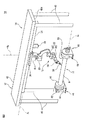
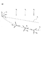
以下、本開示の実施の形態を図面に基づいて詳細に説明する。なお、以下に説明する種々の実施形態において、同様の要素には同じ符号を付し、重複する説明を省略する。また、以下の説明においては、図中の紙面上下左右を、上下左右と言及することがある。まず、図1〜図3を参照して、一実施形態に係るロボットシステム10について説明する。ロボットシステム10は、ロボット12、走行装置14、外部装置16、及び装置100を備える。
Hereinafter, embodiments of the present disclosure will be described in detail with reference to the drawings. In various embodiments described below, similar elements are designated by the same reference numerals, and duplicate description will be omitted. Further, in the following description, the top, bottom, left, and right of the paper surface in the drawing may be referred to as top, bottom, left, and right. First, the
図2を参照して、ロボット12は、走行装置14によって軸線(第1の軸)A1に沿って移動される。本実施形態においては、軸線A1は直線である。ロボット12は、多関節ロボットであって、ベース部18、旋回胴20、ロボットアーム22、手首部24、及びエンドエフェクタ26を備える。旋回胴20は、軸線A3周りに回動可能にベース部18に設けられている。軸線A3は、鉛直方向と略平行である(又は、軸線A1と略直交する)。
Referring to FIG. 2, the
ロボットアーム22は、旋回胴20に回動可能に設けられた第1のアーム28と、該第1のアーム28の先端部に回動可能に設けられた第2のアーム30とを有する。手首部24は、第2のアーム30の先端部に回動可能に設けられている。エンドエフェクタ26は、手首部24の先端部に着脱可能に取り付けられており、手首部24は、エンドエフェクタ26を回動可能に支持する。エンドエフェクタ26は、溶接トーチ、ロボットハンド、レーザ加工ヘッド、又は塗料塗布器等であって、ワークWに対して所定の作業(溶接、ワークハンドリング、レーザ加工、塗工等)を行う。
The
ロボット12の各コンポーネント(ベース部18、旋回胴20、ロボットアーム22、手首部24)には、サーボモータ(図示せず)が内蔵されており、これらサーボモータは、ロボット12の可動コンポーネント(すなわち、旋回胴20、ロボットアーム22、手首部24)を駆動軸周りに回転駆動することによって、エンドエフェクタ26を移動させる。
Each component of the robot 12 (
走行装置14は、ロボット12を軸線A1に沿って移動させる。具体的には、走行装置14は、支持フレーム32、レール34、スライダ36、及び駆動部38を備える。支持フレーム32は、鉛直方向へ延びる複数の柱部40と、該柱部40の上端に固設された天壁部42とを有する。
Traveling
レール34は、天壁部42の底面42aに固設されており、軸線A1に沿って真直ぐに延在している。スライダ36は、軸線A1に沿って摺動可能となるようにレール34と係合している。スライダ36は、レール34と係合することで、軸線A1に沿って往復動するように案内される。
駆動部38は、例えばサーボモータであって、スライダ36を軸線A1に沿って移動させる動力を発生する。駆動部38は、レール34に沿って敷設されたタイミングベルト(図示せず)を回動させ、該タイミングベルトは、スライダ36の上部と係合し、駆動部38が生じた動力をスライダ36へ伝達する。
ロボット12のベース部18は、スライダ36の下面に固定されている。駆動部38がタイミングベルトを回動させると、該タイミングベルトと係合したスライダ36が軸線A1に沿って移動され、これにより、スライダ36に搭載されたロボット12が軸線A1に沿って移動される。
The
外部装置16は、ロボット12の外部に設置され、該ロボット12の作業対象となるワークWを、軸線A2(第2の軸)の周りに回転させる。具体的には、外部装置16は、駆動装置44、及び従動装置46を備える。駆動装置44は、ベース部48、出力フランジ50、及び駆動部52を有する。ベース部48は、作業セルの床の上に固定されている。出力フランジ50は、円盤状の部材であって、軸線A2周りに回転可能となるようにベース部48に設けられている。駆動部52は、例えばサーボモータであって、出力フランジ50を回転させる動力を発生する。
The
従動装置46は、ベース部54、及び従動フランジ56を有する。ベース部54は、作業セルの床の上に固定され、駆動装置44のベース部48と対向配置されている。従動フランジ56は、軸線A2を基準として出力フランジ50と同心に配置された円盤状の部材であって、軸線A2周りに回転可能となるようにベース部54に設けられている。
The driven
ワークWは、治具(図示せず)によって出力フランジ50及び従動フランジ56に固定される。駆動部52が出力フランジ50を回転すると、ワークWも出力フランジ50とともに回転され、従動フランジ56は、ワークWの回転に従って軸線A2周りに回転される。なお、本実施形態においては、軸線A1と軸線A2とは略平行である。
The work W is fixed to the
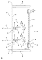
図3に示すように、走行装置14には、走行装置座標系CTが設定される。走行装置座標系CTは、走行装置14の動作を自動制御するためのものであって、3次元空間に固定された固定座標系である。本実施形態においては、走行装置座標系CTは、その原点がレール34の左端に配置され、そのx軸方向が軸線A1と一致し、z軸方向が鉛直方向と平行となるように、設定されている。
As shown in FIG. 3, the traveling device coordinate system CT is set in the
外部装置16には、外部装置座標系CEが設定される。外部装置座標系CEは、外部装置16の動作を自動制御するためのものであって、3次元空間に固定された固定座標系である。本実施形態においては、外部装置座標系CEは、その原点が出力フランジ50の中心に配置され、そのx軸方向が軸線A2と一致するように、設定されている。
The external device coordinate system CE is set in the
一方、ロボット12には、ロボット座標系CRが設定される。ロボット座標系CRは、ロボット12の可動コンポーネントを自動制御するためのものであって、3次元空間内を走行装置14のスライダ36とともに移動する移動座標系である。本実施形態においては、ロボット座標系CRは、その原点がベース部18の中心に配置され、そのz軸方向が軸線A3と一致するように、設定されている。
On the other hand, the robot coordinate system CR is set in the
ロボット12によってワークWに対する作業を行うとき、走行装置14は、ロボット12を、予め定められた作業位置B1及びB2に順次配置させる。これら作業位置B1及びB2は、軸線A1の方向の位置(換言すれば、走行装置座標系CTのx座標)として規定することができる。このとき、ロボット座標系CRは、作業位置B1及びB2に順次設定され、外部装置16がワークWを軸線A2周りに回転させる動作と協調して、ロボット12がロボット座標系CRを基準として制御されて、作業位置B1及びB2の各々でワークWに対して作業を順次行う。
When the
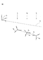
ここで、走行装置14のレール34が、重力等の要因によって変形してしまうことが起こり得る。このようにレール34に変形が生じた例を、図4に示す。図4に示す例では、天壁部42及びレール34が、中央部分で下方へ撓んでいる。この場合、レール34の実際の軸線A1’が、設計上の軸線A1(走行装置座標系CTのx軸)と一致しなくなる。
Here, the
この場合、走行装置14によってロボット12を作業位置B1及びB1に配置したときの該ロボット12のベース部18の位置及び姿勢が、図3に示す設計上の位置及び姿勢とは異なり得る。このようにレール34が変形した場合、実際の軸線A1’の、設計上の軸線A1からのずれを反映させるように、作業位置B1及びB1でロボット座標系CRを設定する必要がある。
In this case, the position and posture of the
本実施形態においては、図4に示す2つの作業位置B1及びB1の各々において、ロボット座標系CR1及びCR2が予め設定される。以下、ロボット座標系設定方法について説明する。まず、走行装置14は、ロボット12を、作業位置B1に配置させる。次いで、外部装置16がワークW(又はダミーワーク)を回転させているときに、ロボット12は、エンドエフェクタ26で、ワークW上に定めた3つの点をタッチアップする。
In the present embodiment, the robot coordinate systems CR1 and CR2 are preset in each of the two working positions B 1 and B 1 shown in FIG. The robot coordinate system setting method will be described below. First, the traveling
このときのロボット12の位置データと、ワークW上に定めた3点の位置を示す情報とから、作業位置B1に配置されたロボット12(具体的には、ベース部18)と外部装置16との相対位置を示すデータを取得できる。ロボット12の位置データは、例えば、ロボット12に内蔵された各サーボモータの回転角度を含み、該回転角度は、該サーボモータに設けられた回転検出器(エンコーダ、又はホール素子)によって検出できる。
The position data of the
一例として、作業位置B1に配置されたロボット12と外部装置16との相対位置のデータとして、該ロボット12(ベース部18)に対する外部装置16の軸線A2の位置及び方向が求められる。この相対位置のデータに基づいて、作業位置B1に設定するロボット座標系CR1の原点位置(すなわち、ベース部18の中心)と、各軸の方向とが決定される。こうして、図4に示すように作業位置B1にロボット座標系CR1を設定することができる。
As an example, as the data of the relative position between the
同様にして、走行装置14によってロボット12を作業位置B2に配置させて、外部装置16がワークWを回転させているときにロボット12がエンドエフェクタ26でワークW上に定めた3つの点をタッチアップし、作業位置B2に配置されたロボット12(ベース部18)と外部装置16との相対位置を示すデータ(例えば、作業位置B2に配置されたロボット12に対する軸線A2の位置及び方向)が取得される。
Similarly, by placing the
この相対位置のデータに基づいて、図4に示すように作業位置B2にロボット座標系CR2を設定することができる。以上のようなロボット座標系設定方法により、ロボット座標系CR1及びCR2が予備的に設定され、これらロボット座標系CR1及びCR2の位置(原点位置)及び姿勢(各軸の方向)の設定情報は、メモリ(図示せず)にそれぞれ記憶される。 Based on the data of the relative positions, it is possible to set the robot coordinate system C R2 in the working position B 2 as shown in FIG. By the robot coordinate system setting method described above, the robot coordinate system C R1 and C R2 are set preliminarily, the position of the robot coordinate system C R1 and C R2 (origin position) and orientation (in the direction of each axis) The setting information is stored in a memory (not shown).
本実施形態に係る装置100は、作業位置B1及びB2の間にさらなる作業位置B3を設定する場合において、該作業位置B3にロボット座標系CR3を自動で設定する。具体的には、図1に示すように、装置100は、座標系取得部102を備える。座標系取得部102は、上述のロボット座標系設定方法により予め設定された2つのロボット座標系CR1及びCR2の位置から、作業位置B3に設定する別のロボット座標系CR3の位置を、演算により求める。
以下、図5を参照して、座標系取得部102の機能について説明する。まず、オペレータは、作業位置B3の位置情報を入力する。例えば、オペレータは、作業位置B3の位置情報を、走行装置座標系CTのx座標として入力する。座標系取得部102は、作業位置B3に設定するロボット座標系CR3の位置を、ロボット座標系CR1の位置(原点)とロボット座標系CR2の位置(原点)とを結ぶ仮想直線A4上の位置として求める。
Hereinafter, the function of the coordinate
具体的には、座標系取得部102は、仮想直線A4の走行装置座標系CTにおける座標(又は関数)を演算により求める(いわゆる、2点間の線形補間)。そして、座標系取得部102は、作業位置B3における仮想直線A4上の点P1の、走行装置座標系CTの座標を演算により求める。こうして、座標系取得部102は、作業位置B3に設定するロボット座標系CR3の原点の位置P1を演算により求めることができる。
Specifically, the coordinate
次いで、座標系取得部102は、作業位置B3に設定するロボット座標系CR3の姿勢を求める。図5に示す例では、座標系取得部102は、ロボット座標系CR3の姿勢を、ロボット座標系CR1の姿勢とロボット座標系CR2の姿勢との中間姿勢として、演算により求める。
Then, the coordinate
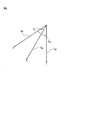
以下、図5及び図6を参照して、ロボット座標系CR3の姿勢を求める方法の一例について、説明する。座標系取得部102は、走行装置座標系CTにおいて、ロボット座標系CR1のz軸方向と、ロボット座標系CR2のz軸方向との中間の方向を演算により求め、求めた該方向を、ロボット座標系CR3のz軸方向として決定する。
Hereinafter, an example of a method of obtaining the posture of the robot coordinate system CR3 will be described with reference to FIGS. 5 and 6. The coordinate
ここで、図6に示すように、ロボット座標系CR1、CR2、及びCR3のz軸の原点を一致させた場合において、ロボット座標系CR1のz軸方向と、ロボット座標系CR2のz軸方向との角度をθz0とし、ロボット座標系CR1のz軸方向と、ロボット座標系CR3のz軸方向との角度をθzとする。 Here, as shown in FIG. 6, in the case where the origin of the z-axis of the robot coordinate system C R1, C R2, and C R3 are matched, and the z-axis direction of the robot coordinate system C R1, the robot coordinate system C R2 the angle between the z-axis direction is defined as theta z0 of the z-axis direction of the robot coordinate system C R1, the angle between the z-axis direction of the robot coordinate system C R3 and theta z.
この場合、ロボット座標系CR1のz軸方向とロボット座標系CR2のz軸方向との中間の方向とは、ロボット座標系CR1及びCR2のz軸と同じ平面上においてθz=θz0/2となる方向として、定義できる。したがって、この場合、ロボット座標系CR3のz軸は、図6に示すように、ロボット座標系CR1及びCR2のz軸と同じ平面上において、ロボット座標系CR1のz軸方向から角度θz=θz0/2だけ、ロボット座標系CR2のz軸方向へ向かって傾斜した方向として、決定される。 In this case, the middle direction of the z-axis direction of the z-axis direction and the robot coordinate system C R2 of the robot coordinate system C R1, the same plane as the z-axis of the robot coordinate system C R1 and C R2 θ z = θ It can be defined as the direction of z0 / 2. Therefore, in this case, the z-axis of the robot coordinate system C R3, as shown in FIG. 6, in the same plane as the z-axis of the robot coordinate system C R1 and C R2, the angle from the z-axis direction of the robot coordinate system C R1 only θ z = θ z0 / 2, as a direction inclined toward the z-axis direction of the robot coordinate system C R2, is determined.
同様に、座標系取得部102は、走行装置座標系CTにおいて、ロボット座標系CR1のx軸(又はy軸)方向と、ロボット座標系CR2のx軸(又はy軸)方向との中間の方向を演算により求め、求めた該方向を、ロボット座標系CR3のx軸(又はy軸)方向として決定する。このようにして、座標系取得部102は、ロボット座標系CR3の姿勢(各軸の方向)を、ロボット座標系CR1及びCR2の姿勢の中間姿勢として求めることができる。
Similarly, the coordinate
代替的には、座標系取得部102は、ロボット座標系CR3の姿勢を、ロボット座標系CR1及びCR2の姿勢と点P1の位置とに基づく関数として求めてもよい。具体的には、ロボット座標系CR3のz軸方向は、図6に示す角度θzが、0≦θz≦θz0の範囲で、走行装置座標系CTのx座標に応じて変化する(例えば、x座標とともに増加する)関数:θz=fz(x)として表すことができる。したがって、座標系取得部102は、作業位置B3の走行装置座標系CTのx座標と関数:θz=fz(x)とを用いて、作業位置B3に設定するロボット座標系CR3のz軸方向を求めることができる。
Alternatively, the coordinate
同様に、ロボット座標系CR3のx軸(又はy軸)方向は、走行装置座標系CTのx座標に応じて変化する関数:θx=fx(x)(又は、θy=fy(x))として表すことができる。したがって、座標系取得部102は、ロボット座標系CR3のx軸(又はy軸)方向を、作業位置B3の走行装置座標系CTのx座標と関数:θx=fx(x)(又は、関数θy=fy(x))とから求めることができる。
Similarly, x-axis of the robot coordinate system C R3 (or y-axis) direction, the function varies in accordance with the x-coordinate of the traveling device coordinate system C T: θ x = f x (x) ( or, theta y = f It can be expressed as y (x)). Therefore, the coordinate
このようにして、座標系取得部102は、ロボット座標系CR3の姿勢を、関数fz(x)、fx(x)、又はfy(x)を用いて演算により求めることができる。なお、これら関数fz(x)、fx(x)、又はfy(x)の係数又は変数等のパラメータは、オペレータによって定められる。
In this way, the coordinate
以上のような方法により、座標系取得部102は、作業位置B3にロボット座標系CR3を、演算により求めた位置P1に、演算により求めた姿勢で、自動で設定できる。なお、座標系取得部102は、ロボット座標系CR3の姿勢を求めることなく、該ロボット座標系CR3を点P1に、予め定めた姿勢で設定してもよい。例えば、座標系取得部102は、ロボット座標系CR3を点P1に、ロボット座標系CR1又はCR2と同じ姿勢で設定してもよい。
The method described above, the coordinate
また、図5に示す例では、座標系取得部102は、ロボット座標系CR3の位置P1を、仮想直線A4上の位置として求めているが、これに限らず、曲線上の位置として求めてもよい。このような形態について、図7を参照して説明する。本実施形態においては、座標系取得部102は、作業位置B3に設定するロボット座標系CR3の位置を、仮想曲線A5上の位置として求める。
Further, in the example shown in FIG. 5, the coordinate
この仮想曲線A5は、例えば、レール34の両端(又は、スライダ36の移動ストローク両端)と、ロボット座標系CR1及びCR2の原点とを結ぶ曲線であって、放物線、円弧線、任意の曲線、又はその組み合わせから構成され得る。座標系取得部102は、仮想曲線A5の走行装置座標系CTにおける座標(又は関数)を演算により求める(いわゆる、複数点間の曲線(放物線、円弧)補間)。
The virtual curve A 5 are, for example, both ends of the rail 34 (or, moving stroke ends of the slider 36) and, a curve connecting the origin of the robot coordinate system C R1 and C R2, parabolic, arc line, any It may consist of curves or a combination thereof. Coordinate
そして、座標系取得部102は、作業位置B3における仮想曲線A5上の点P2の走行装置座標系CTの座標を演算により求める。こうして、座標系取得部102は、作業位置B3に設定するロボット座標系CR3の原点の位置P2を演算により求めることができる。これとともに、座標系取得部102は、上述した方法でロボット座標系CR3の姿勢を決定できる。
Then, the coordinate
以上のような機能を果たす装置100は、例えば、プロセッサ(CPU、GPU等)及びメモリ(ROM、RAM等)を有するコンピュータから構成される。この場合、該コンピュータのプロセッサが、座標系取得部102の機能を実行するための各種演算を行う。なお、装置100は、ロボット12を制御するロボット制御装置であってもよい。
The
以上のように、装置100の座標系取得部102は、軸線A1に沿って予め設定された2つのロボット座標系CR1及びCR2の位置から、該2つのロボット座標系CR1及びCR2の位置の間に設定するロボット座標系CR3の位置P1、P2を演算により求めている。この構成によれば、走行装置14のレール34が変形したとしても、ロボット座標系CR3の位置を、該レール34の変形に対応するように正確且つ自動で求めることができる。
As described above, the coordinate
また、ロボット座標系CR3を基準として作業位置B3に配置したロボット12を制御することで、外部装置16とより高精度な協調動作を実行することが可能となる。また、オペレータがロボット座標系CR3の位置P1、P2を手動で求める必要がないので、ロボットシステム10の立ち上げに掛かる負担を軽減できる。
Further, by controlling the
なお、上述の実施形態においては、軸線A1に沿って2つのロボット座標系CR1及びCR2を予め設定する場合について述べた。しかしながら、これに限らず、オペレータは、軸線A1に沿って第nのロボット座標系CR_n(n=1、2、3・・・)を予め設定してもよい。 Furthermore, in the embodiments discussed above have dealt with the case of pre-set two robot coordinate system C R1 and C R2 along the axis A 1. However, not limited thereto, the operator, a robot coordinate system C R_n of the n the (n = 1,2,3 ···) may be set in advance along the axis A 1.
この場合、座標系取得部102は、上述の方法を用いて、互いに隣接する2つのロボット座標系CR_n−1及びCR_nの位置から、該2つのロボット座標系CR_n−1及びCR_nの間に設定する別のロボット座標系CR_mの位置Pmを演算により求める。このように、予め設定するロボット座標系CR_nの数を増やすことによって、任意の2つのロボット座標系CR_n−1及びCR_nの間に設定するロボット座標系CR_mの位置Pmを、レール34の変形により高精度に対応するように、求めることができる。
In this case, the coordinate
次に、図8を参照して、他のロボットシステム60について説明する。ロボットシステム60は、ロボット12、走行装置14、外部装置16、及びロボット制御装置62を備える。ロボット制御装置62は、ロボット12、走行装置14、及び外部装置16の動作を制御する。
Next, another
ロボット制御装置62は、プロセッサ64、メモリ66、及び入力装置68を有する。プロセッサ64は、CPU又はGPU等を有し、メモリ66及び入力装置68とバス70を介して通信可能に接続されている。プロセッサ64は、メモリ66及び入力装置68と通信しつつ、各種演算を実行する。メモリ66は、ROM又はRAM等を有し、各種データを記憶する。入力装置68は、キーボード、マウス、又はタッチパネル等を有し、オペレータからデータの入力を受け付ける。
The
ロボット制御装置62は、ロボット座標系CRを設定する装置110を備える。本実施形態においては、装置110の機能は、ソフトウェア又はハードウェアとしてロボット制御装置62に実装され、プロセッサ64は、装置110の機能を実行するための各種演算を行う。
The
以下、装置110の機能について説明する。まず、プロセッサ64は、軸線A1に沿って第nのロボット座標系CR_n(n=1,2,3・・・)をそれぞれ予備的に設定する。具体的には、プロセッサ64は、走行装置14を制御して、ロボット12を、第nの作業位置Bnに配置させる。
Hereinafter, the function of the
次いで、プロセッサ64は、上述のロボット座標系設定方法を用いて、外部装置16を制御してワークW(又はダミーワーク)を回転させるとともに、ロボット12を制御してエンドエフェクタ26でワークW上に定めた3つの点をタッチアップし、第nの作業位置Bnに配置されたロボット12と外部装置16との相対位置のデータ(例えば、ロボット12に対する外部装置16の軸線A2の位置及び方向)を取得する。このように、プロセッサ64は、ロボット12と外部装置16との相対位置を取得する位置取得部104として機能する。
Next, the
次いで、プロセッサ64は、取得した相対位置のデータに基づいて、第nの作業位置Bnに設定する第nのロボット座標系CR_nの原点位置(すなわち、ベース部18の中心)と、各軸の方向とを決定する。こうして、プロセッサ64は、第nの作業位置Bnに第nのロボット座標系CR_nを予備的に設定する。
Then, the
このように、プロセッサ64は、相対位置に基づいて第nのロボット座標系CR_nを予備的に設定する座標系設定部106として機能する。プロセッサ64は、第nのロボット座標系CR_nの位置及び姿勢の設定情報(例えば、走行装置座標系CTの座標)を、メモリ66に格納する。
In this way, the
その後、オペレータは、ワークWに対する作業内容等に応じて、互いに隣接する第n−1の作業位置Bn−1と第nの作業位置Bnとの間に、さらなる作業位置Bmを任意で設定する。具体的には、オペレータは、入力装置68を操作して、作業位置Bmの位置情報を、例えば走行装置座標系CTのx座標として、入力する。
After that, the operator arbitrarily sets a further work position B m between the n-1th work position B n-1 and the nth work position B n adjacent to each other according to the work content for the work W and the like. Set. Specifically, the operator operates the
作業位置Bmの位置情報の入力を受け付けると、プロセッサ64は、座標系取得部102として機能し、図5〜図7を参照して上述した方法を用いて、予め設定された第n−1のロボット座標系CR_n−1及び第nのロボット座標系CR_nの位置及び姿勢の設定情報から、該第n−1のロボット座標系CR_n−1と該第nのロボット座標系CR_nとの間に設定する別のロボット座標系CR_mの位置Pm及び姿勢を求める。
Upon receiving the input of the position information of the working position B m , the
作業位置Bmにロボット12を配置させてワークWに対する作業を行う場合、プロセッサ64は、走行装置14を制御してロボット12を作業位置Bmに配置させるとともに、作業位置Bmにロボット座標系CR_mを、上述のように求めた位置Pm及び姿勢で、設定する。
If the working position B m by placing the
そして、プロセッサ64は、ロボット座標系CR_mを基準としてロボット12を制御し、外部装置16によるワークWの回転動作と協調して、ロボット12によってワークWに対する作業を行う。こうして、プロセッサ64は、第nの作業位置Bn及び作業位置Bmの各々で、ロボット12によってワークWに対して作業を順次行うことができる。
Then, the
本実施形態によれば、プロセッサ64は、走行装置14のレール34が変形したとしても、作業位置Bmに設定するロボット座標系CR_mの位置を、該レール34の変形に対応するように正確且つ自動で求めることができる。また、ロボット座標系CR_mを基準として作業位置Bmに配置したロボット12を制御することで、外部装置16とより高精度な協調動作を実行することが可能となる。また、オペレータがロボット座標系CR_mの位置Pmを手動で求める必要がないので、ロボットシステム10の立ち上げに掛かる負担を軽減できる。
According to the present embodiment, even if the
なお、上述の実施形態においては、仮想直線A4、仮想曲線A5、点P1、点P2の座標を、走行装置座標系CTの座標として求める場合について述べたが、これに限らず、例えば、外部装置座標系CEの座標として求めてもよいし、又は、ワールド座標系(図示せず)の座標として求めてもよい。このワールド座標系は、ロボット座標系CR3、走行装置座標系CT、及び外部装置座標系CEとは別に設定され、作業セルの3次元空間を規定する固定座標系である。 In the embodiment described above, the virtual straight line A 4, the virtual curve A 5, the point P 1, the coordinate point P 2, it has dealt with the case of obtaining the coordinates of the traveling device coordinate system C T, is not limited thereto For example, it may be obtained as the coordinates of the external device coordinate system CE , or may be obtained as the coordinates of the world coordinate system (not shown). This world coordinate system is a fixed coordinate system that is set separately from the robot coordinate system CR3 , the traveling device coordinate system CT , and the external device coordinate system CE, and defines the three-dimensional space of the work cell.
また、上述の実施形態においては、作業位置B3、Bmの位置情報が、走行装置座標系CTのx座標として入力される場合について述べた。しかしながら、これに限らず、作業位置B3、Bmの位置情報は、例えば、外部装置座標系CE、又はワールド座標系(図示せず)の座標として入力されてもよい。 In the embodiment described above, the position information of the working position B 3, B m has dealt with the case of being input as x coordinate of the traveling device coordinate system C T. However, not limited to this, the position information of the working positions B 3 and B m may be input as, for example, the coordinates of the external device coordinate system CE or the world coordinate system (not shown).
また、ロボット12は、多関節ロボットに限らず、パラレルリンクロボット等、如何なるタイプのロボットであってもよい。また、走行装置14は、ロボット12を軸線A1に沿って移動可能であれば、如何なるタイプの装置であってもよい。また、軸線A1は、直線に限らず、曲線でもあってもよい。
Further, the
以上、実施形態を通じて本開示を説明したが、上述の実施形態は、特許請求の範囲に係る発明を限定するものではない。 Although the present disclosure has been described above through the embodiments, the above-described embodiments do not limit the invention according to the claims.
10,60 ロボットシステム
12 ロボット
14 走行装置
16 外部装置
100,110 装置
102 座標系取得部
104 位置取得部
106 座標系設定部
10,60
Claims (8)
前記第1の軸に沿って予め設定された2つのロボット座標系の位置から、該2つのロボット座標系の前記位置の間に設定する別のロボット座標系の位置を演算により求める座標系取得部を備える、装置。 A device that sets the robot coordinate system of a robot that moves along the first axis.
A coordinate system acquisition unit that calculates the position of another robot coordinate system set between the positions of the two robot coordinate systems from the positions of the two robot coordinate systems preset along the first axis. A device that comprises.
前記相対位置に基づいて、前記2つのロボット座標系をそれぞれ予備的に設定する座標系設定部と、をさらに備え、
前記座標系取得部は、前記座標系設定部によって予め設定された前記2つのロボット座標系の前記位置から前記別のロボット座標系の前記位置を求める、請求項1〜3のいずれか1項に記載の装置。 A position acquisition unit that acquires a relative position between the robot and an external device installed outside the robot, and
Further, a coordinate system setting unit for preliminarily setting the two robot coordinate systems based on the relative position is provided.
The one according to any one of claims 1 to 3, wherein the coordinate system acquisition unit obtains the position of the other robot coordinate system from the position of the two robot coordinate systems preset by the coordinate system setting unit. The device described.
前記位置取得部は、前記相対位置として、前記ロボットに対する前記第2の軸の位置及び方向を取得する、請求項4に記載の装置。 The external device is configured to rotate the work target of the robot around a second axis.
The device according to claim 4, wherein the position acquisition unit acquires the position and direction of the second axis with respect to the robot as the relative position.
前記ロボットの外部に設置され、該ロボットの作業対象となるワークを第2の軸の周りに回転させる外部装置と、
請求項6に記載のロボット制御装置と、を備え、
前記ロボット制御装置は、前記外部装置が前記ワークを回転させる動作と協調して前記ロボットが前記ワークに対する作業を行うように、該ロボットの動作を制御する、ロボットシステム。 A robot that moves along the first axis,
An external device installed outside the robot and rotating the work target of the robot around a second axis.
The robot control device according to claim 6 is provided.
The robot control device is a robot system that controls the operation of the robot so that the robot performs work on the work in cooperation with the operation of the external device rotating the work.
前記第1の軸に沿って予め設定された2つのロボット座標系の位置から、該2つのロボット座標系の前記位置の間に設定する別のロボット座標系の位置を演算により求める、方法。 A method of setting the robot coordinate system of a robot that is moved along the first axis.
A method of calculating the position of another robot coordinate system set between the positions of the two robot coordinate systems from the positions of two robot coordinate systems preset along the first axis.
Priority Applications (4)
| Application Number | Priority Date | Filing Date | Title |
|---|---|---|---|
| JP2019141675A JP7396829B2 (en) | 2019-07-31 | 2019-07-31 | Device, robot control device, robot system, and method for setting robot coordinate system |
| US16/927,991 US11654562B2 (en) | 2019-07-31 | 2020-07-14 | Apparatus, robot control device, robot system, and method of setting robot coordinate system |
| DE102020119550.8A DE102020119550B4 (en) | 2019-07-31 | 2020-07-24 | Device, robot control device, robot system and method for setting a robot coordinate system |
| CN202010743716.6A CN112297003B (en) | 2019-07-31 | 2020-07-29 | Device for setting robot coordinate system, robot control device, robot system and method |
Applications Claiming Priority (1)
| Application Number | Priority Date | Filing Date | Title |
|---|---|---|---|
| JP2019141675A JP7396829B2 (en) | 2019-07-31 | 2019-07-31 | Device, robot control device, robot system, and method for setting robot coordinate system |
Publications (2)
| Publication Number | Publication Date |
|---|---|
| JP2021024004A true JP2021024004A (en) | 2021-02-22 |
| JP7396829B2 JP7396829B2 (en) | 2023-12-12 |
Family
ID=74165657
Family Applications (1)
| Application Number | Title | Priority Date | Filing Date |
|---|---|---|---|
| JP2019141675A Active JP7396829B2 (en) | 2019-07-31 | 2019-07-31 | Device, robot control device, robot system, and method for setting robot coordinate system |
Country Status (4)
| Country | Link |
|---|---|
| US (1) | US11654562B2 (en) |
| JP (1) | JP7396829B2 (en) |
| CN (1) | CN112297003B (en) |
| DE (1) | DE102020119550B4 (en) |
Cited By (1)
| Publication number | Priority date | Publication date | Assignee | Title |
|---|---|---|---|---|
| JP7538761B2 (en) | 2021-03-25 | 2024-08-22 | 住友重機械工業株式会社 | Processing device, control device, and processing method |
Families Citing this family (2)
| Publication number | Priority date | Publication date | Assignee | Title |
|---|---|---|---|---|
| CN116872253B (en) * | 2023-08-29 | 2026-01-13 | 青岛融合装备科技有限公司 | Method for adjusting parallelism of robot and mobile device |
| CN117773946B (en) * | 2024-01-26 | 2025-09-12 | 广东工业大学 | Automatic programming method and device for external axis trajectory of eight-degree-of-freedom robot linkage welding |
Citations (5)
| Publication number | Priority date | Publication date | Assignee | Title |
|---|---|---|---|---|
| JPH04123403U (en) * | 1991-04-22 | 1992-11-09 | 株式会社明電舎 | robot control device |
| JPH07290379A (en) * | 1994-04-22 | 1995-11-07 | Komatsu Ltd | Robot equipment |
| WO2003035332A1 (en) * | 2001-10-12 | 2003-05-01 | Tecmedic Gmbh | Method and device for the reduction of errors in the positioning of the arm of a robot |
| JP2012210675A (en) * | 2011-03-31 | 2012-11-01 | Ihi Corp | Hand guide device, and control method therefor |
| JP2013226602A (en) * | 2012-04-24 | 2013-11-07 | Panasonic Corp | Industrial machine system |
Family Cites Families (15)
| Publication number | Priority date | Publication date | Assignee | Title |
|---|---|---|---|---|
| JPS59167685U (en) | 1983-04-22 | 1984-11-09 | 三菱電機株式会社 | robot equipment |
| WO2008145184A1 (en) | 2007-05-30 | 2008-12-04 | Abb Technology Ab | A method and an apparatus for calibration of a linear track |
| JP5744587B2 (en) * | 2011-03-24 | 2015-07-08 | キヤノン株式会社 | Robot control apparatus, robot control method, program, and recording medium |
| JP2016163921A (en) * | 2015-03-06 | 2016-09-08 | ファナック株式会社 | Robot system having robot operating synchronously with bending machine |
| DE102015014485A1 (en) | 2015-11-10 | 2017-05-24 | Kuka Roboter Gmbh | Calibrating a system with a conveyor and at least one robot |
| CN106737855B (en) * | 2016-08-22 | 2019-07-02 | 南京理工大学 | A Robot Accuracy Compensation Method Combining Pose Error Model and Stiffness Compensation |
| DE102016013891A1 (en) * | 2016-11-21 | 2018-05-24 | Kuka Roboter Gmbh | Measuring a movement axis of a robot |
| CN107186715B (en) * | 2017-05-25 | 2020-07-31 | 深圳市越疆科技有限公司 | Motion control method and device for robotic arm, storage medium, and computer |
| CN107351084B (en) * | 2017-08-04 | 2020-05-19 | 哈尔滨工业大学 | Space manipulator system error correction method for maintenance task |
| JP6568165B2 (en) | 2017-08-14 | 2019-08-28 | ファナック株式会社 | Robot system and robot controller |
| CN109719438B (en) * | 2017-10-31 | 2021-01-26 | 无锡威卓智能机器人有限公司 | Automatic tracking method for welding seam of industrial welding robot |
| JP6661804B2 (en) * | 2018-07-10 | 2020-03-11 | 株式会社星宇ハイテックSungwoo Hitech Co., Ltd. | Robot system for component assembly and control method |
| CN109623820B (en) * | 2018-12-25 | 2021-09-14 | 哈工大机器人(合肥)国际创新研究院 | Robot space trajectory transition method |
| EP3924152A1 (en) * | 2019-02-11 | 2021-12-22 | Hypertherm, INC. | Motion distribution in robotic systems |
| CN109794943B (en) * | 2019-03-27 | 2021-06-15 | 合肥哈工仞极智能科技有限公司 | Corner transition path and determination method |
-
2019
- 2019-07-31 JP JP2019141675A patent/JP7396829B2/en active Active
-
2020
- 2020-07-14 US US16/927,991 patent/US11654562B2/en active Active
- 2020-07-24 DE DE102020119550.8A patent/DE102020119550B4/en active Active
- 2020-07-29 CN CN202010743716.6A patent/CN112297003B/en active Active
Patent Citations (5)
| Publication number | Priority date | Publication date | Assignee | Title |
|---|---|---|---|---|
| JPH04123403U (en) * | 1991-04-22 | 1992-11-09 | 株式会社明電舎 | robot control device |
| JPH07290379A (en) * | 1994-04-22 | 1995-11-07 | Komatsu Ltd | Robot equipment |
| WO2003035332A1 (en) * | 2001-10-12 | 2003-05-01 | Tecmedic Gmbh | Method and device for the reduction of errors in the positioning of the arm of a robot |
| JP2012210675A (en) * | 2011-03-31 | 2012-11-01 | Ihi Corp | Hand guide device, and control method therefor |
| JP2013226602A (en) * | 2012-04-24 | 2013-11-07 | Panasonic Corp | Industrial machine system |
Cited By (1)
| Publication number | Priority date | Publication date | Assignee | Title |
|---|---|---|---|---|
| JP7538761B2 (en) | 2021-03-25 | 2024-08-22 | 住友重機械工業株式会社 | Processing device, control device, and processing method |
Also Published As
| Publication number | Publication date |
|---|---|
| JP7396829B2 (en) | 2023-12-12 |
| US11654562B2 (en) | 2023-05-23 |
| DE102020119550B4 (en) | 2025-07-10 |
| CN112297003A (en) | 2021-02-02 |
| US20210031369A1 (en) | 2021-02-04 |
| DE102020119550A1 (en) | 2021-02-04 |
| CN112297003B (en) | 2025-01-03 |
Similar Documents
| Publication | Publication Date | Title |
|---|---|---|
| US10525594B2 (en) | Teaching system, robot system, and teaching method | |
| CN102985232B (en) | For being positioned at the method for the calibration of the robot on moveable platform | |
| JP5980867B2 (en) | Robot teaching device that teaches robots offline | |
| US9110466B2 (en) | Programming method for a robot, programming apparatus for a robot, and robot control system | |
| US9120223B2 (en) | Method of controlling seven-axis articulated robot, control program, and robot control device | |
| CN103987485B (en) | Bead former and bead manufacturing process | |
| KR20130066689A (en) | Control device and teaching method for seven-shaft multi-joint robot | |
| CN102033511B (en) | Processing control device, laser processing device and laser processing system | |
| KR20150044812A (en) | Teaching system and teaching method | |
| US11654562B2 (en) | Apparatus, robot control device, robot system, and method of setting robot coordinate system | |
| KR102904385B1 (en) | Method and apparatus for generating moving path of robot, robot system, and program | |
| JP7726845B2 (en) | Robot motion trajectory generation method, motion trajectory generation device, robot system, and program | |
| JP4396553B2 (en) | Robot controller, computer program | |
| JP2006072673A (en) | Positioner setting method for welding robot | |
| JP5978890B2 (en) | Robot motion program correction device | |
| TW202335808A (en) | Robot control device and multi-joint robot | |
| JP2015222196A (en) | CMM and shape measuring method using the same | |
| CN117182898A (en) | Automatic path correction method for industrial robot | |
| KR101246073B1 (en) | Robot controlling apparatus and method thereof | |
| JP2010167507A (en) | Robot system and method of controlling the same | |
| JP7424097B2 (en) | Robot control device and robot control method | |
| CN115302499B (en) | Running carriage position determining device for robot, method thereof, and recording medium | |
| JP4530714B2 (en) | Drive control system for articulated robot | |
| JP2652444B2 (en) | Robot system | |
| JP2759675B2 (en) | Sensor robot |
Legal Events
| Date | Code | Title | Description |
|---|---|---|---|
| A621 | Written request for application examination |
Free format text: JAPANESE INTERMEDIATE CODE: A621 Effective date: 20220408 |
|
| A977 | Report on retrieval |
Free format text: JAPANESE INTERMEDIATE CODE: A971007 Effective date: 20230228 |
|
| A131 | Notification of reasons for refusal |
Free format text: JAPANESE INTERMEDIATE CODE: A131 Effective date: 20230307 |
|
| A521 | Request for written amendment filed |
Free format text: JAPANESE INTERMEDIATE CODE: A523 Effective date: 20230420 |
|
| A131 | Notification of reasons for refusal |
Free format text: JAPANESE INTERMEDIATE CODE: A131 Effective date: 20230801 |
|
| A521 | Request for written amendment filed |
Free format text: JAPANESE INTERMEDIATE CODE: A523 Effective date: 20230920 |
|
| TRDD | Decision of grant or rejection written | ||
| A01 | Written decision to grant a patent or to grant a registration (utility model) |
Free format text: JAPANESE INTERMEDIATE CODE: A01 Effective date: 20231031 |
|
| A61 | First payment of annual fees (during grant procedure) |
Free format text: JAPANESE INTERMEDIATE CODE: A61 Effective date: 20231130 |
|
| R150 | Certificate of patent or registration of utility model |
Ref document number: 7396829 Country of ref document: JP Free format text: JAPANESE INTERMEDIATE CODE: R150 |