JP2021007786A - Improved end effector for wound closure device - Google Patents
Improved end effector for wound closure device Download PDFInfo
- Publication number
- JP2021007786A JP2021007786A JP2020173101A JP2020173101A JP2021007786A JP 2021007786 A JP2021007786 A JP 2021007786A JP 2020173101 A JP2020173101 A JP 2020173101A JP 2020173101 A JP2020173101 A JP 2020173101A JP 2021007786 A JP2021007786 A JP 2021007786A
- Authority
- JP
- Japan
- Prior art keywords
- suture
- tab
- mounting component
- end effector
- opening
- Prior art date
- Legal status (The legal status is an assumption and is not a legal conclusion. Google has not performed a legal analysis and makes no representation as to the accuracy of the status listed.)
- Granted
Links
Images


Classifications
-
- A—HUMAN NECESSITIES
- A61—MEDICAL OR VETERINARY SCIENCE; HYGIENE
- A61B—DIAGNOSIS; SURGERY; IDENTIFICATION
- A61B17/00—Surgical instruments, devices or methods, e.g. tourniquets
- A61B17/04—Surgical instruments, devices or methods, e.g. tourniquets for suturing wounds; Holders or packages for needles or suture materials
- A61B17/0401—Suture anchors, buttons or pledgets, i.e. means for attaching sutures to bone, cartilage or soft tissue; Instruments for applying or removing suture anchors
-
- A—HUMAN NECESSITIES
- A61—MEDICAL OR VETERINARY SCIENCE; HYGIENE
- A61B—DIAGNOSIS; SURGERY; IDENTIFICATION
- A61B17/00—Surgical instruments, devices or methods, e.g. tourniquets
- A61B17/04—Surgical instruments, devices or methods, e.g. tourniquets for suturing wounds; Holders or packages for needles or suture materials
- A61B17/06—Needles ; Sutures; Needle-suture combinations; Holders or packages for needles or suture materials
- A61B17/06166—Sutures
-
- A—HUMAN NECESSITIES
- A61—MEDICAL OR VETERINARY SCIENCE; HYGIENE
- A61B—DIAGNOSIS; SURGERY; IDENTIFICATION
- A61B17/00—Surgical instruments, devices or methods, e.g. tourniquets
- A61B2017/00004—(bio)absorbable, (bio)resorbable, resorptive
-
- A—HUMAN NECESSITIES
- A61—MEDICAL OR VETERINARY SCIENCE; HYGIENE
- A61B—DIAGNOSIS; SURGERY; IDENTIFICATION
- A61B17/00—Surgical instruments, devices or methods, e.g. tourniquets
- A61B2017/00831—Material properties
- A61B2017/00964—Material properties composite
-
- A—HUMAN NECESSITIES
- A61—MEDICAL OR VETERINARY SCIENCE; HYGIENE
- A61B—DIAGNOSIS; SURGERY; IDENTIFICATION
- A61B17/00—Surgical instruments, devices or methods, e.g. tourniquets
- A61B17/04—Surgical instruments, devices or methods, e.g. tourniquets for suturing wounds; Holders or packages for needles or suture materials
- A61B17/0401—Suture anchors, buttons or pledgets, i.e. means for attaching sutures to bone, cartilage or soft tissue; Instruments for applying or removing suture anchors
- A61B2017/0417—T-fasteners
-
- A—HUMAN NECESSITIES
- A61—MEDICAL OR VETERINARY SCIENCE; HYGIENE
- A61B—DIAGNOSIS; SURGERY; IDENTIFICATION
- A61B17/00—Surgical instruments, devices or methods, e.g. tourniquets
- A61B17/04—Surgical instruments, devices or methods, e.g. tourniquets for suturing wounds; Holders or packages for needles or suture materials
- A61B17/0401—Suture anchors, buttons or pledgets, i.e. means for attaching sutures to bone, cartilage or soft tissue; Instruments for applying or removing suture anchors
- A61B2017/0446—Means for attaching and blocking the suture in the suture anchor
- A61B2017/0458—Longitudinal through hole, e.g. suture blocked by a distal suture knot
-
- A—HUMAN NECESSITIES
- A61—MEDICAL OR VETERINARY SCIENCE; HYGIENE
- A61B—DIAGNOSIS; SURGERY; IDENTIFICATION
- A61B17/00—Surgical instruments, devices or methods, e.g. tourniquets
- A61B17/04—Surgical instruments, devices or methods, e.g. tourniquets for suturing wounds; Holders or packages for needles or suture materials
- A61B17/0401—Suture anchors, buttons or pledgets, i.e. means for attaching sutures to bone, cartilage or soft tissue; Instruments for applying or removing suture anchors
- A61B2017/0446—Means for attaching and blocking the suture in the suture anchor
- A61B2017/0461—Means for attaching and blocking the suture in the suture anchor with features cooperating with special features on the suture, e.g. protrusions on the suture
-
- A—HUMAN NECESSITIES
- A61—MEDICAL OR VETERINARY SCIENCE; HYGIENE
- A61B—DIAGNOSIS; SURGERY; IDENTIFICATION
- A61B17/00—Surgical instruments, devices or methods, e.g. tourniquets
- A61B17/04—Surgical instruments, devices or methods, e.g. tourniquets for suturing wounds; Holders or packages for needles or suture materials
- A61B17/0401—Suture anchors, buttons or pledgets, i.e. means for attaching sutures to bone, cartilage or soft tissue; Instruments for applying or removing suture anchors
- A61B2017/0464—Suture anchors, buttons or pledgets, i.e. means for attaching sutures to bone, cartilage or soft tissue; Instruments for applying or removing suture anchors for soft tissue
-
- A—HUMAN NECESSITIES
- A61—MEDICAL OR VETERINARY SCIENCE; HYGIENE
- A61B—DIAGNOSIS; SURGERY; IDENTIFICATION
- A61B17/00—Surgical instruments, devices or methods, e.g. tourniquets
- A61B17/04—Surgical instruments, devices or methods, e.g. tourniquets for suturing wounds; Holders or packages for needles or suture materials
- A61B17/06—Needles ; Sutures; Needle-suture combinations; Holders or packages for needles or suture materials
- A61B17/06166—Sutures
- A61B2017/06176—Sutures with protrusions, e.g. barbs
Abstract
Description
本発明は、全般的に、医療デバイスの分野に関し、特に、改良された複合エンドエフェクタを有する自己保定式縫合デバイスに関する。 The invention generally relates to the field of medical devices, and in particular to self-retaining suturing devices with improved composite end effectors.
多くの創傷及び外科的切開は外科用縫合糸又は何らかの他の外科的閉鎖デバイスを用いて閉鎖される。バーブ付き縫合糸としても知られる自己保定式縫合糸は周知であり、種々の医療用途において注目されてきた。典型的には、自己保定式縫合糸は一連の保定部(「バーブ」又は「突起」としても知られ、本明細書中では区別なく使用される)を有して作製されている。保定部は縫合糸から外側に延び、縫合糸が結紮の必要なく機能することを可能にするように機能する。 Many wounds and surgical incisions are closed using surgical sutures or some other surgical closure device. Self-contained sutures, also known as barbed sutures, are well known and have attracted attention in a variety of medical applications. Typically, self-retaining sutures are made with a series of retainers (also known as "barbs" or "protrusions", used interchangeably herein). The retainer extends outward from the suture and functions to allow the suture to function without the need for ligation.
バーブ付き縫合糸を含むいくつかの縫合糸は、「停止部」を設けるために、縫合糸の遠位端にエンドエフェクタを含むことが知られている。「停止部」は、縫合糸の保定強度を増加させるとともに、遠位端に縫合糸を固定するための結節を作る必要を排除する一方で、縫合糸を組織内において完全に引き通すことを防ぐ又はこれに耐える。エンドエフェクタとしては、例えば、アンカー、ディスク、ボタン、結節、タブ、ループ等が挙げられる。 Some sutures, including barbed sutures, are known to include an end effector at the distal end of the suture to provide a "stop". The "stop" increases the retention strength of the suture and eliminates the need to create a nodule to secure the suture to the distal end, while preventing the suture from being completely drawn through the tissue. Or endure this. Examples of end effectors include anchors, discs, buttons, knots, tabs, loops and the like.
停止部は、縫合糸の遠位端を溶融させる又はそうでなければ変形させることによって、既存の縫合糸材料から直接形成又は変化させてよい。しかしながら、熱形成操作により、停止部に直接隣接する縫合糸材料の、別の方法で慎重に作成された物性を不必要に変えるおそれがある。例えば、縫合糸の端部に結ばれた結節を溶接することにより、縫合糸の結晶構造が変わり、溶接された構造近傍の引張強度を弱化させる可能性がある。 The stop may be formed or modified directly from the existing suture material by melting or otherwise deforming the distal end of the suture. However, the thermoforming operation can unnecessarily alter the otherwise carefully crafted physical properties of the suture material directly adjacent to the stop. For example, welding a nodule tied to the end of a suture may change the crystal structure of the suture and weaken the tensile strength near the welded structure.
縫合糸の端部に停止部を作成するための別の既知の技法は、米国特許出願公開第2013/0085525号に記載されているもののように、中心長手方向軸線側方の材料を除去してコア縫合糸を残す一方、縫合糸の遠位端における中心長手方向軸線側方の材料を残すことによって、縫合糸を平坦な細長い形態から形成することである。このような停止部は、固定タブとしても知られるタブの形態であってもよい。このようにして形成される停止部は、停止部に直接隣接する縫合糸の性質を変えるという課題は排除するものの、平坦であり、縫合糸の遠位端を適切に固定するための、組織に平行な表面積を十分に呈することができない。場合によっては、このようにして形成された停止部の側部は長さに沿って破壊される可能性があり、エンドエフェクタとして機能する能力が低下する。 Another known technique for creating a stop at the end of the suture is to remove the material lateral to the central longitudinal axis, as described in US Patent Application Publication No. 2013/805525. Forming the suture from a flat, elongated form by leaving the core suture while leaving the material lateral to the central longitudinal axis at the distal end of the suture. Such a stop may be in the form of a tab, also known as a fixed tab. The stop formed in this way is flat and in the tissue to properly secure the distal end of the suture, while eliminating the problem of altering the properties of the suture directly adjacent to the stop. It is not possible to provide sufficient parallel surface area. In some cases, the sides of the stop thus formed can be destroyed along the length, reducing the ability to function as an end effector.
したがって、停止部に直接隣接する縫合糸の物性に影響を及ぼすことなく、縫合糸の遠位端に停止部を作製すると有利であろう。更に、停止部に直接隣接する縫合糸材料の物性を変えない手法で用意された、組織に平行な表面積が増加した停止部に対する需要がある。溶接なしで、又は縫合糸の分子構造若しくは物性を変えることなく形成される複合エンドエフェクタが有用であろう。 Therefore, it would be advantageous to create a stop at the distal end of the suture without affecting the physical properties of the suture directly adjacent to the stop. Further, there is a demand for a stop portion having an increased surface area parallel to the tissue, prepared by a method that does not change the physical properties of the suture material directly adjacent to the stop portion. A composite end effector formed without welding or without changing the molecular structure or physical properties of the suture would be useful.
本発明は、未修正エンドエフェクタの強度を増加させる、複合エンドエフェクタを有する縫合デバイスを含む。縫合デバイスは、近位端及び遠位端を有する細長い縫合糸本体と、遠位端にある複合エンドエフェクタであって、長さ、幅、及び厚さを有する固定タブと、長さ、幅、及び厚さを有するタブ開口部を有する上覆取付部品と、を備える、複合エンドエフェクタと、を備えてもよく、固定タブの近位端が上覆取付部品の近位壁に当接するように、固定タブの少なくとも近位端は上覆取付部品に挿入されている。 The present invention includes a suturing device with a composite end effector that increases the strength of the unmodified end effector. The suture device is an elongated suture body with proximal and distal ends and a composite end effector at the distal end with fixed tabs of length, width and thickness, and length, width, And a composite end effector comprising a cover mounting component having a thick tab opening, such that the proximal end of the fixing tab abuts the proximal wall of the cover mounting component. , At least the proximal end of the fixing tab is inserted into the overcoat mounting part.
複合エンドエフェクタを有する縫合デバイスの近位端を組織に挿入する工程と、上覆取付部品の近位端が組織に当接するまで縫合デバイスを組織内において引いて通す工程と、を含む、上記の縫合糸を使用する方法も含まれる。 The steps described above include inserting the proximal end of a suturing device with a composite end effector into the tissue and pulling the suturing device through the tissue until the proximal end of the overcoat mounting component abuts the tissue. Also included is the use of sutures.
長さ、幅、及び厚さを有するタブ開口部を有する上覆取付部品を、近位端及び遠位端を有し、遠位端に固定タブを有する縫合糸本体上において摺動させる工程であって、固定タブがタブ開口部に嵌合するまで上覆取付部品を縫合糸本体に沿って遠位方向に摺動させる、工程を含む、縫合糸を製造する方法も含まれる。 In the process of sliding an overcoat attachment with tab openings of length, width, and thickness over a suture body that has proximal and distal ends and a fixed tab at the distal end. Also included is a method of making a suture, comprising the step of sliding the overcoat attachment component distally along the suture body until the fixing tab fits into the tab opening.
本発明は、近位端及び遠位端を有し、遠位端に結節を有する、細長い縫合糸本体と、遠位端にある複合エンドエフェクタであって、結節と、内部開口部を設けた上覆取付部品と、を備え、結節の少なくとも一部分は、上覆取付部品の内部開口部内に設けられている、複合エンドエフェクタと、を含む、縫合デバイスも備えてよい。当該方法は、結節を結ぶ前に、上覆取付部品を縫合糸本体上に設ける工程、又は縫合糸本体に結節が結ばれた後、上覆取付部品を縫合糸本体上に設ける工程を含んでもよい。 The present invention is an elongated suture body having proximal and distal ends and a nodule at the distal end, and a composite end effector at the distal end, provided with a nodule and an internal opening. A suturing device may also be provided with an overcoat attachment, including a composite end effector, wherein at least a portion of the nodule is provided within an internal opening of the overcoat attachment. The method may include a step of providing the overcoat attachment component on the suture body before tying the nodule, or a step of providing the overcoat attachment component on the suture body after the nodule is tied to the suture body. Good.
本発明は創閉鎖デバイスを提供する。創閉鎖デバイスは、近位端及び遠位端を有する繊維状本体と、繊維状本体の遠位端に停止要素と、を有する、自己保定式縫合糸であってもよい。縫合糸は、任意の適切な方法によって形成されてもよいが、参照によりその全体を本明細書中に組み込む米国特許出願公開第2007/0257395号により詳細に記載されている手法で予備形成された、材料リボン又はストリップから打ち抜かれた複合プロファイル(compound profile)であることが好ましい。いくつかの実施形態では、停止要素は概ね平坦であってもよく、矩形又は四角形状の形状を有してもよく、他の実施形態では、より楕円形若しくは円形の形状を取ってもよい。他の実施形態では、停止要素は結節であってもよく、これにより、縫合糸の形成中に停止部を同時に予め形成する必要性を回避する。 The present invention provides a wound closure device. The wound closure device may be a self-retaining suture having a fibrous body having proximal and distal ends and a stopping element at the distal end of the fibrous body. The suture may be formed by any suitable method, but is preformed by the method detailed in US Patent Application Publication No. 2007/0257395, which is incorporated herein by reference in its entirety. , Is preferably a compound profile punched from a material ribbon or strip. In some embodiments, the stopping element may be generally flat, may have a rectangular or rectangular shape, and in other embodiments may be in a more elliptical or circular shape. In other embodiments, the stopping element may be a nodule, which avoids the need to simultaneously preform the stop during the formation of the suture.
本明細書で使用する場合、「停止要素」という用語は、概して、縫合糸の終(又は遠位)端にあるデバイスを意味し、「アンカー」又は「エンドエフェクタ」とも称される場合がある。エンドエフェクタとしては、例えば、アンカー、ディスク、ボタン、結節、固定タブ、ループ等が挙げられる。本発明で有用であり得るエンドエフェクタの種類の1つとしては、参照により全体を本明細書中に組み込む米国特許出願公開第2013/0085525号に記載されているものに類似するように設計されたタブが挙げられる。別の一般に使用されているエンドエフェクタは、縫合糸の遠位端に結ばれた結節である。前述のタブ設計及び結節設計は有用ではあるが、本発明は、強化された停止及び保持力を付与する一方で、外科的処置中及び後における不耐性及び他の問題を回避する改良エンドエフェクタを提供しようと努めるものである。以下の記載では、改良エンドエフェクタについて記載する。改良エンドエフェクタは、タブ又は結節など、初期停止部から開始する。しかしながら、本明細書中に記載される改良された複合エンドエフェクタの開始点として、任意の既知の既存のエンドエフェクタを使用することができる。結果として得られるエンドエフェクタとその上に設けられた上覆取付部品との組み合わせは、「複合エンドエフェクタ」と称される。 As used herein, the term "stop element" generally means a device at the end (or distal) end of a suture and may also be referred to as an "anchor" or "end effector". .. Examples of end effectors include anchors, discs, buttons, knots, fixed tabs, loops and the like. One of the types of end effectors that may be useful in the present invention is designed to resemble those described in US Patent Application Publication No. 2013/0085525, which is incorporated herein by reference in its entirety. There are tabs. Another commonly used end effector is a nodule tied to the distal end of the suture. Although the tab design and nodule design described above are useful, the present invention provides improved end effectors that provide enhanced stopping and retention while avoiding intolerance and other problems during and after surgery. We strive to provide it. The following description describes the improved end effector. The modified end effector starts at the initial stop, such as a tab or nodule. However, any known existing end effector can be used as a starting point for the improved composite end effectors described herein. The combination of the resulting end effector and the overlay mounting component provided on it is referred to as a "composite end effector".
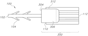
図1は、エンドエフェクタを含む先行技術の縫合デバイス100を示す。エンドエフェクタは、細長い縫合糸本体102の遠位端106に位置する固定タブ108の形態である。縫合糸本体102は、円形、三角形、又は他の構成などの任意の所望の断面構成を有する任意の既知の縫合糸本体であってもよく、概して、その遠位端106と反対側の近位端(図1には示さず)との間に長手方向中心軸線を有する。近位端は挿入端であり、針などの組織穿通機能を備えてもよい。使用時、近位端は組織内に挿入され、縫合糸100は遠位端106が組織に当接するまで組織内を引いて通される。自己保定式縫合糸では、本体102は複数の保定部104を含んでもよく、複数の保定部104は、例えば、対称的、螺旋状、又は不規則な方向を含む任意の構成で縫合糸本体102に沿って配置されていてもよい。保定部104は、縫合糸100を1つのリボン又はプリフォーム材料からパンチング又はスタンピングによって形成されてもよい。あるいは、保定部104は、ブレード、レーザー、又は他の切断手段などにより細長い材料から切り抜くことによって形成されてもよい。好適な実施形態では、縫合糸本体102と、保定部104と、固定タブ108とを備える縫合デバイス100全体が、1つのリボン又はプリフォーム材料からパンチング又はスタンピング又は切断によって形成されており、これにより、所望の大きさ及び形状を有する一体構造を形成している。加えて、デバイス100を1つの単一材料から形成することにより、固定タブ108は、溶接又は化学的若しくは他の物理的手段による接着などの固定方法を要することなく、縫合糸本体102に固定されている。
FIG. 1 shows a prior
図3は、図1の固定タブ108の拡大図を示す。図からわかるように、この図の固定タブ108は略矩形であり、細長い長さ(l)及び幅(w)を有し、前縁110(近位縁)を有する。本明細書では、及び図3からわかるように、エンドエフェクタの長さ(l)は、縫合糸本体102の中心長手方向軸線に実質的に平行である。固定タブ108の幅(w)は、縫合糸本体102の中心長手方向軸線に実質的に垂直である。縫合糸本体102と固定タブ108は、同じ材料のプリフォーム又はリボンから形成されてもよく、したがって、単一の一体構造である。
FIG. 3 shows an enlarged view of the fixed
本明細書では、及び本出願の全体を通して、各構成要素について述べる際、「近位」という用語は、組織内に最初に挿入される縫合デバイスの端部を意味し、「遠位」という用語は、挿入端とは反対側の縫合デバイスの端部を意味する。図1の縫合デバイスでは、遠位端は、概して、縫合糸本体の遠位端106を含み、固定タブ108も含む一方、近位端(図示せず)は、固定タブ108とは反対側の、縫合糸本体102に沿った最も遠い端部であり、挿入端とも呼ばれる。本明細書中に記載されるエンドエフェクタ及び固定タブもまた、近位端及び遠位端を有する。固定タブ108の近位端110は、縫合糸本体102の遠位端106に固定された縁部である。固定タブ108の遠位端112は、近位端110から固定タブ108の長さ(l)だけ離れた縁部である。「遠位」及び「近位」という用語は、概して、縫合デバイス及びその種々の構成要素のこれら方向を意味する。本明細書中で使用される縫合デバイスは、近位端において組織に挿入され、組織内において近位方向に引いて通される。
As used herein and throughout this application, the term "proximal" refers to the end of the suture device that is first inserted into the tissue and the term "distal". Means the end of the suturing device opposite the insertion end. In the suture device of FIG. 1, the distal end generally includes the
図1〜図3にあるようなエンドエフェクタを有する既知の縫合糸は、典型的には、1つの縫合糸材料シートから(スタンピング、切断、又はパンチングなどによって)形成されている。1つの材料シート又はリボンが使用されるため、デバイス100の厚さ構成は長さ全体にわたり実質的に同じである。つまり、エンドエフェクタ108の厚さ構成は縫合糸本体102の厚さ構成と実質的に同じである。デバイス100は単一片からスタンピングされるため、固定タブ108の厚さ構成は縫合糸本体102の厚さ構成と大きく異ならない。いくつかの実施形態では、縫合糸本体102の細長い中央部は保定部104と異なる厚さを有してもよく、この厚さの変化は、固定タブ108の長さ及び幅に沿って同様であってもよい。したがって、図2に見られるように、固定タブ108はその幅に沿って変化する厚さ構成を有してもよい。本明細書中の記載では矩形タブの形状及び構成のエンドエフェクタについて記載しているが、有用なエンドエフェクタは矩形である必要はなく、円形、楕円形、四角形、又は他の構成であってもよい。
Known sutures with end effectors as shown in FIGS. 1-3 are typically formed from a single suture material sheet (by stamping, cutting, punching, etc.). Since one material sheet or ribbon is used, the thickness composition of the
いくつかの実施形態では、図1のエンドエフェクタの厚さ(t)は約203〜635マイクロメートル(約8〜25ミル)であってもよく、幅(w)は約1778〜3048マイクロメートル(約70〜120ミル)であってもよく、長さ(l)は約990〜5080マイクロメートル(約39〜200ミル)であってもよい。タブ付き停止要素の長さ対幅の比は少なくとも1.5〜約5.0であってもよい。 In some embodiments, the end effector thickness (t) of FIG. 1 may be from about 203 to 635 micrometers (about 8 to 25 mils) and width (w) is from about 1778 to 3048 micrometers (w). It may be about 70-120 mils) and the length (l) may be about 990-5080 micrometers (about 39-200 mils). The length-to-width ratio of the tabbed stop element may be at least 1.5 to about 5.0.
図2は、その長さに沿って見た(即ち、幅及び厚さを見ることができるように)、図1のエンドエフェクタの拡大図である。図からわかるように、この実施形態では、エンドエフェクタの中央領域122は縫合糸本体102の中心軸線に沿って延びており、エンドエフェクタはまた、第1及び第2の外側領域120と、厚さt2を有する第1の介在領域124と、同じく厚さt2を有する第2の介在領域124と、を含む。各外側領域120の厚さは同一である必要ははく、介在領域124の厚さもまた同一である必要はない。この厚さの変化は単なる1つの潜在的構成であり、固定タブ108の断面厚さ構成は図と異なっていてもよい。例えば、厚さは固定タブ108の全幅に沿って実質的に同じであってもよい。
FIG. 2 is an enlarged view of the end effector of FIG. 1 as viewed along its length (ie, so that the width and thickness can be seen). As can be seen from the figure, in this embodiment, the
例として、縫合デバイスは1つの縫合糸形成材料シート(リボン又はプリフォームとも呼ばれる)から形成されてもよい。リボンは、約152〜635マイクロメートル(約6〜25ミル)、典型的には、102〜305マイクロメートル(4〜12ミル)の厚さを有してもよく、縫合デバイスの中心軸線に沿って(即ち、縫合糸本体102の中心軸線に沿って)並びに/又は第1の及び/若しくは第2の外側縁部において最大厚さを有し、中心軸線と第1の及び/又は第2の外側縁部との間の位置において最小厚さを有する。リボンの長さは、固定タブを含む所望の縫合糸長さと少なくとも同じ長さとすべきである。幅もまた、固定タブを含む所望の縫合糸幅と少なくとも同じ幅とすべきである。 As an example, the suture device may be formed from a single suture forming material sheet (also called a ribbon or preform). The ribbon may have a thickness of about 152-635 micrometers (about 6-25 mils), typically 102-305 micrometers (4-12 mils), along the central axis of the suturing device. (Ie, along the central axis of the suture body 102) and / or having the maximum thickness at the first and / or second outer edge, the central axis and the first and / or second It has the minimum thickness at the position between it and the outer edge. The length of the ribbon should be at least as long as the desired suture length, including the retaining tabs. The width should also be at least as wide as the desired suture width, including the retaining tabs.
こうした固定タブの保定強度は、固定タブ108の寸法を増加させることにより増加してもよい。しかしながら、縫合糸が組織内において更に進むのを防ぐために使用できる大きさ及び質量には、実施上及び臨床上の制約がある。例えば、タブ108を含むデバイスが小さすぎる又は薄すぎる場合、デバイスは低い強度をもたらす可能性がある、又は組織内において縫合デバイスの動きを制限し損なう可能性がある。対照的に、デバイスが大きすぎる場合、デバイスは植え込む体内に大きな質量を不必要に残す可能性がある。加えて、大きな質量は、製造及び頑丈な構造の付与にあたり困難を伴うことがある。典型的には、臨床的に使用される場合、エンドエフェクタは患者の組織内に植え込まれ、生体吸収性又は分解性材料で作製されている場合は体に完全に吸収される。エンドエフェクタの大きさ及び質量が大きすぎる場合、エンドエフェクタの吸収に必要な組織の反応及び時間に関する懸念がある。更に、エンドエフェクタを向上させるための従前の試みでは、デバイスの補強のために溶接又は化学物質の使用などの方法に依存してきた。
The retention strength of such fixed tabs may be increased by increasing the dimensions of the fixed
本発明は、こうした制約を回避する一方で、エンドエフェクタの保定強度の改良を可能にする。加えて、本発明は、初期の縫合デバイスの一部として形成された既存のタブを物理的に変更又は修正することを必要としない複合エンドエフェクタを提供する。本発明は、既存のエンドエフェクタ(タブ108など)と、固定タブ108の近位端110上に設けられた上覆取付部品と、を備える初期縫合デバイス100を含む、複合デバイスを提供する。複合デバイスは、増加した表面積を固定タブ108の近位端110に付与し、加えて、更なる保定強度を付与する。
The present invention makes it possible to improve the retention strength of the end effector while avoiding such restrictions. In addition, the present invention provides a composite end effector that does not require physical modification or modification of existing tabs formed as part of the initial suturing device. The present invention provides a composite device including an
縫合デバイス100(縫合糸本体102と、保定部104と、固定タブ108とを備える)は、吸収性若しくは非吸収性の、高分子材料、金属材料、又はセラミック材料で作製されていてもよい。更に別の実施形態では、デバイスは、吸収性材料と非吸収性材料の組み合わせ及び/又は共重合体を含む、ポリジオキサノン、ポリグラクチン、ポリグリコール酸、グリコリド、ラクチド、及び/又はカプロラクトンの共重合体、ポリオキサエステル、ポリグレカプロン、ポリプロピレン、ポリエチレン、ポリフッ化ビニリデン(PVDF)、ヘキサフルオロプロピレン、フッ化ビニリデン及びヘキサフルオロプロピレンの共重合体、ポリエステル、ポリエチレンテレフタレート、ポリブチレンテレフタレート、グリコール変性ポリエチレンテレフタレート、ポリテトラフルオロエチレン、フルオロポリマー、熱可塑性エラストマー、アイオノマー、エチレン及びメタクリル酸の共重合体、ポリアミド、ポリテトラメチレンオキシド、ポリスチレン、ポリブタジエン、ポリブチレン等から作製された、吸収性及び非吸収性単独重合体、ランダム共重合体、ブロック共重合体、又はブレンドからなる群から選択されるポリマー材料で作製されている。
The suture device 100 (which includes a
上述のように、本発明は、2つの主要構成要素、即ち、その遠位端106にエンドエフェクタ108を有する細長い縫合糸本体102を備える縫合デバイス100と、エンドエフェクタ108の近位端110に配置される上覆取付部品と、を備える。エンドエフェクタ108は上述の固定タブであってもよく、又は別の停止要素(図12に示される結節のある設計など)であってもよい。縫合デバイス100は、デバイスを1つの材料プリフォーム又はリボンから形成してもよく、それにより、エンドエフェクタがタブであるか結節のある設計であるかを問わず、縫合糸本体102とエンドエフェクタ108とが一体構造にて同じ材料を含んで形成されることを確実としてもよい。あるいは、エンドエフェクタ108と縫合糸本体102は、化学的又は物理的固定手段などによって互いに固定された別個の材料であってもよい。
As mentioned above, the present invention is located at two major components: a
本発明は、縫合デバイス100を用いて、そのエンドエフェクタ108を種々の手法で修正することで、上述の問題を回避する一方、増加した保定強度を有する複合デバイスを提供しようと努めるものである。図4A〜図4Cは、複合エンドエフェクタを形成するために使用され得る上覆取付部品デバイスの一実施形態を示す。図5は、形成された状態の複合デバイス250を示す。複合デバイス250は、上述のエンドエフェクタ108を有する縫合糸を含み、上覆取付部品200がエンドエフェクタ108の近位端110においてエンドエフェクタ108に当接するように、上覆取付部品200がエンドエフェクタ108に固定されている。上述のように、結果的に得られる上覆取付部品200とエンドエフェクタ108との組み合わせは、複合エンドエフェクタ250と呼ばれる。
The present invention seeks to provide a composite device with increased retention strength while avoiding the above problems by modifying the
デバイスの向上した保定強度に加え、本明細書中に記載される複合エンドエフェクタ250は、縫合糸100の初期配置時に、組織に対する複合エンドエフェクタ250の適切な着座を示す触覚フィードバックを与えることによって、外科医を補助する。上述のように、使用時、ユーザは縫合糸の近位端を組織内に挿入し、エンドエフェクタの近位端が組織に当接するまでその組織内にて縫合糸を引いて通す。本明細書中の上覆取付部品200によって、複合エンドエフェクタ250の近位端はより強化されるとともにより効果的になる。上覆取付部品の近位端の表面は、荷重をその上で分散させることができる、拡大された、広い表面積を提供する。加えて、上覆取付部品200がタブ108上にぴったりと装着されている場合、上覆取付部品によりタブの表面のいくつかにかかる摩擦力、タブが感じるエネルギー及び力が上覆取付部品の種々の表面に分散され、それにより、複合エンドエフェクタの強度が増加する。上覆取付部品200は、金属試験治具を用いた引張試験時、未修正固定タブ(例えば、参照番号108)のみと比較した場合、最大荷重、伸び、及び破断時のエネルギーにて統計的に有意な増加をもたらす。加えて、より広い前部表面を有し、後部が既存のタブの周りに延びて部品及びその方向を組織に対し垂直に維持する、上覆取付部品を備えることが有用であり得る。デバイス200はタブを拘束して方向付け、既にそこにある材料が何であれ利用し、近位端110を強化する。デバイス200は縫合糸100の利用可能なあらゆる強度及び分子配向を利用して、性能を最大化する。
In addition to the improved retention strength of the device, the
本明細書で使用する場合、「破断時のエネルギー」という用語は、破断点までの、デバイスの単位体積あたりの吸収総エネルギーである、破断引張エネルギー(tensile energy to break、TEB)を意味する。一部の文書では、この性質は靭性と呼ばれている。破断点エネルギーは引張試験のデータ出力であり、試験デバイスによるエネルギー吸収の測度である。この場合、複合エンドエフェクタは、組織に当接しているとき、植え込み時にユーザが加えるエネルギーを吸収する。複合エンドエフェクタが効果的にエネルギーを吸収するほど、複合エンドエフェクタが破断を制限する可能性が高くなるだけでなく、複合エンドエフェクタがユーザに、適切に着座しているという触覚シグナルを送る可能性も高くなる。実施される引張試験は、複合エンドエフェクタが臨床的に受ける可能性のある機械的荷重をシミュレーションし、最大荷重、伸び、及び破断時のエネルギーなどの性質を測定する。 As used herein, the term "energy at break" means tensile energy to break (TEB), which is the total absorbed energy per unit volume of the device up to the break point. In some documents, this property is called toughness. Break point energy is the data output of a tensile test and is a measure of energy absorption by the test device. In this case, the composite end effector absorbs the energy applied by the user during implantation when in contact with the tissue. The more effectively the composite end effector absorbs energy, the more likely it is that the composite end effector will limit rupture, as well as the possibility that the composite end effector will send the user a tactile signal that they are properly seated. Will also be higher. The tensile tests performed simulate the mechanical loads that the composite end effector may clinically receive and measure properties such as maximum load, elongation, and energy at break.
例えば、図1に見られるような未修正タブを有する1つの縫合糸設計では、このような縫合糸(サイズ1、PDS縫合糸)の引張強度は約80N(約18lbs)である一方、エンドエフェクタ(タブ)は28N(6.5lbs)で破断し始める可能性がある。タブ及び上覆取付部品を備える、本明細書中に記載される複合エンドエフェクタ(例えば、参照番号250)は、破断時のエネルギーを未修正タブ又はエンドエフェクタと比較して2倍にできるとともに、場合によっては、エネルギーが未修正タブの破断時のエネルギーの約2.5又は約3.0倍に増加する可能性がある。 For example, in one suture design with an unmodified tab as seen in FIG. 1, the tensile strength of such a suture (size 1, PDS suture) is about 80 N (about 18 lbs), while the end effector. (Tab) may begin to break at 28N (6.5 lbs). The composite end effectors described herein (eg, reference number 250), including tabs and overcoat mounting components, can double the energy at break compared to unmodified tabs or end effectors, as well as In some cases, the energy can increase to about 2.5 or about 3.0 times the energy at break of the unmodified tab.
図4A〜図4Cに、上覆取付部品200の一実施形態を示す。上覆取付部品200は、近位端202及び遠位端204を含み、近位端202と遠位端204との間に本体206を有する。所望する場合、近位端202は遠位端204より断面が大きくてもよい。上覆取付部品200の近位端202では拡張された近位領域208があってもよく、固定タブ108の近位端110が配置される上覆取付部品200の側を識別する。拡張された近位領域208が上覆取付部品200の遠位端204と異なる断面サイズを有する場合、上覆取付部品200の断面が変化する場所であるテーパ210があってもよい。図4Aに見られるように、例えば、テーパ210は、上覆取付部品200の断面サイズを遠位端204から近位端202へと滑らかに減少させる機能を果たす。テーパ210の使用により、上覆取付部品200の断面サイズは減少するが、部品200は既存のタブの輪郭を収容するほどの十分な厚さ及び質量をなお有するべきである。このようにして、既存のタブにより上覆取付部品200の内壁に作用される折り力/剪断力に耐えるほどの十分な圧縮強度が残る。既存のタブが上覆取付部品200の壁を大きく動かし、曲げることができる場合、部品200の壁が薄すぎる又は弱すぎることで、タブが上覆取付部品200を分裂させる可能性があり得る。上覆取付部品200は、したがって、スムーズな装着を可能にするほど十分に小さくすべきであるが、使用時の破損又は分裂を回避若しくは制限するために十分な質量を有するべきである。
4A to 4C show an embodiment of the
上覆取付部品200は開口部212を含む。図4B及び図4Cで示されるように、開口部212は、遠位端204から近位端202へと、上覆取付部品200の中心軸線を通って延びる。以下、図14A〜図14Cで最も良く示され、記載されるように、開口部は近位端202より遠位端204における寸法が大きく、近位端202における開口部は「縫合糸開口部」と称される。遠位端204から内部壁(当接壁214)への開口部は「タブ開口部」である。以下で説明するように、固定タブは、タブの少なくとも一部分がタブ開口部に嵌合するように、取付部品200に挿入される。
The
上覆取付部品200を縫合糸本体102上に配置することができ、固定タブ108の近位端110に係合させることができるように、開口部212は取付部品200全体を通して延びるべきである。近位端202における開口部212(「縫合糸開口部」)は、保定部104を有する(該当する場合)縫合糸本体102が、縫合糸100又はその構成要素を損傷することなく上覆取付部品200を通過することを可能にするような大きさ及び構成にすべきである。開口部212の近位端には、複合エンドエフェクタ250が準備されたときに固定タブ108が当接する内部当接壁214がある。これにより、固定タブ108を少なくとも部分的に開口部212に挿入することを可能にするが、固定タブ108の近位端110は当接壁214において上覆取付部品200の内側に当接する。これにより、固定タブ108が取付部品200全体にわたり引いて通されることを制限し、タブ108を所定の位置に保持する。
The
開口部212の内部、特に、遠位端204から当接壁214までにおいて画定される開口部212は、固定タブ108の少なくとも一部分に適合するような大きさ及び形状にされるべきであり、開口部212は、固定タブ108の厚さ構成と同様の断面を有してもよい。図4A〜図4Cからわかるように、例えば、開口部212はより大きな中間領域を有し、この中間領域は、固定タブ108を含む縫合デバイス100の中心軸線においてより大きな厚みを構成する。開口部212の他の断面構成も考えられ、固定タブ108の幅及び厚さと同様とすべきである。折り及び曲げを低減し、固定タブ108を組織に垂直に方向付けた状態に維持することで、クラック形成及び破損に耐えるのに有用な場合があり、これにより固定タブの有効性が向上する。以下に記載するように、上覆取付部品200は固定タブ108の長さ(l)全体に沿って延びる必要はないため、開口部212の長さは固定タブ108の長さ(l)と同じである必要はない。取付部品200内に固定タブ108を十分に保持するための後部部分までの十分な長さが取付部品200内にあることが望ましい。スロットまでいくらかの長さがなければ、固定タブ108は十分に拘束されず、折れやすくなる可能性がある。加えて、荷重下にある最中に固定タブ108が破損し始めた場合、スロットは固定タブ108の側部がコアから離れる及び/又は剥がれることを防ぐ。未変更のタブ108では、ひび割れが始まり、剪断/剥離が始まると、剪断された材料がずれてタブが破損する。この場合、十分な上覆取付部品200を使用することで、剪断後のタブ108であっても、タブ108の後ろにある全ての材料に干渉したままとなるとともに、その摩擦支持が増加する。
The inside of the
いくつかの実施形態では、開口部212の長さは、固定タブ108の長さ(l)の約半分、又は固定タブ108の長さ(l)の約4分の3であってもよい。より詳細に記載されるように、開口部212、特にタブ開口部は、その長さ及び/又は厚さに沿ってテーパ状の構成を有し、部品200内におけるタブ108のぴったりとした密着摩擦嵌合を設けてもよい。
In some embodiments, the length of the
図14A〜図14Cは、縫合糸100と取付部品200との取り付けを簡潔に示し、説明する。縫合デバイス100の挿入端(近位端)は上覆取付部品200の遠位端204に通され、上覆取付部品200はそれが固定タブ108に到達するまで縫合糸長さに沿って引かれる。上覆取付部品200は、固定タブ108の近位端110が上覆取付部品200の内部当接壁214に当接するまで、固定タブ108上を引かれる。固定タブ108の少なくとも一部分は開口部212内に配される。上覆取付部品200は固定タブ108の近位端110を強化するように設計されているため、上覆取付部品200は固定タブ108をその長さ(l)全体に沿って完全にカバーする必要はない。つまり、図5からわかるように、固定タブ108の遠位端112は上覆取付部品200を通って「突き出て」もよい。
14A-14C briefly show and describe the attachment of the
図5からわかるように、縫合デバイス100は上覆取付部品200の開口部212内に挿入されており、固定タブ108が開口部212内に少なくとも部分的に挿入されるまで上覆取付部品200は縫合糸本体102に沿って移動している。縫合デバイス100が組織に植え込まれると近位領域208及び近位端202が組織に当接するように、近位領域208及び近位端202は固定タブ108の近位端110をカバーする。荷重下にある間、固定タブ108が、その面110が拘束された状態で組織に垂直に維持され得る限りは、任意の量の固定タブ108が上覆取付部品200の遠位端204を越えて延びてもよい。固定タブ108の近位端110の上を覆う上覆取付部品200を含むことによって、植え込み時に組織に当接する表面が増加する。この増加した表面によりデバイスの強度が向上し、縫合デバイス100を植え込むユーザに触感を与える。加えて、部品200内におけるタブ108の摩擦嵌合から、取付部品200へのエネルギー及び力のより大きな移動があり、複合エンドエフェクタ250を補強する。
As can be seen from FIG. 5, the sewn
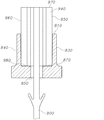
図14A〜図14Cは、縫合糸が上覆取付部品内に供給されている際の上覆取付部品及び縫合糸の断面図である。図14Aは、例示的な上覆取付部品800の断面図を示す。図14A〜図14Cの取付部品800は図4で上述したものと同じ取付部品であることに留意されたい。部品800は、遠位端810及び近位端820を含み、側壁830及び側壁840とともに本体を画定する。近位端820には、タブ開口部860へと通じる縫合糸開口部850がある。タブ開口部860は縫合糸開口部850よりサイズが大きい。タブ開口部860は遠位端810と、側壁830と、側壁840と、タブ当接壁870とによって画定される。縫合糸開口部850の大きさは、縫合糸又はその構成要素を損傷することなく、縫合糸上にある任意の保定部を含む縫合糸を取付部品800内に供給することを可能にするほど十分に大きくすべきであるが、保定部が後退して取付部品800を出ることができるほど大きくすべきではない。タブ開口部860の長さ(遠位端810から当接壁870まで)は任意の長さであってもよく、部品800に挿入されるタブの長さの約50%〜約100%とすべきである。タブ開口部860の幅(第1の壁830の内側から第2の壁840の内側までを測定)は、部品800に挿入される固定タブの側部にぴったりと嵌合するのに十分なものとすべきである。側壁830、840は、当接壁870における長さが遠位端810における長さより小さくなり得るように、テーパ角度を有してもよい。タブが遠位端810にて部品800に挿入され、部品800内に供給されるため、テーパ状構成により、タブが挿入されるにつれてタブが受ける摩擦及び締まりが増加する。また、タブが挿入される際にタブの表面に対する摩擦及び締まりの増加をもたらすために、厚さのテーパ状構成があってもよい。
14A to 14C are cross-sectional views of the suture and the suture when the suture is supplied into the suture. FIG. 14A shows a cross-sectional view of an exemplary
図14Bは、取付部品800内に供給されている、保定部910を有する縫合糸900を示す。縫合糸は近位端(例えば、参照番号920)及び遠位端(例えば、参照番号930)を有し、近位端920は挿入端であり、遠位端930は終端である。縫合糸900の近位端920は取付部品800の遠位端810に挿入され、部品800の長さ全体を通過する。図からわかるように、縫合糸開口部850は、縫合糸900を損傷することなく縫合糸900及びその構成要素(保定部910など)を供給することを可能にするほど、十分に大きい。
FIG. 14B shows a
図14Cは、未修正エンドエフェクタ(この場合、固定タブ940)がタブ開口部860内に着座するように、取付部品800内に完全に供給されている縫合糸900を示す。図示されるように、縫合糸900は、固定タブ940がタブ開口部860に入るまで部品800内において引かれている。固定タブは、側壁950及び側壁960によって画定される幅、並びに遠位端970及び近位端980によって画定される長さを有する。タブ940の近位端980は、タブ当接壁870に当接している。
FIG. 14C shows the
上述のように、タブ開口部860の幅が遠位端810より当接壁870において小さくなるように、取付部品側壁830及び840はテーパ状構成を有することが望まれる。このテーパ状構成は、タブ940が取付部品800内に供給されるにつれてタブ940が受ける締まり及び摩擦の増加を可能にする。テーパは、タブの壁950、960に比して約0.5〜約2度の角度を有してもよい。断面切断のため図14A〜図14Cでは見ることができないが、タブ開口部860の厚さもまた、厚さが遠位端810より当接壁870において小さくなるようにテーパ状に変化していてもよい。
As described above, the mounting
図14Cに見られるように、タブ開口部860の長さはタブ940の長さの約半分であるが、タブ開口部860はタブ940の長さの約50%〜約75%の長さを有してもよい。
As can be seen in FIG. 14C, the length of the
上覆取付部品800が図14Cに(及び図5においても)見られるようなその最終位置に配された後、複合デバイスは使用の準備が整う。デバイスは、エネルギーの印加を要することなく上覆取付部品を所定の位置に固定するための手段を含んでもよく、例えば、複合エンドエフェクタを共に保持するための摩擦嵌合又はスナップ嵌合システムがあってもよい。あるいは、上覆取付部品800は、エネルギー(熱、放射等など)、又は接着剤の使用などによる化学的固定手段によって、所定の位置に固定されてもよい。複合エンドエフェクタは更なる固定なしに使用されてもよい。
After the
図4〜図5を参照すると、本発明は、上述のように固定タブ108及び取付部品200を備える、複合エンドエフェクタ250を有する縫合デバイス100を提供する。本発明は、縫合糸100の近位端を上覆取付部品200の開口部212に挿入すること、及び固定タブ108の少なくとも一部分が開口部212内に供給され、固定タブ108の近位端110が上覆取付部品200の近位端202の内部表面に当接するまで上覆取付部品200を遠位に摺動させることによって、複合エンドエフェクタ250を形成する方法を更に含む。以下でより詳細に記載されるように、上覆取付部品(例えば、参照番号200)は、固定タブ108とは異なるエンドエフェクタを含む縫合糸100とともに使用されてもよい。上覆取付部品200内の開口部212は、例えば、ボタン、ボール、結節、ディスク、バー、及びループを含む任意の大きさ及び形状のエンドエフェクタを収容するように修正してもよい。
With reference to FIGS. 4-5, the present invention provides a
本発明のデバイスは、最終デバイス、即ち、既に準備が整えられ、所定の位置にある複合エンドエフェクタを有する縫合糸としてパッケージ化されてもよい。あるいは、縫合糸と上覆取付部品は臨床医に別々に提供されてもよい。いくつかの実施形態では、1つの縫合糸に複数の上覆取付部品を付与して、ユーザがどの取付部品を使用するかを選択すること、又は縫合糸に取付部品を不適切に取り付けた場合に異なる部品を使用することを可能にしてもよい。 The device of the present invention may be packaged as a final device, a suture having a composite end effector that is already ready and in place. Alternatively, the suture and cover attachment parts may be provided separately to the clinician. In some embodiments, one suture is provided with multiple overcoat attachments and the user chooses which attachment to use, or improperly attaches the attachment to the suture. It may be possible to use different parts for.
本発明は、複合エンドエフェクタ250を有する縫合デバイスを使用する方法を更に含む。複合エンドエフェクタ250を有する縫合糸100が形成される。ユーザは縫合デバイス100の近位端を組織の中へと、及び組織を通って挿入する。ユーザは、組織の表面が上覆取付部品200の近位端202に当接するまで、近位端を組織内にて引いて通す。その時点で、ユーザは組織のその部分内にて縫合糸100を引くのをやめる。ユーザは所望のように近位端を組織の他の部分内に引き続き挿入してもよく、複合エンドエフェクタ250は縫合デバイス100が挿入されている組織の第1の部分に当接したままとなる。縫合糸本体102の少なくとも一部分に沿って配された保定部104により、ユーザは縫合糸を組織内に固定するために結節を結ぶ必要がない。
The present invention further includes a method of using a suturing device with a
上覆取付部品200は、射出成形、又は所望の形状及び大きさを得るための任意の他の所望の手段によって製造されてもよい。モールドは、タブ開口部のプレースホルダとして機能する中心コアリングピンを有する、上覆取付部品の形状であってもよい。成形中、溶融ポリマー材料がピンを取り囲み、ポリマーの固化後にピンが取り出され、スロットを作成する。したがって、モールド及びコアリングピンを設計する際、ピンは所望のスロット寸法と同じ寸法を有するべきである。上覆取付部品200は縫合糸100と同じ材料で作製してもよく、又は異なる材料で作製してもよい。上覆取付部品200は生体吸収性材料で作製してもよく、いくつかの実施形態では、縫合糸100より速い速度で患者の体内に吸収される材料で作製してもよい。金属治具を用いた引張試験時において、例えば、PDSポリマーで作製された射出成形取付部品200は、固定タブ108のみと比較した場合、最大荷重、伸び、及び破断時のエネルギーに統計的に有意な増加をもたらすことが示されている。
The
上覆取付部品200は、デバイスの強度及び植え込みを向上させるものの、挿入後に問題を引き起こすほど大きくないサイズで作製すべきである。複合エンドエフェクタ250(取付部品200及び上覆取付部品200に挿入された固定タブ108を含む)の質量は、サイズ1の縫合糸による従来の5重結節タワー(five throw knot tower)に相当してもよい。複合エンドエフェクタ250の質量は、したがって、複合エンドエフェクタ250が植え込まれる組織に問題を引き起こすような質量の増加を生じさせない。加えて、固定タブ108の大きさにほぼ等しい開口部を上覆取付部品200に含むことによって、上覆取付部品200は、固定タブが折れ、ひび割れが開始するあらゆる望ましくない傾向を効果的に制限することができる。
The
図6は、本発明で有用な上覆取付部品の別実施形態を示す。この図は、開放スロット構成を有する丸形取付部品300を示す。図からわかるように、上覆取付部品300は、遠位端302及び近位端304を含み、遠位端302及び近位端304との間に本体306を有する。上述のように、上覆取付部品300は、遠位端302から近位端304まで本体306の長さ全体に及ぶ開口部308を含む。近位端304から遠位端302まで延びる開口部308を有することで、開口部308内に供給される縫合糸が、上覆取付部品300をエンドエフェクタ108へと遠位に摺動させることを可能にする。
FIG. 6 shows another embodiment of the overcoat mounting component useful in the present invention. This figure shows a
図6の実施形態は、開放スリット設計を示す。この設計では、上覆取付部品300は、上覆取付部品300の遠位端302において開始し、上覆取付部品300の直径全体に及ぶ、スリット310を含む。図からわかるように、開口部308は上覆取付部品300の軸方向中心又はその近傍に位置しており、スリット310は開口部308の中心に延びている。スリット310は上覆取付部品300の本体306内に所望の長さまで続き、そこでタブ当接端312に到達する。特に、開口部308はタブ当接端312内になお続き、このため、縫合糸100は上覆取付部品300の長さ全体に供給され得る。タブ当接端312は使用時に固定タブ108の近位端110が当接する領域であることから、この構成においてタブ当接端312は重要である。
The embodiment of FIG. 6 shows an open slit design. In this design, the
図7A及び図7Bは、固定タブ108及び開放スリット取付部品300を含む複合エンドエフェクタ350を示す。図7Aは上視図であり、図7Bは複合エンドエフェクタ350の側面図である。図からわかるように、上覆取付部品300は縫合糸本体102の長さに沿って遠位に摺動され、上覆取付部品300の遠位端302は固定タブ108上を摺動されている。縫合糸本体102は開口部308を通って供給されている。固定タブ108の近位端110は、近位端110がタブ当接端312に当接するまでスリット310内に供給される。上覆取付部品300は任意の所望の長さを有してもよく、これら図に見られるように、上覆取付部品300の長さは固定タブ108の長さ(l)より短くてもよい。所望であれば、固定タブ108の長さはスリットの長さ(遠位端302からタブ当接端312までを測定)にほぼ等しくてもよく、より長くてもよい。更に、上覆取付部品300の直径は、固定タブ108の幅(w)に等しい又はより大きい必要はない。この構成の上覆取付部品300は開放スリット設計を有するため、固定タブ108の側部は上覆取付部品300の側壁から突き出てもよい。上記と同様に、上覆取付部品300は固定タブ108が上覆取付部品300の内側(タブ当接端312にて)に当接するまで、縫合糸100上を摺動させてもよく、使用されてもよい。所望であれば、上覆取付部品300は、機械的手段(摩擦、スナップ、若しくは移動止めなど)の適用又はエネルギー若しくは化学的手段の適用によって所定の位置に固定されてもよいが、このような固定は必須ではない。
7A and 7B show a
図8及び図9〜図11は、本発明で有用であり得る取付部品の別実施形態を示す。これら取付部品のそれぞれは、上述の同じ材料で作製されていてもよく、これら取付部品は、上述のものと同じ手法で、即ち、縫合糸100の近位端を開口部に挿入し、固定タブ108の近位端110が上覆取付部品の内側部分に当接するまで上覆取付部品を遠位に摺動させることによって、使用されてもよい。
8 and 9-11 show alternative embodiments of mounting components that may be useful in the present invention. Each of these mounting parts may be made of the same material as described above, and these mounting parts may be made in the same manner as described above, i.e., by inserting the proximal end of the
図8は、閉鎖スリットを有する円形取付部品400を示す。この実施形態は図4の上覆取付部品に類似するが、矩形ではなく略円筒状である。この取付部品400は、遠位端402と、近位端404と、遠位端402と近位端404との間の本体406と、上覆取付部品400の中央領域に遠位端402から近位端404まで延びる開口部408と、を備える。この設計は閉鎖スリット408を含む。これは、上覆取付部品400の直径に沿って延びているが、上覆取付部品400の外周を貫通して延びていないスリット408があることを意味する。上覆取付部品400は、近位端404と遠位端402との間の位置に配されたタブ当接端410を含む。スリット408は、固定タブ108を収容するような大きさ及び形状であってもよく、スリット408の幅は固定タブ108の幅(w)にほぼ等しいことが望まれ得る。スリット408の長さ(遠位端402からタブ当接端410までを測定)は固定タブ108の長さ(l)に等しい又はより長い必要はなく、スリット408の長さは固定タブ108の長さ(l)より短いことが望まれ得る。上覆取付部品400の表面は望ましくは滑らかである又は丸みがある。
FIG. 8 shows a
図9〜図11は、図4に示される上覆取付部品の実施形態の変形を示す。図9には、外部テーパ状構成を含む上覆取付部品500が示される。この実施形態では、本体の外部側壁が近位端から遠位端へと、内側にテーパ状に変化している。この実施形態では、近位領域は本体の遠位端より大きな周囲長を有する。
9 to 11 show modifications of the embodiment of the cover mounting component shown in FIG. FIG. 9 shows a
図10に示される実施形態では、上覆取付部品600は、より丸みのある外部構成を有する近位領域を含む。図11に示される実施形態では、近位領域は、丸みのある上面及び底面を含む一方、近位領域の側部は真直である。 In the embodiment shown in FIG. 10, the overcoat mounting component 600 includes a proximal region with a more rounded external configuration. In the embodiment shown in FIG. 11, the proximal region includes a rounded top and bottom, while the sides of the proximal region are straight.
これら構成はそれぞれ、上覆取付部品の設計に施すことができる改良例であり、有用な構成を提供する。上覆取付部品は、細長い壁、丸みのある縁部、及び/又は任意の他の構成を有してもよく、上述のように有用であり得る。 Each of these configurations is an improved example that can be applied to the design of the overcoat mounting component and provides a useful configuration. The overcoat mounting component may have elongated walls, rounded edges, and / or any other configuration and may be useful as described above.
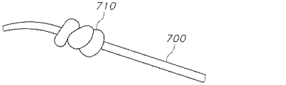
図12A〜図12Cは、結節の形態のアンカーを組み込み、アンカー上に上覆取付部品が設けられる、複合エンドエフェクタの一実施形態を示す。図12Aは、遠位端において結ばれた結節710を有する従来の縫合糸700を示す。この実施形態では、縫合糸700は押出加工を含む従来の縫合糸形成手段によって形成されてもよい。結節は、任意の数の結び目、例えば、1〜10個の結び目を有して結ばれてもよい。結節710の遠位に位置する縫合糸700の終端は結節が形成された後に切り落とし、これにより、結節710を縫合糸700の最遠位端にしてもよい。上記のように、縫合糸700の近位端は、針又は他の先尖要素などの挿入手段を含んでもよい。縫合糸700はその表面に形成された、縫合糸700の表面に切り込みを入れることにより形成される保定部を含む保定部を有してもよい。図12Bは、結節710により縫合糸700を固定するのに有用な上覆取付部品720の一実施形態を示す。本明細書中に示される上覆取付部品720は、その断面が略円形であるが、他の形状を使用してもよい。上覆取付部品720は遠位端730及び近位端740を備え、遠位端730と近位端740との間に本体750を有し、中心開口部760が遠位端730から近位端740まで本体750内を通って延びている。遠位端730における開口部760の直径は、近位端740における開口部760の直径より大きい。これは、例えば、開口部が遠位端730から近位端740へと延びるにつれて開口部の大きさをテーパ状に変化させることによって実現してもよい。あるいは、上覆取付部品720は、上覆取付部品720の近位端740の近傍の位置にフランジ770を備えてもよい。フランジ770は、開口部760の近位端740を結節710が通過するのを制限するような大きさにされてもよい。開口部760は、縫合糸本体700が損傷なく開口部760を通過するのを可能にするほど、断面直径を十分に大きくすべきである。
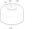
12A-12C show an embodiment of a composite end effector in which an anchor in the form of a nodule is incorporated and a cover mounting component is provided on the anchor. FIG. 12A shows a
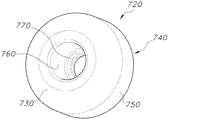
図12Cは、結節710及び取付部品720を有して形成された複合エンドエフェクタ780を示す。縫合糸700の近位端は上覆取付部品720の遠位端730内を通されており、上覆取付部品720は、結節710の少なくとも一部分が上覆取付部品720の遠位端730内に挿入されるまで、縫合糸700に沿って遠位に摺動されている。開口部760の近位端740は開口部760の遠位端730より小さな断面直径を有することから、結節710はフランジ770に当接した状態に維持され、開口部760の近位端740を通して引くことはできない。したがって、結節710は、上覆取付部品720の開口部760によって形成された凹設ボア内に載置される。結節710が取付部品720の開口部760内に載置されると、結節710は取付部品720の開口部760の内壁による機械的な締まりを受ける。この締まり嵌めにより、結節710が開口部760から滑り出るのを制限する。縫合糸700の遠位端は開口部760内に通されてもよく、その後、遠位端にて結節710が結ばれてもよい、あるいは、結節710がまず縫合糸700の遠位端において形成されてもよく、その後、縫合糸の近位端を取付部品の近位端740を通過させ、遠位に移動してもよい。上述のように、複合エンドエフェクタ780は、所望であれば、エネルギー、化学的、又は他の手段を適用することによって固定されてもよい。こうした更なる固定手段は必須ではない。
FIG. 12C shows a
図12A〜図12Cの上覆取付部品720は、大きなサイズの押出縫合糸を、軸方向に穴を開け、穴の口を広げ、任意選択的に座ぐりし、適切な長さに切断して、作製してもよい。あるいは、上覆取付部品720は、射出成形又は他のプロセスによって形成されてもよい。取付部品を押出材料から形成することは、複合エンドエフェクタ780が生分解性材料又は成形が困難若しくは不可能な材料で作製される場合に有用である。押出加工は、デバイスに比較的高度の分子配向を付与し、長手方向と横断方向とで異なる性質を与えることで、破断強度保持率を増加させることができることから、上覆取付部品720の押出加工が好適であり得る。射出成形された部品は、成形プロセス時にいくらかの分子配向が起こり得るものの、十分に均一な性質を有する。場合によっては、取付部品720は、縫合糸材料(縫合糸700に使用される材料と同じであってもよく、異なっていてもよい)の大きなサイズのストランド(例えば、使用される縫合糸700より大きな外径を有するストランド)を押し出し、この押出されたストランドから個々の部品を切断することによって形成されてもよい。例えば、大きなサイズの押出されたストランドは円形断面を有してもよく、押出されたストランドを、押出されたストランドの中心軸線に垂直な平面にてスライスすることによって、個々のディスク状の取付部品に切断してもよい。中心穴が、得られたディスク状の取付部品の中心軸線に又はそれを通って入れられてもよく、ディスクの中心軸線に入れられた座ぐりされた穴があることが望ましい。ディスク状の取付部品は、座ぐりされた穴を取付部品の中心軸線に及びそれを通って入れることを可能にするほどに十分に大きな外径を有し、座ぐりされた穴は、結節710を嵌合しかつ摩擦的に保持できるほど十分に大きいことが望ましい。
The
図13A〜図13Dは、図12の実施形態で有用な上覆取付部品720の一実施形態の種々の図を示す。上覆取付部品720は、遠位端730と、近位端740と、遠位端730と近位端740との間の本体750と、遠位端730から近位端740まで延びる中心開口部760と、を備える。図からわかるように、開口部760の断面直径は、近位端740より遠位端730においてより大きい。図からわかるように、これはフランジ770の使用により実現されてもよい。あるいは、開口部760は、本体750にテーパ状の切り込みを入れることによって形成されてもよい。上覆取付部品720の遠位端730は、滑らかな又は丸みのある縁部を有してもよく、植え込み後、上覆取付部品720の遠位端730が外部組織に曝されることによって縫合糸が組織に植え込まれたときに受ける外傷を低減する。
13A-13D show various views of one embodiment of the
本明細書中では、上覆取付部品を既存のタブに固定する他の方法も考えられる。例えば、取付部品は、ヒンジ側及びスナップフィット式の対向側を含んでもよく、それにより、取付部品を開くことができるとともに、タブ上の所定位置にスナップ留めすることができる。 Other methods of fixing the overcoat mounting component to existing tabs are also conceivable herein. For example, the mounting component may include a hinge side and a snap-fit facing side, which allows the mounting component to be opened and snapped into place on the tab.
上で説明したように、取付部品のタブ開口部の長さ、幅及び厚さに沿った大きさ、並びに開口部の構成は、複合エンドエフェクタによりもたらされる機械的特性を最適化するように変更してもよい。上述のように、タブ開口部は、固定タブ(又は異なるエンドエフェクタが使用される場合は他のエンドエフェクタ)を嵌合するような形状及び大きさにしてもよい。開口部の寸法が固定タブの寸法により厳密に一致するため、荷重、伸び、及び破断時におけるエネルギーのゲインの増加が実現される。固定タブの構成を厳密に一致させることの効果を実証するために、それぞれ異なる大きさのタブ開口部を有する4つの異なるPDS取付部品を形成した。上覆取付部品はそれぞれ縫合糸上に配した。各縫合糸は図1に記載したものと実質的に同一の固定タブを有していた。本実施例において使用した固定タブは、長さ5080マイクロメートル(200ミル)、幅2489マイクロメートル(98ミル)、及び中心軸線のすぐ外側にて厚さ203マイクロメートル(8ミル)及び側部にて厚さ305マイクロメートル(12ミル)であった。縫合糸直径はサイズ1縫合糸のものであった。 As explained above, the length, width and thickness of the tab openings in the mounting components, as well as the size of the openings, have been modified to optimize the mechanical properties provided by the composite end effector. You may. As mentioned above, the tab openings may be shaped and sized to fit fixed tabs (or other end effectors if different end effectors are used). The dimensions of the openings are more closely matched to the dimensions of the fixed tabs, resulting in increased gains in load, elongation, and energy at break. To demonstrate the effect of tightly matching the configuration of the fixed tabs, four different PDS mounting components were formed, each with a different size of tab opening. The overcoat mounting parts were placed on the sutures. Each suture had substantially the same fixing tab as that shown in FIG. The fixed tabs used in this example are 5080 micrometers (200 mils) long, 2489 micrometers (98 mils) wide, and 203 micrometers (8 mils) thick and laterally just outside the central axis. It was 305 micrometers (12 mils) thick. The suture diameter was that of size 1 suture.
4つの取付部品にはRev−2、Rev−2B、Rev−2C、及びRev−2Dの符号を付した。各取付部品の外形寸法は一定であった。各部品において、挿入時に固定タブの周囲により密な摩擦嵌合を生じさせるために、スロットは段階的に狭くなるように作製された。各部品は、タブ開口部を作製するために、成形ピンを使用して射出成形した。成形ピン高さは中央領域にて得られるタブ開口部の厚さに相関し、成形ピンの羽根高さは側壁にて得られるタブ開口部の厚さに相関していた。この試験の目的は、取付部品内にてタブのよりぴったりとした、密な嵌合を用いた場合での効果を実証することである。 The four mounting components are labeled Rev-2, Rev-2B, Rev-2C, and Rev-2D. The external dimensions of each mounting component were constant. In each part, the slots were made to be progressively narrower to create a tighter frictional fit around the retaining tab during insertion. Each part was injection molded using molding pins to create a tab opening. The height of the forming pin was correlated with the thickness of the tab opening obtained in the central region, and the blade height of the forming pin was correlated with the thickness of the tab opening obtained in the side wall. The purpose of this test is to demonstrate the effect of using a tighter, tighter fit of tabs within the mounting part.
Rev−2は、遠位端から近位端に至るまで、中央領域(中心軸線に沿った)におけるコア径が635マイクロメートル(25ミル)であるが、側壁の厚さは、遠位端では457マイクロメートル(18ミル)であり、当接壁では381マイクロメートル(15ミル)となっている、取付部品であった。 Rev-2 has a core diameter of 635 micrometers (25 mils) in the central region (along the central axis) from the distal end to the proximal end, while the side wall thickness is at the distal end. It was a mounting component that was 457 micrometers (18 mils) and 381 micrometers (15 mils) on the abutment wall.
Rev−2Bは、遠位端から近位端に至るまで、中央領域(中心軸線に沿った)におけるコア径が559マイクロメートル(22ミル)であるが、側壁の厚さは、遠位端では406マイクロメートル(16ミル)であり、当接壁では330マイクロメートル(13ミル)となっている、取付部品であった。 Rev-2B has a core diameter of 559 micrometers (22 mils) in the central region (along the central axis) from the distal end to the proximal end, while the side wall thickness is at the distal end. It was a mounting component that was 406 micrometers (16 mils) and 330 micrometers (13 mils) on the abutment wall.
Rev−2Cは、遠位端から近位端に至るまで、中央領域(中心軸線に沿った)におけるコア径が508マイクロメートル(20ミル)であるが、側壁の厚さは、遠位端では381マイクロメートル(15ミル)であり、当接壁では305マイクロメートル(12ミル)となっている、取付部品であった。 Rev-2C has a core diameter of 508 micrometers (20 mils) in the central region (along the central axis) from the distal end to the proximal end, while the side wall thickness is at the distal end. It was a mounting component that was 381 micrometers (15 mils) and 305 micrometers (12 mils) on the abutment wall.
Rev−2Cは、遠位端から近位端に至るまで、中央領域(中心軸線に沿った)におけるコア径が483マイクロメートル(19ミル)であるが、側壁の厚さは、遠位端では356マイクロメートル(14ミル)であり、当接壁では279マイクロメートル(11ミル)となっている、取付部品であった。 Rev-2C has a core diameter of 483 micrometers (19 mils) in the central region (along the central axis) from the distal end to the proximal end, while the side wall thickness is at the distal end. It was a mounting component that was 356 micrometers (14 mils) and 279 micrometers (11 mils) on the abutment wall.
各部品の遠位端での開口部の幅は2743マイクロメートル(108ミル)であり、当接壁での各部品の幅は2667マイクロメートル(105ミル)であった。 The width of the opening at the distal end of each part was 2743 micrometers (108 mils) and the width of each part at the abutment wall was 2667 micrometers (105 mils).
図14A〜図14Cに関して記載した手法で、1本の縫合糸を各取付部品に挿入した。 A single suture was inserted into each attachment in the manner described with respect to FIGS. 14A-14C.
各縫合糸の引張試験を、卓上型インストロン試験による特別仕様の金属治具において行った。特別仕様の金属試験治具は、縫合糸及び/又は複合エンドエフェクタに合わせた大きさ及び形状とした。この試験はより一般的には剪断強度試験と呼ばれ、この例では、試験される固定タブ(単数又は複数)の剪断強度を測定することから、固定タブ剪断強度試験であるとみなされる。各固定タブの剪断強度を、それぞれ個々の縫合糸を特別仕様の金属試験治具に載せることで、試験した。固定タブが板の下面に直に接触し、縫合糸の自由端を板の上面において利用できるように、各試験片を固定治具上板のスリットに導入した。 Tensile tests of each suture were performed on a specially designed metal jig by a tabletop Instron test. The specially designed metal test jig was sized and shaped to fit the suture and / or composite end effector. This test is more commonly referred to as the shear strength test, and in this example it is considered to be a fixed tab shear strength test as it measures the shear strength of the fixed tabs (s) being tested. The shear strength of each fixing tab was tested by placing each individual suture on a specially designed metal test jig. Each test piece was introduced into a slit in the upper plate of the fixing jig so that the fixing tabs were in direct contact with the lower surface of the plate and the free end of the suture was available on the upper surface of the plate.
縫合糸の自由端を、上部インストロングリッパにより(縫合糸をぴんと張った状態に維持するために十分な)低張力下で、ゲージ長2.54センチメートル(1インチ)にて把持した。縫合糸は、固定治具に垂直であり、角度を成さないように、グリップの中心に位置合わせされた。各試験片を30cm/分(12インチ/分)で固定タブの破壊点まで引っ張った。 The free end of the suture was gripped by an upper instrument gripper under low tension (sufficient to keep the suture taut) with a gauge length of 2.54 cm (1 inch). The suture was perpendicular to the fixing jig and centered on the grip so that it did not form an angle. Each test piece was pulled at 30 cm / min (12 inch / min) to the breaking point of the fixing tab.
上覆取付部品を有しない固定タブのサンプル、並びに取付部品Rev−2、Rev−2B、Rev−2C、及びRev−2Dを有する複合縫合糸に対する試験を終了した。上述のように、各取付部品は異なる幅及び高さを有し、それぞれ、上覆取付部品の徐々に密になる嵌合を固定タブの周囲において形成した。上覆取付部品の外形寸法を一定に維持し、固定タブの周囲により密な摩擦嵌合を生じさせるために内部開口部寸法を徐々に狭くすることで、複合エンドエフェクタの機械的性能が向上すること、即ち、エンドエフェクタの剪断強度が増加することが判明した。図15は、得られた剪断強度値の棒グラフを示す。上覆取付部品を有しない固定タブと固定タブに取付部品を付加した複合エンドエフェクタのいずれかのものとを比較した場合にも、COV(変動係数)は大幅に減少することに留意されたい。最大荷重、伸び、及び破断時のエネルギーの増加率は、取付部品が固定されていない固定タブを有する縫合糸に対するものである。結果を以下の表1に示す。 Testing of fixed tab samples without overcoat attachments and composite sutures with attachments Rev-2, Rev-2B, Rev-2C, and Rev-2D was completed. As mentioned above, each mounting component had a different width and height, and each formed a gradually tighter fit of the overcoat mounting component around the fixing tab. The mechanical performance of the composite end effector is improved by keeping the external dimensions of the overcoat mounting component constant and gradually narrowing the internal opening dimensions to create a tighter friction fit around the fixing tabs. That is, it was found that the shear strength of the end effector was increased. FIG. 15 shows a bar graph of the obtained shear strength values. It should be noted that the COV (coefficient of variation) is also significantly reduced when comparing a fixed tab without an overcoat mounting component with either a composite end effector with mounting components added to the fixed tab. The rate of increase in maximum load, elongation, and energy at break is for sutures with fixing tabs to which the attachment is not fixed. The results are shown in Table 1 below.

表からわかるように、Rev−2C及びRev−2Dは機械的性能の観点から互いに統計的に等しく、「最良」の結果をもたらした。これら2つの部品は、タブ開口部内にてタブの最も密でありかつ最もぴったりとした嵌合をもたらした。しかしながら、主観的には、Rev−2C部品が、Rev−2C部品を固定タブ上に楽に着座させるために適度な量の力が用いられるという点で、固定タブへの適用がより容易であることが判明した。Rev−2D部品は、固定タブへの常用的な適用がより困難であり、上覆取付部品を固定タブに適切に着座させるために望ましくない量の力が必要であった。このため、Rev2C取付部品が、製造環境において有利であろうその優れた機械的性能、取付部品を有しないタブを上回る向上、及び上覆取付部品をタブに適用する際の使い易さのため、「最良」であると考えられる。したがって、最も望ましい取付部品は、容易にかつ過度の力なく固定タブを受け入れることができるべきであるものの、一旦挿入されると固定タブの適切に密でありかつぴったりとした嵌合をなおもたらすべきである。部品のタブ開口部のテーパ状構成により、タブが部品に挿入されたとき、保持及び摩擦嵌合の増加をもたらした。 As can be seen from the table, Rev-2C and Rev-2D were statistically equal to each other in terms of mechanical performance, resulting in "best" results. These two parts provided the tightest and tightest fit of the tab within the tab opening. However, subjectively, the Rev-2C component is easier to apply to the fixed tab in that a moderate amount of force is used to comfortably seat the Rev-2C component on the fixed tab. There was found. Rev-2D components are more difficult to routinely apply to fixed tabs and require an undesired amount of force to properly seat the overcoat mounting component on the fixed tabs. For this reason, Rev2C mounting parts have superior mechanical performance that would be advantageous in the manufacturing environment, improvements over tabs without mounting parts, and ease of use when applying overcoat mounting parts to tabs. Considered to be the "best". Therefore, the most desirable mounting part should be able to easily and without undue force to accept the retaining tab, but once inserted it should still provide a properly tight and snug fit of the retaining tab. Is. The tapered construction of the tab openings in the part resulted in increased retention and frictional fitting when the tab was inserted into the part.
上覆取付部品の外形寸法を一定に維持するものの、部品の内部開口部(スロット)寸法を徐々に狭くして本来のエンドエフェクタ(固定タブなど)の周囲により密な摩擦嵌合を生じさせることによって、複合エンドエフェクタの機械的性能が向上することが判明した。つまり、複合エンドエフェクタは未修正固定タブと比較してより高い強度を示した。 Keeping the external dimensions of the overcoat mounting component constant, but gradually narrowing the internal opening (slot) dimensions of the component to create a tighter friction fit around the original end effector (fixing tab, etc.). It was found that the mechanical performance of the composite end effector was improved. That is, the composite end effector showed higher strength compared to the unmodified fixed tab.
〔実施の態様〕
(1) a.近位端及び遠位端を有する細長い縫合糸本体と、
b.前記遠位端にある複合エンドエフェクタであって、
i.長さ、幅、及び厚さを有する固定タブと、
ii.長さ、幅、及び厚さを有するタブ開口部を有する上覆取付部品と、
を備える、複合エンドエフェクタと、
を備え、
前記固定タブの近位端が前記上覆取付部品の近位壁に当接するように、前記固定タブの少なくとも前記近位端は前記上覆取付部品に挿入されている、
縫合デバイス。
(2) 前記縫合糸本体と前記固定タブとは同じ材料から形成されており、一体構造を有する、実施態様1に記載の縫合デバイス。
(3) 前記上覆取付部品は遠位端及び近位端を有し、前記近位端に縫合糸開口部を有し、前記近位端に前記タブ開口部を有する、実施態様1に記載の縫合デバイス。
(4) 前記縫合糸開口部は、前記遠位端にある前記タブ開口部より小さな幅を有する、実施態様3に記載の縫合デバイス。
(5) 前記縫合糸本体は、前記縫合糸本体の軸方向長さの少なくとも一部分に沿って複数の保定部を備える、実施態様1に記載の縫合デバイス。
[Implementation]
(1) a. An elongated suture body with proximal and distal ends,
b. A composite end effector at the distal end
i. With fixed tabs with length, width, and thickness,
ii. Overcoat mounting components with tab openings of length, width, and thickness,
With a composite end effector,
With
At least the proximal end of the fixing tab is inserted into the covering attachment so that the proximal end of the fixing tab abuts against the proximal wall of the covering attachment.
Suture device.
(2) The suture device according to the first embodiment, wherein the suture body and the fixing tab are made of the same material and have an integral structure.
(3) The first embodiment, wherein the cover mounting component has a distal end and a proximal end, a suture opening at the proximal end, and a tab opening at the proximal end. Suture device.
(4) The suture device according to the third embodiment, wherein the suture opening has a width smaller than that of the tab opening at the distal end.
(5) The suture device according to the first embodiment, wherein the suture body includes a plurality of retention portions along at least a part of the axial length of the suture body.
(6) 前記保定部は、前記縫合糸及び前記保定部をプリフォームリボンからスタンピングすることにより形成されている、実施態様5に記載の縫合デバイス。
(7) 前記上覆取付部品及び前記固定タブは摩擦嵌合により互いに接合されている、実施態様1に記載の縫合デバイス。
(8) 前記上覆取付部品と前記固定タブは、前記取付部品と前記固定タブとを互いに溶接することなく互いに接合されている、実施態様7に記載の縫合デバイス。
(9) 前記上覆取付部品及び前記固定タブは同じ材料から作製されている、実施態様1に記載の縫合デバイス。
(10) 前記上覆取付部品及び前記固定タブは異なる材料から作製されている、実施態様1に記載の縫合デバイス。
(6) The suture device according to the fifth embodiment, wherein the retention portion is formed by stamping the suture and the retention portion from a preform ribbon.
(7) The suturing device according to the first embodiment, wherein the overcoat mounting component and the fixing tab are joined to each other by friction fitting.
(8) The suture device according to embodiment 7, wherein the cover mounting component and the fixing tab are joined to each other without welding the mounting component and the fixing tab to each other.
(9) The suturing device according to the first embodiment, wherein the overcoat mounting component and the fixing tab are made of the same material.
(10) The suturing device according to embodiment 1, wherein the overcoat mounting component and the fixing tab are made of different materials.
(11) 前記タブ開口部の前記遠位端が前記近位壁での前記タブ開口部の幅より大きな幅となるように、前記タブ開口部の幅がテーパ状に変化している、実施態様1に記載の縫合デバイス。
(12) 前記タブ開口部の前記遠位端が前記近位壁での前記タブ開口部の厚さより大きな厚さとなるように、前記タブ開口部の厚さがテーパ状に変化している、実施態様1に記載の縫合デバイス。
(13) 縫合糸を製造する方法であって、
a.長さ、幅、及び厚さを有するタブ開口部を有する上覆取付部品を、近位端及び遠位端を有し、前記遠位端に固定タブを有する縫合糸本体上を摺動させる工程であって、前記固定タブが前記タブ開口部内に嵌合するまで前記上覆取付部品を前記縫合糸本体に沿って遠位方向に摺動させる、工程を含む、方法。
(14) 縫合糸を使用する方法であって、
a.実施態様1に記載の縫合デバイスの近位端を組織に挿入する工程と、
b.前記上覆取付部品の近位端が前記組織に当接するまで、前記縫合デバイスを前記組織内を引いて通す工程と、
を含む、方法。
(15) 前記固定タブは、前記固定タブが挿入される前記組織に実質的に垂直に維持され、前記固定タブは、前記上覆取付部品が前記組織に当接した後、折れること又は動くことの少なくとも1つを制限される、実施態様14に記載の方法。
(11) An embodiment in which the width of the tab opening is tapered so that the distal end of the tab opening has a width larger than the width of the tab opening on the proximal wall. The suturing device according to 1.
(12) The thickness of the tab opening is tapered so that the distal end of the tab opening is larger than the thickness of the tab opening on the proximal wall. The suturing device according to aspect 1.
(13) A method for manufacturing sutures.
a. A step of sliding an overcoat attachment component having a tab opening having a length, width, and thickness over a suture body having a proximal end and a distal end and having a fixing tab at the distal end. A method comprising the step of sliding the overcoat attachment component distally along the suture body until the fixing tab fits into the tab opening.
(14) This is a method using sutures.
a. The step of inserting the proximal end of the suturing device according to embodiment 1 into the tissue.
b. A step of pulling the suturing device through the tissue until the proximal end of the overcoat mounting component abuts the tissue.
Including methods.
(15) The fixing tab is maintained substantially perpendicular to the tissue into which the fixing tab is inserted, and the fixing tab is broken or moved after the overcoat mounting component abuts on the tissue. 14. The method of embodiment 14, wherein at least one of the above is restricted.
(16) a.近位端及び遠位端を有し、前記遠位端に結節を有する、細長い縫合糸本体と、
b.前記遠位端にある複合エンドエフェクタであって、前記結節と、内部開口部を設けた上覆取付部品と、を備え、前記結節の少なくとも一部分は、前記上覆取付部品の前記内部開口部内に設けられている、複合エンドエフェクタと、
を備える、縫合デバイス。
(17) 前記結節を結ぶ前に、前記上覆取付部品を前記縫合糸本体上に設ける工程を含む、実施態様16に記載の縫合デバイスを製造する方法。
(18) 前記縫合糸本体に前記結節が結ばれた後に、前記上覆取付部品を前記縫合糸本体上に設ける工程を含む、実施態様16に記載の縫合デバイスを製造する方法。
(19) 前記上覆取付部品は、前記細長い縫合糸本体の直径より大きな外径を有する、押出材料ストランドから前記取付部品を切断することによって形成されている、実施態様16に記載の縫合デバイス。
(16) a. An elongated suture body having proximal and distal ends and a nodule at the distal end.
b. A composite end effector at the distal end comprising the nodule and an overcoat mounting component provided with an internal opening, at least a portion of the nodule within the internal opening of the overcoat mounting component. The composite end effector provided and
A suturing device.
(17) The method for manufacturing a suture device according to embodiment 16, further comprising a step of providing the suture attachment component on the suture body before tying the nodule.
(18) The method of manufacturing the suture device according to the sixteenth embodiment, which comprises a step of providing the cover attachment component on the suture body after the nodule is tied to the suture body.
(19) The suture device according to embodiment 16, wherein the overcoat attachment part is formed by cutting the attachment part from an extruded material strand having an outer diameter larger than the diameter of the elongated suture body.
Claims (1)
a.長さ、幅、及び厚さを有するタブ開口部を有する上覆取付部品を、近位端及び遠位端を有し、前記遠位端に固定タブを有する縫合糸本体上を摺動させる工程であって、前記固定タブが前記タブ開口部内に嵌合するまで前記上覆取付部品を前記縫合糸本体に沿って遠位方向に摺動させる、工程を含む、方法。 A method of manufacturing sutures
a. A step of sliding an overcoat attachment component having a tab opening having a length, width, and thickness over a suture body having a proximal end and a distal end and having a fixing tab at the distal end. A method comprising the step of sliding the overcoat attachment component distally along the suture body until the fixing tab fits into the tab opening.
Applications Claiming Priority (2)
| Application Number | Priority Date | Filing Date | Title |
|---|---|---|---|
| US14/844,210 US10188379B2 (en) | 2015-09-03 | 2015-09-03 | End effector for wound closure device |
| US14/844,210 | 2015-09-03 |
Related Parent Applications (1)
| Application Number | Title | Priority Date | Filing Date |
|---|---|---|---|
| JP2018511629A Division JP6862430B2 (en) | 2015-09-03 | 2016-08-30 | Improved end effector for wound closure devices |
Publications (2)
| Publication Number | Publication Date |
|---|---|
| JP2021007786A true JP2021007786A (en) | 2021-01-28 |
| JP7175949B2 JP7175949B2 (en) | 2022-11-21 |
Family
ID=56959003
Family Applications (2)
| Application Number | Title | Priority Date | Filing Date |
|---|---|---|---|
| JP2018511629A Active JP6862430B2 (en) | 2015-09-03 | 2016-08-30 | Improved end effector for wound closure devices |
| JP2020173101A Active JP7175949B2 (en) | 2015-09-03 | 2020-10-14 | Improved end effector for wound closure devices |
Family Applications Before (1)
| Application Number | Title | Priority Date | Filing Date |
|---|---|---|---|
| JP2018511629A Active JP6862430B2 (en) | 2015-09-03 | 2016-08-30 | Improved end effector for wound closure devices |
Country Status (12)
| Country | Link |
|---|---|
| US (1) | US10188379B2 (en) |
| EP (1) | EP3344159B1 (en) |
| JP (2) | JP6862430B2 (en) |
| KR (1) | KR102593039B1 (en) |
| CN (2) | CN112656470A (en) |
| AU (1) | AU2016317011B2 (en) |
| BR (1) | BR112018004131B1 (en) |
| CA (1) | CA2997498A1 (en) |
| MA (1) | MA47568A (en) |
| MX (1) | MX2018002737A (en) |
| RU (1) | RU2727232C2 (en) |
| WO (1) | WO2017040506A2 (en) |
Families Citing this family (4)
| Publication number | Priority date | Publication date | Assignee | Title |
|---|---|---|---|---|
| KR102184638B1 (en) * | 2018-05-18 | 2020-11-30 | (주)제이월드 | Medical suture and medical suture kit |
| EP3955828A4 (en) * | 2019-04-19 | 2023-06-28 | Suturegard Medical, Inc. | Hemi-bridge and methods of manufacturing and using same |
| USD936830S1 (en) * | 2020-04-02 | 2021-11-23 | Samyang Holdings Corporation | Medical thread |
| WO2022133387A1 (en) * | 2020-12-18 | 2022-06-23 | The John Hopkins University | Perianal fistula closure system |
Citations (5)
| Publication number | Priority date | Publication date | Assignee | Title |
|---|---|---|---|---|
| US20030233022A1 (en) * | 2002-06-12 | 2003-12-18 | Vidlund Robert M. | Devices and methods for heart valve treatment |
| JP2008534084A (en) * | 2005-03-25 | 2008-08-28 | アンプル メディカル, インコーポレイテッド | Apparatus, system, and method for reshaping a heart valve annulus |
| JP2009531071A (en) * | 2005-12-22 | 2009-09-03 | エス.ウェスト ジュニア ヒュー | Bone anchor used to attach soft tissue to bone |
| US20130158598A1 (en) * | 2011-12-20 | 2013-06-20 | Depuy Mitek, Inc. | Systems and methods for repairing tissue |
| WO2014159058A1 (en) * | 2013-03-14 | 2014-10-02 | Kfx Medical Corporation | Tissue capturing bone anchor |
Family Cites Families (61)
| Publication number | Priority date | Publication date | Assignee | Title |
|---|---|---|---|---|
| US5207679A (en) * | 1991-09-26 | 1993-05-04 | Mitek Surgical Products, Inc. | Suture anchor and installation tool |
| US5156616A (en) * | 1992-02-10 | 1992-10-20 | Meadows Bruce F | Apparatus and method for suture attachment |
| US6241747B1 (en) | 1993-05-03 | 2001-06-05 | Quill Medical, Inc. | Barbed Bodily tissue connector |
| US5486197A (en) * | 1994-03-24 | 1996-01-23 | Ethicon, Inc. | Two-piece suture anchor with barbs |
| US5571139A (en) * | 1995-05-19 | 1996-11-05 | Jenkins, Jr.; Joseph R. | Bidirectional suture anchor |
| US7611521B2 (en) * | 1996-09-13 | 2009-11-03 | Tendon Technology, Ltd. | Apparatus and methods for tendon or ligament repair |
| US20050004576A1 (en) | 1998-11-23 | 2005-01-06 | Benderev Theodore V. | System for securing sutures, grafts and soft tissue to bone and periosteum |
| US6306159B1 (en) * | 1998-12-23 | 2001-10-23 | Depuy Orthopaedics, Inc. | Meniscal repair device |
| EP1016377B1 (en) * | 1998-12-30 | 2006-04-26 | Ethicon Inc. | Suture locking device |
| US9521999B2 (en) * | 2005-09-13 | 2016-12-20 | Arthrex, Inc. | Fully-threaded bioabsorbable suture anchor |
| US6398796B2 (en) * | 1999-07-13 | 2002-06-04 | Scion Cardio-Vascular, Inc. | Suture with toggle and delivery system |
| US6206895B1 (en) | 1999-07-13 | 2001-03-27 | Scion Cardio-Vascular, Inc. | Suture with toggle and delivery system |
| US7887551B2 (en) | 1999-12-02 | 2011-02-15 | Smith & Nephew, Inc. | Soft tissue attachment and repair |
| US6264675B1 (en) | 2000-02-04 | 2001-07-24 | Gregory R. Brotz | Single suture structure |
| US20110168192A9 (en) * | 2000-12-20 | 2011-07-14 | Eduardo Fierro | Adjustable autofixing sling for treatment of urinary incontinence |
| US6652563B2 (en) * | 2001-10-02 | 2003-11-25 | Arthrex, Inc. | Suture anchor with internal suture loop |
| US7582097B2 (en) | 2001-12-18 | 2009-09-01 | Ethicon, Inc. | Suture welding system and method |
| US20030149447A1 (en) | 2002-02-01 | 2003-08-07 | Morency Steven David | Barbed surgical suture |
| US7164360B2 (en) * | 2002-08-14 | 2007-01-16 | Mark Schiebler | Multi-use linkage device |
| CN2564116Y (en) * | 2002-09-05 | 2003-08-06 | 锋溢(香港)有限公司 | Operating suture end fixer |
| US20040267309A1 (en) * | 2003-06-27 | 2004-12-30 | Garvin Dennis D. | Device for sutureless wound closure |
| US7021316B2 (en) * | 2003-08-07 | 2006-04-04 | Tools For Surgery, Llc | Device and method for tacking a prosthetic screen |
| RU2310405C2 (en) * | 2004-01-13 | 2007-11-20 | Аркадий Вениаминович Дубровский | Surgical strapling instrument |
| US20050228415A1 (en) * | 2004-03-23 | 2005-10-13 | Michael Gertner | Methods and devices for percutaneous, non-laparoscopic treatment of obesity |
| US8579940B2 (en) * | 2004-04-06 | 2013-11-12 | Arthrex, Inc. | Suture anchor with apertures at tip |
| JP5340593B2 (en) * | 2004-05-14 | 2013-11-13 | エシコン・エルエルシー | Suture method and apparatus |
| US20140316461A1 (en) * | 2005-02-07 | 2014-10-23 | Joseph H. Sklar | Knotless suture anchor for securing soft tissue to bone |
| US20120078298A1 (en) * | 2005-02-07 | 2012-03-29 | Sklar Joseph H | Knotless suture anchor for securing soft tissue to bone |
| CA2601818A1 (en) | 2005-03-25 | 2006-10-05 | Ample Medical, Inc. | Device, systems, and methods for reshaping a heart valve annulus |
| JP5186366B2 (en) * | 2005-06-20 | 2013-04-17 | スーチュラ,インコーポレイテッド | Device for knotting sutures |
| US7862585B2 (en) * | 2005-06-23 | 2011-01-04 | Johnson & Johnson | Tissue repair device and fabrication thereof |
| US7815659B2 (en) * | 2005-11-15 | 2010-10-19 | Ethicon Endo-Surgery, Inc. | Suture anchor applicator |
| US7695495B2 (en) * | 2005-12-13 | 2010-04-13 | Arthrex, Inc. | Peek threaded suture anchor |
| EP1988834A4 (en) * | 2006-02-28 | 2010-03-24 | Devices Pty Limited Aesthetic | Surgical device |
| WO2007131019A2 (en) | 2006-05-04 | 2007-11-15 | Ethicon, Inc. | Tissue holding devices and methods for making the same |
| US8821542B2 (en) * | 2006-10-31 | 2014-09-02 | Depuy Mitek, Llc | Suture management system |
| US8932327B2 (en) | 2008-04-01 | 2015-01-13 | Covidien Lp | Anchoring device |
| US10376261B2 (en) | 2008-04-01 | 2019-08-13 | Covidien Lp | Anchoring suture |
| US9271706B2 (en) * | 2008-08-12 | 2016-03-01 | Covidien Lp | Medical device for wound closure and method of use |
| EP2352435B1 (en) | 2008-10-31 | 2019-11-27 | Sinclair Pharmaceuticals Limited | Minimally invasive tissue support system with a superior tissue support and an inferior anchor |
| US20110054523A1 (en) | 2009-08-25 | 2011-03-03 | Tyco Healthcare Group Lp | System And Method For Creating End Effector |
| US9011487B2 (en) | 2009-08-27 | 2015-04-21 | Ethicon, Inc. | Barbed sutures having pledget stoppers and methods therefor |
| US8297330B2 (en) | 2009-10-01 | 2012-10-30 | Tyco Healthcare Group Lp | Welded knot end effector |
| IT1400838B1 (en) | 2010-07-08 | 2013-07-02 | Assut Europ S P A | SUTURE WIRE. |
| ES2516190T3 (en) * | 2010-09-24 | 2014-10-30 | Sportwelding Gmbh | Device for fixing a suture anchor in a hard fabric |
| US9707069B2 (en) | 2011-02-25 | 2017-07-18 | Avinash Kumar | Suture mesh and method of use |
| KR101132841B1 (en) * | 2011-03-07 | 2012-04-02 | 김영재 | A suture |
| US20120245602A1 (en) | 2011-03-23 | 2012-09-27 | Jonathan Glick | Welded Looped Suture |
| US10973513B2 (en) | 2011-09-29 | 2021-04-13 | Ethicon, Llc | Barbed suture having increased holding strength |
| US20130211451A1 (en) * | 2012-02-09 | 2013-08-15 | Anulex Technologies, Inc. | Bone anchor and related instrumentation and methods |
| US9855028B2 (en) * | 2012-04-06 | 2018-01-02 | Arthrocare Corporation | Multi-suture knotless anchor for attaching tissue to bone and related method |
| US9498202B2 (en) * | 2012-07-10 | 2016-11-22 | Edwards Lifesciences Corporation | Suture securement devices |
| US11672529B2 (en) * | 2012-09-17 | 2023-06-13 | Cilag Gmbh International | Barbed sutures having contoured barbs that facilitate passage through tissue and increase holding strength |
| US9763655B2 (en) * | 2012-09-20 | 2017-09-19 | Medos International Sarl | Systems, devices, and methods for securing tissue using hard anchors |
| US9597068B2 (en) * | 2012-09-20 | 2017-03-21 | Depuy Mitek, Llc | Self-cinching suture anchors, systems, and methods |
| JP6061623B2 (en) * | 2012-11-01 | 2017-01-18 | オリンパス株式会社 | Knotting thread fastener and ligating device |
| US9198650B2 (en) * | 2012-12-27 | 2015-12-01 | Medos International Sarl | Multi-piece anchor inserter |
| DE202014010530U1 (en) * | 2013-04-29 | 2015-11-23 | Keren Medical Ltd. | A thread that can be fastened by pushing a shaft |
| US9504462B2 (en) * | 2013-07-29 | 2016-11-29 | Arthrex, Inc. | Suture anchor and methods of knotless tissue fixation |
| CN104758016A (en) * | 2015-03-18 | 2015-07-08 | 河南科技大学第一附属医院 | Adjustable tension type intradermal surgical suture fixing device |
| EP3273870B1 (en) * | 2015-03-24 | 2023-12-13 | AtriCure, Inc. | Tissue ligation devices |
-
2015
- 2015-09-03 US US14/844,210 patent/US10188379B2/en active Active
-
2016
- 2016-08-30 JP JP2018511629A patent/JP6862430B2/en active Active
- 2016-08-30 EP EP16767410.0A patent/EP3344159B1/en active Active
- 2016-08-30 BR BR112018004131-9A patent/BR112018004131B1/en active IP Right Grant
- 2016-08-30 AU AU2016317011A patent/AU2016317011B2/en active Active
- 2016-08-30 CA CA2997498A patent/CA2997498A1/en active Pending
- 2016-08-30 CN CN202011486297.9A patent/CN112656470A/en not_active Withdrawn
- 2016-08-30 MA MA047568A patent/MA47568A/en unknown
- 2016-08-30 KR KR1020187009256A patent/KR102593039B1/en active IP Right Grant
- 2016-08-30 RU RU2018111441A patent/RU2727232C2/en active
- 2016-08-30 WO PCT/US2016/049457 patent/WO2017040506A2/en active Application Filing
- 2016-08-30 CN CN201680051023.2A patent/CN108289664B/en active Active
- 2016-08-30 MX MX2018002737A patent/MX2018002737A/en unknown
-
2020
- 2020-10-14 JP JP2020173101A patent/JP7175949B2/en active Active
Patent Citations (5)
| Publication number | Priority date | Publication date | Assignee | Title |
|---|---|---|---|---|
| US20030233022A1 (en) * | 2002-06-12 | 2003-12-18 | Vidlund Robert M. | Devices and methods for heart valve treatment |
| JP2008534084A (en) * | 2005-03-25 | 2008-08-28 | アンプル メディカル, インコーポレイテッド | Apparatus, system, and method for reshaping a heart valve annulus |
| JP2009531071A (en) * | 2005-12-22 | 2009-09-03 | エス.ウェスト ジュニア ヒュー | Bone anchor used to attach soft tissue to bone |
| US20130158598A1 (en) * | 2011-12-20 | 2013-06-20 | Depuy Mitek, Inc. | Systems and methods for repairing tissue |
| WO2014159058A1 (en) * | 2013-03-14 | 2014-10-02 | Kfx Medical Corporation | Tissue capturing bone anchor |
Also Published As
| Publication number | Publication date |
|---|---|
| JP7175949B2 (en) | 2022-11-21 |
| KR20180048965A (en) | 2018-05-10 |
| WO2017040506A3 (en) | 2017-05-11 |
| AU2016317011A1 (en) | 2018-03-22 |
| BR112018004131B1 (en) | 2022-07-19 |
| RU2727232C2 (en) | 2020-07-21 |
| KR102593039B1 (en) | 2023-10-25 |
| CN108289664A (en) | 2018-07-17 |
| JP2018526126A (en) | 2018-09-13 |
| MX2018002737A (en) | 2018-08-01 |
| EP3344159A2 (en) | 2018-07-11 |
| RU2018111441A3 (en) | 2020-01-29 |
| CN108289664B (en) | 2023-01-13 |
| US10188379B2 (en) | 2019-01-29 |
| US20170065270A1 (en) | 2017-03-09 |
| EP3344159B1 (en) | 2022-05-11 |
| MA47568A (en) | 2020-01-01 |
| RU2018111441A (en) | 2019-10-09 |
| JP6862430B2 (en) | 2021-04-21 |
| BR112018004131A2 (en) | 2018-10-02 |
| CA2997498A1 (en) | 2017-03-09 |
| CN112656470A (en) | 2021-04-16 |
| WO2017040506A2 (en) | 2017-03-09 |
| AU2016317011B2 (en) | 2020-04-30 |
Similar Documents
| Publication | Publication Date | Title |
|---|---|---|
| JP2021007786A (en) | Improved end effector for wound closure device | |
| US11446022B2 (en) | Barbed suture having increased holding strength | |
| CA2885189C (en) | Barbed sutures having contoured barbs that facilitate passage through tissue and increase holding strength | |
| US10336001B2 (en) | End effector for wound closure device | |
| KR102574533B1 (en) | Improved end effector for wound closure devices | |
| EP3138507B1 (en) | End effector for wound closure device |
Legal Events
| Date | Code | Title | Description |
|---|---|---|---|
| A621 | Written request for application examination |
Free format text: JAPANESE INTERMEDIATE CODE: A621 Effective date: 20201014 |
|
| A131 | Notification of reasons for refusal |
Free format text: JAPANESE INTERMEDIATE CODE: A131 Effective date: 20210615 |
|
| A601 | Written request for extension of time |
Free format text: JAPANESE INTERMEDIATE CODE: A601 Effective date: 20210915 |
|
| A521 | Request for written amendment filed |
Free format text: JAPANESE INTERMEDIATE CODE: A523 Effective date: 20211115 |
|
| A131 | Notification of reasons for refusal |
Free format text: JAPANESE INTERMEDIATE CODE: A131 Effective date: 20220412 |
|
| A521 | Request for written amendment filed |
Free format text: JAPANESE INTERMEDIATE CODE: A523 Effective date: 20220701 |
|
| TRDD | Decision of grant or rejection written | ||
| A01 | Written decision to grant a patent or to grant a registration (utility model) |
Free format text: JAPANESE INTERMEDIATE CODE: A01 Effective date: 20221025 |
|
| A61 | First payment of annual fees (during grant procedure) |
Free format text: JAPANESE INTERMEDIATE CODE: A61 Effective date: 20221109 |
|
| R150 | Certificate of patent or registration of utility model |
Ref document number: 7175949 Country of ref document: JP Free format text: JAPANESE INTERMEDIATE CODE: R150 |