JP2021007772A - Catheter having closed loop array with in-plane linear electrode portion - Google Patents
Catheter having closed loop array with in-plane linear electrode portion Download PDFInfo
- Publication number
- JP2021007772A JP2021007772A JP2020168985A JP2020168985A JP2021007772A JP 2021007772 A JP2021007772 A JP 2021007772A JP 2020168985 A JP2020168985 A JP 2020168985A JP 2020168985 A JP2020168985 A JP 2020168985A JP 2021007772 A JP2021007772 A JP 2021007772A
- Authority
- JP
- Japan
- Prior art keywords
- electrodes
- catheter
- distal
- spine
- pair
- Prior art date
- Legal status (The legal status is an assumption and is not a legal conclusion. Google has not performed a legal analysis and makes no representation as to the accuracy of the status listed.)
- Granted
Links
Images


Classifications
-
- A—HUMAN NECESSITIES
- A61—MEDICAL OR VETERINARY SCIENCE; HYGIENE
- A61B—DIAGNOSIS; SURGERY; IDENTIFICATION
- A61B18/00—Surgical instruments, devices or methods for transferring non-mechanical forms of energy to or from the body
- A61B18/04—Surgical instruments, devices or methods for transferring non-mechanical forms of energy to or from the body by heating
- A61B18/12—Surgical instruments, devices or methods for transferring non-mechanical forms of energy to or from the body by heating by passing a current through the tissue to be heated, e.g. high-frequency current
-
- A—HUMAN NECESSITIES
- A61—MEDICAL OR VETERINARY SCIENCE; HYGIENE
- A61B—DIAGNOSIS; SURGERY; IDENTIFICATION
- A61B5/00—Measuring for diagnostic purposes; Identification of persons
- A61B5/68—Arrangements of detecting, measuring or recording means, e.g. sensors, in relation to patient
- A61B5/6846—Arrangements of detecting, measuring or recording means, e.g. sensors, in relation to patient specially adapted to be brought in contact with an internal body part, i.e. invasive
- A61B5/6847—Arrangements of detecting, measuring or recording means, e.g. sensors, in relation to patient specially adapted to be brought in contact with an internal body part, i.e. invasive mounted on an invasive device
- A61B5/6852—Catheters
- A61B5/6859—Catheters with multiple distal splines
-
- A—HUMAN NECESSITIES
- A61—MEDICAL OR VETERINARY SCIENCE; HYGIENE
- A61B—DIAGNOSIS; SURGERY; IDENTIFICATION
- A61B18/00—Surgical instruments, devices or methods for transferring non-mechanical forms of energy to or from the body
- A61B18/04—Surgical instruments, devices or methods for transferring non-mechanical forms of energy to or from the body by heating
- A61B18/12—Surgical instruments, devices or methods for transferring non-mechanical forms of energy to or from the body by heating by passing a current through the tissue to be heated, e.g. high-frequency current
- A61B18/14—Probes or electrodes therefor
- A61B18/1492—Probes or electrodes therefor having a flexible, catheter-like structure, e.g. for heart ablation
-
- A—HUMAN NECESSITIES
- A61—MEDICAL OR VETERINARY SCIENCE; HYGIENE
- A61B—DIAGNOSIS; SURGERY; IDENTIFICATION
- A61B5/00—Measuring for diagnostic purposes; Identification of persons
- A61B5/24—Detecting, measuring or recording bioelectric or biomagnetic signals of the body or parts thereof
- A61B5/25—Bioelectric electrodes therefor
- A61B5/279—Bioelectric electrodes therefor specially adapted for particular uses
- A61B5/28—Bioelectric electrodes therefor specially adapted for particular uses for electrocardiography [ECG]
- A61B5/283—Invasive
- A61B5/287—Holders for multiple electrodes, e.g. electrode catheters for electrophysiological study [EPS]
-
- A—HUMAN NECESSITIES
- A61—MEDICAL OR VETERINARY SCIENCE; HYGIENE
- A61B—DIAGNOSIS; SURGERY; IDENTIFICATION
- A61B5/00—Measuring for diagnostic purposes; Identification of persons
- A61B5/68—Arrangements of detecting, measuring or recording means, e.g. sensors, in relation to patient
- A61B5/6846—Arrangements of detecting, measuring or recording means, e.g. sensors, in relation to patient specially adapted to be brought in contact with an internal body part, i.e. invasive
- A61B5/6847—Arrangements of detecting, measuring or recording means, e.g. sensors, in relation to patient specially adapted to be brought in contact with an internal body part, i.e. invasive mounted on an invasive device
- A61B5/6852—Catheters
-
- A—HUMAN NECESSITIES
- A61—MEDICAL OR VETERINARY SCIENCE; HYGIENE
- A61B—DIAGNOSIS; SURGERY; IDENTIFICATION
- A61B18/00—Surgical instruments, devices or methods for transferring non-mechanical forms of energy to or from the body
- A61B2018/00053—Mechanical features of the instrument of device
- A61B2018/0016—Energy applicators arranged in a two- or three dimensional array
-
- A—HUMAN NECESSITIES
- A61—MEDICAL OR VETERINARY SCIENCE; HYGIENE
- A61B—DIAGNOSIS; SURGERY; IDENTIFICATION
- A61B18/00—Surgical instruments, devices or methods for transferring non-mechanical forms of energy to or from the body
- A61B2018/00053—Mechanical features of the instrument of device
- A61B2018/00214—Expandable means emitting energy, e.g. by elements carried thereon
- A61B2018/00267—Expandable means emitting energy, e.g. by elements carried thereon having a basket shaped structure
-
- A—HUMAN NECESSITIES
- A61—MEDICAL OR VETERINARY SCIENCE; HYGIENE
- A61B—DIAGNOSIS; SURGERY; IDENTIFICATION
- A61B18/00—Surgical instruments, devices or methods for transferring non-mechanical forms of energy to or from the body
- A61B2018/00315—Surgical instruments, devices or methods for transferring non-mechanical forms of energy to or from the body for treatment of particular body parts
- A61B2018/00345—Vascular system
-
- A—HUMAN NECESSITIES
- A61—MEDICAL OR VETERINARY SCIENCE; HYGIENE
- A61B—DIAGNOSIS; SURGERY; IDENTIFICATION
- A61B18/00—Surgical instruments, devices or methods for transferring non-mechanical forms of energy to or from the body
- A61B2018/00571—Surgical instruments, devices or methods for transferring non-mechanical forms of energy to or from the body for achieving a particular surgical effect
- A61B2018/00577—Ablation
-
- A—HUMAN NECESSITIES
- A61—MEDICAL OR VETERINARY SCIENCE; HYGIENE
- A61B—DIAGNOSIS; SURGERY; IDENTIFICATION
- A61B18/00—Surgical instruments, devices or methods for transferring non-mechanical forms of energy to or from the body
- A61B18/04—Surgical instruments, devices or methods for transferring non-mechanical forms of energy to or from the body by heating
- A61B18/12—Surgical instruments, devices or methods for transferring non-mechanical forms of energy to or from the body by heating by passing a current through the tissue to be heated, e.g. high-frequency current
- A61B18/14—Probes or electrodes therefor
- A61B2018/1405—Electrodes having a specific shape
- A61B2018/1407—Loop
Landscapes
- Health & Medical Sciences (AREA)
- Life Sciences & Earth Sciences (AREA)
- Surgery (AREA)
- Engineering & Computer Science (AREA)
- Veterinary Medicine (AREA)
- General Health & Medical Sciences (AREA)
- Physics & Mathematics (AREA)
- Public Health (AREA)
- Biomedical Technology (AREA)
- Heart & Thoracic Surgery (AREA)
- Medical Informatics (AREA)
- Molecular Biology (AREA)
- Animal Behavior & Ethology (AREA)
- Biophysics (AREA)
- Pathology (AREA)
- Cardiology (AREA)
- Otolaryngology (AREA)
- Plasma & Fusion (AREA)
- Nuclear Medicine, Radiotherapy & Molecular Imaging (AREA)
- Physiology (AREA)
- Measurement And Recording Of Electrical Phenomena And Electrical Characteristics Of The Living Body (AREA)
- Surgical Instruments (AREA)
- Media Introduction/Drainage Providing Device (AREA)
Abstract
Description
本発明は、カテーテルに関し、具体的には、組織診断およびアブレーションのための血管内カテーテルに関する。 The present invention relates to catheters, specifically, intravascular catheters for tissue diagnosis and ablation.
心房細動などの心不整脈は、心組織の特定の領域から隣接組織に電気信号が異常に伝わることにより、正常な心周期が乱されて非同期的リズムを生ずる場合に発生する。望ましくない信号の重要な発信源は、例えば、心房の片方又は心室の片方などの組織領域内に位置している。発信源に関わらず、望ましくない信号は、心臓組織を通って他の場所に伝わり、不整脈を引き起こすか、又は不整脈を継続させる場合がある。 Cardiac arrhythmias, such as atrial fibrillation, occur when an abnormal electrical signal is transmitted from a specific region of cardiac tissue to an adjacent tissue, disrupting the normal cardiac cycle and producing an asynchronous rhythm. An important source of unwanted signals is located within a tissue area, such as one of the atria or one of the ventricles. Regardless of the source, unwanted signals can travel elsewhere through the heart tissue, causing or continuing arrhythmias.
不整脈を治療するための手技としては、不整脈を発生させている信号の発生源を外科的に破壊することと、そのような信号の伝導路を破壊することが挙げられる。さらに最近では、心内膜の電気特性と心容積をマッピングし、エネルギーの印加により心組織を選択的にアブレーションすることによって、心臓のある部分から別の部分への望ましくない電気信号の伝播を中断又は修正することが可能であると判明している。アブレーションプロセスは、非伝導性の損傷部位を形成することによって望ましくない電気経路を破壊するものである。 Techniques for treating arrhythmias include surgically disrupting the source of the signal causing the arrhythmia and disrupting the conduction pathways of such signals. More recently, it interrupts the propagation of unwanted electrical signals from one part of the heart to another by mapping the electrical properties of the endocardium to the volume of the heart and selectively ablating the cardiac tissue by applying energy. Or it turns out that it can be modified. The ablation process disrupts unwanted electrical paths by forming non-conductive damaged sites.
マッピングの後にアブレーションを行うこの2工程の主義において、通常、1つ又は2つ以上の電気センサを備えるカテーテルを心臓の中に前進させ、多数の点でデータを取得することによって、心臓内の各点における電気活動を検知し、測定している。次いで、これらのデータを利用し、アブレーションが実施される標的エリアが選択される。 In this two-step principle of ablation after mapping, each in the heart is usually by advancing a catheter with one or more electrical sensors into the heart and acquiring data at multiple points. It detects and measures electrical activity at points. These data are then used to select the target area where the ablation will be performed.
マッピング解像度を高めるために、例えば、約1平方センチメートルなどの小さい面積内の電気活動を検知する多数の電極を使用することによって、マッピングカテーテルが非常に高密度の信号マップを提供することが望ましい。心房又は心室(例えば、心室の心尖部)内でマッピングするために、カテーテルがより短い時間内により多くのデータ信号を収集することが望ましい。また、かかるカテーテルは、様々な組織表面、例えば、平坦な表面組織、湾曲した表面組織、不規則な表面組織又は平らではない表面組織に適合可能でありながら、検知およびマッピングの間に、電極の空間的な関係が全体的に維持される所定の構造を維持していることも望ましい。 To increase the mapping resolution, it is desirable for the mapping catheter to provide a very dense signal map by using a large number of electrodes that detect electrical activity within a small area, such as about 1 square centimeter. It is desirable for the catheter to collect more data signals in a shorter amount of time for mapping within the atrium or ventricle (eg, the apex of the ventricle). Also, such catheters can adapt to various tissue surfaces such as flat surface tissue, curved surface tissue, irregular surface tissue or uneven surface tissue, while during detection and mapping of the electrodes. It is also desirable to maintain a given structure in which spatial relationships are maintained overall.
本発明のカテーテルは、組織表面の高密度マッピングおよび/又はアブレーションを可能にすることを意図しており、遠位電極アレイは、互いに横方向に相殺される複数の閉じたスパインループを有する。有利には、スパインループは、電極を保持する主要部分と、遠位接続部分とを有し、電極を保持する主要部分は、共通の面に並び(「面内」)、面外の遠位接続部分によって一般的に維持される所定の構造を有し、電極を保持する部分の面内の配置と干渉しない。スパインループの面内での配置は、高密度マッピングシグナルのための電極と組織の接触を最大にし、一方、所定の構造は、組織表面に対する電極の位置において、大きな規則性、一貫性および予測性を与える。 The catheters of the present invention are intended to allow high density mapping and / or ablation of tissue surfaces, where the distal electrode arrays have multiple closed spine loops that cancel each other laterally. Advantageously, the spine loop has a major portion that holds the electrodes and a distal connection portion, the major portions that hold the electrodes aligned in a common plane (“in-plane”) and distal out-of-plane. It has a predetermined structure generally maintained by the connecting portion and does not interfere with the in-plane arrangement of the portion holding the electrode. The in-plane placement of the spine loop maximizes electrode-tissue contact for high-density mapping signals, while a given structure provides great regularity, consistency and predictability in the position of the electrode with respect to the tissue surface. give.
所定の構造は、隣接するスパインループおよび/又は隣接するスパインループの上の隣接する電極の間の1つ又は2つ以上の空間的な関係を含む。例えば、スパインループの電極を保持する主要部分は、ペーシング、ECGリーディングなどを含め、電気生理学的な手順のためのカテーテルの使用中、一貫した空間が与えられ、隣接する電極間に維持されるように、線形であり、互いに平行であってもよい。 A given structure comprises one or more spatial relationships between adjacent spine loops and / or adjacent electrodes on adjacent spine loops. For example, the main part that holds the electrodes of the spine loop should be provided with consistent space and maintained between adjacent electrodes during use of the catheter for electrophysiological procedures, including pacing, ECG reading, etc. In addition, it is linear and may be parallel to each other.
ある実施形態において、カテーテルは、細長いカテーテル本体と、複数のオフセットしたスパインループを備える遠位電極アレイとを備え、それぞれのスパインループが、少なくとも一対の電極保持部分と、前記一対の電極保持部分を接続する遠位部分とを有し、複数のオフセットしたスパインループの電極保持部分が、1つの共通の面の面内に並び、複数のオフセットしたスパインループの遠位部分は、前記1つの共通の面から面外に並ぶ。 In certain embodiments, the catheter comprises an elongated catheter body and a distal electrode array with a plurality of offset spine loops, each spine loop having at least a pair of electrode holding portions and said pair of electrode holding portions. The electrode holding portions of the plurality of offset spine loops having the distal portion to be connected are aligned in the plane of one common surface, and the distal portions of the plurality of offset spine loops are the same in common. Line up from face to face.
ある実施形態において、オフセットしたスパインループの電極保持部分は、線形である。オフセットしたスパインループの電極保持部分は、互いに平行であってもよい。遠位部分は、非線形であってもよく、例えば、湾曲しているか、又は、角を有する角度のついた形状であってもよい。 In certain embodiments, the electrode holding portion of the offset spine loop is linear. The electrode holding portions of the offset spine loops may be parallel to each other. The distal portion may be non-linear, eg, curved or angled with horns.
ある実施形態において、スパインループのオフセット構造は、1つ又は2つ以上の異なるスパインループの電極保持部分の間に配置されるそれぞれのスパインループの少なくとも1つの電極保持部分を含む。 In certain embodiments, the offset structure of the spine loop comprises at least one electrode holding portion of each spine loop that is located between the electrode holding portions of one or more different spine loops.
ある実施形態において、スパインループのオフセット構造は、異なるスパインループの少なくとも電極保持部分によって分離されるそれぞれのスパインループの一対の電極保持部分を含む。 In certain embodiments, the offset structure of the spine loop comprises a pair of electrode holding portions of each spine loop separated by at least electrode holding portions of different spine loops.
ある実施形態において、隣接するスパインループの遠位部分は、電極保持部分の面内の配置と干渉しないままであるように、互いに反対側に面から面外に角度をつけられている。 In certain embodiments, the distal portions of adjacent spine loops are angled from plane to out of plane opposite to each other so that they remain uninterfered with the in-plane placement of the electrode holding portions.
さらなる実施形態において、カテーテルは、細長いカテーテル本体と、複数のオフセットしたスパインループを備える遠位電極アレイとを備え、それぞれのスパインループが、少なくとも一対の線形部分と、この一対の線形部分を接続する遠位部分とを有し、オフセットしたスパインループの線形部分が、1つの共通の面の面内に並び、複数のオフセットしたスパインループの遠位部分は、前記1つの共通の面から面外に並ぶ。 In a further embodiment, the catheter comprises an elongated catheter body and a distal electrode array with a plurality of offset spine loops, each spine loop connecting at least a pair of linear portions and the pair of linear portions. The linear portion of the offset spine loop having a distal portion is aligned in the plane of one common surface, and the distal portion of the plurality of offset spine loops is out of plane from the one common plane. line up.
ある実施形態において、オフセットしたスパインループの線形部分は、互いに平行であり、遠位部分は、非線形である。 In certain embodiments, the linear portions of the offset spine loops are parallel to each other and the distal portions are non-linear.
ある実施形態において、スパインループのオフセット配置は、1つ又は2つ以上の異なるスパインループの線形部分の間に配置されるそれぞれのスパインループの少なくとも1つの線形部分を含む。 In certain embodiments, the offset arrangement of spine loops comprises at least one linear portion of each spine loop arranged between the linear portions of one or more different spine loops.
ある実施形態において、スパインループのオフセット配置は、異なるスパインループの少なくとも線形部分によって分離されるそれぞれのスパインループの一対の線形部分を含む。 In certain embodiments, the offset arrangement of spine loops comprises a pair of linear parts of each spine loop separated by at least a linear part of different spine loops.
ある実施形態において、隣接するスパインループの遠位部分は、互いに反対側に面外に角度がつけられている。 In certain embodiments, the distal portions of adjacent spine loops are angled out-of-plane on opposite sides of each other.
本発明のカテーテルは、少なくとも2つの隣接する線形部分の間に延びる1つ又は2つ以上の空間部材も含み、所定の構造および/又は空間的な関係を維持するのに役立つだろう。 The catheters of the present invention also include one or more spatial members extending between at least two adjacent linear portions, which will help maintain a given structural and / or spatial relationship.
本発明のこれらの特徴および利点、および他の特徴および利点は、添付の図面とともに考慮するとき、以下の詳細な説明を参照することによってさらに理解されるだろう。
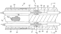
図1に示すように、カテーテル10は、細長いカテーテル本体12と、中間変形部分14と、遠位電極アセンブリ又はアレイ15と、カテーテル本体12の近位端に取り付けられた変形制御ハンドル16とを備える。本発明の特徴によれば、遠位電極アレイ15は、電極を保持する部分が共通の面内にある複数の閉じたオフセットしたスパインループ17を有する。
As shown in FIG. 1, the
図2Aおよび図2Bを参照すると、カテーテル本体12は、単一の軸方向又は中央の内腔18を有する細長い管状構造を含む。カテーテル本体12は、可撓性(すなわち、屈曲可能)であるが、その長さに沿って実質的に非圧縮性である。カテーテル本体12は、任意の好適な構造を有していてもよく、任意の好適な材料で作製することができる。ある実施形態において、カテーテル本体12は、ポリウレタン又はPEBAXで製造された外壁20を有する。外壁20は、ステンレス鋼などの編組メッシュが埋め込まれていることによって、カテーテル本体12のねじり剛性が高められているため、制御ハンドル16が回転すると、カテーテル10の中間部分14がこれに対応する様式で回転する。
With reference to FIGS. 2A and 2B, the
カテーテル本体12の外径は、重要ではない。同様に、外壁20の厚さも重要ではないが、外壁20は、中央の内腔18が、引張りワイヤ、1つ又は2つ以上のリードワイヤおよび他の任意の所望のワイヤ、ケーブル又は管を収容することができるほど十分に薄い。所望の場合、外壁20の内表面は、ねじり安定性を向上させるために補強管22で裏打ちされている。
The outer diameter of the
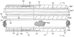
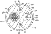
図2A、図2B、および図2Cに示すように、中間部分14は、軸からはずれた4個の内腔31、32、33および34などの複数の内腔を有する、もっと短い管材部分19を含む。第1の内腔31は、スパインループ17の上に保持される環状電極37のための複数のリードワイヤ40Sを保持している。第2の内腔32は、第1の引張りワイヤ24を保持している。第3の内腔33は、電磁位置センサ42のためのケーブル36と、遠位電極アレイ15の近位にあるカテーテルの上に保持される近位の環状電極38Dおよび遠位の環状電極38Pのための複数のリードワイヤ40Dおよび40Pを保持している。第4の内腔34(例えば、図示された実施形態において、第2の内腔32と直径方向に反対にある)は、第2の引張りワイヤ26を保持している。管材19は、好ましくはカテーテル本体12よりも可撓性である、適切な非毒性材料で製造される。管材19に好適な材料の1つは、編組ポリウレタン、すなわち、編組ステンレス鋼などの埋込みメッシュを有するポリウレタンである。それぞれの内腔の寸法は重要ではないが、リードワイヤ、引張りワイヤ、ケーブル、および任意の他の部品を収納するのに十分な大きさである。
As shown in FIGS. 2A, 2B, and 2C, the
カテーテルの有用な長さ、すなわち、身体内に挿入することができる、遠位電極アレイ15を除く部分は、所望に応じて変化させることができる。好ましくは、有用な長さは、約110cm〜約120cmの範囲に及ぶ。中間部分14の長さは、有用な長さを有する比較的より小さい部分であり、好ましくは約3.5cm〜約10cm、より好ましくは約5cm〜約6.5cmの範囲に及ぶ。
The useful length of the catheter, i.e., the portion other than the
カテーテル本体12を中間部分14に取り付ける手段が、図2Aおよび図2Bに示されている。中間部分14の近位端は、カテーテル本体12の内表面を受け入れる外周ノッチ27を含む。中間部分14およびカテーテル本体12は、接着剤などにより取り付けられる。
Means for attaching the
所望の場合、スペーサー(図示せず)を、カテーテル本体内の、(提供される場合)補強管の遠位端と中間部分の近位端との間に配置してもよい。スペーサーは、カテーテル本体と中間部分の接合部で可撓性の変化部分を与え、これによりこの接合部が折り畳まれるか、又はよじれることなく、滑らかに曲がることが可能になる。かかるスペーサーを有するカテーテルは、米国特許第5,964,757号に記載されており、その開示は、参考として本明細書に組み込まれる。 If desired, a spacer (not shown) may be placed within the catheter body between the distal end of the reinforcing tube (if provided) and the proximal end of the intermediate portion. The spacer provides a variable portion of flexibility at the junction between the catheter body and the intermediate portion, which allows the junction to bend smoothly without being folded or twisted. Catheter with such spacers is described in US Pat. No. 5,964,757, the disclosure of which is incorporated herein by reference.
図3Aおよび図3Bに示すように、遠位電極アレイ15は、中間変形部分14の管材19の遠位端に取り付けられた短い管材の形態で取付ステム46を有する。(これに関し、カテーテル10が変形部分14を有していない場合、取付ステム46が、カテーテル本体12の遠位端に取り付けられることを理解されたい。)ステム46は、様々な部品を収納する中央の内腔48を有する。中間部分14とステム46は、接着剤などにより取り付けられる。ステム46は、ニチノールを含め、任意の好適な材料から構成されてよい。
As shown in FIGS. 3A and 3B, the
図4に示すように、ステム46は、電磁位置センサ42と、引張りワイヤ24および26のための遠位固定具を含む、様々な部品を収納する。開示された実施形態において、遠位固定具は、1つ又は2つ以上のワッシャ(例えば、遠位ワッシャ50Dおよび近位ワッシャ50P)を備え、それぞれのワッシャが、複数の適合する軸方向の貫通孔を有し、この貫通孔は、変形部分14とステム46の間の部品の経路となりつつ、カテーテル10の長手方向の軸95に対するこれらの部品の軸方向の整列を維持する。図3Dにも示されるように、貫通孔は、それぞれ管材19の第2の内腔32および第4の内腔34と軸方向に整列した孔54および56を含み、それぞれ、引張りワイヤ24および26の遠位端を受け入れる。引張りワイヤ24および26は、孔54および56を通過する遠位のU字型の湾曲部分とともに単一の引張部材を形成してもよいことが理解される。引張りワイヤ24および26のU字型の湾曲部分によって及ぼされるワッシャ50Dおよび50Pの張力によって、ワッシャは、変形部分14の管材19の遠位端に対して固く接し、固定され、U字型の湾曲部分を遠位に固定する。
As shown in FIG. 4, the
図3Dにも示されるように、それぞれのワッシャも、第1の内腔31と軸方向に整列した貫通孔58を有し、リードワイヤ40Sを変形部分14からステム46の内腔48へと通すことができる。それぞれのワッシャは、さらに、管材19の第3の内腔33と軸方向に整列した貫通孔57も有しており、センサケーブル36を変形部分14からステム46の内腔48へと通すことができ、ステム46の内腔48に電磁位置センサ42が収納されている。リードワイヤ40Dも孔57を通り、ステム46の側壁に作られる開口部(図示せず)を介し、ステム46の外側表面に保持される遠位環状電極38Dに取り付けるための内腔48に入り、これによって、リードワイヤ40Dの遠位端が、当該技術分野で知られているように遠位環状電極38Dに溶接されるか、又は他の方法で取り付けられる。中間変形部分14の遠位端付近の管材19の外側表面に保持されると、近位の環状電極38Pは、管材19の側壁に作られる開口部87(図3B)を介し、リードワイヤ40Pに接続し、第3の内腔33と管材19の外側がつながる。リードワイヤの遠位端は、当該技術分野で知られているように近位環状電極38Pに溶接されるか、又は他の方法で取り付けられる。
As also shown in FIG. 3D, each washer also has a through
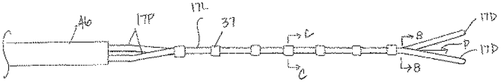
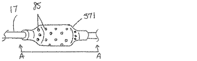
図5に示されるように、遠位電極アレイ15の閉じたスパインループ17は、ステム46の遠位端から延びている。それぞれのスパインループは、それぞれのスパインループの露出した長さ分延びる非導電性被覆64を有する。遠位電極マトリックス15とステム46との接合部において、それぞれのスパインの非伝導性被覆64は、ポリウレタン67などによってその近位端でステム46に密封されていてもよい。
As shown in FIG. 5, the
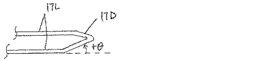
ある実施形態において、それぞれのスパインループ17は、遠位非線形接続部分17D、一対の線形の主要な電極保持部分17Lおよび一対の線形近位支持部分17Pを有し、ステム46に集中している。図7に示されるように、アレイ15の中のすべての線形の主要な部分(例えば、17L1、17L2、17L3および17L4)は、電極と組織の接触が最大になるように、共通の面P内にある(「面内」)。さらに、線形の主要な部分17Lは、共通の面Pの中で所定の構造で整列し、互いに遠位端で主要部分17Lの対応する対に接続する、ループの遠位部分17Dによって維持されるような1つ又は2つ以上の所定の空間的な関係によって規定される。この観点で、遠位部分17Dは、遠位部分17Dが互いに接触しないため、面内に残る線形の主要な部分17Lと干渉しないように、共通の面Pから所定の角度ずれている(「面外」)。遠位部分17Dは非線形であり、任意の湾曲した形状又は角度のついた形状(例えば、三角形(図8)又は長方形(図9))をしていてもよい。
In certain embodiments, each
図7に示されている実施形態において、第1の遠位部分17D1は、ある方向に(例えば、上側に)面から面外に角度がついており、第2の遠位部分17D2は、反対方向に(例えば、下側に)面から面外に角度がついている。さらに、第3のスパインループ17D3は、ある方向に(例えば、上側に)面から面外に角度がついており、第4の遠位部分17D4は、反対方向に(例えば、下側に)面から面外に角度がついている。このように、隣接する遠位部分17D1および17D2の対、および隣接する遠位部分17D2および17D3の対、同様に、遠位部分17D3および17D4の対は、互いに反対方向に角度がついている。面からずれた角度θは、共通の面から約1〜約45°、好ましくは、約5〜20°、さらに好ましくは、約10°の範囲であってもよい。 In the embodiment shown in FIG. 7, the first distal portion 17D1 is angled out-of-plane in one direction (eg, upwards) and the second distal portion 17D2 is in the opposite direction. There is an angle from the surface to the outside (for example, on the lower side). Further, the third spine loop 17D3 is angled out-of-plane in one direction (eg, upwards) and the fourth distal portion 17D4 is in the opposite direction (eg, downwards) from the plane. There is an angle outside the plane. Thus, the pair of adjacent distal portions 17D1 and 17D2 and the pair of adjacent distal portions 17D2 and 17D3, as well as the pair of distal portions 17D3 and 17D4, are angled in opposite directions. The angle θ deviated from the surface may be in the range of about 1 to about 45 °, preferably about 5 to 20 °, and more preferably about 10 ° from the common surface.
さらに、アレイ15の電極密度および電極保持部分としてのそれぞれの線形の主要な部分17Lの効率を最大限にするために、スパインループ17は、横方向に相殺された配置であり、それぞれのスパインループの少なくとも1つの線形の主要な部分17Lは、1つ又は2つ以上の異なるスパインループの線形の主要な部分17Lの間に配置される。又は、言い換えると、スパインループの線形のそれぞれの一対の主要な部分17Lは、異なるスパインループの少なくとも線形の主要な部分17Lによって隔てられている。そのように、アレイ15は、もっと単純な構成を維持しつつ、もっと大きな電極密度を与えることができ、それぞれのスパインループの電極を保持する線形の主要な部分17Lが、干渉しない遠位部分17Dによって支持されるように面内に延びる。
In addition, in order to maximize the electrode density of the
図7に示される実施形態において、スパインループは、横方向に相殺させている。例えば、少なくとも1つの線形部分17L1は、線形部分17L2の間に配置される。さらに、例えば、一対の線形部分17L3は、線形部分17L4によって隔てられている。 In the embodiment shown in FIG. 7, the spine loops are laterally offset. For example, at least one linear portion 17L1 is arranged between the linear portions 17L2. Further, for example, the pair of linear portions 17L3 are separated by a linear portion 17L4.
共通の面Pの中の所定の構造は、スパインループ又はその一部との間の1つ又は2つ以上の所定の空間的な関係を有していてもよい。1つ又は2つ以上の空間的な関係は、図5に示されるように、アレイの長さに沿った隣接する線形の主要な部分17Lの間の空間S(例えば、近位の空間SPおよび遠位の空間SD)によって規定されてもよい。所定の空間的な関係は、線形の主要な部分17Lに保持される環状電極37の間に所定の空間dを含んでいてもよい。図5に示される実施形態において、線形の主要な部分17Lは、近位の空間SPiと遠位の空間SDiが、隣接する線形の一対の主要な部分17Lの間と等しくなるように、互いに平行である。例えば、空間SPi、SDiが互いに、アレイ15全体に均一である場合、空間dは、アレイ15全体で均一であり、アレイ15は、図5に示されるように、格子状のパターンで電極を支持するように構成される。所望な場合、又は適切な場合に、異なる構造を与えるために、空間SPiおよびSDiがアレイ全体で変動していてもよいことが理解される。
The predetermined structure in the common surface P may have one or more predetermined spatial relationships with the spine loop or a part thereof. One or more spatial relationships, as shown in FIG. 5, are the space S between adjacent linear
ステム46中のアレイ15の近位端を固定するために、スパインループの近位部分17Pが、所望な場合、又は適切な場合に、線形の主要な部分17Lが面内に(例えば、ステム中央周囲に同じ角度分布で)支持されるように構成されてもよい。図5に示される実施形態において、4つの近位部分17Pは、ステム46の中央の長手方向の軸46Aの周囲に4分の1ずつ入れられる。
To secure the proximal end of the
複数のループは、約2〜4の範囲であってもよい。それぞれのスパインループは、露出した線形長さが約5〜50mm、好ましくは、約10〜35mm、さらに好ましくは、約28mmであってもよい。アレイは、寸法が約1.5cm×1.0cmであってもよい。それぞれの隣接する線形の主要な部分17Lの間の空間SPおよびSDは、約1mm〜20mm、好ましくは、約2〜10mm、さらに好ましくは、約4mmの範囲であってもよい。電極間の空間dは、約0.5mm〜12mmの範囲である。アレイ15の表面積は、約1.5cm2〜3.0cm2、好ましくは、約1.9cm2〜2.5cm2、さらに好ましくは、約2.2cm2の範囲であってもよい。
The plurality of loops may be in the range of about 2-4. Each spine loop may have an exposed linear length of about 5-50 mm, preferably about 10-35 mm, even more preferably about 28 mm. The array may be approximately 1.5 cm x 1.0 cm in size. The space SP and SD between each adjacent linear
図4に示されるように、それぞれのスパインループ17は、ループの長さ全体に延びる長細い形状記憶支持部材62を有する。それぞれの部材62の近位部分は、ステム46の遠位端部分に延び、ステム46の内腔48に固定される。それぞれのスパインループ17は、形状記憶部材62を覆う非導電性管材又は被覆64を有し、それぞれの線形の主要な部分17Lに保持される複数の環状電極37は、約6〜12個、好ましくは、約6〜9個、さらに好ましくは、約8個の範囲であってもよい。したがって、遠位電極アレイ15は、約20〜72個、好ましくは約28〜36個の範囲の電極、より好ましくは約32個の複数の電極を携行する。ある実施形態において、電極密度は、1平方センチメートルあたり約15個の電極であり、約12mm×18mmの寸法である。
As shown in FIG. 4, each
形状支持部材62は、形状記憶を有する材料、すなわち、力がかかると、その本来の形状から離れて一時的に直線状に伸びるか、又は屈曲させることができ、かつ、力がかからないか、又は取り除かれると、実質的に本来の形状に戻ることができる材料で製造される。支持部材に好適な材料は、ニッケル/チタン合金である。そのような合金は、典型的には、約55%のニッケルおよび約45%のチタンを含むが、約54%〜約57%のニッケルを含み、残部をチタンとすることができる。ニッケル/チタン合金は、ニチノールであり、耐久性、強度、耐食性、電気抵抗および温度安定性とともに、優れた形状記憶性を有する。非導電性被覆64は、任意の好適な材料で製造することが可能であり、好ましくは、ポリウレタン又はPEBAXなどの生体適合性プラスチックから製造される。所望の場合、支持部材62は、除外されてもよく、非導電性被覆64の遠位端は、所望の湾曲又は形状を有するように事前に形成されてもよい。
The
そのそれぞれの非導電性被覆64を通って延びるそれぞれの形状記憶支持部材62は、ポリウレタン67などによって、ステム46に受け入れられ、固定される近位端を有する。スパイン電極37のリードワイヤ40Sは、図4に示されるように、保護ポリチューブ68を通って延びる。リードワイヤ40Sは、ポリチューブ68の遠位端で分岐し、それぞれの形状記憶支持部材62に向かい、それぞれのスパインのそれぞれの非導電性被覆64に延びる。図5Cに示されるように、それぞれのリードワイヤ40Sは、被覆64の側壁に作られるそれぞれの開口部69を介し、スパインループ17の上のそれぞれの環状電極37に接続し、これによって、リードワイヤの遠位端は、被覆64の外側に達し、環状電極37に溶接されるか、又は他の方法で取り付けられる。
Each shape
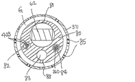
他の実施形態において、灌注された環状電極37Iは、図6、6Aおよび6Bに示されるように、スパインループ17に保持される。スパインを形成するループ17は、複数の内腔の管材80(例えば、複数の内腔を有する)を有し、複数の内腔は、形状記憶部材62のための第1の内腔81と、リードワイヤ40Sのための第2の内腔82と、管材80の側壁に作られる経路88を介し、灌注液を、管材80の外側壁と、流体入口85とともに作られる環状電極37Iの側壁との間の環状の空間ギャップGに通過させるための第3の内腔83とを有する。第4の内腔84は、遠位電磁位置センサ42D(図示せず)のためのケーブル36Dを通すように与えられてもよい。
In another embodiment, the irrigated annular electrode 37I is held in the
スパインループ環状電極37、遠位の環状電極38Dおよび近位の環状電極38Pのためのリードワイヤ40S、40Dおよび40Pの近位端は、それぞれ、制御ハンドル16の遠位端にある適切なコネクタ(図示せず)に電気接続し、当該技術分野で知られているように、アブレーションエネルギー(例えば、RFエネルギー)源に接続する。リードワイヤ40S、40Dおよび40Pは、カテーテル本体12の中央の内腔18を通って延びる(図2B)。リードワイヤ40Sは、中間部分14の管材19の第1の内腔31を通って延び、リードワイヤ40Dおよび40Pは、管材19の第3の内腔33を通って延びる(図2Cおよび3C)。孔58を通ってワッシャ50Dおよび50P内を通り、リードワイヤ40Sは、ポリチューブ68を通って延び、孔58によって損傷を受けるのを防ぐ(図3Dおよび4)。
The
示された実施形態において、カテーテル本体12の中央の内腔18を通って延びるリードワイヤ40Sおよび変形部分14の第1の内腔31は、保護鞘部94に取り囲まれ、カテーテル内の他の部品との接触を防いでもよい。保護鞘部は、任意の好適な材料、好ましくはポリイミドから製造されてもよい。当業者により認識されるように、保護鞘部は、所望の場合、除外されてもよい。
In the embodiments shown, the
環状電極37、37Iおよび38Dおよび38Pは、任意の適切な固体導電性材料(例えば、白金又は金、好ましくは、白金とイリジウムの組み合わせ)で製造することが可能であり、接着剤などを用いて非導電性被覆64、ステム46および/又は管材19に取り付けられる。あるいは、環状電極は、非導電性カバー64、ステム46および/又は管材19を、プラチナ、金および/又はイリジウムなどの導電性材料でコーティングすることによって作成することができる。コーティングは、スパッタリング、イオンビーム蒸着又は同等の手法を使用して塗布することができる。
The
ある実施形態において、それぞれの環状電極は、比較的短く、長さは約0.4mm〜約0.75mmの範囲である。電極は、対に並んでいてもよく、対の2つの電極は、他の電極対よりも互いに接近して空間があけられている。接近して配置された電極対により、心房細動の治療を試みる際に非常に有用である、遠距離場の心房信号に対する近距離場の肺静脈電位の検出の精度を向上させることができる。具体的には、近距離場の肺静脈電位は極めて小さい信号であり、一方で心房は、肺静脈に極めて近接する場所にあり、遙かに大きい信号を提供する。したがって、マッピングアレイが肺静脈の領域内に配置される場合であっても、信号が、小さく、(肺静脈から)近い電位、又はより大きく、(心房から)より遠い電位のいずれであるかを、医師が判定することは、困難である場合がある。近接配置される双極子電極により、医師は、近接する信号を検査しているのか、又は遠方の信号を検査しているか、を、より正確に判定することが可能になる。したがって、近接配置される電極を有することによって、肺動脈電位を有する心筋組織の場所を、正確に標的とすることが可能であるため、臨床医は、特定の組織に治療を施すことが可能になる。さらには、近接配置される電極により、医師は、電気信号によって、心門/複数の心門の正確な解剖学的場所を判定することが可能になる。 In certain embodiments, each annular electrode is relatively short and has a length in the range of about 0.4 mm to about 0.75 mm. The electrodes may be arranged in pairs, and the two electrodes in the pair are closer to each other than the other pair of electrodes. Closely placed electrode pairs can improve the accuracy of short-range pulmonary vein potential detection for long-range atrial signals, which is very useful when attempting to treat atrial fibrillation. Specifically, the pulmonary vein potential in the short-range field is a very small signal, while the atrium is very close to the pulmonary vein and provides a much larger signal. Therefore, even if the mapping array is located within the area of the pulmonary veins, whether the signal is small, near potential (from the pulmonary veins), or greater, farther (from the atrium). , It can be difficult for a doctor to determine. The dipole electrodes placed in close proximity allow the physician to more accurately determine whether he is inspecting a near signal or a distant signal. Therefore, by having electrodes placed in close proximity, it is possible to accurately target the location of myocardial tissue having a pulmonary artery potential, which allows a clinician to treat a specific tissue. .. In addition, the closely placed electrodes allow the physician to determine the exact anatomical location of the phylum / plurality of phylums by electrical signals.
ある実施形態において、近位の電磁位置センサ42Pは、ステムの内腔に収納される(図4)。センサケーブル36Pは、位置センサ42Pの近位端から、ワッシャ50の孔57を通って延び(図3D)、変形部分14の管材19の第3の内腔33を通って延び(図2C)、カテーテル本体12の中央の内腔18を通って延びる(図2B)。ケーブル36Pは、当該技術分野で知られているように、制御ハンドル16のPCボードへ取り付けられる。ある実施形態において、1つ又は2つ以上の遠位電磁位置センサは、アレイ(例えば、アレイの1つ又は2つ以上の遠位部分)に収容されてもよい。センサケーブル36Dは、スパイン被覆64(図5C)又は管材80の内腔84(図6B)を通って延びてもよい。
In certain embodiments, the proximal electromagnetic position sensor 42P is housed in the lumen of the stem (FIG. 4). The
図2Aおよび2Cに示されるように、引張りワイヤ24および26は(2つの別個の引張部材であるか、又は単一の引張部材の一部であるかにかかわらず)、中間部分14の二方向変形のために与えられる。引張りワイヤ24および26は、サム制御ノブ又は変形制御ノブ11に応答する制御ハンドル16内の機構によって動かされる。適切な制御ハンドルは、米国特許第6,123,699号;第6,171,277号;第6,183,435号;第6,183,463号;第6,198,974号;第6,210,407号および第6,267,746号に開示され、その開示全体は、本明細書に参考として組み込まれる。
As shown in FIGS. 2A and 2C, the
引張りワイヤ24および26は、カテーテル本体12の中央の内腔18を通って延び(図2A)、変更部分14の管材19のそれぞれ第2の内腔32および第4の内腔34を通って延びる(図2C)。図3Aおよび図3Cに示すように、それらは、ワッシャ50のそれぞれ孔54および56を通って延びる。引張りワイヤが単一の引張部材の一部である場合、単一の引張部材は、引張りワイヤの遠位端を固定する遠位ワッシャ50Dの遠位面にU字型の湾曲部24/26U(図3A)を有する。この観点で、U字型の湾曲部は、短い保護管材70を通って延び、引張りワイヤを孔54および56から保護する。あるいは、引張りワイヤが別個の引張部材である場合、それらの遠位端は、当該技術分野で知られており、その内容全体が本明細書に参考として組み込まれている、例えば、米国特許第8,603,069号に記載されているように、T型の棒状物を介して固定されてもよい。いずれにせよ、引張りワイヤ24および26は、ステンレス鋼又はニチノールといった任意の好適な金属で製造され、それぞれは、好ましくは、TEFLONなどでコーティングされる。コーティングによって引張りワイヤに潤滑性が付与される。引張りワイヤは、好ましくは直径が約0.02〜約0.025センチメートル(約0.006〜約0.010インチ)の範囲である。
The
図2Bに示されるように、圧縮コイル66は、それぞれの引張りワイヤ24を包む関係でカテーテル本体12の中央の内腔18内に据えられる。それぞれの圧縮コイル66は、カテーテル本体12の近位端から中間部分14の近位端まで延びる。圧縮コイル66は、任意の好適な金属、好ましくはステンレス鋼で製造される。それぞれの圧縮コイル66は、可撓性、すなわち、屈曲性をもたらすが、圧縮に耐えるように、それ自体に密に巻かれる。圧縮コイル66の内径は、好ましくはその引張りワイヤの直径よりも僅かに大きい。それぞれの引張りワイヤ上のTeflonコーティングは、引張りワイヤがその圧縮コイル内で自由に摺動することを可能にする。
As shown in FIG. 2B, the
圧縮コイル66は、その近位端で、近位接着部(図示しない)によってカテーテル本体12の外壁20に固定され、その遠位端で、遠位接着部92によって中間部分14に固定される。両方の接着部は、ポリウレタン接着剤などを含んでもよい。接着剤は、カテーテル本体12の側壁と中央の内腔19との間に作製された孔を通って注射器などによって塗布されてもよい。かかる孔は、例えば、永続的な孔を形成するために十分に加熱された、側壁を穿孔する針などにより形成されてよい。次いで、接着剤は、孔を通って圧縮コイル66の外表面へ導入され、外側の周囲に毛管現象で広がり、圧縮コイルの全周に接着部が形成される。
At its proximal end, the
中間部分14の第2の内腔32および第4の内腔34内では、それぞれの引張りワイヤ24および26は、プラスチック、好ましくはTeflon製の引張りワイヤ鞘部39を通って延び(図2Aおよび2C)、変形部分14が変形するとき、引張りワイヤが、変形部分14の管材19の側壁を切断することを防止する。
Within the second and
使用する際、好適な誘導鞘部(図示しない)が患者内に挿入され、マッピングおよび/又はアブレーションなどの処置などの診断のための所望の組織の場所で、又はその付近に遠位端が配置される。本発明に関連した使用のための好適な誘導鞘部の一例は、Biosense Webster,Inc.(ダイヤモンドバー、カリフォルニア)より市販されるPreface Braided Guiding Sheathである。カテーテル10は、誘導鞘部を通過し、これを通って所望の組織の場所に前進する。特に、遠位電極アレイ15のスパインループ17は、誘導鞘部の近位端に供給される。遠位電極アレイ15が所望の組織の場所へ到達した後、誘導鞘部は、近位に引かれ、アレイが少なくとも露出する。誘導鞘部36の外側に、スパインループの線形の主要な部分17Lは、図5に示されるように、干渉しない角度のついた遠位部分17Dによって支持されるように、ほぼ共通の面に延びる。線形の主要な部分17Lに接続する遠位部分17Dは、線形の主要な部分17Lが広がり、分岐し、および/又は面から面外になるのを防ぐ。
When used, a suitable induction sheath (not shown) is inserted into the patient and the distal end is placed at or near the desired tissue location for diagnosis such as procedures such as mapping and / or ablation. Will be done. An example of a suitable induction sheath for use in connection with the present invention is described by Biosense Webster, Inc. (Diamond Bar, CA) is a Preface Braided Guiding Sheath commercially available. The
アレイ15は、第1の側と第2の側を有する。図10に示すように、ユーザは、第1の側を組織表面に対して置き、少なくとも中間部分14は(カテーテル本体12の遠位部分ではない場合でも)、一般的に組織表面に対して垂直であり、制御ハンドルを動かし、第1の側がカテーテルの方に変形するように中間変形部分14を変形させ(矢印D)、部分14が変形するにつれて、線形の主要部分17Lの第1の側が組織表面を横切って引っ張られる。線形の主要部分17Lは、一般的に線形で平行であり、変形方向Dと同じ方向の軌跡Tに沿って、(遠位部分17Dによって維持されるように)互いにほぼ平行な状態を維持しつつ、組織表面を横切って引っ張られる。
The
又は、図11に示されるように、ユーザが、制御ハンドルを動かし、部分14を方向Dに沿って変形させ、アレイ15の第1の表面がカテーテルに向かって変形する。次いで、ユーザは、組織表面とほぼ平行にカテーテル本体12の少なくとも遠位部分を配置し、組織表面に対してアレイ15の第2の表面を配置する。次いで、ユーザは、(反対側の方向Rに沿って)変形を開放し、変形部分14がまっすぐになるにつれて、線形の主要部分17Lの第2の表面が組織表面を横切って引っ張られる。線形の主要部分17Lは、一般的に線形で平行であり、変形方向Dと反対側の方向Rの軌跡Tに沿って、(遠位部分17Dによって維持されるように)互いにほぼ平行な状態を維持しつつ、組織表面を横切って引っ張られる。
Alternatively, as shown in FIG. 11, the user moves the control handle to deform the
いずれかの様式で、スパイン電極37は、組織表面との接触を最大限にするために、線形の主要な部分17Lの面内に保持され、一方、線形の主要な部分17Lは、高密度の電極検知および均一で予測可能なマッピングのためにスパインループが組織表面を横切って引っ張られるときに、一般的に、互いに一貫した分離空間を維持する。線形の主要な部分17Lが分離された状態に維持されることによって、これらが重なり合う傾向はほとんどなく、電極37は、2つの電極が角に密接しているか、又は接触しているときに生じ得る「クロストーク」又は電磁干渉をほとんど受けない。本発明の特徴に従って、アレイは、例えば、それぞれのスパインの上に8つの電極を有する4つのスパイン、すなわち、マッピングのために近接配置された合計32個の環状電極37である、「n×m」個の電極レイアウト又は配置を有する。
In either manner, the
ある実施形態において、遠位電極アレイ15は、少なくとも2つのスパインの間に延びるスペーサー部材86(例えば、棒状物またはブラケット)を含み、スパインを機械的に制限し、所定の空間的な関係に保持する。スペーサー部材は、他の方向に移動しつつ、1つ又は2つ以上の方向への移動を制限するように構成されてもよい。図5に示される実施形態において、スペーサー部材86は、線形部分17Lの間に延び、その末端を接着剤(例えば、ポリウレタン)によって線形部分17Lに固定するが、スペーサー部材は、所望な場合、又は適切な場合、スパインループ17の同じ部分および/又は異なる部分の任意の2つ又は3つ以上の間に延びてもよい。スパインループの領域は、所望な場合、又は適切な場合、一緒に熱結合されてもよく、又は一緒に溶融されてもよい。
In certain embodiments, the
ある実施形態において、アレイ15の近位の環状電極38Dおよび38Pは、Biosense Webster,Inc.から入手可能なCARTO.RTM 3 SYSTEMなどの3Dマッピングシステムでカテーテルを視覚化するための参照電極として働き、EMセンサ42の位置を自動的に示し、EMセンサからの位置が一定である電極38Dおよび38Pからの参照位置の値を処理し、電極37および37Iの位置を決定し、電極アレイ15の残りを視覚化する。
In certain embodiments, the
上記の説明は、現時点における本発明の好ましい実施形態を参照して示したものである。本発明が関係する分野および技術の当業者であれば、本発明の原理、趣旨および範囲を著しく逸脱することなく、説明した構造の改変および変更を実施できることを理解するであろう。当業者に理解されるように、図面は必ずしも一定の縮尺ではない。また、必要に応じて、又は適切であれば、異なる実施形態の異なる特徴が組み合わされてもよい。さらに、本明細書に記載したカテーテルは、マイクロ波、レーザー、RF、および/又は凍結材を含む、様々なエネルギー形態を適用するように構成されてもよい。したがって、上記の説明文は、添付図面に記載されかつ例示される厳密な構造のみに関連したものとして読み取るべきではなく、むしろ、以下の最も完全で公正な範囲を有するとされる「特許請求の範囲」と符合し、かつそれらを補助するものとして読み取るべきである。 The above description is given with reference to preferred embodiments of the present invention. Those skilled in the art in the arts and arts in which the invention relates will appreciate that the structural modifications and modifications described can be made without significant deviation from the principles, intent and scope of the invention. Drawings are not always to a constant scale, as will be appreciated by those skilled in the art. Also, different features of different embodiments may be combined, if desired or as appropriate. In addition, the catheters described herein may be configured to apply a variety of energy forms, including microwave, laser, RF, and / or freezing material. Therefore, the above description should not be read as relating only to the exact structure described and illustrated in the accompanying drawings, but rather has the most complete and fair scope of the following "claims". It should be read as matching with "range" and supplementing them.
〔実施の態様〕
(1) カテーテルであって、
細長いカテーテル本体と、
複数のオフセットしたスパインループを備える遠位電極アレイとを備え、それぞれのスパインループが、少なくとも一対の電極保持部分と、前記一対の電極保持部分を接続する遠位部分とを有し、前記複数のオフセットしたスパインループの前記電極保持部分が、1つの共通の面の面内に並び、前記複数のオフセットしたスパインループの前記遠位部分は、前記1つの共通の面から面外に並ぶ、カテーテル。
(2) 前記複数のオフセットしたスパインループの前記電極保持部分が線形である、実施態様1に記載のカテーテル。
(3) 前記複数のオフセットしたスパインループの前記電極保持部分は、互いに平行である、実施態様2に記載のカテーテル。
(4) 前記遠位部分が非線形である、実施態様1に記載のカテーテル。
(5) それぞれのスパインループの少なくとも1つの電極保持部分は、1つ又は2つ以上の異なるスパインループの電極保持部分の間に配置されている、実施態様1に記載のカテーテル。
[Implementation]
(1) It is a catheter
With an elongated catheter body,
A distal electrode array with a plurality of offset spine loops, each spine loop having at least a pair of electrode holding portions and a distal portion connecting the pair of electrode holding portions. A catheter in which the electrode holding portions of the offset spine loops are aligned in a plane of one common surface, and the distal portions of the plurality of offset spine loops are aligned out of plane from the one common surface.
(2) The catheter according to the first embodiment, wherein the electrode holding portions of the plurality of offset spine loops are linear.
(3) The catheter according to the second embodiment, wherein the electrode holding portions of the plurality of offset spine loops are parallel to each other.
(4) The catheter according to embodiment 1, wherein the distal portion is non-linear.
(5) The catheter according to embodiment 1, wherein at least one electrode holding portion of each spine loop is disposed between the electrode holding portions of one or more different spine loops.
(6) それぞれのスパインループの前記一対の電極保持部分は、異なるスパインループの少なくとも電極保持部分によって隔てられている、実施態様1に記載のカテーテル。
(7) 隣接するスパインループの遠位部分は、互いに反対側に面外に角度がつけられている、実施態様1に記載のカテーテル。
(8) それぞれの電極保持部分は、1つ又は2つ以上の環状電極を有する、実施態様1に記載のカテーテル。
(9) 前記環状電極は、灌注された環状電極を含む、実施態様8に記載のカテーテル。
(10) カテーテルであって、
細長いカテーテル本体と、
複数のオフセットしたスパインループを備える遠位電極アレイであって、それぞれのスパインループが、少なくとも一対の線形部分と、この一対の線形部分を接続する遠位部分とを有する、遠位電極アレイと、
それぞれの線形部分の上にある1つ又は2つ以上の電極とを備え、
前記複数のオフセットしたスパインループの前記線形部分は、1つの共通の面の面内に並び、前記複数のオフセットしたスパインループの前記遠位部分が、前記1つの共通の面から面外に並ぶ、カテーテル。
(6) The catheter according to embodiment 1, wherein the pair of electrode holding portions of each spine loop are separated by at least electrode holding portions of different spine loops.
(7) The catheter according to embodiment 1, wherein the distal portions of adjacent spine loops are angled out-of-plane on opposite sides of each other.
(8) The catheter according to embodiment 1, wherein each electrode holding portion has one or more annular electrodes.
(9) The catheter according to embodiment 8, wherein the annular electrode comprises an irrigated annular electrode.
(10) A catheter
With an elongated catheter body,
A distal electrode array with a plurality of offset spine loops, each of which has at least a pair of linear portions and a distal portion connecting the pair of linear portions.
With one or more electrodes on each linear portion,
The linear portions of the plurality of offset spine loops line up in the plane of one common surface, and the distal portions of the plurality of offset spine loops line up out of plane from the one common plane. catheter.
(11) 前記複数のオフセットしたスパインループの前記線形部分が、互いに平行である、実施態様10に記載のカテーテル。
(12) 前記遠位部分が非線形である、実施態様10に記載のカテーテル。
(13) それぞれのスパインループの少なくとも1つの線形部分は、1つ又は2つ以上の異なるスパインループの線形部分の間に配置されている、実施態様10に記載のカテーテル。
(14) それぞれのスパインループの前記一対の線形部分は、異なるスパインループの少なくとも線形部分によって隔てられている、実施態様10に記載のカテーテル。
(15) 隣接するスパインループの遠位部分は、互いに反対側に面外に角度がつけられている、実施態様10に記載のカテーテル。
(11) The catheter according to
(12) The catheter according to
(13) The catheter according to
(14) The catheter according to
(15) The catheter according to
(16) 1つ又は2つ以上の環状電極が、灌注された環状電極を含む、実施態様10に記載のカテーテル。
(17) 少なくとも2つの隣接する線形部分の間に延びる1つ又は2つ以上の空間部材をさらに含む、実施態様10に記載のカテーテル。
(18) 前記複数のオフセットしたスパインループが、約2〜4個の範囲である、実施態様10に記載のカテーテル。
(19) それぞれのスパインループは、細長い形状記憶部材を含む、実施態様10に記載のカテーテル。
(20) カテーテルであって、
細長いカテーテル本体と、
複数のオフセットしたスパインループを含む遠位電極アレイであって、それぞれのスパインループが少なくとも一対の線形部分を有する、遠位電極アレイと、
それぞれの線形部分の上にある1つ又は2つ以上の電極と、
少なくとも2つの隣接する線形部分の間に延びる1つ又は2つ以上の空間部材とを備え、
前記複数のオフセットしたスパインループの前記線形部分は、1つの共通の面の面内に並び、前記複数のオフセットしたスパインループの遠位部分が、前記1つの共通の面から面外に並ぶ、カテーテル。
(16) The catheter according to
(17) The catheter according to
(18) The catheter according to
(19) The catheter according to
(20) A catheter
With an elongated catheter body,
A distal electrode array containing a plurality of offset spine loops, each of which has at least a pair of linear portions.
With one or more electrodes on each linear part,
With one or more spatial members extending between at least two adjacent linear portions,
A catheter in which the linear portions of the plurality of offset spine loops are aligned in a plane of one common surface and the distal portions of the plurality of offset spine loops are aligned out of plane from the one common surface. ..
Claims (23)
カテーテルと、回路基板と、を備え、
前記カテーテルは、遠位端を有する細長いカテーテル本体と、前記カテーテル本体の前記遠位端における遠位電極アレイと、を備え、
前記遠位電極アレイは、第1のスパインループと、前記第1のスパインループ上の複数の電極と、第2のスパインループと、前記第2のスパインループ上の複数の電極と、を備え、
前記第1のスパインループは、前記遠位端から延在し、前記第1のスパインループは、遠位非線形接続部分と、一対の線形の主要な電極保持部分と、一対の線形近位支持部分と、を備え、前記一対の線形の主要な電極保持部分は、互いに平行であり、1つの共通の面内に配置され、前記一対の線形の主要な電極保持部分の各々は、長さを有し、
前記第1のスパインループ上の前記複数の電極は、前記第1のスパインループの前記一対の線形の主要な電極保持部分上に置かれており、
前記一対の線形の主要な電極保持部分は、互いに、1mm〜20mmの空間をおいて配置されており、前記複数の電極は、互いに、前記一対の線形の主要な電極保持部分の各々の前記長さに沿って、0.5mm〜12mmの間隔をおいて配置されており、
前記第2のスパインループは、前記遠位端から延在し、前記第2のスパインループは、遠位非線形接続部分と、一対の線形の主要な電極保持部分と、一対の線形近位支持部分と、を備え、前記一対の線形の主要な電極保持部分は、互いに平行であり、前記1つの共通の面内に配置され、前記一対の線形の主要な電極保持部分の各々は、長さを有し、
前記第2のスパインループ上の前記複数の電極は、前記第2のスパインループの前記一対の線形の主要な電極保持部分上に置かれており、
前記回路基板は、前記第1のスパインループおよび前記第2のスパインループ上の前記複数の電極に連結されており、
前記マッピングシステムは、前記遠位電極アレイを視覚化することができる、マッピングシステム。 It ’s a mapping system,
With a catheter and a circuit board,
The catheter comprises an elongated catheter body having a distal end and a distal electrode array at the distal end of the catheter body.
The distal electrode array comprises a first spine loop, a plurality of electrodes on the first spine loop, a second spine loop, and a plurality of electrodes on the second spine loop.
The first spine loop extends from the distal end, and the first spine loop is a distal nonlinear connecting portion, a pair of linear major electrode holding portions, and a pair of linear proximal support portions. The pair of linear main electrode holding portions are parallel to each other and are arranged in one common plane, and each of the pair of linear main electrode holding portions has a length. And
The plurality of electrodes on the first spine loop are placed on the pair of linear main electrode holding portions of the first spine loop.
The pair of linear main electrode holding portions are arranged with a space of 1 mm to 20 mm from each other, and the plurality of electrodes are each having the length of each of the pair of linear main electrode holding portions. They are arranged at intervals of 0.5 mm to 12 mm along the electrodes.
The second spine loop extends from the distal end, and the second spine loop is a distal nonlinear connecting portion, a pair of linear major electrode holding portions, and a pair of linear proximal support portions. And, the pair of linear main electrode holding portions are parallel to each other and are arranged in the one common plane, and each of the pair of linear main electrode holding portions has a length. Have and
The plurality of electrodes on the second spine loop are placed on the pair of linear main electrode holding portions of the second spine loop.
The circuit board is connected to the first spine loop and the plurality of electrodes on the second spine loop.
The mapping system is a mapping system capable of visualizing the distal electrode array.
遠位端を有する細長いカテーテル本体と、前記カテーテル本体の前記遠位端における遠位電極アレイと、を備え、
前記遠位電極アレイは、2つの隣接するアームと、複数の電極と、を備え、
前記2つの隣接するアームは、1つの共通の面内で、互いに平行に配置され、前記2つの隣接するアームの各々は、長さを有し、
前記複数の電極は、前記2つの隣接するアームの各々の上に置かれ、前記複数の電極は、前記2つの隣接するアームの各々の前記長さに沿って、前記2つの隣接するアームの各々に渡って、均一な間隔を置いて配置されており、
前記2つの隣接するアームは、互いに、1mm〜20mmの空間をおいて配置されており、前記複数の電極は、互いに、前記2つの隣接するアームの各々の前記長さに沿って、0.5mm〜12mmの間隔をおいて配置されている、カテーテル。 It ’s a catheter,
An elongated catheter body having a distal end and a distal electrode array at the distal end of the catheter body.
The distal electrode array comprises two adjacent arms and a plurality of electrodes.
The two adjacent arms are arranged parallel to each other in one common plane, and each of the two adjacent arms has a length.
The plurality of electrodes are placed on each of the two adjacent arms, and the plurality of electrodes are placed on each of the two adjacent arms along the length of each of the two adjacent arms. They are evenly spaced across the
The two adjacent arms are arranged with a space of 1 mm to 20 mm from each other, and the plurality of electrodes are 0.5 mm from each other along the length of each of the two adjacent arms. Catheter arranged at intervals of ~ 12 mm.
遠位端を有する細長いカテーテル本体と、前記カテーテル本体の前記遠位端における遠位電極アレイと、を備え、
前記遠位電極アレイは、2つの隣接するアームと、複数の電極と、を備え、
前記2つの隣接するアームは、1つの共通の面内で、互いに平行に配置され、前記2つの隣接するアームの各々は、長さを有し、
前記複数の電極は、前記2つの隣接するアームの各々の上に置かれ、
前記複数の電極は、前記2つの隣接するアームの各々の前記長さに沿って、前記2つの隣接するアームの各々に渡って、均一な間隔を置いて配置されている、カテーテル。 It ’s a catheter,
An elongated catheter body having a distal end and a distal electrode array at the distal end of the catheter body.
The distal electrode array comprises two adjacent arms and a plurality of electrodes.
The two adjacent arms are arranged parallel to each other in one common plane, and each of the two adjacent arms has a length.
The plurality of electrodes are placed on each of the two adjacent arms.
A catheter in which the plurality of electrodes are evenly spaced across each of the two adjacent arms along the length of each of the two adjacent arms.
Priority Applications (1)
| Application Number | Priority Date | Filing Date | Title |
|---|---|---|---|
| JP2021190013A JP7242816B2 (en) | 2015-06-29 | 2021-11-24 | A catheter having a closed loop array with in-plane linear electrode segments |
Applications Claiming Priority (2)
| Application Number | Priority Date | Filing Date | Title |
|---|---|---|---|
| US14/754,553 US10537259B2 (en) | 2015-06-29 | 2015-06-29 | Catheter having closed loop array with in-plane linear electrode portion |
| US14/754,553 | 2015-06-29 |
Related Parent Applications (1)
| Application Number | Title | Priority Date | Filing Date |
|---|---|---|---|
| JP2016127351A Division JP6776021B2 (en) | 2015-06-29 | 2016-06-28 | Catheter with closed loop array with in-plane linear electrode portion |
Related Child Applications (1)
| Application Number | Title | Priority Date | Filing Date |
|---|---|---|---|
| JP2021190013A Division JP7242816B2 (en) | 2015-06-29 | 2021-11-24 | A catheter having a closed loop array with in-plane linear electrode segments |
Publications (2)
| Publication Number | Publication Date |
|---|---|
| JP2021007772A true JP2021007772A (en) | 2021-01-28 |
| JP7080949B2 JP7080949B2 (en) | 2022-06-06 |
Family
ID=56289355
Family Applications (3)
| Application Number | Title | Priority Date | Filing Date |
|---|---|---|---|
| JP2016127351A Active JP6776021B2 (en) | 2015-06-29 | 2016-06-28 | Catheter with closed loop array with in-plane linear electrode portion |
| JP2020168985A Active JP7080949B2 (en) | 2015-06-29 | 2020-10-06 | Catheter with closed loop array with in-plane linear electrode portion |
| JP2021190013A Active JP7242816B2 (en) | 2015-06-29 | 2021-11-24 | A catheter having a closed loop array with in-plane linear electrode segments |
Family Applications Before (1)
| Application Number | Title | Priority Date | Filing Date |
|---|---|---|---|
| JP2016127351A Active JP6776021B2 (en) | 2015-06-29 | 2016-06-28 | Catheter with closed loop array with in-plane linear electrode portion |
Family Applications After (1)
| Application Number | Title | Priority Date | Filing Date |
|---|---|---|---|
| JP2021190013A Active JP7242816B2 (en) | 2015-06-29 | 2021-11-24 | A catheter having a closed loop array with in-plane linear electrode segments |
Country Status (8)
| Country | Link |
|---|---|
| US (4) | US10537259B2 (en) |
| EP (3) | EP3363397B1 (en) |
| JP (3) | JP6776021B2 (en) |
| CN (1) | CN106264715B (en) |
| AU (1) | AU2016204351A1 (en) |
| CA (1) | CA2934214A1 (en) |
| IL (1) | IL246414B (en) |
| RU (1) | RU2016125763A (en) |
Cited By (6)
| Publication number | Priority date | Publication date | Assignee | Title |
|---|---|---|---|---|
| US11642064B2 (en) | 2015-10-21 | 2023-05-09 | St. Jude Medical, Cardiology Division, Inc. | High density electrode mapping catheter |
| US11642063B2 (en) | 2018-08-23 | 2023-05-09 | St. Jude Medical, Cardiology Division, Inc. | Curved high density electrode mapping catheter |
| US11647935B2 (en) | 2017-07-24 | 2023-05-16 | St. Jude Medical, Cardiology Division, Inc. | Masked ring electrodes |
| US11672947B2 (en) | 2017-11-28 | 2023-06-13 | St. Jude Medical, Cardiology Division, Inc. | Lumen management catheter |
| US11786705B2 (en) | 2016-10-24 | 2023-10-17 | St. Jude Medical, Cardiology Division, Inc. | Catheter insertion devices |
| US11918762B2 (en) | 2018-10-03 | 2024-03-05 | St. Jude Medical, Cardiology Division, Inc. | Reduced actuation force electrophysiology catheter handle |
Families Citing this family (23)
| Publication number | Priority date | Publication date | Assignee | Title |
|---|---|---|---|---|
| US9820664B2 (en) | 2014-11-20 | 2017-11-21 | Biosense Webster (Israel) Ltd. | Catheter with high density electrode spine array |
| WO2016123390A1 (en) | 2015-01-28 | 2016-08-04 | St. Jude Medical, Cardiology Division, Inc. | Thermal mapping catheter |
| US9949656B2 (en) | 2015-06-29 | 2018-04-24 | Biosense Webster (Israel) Ltd. | Catheter with stacked spine electrode assembly |
| US10537259B2 (en) | 2015-06-29 | 2020-01-21 | Biosense Webster (Israel) Ltd. | Catheter having closed loop array with in-plane linear electrode portion |
| US10575742B2 (en) | 2015-06-30 | 2020-03-03 | Biosense Webster (Israel) Ltd. | Catheter having closed electrode assembly with spines of uniform length |
| EP3858277B1 (en) | 2016-05-03 | 2023-02-22 | St. Jude Medical, Cardiology Division, Inc. | Irrigated high density electrode catheter |
| US11172858B2 (en) * | 2016-10-28 | 2021-11-16 | St. Jude Medical, Cardiology Division, Inc. | Flexible high-density mapping catheter |
| DE102017001971A1 (en) * | 2017-03-01 | 2018-09-06 | Peter Osypka Stiftung Stiftung des bürgerlichen Rechts | Multi-electrode array |
| JP7050892B2 (en) | 2017-07-07 | 2022-04-08 | セント・ジュード・メディカル,カーディオロジー・ディヴィジョン,インコーポレイテッド | Layered high density electrode mapping catheter |
| EP3658054B1 (en) | 2017-10-13 | 2023-03-22 | St. Jude Medical, Cardiology Division, Inc. | Catheter with high-density mapping electrodes |
| CN111836579B (en) | 2018-03-13 | 2024-03-19 | 圣犹达医疗用品心脏病学部门有限公司 | Variable density mapping catheter |
| CN112040861A (en) * | 2018-04-05 | 2020-12-04 | 圣犹达医疗用品心脏病学部门有限公司 | High-density electrode mapping catheter |
| US20200038101A1 (en) | 2018-08-03 | 2020-02-06 | Biosense Webster (Israel) Ltd. | Unipolar reference electrode for electrophysiology mapping catheter |
| US11850051B2 (en) * | 2019-04-30 | 2023-12-26 | Biosense Webster (Israel) Ltd. | Mapping grid with high density electrode array |
| US20200397338A1 (en) | 2019-06-19 | 2020-12-24 | Biosense Webster (Israel) Ltd. | Multi-Arm Probe Rendering |
| US20210369339A1 (en) * | 2020-05-29 | 2021-12-02 | Biosense Webster (Israel) Ltd. | Electrode apparatus for diagnosis of arrhythmias |
| JP2021186646A (en) * | 2020-05-29 | 2021-12-13 | バイオセンス・ウエブスター・(イスラエル)・リミテッドBiosense Webster (Israel), Ltd. | Intraluminal reference electrode for cardiovascular treatment apparatus |
| US11771373B2 (en) * | 2020-11-09 | 2023-10-03 | Biosense Webster (Israel) Ltd. | Staggered electrode arrangements for electrophysiological sensing |
| IL310283A (en) | 2021-07-30 | 2024-03-01 | Biosense Webster Israel Ltd | Planar end effector with irrigation |
| US20230149069A1 (en) * | 2021-11-16 | 2023-05-18 | Biosense Webster (Israel) Ltd. | Planar catheter with overlapping electrode pairs |
| CN114052895B (en) * | 2021-11-19 | 2024-02-27 | 武汉拓扑转化医学研究中心有限公司 | Pulse atrial fibrillation ablation system and catheter |
| WO2023196810A1 (en) * | 2022-04-06 | 2023-10-12 | St. Jude Medical, Cardiology Division, Inc. | Hybrid mapping and pulsed field ablation catheter |
| CN117752404B (en) * | 2024-02-22 | 2024-05-07 | 四川锦江电子医疗器械科技股份有限公司 | Cardiac electrophysiology mapping and ablation catheter |
Citations (4)
| Publication number | Priority date | Publication date | Assignee | Title |
|---|---|---|---|---|
| JP2011147802A (en) * | 2003-09-26 | 2011-08-04 | Boston Scientific Ltd | Probe assembly for creating circumferential lesion within or around vessel ostium |
| JP2014004368A (en) * | 2012-06-25 | 2014-01-16 | Biosense Webster (Israel) Ltd | Irrigated electrode with enhanced heat conduction |
| WO2014113612A1 (en) * | 2013-01-16 | 2014-07-24 | St. Jude Medical, Cardiology Division, Inc. | Flexible high-density mapping catheter tips and flexible ablation catheter tips with onboard high-density mapping electrodes |
| JP2015100706A (en) * | 2013-11-21 | 2015-06-04 | バイオセンス・ウエブスター・(イスラエル)・リミテッドBiosense Webster (Israel), Ltd. | Multi-electrode balloon catheter with circumferential and point electrodes |
Family Cites Families (103)
| Publication number | Priority date | Publication date | Assignee | Title |
|---|---|---|---|---|
| US4529912A (en) | 1983-03-25 | 1985-07-16 | Xerox Corporation | Mechanism and method for controlling the temperature and light output of a fluorescent lamp |
| US4522212A (en) | 1983-11-14 | 1985-06-11 | Mansfield Scientific, Inc. | Endocardial electrode |
| US6071280A (en) | 1993-11-08 | 2000-06-06 | Rita Medical Systems, Inc. | Multiple electrode ablation apparatus |
| US5885278A (en) | 1994-10-07 | 1999-03-23 | E.P. Technologies, Inc. | Structures for deploying movable electrode elements |
| US5702438A (en) | 1995-06-08 | 1997-12-30 | Avitall; Boaz | Expandable recording and ablation catheter system |
| NL1001890C2 (en) | 1995-12-13 | 1997-06-17 | Cordis Europ | Catheter with plate-shaped electrode array. |
| US6071279A (en) * | 1996-12-19 | 2000-06-06 | Ep Technologies, Inc. | Branched structures for supporting multiple electrode elements |
| US5916213A (en) * | 1997-02-04 | 1999-06-29 | Medtronic, Inc. | Systems and methods for tissue mapping and ablation |
| US6652515B1 (en) | 1997-07-08 | 2003-11-25 | Atrionix, Inc. | Tissue ablation device assembly and method for electrically isolating a pulmonary vein ostium from an atrial wall |
| US5964757A (en) | 1997-09-05 | 1999-10-12 | Cordis Webster, Inc. | Steerable direct myocardial revascularization catheter |
| US6123699A (en) | 1997-09-05 | 2000-09-26 | Cordis Webster, Inc. | Omni-directional steerable catheter |
| US6179832B1 (en) * | 1997-09-11 | 2001-01-30 | Vnus Medical Technologies, Inc. | Expandable catheter having two sets of electrodes |
| US6183463B1 (en) | 1997-12-01 | 2001-02-06 | Cordis Webster, Inc. | Bidirectional steerable cathether with bidirectional control handle |
| US6171277B1 (en) | 1997-12-01 | 2001-01-09 | Cordis Webster, Inc. | Bi-directional control handle for steerable catheter |
| US6522932B1 (en) | 1998-02-10 | 2003-02-18 | Advanced Bionics Corporation | Implantable, expandable, multicontact electrodes and tools for use therewith |
| US6415187B1 (en) | 1998-02-10 | 2002-07-02 | Advanced Bionics Corporation | Implantable, expandable, multicontact electrodes and insertion needle for use therewith |
| US6029091A (en) | 1998-07-09 | 2000-02-22 | Irvine Biomedical, Inc. | Catheter system having lattice electrodes |
| US6198974B1 (en) | 1998-08-14 | 2001-03-06 | Cordis Webster, Inc. | Bi-directional steerable catheter |
| US6210407B1 (en) | 1998-12-03 | 2001-04-03 | Cordis Webster, Inc. | Bi-directional electrode catheter |
| US6183435B1 (en) | 1999-03-22 | 2001-02-06 | Cordis Webster, Inc. | Multi-directional steerable catheters and control handles |
| US6267746B1 (en) | 1999-03-22 | 2001-07-31 | Biosense Webster, Inc. | Multi-directional steerable catheters and control handles |
| US6529756B1 (en) * | 1999-11-22 | 2003-03-04 | Scimed Life Systems, Inc. | Apparatus for mapping and coagulating soft tissue in or around body orifices |
| US7387628B1 (en) | 2000-09-15 | 2008-06-17 | Boston Scientific Scimed, Inc. | Methods and systems for focused bipolar tissue ablation |
| US6961602B2 (en) | 2001-12-31 | 2005-11-01 | Biosense Webster, Inc. | Catheter having multiple spines each having electrical mapping and location sensing capabilities |
| JP2003290247A (en) * | 2002-04-04 | 2003-10-14 | Excel Medei Kk | Electrode catheter for abrasion |
| KR100714327B1 (en) | 2002-08-09 | 2007-05-04 | 제이에스알 가부시끼가이샤 | Anis0tropic conductivity connector, conductive paste composition, probe member, wafer inspecting device, and wafer inspecting method |
| US7089045B2 (en) | 2002-08-30 | 2006-08-08 | Biosense Webster, Inc. | Catheter and method for mapping Purkinje fibers |
| US7027851B2 (en) | 2002-10-30 | 2006-04-11 | Biosense Webster, Inc. | Multi-tip steerable catheter |
| US7003342B2 (en) | 2003-06-02 | 2006-02-21 | Biosense Webster, Inc. | Catheter and method for mapping a pulmonary vein |
| US7326206B2 (en) | 2004-01-16 | 2008-02-05 | St. Jude Medical, Atrial Fibrillation Division, Inc. | Conforming-electrode catheter and method for ablation |
| US7591799B2 (en) | 2004-06-14 | 2009-09-22 | Biosense Webster, Inc. | Steering mechanism for bi-directional catheter |
| US7458971B2 (en) * | 2004-09-24 | 2008-12-02 | Boston Scientific Scimed, Inc. | RF ablation probe with unibody electrode element |
| US20060089637A1 (en) | 2004-10-14 | 2006-04-27 | Werneth Randell L | Ablation catheter |
| US20090240249A1 (en) | 2004-11-08 | 2009-09-24 | Cardima, Inc. | System and Method for Performing Ablation and Other Medical Procedures Using An Electrode Array with Flexible Circuit |
| US7429261B2 (en) | 2004-11-24 | 2008-09-30 | Ablation Frontiers, Inc. | Atrial ablation catheter and method of use |
| US7623899B2 (en) | 2005-09-16 | 2009-11-24 | Biosense Webster, Inc. | Catheter with flexible pre-shaped tip section |
| EP1971285B1 (en) | 2005-12-30 | 2012-01-18 | C.R.Bard, Inc. | Apparatus for ablation of cardiac tissue |
| US7879029B2 (en) | 2005-12-30 | 2011-02-01 | Biosense Webster, Inc. | System and method for selectively energizing catheter electrodes |
| US8744599B2 (en) | 2007-03-09 | 2014-06-03 | St. Jude Medical, Atrial Fibrillation Division, Inc. | High density mapping catheter |
| US8979837B2 (en) | 2007-04-04 | 2015-03-17 | St. Jude Medical, Atrial Fibrillation Division, Inc. | Flexible tip catheter with extended fluid lumen |
| US8187267B2 (en) | 2007-05-23 | 2012-05-29 | St. Jude Medical, Atrial Fibrillation Division, Inc. | Ablation catheter with flexible tip and methods of making the same |
| GB0709834D0 (en) | 2007-05-22 | 2007-07-04 | Gillbe Ivor S | Array stimulator |
| US10492729B2 (en) | 2007-05-23 | 2019-12-03 | St. Jude Medical, Cardiology Division, Inc. | Flexible high-density mapping catheter tips and flexible ablation catheter tips with onboard high-density mapping electrodes |
| US10220187B2 (en) | 2010-06-16 | 2019-03-05 | St. Jude Medical, Llc | Ablation catheter having flexible tip with multiple flexible electrode segments |
| US8974454B2 (en) | 2009-12-31 | 2015-03-10 | St. Jude Medical, Atrial Fibrillation Division, Inc. | Kit for non-invasive electrophysiology procedures and method of its use |
| US20120010490A1 (en) | 2010-06-16 | 2012-01-12 | Kauphusman James V | Medical devices having flexible electrodes mounted thereon |
| US8734440B2 (en) | 2007-07-03 | 2014-05-27 | St. Jude Medical, Atrial Fibrillation Division, Inc. | Magnetically guided catheter |
| US8206404B2 (en) | 2007-07-03 | 2012-06-26 | St. Jude Medical, Atrial Fibrillation Division, Inc. | Magnetically guided catheter |
| US11395694B2 (en) | 2009-05-07 | 2022-07-26 | St. Jude Medical, Llc | Irrigated ablation catheter with multiple segmented ablation electrodes |
| WO2009052423A1 (en) | 2007-10-17 | 2009-04-23 | Neuronexus Technologies | Three-dimensional system of electrode leads |
| US8157848B2 (en) | 2008-02-01 | 2012-04-17 | Siemens Medical Solutions Usa, Inc. | System for characterizing patient tissue impedance for monitoring and treatment |
| KR20110082517A (en) * | 2008-10-04 | 2011-07-19 | 보스톤 싸이엔티픽 싸이메드 인코포레이티드 | Loop structures for supporting diagnostic and/or therapeutic elements in contact with tissue |
| US8712550B2 (en) | 2008-12-30 | 2014-04-29 | Biosense Webster, Inc. | Catheter with multiple electrode assemblies for use at or near tubular regions of the heart |
| US20100185197A1 (en) | 2009-01-21 | 2010-07-22 | Satomi Sakao | Medical treatment apparatus, treatment instrument and treatment method for living tissue using energy |
| US8271099B1 (en) | 2009-03-23 | 2012-09-18 | Advanced Neuromodulation Systems, Inc. | Implantable paddle lead comprising compressive longitudinal members for supporting electrodes and method of fabrication |
| US8287532B2 (en) * | 2009-04-13 | 2012-10-16 | Biosense Webster, Inc. | Epicardial mapping and ablation catheter |
| EP4193948A1 (en) * | 2009-10-27 | 2023-06-14 | Nuvaira, Inc. | Delivery devices with coolable energy emitting assemblies |
| AU2010319477A1 (en) * | 2009-11-11 | 2012-05-24 | Holaira, Inc. | Systems, apparatuses, and methods for treating tissue and controlling stenosis |
| US8979839B2 (en) | 2009-11-13 | 2015-03-17 | St. Jude Medical, Inc. | Assembly of staggered ablation elements |
| AU2010332112B2 (en) | 2009-12-14 | 2015-06-04 | Mayo Foundation For Medical Education And Research | Device and method for treating cardiac disorders by modulating autonomic response |
| JP2012130392A (en) | 2010-12-20 | 2012-07-12 | Japan Lifeline Co Ltd | Electrode catheter |
| WO2012092016A1 (en) | 2010-12-30 | 2012-07-05 | St. Jude Medical, Atrial Fibrillation Division, Inc. | System and method for diagnosing arrhythmias and directing catheter therapies |
| US8391947B2 (en) * | 2010-12-30 | 2013-03-05 | Biosense Webster (Israel), Ltd. | Catheter with sheet array of electrodes |
| US9044245B2 (en) | 2011-01-05 | 2015-06-02 | Medtronic Ablation Frontiers Llc | Multipolarity epicardial radiofrequency ablation |
| US8682410B2 (en) | 2011-03-10 | 2014-03-25 | Medtronic Ablation Frontiers Llc | Multi-array monophasic action potential medical device |
| US20120296232A1 (en) | 2011-05-18 | 2012-11-22 | St. Jude Medical, Inc. | Method and apparatus of assessing transvascular denervation |
| US9220433B2 (en) * | 2011-06-30 | 2015-12-29 | Biosense Webster (Israel), Ltd. | Catheter with variable arcuate distal section |
| US10743932B2 (en) | 2011-07-28 | 2020-08-18 | Biosense Webster (Israel) Ltd. | Integrated ablation system using catheter with multiple irrigation lumens |
| EP2747680B1 (en) | 2011-08-25 | 2016-10-05 | Covidien LP | Systems and devices for treatment of luminal tissue |
| US9592091B2 (en) * | 2011-08-30 | 2017-03-14 | Biosense Webster (Israel) Ltd. | Ablation catheter for vein anatomies |
| US8498686B2 (en) * | 2011-10-04 | 2013-07-30 | Biosense Webster (Israel), Ltd. | Mapping catheter with spiral electrode assembly |
| US10064678B2 (en) | 2011-10-26 | 2018-09-04 | Medtronic Ablation Frontiers Llc | Semi-circular pulmonary vein ablation catheter |
| US9314299B2 (en) | 2012-03-21 | 2016-04-19 | Biosense Webster (Israel) Ltd. | Flower catheter for mapping and ablating veinous and other tubular locations |
| US9717555B2 (en) | 2012-05-14 | 2017-08-01 | Biosense Webster (Israel), Ltd. | Catheter with helical end section for vessel ablation |
| EP3714826A1 (en) * | 2012-07-30 | 2020-09-30 | Fractyl Laboratories, Inc. | Electrical energy ablation systems and devices for the treatment of tissue |
| US9248255B2 (en) | 2012-11-14 | 2016-02-02 | Biosense Webster (Israel) Ltd. | Catheter with improved torque transmission |
| US9833608B2 (en) | 2012-11-20 | 2017-12-05 | NeuroTronik IP Holding (Jersey) Limited | Positioning methods for intravascular electrode arrays for neuromodulation |
| US20140316496A1 (en) | 2012-11-21 | 2014-10-23 | NeuroTronik IP Holding (Jersey) Limited | Intravascular Electrode Arrays for Neuromodulation |
| US9050010B2 (en) * | 2012-12-31 | 2015-06-09 | Biosense Webster (Israel) Ltd. | Double loop lasso with single puller wire for bi-directional actuation |
| US10537286B2 (en) | 2013-01-08 | 2020-01-21 | Biosense Webster (Israel) Ltd. | Catheter with multiple spines of different lengths arranged in one or more distal assemblies |
| WO2014168987A1 (en) * | 2013-04-08 | 2014-10-16 | Shifamed Holdings, Llc | Cardiac ablation catheters and methods of use thereof |
| DE102013110595A1 (en) | 2013-09-25 | 2015-04-09 | Aesculap Ag | HF surgical instrument |
| EP3057488B1 (en) | 2013-10-14 | 2018-05-16 | Boston Scientific Scimed, Inc. | High resolution cardiac mapping electrode array catheter |
| US10105073B2 (en) | 2013-11-21 | 2018-10-23 | Biosense Webster (Israel) Ltd | Flexible multiple-arm diagnostic catheter |
| EP3062688B1 (en) | 2013-12-20 | 2019-01-16 | St. Jude Medical, Cardiology Division, Inc. | Coaxial electrode catheters for extracting electrophysiologic parameters |
| CN203693745U (en) * | 2014-01-21 | 2014-07-09 | 深圳市惠泰医疗器械有限公司 | Multi-electrode basket catheter |
| US9750422B2 (en) | 2014-02-12 | 2017-09-05 | Biosense Webster (Israel) Ltd | Catheter with transverse branches |
| US10470682B2 (en) | 2014-02-25 | 2019-11-12 | St. Jude Medical, Cardiology Division, Inc. | System and method for local electrophysiological characterization of cardiac substrate using multi-electrode catheters |
| IL232423A0 (en) | 2014-05-01 | 2014-08-31 | Wave Guard Technologies Ltd | System and method for online identification of active virtual mobile base-stations based on active network measurments |
| JP2017516588A (en) | 2014-06-04 | 2017-06-22 | ボストン サイエンティフィック サイムド,インコーポレイテッドBoston Scientific Scimed,Inc. | Electrode assembly |
| US9498142B2 (en) | 2014-07-03 | 2016-11-22 | Heraeus Deutschland GmbH & Co. KG | Multi-layered structure and method |
| US9820664B2 (en) | 2014-11-20 | 2017-11-21 | Biosense Webster (Israel) Ltd. | Catheter with high density electrode spine array |
| EP3270776B1 (en) * | 2015-05-12 | 2020-05-27 | St. Jude Medical, Cardiology Division, Inc. | Systems and methods for orientation independent sensing |
| US10537259B2 (en) | 2015-06-29 | 2020-01-21 | Biosense Webster (Israel) Ltd. | Catheter having closed loop array with in-plane linear electrode portion |
| US9949656B2 (en) | 2015-06-29 | 2018-04-24 | Biosense Webster (Israel) Ltd. | Catheter with stacked spine electrode assembly |
| US10575742B2 (en) | 2015-06-30 | 2020-03-03 | Biosense Webster (Israel) Ltd. | Catheter having closed electrode assembly with spines of uniform length |
| WO2017024056A1 (en) | 2015-08-03 | 2017-02-09 | Boston Scientific Scimed, Inc. | Systems and methods for mapping and ablation in the bladder |
| CN111657866B (en) | 2015-10-21 | 2023-10-20 | 圣犹达医疗用品心脏病学部门有限公司 | High-density electrode mapping catheter |
| CN114668490A (en) | 2015-10-21 | 2022-06-28 | 圣犹达医疗用品心脏病学部门有限公司 | High-density electrode mapping catheter |
| US9907480B2 (en) | 2016-02-08 | 2018-03-06 | Biosense Webster (Israel) Ltd. | Catheter spine assembly with closely-spaced bipole microelectrodes |
| EP3858277B1 (en) | 2016-05-03 | 2023-02-22 | St. Jude Medical, Cardiology Division, Inc. | Irrigated high density electrode catheter |
| WO2017223264A1 (en) | 2016-06-23 | 2017-12-28 | St. Jude Medical, Cardiology Division, Inc. | Catheter system and electrode assembly for intraprocedural evaluation of renal denervation |
| US11172858B2 (en) | 2016-10-28 | 2021-11-16 | St. Jude Medical, Cardiology Division, Inc. | Flexible high-density mapping catheter |
-
2015
- 2015-06-29 US US14/754,553 patent/US10537259B2/en active Active
-
2016
- 2016-06-23 IL IL246414A patent/IL246414B/en active IP Right Grant
- 2016-06-24 AU AU2016204351A patent/AU2016204351A1/en not_active Withdrawn
- 2016-06-27 CA CA2934214A patent/CA2934214A1/en not_active Abandoned
- 2016-06-28 RU RU2016125763A patent/RU2016125763A/en not_active Application Discontinuation
- 2016-06-28 EP EP18166678.5A patent/EP3363397B1/en active Active
- 2016-06-28 EP EP22195201.3A patent/EP4134032A1/en active Pending
- 2016-06-28 EP EP16176598.7A patent/EP3111872B1/en active Active
- 2016-06-28 JP JP2016127351A patent/JP6776021B2/en active Active
- 2016-06-29 CN CN201610496549.3A patent/CN106264715B/en active Active
-
2018
- 2018-06-25 US US16/017,298 patent/US10542899B2/en active Active
-
2020
- 2020-01-21 US US16/748,545 patent/US10966623B2/en active Active
- 2020-09-16 US US17/023,273 patent/US20200405166A1/en active Pending
- 2020-10-06 JP JP2020168985A patent/JP7080949B2/en active Active
-
2021
- 2021-11-24 JP JP2021190013A patent/JP7242816B2/en active Active
Patent Citations (4)
| Publication number | Priority date | Publication date | Assignee | Title |
|---|---|---|---|---|
| JP2011147802A (en) * | 2003-09-26 | 2011-08-04 | Boston Scientific Ltd | Probe assembly for creating circumferential lesion within or around vessel ostium |
| JP2014004368A (en) * | 2012-06-25 | 2014-01-16 | Biosense Webster (Israel) Ltd | Irrigated electrode with enhanced heat conduction |
| WO2014113612A1 (en) * | 2013-01-16 | 2014-07-24 | St. Jude Medical, Cardiology Division, Inc. | Flexible high-density mapping catheter tips and flexible ablation catheter tips with onboard high-density mapping electrodes |
| JP2015100706A (en) * | 2013-11-21 | 2015-06-04 | バイオセンス・ウエブスター・(イスラエル)・リミテッドBiosense Webster (Israel), Ltd. | Multi-electrode balloon catheter with circumferential and point electrodes |
Cited By (7)
| Publication number | Priority date | Publication date | Assignee | Title |
|---|---|---|---|---|
| US11642064B2 (en) | 2015-10-21 | 2023-05-09 | St. Jude Medical, Cardiology Division, Inc. | High density electrode mapping catheter |
| US11786705B2 (en) | 2016-10-24 | 2023-10-17 | St. Jude Medical, Cardiology Division, Inc. | Catheter insertion devices |
| US11647935B2 (en) | 2017-07-24 | 2023-05-16 | St. Jude Medical, Cardiology Division, Inc. | Masked ring electrodes |
| US11672947B2 (en) | 2017-11-28 | 2023-06-13 | St. Jude Medical, Cardiology Division, Inc. | Lumen management catheter |
| US11813410B2 (en) | 2017-11-28 | 2023-11-14 | St. Jude Medical, Cardiology Division, Inc. | Controllable expandable catheter |
| US11642063B2 (en) | 2018-08-23 | 2023-05-09 | St. Jude Medical, Cardiology Division, Inc. | Curved high density electrode mapping catheter |
| US11918762B2 (en) | 2018-10-03 | 2024-03-05 | St. Jude Medical, Cardiology Division, Inc. | Reduced actuation force electrophysiology catheter handle |
Also Published As
| Publication number | Publication date |
|---|---|
| JP2017012750A (en) | 2017-01-19 |
| CA2934214A1 (en) | 2016-12-29 |
| EP3111872A1 (en) | 2017-01-04 |
| RU2016125763A (en) | 2018-01-10 |
| US10966623B2 (en) | 2021-04-06 |
| EP4134032A1 (en) | 2023-02-15 |
| US20200405166A1 (en) | 2020-12-31 |
| EP3363397A1 (en) | 2018-08-22 |
| EP3363397B1 (en) | 2022-09-14 |
| JP6776021B2 (en) | 2020-10-28 |
| US20180303361A1 (en) | 2018-10-25 |
| JP7080949B2 (en) | 2022-06-06 |
| EP3111872B1 (en) | 2018-04-11 |
| JP7242816B2 (en) | 2023-03-20 |
| CN106264715A (en) | 2017-01-04 |
| JP2022020838A (en) | 2022-02-01 |
| US20160374753A1 (en) | 2016-12-29 |
| AU2016204351A1 (en) | 2017-01-19 |
| IL246414B (en) | 2019-12-31 |
| CN106264715B (en) | 2020-11-06 |
| US20200155021A1 (en) | 2020-05-21 |
| US10542899B2 (en) | 2020-01-28 |
| US10537259B2 (en) | 2020-01-21 |
| IL246414A0 (en) | 2016-11-30 |
Similar Documents
| Publication | Publication Date | Title |
|---|---|---|
| JP7080949B2 (en) | Catheter with closed loop array with in-plane linear electrode portion | |
| JP6926306B2 (en) | Catheter with high density electrode spine array | |
| US11723574B2 (en) | Catheter having closed electrode assembly with spines of uniform length | |
| US11690552B2 (en) | Catheter with stacked spine electrode assembly |
Legal Events
| Date | Code | Title | Description |
|---|---|---|---|
| A621 | Written request for application examination |
Free format text: JAPANESE INTERMEDIATE CODE: A621 Effective date: 20201006 |
|
| A977 | Report on retrieval |
Free format text: JAPANESE INTERMEDIATE CODE: A971007 Effective date: 20210812 |
|
| A131 | Notification of reasons for refusal |
Free format text: JAPANESE INTERMEDIATE CODE: A131 Effective date: 20210824 |
|
| A521 | Request for written amendment filed |
Free format text: JAPANESE INTERMEDIATE CODE: A523 Effective date: 20211124 |
|
| TRDD | Decision of grant or rejection written | ||
| A01 | Written decision to grant a patent or to grant a registration (utility model) |
Free format text: JAPANESE INTERMEDIATE CODE: A01 Effective date: 20220426 |
|
| A61 | First payment of annual fees (during grant procedure) |
Free format text: JAPANESE INTERMEDIATE CODE: A61 Effective date: 20220525 |
|
| R150 | Certificate of patent or registration of utility model |
Ref document number: 7080949 Country of ref document: JP Free format text: JAPANESE INTERMEDIATE CODE: R150 |