JP2021004792A - Radar device and object detection method of radar device - Google Patents
Radar device and object detection method of radar device Download PDFInfo
- Publication number
- JP2021004792A JP2021004792A JP2019118589A JP2019118589A JP2021004792A JP 2021004792 A JP2021004792 A JP 2021004792A JP 2019118589 A JP2019118589 A JP 2019118589A JP 2019118589 A JP2019118589 A JP 2019118589A JP 2021004792 A JP2021004792 A JP 2021004792A
- Authority
- JP
- Japan
- Prior art keywords
- angle
- antennas
- antenna
- radar device
- transmitting
- Prior art date
- Legal status (The legal status is an assumption and is not a legal conclusion. Google has not performed a legal analysis and makes no representation as to the accuracy of the status listed.)
- Granted
Links
Images


Landscapes
- Radar Systems Or Details Thereof (AREA)
Abstract
Description
本発明は、レーダ装置およびレーダ装置の対象物検出方法に関するものである。 The present invention relates to a radar device and a method for detecting an object of the radar device.
特許文献1および特許文献2に開示された技術では、2チャンネルモノパルスレーダを用いて目標物の位置を特定するレーダ装置において、同一平面に配設された2つの送信アンテナおよび1つの受信アンテナを有し、送信アンテナの一方は、ボアサイト軸に対して角度θ1でスクイントし、送信アンテナの他方はボアサイト軸に対して角度θ2でスクイントし、これら2つの送信アンテナにより形成されるエレベーション振幅比パターンに基づいて、目標物のエレベーション角度を導き出すことを特徴とする。
The techniques disclosed in
しかしながら、特許文献1および特許文献2に開示された技術では、仰俯角(エレベーション角度)と、振幅比との関係が水平角度に応じて異なる場合があり、そのような場合には、仰俯角方向の位置を誤検知するという問題点がある。
However, in the techniques disclosed in
本発明は、対象物の仰俯角方向の位置を精度良く検出することが可能なレーダ装置およびレーダ装置の対象物検出方法を提供することを目的としている。 An object of the present invention is to provide a radar device capable of accurately detecting the position of an object in the elevation / depression angle direction and a method for detecting the object of the radar device.
上記課題を解決するために、本発明は、対象物を検出するレーダ装置において、第1方向に列設された複数の受信アンテナと、前記第1方向と略直交する第2方向について、互いに異なる指向特性を有する少なくとも2つの送信アンテナと、前記第1方向について、前記対象物の存在する角度である第1角度を検出する第1角度検出手段と、前記送信アンテナのそれぞれから送信され、前記受信アンテナで受信した受信信号の強度比に基づいて、前記第2方向について、前記対象物の存在する角度である第2角度を検出する第2角度検出手段と、前記第1角度検出手段で検出されうる各前記第1角度に応じた、前記強度比と前記第2角度との関係を示す複数のテーブルを記憶する記憶手段と、を有し、前記第2角度検出手段は、前記第1角度検出手段で検出された前記第1角度に応じた前記テーブルを参照して前記第2角度を検出する、ことを特徴とする。
このような構成によれば、対象物の仰俯角方向の位置を精度良く検出することが可能となる。
In order to solve the above problems, the present invention is different from each other in a radar device for detecting an object with respect to a plurality of receiving antennas arranged in a row in the first direction and a second direction substantially orthogonal to the first direction. The reception is transmitted from each of the at least two transmitting antennas having directional characteristics, the first angle detecting means for detecting the first angle which is the angle at which the object exists in the first direction, and the transmitting antenna. Based on the intensity ratio of the received signal received by the antenna, the second angle detecting means for detecting the second angle, which is the angle at which the object exists, and the first angle detecting means for detecting the second direction are detected. It has a storage means for storing a plurality of tables showing the relationship between the intensity ratio and the second angle according to each of the first angles, and the second angle detecting means detects the first angle. It is characterized in that the second angle is detected with reference to the table corresponding to the first angle detected by the means.
According to such a configuration, it is possible to accurately detect the position of the object in the elevation / depression angle direction.
また、本発明は、前記第1角度検出手段は、フーリエ変換によって取得される前記受信信号の角度スペクトラムに基づいて前記対象物の前記第1角度を検出する、ことを特徴とする。
このような構成によれば、第1角度を正確かつ簡易に求めることができる。
Further, the present invention is characterized in that the first angle detecting means detects the first angle of the object based on the angle spectrum of the received signal acquired by the Fourier transform.
According to such a configuration, the first angle can be obtained accurately and easily.
また、本発明は、前記第1角度検出手段は、各々の前記送信アンテナから順次送信され、前記受信アンテナで受信した全ての前記受信信号に基づいて前記第1角度を検出し、前記第2角度検出手段は、各々の前記送信アンテナから順次送信され、前記受信アンテナで受信した各々の前記受信信号に基づいて前記第2角度を検出する、ことを特徴とする。
このような構成によれば、全ての送信アンテナに基づいて精度良く第1角度を検出し、各々の送信アンテナに基づいて第2角度を検出することで、構成を共用し、効率よく第1角度と第2角度の検出を実現できる。
Further, in the present invention, the first angle detecting means sequentially transmits from each of the transmitting antennas, detects the first angle based on all the received signals received by the receiving antenna, and detects the first angle, and the second angle. The detection means is characterized in that the second angle is detected based on each of the received signals received by the receiving antenna, which is sequentially transmitted from each of the transmitting antennas.
According to such a configuration, the first angle is detected accurately based on all the transmitting antennas, and the second angle is detected based on each transmitting antenna, thereby sharing the configuration and efficiently performing the first angle. And the detection of the second angle can be realized.
また、本発明は、前記第1角度検出手段は、各々の前記送信アンテナから順次送信され、前記受信アンテナで受信した全ての前記受信信号に対して角度を求める処理を実行し、処理結果のピークとなる位置に基づいて前記第1角度を検出し、前記第2角度検出手段は、各々の前記送信アンテナから順次送信され、前記受信アンテナで受信した各々の前記受信信号に対して角度を求めるフーリエ変換処理を実行し、前記第1角度検出手段によって検出された前記ピークとなる位置に対応する前記第1角度における前記強度比を検出する、ことを特徴とする。
このような構成によれば、全ての送信アンテナの受信信号による角度フーリエ変換結果に基づいて精度よく第1角度を検出し、精度良く検出された第1角度に基づいて第2角度を検出することで、処理を削減しつつ、第2角度の検出精度を向上できる。
Further, in the present invention, the first angle detecting means executes a process of sequentially transmitting from each of the transmitting antennas and obtaining an angle for all the received signals received by the receiving antenna, and peaks the processing result. The first angle is detected based on the position, and the second angle detecting means sequentially transmits from each of the transmitting antennas and obtains an angle for each of the received signals received by the receiving antenna. It is characterized in that the conversion process is executed and the intensity ratio at the first angle corresponding to the peak position detected by the first angle detecting means is detected.
According to such a configuration, the first angle is accurately detected based on the angle Fourier transform results of the received signals of all the transmitting antennas, and the second angle is detected based on the accurately detected first angle. Therefore, the detection accuracy of the second angle can be improved while reducing the processing.
また、本発明は、前記第1方向は略水平方向であり、前記レーダ装置は、車両に搭載されることを特徴とする。
このような構成によれば、車両の周辺に存在する対象物を水平方向において精度よく検出するとともに、その垂直方向の位置についても検出できる。
Further, the present invention is characterized in that the first direction is a substantially horizontal direction, and the radar device is mounted on a vehicle.
According to such a configuration, an object existing around the vehicle can be accurately detected in the horizontal direction, and the position in the vertical direction thereof can also be detected.
また、本発明は、前記送信アンテナおよび前記受信アンテナは、複数の素子アンテナによりそれぞれ構成され、1つの前記送信アンテナを構成する前記素子アンテナの数は、1つの前記受信アンテナを構成する前記素子アンテナの数より少ない、ことを特徴とする。
このような構成によれば、送信側における仰俯角に係る電力低下を抑制し、検出可能距離が短くなることを抑制できる。
Further, in the present invention, the transmitting antenna and the receiving antenna are each composed of a plurality of element antennas, and the number of the element antennas constituting one transmitting antenna is the number of the element antennas constituting one receiving antenna. It is characterized by being less than the number of.
According to such a configuration, it is possible to suppress a decrease in power related to the elevation / depression angle on the transmitting side and suppress a shortening of the detectable distance.
また、本発明は、前記受信アンテナは、前記送信アンテナに最も近接する素子アンテナを含む、互いに隣接する複数の素子アンテナを有し、前記送信アンテナに最も近接する前記素子アンテナに供給される電力は、他の前記複数の素子アンテナに供給される電力以下である、ことを特徴とする。
このような構成によれば、送信アンテナと受信アンテナのアイソレーション特性を改善することができる。
Further, in the present invention, the receiving antenna has a plurality of element antennas adjacent to each other including the element antenna closest to the transmitting antenna, and the power supplied to the element antenna closest to the transmitting antenna is It is characterized in that it is less than or equal to the power supplied to the other plurality of element antennas.
According to such a configuration, the isolation characteristics of the transmitting antenna and the receiving antenna can be improved.
また、本発明は、第1方向に列設された複数の受信アンテナと、前記第1方向と略直交する第2方向について、互いに異なる指向特性を有する少なくとも2つの送信アンテナとを有するレーダ装置の対象物検出方法において、前記第1方向について、前記対象物の存在する角度である第1角度を検出する第1角度検出ステップと、前記送信アンテナのそれぞれから送信され、前記受信アンテナで受信した受信信号の強度比に基づいて、前記第2方向について、前記対象物の存在する角度である第2角度を検出する第2角度検出ステップと、前記第1角度検出ステップにおいて検出されうる各前記第1角度に応じた、前記強度比と前記第2角度との関係を示す複数のテーブルを記憶する記憶ステップと、を有し、前記第2角度検出ステップは、前記第1角度検出ステップで検出された前記第1角度に応じた前記テーブルを参照して前記第2角度を検出する、ことを特徴とする。
このような方法によれば、対象物の仰俯角方向の位置を精度良く検出することが可能となる。
Further, the present invention relates to a radar device having a plurality of receiving antennas arranged in a row in the first direction and at least two transmitting antennas having different directional characteristics in the second direction substantially orthogonal to the first direction. In the object detection method, the first angle detection step of detecting the first angle, which is the angle at which the object exists, and the reception transmitted from each of the transmitting antennas and received by the receiving antenna in the first direction. A second angle detection step that detects a second angle that is an angle at which the object exists in the second direction based on the signal intensity ratio, and each of the first that can be detected in the first angle detection step. It has a storage step for storing a plurality of tables showing the relationship between the intensity ratio and the second angle according to the angle, and the second angle detection step is detected in the first angle detection step. The second angle is detected by referring to the table corresponding to the first angle.
According to such a method, it is possible to accurately detect the position of the object in the elevation / depression angle direction.
本発明によれば、対象物の仰俯角方向の位置を精度良く検出することが可能なレーダ装置およびレーダ装置の対象物検出方法を提供することが可能となる。 According to the present invention, it is possible to provide a radar device capable of accurately detecting the position of an object in the elevation / depression angle direction and a method for detecting the object of the radar device.
次に、本発明の実施形態について説明する。 Next, an embodiment of the present invention will be described.
(A)本発明の実施形態の構成の説明
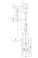
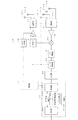
図1は、本発明の実施形態に係るレーダ装置の構成例を示す図である。この図に示すように、本発明の実施形態に係るレーダ装置10は、例えば、自動車等の車両に搭載され、車両の周囲に存在する他の車両、歩行者、障害物等の対象物を検出する。
(A) Explanation of Configuration of Embodiment of the Present Invention FIG. 1 is a diagram showing a configuration example of a radar device according to the embodiment of the present invention. As shown in this figure, the
ここで、レーダ装置10は、制御部11、発振部12、パルス整形部13、可変増幅部14、選択部15、送信アンテナ16−1〜16−2、受信アンテナ17−1〜17−4、選択部18、増幅部19、乗算部20、IF(Intermediate Frequency)増幅部21、A/D(Analog to Digital)変換部22、記憶部23、および、演算部24を主要な構成要素としている。
Here, the
ここで、制御部11は、例えば、CPU(Central Processing Unit)、ROM(Read Only Memory)、および、RAM(Random Access Memory)等によって構成され、装置の各部を制御する。なお、図中破線の矢印は、制御線を示している。
Here, the
発振部12は、制御部11の制御に応じて所定の周波数の局発信号を生成して出力する。
The oscillating
パルス整形部13は、制御部11から供給される矩形波を、後述するパルス波形を有する信号に整形して出力する。
The
可変増幅部14は、電圧制御増幅回路によって構成され、パルス整形部13から供給されるパルス波形の電圧に応じて局発信号を増幅して出力する。
The variable amplification unit 14 is configured by a voltage control amplifier circuit, and amplifies and outputs a locally generated signal according to the voltage of the pulse waveform supplied from the
選択部15は、制御部11の制御に応じて、送信アンテナ16−1〜16−2の一方を選択し、可変増幅部14からの出力信号を供給する。
The
送信アンテナ16−1〜16−2は、可変増幅部14からの出力信号を電磁波として対象物に向けて送信する。 The transmitting antennas 16-1 to 16-2 transmit the output signal from the variable amplification unit 14 as an electromagnetic wave toward the object.
受信アンテナ17−1〜17−4は、送信アンテナ16−1〜16−2によって送信され、対象物によって反射された反射信号を受信し、RF(Radio Frequency)信号に変換して選択部18に供給する。
The receiving antennas 17-1 to 17-4 receive the reflected signal transmitted by the transmitting antennas 16-1 to 16-2 and reflected by the object, convert it into an RF (Radio Frequency) signal, and send it to the
選択部18は、受信アンテナ17−1〜17−4から供給されるRF信号のいずれか一つを選択して増幅部19に出力する。
The
増幅部19は、選択部18から出力されるRF信号を所定のゲインで増幅して乗算部20に供給する。
The
乗算部20は、発振部12から供給される局発信号と、増幅部19から供給されるRF信号とを乗算し、IF(Intermediate Frequency)信号を生成して出力する。
The
IF増幅部21は、乗算部20から出力されるIF信号を所定のゲインで増幅して出力する。
The
A/D変換部22は、IF増幅部21から出力されるIF信号をデジタルデータに変換して出力する。
The A / D conversion unit 22 converts the IF signal output from the
記憶部23は、例えば、RAM等によって構成され、A/D変換部22から供給されるデジタルデータを記憶する。
The
演算部24は、処理部241、水平方向検出部242、垂直方向検出部243、および、処理部244を有している。
The
処理部241は、記憶部23に記憶されているデジタルデータに対して、FFT(Fast Fourier Transform)処理を施し、周波数および距離に関する2次元データを生成して出力する。
The processing unit 241 performs FFT (Fast Fourier Transform) processing on the digital data stored in the
水平方向検出部242は、処理部241から供給される、アレイアンテナ8系統のデータを用いて、角度FFT処理を施し、対象物の水平方向の角度を特定する。
The
垂直方向検出部243は、処理部241から供給されるデータから送信アンテナ16−1,16−2のそれぞれに係るアレイアンテナ4系統のデータを用いて角度FFT処理を施す。また、垂直方向検出部243は、水平方向検出部242によって特定された対象物の水平方向の角度(方位角)における送信アンテナ16−1,16−2のそれぞれに係るアレイアンテナ4系統のデータの強度比を計算する。さらに、垂直方向検出部243は、水平方向検出部242によって特定された対象物の方位角に対応する、垂直方向の角度(仰俯角)と強度比との関係を示す情報をテーブル群243aから取得し、この情報に基づいて対象物の仰俯角を特定する。
The
処理部244は、処理部241で取得した距離情報、ならびに、水平方向検出部242および垂直方向検出部243によって取得した方位角、仰俯角をもとに特定した対象物の位置および速度等に基づいて、自車両との衝突または接触の有無を判定し、判定結果を図示しない上位の装置(例えば、同レーダ装置10内のアプリケーション処理部、または、レーダ装置10外のECU(Electric Control Unit)等)に供給する。あるいは、対象物の位置および速度情報をECUに供給し、自動車との衝突または接触の有無の判定はECUで実施する。
The processing unit 244 is based on the distance information acquired by the processing unit 241 and the position and speed of the object specified based on the azimuth and elevation / depression angles acquired by the
なお、図1では図面を簡略化するために図示を省略しているが、乗算部20は増幅部19から出力される信号を直交復調してIQ信号として出力する。このため、乗算部20以降は、I,Qの2つの成分が伝達される。
Although not shown in FIG. 1 for simplification of the drawings, the
(B)実施形態の動作の説明
つぎに、本発明の実施形態の動作を説明する。以下では、図2〜図23を参照して本発明の実施形態の動作について説明した後、図24〜図27のフローチャートを参照して詳細な動作を説明する。
(B) Description of Operation of Embodiment Next, the operation of the embodiment of the present invention will be described. In the following, the operation of the embodiment of the present invention will be described with reference to FIGS. 2 to 23, and then the detailed operation will be described with reference to the flowcharts of FIGS. 24 to 27.
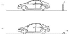
図2〜図8は、本発明の動作原理を示す図である。一例として、図2に示す車両の後部バンパー内にレーダ装置を装備した場合を考える。この場合、従来のレーダ装置は、図3に示すような指向特性を有する送信信号を車両の後方に向けて送信する。図3において、横軸は利得[dB]を示し、縦軸は仰俯角を示す。図3の例では、送信信号は仰俯角0度の軸を中心として線対称の指向特性を有している。従来のレーダ装置は、仰俯角方向の角度を検出することができないため、図2(A)に示す対象物O1(例えば、地面に設置されたポール)と、図2(B)に示す対象物O2(例えば、地面に設置された車止め)とを識別することができない。このため、従来のレーダ装置では、対象物O2に対しても警告を発したり、ブレーキを動作させて停車したりする場合があった。 2 to 8 are diagrams showing the operating principle of the present invention. As an example, consider the case where a radar device is installed in the rear bumper of the vehicle shown in FIG. In this case, the conventional radar device transmits a transmission signal having directivity as shown in FIG. 3 toward the rear of the vehicle. In FIG. 3, the horizontal axis represents the gain [dB] and the vertical axis represents the elevation / depression angle. In the example of FIG. 3, the transmitted signal has a directivity characteristic of line symmetry about the axis of the elevation / depression angle of 0 degrees. Since the conventional radar device cannot detect the angle in the elevation / depression angle direction, the object O1 (for example, a pole installed on the ground) shown in FIG. 2 (A) and the object shown in FIG. 2 (B). It cannot be distinguished from O2 (for example, a bollard installed on the ground). For this reason, in the conventional radar device, a warning may be issued to the object O2, or the vehicle may be stopped by operating the brake.
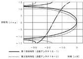
本実施形態では、図4に示すような、垂直方向に異なる指向特性を有する送信信号を異なるタイミングで送信する。そして、対象物で反射されたこれらの反射信号の電力(例えば、強度、振幅等)の差異から、垂直方向の角度を求める。より詳細には、図4に示す例では、実線の曲線は第1指向特性を有する送信信号の指向特性を示し、破線の曲線は第2指向特性を有する送信信号の指向特性を示している。本発明の実施形態では、例えば、送信アンテナ16−1から第1指向特性を有する実線の送信信号を送信し、対象物で反射された第1反射信号を受信する。また、送信アンテナ16−2から第2指向特性を有する破線の送信信号を送信し、対象物で反射された第2反射信号を受信する。 In the present embodiment, as shown in FIG. 4, transmission signals having different directivity in the vertical direction are transmitted at different timings. Then, the angle in the vertical direction is obtained from the difference in the power (for example, intensity, amplitude, etc.) of these reflected signals reflected by the object. More specifically, in the example shown in FIG. 4, the solid line curve shows the directivity characteristic of the transmitted signal having the first directivity characteristic, and the broken line curve shows the directivity characteristic of the transmitted signal having the second directivity characteristic. In the embodiment of the present invention, for example, a solid line transmission signal having the first directivity is transmitted from the transmission antenna 16-1, and the first reflection signal reflected by the object is received. Further, the transmission antenna 16-2 transmits a transmission signal having a broken line having a second directivity characteristic, and receives the second reflection signal reflected by the object.
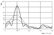
水平方向検出部242は、処理部241から供給される距離および周波数で定義されるデータから全ての送信アンテナ16−1、16−2に係るアレイアンテナ8系統のデータを取得し、角度FFT処理を実行することで、例えば図5に実線で示す処理結果を得る。なお、図5において、横軸はFFT処理後の角度インデックスを示し、縦軸は振幅を示す。
The
水平方向検出部242は、処理結果のデータのピークを検出することで、対象物の水平方向の位置を特定し、そのピーク位置である角度インデックスi1を特定する。水平方向検出部242は、図6に示す、角度インデックスと方位角との対応関係を示す情報を参照し、特定した角度インデックスを方位角に変換する。そして、角度インデックスと方位角とを垂直方向検出部243に出力する。なお、図6の横軸は方位角を示し、縦軸は角度インデックスを示す。図6では、複数の曲線が描画されているが、これらについはて後述する。
The horizontal
垂直方向検出部243は、処理部241から供給される距離および周波数で定義されるデータから送信アンテナ16−1に係るアレイアンテナ4系統のデータに角度FFT処理を施すことで、図5において間隔が長い破線で示す処理結果を得る。また、垂直方向検出部243は、同様に、送信アンテナ16−2に係るアレイアンテナ4系統のデータに角度FFT処理を施すことで、図5において間隔が短い破線で示す処理結果を得る。
The
垂直方向検出部243は、図5に間隔が長い破線で示す処理結果において水平方向検出部242から供給される角度インデックスに対応する振幅値a1を取得するとともに、図5に間隔が短い破線で示す処理結果において水平方向検出部242から供給される角度インデックスに対応する振幅値a2を取得する。そして、振幅値a1,a2の強度比(a1/a2)を求める。
The
垂直方向検出部243は、振幅値の比と仰俯角の対応関係に基づいて、仰俯角を特定する。例えば、図2(B)に示す対象物O2の場合、第2指向特性を有する送信信号に対する第2反射信号はある程度の強度(電力)を有するが、第1指向特性を有する送信信号に対する第1反射信号の強度は第2反射信号に比較して小さい(第2反射信号>第1反射信号である)ため、この場合a1/a2<1となる。
The
一方、図2(A)に示す対象物O1の場合、第1指向特性を有する送信信号に対する第1反射信号も第2指向特性を有する送信信号に対する第2反射信号の強度も略ある程度の大きさを有することから、a1/a2は、図2(B)に比較して大きくなる。すなわち強度比において対象物のおおむねの区別が可能となる。 On the other hand, in the case of the object O1 shown in FIG. 2 (A), the intensity of the first reflected signal with respect to the transmitted signal having the first directivity and the intensity of the second reflected signal with respect to the transmitted signal having the second directivity are approximately a certain magnitude. Therefore, a1 / a2 is larger than that in FIG. 2 (B). That is, it is possible to roughly distinguish the objects in terms of strength ratio.
さらに、a1/a2と、対象物の仰俯角との関係性を対応付けしたテーブルを予め格納しておき、このテーブルを参照することで、a1/a2から対象物の仰俯角を求めることができる。 Further, a table in which the relationship between a1 / a2 and the elevation / depression angle of the object is associated is stored in advance, and by referring to this table, the elevation / depression angle of the object can be obtained from a1 / a2. ..
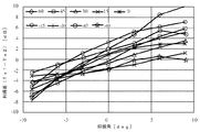
ところで、強度比と仰俯角との関係は、方位角によって必ずしも一定とはならない。図7は、利得差(Tx1−Tx2)と仰俯角の関係を示す図である。図7において、折れ線のそれぞれは、図7の左上に示す方位角における仰俯角と利得差の関係を示している。図7に示すように、実際のレーダ装置では、回路基板やレドーム等により、仰俯角特性は方位角に依存することがある。特に、車載のレーダ装置においては仰俯角範囲と比較して方位角範囲が広いことが一般的であるため、広い方位角を1つの仰俯角特性で定義することは困難である。 By the way, the relationship between the strength ratio and the elevation / depression angle is not always constant depending on the azimuth angle. FIG. 7 is a diagram showing the relationship between the gain difference (Tx1-Tx2) and the elevation / depression angle. In FIG. 7, each of the polygonal lines shows the relationship between the elevation / depression angle and the gain difference at the azimuth angle shown in the upper left of FIG. 7. As shown in FIG. 7, in an actual radar device, the elevation / depression angle characteristic may depend on the azimuth angle depending on the circuit board, radome, and the like. In particular, in an in-vehicle radar device, the azimuth range is generally wider than the elevation / depression range, so it is difficult to define a wide azimuth with one elevation / depression characteristic.
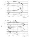
そこで、本実施形態では、垂直方向検出部243は、図7に示す利得差と仰俯角の関係を示す情報または図8に示すように図7に示す特性を直線近似した特性を、それぞれの方位角と対応付けられた複数のテーブルで構成されるテーブル群243aとして予め格納しており、水平方向検出部242によって検出された方位角に対応するテーブルをテーブル群243aから取得し、当該テーブルにおいて対応づけられた利得差(または強度比)と仰俯角との関係に基づいて、仰俯角を特定する。なお、図8では、1つのテーブルとして、切片情報と2種の傾き情報を有する折れ線を用い、当該折れ線を参照して利得差(または強度比)から仰俯角度を特定するようにしているが、仰俯角度の範囲が比較的狭いことから、記憶容量抑制の観点では、このように切片と2種の傾きの情報、あるいはさらに少ない情報(例えば、切片と1種の傾きの情報)を用いて近似的に仰俯角を特定するのが好ましい。なお、図8では、−60度から+60度の範囲を15度刻みの9本の折れ線としているが、これ以外の角度範囲を、これ以外の刻みの折れ線、例えば、3度刻みとしてもよい。また、折れ線ではなく、直線としたり、曲線としたり、あるいは、折れ線、直線、または、曲線を示す近似式を用いるようにしてもよい。また、該当する角度の折れ線が存在しない場合には、近い角度の折れ線から補間処理によって目的とする角度に対する値を求めるようにしてもよい。例えば、55度の場合には、45度と60度の折れ線から補間処理によって求めるようにしてもよい。
Therefore, in the present embodiment, the
処理部244は、垂直方向検出部243から供給される仰俯角に基づいて対象物の高さを検出する。そして、図2(A)に示すように、車両に接触(または衝突)する高さである場合には警告または制御を行い、図2(B)に示すように、車両に接触しない高さである場合には警告または制御を行わないようにすることができる。
The processing unit 244 detects the height of the object based on the elevation / depression angle supplied from the
つぎに、図1〜図23を参照して、本発明の実施形態の詳細な動作について説明する。 Next, the detailed operation of the embodiment of the present invention will be described with reference to FIGS. 1 to 23.
レーダ装置10が装備されている車両(不図示)のエンジンが始動されると、図1に示すレーダ装置10の各部に対して電源電力の供給が開始され、動作が可能な状態になる。
When the engine of the vehicle (not shown) equipped with the
電源電力の供給が開始されると、制御部11は、発振部12に対して局発信号の出力を開始させるとともに、パルス整形部13に対して矩形波を供給し、パルス信号を生成させる。この結果、送信アンテナ16−1〜16−2からは図9に示すパルス信号が出力される。
When the supply of power supply power is started, the
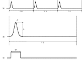
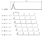
図9は、図1に示すレーダ装置10から送信される送信信号の例を示す図である。図9(A)に示すように、送信信号には繰り返し周期T0でパルスPが含まれている。パルスPは、図9(B)に拡大して示すように、振幅がAとされている。
FIG. 9 is a diagram showing an example of a transmission signal transmitted from the
図9(C)は、制御部11からパルス整形部13に供給される信号の一例を示している。パルス整形部13は、制御部11から供給される図9(C)に示す矩形波を、図9(B)に示すように整形して出力する。可変増幅部14は、パルス整形部13から供給される信号の振幅に基づいて発振部12から供給される局発信号を増幅して出力する。図9(C)に示すように、制御部11から供給される信号は、可変増幅部14から出力されるパルス信号の振幅が図9(B)に示すAとなるように、パルス幅Wが調整されている。
FIG. 9C shows an example of a signal supplied from the
送信アンテナ16−1,16−2のいずれか一方から送信されたパルスPは、対象物によって反射され、反射信号として受信アンテナ17−1〜17−4に受信され、RF信号に変換されて出力される。 The pulse P transmitted from either one of the transmitting antennas 16-1 and 16-2 is reflected by the object, received as a reflected signal by the receiving antennas 17-1 to 17-4, converted into an RF signal, and output. Will be done.
選択部18は、受信アンテナ17−1〜17−4のいずれか1つを選択するので、選択部18によって選択された受信アンテナ17−1〜17−4によって受信された反射信号はRF信号に変換されて増幅部19に供給される。
Since the
増幅部19は、選択部18から供給されるRF信号を所定のゲインで増幅して出力する。乗算部20は、増幅部19から供給される受信信号と、発振部12から供給される局発信号とを乗算してIF信号に変換(ダウンコンバート)して出力する。
The
IF増幅部21は、乗算部20から供給されるIF信号を増幅して出力する。A/D変換部22は、IF増幅部21から供給されるIF信号をA/D変換して出力する。なお、A/D変換部22は、図22を参照して後述するように、IF増幅部21から供給される受信信号を、等価時間サンプリングして出力する。
The
記憶部23は、A/D変換部22から出力されるデジタルデータを記憶し、演算部24の処理部241に供給する。
The
処理部241は、後述するように、記憶部23から供給されるデジタルデータに対してFFT処理を施し、距離および周波数に係る2次元データを生成して、水平方向検出部242および垂直方向検出部243に供給する。
As will be described later, the processing unit 241 performs FFT processing on the digital data supplied from the
水平方向検出部242は、従来のレーダ装置と同様に、水平方向における対象物の位置および速度を検出する処理を実行する。なお、水平方向検出部242は、送信アンテナ16−1〜16−2および受信アンテナ17−1〜17−4を用いて、仮想アレイアンテナの原理を用いることで、水平方向の位置の分解能を高めることができる。
The horizontal
以下では、仮想アレイアンテナの原理について説明する。図10に示すように、間隔dを隔てて、三角形で示す8つの受信アンテナRx(0)〜Rx(7)が配置され、受信アンテナRx(7)から所定の距離を隔てて、同じく三角形で示す送信アンテナTxが配置されているとする。このとき、図10に示すように、各アンテナの正面方向に対する電波の入射角度をθとするとき、受信アンテナRx(0)に対する受信アンテナRx(1)の行路差は、以下の式(1)で表される。なお、符号のプラスは行路差の距離が長いことを示し、マイナスは短いことを示す。 The principle of the virtual array antenna will be described below. As shown in FIG. 10, eight receiving antennas Rx (0) to Rx (7) indicated by triangles are arranged at intervals d, and at a predetermined distance from the receiving antennas Rx (7), they are also formed in triangles. It is assumed that the transmitting antenna Tx shown is arranged. At this time, as shown in FIG. 10, when the incident angle of the radio wave with respect to the front direction of each antenna is θ, the path difference of the receiving antenna Rx (1) with respect to the receiving antenna Rx (0) is calculated by the following equation (1). It is represented by. The plus sign indicates that the distance between the routes is long, and the minus sign indicates that the distance is short.
ΔL=−d・sin(θ) ・・・(1) ΔL = −d · sin (θ) ・ ・ ・ (1)
また、電波の波長をλとするとき、受信アンテナRx(0)に対する受信アンテナRx(1)の位相差Δφは、以下の式(2)で表される。 Further, when the wavelength of the radio wave is λ, the phase difference Δφ of the receiving antenna Rx (1) with respect to the receiving antenna Rx (0) is expressed by the following equation (2).
Δφ=−2πd/λ・sin(θ) ・・・(2) Δφ = -2πd / λ ・ sin (θ) ・ ・ ・ (2)
以上から、各受信アンテナRx(m)(m=0,1,・・・,7)の受信信号v_Rx(m,Tx1)は、以下の式(3)で表される。なお、jは虚数である。 From the above, the received signal v_Rx (m, Tx1) of each receiving antenna Rx (m) (m = 0,1, ..., 7) is represented by the following equation (3). Note that j is an imaginary number.
v_Rx(m,Tx1)=v_Rx(0,Tx1)・exp(j・m・Δφ)
・・・(3)
v_Rx (m, Tx1) = v_Rx (0, Tx1) ・ exp (j ・ m ・ Δφ)
... (3)
ここで以上の式(2),(3)より、各々受信アンテナにおける位相回転成分が電波の入射角に対応することがわかる。これら受信信号をフーリエ変換することで受信信号回転成分の抽出、すなわち電波の入射角を特定することが可能となる。またフーリエ変換に限らずそれ以外の高分解能処理により入射角の特定するようにしてもよい。 From the above equations (2) and (3), it can be seen that the phase rotation components of the receiving antenna correspond to the incident angle of the radio wave. By Fourier transforming these received signals, it is possible to extract the received signal rotation component, that is, to specify the incident angle of the radio wave. Further, the incident angle may be specified by high resolution processing other than the Fourier transform.
つぎに、図11に示すように、送信アンテナTx2を新たに設けるとともに、受信アンテナRx(4)〜Rx(7)を除外する場合を考える。このとき、Tx2から対象物までの距離はTx1に比べてN/2・d・sin(θ)だけ長く、また、受信アンテナRx(4)に対し受信アンテナRx(0)から対象物までの距離もN/2・d・sin(θ)だけ長い。このとき、以下の式(4)および式(5)が成立する。但し、Nは受信アンテナの個数を示す(図11の例ではN=8)。 Next, as shown in FIG. 11, consider a case where the transmitting antenna Tx2 is newly provided and the receiving antennas Rx (4) to Rx (7) are excluded. At this time, the distance from Tx2 to the object is longer by N / 2 ・ d ・ sin (θ) than Tx1, and the distance from the receiving antenna Rx (0) to the object with respect to the receiving antenna Rx (4). Is also longer by N / 2 ・ d ・ sin (θ). At this time, the following equations (4) and (5) are established. However, N indicates the number of receiving antennas (N = 8 in the example of FIG. 11).
v_Rx(m,Tx1)=v_Rx(m,Tx1) ・・・(4)
但し、m≦N/2−1の場合
v_Rx (m, Tx1) = v_Rx (m, Tx1) ... (4)
However, when m ≦ N / 2-1
v_Rx(m,Tx1)=v_Rx(m−N/2,Tx2)・exp(j・N・Δφ)
・・・(5)
但し、m>N/2−1の場合
v_Rx (m, Tx1) = v_Rx (m-N / 2, Tx2) · exp (j · N · Δφ)
... (5)
However, when m> N / 2-1
以上の式(4)および式(5)から、往路と復路の角度が同じである場合、1つの送信アンテナTx1だけの系と、2つの送信アンテナTx1,Tx2の系は等価であることが分かる。 From the above equations (4) and (5), it can be seen that the system of only one transmitting antenna Tx1 and the system of two transmitting antennas Tx1 and Tx2 are equivalent when the angles of the outward path and the returning path are the same. ..
ここで、式(5)の右辺にあるexp(j・N・Δφ)は、位相補正項であり、N分だけアンテナを移動させたのと等価になる項である。このため、図12(A)に示す1つのTx1を有する系と、図12(B)に示す2つのTx1,Tx2を有する系とを等価にする場合、図12(C)に示すように、受信アンテナRx(−4)〜Rx(3)が配置されていると想定して計算することで、以下の式(6)〜式(13)に示すように、位相補正項であるexp(j・N・Δφ)については考慮する必要がなくなる。 Here, exp (j · N · Δφ) on the right side of the equation (5) is a phase correction term, which is equivalent to moving the antenna by N minutes. Therefore, when the system having one Tx1 shown in FIG. 12 (A) is equivalent to the system having two Tx1 and Tx2 shown in FIG. 12 (B), as shown in FIG. 12 (C), By calculating assuming that the receiving antennas Rx (-4) to Rx (3) are arranged, exp (j), which is a phase correction term, is shown in the following equations (6) to (13).・ There is no need to consider N ・ Δφ).
v_Rx(−4,Tx)=v_Rx(0,Tx2) ・・・(6)
v_Rx(−3,Tx)=v_Rx(1,Tx2) ・・・(7)
v_Rx(−2,Tx)=v_Rx(2,Tx2) ・・・(8)
v_Rx(−1,Tx)=v_Rx(3,Tx2) ・・・(9)
v_Rx( 0,Tx)=v_Rx(0,Tx1) ・・・(10)
v_Rx( 1,Tx)=v_Rx(1,Tx1) ・・・(11)
v_Rx( 2,Tx)=v_Rx(2,Tx1) ・・・(12)
v_Rx( 3,Tx)=v_Rx(3,Tx1) ・・・(13)
v_Rx (-4, Tx) = v_Rx (0, Tx2) ... (6)
v_Rx (-3, Tx) = v_Rx (1, Tx2) ... (7)
v_Rx (-2, Tx) = v_Rx (2, Tx2) ... (8)
v_Rx (-1, Tx) = v_Rx (3, Tx2) ... (9)
v_Rx (0, Tx) = v_Rx (0, Tx1) ... (10)
v_Rx (1, Tx) = v_Rx (1, Tx1) ... (11)
v_Rx (2, Tx) = v_Rx (2, Tx1) ... (12)
v_Rx (3, Tx) = v_Rx (3, Tx1) ... (13)
すなわち、2つの送信アンテナを用いることで、4つの受信アンテナを仮想的に8つに拡張することができる。本実施形態では、このような仮想アレイアンテナの原理を利用している。 That is, by using the two transmitting antennas, the four receiving antennas can be virtually expanded to eight. In this embodiment, the principle of such a virtual array antenna is used.
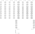
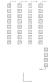
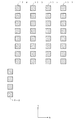
図13は、図1に示す送信アンテナ16−1〜16−2および受信アンテナ17−1〜17−4の詳細な構成例を示している。図13に示す例では、送信アンテナ16−1〜16−2は、それぞれ4つの素子アンテナ、具体的にはパッチアンテナを有するアレイアンテナによって構成されている。また、受信アンテナ17−1〜17−4は、それぞれ8つの素子アンテナ、具体的にはパッチアンテナを有するアレイアンテナによって構成されている。受信アンテナ17−1〜17−4は、例えば、誘電体基板等の表面に形成され、図13に示すように、上下方向であるY方向に8つのパッチが所定の間隔を隔てて直線状に配置されて構成される。また、受信アンテナ17−1〜17−4は、左右方向であるX方向に所定の間隔を隔てて配置され、受信アンテナ17−1〜17−4を構成するパッチがマトリクス状に配置される。送信アンテナ16−1は、受信アンテナ17−1の右下方に配置され、送信アンテナ16−2は、受信アンテナ17−4の左下方に配置される。なお、受信アンテナ17−1〜17−4のそれぞれの距離をdとすると、送信アンテナ16−1〜16−2の距離は4×dで表される。また、送信アンテナ16−1と受信アンテナ17−1とは、X方向に距離D離間して配置され、送信アンテナ16−2と受信アンテナ17−4とは、X方向に距離D離間して配置されている。 FIG. 13 shows a detailed configuration example of the transmitting antennas 16-1 to 16-2 and the receiving antennas 17-1 to 17-4 shown in FIG. In the example shown in FIG. 13, the transmitting antennas 16-1 to 16-2 are each composed of an array antenna having four element antennas, specifically, a patch antenna. Further, the receiving antennas 17-1 to 17-4 are each composed of eight element antennas, specifically, an array antenna having a patch antenna. The receiving antennas 17-1 to 17-4 are formed, for example, on the surface of a dielectric substrate or the like, and as shown in FIG. 13, eight patches in the Y direction, which is the vertical direction, are linearly spaced at predetermined intervals. Arranged and configured. Further, the receiving antennas 17-1 to 17-4 are arranged at predetermined intervals in the X direction, which is the left-right direction, and patches constituting the receiving antennas 17-1 to 17-4 are arranged in a matrix. The transmitting antenna 16-1 is arranged at the lower right of the receiving antenna 17-1, and the transmitting antenna 16-2 is arranged at the lower left of the receiving antenna 17-4. Assuming that the distances of the receiving antennas 17-1 to 17-4 are d, the distances of the transmitting antennas 16-1 to 16-2 are represented by 4 × d. Further, the transmitting antenna 16-1 and the receiving antenna 17-1 are arranged so as to be separated by a distance D in the X direction, and the transmitting antenna 16-2 and the receiving antenna 17-4 are arranged so as to be separated by a distance D in the X direction. Has been done.
なお、図13に示すアンテナの配置は、図11とは異なっているが、図14に示すように、仮想アレイアンテナとして動作することができる。すなわち、送信アンテナ16−1〜16−2を用いることで、受信アンテナ17−1〜17−4が、受信アンテナ17−1〜17−8の8アレイのアンテナに仮想的に拡張される。 Although the arrangement of the antenna shown in FIG. 13 is different from that of FIG. 11, it can operate as a virtual array antenna as shown in FIG. That is, by using the transmitting antennas 16-1 to 16-2, the receiving antennas 17-1 to 17-4 are virtually extended to the 8-array antennas of the receiving antennas 17-1 to 17-8.
図15は、図13に示す送信アンテナ16−1〜16−2の詳細な構成例を示している。なお、図15では、図面を簡略化するために送信アンテナ16−1〜16−2の距離を実際よりも狭めて描画している。図15の例では、送信アンテナ16−1は、4つのパッチアンテナ1611〜1614を有している。また、パッチアンテナ1611〜1614は、給電線L11〜L13によって相互に接続され、給電点Fp1から送信信号が供給される。また、送信アンテナ16−2も同様に、4つのパッチアンテナ1621〜1624を有している。また、パッチアンテナ1621〜1624は、給電線L21〜L23によって相互に接続され、給電点Fp2から送信信号が供給される。 FIG. 15 shows a detailed configuration example of the transmitting antennas 16-1 to 16-2 shown in FIG. In FIG. 15, the distance between the transmitting antennas 16-1 to 16-2 is narrower than the actual distance in order to simplify the drawing. In the example of FIG. 15, the transmitting antenna 16-1 has four patch antennas 1611 to 1614. Further, the patch antennas 1611 to 1614 are connected to each other by feed lines L11 to L13, and a transmission signal is supplied from the feed point Fp1. Similarly, the transmitting antenna 16-2 also has four patch antennas 1621-1624. Further, the patch antennas 1621 to 1624 are connected to each other by feed lines L21 to L23, and a transmission signal is supplied from the feed point Fp2.
ここで、送信アンテナ16−1を構成する給電線L11〜L13の長さは、L13>L12>L11となるように設定されている。送信アンテナ16−2を構成する給電線L21〜L23の長さは、L23>L22>L21となるように設定されている。 Here, the lengths of the feeder lines L11 to L13 constituting the transmitting antenna 16-1 are set so that L13> L12> L11. The lengths of the feeder lines L21 to L23 constituting the transmitting antenna 16-2 are set so that L23> L22> L21.
このように設定することで、給電線の長さに応じた位相遅れが生じることから、送信アンテナ16−1では、給電点Fp1に送信信号が供給されると、パッチアンテナ1611〜1614の順に位相が進んだ電磁波が送信されることから、電磁波が下向きに放射される、送信アンテナ16−2では、パッチアンテナ1624〜1621の順に位相が進んだ電磁波が送信されることから、電磁波が上向きに放射される。これにより、図4に示す指向特性を実現することができる。 By setting in this way, a phase delay occurs according to the length of the feeder line. Therefore, when the transmission signal is supplied to the feed point Fp1 in the transmission antenna 16-1, the phases are in the order of the patch antennas 1611 to 1614. Since the advanced electromagnetic wave is transmitted, the electromagnetic wave is radiated downward. At the transmitting antenna 16-2, the electromagnetic wave whose phase is advanced in the order of the patch antennas 1624 to 1621 is transmitted, so that the electromagnetic wave is radiated upward. Will be done. As a result, the directivity shown in FIG. 4 can be realized.
また、本実施形態では、図13に示すように、送信アンテナ16−1〜16−2を構成するパッチアンテナの数は4とされ、受信アンテナ17−1〜17−4を構成するパッチアンテナの数は8とされ、送信アンテナ16−1〜16−2を構成するパッチアンテナの数の方が少なく設定されている。これは、以下の理由による。すなわち、送信アンテナ16−1〜16−2のビームの幅(例えば、半値幅)が広い場合には、ビームが重複する領域が広く、また、ビームの幅が狭い場合には、ビームが重複する領域が狭い。図16は、ビームが広い場合と狭い場合による重複する領域を模式的に示す図である。より詳細には、図16は垂直方向に上向きと下向きの2つのビームの重複する様子を示す模式図であり、図16(A)はビームの幅が広い場合を示し、図16(B)はビームの幅が狭い場合を示している。なお、図16(A)と図16(B)において、ビームの照射する角度(垂直方向の角度)は同じである。2つの送信アンテナ16−1〜16−2を用いて対象物を検出する場合、対象物を検出可能な範囲は2つのビームが重複する範囲であることから、図16(A)では利得G1に対応する範囲であり、図16(B)では利得G2に対応する範囲である。このため、ビーム幅が広い方が遠くまで対象物の検出が可能になる。 Further, in the present embodiment, as shown in FIG. 13, the number of patch antennas constituting the transmitting antennas 16-1 to 16-2 is 4, and the number of patch antennas constituting the receiving antennas 17-1 to 17-4 is set to 4. The number is set to 8, and the number of patch antennas constituting the transmitting antennas 16-1 to 16-2 is set to be smaller. This is due to the following reasons. That is, when the beam width (for example, half width) of the transmitting antennas 16-1 to 16-2 is wide, the area where the beams overlap is wide, and when the beam width is narrow, the beams overlap. The area is small. FIG. 16 is a diagram schematically showing overlapping regions depending on whether the beam is wide or narrow. More specifically, FIG. 16 is a schematic view showing an overlapping state of two beams upward and downward in the vertical direction, FIG. 16A shows a case where the beam width is wide, and FIG. 16B shows a case where the beam width is wide. The case where the width of the beam is narrow is shown. In addition, in FIG. 16A and FIG. 16B, the beam irradiation angle (vertical angle) is the same. When an object is detected using the two transmitting antennas 16-1 to 16-2, the range in which the object can be detected is the range in which the two beams overlap. Therefore, in FIG. 16A, the gain G1 is obtained. It is the corresponding range, and in FIG. 16B, it is the range corresponding to the gain G2. Therefore, the wider the beam width, the farther the object can be detected.
そこで、本実施形態では、送信アンテナ16−1〜16−2をそれぞれ構成する素子の数を受信アンテナ17−1〜17−4の8よりも少ない4とすることで、垂直方向のビーム幅を広くし、検出可能な距離の変動を、垂直方向のビーム幅が狭い場合に比較して小さくしている。具体的には同様のチルト角であっても仰俯角正面方向の利得低下が小さく、また、車両搭載時のピッチ角変動に対しても利得低下を小さくすることができる。また、送信される電波の他の機器に与える影響は、アンテナのピーク利得と供給電力との積に比例して増減する(例えば、電波法の規制は、アンテナのピーク利得と供給電力との積によって定められる)。このため、ビーム幅を広くすると、アンテナのピーク利得は減少するが、供給される電力をピーク利得の減少に応じて増加することで、仰俯角に係る電力低下を抑えることが可能となる。また、その際、他の機器に与える影響は、増加前と同じである。かつ当然ながら送信アンテナの素子数が少ない分のレーダ装置の小型化が図れる。 Therefore, in the present embodiment, the beam width in the vertical direction is increased by setting the number of elements constituting the transmitting antennas 16-1 to 16-2 to 4, which is less than 8 of the receiving antennas 17-1 to 17-4. It is widened and the fluctuation of the detectable distance is made smaller than when the beam width in the vertical direction is narrow. Specifically, even if the tilt angle is the same, the decrease in gain in the frontal direction of the elevation / depression angle is small, and the decrease in gain can be small even when the pitch angle is changed when the vehicle is mounted. In addition, the effect of transmitted radio waves on other devices increases or decreases in proportion to the product of the peak gain of the antenna and the supplied power (for example, the regulation of the Radio Law is the product of the peak gain of the antenna and the supplied power). Determined by). Therefore, if the beam width is widened, the peak gain of the antenna is reduced, but by increasing the supplied power in accordance with the decrease in the peak gain, it is possible to suppress the power reduction related to the elevation / depression angle. At that time, the influence on other devices is the same as before the increase. And, of course, the radar device can be downsized because the number of elements of the transmitting antenna is small.
なお、以上は、送信アンテナ16−1〜16−2の送信利得についての説明であるが、受信アンテナ17−1〜17−4も受信利得を有しており、送信アンテナ16−1〜16−2の送信利得と受信アンテナ17−1〜17−4の受信利得の積によってトータルの利得が計算できる。図17は、送信アンテナ16−1〜16−2と受信アンテナ17−1〜17−4の積によって得られるトータルの利得を示す図である。この図において、破線は図18(A)に示す受信アンテナを使用した場合の利得を示し、実線は図18(B)に示す受信アンテナを使用した場合の利得を示している。 The above is a description of the transmission gain of the transmitting antennas 16-1 to 16-2, but the receiving antennas 17-1 to 17-4 also have a receiving gain, and the transmitting antennas 16-1 to 16- The total gain can be calculated by multiplying the transmission gain of 2 and the reception gain of the receiving antennas 17-1 to 17-4. FIG. 17 is a diagram showing the total gain obtained by the product of the transmitting antennas 16-1 to 16-2 and the receiving antennas 17-1 to 17-4. In this figure, the broken line shows the gain when the receiving antenna shown in FIG. 18 (A) is used, and the solid line shows the gain when the receiving antenna shown in FIG. 18 (B) is used.
図18(A)に示す受信アンテナでは、パッチアンテナ1711〜1718同士を接続する給電線L31〜L36の幅は略一定とされている。一方、図18(B)に示す受信アンテナでは、パッチアンテナ1721〜1728同士を接続する給電線L41〜L46の一部に隘路が整形されて幅が調整されており、この結果として、図17に実線で示す曲線のように、破線で示す曲線に比較して、サイドローブが抑圧されている。より具体的には、例えば、図18(B)のアンテナの上下方向中央からパッチアンテナ1721〜1724を見た際の、各パッチアンテナのインピーダンスが互いに異なる値となるように、各パッチアンテナを接続する給電線の一部の幅が調整される。パッチアンテナ1725〜1728についても同様である。サイドローブが存在する角度範囲は利得を有しているため、誤検知が発生する虞がある。破線で示す利得曲線の場合、実線の利得曲線に比較してサイドローブの利得が大きく、数も多いことから、メインローブ範囲外の対象物をサイドローブで誤って検出する可能性が高い。一方、実線の利得曲線では、サイドローブが抑圧されている(利得が小さく、数も少ない)ことで、対象物の誤検知を低減することができる。 In the receiving antenna shown in FIG. 18A, the widths of the feeder lines L31 to L36 connecting the patch antennas 1711 to 1718 are substantially constant. On the other hand, in the receiving antenna shown in FIG. 18B, a narrow path is shaped in a part of the feeder lines L41 to L46 connecting the patch antennas 1721 to 1728 to adjust the width, and as a result, FIG. Like the curve shown by the solid line, the side lobes are suppressed as compared with the curve shown by the broken line. More specifically, for example, when the patch antennas 1721 to 1724 are viewed from the center in the vertical direction of the antenna of FIG. 18B, the patch antennas are connected so that the impedances of the patch antennas have different values. The width of a part of the feeding line is adjusted. The same applies to the patch antennas 1725 to 1728. Since the angle range in which the side lobes exist has a gain, false positives may occur. In the case of the gain curve shown by the broken line, the side lobe gain is larger and the number is larger than that of the solid line gain curve, so there is a high possibility that an object outside the main lobe range is erroneously detected by the side lobe. On the other hand, in the solid line gain curve, the side lobes are suppressed (the gain is small and the number is small), so that false detection of the object can be reduced.
なお、前述したように、送信アンテナ16−1〜16−2と受信アンテナ17−1〜17−4の積によってトータルの利得が得られるので、送信アンテナ16−1〜16−2を調整することでもサイドローブを抑圧することは可能である。しかしながら、送信アンテナ16−1〜16−2は、パッチアンテナの数が少ないことから、設計の自由度が低い。一方、受信アンテナ17−1〜17−4は、パッチアンテナの数が多いことから、設計の自由度が高い。そこで、本実施形態では、受信アンテナ17−1〜17−4において、サイドローブを抑圧するようにしている。 As described above, the total gain can be obtained by the product of the transmitting antennas 16-1 to 16-2 and the receiving antennas 17-1 to 17-4, so the transmitting antennas 16-1 to 16-2 should be adjusted. But it is possible to suppress the side lobes. However, since the number of patch antennas of the transmitting antennas 16-1 to 16-2 is small, the degree of freedom in design is low. On the other hand, the receiving antennas 17-1 to 17-4 have a high degree of freedom in design because the number of patch antennas is large. Therefore, in the present embodiment, the side lobes are suppressed in the receiving antennas 17-1 to 17-4.
図19は、送信アンテナ16−1および受信アンテナ17−1を構成する素子に供給される電力を示す図である。なお、送信アンテナ16−2と受信アンテナ17−2〜17−4も、図19と同様の電力が供給されるが、図面の簡略化のために省略している。図19に示すように、受信アンテナ17−1は、両端に近づくにつれて素子の電力が低くなり、電力勾配を有するように設定されている。このようにして、送信アンテナ16−1に最も近接する素子に供給される電力は、当該素子に隣接する素子、およびその素子に隣接する素子等、互いに隣接する複数の素子に供給される電力以下となっている。送信アンテナ16−1から送信された電波の一部は、受信アンテナ17−1に回り込んで受信される。特に、送信アンテナと受信アンテナの最も近接した箇所において回り込みの大きさが顕著となる。このため、例えば、図19に示すように受信アンテナ17−1の電力を設定することで、サイドローブを低減しつつ、送信アンテナ16−1と近接した箇所における電力を抑えることでこのような回り込みを低減することができる。また、これとともにアンテナの偏波方向とアンテナのレイアウト方向を直交させることでも、回り込みを抑制する。これらにより、より近接した対象物の検出と仰俯角の検知が可能となる。また、送信アンテナと受信アンテナと距離を接近させることができるので、装置を小型化することができる。 FIG. 19 is a diagram showing the power supplied to the elements constituting the transmitting antenna 16-1 and the receiving antenna 17-1. The transmitting antenna 16-2 and the receiving antennas 17-2 to 17-4 are also supplied with the same power as in FIG. 19, but are omitted for simplification of the drawings. As shown in FIG. 19, the receiving antenna 17-1 is set so that the power of the element decreases as it approaches both ends and has a power gradient. In this way, the power supplied to the element closest to the transmitting antenna 16-1 is equal to or less than the power supplied to a plurality of elements adjacent to each other, such as an element adjacent to the element and an element adjacent to the element. It has become. A part of the radio wave transmitted from the transmitting antenna 16-1 wraps around the receiving antenna 17-1 and is received. In particular, the size of the wraparound becomes remarkable at the position closest to the transmitting antenna and the receiving antenna. Therefore, for example, by setting the power of the receiving antenna 17-1 as shown in FIG. 19, the side lobe is reduced, and the power in a portion close to the transmitting antenna 16-1 is suppressed, so that such wraparound is performed. Can be reduced. At the same time, the polarization direction of the antenna and the layout direction of the antenna are orthogonal to each other to suppress wraparound. As a result, it is possible to detect an object closer to the object and the elevation / depression angle. Further, since the transmitting antenna and the receiving antenna can be brought close to each other, the device can be miniaturized.
また、本発明の実施形態では、2つの送信アンテナから送信される電波をチルトさせ、受信信号の振幅の差に基づいて仰俯角を検出するようにしている。なお、位相差によって仰俯角を検出することも可能である。すなわち、2つの送信アンテナから送信される電波に位相差を持たせ、受信信号の位相の差に基づいて仰俯角を検出することもできる。位相差に基づいて仰俯角を検出する場合、送信アンテナ16−1〜16−2を垂直方向(Y)方向に位置をずらして配置する必要があるが、角度判別性能を高めるためには、このずれを大きくする必要がある。その場合、送信アンテナ16−1〜16−2が占有するY方向の領域が大きくなるため、装置のサイズが大きくなる。一方、本発明の実施形態の場合、電波をチルトさせるためには、アンテナの位置を変更せず、各アンテナ素子への給電を調整することで達成できるので、チルト角度を大きくしても装置のサイズが大型化しないという特徴もある。 Further, in the embodiment of the present invention, the radio waves transmitted from the two transmitting antennas are tilted, and the elevation / depression angle is detected based on the difference in the amplitude of the received signals. It is also possible to detect the elevation / depression angle by the phase difference. That is, it is also possible to give a phase difference to the radio waves transmitted from the two transmitting antennas and detect the elevation / depression angle based on the phase difference of the received signal. When detecting the elevation / depression angle based on the phase difference, it is necessary to displace the transmitting antennas 16-1 to 16-2 in the vertical direction (Y), but in order to improve the angle discrimination performance, this is necessary. It is necessary to increase the deviation. In that case, the area occupied by the transmitting antennas 16-1 to 16-2 in the Y direction becomes large, so that the size of the device becomes large. On the other hand, in the case of the embodiment of the present invention, in order to tilt the radio wave, it can be achieved by adjusting the power supply to each antenna element without changing the position of the antenna. Therefore, even if the tilt angle is increased, the device can be tilted. There is also a feature that the size does not increase.
つぎに、等価時間サンプリングについて説明する。図22は、パルスPに関する等価時間サンプリング処理の一例を示す図である。図22(A)は、送信されるパルスPを示している。また、図22(B)〜(G)は、等価時間サンプリングにおけるフィールドを示している。より詳細には、図22(A)に示すパルスPが送信されると、図22(B)に示すように、第1フィールドでは、パルスPのピーク位置からA/D変換部22が周期t1でサンプリングを実行する。なお、図22の例では、各フィールドでは、矢印で示すように5回のサンプリングが実行されている。図22(C)に示すように、第2フィールドでは、第1フィールドに比較すると、時間τ1だけオフセットされてサンプリングが開始される。なお、サンプリング周期は、第1フィールドと同様にt1である。図22(D)に示すように、第3フィールドでは、第2フィールドに比較して時間τ1だけオフセットされサンプリングが開始され、同様に、図22(E)〜(G)に示すように、第3〜6フィールドでは直前のフィールドに比べて時間τ1だけオフセットされてサンプリングが開始される。 Next, equivalent time sampling will be described. FIG. 22 is a diagram showing an example of equivalent time sampling processing for pulse P. FIG. 22 (A) shows the transmitted pulse P. Further, FIGS. 22 (B) to 22 (G) show fields in equivalent time sampling. More specifically, when the pulse P shown in FIG. 22 (A) is transmitted, as shown in FIG. 22 (B), in the first field, the A / D conversion unit 22 has a period t1 from the peak position of the pulse P. Perform sampling with. In the example of FIG. 22, each field is sampled five times as shown by an arrow. As shown in FIG. 22C, in the second field, when compared with the first field, sampling is started with an offset of time τ1. The sampling period is t1 as in the first field. As shown in FIGS. 22 (D), in the third field, sampling is started offset by a time τ1 as compared with the second field, and similarly, as shown in FIGS. 22 (E) to 22 (G), the third field is used. In the 3 to 6 fields, sampling is started with an offset of time τ1 as compared with the immediately preceding field.
なお、図22では、詳細は示していないが、各フィールドでは、送信アンテナ16−1,16−2および受信アンテナ17−1〜17−4のそれぞれについて、例えば、1回の高周波パルス信号が送受信され、同じオフセットでサンプリングが実行される。すなわち、第1フィールドでは、例えば、送信アンテナ16−1からパルスが送信され、受信アンテナ17−1により図22(B)に示す各タイミングで反射信号がサンプリングされる。つぎに、受信アンテナ17−2に切り替えられ、図22(B)に示す各タイミングで反射信号がサンプリングされる。つぎに、受信アンテナ17−3〜17−4によって、同様に、図22(B)に示す各タイミングで反射信号がサンプリングされる。つづいて、送信アンテナ16−2に切り替えられ、受信アンテナ17−1〜17−4によって、図22(B)に示す各タイミングで反射信号がサンプリングされる。以上の動作を1サイクルとすると、このようなサイクルを、例えば、第1フィールドについて1回行い(高周波パルス信号を合計8(=2×4×1)回送信し)、第1フィールドにおけるデータが取得される。第1フィールドのサンプリングが終了すると、続いて、第2〜第6フィールドのサンプリングが実行される。そして全てのフィールドのサンプリングが完了すると、再度、第1フィールドのサンプリングに戻る。このような等価時間サンプリング処理を所定回数(例えば、2,048回)繰り返した後、対象物を検出する処理その他が実行される。なお、図22では、各フィールドのサンプリング回数は5回とされているが、これ以外の回数としてもよい。また、各フィールドでは、1サイクルを1回行うようにしているが、これ以外の回数繰り返すようにしてもよい。 Although details are not shown in FIG. 22, in each field, for example, one high-frequency pulse signal is transmitted and received for each of the transmitting antennas 16-1 and 16-2 and the receiving antennas 17-1 to 17-4. And sampling is performed at the same offset. That is, in the first field, for example, a pulse is transmitted from the transmitting antenna 16-1, and the reflected signal is sampled by the receiving antenna 17-1 at each timing shown in FIG. 22 (B). Next, the antenna is switched to the receiving antenna 17-2, and the reflected signal is sampled at each timing shown in FIG. 22 (B). Next, the receiving antennas 17-3 to 17-4 similarly sample the reflected signal at each timing shown in FIG. 22B. Subsequently, the transmitting antenna is switched to 16-2, and the reflected signal is sampled by the receiving antennas 17-1 to 17-4 at each timing shown in FIG. 22 (B). Assuming that the above operation is one cycle, such a cycle is performed once for the first field (a total of 8 (= 2 × 4 × 1) high frequency pulse signals are transmitted), and the data in the first field is obtained. To be acquired. When the sampling of the first field is completed, the sampling of the second to sixth fields is subsequently executed. Then, when the sampling of all the fields is completed, the sampling of the first field is resumed again. After repeating such an equivalent time sampling process a predetermined number of times (for example, 2,048 times), a process of detecting an object and the like are executed. In FIG. 22, the number of sampling times for each field is set to 5, but other times may be used. Further, in each field, one cycle is performed once, but it may be repeated a number of times other than this.
つぎに、演算部24の処理について詳細に説明する。処理部241は、A/D変換部22によって等価時間サンプリングされ、記憶部23において各距離情報を記憶する。また、これら各距離情報を一定時間において繰り返し複数回取得することによって、上記一定時間ごとの各距離情報を記憶部23において記憶する。記憶部23において記憶した各距離における時間ごとのデータを読み出してFFT処理を施すことで、対象物までの距離だけでなく、周波数に係る2次元データを生成する。これにより、送信アンテナ16−1と受信アンテナ17−1〜17−4による4系統の2次元データと、送信アンテナ16−2と受信アンテナ17−1〜17−4による4系統の2次元データ、合計8系統における距離と周波数の2次元データを得る。なお、複数のアンテナ系列、複数の距離系列、周波数成分取得のための繰り返し系列、これらの取得の順番は設計によって任意に決定づけることができる。また、以下の角度処理の前に、何等かしきいを用い、距離と周波数で定義される2次元データのうち、十分な振幅をもつデータを対象物の候補となる信号として絞るような検出処理を行うことも可能である。これにより、以下の角度処理の数量を低減することが可能である。
Next, the processing of the
水平方向検出部242は、図23の左側に破線で囲んだ処理P1を実行する。すなわち、水平方向検出部242は、前述した合計で8系統のデータを8ポイントのデータとし、ゼロパディングを行うことで、例えば、128ポイントまたは256ポイント(2のべき乗ポイント)等のデータを生成する。水平方向検出部242は、ゼロパディングを行って得たデータに対して、8アレイ角度FFT処理(P10)を実行することで、例えば、図5に実線で示すような処理結果、いわゆる角度スペクトラムを得る。
The
つぎに、水平方向検出部242は、8アレイ角度FFT処理によって得られた結果、角度スペクトラムに対して、ピークインデックスサーチ処理(P11)を実行する。この結果、図5の例では、実線で示す曲線におけるピーク位置の角度インデックスi1が取得される。取得したピーク振幅値と、なんらかのしきい値との比較により、対象物の候補となる信号の判定を行うことも可能である。この段階で得られたピーク振幅は、送信アンテナ受信アンテナ全チャンネル情報が積分された結果となっており、S/N(Signal Noise)比が高い結果に基づいて判定することで、精度良く対象物の信号を特定することができる。またこの段階でノイズ成分を対象物から除外することで、処理する回数低減をはかり、以降の処理負荷をさらに軽減することも可能である。また水平面方向における角度検出に全チャンネルの情報を用いることで、広い範囲に高い分解能が要求される水平面において分解能を向上させることが可能である。
Next, the horizontal
つぎに、水平方向検出部242は、あらかじめ格納された角度インデックスと方位角との関係を示すテーブル(TA1)を参照し、対象物の方位角を特定する処理(P12)を実行する。より詳細には、図6に示すような角度インデックスと方位角の関係を示すテーブルを参照して方位角を特定する。例えば、図5の例では、実線の曲線のピーク位置における角度インデックスは“65”程度であり、図6に“65”を適用すると、方位角として約−30度を得る。
Next, the horizontal
なお、送信アンテナ16−1,16−2は垂直方向の指向特性が図4に示すように異なっているため、送信アンテナ16−1,16−2のそれぞれについて角度インデックスと方位角との関係が異なることも想定される。しかしながら、図6に示すように、レーダ装置の取り付け角が水平方向に対して0度の場合(図6の実線で示す場合)と、水平方向に対して+6度の場合(図6に間隔の長い破線で示す場合)と、水平方向に対して−6度の場合(図6に間隔の短い破線で示す場合)とで、ほとんど特性の変化がない。このため、取り付け角や異なる仰俯角に応じて、それぞれについてテーブルを設けるのではなく、1種類のテーブルを用いて判定することができる。もちろん、取り付け角や異なる仰俯角に応じて、それぞれに対してテーブルを有するようにしてもよい。 Since the transmitting antennas 16-1 and 16-2 have different directivity characteristics in the vertical direction as shown in FIG. 4, the relationship between the angular index and the azimuth angle is different for each of the transmitting antennas 16-1 and 16-2. It is expected that they will be different. However, as shown in FIG. 6, when the mounting angle of the radar device is 0 degrees with respect to the horizontal direction (shown by the solid line in FIG. 6) and when it is +6 degrees with respect to the horizontal direction (the interval in FIG. 6). There is almost no change in characteristics between the case of -6 degrees with respect to the horizontal direction (when indicated by a broken line with a short interval in FIG. 6) and the case of -6 degrees with respect to the horizontal direction (when indicated by a long broken line). Therefore, it is possible to make a judgment using one type of table instead of providing a table for each of the mounting angles and different elevation / depression angles. Of course, depending on the mounting angle and different elevation / depression angles, a table may be provided for each.
つぎに、垂直方向検出部243の動作について説明する。垂直方向検出部243は、図23の右側に破線で囲んだ処理P2を実行する。すなわち、垂直方向検出部243は、前述した合計で8系統のデータから送信アンテナ16−1に関する4ポイントのデータを取得し、ゼロパディングを行うことで、例えば、128ポイントまたは256ポイントのデータを生成し、このようなデータに対して4アレイ角度FFT処理(P20)を実行する。これにより、例えば、図5に間隔の長い破線で示す処理結果、4アレイによる角度スペクトラムを得る。
Next, the operation of the
また、垂直方向検出部243は、送信アンテナ16−2に関する4ポイントのデータに対して同様に4アレイ角度FFT処理(P21)を実行する。これにより、例えば、図5に間隔の短い破線で示す処理結果、4アレイによる角度スペクトラムを得る。
Further, the
つぎに、垂直方向検出部243は、水平方向検出部242のP11の処理によって特定された角度インデックスに基づいて、4アレイ角度FFT処理(P20,P21)で得られた処理結果からピーク値を特定し、それぞれのピーク値を第1振幅a1および第2振幅a2とする。より詳細には、垂直方向検出部243は、P11の処理によって特定された角度インデックスが、図5に示すようにi1である場合、4アレイ角度FFT処理(P20)で得られた間隔が長い破線において角度インデックスがi1である場合の第1振幅値a1を取得する処理(P22)を実行し、4アレイ角度FFT処理(P21)で得られた間隔が短い破線において角度インデックスがi1である場合の第1振幅値a2を取得する処理(P23)を実行する。このように、水平方向検出部242で特定されたピーク位置を用いて垂直方向検出部243において4アレイによる角度スペクトラムの振幅値を特定することにより、ピークサーチ処理回数を低減することができる。
Next, the
つぎに、垂直方向検出部243は、P22,P23の処理によって得られた第1振幅a1および第2振幅a2の比を求める。例えば、a1/a2によってこれらの比を求めることができる。なお、比ではなく、差分値としてもよい。また、複素FFTが実行され、I成分とQ成分が得られる場合には、これらの振幅AI,AQに基づいてAI2+AQ2を送信アンテナ16−1および送信アンテナ16−2の受信信号について計算し、垂直方向検出部243は、送信アンテナ16−1に関するAI2+AQ2を、送信アンテナ16−2に関するAI2+AQ2で除して、これらの比を計算するようにしてもよい。要は、第1振幅および第2振幅の大小関係を求めるようにすることができる。
Next, the
つぎに、垂直方向検出部243は、あらかじめ格納されたテーブルTA2(テーブル群243aを構成する1つのテーブルに対応)を参照し、仰俯角を特定する処理(P25)を実行する。より詳細には、垂直方向検出部243は、水平方向検出部242がP12の処理によって特定した方位角に対応する線分を、例えば、図8に示すテーブル群から選択して取得する。例えば、図5および図6の例では、角度インデックスi1に対する方位角は約−30度であるので、図8に細線の間隔が短い破線で示す折れ線(方位角−30度と対応付けられた、a1/a2の値に対して仰俯角を特定するテーブル)を取得する。そして、垂直方向検出部243は、取得した折れ線に対して、P24の処理で求めた強度比を適用し、仰俯角を特定する。例えば、利得差が−6dBである場合には、仰俯角として約−7度を得ることができる。
Next, the
なお、以上では、8アレイ角度FFT処理と4アレイ角度FFT処理の結果に対して、ゼロパディングを行って例として128ポイントまたは256ポイントのデータとなるようにしたが、4アレイ角度FFT処理については8アレイ角度FFT処理よりも少ないポイントとなるようにゼロパディングを行うようにしてもよい。なお、少ないポイントによるゼロパディングを行う場合には、角度インデックスの対応関係において割り算および四捨五入等によって、ポイント数を合わせることができる。また、ポイント数増加させることなく、特に8アレイ角度FFT処理結果に対して、ラグランジュ補間等によって補間するようにしてもよい。これらは、8アレイ角度FFTにおいては角度インデックスの特定が方位角の精度に寄与し、4アレイ角度FFTにおいては振幅値の特定が仰俯角の精度に寄与する状況で、それぞれの角度算出精度を担保した上で処理軽減する手段である。 In the above, the results of the 8-array angle FFT process and the 4-array angle FFT process are subjected to zero padding so that the data becomes 128 points or 256 points as an example. However, regarding the 4-array angle FFT process, Zero padding may be performed so that the number of points is less than that of the 8-array angle FFT process. When zero padding is performed with a small number of points, the number of points can be adjusted by division, rounding, etc. in the correspondence relationship of the angle indexes. Further, the 8-array angle FFT processing result may be interpolated by Lagrange interpolation or the like without increasing the number of points. In these cases, the identification of the angle index contributes to the accuracy of the azimuth in the 8-array angle FFT, and the specification of the amplitude value contributes to the accuracy of the elevation / depression angle in the 4-array angle FFT. It is a means to reduce processing after doing so.
処理部244は、処理部241による距離情報と水平方向検出部242と、垂直方向検出部243との検出結果を統合する処理を実行する。より詳細には、車両が後退している際に、水平方向検出部242によって車両の後方に対象物候補となる信号が検出されたとする。この場合、処理部244は、処理部241において定義づけられた距離情報、垂直方向検出部243の処理結果を参照し、存在する対象物の候補となる信号の位置を特定する。そして、信号の位置情報をもとにクラスタリング処理やトラッキング処理等を実施し、対象物としての位置や速度の特定を行う。対象物が、車両に接触する高さでない場合には警告ないし制御を行わない。また、接触する高さである場合には警告ないし制御を行うことが可能となる。
The processing unit 244 executes a process of integrating the distance information by the processing unit 241 and the detection result of the horizontal
以上に説明したように、本発明の実施形態では、垂直方向に指向性が異なる送信信号を送信し、対象物によって反射された反射信号の強度比に基づいて、垂直方向(仰俯角方向)の対象物の位置を検出するようにしたので、簡易な構成によって、垂直方向の対象物の位置を検出することができる。 As described above, in the embodiment of the present invention, transmission signals having different directivities in the vertical direction are transmitted, and in the vertical direction (elevation / depression angle direction) based on the intensity ratio of the reflected signals reflected by the object. Since the position of the object is detected, the position of the object in the vertical direction can be detected by a simple configuration.
また、本実施形態では、対象物の水平方向の位置を検出した後に、垂直方向の位置を特定するようにしたので、水平方向に応じた校正を垂直方向の位置の検出において実施することで垂直方向の位置精度を担保することが可能である。また、水平方向における角度を先に検出し、垂直方向における検出処理の際に、水平方向での検出角度を参照することで、検出に係る計算負荷を軽減することができる。 Further, in the present embodiment, since the position in the vertical direction is specified after detecting the position in the horizontal direction of the object, the vertical position is detected by performing the calibration according to the horizontal direction in the detection of the position in the vertical direction. It is possible to guarantee the positional accuracy of the direction. Further, by detecting the angle in the horizontal direction first and referring to the detection angle in the horizontal direction during the detection process in the vertical direction, the calculation load related to the detection can be reduced.
また、本実施形態では、図13に示すように、受信アンテナ17−1〜17−4と送信アンテナ16−1〜16−2を水平方向に並べて配置するようにしたので、水平方向に高い分解能を要求される車両に好適なレーダ装置10を構築することができる。
Further, in the present embodiment, as shown in FIG. 13, the receiving antennas 17-1 to 17-4 and the transmitting antennas 16-1 to 16-2 are arranged side by side in the horizontal direction, so that the resolution is high in the horizontal direction. It is possible to construct a
つぎに、図24〜図27を参照して、図1に示す実施形態において実行される処理の一例について説明する。 Next, an example of the processing executed in the embodiment shown in FIG. 1 will be described with reference to FIGS. 24 to 27.
図24は、図1に示す実施形態において実行されるメインの処理の流れを説明するためのフローチャートの例である。図24に示すフローチャートの処理が開始されると、以下のステップが実行される。 FIG. 24 is an example of a flowchart for explaining the flow of the main processing executed in the embodiment shown in FIG. When the processing of the flowchart shown in FIG. 24 is started, the following steps are executed.
ステップS10では、制御部11は、処理回数をカウントするための変数kに初期値1を代入する。
In step S10, the
ステップS11では、制御部11は、処理回数をカウントするための変数jに初期値1を代入する。
In step S11, the
ステップS12では、制御部11は、処理回数をカウントするための変数iに初期値1を代入する。
In step S12, the
ステップS13では、制御部11は、選択部15を制御して、第j送信アンテナを選択させる。なお、送信アンテナ16−1および送信アンテナ16−2のそれぞれを第1送信アンテナおよび第2送信アンテナと定義する。そして、j=1の場合には送信アンテナ16−1が選択され、j=2の場合には送信アンテナ16−2が選択される。
In step S13, the
ステップS14では、制御部11は、選択部18を制御して、第i受信アンテナを選択させる。なお、受信アンテナ17−1〜受信アンテナ17−4のそれぞれを第1受信アンテナ〜第4受信アンテナと定義する。そして、i=1の場合には受信アンテナ17−1が、i=2の場合には受信アンテナ17−2が、i=3の場合には受信アンテナ17−3が、i=4の場合には受信アンテナ17−4が選択される。
In step S14, the
ステップS15では、制御部11は、パルスを送信させる。より詳細には、制御部11は、発振部12を制御して局発信号を出力させるとともに、パルス整形部13に対して図9(C)に示す幅がWの矩形波を供給する。この結果、発振部12から供給される局発信号は、可変増幅部14において、パルス整形部13から供給されるパルスPの波形を有する信号によって変調され、図9(B)に示す振幅がAのパルスPが生成される。このようなパルスPは、ステップS13で選択部15によって選択されている送信アンテナから送信される。
In step S15, the
ステップS16では、パルス受信処理が実行される。なお、パルス受信処理の詳細は、図25を参照して後述する。 In step S16, the pulse reception process is executed. The details of the pulse reception process will be described later with reference to FIG. 25.
ステップS17では、制御部11は、処理回数をカウントする変数iを1インクリメントする。
In step S17, the
ステップS18では、制御部11は、変数iの値が4よりも大きいか否かを判定し、4よりも大きいと判定した場合(ステップS18:Y)にはステップS19に進み、それ以外の場合にはステップS14に戻って同様の処理を繰り返す。ステップS14〜ステップS18の処理を繰り返すことで、受信アンテナ17−1〜17−4が順次選択されて受信処理が実行される。
In step S18, the
ステップS19では、制御部11は、処理回数をカウントする変数jを1インクリメントする。
In step S19, the
ステップS20では、制御部11は、変数jの値が2よりも大きいか否かを判定し、2よりも大きいと判定した場合(ステップS20:Y)にはステップS21に進み、それ以外の場合にはステップS12に戻って同様の処理を繰り返す。ステップS12〜ステップS20の処理を繰り返すことで、送信アンテナ16−1〜16−2が順次選択されて送信処理が実行される。
In step S20, the
ステップS21では、制御部11は、処理回数をカウントする変数kを1インクリメントする。
In step S21, the
ステップS22では、制御部11は、変数kの値がnよりも大きいか否かを判定し、nよりも大きいと判定した場合(ステップS22:Y)には処理を終了し、それ以外の場合にはステップS11に戻って同様の処理を繰り返す。ステップS11〜ステップS22の処理を繰り返すことで、図22に示す等価時間サンプリングが実行される。なお、nは、繰り返し回数であり、本実施形態では、12,288とされる。すなわち、サイクルおよびフィールドの数は、2,048回×6フィールドが繰り返し回数であることから、これらの積は12,288となるからである。
In step S22, the
つぎに、図25を参照して、図24に示すパルス受信処理の詳細について説明する。図25に示すフローチャートの処理が開始されると、以下のステップが実行される。 Next, the details of the pulse reception process shown in FIG. 24 will be described with reference to FIG. 25. When the processing of the flowchart shown in FIG. 25 is started, the following steps are executed.
ステップS30では、制御部11は、処理回数をカウントする変数mに初期値1を代入する。
In step S30, the
ステップS31では、反射信号を受信する。より詳細には、選択部18によって選択された受信アンテナによって受信されたRF信号は、増幅部19によって増幅され、乗算部20によって局発信号と乗算されてIF信号とされ、A/D変換部22に供給される。
In step S31, the reflected signal is received. More specifically, the RF signal received by the receiving antenna selected by the
ステップS32では、制御部11は、A/D変換部22を制御し、反射信号(IF信号)をA/D変換により、デジタルデータに変換させる。
In step S32, the
ステップS33では、制御部11は、A/D変換部22から出力されるデータを記憶部23に記憶させる。
In step S33, the
ステップS34では、制御部11は、処理回数をカウントする変数mを1インクリメントする。
In step S34, the
ステップS35では、制御部11は、変数mの値が5よりも大きいか否かを判定し、m>5を満たす場合(ステップS35:Y)にはステップS36に進み、それ以外の場合(ステップS35:N)にはステップS32に戻って前述の場合と同様の処理を繰り返す。なお、ステップS32〜ステップS35の処理により、図22に示すように、5回のサンプリングが実行される。
In step S35, the
ステップS36では、制御部11は、(k mod 6)の結果が0か否かを判定し、0である場合(ステップS36:Y)にはステップS37に進み、それ以外の場合(ステップS36:N)にはステップS38に進む。なお、modは、kを6で割った余りを求める演算子である。ここで、kは、図18に示す1サイクル(送信アンテナ16−1〜16−2の双方による送信処理および受信アンテナ17−1〜17−4の全てによる受信処理が1サイクル)が実行されると値が1インクリメントされる変数である。パルス受信処理では、1フィールドでは、1サイクルが1回実行されてつぎのフィールドに進み、第6フィールドまで進むと第1フィールドに戻って同じ処理を繰り返す。このため、(k mod 6)が0になる場合には、第1フィールドに戻り、それ以外の場合にはつぎのフィールドに進む。
In step S36, the
ステップS37では、制御部11は、第1フィールドに復帰する。例えば、現在、図22の第6フィールドの処理が完了した場合には、第1フィールドに復帰する。
In step S37, the
ステップS38では、制御部11は、つぎのフィールドの処理に移行する。例えば、現在、図22の第1フィールドの処理が完了した場合には、第2フィールドに移行する。
In step S38, the
つぎに、図26を参照して、図1に示す処理部241、水平方向検出部242、および、垂直方向検出部243において実行される処理について説明する。図26に示すフローチャートの処理が開始されると、以下のステップが実行される。
Next, with reference to FIG. 26, the processing executed by the processing unit 241, the
ステップS50では、処理部241は、8つのアンテナ系統によって得られた距離と時間に係るデータに対して、FFT処理を施すことで、対象物までの距離と周波数に係る2次元データを得る。 In step S50, the processing unit 241 obtains two-dimensional data related to the distance and frequency to the object by performing FFT processing on the data related to the distance and time obtained by the eight antenna systems.
ステップS51では、水平方向検出部242は、ステップS50のFFT処理によって得られたデータから対象物が存在する領域について8ポイント分のデータを取得し、8アレイ角度FFT処理を施す。より詳細には、8ポイント分のデータに対して、ゼロパディングを実施し、128または256ポイントのデータとし、これらのデータに対して角度FFT処理を実行する。
In step S51, the
ステップS52では、水平方向検出部242は、ステップS51の処理によって得られた結果に対して、ピークインデックス検出処理を実行する。例えば、図5の実線の場合では、実線のピーク値に対応する角度インデックスとしてi1(約“65”)が特定される。
In step S52, the
ステップS53では、水平方向検出部242は、水平方向のテーブルを参照し、ステップS52で特定した角度インデックスに対応する方位角を特定する。例えば、いまの例では、角度インデックスである“65”に対応する方位角として約“−30度”が特定される。
In step S53, the
ステップS54では、垂直方向検出部243は、ステップS50の処理によって得られたデータのうち、送信アンテナ16−1に対応する4ポイント分のデータに対して角度FFT処理を実行する。より詳細には、4ポイント分のデータに対して、ゼロパディングを実施し、128または256ポイントのデータとし、これらのデータに対して角度FFT処理を実行する。
In step S54, the
ステップS55では、垂直方向検出部243は、ステップS50の処理によって得られたデータのうち、送信アンテナ16−2に対応する4ポイント分のデータに対して角度FFT処理を実行する。より詳細には、4ポイント分のデータに対して、ゼロパディングを実施し、128または256ポイントのデータとし、これらのデータに対して角度FFT処理を実行する。
In step S55, the
ステップS56では、垂直方向検出部243は、ステップS52で特定されたピーク値に対応する角度インデックスにおける、送信アンテナ16−1に対応するFFT処理結果の振幅値と、送信アンテナ16−2に対応するFFT処理結果の強度比を算出する。例えば、図5の例では、送信アンテナ16−1に対応するFFT処理結果の角度インデックスi1における振幅値と、送信アンテナ16−2に対応するFFT処理結果の角度インデックスi1における振幅値との比を算出する。この結果、振幅比として約“−6”dBが特定される。
In step S56, the
ステップS57では、垂直方向検出部243は、ステップS53において取得された角度における強度比と仰俯角との関係を示す情報をテーブル群243aから取得する。例えば、いまの例では、ステップS53で特定された角度は−30度であるので、図8の細線の間隔が短い破線で示す折れ線が取得される。
In step S57, the
ステップS58では、垂直方向検出部243は、ステップS57で取得した強度比と仰俯角との関係を示す情報に基づいて、仰俯角を特定する。例えば、いまの例では、図8の細線の間隔が短い破線で示す折れ線において、ステップS56で特定された振幅比“−6”dBに対応する仰俯角として約“−7”度が特定される。
In step S58, the
ステップS59では、垂直方向検出部243は、ステップS58で特定した仰俯角を、処理部244に出力する。
In step S59, the
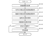
つぎに、図27を参照して図1に示す処理部244において実行される処理の一例について説明する。図27に示す処理が開始されると、以下のステップが実行される。 Next, an example of the processing executed by the processing unit 244 shown in FIG. 1 will be described with reference to FIG. 27. When the process shown in FIG. 27 is started, the following steps are executed.
ステップS90では、処理部241は、距離と周波数で定義づけられる信号情報を取得する。振幅情報によって対象物の1次的な検出を行う。 In step S90, the processing unit 241 acquires the signal information defined by the distance and the frequency. The primary detection of the object is performed by the amplitude information.
ステップS91では、処理部244は、水平方向検出部242の処理結果を取得する。より詳細には、処理部244は、水平方向検出部242から対象物の水平方向の角度を示す情報(方位角)を取得する。また、振幅情報によって対象物の2次的な検出を行う。
In step S91, the processing unit 244 acquires the processing result of the
ステップS92では、処理部244は、垂直方向検出部243から処理結果を取得する。より詳細には、処理部244は、垂直方向検出部243から対象物の垂直方向の角度を示す情報(仰俯角)を取得する。
In step S92, the processing unit 244 acquires the processing result from the
ステップS93では、処理部244は、処理部241における距離情報、水平方向検出部242からの方位角情報、垂直方向検出部243からの仰俯角情報から、センサないし自車から検出された信号の位置を特定する。
In step S93, the processing unit 244 positions the signal detected from the sensor or the own vehicle from the distance information in the processing unit 241, the azimuth angle information from the
ステップS94では、処理部244は、ステップS93で検出された信号の位置情報をもとにクラスタリング処理やトラッキング処理等を実施し、対象物の位置や速度の特定を行う。 In step S94, the processing unit 244 performs clustering processing, tracking processing, and the like based on the position information of the signal detected in step S93, and identifies the position and speed of the object.
ステップS95では、処理部244は、ステップS94で特定した対象物の位置や速度が所定の時間内に衝突の可能性がない安全な対象物か否かを判定し、安全と判定した場合(ステップS95:Y)には処理を終了し、それ以外の衝突の可能性がある場合(ステップS95:N)にはステップS96に進む。 In step S95, the processing unit 244 determines whether the position and speed of the object specified in step S94 is a safe object with no possibility of collision within a predetermined time, and determines that it is safe (step). The process ends in S95: Y), and if there is a possibility of a collision other than that (step S95: N), the process proceeds to step S96.
ステップS96では、処理部244は、対象物に衝突(または接触)する危険があることから、運転者に対して警告を発する処理を実行する。あるいは、処理部244における対象物の位置や速度情報を元に、上位装置であるECUにおいて上記処理、ないし、車両制御を行う。この結果、ECUは、警告音等によって衝突の可能性があることを通知したり、ECUがブレーキを動作させて停車させたりするようにしてもよい。 In step S96, the processing unit 244 executes a process of issuing a warning to the driver because there is a risk of collision (or contact) with the object. Alternatively, the ECU, which is a higher-level device, performs the above processing or vehicle control based on the position and speed information of the object in the processing unit 244. As a result, the ECU may notify that there is a possibility of collision by a warning sound or the like, or the ECU may operate the brake to stop the vehicle.
以上の処理によれば、前述した動作を実現することができる。 According to the above processing, the above-mentioned operation can be realized.
(C)変形実施形態の説明
以上の実施形態は一例であって、本発明が上述したような場合のみに限定されるものでないことはいうまでもない。例えば、以上の実施形態では、パルスPは、図22に示すように、6フィールドを有するとともに、各フィールドが5回のサンプリングを行うようにしたが、これ以外の数のフィールドを有するとともに、これ以外のサンプリング回数としてもよい。
(C) Description of Modified Embodiment The above embodiment is an example, and it goes without saying that the present invention is not limited to the cases described above. For example, in the above embodiment, as shown in FIG. 22, the pulse P has 6 fields and each field is sampled 5 times. However, the pulse P has a number of fields other than this, and this It may be the number of sampling times other than.
さらに、図2の例では、対象物O1,O2はともに地面に接地された状態としたが、例えば、図28に示すように、地面に接地されない対象物O3(例えば、中空に配置されたポール等)を検出対象とすることもできる。このような対象物O3の場合、第1指向特性を有する送信信号に対する第1反射信号は、第2指向特性を有する送信信号に対する第2反射信号の強度よりもおおむね同等ないし大きい(第1反射信号≧第2反射信号)。このような対象物O3の場合、仰俯角検出の結果、対象物が所定の高さ範囲と想定される場合には衝突の可能性があると判定すれば、図28に示す対象物O3への衝突も回避できる。またO4(例えば、上方に存在する橋桁等)を非検出対象とすることもできる。このような対象物O4の場合、第1指向特性を有する送信信号に対する第1反射信号は、第2指向特性を有する送信信号に対する第2反射信号の強度よりも大きい(第1反射信号>第2反射信号)。このような場合、仰俯角検出の結果、対象物が所定の高さ範囲以上と想定される場合には衝突の可能性がないため、警報や制御に反映する必要がない。このようにして、誤検出の虞を低減することができる。 Further, in the example of FIG. 2, both the objects O1 and O2 are in a state of being grounded to the ground, but as shown in FIG. 28, for example, the object O3 not to be grounded (for example, a pole arranged in the air). Etc.) can also be detected. In the case of such an object O3, the first reflected signal with respect to the transmitted signal having the first directivity is generally equal to or larger than the intensity of the second reflected signal with respect to the transmitted signal having the second directivity (first reflected signal). ≧ 2nd reflected signal). In the case of such an object O3, if it is determined as a result of the elevation / depression angle detection that there is a possibility of collision when the object is assumed to be in a predetermined height range, the object O3 shown in FIG. Collisions can also be avoided. Further, O4 (for example, a bridge girder existing above) can be a non-detection target. In the case of such an object O4, the first reflected signal for the transmitted signal having the first directivity characteristic is larger than the intensity of the second reflected signal for the transmitted signal having the second directivity characteristic (first reflected signal> second). Reflected signal). In such a case, if the object is assumed to be above a predetermined height range as a result of the elevation / depression angle detection, there is no possibility of collision, and it is not necessary to reflect it in the warning or control. In this way, the risk of erroneous detection can be reduced.
また、以上の実施形態では、2つの送信アンテナ16−1〜16−2から垂直方向の指向特性が異なる2種類の電磁波を送信するようにしたが、3つ以上の送信アンテナから垂直方向の指向特性が異なる3種類以上の電磁波を送信するようにしてもよい。 Further, in the above embodiment, two types of electromagnetic waves having different directivity in the vertical direction are transmitted from the two transmitting antennas 16-1 to 16-2, but the directivity in the vertical direction is transmitted from three or more transmitting antennas. Three or more types of electromagnetic waves having different characteristics may be transmitted.
また、以上の実施形態では、2つの特性が異なる送信アンテナ16−1〜16−2によって垂直方向の指向特性が異なる電磁波を送信するようにしたが、例えば、特性が変更できる送信アンテナを用いて、送信のたびに特性を変化させることで、垂直方向の指向特性が異なる複数の電磁波を送信するようにしてもよい。 Further, in the above embodiment, electromagnetic waves having different directivity in the vertical direction are transmitted by the transmitting antennas 16-1 to 16-2 having different two characteristics. For example, a transmitting antenna whose characteristics can be changed is used. , A plurality of electromagnetic waves having different directivity characteristics in the vertical direction may be transmitted by changing the characteristics each time the transmission is performed.
また、以上の実施形態では、送信アンテナ16−1〜16−2は2個とし、受信アンテナ17−1〜17−4を4個の2×4の構成としたが、これ以外のn×m(n,m>1)の構成としてもよい。 Further, in the above embodiment, the number of transmitting antennas 16-1 to 16-2 is two, and the number of receiving antennas 17-1 to 17-4 is four 2 × 4, but other n × m The configuration may be (n, m> 1).
また、以上の実施形態では、図9に示すパルスの繰り返し周期T0は固定としたが、例えば、繰り返し周期T0をサンプリング毎に変化させることで、その直前の繰り返し周期において送信されるパルスに対する反射信号による誤検出を防止するようにしてもよい。 Further, in the above embodiment, the pulse repetition cycle T0 shown in FIG. 9 is fixed, but for example, by changing the repetition cycle T0 for each sampling, a reflection signal for the pulse transmitted in the immediately preceding repetition cycle is obtained. It may be possible to prevent false detection due to.
また、以上の実施形態では、パルス方式に基づいて対象物を検出するようにしたが、例えば、FMCW(Frequency Modulated Continuous Wave)方式のレーダ装置に本発明を適用するようにしてもよい。また、複素信号ではなく実信号であってもよい。 Further, in the above embodiment, the object is detected based on the pulse method, but the present invention may be applied to, for example, an FMCW (Frequency Modulated Continuous Wave) type radar device. Further, it may be a real signal instead of a complex signal.
また、以上の実施形態では、給電線の長さを調整することで送信アンテナ16−1〜16−2の指向性を変更するようにしたが、これ以外にも、パッチアンテナの形状を変更したりするようにしてもよい。また素子アンテナは図示したようなパッチ形状に限るものではない。また、送信アンテナ、受信アンテナとも例示しているような中央から分岐した給電に限るものではなく、端から素子アンテナに対して直列に給電するもので構わない。また、図15、図18のように1列状の給電構成に限るものではない。 Further, in the above embodiment, the directivity of the transmitting antennas 16-1 to 16-2 is changed by adjusting the length of the feeder line, but in addition to this, the shape of the patch antenna is changed. You may try to do it. Further, the element antenna is not limited to the patch shape as shown in the figure. Further, both the transmitting antenna and the receiving antenna are not limited to the power feeding branched from the center as illustrated, and the feeding antenna may be fed in series from the end to the element antenna. Further, it is not limited to the one-row power supply configuration as shown in FIGS. 15 and 18.
また、以上の実施形態では、対象物からの反射信号の電力の比に基づいて高さを特定するようにしたが、例えば、反射信号の電力の差に基づいて高さを特定するようにしてもよい。また、電力次元でなく振幅次元であったり、厳密値でなく近似的な値であったりしても構わない。 Further, in the above embodiment, the height is specified based on the ratio of the electric power of the reflected signal from the object, but for example, the height is specified based on the difference in the electric power of the reflected signal. May be good. Further, it may be an amplitude dimension instead of a power dimension, or an approximate value instead of an exact value.
また、図1の例では、水平方向検出部242と垂直方向検出部243を直列に接続するようにしたが、図29に示すように、水平方向検出部242と垂直方向検出部243を並列に接続するようにしてもよい。このような構成によれば、例えば、図23における8アレイ角度FFT処理(P10)と、4アレイ角度FFT処理(P20,P21)と、を並列に処理することで、処理に要する時間を短縮することができる。なお、フーリエ変換として簡易で高速なFFT処理を例示したが、DFT(Discrete Fourier Transform)処理等や、高分解能処理であっても構わない。
Further, in the example of FIG. 1, the
また、以上の実施形態では、何らかのしきい値をもちい比較し、すべての信号のうち十分な振幅をもつデータのみに対して、対象物の候補となる信号として、好適な段階で絞る検出処理を例示したが、対象物の判定処理はこれらに限らず、任意の段階で入れることも可能である。 Further, in the above embodiment, a detection process is performed in which comparison is performed using some threshold value, and only data having a sufficient amplitude among all signals is narrowed down as a candidate signal for an object at an appropriate stage. As illustrated, the determination process of the object is not limited to these, and it is possible to insert it at any stage.
また、以上の実施形態では、車両として自動四輪車を例に挙げて説明したが、これ以外にも自動二輪車や自転車等を検出するようにしてもよい。すなわち、本明細書中において、車両とは自動四輪車には限定されない。 Further, in the above embodiment, the motorcycle has been described as an example of the vehicle, but other than this, a motorcycle, a bicycle, or the like may be detected. That is, in the present specification, the vehicle is not limited to the motorcycle.
また、以上の実施形態では、車両の後方にレーダ装置を搭載する場合を例に挙げて説明したが、前方に搭載するようにしてもよい。 Further, in the above embodiment, the case where the radar device is mounted at the rear of the vehicle has been described as an example, but the radar device may be mounted at the front.
また、以上の実施形態では、垂直方向に指向性が異なる複数の送信信号を異なるタイミングで送信し、受信電力の差異に基づいて対象物の垂直方向の位置を検出するようにしたが、垂直方向以外の所定の方向(例えば、水平方向等)に指向性が異なる複数の送信信号を異なるタイミングで送信し、受信電力の差異に基づいて対象物の所定の方向の位置を検出するようにしてもよい。 Further, in the above embodiment, a plurality of transmission signals having different directivity in the vertical direction are transmitted at different timings, and the position of the object in the vertical direction is detected based on the difference in the received power. Even if a plurality of transmission signals having different directivity are transmitted in a predetermined direction other than the predetermined direction (for example, a horizontal direction) at different timings and the position of the object in the predetermined direction is detected based on the difference in the received power. Good.
また、図24〜図27に示すフローチャートの処理は一例であって、本発明がこれらフローチャートの処理に限定されるものではないことはいうまでもない。 Further, it goes without saying that the processing of the flowcharts shown in FIGS. 24 to 27 is an example, and the present invention is not limited to the processing of these flowcharts.
10 レーダ装置
11 制御部
12 発振部
13 パルス整形部
14 可変増幅部
15 選択部
16−1〜16−2 送信アンテナ
17−1〜17−4 受信アンテナ
18 選択部
19 増幅部
20 乗算部
21 IF増幅部
22 A/D変換部
23 記憶部
24 演算部
241 処理部
242 水平方向検出部
243 垂直方向検出部
243a テーブル
244 処理部
10
Claims (8)
第1方向に列設された複数の受信アンテナと、
前記第1方向と略直交する第2方向について、互いに異なる指向特性を有する少なくとも2つの送信アンテナと、
前記第1方向について、前記対象物の存在する角度である第1角度を検出する第1角度検出手段と、
前記送信アンテナのそれぞれから送信され、前記受信アンテナで受信した受信信号の強度比に基づいて、前記第2方向について、前記対象物の存在する角度である第2角度を検出する第2角度検出手段と、
前記第1角度検出手段で検出されうる各前記第1角度に応じた、前記強度比と前記第2角度との関係を示す複数のテーブルを記憶する記憶手段と、を有し、
前記第2角度検出手段は、前記第1角度検出手段で検出された前記第1角度に応じた前記テーブルを参照して前記第2角度を検出する、
ことを特徴とするレーダ装置。 In a radar device that detects an object
Multiple receiving antennas arranged in a row in the first direction,
At least two transmitting antennas having different directivities in the second direction, which is substantially orthogonal to the first direction,
With respect to the first direction, a first angle detecting means for detecting a first angle which is an angle at which the object exists, and
A second angle detecting means for detecting a second angle, which is an angle at which the object exists, in the second direction based on the intensity ratio of the received signal transmitted from each of the transmitting antennas and received by the receiving antenna. When,
It has a storage means for storing a plurality of tables showing the relationship between the intensity ratio and the second angle according to each of the first angles that can be detected by the first angle detecting means.
The second angle detecting means detects the second angle with reference to the table corresponding to the first angle detected by the first angle detecting means.
A radar device characterized by that.
ことを特徴とする請求項1に記載のレーダ装置。 The first angle detecting means detects the first angle of the object based on the angle spectrum of the received signal acquired by the Fourier transform.
The radar device according to claim 1.
前記第2角度検出手段は、各々の前記送信アンテナから順次送信され、前記受信アンテナで受信した各々の前記受信信号に基づいて前記第2角度を検出する、
ことを特徴とする請求項1または2に記載のレーダ装置。 The first angle detecting means detects the first angle based on all the received signals that are sequentially transmitted from each of the transmitting antennas and received by the receiving antenna.
The second angle detecting means sequentially transmits from each of the transmitting antennas and detects the second angle based on each of the received signals received by the receiving antenna.
The radar device according to claim 1 or 2.
前記第2角度検出手段は、各々の前記送信アンテナから順次送信され、前記受信アンテナで受信した各々の前記受信信号に対して角度を求めるフーリエ変換処理を実行し、前記第1角度検出手段によって検出された前記ピークとなる位置に対応する前記第1角度における前記強度比を検出する、
ことを特徴とする請求項3に記載のレーダ装置。 The first angle detecting means sequentially transmits from each of the transmitting antennas, executes a process of obtaining an angle for all the received signals received by the receiving antenna, and is based on a position at which a peak of the processing result is obtained. The first angle is detected,
The second angle detecting means sequentially transmits from each of the transmitting antennas, executes a Fourier transform process for obtaining an angle with respect to each of the received signals received by the receiving antenna, and detects by the first angle detecting means. The intensity ratio at the first angle corresponding to the peak position is detected.
The radar device according to claim 3, wherein the radar device is characterized.
前記レーダ装置は、車両に搭載されることを特徴とする請求項1乃至4のいずれか1項に記載のレーダ装置。 The first direction is a substantially horizontal direction.
The radar device according to any one of claims 1 to 4, wherein the radar device is mounted on a vehicle.
ことを特徴とする請求項5に記載のレーダ装置。 The transmitting antenna and the receiving antenna are each composed of a plurality of element antennas, and the number of the element antennas constituting one transmitting antenna is smaller than the number of the element antennas constituting one receiving antenna.
The radar device according to claim 5.
前記送信アンテナに最も近接する前記素子アンテナに供給される電力は、他の前記複数の素子アンテナに供給される電力以下である、
ことを特徴とする請求項6に記載のレーダ装置。 The receiving antenna has a plurality of element antennas adjacent to each other, including the element antenna closest to the transmitting antenna.
The power supplied to the element antenna closest to the transmitting antenna is less than or equal to the power supplied to the other plurality of element antennas.
The radar device according to claim 6, wherein the radar device is characterized.
前記第1方向について、前記対象物の存在する角度である第1角度を検出する第1角度検出ステップと、
前記送信アンテナのそれぞれから送信され、前記受信アンテナで受信した受信信号の強度比に基づいて、前記第2方向について、前記対象物の存在する角度である第2角度を検出する第2角度検出ステップと、
前記第1角度検出ステップにおいて検出されうる各前記第1角度に応じた、前記強度比と前記第2角度との関係を示す複数のテーブルを記憶する記憶ステップと、を有し、
前記第2角度検出ステップは、前記第1角度検出ステップで検出された前記第1角度に応じた前記テーブルを参照して前記第2角度を検出する、
ことを特徴とするレーダ装置の対象物検出方法。 In the object detection method of a radar device having a plurality of receiving antennas arranged in a row in the first direction and at least two transmitting antennas having different directivity characteristics in the second direction substantially orthogonal to the first direction.
A first angle detection step for detecting a first angle, which is an angle at which the object exists, in the first direction.
A second angle detection step of detecting a second angle, which is an angle at which the object exists, in the second direction based on the intensity ratio of the received signal transmitted from each of the transmitting antennas and received by the receiving antenna. When,
It has a storage step for storing a plurality of tables showing the relationship between the intensity ratio and the second angle according to each of the first angles that can be detected in the first angle detection step.
The second angle detection step detects the second angle with reference to the table corresponding to the first angle detected in the first angle detection step.
An object detection method for a radar device, characterized in that.
Priority Applications (1)
| Application Number | Priority Date | Filing Date | Title |
|---|---|---|---|
| JP2019118589A JP7306891B2 (en) | 2019-06-26 | 2019-06-26 | RADAR DEVICE AND OBJECT DETECTION METHOD FOR RADAR DEVICE |
Applications Claiming Priority (1)
| Application Number | Priority Date | Filing Date | Title |
|---|---|---|---|
| JP2019118589A JP7306891B2 (en) | 2019-06-26 | 2019-06-26 | RADAR DEVICE AND OBJECT DETECTION METHOD FOR RADAR DEVICE |
Publications (2)
| Publication Number | Publication Date |
|---|---|
| JP2021004792A true JP2021004792A (en) | 2021-01-14 |
| JP7306891B2 JP7306891B2 (en) | 2023-07-11 |
Family
ID=74098143
Family Applications (1)
| Application Number | Title | Priority Date | Filing Date |
|---|---|---|---|
| JP2019118589A Active JP7306891B2 (en) | 2019-06-26 | 2019-06-26 | RADAR DEVICE AND OBJECT DETECTION METHOD FOR RADAR DEVICE |
Country Status (1)
| Country | Link |
|---|---|
| JP (1) | JP7306891B2 (en) |
Citations (8)
| Publication number | Priority date | Publication date | Assignee | Title |
|---|---|---|---|---|
| JPH0511043A (en) * | 1991-06-28 | 1993-01-19 | Nec Corp | Monopulse type rader angle measuring device |
| JP2008151582A (en) * | 2006-12-15 | 2008-07-03 | Denso Corp | Radar system |
| JP2013250226A (en) * | 2012-06-04 | 2013-12-12 | National Univ Corp Shizuoka Univ | Direction measuring apparatus and direction measuring method |
| JP2014529076A (en) * | 2011-09-09 | 2014-10-30 | アスティックス ゲゼルシャフト ミット ベシュレンクテル ハフツング | Imaging radar sensor with synthetic aperture expansion and two-dimensional beam sweep |
| JP2015528111A (en) * | 2012-06-25 | 2015-09-24 | オートリブ エー・エス・ピー・インク | 2-channel monopulse radar for 3D detection |
| DE102016205227A1 (en) * | 2016-03-30 | 2017-10-05 | Astyx Gmbh | Method and device for tracking objects, in particular moving objects, in the three-dimensional space of imaging radar sensors |
| WO2018108359A1 (en) * | 2016-12-14 | 2018-06-21 | Robert Bosch Gmbh | Mimo radar sensor for motor vehicles |
| JP2019500593A (en) * | 2015-11-19 | 2019-01-10 | コンティ テミック マイクロエレクトロニック ゲゼルシャフト ミット ベシュレンクテル ハフツングConti Temic microelectronic GmbH | Radar system with nested serial transmission and parallel reception |
-
2019
- 2019-06-26 JP JP2019118589A patent/JP7306891B2/en active Active
Patent Citations (8)
| Publication number | Priority date | Publication date | Assignee | Title |
|---|---|---|---|---|
| JPH0511043A (en) * | 1991-06-28 | 1993-01-19 | Nec Corp | Monopulse type rader angle measuring device |
| JP2008151582A (en) * | 2006-12-15 | 2008-07-03 | Denso Corp | Radar system |
| JP2014529076A (en) * | 2011-09-09 | 2014-10-30 | アスティックス ゲゼルシャフト ミット ベシュレンクテル ハフツング | Imaging radar sensor with synthetic aperture expansion and two-dimensional beam sweep |
| JP2013250226A (en) * | 2012-06-04 | 2013-12-12 | National Univ Corp Shizuoka Univ | Direction measuring apparatus and direction measuring method |
| JP2015528111A (en) * | 2012-06-25 | 2015-09-24 | オートリブ エー・エス・ピー・インク | 2-channel monopulse radar for 3D detection |
| JP2019500593A (en) * | 2015-11-19 | 2019-01-10 | コンティ テミック マイクロエレクトロニック ゲゼルシャフト ミット ベシュレンクテル ハフツングConti Temic microelectronic GmbH | Radar system with nested serial transmission and parallel reception |
| DE102016205227A1 (en) * | 2016-03-30 | 2017-10-05 | Astyx Gmbh | Method and device for tracking objects, in particular moving objects, in the three-dimensional space of imaging radar sensors |
| WO2018108359A1 (en) * | 2016-12-14 | 2018-06-21 | Robert Bosch Gmbh | Mimo radar sensor for motor vehicles |
Also Published As
| Publication number | Publication date |
|---|---|
| JP7306891B2 (en) | 2023-07-11 |
Similar Documents
| Publication | Publication Date | Title |
|---|---|---|
| US11874363B2 (en) | Radar apparatus and antenna apparatus therefor | |
| US11422254B2 (en) | Radar sensor apparatus for vehicle, object detecting method, and antenna apparatus therefor | |
| US11796662B2 (en) | Radar apparatus and antenna apparatus therefor | |
| US10775491B2 (en) | Radar apparatus with multi-input multi-output antenna | |
| US20180151961A1 (en) | Radar apparatus and antenna apparatus therefor | |
| US6246359B1 (en) | Radar | |
| CN108885254B (en) | Object detection device | |
| US20080100499A1 (en) | Radar Target Detection Method and Radar Apparatus Using the Same | |
| US11342684B2 (en) | Dual edge-fed slotted waveguide antenna for millimeter wave applications | |
| US20220236407A1 (en) | Radar device and antenna device therefor | |
| US20150084810A1 (en) | Phased array radar with monopulse algorithm measurement | |
| JP4984705B2 (en) | Radar | |
| JP2019120514A (en) | Radar device and target detection method of radar device | |
| JP7188448B2 (en) | Antenna device, moving object, and target discrimination method | |
| US11802960B2 (en) | Phase correcting apparatus and method of transmission signal of vehicle radar, and vehicle radar apparatus with the same | |
| CN115728722A (en) | Antenna array of 4D radar, data detection method and 4D radar | |
| KR102667977B1 (en) | Radar Apparatus for Vehicle and Controlling Method thereof | |
| JP7306891B2 (en) | RADAR DEVICE AND OBJECT DETECTION METHOD FOR RADAR DEVICE | |
| KR20220089824A (en) | Smart sensor device for detecting obstacles in mobile devices | |
| JP7061534B2 (en) | Radar device | |
| JP4390916B2 (en) | Scanning radar equipment | |
| TWI808874B (en) | Radar system for vehicle and detecting method | |
| US20240176007A1 (en) | Dual polarization radar | |
| US20240145914A1 (en) | 3d antenna radar device, angle detection system and angle detection method | |
| WO2023218632A1 (en) | Radar device and target detection method |
Legal Events
| Date | Code | Title | Description |
|---|---|---|---|
| RD03 | Notification of appointment of power of attorney |
Free format text: JAPANESE INTERMEDIATE CODE: A7423 Effective date: 20200117 |
|
| A521 | Request for written amendment filed |
Free format text: JAPANESE INTERMEDIATE CODE: A523 Effective date: 20200302 |
|
| A621 | Written request for application examination |
Free format text: JAPANESE INTERMEDIATE CODE: A621 Effective date: 20220120 |
|
| A977 | Report on retrieval |
Free format text: JAPANESE INTERMEDIATE CODE: A971007 Effective date: 20221109 |
|
| A131 | Notification of reasons for refusal |
Free format text: JAPANESE INTERMEDIATE CODE: A131 Effective date: 20221206 |
|
| A521 | Request for written amendment filed |
Free format text: JAPANESE INTERMEDIATE CODE: A523 Effective date: 20230206 |
|
| A131 | Notification of reasons for refusal |
Free format text: JAPANESE INTERMEDIATE CODE: A131 Effective date: 20230418 |
|
| A521 | Request for written amendment filed |
Free format text: JAPANESE INTERMEDIATE CODE: A523 Effective date: 20230605 |
|
| TRDD | Decision of grant or rejection written | ||
| A01 | Written decision to grant a patent or to grant a registration (utility model) |
Free format text: JAPANESE INTERMEDIATE CODE: A01 Effective date: 20230613 |
|
| A61 | First payment of annual fees (during grant procedure) |
Free format text: JAPANESE INTERMEDIATE CODE: A61 Effective date: 20230629 |
|
| R151 | Written notification of patent or utility model registration |
Ref document number: 7306891 Country of ref document: JP Free format text: JAPANESE INTERMEDIATE CODE: R151 |