JP2020531376A - Can end with imprinted rivets, tooling assembly and forming method for it - Google Patents
Can end with imprinted rivets, tooling assembly and forming method for it Download PDFInfo
- Publication number
- JP2020531376A JP2020531376A JP2020511281A JP2020511281A JP2020531376A JP 2020531376 A JP2020531376 A JP 2020531376A JP 2020511281 A JP2020511281 A JP 2020511281A JP 2020511281 A JP2020511281 A JP 2020511281A JP 2020531376 A JP2020531376 A JP 2020531376A
- Authority
- JP
- Japan
- Prior art keywords
- rivet
- imprinted
- button
- tab
- tooling assembly
- Prior art date
- Legal status (The legal status is an assumption and is not a legal conclusion. Google has not performed a legal analysis and makes no representation as to the accuracy of the status listed.)
- Pending
Links
- 238000000034 method Methods 0.000 title claims abstract description 35
- 239000000463 material Substances 0.000 claims description 46
- 230000002093 peripheral effect Effects 0.000 claims description 26
- 230000008878 coupling Effects 0.000 claims description 21
- 238000010168 coupling process Methods 0.000 claims description 21
- 238000005859 coupling reaction Methods 0.000 claims description 21
- 230000008569 process Effects 0.000 claims description 17
- 238000000465 moulding Methods 0.000 claims description 10
- 230000002829 reductive effect Effects 0.000 claims description 10
- 238000000429 assembly Methods 0.000 abstract description 9
- 230000000712 assembly Effects 0.000 abstract description 9
- 238000010586 diagram Methods 0.000 abstract 1
- 229910052751 metal Inorganic materials 0.000 description 17
- 239000002184 metal Substances 0.000 description 17
- 238000006243 chemical reaction Methods 0.000 description 11
- 229910000831 Steel Inorganic materials 0.000 description 7
- 235000013361 beverage Nutrition 0.000 description 7
- 239000010959 steel Substances 0.000 description 7
- 229910052782 aluminium Inorganic materials 0.000 description 6
- XAGFODPZIPBFFR-UHFFFAOYSA-N aluminium Chemical compound [Al] XAGFODPZIPBFFR-UHFFFAOYSA-N 0.000 description 6
- 230000015572 biosynthetic process Effects 0.000 description 6
- 230000014509 gene expression Effects 0.000 description 5
- 125000006850 spacer group Chemical group 0.000 description 5
- 238000002788 crimping Methods 0.000 description 3
- 230000000670 limiting effect Effects 0.000 description 3
- 230000036961 partial effect Effects 0.000 description 3
- 230000007704 transition Effects 0.000 description 3
- 229910045601 alloy Inorganic materials 0.000 description 2
- 239000000956 alloy Substances 0.000 description 2
- 238000005304 joining Methods 0.000 description 2
- 238000005259 measurement Methods 0.000 description 2
- 235000014347 soups Nutrition 0.000 description 2
- 229910000838 Al alloy Inorganic materials 0.000 description 1
- 229910000851 Alloy steel Inorganic materials 0.000 description 1
- CDBYLPFSWZWCQE-UHFFFAOYSA-L Sodium Carbonate Chemical compound [Na+].[Na+].[O-]C([O-])=O CDBYLPFSWZWCQE-UHFFFAOYSA-L 0.000 description 1
- 235000013405 beer Nutrition 0.000 description 1
- 230000008901 benefit Effects 0.000 description 1
- 235000014171 carbonated beverage Nutrition 0.000 description 1
- 230000008859 change Effects 0.000 description 1
- 239000011248 coating agent Substances 0.000 description 1
- 238000000576 coating method Methods 0.000 description 1
- 230000003247 decreasing effect Effects 0.000 description 1
- 238000004049 embossing Methods 0.000 description 1
- 235000013305 food Nutrition 0.000 description 1
- 230000005484 gravity Effects 0.000 description 1
- 238000007689 inspection Methods 0.000 description 1
- 238000004519 manufacturing process Methods 0.000 description 1
- 239000007769 metal material Substances 0.000 description 1
- 150000002739 metals Chemical class 0.000 description 1
- 230000004048 modification Effects 0.000 description 1
- 238000012986 modification Methods 0.000 description 1
- 230000000704 physical effect Effects 0.000 description 1
- 230000004044 response Effects 0.000 description 1
- 230000002441 reversible effect Effects 0.000 description 1
- 238000004381 surface treatment Methods 0.000 description 1
Images


Classifications
-
- B—PERFORMING OPERATIONS; TRANSPORTING
- B21—MECHANICAL METAL-WORKING WITHOUT ESSENTIALLY REMOVING MATERIAL; PUNCHING METAL
- B21D—WORKING OR PROCESSING OF SHEET METAL OR METAL TUBES, RODS OR PROFILES WITHOUT ESSENTIALLY REMOVING MATERIAL; PUNCHING METAL
- B21D51/00—Making hollow objects
- B21D51/16—Making hollow objects characterised by the use of the objects
- B21D51/38—Making inlet or outlet arrangements of cans, tins, baths, bottles, or other vessels; Making can ends; Making closures
- B21D51/383—Making inlet or outlet arrangements of cans, tins, baths, bottles, or other vessels; Making can ends; Making closures scoring lines, tear strips or pulling tabs
-
- B—PERFORMING OPERATIONS; TRANSPORTING
- B21—MECHANICAL METAL-WORKING WITHOUT ESSENTIALLY REMOVING MATERIAL; PUNCHING METAL
- B21D—WORKING OR PROCESSING OF SHEET METAL OR METAL TUBES, RODS OR PROFILES WITHOUT ESSENTIALLY REMOVING MATERIAL; PUNCHING METAL
- B21D51/00—Making hollow objects
- B21D51/16—Making hollow objects characterised by the use of the objects
- B21D51/26—Making hollow objects characterised by the use of the objects cans or tins; Closing same in a permanent manner
-
- B—PERFORMING OPERATIONS; TRANSPORTING
- B21—MECHANICAL METAL-WORKING WITHOUT ESSENTIALLY REMOVING MATERIAL; PUNCHING METAL
- B21D—WORKING OR PROCESSING OF SHEET METAL OR METAL TUBES, RODS OR PROFILES WITHOUT ESSENTIALLY REMOVING MATERIAL; PUNCHING METAL
- B21D22/00—Shaping without cutting, by stamping, spinning, or deep-drawing
- B21D22/02—Stamping using rigid devices or tools
- B21D22/04—Stamping using rigid devices or tools for dimpling
-
- B—PERFORMING OPERATIONS; TRANSPORTING
- B21—MECHANICAL METAL-WORKING WITHOUT ESSENTIALLY REMOVING MATERIAL; PUNCHING METAL
- B21D—WORKING OR PROCESSING OF SHEET METAL OR METAL TUBES, RODS OR PROFILES WITHOUT ESSENTIALLY REMOVING MATERIAL; PUNCHING METAL
- B21D22/00—Shaping without cutting, by stamping, spinning, or deep-drawing
- B21D22/02—Stamping using rigid devices or tools
- B21D22/06—Stamping using rigid devices or tools having relatively-movable die parts
-
- B—PERFORMING OPERATIONS; TRANSPORTING
- B21—MECHANICAL METAL-WORKING WITHOUT ESSENTIALLY REMOVING MATERIAL; PUNCHING METAL
- B21D—WORKING OR PROCESSING OF SHEET METAL OR METAL TUBES, RODS OR PROFILES WITHOUT ESSENTIALLY REMOVING MATERIAL; PUNCHING METAL
- B21D39/00—Application of procedures in order to connect objects or parts, e.g. coating with sheet metal otherwise than by plating; Tube expanders
- B21D39/03—Application of procedures in order to connect objects or parts, e.g. coating with sheet metal otherwise than by plating; Tube expanders of sheet metal otherwise than by folding
- B21D39/031—Joining superposed plates by locally deforming without slitting or piercing
- B21D39/032—Joining superposed plates by locally deforming without slitting or piercing by fitting a projecting part integral with one plate in a hole of the other plate
-
- B—PERFORMING OPERATIONS; TRANSPORTING
- B21—MECHANICAL METAL-WORKING WITHOUT ESSENTIALLY REMOVING MATERIAL; PUNCHING METAL
- B21D—WORKING OR PROCESSING OF SHEET METAL OR METAL TUBES, RODS OR PROFILES WITHOUT ESSENTIALLY REMOVING MATERIAL; PUNCHING METAL
- B21D51/00—Making hollow objects
- B21D51/02—Making hollow objects characterised by the structure of the objects
- B21D51/10—Making hollow objects characterised by the structure of the objects conically or cylindrically shaped objects
-
- B—PERFORMING OPERATIONS; TRANSPORTING
- B21—MECHANICAL METAL-WORKING WITHOUT ESSENTIALLY REMOVING MATERIAL; PUNCHING METAL
- B21D—WORKING OR PROCESSING OF SHEET METAL OR METAL TUBES, RODS OR PROFILES WITHOUT ESSENTIALLY REMOVING MATERIAL; PUNCHING METAL
- B21D51/00—Making hollow objects
- B21D51/16—Making hollow objects characterised by the use of the objects
- B21D51/38—Making inlet or outlet arrangements of cans, tins, baths, bottles, or other vessels; Making can ends; Making closures
-
- B—PERFORMING OPERATIONS; TRANSPORTING
- B65—CONVEYING; PACKING; STORING; HANDLING THIN OR FILAMENTARY MATERIAL
- B65D—CONTAINERS FOR STORAGE OR TRANSPORT OF ARTICLES OR MATERIALS, e.g. BAGS, BARRELS, BOTTLES, BOXES, CANS, CARTONS, CRATES, DRUMS, JARS, TANKS, HOPPERS, FORWARDING CONTAINERS; ACCESSORIES, CLOSURES, OR FITTINGS THEREFOR; PACKAGING ELEMENTS; PACKAGES
- B65D17/00—Rigid or semi-rigid containers specially constructed to be opened by cutting or piercing, or by tearing of frangible members or portions
- B65D17/28—Rigid or semi-rigid containers specially constructed to be opened by cutting or piercing, or by tearing of frangible members or portions at lines or points of weakness
- B65D17/40—Rigid or semi-rigid containers specially constructed to be opened by cutting or piercing, or by tearing of frangible members or portions at lines or points of weakness characterised by having the line of weakness extending circumferentially of the container mouth
-
- B—PERFORMING OPERATIONS; TRANSPORTING
- B65—CONVEYING; PACKING; STORING; HANDLING THIN OR FILAMENTARY MATERIAL
- B65D—CONTAINERS FOR STORAGE OR TRANSPORT OF ARTICLES OR MATERIALS, e.g. BAGS, BARRELS, BOTTLES, BOXES, CANS, CARTONS, CRATES, DRUMS, JARS, TANKS, HOPPERS, FORWARDING CONTAINERS; ACCESSORIES, CLOSURES, OR FITTINGS THEREFOR; PACKAGING ELEMENTS; PACKAGES
- B65D17/00—Rigid or semi-rigid containers specially constructed to be opened by cutting or piercing, or by tearing of frangible members or portions
- B65D17/28—Rigid or semi-rigid containers specially constructed to be opened by cutting or piercing, or by tearing of frangible members or portions at lines or points of weakness
- B65D17/34—Arrangement or construction of pull or lift tabs
Abstract
【解決手段】缶エンド10は、中央パネルと、中央パネル30に配置された圧印加工リベット12とを含む。圧印加工リベット12を形成するように構成されたプレス500、ステーション502、及び/又はツーリングアセンブリ550、552、並びに圧印加工リベット12を形成する方法も提供される。【選択図】図1A can end 10 includes a central panel and imprinted rivets 12 arranged on the central panel 30. Also provided are press 500, station 502, and / or tooling assemblies 550, 552 configured to form imprinted rivets 12, and methods of forming imprinted rivets 12. [Selection diagram] Fig. 1
Description
<関連出願の相互参照>
本願は、2017年8月23日に出願された米国特許出願第15/683,803号の利益を主張し、当該特許出願は、参照により本明細書の一部となる。
<Cross-reference of related applications>
The present application claims the benefit of US Patent Application No. 15 / 683,803 filed on August 23, 2017, which patent application is incorporated herein by reference.
開示且つ特許請求される概念は缶エンドに関しており、より具体的には、圧印加工(coined)リベットへと成形されるシート材料から作製される缶エンドに関する。開示される概念はまた、そのような缶エンドを提供するためのツーリングアセンブリ及び方法に関する。 The disclosed and claimed concept relates to a can end, more specifically to a can end made from a sheet material formed into coined rivets. The disclosed concepts also relate to tooling assemblies and methods for providing such can ends.
金属製容器(例えば、缶)は、製品、限定ではないが、食品や飲料を保持するように構成されている。一般に、金属製容器は、缶ボディ及び缶エンドを含む。例示的な実施形態では、缶ボディは、ベースと付随する側壁とを含む。缶ボディは、一端が開いている概ね閉じた空間を規定する。缶ボディは製品で満たされ、缶エンドはその後、開放端にて缶ボディに結合する。容器は、場合によっては加熱されて、その中身が調理及び/又は滅菌される。このプロセスは、容器の内圧を上昇させる。更に、容器は、場合によっては、加圧製品、限定ではないが例えば炭酸飲料を含む。故に、様々な理由から、容器は最小限の強度を有する必要がある。 Metal containers (eg, cans) are configured to hold products, but not limited to food and beverages. Generally, the metal container includes a can body and a can end. In an exemplary embodiment, the can body includes a base and an accompanying side wall. The can body defines a generally closed space with one end open. The can body is filled with the product and the can end is then coupled to the can body at the open end. The container is optionally heated and its contents are cooked and / or sterilized. This process raises the internal pressure of the container. In addition, the container may optionally include pressurized products, such as, but not limited to, sparkling beverages. Therefore, for various reasons, the container needs to have minimal strength.
一般に、容器の強度は、缶ボディと、缶エンドを形成する金属の厚さと、これら要素の形状とに関連している。本願は、缶ボディではなくて缶エンドを主に取り扱う。缶エンドは、ティアパネル及びタブを含む「イージーオープン(easy open)」エンドである。ティアパネルは、缶エンドの外面(本明細書では、「公側(public side)」として特定される)にあるスコア形状、即ちスコアラインによって規定される。タブは、ティアパネルに隣接して取り付けられる(例えば、限定されないが、リベット留めされる)。プルタブは、持ち上げられて及び/又は引っ張られてスコアラインを切断して、切断可能なパネルを反して及び/又は除去して、それにより、容器の中身を出すための開口を生じるように構成されている。 In general, the strength of the container is related to the thickness of the metal forming the can body and the can end and the shape of these elements. The present application mainly deals with the can end, not the can body. The can end is an "easy open" end that includes tier panels and tabs. The tier panel is defined by a score shape, or score line, on the outer surface of the can end (referred to herein as the "public side"). The tabs are mounted adjacent to the tier panel (eg, but not limited to riveting). The pull tab is configured to be lifted and / or pulled to cut the scoreline and to distort and / or remove the cutable panel, thereby creating an opening for the contents of the container. ing.
缶エンドが作られる場合、それは、ブランクを元にしており、ブランクは、金属シート製品(例えば、限定ではないが、アルミニウムシートや鋼シート)から切り取られる。本明細書では、「ブランク」は、製品に成形される一切れの材料である。「ブランク」という用語は、全ての成形工程が完了するまで、一切れの材料に適用される。例示的な実施形態では、ブランクは、シェルプレスにおいて「シェル(shell)」に成形される。本明細書では、「シェル」又は「初期缶エンド(preliminary can end)」は、ほぼ平らなブランクを元にする構造であって、スコアリング、パネリング(paneling)、リベット形成、タブかしめ以外の成形工程に加えて、既知のステーションを施される。シェルプレスは、幾つかのツールステーションを含んでおり、各ステーションが成形工程を実行する(成形工程を実行しないヌルステーションを含んでいてもよい)。ブランクは、一連のステーションを移動して、「シェル」に成形される。つまり、非限定的な例では、最初のステーションはブランクをシート材料から切り取り、2番目のステーションは、ブランクを付随側壁のあるカップ状構造に成形し、3番目のステーションは、付随側壁をカウンターシンク、チャック側壁等に成形する。 When a can end is made, it is based on a blank, which is cut from a metal sheet product (eg, but not limited to an aluminum sheet or steel sheet). As used herein, a "blank" is a piece of material that is molded into a product. The term "blank" applies to a piece of material until the entire molding process is complete. In an exemplary embodiment, the blank is formed into a "shell" in a shell press. As used herein, a "shell" or "preliminary can end" is a structure based on a nearly flat blank, which is a molding other than scoring, paneling, riveting, and tab caulking. In addition to the process, known stations are applied. The shell press includes several tool stations, each of which performs a molding process (may include a null station that does not perform a molding process). The blank moves through a series of stations and is formed into a "shell". That is, in a non-limiting example, the first station cuts the blank from the sheet material, the second station forms the blank into a cup-like structure with ancillary sidewalls, and the third station countersinks the ancillary sidewalls. , Chuck side wall, etc.
「イージーオープン」エンドでは、シェルは更に、コンバージョンプレスに送られる。コンバージョンプレスはまた、連続した幾つかのツールステーションを有する。あるツールステーションから次のステーションへとシェルが進むと、リベット成形、パネリング、スコアリング、エンボス加工やタブかしめ(即ち、リベットを介してタブをシェルに結合)などの変換工程が実行され、シェルが目的の缶エンドに完全に変換されて、プレスから排出される。更に、リベットを作って、それにタブを結合するプロセスは、米国特許第4,145,801号に開示されており、米国特許第4,145,801号の好ましい実施形態の説明は、参照によって本明細書の一部となる。 At the "easy open" end, the shell is also sent to the conversion press. The conversion press also has several consecutive tool stations. As the shell progresses from one tool station to the next, conversion processes such as riveting, paneling, scoring, embossing and tab caulking (ie, joining tabs to the shell via rivets) are performed and the shell It is completely converted to the desired can end and discharged from the press. Further, the process of creating rivets and attaching tabs to them is disclosed in US Pat. No. 4,145,801, and a description of preferred embodiments of US Pat. No. 4,145,801 is provided by reference. Be part of the specification.
製缶業界では、相当な量の缶を製造するために大量の金属が必要とされている。故に、業界における恒常的な目標は、消費される金属の量を減らすことである。従って、缶エンド、タブ及び缶ボディを作る素材の厚さ、即ちゲージを減らすための努力(「ダウンゲージング(down-gauging)」と称されることもある)が常時行われている。現在、缶エンドは、金属シートから、例えば、限定ではないがアルミニウム、鋼やそれらの金属を含む合金などから作製されている。これらの材料の最小のベース厚さは0.0082インチである。これは問題であって、ベース厚さが薄い金属材料を使用することで、この問題は解決するであろう。 The can manufacturing industry requires large amounts of metal to produce significant quantities of cans. Therefore, the constant goal in the industry is to reduce the amount of metal consumed. Therefore, efforts are constantly being made to reduce the thickness of the material that makes up the can end, tabs and can body, i.e. the gauge (sometimes referred to as "down-gauging"). Currently, can ends are made from metal sheets, such as, but not limited to, aluminum, steel and alloys containing those metals. The minimum base thickness for these materials is 0.0082 inches. This is a problem, and using a metal material with a thin base thickness will solve this problem.
ベース厚さがより薄い材料を使用することは、しかしながら、他の問題、例えば限定ではないが、リベットでの缶エンドの破損を起こす。即ち、ベース厚さが0.0082インチ未満の材料で形成されたリベットは、缶エンドにタブに保持できない。これは問題である。 The use of materials with a thinner base, however, causes other problems, such as, but not limited to, breakage of the can end at the rivet. That is, rivets made of material with a base thickness of less than 0.0082 inches cannot be held on tabs at the can end. This is a problem.
或いは、ベース厚さが厚い材料を薄くして、ベース厚さよりも薄いように、最終的な厚さを薄く又は部分的に薄くすることができる。しかしながら、使用する材料が少なくなると(例えば、ゲージがより薄い)、独自の解決策の開発が必要とされることが問題となる。更に、缶ボディ及び缶エンドを形成するプロセスは材料に応力を引き起こし、それによって、その形成中に缶ボディ又は缶エンドを損傷させる。 Alternatively, the material with a thick base can be thinned to make the final thickness thinner or partially thinner so that it is thinner than the base thickness. However, as less material is used (eg, thinner gauges), the problem is that unique solutions need to be developed. In addition, the process of forming the can body and can end causes stress on the material, thereby damaging the can body or can end during its formation.
薄い金属の使用に関連する問題に対する1つの解決策は、缶エンドに強化構造を設けることある。例えば、米国特許第5,755,134号に開示されているように、リベットを作るプロセスは、リベットを形成する前に、ほぼ平らなブランクにバブル(bubble)を形成することを含む。米国特許第5,755,134号に述べられているように、バブルを形成することは、「十分な金属をエンドパネルからバブルへと移動させて、後続の工程でリベットを形成できるようにすること」を含んでいる。つまり、成形工程中と成形工程後の両方でリベットの強度を高めるために、リベットになる領域に金属が押し出される。言い換えると、リベットとなる領域においてブランクのベース厚さは大きくされる。リベットになる領域においてベース厚さを増すことは、缶エンドの他の領域の厚さを減らすことを意味する。これは問題である。 One solution to the problem associated with the use of thin metal is to provide a reinforced structure at the can end. For example, as disclosed in US Pat. No. 5,755,134, the process of making rivets involves forming bubbles in a nearly flat blank before forming rivets. As stated in U.S. Pat. No. 5,755,134, forming a bubble "allows sufficient metal to move from the end panel to the bubble so that rivets can be formed in subsequent steps. That ”is included. That is, the metal is extruded into the rivet region in order to increase the strength of the rivet both during and after the molding process. In other words, the base thickness of the blank is increased in the rivet area. Increasing the base thickness in the area to be riveted means decreasing the thickness in the other areas of the can end. This is a problem.
更に、かしめる前において、公知のリベットボタンの断面形状はテーパー状である。このような形状のリベットボタンをかしめると、リベットボタンが不均一に潰れやすくなる。つまり、リベットの一部が、ある方向よりも別の方向について、タブにわたってより伸びることが起こり得る。これは問題である。 Further, before caulking, the known cross-sectional shape of the rivet button is tapered. When the rivet button having such a shape is crimped, the rivet button tends to be crushed unevenly. That is, it is possible that some of the rivets will extend more across the tabs in one direction than in another. This is a problem.
故に、缶エンドの他の領域における材料の厚さを減少させない缶エンドリベットが必要である。更に、缶エンドを作るために使用される材料の総量を減らすために、リベットにおける材料の量を減らす必要がある。更に、ベースの厚さが0.0082インチ未満である材料から缶エンドを形成する必要がある。 Therefore, there is a need for can end rivets that do not reduce the thickness of the material in other areas of the can end. In addition, the amount of material in the rivets needs to be reduced in order to reduce the total amount of material used to make the can end. In addition, it is necessary to form the can end from a material whose base thickness is less than 0.0082 inches.
開示且つ請求される概念は、中央パネルと、中央パネルに配置された圧印加工リベットボタンとを含む缶エンドを提供する。開示且つ請求される概念は、圧印加工リベットを形成するように構成されたプレス、ステーション、及び/又はツーリングアセンブリ、並びに圧印加工リベットを形成する方法を提供する。 The disclosed and claimed concept provides a can end that includes a central panel and a stamped rivet button located on the central panel. The disclosed and claimed concepts provide presses, stations, and / or tooling assemblies configured to form imprinted rivets, as well as methods of forming imprinted rivets.
本発明は、添付図面と併せて、好適な実施形態に関する以下の説明から十分に理解することができる。 The present invention, together with the accompanying drawings, can be fully understood from the following description of preferred embodiments.
図面に示されており、以下の説明に記載される具体的な要素は、単に開示される概念の例示的な実施形態に過ぎず、例示のためだけに非限定的な例として提供されると理解される。従って、特定の寸法、向き、アセンブリ、使用される構成要素の数、実施形態の構成、及び本明細書に開示される実施形態のその他の物理的特性は、開示される概念の範囲に関する限定とみなすべきではない。 The specific elements shown in the drawings and described in the following description are merely exemplary embodiments of the disclosed concepts and are provided as non-limiting examples for illustration purposes only. Understood. Accordingly, specific dimensions, orientations, assemblies, number of components used, configurations of embodiments, and other physical properties of embodiments disclosed herein are limitations with respect to the scope of the disclosed concepts. Should not be considered.
本明細書で使用される方向表現、例えば、時計回り、反時計回り、左、右、上、下、上方、下方、及びその派生語は、図示される要素の向きに関連しており、本明細書に明示されない限り特許請求の範囲を限定するものではない。 The directional representations used herein, such as clockwise, counterclockwise, left, right, up, down, up, down, and their derivatives, relate to the orientation of the elements shown and are relevant to the present. It does not limit the scope of claims unless otherwise specified in the specification.
本明細書では、「ある」及び「その」の単数形は、文脈上特に明示されない限り、複数形を含む。 As used herein, the singular forms of "is" and "that" include the plural, unless otherwise specified in the context.
本明細書では、「[動詞]するように構成された」は、特定された要素又はアセンブリが、特定された動詞を実行するように形成された、サイズ決めされた、配置された、結合された、及び/又は構成された構造を有することを意味する。例えば、「移動するように構成された」部材は、別の要素に可動に結合されて部材を移動させる要素を含む、又は部材は、別の要素又はアセンブリに応答して移動するように別の様式で構成される。よって、本明細書では、「[動詞]するように構成された」は、機能ではなく構造を指す。更に、本明細書では、「[動詞]するように構成された」は、特定された要素又はアセンブリが、特定された動詞を実行するように意図及び設計されることを意味する。よって、特定された動詞を単に実行できるだけで、特定された動詞を実行するように意図及び設計されていない要素は、「[動詞]するように構成されていない」。 As used herein, "configured to [verb]" is a sized, arranged, combined combination in which the specified element or assembly is formed to perform the specified verb. And / or has a structured structure. For example, a member "configured to move" includes an element that is movably coupled to another element to move the member, or another member that moves in response to another element or assembly. Consists of styles. Thus, in the present specification, "configured to be [verb]" refers to structure, not function. Further, as used herein, "configured to [verb]" means that the specified element or assembly is intended and designed to perform the specified verb. Thus, elements that are not intended and designed to perform the specified verb, but only to execute the specified verb, are "not configured to [verb]".
本明細書では、「関連付けられる」は、要素が同じアセンブリの一部である、及び/又は共に動作する、又は何らかの様式で相互に作用することを意味する。例えば、自動車は4つのタイヤと4つのハブキャップを有する。全ての要素が自動車の部品と結合されているが、各ハブキャップは特定のタイヤと「関連付けられる」と理解される。 As used herein, "associated" means that the elements are part of the same assembly and / or work together or interact in some way. For example, a car has four tires and four hub caps. All elements are combined with automobile parts, but each hub cap is understood to be "associated" with a particular tire.
本明細書では、「結合アセンブリ」は、2つの又は2つを超えるカップリング又はカップリング構成要素を含む。結合アセンブリのカップリング又は構成要素は一般的には、同じ要素又は他の構成要素の一部ではない。よって、「結合アセンブリ」の構成要素は、以下の説明で同時に記載されないことがある。 As used herein, a "coupling assembly" includes two or more couplings or coupling components. Couplings or components of a coupled assembly are generally not part of the same or other component. Therefore, the components of the "joined assembly" may not be described at the same time in the following description.
本明細書では、「カップリング」又は「カップリング構成要素」は、結合アセンブリの1又は複数の構成要素である。つまり、結合アセンブリは、共に結合されるように構成された少なくとも2つの構成要素を含む。結合アセンブリの構成要素は、相互に適合可能であると理解される。例えば、結合アセンブリでは、一方のカップリング構成要素がスナップソケットである場合には、他方のカップリング構成要素はスナッププラグであって、一方のカップリング構成要素がボルトである場合には、他方のカップリング構成要素はナットである。 As used herein, a "coupling" or "coupling component" is one or more components of a coupling assembly. That is, the join assembly contains at least two components that are configured to be joined together. It is understood that the components of the joined assembly are compatible with each other. For example, in a coupling assembly, if one coupling component is a snap socket, the other coupling component is a snap plug, and if one coupling component is a bolt, the other. The coupling component is a nut.
本明細書では、「締結具」は、2つ以上の要素を結合するように構成された別個の構成要素である。よって、例えば、ボルトは「締結具」であるが、さねはぎ(tongue-and-groove)継ぎは「締結具」ではない。つまり、さねはぎ要素は、結合されている要素の一部であり、別個の構成要素ではない。 As used herein, a "fastener" is a separate component configured to combine two or more elements. So, for example, bolts are "fasteners", but tongue-and-groove joints are not "fasteners". That is, the tongue-and-groove element is part of the combined element, not a separate component.
本明細書では、2つ以上の部品又は構成要素が「結合される」という表現は、結合が発生する限り、それらの部品が、直接的、又は間接的に、即ち、1つ以上の中間部品又は構成要素を通じて、共に接合される、又は動作することを意味するものとする。本明細書では、「直接結合される」は、2つの要素が互いに直接接触することを意味する。本明細書では、「固定的に結合される」又は「固定される」は、2つの構成要素が、相互に一定の向きを維持しながら移動するように結合されることを意味する。従って、2つの要素が結合されると、これらの要素の全ての部分が結合される。しかしながら、第一の要素の特定の部分が第二の要素に結合される、例えば、車軸の第一の端部が第一の車輪に結合されるというような記載は、第一の要素の特定の部分が、第一の要素の他の部分に比べて第二の要素により近く配置されることを意味する。更に、重力によってのみ別の物体上の適所に載置される物体は、上側の物体がそれ以外の方法でほぼ適所に保持されない限り、下側の物体に「結合」されていない。つまり、例えば、テーブル上の本はテーブルに結合されていないが、テーブルに糊付けされる本はテーブルに結合されている。 In the present specification, the expression that two or more parts or components are "combined" means that the parts are directly or indirectly, that is, one or more intermediate parts, as long as the connection occurs. Or, it shall mean that they are joined together or operate through the components. As used herein, "directly coupled" means that the two elements are in direct contact with each other. As used herein, "fixed" or "fixed" means that the two components are joined so as to move while maintaining a constant orientation with each other. Therefore, when two elements are combined, all parts of these elements are combined. However, a statement that a particular part of the first element is coupled to the second element, eg, the first end of the axle is coupled to the first wheel, is a specification of the first element. Means that the part of is placed closer to the second element than the other parts of the first element. Moreover, an object that is placed in place on another object only by gravity is not "bonded" to the lower object unless the upper object is otherwise held approximately in place. That is, for example, a book on a table is not bound to a table, but a book glued to the table is bound to a table.
本明細書では、「着脱可能に結合される」又は「一時的に結合される」という表現は、ある構成要素が別の構成要素に実質上一時的に結合されることを意味する。つまり、2つの構成要素は、構成要素どうしの接合又は分離が容易であり、構成要素にダメージを及ぼさないように結合される。例えば、限られた数の、容易にアクセス可能な締結具、即ち、アクセスが難しくない締結具によって相互に固定された2つの構成要素は、「着脱可能に結合されており」、溶接された、又はアクセスが難しい締結具によって接合された2つの構成要素は、「着脱可能に結合されていない」。「アクセスが難しい締結具」は、締結具へのアクセス前に1又は複数の他の構成要素を取り外す必要がある締結具のことであり、「他の構成要素」は、限定はされないが、例えばドアなどのアクセス装置ではない。 As used herein, the expressions "detachably coupled" or "temporarily coupled" mean that one component is substantially temporarily combined with another. That is, the two components are easily joined or separated from each other and are joined so as not to damage the components. For example, a limited number of easily accessible fasteners, i.e. two components secured to each other by non-accessible fasteners, were "detachably joined" and welded. Alternatively, the two components joined by a fastener that is difficult to access are "not detachably joined". A “difficult-to-access fastener” is a fastener that requires the removal of one or more other components prior to access to the fastener, and the “other components” are, but are not limited to, eg. It is not an access device such as a door.
本明細書では、「一時的に配置される」は、第一の要素又はアセンブリが、第一の要素を分離する又はそれ以外の形で操作することなく、第一の要素/アセンブリを移動させることができるように、第二の要素又はアセンブリに載置されていることを意味する。例えば、テーブルに単に載っている本、即ち、テーブルに糊付け又は固定されていない本は、テーブルに「一時的に配置される」。 As used herein, "temporarily placed" means that the first element or assembly moves the first element / assembly without separating or otherwise manipulating the first element. It means that it is mounted on a second element or assembly so that it can be placed. For example, a book that is simply on the table, that is, a book that is not glued or fixed to the table, is "temporarily placed" on the table.
本明細書では、「動作可能に結合される」は、第一の位置と第二の位置、又は第一の配置と第二の配置の間で移動可能な複数の要素又はアセンブリが、第一の要素が一方の位置/配置から他方の位置/配置に移動し、第二の要素も両者の位置/配置間で移動するように結合されることを意味する。なお、逆が成り立たないように、第一の要素が別の要素に「動作可能に結合され」てもよい。 As used herein, "operably combined" means that a plurality of elements or assemblies that are movable between a first position and a second position, or between a first position and a second position are first. It means that the element of is moved from one position / arrangement to the other position / arrangement, and the second element is also joined so as to move between both positions / arrangements. It should be noted that the first element may be "operably combined" with another element so that the reverse is not true.
本明細書では、「対応する」は、2つの構造構成要素が相互に類似したサイズと形状を有し、最小摩擦量で結合され得ることを示す。よって、部材に対応する開口は、部材が最小摩擦量で開口を通過できるように、部材よりも僅かに大きいサイズを有する。この定義は、2つの構成要素が「ぴったりと」嵌合する場合には変更される。かかる状況では、構成要素間の寸法差がはるかに小さくなるために、摩擦量が増加する。開口を画定する要素及び/又は開口に挿入される構成要素が、変形可能又は圧縮可能な材料から作製される場合、開口は、開口に挿入される構成要素よりも僅かに小さくてもよい。表面、形状、及び線に関して、2つ以上の「対応する」表面、形状、又は線はほぼ同一のサイズ、形状、及び輪郭を有する。 As used herein, "corresponding" indicates that two structural components have similar sizes and shapes to each other and can be coupled with minimal friction. Therefore, the opening corresponding to the member has a size slightly larger than the member so that the member can pass through the opening with the minimum amount of friction. This definition changes when the two components "fit" together. In such a situation, the amount of friction increases because the dimensional difference between the components is much smaller. If the element defining the opening and / or the component inserted into the opening is made of a deformable or compressible material, the opening may be slightly smaller than the component inserted into the opening. With respect to surfaces, shapes, and lines, two or more "corresponding" surfaces, shapes, or lines have approximately the same size, shape, and contour.
本明細書では、「移動経路」又は「経路」は、移動する要素と関連付けられる場合、移動中に要素が通る空間を含む。よって、移動する要素は本来、「移動経路」又は「経路」を有する。更に、「移動経路」又は「経路」は、識別可能な1つの構造体における、別の物体に対する全体としての動きに関連している。例えば、道路が完全に滑らかである仮定すると、自動車の回転する車輪(識別可能な構造体)は、自動車の車体(別の物体)に対してほとんど移動しない。つまり、車輪は全体として、例えば隣接するフェンダーに対する位置を変えない。従って、回転する車輪には、自動車の車体に対する「移動経路」又は「経路」はない。逆に、その車輪の空気吸入弁(識別可能な構造体)には、自動車の車体に対する「移動経路」又は「経路」がある。つまり、車輪が回転して動いている間、吸気弁全体が自動車の車体に対して移動する。 As used herein, a "moving path" or "path", when associated with a moving element, includes a space through which the element passes during movement. Therefore, the moving element originally has a "moving path" or a "path". Further, a "movement path" or "path" is associated with the overall movement of one identifiable structure with respect to another object. For example, assuming the road is perfectly smooth, the rotating wheels of a car (identifiable structure) move very little relative to the body of the car (another object). That is, the wheels as a whole do not change position with respect to, for example, adjacent fenders. Therefore, the rotating wheels do not have a "movement path" or "path" to the vehicle body. Conversely, the air intake valve (identifiable structure) of the wheel has a "movement path" or "path" to the vehicle body of the vehicle. That is, while the wheels are rotating and moving, the entire intake valve moves with respect to the vehicle body.
本明細書では、2つの又は2つを超える部品又は構成要素が相互に「係合する」という表現は、それらの要素が、直接的に、或いは、1又は複数の中間要素又は構成要素を介して相互に力を加えること、又は付勢することを意味する。更に、可動部品に関して本明細書では、可動部品は、ある位置から別の位置への移動中に別の要素に「係合し」てよく、及び/又はいったん記載される位置に至ったら別の要素に「係合し」てよい。よって、「要素Aは、要素の第一の位置まで移動すると、要素Bに係合する」と、「要素Aは、要素の第一の位置に至ると、要素Bに係合する」とは等価の表現であり、この表現は、要素Aは、要素の第一の位置に移動する間に要素Bに係合する、及び/又は要素の第一の位置にいる間、要素Bに係合することを意味すると理解される。 As used herein, the expression that two or more parts or components "engage" with each other means that those elements either directly or through one or more intermediate or components. It means to apply force to each other or to urge each other. Further, with respect to moving parts, herein, moving parts may "engage" with another element while moving from one position to another, and / or once they reach the stated position, another. You may "engage" the element. Therefore, "element A engages element B when it moves to the first position of the element" and "element A engages element B when it reaches the first position of the element". An equivalent representation, in which element A engages element B while moving to the first position of the element and / or engages element B while in the first position of the element. It is understood to mean to do.
本明細書では、「動作可能に係合する」は、「係合し、移動する」ことを意味する。つまり、「動作可能に係合する」は、移動可能又は回転可能な第二の構成要素を移動させるように構成された第一の構成要素と関連して使用されるとき、第一の構成要素が、第二の構成要素を移動させるのに十分な力を加えることを意味する。例えば、ねじ回しは、ねじと接触させて配置することができる。力がねじ回しに加えられないと、ねじ回しは単にねじに「一時的に結合される」だけである。軸方向力がねじ回しに加えられると、ねじ回しがねじを圧迫して、ねじに「係合する」。しかしながら、回転力がねじ回しに加えられると、ねじ回しは、ねじに「動作可能に係合して」、ねじを回転させる。更に、電子構成要素では、「動作可能に係合する」は、ある構成要素が制御信号又は電流によって別の構成要素を制御することを意味する。 As used herein, "operably engaged" means "engaged and moved." That is, "operably engage" is a first component when used in connection with a first component configured to move a movable or rotatable second component. Means that enough force is applied to move the second component. For example, the screwdriver can be placed in contact with the screw. If no force is applied to the screwdriver, the screwdriver is simply "temporarily coupled" to the screwdriver. When an axial force is applied to the screwdriver, the screwdriver compresses the screw and "engages" the screw. However, when a rotational force is applied to the screwdriver, the screwdriver "operably engages" the screw and rotates the screw. Further, in electronic components, "operably engaged" means that one component controls another by a control signal or current.
本明細書では、「一体」という文言は、単一の片又はユニットとして作製されている構成要素を意味する。つまり、別個に作製された後に共にユニットとして結合される構成要素は、「一体」構成要素又は「一体」構造体ではない。 As used herein, the term "integral" means a component made up as a single piece or unit. That is, components that are made separately and then combined as a unit together are not "integral" components or "integral" structures.
本明細書では、「幾つかの」という用語は、1又はそれを超える整数(即ち、複数)を意味するものとする。即ち、例えば、「幾つかの要素」という語句は、1つの要素又は複数の要素を意味する。 As used herein, the term "several" shall mean an integer (ie, plural) greater than or equal to one. That is, for example, the phrase "several elements" means one element or a plurality of elements.
本明細書では、「[x]が第一の位置と第二の位置との間を移動する」、又は「[y]が、第一の位置と第二の位置との間で[x]を移動させるように構成される」という表現において、「[x]」は、要素又はアセンブリの名称である。更に、[x]が複数の位置の間を移動する要素又はアセンブリである場合、「その」という代名詞は、「[x]」、即ち、「その」という代名詞の後に言及される要素又はアセンブリを意味する。 In the present specification, "[x] moves between the first position and the second position", or "[y] is [x] between the first position and the second position. In the expression "configured to move", "[x]" is the name of the element or assembly. Furthermore, if [x] is an element or assembly that moves between multiple positions, the pronoun "that" refers to "[x]", that is, the element or assembly referred to after the pronoun "that". means.
本明細書では、「[要素、点、又は軸]を中心に配置される」、又は「[要素、点、又は軸]を中心に延びる」、又は「[要素、点、又は軸]を中心に[X]度」などの表現における「中心に」は、それを中心に包囲、延在、又は測定されることを意味する。測定又はそれに類似した状況で使用される場合、「約」は、「おおよそ」、即ち、当業者によって理解される、測定に関する近似的な範囲を意味する。 In the present specification, "centered on [element, point, or axis]" or "extends around [element, point, or axis]", or "centered on [element, point, or axis]". "In the center" in expressions such as "[X] degree" means to surround, extend, or measure around it. When used in a measurement or similar situation, "about" means "approximately", i.e., an approximate range of measurements as understood by those skilled in the art.
本明細書では、円状又は円筒状の物体の「径方向側面/面」は、その中心又は中心を通過する高度線周りに延びる、或いはその中心又は中心を通過する高度線を包囲する側面/面である。本明細書では、円状又は円筒状本体の「軸方向側面/面」は、中心を通過する高度線にほぼ垂直に延びる面において延びる側面である。つまり、一般的には、円筒状スープ缶の場合、「径方向側面/面」は略円状側壁であり、「軸方向側面/面」はスープ缶の頂部と底部である。 As used herein, the "radial side / face" of a circular or cylindrical object extends around its center or an altitude line passing through the center, or surrounds the center or an altitude line passing through the center. It is a face. As used herein, the "axial side / face" of a circular or cylindrical body is a side that extends in a plane that extends substantially perpendicular to an altitude line passing through the center. That is, in general, in the case of a cylindrical soup can, the "radial side surface / surface" is a substantially circular side wall, and the "axial side surface / surface" is the top and bottom of the soup can.
本明細書では、「略曲線状」は、複数の湾曲部と、湾曲部と面状部の組合せと、相互に角度を成すことによって曲線を形成する複数の面状部分又はセグメントとを有する要素である。 As used herein, "substantially curved" is an element having a plurality of curved portions, a combination of curved portions and planar portions, and a plurality of planar portions or segments forming a curve by forming an angle with each other. Is.
本明細書では、「一般的に」は、当業者によって理解されるように、修飾される用語に関連して「一般的な方法で」を意味する。 As used herein, "generally" means "in a general way" in relation to the term being modified, as will be understood by those skilled in the art.
本明細書では、「略」は、当業者によって理解されるように、修飾される用語に関連して「概ね」を意味する。 As used herein, "abbreviation" means "generally" in relation to the term being modified, as will be understood by those skilled in the art.
本明細書では、「にて」は用語に関して、当業者によって理解されるように、修飾される用語に関連して位置及び/又はその近傍を意味する。 As used herein, "at" means a position and / or its vicinity in relation to a term to be modified, as will be understood by those skilled in the art.
本明細書では、「圧印加工リベットボタン」は、圧印加工頂部18を含む缶エンド10用のブランク20の一部である。(全ての符号は、以下で説明される)。即ち、バブル38は、かしめられていないリベット又はボタンへ成形される。即ち、「ボタン」は、タブ46(後述する)を結合するかしめ工程前におけるリベットである。バブル38は、リベット部頂部44を含んでおり、「圧印加工リベットボタン」を形成する際に圧印される。即ち、リベット部頂部44は圧印されて、「圧印加工リベットボタン」14及び「圧印加工リベット」12の両方におけるほぼ平らな頂部18になる。更に、「圧印加工リベットボタン」14となるためには、「圧印加工リベットボタン」を形成する際又はその後において、リベット部頂部44直ぐ周り(取り囲む)の領域(以下に述べるリベット部側壁部42)は、圧印されない。故に、本明細書では、「圧印加工リベットボタン」は、圧印加工頂部18と、圧印加工されない側壁部16を含む。
In the present specification, the "imprinted rivet button" is a part of the blank 20 for the can end 10 including the imprinted
本明細書では、「圧印加工リベット」12は、「圧印加工リベットボタン」14から形成されて、圧印加工頂部18を含むリベットである。
In the present specification, the "imprinting rivet" 12 is a rivet formed from the "imprinting rivet button" 14 and including the
本明細書では、「圧印加工」とは、ブランク20の両側に同時に係合し、材料の表面に塑性流動を誘引することを意味する。知られているように、材料の圧印は表面を硬化させる一方で、材料はその靭性及び延性を保持する。 As used herein, "imprinting" means simultaneously engaging both sides of the blank 20 to induce plastic flow on the surface of the material. As is known, imprinting of a material cures the surface, while the material retains its toughness and ductility.
以下の説明では、缶エンド10に「圧印加工リベットボタン」14を形成し、タブ46を「圧印加工リベットボタン」にかしめることによって「圧印加工リベット」12が作られる。しかしながら、これらの要素と、これらの要素の作製に使用されたツーリングに関連する方法とは、シェルとそのシェルを作製するツール及び方法とに組み入れることもできる。即ち、シェルプレス(図示せず)では、リベット頂部を形成するシェルの部分が圧印加工される。例示的な実施形態では、リベットを形成することになるシェルの部分は圧印される一方で、材料はほぼ平らである。別の実施形態では、シェルブランクにバブルが形成され、リベット頂部を形成することになるシェルの部分が圧印され、バブルは、シェルのほぼ平らな部分へと再成形される。シェルのそのような圧印加工部分を形成するように構成されたツーリング及び方法は、圧印面578及び圧印面579(以下に述べる)と、以下に述べる圧印方法と同様である。以下の説明は、シェル又は初期缶エンドではなく缶エンド10に圧印加工リベット14を作ることに焦点を当てている。
In the following description, the "imprinting rivet" 12 is made by forming the "imprinting rivet button" 14 on the can end 10 and crimping the
以下の説明及び図では、例として、図1の概ね円筒形の缶エンド10が使用される。開示及び請求される概念は、任意の形状の缶エンド10で動作可能であって、記載及び図示された円筒形状は、単に例示であることは理解される。更に、例示的な実施形態と以下に説明する寸法とにおいて、缶エンドはアルミニウム又はアルミニウム合金から作られており、飲料缶(即ち、ビールや炭酸飲料などの飲料を収容するように構成された缶)に結合されるように構成されている。飲料缶の非限定的な一例は、12オンスの飲料缶である。しかしながら、以下に開示される概念は、他の材料、これらに限定されないが、例えばスチールやスチール合金などで作られた缶エンドにも適用可能であることは理解される。更に、スチール缶やスチール缶エンドは、典型的には、アルミニウム缶エンドよりもベース厚さが薄い材料から作られることは理解される。従って、本明細書に開示されているダウンゲージングの概念を含むスチール缶エンドは、以下で説明するように、アルミニウム缶の寸法よりもベース厚さが薄く、本明細書に開示されているダウンゲージの概念を含まない缶エンドを作るために使用する金属よりもベース厚さが薄い。 In the following description and figures, the generally cylindrical can end 10 of FIG. 1 is used as an example. It is understood that the concepts disclosed and claimed are operational with can ends 10 of any shape, and the cylindrical shapes described and illustrated are merely exemplary. Further, in an exemplary embodiment and the dimensions described below, the can end is made of aluminum or an aluminum alloy and is configured to contain a beverage can (ie, a beverage such as beer or sparkling beverage). ) Is configured to be combined. A non-limiting example of a beverage can is a 12 ounce beverage can. However, it is understood that the concepts disclosed below are also applicable to other materials, such as, but not limited to, can ends made of, for example, steel or steel alloys. Further, it is understood that steel cans and steel can ends are typically made of materials with a thinner base thickness than aluminum can ends. Therefore, steel can ends that include the concept of downgagging disclosed herein have a base thickness that is thinner than the dimensions of an aluminum can, as described below, and the downgauge disclosed herein. The base thickness is thinner than the metal used to make can ends that do not contain the concept of.
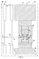
周知のように、缶エンド10は、缶ボディ(図示せず)に、密封するように結合、直接結合、又は固定されて容器(図示せず)を形成するように構成されている。缶エンドは、以下に説明するように、ほぼ平らな中央パネル30と、以下に定義するように、圧印加工リベット12とを含む。圧印加工リベット12は、圧印加工リベットボタン14から形成される(図2)。即ち、圧印加工リベットボタン14は、図示のように、中央パネル30から上向きに突出しており、側壁16とほぼ平らな頂部18とを含んでいる。側壁16及び頂部18なる用語は、圧印加工リベット12及び圧印加工リベットボタン14の両方における同じ要素を説明しており、これら共通の要素を説明するために同じ名称/符号が使用される。
As is well known, the can end 10 is configured to be hermetically coupled, directly coupled, or fixed to the can body (not shown) to form a container (not shown). The can end includes a substantially flat
例示的な実施形態では、缶エンド10は、0.0082インチ未満のベース厚さを有するシート材料から形成される。これにより、上述の問題が解決される。本明細書では、シート材料22のベース厚さはまた、以下で説明する中央パネル30の圧印加工されていない部分の「平均厚さ」である。本明細書では、「厚さ」は、材料、即ちブランク20の表面に実質的に垂直な線に沿って測定される。以下に説明する圧印加工プロセスは、頂部18の厚さを0.0082インチ未満の厚さに減少させる。例示的な実施形態では、頂部18の厚さは、約0.003から0.0082インチ未満である。この例では、シート材料22は、炭酸飲料を保持するように構成された容器、即ち「ソーダ」又は「炭酸飲料(pop)」缶用の缶エンド10に形成される。圧印加工リベットボタン14及び圧印加工リベット12の更なる詳細は、以下に述べられる。
In an exemplary embodiment, the can end 10 is formed from a sheet material having a base thickness of less than 0.0082 inches. This solves the above problem. As used herein, the base thickness of the sheet material 22 is also the "average thickness" of the unimprinted portion of the
缶エンド10は、最初は、限定ではないが、アルミニウム、スチール、又はこれらの合金などである、ほぼ平らな材料のシート22から切断されたブランク20である。即ち、例示的な実施形態では、ほぼ平らな材料のシート22(以下、「シート材料」22)は、コンバージョンプレスのような図3に概略的に示されるプレス500に供給される。プレス500は、シート材料22を缶エンド10(図1)に成形するように構成されている。或いは、シート材料22は、シェルプレス(図示せず)において、シェル(以下、シェルブランク)20に成形される。シェルブランク20は次に、「コンバージョンプレス500」として特定されるプレス500に供給される。 The can end 10 is initially a blank 20 cut from a sheet 22 of a nearly flat material, such as, but not limited to, aluminum, steel, or alloys thereof. That is, in an exemplary embodiment, a sheet 22 of a substantially flat material (hereinafter, "sheet material" 22) is fed to a press 500, such as a conversion press, schematically shown in FIG. The press 500 is configured to form the sheet material 22 into a can end 10 (FIG. 1). Alternatively, the sheet material 22 is formed into a shell (hereinafter, shell blank) 20 in a shell press (not shown). The shell blank 20 is then fed to a press 500 identified as a "conversion press 500".
プレス500は幾つかのステーション502(一部が概略的に示されている)を含んでおり、各ステーションはシェルブランク20に幾つかの成形工程を実行する。シェルブランク20は、コンベア504上でコンバージョンプレス500を通って移動する。コンベア504は、概略的に示されており、間欠又は割り出し動作で動くように構成されている。例示的な実施形態では、コンベア504は、図示されていない幾つかの窪みを含むベルト506(概略的に示されている)である。ベルト506は、設定距離を移動して停止し、その後、設定距離を再度移動する。ベルト506が移動すると、ブランク20は、コンバージョンプレスの幾つかのステーション502を順番に通って移動し、上記のように、各ステーション502は、ブランク20に単一の成形動作又は幾つかの成形動作を実行する。
The press 500 includes several stations 502 (some of which are schematically shown), each station performing several forming steps on the shell blank 20. The shell blank 20 moves on the
コンバージョンプレス500、言い換えると、その各ステーション502は、上側ツーリングアセンブリ550及び下側ツーリングアセンブリ552を含む。複数のステーション502用の上側ツーリングアセンブリ550及び下側ツーリングアセンブリ552は、例示的な実施形態では、一体であるか又は結合されており、各ステーションのダイ、パンチ及び他の要素を支持する。この構成では、それらステーションの上側ツーリングアセンブリ550は同時に移動し、単一の駆動アセンブリ(図示せず)によって駆動される。特定の構成要素を特定するために、ツーリングアセンブリの要素はまた、特定のステーション502の一部としても特定される。即ち、例えば、以下で述べられるバブルステーション512での上側ツーリングアセンブリ550は、バブルステーションの上側ツーリングアセンブリ560としても特定される。例えば「第1のリベットステーションの上側ツーリングアセンブリ」のような具体的に特定された任意の上側ツーリングアセンブリ550又は下側ツーリングアセンブリ552は概して、夫々、上側/下側ツーリングアセンブリ550/552の一部であって、識別子/名称は、単にステーションの性質を示すだけであることは理解される。
The conversion press 500, in other words, each
コンバージョンプレス500は、フレーム554及び駆動アセンブリを更に含む。例示的な実施形態では、下側ツーリングアセンブリ552は、フレーム554に固定されており、実質的に静止している。上側ツーリングアセンブリ550はフレーム554に移動可能に結合されており、上側ツーリングアセンブリ550が下側ツーリングアセンブリ552から離間している第1の位置と、上側ツーリングアセンブリ550が下側ツーリングアセンブリ552により接近している、例示的な実施形態では隣接している第2の位置とから移動するように構成されている。下側ツーリングアセンブリ552は、例示的な実施形態では、フレーム554に結合、直接結合、又は固定される。
The conversion press 500 further includes a frame 554 and a drive assembly. In an exemplary embodiment, the
概して、上側ツーリングアセンブリ550が第1の位置にある(或いは、第1の位置に向かうように又はそこから離れるように動いている)場合、ベルト506が動くことは理解される。逆に、上側ツーリングアセンブリ550が第2の位置にある場合、ベルト506は停止している。知られているように、駆動アセンブリは、上側ツーリングアセンブリ550を第1の位置と第2の位置の間で移動させるように構成されている。更に、知られているように、上側ツーリングアセンブリ550及び下側ツーリングアセンブリ552は、個別に可動可能な要素、例えば、パンチ、ダイ、スペーサ、パッド、ライザーやその他の部分要素(以下、まとめて「部分要素(sub-element)」)を含んでおり、それらは、互いに別々に動くように構成されている。しかしながら、全ての要素は、概して、第1の位置と第2の位置の間で上側ツーリングアセンブリ550と共に動く。即ち、概して、部分要素の動きは互いに関連しているが、全体として、上側ツーリングアセンブリ550は、上述のように、第1の位置と第2の位置との間を移動する。更に、駆動アセンブリは、上側ツーリングアセンブリ550及び下側ツーリングアセンブリ552の部分要素を適切な順序で動かすように構成されたカム、リンク機構、及びその他の要素を含むことは理解される。即ち、上側ツーリングアセンブリ550及び下側ツーリングアセンブリ552の選択された部分要素は、その他の選択された部分要素及び特定の選択された部分要素とは独立して動くように構成されている。例えば、選択された1つの部分要素は、第2の位置に移動してそこに留まるように構成される一方で、別の1つの部分要素は第2の位置に出入りする。部分要素のそのような選択的な動作は、当技術分野で知られている。
In general, it is understood that the
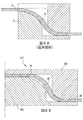
本開示においては、図1及び図2に示すように、ブランクシェル20、即ちブランクは、中央パネル30、環状カウンターシンク32、チャック壁34、及びカール36を含んでおり、コンバージョンプレス500に供給される。知られているように、一般的なコンバージョンプレスステーション502(図に示されているように、既知のステーションは概して符号502で特定される)は、シェルブランク20に、本開示に関係のない形成工程を実行する。本願の目的のために、次のステーションが特定される:バブルステーション512(図3)、第1のリベットステーション514(図5)、第2のリベットステーション516(図7)、スコアステーション518(図9)、パネルステーション520(図10)、及びかしめステーション522(図11)。例示的な実施形態では、第1のリベットステーション514は、「圧印加工(coining)」リベットステーション514であって、「圧印加工リベット」12になる「圧印加工リベットボタン」14を形成するように構成されている。最初に、シェルブランク20は、図3のバブルステーション512に移動される。バブルステーション512は、バブルステーション上側ツーリングアセンブリ560及びバブルステーション下側ツーリングアセンブリ562を含む。概して、バブルステーション下側ツーリングアセンブリ562は、環状のほぼ平らな部分564及び中央のドーム状部分565を有するダイ563を含む。バブルステーション上側ツーリングアセンブリ560は、環状のほぼ平らな部分567及びドーム状部分568を有するパンチ566を含む。ほぼ平らな中央パネル30を有するブランク20(図示せず)が、バブルステーション上側ツーリングアセンブリ560とバブルステーション下側ツーリングアセンブリ562との間に配置される。バブルステーション上側ツーリングアセンブリ560が第2の位置に移動すると、図4に示すように、そこでバブル38が形成される。図4に示すように、バブル38は、断面で見たときに、概ね弓形、又は概ね曲線形である。バブル38は、外周縁部39及び「リベット部」40を含む。知られているように、例示的な実施形態では、外周縁部39は、バブル38の形成中に圧印される。本明細書では、「リベット部」40は、リベットボタン14、その後リベット12になるバブル38の部分である。更に、リベット部40は、側壁部42及び頂部44を含む。リベット部分の側壁部42は、リベットボタンの側壁16になり、その後、圧印加工リベットの側壁16になる。同様に、頂部44は、圧印加工リベットボタンの頂部18になり、その後、圧印加工リベットの頂部18になる。言い換えると、外周縁部39は、側壁部42周りに同心円状に配置される。 更に、側壁部42は、頂部44周りに同心円状に配置される。例示的な実施形態では、外周縁部39は、側壁部42周りに同心円状に隣接しており、側壁部42は、頂部44周りに同心円状に隣接して配置される。
In the present disclosure, as shown in FIGS. 1 and 2, the blank shell 20, or blank, includes a
上記のように、バブル38が形成されると、その外周縁部39が圧印される。続いて、バブルの外周縁部39は、リベット12(を囲んで)周りに配置される中央パネル30の領域になる。例示的な実施形態では、バブルの外周縁部39は、約0.005インチ乃至0.008インチ、又は約0.0065インチの厚さを有する。更に、バブルの外周縁部39は、例示的な実施形態では、以下で説明する圧印加工された頂部18の厚さよりも厚い。即ち、圧印された頂部18がその厚さ範囲の上端にある場合、外周縁部39もその厚さ範囲の上端にある。圧印された頂部18がその厚さ範囲の下端にある場合には、圧印された外周縁部39が圧印された頂部18より厚い限り、外周縁部39はその厚さ範囲のどこかにある。更に、上述のように、外周縁部39周りに配置された中央パネル30の圧印加工されていない部分は、シート材料22のベース厚さ、即ち平均厚さに等しい厚さを有する。
As described above, when the
次に、シェルブランク20は、圧印加工リベットステーション514に移動する。図5の圧印加工リベットステーション514は、バブル38を圧印加工リベットボタン14に成形するように構成されている。圧印加工リベットステーション514は、圧印加工リベットステーションの上側ツーリングアセンブリ570及び圧印加工リベットステーションの下側ツーリングアセンブリ572を含む。概して、圧印加工リベットステーションの下側ツーリングアセンブリ572は、環状のほぼ平らな部分574と、中央パンチ575を有するダイ573とを含む。圧印加工リベットステーションの上側ツーリングアセンブリ570は、中央パンチ576と、中央パンチ576(を囲むように)周りに配置された外側環状パンチ577とを含む。ブランク20を保持するように構成されたパッド(符号なし)は、圧印加工リベットステーションの下側ツーリングアセンブリのダイ573及び圧印加工リベットステーションの下側ツーリングアセンブリの中央パンチ575に加えて、圧印加工リベットステーションの上側ツーリングアセンブリのパンチ576、577周りに配置される。
Next, the shell blank 20 moves to the
圧印加工リベットステーションの上側ツーリングアセンブリの中央パンチ576は、第1の圧印面578(以下、「第1の圧印面」578、又は「上側ツーリングアセンブリの第1の圧印面」578)を規定する。例示的な実施形態では、第1の圧印面578は、実質的に平らである。同様に、圧印加工リベットステーションの下側ツーリングアセンブリの中央パンチ575は、第2の圧印面579(以下、「第2の圧印面」579又は「下側ツーリングアセンブリの第2の圧印面」579)を画定する。例示的な実施形態では、第2の圧印面579も実質的に平らである。圧印加工リベットステーションの下側ツーリングアセンブリの平面部分574は、圧印加工リベットステーションの上側ツーリングアセンブリの環状パンチ577に対向して配置される。更に、圧印加工リベットステーションの下側ツーリングアセンブリの中央パンチ575は、圧印加工リベットステーションの上側ツーリングアセンブリの中央パンチ576に対向して配置される。圧印加工リベットステーションの下側ツーリングアセンブリの中央パンチ575と、圧印加工リベットステーションの下側ツーリングアセンブリの中央パンチ576とは、リベット部の頂部44と動作可能に係合して、圧印加工する。即ち、第1の圧印面578は、第1の圧印面578が第2の圧印面579から離間している第1の位置と、第1の圧印面578が第2の圧印面579から圧印加工距離にある第2の位置との間で移動するように構成される。本明細書では、「圧印加工距離(coining distance)」は、2つの表面の間に配置された材料を圧印加工するために十分に近くなっている2つの表面間の距離である。故に、第1の圧印面578及び第2の圧印面579は、第1の圧印面578及び第2の圧印面579が第2の位置にある場合に、リベットの圧印加工された頂部18を形成するように構成されている。以下では、「頂部18」は、それが圧印加工リベットボタン14(又は圧印加工リベット12)の一部であることと、その金属が「圧印加工されている」ことの両方から、「圧印加工リベット頂部18」として特定される。逆に、側壁16は、以後、依然として「側壁16」として特定される。即ち、側壁16は圧印加工リベットボタン14の一部であるが、側壁16の金属は圧印加工されず、「圧印加工リベット側壁部」という用語は、側壁16も圧印加工されていることを意味し得る。
The central punch 576 of the upper tooling assembly of the stamping rivet station defines a first stamping surface 578 (hereinafter, "first stamping surface" 578, or "first stamping surface of the upper tooling assembly" 578). In an exemplary embodiment, the first imprint surface 578 is substantially flat. Similarly, the central punch 575 of the lower tooling assembly of the stamping rivet station has a second stamping surface 579 (hereinafter, "second stamping surface" 579 or "second stamping surface of the lower tooling assembly" 579). Is defined. In an exemplary embodiment, the second imprint surface 579 is also substantially flat. The
即ち、圧印加工リベットステーションの下側ツーリングアセンブリの中央パンチ575と、圧印加工リベットステーションの下側ツーリングアセンブリの中央パンチ576とは、バブル38の外周縁部に動作可能に係合し、圧印加工リベット頂部18が形成されている間に、バブル38の外周縁部を中央パネル30の平面に戻す。圧印加工リベット頂部18は、中央パネル30と同じ平面内に位置しない。つまり、リベット部の側壁部42は、一般に知られているように、圧印加工リベットステーションの下側ツーリングアセンブリの中央パンチ575上で形成される。リベット部の側壁部42は、圧印加工されない。
That is, the central punch 575 of the lower tooling assembly of the imprinting rivet station and the central punch 576 of the lower tooling assembly of the imprinting rivet station are operably engaged with the outer peripheral edge of the
則ち、リベット部頂部44は圧印加工されて、より薄く、より剛性の高い頂部18となる。同時に、リベット部頂部44の材料の一部は、側壁部42が側壁16になる際に側壁部42に流れ込む。例示的な実施形態では、頂部18は第1の厚さを有し、側壁16は第2の厚さを有する。図1Aに示すように、第1の厚さは第2の厚さよりも薄い。更に、側壁16は圧印加工されておらず、故に、圧印加工リベット頂部18又は中央パネル30における圧印加工部分(以前は、上述の圧印加工外周縁部39)よりも延性が高い。例示的な実施形態では、頂部18の第1の厚さは、0.003インチより大きく0.0082インチ未満であり、又は約0.004インチである。別の実施形態では、頂部18の第1の厚さは、約0.004インチから0.008インチ未満であり、又は約0.006インチである。別の例示的な実施形態では、頂部18の第1の厚さは、0.0082インチ未満である。
That is, the rivet portion top 44 is imprinted to become a thinner and more rigid top 18. At the same time, a part of the material of the top portion 44 of the rivet portion flows into the
例示的な実施形態では、圧印加工リベット頂部18の平面は、中央パネル30の平面とほぼ平行に延びる。側壁16は、断面で見た場合に、図6に示されるように、中央パネル30の平面に対して約70°と90°の間、又は約90°の角度(α)を有する。別の例示的な実施形態では、側壁16は、断面で見た場合に、90°未満であるが80°を超える角度(α)を有する。圧印加工リベットボタン14は、非圧印加工リベットボタンよりも使用する材料が少ないことから、上記の問題を解決する。更に、本明細書では、第1のリベットステーション514にて圧印加工頂部18と共に最初に形成される圧印加工リベットボタン14は、本明細書における「初期圧印加工リベットボタン」である。第1のリベットステーションで頂部18を圧印加工すると、その後の成形工程中に頂部18に流れ込む金属の量が減少するので、上記の問題が解決される。別の実施形態では、第2のリベットステーション516は、「圧印加工」リベットステーションである。
In an exemplary embodiment, the plane of the imprinted
更に、図6Aに示すように、従来技術では、リベットボタンAの形成は、リベット部の側壁部を下側ツーリングCの上で、即ち、それと接触させて変形させることを含んでいたことに留意のこと。図6Bに示されるように、圧印加工リベットステーション514は、リベット部の側壁部42が下側ツーリング572と隙間を作る、即ち、それから離間するように構成されている。このような構成はまた、頂部18及びバブルの外周縁部39が圧印加工されることから生じる。プレスステーション502、即ち、上側ツーリングアセンブリ550及び下側ツーリングアセンブリ552は、圧印加工される材料の2つの領域間に配置されるリベット部の側壁部42を、ツーリングアセンブリ550、552から離間させるように構成されており、本明細書における「ギャップド(gapped)プレスステーション」であって、そのツーリングアセンブリは夫々、「ギャップドツーリングアセンブリ」である。故に、例示的な実施形態では、圧印加工リベットステーション514は「ギャップド」圧印加工リベットステーション514であり、そのツーリングアセンブリ570、572は「ギャップド」ツーリングアセンブリ570、572である。ギャップド圧印加工リベットステーション514を使用することにより、リベット部の側壁部42及びその後に形成される側壁16の厚さを、圧印加工頂部18よりも厚くすることで、上記の問題が解決される。即ち、圧印加工頂部18よりも厚い側壁16を有することにより、圧印加工リベット12での破損の可能性が低減され、上述の問題が解決される。
Further, as shown in FIG. 6A, it should be noted that in the prior art, the formation of the rivet button A included deforming the side wall portion of the rivet portion on the lower tooling C, i.e. in contact with it. That thing. As shown in FIG. 6B, the
例示的な実施形態において、ブランク20はその後、図7に示されるように、第2のリベットステーション516に移動する。第2のリベットステーション516は、上側ツーリングアセンブリを含んでおり、当該上側ツーリングアセンブリは、圧印加工リベットステーション514と概ね同様であるが、圧印加工リベットステーションの上側ツーリングアセンブリの中央パンチ576と同じものを含まない。この構成では、第2のリベットステーションの下側ツーリングアセンブリの中央パンチ585に対向配置しているものはない。故に、第2のリベットステーションの上側ツーリングアセンブリの外側環状パンチ587が下向きに移動すると、圧印加工リベットボタン14が更に、第2のリベットステーションの下側ツーリングアセンブリの中央パンチ585の上で、ほぼ垂直な側壁16を有するように形成される。第2のリベットステーション516での形成後におけるブランクシェル20の断面図は、図2に示されている。
In an exemplary embodiment, the blank 20 is then moved to a
即ち、断面で見た場合、側壁16は、中央パネル30の平面に対してほぼ垂直である。側壁16と圧印加工リベット頂部18との間の移行部は、本明細書では、「周縁上端部」19である。頂部18は圧印加工されているので、周縁上端部19は、リベットボタン側壁とリベットボタン頂部の間の従来技術の移行部よりも、屈曲が鋭いように構成されている。例示的な実施形態では、周縁上端部19は、約0.012インチ乃至0.031インチのアールを有する。約0.012インチ乃至0.031インチのアールを伴っているリベットボタン側壁とリベットボタン頂部との間の移行部は、本明細書では、「減少アール」周縁上端部19である。即ち、図2に示されるように、断面で見た場合、減少アール周縁上端部19は、約0.012インチと0.031インチの間のアールを有する。この構成の圧印加工リベットボタン14、即ち、ほぼ垂直な側壁16と圧印加工リベット頂部18とを備えたボタンは、本明細書では、図8に示すように、「四角状圧印加工リベットボタン」14’である。四角状圧印加工リベットボタン14’は、以下に説明するように、かしめたときにつぶれるように構成されており、タブ本体47のオーバーラップが強化されている。
That is, when viewed in cross section, the
図9のスコアステーション518は、当該技術分野で知られているように、ティアパネルを規定する幾つかのスコア(図示せず)を生じる。図10のパネルステーション520は、知られているように、ブランク20上に任意の追加の構成、例えば、窪みを形成する。例示的な実施形態では、幾つかのパネルステーション520がある。これらのステーションは、本開示には関係していない。
The
本開示に関連する最後のステーションは、図11のかしめステーション522であってタブ46を圧印加工リベットボタン14に結合するように構成されている。かしめステーション522での成形後のブランクシェル20の断面図が図1に示されている。かしめステーション522は、米国特許第5,755,134号に記載されている要素を含み、同様に動作し、そこに記載されているかしめプロセスと、上側ツーリングアセンブリ550と下側ツーリングアセンブリ552の説明は、参照により本明細書の一部となる。概して、かしめステーション522は、かしめパンチ594及びかしめ調整スペーサ596を備えた上側ツーリングアセンブリ590と、主アンビル598を備えた下側ツーリングアセンブリ592とを含むことに留意のこと。かしめステーション下側ツーリングアセンブリの主アンビル598の断面積は、圧印加工リベットボタン14(又は、四角状圧印加工リベットボタン14’)よりも小さくなっている。かしめステーションの上側ツーリングアセンブリのかしめ調整スペーサ596は増大断面積を有していることに留意のこと。本明細書では、かしめステーションの上側ツーリングアセンブリのかしめ調整スペーサ596の「増大断面積」とは、以下に述べるように、タブ本体47のオーバーラップが増大しているかしめられた圧印加工リベット12を形成するように断面積が構成されていることを意味する。
The last station related to the present disclosure is the caulking station 522 of FIG. 11 which is configured to connect the
図1に示されるように、概略的に示されたタブ46は、結合用開口48を規定する細長い、ほぼ平らな本体47を含む。また知られているように、タブ46は、圧印加工リベットボタン14(又は四角状圧印加工リベットボタン14’;以下において、圧印加工リベットボタン14の説明は、四角状圧印加工リベットボタン14’にも当てはまることを理解のこと)の上に配置される。即ち、圧印加工リベットボタン14は、タブ結合用開口48を通って延びる。かしめステーションの上側ツーリングアセンブリのかしめパンチ594と、かしめステーションの上側ツーリングアセンブリのかしめ調整スペーサ596とがそれらの第2の位置に移動すると、かしめステーションの上側ツーリングアセンブリのかしめパンチ594は、圧印加工リベットボタン頂部18と係合し、それにより側壁16を変形させる。これにより、リベットボタン14は、リベット12となるように変形するように構成されている。
As shown in FIG. 1, the generally shown
故に、圧印加工リベットボタン14は、タブ46が圧印加工リベット12上で留められていない第1の形態と、圧印加工リベットボタン14が圧印加工リベット12に成形されており、タブ46が圧印加工リベット12に留められた第2の構成とを有する。更に、圧印加工リベットボタン14は、第1の最大断面積、第1の高さを有しており、側壁16は、第1の厚さを有する。圧印加工リベット12、即ち、かしめ/変形後の圧印加工リベットボタン14は、第2の最大断面積、第2の高さを有しており、側壁16は第2の厚さを有する。圧印加工リベット12の第2の最大断面積は、圧印加工リベットボタン14の第1の最大断面積よりも大きく、圧印加工リベットボタン14の第1の高さは、圧印加工リベット12秒の高さより大きく、側壁16の第2の厚さは、側壁16の第1の厚さに対して増大した厚さである。本明細書では、「増大した厚さ」は、側壁16の厚さがシート材料のベース厚さよりも大きいことを意味する。
Therefore, the
更に、圧印加工されない側壁16は、中央パネル30の圧印加工された金属と圧印加工リベットボタン頂部18との間に配置されることから、側壁16は、頂部が圧印加工されていない従来技術のリベットと比較して、より大きい度合いで変形する。従って、かしめ工程中に変形すると、圧印加工リベットボタン14及び側壁16は、タブ本体47が「増大したオーバーラップ」した圧印加工リベット12を形成する。本明細書では、タブ本体の「増大したオーバーラップ」は、変形した側壁16が四角状リベットボタン14’から形成されたことを意味する。本明細書では、「四角状」リベットボタン14’は、断面で見ると、中央パネル30の平面に対して約70°と90°の間、又は約90°の角度(α)を有する側壁16を有するリベットボタンである。更に、「四角状」リベットボタン14となるために、周縁上端部19は、減少したアールを有する。例示的な実施形態では、圧印加工リベット12は、最小で0.008インチだけタブ結合用開口48の側面とオーバーラップする。これによって、上記の問題が解決する。タブ本体47が「増大したオーバーラップ」している、圧印加工リベット12によって缶エンド10に結合されたタブ本体47は、缶エンド10から分離し難く、それによって上記の問題が解決される。更に、外側に変形する側壁16の金属の量は、側壁16が中央パネル30の平面に対してほぼ垂直に延びると増加する。故に、四角状圧印加工リベットボタン14’は、上記のように変形される場合に、「非常に増大したオーバーラップ」を形成する。つまり、本明細書では、「非常に強化されたオーバーラップ」とは、四角状圧印加工リベットボタン14’を使用してタブ46を缶エンド10に結合した場合に生じるタブ46の重なりを意味する。これによっても、上記の問題が解決される。
Further, since the
従って、図12に示されるように、圧印加工リベット12を有する缶エンド10を形成する方法は、ベース厚さを有するシート材料22を準備する工程1000と、シート材料に予備成形工程を実行してシェルブランクを作製する工程1002と、シェルブランク20に圧印加工リベットボタン14を形成する工程1004と、圧印加工リベットボタン14にタブ46をかしめる工程1005と、缶エンドに仕上げ工程を実行する工程1006と、を含む。既知のように、シート材料に予備成形工程を実行してシェルブランクを作製する工程1002は、中央パネル30、環状カウンターシンク32、チャック壁34、及びカール36を形成することを含む。或いは、圧印加工リベット12を有する缶エンド10を形成する方法は、中央パネル30、環状カウンターシンク32、チャック壁34、及びカール36を有するシェルブランク20を準備する工程1001を含む。本明細書では、「仕上げ工程」には、シェルブランク20をスコアリングする工程、シェルブランク20をパネリングする工程、シェルブランク20の検査、又はシェルブランク20にコーティング及び/又は他の表面処理を施す工程が含まれるが、これらに限定されない。
Therefore, as shown in FIG. 12, the method of forming the can end 10 having the
例示的な実施形態では、シェルブランク20に圧印加工リベットボタンを形成する工程1004は、リベット部頂部44を含むバブルを形成する工程1010と、リベット部頂部44を含むバブルを圧印加工リベットボタン14に成形する工程1020と、及び/又は、側壁16、ほぼ平らな頂部18、及び周縁上端部19を有する圧印加工リベットボタンへとバブルを成形する工程1022と、約0.003インチ乃至0.0082インチ未満、又は、約0.004インチ、又は、約0.004インチ乃至0.0082インチ未満、又は、約0.006インチのうちの1つである厚さで、圧印加工リベットボタンの頂部を形成する工程1024と、及び/又は、約0.012インチ乃至0.031インチのアールを有するように圧印加工リベットボタンの周縁上端部19を成形する工程1026と、約0.003インチ超乃至0.0082インチ未満、又は、約0.004インチ、又は、約0.004インチ乃至0.0082インチ未満、又は、約0.006インチのうちの1つである厚さを有する圧印加工リベットボタンの頂部を形成する工程1026と、
を含む。
In an exemplary embodiment, the step 1004 of forming the imprinted rivet button on the shell blank 20 is the step 1010 of forming the bubble including the rivet top 44 and the
including.
更に、例示的な実施形態では、タブ46を圧印加工リベットボタン1にかしめる工程1005は、結合用開口48を含む本体47を有するタブ46を準備する工程1030と、圧印加工リベットボタン14にタブ46を配置する工程1032であって、圧印加工リベットボタン14はタブの結合用開口48を通って延びる、工程と、圧印加工リベットボタン14を圧印加工リベット12に成形する工程1034であって、圧印加工リベット12は、タブ本体47の増大したオーバーラップを有する、工程と、を含む。
Further, in an exemplary embodiment, the step 1005 of crimping the
本発明の特定の実施形態について詳細に説明したが、当業者であれば、それらの詳細に対する様々な修正や代替を、本開示の教示全体に鑑み開発することができると認識されるであろう。従って、開示される特定の構成は、単に例示であることを意図しており、添付の特許請求の範囲及びその全ての均等物の全範囲を、提供される発明の範囲に関して限定するものではない。 Although specific embodiments of the present invention have been described in detail, those skilled in the art will recognize that various modifications and alternatives to those details can be developed in light of the teachings of the present disclosure. .. Accordingly, the particular configurations disclosed are intended to be merely exemplary and do not limit the scope of the appended claims and all their equivalents with respect to the scope of the invention provided. ..
Claims (20)
中央パネル(30)と、
前記中央パネル(30)に配置された圧印加工リベット(12)と、
を備える缶エンド。 Can end (10)
With the center panel (30)
The imprinting rivet (12) arranged on the central panel (30) and
Can end with.
前記タブの本体(47)は、結合用開口(48)を含んでおり、
前記タブ(46)は、前記圧印加工リベット(12)に結合され、前記圧印加工リベットは、前記タブの本体の結合用開口(48)を通って延びており、
前記圧印加工リベット(12)は、前記タブの本体(47)の増大したオーバーラップ、又は、前記タブの本体(47)の増大したオーバーラップのうちの1つを有する、請求項5に記載の缶エンド。 The central panel (30) includes a tab (46) having a body (47).
The body of the tab (47) includes a coupling opening (48).
The tab (46) is coupled to the imprinted rivet (12), and the imprinted rivet extends through a coupling opening (48) in the body of the tab.
5. The imprinted rivet (12) has one of an increased overlap of the tab body (47) or an increased overlap of the tab body (47), claim 5. Can end.
前記タブの本体(47)は、結合用開口(48)を含んでおり、
前記タブ(46)は、前記圧印加工リベット(12)に結合され、前記圧印加工リベットは、前記タブの本体の結合用開口(48)を通って延びており、
前記圧印加工リベット(12)は、前記タブの本体(47)の増大したオーバーラップ、又は、前記タブの本体(47)の非常に増大したオーバーラップのうちの1つを有する、請求項5に記載の缶エンド。 The central panel (30) includes a tab (46) having a body (47).
The body of the tab (47) includes a coupling opening (48).
The tab (46) is coupled to the imprinted rivet (12), and the imprinted rivet extends through a coupling opening (48) in the body of the tab.
5. The imprinted rivet (12) has one of an increased overlap of the body of the tab (47) or a very increased overlap of the body of the tab (47), claim 5. The described can end.
前記シート材料(22)はベース厚さを有し、
前記シート材料(22)はバブル(38)を含むシェルに成形され、
前記バブル(38)はリベット部の頂部(44)を含んでおり、
前記缶エンド(10)は製品側及び公側を有しており、
前記プレス(500)は、
フレーム(554)と、
前記フレーム(554)に移動可能に結合されており、第1の圧印面(578)を含む上側ツーリングアセンブリ(550)と、
前記フレーム(554)に移動可能に結合されており、第2の圧印面(579)を含む下側ツーリングアセンブリ(552)と、
を含んでおり、
前記第1の圧印面(578)は、前記第2の圧印面(579)から離間している第1の位置と、前記第2の圧印面(579)から圧印加工距離にある第2の位置との間を移動するように構成されており、
前記第1の圧印面(578)及び前記第2の圧印面(579)は、前記第1の圧印面(578)と前記第2の圧印面(579)との間に配置されたリベット部の頂部(44)と係合するように構成されており、
前記第1の圧印面(578)及び前記第2の圧印面(579)が前記第2の位置にある場合、前記第1の圧印面(578)及び前記第2の圧印面(579)は、リベットの圧印加工頂部(44)を形成する、プレス。 In a press (500) configured to form a can end (10) from a sheet material (22).
The sheet material (22) has a base thickness and has a base thickness.
The sheet material (22) is molded into a shell containing bubbles (38) and
The bubble (38) includes the top of the rivet portion (44).
The can end (10) has a product side and a public side.
The press (500)
Frame (554) and
With the upper tooling assembly (550), which is movably coupled to the frame (554) and includes a first imprint surface (578).
With the lower tooling assembly (552), which is movably coupled to the frame (554) and includes a second imprint surface (579),
Includes
The first imprint surface (578) is a first position separated from the second imprint surface (579) and a second position at a imprint processing distance from the second imprint surface (579). It is configured to move between and
The first imprint surface (578) and the second imprint surface (579) are rivet portions arranged between the first imprint surface (578) and the second imprint surface (579). It is configured to engage the top (44) and
When the first imprint surface (578) and the second imprint surface (579) are in the second position, the first imprint surface (578) and the second imprint surface (579) are A press that forms the rivet imprint top (44).
前記上側パンチ(566)は、上端及び下端を有する本体を含んでおり、
前記第1の圧印面(578)は、前記上側パンチの本体の下端に配置されており、
前記上側パンチ(566)は、前記下側ツーリングアセンブリ(552)から離間している第1の位置と、前記下側ツーリングアセンブリ(552)に隣接している第2の位置との間を移動する、請求項8に記載のプレス。 The upper tooling assembly (550) includes an upper punch (566).
The upper punch (566) includes a body having upper and lower ends.
The first imprint surface (578) is arranged at the lower end of the main body of the upper punch.
The upper punch (566) moves between a first position away from the lower tooling assembly (552) and a second position adjacent to the lower tooling assembly (552). , The press according to claim 8.
前記下側パンチは、上端及び下端を有する本体を含んでおり、
前記第2の圧印面(579)は、前記下側パンチの本体の上端に配置されており、
前記下側パンチは、前記上側ツーリングアセンブリ(550)から離間している第1の位置と、前記上側ツーリングアセンブリ(550)に隣接している第2の位置との間を移動するように構成されている、請求項8に記載のプレス。 The lower tooling assembly (552) includes a lower punch.
The lower punch includes a body having upper and lower ends.
The second imprint surface (579) is arranged at the upper end of the main body of the lower punch.
The lower punch is configured to move between a first position away from the upper tooling assembly (550) and a second position adjacent to the upper tooling assembly (550). The press according to claim 8.
前記圧印リベットボタンの側壁(16)及び前記圧印加工リベットボタンの頂部(44)は、減少アール周縁上端部(19)で交わる、請求項10に記載のプレス。 The body of the lower punch is configured to form the bubble (38) into a stamped rivet button (14) having a side wall (16) and a substantially flat top (18).
The press according to claim 10, wherein the side wall (16) of the imprinted rivet button and the top portion (44) of the imprinted rivet button intersect at the upper end portion (19) of the reduced radius peripheral edge.
ベース厚さを有するシート材料(22)を準備する工程(1000)と、
前記シート材料(22)を缶エンド(10)へと成形する工程(1002)と、
前記缶エンド(10)に圧印加工リベットボタン(14)を成形する工程(1004)と、
前記缶エンド(10)に対して仕上げ工程を行う工程(1006)と、
を含む、方法。 A method of forming a can end (10) with imprinted rivets (12).
A step (1000) of preparing a sheet material (22) having a base thickness, and
A step (1002) of molding the sheet material (22) into a can end (10),
The step (1004) of forming the imprinting rivet button (14) on the can end (10),
A step (1006) of performing a finishing step on the can end (10) and
Including methods.
リベット部の頂部(44)を含むバブル(38)を形成する工程(1010)と、
前記リベット部の頂部(44)を前記圧印加工リベットボタン(14)に成形する工程(1020)と、
を含む、請求項15に記載の方法。 The step (1002) of molding the sheet material (22) into a can end (10) and the step (1004) of forming a stamping rivet button (14) on the can end (10) are
The step (1010) of forming the bubble (38) including the top (44) of the rivet portion, and
A step (1020) of forming the top portion (44) of the rivet portion into the imprinted rivet button (14), and
15. The method of claim 15.
前記圧印加工リベットボタンの側壁(16)及び前記圧印加工リベットボタンの頂部(18)は、減少アール周縁上端部(19)で交わり、
前記減少アール周縁上端部(19)は、約0.012インチ乃至0.022インチのアールを有する、請求項16に記載の方法。 In the step (1004) of forming the imprinted rivet button (14) on the can end (10), the imprinted rivet button (14) having the bubble (38) with a side wall (16) and a substantially flat top (18). ) Includes the molding process
The side wall (16) of the imprinted rivet button and the top (18) of the imprinted rivet button intersect at the upper end (19) of the reduced radius peripheral edge.
16. The method of claim 16, wherein the reduced radius margin upper end (19) has a radius of about 0.012 to 0.022 inches.
結合用開口(48)を含む本体(47)を有するタブ(46)を準備する工程(1030)と、
前記タブ(46)を前記圧印加工リベットボタン(14)上に配置する工程(1032)であって、前記圧印加工リベットボタンは前記タブの結合用開口(48)を通って延びる、工程と、
前記圧印加工リベットボタン(14)を圧印加工リベット(12)に成形する工程(1034)と、
を含んでおり、
前記圧印加工リベット(12)は、前記タブの本体(47)の増強されたオーバーラップを有する、請求項15に記載の方法。 The step (1006) of performing the finishing step on the can end (10) is
A step (1030) of preparing a tab (46) having a body (47) including a coupling opening (48), and
A step (1032) of arranging the tab (46) on the imprinted rivet button (14), wherein the imprinted rivet button extends through the coupling opening (48) of the tab.
The step (1034) of forming the imprinted rivet button (14) into the imprinted rivet (12), and
Includes
15. The method of claim 15, wherein the imprinted rivet (12) has an enhanced overlap of the body of the tab (47).
Priority Applications (1)
| Application Number | Priority Date | Filing Date | Title |
|---|---|---|---|
| JP2023051098A JP2023082070A (en) | 2017-08-23 | 2023-03-28 | Can end with coined rivet, tooling assembly therefor, and method of forming |
Applications Claiming Priority (3)
| Application Number | Priority Date | Filing Date | Title |
|---|---|---|---|
| US15/683,803 | 2017-08-23 | ||
| US15/683,803 US20190060977A1 (en) | 2017-08-23 | 2017-08-23 | Can end with a coined rivet, tooling assembly therefor and a method of forming |
| PCT/US2018/027003 WO2019040128A1 (en) | 2017-08-23 | 2018-04-11 | Can end with a coined rivet, tooling assembly therefor and a method of forming |
Related Child Applications (1)
| Application Number | Title | Priority Date | Filing Date |
|---|---|---|---|
| JP2023051098A Division JP2023082070A (en) | 2017-08-23 | 2023-03-28 | Can end with coined rivet, tooling assembly therefor, and method of forming |
Publications (1)
| Publication Number | Publication Date |
|---|---|
| JP2020531376A true JP2020531376A (en) | 2020-11-05 |
Family
ID=65436710
Family Applications (2)
| Application Number | Title | Priority Date | Filing Date |
|---|---|---|---|
| JP2020511281A Pending JP2020531376A (en) | 2017-08-23 | 2018-04-11 | Can end with imprinted rivets, tooling assembly and forming method for it |
| JP2023051098A Pending JP2023082070A (en) | 2017-08-23 | 2023-03-28 | Can end with coined rivet, tooling assembly therefor, and method of forming |
Family Applications After (1)
| Application Number | Title | Priority Date | Filing Date |
|---|---|---|---|
| JP2023051098A Pending JP2023082070A (en) | 2017-08-23 | 2023-03-28 | Can end with coined rivet, tooling assembly therefor, and method of forming |
Country Status (5)
| Country | Link |
|---|---|
| US (2) | US20190060977A1 (en) |
| EP (1) | EP3672743A4 (en) |
| JP (2) | JP2020531376A (en) |
| CN (2) | CN114535447B (en) |
| WO (1) | WO2019040128A1 (en) |
Families Citing this family (2)
| Publication number | Priority date | Publication date | Assignee | Title |
|---|---|---|---|---|
| KR101992210B1 (en) * | 2017-11-13 | 2019-09-30 | 주식회사 프리캔 | Upper plate forming apparatus for container and upper plate forming method |
| USD999631S1 (en) * | 2021-07-23 | 2023-09-26 | Stolle Machinery Company, Llc | Ring pull tab |
Citations (7)
| Publication number | Priority date | Publication date | Assignee | Title |
|---|---|---|---|---|
| US3391819A (en) * | 1963-06-11 | 1968-07-09 | Continental Can Co | Rivet on metal can end for attaching pull tab |
| DE1652624A1 (en) * | 1968-03-14 | 1971-09-16 | Fraze Ermal C | Method for manufacturing a rivet and tooling device for carrying out the method |
| US4580692A (en) * | 1985-05-29 | 1986-04-08 | Aluminum Company Of America | Container sealing cap |
| US4627265A (en) * | 1985-08-12 | 1986-12-09 | Redicon Corporation | Double action conversion system |
| JPH07275976A (en) * | 1994-04-11 | 1995-10-24 | Hokkai Can Co Ltd | Stay on tab type can lid and production thereof |
| US5749257A (en) * | 1994-11-09 | 1998-05-12 | Aluminum Company Of America | Rivet in a converted can end, method of manufacture, and tooling |
| JP2013514952A (en) * | 2009-12-21 | 2013-05-02 | ストール マシーナリ カンパニー,エルエルシー | Reinforced rivet perforated tab, tooling and related methods for providing the same |
Family Cites Families (13)
| Publication number | Priority date | Publication date | Assignee | Title |
|---|---|---|---|---|
| US3638597A (en) * | 1969-09-26 | 1972-02-01 | Fraze Ermal C | Method of forming a rivet |
| BE793904A (en) * | 1972-01-11 | 1973-07-11 | Leer Koninklijke Emballage | VAT MET DEKSEL |
| US4017000A (en) * | 1976-06-21 | 1977-04-12 | Wescan, Inc. | Easy open container end with protective edges for its severed score |
| US4145801A (en) | 1978-02-13 | 1979-03-27 | Aluminum Company Of America | Method of forming an integral rivet for an easy open can end |
| CA2023420A1 (en) * | 1989-08-23 | 1991-02-24 | W. Coy Willis | Resealable container closure |
| US20020113069A1 (en) * | 2000-12-27 | 2002-08-22 | Forrest Randy G. | Can end for a container |
| CN102285479B (en) * | 2011-08-17 | 2014-04-02 | 浙江祥珑科技有限公司 | Plastic zip-top can for foods |
| US9156585B2 (en) * | 2012-04-04 | 2015-10-13 | Anheuser-Busch Inbev S.A. | Double opening beverage can lid system |
| ES2647932T3 (en) * | 2012-05-04 | 2017-12-27 | Ball Corporation | Metal end closure with tear panel that has improved rigidity |
| EP3656482B1 (en) * | 2012-10-18 | 2023-08-23 | Stolle Machinery Company, LLC | End closure with coined panel radius and reform step |
| US9033174B2 (en) * | 2013-03-15 | 2015-05-19 | Ball Corporation | Easy access opening tab for a container end closure |
| CN106132837B (en) * | 2014-03-07 | 2019-05-14 | 鲍尔公司 | End cap with big opening ring pull tab |
| CN104148532A (en) * | 2014-06-30 | 2014-11-19 | 北京爱创科技股份有限公司 | Production process of ring-pull can top covers and ring-pull can top covers |
-
2017
- 2017-08-23 US US15/683,803 patent/US20190060977A1/en not_active Abandoned
-
2018
- 2018-04-11 JP JP2020511281A patent/JP2020531376A/en active Pending
- 2018-04-11 CN CN202210396517.1A patent/CN114535447B/en active Active
- 2018-04-11 WO PCT/US2018/027003 patent/WO2019040128A1/en unknown
- 2018-04-11 CN CN201880054426.1A patent/CN110997175B/en active Active
- 2018-04-11 EP EP18848278.0A patent/EP3672743A4/en active Pending
-
2022
- 2022-09-28 US US17/935,960 patent/US20230016790A1/en active Pending
-
2023
- 2023-03-28 JP JP2023051098A patent/JP2023082070A/en active Pending
Patent Citations (7)
| Publication number | Priority date | Publication date | Assignee | Title |
|---|---|---|---|---|
| US3391819A (en) * | 1963-06-11 | 1968-07-09 | Continental Can Co | Rivet on metal can end for attaching pull tab |
| DE1652624A1 (en) * | 1968-03-14 | 1971-09-16 | Fraze Ermal C | Method for manufacturing a rivet and tooling device for carrying out the method |
| US4580692A (en) * | 1985-05-29 | 1986-04-08 | Aluminum Company Of America | Container sealing cap |
| US4627265A (en) * | 1985-08-12 | 1986-12-09 | Redicon Corporation | Double action conversion system |
| JPH07275976A (en) * | 1994-04-11 | 1995-10-24 | Hokkai Can Co Ltd | Stay on tab type can lid and production thereof |
| US5749257A (en) * | 1994-11-09 | 1998-05-12 | Aluminum Company Of America | Rivet in a converted can end, method of manufacture, and tooling |
| JP2013514952A (en) * | 2009-12-21 | 2013-05-02 | ストール マシーナリ カンパニー,エルエルシー | Reinforced rivet perforated tab, tooling and related methods for providing the same |
Also Published As
| Publication number | Publication date |
|---|---|
| CN110997175A (en) | 2020-04-10 |
| JP2023082070A (en) | 2023-06-13 |
| CN114535447A (en) | 2022-05-27 |
| EP3672743A4 (en) | 2021-05-19 |
| CN110997175B (en) | 2022-03-18 |
| WO2019040128A1 (en) | 2019-02-28 |
| US20190060977A1 (en) | 2019-02-28 |
| BR112020003586A2 (en) | 2020-09-01 |
| CN114535447B (en) | 2024-03-22 |
| US20230016790A1 (en) | 2023-01-19 |
| EP3672743A1 (en) | 2020-07-01 |
Similar Documents
| Publication | Publication Date | Title |
|---|---|---|
| US20230016790A1 (en) | Can end with a coined rivet, tooling assembly therefor and a method of forming | |
| JP2024020235A (en) | Shell with expandable rivet button and tooling therefor | |
| JP7236437B2 (en) | Pressure can ends compatible with standard can seams | |
| JP7162665B2 (en) | Shell with expandable bubble and tooling therefor | |
| JP2021523021A (en) | Methods and equipment for making can shells using the draw-stretch process | |
| JP7217265B2 (en) | back pressure can end | |
| CN110087792B (en) | Truncated raised cup | |
| JP2018520877A (en) | Containers, selectively formed shells, tooling for providing them, and related methods | |
| EP3983148A1 (en) | Reverse pressure can end |
Legal Events
| Date | Code | Title | Description |
|---|---|---|---|
| A621 | Written request for application examination |
Free format text: JAPANESE INTERMEDIATE CODE: A621 Effective date: 20201210 |
|
| A131 | Notification of reasons for refusal |
Free format text: JAPANESE INTERMEDIATE CODE: A131 Effective date: 20211109 |
|
| A521 | Request for written amendment filed |
Free format text: JAPANESE INTERMEDIATE CODE: A523 Effective date: 20220209 |
|
| A131 | Notification of reasons for refusal |
Free format text: JAPANESE INTERMEDIATE CODE: A131 Effective date: 20220614 |
|
| A521 | Request for written amendment filed |
Free format text: JAPANESE INTERMEDIATE CODE: A523 Effective date: 20220829 |
|
| A02 | Decision of refusal |
Free format text: JAPANESE INTERMEDIATE CODE: A02 Effective date: 20221206 |