JP2020531083A - Imaging system extended field of view - Google Patents
Imaging system extended field of view Download PDFInfo
- Publication number
- JP2020531083A JP2020531083A JP2020508393A JP2020508393A JP2020531083A JP 2020531083 A JP2020531083 A JP 2020531083A JP 2020508393 A JP2020508393 A JP 2020508393A JP 2020508393 A JP2020508393 A JP 2020508393A JP 2020531083 A JP2020531083 A JP 2020531083A
- Authority
- JP
- Japan
- Prior art keywords
- truncated
- curve
- views
- synogram
- view
- Prior art date
- Legal status (The legal status is an assumption and is not a legal conclusion. Google has not performed a legal analysis and makes no representation as to the accuracy of the status listed.)
- Withdrawn
Links
Images


Classifications
-
- G—PHYSICS
- G06—COMPUTING; CALCULATING OR COUNTING
- G06T—IMAGE DATA PROCESSING OR GENERATION, IN GENERAL
- G06T11/00—2D [Two Dimensional] image generation
- G06T11/003—Reconstruction from projections, e.g. tomography
-
- G—PHYSICS
- G06—COMPUTING; CALCULATING OR COUNTING
- G06T—IMAGE DATA PROCESSING OR GENERATION, IN GENERAL
- G06T11/00—2D [Two Dimensional] image generation
- G06T11/003—Reconstruction from projections, e.g. tomography
- G06T11/005—Specific pre-processing for tomographic reconstruction, e.g. calibration, source positioning, rebinning, scatter correction, retrospective gating
-
- A—HUMAN NECESSITIES
- A61—MEDICAL OR VETERINARY SCIENCE; HYGIENE
- A61B—DIAGNOSIS; SURGERY; IDENTIFICATION
- A61B6/00—Apparatus for radiation diagnosis, e.g. combined with radiation therapy equipment
- A61B6/02—Devices for diagnosis sequentially in different planes; Stereoscopic radiation diagnosis
- A61B6/03—Computerised tomographs
- A61B6/032—Transmission computed tomography [CT]
- A61B6/035—Mechanical aspects of CT
-
- G—PHYSICS
- G06—COMPUTING; CALCULATING OR COUNTING
- G06T—IMAGE DATA PROCESSING OR GENERATION, IN GENERAL
- G06T2211/00—Image generation
- G06T2211/40—Computed tomography
- G06T2211/432—Truncation
Abstract
撮像システム(100)は、ボア(150)を備えた回転ガントリ(212)と、回転ガントリによって支持され、ボアの周りを回転し、ボアの少なくとも一部を横断するX線放射線を放出するX線放射線源(100)とを含む。 X線放射線源の反対側にある回転ガントリによって支持されている検出器アレイ(120)は、ボア内にある物体(110)を通過したX線を検出し、検リングされるデータ(320、322)に適合することにより、サイノグラム内の切り捨てられる物体(402)の一部を推定し、切り捨てられる物体の推定部分と生成される投影データに基づいて物体の画像(252)を再構成する。出されるX線を示す投影データを生成し 、投影データはサイノグラム(216、316、412)を含む。 プロセッサは、曲線(400)を、切り捨てられるビュー(314)のセットに隣接するサイノグラム内の物体の複数のビュー(324)からサンプリングされたデータ(320、322)に適合することにより、サイノグラム内の切り捨てられた物体(402)の一部を推定し、切り捨てられる物体の推定部分と生成される投影データに基づいて物体の画像(252)を再構成する。The imaging system (100) is supported by a rotating gantry (212) with a bore (150) and an X-ray that rotates around the bore and emits X-ray radiation that traverses at least a portion of the bore. Includes radiation source (100). A detector array (120) supported by a rotating gantry on the opposite side of the X-ray radiation source detects and detects X-rays that have passed through an object (110) in the bore (320, 322). ), It estimates a part of the truncated object (402) in the synogram and reconstructs the image of the object (252) based on the estimated portion of the truncated object and the projected data generated. It produces projection data showing the emitted X-rays, and the projection data contains synograms (216, 316, 412). The processor fits the curve (400) into the data (320, 322) sampled from multiple views (324) of the object in the synogram adjacent to the set of truncated views (314) in the synogram. A part of the truncated object (402) is estimated, and the image of the object (252) is reconstructed based on the estimated portion of the truncated object and the generated projection data.
Description
以下は概して撮像に関し、より具体的には視野外の対象物又は被検体の一部の推定に関するものであり、コンピュータ断層撮影(CT)医用撮像への特定の応用とともに説明されているが、他の撮像モダリティにも適している。 The following generally relates to imaging, more specifically to estimating a portion of an object or subject outside the field of view, described with specific applications for computed tomography (CT) medical imaging, but others. It is also suitable for imaging modality.
CT撮像装置の例を図1に示す。CT撮像装置は、被検体又は物体110の一部を横断し、検出器120、d0 122、…dn 124によって検出されるX線放射105を放出する線源100を含む。体積測定スキャンの場合、線源100及び検出器120は、物体110の周りを協調して回転する。検出器120は、回転すると、回転経路(収集間隔)に沿った所定の複数の弧で放射線を検出する。各収集間隔について、各検出器diはそれに入射するX線放射を検出し、線源100から検出器120までの経路に沿った全X線減衰(線積分又は投影データ)を示す電気信号を生成する。収集間隔の線積分のセットは、投影又はビューと呼ばれる。
An example of a CT imaging device is shown in FIG. The CT imaging device includes a
視野(FOV)140は、線源100と検出器120の相対位置、及び開口部又はボア150の開口のサイズによって制約され得る検出器120の長さによって規定される。 FOV140は、ボア150の中心Xと同心であり、線源100及び検出器120が回転するとき、線源100から外側検出器d0及びdnまで横断する(仮想円に接する)周辺X線105によって境界付けられる仮想円内の領域と考えることができる。すなわち、FOV140は、各投影ビューの異なる回転位置からの放出放射線105によって共通に横断されるボア150の領域を含む。被検体の一部及び/又はFOV 140外の物体170について、少なくとも180度にファン角度を加えたこの領域に対して一部のデータは取得されないため、不完全なデータが取得され、投影データが体積画像データに再構成されるとき、部分スキャンアーチファクトがもたらされる。残念ながら、部分スキャンアーチファクトにより、体積画像データ内のFOV 140の外側の物体170は診断又は治療計画の目的に適さない可能性がある。
The field of view (FOV) 140 is defined by the relative position of the
「CTスキャンの視野を拡張する新しい再構成アルゴリズム」(2004)においてJ. Hsiehらによって示されているように、切り捨てアーチファクトに対処する1つのアプローチは、物体110がFOV 140内に完全に収まるように、より大きなボア150とより大きなFOV 140を備えたCT撮像システムを構築することにある。 Hsiehによる他のアプローチは、部分的なウォーターシリンダーを使用して、各々の切り捨てられるビューkiのために検出される減衰値にラインを適合させることにある。しかしながら、このアプローチはすべての物体形状に対して正確ではなく、アーチファクトにつながる可能性がある。「切り捨てられる画像の物体サポートを推定するアルゴリズム」(2014)においてS. Hsiehによって説明される別のアプローチは、反復アプローチによって物体の切り捨てられる部分を推定しようとすることにある。残念ながら、これには時間がかかり、計算コストが高くなる可能性がある。以下の発明は、サイノグラム領域で物体の範囲を直接推定するための高速で正確な方法を提供する。
As shown by J. Hsieh et al. In "A New Reconstruction Algorithm to Extend the Field of View of CT Scans" (2004), one approach to address truncation artifacts is to ensure that
本明細書で説明される態様は、上記で参照された問題及びその他に対処する。 The embodiments described herein address the problems referred to above and others.
以下は、サイノグラム内の複数のビューにわたって被検体の一部のサンプリングされた縁に曲線を適合することにより、拡張視野内の被検体の範囲を推定するシステム及び方法の実施形態を説明する。被検体のサンプリングされた部分は、ビューのセットで切り捨てられる被検体の部分の前縁及び/又は後縁を含むことができる。推定された被検体の範囲はマスクとして画像領域に反転され、逆投影される。マスクは、画像領域内の他のアルゴリズムで調整できる。画像領域でマスクを使用するか、又は投影領域で近似曲線によって推定された範囲を使用することにより、被検体の画像を生成できる。 The following describes embodiments of systems and methods for estimating the extent of a subject within an extended field of view by fitting a curve to some sampled edges of the subject across multiple views within the synogram. The sampled portion of the subject can include the leading edge and / or trailing edge of the portion of the subject that is truncated in the set of views. The estimated range of the subject is inverted in the image area as a mask and back-projected. The mask can be adjusted by other algorithms within the image area. An image of the subject can be generated by using a mask in the image area or by using the range estimated by the fitted curve in the projected area.
一態様では、撮像システムは、ボアを備えた回転ガントリと、回転ガントリによって支持され、ボアの周りを回転し、ボアの少なくとも一部を横切るX線放射を放出するX線放射源とを含む。 X線放射源の反対側に位置する回転ガントリによって支持された検出器アレイは、ボア内に位置する物体を横断したX線放射を検出し、検出されたX線放射を示す投影データを生成する。投影データにはサイノグラムが含まれる。プロセッサは、サイノグラム内の物体の切り捨てられるビューのセットに隣接するサイノグラム内の物体の複数のビューからサンプリングされるデータに曲線を適合することにより、サイノグラムで切り捨てられる物体の一部を推定し、切り捨てられる物体の推定部分と生成される投影データに基づいて物体の画像を再構成する。 In one aspect, the imaging system comprises a rotating gantry with a bore and an X-ray source that is supported by the rotating gantry, rotates around the bore, and emits X-ray radiation that crosses at least a portion of the bore. A detector array supported by a rotating gantry located opposite the X-ray source detects X-ray radiation across an object located in the bore and produces projection data showing the detected X-ray radiation. .. The projection data includes cynograms. The processor estimates and truncates some of the objects to be truncated in the synogram by fitting a curve to the data sampled from multiple views of the objects in the synogram adjacent to the set of truncated views of the objects in the synogram. The image of the object is reconstructed based on the estimated part of the object to be generated and the projected data generated.
別の態様では、撮像方法は、検出器アレイによって生成される物体のサイノグラムを受信するステップを含む。サイノグラムで切り捨てられる物体の一部は、サイノグラム内で物体の切り捨てられるビューのセットに隣接するサイノグラムで物体の複数のビューからサンプリングされるデータに曲線を適合することによって推定される。切り捨てられる物体の推定部分とサイノグラムに基づいて、物体の画像が再構成される。 In another aspect, the imaging method comprises receiving a synogram of the object produced by the detector array. Some of the objects that are truncated in the synogram are estimated by fitting a curve to the data sampled from multiple views of the object in the synogram adjacent to the set of truncated views of the object in the synogram. The image of the object is reconstructed based on the estimated portion of the object to be truncated and the synogram.
別の態様では、命令を担持する非一時的なコンピュータ可読記憶媒体が、検出器アレイによって生成される物体のサイノグラムを受信し、サイノグラム内の前記物体の切り捨てられるビューのセットに隣接する前記サイノグラム内の前記物体の複数のビューからサンプリングされるデータに曲線を適合することによって前記サイノグラム内で切り捨てられる前記物体の一部を推定するように1つ以上のプロセッサを制御する。1つ以上のプロセッサはさらに、切り捨てられる物体の推定部分及びサイノグラムに基づいて物体の画像を再構成するように制御される。 In another aspect, a non-temporary computer-readable storage medium carrying instructions receives a synogram of an object produced by the detector array and within the synogram adjacent to a set of truncated views of the object in the synogram. One or more processors are controlled to estimate a portion of the object to be truncated within the synogram by fitting a curve to data sampled from multiple views of the object. One or more processors are further controlled to reconstruct the image of the object based on the estimated portion of the object to be truncated and the synogram.
本発明のこれらの態様及び他の態様は、以下に記載される実施形態を参照して明らかになり、解明されるであろう。 These and other aspects of the invention will be apparent and elucidated with reference to the embodiments described below.
本発明は、様々な構成要素及び構成要素の配置、ならびに様々なステップ及びステップの配置の形をとることができる。図面は、好ましい実施形態を説明するためだけのものであり、本発明を限定するものとして解釈されるべきではない。 The present invention can take the form of various components and arrangements of components, as well as various steps and arrangements of steps. The drawings are for illustration purposes only and should not be construed as limiting the invention.
図2を参照すると、拡張視野(eFOV)160内にある視野(FOV)140の外側の物体又は被検体110の範囲を推定するシステム200の実施形態が概略的に示されている。 FOV140は、各回転位置で共通に検出されるボア150の領域を含む。 eFOV160は、FOV140を除外し、少なくとも1つの回転位置で検出されるボア150内に第2の領域を含む。
With reference to FIG. 2, an embodiment of a
システム200は、固定ガントリ214によって支持される回転ガントリ212を含むCT撮像装置210を含むことができる。回転ガントリは、線源100及び検出器120を支持する。検出器120は、物体110の投影データを生成し、サイノグラム216として記憶及び/又は表示される。サイノグラム216は、投影/ビュー(ki)対検出器d0、…dnとして配列される減衰値の2次元アレイである。サイノグラム216のビューは、回転位置、例えば、連続した回転位置によって順序付けられている。検出器120は、個々の検出器のM×Nアレイを含むことができ、M及びNは1以上の整数であり、例えばxy平面で、Mは「z」方向に沿っており、Nは「z」方向を横切る方向に沿っている。以下は、MxNアレイに拡張可能な検出器120の1xNアレイを使用して説明される。
The
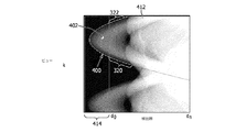
切り捨て識別子220は、ksからkeまでの切り捨てられるビュー314の範囲又はセットを識別する。切り捨てられるビュー314の例は、図3のシミュレートされるサイノグラム316に示されている。切り捨てられるビュー314の各セットは、連続した回転位置を含むビューのグループを表す。図3では、ビュー330が垂直軸上に表され、検出器340が水平軸上に表され、先頭の検出器d0が空気を示す減衰値から、皮膚、軟組織、又は他の所定の値を示す値のような、非空気を示す減衰値に変化するか、又は後続の検出器dnが空気を示す減衰値から非空気を示す減衰値に変化する場合、切り捨てが識別される。 ksからkeまでの識別される切り捨てられるビュー314は、1つの切り捨ての開始及び終了に対応する。これらの切り捨てられるビュー314は、物体又は被検体170の一部が、検出される放射線の経路を去り、線源100及び検出器120が回転するときに、検出される放射線の経路に再び入る場所を表す。
図2及び図3を参照すると、切り捨て識別子230は、それぞれ識別される切り捨てのビューに先行及び/又は後続する複数のビュー324にわたる物体又は被検体170の部分の前縁320及び/又は後縁322の検出器を識別する。例えば、切り捨て識別子240は、ビューks‐1乃至ks‐pに対する前縁320を特定し、ここでpはビューの所定の整数であり、検出器120の初期検出器d0は回転の方向にある。 pの値は、所定の値、統計的サンプリング基準、それらの組み合わせ、及び/又は他の値であり得る。前縁320のビュー324の各ビューの検出器は、第1の検出器djを含み、同じビューにおける第1の検出器djから次の検出器dj‐1への減衰値は、空気(又は他の所定の値)から物体又は被検体170の部分に変化する。後縁322も同様に識別される。前縁320及び/又は後縁322は、回転方向の第一の検出器(d0、…dp)及び/又は最後の検出器(dn−p、…、dn)などの検出器アレイ120内の外側検出器に対応し、回転方向に後続する。
With reference to FIGS. 2 and 3, the
図2乃至4を参照すると、曲線適合器230は、物体110の前縁320、物体110の後縁322、又はそれらの組み合わせの識別される検出器位置の関数として、識別されるビューに曲線400を適合させる。図4では、適合曲線400は、仮想検出器414を備えた部分的にシミュレートされるサイノグラム412に示されている。適合曲線400は、仮想検出器414を使用して拡張視野160内の物体又は被検体170の部分の範囲402を規定する。すなわち、範囲402は、適合線400と、切り捨てられるビュー314の端部(d0又はdnなど)の初期検出器の線との間の領域を含む。適合曲線400は、サイノグラム120内の前縁320及び/又は後縁322のサンプリングされる検出器位置を含むサンプルセットに基づいて適合される。そのような線は、物体又は被検体170の切り捨てられるビュー314の各々の識別されるセットに適合される。
With reference to FIGS. 2-4, the curve fitter 230
図2乃至5を参照すると、マスク生成器240は、適合線400によって規定され、画像領域に逆投影される拡張視野の範囲でサイノグラム216から伝播される画像マスク242(図5)を生成することができる。 バイナリ画像マスク(例えば、黒及び他の1つの値)などの画像マスク242は、物体110を示す第1の値500と、空気又は非被検体を示す第2の値510とを含む。第1の値500及び第2の値510は、画像領域のx‐y座標系で表される。画像マスク242は、画像再構成の現在の方法を使用して他の画像領域マスク244を精緻化するために使用することができる。例えば、画像マスク242は、画像マスク242と他の画像領域マスク244との交点を使用して精緻化することができる。画像マスク242は、水又は他の所定値などの減衰値で満たすことができる。
With reference to FIGS. 2-5, the
引き続き図2乃至5を参照すると、画像再構成器250は、適合線400及びサイノグラム216によって規定される物体110の範囲402に基づいて物体110の画像252を再構成する。一つの実施例において、再構成器250は、範囲402を追加の制約として使用して、投影領域におけるデータ外挿技術をさらに改善する。たとえば、部分ウォーターシリンダーを個々のビューに合わせたラインは、適合線400を使用して平滑化できる。
Continuing with reference to FIGS. 2-5, the
いくつかの実施形態では、画像再構成器250は、再構成又は反復再構成において画像マスク242又はその精緻化を使用する。例えば、再構成画像252内の画像マスク242によって規定される拡張視野内の被検体170の部分は、水又は他の物質を示す推定ハウンズフィールドユニット(HU)で満たすことができる。場合によっては、eFOV 160の満たされる部分は、一部の放射線治療アプリケーションに十分な品質の計算上高速な推定を提供する。精緻化は、FOV 140内の画像の詳細を放射状に外挿することによって遷移を滑らかにし、推定HUを使用してeFOV 160で満たされる再構成画像と結果をブレンドする。
In some embodiments, the
さらなる精緻化は、精緻化される画像を投影領域に前方投影し、仮想検出器414及びサイノグラム216で表されるeFOV 160の前方投影の一部を使用して、仮想検出器414を使用する物体110又は範囲402の推定部分を備える精緻化されるサイノグラムを生成することによって、精緻化される画像においてeFOV 160に更なる詳細を追加することができる。それから、範囲402を備えた精緻化されるサイノグラムを逆投影して、再構成画像252を生成することができる。いくつかの例において、更なる精緻化は、 eFOV 160における物体の更なる詳細を提供し得る。
Further refinement is an object that uses the
引き続き図2乃至5を参照すると、ユーザインターフェース260は、再構成画像252をディスプレイ装置262に表示し、及び/又は画像アーカイブ及び通信システム(PACS)、放射線情報システム(RIS)、電子医用記録(EMR)などのストレージサブシステムに画像252を格納することができる。
Continuing with reference to FIGS. 2-5, the
切り捨て識別子220、曲線適合器230、マスク生成器240、画像再構成器250、及びユーザインターフェース260は、デジタルプロセッサ、マイクロプロセッサ、電子プロセッサ、光学装置などの構成されるコンピュータプロセッサ264によって適切に具現化される。プロセッサ、マルチプロセッサ、ピアツーピア又は協調動作プロセッサを含むプロセッサの分散、プロセッサのクライアント/サーバー配置など、構成されるプロセッサ264によって適切に具現化され、切り捨てられるビューを識別し、前縁320及び/又はトレーリング縁322を識別及びサンプリングし、曲線400に適合させ、画像マスク242を生成し、画像252を再構成し、表示装置262及び1つ以上の入力装置266を操作するように構成される。
The
構成されるコンピュータプロセッサは、光ディスク、磁気ディスク、構成されるプロセッサを備えた計算装置の半導体メモリなどのコンピュータ可読記憶媒体268に格納される少なくとも1つのコンピュータ可読命令を実行し、一時的な媒体を除外し、開示される技術を実行するための物理メモリ及び/又は他の非一時的な媒体を含む。構成されるプロセッサは、搬送波、信号、又は他の一時的な媒体によって運ばれる1つ又は複数のコンピュータ可読命令を実行することもできる。図2の図に示されているコンポーネント間の線は、通信パスを表している。
The configured computer processor executes at least one computer-readable instruction stored in a computer-
構成されるプロセッサ264、表示装置262、及び入力装置266は、コンソール、ラップトップコンピュータ、デスクトップコンピュータ、タブレットコンピュータ、スマートフォン、身体装着計算装置、サーバー、又は計算装置などの協調的な配置などの計算装置270を含むことができる。ディスプレイ装置262は、コンピュータディスプレイ、スマートフォンディスプレイ、プロジェクタ、身体装着型ディスプレイ、テレビ(TV)、それらの組み合わせなどによって適切に具現化される。入力装置266は、キーボード、マウス、トラックボール、マイクロフォン、それらの組み合わせなどにより適切に具体化される。
The
サイノグラム216、画像マスク242、他の画像領域マスク244、及び再構成画像252は、データ構造、ファイル構造、データベース編成、画像フォーマットなどを含むことができる電子メモリ又はコンピュータメモリによって適切に具現化される。
The
いくつかの実施形態では、切り捨て識別子220、曲線適合器230、マスク生成器240、画像再構成器250、及びユーザインターフェース260は、コンピュータプログラム製品として適切に具現化される。
In some embodiments, the
図6を参照すると、シミュレートされるサイノグラム412の複数のビューにわたる物体110の一部のサンプリングされる縁320、322に適合する曲線の例が概略的に示されている。図6では、第1の正弦曲線600が第1のサンプリングされる複数のビュー602にわたって前縁320に適合される。第2の正弦曲線610が第2のサンプリングされる複数のビュー612にわたって後縁322に適合される。サンプルセットされるは、
![]()
![]()
![]()
![]()
![]()
![]()
![]()
![]()
正弦関数は、
![]()
![]()
![]()
![]()
第1の正弦曲線600及び第2の正弦曲線610を補間して、適合曲線400を生成することができる。例えば、適合曲線400は、第1の正弦曲線600及び第2の正弦曲線610の平均、加重平均又は他の関数を使用して点ごとに補間することができる。2セットのパラメーター(a1、b1、c1)及び(a2、b2、c2)で規定される2つの曲線間の補間の1つの数式は、
![]()
![]()
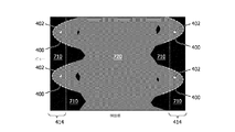
図7を参照すると、範囲402を備えた例示的な投影領域マスク又はサイノグラムマスク700が示されている。サイノグラムマスク700は、仮想検出器414を使用してeFOV160内の範囲を示している。サイノグラムマスク700は、画像に寄与せずに、空気のみを通過する検出X線の第1の領域710を含む。サイノグラムマスク700は、画像に寄与し、物体110のある部分を通過する検出X線の第2の領域720を含む。
With reference to FIG. 7, an exemplary projection area mask or synogram mask 700 with
範囲402を有するサイノグラムマスク700は、反転され、画像領域に逆投影され得る。結果のマスク画像は、空気を通過する光線が画像に寄与する領域と、画像に寄与しない他のすべての領域を識別する。図5に示すように、第2の反転により、画像領域内の物体110の領域を示す画像マスク242が得られる。
The synogram mask 700 with
図8は、本明細書の実施形態によるフローチャートを示す。 FIG. 8 shows a flowchart according to an embodiment of the present specification.
800で、被検体のサイノグラム216が受け取られる。サイノグラム216は、CT撮像装置210から直接受信され、CT撮像装置210によって生成されるか、又は記憶サブシステムから間接的に受信されることができる。サイノグラム216は投影データを含む。例えば、各行は、順序付けられた回転位置からの物体110のビューを表し、各列は、空間的に順序付けられた検出器アレイの検出器を表す。
At 800, the
810では、受信サイノグラム216で切り捨てられるビューのセット314が識別される。切り捨てられるビューのセット314は、空気の値を超えるなどの所定のしきい値を超える減衰値を有する先頭又は末尾の検出器によって識別することができる。
The 810 identifies a set of
820で、切り捨てられるビュー314の各セットについて、サイノグラム216で表される物体110の縁が複数のビューにわたってサンプリングされる。サンプリングされる縁は、検出器の位置と、物体110の前縁320及び/又は後縁322のビュー識別子を含む。前縁320は、切り捨てられるビュー314のセットの直後に続く。後縁322は、切り捨てられるビュー314のセットの直前にある。
At 820, for each set of
830で、切り捨てられるビュー314の各セットについて、曲線400はサンプリングされる縁に適合される。適合曲線400は、ビューの関数として、仮想検出器414まで拡張される検出器の位置又は場所を含む。適合曲線400は、2つの適合曲線600、610の補間、サンプリングされる前縁320に適合される第1の曲線600、及びサンプリングされる後縁322に適合される第2の曲線610を含み得る。他の適合曲線は考えられる。
At 830, for each set of
840では、サイノグラムマスク700が生成され、画像マスク242として切り捨てられるビュー314の各セットに対する適合曲線400によって規定される範囲402で画像領域に伝播される。画像マスク242は、他の画像領域マスク244を使用して精緻化することができ、視野140及び拡張視野160内の物体110によって占有される空間領域又は体積を規定する。いくつかの実施形態では、画像マスク242は省略でき、投影領域内の曲線400によって規定される範囲402は、投影領域内の範囲402を規定する他の技術をさらに精緻化するために使用される。
At 840, a synogram mask 700 is generated and propagated to the image region in the
850で、物体110の画像252は、適合曲線400により規定される範囲402に基づいてサイノグラム212から再構成され得る。画像252は、画像領域の画像マスク242及びサイノグラム252を使用して再構成され得る。画像252は、適合曲線400によって規定される範囲402によって規定されるか、それによって精緻化される投影データを使用して再構成することができる。
At 850, the
860で、再構成される画像252は、ディスプレイ装置262に表示され、及び/又はストレージサブシステムに保存され得る。
At 860, the
上記は、コンピュータ可読記憶媒体にエンコード又は埋め込まれたコンピュータ可読命令によって実装され、コンピュータプロセッサによって実行されると、プロセッサに記述される動作を実行させる。追加的又は代替的に、コンピュータ可読命令の少なくとも1つは、信号、搬送波、又は他の一時的な媒体によって実行される。 The above is implemented by computer-readable instructions encoded or embedded in a computer-readable storage medium, and when executed by a computer processor, causes the operation described by the processor to be performed. Additional or alternative, at least one of the computer-readable instructions is executed by a signal, carrier wave, or other temporary medium.
上記の手順は、異なる順序で実行でき、及び/又は一部の手順を省略できる。 The above steps can be performed in a different order and / or some steps can be omitted.
本発明は、図面及び前述の説明において詳細に図示及び説明されているが、そのような図示及び説明は、例示的又は例証的であり、限定的ではないと見なされるべきである。本発明は、開示される実施形態に限定されない。開示される実施形態に対する他の変形は、図面、開示、及び添付の特許請求の範囲の研究から、請求される発明を実施する際に当業者によって理解及び達成され得る。 The present invention is illustrated and described in detail in the drawings and the aforementioned description, but such illustration and description should be considered exemplary or exemplary and not limiting. The present invention is not limited to the disclosed embodiments. Other modifications to the disclosed embodiments can be understood and achieved by one of ordinary skill in the art in carrying out the claimed invention from the drawings, disclosures, and studies of the appended claims.
請求項において、「含む」という語は他の要素又はステップを除外せず、不定冠詞「a」又は「an」は複数を除外しない。単一のプロセッサ又は他のユニットは、特許請求の範囲に記載されているいくつかのアイテムの機能を果たし得る。特定の手段が相互に異なる従属請求項に記載されているという単なる事実は、これらの手段の組み合わせが有利に使用できないことを示すものではない。 In the claims, the word "contains" does not exclude other elements or steps, and the indefinite article "a" or "an" does not exclude more than one. A single processor or other unit may perform the functions of some of the items described in the claims. The mere fact that certain means are described in different dependent claims does not indicate that the combination of these means cannot be used in an advantageous manner.
コンピュータプログラムは、他のハードウェアとともに、又は他のハードウェアの一部として提供される光記憶媒体又はソリッドステート媒体などの適切な媒体に格納/配布できるが、インターネット又は他の有線又は無線の通信システムなどの他の形式で配布することもできる。請求項中の参照符号は、範囲を限定するものと解釈されるべきではない。 Computer programs can be stored / distributed with other hardware or on suitable media such as optical storage or solid state media provided as part of other hardware, but with internet or other wired or wireless communications. It can also be distributed in other formats such as the system. The reference code in the claims should not be construed as limiting the scope.
Claims (20)
ボアを備えた回転ガントリと、
前記回転ガントリによって支持され、前記ボアの周りを回転し、前記ボアの少なくとも一部を横切るX線放射線を放出するように構成されるX線放射線源と、
前記回転ガントリによって支持され、前記X線放射線源の反対側に配置され、前記ボア内に位置される物体を通過したX線放射線を検出し、前記検出されるX線放射線を示す投影データを生成するように構成される検出器アレイであって、前記投影データはサイノグラムを含む、検出器アレイと、
プロセッサであって、
前記サイノグラム内の前記物体の切り捨てられるビューのセットに隣接する前記サイノグラム内の前記物体の複数のビューからサンプリングされるデータに曲線を適合することによって前記サイノグラム内で切り捨てられる前記物体の一部を推定し、
前記切り捨てられる物体の前記推定される部分及び前記生成される投影データに基づいて前記物体の画像を再構成する
ように構成される、プロセッサと
を有する、撮像システム。 It ’s an imaging system,
A rotating gantry with a bore and
With an X-ray radiation source supported by the rotating gantry and configured to rotate around the bore and emit X-ray radiation across at least a portion of the bore.
Detects X-ray radiation that is supported by the rotating gantry and is located on the opposite side of the X-ray radiation source and has passed through an object located in the bore, and generates projection data indicating the detected X-ray radiation. A detector array configured to include, said projection data containing x-rays.
It ’s a processor,
Estimate a portion of the object to be truncated in the synogram by fitting a curve to data sampled from multiple views of the object in the synogram adjacent to a set of truncated views of the object in the synogram. And
An imaging system comprising a processor configured to reconstruct an image of the object based on the estimated portion of the truncated object and the projected projection data generated.
第一の正弦曲線を前記物体の前記前縁に適合し、
第二の正弦曲線を前記物体の前記後縁に適合し、
前記第一の正弦曲線及び前記第二の正弦曲線の間で補間して前記曲線に適合する
ように更に構成される、請求項2に記載のシステム。 The processor
The first sinusoidal curve fits the leading edge of the object and
Fit the second sinusoidal curve to the trailing edge of the object and
The system of claim 2, further configured to fit the curve by interpolating between the first sine curve and the second sine curve.
各々の前記適合曲線に従って、拡張視野内及び視野の外側に位置される切り捨てられるビューの各セット内の前記物体の各範囲を推定するように更に構成され、各回転位置で共通に検出される前記ボア内の領域は視野を規定し、少なくとも1つの回転位置で検出される前記視野を除く前記ボアの第二の領域は拡張視野を規定し、各回転位置における前記生成される投影データはビューを規定する、
請求項1に記載のシステム。 The processor
The said fit curves are further configured to estimate each range of the object within each set of truncated views located within and outside the extended field of view, and are commonly detected at each rotation position. The area within the bore defines the field of view, the second area of the bore except the field of view detected at at least one rotation position defines the extended field of view, and the generated projection data at each rotation position provides a view. Prescribe,
The system according to claim 1.
前記物体の切り捨てられるビューのセットを検出するように更に構成され、前記少なくとも1つのサンプリングされる縁は、前記物体の切り捨てられるビューの前記セットに隣接するビューのセットを有する、請求項2に記載のシステム。 The processor
2. The second aspect of claim 2, further configured to detect a set of truncated views of the object, wherein the at least one sampled edge has a set of views adjacent to the set of truncated views of the object. System.
前記適合曲線に従って前記サイノグラムで切り捨てられる前記物体の前記推定部分に基づいて画像領域の座標系内で画像マスクを生成するように更に構成され、前記画像マスクは前記画像領域内の拡張視野及び視野内の前記物体の面積又は体積を表す、請求項1に記載のシステム。 The processor
It is further configured to generate an image mask in the coordinate system of the image region based on the estimated portion of the object truncated by the synogram according to the fit curve, the image mask being in the extended visual field and in the visual field in the image region. The system according to claim 1, which represents the area or volume of the object.
検出器アレイによって生成される物体のサイノグラムを受信するステップと、
前記サイノグラム内の前記物体の切り捨てられるビューのセットに隣接する前記サイノグラム内の前記物体の複数のビューからサンプリングされるデータに曲線を適合することによって前記サイノグラム内で切り捨てられる前記物体の一部を推定するステップと、
前記切り捨てられる物体の前記推定される部分及び前記サイノグラムに基づいて前記物体の画像を再構成するステップと
を有する、方法。 It ’s a method for taking pictures.
Steps to receive the synogram of the object produced by the detector array,
Estimate a portion of the object to be truncated in the synogram by fitting a curve to data sampled from multiple views of the object in the synogram adjacent to a set of truncated views of the object in the synogram. Steps to do and
A method comprising the presumed portion of the truncated object and a step of reconstructing an image of the object based on the synogram.
を更に有する、請求項8に記載の方法。 The step of determining the plurality of views to have at least one sampled edge of the object, wherein the at least one sampled edge is adjacent to the detector position and the set of truncated views. 8. The method of claim 8, further comprising a step having at least one view identifier selected from the group consisting of a trailing edge and a leading edge of the object.
第一の正弦曲線を前記物体の前記前縁に適合するステップと、
第二の正弦曲線を前記物体の前記後縁に適合するステップと、
前記第一の正弦曲線及び前記第二の正弦曲線の間で補間するステップと
を有する、請求項9に記載の方法。 The step of estimating the curve is
With the step of fitting the first sinusoidal curve to the leading edge of the object,
With the step of fitting the second sinusoidal curve to the trailing edge of the object,
9. The method of claim 9, comprising interpolating between the first sine curve and the second sine curve.
各々の前記適合曲線に従って、拡張視野内及び視野の外側に位置される切り捨てられるビューの各セット内の前記物体の各範囲を推定するステップであって、前記検出器アレイの各回転位置で共通に検出される撮像装置のボア内の領域及び前記ボアの周りの線源は視野を規定し、少なくとも1つの回転位置で検出される前記視野を除く前記ボアの第二の領域は拡張視野を規定し、各回転位置における前記生成される投影データはビューを規定する、ステップ
を有する、請求項8に記載の方法。 The step of estimating the curve is
A step of estimating each range of the object in each set of truncated views located in and out of the extended field of view according to each of the fit curves, common to each rotation position of the detector array. The area within the bore of the imager to be detected and the source around the bore define the field of view, and the second area of the bore except the field of view detected at at least one rotational position defines the extended field of view. The method of claim 8, wherein the generated projection data at each rotation position has a step that defines a view.
を更に有する、請求項8に記載の方法。 Further comprising a step of detecting said set of truncated views of the object, wherein the at least one sampled edge has a set of views adjacent to said set of truncated views of the object. The method according to claim 8.
を更に有する、請求項8に記載の方法。 A step of generating an image mask in the coordinate system of an image region based on the estimated portion of the object to be truncated by the synogram according to the conformance curve, wherein the mask is the extended visual field in the image region and the said in the visual field. The method of claim 8, further comprising a step representing the area or volume of an object.
前記サイノグラム内の前記物体の切り捨てられるビューのセットに隣接する前記サイノグラム内の前記物体の複数のビューからサンプリングされるデータに曲線を適合することによって前記サイノグラム内で切り捨てられる前記物体の一部を推定させ、
前記切り捨てられる物体の前記推定される部分及び前記サイノグラムに基づいて前記物体の画像を再構成させる
ように一つ又はそれより多くのプロセッサを制御する命令を担持する非一時的なコンピュータ可読記憶媒体。 Receive the synogram of the object generated by the detector array and
Estimate a portion of the object to be truncated in the synogram by fitting a curve to data sampled from multiple views of the object in the synogram adjacent to a set of truncated views of the object in the synogram. Let me
A non-temporary computer-readable storage medium carrying instructions that control one or more processors to reconstruct an image of the object based on the presumed portion of the truncated object and the synogram.
前記物体の少なくとも1つのサンプリングされる縁を有するように前記複数のビューを決定するように更に制御され、前記少なくとも1つのサンプリングされる縁は検出器位置及び切り捨てられるビューの前記セットに隣接する前記物体の後縁及び前記物体の前縁から成るグループから選択される少なくとも1つのビュー識別子を有する、
請求項15に記載の非一時的なコンピュータ可読記憶媒体。 One or more of the above processors
The plurality of views are further controlled to have at least one sampled edge of the object, said that the at least one sampled edge is adjacent to the detector position and the set of truncated views. It has at least one view identifier selected from the group consisting of the trailing edge of the object and the leading edge of the object.
The non-temporary computer-readable storage medium according to claim 15.
第一の正弦曲線を前記物体の前記前縁に適合させ、
第二の正弦曲線を前記物体の前記後縁に適合させ、
前記第一の正弦曲線及び前記第二の正弦曲線の間で補間させる
ように更に制御される、請求項16に記載の非一時的なコンピュータ可読記憶媒体。 One or more of the above processors
The first sinusoidal curve is fitted to the leading edge of the object and
A second sinusoidal curve is fitted to the trailing edge of the object and
The non-temporary computer-readable storage medium of claim 16, further controlled to interpolate between the first sine curve and the second sine curve.
前記適合曲線に従って前記サイノグラムで切り捨てられる前記物体の前記推定部分に基づいて画像領域の座標系内で画像マスクを生成するようにさらに制御され、前記画像マスクは前記画像領域内の拡張視野及び視野内の前記物体の面積又は体積を表す、
請求項15に記載の非一時的なコンピュータ可読記憶媒体。 One or more of the above processors
Further controlled to generate an image mask in the coordinate system of the image region based on the estimated portion of the object truncated by the synogram according to the fit curve, the image mask is in the extended visual field and in the visual field in the image region. Represents the area or volume of the object in
The non-temporary computer-readable storage medium according to claim 15.
各々の前記適合曲線に従って、拡張視野内及び視野の外側に位置される切り捨てられるビューの各セット内の前記物体の各範囲を推定するようにさらに制御され、前記検出器アレイの各回転位置で共通に検出される撮像装置のボア内の領域及び前記ボアの周りの線源は視野を規定し、少なくとも1つの回転位置で検出される前記視野を除く前記ボアの第二の領域は拡張視野を規定し、各回転位置における前記生成される投影データはビューを規定する、
請求項15に記載の非一時的なコンピュータ可読記憶媒体。 One or more of the above processors
According to each said fit curve, it is further controlled to estimate each range of said object within each set of truncated views located within and outside the field of view, and is common to each rotation position of the detector array. The region in the bore of the imaging device detected in and the radiation source around the bore define the field of view, and the second region of the bore other than the field of view detected at at least one rotational position defines the extended field of view. And the generated projection data at each rotation position defines the view.
The non-temporary computer-readable storage medium according to claim 15.
前記物体の切り捨てられるビューの前記セットを検出するようにさらに制御され、前記少なくとも1つのサンプリングされる縁は、前記物体の切り捨てられるビューの前記セットに隣接するビューのセットを有する、
請求項15に記載の非一時的なコンピュータ可読記憶媒体。 One or more of the above processors
Further controlled to detect the set of truncated views of the object, the at least one sampled edge has a set of views adjacent to the set of truncated views of the object.
The non-temporary computer-readable storage medium according to claim 15.
Applications Claiming Priority (3)
| Application Number | Priority Date | Filing Date | Title |
|---|---|---|---|
| US201762545520P | 2017-08-15 | 2017-08-15 | |
| US62/545,520 | 2017-08-15 | ||
| PCT/EP2018/071440 WO2019034486A1 (en) | 2017-08-15 | 2018-08-08 | Imaging system extended field-of-view |
Publications (2)
| Publication Number | Publication Date |
|---|---|
| JP2020531083A true JP2020531083A (en) | 2020-11-05 |
| JP2020531083A5 JP2020531083A5 (en) | 2021-09-16 |
Family
ID=63168406
Family Applications (1)
| Application Number | Title | Priority Date | Filing Date |
|---|---|---|---|
| JP2020508393A Withdrawn JP2020531083A (en) | 2017-08-15 | 2018-08-08 | Imaging system extended field of view |
Country Status (5)
| Country | Link |
|---|---|
| US (1) | US11238625B2 (en) |
| EP (1) | EP3669328A1 (en) |
| JP (1) | JP2020531083A (en) |
| CN (1) | CN110998662A (en) |
| WO (1) | WO2019034486A1 (en) |
Families Citing this family (5)
| Publication number | Priority date | Publication date | Assignee | Title |
|---|---|---|---|---|
| US10969771B2 (en) * | 2019-06-12 | 2021-04-06 | Edison Welding Institute, Inc. | Computed tomography for non-destructive evaluation of manufactured parts |
| CN111631741B (en) * | 2020-05-29 | 2023-06-06 | 上海联影医疗科技股份有限公司 | Image truncation artifact correction method, device, equipment and storage medium |
| US11651477B2 (en) * | 2020-08-07 | 2023-05-16 | Adobe Inc. | Generating an image mask for a digital image by utilizing a multi-branch masking pipeline with neural networks |
| US11393100B2 (en) | 2020-08-07 | 2022-07-19 | Adobe Inc. | Automatically generating a trimap segmentation for a digital image by utilizing a trimap generation neural network |
| CN112598760B (en) * | 2020-12-18 | 2023-07-04 | 上海联影医疗科技股份有限公司 | Image truncation artifact correction method and system |
Family Cites Families (5)
| Publication number | Priority date | Publication date | Assignee | Title |
|---|---|---|---|---|
| US7515676B2 (en) * | 2006-04-28 | 2009-04-07 | Kabushiki Kaisha Toshiba | Method, apparatus, and computer program product for sinogram completion |
| US8433119B2 (en) * | 2009-10-23 | 2013-04-30 | Analogic Corporation | Extension of the field of view of a computed tomography system in the presence of interfering objects |
| CN102110288B (en) * | 2011-02-14 | 2012-06-27 | 东南大学 | Projected chord graph repair method for CT image |
| CN104751502B (en) * | 2015-04-17 | 2017-06-06 | 北京锐视康科技发展有限公司 | One kind is for expanding wide-field CT image rebuilding methods |
| CN105761226B (en) | 2016-02-24 | 2018-05-18 | 赛诺威盛科技(北京)有限公司 | A kind of compensated reconstruction method of ultraphotic open country CT scan image |
-
2018
- 2018-08-08 US US16/637,947 patent/US11238625B2/en active Active
- 2018-08-08 EP EP18753144.7A patent/EP3669328A1/en not_active Withdrawn
- 2018-08-08 WO PCT/EP2018/071440 patent/WO2019034486A1/en unknown
- 2018-08-08 JP JP2020508393A patent/JP2020531083A/en not_active Withdrawn
- 2018-08-08 CN CN201880052806.1A patent/CN110998662A/en active Pending
Also Published As
| Publication number | Publication date |
|---|---|
| US11238625B2 (en) | 2022-02-01 |
| US20200175730A1 (en) | 2020-06-04 |
| CN110998662A (en) | 2020-04-10 |
| EP3669328A1 (en) | 2020-06-24 |
| WO2019034486A1 (en) | 2019-02-21 |
Similar Documents
| Publication | Publication Date | Title |
|---|---|---|
| Maier et al. | Real‐time scatter estimation for medical CT using the deep scatter estimation: method and robustness analysis with respect to different anatomies, dose levels, tube voltages, and data truncation | |
| JP2020531083A (en) | Imaging system extended field of view | |
| Bergner et al. | An investigation of 4D cone‐beam CT algorithms for slowly rotating scanners | |
| EP1522045B1 (en) | Motion artifact correction of tomographical images | |
| US10878544B2 (en) | Image data processing | |
| Kim et al. | Cardiac motion correction based on partial angle reconstructed images in x‐ray CT | |
| JP2007296352A (en) | Method and device of completing sinogram, storage medium and program | |
| JP5913351B2 (en) | Forward projection device | |
| JP2008537113A (en) | 3D time-of-flight PET with coarse angle and slice rebinning | |
| CN108242067B (en) | Computing four-dimensional DSA data sets with variable spatial resolution | |
| US20160242721A1 (en) | Apparatus and method for fast iterative reconstruction in computed tomography | |
| KR20100133950A (en) | Dose reduction and image enhancement in tomography through the utilization of the object's surroundings as dynamic constraints | |
| JP2006015139A (en) | Method and system for three-dimensional reconstruction of image | |
| JP2019525179A (en) | TOF PET image reconstruction using a locally modified time-of-flight (TOF) kernel | |
| JP2013085955A (en) | X-ray computer tomographic imaging apparatus (x-ray ct apparatus) for supplementing detail image in successive multi-scale reconstruction, medical image treatment apparatus and medical image treatment method | |
| JP5281635B2 (en) | Isotropic resolution image reconstruction | |
| Jang et al. | Head motion correction based on filtered backprojection for x‐ray CT imaging | |
| JP2018020120A (en) | Medical image processor and medical image processing program | |
| Beaudry et al. | Learning from our neighbours: a novel approach on sinogram completion using bin-sharing and deep learning to reconstruct high quality 4DCBCT | |
| JP2022547463A (en) | Confidence Map for Limited Angle Artifact Mitigation Based on Neural Networks in Cone-Beam CT | |
| US10984564B2 (en) | Image noise estimation using alternating negation | |
| JP2016198504A (en) | Image generation device, x-ray computer tomography device and image generation method | |
| JP6437163B1 (en) | Computer tomography image generator | |
| JP2018143574A (en) | X-ray CT apparatus and image processing method | |
| JP2005127837A (en) | Spect system and spect image reconstitution method |
Legal Events
| Date | Code | Title | Description |
|---|---|---|---|
| A521 | Written amendment |
Free format text: JAPANESE INTERMEDIATE CODE: A523 Effective date: 20210804 |
|
| A621 | Written request for application examination |
Free format text: JAPANESE INTERMEDIATE CODE: A621 Effective date: 20210804 |
|
| A761 | Written withdrawal of application |
Free format text: JAPANESE INTERMEDIATE CODE: A761 Effective date: 20211006 |