JP2020522809A - Method and device for detecting planes and/or quadtrees for use as virtual substrates - Google Patents
Method and device for detecting planes and/or quadtrees for use as virtual substrates Download PDFInfo
- Publication number
- JP2020522809A JP2020522809A JP2019566687A JP2019566687A JP2020522809A JP 2020522809 A JP2020522809 A JP 2020522809A JP 2019566687 A JP2019566687 A JP 2019566687A JP 2019566687 A JP2019566687 A JP 2019566687A JP 2020522809 A JP2020522809 A JP 2020522809A
- Authority
- JP
- Japan
- Prior art keywords
- plane
- quadtrees
- planes
- electronic device
- touch
- Prior art date
- Legal status (The legal status is an assumption and is not a legal conclusion. Google has not performed a legal analysis and makes no representation as to the accuracy of the status listed.)
- Granted
Links
Images


Classifications
-
- G—PHYSICS
- G06—COMPUTING OR CALCULATING; COUNTING
- G06T—IMAGE DATA PROCESSING OR GENERATION, IN GENERAL
- G06T7/00—Image analysis
- G06T7/70—Determining position or orientation of objects or cameras
- G06T7/73—Determining position or orientation of objects or cameras using feature-based methods
-
- G—PHYSICS
- G06—COMPUTING OR CALCULATING; COUNTING
- G06T—IMAGE DATA PROCESSING OR GENERATION, IN GENERAL
- G06T19/00—Manipulating 3D models or images for computer graphics
- G06T19/006—Mixed reality
-
- G—PHYSICS
- G06—COMPUTING OR CALCULATING; COUNTING
- G06F—ELECTRIC DIGITAL DATA PROCESSING
- G06F3/00—Input arrangements for transferring data to be processed into a form capable of being handled by the computer; Output arrangements for transferring data from processing unit to output unit, e.g. interface arrangements
- G06F3/01—Input arrangements or combined input and output arrangements for interaction between user and computer
- G06F3/048—Interaction techniques based on graphical user interfaces [GUI]
- G06F3/0484—Interaction techniques based on graphical user interfaces [GUI] for the control of specific functions or operations, e.g. selecting or manipulating an object, an image or a displayed text element, setting a parameter value or selecting a range
- G06F3/04845—Interaction techniques based on graphical user interfaces [GUI] for the control of specific functions or operations, e.g. selecting or manipulating an object, an image or a displayed text element, setting a parameter value or selecting a range for image manipulation, e.g. dragging, rotation, expansion or change of colour
-
- G—PHYSICS
- G06—COMPUTING OR CALCULATING; COUNTING
- G06T—IMAGE DATA PROCESSING OR GENERATION, IN GENERAL
- G06T11/00—2D [Two Dimensional] image generation
- G06T11/40—Filling a planar surface by adding surface attributes, e.g. colour or texture
-
- G—PHYSICS
- G06—COMPUTING OR CALCULATING; COUNTING
- G06T—IMAGE DATA PROCESSING OR GENERATION, IN GENERAL
- G06T19/00—Manipulating 3D models or images for computer graphics
- G06T19/20—Editing of 3D images, e.g. changing shapes or colours, aligning objects or positioning parts
-
- G—PHYSICS
- G06—COMPUTING OR CALCULATING; COUNTING
- G06T—IMAGE DATA PROCESSING OR GENERATION, IN GENERAL
- G06T2200/00—Indexing scheme for image data processing or generation, in general
- G06T2200/24—Indexing scheme for image data processing or generation, in general involving graphical user interfaces [GUIs]
-
- G—PHYSICS
- G06—COMPUTING OR CALCULATING; COUNTING
- G06T—IMAGE DATA PROCESSING OR GENERATION, IN GENERAL
- G06T2207/00—Indexing scheme for image analysis or image enhancement
- G06T2207/10—Image acquisition modality
- G06T2207/10028—Range image; Depth image; 3D point clouds
-
- G—PHYSICS
- G06—COMPUTING OR CALCULATING; COUNTING
- G06T—IMAGE DATA PROCESSING OR GENERATION, IN GENERAL
- G06T2219/00—Indexing scheme for manipulating 3D models or images for computer graphics
- G06T2219/20—Indexing scheme for editing of 3D models
- G06T2219/2016—Rotation, translation, scaling
Landscapes
- Engineering & Computer Science (AREA)
- Theoretical Computer Science (AREA)
- Physics & Mathematics (AREA)
- General Physics & Mathematics (AREA)
- General Engineering & Computer Science (AREA)
- Software Systems (AREA)
- Computer Hardware Design (AREA)
- Computer Graphics (AREA)
- Architecture (AREA)
- Computer Vision & Pattern Recognition (AREA)
- Human Computer Interaction (AREA)
- User Interface Of Digital Computer (AREA)
- Processing Or Creating Images (AREA)
- Studio Devices (AREA)
Abstract
電子デバイスは、電子デバイスの画像センサの視野内のオブジェクトのメディアキャプチャプレビューにオーバーレイされた、第1の外観状態のレチクル要素を電子デバイスのディスプレイ上に表示し、ここで、画像センサの視野内のオブジェクトが変化したときに、メディアキャプチャプレビューは変化し、メディアキャプチャプレビュー内の平面を検出し、平面の検出に応じて、メディアキャプチャプレビューにオーバーレイされた第2の外観状態のレチクル要素をディスプレイ上に表示し、レチクル要素は、第2の外観状態で表示されている間に、平面の範囲の一部のインジケーションに対応する。電子デバイスは、複数の画像のセットを取得し、複数の画像のセットのそれぞれについて、3次元点群を合成し、それぞれの3次元点群を使用して平面を構築し、3次元点群にわたる平面のマージされたセットを特徴付ける四分木のマージされたセットを生成する。
【選択図】図4CThe electronic device displays a reticle element in a first appearance state on the display of the electronic device, overlaid with a media capture preview of an object in the image sensor's view of the electronic device, where the image sensor's view of the reticle element is in the view of the image sensor. When the object changes, the media capture preview changes to detect the plane in the media capture preview and, depending on the detection of the plane, a second appearance state reticle element overlaid on the media capture preview on the display. Display and the reticle element corresponds to an indication of a portion of the extent of the plane while being displayed in the second appearance state. The electronic device acquires a plurality of sets of images, synthesizes a 3D point cloud for each of the plurality of image sets, constructs a plane using each 3D point cloud, and spans the 3D point cloud. Generate a merged set of quadtrees that characterizes the merged set of planes.
[Selection diagram] Fig. 4C
Description
本出願は、概して、検出された平面及び/又は四分木が仮想基体として使用されることを可能にする電子デバイスを含むが、これらに限定されない、シーン内の平面及び/又は四分木を検出することに関する。 The present application generally includes planes and/or quadtrees in a scene including, but not limited to, electronic devices that allow detected planes and/or quadtrees to be used as virtual substrates. Regarding to detect.
マッピングされていないシーン又は動的なシーン内に拡張現実/仮想現実(AR/VR)オブジェクトを配置することは、少なくともユーザエクスペリエンスの視点から課題を提示する。AR/VRオブジェクトが、好適な仮想基体を用いることなくシーン内に配置されると、AR/VRオブジェクトが、シーン内にある現実世界の表面に固定されない場合がある。したがって、AR/VRが空中で浮遊するか、現実世界のオブジェクトを遮蔽するか、又は現実世界のオブジェクトと衝突する場合がある。これによって、現実味も真実味もない、乏しいユーザエクスペリエンスがもたらされる。 Placing Augmented Reality/Virtual Reality (AR/VR) objects in unmapped or dynamic scenes presents challenges, at least from a user experience perspective. When the AR/VR object is placed in the scene without using a suitable virtual substrate, the AR/VR object may not be fixed to the real-world surface in the scene. Thus, the AR/VR may float in the air, occlude real-world objects, or collide with real-world objects. This results in a poor user experience that is neither real nor real.
以下に記載される実施形態では、この課題は、AR/VRオブジェクトが配置される仮想基体を提供するために、シーン内の平面又は四分木を検出し、それらの範囲を判定することによって解決される。 In the embodiments described below, this problem is solved by detecting planes or quadtrees in the scene and determining their extents to provide a virtual substrate on which AR/VR objects are placed. To be done.
いくつかの実施形態によれば、方法は、1つ以上のプロセッサ、非一時的メモリ、画像センサ、ディスプレイ、及び1つ以上の入力デバイスを備える電子デバイスで実行される。方法は、画像センサの視野内のオブジェクトのメディアキャプチャプレビューにオーバーレイされた、第1の外観状態のレチクル要素をディスプレイ上に表示することを含み、ここで、画像センサの視野内のオブジェクトが変化したときに、メディアキャプチャプレビューは変化する。方法は、メディアキャプチャプレビュー内の平面を検出することと、平面の検出に応じて、メディアキャプチャプレビューにオーバーレイされた第2の外観状態のレチクル要素をディスプレイ上に表示することと、を含み、レチクル要素は、第2の外観状態で表示されている間に、平面の範囲の一部のインジケーションに対応する。 According to some embodiments, the method is performed on an electronic device that comprises one or more processors, non-transitory memory, an image sensor, a display, and one or more input devices. The method includes displaying on a display a reticle element in a first appearance state overlaid on a media capture preview of an object in the field of view of the image sensor, where the object in the field of view of the image sensor has changed. Sometimes the media capture preview changes. The method includes detecting a plane in the media capture preview and, in response to the detection of the plane, displaying a reticle element in a second appearance state overlaid on the media capture preview on a display. The element corresponds to an indication of a portion of the extent of the plane while being displayed in the second appearance state.
いくつかの実施形態によれば、方法は、1つ以上のプロセッサ及び非一時的メモリを備える電子デバイスにおいて実行される。方法は、複数の画像のセットを取得することと、複数の画像のセットのそれぞれについて、3次元点群を合成することと、それぞれの3次元点群を使用して平面を構築することと、3次元点群にわたる平面のマージされたセットを特徴付ける四分木のマージされたセットを生成することと、を含む。 According to some embodiments, the method is performed on an electronic device that comprises one or more processors and non-transitory memory. The method comprises obtaining a set of images, synthesizing a 3D point cloud for each of the plurality of image sets, and constructing a plane using each 3D point cloud. Generating a merged set of quadtrees that characterizes the merged set of planes over the 3D point cloud.
いくつかの実施形態によれば、電子デバイスは、ディスプレイ、1つ以上の入力デバイス、1つ以上のプロセッサ、非一時的メモリ、及び1つ以上のプログラムを含み、1つ以上のプログラムは非一時的メモリに記憶され、1つ以上のプロセッサによって実行されるように構成され、1つ以上のプログラムは、本明細書に開示される方法のいずれかの動作を実行する又は実行を引き起こす命令を含む。いくつかの実施形態によれば、非一時的コンピュータ可読記憶媒体は、命令を内部に記憶し、命令はディスプレイ及び1つ以上の入力デバイスを備える電子デバイスの1つ以上のプロセッサによって実行されると、デバイスに本明細書に開示される方法のいずれかの動作を実行させる又は実行を引き起こす。いくつかの実施形態によれば、電子デバイスは、ディスプレイ、1つ以上の入力デバイス、及び本明細書に開示される方法のいずれかの動作を実行する又は実行を引き起こす手段を含む。いくつかの実施形態によれば、ディスプレイ及び1つ以上の入力デバイスを備える電子デバイスにおいて使用するための情報処理装置は、本明細書に開示される方法のいずれかの動作を実行する又は引き起こす手段を含む。 According to some embodiments, the electronic device includes a display, one or more input devices, one or more processors, non-transitory memory, and one or more programs, where the one or more programs are non-transitory. Stored in a dynamic memory and configured to be executed by one or more processors, the one or more programs including instructions for performing or causing the operations of any of the methods disclosed herein. .. According to some embodiments, a non-transitory computer readable storage medium stores instructions therein, the instructions being executed by one or more processors of an electronic device comprising a display and one or more input devices. , Cause or cause the device to perform any of the acts of the methods disclosed herein. According to some embodiments, the electronic device includes a display, one or more input devices, and means for performing or causing the actions of any of the methods disclosed herein. According to some embodiments, an information processing device for use in an electronic device comprising a display and one or more input devices is a means for performing or causing the operations of any of the methods disclosed herein. including.
説明される様々な実施形態をより良く理解するため、以下の図面と併せて、以下の「発明を実施するための形態」が参照されるべきであり、類似の参照番号は、以下の図の全てを通じて、対応する部分を指す。 For a better understanding of the various embodiments described, reference should be made to the following "Description of Embodiments" taken in conjunction with the following drawings, wherein like reference numerals refer to the following figures: Throughout all, refers to the corresponding part.
以下に説明する実施形態では、画像センサの視野内のシーンのメディアキャプチャプレビューを表示している間に、メディアキャプチャプレビューにオーバーレイされたレチクル要素は、第1の外観状態から第2の外観に遷移して、シーン内で平面が検出されたという視覚的な合図を提供する。以下に説明する実施形態では、第2の外観状態で表示されている間に、レチクル要素は、検出された平面の範囲を示す。したがって、以下に説明する実施形態は、仮想基体として使用される検出された平面に対して、拡張現実/仮想現実(AR/VR)オブジェクトをシーン内に配置する際に、より短い時間及びより少ないユーザ入力しか必要とされないシームレスなユーザエクスペリエンスを提供する。またこれは、ユーザがデバイスをより迅速かつ効率的に使用することを可能にすることで、電力使用量を低減し、デバイスのバッテリ寿命を改善する。 In the embodiments described below, the reticle element overlaid on the media capture preview transitions from the first appearance state to the second appearance while displaying the media capture preview of the scene within the field of view of the image sensor. And provide a visual cue that a plane has been detected in the scene. In the embodiments described below, the reticle element exhibits a range of detected planes while being displayed in the second appearance state. Thus, the embodiments described below require less time and less time to place an augmented/virtual reality (AR/VR) object in a scene with respect to a detected plane used as a virtual substrate. Provide a seamless user experience that requires only user input. It also reduces power usage and improves the battery life of the device by allowing the user to use the device more quickly and efficiently.
以下に説明する実施形態では、異なる視点又は視野についての平面又は四分木のセットは、時間次元にわたり相関されて、四分木のマージされたセットが取得され、それらが次に仮想基体として使用される。したがって、以下に説明する実施形態は、経時的なシーンの異なる視野に基づいて、仮想基体の正確な範囲を識別するプロセスを提供する。したがって、以下に説明する実施形態は、四分木(又はそれに関連付けられた平面)のマージされたセットに対して、AR/VRオブジェクトをシーン内に配置する際に、より短い時間及びより少ないユーザ入力しか必要とされないシームレスなユーザエクスペリエンスを提供する。またこれは、ユーザがデバイスをより迅速かつ効率的に使用することを可能にすることで、電力使用量を低減し、デバイスのバッテリ寿命を改善する。 In the embodiments described below, sets of planes or quadtrees for different viewpoints or fields of view are correlated over the time dimension to obtain a merged set of quadtrees, which are then used as virtual substrates. To be done. Therefore, the embodiments described below provide a process for identifying the exact extent of a virtual substrate based on different views of the scene over time. Thus, the embodiments described below require less time and less user time to place AR/VR objects in a scene for a merged set of quadtrees (or planes associated with it). Provide a seamless user experience that requires only input. It also reduces power usage and improves the battery life of the device by allowing the user to use the device more quickly and efficiently.
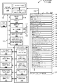
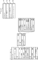
以下では、図1A〜図1B、図2、図3及び図11は、例示的なデバイスの説明を提供する。図7は、仮想基体を検出し、仮想基体の上にオブジェクトを配置する方法のフロー図を示す。図4A〜図4Mにおけるユーザインタフェースは、図7におけるプロセスを説明するために使用される。図8〜図10は、仮想基体として使用するための四分木のセットを生成する方法のフロー図を示す。図5A〜図5Bにおける抽象ブロック図及び図6A〜図6Gにおけるユーザインタフェースは、図8〜図10におけるプロセスを示すために使用される。
例示的なデバイス
In the following, FIGS. 1A-1B, 2, 3, and 11 provide a description of exemplary devices. FIG. 7 shows a flow diagram of a method of detecting a virtual substrate and placing an object on the virtual substrate. The user interface in FIGS. 4A-4M is used to describe the process in FIG. 8-10 show flow diagrams of a method of generating a set of quadtrees for use as a virtual substrate. The abstract block diagrams in FIGS. 5A-5B and the user interface in FIGS. 6A-6G are used to illustrate the processes in FIGS. 8-10.
Exemplary device
ここで、添付図面に実施例が示される実施形態への詳細な参照が行われる。以下の詳細な説明では、説明される様々な実施形態の完全な理解を提供するために数多くの具体的な詳細が記載されている。しかしながら、記載されている様々な実施形態は、これらの具体的な詳細を伴わずとも実践し得ることが、当業者には明らかであろう。他の例では、周知の方法、手順、構成要素、回路、及びネットワークは、実施形態の態様を不必要に不明瞭にしないよう詳細には説明されていない。 Reference will now be made in detail to the embodiments, examples of which are illustrated in the accompanying drawings. In the following detailed description, numerous specific details are set forth in order to provide a thorough understanding of the various embodiments described. However, it will be apparent to one of ordinary skill in the art that the various described embodiments may be practiced without these specific details. In other instances, well-known methods, procedures, components, circuits, and networks have not been described in detail so as not to unnecessarily obscure aspects of the embodiments.
本明細書では、第1、第2などの用語は、いくつかの実施例で、様々な要素を説明するために使用されるが、これらの要素は、それらの用語によって限定されるべきではないことも理解されるであろう。これらの用語は、ある要素を別の要素と区別するためにのみ使用される。例えば、説明されている様々な実施形態の範囲から逸脱することなく、第1の接触は、第2の接触と称することができ、同様に、第2の接触は、第1の接触と称し得る。第1の接触及び第2の接触は両方とも接触であるが、文脈がそうではないことを明確に示さない限り、それらは同じ接触ではない。 Although terms such as “first” and “second” are used herein to describe various elements in some examples, these elements should not be limited by those terms. It will also be understood. These terms are only used to distinguish one element from another. For example, the first contact can be referred to as the second contact, and similarly, the second contact can be referred to as the first contact without departing from the scope of the various described embodiments. .. The first contact and the second contact are both contacts, but they are not the same contact, unless the context clearly indicates otherwise.
本明細書に記載する様々な実施形態の説明で使用される術語は、特定の実施形態を説明することのみを目的とし、限定的であることは意図されていない。記載する様々な実施形態の説明及び添付の特許請求の範囲では、単数形の「a(1つ、一)」、「an(1つ、一)」、及び「the(その、この)」は、文脈上別途明白に記載しない限り、複数形も同様に含むことが意図される。また、本明細書で使用されるとき、用語「及び/又は」は、関連する列挙された項目のうちの1つ以上のいずれか及び全ての考えられる組み合わせを指し、かつこれを含むことを理解されたい。用語「includes(含む)」、「including(含む)」、「comprises(含む、備える)」、及び/又は「comprising(含む、備える)」は、本明細書で使用する場合、述べられた特徴、整数、ステップ、動作、要素、及び/又は構成要素の存在を指定するが、1つ以上の他の特徴、整数、ステップ、動作、要素、構成要素、及び/又はそれらのグループの存在又は追加を除外しないことが更に理解されるであろう。 The terminology used in the description of various embodiments herein is for the purpose of describing particular embodiments only and is not intended to be limiting. In the description of the various embodiments described and the appended claims, the singular forms "a", "an", "an", and "the" Also, unless the context clearly dictates otherwise, plural forms are intended to be included as well. Also, as used herein, the term "and/or" refers to and includes any and all possible combinations of one or more of the associated listed items. I want to be done. The terms "includes," "includes," "comprises," and/or "comprising," as used herein, refer to the stated features, Specifies the presence of an integer, step, action, element, and/or component, but does not specify the presence or addition of one or more other features, integers, steps, actions, elements, components, and/or groups thereof. It will be further understood that it does not exclude.
本明細書に記載される場合、用語「if(〜の場合)」は、任意選択で、文脈に依存して「when(〜のとき)」、「upon(〜すると)」、「in response to determining(〜と判定したことに応じて)」、又は「in response to detecting(〜を検出したことに応じて)」を意味するものと解釈される。同様に、「〜と判定された場合(if it is determined)」又は「[記載の状態又はイベント]が検出された場合(if[a stated condition or event]is detected)」という語句は、任意選択的に、文脈に応じて、「〜と判定したとき(upon determining)」若しくは「〜と判定したことに応じて(in response to determining)」、又は「[記載の状態又はイベント]を検出したとき(upon detecting[the stated condition or event])」若しくは「[記載の状態又はイベント]を検出したことに応じて(in response to detecting[the stated condition or event])」を意味すると解釈される。 As used herein, the term “if” is optionally, depending on the context, “when”, “upon”, “in response to”. Determining (depending on the determination of ~)" or "in response to detecting (depending on the detection of ~)". Similarly, the phrase “if it is determined” or “if [a stated condition or event] is detected” is optional. Depending on the context, “when determining (upon)” or “in response to determining”, or when “[state or event of description] is detected” (Upon detecting [the stated condition or event])” or “in response to detecting [the stated condition or event]”.
電子デバイス、そのようなデバイス用のユーザインタフェース、及びそのようなデバイスを使用する関連するプロセスの実施形態が説明される。いくつかの実施形態では、デバイスは、PDA機能及び/又は音楽プレーヤ機能などの他の機能も含む、携帯電話などのポータブル通信デバイスである。ポータブル多機能デバイスの例示的な実施形態は、Cupertino、CaliforniaのApple Inc.からのiPhone(登録商標)、iPod Touch(登録商標)、及びiPad(登録商標)デバイスを含むが、これらに限定されない。タッチ感知面(例えば、タッチスクリーンディスプレイ及び/又はタッチパッド)を有するラップトップ又はタブレットコンピュータなどの他のポータブル電子デバイスが任意選択で使用される。いくつかの実施形態では、デバイスはポータブル通信デバイスではなく、タッチ感知面(例えば、タッチスクリーンディスプレイ及び/又はタッチパッド)を有するデスクトップコンピュータであることも理解されたい。 Embodiments of electronic devices, user interfaces for such devices, and related processes for using such devices are described. In some embodiments, the device is a portable communication device, such as a cell phone, that also includes other features such as PDA functionality and/or music player functionality. An exemplary embodiment of a portable multifunction device is available from Apple Inc. of Cupertino, Calif. Including, but not limited to, iPhone®, iPod Touch®, and iPad® devices from Microsoft. Other portable electronic devices, such as laptop or tablet computers, that have touch-sensitive surfaces (eg, touch screen displays and/or touch pads) are optionally used. It should also be appreciated that in some embodiments, the device is not a portable communication device, but a desktop computer with a touch-sensitive surface (eg, touch screen display and/or touch pad).
以下の論考では、ディスプレイ及びタッチ感知面を含む電子デバイスについて説明する。しかしながら、電子デバイスは任意選択で、物理キーボード、マウス、及び/又はジョイスティックなどの、1つ以上の他の物理ユーザインタフェースデバイスを含むことを理解されたい。 The following discussion describes an electronic device that includes a display and a touch sensitive surface. However, it should be understood that the electronic device optionally includes one or more other physical user interface devices, such as a physical keyboard, mouse, and/or joystick.
このデバイスは、典型的には、描画アプリケーション、プレゼンテーションアプリケーション、ワードプロセッシングアプリケーション、ウェブサイト作成アプリケーション、ディスクオーサリングアプリケーション、スプレッドシートアプリケーション、ゲームアプリケーション、電話アプリケーション、ビデオ会議アプリケーション、電子メールアプリケーション、インスタントメッセージングアプリケーション、トレーニングサポートアプリケーション、写真管理アプリケーション、デジタルカメラアプリケーション、デジタルビデオカメラアプリケーション、ウェブブラウジングアプリケーション、デジタル音楽再生アプリケーション、及び/又はデジタルビデオ再生アプリケーションのうちの1つ以上などの、様々なアプリケーションをサポートする。 This device is typically a drawing application, a presentation application, a word processing application, a website authoring application, a disc authoring application, a spreadsheet application, a game application, a telephone application, a video conferencing application, an email application, an instant messaging application, Supports various applications such as one or more of a training support application, a photo management application, a digital camera application, a digital video camera application, a web browsing application, a digital music playback application, and/or a digital video playback application.
本デバイス上で実行される様々なアプリケーションは、タッチ感知面などの、少なくとも1つの共通の物理ユーザインタフェースデバイスを、任意選択的に使用する。タッチ感知面の1つ以上の機能、並びにデバイス上に表示される対応する情報は、アプリケーションごとに、及び/又はそれぞれのアプリケーション内で、任意選択的に、調節及び/又は変更される。このように、デバイスの共通の物理アーキテクチャ(タッチ感知面など)は、任意選択的に、ユーザにとって直観的かつ分かり易いユーザインタフェースを備える様々なアプリケーションをサポートする。 Various applications running on the device optionally use at least one common physical user interface device, such as a touch-sensitive surface. One or more functions of the touch-sensitive surface, and corresponding information displayed on the device, may be adjusted and/or changed on a per-application basis and/or optionally within each application. In this way, the common physical architecture of the device (such as the touch-sensitive surface) optionally supports a variety of applications with a user interface that is intuitive and easy for the user to understand.
ここで、タッチ感知ディスプレイを備えるポータブルデバイスの実施形態に注意を向ける。図1Aは、いくつかの実施形態に係る、タッチ感知ディスプレイシステム112を備えるポータブル多機能デバイス100を示すブロック図である。タッチ感知ディスプレイシステム112は、便宜上「タッチスクリーン」と呼ばれる場合もあれば、単にタッチ感知ディスプレイと呼ばれる場合もある。デバイス100は、メモリ102(任意選択で、1つ以上のコンピュータ可読記憶媒体を含む)、メモリコントローラ122、1つ以上の処理ユニット(CPU)120、周辺機器インタフェース118、RF回路108、オーディオ回路110、スピーカ111、マイクロフォン113、入出力(I/O)サブシステム106、その他の入力又は制御デバイス116、及び外部ポート124を含む。デバイス100は、任意選択で、1つ以上の光センサ164を含む。デバイス100は、任意選択で、デバイス100(例えば、デバイス100のタッチ感知ディスプレイシステム112などのタッチ感知面)上の接触の強度を検出するための、1つ以上の強度センサ165を含む。デバイス100は、任意選択で、デバイス100上で触知出力を生成する(例えばデバイス100のタッチ感知ディスプレイシステム112又はデバイス300のタッチパッド355などのタッチ感知面上で触知出力を生成する)1つ以上の触知出力生成器163を含む。これらの構成要素は、任意選択で、1つ以上の通信バス又は信号線103を介して通信する。
Attention is now directed to embodiments of portable devices that include touch-sensitive displays. FIG. 1A is a block diagram illustrating a
本明細書及び特許請求の範囲で使用されるように、用語「触知出力」は、ユーザの触覚でユーザによって検出されることになる、デバイスの従前の位置に対するそのデバイスの物理的変位、デバイスの構成要素(例えば、タッチ感知面)の、そのデバイスの別の構成要素(例えば、筐体)に対する物理的変位、又は、デバイスの質量中心に対する構成要素の変位を指す。例えば、デバイス又はデバイスの構成要素が、タッチに敏感なユーザの表面(例えば、ユーザの手の指、手のひら、又は他の部分)に接触している状況では、物理的変位によって生成された触知出力は、そのデバイス又はデバイスの構成要素の物理的特性の認識される変化に相当する触感として、ユーザによって解釈されることになる。例えば、タッチ感知面(例えば、タッチ感知ディスプレイ又はトラックパッド)の移動は、ユーザによって、物理アクチュエータボタンの「ダウンクリック」又は「アップクリック」として、任意選択的に解釈される。いくつかの場合、ユーザの動作により物理的に押された(例えば、変位された)タッチ感知面に関連付けられた物理アクチュエータボタンの移動がない時でさえ、ユーザは「ダウンクリック」又は「アップクリック」などの触感を感じる。別の例として、タッチ感知面の移動は、タッチ感知面の平滑度に変化がない場合であっても、ユーザによって、そのタッチ感知面の「粗さ」として、任意選択的に解釈又は感知される。そのようなユーザによるタッチの解釈は、ユーザの個人的な感覚認知に左右されるが、大多数のユーザに共通する、多くのタッチの感覚認知が存在する。したがって、触知出力が、ユーザの特定の感覚認知(例えば、「アップクリック」「ダウンクリック」、「粗さ」)に対応するものと記述される場合、別途記載のない限り、生成された触知出力は、典型的な(又は、平均的な)ユーザの記述された感覚認知を生成するデバイス、又はデバイスの構成要素の物理的変位に対応する。 As used herein and in the claims, the term "tactile output" refers to the physical displacement of a device relative to the device's previous position, which is to be detected by the user in the tactile sense of the device. Of a component (eg, touch-sensitive surface) relative to another component of the device (eg, housing) or displacement of the component with respect to the center of mass of the device. For example, tactile sensations generated by physical displacement in situations where a device or component of a device is in contact with a touch-sensitive surface of a user (eg, a finger, palm, or other part of the user's hand). The output will be interpreted by the user as a tactile sensation that corresponds to a perceived change in the physical properties of the device or component of the device. For example, movement of a touch-sensitive surface (eg, touch-sensitive display or trackpad) is optionally interpreted by the user as a “down click” or “up click” of a physical actuator button. In some cases, the user may "down-click" or "up-click" even when there is no movement of a physical actuator button associated with a touch-sensitive surface that is physically pressed (eg, displaced) by the user's action. I feel the touch. As another example, movement of the touch-sensitive surface is optionally interpreted or sensed by the user as "roughness" of the touch-sensitive surface, even if the smoothness of the touch-sensitive surface is unchanged. It The interpretation of touch by such a user depends on the user's personal sensory perception, but there are many sensory perceptions of touch that are common to most users. Therefore, if the tactile output is described as corresponding to a particular sensory perception of the user (eg, "up-click", "down-click", "roughness"), unless otherwise stated, the generated tactile output. The intelligent output corresponds to the physical displacement of the device, or a component of the device, that produces the typical (or average) user's described sensory perception.
デバイス100は、ポータブル多機能デバイスの一例に過ぎず、デバイス100は、任意選択で、示されているものよりも多くの構成要素又は少ない構成要素を有するか、任意選択で、2つ以上の構成要素を組み合わせるか、又は、任意選択で、それらの構成要素の異なる構成若しくは配置を有すると理解されたい。図1Aに示された様々な構成要素は、1つ以上の信号処理回路及び/又は特定用途向け集積回路を含む、ハードウェア、ソフトウェア、ファームウェア、又はそれらの組み合わせで実装される。
メモリ102は、任意選択で、高速ランダムアクセスメモリを含み、また任意選択で、1つ以上の磁気ディスク記憶デバイス、フラッシュメモリデバイス、又は他の不揮発性ソリッドステートメモリデバイスなどの不揮発性メモリも含む。CPU(単数又は複数)120及び周辺機器インタフェース118などのデバイス100の他の構成要素によるメモリ102へのアクセスは、任意選択で、メモリコントローラ122により制御される。
デバイスの入力及び出力周辺機器を、CPU(単数又は複数)120及びメモリ102に結合させるために、周辺機器インタフェース118を使用することができる。1つ以上のプロセッサ120は、メモリ102に記憶された様々なソフトウェアプログラム及び/又は命令セットを動作させるか、又は実行して、デバイス100のための様々な機能を実行し、データを処理する。
いくつかの実施形態では、周辺機器インタフェース118、CPU(単数又は複数)120、及びメモリコントローラ122は、任意選択で、チップ104などの単一チップに実装される。いくつかの他の実施形態では、それらは、任意選択で、別々のチップに実装される。
In some embodiments, the
RF(無線周波数)回路108は、電磁信号とも呼ばれるRF信号を受信及び送信する。RF回路108は、電気信号を電磁信号に、又は電磁信号を電気信号に変換し、電磁信号を介して通信ネットワーク及び他の通信デバイスと通信する。RF回路108は、任意選択で、これらの機能を実行するための周知の回路を含み、それらの回路としては、限定するものではないが、アンテナシステム、RF送受信機、1つ以上の増幅器、同調器、1つ以上の発振器、デジタルシグナルプロセッサ、CODECチップセット、加入者識別モジュール(SIM)カード、メモリなどが挙げられる。RF回路108は、任意選択で、Bluetooth(登録商標)ネットワークなどのパーソナルエリアネットワーク(PAN)、802.11xWi−Fiネットワークなどのローカルエリアネットワーク(LAN)、及び/又は4Gセルラネットワークなどのワイドエリアネットワーク(WAN)と通信する。
The RF (radio frequency)
オーディオ回路110、スピーカ111、及びマイクロフォン113は、ユーザとデバイス100との間のオーディオインタフェースを提供する。オーディオ回路110は、周辺機器インタフェース118からオーディオデータを受信し、このオーディオデータを電気信号に変換し、この電気信号をスピーカ111に伝送する。スピーカ111は、電気信号を人間の可聴音波に変換する。また、オーディオ回路110は、マイクロフォン113によって音波から変換された電気信号を受信する。オーディオ回路110は、電気信号をオーディオデータに変換し、このオーディオデータを処理のために周辺機器インタフェース118に伝送する。オーディオデータは、任意選択で、周辺機器インタフェース118によって、メモリ102及び/若しくはRF回路108から取得され、かつ/又はメモリ102及び/若しくはRF回路108に伝送される。いくつかの実施形態では、オーディオ回路110は、ヘッドセットジャック(例えば、212、図2)も含む。ヘッドセットジャックは、オーディオ回路110と、出力専用ヘッドホン又は出力(例えば片耳又は両耳用のヘッドホン)及び入力(例えばマイクロフォン)の両方を備えるヘッドセットなどの着脱可能なオーディオ入出力周辺機器との間のインタフェースを提供する。
I/Oサブシステム106は、タッチ感知ディスプレイシステム112及びその他の入力又は制御デバイス116などのデバイス100における入出力周辺機器を周辺機器インタフェース118と結合する。I/Oサブシステム106は、任意選択で、ディスプレイコントローラ156、光センサコントローラ158、強度センサコントローラ159、触覚フィードバックコントローラ161、及び他の入力若しくは制御デバイスのための1つ以上の入力コントローラ160を含む。1つ以上の入力コントローラ160は、他の入力若しくは制御デバイス116から電気信号を受信する、又は、他の入力若しくは制御デバイス116に電気信号を送信する。他の入力又は制御デバイス116は、任意選択で、物理的ボタン(例えば、プッシュボタン、ロッカボタンなど)、ダイヤル、スライダスイッチ、ジョイスティック、クリックホイールなどを含む。いくつかの代替的実施形態では、入力コントローラ(単数又は複数)160は、任意選択で、キーボード、赤外線ポート、USBポート、スタイラス、及び/又はマウスなどのポインタデバイスのうちのいずれかに結合される(又は、いずれにも結合されない)。1つ以上のボタン(例えば、208、図2)は、任意選択で、スピーカ111及び/又はマイクロフォン113の音量制御のためのアップ/ダウンボタンを含む。1つ以上のボタンは、任意選択で、プッシュボタン(例えば、206、図2)を含む。
I/O subsystem 106 couples input/output peripherals in
タッチ感知ディスプレイシステム112は、デバイスとユーザとの間の入力インタフェース及び出力インタフェースを提供する。ディスプレイコントローラ156は、タッチ感知ディスプレイシステム112から電気信号を受信し、及び/又はタッチ感知ディスプレイシステム112に電気信号を送信する。タッチ感知ディスプレイシステム112は、ユーザに視覚出力を表示する。この視覚出力は、任意選択で、グラフィック、テキスト、アイコン、ビデオ、及びそれらの任意の組み合わせ(「グラフィック」と総称する)を含む。いくつかの実施形態では、視覚出力の一部又は全ては、ユーザインタフェースオブジェクトに対応する。 The touch sensitive display system 112 provides an input interface and an output interface between the device and the user. The display controller 156 receives electrical signals from the touch sensitive display system 112 and/or sends electrical signals to the touch sensitive display system 112. Touch-sensitive display system 112 displays visual output to the user. The visual output optionally includes graphics, text, icons, videos, and any combination thereof (collectively "graphics"). In some embodiments, some or all of the visual output corresponds to user interface objects.
タッチ感知ディスプレイシステム112は、触覚/触知の接触に基づくユーザからの入力を受け付けるタッチ感知面、センサ、又はセンサのセットを有する。(メモリ102内の任意の関連付けられたモジュール及び/又は命令セットとともに)タッチ感知ディスプレイシステム112及びディスプレイコントローラ156は、タッチ感知ディスプレイシステム112における接触(及び、接触の任意の移動又は中断)を検出し、検出された接触をタッチ感知ディスプレイシステム112上に表示されるユーザインタフェースオブジェクト(例えば、1つ以上のソフトキー、アイコン、ウェブページ、又は画像)との相互作用に変換する。例示的な実施形態では、タッチ感知ディスプレイシステム112とユーザとの間の接触点は、ユーザの指又はスタイラスに対応する。 The touch-sensitive display system 112 has a touch-sensitive surface, a sensor, or a set of sensors that receives input from a user based on tactile/tactile contact. Touch-sensitive display system 112 and display controller 156 (along with any associated modules and/or instruction sets in memory 102) detect a touch (and any movement or interruption of a touch) in touch-sensitive display system 112. , Transforming the detected contact into an interaction with a user interface object (eg, one or more softkeys, icons, web pages, or images) displayed on the touch-sensitive display system 112. In the exemplary embodiment, the point of contact between touch-sensitive display system 112 and the user corresponds to the user's finger or stylus.
タッチ感知ディスプレイシステム112は、任意選択で、LCD(液晶ディスプレイ)技術、LPD(発光ポリマディスプレイ)技術、又はLED(発光ダイオード)技術を使用するが、他の実施形態では、他のディスプレイ技術が使用される。タッチ感知ディスプレイシステム112及びディスプレイコントローラ156は、任意選択で、容量技術、抵抗性技術、赤外線技術、及び表面音響波技術、並びに、タッチ感知ディスプレイシステム112との1つ以上の接触点を判定するための他の近接センサアレイ又は他の要素を含むが、これらに限定されない、現在既知の又は後に開発される複数のタッチ感知技術のうちのいずれかを使用して、接触及びその任意の移動又は中断を検出する。例示的な実施形態では、Cupertino、CaliforniaのApple Inc.からのiPhone(登録商標)、iPod Touch(登録商標)、及びiPad(登録商標)などにおいて見られるような、投影型相互容量感知技術が使用される。 The touch-sensitive display system 112 optionally uses LCD (Liquid Crystal Display) technology, LPD (Light Emitting Polymer Display) technology, or LED (Light Emitting Diode) technology, although in other embodiments, other display technologies are used. To be done. The touch-sensitive display system 112 and the display controller 156 optionally determine one or more points of contact with the capacitive, resistive, infrared, and surface acoustic wave technologies, and the touch-sensitive display system 112. Contact and any movement or interruption thereof using any of a number of touch sensing technologies now known or later developed, including but not limited to other proximity sensor arrays or other elements of To detect. In an exemplary embodiment, Apple Inc. of Cupertino, California. Projected Mutual Capacitive Sensing Technology is used, such as found in the iPhone, iPod Touch, and iPad etc.
タッチ感知ディスプレイシステム112は、任意選択で、100dpiを超えるビデオ解像度を有する。いくつかの実施形態では、タッチスクリーンのビデオ解像度は、400dpiを超える(例えば、500dpi、800dpi、又はそれより高い)。ユーザは、任意選択で、スタイラス、指などの任意の適切なオブジェクト又は付属物を使用して、タッチ感知ディスプレイシステム112と接触する。いくつかの実施形態では、ユーザインタフェースは、指に基づく接触及びジェスチャで機能するように設計されるが、これらは、タッチスクリーン上での指の接触面積がスタイラスの接触面積よりも大きいことに起因して、スタイラスに基づく入力よりも精度が低い場合がある。いくつかの実施形態では、デバイスは、指に基づく粗い入力を、ユーザによって所望されているアクションを実行するための、正確なポインタ/カーソルの位置又はコマンドに変換する。 The touch sensitive display system 112 optionally has a video resolution greater than 100 dpi. In some embodiments, the touch screen video resolution is greater than 400 dpi (eg, 500 dpi, 800 dpi, or higher). The user optionally contacts the touch-sensitive display system 112 using any suitable object or attachment, such as a stylus, finger, etc. In some embodiments, the user interface is designed to work with finger-based contact and gestures due to the contact area of the finger on the touch screen being greater than the contact area of the stylus. Then, the accuracy may be lower than the input based on the stylus. In some embodiments, the device translates the finger-based rough input into the correct pointer/cursor position or command to perform the action desired by the user.
いくつかの実施形態では、タッチスクリーンに加えて、デバイス100は、任意選択で、特定の機能をアクティブ化又は非アクティブ化するためのタッチパッドを含む。いくつかの実施形態では、タッチパッドは、タッチスクリーンとは異なり、視覚出力を表示しない、デバイスのタッチ感知エリアである。タッチパッドは、任意選択で、タッチ感知ディスプレイシステム112とは別個のタッチ感知面であるか、又はタッチスクリーンによって形成されたタッチ感知面の拡張部である。
In some embodiments, in addition to a touch screen,
デバイス100は、様々な構成要素に電力を供給する電力システム162も含む。電力システム162は、任意選択で、電力管理システム、1つ以上の電源(例えば、バッテリ、交流(AC))、再充電システム、停電検出回路、電力コンバータ又は電力インバータ、電力状態インジケータ(例えば、発光ダイオード(LED))、並びにポータブルデバイス内での電力の生成、管理、及び分配に関連付けられた任意の他の構成要素を含む。
The
デバイス100は、任意選択で、1つ以上の光センサ164(本明細書では「画像センサ」又は「カメラアセンブリ」と呼ばれる場合もある)も含む。図1Aは、I/Oサブシステム106内の光センサコントローラ158に結合された光センサを示す。光センサ(単数又は複数)164は、任意選択で、電荷結合デバイス(CCD)又は相補型金属酸化膜半導体(CMOS)フォトトランジスタを含む。光センサ(単数又は複数)164は、1つ以上のレンズを通じて投影された、周囲環境からの光を受信し、この光を画像を表すデータに変換する。撮像モジュール143(カメラモジュールとも呼ばれる)と連携して、光センサ(単数又は複数)164は、任意選択で、静止画像及び/又はビデオをキャプチャする。いくつかの実施形態では、タッチスクリーンを静止画像及び/又はビデオ画像の取得のためのビューファインダとして使用することができるように、光センサは、デバイスの前面におけるタッチ感知ディスプレイシステム112の反対である、デバイス100の背面に配置される。いくつかの実施形態では、ユーザの画像が取得されるように(例えば、自撮りのため、ユーザがタッチスクリーン上で他のビデオ会議参加者を見ている間のビデオ会議のためなど)、別の光センサがデバイスの前面に配置される。
The
デバイス100は、任意選択で、1つ以上の接触強度センサ165も含む。図1Aは、I/Oサブシステム106内の強度センサコントローラ159に結合された接触強度センサを示す。接触強度センサ(単数又は複数)165は、任意選択で、1つ以上のピエゾ抵抗ひずみゲージ、容量式力センサ、電気式力センサ、圧電式力センサ、光学式力センサ、容量式タッチ感知面、又は他の強度センサ(例えば、タッチ感知面上の接触の力(若しくは圧力)を測定するために使用されるセンサ)を含む。接触強度センサ(単数又は複数)165は、周囲環境から接触強度情報(例えば、圧力情報又は圧力情報の代用となる情報)を受信する。いくつかの実施形態では、少なくとも1つの接触強度センサは、タッチ感知面(例えばタッチ感知ディスプレイシステム112)と並置される、又はそれに近接される。いくつかの実施形態では、少なくとも1つの接触強度センサは、デバイス100の前面に位置するタッチスクリーンディスプレイシステム112の反対である、デバイス100の背面に配置される。
The
デバイス100は、任意選択で、1つ以上の近接センサ166も含む。図1Aは、周辺機器インタフェース118に結合された、近接センサ166を示す。あるいは、近接センサ166は、I/Oサブシステム106内の入力コントローラ160に結合される。いくつかの実施形態では、近接センサは、(例えば、ユーザが通話を行っているときに)多機能デバイスがユーザの耳の近くに配置されると、タッチ感知ディスプレイシステム112をターンオフ及び使用禁止にする。
The
デバイス100は、任意選択で、1つ以上の触知出力生成器163を含む。図1Aは、I/Oサブシステム106内の触覚フィードバックコントローラ161に結合された触知出力生成器を示す。触知出力生成器(単数又は複数)163は、任意選択で、スピーカ若しくは他のオーディオ構成要素などの1つ以上の電気音響デバイス、及び/又はモータ、ソレノイド、電気活性ポリマ、圧電アクチュエータ、静電アクチュエータ、若しくは他の触知出力生成構成要素(例えば、デバイス上で電気信号を触知出力に変換する構成要素)などの、エネルギーを直線運動に変換する電気機械デバイスを含む。触知出力生成器(単数又は複数)163は、触覚フィードバックモジュール133から触知フィードバック生成命令を受信し、デバイス100のユーザが感知できる触知出力をデバイス100上で生成する。いくつかの実施形態では、少なくとも1つの触知出力生成器は、タッチ感知面(例えば、タッチ感知ディスプレイシステム112)に配置されているか、又はそれに近接しており、任意選択で、タッチ感知面を垂直方向(例えば、デバイス100の表面の内/外)に、又は水平方向(例えば、デバイス100の表面と同じ平面内の前後)に動かすことによって、触知出力を生成する。いくつかの実施形態では、少なくとも1つの触知出力生成器センサは、デバイス100の前面に位置するタッチ感知ディスプレイシステム112の反対である、デバイス100の背面に配置される。
デバイス100は、任意選択で、デバイスの位置(例えば、姿勢)に関する情報を取得するための、1つ以上の加速度計167、ジャイロスコープ168、及び/又は磁気計169(例えば、慣性測定ユニット(inertial measurement unit、IMU)の一部として)も含む。図1Aは、周辺機器インタフェース118に結合されたセンサ167、168、及び169を示す。あるいは、センサ167、168、及び169は、任意選択で、I/Oサブシステム106内の入力コントローラ160に結合される。いくつかの実施形態では、情報は、1つ以上の加速度計から受信されたデータの分析に基づいて、縦長ビュー又は横長ビュー内でタッチスクリーンディスプレイ上に表示される。デバイス100は、任意選択で、デバイス100の場所に関する情報を取得するためのGPS(若しくはGLONASS又は他の全地球的航法システム)受信機を含む。
The
いくつかの実施形態では、メモリ102に記憶されたソフトウェア構成要素は、オペレーティングシステム126、通信モジュール(又は、命令セット)128、接触/動きモジュール(又は、命令セット)130、グラフィックモジュール(又は、命令セット)132、触覚フィードバックモジュール(又は、命令セット)133、テキスト入力モジュール(又は、命令セット)134、全地球測位システム(GPS)モジュール(又は、命令セット)135、及びアプリケーション(又は、命令セット)136を含む。更に、いくつかの実施形態では、図1A及び図3に示すように、メモリ102は、デバイス/グローバル内部状態157を記憶する。デバイス/グローバル内部状態157は、現在アクティブ状態のアプリケーションがある場合に、どのアプリケーションがアクティブであるかを示す、アクティブアプリケーション状態、アプリケーション、ビュー、又は他の情報がタッチ感知ディスプレイシステム112の様々な領域を占有していることを示す表示状態、デバイスの様々なセンサ及び他の入力又は制御デバイス116から取得される情報を含むセンサ状態、並びにデバイスの位置及び/又は姿勢に関する場所情報及び/若しくは位置情報、のうちの1つ以上を含む。
In some embodiments, the software components stored in
オペレーティングシステム126(例えば、iOS、MacOS、Darwin、LINUX、UNIX(登録商標)、WINDOWS(登録商標)、又はVxWorksなどの組み込みオペレーティングシステム)は、汎用システムタスク(例えば、メモリ管理、記憶デバイス制御、電力管理など)を制御及び管理するための様々なソフトウェア構成要素及び/又はドライバを含み、様々なハードウェア構成要素とソフトウェア構成要素との間の通信を促進する。 Operating system 126 (eg, an embedded operating system such as iOS, MacOS, Darwin, LINUX, UNIX®, WINDOWS®, or VxWorks) can perform general system tasks (eg, memory management, storage device control, power management). Various software components and/or drivers for controlling and managing (eg, managing) and facilitating communication between various hardware and software components.
通信モジュール128は、1つ以上の外部ポート124を介する他のデバイスとの通信を容易にし、RF回路108及び/又は外部ポート124が受信したデータを処理するための様々なソフトウェア構成要素も含む。外部ポート124(例えばユニバーサルシリアルバス(USB)、FIREWIRE(登録商標)など)は、直接的に、又はネットワーク(例えばインターネット、無線LANなど)を介して間接的に、他のデバイスに結合されるように適合されている。いくつかの実施形態では、外部ポートは、Cupertino、CaliforniaのApple Inc.からのいくつかのiPhone(登録商標)、iPod Touch(登録商標)、及びiPad(登録商標)デバイスにおいて使用される30ピンコネクタと同一若しくは類似した、及び/又は互換性のあるマルチピン(例えば、30ピン)コネクタである。いくつかの実施形態では、外部ポートは、Cupertino、CaliforniaのApple Inc.からのいくつかのiPhone(登録商標)、iPod Touch(登録商標)、及びiPad(登録商標)デバイスにおいて使用されるLightningコネクタと同一若しくは類似した、及び/又は互換性のあるLightningコネクタである。
The
接触/動きモジュール130は、任意選択で、タッチ感知ディスプレイシステム112との接触(ディスプレイコントローラ156と連携して)、及び他のタッチ感知デバイス(例えば、タッチパッド又は物理クリックホイール)との接触を検出する。接触/動きモジュール130は、接触が発生したかどうかの判定(例えば、フィンガダウンイベントの検出)、接触の強度(例えば、接触の力若しくは圧力、又は、接触の力若しくは圧力に代わるもの)の判定、タッチ感知面にわたる接触の移動及びその移動の追跡(例えば、1つ以上のフィンガドラッグイベントの検出)があるかどうかの判定、並びに接触が解消されたかどうか(例えば、フィンガアップイベント又は接触の中断の検出)の判定などの、(例えば、指又はスタイラスによる)接触の検出に関係する様々な動作を実行するための、ソフトウェア構成要素を含む。接触/動きモジュール130は、タッチ感知面から接触データを受信する。一連の接触データによって表される、接触点の移動を判定することは、任意選択で、接触点の速さ(大きさ)、速度(大きさ及び方向)、及び/又は加速度(大きさ及び/又は方向の変化)を判定することを含む。これらの動作は、任意選択で、単一の接触(例えば、1本の指の接触若しくはスタイラスの接触)、又は複数の同時接触(例えば、「マルチタッチ」/複数の指の接触及び/若しくはスタイラスの接触)に適用される。いくつかの実施形態では、接触/動きモジュール130及びディスプレイコントローラ156は、タッチパッド上の接触を検出する。
The touch/
接触/動きモジュール130は、任意選択で、ユーザによって入力されたジェスチャを検出する。タッチ感知面上の異なるジェスチャは、異なる接触パターン(例えば検出される接触の異なる動き、タイミング、及び/又は強度)を有する。したがって、ジェスチャは、任意選択で、特定の接触パターンを検出することによって検出される。例えば、指のタップジェスチャを検出することは、フィンガダウンイベントを検出し、続いて(例えば、アイコンの位置での)そのフィンガダウンイベントと同一の位置(又は、実質的に同一の位置)でのフィンガアップ(リフトオフ)イベントを検出することを含む。別の実施例として、タッチ感知面上の指のスワイプジェスチャを検出することは、フィンガダウンイベントを検出し、続いて1つ以上の指のドラッグイベントを検出し、その後、フィンガアップ(リフトオフ)イベントを検出することを含む。同様に、タップ、スワイプ、ドラッグ、及び他のジェスチャは、任意選択で、スタイラスに対して、スタイラスに対する特定の接触パターンを検出することにより、検出される。
Contact/
グラフィックモジュール132は、表示されるグラフィックの視覚的影響(例えば、輝度、透明度、彩度、コントラスト、又は他の視覚特性)を変更するための構成要素を含む、タッチ感知ディスプレイシステム112又は他のディスプレイ上でグラフィックをレンダリング及び表示するための様々な既知のソフトウェア構成要素を含む。本明細書で使用される場合、用語「グラフィック」は、テキスト、ウェブページ、アイコン(ソフトキーを含むユーザインタフェースオブジェクトなど)、デジタル画像、ビデオ、及びアニメーションなどを含むがこれらに限定されない、ユーザに対して表示することができるいずれかのオブジェクトを含む。
いくつかの実施形態では、グラフィックモジュール132は、使用されることになるグラフィックを表すデータを記憶する。各グラフィックには、任意選択で、対応するコードが割り当てられる。グラフィックモジュール132は、アプリケーションなどから、必要に応じて、座標データ及び他のグラフィック特性データと共に表示されることとなるグラフィックを指定する1つ以上のコードを受信し、次にディスプレイコントローラ156に出力するスクリーンの画像データを生成する。
In some embodiments,
触覚フィードバックモジュール133は、デバイス100とのユーザ対話に応じて、デバイス100上の1つ以上の場所で触知出力を生成するために、触知出力生成器(単数又は複数)163によって使用される命令を生成するための、様々なソフトウェア構成要素を含む。
任意選択でグラフィックモジュール132の構成要素であるテキスト入力モジュール134は、様々なアプリケーション(例えば、連絡先モジュール137、電子メールモジュール140、IMモジュール141、ウェブブラウザモジュール147、及びテキスト入力を受け取る任意の他のアプリケーション)でテキストを入力するためのソフトキーボードを提供する。
The
GPSモジュール135は、デバイスの位置を判定し、この情報を様々なアプリケーションで使用するために(例えば、ロケーションベースのダイヤルに使用するための電話138へ、ピクチャ/ビデオのメタデータとしてカメラ143へ、並びに気象ウィジェット、地方のイエローページウィジェット、及び地図/ナビゲーションウィジェットなどのロケーションベースのサービスを提供するアプリケーションへ)提供する。
The
アプリケーション136は、任意選択で、以下のモジュール(若しくは命令セット)、又はそれらのサブセット若しくはスーパーセットを含む:連絡先モジュール137(アドレス帳又は連絡先リストと呼ばれる場合もある)、電話モジュール138、ビデオ会議モジュール139、電子メールクライアントモジュール140、インスタントメッセージング(IM)モジュール141、健康/トレーニングモジュール142、静止画像及び/又はビデオ画像のためのカメラモジュール143、画像管理モジュール144、ウェブブラウザモジュール147、カレンダモジュール148、任意選択で天気ウィジェット、株価ウィジェット、計算機ウィジェット、アラーム時計ウィジェット、辞書ウィジェット、及びユーザによって取得された他のウィジェット、並びにユーザ作成ウィジェットのうちの1つ以上を含むウィジェットモジュール149、ユーザ作成ウィジェットを作成するためのウィジェット作成モジュール150、検索モジュール151、任意選択でビデオプレーヤモジュールと音楽プレーヤモジュールとから構成されたビデオ及び音楽プレーヤモジュール152、メモモジュール153、地図モジュール154、及び/又はオンラインビデオモジュール155。
The
任意選択でメモリ102に記憶される他のアプリケーション136の例としては、他のワードプロセッシングアプリケーション、他の画像編集アプリケーション、描画アプリケーション、プレゼンテーションアプリケーション、JAVA(登録商標)対応アプリケーション、暗号化、デジタル著作権管理、音声認識、及び音声複製が挙げられる。
Examples of
上記特定されたモジュール及びアプリケーションの各々は、上記説明された1つ以上の機能、並びに本出願で説明される方法(例えば、コンピュータにより実行される方法、及び本明細書で説明される他の情報処理方法)を実行する実行可能な命令セットに対応する。それらのモジュール(すなわち、命令セット)は、別々のソフトウェアプログラム、手順、又はモジュールとして実装される必要はなく、よって、それらのモジュールの様々なサブセットは、任意選択で、様々な実施形態において、組み合わされ、又はその他の方式で再配置される。いくつかの実施形態では、メモリ102は、任意選択で、上記で特定したモジュール及びデータ構造のサブセットを記憶する。更に、メモリ102は、任意選択で、上記で説明されていない追加のモジュール及びデータ構造を記憶する。
Each of the above-identified modules and applications may include one or more of the functions described above, as well as the methods described in this application (eg, computer-implemented methods, and other information described herein). Processing method) corresponding to an executable instruction set. The modules (ie, instruction sets) need not be implemented as separate software programs, procedures, or modules, and thus various subsets of the modules, optionally in various embodiments, combined. Or otherwise rearranged. In some embodiments,
いくつかの実施形態では、デバイス100は、そのデバイスにおける所定の機能のセットの動作がタッチスクリーン及び/又はタッチパッドのみを通じて実行されるデバイスである。デバイス100が動作するための主要な入力コントロールデバイスとしてタッチスクリーン及び/又はタッチパッドを使用することによって、デバイス100における物理的な入力コントロールデバイス(プッシュボタン、ダイヤルなど)の数は任意選択で削減される。
In some embodiments,
タッチスクリーン及び/又はタッチパッドを通じてのみ実行される所定の機能のセットは、任意選択で、ユーザインタフェース間のナビゲーションを含む。いくつかの実施形態では、タッチパッドは、ユーザによってタッチされたときに、デバイス100上に表示される任意のユーザインタフェースから、メインメニュー、ホームメニュー、又はルートメニューにデバイス100をナビゲートする。このような実施形態では、「メニューボタン」は、タッチパッドを使用して実装される。いくつかの他の実施形態では、メニューボタンは、タッチパッドではなく、物理的なプッシュボタン又は他の物理的な入力コントロールデバイスである。
The predetermined set of functions performed only through the touch screen and/or touch pad optionally includes navigation between user interfaces. In some embodiments, the touchpad navigates the
図1Bは、いくつかの実施形態に係る、イベント処理のための例示的な構成要素を示すブロック図である。いくつかの実施形態では、メモリ102(図1A)又は370(図3)は、イベントソート部170(例えば、オペレーティングシステム126内)及びそれぞれのアプリケーション136−1(例えば、上述したアプリケーション136、137〜155、380〜390のうちのいずれか)を含む。
FIG. 1B is a block diagram illustrating exemplary components for event processing, according to some embodiments. In some embodiments, memory 102 (FIG. 1A) or 370 (FIG. 3) may include event sorter 170 (eg, within operating system 126) and respective application 136-1 (eg,
イベントソート部170は、イベント情報を受信し、イベント情報が配信されるアプリケーション136−1及びアプリケーション136−1のアプリケーションビュー191を判定する。イベントソート部170は、イベントモニタ171及びイベントディスパッチャモジュール174を含む。いくつかの実施形態では、アプリケーション136−1は、アプリケーションがアクティブ又は実行中のとき、タッチ感知ディスプレイシステム112上で表示される現在のアプリケーションビュー(単数又は複数)を示すアプリケーション内部状態192を含む。いくつかの実施形態では、デバイス/グローバル内部状態157は、どのアプリケーション(単数又は複数)が現在アクティブであるかを判定するためにイベントソート部170によって使用され、アプリケーション内部状態192は、イベント情報が配信されるアプリケーションビュー191を判定するためにイベントソート部170によって使用される。
The event sorting unit 170 receives the event information and determines the application 136-1 to which the event information is distributed and the application view 191 of the application 136-1. The event sorting section 170 includes an
いくつかの実施形態では、アプリケーション内部状態192は、アプリケーション136−1が実行を再開するときに使用される再開情報、アプリケーション136−1によって表示されている又は表示される準備ができている情報を示すユーザインタフェース状態情報、ユーザがアプリケーション136−1の以前の状態又はビューに戻ることを可能にする状態待ち行列、及びユーザが行った以前のアクションのリドゥ/アンドゥ待ち行列のうちの1つ以上などの追加の情報を含む。
In some embodiments, the application
イベントモニタ171は、周辺機器インタフェース118からイベント情報を受信する。イベント情報は、サブイベント(例えば、マルチタッチジェスチャの一部としての、タッチ感知ディスプレイシステム112上のユーザのタッチ)についての情報を含む。周辺機器インタフェース118は、I/Oサブシステム106、あるいは、近接センサ166、加速度計(単数若しくは複数)167、ジャイロスコープ(単数若しくは複数)168、磁気計(単数若しくは複数)169、及び/又は(オーディオ回路110を介する)マイクロフォン113などのセンサから受信する情報を送信する。周辺機器インタフェース118がI/Oサブシステム106から受信する情報は、タッチ感知ディスプレイシステム112又はタッチ感知面からの情報を含む。
The event monitor 171 receives event information from the
いくつかの実施形態では、イベントモニタ171は、所定の間隔で周辺機器インタフェース118に要求を送信する。それに応じて、周辺機器インタフェース118は、イベント情報を伝送する。他の実施形態では、周辺機器インタフェース118は、重要なイベント(例えば、所定のノイズ閾値を上回り、及び/又は所定の期間よりも長い入力を受信すること)が存在するときのみ、イベント情報を送信する。
In some embodiments, event monitor 171 sends requests to peripherals interface 118 at predetermined intervals. In response, the
いくつかの実施形態では、イベントソート部170は、ヒットビュー判定モジュール172及び/又はアクティブイベント認識部判定モジュール173を含む。
In some embodiments, the event sorter 170 includes a hit
ヒットビュー判定モジュール172は、タッチ感知ディスプレイシステム112が2つ以上のビューを表示するとき、1つ以上のビュー内のどこにおいてサブイベントが行われるかを判定するためのソフトウェア手順を提供する。ビューは、ユーザがディスプレイ上で見ることができる制御要素及び他の要素から構成されている。
The hit
アプリケーションに関連付けられたユーザインタフェースの別の態様は、本明細書ではアプリケーションビュー又はユーザインタフェースウィンドウと呼ばれることもあるビューのセットであり、その中で情報が表示され、タッチに基づくジェスチャが生じる。タッチが検出される(それぞれのアプリケーションの)アプリケーションビューは、任意選択で、アプリケーションのプログラム階層又はビュー階層内のプログラムレベルに対応する。例えば、タッチが検出される最下位レベルビューは、任意選択で、ヒットビューと呼ばれ、また、適切な入力として認識されるイベントのセットは、任意選択で、タッチに基づくジェスチャを開始する最初のタッチのヒットビューに少なくとも部分的に基づいて判定される。 Another aspect of the user interface associated with an application is a set of views, sometimes referred to herein as application views or user interface windows, in which information is displayed and touch-based gestures occur. The application view (for each application) in which the touch is detected optionally corresponds to the program hierarchy of the application or program level within the view hierarchy. For example, the lowest level view in which a touch is detected is optionally called the hit view, and the set of events recognized as the appropriate inputs is optionally the first to initiate a touch-based gesture. Determined based at least in part on the hit view of the touch.
ヒットビュー判定モジュール172は、タッチに基づくジェスチャのサブイベントに関連する情報を受信する。アプリケーションが階層状に構成された複数のビューを有するときには、ヒットビュー判定モジュール172は、サブイベントを処理すべき、階層内の最下位のビューとしてのヒットビューを特定する。ほとんどの状況では、ヒットビューは、開始するサブイベント(すなわち、イベント又は潜在的なイベントを形成する一連のサブイベントにおける最初のサブイベント)が発生する最下位レベルのビューである。ヒットビューがヒットビュー判定モジュールによって特定されると、ヒットビューは典型的には、それがヒットビューとして特定された同一のタッチ又は入力元に関連する全てのサブイベントを受信する。
The hit
アクティブイベント認識部判定モジュール173は、ビュー階層内のどのビュー(単数又は複数)がサブイベントの特定のシーケンスを受信すべきかを判定する。いくつかの実施形態では、アクティブイベント認識部判定モジュール173は、ヒットビューのみがサブイベントの特定のシーケンスを受信すべきであると判定する。他の実施形態では、アクティブイベント認識部判定モジュール173は、サブイベントの物理位置を含む全てのビューがアクティブに関わりがあるビューであると判定し、したがって、全てのアクティブに関わりがあるビューが、サブイベントの特定のシーケンスを受信すべきであると判定する。他の実施形態では、タッチサブイベントが1つの特定のビューに関連付けられたエリアに完全に限定された場合でも、階層内の上位のビューは、依然としてアクティブに関わりがあるビューであり続ける。
The active event
イベントディスパッチャモジュール174は、イベント情報をイベント認識部(例えばイベント認識部180)にディスパッチする。アクティブイベント認識部判定モジュール173を含むいくつかの実施形態では、イベントディスパッチャモジュール174は、アクティブイベント認識部判定モジュール173により判定されたイベント認識部にイベント情報を配信する。いくつかの実施形態では、イベントディスパッチャモジュール174は、それぞれのイベント受信部モジュール182によって取得されたイベント情報をイベント待ち行列に記憶する。
The
いくつかの実施形態では、オペレーティングシステム126は、イベントソート部170を含む。あるいは、アプリケーション136−1がイベントソート部170を含む。更に他の実施形態では、イベントソート部170は、独立型のモジュール、又は接触/動きモジュール130などの、メモリ102に記憶された別のモジュールの一部である。
In some embodiments,
いくつかの実施形態では、アプリケーション136−1は、それぞれがアプリケーションのユーザインタフェースのそれぞれのビュー内で発生するタッチイベントを処理する命令を含む、複数のイベント処理部190及び1つ以上のアプリケーションビュー191を含む。アプリケーション136−1の各アプリケーションビュー191は、1つ以上のイベント認識部180を含む。典型的には、それぞれのアプリケーションビュー191は、複数のイベント認識部180を含む。他の実施形態では、イベント認識部180のうちの1つ以上は、ユーザインタフェースキット、又は、アプリケーション136−1が方法及び他の属性を継承する上位レベルのオブジェクトなどの、別個のモジュールの一部である。いくつかの実施形態では、それぞれのイベント処理部190は、データ更新部176、オブジェクト更新部177、GUI更新部178、及び/又はイベントソート部170から受信されたイベントデータ179、のうちの1つ以上を含む。イベント処理部190は、任意選択で、アプリケーション内部状態192を更新するために、データ更新部176、オブジェクト更新部177、又はGUI更新部178を利用し、又は呼び出す。あるいは、アプリケーションビュー191のうちの1つ以上は、1つ以上のそれぞれのイベント処理部190を含む。また、いくつかの実施形態では、データ更新部176、オブジェクト更新部177、及びGUI更新部178のうちの1つ以上は、それぞれのアプリケーションビュー191に含まれる。
In some embodiments, the application 136-1 includes a plurality of
それぞれのイベント認識部180は、イベントソート部170からイベント情報(例えば、イベントデータ179)を受信し、イベント情報からイベントを特定する。イベント認識部180は、イベント受信部182及びイベント比較部184を含む。いくつかの実施形態では、イベント認識部180は少なくとも、メタデータ183、及びイベント配信命令188(任意選択で、サブイベント配信命令を含む)のうちのサブセットも含む。
Each
イベント受信部182は、イベントソート部170からイベント情報を受信する。イベント情報は、サブイベントについての情報、例えば、タッチ又はタッチの移動についての情報を含む。サブイベントに応じて、イベント情報は、サブイベントの位置などの追加の情報も含む。サブイベントがタッチの動きに関わるとき、イベント情報は、任意選択で、サブイベントの速度及び方向も含む。いくつかの実施形態では、イベントは、1つの向きから別の向きへの(例えば、縦向きから横向きへ、又はその逆の)デバイスの回転を含み、イベント情報は、デバイスの現在の向き(デバイスの姿勢とも呼ぶ)についての対応する情報を含む。
The
イベント比較部184は、イベント情報を、定義済みのイベント又はサブイベントの定義と比較し、その比較に基づいて、イベント又はサブイベントを判定するか、あるいはイベント又はサブイベントの状態を判定若しくは更新する。いくつかの実施形態では、イベント比較部184は、イベント定義186を含む。イベント定義186は、例えば、イベント1(187−1)、及びイベント2(187−2)などのイベント(例えば、所定のサブイベントのシーケンス)の定義を含む。いくつかの実施形態では、イベント187におけるサブイベントは、例えば、タッチの始め、タッチの終わり、タッチの移動、タッチの中止、及び複数のタッチを含む。一実施例では、イベント1(187−1)についての定義は、表示されたオブジェクト上のダブルタップである。ダブルタップは、例えば、表示されたオブジェクト上の予め定められた段階についての第1のタッチ(タッチの始め)、予め定められた段階についての第1のリフトオフ(タッチの終わり)、表示されたオブジェクト上の予め定められた段階についての第2のタッチ(タッチの始め)、及び予め定められた段階についての第2のリフトオフ(タッチの終わり)を含む。別の実施例では、イベント2(187−2)の定義は、表示されたオブジェクト上のドラッグである。ドラッグは、例えば、表示されたオブジェクト上の予め定められた段階についてのタッチ(又は、接触)、タッチ感知ディスプレイシステム112を横切るタッチの移動、及びタッチのリフトオフ(タッチの終わり)を含む。いくつかの実施形態では、イベントは、1つ以上の関連付けられたイベント処理部190に関する情報も含む。
The
いくつかの実施形態では、イベント定義187は、それぞれのユーザインタフェースオブジェクトについてのイベントの定義を含む。いくつかの実施形態では、イベント比較部184は、どのユーザインタフェースオブジェクトがサブイベントに関連付けられているかを判定するヒットテストを実行する。例えば、3つのユーザインタフェースオブジェクトがタッチ感知ディスプレイシステム112上で表示されるアプリケーションビューにおいて、タッチ感知ディスプレイシステム112上でタッチが検出されたとき、イベント比較部184は、3つのユーザインタフェースオブジェクトのうちのどれがタッチ(サブイベント)と関連付けられているかを判定するためにヒットテストを実行する。表示された各オブジェクトが、それぞれのイベント処理部190に関連付けられている場合、イベント比較部は、ヒットテストの結果を用いて、どのイベント処理部190をアクティブ化すべきかを判定する。例えば、イベント比較部184は、ヒットテストをトリガするサブイベント及びオブジェクトに関連付けられたイベント処理部を選択する。
In some embodiments, the event definition 187 includes a definition of the event for each user interface object. In some embodiments, the
いくつかの実施形態では、それぞれのイベント187の定義は、一連のサブイベントがイベント認識部のイベントタイプに対応するかどうかが判定されるまで、イベント情報の配信を遅らせる遅延アクションも含む。 In some embodiments, the definition of each event 187 also includes a deferred action that delays the delivery of event information until it is determined whether the set of sub-events corresponds to the event type of the event recognizer.
それぞれのイベント認識部180が、一連のサブイベントはイベント定義186のいずれのイベントとも一致しないと判定した場合には、それぞれのイベント認識部180は、イベント不可能、イベント失敗、又はイベント終了の状態になり、その後は、タッチに基づくジェスチャの後続のサブイベントを無視する。この状況では、ヒットビューについてアクティブのままである他のイベント認識部があれば、そのイベント認識部は、進行中のタッチに基づくジェスチャのサブイベントの追跡及び処理を続行する。
When each
いくつかの実施形態では、それぞれのイベント認識部180は、イベント配信システムがどのようにサブイベント配信を実行すべきかをアクティブに関与しているイベント認識部に示す構成可能なプロパティ、フラグ、及び/又はリストを有するメタデータ183を含む。いくつかの実施形態では、メタデータ183は、イベント認識部が互いにどのように対話するか、又はイベント認識部が互いにどのように対話することができるようになっているかを示す構成可能なプロパティ、フラグ、及び/又はリストを含む。いくつかの実施形態では、メタデータ183は、サブイベントがビュー階層又はプログラム階層における多様なレベルに配信されるかを示す構成可能なプロパティ、フラグ、及び/又はリストを含む。
In some embodiments, each
いくつかの実施形態では、それぞれのイベント認識部180は、イベントの1つ以上の特定のサブイベントが認識されるときに、イベントに関連付けられたイベント処理部190をアクティブ化する。いくつかの実施形態では、それぞれのイベント認識部180は、イベントに関連付けられたイベント情報をイベント処理部190に配信する。イベント処理部190をアクティブ化することは、それぞれのヒットビューにサブイベントを送信する(及び、送信を延期する)こととは別個である。いくつかの実施形態では、イベント認識部180は、認識したイベントに関連付けられたフラグを投入し、そのフラグに関連付けられたイベント処理部190は、そのフラグを捕らえ、所定のプロセスを実行する。
In some embodiments, each
いくつかの実施形態では、イベント配信命令188は、イベント処理部をアクティブ化することなくサブイベントについてのイベント情報を配信するサブイベント配信命令を含む。代わりに、サブイベント配信命令は、一連のサブイベントに関連付けられたイベント処理部に、又はアクティブに関与しているビューにイベント情報を配信する。一連のサブイベント又はアクティブに関与しているビューに関連付けられたイベント処理部は、イベント情報を受信し、所定の処理を実行する。
In some embodiments,
いくつかの実施形態では、データ更新部176は、アプリケーション136−1で使用されるデータを作成及び更新する。例えば、データ更新部176は、連絡先モジュール137で使用される電話番号を更新するか、又はビデオプレーヤモジュール145で使用されるビデオファイルを記憶する。いくつかの実施形態では、オブジェクト更新部177は、アプリケーション136−1で使用されるオブジェクトを作成及び更新する。例えば、オブジェクト更新部176は、新たなユーザインタフェースオブジェクトを作成するか、又はユーザインタフェースオブジェクトの位置を更新する。GUI更新部178は、GUIを更新する。例えば、GUI更新部178は、表示情報を準備し、タッチ感知ディスプレイ上に表示するために表示情報をグラフィックモジュール132に送信する。
In some embodiments, the
いくつかの実施形態では、イベント処理部(単数又は複数)190は、データ更新部176、オブジェクト更新部177、及びGUI更新部178を含むか又はそれらへのアクセスを有する。いくつかの実施形態では、データ更新部176、オブジェクト更新部177、及びGUI更新部178は、それぞれのアプリケーション136−1又はアプリケーションビュー191の単一のモジュールに含まれる。他の実施形態では、それらは、2つ以上のソフトウェアモジュールに含まれる。
In some embodiments, the event handler(s) 190 includes or has access to a
タッチ感知ディスプレイ上のユーザのタッチのイベント処理に関する前述の記載は、入力デバイスを用いて多機能デバイス100を動作させるための他の形態のユーザ入力にも適用されるが、その全てがタッチスクリーン上で開始されるわけではないことを理解されたい。例えば、キーボードの単一又は複数の押圧若しくは保持と任意選択で連携される、マウスの移動及びマウスボタンの押圧、タッチパッド上のタップ、ドラッグ、スクロールなどの接触の移動、ペンスタイラス入力、デバイスの移動、口頭による命令、検出された目の動き、バイオメトリック入力、並びに/又はそれらの任意の組み合わせが、任意選択で、認識されるべきイベントを定義するサブイベントに対応する入力として利用される。
The above description of event handling of a user's touch on a touch-sensitive display also applies to other forms of user input for operating the
図2は、いくつかの実施形態に係る、タッチスクリーン(例えば、タッチ感知ディスプレイシステム112、図1A)を有するポータブル多機能デバイス100を示す。タッチスクリーンは、任意選択で、ユーザインタフェース(UI)200内に1つ以上のグラフィックを表示する。本実施形態、並びに以下で説明される他の実施形態では、ユーザは、例えば、1本以上の指202(図には正確な縮尺では描かれていない)又は1つ以上のスタイラス203(図には正確な縮尺では描かれていない)を使用して、グラフィック上でジェスチャを実施することによって、それらのグラフィックのうちの1つ以上を選択することが可能となる。いくつかの実施形態では、1つ以上のグラフィックの選択は、ユーザが、その1つ以上のグラフィックとの接触を中断する場合に実施される。いくつかの実施形態では、ジェスチャは、任意選択で、1回以上のタップ、1回以上のスワイプ(左から右へ、右から左へ、上向きに及び/若しくは下向きに)、並びに/又は、デバイス100と接触した指のローリング(右から左へ、左から右へ、上向きに及び/若しくは下向きに)を含む。いくつかの実施装形態又は状況では、グラフィックとの不測の接触は、そのグラフィックを選択しない。例えば、選択に対応するジェスチャがタップである場合、アプリケーションアイコンの上をスイープするスワイプジェスチャは、任意選択で、対応するアプリケーションを選択しない。
FIG. 2 illustrates a
デバイス100は、任意選択で、「ホーム」又はメニューボタン204などの1つ以上の物理的ボタンも含む。前述のように、メニューボタン204は、任意選択で、デバイス100上で任意選択で実行される、アプリケーションのセットにおける任意のアプリケーション136にナビゲートするために使用される。あるいは、いくつかの実施形態では、メニューボタンは、タッチスクリーンディスプレイ上で表示されるGUI内のソフトキーとして実装される。
The
いくつかの実施形態では、デバイス100は、タッチスクリーンディスプレイ、メニューボタン204、デバイスへの電源供給のオン/オフ及びデバイスのロックのためのプッシュボタン206、ボリューム調節ボタン(単数又は複数)208、加入者識別モジュール(SIM)カードスロット210、ヘッドセットジャック212、及びドッキング/充電用外部ポート124を含む。プッシュボタン206は、任意選択で、ボタンを押し下げて、所定の期間にわたってボタンを押し下げた状態に保持することによって、デバイスの電源をオン/オフするため、ボタンを押し下げて、所定の期間が経過する前にボタンを解放することによって、デバイスをロックするため、及び/又はデバイスをロック解除する、若しくはロック解除プロセスを開始するために、使用される。いくつかの実施形態では、デバイス100は、マイクロフォン113を介して、一部の機能をアクティブ化又は非アクティブ化するための口頭入力も受け入れる。デバイス100は、任意選択で、タッチ感知ディスプレイシステム112上の接触強度を検出するための1つ以上の接触強度センサ165、及び/又はデバイス100のユーザに対する触知出力を生成するための1つ以上の触知出力生成器163も含む。
In some embodiments, the
図3は、いくつかの実施形態に係る、ディスプレイ及びタッチ感知面を有する例示的な多機能デバイスのブロック図である。デバイス300は、ポータブル型である必要はない。いくつかの実施形態では、デバイス300は、ラップトップコンピュータ、デスクトップコンピュータ、タブレットコンピュータ、マルチメディア再生デバイス、ナビゲーションデバイス、教育的デバイス(子供の学習玩具など)、ゲームシステム、又は制御デバイス(例えば、家庭用又は業務用のコントローラ)である。デバイス300は、典型的には、1つ以上の処理ユニット(CPU)310、1つ以上のネットワーク又は他の通信インタフェース360、メモリ370、及びこれらの構成要素を相互接続する1つ以上の通信バス320を含む。通信バス320は、任意選択で、システム構成要素間の通信を相互接続及び制御する回路(チップセットと呼ばれることもある)を含む。デバイス300は、典型的にはタッチスクリーンディスプレイであるディスプレイ340を含む、入出力(I/O)インタフェース330を含む。I/Oインタフェース330は、任意選択で、キーボード及び/又はマウス(又は他のポインティングデバイス)350並びにタッチパッド355、デバイス300上に触知出力を生成するための触知出力生成器357(例えば、図1Aを参照して上記で説明された触知出力生成器(単数又は複数)163に類似する)、センサ359(例えば、図1Aを参照して上記で説明されたセンサ112、164、165、166、167、168、及び169に類似する、タッチ感知センサ、光センサ、接触強度センサ、近接センサ、加速度センサ、姿勢センサ、及び/又は磁気センサ)も含む。メモリ370は、DRAM、SRAM、DDR RAM、又は他のランダムアクセスソリッドステートメモリデバイスなどの高速ランダムアクセスメモリを含み、任意選択で、1つ以上の磁気ディスク記憶デバイス、光ディスク記憶デバイス、フラッシュメモリデバイス、又は他の不揮発性ソリッドステート記憶デバイスなどの不揮発性メモリを含む。メモリ370は、任意選択で、CPU(単数又は複数)310からリモートに位置する1つ以上の記憶デバイスを含む。いくつかの実施形態では、メモリ370は、ポータブル多機能デバイス100(図1A)のメモリ102に記憶されたプログラム、モジュール、及びデータ構造に類似するプログラム、モジュール、及びデータ構造、又はそれらのサブセットを記憶する。更に、メモリ370は、任意選択で、ポータブル多機能デバイス100のメモリ102に存在しない追加のプログラム、モジュール、及びデータ構造を記憶する。例えば、デバイス300のメモリ370は、任意選択で、描画モジュール380、プレゼンテーションモジュール382、ワードプロセッシングモジュール384、ウェブサイト作成モジュール386、ディスクオーサリングモジュール388、及び/又はスプレッドシートモジュール390を記憶するが、ポータブル多機能デバイス100(図1A)のメモリ102は、任意選択で、それらのモジュールを記憶しない。
FIG. 3 is a block diagram of an exemplary multifunction device having a display and a touch-sensitive surface, according to some embodiments. Device 300 need not be portable. In some embodiments, the device 300 is a laptop computer, desktop computer, tablet computer, multimedia playback device, navigation device, educational device (such as a child's learning toy), gaming system, or control device (eg, home device). Or commercial controller). The device 300 typically includes one or more processing units (CPUs) 310, one or more networks or
上記で特定された図3における要素の各々は、任意選択で、前述のメモリデバイスのうちの1つ以上に記憶される。上記で特定されたモジュールの各々は、上記で説明された機能を実行する命令セットに対応する。上記で特定されたモジュール又はプログラム(すなわち、命令セット)は、別個のソフトウェアプログラム、手順、又はモジュールとして実装される必要はなく、したがって、それらのモジュールの様々なサブセットは、任意選択で、様々な実施形態において組み合わされるか、又はその他の方式で再配置される。いくつかの実施形態では、メモリ370は、任意選択で、上記で特定されたモジュール及びデータ構造のサブセットを記憶する。更に、メモリ370は、任意選択で、上記で説明されていない追加のモジュール及びデータ構造を記憶する。
ユーザインタフェース及び関連付けられた処理
Each of the elements identified above in FIG. 3 are optionally stored in one or more of the aforementioned memory devices. Each of the modules identified above corresponds to an instruction set that performs the functions described above. The modules or programs (ie, instruction sets) identified above need not be implemented as separate software programs, procedures, or modules, and thus different subsets of those modules may, optionally, be different. Combined in embodiments or otherwise rearranged. In some embodiments, memory 370 optionally stores a subset of the modules and data structures identified above. In addition, memory 370 optionally stores additional modules and data structures not described above.
User interface and associated processing
ここで、ディスプレイ、タッチ感知面、及び任意選択で、タッチ感知面との接触強度を検出する1つ以上のセンサを備えるポータブル多機能デバイス(PMD)100などの電子デバイス、又は1つ以上のプロセッサ、非一時的メモリ、ディスプレイ、及び入力デバイスを備えるデバイス300上で実装することができるユーザインタフェース(「UI」)及び関連付けられたプロセスの実施形態に注意を向ける。 Here, an electronic device, such as a portable multifunction device (PMD) 100, comprising a display, a touch-sensitive surface, and optionally one or more sensors for detecting the contact strength with the touch-sensitive surface, or one or more processors Attention is directed to embodiments of a user interface (“UI”) and associated processes that may be implemented on a device 300 that includes a non-transitory memory, a display, and an input device.
以下の実施例は、主に指入力(例えば、指の接触、指のタップジェスチャ、指のスワイプジェスチャなど)を参照して与えられるが、いくつかの実施形態では、それらの指の入力のうちの1つ以上は、別の入力デバイスからの入力(例えば、マウスに基づく入力又はスタイラス入力)に置き換えられると理解されたい。例えば、スワイプジェスチャは、任意選択で、(例えば、接触の代わりの)マウスクリックに続く、(例えば、接触の移動の代わりの)スワイプの経路に沿ったカーソルの移動に置き換えられる。別の実施例として、タップジェスチャは、任意選択で、(例えば、接触の検出に続く、接触の検出の停止の代わりの)カーソルがタップジェスチャの位置の上に位置する間のマウスクリックに置き換えられる。同様に、複数のユーザ入力が同時に検出されるとき、複数のコンピュータマウスは、任意選択で、同時に使用されるか、又はマウス及び指の接触が、任意選択で、同時に使用されることを理解されたい。 The examples below are given primarily with reference to finger input (eg, finger touch, finger tap gesture, finger swipe gesture, etc.), but in some embodiments, of those finger inputs. It should be understood that one or more of the can be replaced with input from another input device (eg, mouse-based input or stylus input). For example, swipe gestures are optionally replaced with mouse movements (eg, instead of contact) followed by movement of the cursor along the path of the swipe (eg, instead of movement of contact). As another example, the tap gesture is optionally replaced with a mouse click while the cursor (eg, following contact detection, instead of stopping contact detection) is over the location of the tap gesture. .. Similarly, it is understood that when multiple user inputs are detected simultaneously, multiple computer mice are optionally used at the same time, or mouse and finger contact are optionally used at the same time. I want to.
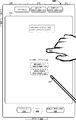
図4A〜図4Mは、いくつかの実施形態に係る、仮想基体を検出し、仮想基体の上にオブジェクトを配置するための例示的なユーザインタフェースを示す。これらの図でのユーザインタフェースは、図7での処理を含む後述の処理を説明するために使用される。以下の実施例のうちのいくつかは、(タッチ感知面及びディスプレイが組み合わされた)タッチスクリーンディスプレイ上での入力を参照して説明されるが、いくつかの実施形態では、デバイスは、ディスプレイとは別個の入力デバイス(例えば、別個のタッチパッド及びディスプレイを備えるラップトップ、又は別個のマウス及びディスプレイを備えるデスクトップ)を介した入力を検出する。 4A-4M illustrate an exemplary user interface for detecting a virtual substrate and placing an object on the virtual substrate according to some embodiments. The user interface in these figures is used to describe the processing described below including the processing in FIG. 7. Although some of the following examples are described with reference to input on a touch screen display (combined touch sensitive surface and display), in some embodiments the device is Detects input via a separate input device (eg, a laptop with a separate touchpad and display, or a desktop with a separate mouse and display).
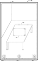
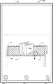
図4Aに示されるように、デバイス100は、平面を検出し、平面の上に拡張現実及び/又は仮想現実(AR/VR)オブジェクトを配置するために提供されたメディアキャプチャ/対話インタフェース402を表示する。いくつかの実施形態によれば、メディアキャプチャ/対話インタフェース402は、画像センサの視野の変化と共に変化する、デバイスの画像センサの視野内のオブジェクトを含むシーンのメディアキャプチャプレビューに対応する。例えば、図4Aでは、メディアキャプチャプレビューは、室内にテーブル415がある部屋への開かれた出入口を含む。
As shown in FIG. 4A,
図4Aでは、メディアキャプチャ/対話インタフェース402は、(例えば、接触ジェスチャ又は選択ジェスチャによる)その選択に応じて画像をキャプチャするために提供されたスナップショットアフォーダンス404a、(例えば、接触ジェスチャ又は選択ジェスチャによる)その選択に応じて(例えば、図4E〜図4Fに示されるように)オブジェクト選択インタフェースを表示するために提供されたAR/VRオブジェクトメニューアフォーダンス404b、及び(例えば、接触ジェスチャ又は選択ジェスチャによる)その選択に応じてオプションメニュー並びに/又はセッティングメニューを表示するために提供されたオプションアフォーダンス404cを含む。図4Aでは、メディアキャプチャ/対話インタフェース402は、第1の外観状態410で表示されたレチクル要素も含む。図4Aに示されるように、第1の外観状態410では、レチクル要素は、不透明な角を有するが、辺を有さない透明な矩形に対応する。いくつかの実施形態では、レチクル要素は、矩形、楕円形、多角形、拡大鏡、十字線などに対応する。
In FIG. 4A, the media capture/
図4A〜図4Bは、デバイス100の画像センサの視野の変化に基づいて、メディアキャプチャ/対話インタフェース402が更新されるシーケンスを示す。例えば、図4Bでは、メディアキャプチャプレビューは、室内にテーブル415がある部屋の2つの壁を含む。したがって、デバイス100の視点又は展望点は、図4Aと図4Bとの間で変化する。
4A-4B show a sequence in which the media capture/
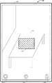
図4B〜図4Cは、レチクル要素の外観状態が、レチクル要素に近接した平面の検出に応じて、第1の外観状態から第2の外観状態に変化するシーケンスを示す。例えば、デバイス100は、テーブル415に関連付けられた平面を検出する。この実施例を続けると、平面の検出に応じて、デバイス100は、レチクル要素を第1の外観状態410から第2の外観状態410’に変更する。図4Cに示されるように、第2の外観状態410’において、レチクル要素は、点線の辺を有する網掛けの矩形に対応する。いくつかの実施形態では、第2の外観状態410’において、レチクル要素の辺は明滅又は点滅する。いくつかの実施形態では、第2の外観状態410’において、レチクル要素の辺は、時計回り又は反時計回りに明滅又は点滅する。いくつかの実施形態によれば、第2の外観状態410’で表示されている間、レチクル要素は、デバイス100がシーン内の平面を検出したという視覚的な合図を提供する。いくつかの実施形態によれば、第2の外観状態410’で表示されている間に、レチクル要素は、テーブル415に関連付けられた検出された平面の範囲の一部の視覚的なインジケーションを提供する。
4B to 4C show a sequence in which the appearance state of the reticle element changes from the first appearance state to the second appearance state in response to detection of a plane close to the reticle element. For example,
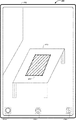
図4C〜図4Dは、レチクル要素の外観状態が、平面の向きの検出に応じて、第2の外観状態から第3の外観状態に変化するシーケンスを示す。例えば、図4Dでは、デバイス100は、レチクル要素をテーブル415に関連付けられた検出された平面の向きに回転させる及び/又は位置合わせすることによって、レチクル要素を第3の外観状態410’’で表示する。
4C to 4D show a sequence in which the appearance state of the reticle element changes from the second appearance state to the third appearance state in response to the detection of the orientation of the plane. For example, in FIG. 4D, the
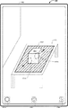
図4D〜図4Eは、レチクル要素の外観状態が、平面のより大きい範囲の検出に応じて、第3の外観状態から第4の外観状態に変化するシーケンスを示す。例えば、図4Eでは、デバイス100は、その範囲が以前に検出されたものよりも大きいことを示す平面に関連付けられた追加の点の検出に応じてレチクル要素の面積を拡大することによって、レチクル要素を第4の外観状態410’’’で表示する。
4D-4E show a sequence in which the appearance state of a reticle element changes from a third appearance state to a fourth appearance state in response to detection of a larger area of a plane. For example, in FIG. 4E,
図4E〜図4Gは、AR/VRオブジェクトが、検出された平面に対してシーン内に配置されるシーケンスを示す。図4Eに示されるように、デバイス100は、AR/VRオブジェクトメニューアフォーダンス404bに対応する場所において、接触412(例えば、タップジェスチャ又は選択ジェスチャ)を検出する。図4Fに示されるように、デバイス100は、図4EにおけるAR/VRオブジェクトメニューアフォーダンス404bの選択の検出に応じて、メディアキャプチャ/対話インタフェース402上にオーバーレイされたオブジェクト選択インタフェース472を表示する。
4E-4G show a sequence in which AR/VR objects are placed in a scene relative to a detected plane. As shown in FIG. 4E, the
図4Fでは、オブジェクト選択インタフェース472は、形状、動物、及び輸送それぞれに関連付けられた複数のAR/VRオブジェクトカテゴリタブ474a、474b、及び474cを含む。図4Fでは、形状に関連付けられたAR/VRオブジェクトカテゴリタブ474aが目下選択されている。結果として、オブジェクト選択インタフェース472は、形状カテゴリに関連付けられた複数のユーザ選択可能AR/VRオブジェクト476a、476b、476c、476d、476e、及び476f(本明細書では、「ユーザ選択可能なAR/VRオブジェクト476」と総称することもある)を含む。いくつかの実施形態では、ユーザ選択可能なAR/VRオブジェクト476のそれぞれは、名前、プレビュー画像、関連メタデータなどに関連付けられる。図4Fでは、オブジェクト選択インタフェース472は、(例えば、接触ジェスチャ又は選択ジェスチャによる)その選択に応じてAR/VRオブジェクトの追加のカテゴリを表示するために提供された追加のカテゴリアフォーダンス478も含む。
In FIG. 4F, the
図4Fに示されるように、デバイス100は、ユーザ選択可能AR/VRオブジェクト476f(例えば、直方体オブジェクト)に対応する場所において、接触414(例えば、タップジェスチャ又は選択ジェスチャ)を検出する。図4Gに示されるように、デバイス100は、図4Fにおけるユーザ選択可能AR/VRオブジェクト476fの選択の検出に応じて、検出された平面に対して、シーン内に直方体AR/VRオブジェクト420を表示する。いくつかの実施形態では、デバイスは、検出された平面の幾何学的中心(例えば、重心)に直方体AR/VRオブジェクト420を表示する。
As shown in FIG. 4F, the
図4G〜図4Hは、直方体AR/VRオブジェクト420のサイズを拡大するシーケンスを示す。図4Gに示されるように、デバイス100は、直方体AR/VRオブジェクト420における接触416a及び416bによる逆ピンチジェスチャを検出する。図4Hに示されるように、デバイス100は、図4Gにおける逆ピンチジェスチャの検出に応じて、検出された平面に対して、シーン内の直方体AR/VRオブジェクト420のサイズを拡大する。
4G to 4H show a sequence for increasing the size of the rectangular parallelepiped AR/
図4H〜図4Iは、直方体AR/VRオブジェクト420が、検出された平面に対して移動するシーケンスを示す。図4Hに示されるように、デバイス100は、直方体AR/VRオブジェクト420における接触418によるタップアンドドラッグジェスチャを検出する。図4Iに示されるように、デバイス100は、図4Hにおけるタップアンドドラッグジェスチャの検出に応じて、検出された平面に対して、直方体AR/VRオブジェクト420をテーブル415の手前の辺423の近くに表示する。
4H to 4I show a sequence in which the rectangular parallelepiped AR/
図4I〜図4Jは、直方体AR/VRオブジェクト420の向きが変更されるシーケンスを示す。図4Iに示されるように、デバイス100は、直方体AR/VRオブジェクト420における接触422a及び422bによる反時計回り回転ジェスチャを検出する。図4Jに示されるように、デバイス100は、図4Iにおける反時計回り回転ジェスチャの検出に応じて、検出された平面に対して、シーン内で直方体AR/VRオブジェクト420を反時計回りに回転させる。
4I to 4J show a sequence in which the orientation of the rectangular parallelepiped AR/
図4J〜図4Kは、直方体AR/VRオブジェクト420が直方体AR/VRオブジェクト430a及び430bに分割されるシーケンスを示す。図4Jに示されるように、デバイス100は、直方体AR/VRオブジェクト420の中間の手前の上辺427に対応する場所における接触424による所定の対話ジェスチャ(例えば、シングルタップジェスチャ又はダブルタップジェスチャ)を検出する。図4Kに示されるように、デバイス100は、図4Hにおける対話ジェスチャの位置に基づいて直方体AR/VRオブジェクト420を直方体AR/VRオブジェクト430a及び430bに分割し、検出された平面に対して、直方体AR/VRオブジェクト430a及び430bを表示する。
4J to 4K show a sequence in which the rectangular parallelepiped AR/
図4K〜図4Lは、デバイス100の画像センサの視野の変化に基づいて、メディアキャプチャ/対話インタフェース402が更新されるシーケンスを示す。例えば、図4Lでは、メディアキャプチャプレビューは、室内にテーブル415がある部屋の単一の壁を含む。したがって、デバイス100の視点又は展望点が変化し、それに従って直方体AR/VRオブジェクト430a及び430bの視点が変化する。
4K-4L illustrate a sequence in which the media capture/
図4L〜図4Mは、レチクル要素の外観状態が、レチクル要素の辺とのユーザ入力対話の検出に応じて、第4の外観状態から第5の外観状態に変化するシーケンスを示す。図4Lに示されるように、デバイス100は、接触426によるタップアンドドラッグジェスチャを検出し、それによって、レチクル要素の辺442は、テーブル415の辺444に向かってドラッグされる。例えば、図4Mでは、デバイス100は、図4Lにおけるタップアンドドラッグジェスチャの検出に応じて、レチクル要素のサイズを拡大することによって、レチクル要素を第5の外観状態410’’’’で表示する。
4L-4M illustrate a sequence in which the appearance state of a reticle element changes from a fourth appearance state to a fifth appearance state in response to detecting a user input interaction with a side of the reticle element. As shown in FIG. 4L,
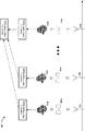
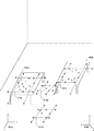
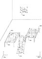
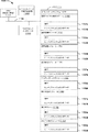
図5Aは、いくつかの実施形態に係る、四分木のセットを生成するためのプロセス500に関連付けられた抽象ブロック図を示す。関連する特徴が示されているが、当業者は、本明細書に開示される例示的な実施形態のより適切な態様を曖昧にしないよう、簡潔にするために様々な他の特徴が示されていないことを、本開示から理解されよう。例えば、いくつかの実施形態では、プロセス500において、四分木のセット525は、時間にわたって異なる基準点/展望点(例えば、カメラ位置又は視野)においてキャプチャされた画像のセットから構築された平面のセット520a、520b〜520nをマージすることによって生成される。
FIG. 5A illustrates an abstract block diagram associated with a
図5Aに示されるように、デバイス100又はその構成要素(例えば、図11における画像キャプチャ制御モジュール1150)は、第1の基準点/展望点502aに対して画像の第1のセット504a(例えば、画像データ)を取得する。いくつかの実施形態では、デバイス100又はその構成要素(例えば、図11における点群合成モジュール1156)は、画像の第1のセット504aに基づいて、第1の3次元(3d)点群506aを合成する。いくつかの実施形態では、デバイス100又はその構成要素(例えば、図11における平面フィッティングモジュール1158)は、第1の3d点群506aに基づいて、平面の第1のセット520aを構築する。例えば、デバイス100は、当該技術分野における既知のアルゴリズム又は技術(例えば、最小二乗法、主成分分析、自己位置推定・環境地図作成(SLAM)など)に従って、第1の3d点群506aに平面をフィットさせることによって、平面の第1のセット520aを構築する。
As shown in FIG. 5A,
同様に、図5Aに示されるように、デバイス100又はその構成要素(例えば、図11における画像キャプチャ制御モジュール1150)は、第2の基準点/展望点502bに対して画像の第2のセット504bを取得する。いくつかの実施形態では、デバイス100又はその構成要素(例えば、図11における点群合成モジュール1156)は、画像の第2のセット504bに基づいて、第2の3d点群506bを合成する。いくつかの実施形態では、デバイス100又はその構成要素(例えば、図11における平面フィッティングモジュール1158)は、第2の3d点群506bに基づいて、平面の第2のセット520bを構築する。
Similarly, as shown in FIG. 5A,
同様に、図5Aに示されるように、デバイス100又はその構成要素(例えば、図11における画像キャプチャ制御モジュール1150)は、第nの基準点/展望点502nに対して画像の第nのセット504nを取得する。いくつかの実施形態では、デバイス100又はその構成要素(例えば、図11における点群合成モジュール1156)は、画像の第nのセット504nに基づいて、第nの3d点群506nを合成する。いくつかの実施形態では、デバイス100又はその構成要素(例えば、図11における平面フィッティングモジュール1158)は、第nの3d点群506nに基づいて、平面の第nのセット520nを構築する。
Similarly, as shown in FIG. 5A, the
いくつかの実施形態によれば、デバイス100又はその構成要素(例えば、図11における相関モジュール1162)は、平面の第1のセット520a、平面の第2のセット520b〜平面の第nのセット520nを相関させて、平面のマージされたセットを生成する。次に、いくつかの実施形態では、デバイス100又はその構成要素(例えば、図11における四分木生成モジュール1160)は、平面のマージされたセットに基づいて、四分木のセット525を生成する。例えば、デバイス100は、当該技術分野において既知のアルゴリズム又は技術に従って、四分木のセット525を生成する。
According to some embodiments,
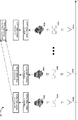
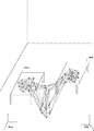
図5Bは、いくつかの実施形態に係る、四分木のセットを生成するためのプロセス550に関連付けられた抽象ブロック図を示す。関連する特徴が示されているが、当業者は、本明細書に開示される例示的な実施形態のより適切な態様を曖昧にしないよう、簡潔にするために様々な他の特徴が示されていないことを、本開示から理解されよう。例えば、いくつかの実施形態では、プロセス550において、四分木のマージされたセット540は、時間にわたって異なる基準点/展望点(例えば、カメラ位置又は視野)に関連付けられた3d点群から構築された四分木のセット530a、530b〜530nをマージすることによって生成される。
FIG. 5B illustrates an abstract block diagram associated with a
図5Bに示されるように、デバイス100又はその構成要素(例えば、図11における画像キャプチャ制御モジュール1150)は、第1の基準点/展望点502aに対して画像の第1のセット504a(例えば、画像データ)を取得する。いくつかの実施形態では、デバイス100又はその構成要素(例えば、図11における点群合成モジュール1156)は、画像の第1のセット504aに基づいて、第1の3d点群506aを合成する。いくつかの実施形態では、デバイス100又はその構成要素(例えば、図11における平面フィッティングモジュール1158)は、第1の3d点群506a及び/又は画像の第1のセット504aに基づいて、平面の第1のセット520aを構築する。いくつかの実施形態では、デバイス100又はその構成要素(例えば、図11における四分木生成モジュール1160)は、平面の第1のセット520a及び/又は第1の3d点群506aに基づいて、四分木の第1のセット530aを生成する。例えば、デバイス100は、図10を参照して説明する詳細に従って、四分木の第1のセット530aを生成する。
As shown in FIG. 5B, the
同様に、図5Bに示されるように、デバイス100又はその構成要素(例えば、図11における画像キャプチャ制御モジュール1150)は、第2の基準点/展望点502bに対して画像の第2のセット504bを取得する。いくつかの実施形態では、デバイス100又はその構成要素(例えば、図11における点群合成モジュール1156)は、画像の第2のセット504bに基づいて、第2の3d点群506bを合成する。いくつかの実施形態では、デバイス100又はその構成要素(例えば、図11における平面フィッティングモジュール1158)は、第2の3d点群506b及び/又は画像の第2のセット504bに基づいて、平面の第2のセット520bを構築する。いくつかの実施形態では、デバイス100又はその構成要素(例えば、図11における四分木生成モジュール1160)は、平面の第2のセット520b及び/又は第2の3d点群506bに基づいて、四分木の第2のセット530bを生成する。
Similarly, as shown in FIG. 5B, the
同様に、図5Bに示されるように、デバイス100又はその構成要素(例えば、図11における画像キャプチャ制御モジュール1150)は、第nの基準点/展望点502nに対して画像の第nのセット504nを取得する。いくつかの実施形態では、デバイス100又はその構成要素(例えば、図11における点群合成モジュール1156)は、画像の第nのセット504nに基づいて、第nの3d点群506nを合成する。いくつかの実施形態では、デバイス100又はその構成要素(例えば、図11における平面フィッティングモジュール1158)は、第nの3d点群506n及び/又は画像の第nのセット504nに基づいて、平面の第nのセット520nを構築する。いくつかの実施形態では、デバイス100又はその構成要素(例えば、図11における四分木生成モジュール1160)は、平面の第nのセット520n及び/又は第nの3d点群506nに基づいて、四分木の第nのセット530nを生成する。
Similarly, as shown in FIG. 5B, the
いくつかの実施形態によれば、デバイス100又はその構成要素(例えば、図11における相関モジュール1162)は、四分木の第1のセット530a、四分木の第2のセット530b〜四分木の第nのセット530nを相関させて、四分木のマージされたセット540を生成する。例えば、デバイス100は、図10を参照して説明する詳細に従って、四分木のマージされたセット540を生成する。
According to some embodiments,
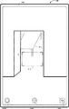
図6A〜図6Gは、いくつかの実施形態に係る、仮想基体を検出するための例示的なユーザインタフェースを示す。これらの図でのユーザインタフェースは、図8〜図10におけるプロセスを含む、後述のプロセスを説明するために使用される。以下の実施例のうちのいくつかは、(タッチ感知面とディスプレイとを組み合わせた)タッチスクリーンディスプレイ上での入力を参照して説明されるが、いくつかの実施形態では、デバイスは、図4Bに示されるように、ディスプレイ450とは別個のタッチ感知面451上で入力を検出する。 6A-6G show an exemplary user interface for detecting a virtual substrate, according to some embodiments. The user interface in these figures is used to describe the processes described below, including the processes in FIGS. 8-10. Although some of the following examples are described with reference to input on a touch screen display (combined touch sensitive surface and display), in some embodiments, the device is shown in FIG. Inputs are detected on a touch-sensitive surface 451 separate from the display 450, as shown in FIG.
いくつかの実施形態では、デバイス100は、図6Gにおけるメディアキャプチャ/対話インタフェース652と同様のユーザインタフェース内に、図6A〜図6Hにおいて実行されるステップを表示する。いくつかの実施形態では、デバイス100は、図6A〜図6Hにおけるステップを実行するが、表示はせず、その代わりに、図6Gにおけるメディアキャプチャ/対話インタフェース652内に、結果として生じる平面650a、650b、650c、及び650dを表示する。
In some embodiments,
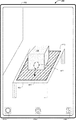
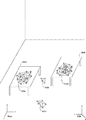
図6Aに示されるように、デバイス100は、シーン内の複数の点のクラスタ605a、605b、605c、及び605dを検出する。例えば、点のクラスタ605aは、シーン内の第1のテーブル604aに対応する。例えば、点のクラスタ605bは、シーン内の床の一部に対応する。例えば、点のクラスタ605cは、シーン内の床の別の一部に対応する。例えば、点のクラスタ605dは、シーン内の第2のテーブル604bに対応する。いくつかの実施形態によれば、デバイス100は、シーンの複数の画像を取得し、点のクラスタ605a、605b、605c、及び605dを含むシーンにおいて特定された点の3次元(3d)点群を合成する。いくつかの実施形態では、デバイス100又はその構成要素(例えば、図11における座標変換モジュール1154)は、デバイス座標602bに関連付けられた画像空間と、ワールド座標602aに関連付けられた3d空間(例えば、図6A〜図6Gにおける部屋又はシーン)との間の変換を実行するために、ワールド座標602a及びデバイス座標602bを追跡する。
As shown in FIG. 6A,
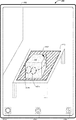
図6Bに示されるように、3d点群に関連付けられた3d座標空間において、デバイス100は、図6Aにおける点のクラスタ605a、605b、605c、及び605dに基づいて、複数の平面610a、610b、610c、及び610d(例えば、無限平面)を構築する(例えば、特定する)。いくつかの実施形態では、デバイス100は、当該技術分野において既知のアルゴリズム又は技術(例えば、最小二乗法、主成分分析、自己位置推定・環境地図作成(SLAM)など)に従って、3d点群における点のクラスタ605a、605b、605c、及び605dに無限平面をフィットさせることによって、複数の平面610a、610b、610c、及び610dを構築する。
As shown in FIG. 6B, in the 3d coordinate space associated with the 3d point cloud, the
図6Cに示されるように、3d点群を合成するために使用される複数の画像に関連付けられた2次元(2d)座標空間において、デバイス100は、図6Aにおける点のクラスタ605a、605b、605c、及び605d内の点を三角分割する。
As shown in FIG. 6C, in a two-dimensional (2d) coordinate space associated with the multiple images used to synthesize the 3d point cloud,
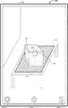
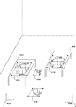
図6Dに示されるように、2d座標空間において、デバイス100は、図6Bにおける複数の平面610a、610b、610c、及び610dに基づいて、同じ平面に関連付けられていない点を有する三角形を除去して、複数の制約付き三角分割領域620a、620b、620c、及び620dを取得する。
As shown in FIG. 6D, in 2d coordinate space, the
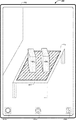
図6Eに示されるように、デバイス100は、複数の制約付き三角分割領域620a、620b、620c、及び620dを再び3d座標空間に投影し、複数の制約付き三角分割領域620a、620b、620c、及び620dを方形化して、四分木630a、630b、630c、及び630dを取得する。図6Eでは、四分木630a、630b、630c、及び630dは、その範囲に基づいて、バウンディングボックスによって囲まれている。
As shown in FIG. 6E, the
図6Fに示されるように、追加の点の検出により、第1のテーブル604aに関連付けられた四分木630aは、そのサイズが状態630a’に拡大されており、床に関連付けられた四分木630b及び630cは、四分木630eにマージされており、第2テーブル604bに関連付けられた四分木630dは、そのサイズが状態630d’に拡大されており、シーン内の部屋の壁に関連付けられた新たな四分木630fが検出されている。
As shown in FIG. 6F, the detection of the additional point causes the
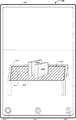
図6Gに示されるように、デバイス100は、平面を検出し、平面の上に拡張現実及び/又は仮想現実(AR/VR)オブジェクトを配置するために提供されたメディアキャプチャ/対話インタフェース652を表示する。いくつかの実施形態によれば、メディアキャプチャ/対話インタフェース652は、画像センサの視野の変化と共に変化する、デバイスの画像センサの視野内のオブジェクトを含むシーンのメディアキャプチャプレビューに対応する。例えば、図6Gでは、メディアキャプチャプレビューは、テーブル604a及び604bを有する図6A〜図6Fに示されたシーンを含む。いくつかの実施形態によれば、図6Gにおけるメディアキャプチャ/対話インタフェース652は、図4A〜図4Mにおけるメディアキャプチャ/対話インタフェース402に類似又は適合する。
As shown in FIG. 6G,
図6Gでは、メディアキャプチャ/対話インタフェース652は、(例えば、接触ジェスチャ又は選択ジェスチャによる)その選択に応じて画像をキャプチャするために提供されたスナップショットアフォーダンス654a、(例えば、接触ジェスチャ又は選択ジェスチャによる)その選択に応じてオブジェクト選択インタフェースを表示するために提供されたAR/VRオブジェクトメニューアフォーダンス654b、及び(例えば、接触ジェスチャ又は選択ジェスチャによる)その選択に応じてオプションメニュー並びに/又はセッティングメニューを表示するために提供されたオプションアフォーダンス654cを含む。図6Gでは、ユーザインタフェース602は、図6Fにおける四分木630a’、630d’、630e、及び630fのバウンディングボックスにそれぞれ対応する平面範囲650a、650b、650c、及び650dも含む。
In FIG. 6G, the media capture/
図6Gに示されるように、平面範囲650a、650b、650c、及び650dのそれぞれは、固有の外観、パターン、塗り潰し、及び/又は同様のものと共に表示される。いくつかの実施形態によれば、平面範囲650a、650b、650c、及び650dのそれぞれは、その上にAR/VRオブジェクトを(例えば、図4F〜図4Gに示されるように)配置することができ、またその上でAR/VRオブジェクトを(例えば、図4G〜図4Kに示されるように)操作することができる仮想基体に対応する。いくつかの実施形態では、平面範囲650a、650b、650c、及び650dのそれぞれは、平面がシーン内で検出されたという視覚的な合図を提供する。いくつかの実施形態では、平面範囲650a、650b、650c、及び650dのそれぞれは、関連付けられた検出された四分木の範囲の一部の視覚的なインジケーションを提供する。
As shown in FIG. 6G, each of the
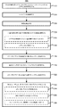
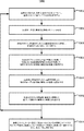
図7は、いくつかの実施形態に係る、仮想基体を検出し、仮想基体の上にオブジェクトを配置する方法700のフローチャート表現である。いくつかの実施形態では(また、一実施例として下記で詳述するように)、方法700は、1つ以上のプロセッサ、非一時的メモリ、画像センサ又はカメラアセンブリ、ディスプレイ、及び1つ以上の入力デバイスを含む、図1における電子デバイス100又は図3におけるデバイス300などの電子デバイス(又はその一部)によって実行される。例えば、ディスプレイ及び1つ以上の入力デバイスは、タッチスクリーンディスプレイに組み合わされる。この実施例では、電子デバイスは、スマートフォン又はタブレットに対応する。別の実施例では、ディスプレイ及び1つ以上の入力デバイスは別個である。この実施例では、電子デバイスは、ラップトップコンピュータ又はデスクトップコンピュータに対応する。例えば、電子デバイスは、着用型コンピューティングデバイス、スマートフォン、タブレット、ラップトップコンピュータ、デスクトップコンピュータ、キオスク、セットトップボックス(STB)、オーバーザトップ(OTT)ボックス、ゲーム機、及び/又は同様のものに対応する。
FIG. 7 is a flow chart representation of a
いくつかの実施形態では、方法700は、ハードウェア、ファームウェア、ソフトウェア、又はそれらの好適な組み合わせを含む処理ロジックによって実行される。いくつかの実施形態では、方法700は、非一時的コンピュータ可読記憶媒体(例えば、非一時的メモリ)に記憶されたコード、プログラム、又は命令を実行する1つ以上のプロセッサによって実行される。方法700における一部の動作は、任意選択で組み合わされ、及び/又は、一部の動作の順序は、任意選択で変更される。簡潔に述べると、方法700は、シーン内の平面の検出に応じて、レチクル要素を第1の外観状態から第2の外観状態に変更することと、検出された平面に対して、シーン内に拡張現実/仮想現実(AR/VR)オブジェクトを配置することと、ユーザ入力に基づいて、AR/VRオブジェクトを修正/操作することと、を含む。
In some embodiments,
方法700は、ブロック702において、電子デバイスが、第1の外観状態にあるメディアキャプチャプレビューにオーバーレイされたレチクル要素を表示することから開始される。例えば、図4Bでは、デバイス100は、室内にテーブル415及び2つの壁がある部屋に対応するシーンのメディアキャプチャプレビューを含むメディアキャプチャ/対話インタフェース402を表示する。この実施例を続けると、図4Bでは、メディアキャプチャ/対話インタフェース402は、第1の外観状態410で表示されたレチクル要素も含む。いくつかの実施形態では、第1の外観状態410では、レチクル要素は、不透明な角を有するが、辺を有さない透明な矩形に対応する。いくつかの実施形態では、レチクル要素は、矩形、楕円形、多角形、拡大鏡、十字線などに対応する。
The
方法700は、ブロック704において、電子デバイスが、シーンデータを取得することで継続される。いくつかの実施形態によれば、デバイス100又はその構成要素(例えば、図11における画像キャプチャ制御モジュール1150)は、画像センサ又はカメラアセンブリで、第1の基準点/展望点(例えば、カメラ位置又は視野)からシーンの2つ以上の画像をキャプチャすることによって、シーンデータ(例えば、画像データ)を取得する。
The
方法700は、ブロック706において、電子デバイスが、シーンデータに基づいて平面を検出することで継続される。例えば、デバイスは、シーンデータ内の平坦な表面(例えば、床、壁、テーブル上面など)を検出する。いくつかの実施形態によれば、デバイス100又はその構成要素(例えば、図11における平面フィッティングモジュール1158)は、シーンデータを処理することによって少なくとも1つの平面を検出する。例えば、図4Bを参照すると、デバイス100は、テーブル415の上面に対応する平面を検出する。いくつかの実施形態では、平面の全体はレチクル要素内にある。いくつかの実施形態では、平面の少なくとも一部はレチクル要素内にある。いくつかの実施形態では、平面はレチクル要素の範囲よりも大きい。いくつかの実施形態では、平面はレチクル要素の範囲よりも小さい。いくつかの実施形態では、2つ以上の平面の検出に応じて、デバイスは、2つ以上の検出された平面に近接した位置において、複数のレチクル要素を第2の外観状態で表示する。
The
方法700は、ブロック708において、電子デバイスが、平面の検出を示す第2の外観状態でレチクル要素を表示することで継続される。例えば、図4Cでは、デバイス100は、レチクル要素に近接したテーブル415の上面に関連付けられた平面の検出に応じて、レチクル要素を第1の外観状態410から第2の外観状態410’に変更する。いくつかの実施形態では、第2の外観状態では、レチクル要素は、不透明な又は点滅する辺を有する透明な矩形として表示される。いくつかの実施形態では、第2の外観状態では、レチクル要素は、不透明な又は点滅する辺を有する部分的に透明な矩形として表示される。いくつかの実施形態では、第2の外観状態で表示されている間に、レチクル要素は、AR/VRオブジェクトのための仮想基体として使用することができる平面が検出されたという視覚的な合図を提供する。いくつかの実施形態では、第2の外観状態で表示されている間に、レチクル要素は、AR/VRオブジェクトのための仮想基体として使用することができる検出された平面の境界の視覚的な合図も提供する。
The
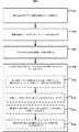
いくつかの実施形態では、デバイスは、第1の外観状態で表示されている間に、検出された平面がレチクル要素に近接しているという判定に従って、レチクル要素を第1の外観状態から第2の外観状態に遷移させる。いくつかの実施形態によれば、検出された平面がシーンデータに関連付けられた画像空間(例えば、デバイス座標に関連付けられた2次元空間)上に投影され、少なくとも所定数のピクセルがレチクル要素と検出された平面とで重複する場合、検出された平面は、レチクル要素に近接している。いくつかの実施形態によれば、レチクル要素がシーンに関連付けられた現実世界空間(例えば、ワールド座標に関連付けられた3次元空間)上に投影され、少なくとも所定数のピクセルがレチクル要素と検出された平面とで重複する場合、検出された平面は、レチクル要素に近接している。 In some embodiments, the device moves the reticle element from the first appearance state to the second appearance state according to the determination that the detected plane is proximate to the reticle element while being displayed in the first appearance state. Transition to the appearance state of. According to some embodiments, the detected plane is projected onto an image space associated with the scene data (eg, a two-dimensional space associated with device coordinates) and at least a predetermined number of pixels are detected as reticle elements. The detected plane is proximate to the reticle element if it overlaps the defined plane. According to some embodiments, the reticle element is projected onto a real-world space associated with the scene (eg, a three-dimensional space associated with world coordinates) and at least a predetermined number of pixels are detected as the reticle element. The detected plane is close to the reticle element if it overlaps with the plane.
いくつかの実施形態では、デバイスは、第1の外観状態で表示されている間に、検出された平面がレチクル要素の閾値距離内にあるという判定に従って、レチクル要素を第1の外観状態から第2の外観状態に遷移させる。いくつかの実施形態によれば、検出された平面がデバイスの所定の距離内にある場合、検出された平面は、レチクル要素の閾値距離内にある。
In some embodiments, the device moves the reticle element from the first appearance state to the first appearance state according to the determination that the detected plane is within a threshold distance of the reticle element while being displayed in the first appearance state. Transition to
いくつかの実施形態では、ブロック712によって表されるように、デバイスは、レチクル要素を検出された平面の向きに位置合わせする。例えば、図4Dでは、デバイス100は、レチクル要素をテーブル415に関連付けられた検出された平面の向きに回転させる及び/又は位置合わせすることによって、レチクル要素を第3の外観状態410’’で表示する。いくつかの実施形態では、レチクル要素は、検出された平面のヨー、ピッチ、及び/又はローに位置合わせされる。
In some embodiments, as represented by
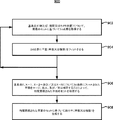
いくつかの実施形態では、ブロック714によって表されるように、デバイスは、レチクル要素を拡大する。例えば、図4Eでは、デバイス100は、その範囲が以前に検出されたものよりも大きいことを示す平面に関連付けられた追加の点の検出に応じてレチクル要素の面積を拡大することによって、レチクル要素を第4の外観状態410’’’で表示する。いくつかの実施形態では、レチクル要素は、平面の検出されたサイズに拡げられる。いくつかの実施形態では、レチクル要素は、平面の検出されたサイズに縮められる。いくつかの実施形態では、レチクル要素が第2の外観状態で表示されている間に、レチクル要素のサイズは、追加の点の検出に基づいた、検出された平面のサイズの変化と共に、動的に変化する。
In some embodiments, the device magnifies the reticle element, as represented by
例えば、デバイスは、ピンチジェスチャ、ピンチアウトジェスチャ、タップアンドドラッグジェスチャなどのレチクル要素の1つ以上の寸法の変更に対応するユーザ入力を検出する。例えば、図4L〜図4Mは、レチクル要素の寸法が図4Lにおけるレチクル要素上でのタップアンドドラッグジェスチャの検出に応じて変更される(例えば、レチクル要素の高さが、テーブル415の手前の辺444に向かって移動される)シーケンスを示す。いくつかの実施形態では、ユーザ入力は、検出された平面の境界内のレチクル要素のサイズを修正する。したがって、いくつかの実施形態では、ユーザ入力は、検出された平面の範囲を超えてレチクル要素をリサイズしない。 For example, the device detects user input corresponding to a change in one or more dimensions of a reticle element such as a pinch gesture, a pinch out gesture, a tap and drag gesture. For example, FIGS. 4L-4M show that the dimensions of the reticle element are changed in response to detecting a tap-and-drag gesture on the reticle element in FIG. (Moved towards 444) sequence. In some embodiments, the user input modifies the size of the reticle element within the boundaries of the detected plane. Therefore, in some embodiments, the user input does not resize the reticle element beyond the range of the detected plane.
方法700は、ブロック716において、電子デバイスが、拡張現実及び/又は仮想現実(AR/VR)オブジェクトをシーン内に配置する第1のユーザ入力を検出することで継続される。例えば、図4Fでは、デバイス100は、オブジェクト選択インタフェース472内のユーザ選択可能AR/VRオブジェクト476f(例えば、直方体オブジェクト)に対応する場所において、接触414(例えば、タップジェスチャ又は選択ジェスチャ)を検出する。いくつかの実施形態では、デバイスは、所定のアフォーダンス(例えば、AR/VRオブジェクトメニューアフォーダンス404b)の選択に応じて、オブジェクト選択インタフェース(例えば、ポップオーバー又はプルダウンメニュー/パネル)を表示する。
The
方法700は、ブロック718において、電子デバイスが、検出された平面に対して、シーン内にAR/VRオブジェクトを表示することで継続される。例えば、図4Gに示されるように、デバイス100は、図4Fにおけるユーザ選択可能AR/VRオブジェクト476fの選択の検出に応じて、検出された平面に対して、シーン内に直方体AR/VRオブジェクト420を表示する。いくつかの実施形態では、AR/VRオブジェクトは、検出された平面の幾何学的中心(例えば、重心)に表示される。いくつかの実施形態では、検出された平面に対して、シーン内にAR/VRオブジェクトを配置した後、デバイス100はレチクル要素を除去する。いくつかの実施形態では、デバイス100は、AR/VRオブジェクトを表示するときに、オクルージョン及びクラッタを低減するためにレチクル要素を除去する。いくつかの実施形態では、デバイスは、検出された平面の向きに基づいて、AR/VRオブジェクトに回転(例えば、ヨー、ピッチ、及び/又はロール)を適用する。
The
方法700は、ブロック720において、電子デバイスが、AR/VRオブジェクトとの対話により配置を行う第2のユーザ入力を検出することで継続される。一実施例として、図4Gでは、デバイス100は、直方体AR/VRオブジェクト420における接触416a及び416bによる逆ピンチジェスチャを検出する。別の実施例として、図4Hでは、デバイス100は、直方体AR/VRオブジェクト420における接触418によるタップアンドドラッグジェスチャを検出する。更に別の実施例として、図4Iでは、デバイス100は、直方体AR/VRオブジェクト420における接触422a及び422bによるツーフィンガ反時計回り回転ジェスチャを検出する。更に別の実施例として、図4Iでは、デバイス100は、直方体AR/VRオブジェクト420における接触424によるワンフィンガタップジェスチャを検出する。
The
方法700は、ブロック722において、電子デバイスが、第2のユーザ入力の1つ以上の特性に基づいて、AR/VRオブジェクトを修正することで継続される。一実施例として、図4H〜4Iは、図4Hにおける直方体AR/VRオブジェクト420上でのタップアンドドラッグジェスチャの検出に応じて、直方体AR/VRオブジェクト420がテーブル415の手前の辺423に近づくように移動するシーケンスを示す。いくつかの実施形態では、第2のユーザ入力の1つ以上の特性は、入力形式(例えば、音声コマンド、ピンチジェスチャ、逆ピンチジェスチャ、タップアンドフラッグジェスチャ、スワイプジェスチャ、ワンフィンガタップジェスチャ、ツーフィンガタップジェスチャ、ワンフィンガダブルタップジェスチャ、ツーフィンガダブルタップジェスチャなど)、入力方向、入力の大きさ、入力速度、及び/又は同様のものに対応する。
The
いくつかの実施形態では、1つ以上の特性は入力形式に対応する。例えば、第3のユーザ入力がタップアンドドラッグジェスチャに対応する場合、デバイスは、検出された平面に対してAR/VRオブジェクトの位置を修正する。いくつかの実施形態では、タップアンドドラッグジェスチャが、AR/VRオブジェクトを検出された平面の外側に移動させる場合、デバイスは、AR/VRオブジェクトを次の最も近い平面(例えば、床面)上に表示する。いくつかの実施形態では、タップアンドドラッグジェスチャが、AR/VRオブジェクトを検出された平面の外側に移動させる場合、デバイスは、検出された平面の縁部におけるAR/VRオブジェクトの表示を維持する。別の実施例では、第3のユーザ入力がピンチジェスチャに対応する場合、デバイスは、AR/VRオブジェクトのサイズを修正する。別の実施例では、第3のユーザ入力が所定のジェスチャに対応する場合、デバイスは、AR/VRオブジェクトと共に所定のアニメーションを表示するか、又はAR/VRオブジェクト上での所定の動作を実行する。いくつかの実施形態では、デバイスは、AR/VRオブジェクトと共に所定のアニメーションを表示するか、又はAR/VRオブジェクトに対してデバイスの距離に基づいて、AR/VRオブジェクト上での所定の動作を実行する。いくつかの実施形態では、デバイスの位置がAR/VRオブジェクトに対して変化すると、デバイスは、AR/VRオブジェクトの視点を維持する(例えば、サイズを拡大/縮小する、AR/VRオブジェクトの異なる角度を示す、など)。 In some embodiments one or more characteristics correspond to an input format. For example, if the third user input corresponds to a tap and drag gesture, the device modifies the position of the AR/VR object with respect to the detected plane. In some embodiments, if the tap and drag gesture moves the AR/VR object outside of the detected plane, the device places the AR/VR object on the next closest plane (eg, floor). indicate. In some embodiments, when the tap-and-drag gesture moves the AR/VR object outside the detected plane, the device maintains the display of the AR/VR object at the edge of the detected plane. In another embodiment, the device modifies the size of the AR/VR object if the third user input corresponds to a pinch gesture. In another example, if the third user input corresponds to a predetermined gesture, the device displays a predetermined animation with the AR/VR object or performs a predetermined action on the AR/VR object. .. In some embodiments, the device displays a predetermined animation with the AR/VR object or performs a predetermined action on the AR/VR object based on the device's distance to the AR/VR object. To do. In some embodiments, when the position of the device changes with respect to the AR/VR object, the device maintains a view of the AR/VR object (eg, scales up/down in size, different angles of the AR/VR object). , Etc.).
いくつかの実施形態では、ブロック724によって表されるように、デバイスは、AR/VRオブジェクトを回転させる。例えば、図4I〜図4Jは、図4Iにおける直方体AR/VRオブジェクト420上での反時計回り回転ジェスチャの検出に応じて、直方体AR/VRオブジェクト420の向きが変更されるシーケンスを示す。
In some embodiments, the device rotates the AR/VR object, as represented by
いくつかの実施形態では、ブロック726によって表されるように、デバイスは、AR/VRオブジェクトをリサイズする。例えば、図4G〜図4Hは、図4Gにおける直方体AR/VRオブジェクト420上での逆ピンチジェスチャの検出に応じて、直方体AR/VRオブジェクト420のサイズを拡大するシーケンスを示す。
In some embodiments, the device resizes the AR/VR object, as represented by
いくつかの実施形態では、ブロック728によって表されるように、デバイスは、AR/VRオブジェクトに関連付けられた挙動をトリガする。いくつかの実施形態では、挙動は、AR/VR動物を可愛がって吠えさせる若しくは泣き声を出させること、AR/VR車をタップしてクラクションを鳴らす若しくはエンジン回転数を上げること、AR/VR立方体をハンマーのようにタップしてキューブを半分に割ること、AR/VR火山をタップして噴火させること、及び/又は同様のこと、などのAR/VRオブジェクト上で実行される所定のアニメーション又は動作に対応する。例えば、図4J〜4Kは、図4Jにおける直方体AR/VRオブジェクト420上での所定の対話ジェスチャの検出に応じて、直方体AR/VRオブジェクト420が直方体AR/VRオブジェクト430a及び430bに分割されるシーケンスを示す。
In some embodiments, as represented by
図8は、いくつかの実施形態に係る、仮想基体として使用するための四分木のマージされたセットを生成する方法800のフローチャート表現である。いくつかの実施形態では(また、一実施例として下記で詳述するように)、方法800は、1つ以上のプロセッサ及び非一時的メモリを含む、図1における電子デバイス100又は図3におけるデバイス300などの電子デバイス(又はその一部)によって実行される。いくつかの実施形態では、デバイスは、任意選択で、ディスプレイ、画像センサ又はカメラアセンブリ、及び1つ以上の入力デバイス(例えば、タッチスクリーンディスプレイ、タッチパッド、マウス、キーボード、物理的ボタン、マイクロフォンなど)を含む。例えば、ディスプレイ及び1つ以上の入力デバイスは、タッチスクリーンディスプレイに組み合わされる。この実施例では、電子デバイスは、スマートフォン又はタブレットに対応する。別の実施例では、ディスプレイ及び1つ以上の入力デバイスは別個である。この実施例では、電子デバイスは、ラップトップコンピュータ又はデスクトップコンピュータに対応する。例えば、電子デバイスは、着用型コンピューティングデバイス、スマートフォン、タブレット、ラップトップコンピュータ、デスクトップコンピュータ、キオスク、セットトップボックス(STB)、オーバーザトップ(OTT)ボックス、ゲーム機、及び/又は同様のものに対応する。
FIG. 8 is a flow chart representation of a
いくつかの実施形態では、方法800は、ハードウェア、ファームウェア、ソフトウェア、又はそれらの好適な組み合わせを含む処理ロジックによって実行される。いくつかの実施形態では、方法800は、非一時的コンピュータ可読記憶媒体(例えば、非一時的メモリ)に記憶されたコード、プログラム、又は命令を実行する1つ以上のプロセッサによって実行される。方法800における一部の動作は、任意選択で組み合わされ、及び/又は、一部の動作の順序は、任意選択で変更される。簡潔に述べると、方法800は、異なる基準点/展望点についての複数の画像のセットを取得することと、複数の画像のセットのそれぞれについて、3d点群を合成することと、それぞれの3d点群を使用して平面を構築することと、3d点群にわたる平面のマージされたセットを特徴付ける四分木のセットを生成することと、を含む。
In some embodiments,
方法800は、ブロック802において、電子デバイスが、異なる基準点/展望点についての複数の画像のセットを取得することから開始される。例えば、図5A〜図5Bに示されるように、デバイス100又はその構成要素(例えば、図11における画像キャプチャ制御モジュール1150)は、基準点/展望点502a、502b〜502nそれぞれについての画像のセット(例えば、画像データ)504a、504b〜504nをそれぞれ取得する。いくつかの実施形態では、画像のセットのそれぞれは、2つ以上の画像を含む。いくつかの実施形態では、画像のセットのそれぞれは、異なる基準点/展望点(例えば、異なるカメラ位置又は視野)に対応する。
The
方法800は、ブロック804において、電子デバイスが、複数の画像のセットのそれぞれについての3次元(3d)点群を合成することで継続される。例えば、図5A〜図5Bに示されるように、デバイス100又はその構成要素(例えば、図11における点群合成モジュール1156)は、基準点/展望点502a、502b〜502nそれぞれについての画像のセット504a、504b〜504nに基づいて、3次元(3d)点群506a、506b〜506nを合成する。いくつかの実施形態では、デバイス100は、画像の各セットについての点のセットを特定し、3d空間内にそれらの点を配置することによって、当該技術分野において既知のアルゴリズム又は技術に従って、3d点群を合成する。
The
方法800は、ブロック806において、電子デバイスが、それぞれの3d点群を使用して平面を構築することで継続される。例えば、図5A〜図5Bに示されるように、デバイス100又はその構成要素(例えば、図11における平面フィッティングモジュール1158)は、3d点群506a、506b〜506nそれぞれに基づいて、平面のセット520a、520b〜520nを構築する。いくつかの実施形態では、デバイス100は、当該技術分野における既知のアルゴリズム又は技術(例えば、最小二乗法、主成分分析、自己位置推定・環境地図作成(SLAM)など)に従って、3d点群に平面を構築する(例えば、フィットさせる)。
The
方法800は、ブロック808において、電子デバイスが、3d点群にわたる平面のマージされたセットを特徴付ける四分木のセットを生成することで継続される。例えば、図5Aに示されるように、デバイス100又はその構成要素(例えば、図11における四分木生成モジュール1160)は、経時的に3d点群506a、506b〜506nにわたる平面のマージされたセットを特徴付ける四分木のセット525を生成する。例えば、図5Bに示されるように、デバイス100又はその構成要素(例えば、図11における四分木生成モジュール1160)は、経時的に3d点群506a、506b〜506nにわたる平面のマージされたセットを特徴付ける四分木のマージされたセット540を生成する。いくつかの実施形態では、デバイス100は、当該技術分野において既知のアルゴリズム又は技術に従って、四分木のセットを生成する。いくつかの実施形態によれば、当該技術分野における当業者には理解されるように、方法800は、シーンを特徴付ける八分木の生成にも適用可能である。
The
いくつかの実施形態では、ブロック810によって表されるように、デバイスは、3d点群のそれぞれについての平面のセットを生成し、平面のセットを相関させることによって、平面のマージされたセットを生成する。いくつかの実施形態では、ブロック812によって表されるように、デバイスは、平面のマージされたセットに基づいて、四分木のセットを生成する。例えば、図5Aに示されるように、デバイス100又はその構成要素(例えば、図11における相関モジュール1162)は、平面の第1のセット520a、平面の第2のセット520b〜平面の第nのセット520nを相関させて、平面のマージされたセットを生成する。次に、図5Aにおける実施例を続けると、デバイス100又はその構成要素(例えば、図11における四分木生成モジュール1160)は、平面のマージされたセットに基づいて、四分木のセット525を生成する。
In some embodiments, as represented by
いくつかの実施形態では、ブロック814によって表されるように、デバイスは、関連付けられた平面に基づいて、3d点群のそれぞれについての四分木の中間セットを生成する。いくつかの実施形態では、ブロック816によって表されるように、デバイスは、四分木の中間セットを相関させることによって、四分木のセットを生成する。例えば、図5Bに示されるように、デバイス100又はその構成要素(例えば、図11における四分木生成モジュール1160)は、平面のセット520a、520n〜520n及び/又は3d点群506a、506b〜506nそれぞれに基づいて、四分木のセット530a、530b〜530nを生成する。次に、図5Bにおける実施例を続けると、デバイス100又はその構成要素(例えば、図11における相関モジュール1162)は、四分木のセット530a、530b〜530nを相関させて、四分木のマージされたセット540を生成する。
In some embodiments, as represented by
図9は、いくつかの実施形態に係る、仮想基体として使用するための四分木のセットを生成する方法900のフローチャート表現である。いくつかの実施形態では(また、一実施例として下記で詳述するように)、方法900は、1つ以上のプロセッサ、非一時的メモリ、任意選択の画像センサ又はカメラアセンブリ、任意選択のディスプレイ、及び1つ以上の任意選択の入力デバイスを含む、図1における電子デバイス100又は図3におけるデバイス300などの電子デバイス(又はその一部)によって実行される。例えば、電子デバイスは、着用型コンピューティングデバイス、スマートフォン、タブレット、ラップトップコンピュータ、デスクトップコンピュータ、キオスク、セットトップボックス(STB)、オーバーザトップ(OTT)ボックス、ゲーム機、及び/又は同様のものに対応する。
FIG. 9 is a flow chart representation of a
いくつかの実施形態では、方法900は、ハードウェア、ファームウェア、ソフトウェア、又はそれらの好適な組み合わせを含む処理ロジックによって実行される。いくつかの実施形態では、方法900は、非一時的コンピュータ可読記憶媒体(例えば、非一時的メモリ)に記憶されたコード、プログラム、又は命令を実行する1つ以上のプロセッサによって実行される。方法900における一部の動作は、任意選択で組み合わされ、及び/又は、一部の動作の順序は、任意選択で変更される。簡潔に述べると、方法900は、異なる基準点/展望点についての複数の平面のセットを生成することと、平面のセットを相関させて、経時的に平面のマージされたセットを取得することと、平面のマージされたセットに基づいて、四分木のセットを生成することと、を含む。
In some embodiments,
方法900は、ブロック902において、電子デバイスが、基準点X(例えば、期間又はカメラ位置)についての画像のセットに基づいて、3次元(3d)点群を取得することから開始される。一実施例として、図5Aでは、デバイス100又はその構成要素(例えば、図11における点群合成モジュール1156)は、第nの基準点/展望点502n(例えば、基準点X)に対して画像の第nのセット504nに基づいて、第nの3d点群506nを合成する。例えば、デバイス100は、画像の第nのセット504n内の点を特定し、当該技術分野において既知のアルゴリズム又は技術に従って、デバイス座標に関連付けられた画像空間内の点の場所をワールド座標に変換することによって、ワールド座標に対して点を配置することによって、第nの3d点群506nを合成する。
The
方法900は、ブロック904において、電子デバイスが、基準点Xについての3d点群に平面をフィットさせることで継続される。一実施例として、図5Aでは、デバイス100又はその構成要素(例えば、図11における平面フィッティングモジュール1158)は、第nの3d点群506nに基づいて、平面の第nのセット520nを構築する。例えば、デバイス100は、当該技術分野における既知のアルゴリズム又は技術(例えば、最小二乗法、主成分分析、自己位置推定・環境地図作成(SLAM)など)に従って、第nの3d点群506nに平面をフィットさせることによって、平面の第nのセット520nを構築する。
The
方法900は、ブロック906において、電子デバイスが、基準点X、X−1、X−2〜X−Nについての3d点群にフィットされた平面をマージ、拡大、及び/又は補正することによって、時間累積された平面のセットを取得することで継続される。一実施例として、図5Aでは、デバイス100又はその構成要素(例えば、図11における相関モジュール1162)は、(例えば、基準点X−2に関連付けられた)平面の第1のセット520a、(例えば、基準点X−1に関連付けられた)平面の第2のセット520b〜(例えば、基準点Xに関連付けられた)平面の第nのセット520nを相関させて、平面のマージされたセットを生成する。例えば、基準点X、X−1、X−2〜X−Nについての3d点群にフィットされた平面のセットを相関させることは、平面を拡大することと、平面をマージすることと、並びに/若しくは、基準点X、X−1、X−2〜X−Nについての3d点群にフィットされた平面の位置、サイズ及び/又は向きの特定された類似性及び/又は差異に基づいて、時間次元にわたり平面のサイズ又は向きを補正することと、を含む。いくつかの実施形態では、平面のセットを相関させることによって、サイズが経時的に変化する動的な平面が補正される。いくつかの実施形態では、追加の関連付けられた点が経時的に検出されると、平面のセットを相関させることによって、平面が拡大される。いくつかの実施形態では、2つ以上の平面が経時的に同一の平面の一部であると判定されると、平面のセットを相関させることによって、平面がマージされる。
The
方法900は、ブロック908において、電子デバイスが、時間累積された平面のセットに基づいて、四分木のセットを生成することで継続される。一実施例として、図5Aでは、デバイス100又はその構成要素(例えば、図11における四分木生成モジュール1160)は、ブロック906からの平面のマージされたセットに基づいて、四分木のセット525を生成する。例えば、デバイス100は、当該技術分野において既知のアルゴリズム又は技術に従って、四分木のセット525を生成する。
The
図10は、いくつかの実施形態に係る、四分木のマージされたセットを生成する方法1000のフローチャート表現である。いくつかの実施形態では(また、一実施例として下記で詳述するように)、方法1000は、1つ以上のプロセッサ、非一時的メモリ、任意選択の画像センサ又はカメラアセンブリ、任意選択のディスプレイ、及び1つ以上の任意選択の入力デバイスを含む、図1における電子デバイス100又は図3におけるデバイス300などの電子デバイス(又はその一部)によって実行される。例えば、電子デバイスは、着用型コンピューティングデバイス、スマートフォン、タブレット、ラップトップコンピュータ、デスクトップコンピュータ、キオスク、セットトップボックス(STB)、オーバーザトップ(OTT)ボックス、ゲーム機、及び/又は同様のものに対応する。
FIG. 10 is a flow chart representation of a
いくつかの実施形態では、方法1000は、ハードウェア、ファームウェア、ソフトウェア、又はそれらの好適な組み合わせを含む処理ロジックによって実行される。いくつかの実施形態では、方法1000は、非一時的コンピュータ可読記憶媒体(例えば、非一時的メモリ)に記憶されたコード、プログラム、又は命令を実行する1つ以上のプロセッサによって実行される。方法1000における一部の動作は、任意選択で組み合わされ、及び/又は、一部の動作の順序は、任意選択で変更される。簡潔に述べると、方法1000は、異なる基準点/展望点についての四分木のセットを生成することと、四分木のセットを相関させて、経時的に四分木のマージされたセットを取得することと、を含む。
In some embodiments,
方法1000は、ブロック1002において、電子デバイスが、基準点X(例えば、期間又はカメラ位置)についての画像のセットに基づいて、3次元(3d)点群を取得することから開始される。一実施例として、図5Bでは、デバイス100又はその構成要素(例えば、図11における点群合成モジュール1156)は、第nの基準点/展望点502n(例えば、基準点X)に対して画像の第nのセット504nに基づいて、第nの3d点群506nを合成する。例えば、デバイス100は、画像の第nのセット504n内の点を特定し、当該技術分野において既知のアルゴリズム又は技術に従って、デバイス座標に関連付けられた画像空間内の点の場所をワールド座標に変換することによって、ワールド座標に対して点を配置することによって、第nの3d点群506nを合成する。
The
方法1000は、ブロック1004において、電子デバイスが、基準点Xについての3d点群に平面をフィットさせることで継続される。一実施例として、図5Bでは、デバイス100又はその構成要素(例えば、図11における平面フィッティングモジュール1158)は、(例えば、基準点Xに関連付けられた)第nの3d点群506nに基づいて、平面の第nのセット520nを構築する。例えば、デバイス100は、当該技術分野における既知のアルゴリズム又は技術(例えば、最小二乗法、主成分分析、自己位置推定・環境地図作成(SLAM)など)に従って、第nの3d点群506nに平面をフィットさせることによって、平面の第nのセット520nを構築する。図6Bに示されるように、例えば、3d点群に関連付けられた3d座標空間において、デバイス100は、図6Aにおける点のクラスタ605a、605b、605c、及び605dに基づいて、複数の平面610a、610b、610c、及び610d(例えば、無限平面)を構築する(例えば、特定する)。
The
方法1000は、ブロック1006において、電子デバイスが、基準点Xについての画像のセットに関連付けられた2次元(2d)座標空間内で3d点群に関連付けられた点を三角分割することで継続される。図6Cに示されるように、例えば、3d点群を合成するために使用される複数の画像に関連付けられた2次元(2d)座標空間において、デバイス100は、図6Aにおける点のクラスタ605a、605b、605c、及び605d内の点を三角分割する。
The
方法1000は、ブロック1008において、電子デバイスが、3d点群にフィットされた平面と相関されない2d座標空間内の三角形を除去して、基準点Xについての制約付き三角分割領域を取得することで継続される。図6Dに示されるように、例えば、2d座標空間において、デバイス100は、図6Bにおける複数の平面610a、610b、610c、及び610dに基づいて、同じ平面に関連付けられていない点を有する三角形を除去して、複数の制約付き三角分割領域620a、620b、620c、及び620dを取得する。
The
いくつかの実施形態では、電子デバイスは、図10に示される順序に従って、ブロック1004、1006、1008、及び1010に対応する動作を順次実行する。いくつかの実施形態では、電子デバイスは、図10に示される順序とは異なる順序に従って、ブロック1004、1006、1008、及び1010に対応する動作を順次実行する。いくつかの実施形態では、電子デバイスは、ブロック1004、1006、1008、及び1010に対応する動作を並列に実行する。
In some embodiments, the electronic device sequentially performs the operations corresponding to
方法1000は、ブロック1010において、電子デバイスが3d点群に関連付けられた3d座標空間上に制約付き三角分割領域を投影することで継続される。方法1000は、ブロック1012において、電子デバイスが、基準点Xについての制約付き三角分割領域に基づいて、四分木のセットを生成することで継続される。一実施例として、図5Bでは、デバイス100又はその構成要素(例えば、図11における平面フィッティングモジュール1158)は、平面の第nのセット520n及び/又は第nの3d点群506nに基づいて、(例えば、基準点Xに関連付けられた)四分木の第nのセット530nを生成する。例えば、デバイス100は、当該技術分野において既知のアルゴリズム又は技術に従って、四分木の第nのセット530nを生成する。図6Eに示されるように、例えば、デバイス100は、複数の制約付き三角分割領域620a、620b、620c、及び620dを再び3d座標空間に投影し、複数の制約付き三角分割領域620a、620b、620c、及び620dを方形化して、四分木630a、630b、630c、及び630dを取得する。図6Eでは、四分木630a、630b、630c、及び630dは、その範囲に基づいて、バウンディングボックスによって囲まれている。
The
方法1000は、ブロック1014において、電子デバイスが、基準点X−1、X−2〜X−Nの四分木のセットに基づいて、基準点Xについての四分木のセットの一部をマージ、拡大、及び/又は補正することで継続される。一実施例として、図5Bでは、デバイス100又はその構成要素(例えば、図11における相関モジュール1162)は、(例えば、基準点X−2に関連付けられた)四分木の第1のセット530a、(例えば、基準点X−1に関連付けられた)四分木の第2のセット530b〜(例えば、基準点Xに関連付けられた)四分木の第nのセット530nを相関させて、四分木のマージされたセット540を生成する。
The
例えば、基準点X、X−1、X−2〜X−Nについての四分木のセットを相関させることは、四分木平面、四分木をマージすることと、並びに/若しくは、基準点X、X−1、X−2〜X−Nについての四分木のセットの位置、サイズ及び/又は向きの特定された類似性及び/又は差異に基づいて、時間次元にわたり四分木のサイズ又は向きを補正することと、を含む。いくつかの実施形態では、四分木のセットを相関させることによって、サイズが経時的に変化する動的な平面に関連付けられた四分木が補正される。いくつかの実施形態では、追加の関連付けられた点が経時的に検出されると、四分木のセットを相関させることによって、四分木が拡大される。いくつかの実施形態では、2つ以上の四分木が経時的に同一の四分木の一部であると判定されると、四分木のセットを相関させることによって、四分木がマージされる。いくつかの実施形態では、四分木のマージされたセットにおける各四分木は、実質的に水平な平面、実質的に垂直な平面、又は3つの自由度のうちの1つ以上に従って角度付けされた平面のうちの1つのインジケーションを提供する。いくつかの実施形態では、マージされた四分木のセットのそれぞれは、仮想基体に対応する。 For example, correlating the set of quadtrees for reference points X, X-1, X-2 to X-N may include quadtree planes, merging quadtrees, and/or reference points. Size of the quadtree over the time dimension based on the identified similarities and/or differences in the position, size and/or orientation of the set of quadtrees for X, X-1, X-2 to X-N. Or correcting the orientation. In some embodiments, correlating a set of quadtrees corrects quadtrees associated with dynamic planes of varying size over time. In some embodiments, the quadtree is expanded by correlating the set of quadtrees as additional associated points are detected over time. In some embodiments, when two or more quadtrees are determined to be part of the same quadtree over time, the quadtrees are merged by correlating the set of quadtrees. To be done. In some embodiments, each quadtree in the merged set of quadtrees is angled according to a substantially horizontal plane, a substantially vertical plane, or one or more of three degrees of freedom. An indication of one of the defined planes. In some embodiments, each of the merged quadtree sets corresponds to a virtual substrate.
図11は、いくつかの実施形態に係る、コンピューティングデバイス1100のブロック図である。いくつかの実施形態では、コンピューティングデバイス1100は、図1におけるデバイス100又は図3におけるデバイス300の少なくとも一部に対応し、上記で説明された機能性のうちの1つ以上を実行する。特定の特徴が示されているが、当業者は、本明細書に開示される実施形態のより適切な態様を曖昧にしないよう、簡潔にするために様々な他の特徴が示されていないことを、本開示から理解されよう。そのために、非限定的な実施例として、いくつかの実施形態では、コンピューティングデバイス1100は、1つ以上の処理ユニット(CPU)1102(例えば、プロセッサ)、1つ以上の入出力(I/O)インタフェース1103(例えば、ネットワークインタフェース、入力デバイス、出力デバイス、及び/又はセンサインタフェース)、メモリ1110、プログラミングインタフェース1105、及びこれら及び様々な他の構成要素を相互接続するための1つ以上の通信バス1104を含む。
FIG. 11 is a block diagram of a
いくつかの実施形態では、通信バス1104は、システム構成要素を相互接続し、システム構成要素間の通信を制御する回路を含む。メモリ1110は、DRAM、SRAM、DDR RAM、又は他のランダムアクセスソリッドステートメモリデバイスなどの高速ランダムアクセスメモリを含み、いくつかの実施形態では、1つ以上の磁気ディスク記憶デバイス、光ディスク記憶デバイス、フラッシュメモリデバイス、又は他の不揮発性ソリッドステート記憶デバイスなどの不揮発性メモリを含む。メモリ1110は、任意選択で、CPU(単数又は複数)1102からリモートに位置する1つ以上の記憶デバイスを含む。メモリ1110は、非一時的コンピュータ可読記憶媒体を含む。更に、いくつかの実施形態では、メモリ1110又はメモリ1110の非一時的コンピュータ可読記憶媒体は、任意選択のオペレーティングシステム1120、画像キャプチャ制御モジュール1150、画像処理モジュール1152、座標変換モジュール1154、点群合成モジュール1156、平面フィッティングモジュール1158、四分木生成モジュール1160、相関モジュール1162、並びに拡張現実及び/又は仮想現実(AR/VR)処理モジュール1164、を含むプログラム、モジュール及びデータ構造、又はそれらのサブセットを記憶する。いくつかの実施形態では、1つ以上の命令は、論理メモリ及び非一時的メモリの組み合わせに含まれる。オペレーティングシステム1120は、様々な基本システムサービスを処理するための及びハードウェア依存タスクを実行するための手順を含む。
In some embodiments,
いくつかの実施形態では、画像キャプチャ制御モジュール1150は、画像をキャプチャするか、又は画像データを取得するための画像センサ又はカメラアセンブリの機能性を制御するように構成される。そのために、画像キャプチャ制御モジュール1150は、命令セット1151a並びにヒューリスティック及びメタデータ1151bを含む。
In some embodiments, the image capture control module 1150 is configured to control the functionality of the image sensor or camera assembly for capturing an image or acquiring image data. To that end, the image capture control module 1150 includes an
いくつかの実施形態では、画像処理モジュール1152は、画像センサ又はカメラアセンブリから生画像データを前処理する(例えば、RAW画像データをRGB画像データ又はYCbCr画像データに変換する)ように構成される。そのために、画像処理モジュール1152は、命令セット1153a並びにヒューリスティック及びメタデータ1153bを含む。
In some embodiments, the image processing module 1152 is configured to pre-process raw image data from an image sensor or camera assembly (eg, convert RAW image data to RGB image data or YCbCr image data). To that end, the image processing module 1152 includes an
いくつかの実施形態では、座標変換モジュール1154は、ワールド座標及びデバイス座標を維持するように構成される。いくつかの実施形態では、座標変換モジュール1154は、座標セット間で変換を行うようにも構成される。そのために、座標変換モジュール1154は、命令セット1155a並びにヒューリスティック及びメタデータ1155bを含む。
In some embodiments, coordinate transformation module 1154 is configured to maintain world coordinates and device coordinates. In some embodiments, coordinate transformation module 1154 is also configured to perform transformations between coordinate sets. To that end, coordinate transformation module 1154 includes
いくつかの実施形態では、点群合成モジュール1156は、2つ以上の画像に基づいて、基準点/展望点(例えば、カメラ位置)についての3次元(3d)点群を合成するように構成される。そのために、点群合成モジュール1156は、命令セット1157a並びにヒューリスティック及びメタデータ1157bを含む。
In some embodiments, the point cloud synthesis module 1156 is configured to synthesize a three-dimensional (3d) point cloud for a reference point/viewpoint (eg, camera position) based on two or more images. It To that end, the point cloud synthesis module 1156 includes an instruction set 1157a and heuristics and
いくつかの実施形態では、平面フィッティングモジュール1158は、それぞれの3d点群についての平面のセットを(例えば、最小二乗法、主成分分析、自己位置推定・環境地図作成(SLAM)など、によって)構築する(例えば、フィットさせる)ように構成される。そのために、平面フィッティングモジュール1158は、命令セット1159a並びにヒューリスティック及びメタデータ1159bを含む。
In some embodiments, the plane fitting module 1158 builds a set of planes for each 3d point cloud (eg, by least squares, principal component analysis, self localization and environment mapping (SLAM), etc.). Configured (eg, fitted). To that end, the planar fitting module 1158 includes an
いくつかの実施形態では、四分木生成モジュール1160は、それぞれの3d点群についての四分木のセットを生成するように構成される。そのために、四分木生成モジュール1160は、命令セット1161a並びにヒューリスティック及びメタデータ1161bを含む。
In some embodiments, the quadtree generation module 1160 is configured to generate a set of quadtrees for each 3d point cloud. To that end, the quadtree generation module 1160 includes an instruction set 1161a and heuristics and
いくつかの実施形態では、相関モジュール1162は、時間次元にわたる異なる基準点/展望点についての四分木のセットを相関させて、四分木のマージされたセットを取得するように構成される。いくつかの実施形態では、相関モジュール1162は、時間次元にわたる異なる基準点/展望点についての平面のセットを相関させて、平面のマージされたセットを取得するように構成される。そのために、相関モジュール1162は、命令セット1163a並びにヒューリスティック及びメタデータ1163bを含む。 In some embodiments, the correlation module 1162 is configured to correlate sets of quadtrees for different reference points/viewpoints across the time dimension to obtain a merged set of quadtrees. In some embodiments, the correlation module 1162 is configured to correlate sets of planes for different fiducial/viewpoints across the time dimension to obtain a merged set of planes. To that end, the correlation module 1162 includes an instruction set 1163a and heuristics and metadata 1163b.
いくつかの実施形態では、AR/VR処理モジュール1164は、検出された平面及び/又は四分木の視覚的なインジケーションを表示するように構成される。いくつかの実施形態では、AR/VR処理モジュール1164は、AR/VRオブジェクトを表示及び修正するように構成される。そのために、AR/VR処理モジュール1164は、命令セット1165a並びにヒューリスティック及びメタデータ1165bを含む。
In some embodiments, the AR/VR processing module 1164 is configured to display a visual indication of the detected plane and/or quadtree. In some embodiments, the AR/VR processing module 1164 is configured to display and modify AR/VR objects. To that end, the AR/VR processing module 1164 includes an
画像キャプチャ制御モジュール1150、画像処理モジュール1152、座標変換モジュール1154、点群合成モジュール1156、平面フィッティングモジュール1158、四分木生成モジュール1160、相関モジュール1162、及びAR/VR処理モジュール1164は、単一のコンピューティングデバイス1100に存在するものとして示されているが、他の実施形態では、画像キャプチャ制御モジュール1150、画像処理モジュール1152、座標変換モジュール1154、点群合成モジュール1156、平面フィッティングモジュール1158、四分木生成モジュール1160、相関モジュール1162、及びAR/VR処理モジュール1164の任意の組み合わせが、様々な実施形態における別個のコンピューティングデバイスに存在できることを理解されたい。例えば、いくつかの実施形態では、画像キャプチャコントロールモジュール1150、画像処理モジュール1152、座標変換モジュール1154、点群合成モジュール1156、平面フィッティングモジュール1158、四分木生成モジュール1160、相関モジュール1162、及びAR/VR処理モジュール1164のそれぞれは、別個のコンピューティングデバイス又はクラウドに存在する。
The image capture control module 1150, the image processing module 1152, the coordinate conversion module 1154, the point cloud synthesis module 1156, the plane fitting module 1158, the quadtree generation module 1160, the correlation module 1162, and the AR/VR processing module 1164 are combined into a single unit. Although shown as being present on
更に、図11は、本明細書に開示される実施形態の構造概略とは対照的に、特定の実装形態に存在する様々な特徴の機能的説明を更に意図している。当業者によって認識されるように、別々に示されたアイテムを組み合わせることができ、一部のアイテムを分離することができる。例えば、図11に別々に示されるいくつかの機能モジュールは、単一のモジュール内に実装することができ、単一の機能ブロックの様々な機能は、様々な実装形態において1つ以上の機能ブロックによって実装することができる。モジュールの実際の数並びに特定の機能の分割及びそれらにどのように機能が割り当てられるかは、実施形態によって異なり、特定の実施形態のために選択されたハードウェア、ソフトウェア及び/又はファームウェアの特定の組み合わせに部分的に依存することができる。 Further, FIG. 11 further contemplates a functional description of various features that are present in a particular implementation, as opposed to the structural overview of the embodiments disclosed herein. As will be appreciated by those skilled in the art, items shown separately can be combined and some items can be separated. For example, some functional modules that are shown separately in FIG. 11 may be implemented within a single module, and the various functions of a single functional block may differ in one or more functional blocks in various implementations. Can be implemented by The actual number of modules and the division of particular functions and how the functions are assigned to them will vary from embodiment to embodiment and will depend on the particular hardware, software and/or firmware selected for a particular embodiment. It can depend in part on the combination.
本開示は、様々な特徴を説明するが、そのどの特徴も単独で、本明細書に開示される利点に関与することはない。当業者には明らかであるように、本明細書に開示される様々な特徴は、組み合わせることができる、修正することができる、又は省略することができることが理解されるであろう。本明細書に具体的に開示されるもの以外の他の組み合わせ及びサブ組み合わせは、当業者には明らかであり、本開示の一部を成すことが意図される。様々な方法が、様々なフローチャートステップ及び/又は段階に関連して、本明細書に開示される。多くの場合、フローチャートに示される複数のステップ及び/又は段階が単一のステップ及び/又は段階として実行できるように、特定のステップ及び/又は段階は、一緒に組み合わせることができることが理解されるであろう。また、特定のステップ及び/又は段階は、別個に実行される追加のサブ構成要素に分割することができる。場合によっては、ステップ及び/又は段階の順序は再配置することができ、特定のステップ及び/又は段階は完全に省略することができる。また、本明細書に開示される方法は、本明細書に示して開示されるそれらの方法への追加のステップ及び/又は段階も実行できるように非限定的であると理解されるべきである。 Although this disclosure describes various features, none of them is solely responsible for the advantages disclosed herein. It will be appreciated that the various features disclosed herein may be combined, modified or omitted as will be apparent to those skilled in the art. Other combinations and subcombinations than those specifically disclosed herein will be apparent to those of skill in the art and are intended to form part of this disclosure. Various methods are disclosed herein in connection with various flowchart steps and/or stages. It is to be understood that in many cases particular steps and/or stages may be combined together so that the steps and/or stages shown in the flowcharts may be performed as a single step and/or stage. Ah Also, the specific steps and/or stages may be divided into additional sub-components that are performed separately. In some cases, the order of steps and/or steps may be rearranged and certain steps and/or steps may be omitted altogether. It should also be understood that the methods disclosed herein are non-limiting so that additional steps and/or steps to those methods shown and disclosed herein may also be performed. ..
本明細書に開示される方法及びタスクの一部又は全ては、コンピュータシステムによって実行することができ、完全に自動化することができる。コンピュータシステムとして、いくつかの場合、説明される機能を実行するためにネットワークを介して通信及び相互運用する複数の別個のコンピュータ又はコンピューティングデバイス(例えば、物理サーバ、ワークステーション、ストレージアレイなど)を含むことができる。このようなコンピューティングデバイスのそれぞれは、典型的には、メモリ又は他の非一時的コンピュータ可読記憶媒体又はデバイスに記憶されたプログラム命令又はモジュールを実行するプロセッサ(又は複数のプロセッサ)を含む。本明細書に開示される様々な機能は、そのようなプログラム命令において具現化することができ、それにもかかわらず、開示される機能の一部又は全ては、代替的に、コンピュータシステムの特定用途向け回路(例えば、ASIC又はFPGA又はGP−GPUs)に実装することができる。コンピュータシステムが複数のコンピューティングデバイスを含む場合、これらのデバイスは、同一の場所に配置することができるが、必ずしもそうである必要はない。開示された方法及びタスクの結果は、異なる状態に変換することによって、ソリッドステートメモリチップ及び/又は磁気ディスクなどの物理記憶デバイスに永続的に記憶することができる。 Some or all of the methods and tasks disclosed herein can be performed by a computer system and can be fully automated. As a computer system, in some cases, a plurality of separate computers or computing devices (eg, physical servers, workstations, storage arrays, etc.) that communicate and interoperate over a network to perform the described functions. Can be included. Each such computing device typically includes a processor (or processors) that execute program instructions or modules stored in memory or other non-transitory computer-readable storage medium or device. The various functions disclosed herein may be embodied in such program instructions, nevertheless, some or all of the disclosed functions may alternatively be used in a particular application of a computer system. It can be implemented in a directing circuit (eg ASIC or FPGA or GP-GPUs). If the computer system includes multiple computing devices, these devices may, but need not, be co-located. The results of the disclosed methods and tasks can be permanently stored on a physical storage device such as a solid state memory chip and/or a magnetic disk by converting them to different states.
本開示は、本明細書に示す実施形態に限定されることを意図するものではない。本開示に開示される実施形態に対する様々な修正は、当業者には容易に明らかになり得、本明細書で定義される一般的な原理は、本開示の趣旨又は範囲から逸脱することなく他の実施形態に適用することができる。本明細書で提供される本発明の教示は、他の方法及びシステムに適用することができ、上記で説明された方法及びシステムに限定されるものではなく、上記で説明された様々な実施形態の要素及び作用を組み合わせて更なる実施形態を提供することができる。したがって、本明細書に開示される新規な方法及びシステムは、様々な他の形態で具現化することができ、更に、本明細書に開示される方法及びシステムの形態の様々な省略、置換、及び変更は、本開示の趣旨から逸脱することなく行うことができる。添付の特許請求の範囲及びそれらの等価物は、本開示の範囲及び趣旨に含まれるようなそのような形態又は修正を網羅することを意図している。 This disclosure is not intended to be limited to the embodiments set forth herein. Various modifications to the disclosed embodiments may be readily apparent to those skilled in the art, and the general principles defined herein may be changed without departing from the spirit or scope of the disclosure. Can be applied to the embodiment. The teachings of the invention provided herein can be applied to other methods and systems, and are not limited to the methods and systems described above, but to the various embodiments described above. The elements and actions of can be combined to provide further embodiments. Accordingly, the novel methods and systems disclosed herein may be embodied in various other forms, and further, various omissions, substitutions, and variations of the method and system forms disclosed herein, And, changes can be made without departing from the spirit of the present disclosure. The appended claims and their equivalents are intended to cover such forms or modifications as fall within the scope and spirit of this disclosure.
Claims (28)
前記画像センサの視野内のオブジェクトのメディアキャプチャプレビューにオーバーレイされた、第1の外観状態のレチクル要素を前記ディスプレイ上に表示することであって、前記画像センサの前記視野内の前記オブジェクトが変化したときに、前記メディアキャプチャプレビューが変化する、ことと、
前記メディアキャプチャプレビュー内の平面を検出することと、
前記平面の検出に応じて、前記メディアキャプチャプレビューにオーバーレイされた第2の外観状態の前記レチクル要素を前記ディスプレイ上に表示することであって、前記レチクル要素が、前記第2の外観状態で表示されている間に、前記平面の範囲の一部のインジケーションに対応する、ことと、
を含む、方法。 In an electronic device comprising one or more processors, non-transitory memory, image sensors, displays, and one or more input devices,
Displaying a reticle element in a first appearance state on the display overlaid on a media capture preview of an object in the field of view of the image sensor, wherein the object in the field of view of the image sensor has changed Sometimes the media capture preview changes, and
Detecting a plane in the media capture preview,
Displaying the reticle element in a second appearance state overlaid on the media capture preview on the display in response to the detection of the plane, the reticle element being displayed in the second appearance state. Corresponding to an indication of a part of the area of the plane while being
Including the method.
請求項1〜3のいずれか一項に記載の方法。 Further comprising displaying a transition animation from the first appearance state of the reticle element to the second appearance state of the reticle element, the transition animation being consistent with the detected plane orientation. Corresponding to adjusting the orientation of the reticle element,
The method according to claim 1.
を更に含む、請求項1〜4のいずれか一項に記載の方法。 Modifying the size of the reticle element to correspond to the size of the detected plane while the reticle element is displayed in the second appearance state.
The method according to any one of claims 1 to 4, further comprising:
前記第1のユーザ入力の検出に応じて、前記検出された平面と、前記第1のユーザ入力の方向、前記第1のユーザ入力の大きさ、又は前記第1のユーザ入力の速度のうちの少なくとも1つとに基づいて、前記レチクル要素の前記サイズを修正することと、
を更に含む、請求項1〜5のいずれか一項に記載の方法。 Detecting a first user input corresponding to adjusting the size of the reticle element via the one or more input devices while the reticle element is displayed in the second appearance state. When,
Of the detected plane and the direction of the first user input, the magnitude of the first user input, or the speed of the first user input in response to detecting the first user input. Modifying the size of the reticle element based on at least one;
The method according to any one of claims 1 to 5, further comprising:
前記第2のユーザ入力の検出に応じて、前記検出された平面に対して前記メディアキャプチャプレビューにオーバーレイされた前記選択された拡張現実又は仮想現実オブジェクトを前記ディスプレイ上に表示することと、
を更に含む、請求項1〜6のいずれか一項に記載の方法。 A second user corresponding to selecting an augmented reality or virtual reality object from an object selection interface via the one or more input devices while the reticle element is displayed in the second appearance state. Detecting input,
Displaying the selected augmented reality or virtual reality object overlaid on the media capture preview with respect to the detected plane on the display in response to detecting the second user input;
7. The method according to any one of claims 1 to 6, further comprising:
前記平面の向きに基づいて、前記選択された拡張現実又は仮想現実オブジェクトに回転を適用することを含む、請求項7に記載の方法。 Displaying the selected augmented or virtual relative object overlaid on the detected plane prior to the media capture,
The method of claim 7, comprising applying a rotation to the selected augmented reality or virtual reality object based on the orientation of the plane.
を更に含む、請求項7又は8に記載の方法。 Stopping the display of the reticle element overlaid on the media capture preview in response to detecting the second user input;
The method according to claim 7 or 8, further comprising:
前記第3のユーザ入力の検出に応じて、前記第3のユーザ入力の1つ以上の特性に少なくとも部分的に基づいて、前記拡張現実又は仮想現実オブジェクトを修正することと、
を更に含む、請求項7〜9のいずれか一項に記載の方法。 Detecting a third user input corresponding to the interaction with the augmented reality or virtual reality object via the one or more input devices;
Modifying the augmented reality or virtual reality object based at least in part on one or more characteristics of the third user input in response to detecting the third user input;
The method according to any one of claims 7 to 9, further comprising:
画像センサと、
1つ以上の入力デバイスと、
1つ以上のプロセッサと、
非一時的メモリと、
1つ以上のプログラムと、
を備える電子デバイスであって、
前記1つ以上のプログラムが、前記非一時的メモリに記憶され、前記1つ以上のプロセッサによって実行されるように構成されており、前記1つ以上のプログラムは、請求項1〜10のいずれか一項に記載の方法を実行する又は実行を引きおこす命令を含む、電子デバイス。 Display,
An image sensor,
One or more input devices,
One or more processors,
Non-transient memory,
One or more programs,
An electronic device comprising:
11. The one or more programs are stored in the non-transitory memory and are configured to be executed by the one or more processors, the one or more programs being any of claims 1-10. An electronic device comprising instructions for performing or causing the method of claim 1.
画像センサと、
1つ以上の入力デバイスと、
請求項1〜10のいずれか一項に記載の方法を実行する又は実行を引き起こす手段と、
を備える、電子デバイス。 Display,
An image sensor,
One or more input devices,
Means for performing or causing the method according to any one of claims 1 to 10,
An electronic device comprising:
請求項1〜10の方法のいずれか一項に記載の方法を実行する又は実行を引き起こす手段を備える、情報処理装置。 An information processing device for use in an electronic device comprising a display, an image sensor, and one or more input devices,
An information processing device comprising means for executing or causing the method according to any one of claims 1-10.
複数の画像のセットを取得することと、
前記複数の画像のセットのそれぞれについて、3次元点群を合成することと、
それぞれの前記3次元点群を使用して平面を構築することと、
前記3次元点群にわたる平面のマージされたセットを特徴付ける四分木のマージされたセットを生成することと、
を含む、方法。 In a device comprising one or more processors and non-transient memory,
Getting a set of multiple images,
Synthesizing a three-dimensional point cloud for each of the plurality of sets of images;
Constructing a plane using each said 3D point cloud,
Generating a merged set of quadtrees that characterizes the merged set of planes over the three-dimensional point cloud;
Including the method.
前記四分木のマージされたセットを生成することが、前記平面のマージされたセットに従って、前記四分木のマージされたセットを生成することを含む、請求項15に記載の方法。 Constructing the planes constructs a set of planes for each of the three-dimensional point clouds and correlates the set of planes over a time dimension to obtain a merged set of planes. Generating, and
16. The method of claim 15, wherein generating the merged set of quadtrees comprises generating the merged set of quadtrees according to the merged set of planes.
前記四分木のマージされたセットを生成することが、時間次元にわたる前記複数の四分木のセットを相関させることによって、前記マージされた四分木のマージされたセットを生成することを含む、請求項15に記載の方法。 Further comprising generating a set of quadtrees for each of the three-dimensional point clouds,
Generating the merged set of quadtrees comprises generating the merged set of quadtrees by correlating the plurality of quadtree sets across a time dimension. The method according to claim 15.
前記四分木のマージされたセットを生成することが、
前記3次元点群にわたる点を三角分割することと、
前記平面のマージされたセットにない点を有する三角形を除去して、制約付き三角分割領域を取得することと、
前記制約付き三角分割領域を前記平面のマージされたセットに投影することと、
前記制約付き三角分割領域を方形化して、前記四分木のマージされたセットを取得することと、
を含む、請求項15〜19のいずれか一項に記載の方法。 Constructing the plane includes fitting the plane to a cluster of points in the three-dimensional point cloud to obtain a merged set of planes,
Generating a merged set of said quadtrees,
Triangulating the points over the 3D point cloud;
Removing triangles with points not in the merged set of planes to obtain a constrained triangulation region;
Projecting the constrained triangulation region onto the merged set of planes;
Squaring the constrained triangulation region to obtain a merged set of the quadtrees,
20. A method according to any one of claims 15 to 19, comprising:
前記四分木のマージされたセットの生成に応じて、
前記メディアキャプチャプレビューにオーバーレイされた前記四分木のマージされたセットに関連付けられた平面を前記ディスプレイ上に表示することであって、前記平面の外周は、マージされた四分木の前記セットの境界に対応することを更に含む、請求項15〜19のいずれか一項に記載の方法。 Displaying a media capture preview of an object in the field of view of the image sensor of the electronic device on a display of the electronic device, the media capture preview when the object in the field of view of the image sensor changes. Changes,
Depending on the generation of the merged set of quadtrees,
Displaying a plane associated with the merged set of quadtrees overlaid on the media capture preview on the display, the perimeter of the plane being of the set of merged quadtrees. 20. The method according to any one of claims 15-19, further comprising corresponding boundaries.
前記ユーザ入力の検出に応じて、前記平面のうちの1つに対して前記メディアキャプチャプレビューにオーバーレイされた前記選択された拡張現実又は仮想現実オブジェクトを前記ディスプレイ上に表示することと、
を更に含む、請求項21に記載の方法。 A user corresponding to selecting an augmented reality or virtual reality object from an object selection interface via one or more input devices of the electronic device while the plane overlaid in the media capture preview is displayed. Detecting input,
Displaying the selected augmented reality or virtual reality object overlaid on the media capture preview on one of the planes in response to detecting the user input;
22. The method of claim 21, further comprising:
非一時的メモリと、
1つ以上のプログラムと、を備える、電子デバイスであって、
前記1つ以上のプログラムは前記非一時的メモリに記憶され、前記1つ以上のプロセッサによって実行されるように構成され、前記1つ以上のプログラムは、請求項15〜24の方法のいずれか一項に記載の方法を実行する又は実行を引き起こす命令を含む、電子デバイス。 One or more processors,
Non-transient memory,
An electronic device comprising one or more programs,
25. The method of any of claims 15-24, wherein the one or more programs are stored in the non-transitory memory and are configured to be executed by the one or more processors. An electronic device comprising instructions for performing or causing the method according to paragraph.
Applications Claiming Priority (3)
| Application Number | Priority Date | Filing Date | Title |
|---|---|---|---|
| US201762514529P | 2017-06-02 | 2017-06-02 | |
| US62/514,529 | 2017-06-02 | ||
| PCT/US2018/023493 WO2018222248A1 (en) | 2017-06-02 | 2018-03-21 | Method and device for detecting planes and/or quadtrees for use as a virtual substrate |
Publications (2)
| Publication Number | Publication Date |
|---|---|
| JP2020522809A true JP2020522809A (en) | 2020-07-30 |
| JP6812579B2 JP6812579B2 (en) | 2021-01-13 |
Family
ID=61972207
Family Applications (1)
| Application Number | Title | Priority Date | Filing Date |
|---|---|---|---|
| JP2019566687A Active JP6812579B2 (en) | 2017-06-02 | 2018-03-21 | Methods and devices for detecting planes and / or quadtrees for use as virtual substrates |
Country Status (6)
| Country | Link |
|---|---|
| US (2) | US10796445B2 (en) |
| JP (1) | JP6812579B2 (en) |
| KR (1) | KR102355391B1 (en) |
| CN (1) | CN111033572B (en) |
| DE (1) | DE112018002775B4 (en) |
| WO (1) | WO2018222248A1 (en) |
Cited By (1)
| Publication number | Priority date | Publication date | Assignee | Title |
|---|---|---|---|---|
| JP2023181639A (en) * | 2022-06-13 | 2023-12-25 | 株式会社Nttドコモ | information processing equipment |
Families Citing this family (19)
| Publication number | Priority date | Publication date | Assignee | Title |
|---|---|---|---|---|
| JP2018005091A (en) * | 2016-07-06 | 2018-01-11 | 富士通株式会社 | Display control program, display control method and display controller |
| US10748345B2 (en) * | 2017-07-07 | 2020-08-18 | Adobe Inc. | 3D object composition as part of a 2D digital image through use of a visual guide |
| NL2020562B1 (en) * | 2018-03-09 | 2019-09-13 | Holding Hemiglass B V | Device, System and Methods for Compensating for Partial Loss of Visual Field |
| US11609675B2 (en) * | 2018-12-19 | 2023-03-21 | Google Llc | Placement of objects in an augmented reality environment |
| WO2020226832A1 (en) * | 2019-05-06 | 2020-11-12 | Apple Inc. | Device, method, and computer-readable medium for presenting computer-generated reality files |
| WO2021073562A1 (en) * | 2019-10-17 | 2021-04-22 | 贝壳找房(北京)科技有限公司 | Multipoint cloud plane fusion method and device |
| US11554323B2 (en) * | 2020-09-11 | 2023-01-17 | Riot Games, Inc. | System and method for precise positioning with touchscreen gestures |
| CN114756162B (en) * | 2021-01-05 | 2023-09-05 | 成都极米科技股份有限公司 | Touch system and method, electronic device and computer readable storage medium |
| US11741676B2 (en) | 2021-01-21 | 2023-08-29 | Samsung Electronics Co., Ltd. | System and method for target plane detection and space estimation |
| US11995230B2 (en) | 2021-02-11 | 2024-05-28 | Apple Inc. | Methods for presenting and sharing content in an environment |
| US12236515B2 (en) * | 2021-07-28 | 2025-02-25 | Apple Inc. | System and method for interactive three- dimensional preview |
| US20230040610A1 (en) * | 2021-08-06 | 2023-02-09 | Apple Inc. | Object placement for electronic devices |
| CN113971307B (en) * | 2021-10-27 | 2024-10-01 | 深圳须弥云图空间科技有限公司 | Incidence relation generation method and device, storage medium and electronic equipment |
| EP4383191A4 (en) * | 2021-11-01 | 2024-11-27 | Huawei Technologies Co., Ltd. | DISPLAY METHOD AND ELECTRONIC DEVICE |
| US12456271B1 (en) | 2021-11-19 | 2025-10-28 | Apple Inc. | System and method of three-dimensional object cleanup and text annotation |
| US11682180B1 (en) * | 2021-12-09 | 2023-06-20 | Qualcomm Incorporated | Anchoring virtual content to physical surfaces |
| WO2023141535A1 (en) | 2022-01-19 | 2023-07-27 | Apple Inc. | Methods for displaying and repositioning objects in an environment |
| US12112011B2 (en) | 2022-09-16 | 2024-10-08 | Apple Inc. | System and method of application-based three-dimensional refinement in multi-user communication sessions |
| CN118314302A (en) * | 2024-02-18 | 2024-07-09 | 玩出梦想(上海)科技有限公司 | Plane detection method |
Citations (2)
| Publication number | Priority date | Publication date | Assignee | Title |
|---|---|---|---|---|
| JP2010217719A (en) * | 2009-03-18 | 2010-09-30 | Ricoh Co Ltd | Wearable display device, and control method and program therefor |
| JP2014522007A (en) * | 2011-04-20 | 2014-08-28 | クアルコム,インコーポレイテッド | Online reference patch generation and pose estimation for augmented reality |
Family Cites Families (29)
| Publication number | Priority date | Publication date | Assignee | Title |
|---|---|---|---|---|
| US3246382A (en) * | 1964-11-13 | 1966-04-19 | Frank P Zierden | Adapter for seating carbide cutters |
| US5644324A (en) * | 1993-03-03 | 1997-07-01 | Maguire, Jr.; Francis J. | Apparatus and method for presenting successive images |
| US7234937B2 (en) * | 1999-11-30 | 2007-06-26 | Orametrix, Inc. | Unified workstation for virtual craniofacial diagnosis, treatment planning and therapeutics |
| US6654506B1 (en) * | 2000-01-25 | 2003-11-25 | Eastman Kodak Company | Method for automatically creating cropped and zoomed versions of photographic images |
| JP4103073B2 (en) * | 2001-01-09 | 2008-06-18 | ミクロナス ミュニッヒ ゲーエムベーハー | Method and apparatus for converting video signals |
| DE10126119C1 (en) * | 2001-05-29 | 2002-11-07 | Breed Automotive Tech | Conduit cable removal device has deflector for directing electrical cable through exit opening in conduit wall |
| US7755667B2 (en) * | 2005-05-17 | 2010-07-13 | Eastman Kodak Company | Image sequence stabilization method and camera having dual path image sequence stabilization |
| EP1915860A2 (en) * | 2005-08-12 | 2008-04-30 | Nxp B.V. | Method and system for digital image stabilization |
| US7627174B1 (en) * | 2005-08-24 | 2009-12-01 | Qurio Holdings, Inc. | Digital image crop and order linked to a physical cropping tool |
| AU2006352758A1 (en) * | 2006-04-10 | 2008-12-24 | Avaworks Incorporated | Talking Head Creation System and Method |
| CN101529201B (en) * | 2006-10-20 | 2012-06-13 | 电子地图有限公司 | Computer arrangement for and method of matching location data of different sources |
| CN101464999B (en) * | 2007-12-19 | 2011-01-05 | 鸿富锦精密工业(深圳)有限公司 | Three-dimensional tone gradation comparison system and method |
| US7855737B2 (en) * | 2008-03-26 | 2010-12-21 | Fotonation Ireland Limited | Method of making a digital camera image of a scene including the camera user |
| US8264499B1 (en) * | 2009-06-02 | 2012-09-11 | Sprint Communications Company L.P. | Enhancing viewability of information presented on a mobile device |
| KR20120040573A (en) * | 2010-10-19 | 2012-04-27 | 주식회사 팬택 | Apparatus and method for providing augmented reality information using mobile tag |
| US8531535B2 (en) * | 2010-10-28 | 2013-09-10 | Google Inc. | Methods and systems for processing a video for stabilization and retargeting |
| US9292973B2 (en) * | 2010-11-08 | 2016-03-22 | Microsoft Technology Licensing, Llc | Automatic variable virtual focus for augmented reality displays |
| US8659697B2 (en) * | 2010-11-11 | 2014-02-25 | DigitalOptics Corporation Europe Limited | Rapid auto-focus using classifier chains, MEMS and/or multiple object focusing |
| WO2012071478A2 (en) * | 2010-11-24 | 2012-05-31 | Liberty Plugins, Inc. | System and method for secure addition of machine readable identification to an off-line database |
| US20120249544A1 (en) * | 2011-03-29 | 2012-10-04 | Giuliano Maciocci | Cloud storage of geotagged maps |
| US9324190B2 (en) * | 2012-02-24 | 2016-04-26 | Matterport, Inc. | Capturing and aligning three-dimensional scenes |
| GB201208088D0 (en) * | 2012-05-09 | 2012-06-20 | Ncam Sollutions Ltd | Ncam |
| US9279983B1 (en) * | 2012-10-30 | 2016-03-08 | Google Inc. | Image cropping |
| US9619911B2 (en) * | 2012-11-13 | 2017-04-11 | Qualcomm Incorporated | Modifying virtual object display properties |
| US9047706B1 (en) * | 2013-03-13 | 2015-06-02 | Google Inc. | Aligning digital 3D models using synthetic images |
| AU2014100582A4 (en) * | 2013-06-09 | 2014-07-03 | Apple Inc. | Device, method, and graphical user interface for managing folders with multiple pages |
| CN107219628B (en) * | 2013-11-27 | 2020-05-01 | 奇跃公司 | Virtual and augmented reality systems and methods |
| CN112346638B (en) * | 2014-01-17 | 2024-06-28 | 曼托第一收购有限责任公司 | Perspective computer display system |
| JP6421445B2 (en) * | 2014-01-24 | 2018-11-14 | 株式会社リコー | Projection system, image processing apparatus, calibration method, system, and program |
-
2018
- 2018-03-21 CN CN201880034500.3A patent/CN111033572B/en active Active
- 2018-03-21 DE DE112018002775.9T patent/DE112018002775B4/en active Active
- 2018-03-21 JP JP2019566687A patent/JP6812579B2/en active Active
- 2018-03-21 WO PCT/US2018/023493 patent/WO2018222248A1/en not_active Ceased
- 2018-03-21 KR KR1020197035029A patent/KR102355391B1/en active Active
- 2018-05-12 US US15/978,130 patent/US10796445B2/en active Active
-
2020
- 2020-08-03 US US16/983,722 patent/US11443453B2/en active Active
Patent Citations (2)
| Publication number | Priority date | Publication date | Assignee | Title |
|---|---|---|---|---|
| JP2010217719A (en) * | 2009-03-18 | 2010-09-30 | Ricoh Co Ltd | Wearable display device, and control method and program therefor |
| JP2014522007A (en) * | 2011-04-20 | 2014-08-28 | クアルコム,インコーポレイテッド | Online reference patch generation and pose estimation for augmented reality |
Cited By (2)
| Publication number | Priority date | Publication date | Assignee | Title |
|---|---|---|---|---|
| JP2023181639A (en) * | 2022-06-13 | 2023-12-25 | 株式会社Nttドコモ | information processing equipment |
| JP7777039B2 (en) | 2022-06-13 | 2025-11-27 | 株式会社Nttドコモ | Information processing device |
Also Published As
| Publication number | Publication date |
|---|---|
| US20180350099A1 (en) | 2018-12-06 |
| DE112018002775T5 (en) | 2020-02-20 |
| WO2018222248A1 (en) | 2018-12-06 |
| US20200364897A1 (en) | 2020-11-19 |
| KR102355391B1 (en) | 2022-01-24 |
| CN111033572B (en) | 2023-09-05 |
| CN111033572A (en) | 2020-04-17 |
| KR20190141748A (en) | 2019-12-24 |
| DE112018002775B4 (en) | 2025-10-30 |
| US11443453B2 (en) | 2022-09-13 |
| US10796445B2 (en) | 2020-10-06 |
| JP6812579B2 (en) | 2021-01-13 |
Similar Documents
| Publication | Publication Date | Title |
|---|---|---|
| JP6812579B2 (en) | Methods and devices for detecting planes and / or quadtrees for use as virtual substrates | |
| US11727650B2 (en) | Systems, methods, and graphical user interfaces for displaying and manipulating virtual objects in augmented reality environments | |
| US11941764B2 (en) | Systems, methods, and graphical user interfaces for adding effects in augmented reality environments | |
| US11429246B2 (en) | Device, method, and graphical user interface for manipulating 3D objects on a 2D screen | |
| US12406451B2 (en) | Systems, methods, and graphical user interfaces for modeling, measuring, and drawing using augmented reality | |
| KR102606618B1 (en) | Systems, methods, and graphical user interfaces for interacting with augmented and virtual reality environments | |
| US12462498B2 (en) | Systems, methods, and graphical user interfaces for adding effects in augmented reality environments | |
| US9600120B2 (en) | Device, method, and graphical user interface for orientation-based parallax display | |
| US20230401798A1 (en) | Accessible mixed reality applications | |
| CN110069190A (en) | Apparatus, method and graphical user interface for system level behavior of 3D models | |
| US10558344B2 (en) | Linking multiple windows in a user interface display | |
| US11393164B2 (en) | Device, method, and graphical user interface for generating CGR objects | |
| US12314469B2 (en) | Content manipulation via a computer-generated representation of a trackpad | |
| KR20250127285A (en) | User interfaces for image capture |
Legal Events
| Date | Code | Title | Description |
|---|---|---|---|
| A521 | Request for written amendment filed |
Free format text: JAPANESE INTERMEDIATE CODE: A523 Effective date: 20191205 |
|
| A621 | Written request for application examination |
Free format text: JAPANESE INTERMEDIATE CODE: A621 Effective date: 20191205 |
|
| A131 | Notification of reasons for refusal |
Free format text: JAPANESE INTERMEDIATE CODE: A131 Effective date: 20201022 |
|
| A521 | Request for written amendment filed |
Free format text: JAPANESE INTERMEDIATE CODE: A523 Effective date: 20201030 |
|
| TRDD | Decision of grant or rejection written | ||
| A01 | Written decision to grant a patent or to grant a registration (utility model) |
Free format text: JAPANESE INTERMEDIATE CODE: A01 Effective date: 20201116 |
|
| A61 | First payment of annual fees (during grant procedure) |
Free format text: JAPANESE INTERMEDIATE CODE: A61 Effective date: 20201216 |
|
| R150 | Certificate of patent or registration of utility model |
Ref document number: 6812579 Country of ref document: JP Free format text: JAPANESE INTERMEDIATE CODE: R150 |
|
| R250 | Receipt of annual fees |
Free format text: JAPANESE INTERMEDIATE CODE: R250 |
|
| R250 | Receipt of annual fees |
Free format text: JAPANESE INTERMEDIATE CODE: R250 |