JP2020521663A - Rotary shifter with auto return and cam lock mechanism - Google Patents
Rotary shifter with auto return and cam lock mechanism Download PDFInfo
- Publication number
- JP2020521663A JP2020521663A JP2019563784A JP2019563784A JP2020521663A JP 2020521663 A JP2020521663 A JP 2020521663A JP 2019563784 A JP2019563784 A JP 2019563784A JP 2019563784 A JP2019563784 A JP 2019563784A JP 2020521663 A JP2020521663 A JP 2020521663A
- Authority
- JP
- Japan
- Prior art keywords
- rotor
- lock
- spring
- track
- drum cam
- Prior art date
- Legal status (The legal status is an assumption and is not a legal conclusion. Google has not performed a legal analysis and makes no representation as to the accuracy of the status listed.)
- Granted
Links
Images
Classifications
-
- F—MECHANICAL ENGINEERING; LIGHTING; HEATING; WEAPONS; BLASTING
- F16—ENGINEERING ELEMENTS AND UNITS; GENERAL MEASURES FOR PRODUCING AND MAINTAINING EFFECTIVE FUNCTIONING OF MACHINES OR INSTALLATIONS; THERMAL INSULATION IN GENERAL
- F16H—GEARING
- F16H63/00—Control outputs from the control unit to change-speed- or reversing-gearings for conveying rotary motion or to other devices than the final output mechanism
- F16H63/40—Control outputs from the control unit to change-speed- or reversing-gearings for conveying rotary motion or to other devices than the final output mechanism comprising signals other than signals for actuating the final output mechanisms
- F16H63/48—Signals to a parking brake or parking lock; Control of parking locks or brakes being part of the transmission
-
- F—MECHANICAL ENGINEERING; LIGHTING; HEATING; WEAPONS; BLASTING
- F16—ENGINEERING ELEMENTS AND UNITS; GENERAL MEASURES FOR PRODUCING AND MAINTAINING EFFECTIVE FUNCTIONING OF MACHINES OR INSTALLATIONS; THERMAL INSULATION IN GENERAL
- F16H—GEARING
- F16H59/00—Control inputs to control units of change-speed- or reversing-gearings for conveying rotary motion
- F16H59/02—Selector apparatus
- F16H59/08—Range selector apparatus
-
- F—MECHANICAL ENGINEERING; LIGHTING; HEATING; WEAPONS; BLASTING
- F16—ENGINEERING ELEMENTS AND UNITS; GENERAL MEASURES FOR PRODUCING AND MAINTAINING EFFECTIVE FUNCTIONING OF MACHINES OR INSTALLATIONS; THERMAL INSULATION IN GENERAL
- F16H—GEARING
- F16H61/00—Control functions within control units of change-speed- or reversing-gearings for conveying rotary motion ; Control of exclusively fluid gearing, friction gearing, gearings with endless flexible members or other particular types of gearing
- F16H61/22—Locking of the control input devices
-
- F—MECHANICAL ENGINEERING; LIGHTING; HEATING; WEAPONS; BLASTING
- F16—ENGINEERING ELEMENTS AND UNITS; GENERAL MEASURES FOR PRODUCING AND MAINTAINING EFFECTIVE FUNCTIONING OF MACHINES OR INSTALLATIONS; THERMAL INSULATION IN GENERAL
- F16H—GEARING
- F16H61/00—Control functions within control units of change-speed- or reversing-gearings for conveying rotary motion ; Control of exclusively fluid gearing, friction gearing, gearings with endless flexible members or other particular types of gearing
- F16H61/24—Providing feel, e.g. to enable selection
-
- F—MECHANICAL ENGINEERING; LIGHTING; HEATING; WEAPONS; BLASTING
- F16—ENGINEERING ELEMENTS AND UNITS; GENERAL MEASURES FOR PRODUCING AND MAINTAINING EFFECTIVE FUNCTIONING OF MACHINES OR INSTALLATIONS; THERMAL INSULATION IN GENERAL
- F16H—GEARING
- F16H63/00—Control outputs from the control unit to change-speed- or reversing-gearings for conveying rotary motion or to other devices than the final output mechanism
- F16H63/02—Final output mechanisms therefor; Actuating means for the final output mechanisms
- F16H63/30—Constructional features of the final output mechanisms
- F16H63/34—Locking or disabling mechanisms
- F16H63/3416—Parking lock mechanisms or brakes in the transmission
- F16H63/3491—Emergency release or engagement of parking locks or brakes
-
- G—PHYSICS
- G05—CONTROLLING; REGULATING
- G05G—CONTROL DEVICES OR SYSTEMS INSOFAR AS CHARACTERISED BY MECHANICAL FEATURES ONLY
- G05G1/00—Controlling members, e.g. knobs or handles; Assemblies or arrangements thereof; Indicating position of controlling members
- G05G1/08—Controlling members for hand actuation by rotary movement, e.g. hand wheels
- G05G1/10—Details, e.g. of discs, knobs, wheels or handles
-
- G—PHYSICS
- G05—CONTROLLING; REGULATING
- G05G—CONTROL DEVICES OR SYSTEMS INSOFAR AS CHARACTERISED BY MECHANICAL FEATURES ONLY
- G05G5/00—Means for preventing, limiting or returning the movements of parts of a control mechanism, e.g. locking controlling member
- G05G5/05—Means for returning or tending to return controlling members to an inoperative or neutral position, e.g. by providing return springs or resilient end-stops
-
- G—PHYSICS
- G05—CONTROLLING; REGULATING
- G05G—CONTROL DEVICES OR SYSTEMS INSOFAR AS CHARACTERISED BY MECHANICAL FEATURES ONLY
- G05G5/00—Means for preventing, limiting or returning the movements of parts of a control mechanism, e.g. locking controlling member
- G05G5/06—Means for preventing, limiting or returning the movements of parts of a control mechanism, e.g. locking controlling member for holding members in one or a limited number of definite positions only
-
- F—MECHANICAL ENGINEERING; LIGHTING; HEATING; WEAPONS; BLASTING
- F16—ENGINEERING ELEMENTS AND UNITS; GENERAL MEASURES FOR PRODUCING AND MAINTAINING EFFECTIVE FUNCTIONING OF MACHINES OR INSTALLATIONS; THERMAL INSULATION IN GENERAL
- F16H—GEARING
- F16H59/00—Control inputs to control units of change-speed- or reversing-gearings for conveying rotary motion
- F16H59/02—Selector apparatus
- F16H59/08—Range selector apparatus
- F16H2059/081—Range selector apparatus using knops or discs for rotary range selection
-
- F—MECHANICAL ENGINEERING; LIGHTING; HEATING; WEAPONS; BLASTING
- F16—ENGINEERING ELEMENTS AND UNITS; GENERAL MEASURES FOR PRODUCING AND MAINTAINING EFFECTIVE FUNCTIONING OF MACHINES OR INSTALLATIONS; THERMAL INSULATION IN GENERAL
- F16H—GEARING
- F16H61/00—Control functions within control units of change-speed- or reversing-gearings for conveying rotary motion ; Control of exclusively fluid gearing, friction gearing, gearings with endless flexible members or other particular types of gearing
- F16H61/22—Locking of the control input devices
- F16H2061/223—Electrical gear shift lock, e.g. locking of lever in park or neutral position by electric means if brake is not applied; Key interlock, i.e. locking the key if lever is not in park position
-
- F—MECHANICAL ENGINEERING; LIGHTING; HEATING; WEAPONS; BLASTING
- F16—ENGINEERING ELEMENTS AND UNITS; GENERAL MEASURES FOR PRODUCING AND MAINTAINING EFFECTIVE FUNCTIONING OF MACHINES OR INSTALLATIONS; THERMAL INSULATION IN GENERAL
- F16H—GEARING
- F16H61/00—Control functions within control units of change-speed- or reversing-gearings for conveying rotary motion ; Control of exclusively fluid gearing, friction gearing, gearings with endless flexible members or other particular types of gearing
- F16H61/24—Providing feel, e.g. to enable selection
- F16H2061/247—Detents for range selectors
-
- G—PHYSICS
- G05—CONTROLLING; REGULATING
- G05G—CONTROL DEVICES OR SYSTEMS INSOFAR AS CHARACTERISED BY MECHANICAL FEATURES ONLY
- G05G2505/00—Means for preventing, limiting or returning the movements of parts of a control mechanism, e.g. locking controlling member
Landscapes
- Engineering & Computer Science (AREA)
- General Engineering & Computer Science (AREA)
- Mechanical Engineering (AREA)
- Physics & Mathematics (AREA)
- General Physics & Mathematics (AREA)
- Automation & Control Theory (AREA)
- Gear-Shifting Mechanisms (AREA)
- Arrangement Or Mounting Of Control Devices For Change-Speed Gearing (AREA)
Abstract
現在のロータリーシフターは、回転ロック機構と、感触ポジショナ機構と、シフターが駐車に戻された後、ロック機構がリセットされている間、シフター/ロータが駐車にロックされたままになるホーム復帰位置(駐車)機構とを含む。この設計では、ドラムカムの高さとフォロワの位置に基づいて、任意の数のロック位置が可能である。図示されているように、ダイヤル式ロータは、感触ポジショナが解除されている間、ドラムカムとアクチュエータモータのプッシャー機能によってホーム位置に移動し、よりスムーズな回転運動が可能になる。いったんホーム(駐車)位置になると、ロックリング(「フォロワ」とも呼ばれる)がバネ(または他の方法)によって上方向に押し上げられ、元とは異なる高さのトラックに乗り、そのため、ドラムカムが回転してロック位置に戻るまで、ロータとの係合を維持する。
【選択図】図1Current rotary shifters have a rotary lock mechanism, a tactile positioner mechanism, and a home return position where the shifter/rotor remains locked in the park while the lock mechanism is reset after the shifter is returned to parking ( Parking mechanism). This design allows for any number of lock positions based on drum cam height and follower position. As shown, the dial rotor moves to the home position by the pusher function of the drum cam and the actuator motor while the feel positioner is released, which allows a smoother rotational movement. Once in the home (parked) position, the lock ring (also known as the "follower") is pushed upwards by the spring (or other method) and rides on a truck at a different height than the original, which causes the drum cam to rotate. Maintain engagement with the rotor until it returns to the locked position.
[Selection diagram] Figure 1
Description
本発明は、ロータリーシフターに関し、より具体的には、車両トランスミッション用のロータリーシフターに関するが、車両トランスミッションのみに限定されない。 The present invention relates to rotary shifters, and more particularly to rotary shifters for vehicle transmissions, but not limited to vehicle transmissions.
多くの自動車メーカーは、現在、シフトバイワイヤ・トランスミッションシフターを車両に組み込んでいる。これらのシフターでは、車両の運転者が駐車、リバース、ニュートラル、ドライブなどのさまざまなギアシフトポジションを選択するときに、トランスミッションシフターから生成される電気信号を使用することによって、車両のパワートレインとトランスミッションの制御の大部分が達成される。さまざまな機能がシフターに組み込まれているため、シフターの安全性と設計の柔軟性は重要である。特に、シフターの自動駐車復帰操作で高レベルの安全性を維持するための改善が望まれている。 Many automobile manufacturers now incorporate shift-by-wire transmission shifters into their vehicles. These shifters use the electrical signals generated by the transmission shifters to assist the vehicle's powertrain and transmission in selecting various gearshift positions such as parking, reverse, neutral and drive. Most of the control is achieved. The safety and design flexibility of the shifter is important because various features are built into the shifter. In particular, improvement is desired to maintain a high level of safety in the automatic parking return operation of the shifter.
コスト、資本投資、取り付けと取り外しの効率、安全性、設計の柔軟性、および自動駐車復帰機能中のシフター構成部品にわたる制御の改善に関して、節約/改善を提供する改善が望まれる。 Improvements are desired that provide savings/improvements with respect to cost, capital investment, installation and removal efficiency, safety, design flexibility, and improved control over shifter components during automatic parking return functions.
本発明の一態様では、車両用シフター装置はベースと、ベース上に回転可能に支持され、かつトラックを有するドラムカムとを含む。ロックリングは、回転および軸方向の移動のために、ドラムカム上に移動可能に支持され、ロックリングは、トラックに係合するフォロワピンと、バネ付勢ピンと、ノッチ係合ロックピンとを有する。ロータはドラムカム上に移動可能に支持され、駐車(P)、リバース(R)、ニュートラル(N)、ドライブ(D)の位置、および少なくとも1つのレバー制御ロックノッチを画定する起伏のある表面を含む。感触ポジショナ機構は、P、R、NおよびD位置のうちの1つにロータを保持するために起伏のある表面と動作可能に係合するバネループを備えた少なくとも1つの感触ポジショナバネを含む。ロータ制御機構は、ロックピン、ロックノッチ、トラック、フォロワピンを含み、トラックとフォロワピンが相互作用して、少なくとも1つのロックノッチ内のロックピンの係合と係脱を制御する。バネ付勢ピンは、ロックリングの軸方向の移動に基づいてバネループと動作可能に係合し、かつ少なくとも1つの第1バネ位置で、起伏のある表面に対してバネループをロックするように構成され、少なくとも1つの第2バネ位置で、起伏のある表面からバネループを係脱するように構成される。トラックは、ロックリングの軸方向の移動を制御して感触ポジショナ機構のロックおよびロック解除を制御し、かつロータ制御機構のロックおよびロック解除を制御する上部トラックセクションおよび下部トラックセクションを含む。 In one aspect of the present invention, a vehicle shifter device includes a base and a drum cam rotatably supported on the base and having a track. The lock ring is movably supported on the drum cam for rotation and axial movement, and the lock ring has a follower pin for engaging the track, a spring biasing pin, and a notch engaging lock pin. A rotor is movably supported on the drum cam and includes a rugged surface defining parking (P), reverse (R), neutral (N), drive (D) positions, and at least one lever control locking notch. .. The tactile positioner mechanism includes at least one tactile positioner spring with a spring loop operatively engaged with the undulating surface to hold the rotor in one of the P, R, N and D positions. The rotor control mechanism includes a lock pin, a lock notch, a track, and a follower pin, and the track and the follower pin interact to control engagement and disengagement of the lock pin in at least one lock notch. The spring biasing pin is operatively engaged with the spring loop based on axial movement of the lock ring and is configured to lock the spring loop against the undulating surface in at least one first spring position. , Configured to disengage the spring loop from the undulating surface in at least one second spring position. The track includes upper and lower track sections that control axial movement of the lock ring to control locking and unlocking of the feel positioner mechanism and lock and unlock of the rotor control mechanism.
本発明の別の態様では、車両用シフター装置はベースと、ベース上に回転可能に支持され、かつトラックを有するドラムカムとを含む。ロックリングは、回転および軸方向の移動のために、ドラムカム上に移動可能に支持され、ロックリングは、トラックに係合するフォロワピンと、バネ付勢ピンと、ノッチ係合ロックピンとを有する。ロータは、ドラムカム上で移動可能に支持され、かつP、R、N、Dの位置を画定する起伏のある表面を含む。感触ポジショナ機構は、P、R、NおよびD位置のうちの1つにロータを保持するために起伏のある表面と動作可能に係合するバネを備えた少なくとも1つの感触ポジショナバネを含む。バネ付勢ピンは、ロックリングの軸方向の移動に基づいてバネと動作可能に係合し、かつ起伏のある表面に対するバネの係合と係脱を制御するように構成されている。 In another aspect of the present invention, a vehicle shifter device includes a base and a drum cam rotatably supported on the base and having a track. The lock ring is movably supported on the drum cam for rotation and axial movement, and the lock ring has a follower pin for engaging the track, a spring biasing pin, and a notch engaging lock pin. The rotor is movably supported on the drum cam and includes a contoured surface that defines the P, R, N, D positions. The tactile positioner mechanism includes at least one tactile positioner spring with a spring operatively engaging an undulating surface to hold the rotor in one of the P, R, N and D positions. The spring biasing pin is operatively engaged with the spring based on axial movement of the lock ring and is configured to control engagement and disengagement of the spring with respect to the undulating surface.
本発明の別の態様では、車両用のシフター装置は、ベースと、ベース上に回転可能に支持され、かつトラックを有するドラムカムとを含む。ロックリングは、回転と軸方向の移動のために、ドラムカム上に移動可能に支持されており、ロックリングは、トラックに係合するフォロワピンとノッチ係合ロックピンを有する。ロータは、ドラムカム上に移動可能に支持され、少なくとも1つのレバー制御ロックノッチを含む。ロータ制御機構は、ロックピン、ロックノッチ、トラック、およびフォロワピンを含み、トラックとフォロワピンが相互作用して、少なくとも1つのロックノッチ内のロックピンの係合と係脱を制御する。 In another aspect of the present invention, a shifter device for a vehicle includes a base and a drum cam rotatably supported on the base and having a track. The lock ring is movably supported on the drum cam for rotation and axial movement, and the lock ring has a follower pin for engaging a track and a notch engaging lock pin. The rotor is movably supported on the drum cam and includes at least one lever control lock notch. The rotor control mechanism includes a lock pin, a lock notch, a track, and a follower pin, and the track and the follower pin interact to control engagement and disengagement of the lock pin within the at least one lock notch.
本発明の別の態様では、車両用のシフター装置は、ベースと、ベース上に回転可能に支持され、かつトラックを有するドラムカムとを含む。ロックリングは、回転および軸方向の移動のために、ドラムカム上に移動可能に支持され、ロックリングは、トラックに係合するフォロワピンと、バネ付勢ピンと、ノッチ係合ロックピンとを有する。ダイヤルシミュレーションロータは、ドラムカム上に移動可能に支持されている。感触ポジショナ機構とロータ制御機構は、ロータ、ロックリング、およびドラムカムに対する嵌合構成部品を含む。ロックリングは軸方向に移動して、ロータ制御機構をロックおよびロック解除してロータの回転を制御し、ロックリングは軸方向に移動して感触ポジショナを選択的に係合および係脱する。 In another aspect of the present invention, a shifter device for a vehicle includes a base and a drum cam rotatably supported on the base and having a track. The lock ring is movably supported on the drum cam for rotation and axial movement, and the lock ring has a follower pin for engaging the track, a spring biasing pin, and a notch engaging lock pin. The dial simulation rotor is movably supported on the drum cam. The feel positioner mechanism and the rotor control mechanism include mating components for the rotor, lock ring, and drum cam. The lock ring moves axially to lock and unlock the rotor control mechanism to control rotation of the rotor, and the lock ring moves axially to selectively engage and disengage the feel positioner.
本発明の別の態様では、車両用のシフター装置は、ベースと、ベース上に回転可能に支持され、かつトラックを有するドラムカムとを含む。ロックリングは、回転および軸方向の移動のために、ドラムカム上に移動可能に支持され、ロックリングは、トラックに係合するフォロワピンと、バネ付勢ピンと、ノッチ係合ロックピンとを有する。ロータはドラムカム上に移動可能に支持され、かつP、R、N、Dの位置、および少なくとも1つのレバー制御ロックノッチを画定する起伏のある表面を含む。P、R、N、D位置のうちの1つにロータを保持するために、感触ポジショナ機構が構築されている。ロータ制御機構は、ロックピン、ロックノッチ、トラック、およびフォロワピンを含み、トラックとフォロワピンが相互作用して、少なくとも1つのロックノッチ内のロックピンの係合と係脱を制御する。ロータ制御機構のセンサは、ロータとロックリングの位置を検知する。アクチュエータは、ロックピンをロックノッチから係脱し、かつロータをホーム位置に移動させるために、ロータ、ドラムカム、およびロックリングのうちの少なくとも1つに動作可能に接続されている。センサとアクチュエータに制御回路が接続されており、制御回路は、アクチュエータがロックピンをロックノッチから係脱し、その後ロータをホーム位置へと回転させることを含むホーム復帰動作を実行するようにプログラムされている。 In another aspect of the present invention, a shifter device for a vehicle includes a base and a drum cam rotatably supported on the base and having a track. The lock ring is movably supported on the drum cam for rotation and axial movement, and the lock ring has a follower pin for engaging the track, a spring biasing pin, and a notch engaging lock pin. The rotor is movably supported on the drum cam and includes a contoured surface defining P, R, N, D positions and at least one lever control locking notch. A tactile positioner mechanism is constructed to hold the rotor in one of the P, R, N, D positions. The rotor control mechanism includes a lock pin, a lock notch, a track, and a follower pin, and the track and the follower pin interact to control engagement and disengagement of the lock pin within the at least one lock notch. The sensor of the rotor control mechanism detects the position of the rotor and the lock ring. The actuator is operably connected to at least one of the rotor, the drum cam, and the lock ring to disengage the lock pin from the lock notch and move the rotor to the home position. A control circuit is connected to the sensor and the actuator, and the control circuit is programmed to perform a home return operation that includes the actuator disengaging the lock pin from the lock notch and then rotating the rotor to the home position. There is.
本発明の別の態様では、方法は、ダイヤルシミュレーションロータと、ドラムカムと、ロックリングと、感触ポジショナ機構と、ロータ制御機構と、感触ポジショナ機構およびロータ制御機構を制御するための少なくとも1つのアクチュエータとを含む、車両シフターを提供することと、少なくとも1つのアクチュエータおよびシフター上のセンサに動作可能に接続された車両電気制御システムを提供することとを含む。この方法は、ロータがロックされた第1の位置にあることを検知することと、少なくとも1つのアクチュエータを動作させて、ロータが一貫していない摩擦なしに動くことができるように感触ポジショナ機構を解放し、かつ少なくとも1つのアクチュエータを動作させて、ロータ制御機構にロータをロックされた第1の位置からロック解除させることと、少なくとも1つのアクチュエータを動作させて、ロータを新しい位置に移動させることと、少なくとも1つのアクチュエータを動作させて、感触ポジショナ機構を再係合させ、かつロータ制御機構を再係合させることと、をさらに含む。 In another aspect of the invention, a method includes a dial simulation rotor, a drum cam, a lock ring, a feel positioner mechanism, a rotor control mechanism, and at least one actuator for controlling the feel positioner mechanism and the rotor control mechanism. Providing a vehicle shifter, and providing a vehicle electrical control system operably connected to at least one actuator and a sensor on the shifter. This method senses that the rotor is in the locked first position and activates at least one actuator to provide a tactile positioner mechanism to allow the rotor to move without inconsistent friction. Releasing and operating at least one actuator to cause the rotor control mechanism to unlock the rotor from the locked first position and operating at least one actuator to move the rotor to a new position. And activating at least one actuator to re-engage the feel positioner mechanism and re-engage the rotor control mechanism.
本発明の別の態様では、シフター装置は、P、R、N、およびD位置を画定するレバーを含み、かつ感触ポジショナ機構、レバー制御機構、および感触ポジショナ機構およびレバー制御機構を制御するための少なくとも1つのアクチュエータを含むシフターを含む。感触ポジショナ機構は、P、R、N、およびD位置に関連付けられたくぼみを持つ起伏のある表面を含み、およびくぼみと係合するバネループを有するバネを含む。レバー制御機構は、バネループを通って延びる付勢ピンを含み、レバー制御機構は、付勢ピンがバネループに係合し、バネループを起伏のある表面に対して保持する第1の位置と、付勢ピンがバネループの概して中心にあり、したがってバネループが、付勢ピンからの制限なしに上下に浮くことを可能にする第2の位置と、付勢ピンがバネループに係合し、かつ感触ポジショナ機構が完全に係脱されるように、バネループを起伏のある表面から離して保持する第3の位置の間で、付勢ピンを動かすアクチュエータも含む。 In another aspect of the invention, a shifter device includes a lever defining P, R, N, and D positions and for controlling a tactile positioner mechanism, a lever control mechanism, and a tactile positioner mechanism and a lever control mechanism. It includes a shifter including at least one actuator. The feel positioner mechanism includes a contoured surface having depressions associated with P, R, N, and D positions, and includes a spring having a spring loop that engages the depressions. The lever control mechanism includes a biasing pin extending through the spring loop, the lever control mechanism including a first position for the biasing pin to engage the spring loop and hold the spring loop against the undulating surface, and a biasing force. A second position in which the pin is generally central to the spring loop, thus allowing the spring loop to float up and down without restriction from the biasing pin, and the biasing pin engaging the spring loop and the feel positioner mechanism It also includes an actuator that moves the biasing pin between a third position that holds the spring loop away from the contoured surface so that it is fully disengaged.
本発明の別の態様では、シフター装置は、連続トラックを備えた回転ドラムカムと、軸方向に移動するフォロワを含むロックリングと、カムフォロワがロータの回転をロックするように係合するためのロック機能を備えたロータとを含む。フォロワは、トラックの上部と下部と順次係合して2つの異なるカム経路を切り替え、その結果、ロックリングに対するドラムカムの相対角度に基づいてフォロワの位置の2つの異なる機能を切り替える。トラックの形状とロックリング上の付勢部材が、ドラムカムの回転方向に応じて取られるカム経路を決定する。 In another aspect of the invention, a shifter device includes a rotating drum cam with a continuous track, a lock ring including an axially moving follower, and a locking feature for the cam follower to engage to lock the rotation of the rotor. And a rotor provided with. The follower sequentially engages the top and bottom of the track to switch between two different cam paths, thereby switching between two different functions of follower position based on the relative angle of the drum cam with respect to the lock ring. The shape of the track and the biasing member on the lock ring determine the cam path taken depending on the direction of rotation of the drum cam.
本発明の別の態様では、ロータ、ドラムカムおよびロックリングの組み合わせが相互作用して、ロータの自由回転を可能にする第1の位置と、ロータの角度位置をロックする第2の位置と、ロータの移動は許可されるが、ロータに対するドラムカムの相対的な角度位置に基づいて制御される第3の位置と、を含む少なくとも3つの動作位置を画定し、2つの異なるドラムカム経路が、ドラムカムが異なるカム経路のうちの1つにある間、カムの回転全体にわたってロータをロックしたままにできるという利点をもたらす。この配置により、ロータは1つの回転位置から別の回転位置に簡単に移動できるが、ドラムカムが元のホーム位置に戻る間、カムはロータをホーム位置にロックする。 In another aspect of the invention, a rotor, a drum cam and a lock ring combination interact to provide a first position for free rotation of the rotor, a second position for locking the angular position of the rotor, and a rotor. Movement of the drum cam is permitted, but a third position controlled based on the relative angular position of the drum cam with respect to the rotor, and two different drum cam paths, wherein the different drum cam paths are different. The advantage is that the rotor can remain locked throughout the rotation of the cam while in one of the cam paths. This arrangement allows the rotor to easily move from one rotational position to another, but the cam locks the rotor in its home position while the drum cam returns to its original home position.
本発明の別の態様では、シフター装置は、ベースおよびベース上で回転可能に支持されたシフターと、トラックを有する回転ドラムカムと、フォロワがトラックに係合してトラックに沿って移動するとき、カムリングを軸方向に移動させるフォロワを含むカムリングとを含む。シフターはカムフォロワがロータと係合して回転をロックするロック機能を備えたロータと、カムリング上の作動アームと、作動アームを囲むバネループを有する第1のバネと、作動アームに小さな付勢を加える追加のバネとを含む。作動アームの外径、バネループの内径、およびフォロワの動きの組み合わせが、フォロワをロータが抵抗なく動く自由状態と、作動アームがドラムカムの表面に対して反力を生成してロータの回転に影響を与える力生成状態との間で動かし、カムリングに対する反力はカムリングとフォロワを特定の位置に強制するために使用される。 In another aspect of the invention, a shifter device includes a base and a shifter rotatably supported on the base, a rotating drum cam having a track, and a cam ring when the follower engages the track and moves along the track. And a cam ring including a follower that moves the shaft in the axial direction. The shifter applies a small bias to the rotor, the rotor having a lock function in which the cam follower engages with the rotor to lock the rotation, the actuation arm on the cam ring, the first spring having a spring loop surrounding the actuation arm, and the actuation arm. Includes additional springs. The combination of the outer diameter of the working arm, the inner diameter of the spring loop, and the movement of the follower influences the free state of the rotor moving the follower freely and the reaction force of the working arm against the surface of the drum cam to affect the rotation of the rotor. Moving to and from the applied force producing state, the reaction force against the cam ring is used to force the cam ring and follower to a particular position.
本発明の一態様は、シフターが回転してホーム位置に戻り、装置が回転を逆転する間、ホーム位置にロックされたままである。これにより、シフターを駐車位置に戻し、すぐにロックできる。装置のリセット中、シフターはロックされたままになる。ドラム(バレル)カムには、デュアル経路とフォロワ/ロータをロックする配置が含まれる。フォロワが通る軸方向の経路は、ドラムカムが回転する方向に依存する。フォロワは、適切な経路の位置に配置されるニュートラル位置に向かって付勢されることになる。 One aspect of the invention is that the shifter rotates back to the home position and remains locked in the home position while the device reverses rotation. This allows the shifter to be returned to the parking position and locked immediately. The shifter remains locked during device reset. The drum (barrel) cam includes a dual path and follower/rotor locking arrangement. The axial path taken by the follower depends on the direction in which the drum cam rotates. The follower will be biased towards the neutral position which is located in the proper path position.
本発明の別の態様では、車両用のシフト装置はベースを含む。ドラムカムは、ベース上に回転可能に支持され、かつトラックを有する。ロックリングはベース上に回転可能に支持され、かつドラムカムのトラックに対して軸方向に動作可能である。ロータはベースに回転可能に支持される。ロックリングは、ドラムカムとロータの間に延びる。ドラムカムのトラックの回転動作は、ロックリングの複数の軸方向位置を画定する。複数の軸方向位置は、ロータの複数のギア位置に対応する。 In another aspect of the invention, a shift device for a vehicle includes a base. The drum cam is rotatably supported on the base and has a track. The lock ring is rotatably supported on the base and is axially movable with respect to the track of the drum cam. The rotor is rotatably supported by the base. The lock ring extends between the drum cam and the rotor. The rotational movement of the drum cam track defines a plurality of axial positions of the lock ring. The plurality of axial positions correspond to the plurality of gear positions of the rotor.
本発明のこれらおよび他の態様、目的および特徴は、以下の明細書、特許請求の範囲および添付の図面を検討することにより、当業者に理解されるであろう。 These and other aspects, objects and features of the present invention will be appreciated by those of skill in the art upon reviewing the following specification, claims and accompanying drawings.
図面において、
本明細書での説明の目的で、「上側」、「下側」、「右」、「左」、「後」、「前」、「垂直」、「水平」という用語、およびそこから派生したものは、図1で方向付けられているような本発明に関連するものとする。ただし、当然のことながら、それに反して明示的に特定された場合を除き、本発明は、これと代わるさまざまな向きをとることが仮定されうる。また、これも当然のことながら、添付した図面に図示し、以下の明細書で説明した特定の装置およびプロセスは、添付した特許請求の範囲に規定された発明の概念の単なる例示的実施形態にすぎない。よって、特許請求の範囲でそうでないことが明示的に述べられていない限り、本明細書で開示された実施形態に関連する具体的な寸法およびその他の物理的特性は、限定とはみなされない。 For purposes of the description herein, the terms "upper", "lower", "right", "left", "rear", "front", "vertical", "horizontal", and derivatives thereof. Things shall be relevant to the present invention as oriented in FIG. However, it should be understood that the invention, in contrast to this, can be hypothesized to take various alternative forms, unless explicitly specified otherwise. It is also to be understood that the particular apparatus and processes illustrated in the accompanying drawings and described in the following specification are merely exemplary embodiments of the inventive concept defined in the appended claims. Only. Thus, specific dimensions and other physical characteristics associated with the embodiments disclosed herein are not to be considered limiting, unless the claims expressly state otherwise.
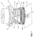
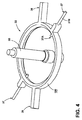
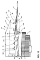
図1〜14に例示されるように、本シフター装置30は、ドラムカム31と、通常フォロワを含むロックリング32と、ベース34およびシャフト35に動作可能に取り付けられたノブまたはダイヤルとして示されるロータ33とを含む。これらの構成部品および以下で説明する他の構成部品は、シフター装置30が駐車、ニュートラル、およびドライブの位置72、74、76を含むことができるさまざまなギア位置70のいずれか1つにあるときにロック機能を引き起こすように相互作用する。また、これらの構成部品は、以下に説明するように、自動RTP機能78が完了するまで、ロータ33が駐車72にロックされる駐車復帰またはRTP機能78を引き起こすために車両が動作停止されるときに相互作用する。本シフター装置30は、駐車72またはニュートラル74などの特定の位置にあるときに独特の方法でロックし、ドライブ76などの他の特定のギア位置70にあるときにシフター装置30を部分的にロックする。本シフター装置30はまた、車両の電源が切られた後にシフター装置30を駐車復帰(RTP)位置80に自動的に移動させる自動RTP機能78も含む。トランスミッションの実際の駐車ロック機能は、典型的には車両の電源を切ると発生することができる。本シフター装置30は、車両の電源が切られたときに運転者の便宜上、ロータ33またはシフトレバーを駐車72に自動的に戻す。有利なことに、本発明の概念は、どのギア位置70がロック、または部分的にロック、または解放であるかという点で、またいつギア位置70がロック、部分的にロック、または解放されるかという点で設計上の著しい柔軟性を可能にする。本発明の概念はまた、RTP機能78(例えば、ギア位置)に関して、およびシフター状態の電子制御および検知に関して、著しい柔軟性を可能にする。
As illustrated in FIGS. 1-14, the
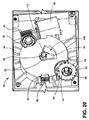
運転者がシフター装置30を駐車72からリバース90に移動させると、本シフター装置30は、駐車72から外れるようにシフトを許可するように機能する。運転者が足をブレーキに乗せる(またはリリースボタンを使用する)と、本シフター装置30は、AFバネ94がAF戻り止め96内に係合する人工的な感触(AF)位置92までドラムカム31を回転させることによりロックを解除する。AF位置92では、運転者は典型的には、すべての場合に正常なシフターの感触を経験する。したがって、AFバネ94は、ロータ33を中心として、ロータ33を特定のギア位置70に選択的に保持する。本シフター装置30のロックは、典型的には、駐車72、ニュートラル74、およびドライブ76で発生する。RTP機能78は、任意のギア位置70から開始してもよく、位置センサは、すべての場合においてドラムカム31およびロータ33の位置を監視する。本シフター装置30は、ロータ33の位置を監視するためにある1組の位置センサと、ドラムカム31の位置を監視する1組の位置センサである、2つの磁石および関連する位置センサを含む。磁石とセンサの対は半独立的に機能し、また車両の電気(制御)システムに動作可能に接続されている。磁石およびセンサの対の構成(図20および図21に示される)は、以下により完全に説明される。
When the driver moves the
本シフター装置30は、典型的には車両の電源が切られた後に、駐車72に自動復帰するロータ33を含む。トランスミッションの実際の駐車ロック機能は、典型的には車両の電源が切られた直後に発生する。しかし、運転者の便宜上、ロータ33は、駐車72などのホーム位置に戻る。ドラムカム31はRTP位置80まで回転し、ドラムカム31の下側のスロット110が、センサ磁石112(図20〜23に示される)を保持するノブ上の特徴部と接触するとき、AFバネ94の戻り止めタイプの力を除去し、ロータ33を駐車72に回転させる。ロータ33は、典型的には回転ノブまたはダイヤルの形態をとる。
The
ロータ33を見るときに知覚される「スタート−ストップ」運動がなく、ロータ33が駐車72に戻る際にRTP機能78が動作するときに聞くモータが揺れる音もないようにロータ33とAFバネ94との間の戻り止めタイプの力の除去と同様に、車両トランスミッションを駐車に自動的に配置することは、自動車の相手先商標製品製造(OEM:Original Equipment Manufacturer)企業の最近の要件である。
There is no "start-stop" motion perceived when looking at the
本装置では、RTP機能78の間、本シフター装置30は、感触ポジショナ120のAFバネ94を引っ込めることにより、感触ポジショナ120を係脱する。したがって、AFバネ94の戻り止め係合機能が感触ポジショナ120の関連する起伏のある表面39から離れるように分離する。起伏のある表面39は、典型的には少なくとも、駐車、リバース、ニュートラル、およびドライブの位置72、90、74、76を画定するロータ33のAF戻り止め96を含む。この構成により、RTP機能78は簡単かつ一貫して動作できる。これは、例えば図13に示されているものとは別の感触ポジショナ120のモードである。ここではロータ33はロックされ、感触ポジショナ120は、少なくとも駐車、リバース、ニュートラル、およびドライブの位置72、90、74、76を形成するAF戻り止めを有する起伏部39に完全に係合し、かつ起伏部39に対してロックされる。これはまた、例えば図15に示されるものとは異なる感触ポジショナ120のモードである。ここでは、ロータ33はロック解除されているが、AFバネ94は、依然として、表面起伏部39へと感触ポジショナ120を付勢している。これは、図16に例示したモードとも異なる。ここでは、ロータ33の回転に影響する感触ポジショナ120からの戻り止めタイプまたは「スタート−ストップ」力を用いずにロータ33を駐車72に戻すように移動することができるように、AFバネ94をAF戻り止め96から引っ込め、かつ感触ポジショナ120が解除される。
In the present device, during the
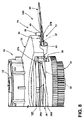
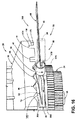
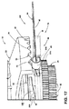
図面に関して、図1は、上部トラックセクション36Aおよび下部トラックセクション36Bを含むトラック36を備えたドラムカム31の分解斜視図である。フォロワまたはロックリング32は、トラック36と係合し、かつ少なくとも1つのロックピン38を含むカムフォロワ/付勢ピン37を含む。ロータ33は、少なくともP、R、N、およびD位置(72、90、74、76)に関連付けられたくぼみを有する表面起伏部39を含む。ロータ33の表面起伏部39は、駐車72用のロックノッチ40と、ニュートラル74用のゲートロックノッチ41(およびゲートロックノッチ41に接続されたドライブ76用の浅いハーフノッチ130)ともまた含む。ノッチ40、41は、以下で説明するように、対応するロックピン38によって選択的に係合される。
With reference to the drawings, FIG. 1 is an exploded perspective view of a
ロータ33は、回転可能なダイヤル式ノブとして示されている。しかし、本発明は、レバーなどの他のシフト機構で実施することができ、単に例示した回転/ダイヤルシフターシステムよりも広くすることができることに留意されたい。
The
装置のさまざまな態様によれば、本シフター装置30の構成部品は、安全性と車両制御および運転者の利便性のために、選択されたギア位置70にあるときにロック機能を引き起こし/促進し、かつロータ33の移動を含むシフター装置30の動作を制御するように相互作用する。シフター装置30の構成部品はまた、安全性および利便性の理由で車両が動作停止されたときに、自動駐車復帰RTP機能78を引き起こし/促進するように相互作用する。
According to various aspects of the device, the components of the
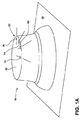
図1Aは、ベース34上に、車両コンソール、ステアリングコラム、またはインストルメント・パネルなどの、軸またはシャフト35(図1、2、3に示す)および美的カバー/ハウジング42(図7、21も参照)を有して動作可能に搭載されている、図1のシフター装置30の斜視図である。
FIG. 1A shows a shaft or shaft 35 (shown in FIGS. 1, 2, and 3) and an aesthetic cover/housing 42 (see also FIGS. 7, 21) such as a vehicle console, steering column, or instrument panel on a
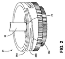
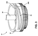
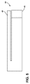
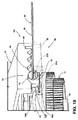
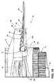
図2〜3は、図1のドラムカム31の異なる周方向部分の斜視図である。図2〜3は組み合わされて、ドラムカム31の外面140上に画定された周方向トラック36の実質的に完全な形状を示し、これは組み合わされて連続ループとしてトラック36を形成する上部トラックセクション36Aおよび下部トラックセクション36Bを含む。上部トラックセクション36Aは、フォロワ/付勢ピン37の内側脚37A(図4および図7〜19を参照)が、ロックリング32(およびロックピン38および付勢ピン37の外側脚37B)を、所定の経路に沿って選択的に移動(図のように一般に軸方向)させる経路を画定する。ドラムカム31の回転は、トラック36内で内側脚37Aを摺動可能に動作させ、ドラムカム31の相対回転部分に対してロックリング32の軸方向の移動を引き起こす。この軸方向の移動により、ロックピン38が移動し、駐車位置、ニュートラル位置、および/またはドライブ位置72、74、76に関連するノッチ40、41のうちの1つを係脱し、したがってロータ33の特定の回転位置にロックされる。
2 to 3 are perspective views of different circumferential portions of the
下部トラックセクション36Bは、ドラムカム31の回転中にフォロワ/付勢ピン37の内側脚37Aが、トラック36を通って並進する経路を画定し、そしてロックリング32(およびロックピン38と付勢ピン37の外側脚37B)を、所定の経路(図のように概して軸方向)に沿って選択的に移動させる。例えば、トラック36と内側脚37Aとのこの相互作用により、ロックピン38は軸方向下向きに移動し、駐車、ニュートラルおよび/またはドライブの位置72、74、76に関連する特定のノッチ40、41から係脱し、したがって、回転運動のためにロータ33のロックを解除する。このようにして、ドラムカム31の回転は、ロータ33をロックするとともに、瞬間的にそれと係合して、RTP機能78の実行中のように、典型的には一方向にそれを回転させる。一旦ロックされると、ロックピン38とノッチ40または41は係合したままであるが、一方でドラムカム31が別の動作位置にリセットされる。ドラムカム31は、構造および安定性を高めるために単一のトラック36または複数のトラック36を含むことができることを理解されたい。
The
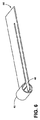
図4は、ロックリング32の斜視図である。付勢ピン37は、トラック36に係合および追従する内側脚37Aを含む。トラック36とのこの係合(図7〜19を参照)により、ロックリング32が、ドラムカム31およびロータ33に対して軸方向に上下に移動し、ロータ33のロックノッチ40、41に対してロックピン38を選択的に係合および係脱する。ロックリング32の選択的な上下運動はまた、シフター装置30の感触ポジショナ120の動作を制御するために、付勢ピン37の外側脚37Bも、付勢バネ44のバネループ43と係合および係脱させる。付勢バネ44は、AFバネ94の形態をとることができる。
FIG. 4 is a perspective view of the
中央シャフト35または軸は、ベース34からドラムカム31、ロックリング32、およびロータ33を通って上向きに延び、これらの組み立てられた構成部品を回転可能に支持する。この係合により、ドラムカム31およびロータ33が回転動作し、ロックリング32が互いに対して軸方向に動作することが可能になる。ドラムカム31の回転により、ロックリング32がロータ33とドラムカム31の間で軸方向に並進する。
The
図5〜図6は、板バネの形態をとることができるバネループ43を備えた感触ポジショナ120の付勢バネ44またはAFバネ94の平面図および斜視図である。付勢バネ44はまた、付勢ピン37の外側脚37Bと係合する第2の板バネ状の脚バネ45を有する。脚バネ45は、以下に説明するように、内側脚37Aを選択的に付勢して下部トラックセクション36Bに向かって移動させる働きをする。また、外側脚37Bは、バネループ43を通って延び、その内部に維持される。このようにして、RTP機能中に、バネループ43は、これも以下で説明するように、内側脚37Aを上部トラックセクション37Aに向かって付勢すしうる。
5 to 6 are a plan view and a perspective view of the biasing
図7は、図5の一対の付勢バネ44の一方を示す斜視図である。図示されたバネループ43は、ロータ33の起伏のある表面39のAF戻り止め96と動作可能に係合する。2つの付勢バネ44を対向する側で使用して、ロータ33とロックリング32にかかる力のバランスをとる補助とすることができる(図4および23を参照。)。戻り止めまたは付勢バネ44は、ドラムカム31の動作に特に最適化されかつ調整されたバネループ43およびバネ脚45を含む。付勢バネ44による圧力が大きすぎるとアセンブリが拘束される可能性があり、一方で付勢バネ44からの圧力が小さすぎると、ロックリング37の内側脚37Aが戻りトラック36まで移動できない場合があるため、アセンブリが有効でない可能性がある。
FIG. 7 is a perspective view showing one of the pair of biasing springs 44 of FIG. The illustrated
付勢バネ44の脚バネ45は、概して外側脚37Bを下向きの方向に付勢する。脚バネ45によって加えられるこの下向きの付勢力は、典型的には外側脚37Bが上向きに平行移動し、ロックピン38がロックノッチ40およびゲートロックノッチ41のうちの一方へと移動したときに生じる。部分的にロックされた位置170を有するゲートロックノッチ41はドライブ76に対応し、完全にロックされた位置150はニュートラル74に対応する。脚バネ45の下向きの付勢力は、ロックノッチ40およびゲートロックノッチ41からロックピン38を取り外すのを助ける。装置のさまざまな態様において、バネループ43によって加えられる付勢力は、脚バネ45によって加えられる付勢力より大きい可能性がある。典型的にはバネループ43およびバネ脚45は、付勢バネ44を画定するために単一の金属板から作られる。
The
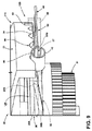
図8は、トラック36を備えたドラムカム31、カムフォロワとして作用するロックリング32、ロータ33、および感触ポジショナ120の付勢バネ44の分解図である。図8に示すように、ロータ33は、ロータ33のロックノッチ40に係合するロックリング32のロックピン38により駐車72に完全にロックされる。感触ポジショナ120の付勢バネ44は、ロータ33の起伏のある表面39内で駐車72に対応するAF戻り止め96と完全に係合するバネループ43を含む。ロックリング32上の付勢ピン72の外側脚37Bは、付勢バネ44のバネループ43を起伏のある表面39に対して完全にロックされた位置150に保持するように配置されている。このようにして、ロックリング32の軸方向の移動は、AFバネ94のバネループ43に対する外側脚37Bの係合および引っ込むタイプの動きをもたらす。
FIG. 8 is an exploded view of the
図9は図8に類似し、ロックリング32(カムフォロワ)が、カムトラック36に沿って、ロック解除プロセス中にロックリング32の内側脚37Aが横断する移行ゾーン152へと移動する。この位置では、付勢バネ44のバネループ43(すなわち「感触ポジショナ係合部分」)は、起伏のある表面39のAF戻り止め96と係合している。また、ロックリング32(フォロワ)上の方向/引っ込み付勢ピン37は、バネループ43の中央または中間位置162に移動する。このようにして、ロックピン38が、駐車72に関連するロックノッチ40から部分的に外れた状態で、バネループ43を「浮く」状態にすることができる。バネループ43が「浮く」状態は、バネループ43にわたるロータ33のAF戻り止め96の選択的動作に対応し、さまざまなギア位置70を画定する。
FIG. 9 is similar to FIG. 8, with the lock ring 32 (cam follower) moving along the
図10は図9に類似し、シフター装置30のロータ33がロック解除位置160にあり、フォロワピン37が、AF位置92を示すバネループ43の中間位置162にある。AF位置92では、ロックピン38はロックノッチ40から完全に外れており、バネループ43は、ロータ33の回転中の人工的な感触のためにAF戻り止め96を通って自由に上下に動くことができる。ロータ33を動かすとき、AF位置92は、起伏部39に沿ったバネループ43の摺動係合により提供される。したがって、AF位置92は、さまざまなギア位置70を選択するための起伏部39を通るロータ33の移動を可能にする。
FIG. 10 is similar to FIG. 9 with the
図11は図10に類似する。しかし、ロータ33は、ドライブ76に対応するギア位置70に動いている。この位置では、ロックリング32(フォロワ)のフォロワ/付勢ピン37の外側脚37Bは、バネループ43をドライブ76に関連する表面起伏部39の下に、かつそこから離して保持する、下げられたロック解除位置160にある。故にロックリング32のロックピン38は、ニュートラル74およびドライブ76に関連するゲートロックノッチ41の下に、かつその外側にある。
FIG. 11 is similar to FIG. However, the
図12は図11に類似する。しかし、バネループ43の中間位置162にあるフォロワ/付勢ピン37は、バネループ43が浮いて、かつ起伏のある表面39のAF戻り止め96の少なくとも一部を通って摺動可能に動作することを可能にする。この位置において、ロックリング32上のロックピン38は、ここでは部分的にロックされた位置170にある(すなわち、「ハーフロック」と呼ばれるゲートロックノッチ41への途中)。部分的にロックされた位置170により、ゲートロックノッチ41の(浅い)ドライブノッチ172と(より深い)ニュートラルノッチ174(図11参照)の組み合わされた相互接続形状により、シフター装置30のロータ33を、起伏のある表面39上でドライブ76からニュートラル74に移動させることができる。この位置から、ロータ33は、ロックピン38が部分的にロックされた位置170にあるドライブ76から、ロックピン38が完全にロックされた位置150にあるニュートラル74にのみ移動できる。
FIG. 12 is similar to FIG. However, the follower/
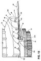
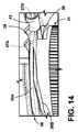
図13は図12に類似する。しかし、ロックリング32のロックピン38は、ここではゲートロックノッチ41の完全にロックされた位置150にあり、ロータ33はニュートラル74に対応するギア位置70にある。またフォロワ/付勢ピン37は、ニュートラル74に関連付けられた起伏のある表面39のAF戻り止め96にバネループ43を保持している。図14は、図13の中央領域の拡大図である。ニュートラル74に対応するこの完全にロックされた位置150から、外側脚37Bは、RTP機能78または他のシフト動作によるなどの、ドラムカム31の回転により下げられなければならない。
FIG. 13 is similar to FIG. However, the
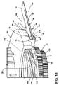
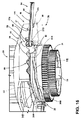
図15は図14に類似する。しかし、ドラムカム31は回転し、またシフター装置30は駐車位置72に戻るプロセスを開始している(RTP機能78)。付勢バネ44の脚バネ45は、カムフォロワ付勢ピン37(およびロックリング32/フォロワ)の外側脚37Bをトラック36の下部トラック部分36Bへと押す。脚バネ45によって生成されるこの付勢運動により、ロックピン38は、RTP機能78を開始するためにドライブ76に関連するゲートロックノッチ41の外へと移動する。
FIG. 15 is similar to FIG. However, the
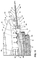
図16は図15に類似するが、ドラムカム31はさらに回転し、そしてシフター装置30はさらにRTP機能78のプロセスにある。ロックピン38は、ロータ33上のゲートロックノッチ41から係脱され、また下部トラック36B内のロックリング32/フォロワの内側脚37Aは、バネループ43を引っ張って起伏のある表面39のAF戻り止めから完全に離して、回転中のロータ33上のあらゆるスタート−ストップの摩擦を除去する。したがって、ロータ33は駆動部76に示されているが、バネ44およびロックピン38が起伏のある表面39から引っ込められて離されているため、AF戻り止め96からの「スタート−ストップ」抵抗なしに駐車72に対応するギア位置70に戻る準備ができている。
16 is similar to FIG. 15, but the
図17は図16に類似し、シフター装置30は、またさらにRTP機能78のプロセス中である。ロックリング32(フォロワ)上の内側脚37Aは、まだ下部トラック36B内にあり、外側脚37Bが、感触ポジショナ120の起伏のある表面39からバネループ43を離すように付勢させる。ロックリング32そしてひいては付勢ピン37は、ここでは偏向されたバネループ43からの付勢力で上向きに移動するように付勢されている。
FIG. 17 is similar to FIG. 16 and
図18は図17に類似し、シフター装置30は、さらにRTP機能78にある。ロータ33は、駐車72に示されており、AFバネ94のバネループ43は、駐車72に関連する表面起伏部39のAF戻り止め96と係合している(RTP位置80)。ロックピン38は、駐車72に関連するゲートロックノッチ40とまだ完全には係合していない。この位置では、内側脚37Aは、バネループ43の上向きの付勢力によって上部トラック36Aに戻される。この位置では、外側脚37Bはバネループ43内の中間位置162にあり、付勢バネ44は静止状態にある。
FIG. 18 is similar to FIG. 17, and the
図19は図18に類似するが、シフター装置30は、駐車72に対応する完全にロックされた位置150にあり、また感触ポジショナ120が駐車72に完全に係合し、ロックされるように、ドラムカム31は回転して、ロックリング32(カムフォロワ)が、外側脚37Bをバネループ43に対して上向きに移動させる。また、ロックピン38は、駐車72に関連するロックノッチ40に完全に係合している。
19 is similar to FIG. 18, but the
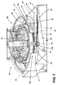
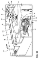
図20は、ベース34(およびカバー/ハウジング42)において、シフター装置30の下側を上向きに見た底面図である(図7を参照)。図20は、ロータ位置センサ50と、ロータ位置センサ50において信号を生成するためのシフター装置30の中央シャフト35上の関連するロータ磁石ホルダ51と、カムシリンダーギア52と、カムシリンダーギア52に関連付けられるかまたは固定されたかみ合い歯55と係合するホイール54上のカム位置センサ53と、カム位置センサ53において信号を生成するための固定軸58上のカム磁石ホルダ57と、アクチュエータ(モータ60、モータ軸に取り付けられたウォームギア61、およびカムギア62と係合する被駆動動/駆動ギア)と、を含むシフター装置30のいくつかの構成部品を示す。カムギア62は、機械的利点のために減速ギアを含むことができる。図21は、図20と同様の斜視図である。ただし、異なる角度におけるものであり、構成部品を部分的に切り欠いているため、下にある構成部品をより良好に示している。
FIG. 20 is a bottom view of the base 34 (and the cover/housing 42) in which the lower side of the
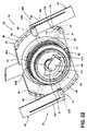
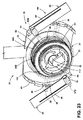
図22〜図23は、図20〜図21と同様の方向から見た部分斜視図である。図22は、ロック解除後でかつRTP機能78の開始時のドライブ76におけるロータ33を示している。図23は、RTP位置80にあるロータ33を示し、下にある構成部品とそれらの関係をより良好に示すために構成部品が削除されている。また、2つの付勢バネ44と2つのロックピン38の対向する「バランス」した位置、2つのトラック36および関連する起伏のある表面39および付勢バネ44およびロックピン38によって係合されるロックノッチ40、41も示している。
22 to 23 are partial perspective views seen from the same direction as FIGS. 20 to 21. FIG. 22 shows the
本配置は、回転バレルドラムカム31と、軸方向に移動するロックリング32とも呼ばれるカムフォロワと、カムフォロワ37の内側脚37Aがロータ33の回転と係合し、かつロックおよびロック解除するためのトラック特徴部36を有するロータ33(本明細書ではダイヤル式シフターまたはノブとも呼ばれる)とを含む。ドラムカム31上の連続トラック36により、フォロワ32は2つの経路間を切り替えることができ、その結果、フォロワ位置対カム角度に基づいて2つの異なる機能(すなわち、ロータ33のロックおよびロック解除)を生じさせる。トラック36A/36Bおよび付勢部材44の形状は、ドラムカム31の回転方向に応じてロックリング32(フォロワ)がとる経路を決定する。これらの物品の組み合わせにより、ロータ33の自由な回転、またはロータ33のロック、および/またはドラムカム31の位置決めに基づくロータ33の制御された動きが可能になる。2つの別個の上部および下部トラック36A、36Bの著しい利点は、トラック36内にある間に、ドラムカム31の全回転を通してロータ33をロック状態に保つ能力である。
This arrangement is a rotary
ドラムカム31がロータ33をロックおよびロック解除する配置を提供する能力は重要である。この配置の特徴は、ロータ33をある1つの位置から別の位置に回転させ、その後ドラムカム31がその元の(ロックまたはロック解除)位置に戻る間、ロータ33を完全にロックされた位置150に保つ能力である。
The ability of the
本配置は、付勢ピン37の形態の作動アームと、付勢ピン37の一部分を囲むバネループ43と、付勢ピン37に小さな付勢を加える追加の脚バネ45とを含む。付勢ピン37の囲まれた部分は、上述のフォロワまたはロックリング32の付属物である。作動アームまたは付勢ピン37または付勢ピンの外径180、バネループ43の内径、およびトラック36A、36Bに沿ったカムフォロワまたは内側脚37Aのカムフォロワの動きの組み合わせにより、ロックリング32は、ロータ33がドラムカム31の嵌合面に対して自由に回転または反応できる自由状態にあるかどうかが、決定される。ドラムカム31に対する反力は、フォロワまたはロックリング32を特定の位置に強制するために、付勢バネ44に対する機構で使用することができる。あるいは、ドラムカム31は、バネループ43を特定の位置に強制することができ、かつ潜在的にバネループ43をその位置にロックすることができる。脚バネ45は、バネループ43/付勢ピン37が自由状態にある間に比較的小さな力を提供するために使用される。これの目的は2つある。1.)上記のドラムカム31/フォロワ32の組み合わせが機能することを可能にすること、および、2.)フォロワロックリング32がドラムカム31のトラック36内でガタつくのを防止することである。
This arrangement includes an actuating arm in the form of a biasing
この付勢バネ44/付勢ピン37の組み合わせの著しい利点は、ドラムカム31が(付勢バネ44を偏向させることにより)ある1つの位置でバネ力を除去し、一方で別の位置で付勢バネ44に追加の力を加える、その能力である。シフター装置30の利点は、RTP機能78の間の戻り止め動作の除去、および電子シフター装置30がロータ33をAF戻り止め96内のAF位置92に強制する能力である。これは、AF戻り止め96だけではギア位置70にセンタリングするのに十分な力が提供されない場合に利点である。
The significant advantage of this biasing
したがって、本発明の概念から逸脱することなく、前述の構造に対する変形および修正が可能であることを理解されたい。さらに、そのような概念は、これらの請求項がその言語により明示的に別段の記載をしない限り、以下の請求項によって包含されることを意図していることを理解されたい。 Therefore, it should be understood that variations and modifications can be made to the structures described above without departing from the inventive concept. Furthermore, it is to be understood that such concepts are intended to be covered by the following claims, unless these claims are expressly stated by the language.
Claims (31)
前記ベース上に回転可能に支持され、かつトラックを有するドラムカムと、
前記ドラムカムに対する軸方向の移動のために、前記ドラムカム上に移動可能に支持されたロックリングであって、前記トラックに係合するフォロワピンと、バネ付勢ピンと、ノッチ係合ロックピンとを有するロックリングと、
前記ドラムカム上に回転可能に支持され、かつ複数のギア位置と少なくとも1つのロックノッチを画定する起伏のある表面を含むロータであって、前記ロックピンが、前記少なくとも1つのロックノッチと選択的に係合して、前記複数のギア位置のうちの少なくとも駐車位置を画定する、ロータと、
前記複数のギア位置のうちの1つに前記ロータを保持するために、前記起伏のある表面と選択的に係合するバネループを備えた少なくとも1つの感触ポジショナバネを含む感触ポジショナ機構と、
前記ロックピン、前記少なくとも1つのロックノッチ、前記トラックおよび前記フォロワピンを含むロータ制御機構であって、前記トラックおよび前記フォロワピンが、前記少なくとも1つのロックノッチとの前記ロックピンの選択的な係合および係脱を制御するように相互作用する、ロータ制御機構とを含み、
前記バネ付勢ピンが、前記ドラムカムの協調回転運動と前記ロックリングの軸方向の移動に基づいて、前記バネループと動作可能に係合し、
前記バネ付勢ピンが、少なくとも1つの第1バネ位置において前記起伏のある表面に対して前記バネループを選択的に付勢し、
前記バネ付勢ピンが、少なくとも1つの第2バネ位置において、前記起伏のある表面から前記バネループを選択的係脱する、車両用シフター装置。 Base,
A drum cam rotatably supported on the base and having a track;
A lock ring movably supported on the drum cam for axial movement with respect to the drum cam, the lock ring having a follower pin engaging the track, a spring biasing pin, and a notch engaging lock pin. When,
A rotor rotatably supported on the drum cam and including an undulating surface defining a plurality of gear positions and at least one lock notch, wherein the lock pin selectively contacts the at least one lock notch. A rotor that engages to define at least a parking position of the plurality of gear positions;
A tactile positioner mechanism including at least one tactile positioner spring with a spring loop selectively engaging the undulating surface to retain the rotor in one of the plurality of gear positions.
A rotor control mechanism including the lock pin, the at least one lock notch, the track and the follower pin, the track and the follower pin selectively engaging the lock pin with the at least one lock notch and A rotor control mechanism that interacts to control engagement and disengagement,
The spring biasing pin is operably engaged with the spring loop based on the coordinated rotational movement of the drum cam and axial movement of the lock ring;
The spring biasing pin selectively biases the spring loop against the undulating surface in at least one first spring position;
A vehicle shifter device in which the spring biasing pin selectively disengages the spring loop from the undulating surface in at least one second spring position.
前記ベース上に回転可能に支持され、かつトラックを有するドラムカムと、
前記ドラムカムの回転動作に応答して軸方向の移動のために、前記ドラムカム上に移動可能に支持されたロックリングであって、前記トラックに係合するフォロワピンと、バネ付勢ピンと、ノッチ係合ロックピンとを有するロックリングと、
前記ドラムカム上に回転可能に支持され、かつ複数のギア位置を画定する起伏のある表面を含むロータと、
前記複数のギア位置のうちの1つに前記ロータを位置付けるために、前記起伏のある表面と動作可能に係合するバネループを備えた少なくとも1つの感触ポジショナバネを含む感触ポジショナ機構であって、前記バネ付勢ピンが、前記ロックリングの軸方向の移動に基づいて前記感触ポジショナバネに動作可能に係合し、かつ前記起伏のある表面に対する前記バネループの係合および係脱を制御するように構成されている、感触ポジショナ機構とを含む、車両用シフター装置。 Base,
A drum cam rotatably supported on the base and having a track;
A lock ring movably supported on the drum cam for axial movement in response to rotational movement of the drum cam, the follower pin engaging the track, a spring biasing pin, and a notch engagement. A lock ring having a lock pin,
A rotor rotatably supported on the drum cam and including an undulating surface defining a plurality of gear positions;
A tactile positioner mechanism comprising at least one tactile positioner spring with a spring loop operably engaging the undulating surface for positioning the rotor in one of the plurality of gear positions, the tactile positioner mechanism comprising: A spring biasing pin operatively engages the feel positioner spring based on axial movement of the lock ring and controls engagement and disengagement of the spring loop with respect to the contoured surface. A shifter device for a vehicle including a feel positioner mechanism.
前記ベース上に回転可能に支持され、かつトラックを有するドラムカムと、
軸方向の移動のために、前記ドラムカム上に移動可能に支持されたロックリングであって、前記トラックに係合するフォロワピンとノッチ係合ロックピンとを有するロックリングと、
前記ドラムカム上に移動可能に支持され、かつ少なくとも1つのレバー制御ロックノッチを含むロータと、
前記ロックピンと、前記少なくとも1つのレバー制御ロックノッチと、前記トラックと、前記フォロワピンとを含むロータ制御機構であって、前記トラックと前記フォロワピンが相互作用して、前記少なくとも1つのレバー制御ロックノッチにおける前記ロックピンの係合と係脱を制御するロータ制御機構とを含む、車両用シフター装置。 Base,
A drum cam rotatably supported on the base and having a track;
A lock ring movably supported on the drum cam for axial movement, the lock ring having a follower pin and a notch engagement lock pin for engaging the track,
A rotor movably supported on the drum cam and including at least one lever control lock notch;
A rotor control mechanism comprising: the lock pin, the at least one lever control lock notch, the track, and the follower pin, wherein the track and the follower pin interact to form at least one lever control lock notch. A vehicle shifter device including a rotor control mechanism for controlling engagement and disengagement of the lock pin.
前記ベース上に回転可能に支持され、かつ連続ループトラックを有するドラムカムと、
軸方向の移動のために、前記ドラムカム上に移動可能に支持されたロックリングであって、前記トラックに係合するフォロワピンとバネ付勢ピンとノッチ係合ロックピンとを有するロックリングと、
前記ドラムカム上に移動可能に支持されたダイヤルシミュレーションロータと、
前記ロータ、前記ロックリング、および前記ドラムカムの間に画定された感触ポジショナ機構およびロータ制御機構であって、前記ロックリングが軸方向に移動して、前記ロータの回転を制御する前記ロータ制御機構をロックおよびロック解除し、かつ前記ロックリングが軸方向に移動して、前記感触ポジショナ機構を選択的に係合および係脱する、感触ポジショナ機構およびロータ制御機構と、を含む、車両用シフター装置。 Base,
A drum cam rotatably supported on the base and having a continuous loop track;
A lock ring movably supported on the drum cam for axial movement, the lock ring having a follower pin engaging the track, a spring biasing pin, and a notch engaging lock pin.
A dial simulation rotor movably supported on the drum cam,
A feeler positioner mechanism and a rotor control mechanism defined between the rotor, the lock ring, and the drum cam, wherein the lock ring moves axially to control rotation of the rotor. A shifter device for a vehicle, comprising: a feeler positioner mechanism and a rotor control mechanism that locks and unlocks and the lock ring moves axially to selectively engage and disengage the feeler positioner mechanism.
前記ベース上に回転可能に支持され、かつトラックを有するドラムカムと、
回転および軸方向の移動のために、前記ドラムカム上に移動可能に支持されたロックリングであって、前記トラックに係合するフォロワピンとバネ付勢ピンとノッチ係合ロックピンとを有するロックリングと、
前記ドラムカム上に移動可能に支持され、かつP、R、N、およびD位置を画定する起伏のある表面と、ロックノッチとを含むロータと、
前記ロータを前記P、R、N、およびD位置のうちの1つに保持するように構成された感触ポジショナ機構と、
前記ロックピン、前記ロックノッチ、前記トラックおよび前記フォロワピンを含むロータ制御機構であって、前記トラックおよびフォロワピンが、前記ロックノッチ内の前記ロックピンの係合および係脱を制御するように相互作用するロータ制御機構と、
前記ロータと前記ロックリングの位置を検知する前記ロータ制御機構のセンサと、
前記ロックピンを前記ロックノッチから係脱し、かつ前記ロータをホーム位置に移動させるために、前記ロータ、前記ドラムカム、および前記ロックリングのうちの少なくとも1つに動作可能に接続されたアクチュエータと、
前記センサとアクチュエータに接続された制御回路であって、前記アクチュエータに、前記ロックピンを前記ロックノッチから係脱し、次に前記ロータを前記ホーム位置まで回転させることを含み、かつ前記ロータをある1つの位置から別の位置に回転させ、次に前記ドラムカムがホーム位置に戻る間、前記ロータをロックしたままにすることも含む、ホーム復帰動作を実行させるようにプログラムされている制御回路とを含む、車両用シフター装置。 Base,
A drum cam rotatably supported on the base and having a track;
A lock ring movably supported on the drum cam for rotation and axial movement, the lock ring having a follower pin engaging the track, a spring biasing pin, and a notch engaging lock pin,
A rotor movably supported on the drum cam and including an undulating surface defining P, R, N, and D positions; and a lock notch,
A feel positioner mechanism configured to hold the rotor in one of the P, R, N and D positions;
A rotor control mechanism including the lock pin, the lock notch, the track and the follower pin, the track and follower pin interacting to control engagement and disengagement of the lock pin within the lock notch. A rotor control mechanism,
A sensor of the rotor control mechanism for detecting the position of the rotor and the lock ring;
An actuator operably connected to at least one of the rotor, the drum cam, and the lock ring to disengage the lock pin from the lock notch and move the rotor to a home position;
A control circuit connected to the sensor and an actuator, the actuator including: disengaging the lock pin from the lock notch and then rotating the rotor to the home position; and A control circuit programmed to perform a home return operation, including rotating from one position to another and then keeping the rotor locked while the drum cam returns to the home position. , Vehicle shifter devices.
前記少なくとも1つのアクチュエータおよび前記シフター上のセンサに動作可能に接続された車両電気制御システムを提供することと、
前記ロータがロックされた第1の位置にあることを検知することと、
前記ロータが、一貫していない摩擦なしに動くことができるように前記感触ポジショナ機構を解放するために、前記少なくとも1つのアクチュエータを動作し、かつ前記ロータ制御機構に、前記ロータを前記ロックされた第1の位置からロック解除させるために、前記少なくとも1つのアクチュエータを動作することと、
前記ロータを新しい位置に移動させるために、前記少なくとも1つのアクチュエータを動作することと、
前記感触ポジショナ機構を再係合させ、かつ前記ロータ制御機構を再係合させるために、前記少なくとも1つのアクチュエータを動作することと、を含む、方法。 To provide a vehicle shifter including a dial simulation rotor, a drum cam, a lock ring, a feeler positioner mechanism, a rotor control mechanism, and at least one actuator for controlling the feeler positioner mechanism and the rotor control mechanism. When,
Providing a vehicle electrical control system operably connected to the at least one actuator and a sensor on the shifter;
Detecting that the rotor is in the locked first position;
Actuating the at least one actuator and releasing the rotor to a rotor control mechanism to release the feel positioner mechanism to allow the rotor to move without inconsistent friction; Operating the at least one actuator to unlock from the first position;
Operating the at least one actuator to move the rotor to a new position;
Reengaging the feel positioner mechanism and operating the at least one actuator to reengage the rotor control mechanism.
前記駐車、リバース、ニュートラル、ドライブの位置に関連付けられたくぼみのある起伏のある表面を含み、かつくぼみと係合するバネループを有するバネを含む、前記感触ポジショナ機構とを含み、
前記レバー制御機構が、前記バネループを通って延びる付勢ピンを含み、前記レバー制御機構が、前記付勢ピンを前記付勢ピンが前記バネループに係合し、かつ前記バネループを前記起伏のある表面に対して保持する第1の位置と、前記付勢ピンが概して前記バネループの中心にあり、したがって、前記バネループが、前記付勢ピンからの制限なしに上下に浮くことができる第2の位置と、前記付勢ピンが前記バネループに係合し、かつ前記感触ポジショナ機構が完全に係脱されるように、前記バネループを前記起伏のある表面から離して保持する第3の位置と、の間で動かすアクチュエータも含む、シフター装置。 A shifter including levers defining parking, reverse, neutral, and drive positions and including a tactile positioner mechanism, a lever control mechanism, and at least one actuator for controlling the tactile positioner mechanism and the lever control mechanism;
A tactile positioner mechanism including a spring having a recessed undulating surface associated with the parking, reverse, neutral, drive positions and including a spring having a spring loop for engaging the recess;
The lever control mechanism includes a biasing pin extending through the spring loop, the lever control mechanism causing the biasing pin to engage the spring loop and the spring loop to the undulating surface. And a second position in which the biasing pin is generally in the center of the spring loop, so that the spring loop can float up and down without restriction from the biasing pin. A third position holding the spring loop away from the contoured surface such that the biasing pin engages the spring loop and the feel positioner mechanism is fully disengaged. A shifter device that also includes a moving actuator.
軸方向に移動するフォロワを含むロックリングと、
前記カムフォロワが前記ロータの回転をロックするために係合するためのロック機能を備えたロータと、を含み、
前記フォロワが、前記トラックの上部と下部と順次係合して2つの異なるカム経路を切り替え、その結果、前記ロックリングに対する前記ドラムカムの相対角度に基づいて前記フォロワの位置の2つの異なる機能を切り替え、
前記連続トラックの形状と前記ロックリング上の付勢部材が、前記ドラムカムの回転方向に応じて取られる前記カム経路を決定する、シフター装置。 Rotating drum cam with continuous track,
A lock ring including a follower that moves in the axial direction,
A rotor having a lock function for engaging the cam follower to lock the rotation of the rotor;
The follower sequentially engages the top and bottom of the track to switch between two different cam paths, thus switching between two different functions of the position of the follower based on the relative angle of the drum cam with respect to the lock ring. ,
A shifter device in which the shape of the continuous track and the biasing member on the lock ring determine the cam path taken according to the rotation direction of the drum cam.
トラックを有する回転ドラムカムと、
前記フォロワが前記トラックに係合して前記トラックに沿って移動するとき、カムリングを軸方向に移動させるフォロワを含むカムリングと、
前記フォロワがロータの回転をロックするために係合するロック機能を備えた前記ロータを含む前記シフターと、
前記カムリング上の作動アームと、
作動アームを囲むバネループを有する第1のバネと、
前記作動アームに小さな付勢を加える追加のバネと、を含み、
前記作動アームの外径、前記バネループの内径、および前記フォロワの動きの組み合わせが、前記フォロワを前記ロータが抵抗なく動く自由状態と、前記作動アームが前記ドラムカムの表面に対して反力を生成して前記ロータの回転に影響を与える力生成状態であって、前記カムリングに対する前記反力が、前記カムリングとフォロワを特定の位置へと強制するために使用される、力生成状態との間で動かす、シフター装置。 A base and a shifter rotatably supported on the base;
A rotating drum cam having a track,
A cam ring including a follower for axially moving the cam ring when the follower engages with the track and moves along the track;
The shifter including the rotor with a locking function that the follower engages to lock the rotation of the rotor;
An actuation arm on the cam ring,
A first spring having a spring loop surrounding the actuation arm;
An additional spring for applying a small bias to the actuating arm,
The combination of the outer diameter of the working arm, the inner diameter of the spring loop, and the movement of the follower creates a reaction force against the surface of the drum cam when the rotor freely moves in the follower without any resistance. And a force producing condition that affects rotation of the rotor, wherein the reaction force on the cam ring moves between the cam ring and a force producing condition used to force the follower to a particular position. , Shifter device.
前記ベース上に回転可能に支持され、かつトラックを有するドラムカムと、
前記ベース上に回転可能に支持され、かつ前記ドラムカムの前記トラックに対して軸方向に動作可能なロックリングと、
前記ベース上に回転可能に支持されるロータであって、前記ロックリングが前記ドラムカムと前記ロータとの間に延び、前記ドラムカムの前記トラックの回転動作が、前記ロックリングの複数の軸方向位置を画定し、前記複数の軸方向位置が、前記ロータの複数のギア位置に対応する、ロータとを含む、車両用シフト装置。 Base,
A drum cam rotatably supported on the base and having a track;
A lock ring rotatably supported on the base and axially movable with respect to the track of the drum cam;
A rotor rotatably supported on the base, wherein the lock ring extends between the drum cam and the rotor, and the rotational movement of the track of the drum cam causes a plurality of axial positions of the lock ring. A shifter for a vehicle, the rotor being defined, the rotor having a plurality of axial positions corresponding to a plurality of gear positions of the rotor.
Priority Applications (1)
| Application Number | Priority Date | Filing Date | Title |
|---|---|---|---|
| JP2022144978A JP7442593B2 (en) | 2017-05-24 | 2022-09-13 | Rotary shifter with auto return and cam lock mechanism |
Applications Claiming Priority (3)
| Application Number | Priority Date | Filing Date | Title |
|---|---|---|---|
| US201762510451P | 2017-05-24 | 2017-05-24 | |
| US62/510,451 | 2017-05-24 | ||
| PCT/US2018/034090 WO2018217865A1 (en) | 2017-05-24 | 2018-05-23 | Rotary shifter with auto-return and cam lock mechanism |
Related Child Applications (1)
| Application Number | Title | Priority Date | Filing Date |
|---|---|---|---|
| JP2022144978A Division JP7442593B2 (en) | 2017-05-24 | 2022-09-13 | Rotary shifter with auto return and cam lock mechanism |
Publications (2)
| Publication Number | Publication Date |
|---|---|
| JP2020521663A true JP2020521663A (en) | 2020-07-27 |
| JP7241031B2 JP7241031B2 (en) | 2023-03-16 |
Family
ID=64397029
Family Applications (2)
| Application Number | Title | Priority Date | Filing Date |
|---|---|---|---|
| JP2019563784A Active JP7241031B2 (en) | 2017-05-24 | 2018-05-23 | Rotary shifter with auto-return and cam-lock mechanism |
| JP2022144978A Active JP7442593B2 (en) | 2017-05-24 | 2022-09-13 | Rotary shifter with auto return and cam lock mechanism |
Family Applications After (1)
| Application Number | Title | Priority Date | Filing Date |
|---|---|---|---|
| JP2022144978A Active JP7442593B2 (en) | 2017-05-24 | 2022-09-13 | Rotary shifter with auto return and cam lock mechanism |
Country Status (6)
| Country | Link |
|---|---|
| US (1) | US11255426B2 (en) |
| EP (1) | EP3631248A4 (en) |
| JP (2) | JP7241031B2 (en) |
| KR (1) | KR102657792B1 (en) |
| CN (1) | CN110869651B (en) |
| WO (1) | WO2018217865A1 (en) |
Cited By (1)
| Publication number | Priority date | Publication date | Assignee | Title |
|---|---|---|---|---|
| JP2024501353A (en) * | 2021-03-27 | 2024-01-11 | 蘇州名科紡織科技有限公司 | Folding device for clothing processing |
Families Citing this family (27)
| Publication number | Priority date | Publication date | Assignee | Title |
|---|---|---|---|---|
| BR102017017485B1 (en) * | 2017-08-15 | 2024-02-06 | Weg Drives And Controls Automação Ltda | ROTATING HANDLE DEVICE AND MOUNTING METHOD FOR ROTARY HANDLE DEVICE |
| JP6752766B2 (en) * | 2017-09-04 | 2020-09-09 | 株式会社東海理化電機製作所 | Shift device |
| JP6943759B2 (en) * | 2017-12-28 | 2021-10-06 | 株式会社東海理化電機製作所 | Shift device |
| US10890251B2 (en) * | 2017-12-28 | 2021-01-12 | Dura Operating, Llc | Transmission shifter assembly with removable feedback |
| US11376957B2 (en) | 2018-01-05 | 2022-07-05 | Ghsp, Inc. | Vehicle shifter interface having capacitive touch rotary shifting |
| WO2019181288A1 (en) * | 2018-03-19 | 2019-09-26 | アルプスアルパイン株式会社 | Input device |
| JP6807487B2 (en) * | 2018-03-19 | 2021-01-06 | アルプスアルパイン株式会社 | Input device |
| JP7462576B2 (en) | 2018-06-15 | 2024-04-05 | ジーエイチエスピー・インコーポレイテッド | Rotary shifter with secondary rotary knob |
| DE102018210837A1 (en) * | 2018-07-02 | 2020-01-02 | Zf Friedrichshafen Ag | turntable |
| KR102088352B1 (en) * | 2018-08-21 | 2020-03-12 | 경창산업주식회사 | Dial transmission lever device for vehicle |
| CN109611549B (en) * | 2019-01-14 | 2023-09-12 | 广州小鹏汽车科技有限公司 | A drive motor assembly and automobile capable of realizing P gear function |
| CN109973640B (en) * | 2019-02-22 | 2021-05-04 | 广汽零部件有限公司 | Monostable knob selector that can automatic re-setting |
| CN110597351B (en) * | 2019-08-06 | 2021-01-05 | 佛山市高明安华陶瓷洁具有限公司 | A compact dual-recognition magnetic knob |
| DE102019213557A1 (en) * | 2019-09-06 | 2021-03-11 | Zf Friedrichshafen Ag | Selector lever arrangement for selecting and switching different driving modes in a vehicle transmission |
| EP3809021A1 (en) * | 2019-10-14 | 2021-04-21 | Fico Triad, S.A. | Rotary gear shifter with noise damping for motor vehicle transmissions |
| KR102812073B1 (en) | 2019-11-14 | 2025-05-22 | 현대자동차주식회사 | Ambient light device for dial type shift control apparatus |
| KR102730517B1 (en) * | 2019-11-14 | 2024-11-13 | 현대자동차주식회사 | Rattle reducing device for dial type shift control apparatus |
| KR102210583B1 (en) * | 2019-11-15 | 2021-02-02 | 에스엘 주식회사 | Automotive transmission |
| US11236818B2 (en) | 2019-12-10 | 2022-02-01 | Kuster North America, Inc. | Lever shifter with auto return to park and lock function |
| JP7079806B2 (en) * | 2020-03-30 | 2022-06-02 | 本田技研工業株式会社 | Shift device |
| JP7058684B2 (en) * | 2020-03-30 | 2022-04-22 | 本田技研工業株式会社 | Shift device |
| KR102279262B1 (en) * | 2020-03-30 | 2021-07-20 | 경창산업주식회사 | Dial Gear Selector |
| DE102020117326B4 (en) | 2020-07-01 | 2022-04-21 | Dr. Ing. H.C. F. Porsche Aktiengesellschaft | switching device |
| USD981205S1 (en) * | 2021-01-15 | 2023-03-21 | Jun Lu | Electronic door knob |
| CN113142917B (en) * | 2021-03-15 | 2022-07-08 | 内蒙古师范大学 | A multifunctional visual communication display device |
| USD1042087S1 (en) * | 2021-03-24 | 2024-09-17 | Boxlock, Inc. | Cam lock |
| DE102022204022A1 (en) | 2022-04-26 | 2023-10-26 | Signata GmbH | Selector lever arrangement for an automatic transmission of a vehicle |
Citations (7)
| Publication number | Priority date | Publication date | Assignee | Title |
|---|---|---|---|---|
| JPH10114233A (en) * | 1996-10-09 | 1998-05-06 | Seirei Ind Co Ltd | Running gear shift operation mechanism of walking type management machine |
| JP2008511063A (en) * | 2004-08-24 | 2008-04-10 | ツェットエフ フリードリヒスハーフェン アクチエンゲゼルシャフト | Operating device |
| JP2008526605A (en) * | 2005-01-14 | 2008-07-24 | ツェットエフ フリードリヒスハーフェン アクチエンゲゼルシャフト | Operating device with rotary switch |
| JP2009107559A (en) * | 2007-10-31 | 2009-05-21 | Tokai Rika Co Ltd | Shift device |
| JP2012136132A (en) * | 2010-12-27 | 2012-07-19 | Atsumi Tec:Kk | Shifting apparatus for automatic transmission |
| JP2015107671A (en) * | 2013-12-03 | 2015-06-11 | 株式会社東海理化電機製作所 | Shift device |
| JP2016094082A (en) * | 2014-11-13 | 2016-05-26 | 株式会社東海理化電機製作所 | Shift device |
Family Cites Families (15)
| Publication number | Priority date | Publication date | Assignee | Title |
|---|---|---|---|---|
| SU258797A1 (en) | 1968-08-30 | 1969-12-03 | Л. Ю. Казенас Вильнюсский станкостроительный завод Жальгирис | Switching mechanism for transmission gear boxes |
| US7571662B2 (en) * | 2004-08-18 | 2009-08-11 | Jaguars Cars Limited | Selector mechanism for a motor vehicle transmission |
| US9494228B2 (en) | 2011-11-21 | 2016-11-15 | Kongsberg Automotive Ab | Shifter assembly |
| EP2815287B1 (en) * | 2012-02-16 | 2021-05-05 | Kostal of America | Rotary selector switch and related systems and methods |
| KR101315493B1 (en) * | 2012-10-05 | 2013-10-07 | 에스엘 주식회사 | Shift lever of dial type |
| KR101836523B1 (en) * | 2012-10-18 | 2018-03-08 | 현대자동차주식회사 | Dct control method for vehicle |
| KR101404909B1 (en) * | 2013-03-14 | 2014-06-11 | 대성전기공업 주식회사 | Vehicular transmission range switching device |
| RU2551786C1 (en) | 2013-03-21 | 2015-05-27 | Государственное учреждение высшего профессионального образования "Белорусско-Российский университет" | Operation mode selector of automatic transmission of car |
| JP6013970B2 (en) * | 2013-05-21 | 2016-10-25 | 株式会社東海理化電機製作所 | Shift operating device |
| DE102013221039A1 (en) * | 2013-10-17 | 2015-04-23 | Lemförder Electronic GmbH | Device for locking an operating element of an automatic transmission of a vehicle, method for operating such a device and switching device for switching an automatic transmission of a vehicle |
| DE102013221041A1 (en) * | 2013-10-17 | 2015-04-23 | Lemförder Electronic GmbH | Device for adjusting an operating element of an automatic transmission of a vehicle in a parking position, method for operating such a device and switching device for switching an automatic transmission of a vehicle |
| US9334949B2 (en) * | 2013-12-13 | 2016-05-10 | Ghsp, Inc. | Rotary shifting device with motorized knob |
| WO2015107592A1 (en) * | 2014-01-16 | 2015-07-23 | パナソニックIpマネジメント株式会社 | Shift operation device |
| EP3317150B1 (en) * | 2015-07-02 | 2019-10-09 | Kongsberg Driveline Systems I, Inc. | Manual park release device for vehicle |
| US20170074391A1 (en) | 2015-09-16 | 2017-03-16 | Ghsp, Inc. | Rotatable vehicle transmission shifter apparatus |
-
2018
- 2018-05-23 EP EP18805395.3A patent/EP3631248A4/en not_active Withdrawn
- 2018-05-23 JP JP2019563784A patent/JP7241031B2/en active Active
- 2018-05-23 WO PCT/US2018/034090 patent/WO2018217865A1/en not_active Ceased
- 2018-05-23 US US16/609,362 patent/US11255426B2/en not_active Expired - Fee Related
- 2018-05-23 KR KR1020197036772A patent/KR102657792B1/en active Active
- 2018-05-23 CN CN201880031861.2A patent/CN110869651B/en active Active
-
2022
- 2022-09-13 JP JP2022144978A patent/JP7442593B2/en active Active
Patent Citations (7)
| Publication number | Priority date | Publication date | Assignee | Title |
|---|---|---|---|---|
| JPH10114233A (en) * | 1996-10-09 | 1998-05-06 | Seirei Ind Co Ltd | Running gear shift operation mechanism of walking type management machine |
| JP2008511063A (en) * | 2004-08-24 | 2008-04-10 | ツェットエフ フリードリヒスハーフェン アクチエンゲゼルシャフト | Operating device |
| JP2008526605A (en) * | 2005-01-14 | 2008-07-24 | ツェットエフ フリードリヒスハーフェン アクチエンゲゼルシャフト | Operating device with rotary switch |
| JP2009107559A (en) * | 2007-10-31 | 2009-05-21 | Tokai Rika Co Ltd | Shift device |
| JP2012136132A (en) * | 2010-12-27 | 2012-07-19 | Atsumi Tec:Kk | Shifting apparatus for automatic transmission |
| JP2015107671A (en) * | 2013-12-03 | 2015-06-11 | 株式会社東海理化電機製作所 | Shift device |
| JP2016094082A (en) * | 2014-11-13 | 2016-05-26 | 株式会社東海理化電機製作所 | Shift device |
Cited By (2)
| Publication number | Priority date | Publication date | Assignee | Title |
|---|---|---|---|---|
| JP2024501353A (en) * | 2021-03-27 | 2024-01-11 | 蘇州名科紡織科技有限公司 | Folding device for clothing processing |
| JP7500883B2 (en) | 2021-03-27 | 2024-06-17 | 蘇州名科紡織科技有限公司 | Clothing processing folding device |
Also Published As
| Publication number | Publication date |
|---|---|
| US20200191259A1 (en) | 2020-06-18 |
| EP3631248A1 (en) | 2020-04-08 |
| JP7241031B2 (en) | 2023-03-16 |
| EP3631248A4 (en) | 2021-02-24 |
| KR20200010319A (en) | 2020-01-30 |
| CN110869651B (en) | 2021-11-12 |
| JP2022174221A (en) | 2022-11-22 |
| KR102657792B1 (en) | 2024-04-17 |
| CN110869651A (en) | 2020-03-06 |
| JP7442593B2 (en) | 2024-03-04 |
| WO2018217865A1 (en) | 2018-11-29 |
| US11255426B2 (en) | 2022-02-22 |
Similar Documents
| Publication | Publication Date | Title |
|---|---|---|
| JP7442593B2 (en) | Rotary shifter with auto return and cam lock mechanism | |
| EP2963314B1 (en) | Shift range switching device for vehicle | |
| CN103269893B (en) | For the variable speed operation equipment of automatic transmission | |
| JP4986858B2 (en) | Operating device with rotary switch | |
| US9618110B2 (en) | Shift/tilt locking apparatus and method for shift lever of automatic transmission | |
| JP2018527242A (en) | Rotating vehicle transmission shifter device | |
| KR20150056992A (en) | Shifting apparatus for vehicle | |
| JP2013039918A (en) | Gear shift device for transmission | |
| KR20190076434A (en) | Automotive transmission | |
| KR20200081764A (en) | Automotive transmission | |
| KR101691843B1 (en) | Transmission for vehicle | |
| JP3908484B2 (en) | Manual transmission gearbox | |
| JP2019119352A (en) | Shifter | |
| JP3453306B2 (en) | Operating device for automatic transmission with rotation knob | |
| US20070068325A1 (en) | Shift mechanism for a vehicle | |
| JP6003785B2 (en) | Vehicle shift device | |
| KR101928754B1 (en) | Transmission for vehicle | |
| JP6783396B2 (en) | Operating device | |
| CN110886837B (en) | Speed change device for vehicle | |
| JP3428061B2 (en) | Shifting device for automatic transmission | |
| WO2017110454A1 (en) | Shifting device | |
| JPH0641872Y2 (en) | Selector lever locking device | |
| JP2019006138A (en) | Shifter | |
| JP2019006139A (en) | Shifter | |
| WO2022224880A1 (en) | Shift device |
Legal Events
| Date | Code | Title | Description |
|---|---|---|---|
| A621 | Written request for application examination |
Free format text: JAPANESE INTERMEDIATE CODE: A621 Effective date: 20210423 |
|
| A131 | Notification of reasons for refusal |
Free format text: JAPANESE INTERMEDIATE CODE: A131 Effective date: 20220705 |
|
| A521 | Request for written amendment filed |
Free format text: JAPANESE INTERMEDIATE CODE: A523 Effective date: 20220914 |
|
| A131 | Notification of reasons for refusal |
Free format text: JAPANESE INTERMEDIATE CODE: A131 Effective date: 20230124 |
|
| A521 | Request for written amendment filed |
Free format text: JAPANESE INTERMEDIATE CODE: A523 Effective date: 20230127 |
|
| TRDD | Decision of grant or rejection written | ||
| A01 | Written decision to grant a patent or to grant a registration (utility model) |
Free format text: JAPANESE INTERMEDIATE CODE: A01 Effective date: 20230214 |
|
| A61 | First payment of annual fees (during grant procedure) |
Free format text: JAPANESE INTERMEDIATE CODE: A61 Effective date: 20230306 |
|
| R150 | Certificate of patent or registration of utility model |
Ref document number: 7241031 Country of ref document: JP Free format text: JAPANESE INTERMEDIATE CODE: R150 |
|
| R250 | Receipt of annual fees |
Free format text: JAPANESE INTERMEDIATE CODE: R250 |