JP2020519319A - System and method for local activity time (LAT) mapping - Google Patents
System and method for local activity time (LAT) mapping Download PDFInfo
- Publication number
- JP2020519319A JP2020519319A JP2019555433A JP2019555433A JP2020519319A JP 2020519319 A JP2020519319 A JP 2020519319A JP 2019555433 A JP2019555433 A JP 2019555433A JP 2019555433 A JP2019555433 A JP 2019555433A JP 2020519319 A JP2020519319 A JP 2020519319A
- Authority
- JP
- Japan
- Prior art keywords
- lat
- range
- mapping
- sub
- data points
- Prior art date
- Legal status (The legal status is an assumption and is not a legal conclusion. Google has not performed a legal analysis and makes no representation as to the accuracy of the status listed.)
- Granted
Links
Images
Classifications
-
- G—PHYSICS
- G16—INFORMATION AND COMMUNICATION TECHNOLOGY [ICT] SPECIALLY ADAPTED FOR SPECIFIC APPLICATION FIELDS
- G16H—HEALTHCARE INFORMATICS, i.e. INFORMATION AND COMMUNICATION TECHNOLOGY [ICT] SPECIALLY ADAPTED FOR THE HANDLING OR PROCESSING OF MEDICAL OR HEALTHCARE DATA
- G16H30/00—ICT specially adapted for the handling or processing of medical images
- G16H30/40—ICT specially adapted for the handling or processing of medical images for processing medical images, e.g. editing
-
- A—HUMAN NECESSITIES
- A61—MEDICAL OR VETERINARY SCIENCE; HYGIENE
- A61B—DIAGNOSIS; SURGERY; IDENTIFICATION
- A61B5/00—Measuring for diagnostic purposes; Identification of persons
- A61B5/24—Detecting, measuring or recording bioelectric or biomagnetic signals of the body or parts thereof
- A61B5/316—Modalities, i.e. specific diagnostic methods
- A61B5/318—Heart-related electrical modalities, e.g. electrocardiography [ECG]
- A61B5/367—Electrophysiological study [EPS], e.g. electrical activation mapping or electro-anatomical mapping
-
- A—HUMAN NECESSITIES
- A61—MEDICAL OR VETERINARY SCIENCE; HYGIENE
- A61B—DIAGNOSIS; SURGERY; IDENTIFICATION
- A61B5/00—Measuring for diagnostic purposes; Identification of persons
- A61B5/24—Detecting, measuring or recording bioelectric or biomagnetic signals of the body or parts thereof
- A61B5/25—Bioelectric electrodes therefor
- A61B5/279—Bioelectric electrodes therefor specially adapted for particular uses
- A61B5/28—Bioelectric electrodes therefor specially adapted for particular uses for electrocardiography [ECG]
- A61B5/283—Invasive
-
- A—HUMAN NECESSITIES
- A61—MEDICAL OR VETERINARY SCIENCE; HYGIENE
- A61B—DIAGNOSIS; SURGERY; IDENTIFICATION
- A61B5/00—Measuring for diagnostic purposes; Identification of persons
- A61B5/24—Detecting, measuring or recording bioelectric or biomagnetic signals of the body or parts thereof
- A61B5/25—Bioelectric electrodes therefor
- A61B5/279—Bioelectric electrodes therefor specially adapted for particular uses
- A61B5/28—Bioelectric electrodes therefor specially adapted for particular uses for electrocardiography [ECG]
- A61B5/283—Invasive
- A61B5/287—Holders for multiple electrodes, e.g. electrode catheters for electrophysiological study [EPS]
-
- A—HUMAN NECESSITIES
- A61—MEDICAL OR VETERINARY SCIENCE; HYGIENE
- A61B—DIAGNOSIS; SURGERY; IDENTIFICATION
- A61B5/00—Measuring for diagnostic purposes; Identification of persons
- A61B5/24—Detecting, measuring or recording bioelectric or biomagnetic signals of the body or parts thereof
- A61B5/316—Modalities, i.e. specific diagnostic methods
- A61B5/318—Heart-related electrical modalities, e.g. electrocardiography [ECG]
- A61B5/346—Analysis of electrocardiograms
- A61B5/349—Detecting specific parameters of the electrocardiograph cycle
-
- G—PHYSICS
- G06—COMPUTING OR CALCULATING; COUNTING
- G06T—IMAGE DATA PROCESSING OR GENERATION, IN GENERAL
- G06T11/00—Two-dimensional [2D] image generation
- G06T11/20—Drawing from basic elements
- G06T11/26—Drawing of charts or graphs
-
- G—PHYSICS
- G06—COMPUTING OR CALCULATING; COUNTING
- G06T—IMAGE DATA PROCESSING OR GENERATION, IN GENERAL
- G06T5/00—Image enhancement or restoration
- G06T5/90—Dynamic range modification of images or parts thereof
-
- G—PHYSICS
- G06—COMPUTING OR CALCULATING; COUNTING
- G06T—IMAGE DATA PROCESSING OR GENERATION, IN GENERAL
- G06T2207/00—Indexing scheme for image analysis or image enhancement
- G06T2207/30—Subject of image; Context of image processing
- G06T2207/30004—Biomedical image processing
- G06T2207/30048—Heart; Cardiac
-
- G—PHYSICS
- G06—COMPUTING OR CALCULATING; COUNTING
- G06T—IMAGE DATA PROCESSING OR GENERATION, IN GENERAL
- G06T2210/00—Indexing scheme for image generation or computer graphics
- G06T2210/41—Medical
Landscapes
- Health & Medical Sciences (AREA)
- Life Sciences & Earth Sciences (AREA)
- Engineering & Computer Science (AREA)
- Cardiology (AREA)
- Physics & Mathematics (AREA)
- Medical Informatics (AREA)
- Public Health (AREA)
- General Health & Medical Sciences (AREA)
- Molecular Biology (AREA)
- Veterinary Medicine (AREA)
- Heart & Thoracic Surgery (AREA)
- Pathology (AREA)
- Biophysics (AREA)
- Surgery (AREA)
- Animal Behavior & Ethology (AREA)
- Biomedical Technology (AREA)
- Theoretical Computer Science (AREA)
- General Physics & Mathematics (AREA)
- Physiology (AREA)
- Nuclear Medicine, Radiotherapy & Molecular Imaging (AREA)
- Radiology & Medical Imaging (AREA)
- Epidemiology (AREA)
- Primary Health Care (AREA)
- Measurement And Recording Of Electrical Phenomena And Electrical Characteristics Of The Living Body (AREA)
Abstract
局所活動時間(LAT)は、複数の電気生理学的データ点に関するLAT範囲を計算し、LAT範囲を2つ以上のLATサブ範囲に分割し、LATマップを対応する数のLATサブマップに分割し、マッピングサブ規則(例えば、色スペクトル、グレースケール、及び/又は、パターン密度範囲)をLATサブマップのそれぞれに関連付けることによって、マッピングされる。マッピングサブ規則は、それらのそれぞれのLATサブ範囲に対して、(例えば、線形的に、対数的に)スケーリングすることができ、専門家にとって特に関心があるLATサブ範囲に対して増加した粒度を提供する全体的なLATマップを可能にする。LATサブマップは、追加の電気生理学的データ点が収集されるにつれてリアルタイムで更新することができる。
【選択図】 図3Local activity time (LAT) calculates the LAT range for multiple electrophysiological data points, divides the LAT range into two or more LAT subranges, divides the LAT map into a corresponding number of LAT submaps, Mapping is performed by associating a mapping sub-rule (eg, color spectrum, grayscale, and/or pattern density range) with each of the LAT submaps. The mapping sub-rules can be scaled (eg, linearly, logarithmically) for their respective LAT sub-ranges, with increased granularity for LAT sub-ranges of particular interest to the expert. Allows for an overall LAT map to be provided. The LAT submap can be updated in real time as additional electrophysiological data points are collected.
[Selection diagram]
Description
(関連出願との相互参照)
本出願は、本明細書に完全に記載されているように、参照により本明細書に組み込まれる、2017年5月17日に出願した米国仮出願第62/507,289号の利益を主張するものである。
(Cross-reference with related applications)
This application claims the benefit of US Provisional Application No. 62/507,289 filed May 17, 2017, which is incorporated herein by reference in its entirety, as if fully set forth herein. It is a thing.
本開示は、一般的に、心臓アブレーションなどの心臓治療処置に関する。より具体的には、本開示は、局所活動時間のマップを生成するためのシステム、装置、及び、方法に関する。 The present disclosure relates generally to cardiac therapeutic procedures such as cardiac ablation. More specifically, the present disclosure relates to systems, devices, and methods for generating maps of local activity time.
電気生理学的マッピング、より具体的には心電図マッピングは、多くの心臓ならびに診断、及び、治療処置の一部である。しかしながら、そのような手順の複雑さが増すにつれて、利用される電気生理学的マップは、品質、密度、ならびに、それらが生成され得る速さ、及び、容易さを向上しなければならない。 Electrophysiological mapping, and more specifically electrocardiographic mapping, is part of many heart and diagnostic and therapeutic procedures. However, as the complexity of such procedures increases, the electrophysiological maps utilized must improve in quality, density, and the speed and ease with which they can be produced.
電気生理学的検査は、局所活動時間(「LAT:local activation time」)マップの生成を含み得る。例えば、LATマップは、不整脈が心室内をどのように移動しているかについて、専門家に洞察を提供することができる。 Electrophysiological examination may include the generation of a local activation time (“LAT”) map. For example, a LAT map can provide an expert with insight as to how an arrhythmia is moving within the ventricle.
しかしながら、現存するLATマップを使用して、上室性及び/又は心室性期外収縮などの特定の不整脈を視覚化することは、困難な場合がある。 However, using existing LAT maps to visualize certain arrhythmias such as supraventricular and/or ventricular extrasystoles can be difficult.
本明細書では、複数の電気生理学的データ点から局所活動時間をマッピングする方法が開示される。方法は、複数の電気生理学的データ点に関するLAT範囲を計算するステップと、LAT範囲を、少なくとも第1のLATサブ範囲と第2のサブ範囲とに分割するステップと、少なくとも、第1のLATサブ範囲内に含まれる複数の電気生理学的データ点の第1のサブセットと、第2のLATサブ範囲内に含まれる複数の電気生理学的データ点の第2のサブセットと、を画定するステップと、少なくとも、複数の電気生理学的データ点の第1のサブセットの第1のLATサブマップと、複数の電気生理学的データ点の第2のサブセットの第2のLATサブマップと、を生成するステップであって、第1のLATサブマップは第1のマッピングサブ規則を使用して生成され、第2のLATサブマップは第2のマッピングサブ規則を使用して生成される、ステップと、を備える。 Disclosed herein is a method of mapping local activity time from a plurality of electrophysiological data points. The method calculates a LAT range for a plurality of electrophysiological data points, divides the LAT range into at least a first LAT subrange and a second subrange, and at least a first LAT subrange. Defining a first subset of electrophysiological data points contained within the range and a second subset of electrophysiological data points contained within the second LAT sub-range; Generating a first LAT submap of a first subset of electrophysiological data points and a second LAT submap of a second subset of electrophysiological data points. , The first LAT submap is generated using the first mapping subrule, and the second LAT submap is generated using the second mapping subrule.
本開示の実施形態では、第1のマッピングサブ規則は、第2のマッピングサブ規則と連続している。例えば、第1のマッピングサブ規則が、第1の色スペクトルを備えて、第2のマッピングサブ規則が、第1の色スペクトルと連続する第2の色スペクトルを備えてもよい。別の例として、第1のマッピングサブ規則が、第1のグレースケール範囲を備え、第2のマッピングサブ規則が、第1のグレースケールと連続する第2のグレースケール範囲を備えてもよい。さらに別の例として、第1のマッピングサブ規則が、第1のパターン密度範囲を備え、第2のマッピングサブ規則が、第1のパターン密度範囲と連続する第2のパターン密度範囲を備えてもよい。 In the embodiment of the present disclosure, the first mapping sub-rule is continuous with the second mapping sub-rule. For example, the first mapping sub-rule may comprise a first color spectrum and the second mapping sub-rule may comprise a second color spectrum that is continuous with the first color spectrum. As another example, the first mapping sub-rule may comprise a first grayscale range and the second mapping sub-rule may comprise a second grayscale range contiguous with the first grayscale. As yet another example, the first mapping sub-rule may comprise a first pattern density range and the second mapping sub-rule may comprise a second pattern density range contiguous with the first pattern density range. Good.
第1及び第2のマッピングサブ規則は、それぞれのLATサブ範囲にスケーリングされてもよい。例えば、第1のマッピングサブ規則が、第1のLATサブ範囲に対して線形的にスケーリングされ、第2のマッピングサブ規則が、第2のLATサブ範囲に対して線形的にスケーリングされてもよい。代替的には、第1のマッピングサブ規則が、第1のLATサブ範囲に対して対数的にスケーリングされ、第2のマッピングサブ規則が、第2のLATサブ範囲に対して対数的にスケーリングされてもよい。 The first and second mapping sub-rules may be scaled to their respective LAT sub-ranges. For example, the first mapping sub-rule may be linearly scaled to the first LAT sub-range and the second mapping sub-rule may be linearly scaled to the second LAT sub-range. .. Alternatively, the first mapping sub-rule is logarithmically scaled to the first LAT sub-range and the second mapping sub-rule is logarithmically scaled to the second LAT sub-range. May be.
本開示の態様によれば、第1のLATサブ範囲が、LAT範囲の50%未満をカバーし、第2のLATサブ範囲が、LAT範囲の50%超をカバーする。例えば、第1のLATサブ範囲が、LAT範囲の約5%をカバーし、第2のLATサブ範囲が、LAT範囲の約95%をカバーしてもよい。 According to aspects of the present disclosure, the first LAT sub-range covers less than 50% of the LAT range and the second LAT sub-range covers more than 50% of the LAT range. For example, the first LAT sub-range may cover about 5% of the LAT range and the second LAT sub-range may cover about 95% of the LAT range.
方法は、追加の電気生理学的データ点を収集するステップと、次いで、追加の電気生理学的データ点を複数の電気生理学的データ点内に含めて、複数の電気生理学的データ点に関するLAT範囲を再計算するステップと、LAT範囲を、少なくとも第1のLATサブ範囲と第2のLATサブ範囲とに分割するステップと、少なくとも、第1のLATサブ範囲内に含まれる複数の電気生理学的データ点の第1のサブセットと、第2のLATサブ範囲内に含まれる複数の電気生理学的データ点の第2のサブセットと、を画定するステップと、少なくとも、複数の電気生理学的データ点の第1のサブセットの第1のLATサブマップと、複数の電気生理学的データ点の第2のサブセットの第2のLATサブマップと、を生成するステップであって、第1のLATサブマップは第1のマッピングサブ規則を使用して生成され、第2のLATサブマップは第2のマッピングサブ規則を使用して生成される、ステップと、を備える。 The method collects additional electrophysiological data points and then includes the additional electrophysiological data points within the plurality of electrophysiological data points to re-generate the LAT range for the plurality of electrophysiological data points. Calculating, dividing the LAT range into at least a first LAT sub-range and a second LAT sub-range, and calculating at least a plurality of electrophysiological data points contained within the first LAT sub-range. Defining a first subset and a second subset of electrophysiological data points contained within a second LAT subrange, and at least a first subset of electrophysiological data points Generating a first LAT submap of the first LAT submap and a second LAT submap of the second subset of electrophysiological data points, the first LAT submap comprising the first mapping submap. Generated using the rules and the second LAT submap is generated using the second mapping subrules.
本開示の追加の態様では、方法は、3次元心臓モデルにおける少なくとも第1のLATサブマップ及び第2のLATサブマップのグラフ表示を出力するステップを含むこともできる。 In an additional aspect of the disclosure, the method may also include outputting a graphical representation of at least the first LAT submap and the second LAT submap in the three-dimensional heart model.
また、本明細書では、局所活動時間をマッピングする方法が開示される。方法は、心臓の少なくとも一部に関するLATマップであって、マッピング規則に関連付けられているLATマップを受信するステップと、LATマップに関するLAT範囲を計算するステップと、LAT範囲を複数のLATサブ範囲に分割するステップと、LATマップを複数のLATサブマップに分割するステップであって、LATサブマップの数がLATサブ範囲の数に対応し、複数のLATサブマップのそれぞれのLATサブマップが、複数のマッピングサブ規則のそれぞれのマッピングサブ規則に関連付けられている、ステップと、を備える。 Also disclosed herein is a method of mapping local activity time. The method includes receiving a LAT map for at least a portion of the heart, the LAT map being associated with a mapping rule, calculating a LAT range for the LAT map, and dividing the LAT range into a plurality of LAT subranges. Dividing the LAT map into a plurality of LAT submaps, wherein the number of LAT submaps corresponds to the number of LAT subranges, and each of the plurality of LAT submaps has a plurality of LAT submaps. Associated with each mapping sub-rule of the mapping sub-rules of.
複数のマッピングサブ規則は、連続的であり、マッピング規則を集合的に備えてもよい。例えば、マッピング規則が、色スペクトル、グレースケール、及び/又は、パターン密度範囲を備えてもよい。 The multiple mapping sub-rules are sequential and may collectively comprise mapping rules. For example, the mapping rule may comprise color spectrum, gray scale, and/or pattern density range.
方法は、さらに、3次元心臓モデルにおける複数のLATサブマップのグラフ表示を出力する出力ステップを備えてもよい。 The method may further comprise an output step of outputting a graphical representation of the plurality of LAT submaps in the 3D heart model.
本開示の態様によれば、複数のLATサブ範囲は、第1のLATサブ範囲と第2のLATサブ範囲とを備え、第1のLATサブ範囲が、LAT範囲の50%未満(例えば、LAT範囲の約5%)であり、第2のLATサブ範囲が、LAT範囲の50%超(例えば、LAT範囲の約95%)である。 In accordance with aspects of the present disclosure, the plurality of LAT sub-ranges comprises a first LAT sub-range and a second LAT sub-range, the first LAT sub-range being less than 50% of the LAT range (eg, LAT). The second LAT subrange is greater than 50% of the LAT range (eg, about 95% of the LAT range).
本開示は、さらに、局所活動時間をマッピングするためのシステムを提供する。システムは、心臓の少なくとも一部のLATマップであって、マッピング規則に関連付けられているLATマップを受信する処理と、LATマップに関するLAT範囲を計算する処理と、LAT範囲を複数のLATサブ範囲に分割する分割処理と、LATマップを複数のLATサブマップに分割する処理であって、LATサブマップの数がLATサブ範囲の数に対応し、複数のLATサブマップのうちのLATサブマップのそれぞれが、複数のマッピングサブ規則のそれぞれのマッピングサブ規則に関連付けられている、処理と、を実行するように構成されているマッピングプロセッサを備える。 The present disclosure further provides a system for mapping local activity time. The system receives a LAT map of at least a portion of the heart, the LAT map being associated with a mapping rule, calculating a LAT range for the LAT map, and dividing the LAT range into a plurality of LAT sub-ranges. A division process of dividing and a process of dividing the LAT map into a plurality of LAT submaps, wherein the number of LAT submaps corresponds to the number of LAT subranges, and each of the LAT submaps of the plurality of LAT submaps Includes a mapping processor configured to perform the processing associated with each mapping subrule of the plurality of mapping subrules.
システムは、3次元心臓モデルにおける複数のLATサブマップのグラフ表示を出力するように構成された出力プロセッサを備えてもよい。 The system may include an output processor configured to output a graphical representation of multiple LAT submaps in the three-dimensional heart model.
本発明の上記及び他の態様、特徴、詳細、有用性、及び、利点は、以下の説明及び特許請求の範囲を読み、添付図面を検討することから明らかになるであろう。 The above and other aspects, features, details, utilities, and advantages of the invention will be apparent from a reading of the following description and claims, and a review of the accompanying drawings.
複数の実施形態が開示されるが、本開示のさらに他の実施形態が、例示的な実施形態を示し、説明する以下の詳細な説明から当業者には明らかになるであろう。従って、図面及び詳細な説明は、本質的に例示的であり、限定的ではないとみなされるべきである。 While multiple embodiments are disclosed, further embodiments of the present disclosure will be apparent to those skilled in the art from the following detailed description, which illustrates and describes exemplary embodiments. Therefore, the drawings and detailed description are to be regarded as illustrative in nature and not restrictive.
本開示は、局所活動時間(「LAT」)のマップを生成するためのシステム、装置、及び、方法を提供する。説明の目的のために、本開示の態様は、期外収縮のマッピングに関連して説明される。しかしながら、本明細書の教示は、他の状況(例えば、他の電気生理学的マップの作成)で良好な利点に適用することができることが理解されるべきである。 The present disclosure provides systems, devices, and methods for generating local activity time (“LAT”) maps. For purposes of explanation, aspects of the disclosure will be described in the context of extra systolic mapping. However, it should be understood that the teachings herein can be applied to good advantage in other contexts (eg, creating other electrophysiological maps).
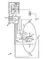
図1は、心臓カテーテルをナビゲートし、患者11の心臓10に生じる電気的活動を測定し、電気的活動、及び/又は、そのように測定された電気的活動に関連する情報又はその電気的活動を3次元マッピングすることによって、心臓電気生理学的検査を行うための例示的な解剖学的マッピングシステム8の概略図を示す。システム8は、例えば、1つ又は複数の電極を使用して、患者の心臓10の解剖学的モデルを作成するために使用することができる。システム8は、例えば、患者の心臓10の診断データマップを作成するために、心臓表面に沿った複数の点において電気生理学的データを測定し、電気生理学的データが測定された各測定点に関する位置情報と関連付けて測定データを記憶するために使用することができる。本明細書でさらに論じるように、いくつかの実施形態において、システム8は、LATマップを生成することができる。
FIG. 1 illustrates navigating a cardiac catheter, measuring electrical activity occurring in a
当業者が認識し、以下でさらに説明するように、システム8は、典型的には3次元空間内の物体の位置と、いくつかの実施形態では向きと、を決定し、少なくとも1つの基準に対して決定された位置情報としてそれらの位置を表す。 As those skilled in the art will appreciate and as will be further described below, the system 8 typically determines the position of an object in three-dimensional space and, in some embodiments, the orientation and uses at least one criterion. Those positions are represented as the position information determined for them.
説明を簡単にするために、患者11は、概略的に楕円形として描かれている。図1に示す実施形態では、3つのセットの表面電極(例えば、パッチ電極)が患者11の表面に適用されて示されている。本明細書では、x軸、y軸、及び、z軸と呼ばれる3つの略直交する軸が画定される。他の実施形態では、電極は、他の配置、例えば、複数の電極を特定の身体表面上に配置することができる。さらなる代替として、電極は、身体表面上にある必要はなく、身体の内部に配置することができる。 For simplicity of explanation, the patient 11 is depicted schematically as oval. In the embodiment shown in FIG. 1, three sets of surface electrodes (eg, patch electrodes) are shown applied to the surface of patient 11. Three generally orthogonal axes are defined herein, called the x-axis, y-axis, and z-axis. In other embodiments, the electrodes may have other arrangements, for example, a plurality of electrodes arranged on a particular body surface. As a further alternative, the electrodes need not be on the body surface and can be placed inside the body.
図1において、x軸表面電極12、14は、患者の胸郭領域の側部上など、第1の軸に沿って患者(例えば、各腕の下の患者の皮膚)に適用され、左電極及び右電極と呼ぶことができる。y軸電極18、19は、患者の内腿領域及び頸部領域に沿うなど、x軸にほぼ直交する第2の軸に沿って患者に適用され、左脚電極及び頸部電極と呼ぶことができる。z軸電極16、22は、胸郭領域において患者の胸骨及び脊椎に沿うなど、x軸とy軸の両方に略直交する第3の軸に沿って適用され、胸部電極及び背部電極と呼ぶことができる。心臓10は、これらの表面電極のペア12/14、18/19、及び、16/22の間に位置する。
In FIG. 1,
追加の表面基準電極(例えば、「腹部パッチ」)21は、システム8のための基準電極及び/又は接地電極を提供する。腹部パッチ電極21は、以下でさらに詳細に説明する固定心臓内電極31の代替であってもよい。加えて、患者11は、従来の心電図(「ECG」又は「EKG」)システムリード線の大部分又はすべてを定位置に有してもよいことも理解されるべきである。特定の実施形態では、例えば、患者の心臓10の心電図を感知するために12個のECGリード線の標準セットが利用されてもよい。このECG情報は、システム8で利用可能である(例えば、コンピュータ・システム20への入力として提供することができる)。ECGリード線が十分に理解されている限りにおいて、図面の明瞭化のために、単一のリード線6、及び、コンピュータ20への接続のみが、図1において図示されている。
An additional surface reference electrode (eg, “abdominal patch”) 21 provides a reference electrode and/or ground electrode for system 8. The
少なくとも1つの電極17を有する典型的なカテーテル13も示されている。この典型的なカテーテル電極17は、本明細書全体にわたって「ロービング電極」、「移動電極」、又は、「測定電極」と呼ばれる。典型的には、カテーテル13上、又は、複数のカテーテル上の複数の電極17が使用される。一実施形態では、例えば、システム8は、患者の心臓、及び/又は、脈管構造内に配置される12個のカテーテル上の64個の電極を備えていてもよい。もちろん、この実施形態は、単なる例示であり、任意の数の電極、及び、カテーテルを使用することができる。
A
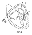
同様に、カテーテル13(又は複数のカテーテル)は、典型的には、1つ又は複数の導入器を介して、よく知られた手順を使用して心臓、及び/又は、脈管構造内に導入されることが理解されるべきである。本開示の目的のために、例示的な多電極カテーテル13のセグメントが図2に示されている。図2において、カテーテル13は、経中隔シース35を介して患者の心臓10の左心室50内に延びる。左心室への経中隔アプローチの使用は、周知であり、当業者によく知られており、本明細書でさらに説明する必要はない。もちろん、カテーテル13は、任意の他の適切な方法で心臓10に導入することもできる。
Similarly, the catheter 13 (or catheters) is typically introduced into the heart and/or vasculature via one or more introducers using well known procedures. It should be understood that is done. For purposes of this disclosure, a segment of an exemplary
カテーテル13は、その遠位先端上に電極17、及び、図示の実施形態ではその長さに沿って離間された複数の追加の測定電極52、54、56を備える。典型的には、隣接する電極間の間隔は、既知であるが、電極は、カテーテル13に沿って均一に離間されていなくてもよいし、互いに等しいサイズでなくてもよいことが理解されるべきである。これらの電極17、52、54、56の各々が患者内にあるので、位置データが、システム8によって電極の各々について同時に収集されてもよい。
The
同様に、各電極17、52、54、56は、心臓表面から電気生理学的データを収集するために使用することができる。当業者は、そのさらなる議論が本明細書で開示された技術を理解するために必要がないように、(例えば、接触電気生理学的マッピングと非接触電気生理学的マッピングとの両方を含む)電気生理学的データ点の獲得及び処理のための様々な様式に精通しているであろう。同様に、当該技術分野でよく知られている様々な技法を、複数の電気生理学的データ点からグラフ表示を生成するために使用することができる。当業者が電気生理学的データ点から電気生理学的マップを作成する方法を理解する限り、その態様は、本開示を理解するのに必要な程度にのみ本明細書で説明される。
Similarly, each
図1に戻ると、いくつかの実施形態では、(例えば、心臓10の壁に取り付けられる)任意の固定基準電極31が第2のカテーテル29上に示されている。この電極31は、較正の目的のため、(例えば、心臓の壁に取り付けられる、又は、近接して)静止していてもよいし、又は、ロービング電極(例えば、電極17)と固定された空間関係に配置されてもよく、「ナビゲーション基準」又は「局所基準」と呼ばれることがある。固定基準電極31は、上記で説明した表面基準電極21に加えて、又は、その代替として使用されてもよい。多くの場合、心臓10においての冠状静脈洞電極又は他の固定電極が、電圧及び変位を測定するための基準として使用することができる。即ち、以下で説明するように、固定基準電極31は、座標系の原点を定義してもよい。
Returning to FIG. 1, in some embodiments an optional fixed reference electrode 31 (eg, attached to the wall of the heart 10) is shown on the
各表面電極は、多重スイッチ24に接続されている。表面電極のペアは、表面電極を信号発生器25に接続するコンピュータ20で実行されるソフトウェアによって選択される。代替的には、スイッチ24は、省略されてもよく、信号発生器25の複数(例えば、3つ)のインスタンスが、測定軸毎に(即ち、表面電極ペア毎に)1つ設けられてもよい。
Each surface electrode is connected to the
コンピュータ20は、例えば、従来の汎用コンピュータ、専用コンピュータ、分散コンピュータ、又は、任意の他のタイプのコンピュータを備えていてもよい。コンピュータ20は、本明細書に記載された様々な態様を実施するための命令を実行することができる単一の中央処理装置(「CPU」)、又は、一般に並列処理環境と呼ばれる複数の処理装置などの1つ又は複数のプロセッサ28を備えていてもよい。
一般に、生物学的導体におけるカテーテルのナビゲーションを実現するために、3つの名目上の直交電場が、一連の駆動及び感知電気双極子(例えば、表面電極ペア12/14、18/19、及び、16/22)によって生成される。代替的には、これらの直交電場は、分解することができ、表面電極の任意のペアは、有効な電極三角測量を提供するための双極子として駆動することができる。同様に、電極12、14、18、19、16、及び、22(又は任意の数の電極)は、心臓内の電極に電流を駆動するため、又は、心臓内の電極からの電流を感知するための任意の他の有効な位置に配置することができる。例えば、複数の電極は、患者11の背部、側部、及び/又は、腹部に配置することができる。加えて、そのような非直交方法論は、システムの柔軟性を増す。任意の所望の軸について、駆動(ソースシンク)構成の所定のセットから結果として生じるロービング電極にわたって測定される電位は、直交軸に沿って均一な電流を単に駆動することによって得られるのと同じ有効電位を生じさせるために、代数的に組み合わせられてもよい。
In general, three nominal quadrature electric fields are used to provide a series of driven and sensed electric dipoles (eg, surface electrode pairs 12/14, 18/19, and 16) to achieve catheter navigation in biological conductors. /22). Alternatively, these orthogonal electric fields can be resolved and any pair of surface electrodes can be driven as a dipole to provide effective electrode triangulation. Similarly,
このため、表面電極12、14、16、18、19、22のうちの任意の2つは、腹部パッチ21のような接地基準に対する双極子ソース及びドレインとして選択されてもよく、非励起電極は、接地基準に対する電圧を測定する。心臓10内に配置されたロービング電極17は、電流パルスからの場にさらされ、腹部パッチ21などの接地に対して測定される。実際には、心臓10内のカテーテルは、図示の16個よりも多い又は少ない電極を含んでもよく、各電極電位が測定されてもよい。前述したように、少なくとも1個の電極が、固定基準電極31を形成するために心臓の内側表面に固定されてもよく、これも、腹部パッチ21のような接地に対して測定され、システム8が位置を測定する座標系の原点として定義されてもよい。表面電極、内部電極、及び、仮想電極の各々からのデータセットは、全て、心臓10内のロービング電極17の位置を決定するために使用することができる。
Thus, any two of the
測定された電圧は、基準電極31などの基準位置に対して、ロービング電極17などの心臓内部の電極の3次元空間における位置を決定するために、システム8によって使用されてもよい。即ち、基準電極31において測定された電圧は、座標系の原点を定義するために使用されてもよいし、ロービング電極17において測定された電圧は、原点に対するロービング電極17の位置を表すために使用されてもよい。いくつかの実施形態では、座標系は、3次元(x、y、z)デカルト座標系であるが、極座標系、球面座標系、及び、円筒座標系等の他の座標系も考えられる。
The measured voltage may be used by the system 8 to determine the position in three-dimensional space of an electrode within the heart, such as the
前述の議論から明らかであるように、心臓内の電極の位置を決定するために使用されるデータは、表面電極ペアが心臓に電場を印加しながら測定される。電極データは、例えば、参照によりその全体が本明細書に組み込まれる米国特許第7,263,397号に記載されているように、電極位置のための生の位置データを改善するために使用される呼吸補償値を作成するために使用されてもよい。電極データは、例えば、同じく参照によりその全体が本明細書に組み込まれる米国特許第7,885,707号に記載されているように、患者の身体のインピーダンスにおける変化を補償するために使用されてもよい。 As will be apparent from the discussion above, the data used to determine the position of electrodes within the heart is measured while the surface electrode pairs apply an electric field to the heart. Electrode data is used to improve raw position data for electrode positions, for example, as described in US Pat. No. 7,263,397, which is incorporated herein by reference in its entirety. May be used to create a respiratory compensation value. Electrode data is used to compensate for changes in the impedance of the patient's body, for example, as described in US Pat. No. 7,885,707, which is also incorporated herein by reference in its entirety. Good.
従って、1つの典型的な実施形態では、システム8は、最初に表面電極のセットを選択し、次いで、それらを電流パルスで駆動する。電流パルスが送達されている間、残りの表面電極及び生体内電極のうちの少なくとも1つを用いて測定される電圧などの電気的活動が測定され、記憶される。上記のように、呼吸、及び/又は、インピーダンスシフトなどのアーティファクトの補償が実行されてもよい。 Thus, in one exemplary embodiment, the system 8 first selects a set of surface electrodes and then drives them with current pulses. While the current pulse is being delivered, electrical activity, such as voltage measured with at least one of the remaining surface electrode and the in-vivo electrode, is measured and stored. As mentioned above, compensation for artifacts such as breathing and/or impedance shifts may be performed.
いくつかの実施形態では、システム8は、Abbott LaboratoriesのEnSite Velocity(商標)、又は、EnSite Precision(商標)心臓マッピング及び視覚化システムである。しかしながら、例えば、Biosense Webster, Inc.のCARTOナビゲーション及び位置特定システム、Northern Digital Inc.のAURORA(登録商標)システム、SterotaxisのNIOBE(登録商標)磁気ナビゲーションシステム、ならびに、Abbott LaboratoriesからのMediGuide(商標)Technologyを含む他の位置特定システムが、本教示に関連して使用されてもよい。 In some embodiments, system 8 is an Abbott Laboratories EnSite Velocity™ or EnSite Precision™ cardiac mapping and visualization system. However, for example, the CARTO navigation and localization system of Biosense Webster, Inc., the AURORA® system of Northern Digital Inc., the NIOBE® magnetic navigation system of Sterotaxis, and the MediGuide® from Abbott Laboratories. Other localization systems, including Technology, may be used in connection with the present teachings.
(参照によりそれらの全体が本明細書に組み込まれる)以下の特許、米国特許第6,990,370号、第6,978,168号、第6,947,785号、第6,939,309号、第6,728,562号、第6,640,119号、第5,983,126号、及び、第5,697,377号に記載の位置特定及びマッピングシステムも、本明細書と共に使用することができる。 The following patents (incorporated herein by reference in their entirety), US Pat. Nos. 6,990,370, 6,978,168, 6,947,785, 6,939,309. The location and mapping systems described in Nos. 6,728,562, 6,640,119, 5,983,126, and 5,697,377 are also used herein. can do.
本開示の態様は、LATマップを生成することに関する。従って、システム8は、LATマップを生成するために使用することができるLATマッピングモジュール58を含むこともできる。 Aspects of the disclosure relate to generating LAT maps. Therefore, the system 8 may also include a LAT mapping module 58 that may be used to generate the LAT map.
LATマップは、電気生理学的マップの一種である。当業者は、限定はしないが、LATマップを含む電気生理学的マップが複数の電気生理学的データ点を含み、各電気生理学的データ点が、測定された電気生理学的データ(例えば、心電図(「EGM」)などの電気生理学的信号)と位置データ(例えば、カテーテル13及び/又はその上の電極17、52、54、56の位置に関する情報)の両方を含み、測定された電気生理学的情報が空間内の特定の位置に関連付けられることを可能にする(すなわち、測定された電気生理学的情報が患者の心臓上の点における電気活動を示すものとして解釈されることを可能にする)ことを理解するであろう。
The LAT map is a kind of electrophysiological map. Those skilled in the art will appreciate that electrophysiological maps, including but not limited to LAT maps, include a plurality of electrophysiological data points, each electrophysiological data point being measured electrophysiological data (eg, electrocardiogram (“EGM” (“EGM”)). )) and position data (eg, information regarding the position of the
当業者は、電気生理学的データ点の収集、及び、そこからの電気生理学的マップの生成の様々な態様にも精通しているであろう。しかしながら、例として、本明細書に完全に記載されているかのように、参照により本明細書に組み込まれる米国特許出願公開第2015/0057507号は、本開示の教示を適用することができる電気生理学的データ点の収集、及び、電気生理学的マップの作成のための様々な方法及びシステムを説明している。 Those skilled in the art will also be familiar with various aspects of collecting electrophysiological data points and generating electrophysiological maps therefrom. However, by way of example, U.S. Patent Application Publication No. 2015/0057507, which is incorporated herein by reference as if fully set forth herein, is an electrophysiology to which the teachings of the present disclosure may be applied. Various methods and systems for the collection of statistical data points and the creation of electrophysiological maps are described.
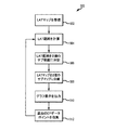
本教示による複数の電気生理学的データ点などからLATをマッピングする1つの例示的な方法について、図3として提示される典型的なステップのフローチャート300を参照して説明する。いくつかの実施形態では、例えば、フローチャート300は、図1の電気解剖学的マッピングシステム8(例えば、プロセッサ28及び/又はLATマッピングモジュール58)によって実行することができるいくつかの例示的なステップを表すことができる。以下で説明される典型的なステップは、ハードウェア又はソフトウェアのいずれかによって実施することができることが理解されるべきである。説明のために、「信号プロセッサ」という用語は、本明細書の教示のハードウェアベースの実装形態とソフトウェアベースの実装形態の両方を説明するために本明細書で使用される。
One exemplary method of mapping a LAT, such as from multiple electrophysiological data points in accordance with the present teachings, is described with reference to the
ブロック302において、心臓の少なくとも一部に関するLATマップが受信される。当業者は、ブロック302で受信されるLATマップが、複数の電気生理学的データ点を含み、各々が(他の位置及び電気生理学的情報に加えて)関連するLATを有することを理解するであろう。
At
当業者は、LATマップを色スペクトル、グレースケール、パターン密度範囲などのマッピング規則に関連付けることができることも認識するであろう。このマッピング規則は、例えば、3次元心臓モデルにおけるLATマップのグラフ表示をレンダリングするときにLATマップデータに適用することができる。当業者がLATマップを含む電気生理学的マップのグラフ表示に一般的に精通している限り、同じもののさらなる詳細は、本開示の理解には必要ない。 One of ordinary skill in the art will also recognize that the LAT map can be associated with mapping rules such as color spectrum, gray scale, pattern density range, and the like. This mapping rule can be applied to LAT map data when rendering a graphical representation of a LAT map in a three-dimensional heart model, for example. As long as one of ordinary skill in the art is generally familiar with graphical representations of electrophysiological maps, including LAT maps, further details of the same are not necessary for an understanding of the present disclosure.
ブロック304において、LAT範囲が計算される。LAT範囲は、LATマップ内の最も早いLATと最新のLATとの間の変動である。
At
ブロック306において、LAT範囲は、複数のLATサブ範囲に分割される。本開示の態様によれば、LAT範囲は、LAT範囲の50%未満をカバーする第1のLATサブ範囲と、LAT範囲の残りをカバーする第2のLATサブ範囲と、に分割される。例えば、本明細書に開示される実施形態では、第1のLATサブ範囲は、LAT範囲の最も早い5%をカバーし、第2のLATサブ範囲は、LAT範囲の残りの95%をカバーする。換言すれば、本開示の態様によれば、LATサブ範囲は、LAT範囲を集合的に構成する。しかしながら、LATサブ範囲が全LAT範囲未満を集合的に構成することも考えられる(例えば、専門家にとって関心のないLAT範囲の部分が存在する場合、LAT範囲のその部分は、LATサブ範囲において反映される必要はない)。以下でさらに論じられるように、LAT範囲をサブ範囲に分割することによって、他のLATサブマップと比較していくつかのLATサブマップをグラフ表示するときに、増加した粒度を達成することができる。
At
ブロック308において、LATマップは、複数のLATサブマップに分割される。一般に、LATサブマップの数は、LATサブ範囲の数に対応する(例えば、2つのLATサブ範囲について、2つのLATサブマップが存在し、1つが各LATサブ範囲に対応する)。
At
従って、例えば、第1のLATサブマップは、第1のLATサブ範囲内に含まれるLATを有するLATマップ内の複数の電気生理学的データ点の第1のサブセットを識別することによって生成することができる。同様に、第2のLATサブマップは、第2のLATサブ範囲内に含まれるLATを有するLATマップ内の複数の電気生理学的データ点の第2のサブセットを識別することによって生成することができる。 Thus, for example, the first LAT submap may be generated by identifying a first subset of electrophysiological data points in the LAT map having LATs that fall within the first LAT subrange. it can. Similarly, the second LAT submap can be generated by identifying a second subset of electrophysiological data points in the LAT map having LATs that fall within the second LAT subrange. ..
LATサブマップの各々は、関連するマッピングサブ規則も有する。マッピングサブ規則は、連続的であり、LATマップに関するマッピング規則を集合的にカバーすることが望ましい。 Each of the LAT submaps also has an associated mapping subrule. The mapping sub-rules are sequential and preferably collectively cover the mapping rules for the LAT map.
本開示のいくつかの態様によれば、マッピングサブ規則は、それらのそれぞれのLATサブ範囲に対して線形的にスケーリングされる。本開示の他の態様では、マッピングサブ規則は、それらのそれぞれのLATサブ範囲に対して対数的にスケーリングされる。マッピングサブ規則は、本教示の範囲から逸脱することなく、他の方法でそれらのそれぞれのLATサブ範囲にスケーリングすることができる。さらに、スケールの組合せが考えられる(例えば、1つのマッピングサブ規則をそのLATサブ範囲に対して線形的にスケーリングすることができ、別のマッピングサブ規則をそのLATサブ範囲に対して対数的にスケーリングすることができる)。 According to some aspects of the disclosure, the mapping sub-rules are linearly scaled to their respective LAT sub-ranges. In another aspect of the disclosure, the mapping sub-rules are logarithmically scaled to their respective LAT sub-ranges. The mapping sub-rules can be scaled to their respective LAT sub-ranges in other ways without departing from the scope of the present teachings. Further, combinations of scales are possible (eg, one mapping subrule can be linearly scaled to its LAT subrange and another mapping subrule can be logarithmically scaled to its LAT subrange. can do).
例えば、マッピング規則が色スペクトル(例えば、白色から紫色まで)である場合、第1のLATサブマップは、第1のLATサブ範囲に対して線形的にスケーリングされる第1の色スペクトル(例えば、白色からオレンジ色まで)である第1のマッピングサブ規則を有することができ、第2のLATサブマップは、第2のLATサブ範囲に対して線形的にスケーリングされる第2の色スペクトル(例えば、黄色から紫色まで)である第2のマッピングサブ規則を有することができる。 For example, if the mapping rule is a color spectrum (eg, white to purple), the first LAT submap may be a first color spectrum (eg, white) that is linearly scaled to the first LAT subrange. The second LAT submap may have a first mapping sub-rule that is white to orange) and the second LAT sub-map is a second color spectrum that is linearly scaled to the second LAT sub-range (eg, , Yellow to purple).
別の例として、マッピング規則がグレースケールである場合、第1のLATサブマップは、第1のLATサブ範囲に対して線形的にスケーリングされる第1のグレースケール範囲である第1のマッピングサブ規則を有することができ、第2のLATサブマップは、第2のLATサブ範囲に対して線形的にスケーリングされる第2のグレースケール範囲である第2のマッピングサブ規則を有することができる。 As another example, if the mapping rule is grayscale, then the first LAT submap is a first grayscale range that is linearly scaled with respect to the first LAT subrange. The second LAT submap may have a second mapping sub-rule that is a second grayscale range that is linearly scaled with respect to the second LAT sub-range.
同様に、マッピング規則がパターン密度範囲である場合、第1のLATサブマップは、総パターン密度範囲の第1の部分をカバーし、第1のLATサブ範囲に対して線形的にスケーリングされる第1のマッピングサブ規則を有することができ、第2のLATサブマップは、総パターン密度範囲の残りの部分をカバーし、第2のLATサブ範囲に対して線形的にスケーリングされる第2のマッピングサブ規則を有することができる。 Similarly, if the mapping rule is a pattern density range, the first LAT submap covers a first portion of the total pattern density range and is linearly scaled with respect to the first LAT subrange. A second LAT submap, which covers the remaining portion of the total pattern density range and is linearly scaled to the second LAT subrange. Can have sub-rules.
他の実施形態では、マッピングサブ規則は、不連続である。例えば、第1のマッピングサブ規則を色スペクトルとすることができ、第2のマッピング規則をグレースケール範囲とすることができる。 In other embodiments, the mapping subrules are discontinuous. For example, the first mapping sub-rule can be a color spectrum and the second mapping rule can be a grayscale range.
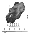
ブロック310において、LATサブマップのグラフ表示を出力することができる。例えば、図4は、前述の開示に従って生成される(例えば、図1のLATモジュール58によって生成され、ディスプレイ23上に出力される)例示的なグラフ表示400である。図4に示すように、グラフ表示400は、LATの最も早い5%(例えば、約−300ms〜約−260ms)を描写するために第1のマッピングサブ規則(例えば、グレースケール範囲)402を利用し、LATの残りの95%(例えば、約−250ms〜約350ms)を描写するために第2のマッピングサブ規則(例えば、グレースケール範囲)404を利用する。
At
ブロック312において、追加の電気生理学的データ点を追加することができる。ブロック312において1つ(又は複数)の追加の電気生理学的データ点が収集された後、プロセスは、LAT範囲を再計算し、新たに収集された電気生理学的データ点を含めるようにLATサブ範囲を再生成するために、ブロック304に戻ることができる。
At
本教示は、期外収縮をマッピングするときに良好な利点に適用することができる。具体的には、本教示は、(すべてのLATを単一のマッピング規則に含めるのとは対照的に)LATの最も早い5%について専用のマッピングサブ規則を使用することによって、最も早い活動の場所の改善された視覚化を可能にする。この改善された視覚化のほんの一例として、本教示は、全体的に非線形であるが、複数の線形マッピングサブ規則で構成されるマッピング規則を可能にし、それによって、専門家にとって特に関心がある1つ又は複数のLATサブ範囲の増加したグラフ粒度を可能にすることによって、LAT範囲全体の一部の視覚化を改善する。 The present teachings can be applied to good advantage when mapping extrasystoles. Specifically, the present teachings use a dedicated mapping sub-rule for the earliest 5% of LATs (as opposed to including all LATs in a single mapping rule), thereby Allows for improved visualization of places. As just one example of this improved visualization, the present teachings allow mapping rules that are generally non-linear, but are composed of multiple linear mapping sub-rules, which are of particular interest to professionals. By allowing for increased graph granularity of one or more LAT sub-ranges, it improves the visualization of parts of the entire LAT range.
いくつかの実施形態について、ある程度の詳細で上記に説明したが、当業者は、本発明の要旨又は範囲から逸脱することなく、開示された実施形態に多数の変更を加えることができる。 Although some embodiments have been described above in some detail, those skilled in the art can make numerous changes to the disclosed embodiments without departing from the spirit or scope of the invention.
例えば、本明細書の教示は、LAT範囲を、2つを超えるサブ範囲に拡張することができる。 For example, the teachings herein can extend the LAT range to more than two sub-ranges.
別の例として、本明細書の教示は、リアルタイムで(例えば、電気生理学的検査中に)、又は、後処理中に(例えば、以前に実行された電気生理学的検査中に収集された電気生理学的データ点に対して)適用することができる。 As another example, the teachings herein provide for electrophysiology collected in real time (eg, during electrophysiological examination) or during post-processing (eg, during previously performed electrophysiological examination). Applied to specific data points).
すべての方向の参照(例えば、上部、下部、上向き、下向き、左、右、左側、右側、上部、下部、より上、より下、垂直、水平、時計回り、及び反時計回り)は、本発明の読者の理解を助ける識別目的のためにのみ使用され、特に発明の位置、向き、又は使用に関して制限をするものではない。接合の参照(例えば、取り付けられた、結合された、接続されたなど)は、広く解釈されるべきであり、要素の接続と要素間の相対的な移動との間に中間部材を含む場合がある。そのように、接合の参照は、必ずしも、2つの要素が直接接続され、互いに固定された関係にあることを意味するものではない。 References in all directions (eg, top, bottom, up, down, left, right, left, right, top, bottom, above, below, vertical, horizontal, clockwise, and counterclockwise) are in accordance with the invention. Used for identification purposes only to aid the reader's understanding of the invention, and not as a limitation on the position, orientation, or use of the invention. Junction references (eg, attached, joined, connected, etc.) should be construed broadly and may include intermediate members between the connection of the elements and the relative movement between the elements. is there. As such, a joining reference does not necessarily mean that the two elements are directly connected and in a fixed relationship to each other.
上記の説明に含まれる、又は添付図面に示されるすべての事項は、単なる例示として解釈されるべきであり、限定として解釈されるべきではない。詳細又は構造の変化は、添付の特許請求の範囲に規定された本発明の要旨から逸脱することなくなされ得る。 It is intended that all matter contained in the above description or shown in the accompanying drawings shall be interpreted as illustrative only and not limiting. Changes in detail or structure may be made without departing from the spirit of the invention as defined in the appended claims.
上記の説明に含まれる、又は添付図面に示されるすべての事項は、単なる例示として解釈されるべきであり、限定として解釈されるべきではない。詳細又は構造の変化は、添付の特許請求の範囲に規定された本発明の要旨から逸脱することなくなされ得る。
以下の項目は、国際出願時の請求の範囲に記載の要素である。
(項目1)
複数の電気生理学的データ点から局所活動時間をマッピングする方法であって、
前記複数の電気生理学的データ点に関するLAT範囲を計算するステップと、
前記LAT範囲を、少なくとも第1のLATサブ範囲と第2のLATサブ範囲とに分割するステップと、
少なくとも、前記第1のLATサブ範囲内に含まれる前記複数の電気生理学的データ点の第1のサブセットと、前記第2のLATサブ範囲内に入る前記複数の電気生理学的データ点の第2のサブセットと、を画定するステップと、
少なくとも、前記複数の電気生理学的データ点の前記第1のサブセットの第1のLATサブマップと、前記複数の電気生理学的データ点の前記第2のサブセットの第2のLATサブマップと、を生成するステップであって、前記第1のLATサブマップは第1のマッピングサブ規則を使用して生成され、前記第2のLATサブマップは第2のマッピングサブ規則を使用して生成される、ステップと、
を備える方法。
(項目2)
前記第1のマッピングサブ規則は、前記第2のマッピングサブ規則と連続している、項目1に記載の方法。
(項目3)
前記第1のマッピングサブ規則が、第1の色スペクトルを備え、
前記第2のマッピングサブ規則が、第2の色スペクトルを備える、項目1に記載の方法。
(項目4)
前記第1のマッピングサブ規則が、第1のグレースケール範囲を備え、
前記第2のマッピングサブ規則が、第2のグレースケール範囲を備える、項目1に記載の方法。
(項目5)
前記第1のマッピングサブ規則が、第1のパターン密度範囲を備え、
前記第2のマッピングサブ規則が、第2のパターン密度範囲を備える、項目1に記載の方法。
(項目6)
前記第1のマッピングサブ規則が、前記第1のLATサブ範囲に対して線形的にスケーリングされ、
前記第2のマッピングサブ規則が、前記第2のLATサブ範囲に対して線形的にスケーリングされる、項目1に記載の方法。
(項目7)
前記第1のマッピングサブ規則が、前記第1のLATサブ範囲に対して対数的にスケーリングされ、
前記第2のマッピングサブ規則が、前記第2のLATサブ範囲に対して対数的にスケーリングされる、項目1に記載の方法。
(項目8)
前記第1のLATサブ範囲が、前記LAT範囲の50%未満をカバーし、
前記第2のLATサブ範囲が、前記LAT範囲の50%超をカバーする、項目1に記載の方法。
(項目9)
前記第1のLATサブ範囲が、前記LAT範囲の5%をカバーし、
前記第2のLATサブ範囲が、前記LAT範囲の95%をカバーする、項目7に記載の方法。
(項目10)
前記方法は、さらに、
追加の電気生理学的データ点を収集する収集ステップと、
前記追加の電気生理学的データ点を前記複数の電気生理学的データ点に含めて、
前記複数の電気生理学的データ点に関するLAT範囲を再計算するステップと、
前記LAT範囲を、少なくとも第1のLATサブ範囲と第2のLATサブ範囲とに分割するステップと、
少なくとも、前記第1のLATサブ範囲内に含まれる前記複数の電気生理学的データ点の第1のサブセットと、前記第2のLATサブ範囲内に含まれる前記複数の電気生理学的データ点の第2のサブセットと、を画定するステップと、
少なくとも、前記複数の電気生理学的データ点の前記第1のサブセットの第1のLATサブマップと、前記複数の電気生理学的データ点の前記第2のサブセットの第2のLATサブマップと、を生成するステップであって、前記第1のLATサブマップは第1のマッピングサブ規則を使用して生成され、前記第2のLATサブマップは第2のマッピングサブ規則を使用して生成される、ステップと、
を繰り返すステップと、
備える、項目1に記載の方法。
(項目11)
前記方法は、さらに、
3次元心臓モデルにおける少なくとも前記第1のLATサブマップ及び前記第2のLATサブマップのグラフ表示を出力するステップを備える、項目1に記載の方法。
(項目12)
局所活動時間をマッピングする方法であって、
心臓の少なくとも一部のLATマップであって、マッピング規則に関連付けられている前記LATマップを受信するステップと、
前記LATマップに関するLAT範囲を計算するステップと、
前記LAT範囲を複数のLATサブ範囲に分割するステップと、
前記LATマップを複数のLATサブマップに分割するステップであって、前記LATサブマップの数が前記LATサブ範囲の数に対応し、前記複数のLATサブマップのそれぞれのLATサブマップが、複数のマッピングサブ規則のそれぞれのマッピングサブ規則に関連付けられている、ステップと、
を備える方法。
(項目13)
前記複数のマッピングサブ規則は連続的であり、前記マッピング規則を集合的に備える、項目11に記載の方法。
(項目14)
前記マッピング規則は、色スペクトルを備える、項目12に記載の方法。
(項目15)
前記マッピング規則は、グレースケールを備える、項目12に記載の方法。
(項目16)
前記マッピング規則は、パターン密度範囲を備える、項目12に記載の方法。
(項目17)
前記方法は、さらに、
3次元心臓モデルにおける前記複数のLATサブマップのグラフ表示を出力するステップを備える、項目11に記載の方法。
(項目18)
前記複数のLATサブ範囲は、第1のLATサブ範囲と第2のLATサブ範囲とを備え、
前記第1のLATサブ範囲は、前記LAT範囲の50%未満であり、
前記第2のLATサブ範囲は、前記LAT範囲の50%超である、項目11に記載の方法。
(項目19)
前記第1のLATサブ範囲は、前記LAT範囲の5%であり、
前記第2のLATサブ範囲は、前記LAT範囲の95%である、項目17に記載の方法。
(項目20)
局所活動時間をマッピングするためのシステムであって、
心臓の少なくとも一部のLATマップであって、マッピング規則に関連付けられている前記LATマップを受信する処理と、
前記LATマップに関するLAT範囲を計算する処理と、
前記LAT範囲を複数のLATサブ範囲に分割する処理と、
前記LATマップを複数のLATサブマップに分割する処理であって、前記LATサブマップの数が前記LATサブ範囲の数に対応し、前記複数のLATサブマップのうちのLATサブマップのそれぞれが、複数のマッピングサブ規則のそれぞれのマッピングサブ規則に関連付けられている、処理と、
を実行するように構成されたマッピングプロセッサを備えるシステム。
(項目21)
前記システムは、さらに、
3次元心臓モデルにおける前記複数のLATサブマップのグラフ表示を出力するように構成された出力プロセッサを備える、項目20に記載のシステム。
It is intended that all matter contained in the above description or shown in the accompanying drawings shall be interpreted as illustrative only and not limiting. Changes in detail or structure may be made without departing from the spirit of the invention as defined in the appended claims.
The following items are elements described in the claims at the time of international application.
(Item 1)
A method of mapping local activity time from multiple electrophysiological data points, comprising:
Calculating a LAT range for the plurality of electrophysiological data points;
Dividing the LAT range into at least a first LAT sub-range and a second LAT sub-range;
At least a first subset of the plurality of electrophysiological data points contained within the first LAT subrange and a second subset of the plurality of electrophysiological data points falling within the second LAT subrange. Defining a subset, and
Generating at least a first LAT submap of the first subset of the plurality of electrophysiological data points and a second LAT submap of the second subset of the plurality of electrophysiological data points. Wherein the first LAT submap is generated using a first mapping subrule and the second LAT submap is generated using a second mapping subrule. When,
A method comprising.
(Item 2)
The method of item 1, wherein the first mapping sub-rule is contiguous with the second mapping sub-rule.
(Item 3)
The first mapping sub-rule comprises a first color spectrum,
The method of item 1, wherein the second mapping sub-rule comprises a second color spectrum.
(Item 4)
The first mapping subrule comprises a first grayscale range,
The method of item 1, wherein the second mapping subrule comprises a second grayscale range.
(Item 5)
The first mapping sub-rule comprises a first pattern density range,
The method of item 1, wherein the second mapping subrule comprises a second pattern density range.
(Item 6)
The first mapping sub-rule is linearly scaled with respect to the first LAT sub-range,
The method of item 1, wherein the second mapping sub-rule is linearly scaled with respect to the second LAT sub-range.
(Item 7)
Said first mapping sub-rule is logarithmically scaled to said first LAT sub-range,
The method of item 1, wherein the second mapping sub-rule is logarithmically scaled with respect to the second LAT sub-range.
(Item 8)
The first LAT sub-range covers less than 50% of the LAT range,
The method of item 1, wherein the second LAT sub-range covers more than 50% of the LAT range.
(Item 9)
The first LAT sub-range covers 5% of the LAT range,
8. The method of item 7, wherein the second LAT sub-range covers 95% of the LAT range.
(Item 10)
The method further comprises
A collecting step for collecting additional electrophysiological data points,
Including the additional electrophysiological data points in the plurality of electrophysiological data points,
Recalculating a LAT range for the plurality of electrophysiological data points;
Dividing the LAT range into at least a first LAT sub-range and a second LAT sub-range;
At least a first subset of the plurality of electrophysiological data points contained within the first LAT subrange and a second subset of the plurality of electrophysiological data points contained within the second LAT subrange. Defining a subset of
Generating at least a first LAT submap of the first subset of the plurality of electrophysiological data points and a second LAT submap of the second subset of the plurality of electrophysiological data points. Wherein the first LAT submap is generated using a first mapping subrule and the second LAT submap is generated using a second mapping subrule. When,
Repeat step,
The method according to item 1, comprising:
(Item 11)
The method further comprises
The method of claim 1, comprising outputting a graphical representation of at least the first LAT submap and the second LAT submap in a three-dimensional heart model.
(Item 12)
A method for mapping local activity time,
Receiving a LAT map of at least a portion of the heart, said LAT map being associated with a mapping rule,
Calculating a LAT range for the LAT map,
Dividing the LAT range into a plurality of LAT sub-ranges;
Dividing the LAT map into a plurality of LAT submaps, wherein the number of LAT submaps corresponds to the number of LAT subranges, and each LAT submap of the plurality of LAT submaps has a plurality of A step associated with each mapping subrule of the mapping subrule, and
A method comprising.
(Item 13)
12. The method of item 11, wherein the plurality of mapping sub-rules are consecutive and collectively comprise the mapping rules.
(Item 14)
13. The method of
(Item 15)
13. The method of
(Item 16)
13. The method of
(Item 17)
The method further comprises
12. The method of item 11, comprising outputting a graphical representation of the plurality of LAT submaps in a 3D heart model.
(Item 18)
The plurality of LAT sub-ranges comprises a first LAT sub-range and a second LAT sub-range,
The first LAT subrange is less than 50% of the LAT range,
12. The method of item 11, wherein the second LAT subrange is greater than 50% of the LAT range.
(Item 19)
The first LAT sub-range is 5% of the LAT range,
18. The method of
(Item 20)
A system for mapping local activity time, comprising:
Receiving a LAT map of at least a portion of the heart, the LAT map being associated with a mapping rule;
Processing to calculate a LAT range for the LAT map;
A process of dividing the LAT range into a plurality of LAT sub-ranges;
In the process of dividing the LAT map into a plurality of LAT submaps, the number of the LAT submaps corresponds to the number of the LAT subranges, and each of the LAT submaps of the plurality of LAT submaps includes: A process associated with each mapping subrule of the plurality of mapping subrules,
A system comprising a mapping processor configured to perform.
(Item 21)
The system further comprises
21. The system of
Claims (21)
前記複数の電気生理学的データ点に関するLAT範囲を計算するステップと、
前記LAT範囲を、少なくとも第1のLATサブ範囲と第2のLATサブ範囲とに分割するステップと、
少なくとも、前記第1のLATサブ範囲内に含まれる前記複数の電気生理学的データ点の第1のサブセットと、前記第2のLATサブ範囲内に入る前記複数の電気生理学的データ点の第2のサブセットと、を画定するステップと、
少なくとも、前記複数の電気生理学的データ点の前記第1のサブセットの第1のLATサブマップと、前記複数の電気生理学的データ点の前記第2のサブセットの第2のLATサブマップと、を生成するステップであって、前記第1のLATサブマップは第1のマッピングサブ規則を使用して生成され、前記第2のLATサブマップは第2のマッピングサブ規則を使用して生成される、ステップと、
を備える方法。 A method of mapping local activity time from multiple electrophysiological data points, comprising:
Calculating a LAT range for the plurality of electrophysiological data points;
Dividing the LAT range into at least a first LAT sub-range and a second LAT sub-range;
At least a first subset of the plurality of electrophysiological data points contained within the first LAT subrange and a second subset of the plurality of electrophysiological data points falling within the second LAT subrange. Defining a subset, and
Generating at least a first LAT submap of the first subset of the plurality of electrophysiological data points and a second LAT submap of the second subset of the plurality of electrophysiological data points Wherein the first LAT submap is generated using a first mapping subrule and the second LAT submap is generated using a second mapping subrule. When,
A method comprising.
前記第2のマッピングサブ規則が、第2の色スペクトルを備える、請求項1に記載の方法。 The first mapping sub-rule comprises a first color spectrum,
The method of claim 1, wherein the second mapping subrule comprises a second color spectrum.
前記第2のマッピングサブ規則が、第2のグレースケール範囲を備える、請求項1に記載の方法。 The first mapping subrule comprises a first grayscale range,
The method of claim 1, wherein the second mapping subrule comprises a second grayscale range.
前記第2のマッピングサブ規則が、第2のパターン密度範囲を備える、請求項1に記載の方法。 The first mapping sub-rule comprises a first pattern density range,
The method of claim 1, wherein the second mapping subrule comprises a second pattern density range.
前記第2のマッピングサブ規則が、前記第2のLATサブ範囲に対して線形的にスケーリングされる、請求項1に記載の方法。 The first mapping sub-rule is linearly scaled with respect to the first LAT sub-range,
The method of claim 1, wherein the second mapping subrule is linearly scaled with respect to the second LAT subrange.
前記第2のマッピングサブ規則が、前記第2のLATサブ範囲に対して対数的にスケーリングされる、請求項1に記載の方法。 Said first mapping sub-rule is logarithmically scaled to said first LAT sub-range,
The method of claim 1, wherein the second mapping sub-rule is logarithmically scaled to the second LAT sub-range.
前記第2のLATサブ範囲が、前記LAT範囲の50%超をカバーする、請求項1に記載の方法。 The first LAT sub-range covers less than 50% of the LAT range,
The method of claim 1, wherein the second LAT sub-range covers more than 50% of the LAT range.
前記第2のLATサブ範囲が、前記LAT範囲の95%をカバーする、請求項7に記載の方法。 The first LAT sub-range covers 5% of the LAT range,
8. The method of claim 7, wherein the second LAT subrange covers 95% of the LAT range.
追加の電気生理学的データ点を収集するステップと、
前記追加の電気生理学的データ点を前記複数の電気生理学的データ点に含めて、
前記複数の電気生理学的データ点に関するLAT範囲を再計算するステップと、
前記LAT範囲を、少なくとも第1のLATサブ範囲と第2のLATサブ範囲とに分割するステップと、
少なくとも、前記第1のLATサブ範囲内に含まれる前記複数の電気生理学的データ点の第1のサブセットと、前記第2のLATサブ範囲内に含まれる前記複数の電気生理学的データ点の第2のサブセットと、を画定するステップと、
少なくとも、前記複数の電気生理学的データ点の前記第1のサブセットの第1のLATサブマップと、前記複数の電気生理学的データ点の前記第2のサブセットの第2のLATサブマップと、を生成するステップであって、前記第1のLATサブマップは第1のマッピングサブ規則を使用して生成され、前記第2のLATサブマップは第2のマッピングサブ規則を使用して生成される、ステップと、
を繰り返すステップと、
備える、請求項1に記載の方法。 The method further comprises
Collecting additional electrophysiological data points,
Including the additional electrophysiological data points in the plurality of electrophysiological data points,
Recalculating a LAT range for the plurality of electrophysiological data points;
Dividing the LAT range into at least a first LAT sub-range and a second LAT sub-range;
At least a first subset of the plurality of electrophysiological data points contained within the first LAT subrange and a second subset of the plurality of electrophysiological data points contained within the second LAT subrange. Defining a subset of
Generating at least a first LAT submap of the first subset of the plurality of electrophysiological data points and a second LAT submap of the second subset of the plurality of electrophysiological data points Wherein the first LAT submap is generated using a first mapping subrule and the second LAT submap is generated using a second mapping subrule. When,
Repeat step,
The method of claim 1, comprising.
3次元心臓モデルにおける少なくとも前記第1のLATサブマップ及び前記第2のLATサブマップのグラフ表示を出力するステップを備える、請求項1に記載の方法。 The method further comprises
The method of claim 1, comprising outputting a graphical representation of at least the first LAT submap and the second LAT submap in a three-dimensional heart model.
心臓の少なくとも一部のLATマップであって、マッピング規則に関連付けられている前記LATマップを受信するステップと、
前記LATマップに関するLAT範囲を計算するステップと、
前記LAT範囲を複数のLATサブ範囲に分割するステップと、
前記LATマップを複数のLATサブマップに分割するステップであって、前記LATサブマップの数が前記LATサブ範囲の数に対応し、前記複数のLATサブマップのそれぞれのLATサブマップが、複数のマッピングサブ規則のそれぞれのマッピングサブ規則に関連付けられている、ステップと、
を備える方法。 A method for mapping local activity time,
Receiving a LAT map of at least a portion of the heart, said LAT map being associated with a mapping rule,
Calculating a LAT range for the LAT map,
Dividing the LAT range into a plurality of LAT sub-ranges;
Dividing the LAT map into a plurality of LAT submaps, wherein the number of LAT submaps corresponds to the number of LAT subranges, and each LAT submap of the plurality of LAT submaps has a plurality of A step associated with each mapping subrule of the mapping subrule, and
A method comprising.
3次元心臓モデルにおける前記複数のLATサブマップのグラフ表示を出力するステップを備える、請求項11に記載の方法。 The method further comprises
12. The method of claim 11, comprising outputting a graphical representation of the plurality of LAT submaps in a 3D heart model.
前記第1のLATサブ範囲は、前記LAT範囲の50%未満であり、
前記第2のLATサブ範囲は、前記LAT範囲の50%超である、請求項11に記載の方法。 The plurality of LAT sub-ranges comprises a first LAT sub-range and a second LAT sub-range,
The first LAT subrange is less than 50% of the LAT range,
The method of claim 11, wherein the second LAT subrange is greater than 50% of the LAT range.
前記第2のLATサブ範囲は、前記LAT範囲の95%である、請求項17に記載の方法。 The first LAT sub-range is 5% of the LAT range,
18. The method of claim 17, wherein the second LAT subrange is 95% of the LAT range.
心臓の少なくとも一部のLATマップであって、マッピング規則に関連付けられている前記LATマップを受信する処理と、
前記LATマップに関するLAT範囲を計算する処理と、
前記LAT範囲を複数のLATサブ範囲に分割する処理と、
前記LATマップを複数のLATサブマップに分割する処理であって、前記LATサブマップの数が前記LATサブ範囲の数に対応し、前記複数のLATサブマップのうちのLATサブマップのそれぞれが、複数のマッピングサブ規則のそれぞれのマッピングサブ規則に関連付けられている、処理と、
を実行するように構成されたマッピングプロセッサを備えるシステム。 A system for mapping local activity time, comprising:
Receiving a LAT map of at least a portion of the heart, the LAT map being associated with a mapping rule;
Processing to calculate a LAT range for the LAT map;
A process of dividing the LAT range into a plurality of LAT sub-ranges;
In the process of dividing the LAT map into a plurality of LAT submaps, the number of the LAT submaps corresponds to the number of the LAT subranges, and each of the LAT submaps of the plurality of LAT submaps is A process associated with each mapping subrule of the plurality of mapping subrules,
A system comprising a mapping processor configured to perform.
3次元心臓モデルにおける前記複数のLATサブマップのグラフ表示を出力するように構成された出力プロセッサを備える、請求項20に記載のシステム。 The system further comprises
21. The system of claim 20, comprising an output processor configured to output a graphical representation of the plurality of LAT submaps in a 3D heart model.
Applications Claiming Priority (3)
| Application Number | Priority Date | Filing Date | Title |
|---|---|---|---|
| US201762507289P | 2017-05-17 | 2017-05-17 | |
| US62/507,289 | 2017-05-17 | ||
| PCT/US2018/030687 WO2018212996A1 (en) | 2017-05-17 | 2018-05-02 | System and method for mapping local activation times |
Publications (2)
| Publication Number | Publication Date |
|---|---|
| JP2020519319A true JP2020519319A (en) | 2020-07-02 |
| JP6883117B2 JP6883117B2 (en) | 2021-06-09 |
Family
ID=62685062
Family Applications (1)
| Application Number | Title | Priority Date | Filing Date |
|---|---|---|---|
| JP2019555433A Active JP6883117B2 (en) | 2017-05-17 | 2018-05-02 | Systems and methods for mapping local activity time (LAT) |
Country Status (5)
| Country | Link |
|---|---|
| US (1) | US11380029B2 (en) |
| EP (1) | EP3580763A1 (en) |
| JP (1) | JP6883117B2 (en) |
| CN (1) | CN110622254B (en) |
| WO (1) | WO2018212996A1 (en) |
Families Citing this family (5)
| Publication number | Priority date | Publication date | Assignee | Title |
|---|---|---|---|---|
| EP3923847B1 (en) | 2019-02-14 | 2025-06-18 | Kardium Inc. | Catheter navigation systems |
| US11344245B2 (en) * | 2019-06-11 | 2022-05-31 | Biosense Webster (Israel) Ltd. | Visually differentiating primary and secondary activations on electrophysiological maps |
| US11452485B2 (en) * | 2019-08-05 | 2022-09-27 | Biosense Webster (Israel) Ltd. | Electroanatomical map re-annotation |
| US11819331B2 (en) * | 2021-12-08 | 2023-11-21 | Biosense Webster (Israel) Ltd. | Visualization of epicardial and endocardial electroanatomical maps |
| US20230337960A1 (en) * | 2022-04-20 | 2023-10-26 | Biosense Webster (Israel) Ltd. | Projecting activation wave velocity onto mapped cardiac chamber |
Citations (5)
| Publication number | Priority date | Publication date | Assignee | Title |
|---|---|---|---|---|
| JP2001061789A (en) * | 1999-07-22 | 2001-03-13 | Biosense Inc | Status display method by mapping |
| JP2009539566A (en) * | 2006-06-13 | 2009-11-19 | リズミア メディカル インコーポレイテッド | Non-contact cardiac mapping including catheter movement and multi-beat integration |
| JP2014506171A (en) * | 2010-12-30 | 2014-03-13 | セント・ジュード・メディカル・エイトリアル・フィブリレーション・ディヴィジョン・インコーポレーテッド | System and method for arrhythmia diagnosis and catheter therapy |
| WO2016061387A1 (en) * | 2014-10-15 | 2016-04-21 | St. Jude Medical, Cardiology Division, Inc. | Methods and systems for generating integrated substrate maps for cardiac arrhythmias |
| JP2016123870A (en) * | 2014-12-31 | 2016-07-11 | バイオセンス・ウエブスター・(イスラエル)・リミテッドBiosense Webster (Israel), Ltd. | System and method for visualizing electrophysiological data |
Family Cites Families (15)
| Publication number | Priority date | Publication date | Assignee | Title |
|---|---|---|---|---|
| DE69315354T2 (en) | 1992-09-23 | 1998-03-19 | Endocardial Solutions Inc | ENDOCARD-MAPPING SYSTEM |
| US5662108A (en) | 1992-09-23 | 1997-09-02 | Endocardial Solutions, Inc. | Electrophysiology mapping system |
| US6939309B1 (en) | 1993-09-23 | 2005-09-06 | Endocardial Solutions, Inc. | Electrophysiology mapping system |
| US5697377A (en) | 1995-11-22 | 1997-12-16 | Medtronic, Inc. | Catheter mapping system and method |
| GB2328539B (en) * | 1997-08-22 | 2001-04-18 | Ibm | Data charting |
| US7263397B2 (en) | 1998-06-30 | 2007-08-28 | St. Jude Medical, Atrial Fibrillation Division, Inc. | Method and apparatus for catheter navigation and location and mapping in the heart |
| US8269774B2 (en) * | 2004-03-31 | 2012-09-18 | Trading Technologies International, Inc. | Graphical display with integrated recent period zoom and historical period context data |
| JP4786150B2 (en) * | 2004-07-07 | 2011-10-05 | 株式会社東芝 | Ultrasonic diagnostic apparatus and image processing apparatus |
| US7885707B2 (en) | 2005-09-15 | 2011-02-08 | St. Jude Medical, Atrial Fibrillation Division, Inc. | Method of scaling navigation signals to account for impedance drift in tissue |
| CN105264533B (en) * | 2013-01-18 | 2019-09-24 | 西门子公司 | The method and system of interactive computing for heart electromechanics |
| GB201307211D0 (en) * | 2013-04-22 | 2013-05-29 | Imp Innovations Ltd | Image display interfaces |
| JP6200590B2 (en) | 2013-08-20 | 2017-09-20 | セント・ジュード・メディカル・エイトリアル・フィブリレーション・ディヴィジョン・インコーポレーテッド | System and method for generating an electrophysiological map |
| CN105474219B (en) * | 2013-08-28 | 2019-10-18 | 西门子公司 | Systems and methods for estimating physiological cardiac measurements from medical images and clinical data |
| US20150228254A1 (en) * | 2014-02-07 | 2015-08-13 | St. Jude Medical, Cardiology Division, Inc. | Systems and Methods for Generating, Storing, and Displaying Anatomical Maps |
| US10395382B2 (en) * | 2016-12-30 | 2019-08-27 | Biosense Webster (Israel) Ltd. | Visualization of distances on an electroanatomical map |
-
2018
- 2018-05-02 JP JP2019555433A patent/JP6883117B2/en active Active
- 2018-05-02 US US16/494,519 patent/US11380029B2/en active Active
- 2018-05-02 EP EP18732946.1A patent/EP3580763A1/en not_active Ceased
- 2018-05-02 WO PCT/US2018/030687 patent/WO2018212996A1/en not_active Ceased
- 2018-05-02 CN CN201880029269.9A patent/CN110622254B/en active Active
Patent Citations (5)
| Publication number | Priority date | Publication date | Assignee | Title |
|---|---|---|---|---|
| JP2001061789A (en) * | 1999-07-22 | 2001-03-13 | Biosense Inc | Status display method by mapping |
| JP2009539566A (en) * | 2006-06-13 | 2009-11-19 | リズミア メディカル インコーポレイテッド | Non-contact cardiac mapping including catheter movement and multi-beat integration |
| JP2014506171A (en) * | 2010-12-30 | 2014-03-13 | セント・ジュード・メディカル・エイトリアル・フィブリレーション・ディヴィジョン・インコーポレーテッド | System and method for arrhythmia diagnosis and catheter therapy |
| WO2016061387A1 (en) * | 2014-10-15 | 2016-04-21 | St. Jude Medical, Cardiology Division, Inc. | Methods and systems for generating integrated substrate maps for cardiac arrhythmias |
| JP2016123870A (en) * | 2014-12-31 | 2016-07-11 | バイオセンス・ウエブスター・(イスラエル)・リミテッドBiosense Webster (Israel), Ltd. | System and method for visualizing electrophysiological data |
Also Published As
| Publication number | Publication date |
|---|---|
| JP6883117B2 (en) | 2021-06-09 |
| US20200085329A1 (en) | 2020-03-19 |
| US11380029B2 (en) | 2022-07-05 |
| EP3580763A1 (en) | 2019-12-18 |
| CN110622254B (en) | 2024-04-05 |
| WO2018212996A1 (en) | 2018-11-22 |
| CN110622254A (en) | 2019-12-27 |
Similar Documents
| Publication | Publication Date | Title |
|---|---|---|
| JP6320634B2 (en) | Method and system for mapping local conduction velocities | |
| JP6531170B2 (en) | Method and system for generating an integrated substrate map for cardiac arrhythmias | |
| JP7093776B2 (en) | Systems and Methods for Generating Premature Ventricular Contraction Electrophysiological Maps | |
| US11751794B2 (en) | System and method for mapping electrophysiological activation | |
| US9220435B2 (en) | System and method for generating electrophysiology maps | |
| JP7175333B2 (en) | Systems and methods for displaying electrophysiological signals from multidimensional catheters | |
| JP6883117B2 (en) | Systems and methods for mapping local activity time (LAT) | |
| EP3923793B1 (en) | System and method for cardiac mapping | |
| US20250025087A1 (en) | Method and system for visualizing ablation procedure data | |
| WO2019009967A1 (en) | System and method for electrophysiological mapping | |
| US11564606B2 (en) | System and method for electrophysiological mapping | |
| JP2023518239A (en) | Systems, methods, and apparatus for mapping local activation times | |
| EP3846684B1 (en) | System and method for mapping cardiac activation wavefronts | |
| JP7005778B2 (en) | A system for mapping the orientation of myocardial fibers and a method for operating the system for mapping the orientation of myocardial fibers. | |
| JP7712475B2 (en) | Method and system for generating a respiratory signal for use in electrophysiological procedures - Patent Application 20070123633 |
Legal Events
| Date | Code | Title | Description |
|---|---|---|---|
| A521 | Request for written amendment filed |
Free format text: JAPANESE INTERMEDIATE CODE: A523 Effective date: 20200110 |
|
| A621 | Written request for application examination |
Free format text: JAPANESE INTERMEDIATE CODE: A621 Effective date: 20200110 |
|
| A521 | Request for written amendment filed |
Free format text: JAPANESE INTERMEDIATE CODE: A523 Effective date: 20200302 |
|
| A131 | Notification of reasons for refusal |
Free format text: JAPANESE INTERMEDIATE CODE: A131 Effective date: 20210105 |
|
| A977 | Report on retrieval |
Free format text: JAPANESE INTERMEDIATE CODE: A971007 Effective date: 20210106 |
|
| A521 | Request for written amendment filed |
Free format text: JAPANESE INTERMEDIATE CODE: A523 Effective date: 20210316 |
|
| TRDD | Decision of grant or rejection written | ||
| A01 | Written decision to grant a patent or to grant a registration (utility model) |
Free format text: JAPANESE INTERMEDIATE CODE: A01 Effective date: 20210420 |
|
| A61 | First payment of annual fees (during grant procedure) |
Free format text: JAPANESE INTERMEDIATE CODE: A61 Effective date: 20210507 |
|
| R150 | Certificate of patent or registration of utility model |
Ref document number: 6883117 Country of ref document: JP Free format text: JAPANESE INTERMEDIATE CODE: R150 |
|
| R250 | Receipt of annual fees |
Free format text: JAPANESE INTERMEDIATE CODE: R250 |
|
| R250 | Receipt of annual fees |
Free format text: JAPANESE INTERMEDIATE CODE: R250 |