JP2020519313A - Finger cuff connector - Google Patents
Finger cuff connector Download PDFInfo
- Publication number
- JP2020519313A JP2020519313A JP2019515586A JP2019515586A JP2020519313A JP 2020519313 A JP2020519313 A JP 2020519313A JP 2019515586 A JP2019515586 A JP 2019515586A JP 2019515586 A JP2019515586 A JP 2019515586A JP 2020519313 A JP2020519313 A JP 2020519313A
- Authority
- JP
- Japan
- Prior art keywords
- connector
- finger cuff
- blood pressure
- finger
- pressure measurement
- Prior art date
- Legal status (The legal status is an assumption and is not a legal conclusion. Google has not performed a legal analysis and makes no representation as to the accuracy of the status listed.)
- Pending
Links
- 238000009530 blood pressure measurement Methods 0.000 claims abstract description 56
- 230000033228 biological regulation Effects 0.000 claims abstract description 31
- 230000001105 regulatory effect Effects 0.000 claims abstract description 10
- 230000036772 blood pressure Effects 0.000 claims description 22
- 238000000034 method Methods 0.000 claims description 20
- 230000007246 mechanism Effects 0.000 claims description 19
- 230000014759 maintenance of location Effects 0.000 claims description 2
- 210000001367 artery Anatomy 0.000 description 10
- 238000012545 processing Methods 0.000 description 5
- 230000004872 arterial blood pressure Effects 0.000 description 3
- 230000005540 biological transmission Effects 0.000 description 3
- 239000000696 magnetic material Substances 0.000 description 3
- 230000001276 controlling effect Effects 0.000 description 2
- 238000013461 design Methods 0.000 description 2
- 238000009429 electrical wiring Methods 0.000 description 2
- 230000006870 function Effects 0.000 description 2
- 230000003993 interaction Effects 0.000 description 2
- 238000005259 measurement Methods 0.000 description 2
- 238000012544 monitoring process Methods 0.000 description 2
- 230000010399 physical interaction Effects 0.000 description 2
- 210000000707 wrist Anatomy 0.000 description 2
- 238000004364 calculation method Methods 0.000 description 1
- 230000003750 conditioning effect Effects 0.000 description 1
- 238000010586 diagram Methods 0.000 description 1
- 239000002184 metal Substances 0.000 description 1
- 238000012986 modification Methods 0.000 description 1
- 230000004048 modification Effects 0.000 description 1
- 230000008569 process Effects 0.000 description 1
- 230000009466 transformation Effects 0.000 description 1
- 210000003462 vein Anatomy 0.000 description 1
- 230000008320 venous blood flow Effects 0.000 description 1
Images
Classifications
-
- A—HUMAN NECESSITIES
- A61—MEDICAL OR VETERINARY SCIENCE; HYGIENE
- A61B—DIAGNOSIS; SURGERY; IDENTIFICATION
- A61B5/00—Measuring for diagnostic purposes; Identification of persons
- A61B5/02—Detecting, measuring or recording pulse, heart rate, blood pressure or blood flow; Combined pulse/heart-rate/blood pressure determination; Evaluating a cardiovascular condition not otherwise provided for, e.g. using combinations of techniques provided for in this group with electrocardiography or electroauscultation; Heart catheters for measuring blood pressure
- A61B5/021—Measuring pressure in heart or blood vessels
- A61B5/022—Measuring pressure in heart or blood vessels by applying pressure to close blood vessels, e.g. against the skin; Ophthalmodynamometers
- A61B5/02233—Occluders specially adapted therefor
- A61B5/02241—Occluders specially adapted therefor of small dimensions, e.g. adapted to fingers
-
- A—HUMAN NECESSITIES
- A61—MEDICAL OR VETERINARY SCIENCE; HYGIENE
- A61B—DIAGNOSIS; SURGERY; IDENTIFICATION
- A61B5/00—Measuring for diagnostic purposes; Identification of persons
- A61B5/68—Arrangements of detecting, measuring or recording means, e.g. sensors, in relation to patient
- A61B5/6801—Arrangements of detecting, measuring or recording means, e.g. sensors, in relation to patient specially adapted to be attached to or worn on the body surface
- A61B5/6813—Specially adapted to be attached to a specific body part
- A61B5/6825—Hand
- A61B5/6826—Finger
-
- H—ELECTRICITY
- H01—ELECTRIC ELEMENTS
- H01R—ELECTRICALLY-CONDUCTIVE CONNECTIONS; STRUCTURAL ASSOCIATIONS OF A PLURALITY OF MUTUALLY-INSULATED ELECTRICAL CONNECTING ELEMENTS; COUPLING DEVICES; CURRENT COLLECTORS
- H01R13/00—Details of coupling devices of the kinds covered by groups H01R12/70 or H01R24/00 - H01R33/00
- H01R13/005—Electrical coupling combined with fluidic coupling
-
- H—ELECTRICITY
- H01—ELECTRIC ELEMENTS
- H01R—ELECTRICALLY-CONDUCTIVE CONNECTIONS; STRUCTURAL ASSOCIATIONS OF A PLURALITY OF MUTUALLY-INSULATED ELECTRICAL CONNECTING ELEMENTS; COUPLING DEVICES; CURRENT COLLECTORS
- H01R13/00—Details of coupling devices of the kinds covered by groups H01R12/70 or H01R24/00 - H01R33/00
- H01R13/62—Means for facilitating engagement or disengagement of coupling parts or for holding them in engagement
- H01R13/6205—Two-part coupling devices held in engagement by a magnet
-
- H—ELECTRICITY
- H01—ELECTRIC ELEMENTS
- H01R—ELECTRICALLY-CONDUCTIVE CONNECTIONS; STRUCTURAL ASSOCIATIONS OF A PLURALITY OF MUTUALLY-INSULATED ELECTRICAL CONNECTING ELEMENTS; COUPLING DEVICES; CURRENT COLLECTORS
- H01R13/00—Details of coupling devices of the kinds covered by groups H01R12/70 or H01R24/00 - H01R33/00
- H01R13/62—Means for facilitating engagement or disengagement of coupling parts or for holding them in engagement
- H01R13/629—Additional means for facilitating engagement or disengagement of coupling parts, e.g. aligning or guiding means, levers, gas pressure electrical locking indicators, manufacturing tolerances
- H01R13/631—Additional means for facilitating engagement or disengagement of coupling parts, e.g. aligning or guiding means, levers, gas pressure electrical locking indicators, manufacturing tolerances for engagement only
-
- H—ELECTRICITY
- H01—ELECTRIC ELEMENTS
- H01R—ELECTRICALLY-CONDUCTIVE CONNECTIONS; STRUCTURAL ASSOCIATIONS OF A PLURALITY OF MUTUALLY-INSULATED ELECTRICAL CONNECTING ELEMENTS; COUPLING DEVICES; CURRENT COLLECTORS
- H01R24/00—Two-part coupling devices, or either of their cooperating parts, characterised by their overall structure
- H01R24/38—Two-part coupling devices, or either of their cooperating parts, characterised by their overall structure having concentrically or coaxially arranged contacts
-
- H—ELECTRICITY
- H01—ELECTRIC ELEMENTS
- H01R—ELECTRICALLY-CONDUCTIVE CONNECTIONS; STRUCTURAL ASSOCIATIONS OF A PLURALITY OF MUTUALLY-INSULATED ELECTRICAL CONNECTING ELEMENTS; COUPLING DEVICES; CURRENT COLLECTORS
- H01R35/00—Flexible or turnable line connectors, i.e. the rotation angle being limited
- H01R35/04—Turnable line connectors with limited rotation angle with frictional contact members
-
- H—ELECTRICITY
- H01—ELECTRIC ELEMENTS
- H01R—ELECTRICALLY-CONDUCTIVE CONNECTIONS; STRUCTURAL ASSOCIATIONS OF A PLURALITY OF MUTUALLY-INSULATED ELECTRICAL CONNECTING ELEMENTS; COUPLING DEVICES; CURRENT COLLECTORS
- H01R43/00—Apparatus or processes specially adapted for manufacturing, assembling, maintaining, or repairing of line connectors or current collectors or for joining electric conductors
- H01R43/26—Apparatus or processes specially adapted for manufacturing, assembling, maintaining, or repairing of line connectors or current collectors or for joining electric conductors for engaging or disengaging the two parts of a coupling device
-
- A—HUMAN NECESSITIES
- A61—MEDICAL OR VETERINARY SCIENCE; HYGIENE
- A61B—DIAGNOSIS; SURGERY; IDENTIFICATION
- A61B2562/00—Details of sensors; Constructional details of sensor housings or probes; Accessories for sensors
- A61B2562/22—Arrangements of medical sensors with cables or leads; Connectors or couplings specifically adapted for medical sensors
- A61B2562/225—Connectors or couplings
- A61B2562/227—Sensors with electrical connectors
Landscapes
- Health & Medical Sciences (AREA)
- Life Sciences & Earth Sciences (AREA)
- Engineering & Computer Science (AREA)
- Cardiology (AREA)
- Vascular Medicine (AREA)
- Surgery (AREA)
- Veterinary Medicine (AREA)
- Heart & Thoracic Surgery (AREA)
- Medical Informatics (AREA)
- Molecular Biology (AREA)
- Physics & Mathematics (AREA)
- Animal Behavior & Ethology (AREA)
- General Health & Medical Sciences (AREA)
- Public Health (AREA)
- Biomedical Technology (AREA)
- Biophysics (AREA)
- Pathology (AREA)
- Ophthalmology & Optometry (AREA)
- Dentistry (AREA)
- Manufacturing & Machinery (AREA)
- Physiology (AREA)
- Measuring Pulse, Heart Rate, Blood Pressure Or Blood Flow (AREA)
Abstract
圧力発生及び調整システムと、フィンガーカフと、を含む血圧測定システム用のコネクタが開示されており、コネクタは、圧力発生及び調整システムに空気圧的及び延期的に接続された第1の半分体と、フィンガーカフに固定して取り付けられた第2の半分体と、を備え、第1の半分体と第2の半分体とは、2つ以上の配向で接続可能であり、第1の半分体と第2の半分体が接続される際、圧力発生及び調整システムとフィンガーカフとは空気圧的及び電気的に接続される。Disclosed is a connector for a blood pressure measurement system that includes a pressure generation and regulation system and a finger cuff, the connector including a first half that is pneumatically and deferredly connected to the pressure generation and regulation system. A second half fixedly attached to the finger cuff, the first half and the second half being connectable in more than one orientation, the first half and When the second half is connected, the pressure generating and regulating system and the finger cuff are pneumatically and electrically connected.
Description
本発明の実施形態は、ボリュームクランプ法を利用するフィンガーカフを含む血圧測定システム用のフィンガーカフコネクタに関する。 Embodiments of the present invention relate to finger cuff connectors for blood pressure measurement systems that include finger cuffs that utilize the volume clamp method.
ボリュームクランプ法は、静脈血流が完全に遮断され動脈圧が一定の動脈容積を維持するために時間的に変動する圧力によってバランスが取られるように圧力が被験者の指に加えられる血圧を非侵襲的に測定する技術である。適切にフィットし、較正されたシステムでは、適用される時変圧は指の動脈血圧に等しい。加えられた時変圧を測定して、患者の動脈血圧を読み取ることができる。 The volume clamp method is a non-invasive method of applying blood pressure to a subject's finger so that venous blood flow is completely blocked and arterial pressure is balanced by time-varying pressure to maintain a constant arterial volume. It is a technology to measure it. With a properly fitted and calibrated system, the applied voltage transformation is equal to the arterial blood pressure of the finger. The applied voltage can be measured to read the patient's arterial blood pressure.
これは、患者の指の周りに配置されているフィンガーカフによって達成され得る。フィンガーカフは、赤外線光源、赤外線センサ、及び、膨張式ブラダ(inflatable bladder)を含み得る。赤外光は、指の動脈が存在する指を通して送られ得る。赤外線センサは赤外線を選別し、センサによって記録される赤外線の量は動脈の直径に反比例し、動脈内の圧力を示し得る。 This may be accomplished with finger cuffs placed around the patient's finger. The finger cuff may include an infrared light source, an infrared sensor, and an inflatable bladder. Infrared light may be sent through the finger where the finger arteries reside. An infrared sensor filters infrared light, and the amount of infrared light recorded by the sensor is inversely proportional to the diameter of the artery and may be indicative of pressure within the artery.
フィンガーカフの実施において、フィンガーカフ内のブラダを膨張させることによって、指動脈に圧力がかかる。圧力が十分に高い場合、それは動脈を圧迫し、センサによって記録される光量が増加します。動脈を圧縮するために膨張式ブラダに必要な圧力の量は血圧に依存する。指動脈の直径が一定に保たれるように膨張式ブラダの圧力を制御することによって、膨張式ブラダ内の圧力が血圧に直接関連するので、血圧を非常に正確に詳細に監視することができる。 In a finger cuff implementation, inflation of the bladder within the finger cuff places pressure on the finger arteries. If the pressure is high enough, it compresses the artery, increasing the amount of light recorded by the sensor. The amount of pressure required for the inflatable bladder to compress the artery depends on blood pressure. By controlling the pressure of the inflatable bladder so that the diameter of the finger artery is kept constant, the blood pressure can be monitored very accurately and in detail because the pressure in the inflatable bladder is directly related to the blood pressure. ..
今日の典型的なフィンガーカフの実施においては、ボリュームクランプシステムがフィンガーカフと共に使用される。ボリュームクランプシステムは、典型的には、圧力発生システムと、動脈容積の測定に使用される閉ループフィードバックシステム内に、ポンプ、弁、及び圧力センサを含む調整システムと、を含む。正確に血圧を測定するために、フィードバックループは、被験者の血圧の圧力変動と一致するのに十分な圧力生成及び解放機能をもたらす。 In a typical finger cuff implementation today, a volume clamp system is used with the finger cuff. Volume clamp systems typically include a pressure generation system and a regulation system that includes a pump, a valve, and a pressure sensor within a closed loop feedback system used to measure arterial volume. To accurately measure blood pressure, the feedback loop provides sufficient pressure generation and release capabilities to match pressure fluctuations in the subject's blood pressure.
今日の実施では、圧力発生及び調整システムは、クランプされた指から離れて配置されている。動脈容積測定のための空気圧ライン及び電気的接続を含むケーブルにより、圧力発生及び調整システムが、指に圧力を加えるフィンガーカフに接続される。フィンガーカフと患者の指との間の物理的相互作用は、フィンガーカフ内の圧力が患者の動脈内の圧力と等しくなるように(例えば、経壁圧降下が無視できるように)、適切にフィットし較正されたシステムを達成するために重要である。ケーブルによってフィンガーカフに加えられる機械的な力は、フィンガーカフと患者の指の間のフィット感と相互作用に影響を与え、それによって正確で継続的な血圧測定を妨げる可能性がある。 In today's practice, the pressure generation and adjustment system is located away from the clamped fingers. A cable containing pneumatic lines and electrical connections for arterial volume measurement connects the pressure generation and regulation system to a finger cuff that applies pressure to the finger. The physical interaction between the finger cuff and the patient's finger fits properly so that the pressure in the finger cuff is equal to the pressure in the patient's artery (eg, transmural pressure drop is negligible). It is important to achieve a calibrated system. The mechanical force exerted by the cable on the finger cuff can affect the fit and interaction between the finger cuff and the patient's finger, thereby impeding accurate and continuous blood pressure measurements.
本発明の実施形態は、圧力発生及び調整システムとフィンガーカフとを含む血圧測定システム用のコネクタに関する。コネクタは、圧力発生及び調整システムに空気圧的かつ電気的に接続ざれた第1の半分体と、フィンガーカフに固定して取り付けられた第2の半分体と、を備え、第1の半分体及び第2の半分体は、2つ以上の配向で接続可能であり、圧力発生及び調整システムとフィンガーカフとは、第1の半分体及び第2の半分体が接続されている際は、空気圧的かつ電気的に接続されている。 Embodiments of the present invention relate to a connector for a blood pressure measurement system that includes a pressure generation and regulation system and a finger cuff. The connector comprises a first half that is pneumatically and electrically connected to a pressure generation and regulation system and a second half that is fixedly attached to a finger cuff, the first half and The second half is connectable in more than one orientation and the pressure generating and regulating system and the finger cuff are pneumatically connected when the first and second halves are connected. And it is electrically connected.
本発明の実施形態は、圧力発生及び調整システムとフィンガーカフとを含む血圧測定システム用のコネクタに関する。コネクタは、圧力発生及び調整システムに空気圧的かつ電気的に接続ざれた第1の半分体と、フィンガーカフに固定して取り付けられた第2の半分体と、を備え、第1の半分体及び第2の半分体は、2つ以上の配向で接続可能であり、圧力発生及び調整システムとフィンガーカフとは、第1の半分体及び第2の半分体が接続されている際は、空気圧的かつ電気的に接続されている。 Embodiments of the present invention relate to a connector for a blood pressure measurement system that includes a pressure generation and regulation system and a finger cuff. The connector comprises a first half that is pneumatically and electrically connected to a pressure generation and regulation system and a second half that is fixedly attached to a finger cuff, the first half and The second half is connectable in more than one orientation and the pressure generating and regulating system and the finger cuff are pneumatically connected when the first and second halves are connected. And it is electrically connected.
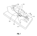
図1を参照して、血圧測定装置102の一例を説明する。本発明の実施形態によるフィンガーカフコネクタ122は、血圧測定装置102と共に利用され得る。図1に示すように、血圧測定装置102は、患者の指に取り付けられ得る適切な構造を有するフィンガーカフ104と、患者の体(例えば患者の手)に取り付けられ得る血圧測定コントローラ120と、を含み得る。血圧測定装置102は、患者監視装置130、及び、いくつかの実施形態ではポンプ134にさらに接続され得る。さらに、フィンガーカフ104は、フィンガーカフには一般的な、ブラダ(図示せず)及びLED−PD対(図示せず)を含み得る。
An example of the blood
一実施形態では、血圧測定装置102は、小型内部ポンプ、小型内部弁、圧力センサ、及び、制御回路を含む血圧測定コントローラ120を含み得る。この実施形態では、制御回路は、内部ポンプによってフィンガーカフ104のブラダに印加される空気圧を制御して、フィンガーカフ104のLED−PD対から受信したプレース信号(pleth signal)を測定することに基づいて患者の血圧を再現するように構成され得る。さらに、制御回路は、内部弁の開放を制御してブラダから空気圧を解放する、或いは、内部弁は単に制御されていないオリフィスであり得る、ように構成され得る。フィンガーカフコネクタ122は、チューブ123を介して血圧測定コントローラ120からフィンガーカフ104のブラダまで受けた空気圧を伝達する。随意的に、制御回路は、圧力センサからの入力に基づき、患者の血圧と同じであるべきであるブラダの圧力を監視することによって患者の血圧を測定し、かつ、患者監視装置130上に患者の血圧を表示し得るように構成され得る。
In one embodiment, blood
別の実施形態では、ポンプ134が患者の体から離れて配置されている従来の圧力生成及び調整システムが利用され得る。この実施形態では、血圧測定コントローラ120は、チューブ136を介して遠隔ポンプ134から空気圧を受け取り、チューブ123を介してフィンガーカフコネクタ122を介してフィンガーカフ104のブラダまで空気圧を伝達する。また、他の機能と同様に、フィンガーカフ104に加えられる空気圧を制御する(例えば、制御可能な弁を利用する)。この例では、フィンガーカフ104のLED−PD対から受信したプレース信号を測定すること、及び、ブラダの圧力を監視することによって患者の血圧を測定することに基づいて患者の血圧を再現する、ポンプ134によってフィンガーカフ104のブラダに加えられる空気圧は、遠隔コンピューティングデバイス及び/または血圧測定コントローラ120及び/または患者監視装置130自体によって制御されてもよく、患者監視装置130は、患者の血圧も表示し得る。
In another embodiment, a conventional pressure generation and regulation system may be utilized where the
フィンガーカフコネクタ122に関する本発明の実施形態は、前述のように小型内部ポンプ及び制御回路を有する血圧測定コントローラ120と共に、または、遠隔ポンプ134及び遠隔処理、または、これらの任意の組み合わせを含む従来の圧力生成及び調整システムと共に利用され得ることを理解されたい。さらに、いくつかの実施形態では、血圧測定コントローラ120は全く使用されず、遠隔圧力調整システムを含む遠隔ポンプ134から、チューブ123からフィンガーカフコネクタ122への接続が単にあるだけであり、圧力発生及び調整システム、データ処理、及び、表示のためのすべての処理は、遠隔コンピューティングデバイスによって実行される。フィンガーカフ104及び血圧測定コントローラ120を含む血圧測定装置102の操作は、内部小型ポンプ及び制御回路を有する血圧測定コントローラ120に対して以下により詳細に説明さるだろうが、フィンガーカフコネクタ122は、遠隔ポンプ134及び遠隔処理を含む従来の圧力発生及び調整システムと共に同様に利用され得ることを理解されたい。
Embodiments of the present invention relating to
この例を続けると、図1に示されるように、血圧測定装置102を用いて患者の血圧を測定するために、患者の手を肘掛け112の面110に置くことができる。血圧測定装置102の血圧測定コントローラ120は、血圧測定に使用するためのブラダに空気圧を提供するために、フィンガーカフコネクタ122を介してフィンガーカフ104のブラダに結合され得る。血圧測定コントローラ120は、電源/データケーブル132を介して患者監視装置130に結合され得る。また、一実施形態では、前述のように、遠隔実施において、血圧測定コントローラ120は、チューブ136を介して遠隔ポンプ134に結合され、フィンガーカフ104のブラダの空気圧を受け得る。患者監視装置130は、血圧を含む患者の生理学的読み取り値/データ、及び、その他の適切な生理学的患者の測定値を読み取り、収集、処理、表示等することができる任意の種類の医療用電子装置とすることができる。したがって、電源/データケーブル132は、患者監視装置130へ、または患者監視装置130からデータを伝送でき、かつ、患者監視装置130から血圧測定コントローラ120及びフィンガーカフ104に電力を供給することもできる。
Continuing with this example, as shown in FIG. 1, the patient's hand may be placed on
一実施形態では、ハートリファレンスセンサ(HRS)を患者の心臓レベルの近くに配置し、HRSコネクタによって血圧測定装置102の血圧測定コントローラ120に接続され、血圧測定値の計算におけるフィンガーカフ104と心臓レベルとの間の高さの差による潜在的な誤差の補償を可能にする。
In one embodiment, a Heart Reference Sensor (HRS) is located near the patient's heart level and is connected by an HRS connector to the blood
図1から分かるように、一例では、フィンガーカフ104を患者の指に装着し、血圧測定コントローラ120を患者の手首に巻き付ける装着ブレスレット121を用いて患者の手に装着することができる。しかしながら、血圧測定コントローラ120のサイズが小さいために、多種多様な取り付け構成が利用され得ることを理解されたい。例えば、血圧測定コントローラ120は、患者の指(例えば、フィンガーカフ104と同じ指、或いは、1つまたは複数の異なる指)、手、手首、腕、または、それが便利な方法でフィンガーカフ104に局所的に配置される他の場所に位置し得る。1つの特定の例として、血圧測定コントローラ120は、(例えば、装着ブレスレットまたは単にベルクロテープを利用して)一対の患者の他の指に留められ得る。装着ブレスレット121は、金属、プラスチック、ベルクロなどであり得る。
As can be seen in FIG. 1, in one example, the
或いは、血圧測定コントローラ120は、患者の体の上ではなく、フィンガーカフ104に近接して配置または取り付けられ得る。例えば、血圧測定コントローラ120は、フィンガーカフ104の近くに肘掛け112に固定または取り付けられ得(例えば、クリップ上に置かれるか、またはベルクロテープ(登録商標)で固定される)、または、単にフィンガーカフ104からぶら下がってもよく、何にも取り付けられなくてもよい。血圧測定コントローラ120を患者の身体から取り外すことによって、患者の動脈及び静脈へのアクセスが自由になる。さらに、図1に示す血圧測定コントローラ120の略長方形の構成は単なる設計上の実施形態であり、任意の適切な形状が使用され得ることを理解されたい。血圧測定コントローラ120のサイズが小さいため、多種多様な取り付け構成を利用することができ、これらは単なる例であることをさらに理解されたい。
Alternatively, blood
本発明の実施形態によるフィンガーカフコネクタ122は、フィンガーカフ104を本明細書に記載の血圧測定コントローラ120に、または、患者の体から離れて配置されている従来の圧力発生及び調整システム(例えば、患者から離れて配置されているポンプ134)などの任意の他の種類の圧力発生及び調整システムに、接続するように利用され得ることを理解されたい。血圧測定コントローラ120を含むがこれに限定されない、使用可能な任意の種類の圧力発生及び調整システムは、単に圧力発生及び調整システムとして説明され得る。さらなる例として、いくつかの実施形態では、血圧測定コントローラ120がまったくなくてもよく、遠隔制御される遠隔ポンプ134がチューブ136及び123を介してフィンガーカフコネクタ122及びフィンガーカフ104に直接接続されてフィンガーカフ104に空気圧を与え得る。
The
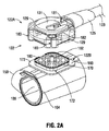
図2A〜図2Cを参照すると、フィンガーカフコネクタ122の一例を示す図が示されている。説明したように、フィンガーカフコネクタ122はフィンガーカフ104に結合され得る。フィンガーカフ104は、患者の指の周りにブラダ105を巻き付けてLED−PD対(図示せず)を整列させるための適切な可撓性円形構造を含み得る。フィンガーカフ104を患者にしっかりと取り付けるために、フィンガーカフ104の外側部分(例えば、外側部分のベルクロテープ(登録商標))に固定するための拡張された固定部153(例えば、内側のベルクロテープ(登録商標))を有し得る。フィンガーカフコネクタ122は、図2A及び図2Bに示すように、フィンガーカフ104の上部に取り付けられ得る。
Referring to FIGS. 2A-2C, diagrams showing an example of the
フィンガーカフコネクタ122は、ケーブル部123、接続部125、及び、フィンガーカフコネクタ対(122A及び122B)を含み得る。上部フィンガーカフコネクタ122Aのハウジングは、取扱い、配置、取り付け、及び、下部フィンガーカフコネクタ122Bへのユーザによる回転を容易にするために、2つの対向する突起129を有する略円形であり、下部フィンガーカフコネクタ122Bは略正方形であり得る。そして、後述するように、上部及び下部フィンガーカフコネクタ122A及び122Bは互いに嵌合する。接続部125は、フィンガーカフコネクタ対122A及び122Bをケーブル部123に接続する。ケーブル部123は、前述のように空気圧用の管部を含み得、特に適切な空圧管部127を含み得る。フィンガーカフ104のブラダ105及び適切な電気接続(例えば、電気配線−図示せず)に空気圧を供給して、フィンガーカフ104のLED−PD対から受信したプレース信号を適切なコンピューティングデバイスに送信する。
The
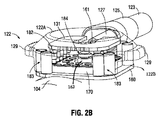
前述のように、フィンガーカフコネクタ対122は、2つの半分体を備え得、第1の半分体122Aは、空圧管部127(空気圧の伝達用)及び電線(伝達用及び伝達用)を介して圧力発生及び調整システムに接続されており、第2の半分体122Bは、正方形の取付板160上でフィンガーカフ104に固定的に取り付けられている。図2A〜図2Cに示すように、フィンガーカフコネクタの上部第1の半分体122Aは、開放内部と、外側部が接続される取付板160の外側部と接触する略正方形の底部と、を有する。さらに、後述するように、フィンガーカフコネクタの上部第1の半分体122Aの内側部分は、以下により詳細に説明するように、多様の可能な配向をもたらせるように、略正方形の取付部170を取り囲む。また、第1の半分体122Aは、電気コネクタピン182を装着し、ケーブル部123内の電気配線に接続するためのU字形プリント回路基板部131を含み得る。
As previously mentioned, the finger
第1の上半分体122Aと第2の下半分体122Bとが適切に接続されると、電気的接続及び空気圧接続がフィンガーカフコネクタ対122の各半分体内に配置され、これにより、フィンガーカフコネクタ対122の第1の半分体122Aと第2の半分体122Bとが適切に接続されると、圧力発生及び調整システムとフィンガーカフ104との間に適切な電気的接続及び空気圧接続が確立される。
When the first
一例として、圧力発生及び調整システムとフィンガーカフ104との間に適切に確立された電気接続は、圧力発生及び調整システムの回路とフィンガーカフ104の回路との間の適切な電力、データ、及び、制御信号接続を含み得る(例えば、LED−PD対)。
By way of example, a properly established electrical connection between the pressure generation and regulation system and the
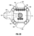
一実施形態では、適切な電気的接続を達成するために、フィンガーカフコネクタ対122の第2の半分体122Bは、取付部170内に配置された複数の電気コネクタパッド180を含み、取付部170は、電気コネクタパッド180のための適切なプリント回路基板部を含む。後述するように、電気コネクタパッド180の組の数は、可能性のあるコネクタの配向の数と釣り合い、これにより、2つの半分体が任意の可能な配向で接続されている際、第1の半分体122A内のコネクタピン182との適切な接触を可能にする、第2の半分体122Bに内に電気コネクタパッド180の組が存在する。もちろん、本開示の範囲から逸脱することなく、パッド−ピン接続以外の他の種類の電気的接続も利用され得る。特定の配向で正しく接続されると、フィンガーカフ104のLED−PD対からのデータは、コネクタパッド180及びコネクタピン182を通ってケーブル部123のワイヤを通って圧力発生及び調整システムに伝送されて処理される。
In one embodiment, to achieve the proper electrical connection, the
さらに、圧力発生及び調整システムとフィンガーカフ104との間に適切に確立された空気圧接続は、圧力発生及び調整システムのポンプがフィンガーカフ104のブラダ105に空気圧を提供することを可能にする。
Further, a properly established pneumatic connection between the pressure generation and regulation system and the
一実施形態では、第1の半分体122Aからのケーブル部123の空圧管部127からの空気圧は、フィンガーカフ104のブラダ105に接続されている第2の半分体122Bのチューブ162に接続され得る。これは、適切な回転可能な取り付け装置184(例えば、回転可能なシール)によってチューブ162に回転可能に連結されているL字形のコネクタチューブ161によって作られる。このようにして、2つの半分体122A及び122Bが、以下に説明される任意の可能な配向で接続されると、圧力発生システムによってフィンガーコネクタ対122を介してフィンガーカフ104のブラダ105に空気圧がもたらされる。
In one embodiment, air pressure from
後述するように、異なる実施形態では、フィンガーカフコネクタ対122の第1の半分体122A及び第2の半分体122Bは、様々な異なる配向(例えば、2つ以上の可能な配向)で接続され得る。例えば、第1の半分体122A及び第2の半分体122Bは、2つの配向(たとえば90度)、4つの配向(たとえば45度)、6つの配向(60度)、または任意の数の異なる配向で接続され得る。また、一実施形態では、第1の半分体122Aと第2の半分体122Bとが互いに接続または嵌合すると、第1の半分体122Aは、固定された第2の半分体122Bに対して平面内で連続的に回転し得る。
As described below, in different embodiments, the
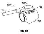
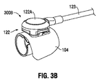
図3A及び図3Bをさらに参照すると、符号300A、300Bは、2つの異なる配向(例えば、90度)で接続された例示的なフィンガーカフコネクタ対122を示す。図3Aは、後方向きに接続されたフィンガーカフコネクタ対122の第1の半分体122A及び第2の半分体(その中に含まれる)を示す。図3Bは、前方向きに接続されたフィンガーカフコネクタ対122の第1の半分体122A及び第2の半分体(その中に含まれる)を示す。
With further reference to FIGS. 3A and 3B,
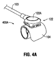
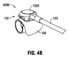
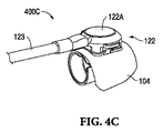
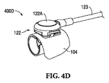
図4A、図4B、図4C、及び図4Dをさらに参照すると、符号400A、400B、400C、400Dは、4つの異なる配向(例えば、45度)で接続された例示的なフィンガーカフコネクタ対122を示す。図4Aは、左方向に接続されたフィンガーカフコネクタ対122の第1の半分体122A及び第2の半分体(その中に含まれる)を示す。図4Bは、右向きに接続されたフィンガーカフコネクタ対122の第1の半分体122A及び第2の半分体(その中に含まれる)を示す。
図4Cは、後方向きに接続されたフィンガーカフコネクタ対122の第1の半分体122A及び第2の半分体(その中に含まれる)を示す。図4Dは、前方向きに接続されたフィンガーカフコネクタ対122の第1の半分体122A及び第2の半分体(その中に含まれる)を示す。
With further reference to FIGS. 4A, 4B, 4C, and 4D,
FIG. 4C shows the
再び図2A〜図2Cをさらに参照して、図3〜図4の異なる配向を達成するための様々な実施例、ならびに他の実施形態について説明する。 With reference again to FIGS. 2A-2C, various examples for achieving the different orientations of FIGS. 3-4, as well as other embodiments, are described.
一実施形態では、フィンガーカフコネクタ対122の第1の上半分体122A及び第2の下半分体122Bは、図3〜図4に示すような、2つ以上の別々の可能な配向で接続され得る。これを達成するために、機械的キー及び磁気的特徴部を利用することができる。特に、フィンガーカフコネクタ対122の第1の半分体122Aは、コネクタ半分体の適切な整列を容易にするようにフィンガーカフコネクタ対122の固定された第2の半分体122Bに対して回転させて位置決めされ得、かつ、圧力発生及び調整システムとの適切な電気的接続及び空気圧接続を確立するために固定された第2の半分体122Bに取り付けられ得る。
In one embodiment, the first
一実施形態では、磁気的特徴部と組み合わせたキーイング特徴部が、4つの可能な配向を達成するために実施され得る。この実施形態では、フィンガーカフコネクタ対122の第1の上半分体122Aと第2の下半分体122Bとは互いに接続されるかまたは嵌合する。フィンガーカフコネクタ122Aの上部の第1の半分体は、開放内部と、取付板160の外側部分と接触する略正方形の底部と、を有し、取付板160は、磁性材料で形成され得る。さらに、フィンガーカフコネクタ122Aの上部の第1の半分体は、フィンガーカフコネクタ122Aの上部の第1の半分体の略四隅に配置された4対の略円筒形の磁石183を含む。フィンガーカフコネクタ122Bの第2の下半分体は、角度が付いた四隅172を含む略正方形の取付部170を有する。
In one embodiment, keying features in combination with magnetic features may be implemented to achieve four possible orientations. In this embodiment, the first
したがって、一例として、ユーザは、それらを互いに接続するために、4つの前述の配向(例えば、図3〜図4)のうちの1つで、第1の上半分体122Aを第2の下半分体122Bと位置合わせし得る。この接続動作では、フィンガーカフコネクタの上半分体122Aの内側部分は、固定された下半分体122Bの取付部170を取り囲み、その結果、上半分体122Aの四隅にある円筒形状の磁石183は、下半分体122Bの角度のついた四隅と嵌合して当接して、4つの異なる配向位置のうちの1つに適切に整列して接続する。このようにしてキーイング特徴部が提供される。さらに、円筒形状の磁石183は、取付板160に当接し、取付板160の磁性材料と磁気的に接続し、これにより、第1の半分体と第2の半分体とが互いに磁気的に取り付けられる(例えば、より確実な接続を提供する)。これはほんの一例であり、設計上の考慮事項に応じて、2つ(90度)、6つ(60度)、8つ(45度)など、多種多様な配向が可能であることを理解されたい。
Thus, by way of example, a user may connect the first
上述したように、第1の上半分体122Aと第2の下半分体122Bとが互いに接続されると、第1の半分体122Aの電気コネクタピン182が、フィンガーカフの第2の半分体122Bの取付部170の電気コネクタパッド180と接触することによって適切な電気接続が達成され得る。電気コネクタパッド180の組の数は、2つの半分体が可能な配向のいずれかで接続されている際に第1の半分体122Aの電気コネクタピン182と適切に接触する第2の半分体122Bの電気コネクタパッド180の組があるように可能なコネクタの配向の数と釣り合い得る。図2A〜図2Cに示されるように、電気コネクタピン182と接続するのに十分な電気コネクタパッド180が設けられて、2つまたは4つの異なる配向の電気接続を提供する(例えば、図3〜図4)。このようにして、圧力発生及び調整システムとフィンガーカフ104との間に電気接続を適切に確立することができ、これらの電気接続は、圧力発生及び調整システムの回路とフィンガーカフ104の回路との間の適切な電力、データ及び制御信号接続を含み得る((例えば、LED−PD対)。
As described above, when the first
また、第1の上半分体122Aと第2の下半分体122Bとが嵌合すると、第1の半分体122Aからのケーブル部123の空圧管部127からの空気圧が、適切な回転可能な取り付け装置184(例えば、回転可能なシール)によってチューブ162に回転可能に連結されているL字型のコネクタチューブ161によってブラダ105に接続されている第2の半分体122Bのチューブ162に接続され得る。このようにして、2つの半分体122A及び122Bが任意の可能な配向で接続されている際に、圧力発生システムによってフィンガーカフコネクタ122を介して空気圧がフィンガーカフ104のブラダ105に供給され得る。特に、空気圧は、前述の配向(例えば、2つまたは4つの異なる配向(例えば、図3〜図4))のうちのいずれかでフィンガーカフ104のブラダ105に供給され得る。
Further, when the first upper
また、他の様々な種類の電気接続方法が利用され得る。例えば、一実施形態では、スイッチング回路が、適切な電気的接続を確実にするために2つの半分体が接続されている配向で基づいて第1の半分体122A及び/または第2の半分体122Bの電気コネクタを再構成するように利用され得る。
Also, various other types of electrical connection methods may be utilized. For example, in one embodiment, the switching circuit is based on the orientation in which the two halves are connected to ensure proper electrical connection, the
さらに、別の実施形態では、フィンガーカフコネクタ122の第1の半分体122Aは、接続時に平面内でフィンガーカフコネクタの第2の半分体122Bに対して回転し得る。この実施形態では、第2の半分体122Bの電気コネクタパッドは、第1の半分体122Aの電気コネクタピンとの電気的接続に適応するように同心円状に形成され得る。
Further, in another embodiment, the
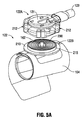
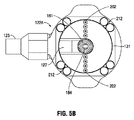
図5A〜図5Bをさらに参照して、接続時にフィンガーカフコネクタ122の第1の半分体122Aが平面内でフィンガーカフコネクタの第2の半分体122Bに対して回転することができる別の実施形態について説明する。この実施形態では、第2の半分体122Bの電気コネクタパッドは、第1の半分体122Aの電気コネクタピン202との電気的接続に適応するように同心リング200に成形され得る。
With further reference to FIGS. 5A-5B, another embodiment in which the
この実施形態では、フィンガーカフコネクタ122の第1の半分体122Aは、接続時にフィンガーカフコネクタの第2の半分体122Bに対して平面内で回転し、その結果、任意の配向位置がユーザによって選択可能であり得る。特に、フィンガーカフコネクタ対122の第1の半分体122Aは、任意の配向位置でコネクタ半分体の適切な整列を容易にするようにフィンガーカフコネクタ対122の固定された第2の半分体122Bに対して位置決めされ、かつ、圧力発生及び調整システムとの適切な電気的接続及び空気圧接続を確立するように、固定された第2の半分体122Bに取り付けられ得る。
In this embodiment, the
前述の実施形態と同様に、フィンガーカフコネクタ122Aの上部の第1の半分体は、略円形の開口内部と、取付板210の外側部分に接触する略正方形の底部と、を有し、取付板210は、磁性材料で形成され得、かつ、略円形である。さらに、フィンガーカフコネクタ122Aの上部の第1の半分体は、フィンガーカフコネクタ122Aの上部の第1の半分体の略四隅に配置された4対の略円筒形の磁石212を含む。フィンガーカフコネクタ122Bの第2の下半分体は、略円形の取付部215を有する。一例として、ユーザは、第1の上半分体122Aを第2の下半分体122Bと整列させて、これらを任意の配向位置で互いに接続し得る。この接続動作では、フィンガーカフコネクタの上半分体122Aの内側部分は固定された下半分体122Bの取付部215を囲み、上半分体122Aの四隅で円筒形磁石212は両方の円形取付部に当接する。第1の半分体と第2の半分体とが互いに磁気的に取り付けられるように(例えば、より確実な接続を提供する)、215と取付板210との間で取り付けられる。さらに、これにより、フィンガーカフコネクタの第1及び第2の半分体122A及び122Bをユーザが選択した任意の配向で接続することが可能になる。
Similar to the previous embodiments, the first half of the top of the
第1の上半分体122Aと第2の下半分体122Bが互いに接続されると、フィンガーカフ104の第2の半分体122Bの取付部215の電気同心コネクタパッドリング200に接触させている(ケーブル部123内の電気配線に接続する)U字型プリント回路基板部131の電気コネクタピン202によって適切な電気接続が達成され得る。このようにして、圧力発生及び調整システムとフィンガーカフ104との間に電気的接続を適切に確立することができ、これらの電気的接続は、圧力生成及び調整システムの回路とフィンガーカフ104の回路(例えば、LED−PD対)との間の適切な電力、データ、及び制御信号接続を含み得る。また、第1の上半分体122Aと第2の下半分体122Bとが嵌合すると、第1の半分体122Aからのケーブル部123の空圧管部127からの空気圧が、前述したように、L字型のコネクタチューブ161によってブラダに接続されている第2の半分体122Bのチューブ162に接続され得る。空気圧接続は、前述の実施形態と同じ方法で行われ、これにより、2つの半分体122A及び122Bが可能な回転方向のいずれかで接続されると、圧力発生システムによってフィンガーカフコネクタ122を介して空気圧がフィンガーカフ104のブラダに提供され得る。したがって、この実施形態では、フィンガーカフコネクタ122の第1の半分体122Aは、任意の配向の位置がユーザによって選択され得るように、接続時にフィンガーカフコネクタの第2の半分体122Bに対して平面内で回転する。
When the first
フィンガーカフコネクタ122の第1の半分体122Aと第2の半分体122Bとの間の物理的な接続を保持するために、前述の機構に加えて、またはその代わりに、様々な異なる種類の機構が利用され得ることを理解されたい。他の種類の磁気保持機構、スナップ機構、ツイストオン機構(twist-on mechanism)、圧入機構、カムラッチ(cam latch)、または任意の他の適切な機構を含み得る。したがって、適切な機械的、磁気的、または電気機械的機構などの様々な他の機構もまた、様々な異なる種類の配向及び適切な位置合わせを容易にするために利用され得る。
In addition to or in place of the mechanism described above, a variety of different types of mechanisms may be used to maintain the physical connection between the first and
フィンガーカフと患者の指との間の物理的相互作用は、フィンガーカフ内の圧力が患者の動脈内の圧力と等しくなるように(例えば、経壁圧力降下はごくわずかになるように)適切にフィットし、較正されたシステムを達成するために重要であることが理解されるだろう。ケーブルによってフィンガーカフに加えられる機械的な力は、フィンガーカフと患者の指の間のフィット感と相互作用に影響を与え、これにより、正確で継続的な血圧測定を妨げ得る。 The physical interaction between the finger cuff and the patient's finger should be such that the pressure in the finger cuff is equal to the pressure in the patient's artery (eg, the transmural pressure drop is negligible). It will be appreciated that it is important to achieve a fitted and calibrated system. The mechanical force exerted by the cable on the finger cuff may affect the fit and interaction between the finger cuff and the patient's finger, thereby impeding accurate and continuous blood pressure measurements.
前述の本発明の実施形態によれば、複数のタイプのコネクタの配向を利用することによって、患者の指にかかる力を軽減するようにケーブルを構成するために、大きな柔軟性がもたらされる。この種の柔軟性は、手術中及び集中治療室(ICU)、緊急治療室(ER)、及び他の場所における患者の位置及び補助機器の位置の変動に対応するために非常に必要とされている。 According to the embodiments of the invention described above, utilizing the orientations of multiple types of connectors provides great flexibility for configuring the cable to reduce the force on the patient's fingers. This kind of flexibility is highly needed to accommodate variations in the patient's position and the position of assistive devices in the intraoperative and intensive care unit (ICU), emergency room (ER), and elsewhere. There is.
前述の本発明の態様は、プロセッサ、回路、コントローラ、制御回路などによる命令の実行と併せて実施され得ることが理解されたい。一例として、制御回路は、プログラムの制御、アルゴリズム、ルーチン、または、命令の実行の下で作動し、前述の本発明の実施形態による方法またはプロセスを実行し得る。たとえば、このようなプログラムは、ファームウェアまたはソフトウェア(たとえば、メモリ及び/または他の場所に格納される)で実装され得、プロセッサ、制御回路、及び/または他の回路によって実施され得、これらの用語は交換可能に使用される。また、プロセッサ、マイクロプロセッサ、回路、制御回路、回路基板、コントローラ、マイクロコントローラなどの用語は、本発明の実施形態を実行するために利用され得る、論理、コマンド、命令、ソフトウェア、ファームウェア、機能性を実行することができる任意のタイプの論理または回路を指すことを理解されたい。 It should be appreciated that the aspects of the invention described above may be implemented in connection with the execution of instructions by a processor, circuit, controller, control circuit, or the like. By way of example, a control circuit may operate under the control of a program, execution of algorithms, routines, or instructions to carry out the methods or processes according to embodiments of the invention described above. For example, such a program may be implemented in firmware or software (eg, stored in memory and/or elsewhere), implemented by a processor, control circuitry, and/or other circuitry, and these terms Are used interchangeably. Also, the terms processor, microprocessor, circuit, control circuit, circuit board, controller, microcontroller, etc. may be used to implement embodiments of the present invention as logic, commands, instructions, software, firmware, functionality. Should be understood to refer to any type of logic or circuit capable of performing
本明細書に開示された実施形態に関連して説明された様々な例示的な論理ブロック、プロセッサ、モジュール、及び回路は、汎用プロセッサ、特殊プロセッサ、回路、マイクロコントローラ、デジタル信号プロセッサ(DSP)、特定用途向け集積回路(ASIC)、フィールドプログラマブルゲートアレイ(FPGA)または他のプログラマブルロジックデバイス、ディスクリートゲートまたはトランジスタロジック、ディスクリートハードウェアコンポーネント、或いは、本明細書に記載の機能を実行するように設計されたこれらの任意の組み合わせで実装または実行され得る。プロセッサは、マイクロプロセッサまたは任意の従来のプロセッサ、コントローラ、マイクロコントローラ、回路、または状態機械であり得る。プロセッサはまた、コンピューティングデバイスの組み合わせ、例えばDSPとマイクロプロセッサの組み合わせ、複数のマイクロプロセッサ、DSPコアと連携した1つ以上のマイクロプロセッサ、または他の任意のそのような構成として実装され得る。 Various exemplary logic blocks, processors, modules, and circuits described in connection with the embodiments disclosed herein include general purpose processors, special purpose processors, circuits, microcontrollers, digital signal processors (DSPs), Application Specific Integrated Circuit (ASIC), Field Programmable Gate Array (FPGA) or other programmable logic device, discrete gate or transistor logic, discrete hardware component, or designed to perform the functions described herein. It may be implemented or implemented in any combination of these. The processor can be a microprocessor or any conventional processor, controller, microcontroller, circuit, or state machine. The processor may also be implemented as a combination of computing devices, such as a DSP and microprocessor combination, multiple microprocessors, one or more microprocessors associated with a DSP core, or any other such configuration.
本明細書に開示されている実施形態に関連して説明されている方法またはアルゴリズムのステップは、ハードウェア、プロセッサによって実行されるソフトウェアモジュール/ファームウェア、またはそれらの任意の組み合わせにおいて直接実施され得る。ソフトウェアモジュールは、RAMメモリ、フラッシュメモリ、ROMメモリ、EPROMメモリ、EEPROMメモリ、レジスタ、ハードディスク、リムーバブルディスク、CD−ROM、または当技術分野で公知の他の任意の形態の記憶媒体に存在し得る。例示的な記憶媒体は、プロセッサが記憶媒体から情報を読み取り、記憶媒体に情報を書き込むことができるようにプロセッサに結合される。代替として、記憶媒体はプロセッサに統合され得る。 The steps of the methods or algorithms described in connection with the embodiments disclosed herein may be implemented directly in hardware, software modules/firmware executed by a processor, or any combination thereof. The software modules may reside in RAM memory, flash memory, ROM memory, EPROM memory, EEPROM memory, registers, hard disks, removable disks, CD-ROMs, or any other form of storage medium known in the art. An exemplary storage medium is coupled to the processor such that the processor can read information from, and write information to, the storage medium. Alternatively, the storage medium may be integral to the processor.
開示された実施形態のこれまでの説明は、当業者が本発明を製作または使用することを可能にするために提供されている。これらの実施形態に対する様々な変更は当業者には容易に明らかとなり、本明細書で定義された一般的な原理は、本発明の精神または範囲から逸脱することなく他の実施形態に適用され得る。したがって、本発明は、本明細書に示されている実施形態に限定されることを意図するものではなく、本明細書に開示されている原理及び新規な特徴と一致する最も広い範囲を与えられるべきである。 The previous description of the disclosed embodiments is provided to enable any person skilled in the art to make or use the present invention. Various modifications to these embodiments will be readily apparent to those skilled in the art, and the general principles defined herein may be applied to other embodiments without departing from the spirit or scope of the invention. .. Therefore, the present invention is not intended to be limited to the embodiments set forth herein, but is given the broadest scope consistent with the principles and novel features disclosed herein. Should be.
102 血圧測定装置
104 フィンガーカフ
105 ブラダ
120 血圧測定コントローラ
121 装着ブレスレット
122 フィンガーカフコネクタ
122A 第1の半分体
122B 第2の半分体
123 チューブ、ケーブル部
127 空圧管部
130 患者監視装置
131 U字形プリント回路基板部
132 データケーブル
134 ポンプ
136 チューブ
153 固定部
160 取付板
161 コネクタチューブ
162 チューブ
170 取付部
172 四隅
180 電気コネクタパッド
182 電気コネクタピン
183 磁石
184 装置
200 電気同心コネクタパッドリング、同心リング
202 電気コネクタピン
210 取付板
212 円筒形磁石
215 取付部
102 blood
Claims (30)
前記圧力発生及び調整システムに空気圧的及び電気的に接続されている第1の半分体と、
前記フィンガーカフに固定して取り付けられた第2の半分体であって、前記第1の半分体と前記第2の半分体とは、2つ以上の配向で接続可能であり、前記圧力発生及び調整システムと前記フィンガーカフとは、前記第1の半分体と前記第2の半分体が接続されている際に、空気圧的及び電気的に接続されてことを特徴とするコネクタ。 A connector for a blood pressure measurement system including a pressure generation and regulation system and a finger cuff, comprising:
A first half that is pneumatically and electrically connected to the pressure generating and regulating system;
A second half fixedly attached to the finger cuff, wherein the first half and the second half are connectable in two or more orientations, A connector, wherein the adjusting system and the finger cuff are pneumatically and electrically connected when the first half and the second half are connected.
前記フィンガーカフを前記患者の指に取り付けるステップと、
前記コネクタの第1の半分体を前記コネクタの第2の半分体に接続し、前記コネクタの第2の半分体は、前記フィンガーカフに固定して取り付けられており、前記第1の半分体は、前記圧力発生及び調整システムに空気圧的及び電気的に接続されており、前記第1の半分体と前記第2の半分体とは、2つ以上の配向で接続可能であり、前記第1の半分体と前記第2の半分体とが接続される際、前記圧力発生及び調整システムと前記フィンガーカフとは空気圧的及び電気的に接続されることを特徴とする方法。 A method for applying a connector to a finger cuff of a blood pressure measurement system including a pressure generation and regulation system for measuring a patient's blood pressure, the method comprising:
Attaching the finger cuff to the patient's finger,
Connecting a first half of the connector to a second half of the connector, the second half of the connector fixedly attached to the finger cuff, the first half being , Pneumatically and electrically connected to said pressure generating and regulating system, said first half and said second half being connectable in more than one orientation, said first half The method of claim 1, wherein the pressure generating and regulating system and the finger cuff are pneumatically and electrically connected when the half and the second half are connected.
患者の指に付けられたフィンガーカフと
コネクタであって、
圧力発生及び調整システムに空気圧的及び電気的に接続されている第1の半分体と、
前記フィンガーカフに固定して取り付けられた第2の半分体であって、前記第1の半分体と前記第2の半分体とは、2つ以上の配向で接続可能であり、前記第1の半分体と前記第2の半分体とが接続される際、前記圧力発生及び調整システムと前記フィンガーカフとは、空気圧的及び電気的に接続される、第2の半分体と、
を備えるコネクタ、
を備えることを特徴とする血圧測定システム。 A blood pressure measurement system including a pressure generation and adjustment system for measuring a blood pressure of a patient, the blood pressure measurement system comprising:
A finger cuff and connector on the patient's finger,
A first half that is pneumatically and electrically connected to a pressure generation and regulation system;
A second half fixedly attached to the finger cuff, the first half and the second half being connectable in more than one orientation, A second half that is pneumatically and electrically connected to the pressure generation and regulation system and the finger cuff when the half is connected to the second half;
A connector,
A blood pressure measurement system comprising:
Applications Claiming Priority (5)
| Application Number | Priority Date | Filing Date | Title |
|---|---|---|---|
| US201762503610P | 2017-05-09 | 2017-05-09 | |
| US62/503,610 | 2017-05-09 | ||
| US15/955,939 US20180325396A1 (en) | 2017-05-09 | 2018-04-18 | Finger cuff connector |
| US15/955,939 | 2018-04-18 | ||
| PCT/US2018/031491 WO2018208713A1 (en) | 2017-05-09 | 2018-05-08 | Finger cuff connector |
Publications (1)
| Publication Number | Publication Date |
|---|---|
| JP2020519313A true JP2020519313A (en) | 2020-07-02 |
Family
ID=64096047
Family Applications (1)
| Application Number | Title | Priority Date | Filing Date |
|---|---|---|---|
| JP2019515586A Pending JP2020519313A (en) | 2017-05-09 | 2018-05-08 | Finger cuff connector |
Country Status (5)
| Country | Link |
|---|---|
| US (1) | US20180325396A1 (en) |
| EP (1) | EP3531907B1 (en) |
| JP (1) | JP2020519313A (en) |
| CN (2) | CN208767517U (en) |
| WO (1) | WO2018208713A1 (en) |
Families Citing this family (2)
| Publication number | Priority date | Publication date | Assignee | Title |
|---|---|---|---|---|
| US20180325396A1 (en) * | 2017-05-09 | 2018-11-15 | Edwards Lifesciences Corporation | Finger cuff connector |
| CN215732537U (en) * | 2021-07-23 | 2022-02-01 | 东莞市承越电子科技有限公司 | One-way random pull data line |
Citations (3)
| Publication number | Priority date | Publication date | Assignee | Title |
|---|---|---|---|---|
| JPS61177605U (en) * | 1985-04-24 | 1986-11-06 | ||
| US20110046494A1 (en) * | 2009-08-19 | 2011-02-24 | Mindray Ds Usa, Inc. | Blood Pressure Cuff and Connector Incorporating an Electronic Component |
| JP2013509225A (en) * | 2009-10-29 | 2013-03-14 | シーエヌシステムズ メディジンテクニク アクチェンゲゼルシャフト | Digital control method for blood pressure measurement |
Family Cites Families (12)
| Publication number | Priority date | Publication date | Assignee | Title |
|---|---|---|---|---|
| JPH08332172A (en) * | 1995-06-07 | 1996-12-17 | Hioki Ee Corp | Cuff structure for finger for bloodless sphygmomanometry |
| US7396995B2 (en) | 2003-09-19 | 2008-07-08 | Fisher & Paykel Healthcare Limited | Connector |
| JP4590998B2 (en) * | 2004-09-15 | 2010-12-01 | オムロンヘルスケア株式会社 | Sphygmomanometer |
| KR100659162B1 (en) * | 2005-07-20 | 2006-12-19 | 삼성전자주식회사 | Cuff for tonometer |
| JP2007044439A (en) * | 2005-08-12 | 2007-02-22 | Omron Healthcare Co Ltd | Electronic sphygmomanometer |
| US20090318818A1 (en) * | 2008-06-20 | 2009-12-24 | Welch Allyn, Inc. | Blood pressure monitoring system |
| US8123694B2 (en) | 2008-07-18 | 2012-02-28 | Welch Allyn, Inc. | Electro pneumatic interface for blood pressure system |
| WO2012021731A2 (en) * | 2010-08-11 | 2012-02-16 | Empirical Technologies Corporation | Hydrostatic finger cuff for blood wave form analysis and diagnostic support |
| US9717873B2 (en) | 2011-05-20 | 2017-08-01 | Koninklijke Philips N.V. | Rotating electrical connector ADN respiratory gas delivery system employing same |
| US20170238825A9 (en) * | 2013-06-25 | 2017-08-24 | Qardio, Inc. | Devices and methods for measuring blood pressure |
| CN104665786A (en) * | 2015-01-26 | 2015-06-03 | 周常安 | Cardiovascular health monitoring device and cardiovascular health monitoring method |
| US20180325396A1 (en) * | 2017-05-09 | 2018-11-15 | Edwards Lifesciences Corporation | Finger cuff connector |
-
2018
- 2018-04-18 US US15/955,939 patent/US20180325396A1/en not_active Abandoned
- 2018-05-08 JP JP2019515586A patent/JP2020519313A/en active Pending
- 2018-05-08 CN CN201820672772.3U patent/CN208767517U/en active Active
- 2018-05-08 EP EP18797602.2A patent/EP3531907B1/en active Active
- 2018-05-08 WO PCT/US2018/031491 patent/WO2018208713A1/en unknown
- 2018-05-08 CN CN201880003508.3A patent/CN109688912A/en active Pending
Patent Citations (3)
| Publication number | Priority date | Publication date | Assignee | Title |
|---|---|---|---|---|
| JPS61177605U (en) * | 1985-04-24 | 1986-11-06 | ||
| US20110046494A1 (en) * | 2009-08-19 | 2011-02-24 | Mindray Ds Usa, Inc. | Blood Pressure Cuff and Connector Incorporating an Electronic Component |
| JP2013509225A (en) * | 2009-10-29 | 2013-03-14 | シーエヌシステムズ メディジンテクニク アクチェンゲゼルシャフト | Digital control method for blood pressure measurement |
Also Published As
| Publication number | Publication date |
|---|---|
| CN208767517U (en) | 2019-04-19 |
| EP3531907B1 (en) | 2023-11-29 |
| EP3531907A1 (en) | 2019-09-04 |
| US20180325396A1 (en) | 2018-11-15 |
| CN109688912A (en) | 2019-04-26 |
| EP3531907A4 (en) | 2019-11-20 |
| WO2018208713A1 (en) | 2018-11-15 |
Similar Documents
| Publication | Publication Date | Title |
|---|---|---|
| US11202571B2 (en) | Wearable pulse oximeter and respiration monitor | |
| JP7338830B2 (en) | Blood pressure signal measurement system using pressure sensor array | |
| US6106477A (en) | Chronically implantable blood vessel cuff with sensor | |
| US6077227A (en) | Method for manufacture and implant of an implantable blood vessel cuff | |
| US10918290B2 (en) | Multi-channel vitals device | |
| AU2007224297B2 (en) | Portable audiometer enclosed within a patient response mechanism housing | |
| KR101858659B1 (en) | Simulator for emergency medical training | |
| JP2020519313A (en) | Finger cuff connector | |
| US20180289271A1 (en) | Blood pressure measurement device wearable by a patient | |
| TWI653031B (en) | Wireless pressure sensor | |
| US20190082983A1 (en) | Finger cuff assembly having a single-sized inflatable bladder | |
| JP2020517384A (en) | Clamping mechanism that supports wearing finger cuffs | |
| CN211884369U (en) | Hemodialysis puncture is with novel nursing device | |
| CN110123525A (en) | A kind of pressure bandage based on diaphragm pressure sensor | |
| AU2018279147B2 (en) | Pulse meter for newborn | |
| US20090124911A1 (en) | Sphygmomanometer capable of adjusting a viewing angle of a display screen | |
| WO2019027904A1 (en) | Finger cuff | |
| CN214856642U (en) | Sphygmomanometer | |
| US20220148724A1 (en) | Sleep apnea test device | |
| JP2020523092A (en) | Finger cuff with shell | |
| US20190082982A1 (en) | Finger cuff utilizing multiple sensors for blood pressure measurement | |
| TW201008542A (en) | Capsule endoscope with embedded metal contacts | |
| CN117357124A (en) | Wearable electrocardiogram detection device | |
| US20240023820A1 (en) | Wearable Devices And Methods For Providing Therapy To A User And/Or For Measuring Physiological Parameters Of The User | |
| WO2022070196A1 (en) | Electronic device casing for coupling to a garment |
Legal Events
| Date | Code | Title | Description |
|---|---|---|---|
| A621 | Written request for application examination |
Free format text: JAPANESE INTERMEDIATE CODE: A621 Effective date: 20210326 |
|
| A977 | Report on retrieval |
Free format text: JAPANESE INTERMEDIATE CODE: A971007 Effective date: 20220204 |
|
| A131 | Notification of reasons for refusal |
Free format text: JAPANESE INTERMEDIATE CODE: A131 Effective date: 20220207 |
|
| A601 | Written request for extension of time |
Free format text: JAPANESE INTERMEDIATE CODE: A601 Effective date: 20220509 |
|
| A521 | Request for written amendment filed |
Free format text: JAPANESE INTERMEDIATE CODE: A523 Effective date: 20220624 |
|
| A131 | Notification of reasons for refusal |
Free format text: JAPANESE INTERMEDIATE CODE: A131 Effective date: 20220920 |
|
| A601 | Written request for extension of time |
Free format text: JAPANESE INTERMEDIATE CODE: A601 Effective date: 20221220 |
|
| A02 | Decision of refusal |
Free format text: JAPANESE INTERMEDIATE CODE: A02 Effective date: 20230522 |