JP2020518298A - Treating sleep apnea with negative pressure, obtaining information related to sleep apnea event and sleep apnea treatment with a sleep apnea device, and sleep apnea event and Correlating sleep apnea treatment with subject lifestyle and well-being. - Google Patents

Treating sleep apnea with negative pressure, obtaining information related to sleep apnea event and sleep apnea treatment with a sleep apnea device, and sleep apnea event and Correlating sleep apnea treatment with subject lifestyle and well-being. Download PDF

Info

Publication number
JP2020518298A
JP2020518298A JP2019538418A JP2019538418A JP2020518298A JP 2020518298 A JP2020518298 A JP 2020518298A JP 2019538418 A JP2019538418 A JP 2019538418A JP 2019538418 A JP2019538418 A JP 2019538418A JP 2020518298 A JP2020518298 A JP 2020518298A
Authority
JP
Japan
Prior art keywords
subject
sleep apnea
controller
assembly
collar
Prior art date
Legal status (The legal status is an assumption and is not a legal conclusion. Google has not performed a legal analysis and makes no representation as to the accuracy of the status listed.)
Pending
Application number
JP2019538418A
Other languages
Japanese (ja)
Other versions
JP2020518298A5 (en
Inventor
ジー. カルデイラ,ケネス
ジー. カルデイラ,ケネス
エー. ハイド,ロデリック
エー. ハイド,ロデリック
エル. マックナイト,ゲーリー
エル. マックナイト,ゲーリー
ジェイ. リベット,デニス
ジェイ. リベット,デニス
シャラディン,キャサリン
エー. スミス,マイケル
エー. スミス,マイケル
ウッド,ロウェル,エル.,ジュニア
Original Assignee
エルファー エルエルシー
エルファー エルエルシー
Priority date (The priority date is an assumption and is not a legal conclusion. Google has not performed a legal analysis and makes no representation as to the accuracy of the date listed.)
Filing date
Publication date
Priority claimed from US15/406,379 external-priority patent/US10780017B2/en
Application filed by エルファー エルエルシー, エルファー エルエルシー filed Critical エルファー エルエルシー
Publication of JP2020518298A publication Critical patent/JP2020518298A/en
Publication of JP2020518298A5 publication Critical patent/JP2020518298A5/ja
Pending legal-status Critical Current

Links

Images

Classifications

    • AHUMAN NECESSITIES
    • A61MEDICAL OR VETERINARY SCIENCE; HYGIENE
    • A61BDIAGNOSIS; SURGERY; IDENTIFICATION
    • A61B5/00Measuring for diagnostic purposes; Identification of persons
    • A61B5/02Detecting, measuring or recording pulse, heart rate, blood pressure or blood flow; Combined pulse/heart-rate/blood pressure determination; Evaluating a cardiovascular condition not otherwise provided for, e.g. using combinations of techniques provided for in this group with electrocardiography or electroauscultation; Heart catheters for measuring blood pressure
    • A61B5/0205Simultaneously evaluating both cardiovascular conditions and different types of body conditions, e.g. heart and respiratory condition
    • AHUMAN NECESSITIES
    • A61MEDICAL OR VETERINARY SCIENCE; HYGIENE
    • A61BDIAGNOSIS; SURGERY; IDENTIFICATION
    • A61B5/00Measuring for diagnostic purposes; Identification of persons
    • A61B5/08Detecting, measuring or recording devices for evaluating the respiratory organs
    • A61B5/0826Detecting or evaluating apnoea events
    • AHUMAN NECESSITIES
    • A61MEDICAL OR VETERINARY SCIENCE; HYGIENE
    • A61BDIAGNOSIS; SURGERY; IDENTIFICATION
    • A61B5/00Measuring for diagnostic purposes; Identification of persons
    • A61B5/103Detecting, measuring or recording devices for testing the shape, pattern, colour, size or movement of the body or parts thereof, for diagnostic purposes
    • A61B5/11Measuring movement of the entire body or parts thereof, e.g. head or hand tremor, mobility of a limb
    • A61B5/113Measuring movement of the entire body or parts thereof, e.g. head or hand tremor, mobility of a limb occurring during breathing
    • AHUMAN NECESSITIES
    • A61MEDICAL OR VETERINARY SCIENCE; HYGIENE
    • A61BDIAGNOSIS; SURGERY; IDENTIFICATION
    • A61B5/00Measuring for diagnostic purposes; Identification of persons
    • A61B5/145Measuring characteristics of blood in vivo, e.g. gas concentration, pH value; Measuring characteristics of body fluids or tissues, e.g. interstitial fluid, cerebral tissue
    • A61B5/1455Measuring characteristics of blood in vivo, e.g. gas concentration, pH value; Measuring characteristics of body fluids or tissues, e.g. interstitial fluid, cerebral tissue using optical sensors, e.g. spectral photometrical oximeters
    • A61B5/14551Measuring characteristics of blood in vivo, e.g. gas concentration, pH value; Measuring characteristics of body fluids or tissues, e.g. interstitial fluid, cerebral tissue using optical sensors, e.g. spectral photometrical oximeters for measuring blood gases
    • AHUMAN NECESSITIES
    • A61MEDICAL OR VETERINARY SCIENCE; HYGIENE
    • A61BDIAGNOSIS; SURGERY; IDENTIFICATION
    • A61B5/00Measuring for diagnostic purposes; Identification of persons
    • A61B5/48Other medical applications
    • A61B5/4806Sleep evaluation
    • A61B5/4818Sleep apnoea
    • AHUMAN NECESSITIES
    • A61MEDICAL OR VETERINARY SCIENCE; HYGIENE
    • A61BDIAGNOSIS; SURGERY; IDENTIFICATION
    • A61B5/00Measuring for diagnostic purposes; Identification of persons
    • A61B5/68Arrangements of detecting, measuring or recording means, e.g. sensors, in relation to patient
    • A61B5/6801Arrangements of detecting, measuring or recording means, e.g. sensors, in relation to patient specially adapted to be attached to or worn on the body surface
    • A61B5/6813Specially adapted to be attached to a specific body part
    • A61B5/6822Neck
    • AHUMAN NECESSITIES
    • A61MEDICAL OR VETERINARY SCIENCE; HYGIENE
    • A61FFILTERS IMPLANTABLE INTO BLOOD VESSELS; PROSTHESES; DEVICES PROVIDING PATENCY TO, OR PREVENTING COLLAPSING OF, TUBULAR STRUCTURES OF THE BODY, e.g. STENTS; ORTHOPAEDIC, NURSING OR CONTRACEPTIVE DEVICES; FOMENTATION; TREATMENT OR PROTECTION OF EYES OR EARS; BANDAGES, DRESSINGS OR ABSORBENT PADS; FIRST-AID KITS
    • A61F5/00Orthopaedic methods or devices for non-surgical treatment of bones or joints; Nursing devices; Anti-rape devices
    • A61F5/56Devices for preventing snoring
    • AHUMAN NECESSITIES
    • A61MEDICAL OR VETERINARY SCIENCE; HYGIENE
    • A61HPHYSICAL THERAPY APPARATUS, e.g. DEVICES FOR LOCATING OR STIMULATING REFLEX POINTS IN THE BODY; ARTIFICIAL RESPIRATION; MASSAGE; BATHING DEVICES FOR SPECIAL THERAPEUTIC OR HYGIENIC PURPOSES OR SPECIFIC PARTS OF THE BODY
    • A61H9/00Pneumatic or hydraulic massage
    • A61H9/005Pneumatic massage
    • A61H9/0078Pneumatic massage with intermittent or alternately inflated bladders or cuffs
    • A61H9/0092Cuffs therefor
    • AHUMAN NECESSITIES
    • A61MEDICAL OR VETERINARY SCIENCE; HYGIENE
    • A61HPHYSICAL THERAPY APPARATUS, e.g. DEVICES FOR LOCATING OR STIMULATING REFLEX POINTS IN THE BODY; ARTIFICIAL RESPIRATION; MASSAGE; BATHING DEVICES FOR SPECIAL THERAPEUTIC OR HYGIENIC PURPOSES OR SPECIFIC PARTS OF THE BODY
    • A61H2201/00Characteristics of apparatus not provided for in the preceding codes
    • A61H2201/16Physical interface with patient
    • A61H2201/1602Physical interface with patient kind of interface, e.g. head rest, knee support or lumbar support
    • A61H2201/1609Neck
    • A61H2201/1611Holding means therefor
    • AHUMAN NECESSITIES
    • A61MEDICAL OR VETERINARY SCIENCE; HYGIENE
    • A61HPHYSICAL THERAPY APPARATUS, e.g. DEVICES FOR LOCATING OR STIMULATING REFLEX POINTS IN THE BODY; ARTIFICIAL RESPIRATION; MASSAGE; BATHING DEVICES FOR SPECIAL THERAPEUTIC OR HYGIENIC PURPOSES OR SPECIFIC PARTS OF THE BODY
    • A61H2201/00Characteristics of apparatus not provided for in the preceding codes
    • A61H2201/50Control means thereof
    • A61H2201/5002Means for controlling a set of similar massage devices acting in sequence at different locations on a patient
    • AHUMAN NECESSITIES
    • A61MEDICAL OR VETERINARY SCIENCE; HYGIENE
    • A61HPHYSICAL THERAPY APPARATUS, e.g. DEVICES FOR LOCATING OR STIMULATING REFLEX POINTS IN THE BODY; ARTIFICIAL RESPIRATION; MASSAGE; BATHING DEVICES FOR SPECIAL THERAPEUTIC OR HYGIENIC PURPOSES OR SPECIFIC PARTS OF THE BODY
    • A61H2201/00Characteristics of apparatus not provided for in the preceding codes
    • A61H2201/50Control means thereof
    • A61H2201/5007Control means thereof computer controlled
    • AHUMAN NECESSITIES
    • A61MEDICAL OR VETERINARY SCIENCE; HYGIENE
    • A61HPHYSICAL THERAPY APPARATUS, e.g. DEVICES FOR LOCATING OR STIMULATING REFLEX POINTS IN THE BODY; ARTIFICIAL RESPIRATION; MASSAGE; BATHING DEVICES FOR SPECIAL THERAPEUTIC OR HYGIENIC PURPOSES OR SPECIFIC PARTS OF THE BODY
    • A61H2201/00Characteristics of apparatus not provided for in the preceding codes
    • A61H2201/50Control means thereof
    • A61H2201/5058Sensors or detectors
    • A61H2201/5071Pressure sensors

Abstract

睡眠時無呼吸を治療するためのシステムの一実施形態は、カラー、ポンプ、モータ、センサ、メモリ機構、およびコントローラを含む。カラーは、対象者の咽喉に大きさを有する負圧を印加することによって、対象者が睡眠している間、対象者の気道を開いた状態に維持するように構成され、ポンプは負圧を生成するように構成される。モータは、ポンプを駆動するように構成され、センサは、気道が開いている程度に関連する感知信号を生成するように構成される。そして、コントローラは、感知信号に応答して負圧の大きさを変化させるように構成される。さらに、コントローラは睡眠時無呼吸システムの使用および設定に関する情報を取得し、メモリに記憶することができ、コントローラまたは別のコンピューティングシステムは、この情報を対象者のウェルビーイングと相関させることができ、対象者のウェルビーイングを改善することができる睡眠時無呼吸システムの使用または設定の変更を推奨することができる。One embodiment of a system for treating sleep apnea includes a collar, pump, motor, sensor, memory mechanism, and controller. The collar is configured to maintain a subject's airways open while the subject sleeps by applying a magnitude negative pressure to the subject's throat, and the pump applies a negative pressure. Configured to generate. The motor is configured to drive the pump and the sensor is configured to generate a sensing signal related to the degree to which the airway is open. The controller is then configured to change the magnitude of the negative pressure in response to the sensed signal. In addition, the controller can obtain information about the use and settings of the sleep apnea system and store it in memory, and the controller or another computing system can correlate this information with the wellbeing of the subject. , The use of sleep apnea system or changes in settings that can improve the well-being of the subject can be recommended.

Description

優先出願のすべての主題は、そのような主題が本明細書と矛盾しない限り、参照により本明細書に組み込まれる。 All subject matter of the priority application is incorporated herein by reference, unless such subject matter is contradictory to the present specification.

以下の概要は、例示に過ぎず、決して限定することを意図するものではない。上述の例示的な態様、実施形態、および特徴に加えて、さらなる態様、実施形態、および特徴は、図面および以下の詳細な説明を参照することによって明らかになるのであろう。 The following summary is merely exemplary and is in no way intended to be limiting. In addition to the exemplary aspects, embodiments, and features described above, further aspects, embodiments, and features will be apparent by reference to the drawings and the following detailed description.

睡眠時無呼吸を治療するためのシステムは、カラーと、ポンプと、モータと、センサと、メモリ機構と、コントローラとを含む。カラーは対象者の咽喉に大きさ(magnitude)を有する負圧を加えることによって、対象者が睡眠している間、対象者の気道を開いた状態に維持するように構成され、ポンプは負圧を生成するように構成される。モータはポンプを駆動するように構成され、センサは気道が開放または閉塞される程度に関連する感知信号を生成するように構成される。また、コントローラは、感知信号に応答して負圧の大きさを変化させ、対象者が経験する睡眠時無呼吸事象または睡眠時無呼吸治療に関連する情報をメモリに記憶するように構成される。 A system for treating sleep apnea includes a collar, a pump, a motor, a sensor, a memory mechanism, and a controller. The collar is configured to keep the subject's airways open while the subject sleeps by applying a negative pressure of magnitude to the subject's throat, and the pump is under negative pressure. Is configured to generate. The motor is configured to drive the pump and the sensor is configured to generate a sensing signal related to the degree to which the airway is opened or closed. The controller is also configured to change the magnitude of the negative pressure in response to the sensed signal and store in memory information related to the sleep apnea event or sleep apnea treatment experienced by the subject. ..

例えば、ポンプ、モータ、センサ、およびコントローラのうちの1つ以上はシステムが自己完結型であるように、すなわち、システム全体が対象者によって装着され得るように、例えばストラップアセンブリによって対象者の咽喉の上に保持され得るように、カラーに固定され得る。あるいは、システムが少なくともポンプおよびモータを含むベースユニットを含むことができ、ポンプがホースを介して負圧を生成することができるように、ベースユニットをカラーに結合するエアホースを含むことができる。 For example, one or more of the pumps, motors, sensors, and controllers may allow the system to be self-contained, i.e., the entire system may be worn by the subject, e.g. It can be fixed to the collar so that it can be retained on it. Alternatively, the system can include a base unit that includes at least a pump and a motor, and can include an air hose that couples the base unit to the collar so that the pump can create a negative pressure through the hose.

さらに、コントローラは睡眠時無呼吸事象に関連する情報(例えば、一夜当たりの平均事象数、事象の平均頻度、各事象の平均持続時間、事象を引き起こす気道閉塞の平均レベル)を取得し、メモリに記憶することができ、コントローラまたは別のコンピューティングシステムはこの情報を対象者の生活様式選択と相関させることができ、対象者の睡眠時無呼吸症状を改善する(例えば、一夜当たりの平均事象数を低減する、事象の頻度を低減する、各事象の平均持続時間を低減する、各事象を引き起こす気道閉塞の平均レベルを低減する)ことができる生活様式(lifestyle)の変更(例えば、体重を減少する、長時間睡眠する、早寝する、就寝前2時間以内にカフェイン入り飲料を飲まない)を推奨することができる。 In addition, the controller obtains information related to sleep apnea events (eg, average number of events per night, average frequency of events, average duration of each event, average level of airway obstruction that causes the event) and stores in memory. Can be stored and a controller or another computing system can correlate this information with the subject's lifestyle choices to improve the subject's sleep apnea symptoms (eg, average number of events per night). Lifestyle changes (eg, reducing body weight) that can reduce, reduce the frequency of events, reduce the average duration of each event, reduce the average level of airway obstruction that causes each event , Sleep for a long time, go to bed early, and do not drink caffeinated beverages within 2 hours before bed).

さらに、コントローラは睡眠時無呼吸事象に関連するかもしれず、しないかもしれない睡眠障害(sleep disturbances)に関連する情報(例えば、対象者の動き、寝床を離れた回数、睡眠時間数、無呼吸事象につながらない呼吸障害またはいびき、または睡眠時無呼吸事象に直接関連しない血圧、体温、心拍数などの他の生理学的特性)を取得し、メモリに保存することができる。 In addition, the controller may have information related to sleep disturbances that may or may not be associated with sleep apnea events (eg, subject motion, number of times bed was abandoned, number of sleep hours, apnea events). Other physiological characteristics such as blood pressure, body temperature, heart rate, etc. that are not directly associated with breathing disorders or snoring that do not lead to sleep apnea events) can be obtained and stored in memory.

さらに、コントローラは睡眠時無呼吸システムの利用および設定に関連する情報(例えば、対象者がシステムを利用する一夜当たりの平均時間数、対象者がデバイスを利用する平均頻度(一週間当たりの日数)、対象者の就寝時間および起床時間、圧力設定、温度設定)を取得し、メモリに記憶することができ、コントローラまたは別のコンピューティングシステムはこの情報を対象者のウェルビーイング(wellbeing)(例えば、体重、血圧、血糖、精神状態、感情状態、心臓血管の健康、日中眠気)または対象者のウェルビーイングの変化(例えば、体重、血圧、血糖レベル、精神状態、感情状態、心臓血管の健康、日中眠気の変化)と相関させることができ、対象者のウェルビーイングを改善する(例えば、体重を減少する、血圧を下げる、血糖レベルを下げる、精神状態を改善する、感情状態を改善する、心臓血管の健康を改善する、対象者の日中の覚醒を改善する)ことができる睡眠時無呼吸システムの利用または設定の変化を推奨することができる。 Additionally, the controller may provide information related to sleep apnea system usage and settings (eg, the average number of nights the subject spends on the system per night, the average frequency of the subject using the device (days per week)). , The subject's bedtime and wake-up time, pressure settings, temperature settings) can be obtained and stored in memory, and the controller or another computing system can store this information in the subject's wellbeing (eg, Weight, blood pressure, blood sugar, mental status, emotional status, cardiovascular health, daytime sleepiness) or changes in the subject's wellbeing (eg, weight, blood pressure, blood sugar level, mental status, emotional status, cardiovascular health, Daytime sleepiness changes) and improve a subject's well-being (eg, losing weight, lowering blood pressure, lowering blood glucose levels, improving mental status, improving emotional status, Changes in the use or settings of sleep apnea systems that can improve cardiovascular health, improve a subject's daytime alertness) can be recommended.

ヒト対象者の気道、ならびに気道付近の他の生物学的組織および構造の図である。FIG. 3 is a diagram of the airways of a human subject, as well as other biological tissues and structures near the airways. CPAPマシンを用いた対象者の図である。It is a figure of the subject who used a CPAP machine. 対象者の頚および頚の咽喉領域の図である。FIG. 3 is a diagram of a subject's neck and throat region of the neck. 一実施形態による、睡眠時無呼吸を治療するためのシステムを装着した対象者の図である。FIG. 3 is a diagram of a subject wearing a system for treating sleep apnea, according to one embodiment. 一実施形態による、睡眠時無呼吸を治療するためのシステムの図である。FIG. 3 is a diagram of a system for treating sleep apnea according to one embodiment. 別の一実施形態による、睡眠時無呼吸を治療するためのシステムの図である。FIG. 6 is a diagram of a system for treating sleep apnea according to another embodiment. さらに別の一実施形態による、睡眠時無呼吸を治療するためのシステムの図である。FIG. 8 is a diagram of a system for treating sleep apnea according to yet another embodiment. 一実施形態による、図4〜図7の睡眠時無呼吸システムの構成要素モジュールのブロック図である。FIG. 8 is a block diagram of component modules of the sleep apnea system of FIGS. 4-7, according to one embodiment. 一実施形態による、図8の無呼吸度センサアセンブリの一部、ならびに対象者の頚および気道の断面の図である。FIG. 9 is a cross-sectional view of a portion of the apnea sensor assembly of FIG. 8 and a subject's neck and airway, according to one embodiment. 別の一実施形態による、図8の無呼吸度センサアセンブリの一部、ならびに対象者の頚および気道の断面の図である。FIG. 9 is a cross-sectional view of a portion of the apnea sensor assembly of FIG. 8 and a subject's neck and airway according to another embodiment. さらに別の一実施形態による、図8の無呼吸度センサアセンブリの一部、ならびに対象者の頚および気道の断面の図である。FIG. 9 is a cross-sectional view of a portion of the apnea sensor assembly of FIG. 8 and a subject's neck and airway according to yet another embodiment. さらに別の一実施形態による、図8の無呼吸度センサアセンブリの一部、および対象者の図である。FIG. 9 is a diagram of a portion of the apnea sensor assembly of FIG. 8 and a subject, according to yet another embodiment. 一実施形態による、対象者の気道が開いている程度を、気道が開いている程度に関連する状態に相関させるための手順の流れ図である。6 is a flow chart of a procedure for correlating a subject's airway openness to a condition associated with airway openness, according to one embodiment. 一実施形態による、図4〜図7のカラーのシール面および真空面の図である。FIG. 8 is a view of a sealing surface and a vacuum surface of the collar of FIGS. 4-7, according to one embodiment. 別の一実施形態による、図4〜図7のカラーのシール面の図である。FIG. 8 is a view of a sealing surface of the collar of FIGS. 4-7 according to another embodiment. 一実施形態による、図4〜図7のカラーの一部の図である。FIG. 8 is a view of a portion of the collar of FIGS. 4-7, according to one embodiment. 一実施形態による、図16の線A‐Aに沿った図16のカラー部分の図である。FIG. 17 is a view of the collar portion of FIG. 16 taken along the line AA of FIG. 16 according to one embodiment. 一実施形態による、図16のカラー部分の端部領域の図である。FIG. 17 is a diagram of an end region of the collar portion of FIG. 16, according to one embodiment. 別の一実施形態による、図4〜図7のカラーの一部の図である。FIG. 8 is a view of a portion of the collar of FIGS. 4-7 according to another embodiment. 一実施形態による、図19の線A‐Aに沿った図19のカラー部分の図である。FIG. 20 is a view of the collar portion of FIG. 19 taken along the line AA of FIG. 19 according to one embodiment. さらに別の一実施形態による、図4〜図7のカラーの一部の図である。FIG. 8 is a view of a portion of the collar of FIGS. 4-7 according to yet another embodiment. 一実施形態による、図21の線A−Aに沿った図21のカラー部分の図である。22 is a view of the collar portion of FIG. 21 taken along the line AA of FIG. 21, according to one embodiment. 一実施形態による、図4〜図7の睡眠時無呼吸治療システムの動作の流れ図である。8 is a flow chart of operation of the sleep apnea therapy system of FIGS. 4-7, according to one embodiment. 一実施形態による、対象者の頚、頚の咽喉領域、および咽喉の睡眠時無呼吸の治療のために負圧を印加するための領域の正面図である。FIG. 6 is a front view of a subject's neck, cervical throat region, and region for applying negative pressure for treatment of sleep apnea of the throat, according to one embodiment. 一実施形態による、図24の頚、咽喉領域、および負圧印圧力領域の側面図である。FIG. 25 is a side view of the neck, throat region, and negative impression pressure region of FIG. 24, according to one embodiment. 一実施形態による、図24〜25の負圧印加領域に負圧を印加することによって睡眠時無呼吸を治療するように設計されたシステムを装着した対象者の正面図である。FIG. 26 is a front view of a subject wearing a system designed to treat sleep apnea by applying negative pressure to the negative pressure application areas of FIGS. 24-25, according to one embodiment. 一実施形態による、図26の睡眠時無呼吸治療システムを装着した対象者の側面図である。FIG. 27 is a side view of a subject wearing the sleep apnea treatment system of FIG. 26, according to one embodiment. 一実施形態による、図26の睡眠時無呼吸治療システムを装着した対象者の別の側面図である。FIG. 27 is another side view of a subject wearing the sleep apnea treatment system of FIG. 26, according to one embodiment. 一実施形態による、図26〜図28の睡眠時無呼吸治療システムを装着した対象者の背面図である。FIG. 29 is a rear view of a subject wearing the sleep apnea treatment system of FIGS. 26-28, according to one embodiment. 一実施形態による、図26〜図29の睡眠時無呼吸治療システムの等角側面図である。FIG. 30 is an isometric side view of the sleep apnea treatment system of FIGS. 26-29, according to one embodiment. 一実施形態による、図26〜図30の睡眠時無呼吸治療システムの等角背面図である。FIG. 31 is an isometric rear view of the sleep apnea treatment system of FIGS. 26-30, according to one embodiment. 一実施形態による、図26〜31の睡眠時無呼吸治療システムの分解図である。FIG. 32 is an exploded view of the sleep apnea treatment system of FIGS. 26-31, according to one embodiment. 一実施形態による、透視部分を有する図26〜図32の睡眠時無呼吸治療システムのカラーアセンブリの等角正面図である。FIG. 33 is an isometric front view of a collar assembly of the sleep apnea therapy system of FIGS. 26-32 having a perspective portion, according to one embodiment. 一実施形態による、透視部分を有する図26〜図33の睡眠時無呼吸治療システムのカラーアセンブリの等角側面図である。FIG. 34 is an isometric side view of a collar assembly of the sleep apnea treatment system of FIGS. 26-33 having a perspective portion, according to one embodiment. 一実施形態による、図26〜図34のカラーアセンブリの等角透視側面図である。FIG. 35 is an isometric perspective side view of the collar assembly of FIGS. 26-34, according to one embodiment. 一実施形態による、触覚オン/オフスイッチを含む図26〜図35のカラーアセンブリの等角正面図である。FIG. 36 is an isometric front view of the color assembly of FIGS. 26-35 including a haptic on/off switch, according to one embodiment. 一実施形態による、発光ダイオード(LED)バッテリレベルインジケータを有する図26〜図35のカラーアセンブリと、カラーアセンブリの遠隔制御のためのデバイスとの等角正面図である。FIG. 36 is an isometric front view of the color assembly of FIGS. 26-35 with a light emitting diode (LED) battery level indicator and a device for remote control of the color assembly, according to one embodiment. 一実施形態による、位置調節可能なセンサを含む、図26〜図32の睡眠時無呼吸治療システムを装着している対象者の等角側面図である。FIG. 33 is an isometric side view of a subject wearing the sleep apnea therapy system of FIGS. 26-32, including an adjustable position sensor, according to one embodiment. 一実施形態による、図26〜図32の睡眠時無呼吸治療システムのカラーアセンブリおよびガスケットアセンブリの等角分解図である。FIG. 33 is an isometric exploded view of the collar assembly and gasket assembly of the sleep apnea treatment system of FIGS. 26-32, according to one embodiment. 一実施形態による、図29のガスケットアセンブリのガスケットの切断側面図である。FIG. 30 is a cutaway side view of a gasket of the gasket assembly of FIG. 29, according to one embodiment. 一実施形態による、交換可能なスリーブを含む、図26〜図32の睡眠時無呼吸治療システムの等角分解図である。FIG. 33 is an isometric exploded view of the sleep apnea treatment system of FIGS. 26-32, including a replaceable sleeve, according to one embodiment. 一実施形態による、バッテリ充電コンタクトを含む図26〜図32の睡眠時無呼吸治療システムの等角図である。FIG. 33 is an isometric view of the sleep apnea therapy system of FIGS. 26-32 including battery charging contacts, according to one embodiment. 一実施形態による、図42の睡眠時無呼吸治療システムのための、開姿勢にあるバッテリ充電保管ケースの等角上面図である。FIG. 43 is an isometric top view of a battery charging storage case in an open position for the sleep apnea treatment system of FIG. 42, according to one embodiment. 一実施形態による、図43のバッテリ充電保管ケース内に配置された図42の睡眠時無呼吸治療システムの等角図である。43 is an isometric view of the sleep apnea treatment system of FIG. 42 disposed within the battery charging storage case of FIG. 43, according to one embodiment. 一実施形態による、図26〜図32、図42、および図44の睡眠時無呼吸治療システムの構成要素モジュールのブロック図である。FIG. 45 is a block diagram of component modules of the sleep apnea therapy system of FIGS. 26-32, 42, and 44, according to one embodiment. 一実施形態による、図45の補助電源が含むことができる、環境発電(energy-harvesting)熱起電電源の等角図である。FIG. 46 is an isometric view of an energy-harvesting thermoelectric power source that the auxiliary power source of FIG. 45 may include, according to one embodiment. 一実施形態による、図45の補助電源が含むことができる環境発電運動電源の素子の等角図である。FIG. 47 is an isometric view of elements of an energy harvesting exercise power supply that the auxiliary power supply of FIG. 45 can include, according to one embodiment. 一実施形態による、図47の素子の二等分断面の等角図である。FIG. 48 is an isometric view of a bisection of the device of FIG. 47, according to one embodiment. 一実施形態による、図47〜図48の素子を含む環境発電運動電源の等角図である。FIG. 49 is an isometric view of an energy harvesting exercise power supply including the elements of FIGS. 47-48, according to one embodiment. 別の一実施形態による、図47〜図48の素子を含む環境発電運動電源の等角図である。FIG. 49 is an isometric view of an energy harvesting exercise power supply including the elements of FIGS. 47-48, according to another embodiment. 別の一実施形態による、図50の環境発電運動電源の動作の態様の図である。FIG. 51 is a diagram of an aspect of operation of the energy harvesting exercise power supply of FIG. 50, according to another embodiment. 一実施形態による、図45の補助電源が含むことができる環境発電ツイストストレッチ(twist-stretch)電源の等角図である。FIG. 47 is an isometric view of an energy harvesting twist-stretch power supply that the auxiliary power supply of FIG. 45 can include, according to one embodiment. 一実施形態による、図52の環境発電ツイストストレッチ電源の摩擦電気ナノジェネレータ(TENG)の切断側面図である。FIG. 53 is a cutaway side view of a triboelectric nanogenerator (TENG) of the energy harvesting twist stretch power supply of FIG. 52, according to one embodiment. 一実施形態による、図52の環境発電ツイストストレッチ運動電源のエネルギー貯蔵構成要素の切断側面図である。FIG. 53 is a cutaway side view of an energy storage component of the energy harvesting twist stretch exercise power supply of FIG. 52, according to one embodiment. 一実施形態による、図26〜図32、図42、および図44の睡眠時無呼吸治療システムと、クライアントと、睡眠時無呼吸治療システムによって取得されたデータを、睡眠時無呼吸治療システムを使用する対象者に関連するデータと相関させることができるコンピュータ回路とを含むシステムのブロック図である。Using the sleep apnea therapy system with data acquired by the sleep apnea therapy system of FIGS. 26-32, 42, and 44, the client, and the sleep apnea therapy system, according to one embodiment. FIG. 3 is a block diagram of a system including computer circuitry that can be correlated with data related to a subject. 一実施形態による、対象者の睡眠時無呼吸を改善することができる対象者のライフスタイルの変化を決定するために、図55のシステムによって実行することができるアルゴリズムの流れ図である。FIG. 56 is a flow diagram of an algorithm that can be executed by the system of FIG. 55 to determine changes in a subject's lifestyle that can improve a subject's sleep apnea, according to one embodiment. 一実施形態による、対象者の睡眠時無呼吸治療装置の使用に関連し、対象者のウェルビーイングを改善することができる変化を決定するために、図55のシステムによって実行することができるアルゴリズムの流れ図である。In accordance with one embodiment, an algorithm that can be executed by the system of FIG. 55 to determine changes associated with the use of a subject's sleep apnea therapy device that can improve a subject's well-being. It is a flow chart. 別の一実施形態による睡眠時無呼吸治療システムの等角図である。FIG. 8 is an isometric view of a sleep apnea treatment system according to another embodiment. 別の一実施形態による睡眠時無呼吸治療システムの等角図である。FIG. 8 is an isometric view of a sleep apnea treatment system according to another embodiment. さらに別の一実施形態による睡眠時無呼吸治療システムの等角図である。FIG. 8 is an isometric view of a sleep apnea treatment system according to yet another embodiment. さらに別の一実施形態による睡眠時無呼吸治療システムの等角図である。FIG. 8 is an isometric view of a sleep apnea treatment system according to yet another embodiment. 別の一実施形態による、睡眠時無呼吸治療システムを装着している対象者の等角図である。FIG. 8 is an isometric view of a subject wearing a sleep apnea treatment system, according to another embodiment. さらに別の一実施形態による、睡眠時無呼吸治療システムを装着している対象者の等角図である。FIG. 8 is an isometric view of a subject wearing a sleep apnea treatment system, according to yet another embodiment.

以下の詳細な説明では、本明細書の一部を形成する添付の図面を参照する。図面において、別段の指示がない限り、同様の記号は、典型的には同様の構成要素を識別する。詳細な説明、図面、および特許請求の範囲に記載される例示的な実施形態は、限定することを意味しない。ここに提示される主題の精神または範囲から逸脱することなく、他の実施形態を利用することができ、また、他の変更を行うことができる。 The following detailed description refers to the accompanying drawings, which form a part of the specification. In the drawings, similar symbols typically identify similar components, unless context dictates otherwise. The illustrative embodiments described in the detailed description, drawings, and claims are not meant to be limiting. Other embodiments may be utilized, and other changes may be made, without departing from the spirit or scope of the subject matter presented here.

図面を参照して1つ以上の実施形態を説明し、全体を通して、同様の要素を指すために同様の参照番号を使用することができる。以下の説明では、説明の目的で、1つ以上の実施形態の完全な理解を提供するために、多数の特定の詳細が述べられる。しかし、これらの特定の詳細なしに1つ以上の実施形態を実施できることは明らかであろう。他の例では、1つ以上の実施形態の説明を容易にするために、周知の構造および装置がブロック図の形で示される。 One or more embodiments are described with reference to the drawings, wherein like reference numerals can be used to refer to like elements. In the following description, for the purposes of explanation, numerous specific details are set forth in order to provide a thorough understanding of one or more embodiments. However, it will be apparent that one or more embodiments may be practiced without these specific details. In other instances, well-known structures and devices are shown in block diagram form in order to facilitate the description of one or more embodiments.

睡眠時無呼吸は睡眠中の異常に少ない呼吸の事例によって、または呼吸の異常な休止(例えば、「無呼吸」または「無呼吸事象」)の例によって特徴付けられる疾患であり、例えば、そのような無呼吸は1時間あたり約5〜30回以上の頻度で起こることがあり、各無呼吸は、約10秒から1分以上続くことがありうる。 Sleep apnea is a disease characterized by an instance of abnormally low breathing during sleep or by an example of abnormal breathing pauses (eg, "apnea" or "apnea event"), such as: Apneas can occur at a frequency of about 5 to 30 times or more per hour, and each apnea can last from about 10 seconds to 1 minute or more.

睡眠時無呼吸に罹っている対象者が無呼吸中に窒息するのを防止するために、身体はアドレナリンの短い「バースト」を生成し、このバーストは通常は対象者が再び呼吸を開始するのに十分であるが、対象者を完全に覚醒させるのに十分ではない程度に対象者を覚醒させる。 To prevent a subject suffering from sleep apnea from suffocating during apnea, the body produces a short "burst" of adrenaline, which usually causes the subject to start breathing again. Sufficient, but not enough to fully awaken the subject.

残念ながら、これらのアドレナリンのバーストは、対象者を重大な健康問題に直面させる可能性がある。例えば、このようなアドレナリンのバーストは対象者の心拍数を比較的迅速に増加させることによって対象者の心臓にストレスを与え得るので、このようなバーストは対象者の心臓発作または卒中のリスクを増加させ得る。さらに、これらのアドレナリンのバーストは対象者の熟睡パターンを中断するので、これらのバーストは睡眠の不足に関連する健康問題の根本的要因になりうる。このような睡眠不足に関連する健康問題の例には、体脂肪(脂肪組織(adipose tissue)の増加、動脈硬化症、日中の疲労、認知機能の低下、反応時間の低下、および注意スパンの低下が含まれる。 Unfortunately, these bursts of adrenaline can cause the subject to face significant health problems. For example, such bursts of adrenaline can stress the subject's heart by increasing the subject's heart rate relatively quickly, so such bursts increase the subject's risk of a heart attack or stroke. Can be done. Moreover, these bursts of adrenaline disrupt the subject's sound sleep patterns, so that these bursts may be an underlying factor in health problems associated with sleep deprivation. Examples of such health problems associated with sleep deprivation include increased body fat (adipose tissue, arteriosclerosis, daytime fatigue, decreased cognitive function, decreased reaction time, and attention span). Includes decline.

睡眠時無呼吸に罹っている対象者は、睡眠中または覚醒後でさえ呼吸困難を抱えていることにめったに気付いていないので、1つ以上の症状が、例えば、上記の健康問題の1つ以上の形態で、対象者に医療処置を求めさせる程に症状を現わすまで、対象者は、長年、睡眠時無呼吸に罹っていることに気付かないことがある。しかし、そのときまでに、対象は重篤な損傷(例えば、心臓発作)や障害(例えば、卒中によってもたらされる)を被っているかもしれず、または死亡(例えば、対象者が無呼吸後に呼吸を開始することができないことによってもたらされる)してしまっているかもしれない。 Subjects suffering from sleep apnea are rarely aware that they have dyspnea during sleep or even after waking, so one or more symptoms may be associated with, for example, one or more of the health problems above. In the form of, the subject may be unaware of having sleep apnea for many years until the subject is symptomatic enough to require medical attention. However, by that time, the subject may have suffered severe injury (eg, a heart attack) or disability (eg, caused by a stroke), or death (eg, subject begins breathing after apnea). It is caused by the inability to do).

結果として、睡眠時無呼吸の適切な治療は、短期および長期の両方において対象者の健康を改善することができ、場合によっては、対象者の早死を予防することさえできる。 As a result, proper treatment of sleep apnea can improve a subject's health, both short-term and long-term, and in some cases even prevent premature death of the subject.

最も一般的なタイプの睡眠時無呼吸は、閉塞性睡眠時無呼吸である。 The most common type of sleep apnea is obstructive sleep apnea.

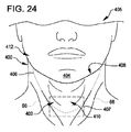
図1は、対象者12の頭頸領域10の切断図である。 FIG. 1 is a cutaway view of a head and neck region 10 of a subject 12.

図1を参照すると、閉塞性睡眠時無呼吸は対象者12の気道14が潰れていること、すなわち、睡眠中に、例えば、舌16の背部、軟口蓋18、または口蓋垂20によってブロックされることを特徴とし、したがって、ブロックされた気道の各事例は、典型的には上述のように「無呼吸」を引き起こす。睡眠中の気道14がブロックされる原因には、舌16、軟口蓋18、または口蓋垂20における筋緊張の低下、過剰な弛緩、または過剰な組織が含まれ得る。 Referring to FIG. 1, obstructive sleep apnea indicates that the airway 14 of the subject 12 is collapsed, ie, blocked during sleep, for example, by the back of the tongue 16, the soft palate 18, or the uvula 20. Characterized, and thus, each case of blocked airways typically causes "apnea" as described above. Causes of blocked airways 14 during sleep may include decreased muscle tone, excessive relaxation, or excess tissue in the tongue 16, soft palate 18, or uvula 20.

対象者12の身体が上述のように対象者の呼吸を再び開始するために、閉塞気道誘発(blocked-airway-induced)無呼吸の間にアドレナリンのバーストを生成すると、アドレナリンバーストは対象者に、例えば咳をさせたりる、頚22、頭24、または顎26を動かしたり、またはより深く呼吸させたり(より深い呼吸によって引き起こされるより強い吸引は、気道を開放させ得る)することによって、気道14の閉塞を開放し得る。 If the body of the subject 12 produces a burst of adrenaline during a blocked-airway-induced apnea to restart the subject's breathing as described above, the adrenaline burst will cause the subject to: For example, by coughing, moving the neck 22, head 24, or jaw 26, or breathing deeper (stronger suction caused by deeper breathing may open the airway). Can open the occlusion.

次いで、対象者12がより深い睡眠に戻った後、頚22および顎26の筋肉は弛緩し、対象者の呼吸数はより深い睡眠レベルに戻り、したがって、アドレナリンバーストがその後に続く無呼吸の別のサイクルが開始し得る。 Then, after subject 12 returns to a deeper sleep, the muscles of cervical 22 and jaw 26 relax and the subject's respiratory rate returns to a deeper sleep level, thus another apnea followed by an adrenaline burst. Cycle can begin.

さらに図1を参照すると、閉塞性睡眠時無呼吸に利用できる多くの治療がある。 Still referring to FIG. 1, there are many treatments available for obstructive sleep apnea.

侵襲的治療の例には、気道14の閉塞の原因となる身体部分(例えば、舌16、軟口蓋18、または口蓋垂20)から組織を除去するための外科手術、および身体部分を「硬化」させるために閉塞身体部分に1つ以上の部材を移植する(例えば、軟口蓋にプラスチックロッドを移植する)ための外科手術が含まれる。 Examples of invasive treatments include surgery to remove tissue from the body part (eg, tongue 16, soft palate 18, or uvula 20) that causes obstruction of the airways 14, and to “harden” the body part. Surgical procedures for implanting one or more members in the occluded body part (eg, implanting a plastic rod in the soft palate).

残念なことに、このような侵襲的治療に伴う潜在的な問題には、外科的処置に関連するリスク、回復時間、不可逆性、および疼痛が含まれ、これには、この処置が飲食の際に回復後の不快感を対象者に引き起こすリスク、ならびにこの処置が閉塞性睡眠時無呼吸を引き起こす気道閉塞の再発を予防するのに成功しなかったと最終的に判明するリスクが含まれる。 Unfortunately, potential problems with such invasive therapies include risks associated with surgical procedures, recovery time, irreversibility, and pain, which can result when the procedure is consumed during eating and drinking. Include the risk of post-recovery discomfort in the subject, as well as the risk that this procedure will ultimately prove unsuccessful in preventing the recurrence of airway obstruction that causes obstructive sleep apnea.

非侵襲的治療の例には、対象者12が体重を減らすこと、睡眠中に対象者の顎26をわずかに突出した位置に維持する口腔器具を使用すること、図2に関連して以下に説明する連続気道正圧(Continuous Positive Airway Pressure,CPAP)マシンを使用することが含まれる。 Examples of non-invasive treatments include subject 12 losing weight, using an oral appliance to maintain subject's jaws 26 in a slightly protruding position during sleep, below in connection with FIG. It includes using a Continuous Positive Airway Pressure (CPAP) machine as described.

そのような非侵襲的処置は例えば、侵襲的治療と比べてリスクおよび副作用が少ないので、侵襲的治療よりも一般的に好ましいが、体重を減らし、口腔器具を使用するなどのいくつかの非侵襲的処置は閉塞性睡眠時無呼吸に罹っている一部の対象者にとっては得ることが困難であるか、または無効であり得る。 Such non-invasive treatments are generally preferred over invasive treatments, for example because they have less risk and side effects than invasive treatments, but some non-invasive treatments such as weight loss and use of oral appliances. Treatment can be difficult or ineffective for some subjects with obstructive sleep apnea.

しかし、残念ながら、CPAPマシンは、これがなければ閉塞性睡眠時無呼吸に悩まされる大部分の対象者において閉塞性睡眠時無呼吸をうまく治療できることが分かっている。 Unfortunately, however, CPAP machines have been shown to successfully treat obstructive sleep apnea in most subjects who would otherwise suffer from obstructive sleep apnea.

図2は、閉塞性睡眠時無呼吸の発生を防止するためにCPAPマシン30を使用する睡眠中の対象者12の図である。 FIG. 2 is a diagram of a sleeping subject 12 using a CPAP machine 30 to prevent the development of obstructive sleep apnea.

CPAPマシン30は、ベースユニット32と、ホース34と、マスクアセンブリ36とを含む。 The CPAP machine 30 includes a base unit 32, a hose 34, and a mask assembly 36.

ベースユニット32は、ホース34内、したがって対象者12の気道14(図1)内の空気圧を、対象者が息を吸っている間(吸気)、および対象者が息を吐いている間(呼気)、ほぼ一定のレベルに維持するように構成される。CPAPマシン30がほぼ一定のレベルに維持する気道圧力が、呼気中と吸気中とで異なる場合、それはより適切にはBiPAP機械と呼ばれるが、一般的な使用法では「CPAP」は、吸気中および呼気中に気道圧力を同じ正のレベルに維持する機械と、吸気中および呼気中に気道圧力を異なる正のレベルに維持する機械との両方を示すために使用される。ベースユニット32は典型的には家庭用電源コンセント(例えば、110/220VAC)に直接差し込まれるか、またはACアダプタに結合可能な電源コードを含む。 The base unit 32 controls the air pressure in the hose 34, and thus in the airway 14 (FIG. 1) of the subject 12, while the subject is inhaling (inhaling) and exhaling (exhaling). ), configured to maintain a near constant level. If the airway pressure that the CPAP machine 30 maintains at a nearly constant level is different during exhalation and during inspiration, it is more properly called a BiPAP machine, but in general usage "CPAP" means during inspiration and It is used to indicate both machines that maintain airway pressure at the same positive level during exhalation and machines that maintain airway pressure at different positive levels during inspiration and expiration. The base unit 32 typically includes a power cord that plugs directly into a household power outlet (eg, 110/220 VAC) or can be coupled to an AC adapter.

ホース34はベースユニット32をマスクアセンブリ36に結合するように構成され、典型的には、対象者がCPAPマシン30を使用している間に、対象者12がベースユニットを床またはナイトスタンドの上に置くことを可能にするのに十分な長さ(例えば、6〜10フィート)である。
マスクアセンブリ36は、接続具(fitting)38、マスク40、およびストラップ42を含む。接続具38は、マスク40をホース34に結合するように構成され、対象者12がいくらか自由に動けるようにするスイベルジョイント(swivel joint)でマスクに結合することができる。マスク40は対象者12の少なくとも鼻の周りに気密シール44を形成するように構成され(ただし、マスクは図2に示すように対象者の口の周りにシールを形成することもできる)、空気がベースユニット32からホース34および接続具38を通ってマスク40に流入し続け、吸気中であっても1つ以上の開口部を通って流出し続けることを可能にする1つ以上の開口部(図2には図示せず)を含む。この絶え間ない空気流なしでは、対象者によって吸い込まれる空気は「淀む」。そして、ストラップ42は、マスクと対象者の顔面との間に気密シール44を形成するのに十分な程度のきつさで、マスク40を対象者12の頭24に固定する。
The hose 34 is configured to couple the base unit 32 to the mask assembly 36, typically while the subject 12 is using the CPAP machine 30, the subject 12 places the base unit on a floor or nightstand. Long enough (eg, 6-10 feet) to allow placement in
The mask assembly 36 includes a fitting 38, a mask 40, and a strap 42. The connector 38 is configured to couple the mask 40 to the hose 34 and may be coupled to the mask with a swivel joint that allows the subject 12 some freedom of movement. The mask 40 is configured to form an airtight seal 44 around at least the nose of the subject 12 (although the mask can also form a seal around the subject's mouth as shown in FIG. 2) and air One or more openings that allow air to continue to flow from the base unit 32 through the hose 34 and the connector 38 into the mask 40 and through the one or more openings even during inspiration. (Not shown in FIG. 2). Without this constant airflow, the air inhaled by the subject is "stuck." The strap 42 then secures the mask 40 to the subject's 12 head 24 with sufficient tightness to form an airtight seal 44 between the mask and the subject's face.

さらに図2を参照すると、上述したように、CPAPマシン30は閉塞性睡眠時無呼吸のための効果的な非侵襲的治療であるが、CPAPマシンは依然としていくつかの欠点を有することがある。例えば、マスクアセンブリ36をベースユニット32に効果的につなぐホース34の性質上、睡眠中に対象者12の全範囲の運動を奪うことがあり得る。一例として、対象者12が左に転がると、ホース34がベースユニット32を引っ張り、ナイトスタンドから落としてしまうかもしれない。または、ベースユニットが床上にある場合に、対象者が左に転がると、ホース34が教えられる(taught)ようになり、したがって、マスク40を対象者の顔から外され、シール44を破ることがあり得る。さらに、対象者12が横向きで寝ると、枕によってマスク40が対象者の顔から外れ、シール44を破ることがある。さらに、気密シールを形成するためにストラップ42がマスク40を対象者12の顔面に対して保持しなければならない力は、対象者に不快感を引き起こす可能性がある。加えて、CPAPマシン30は、例えば、航空機に載せてされて運ぶとき、対象者12は、セキュリティを通過する時、少なくともベースユニット32を他のアイテムから分離しなければならず、ベースユニットの寸法では、ブリーフケースまたはボストンバッグに入れて運ぶことが困難なので、移動に不便であることが判明し得る。 Still referring to FIG. 2, as mentioned above, the CPAP machine 30 is an effective non-invasive treatment for obstructive sleep apnea, but the CPAP machine may still have some drawbacks. For example, the nature of the hose 34 that effectively connects the mask assembly 36 to the base unit 32 may deprive the subject 12 of full range of movement during sleep. As an example, when the subject 12 rolls to the left, the hose 34 may pull the base unit 32 and drop it from the nightstand. Alternatively, when the base unit is on the floor and the subject rolls to the left, the hose 34 becomes taught so that the mask 40 may be removed from the subject's face and the seal 44 may be broken. possible. Further, when the subject 12 sleeps sideways, the pillow may cause the mask 40 to come off the subject's face and break the seal 44. Moreover, the force with which the strap 42 must hold the mask 40 against the subject's 12 face to form a hermetic seal can cause discomfort to the subject. In addition, when the CPAP machine 30 is carried on an aircraft, for example, the subject 12 must at least separate the base unit 32 from other items when passing security, the dimensions of the base unit being Can be found to be inconvenient to move because it is difficult to carry in a briefcase or Boston bag.

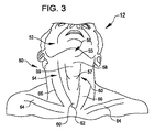
図3は、対象者12の頚50及び顎52、並びに咽喉54の図である。 FIG. 3 is a view of the subject's 12 neck 50 and jaw 52, and throat 54.

図3を参照すると、対象者12の頚50および/または顎52の1つ以上の領域に負圧(すなわち、吸引または真空)を加えることにより、閉塞性睡眠時無呼吸を非侵襲的に治療することができる。例えば、顎52の下側56、即ち、顎の下の咽喉54の(舌骨筋などの)領域58に負圧を加えると、対象者12が寝ている間、対象者の気道14(図1)を開き、開いた状態に維持するように、対象者の顎、舌16(図1)、または対象者の1つ以上の他の生物学的構造を配置するのを補助することができる。別の例では、咽喉領域60(咽喉領域58の下、胸骨頭62および鎖骨64の上、および胸鎖乳突筋66の間にある)の1つ以上の部分に負圧を加えると、対象者12が寝ている間、対象者の気道14を開き、開いた状態を維持するように、対象者12の1つ以上の生物学的構造を配置することもできる。さらに別の例では、対象者12が寝ている間に、咽喉54の、二腹(Digastricus)55の前腹部と、甲状軟骨(すなわち、のどぼとけ)57と、胸鎖乳突筋66との間の領域に負圧を加えると、対象者12の気道14を開き、開いた状態を維持するように、対象者12の1つ以上の生物学的構造を配置することもできる。さらに別の例では、対象者12が寝ている間に、咽喉54の二腹55の前腹部、舌骨59、および胸鎖乳突筋66の間の領域に負圧を印加すると、対象者の気道14を開き、開いた状態を維持するように、対象者12の1つ以上の生物学的構造を配置することもできる。 Referring to FIG. 3, non-invasively treat obstructive sleep apnea by applying a negative pressure (ie, suction or vacuum) to one or more areas of the neck 50 and/or jaw 52 of subject 12. can do. For example, applying a negative pressure to the underside 56 of the chin 52, ie, the area 58 (such as the hyoid muscle) of the throat 54 below the chin, while the subject 12 sleeps, the subject's airway 14 (see FIG. 1) Can help to position the subject's jaw, tongue 16 (FIG. 1), or one or more other biological structures of the subject, to keep the open and open .. In another example, applying negative pressure to one or more portions of the throat region 60 (below the throat region 58, above the sternum head 62 and clavicle 64, and between the sternocleidomastoid muscles 66) causes the subject to One or more biological structures of subject 12 may also be arranged to open and maintain the subject's airways 14 while sleeping. In yet another example, the anterior abdomen of the Digastricus 55 of the throat 54, the thyroid cartilage (ie, throat) 57, and the sternocleidomastoid muscle 66 while the subject 12 is sleeping. One or more biological structures of subject 12 may also be positioned to open and maintain open airways 14 of subject 12 when negative pressure is applied to the region in between. In yet another example, applying negative pressure to the area between the anterior abdomen of the flank 55 of the throat 54, the hyoid bone 59, and the sternocleidomastoid muscle 66 while the subject 12 is asleep may result in One or more biological structures of the subject 12 may also be arranged to open the airway 14 and maintain it open.

図4は、一実施形態による、閉塞性睡眠時無呼吸を治療するように構成された負圧睡眠時無呼吸治療システム70を使用する対象者12の図である。図5〜図22に関連して以下に説明するように、システム70は自己完結型であり、対象者の頚50、顎52、または咽喉54の1つ以上の領域に負圧を加えて維持することによって、睡眠中に対象者の気道14(図1)を開き、開いた状態を維持するように構成される。上記および以下で使用されるように、「自己完結型」(self-contained)は、システム70が閉塞性睡眠時無呼吸を単独で治療するように構成されることを意味する。図2のCPAPマシン30のようなCPAPマシンと比較して、システム70は他のいかなるアイテムまたは場所にもつながれていないので、対象者12により多くの運動の自由を可能にすることができ、頚の周りに着用され、顔の上に着用されていないので、より快適であることができ、より部品を少なく、より小さくすることができ、折り畳むことができるので、移動により相応しい。 FIG. 4 is a diagram of a subject 12 using a negative pressure sleep apnea treatment system 70 configured to treat obstructive sleep apnea, according to one embodiment. As described below with respect to FIGS. 5-22, the system 70 is self-contained and maintains a negative pressure in one or more areas of the subject's neck 50, jaws 52, or throat 54. By doing so, the subject's airways 14 (FIG. 1) are configured to open and remain open during sleep. As used above and below, "self-contained" means that the system 70 is configured to treat obstructive sleep apnea alone. Compared to a CPAP machine such as the CPAP machine 30 of FIG. 2, the system 70 is not tethered to any other item or location, thus allowing the subject 12 more freedom of movement and It is worn around and not on the face, so it is more comfortable, has fewer parts, can be smaller, and can be folded, making it more suitable for movement.

負圧睡眠時無呼吸治療システム70は、カラーアセンブリ72と、カラーに固定されるように構成された構成要素モジュール74とを含む。 The negative pressure sleep apnea therapy system 70 includes a collar assembly 72 and a component module 74 configured to be secured to the collar.

カラーアセンブリ72は、カラー76と、ストラップ、スナップ、ボタン、またはVelcro(登録商標)ストリップなどの締結具(図4では見えない)とを含み、締結具は、システム70が負圧を加えるように構成される対象者の頚、顎52、または咽喉54の1つ以上の領域の周りに気密シールをカラーが形成するように、カラーを対象者の頚50に固定するように構成される。カラー76は、部分的にまたは完全に可撓性であってもよく、布、発泡体、金属、またはプラスチックなどの1つ以上の適切な材料から形成されてもよい。カラーまたは締結具は、アセンブリが様々な頚の周囲、長さ、および形状を有する対象者に適合できるように、カラーアセンブリ内部寸法の調節を可能にするように構成されてもよい。カラーアセンブリ72は、図5〜図7に関連して以下に更に説明する。 The collar assembly 72 includes a collar 76 and fasteners (not visible in FIG. 4), such as straps, snaps, buttons, or Velcro® strips, such that the system 70 applies negative pressure. The collar is configured to be secured to the subject's neck 50 such that the collar forms an airtight seal about one or more areas of the subject's neck, jaw 52, or throat 54 to be constructed. The collar 76 may be partially or fully flexible and may be formed from one or more suitable materials such as cloth, foam, metal, or plastic. The collar or fastener may be configured to allow adjustment of the internal dimensions of the collar assembly so that the assembly can accommodate subjects having varying neck circumferences, lengths, and shapes. The collar assembly 72 is described further below in connection with FIGS.

そして、モジュール74は、カラーアセンブリ72以外のシステム70の1つ以上の構成要素を含むように構成される。例えば、モジュール74は、エアポンプ、モータ、電源、圧力、気道、および他のセンサ、ならびにマイクロプロセッサまたはマイクロコントローラなどのコントローラ回路を含むことができる。モジュール74は、図8に関連して以下に更に説明される。 The module 74 is then configured to include one or more components of the system 70 other than the color assembly 72. For example, module 74 may include air pumps, motors, power supplies, pressure, airways, and other sensors, and controller circuits such as microprocessors or microcontrollers. Module 74 is described further below in connection with FIG.

引き続き図4を参照すると、負圧睡眠時無呼吸治療システム70の代替実施形態が企図されている。例えば、可撓性である代わりに、カラー76は互いにヒンジ結合された2つ以上の剛性部分を含み、これらの剛性部分が開いて対象者の頚50を受け入れ、そして、閉じて頚の周りに付着するように構成されてもよい。更に、カラーアセンブリ72以外のシステム構成要素の全てがモジュール74内に配置されなくてもよい。例えば、これらの他の構成要素の幾つか又は全ては、カラー76の外側又は締結具の外側に固定することができ、カラーの内側又は締結具の内側に固定することができ、又はカラー76又は締結具の内側に配置することができる。さらに、モジュール74およびカラー76は、図4に示すもの以外の任意の適切な形状を有することができる。 With continued reference to FIG. 4, an alternative embodiment of the negative pressure sleep apnea treatment system 70 is contemplated. For example, instead of being flexible, the collar 76 includes two or more rigid portions that are hingedly attached to each other such that the rigid portions open to receive the subject's neck 50 and close to surround the neck. It may be configured to adhere. Further, not all system components except color assembly 72 may be located within module 74. For example, some or all of these other components can be secured outside collar 76 or outside the fastener, inside the collar or inside the fastener, or collar 76 or It can be placed inside the fastener. Further, the module 74 and the collar 76 can have any suitable shape other than that shown in FIG.

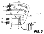
図5は、一実施形態による、図4の負圧睡眠時無呼吸治療システム70の図である。 5 is a diagram of the negative pressure sleep apnea therapy system 70 of FIG. 4, according to one embodiment.

カラー76は、対象者がシステム70を装着している間、対象者の頚50(図4)を完全に取り囲むように構成された単一の可撓性ピースであり、Velcro(登録商標)締結具78は、システム70が様々な頚のサイズおよび形状に適合できるように調節可能である。 The collar 76 is a single flexible piece configured to completely surround the subject's neck 50 (FIG. 4) while the subject is wearing the system 70, and the Velcro® fastening. Tool 78 is adjustable to allow system 70 to accommodate various neck sizes and shapes.

システム70はまた、構成要素モジュール74のレセプタクル92に結合するように構成されたACアダプタ/充電器90を含み、このACアダプタ/充電器90は、システムが動作している間、システムに電力を供給するように、もしくはシステムが動作している間、または動作していない間、システムのバッテリ(図5には示されていない)を充電するように構成されている。あるいは、レセプタクル92が標準的な電源コンセント(例えば、110VAC,220VAC)に結合するように構成された電源コードに結合するように構成されてもよい。 The system 70 also includes an AC adapter/charger 90 configured to couple to a receptacle 92 of the component module 74, which AC adapter/charger 90 powers the system while the system is operating. It is configured to charge the system's battery (not shown in FIG. 5) to supply or while the system is operating or not operating. Alternatively, the receptacle 92 may be configured to couple to a power cord that is configured to couple to a standard power outlet (eg, 110 VAC, 220 VAC).

さらに、システム70は、対象者の頚50のそれぞれの対向領域とそれぞれ気密シールを形成するように構成された1つ以上のシール面94を含み、シール面94によって境界が定められ、システムが負圧を加える対象者の頚50(図4)、顎52(図4)、または咽喉54(図4)の領域に向かい合って位置するように構成された1つ以上の真空面96を含む。1つ以上のシール面94および1つ以上の真空面96は、図14〜図21に関連して以下でさらに説明される。 Further, the system 70 includes one or more sealing surfaces 94 each configured to form a hermetic seal with a respective opposing region of the subject's neck 50, the sealing surfaces 94 delimiting the system to a negative pressure. It includes one or more vacuum surfaces 96 configured to face the area of the subject's neck 50 (FIG. 4), jaw 52 (FIG. 4), or throat 54 (FIG. 4) to which pressure is applied. One or more sealing surfaces 94 and one or more vacuum surfaces 96 are described further below in connection with FIGS. 14-21.

さらに、構成要素モジュール74は、入出力装置98、電力スイッチアセンブリ100、および排気口アセンブリ102を含む。入出力装置98は例えば、タッチスクリーンであり、対象者12(図4)がシステム70をプログラムし、または他の方法で制御し、システム70から状態情報およびプログラミングの確認などの情報を受信することを可能にする。例えば、入出力装置は、対象者12が負圧の大きさまたはその最大閾値を設定することを可能にし、システム70が対象者を穏やかに覚醒させるように覚醒時間の設定(例えば、負圧の大きさ)を調整することができることを見越して対象者が覚醒時間を設定することを可能にするように構成することができる。あるいは、入出力装置98が別個の入力装置(例えば、キーパッド)および出力装置(例えば、ディスプレイ、タッチスクリーンディスプレイ)を含み得る。電力スイッチアセンブリ100は、例えば、対象者12(図4)がシステム70を「オン」または「オフ」にすることを可能にする任意の適切なアセンブリ(例えば、トグルスイッチまたはタッチスクリーンによって表示される触覚スライドスイッチ)である。そして、排気口アセンブリ102は、システム70がカラー76と対象者の頚50(図4)、顎52(図4)、または咽喉54(図4)との間に負圧の1つ以上の領域を生成するために、カラーと頚、顎、または咽喉との間から吸引する空気のための排気口を提供する。 In addition, the component module 74 includes an input/output device 98, a power switch assembly 100, and an exhaust assembly 102. The input/output device 98 is, for example, a touch screen and allows the subject 12 (FIG. 4) to program or otherwise control the system 70 to receive information from the system 70, such as status information and programming confirmation. To enable. For example, the I/O device allows the subject 12 to set the magnitude of the negative pressure or its maximum threshold, and the system 70 sets the wake-up time (eg, negative pressure) to wake the subject gently. It can be configured to allow the subject to set the wake-up time in anticipation that the size) can be adjusted. Alternatively, the input/output device 98 may include a separate input device (eg, keypad) and output device (eg, display, touch screen display). The power switch assembly 100 is displayed, for example, by any suitable assembly that allows the subject 12 (FIG. 4) to “turn on” or “off” the system 70 (eg, a toggle switch or a touch screen). Tactile slide switch). And, the vent assembly 102 allows the system 70 to provide one or more areas of negative pressure between the collar 76 and the subject's neck 50 (FIG. 4), chin 52 (FIG. 4), or throat 54 (FIG. 4). An air outlet is provided for inhaling air from between the collar and the neck, jaw, or throat to produce the.

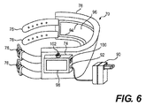
図6は、さらに別の一実施形態による、図4の負圧睡眠時無呼吸治療システム70の図である。図6のシステム70は、カラー76がシステムを装着したときに対象者の頚50(図4)を部分的にのみ取り囲むように構成され、図6の調節可能なVelcro(登録商標)締結具78が図5の締結具78よりも長く、カラーの減少した長さを補償することを除いて、図5のシステム70と同様である。 FIG. 6 is a diagram of the negative pressure sleep apnea therapy system 70 of FIG. 4 according to yet another embodiment. The system 70 of FIG. 6 is configured so that the collar 76 only partially surrounds the subject's neck 50 (FIG. 4) when the system is worn, and the adjustable Velcro® fastener 78 of FIG. 5 is similar to the system 70 of FIG. 5, except that it is longer than the fastener 78 of FIG. 5 and compensates for the reduced length of the collar.

図7は、さらに別の実施形態による、図4の負圧睡眠時無呼吸治療システム70の図である。図7のシステム70は、カラー76が対象者12(図4)の顎52(図4)の下に位置決めするように構成された部分104を含み、システムがカラー支持体106も含むことを除いて、図5〜図6のシステム70と同様である。カラー76は、対象者12(図4)の頚50(図4)を部分的にのみ取り囲むように構成され、対象者の顎52(図4)または顎先26(図1)の下に負圧を加えることができるように構成された部分104を含む。また、カラー支持体106は、図5および図6の締結具78の代わりに、またはそれに加えて、対象者12の肩(図7には図示せず)に嵌合するように構成されている。支持体106は可撓性、剛性、または半剛性である任意の適切な材料から作製することができ、睡眠中に対象者12に動きの自由を与えるように設計されることができる。また、図7には示されていないが、図7のシステム70は、ACアダプタ90、アダプタ・レセプタクル92、シール面94、および真空面96、またはそれらの任意の適切な代替物のうちの1つ以上を含むことができる。 7 is a diagram of the negative pressure sleep apnea treatment system 70 of FIG. 4 according to yet another embodiment. The system 70 of FIG. 7 includes a portion 104 configured to position the collar 76 under the chin 52 (FIG. 4) of the subject 12 (FIG. 4), except that the system also includes a collar support 106. And is similar to the system 70 of FIGS. The collar 76 is configured to only partially surround the neck 50 (FIG. 4) of the subject 12 (FIG. 4) and is placed under the subject's chin 52 (FIG. 4) or chin 26 (FIG. 1). It includes a portion 104 adapted to be capable of applying pressure. Also, the collar support 106 is configured to fit on the shoulder (not shown in FIG. 7) of the subject 12 in place of or in addition to the fastener 78 of FIGS. 5 and 6. .. Support 106 can be made of any suitable material that is flexible, rigid, or semi-rigid and can be designed to give subject 12 freedom of movement during sleep. Also, although not shown in FIG. 7, the system 70 of FIG. 7 includes an AC adapter 90, an adapter receptacle 92, a sealing surface 94, and a vacuum surface 96, or one of any suitable alternatives thereof. It can include one or more.

図4〜図7を参照すると、睡眠時無呼吸治療システム70の代替実施形態が企図されている。例えば、カラーアセンブリ72に対する構成要素モジュール74の位置は、説明したものとは異なっていてもよい。さらに、構成要素モジュール74に対する入出力装置98、電力スイッチ100、および排気口102の位置は、説明したものとは異なっていてもよい。さらに、図4〜図6のカラー76は、図7の部分104と同じ機能を果たす顎部分または顎先部分を有してもよい。さらに、システム70は、任意の適切な方法で変更されてもよい。 With reference to FIGS. 4-7, alternative embodiments of sleep apnea treatment system 70 are contemplated. For example, the position of the component module 74 with respect to the collar assembly 72 may differ from that described. Further, the positions of the input/output device 98, the power switch 100, and the exhaust port 102 with respect to the component module 74 may differ from those described. Additionally, the collar 76 of FIGS. 4-6 may have a jaw or chin portion that performs the same function as the portion 104 of FIG. Moreover, system 70 may be modified in any suitable manner.

図8は、一実施形態による、図4〜図7の構成要素モジュール74のブロック図である。電源レセプタクル92、入出力装置98、電力スイッチアセンブリ100、および排気口アセンブリ102に加えて、構成要素モジュール74は、以下の構成要素:バッテリ110などの電源、補助電源112、電力供給器(power supply)114、モータアセンブリ116、ポンプアセンブリ118、圧力調整器アセンブリ120、バルブアセンブリ122、シーリング材ディスペンサアセンブリ124、圧力センサアセンブリ126、無呼吸度センサアセンブリ128、メモリ130、温度制御アセンブリ132、コントローラ134、およびバス136を含む。モジュール74は、また、これらの構成要素を収容するパッケージ(図8には図示せず)を含み得る。例えば、パッケージはエポキシ樹脂から形成されてもよく、収容された構成要素を保護するために、またはそれへのアクセスを防止するために封止されてもよく、または、例えば、修理または交換のために、収容された構成要素のうちの1つ以上へのアクセスを可能にする構造を含んでもよい。さらに、構成要素モジュール74は、電源レセプタクル92に加えて、例えば、圧力調整器アセンブリ120、バルブアセンブリ122、およびカラー76(図4〜図7)の間の通気、ディスペンサアセンブリ124とカラーとの間のシーリング材の流動、ならびにセンサアセンブリ126およびセンサアセンブリ128の間の信号通信を可能にする他の適切なレセプタクルまたはコネクタを含むことができる。 FIG. 8 is a block diagram of the component module 74 of FIGS. 4-7, according to one embodiment. In addition to the power receptacle 92, the input/output device 98, the power switch assembly 100, and the exhaust assembly 102, the component module 74 includes the following components: a power source such as a battery 110, an auxiliary power source 112, a power supply. ) 114, motor assembly 116, pump assembly 118, pressure regulator assembly 120, valve assembly 122, sealant dispenser assembly 124, pressure sensor assembly 126, apnea sensor assembly 128, memory 130, temperature control assembly 132, controller 134, And bus 136. Module 74 may also include a package (not shown in FIG. 8) that houses these components. For example, the package may be formed from epoxy resin, sealed to protect the contained components or prevent access to it, or for example for repair or replacement. May include structures that allow access to one or more of the contained components. In addition, the component module 74, in addition to the power receptacle 92, provides, for example, ventilation between the pressure regulator assembly 120, the valve assembly 122, and the collar 76 (FIGS. 4-7), between the dispenser assembly 124 and the collar. Other suitable receptacles or connectors that allow for flow of sealing material and signal communication between sensor assembly 126 and sensor assembly 128 may be included.

電源レセプタクル92は、電力スイッチアセンブリ100を介して、例えばACアダプタ90(図5〜図6)からDC電力信号を受信するように構成されるか、または例えば標準電源コンセント(例えば110VAC、220VAC)からAC電力信号を受信するように構成される。 The power receptacle 92 is configured to receive a DC power signal, eg, from an AC adapter 90 (FIGS. 5-6), via the power switch assembly 100, or, eg, from a standard power outlet (eg, 110 VAC, 220 VAC). It is configured to receive an AC power signal.

入出力装置98は例えば、対象者12(図4)、睡眠技師、または睡眠医師からデータを受信し、対象者、技師、または医師にデータを提供するように構成される。例えば、装置98は、データを入力することを可能にし、データを表示するタッチスクリーンとすることができる。あるいは、デバイス98はキーパッドまたはカードリーダなどの別個の入力デバイス138と、ディスプレイ画面またはカードライタなどの別個の出力デバイス140とを含むことができる。装置98を介して構成要素モジュール74に入力することができるデータの例には、コントローラ134のための命令プログラム、ならびに圧力および温度の範囲および閾値レベルなどのシステム構成パラメータおよびシステム動作パラメータが含まれる。 The input/output device 98 is configured, for example, to receive data from the subject 12 (FIG. 4), a sleep technician, or a sleeping doctor and provide the data to the subject, technician, or doctor. For example, the device 98 may be a touch screen that allows data to be entered and displays the data. Alternatively, the device 98 may include a separate input device 138 such as a keypad or card reader and a separate output device 140 such as a display screen or card writer. Examples of data that can be input to the component module 74 via the device 98 include an instruction program for the controller 134, and system configuration parameters and system operating parameters such as pressure and temperature ranges and threshold levels. ..

バッテリ110は、構成要素モジュール74の構成要素に電力を供給し、負圧睡眠時無呼吸治療システム70(図4〜図7)に全体的に電力を供給するためのエネルギーを蓄積するように構成される。バッテリ110は、ニッケル‐カドミウムバッテリ、リチウムイオンバッテリ、またはアルカリバッテリなどの任意の適切なタイプのバッテリとすることができ、任意の適切な出力電圧(例えば、5〜25VDCの範囲内)を生成することができ、1回限り使用可能または再充電可能とすることができる。さらに、バッテリ110は、電気的に直列、電気的に並列、または電気的に直列および電気的に並列の両方で一緒に結合された2つ以上のバッテリまたはバッテリセルを含むことができる。さらに、バッテリ110は、バッテリが蓄積する充電または電圧の大きさが低充電閾値以下に低下した場合に、例えばコントローラ134または入出力装置98にアラーム(例えばアラーム信号)を提供することができ、あるいは、別の構成要素、例えばコントローラ134が、バッテリの充電または電圧を監視し、そのようなアラームを生成することができる。さらに、構成要素モジュール74は、バッテリ110を保持するためのレセプタクルを含むことができる。 Battery 110 is configured to power the components of component module 74 and to store energy to generally power negative pressure sleep apnea therapy system 70 (FIGS. 4-7). To be done. Battery 110 can be any suitable type of battery, such as a nickel-cadmium battery, a lithium-ion battery, or an alkaline battery, and produces any suitable output voltage (eg, in the range of 5-25 VDC). It can be one-time useable or rechargeable. Further, the battery 110 can include two or more batteries or battery cells electrically coupled in series, electrically parallel, or both electrically series and electrically parallel. Further, the battery 110 may provide an alarm (eg, an alarm signal) to, for example, the controller 134 or the input/output device 98 when the amount of charge or voltage the battery is accumulating drops below a low charge threshold, or , Another component, such as controller 134, can monitor the battery charge or voltage and generate such an alarm. Further, the component module 74 can include a receptacle for holding the battery 110.

補助電源112は、構成要素モジュール74の構成要素に電力を供給し、負圧睡眠時無呼吸治療システム70(図4〜図7)に全体的に電力を供給するためのエネルギーを生成するように構成される。例えば、補助電源112は、ばねと、対象者12(図4)が巻かれたばねにエネルギーを蓄積するようにばねを巻くために回転することができる手動巻き取り機構とを含むことができ、ばねが巻き戻されると、ばねは、電力信号を生成するように構成された発電機(発電機も補助電源に含まれる)を駆動するように構成される。あるいは、補助電源112は、システム70を装着している間に対象者12が動くときなどの、補助電源の運動に応答してばねを巻き取る自動巻き取り機構を含むことができ、そのような自動巻き取り機構は自動巻き取り時計のばねを巻き取るために使用される従来の機構と同様であり得る。あるいは、補助電源112は、補助電源の運動に応答して発電機を自動的に駆動するための機構を含むことができ、このような機構は自家動力式時計の発電機を駆動するために使用される従来の機構に類似することができる。補助電源112は、発電機によって生成された電力信号を電力供給器114に直接供給するように構成することができ、または、生成された電力信号で、バッテリ110、または補助電源の一部である別のバッテリを充電するように構成することができる。 The auxiliary power source 112 powers the components of the component module 74 to generate energy for generally powering the negative pressure sleep apnea therapy system 70 (FIGS. 4-7). Composed. For example, the auxiliary power source 112 may include a spring and a manual winding mechanism that may be rotated by the subject 12 (FIG. 4) to wind the spring to store energy in the wound spring. When is rewound, the spring is configured to drive a generator configured to generate a power signal, the generator also included in the auxiliary power source. Alternatively, the auxiliary power supply 112 can include an automatic winding mechanism that winds a spring in response to movement of the auxiliary power supply, such as when the subject 12 moves while wearing the system 70. The automatic winding mechanism may be similar to the conventional mechanism used to wind the spring of an automatic winding timepiece. Alternatively, the auxiliary power source 112 may include a mechanism for automatically driving the generator in response to movement of the auxiliary power source, such a mechanism being used to drive the generator of a self-powered watch. Can be similar to the conventional mechanism described. The auxiliary power supply 112 may be configured to directly supply the power signal generated by the generator to the power supply 114, or the generated power signal, which may be the battery 110, or part of the auxiliary power supply. It can be configured to charge another battery.

電力供給器114は(電力スイッチアセンブリ100を介して)レセプタクル92、バッテリ110、および補助電源112のうちの1つ以上から電力を受け取り、この電力を、電力供給器自体、モジュール74の他の構成要素、およびシステム70(図4〜図7)の任意の他の構成要素に電力を供給するのに適した1つ以上の電流および電圧に変換するように構成される。例えば、電力供給器114はレセプタクル92で電力信号を感知し、この感知された信号を、それぞれのDC電圧を有する1つ以上のDC電力信号に変換するように構成することができる。さらに、電力供給器114は電力供給器がレセプタクル92から電力信号を受信している間に、バッテリ110(および補助電源112内の任意のバッテリ)を充電するように構成することができる。電力供給器114はレセプタクル92で電力信号を感知しない場合、補助電源112からの電力信号を1つ以上のDC電力信号に変換し、バッテリ110(および補助電源112内の任意のバッテリ)を充電するために、補助電源からの任意の過剰電力(すなわち、睡眠時無呼吸治療システム70の構成要素に電力を供給するのに必要な電力レベルよりも高い電力レベル)を使用するように構成することもできる。さらに、電力供給器114はレセプタクル92で電力信号を感知せず、補助電源112からの電力がシステム70の電力需要を満たすのに不十分であることを感知した場合、バッテリ110からの電力信号を1つ以上のDC電力信号に変換し、補助電源からのいくらかの電力を使用してバッテリを充電するように構成することができる。電力供給器114は任意の適切なタイプの電力供給器、例えば、バックコンバータ、ブーストコンバータ、またはバックブーストコンバータなどのDC‐DCコンバータとすることができ、またはそれらを含むことができる。 The power supply 114 receives power (via the power switch assembly 100) from one or more of the receptacle 92, the battery 110, and the auxiliary power supply 112, which power is supplied to the power supply itself, another configuration of the module 74. The elements and any other components of system 70 (FIGS. 4-7) are configured to be converted into one or more currents and voltages suitable for powering. For example, power supply 114 can be configured to sense a power signal at receptacle 92 and convert the sensed signal into one or more DC power signals having respective DC voltages. Further, the power supply 114 can be configured to charge the battery 110 (and any battery in the auxiliary power supply 112) while the power supply is receiving the power signal from the receptacle 92. If the power supply 114 does not sense the power signal at the receptacle 92, it converts the power signal from the auxiliary power supply 112 into one or more DC power signals to charge the battery 110 (and any battery in the auxiliary power supply 112). May be configured to use any excess power from the auxiliary power source (ie, a power level higher than that required to power the components of sleep apnea therapy system 70). it can. In addition, the power supply 114 does not sense the power signal at the receptacle 92, and if it senses that the power from the auxiliary power source 112 is insufficient to meet the power demand of the system 70, the power signal from the battery 110 is detected. It can be configured to convert to one or more DC power signals and use some power from the auxiliary power source to charge the battery. The power supply 114 can be or include any suitable type of power supply, eg, a DC-DC converter such as a buck converter, a boost converter, or a buck-boost converter.

モータアセンブリ116は、電力供給器114からの電力信号の形態の電気エネルギーを、ポンプアセンブリ118の1つ以上のポンプを駆動するための機械エネルギーに変換するように構成された1つ以上のモータを含む。例えば、モータアセンブリ116は、DCモータ、ブラシレスDCモータ、ブラシ付きAC同期モータ、または誘導モータなどの任意の適切な電気モータを含むことができる。さらに、モータアセンブリ116は、電力供給器114からの電力信号を、1つ以上のモータを駆動、整流、および他の方法で制御するための1つ以上の適切な信号に変換するためのモータコントローラ回路を含むことができる。さらに、モータアセンブリ116は1つ以上のモータを冷却するか、1つ以上のモータによって生成された振動を制止し、または他の方法で補償するか、あるいは1つ以上のモータによって生成された音を消音するかして、モータアセンブリが睡眠中に対象者12(図4)を邪魔しないように構成された1つ以上の構造を含むことができる。 The motor assembly 116 includes one or more motors configured to convert electrical energy in the form of a power signal from the power supply 114 into mechanical energy to drive one or more pumps of the pump assembly 118. Including. For example, the motor assembly 116 can include any suitable electric motor such as a DC motor, a brushless DC motor, a brushed AC synchronous motor, or an induction motor. Further, the motor assembly 116 is a motor controller for converting the power signal from the power supply 114 into one or more suitable signals for driving, commutating, and otherwise controlling one or more motors. Circuitry may be included. Further, the motor assembly 116 may cool the one or more motors, dampen or otherwise compensate for vibrations generated by the one or more motors, or generate sound generated by the one or more motors. Alternatively, the motor assembly may include one or more structures configured to not interfere with the subject 12 (FIG. 4) during sleep.

ポンプアセンブリ118は、モータアセンブリ116によって駆動されている間にカラー76(図4〜図7)と対象者12(図4)の頚50(図4)との間の各圧力領域内(圧力領域は、図14〜図21に関連して以下でさらに説明される)に各負圧を生成するように構成された主ポンプ142と、モータアセンブリとは独立して動作するように構成された補助ポンプ144と、を含む。例えば、ポンプアセンブリ118は、例えば、1つ以上の回転軸およびトランスミッションを用いて、モータアセンブリ116に機械的に連結され得る。主ポンプ142は、インペラポンプまたはピストンポンプなどの任意の適切な流体ポンプまたは圧縮機とすることができる。また、主ポンプ142と同様に、補助ポンプ144はインペラポンプまたはピストンポンプなどの任意の適切な流体ポンプまたは圧縮機であってもよいが、主ポンプとは異なり、補助ポンプはモータアセンブリ116とは独立して駆動可能であるように構成される。例えば、補助ポンプ144は、補助電源112に関連して上述したばね機構と同様のものとすることができる手動または自動巻きばね機構を含むことができ、それによって駆動することができる。あるいは、補助ポンプ144が補助電源112に関連して上述した自家発電機構と同様のものとすることができる自家発電機構を含むことができ、それによって駆動可能であり得る。
ポンプアセンブリ118は、電力供給器114がモータアセンブリ116を作動させるのに十分な電力を供給している間は主ポンプ142と係合し、電力供給器がモータアセンブリを作動させるのに十分な電力を供給していない間は、補助ポンプ144と単独で又は主ポンプと共に係合するように構成されている。その結果、ポンプアセンブリ118は、供給器114からの電力がなくても負圧を発生するように構成される。
The pump assembly 118 is disposed within each pressure region (the pressure region) between the collar 76 (FIGS. 4-7) and the neck 50 (FIG. 4) of the subject 12 (FIG. 4) while being driven by the motor assembly 116. Is further described below in connection with FIGS. 14-21) and a main pump 142 configured to generate each negative pressure, and an auxiliary configured to operate independently of the motor assembly. And a pump 144. For example, pump assembly 118 may be mechanically coupled to motor assembly 116 using, for example, one or more rotating shafts and transmissions. The main pump 142 can be any suitable fluid pump or compressor such as an impeller pump or piston pump. Also, like the main pump 142, the auxiliary pump 144 may be any suitable fluid pump or compressor, such as an impeller pump or piston pump, but unlike the main pump, the auxiliary pump differs from the motor assembly 116. It is configured so that it can be driven independently. For example, the auxiliary pump 144 can include, and can be driven by, a manually or automatically wound spring mechanism, which can be similar to the spring mechanism described above in connection with the auxiliary power source 112. Alternatively, auxiliary pump 144 may include and may be drivable by an in-house power generation mechanism, which may be similar to the in-situ power generation mechanism described above in connection with auxiliary power source 112.
The pump assembly 118 engages the main pump 142 while the power supply 114 is supplying sufficient power to operate the motor assembly 116, and the power supply 118 supplies sufficient power to operate the motor assembly. Is configured to engage the auxiliary pump 144 alone or together with the main pump while not supplying. As a result, pump assembly 118 is configured to generate a negative pressure in the absence of power from supplier 114.

ポンプアセンブリ118がカラー76(図4〜図7)と対象者の頚50(図4)との間の圧力領域から圧送し、各負圧を生成する空気は、排気口102を介してポンプアセンブリから出る。 Air that the pump assembly 118 pumps from the pressure region between the collar 76 (FIGS. 4-7) and the subject's neck 50 (FIG. 4) to create each negative pressure is pumped through the exhaust outlet 102. Get out of.

さらに、単一の主ポンプ142および単一の補助ポンプ144を含むものとして説明したが、ポンプアセンブリ118は複数の主ポンプまたは複数の補助ポンプを含むことができる。 Further, although described as including a single main pump 142 and a single auxiliary pump 144, pump assembly 118 can include multiple main pumps or multiple auxiliary pumps.

さらに、主ポンプ142および補助ポンプ144を停止させるだけによるよりも速く圧力領域内の負圧の大きさを減少させるために、ポンプアセンブリ118は、空気を圧力領域に送り込む1つ以上のポンプを含むことができる。あるいは、モータアセンブリ116またはポンプアセンブリ118が1つ以上の主ポンプ142および補助ポンプ144を逆に駆動して、空気を圧力領域に送り込み、圧力領域内の負圧の大きさをより迅速に低減するように構成され得る。 In addition, the pump assembly 118 includes one or more pumps that pump air into the pressure region to reduce the magnitude of the negative pressure in the pressure region faster than by simply shutting off the main pump 142 and the auxiliary pump 144. be able to. Alternatively, the motor assembly 116 or pump assembly 118 reversely drives one or more main pumps 142 and auxiliary pumps 144 to force air into the pressure region to more quickly reduce the magnitude of the negative pressure within the pressure region. Can be configured as follows.

圧力調整器アセンブリ120およびバルブアセンブリ122は協働して、対象者12(図4)の頚50(図4)とカラー76(図4)との間の1つ以上の圧力領域の各々に各負圧を提供し、これらの1つ以上の圧力を調整するように構成される。バルブアセンブリ122はカラー76(図4〜図7)と頚50(図4)との間の1つ以上の圧力領域に1つ以上の負圧をそれぞれ向けるように構成された1つ以上のバルブを含み、圧力調整器アセンブリ120は、バルブに結合され、これらの1つ以上の負圧を各圧力レベルに調整するように構成された1つ以上の圧力調整器を含む。例えば、1つ以上のバルブは、それぞれ、空気がカラー76からポンプアセンブリ118に向かって流れることを可能にする一方向バルブであり得る。また、1つ以上の圧力調整は、それぞれ、1つ以上の負圧のそれぞれをそれぞれのレベルに維持するために必要とされる吸引空気のレベルを超えて、ポンプアセンブリ118によって吸引される任意の空気をバイパスする、機械的な開ループ調整器であり得る。あるいは、各圧力調整器がポンプ・パワーを制御することによってそれぞれの圧力を調整するために、直接またはコントローラ134を介して、ポンプアセンブリ118またはモータアセンブリ116へのフィードバックを使用することができる。さらに、1つ以上の圧力調整器および1つ以上のバルブは、調整器アセンブリ120およびバルブアセンブリ122の一方または両方の一部とすることができ、またはこれらのアセンブリから分離することができる、ホースおよびカップリングの適切なネットワークを介して、互いに結合し、およびカラー76と頚50との間の圧力領域に結合することができる。さらに、調整器アセンブリ120の圧力調整器はカラー76と頚50との間の圧力領域における空気漏れを検出し、直接またはコントローラ134を介して、シーリング材ディスペンサ124に、漏れを封止するために空気漏れの近傍にシーリング材を分配するように命令するように構成することができる。さらに、1つ以上の圧力調整器はそれぞれ、それぞれの圧力領域内の負圧の大きさを、対象者12のほぼ最大安全限界であると決定された閾値圧力レベルに制限するように構成することができる。さらに、調整器アセンブリ120およびバルブアセンブリ122は、1つ以上の圧力室内の圧力を急速に上昇させることによって、対象者12の頚50への負圧の印加を急速に解除するように構成された急速再加圧アセンブリの一部または全部を形成することができる。この急速な再加圧は対象者12に対する不快感または損傷を防止するのに役立つことができ、対象者によって手動で(例えば、非常またはパニックボタンあるいは音声コマンドによって)作動させることができ、または、例えば、呼吸困難音異常心臓活動または低血中酸素レベルを検出することに応答してセンサによってトリガすることができる。そして、この急速な再加圧はポンプアセンブリ118のポンプのうちの1つ以上を停止すること、バルブ(例えば、非常バルブ)を開くこと、または頚50と1つ以上のシール面94との間のシールを破って、周囲の空気が1つ以上の圧力領域に入ることを可能にすること、または1つ以上の同様の動作を行うことを含み得る。 The pressure regulator assembly 120 and the valve assembly 122 cooperate to each one of one or more pressure regions between the neck 50 (FIG. 4) and collar 76 (FIG. 4) of the subject 12 (FIG. 4). It is configured to provide a negative pressure and regulate one or more of these pressures. The valve assembly 122 includes one or more valves configured to direct one or more negative pressures respectively to one or more pressure regions between the collar 76 (FIGS. 4-7) and the neck 50 (FIG. 4). And the pressure regulator assembly 120 includes one or more pressure regulators coupled to the valves and configured to regulate one or more of these negative pressures to each pressure level. For example, the one or more valves may each be a one-way valve that allows air to flow from the collar 76 toward the pump assembly 118. Also, each of the one or more pressure adjustments exceeds any level of aspirated air required to maintain each of the one or more negative pressures at their respective levels, and any of the pressure adjustments drawn by pump assembly 118. It can be a mechanical open loop regulator that bypasses air. Alternatively, each pressure regulator can use feedback to the pump assembly 118 or motor assembly 116, either directly or via the controller 134, to regulate its respective pressure by controlling the pump power. Further, the one or more pressure regulators and the one or more valves can be part of one or both of the regulator assembly 120 and the valve assembly 122 or can be separate from these assemblies. And via a suitable network of couplings, and to the pressure region between collar 76 and neck 50. In addition, the pressure regulator of the regulator assembly 120 detects air leaks in the pressure region between the collar 76 and the neck 50, and seals the leak to the sealant dispenser 124, either directly or via the controller 134. It can be configured to command the sealing material to be dispensed in the vicinity of the air leak. Further, each of the one or more pressure regulators is configured to limit the magnitude of the negative pressure within the respective pressure region to a threshold pressure level determined to be approximately the maximum safe limit for subject 12. You can Further, the regulator assembly 120 and the valve assembly 122 are configured to rapidly release negative pressure from the subject's 12 neck 50 by rapidly increasing the pressure within the one or more pressure chambers. Some or all of the rapid repressurization assembly can be formed. This rapid re-pressurization can help prevent discomfort or injury to the subject 12, can be manually actuated by the subject (eg, by an emergency or panic button or voice command), or For example, it can be triggered by a sensor in response to detecting dyspnea abnormal heart activity or low blood oxygen levels. This rapid repressurization then shuts down one or more of the pumps of pump assembly 118, opens a valve (eg, an emergency valve), or between neck 50 and one or more sealing surfaces 94. May be broken to allow ambient air to enter one or more pressure zones, or to perform one or more similar actions.

シーリング材ディスペンサアセンブリ124は、シーリング材リザーバ146を含み、シーリング材をリザーバから1つ以上のシール面94(図5〜6および14〜15)に、またはその近くに分配するように構成され、これは、シール面と対象者12(図4)の頚50(図4)との間の気密シールを容易にし、強化し、および/または修復するためである。例えば、ディスペンサアセンブリ124は、ポンプアセンブリ118のポンプ142およびポンプ144の一方または両方に類似することができる1つ以上のシーリング材ポンプを含むことができる。さらに、ディスペンサアセンブリ124は、リザーバからシーリング材を輸送するために、リザーバ146を加圧するように、リザーバに力を加える(例えば、圧搾する)ように、ピストンを介してリザーバからシーリング材を押し出すように、または1つ以上の同様の動作を行うように構成された1つ以上のポンプまたは他の構造を含むことができる。さらに、ディスペンサアセンブリ124は、ホース、カップリング、および噴射ノズルの適切なネットワークを介して、リザーバ146およびカラー76に連結され得、これらの構成要素は、ディスペンサアセンブリの一部であってもよく、またはディスペンサアセンブリとは別個であってもよい。 The sealant dispenser assembly 124 includes a sealant reservoir 146 and is configured to dispense the sealant from the reservoir at or near one or more sealing surfaces 94 (FIGS. 5-6 and 14-15). To facilitate, strengthen, and/or repair a hermetic seal between the sealing surface and the neck 50 (FIG. 4) of the subject 12 (FIG. 4). For example, dispenser assembly 124 can include one or more sealant pumps that can be similar to one or both of pump 142 and pump 144 of pump assembly 118. In addition, the dispenser assembly 124 pushes the sealing material from the reservoir through the piston, such as to pressurize the reservoir 146, to exert a force on the reservoir (eg, to squeeze) to transport the sealing material from the reservoir. Or one or more pumps or other structures configured to perform one or more similar operations. Additionally, the dispenser assembly 124 may be coupled to the reservoir 146 and collar 76 via a suitable network of hoses, couplings, and injection nozzles, these components may be part of the dispenser assembly, Alternatively, it may be separate from the dispenser assembly.

リザーバ146内に保持されるシーリング材は、可撓性または剛性のシール材を形成し、対象者の皮膚を刺激しない液体、ゲル、クリーム、または発泡体などの任意の適切な物質とすることができ、そのようなゲルの例には、シリコーンベースのゲルが含まれる。さらに、シーリング材は、シール面94(図5〜図6)によって形成されるシールとは別個の第2のシールを形成するように構成することができる。 The sealing material retained within the reservoir 146 may be any suitable substance, such as a liquid, gel, cream, or foam that forms a flexible or rigid seal and does not irritate the skin of the subject. Yes, examples of such gels include silicone-based gels. Further, the sealing material can be configured to form a second seal that is separate from the seal formed by the sealing surface 94 (FIGS. 5-6).

例えば、アセンブリ120の圧力調整器、またはアセンブリ126の圧力センサが圧力領域のうちの1つ(図14〜21に関連して以下で説明する)における漏れを感知した場合、圧力調整器は直接的にまたはコントローラ134を介して、ディスペンサアセンブリ124に、圧力領域に接する1つ以上のシール面94(図5〜6および14〜15)に、またはその近くに、リザーバ146に保持されたシーリング材を分配するように命令することができる。例えば、圧力調整器は、漏れが遅くなったかまたは停止したことを圧力調整器が検出するまで、圧力領域に接する1つ以上のシール面94の近くに、各シーリング材‐ディスペンサノズル(例えば、図15に関連して以下に記載される)を介してシーリング材を連続的に分配するように、ディスペンサアセンブリ124に命令するように構成され得る。コントローラ134、圧力調整器アセンブリ120、または構成要素モジュール74の別の1つ以上の構成要素は、以下の方法のうちの1つ以上によって圧力領域における漏れを検出するように構成され得る:ポンプアセンブリ118内のポンプの速度が閾値レベルを超えていると判定すること、ポンプアセンブリ118によって消費されたエネルギーまたは生成された熱が閾値レベルを超えていると判定すること、ポンプアセンブリを通る通気レベルがフローまたは漏れ閾値を超えていると判定すること、またはシール面94と、シール面と向かい合う対象者の頚50(図4)の部分との間に空間を検出することによって。 For example, if the pressure regulator of assembly 120 or the pressure sensor of assembly 126 senses a leak in one of the pressure regions (discussed below in connection with FIGS. 14-21), then the pressure regulator is direct. At or near the one or more sealing surfaces 94 (FIGS. 5-6 and 14-15) contacting the pressure area, at or near the dispenser assembly 124 via the controller 134. Can be ordered to dispense. For example, the pressure regulator may close each sealant-dispenser nozzle (e.g., figure 1) near one or more sealing surfaces 94 that contact the pressure area until the pressure regulator detects that the leak has slowed or stopped. 15 (described below in connection with 15) and may be configured to instruct the dispenser assembly 124 to continuously dispense the sealant. Controller 134, pressure regulator assembly 120, or another component or components of component module 74 may be configured to detect a leak in the pressure region by one or more of the following methods: pump assembly. Determining that the speed of the pump in 118 is above a threshold level, determining that the energy consumed or heat generated by the pump assembly 118 is above a threshold level, and the level of ventilation through the pump assembly is By determining that a flow or leak threshold has been exceeded, or by detecting a space between the sealing surface 94 and the portion of the subject's neck 50 (FIG. 4) that faces the sealing surface.

圧力センサアセンブリ126は、カラー76(図4)と対象者12(図4)の頚50(図4)との間に形成された1つ以上の圧力領域の各々における圧力のそれぞれの指標(例えば、フィードバック信号)を生成し、コントローラ134に提供するように構成される。例えば、圧力センサアセンブリ126は、各圧力領域内に、または各圧力領域に結合されたエアホース内に、それぞれの圧力センサ(例えば、圧電真空センサ)を含むことができる。これらの圧力指標に応答して、コントローラ134は、ポンプアセンブリ118、圧力調整器アセンブリ120、またはバルブアセンブリ122を制御して、各圧力領域内の圧力を、それぞれのプログラムされた、または別の方法で設定されたレベルに維持するように構成され得る。さらに、コントローラ134が圧力室のうちの1つに漏れがあると判定した場合、コントローラは、漏れを封止するために上述したようにシーリング材を分配するようにシーリング材ディスペンサアセンブリ124を制御するように構成することができる。さらに、コントローラ134が、圧力領域内の圧力が安全閾値圧力レベルなどの閾値圧力レベルを超えたと判定した場合、コントローラは圧力領域内の圧力を安全閾値圧力レベル以下に維持するように、ポンプアセンブリ118、圧力調整器アセンブリ120、またはバルブアセンブリ122を制御することができる。さらに、圧力センサアセンブリ126からの1つ以上の圧力指標に応答して、コントローラ134は図16〜図18に関連して以下で説明するように、蠕動処置を実施することができる。換言すれば、ポンプアセンブリ118、圧力調整器アセンブリ120、バルブアセンブリ122、圧力センサアセンブリ124、及びコントローラ134は、それぞれのプログラムされた又は別の方法で設定された範囲内に1つ以上の圧力領域の各々内のそれぞれの圧力を維持するためのフィードバックループの少なくとも一部を形成し、或いは、少なくともコントローラ134がこのフィードバックループから省略することができる。さらに、圧力センサアセンブリ126は圧力調整器アセンブリ120の機能の少なくともいくつかを実行するように構成することができ、したがって、これらの機能のための冗長性を提供するように構成することができる。あるいは、圧力センサアセンブリ126がいくつかの圧力関連機能を実行するように構成することができ、圧力調整器アセンブリ120は他の圧力関連機能を実行するように構成することができ、例えば、圧力調整器アセンブリ120は任意の圧力領域内の圧力の大きさが安全閾値圧力レベルを超えないように構成することができ、圧力センサアセンブリ126は他のすべての圧力関連検知機能を実行するように構成することができる。 The pressure sensor assembly 126 includes a respective indicator of pressure (eg, in each of one or more pressure regions formed between the collar 76 (FIG. 4) and the neck 50 (FIG. 4) of the subject 12 (FIG. 4). , A feedback signal) and provide them to the controller 134. For example, the pressure sensor assembly 126 can include a respective pressure sensor (eg, piezoelectric vacuum sensor) within each pressure region or within an air hose coupled to each pressure region. In response to these pressure indicators, controller 134 controls pump assembly 118, pressure regulator assembly 120, or valve assembly 122 to control the pressure within each pressure region to its respective programmed or otherwise. Can be configured to maintain the level set at. Further, if the controller 134 determines that there is a leak in one of the pressure chambers, the controller controls the sealant dispenser assembly 124 to dispense the sealant as described above to seal the leak. Can be configured as. Further, if the controller 134 determines that the pressure in the pressure region has exceeded a threshold pressure level, such as a safe threshold pressure level, the controller keeps the pressure in the pressure region below the safe threshold pressure level. , The pressure regulator assembly 120, or the valve assembly 122 can be controlled. Further, in response to the one or more pressure indicators from pressure sensor assembly 126, controller 134 can perform a peristaltic procedure, as described below in connection with FIGS. 16-18. In other words, the pump assembly 118, the pressure regulator assembly 120, the valve assembly 122, the pressure sensor assembly 124, and the controller 134 each have one or more pressure zones within their programmed or otherwise set ranges. May form at least part of a feedback loop for maintaining a respective pressure within each of, or at least controller 134 may omit from this feedback loop. Further, pressure sensor assembly 126 can be configured to perform at least some of the functions of pressure regulator assembly 120, and thus can be configured to provide redundancy for these functions. Alternatively, the pressure sensor assembly 126 can be configured to perform some pressure related functions and the pressure regulator assembly 120 can be configured to perform other pressure related functions, eg, pressure regulation. The vessel assembly 120 can be configured such that the magnitude of pressure within any pressure region does not exceed a safe threshold pressure level, and the pressure sensor assembly 126 is configured to perform all other pressure related sensing functions. be able to.

無呼吸度センサアセンブリ128は対象者12(図4)が睡眠中に経験している睡眠時無呼吸の度合いの指標を生成し、コントローラ134に提供するように構成される。例えば、無呼吸度センサアセンブリ128は、対象者の気道14(図1)が開いている度合いの指標を生成するように構成された1つ以上のセンサを含むことができる。この指標に応答して、コントローラ134はポンプアセンブリ118または圧力調整器アセンブリ120を制御して、対象者12が経験している睡眠時無呼吸の程度を低下させるように、少なくとも1つの圧力領域の圧力を変化させるように構成される。例えば、無呼吸度センサアセンブリ128が対象者の気道14が開いている程度が目標範囲未満であることを示す場合、コントローラ134はポンプアセンブリ118または圧力調整器アセンブリ120を制御して、少なくとも1つの圧力領域内の負圧の大きさを変化(例えば、増加)させて、気道の開放度を目標範囲内にするために対象者の気道が開いている程度を増加させるように構成され、対象者の気道が開いている程度を増加させることは、例えば、閉塞されているか、または閉塞されるのであろう位置における気道の横断面積を増加させることを意味し得る。対照的に、無呼吸度センサアセンブリ128が、対象者の気道14が開いている程度が目標範囲を超えていることを示す場合、コントローラ134はポンプアセンブリ118または圧力調整器アセンブリ120を制御して、少なくとも1つの圧力領域内の負圧の大きさを変化(例えば、低下)させ、気道の開放度を目標範囲にするために、対象者の気道が開いている程度を低下させるように構成される。すなわち、ポンプアセンブリ118、圧力調整器アセンブリ120、バルブアセンブリ122、無呼吸度センサアセンブリ128、およびコントローラ134は、対象者12が経験する無呼吸の程度を低減する(例えば、ゼロにする)ように、対象者の気道14が開いている度合をプログラムされた、または他の方法で設定された目標範囲内に維持するためのフィードバックループの少なくとも一部を形成し、あるいは、少なくともコントローラ134がこのフィードバックループから省略されてもよい。無呼吸度センサアセンブリ128は、図9〜13に関連して以下でさらに説明される。 Apnea sensor assembly 128 is configured to generate and provide to controller 134 an indication of the degree of sleep apnea that subject 12 (FIG. 4) is experiencing during sleep. For example, the apnea sensor assembly 128 can include one or more sensors configured to generate an indication of the degree to which the subject's airway 14 (FIG. 1) is open. In response to this indication, controller 134 controls pump assembly 118 or pressure regulator assembly 120 to reduce the degree of sleep apnea experienced by subject 12 in at least one pressure region. It is configured to change the pressure. For example, if the apnea sensor assembly 128 indicates that the subject's airway 14 is open to less than the target range, the controller 134 controls the pump assembly 118 or the pressure regulator assembly 120 to cause the at least one It is configured to change (eg, increase) the magnitude of negative pressure in the pressure region to increase the degree to which the subject's airways are open in order to bring the airway openness within the target range. Increasing the degree to which the airways are open can mean, for example, increasing the cross-sectional area of the airways at a location that is or will be occluded. In contrast, if the apnea sensor assembly 128 indicates that the airway 14 of the subject is open beyond the target range, the controller 134 controls the pump assembly 118 or the pressure regulator assembly 120. Configured to change (eg, decrease) the magnitude of the negative pressure within at least one pressure region to reduce the degree to which the subject's airway is open in order to bring the airway openness to a target range. It That is, the pump assembly 118, the pressure regulator assembly 120, the valve assembly 122, the apnea rate sensor assembly 128, and the controller 134 reduce the degree of apnea experienced by the subject 12 (eg, to zero). , Forms at least part of a feedback loop for maintaining the degree of openness of the subject's airway 14 within a programmed or otherwise set target range, or at least the controller 134 provides this feedback. It may be omitted from the loop. Apnea sensor assembly 128 is further described below in connection with FIGS.

メモリ130は任意の適切なタイプの揮発性メモリ回路(例えば、DRAM、SRAM)または不揮発性メモリ回路(例えば、EPROM、EEPROM(登録商標)、FLASH)とすることができ、コントローラ134が実行するように構成されるプログラム命令を格納するように構成され、システム70のための他のソフトウェア、ファームウェア、およびデータを格納するように構成される。例えば、メモリ130は各圧力室について1つ以上の安全閾値レベルまたは他の閾値レベルを格納し、1つ以上の無呼吸度目標範囲を格納し、負圧睡眠時無呼吸システム70(図4〜7)について1つ以上の構成パラメータまたは動作パラメータを格納するように構成され得る。さらに、メモリ130は図13に関連して以下でさらに説明するように、無呼吸度センサアセンブリ128から受信した信号レベルを無呼吸の程度(例えば、対象者の気道14(図1)が開いている程度)と相関させるように構成されたルックアップテーブル(LUT)148を含むように構成することができ、メモリはまた、無呼吸度センサアセンブリからの信号レベルを睡眠時無呼吸の程度と相関させる曲線の表示を記憶するように構成することもできる。 The memory 130 can be any suitable type of volatile memory circuit (eg, DRAM, SRAM) or non-volatile memory circuit (eg, EPROM, EEPROM®, FLASH), as the controller 134 executes. And configured to store other software, firmware, and data for the system 70. For example, the memory 130 may store one or more safety threshold levels or other threshold levels for each pressure chamber, one or more apnea target ranges, and the negative pressure sleep apnea system 70 (FIGS. 7) may be configured to store one or more configuration or operating parameters. In addition, the memory 130 provides signal levels received from the apnea sensor assembly 128 to the extent of apnea (eg, when the subject's airway 14 (FIG. 1) is open), as described further below in connection with FIG. A look-up table (LUT) 148 that is configured to correlate the signal level from the apnea sensor assembly with the degree of sleep apnea. It may be configured to store the display of the curved line.

温度制御アセンブリ132は、例えば対象者12(図4)の快適さのために、カラー76(図4〜図7)と対象者の頚50(図4)との間の1つ以上の圧力領域のそれぞれの温度を制御するように、あるいは対象者が睡眠時無呼吸事象の間に体験する気道閉塞の程度を低減または気道閉塞を排除するように構成される。アセンブリ132はカラー76の周り(例えば、カラーの内側または表面上)に戦略的に配置された1つ以上の加熱素子(例えば、抵抗加熱素子)および冷却素子(例えば、熱電冷却素子)に結合されるように構成することができ、また、同様に戦略的に配置された1つ以上の温度センサに結合されるように構成することができ、加熱素子、冷却素子、および温度センサは温度制御アセンブリに含めることができ、または温度制御アセンブリとは別体とすることができる。1つのそのような温度センサからの指標(例えば、温度信号)に応答して、温度制御アセンブリ132は、対応する圧力領域内の温度を、プログラムされたまたは別の方法で設定された温度範囲内になるように調節するように構成され得る。あるいは、アセンブリ132は、各圧力領域の温度のそれぞれの指標をコントローラ134に提供するように構成され得、コントローラ134は加熱要素および冷却要素を制御して、各圧力領域内の温度をそれぞれの温度範囲内に維持するように構成され得る。さらに、温度制御アセンブリ132はカラー76の周りに戦略的に配置されるバルブに結合されて、1つ以上の圧力領域を周囲空気に通気して、各圧力室内のそれぞれの湿度レベルまたは温度レベルを制御するのを助けることができ、これらのバルブは、温度制御アセンブリまたはバルブアセンブリ122の一部を形成してもよく、またはこれらのアセンブリとは別体であってもよい。このようなバルブは、図14〜図22に関連して以下にさらに説明される。さらに、コントローラ134は対象者が経験する睡眠時無呼吸の程度を低減するために、1つ以上の圧力領域内の温度を調節するように構成することができる。例えば、1つ以上の圧力領域の空気または皮膚を冷却することにより、対象者の気道筋を緊張させることができ、これにより対象者の気道を開くことができる。コントローラ134は対象者の気道を開き、開いた状態を維持するために、1つ以上の圧力領域内の温度を調節するフィードバックループを実施するように構成され得る。このループは、コントローラ134が1つ以上の圧力領域内の負圧を調節することによって実施する、可能な限り最小の負圧で対象者の気道を開き、開いた状態を維持するように構成されたフィードバックループとは独立しているか、またはそれと組み合わせることができる。これらのフィードバックループが独立している場合、コントローラ134は対象者の気道を開き、開いた状態を維持するように調節することができる少なくとも2つの変数、圧力および温度を有する。コントローラ134および温度制御アセンブリ132はまた、コントローラ134が圧力領域以外の領域の温度を調整して、対象者が経験する睡眠時無呼吸の程度を低減することができるように構成することができる。例えば、コントローラ134は、対象者が経験する睡眠時無呼吸の程度を低減するために、圧力領域の外側の対象者の頚の1つ以上の領域の温度を調節するように構成され得る。一実施形態では、デバイスは、睡眠時無呼吸事象が検出されない限りまたは検出されるまで、低いまたは「オフ」のポンプ位置にあり得、検出された時点で、デバイスポンプは「オン」またはより高い電力でトリガされる。一実施形態では、デバイスが任意の感知された睡眠時無呼吸事象または睡眠障害にかかわらず、連続設定を有することができる。 The temperature control assembly 132 includes one or more pressure regions between the collar 76 (FIGS. 4-7) and the subject's neck 50 (FIG. 4) for comfort of the subject 12 (FIG. 4), for example. Is configured to control the temperature of each of, or reduce, or eliminate, the degree of airway obstruction a subject experiences during a sleep apnea event. The assembly 132 is coupled to one or more heating elements (eg, resistive heating elements) and cooling elements (eg, thermoelectric cooling elements) strategically placed around the collar 76 (eg, inside or on the collar). And a heating element, a cooling element, and a temperature sensor, the heating element, the cooling element, and the temperature sensor may be configured to be coupled to one or more temperature sensors that are also strategically located. Or may be separate from the temperature control assembly. In response to an indication (eg, a temperature signal) from one such temperature sensor, the temperature control assembly 132 causes the temperature in the corresponding pressure region to fall within a programmed or otherwise set temperature range. Can be configured to adjust Alternatively, the assembly 132 may be configured to provide a respective indicator of the temperature in each pressure zone to the controller 134, which controls the heating and cooling elements to change the temperature in each pressure zone to the respective temperature. It can be configured to stay within range. In addition, the temperature control assembly 132 is coupled to valves strategically placed around the collar 76 to vent one or more pressure zones to ambient air to control the respective humidity or temperature level in each pressure chamber. It may help control, and these valves may form part of the temperature control assembly or valve assembly 122, or may be separate from these assemblies. Such valves are described further below in connection with FIGS. 14-22. Further, the controller 134 can be configured to regulate the temperature within one or more pressure zones to reduce the degree of sleep apnea experienced by the subject. For example, cooling the air or skin in one or more pressure zones can tension the airway muscles of the subject, thereby opening the subject's airways. The controller 134 may be configured to implement a feedback loop that regulates the temperature within the one or more pressure zones to open and maintain the subject's airways. The loop is configured to open and maintain an open airway in the subject with the lowest possible negative pressure, which the controller 134 implements by adjusting the negative pressure in one or more pressure zones. It can be independent of or combined with the feedback loop. When these feedback loops are independent, the controller 134 has at least two variables, pressure and temperature, that can be adjusted to open and maintain an open airway in the subject. The controller 134 and the temperature control assembly 132 can also be configured to allow the controller 134 to regulate the temperature in regions other than the pressure region to reduce the degree of sleep apnea experienced by the subject. For example, the controller 134 may be configured to regulate the temperature of one or more regions of the subject's neck outside the pressure region to reduce the degree of sleep apnea experienced by the subject. In one embodiment, the device may be in a low or “off” pump position unless or until a sleep apnea event is detected, at which point the device pump is “on” or higher. Power triggered. In one embodiment, the device may have a continuous setting regardless of any sensed sleep apnea event or sleep disorder.

コントローラ134はプロセッサ、マイクロプロセッサ、マイクロコントローラ、または任意の他の適切な命令実行または非命令実行コンピューティングマシンおよびコンピューティング回路を含むことができ、上述のように構成要素モジュール74の構成要素を制御するように構成され、睡眠時無呼吸システム70(図4〜図7)の1つ以上の他の構成要素を一般に制御するように構成されることもできる。コントローラ134はメモリ130に格納されたプログラム命令を実行し、計算を実行するとき、または他の方法で決定を行うとき、メモリをワーキングメモリとして使用するように構成することができる。 Controller 134 may include a processor, microprocessor, microcontroller, or any other suitable instruction executing or non-instruction executing computing machine and computing circuitry, and controls the components of component module 74 as described above. Configured to generally control one or more other components of sleep apnea system 70 (FIGS. 4-7). Controller 134 may be configured to use the memory as a working memory when executing program instructions stored in memory 130, performing calculations, or otherwise making decisions.

例えば、コントローラ134は、睡眠時無呼吸システム70を定圧モードで動作させるように構成することができる。このモードにある間、コントローラ134は、モータアセンブリ116およびポンプアセンブリ118を作動させ、次いで、1つ以上の圧力領域内の圧力の大きさがそれぞれの第1の閾値以上であることを示す圧力センサアセンブリ126の1つ以上の圧力センサに応答して、モータアセンブリおよびポンプアセンブリを非作動にするように構成される。次に、1つ以上の圧力領域内の圧力の大きさがそれぞれの第2の閾値以下であることを示す圧力センサアセンブリ126の1つ以上の圧力センサに応答して、コントローラ134は、モータアセンブリ116およびポンプアセンブリ118を作動させることができ、必要に応じて頻繁にこのサイクルを繰り返すことができる(第2の閾値のそれぞれは、ヒステリシスを提供するために対応する第1の閾値よりも低くすることができる)。無呼吸度センサアセンブリ128の1つ以上のセンサが対象者12(図4)が無呼吸事象、例えば気道閉塞を経験していることを検出することに応答して、コントローラ134は、第1の閾値、または第1および第2の閾値を、無呼吸事象を停止する、例えば気道から閉塞を除去するレベルまで増加させるように構成され得る。あるいは、コントローラ134は、対象者12が睡眠時無呼吸事象を経験するかどうかにかかわらず、1つ以上の圧力領域内の負圧を第1の圧力閾値とそれぞれの第2の圧力閾値との間に含まれるように維持するように構成することができる。 For example, the controller 134 can be configured to operate the sleep apnea system 70 in a constant pressure mode. While in this mode, the controller 134 activates the motor assembly 116 and the pump assembly 118 and then indicates a pressure sensor that indicates that the magnitude of the pressure within the one or more pressure regions is greater than or equal to the respective first threshold value. Configured to deactivate the motor and pump assemblies in response to one or more pressure sensors of assembly 126. The controller 134 then causes the motor assembly to respond to the one or more pressure sensors of the pressure sensor assembly 126 indicating that the magnitude of the pressure in the one or more pressure zones is below a respective second threshold. 116 and pump assembly 118 can be activated and the cycle can be repeated as often as needed (each second threshold is lower than the corresponding first threshold to provide hysteresis). be able to). In response to the one or more sensors of the apnea sensor assembly 128 detecting that the subject 12 (FIG. 4) is experiencing an apnea event, eg, airway obstruction, the controller 134 causes the first to the first. The threshold, or the first and second thresholds, may be configured to increase to a level at which the apnea event is stopped, eg, the obstruction is removed from the airways. Alternatively, the controller 134 determines whether the negative pressure within the one or more pressure regions is between the first pressure threshold and the respective second pressure threshold regardless of whether the subject 12 experiences a sleep apnea event. It can be configured to remain contained in between.

さらに、コントローラ134は、睡眠時無呼吸システム70を無呼吸が検出されるまでオフであるモード(off until apnea detected mode)で動作させるように構成することができる。このモードの場合、コントローラ134は、無呼吸度センサアセンブリ128の1つ以上のセンサが、対象者12(図4)が睡眠時無呼吸事象を経験していることを示すまで、モータアセンブリ116およびポンプアセンブリ118を非作動にするように構成される。そして、1つ以上のセンサが睡眠時無呼吸事象を検出することに応答して、コントローラ134は、アセンブリ128の1つ以上のセンサが、対象者がもはや睡眠時無呼吸事象を経験していないことを示すまで、モータアセンブリ116およびポンプアセンブリ118を作動させるように構成される。次に、コントローラは、アセンブリ128の1つ以上のセンサが次の睡眠時無呼吸事象を検出するまで、モータアセンブリ116およびポンプアセンブリ118を非作動にする。コントローラ134はまた、対象者12がまだ無呼吸事象を経験しているかどうかにかかわらず、1つ以上の圧力領域における負圧がそれぞれの第1の最大圧力閾値以上ならば、モータアセンブリ116およびポンプアセンブリ118を非作動にするように構成され得、対応する第1の最大圧力閾値未満であるそれぞれの第2の最大圧力閾値以下である全ての圧力領域における負圧に応答して、モータアセンブリ116およびポンプアセンブリ118を再作動させるように構成され得る。 Further, the controller 134 can be configured to operate the sleep apnea system 70 in an off until apnea detected mode until an apnea is detected. In this mode, controller 134 causes motor assembly 116 and motor assembly 116 and until the one or more sensors of apnea sensor assembly 128 indicate that subject 12 (FIG. 4) is experiencing a sleep apnea event. Configured to deactivate pump assembly 118. And in response to the one or more sensors detecting the sleep apnea event, controller 134 causes controller 128 to cause the one or more sensors of assembly 128 to no longer experience the sleep apnea event. Until then, the motor assembly 116 and the pump assembly 118 are configured to operate. The controller then deactivates motor assembly 116 and pump assembly 118 until one or more sensors in assembly 128 detect the next sleep apnea event. The controller 134 may also, regardless of whether the subject 12 is still experiencing an apnea event, the motor assembly 116 and the pump if the negative pressure in the one or more pressure regions is greater than or equal to the respective first maximum pressure threshold. The motor assembly 116 may be configured to deactivate the assembly 118 and is responsive to negative pressure in all pressure regions below a respective second maximum pressure threshold that is less than a corresponding first maximum pressure threshold. And may be configured to reactivate pump assembly 118.

さらに、コントローラ134は、低‐高モードで睡眠時無呼吸システム70を動作させるように構成することができる。このモードの場合、コントローラ134は、圧力度センサアセンブリ126の1つ以上のセンサが1つ以上の圧力領域内の負圧の大きさが第1の(より高い)閾値と第2の(より下部)閾値との間に含まれることを示すまで、モータアセンブリ116およびポンプアセンブリ118を作動させるように構成される。そして、無呼吸度センサアセンブリ128の1つ以上のセンサが、対象者12(図4)が睡眠時無呼吸事象を経験していることを検出することに応答して、コントローラ134は、圧力度センサアセンブリ126の1つ以上のセンサが、1つ以上の圧力領域内の負圧の大きさが、それぞれの第2の圧力閾値よりも高いそれぞれの第1の圧力閾値以上であることを示すまで、モータアセンブリ116およびポンプアセンブリ118を作動させるように構成される。次に、睡眠時無呼吸センサアセンブリ128の1つ以上のセンサが、対象者12が以前に検出された睡眠時無呼吸事象をもはや経験していないことを検出したことに応答して、コントローラ134は、1つ以上の圧力領域内の負圧がそれぞれ対応する第1の閾値と第2の閾値との間に含まれることを圧力センサアセンブリ126の1つ以上のセンサが示すまで、モータアセンブリ116およびポンプアセンブリ118を非作動にするか、または他の方法でそれらの出力を低減するように構成される。コントローラ134は、無呼吸度センサアセンブリ128の1つ以上のセンサが対象者12が別の睡眠時無呼吸事象を経験していることを検出することに応答して、上記のサイクルを繰り返すことができる。
さらに、コントローラ134は、設定時間(例えば、入力デバイス88を介してシステム70にプログラムされた覚醒時間の1/2時間前または別の設定時間)に、または周囲光の増加に応答して(例えば、朝であるという指標として)、対象者12(図4)の覚醒を補助するために、1つ以上の圧力領域の各々の中の圧力の大きさを変化(例えば、減少)させるように構成され得、または対象者が覚醒しているという無呼吸レベル度センサアセンブリ128からの指標に応答して圧力の大きさを変化(例えば、減少)させるように構成され得る。例えば、コントローラ134は設定可能な開始時間において1つ以上の圧力領域の各々の中のそれぞれの圧力を変化させ始め、設定可能な停止時間において終了する設定可能な持続時間の間、設定可能な圧力プロファイルに従って1つ以上の圧力を制御するようにプログラムされるか、または他の方法で構成され得る。これにおいて、圧力プロファイルは設定可能な持続時間にわたって、1つ以上の圧力を線形に、または別様に単調に変化させることを含み得、圧力プロファイルは、1つ以上の圧力領域に共通であっても、1つ以上の圧力領域のそれぞれのグループにそれぞれ関連付けられた複数の圧力プロファイルであってもよい。本明細書で使用される「プロファイル」は、時間にわたる圧力などの量のプロットまたはプロットの表現である。また、量は例えば、大きさ、相、濃度、大きさの変化、相の変化、および濃度の変化の単位を有することができる。さらに、「プロファイル」は睡眠時無呼吸システム70自体の使用または機能のためのパラメータを含むことができ、または対象者12(図4)の睡眠特性、または対象者の識別、対象者の食事、および対象者の運動レジームなど、対象者に関連する他のパラメータを含むことができる。あるいは、設定可能な停止時間の代わりに、コントローラ134は、1つ以上の圧力の各々が停止閾値を超えるときに、1つ以上の圧力の変化を個別に停止してもよく、または1つ以上の圧力のいずれか1つが停止閾値を超えるのとほぼ同時に、1つ以上の圧力の変化を停止してもよい。そして、この覚醒処置の持続時間の後に、対象者12(図4)がまだ眠っているとコントローラ134が判定した場合、コントローラは、上述の方法での対象者の睡眠時無呼吸の治療に戻ることができる。さらに、この覚醒処置は睡眠時無呼吸を治療するための1つ以上の負圧を生成するシステム70に関連して説明されるが、この覚醒処置は睡眠時無呼吸を治療するための1つ以上の正圧を生成するCPAPシステムなどのシステムのために修正することができる。また、コントローラ134は、対象者12を覚醒させる以外の理由で、この処置を実施することができる。
Further, the controller 134 can be configured to operate the sleep apnea system 70 in a low-high mode. In this mode, the controller 134 causes the one or more sensors of the pressure sensor assembly 126 to have a first (higher) threshold value and a second (lower) threshold value for the negative pressure magnitude within the one or more pressure regions. ) Is configured to operate the motor assembly 116 and the pump assembly 118 until shown to fall within a threshold. Then, in response to the one or more sensors of the apnea sensor assembly 128 detecting that the subject 12 (FIG. 4) is experiencing a sleep apnea event, the controller 134 causes the pressure measure to increase. Until the one or more sensors of sensor assembly 126 indicate that the magnitude of the negative pressure in the one or more pressure regions is greater than or equal to a respective first pressure threshold that is greater than a respective second pressure threshold. , Motor assembly 116 and pump assembly 118 are configured to operate. The controller 134 is then responsive to the one or more sensors of the sleep apnea sensor assembly 128 detecting that the subject 12 is no longer experiencing a previously detected sleep apnea event. Until the one or more sensors of the pressure sensor assembly 126 indicate that the negative pressure in the one or more pressure regions is included between the corresponding first and second thresholds, respectively. And configured to deactivate pump assembly 118 or otherwise reduce their output. Controller 134 may repeat the above cycles in response to one or more sensors of apnea sensor assembly 128 detecting that subject 12 is experiencing another sleep apnea event. it can.
In addition, the controller 134 may respond to a set time (eg, 1/2 hour before the wake-up time programmed into the system 70 via the input device 88 or another set time) or in response to an increase in ambient light (eg, , As an indicator that it is morning), configured to change (eg, decrease) the magnitude of pressure in each of the one or more pressure regions to assist the subject 12 (FIG. 4) in waking. Or may be configured to change (eg, decrease) the magnitude of pressure in response to an indication from the apnea level sensor assembly 128 that the subject is awake. For example, controller 134 begins to change the respective pressure in each of the one or more pressure zones at a configurable start time and ends at a configurable stop time for a configurable duration during a configurable duration. It may be programmed or otherwise configured to control one or more pressures according to a profile. In this, the pressure profile may include varying one or more pressures linearly or otherwise monotonically over a configurable duration, the pressure profile being common to one or more pressure regions. Also, there may be multiple pressure profiles, each associated with a respective group of one or more pressure regions. As used herein, a "profile" is a plot or representation of a plot of an amount such as pressure over time. Also, an amount can have units of, for example, size, phase, concentration, change in size, change in phase, and change in concentration. Further, the “profile” may include parameters for use or function of the sleep apnea system 70 itself, or sleep characteristics of the subject 12 (FIG. 4), or identification of the subject, diet of the subject, And other parameters associated with the subject, such as the subject's exercise regime. Alternatively, instead of a configurable stop time, the controller 134 may individually stop one or more pressure changes when each of the one or more pressures exceeds a stop threshold, or one or more. Of one or more pressures above the stop threshold, at about the same time as one or more pressure changes may stop. Then, after the duration of this wakefulness procedure, if the controller 134 determines that the subject 12 (FIG. 4) is still asleep, the controller returns to treating the subject's sleep apnea in the manner described above. be able to. Further, although the wakefulness procedure is described in connection with system 70 that produces one or more negative pressures to treat sleep apnea, the wakefulness procedure may be one of the methods for treating sleep apnea. The above can be modified for systems such as CPAP systems that produce positive pressure. The controller 134 can also perform this treatment for reasons other than waking the subject 12.

さらに図8を参照すると、構成要素モジュール74の代替実施形態が考えられる。例えば、モジュール74は上述の構成要素のうちの任意の1つ以上を省略することができ、または1つ以上の他の構成要素を含むことができる。さらに、上述の機能のうちの1つ以上は、動作が起因する1つ以上の構成要素以外の1つ以上の構成要素によって実行され得る。さらに、少なくともコントローラ134は、ソフトウェア、ファームウェア、ハードウェア、またはソフトウェア、ファームウェア、およびハードウェアのいずれかの組合せまたはサブ組合せで実装され得る。 Still referring to FIG. 8, alternative embodiments of component module 74 are contemplated. For example, module 74 can omit any one or more of the components described above, or can include one or more other components. Moreover, one or more of the functions described above may be performed by one or more components other than the one or more components in which the operation originates. Further, at least controller 134 may be implemented in software, firmware, hardware, or any combination or subcombination of software, firmware, and hardware.

図9は一実施形態による、図8の無呼吸度センサアセンブリ128の一部、ならびに対象者12(図4)の頚50(図4)および気道14(図1)の断面の図であり、頚は円形断面を有するものとして示され、気道は円形断面を有するものとして示されているが、頚および気道はそれぞれ他の断面を有する可能性がある。 9 is a cross-sectional view of a portion of the apnea sensor assembly 128 of FIG. 8 and the neck 50 (FIG. 4) and airway 14 (FIG. 1) of the subject 12 (FIG. 4), according to one embodiment. Although the neck is shown as having a circular cross section and the airways are shown as having a circular cross section, the neck and airways can each have other cross sections.

センサアセンブリ128はエネルギー波を頚50および気道14に向けて送信し、気道壁の表面162の領域によって方向転換された(例えば反射された)送信エネルギー波の一部を受信し、そして、エネルギー波の受信部分に応じて気道が開いている程度を決定するか、または、気道が開いている程度をコントローラが決定することができるように、エネルギー波の受信部分に関連する情報をコントローラ134に提供するように構成されたエネルギー波送受信機160を含む。あるいは、センサアセンブリ128は、気道14が潰れている程度を決定することができるか、または気道が潰れている程度をコントローラ134が決定することができるように情報を提供することができる。例えば、センサアセンブリ128またはコントローラ134はエネルギー波の受信された方向転換された部分を使用して、気道14の寸法Dを決定することができ、Dの値は、気道が開いている(またはつぶれている)程度に対応する。すなわち、Dの値が大きいほど、気道14が開いている程度が高くなり(気道がつぶれている程度が低くなる)、Dの値が小さいほど、気道が開いている程度が低くなり(気道が潰れている程度が高くなる)、以下では気道が開いている程度を決定することだけを説明するが、対応する説明は気道がつぶれている度合いを決定することにも適用できることが理解される。あるいは、センサアセンブリ128またはコントローラ134は、エネルギー波の受信された方向転換された部分を使用して、気道14の2つ以上の寸法を決定するか、または気道の画像を取得し、取得された画像から1つ以上の気道寸法を決定し得る。 The sensor assembly 128 transmits an energy wave toward the neck 50 and the airway 14, receives a portion of the transmitted energy wave that is diverted (eg, reflected) by the area of the airway wall surface 162, and the energy wave. The controller 134 with information related to the received portion of the energy wave so that the controller can determine the degree to which the airway is open depending on the received portion of the An energy wave transceiver 160 configured to. Alternatively, the sensor assembly 128 can provide information so that the degree to which the airway 14 is collapsed can be determined or the controller 134 can determine the degree to which the airway is collapsed. For example, the sensor assembly 128 or controller 134 can use the received redirected portion of the energy wave to determine the dimension D of the airway 14, the value of D being the open (or collapsed) airway. It corresponds to the degree. That is, the larger the value of D, the higher the degree of opening of the airway 14 (the lower the degree of collapse of the airway), and the smaller the value of D, the lower the degree of opening of the airway (airway is The degree of collapse will be higher), but the following will only describe determining the degree to which the airways are open, but it is understood that the corresponding explanation is also applicable to determining the degree to which the airways are collapsed. Alternatively, the sensor assembly 128 or controller 134 uses the received redirected portion of the energy wave to determine more than one dimension of the airway 14 or acquire an image of the airway and acquire it. One or more airway dimensions can be determined from the image.

送受信機160は、気道14の表面162が少なくとも部分的に方向転換する任意の適切なタイプのエネルギー波を送信するように構成することができる。例えば、送受信機160は、従来の超音波機械で使用されるような音響超音波、またはマイクロインパルスレーダ波を送信するように構成することができる。さらに、送受信機160は、連続エネルギー波、パルスエネルギー波、または任意の他の適切なタイプのエネルギー波を送信するように構成することができる。 Transceiver 160 can be configured to transmit any suitable type of energy wave in which surface 162 of airway 14 is at least partially redirected. For example, the transceiver 160 can be configured to transmit acoustic ultrasonic waves, as used in conventional ultrasonic machines, or micro-impulse radar waves. Further, the transceiver 160 can be configured to transmit a continuous energy wave, a pulsed energy wave, or any other suitable type of energy wave.

送受信機160は、気道14の断面全体の「画像」を得るために複数の送信機および複数の受信機を含むことができ、またはセンサアセンブリ128が気道の断面全体をカバーするように掃引する少数または1つの送信機、およびセンサアセンブリが同様に掃引する少数または1つの受信機を含むことができ、この場合、センサアセンブリは送信機または受信機を機械的に掃引しても、電子的に(例えば、フェーズドアレイレーダを用いたビーム形成におけるように)掃引してもよい。送受信機160が複数の送信機または複数の受信機を含む場合、これらは、カラー76(図4〜図7)の内側または表面上の、または構成要素モジュール74(図4〜図8)内の様々な位置に戦略的に配置することができる。適切な送信機および適切な受信機の一例は、異時的に送信機として動作したり受信機として動作したりすることができるトランスデューサ、例えば、圧電トランスデューサを含む。 Transceiver 160 may include multiple transmitters and multiple receivers to obtain an "image" of the entire cross-section of airway 14, or a small number that sensor assembly 128 sweeps to cover the entire cross-section of the airway. Or it may include one transmitter and a few or one receiver that the sensor assembly similarly sweeps, in which case the sensor assembly may sweep the transmitter or receiver mechanically but still electronically ( For example, it may be swept (as in beamforming with a phased array radar). If the transceiver 160 includes multiple transmitters or multiple receivers, these may be on or on the surface of the collar 76 (FIGS. 4-7) or in the component module 74 (FIGS. 4-8). It can be strategically placed in various positions. One example of a suitable transmitter and a suitable receiver includes a transducer, eg, a piezoelectric transducer, that can act as a transmitter or a receiver at different times.

センサアセンブリ128またはコントローラ134は、例えば、超音波機械が対象者の内部組織によって方向転換される送信音波の受信された方向転換部分を分析する方法など、任意の適切な方法で、エネルギー波の1つ以上の受信された方向転換部分のそれぞれの時間遅延(例えば、波の送信時間に対する)、位相(例えば、送信された位相に対する)、周波数スペクトル(例えば、送信された波の周波数スペクトルに対する)、波形(例えば、送信された波の波形に対する)、パワー(例えば、送信されたパワーに対する)、および振幅(例えば、送信された波の振幅に対する)のうちの1つ以上を分析することによって、気道14の寸法Dを決定するように構成される。 The sensor assembly 128 or controller 134 may provide one of the energy waves in any suitable manner, such as, for example, a method in which an ultrasonic machine analyzes the received redirected portion of the transmitted sound waves that are redirected by the internal tissue of the subject. A time delay (eg, for the transmission time of the wave), a phase (eg, for the transmitted phase), a frequency spectrum (eg, for the frequency spectrum of the transmitted wave) of each of the one or more received redirecting portions, The airway by analyzing one or more of a waveform (eg, for the waveform of the transmitted wave), a power (eg, for the transmitted power), and an amplitude (eg, for the amplitude of the transmitted wave). 14 is configured to determine the dimension D.

図10は、別の一実施形態による、図8の無呼吸度センサアセンブリ128の一部、および対象者12(図4)の頚50(図4)および気道14(図1)の断面の図であり、頚は円形断面を有するものとして示され、気道は円形断面を有するものとして示されているが、頚および気道はそれぞれ他の断面を有する可能性がある。 10 is a cross-sectional view of a portion of the apnea sensor assembly 128 of FIG. 8 and the neck 50 (FIG. 4) and airway 14 (FIG. 1) of the subject 12 (FIG. 4), according to another embodiment. , And the airway is shown as having a circular cross-section, but the neck and airway may each have other cross-sections.

センサアセンブリ128は、エネルギー波を気道14に向けて送信するように構成されたエネルギー波送信機164と、頚50および気道14を貫通する送信されたエネルギー波の1つ以上の部分を受信するように構成されたエネルギー受信機と、を含み、エネルギー波の受信された部分に応答して気道が開いている程度を決定するように、またはエネルギー波の受信された部分に関連する情報をコントローラ134に提供して、気道が開いている程度をコントローラが決定することができるように構成されている。例えば、センサアセンブリ128またはコントローラ134は、エネルギー波の受信された部分を使用して、気道14の寸法Dを決定することができ、Dの値は、気道が開いている程度に対応する。すなわち、Dの値が大きいほど、気道14が開いている程度は高く、Dの値が小さいほど、気道が開いている程度は低い。あるいは、センサアセンブリ128またはコントローラ134は、エネルギー波の受信された部分を使用して、気道14の2つ以上の寸法を決定し得る。 The sensor assembly 128 is adapted to receive energy wave transmitters 164 configured to transmit energy waves towards the airway 14 and one or more portions of the transmitted energy waves penetrating the neck 50 and airway 14. An energy receiver configured to determine the extent to which the airway is open in response to the received portion of the energy wave, or information related to the received portion of the energy wave to controller 134. And is configured to allow the controller to determine the degree to which the airway is open. For example, the sensor assembly 128 or controller 134 can use the received portion of the energy wave to determine the dimension D of the airway 14, the value of D corresponding to the degree to which the airway is open. That is, the larger the value of D, the higher the degree of opening of the airway 14, and the smaller the value of D, the lower the degree of opening of the airway. Alternatively, sensor assembly 128 or controller 134 may use the received portion of the energy wave to determine more than one dimension of airway 14.

送信機164は、送信機と気道14との間の頚50の第1の部分、気道、および気道と受信機166との間の頚の第2の部分を少なくとも部分的に通過することができる任意の適切なタイプのエネルギー波を送信するように構成することができる。例えば、送信機164は、従来のx線機械で使用されるようなx線波、またはマイクロインパルスレーダ波を送信するように構成することができる。さらに、送信機134は、連続エネルギー波、パルスエネルギー波、または任意の他の適切なタイプのエネルギー波を送信するように構成され得る。 The transmitter 164 may pass at least partially through a first portion of the neck 50 between the transmitter and the airway 14, an airway, and a second portion of the neck between the airway and the receiver 166. It can be configured to transmit any suitable type of energy wave. For example, the transmitter 164 may be configured to transmit x-ray waves, such as those used in conventional x-ray machines, or microimpulse radar waves. Further, the transmitter 134 may be configured to transmit a continuous energy wave, a pulsed energy wave, or any other suitable type of energy wave.

センサアセンブリ128が気道14の断面全体の「画像」を得ることができるように、送信機164は複数の送信機を含むことができ、受信機166は複数の受信機を含むことができる。あるいは、送信機164は、気道14の断面全体をおおうカバーするようにセンサアセンブリ128が掃引する送信機を少数または1つ含むことができ、受信機166は、センサアセンブリが同様に掃引する受信機を少数または1つ含むことができ、この場合、センサアセンブリは送信機または受信機を機械的に掃引しても、電子的に(例えば、フェーズドアレイレーダを用いたビーム形成のように)掃引してもよい。送信機164が複数の送信機を含む場合、または受信機166が複数の受信機を含む場合、これらは、カラー76(図4〜図7)の内側または表面上の、または構成要素モジュール74(図4〜図8)内の様々な位置に戦略的に配置することができる。 Transmitter 164 can include multiple transmitters and receiver 166 can include multiple receivers so that sensor assembly 128 can obtain an “image” of the entire cross-section of airway 14. Alternatively, the transmitter 164 may include a few or one transmitter that the sensor assembly 128 sweeps to cover the entire cross-section of the airway 14, and the receiver 166 may include the receiver that the sensor assembly similarly sweeps. May be included in a small number or one, in which case the sensor assembly may mechanically sweep the transmitter or receiver but electronically (eg, beamforming using a phased array radar). May be. If transmitter 164 includes multiple transmitters, or receiver 166 includes multiple receivers, these may be on the inside or surface of collar 76 (FIGS. 4-7) or on component module 74 ( It can be strategically placed at various locations within FIGS. 4-8).

センサアセンブリ128またはコントローラ134は、例えば、x線機械が送信されたx線波の受信された部分を分析する方法などの任意の適切な方法で、エネルギー波の1つ以上の受信された部分のそれぞれの時間遅延(例えば、波の送信時間に対する)、位相(例えば、送信された位相に対する)、周波数スペクトル(例えば、送信された波の周波数スペクトルに対する)、波形(例えば、送信された波の波形に対する)、パワー(例えば、送信されたパワーに対する)、および振幅(例えば、送信された波の振幅に対する)のうちの1つ以上を分析することによって、寸法Dを決定するように構成される。 The sensor assembly 128 or controller 134 may detect the one or more received portions of the energy wave in any suitable manner, such as, for example, by an x-ray machine analyzing the received portion of the transmitted x-ray wave. Each time delay (eg, relative to the transmission time of the wave), phase (eg, to the transmitted phase), frequency spectrum (eg, to the frequency spectrum of the transmitted wave), waveform (eg, waveform of the transmitted wave) ), power (eg, for transmitted power), and amplitude (eg, for amplitude of transmitted wave).

図11は、さらに別の一実施形態による、図8の無呼吸度センサアセンブリ128の一部、および図4の対象者12の図である。 11 is a diagram of a portion of the apnea sensor assembly 128 of FIG. 8 and the subject 12 of FIG. 4 according to yet another embodiment.

センサアセンブリ128は、対象者12によって生成された1つ以上のエネルギー波の1つ以上の部分を受信するように構成され、受信された1つ以上のエネルギー波部分に応答して対象者の気道14(図9〜10)が開いている程度を決定するように、または気道が開いている程度をコントローラが決定できるように、受信された1つ以上のエネルギー波部分に関連する情報をコントローラ134に提供するように構成されたエネルギー波受信機168を含む。例えば、センサアセンブリ128またはコントローラ134は、受信された1つ以上のエネルギー波部分を使用して、気道14の寸法D(図9〜10)を決定することができ、Dの値は、気道が開いている程度に対応する。すなわち、Dの値が大きいほど、気道14が開いている程度は高く、Dの値が小さいほど、気道が開いている程度は低い。あるいは、センサアセンブリ128またはコントローラ134は、受信された1つ以上のエネルギー波部分を使用して、気道14の2つ以上の寸法を決定することができる。 The sensor assembly 128 is configured to receive one or more portions of one or more energy waves generated by the subject 12 and is responsive to the one or more energy wave portions received. 14 (FIGS. 9-10) to determine the extent to which the controller 14 is open, or to allow the controller to determine the extent to which the airway is open, information related to the one or more energy wave portions received by the controller 134. And an energy wave receiver 168 configured to provide the. For example, the sensor assembly 128 or the controller 134 can use the received one or more energy wave portions to determine the dimension D (FIGS. 9-10) of the airway 14, where the value of D is Corresponds to the open degree. That is, the larger the value of D, the higher the degree of opening of the airway 14, and the smaller the value of D, the lower the degree of opening of the airway. Alternatively, sensor assembly 128 or controller 134 may use the received one or more energy wave portions to determine two or more dimensions of airway 14.

エネルギー波受信機168は、対象者12が生成する任意の適切なタイプのエネルギー波を受信するように構成することができる。例えば、受信機168は、対象者12が呼吸器音(例えば、呼吸音またはいびき音)を発するときに生成されるような音波、対象者が目(目が閉じているときでさえ)または別の身体部分(例えば、鼻、口、顎、または顎先)を動かすときに生成されるような光波の乱れ、または脳波もしくは心臓波(例えば、心電図波)のような電磁波を受信するように構成され得る。 Energy wave receiver 168 may be configured to receive any suitable type of energy wave produced by subject 12. For example, the receiver 168 may include sound waves, such as those generated when the subject 12 makes respiratory sounds (eg, breathing or snoring), eyes (even when the eyes are closed), or otherwise. Configured to receive disturbances in light waves, such as those generated when moving a body part of the body (eg, nose, mouth, jaw, or chin), or electromagnetic waves such as brain or heart waves (eg, electrocardiogram waves) Can be done.

センサアセンブリ128は、対象者12の頭領域、頚領域、または他の領域の周りの任意の場所から発せられるエネルギー波をピックアップすることができるように、複数の受信機168を含むことができ、またはセンサアセンブリが機械的または電子的(例えば、フェーズドアレイレーダを用いたビーム形成におけるように)に掃引する受信機を少数または1つ含むことができる。センサアセンブリ128が複数の受信機者168を含む場合、これらは、カラー76(図4)の内側または表面上の、または構成要素モジュール74(図4〜図8)内の様々な位置に戦略的に配置されてもよい。さらに、1つ以上の受信機168は対象者の頚以外の対象者の領域(例えば、頭、胸郭)に向けられてもよい。 The sensor assembly 128 may include a plurality of receivers 168 so that it can pick up energy waves emanating from anywhere around the subject's 12 head, neck, or other areas, Alternatively, the sensor assembly may include a few or one receiver that sweeps mechanically or electronically (eg, as in beamforming using phased array radar). If the sensor assembly 128 includes multiple receivers 168, these may be strategically located at various locations inside or on the surface of the collar 76 (FIG. 4) or within the component module 74 (FIGS. 4-8). May be located at. Further, one or more receivers 168 may be directed to an area of the subject other than the subject's neck (eg, head, thorax).

センサアセンブリ128またはコントローラ134は、従来の方法で、1つ以上の受信されたエネルギー波部分の各々の位相、周波数スペクトル、波形、パワー、および振幅のうちの1つ以上を分析し、次いで、この分析の結果を、例えば、図8のルックアップテーブル148または適合された曲線を使用して、気道14(図9〜10)が開いている程度と相関させることによって、寸法Dを決定するように構成される。このような相関関係を作成し、使用するための手順を、図13に関連して以下に説明する。 The sensor assembly 128 or controller 134 analyzes one or more of the phase, frequency spectrum, waveform, power, and amplitude of each of the one or more received energy wave portions in a conventional manner, and then this To determine the dimension D by correlating the results of the analysis with the extent to which the airway 14 (FIGS. 9-10) is open, using, for example, the look-up table 148 of FIG. 8 or a fitted curve. Composed. The procedure for creating and using such a correlation is described below in connection with FIG.

図12は、さらに別の実施形態による、図8の無呼吸度センサアセンブリ128の一部、および図4の対象者12の図である。 12 is a diagram of a portion of the apnea sensor assembly 128 of FIG. 8 and the subject 12 of FIG. 4 according to yet another embodiment.

センサアセンブリ128は、対象者12の1つ以上の生物学的状態を感知するように構成された生物学的状態センサ170を含み、1つ以上の感知された生物学的状態に応答して対象者の気道14(図9〜10)が開いている程度を決定するように、またはコントローラ134に感知された1つ以上の生物学的状態に関連する情報を提供して、気道が開いている程度をコントローラが決定するように構成される。例えば、センサアセンブリ128またはコントローラ134は、感知された1つ以上の生物学的状態を使用して、気道14の寸法D(図9〜10)を決定し得、Dの値は気道が開いている程度に対応する。すなわち、Dの値が大きいほど、気道14が開いている程度は高く、Dの値が小さいほど、気道が開いている程度は低い。あるいは、センサアセンブリ128またはコントローラ134は、感知された1つ以上の生物学的状態を使用して、気道14の2つ以上の寸法を決定し得る。 The sensor assembly 128 includes a biological condition sensor 170 configured to sense one or more biological conditions of the subject 12 and is responsive to the one or more sensed biological conditions. The airway is open to determine the degree to which the person's airway 14 (FIGS. 9-10) is open, or by providing the controller 134 with information relating to one or more biological conditions sensed. The controller is configured to determine the degree. For example, the sensor assembly 128 or controller 134 may use the sensed one or more biological states to determine the dimension D of the airway 14 (FIGS. 9-10), where the value of D indicates that the airway is open. Corresponds to the extent That is, the larger the value of D, the higher the degree of opening of the airway 14, and the smaller the value of D, the lower the degree of opening of the airway. Alternatively, sensor assembly 128 or controller 134 may use the sensed one or more biological states to determine more than one dimension of airway 14.

センサ170は、対象者12の任意の適切なタイプの生物学的状態を感知するように構成され得る。そのような生物学的状態の例には、呼吸数、心拍数、血糖レベル、血中酸素レベル、血中アドレナリンレベル、体温、体汗レベル、体‐コルチゾールレベル(対象者の汗中のコルチゾールから)、体動レベル(例えば、センサは加速度計を含むことができる)、血圧、呼気ガス組成、および身体部分位置(例えば、顎先の位置、対象者の口が開いている程度、または対象者の鼻孔が広がっている程度)。
センサアセンブリ128は、対象者12の複数の生物学的状態を感知することができるように、複数の生物学的状態センサ170を含むことができ、1つ以上のセンサはカラー76(図4〜図7)の内側または表面上(着脱可能または固定的に取り付けられる)、構成要素モジュール74(図4〜図8)内の様々な位置に、または対象者の身体上または身体内の様々な位置にさえ、戦略的に配置することができ、身体上または身体内の場合、そのような各センサは有線または他の適切なコネクタで構成要素モジュール74(図4〜図8)につなぐことができ、またはセンサアセンブリ128のベース部分と無線で通信することができる。例えば、センサアセンブリ128は、睡眠中の対象者12の動きを監視するように構成された1つ以上の動きセンサを利用することができる。これらの1つ以上のセンサは、カラーアセンブリ72(例えば、1つ以上の加速度計)に搭載され得るか、またはカラーアセンブリから離れ得る(例えば、対象の四肢または胴に取り付けられた加速度計、または遠隔撮像装置(例えば、低光カメラまたはIRカメラ、またはマイクロインパルスレーダ))。カラーアセンブリ72から離れているセンサは、カラーアセンブリに搭載されているセンサアセンブリ128の一部に、その測定値を無線で、または1つ以上の信号ケーブルを介して送達することができる。そのような1つ以上のセンサによって提供される読み取り値に応答して、コントローラ134は、対象者12の過度の運動(例えば、もがく、または頻繁な姿勢変化)または運動の欠如(例えば、過度の静止)を、対象者が睡眠時無呼吸を経験していることの指標として解釈することができる。
Sensor 170 may be configured to sense any suitable type of biological condition in subject 12. Examples of such biological conditions include respiratory rate, heart rate, blood glucose level, blood oxygen level, blood adrenaline level, body temperature, body sweat level, body-cortisol level (from cortisol in the subject's sweat). ), body movement level (eg, the sensor can include an accelerometer), blood pressure, exhaled gas composition, and body part location (eg, chin position, degree of subject's mouth open, or subject) The extent that the nostrils have spread).
The sensor assembly 128 may include a plurality of biological condition sensors 170 such that one or more of the sensors may be collar 76 (FIGS. 7) inside or on the surface (removably or fixedly attached), at various locations within the component module 74 (FIGS. 4-8), or at various locations on or within the subject's body. Can be strategically placed and each such sensor, if on or in the body, can be connected to the component module 74 (FIGS. 4-8) by wire or other suitable connector. , Or can communicate wirelessly with the base portion of the sensor assembly 128. For example, the sensor assembly 128 can utilize one or more motion sensors configured to monitor the motion of the subject 12 during sleep. These one or more sensors may be mounted on or off the color assembly 72 (eg, one or more accelerometers) (eg, an accelerometer attached to the subject's limb or torso, or Remote imaging device (eg, low light or IR camera, or micro impulse radar). A sensor remote from the collar assembly 72 can deliver its measurements wirelessly or via one or more signal cables to a portion of the sensor assembly 128 mounted on the collar assembly. In response to the readings provided by such one or more sensors, controller 134 may cause excessive movement (eg, struggling or frequent posture changes) or lack of movement (eg, excessive movement) of subject 12. Rest) can be interpreted as an indicator that the subject is experiencing sleep apnea.

センサアセンブリ128またはコントローラ134は、任意の適切な方法で、1つ以上の感知された生物学的状態の各々の1つ以上のパラメータを分析し、次いで、この分析の結果を、例えば、図8のルックアップテーブル148、またはメモリ130に記憶された適合曲線を使用して、気道14(図9〜10)が開いている程度と相関させることによって、寸法Dを決定するように構成される。このような相関関係を作成し、使用するための手順を、図13に関連して以下に説明する。 The sensor assembly 128 or controller 134 analyzes one or more parameters of each of the one or more sensed biological states in any suitable manner, and then the results of this analysis are analyzed, for example, in FIG. Look-up table 148, or a fitted curve stored in memory 130, to determine the dimension D by correlating with the degree to which the airway 14 (FIGS. 9-10) is open. The procedure for creating and using such a correlation is described below in connection with FIG.

図8〜図12を参照すると、無呼吸度センサアセンブリ128の代替実施形態が企図されている。例えば、センサアセンブリ128は、エネルギー波送受信機160、エネルギー波送信機164、エネルギー受信機166および168、ならびに生物学的状態センサ170のそれぞれのうちの1つ以上の任意の組合せまたはサブ組合せを含むことができる。 With reference to FIGS. 8-12, alternative embodiments of the apnea sensor assembly 128 are contemplated. For example, sensor assembly 128 includes any combination or sub-combination of one or more of energy wave transceiver 160, energy wave transmitter 164, energy receivers 166 and 168, and biological state sensor 170, respectively. be able to.

図13は一実施形態による、対象者12(例えば、図12)の1つ以上の生物学的状態を、対象者が経験している睡眠時無呼吸の程度に関連付けるための手順のフロー図180である。例えば、この手順は1つ以上の生物学的状態を、対象者の気道14(例えば、図9〜10)が開いている程度に相関させ得、気道開放度は、対象者が経験している睡眠時無呼吸の程度に関連する。フロー図180に関連して以下に説明する例では、相関させられる生物学的状態が対象者12の呼吸数であるが、図8〜図12に関連して上述した無呼吸度センサアセンブリ128の実施形態のいずれかによって感知される任意の1つ以上の他の生物学的状態を、同様の方法で相関させることができることを理解されたい。さらに、睡眠医または睡眠技師は、睡眠検査室設定内の対象者12との相関付けを実行し、次いで、例えば、対象者の睡眠時無呼吸治療システム70のルックアップテーブル(LUT)148(図8)を相関データ構造でプログラムするか、または生体状態を睡眠時無呼吸の程度に関連させる適合曲線の表現でシステムのメモリ130(図8)をプログラムすることができる。あるいは、対象者のシステム70またはシステムの検査室バージョンは、睡眠医学専門家または対象者12の助けを借りて、または借りずに、この手順を実行してもよい。 FIG. 13 is a flow diagram 180 of a procedure for associating one or more biological states of a subject 12 (eg, FIG. 12) with a degree of sleep apnea that the subject is experiencing, according to one embodiment. Is. For example, the procedure can correlate one or more biological states to the extent to which the subject's airways 14 (eg, FIGS. 9-10) are open, and airway openness is experienced by the subject. It is related to the degree of sleep apnea. In the example described below in connection with the flow diagram 180, the biological condition that is correlated is the respiratory rate of the subject 12, but for the apnea sensor assembly 128 described above in connection with FIGS. It should be appreciated that any one or more other biological conditions sensed by any of the embodiments can be correlated in a similar manner. In addition, the psychiatrist or sleep technician may perform a correlation with the subject 12 in the sleep laboratory setting, and then, for example, a look-up table (LUT) 148 of the subject's sleep apnea therapy system 70 (Fig. 8) can be programmed with a correlation data structure, or the system's memory 130 (FIG. 8) can be programmed with a representation of a fitted curve relating biological status to the degree of sleep apnea. Alternatively, the subject's system 70 or laboratory version of the system may perform this procedure with or without the help of a sleep medicine specialist or subject 12.

ステップ182で、睡眠技師は、対象者12(図4)の気道14(図9〜10)が睡眠中に開いている程度を監視する。例えば、図9に関連して上述したように、超音波を用いて気道14の1つ以上の寸法D(図9〜図10)を監視することができる。超音波および結果として生じる超音波画像は、図9に関連して上述した無呼吸治療システム70の一実施形態によって生成されてもよく、または独立した超音波機械によって生成されてもよい。 At step 182, the sleep technician monitors the degree to which the airway 14 (FIGS. 9-10) of the subject 12 (FIG. 4) is open during sleep. For example, as described above in connection with FIG. 9, ultrasound may be used to monitor one or more dimensions D (FIGS. 9-10) of airway 14. The ultrasound waves and the resulting ultrasound images may be generated by one embodiment of the apnea treatment system 70 described above in connection with FIG. 9, or by an independent ultrasound machine.

同時にステップ184で、睡眠中に対象者の気道14(図9〜図10)が開いている程度に関連付けられる対象者12(図4)の生物学的状態を監視する。例えば、対象者の呼吸器音(例えば、呼吸、いびき)の音量また周波数スペクトル、またはこの例のように対象者の呼吸数を監視することができる。 At the same time, in step 184, the biological status of the subject 12 (FIG. 4) associated with the degree to which the subject's airways 14 (FIGS. 9-10) are open during sleep is monitored. For example, the volume or frequency spectrum of the subject's respiratory sounds (eg, breathing, snoring), or the subject's respiratory rate, as in this example, can be monitored.

そして、適切な時間(例えば、対象者が目ている間の2−8時間)ステップ182およびステップ184を実行した後、ステップ186で、監視した1つ以上の生物学的状態のそれぞれを、気道((図9〜図10))の開放度に相関させる。例えば、対応するサンプル時間での対象者の呼吸数の観測値をデジタル化し、同じ対応するサンプル時間での対象者の気道14の開放度の観測値をデジタル化し、それぞれのサンプル時間で得られた呼吸数の各値を、同じそれぞれのサンプル時間で得られた対応する気道の開放度と組み合せることができる。さらに、場合によっては、予測相関を導出することができる。例えば、対象者12の気道14の無呼吸誘発閉鎖に先行する期間(例えば、2分の長さ)中に、呼吸器音の特定のパターンが気道閉鎖に先行することが多いことが決定されてもよい。したがって、このような相関は、対象者の頚50の選択された1つ以上の領域に負圧を先制的に適用して、まさに起こる前に睡眠時無呼吸事象の開始を防止するために使用され得る。 Then, after performing steps 182 and 184 for an appropriate amount of time (eg, 2-8 hours while the subject is watching), at step 186, each of the one or more monitored biological conditions is airwayd. ((FIGS. 9-10)). For example, digitized observations of the subject's respiratory rate at corresponding sample times and digitized observations of the subject's airway 14 openness at the same corresponding sample times were obtained at each sample time. Each value of respiratory rate can be combined with the corresponding airway openness obtained at the same respective sample time. Further, in some cases, a predictive correlation can be derived. For example, it has been determined that a particular pattern of respiratory sounds often precedes airway closure during the period of time (eg, 2 minutes long) that precedes apnea-induced closure of the airway 14 of the subject 12. Good. Accordingly, such correlations are used to pre-emptively apply negative pressure to selected one or more regions of the subject's neck 50 to prevent the initiation of sleep apnea events just before they occur. Can be done.

次に、ステップ188で、生物学的状態のそれぞれと気道開放度との間の相関関係を示すそれぞれのデータ構造を生成する。 Next, at step 188, respective data structures are generated that show the correlation between each of the biological states and airway openness.

例えば、呼吸数のデジタル化された値と、気道開放度の対応するデジタル化された値との相関を表すデータ構造を生成し、このデータ構造をLUT148(図8)に格納することができる。すなわち、呼吸数の値の各々をLUT148の対応するアドレスに関連付け、各アドレスにおいて、そのアドレスに関連付けられた呼吸数の値に対応する気道開放度を記憶することができる。 For example, a data structure representing the correlation between the digitized value of respiratory rate and the corresponding digitized value of airway openness may be generated and stored in LUT 148 (FIG. 8). That is, each breath rate value can be associated with a corresponding address in the LUT 148, and at each address, the airway openness corresponding to the breath rate value associated with that address can be stored.

無呼吸度センサアセンブリ128(図8および図12)が対象者の呼吸数のデジタル化された値を提供する場合、呼吸数値対アドレス変換器(このような変換器はアセンブリ128の一部であってもよく、構成要素モジュール74の任意の他の構成要素の一部であってもよく、または構成要素モジュールの別個の構成要素であってもよい)は、その値をLUT148のアドレスに変換する。そして、センサアセンブリ128またはコントローラ134は、このアドレスにおけるLUT148の位置から気道開放度の対応する値を取得し、この気道開放度の値を使用して、ポンプアセンブリ118(図8)、圧力調整器アセンブリ120、またはバルブアセンブリ122を制御し、対象者12が経験する睡眠時無呼吸のレベルを制御する。例えば、LUT148から得られた気道開放度の値が、プログラムされたまたは他の方法で設定された無呼吸レベル目標範囲未満である場合、センサアセンブリ128またはコントローラ134は、気道開放度を目標範囲に向かって増加させるように作用することができ、対照的に、LUTから得られた気道開放度の値が無呼吸レベル目標範囲を超える場合、センサアセンブリ128またはコントローラ134は、気道開放度を目標範囲に向かって低下させるように、または気道開放度を現在のレベルに維持するように作用することができる。 If the apnea sensor assembly 128 (FIGS. 8 and 12) provides a digitized value of a subject's respiratory rate, a respiratory value-to-address converter (such converter is part of the assembly 128). May be a part of any other component of the component module 74 or may be a separate component of the component module) and translates its value into the address of the LUT 148. .. The sensor assembly 128 or controller 134 then obtains the corresponding value of airway openness from the position of the LUT 148 at this address and uses this airway openness value to pump assembly 118 (FIG. 8), pressure regulator. The assembly 120 or valve assembly 122 is controlled to control the level of sleep apnea experienced by the subject 12. For example, if the airway openness value obtained from the LUT 148 is less than the programmed or otherwise set apnea level target range, the sensor assembly 128 or controller 134 sets the airway openness to the target range. In contrast, if the airway openness value obtained from the LUT exceeds the apnea level target range, the sensor assembly 128 or controller 134 may cause the airway openness to reach the target range. Can act to decrease towards or to maintain airway openness at current levels.

あるいは、呼吸数のデジタル化された値および気道開放度の対応するデジタル化された値を曲線に適合させ、この曲線の表現をメモリ130(図8)に記憶することができる。 Alternatively, the digitized value of respiratory rate and the corresponding digitized value of airway openness can be fitted to a curve and a representation of this curve stored in memory 130 (FIG. 8).

無呼吸度センサアセンブリ128(図8および図12)が対象者の呼吸数のデジタル化された値を提供すると、コントローラ134は適合した曲線の表現を使用して、この値を気道開放度の対応する値に変換し、この気道開放度の値を使用して、ポンプアセンブリ118(図8)、圧力調整器アセンブリ120、またはバルブアセンブリ122を制御し、対象者12が経験する睡眠時無呼吸のレベルを制御する。例えば、適合曲線が直線である場合、呼吸数値および気道開放度値に関して線を定義する数式がメモリ130に記憶され、コントローラ134は、この数式を使用して、呼吸数の提供された値に対応する気道開放度を計算する。したがって、適合曲線から得られた気道開放度の値が、プログラムされたまたは他の方法で設定された無呼吸レベル目標範囲を下回る場合、センサアセンブリ128またはコントローラ134は、目標範囲に向かって気道開放度を増加させるように作用することができ、対照的に、適合曲線から得られた気道開放度の値が無呼吸レベル目標範囲を上回る場合、センサアセンブリ128またはコントローラ134は目標範囲に向かって気道開放度を低下させるように、または気道開放度を現在のレベルに維持するように作用することができる。 When the apnea sensor assembly 128 (FIGS. 8 and 12) provides a digitized value of the subject's respiratory rate, the controller 134 uses a fitted curve representation to correlate this value to the airway openness. The airway openness value is used to control the pump assembly 118 (FIG. 8), the pressure regulator assembly 120, or the valve assembly 122 to determine the sleep apnea experienced by the subject 12. Control the level. For example, if the fitted curve is a straight line, an equation defining the line for the breathing value and the airway openness value is stored in memory 130 and used by controller 134 to correspond to the provided value of the breathing rate. Calculate the open airway. Thus, if the airway openness value obtained from the fit curve is below the programmed or otherwise set apnea level target range, the sensor assembly 128 or controller 134 will open the airway toward the target range. If the value of airway openness obtained from the fitted curve is above the apnea level target range, the sensor assembly 128 or controller 134 may move toward the target range. It can act to reduce openness or maintain airway openness at current levels.

さらに図13を参照すると、フロー図180によって表される手順の代替実施形態が企図されている。例えば、列挙されたステップ182〜188のうちの任意の1つ以上を省略することができ、1つ以上の他のステップを追加することができる。さらに、列挙されたステップのいずれも、手動で、コンピューティング装置によって、または任意の他の適切な装置によって実行され得る。 Still referring to FIG. 13, an alternative embodiment of the procedure represented by flow diagram 180 is contemplated. For example, any one or more of the listed steps 182-188 may be omitted and one or more other steps may be added. Moreover, any of the steps listed may be performed manually, by a computing device, or by any other suitable device.

図14は、一実施形態による、2つのシール面94の部分および真空面96の部分を含む、図4〜図7のカラー76の内側部分の平面図である。「内側部分」は対象者が睡眠時無呼吸治療システム70(図4〜図7)を着用している間に、対象者12(図4)の頚50(図4)に面するように構成されたカラー76の部分を意味する。 FIG. 14 is a plan view of an inner portion of the collar 76 of FIGS. 4-7, including two sealing surfaces 94 portions and a vacuum surface 96 portion, according to one embodiment. The “inner portion” is configured to face the neck 50 (FIG. 4) of the subject 12 (FIG. 4) while the subject is wearing the sleep apnea treatment system 70 (FIGS. 4-7). Means the portion of the collar 76 that has been marked.

シール面94はそれぞれ、対象者12(図4)の頚50(図4)の各部分に接触し、それぞれの接触した頚部分とそれぞれの気密シールを形成するように構成される。 Each sealing surface 94 is configured to contact each portion of the neck 50 (FIG. 4) of the subject 12 (FIG. 4) and form a respective hermetic seal with each contacted neck portion.

そして、真空面96は、シール面94、頚50の接触部分、及び真空面に対向する対象者の頚の部分と共に負圧領域200を形成するように構成され、真空面は圧力面とも呼ばれ、負圧領域は真空領域、圧力室、又は真空室とも呼ばれる。図16〜図22に関連して以下に説明するように、カラー76は、真空面96の少なくとも一部が対象者の頚50に接触しないようにフレームを含むことができる。 The vacuum surface 96 is then configured to form a negative pressure region 200 with the sealing surface 94, the contact portion of the neck 50, and the portion of the subject's neck that opposes the vacuum surface, which is also referred to as the pressure surface. The negative pressure region is also called a vacuum region, a pressure chamber, or a vacuum chamber. As described below in connection with FIGS. 16-22, the collar 76 can include a frame so that at least a portion of the vacuum surface 96 does not contact the subject's neck 50.

各シール面94は、剛性、半剛性、または可撓性であってもよく、プラスチック、ゴム、発泡体、またはシリコーン樹脂などの任意の適切なシーリング材料から形成されてもよい。 Each sealing surface 94 may be rigid, semi-rigid, or flexible and may be formed from any suitable sealing material such as plastic, rubber, foam, or silicone resin.

真空面96も、剛性、半剛性、または可撓性であり得、プラスチック、ゴム、発泡体、またはシリコーン樹脂などの任意の適切な材料から形成され得、1つ以上の吸入開口部202のセット、および1つ以上の排出開口部204のセットを含み、吸入開口部および排出開口部は、任意の適切なパターンで互いに対して配置され得、任意の適切な大きさおよび形状を有し得る。さらに、ノズル、一方向バルブ、または他の適切な構成要素が、開口部202および開口部204のうちの1つ以上の内部に配置され得る。 The vacuum surface 96 may also be rigid, semi-rigid, or flexible and may be formed from any suitable material such as plastic, rubber, foam, or silicone resin, and the set of one or more suction openings 202. , And a set of one or more discharge openings 204, wherein the suction openings and discharge openings may be arranged with respect to each other in any suitable pattern and may have any suitable size and shape. Further, nozzles, one-way valves, or other suitable components may be placed inside one or more of openings 202 and 204.

1つ以上の吸入開口部202は、空気がカラー76の外側部分から、1つ以上の吸入バルブ(図16〜22に関連して以下に説明される)を通り、1つ以上の吸入開口部を通り、負圧領域200に流入することを可能にするように構成され、「外側部分」は、対象者が睡眠時無呼吸治療システム70(図4〜7)を着用している間、対象者12(図4)の頚50(図4)に背を向けるように構成されたカラー76の部分である。カラー76内のホースおよびカップリングは、1つ以上の吸入開口部202を1つ以上の吸入バルブに連結することができる。さらに、これらのホースおよびカップリングの一部または全部、1つ以上の吸入バルブ、および1つ以上の吸入開口部202は、バルブアセンブリ122(図8)の一部であると考えることができる。 The one or more intake openings 202 allow air to pass from an outer portion of the collar 76 through one or more intake valves (discussed below in connection with FIGS. 16-22). Configured to allow entry into the negative pressure region 200 through the “outer portion” while the subject is wearing the sleep apnea treatment system 70 (FIGS. 4-7). 4 is a portion of a collar 76 configured to turn its back on the neck 50 (FIG. 4) of the person 12 (FIG. 4). Hoses and couplings in collar 76 may connect one or more intake openings 202 to one or more intake valves. Further, some or all of these hoses and couplings, one or more suction valves, and one or more suction openings 202 can be considered part of valve assembly 122 (FIG. 8).

そして、1つ以上の排出開口部204は、空気が負圧領域200から、1つ以上の排出開口部を通り、バルブアセンブリ122(図8)および圧力調整器アセンブリ120(図8)を通り、ポンプアセンブリ118(図8)を通り、排出バルブ102(図4〜図8)を通って流出することを可能にするように構成される。カラー76内のホースおよびカップリングは、1つ以上の排出開口部204をバルブアセンブリ122および圧力調整器アセンブリ120(図8)に連結することができる。さらに、これらのホースおよびカップリングの一部または全部、および1つ以上の排出開口部204は、バルブアセンブリ122(図8)の一部であると考えることができる。 The one or more exhaust openings 204 then allow air to pass from the negative pressure region 200 through the one or more exhaust openings through the valve assembly 122 (FIG. 8) and the pressure regulator assembly 120 (FIG. 8). It is configured to allow exit through pump assembly 118 (FIG. 8) and through exhaust valve 102 (FIGS. 4-8). Hoses and couplings in collar 76 can connect one or more drain openings 204 to valve assembly 122 and pressure regulator assembly 120 (FIG. 8). Additionally, some or all of these hoses and couplings, and one or more drain openings 204 can be considered part of valve assembly 122 (FIG. 8).

負圧領域200を通って空気が流れることを可能にすることは、吸入開口部202が存在しない場合よりも対象者12(図4)にとってより快適であり得、これは1つ以上の吸入開口部がない場合、圧力領域内の空気は対象者の発汗により高温多湿になり、そうしなければ「淀む」可能性があるからである。負圧睡眠時無呼吸治療システム70(図4〜7)は圧力領域200内の空気を冷却するために温度制御アセンブリ132(図8)を含むことができるが、上述の通気はそのような冷却の必要性を低減または排除することができ、したがって、システムが消費するエネルギーを低減することができ、温度制御アセンブリから冷却能力を省略することによってシステムのコストを低減することができる。
さらに図14を参照すると、シール面94および真空面96の代替実施形態が企図されている。例えば、互いに平行に配置されて示されているが、シール面94は互いに対して任意の他の適切な方位で配置することができる。更に、カラー76は、2つよりも少ない又は多いシール面94と、1つよりも多い真空面96とを含むことができる。さらに、1つ以上のシール面94は、それぞれの面が頚50(図4)と作るシールの強度を増大させるために、1つ以上の排出開口部204をそれぞれ含むことができる。さらに、シール面94の1つ以上の部分および真空面96の1つ以上の部分は、同じ表面の一部であってもよい。さらに、各圧力領域200を形成する真空面96の部分は、1つ以上のシール面94によって完全にまたは部分的に囲まれ得る(部分的に囲まれる場合、真空面の一部は、真空面のシール部分と対向する対象者の頚50(図4)の部分と気密シールを形成することによって、圧力領域の周りにシールの残りを形成し得る)。さらに、圧力領域200を形成するために、1つ以上のシール面94および1つ以上の真空面96が対象者の頚50(図4)のそれぞれの部分と共に形成する気密シールは、圧力領域の周りに部分的にのみ延在することができ、これは、例えば、ポンプアセンブリ118(図8)が気密シールの形成されていない圧力領域の側を通して外部空気を引き込むことができるので、吸入開口部202の必要性をなくすことができる。さらに、1つ以上のシール面94はそれぞれ、1つ以上の排出開口部204を含むことができ、これらの排出開口部は、各シール面が負圧を使用して対象者の皮膚に対するシールを形成することを可能にする。1つ以上のシール面94はそれぞれ、近接して離間された別個の排出開口部204のアレイを含むことができ、または多孔性表面を含むことができる。1つ以上のシール面の排出開口部204または細孔はマニホールドまたはプレナムを通じて、(例えば、ポンプアセンブリ118、圧力調整器アセンブリ120、またはバルブアセンブリ122に属する)ポンプに連結され得、このポンプは、シール面を使用者の皮膚に接着する負圧を提供するために使用される。1つ以上のシールを形成する1つ以上の負圧レベルは、1つ以上の圧力領域200内の1つ以上の負圧レベルとは異なることができる。あるいはシールを形成するために使用される圧力レベルと、隣接する圧力領域200における圧力レベルとは同じであってもよく、例えば、シール面94の排出開口部/細孔にサービスを提供するマニホールドは排出開口部/細孔を隣接する圧力領域に結合することができ、それによって、別個のポンプを必要としない。
Allowing air to flow through the negative pressure region 200 may be more comfortable for the subject 12 (FIG. 4) than if the inhalation opening 202 were not present, which may be more than one inhalation opening. If there are no parts, the air in the pressure area may become hot and humid due to the subject's sweating, and otherwise “stagnate”. Although the negative pressure sleep apnea therapy system 70 (FIGS. 4-7) can include a temperature control assembly 132 (FIG. 8) to cool the air in the pressure region 200, the ventilation described above does. Can be reduced or eliminated, thus reducing the energy consumed by the system and reducing the cost of the system by omitting the cooling capacity from the temperature control assembly.
Still referring to FIG. 14, alternative embodiments of sealing surface 94 and vacuum surface 96 are contemplated. For example, although shown parallel to each other, the sealing surfaces 94 can be positioned relative to each other in any other suitable orientation. Additionally, the collar 76 may include less than or more than two sealing surfaces 94 and more than one vacuum surface 96. Additionally, the one or more sealing surfaces 94 can each include one or more drainage openings 204 to increase the strength of the seal each surface makes with the neck 50 (FIG. 4). Further, one or more portions of sealing surface 94 and one or more portions of vacuum surface 96 may be part of the same surface. Further, the portion of the vacuum surface 96 forming each pressure region 200 may be wholly or partially surrounded by one or more sealing surfaces 94 (if partially enclosed, a portion of the vacuum surface is a vacuum surface). By forming an airtight seal with the portion of the subject's neck 50 (FIG. 4) opposite the sealing portion of the seal of FIG. 4). Further, to form the pressure area 200, the hermetic seal formed by the one or more sealing surfaces 94 and the one or more vacuum surfaces 96 with respective portions of the subject's neck 50 (FIG. 4) is It may only partially extend around, which may, for example, allow the pump assembly 118 (FIG. 8) to draw in external air through the side of the pressure area where the hermetic seal is not formed, so that the suction opening. The need for 202 can be eliminated. Additionally, each of the one or more sealing surfaces 94 can include one or more draining openings 204, which seal surfaces use negative pressure to provide a seal against the skin of the subject. Allows to form. Each of the one or more sealing surfaces 94 can include an array of closely spaced, separate ejection openings 204, or can include a porous surface. The one or more sealing surface discharge openings 204 or pores may be coupled through a manifold or plenum to a pump (eg, belonging to pump assembly 118, pressure regulator assembly 120, or valve assembly 122), which pump comprises: Used to provide a negative pressure to adhere the sealing surface to the user's skin. The one or more underpressure levels forming the one or more seals can be different than the one or more underpressure levels in one or more pressure zones 200. Alternatively, the pressure level used to form the seal may be the same as the pressure level in the adjacent pressure region 200, for example, the manifold servicing the discharge openings/pores of the sealing surface 94 may be The discharge openings/pores can be connected to adjacent pressure zones, whereby a separate pump is not required.

図15は、一実施形態によるシール面94の一部の平面図である。 FIG. 15 is a plan view of a portion of the sealing surface 94 according to one embodiment.

図15のシール面94の部分は、図15のシール面の部分が1つ以上のシーリング材ディスペンサ開口部210を含むことを除いて、図14のシール面94の部分と同様であり得る。 The portion of sealing surface 94 of FIG. 15 may be similar to the portion of sealing surface 94 of FIG. 14, except that the portion of the sealing surface of FIG. 15 includes one or more sealing material dispenser openings 210.

各シーリング材ディスペンサ開口部210は、図8のシーリング材ディスペンサアセンブリ124からシーラントを放出するように構成され、ここで、シーリング材は、図14に関連して上述したようにシール面94が対象者12(図4)の頚50(図4)の部分と形成するように構成された気密シールを強化するか、または漏れを修復するように構成される。例えば、シーリング材は、シール面94と対象者の頚50(図4)との間にある対象者の毛髪の1房以上の周りに形成された漏れを修復することができる。さらに、ノズル、一方向バルブ、または他の適切な構成要素が、1つ以上の開口部210内に配置され得る。さらに、カラー76(図14)内のホースおよびカップリングは1つ以上のシーリング材ディスペンサ開口部210をシーリング材ディスペンサ装置アセンブリ124(図8)に連結することができ、これらのホースおよびカップリングの一部または全部、および1つ以上のシーリング材ディスペンサ開口部は、シーリング材ディスペンサ装置アセンブリの一部であると考えることができる。さらに、1つ以上のシーリング材ディスペンサ開口部210は任意の適切な大きさおよび形状を有することができ、シール面94に沿って任意の適切な間隔および任意の適切なパターンで配置することができる。さらに、開口部210はシーリング材ディスペンサ開口部の一部分がシール面に形成され、別の部分が隣接する真空面96に形成されるように、シール面94のエッジ212と重なり合うことができる(図14)。あるいは、開口210が例えば、シール面94のエッジ212の近くで、完全に真空面96に形成することができる。 Each sealant dispenser opening 210 is configured to expel sealant from the sealant dispenser assembly 124 of FIG. 8, where the sealant is sealed to the sealing surface 94 as described above in connection with FIG. 12 (FIG. 4) configured to form a hermetic seal configured to form part of neck 50 (FIG. 4) or to repair a leak. For example, the sealant may repair leaks formed between the seal surface 94 and the subject's neck 50 (FIG. 4) around one or more locks of the subject's hair. Further, nozzles, one-way valves, or other suitable components may be placed within one or more openings 210. Additionally, the hoses and couplings in the collar 76 (FIG. 14) can connect one or more sealant dispenser openings 210 to the sealant dispenser device assembly 124 (FIG. 8), and the hose and couplings Some or all, and one or more sealant dispenser openings can be considered part of a sealant dispenser device assembly. Further, the one or more sealant dispenser openings 210 can have any suitable size and shape and can be arranged along the sealing surface 94 in any suitable spacing and in any suitable pattern. .. Further, the opening 210 can overlap the edge 212 of the sealing surface 94 such that a portion of the sealing material dispenser opening is formed in the sealing surface and another portion is formed in the adjacent vacuum surface 96 (FIG. 14). ). Alternatively, the opening 210 can be formed entirely in the vacuum surface 96, for example near the edge 212 of the sealing surface 94.

睡眠時無呼吸システム70(図4〜図7)の動作において、一実施形態によれば、例えば、コントローラ134(図8)が圧力領域200(図14)内の漏れを検出した場合、コントローラは、シーリング材ディスペンサアセンブリ124(図8)に、圧力領域を形成するかそうでなければ圧力領域に接しているシール面94の一部分に沿って、1つ以上のシーリング材ディスペンサ開口部210を介して、リザーバ146(図8)からシーリング材を分配させることができる。例えば、コントローラ134は、漏れがシールされたことをコントローラが検出するまでの時に、シーリング材ディスペンサアセンブリ124に、シール面94の1つの開口部210からシーリング材を分配させることができる。 In operation of the sleep apnea system 70 (FIGS. 4-7), according to one embodiment, for example, if the controller 134 (FIG. 8) detects a leak in the pressure region 200 (FIG. 14), the controller may: , Sealing material dispenser assembly 124 (FIG. 8) through one or more sealing material dispenser openings 210 along a portion of the sealing surface 94 that forms or otherwise contacts the pressure area. , Sealing material can be dispensed from the reservoir 146 (FIG. 8). For example, the controller 134 may cause the sealant dispenser assembly 124 to dispense the sealant through one opening 210 in the sealing surface 94 until the controller detects that the leak is sealed.

さらに図15を参照すると、代替実施が考えられる。例えば、1つのシール面94のみが記載されているが、複数のシール面が1つ以上のシーリング材ディスペンサ開口部210を含むことができる。さらに、シーリング材ディスペンサアセンブリ124(図8)は、シーラント分配開口部210の全てではないが1つ以上から任意の一時にシーリング材を選択的に分配するように構成することができる。さらに、開口部210がノズルを含む場合、シーリング材ディスペンサアセンブリ124はシーリング材を分配する前、分配中、または分配後に、選択された方向にノズルを配向することができる。 Still referring to FIG. 15, alternative implementations are contemplated. For example, although only one sealing surface 94 is described, multiple sealing surfaces can include one or more sealant dispenser openings 210. Additionally, the sealant dispenser assembly 124 (FIG. 8) can be configured to selectively dispense the sealant at any one or more, but not all, of the sealant dispensing openings 210. Further, if the opening 210 includes a nozzle, the sealant dispenser assembly 124 can orient the nozzle in a selected direction before, during, or after dispensing the sealant.

図16は、一実施形態による、図4〜図7および図14のカラー76の部分220の図である。 16 is a view of a portion 220 of the collar 76 of FIGS. 4-7 and 14, according to one embodiment.

図17は、一実施形態による、図16の線A‐Aに沿った図16のカラー部分220の中央領域、ならびに対象者の頚50および気道14の部分222の断面の図である。 17 is a cross-sectional view of the central region of collar portion 220 of FIG. 16 and portion 222 of subject's neck 50 and airway 14 taken along line AA of FIG. 16 according to one embodiment.

図18は、一実施形態による、図16のカラー部分220の端部領域、ならびに対象者の頚50および気道14の部分222の断面の図である。 FIG. 18 is a cross-sectional view of an end region of collar portion 220 of FIG. 16 and a portion 222 of subject's neck 50 and airway 14 according to one embodiment.

図16〜図17を参照すると、カラー76は1つ以上のセグメント224を含み、これは、負圧睡眠時無呼吸治療システム70(図4〜図7)が対象者12(図4)によって着用されている間、対象者の頚50の周りにほぼ円周方向に配向されるように構成される。 16-17, the collar 76 includes one or more segments 224 that the negative pressure sleep apnea therapy system 70 (FIGS. 4-7) wears by the subject 12 (FIG. 4). While being held, it is configured to be oriented substantially circumferentially around the subject's neck 50.

各セグメント224は、フレーム228のそれぞれの剛性または半剛性部分226によって形成される。各フレーム部分226は湾曲した形状を有し、プラスチック、金属、またはワイヤメッシュなどの任意の適切な材料から作製することができる。 Each segment 224 is formed by a respective rigid or semi-rigid portion 226 of frame 228. Each frame portion 226 has a curved shape and can be made from any suitable material such as plastic, metal, or wire mesh.

各フレーム部分226には、真空面96のそれぞれの部分(例えば、図14に関連して上述した)と、プラスチック又は布のような任意の適切な材料から作ることができる外側カバー230のそれぞれの部分とが取り付けられている。真空面96および外側カバー230をフレーム部分226に取り付けるために、接着または粘着などの任意の適切な取り付け技術を使用することができる。 Each frame portion 226 includes a respective portion of the vacuum surface 96 (eg, described above in connection with FIG. 14) and a respective outer cover 230 that may be made of any suitable material such as plastic or cloth. Parts and are attached. Any suitable attachment technique, such as gluing or tacking, may be used to attach the vacuum surface 96 and the outer cover 230 to the frame portion 226.

各フレーム部分226は、溶接、結着(bonding)、接着(cementing)、または粘着(gluing)などの任意の適切な取り付け技術によって、それぞれのジョイント232で隣接するフレーム部分に取り付けられる。あるいは、フレーム228は、フレーム部分226が互いに一体化されたような一体部品から作製されてもよい。あるいは、ジョイント232が例えば、ヒンジを用いて、共に柔軟に結合されてもよい。 Each frame portion 226 is attached to an adjacent frame portion at its respective joint 232 by any suitable attachment technique such as welding, bonding, cementing, or gluing. Alternatively, the frame 228 may be made from a unitary piece such that the frame portions 226 are integrated together. Alternatively, joint 232 may be flexibly coupled together, for example using a hinge.

それぞれのシール面94(図14〜図15に関連して上述した)は、各ジョイント232に沿って配置されている。 A respective sealing surface 94 (described above in connection with FIGS. 14-15) is located along each joint 232.

カラー76が対象者に着用されている間、シール面94は、対象者の頚50の各部分234と係合して圧力領域200を、この例ではカラーセグメント224毎に1つの圧力領域を形成する。 While the collar 76 is being worn by the subject, the sealing surface 94 engages each portion 234 of the subject's neck 50 to create a pressure region 200, one pressure region for each collar segment 224 in this example. To do.

各カラーセグメント224はまた、図14に関連して上述したように、ポンプアセンブリ118(図8)がそれぞれの圧力領域200内に外気を引き込むことを可能にするそれぞれの吸入バルブ238を含む。 Each collar segment 224 also includes a respective intake valve 238 that allows the pump assembly 118 (FIG. 8) to draw ambient air into the respective pressure region 200, as described above in connection with FIG.

例えば、図8および図14〜図15に関連して上述したように、カラー76内に配置することができる任意のホースまたはカップリングは、明確にするために図16〜図18から省略されている。 For example, as described above in connection with FIGS. 8 and 14-15, any hoses or couplings that may be placed in the collar 76 have been omitted from FIGS. 16-18 for clarity. There is.

図18を参照すると、カラー76の端部領域の断面は、セグメントターミネータ240が追加されていることを別として、図17に関連して上述したカラーの中央領域の断面と同様である。 Referring to FIG. 18, the cross-section of the end region of the collar 76 is similar to the cross-section of the central region of the collar described above with respect to FIG. 17, except that a segment terminator 240 has been added.

ターミネータ240は、カラーセグメント224の端部に気密シールを形成するように構成され、プラスチック、金属、またはワイヤメッシュなどの任意の適切な剛性または半剛性材料から作製されてもよい。 Terminator 240 is configured to form a hermetic seal at the ends of collar segment 224 and may be made from any suitable rigid or semi-rigid material such as plastic, metal, or wire mesh.

シール面94はターミネータ240の底部に沿って延在し、頚50の部分242と気密シールするように構成され、ターミネータの湾曲した頂部は、任意の適切な気密様式でシーム(seam)244に沿って真空面96に取り付けられる。 The sealing surface 94 extends along the bottom of the terminator 240 and is configured to provide a hermetic seal with the portion 242 of the neck 50, with the curved top of the terminator along the seam 244 in any suitable hermetic manner. Attached to the vacuum surface 96.

あるいは、ターミネータ240がそれぞれのフレーム部分226に直接取り付けられてもよく、またはフレーム部分と一体に形成されてもよく、または全体としてフレーム228の一体部分として形成されてもよい。 Alternatively, the terminator 240 may be attached directly to the respective frame portion 226, or may be integrally formed with the frame portion, or may be integrally formed as an integral part of the frame 228.

図16〜図18を参照すると、睡眠時無呼吸治療システム70(図4〜図7)の動作において、一実施形態によれば、ポンプアセンブリ118(図8)は負圧領域200から空気を引き出すことによって負圧領域200内に負圧を存在させるように構成される。吸入バルブ238は負圧領域内への空気の流入を可能にするが、ポンプアセンブリの力はこの流入に打ち勝って負圧領域内に負圧を生成する。さらに、領域200内の負圧は、互いに同じであっても異なっていてもよい。 16-18, in operation of sleep apnea therapy system 70 (FIGS. 4-7), pump assembly 118 (FIG. 8) draws air from negative pressure region 200, according to one embodiment. As a result, a negative pressure exists in the negative pressure region 200. The intake valve 238 allows air to enter the negative pressure region, but the force of the pump assembly overcomes this inflow to create a negative pressure in the negative pressure region. Further, the negative pressures in region 200 may be the same or different from each other.

カラー76の外側の圧力は圧力領域200内の圧力よりも大きいので、外側の空気はフレーム228を効果的に押圧し、これは、次に、シール面94を頚部分234および頚部分242に対して押圧して、それぞれの気密シールを形成する。あるいは、別の見方では、フレーム228はシール面94がそれぞれの頚部分234および頚部分242に押し付けられるように、頚50に対して効果的に「吸引」される。この効果は、カラーアセンブリ72を対象者12の頚部50に取り付けるための主要な機構として使用することができ、したがって、ストラップを介して、または頚部を完全に取り囲むことによって、対象者に積極的に取り付ける必要のないカラーアセンブリを可能にする。このようなカラーアセンブリ72は一般に、1つ以上の圧力領域200において、カラーアセンブリを対象者の頚50に対して保持するのに十分であるが、弱すぎて気道14を認識可能な程に開くことができない適度な「把持」レベルの負圧を利用することができ、カラーアセンブリは、対象者の気道を開く必要または気道を開いた状態に維持する必要に応じて、1つ以上の圧力領域における負圧の大きさを増加させて、無呼吸を停止するか、または無呼吸が生じるのを防止することができる。 Since the pressure on the outside of the collar 76 is greater than the pressure in the pressure area 200, the outside air effectively presses the frame 228, which in turn causes the sealing surface 94 against the neck portion 234 and neck portion 242. And press to form each hermetic seal. Alternatively, from another perspective, the frame 228 is effectively “sucked” against the neck 50 such that the sealing surface 94 is pressed against the respective neck portion 234 and neck portion 242. This effect can be used as a primary mechanism for attaching the collar assembly 72 to the neck 50 of the subject 12, and thus positively impacts the subject via straps or by completely surrounding the neck. Allows a color assembly that does not need to be installed. Such a collar assembly 72 is generally sufficient to hold the collar assembly against the subject's neck 50 in one or more pressure regions 200, but is too weak to visibly open the airway 14. A moderate “grasping” level of negative pressure, which is not possible, is available and the collar assembly provides one or more pressure zones as needed to keep the airway open or to keep it open. The magnitude of the negative pressure at can be increased to stop apnea or prevent apnea from occurring.

さらに、フレーム228およびターミネータ240は剛性または半剛性なので、フレーム部分226およびターミネータは、フレーム部分によって覆われた頚50の部分246から真空面96を離して保持する。したがって、領域200内の負圧は頚部分246を外側に拡張させることができ、したがって、対象者の気道14を「引っ張って」開くという所望の結果を与える。仮に、フレーム部分226およびターミネータ240が剛性または半剛性でなかった場合、真空面96は頚部分246に対して潰れ、その結果、対象者の気道14は意図されるように「引っ張られて」開かれない。 Further, because frame 228 and terminator 240 are rigid or semi-rigid, frame portion 226 and terminator hold vacuum surface 96 away from portion 246 of neck 50 covered by the frame portion. Thus, the negative pressure in the region 200 can cause the neck portion 246 to expand outwardly, thus providing the desired result of "pulling" and opening the airway 14 of the subject. If the frame portion 226 and the terminator 240 were not rigid or semi-rigid, the vacuum surface 96 would collapse against the neck portion 246, resulting in the subject's airway 14 being "pulled" open as intended. Not be

さらに図16〜図18を参照すると、睡眠時無呼吸治療システム70(図4〜図7)の動作において、別の一実施形態によれば、システムは、蠕動を模倣するように圧力領域200内の圧力を調節することができる。例えば、システム70は、システムが頚50の部分246に、負圧への長時間の連続曝露によって引き起こされる浮腫(例えば、「ヒッキー(hickey)」)を形成させる可能性を低減または排除するように、圧力をそのように調節することができる。 Still referring to FIGS. 16-18, in operation of the sleep apnea treatment system 70 (FIGS. 4-7), according to another embodiment, the system operates within the pressure region 200 to mimic peristalsis. The pressure of can be adjusted. For example, the system 70 may reduce or eliminate the possibility that the system will cause the portion 246 of the neck 50 to form edema (eg, a “hickey”) caused by prolonged continuous exposure to negative pressure. , The pressure can be adjusted so.

蠕動は筋管を形成する筋肉の放射状に対称的な収縮および弛緩であり、収縮は、前向性様式で筋管を下って波状に伝播する。ヒトにおけるそのような筋管の例は食道であり、その筋肉は蠕動様式で収縮して食物および飲料を口から胃に移動させる。 Peristalsis is a radially symmetric contraction and relaxation of the muscles that form the myotubes, the contractions propagating undulatingly down the myotubes in a forward-looking manner. An example of such a myotube in humans is the esophagus, whose muscles contract in a peristaltic manner to move food and beverages from the mouth to the stomach.

一実施形態では、圧力調整器アセンブリ120(図8)が最初に、カラー76の下側の圧力領域200内の圧力を増加させ(すなわち、負圧の大きさを減少させ)、その間、中間および上側の圧力領域内の圧力を変化させないように維持する。圧力調整器アセンブリ120が下側の圧力領域200内の圧力を増加させる量およびプロファイル、およびこの圧力増加の持続時間は、隣接するシール面94と頚部分234および頚部分242との間に形成される気密シールを破壊することなく、下側の頚部分246に浮腫が形成される可能性を低減または排除するのに適し得る。 In one embodiment, the pressure regulator assembly 120 (FIG. 8) first increases the pressure in the pressure region 200 below the collar 76 (ie, reduces the magnitude of the negative pressure) during the middle and The pressure in the upper pressure area is kept unchanged. The amount and profile by which the pressure regulator assembly 120 increases the pressure in the lower pressure region 200, and the duration of this pressure increase, is formed between the adjacent sealing surface 94 and the neck portion 234 and neck portion 242. It may be suitable to reduce or eliminate the possibility of edema formation in the lower neck portion 246 without breaking the airtight seal.

次に、圧力調整器アセンブリ120(図8)は、コントローラ134(図8)が対象者の睡眠時無呼吸を治療するのに適していると判断するレベルに達するまで、下側の圧力領域200内の圧力を低下させる(すなわち、負圧の大きさを増加させる)。圧力調整器アセンブリ120が下側の圧力領域200内の圧力を低下させるプロファイル、及びこの圧力低下の持続時間は、下側の頚部分246に浮腫が形成される可能性を低減又は排除するのに適し得る。 The pressure regulator assembly 120 (FIG. 8) then causes the lower pressure region 200 to reach a level at which the controller 134 (FIG. 8) determines that it is suitable for treating the subject's sleep apnea. Reduce the pressure within (ie increase the magnitude of the negative pressure). The profile by which the pressure regulator assembly 120 lowers the pressure in the lower pressure region 200, and the duration of this pressure drop, will reduce or eliminate the likelihood of edema formation in the lower neck portion 246. Can be suitable.

そして、下側の負圧領域200内の圧力を低下させている間または低下させた後に、圧力調整器アセンブリ120(図8)は、中間の圧力領域200内の圧力を上昇させ(すなわち、負圧の大きさを減少させ)、その間、少なくとも上側の圧力領域内の圧力を変化させないように維持する。圧力調整器アセンブリ120が中間の圧力領域200内の圧力を増加させる量およびプロファイル、およびこの圧力増加の持続時間は、隣接するシール面94と頚部分234および頚部分242との間に形成される気密シールを破壊することなく、中間の頚部分246に浮腫が形成される可能性を低減または排除するのに適し得る。 The pressure regulator assembly 120 (FIG. 8) then raises the pressure in the intermediate pressure region 200 (ie, negative pressure) during or after reducing the pressure in the lower negative pressure region 200. The pressure magnitude is reduced), during which the pressure remains at least unchanged in the upper pressure zone. The amount and profile by which the pressure regulator assembly 120 increases the pressure in the intermediate pressure region 200, and the duration of this pressure increase, is formed between the adjacent sealing surface 94 and the neck portion 234 and neck portion 242. It may be suitable to reduce or eliminate the possibility of edema formation in the intermediate neck portion 246 without breaking the hermetic seal.

次に、圧力調整器アセンブリ120(図8)は、コントローラ134(図8)が対象者の睡眠時無呼吸を治療するのに適していると判断したレベルに達するまで、中間の圧力領域200内の圧力を低下させる(すなわち、負圧の大きさを増加させる)。圧力調整器アセンブリ120が中間の圧力領域200内の圧力を低下させるプロファイル、およびこの圧力低下の持続時間は、中間の頚部分246内に浮腫が形成される可能性を低減または排除するのに適し得る。 The pressure regulator assembly 120 (FIG. 8) then moves within the intermediate pressure region 200 until the controller 134 (FIG. 8) reaches a level that is determined to be suitable for treating the subject's sleep apnea. Decrease the pressure of (i.e. increase the magnitude of the negative pressure). The profile by which the pressure regulator assembly 120 reduces the pressure in the intermediate pressure region 200, and the duration of this pressure reduction, are suitable for reducing or eliminating the likelihood of edema formation in the intermediate neck portion 246. obtain.

次いで、中間の圧力領域200内の圧力を低下させている間または低下させた後に、圧力調整器アセンブリ120(図8)は、上側の圧力領域200内の圧力を上昇させ(すなわち、負圧の大きさを減少させ)、その間、少なくとも下側の圧力領域内の圧力を変化させずに維持する。圧力調整器アセンブリ120が上側の圧力領域200内の圧力を増加させる量及びプロファイル、及びこの圧力増加の持続時間は、隣接するシール面94と頚部分234及び頚部分242との間に形成される気密シールを破壊することなく、上側の頚部分246に浮腫が形成される可能性を低減又は排除するのに適し得る。 The pressure regulator assembly 120 (FIG. 8) then increases the pressure in the upper pressure region 200 (ie, at negative pressure) during or after reducing the pressure in the intermediate pressure region 200. The size is reduced), during which the pressure, at least in the lower pressure area, remains unchanged. The amount and profile by which the pressure regulator assembly 120 increases the pressure in the upper pressure region 200, and the duration of this pressure increase, are formed between the adjacent sealing surface 94 and the neck portion 234 and neck portion 242. It may be suitable to reduce or eliminate the possibility of edema formation in the upper neck portion 246 without breaking the hermetic seal.

次に、圧力調整器アセンブリ120(図8)は、コントローラ134(図8)が対象者の睡眠時無呼吸を治療するのに適していると判断するレベルに達するまで、上側の圧力領域200内の圧力を低下させる(すなわち、負圧の大きさを増加させる)。圧力調整器アセンブリ120が上側の圧力領域200内の圧力を低下させるプロファイル、およびこの圧力低下の持続時間は、上側の頚部分246に浮腫が形成される可能性を低減または排除するのに適し得る。 The pressure regulator assembly 120 (FIG. 8) then moves within the upper pressure region 200 until it reaches a level that the controller 134 (FIG. 8) determines is suitable for treating the subject's sleep apnea. Decrease the pressure of (i.e. increase the magnitude of the negative pressure). The profile by which the pressure regulator assembly 120 reduces pressure in the upper pressure region 200, and the duration of this pressure drop, may be suitable to reduce or eliminate the likelihood of edema formation in the upper neck portion 246. ..

上述の蠕動手順を要約すると、コントローラ134は、下側、中間および上側圧力領域内の圧力が時間的に、したがって位相的に、互いに相殺されるように、かつ、コントローラがカラー76を上下に伝播する圧力「波」を効果的に生成するように、下側、中間および上側の圧力領域内の圧力を変化させる。 To summarize the peristaltic procedure described above, the controller 134 causes the pressures in the lower, middle and upper pressure regions to cancel each other out in time, and thus topologically, and the controller propagates the collar 76 up and down. The pressures in the lower, middle and upper pressure zones are varied so as to effectively generate pressure "waves" that act.

コントローラ134(図8)はこの蠕動手順を、プログラムされたまたは他の方法で設定された間隔で定期的に実行してもよく、または閾値サイズの浮腫が対象者の頚50の領域(例えば、領域246)に形成されたか、またはすぐに形成され得ることを示すシステム70のセンサに応答して実行してもよい。さらに、コントローラ134は、任意の一時に正圧にした圧力領域の数が、カラー76が対象者の頚50(図4)から完全に外れるか、または他の方法で対象者の睡眠時無呼吸の治療に問題を引き起すかことがないほど十分に小さい限り、蠕動処置のそれぞれの部分の間に、1つ以上の圧力領域200をそれぞれの正圧にすることができる。例えば、コントローラ134は、1つの端部圧力領域(例えば、上側または下側の圧力領域)200だけが、任意の一時に、減圧された大きさの負圧、または正圧を有するように構成され得る。 The controller 134 (FIG. 8) may perform this peristaltic procedure periodically, at programmed or otherwise set intervals, or when a threshold size edema is present in an area of the subject's neck 50 (eg, It may be performed in response to a sensor of system 70 indicating that it has been formed in region 246) or may be formed soon. In addition, the controller 134 may cause the number of pressure areas that have been positively pressured at any one time such that the collar 76 is completely out of the subject's neck 50 (FIG. 4) or otherwise is the subject's sleep apnea. One or more pressure regions 200 can be at their respective positive pressures during each part of the peristaltic procedure, as long as they are small enough not to cause any problems in the treatment of. For example, controller 134 may be configured such that only one end pressure region (eg, upper or lower pressure region) 200 has a reduced amount of negative or positive pressure at any one time. obtain.

さらに図16〜図18を参照すると、カラー76の代替実施形態、および総体的にシステム70(図4〜図7)の代替実施形態が、企図されている。例えば、カラーセグメント224は互いに異なるサイズ又は形状を有することができ、説明されるものとは異なるサイズ又は形状を有することができる。さらに、3つより少ないまたは多いセグメント224があってもよい。さらに、蠕動作用は下側から上側ではなく、カラー76の上側から下側へ伝播することができ、伝播方向を交互にすることができ、任意の適切な方法で変更することができる。 Still referring to FIGS. 16-18, alternative embodiments of collar 76, and generally system 70 (FIGS. 4-7), are contemplated. For example, the color segments 224 can have different sizes or shapes from each other and can have different sizes or shapes than those described. Further, there may be less or more than three segments 224. Further, the peristaltic movements can propagate from the top to the bottom of the collar 76, rather than from the bottom to the top, the directions of propagation can be alternated, and can be modified in any suitable manner.

図19は、別の一実施形態による、図4〜図7および図14のカラー76の一部分250の図である。 19 is a view of a portion 250 of the collar 76 of FIGS. 4-7 and 14, according to another embodiment.

図20は、一実施形態による、図11の線A‐Aに沿った図19のカラー部分250、ならびに対象者の頚50および気道14の部分222の断面図である。 20 is a cross-sectional view of collar portion 250 of FIG. 19 and portion 222 of subject's neck 50 and airway 14 taken along line AA of FIG. 11, according to one embodiment.

図19〜図20を参照すると、カラー部分250は図16〜図18のカラー部分220と、それぞれがターミネータ240から離れてシール面94を横切る1つ以上のシール面252が追加され、ターミネータ240と同様であってもよく、横断するシール面を支持する対応する1つ以上の圧力領域セパレータ254が追加されていることを別として、同様である。横断するシール面252はシール面94と同様のものとすることができ、任意の適切な方法でセパレータ254に取り付けることができる。また、セパレータ254は、フレーム部分226またはターミネータ240と同じ材料から作ることができ、図18に関連して上述したようにターミネータを真空面またはフレーム部分に取り付けることができるのと同様の方法で、真空面96またはフレーム部分に取り付けることができる。あるいは、セパレータ254は、図18に関連して上述したように、ターミネータ240をフレーム部分226と一体に形成することができる方法と同様の方法で、フレーム部分226と一体に形成することができる。 With reference to FIGS. 19-20, the collar portion 250 includes the collar portion 220 of FIGS. 16-18 with the addition of one or more sealing surfaces 252, each of which separates from the terminator 240 and crosses the sealing surface 94. It may be similar, but with the addition of corresponding one or more pressure zone separators 254 supporting transverse sealing surfaces. The transverse sealing surface 252 can be similar to the sealing surface 94 and can be attached to the separator 254 in any suitable manner. Also, the separator 254 can be made from the same material as the frame portion 226 or the terminator 240, in a manner similar to that the terminator can be attached to the vacuum surface or the frame portion as described above in connection with FIG. It can be attached to the vacuum surface 96 or the frame portion. Alternatively, the separator 254 can be integrally formed with the frame portion 226 in a manner similar to that which allows the terminator 240 to be integrally formed with the frame portion 226, as described above in connection with FIG.

横断するシール面252およびセパレータ254は、カラーセグメント224を複数のセクションに分割することによって、追加の圧力領域200(図16〜図18)を形成する。 The transverse sealing surface 252 and the separator 254 form an additional pressure area 200 (FIGS. 16-18) by dividing the collar segment 224 into sections.

さらに、睡眠時無呼吸治療システム70(図4〜7)が蠕動を模倣するように圧力領域200(図16〜18)内の圧力を調節する場合、コントローラ134(図8)は、同じカラーセグメント224に属する圧力領域内の圧力を同時に変化させるように構成することができる。あるいは、コントローラ134は、図16〜図18に関連して上述した蠕動技術と同様の方法で、ただし円周方向(すなわち、頚を上下する方向ではなく、頚50の周りの方向)に、圧力領域200内の圧力を調節するように構成され得る。あるいは、コントローラ134システムは、横断方向(すなわち、頚の上下)および円周方向の両方において、圧力領域200内の圧力を調節するように構成され得る。 Further, when the sleep apnea therapy system 70 (FIGS. 4-7) adjusts the pressure within the pressure region 200 (FIGS. 16-18) to mimic peristalsis, the controller 134 (FIG. 8) causes the same color segment. The pressure in the pressure region belonging to 224 can be changed at the same time. Alternatively, the controller 134 may apply pressure in a manner similar to the peristaltic technique described above in connection with FIGS. 16-18, but circumferentially (ie, around the neck 50 rather than up and down the neck). It can be configured to regulate the pressure in region 200. Alternatively, the controller 134 system may be configured to regulate the pressure within the pressure zone 200 both transversely (ie, above and below the neck) and circumferentially.

さらに図19〜図20を参照すると、カラー76の代替実施形態、および総体的にシステム70(図4〜図7)の代替実施形態が、企図されている。例えば、図16〜図18のカラー76について上述したのと同じ代替例を、図19〜図20のカラー76に適用することができる。 Still referring to FIGS. 19-20, alternate embodiments of collar 76, and generally system 70 (FIGS. 4-7), are contemplated. For example, the same alternatives described above for collar 76 of FIGS. 16-18 can be applied to collar 76 of FIGS. 19-20.

図21は、さらに別の一実施形態による、図4〜図7および図14のカラー76の部分260の図である。 21 is a view of a portion 260 of the collar 76 of FIGS. 4-7 and 14, according to yet another embodiment.

図22は、一実施形態による、図21の線A‐Aに沿った図21のカラー部分260、ならびに対象者の頚50および気道14の部分222の断面図である。 FIG. 22 is a cross-sectional view of collar portion 260 of FIG. 21 and portion 222 of subject's neck 50 and airway 14 taken along line AA of FIG. 21, according to one embodiment.

図21〜図22を参照すると、カラー部分260は、カラーセグメント262が、対象者12(図4)が睡眠時無呼吸システム70を装着すると、横断する方向(すなわち、頚50の上/下)に延びるように構成されているが、カラーセグメント224(図16〜図18)が円周方向(すなわち、頚の周り)に延びるように構成されていることを除いて、図16〜図18のカラー部分220と同様である。また、図示されていないが、カラー部分260は、シール面252およびセパレータ254と同様であり、シール面92およびジョイント264をほぼ横切る(すなわち、図21の線A‐Aとほぼ同じ方向に)シール面およびセパレータを含むことができるという点で、図19〜図20のカラー部分250と同様であってもよい。 21-22, the collar portion 260 includes a collar segment 262 that is transverse to the subject 12 (FIG. 4) when the sleep apnea system 70 is worn (ie, above/below the neck 50). 16-18 except that the collar segment 224 (FIGS. 16-18) is configured to extend circumferentially (ie, around the neck). It is similar to the collar portion 220. Also, although not shown, collar portion 260 is similar to sealing surface 252 and separator 254 and seals substantially across sealing surface 92 and joint 264 (ie, in substantially the same direction as line AA in FIG. 21). It may be similar to collar portion 250 of FIGS. 19-20 in that it may include a face and a separator.

さらに図21〜図22を参照すると、カラー76の代替実施形態、および総体的にシステム70(図4〜図7)の代替実施形態が、企図されている。例えば、図16〜図20に関連して上述したのと同じ代替例を、図21〜図22のカラー76に適用することができる。 21-22, alternative embodiments of collar 76, and generally system 70 (FIGS. 4-7), are contemplated. For example, the same alternatives described above with respect to FIGS. 16-20 can be applied to collar 76 of FIGS. 21-22.

図23は、一実施形態による、睡眠時無呼吸治療システム70(図4〜7)の動作モードのフロー図270である。 FIG. 23 is a flow diagram 270 of operational modes of the sleep apnea therapy system 70 (FIGS. 4-7), according to one embodiment.

図4〜図8、および図14〜図22を参照して、一実施形態による睡眠時無呼吸治療システム70(図4〜図7)の動作が説明される。 The operation of the sleep apnea treatment system 70 (FIGS. 4-7) according to one embodiment is described with reference to FIGS. 4-8 and 14-22.

対象者12が(例えば、電力スイッチアセンブリ100を介して)治療システム70をオンにし、作動させた後、フロー図270のステップ272において、コントローラ134はポンプアセンブリ118および圧力調整器アセンブリ120に、各圧力領域200内にそれぞれの初期圧力を、例えば、それぞれの負圧を生成させる。すなわち、ポンプアセンブリ118は、カラー76の外側から吸入バルブ238内に、吸入開口部202を通って1つ以上の圧力領域100内に、排出開口部204を通って、バルブアセンブリ122及び圧力調整器アセンブリ120を通って、ポンプアセンブリ118内に、そして排出バルブ102を通って外に空気を引き出すことによって、1つ以上の負圧を発生する。あるいは、ポンプアセンブリがそれぞれの持続的な通気を生成することなく、1つ以上の負圧の少なくとも一部を生成するように、吸入バルブ238および吸入開口部202のうちの1つ以上は不活性化され得るか、または省略され得る。 After the subject 12 turns on and activates the treatment system 70 (eg, via the power switch assembly 100), at step 272 of the flow diagram 270, the controller 134 directs the pump assembly 118 and the pressure regulator assembly 120 to each. The respective initial pressures, for example the respective negative pressures, are generated in the pressure region 200. That is, the pump assembly 118 is external to the collar 76 into the intake valve 238, through the intake opening 202 into one or more pressure regions 100, through the discharge opening 204, the valve assembly 122 and the pressure regulator. One or more negative pressures are created by drawing air through the assembly 120, into the pump assembly 118, and out through the exhaust valve 102. Alternatively, one or more of the inlet valve 238 and the inlet opening 202 are inert so that the pump assembly produces at least a portion of the one or more negative pressures without producing a respective continuous vent. It may be compounded or omitted.

次に、フロー図270のステップ274で、コントローラ134は、圧力センサアセンブリ126からの1つ以上の圧力指標に応答して、1つ以上の圧力領域200の空気漏れを監視する。 Next, at step 274 of flow diagram 270, controller 134 is responsive to the one or more pressure indicators from pressure sensor assembly 126 to monitor one or more pressure regions 200 for air leaks.

ステップ276で、コントローラ134は、空気漏れがあるかどうかを判定する。漏れがないとコントローラ134が判定した場合、コントローラはステップ280に進む。しかし、コントローラ134が少なくとも1つの漏れがあると判定した場合、コントローラ134はステップ278に進む。 At step 276, controller 134 determines if there is an air leak. If controller 134 determines that there are no leaks, the controller proceeds to step 280. However, if controller 134 determines that there is at least one leak, controller 134 proceeds to step 278.

ステップ278で、コントローラ134は、例えば、シーリング材ディスペンサアセンブリ124に、各漏れの近傍の1つ以上のシーリング材ディスペンサ開口部210を介してリザーバ146からシーリング材を分配させることによって、検出された1つ以上の漏れの各修理を行わせる。 At step 278, the controller 134 detects 1 by, for example, causing the sealant dispenser assembly 124 to dispense the sealant from the reservoir 146 through the one or more sealant dispenser openings 210 near each leak. Have each repair done on one or more leaks.

次に、ステップ280において、コントローラ134は、無呼吸度センサアセンブリ128を介して、対象者12が経験している睡眠時無呼吸の程度を監視する。例えば、コントローラ134は、対象者の呼吸数を監視することができる。 Next, in step 280, controller 134 monitors the degree of sleep apnea that subject 12 is experiencing via apnea sensor assembly 128. For example, controller 134 can monitor a subject's respiratory rate.

次に、ステップ282において、コントローラ134は、対象者12が経験している睡眠時無呼吸の程度が目標範囲内であるか否かを判定する。例えば、コントローラ134は、対象者の呼吸数が目標範囲内にあるかどうかを判定することができる。コントローラ134が、睡眠時無呼吸の程度が目標範囲内にあると判定した場合、コントローラはステップ286に進む。しかし、コントローラ134が、睡眠時無呼吸の程度が目標範囲外であると判定した場合、コントローラはステップ284に進む。 Next, in step 282, the controller 134 determines whether or not the degree of sleep apnea that the subject 12 is experiencing is within the target range. For example, the controller 134 can determine if the subject's respiratory rate is within a target range. If the controller 134 determines that the degree of sleep apnea is within the target range, then the controller proceeds to step 286. However, if the controller 134 determines that the degree of sleep apnea is outside the target range, then the controller proceeds to step 284.

ステップ284において、コントローラ134はコントローラが調整すべきと判断した1つ以上の圧力領域200を識別し、睡眠時無呼吸の程度を目標範囲に向かって推進するために、識別された1つ以上の圧力領域内の圧力を調整するようにポンプアセンブリ118または圧力調整器アセンブリ120を制御する。 At step 284, the controller 134 identifies one or more pressure regions 200 that the controller has determined to adjust, and identifies one or more identified pressure regions 200 to drive the degree of sleep apnea toward the target range. The pump assembly 118 or pressure regulator assembly 120 is controlled to regulate the pressure within the pressure region.

次に、ステップ286において、コントローラ134は、システム70(図4〜図7)の1つ以上の快適セクタにおける1つ以上の快適条件を監視する。例えば、コントローラ134は、1つ以上の圧力領域200内の温度又は圧力を監視することができる。 Next, in step 286, controller 134 monitors one or more comfort conditions in one or more comfort sectors of system 70 (FIGS. 4-7). For example, controller 134 can monitor the temperature or pressure within one or more pressure zones 200.

次に、ステップ288で、コントローラ134は、1つ以上の快適セクタにおける1つ以上の快適条件が各目標範囲内にあるかどうかを判定する。例えば、コントローラ134は、各圧力領域200内の温度がそれぞれの目標範囲内にあるかどうかを判定することができる。コントローラ134が、1つ以上の快適条件のそれぞれがその各目標範囲内にあると判定した場合、コントローラはステップ292に進む。しかし、コントローラ134が、1つ以上の快適条件のうちの少なくとも1つがその各目標範囲外であると判定した場合、コントローラはステップ290に進む。 Next, at step 288, the controller 134 determines whether one or more comfort conditions in one or more comfort sectors are within each target range. For example, controller 134 can determine whether the temperature within each pressure region 200 is within its respective target range. If the controller 134 determines that each of the one or more comfort conditions is within its respective target range, then the controller proceeds to step 292. However, if the controller 134 determines that at least one of the one or more comfort conditions is outside its respective target range, then the controller proceeds to step 290.

ステップ290において、コントローラ134は調整されるべき1つ以上の快適セクタを識別し、1つ以上の快適条件を各目標範囲に向かって推進するために、識別された1つ以上の快適セクタの1つ以上の快適パラメータ(例えば、温度)を調整するように温度制御アセンブリ132を制御する。加えてまたは代わりに、コントローラ134は1つ以上の圧力領域200内の圧力の大きさを一時的に低減して浮腫が形成される可能性を低減するように、またはそうでなければ対象者の頚50のそれぞれの領域246に、より高い大きさの圧力からの「休憩」を与えるように、蠕動方式でポンプアセンブリ118および圧力調整器アセンブリ120を制御することができる。 In step 290, the controller 134 identifies one or more comfort sectors to be adjusted, and one of the identified one or more comfort sectors to promote one or more comfort conditions towards each target range. The temperature control assembly 132 is controlled to adjust one or more comfort parameters (eg, temperature). Additionally or alternatively, controller 134 may temporarily reduce the magnitude of pressure within one or more pressure regions 200 to reduce the likelihood of edema formation, or otherwise of the subject. The pump assembly 118 and pressure regulator assembly 120 may be controlled in a peristaltic manner to provide a "rest" from the higher magnitude pressure in each region 246 of the neck 50.

ステップ292において、コントローラ134は対象者12が覚醒する時間であるか、さもなければシステムの電源を切る時間である(例えば、対象者がシステム70を取り外し、電力スイッチアセンブリ100を介してシステムを「オフ」にしたため)か、を決定する。対象者12を覚醒させる時間でない場合、コントローラ134はステップ274に戻る。しかし、対象者12を覚醒させる時間である場合、コントローラ134はステップ294に進む。 In step 292, controller 134 is the time for subject 12 to wake up or otherwise power off the system (eg, subject removes system 70 and powers system through power switch assembly 100). "Because it was turned off"). If it is not time to wake up subject 12, controller 134 returns to step 274. However, if it is time to wake up the subject 12, the controller 134 proceeds to step 294.

ステップ294において、コントローラ134は覚醒ルーチンを実行し、次いで、システム70(図4)の動作を停止する、あるいは、コントローラが覚醒ルーティングをスキップし、システムの動作を停止する。覚醒ルーチンの例として、コントローラ134は特定の時間に、または周囲光の増加に応答して、可聴アラームを鳴らし、各圧力領域200内のそれぞれの圧力の大きさをゆっくりと減少させることによって、または対象を穏やかに覚醒させる配列またはパターンに従って1つ以上の圧力領域内のそれぞれの圧力を変化させることによって、対象者12を覚醒させるのを助けるようにプログラムされることができる。 In step 294, the controller 134 executes a wakeup routine and then shuts down the system 70 (FIG. 4), or the controller skips wakeup routing and shuts down the system. As an example of a wake-up routine, controller 134 sounds an audible alarm at a specific time or in response to an increase in ambient light, by slowly decreasing the magnitude of the respective pressure in each pressure region 200, or It can be programmed to help wake the subject 12 by varying the respective pressures in one or more pressure zones according to an arrangement or pattern that gently awakens the subject.

ステップ294の後、上述の動作モードは終了し、対象者12が睡眠時無呼吸治療システム70を作動させる次のときに繰り返される。 After step 294, the operating mode described above ends and is repeated the next time the subject 12 activates the sleep apnea therapy system 70.

負圧睡眠時無呼吸治療システムのさらなる実施形態を、図24〜図63に関連して以下に説明する。図4〜図23に関連して上述した睡眠時無呼吸治療システム70は図24〜図63に関連して以下に説明する任意の睡眠時無呼吸治療システムの任意の実施形態の任意の1つ以上の特徴を含むように修正することができ、同様に、図24〜図63に関連して以下に説明する睡眠時無呼吸治療システムは、それぞれ、睡眠時無呼吸治療70の任意の実施形態の任意の1つ以上の特徴を含むように修正することができる。さらに、図24〜図63に関連して以下に説明する睡眠時無呼吸治療システムの実施形態は、そうではないと断らない限り、睡眠時無呼吸治療システム70の実施形態のうちの1つ以上と構造的および動作的に同じように構成することができる。 Further embodiments of the negative pressure sleep apnea therapy system are described below in connection with FIGS. 24-63. The sleep apnea treatment system 70 described above in connection with FIGS. 4-23 is any one of any of the embodiments of any sleep apnea treatment system described below in connection with FIGS. 24-63. The sleep apnea treatment system, which can be modified to include the features described above, and similarly described below in connection with FIGS. 24-63, respectively, is any embodiment of sleep apnea treatment 70. Can be modified to include any one or more features of Further, the embodiments of the sleep apnea therapy system described below with respect to FIGS. 24-63 include one or more of the embodiments of the sleep apnea therapy system 70 unless otherwise stated. Can be structurally and operationally similar.

図24〜図25は、一実施形態による、閉塞性睡眠時無呼吸などの睡眠時無呼吸を治療するために負圧を印加するための、対象者405の頚400、咽喉402、および顎先404、ならびに咽喉領域406および咽喉領域407の、それぞれ等角正面図および等角側面図である。 24-25 illustrate a subject's 405 neck 400, throat 402, and chin for applying negative pressure to treat sleep apnea, such as obstructive sleep apnea, according to one embodiment. 404 is an isometric front view and an isometric side view of throat region 406 and throat region 407, respectively.

図3および図24〜図25を参照すると、一実施形態で、負圧印加領域406は、下側が対象者の胸骨頭62によって、側方側が対象者の胸鎖乳突筋66によって、上側が対象者の顎先404と対象者の咽喉402との交差部408(すなわち、図3の二腹55の前腹部)によって境界付けられる。図24〜図25に示す別の一実施形態で、負圧印加領域406は、下側が対象者の咽喉仏410(図3の甲状軟骨57)によって、側方側が対象者の胸鎖乳突筋66によって、上側が対象者の顎先404と対象者の咽喉402との交差部408によって境界付けられる。 Referring to FIGS. 3 and 24-25, in one embodiment, the negative pressure application region 406 is targeted at the lower side by the subject's sternum head 62 and laterally by the subject's sternocleidomastoid muscle 66. It is bounded by the intersection 408 of the person's chin 404 and the subject's throat 402 (ie, the anterior abdomen of the two bellies 55 in FIG. 3). In another embodiment shown in FIGS. 24 to 25, the negative pressure application region 406 includes a lower side of the subject's throat 410 (thyroid cartilage 57 of FIG. 3) and a lateral side of the subject's sternocleidomastoid muscle 66. The upper side is bounded by the intersection 408 of the subject's chin 404 and the subject's throat 402.

負圧印加領域407は典型的には領域406よりも小さく、領域406内に部分的に又は完全に存在することができ、対象者の咽喉仏410の周りの長方形又は正方形とすることができる。例えば、領域407の側方側境界は対象者の口のそれぞれの角と位置合わせすることができ、領域407の上側境界は、対象者の顎先404のすぐ下にあることができる。一実施形態では、負圧印加が対象者の舌および/または他の軟口蓋組織を前方に移動させるのに十分であり、それによって気道閉塞を低減または排除する。一実施形態では、負圧印加が対象者の舌および/または他の軟口蓋組織を前方に移動させるのに十分であり、それによって、気道閉塞を伴わずにいびきを低減または排除する。 Negative pressure application area 407 is typically smaller than area 406 and may be partially or completely within area 406 and may be rectangular or square around throat 410 of the subject. For example, the lateral borders of region 407 can be aligned with the respective corners of the subject's mouth, and the upper border of region 407 can be directly below the subject's chin 404. In one embodiment, the application of negative pressure is sufficient to move the subject's tongue and/or other soft palate tissue anteriorly, thereby reducing or eliminating airway obstruction. In one embodiment, the application of negative pressure is sufficient to move the subject's tongue and/or other soft palate tissue anteriorly, thereby reducing or eliminating snoring without airway obstruction.

上述のように、領域406または領域407に印加される負圧(例えば、吸引)は、対象者の気道(図1の気道14)を閉塞する組織の、閉塞を低減または除去するのに十分な移動を引き起こし得る。負圧は領域406または領域407内の組織を「引き出す」ことができ、この組織は、閉塞組織または対象者の気道に隣接する他の組織に接続されることによって、閉塞を低減または除去するのに十分な距離を、閉塞組織または対象者の気道に隣接する他の組織を「引く」ことができる。あるいは、負圧は、閉塞を低減または除去するのに十分に、対象者の顎412を動かすことができる(例えば、前方、下方、または前方および下方の両方)。あるいは、負圧が領域406または領域407内の組織を「引き出す」こと、および顎部412を移動させることの両方によって、気道閉塞を低減または除去し得る。 As described above, the negative pressure (eg, suction) applied to region 406 or region 407 is sufficient to reduce or eliminate obstruction of the tissue that occludes the airway of the subject (airway 14 of FIG. 1). Can cause migration. Negative pressure can “pull out” tissue within region 406 or region 407 that is connected to occluded tissue or other tissue adjacent to the subject's airways to reduce or eliminate occlusion. A sufficient distance to "pull" the occluded tissue or other tissue adjacent to the subject's airways. Alternatively, the negative pressure can move the subject's jaw 412 sufficiently to reduce or eliminate the occlusion (eg, anterior, inferior, or both anterior and inferior). Alternatively, negative pressure may reduce or eliminate airway obstruction by both "pulling" tissue within region 406 or region 407 and moving jaw 412.

図24〜図25を参照すると、負圧印加領域406,407の他の実施形態が企図されている。例えば、領域406又は領域407の上述の境界の各々は、例えば±25ミリメートル(mm)の距離範囲内の任意の距離だけ変更することができる。 24-25, other embodiments of negative pressure application regions 406, 407 are contemplated. For example, each of the aforementioned boundaries of region 406 or region 407 can be modified by any distance within a distance range of, for example, ±25 millimeters (mm).

図26は、一実施形態による、負圧睡眠時無呼吸治療システム420を装着した対象者405の等角正面図である。システム420は図24〜図25に関連して上述したように、対象者の咽喉領域406、咽喉領域407、または咽喉領域406,407の両方に負圧を加えるように設計されている。図26〜図63に関連して以下に説明する構造的および動作的特徴に加えて、システム420は、図4〜図23に関連して上述した睡眠時無呼吸治療システム70の任意の実施形態の構造的および動作的特徴のいずれかを有することができる。 FIG. 26 is an isometric front view of a subject 405 wearing a negative pressure sleep apnea treatment system 420 according to one embodiment. System 420 is designed to apply a negative pressure to throat region 406, throat region 407, or both throat regions 406, 407 of the subject, as described above in connection with FIGS. In addition to the structural and operational features described below with respect to FIGS. 26-63, the system 420 is any embodiment of the sleep apnea therapy system 70 described above with respect to FIGS. 4-23. Can have any of the structural and operational characteristics of

睡眠時無呼吸治療システム420は、動作するために外部装置(例えば、ベースステーション、電源コンセント)への接続を必要としないように、内蔵型とすることができ、したがって、従来のCPAPマシン、または、例えば、ベースステーションと、ベースステーションとシステムとの間に結合されたエアホースとを含む他の睡眠時無呼吸治療システムよりも快適とすることができる。例えば、睡眠時無呼吸システム420の内蔵型バージョンは、対象者405が睡眠時無呼吸システムを装着/使用していない間に再充電可能なバッテリ(例えば、バッテリ110)を含むことができ、その結果、睡眠時無呼吸システムは対象者が睡眠時無呼吸システムを装着または別様に使用している間に別の装置または場所への物理的接続(例えば、電源コード、ホース、および有線通信リンク)を必要としない。しかし、内蔵バージョンの睡眠時無呼吸システム420は、無線通信リンクおよび無線電力リンクを含むように構成することができる。 The sleep apnea therapy system 420 can be self-contained so that it does not require a connection to an external device (eg, base station, power outlet) to operate, and thus can be a conventional CPAP machine, or , It may be more comfortable than other sleep apnea therapy systems that include a base station and an air hose coupled between the base station and the system. For example, a self-contained version of sleep apnea system 420 can include a battery (eg, battery 110) that can be recharged while subject 405 is not wearing/using the sleep apnea system. As a result, the sleep apnea system may have a physical connection (e.g., power cord, hose, and wired communication link) to another device or location while the subject is wearing or otherwise using the sleep apnea system. ) Is not required. However, the built-in version of sleep apnea system 420 can be configured to include a wireless communication link and a wireless power link.

図27〜図28は、一実施形態による、図26の負圧睡眠時無呼吸治療システム420を装着した対象者405のそれぞれの等角側面図である。睡眠時無呼吸システム420は、取り外し可能なガスケットアセンブリ422を含み、ガスケットアセンブリ422は睡眠時無呼吸システムの周囲の周りに気密シールを形成するように構成され、取り外し可能なストラップアセンブリ424を含み、ストラップアセンブリ424は、対象者405の頚400の周りに睡眠時無呼吸システムを固定するように構成される。あるいは、ストラップアセンブリ424は、睡眠時無呼吸システム420を対象者405の頭425に、または頭の周りに固定するように構成することができる。 27-28 are respective isometric side views of a subject 405 wearing the negative pressure sleep apnea treatment system 420 of FIG. 26, according to one embodiment. The sleep apnea system 420 includes a removable gasket assembly 422, which is configured to form an airtight seal around the perimeter of the sleep apnea system and includes a removable strap assembly 424, The strap assembly 424 is configured to secure the sleep apnea system around the subject's 405 neck 400. Alternatively, the strap assembly 424 can be configured to secure the sleep apnea system 420 to or around the head 425 of the subject 405.

図29は、一実施形態による、図26〜図28の負圧睡眠時無呼吸治療システム420を装着した対象者405の等角読み取り図である。ストラップアセンブリ424は、対象者の頚400の後部でストラップアセンブリのストラップ428および430の後端を一緒に連結するように構成された結合器426を含むことができる。結合器426はまた、ストラップアセンブリ424のストラップ428および430によって形成されるネックループのサイズの調節を可能にするように構成される。すなわち、結合器426を使用して、睡眠時無呼吸システム420のフィットが対象者405に不快感を引き起こすほど「きつく」ないように、かつ、ガスケットアセンブリ422が対象者の頚400に接触する場所で空気漏れを可能にするほど「緩く」ないように、ループサイズを調節することができる。結合器426およびストラップ428および430の端部は、Velcro(登録商標)またはストラップを一緒に調節可能に連結することを可能にする任意の他の適切な材料もしくは構造を含み得る。あるいは、結合器426を睡眠時無呼吸システム420から省略することができ、Velcro(登録商標)を含むことができるストラップ端部を互いに直接連結することができる。 FIG. 29 is an isometric view of a subject 405 wearing the negative pressure sleep apnea treatment system 420 of FIGS. 26-28, according to one embodiment. The strap assembly 424 can include a coupler 426 configured to connect the back ends of straps 428 and 430 of the strap assembly together at the back of the subject's neck 400. Coupler 426 is also configured to allow adjustment of the size of the neck loop formed by straps 428 and 430 of strap assembly 424. That is, the coupler 426 is used to ensure that the fit of the sleep apnea system 420 is not “tight” so as to cause discomfort to the subject 405, and where the gasket assembly 422 contacts the subject's neck 400. The loop size can be adjusted so that it is not "loose" to allow air leakage at. The ends of the coupler 426 and straps 428 and 430 may comprise Velcro® or any other suitable material or structure that allows the straps to be adjustably coupled together. Alternatively, the combiner 426 can be omitted from the sleep apnea system 420 and the strap ends, which can include Velcro®, can be directly coupled to each other.

図30は、一実施形態による、図26〜図29の負圧睡眠時無呼吸治療システム420の等角側面図である。 30 is an isometric side view of the negative pressure sleep apnea therapy system 420 of FIGS. 26-29, according to one embodiment.

図31は、一実施形態による、図26〜図30の負圧睡眠時無呼吸治療システム420の等角背面図である。 31 is an isometric rear view of the negative pressure sleep apnea therapy system 420 of FIGS. 26-30, according to one embodiment.

図32は、一実施形態による、図26〜図31の負圧睡眠時無呼吸治療システム420の等角分解図である。 32 is an isometric exploded view of the negative pressure sleep apnea treatment system 420 of FIGS. 26-31, according to one embodiment.

図30〜32を参照すると、ガスケットアセンブリ422およびストラップアセンブリ424に加えて、負圧睡眠時無呼吸治療システム420は、カラーアセンブリ(以後、「カラー」)を含む。 Referring to FIGS. 30-32, in addition to gasket assembly 422 and strap assembly 424, negative pressure sleep apnea therapy system 420 includes a collar assembly (hereinafter “color”).

ガスケットアセンブリ422は、例えばカラーの周囲442に「スナップ」することによって、カラー440に取り外し可能に取り付け可能であるように構成される。睡眠時無呼吸システム420の一実施形態では、ガスケットアセンブリ422が摩耗し、アップグレードされ、またはそうでなくてもカラー440よりも頻繁に修理または交換を必要とすることが予想され、したがって、ガスケットアセンブリを取り外し可能に構成することによって、カラーとは無関係にガスケットアセンブリの交換を可能にすることができる。 Gasket assembly 422 is configured to be removably attachable to collar 440, eg, by “snapping” around collar perimeter 442. In one embodiment of sleep apnea system 420, gasket assembly 422 is expected to wear, upgrade, or otherwise require more frequent repairs or replacements than collar 440, and thus gasket assembly The removable configuration allows the gasket assembly to be replaced independently of the collar.

ストラップアセンブリ424はまた、例えばカラーの側面に取り付けることによって、カラー440に取り外し可能に取り付け可能であるように構成される。ストラップアセンブリ424のストラップ428および430は、カラー440のそれぞれの側部448および450に取り外し可能に取り付けられるように構成された、それぞれの前端部444および446を有する。例えば、ストラップ前端部444及びカラー側部448は、ストラップ前端部446及びカラー側部450と同様に、対向の構造のBelcro(登録商標)部品を含み得る。さらに、ストラップ前端部444および446の位置は、ストラップアセンブリ424のストラップ428および430によって形成されるネックループのサイズを調節することを可能にするために、カラー側部448および450に対して調節可能であり得る。さらに、睡眠時無呼吸システム420の一実施形態では、ストラップアセンブリ424が摩耗し、アップグレードされ、またはそうでなくてもカラー440よりも頻繁に修理または交換を必要とすることが予想され、したがって、ストラップアセンブリを取り外し可能に構成することによって、ストラップアセンブリをカラー440から独立して交換することが可能になる。 The strap assembly 424 is also configured to be removably attachable to the collar 440, for example by attaching to the sides of the collar. Straps 428 and 430 of strap assembly 424 have respective front ends 444 and 446 configured to be removably attached to respective sides 448 and 450 of collar 440. For example, strap front end 444 and collar side 448, as well as strap front end 446 and collar side 450, may include Belcro® components of opposing construction. Further, the positions of the strap front ends 444 and 446 are adjustable relative to the collar sides 448 and 450 to allow for adjusting the size of the neck loop formed by the straps 428 and 430 of the strap assembly 424. Can be Further, in one embodiment of the sleep apnea system 420, it is expected that the strap assembly 424 will wear, upgrade, or otherwise require more frequent repairs or replacements than the collar 440, thus The removable configuration of the strap assembly allows the strap assembly to be replaced independently of the collar 440.

図31を参照すると、カラー440の後側452(睡眠時無呼吸システム420が装着されているときに、対象者の頚400(例えば、図26〜図29)に面するように構成された側)の上には、または貫いて、1つ以上の排出開口部454(図31には1つの開口のみが示されている)および1つ以上のセンサ456(図31には1つのセンサのみが示されている)が配置されている。例えば、1つ以上の排出開口部454は図14の排出開口部204と構造的および機能的に同様であり得、1つ以上のセンサ456は図8のセンサアセンブリ126,128のセンサと構造的および機能的に同様であり得る。図4〜図23に関連して上述したように、また以下に説明するように、ポンプ(図31には図示せず)は、1つ以上の排出開口部454を通して空気を吸引して、カラー440の後側452と対象者の咽喉領域406または咽喉領域407(図24〜図25)との間に負圧の体積または領域を形成する。 Referring to FIG. 31, a posterior side 452 of the collar 440 (the side configured to face the subject's neck 400 (eg, FIGS. 26-29) when the sleep apnea system 420 is worn). ) Or through, one or more discharge openings 454 (only one opening is shown in FIG. 31) and one or more sensors 456 (only one sensor in FIG. 31). (Shown) are arranged. For example, one or more exhaust openings 454 may be structurally and functionally similar to exhaust opening 204 of FIG. 14 and one or more sensors 456 may be structurally similar to the sensors of sensor assemblies 126, 128 of FIG. And can be functionally similar. As described above in connection with FIGS. 4-23 and described below, a pump (not shown in FIG. 31) draws air through one or more exhaust openings 454 to cause the collar to A negative pressure volume or region is created between the posterior side 452 of 440 and the throat region 406 or throat region 407 (FIGS. 24-25) of the subject.

1つ以上の排出開口部454を通る空気の引き込みは、1つ以上の排出開口部を介して真空に引き込むこと、または部分真空に引き込むことと呼ぶこともでき、負圧の体積または領域は真空、部分真空、または圧力領域と呼ぶことができ、たとえば図17に関連して上述した圧力領域200と構造的および機能的に同様とすることができる。さらに、図4〜図24に関連して上述し、以下で説明するように、1つ以上のセンサ456は情報または1つ以上の身体的パラメータを感知し提供するように構成されることができ、この情報または1つ以上の身体的パラメータから、睡眠時無呼吸システム420は、負圧の大きさまたは他のパラメータ(例えば、頚の温度)を調節して、対象者の気道(例えば、図1の気道14)を開くか、または開いた状態を維持するために、睡眠時無呼吸システムが使用することができる情報を導出することができる。さらに、1つ以上のセンサ456は、睡眠時無呼吸システム420が他の情報を導出することができる他の情報または他の1つ以上の身体的パラメータを感知し提供するように構成されることができる。例えば、図8に関連して上述したようにおよび以下のように、1つ以上のセンサ456は対象者405の身体的、精神的、感情的、健康、またはウェルビーイング(wellbeing)の状態または状況(例えば、図26〜29)に関連する情報、または対象者の睡眠時無呼吸システム420の使用または設定に関連する情報を感知し、提供するように構成することができる。さらに、1つ以上の排出開口部454および1つ以上のセンサ456は任意の適切な位置、形状、およびサイズを有することができ、その位置、形状、およびサイズは、図30〜図32に示すものとは異なることができる。 The pulling of air through the one or more discharge openings 454 can also be referred to as pulling a vacuum through one or more discharge openings, or pulling into a partial vacuum, where the negative pressure volume or region is a vacuum. , Partial vacuum, or pressure region, and may be structurally and functionally similar to pressure region 200 described above in connection with FIG. 17, for example. Further, as described above in connection with FIGS. 4-24 and described below, one or more sensors 456 can be configured to sense and provide information or one or more physical parameters. From this information or one or more physical parameters, sleep apnea system 420 may adjust the magnitude of negative pressure or other parameters (eg, neck temperature) to adjust the subject's airways (eg, figure). Information can be derived that the sleep apnea system can use to open or maintain one airway 14). Further, the one or more sensors 456 are configured to sense and provide other information or one or more other physical parameters from which the sleep apnea system 420 can derive other information. You can For example, as described above in connection with FIG. 8 and as described below, one or more sensors 456 may be used to determine the physical or mental, emotional, health, or wellbeing condition or status of subject 405. It may be configured to sense and provide information related to (eg, FIGS. 26-29) or related to the use or setting of the subject's sleep apnea system 420. Further, the one or more discharge openings 454 and the one or more sensors 456 can have any suitable position, shape, and size, which position, shape, and size are shown in FIGS. 30-32. It can be different from the one.

さらに図30〜図32を参照すると、カラー440は対象者405(例えば、図29)の頚400により良く適合するようにカスタム製造されることができる。例えば、医師または他の人は、従来の撮像装置または従来のスキャナを使用して、対象者の頚400(少なくとも対象者の頚の正面および側面)の3次元(3D)画像またはマップを生成することができる。次いで、3D画像またはマップを、カラー440を「印刷」することができる3Dプリンタに適したフォーマットを有する印刷ファイルに変換することができる。または、カラー440を3D画像またはマップからCNCまたは他のマシンによって製造することができる。睡眠時無呼吸システム420の他の構成要素(例えば、ガスケットアセンブリ422、ストラップアセンブリ424)を、同様の方法で製造することができる。 30-32, the collar 440 can be custom manufactured to better fit the neck 400 of the subject 405 (eg, FIG. 29). For example, a physician or other person may use a conventional imaging device or a conventional scanner to generate a three-dimensional (3D) image or map of the subject's neck 400 (at least the front and sides of the subject's neck). be able to. The 3D image or map can then be converted into a print file having a format suitable for a 3D printer capable of "printing" the colors 440. Alternatively, the color 440 can be manufactured by CNC or other machine from a 3D image or map. Other components of sleep apnea system 420 (eg, gasket assembly 422, strap assembly 424) can be manufactured in a similar manner.

図33は、一実施形態による、図26〜図32のガスケットアセンブリ422およびカラー440の等角正面図である。 FIG. 33 is an isometric front view of the gasket assembly 422 and collar 440 of FIGS. 26-32, according to one embodiment.

図34は、一実施形態による、図26〜図33のガスケットアセンブリ422およびカラー440の等角側面図である。 34 is an isometric side view of the gasket assembly 422 and collar 440 of FIGS. 26-33, according to one embodiment.

図35は、一実施形態による、透視部分を有する図26〜図34のカラー440の等角側面等角図である。 FIG. 35 is an isometric side isometric view of collar 440 of FIGS. 26-34 having a perspective portion, according to one embodiment.

図33〜図35を参照すると、カラー440は半剛性ハウジング460を含み、ハウジングの前部に形成され、睡眠時無呼吸システム420の1つ以上の構成要素を保持するように構成されたコンパートメント462を含む。 Referring to FIGS. 33-35, collar 440 includes a semi-rigid housing 460, formed in the front of the housing, and compartment 462 configured to hold one or more components of sleep apnea system 420. including.

図35を参照すると、カラーハウジング460は、可撓性、弾性のオーバーモールド又はパッケージ466内に配置された剛性の内部フレーム464を含む。 Referring to FIG. 35, the collar housing 460 includes a rigid inner frame 464 disposed within a flexible, resilient overmold or package 466.

フレーム464はスラット468を含み、プラスチック金属からまたは、カラー440がカラーの後面452と対象者405の頚400(例えば、図26〜29)との間に、後面が頚に対して「潰れる」ことなく、負圧の領域を形成することを可能にするのに十分な強度および剛性を有する任意の他の材料から形成され得る。垂直方向に向いているように示されているが、スラット468のうちの1つ以上は水平方向または対角線方向に向いていてもよく、垂直スラットは水平方向または対角線方向のクロススラット(図35には示されていない)によって互いに結合されていてもよい。さらに、フレーム464は、ストラップアセンブリ424(例えば、図32)と係合するための任意選択のストラップ取付部470および472を含むことができ、この場合、取付部は、図30〜図32に関連して上述したVelcro(登録商標)ストラップ取付部444、446、448、450に取って代わるか、またはそうでなくても不要にすることができる。各ストラップ取付部470,472は、2つの小穴474,476を含むように示されているが、ストラップ取付部の一方または両方が、2つより少ない、または多いストラップ小穴を含み得る。 The frame 464 includes slats 468, either from plastic metal or with the collar 440 "collapsed" with respect to the neck between the collar's posterior surface 452 and the subject's 405 neck 400 (eg, FIGS. 26-29). No, it may be formed from any other material that has sufficient strength and rigidity to allow the negative pressure region to be formed. Although shown as oriented vertically, one or more of the slats 468 may be oriented horizontally or diagonally, and the vertical slats may be horizontal or diagonal cross slats (see FIG. 35). Are not shown). Further, the frame 464 can include optional strap attachments 470 and 472 for engaging the strap assembly 424 (eg, FIG. 32), where the attachments are associated with FIGS. The Velcro(R) strap attachments 444, 446, 448, 450 described above may then be replaced or otherwise eliminated. Although each strap attachment 470, 472 is shown to include two eyelets 474, 476, one or both strap attachments may include less than or more than two strap eyelets.

オーバーモールド466はプラスチック金属からまたは、カラー440がカラーの後面452と対象者405(例えば、図27〜図28)の咽喉領域406または咽喉領域407(例えば、図24〜25)との間に、後面が咽喉に対して「潰れる」ことなく、負圧の領域を形成することを可能にするのに十分な強度および剛性を有し、カラーが対象者の頚400(例えば、図27〜図28)に対して快適にフィットし、その形状に沿うことを可能にするのに十分な可撓性および表面テクスチャをさらに有する任意の他の適切な材料から形成され得る。カラー440がカラーの後面452と咽喉領域407との間に負圧の領域を形成するように構成されている場合、カラー440がカラーの後面と咽喉領域406との間に負圧の領域を形成するように構成されている場合よりも、より小さくすることができ、または、所与のサイズについて、構成要素モジュール550の構成要素などの構成要素のための余地をより多く有することができる。 The overmold 466 is made of plastic metal or the collar 440 is between the posterior surface 452 of the collar and the throat region 406 or throat region 407 (eg, FIGS. 24-25) of the subject 405 (eg, FIGS. 27-28). The posterior surface has sufficient strength and rigidity to allow it to create an area of negative pressure without “collapse” against the throat, and the collar is the subject's neck 400 (eg, FIGS. 27-28). A) and may be formed from any other suitable material that also has sufficient flexibility and surface texture to allow it to conform to its shape. When collar 440 is configured to create an area of negative pressure between posterior surface 452 of collar and throat area 407, collar 440 creates an area of negative pressure between posterior surface of collar and throat area 406. It may be smaller than it is configured to, or for a given size, may have more room for components, such as components of component module 550.

ハウジング460を形成するために、まず、従来の射出成形によってフレーム464を形成し、次に、従来の射出成形によってもフレームの上にオーバーモールド466を形成することができる。 To form the housing 460, the frame 464 can first be formed by conventional injection molding, and then the overmold 466 can be formed on the frame also by conventional injection molding.

再び図33〜図35を参照すると、コンパートメント462はオーバーモールド466と一体のコンパートメントとして形成することができ、又は追加の強度のためにフレーム464の一部として形成することができる。さらに、コンパートメント462はコンパートメント内の構成要素の修理または交換を可能にするために、カラー440の後部(対象者105に面する側)に、またはカラーの前部(対象者に背を向ける側)にアクセスパネル(図33〜35には図示せず)を含むことができる。あるいは、コンパートメント462は、構成要素がコンパートメント内に密封され、カラー440を分解または破壊する(例えば、オーバーモールド466を切り開くことによって)ことなく修理または交換することができないように、アクセスパネルを含まなくてもよい。コンパートメント462内に配置することができる構成要素の例にはバッテリ、モータ、ポンプ、バルブ、センサ、電子回路および電子部品、ならびに機械的アセンブリおよび機械的部品が含まれる(このような構成要素のさらなる例は例えば、図8に関連して上述され、以下では例えば、図45に関連して説明される)。 Referring again to FIGS. 33-35, the compartment 462 can be formed as an integral compartment with the overmold 466 or can be formed as part of the frame 464 for added strength. Further, the compartment 462 may be at the rear of the collar 440 (side facing the subject 105) or at the front of the collar (side facing the subject) to allow repair or replacement of components within the compartment. And an access panel (not shown in FIGS. 33-35). Alternatively, compartment 462 does not include an access panel so that the components are sealed within the compartment and cannot be repaired or replaced without disassembling or destroying collar 440 (eg, by slitting overmold 466). May be. Examples of components that can be placed in compartment 462 include batteries, motors, pumps, valves, sensors, electronic circuits and electronic components, and mechanical assemblies and mechanical components (further details of such components). Examples are described above, for example, with respect to FIG. 8 and below with respect to, for example, FIG. 45).

図36は、一実施形態による、図26〜図35のカラー440、および負圧睡眠時無呼吸治療システム420のためのオン/オフスイッチ480の等角正面図である。スイッチ480は、例えば構成要素コンパートメント462の前側に、配置された触覚型スライドスイッチとすることができる。すなわち、スマートフォンの画面上に表示されたスイッチを切り換えるのとちょうど同じように、コンパートメント462の前面を横切って指をスワイプすることによって、スイッチ480をその「オン」状態と「オフ」状態との間で切り替えることができる。例えば、カラー440は、コンパートメント462の前側を通って露出されるか、またはそのすぐ後ろに配置されるディスプレイ画面または静電容量センサなどの装置を含み、スイッチ480は、装置によって形成されるか、または別の方法で実施される。スイッチ480は、その「オン」状態でシステムの構成要素(例えば、コンパートメント462内のモータおよび他の構成要素、ならびに図31のセンサ456)をコンパートメント内に配置されたバッテリなどの電源に接続することによって睡眠時無呼吸システム420を作動させるように構成され、その「オフ」状態で睡眠時無呼吸システムの構成要素を電源から切り離すことによって睡眠時無呼吸システムを作動停止させるように構成される。スイッチ480はさらに、対象者405(例えば、図29)が、対象者が睡眠中で睡眠時無呼吸システム420を装着している間、スイッチを不慮に「オフ」状態に切り替えることが困難または不可能であるように構成される。例えば、スイッチ480は、寝具がスイッチと絡み合い、対象者405の動き(例えば、対象者が寝返って俯せになる、または俯せで寝ている間に動く)のためにスイッチをその「オフ」状態に切り替えることが困難または不可能であるように構成することができる。さらに、コンパートメント462の前側に配置されているように示されているが、スイッチ480はカラー440内または上の任意の他の適切な位置に配置することができる。さらに、スイッチ480は睡眠時無呼吸システム420のコントローラ(例えば、図8および図45のコントローラ134)による制御のために構成することができる。例えば、コントローラは、対象者405が頚400の周りから睡眠時無呼吸システム420を取り外したことを検出したことに応答して、スイッチ480を「オフ」状態に自動的に切り替え、対象者がまだ寝ている間にスイッチが「オフ」状態に切り替えたことを検出することに応答して、スイッチを「オン」状態に自動的に切り替えるように構成することができる。 FIG. 36 is an isometric front view of collar 440 of FIGS. 26-35 and on/off switch 480 for negative pressure sleep apnea therapy system 420, according to one embodiment. The switch 480 can be, for example, a tactile slide switch located in front of the component compartment 462. That is, by swiping your finger across the front of compartment 462, switch 480 is switched between its "on" and "off" states, just like switching the switch displayed on the screen of a smartphone. You can switch with. For example, the collar 440 includes a device such as a display screen or a capacitive sensor that is exposed through the front side of the compartment 462 or is located directly behind it, and the switch 480 is formed by the device. Or otherwise implemented. Switch 480, in its “on” state, connects the system components (eg, motors and other components in compartment 462, and sensor 456 of FIG. 31) to a power source such as a battery located in the compartment. Configured to activate the sleep apnea system 420, and in its "off" state to deactivate the sleep apnea system by disconnecting the components of the sleep apnea system from the power source. The switch 480 also makes it difficult or impossible for the subject 405 (eg, FIG. 29) to inadvertently switch the switch to the “off” state while the subject is asleep and wearing the sleep apnea system 420. Configured to be possible. For example, the switch 480 may cause the bedding to entangle with the switch and put the switch in its “off” state due to movement of the subject 405 (eg, movement while the subject rolls over or lies down). It can be configured to be difficult or impossible to switch. Further, although shown as located on the front side of compartment 462, switch 480 can be located in any other suitable position within or on collar 440. In addition, the switch 480 can be configured for control by a controller of the sleep apnea system 420 (eg, controller 134 of FIGS. 8 and 45). For example, the controller may automatically switch the switch 480 to the “off” state in response to detecting that the subject 405 has removed the sleep apnea system 420 from around the neck 400 and the subject is still The switch may be configured to automatically switch to the "on" state in response to detecting that the switch has switched to the "off" state while sleeping.

図37は、一実施形態による、図26〜図36のカラー440、バッテリレベルインジケータ482、および遠隔制御装置484の等角正面図である。 FIG. 37 is an isometric front view of collar 440, battery level indicator 482, and remote control 484 of FIGS. 26-36, according to one embodiment.

バッテリレベルインジケータ482は、睡眠時無呼吸治療システム420に電力を供給する1つ以上のバッテリ110(図8および図45)の充電状態を示すために、色、強度、または色および強度の両方を変化させるように構成された発光ダイオード(LED)ディスプレイなどの任意の適切なタイプのインジケータとすることができる。インジケータ482は、例えば構成要素コンパートメント462の前側に、またはカラー440の任意の他の適切な位置に配置することができる。1つ以上のバッテリ110が低充電状態にあることを示すインジケータ482に応答して、図5に関連して上述したように、例えばACアダプタを用いてバッテリを充電することができる。 The battery level indicator 482 displays color, intensity, or both color and intensity to indicate the state of charge of one or more batteries 110 (FIGS. 8 and 45) that power the sleep apnea therapy system 420. It can be any suitable type of indicator, such as a light emitting diode (LED) display configured to vary. Indicator 482 may be located, for example, on the front side of component compartment 462 or in any other suitable location on collar 440. In response to the indicator 482 indicating that one or more batteries 110 are in a low state of charge, the batteries may be charged, for example, using an AC adapter, as described above in connection with FIG.

遠隔制御装置484は、睡眠時無呼吸治療システム420の動作を制御するように構成され得、専用の遠隔制御装置またはスマートフォンなどの任意の適切なデバイスとされ得、Bluetooth(登録商標)、WiFi(登録商標)、Zigbee(登録商標)、無線周波数(RF)、または赤外線(IR)などの任意の適切な無線または有線プロトコルに従って睡眠時無呼吸システムと通信するように構成され得る。例えば、遠隔制御装置484は、睡眠時無呼吸治療システム420の設定(例えば、負圧の大きさ、覚醒時間)を調節すること、睡眠時無呼吸システムのメモリ130(図8および図45)にデータを入力するか、またはそこからデータを取り出すこと、および睡眠時無呼吸治療システムを「オン」または「オフ」にすることを可能にするように構成され得る。遠隔制御装置484はまた、例えばファームウェアまたはソフトウェアによって設定可能でおよび再設定可能であってもよい。例えば、遠隔制御装置484がスマートフォンである場合、スマートフォンのメモリに、スマートフォンを使用して睡眠時無呼吸治療システム420を制御することを可能にするソフトウェアアプリケーションをダウンロードすることができてもよい。遠隔制御装置484に加えて、または遠隔制御装置の代わりに、カラー440は入力装置98(図8および図45)を含むことができ、入力装置98は例えば、キーパッドまたは表示画面とすることができ、睡眠時無呼吸治療システム420を制御し、睡眠時無呼吸治療システム420のメモリ130にデータを入力し、または睡眠時無呼吸治療システム420のメモリからデータを取り出すことができるように構成され得る。さらに、遠隔制御装置484は睡眠時無呼吸治療システム420(例えば、図26〜図32)の一部であってもよく、または、睡眠時無呼吸治療システム420とは別個のものであってもよい。 The remote controller 484 may be configured to control the operation of the sleep apnea therapy system 420 and may be a dedicated remote controller or any suitable device such as a smartphone, Bluetooth®, WiFi( It may be configured to communicate with the sleep apnea system according to any suitable wireless or wired protocol, such as ™, Zigbee®, Radio Frequency (RF), or Infrared (IR). For example, the remote control 484 may adjust the settings (eg, negative pressure magnitude, wake-up time) of the sleep apnea therapy system 420 to the sleep apnea system memory 130 (FIGS. 8 and 45). It may be configured to allow data to be entered or retrieved from it and the sleep apnea therapy system to be "on" or "off". The remote control 484 may also be configurable and reconfigurable, for example by firmware or software. For example, if remote control device 484 is a smartphone, it may be possible to download into the memory of the smartphone a software application that allows the smartphone to be used to control sleep apnea therapy system 420. In addition to or instead of remote control 484, collar 440 may include input device 98 (FIGS. 8 and 45), which may be, for example, a keypad or display screen. And configured to control the sleep apnea therapy system 420, enter data into the memory 130 of the sleep apnea therapy system 420, or retrieve data from the memory of the sleep apnea therapy system 420. obtain. Further, remote control 484 may be part of sleep apnea therapy system 420 (eg, FIGS. 26-32) or may be separate from sleep apnea therapy system 420. Good.

図38は、図31の1つ以上のセンサ456があるカラー440の後側452以外に配置された1つ以上のセンサ490をシステムが含む一実施形態による、図26〜図32の負圧睡眠時無呼吸治療システム420を装着した対象者405の等角側面図である。 FIG. 38 illustrates the negative pressure sleep of FIGS. 26-32 according to one embodiment where the system includes one or more sensors 490 located other than the back side 452 of the collar 440 with one or more sensors 456 of FIG. 31. FIG. 10 is an isometric side view of a subject 405 wearing an hour apnea treatment system 420.

1つ以上のセンサ490は調節可能なアーム492に取り付けられ、アーム492はカラー440に取り付けられるか、またはカラー440と一体であり、金属またはプラスチックなどの任意の適切な材料から作製され得る。例えば、アーム492はジョイント494を含むことができ、ジョイント494を中心として、アームの下部498を含む平面に平行な平面内でアームの上部496を回転させることができる。さらに、アーム492は、カラー440と下部アームセクション498との間に配置された別のジョイント500を含むことができ、ジョイント500を中心として、下部アームセクションを回転または旋回させることができる。さらに、上腕部496および下腕部498の一方または両方は、例えば入れ子式に伸縮可能であってもよい。さらに、睡眠時無呼吸システム420は、コントローラ134(図8および図45)の制御下で1つ以上のセンサ490の位置を変更するための1つ以上のモータを含むことができる。さらに、アーム492は、任意の他の適切な方法で、構造的および機能的に構成され得る。さらに、アーム493の端部に搭載されているように示されているが、1つ以上のセンサ490は、アームの他の任意の部分に搭載され得る。 One or more sensors 490 are attached to adjustable arm 492, which is attached to collar 440 or is integral with collar 440 and may be made from any suitable material such as metal or plastic. For example, the arm 492 can include a joint 494 about which the upper portion 496 of the arm can be rotated in a plane parallel to the plane containing the lower portion 498 of the arm. In addition, the arm 492 can include another joint 500 disposed between the collar 440 and the lower arm section 498, about which the lower arm section can rotate or pivot. Further, one or both of the upper arm portion 496 and the lower arm portion 498 may be telescopically expandable, for example. In addition, sleep apnea system 420 can include one or more motors for changing the position of one or more sensors 490 under the control of controller 134 (FIGS. 8 and 45). Moreover, arm 492 may be structurally and functionally configured in any other suitable manner. Further, although shown mounted on the end of arm 493, one or more sensors 490 may be mounted on any other portion of the arm.

1つ以上のセンサ490は、それぞれの物理量を感知し、対応する量のそれぞれのパラメータ(たとえば、大きさ、位相、周波数)を表すそれぞれのアナログまたはデジタル電子信号を生成するように構成された任意の適切なタイプのセンサを含むことができる。例えば、1つ以上のセンサ490は、対象者405によって吐き出された空気(例えば、対象者の呼気)中の1つ以上の物質(例えば、対象者の吐き出し物)を感知するように、または周囲空気中の1つ以上の物質のレベルと対象者の呼気中の同じ1つ以上の物質のレベルとの差を感知するように構成された1つ以上のガスセンサを含むことができる。あるいは、1つ以上のセンサ490は、対象者405によって生成される1つ以上の音(例えば、いびき)を感知するように構成された、マイクロフォンなどの1つ以上の音センサを含むことができる。あるいは、1つ以上のセンサ490は、対象者の目502が開いているか閉じているかを感知することによって、対象者405が覚醒しているか睡眠しているかを感知するように構成された、1つ以上のカメラ、または他の視覚センサを含むことができる。さらに、1つ以上のセンサ490は、対象者405の動きを感知するため、または対象者が空気を吐き出す力を感知するために、1つ以上の加速度計またはジャイロスコープ(たとえば、微小電気機械(microelectromechanical,MEMS)加速度計またはジャイロスコープ)を含むことができる。 Any one or more sensors 490 configured to sense a respective physical quantity and generate a respective analog or digital electronic signal representative of a corresponding quantity of the respective parameter (eg magnitude, phase, frequency). Any suitable type of sensor can be included. For example, the one or more sensors 490 may sense one or more substances (eg, a subject's exhaled matter) in the air exhaled by the subject (eg, the subject's exhaled breath) 405, or the ambient. One or more gas sensors configured to sense a difference between the level of one or more substances in the air and the level of the same one or more substances in the subject's exhaled breath can be included. Alternatively, the one or more sensors 490 can include one or more sound sensors, such as microphones, configured to sense one or more sounds (eg, snoring) generated by the subject 405. .. Alternatively, the one or more sensors 490 are configured to sense whether the subject 405 is awake or sleeping by sensing whether the subject's eyes 502 are open or closed. It can include one or more cameras, or other visual sensors. Further, the one or more sensors 490 may include one or more accelerometers or gyroscopes (eg, microelectromechanical () for sensing movement of the subject 405, or for sensing the force the subject expels air. microelectromechanical (MEMS) accelerometer or gyroscope).

図39は、睡眠時無呼吸システムがカラー端部512,514におけるカラーの後側452上など、カラーの任意の適切な位置に配置された1つ以上の電極510を含む一実施形態による、図26〜図32および図38の負圧睡眠時無呼吸治療システム420のガスケットアセンブリ422およびカラー440の等角分解図である。 FIG. 39 is an illustration of a sleep apnea system according to one embodiment including one or more electrodes 510 disposed at any suitable location on the collar, such as on the posterior side 452 of the collar at collar ends 512, 514. FIG. 39 is an isometric exploded view of the gasket assembly 422 and collar 440 of the negative pressure sleep apnea therapy system 420 of FIGS. 26-32 and 38.

図40は、一実施形態による、図26〜図34および図39のガスケットアセンブリ422のガスケット516の断面側面図である。 40 is a cross-sectional side view of the gasket 516 of the gasket assembly 422 of FIGS. 26-34 and 39, according to one embodiment.

図39〜図40を参照すると、ガスケットアセンブリ422の前部518は係合部分(例えば、「リップ」)520を含み、ガスケットアセンブリの後部522はガスケット516を含む。 With reference to FIGS. 39-40, the front portion 518 of the gasket assembly 422 includes an engagement portion (eg, “lip”) 520 and the rear portion 522 of the gasket assembly includes a gasket 516.

ガスケットアセンブリ422の係合部分520は、ガスケットアセンブリ422の周囲524の周りに配置され、カラー440の周囲442の周りに配置されたリム526と取り外し可能に係合するように構成される。例えば、係合部分520はリムに「スナップ」嵌めすることによってリム526に係合することができ、リムから「スナップ」外しすることによってリムを係合解除することができる。あるいは、係合部分520は、接着剤(図39〜40には示されていない)を用いて、または係合部分に配置され、リムに配置されたレセプタクル(図39〜40には示されていない)に/から「スナップ」嵌め/外しされるピン(図39〜図40には示されていない)を用いて、リム526に取付け得る。さらに、係合部分520は、カラー440と共に屈曲するのに十分な可撓性および弾性を有し、例えば、係合部分をカラーリム526に/から「スナップ」嵌め/外しすることを可能にする任意の適切な材料から形成することができる。 The engagement portion 520 of the gasket assembly 422 is disposed about the perimeter 524 of the gasket assembly 422 and is configured to removably engage a rim 526 disposed about the perimeter 442 of the collar 440. For example, the engagement portion 520 can engage the rim 526 by a "snap" fit on the rim and can disengage the rim by "snap" off the rim. Alternatively, the engagement portion 520 may be positioned with a glue (not shown in FIGS. 39-40) or on the engagement portion and positioned on the rim (shown in FIGS. 39-40). (Not shown) may be attached to the rim 526 using pins (not shown in FIGS. 39-40) that are “snapped” into/out of (not shown). Further, the engagement portion 520 is flexible and resilient enough to flex with the collar 440, for example, to allow the engagement portion to "snap" in/out of the collar rim 526. Can be formed from any suitable material.

ガスケット522は、図26〜図32および図38の睡眠時無呼吸治療システム420を装着している対象者405(例えば、図38)の頚400と気密シールを形成するように構成される。ガスケット522は、ガスケットアセンブリ422の前部518に、ガスケットがガスケットアセンブリの前部から独立して取り外し可能/交換可能であるように、あるいはガスケットがガスケットアセンブリの前部に永久的に取り付けられるまたは一体であるように、例えば接着剤によって取り付けられることができる。さらに、ガスケット522は、対象者の頚400と気密シールを形成するのに適した任意の材料から形成することができ、そのような材料の例には、発泡体、発泡ゴム、ゴム、およびゲルが含まれる。さらに、図40を参照すると、ガスケット522はチャネル528を含むことができ、チャネル528が有する開口部530は、真空がチャネルを通じて引かれると、ガスケットが皮膚に対して引かれるかまたは「吸引」されて、ストラップアセンブリ424(例えば、図32)のみで得られるよりもより緊密なシールを形成するように、対象者の頚400の皮膚532と連続するように構成されている。例えば、チャネル528は、カラー440と対象者の頚400との間に負圧領域を生成するために1つ以上の排出開口部454(図31)を通して引かれる真空がチャネル528を通して引かれるように、ガスケットアセンブリ前部516の内向き側534上に開口(図39〜図40には図示せず)を含み得る。あるいはカラーリム526は、およびガスケットアセンブリ前部516も、負圧領域を生成するポンプが負圧領域とは無関係にチャネル528と連通することを可能にするように構成される、1つ以上の真空チャネル(図39〜図40に図示せず)を含み得る。さらに、対象者405が睡眠時無呼吸システム420を「装着」する前に、皮膚に接触するように構成されたガスケットの表面に、ゲルまたは発泡体などのシーリング材を塗布することによって、ガスケット522によって形成されるシールを強化することができる。このシーリング材はまた、ガスケット522が皮膚に接触する領域における跡、痛み、または発疹を防止するために、対象者の皮膚を保湿し、および別の方法で鎮静または治癒し得る。さらに、ガスケット522は1つ以上のシーリング材ディスペンサ開口部210(図15)を含むことができ、シーリング材ディスペンサ開口部210を通してシーリング材ディスペンサアセンブリ124(図8および図45)がシーリング材をシーリング材リザーバ146(図8および図45)から分配して、図8および図15に関連して上述したように、シールを形成するか、またはシールでの漏れを止めることができる。さらに、ガスケット522によって形成されるシールは、一方側がガスケット522の皮膚に面する表面に接着するように構成され、他方側が皮膚に接触するように構成され、皮膚とのシールを強化するための接着剤または他の物質を有する、交換可能かつ使い捨て可能な自己接着シール部材(図39〜図40には図示せず)によって強化されることができる。このようなシール部材は、例えば日常的に各使用前に、ガスケット522及びガスケットアセンブリ422を取り替えるよりも頻繁に定期的に取り替えることができる。 The gasket 522 is configured to form an airtight seal with the neck 400 of the subject 405 (eg, FIG. 38) wearing the sleep apnea treatment system 420 of FIGS. 26-32 and 38. The gasket 522 may be attached to the front portion 518 of the gasket assembly 422 such that the gasket is removable/replaceable independently of the front portion of the gasket assembly, or the gasket is permanently attached or integral to the front portion of the gasket assembly. Can be attached by, for example, an adhesive. Further, the gasket 522 can be formed from any material suitable for forming a hermetic seal with the subject's neck 400, examples of such materials being foam, foam rubber, rubber, and gel. Is included. Still referring to FIG. 40, the gasket 522 can include a channel 528, the opening 530 of which the channel 528 has, when the vacuum is pulled through the channel, the gasket is pulled or "sucked" against the skin. And is configured to be continuous with the skin 532 of the subject's neck 400 so as to form a tighter seal than is obtained with the strap assembly 424 (eg, FIG. 32) alone. For example, the channel 528 may be such that a vacuum is drawn through the channel 528 through one or more discharge openings 454 (FIG. 31) to create a negative pressure region between the collar 440 and the subject's neck 400. , May include an opening (not shown in FIGS. 39-40) on the inward side 534 of the gasket assembly front 516. Alternatively, the collar rim 526, and also the gasket assembly front 516, are configured to allow a pump that creates a negative pressure region to communicate with the channel 528 independent of the negative pressure region. (Not shown in FIGS. 39-40). Further, before the subject 405 "wears" the sleep apnea system 420, the gasket 522 is applied by applying a sealing material, such as a gel or foam, to the surface of the gasket configured to contact the skin. The seal formed by can be enhanced. The sealant may also moisturize and otherwise soothe or heal the subject's skin to prevent scars, pain, or rashes in the areas where the gasket 522 contacts the skin. Additionally, the gasket 522 can include one or more sealant dispenser openings 210 (FIG. 15) through which the sealant dispenser assembly 124 (FIGS. 8 and 45) seals the sealant. The reservoir 146 (FIGS. 8 and 45) can be dispensed to form a seal or stop leakage at the seal, as described above in connection with FIGS. 8 and 15. Further, the seal formed by the gasket 522 is configured such that one side is configured to adhere to the skin-facing surface of the gasket 522 and the other side is configured to contact the skin to provide an adhesion to enhance the seal with the skin. It can be reinforced by a replaceable and disposable self-adhesive sealing member (not shown in Figures 39-40) with an agent or other substance. Such a seal member may be replaced, for example, on a routine basis, more often than before replacing gasket 522 and gasket assembly 422, before each use.

図39を再び参照して、1つ以上の電極510(図39に示される2つの電極510a,510b)は、センサとして、治療適用装置として、またはセンサおよび治療適用装置の両方として機能し得る。例えば、センサとして機能している間、睡眠時無呼吸治療システム420のコントローラ134(図8および45)または他の回路は、電極510a,510bの間の電圧を測定し、電極へのまたは電極からのそれぞれの電流を測定するように構成されることができ、この場合、電圧、電流、または電圧および電流の両方(例えば、電圧または電流の大きさ、位相流)は、対象者405(例えば、図38)が経験している睡眠時無呼吸のレベルを示すことができ、または血圧、血糖値、血中酸素レベル、および身体または皮膚温度などの対象者の状態またはパラメータを示すことができる。また、治療適用装置として機能している間、睡眠時無呼吸治療システム420のコントローラ134または他の回路は、対象者405を治療するために、電極510a,510bに電圧を印加し、電極にまたは電極層からそれぞれの電流を印加するように構成されることができる(例えば、コントローラ/回路は、電圧および電流の大きさおよび位相を制御するように構成されることができる)。そのような治療の例には、睡眠時無呼吸のレベルを低下させること、高血圧を低下させること、高血糖レベルを低下させること、および低血中酸素レベルを上昇させることが含まれる。コントローラ134または回路がそのような治療にどのように影響を及ぼすことができるかの例には、身体または皮膚温度を変化させること、ならびに、例えば対象者の頚または咽喉の、筋肉および他の組織を弛緩、緊張、または「ショックを与える」ことが含まれる。対象者から収集された任意のデータは、他の装置(例えば、主治医、他のユーザのデータベース、モバイルデバイス、タブレット、ソーシャルメディアなど)に記憶されても、および/またはシェアされてもよい。 Referring again to FIG. 39, one or more electrodes 510 (two electrodes 510a, 510b shown in FIG. 39) can function as a sensor, a therapeutic application device, or both a sensor and therapeutic application device. For example, while functioning as a sensor, controller 134 (FIGS. 8 and 45) or other circuitry of sleep apnea therapy system 420 measures the voltage between electrodes 510a, 510b and to or from the electrodes. Can be configured to measure the respective currents of each of the subjects, where voltage, current, or both voltage and current (eg, voltage or current magnitude, phase current) can be measured by subject 405 (eg, FIG. 38) can indicate the level of sleep apnea that it is experiencing, or it can indicate a subject's condition or parameter such as blood pressure, blood glucose, blood oxygen level, and body or skin temperature. Also, while functioning as a therapeutic application device, controller 134 or other circuitry of sleep apnea therapy system 420 applies a voltage to electrodes 510a, 510b to treat subject 405, or to the electrodes. It can be configured to apply a respective current from the electrode layers (eg, the controller/circuit can be configured to control the magnitude and phase of the voltage and current). Examples of such treatments include reducing levels of sleep apnea, reducing hypertension, reducing high blood glucose levels, and increasing low blood oxygen levels. Examples of how the controller 134 or circuitry can affect such treatment include changing body or skin temperature, and muscle and other tissue, such as the subject's neck or throat. To relax, strain, or "shock". Any data collected from the subject may be stored and/or shared on other devices (eg, attending physicians, databases of other users, mobile devices, tablets, social media, etc.).

図41は、一実施形態による、図26〜図32および図38の負圧睡眠時無呼吸治療システム420のガスケットアセンブリ422、カラー440、およびスリーブ534の等角分解図である。スリーブ534は、カラー440とガスケットアセンブリ422との間に配置するように構成することができ、任意の適切な方法で適所に保持することができる。例えば、スリーブ534をカラー440の後面454に対してまたは隣接して設置し、次いで、図39〜図40に関連して上述したように、ガスケットアセンブリ422をカラーリム526に「スナップ」することによって、スリーブを適所に固定することができる。または、スリーブ534をカラー440またはガスケットアセンブリ422に接着剤で固定することができる。さらに、スリーブ534は、スリーブなしの睡眠時無呼吸システムと比較して、睡眠時無呼吸システム420を対象者405(例えば、図38)にとってより快適にすると同時に、依然として睡眠時無呼吸システムがスリーブを通して真空を引き、スリーブと対象者の頚400(例えば、図38)との間に負圧領域を生成することを可能にするために、柔らかく、通気性で、湿気を逃がす布地などの任意の適切な材料から作製され得る。さらに、睡眠時無呼吸システムの構成要素(例えば、ポンプ、モータ、コントローラ、バッテリ、温度センサ、温度調整器)の一部または全部を、スリーブ534に固定するか、またはスリーブ534内に形成された1つ以上のコンパートメント中に配置することができる。さらに、スリーブ534は洗濯機で洗濯可能かつ交換可能であってもよく、スリーブに固定または配置された構成要素が存在する場合、これらの構成要素は使用済みスリーブと共に廃棄され、新しいスリーブと共に交換されてもよく、またはこれらの構成要素は使用済みスリーブから取り外され、新しいスリーブと共に再設置されてもよい。さらに、スリーブ534は、対象者の頚400の周りに部分的にまたは完全に延びるように構成され得る。 41 is an isometric exploded view of the gasket assembly 422, collar 440, and sleeve 534 of the negative pressure sleep apnea treatment system 420 of FIGS. 26-32 and 38, according to one embodiment. The sleeve 534 can be configured to be placed between the collar 440 and the gasket assembly 422 and can be held in place in any suitable manner. For example, by placing the sleeve 534 against or adjacent the rear surface 454 of the collar 440 and then “snapping” the gasket assembly 422 to the collar rim 526, as described above in connection with FIGS. 39-40. The sleeve can be fixed in place. Alternatively, sleeve 534 can be adhesively secured to collar 440 or gasket assembly 422. Further, the sleeve 534 makes the sleep apnea system 420 more comfortable for the subject 405 (eg, FIG. 38) as compared to a sleeveless sleep apnea system while the sleep apnea system is still sleeved. A vacuum through which to create a negative pressure area between the sleeve and the subject's neck 400 (eg, FIG. 38), any soft, breathable, moisture-wicking fabric or the like. It can be made of any suitable material. Additionally, some or all of the components of the sleep apnea system (eg, pumps, motors, controllers, batteries, temperature sensors, temperature regulators) are secured to or formed within sleeve 534. It can be placed in one or more compartments. Further, the sleeve 534 may be machine washable and replaceable, such that if there are components fixed or placed on the sleeve, those components are discarded with the used sleeve and replaced with a new sleeve. Or these components may be removed from the used sleeve and reinstalled with a new sleeve. Further, the sleeve 534 may be configured to extend partially or completely around the subject's neck 400.

図42は、睡眠時無呼吸システムが再充電可能なバッテリ110(図8および図45)を含む一実施形態による、図26〜図32および図38の睡眠時無呼吸治療システム420の等角図である。 42 is an isometric view of the sleep apnea therapy system 420 of FIGS. 26-32 and 38, according to one embodiment, where the sleep apnea system includes a rechargeable battery 110 (FIGS. 8 and 45). Is.

図43は、一実施形態による、図41の睡眠時無呼吸治療システム420のための空の充填保管ケース540の等角上面図である。 43 is an isometric top view of an empty filled storage case 540 for the sleep apnea treatment system 420 of FIG. 41, according to one embodiment.

図44は、一実施形態による、図43の充電保管ケース540の内側の図42の睡眠時無呼吸治療システム420の等角正面図である。 44 is an isometric front view of the sleep apnea treatment system 420 of FIG. 42 inside the charging storage case 540 of FIG. 43, according to one embodiment.

図42〜図44を参照すると、睡眠時無呼吸システム420は、睡眠時無呼吸システムがケース内に格納されている間、ケース540内に配置された導電性充電接点544と係合するように構成された導電性充電接点542を含む。 With reference to FIGS. 42-44, the sleep apnea system 420 may engage conductive charging contacts 544 located within the case 540 while the sleep apnea system is stored within the case. Includes a configured conductive charging contact 542.

充電保管ケース540は、任意の適切な材料から作製することができ、任意の適切な構成を有することができる。例えば、充電ケース540はプラスチックから作ることができ、図43〜図44に示すような背面ヒンジ式クラムシェル構成を有することができる。 Charging storage case 540 can be made from any suitable material and can have any suitable configuration. For example, the charging case 540 can be made of plastic and have a rear hinged clamshell configuration as shown in FIGS. 43-44.

さらに、充電保管ケース540は、標準的な交流(AC)壁コンセント(110VACまたは220VAC)、ACアダプタ(例えば、「壁挿し型電源アダプタ(wall wart)」)、太陽電池、および別のバッテリなどの電源(図42〜44には図示せず)から電力信号(例えば、入力電圧または入力電流)を受信するように構成され、有線接続(例えば、電源コード)を介して、または無線で(例えば、誘導的に、または他の方法で電磁的に)電力信号を受信することができる。 In addition, the charging storage case 540 may include standard alternating current (AC) wall outlets (110 VAC or 220 VAC), AC adapters (eg, “wall wart”), solar cells, and other batteries and the like. Configured to receive a power signal (eg, input voltage or current) from a power source (not shown in FIGS. 42-44), via a wired connection (eg, power cord), or wirelessly (eg, The power signal may be received inductively or otherwise electromagnetically.

睡眠時無呼吸システム420または充電保管ケース540のいずれかは、電源からの電力信号を、睡眠時無呼吸システム420に搭載された(例えば、図34のコンパートメント462内の)バッテリ110(図8および図45)を充電するのに適した充電信号(例えば、充電電流または充電電圧)に変換するように構成されたバッテリ充電回路(図42〜図44には図示せず)を含む。睡眠時無呼吸システム420がバッテリ充電回路を含む場合、ケース540は、充電接点542,544を介して、ケースが結合されている電源からの電力信号をバッテリ充電回路に提供する。そうでなくて、ケース540がバッテリ充電回路を含む場合、ケースは、充電接点542,544を介してバッテリ110に充電信号を提供する。一実施形態では、ケース540が、睡眠時無呼吸システム420のサイズおよび重量を低減するために、バッテリ充電回路を含む。 Either the sleep apnea system 420 or the charging storage case 540 provides a power signal from a power source to the battery 110 (eg, in compartment 462 of FIG. 34) mounted on the sleep apnea system 420 (FIGS. 8 and 45) includes a battery charging circuit (not shown in FIGS. 42-44) configured to convert a charging signal (eg, charging current or charging voltage) suitable for charging. When sleep apnea system 420 includes a battery charging circuit, case 540 provides the battery charging circuit with a power signal from the power source to which the case is coupled via charging contacts 542 and 544. Otherwise, if case 540 includes a battery charging circuit, the case provides a charging signal to battery 110 via charging contacts 542,544. In one embodiment, case 540 includes a battery charging circuit to reduce the size and weight of sleep apnea system 420.

あるいは睡眠時無呼吸システム420および充電保管ケース540は、接点542,544を省略することができ、ケースは電力信号または充電信号を睡眠時無呼吸システムに無線方式で提供するように構成することができる。例えば、ケース540は電力信号または充電信号を睡眠時無呼吸システム420に誘導的に、すなわち、カードリーダが電力信号をスマートカードに搭載された回路に提供する方法と同様の方法で提供するように構成することができる。 Alternatively, sleep apnea system 420 and charging storage case 540 may omit contacts 542 and 544, and the case may be configured to wirelessly provide a power or charging signal to the sleep apnea system. it can. For example, case 540 may provide a power or charge signal to sleep apnea system 420 inductively, ie, in a manner similar to how a card reader provides a power signal to a circuit mounted on a smart card. Can be configured.

図45は、一実施形態による、図26〜図32、図38、図42、および図44の負圧睡眠時無呼吸治療システム420の構成要素モジュール550のブロック図である。例えば、構成要素モジュール550は、カラー440のカラーコンパートメント462(図34)内に部分的に又は完全に配置することができ、コンパートメント内に部分的にのみ配置される場合、構成要素モジュールの残りの部分はカラーの他の部分、ガスケットアセンブリ422、又はカラー及びガスケットアセンブリの外側に配置することができる。 45 is a block diagram of component modules 550 of the negative pressure sleep apnea treatment system 420 of FIGS. 26-32, 38, 42, and 44, according to one embodiment. For example, the component module 550 can be partially or completely located within the color compartment 462 (FIG. 34) of the collar 440, and if only partially located within the compartment, the remaining component module The portion can be located on another portion of the collar, the gasket assembly 422, or outside the collar and gasket assembly.

そうではないと断らない限り、構成要素モジュール550の構成要素の構造および機能は、図8の構成要素モジュール74の対応する構成要素の構造および機能と同じであってもよく、または同様であってもよく、したがって、構成要素モジュール550の同様の構成要素は、構成要素モジュール74の対応する構成要素と同じ参照番号で識別される。 Unless otherwise stated, the structure and function of the components of the component module 550 may or may not be the same as the structure and function of the corresponding components of the component module 74 of FIG. As such, similar components of component module 550 are identified with the same reference numbers as corresponding components of component module 74.

また、そうではないと断らない限り、図26〜図32、図38、図42、および図44の睡眠時無呼吸システム420、ならびに構成要素モジュール550およびその構成要素は、図23のフロー図270に従って動作するように構成することができる。 Also, unless otherwise noted, the sleep apnea system 420 of FIGS. 26-32, 38, 42, and 44, and the component module 550 and its components are similar to the flow diagram 270 of FIG. Can be configured to operate according to.

図8に関連して上述した電力スイッチアセンブリ100の構造及び機能に加えて、電力スイッチアセンブリは、図36に関連して上述したスイッチ480及び他の回路を含むことができる。さらに、手動で操作されることに加えて、電力スイッチアセンブリ100は、遠隔制御装置484(図37)などの遠隔制御装置によって、例えば睡眠時無呼吸システム420を「オン」(活性化)および「オフ」(非活性化)にするように、操作され得る。さらに、電力スイッチアセンブリ100は、睡眠時無呼吸システムがベースまたはケース(例えば、図43〜図44のケース540)に配置されている間、または睡眠時無呼吸システムが真空ホース(図45には示されていない)に取り付けられている間に(この場合、電力スイッチアセンブリは、対象者405(例えば、図38)が、ホースが取り付けられているベースユニットに配置された真空源を作動および非作動にすることを可能にするように構成することができる。)、睡眠時無呼吸システム420を作動および非作動にするように操作することができる。さらに、電力スイッチアセンブリ100は、対象者405が睡眠時無呼吸システムを身体から取り外したときに、睡眠時無呼吸システム420を自動的に停止させるように構成することができる。例えば、睡眠時無呼吸システム420は、対象者405が睡眠時無呼吸システム420を装着または外した時を感知するように構成されたセンサ(例えば、加速度計、ジャイロスコープ、温度センサ、赤外線センサ)を含むことができる。 In addition to the structure and function of power switch assembly 100 described above in connection with FIG. 8, power switch assembly may include switch 480 and other circuitry described above in connection with FIG. Further, in addition to being manually operated, the power switch assembly 100 may be “on” (activated) and “activated” by, for example, a sleep apnea system 420 via a remote control device, such as remote control device 484 (FIG. 37). It can be manipulated to be "off" (deactivated). In addition, the power switch assembly 100 may be used while the sleep apnea system is placed in the base or case (eg, case 540 of FIGS. 43-44) or the sleep apnea system has a vacuum hose (FIG. 45). While not attached) (in this case, the power switch assembly causes the subject 405 (eg, FIG. 38) to activate and deactivate the vacuum source located on the base unit to which the hose is attached. The sleep apnea system 420 can be operated to be activated and deactivated. Further, the power switch assembly 100 can be configured to automatically shut down the sleep apnea system 420 when the subject 405 removes the sleep apnea system from the body. For example, sleep apnea system 420 is a sensor configured to sense when subject 405 wears or removes sleep apnea system 420 (eg, accelerometer, gyroscope, temperature sensor, infrared sensor). Can be included.

図8に関連して上述したモータアセンブリ116およびポンプアセンブリ118の機能に加えて、コントローラ134は、連続的にモータを作動させて1つ以上のポンプを駆動するのと比較して電力を節約するために断続的に、モータアセンブリを作動させ、その結果、ポンプアセンブリの1つ以上のポンプを駆動するように構成することができる。例えば、コントローラ134は、対象者の気道14(図1)を開くために、以下のようにヒステリシスを用いて、モータアセンブリ116およびポンプアセンブリ118を作動させるように構成され得る。コントローラ134は、1つ以上の圧力領域内の負圧の大きさが第1の閾値の大きさに等しくなるか、またはそれを超えるまで、モータアセンブリ116を作動させて、ポンプアセンブリ118の1つ以上のポンプを駆動するように構成される。そしてコントローラ134は、負圧の大きさが、第1の閾値の大きさよりも小さい第2の閾値の大きさに落ちるまたは下回るまで、モータアセンブリ116を非作動にするように構成される。負圧の大きさが第2の閾値以下であることに応答して、コントローラ134は、モータアセンブリ116を作動させてヒステリシスサイクルを繰り返すように構成される。 In addition to the functions of motor assembly 116 and pump assembly 118 described above in connection with FIG. 8, controller 134 saves power as compared to continuously activating the motor to drive one or more pumps. For intermittent operation, the motor assembly may be activated, and as a result, configured to drive one or more pumps of the pump assembly. For example, the controller 134 may be configured to operate the motor assembly 116 and pump assembly 118 with hysteresis as follows to open the airway 14 (FIG. 1) of the subject. The controller 134 operates the motor assembly 116 until one of the pump assemblies 118 until the magnitude of the negative pressure in the one or more pressure regions equals or exceeds the magnitude of the first threshold. It is configured to drive the above pump. The controller 134 is then configured to deactivate the motor assembly 116 until the magnitude of negative pressure drops below or falls below a second threshold magnitude that is less than the first threshold magnitude. In response to the negative pressure magnitude being less than or equal to the second threshold, the controller 134 is configured to activate the motor assembly 116 to repeat the hysteresis cycle.

さらに、図8の構成要素モジュール74に関連して上述した構成要素に加えて、構成要素モジュール550は、少なくとも通信回路552と、状態‐他センサアセンブリ554と、治療アセンブリ556とを含む。 Further, in addition to the components described above in connection with the component module 74 of FIG. 8, the component module 550 includes at least a communication circuit 552, a status-other sensor assembly 554, and a treatment assembly 556.

通信回路552は、コントローラ134が遠隔コンピュータシステムなど遠隔装置または遠隔制御装置484(図37)などの遠隔装置と通信することを可能にするように構成される。例えば、通信回路552は、有線イーサネット(登録商標)接続を介して、およびBluetooth(登録商標)、Wi‐Fi(登録商標)、Zigbee(登録商標)、赤外線、または無線周波数(RF)チャネルなどの無線チャネルを介して、コントローラ134が遠隔装置と通信することを可能にするように構成される、回路、コネクタおよびアンテナを備え得る。コントローラ134は、例えば、遠隔装置から命令および設定を受信し、遠隔装置に、睡眠時無呼吸システム420(図26〜図32、図38、図42、および図44)に関する状態、使用、および他の情報を提供し、睡眠時無呼吸システムを使用する対象者405(例えば、図38)に関する情報を遠隔装置に提供するように構成される。そのような指示および設定の例は、睡眠時無呼吸システム420によって生成される1つ以上の負圧領域の最大負圧閾値、覚醒時間、およびシーリング材をシーリング材ディスペンサアセンブリ124で分配するかどうかを含む。状態、使用、および他の情報の例には、バッテリ110の充電レベル、対象者405が睡眠時無呼吸システム420を使用した時間、および検出された無呼吸事象のプロファイル(例えば、無呼吸事象の程度/大きさのプロファイル、単位時間当たりの無呼吸事象の数、無呼吸事象の程度/大きさの平均変化、および単位時間当たりの無呼吸事象の数の変化)、ならびに睡眠時無呼吸システムの1つ以上の指定された構成要素を交換する時間であるかどうかが含まれる。また、対象者405に関する情報の例には、対象者の経時的な身体状態またはパラメータ(例えば、血圧、血糖値)のプロファイル(例えば、大きさ、位相、大きさの変化、および位相の変化)が含まれる。さらに、通信回路552は、コントローラ134がこの情報をクラウドデータベースなどのデータベースにアップロードすることを可能にするように構成されることができる。さらに、コントローラ134がソフトウェア命令を実行することによって動作するように構成されるか、またはソフトウェアもしくはファームウェアを構成可能である場合、コントローラは、通信回路552を介してソフトウェアおよびファームウェアをダウンロードするように構成され得る。 Communications circuitry 552 is configured to allow controller 134 to communicate with a remote device, such as a remote computer system or remote device, such as remote controller 484 (FIG. 37). For example, the communication circuit 552 may be via a wired Ethernet connection and may be a Bluetooth, Wi-Fi, Zigbee, infrared, or radio frequency (RF) channel. Circuitry, connectors and antennas may be included that are configured to allow the controller 134 to communicate with remote devices over a wireless channel. The controller 134 receives commands and settings from, for example, a remote device and informs the remote device of the status, use, and other aspects of the sleep apnea system 420 (FIGS. 26-32, 38, 42, and 44). And information about the subject 405 (eg, FIG. 38) using the sleep apnea system to the remote device. Examples of such instructions and settings include whether the maximum aspiration threshold of one or more underpressure regions produced by sleep apnea system 420, the wake-up time, and whether the sealant is dispensed by sealant dispenser assembly 124. including. Examples of status, use, and other information include the charge level of the battery 110, the time that the subject 405 used the sleep apnea system 420, and the profile of detected apnea events (eg, of apnea events). Degree/magnitude profile, number of apnea events per unit time, mean change in degree/magnitude of apnea events, and change in number of apnea events per unit time), and sleep apnea system Included is whether it is time to replace one or more specified components. In addition, examples of the information regarding the subject 405 include a profile (eg, size, phase, change in size, and change in phase) of a physical condition or parameter (for example, blood pressure, blood sugar level) of the subject over time. Is included. Further, the communication circuit 552 can be configured to allow the controller 134 to upload this information to a database such as a cloud database. Further, if the controller 134 is configured to operate by executing software instructions or is software or firmware configurable, the controller is configured to download software and firmware via the communication circuit 552. Can be done.

さらに図45を参照すると、状態‐他センサアセンブリ554は、対象者が経験している睡眠時無呼吸のレベルを検出する以外の理由のため、およびカラー440(例えば、図44)と対象者405の頚400(例えば、図38)との間に生成される負圧のレベルを検出する以外の理由のために、対象者405(例えば、図45)の1つ以上の状態、または他の状態を感知するように構成された1つ以上のセンサを含むことができる。例えば、アセンブリ554は対象者405の健康または快適さのレベルを示す状態(例えば、血圧、血糖値、身体運動レベル、睡眠の質)を検出するように構成された1つ以上のセンサを含み得る。さらに、アセンブリ554は、睡眠時無呼吸治療システム420の対象者の使用状態(例えば、対象者が眠っているとき、対象者が目覚めたとき、対象者が着脱したとき)、および睡眠時無呼吸システムを使用している間に対象者405を囲む環境の状態(例えば、周囲温度、周囲光のレベル、周囲/背景雑音のレベル、汚染のレベル)を検出するように構成された1つ以上のセンサを含むことができる。 Still referring to FIG. 45, the status-other sensor assembly 554 may be used for reasons other than detecting the level of sleep apnea that the subject is experiencing, and for the collar 440 (eg, FIG. 44) and the subject 405. One or more states of the subject 405 (eg, FIG. 45), or other states, for reasons other than detecting the level of negative pressure created between the subject's neck 400 (eg, FIG. 38). Can include one or more sensors configured to sense. For example, the assembly 554 may include one or more sensors configured to detect conditions indicative of the level of health or comfort of the subject 405 (eg, blood pressure, blood sugar levels, physical activity levels, sleep quality). .. In addition, the assembly 554 may be used by the subject of the sleep apnea therapy system 420 (eg, when the subject is sleeping, when the subject is awake, when the subject is on and off), and sleep apnea. One or more configured to detect environmental conditions (eg, ambient temperature, ambient light level, ambient/background noise level, contamination level) surrounding the subject 405 while using the system. A sensor can be included.

以下は、無呼吸度センサアセンブリ128、状態-他センサアセンブリ554、またはセンサアセンブリ128,554の両方に含まれ得るセンサの説明である。例えば、各センサアセンブリ128,554は、同じタイプのそれぞれのセンサ(例えば、パルス酸素測定)を含むことができ、またはアセンブリ128,554は、例えば対象者405(例えば、図38)によって経験されている睡眠時無呼吸のレベルを決定するために、および対象者によって経験されている睡眠時無呼吸のレベルを決定すること以外の目的のために対象者の状態を決定するために、コントローラ134が使用することができるそのようなセンサを効果的に共有することができる。 The following is a description of sensors that may be included in the apnea sensor assembly 128, the status-other sensor assembly 554, or both sensor assemblies 128,554. For example, each sensor assembly 128,554 can include a respective sensor of the same type (eg, pulse oximetry), or the assembly 128,554 can be experienced by, for example, a subject 405 (eg, FIG. 38). A controller 134 to determine the level of sleep apnea that is present, and to determine the subject's condition for purposes other than determining the level of sleep apnea being experienced by the subject. Such sensors that can be used can be effectively shared.

例えば、センサアセンブリ128,554の一方または両方は、従来のパルス酸素測定(パルスオキシ)センサを含むことができ、パルスオキシセンサは、対象者の血液中の酸素濃度を示す信号を生成するように構成され、また、対象者の心拍数を示す信号も生成するように構成され得る。
パルスオキシセンサには、反射型と透過型の2種類がある。反射型のパルスオキシセンサのみを本明細書で詳細に説明するが、アセンブリ128,554は透過型のパルスオキシセンサを含むこともできる。
For example, one or both of the sensor assemblies 128, 554 can include a conventional pulse oximetry (pulse oxy) sensor, such that the pulse oxi sensor produces a signal indicative of the oxygen concentration in the blood of the subject. It may be configured and may also be configured to generate a signal indicative of the subject's heart rate.
There are two types of pulse oxysensors, a reflection type and a transmission type. Although only the reflective pulse oximeter is described in detail herein, the assemblies 128, 554 can also include a transmissive pulse ox sensor.

反射パルスオキシセンサは、対象者405の皮下へ近赤外線波長の2つの信号を送信し、対象者の血管で、第1および第2の信号の部分が方向転換されて、パルスオキシセンサに戻る。第1の信号の受信される方向転換された部分の振幅は、血管を通って流れる血液中のヘモグロビンによって運ばれる酸素の量とは無関係であり、したがって、第1の信号は基準信号として機能する。対照的に、第2の信号の受信される方向転換された部分の振幅は、血管を通って流れる血液中のヘモグロビンによって運ばれる酸素の量に比例する。第1および第2の信号は、伝播するときに通る組織から同じ減衰を受けるので、信号の振幅の差は対象者の血液中の酸素濃度に比例する。 The reflected pulse oximeter sends two signals of near-infrared wavelengths subcutaneously to the subject 405, and in the subject's blood vessel, portions of the first and second signals are diverted back to the pulse oximeter. The amplitude of the received diverted portion of the first signal is independent of the amount of oxygen carried by hemoglobin in the blood flowing through the blood vessel, thus the first signal serves as a reference signal. .. In contrast, the amplitude of the received redirected portion of the second signal is proportional to the amount of oxygen carried by hemoglobin in the blood flowing through the blood vessel. The difference in amplitude of the signals is proportional to the oxygen concentration in the blood of the subject, as the first and second signals undergo the same attenuation from the tissues they pass through as they propagate.

反射パルスオキシセンサは、第1および第2の信号の方向転換された部分を受信するように構成され、センサ内の回路またはセンサとは別個の回路(例えば、センサアセンブリ128、センサアセンブリ554、コントローラ134、または構成要素モジュール550内の他の場所)は、従来の方法で、第1および第2の信号の受信された方向転換された部分の振幅の差に応答してパルスオックス読取り値を決定するように構成される。 The reflective pulse oxysensor is configured to receive the redirected portions of the first and second signals and may be within the sensor or separate from the sensor (eg, sensor assembly 128, sensor assembly 554, controller). 134, or elsewhere in component module 550) determines the pulse ox reading in a conventional manner in response to the difference in amplitude of the received redirected portions of the first and second signals. To be configured.

センサ内の回路またはセンサとは別個の回路は、第1および第2の信号が受信され方向転換された部分の振幅の差に応答して、対象者の心拍数を決定するように構成することもできる。生きている対象者405の血液中には常にいくらかの酸素が存在するので、対象者の心周期の高圧期(すなわち、収縮期)の間、2つの送信されたIR信号が入射する血管の部分に血液が多くなり、したがって、全体の酸素が多くなるので、第2の信号の方向転換された部分の振幅は高くなり、同様に、心周期の低圧期(すなわち、拡張期)の間、2つの送信されたIR信号が入射する血管の部分に血液が少なくなり、したがって、全体の酸素が少なくなるので、第2の信号の方向転換された部分の振幅は低くなる。したがって、第1および第2の受信された方向転換された信号の振幅間の差を表す信号を、約50Hz〜300Hzの通過帯域を有する帯域通過フィルタに通すと、対象者の心拍数にほぼ等しい周波数を有するフィルタリングされた信号が得られる。 Circuitry within the sensor or separate from the sensor is configured to determine the heart rate of the subject in response to a difference in amplitude of the redirected portion where the first and second signals are received. Can also Since there is always some oxygen in the blood of a living subject 405, the portion of the blood vessel where two transmitted IR signals are incident during the high pressure phase (ie, systole) of the subject's cardiac cycle. Since there is more blood and thus more total oxygen, the amplitude of the diverted portion of the second signal is higher, as well as during the low pressure phase (ie, diastole) of the cardiac cycle. The diverted portion of the second signal has a lower amplitude because there is less blood in the portion of the blood vessel where the two transmitted IR signals are incident and therefore less total oxygen. Thus, when the signal representing the difference between the amplitudes of the first and second received diverted signals is passed through a bandpass filter having a passband of about 50 Hz to 300 Hz, it is approximately equal to the heart rate of the subject. A filtered signal having a frequency is obtained.

パルスオキシセンサが無呼吸度センサアセンブリ128に含まれる場合、コントローラ134は、パルスオックスセンサによって提供される情報を使用して、対象者405(例えば、図38)が経験している睡眠時無呼吸の程度を決定するように構成され得る。対象者の気道14(図1)が閉塞性睡眠時無呼吸事象中に閉塞されていると同時に、対象者の肺を介して対象者の血液に到達する酸素のレベルは低下し、対象者の心拍数は上昇する。したがって、血中酸素濃度の低下および心拍数の増加のうちの少なくとも1つを検出することによって、コントローラ134は対象者が睡眠時無呼吸事象を経験していることを決定することができ、閉塞を軽減するために適切な措置(例えば、対象者の咽喉領域406または咽喉領域407(図24〜25)に印加される負圧の大きさを増加させること)を講じることができる。 If a pulse oxysensor is included in the apnea sensor assembly 128, the controller 134 uses the information provided by the pulse ox sensor to determine the sleep apnea that the subject 405 (eg, FIG. 38) is experiencing. Can be configured to determine the degree of At the same time that the subject's airway 14 (FIG. 1) is occluded during an obstructive sleep apnea event, the level of oxygen reaching the subject's blood through the subject's lungs is reduced, Heart rate increases. Thus, by detecting at least one of a decrease in blood oxygen level and an increase in heart rate, the controller 134 can determine that the subject is experiencing a sleep apnea event and the occlusion. Appropriate measures (eg, increasing the amount of negative pressure applied to the throat area 406 or throat area 407 (FIGS. 24-25) of the subject) can be taken to mitigate the effect.

場合によっては、気道閉塞の開始と血中酸素レベルの測定可能な減少または心拍数の測定可能な増加との間の時間が、血中酸素レベルまたは心拍数をコントローラ134が応答する睡眠時無呼吸の指標として使用するには長すぎることがある。 In some cases, the time between the onset of airway obstruction and the measurable decrease in blood oxygen level or the measurable increase in heart rate depends on the blood oxygen level or heart rate that controller 134 responds to during sleep apnea. May be too long to use as an indicator of.

しかし、これらの場合でさえ、低血中酸素レベルまたは上昇した心拍数は、コントローラ134が別のマーカーの感知を介して検出した睡眠時無呼吸事象から対象者405がまだ回復している最中であることを示す指標として使用することができる。 However, even in these cases, low blood oxygen levels or elevated heart rate may occur while subject 405 is still recovering from a sleep apnea event detected by controller 134 via sensing another marker. It can be used as an index indicating that.

また、パルスオキシセンサが状態-他センサアセンブリ554に含まれる場合、コントローラ134は、パルスオキシセンサによって提供される情報を使用して、対象者405の健康状態または他のパラメータを決定するように構成されることができる。例えば、長時間にわたる低血中酸素レベル、あるいは上昇した、低下した、もしくは不規則な心拍数は、対象者405が慢性閉塞性肺疾患(chronic obstructive pulmonary disease,COPD)などの健康問題、あるいは心房細動もしくは別の心臓不整脈、うっ血性心不全、または血管閉塞などの心臓の問題を有することを示し得る。したがって、パルスオキシセンサからのこのような情報に応答して、コントローラ134は出力デバイス140または通信回路552を介して、対象者405に異常パラメータを警告し、対象者が医師に診てもらうことを示唆するように構成されることができる。あるいは、コントローラ140が異常パラメータの原因となる問題を診断し、出力デバイス140または通信回路552を介して、対象者405または対象者の医師に通知するように構成することもできる。 Also, if a pulse oxysensor is included in the status-other sensor assembly 554, the controller 134 is configured to use the information provided by the pulse oxysensor to determine the health status or other parameters of the subject 405. Can be done. For example, low blood oxygen levels over time, or elevated, decreased, or irregular heart rate may indicate that the subject 405 has a health problem, such as chronic obstructive pulmonary disease (COPD), or atrial. It may be indicated to have a cardiac problem such as fibrillation or another cardiac arrhythmia, congestive heart failure, or vascular occlusion. Therefore, in response to such information from the pulse oxysensor, the controller 134, via the output device 140 or the communication circuit 552, alerts the subject 405 of abnormal parameters and informs the subject to see a doctor. Can be configured to suggest. Alternatively, the controller 140 may be configured to diagnose the problem causing the abnormal parameter and notify the subject 405 or the subject's doctor via the output device 140 or the communication circuit 552.

図45を更に参照して、センサアセンブリ128,554の一方または両方が、受信した音のレベルを示す信号を生成するように構成された圧電マイクロフォンなどの音声センサを含み得る。 Still referring to FIG. 45, one or both of the sensor assemblies 128, 554 may include an audio sensor such as a piezoelectric microphone configured to generate a signal indicative of the level of sound received.

音声センサ内の回路または音声センサとは別個の回路は、コントローラ134が信号から情報を収集できるように、音声センサによって生成された信号をフィルタリングするか、または他の方法で処理するように構成され得る。例えば、回路は、センサ信号をフィルタリングして、対象者の呼吸数にほぼ等しい周波数を有するフィルタリングされた信号を生成するように構成され得る。あるいは、回路は、センサ信号をスペクトル的に分析して、対象者405(例えば、図38)によって鳴らされた呼吸音を生じさせるように、または対象者の呼吸量を生じさせるように構成され得る。 Circuitry within the voice sensor or separate from the voice sensor is configured to filter or otherwise process the signal produced by the voice sensor so that the controller 134 can collect information from the signal. obtain. For example, the circuit may be configured to filter the sensor signal to produce a filtered signal having a frequency approximately equal to the respiratory rate of the subject. Alternatively, the circuit may be configured to spectrally analyze the sensor signal to produce a breathing sound made by the subject 405 (eg, FIG. 38) or to produce a breath volume of the subject. ..

音声センサが無呼吸度センサアセンブリ128に含まれる場合、コントローラ134は、音声センサによって提供された情報を使用して、対象者405が経験している睡眠時無呼吸の度合いを決定するように構成することができる。例えば、閉塞性睡眠時無呼吸事象中に対象者の気道14(図1)が閉塞されることに応答して、対象者405が鳴らす呼吸音(例えば、いびき)が変化することができ、対象者の呼吸数が変化することができ、または対象者の呼吸量(すなわち、吸気または呼気の量)が変化することができる。上述のように、回路は音声センサによって生成された信号を処理するように構成され得、コントローラ134は、処理された信号に応答して、対象者が睡眠時無呼吸事象を経験しているかどうか、およびそのような事象のレベルまたは程度を判定するように構成され得る。例えば、コントローラ134は、処理された信号に応答して、対象者405の呼吸音プロファイルを経時的に決定するように構成されることができ、ルックアップテーブル(look-up table,LUT)148は、対象者が経験している気道閉塞のそれぞれのレベルに対する対象者の異なる呼吸音プロファイルの表現を記憶し、対象者が経験している気道閉塞のそれぞれのレベルに対して対象者の異なる呼吸音プロファイルを関連付けることができる。決定された呼吸音プロファイルに対応する(または、決定されたプロファイルに最もよく一致する記憶されたプロファイルに対応する)気道閉塞のレベルをLUT148から検索することによって、コントローラ134は、感知された呼吸音に応答して、対象者405が経験している気道閉塞のレベルを決定することができ、適切な措置(例えば、対象者の咽喉領域406または咽喉領域407(図24〜25)に印加されている負圧の大きさを増加させること)を講じることができる。同様に、コントローラ134は、対象者405の呼吸数または呼吸量プロファイルを決定するように構成されることができ、LUT148は、対象者の異なる呼吸数または呼吸量プロファイルを記憶し、対象者が経験している気道閉塞のそれぞれのレベルに対して相関させることができる。決定された呼吸数または呼吸量プロファイル(または決定されたプロファイルに最もよく一致する記憶されたプロファイル)に対応する気道閉塞のレベルをLUT148から検索することによって、コントローラ134は感知された呼吸数または感知された呼吸量に応答して、対象者が経験している気道閉塞のレベルを決定することができ、閉塞を軽減するために適切な措置(例えば、対象者の咽喉領域406または咽喉領域407(図24〜25)に印加されている負圧の大きさを増加させること)を講ずることができる。 If an audio sensor is included in the apnea sensor assembly 128, the controller 134 is configured to use the information provided by the audio sensor to determine the degree of sleep apnea that the subject 405 is experiencing. can do. For example, in response to an obstruction of the subject's airway 14 (FIG. 1) during an obstructive sleep apnea event, the breathing sound (eg, snoring) made by the subject 405 may change, The breathing rate of the subject can change, or the breathing volume of the subject (ie, the amount of inspiration or expiration) can change. As mentioned above, the circuit may be configured to process the signal produced by the audio sensor and the controller 134 is responsive to the processed signal to determine if the subject is experiencing a sleep apnea event. , And the level or degree of such event. For example, the controller 134 may be configured to determine the breath sound profile of the subject 405 over time in response to the processed signal, and the look-up table (LUT) 148 may be , Storing a representation of the subject's different breath sound profiles for each level of airway obstruction the subject is experiencing, and different breath sounds of the subject for each level of airway obstruction the subject is experiencing. Profiles can be associated. By retrieving the level of airway obstruction corresponding to the determined respiratory sound profile (or corresponding to the stored profile that best matches the determined profile) from the LUT 148, the controller 134 causes the sensed respiratory sound profile to In response to, the level of airway obstruction that the subject 405 is experiencing can be determined and appropriate measures (eg, applied to the subject's throat region 406 or throat region 407 (FIGS. 24-25)). (Increasing the magnitude of the negative pressure present) can be taken. Similarly, the controller 134 can be configured to determine a respiratory rate or volume profile of the subject 405, and the LUT 148 stores the different respiratory rate or volume profile of the subject, which the subject experiences. Can be correlated to each level of airway obstruction occurring. By retrieving from the LUT 148 the level of airway obstruction that corresponds to the determined respiratory rate or volume profile (or the stored profile that best matches the determined profile), the controller 134 causes the sensed respiratory rate or sense. In response to the tidal volume delivered, the level of airway obstruction the subject is experiencing can be determined and appropriate measures can be taken to reduce the obstruction (eg, the subject's throat region 406 or throat region 407( 24 to 25), the magnitude of the negative pressure applied can be increased).

音声センサが状態-他センサアセンブリ554に含まれる場合、コントローラ134は、音声センサによって提供される情報を使用して、対象者の健康状態または他のパラメータを決定するように構成され得る。例えば、長期間にわたる低い呼吸数または低い呼吸量は、対象者が慢性閉塞性肺疾患(COPD)または睡眠時無呼吸システム420が緩和できない気道閉塞などの健康問題を有することを示し得る。したがって、音声センサからのこのような情報に応答して、コントローラ134は出力デバイス140または通信回路552を介して、対象者405に異常パラメータを警告し、対象者が医師に診てもらうことを示唆するように構成され得る。あるいは、コントローラ134が異常パラメータの原因となる問題を診断し、出力デバイス140または通信回路552を介して対象者405または対象者の医師に診断を提供するように構成され得る。 If an audio sensor is included in the status-other sensor assembly 554, the controller 134 may be configured to use the information provided by the audio sensor to determine the health condition or other parameter of the subject. For example, low respiratory rate or low tidal volume over an extended period of time may indicate that the subject has a health problem, such as chronic obstructive pulmonary disease (COPD) or an airway obstruction that sleep apnea system 420 cannot alleviate. Thus, in response to such information from the voice sensor, the controller 134, via the output device 140 or the communication circuit 552, alerts the subject 405 of abnormal parameters and suggests that the subject see a doctor. Can be configured to. Alternatively, controller 134 may be configured to diagnose the problem causing the anomalous parameter and provide the diagnosis to subject 405 or the subject's physician via output device 140 or communication circuitry 552.

さらに、センサアセンブリ128,554の一方または両方はMEMS加速度計またはジャイロスコープなどの運動センサを含むことができ、この運動センサは、例えば対象者405(例えば、図38)の運動に起因して、センサが経験する運動のレベルを示す信号を生成するように構成され得る。 Further, one or both of sensor assemblies 128, 554 can include a motion sensor, such as a MEMS accelerometer or gyroscope, which motion sensor can, for example, result from motion of subject 405 (eg, FIG. 38). It may be configured to generate a signal that is indicative of the level of motion the sensor is experiencing.

運動センサ内の回路または運動センサとは別個の回路は、コントローラ134が信号から情報を収集できるように、運動センサによって生成された信号をフィルタリングするか、または他の方法で処理するように構成され得る。例えば、運動センサは、呼吸するに伴う対象者の胸部の上昇および下降を感知するように構成され得、この上昇および下降の周波数は対象者の呼吸数であり、この上昇および下降の振幅は、対象者の呼吸量に比例する。したがって、回路は、センサ信号をフィルタリングして、対象者の呼吸数にほぼ等しい周波数を有するフィルタリングされた信号を生成するように構成され得る。あるいは、回路は、センサ信号をスペクトル的に分析して、対象者405によって行われた他の呼吸運動(例えば、咳または喘ぎ)の表現を生じさせるか、または対象者の呼吸量の表現を生じさせることができる。さらに、運動センサが対象者の頸動脈の1つに十分に近い場合、回路は、センサ信号をフィルタリングして、対象者の心拍/脈拍数に等しい周波数を有するフィルタリングされた信号を生じるように構成され得る。 Circuitry within the motion sensor or separate from the motion sensor is configured to filter or otherwise process the signal generated by the motion sensor so that the controller 134 can collect information from the signal. obtain. For example, the motion sensor may be configured to sense the rise and fall of the subject's chest as they breathe, the frequency of the rise and fall being the breathing rate of the subject, and the amplitude of the rise and fall being It is proportional to the breathing volume of the subject. Accordingly, the circuit may be configured to filter the sensor signal to produce a filtered signal having a frequency approximately equal to the respiratory rate of the subject. Alternatively, the circuit spectrally analyzes the sensor signal to produce an expression of other respiratory movements (eg, coughing or panting) performed by the subject 405, or to produce an expression of the subject's respiratory volume. Can be made. Further, if the motion sensor is sufficiently close to one of the subject's carotid arteries, the circuit is configured to filter the sensor signal to yield a filtered signal having a frequency equal to the subject's heartbeat/pulse rate. Can be done.

運動センサが無呼吸度センサアセンブリ128に含まれる場合、コントローラ134は、運動センサによって提供される情報を使用して、対象者405が経験している睡眠時無呼吸の度合いを決定するように構成され得る。閉塞性睡眠時無呼吸事象中に対象者の気道14(図1)が閉塞されることに応答して、対象者405が行う呼吸運動(例えば、いびきによる振動、胸部の上昇および下降、咳、喘ぎ)が変化し得、対象者の呼吸数が変化し得、対象者の呼吸量が変化し得、対象者の心拍数が変化し得る。上述のように、回路は運動センサによって生成された信号を処理するように構成され得、コントローラ134は処理された信号に応答して、対象者405が睡眠時無呼吸事象を経験しているかどうか、およびそのような事象の程度/レベルを決定するように構成され得る。例えば、コントローラ134は処理された信号に応答して、対象者405の呼吸運動プロファイルを決定するように構成され得、LUT148は、対象者の異なる呼吸運動プロファイルを記憶し、対象者が経験している気道閉塞のそれぞれのレベルに対して相関させることができる。決定された呼吸運動プロファイルに対応する(または、決定されたプロファイルに最もよく一致する記憶されたプロファイルに対応する)気道閉塞のレベルをLUT148から検索することによって、コントローラ134は、感知された呼吸運動に応答して対象者405が経験している気道閉塞のレベルを決定することができ、適切な措置(例えば、対象者の咽喉領域406または咽喉領域407(図24〜25)に適用されている負圧の大きさを増加させること)を講じることができる。同様に、コントローラ134は対象者405の呼吸数、呼吸量、または心拍数のプロファイルを決定するように構成されることができ、LUT148は対象者の異なる呼吸数、呼吸量、または心拍数のプロファイルを記憶し、対象者が経験している気道閉塞のそれぞれのレベルに対して相関させることができる。決定された呼吸数、呼吸量、または心拍数のプロファイルに対応する(または、決定されたプロファイルに最もよく一致する記憶されたプロファイルに対応する)気道閉塞のレベルLUT148から検索することによって、コントローラ134は、感知された呼吸数、呼吸量、または心拍数に応答して、対象者が経験している気道閉塞のレベルを決定することができ、気道閉塞の程度を低減するか、または気道閉塞を排除するために適切な措置を講ずることができる。 If a motion sensor is included in the apnea sensor assembly 128, the controller 134 is configured to use the information provided by the motion sensor to determine the degree of sleep apnea that the subject 405 is experiencing. Can be done. Respiratory movements performed by the subject 405 in response to the subject's airway 14 (FIG. 1) being occluded during an obstructive sleep apnea event (eg, snoring vibrations, chest rise and fall, cough, (Panting) may change, the respiratory rate of the subject may change, the respiratory rate of the subject may change, and the heart rate of the subject may change. As mentioned above, the circuit may be configured to process the signal produced by the motion sensor and the controller 134 is responsive to the processed signal to determine whether the subject 405 is experiencing a sleep apnea event. , And the degree/level of such events. For example, the controller 134 may be configured to determine a respiratory motion profile of the subject 405 in response to the processed signal, and the LUT 148 stores the different respiratory motion profile of the subject, which the subject experiences. Can be correlated to each level of airway obstruction present. By retrieving from the LUT 148 the level of airway obstruction that corresponds to the determined respiratory motion profile (or to the stored profile that best matches the determined profile), the controller 134 causes the controller 134 to detect the sensed respiratory motion. In response to determining the level of airway obstruction that the subject 405 is experiencing and applying appropriate measures (eg, to the subject's throat region 406 or throat region 407 (FIGS. 24-25)). (Increasing the magnitude of the negative pressure) can be taken. Similarly, controller 134 can be configured to determine a respiratory rate, respiratory volume, or heart rate profile of subject 405, and LUT 148 can be used to determine different respiratory rate, respiratory rate, or heart rate profiles of subject. Can be stored and correlated to each level of airway obstruction the subject is experiencing. The controller 134 by retrieving from the level LUT 148 of the airway obstruction that corresponds to the determined respiratory rate, volume, or heart rate profile (or to the stored profile that best matches the determined profile). Can determine the level of airway obstruction a subject is experiencing in response to sensed respiratory rate, volume, or heart rate, reducing the degree of airway obstruction, or reducing airway obstruction. Appropriate measures can be taken to eliminate it.

運動センサが状態-他センサアセンブリ554に含まれる場合、コントローラ134は、運動センサによって提供される情報を使用して、対象者の健康状態または他のパラメータを決定するように構成され得る。例えば、長期間にわたる過度の身体の動きは、対象者405が快適に又は十分に深く寝ていないこと、睡眠時遊行中であること、又はむずむず脚症候群を有することを示すことができる。したがって、運動センサからのそのような情報に応答して、コントローラ134は出力デバイス140または通信回路552を介して、対象者405または対象者の医師に異常パラメータを警告し、対象者が医師に診てもらうことを示唆するように構成されることができる。あるいは、コントローラ140が異常パラメータの原因となる問題を診断し、出力デバイス140または通信回路552を介して対象者405または対象者の医師に診断を提供するように構成され得る。 If a motion sensor is included in the condition-other sensor assembly 554, the controller 134 may be configured to use the information provided by the motion sensor to determine the subject's health condition or other parameter. For example, excessive physical movement over an extended period of time may indicate that the subject 405 is not sleeping comfortably or deeply enough, is asleep during sleep, or has restless legs syndrome. Accordingly, in response to such information from the motion sensor, the controller 134 alerts the subject 405 or the subject's doctor via the output device 140 or the communication circuit 552 of the abnormal parameter, and the subject sees the doctor. Can be configured to suggest that someone be asked. Alternatively, controller 140 may be configured to diagnose the problem causing the anomalous parameter and provide the diagnosis to subject 405 or the subject's physician via output device 140 or communication circuitry 552.

さらに、センサアセンブリ128,554の一方または両方が、対象者の心臓の1回拍出量または1回拍出量の変化を示す信号を生成するように構成することができるマイクロインパルスレーダトランシーバのような拍出量センサを含むことができる(1回拍出量は、1回の心周期中に左心室がポンプする血液量である)。 Further, one or both of the sensor assemblies 128, 554 may be configured as a micro-impulse radar transceiver that may be configured to generate a signal indicative of stroke volume or changes in stroke volume of the subject's heart. A stroke volume sensor may be included (stroke volume is the volume of blood that the left ventricle pumps during one cardiac cycle).

拍出量センサ内の回路または拍出量センサとは別個の回路は、コントローラ134が信号から対象者の心臓の拍出量を収集できるように、拍出量センサによって生成された信号をフィルタ、または他の方法で処理するように構成されることができる。例えば、センサによって生成された信号は、時間の経過とともに左心室の画像を表すことができ、回路は、フィルタリングされた信号の振幅が1回拍出量(最大容積における左心室と最小容積における左心室との間の差)に比例するように、信号をフィルタすることができる。 Circuitry within the stroke volume sensor or separate from the stroke volume sensor filters the signal produced by the stroke volume sensor so that the controller 134 can collect the stroke volume of the subject's heart from the signal. Alternatively, it may be configured to process in other ways. For example, the signal generated by the sensor may represent an image of the left ventricle over time, and the circuit may be such that the amplitude of the filtered signal is a stroke volume (left ventricle at maximum volume and left at minimum volume). The signal can be filtered to be proportional to the difference between the ventricles).

拍出量センサが無呼吸度センサアセンブリ128に含まれる場合、コントローラ134は、拍出量センサによって提供される情報を使用して、対象者405が経験している睡眠時無呼吸の程度を決定するように構成することができる。閉塞性睡眠時無呼吸事象の間に対象者の気道14(図1)が閉塞されることに応答して、心臓は、閉塞性睡眠時無呼吸事象外の血液よりも酸素が乏しい血液で、対象者の組織により多くの酸素を提供しようとするので、対象者の心臓の1回拍出量が増加し得る。すなわち、拍出量は、気道閉塞による対象者の血液中の酸素濃度の低下を補償するために増加する。上述のように、回路は、拍出量センサで生成された信号を処理するように構成され得、コントローラ134は処理された信号に応答して、対象者が睡眠時無呼吸事象を経験しているかどうか、およびそのような事象の程度/レベルを決定するように構成され得る。例えば、コントローラ134は処理された信号に応答して、対象者405の拍出量プロファイルを決定するように構成されることができ、LUT148は対象者が経験している気道閉塞のそれぞれの程度/レベルを記憶し、対象者の異なる拍出量プロファイルに対して、相関させることができる。決定された拍出量プロファイルに対応する(または決定されたプロファイルに最もよく一致する記憶されたプロファイルに対応する)気道閉塞のレベルをLUT148から検索することによって、コントローラ134は、感知された拍出量に応答して対象者405が経験している気道閉塞のレベルを決定することができ、閉塞を緩和するために適切な措置(例えば、対象者の咽喉領域406または咽喉領域407(図24〜25)に加えられる負圧の大きさを増加させる)を講じることができる。 When a stroke volume sensor is included in the apnea sensor assembly 128, the controller 134 uses the information provided by the stroke volume sensor to determine the degree of sleep apnea that the subject 405 is experiencing. Can be configured to. In response to the subject's airway 14 (FIG. 1) being occluded during an obstructive sleep apnea event, the heart is blood that is less oxygenated than blood outside the obstructive sleep apnea event, The stroke volume of the subject's heart may increase as it seeks to provide more oxygen to the subject's tissue. That is, stroke volume is increased to compensate for the decrease in oxygen concentration in the blood of the subject due to airway obstruction. As mentioned above, the circuit may be configured to process the signal produced by the stroke volume sensor, and the controller 134 is responsive to the processed signal to cause the subject to experience a sleep apnea event. May be configured and to determine the extent/level of such an event. For example, the controller 134 can be configured to determine the stroke volume profile of the subject 405 in response to the processed signals, and the LUT 148 can determine the respective extent/of the airway obstruction that the subject is experiencing. Levels can be stored and correlated to different subject's stroke volume profiles. By searching the LUT 148 for the level of airway obstruction that corresponds to the determined stroke volume profile (or to the stored profile that best matches the determined profile), the controller 134 causes the controller 134 to sense the stroke volume. In response to the amount, the level of airway obstruction that the subject 405 is experiencing can be determined and appropriate measures to relieve the obstruction (eg, the subject's throat region 406 or throat region 407 (FIGS. 25) to increase the magnitude of the negative pressure applied).

場合によっては、気道閉塞の開始と1回拍出量の測定可能な増加との間の時間が、1回拍出量をコントローラ134が応答する睡眠時無呼吸マーカーとして使用されるには長すぎる。 In some cases, the time between the onset of airway obstruction and the measurable increase in stroke volume is too long for stroke volume to be used as a sleep apnea marker to which controller 134 responds. ..

しかし、これらの例でさえ、1回拍出量は、対象者405が別の睡眠時無呼吸マーカー(例えば、呼吸音)の感知を介して検出された睡眠時無呼吸事象から依然として回復している最中であることを示す指標として使用することができる。 However, even in these examples, the stroke volume is still recovering from a sleep apnea event detected by subject 405 via sensing another sleep apnea marker (eg, breath sounds). It can be used as an indicator that you are in the middle of being.

拍出量センサが状態-他センサアセンブリ554に含まれる場合、コントローラ134は、拍出量センサによって提供される情報を使用して、対象者405の健康状態または他のパラメータを決定するように構成され得る。例えば、対象者405が睡眠している間の長期間にわたる過剰なまたは低い拍出量は、対象者が快適にまたは十分に深く睡眠していないこと、睡眠時歩行中であること、またはうっ血性心不全などの心臓の問題を有することを示すことができる。従って、拍出量センサからのこのような情報に応答して、コントローラ134は出力デバイス140または通信回路552を介して、対象者405または対象者の医師に異常な拍出量を警告し、対象者が医師に診てもらうことを示唆するように構成されることができる。あるいは、コントローラ140が異常な拍出量の原因となる問題を診断し、出力デバイス140または通信回路552を介して対象者または対象者の医師に診断を提供するように構成されてもよい。 If a stroke volume sensor is included in the status-other sensor assembly 554, the controller 134 is configured to use the information provided by the stroke sensor to determine the health status or other parameters of the subject 405. Can be done. For example, excessive or low stroke volume over a long period of time while subject 405 sleeps may indicate that the subject is not sleeping comfortably or deeply enough, is asleep while walking, or is congestive. It can be shown to have a heart problem such as heart failure. Accordingly, in response to such information from the stroke volume sensor, the controller 134, via the output device 140 or the communication circuit 552, alerts the subject 405 or the subject's physician of abnormal stroke volume, It can be configured to suggest that the person consult a doctor. Alternatively, the controller 140 may be configured to diagnose a problem causing abnormal stroke volume and provide the diagnosis to the subject or the subject's physician via the output device 140 or the communication circuit 552.

そして、拍出量が周期的に発生するので、拍出量センサおよび関連回路も、対象者405(例えば、図38)の心拍数を提供するように構成されることができる。 And, as the stroke volume occurs periodically, the stroke volume sensor and associated circuitry can also be configured to provide the heart rate of the subject 405 (eg, FIG. 38).

さらに、アセンブリ128,554の一方または両方は、従来のガスセンサ(例えば、スペクトルガスセンサ)を含み得、従来のガスセンサは、対象者の呼気(すなわち、対象者405によって吐き出された空気)中の物質の割合またはレベル(例えば、質量、体積、または分子数による)を示す信号、または割合またはレベルの変化を示す信号を生成するように構成され得る。そのような物質の例には、水蒸気、二酸化炭素(CO)、酸素(O)、および揮発性有機化合物(VOC)が挙げられる。そして、感知される物質がCOである場合、ガスセンサは、非分散赤外COモジュールを含むことができる。 In addition, one or both of the assemblies 128, 554 may include a conventional gas sensor (eg, a spectral gas sensor), which may detect substances in the subject's exhaled breath (ie, the air exhaled by the subject 405). It may be configured to generate a signal indicative of a rate or level (eg, by mass, volume, or number of molecules) or a signal indicative of a change in rate or level. Examples of such materials include water vapor, carbon dioxide (CO 2 ), oxygen (O 2 ), and volatile organic compounds (VOC). When the substance to be sensed is CO 2, the gas sensor may include a non-dispersive infrared CO 2 module.

ガスセンサ内の回路またはガスセンサとは別個の回路は、コントローラ134が対象者によって排出された物質の総量と比較して、対象者によって排出されたある物質の割合もしくはレベル、または割合もしくはレベルの変化を収集することができるように、ガスセンサによって生成された信号をフィルタリングするか、または他の方法で処理するように構成され得る。 A circuit within the gas sensor or a circuit separate from the gas sensor allows the controller 134 to determine the percentage or level of a certain substance emitted by the subject, or a change in the percentage or level, as compared to the total amount of the substance emitted by the subject. The signal produced by the gas sensor may be configured to be filtered or otherwise processed so that it can be collected.

ガスセンサが無呼吸度センサアセンブリ128に含まれる場合、コントローラ134は、ガスセンサによって提供される情報を使用して、対象者405によって経験されている睡眠時無呼吸の程度を決定するように構成され得る。閉塞性睡眠時無呼吸事象中に対象者の気道14(図1)が閉塞されることに応じて、対象者の呼気中のある物質の割合または濃度は上昇(例えば、CO)または低下(例えば、O)し得る。上述のように、回路はガスセンサによって生成された信号を処理するように構成されることができ、コントローラ134は、処理された信号に応答して、対象者405が睡眠時無呼吸事象を経験しているかどうか、およびそのような事象の程度/レベルを決定するように構成することができる。例えば、コントローラ134は処理された信号に応答して、対象者405の呼気物質プロファイルを決定するように構成されることができ、LUT148は、対象者405の異なる呼気物質プロファイルを記憶し、対象者が経験している気道閉塞のそれぞれの程度/レベルに対して相関させることができる。決定された呼気物質プロファイルに対応する(または、決定されたプロファイルに最もよく一致する記憶されたプロファイルに対応する)気道閉塞の程度/レベルをLUT148から検索することによって、コントローラ134は、感知された呼気物質に応答して対象者405が経験している気道閉塞のレベルを決定することができ、閉塞を軽減するために適切な措置(例えば、対象者の咽喉領域406または咽喉領域407(図24〜25)に加えられている負圧の大きさを増加させること)を講じることができる。 If a gas sensor is included in the apnea sensor assembly 128, the controller 134 may be configured to use the information provided by the gas sensor to determine the degree of sleep apnea being experienced by the subject 405. .. In response to an obstruction of the subject's airway 14 (FIG. 1) during an obstructive sleep apnea event, the percentage or concentration of a substance in the subject's exhaled breath may increase (eg, CO 2 ) or decrease (eg For example, O 2 ). As mentioned above, the circuit can be configured to process the signal generated by the gas sensor and the controller 134 is responsive to the processed signal to cause the subject 405 to experience a sleep apnea event. Can be configured to determine whether or not, and the extent/level of such events. For example, the controller 134 can be configured to determine the exhaled breath profile of the subject 405 in response to the processed signal, and the LUT 148 stores the different exhaled breath profile of the subject 405. Can be correlated to each degree/level of airway obstruction that the person is experiencing. The controller 134 is sensed by retrieving from the LUT 148 the degree/level of airway obstruction that corresponds to (or corresponds to the stored profile that best matches the determined profile) the determined exhaled substance profile. The level of airway obstruction that the subject 405 is experiencing in response to the exhaled substance can be determined and appropriate measures are taken to reduce the obstruction (eg, the subject's throat region 406 or throat region 407 (FIG. 24). ~25) to increase the magnitude of the negative pressure being applied).

ガスセンサが状態-他センサアセンブリ554に含まれる場合、コントローラ134は、ガスセンサによって提供される情報を使用して、対象者405の健康状態または他のパラメータを決定するように構成され得る。例えば、対象者405が睡眠している間に長期間にわたって過剰な割合またはレベルのCOを吐出することは、対象者が快適にまたは十分に深く眠っていないこと、または肺障害を有することを示すことができる。したがって、ガスセンサからのそのような情報に応答して、コントローラ134は出力デバイス140または通信回路552を介して、異常な呼気プロファイルを対象者405または対象者の医師に警告し、対象者が医師に診てもらうことを示唆するように構成され得る。あるいは、コントローラ140が異常な呼気プロファイルの原因となる問題を診断し、出力デバイス140または通信回路552を介して対象者405または対象者の医師に診断を提供するように構成され得る。 If a gas sensor is included in the condition-other sensor assembly 554, the controller 134 may be configured to use the information provided by the gas sensor to determine the health condition or other parameter of the subject 405. For example, exhaling an excessive rate or level of CO 2 over an extended period of time while the subject 405 sleeps may indicate that the subject is not sleeping comfortably or deeply enough, or has a lung disorder. Can be shown. Thus, in response to such information from the gas sensor, the controller 134 alerts the subject 405 or the subject's physician via the output device 140 or the communication circuit 552 of the abnormal breath profile, and the subject is informed of the physician. It may be configured to suggest to be seen. Alternatively, the controller 140 may be configured to diagnose a problem causing an abnormal breath profile and provide the diagnosis to the subject 405 or the subject's physician via the output device 140 or the communication circuit 552.

図45を更に参照して、アセンブリ128,554の一方または両方は、従来の化学センサを含み得、従来の化学センサは、例えば対象者の汗、呼気、唾液、脂質または涙の中の、感知される物質(例えば、液相または気相)の割合またはレベル(例えば、質量、体積、または分子数による)を示す信号、または割合またはレベルの変化を示す信号を生成するように構成され得る。そのような物質の例には、コルチゾールなどのホルモン、アルコール、水蒸気、二酸化炭素(CO)、酸素(O)、および揮発性有機化合物(VOC)が挙げられる。 Still referring to FIG. 45, one or both of the assemblies 128, 554 can include a conventional chemical sensor, which senses, for example, in a subject's sweat, exhaled breath, saliva, lipids or tears. It may be configured to generate a signal indicative of a rate or level (eg, by mass, volume, or number of molecules) of a substance (eg, liquid or gas phase) to be treated or a signal indicative of a change in rate or level. Examples of such substances include hormones such as cortisol, alcohols, water vapor, carbon dioxide (CO 2 ), oxygen (O 2 ), and volatile organic compounds (VOC).

化学センサ内の回路または化学センサとは別個の回路は、対象者によって排出された物質の総量と比較して、コントローラ134が対象者405によって排出されたある物質の割合もしくはレベル、または画分もしくはレベルの変化を収集することができるように、化学センサによって生成された信号をフィルタリングするか、または他の方法で処理するように構成され得る。 A circuit within the chemical sensor or a circuit separate from the chemical sensor allows the controller 134 to determine the percentage or level of a certain substance emitted by the subject 405, or a fraction or level, as compared to the total amount of the substance emitted by the subject. The signal generated by the chemical sensor may be configured to be filtered or otherwise processed so that the change in level may be collected.

化学センサが無呼吸度センサアセンブリ128に含まれる場合、コントローラ134は、化学センサによって提供される情報を使用して、対象者405が経験している睡眠時無呼吸の度合い/レベルを決定するように構成することができる。閉塞性睡眠時無呼吸事象の間に対象者の気道14(図1)が閉塞されることに応答して、対象者405が排出する物質の割合またはレベルは増加(例えば、コルチゾール)または低下し得る。上述のように、回路は化学センサによって生成された信号を処理するように構成されることができ、コントローラ134は、処理された信号に応答して、対象者405が睡眠時無呼吸事象を経験しているかどうか、およびそのような事象の程度/レベルを決定するように構成することができる。例えば、コントローラ134は処理された信号に応答して、対象者405の汗物質または唾液物質のプロファイルを決定するように構成されることができ、LUT148は対象者の異なる汗物質および唾液物質のプロファイルを記憶し、対象者405が経験している気道閉塞のそれぞれのレベルに対して相関させることができる。決定された汗物質および唾液物質のプロファイルに対応する(または、決定されたプロファイルに最もよく一致する記憶されたプロファイルに対応する)気道閉塞のレベルをLUT148から検索することによって、コントローラ134は、感知された排出された物質に応答して対象者405が経験している気道閉塞のレベルを決定することができ、閉塞を軽減するために適切な措置(例えば、対象者の咽喉領域406または咽喉領域407(図24〜図25)に加えられている負圧の大きさを増加させること)を講じることができる。 If a chemical sensor is included in the apnea sensor assembly 128, the controller 134 may use the information provided by the chemical sensor to determine the degree/level of sleep apnea that the subject 405 is experiencing. Can be configured to. In response to an obstruction of a subject's airway 14 (FIG. 1) during an obstructive sleep apnea event, the percentage or level of substance excreted by subject 405 may increase (eg, cortisol) or decrease. obtain. As mentioned above, the circuit can be configured to process the signal generated by the chemical sensor and the controller 134 is responsive to the processed signal to cause the subject 405 to experience a sleep apnea event. Can be configured to determine whether or not, and the extent/level of such events. For example, the controller 134 can be configured to determine a sweat or salivary material profile of the subject 405 in response to the processed signal, and the LUT 148 can cause the different sweat and saliva substance profiles of the subject. Can be stored and correlated to each level of airway obstruction that subject 405 is experiencing. By retrieving from the LUT 148 the level of airway obstruction that corresponds to the determined sweat and salivary substance profile (or to the stored profile that best matches the determined profile), the controller 134 causes The level of airway obstruction that the subject 405 is experiencing in response to the expelled material that has been delivered can be determined and appropriate measures can be taken to reduce the obstruction (eg, the throat area 406 or throat area of the subject). 407 (increasing the magnitude of the negative pressure being applied to FIGS. 24-25).

化学センサが状態-他センサアセンブリ554に含まれる場合、コントローラ134は、化学センサによって提供される情報を使用して、対象者のウェルビーイングの健康状態または他のパラメータを決定するように構成され得る。例えば、対象者405が睡眠中に長期間にわたって過剰な割合またはレベルのコルチゾールを発汗して排出することは対象者が快適にまたは十分に深く睡眠していないことを示すことができ、同様に、対象者が睡眠中に長期間にわたって過剰な割合またはレベルのアルコールを発汗して排出することは、対象者が飲酒しており、したがって、飲酒問題を有する可能性があることを示し得る。したがって、化学センサからのそのような情報に応答して、コントローラ134は出力デバイス140または通信回路552を介して、対象者405または対象者の医師に異常排出プロファイルを警告し、対象者が対象者の医師に診てもらうことを示唆するように構成され得る。あるいは、コントローラ140が異常な排泄物プロファイルの原因となる問題を診断し、出力デバイス140または通信回路552を介して対象者405または対象者の医師に診断を提供するように構成され得る。 If a chemical sensor is included in the status-other sensor assembly 554, the controller 134 may be configured to use the information provided by the chemical sensor to determine the well-being health or other parameter of the subject. .. For example, sweating and excreting an excessive rate or level of cortisol over a long period of time during sleep by subject 405 may indicate that the subject is not sleeping comfortably or deeply alike, and A subject's sweating and excretion of excessive proportions or levels of alcohol over an extended period of time during sleep may indicate that the subject is drinking and therefore may have a drinking problem. Thus, in response to such information from the chemical sensor, the controller 134 alerts the subject 405 or the subject's physician via the output device 140 or the communication circuit 552 of the abnormal emission profile, and the subject Can be configured to suggest to see your doctor. Alternatively, the controller 140 may be configured to diagnose a problem causing an abnormal excrement profile and provide the diagnosis to the subject 405 or the subject's physician via the output device 140 or the communication circuit 552.

さらに、センサアセンブリ128および554の一方または両方は、脳波(electroencephalogram,EEG)センサアセンブリを含み得、これは、対象者405(例えば、図38)の脳における電気的活動を表す1つ以上の信号を生成するように構成される。EEGセンサアセンブリは、カラー440に取り付けられた、またはカラーの一部である、またはカラーとは別個の(このような遠隔センサの例は、対象者の皮膚上に直接プリント、または取り付け、または搭載することができる表皮電子センサである)1つ以上のセンサを含み得る。 Further, one or both of sensor assemblies 128 and 554 may include an electroencephalogram (EEG) sensor assembly, which is one or more signals representative of electrical activity in the brain of subject 405 (eg, FIG. 38). Is configured to generate. The EEG sensor assembly is attached to, or is part of, the collar 440 or is separate from the collar (examples of such remote sensors are printed or attached directly to or on the skin of the subject. Can include one or more sensors (which are electronic skin sensors that can be).

脳波センサアセンブリ内の回路またはEEGセンサアセンブリとは別個の回路は、コントローラ134が1つ以上の信号から情報を収集できるように、EEGセンサアセンブリによって生成された1つ以上の信号をフィルタリングするか、または他の方法で処理するように構成され得る。例えば、回路は、1つ以上のセンサ信号のうちの1つ以上をフィルタリングして、対象者405の睡眠状態または他の状態を表す1つ以上のフィルタリングされた信号を生成するように構成されることができる。あるいは、回路が1つ以上のセンサ信号のうちの1つ以上をスペクトル的に分析して、対象者405の睡眠状態または他の状態を生じるように構成され得る。 A circuit within the EEG sensor assembly or a circuit separate from the EEG sensor assembly filters one or more signals generated by the EEG sensor assembly such that the controller 134 can collect information from the one or more signals. Or it may be configured to process in other ways. For example, the circuit is configured to filter one or more of the one or more sensor signals to produce one or more filtered signals representative of a sleep state or other state of the subject 405. be able to. Alternatively, circuitry may be configured to spectrally analyze one or more of the one or more sensor signals to produce a sleep or other condition in subject 405.

脳波センサアセンブリが無呼吸度センサアセンブリ128に含まれる場合、コントローラ134は、EEGセンサアセンブリによって提供される情報を使用して、対象者405が経験している睡眠時無呼吸の程度を決定するように構成され得る。例えば、閉塞性睡眠時無呼吸事象中に対象者の気道14(図1)が閉塞されることに応答して、対象者405の睡眠状態が変化することができ、または対象者の脳内の電気的活動がそれ以外に変化することができる。上述のように、回路は、EEGセンサアセンブリによって生成された1つ以上の信号を処理するように構成されることができ、コントローラ134は、処理された1つ以上の信号に応答して、対象者が睡眠時無呼吸事象を経験しているかどうか、およびそのような事象のレベルまたは程度を決定するように構成されることができる。例えば、コントローラ134は、1つ以上の処理された信号に応答して、対象者405の睡眠状態プロファイルまたは脳波プロファイルを経時的に決定するように構成され得、ルックアップテーブル(LUT)148は対象者の異なる睡眠状態プロファイルおよび脳波プロファイルを記憶し、対象者が経験している気道閉塞のそれぞれのレベルに対し相関させることができる。決定された睡眠状態または脳波のプロファイルに対応する(または、決定されたプロファイルに最もよく一致する記憶されたプロファイルに対応する)気道閉塞のレベルをLUT148から検索することによって、コントローラ134は、感知された睡眠状態または脳の電気的活動に応答して、対象者405が経験している気道閉塞のレベルを決定することができ、適切な措置(例えば、対象者の咽喉領域406または咽喉領域407(図24〜25)に印加されている負圧の大きさを増加させること)を講じることができる。 When the EEG sensor assembly is included in the apnea sensor assembly 128, the controller 134 uses the information provided by the EEG sensor assembly to determine the degree of sleep apnea that the subject 405 is experiencing. Can be configured to. For example, a subject's 405 sleep state may change in response to an obstruction of the subject's airway 14 (FIG. 1) during an obstructive sleep apnea event, or in the subject's brain. Electrical activity can otherwise change. As mentioned above, the circuit can be configured to process one or more signals generated by the EEG sensor assembly, and the controller 134 is responsive to the processed one or more signals. It can be configured to determine if the person is experiencing a sleep apnea event and the level or degree of such event. For example, the controller 134 may be configured to determine a sleep state profile or an electroencephalogram profile of the subject 405 over time in response to the one or more processed signals, and the look-up table (LUT) 148 is the target. The person's different sleep state and electroencephalogram profiles can be stored and correlated to each level of airway obstruction the subject is experiencing. The controller 134 senses the level of airway obstruction corresponding to the determined sleep state or EEG profile (or corresponding to the stored profile that best matches the determined profile) by sensing from the LUT 148. Responsive to sleep conditions or electrical activity of the brain, the level of airway obstruction that the subject 405 is experiencing can be determined and appropriate measures (eg, the subject's throat region 406 or throat region 407( 24 to 25) can be taken) to increase the magnitude of the negative pressure applied.

脳波センサアセンブリが状態-他センサアセンブリ554に含まれる場合、コントローラ134は、EEGセンサアセンブリによって提供される情報を使用して、対象者の健康状態または他のパラメータを決定するように構成され得る。例えば、長期間にわたる質の低い睡眠状態プロファイル(例えば、1つ以上の睡眠状態に入らない、睡眠状態に留まる時間が短すぎるかまたは長すぎる)は、対象が慢性閉塞性肺疾患(COPD)などの健康問題、睡眠時無呼吸システム420が緩和できない気道閉塞、または対象の睡眠を妨害する精神的問題を有することを示すことができる。したがって、EEGセンサアセンブリからのこのような情報に応答して、コントローラ134は出力デバイス140または通信回路552を介して、異常パラメータ(例えば、質の低い睡眠状態プロファイル)を対象者405に警告し、対象者が医師に診てもらうことを示唆するように構成され得る。あるいは、コントローラ134が異常パラメータの原因となる問題(例えば、不安)を診断し、出力デバイス140または通信回路552を介して対象者405または対象者の医師に診断を提供するように構成され得る。 If an electroencephalogram sensor assembly is included in the status-other sensor assembly 554, the controller 134 may be configured to use the information provided by the EEG sensor assembly to determine the subject's health status or other parameters. For example, a poor quality sleep state profile over a long period of time (eg, one or more sleep states not staying too short or too long) may indicate that the subject has chronic obstructive pulmonary disease (COPD), etc. Health problems, sleep apnea system 420 may have unrelieved airway obstruction, or a mental problem that interferes with the sleep of the subject. Accordingly, in response to such information from the EEG sensor assembly, the controller 134 alerts the subject 405 via the output device 140 or the communication circuit 552 of abnormal parameters (eg, poor sleep state profile), It may be configured to suggest that the subject seek medical attention. Alternatively, the controller 134 may be configured to diagnose a problem (eg, anxiety) that causes an abnormal parameter and provide the diagnosis to the subject 405 or the subject's physician via the output device 140 or the communication circuit 552.

さらに、センサアセンブリ128,554の一方または両方は、心電図(electrocardiogram,EKG)センサアセンブリを含み得、EKGセンサアセンブリは対象者405(例えば、図38)の心臓における電気的活動を表す1つ以上の信号を生成するように構成される。EKGセンサアセンブリは、カラー440に取り付けられた、またはカラーの一部である、またはカラーとは別個の(このような遠隔センサの例は対象者の皮膚上に直接プリントまたは取り付けまたは取り付けることができる表皮電子センサである)1つ以上のセンサを含むことができる。 Further, one or both of sensor assemblies 128, 554 may include an electrocardiogram (EKG) sensor assembly, where the EKG sensor assembly is one or more representative of electrical activity in the heart of subject 405 (eg, FIG. 38). It is configured to generate a signal. The EKG sensor assembly is attached to, or is part of, the collar 440 or separate from the collar (examples of such remote sensors can be printed or attached or attached directly onto the skin of the subject. One or more sensors (which are electronic skin sensors) can be included.

EKGセンサアセンブリ内の回路またはEKGセンサアセンブリとは別個の回路は、コントローラ134が1つ以上の信号から情報を収集できるように、EKGセンサアセンブリによって生成された1つ以上の信号をフィルタリングするか、または他の方法で処理するように構成され得る。例えば、回路は、1つ以上のセンサ信号のうちの1つ以上をフィルタリングして、対象者405の睡眠状態、または他の状態もしくは他のパラメータを表す1つ以上のフィルタリングされた信号を生成するように構成され得る。あるいは、回路が1つ以上のセンサ信号のうちの1つ以上をスペクトル的に分析して、対象者405の睡眠状態または他の状態を生じるように構成され得る。 A circuit within the EKG sensor assembly or a circuit separate from the EKG sensor assembly filters one or more signals generated by the EKG sensor assembly such that the controller 134 can collect information from the one or more signals. Or it may be configured to process in other ways. For example, the circuit filters one or more of the one or more sensor signals to produce one or more filtered signals representative of the sleep state of the subject 405, or other conditions or other parameters. Can be configured as follows. Alternatively, circuitry may be configured to spectrally analyze one or more of the one or more sensor signals to produce a sleep or other condition in subject 405.

EKGセンサアセンブリが無呼吸度センサアセンブリ128に含まれる場合、コントローラ134は、EKGセンサアセンブリによって提供される情報を使用して、対象者405が経験している睡眠時無呼吸の程度を決定するように構成され得る。例えば、閉塞性睡眠時無呼吸事象中に対象者の気道14(図1)が閉塞されることに応答して、対象者405の睡眠状態が変化することができ、または対象者の心拍における電気的活動がそれ以外に変化することができる。上述のように、回路はEKGセンサアセンブリによって生成された1つ以上の信号を処理するように構成され得、コントローラ134は、処理された1つ以上の信号に応答して、対象者が睡眠時無呼吸事象を経験しているかどうか、およびそのような事象のレベルまたは程度を決定するように構成され得る。例えば、コントローラ134は1つ以上の処理された信号に応答して、対象者405の睡眠状態プロファイルまたは心波プロファイルを経時的に決定するように構成され得、ルックアップテーブル(LUT)148は対象者の異なる睡眠状態プロファイルおよび心波プロファイルを記憶し、対象者が経験している気道閉塞のそれぞれのレベルに対して相関させることができる。決定された睡眠状態または心波のプロファイルに対応する(または、決定されたプロファイルに最もよく一致する記憶されたプロファイルに対応する)気道閉塞のレベルをLUT148から検索することによって、コントローラ134は感知された睡眠状態または心臓電気活動に応答して、対象者405が経験している気道閉塞のレベルを決定することができ、適切な措置(例えば、対象者の咽喉領域406または咽喉領域407(図24〜25)に適用されている負圧の大きさを増加すること)を講じることができる。 When the EKG sensor assembly is included in the apnea sensor assembly 128, the controller 134 uses the information provided by the EKG sensor assembly to determine the degree of sleep apnea that the subject 405 is experiencing. Can be configured to. For example, a subject's 405 sleep state may change in response to an obstruction of the subject's airway 14 (FIG. 1) during an obstructive sleep apnea event, or electrical activity in the subject's heartbeat. Other activities can change. As mentioned above, the circuitry may be configured to process one or more signals generated by the EKG sensor assembly, and the controller 134 may be responsive to the processed one or more signals to cause the subject to sleep. It may be configured to determine if it is experiencing an apnea event and the level or degree of such event. For example, the controller 134 may be configured to determine a sleep state profile or an electrocardiographic profile of the subject 405 over time in response to the one or more processed signals, and the look-up table (LUT) 148 may be a target. The person's different sleep state profiles and heart wave profiles can be stored and correlated to each level of airway obstruction the subject is experiencing. Controller 134 is sensed by retrieving from LUT 148 the level of airway obstruction that corresponds to the determined sleep state or heart wave profile (or to the stored profile that best matches the determined profile). In response to the sleep state or cardiac electrical activity, the level of airway obstruction that the subject 405 is experiencing can be determined and appropriate measures can be taken (eg, the subject's throat region 406 or throat region 407 (FIG. 24). ~25) to increase the magnitude of the negative pressure applied).

EKGセンサアセンブリが状態-他センサアセンブリに含まれる場合、コントローラ134は、EKGセンサアセンブリによって提供される情報を使用して、対象の健康状態または他のパラメータを決定するように構成され得る。例えば、長期間にわたる質の低い睡眠状態プロファイル(例えば、1つ以上の睡眠状態に入らない、睡眠状態に留まる時間が短すぎるかまたは長すぎる)は、対象者が慢性閉塞性肺疾患(COPD)などの健康問題、睡眠時無呼吸システム420が緩和できない気道閉塞、心臓疾患、または対象の睡眠を妨害する別の聴覚問題を有することを示すことができる。したがって、EKGセンサアセンブリからのこのような情報に応答して、コントローラ134は出力デバイス140または通信回路552を介して、異常なパラメータ(例えば、質の低い睡眠状態プロファイル、質の低い心臓波プロファイル)を対象者405に警告し、対象者が医師に診てもらうことを示唆するように構成され得る。あるいは、コントローラ134が異常パラメータの原因となる問題(例えば、心疾患、心房細動)を診断し、出力デバイス140または通信回路552を介して対象者405または対象者の医師に診断を提供するように構成され得る。 If the EKG sensor assembly is included in a status-other sensor assembly, the controller 134 may be configured to use the information provided by the EKG sensor assembly to determine the health status or other parameters of the subject. For example, a poor quality sleep state profile over a long period of time (eg, one or more sleep states not staying too short or too long) may result in a subject having chronic obstructive pulmonary disease (COPD). It may be indicated that the sleep apnea system 420 has an unrelieved airway obstruction, a heart disease, or another hearing problem that interferes with the sleep of the subject, such as a health problem. Thus, in response to such information from the EKG sensor assembly, the controller 134, via the output device 140 or the communication circuit 552, causes abnormal parameters (eg, poor sleep state profile, poor cardiac wave profile). May be configured to alert subject 405 and suggest that the subject see a doctor. Alternatively, the controller 134 may diagnose the problem causing the abnormal parameter (eg, heart disease, atrial fibrillation) and provide the diagnosis to the subject 405 or the subject's physician via the output device 140 or the communication circuit 552. Can be configured to.

さらに、コントローラ134は対象者の心拍数、経時的な心拍数の変動、経時的な1回拍出量の変化、および呼吸数のうちの1つ以上から心弾動図(ballistocardiogram,BCG)を決定するように構成され得、決定されたBCGを使用して、対象者405が睡眠時無呼吸事象を経験しているかどうかを決定することができる。例えば、無呼吸度センサアセンブリ128内の上述のセンサのうちの1つ以上は対象者の心拍数、経時的な心拍数の変動、経時的な拍出量の変化、および呼吸数を感知することができ、センサおよび対応する回路は、これらの量を表す信号を生成することができる。コントローラ134は処理された信号に応答して、対象者405のBCGプロファイルを決定するように構成され得、LUT148は対象者の異なるBCGプロファイルを記憶し、対象者が経験している気道閉塞のそれぞれのレベルに対して相関させることができる。決定されたBCGプロファイルに対応する(または、決定されたプロファイルに最もよく一致する記憶されたプロファイルに対応する)気道閉塞のレベルをLUT148から検索することによって、コントローラ134は、対象者が経験している気道閉塞のレベルを決定することができ、閉塞を軽減するために適切な措置(例えば、対象者の咽喉領域406または咽喉領域407(図24〜25)に加えられている負圧の大きさを増加させる)を講じることができる。 In addition, the controller 134 produces a ballistocardiogram (BCG) from one or more of the subject's heart rate, heart rate variability over time, stroke volume change over time, and respiration rate. The determined BCG can be configured to determine and can be used to determine whether the subject 405 is experiencing a sleep apnea event. For example, one or more of the above-described sensors in the apnea sensor assembly 128 may sense a subject's heart rate, heart rate variability over time, stroke volume change over time, and respiration rate. And the sensor and corresponding circuitry can generate signals representative of these quantities. The controller 134 may be configured to determine the BCG profile of the subject 405 in response to the processed signals, and the LUT 148 stores the subject's different BCG profile and each of the airway obstructions the subject is experiencing. Can be correlated to the level of. By retrieving from the LUT 148 the level of airway obstruction that corresponds to the determined BCG profile (or that corresponds to the stored profile that best matches the determined profile), the controller 134 causes the subject to experience. The level of airway obstruction present can be determined and appropriate measures are taken to relieve the obstruction (eg, the magnitude of the negative pressure being applied to the subject's throat region 406 or throat region 407 (FIGS. 24-25). Can be taken).

あるいは、コントローラ134が決定されたBCGを使用して、対象者405の健康状態または他のパラメータを決定するように構成され得る。例えば、異常なBCGは、対象者405が心臓障害を有することを示すことができる。したがって、異常なBCGに応答して、コントローラ134は出力デバイス140または通信回路552を介して、対象者405または対象者の医師に異常なBCGを警告し、対象者が医師に診てもらうことを示唆するように構成され得る。あるいは、コントローラ140が異常なBCGの原因となる問題を診断し、出力デバイス140または通信回路552を介して対象者または対象者の医師に診断を提供するように構成され得る。 Alternatively, the controller 134 may be configured to use the determined BCG to determine the health status or other parameters of the subject 405. For example, an abnormal BCG can indicate that subject 405 has a heart disorder. Therefore, in response to the abnormal BCG, the controller 134, via the output device 140 or the communication circuit 552, alerts the subject 405 or the subject's doctor of the abnormal BCG and informs the subject to see a doctor. It can be configured as suggested. Alternatively, the controller 140 may be configured to diagnose the problem causing the abnormal BCG and provide the diagnosis to the subject or the subject's physician via the output device 140 or the communication circuit 552.

さらに、コントローラ134はパルス酸素測定センサによって提供される情報からフォトプレチスモグラフィ(photoplethysmography,PPG)を決定し、決定されたPPGを使用して、対象者405が睡眠時無呼吸事象を経験しているかどうかを決定するように構成され得る。コントローラ134はパルス酸素測定センサからの処理された信号に応答して、対象者405のPPGプロファイルを決定するように構成され得、LUT148は対象者の異なるPPGプロファイルを記憶し、対象者が経験している気道閉塞のそれぞれの程度/レベルに対して相関させることができる。決定されたPPGプロファイルに対応する気道閉塞のレベル(または、決定されたプロファイルに最もよく一致する記憶されたプロファイルに対応する)気道閉塞のレベルをLUT148から検索することによって、コントローラ134は、対象者405が経験している気道閉塞のレベルを決定することができ、閉塞を軽減するために適切な措置(例えば、対象者の咽喉領域406または咽喉領域407(図24〜25)に加えられている負圧の大きさを増加させること)を講じることができる。 In addition, the controller 134 determines a photoplethysmography (PPG) from the information provided by the pulse oximetry sensor and uses the determined PPG to determine whether the subject 405 is experiencing a sleep apnea event. May be configured to determine. The controller 134 may be configured to determine the PPG profile of the subject 405 in response to the processed signal from the pulse oximetry sensor, and the LUT 148 stores the subject's different PPG profile and experiences the subject. Can be correlated to each degree/level of airway obstruction. By retrieving from the LUT 148 the level of airway obstruction that corresponds to the determined PPG profile (or the stored profile that best matches the determined profile), the controller 134 causes the subject The level of airway obstruction that the 405 is experiencing can be determined and appropriate measures have been added to relieve the obstruction (eg, the subject's throat region 406 or throat region 407 (FIGS. 24-25). (Increasing the magnitude of the negative pressure) can be taken.

あるいは、コントローラ134は、決定されたPPGを使用して、対象者405(例えば、図38)の健康状態または他のパラメータを決定するように構成され得る。例えば、異常なPPGは、対象者405が肺障害または心臓障害を有することを示すことができる。したがって、異常なPPGに応答して、コントローラ134は出力デバイス140または通信回路552を介して、対象者405または対象者の医師に異常なPPGを警告し、対象者が医師に診てもらうことを示唆するように構成され得る。あるいは、コントローラ140が異常なPPGの原因となる問題を診断し、出力デバイス140または通信回路552を介して対象者405または対象者の医師に診断を提供するように構成され得る。 Alternatively, controller 134 may be configured to use the determined PPG to determine the health condition or other parameter of subject 405 (eg, FIG. 38). For example, an abnormal PPG can indicate that the subject 405 has a lung disorder or a heart disorder. Accordingly, in response to the abnormal PPG, the controller 134, via the output device 140 or the communication circuit 552, alerts the subject 405 or the subject's doctor of the abnormal PPG and informs the subject to see the doctor. It can be configured as suggested. Alternatively, the controller 140 may be configured to diagnose the problem causing the abnormal PPG and provide the diagnosis to the subject 405 or the subject's physician via the output device 140 or the communication circuit 552.

さらに図45を参照すると、一実施形態によれば、治療アセンブリ556はコントローラ134の制御下で、負圧睡眠時無呼吸システム420(図26〜図32、図38、図42、および図44)を装着している間に、対象者405に治療を提供するように構成される。例えば、治療アセンブリ556は電極510a,510b(図39)を含み得、電極を介して、対象者405を刺激または「ショックを与える」ことによって、対象者の気道14(図1)を開くか、または開いた状態を維持するために、電流または電圧を印加し得る。コントローラ134は対象者の気道14を開き、開いた状態を維持するために、電極510を介して印加される電流または電圧を調節するフィードバックループを実施するように構成され得る。このループは、コントローラ134が可能な限り最小の負圧で対象者の気道14を開き、開いた状態を維持するために、別のパラメータ(例えば、1つ以上の圧力領域内の負圧)を調節することによって実施するように構成されるフィードバックループとは独立し得、または組み合わされ得る。これらのフィードバックが独立な場合、コントローラは、対象者の気道14を開き、開いた状態を維持するために調整し得る少なくとも2つの変数、圧力および温度を有する。さらに、治療アセンブリ556は圧電スピーカを含むことができ、スピーカを用いて、対象者405を鎮静させることができ、対象者が睡眠するのを助けることができる、浜辺に打ち寄せる波音などの音声を生成するように構成することができる。あるいは、治療アセンブリ556は、安全時間閾値を超える時間続いた睡眠時無呼吸事象をコントローラ134が検出したことに応答して、対象者405を覚醒させるために、スピーカを用いてアラームを鳴らすように構成され得る。 Still referring to FIG. 45, according to one embodiment, the treatment assembly 556 is under the control of the controller 134 and the negative pressure sleep apnea system 420 (FIGS. 26-32, 38, 42, and 44). Is configured to provide treatment to the subject 405 while wearing the. For example, the treatment assembly 556 can include electrodes 510a, 510b (FIG. 39) through which the subject's 405 can be stimulated or “shocked” to open the subject's airway 14 (FIG. 1), or Alternatively, current or voltage may be applied to maintain the open state. The controller 134 may be configured to implement a feedback loop that regulates the current or voltage applied through the electrode 510 to open and maintain the subject's airway 14 open. This loop opens another parameter (eg, negative pressure in one or more pressure zones) to keep the subject's airway 14 open and open with the minimum negative pressure possible by the controller 134. It may be independent of, or combined with, a feedback loop configured to be implemented by adjusting. When these feedbacks are independent, the controller has at least two variables that can be adjusted to maintain the subject's airway 14 open and open: pressure and temperature. Further, the treatment assembly 556 can include a piezoelectric speaker that can be used to soothe the subject 405 and help the subject to sleep, and generate sounds, such as surfing waves on the beach. Can be configured to. Alternatively, the treatment assembly 556 may use a speaker to sound an alarm to wake up the subject 405 in response to the controller 134 detecting a sleep apnea event that lasted above the safe time threshold. Can be configured.

さらに図45を参照すると、構成要素モジュール550の代替実施形態が企図されている。例えば、構成要素モジュール74について図8に関連して上述した代替実施形態を構成要素モジュール550に適用することもでき、構成要素モジュール550について説明した代替実施形態を構成要素モジュール74に適用することもできる。さらに、構成要素モジュール500は本明細書に開示されていない構成要素を含むことができ、または本明細書に開示されている構成要素のうちの1つ以上を省略することができる。 Still referring to FIG. 45, an alternative embodiment of the component module 550 is contemplated. For example, the alternative embodiments described above in connection with FIG. 8 for component module 74 may be applied to component module 550, and the alternative embodiments described for component module 550 may be applied to component module 74. it can. Further, component module 500 may include components not disclosed herein, or one or more of the components disclosed herein may be omitted.

図46は、一実施形態による、構成要素モジュール74,550(図8および図45)の補助電源112の従来の熱電対(thermoelectric couple,TEC)560の等角図である。TEC560は、対象者が負圧睡眠時無呼吸治療システム420(図26〜図32、図38、図42、および図44)を装着している間に、対象者405(例えば、図38)からエネルギーを環境発電するように構成される。構成要素モジュール74,550の電力供給器117は、TEC560によって環境発電されたエネルギーを受け取り、環境発電されたエネルギーを、構成要素モジュール74,550の構成要素のうちの1つ以上に電力供給するため、およびバッテリ110を充電するための電力信号に変換するように構成され得る。 FIG. 46 is an isometric view of a conventional thermoelectric couple (TEC) 560 of the auxiliary power supply 112 of the component modules 74, 550 (FIGS. 8 and 45), according to one embodiment. The TEC 560 is removed from the subject 405 (eg, FIG. 38) while the subject is wearing the negative pressure sleep apnea treatment system 420 (FIGS. 26-32, 38, 42, and 44). It is configured to harvest energy from energy. The power supply 117 of the component module 74, 550 receives the energy harvested by the TEC 560 and powers the energy harvested to one or more of the components of the component module 74, 550. , And to convert the battery 110 into a power signal for charging.

TEC560は、「高温」側562と「低温」側564との間の温度差を、導電性端子566,568を通る電流および両端子間の電圧に変換するように構成される。例えば、TEC560は、「高温」側562が対象者の身体の一部(例えば、頚400)に接触し、「低温」側564が空気に曝されるように、睡眠時無呼吸システム420(図26〜図32、図38、図42、および図44)内に配置され得る。ヒト対象者の正常な体温は約98.6°Fであり、典型的な室温は約68°Fであるので、「高温」側562および「低温」側564の間の温度差は約30°Fである。このような温度差に応答して、約100平方ミリメートル(mm)の実効面積を有する「高温」側562と、約120mmの実効面積を有する「低温」側564とを総体で有するように構成された1つ以上のTEC560は、約5ミリワット(mW)の電力を生成することができる。1つ以上のTEC560は、例えば睡眠時無呼吸システム420のストラップ444,446(図32)に配置され得、その結果、各TECの「高温」側562は対象者の頚400(例えば、図38)に隣接または接触する。あるいは、1つ以上のTEC560は、スリーブ534(図41)内でカラー440(例えば、図31)の内面452に沿って、または睡眠時無呼吸システム420から離れて(例えば、シャツまたは帽子などの衣料品内に)配置することができる。睡眠時無呼吸システム420から離れて配置される場合、1つ以上のTEC560は、有線または無線接続を介して、環境発電された電力を電力供給器117(図8および図45)に転送することができる。 The TEC 560 is configured to convert the temperature difference between the “hot” side 562 and the “cold” side 564 into a current through the conductive terminals 566, 568 and a voltage across the terminals. For example, the TEC 560 may have a sleep apnea system 420 (Fig. 4) such that the "hot" side 562 contacts a portion of the subject's body (eg, the neck 400) and the "cold" side 564 is exposed to air. 26-32, 38, 42, and 44). A human subject has a normal body temperature of about 98.6°F and a typical room temperature of about 68°F, so the temperature difference between the "hot" side 562 and the "cold" side 564 is about 30°. It is F. Responsive to such a temperature difference, collectively having a “hot” side 562 having an effective area of about 100 square millimeters (mm 2 ) and a “cold” side 564 having an effective area of about 120 mm 2. The configured one or more TECs 560 can generate about 5 milliwatts (mW) of power. One or more TECs 560 may be placed, for example, on straps 444, 446 (FIG. 32) of sleep apnea system 420 such that the “hot” side 562 of each TEC is on the subject's neck 400 (eg, FIG. 38). ) Adjacent to or contact. Alternatively, one or more TECs 560 may be disposed within sleeve 534 (FIG. 41) along inner surface 452 of collar 440 (eg, FIG. 31) or away from sleep apnea system 420 (eg, such as a shirt or hat). Can be placed (in clothing). When located remotely from the sleep apnea system 420, the one or more TECs 560 may transfer the harvested power to a power supply 117 (FIGS. 8 and 45) via a wired or wireless connection. You can

さらに図46を参照すると、TEC560、および補助電源112(図8および45)が含み得る他の環境発電装置のさらなる詳細は、Bhatnagarら著の、「補助アプリケーションおよび携帯アプリケーションのための環境発電(Energy Harvesting for Assistive and Mobile Applications)」、Energy Science & Engineering,3(3)、pp.153〜173(2015)に開示されており、参照により本明細書に組み込まれる。 Still referring to FIG. 46, further details of the TEC 560, and other energy harvesting devices that may be included in the auxiliary power source 112 (FIGS. 8 and 45), can be found in Bhatnagar et al. Harvesting for Assistive and Mobile Applications)", Energy Science & Engineering, 3(3), pp. 153-173 (2015), which is incorporated herein by reference.

図47は、一実施形態による、形状順応型摩擦電気ナノジェネレータ(shape adaptive triboelectric nanogenerator,saTENG)ユニット580の等角図である。 FIG. 47 is an isometric view of a shape adaptive triboelectric nanogenerator (saTENG) unit 580 according to one embodiment.

図48は、一実施形態による、図47のsaTENGユニット580の等角断面図である。 48 is an isometric cross-sectional view of the saTENG unit 580 of FIG. 47, according to one embodiment.

図47〜図48を参照すると、saTENGユニット580は、ゴム層またはシェル584の内側に配置された導電性液体電極582を含む。導体は電極582のための端子またはピン586を提供するために、シェル584の端部を通って挿入される。電極582を形成し得る物質の例には、水と塩化ナトリウム(NaCl)の溶液とが含まれる。 With reference to FIGS. 47-48, the saTENG unit 580 includes a conductive liquid electrode 582 disposed inside a rubber layer or shell 584. A conductor is inserted through the end of shell 584 to provide a terminal or pin 586 for electrode 582. Examples of materials that can form the electrode 582 include water and a solution of sodium chloride (NaCl).

図49は、一実施形態による、図47〜図48のsaTENGユニット580を含むsaTENG発電機588の等角図である。構成要素モジュール74,550(図8および図45)の補助電源112は、負圧睡眠時無呼吸治療システム420(図26〜32、38、42、および44)を装着している間に対象者405から環境発電するように構成された発電機588を含む。構成要素モジュール74,550の電力供給器117(図8および図45)は、発電機588によって環境発電されたエネルギーを受け取り、環境発電されたエネルギーを、構成要素モジュールの構成要素のうちの1つ以上に電力を供給するため、および構成要素モジュールのバッテリ110(図8および図45)を充電するための電力信号に変換するように構成され得る。 FIG. 49 is an isometric view of a saTENG generator 588 including the saTENG unit 580 of FIGS. 47-48, according to one embodiment. The auxiliary power supply 112 of the component modules 74, 550 (FIGS. 8 and 45) can be used by the subject while wearing the negative pressure sleep apnea therapy system 420 (FIGS. 26-32, 38, 42, and 44). 405 includes a generator 588 configured to harvest energy. The power supply 117 (FIGS. 8 and 45) of the component modules 74, 550 receives energy harvested by the generator 588 and outputs the energy harvested to one of the components of the component module. It may be configured to provide power to the above and convert to a power signal for charging the component module battery 110 (FIGS. 8 and 45).

saTENGユニット580(図47〜図48)に加えて、発電機588は、ナイロン層592およびアルミニウム層594を有する電極590を含む。 In addition to the saTENG unit 580 (FIGS. 47-48), the generator 588 includes an electrode 590 having a nylon layer 592 and an aluminum layer 594.

発電機588は電極590に対するsaTENGユニット580の運動および変形(例えば、伸張および収縮)を、導電性端子596,598を通る電流および両端子間の電圧に変換するように構成される。例えば、1つ以上の発電機588を睡眠時無呼吸システム420内に配置して、対象者の身体の動き(例えば、呼吸または寝返りおよび寝返りによって引き起こされる動き)によって、1つ以上の発電機の各々の各saTENGユニット580が各電極590に対して運動または変形するようにすることができる。1つ以上の発電機588の各々における各saTENGユニット580のこのような運動または変形に応答して、発電機は、上述のように電力供給器117(図8および図45)に電力を生成するように構成される。1つ以上の発電機588は、例えば、睡眠時無呼吸システム420のストラップ444,446(図32)内に配置することができる。あるいは、1つ以上の発電機588がカラー440(図31)またはスリーブ534(図41)の内側に配置され得るか、またはそうでなくてもカラーまたはスリーブに固定され得、あるいは睡眠時無呼吸システム420から離れて(例えば、シャツまたは帽子などの衣料品中に)配置され得る。睡眠時無呼吸システム420から離れて配置される場合、1つ以上の発電機588は、有線または無線接続を介して、環境発電された電力を電力供給器117に転送するように構成され得る。 Generator 588 is configured to convert movement and deformation (eg, stretching and contracting) of saTENG unit 580 relative to electrode 590 into a current through conductive terminals 596 and 598 and a voltage across the terminals. For example, one or more generators 588 may be placed within the sleep apnea system 420 such that movement of the subject's body (eg, breathing or rolling and rolling-induced movements) causes one or more generators 588 to Each respective saTENG unit 580 may be allowed to move or deform with respect to each electrode 590. In response to such movement or deformation of each saTENG unit 580 in each of the one or more generators 588, the generators generate power to the power supply 117 (FIGS. 8 and 45) as described above. Is configured as follows. One or more generators 588 can be located, for example, in straps 444, 446 (FIG. 32) of sleep apnea system 420. Alternatively, one or more generators 588 may be located inside the collar 440 (FIG. 31) or sleeve 534 (FIG. 41), or otherwise secured to the collar or sleeve, or sleep apnea. It may be located remote from system 420 (eg, in clothing such as a shirt or hat). When located remotely from the sleep apnea system 420, the one or more generators 588 may be configured to transfer the energy harvested to the power supplier 117 via a wired or wireless connection.

再び図47〜図49を参照すると、saTENGユニット580、発電機588、および補助電源112(図8および45)が含み得る他の環境発電装置のさらなる詳細がYiら著の、「環境発電および自家発電の生体力学的監視のための導電性液体ベースの形状順応型、伸張可能設計(A Highly Shape Adaptive, Stretchable Design Based On Conductive Liquid For Energy Harvesting And Self Powered Biomechanical Monitoring)」、2016年6月17日付のSci.Adv.,pp.1〜10に開示されており、参照により本明細書に組み込まれる。
図50は、別の一実施形態による、図47〜図48のsaTENGユニット580を含むsaTENG発電機610の等角図である。構成要素モジュール74,550(図8および図45)の補助電源112は、負圧睡眠時無呼吸治療システム420(図26〜図32、図38、図42、および図44)を装着している間に対象者405から環境発電するように構成された発電機610を含む。構成要素モジュール74,550の電力供給器117(図8および45)は、発電機610によって環境発電されたエネルギーを受け取り、環境発電されたエネルギーを、構成要素モジュールの構成要素のうちの1つ以上に電力を供給するため、および構成要素モジュールのバッテリ110(図8および図45)を充電するための電力信号に変換するように構成され得る。
Referring again to FIGS. 47-49, further details of the saTENG unit 580, the generator 588, and other energy harvesters that may be included in the auxiliary power source 112 (FIGS. 8 and 45) are provided by Yi et al. A Highly Shape Adaptive, Stretchable Design Based On Conductive Liquid For Energy Harvesting And Self Powered Biomechanical Monitoring”, June 17, 2016. Sci. Adv., pp. 1-10, and incorporated herein by reference.
FIG. 50 is an isometric view of a saTENG generator 610 including the saTENG unit 580 of FIGS. 47-48, according to another embodiment. The auxiliary power supply 112 of the component modules 74, 550 (FIGS. 8 and 45) is equipped with a negative pressure sleep apnea therapy system 420 (FIGS. 26-32, 38, 42, and 44). In between includes a generator 610 configured to harvest energy from the subject 405. The power supply 117 (FIGS. 8 and 45) of the component modules 74, 550 receives the energy energy harvested by the generator 610 and outputs the energy harvested to one or more of the components of the component module. Can be configured to provide power to and to convert a power signal to charge the component module battery 110 (FIGS. 8 and 45).

図47〜図48のsaTENGユニット580に加えて、発電機610はアルミニウム電極612を含む。 In addition to the saTENG unit 580 of FIGS. 47-48, the generator 610 includes an aluminum electrode 612.

図51は図50の発電機610の充電図であり、一実施形態による、電極612に対するsaTENG580の運動が、電極582,612内の電荷をどのように移動させるかを示す図である。後述するように、この電荷の移動に応答して、発電機610が電流および電圧を生成する。 FIG. 51 is a charge diagram of the generator 610 of FIG. 50 and illustrates how movement of saTENG 580 relative to electrode 612 displaces charge within electrodes 582 and 612, according to one embodiment. In response to this charge transfer, the generator 610 produces current and voltage, as described below.

図50〜図51を参照して、一実施形態による発電機610の動作を説明する。 The operation of the generator 610 according to the embodiment will be described with reference to FIGS. 50 to 51.

発電機610は、電極582(図48)および電極612内の電荷を変位させることによって、電極612に対するsaTENGユニット580の運動および変形(例えば、伸長および収縮)を、導電性端子614,616を通る電流および両端子間の電圧に変換するように構成される。例えば、1つ以上の発電機610を睡眠時無呼吸システム420内に配置して、対象者の身体の動き(例えば、呼吸または寝返りおよび寝返りによって引き起こされる動き)によって、1つ以上の発電機の各々における各のsaTENGユニット580が各電極612に対して移動または変形するようにすることができる。1つ以上の発電機610の各々における各saTENGユニット580のこのような運動または変形に応答して、発電機は、上述のように電力供給器117に電力を生成することができる。1つ以上の発電機610は、例えば、睡眠時無呼吸システム420のストラップ444,446(図32)に配置され得る。あるいは、1つ以上の発電機610は、カラー440(図31)またはスリーブ534(図41)の内側に配置され得るか、またはそうでなければカラーまたはスリーブに固定され得るか、あるいは睡眠時無呼吸システム420から離れて、例えば、シャツまたは帽子などの衣料品に配置され得る。睡眠時無呼吸システム420から離れて配置される場合、1つ以上の発電機610は、有線または無線接続を介して、環境発電された電力を電力供給器源117(図8および図45)に転送することができる。 Generator 610 causes movement and deformation (eg, extension and contraction) of saTENG unit 580 relative to electrode 612 by displacing the charge within electrode 582 (FIG. 48) and electrode 612 through conductive terminals 614, 616. It is configured to convert a current and a voltage across the terminals. For example, one or more generators 610 may be placed in the sleep apnea system 420 such that movements of the subject's body (eg, breathing or rolling and rolling-induced movements) cause one or more generators to Each saTENG unit 580 in each may be moved or deformed with respect to each electrode 612. In response to such movement or deformation of each saTENG unit 580 in each of the one or more generators 610, the generator may generate power to the power supply 117 as described above. One or more generators 610 may be located, for example, on straps 444, 446 (FIG. 32) of sleep apnea system 420. Alternatively, one or more generators 610 may be located inside collar 440 (FIG. 31) or sleeve 534 (FIG. 41), or otherwise secured to the collar or sleeve, or sleepless. Remote from the breathing system 420, it may be placed on clothing, such as a shirt or hat. When located remotely from the sleep apnea system 420, the one or more generators 610 may deliver the stored energy to the power supply source 117 (FIGS. 8 and 45) via a wired or wireless connection. Can be transferred.

さらに図50〜図51を参照すると、発電機610、および補助電源112(図8および図45)が含み得る他の環境発電装置のさらなる詳細がYiら著の、「環境発電および自家動力の生体力学的監視のための導電性液体ベースの形状順応型、伸張可能設計(A Highly Shape Adaptive, Stretchable Design Based On Conductive Liquid For Energy Harvesting And Self Powered Biomechanical Monitoring)」、2016年6月17日付のSci.Adv.,pp.1−10に開示されており、参照により本明細書に組み込まれている。 With further reference to FIGS. 50-51, further details of the generator 610 and other energy harvesters that may be included in the auxiliary power source 112 (FIGS. 8 and 45) are provided by Yi et al. A Highly Shape Adaptive, Stretchable Design Based On Conductive Liquid For Energy Harvesting And Self Powered Biomechanical Monitoring”, June 17, 2016, Sci. Adv., pp. 1-10, incorporated herein by reference.

図52は、別の一実施形態によるTENG発電機620の等角透視図である。構成要素モジュール74,550(図8および図45)の補助電源112は、負圧睡眠時無呼吸治療システム420(図26〜図32、図38、図42、および図44)を装着している間に、対象者405(例えば、図38)から環境発電するように構成された発電機620を含む。構成要素モジュール74,550の電力供給器117(図8および図45)は、発電機620によって環境発電されたエネルギーを受け取り、環境発電されたエネルギーを、構成要素モジュールの構成要素のうちの1つ以上に電力を供給するため、および構成要素モジュールのバッテリ110(図8および図45)を充電するための電力信号に変換するように構成され得る。 FIG. 52 is an isometric perspective view of a TENG generator 620 according to another embodiment. The auxiliary power source 112 of the component modules 74, 550 (FIGS. 8 and 45) is equipped with a negative pressure sleep apnea therapy system 420 (FIGS. 26-32, 38, 42, and 44). In between includes a generator 620 configured to harvest energy from a subject 405 (eg, FIG. 38). The power supply 117 (FIGS. 8 and 45) of the component modules 74, 550 receives energy harvested by the generator 620 and outputs the energy harvested to one of the components of the component module. It may be configured to provide power to the above and convert to a power signal for charging the component module battery 110 (FIGS. 8 and 45).

TENG発電機620は、包装体622と、包装体内に配置されたTENG624と、少なくとも1つのスーパーキャパシタ(ここでは、2つの等しいサイズのスーパーキャパシタ626,628)とを含み、スーパーキャパシタ626,628は、包装体内に配置され、スーパーキャパシタ626,628の各々の2倍の静電容量を有する単一のスーパーキャパシタを事実上形成するように電気的に並列に互いに結合されている。包装体622は、伸縮性であるように構成され得、シリコーンゴムなどの任意の適切な材料から作製され得る。 The TENG generator 620 includes a package 622, a TENG 624 disposed within the package, and at least one supercapacitor (here, two equally sized supercapacitors 626,628), where the supercapacitors 626,628 are , Disposed within the package and electrically coupled together in parallel to effectively form a single supercapacitor having twice the capacitance of each of the supercapacitors 626,628. The wrapper 622 can be configured to be stretchable and can be made from any suitable material such as silicone rubber.

図53は、一実施形態による、図52のTENG624の断面図である。TENG624は、2つの電極630,632と、電極間の空間634と、電極間に配置された包装体622の部分636とを含む。空間634は空気などの任意の適切な材料で充填され得、電極630,632は、カーボンブラック(CB)およびシリコーンゴムの化合物などの任意の適切な材料から形成され得る。 53 is a cross-sectional view of TENG 624 of FIG. 52, according to one embodiment. The TENG 624 includes two electrodes 630 and 632, a space 634 between the electrodes, and a portion 636 of the package 622 disposed between the electrodes. The space 634 can be filled with any suitable material such as air, and the electrodes 630, 632 can be formed from any suitable material such as carbon black (CB) and silicone rubber compounds.

図54は、一実施形態による、図52のスーパーキャパシタ626,628の各断面図である。各スーパーキャパシタ626,628は、2つの電極638,640と、各電極上のコーティング642と、電極間に配置された電解質646と、電解質内に配置されたしわ付きセパレータ648とを含む。電極638,640は、図53のTENG624の電極630,632を形成するのと同じ材料など、任意の適切な材料から形成することができる。コーティング642は活性材料(例えば、可溶性ポリピロール(polypyrrole,PPy))と導電性添加剤(例えば、カーボンブラック)との混合物などの任意の適切な材料から形成することができる。電解質646は、ポリビニルアルコール(poly vinyl alcohol,PVA)リン酸(HPO)ジェルなどの任意の適切な材料から形成することができる。また、セパレータ648は、スーパーキャパシタ626,628が伸ばされるまたは捩じられるときに、電極638,640が互いと短絡することを防止し、ポリエチレンなどの任意の適切な材料から形成され得る。 54 is a cross-sectional view of supercapacitors 626 and 628 of FIG. 52, according to one embodiment. Each supercapacitor 626,628 includes two electrodes 638,640, a coating 642 on each electrode, an electrolyte 646 disposed between the electrodes, and a wrinkled separator 648 disposed within the electrolyte. Electrodes 638 and 640 can be formed from any suitable material, such as the same materials that form electrodes 630 and 632 of TENG 624 in FIG. The coating 642 can be formed of any suitable material, such as a mixture of an active material (eg, polypyrrole, PPy) and a conductive additive (eg, carbon black). The electrolyte 646 can be formed from any suitable material, such as polyvinyl alcohol (PVA) phosphoric acid (H 3 PO 4 ) gel. Also, the separator 648 prevents the electrodes 638, 640 from shorting together when the supercapacitors 626, 628 are stretched or twisted, and may be formed of any suitable material such as polyethylene.

図52〜図54を参照すると、TENG発電機620は発電機が変形される(例えば、伸ばされる、または捩じられる)ことに応答して電力を生成するように構成される。TENG624は変形されるのに応答して、スーパーキャパシタ626,628を充電し、スーパーキャパシタ626,628は、バッテリと同様に、蓄積された電荷で電圧および電流を発生するように構成される。例えば、1つ以上の発電機620を睡眠時無呼吸システム420(図26〜図32、図38、図42、および図44)内に配置して、対象者の身体の動き(例えば、呼吸または寝返りおよび寝返りによって引き起こされる動き)が、1つ以上の発電機の各々における各TENG624を変形するようにすることができる。1つ以上の発電機620の各々における各TENG624のこのような変形に応答して、発電機は上述のように、電源力供給器17(図8および図45)に電力を提供し得る。1つ以上の発電機620は、特に対象者が睡眠時無呼吸システム420を着用している最中、または外している間、ストラップが伸張および捻れを受ける可能性があることを考慮して、例えば、睡眠時無呼吸システム420のストラップ444,446(図32)内に配置され得る。または1つ以上の発電機620は、カラー440(図31)またはスリーブ534(図41)の内部に配置され得るか、または他の方法で固定され得るか、あるいは睡眠・無呼吸システム420から離れた場所、例えば、シャツまたは帽子のような衣料品に配置され得る。睡眠時無呼吸システム420から離れて配置される場合、1つ以上数の発電機630は、有線または無線接続を介して、環境発電された電力を電力供給器117(図8および図45)に転送することができる。 52-54, the TENG generator 620 is configured to generate power in response to the generator being deformed (eg, stretched or twisted). In response to being deformed, TENG 624 charges supercapacitors 626 and 628, which, like batteries, are configured to generate voltage and current with stored charge. For example, one or more generators 620 may be placed within the sleep apnea system 420 (FIGS. 26-32, 38, 42, and 44) to move the subject's body movements (eg, breathing or The rolling and the movement caused by the rolling) may cause each TENG 624 in each of the one or more generators to deform. In response to such deformation of each TENG 624 in each of the one or more generators 620, the generators may provide power to the power supply 17 (FIGS. 8 and 45), as described above. One or more generators 620 may be used, especially considering that the straps may undergo stretching and twisting while the subject is wearing or not wearing the sleep apnea system 420. For example, it can be placed within straps 444, 446 (FIG. 32) of sleep apnea system 420. Alternatively, one or more generators 620 may be located inside collar 440 (FIG. 31) or sleeve 534 (FIG. 41), or otherwise secured, or separated from sleep and apnea system 420. Location, for example, a clothing item such as a shirt or hat. When located remotely from the sleep apnea system 420, one or more generators 630 may deliver the environmentally generated power to the power supply 117 (FIGS. 8 and 45) via a wired or wireless connection. Can be transferred.

さらに図52〜図54を参照すると、発電機620、および補助電源112(図8および図45)が含み得る他の環境発電装置のさらなる詳細がYiら著の、「様々な変形からの環境発電およびウェアラブル電子機器への電力供給のための伸縮性防水自家充電電力システム(Stretchable And Waterproof Self charging Power System For Harvesting Energy From Diverse Deformation And Powering Wearable Electronics)」、American Chemical Society(ACS)Nano、10、pp.6519−6525,(2016)に開示されており、参照により本明細書に組み込まれている。 52-54, further details of the generator 620 and other energy harvesters that may be included in the auxiliary power source 112 (FIGS. 8 and 45) are provided by Yi et al., “Energy harvesting from various variants.” And Stretchable And Waterproof Self charging Power System For Harvesting Energy From Diverse Deformation And Powering Wearable Electronics", American Chemical Society (ACS) Nano, 10, pp. . 6519-6525, (2016), which is incorporated herein by reference.

図55は、一実施形態による負圧睡眠時無呼吸治療システム420(図26〜図32、図38、図42、および図44)を含むシステム700のブロック図である。以下で説明するように、システム700は対象者が経験する睡眠時無呼吸事象の頻度または重症度を低減するための生活様式の変化を決定し、対象者450に伝えるように構成され得、対象者のウェルビーイング(例えば、健康)を改善するための対象者の睡眠時無呼吸システム420の使用に対する調整を決定し、対象者に伝えるように構成され得る。 FIG. 55 is a block diagram of a system 700 that includes a negative pressure sleep apnea therapy system 420 (FIGS. 26-32, 38, 42, and 44) according to one embodiment. As described below, the system 700 may be configured to determine and communicate to a subject 450 lifestyle changes to reduce the frequency or severity of sleep apnea events experienced by the subject. The subject may be configured to determine and communicate adjustments to the subject's use of the sleep apnea system 420 to improve the well-being (eg, health) of the subject.

睡眠時無呼吸システム420に加えて、システム700は、クライアント機器702およびコンピューティング回路704を含む。コンピューティング回路704および睡眠時無呼吸システム420は有線または無線チャネル(例えば、有線または無線バス)706を介して互いに通信するように構成され、コンピューティング回路およびクライアント機器702は有線または無線チャネル708を介して互いに通信するように構成され、睡眠時無呼吸システムおよびクライアント機器は有線または無線チャネル710を介して互いに通信するように構成される。 In addition to sleep apnea system 420, system 700 includes client device 702 and computing circuitry 704. The computing circuit 704 and the sleep apnea system 420 are configured to communicate with each other via a wired or wireless channel (eg, wired or wireless bus) 706, and the computing circuit and the client device 702 have a wired or wireless channel 708. The sleep apnea system and the client device are configured to communicate with each other via a wired or wireless channel 710.

クライアント機器702は、対象者405(例えば、図38)、構成要素モジュール74,550(図8および図45)のセンサ126,128、または構成要素モジュール550のセンサ554が対象者の生活様式およびウェルビーイングに関するデータを入力することを可能にするのに適した任意の装置を含むことができる。クライアント機器702の例には、ラップトップコンピュータ、タブレットコンピュータ、またはスマートフォンなどのクライアントコンピュータ、または血圧、気分、食事、覚醒度、および対象者が覚醒しているか睡眠しているかなど、対象者405の状態および他のパラメータを感知することができる1つ以上のセンサが含まれる。 Client device 702 determines that subject 405 (eg, FIG. 38), sensor 126, 128 of component module 74, 550 (FIGS. 8 and 45), or sensor 554 of component module 550 is the subject's lifestyle and well. Any device suitable for allowing the input of data regarding being can be included. Examples of client device 702 include a client computer, such as a laptop computer, tablet computer, or smartphone, or a subject's 405 such as blood pressure, mood, diet, alertness, and whether the subject is awake or sleeping. Included are one or more sensors capable of sensing conditions and other parameters.

また、コンピューティング回路704は、対象者の睡眠時無呼吸を改善するための対象者の生活様式の変化、および対象者のウェルビーイングを改善するために対象者の睡眠時無呼吸システム420の使用の変化を、決定し、伝達または実施するのに適した任意の回路を含むことができる。例えば、コンピューティング回路704は、上述および後述されるような計算およびタスクを実行するように永続的に構成される特殊化された回路を含むことができる。コンピューティング回路704はまた、上述および後述されるような計算およびタスクを実行するようにソフトウェアによって構成可能であるマイクロプロセッサまたはマイクロコントローラなどの回路を含むことができる。さらに、コンピューティング回路704は、上述および後述されるような計算およびタスクを実行するようにファームウェアによって構成可能である1つ以上のフィールド・プログラマブル・ゲート・アレイ(field-programmable-gate arrays,FPGA)またはFPGA回路などの回路を含むことができる。また、コンピューティング回路704は、睡眠時無呼吸システム420およびクライアント機器702に対してローカルであってもよく、またはインターネットまたはクラウドなどのより大きなネットワークの一部であってもよい。 The computing circuitry 704 also uses the subject's sleep apnea system 420 to improve the subject's lifestyle changes to improve the subject's sleep apnea and the subject's wellbeing. Any circuit suitable for determining, communicating, or implementing a change in For example, computing circuitry 704 may include specialized circuitry that is permanently configured to perform the calculations and tasks described above and below. Computing circuitry 704 can also include circuitry such as a microprocessor or microcontroller that can be configured by software to perform calculations and tasks as described above and below. Additionally, computing circuitry 704 may include one or more field-programmable-gate arrays (FPGAs) that are configurable by firmware to perform calculations and tasks as described above and below. Alternatively, a circuit such as an FPGA circuit can be included. Also, computing circuitry 704 may be local to sleep apnea system 420 and client device 702, or it may be part of a larger network such as the Internet or the cloud.

さらに図55を参照すると、システム700の代替実施形態が企図される。例えば、クライアント機器702およびコンピューティング回路704の一方または両方は、睡眠時無呼吸システム420に搭載され得、睡眠時無呼吸システムの構成要素モジュール74,550(図8および図45)の一部であり得る。さらに、構成要素モジュール74の1つ以上のセンサ554(図8および図45)は、クライアント機器702としても機能するか、またはその一部であり得、対象者の生活様式およびウェルビーイングを示す対象者405の1つ以上の状態または他のパラメータを感知するように構成され得る。さらに、システム700は、睡眠時無呼吸治療システム420の代わりにまたは加えて、睡眠時無呼吸治療システム70(図4〜図8)を含むことができる。 Still referring to FIG. 55, an alternative embodiment of system 700 is contemplated. For example, one or both of client device 702 and computing circuitry 704 may be included in sleep apnea system 420 and are part of sleep apnea system component modules 74, 550 (FIGS. 8 and 45). possible. In addition, one or more sensors 554 (FIGS. 8 and 45) of component module 74 may also function as part of, or be part of, client device 702, which is indicative of the subject's lifestyle and well-being. The person 405 may be configured to sense one or more conditions or other parameters. Additionally, system 700 can include sleep apnea therapy system 70 (FIGS. 4-8) instead of or in addition to sleep apnea therapy system 420.

図56は、一実施形態による、図55のシステム700が対象者の睡眠時無呼吸を軽減するために実施するように構成され得る手順のフロー図720である。 56 is a flow diagram 720 of procedures that the system 700 of FIG. 55 may be configured to implement to reduce sleep apnea in a subject, according to one embodiment.

図55〜56を参照して、一実施形態による、フロー図720の手順を説明する。 55-56, the procedure of flow diagram 720 according to one embodiment is described.

ステップ722において、コンピューティング回路704は、ある期間にわたって対象者405(例えば、図38)が経験した1つ以上の睡眠時無呼吸事象に関する情報を睡眠時無呼吸システム420から受信する。例えば、睡眠時無呼吸システム420は、センサアセンブリ128(図8および図45)の1つ以上のセンサを用いて1つ以上の睡眠時無呼吸事象を検出し、コントローラ134を用いて1つ以上の事象の1つ以上のパラメータを決定するように構成され得る。睡眠時無呼吸事象の例には、気道閉塞および気道閉塞に起因する睡眠障害(例えば、対象者の睡眠状態の変化、対象者の睡眠持続時間の変化、および対象者の睡眠パターンの他の変化)が含まれ、睡眠時無呼吸事象のパラメータの例には、事象の持続時間、頻度、および重症度(例えば、気道が開いているまたは閉塞されている割合、対象者が事象によって覚醒したかどうか、および対象者の睡眠持続時間がベンチマーク持続時間からどれだけ変化したかなど、対象者の睡眠状態の変化の程度)が含まれる。睡眠時無呼吸システム420は、これらの決定されたパラメータをメモリ130(図8および図45)に記憶し、これらの記憶されたパラメータを自動的に、または、例えばコンピューティング回路からの要求に応答して、コンピューティング回路704に提供するように構成され得る。 In step 722, computing circuit 704 receives information from sleep apnea system 420 regarding one or more sleep apnea events that subject 405 (eg, FIG. 38) has experienced over a period of time. For example, sleep apnea system 420 may detect one or more sleep apnea events using one or more sensors of sensor assembly 128 (FIGS. 8 and 45) and one or more using controller 134. Can be configured to determine one or more parameters of the event. Examples of sleep apnea events include airway obstruction and sleep disorders resulting from airway obstruction (eg, changes in a subject's sleep status, changes in a subject's sleep duration, and other changes in a subject's sleep patterns. Examples of parameters for sleep apnea events include the duration, frequency, and severity of the event (eg, the rate at which the airway is open or obstructed, whether the subject was awakened by the event). The degree of change in the sleep state of the subject, such as whether or not the sleep duration of the subject has changed from the benchmark duration. Sleep apnea system 420 stores these determined parameters in memory 130 (FIGS. 8 and 45) and may store these stored parameters either automatically or in response to a request from a computing circuit, for example. And may be configured to provide to computing circuitry 704.

次に、ステップ724において、コンピューティング回路704はクライアント機器702から、対象者の生活様式に関する情報を受信する。対象者の生活様式に関する情報の例としては、対象者の食事、食事時間、間食時間、運動頻度、運動強度および運動の種類を含む運動レジメン、体重、体脂肪率、一晩の睡眠時間数、就寝時間および起床時間を含む睡眠スケジュール(コンピューティング回路704は睡眠時無呼吸システム420からこの情報を既に受け取ったかもしれない)、ストレスレベル、習慣(例えば、喫煙、過度の飲酒、および栄養補助食品の摂取)、血圧、血糖値、服用医薬品、服薬スケジュール、ならびに睡眠前または睡眠間(例えば、覚醒して電子装置を使用した後、睡眠に戻る)の寝床での一日の使用時間数を含むエレクトロニクスの使用が挙げられる。例えば、対象者405または別の人は、クライアント機器702のキーボードを介してこの情報を入力することができ、あるいはクライアント機器は、そのような生活様式パラメータを感知するための1つ以上のセンサを含むことができる。クライアント機器702は、これらのライフスタイルパラメータをメモリ(図56には図示せず)に記憶し、これらの記憶されたパラメータを自動的に、または、例えばコンピューティング回路からの要求に応答して、コンピューティング回路704に提供するように構成され得る。 Next, in step 724, the computing circuit 704 receives from the client device 702 information about the subject's lifestyle. Examples of information about the lifestyle of the subject include the subject's diet, meal time, snack time, exercise frequency, exercise regimen including exercise intensity and type of exercise, weight, body fat percentage, number of sleep hours per night, Sleep schedules including bedtime and wake-up time (computing circuit 704 may have already received this information from sleep apnea system 420), stress levels, habits (eg, smoking, excessive drinking, and dietary supplements). Intake), blood pressure, blood sugar, medications, dosing schedules, and number of hours in bed before or during sleep (eg, after waking to use electronic devices and then returning to sleep) The use of electronics is mentioned. For example, the subject 405 or another person can enter this information via the keyboard of the client device 702, or the client device may have one or more sensors to sense such lifestyle parameters. Can be included. The client device 702 stores these lifestyle parameters in memory (not shown in FIG. 56) and stores these stored parameters automatically, or in response to a request from a computing circuit, for example. It may be configured to provide to computing circuitry 704.

次に、ステップ726において、コンピューティング回路704は、対象者405が経験した睡眠時無呼吸事象に関する睡眠時無呼吸システム420から受信した情報を、対象者の生活様式に関するクライアント機器702から受信した情報と相関させる。例えば、コンピューティング回路704は、ある期間にわたる気道閉塞の重症度を対象者の体重に相関させることができ、睡眠時無呼吸事象の頻度を、対象者がコーヒーのような特定の飲食物を消費する頻度または量に相関させることができる。また、さらなる例では、コンピューティング回路704は、気道閉塞の重症度を、対象者が30分を超えて運動する一週間当たりの日数と相関させることができる。 Next, in step 726, the computing circuit 704 receives the information received from the sleep apnea system 420 regarding the sleep apnea event experienced by the subject 405 from the client device 702 regarding the lifestyle of the subject. Correlate with. For example, the computing circuitry 704 can correlate the severity of airway obstruction over a period of time with the subject's weight, and the frequency of sleep apnea events as the subject consumes a particular food or beverage such as coffee. Can be correlated to the frequency or amount of dosing. Also, in a further example, computing circuitry 704 can correlate the severity of airway obstruction with the number of days per week the subject exercises for more than 30 minutes.

次に、ステップ728で、コンピューティング回路704は、ステップ726で生成された相関関係の1つ以上のプロット、チャート、グラフ、または他の表現を生成する。例えば、コンピュータ回路704は、対象者の運動ルーチンの平均継続時間に対する気道閉塞の頻度のプロットを生成することができる。これらの表現は例えば、クライアント機器702の一部である表示装置を介して、対象者405または別の人(例えば、対象者の医師)に表示するように設計され得る。あるいは、これらの表現を、コンピューティング回路704のメモリ内のデータ構造とし得る。 Next, at step 728, the computing circuit 704 generates one or more plots, charts, graphs, or other representations of the correlations generated at step 726. For example, the computer circuitry 704 can generate a plot of airway obstruction frequency against the average duration of the subject's exercise routine. These representations may be designed to be displayed to subject 405 or another person (eg, the subject's physician) via a display device that is part of client device 702, for example. Alternatively, these representations may be data structures in memory of computing circuit 704.

次いで、ステップ730で、コンピューティング回路704は、ステップ728で生成された相関表現に応答して、対象者の睡眠時無呼吸を改善または排除し得る対象者の生活様式の変化の推奨を決定する。例えば、対象者の体重に対する気道閉塞のパーセンテージの相関関係が対象者の体重が増加するにつれて気道閉塞の平均パーセンテージが増加することを示す場合、コンピューティング装置704は、クライアント機器702を介した表示/再生のために、対象者405が特定のポンド数を失った場合、対象者が、気道閉塞の平均パーセンテージを特定の量だけ減少させることができると述べるテキストメッセージまたは音声メッセージを生成し得る。あるいは1晩当たりの気道閉塞の平均頻度対1日当たりのコーヒーの杯数の相関関係が、1日当たりのコーヒーの杯数が増加するにつれて1晩当たりの気道閉塞の平均頻度が増加することを示す場合、コンピューティング装置704は、クライアント機器702を介した表示/再生のために、対象者405が1日当たりのコーヒーの杯数を特定の杯数以下に減らす場合、対象者は1晩当たりの気道閉塞の平均頻度を特定の量だけ減少させることができると述べるテキストメッセージまたは音声メッセージを生成し得る。 Then, in step 730, the computing circuit 704, in response to the correlation representation generated in step 728, determines a recommendation for the subject's lifestyle change that may improve or eliminate the subject's sleep apnea. .. For example, if the correlation of the percentage of airway obstruction to the subject's weight indicates that the average percentage of airway obstruction increases as the subject's weight increases, the computing device 704 displays/displays via the client device 702. If the subject 405 loses a certain number of pounds for replay, the subject may generate a text or voice message stating that the average percentage of airway obstructions can be reduced by a certain amount. Or if the correlation between the average frequency of airway obstruction per night versus the number of coffee cups per day shows that the average frequency of airway obstruction per night increases as the number of coffee cups per day increases. , The computing device 704, if the subject 405 reduces the number of cups of coffee per day below a certain number of cups for display/playback via the client device 702, the subject will have airway obstruction per night. A text or voice message may be generated stating that the average frequency of the can be reduced by a certain amount.

次に、ステップ732で、コンピューティング回路704はクライアント機器702などのメディアレンダリング装置を介して、ステップ730で決定された1つ以上複数の推奨を提供(例えば、表示または再生)する。 Next, in step 732, the computing circuit 704 provides (eg, displays or plays) the one or more recommendations determined in step 730 via a media rendering device, such as the client device 702.

さらに図56を参照すると、フロー図720に関連して説明した手順の代替実施形態が企図されている。例えば、手順は記載されたものに加えて1つ以上のステップを含むことができ、または記載されたステップ722〜732の1つ以上を省略することができる。さらに、相関データに基づいて推奨を生成する代わりに、コンピューティング回路704は相関データを医師または別の医療専門家に提供することができ、医師または別の医療専門家は相関データに応答して推奨を作成することができ、作成された推奨を対象者405に推奨することができる。あるいは、コンピューティング回路704は、対象者405に相関データを提供することができ、対象者405はデータから自分自身の結論を引き出し、それに応じて自分のライフスタイルを調整することができる。 Still referring to FIG. 56, an alternative embodiment of the procedure described in connection with flow diagram 720 is contemplated. For example, a procedure can include one or more steps in addition to those described, or one or more of steps 722 to 732 described can be omitted. Further, instead of generating recommendations based on the correlation data, computing circuit 704 can provide the correlation data to a doctor or another medical professional, who can respond to the correlation data. Recommendations can be created and the created recommendations can be recommended to the subject 405. Alternatively, computing circuitry 704 can provide the correlation data to subject 405, who can draw his own conclusions from the data and adjust his lifestyle accordingly.

図57は、一実施形態による、図55のシステム700が対象者のウェルビーイングを改善するために実施するように構成され得る手順のフロー図740である。 57 is a flow diagram 740 of a procedure that the system 700 of FIG. 55 may be configured to perform to improve well-being of a subject, according to one embodiment.

図55および図57を参照して、一実施形態による、フロー図740の手順を説明する。 55 and 57, the procedure of flow diagram 740 according to one embodiment is described.

ステップ742において、コンピューティング回路704は睡眠時無呼吸システム420から、ある期間にわたる対象者の睡眠時無呼吸システムの使用に関する情報を受信する。例えば、睡眠時無呼吸システム420のコントローラ134(図8および図45)は、構成要素モジュール74,550(図8および図45)の1つ以上のセンサ126,128によって、構成要素モジュール550の1つ以上のセンサ554によって、または構成要素モジュールの他の構成要素によって感知され、提供される情報に応答して、対象者の睡眠時無呼吸システムの使用のパラメータを決定するように構成され得る。睡眠時無呼吸システム420の使用パラメータの例は、対象者405が睡眠時無呼吸システムを装着している一晩当たりの平均時間数および一週間当たりの平均夜数、ならびに睡眠時無呼吸システムの設定(例えば、最大負圧、圧力室内の温度、シーリング材ディスペンサアセンブリ124(図8および図45)がアクティブであるかどうか、設定された覚醒時間、および無呼吸事象を検出するためにどのパラメータが感知されるか(例えば、呼吸音、呼吸速度))を含む。睡眠時無呼吸システム420は、これらの決定されたパラメータをメモリ130(図8および図45)に記憶し、これらの記憶されたパラメータを自動的に、または、例えばコンピューティング回路からの要求に応答して、コンピューティング回路704に提供するように構成され得る。 In step 742, the computing circuit 704 receives information from the sleep apnea system 420 regarding the subject's use of the sleep apnea system over a period of time. For example, the controller 134 (FIGS. 8 and 45) of the sleep apnea system 420 causes one or more of the component modules 550 by one or more sensors 126, 128 of the component modules 74, 550 (FIGS. 8 and 45). It may be configured to determine a parameter of use of the subject's sleep apnea system in response to information provided and sensed by one or more sensors 554 or by other components of the component module. Examples of use parameters for sleep apnea system 420 include average hours per night and average nights per week that subject 405 wears the sleep apnea system, and sleep apnea system Settings (eg, maximum negative pressure, temperature in pressure chamber, whether sealant dispenser assembly 124 (FIGS. 8 and 45) is active, set wake up time, and which parameters to detect apnea events. Sensed (eg breath sounds, breath rate). Sleep apnea system 420 stores these determined parameters in memory 130 (FIGS. 8 and 45) and may store these stored parameters either automatically or in response to a request from a computing circuit, for example. And may be configured to provide to computing circuitry 704.

次に、ステップ744において、コンピューティング回路704はクライアント機器702から、対象者のウェルビーイングに関する情報を受信する。対象者のウェルビーイングに関する情報の例には、対象者の精神状態、感情状態、日中の疲労のレベル(例えば、対象者がうたた寝または「こっくり」するの一日当たりの回数)、ならびに対象者の体重、体脂肪率、血圧、血糖値、血中酸素レベル、および対象者の身体の他の物質(例えば、ビタミン、ミネラル、およびホルモン)のレベルなどの健康パラメータが含まれる。例えば、対象者405または別の人は、クライアント機器702のキーボードを介してこの情報を入力することができ、またはクライアント機器は、そのような健康パラメータを感知するための1つ以上のセンサを含むことができる。クライアント機器702はこれらのウェルビーイングパラメータをメモリ(図55および図57には図示せず)に記憶し、これらの記憶されたパラメータを自動的に、または、例えばコンピューティング回路からの要求に応答して、コンピューティング回路704に提供するように構成され得る。 Next, in step 744, the computing circuit 704 receives information from the client device 702 regarding the subject's well-being. Examples of information about a subject's well-being include the subject's mental state, emotional state, level of fatigue during the day (eg, the number of times the subject is napping or "hitting" per day), as well as the subject's well-being. Health parameters such as weight, body fat percentage, blood pressure, blood sugar, blood oxygen levels, and levels of other substances (eg, vitamins, minerals, and hormones) in the subject's body are included. For example, the subject 405 or another person can enter this information via the keyboard of the client device 702, or the client device includes one or more sensors to sense such health parameters. be able to. Client device 702 stores these well-being parameters in memory (not shown in FIGS. 55 and 57) and stores these stored parameters either automatically or in response to a request from a computing circuit, for example. And may be configured to provide computing circuit 704.

そして、ステップ746において、コンピューティング回路704は、睡眠時無呼吸システム420から受信した、対象者の睡眠時無呼吸システムの使用に関する情報を、対象者のウェルビーイングに関するクライアント機器702から受信した情報と相関させる。例えば、コンピューティング回路704は、対象者405が睡眠時無呼吸システム420を装着している1晩当たりの平均時間数を、ある期間にわたる対象者の血圧と相関させることができ、対象者が睡眠時無呼吸システムを装着している1週間当たりの平均夜数を、ある期間にわたる対象者の報告された日中疲労レベルと相関させることができる。 Then, in step 746, the computing circuitry 704 receives the information received from the sleep apnea system 420 regarding the subject's use of the sleep apnea system from the information received from the client device 702 regarding the subject's wellbeing. Correlate. For example, the computing circuitry 704 can correlate the average number of nights the subject 405 wears the sleep apnea system 420 with the subject's blood pressure over a period of time, and the subject sleeps. The average number of nights per week wearing the hour apnea system can be correlated with the subject's reported daytime fatigue level over a period of time.

次に、ステップ748で、コンピューティング回路704は、ステップ746で生成された相関関係の1つ以上のプロット、チャート、グラフ、または他の表現を生成する。例えば、コンピュータ回路704は、対象者が睡眠時無呼吸システム420を装着した1晩当たりの平均時間数対対象者の体脂肪率のプロットを生成し得る。これらの表現は、例えばクライアント機器702の一部である表示装置を介して、対象者405または別の人に表示するように設計され得る。あるいは、これらの表現をコンピューティング回路704のメモリ内のデータ構造とし得る。 Next, at step 748, computing circuit 704 generates one or more plots, charts, graphs, or other representations of the correlations generated at step 746. For example, the computer circuitry 704 may generate a plot of the average number of hours a subject wears the sleep apnea system 420 per night versus the subject's body fat percentage. These representations may be designed for display to subject 405 or another person, eg, via a display device that is part of client device 702. Alternatively, these representations may be data structures in memory of computing circuit 704.

次に、ステップ750で、コンピューティング回路704は、ステップ748で生成された相関表現に応答して、対象者のウェルビーイングを改善することができる対象者の睡眠時無呼吸システム420の使用に対する変化の推奨を決定する。例えば、対象者が睡眠時無呼吸システム420を使用する平均夜数対対象者の体重の相関が、平均使用夜数が減少するにつれて対象者の体重が増加することを示す場合、コンピューティング装置704は、対象者405が睡眠時無呼吸システム420を使用する一週間当たりの日数をコンピューティング装置が指定する数まで増加させる場合、コンピューティング装置が指定する範囲(例えば、5〜15ポンド)内の体重減少の可能性があることを示す、クライアント機器702を介した表示/再生のためのテキストメッセージまたは音声メッセージを生成することができる。あるいは、対象者405が睡眠時無呼吸システム420を使用する1晩当たりの平均時間数対対象者の血圧の相関が1晩当たりの平均使用時間数が減少するにつれて対象者の血圧が増加することを示す場合、コンピューティング装置704は、対象者が睡眠時無呼吸システム420を使用する1晩当たりの時間数を、コンピューティング装置が指定する時間数まで増やす(例えば、5時間から7時間まで2時間だけ増やす)場合、対象者はある範囲(例えば、5〜15ミリメートル水銀柱(mmHg))内の量だけ自身の収縮期血圧を減少させることができることを示す、クライアント機器702を介した表示/再生用のテキストメッセージまたは音声メッセージを生成し得る。 Next, at step 750, the computing circuit 704 is responsive to the correlation representation generated at step 748 to improve the subject's well-being changes to the subject's use of the sleep apnea system 420. Determine recommendations. For example, if the correlation of the average number of nights the subject uses the sleep apnea system 420 to the subject's weight indicates that the subject's weight increases as the average number of nights used decreases, the computing device 704. If the subject 405 increases the number of days per week they use the sleep apnea system 420 to the number specified by the computing device, within the range specified by the computing device (eg, 5-15 pounds). A text or voice message may be generated for display/playback via the client device 702 indicating a potential weight loss. Alternatively, the correlation between the average number of hours per night that the subject 405 uses the sleep apnea system 420 versus the subject's blood pressure is such that the subject's blood pressure increases as the average number of hours used per night decreases. , The computing device 704 increases the number of hours the subject uses the sleep apnea system 420 per night to the number of hours specified by the computing device (eg, 2 hours from 5 hours to 7 hours). Display/playback via client device 702, indicating that the subject can decrease their systolic blood pressure by an amount within a range (eg, 5-15 millimeters of mercury (mmHg)) if increased by time). A text message or a voice message for can be generated.

次に、ステップ752で、コンピューティング回路704は、クライアント機器702などのメディアレンダリング装置を介して、ステップ750で決定された1つ以上の推奨を表示またはそれ以外の方法で提供する。 Next, in step 752, the computing circuit 704 displays or otherwise provides, via a media rendering device, such as the client device 702, the one or more recommendations determined in step 750.

さらに図57を参照すると、フロー図740に関連して説明した手順の代替実施形態が企図されている。例えば、手順は記載されたものに加えて1つ以上のステップを含むことができ、または記載されたステップ742〜752の1つ以上を省略することができる。さらに、相関データに基づいて推奨を生成する代わりに、コンピューティング回路704は相関データを医師または他の医療専門家に提供することができ、医師または他の医療専門家は相関データに応答して対象者405に推奨を作成することができる。あるいは、コンピューティング回路704が相関データを対象者405に提供することができ、対象者405はデータから自分自身の結論を引き出し、それに応じて睡眠時無呼吸システム420の使用を調整することができる。 Still referring to FIG. 57, an alternative embodiment of the procedure described in connection with flow diagram 740 is contemplated. For example, a procedure can include one or more steps in addition to those described, or one or more of steps 742-752 described can be omitted. Further, instead of generating recommendations based on the correlation data, computing circuit 704 may provide the correlation data to a doctor or other medical professional, who may respond to the correlation data. Recommendations can be made to the subject 405. Alternatively, computing circuitry 704 can provide the correlation data to subject 405, who can draw his own conclusions from the data and adjust the use of sleep apnea system 420 accordingly. ..

図58は、別の一実施形態による負圧睡眠時無呼吸治療システム420の等角図である。 58 is an isometric view of a negative pressure sleep apnea therapy system 420 according to another embodiment.

図59は、一実施形態による、図58の睡眠時無呼吸治療システム420の等角分解図である。 59 is an isometric exploded view of the sleep apnea treatment system 420 of FIG. 58, according to one embodiment.

図58〜図59を参照すると、睡眠時無呼吸システム420は、レセプタクル762を有するカラーアセンブリ760と、睡眠時無呼吸システムを対象者の頚400(例えば、図38)に固定するように構成されたストラップアセンブリ764と、対象者の頚と気密シールを形成するように構成されたガスケットアセンブリ765と、ストラップアセンブリに取り付けられ、対象者が睡眠時無呼吸システムを装着している間にレセプタクルに嵌合するように構成された構成要素モジュール766とを含む。レセプタクル762を有すること以外に、カラーアセンブリ760はカラーアセンブリ440(例えば、図30〜図37)と同様であり得、ストラップアセンブリ764はストラップアセンブリ424(例えば、図30〜図32)が作製される材料と同様の材料から作製され得、そしてガスケットアセンブリ765は、ガスケットアセンブリ422(図27〜図28、図30〜図34、および図39〜図40)と同様であり得る。また、構成要素モジュール766は、レセプタクル762に嵌合するように構成される以外、構成要素モジュール550(図45)と構造的および機能的に同様であり得る。 58-59, a sleep apnea system 420 is configured to secure a collar assembly 760 having a receptacle 762 and a sleep apnea system to a subject's neck 400 (eg, FIG. 38). A strap assembly 764, a gasket assembly 765 configured to form an airtight seal with the subject's neck, and attached to the strap assembly to fit into the receptacle while the subject is wearing the sleep apnea system. A component module 766 configured to mate. Other than having a receptacle 762, the collar assembly 760 can be similar to the collar assembly 440 (eg, FIGS. 30-37) and the strap assembly 764 is made into the strap assembly 424 (eg, FIGS. 30-32). The gasket assembly 765 may be made of a material similar to the material and may be similar to the gasket assembly 422 (FIGS. 27-28, 30-34, and 39-40). Also, the component module 766 may be structurally and functionally similar to the component module 550 (FIG. 45) except that it is configured to mate with the receptacle 762.

さらに図58〜図59を参照すると、睡眠時無呼吸システム420の代替実施形態が企図されている。例えば、遠隔制御装置484(図37)のような遠隔制御装置は、睡眠時無呼吸システム420の状態をプログラムし、受信し、分析するように、または別様に睡眠時無呼吸システム420を制御するように構成され得る。遠隔制御装置484は睡眠時無呼吸システム420の一部であってもよいし、睡眠時無呼吸システム420とは別個であってもよい。 With further reference to FIGS. 58-59, alternative embodiments of the sleep apnea system 420 are contemplated. For example, a remote controller, such as remote controller 484 (FIG. 37), controls sleep apnea system 420 to program, receive, analyze sleep apnea system 420 status, or otherwise. Can be configured to. Remote control 484 may be part of sleep apnea system 420 or may be separate from sleep apnea system 420.

図60は、さらに別の一実施形態による、負圧睡眠時無呼吸治療システム420の等角図である。 FIG. 60 is an isometric view of a negative pressure sleep apnea therapy system 420 according to yet another embodiment.

睡眠時無呼吸システム420は、装着ユニット770と、ベースユニット772と、装着ユニットをベースユニットに空気圧的に結合するように構成されたエアホース774とを含む。装着ユニット770は、ホースコネクタ778を有するカラーアセンブリ776と、装着ユニット770を対象者の頚400(例えば、図38)の周りに固定するように構成されたストラップアセンブリ(図60には図示せず)と、対象者の頚と気密シールを形成するように構成されたガスケットアセンブリ(図60には図示せず)とを含む。ベースユニット772は、図45のモータアセンブリ116およびポンプアセンブリ118のような、少なくとも1つのモータアセンブリおよびポンプアセンブリ(図60には示されていない)を含み、コネクタ778、ホース774、およびベースユニット上に配置された別のホースコネクタ(図60には示されていない)を介して圧力室内に真空を引くことによって、カラーアセンブリの内面と対象者の頚400との間の圧力室(図60には示されていない)内に負圧を生成するように構成される。ホースコネクタ778を有すること以外に、カラーアセンブリ776はカラーアセンブリ440(例えば、図30〜図37)と同様であり得、ストラップアセンブリはストラップアセンブリ424(例えば、図30〜図32)と同様であり得、そしてガスケットアセンブリは、ガスケットアセンブリ422(図27〜図28、図30〜図34、および図39〜図40)と同様であり得る。ポンプアセンブリ118およびモータアセンブリ116に加えて、ベースユニット772は構成要素モジュール550(図45)の1つ以上の他の構成要素を含むことができ、110VACまたは220VACを提供する壁コンセントにベースユニットを「差し込む」ことを可能にする電力供給器(図60には図示せず)を含むことができる。さらに、カラーアセンブリ776は、ベースユニット772が欠けているモジュールの構成要素など、構成要素モジュール550の1つ以上の構成要素を含むこともできる。 The sleep apnea system 420 includes a mounting unit 770, a base unit 772, and an air hose 774 configured to pneumatically couple the mounting unit to the base unit. The mounting unit 770 includes a collar assembly 776 having a hose connector 778 and a strap assembly (not shown in FIG. 60) configured to secure the mounting unit 770 around the subject's neck 400 (eg, FIG. 38). ) And a gasket assembly (not shown in FIG. 60) configured to form a hermetic seal with the subject's neck. Base unit 772 includes at least one motor and pump assembly (not shown in FIG. 60), such as motor assembly 116 and pump assembly 118 of FIG. 45, connector 778, hose 774, and on the base unit. The vacuum chamber between the inner surface of the collar assembly and the subject's neck 400 (see FIG. 60) by drawing a vacuum into the pressure chamber through another hose connector (not shown in FIG. 60) located at Are not shown). Other than having a hose connector 778, the collar assembly 776 may be similar to the collar assembly 440 (eg, FIGS. 30-37) and the strap assembly is similar to the strap assembly 424 (eg, FIGS. 30-32). The gasket assembly may be similar to the gasket assembly 422 (FIGS. 27-28, 30-34, and 39-40). In addition to the pump assembly 118 and the motor assembly 116, the base unit 772 may include one or more other components of the component module 550 (FIG. 45), which allows the base unit to be plugged into a wall outlet that provides 110 VAC or 220 VAC. A power supply (not shown in FIG. 60) that allows “plugging” can be included. Additionally, the collar assembly 776 can also include one or more components of the component module 550, such as a component of a module that lacks the base unit 772.

さらに図60を参照すると、睡眠時無呼吸システム420の代替実施形態が企図されている。例えば、遠隔制御装置484(図37)のような遠隔制御装置は、睡眠時無呼吸システム420の状態をプログラムし、受信し、分析するように、または別様に睡眠時無呼吸システム420を制御するように構成され得る。遠隔制御装置484は睡眠時無呼吸システム420の一部であってもよいし、睡眠時無呼吸システム420とは別個であってもよい。 Still referring to FIG. 60, an alternative embodiment of the sleep apnea system 420 is contemplated. For example, a remote controller, such as remote controller 484 (FIG. 37), controls sleep apnea system 420 to program, receive, analyze sleep apnea system 420 status, or otherwise. Can be configured to. Remote control 484 may be part of sleep apnea system 420 or may be separate from sleep apnea system 420.

図61は、さらに別の一実施形態による、負圧睡眠時無呼吸治療システム420の等角図である。 61 is an isometric view of a negative pressure sleep apnea therapy system 420 according to yet another embodiment.

睡眠時無呼吸システム420は、装着ユニット790と、対象者の咽喉領域、例えば咽喉領域406または咽喉領域407(図24〜25)に隣接する圧力室(図61には図示せず)に負圧をかけるためのハンドヘルドユニット792とを含む。装着ユニット790は、空気圧コネクタ796を有するカラーアセンブリ794と、装着ユニット790を対象者の頚400(例えば、図38)の周りに固定するように構成されたストラップアセンブリ(図61には図示せず)と、対象者の頚と気密シールを形成するように構成されたガスケットアセンブリ(図61には図示せず)とを含む。ハンドヘルドユニット792は、空気圧コネクタ798と、モータアセンブリ116およびポンプアセンブリ118(図45)などの少なくとも1つのモータアセンブリおよびポンプアセンブリ(図60には図示せず)とを含み、コネクタ796および798を介して圧力室内に真空を引くことによって、カラーアセンブリの内面と対象者の頚400との間の圧力室内に負圧を生成するように構成される。睡眠時無呼吸システム420のカラーアセンブリ794およびガスケットアセンブリはある期間(例えば、1時間以上、または対象者が睡眠している時間全体)の間、圧力室内を負圧に保持するように設計される。負圧の大きさが閾値圧力以下に減少した場合、カラーアセンブリ794に搭載された回路は対象者405(例えば、図38)に、対象者が圧力室内の適切な圧力を再確立するためにハンドヘルドユニット792を使用すべきであることを通知するために、アラームを鳴らすことができる。あるいはカラーアセンブリ794は、負圧の大きさが閾値圧力以下に減少したことをハンドヘルドユニットが決定するのに十分な情報をハンドヘルドユニット792に送信するように構成され得、この決定に応答して、ハンドヘルドユニットは上述のアラームを鳴らすことができる。空気圧コネクタ796を有すること以外に、カラーアセンブリ794はカラーアセンブリ440(例えば、図30〜37)と同様であり得、ストラップアセンブリはストラップアセンブリ424(例えば、図30〜32)と同様であり得、そしてガスケットアセンブリは、ガスケットアセンブリ422(図27〜28、30〜34、および39〜40)と同様であり得る。ポンプアセンブリ118およびモータアセンブリ116に加えて、ハンドヘルドユニット792は構成要素モジュール550(図45)の1つ以上の他の構成要素を含むことができ、110VACまたは220VACを提供する壁コンセントにハンドヘルドユニットを「差し込む」ことを可能にする電力供給器(図60には図示せず)を含むことができる。さらに、カラーアセンブリ794はまた、ハンドヘルドユニット792が欠いているモジュールの構成要素など、構成要素モジュール550の1つ以上の構成要素を含むことができる。 The sleep apnea system 420 applies negative pressure to the wearing unit 790 and a pressure chamber (not shown in FIG. 61) adjacent to the subject's throat region, eg, throat region 406 or throat region 407 (FIGS. 24-25). And a handheld unit 792 for hanging. The mounting unit 790 includes a collar assembly 794 having a pneumatic connector 796 and a strap assembly (not shown in FIG. 61) configured to secure the mounting unit 790 around the subject's neck 400 (eg, FIG. 38). ) And a gasket assembly (not shown in FIG. 61) configured to form a hermetic seal with the subject's neck. Handheld unit 792 includes a pneumatic connector 798 and at least one motor assembly and pump assembly (not shown in FIG. 60), such as motor assembly 116 and pump assembly 118 (FIG. 45), via connectors 796 and 798. Is configured to create a negative pressure in the pressure chamber between the interior surface of the collar assembly and the subject's neck 400 by drawing a vacuum in the pressure chamber. The collar assembly 794 and gasket assembly of the sleep apnea system 420 are designed to hold a negative pressure in the pressure chamber for a period of time (eg, one hour or more, or the entire time the subject sleeps). .. If the magnitude of the negative pressure is reduced below a threshold pressure, the circuitry mounted on the collar assembly 794 will cause the subject 405 (eg, FIG. 38) to handheld the subject to reestablish the proper pressure in the pressure chamber. An alarm can be sounded to notify that the unit 792 should be used. Alternatively, the collar assembly 794 may be configured to send to the handheld unit 792 sufficient information for the handheld unit to determine that the magnitude of the negative pressure has decreased below the threshold pressure, and in response to this determination, The handheld unit can sound the alarm described above. The collar assembly 794 may be similar to the collar assembly 440 (e.g., Figures 30-37) and the strap assembly may be similar to the strap assembly 424 (e.g., Figures 30-32), except having a pneumatic connector 796. And the gasket assembly may be similar to the gasket assembly 422 (FIGS. 27-28, 30-34, and 39-40). In addition to the pump assembly 118 and the motor assembly 116, the handheld unit 792 can include one or more other components of the component module 550 (FIG. 45), which allows the handheld unit to be plugged into a wall outlet that provides 110 VAC or 220 VAC. A power supply (not shown in FIG. 60) that allows “plugging” can be included. In addition, the collar assembly 794 can also include one or more components of the component module 550, such as those components of the module that the handheld unit 792 lacks.

さらに図61を参照すると、睡眠時無呼吸システム420の代替実施形態が企図されている。例えば、遠隔制御装置484(図37)と同様であり得る遠隔制御装置800は睡眠時無呼吸システム420のハンドヘルドユニット792の状態をプログラムし、受信し、分析するように、または別様に睡眠時無呼吸システム420を制御するように構成され得る。遠隔制御装置800は睡眠時無呼吸システム420の一部であってもよいし、睡眠時無呼吸システム420とは別個であってもよい。 Still referring to FIG. 61, an alternative embodiment of the sleep apnea system 420 is contemplated. For example, remote controller 800, which may be similar to remote controller 484 (FIG. 37), may program, receive, analyze, or otherwise sleep the status of handheld unit 792 of sleep apnea system 420. It may be configured to control the apnea system 420. Remote control device 800 may be part of sleep apnea system 420 or may be separate from sleep apnea system 420.

図62は、別の一実施形態による、負圧睡眠時無呼吸治療システム420を装着した対象者405の等角図である。 FIG. 62 is an isometric view of a subject 405 wearing a negative pressure sleep apnea treatment system 420 according to another embodiment.

睡眠時無呼吸システム420は、装着ユニット810と、衣類ユニット812と、装着ユニットを衣類ユニットに空気圧的に結合するように構成されたエアホース814とを含む。装着ユニット810は、ホースコネクタ818を有するカラーアセンブリ816と、装着ユニット810を対象者の頚00の周りに固定するように構成されたストラップアセンブリ819と、対象者の頚と気密シールを形成するように構成されたガスケットアセンブリ(図62には図示せず)とを含む。衣類ユニット812は、ホースコネクタ822と、モータアセンブリ116及びポンプアセンブリ118(図45)のような少なくとも1つのモータアセンブリ及びポンプアセンブリ(図62には図示せず)とを含み、ホース814及びコネクタ818,822を介して圧力室内を真空に引くことによって、カラーアセンブリ816の内面と対象者の頚400との間の圧力室(図62には図示せず)内に負圧を生成するように構成される。ホースコネクタ818を有すること以外に、カラーアセンブリ816はカラーアセンブリ440(例えば、図30〜図37)と同様であり得、ストラップアセンブリ819はストラップアセンブリ424(例えば、図30〜図32)と同様であり得、そしてガスケットアセンブリは、ガスケットアセンブリ422(図27〜図28、図30〜図34、および図39〜図40)と同様であり得る。衣類ユニット812は下着、シャツ、ズボン、アームバンド、または帽子などの任意の装着可能な品とすることができ、任意の適切な材料から作製することができる。ポンプアセンブリ118およびモータアセンブリ116に加えて、衣類ユニット812は、構成要素モジュール550(図45)の1つ以上の他の構成要素を含むことができ、110VACまたは220VACを提供する壁コンセントに衣類ユニットを「差し込む」ことを可能にする電力供給器(図60には図示せず)を含むことができる。例えば、衣類ユニット812は、モジュール550と同様のモジュール824を含むことができ、衣類ユニットの適切な位置に配置された1つ以上のセンサ126、128、554(図45)を有することができる。そのような1つ以上のセンサ126、128、554は、衣服の内面(着用時に対象者405に面する側)、衣服の内部、または衣服の外面(着用時に対象者に背を向ける側)に配置することができる。さらに、カラーアセンブリ816は、衣類ユニット812に欠けているモジュールの構成要素など、構成要素モジュール550の1つ以上の構成要素を含むこともできる。 Sleep apnea system 420 includes a mounting unit 810, a garment unit 812, and an air hose 814 configured to pneumatically couple the mounting unit to the garment unit. The mounting unit 810 includes a collar assembly 816 having a hose connector 818, a strap assembly 819 configured to secure the mounting unit 810 around the subject's neck 00, and to form a hermetic seal with the subject's neck. And a gasket assembly (not shown in FIG. 62) configured as described above. The garment unit 812 includes a hose connector 822 and at least one motor and pump assembly (not shown in FIG. 62), such as a motor assembly 116 and a pump assembly 118 (FIG. 45), a hose 814 and a connector 818. And 822 to create a vacuum in the pressure chamber (not shown in FIG. 62) between the inner surface of the collar assembly 816 and the subject's neck 400. To be done. Other than having a hose connector 818, the collar assembly 816 may be similar to the collar assembly 440 (eg, FIGS. 30-37) and the strap assembly 819 is similar to the strap assembly 424 (eg, FIGS. 30-32). The gasket assembly can be similar to the gasket assembly 422 (FIGS. 27-28, 30-34, and 39-40). Garment unit 812 can be any wearable item such as underwear, shirts, pants, armbands, or hats, and can be made from any suitable material. In addition to the pump assembly 118 and the motor assembly 116, the garment unit 812 can include one or more other components of the component module 550 (FIG. 45) to a wall outlet that provides 110 VAC or 220 VAC. A power supply (not shown in FIG. 60) may be included to allow the “plug in”. For example, the garment unit 812 can include a module 824 similar to the module 550 and can have one or more sensors 126, 128, 554 (FIG. 45) located at appropriate locations on the garment unit. Such one or more sensors 126, 128, 554 may be on the inside surface of the garment (the side that faces the subject 405 when worn), the inside of the garment, or the outside surface of the garment (the side that is turned toward the subject when worn). Can be placed. Additionally, the collar assembly 816 may also include one or more components of the component module 550, such as a component of a module that is missing from the garment unit 812.

さらに図62を参照すると、睡眠時無呼吸システム420の代替実施形態が企図されている。例えば、遠隔制御装置484(図37)のような遠隔制御装置は、睡眠時無呼吸システム420の状態をプログラムし、受信し、分析するように、または別様に睡眠時無呼吸システム420を制御するように構成され得る。遠隔制御装置は睡眠時無呼吸システム420の一部であってもよく、または睡眠時無呼吸システム420とは別個であってもよい。 Still referring to FIG. 62, an alternative embodiment of the sleep apnea system 420 is contemplated. For example, a remote controller, such as remote controller 484 (FIG. 37), controls sleep apnea system 420 to program, receive, analyze sleep apnea system 420 status, or otherwise. Can be configured to. The remote control may be part of sleep apnea system 420 or may be separate from sleep apnea system 420.

図63は、一実施形態による負圧睡眠時無呼吸治療システム830の等角図である。 FIG. 63 is an isometric view of a negative pressure sleep apnea therapy system 830 according to one embodiment.

睡眠時無呼吸システム830は、複数の圧力室ユニット832(この実施形態では2つのユニット)と、圧力室ユニットの間に配置され、これらを互いに結合する弾性カプラ834と、対象者405の頚および咽喉に対して圧力室ユニットを定位置に保持するために対象者の頚400の後の周りに固定するように構成されたストラップアセンブリ(図63には図示せず)とを含む。各圧力室ユニット832は、対象者の頚400に対して気密シールを形成するように構成されたガスケットアセンブリ838と、モータアセンブリ116およびポンプアセンブリ118(図45)などの少なくとも1つのモータアセンブリおよびポンプアセンブリ(図63には図示せず)とを含み、圧力室内を真空に引くことによって、圧力室ユニット832の内面と対象者の咽喉との間の圧力室(図63には図示せず)内に負圧を生成するように構成される。例えば、各ユニット832は、構成要素モジュール550(図45)のような構成要素モジュール(図63には図示せず)を含むことができる。あるいはユニット832のうちの1つは、モジュール550の少なくとも1つの構成要素を含むことができ、他の圧力室ユニットはモジュール550の少なくとも1つの他の構成要素を含むことができ、圧力室ユニットは、弾性カプラ834内またはその上に配置された1つ以上の各導管(図63には図示せず)を介して、電気的または空気圧的に互いに連通することができる。異なるサイズおよび異なる形状を有すること以外に、各圧力室ユニット832はカラーアセンブリ440(例えば、図30〜図37)と同様であり得、ストラップアセンブリはストラップアセンブリ424(例えば、図30〜図32)と同様であり得、そしてガスケットアセンブリは、ガスケットアセンブリ422(図27〜図28、図30〜図34、および図39〜図40)と同様であり得る。また、弾性カプラ834は、ストラップアセンブリが形成される材料と同じ材料など、任意の適切な材料から形成することができる。 The sleep apnea system 830 includes a plurality of pressure chamber units 832 (two units in this embodiment), an elastic coupler 834 disposed between the pressure chamber units, and connecting them to each other, and a neck of the subject 405 and Strap assembly (not shown in FIG. 63) configured to secure around the back of the subject's neck 400 to hold the pressure chamber unit in place relative to the throat. Each pressure chamber unit 832 includes a gasket assembly 838 configured to form an airtight seal with the subject's neck 400 and at least one motor assembly and pump, such as motor assembly 116 and pump assembly 118 (FIG. 45). An assembly (not shown in FIG. 63 ), and by drawing a vacuum in the pressure chamber, the inside of the pressure chamber (not shown in FIG. 63) between the inner surface of the pressure chamber unit 832 and the throat of the subject. Is configured to generate a negative pressure at. For example, each unit 832 can include a component module (not shown in FIG. 63), such as component module 550 (FIG. 45). Alternatively, one of the units 832 can include at least one component of the module 550, the other pressure chamber unit can include at least one other component of the module 550, and the pressure chamber unit can be , Can be in electrical or pneumatic communication with one another via one or more conduits (not shown in FIG. 63) located in or on the elastic coupler 834. Other than having different sizes and different shapes, each pressure chamber unit 832 can be similar to the collar assembly 440 (eg, FIGS. 30-37) and the strap assembly can be a strap assembly 424 (eg, FIGS. 30-32). And the gasket assembly may be similar to gasket assembly 422 (FIGS. 27-28, 30-34, and 39-40). Also, the elastic coupler 834 can be formed from any suitable material, such as the same material from which the strap assembly is formed.

さらに図63を参照すると、睡眠時無呼吸システム830の代替実施形態が企図されている。例えば、遠隔制御装置484(図37)のような遠隔制御装置は、睡眠時無呼吸システム830の状態をプログラムし、受信し、分析するように、または別様で睡眠時無呼吸システム830を制御するように構成され得る。遠隔制御装置は、睡眠時無呼吸システム830の一部であってもよく、または睡眠時無呼吸システムとは別個であってもよい。 Still referring to FIG. 63, an alternative embodiment of the sleep apnea system 830 is contemplated. For example, a remote control device, such as remote control device 484 (FIG. 37), controls sleep apnea system 830 to program, receive, analyze the status of sleep apnea system 830, or otherwise. Can be configured to. The remote control may be part of the sleep apnea system 830 or may be separate from the sleep apnea system.

上記から、特定の実施形態が解説の目的で本明細書に記載されているが、本開示の精神および範囲から逸脱することなく、様々な修正を行うことができることが理解されるのであろう。さらに、実施形態に関連して開示される任意の特徴は、任意の他の実施形態に組み込まれ得ることが企図される。例えば、睡眠時無呼吸治療システム70の実施形態に関連して開示される任意の特徴は、睡眠時無呼吸治療システム420および830の任意の実施形態に組み込むことができ、その逆も同様である。さらに、特定の実施形態について代替案が開示されている場合、この代替案は、明確に述べられていなくても、他の実施形態にも適用することができる。例えば、上述の技術のうちの1つ以上は、睡眠時無呼吸治療システム70、420、830以外の睡眠時無呼吸治療システム(例えば、CPAPシステム)で実施され得る。さらに、上述の技術のうちの1つ以上は、負圧の代わりに正圧で睡眠時無呼吸を治療するシステム(例えば、CPAPシステム)上での実施のために修正することができる。さらに、システムは、1つ以上の上記の技術を使用して、正圧および負圧の両方で睡眠時無呼吸を処置し得ることが企図される。また、「および」および「または」は、以下のように解釈されるべきである。A「または」B、およびA「および」Bは、そうではないと明示的にまたは暗示的に(例えば文脈によって)示されない限り、A、B、またはAおよびBの両方を意味すると解釈されるべきである。 From the above, it will be appreciated that although particular embodiments are described herein for purposes of explanation, various modifications can be made without departing from the spirit and scope of the disclosure. Moreover, it is contemplated that any feature disclosed in connection with an embodiment may be incorporated into any other embodiment. For example, any of the features disclosed in connection with an embodiment of sleep apnea therapy system 70 may be incorporated into any embodiment of sleep apnea therapy system 420 and 830, and vice versa. .. Furthermore, if an alternative is disclosed for a particular embodiment, this alternative may be applicable to other embodiments even if not explicitly stated. For example, one or more of the techniques described above may be implemented in a sleep apnea therapy system other than sleep apnea therapy system 70, 420, 830 (eg, a CPAP system). Further, one or more of the techniques described above can be modified for implementation on a system (eg, CPAP system) for treating sleep apnea with positive pressure instead of negative pressure. Further, it is contemplated that the system may use one or more of the above techniques to treat sleep apnea with both positive and negative pressure. Also, "and" and "or" should be interpreted as follows. A "or" B, and A "and" B are taken to mean A, B, or both A and B, unless expressly or implicitly indicated otherwise (for example by context). Should be.

様々な態様および実施形態が本明細書で開示されているが、他の態様および実施形態は本明細書で提供される詳細な説明から当業者には明らかであろう。本明細書で開示される様々な態様および実施形態は例示の目的のためであり、限定することを意図するものではなく、真の範囲および精神は、以下の特許請求の範囲によって示される。
While various aspects and embodiments are disclosed herein, other aspects and embodiments will be apparent to those skilled in the art from the detailed description provided herein. The various aspects and embodiments disclosed herein are for purposes of illustration and are not intended to be limiting, the true scope and spirit being indicated by the following claims.

Claims (32)

対象者の咽喉に大きさを有する負圧を印加することによって、前記対象者が睡眠している間、前記対象者の気道を開いた状態に維持するように構成されたカラーと、
前記負圧を生成するように構成されたポンプと、
前記ポンプを駆動するように構成されたモータと、
前記気道が開いている程度に関連する第1の感知信号を生成するように構成された第1のセンサと、
メモリと、
前記感知信号に応答して前記負圧の前記大きさを変化させ、前記対象者が経験した睡眠時無呼吸事象または睡眠時無呼吸治療に関連する情報を前記メモリに記憶するように構成されたコントローラと、を含むシステム。
A collar configured to maintain the subject's airways open while the subject sleeps by applying a negative pressure having a magnitude to the subject's throat,
A pump configured to generate the negative pressure,
A motor configured to drive the pump,
A first sensor configured to generate a first sensing signal related to the degree to which the airway is open;
Memory and
Configured to change the magnitude of the negative pressure in response to the sensed signal and to store in the memory information associated with a sleep apnea event or sleep apnea treatment experienced by the subject. A system including a controller.
前記ポンプ、前記モータ、前記第1のセンサ、前記メモリ、および前記コントローラが、前記カラーに固定される、請求項1に記載のシステム。 The system of claim 1, wherein the pump, the motor, the first sensor, the memory, and the controller are fixed to the collar. 前記ポンプおよび前記モータを含むベースユニットと、
前記ベースユニットを前記カラーに結合するように構成されたホースと、をさらに含む請求項1に記載のシステム。
A base unit including the pump and the motor;
The system of claim 1, further comprising a hose configured to couple the base unit to the collar.
前記ポンプと、前記モータと、前記第1のセンサと、前記メモリと、前記コントローラとを含むベースユニットと、
前記ベースユニットを前記カラーに結合するように構成されたホースと、をさらに含む請求項1に記載のシステム。
A base unit including the pump, the motor, the first sensor, the memory, and the controller;
The system of claim 1, further comprising a hose configured to couple the base unit to the collar.
前記コントローラは、
前記感知信号に応答して、前記対象者の前記気道に対する閉塞を検出し、
前記コントローラが前記気道に対する閉塞を検出した時刻を情報として前記メモリに記憶するように構成される、請求項1に記載のシステム。
The controller is
Detecting an obstruction to the airway of the subject in response to the sensing signal,
The system of claim 1, wherein the controller is configured to store in the memory the time at which the controller detected an obstruction to the airway.
前記カラーは、前記対象者の胸骨頭の上、前記対象者の二腹(Digastricus)前腹部の下、及び前記対象者の胸鎖乳突筋の間の咽喉の領域に前記負圧を印加するように構成される、請求項1に記載のシステム。 The collar is adapted to apply the negative pressure above the subject's sternum head, below the subject's digastric anterior abdomen, and to the area of the throat between the subject's sternocleidomastoid muscles. The system according to claim 1, wherein the system is configured in. 前記コントローラは、
前記感知信号に応答して、前記対象者の前記気道に対する閉塞を検出し、
前記コントローラが検出する前記気道に対する閉塞の持続時間を決定し、
前記持続時間を情報として前記メモリに記憶するように構成される、請求項1に記載のシステム。
The controller is
Detecting an obstruction to the airway of the subject in response to the sensing signal,
Determining the duration of the obstruction to the airways detected by the controller,
The system of claim 1, configured to store the duration as information in the memory.
前記ポンプ、前記モータ、前記センサ、前記コントローラ、および電源のうちの1つが固定され、前記カラーと前記対象者の前記咽喉との間に配置されるように構成される、取り外し可能な可撓性スリーブをさらに備える、請求項1に記載のシステム。 Removable flexible, wherein one of the pump, the motor, the sensor, the controller, and a power source is fixed and configured to be positioned between the collar and the throat of the subject. The system of claim 1, further comprising a sleeve. 前記センサは、前記対象者の血液中の酸素レベルに関連する前記感知信号を生成するように構成されたパルス酸素測定センサを含み、
前記コントローラは、
前記感知信号に応答して、前記対象者の血液中の酸素レベルの時間プロファイルを決定し、
決定された前記対象者の血液中の酸素レベルの時間プロファイルを情報として前記メモリに記憶するように構成される、請求項1に記載のシステム。
The sensor includes a pulse oximetry sensor configured to generate the sensing signal related to the oxygen level in the blood of the subject,
The controller is
Determining a time profile of oxygen levels in the blood of the subject in response to the sensed signal;
The system of claim 1, wherein the system is configured to store the determined temporal profile of oxygen levels in the blood of the subject as information in the memory.
前記センサは、前記対象者によって生成された音のレベルに関連する前記感知信号を生成するように構成されたマイクロフォンを含み、
前記コントローラは、
前記感知信号に応答して、前記対象者によって生成された音のレベルの時間プロファイルを決定し、
決定された前記対象者によって生成された音のレベルの時間プロファイルを情報として前記メモリに記憶するように構成される、請求項1に記載のシステム。
The sensor includes a microphone configured to generate the sensed signal related to the level of sound produced by the subject;
The controller is
Determining a time profile of the level of sound produced by the subject in response to the sensed signal;
The system of claim 1, wherein the system is configured to store information in the memory of a determined temporal profile of the level of sound produced by the subject.
前記センサは、前記対象者の動きのレベルに関連する前記感知信号を生成するように構成された加速度計を含み、
前記コントローラは、
前記感知信号に応答して、前記対象者の動きのレベルの時間プロファイルを決定し、
決定された前記対象者の動きのレベルの時間プロファイルを情報として前記メモリに記憶するように構成される、請求項1に記載のシステム。
The sensor includes an accelerometer configured to generate the sensing signal related to the level of movement of the subject,
The controller is
Determining a temporal profile of the level of motion of the subject in response to the sensed signal;
The system of claim 1, configured to store a temporal profile of the determined level of motion of the subject as information in the memory.
前記センサは、電極を含み、前記電極は、前記対象者の頸に接触し、前記電極のうちの1つに流入または流出する電流に関連する前記感知信号を生成するように構成され、
前記コントローラは、
前記感知信号に応答して、前記電極のうちの1つに流入または流出する電流の時間プロファイルを決定し、
決定された前記電極のうちの1つに流入または流出する電流の時間プロファイルを情報として前記メモリに記憶するように構成される、請求項1に記載のシステム。
The sensor includes an electrode, the electrode being configured to contact the subject's neck and generate the sensing signal associated with a current flowing in or out of one of the electrodes,
The controller is
Determining a time profile of current flowing in or out of one of the electrodes in response to the sensing signal;
The system of claim 1, wherein the system is configured to store information in the memory as a time profile of a determined current flowing in or out of one of the electrodes.
前記センサは電極を含み、前記電極は、前記対象者の頸に接触し、前記電極間の電圧に関連する前記感知信号を生成するように構成され、
前記コントローラは、
前記感知信号に応答して、前記電極間の電圧の時間プロファイルを決定し、
決定された前記電極間の電圧の時間プロファイルを情報として前記メモリに記憶するように構成される、請求項1に記載のシステム。
The sensor includes electrodes, the electrodes being configured to contact the subject's neck and generate the sensing signal related to the voltage across the electrodes;
The controller is
Determining a time profile of the voltage across the electrodes in response to the sense signal,
The system of claim 1, configured to store the determined time profile of the voltage across the electrodes as information in the memory.
前記カラーに固定され、電源に結合され、前記対象者の頚の領域を加熱および冷却するように構成された加熱‐冷却アセンブリをさらに含み、
前記コントローラは、前記感知信号に応答して、前記加熱‐冷却アセンブリに前記対象者の前記頚の前記領域の温度を変化させるように構成される、請求項1に記載のシステム。
Further comprising a heating-cooling assembly secured to the collar, coupled to a power source, and configured to heat and cool the neck region of the subject.
The system of claim 1, wherein the controller is configured to cause the heating-cooling assembly to change the temperature of the region of the subject's neck in response to the sensed signal.
前記カラーに固定され、電源から、前記モータ、前記センサ、および前記コントローラのうちの1つに電力を供給するように構成された電力供給器をさらに備える、請求項1に記載のシステム。 The system of claim 1, further comprising a power supply fixed to the collar and configured to supply power from a power supply to one of the motor, the sensor, and the controller. 前記カラーの側面に隣接して配置された触覚スイッチであって、前記側面は、前記対象者に背を向けるように構成され、前記触覚スイッチは、オン状態およびオフ状態を有する触覚スイッチと、
カラーに固定された電力供給器であって、
オン状態を有する前記触覚スイッチに応答して、前記モータ、前記センサ、および前記コントローラのうちの1つに電源から電力を供給し、
オフ状態を有する前記触覚スイッチに応答して、前記モータ、前記センサ、および前記コントローラのうちの1つの電力を停止するように構成された電力供給器と、をさらに備える請求項1に記載のシステム。
A tactile switch disposed adjacent to a side surface of the collar, the side surface configured to turn his back on the subject, the tactile switch having a tactile switch having an on state and an off state.
A power supply fixed to the collar,
Powering one of the motor, the sensor and the controller from a power source in response to the tactile switch having an on state;
The system of claim 1, further comprising a power supply configured to turn off power to one of the motor, the sensor, and the controller in response to the tactile switch having an off state. ..
対象者の胸骨頭の上、前記対象者の二腹(Digastricus)の前腹の下、及び前記対象者の胸鎖乳突筋の間の前記対象者の咽喉の領域に大きさを有する負圧を印加することによって、前記対象者が睡眠している間、前記対象者の気道を開いた状態に維持するステップと、
前記気道が開いている程度を決定するステップと、
決定された前記気道が開いている程度に応答して、前記負圧の前記大きさを調整するステップと、
前記維持するステップ、前記決定するステップ、および前記調整するステップのうちの1つに関する情報を記憶するステップと、を含む方法。
Negative pressure having a magnitude is applied to the subject's thoracic head, below the subject's digastric anterior abdomen, and between the subject's sternocleidomastoid muscles in the region of the subject's throat. Maintaining the subject's airways open while the subject sleeps by applying.
Determining the degree to which the airways are open;
Adjusting the magnitude of the negative pressure in response to the determined degree to which the airway is open;
Storing information about one of the maintaining, the determining, and adjusting.
前記気道が開いている程度を決定するステップは、
電磁エネルギーを前記対象者に向けて送信するステップと、
前記対象者によって方向転換された送信された前記電磁エネルギーの一部を受信するステップと、
送信した前記電磁エネルギーの受信部分に応答して、前記気道が開いている程度を決定するステップと、を含む請求項17に記載の方法。
The step of determining the degree to which the airways are open comprises:
Transmitting electromagnetic energy towards the subject,
Receiving a portion of the transmitted electromagnetic energy diverted by the subject;
18. Responding to the received portion of the transmitted electromagnetic energy, determining the degree to which the airway is open.
前記気道が開いている程度を決定するステップは、
前記対象者の血液中の酸素濃度を決定するステップと、
決定された前記対象者の前記血液中の酸素濃度に応答して、前記気道が開いている程度を決定するステップと、を含む請求項17に記載の方法。
The step of determining the degree to which the airways are open comprises:
Determining the oxygen concentration in the blood of the subject,
18. The method of claim 17, comprising: determining the degree to which the airways are open in response to the determined oxygen concentration in the blood of the subject.
前記気道が開いている程度を決定するステップは、
前記対象者によって生成された音のレベルを決定するステップと、
決定された前記対象者によって生成された音のレベルに応答して、前記気道が開いている程度を決定するステップと、を含む請求項17に記載の方法。
The step of determining the degree to which the airways are open comprises:
Determining the level of sound produced by the subject;
18. The method of claim 17, comprising: responsive to the determined level of sound produced by the subject, determining the degree to which the airways are open.
前記気道が開いている程度を決定するステップは、
前記対象者の動きのレベルを決定するステップと、
決定された前記対象者の動きのレベルに応答して、前記気道が開いている程度を決定するステップと、を含む請求項17に記載の方法。
The step of determining the degree to which the airways are open comprises:
Determining a level of movement of the subject;
18. The method of claim 17, comprising responsive to the determined level of movement of the subject, determining the degree to which the airways are open.
前記気道が開いている程度を決定するステップは、
前記対象者の前記気道の横断面積を決定するステップと、
決定された前記対象者の前記気道の横断面積に応答して、前記気道が開いている程度を決定するステップと、を含む請求項17に記載の方法。
The step of determining the degree to which the airways are open comprises:
Determining a cross-sectional area of the airway of the subject;
18. The method of claim 17, comprising: responsive to a determined cross-sectional area of the airway of the subject, determining the degree to which the airway is open.
前記気道が開いている程度を決定するステップは、
前記対象者の心臓の1回拍出量を決定するステップと、
決定された前記対象者の前記心臓の1回拍出量に応答して、前記気道が開いている程度を決定するステップと、を含む請求項17に記載の方法。
The step of determining the degree to which the airways are open comprises:
Determining a stroke volume of the subject's heart;
18. The method of claim 17, comprising: responsive to a determined stroke volume of the heart of the subject, determining the degree to which the airways are open.
前記気道が開いている程度を決定するステップは、
呼気の間に前記対象者によって放出される空気中の物質のレベルを決定するステップと、
前記物質の決定されたレベルに応答して、前記気道が開いている程度を決定するステップと、を含む請求項17に記載の方法。
The step of determining the degree to which the airways are open comprises:
Determining the level of substances in the air released by the subject during exhalation;
18. The method of claim 17, comprising responsive to a determined level of the substance, determining the degree to which the airways are open.
前記気道が開いている程度を決定するステップは、
前記対象者の頚に流入または頸から流出する電流のパラメータを決定するステップと、
前記電流の決定されたパラメータに応答して、前記気道が開いている程度を決定するステップと、を含む請求項17に記載の方法。
The step of determining the degree to which the airways are open comprises:
Determining a parameter of current flowing into or out of the subject's neck,
18. The method of claim 17, comprising responsive to a determined parameter of the electrical current, determining a degree to which the airway is open.
前記気道が開いている程度を決定するステップは、
前記対象者の頚の2つの領域の間の電圧のパラメータを決定するステップと、
決定された前記電圧のパラメータに応答して、前記気道が開いている程度を決定するステップと、を含む請求項17に記載の方法。
The step of determining the degree to which the airways are open comprises:
Determining a parameter of the voltage between the two regions of the subject's neck,
18. The method of claim 17, comprising responsive to the determined parameter of the voltage, determining a degree to which the airway is open.
コンピュータシステムを使用して、対象者による睡眠時無呼吸装置の使用のパラメータを前記睡眠時無呼吸治療装置から受信するステップと、
前記コンピュータシステムを使用して、前記対象者のウェルビーイング(wellbeing)の態様を受信するステップと、
前記コンピュータシステムを使用して、前記睡眠時無呼吸装置の使用の前記パラメータをウェルビーイングの前記態様と相関させるステップと、
前記コンピュータシステムを使用して、前記ウェルビーイングの前記態様を改めるための前記睡眠時無呼吸装置の使用の前記パラメータの変更についての推奨を決定するステップと、
前記コンピュータシステムを使用して、前記対象者に前記推奨を提供するステップと、を含む方法。
Using a computer system to receive parameters of sleep apnea device use by the subject from the sleep apnea therapy device;
Using the computer system to receive aspects of wellbeing of the subject;
Correlating the parameters of use of the sleep apnea device with the aspects of well-being using the computer system;
Using the computer system to determine recommendations for changing the parameter of use of the sleep apnea device to alter the aspect of the well-being;
Providing the recommendation to the subject using the computer system.
前記睡眠時無呼吸装置を用いている前記対象者による前記睡眠時無呼吸装置の使用のパラメータを取得するステップをさらに含み、
前記睡眠時無呼吸装置は、
前記対象者の咽喉に大きさを有する負圧を印加することによって、前記対象者が睡眠している間、前記対象者の気道を開いた状態に維持するように構成されたカラーと、
前記負圧を生成するように構成されたポンプと、
前記ポンプを駆動するように構成されたモータと、
前記気道が開いている程度に関連する第1の感知信号を生成するように構成された第1のセンサと、
メモリと、
コントローラであって、
前記感知信号に応答して、前記負圧の前記大きさを変化させ、
前記睡眠時無呼吸装置の使用を検出し、
前記睡眠時無呼吸装置の前記使用に関連する前記パラメータを前記メモリに記憶し、
記憶された前記パラメータを前記コンピュータシステムに提供するように構成されたコントローラと、を含む、請求項27に記載の方法。
Further comprising obtaining parameters of use of the sleep apnea device by the subject using the sleep apnea device,
The sleep apnea device,
A collar configured to maintain an open airway of the subject while the subject sleeps by applying a negative pressure having a magnitude to the subject's throat,
A pump configured to generate the negative pressure,
A motor configured to drive the pump,
A first sensor configured to generate a first sensing signal related to the degree to which the airway is open;
Memory and
A controller,
Changing the magnitude of the negative pressure in response to the sensing signal,
Detecting the use of the sleep apnea device,
Storing the parameters associated with the use of the sleep apnea device in the memory;
28. The method of claim 27, including a controller configured to provide the stored parameters to the computer system.
前記睡眠時無呼吸装置の使用の前記パラメータは、前記対象者が前記睡眠時無呼吸装置を使用する1日当たりの平均時間数を含む、請求項27に記載の方法。 28. The method of claim 27, wherein the parameter of use of the sleep apnea device comprises an average number of hours per day the subject uses the sleep apnea device. 前記睡眠時無呼吸装置の使用の前記パラメータは、前記対象者が前記睡眠時無呼吸装置を使用する頻度を含む、請求項27に記載の方法。 28. The method of claim 27, wherein the parameter of use of the sleep apnea device comprises the frequency with which the subject uses the sleep apnea device. 前記睡眠時無呼吸装置の使用の前記パラメータは、前記対象者が前記睡眠時無呼吸装置を使用する1日のうちの時間帯を含む、請求項27に記載の方法。 28. The method of claim 27, wherein the parameter of use of the sleep apnea device comprises a time of day during which the subject uses the sleep apnea device. 前記睡眠時無呼吸装置の使用の前記パラメータは、前記対象者が前記睡眠時無呼吸装置を使用する、ある1日当たりの時間数と別の1日当たりの時間数との間の差を含む、請求項27に記載の方法。

The parameter of use of the sleep apnea device comprises a difference between the number of hours per day and the number of hours per day the subject uses the sleep apnea device. Item 27. The method according to Item 27.

JP2019538418A 2017-01-13 2018-01-12 Treating sleep apnea with negative pressure, obtaining information related to sleep apnea event and sleep apnea treatment with a sleep apnea device, and sleep apnea event and Correlating sleep apnea treatment with subject lifestyle and well-being. Pending JP2020518298A (en)

Applications Claiming Priority (5)

Application Number Priority Date Filing Date Title
US15/406,379 US10780017B2 (en) 2013-03-15 2017-01-13 Treating sleep apnea with negative pressure
US15/406,372 US10874577B2 (en) 2013-03-15 2017-01-13 Obtaining, with a sleep-apnea device, information related to sleep-apnea events and sleep-apnea treatment, and correlating sleep apnea events and sleep-apnea treatment with subject lifestyle and wellbeing
US15/406,372 2017-01-13
US15/406,379 2017-01-13
PCT/US2018/013465 WO2018132646A1 (en) 2017-01-13 2018-01-12 Treating sleep apnea with negative pressure and obtaining, with a sleep-apnea device, information related to sleep-apnea events and sleep-apnea treatment, and correlating sleep apnea events and sleep-apnea treatment with subject lifestyle and wellbeing

Publications (2)

Publication Number Publication Date
JP2020518298A true JP2020518298A (en) 2020-06-25
JP2020518298A5 JP2020518298A5 (en) 2021-02-25

Family

ID=62839696

Family Applications (1)

Application Number Title Priority Date Filing Date
JP2019538418A Pending JP2020518298A (en) 2017-01-13 2018-01-12 Treating sleep apnea with negative pressure, obtaining information related to sleep apnea event and sleep apnea treatment with a sleep apnea device, and sleep apnea event and Correlating sleep apnea treatment with subject lifestyle and well-being.

Country Status (5)

Country Link
EP (1) EP3568116A4 (en)
JP (1) JP2020518298A (en)
CN (1) CN110430854A (en)
SG (1) SG11201906387VA (en)
WO (1) WO2018132646A1 (en)

Families Citing this family (2)

* Cited by examiner, † Cited by third party
Publication number Priority date Publication date Assignee Title
CN116439900B (en) * 2023-06-16 2023-08-18 苏州小蓝医疗科技有限公司 Respiratory feedback type snore stopping treatment control device, electronic equipment, system and medium
CN116617514A (en) * 2023-07-24 2023-08-22 苏州小蓝医疗科技有限公司 Negative pressure regulation and control method, device, equipment, system and medium of auxiliary breathing machine

Citations (5)

* Cited by examiner, † Cited by third party
Publication number Priority date Publication date Assignee Title
JP2009160459A (en) * 2004-08-05 2009-07-23 Sapporo Breweries Ltd Device and method for measuring continuous swallowing motion
US20140276252A1 (en) * 2013-03-15 2014-09-18 Elwha Llc Treating sleep apnea with negative pressure
JP2015526258A (en) * 2012-08-31 2015-09-10 ユニバーシティ オブ フロリダ リサーチ ファンデーション インコーポレーティッド Cough and swallowing control
JP2015188760A (en) * 2014-03-28 2015-11-02 ヴァインマン ゲレーテ フュア メディツィン ゲゼルシャフト ミット ベシュレンクテル ハフツング プラス カンパニー ケージー Method and device for therapy of periodic respiration
JP2016128034A (en) * 2008-05-20 2016-07-14 ソメトリクス インコーポレイテッド Device and method for maintaining airway

Family Cites Families (7)

* Cited by examiner, † Cited by third party
Publication number Priority date Publication date Assignee Title
US5123425A (en) * 1990-09-06 1992-06-23 Edentec Obstructive sleep apnea collar
WO2002065901A2 (en) * 2000-12-29 2002-08-29 Ares Medical, Inc. Sleep apnea risk evaluation
US20030167018A1 (en) * 2002-03-04 2003-09-04 Robert Wyckoff Sleep apnea device and method thereof
BRPI0721116A2 (en) * 2006-12-15 2014-02-25 5I Sciences Inc THERAPEUTIC APPARATUS FOR RELIEFING A PATIENT'S UPPER AIRWAYS, AND METHODS FOR APPLYING A FORCE TO RELIEVE A PATIENT'S UPPER AIRWAYS AND REDUCE RONQUE
DE102008014652A1 (en) * 2008-03-17 2009-09-24 Robert Bosch Gmbh Medical detection device for the detection of sleep apnea and / or sleep hypopneas
EP2629661B1 (en) * 2010-10-20 2016-12-14 Koninklijke Philips N.V. Apparatus for diagnosing obstructive sleep apnea with an awake patient
EP3071288B1 (en) * 2013-11-19 2018-11-14 The Cleveland Clinic Foundation System for treating obstructive sleep apnea using a neuromuscular stimulator

Patent Citations (6)

* Cited by examiner, † Cited by third party
Publication number Priority date Publication date Assignee Title
JP2009160459A (en) * 2004-08-05 2009-07-23 Sapporo Breweries Ltd Device and method for measuring continuous swallowing motion
JP2011200662A (en) * 2004-08-05 2011-10-13 Sapporo Breweries Ltd Method for evaluation of beverage
JP2016128034A (en) * 2008-05-20 2016-07-14 ソメトリクス インコーポレイテッド Device and method for maintaining airway
JP2015526258A (en) * 2012-08-31 2015-09-10 ユニバーシティ オブ フロリダ リサーチ ファンデーション インコーポレーティッド Cough and swallowing control
US20140276252A1 (en) * 2013-03-15 2014-09-18 Elwha Llc Treating sleep apnea with negative pressure
JP2015188760A (en) * 2014-03-28 2015-11-02 ヴァインマン ゲレーテ フュア メディツィン ゲゼルシャフト ミット ベシュレンクテル ハフツング プラス カンパニー ケージー Method and device for therapy of periodic respiration

Also Published As

Publication number Publication date
CN110430854A (en) 2019-11-08
EP3568116A4 (en) 2020-11-04
WO2018132646A1 (en) 2018-07-19
EP3568116A1 (en) 2019-11-20
SG11201906387VA (en) 2019-08-27

Similar Documents

Publication Publication Date Title
US20210106493A1 (en) Obtaining, with a sleep-apnea device, information related to sleep-apnea events and sleep-apnea treatment, and correlating sleep apnea events and sleep-apnea treatment with subject lifestyle and wellbeing
EP2968809B1 (en) Sleep-apnea-treatment system with multiple pressure and sealing surfaces
US8122891B2 (en) Suction therapy apparatus and method
CN107635615B (en) Devices, systems, and methods for treating obstructive sleep apnea
JP4555919B2 (en) Physiological signature feedback system
CN111938576B (en) Sleep physiological warning system
US20230277800A1 (en) Sleep performance system and method of use
WO2017190049A1 (en) Monitoring and management of physiologic parameters of a subject
CN102149415B (en) breast pump system
EP2453865A1 (en) Automated infant massager
WO2016176668A1 (en) Breathing disorder detection and treatment device and methods
JP2008173408A (en) Apparatus for preventing sleeping respiratory obstruction and a sleeping respiratory obstruction prevention method using the same
KR100622848B1 (en) Sleep surveillance and control apparatus
TWM599629U (en) Sleep physiological system
WO2020228725A1 (en) System for sleep physiology and sleep alert method
JP2020518298A (en) Treating sleep apnea with negative pressure, obtaining information related to sleep apnea event and sleep apnea treatment with a sleep apnea device, and sleep apnea event and Correlating sleep apnea treatment with subject lifestyle and well-being.
CN116018172A (en) Patient interface and positioning and stabilization structure for patient interface
CN115397316A (en) Sleep monitoring system with multiple vibration sensors
WO2023181707A1 (en) Respiratory support system
CN115054826A (en) Respiration electrical stimulation device
JP2023143622A (en) Respiration support system
WO2023187686A1 (en) Systems and methods for determining a positional sleep disordered breathing status
CN116583317A (en) Eye shield system
CN116367773A (en) Patient interface

Legal Events

Date Code Title Description
A521 Request for written amendment filed

Free format text: JAPANESE INTERMEDIATE CODE: A523

Effective date: 20210112

A621 Written request for application examination

Free format text: JAPANESE INTERMEDIATE CODE: A621

Effective date: 20210112

A711 Notification of change in applicant

Free format text: JAPANESE INTERMEDIATE CODE: A711

Effective date: 20210518

A521 Request for written amendment filed

Free format text: JAPANESE INTERMEDIATE CODE: A821

Effective date: 20210518

A131 Notification of reasons for refusal

Free format text: JAPANESE INTERMEDIATE CODE: A131

Effective date: 20210817

A521 Request for written amendment filed

Free format text: JAPANESE INTERMEDIATE CODE: A523

Effective date: 20211117

A02 Decision of refusal

Free format text: JAPANESE INTERMEDIATE CODE: A02

Effective date: 20211207