JP2020517330A - Pressure contact sensitive patient table for tomographic imaging - Google Patents
Pressure contact sensitive patient table for tomographic imaging Download PDFInfo
- Publication number
- JP2020517330A JP2020517330A JP2019556629A JP2019556629A JP2020517330A JP 2020517330 A JP2020517330 A JP 2020517330A JP 2019556629 A JP2019556629 A JP 2019556629A JP 2019556629 A JP2019556629 A JP 2019556629A JP 2020517330 A JP2020517330 A JP 2020517330A
- Authority
- JP
- Japan
- Prior art keywords
- patient
- droop
- moved
- pressure
- original position
- Prior art date
- Legal status (The legal status is an assumption and is not a legal conclusion. Google has not performed a legal analysis and makes no representation as to the accuracy of the status listed.)
- Pending
Links
Images


Classifications
-
- A—HUMAN NECESSITIES
- A61—MEDICAL OR VETERINARY SCIENCE; HYGIENE
- A61B—DIAGNOSIS; SURGERY; IDENTIFICATION
- A61B6/00—Apparatus for radiation diagnosis, e.g. combined with radiation therapy equipment
- A61B6/04—Positioning of patients; Tiltable beds or the like
- A61B6/0407—Supports, e.g. tables or beds, for the body or parts of the body
-
- A—HUMAN NECESSITIES
- A61—MEDICAL OR VETERINARY SCIENCE; HYGIENE
- A61B—DIAGNOSIS; SURGERY; IDENTIFICATION
- A61B6/00—Apparatus for radiation diagnosis, e.g. combined with radiation therapy equipment
- A61B6/52—Devices using data or image processing specially adapted for radiation diagnosis
- A61B6/5258—Devices using data or image processing specially adapted for radiation diagnosis involving detection or reduction of artifacts or noise
- A61B6/5264—Devices using data or image processing specially adapted for radiation diagnosis involving detection or reduction of artifacts or noise due to motion
- A61B6/5276—Devices using data or image processing specially adapted for radiation diagnosis involving detection or reduction of artifacts or noise due to motion involving measuring table sag
-
- A—HUMAN NECESSITIES
- A61—MEDICAL OR VETERINARY SCIENCE; HYGIENE
- A61B—DIAGNOSIS; SURGERY; IDENTIFICATION
- A61B6/00—Apparatus for radiation diagnosis, e.g. combined with radiation therapy equipment
- A61B6/54—Control of apparatus or devices for radiation diagnosis
- A61B6/541—Control of apparatus or devices for radiation diagnosis involving acquisition triggered by a physiological signal
-
- A—HUMAN NECESSITIES
- A61—MEDICAL OR VETERINARY SCIENCE; HYGIENE
- A61B—DIAGNOSIS; SURGERY; IDENTIFICATION
- A61B2562/00—Details of sensors; Constructional details of sensor housings or probes; Accessories for sensors
- A61B2562/02—Details of sensors specially adapted for in-vivo measurements
- A61B2562/0247—Pressure sensors
-
- A—HUMAN NECESSITIES
- A61—MEDICAL OR VETERINARY SCIENCE; HYGIENE
- A61B—DIAGNOSIS; SURGERY; IDENTIFICATION
- A61B2562/00—Details of sensors; Constructional details of sensor housings or probes; Accessories for sensors
- A61B2562/04—Arrangements of multiple sensors of the same type
- A61B2562/046—Arrangements of multiple sensors of the same type in a matrix array
-
- A—HUMAN NECESSITIES
- A61—MEDICAL OR VETERINARY SCIENCE; HYGIENE
- A61B—DIAGNOSIS; SURGERY; IDENTIFICATION
- A61B6/00—Apparatus for radiation diagnosis, e.g. combined with radiation therapy equipment
- A61B6/04—Positioning of patients; Tiltable beds or the like
-
- A—HUMAN NECESSITIES
- A61—MEDICAL OR VETERINARY SCIENCE; HYGIENE
- A61N—ELECTROTHERAPY; MAGNETOTHERAPY; RADIATION THERAPY; ULTRASOUND THERAPY
- A61N5/00—Radiation therapy
- A61N5/10—X-ray therapy; Gamma-ray therapy; Particle-irradiation therapy
- A61N5/1048—Monitoring, verifying, controlling systems and methods
- A61N5/1049—Monitoring, verifying, controlling systems and methods for verifying the position of the patient with respect to the radiation beam
- A61N2005/1057—Monitoring, verifying, controlling systems and methods for verifying the position of the patient with respect to the radiation beam monitoring flexing of the patient support or the radiation treatment apparatus
Abstract
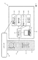
医用撮像手順中に患者が横たわるデバイス10は、本体12を含む。本体の上面14に配置された圧力センサ16のマトリクスは、上面全体の圧力を連続的に測定する。少なくとも1つの電子プロセッサ22が、圧力センサを読み取るために動作可能に接続される。非一時的記憶媒体が、圧力センサのマトリクスを使用して、垂下推定演算200、動き推定演算300及び呼吸モニタリング演算400のうちの少なくとも1つを行うために、少なくとも1つの電子プロセッサによって読み取り可能及び実行可能な命令を記憶する。The device 10 on which a patient lies during a medical imaging procedure includes a body 12. A matrix of pressure sensors 16 arranged on the upper surface 14 of the body continuously measures the pressure across the upper surface. At least one electronic processor 22 is operably connected to read the pressure sensor. A non-transitory storage medium is readable by at least one electronic processor for performing at least one of droop estimation operation 200, motion estimation operation 300, and respiratory monitoring operation 400 using the matrix of pressure sensors and Store executable instructions.
Description
以下は、概して、医用撮像技術、画像位置決め技術、画像動き補正技術及び関連技術に関する。 The following generally relates to medical imaging techniques, image registration techniques, image motion compensation techniques and related techniques.
リアルタイムの動き検出及び正確な患者の位置決め追跡は、医用撮像における重要な関心事であり、精密医療のための鍵の1つである。リアルタイムビデオ追跡デバイスを使用することにより、ある程度の進歩があった。しかし、これらのデバイス及び技術は、高価な高解像度の深度感知光学系及び電子機器、正確な照準並びに取得ビデオの複雑かつ計算量の多い処理を必要とする。 Real-time motion detection and accurate patient positioning tracking are important concerns in medical imaging and one of the keys to precision medicine. Some progress has been made by using real-time video tracking devices. However, these devices and techniques require expensive high-resolution depth-sensing optics and electronics, precise aiming, and complex and computationally intensive processing of the acquired video.
更に、呼吸パターンの追跡により、患者スキャン(例えばコンピュータ断層撮影(CT)及びポジトロン放出断層撮影(PET)スキャン)中での呼吸運動又は呼吸ゲーティングの補正が可能になる。単純だが信頼性の高い呼吸運動の検出及び追跡は、データ取得及び処理に追跡情報を使用することにより、画質及び定量化を大幅に向上させることができる。従来の手法では、心拍及び呼吸運動の検出等にECG誘導を使用して、様々な光学デバイス又はベローズの圧力センサを使用する。 Moreover, tracking of respiratory patterns allows for correction of respiratory motion or respiratory gating during patient scans (eg, Computed Tomography (CT) and Positron Emission Tomography (PET) scans). Simple but reliable respiratory motion detection and tracking can greatly improve image quality and quantification by using tracking information for data acquisition and processing. Conventional approaches use ECG guidance, such as for detecting heartbeat and respiratory movements, and use pressure sensors on various optical devices or bellows.
以下に、これらの問題を解決するための新規かつ改良されたシステム及び方法を開示する。 The following discloses a new and improved system and method for solving these problems.
開示される一態様では、医用撮像手順中に患者が横たわるデバイスが、本体を含む。圧力センサのマトリクスが、本体の上面に配置され、上面全体の圧力を測定する。少なくとも1つの電子プロセッサが、圧力センサを読み取るように動作可能に接続される。非一時的記憶媒体が、圧力センサのマトリクスを使用して、垂下推定演算、動き推定演算及び呼吸モニタリング演算のうちの少なくとも1つを行うために、少なくとも1つの電子プロセッサによって読み取り可能及び実行可能である命令を記憶する。 In one aspect disclosed, a device on which a patient lies during a medical imaging procedure includes a body. A matrix of pressure sensors is located on the top surface of the body and measures the pressure across the top surface. At least one electronic processor is operably connected to read the pressure sensor. A non-transitory storage medium is readable and executable by at least one electronic processor to perform at least one of droop estimation, motion estimation and respiratory monitoring operations using the matrix of pressure sensors. Remember a command.
別の開示される態様では、医用撮像手順中に患者が横たわるデバイスが、撮像デバイスを含む。本体が、撮像のために患者を撮像デバイス内に入れるように構成される。患者支持体の上面に配置される圧力センサのマトリクスが、上面全体の圧力を測定する。少なくとも1つの電子プロセッサが、圧力センサを読み取るために動作可能に接続される。非一時的記憶媒体が、圧力センサのマトリクスを使用して、垂下推定演算、動き推定演算及び呼吸モニタリング演算のうちの少なくとも1つを行うために、少なくとも1つの電子プロセッサにより読み取り可能及び実行可能である命令を記憶する。 In another disclosed aspect, the device on which the patient lies during the medical imaging procedure comprises an imaging device. The body is configured to enter a patient within an imaging device for imaging. A matrix of pressure sensors located on the upper surface of the patient support measures the pressure across the upper surface. At least one electronic processor is operably connected to read the pressure sensor. A non-transitory storage medium is readable and executable by at least one electronic processor to perform at least one of a droop estimation operation, a motion estimation operation and a respiratory monitoring operation using the matrix of pressure sensors. Remember a command.
別の開示される態様では、画像取得手順中に患者をモニタリングする方法が、圧力データを取得するために、本体の上面上の患者の身体の一部に接触する圧力センサを読み取るステップと、取得した圧力データに基づいて、本体の垂下を推定するステップとを含む。 In another disclosed aspect, a method of monitoring a patient during an image acquisition procedure includes reading a pressure sensor that contacts a portion of a patient's body on a top surface of a body to acquire pressure data. Estimating the droop of the body based on the pressure data.
1つの利点は、撮像されている患者の位置及び動きを正確に推定するシステムが提供される点にある。 One advantage resides in providing a system that accurately estimates the position and movement of the patient being imaged.
別の利点は、撮像されている患者の検出された動きに応じて状況依存の是正措置が提供される点にある。 Another advantage resides in providing context sensitive corrective action in response to detected movement of the patient being imaged.
別の利点は、患者に追加のデバイスを取り付ける必要なく呼吸情報を追跡できる点にあり、これは、伏臥位(即ち、うつ伏せ)又は仰臥位(即ち、仰向け)での患者の呼吸のモニタリングに適用することができる。 Another advantage resides in the ability to track respiratory information without the need to attach an additional device to the patient, which applies to monitoring patient breathing in the prone (ie prone) or supine (ie supine) position. can do.
別の利点は、テーブル垂下量をリアルタイムで正確に決定できる点にある。 Another advantage is that the amount of table droop can be accurately determined in real time.
所与の実施形態は、上記利点を幾つか提供し、及び/又は、本開示を読み、理解した当業者には明らかとなる他の利点を提供する。 A given embodiment provides some of the above advantages and/or other advantages that will be apparent to those of ordinary skill in the art upon reading and understanding the present disclosure.
本発明は、様々なコンポーネント及びコンポーネントの構成、また、様々なステップ及びステップの構成の形を取ってよい。図面は、好適な実施形態を例示することのみを目的とし、本発明を限定するものと解釈されるべきではない。 The invention may take form in various components and arrangements of components, and in various steps and arrangements of steps. The drawings are only for purposes of illustrating the preferred embodiments and are not to be construed as limiting the invention.
以下に、医用撮像分野における重要な問題に対処するために、患者テーブルに配置された圧力センサのアレイを利用する様々な実施形態を開示する。幾つかの例示的な実施形態では、圧力センサは、患者が動かした身体部分(例えば脚又は腕)を特定し、その動きの時間、また、幾つかの実施形態では、その動きの方向を検出するために使用される。この情報は、スキャンをやり直す必要があるか、データの特定部分に動き補正を適用する必要があるかについてのガイダンスを提供する。 In the following, various embodiments will be disclosed which utilize an array of pressure sensors arranged on a patient table to address an important issue in the field of medical imaging. In some exemplary embodiments, the pressure sensor identifies a body part (eg, leg or arm) moved by the patient and detects the time of its movement and, in some embodiments, the direction of its movement. Used to do. This information provides guidance as to whether the scan needs to be redone or if motion compensation needs to be applied to specific parts of the data.
呼吸情報もまた、患者に任意の追加のデバイスを装着する必要なく、圧力測定値に基づいて追跡することができる。幾つかの実施形態では、圧力の大きさ対時間の信号が測定され、そこから呼吸周期を推定することができる。有利なことに、この手法は、吸気中に胸部がテーブルから離れて上がる仰臥位患者の場合でも機能する。本明細書において認識されるように、呼吸周期中の胸部容積の拡大は、圧力センサによってその大きさを測定することができる患者テーブルへの下向きの力を加える体重再配分をもたらす。この圧力の大きさは、胸部の拡大及び収縮の程度並びに方向によって変化すると予想されるため、圧力の大きさ対時間の信号は、呼吸周期と相関して変化すると予想される。同様に、圧力の大きさ対時間の信号(の高周波成分)を介して心周期をモニタリングすることも考えられる。 Respiratory information can also be tracked based on pressure measurements without the need to equip the patient with any additional devices. In some embodiments, a pressure magnitude versus time signal can be measured from which the respiratory cycle can be estimated. Advantageously, this approach works even for supine patients whose chest rises off the table during inspiration. As will be appreciated herein, the expansion of the chest volume during the respiratory cycle results in weight redistribution that applies a downward force to the patient table whose size can be measured by the pressure sensor. The magnitude of this pressure is expected to vary with the extent and direction of chest expansion and contraction, so the pressure magnitude versus time signal is expected to vary in correlation with the respiratory cycle. Similarly, it is also conceivable to monitor the cardiac cycle via (a high frequency component of) a signal of pressure magnitude versus time.
幾つかの実施形態では、圧力センサ測定値を使用して、テーブル垂下がより正確に評価される。垂下は、患者支持体(テーブル、パレット又は患者を支える他の本体)が片持ち位置にあるときに生じる。例えばハイブリッドPET/CT又はSPECT/CT撮像システムでは、患者支持体は、一般に、CTガントリ内に移動する、また、(移動が続行する場合は)PET又はSPECTガントリ内に移動する、テーブルトップ(又はパレット若しくは本体ともいう)を有するカウチ等を含む。このようなデザインでは、テーブルトップ又はパレットは、CTガントリ又はPET/SPECTガントリ内に突き出る端部が支持されずに片持ち状態にされる。この支持されない端部が、患者の体重によって垂れ下がる垂下の可能性がある。垂下は、テーブルトップ又はパレットの剛性に依存し、また、従来では、テーブルトップ又はパレットによって支えられる患者の体重に更に依存すると認識されている。しかし、本明細書において認識されるように、垂下は、より具体的には、テーブルトップ又はパレットによって支えられる重量分布に依存する。したがって、本明細書に開示される垂下推定の実施形態では、圧力センサのアレイにより、患者テーブル全体の重量分布の決定が可能になり、この重量分布から、垂下をより正確に推定することができる。1つのアプローチでは、患者の体重だけに基づく推定と比較して、患者の重心(COM)及び総重量を使用してテーブル垂下がより正確に推定される。別の手法では、例えば積分又は合計によって重量分布の部分の垂下寄与の複合効果が計算されてテーブル垂下が推定される。患者の体重ではなく重量分布を使用すると、より正確に位置依存のテーブル垂下を推定することができる。テーブル垂下はまたリアルタイムで測定される。これは、患者テーブルは、通常、スキャンのために患者テーブルがガントリの奥へと更に延ばされる(例えば片持ち状態のテーブルの長さがより長くなる)につれて、増分だけ患者の体重によって曲がるので有利である。テーブル垂下をリアルタイムで正確に測定することにより、適切なPET/CT画像の再位置合わせに必要な補正係数を導き出すことができる。 In some embodiments, pressure sensor measurements are used to more accurately assess table sag. Sagging occurs when the patient support (table, pallet or other body supporting the patient) is in a cantilevered position. In a hybrid PET/CT or SPECT/CT imaging system, for example, the patient support typically moves into a CT gantry and (if movement continues) into a PET or SPECT gantry tabletop (or It also includes a couch having a pallet or a main body). In such a design, the tabletop or pallet is cantilevered with its unsupported end protruding into the CT or PET/SPECT gantry. This unsupported end can sag depending on the weight of the patient. It has been recognized that droop depends on the rigidity of the table top or pallet and is also traditionally further dependent on the weight of the patient supported by the table top or pallet. However, as will be appreciated herein, droop depends more specifically on the weight distribution carried by the tabletop or pallet. Thus, in the embodiment of droop estimation disclosed herein, an array of pressure sensors allows for the determination of the weight distribution across the patient table, from which the droop can be more accurately estimated. .. In one approach, table droop is more accurately estimated using the patient's center of gravity (COM) and total weight as compared to an estimate based on patient weight alone. In another approach, the table droop is estimated by calculating the combined effect of the droop contributions of parts of the weight distribution, for example by integration or summation. The use of weight distribution rather than patient weight allows a more accurate estimation of position dependent table droop. Table droop is also measured in real time. This is advantageous because the patient table typically bends by the patient's weight in increments as the patient table is further extended further into the gantry for scanning (eg, the cantilevered table is longer). Is. By accurately measuring the table droop in real time, the correction factors necessary for proper PET/CT image realignment can be derived.
これらの手法は、患者テーブルの上部に配置された圧力接触感知層を利用する。感圧層は、個々の感圧セル又は要素のグリッドで構成することができる。圧力センサのアレイは、患者と確実に接触すると予想される患者テーブルの上部の表面積の少なくとも一部を範囲とする。圧力センサを読み取り、センサからの情報を解釈し、リアルタイムの患者体重分布及び他の情報(例えばセンサアレイに触れている患者の部分の患者輪郭)を計算し、それらを画像再構成チェーンに更に渡すために電子プロセッサが動作可能に接続されている。圧力センサのアレイは、患者テーブルの上部と一体に形成されても(例えば患者テーブルの上面に埋め込まれても)、又は、圧力センサは、同じ目的のために患者テーブル表面に後に配置されるテーブルカバー又は適合されたシートに別箇に取付けられてもよい。これは、既に発売されているカウチモデルを全く再設計/交換する必要なく、既存の患者テーブルにレトロフィットさせることを可能とするのに有利である。 These approaches utilize a pressure contact sensitive layer located on top of the patient table. The pressure sensitive layer may consist of individual pressure sensitive cells or grids of elements. The array of pressure sensors covers at least a portion of the surface area of the upper portion of the patient table that is expected to make positive contact with the patient. It reads the pressure sensor, interprets information from the sensor, calculates real-time patient weight distribution and other information (eg, patient contour of the portion of the patient touching the sensor array) and passes them further to the image reconstruction chain. An electronic processor is operably connected thereto. The array of pressure sensors may be integrally formed with the top of the patient table (eg embedded in the top surface of the patient table) or the pressure sensors may be placed later on the patient table surface for the same purpose. It may be attached separately to the cover or a fitted sheet. This is advantageous as it allows retrofitting to existing patient tables without the need to redesign/replace existing couch models.
動き評価に関しては、圧力センサを使用して、動きが発生する時、体のどの部分が動かされたのか(患者のフットプリント及び予想される解剖学的構造に基づく)並びに動きの方向及び大きさを検出することができる。例えばセンサは、患者が左脚を右に動かしたことを検出することができる。この情報は様々に使用することができる。PET/CTの場合、PET及びCTの両方で既に撮像されている身体部分の動きは問題にはならない。動かされた身体部分がまだ撮像されていない場合、様々な是正措置を講じることができる。動かされた身体部分の撮像中に動きが生じた場合、動きの前後に取得された撮像データセットがそれぞれ個別に再構築され、任意選択的に後に空間位置合わせによってマージされる。当該身体部分の撮像の早い段階で動きが生じた場合、早期のデータは破棄され、任意選択的に破棄された早期部分を補償するために撮像時間を延長することができる。動かされた身体部分のPET撮像が開始する前であるが、当該動かされた身体部分のCT撮像の後に動きが生じる場合、患者に当該身体部分を元の位置に戻すように求めることが考えられる。この「補正」を行う際、圧力センサを使用して、当該身体部分が元の位置に戻されたことを検出することができる。 For motion estimation, a pressure sensor is used to determine which part of the body was moved when the motion occurred (based on the patient's footprint and expected anatomy) and the direction and magnitude of the motion. Can be detected. For example, the sensor can detect that the patient has moved his left leg to the right. This information can be used in various ways. In the case of PET/CT, movement of body parts already imaged in both PET and CT is not a problem. If the moved body part has not yet been imaged, various corrective actions can be taken. If motion occurs during the imaging of the moved body part, the imaging datasets acquired before and after the motion are individually reconstructed and optionally later merged by spatial registration. If motion occurs early in the imaging of the body part, the early data is discarded and the imaging time can be optionally extended to compensate for the discarded early part. If the PET imaging of the moved body part is not started but the movement occurs after the CT imaging of the moved body part, it is conceivable to ask the patient to return the body part to its original position. .. In making this "correction", a pressure sensor can be used to detect that the body part has been returned to its original position.
圧力センサを使用する呼吸モニタリングは、患者が仰向けに横たわっている(仰臥位)場合でも、呼吸はテーブルにかかる圧力の大きさを変えるという洞察に基づいている。したがって、仰臥位患者の背中に接触する圧力センサによって取得された圧力の大きさ対時間の曲線から呼吸周期を抽出することができる。この技術による心周期モニタリングも想定される。 Respiratory monitoring using pressure sensors is based on the insight that breathing alters the amount of pressure exerted on the table, even when the patient is lying on his or her back (supine). Therefore, the respiratory cycle can be extracted from the curve of pressure magnitude versus time acquired by the pressure sensor in contact with the back of the supine patient. Cardiac cycle monitoring with this technique is also envisioned.
テーブル垂下補正では、圧力センサを使用してテーブル全体の重量分布を測定することにより、患者の総重量に基づく推定に比べてより正確に垂下を推定することができる。様々な手法を採用することができるが、1つの手法では、圧力センサ測定値から重心(COM)及び総重量が決定され、これは、経験的ルックアップテーブルにおいて使用されるか、又は、第一原理ビーム偏向方程式を適用してテーブル垂下が決定される。より正確な手法では、各圧力センサ(又は圧力センサの連続したグループ)によって測定された各重量成分に対して、ルックアップテーブル又はビーム偏向方程式が要素毎に適用され、合計垂下はこれらの「局所的な」垂下寄与の合計である。有利なことに、圧力センサはリアルタイムで重量分布をモニタリングするため、撮像セッション中の患者の動きや体位変更による垂下の変化が実現可能にされる。 Table droop correction allows a more accurate estimation of droop compared to an estimate based on total patient weight by using a pressure sensor to measure the weight distribution across the table. Although various approaches can be employed, one approach determines the center of gravity (COM) and gross weight from the pressure sensor measurements, which is used in an empirical look-up table or The principle beam deflection equation is applied to determine the table droop. In a more accurate approach, for each weight component measured by each pressure sensor (or a contiguous group of pressure sensors), a look-up table or beam deflection equation is applied element by element, and the total droop is these "local" "Total" drooping contribution. Advantageously, the pressure sensor monitors the weight distribution in real time, allowing changes in droop due to patient movement and repositioning during the imaging session.
図1を参照すると、医用撮像手順中に患者が横たわる例示的なデバイス10が示される。図1に示すように、装置10は本体12を含む。一例では、本体12は、患者が横たわるテーブルを含むことができる。別の例では、本体12は、テーブルの上部のパッド付き部分を含むことができる(即ち、テーブルの脚がない)。他の例では、本体12は、患者が横たわるベンチ又はカウチを含むことができる。本体12は、撮像手順のために患者が横たわる上面14を含む。
Referring to FIG. 1, an
圧力センサ16のマトリクスが、本体12の上面14に配置される。図1に示すように、圧力センサ16は、上面14の長さ及び幅全体に分布している。しかし、圧力センサは上面の一部にのみ配置されてもよい。圧力センサ16は、上面14全体の圧力を連続的に測定する。例えば圧力センサ16は、患者が上面14に横たわっているときの圧力値を測定することができる。圧力センサ16は、センサの上にある患者の様々な身体部分の位置で圧力を測定する。圧力センサ16は、実質的に任意のタイプの圧力検知技術を採用することができ、例えばピエゾ抵抗ひずみセンサ、圧力がコンデンサの誘電体厚を圧縮的に減少させる容量性圧力センサ、ダイアフラム又は他の可動要素の圧力誘起変位が誘導変化等として検出される電磁センサ、圧電センサ等であってよい。
A matrix of pressure sensors 16 is arranged on the
幾つかの例では、デバイス10はまた、患者が本体12の上面14に横たわっているときに患者の画像を取得するハイブリッドポジトロン放出断層撮影(PET)/コンピュータ断層撮影(CT)スキャナといった撮像デバイス18を含むか、それと共に動作することができる。しかし、当然ながら、撮像デバイス18は、より一般的には、任意の適切な撮像モダリティスキャナ(例えば磁気共鳴、単光子放出コンピュータ断層撮影用のガンマカメラ、X線等)であってよい。電子プロセッサ22を含むコンピュータ20又は他の電子デバイスが、圧力センサ16と電気的に通信している。コンピュータ20は、上記少なくとも1つの電子プロセッサ22を含み、当該電子プロセッサ22は、圧力センサ16を読み取るための圧力センサ読み取りユニット23を含むか又は圧力センサ読み取りユニット23に動作可能に接続される。少なくとも1つの電子プロセッサ22は、電子プロセッサ22によって読み取り可能及び実行可能である命令を格納する非一時的記憶媒体に動作可能に接続されて、撮像デバイス18を制御して撮像データ取得プロセス100を行うことを含む開示される演算を行う。更に、非一時的記憶媒体は、圧力センサ16から圧力値を受信すると、例えば(1)垂下推定演算200、(2)動き推定演算300、及び、(3)呼吸モニタリング演算(及び任意選択的に呼吸ゲーティング演算)400のうちの少なくとも1つを含む1つ以上の演算を行うように電子プロセッサ22によって読み取り可能及び実行可能である命令を記憶してよい。各演算については、以下により詳細に説明する。非一時的記憶媒体は、例えばハードディスクドライブ、RAID若しくは他の磁気記憶媒体、ソリッドステートドライブ、フラッシュドライブ、電子的に消去可能な読み取り専用メモリ(EEROM)若しくはその他の電子メモリ、光ディスク若しくはその他の光学記憶装置又はこれらの様々な組み合わせ等を含んでよい。
In some examples, the
図2を参照すると、垂下推定演算200がフローチャートとして図示されている。ステップ202において、圧力センサ16の測定値に基づいて本体12の上面14全体の重量分布が決定される。ステップ204において、重量分布に基づいて本体12の垂下値が決定される。これを行うために、一例では、ステップ206において、重量分布の重心及び総重量が決定される。ステップ208において、重心値及び総重量値をルックアップテーブル又は数学的変換(例えばコンピュータ20によって読み取られる非一時的記憶媒体に記憶される)に入力することにより、垂下値が決定される。別の例では、ステップ210において、垂下値は、重量分布全体の患者の体重部分の垂下寄与を積分又は合計することにより決定される。垂下値が推定されると、当該垂下値を使用して、撮像手順中に本体12の上面14上の患者の位置の撮像データを補正することができる。考えられる別の実施形態では、このような垂下補正は行われないが、代わりに、垂下が選択された警告閾値を超えると、例えばコンピュータ20のディスプレイに過度垂下の警告が出力される。
Referring to FIG. 2, droop
図3を参照すると、動き推定演算300がフローチャートとして図示されている。この動き推定300は、例えば撮像データ取得プロセス100の実行中に、患者の随意的な動きを検出し、必要に応じてそのような動きを任意選択的に修正するために有用に行うことができる。ステップ302において、撮像手順中に上面14上で動かされる患者の身体の一部が特定され、患者の身体の当該一部が動かされた時間が決定される。任意選択のステップ304において、患者が動かした身体の当該一部の方向及び大きさが決定される。ステップ306において、電子プロセッサ22の制御下でスキャナ18によって行われる撮像データ取得プロセス100による患者の画像取得が中断又は停止され、患者が動かした身体の一部をその元の位置に戻すように再配置する要求が、例えばコンピュータ20のディスプレイに表示することにより出される。ステップ308において、プロセッサ22は、圧力センサ16を連続的に(又は高速間隔で)読み取り、患者が動かした身体の一部がその元の位置に再配置されたことを検出するようにプログラムされる。これを行うために、動き検出イベント302の前に記録された圧力分布が、現在読み取られた圧力分布と比較され、これらが選択された許容範囲内で一致すると、患者は身体の一部をその元の位置に戻したとみなされる。幾つかの実施形態では、更なるプロンプトが出されてもよい。例えば身体の一部はその元の位置の近くまで動かされたが、元の位置からまだ(例えば)5センチメートル右にずれていることが検出された場合、患者に身体の一部(例えば脚又は腕)を更に5センチメートル左に動かすように要求する更なるプロントが出されてもよい。ステップ310において、プロセッサ22が、患者の身体の一部が再配置されたことを検出すると、スキャナ18による画像データ取得が再開される。
Referring to FIG. 3,
変形実施形態では、修正は、撮像データ取得プロセス100のコンテキストにおいて、動かされた身体の一部の影響を考慮することにより行われる。この実施形態では、ステップ302において決定された動きがあった時間が、撮像データ取得プロセス100の進行状態と比較される。全身スキャンといった取得の場合、撮像は、連続的に又は特定のステップ数で、頭部から足まで連続して進むのが一般的である。この場合、動かされた身体の一部が既に撮像されているならば、当該動きは重要ではなく、何も行われない。一方、動かされた身体の一部がまだスキャンされていない又は追加でスキャンする必要があるならば、何らかの修正措置が必要である。これには、図3の上記プロセスが含まれる。これにより、患者は身体の一部をその元の位置に戻すように指示される。別の修正手法では、(例えばステップ302において検出された動きの前後に取得された重量分布を比較することにより)ステップ304において身体の一部が動かされた方向及び距離が決定されたならば、ステップ302において検出された動きの前後に取得された撮像データが別々に再構成され、2つの結果として得られる画像を、ステップ304からの動きの方向及び距離情報を、空間位置合わせ調整の初期値として使用して空間的に位置合わせすることができる。
In a variant embodiment, the correction is made in the context of the imaging
考えられる別の修正手法では、ステップ302における動きの検出が、データ取得の早い段階で生じる場合、当該動きの前に取得された撮像データは破棄されてもよい。任意選択的に、データ取得プロセス100はまた、破棄された撮像データの損失を補償するために時間を延長することもできる。更に考えられる修正手法では、ステップ302において、動きが検出されると、データ取得プロセス100が完全に中断されて繰り返されてもよい。その際、任意選択的に、撮像データ取得プロセス100中に、患者に静止したままでいるように警告するメッセージが出される。
In another possible modification approach, if the detection of motion in
非一時的記憶媒体に記憶される命令には、これらのオプションのうちの選択された何れかを実行するための命令が含まれることが考えられ、決定は、進行中の撮像データ取得プロセス100のコンテキストにおいて、ステップ302において検出された動きがあった時間に基づいて行われてよい。例えばデータ取得プロセス100のある閾値時間までに動きが検出された場合、早い段階のデータを破棄する手法が採用されてもよい。一方で、データ取得プロセス100の当該閾値時間を過ぎて動きが検出された場合、図3のフローチャートに示す通りに、取得プロセス100全体を中断して繰り返すか又は患者に動かした身体の一部を再配置するように誘導するといった別の修正手法が行われてよい。
The instructions stored on the non-transitory storage medium may include instructions for performing any of these selected options, and the decision may be made by the ongoing imaging
どの修正措置を行うかの選択もまた、任意選択的に、動かされた身体の一部の重要性に依存してよい。例えば胴体スキャン中の足の動きはほとんど関係がない(したがって、修正は行われない)。一方で、このような胴体スキャン中の下腕の動きは、小さい影響を与える可能性があるが、図3の手法に従って下腕の再配置を誘導することで補正することができる。一方で、肩の動きは、胴体スキャンに大きな影響を与える可能性が高く、胴体スキャンを中止して繰り返すという最も侵襲的な修正が必要になる。 The choice of which corrective action to take may also optionally depend on the importance of the part of the body that was moved. For example, foot movement during a torso scan is largely irrelevant (and therefore not corrected). On the other hand, the movement of the lower arm during such a torso scan may have a small influence, but it can be corrected by inducing the rearrangement of the lower arm according to the method of FIG. On the other hand, shoulder movements are likely to have a significant impact on the torso scan, requiring the most invasive modification of stopping and repeating the torso scan.
図4を参照すると、呼吸モニタリング演算400がフローチャートとして図示されている。このプロセス400も、撮像データ取得プロセス100と同時に行われることが好適である。ステップ402において、本体12の上面14上の患者の身体の一部に接触する圧力センサ16が読み取られて、圧力の大きさ対時間の信号が取得される。ステップ404において、圧力の大きさ対時間の信号から呼吸周期信号が抽出される。これには、例えば圧力の大きさ対時間の信号をフィルタリングして、呼吸周波数における成分を抽出することが必要である。ステップ406において、例えば心拍周波数における信号成分を抽出するためにフィルタリングすることによって、圧力の大きさ対時間の信号から心周期信号が任意選択的に抽出される。好適には、呼吸信号対時間が記録され、同時に行われる撮像データ取得プロセス100によって取得される撮像データの呼吸ゲーティングを行うために使用されてよい。このようなゲーティングは、例えば撮像データ(例えばエミッション撮像における個々のカウント)が取得されるにつれて撮像データにタイムスタンプを付け、呼吸信号によって示される呼吸相に基づいて、撮像データを呼吸相ビンにビニングすることによってレトロスペクティブに行われよい。或いは、プロスペクティブ呼吸ゲーティングプロセスでは、患者の呼吸周期が選択された呼吸相にある場合にのみ撮像データを取得するように、撮像データ取得プロセス100がプロスペクティブに制御される。
Referring to FIG. 4, a
図4の呼吸モニタリングプロセス400の有効性は、圧力の大きさが呼吸をどれだけよく反映しているかに依存する。この相関は、患者の胴体に接触する圧力センサについて最も強いと予想される。したがって、幾つかの実施形態では、圧力読み取りステップ402において、胴体付近の圧力センサ16しか読み取らない。加えて、ステップ404において、選択プロセスを行って、圧力の大きさ信号が呼吸と最も強く相関する圧力センサ16から呼吸信号を抽出する(又は、圧力の大きさ信号が呼吸と最も強く相関する圧力センサの小さいグループから呼吸信号を抽出する)ことが考えられる。これは、例えば圧力の大きさ対時間の信号を、例えばフーリエ変換を使用して周波数領域に変換し、信頼できる呼吸数に対応する周波数帯域(例えば安静時の成人は、通常、毎分約12〜20回呼吸をするため、信頼できる呼吸数の周波数帯域は毎分8〜24サイクルの範囲内)の信号強度で圧力センサ16をランク付けすることによって行われてよい。
The effectiveness of the
同様の処理をステップ406について行い、心周期信号の検出を向上させることができる。ここでも胴体に近い圧力センサが、最も強い心周期信号を提供することが予想され、この場合のセンサのランク付けは、例えば通常の成人の信頼できる心拍数範囲に対応する毎分40〜150サイクルほどの信頼できる心拍数帯域における信号強度による。
Similar processing can be performed for
本開示は、好適な実施形態を参照して説明された。前述の詳細な説明を読んで理解すると、改良態様及び変形態様が想到できるであろう。本発明は、添付の特許請求の範囲又はその均等物の範囲内にある限り、このようなすべての改良態様及び変形態様を含むと解釈されることが意図している。
The present disclosure has been described with reference to the preferred embodiments. Upon reading and understanding the above detailed description, modifications and variations will be conceivable. It is intended that the invention be construed to include all such improvements and modifications as long as they come within the scope of the appended claims or the equivalents thereof.
Claims (23)
前記本体の上面に配置され、前記上面全体の圧力を測定する圧力センサのマトリクスと、
前記圧力センサを読み取るように動作可能に接続される少なくとも1つの電子プロセッサと、
前記圧力センサのマトリクスを使用して、垂下推定演算、動き推定演算及び呼吸モニタリング演算のうちの少なくとも1つを行うために、前記少なくとも1つの電子プロセッサによって読み取り可能及び実行可能である命令を記憶する非一時的記憶媒体と、
を含む、医用撮像手順中に患者が横たわるためのデバイス。 Body,
A matrix of pressure sensors arranged on the top surface of the body for measuring the pressure across the top surface;
At least one electronic processor operably connected to read the pressure sensor;
The matrix of pressure sensors is used to store instructions readable and executable by the at least one electronic processor to perform at least one of a droop estimation operation, a motion estimation operation, and a respiratory monitoring operation. A non-transitory storage medium,
A device for the patient to lie down during a medical imaging procedure.
前記圧力センサの測定値に基づいて前記本体の前記上面全体の重量分布を決定することと、
前記重量分布に基づいて前記本体の垂下を定量化する垂下値を決定することと、
を含む前記垂下推定演算を行うために、前記少なくとも1つの電子プロセッサによって読み取り可能及び実行可能である命令を記憶する、請求項1に記載のデバイス。 The non-transitory storage medium is
Determining a weight distribution over the top surface of the body based on the pressure sensor measurements;
Determining a droop value quantifying droop of the body based on the weight distribution;
2. The device of claim 1, storing instructions readable and executable by the at least one electronic processor to perform the droop estimation operation including.
前記本体の前記上面全体の前記重量分布の重心及び総重量を決定することと、
前記重心及び前記総重量をルックアップテーブル又は数学的変換に入力することにより、前記垂下値を決定することと、
を含む、請求項2に記載のデバイス。 The drooping estimation operation further includes
Determining the center of gravity and the total weight of the weight distribution over the top surface of the body;
Determining the droop value by inputting the center of gravity and the total weight into a look-up table or mathematical transformation;
The device of claim 2, comprising:
前記重量分布全体の前記重量分布の部分の垂下寄与を積分又は合計することにより、前記垂下値を決定することを含む、請求項2に記載のデバイス。 The drooping estimation operation further includes
The device of claim 2, comprising determining the droop value by integrating or summing the droop contributions of portions of the weight distribution of the overall weight distribution.
前記圧力センサのマトリクスを使用して、元の位置から動かされた前記患者の身体の一部と、前記元の位置から前記患者の身体の前記一部が動かされた時間とを決定することを含む動き推定演算を行うために、前記少なくとも1つの電子プロセッサによって読み取り可能及び実行可能である命令を記憶する、請求項1乃至4の何れか一項に記載のデバイス。 The non-transitory storage medium is
Using the matrix of pressure sensors to determine a portion of the patient's body that was moved from its original position and the time that the portion of the patient's body was moved from the original position. 5. A device according to any one of claims 1 to 4, storing instructions readable and executable by the at least one electronic processor to perform a motion estimation operation comprising.
撮像データ取得を中断し、動かされた前記患者の身体の前記一部を前記元の位置に戻すように再配置する要求を生成することと、
前記圧力センサのマトリクスを使用して、動かされた前記患者の身体の前記一部が前記元の位置に再配置されたことを検出することと、
前記検出後に前記撮像データ取得を再開することと、
を含む、請求項5又は6に記載のデバイス。 The motion estimation calculation further includes
Generating a request to interrupt imaging data acquisition and reposition the moved portion of the patient's body back to the original position;
Using the matrix of pressure sensors to detect that the portion of the moved patient's body has been repositioned to the original position;
Restarting the imaging data acquisition after the detection,
7. A device according to claim 5 or 6, comprising:
前記患者に対し、動かされた身体の前記一部を前記元の位置に戻す指示を生成することと、
前記動きが検出される前と後とに取得された画像を個別に再構成することと、
前記動きの前記検出前に取得した画像を破棄することと、
前記画像の取得を再開する指示を生成することと、
から選択される少なくとも1つの修正演算を行うように更にプログラミングされる、請求項7に記載のデバイス。 When movement of a portion of the patient's body is detected, the at least one electronic processor
Generating instructions for the patient to return the part of the moved body to the original position;
Individually reconstructing the images acquired before and after the motion is detected;
Discarding the image acquired before the detection of the movement;
Generating an instruction to resume the acquisition of the image;
8. The device of claim 7, further programmed to perform at least one modification operation selected from
圧力の大きさ対時間の信号を得るために、前記主体の前記上面上の前記患者の身体の一部に接触する前記圧力センサを読み取ることと、
前記圧力の大きさ対時間の信号から呼吸周期信号を抽出することと、
を含む呼吸モニタリング演算を行うために、前記少なくとも1つの電子プロセッサによって読み取り可能及び実行可能である命令を記憶する、請求項1乃至8の何れか一項に記載のデバイス。 The non-transitory storage medium is
Reading the pressure sensor in contact with a portion of the patient's body on the upper surface of the subject to obtain a pressure magnitude versus time signal;
Extracting a respiratory cycle signal from the pressure magnitude versus time signal;
9. The device of any one of claims 1-8, storing instructions readable and executable by the at least one electronic processor to perform a respiratory monitoring operation including.
前記圧力の大きさ対時間の信号から心周期信号を抽出することを含む心臓モニタリング演算を行うために、前記少なくとも1つの電子プロセッサによって読み取り可能及び実行可能である命令を記憶する、請求項9に記載のデバイス。 The non-transitory storage medium further comprises
10. The instructions readable and executable by the at least one electronic processor are stored to perform a cardiac monitoring operation that includes extracting a cardiac cycle signal from the pressure magnitude versus time signal. The listed device.
前記撮像スキャナは、磁気共鳴スキャナ、単光子放出コンピュータ断層撮影用のガンマカメラ、X線スキャナ、コンピュータ断層撮影スキャナ、ポジトロン放出断層撮影スキャナ及びハイブリッドポジトロン放出断層撮影/コンピュータ断層撮影スキャナから選択される、請求項1乃至10の何れか一項に記載のデバイス。 Further comprising an imaging scanner for acquiring an image of the patient when the patient is lying on the top surface of the body,
The imaging scanner is selected from a magnetic resonance scanner, a gamma camera for single photon emission computed tomography, an X-ray scanner, a computer tomography scanner, a positron emission tomography scanner and a hybrid positron emission tomography/computed tomography scanner, The device according to any one of claims 1 to 10.
撮像のために前記撮像デバイス内に患者を入れるように構成される本体と、
患者支持体の上面に配置され、前記上面全体の圧力を測定する圧力センサのマトリクスと、
前記圧力センサを読み取るために動作可能に接続される少なくとも1つの電子プロセッサと、
前記圧力センサのマトリクスを使用して、垂下推定演算、動き推定演算及び呼吸モニタリング演算のうちの少なくとも1つを行うために、前記少なくとも1つの電子プロセッサにより読み取り可能及び実行可能である命令を記憶する非一時的記憶媒体と、
を含む、医用撮像手順中に患者が横たわるためのデバイス。 An imaging device,
A body configured to enter a patient within the imaging device for imaging;
A matrix of pressure sensors arranged on the upper surface of the patient support for measuring the pressure across said upper surface;
At least one electronic processor operably connected to read the pressure sensor;
The matrix of pressure sensors is used to store instructions readable and executable by the at least one electronic processor to perform at least one of a droop estimation operation, a motion estimation operation, and a respiratory monitoring operation. A non-transitory storage medium,
A device for the patient to lie down during a medical imaging procedure.
前記圧力センサの測定値に基づいて前記本体の前記上面全体の重量分布を決定することと、
前記重量分布の重心及び総重量を決定することと、
前記重心及び前記総重量をルックアップテーブル又は数学的変換に入力することにより、前記本体の垂下を定量化する垂下値を決定することと、
を含む、請求項12に記載のデバイス。 The droop estimation calculation is
Determining a weight distribution over the top surface of the body based on the pressure sensor measurements;
Determining the centroid and total weight of the weight distribution,
Determining a droop value quantifying droop of the body by inputting the center of gravity and the total weight into a look-up table or mathematical transformation;
13. The device of claim 12, comprising:
前記圧力センサの測定値に基づいて前記本体の前記上面全体の重量分布を決定することと、
前記重量分布全体の前記重量分布の部分の垂下寄与を積分又は合計することにより、前記垂下値を決定することと、
を含む、請求項12に記載のデバイス。 The droop estimation calculation is
Determining a weight distribution over the top surface of the body based on the pressure sensor measurements;
Determining the droop value by integrating or summing the droop contributions of portions of the weight distribution of the entire weight distribution;
13. The device of claim 12, comprising:
前記圧力センサのマトリクスを使用して、元の位置から動かされた前記患者の身体の一部と、前記元の位置から前記患者の身体の前記一部が動かされた時間とを決定することを含む、請求項12乃至14の何れか一項に記載のデバイス。 The motion estimation calculation is
Using the matrix of pressure sensors to determine a portion of the patient's body that was moved from its original position and the time that the portion of the patient's body was moved from the original position. 15. A device according to any one of claims 12 to 14 including.
前記動き推定演算は更に、
前記患者の身体の前記一部が前記元の位置から動かされたことの決定に応えて前記撮像データ取得プロセスを停止することと、
前記画像取得中に動かされた前記患者の身体の前記一部を前記元の位置に戻すように再配置する要求を生成することと、
前記圧力センサのマトリクスを使用して、動かされた前記患者の身体の前記一部が前記元の位置に再配置されたことを検出することと、
動かされた前記患者の身体の前記一部が前記元の位置に再配置されたことが検出された後に、前記撮像データ取得プロセスを再開することと、
を含む、請求項15に記載のデバイス。 The non-transitory storage medium further stores instructions readable and executable by the at least one electronic processor to control the imaging device to perform an imaging data acquisition process,
The motion estimation calculation further includes
Stopping the imaging data acquisition process in response to determining that the portion of the patient's body has been moved from the original position;
Generating a request to reposition the portion of the patient's body that was moved during the image acquisition back to the original position;
Using the matrix of pressure sensors to detect that the portion of the moved patient's body has been repositioned to the original position;
Restarting the imaging data acquisition process after it is detected that the portion of the moved patient's body has been repositioned to the original position;
16. The device of claim 15, comprising:
撮像データ取得プロセスを行うように前記撮像デバイスを制御し、
前記元の位置から動かされた前記患者の身体の前記一部と、前記患者の身体の前記一部が前記元の位置から動かされた時間とに基づいて、前記撮像データ取得プロセスが、前記患者の身体の前記一部が動かされたときに、動かされた前記患者の身体の前記一部の撮像データを既に取得しているかどうかを決定し、
前記撮像データ取得プロセスが、前記患者の身体の前記一部が動かされたときに、動かされた前記患者の身体の前記一部の撮像データをまだ取得していない場合にのみ、前記撮像データ取得プロセスを中断又は停止するように、前記少なくとも1つの電子プロセッサによって読み取り可能及び実行可能である命令を記憶する、請求項15に記載のデバイス。 The non-transitory storage medium further comprises
Controlling the imaging device to perform an imaging data acquisition process,
The imaging data acquisition process based on the portion of the patient's body moved from the original position and the time of the portion of the patient's body moved from the original position. Determining whether the imaging data of the part of the moved patient body has already been acquired when the part of the body has been moved,
Only if the imaging data acquisition process has not already acquired imaging data of the portion of the patient's body that was moved when the portion of the patient's body was moved. 16. The device of claim 15, storing instructions readable and executable by the at least one electronic processor to suspend or stop a process.
圧力の大きさ対時間の信号を得るために、前記本体の前記上面上の前記患者の身体の一部に接触する前記圧力センサを読み取ることと、
前記圧力の大きさ対時間の信号から、呼吸周期信号を抽出することと、
を含む、請求項12乃至17の何れか一項に記載のデバイス。 The respiratory monitoring calculation is
Reading the pressure sensor in contact with a portion of the patient's body on the upper surface of the body to obtain a pressure magnitude versus time signal;
Extracting a respiratory cycle signal from the pressure magnitude vs. time signal;
18. A device according to any one of claims 12 to 17, comprising:
圧力データを取得するために、本体の上面上の前記患者の身体の一部に接触する圧力センサを読み取るステップと、
取得した前記圧力データに基づいて、
前記本体の垂下を推定するステップと、
前記患者の身体の一部の動きを推定するステップと、
前記患者の呼吸をモニタリングするステップと、
のうちの少なくとも1つを行うステップと、
を含む、方法。 A method of monitoring a patient during an image acquisition procedure, comprising:
Reading a pressure sensor that contacts a portion of the patient's body on the top surface of the body to obtain pressure data;
Based on the acquired pressure data,
Estimating the droop of the body,
Estimating movement of a part of the patient's body;
Monitoring the patient's breathing;
Performing at least one of
Including the method.
前記圧力データから前記本体の前記上面全体の重量分布を決定するステップと、
前記重量分布の重心及び総重量を決定し、前記垂下を出力するルックアップテーブル又は数学的変換に前記重心及び前記総重量を入力することによって、前記重量分布に基づいて、前記本体の前記垂下を決定するステップと、
を含む、請求項19に記載の方法。 Estimating the droop of the body, and estimating the droop,
Determining a weight distribution over the top surface of the body from the pressure data;
By determining the center of gravity and the total weight of the weight distribution and inputting the center of gravity and the total weight into a look-up table or a mathematical transformation that outputs the droop, the droop of the body is determined based on the weight distribution. The steps to determine,
20. The method of claim 19, comprising:
前記重量分布全体の重量部分の垂下寄与を積分又は合計するステップを含む、請求項19に記載の方法。 Estimating the droop of the body, and estimating the droop,
20. The method of claim 19 including the step of integrating or summing the droop contributions of the weight portion of the overall weight distribution.
前記患者の身体の前記一部がその元の位置から動かされたことの決定に応えて、撮像データ取得プロセスを停止するステップと、
前記画像取得中に、動かされた前記患者の身体の前記一部を前記元の位置に戻すように再配置する要求を生成するステップと、
前記圧力センサを使用して、動かされた前記患者の身体の前記一部が前記元に位置に再配置されたことを検出するステップと、
動かされた前記患者の身体の前記一部が前記元の位置に再配置されたことを検出した後に、前記撮像データ取得プロセスを再開するステップと、
を含む、請求項19に記載の方法。 The movement of the part of the patient's body is estimated and the step of estimating the movement comprises:
Stopping the imaging data acquisition process in response to determining that the portion of the patient's body has been moved from its original position;
Generating a request to reposition the portion of the patient's body that was moved during the image acquisition to return to the original position;
Detecting using the pressure sensor that the part of the moved body of the patient has been repositioned to the original position;
Restarting the imaging data acquisition process after detecting that the portion of the moved patient's body has been repositioned to the original position;
20. The method of claim 19, comprising:
圧力の大きさ対時間の信号を得るために、前記本体の前記上面上の前記患者の身体の一部に接触する前記圧力センサを読み取るステップと、
前記圧力の大きさ対時間の信号から呼吸周期信号を抽出するステップと、
を含む、請求項19に記載の方法。
Monitoring the patient's breathing comprises:
Reading the pressure sensor in contact with a portion of the patient's body on the upper surface of the body to obtain a pressure magnitude versus time signal;
Extracting a respiratory cycle signal from the pressure magnitude versus time signal;
20. The method of claim 19, comprising:
Applications Claiming Priority (3)
| Application Number | Priority Date | Filing Date | Title |
|---|---|---|---|
| US201762488196P | 2017-04-21 | 2017-04-21 | |
| US62/488,196 | 2017-04-21 | ||
| PCT/EP2018/059813 WO2018192933A1 (en) | 2017-04-21 | 2018-04-18 | Pressure touch sensitive patient table for tomographic imaging |
Publications (2)
| Publication Number | Publication Date |
|---|---|
| JP2020517330A true JP2020517330A (en) | 2020-06-18 |
| JP2020517330A5 JP2020517330A5 (en) | 2021-05-27 |
Family
ID=62111022
Family Applications (1)
| Application Number | Title | Priority Date | Filing Date |
|---|---|---|---|
| JP2019556629A Pending JP2020517330A (en) | 2017-04-21 | 2018-04-18 | Pressure contact sensitive patient table for tomographic imaging |
Country Status (5)
| Country | Link |
|---|---|
| US (1) | US20210121139A1 (en) |
| EP (1) | EP3612099A1 (en) |
| JP (1) | JP2020517330A (en) |
| CN (1) | CN110545730A (en) |
| WO (1) | WO2018192933A1 (en) |
Families Citing this family (7)
| Publication number | Priority date | Publication date | Assignee | Title |
|---|---|---|---|---|
| JP7204351B2 (en) * | 2018-06-13 | 2023-01-16 | キヤノン株式会社 | DISPLAY CONTROL DEVICE, CONTROL METHOD FOR DISPLAY CONTROL DEVICE, AND PROGRAM |
| CN108742680B (en) * | 2018-06-29 | 2023-07-25 | 上海联影医疗科技股份有限公司 | Medical imaging device |
| DE102019219532A1 (en) * | 2019-12-13 | 2021-06-17 | Robert Bosch Gmbh | Control system for a medical device |
| AU2021244320A1 (en) * | 2020-03-25 | 2022-09-22 | Data Integrity Advisors, Llc | Method for positioning a patient within an X-ray apparatus |
| WO2022225452A1 (en) * | 2021-04-20 | 2022-10-27 | Nanyang Technological University | Table motion motor test system |
| CN113082555A (en) * | 2021-05-07 | 2021-07-09 | 北京肿瘤医院(北京大学肿瘤医院) | Human body chest and abdomen compression monitoring system, method and application thereof |
| WO2023154546A1 (en) * | 2022-02-14 | 2023-08-17 | The General Hospital Corporation | Weight bearing imaging calibration based on pressure sensing |
Citations (5)
| Publication number | Priority date | Publication date | Assignee | Title |
|---|---|---|---|---|
| JPH02302248A (en) * | 1989-05-16 | 1990-12-14 | Toshiba Corp | Image re-pickup device for ct device |
| US20090129556A1 (en) * | 2007-11-19 | 2009-05-21 | Pyronia Medical Technologies, Incorporated | Patient positioning system and methods for diagnostic radiology and radiotherapy |
| JP2010179094A (en) * | 2009-01-08 | 2010-08-19 | Fujifilm Corp | Radiation tomographic image generator |
| US20120310079A1 (en) * | 2011-06-01 | 2012-12-06 | Andre Henning | Medical apparatus installation, and method for controlling a medical apparatus |
| JP2014100553A (en) * | 2012-10-24 | 2014-06-05 | Toshiba Corp | Bed for medical image diagnostic apparatus, and medical image diagnostic apparatus |
Family Cites Families (7)
| Publication number | Priority date | Publication date | Assignee | Title |
|---|---|---|---|---|
| US6646556B1 (en) * | 2000-06-09 | 2003-11-11 | Bed-Check Corporation | Apparatus and method for reducing the risk of decubitus ulcers |
| US7020315B2 (en) * | 2001-01-10 | 2006-03-28 | Elgems Ltd. | Sag correction |
| FI116097B (en) * | 2002-08-21 | 2005-09-15 | Heikki Ruotoistenmaeki | Force or pressure sensor and method for its application |
| DE102005004142A1 (en) * | 2005-01-28 | 2006-08-10 | Siemens Ag | System or method for examining a patient by means of an imaging medical diagnostic device |
| US20110144455A1 (en) * | 2007-08-31 | 2011-06-16 | Bam Labs, Inc. | Systems and methods for monitoring a subject at rest |
| EP2399521B1 (en) * | 2010-06-22 | 2013-03-06 | General Electric Company | Patient table system for medical applications and associated medical imaging device |
| EP3541287A4 (en) * | 2016-11-15 | 2020-09-30 | RefleXion Medical, Inc. | Radiation therapy patient platform |
-
2018
- 2018-04-18 WO PCT/EP2018/059813 patent/WO2018192933A1/en active Application Filing
- 2018-04-18 EP EP18721965.4A patent/EP3612099A1/en not_active Withdrawn
- 2018-04-18 JP JP2019556629A patent/JP2020517330A/en active Pending
- 2018-04-18 US US16/605,881 patent/US20210121139A1/en not_active Abandoned
- 2018-04-18 CN CN201880026368.1A patent/CN110545730A/en active Pending
Patent Citations (5)
| Publication number | Priority date | Publication date | Assignee | Title |
|---|---|---|---|---|
| JPH02302248A (en) * | 1989-05-16 | 1990-12-14 | Toshiba Corp | Image re-pickup device for ct device |
| US20090129556A1 (en) * | 2007-11-19 | 2009-05-21 | Pyronia Medical Technologies, Incorporated | Patient positioning system and methods for diagnostic radiology and radiotherapy |
| JP2010179094A (en) * | 2009-01-08 | 2010-08-19 | Fujifilm Corp | Radiation tomographic image generator |
| US20120310079A1 (en) * | 2011-06-01 | 2012-12-06 | Andre Henning | Medical apparatus installation, and method for controlling a medical apparatus |
| JP2014100553A (en) * | 2012-10-24 | 2014-06-05 | Toshiba Corp | Bed for medical image diagnostic apparatus, and medical image diagnostic apparatus |
Also Published As
| Publication number | Publication date |
|---|---|
| RU2019137095A3 (en) | 2021-08-20 |
| RU2019137095A (en) | 2021-05-21 |
| EP3612099A1 (en) | 2020-02-26 |
| US20210121139A1 (en) | 2021-04-29 |
| CN110545730A (en) | 2019-12-06 |
| WO2018192933A1 (en) | 2018-10-25 |
Similar Documents
| Publication | Publication Date | Title |
|---|---|---|
| JP2020517330A (en) | Pressure contact sensitive patient table for tomographic imaging | |
| US7756565B2 (en) | Method and system for composite gating using multiple inputs | |
| US8137282B2 (en) | Method and system for determining a period of interest using multiple inputs | |
| JP6132354B2 (en) | Evaluation system for scoliosis and evaluation instrument applied to the system | |
| CN102908144B (en) | Magnetic resonance imaging for treatment plan | |
| JP5323397B2 (en) | Internal positioning system with movement compensation | |
| CN102805638B (en) | Control the method for armarium, the device with armarium and data medium | |
| CN105142503A (en) | Neurophysiological monitoring for prospective motion gating in radiological imaging | |
| US8295911B2 (en) | Motion correction for tomographic medical image data of a patient | |
| JP2015526708A (en) | Motion compensation for medical imaging | |
| JP2013540554A (en) | Treatment device, computer-implemented method, and computer program for controlling the focus of radiation into a moving target area | |
| US8285359B2 (en) | Method and system for retrospective gating using multiple inputs | |
| US20070016005A1 (en) | Apparatus and method for recording the movement of organs of the body | |
| US20190192101A1 (en) | Reconstructing A Three-Dimensional Image Data Record Recorded With A Biplanar X-Ray Device | |
| KR20150145106A (en) | Method and appartus for registering medical images | |
| US8064979B2 (en) | Tempero-spatial physiological signal detection method and apparatus | |
| US20130310655A1 (en) | Systems and methods for motion detecting for medical imaging | |
| Fries et al. | Comparison of retrospectively self-gated and prospectively triggered FLASH sequences for cine imaging of the aorta in mice at 9.4 Tesla | |
| US8064983B2 (en) | Method and system for prospective gating using multiple inputs | |
| US20200069971A1 (en) | Position measurement device, treatment system including the same, and position measurement method | |
| JP6873902B2 (en) | Blood flow imaging | |
| RU2780290C2 (en) | Patient's table sensitive to touch pressure for tomographic imaging | |
| CN117202842A (en) | Method for determining heart wall movement | |
| EP4184454A1 (en) | Weight estimation of a patient | |
| US20210290143A1 (en) | Bioelectric current estimation method, bioelectric current estimation apparatus, biomagnetic measurement apparatus, and biomagnetic measurement system |
Legal Events
| Date | Code | Title | Description |
|---|---|---|---|
| A521 | Request for written amendment filed |
Free format text: JAPANESE INTERMEDIATE CODE: A523 Effective date: 20210415 |
|
| A621 | Written request for application examination |
Free format text: JAPANESE INTERMEDIATE CODE: A621 Effective date: 20210415 |
|
| A977 | Report on retrieval |
Free format text: JAPANESE INTERMEDIATE CODE: A971007 Effective date: 20220325 |
|
| A131 | Notification of reasons for refusal |
Free format text: JAPANESE INTERMEDIATE CODE: A131 Effective date: 20220418 |
|
| A601 | Written request for extension of time |
Free format text: JAPANESE INTERMEDIATE CODE: A601 Effective date: 20220712 |
|
| A521 | Request for written amendment filed |
Free format text: JAPANESE INTERMEDIATE CODE: A523 Effective date: 20221014 |
|
| A131 | Notification of reasons for refusal |
Free format text: JAPANESE INTERMEDIATE CODE: A131 Effective date: 20230120 |
|
| A02 | Decision of refusal |
Free format text: JAPANESE INTERMEDIATE CODE: A02 Effective date: 20230822 |