JP2020512902A - Elbow joint prosthesis - Google Patents
Elbow joint prosthesis Download PDFInfo
- Publication number
- JP2020512902A JP2020512902A JP2019555151A JP2019555151A JP2020512902A JP 2020512902 A JP2020512902 A JP 2020512902A JP 2019555151 A JP2019555151 A JP 2019555151A JP 2019555151 A JP2019555151 A JP 2019555151A JP 2020512902 A JP2020512902 A JP 2020512902A
- Authority
- JP
- Japan
- Prior art keywords
- collar
- joint
- assembly
- locking ring
- opening
- Prior art date
- Legal status (The legal status is an assumption and is not a legal conclusion. Google has not performed a legal analysis and makes no representation as to the accuracy of the status listed.)
- Granted
Links
Images


Classifications
-
- A—HUMAN NECESSITIES
- A61—MEDICAL OR VETERINARY SCIENCE; HYGIENE
- A61F—FILTERS IMPLANTABLE INTO BLOOD VESSELS; PROSTHESES; DEVICES PROVIDING PATENCY TO, OR PREVENTING COLLAPSING OF, TUBULAR STRUCTURES OF THE BODY, e.g. STENTS; ORTHOPAEDIC, NURSING OR CONTRACEPTIVE DEVICES; FOMENTATION; TREATMENT OR PROTECTION OF EYES OR EARS; BANDAGES, DRESSINGS OR ABSORBENT PADS; FIRST-AID KITS
- A61F2/00—Filters implantable into blood vessels; Prostheses, i.e. artificial substitutes or replacements for parts of the body; Appliances for connecting them with the body; Devices providing patency to, or preventing collapsing of, tubular structures of the body, e.g. stents
- A61F2/02—Prostheses implantable into the body
- A61F2/30—Joints
- A61F2/38—Joints for elbows or knees
- A61F2/3804—Joints for elbows or knees for elbows
-
- A—HUMAN NECESSITIES
- A61—MEDICAL OR VETERINARY SCIENCE; HYGIENE
- A61F—FILTERS IMPLANTABLE INTO BLOOD VESSELS; PROSTHESES; DEVICES PROVIDING PATENCY TO, OR PREVENTING COLLAPSING OF, TUBULAR STRUCTURES OF THE BODY, e.g. STENTS; ORTHOPAEDIC, NURSING OR CONTRACEPTIVE DEVICES; FOMENTATION; TREATMENT OR PROTECTION OF EYES OR EARS; BANDAGES, DRESSINGS OR ABSORBENT PADS; FIRST-AID KITS
- A61F2/00—Filters implantable into blood vessels; Prostheses, i.e. artificial substitutes or replacements for parts of the body; Appliances for connecting them with the body; Devices providing patency to, or preventing collapsing of, tubular structures of the body, e.g. stents
- A61F2/02—Prostheses implantable into the body
- A61F2/30—Joints
- A61F2/46—Special tools for implanting artificial joints
- A61F2/4637—Special tools for implanting artificial joints for connecting or disconnecting two parts of a prosthesis
-
- A—HUMAN NECESSITIES
- A61—MEDICAL OR VETERINARY SCIENCE; HYGIENE
- A61F—FILTERS IMPLANTABLE INTO BLOOD VESSELS; PROSTHESES; DEVICES PROVIDING PATENCY TO, OR PREVENTING COLLAPSING OF, TUBULAR STRUCTURES OF THE BODY, e.g. STENTS; ORTHOPAEDIC, NURSING OR CONTRACEPTIVE DEVICES; FOMENTATION; TREATMENT OR PROTECTION OF EYES OR EARS; BANDAGES, DRESSINGS OR ABSORBENT PADS; FIRST-AID KITS
- A61F2/00—Filters implantable into blood vessels; Prostheses, i.e. artificial substitutes or replacements for parts of the body; Appliances for connecting them with the body; Devices providing patency to, or preventing collapsing of, tubular structures of the body, e.g. stents
- A61F2/02—Prostheses implantable into the body
- A61F2/30—Joints
- A61F2/46—Special tools for implanting artificial joints
- A61F2/4603—Special tools for implanting artificial joints for insertion or extraction of endoprosthetic joints or of accessories thereof
- A61F2/4605—Special tools for implanting artificial joints for insertion or extraction of endoprosthetic joints or of accessories thereof of elbows
-
- A—HUMAN NECESSITIES
- A61—MEDICAL OR VETERINARY SCIENCE; HYGIENE
- A61F—FILTERS IMPLANTABLE INTO BLOOD VESSELS; PROSTHESES; DEVICES PROVIDING PATENCY TO, OR PREVENTING COLLAPSING OF, TUBULAR STRUCTURES OF THE BODY, e.g. STENTS; ORTHOPAEDIC, NURSING OR CONTRACEPTIVE DEVICES; FOMENTATION; TREATMENT OR PROTECTION OF EYES OR EARS; BANDAGES, DRESSINGS OR ABSORBENT PADS; FIRST-AID KITS
- A61F2/00—Filters implantable into blood vessels; Prostheses, i.e. artificial substitutes or replacements for parts of the body; Appliances for connecting them with the body; Devices providing patency to, or preventing collapsing of, tubular structures of the body, e.g. stents
- A61F2/02—Prostheses implantable into the body
- A61F2/30—Joints
- A61F2002/30001—Additional features of subject-matter classified in A61F2/28, A61F2/30 and subgroups thereof
- A61F2002/30316—The prosthesis having different structural features at different locations within the same prosthesis; Connections between prosthetic parts; Special structural features of bone or joint prostheses not otherwise provided for
- A61F2002/30329—Connections or couplings between prosthetic parts, e.g. between modular parts; Connecting elements
- A61F2002/30383—Connections or couplings between prosthetic parts, e.g. between modular parts; Connecting elements made by laterally inserting a protrusion, e.g. a rib into a complementarily-shaped groove
-
- A—HUMAN NECESSITIES
- A61—MEDICAL OR VETERINARY SCIENCE; HYGIENE
- A61F—FILTERS IMPLANTABLE INTO BLOOD VESSELS; PROSTHESES; DEVICES PROVIDING PATENCY TO, OR PREVENTING COLLAPSING OF, TUBULAR STRUCTURES OF THE BODY, e.g. STENTS; ORTHOPAEDIC, NURSING OR CONTRACEPTIVE DEVICES; FOMENTATION; TREATMENT OR PROTECTION OF EYES OR EARS; BANDAGES, DRESSINGS OR ABSORBENT PADS; FIRST-AID KITS
- A61F2/00—Filters implantable into blood vessels; Prostheses, i.e. artificial substitutes or replacements for parts of the body; Appliances for connecting them with the body; Devices providing patency to, or preventing collapsing of, tubular structures of the body, e.g. stents
- A61F2/02—Prostheses implantable into the body
- A61F2/30—Joints
- A61F2002/30001—Additional features of subject-matter classified in A61F2/28, A61F2/30 and subgroups thereof
- A61F2002/30316—The prosthesis having different structural features at different locations within the same prosthesis; Connections between prosthetic parts; Special structural features of bone or joint prostheses not otherwise provided for
- A61F2002/30329—Connections or couplings between prosthetic parts, e.g. between modular parts; Connecting elements
- A61F2002/30476—Connections or couplings between prosthetic parts, e.g. between modular parts; Connecting elements locked by an additional locking mechanism
- A61F2002/30495—Connections or couplings between prosthetic parts, e.g. between modular parts; Connecting elements locked by an additional locking mechanism using a locking ring
-
- A—HUMAN NECESSITIES
- A61—MEDICAL OR VETERINARY SCIENCE; HYGIENE
- A61F—FILTERS IMPLANTABLE INTO BLOOD VESSELS; PROSTHESES; DEVICES PROVIDING PATENCY TO, OR PREVENTING COLLAPSING OF, TUBULAR STRUCTURES OF THE BODY, e.g. STENTS; ORTHOPAEDIC, NURSING OR CONTRACEPTIVE DEVICES; FOMENTATION; TREATMENT OR PROTECTION OF EYES OR EARS; BANDAGES, DRESSINGS OR ABSORBENT PADS; FIRST-AID KITS
- A61F2/00—Filters implantable into blood vessels; Prostheses, i.e. artificial substitutes or replacements for parts of the body; Appliances for connecting them with the body; Devices providing patency to, or preventing collapsing of, tubular structures of the body, e.g. stents
- A61F2/02—Prostheses implantable into the body
- A61F2/30—Joints
- A61F2002/30001—Additional features of subject-matter classified in A61F2/28, A61F2/30 and subgroups thereof
- A61F2002/30316—The prosthesis having different structural features at different locations within the same prosthesis; Connections between prosthetic parts; Special structural features of bone or joint prostheses not otherwise provided for
- A61F2002/30535—Special structural features of bone or joint prostheses not otherwise provided for
- A61F2002/30602—Shaft made of a bundle of anchoring rods or bristles, e.g. fasciculate shaft
-
- A—HUMAN NECESSITIES
- A61—MEDICAL OR VETERINARY SCIENCE; HYGIENE
- A61F—FILTERS IMPLANTABLE INTO BLOOD VESSELS; PROSTHESES; DEVICES PROVIDING PATENCY TO, OR PREVENTING COLLAPSING OF, TUBULAR STRUCTURES OF THE BODY, e.g. STENTS; ORTHOPAEDIC, NURSING OR CONTRACEPTIVE DEVICES; FOMENTATION; TREATMENT OR PROTECTION OF EYES OR EARS; BANDAGES, DRESSINGS OR ABSORBENT PADS; FIRST-AID KITS
- A61F2/00—Filters implantable into blood vessels; Prostheses, i.e. artificial substitutes or replacements for parts of the body; Appliances for connecting them with the body; Devices providing patency to, or preventing collapsing of, tubular structures of the body, e.g. stents
- A61F2/02—Prostheses implantable into the body
- A61F2/30—Joints
- A61F2/38—Joints for elbows or knees
- A61F2/3804—Joints for elbows or knees for elbows
- A61F2002/3809—Joints for elbows or knees for elbows for radio-humeral joints
-
- A—HUMAN NECESSITIES
- A61—MEDICAL OR VETERINARY SCIENCE; HYGIENE
- A61F—FILTERS IMPLANTABLE INTO BLOOD VESSELS; PROSTHESES; DEVICES PROVIDING PATENCY TO, OR PREVENTING COLLAPSING OF, TUBULAR STRUCTURES OF THE BODY, e.g. STENTS; ORTHOPAEDIC, NURSING OR CONTRACEPTIVE DEVICES; FOMENTATION; TREATMENT OR PROTECTION OF EYES OR EARS; BANDAGES, DRESSINGS OR ABSORBENT PADS; FIRST-AID KITS
- A61F2/00—Filters implantable into blood vessels; Prostheses, i.e. artificial substitutes or replacements for parts of the body; Appliances for connecting them with the body; Devices providing patency to, or preventing collapsing of, tubular structures of the body, e.g. stents
- A61F2/02—Prostheses implantable into the body
- A61F2/30—Joints
- A61F2/38—Joints for elbows or knees
- A61F2/3804—Joints for elbows or knees for elbows
- A61F2002/3813—Joints for elbows or knees for elbows for ulno-humeral joints
-
- A—HUMAN NECESSITIES
- A61—MEDICAL OR VETERINARY SCIENCE; HYGIENE
- A61F—FILTERS IMPLANTABLE INTO BLOOD VESSELS; PROSTHESES; DEVICES PROVIDING PATENCY TO, OR PREVENTING COLLAPSING OF, TUBULAR STRUCTURES OF THE BODY, e.g. STENTS; ORTHOPAEDIC, NURSING OR CONTRACEPTIVE DEVICES; FOMENTATION; TREATMENT OR PROTECTION OF EYES OR EARS; BANDAGES, DRESSINGS OR ABSORBENT PADS; FIRST-AID KITS
- A61F2/00—Filters implantable into blood vessels; Prostheses, i.e. artificial substitutes or replacements for parts of the body; Appliances for connecting them with the body; Devices providing patency to, or preventing collapsing of, tubular structures of the body, e.g. stents
- A61F2/02—Prostheses implantable into the body
- A61F2/30—Joints
- A61F2/38—Joints for elbows or knees
- A61F2/3804—Joints for elbows or knees for elbows
- A61F2002/3827—Radial components
Landscapes
- Health & Medical Sciences (AREA)
- Orthopedic Medicine & Surgery (AREA)
- Transplantation (AREA)
- Heart & Thoracic Surgery (AREA)
- Life Sciences & Earth Sciences (AREA)
- Oral & Maxillofacial Surgery (AREA)
- Engineering & Computer Science (AREA)
- Biomedical Technology (AREA)
- Physical Education & Sports Medicine (AREA)
- Vascular Medicine (AREA)
- Cardiology (AREA)
- Animal Behavior & Ethology (AREA)
- General Health & Medical Sciences (AREA)
- Public Health (AREA)
- Veterinary Medicine (AREA)
- Prostheses (AREA)
- Branch Pipes, Bends, And The Like (AREA)
- Mutual Connection Of Rods And Tubes (AREA)
Abstract
ステム(124)と、カラー(108)と、ロッキングリング(112)と、関節部材(116)と、を有する橈骨ヘッド組立体(100)が提供される。ステムがその一方の端部に凸形の関節ヘッド(128)を有する。ロッキングリングがリング壁(220)を有し、リング壁(220)がリング開口部(224)を有する。リング壁が、角度付き外側表面(228)と、リング壁を径方向に拡大するのを可能にするように構成されるスロット(232)と、を有する。角度付き外側表面が、カラーの内部表面(172)の角度付き部分(176)に係合される。関節部材およびロッキングリングがカラー内に関節窩(120)を画定する。関節窩が凸形の関節ヘッドを受けるように構成される。A radial head assembly (100) is provided that includes a stem (124), a collar (108), a locking ring (112), and an articulation member (116). The stem has a convex articulating head (128) at one end. The locking ring has a ring wall (220) and the ring wall (220) has a ring opening (224). The ring wall has an angled outer surface (228) and a slot (232) configured to allow radial expansion of the ring wall. The angled outer surface engages the angled portion (176) of the collar inner surface (172). The articulation member and locking ring define a glenoid fossa (120) within the collar. The glenoid is configured to receive the convex joint head.
Description
参照による援用
2017年4月4日に出願された米国仮特許出願第62/481,484号の全内容が、参照により全体として本明細書に援用され、本開示の一部を形成する。上記の仮特許出願内の任意の実施形態で説明されるおよび/または示される任意の特徴、構造、材料、方法、またはステップが、本明細書の以下のパラグラフで説明されるおよび/または添付図面に示される任意の特徴、構造、材料、方法、またはステップと共に使用され得るか、またはそれらの代わりに使用され得る。
Incorporation by reference
The entire content of US Provisional Patent Application No. 62 / 481,484, filed April 4, 2017, is hereby incorporated by reference in its entirety and forms part of this disclosure. Any feature, structure, material, method, or step described and / or shown in any embodiment within the above provisional patent application is described in the following paragraphs of the present specification and / or the accompanying drawings. May be used in place of, or in place of, any of the features, structures, materials, methods, or steps shown in.
本出願は、肘関節プロテーゼ(elbow joint prosthesis)と、上記肘関節プロテーゼを、組み立てるための、嵌合するための、および移植するための方法とに関する。 The present application relates to elbow joint prosthesis and methods for assembling, fitting and implanting the elbow joint prosthesis.
肘プロテーゼは、場合によっては、肘関節機能を低下させて患者の中に移植される。肘関節機能は、骨粗鬆症、軟骨摩耗、外傷、および他の原因を含めた、多数の原因により低下する可能性がある。肘は3つの骨に関与する複雑な関節であり、ここでは、上腕骨の遠位端ならびに橈骨および尺骨の近位端が接触するところに関節が形成される。これらの骨は、より一般的に交換される他の関節のところに見られる骨より小さい。その結果、個別の構成要素も小さいものとなる。 Elbow prostheses are sometimes implanted in patients with reduced elbow joint function. Elbow joint function can be compromised by a number of causes, including osteoporosis, cartilage wear, trauma, and other causes. The elbow is a complex joint involving three bones, where the joint is formed where the distal end of the humerus and the proximal ends of the radius and ulna meet. These bones are smaller than those found in other joints that are more commonly replaced. As a result, the individual components are also smaller.
前腕は高い可動性を有することから、人工の肘関節構成要素が高い可動性を有さなければならず、故障することなく広範囲の荷重を支えることができなければならない。 Since the forearm is highly mobile, the artificial elbow joint component must be highly mobile and able to support a wide range of loads without failure.
したがって、上記を考慮して、改善される肘関節プロテーゼおよび構成要素が所望される。例えば、大きい荷重および/または広範囲の方向にわたる荷重を支えることができるような、改善される橈骨ヘッド組立体(radial head assembly)が所望される。 Thus, in view of the above, improved elbow joint prostheses and components are desired. For example, an improved radial head assembly that is capable of carrying large loads and / or loads over a wide range of directions is desired.
一実施形態では、ステムと、カラーと、ロッキングリングと、関節部材(articular member)と、を有する橈骨ヘッド組立体が提供される。ステムがその一方の端部に凸形の関節ヘッドを有する。カラーが、第1のカラー開口部と、第2のカラー開口部と、そこを通る通路と、を画定するカラー壁を有する。カラー壁が、第1のカラー開口部の近傍に角度付き部分を有する内部カラー表面を有する。ロッキングリングがリング壁を有する。リング壁がリング開口部を有する。リング壁が、角度付き外側表面と、リング壁を径方向に拡大するのを可能にするように構成されるスロットと、を有する。角度付き外側表面が内部カラー表面の角度付き部分に係合される。関節部材が基部および突出部を有する。基部が、外側リムと、第1の凹形表面と、を有する。突出部が基部から延在し、第1の凹形表面と第1の凹形表面の反対側にある関節部材の端部との間に配置される第2の凹形表面を有する。突出部が、内部カラー表面に係合されるように構成される周囲表面を有する。関節部材およびロッキングリングがカラー内に関節窩を画定する。関節窩が凸形の関節ヘッドを受けるように構成される。 In one embodiment, a radial head assembly is provided that has a stem, a collar, a locking ring, and an articular member. The stem has a convex articulating head at one end thereof. The collar has a collar wall that defines a first collar opening, a second collar opening, and a passageway therethrough. The collar wall has an interior collar surface with an angled portion proximate the first collar opening. The locking ring has a ring wall. The ring wall has a ring opening. The ring wall has an angled outer surface and a slot configured to allow the ring wall to radially expand. The angled outer surface engages the angled portion of the inner collar surface. The joint member has a base and a protrusion. The base has an outer rim and a first concave surface. A protrusion extends from the base and has a second concave surface disposed between the first concave surface and an end of the articulation member opposite the first concave surface. The protrusion has a peripheral surface configured to engage the interior collar surface. The articulation member and the locking ring define a glenoid fossa within the collar. The glenoid is configured to receive a convex joint head.
別の実施形態では、第1の骨に結合されるステムに結合されるように構成される関節部分を有する関節の組立体が提供される。関節部分が、凹形表面と、カラーと、捕捉部材と、を有する。凹形表面が、第1の骨の反対側の第2の骨の方を向く関節部分上に配置される。カラーが、凹形表面の反対側にあるカラー開口部と、カラー開口部の近傍にある内部捕捉表面と、を画定するカラー壁を有する。空間がカラー開口部からカラーの内部まで延在する。捕捉部材が、開口部と、内部捕捉表面に係合されるように構成される対合表面と、を有する。関節の組立体が、捕捉部材が拡大するのを防止するために内部捕捉表面が対合表面に係合されるような構成を有し、その結果、関節窩内に配置されるステムのヘッドが関節窩内で保持され得る。 In another embodiment, an assembly of joints is provided having a joint portion configured to be coupled to a stem that is coupled to the first bone. The articulation portion has a concave surface, a collar and a capture member. A concave surface is placed on the articulation portion facing the second bone opposite the first bone. The collar has a collar wall defining a collar opening opposite the concave surface and an internal capture surface proximate the collar opening. A space extends from the collar opening to the interior of the collar. A capture member has an opening and a mating surface configured to engage the internal capture surface. The assembly of the joint has a configuration such that the internal capture surface is engaged with the mating surface to prevent expansion of the capture member so that the head of the stem located within the glenoid socket is It can be retained in the glenoid.
別の実施形態では、手術方法が提供される。この方法では、ステムの遠位側部分が第1の骨に取り付けられる。ステムがステムの近位端上に関節ヘッドを有する。関節の組立体の開口部が関節ヘッド上に配置される。関節の組立体が、凹形表面と、捕捉部材と、を有する。凹形表面が、第1の骨の反対側の第2の骨の方を向くように開口部の反対側で関節の組立体上に配置される。カラーが開口部を画定する。空間が開口部から関節の組立体の内部まで延在する。内部捕捉表面が関節の組立体の開口部の近傍に配置される。捕捉部材が開口部内に配置される。捕捉部材が拡大される。関節ヘッドが捕捉部材を通るように前進させられ、その結果、関節ヘッドが捕捉部材と凹形表面との間に配置される。捕捉部材が関節ヘッドと内部捕捉表面との間に配置される。 In another embodiment, a surgical method is provided. In this method, the distal portion of the stem is attached to the first bone. The stem has an articulating head on the proximal end of the stem. The opening of the joint assembly is located on the joint head. The joint assembly has a concave surface and a capture member. A concave surface is located on the assembly of the joint opposite the opening and facing the second bone opposite the first bone. The collar defines the opening. A space extends from the opening to the interior of the joint assembly. An internal capture surface is located near the opening in the joint assembly. A capture member is disposed within the opening. The capture member is enlarged. The articulating head is advanced through the capture member so that the articulating head is located between the capture member and the concave surface. A capture member is disposed between the joint head and the internal capture surface.
別の実施形態では、橈骨ヘッド組立体と、取り外しツールと、を有するキットが提供される。橈骨ヘッド組立体が、カラーと、ロッキングリングと、を有する。カラーが、カラーの内部空間の中にアクセスするのを可能にする開口部を有する。外部壁が開口部から延在する。内部壁が開口部から延在する。カラー壁が、外部壁から内部壁に向かって延在するアパーチャを有する。ロッキングリングが、フランジと、角度付き表面と、を有する。ロッキングリングが、フランジを開口部から離間する第1の位置において、およびロッキングリングを開口部内で固定的に保持するために、フランジが開口部を横断する第2の位置において、内部空間内に配置可能である。取り外しツールが、第2の位置から第1の位置までリングを移動させるのを可能にすることを目的としてロッキングリングを圧縮するために、アパーチャを通して挿入されるように構成される突出部を備える遠位端を有する。 In another embodiment, a kit is provided that includes a radial head assembly and a removal tool. The radial head assembly has a collar and a locking ring. The collar has an opening that allows access into the interior space of the collar. An outer wall extends from the opening. An inner wall extends from the opening. The collar wall has an aperture extending from the outer wall toward the inner wall. A locking ring has a flange and an angled surface. The locking ring is positioned within the interior space in a first position where the flange is spaced from the opening and in a second position where the flange is transverse to the opening for fixedly holding the locking ring within the opening. It is possible. The removal tool includes a protrusion that is configured to be inserted through the aperture to compress the locking ring for the purpose of allowing the ring to move from the second position to the first position. It has an end.
別の実施形態では、第1の関節部分と、第1の骨に結合されるステムに結合されるように構成される関節部分と、を有する関節の組立体が提供される。第1の関節部材が凹形表面を備える。凹形表面が、第1の骨の反対側の第2の骨の方を向く第1の関節部分上に配置される。関節部分が、カラーと、捕捉部材と、を有する。カラーが、凹形表面に隣接するカラー開口部と、カラー開口部の近傍にある内部捕捉表面と、を画定するカラー壁を有する。空間がカラー開口部からカラーの内部まで延在する。捕捉部材が、捕捉部材開口部と、内部捕捉表面に係合されるように構成される対合表面と、有する。関節の組立体は、捕捉部材が拡大するのを防止するために内部捕捉表面が対合表面に係合されるような構成を有し、その結果、凹形表面に結合されて関節窩内に配置されるヘッド部材が関節窩内で保持され得る。 In another embodiment, an assembly of joints is provided that has a first joint portion and a joint portion configured to be coupled to a stem that is coupled to the first bone. The first articulation member comprises a concave surface. A concave surface is located on the first joint portion facing the second bone opposite the first bone. The joint portion has a collar and a capture member. The collar has a collar wall that defines a collar opening adjacent the concave surface and an internal capture surface proximate the collar opening. A space extends from the collar opening to the interior of the collar. A capture member has a capture member opening and a mating surface configured to engage an internal capture surface. The joint assembly has a configuration such that the internal capture surface is engaged with the mating surface to prevent expansion of the capture member so that it is coupled to the concave surface and into the glenoid fossa. A deployed head member may be retained within the glenoid.
本明細書で開示される任意の特徴、構造、またはステップが、本明細書で開示される任意の他の特徴、構成、またはステップと交換されたりまたは組み合わされたりされ得るか、あるいは排除され得る。さらに、本開示を要約することを目的として、本発明の特定の態様、利点、および特徴が本明細書で説明される。そのような任意のまたはすべての利点が、本明細書で開示される本発明の任意特定の実施形態に従って必ずしも達成されるわけではないことを理解されたい。本開示の個別の態様は必須なものではなく、不可欠なものでもない。 Any feature, structure, or step disclosed herein may be replaced or combined with, or eliminated from any other feature, configuration, or step disclosed herein. .. Further, for purposes of summarizing the disclosure, certain aspects, advantages and features of the invention are described herein. It is to be understood that any or all such advantages are not necessarily achieved in accordance with any particular embodiment of the invention disclosed herein. Individual aspects of the disclosure are not required, nor are they essential.
図面を参照して以下でこれらのおよび他の特徴、態様、および利点を説明する。図面は説明を目的とすることを意図され、実施形態の範囲を限定するものとして解釈されるべきではない。また、開示される多様な実施形態の種々の特徴が追加の実施形態を形成するために組み合わせされ得、追加の実施形態も本開示の一部である。図面では、同様の参照符号が類似の実施形態全体を通し一貫して対応する特徴を示す。以下は各々の図面の簡単な説明である。 These and other features, aspects, and advantages are described below with reference to the drawings. The drawings are intended for purposes of illustration and should not be construed as limiting the scope of the embodiments. Also, various features of the various disclosed embodiments may be combined to form additional embodiments, which are also part of this disclosure. In the drawings, like reference numbers generally indicate corresponding features throughout similar embodiments. The following is a brief description of each drawing.
本出願は、肘関節プロテーゼと、肘関節交換手技において使用され得る方法とを対象とし、これらが、奇形、摩耗、変形性関節症、および外傷を含めた肘関節状態を矯正するのに使用され得る。以下でより詳細に考察されるように、本明細書の装置および方法は、脱臼および脱着のリスクを低減し、また、外科手技中に装置の移植および取り外しを容易にし、また、患者全般により良好に嵌合するサイズ範囲を提供する。 This application is directed to elbow joint prostheses and methods that may be used in elbow joint replacement procedures, which are used to correct elbow joint conditions, including malformations, wear, osteoarthritis, and trauma. obtain. As discussed in more detail below, the devices and methods herein reduce the risk of dislocations and dismounts, facilitate device implantation and removal during surgical procedures, and are better for patients in general. Provide a size range to fit in.
I.肘関節構成要素および力動性
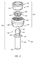
図1は肘関節プロテーゼ10を示す。プロテーゼ10が、上腕骨ステム14と、上腕骨スプール18と、橈骨ステム22と、を有する。橈骨ステム22が橈骨26内に埋設されて示されている。プロテーゼ10が、尺骨30内に埋設される尺骨ステム(図示略)をさらに有することができる。橈骨ヘッド34が橈骨ステム22上に配置され、上腕骨スプール18の一方の端部に結合される。橈骨ヘッド34が両端部で接合可能となり得る。例えば、橈骨および尺骨が上腕骨に向かって上方に回転させられるときに上腕骨ステム14が静止状態で保持される場合、橈骨ヘッド34が上腕骨スプール18の球状端部の中心の周りを回転することができる。この動作は両方向矢印R1によって提示される方向に対応する。また、矢印R1の方向の回転が行われないかまたは最小限に行われる場合、前腕も回転することができ、例えば橈骨が前腕の中心軸を中心として回転することができる。この動作は両方向矢印R2によって示される動作に対応していてよい。さらに、一部の事例では、橈骨ステム22を基準として橈骨ヘッド34を枢動させることが可能となり得る。この回転は矢印R1および矢印R2によって示される方向と同じ方向であってよいが、橈骨ヘッド34と上腕骨スプール18の球状部分との間のインターフェースのところでの動作が行われない。
I. Elbow Joint Components and Dynamics Figure 1 shows an elbow
また、橈骨ヘッド34は荷重を受けることから、このような荷重時に無傷の状態を維持しなければならない。発生し得る2つの荷重は、矢印Dによって示される延長荷重(distraction load)と、矢印Lによって示される側方荷重である。延長荷重Dは、関節から離れて肩に向かうおよび/または手に向かう方向で、関節のところに加えられ得る。延長荷重Dはステム22から橈骨ヘッド34を分離する可能性がある。側方荷重Lは前腕の高レベルの範囲での捻じれで発生し得る。このような捻じれは、ノブを回すのに使用される動作などにおいて、上腕を静止状態で保持して手を回転させるときに、発生し得る。橈骨ヘッド34がステム22または橈骨26の一部分などの硬い表面に接触する場合、このような運動中に橈骨ヘッド34がステム22からこじ開けられる可能性がある。これらの問題が、安全性の向上した橈骨ヘッドの設計の必要性を促進する。安全性を向上させることが有利である一方で、特定の実施形態は容易な取り外しも実現する。
Further, since the
II.安全性の向上した肘関節組立体
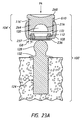
広範囲の解剖学的荷重にわたって組立体の安全を向上させることならびに移植および取り外しの利便性を向上させることなどの、性能を向上させる多様な肘関節プロテーゼ組立体および構成要素が本明細書で提供される。図2〜図15を伴うセクションII(A)、図17を伴うセクションII(C)、および図18および図19を伴うセクションII(D)が、解剖学的荷重の安全性ならびに移植および取り外しの容易さを確保するような、橈骨ヘッド組立体の多様な実施形態を示す。図16A〜図16Bを伴うセクションII(B)が、手技を容易にするために提供され得る多様な有用なキットを示す。図20A、図20B、および図23A〜図23Eを伴うセクションIII(A)が、患者に対しての、橈骨ヘッド組立体を組み立てる方法を示す。図21、図21A、および図22を伴うセクションIII(B)が、患者に対しての、橈骨ヘッド組立体を取り外す方法を示す。
II. Safer Elbow Joint Assemblies A variety of elbow joint prosthesis sets that improve performance, including improved assembly safety over a wide range of anatomical loads and improved implant and removal convenience. Solids and components are provided herein. Section II (A) with FIGS. 2-15, Section II (C) with FIG. 17, and Section II (D) with FIGS. 18 and 19 show anatomical loading safety and implantation and removal. 6 illustrates various embodiments of a radial head assembly to ensure ease. Section II (B) with FIGS. 16A-16B shows a variety of useful kits that can be provided to facilitate the procedure. Section III (A) with FIGS. 20A, 20B, and 23A-23E shows a method of assembling a radial head assembly for a patient. Section III (B) with FIGS. 21, 21A, and 22 illustrates a method of removing a radial head assembly for a patient.
A.荷重の安全性の向上した橈骨ヘッド組立体
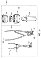
図2は、橈骨ヘッド組立体100の一実施形態の分解図を示す。橈骨ヘッド組立体100が図1の肘関節プロテーゼの一部分を形成することができる。橈骨ヘッド組立体100が、関節の組立体104と、ステム124と、を有する。関節の組立体104が、カラー108と、ロッキングリング112と、関節部材116と、を有する。
A. Radial Head Assembly With Improved Load Safety FIG. 2 shows an exploded view of one embodiment of the
ステム124が、遠位端125と、近位側部分126と、を有する。ステム124の遠位側部分127が遠位端125から近位側部分126の方に延在する。遠位側部分127が骨の中に埋設されるように構成され、例えば上で考察するように、肘関節に隣接する橈骨の中に埋設されるように構成される。遠位側部分127が、ステムを橈骨に一体化するために骨の内方成長を実現するように適合される、テクスチャード表面、粗い表面、あるいは他の構造または処理剤を有することができる。テクスチャード表面が、骨の中でステム124を固定するのに骨セメントが使用される場合に骨セメント内での機械的握持を実現する。テクスチャード表面がまた、圧入システムまたはテクニックとしてステム124が移植されるところでの骨の内方成長を実現する。近位側部分126が凸形の関節ヘッド128を有することができる。関節ヘッド128がステム124の近位端130上に配置され得るか、または近位端130から延在してよい。
ステム124が、環状部材132をさらに有することができる。環状部材132が凸形の環状ヘッド128に隣接して配置され得る。環状部材132が、遠位側部分127の近位端に隣接するところから外側周縁部まで延在する遠位側面を有することができる。環状部材132の外側周縁部が、遠位側部分127の近位端から径方向または横方向において一定距離だけ離間され得る。遠位側部分127の近位端と環状部材132の外側周縁部との間の距離が、環状部材132の幅に一致してよい。環状部材132の幅が一定であってよい。環状部材132が橈骨の近位側端面にインターフェース接続されるように構成され得る。いくつかの方法では、環状部材132が、ステム124を橈骨の中に挿入するときにポジティブストップを実現する。いくつかの実施形態では、遠位側面の反対側にある環状部材132の近位側面が、関節の組立体104と橈骨の近位側面との間に置かれる橈骨ヘッド組立体100の一部分を提供する。環状部材132が、関節の組立体104による橈骨に対しての衝突からの保護を実現することができる。
The
一実施形態では、近位側部分126が、凸形の関節ヘッド128と、凸形の関節ヘッド128と環状部材132との間を一定の距離に沿って延在する軸方向部分134と、を有する。軸方向部分134が、環状部材132の近位側面の上方まで関節の組立体104を上昇させる。組立体100が移植されるとき、軸方向部分134が橈骨の上方まで関節の組立体104を上昇させる。このように上昇させることにより関節の組立体104と橈骨の近位側面との間にクリアランスを形成し、後でさらに説明するように、その中にステム124が挿入される。
In one embodiment, the
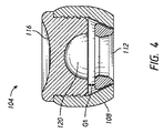
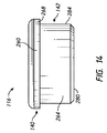
図3および図4は、一構成において、本明細書で開示される捕捉部材の実施例である、ロッキングリング112がカラー108の中に配置され、関節部材116がカラー108の中に部分的に配置される、ことを示している。関節部材116は、近位側部分140と、遠位側部分142と、を有することができる(図2、図14、および図15に示される)。近位側部分140が、関節の組立体104の近位側表面を有することができる。近位側部分140がカラー108の近位側部分144の外側に露出され得る(図2、図7、および図8に示される)。関節部材116の遠位側部分142がカラー108の中を前進させられるように構成され得る。遠位側部分142が、図4のカラー108の近位側部分144の遠位側に配置される。遠位側部分142がカラー108の内側に配置され得る。例えばカラー108の近位端から遠位端までの方向に沿う、カラー108の軸方向長さが、関節部材116の遠位側部分142の軸方向長さより大きくてよく、その結果、関節部材116の遠位端または遠位側面がカラー108の遠位端の近位側にくる。図4は、関節部材116の遠位側部分142の遠位端がカラー108の中に半分以上先へと前進させられ得ることを示している。図4は、遠位側部分142の遠位端がカラー108の遠位端に十分に届かないところに配置されてよく、それにより後でさらに考察するようにロッキングリング112の可動範囲が得られることを示している。いくつかの実施形態では、図4Aおよび図4Bでそれぞれ示されるように、関節の組立体104'が非ロック構成および/またはロック構成にあるとき、関節部材116'の遠位側部分142がロッキングリング112に接触するように配置され得る。
3 and 4 illustrate, in one configuration, an embodiment of a capture member disclosed herein, a
図4は、関節部材116がカラー108に対合しているのを示している。一実施形態では、近位側部分140が関節部材116の基部260を備える(図14および図15に示される)。近位側部分140が、カラー108の近位側部分144のところの開口部より少なくとも一部分において大きい寸法を有することができる。この構成により、近位側部分140の外側リム268(図14および図15に示される)がカラー108の例えば近位側壁などの近位側部分の上に配置されるようになるまで関節部材116を挿入することが可能となる。外側リム268がカラー108の近位側部分144に当接され得る。近位側部分144に対して近位側部分140が当接されることにより、カラー108の中に関節部材116が挿入されるときの関節部材116のためのポジティブストップを実現する。遠位側部分142が関節部材116の突出部264を備えることができる(図14および図15に示される)。突出部264が関節部材116の基部260から突出してよい。遠位側部分142が、後でより詳細に考察するように、締まり嵌めにより、カラー108の内部に固定され得る。例えば、関節部材116がカラー118から離れているとき、関節部材116の周囲表面または外側周縁部が、カラー108の例えば内側周縁部などの内部表面の少なくとも一部分より大きくてよい。したがって、カラー108に対して関節部材116が対合するとき、遠位側部分142が少なくともいくらかの程度で変形し得るかまたはカラー108の内側周縁部の一部分が圧縮され得る。この圧縮または変形により、例えば肘関節の空間内で動作荷重を受けるときに、カラー108から意図されずに関節部材116が分離するのを防止するための十分な摩擦を発生させる。
FIG. 4 shows
一実施形態では、関節部材116が、ポリエチレン、PEEKなどのポリマー、熱分解炭素などのセラミックを含めた材料で形成され、カラー108が、コバルトクロム、チタン、または他の同様の生物適合性耐久性材料などの耐久性金属で形成される。これらの材料の材料特性の違いにより、挿入時に締まり嵌めを形成するために、関節部材116が変形すること、例えば圧縮されることが可能となり得る。
In one embodiment, the
ロッキングリング112が、図2および図11に示される、近位側部分148と、遠位側部分150とを有する。図3および図4は、カラー108内にロッキングリング112が配置されるような関節の組立体104の構成を示している。例えば、近位側部分148および遠位側部分150がカラー108の近位端と遠位端との間に配置され得る。図4は、特定の実施形態において、ロッキングリング112が関節部材116の遠位端とカラー108の遠位端との間に配置され得ることを示している。図4は、ロッキングリング112の遠位端がカラー108の遠位端と同じ位置に配置される場合に、ロッキングリング112の近位端と関節部材116の遠位端との間の隙間G1が存在する、ことを示している。隙間G1が、カラー108内の軸方向においてロッキングリング112の可動範囲に沿うロッキングリング112の位置に対応する。この文脈では、軸方向がステム124の長手方向軸に沿う方向に対応する(図20Aを参照)。隙間G1の大きさを縮小する軸方向におけるロッキングリング112の動作が、有利には、カラー108によりロッキングリング112が閉じ込められるかまたは拘束されるロック構成から、ロッキングリング112の拘束または閉じ込めが相対的に緩められる自由構成まで、ロッキングリング112が移動することを可能にする。カラー108によりロッキング112に対して課される閉じ込めまたは拘束を軽減することにより、ロッキングリング112が拡大することが可能となる。例えば、ロッキングリング112が関節部材116の方に移動することにより、隙間G1の大きさが縮小する。ロッキングリング112が関節部材116から離れるように移動することにより、隙間G1の大きさが増大する。ロッキングリング112が移動させられて関節部材116に接触すると、隙間G1が排除される。これはロッキングリング112の自由構成の一実施例である。自由構成の場合、隙間G8(図20Aを参照)がロッキングリング112の外側周縁部とカラー108の内部との間に配置される。隙間G8およびロッキングリング112の可撓性により、ロッキングリング112が拡大することが可能となる。隙間G1が最大であるとき、ロッキングリング112がロック構成となり、カラー108の開口部の上に係合される。ロック構成が、後でさらに考察するように、関節の組立体104からステム124が意図されずに外されることを防止する。
Locking
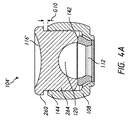
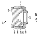
図4Aおよび図4Bは、特定の実施形態において、例えば非ロック構成において、ロッキングリング112の全体がカラー108の中に配置される場合、関節部材116'の突出部264がロッキングリング112に当接されるのに十分な長さを有することができる、ことを示している。したがって、ロッキングリング112の近位端と関節部材116'の遠位端との間に隙間が存在し得ない。いくつかの実施形態では、関節部材116'がカラー108内に非ロック位置およびロック位置を有することができる(それぞれ、図4Aおよび図4Bに示される)。例えば、図4Aは、関節の組立体104'が非ロック構成にある場合、関節部材116'が、ロック位置の場合のカラー108内での関節部材116'の位置と比較して、カラー108内で近位側の位置にあってよいことを示している。関節部材116'が非ロック構成にあるとき、隙間G10が関節部材116'の基部260の遠位側端面とカラー108の近位側部分144の近位端との間に存在し得る。隙間G10の長さは、関節部材116'の非ロック位置およびロック位置に関連して、カラー108内の軸方向において関節部材116'の可動範囲に沿う関節部材116'の位置に対応していてよい。この文脈では、軸方向がステム124の長手方向軸に沿う方向に対応する(図23A〜図23Eを参照)。
4A and 4B illustrate that in certain embodiments, for example, in the unlocked configuration, when the
隙間G10の大きさを縮小するように軸方向において関節部材116'を移動させることにより、有利には、関節部材116'が非ロック構成からロック構成まで移動することが可能となる。関節部材116'が非ロック構成からロック構成まで移動するとき、関節部材116'の遠位側端面がロッキングリング112に当接され、さらに、ロッキングリング112の拘束または閉じ込めが相対的に緩い非ロック構成(図4Aに示される)から、カラー108によりロッキングリングを閉じ込めるまたは拘束するロック位置まで(図4Bに示される)、ロッキングリング112を移動もさせる。本明細書で考察されるように、カラー108によりロッキングリング112に対して課される閉じ込めまたは拘束を強化することにより、ロッキングリング112が収縮することになる。本明細書で開示される他の実施形態と同様に、非ロック構成にある場合、隙間G8(図23Aを参照)が、ロッキングリング112の外側周縁部とカラー108の内部との間に配置される。隙間G8およびロッキングリング112の可撓性により、ロッキングリング112が拡大することが可能となる。関節部材116'の遠位方向への軸方向の移動により隙間G10が最小となるおよび/または排除される場合、ロッキングリング112がロック構成となり、カラー108の開口部の上に係合される。ロック構成が、後でさらに考察するように、関節の組立体104'からステム124が意図されずに外されることを防止する。
Moving the articulation member 116 'axially to reduce the size of the gap G10 advantageously allows the articulation member 116' to move from an unlocked configuration to a locked configuration. As the articulation member 116 'moves from the unlocked configuration to the locked configuration, the distal end surface of the articulation member 116' abuts the
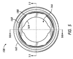
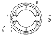
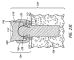
図5〜図8は、関節の組立体104のカラー108の種々の図を示す。カラー108が、カラー108の外側周縁部とカラー108の内側周縁部との間に延在するカラー壁160を有する。カラー壁160が、第1のカラー開口部164と、第2のカラー開口部168と、そこを通る通路166と、を画定する。第1のカラー開口部164が、カラー108の遠位端のところに配置される。第2のカラー開口部168が、カラー108の近位端のところに配置される。カラー壁160が内部カラー表面172を有する。内部カラー表面172が第1のカラー開口部164の近傍に角度付き部分176を有することができる。角度付き部分176が、その近位側部分と比較してその遠位側部分をカラー108の中心長手方向軸A1に近づけるように、構成される。角度付き部分176の遠位側部分が第1のカラー開口部164に隣接して配置される。角度付き部分176が軸A1を中心として対称構成を有することができる。図7および図8は、角度付き部分176が、通路166の円錐台形部分を形成するような、断面における線形プロフィールを有することができる、ことを示している。図5は、いくつかの実施形態において、第2のカラー開口部168が第1のカラー開口部164より大きいことを示している。
5-8 show various views of the
後でさらに考察するように、関節の組立体104の少なくとも1つの構成において、カラー108とロッキングリング112との間で固定的な接続が実現される。カラー108が、好適には適切な場合にロッキングリング112をカラー108から切り離すのを促進するように構成される。例えば、カラー108が、カラー108内に配置されるロッキングリング112の一部分へのアクセスを実現するためのアパーチャ180を有することができる。アパーチャ180がカラー108の遠位側部分146内に配置され得る。例えば、アパーチャ180がカラー108の遠位端のところに位置することができ、そこから近位側に延在してよい。アパーチャ180が半円形状を有することができ、その直径がカラー108の遠位端のところに位置する。アパーチャ180が、図16Aおよび図21に関連して後で考察するように、取り外しツール324の作用端部の形状に適合する形状を有することができる。アパーチャ180が半円形状を有する一方で、アパーチャ180が取り外しツール324と相互作用することができる任意適切な形状および/または構成を有してもよいことが企図される。
As will be discussed further below, in at least one configuration of the
図3、図8、図16A、および図21は、取り外しツール324をアパーチャ180の中まで前進させるのを可能にするようにおよびロッキングリング112をカラー108から切り離すのを可能にするように、アパーチャ180が構成される、ことを示している。図3は、ここで示される構成において、アパーチャ180がロッキングリング112へのアクセスを実現することを示している。図20Bおよび図21は、ロック構成にあるロッキングリング112を示しており、ここでは、ロッキングリング112がカラー108を基準として遠位側に前進させられることにより固定される。この構成では、ロッキングリング112の遠位側部分が第1のカラー開口部164上に配置され、ロッキングリング112の遠位側部分150とカラー壁160の遠位側部分との間の干渉が実現され、それによりカラー108にロッキングリング112を固定する。ロック構成では、ロッキングリング112がアパーチャ180を通したアクセス可能状態を維持する。図8は、取り外しツール324により圧縮力F1がアパーチャ180を通して加えられ得ることを示している。圧縮力F1が内側に向けられ得、例えばステム124の長手方向軸に対して横方向に向けられ得る。圧縮力F1が軸方向に向けられ得、例えば概して近位側および/または遠位側に向けられ得るか、あるいはステム124の長手方向軸に概して位置合わせされ得る。圧縮力F1は、ロッキングリング112をカラー108の中の、例えば図3の位置または自由構成における、隙間G1を図4に描かれる隙間G1よりも小さくするような関節部材116により近い位置まで、近位側に移動させるのを可能にすることを目的として、ロッキングリング112を圧縮するのに十分な大きさであってよい。
FIGS. 3, 8, 16A, and 21 show that the
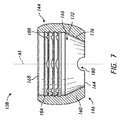
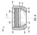
図7および図8は、いくつかの実施形態において、内部カラー表面172が、関節部材116に取り付けられるための少なくとも1つのカラー接続構造部184を有することを示す。接続構造部184が第2の開口部168に隣接して配置され得る。接続構造部184が関節部材116の周囲表面に係合されるように構成され、それにより関節部材116をカラー108内に保持する。カラー接続構造部184が、ねじ嵌合、スナップ嵌合、締まり嵌め、または他の手法により、関節部材116を受けるかまたは関節部材116によって受けられるように構成される、ペグ、棘、ねじ部、または他の突出構造を有することができる。接続構造部184が、関節部材116およびカラー108が係合されるときにカラー108を基準として関節部材116が回転変位するのを防止するように構成される、少なくとも1つの回転防止構造部188を有することができる。回転防止構造部188が、関節部材116を受けるかまたは関節部材116によって受けられるように構成される、溝、スカロップ、ノッチ、キャビティ、または他の窪み構造を有することができる。図5および図8は、回転防止構造部188がカラー壁160まで外側に延在するこのようなスカロップのアレイを有することができることを示している。一実施形態では、回転防止構造部188のアレイが、関節部材116の挿入軸(例えば、関節部材104の近位側から遠位側への軸)に沿って配置される複数のこのような構造部を有する。一実施形態では、回転防止構造部188のアレイが、例えば関節部材116の挿入軸(例えば、関節部材104の近位側から遠位側への軸)に沿う任意の1つの位置において壁172の周りに配置されるといったように、カラーの内周の周りに配置されるこのような複数の構造部を有する。一実施形態では、回転防止構造部188のアレイが、例えば関節部材116の挿入軸に沿う任意の1つの位置において壁172の周りに配置されるといったように、関節部材116の挿入軸に沿ってカラーの内周の周りに配置される複数のこのような構造部を有する。接続構造部184が、カラー108内での関節部材116の軸方向の移動(例えば、近位側から遠位側への方向)または回転(例えば、近位側から遠位側の方向を中心とする)を防止することを目的として、締まり嵌めまたは他の手法により関節部材116の突出部または遠位側部分142に係合されるように構成される。
7 and 8 show that, in some embodiments, the
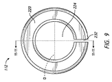
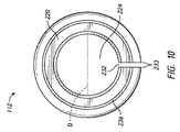
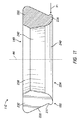
図9〜図11は、関節の組立体104のロッキングリング112の種々の図を示す。ロッキングリング112が、ロッキングリング112の外側周縁部とロッキングリング112の内側周縁部との間を延在するリング壁220を有する。リング壁220がリング開口部224を画定する。リング壁220が、角度付き外側表面228と、リング壁220を拡大および圧縮させるのを可能にするように構成されるスロット232と、を有することができる。角度付き外側表面228が、例えば、ロック構成において関節ヘッド128が組立体104内に配置されるときといったような、関節の組立体104に対してステム124が結合されるときに、内部カラー表面172の角度付き部分176に係合されるように構成される。ロッキングリング112が自由構成のときに拡大するように構成され、それにより関節ヘッド128がリング開口部を通過してカラー108内に配置されるのを可能にする。例えば、スロット232がロッキングリング112の2つの自由端233の間に画定される。2つの自由端233が、一実施形態では、例えばカラー108内に完全には拘束されない場合といったように、自由構成時に、互いの方におよび互いから離れるようにいずれにも移動することができる。ロッキングリング112が例えばカラー108に係合されるといったようにロック構成にある場合、自由端233がある程度拘束される。例えば、図3および図4に示される位置では、ロッキングリング112の自由端233が互いから離れるように移動することが内部カラー表面172によって制限される。ロッキングリング112が関節部材116の方に移動させられて隙間G1が縮小すると、ロッキングリング112の自由端233が互いから離れるようにより大きく移動することが起こり得る。関節の組立体104のこの特性は、ステム124に対しての関節の組立体104の結合時に有用である。ロッキングリング112の自由端233が互いから離れるように移動することは、後でさらに考察するように、図20Bおよび図21の位置でさらに拘束される。ロッキングリング112の自由端233が互いの方に移動することは、上で考察したように、アパーチャ180によって強化され得る。いくつかの実施形態では、スロット232が小さく、ここでは自由端233が互いに非常に近くにあり、例えば自由状態において自由端233の間に有意な隙間が存在しない。このような実施形態では、材料の可撓性あるいは変形可能性または延性により、ロッキングリング112がカラー108内で固定されることが可能となり得る。
9-11 show various views of the
ロッキングリング112のリング壁220が内部リング表面を有する。内部リング表面がロッキングリング112の近位側部分148に隣接する近位側部分238を有する。近位側部分238がテーパ状であってよい。近位側部分のテーパ角および長さは、例えばロッキングリング112を通るように関節ヘッド128が配置されるといったように、関節の組立体104に対してステム124が結合されるときに、ステム124の関節ヘッド128にインターフェース接続されるように構成され得る。ロッキングリング112がロック構成にあるとき、近位側部分238がステム124の関節ヘッド128の形状に対応するように成形され得る。近位側部分238が、関節ヘッド128の曲率に適合する球面を有することができる。近位側部分238がリング壁220の全幅に沿って延在することができる。
The
内部リング表面が中間部分242を有することができる。中間部分242は実質的に直線であってよいか、またはテーパ状であってよい。中間部分242がロッキングリング112の内径Dを画定する。ロッキングリング112が拡大するとき内径Dが増大することができ、それにより関節の組立体104の中にステム124を挿入することが可能となる。例えば、ロッキングリング112が自由端233を有する場合、自由端233が互いから離れて移動するときに内径Dが拡大することができる。ロッキングリング112が自由構成にあるとき、内径Dがステム124の関節ヘッド128の幅と同じであってよいか、またはそれより小さくてもよい。ロッキングリング112がロック構成にあるとき、内径Dがステム124の関節ヘッド128の幅より小さくてよく、それによりステム124がロッキングリング112から切り離されるのを阻害する。
The inner ring surface can have an
内部リング表面がロッキングリング112の遠位側部分150に隣接する遠位側部分240を有することができる。遠位側部分240は、ロッキングリング112の遠位側部分150に隣接するその一部分と比較して、内部リング表面の中間部分242に隣接するその一部分をロッキングリング112の中心長手方向軸A4に近づけるように、構成される。遠位側部分240が軸A4を中心として対称構成を有することができ、それによりリング開口部224の円錐部分および/または湾曲部分を提供する。いくつかの実施形態では、遠位側部分240の内径が近位側部分238の内径より大きい。遠位側部分240が遠位側に拡大する構造を有することができ、この遠位側に拡大する構造が、自由構成において中間部分242から遠位側部分150に向かって直径を拡大させる。直径の範囲は、好適には関節ヘッド128の直径より大きい直径にまで及び、その結果、後で考察するように、遠位側部分240が関節ヘッド128を受けることができ、組み立ての前にその上に載置され得る。
The inner ring surface can have a
ロッキングリング112の遠位側部分150が、少なくとも1つのリング接続構造部236を有することができる。リング接続構造部236がロッキングリング112のリング壁228から突出していてよい。リング接続構造部236が遠位側部分240に隣接して配置される。リング接続構造部236が、カラー108内でロッキングリング112を保持するためにカラー壁160に係合されるように構成される。リング接続構造部236が、ねじ嵌合、スナップ嵌合、締まり嵌め、または他の手法により、第1のカラー開口部164に係合されるように構成される、ペグ、棘、ねじ部、または他の突出構造を有することができる。各リング接続構造部236は、ロッキングリング112がロック構成から切り離されるのを阻害するように構成され得る。いくつかの実施形態では、リング接続構造部236が、リング壁220の端部から径方向外側に延在するフランジである。接続構造部236が、本明細書で考察されるように、カラー108の一部分を受けることができる外部凹形構造を有することができる。外部凹形構造が、ロッキングリング112の周りを延在する円周方向溝237を有することができる。円周方向溝237が、一実施形態では、ロッキングリング112の自由端233の間でロッキングリング112の周りの全体を延在してよい。
The
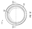
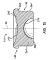
図12〜図15は、関節の組立体104の関節部材116の種々の図を示す。以下の考察は図12〜図15に示される関節部材116を参照するが、図4Aおよび図4Bに示される関節部材116'は、図12〜図15に示される関節部材116に類似する。したがって、関節部材116を参照して説明される特徴が、本明細書で説明および/または企図される任意の他の関節部材と共に使用され得ることが理解されよう。例えば、図4Aおよび図4Bの関節部材116'が、特に明記しない限りにおいて、図12〜図15の関節部材116を参照して本明細書で説明される任意の特徴、構造、材料、ステップ、または構成要素を有することができる。
12-15 show various views of the
関節部材116の近位側部分140は、基部260を有する。関節部材116の遠位側部分142は、基部260から突出する突出部264を有する。いくつかの実施形態では、基部260が外側リム268を有することができる。外側リム268が突出部264に隣接して配置され得る。外側リム268が、突出部264の近位端に隣接するところから外側周縁部まで延在する遠位側面269を有することができる。外側リム268の外側周縁部が、突出部264の近位端から、径方向においてまたは横方向において、一定距離だけ離間され得る。突出部264の近位端と外側リム268の外側周縁部との間の距離が、外側リム268の幅に対応していてよい。外側リムの幅が一定であってよい。外側リム268が、上で考察したように、カラー108の近位側部分144にインターフェース接続されるように構成され得る。
The
いくつかの実施形態では、基部260が第1の凹形表面272を有する。第1の凹形表面272が基部260の近位側表面上に配置され得る。例えば、第1の凹形表面272が基部260の近位端のところに位置してよく、その中に窪んだ表面を画定することができる。第1の凹形表面272が、例えば上腕骨スプール18などの、対応する上腕骨構成要素の少なくとも一部分を受けるように構成される。第1の凹形表面272が湾曲していてよく、例えば半円形状であってよい。第1の凹形表面272が、上腕骨スプールの少なくとも一部分に沿う回転を促進するように適合される、滑らかな表面、あるいは他の構造または処理剤を有することができる。第1の凹形表面272が近位側部分140の一領域であってよい。第1の凹形表面272が、近位側部分140の中に挿入されて近位側部分140によって保持される別個の部材の上に配置され得る。
In some embodiments, the
関節部材116の突出部264が基部から延在し、周囲表面284を有することができる。周囲表面284は、関節部材116の中心長手方向軸A8に実質的に平行に周囲表面284が延在するように、構成される。周囲表面284が、軸A8を中心とした対称構成を有することができる。突出部264の周囲表面284が、中心長手方向軸A8から、径方向においてまたは横方向において、一定距離だけ離間され得る。周囲表面284と中心長手方向軸との間の距離が突出部264の半径に対応していてよい。突出部264の半径および対応する幅が実質的に一定であってよい。突出部264がカラー108の内部カラー表面172にインターフェース接続されるように構成され得る。いくつかの実施形態では、周囲表面284が、内部カラー表面172に取り付けられるのを促進するための少なくとも1つの突出部接続構造部を有する。各突出部接続構造部は、ねじ嵌合、スナップ嵌合、締まり嵌め、または他の手法により内部カラー表面274を受けるか、または内部カラー表面274によって受けられるように構成される、ペグ、棘、ねじ部、または他の突出構造であってよい。例えば、突出部264の幅が内部カラー表面172の周縁部より大きくてよく、その結果、カラー108に対して関節部材116を対合させるときに突出部264が少なくともいくらかの程度で変形する。いくつかの例では、突出部接続構造部が、内部カラー表面172にねじ込み式に係合されるねじ部分を有することができる。
A
突出部264が第2の凹形表面276を有することができる。第2の凹形表面276が突出部264の遠位側面上に配置され得る。例えば、第2の凹形表面276が、第1の凹形表面272の反対側で、第1の凹形表面272と関節部材116の遠位端表面280との間に位置してよい。関節の組立体104に対してステム124が結合されるとき、第2の凹形表面276がステム124の関節ヘッド128の少なくとも一部分を受けるように構成される。第2の凹形表面276が、関節ヘッド128の形状に対応するように成形され得る。第2の凹形表面276が湾曲していてよく、例えば半円形状であってよい。第2の凹形表面276が、関節ヘッド128の少なくとも一部分に沿う回転を促進するように適合される、滑らかな表面、あるいは他の構造または処理剤を有することができる。
The
関節部材116の遠位側部分142が、関節部材116の遠位端表面280から近位側に延在する。遠位端表面280がテーパ状であってよい。遠位端表面280のテーパ角および長さは、カラー108の中に関節部材116を挿入するのを促進するように構成され得る。テーパ部分が端部表面280の少なくとも一部分に沿って延在してよい。遠位端表面が軸A8を中心として対称構成を有することができ、それにより第2の凹形表面276の外側周縁部に沿って延在する湾曲部分を提供する。
A
関節の組立体104が完全に組み立てられるとき(図3〜図4B、図20B、図21、および図23Eに示される)、関節部材116およびロッキングリング112がカラー108内に関節窩120を少なくとも部分的に画定する。関節窩がステム124の関節ヘッド128を受けて保持するように構成される。例えば、関節窩120が、特には橈骨ヘッド組立体100が側方荷重を受ける場合に、ステム124を中心として関節の組立体104が枢動するのを可能にするための概略球形状を有することができる。球形状は、ロッキングリング112および関節部材116上の球形表面で形成され得る。
When the
例えば関節の組立体104がロック構成にあるといったように、関節ヘッド128が関節窩120の中に挿入されている場合、関節の組立体104が両端部で接合可能である。両端部での接合により、関節ヘッド128上での関節部材116の回転と、上腕骨スプール18の球形部分の上での関節部材116の接合と、を実現することができる。例えば本明細書で説明されるように、カラー108に対してロッキングリング112を係合させるときの手法を含めた、関節ヘッド128に対して関節の組立体104をインターフェース接続するときに介するところの係合機構が、取り付けの安全性を向上させる。安全性が向上することで、橈骨ヘッド組立体100が多様な橈骨動作および荷重の力を受ける可能性があるときの脱臼および/または脱着のリスクを低減する。
If the
B.関節の組立体を移植するためのおよび/または取り外すための橈骨ヘッド組立体キット
図16Aは、提供され得る肘関節プロテーゼキット320Aを示す。キット320Aが、関節の組立体104と、ステム124と、取り外しツール324と、ロッキングツール328とを有する。通常の肘関節交換手技の間、本明細書で考察されるように、関節の組立体104が橈骨ヘッド組立体100に組み付けられるとき、ステム124が、橈骨に対して関節の組立体104を固着するのに使用され得る。キット320Aの中に取り外しツール324を有することにより関節の組立体104を取り外すのを実現することが有利となり得る。
B. Radial Head Assembly Kit for Implanting and / or Removing Joint Assembly FIG. 16A shows an elbow
図16Aは、取り外しツール324の実施例を示す。取り外しツール324が、突出部326を備える遠位端を有することができる。突出部326がアパーチャ180を通して挿入されるように構成され得る。この挿入時、ツール324の近位端への作用により力F1(図21および図22に示される)をロッキングリング112に加えることができ、それによりロッキングリング112をカラー108から切り離すことができる。ロック構成にあるとき、ロッキングリング112がカラー壁160に係合され、それにより、上で考察したように、カラー108内でロッキングリング112が保持される。例えば、カラー108の縁部がリング接続構造部236によって受けられ、それによりロッキングリング112および関節ヘッド128を定位置で固定する。取り外しツール324が、アパーチャ180を通してロッキングリング112の少なくとも一部分に圧縮力F1(図8、図11、および図21に示される)を加えることができる。圧縮力F1がロッキングリング112を圧縮し、2つの自由端233を互いの方に移動させる。2つの自由端233が互いの方に移動すると、ロッキングリング112の幅が縮小し、リング接続構造部236がカラー壁160の縁部から切り離され得る。カラー壁160から切り離されると、ロッキングリング112が、ロック構成の定位置から自由構成の別の第2の位置まで、関節部材116に向かって前進させられ得る。自由構成がロッキングリング112を拡大するのを可能にし、関節ヘッド128をロッキングリング112を通過させるのを可能にする。このようにして、関節の組立体104がステム124から取り外され得る。
FIG. 16A shows an example of the
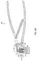
継続して図16Aを参照すると、キット320Aがロッキングツール328を備えることができる。ロッキングツール328が、カラー係合部分330と関節部材係合部分332とを備える遠位端を有することができる。カラー係合部分330がカラー108の遠位側端面に当接されるように構成され得、関節部材係合部分332が関節部材116'の近位側端面に当接されるように構成され得る。カラー係合部分330および/または関節部材係合部分332が、いくつかの例では、橈骨ヘッド組立体100'の任意の他の部分に係合されるように構成され得、それにより関節の組立体104'を非ロック構成からロック構成へと移行させる。この係合時、ロッキングツール328の近位端への作用により力F10およびF10'(図23Cに示される)を関節の組立体104'に加えることができ、それにより関節部材116'およびロッキングリング112をカラー108を基準として遠位側方向に移動させる。関節部材116'およびロッキングリング112が遠位側に変位させられると、関節の組立体104'が非ロック構成からロック構成へと移行する。本明細書で考察されるように、ロック構成時、ロッキングリング112がカラー壁160に係合され、それによりロッキングリング112をカラー108内で保持する。例えば、カラー108の縁部がカラー係合部分330によって受けられ、それによりカラー108を定位置で固定する。ロッキングツール328が、関節部材係合部分332を通して、1つまたは複数の圧縮力F10およびF10'(図23Cおよび図23Eに示される)を関節部材116'に加えることができる。圧縮力F10、F10'が、関節部材116'をカラー108を基準として遠位側に移動させてロッキングリング112の近位側面に接触させ、さらにロッキングリング112をカラー108を基準として遠位側方向に移動させる。ロッキングリング112が移動させられると、ロッキングリング112がカラー108に係合され、ロック構成に入る。
Continuing to refer to FIG. 16A,
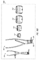
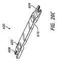
肘関節プロテーゼキットが、いくつかの実施形態によると、患者全般により良好に嵌合するために多様なサイズの複数の関節の組立体104を有することができる。キットのいくつかの実施形態では、ステム124が、ヘッド128のための多様な高さを有するなどして、多様なサイズで提供される。図16Bは、例えば少なくとも4つといったように、多様なサイズの複数の関節の組立体104と少なくとも1つの取り外しツール324とを有するキット320Bを示している。多様な関節の組立体104により、患者の解剖学的構造に適合する関節の組立体を移植することが可能となる。4つのサイズより多くのサイズ、またはより少ないサイズが提供されてもよい。アパーチャ180がサイズに基づいて修正される場合、2つ以上の取り外しツール324が提供されてもよい。いくつかの実施形態では、取り外しツールが、図20Cに示されるようにテーパ状の作用端部および/または複数の作用構造部を有することなどにより、2つ以上のサイズにおいて使用されるように構成され得る。
The elbow joint prosthesis kit, according to some embodiments, can have a plurality of
所与の対応する上腕骨スプール18の1つまたは複数のサイズの範囲に従って、肘関節プロテーゼのための関節の組立体104が選択され得、移植され得る。例えば図16Bは、3つの異なるサイズの関節の組立体104を示している。図16Bは、関節の組立体104'と、関節の組立体104'より大きい関節の組立体104''と、関節の組立体104''より大きい関節の組立体104'''と、を示している。異なるサイズの関節の組立体104'、104''、104'''が、関節の組立体を、肘関節内のそれぞれの上腕骨スプールに合わせるのを可能にする。いくつかの実施形態では、キットが、多数の等しいサイズの関節の組立体104を有することができる。例えば図16Bは、少なくとも2つの大きい関節の組立体104'''を備えるキット320Bを示している。
A
上で考察したように、取り外しツール324を有することにより、移植後に関節の組立体104を取り外すことが可能となる。移植された関節の組立体104が患者にとって適切なサイズではないと判断される場合、取り外しツール324が、移植した関節の組立体104を取り外して、キット320B内に含まれる異なるサイズの関節の組立体104と交換するのに使用され得る。これは、関節の組立体が移植された後で取り外されたりおよび/または交換されたりし得ない固定の組立体サイズをしばしば有する既存の橈骨ヘッド組立体よりも優れる。
As discussed above, having a
C.代替のロッキングリング係合機構を備える橈骨ヘッド組立体
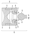
図17は、橈骨ヘッド組立体400の別の実施形態を示す。橈骨ヘッド組立体400は、後で異なる形で説明されることを除いて、橈骨ヘッド組立体100に似ており、つまり類似する。したがって、図2〜図15に示される橈骨ヘッド組立体100の特徴を示すのに使用される数字に対して、図17に示される橈骨ヘッド組立体400の同様の特徴を示すために、300だけ数字が加算される。上記の記述は、他の多様な実施形態での以下の具体的な考察と組み合わされ得る。
C. Radial Head Assembly with Alternate Locking Ring Engagement Mechanism FIG. 17 illustrates another embodiment of a
橈骨ヘッド組立体400は、関節の組立体404とステム424とを有する。関節の組立体404が、カラー408と、ロッキングリング412と、関節部材416と、を有する。図17は、一構成において、ロッキングリング412がカラー408内に配置され、関節部材416がカラー408内に少なくとも部分的に配置される、ことを示している。ロッキングリング412が、カラー408の中まで前進させられるように構成され得、例えば後でさらに詳細に考察されるように、ロッキングリング412の少なくとも一部分がカラー408の第1の開口部内に配置される。
The
カラー408が、カラー408の外側周縁部とカラー408の内側周縁部との間に延在するカラー壁を有する。カラー壁が、第1のカラー開口部と、第2のカラー開口部と、そこを通る通路と、を画定する。第1のカラー開口部が、カラー408の遠位端446のところに配置される。第2のカラー開口部が、カラー408の近位端444のところに配置される。カラー壁が、ロッキングリング412に結合されるように構成される内部カラー表面を有することができる。
The
いくつかの実施形態では、内部カラー表面が内側リム450を有する。内側リム450がカラー壁の遠位端に隣接して配置され得る。内側リム450が、カラー壁の遠位端に隣接するところから内側周縁部まで延在する内側面を有することができる。内側リム450の内側周縁部が、径方向または横方向において、カラー壁の遠位端から一定の距離だけ離間され得る。カラー壁の遠位端と内側リム450の内側周縁部との間の距離が、内側リム450の幅に対応していてよい。内側リム450の幅が一定であってよい。内側リム450が、後でさらに詳細に考察されるように、ロッキングリング412の対合表面462にインターフェース接続されるように構成され得る。内側リム450が、カラー408の中にロッキングリング412が挿入されるときに、ロッキングリング412に当接されるように構成される。この構成では、内側リム450がロッキングリング412に係合され、ロッキングリング412が径方向に拡大することが防止され、その結果、関節の組立体404に結合されるステム424の関節ヘッド426が関節窩420内で保持され得る。
In some embodiments, the inner collar surface has an
内側リム450が、第1のカラー開口部の近傍に角度付き部分454を有することができる。内側リム447の角度付き部分454が、ロッキングリング412の遠位端458に対応していてよい。遠位端458も角度付き部分を有することができる。角度付き部分454が、カラー408内でロッキングリング412が近位側に前進させられるときに、ロッキングリング412を拡大させるのを促進することができる。また、角度付き部分454が、角度付き部分454の上で遠位端458の角度付き部分を摺動させることにより、圧縮するのを促進することができる。具体的には、遠位端458の角度付き部分が角度付き部分454の上を移動するとき、角度付き部分454がリングを内側に押し込む。
The
ロッキングリング412が、近位側部分と遠位側部分とを有する。近位側部分が、図17に示されるように、内側リム450に係合されるように構成される対合表面462を有することができる。対合表面462が、少なくとも一部分において、内側リム450の内側周縁部より大きい寸法を有することができる。この構成により、内側リム450に対して対合表面462が当接されるようになるまで、ロッキングリング412が挿入されることが可能となる。内側リム450に対して対合表面462が当接されることにより、ロッキングリング412のためのポジティブストップが実現され、それにより、関節部材416から離れる方向の力が加えられるときに、リング412が引き出されることが防止される。いくつかの実施形態では、ロッキングリング412の遠位側部分が締まり嵌めにより第1のカラー開口部内で固定され得る。例えば、ロッキングリング412の遠位側部分の外側周縁部が第1のカラー開口部の内側周縁部より大きくてよく、その結果、カラー408に対してロッキングリング412を対合させるときに、遠位側部分が少なくともいくらかの程度で変形する。ロッキングリング412および/またはカラー408の材料によりロッキングリング412が変形すること、例えば圧縮されることが可能となり得、挿入時に締まり嵌めを形成する。
Locking
例えば、ロッキングリング412の近位側部分からロッキングリング412の遠位側部分の方向に沿う、ロッキングリング412の軸方向長さが、内側リム450の軸方向長さより大きくてよく、その結果、ロッキングリング412の遠位端458が、カラー408の遠位端の近位側にあり、対してロッキングリング412の近位端が、内側リム450の近位側にある。図17は、ロッキングリングの遠位端458が第1のカラー開口部の中に半分以上先へと前進させられ得ることを示している。ロッキングリング412の近位端が関節部材416の遠位端に十分に届かないところに配置されてよく、それによりロッキングリング412の可動範囲が得られる。
For example, the axial length of the
図17は、ロッキングリング412の遠位端がカラー408の遠位端と同じ場所に配置されるときに、ロッキングリング412の近位端と関節部材416の遠位端との間に隙間G4が存在する、ことをさらに示している。隙間G4は、カラー408内での軸方向におけるロッキングリング412の可動範囲に沿うロッキングリング112の1つの位置に対応する。軸方向におけるロッキングリング412の動作により、有利には、例えば内側リム450の径方向内側を向く構造部(図17に示される)により、カラー408によりロッキングリング412を閉じ込めるか、または拘束するようなカラー408内の位置から、ロッキングリング412の拘束または閉じ込めを相対的に緩める位置まで、ロッキングリング412を移動させることが可能となる。例えば内側リム450によってなどといったように、カラー408によりロッキングリング412に対して課される閉じ込めまたは拘束を軽減することにより、ロッキングリング412が拡大することが可能となる。例えば、ロッキングリング412が関節部材416の方に移動することにより、隙間G4が縮小するが、ロッキングリング412を、内側リム450の近位側にロッキングリングの遠位端458が配置されるような位置まで、移動する。内側リム450の近位側のカラー408の部分では、より大きい横方向の幅が提供され、これは、ステム424のヘッド426をカラー408から引っ込めるのを可能にするために、リング412を拡大させるのを可能にするのに十分な大きさである。
FIG. 17 shows that when the distal end of locking
D.ステムに結合される関節部分を有する橈骨ヘッド組立体
図18および図19は、後で異なる形で説明されることを除いて、橈骨ヘッド組立体100に類似する、橈骨ヘッド組立体の他の実施形態を示している。上記の記述は、他の多様な実施形態での以下の具体的な考察と組み合わされ得る。
D. Radial Head Assembly with Articulation Part Connected to Stem Figures 18 and 19 show another radial head assembly similar to
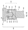
別の実施形態で、関節の組立体480が、第1の関節部材492と、第1の骨に結合されるステム488に結合されるように構成される関節部分484と、を有する。関節部分484が、カラー496と捕捉部材500とを有する。ステム488が、近位側部分490と遠位側部分とを有する。ステム488の遠位側部分が、近位側部分490からステム488の遠位端の方に延在する。遠位側部分490が骨の中に埋設されるように構成され、例えば上で考察するように、肘に隣接する橈骨の中に埋設されるように構成される。近位側部分490が、関節部分484を有することができる。関節部分484がステム488の近位端上に配置され得るか、または近位端から延在してよい。
In another embodiment, a
第1の関節部材492が、近位側部分と遠位側部分とを有する。近位側部分が基部493を有する。近位側部分が、遠位側部分に隣接して配置される外側リムを有することができる。外側リムが、遠位側部分の近位端に隣接するところから外側周縁部まで延在する遠位側面を有することができる。外側リムの外側周縁部が、径方向または横方向において、遠位側部分の近位端から一定の距離だけ離間され得る。外側リムの遠位側部分と外側リムの外側周縁部との間の距離が基部493の幅に対応していてよい。基部493の幅が一定であってよい。基部493が、上で考察するように、カラー496の近位側部分にインターフェース接続されるように構成され得る。
The
いくつかの実施形態では、第1の凹形表面495が、第1の骨の反対側の第2の骨の方を向くように、第1の関節部材492の基部493上に配置される。第1の凹形表面495が基部493の近位側表面上に配置され得る。例えば、第1の凹形表面495が基部493の近位端のところに位置してよく、その中に窪んだ表面を画定することができる。第1の凹形表面495が、対応する上腕骨スプールの少なくとも一部分を受けるように構成される。第1の凹形表面495が湾曲していてよく、例えば半円形状であってよい。第1の凹形表面495が、上腕骨スプールの少なくとも一部分に沿う回転を促進するように適合される、滑らかな表面、または他の構造または処理剤を有することができる。第1の関節部材492の遠位側部分が、凸形関節ヘッド494を有する。関節ヘッド494が、関節の組立体484にインターフェース接続されるように構成され得る。
In some embodiments, the first
カラー496が、カラー開口部504を画定するカラー壁と、カラー開口部504の近傍にある内部捕捉表面508と、を有する。空間がカラー開口部504からカラー496の内部の中まで延在する。捕捉部材500が、捕捉部材開口部と、内部捕捉表面508に係合されるように構成される対合表面512と、を有する。橈骨ヘッド組立体480が、捕捉部材500を拡大させるのを防止するために、カラー496の対合表面512に対して内部捕捉表面508が係合されるような構成を有し、その結果、関節窩516内に配置される関節ヘッド494が関節窩516内で保持され得る。
A
関節部分484が第2の関節部材520を備えることができる。第2の関節部材520がカラー496内に配置され得、第2の凹形表面524を有する。第2の凹形表面524が、第2の関節部材520の遠位側面525上に配置され得る。第2の凹形表面524が、カラー496に対して第1の関節部材492が結合されるときに、第1の関節部材492の関節ヘッド494の少なくとも一部分を受けるように構成される。第2の凹形表面524が、関節ヘッド494の形状に対応するように成形され得る。第2の凹形表面524が湾曲していてよく、例えば半円形状であってよい。第2の凹形表面524が、関節ヘッド494の少なくとも一部分に沿う回転を促進するように適合される、滑らかな表面、あるいは他の構造または処理剤を有することができる。
The
図19は、ステムに対して関節部分が結合されている状態の、橈骨ヘッド組立体の別の実施形態を示している。橈骨ヘッド組立体540は、異なる形で説明されることを除いて、図18の橈骨ヘッド組立体480に類似する。図19は橈骨ヘッド組立体540の実施形態を示しており、ここでは、基部548が第1の関節部材544に取り外し可能に係合される。いくつかの例では、例えば第1の関節部材544および第1の凹形表面552のうちの少なくとも一方が摩耗し始める場合に、第1の関節部材544から基部548を取り外すことが必要となる可能性がある。締まり嵌め、対合するテーパ部分、棘もしくはフック、ロッキングリング、ねじ部、または他の捕捉構造部を含めた、基部548に対して関節部材544を継ぎ合わせるための任意適切なテクニックが提供され得る。
FIG. 19 shows another embodiment of the radial head assembly with the articulating portion attached to the stem. The
III.改善された肘関節組立体のための移植方法
図2〜図15に示される橈骨ヘッド組立体100を再び参照すると、使用時に、関節の組立体104がステム124上に配置される前に、ステム124が橈骨内に移植され得る。関節の組立体104の関節窩120の中に、ステム124の関節ヘッド128を挿入することにより、ステム124が関節の組立体104に固定される。いくつかの事例では、橈骨ヘッド組立体100を交換することが必要となる可能性がある。関節の組立体104が交換される間、ステム124が橈骨に結合された状態を維持することができる。外科医が、新しい関節の組立体104、または異なる構成の関節の組立体104を提供することができる。図20Aおよび図20Bは、本明細書で開示される、装置の移植に関連する手術方法の態様を示す。図21は、本明細書で開示される、装置の取り外しに関連する手術方法の態様を示す。
III. Implantation Method for Improved Elbow Joint Assembly Referring again to the
A.ステムの橈骨ヘッドの上に接合組立体を移植する方法
図2、図20A、図20B、および図23A〜図23Eが、肘関節プロテーゼを移植するための多様な手術方法を示している。これらの方法では、ステム124の遠位側部分が第1の骨に取り付けられ、ここでは、関節ヘッド128がステム124の近位端130から延在する。手技中に関節が分離され得るかまたは位置をずらされ得るが、手技後、ヘッド128の位置が第1の骨と第2の骨との間の関節空間内にくることになる。例えば、ステム124が肘関節に隣接する橈骨に取り付けられ得、手技の完了後、関節ヘッド128が橈骨と上腕骨との間に配置され得る。いくつかの実施形態では、ステム124が環状部材132を有する。環状部材132が、第1の骨の中へのステム124の遠位側部分の挿入時にポジティブストップとして機能することができる。図20Aに示されるように環状部材132が第1の骨の近位側の位置にくるまで、ステム124が挿入され得る。環状部分132が、環状組立体104による橈骨に対しての衝突の保護を実現することができる。
A. Method of Implanting the Junction Assembly on the Radial Head of the Stem Figures 2, 20A, 20B, and 23A-23E illustrate various surgical methods for implanting an elbow joint prosthesis. In these methods, the distal portion of
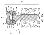
図2、図20A、および図20Bを参照すると、図20Aに示されるように、関節の組立体104が関節ヘッド128上に移植される前に、関節の組立体104が完全に組み立てられ得る。ロッキングリング112および関節部材116をカラー108の中に少なくとも部分的に配置することにより、関節の組立体104が組み立てられ得る。ロッキングリング112が、ほぼ圧縮されないかまたは一切圧縮されずに、第2のカラー開口部168を通してカラー108の中に挿入され得る。円周部分の圧縮時に、ロッキングリング112が第1のカラー開口部164を通してカラー108の中に挿入され得る。図20Aに示されるように、自由構成においてロッキングリング112がカラー108内に配置され得る。一方で、自由構成では、ロッキングリング112がカラー108から切り離され、内部カラー表面172によって閉じ込められたり、または拘束されたりし得ない。ロッキングリング112が、上で考察したように、カラー108内で一定範囲の軸方向および/または径方向の動作を受けることが可能である。図20Aは、ロッキングリング112と内部カラー表面172との間に配置される隙間G8を示す。隙間G8が、内部カラー表面172によって閉じ込められることなく、カラー108内においてロッキングリング112が円周方向にまたは横方向に拡大するのを可能にする。アパーチャ180に対して回転方向においてスロット232が位置合わせされるような位置において、ロッキングリング112がカラー108内で配置され得る。次いで、本明細書で説明されるように、長手方向においてアパーチャ180に対してスロット232が位置合わせされるような位置まで、ロッキングリング112がカラー108内で前進させられ得、それによりロッキングリング112を取り外すのを容易にする。
2, 20A, and 20B, as shown in FIG. 20A, the
関節の組立体104の組み立て中、関節部材116が少なくとも部分的にカラー108の中に挿入される。カラー108の中への関節部材116の挿入時、突出部264がカラー108の中に前進させられ得、ここでは、外側リム268がポジティブストップとして機能する。近位側部分140がカラー108の近位側部分144の外側に露出され得、したがって第1の凹形表面272を第2のカラー開口部168の近位側に位置させておく。突出部264が、カラー接続構造部184および回転防止構造部188(図7および図8に示される)のうちの少なくとも一方との相互作用を介して、カラー108内で固定され得る。上で考察したように、遠位端表面280がカラー108の遠位端に十分に届かないところに配置されてよく、それによりカラー108の内部の中でのロッキングリング112の一定範囲の軸方向および径方向の動作が実現される。
During assembly of the
関節の組立体104が完全に組み立てられるとき、カラー108、ロッキングリング112、および関節部材116が、関節の組立体104の内部の中に関節窩120を画定する。関節窩120の中に関節ヘッド128を挿入するために、図20Aに示されるように、関節の組立体104の第1のカラー開口部164が関節ヘッド128上に配置される。関節ヘッド128が、ロッキングリング112の遠位側部分240と相互作用する。関節ヘッド128との相互作用により、関節部材116の遠位端に当接されるところの位置まで、カラー108内でロッキングリング112を近位側に前進させることができる。関節ヘッド128の長手方向軸の方向の力F4が関節の組立体104に加えられ得る。力F4が関節の組立体104を関節ヘッド128に係合させることができ、関節部材116と関節ヘッド128との間でロッキングリング112を圧縮することができる。力F4が加えられるとき、関節ヘッド128がリング開口部224の中まで前進させられ得、次いでロッキングリング112を拡大させることができる。スロット232が、2つの自由端233を互いから離すように移動させるのを可能にする。したがって、ロッキングリング112の内径Dが、隙間G8によって提供される空間内で増大する。ロッキングリング112が拡大することで、ロッキングリング112の増大した直径Dを通って、関節ヘッド128が前進させられることが可能となる。ロッキングリング112を通して挿入されると、関節ヘッド128が、ロッキングリング112と第2の凹形表面276との間の関節窩120内に配置される。ロッキングリング112が、関節ヘッド128と内部カラー表面172の角度付き部分176との間に配置される。
When the
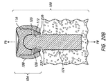
図20Bは、ロッキングリング112をロック構成で配置するための方法を示している。関節ヘッド128が関節窩120内に配置される場合、延長力(distraction force)F8がステム124と関節の組立体104との間に加えられ得、それにより橈骨ヘッド組立体100をロック構成に配置する。延長力F8および対応する等しい反対方向の反動力F8'が、橈骨ヘッド組立体100に加えられ得る。延長力F8が、ロッキングリング112の近位側部分238(図11に示される)を関節ヘッド128にインターフェース接続させる。延長力F8が加えられると、関節ヘッド128が、第1のカラー開口部164に隣接する位置までロッキングリング112を遠位側に前進させることができる。ロッキングリング112の角度付き外側表面228が、内部カラー表面172の角度付き部分176に係合され得る。ロッキングリング112が遠位側に移動することで、ロッキングリング112と内部カラー表面172との間の隙間G8が縮小する。隙間G8が縮小すると、拡大するためのロッキングリング112の能力が低下する。これにより、ステム124が、関節の組立体104から意図されずに外れることが防止される。
FIG. 20B illustrates a method for placing
いくつかの実施形態では、関節ヘッド128に対して延長力F8を継続して加えることにより、ロッキングリング112の遠位側部分150が、第1のカラー開口部164の遠位側に配置されるロック構成に入る。少なくとも1つのリング接続構造部236がカラー壁160に係合され得、それによりロッキングリング112をカラー108内で保持する。上で考察したように、リング接続構造部236が、カラー108からロッキングリング112が切り離されるのを阻害するように構成され得る溝、またはフランジを有することができる。カラー壁160がロッキングリング112を閉じ込めることができ、ロック構成時のロッキングリング112の拡大を阻害することができる。ロック構成が、関節ヘッド128がロッキングリング112を通過して関節の組立体104を切り離すのを防止する。しかし、ロック構成はそれでも両端部での接合を可能とし、それにより大きい移動範囲を確保し、それにより橈骨ヘッド組立体100を採用するプロテーゼでの自然なまたはほぼ自然な関節動作を実現する。
In some embodiments, continued application of an extension force F8 to the articulating
図20Cは、ロッキングリング112の円周方向溝237とカラー108の遠位側部分146との間の接続を堅固にする別の方法を示す。カラー108の周りにロッキングリング112を着座させるように構成される遠位端604を有するアクチュエータ600が提供され得る。遠位端が2つの対向する枝を有するU形構成を有することができ、枝が環状部材132とロッキングリング112の遠位側部分との間に挿入され得る。環状部材132とロッキングリング112との間の空間に挿入されると、さらに挿入されることおよびステム124の周りで回転することにより、円周方向溝237をカラー108の遠位側部分146に係合させることができる。アクチュエータ600のための近位端608が、同様に挿入されるように構成される枝を備える別のU形部分を有することができる。枝の深さ(アクチュエータ600の下側から上側までで測定される)が、遠位端604のところよりも近位端608のところの方が大きい。近位端608のところの枝が、より長いステムに対して適しており、ここでは環状部材132からロッキングリング112までの距離が大きい。アクチュエータ600が、細長い棒部材として構成され得る。遠位端604と近位端608との間のスパン412内で、握持部分616が下側に形成され得、握持部分620が上側に形成され得る。握持部分616、620は、外科医がアクチュエータ600を握って作動させるのを補助する。
FIG. 20C illustrates another method of stiffening the connection between the
図2〜図15に示される橈骨ヘッド組立体100の文脈においてこの方法を説明しているが、図17〜図19に示される橈骨ヘッド組立体400、480を移植するのに同様の方法が使用され得る。
Although this method is described in the context of the
図23A〜23Eは、いくつかの実施形態による、肘関節プロテーゼを移植するための手術方法の種々の図である。具体的には、図23A〜図23Eは、図4Aおよび図4Bを参照して本明細書で考察される、関節部材116'を含めた関節の組立体104'を移植するための手術方法を示す。特に明記しない限りにおいて、図23A〜図23Eでは、本明細書で考察される残りの図の構成要素と同じであるか、または概して同様である構成要素を示すのに等しい参照符号が使用される。図23A〜図23Eに示される関節部材116'を参照して説明される特徴が、本明細書で説明および/または企図される実施形態のうちの任意の実施形態と共に使用され得ることが理解されよう。また、本明細書で説明されるおよび/または示される任意の実施形態の任意の特徴、構造、材料、ステップ、または構成要素が、図23A〜図23Eに示される関節部材116'の任意の実施形態の任意の他の特徴、構造、材料、ステップ、または構成要素と共に使用され得るか、またはそれらの代わりに使用され得ることも理解されよう。
23A-23E are various views of a surgical method for implanting an elbow joint prosthesis, according to some embodiments. Specifically, FIGS.23A-23E illustrate a surgical method for implanting a
いくつかの例では、図23Aに示されるように、関節の組立体104'が関節ヘッド128上に移植される前に、関節の組立体104'が非ロック構成で組み立てられる。関節部材116'がカラー108の中に部分的に挿入され得、それにより、関節部材116'の基部260の遠位側端面と、カラー108の近位側部分144の近位端と、の間に隙間G10を作る。近位側部分140、および突出部264の少なくとも一部分が、カラー108の近位部分144の外側に露出され得る。カラー108の中に挿入される突出部264の部分が、カラー接続構造部184および回転防止構造部188(図7および図8に示されてそれらに関連して説明される)のうちの少なくとも一方との相互作用を介して、カラー108内で固定され得る。いくつかの実施形態では、図23Aに示されるように、関節部材116'の遠位端表面280(図14および図15を参照)がカラー108の遠位端の近位側のロケーションに配置され得、それにより、ロッキングリング112に、カラー108の内部の中での軸方向および径方向の可動範囲を提供する。別法として、関節部材116'がカラー108の中に十分に挿入され得、その結果、ロッキングリング112がカラー118内で自由構成または非ロック構成である場合に、遠位端表面280がロッキングリング112に当接される。
In some examples, as shown in FIG. 23A, the
本明細書で考察されるように、関節の組立体104'が組み立てられるとき、カラー108、ロッキングリング112、および関節部材116'が、関節の組立体104'の内部の中に関節窩120を画定する。関節ヘッド128を関節窩120の中に挿入するために、図23Aおよび図23Bに示されるような関節ヘッド128の上まで関節の組立体104'が軸方向に移動するものとして示されるように、関節の組立体104'の第1のカラー開口部164が関節ヘッド128上に配置される。関節ヘッド128がロッキングリング112の遠位側部分240と相互作用する。関節ヘッド128との相互作用により、図23Bに示されるように、関節部材116'の遠位端に当接される位置まで、カラー108内でロッキングリング112を近位側に前進させることができる。関節ヘッド128の長手方向軸の方向の力F4が、関節の組立体104'に加えられ得る。力F4が関節の組立体104'を関節ヘッド128に係合させることができ、関節部材116'と関節ヘッド128との間でロッキングリング112を圧縮することができる。力F4が加えられると、関節ヘッド128がリング開口部224内で前進させられ得、それによりロッキングリング112を拡大させることができる。スロット232が、2つの自由端233を互いの方におよび互いから離れるように移動させるのを可能にする。したがって、ロッキングリング112の内径D(図9および図10を参照)が、後でさらに考察されるように、隙間G8によって提供される空間内で増大するかまたは縮小する。ロッキングリング112が拡大することで、ロッキングリング112の増大した直径Dを通って関節ヘッド128を前進させることが可能となる。ロッキングリング112を通して挿入されると、関節ヘッド128が、ロッキングリング112と第2の凹形表面276との間の関節窩120内に配置される。ロッキングリング112が、図23Cに示されるように、関節ヘッド128と内部カラー表面172の角度付き部分176(図7および図8を参照)との間に配置される。
As discussed herein, when the
図23C〜図23Eは、図23Dに示されるロッキングツール328を使用することを介して、ロッキングリング112をロック構成に配置する方法を示す。関節ヘッド128が関節窩120内に配置されると、圧縮力F10、F10'(図23Cを参照)がカラー108の遠位側端面と関節部材116'の近位端との間に加えられ得、それにより橈骨ヘッド組立体100'をロック構成で配置する。圧縮力F10および対応する等しい反対方向の反動力F10'が、関節の組立体104'に加えられ得る。圧縮力F10、F10'が、カラー108を基準として関節部材116'を遠位方向に移動させ、ロッキングリング112にインターフェース接続させる。圧縮力F10、F10'が加えられると、関節部材116'およびロッキングリング112がカラー108を基準として遠位側に前進することができ、それにより第1のカラー開口部164に隣接する位置までロッキングリング112を移動させることができる。ロッキングリング112の角度付き外側表面228が、内部カラー表面172の角度付き部分176に係合され得る。関節部材116'およびロッキングリング112が遠位側に移動すると、ロッキングリング112と内部カラー表面172との間の隙間G8を縮小する。隙間G8が縮小すると、拡大するためのロッキングリング112の能力が低下する。これにより、ステム124が関節の組立体104'から意図されずに外れることが防止される。
23C-23E illustrate a method of placing
いくつかの実施形態では、圧縮力F10およびF10'が継続して加えられると、突出部264がカラー108の中まで前進させられ得、ここではカラー108の中への関節部材116'の挿入時に外側リム268がポジティブストップとして機能する。関節部材116'の突出部264が、カラー108の近位側表面に対して関節部材116'の外側リム268が係合されるときに、第1のカラー開口部164の遠位側に配置されるロック構成へと、ロッキングリング112の遠位側部分150を入れるのに十分な長さを有することができる。少なくとも1つのリング接続構造部236がカラー壁160に係合され得、それによりカラー108内でロッキングリング112を保持する。上で説明したように、リング接続構造部236が、カラー108からロッキングリング112が切り離されるのを阻害するように構成され得る溝またはフランジを有することができる。カラー壁160がロッキングリング112を閉じ込めることができ、ロック構成時のロッキングリング112の拡大を阻害することができる。ロック構成が、関節ヘッド128がロッキングリング112を通過して関節の組立体104'を切り離すのを防止する。しかし、ロック構成はそれでも両端部での接合を可能とし、それにより大きい移動範囲を確保し、それにより、橈骨ヘッド組立体100を採用するプロテーゼでの自然なまたはほぼ自然な関節動作を実現する。
In some embodiments, when the compressive forces F10 and F10 ′ are continuously applied, the
B.関節の組立体を取り外す方法
上で考察したように、本明細書で開示される関節-橈骨ヘッド組立体(articulation and radial head assembly)は、非常に安全な接続を実現する。さらに、有利な特徴により、分解が容易なものとなる。例えば、橈骨ヘッド組立体100が摩耗し始める場合、関節ヘッド128から橈骨ヘッド組立体100を取り外すことが必要となる可能性がある。
B. Method of Removing the Joint Assembly As discussed above, the articulation and radial head assembly disclosed herein provides a very secure connection. Furthermore, the advantageous features make it easy to disassemble. For example, it may be necessary to remove the
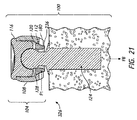
図21は、肘関節プロテーゼシステムを取り外すための手術方法を示す。この方法では、関節の組立体104が完全に組み立てられており、ロック構成においてステム124に係合されている。ロック構成では、ロッキングリング112の遠位端150が、カラー壁160の遠位側に配置されてカラー壁160に係合される。例えば溝またはフランジなどの、少なくとも1つのリング接続構造部236がカラー壁の遠位端表面に係合され得、上で考察したように、第1のカラー開口部164内でロッキングリング112を保持する。ロッキングリング112がカラー壁160によって収容され、それによりロッキングリング112が拡大するのを阻害する。
FIG. 21 shows a surgical method for removing the elbow joint prosthesis system. In this way, the
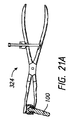
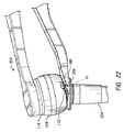
取り外しツール324がカラー壁160からロッキングリング112を切り離すのに使用され得る。取り外しツール324が、その遠位側部分のところにある突出部326がカラー壁160内のアパーチャ180を通して挿入されて、それによりロッキングリング112を切り離すことができるように、構成され得る。取り外しツール324は、アパーチャ180を通して圧縮力F1(図8、図11、および図21に示す)を加えることができる。圧縮力F1が、リング接続構造部236、スロット232、リング112の自由端233、およびリング壁220、のうちの少なくとも1つに作用することができ、それによりロッキングリング112を圧縮する。圧縮力F1を加えることで、ロッキングリング112の2つの自由端233の間の距離を縮小することができる。2つの自由端233が移動して互いに接近すると、ロッキングリング112の直径が縮小し、ロッキングリング112がカラー壁160から切り離され得る。図21Aおよび図22は、いくつかの実施形態において、関節の組立体104を静止状態で保持するために取り外しツール324が関節部材116に作用することができる、ことを示しており、その結果、力F1がロッキングリング112に集中する。図22が、取り外しツール324の一方のアームのテーパ形状またはくさび形状の遠位端上に突出部326が形成され得る、ことを示している。テーパ形状またはくさび形状の遠位端が、環状部材132とロッキングリング112との間の空間の中まで、ツール324を付勢するのを可能にする。カラー壁160から切り離されると、ロッキングリング112が、ロック構成から自由構成まで、カラー108内で近位側に前進させられ得る。図20Aを参照して上で考察したように、隙間G8がリング壁220と内部カラー表面172との間に配置され得る。自由構成がロッキングリング112を拡大するのを可能にし、ロッキングリング112を関節ヘッド128が通過するのを可能にする。このようにして、関節の組立体104がステム124から取り外され得る。
A
図2〜図15に示される橈骨ヘッド組立体100の文脈においてこの方法を説明しているが、図17〜図19に示される橈骨ヘッド組立体400、480を移植するのに同様の方法が使用され得る。
Although this method is described in the context of the
用語
本明細書で特定の実施形態を説明してきたが、文脈によって決定され得る通りに、本明細書で説明されるインプラントおよび方法は交換可能に任意の関節構成要素を使用することができる。
Terminology Although particular embodiments have been described herein, the implants and methods described herein can use any joint component interchangeably, as can be determined by context.
本明細書で使用される場合の「近位側」および「遠位側」という相対的用語は橈骨ヘッド組立体の位置関係から定義されるものとする。 The relative terms "proximal" and "distal" as used herein shall be defined from the positional relationship of the radial head assembly.
「can」、「could」、「might」、または「may」などの条件付きの表現は、特に明記しない限りにおいて、または使用される文脈において他の意味で理解されない限りにおいて、他の実施形態が含まない一方で、特定の実施形態が特定の特徴、要素、および/またはステップを含むことを概して伝えることを意図される。したがって、このような条件付きの表現は、概して、1つまたは複数の実施形態において、特徴、要素、および/またはステップが必要であるということを暗に意味することを意図されない。 Conditional expressions such as “can”, “could”, “might”, or “may” are used in other embodiments, unless stated otherwise or understood to the contrary in the context in which they are used. While not included, it is intended to generally convey that a particular embodiment includes a particular feature, element, and / or step. Thus, such conditional expressions are generally not meant to imply that features, elements, and / or steps are required in one or more embodiments.
「comprising」、「including」、および「having」などの用語は類義であり、オープンエンド的に包括的に使用されるものであり、追加の要素、特徴、行為、および動作などを排除しない。また、「or」という用語はその包括的な意味で使用され(その排他的な意味で使用されない)、したがって、例えば要素のリストを接続するために使用される場合、「or」という用語は、リスト内の要素のうちの、1つの要素、いくつかの要素、またはすべての要素を意味する。加えて、冠詞「a」、「an」、および「the」は、本出願および添付の特許請求の範囲で使用される場合、特に明記しない限りにおいて、「1つまたは複数」または「少なくとも1つ」を意味するものとして解釈される。 The terms "comprising", "including", and "having" are synonymous and are used open-ended, inclusive, and do not exclude additional elements, features, acts, or acts. Also, the term "or" is used in its inclusive sense (and not in its exclusive sense), and thus when used to connect a list of elements, for example, the term "or" Means one, some, or all of the elements in the list. In addition, the articles "a", "an", and "the", as used in this application and the appended claims, unless otherwise specified, include "one or more" or "at least one." Is understood to mean.
また、本明細書で開示される範囲は、任意のすべての重複、部分的な範囲、およびその組み合わせを包含する。「最大」、「少なくとも」、「以上」、「以下」、および「の間」などの表現は記載される数値を含む。「約」または「およそ」などの用語が頭につく数値は記載される数値を含み、状況に基づいて解釈されるべきである(例えば、例えば±5%、±10%、±15%などといったように、条件下で妥当な範囲で可能な限り正確である)。例えば、「約1」は「1」を含む。「実質的に」および「概して」などの用語が頭につくフレーズは記載されるフレーズを含み、状況に基づいて解釈されるべきである(例えば、条件下で妥当な範囲で可能な限りの程度である)。例えば、「実質的には球形」は「球形」を含む。特に明記しない限りにおいて、すべての測定は、温度および圧力を含めて標準状態下にある。 Also, the ranges disclosed herein include any and all overlaps, subranges, and combinations thereof. Expressions such as “maximum”, “at least”, “greater than or equal to”, “less than or equal to”, and “between” include the stated numerical values. Numerical values such as "about" or "approximately" are inclusive of the stated numerical values and should be construed accordingly (e.g., ± 5%, ± 10%, ± 15%, etc. As accurate as reasonably possible under the conditions). For example, “about 1” includes “1”. Phrases headed by terms such as "substantially" and "generally" include the phrase being described and should be construed in context (e.g., to the extent possible to the extent reasonably possible under the conditions). Is). For example, “substantially spherical” includes “spherical”. Unless otherwise noted, all measurements are under standard conditions, including temperature and pressure.
本明細書で使用される場合のアイテムリストのうちの「少なくとも1つ」ということを意味するフレーズは、単一の部材も含めて、これらのアイテムの任意の組み合わせを意味する。例えば、「A, B, or Cのうちの少なくとも1つ」は、「A, B, C」、「AおよびB」、「AおよびC」、「BおよびC」、および「A、B、およびC」を包含することを意図される。別法として、「X、Y、およびZのうちの少なくとも1つ」というフレーズなどの連言的な表現は、特に明記しない限りにおいて、アイテム、用語などが、X、Y、またはZのうちの少なくとも1つであってよい、ということを概して伝えるものとして使用されるものとして文脈において理解される。したがって、このような連言的な表現は、特定の実施形態が、Xのうちの少なくとも1つ、Yのうちの少なくとも1つ、およびZのうちの少なくとも1つ、のそれぞれが存在することが必要である、ということを暗に意味することを概して意図されない。 As used herein, the phrase "at least one" of a list of items means any combination of these items, including single items. For example, "at least one of A, B, or C" means "A, B, C," "A and B," "A and C," "B and C," and "A, B, And C ”are intended to be included. Alternatively, a conjunctive expression, such as the phrase "at least one of X, Y, and Z", refers to an item, term, etc., of X, Y, or Z unless specified otherwise. It is understood in the context as generally used to convey that there may be at least one. Thus, such a conjunctive expression is such that in certain embodiments, each of at least one of X, at least one of Y, and at least one of Z is present. It is generally not intended to imply that it is necessary.
本明細書では特定の実施形態および実施例を説明してきたが、本開示で示されて説明される肘関節プロテーゼに対して多くの変形形態および修正形態が作られ得、肘関節プロテーゼの要素が、さらに別の実施形態または許容される実施例を形成するためには別の形で組み合わされるおよび/または修正されるものとして理解されるべきである、ということを強調しておく。これらのすべての修正形態および変形形態は本明細書では本開示の範囲内に含まれることを意図される。多種多様なデザインおよび手法が可能である。本明細書で開示される特徴、構造、またはステップは必須なものではなく、不可欠なものでもない。 Although particular embodiments and examples have been described herein, many variations and modifications can be made to the elbow joint prosthesis shown and described in this disclosure, including elements of the elbow joint prosthesis. It should be emphasized that it should be understood as being combined and / or modified differently to form further embodiments or acceptable examples. All these modifications and variations are intended to be included herein within the scope of the present disclosure. A wide variety of designs and techniques are possible. The features, structures, or steps disclosed herein are not essential or essential.
いくつかの実施形態を添付図面に関連させて説明してきた。しかし、図が正確な縮尺ではないことを理解されたい。距離、角度などは単に例示的なものであり、示されるデバイスの実際の寸法およびレイアウトの正確な関係を必ずしも有するわけではない。構成要素は、追加され得、取り外され得、および/または再配置され得る。さらに、種々の実施形態に関連する、任意特定の特徴、態様、方法、特性、性質、品質、属性、または要素などの、本明細書での開示は、本明細書に記載される他のすべての実施形態で使用され得る。加えて、本明細書で説明される任意の方法が、記載されるステップを実施するのに適する任意のデバイスを使用して実施され得ることが認識されよう。 Some embodiments have been described with reference to the accompanying drawings. However, it should be understood that the figures are not to scale. Distances, angles, etc. are merely exemplary and do not necessarily have an exact relationship to the actual dimensions and layout of the device shown. Components may be added, removed, and / or repositioned. In addition, the disclosure herein, such as any particular feature, aspect, method, property, property, quality, attribute, or element, relating to various embodiments, is hereby incorporated by reference in its entirety. Can be used in the following embodiments. In addition, it will be appreciated that any of the methods described herein may be implemented using any device suitable for performing the described steps.
本開示の目的に照らし、本明細書においては、特定の態様、利点、および新規な特徴が説明される。このようなすべての利点が任意特定の実施形態に従って必ずしも達成され得るわけではないことを理解されたい。したがって、例えば、本明細書で教示または提案され得るような他の利点を必ずしも達成しなくても、本明細書で教示される1つの利点または利点のグループを達成するという形で本開示が具体化または実行され得ることが当業者には認識されよう。 For the purposes of this disclosure, certain aspects, advantages, and novel features are described herein. It should be appreciated that not all such advantages may be achieved in accordance with any particular embodiment. Thus, for example, the disclosure is embodied in the form of achieving one advantage or group of advantages taught herein without necessarily achieving other advantages as may be taught or suggested herein. One of ordinary skill in the art will recognize that this can be implemented or performed.
また、本明細書では例示の実施形態を説明してきたが、本発明の範囲が、具体的に開示される実施形態を超えて、実施形態の特定の特徴および態様(例えば、種々の実施形態に跨る態様)の等価の要素、修正、排除、組み合わせまたは下位の組み合わせ、を有する任意のすべての実施形態、適応および/または変形、ならびに本開示に基づいて当業者によって認識され得るような本発明の使用、にまで及ぶ、ことを当業者であれば理解するであろう。特許請求の範囲の限定は特許請求の範囲で採用される表現に基づいて広い意味で解釈されるべきであり、本明細書で説明される実施例に限定されるべきではなく、つまり本出願の審査においては、これらの実施例は非排他的であると解釈されるべきである。さらに、開示されるプロセスおよび方法のアクションは、アクションの順序を変更すること、追加のアクションを挿入すること、および/またはアクションを排除することを含めた、任意の形で修正され得る。したがって、本明細書および実施例は単に例示的であるとみなされることを意図され、真の範囲および趣旨は特許請求の範囲およびそれらの均等物の全範囲によって示される。 Also, although exemplary embodiments have been described herein, the scope of the invention is beyond the specifically disclosed embodiments, and with certain features and aspects of the embodiments (e.g., in various embodiments). Cross-section) equivalent elements, modifications, exclusions, combinations or sub-combinations, One of ordinary skill in the art will understand that it extends to use. The scope of the claims should be construed in a broad sense based on the expressions adopted in the claims, and should not be limited to the examples described in the specification, that is, the present application. In examination, these examples should be construed as non-exclusive. Moreover, the actions of the disclosed processes and methods may be modified in any manner, including changing the order of actions, inserting additional actions, and / or eliminating actions. Accordingly, the specification and examples are intended to be considered merely illustrative, with the true scope and spirit of the invention being indicated by the full scope of the claims and their equivalents.
本明細書で開示されるいかなる方法も記載される順序で実施される必要はない。本明細書で開示される方法は専門家によって行われる特定のアクションを含むが、これらの方法は、明記する形でまたは暗に、これらのアクションの任意のサードパーティへの指示をさらに含むことができる。例えば、「関節の組立体の開口部を関節ヘッド上に配置する」などのアクションは、「関節の組立体の開口部を関節ヘッドの上に配置することを指示する」を含む。 It is not necessary for any of the methods disclosed herein to be performed in the order described. Although the methods disclosed herein include specific actions taken by a practitioner, these methods may, in addition, either explicitly or implicitly, further include the instruction to any third party of these actions. it can. For example, an action such as "place the opening of the joint assembly on the joint head" includes "instruct to place the opening of the joint assembly on the joint head".
10 肘関節プロテーゼ
14 上腕骨ステム
18 上腕骨スプール
22 橈骨ステム
26 橈骨
30 尺骨
34 橈骨ヘッド
100 橈骨ヘッド組立体
104 関節の組立体
104' 関節の組立体
104'' 関節の組立体
104''' 関節の組立体
108 カラー
112 ロッキングリング
116 関節部材
116' 関節部材
124 ステム
125 遠位端
126 近位側部分
127 遠位側部分
128 関節ヘッド
130 近位端
132 環状部材
140 近位側部分
142 遠位側部分
144 近位側部分
146 遠位側部分
148 近位側部分
150 遠位側部分
160 カラー壁
164 第1のカラー開口部
166 通路
168 第2のカラー開口部
172 内部カラー表面
176 角度付き部分
180 アパーチャ
184 カラー接続構造部
188 回転防止構造部
220 リング壁
224 リング開口部
228 角度付き外側表面
232 スロット
233 自由端
236 リング接続構造部
237 円周方向溝
238 近位側部分
240 遠位側部分
242 中間部分
260 基部
264 突出部
268 外側リム
269 遠位側面
272 第1の凹形表面
276 第2の凹形表面
280 遠位端表面
284 周囲表面
320A 肘関節プロテーゼキット
320B キット
324 取り外しツール
326 突出部
328 ロッキングツール
330 カラー係合部分
332 関節部材係合部分
400 橈骨ヘッド組立体
404 関節の組立体
408 カラー
412 ロッキングリング
416 関節部材
424 ステム
444 近位端
446 遠位端
447 内側リム
450 内側リム
454 角度付き部分
458 遠位端
462 対合表面
480 関節の組立体
484 関節部分
488 ステム
490 近位側部分
492 第1の関節部材
493 基部
494 凸形関節ヘッド
495 第1の凹形表面
496 カラー
500 捕捉部材
504 カラー開口部
508 内部捕捉表面
512 対合表面
516 関節窩
520 第2の関節部材
524 第2の凹形表面
540 橈骨ヘッド組立体
544 第1の関節部材
548 基部
552 第1の凹形表面
600 アクチェエータ
604 遠位端
608 近位端
616 握持部分
620 握持部分
10 Elbow joint prosthesis
14 Humeral stem
18 humerus spool
22 Radial stem
26 radius
30 ulna
34 radius head
100 radius head assembly
104 joint assembly
104 'joint assembly
104 '' joint assembly
104 '''joint assembly
108 colors
112 rocking ring
116 Joint member
116 'joint member
124 stem
125 distal end
126 proximal part
127 distal part
128 joint head
130 proximal end
132 Annular member
140 proximal part
142 distal part
144 proximal part
146 Distal part
148 Proximal part
150 distal part
160 color wall
164 1st color opening
166 passage
168 Second collar opening
172 Internal color surface
176 angled part
180 aperture
184 Color connection structure
188 Anti-rotation structure
220 ring wall
224 Ring opening
228 Angled outer surface
232 slots
233 Free end
236 Ring connection structure
237 circumferential groove
238 Proximal part
240 distal part
242 middle part
260 base
264 Projection
268 outer rim
269 distal side
272 First concave surface
276 Second concave surface
280 distal end surface
284 surrounding surface
320A Elbow Prosthesis Kit
320B kit
324 Removal Tool
326 Projection
328 Rocking Tool
330 Collar engagement part
332 Joint member engaging part
400 radius head assembly
404 Joint Assembly
408 colors
412 locking ring
416 Joint member
424 stem
444 proximal end
446 distal end
447 inner rim
450 inner rim
454 angled part
458 distal end
462 mating surface
480 joint assembly
484 joint
488 stem
490 proximal part
492 First joint member
493 base
494 convex joint head
495 First concave surface
496 colors
500 capture member
504 color opening
508 Internal capture surface
512 mating surface
516 glenoid
520 Second joint member
524 Second concave surface
540 Radial head assembly
544 First joint member
548 base
552 first concave surface
600 actuator
604 distal end
608 proximal end
616 grip part
620 grip part
Claims (38)
第1のカラー開口部と、第2のカラー開口部と、それらを通じた通路と、を画定するカラー壁を備え、前記カラー壁が、前記第1のカラー開口部の近傍に角度付き部分を備える内部カラー表面を有する、カラーと、
リング開口部を画定するリング壁を備え、前記リング壁が、角度付き外側表面と、前記リング壁が径方向に拡大するのを可能にするように構成されるスロットと、を有し、前記角度付き外側表面が前記内部カラー表面の前記角度付き部分に係合される、ロッキングリングと、
関節部材であって、
外側リムと、第1の凹形表面と、を有する基部、および
前記基部から延在し、前記第1の凹形表面と、前記第1の凹形表面の反対側にある前記関節部材の端部と、の間に配置される第2の凹形表面と、を備え、前記内部カラー表面に係合されるように構成される周囲表面を有する、突出部、
を備える、関節部材と、
を備え、
前記関節部材および前記ロッキングリングが前記カラー内に関節窩を画定し、前記関節窩が前記凸形の関節ヘッドを受けるように構成される、
橈骨ヘッド組立体。 A stem with a convex joint head at one end,
A collar wall defining a first collar opening, a second collar opening, and a passageway therethrough, the collar wall comprising an angled portion proximate the first collar opening. A color having an internal color surface, and
A ring wall defining a ring opening, the ring wall having an angled outer surface and a slot configured to allow the ring wall to expand radially; A locking ring, the locking outer surface being engaged with the angled portion of the inner collar surface;
A joint member,
A base having an outer rim and a first concave surface; and an end of the articulation member extending from the base and opposite the first concave surface and the first concave surface. A protrusion, the protrusion having a peripheral surface configured to be engaged with the interior collar surface, the protrusion having a second concave surface disposed therebetween.
And a joint member,
Equipped with
The articulation member and the locking ring define a glenoid in the collar, the glenoid being configured to receive the convex joint head
Radial head assembly.
前記関節部材が前記非ロック位置から前記ロック位置へと移動する場合に、前記関節部材が前記ロッキングリングと係合して、前記ロッキングリングをロックされたリング位置へと移動させ、それにより前記ロッキングリングの拡大を阻害して、前記関節窩から前記凸形の関節ヘッドが取り外されるのを防止する、
請求項1から14のいずれか一項に記載の組立体。 The articulation member is configured to move from an unlocked position to a locked position,
When the articulation member moves from the unlocked position to the locked position, the articulation member engages the locking ring to move the locking ring to a locked ring position, thereby causing the locking. Inhibiting expansion of the ring to prevent removal of the convex joint head from the glenoid,
Assembly according to any one of claims 1 to 14.
第1の骨に結合されるステムに結合されるように構成される関節部分を備え、前記関節部分は
前記第1の骨の反対側の第2の骨の方を向く前記関節部分上に配置される凹形表面と、
前記凹形表面の反対側にあるカラー開口部と、前記カラー開口部の近傍にある内部捕捉表面と、を画定するカラー壁を備えるカラーと、
前記カラー開口部から前記カラーの内部まで延在する空間と、
捕捉部材開口部と、前記内部捕捉表面に係合されるように構成される対合表面とを備える捕捉部材と
を備え、
前記関節の組立体は、前記捕捉部材が拡大するのを防止するために前記内部捕捉表面が前記対合表面と係合する構成を有し、その結果、前記関節窩内に配置されるステムのヘッドが前記関節窩内で保持され得る、
関節の組立体。 A joint assembly,
A joint portion configured to be coupled to a stem that is coupled to a first bone, the joint portion being disposed on the joint portion facing the second bone opposite the first bone. Concave surface,
A collar having a collar wall defining a collar opening opposite the concave surface and an internal capture surface proximate the collar opening;
A space extending from the collar opening to the interior of the collar,
A capture member having a capture member opening and a mating surface configured to engage the internal capture surface;
The joint assembly has a configuration in which the internal capture surface engages the mating surface to prevent expansion of the capture member, such that a stem disposed within the glenoid fossa. A head may be retained within the glenoid fossa,
Joint assembly.
前記関節ヘッドの上に関節の組立体の開口部を配置するステップであって、前記関節の組立体が、
前記第1の骨の反対側の第2の骨の方を向くように前記開口部の反対側で前記関節の組立体上に配置される凹形表面と、前記開口部を画定するカラーと、前記開口部から前記関節の組立体の内部へと延在する空間と、前記開口部の近傍にある内部捕捉表面と、
前記開口部内に配置される捕捉部材と、
を備える、配置するステップと、
前記捕捉部材を拡大するステップと、
前記捕捉部材を通るように前記関節ヘッドを前進させるステップであって、その結果、前記関節ヘッドが前記捕捉部材と前記凹形表面との間に配置され、前記捕捉部材が前記関節ヘッドと前記内部捕捉表面との間に配置される、前進させるステップと、
を含む、
手術方法。 Attaching a distal portion of the stem to a first bone, the stem comprising an articulating head on the proximal end of the stem; attaching
Disposing an opening in the joint assembly over the joint head, the joint assembly comprising:
A concave surface disposed on the assembly of the joint opposite the opening to face the second bone opposite the first bone; and a collar defining the opening, A space extending from the opening into the interior of the joint assembly; an internal capture surface proximate the opening;
A capture member disposed within the opening,
Arranging, and arranging,
Enlarging the capture member,
Advancing the articulating head through the capture member, such that the articulating head is located between the capture member and the concave surface, the capture member being the articulating head and the interior. An advancing step positioned between the capture surface and
including,
Surgical method.
カラーであって、前記カラーの内部空間の中にアクセスするのを可能にする開口部と、前記開口部から延在する外部壁と、前記開口部から延在する内部壁と、を備え、カラー壁が前記外部壁から前記内部壁に向かって延在するアパーチャを有する、カラー、ならびに
フランジおよび角度付き表面を備えるロッキングリングであって、前記フランジが前記開口部から離間する第1の位置において、および前記開口部内で前記ロッキングリングを固定的に保持するために、前記フランジが前記開口部を横断する第2の位置において、前記内部空間内に配置可能である、ロッキングリング、
を備える、橈骨ヘッド組立体と、
前記第1の位置と前記第2の位置との間を前記ロッキングリングが移動するのを可能にするように構成されるツールと、
を備える、キット。 A radial head assembly,
A collar having an opening for allowing access into an interior space of the collar, an outer wall extending from the opening, and an inner wall extending from the opening, A locking ring, the wall having an aperture extending from the outer wall toward the inner wall, and a locking ring comprising a flange and an angled surface, the flange in a first position spaced from the opening, And a locking ring, wherein the flange is positionable in the interior space in a second position transverse to the opening for fixedly holding the locking ring in the opening,
A radial head assembly,
A tool configured to allow the locking ring to move between the first position and the second position;
A kit comprising.
前記第1の骨に結合されるステムに結合するように構成される関節部分であって、
前記凹形表面に隣接するカラー開口部と、前記カラー開口部の近傍にある内部捕捉表面と、を画定するカラー壁を備えるカラーと、
前記カラー開口部から前記カラーの内部まで延在する空間と、
捕捉部材開口部と、前記内部捕捉表面に係合されるように構成される対合表面と、を備える捕捉部材と、
を備える、関節部分と、
を備える、関節の組立体であって、
前記関節の組立体が、前記捕捉部材が拡大するのを防止するために前記内部捕捉表面が前記対合表面に係合するような、構成を有し、その結果、前記凹形表面に結合されて前記関節窩内に配置されるヘッド部材が、前記関節窩内で保持され得る、
関節の組立体。 An articulation member comprising a concave surface facing the second bone opposite the first bone;
A joint portion configured to connect to a stem connected to the first bone,
A collar having a collar wall defining a collar opening adjacent the concave surface and an internal capture surface proximate the collar opening;
A space extending from the collar opening to the interior of the collar,
A capture member comprising a capture member opening and a mating surface configured to engage the internal capture surface;
And a joint part,
A joint assembly comprising:
The articulation assembly has a configuration such that the internal capture surface engages the mating surface to prevent expansion of the capture member and, as a result, is coupled to the concave surface. A head member disposed within the glenoid may be retained within the glenoid.
Joint assembly.
Applications Claiming Priority (3)
| Application Number | Priority Date | Filing Date | Title |
|---|---|---|---|
| US201762481484P | 2017-04-04 | 2017-04-04 | |
| US62/481,484 | 2017-04-04 | ||
| PCT/US2018/025737 WO2018187233A1 (en) | 2017-04-04 | 2018-04-02 | Elbow joint prostheses |
Publications (2)
| Publication Number | Publication Date |
|---|---|
| JP2020512902A true JP2020512902A (en) | 2020-04-30 |
| JP7220669B2 JP7220669B2 (en) | 2023-02-10 |
Family
ID=62067785
Family Applications (1)
| Application Number | Title | Priority Date | Filing Date |
|---|---|---|---|
| JP2019555151A Active JP7220669B2 (en) | 2017-04-04 | 2018-04-02 | elbow joint prosthesis |
Country Status (6)
| Country | Link |
|---|---|
| US (2) | US11109978B2 (en) |
| EP (1) | EP3606475B1 (en) |
| JP (1) | JP7220669B2 (en) |
| CN (1) | CN110913804B (en) |
| AU (2) | AU2018249496B2 (en) |
| WO (1) | WO2018187233A1 (en) |
Families Citing this family (7)
| Publication number | Priority date | Publication date | Assignee | Title |
|---|---|---|---|---|
| EP3630018B1 (en) * | 2017-06-02 | 2023-05-10 | OT Medizintechnik GmbH | Radial-capitellar implant |
| US11020234B2 (en) | 2018-02-20 | 2021-06-01 | Synthes Gmbh | Radial head orthopedic implant apparatus and method of using same |
| JP7013620B2 (en) * | 2018-10-03 | 2022-01-31 | ハウメディカ オステオニクス コーポレイション | Elbow prosthesis |
| US11684398B2 (en) * | 2019-01-29 | 2023-06-27 | Howmedica Osteonics Corp. | Press fit stem |
| WO2022159958A1 (en) * | 2021-01-21 | 2022-07-28 | Howmedica Osteonics Corp. | Elbow joint prostheses |
| CN116531149A (en) * | 2022-01-25 | 2023-08-04 | 苏州微创关节医疗科技有限公司 | radial head prosthesis |
| WO2025223701A1 (en) * | 2024-04-26 | 2025-10-30 | Adler Ortho S.P.A. | Radial capitellum prosthesis |
Citations (5)
| Publication number | Priority date | Publication date | Assignee | Title |
|---|---|---|---|---|
| US20040254646A1 (en) * | 2003-06-16 | 2004-12-16 | Stone Kevin T. | Provisional coupling mechanism |
| US20060064173A1 (en) * | 2004-09-08 | 2006-03-23 | Arthrex, Inc. | Modular system for replacement of radial head |
| US20060142866A1 (en) * | 2004-08-23 | 2006-06-29 | Mark Baratz | Radial head implant apparatuses and methods |
| US20120022664A1 (en) * | 2006-03-22 | 2012-01-26 | Ascension Orthopedics, Inc. | Prosthetic implant and assembly method |
| US20140074246A1 (en) * | 2012-09-10 | 2014-03-13 | Acumed Llc | Radial head prosthesis with floating articular member |
Family Cites Families (19)
| Publication number | Priority date | Publication date | Assignee | Title |
|---|---|---|---|---|
| US4383337A (en) * | 1980-10-22 | 1983-05-17 | Zimmer Usa, Inc. | Elbow prosthesis |
| US4936855A (en) | 1989-04-24 | 1990-06-26 | Intermedics, Orthopedics, Inc. | Stepped-lock ring system for implantable joint prostheses |
| CN1103207C (en) | 1992-10-29 | 2003-03-19 | 奥托伯克矫形外科工业产业管理公司 | Elbow joint |
| DE4331282A1 (en) | 1993-09-15 | 1995-03-16 | Hahn Michael | Joint endoprosthesis |
| DE19620525A1 (en) | 1996-05-22 | 1997-11-27 | Gmt Medizinische Technik Gmbh | Elbow joint endoprosthesis |
| FR2758455B1 (en) | 1997-01-23 | 1999-08-06 | Tornier Sa | TOTAL ELBOW PROSTHESIS |
| US5824108A (en) | 1997-03-26 | 1998-10-20 | Johnson & Johnson Professional, Inc. | Bipolar acetabular cup |
| FR2793404B1 (en) | 1999-05-14 | 2001-09-14 | Tornier Sa | ELBOW PROSTHESIS |
| US6270529B1 (en) | 1999-09-01 | 2001-08-07 | Wright Medical Technology, Inc. | Modular implant for replacing end of radius and having drainage passage for trapped fluid |
| US8114163B2 (en) | 2000-04-10 | 2012-02-14 | Biomet Manufacturing Corp. | Method and apparatus for adjusting height and angle for a radial head |
| FR2826860B1 (en) | 2001-07-09 | 2004-03-05 | Tornier Sa | ANCILLARY OF POSITION OF A CUBITAL COMPONENT AND / OR A RADIAL COMPONENT OF ELBOW PROSTHESIS |
| FR2826859B1 (en) | 2001-07-09 | 2003-09-19 | Tornier Sa | ANCILLARY OF LAYING OF A HUMERAL COMPONENT OF ELBOW PROSTHESIS |
| US6986792B2 (en) | 2002-09-13 | 2006-01-17 | Smith & Nephew, Inc. | Prostheses |
| FR2855397B1 (en) | 2003-05-28 | 2005-07-15 | Tornier Sa | ELBOW PROSTHESIS |
| US7160329B2 (en) | 2004-12-01 | 2007-01-09 | Mayo Foundation For Medical Research And Education | Radial-capitellar implant |
| US9636228B2 (en) | 2007-02-10 | 2017-05-02 | Howmedica Osteonics Corp. | Radial head implant |
| US9023110B2 (en) | 2008-07-25 | 2015-05-05 | Kyon Ag | Elbow joint prosthesis and method for implantation |
| WO2014160924A1 (en) * | 2013-03-28 | 2014-10-02 | Mayo Foundation For Medical Education And Research | Radial head trials |
| JP7013620B2 (en) | 2018-10-03 | 2022-01-31 | ハウメディカ オステオニクス コーポレイション | Elbow prosthesis |
-
2018
- 2018-04-02 CN CN201880029429.XA patent/CN110913804B/en active Active
- 2018-04-02 JP JP2019555151A patent/JP7220669B2/en active Active
- 2018-04-02 EP EP18720821.0A patent/EP3606475B1/en active Active
- 2018-04-02 AU AU2018249496A patent/AU2018249496B2/en active Active
- 2018-04-02 US US15/942,858 patent/US11109978B2/en active Active
- 2018-04-02 WO PCT/US2018/025737 patent/WO2018187233A1/en not_active Ceased
-
2021
- 2021-07-12 US US17/372,955 patent/US20210338439A1/en active Pending
-
2023
- 2023-09-04 AU AU2023226626A patent/AU2023226626B2/en active Active
Patent Citations (5)
| Publication number | Priority date | Publication date | Assignee | Title |
|---|---|---|---|---|
| US20040254646A1 (en) * | 2003-06-16 | 2004-12-16 | Stone Kevin T. | Provisional coupling mechanism |
| US20060142866A1 (en) * | 2004-08-23 | 2006-06-29 | Mark Baratz | Radial head implant apparatuses and methods |
| US20060064173A1 (en) * | 2004-09-08 | 2006-03-23 | Arthrex, Inc. | Modular system for replacement of radial head |
| US20120022664A1 (en) * | 2006-03-22 | 2012-01-26 | Ascension Orthopedics, Inc. | Prosthetic implant and assembly method |
| US20140074246A1 (en) * | 2012-09-10 | 2014-03-13 | Acumed Llc | Radial head prosthesis with floating articular member |
Also Published As
| Publication number | Publication date |
|---|---|
| US20180280150A1 (en) | 2018-10-04 |
| JP7220669B2 (en) | 2023-02-10 |
| AU2018249496A1 (en) | 2019-10-24 |
| CN110913804B (en) | 2022-03-15 |
| WO2018187233A1 (en) | 2018-10-11 |
| EP3606475A1 (en) | 2020-02-12 |
| US11109978B2 (en) | 2021-09-07 |
| US20210338439A1 (en) | 2021-11-04 |
| EP3606475B1 (en) | 2021-01-27 |
| AU2023226626B2 (en) | 2025-02-20 |
| CN110913804A (en) | 2020-03-24 |
| AU2023226626A1 (en) | 2023-09-21 |
| CA3058924A1 (en) | 2018-10-11 |
| AU2018249496B2 (en) | 2023-06-08 |
Similar Documents
| Publication | Publication Date | Title |
|---|---|---|
| JP2020512902A (en) | Elbow joint prosthesis | |
| EP2638881B1 (en) | Joint implant trial components | |
| US7294150B1 (en) | Liner for acetabular cup | |
| EP1493406B1 (en) | Acetabular component | |
| US12178707B2 (en) | Elbow joint prostheses | |
| JPH10337297A (en) | Acetabulum cup assembly | |
| JP2012525942A (en) | Modular trial prosthesis head | |
| AU2025201408A1 (en) | Reverse shoulder systems | |
| US20160199188A1 (en) | Liner System | |
| US20230033626A1 (en) | Implant component assembly | |
| CA3058924C (en) | Elbow joint prostheses | |
| JP2023163165A (en) | Hip arthroplasty implants |
Legal Events
| Date | Code | Title | Description |
|---|---|---|---|
| A621 | Written request for application examination |
Free format text: JAPANESE INTERMEDIATE CODE: A621 Effective date: 20210401 |
|
| A711 | Notification of change in applicant |
Free format text: JAPANESE INTERMEDIATE CODE: A711 Effective date: 20210910 |
|
| A521 | Request for written amendment filed |
Free format text: JAPANESE INTERMEDIATE CODE: A523 Effective date: 20211108 |
|
| A977 | Report on retrieval |
Free format text: JAPANESE INTERMEDIATE CODE: A971007 Effective date: 20220209 |
|
| A131 | Notification of reasons for refusal |
Free format text: JAPANESE INTERMEDIATE CODE: A131 Effective date: 20220221 |
|
| A521 | Request for written amendment filed |
Free format text: JAPANESE INTERMEDIATE CODE: A523 Effective date: 20220519 |
|
| A02 | Decision of refusal |
Free format text: JAPANESE INTERMEDIATE CODE: A02 Effective date: 20220711 |
|
| A521 | Request for written amendment filed |
Free format text: JAPANESE INTERMEDIATE CODE: A523 Effective date: 20221111 |
|
| C60 | Trial request (containing other claim documents, opposition documents) |
Free format text: JAPANESE INTERMEDIATE CODE: C60 Effective date: 20221111 |
|
| C11 | Written invitation by the commissioner to file amendments |
Free format text: JAPANESE INTERMEDIATE CODE: C11 Effective date: 20221128 |
|
| A911 | Transfer to examiner for re-examination before appeal (zenchi) |
Free format text: JAPANESE INTERMEDIATE CODE: A911 Effective date: 20221220 |
|
| C21 | Notice of transfer of a case for reconsideration by examiners before appeal proceedings |
Free format text: JAPANESE INTERMEDIATE CODE: C21 Effective date: 20221223 |
|
| TRDD | Decision of grant or rejection written | ||
| A01 | Written decision to grant a patent or to grant a registration (utility model) |
Free format text: JAPANESE INTERMEDIATE CODE: A01 Effective date: 20230104 |
|
| A61 | First payment of annual fees (during grant procedure) |
Free format text: JAPANESE INTERMEDIATE CODE: A61 Effective date: 20230131 |
|
| R150 | Certificate of patent or registration of utility model |
Ref document number: 7220669 Country of ref document: JP Free format text: JAPANESE INTERMEDIATE CODE: R150 |
|
| R250 | Receipt of annual fees |
Free format text: JAPANESE INTERMEDIATE CODE: R250 |