JP2020511558A - Process and system for converting crude oil to petrochemical and fuel products, integrating vacuum gas oil hydrocracking and steam cracking - Google Patents
Process and system for converting crude oil to petrochemical and fuel products, integrating vacuum gas oil hydrocracking and steam cracking Download PDFInfo
- Publication number
- JP2020511558A JP2020511558A JP2019527425A JP2019527425A JP2020511558A JP 2020511558 A JP2020511558 A JP 2020511558A JP 2019527425 A JP2019527425 A JP 2019527425A JP 2019527425 A JP2019527425 A JP 2019527425A JP 2020511558 A JP2020511558 A JP 2020511558A
- Authority
- JP
- Japan
- Prior art keywords
- zone
- range
- oil
- stream
- hydrogen
- Prior art date
- Legal status (The legal status is an assumption and is not a legal conclusion. Google has not performed a legal analysis and makes no representation as to the accuracy of the status listed.)
- Withdrawn
Links
Images


Classifications
-
- C—CHEMISTRY; METALLURGY
- C10—PETROLEUM, GAS OR COKE INDUSTRIES; TECHNICAL GASES CONTAINING CARBON MONOXIDE; FUELS; LUBRICANTS; PEAT
- C10G—CRACKING HYDROCARBON OILS; PRODUCTION OF LIQUID HYDROCARBON MIXTURES, e.g. BY DESTRUCTIVE HYDROGENATION, OLIGOMERISATION, POLYMERISATION; RECOVERY OF HYDROCARBON OILS FROM OIL-SHALE, OIL-SAND, OR GASES; REFINING MIXTURES MAINLY CONSISTING OF HYDROCARBONS; REFORMING OF NAPHTHA; MINERAL WAXES
- C10G55/00—Treatment of hydrocarbon oils, in the absence of hydrogen, by at least one refining process and at least one cracking process
- C10G55/02—Treatment of hydrocarbon oils, in the absence of hydrogen, by at least one refining process and at least one cracking process plural serial stages only
- C10G55/06—Treatment of hydrocarbon oils, in the absence of hydrogen, by at least one refining process and at least one cracking process plural serial stages only including at least one catalytic cracking step
-
- C—CHEMISTRY; METALLURGY
- C10—PETROLEUM, GAS OR COKE INDUSTRIES; TECHNICAL GASES CONTAINING CARBON MONOXIDE; FUELS; LUBRICANTS; PEAT
- C10G—CRACKING HYDROCARBON OILS; PRODUCTION OF LIQUID HYDROCARBON MIXTURES, e.g. BY DESTRUCTIVE HYDROGENATION, OLIGOMERISATION, POLYMERISATION; RECOVERY OF HYDROCARBON OILS FROM OIL-SHALE, OIL-SAND, OR GASES; REFINING MIXTURES MAINLY CONSISTING OF HYDROCARBONS; REFORMING OF NAPHTHA; MINERAL WAXES
- C10G7/00—Distillation of hydrocarbon oils
- C10G7/06—Vacuum distillation
-
- B—PERFORMING OPERATIONS; TRANSPORTING
- B01—PHYSICAL OR CHEMICAL PROCESSES OR APPARATUS IN GENERAL
- B01D—SEPARATION
- B01D3/00—Distillation or related exchange processes in which liquids are contacted with gaseous media, e.g. stripping
- B01D3/14—Fractional distillation or use of a fractionation or rectification column
-
- C—CHEMISTRY; METALLURGY
- C10—PETROLEUM, GAS OR COKE INDUSTRIES; TECHNICAL GASES CONTAINING CARBON MONOXIDE; FUELS; LUBRICANTS; PEAT
- C10G—CRACKING HYDROCARBON OILS; PRODUCTION OF LIQUID HYDROCARBON MIXTURES, e.g. BY DESTRUCTIVE HYDROGENATION, OLIGOMERISATION, POLYMERISATION; RECOVERY OF HYDROCARBON OILS FROM OIL-SHALE, OIL-SAND, OR GASES; REFINING MIXTURES MAINLY CONSISTING OF HYDROCARBONS; REFORMING OF NAPHTHA; MINERAL WAXES
- C10G21/00—Refining of hydrocarbon oils, in the absence of hydrogen, by extraction with selective solvents
-
- C—CHEMISTRY; METALLURGY
- C10—PETROLEUM, GAS OR COKE INDUSTRIES; TECHNICAL GASES CONTAINING CARBON MONOXIDE; FUELS; LUBRICANTS; PEAT
- C10G—CRACKING HYDROCARBON OILS; PRODUCTION OF LIQUID HYDROCARBON MIXTURES, e.g. BY DESTRUCTIVE HYDROGENATION, OLIGOMERISATION, POLYMERISATION; RECOVERY OF HYDROCARBON OILS FROM OIL-SHALE, OIL-SAND, OR GASES; REFINING MIXTURES MAINLY CONSISTING OF HYDROCARBONS; REFORMING OF NAPHTHA; MINERAL WAXES
- C10G47/00—Cracking of hydrocarbon oils, in the presence of hydrogen or hydrogen- generating compounds, to obtain lower boiling fractions
- C10G47/02—Cracking of hydrocarbon oils, in the presence of hydrogen or hydrogen- generating compounds, to obtain lower boiling fractions characterised by the catalyst used
-
- C—CHEMISTRY; METALLURGY
- C10—PETROLEUM, GAS OR COKE INDUSTRIES; TECHNICAL GASES CONTAINING CARBON MONOXIDE; FUELS; LUBRICANTS; PEAT
- C10G—CRACKING HYDROCARBON OILS; PRODUCTION OF LIQUID HYDROCARBON MIXTURES, e.g. BY DESTRUCTIVE HYDROGENATION, OLIGOMERISATION, POLYMERISATION; RECOVERY OF HYDROCARBON OILS FROM OIL-SHALE, OIL-SAND, OR GASES; REFINING MIXTURES MAINLY CONSISTING OF HYDROCARBONS; REFORMING OF NAPHTHA; MINERAL WAXES
- C10G69/00—Treatment of hydrocarbon oils by at least one hydrotreatment process and at least one other conversion process
- C10G69/02—Treatment of hydrocarbon oils by at least one hydrotreatment process and at least one other conversion process plural serial stages only
- C10G69/06—Treatment of hydrocarbon oils by at least one hydrotreatment process and at least one other conversion process plural serial stages only including at least one step of thermal cracking in the absence of hydrogen
-
- C—CHEMISTRY; METALLURGY
- C10—PETROLEUM, GAS OR COKE INDUSTRIES; TECHNICAL GASES CONTAINING CARBON MONOXIDE; FUELS; LUBRICANTS; PEAT
- C10G—CRACKING HYDROCARBON OILS; PRODUCTION OF LIQUID HYDROCARBON MIXTURES, e.g. BY DESTRUCTIVE HYDROGENATION, OLIGOMERISATION, POLYMERISATION; RECOVERY OF HYDROCARBON OILS FROM OIL-SHALE, OIL-SAND, OR GASES; REFINING MIXTURES MAINLY CONSISTING OF HYDROCARBONS; REFORMING OF NAPHTHA; MINERAL WAXES
- C10G69/00—Treatment of hydrocarbon oils by at least one hydrotreatment process and at least one other conversion process
- C10G69/02—Treatment of hydrocarbon oils by at least one hydrotreatment process and at least one other conversion process plural serial stages only
- C10G69/08—Treatment of hydrocarbon oils by at least one hydrotreatment process and at least one other conversion process plural serial stages only including at least one step of reforming naphtha
-
- C—CHEMISTRY; METALLURGY
- C10—PETROLEUM, GAS OR COKE INDUSTRIES; TECHNICAL GASES CONTAINING CARBON MONOXIDE; FUELS; LUBRICANTS; PEAT
- C10G—CRACKING HYDROCARBON OILS; PRODUCTION OF LIQUID HYDROCARBON MIXTURES, e.g. BY DESTRUCTIVE HYDROGENATION, OLIGOMERISATION, POLYMERISATION; RECOVERY OF HYDROCARBON OILS FROM OIL-SHALE, OIL-SAND, OR GASES; REFINING MIXTURES MAINLY CONSISTING OF HYDROCARBONS; REFORMING OF NAPHTHA; MINERAL WAXES
- C10G7/00—Distillation of hydrocarbon oils
-
- C—CHEMISTRY; METALLURGY
- C10—PETROLEUM, GAS OR COKE INDUSTRIES; TECHNICAL GASES CONTAINING CARBON MONOXIDE; FUELS; LUBRICANTS; PEAT
- C10G—CRACKING HYDROCARBON OILS; PRODUCTION OF LIQUID HYDROCARBON MIXTURES, e.g. BY DESTRUCTIVE HYDROGENATION, OLIGOMERISATION, POLYMERISATION; RECOVERY OF HYDROCARBON OILS FROM OIL-SHALE, OIL-SAND, OR GASES; REFINING MIXTURES MAINLY CONSISTING OF HYDROCARBONS; REFORMING OF NAPHTHA; MINERAL WAXES
- C10G9/00—Thermal non-catalytic cracking, in the absence of hydrogen, of hydrocarbon oils
- C10G9/34—Thermal non-catalytic cracking, in the absence of hydrogen, of hydrocarbon oils by direct contact with inert preheated fluids, e.g. with molten metals or salts
- C10G9/36—Thermal non-catalytic cracking, in the absence of hydrogen, of hydrocarbon oils by direct contact with inert preheated fluids, e.g. with molten metals or salts with heated gases or vapours
-
- C—CHEMISTRY; METALLURGY
- C10—PETROLEUM, GAS OR COKE INDUSTRIES; TECHNICAL GASES CONTAINING CARBON MONOXIDE; FUELS; LUBRICANTS; PEAT
- C10G—CRACKING HYDROCARBON OILS; PRODUCTION OF LIQUID HYDROCARBON MIXTURES, e.g. BY DESTRUCTIVE HYDROGENATION, OLIGOMERISATION, POLYMERISATION; RECOVERY OF HYDROCARBON OILS FROM OIL-SHALE, OIL-SAND, OR GASES; REFINING MIXTURES MAINLY CONSISTING OF HYDROCARBONS; REFORMING OF NAPHTHA; MINERAL WAXES
- C10G2300/00—Aspects relating to hydrocarbon processing covered by groups C10G1/00 - C10G99/00
- C10G2300/10—Feedstock materials
- C10G2300/1037—Hydrocarbon fractions
- C10G2300/104—Light gasoline having a boiling range of about 20 - 100 °C
-
- C—CHEMISTRY; METALLURGY
- C10—PETROLEUM, GAS OR COKE INDUSTRIES; TECHNICAL GASES CONTAINING CARBON MONOXIDE; FUELS; LUBRICANTS; PEAT
- C10G—CRACKING HYDROCARBON OILS; PRODUCTION OF LIQUID HYDROCARBON MIXTURES, e.g. BY DESTRUCTIVE HYDROGENATION, OLIGOMERISATION, POLYMERISATION; RECOVERY OF HYDROCARBON OILS FROM OIL-SHALE, OIL-SAND, OR GASES; REFINING MIXTURES MAINLY CONSISTING OF HYDROCARBONS; REFORMING OF NAPHTHA; MINERAL WAXES
- C10G2300/00—Aspects relating to hydrocarbon processing covered by groups C10G1/00 - C10G99/00
- C10G2300/10—Feedstock materials
- C10G2300/1037—Hydrocarbon fractions
- C10G2300/1048—Middle distillates
- C10G2300/1051—Kerosene having a boiling range of about 180 - 230 °C
-
- C—CHEMISTRY; METALLURGY
- C10—PETROLEUM, GAS OR COKE INDUSTRIES; TECHNICAL GASES CONTAINING CARBON MONOXIDE; FUELS; LUBRICANTS; PEAT
- C10G—CRACKING HYDROCARBON OILS; PRODUCTION OF LIQUID HYDROCARBON MIXTURES, e.g. BY DESTRUCTIVE HYDROGENATION, OLIGOMERISATION, POLYMERISATION; RECOVERY OF HYDROCARBON OILS FROM OIL-SHALE, OIL-SAND, OR GASES; REFINING MIXTURES MAINLY CONSISTING OF HYDROCARBONS; REFORMING OF NAPHTHA; MINERAL WAXES
- C10G2300/00—Aspects relating to hydrocarbon processing covered by groups C10G1/00 - C10G99/00
- C10G2300/10—Feedstock materials
- C10G2300/1037—Hydrocarbon fractions
- C10G2300/1048—Middle distillates
- C10G2300/1055—Diesel having a boiling range of about 230 - 330 °C
-
- C—CHEMISTRY; METALLURGY
- C10—PETROLEUM, GAS OR COKE INDUSTRIES; TECHNICAL GASES CONTAINING CARBON MONOXIDE; FUELS; LUBRICANTS; PEAT
- C10G—CRACKING HYDROCARBON OILS; PRODUCTION OF LIQUID HYDROCARBON MIXTURES, e.g. BY DESTRUCTIVE HYDROGENATION, OLIGOMERISATION, POLYMERISATION; RECOVERY OF HYDROCARBON OILS FROM OIL-SHALE, OIL-SAND, OR GASES; REFINING MIXTURES MAINLY CONSISTING OF HYDROCARBONS; REFORMING OF NAPHTHA; MINERAL WAXES
- C10G2300/00—Aspects relating to hydrocarbon processing covered by groups C10G1/00 - C10G99/00
- C10G2300/10—Feedstock materials
- C10G2300/1037—Hydrocarbon fractions
- C10G2300/1048—Middle distillates
- C10G2300/1059—Gasoil having a boiling range of about 330 - 427 °C
-
- C—CHEMISTRY; METALLURGY
- C10—PETROLEUM, GAS OR COKE INDUSTRIES; TECHNICAL GASES CONTAINING CARBON MONOXIDE; FUELS; LUBRICANTS; PEAT
- C10G—CRACKING HYDROCARBON OILS; PRODUCTION OF LIQUID HYDROCARBON MIXTURES, e.g. BY DESTRUCTIVE HYDROGENATION, OLIGOMERISATION, POLYMERISATION; RECOVERY OF HYDROCARBON OILS FROM OIL-SHALE, OIL-SAND, OR GASES; REFINING MIXTURES MAINLY CONSISTING OF HYDROCARBONS; REFORMING OF NAPHTHA; MINERAL WAXES
- C10G2300/00—Aspects relating to hydrocarbon processing covered by groups C10G1/00 - C10G99/00
- C10G2300/40—Characteristics of the process deviating from typical ways of processing
- C10G2300/4006—Temperature
-
- C—CHEMISTRY; METALLURGY
- C10—PETROLEUM, GAS OR COKE INDUSTRIES; TECHNICAL GASES CONTAINING CARBON MONOXIDE; FUELS; LUBRICANTS; PEAT
- C10G—CRACKING HYDROCARBON OILS; PRODUCTION OF LIQUID HYDROCARBON MIXTURES, e.g. BY DESTRUCTIVE HYDROGENATION, OLIGOMERISATION, POLYMERISATION; RECOVERY OF HYDROCARBON OILS FROM OIL-SHALE, OIL-SAND, OR GASES; REFINING MIXTURES MAINLY CONSISTING OF HYDROCARBONS; REFORMING OF NAPHTHA; MINERAL WAXES
- C10G2300/00—Aspects relating to hydrocarbon processing covered by groups C10G1/00 - C10G99/00
- C10G2300/40—Characteristics of the process deviating from typical ways of processing
- C10G2300/4012—Pressure
-
- C—CHEMISTRY; METALLURGY
- C10—PETROLEUM, GAS OR COKE INDUSTRIES; TECHNICAL GASES CONTAINING CARBON MONOXIDE; FUELS; LUBRICANTS; PEAT
- C10G—CRACKING HYDROCARBON OILS; PRODUCTION OF LIQUID HYDROCARBON MIXTURES, e.g. BY DESTRUCTIVE HYDROGENATION, OLIGOMERISATION, POLYMERISATION; RECOVERY OF HYDROCARBON OILS FROM OIL-SHALE, OIL-SAND, OR GASES; REFINING MIXTURES MAINLY CONSISTING OF HYDROCARBONS; REFORMING OF NAPHTHA; MINERAL WAXES
- C10G2400/00—Products obtained by processes covered by groups C10G9/00 - C10G69/14
- C10G2400/04—Diesel oil
-
- C—CHEMISTRY; METALLURGY
- C10—PETROLEUM, GAS OR COKE INDUSTRIES; TECHNICAL GASES CONTAINING CARBON MONOXIDE; FUELS; LUBRICANTS; PEAT
- C10G—CRACKING HYDROCARBON OILS; PRODUCTION OF LIQUID HYDROCARBON MIXTURES, e.g. BY DESTRUCTIVE HYDROGENATION, OLIGOMERISATION, POLYMERISATION; RECOVERY OF HYDROCARBON OILS FROM OIL-SHALE, OIL-SAND, OR GASES; REFINING MIXTURES MAINLY CONSISTING OF HYDROCARBONS; REFORMING OF NAPHTHA; MINERAL WAXES
- C10G2400/00—Products obtained by processes covered by groups C10G9/00 - C10G69/14
- C10G2400/06—Gasoil
-
- C—CHEMISTRY; METALLURGY
- C10—PETROLEUM, GAS OR COKE INDUSTRIES; TECHNICAL GASES CONTAINING CARBON MONOXIDE; FUELS; LUBRICANTS; PEAT
- C10G—CRACKING HYDROCARBON OILS; PRODUCTION OF LIQUID HYDROCARBON MIXTURES, e.g. BY DESTRUCTIVE HYDROGENATION, OLIGOMERISATION, POLYMERISATION; RECOVERY OF HYDROCARBON OILS FROM OIL-SHALE, OIL-SAND, OR GASES; REFINING MIXTURES MAINLY CONSISTING OF HYDROCARBONS; REFORMING OF NAPHTHA; MINERAL WAXES
- C10G2400/00—Products obtained by processes covered by groups C10G9/00 - C10G69/14
- C10G2400/20—C2-C4 olefins
-
- C—CHEMISTRY; METALLURGY
- C10—PETROLEUM, GAS OR COKE INDUSTRIES; TECHNICAL GASES CONTAINING CARBON MONOXIDE; FUELS; LUBRICANTS; PEAT
- C10G—CRACKING HYDROCARBON OILS; PRODUCTION OF LIQUID HYDROCARBON MIXTURES, e.g. BY DESTRUCTIVE HYDROGENATION, OLIGOMERISATION, POLYMERISATION; RECOVERY OF HYDROCARBON OILS FROM OIL-SHALE, OIL-SAND, OR GASES; REFINING MIXTURES MAINLY CONSISTING OF HYDROCARBONS; REFORMING OF NAPHTHA; MINERAL WAXES
- C10G2400/00—Products obtained by processes covered by groups C10G9/00 - C10G69/14
- C10G2400/30—Aromatics
Abstract
統合された様式で複数の処理ユニットを用いて供給原油を石油化学製品に転化することが可能なプロセススキーム配置が開示される。本設計は、水蒸気分解炉複合設備に適した原料を調製するのに最小限の設備投資しか使用しない。原油を、オレフィン及び芳香族化合物を含む石油化学生成物ならびに燃料製品に転化する統合プロセスは、混合原料水蒸気分解及び軽油水蒸気分解を含む。混合原料水蒸気分解炉への供給原料は、装置の境界内の水素化処理域から出る軽質生成物及びナフサ、C3及びC4オレフィン回収工程から出る循環使用流、ならびに装置の境界内の熱分解ガソリン芳香族化合物抽出域から出る抽残液を含む。軽油水蒸気分解炉への供給原料は、減圧軽油水素化精製から出る未転化油中間体を含む。【選択図】図1Disclosed is a process scheme arrangement that is capable of converting feed crude oil to petrochemicals using multiple processing units in an integrated fashion. The design uses minimal capital investment to prepare feedstock suitable for steam cracker complex equipment. Integrated processes for converting crude oil into petrochemical products including olefins and aromatics and fuel products include mixed feed steam cracking and gas oil steam cracking. The feedstock to the mixed feed steam cracking furnace is comprised of light products and naphtha from the hydrotreating zone within the boundaries of the unit, recycle streams from the C3 and C4 olefins recovery process, and pyrolysis gasoline aroma within the boundaries of the unit. It contains the raffinate from the group compound extraction zone. The feedstock to the gas oil steam cracking furnace comprises unconverted oil intermediates from vacuum gas oil hydrorefining. [Selection diagram] Figure 1
Description
関連出願
本出願は、2016年11月21日出願の米国特許仮出願番号第62/424,883号、2017年1月24日出願の米国特許仮出願番号第62/450,018号、2017年1月24日出願の米国特許仮出願番号第62/450,031号、2017年1月24日出願の米国特許仮出願番号第62/450,043号、及び2017年1月24日出願の米国特許仮出願番号第62/450,062号の優先権を主張し、これらの内容はすべて、そのまま全体が本明細書により参照により援用される。
Related Applications This application is US Provisional Application No. 62 / 424,883 filed on November 21, 2016, and US Provisional Application No. 62 / 450,018, 2017 filed on January 24, 2017. U.S. Provisional Application No. 62 / 450,031 filed January 24, U.S. Patent Application No. 62 / 450,043 filed January 24, 2017, and U.S. Patent Application January 24, 2017. Claiming priority of Patent Provisional Application No. 62 / 450,062, the contents of all of which are hereby incorporated by reference in their entireties.
本明細書中開示される本発明は、原油を石油化学製品及び燃料製品に転化するための統合されたプロセス及びシステムに関する。 The invention disclosed herein relates to an integrated process and system for converting crude oil into petrochemical and fuel products.
低級オレフィン(すなわち、エチレン、プロピレン、ブチレン、及びブタジエン)及び芳香族化合物(すなわち、ベンゼン、トルエン、及びキシレン)は、石油化学工業及び化学工業において広く使用される基本的な中間体である。熱分解、または蒸気熱分解は、こうした材料を形成するプロセスの主要なタイプのものであり、典型的には、蒸気の存在下、及び酸素不在下で行われる。蒸気熱分解の典型的な原料として、エタンなどの石油ガス、ならびにナフサ、灯油、及び軽油などの留分を挙げることができる。こうした原料は、入手可能性が通常限られており、原油精製所において、高額の費用及び大量のエネルギーを消費するプロセス工程が必要となる。 Lower olefins (ie ethylene, propylene, butylene, and butadiene) and aromatic compounds (ie benzene, toluene, and xylene) are basic intermediates widely used in the petrochemical and chemical industries. Pyrolysis, or steam pyrolysis, is the major type of process for forming such materials, typically in the presence of steam and in the absence of oxygen. Typical feedstocks for steam pyrolysis include petroleum gases such as ethane, and fractions such as naphtha, kerosene, and gas oil. These feedstocks are usually limited in availability and require expensive and high energy consuming process steps in crude oil refineries.
エチレン製造は、非常に多くの部分を、原料としてのナフサに依存する。しかしながら、重質ナフサは、軽質ナフサよりもパラフィン含有量が少なくまた芳香族化合物含有量が多く、そのため、アップグレーディングしないことには、エチレン製造の原料としてあまり適さない。重質ナフサは、その供給源に基づいて、全パラフィン及び芳香族化合物の量が変化し得る。パラフィン含有量は、約27〜70%の範囲が可能であり、ナフテン含有量は、約15〜60%の範囲が可能であり、芳香族化合物含有量は、約10〜36%の範囲が可能である(体積基準)。 Ethylene production relies in large part on naphtha as a raw material. However, heavy naphtha has a lower paraffin content and a higher aromatic compound content than light naphtha and is therefore not well suited as a raw material for ethylene production without upgrading. Heavy naphtha can vary in the amount of total paraffins and aromatics based on its source. The paraffin content can range from about 27-70%, the naphthene content can range from about 15-60%, and the aromatic compound content can range from about 10-36%. (Volume basis).
多くの化学製品製造業者は、供給原料として石油精製副産物に依存しているため、近隣の精製業者からの供給及び供給原料の品質により制限を受ける。多くの化学製品製造業者はまた、石油精製及びそれに関連する燃料市場の高額な費用によっても制限を受け、このことは、製油所起源の供給原料の経済価値に負の影響を及ぼす可能性がある。自動車及びトラック用の燃費効率の世界基準が高くなれば、燃料需要が低下して精製のマージンが狭まることになり、そして燃料及び化学製品の供給及び/または市場の経済を悪化させる可能性がある。 Many chemical manufacturers rely on petroleum refining by-products as a feedstock and are therefore limited by the supply from nearby refiners and the quality of the feedstock. Many chemical producers are also limited by the high cost of petroleum refining and associated fuel markets, which can negatively impact the economic value of refinery-sourced feedstocks. . Higher global fuel efficiency standards for cars and trucks could reduce fuel demand, narrow refining margins, and adversely impact fuel and chemical supply and / or market economies .
原油を、低級オレフィン及び芳香族化合物などの基本化学中間体に転化するプロセスの改善は、当該分野で依然として必要とされている。また、規模の経済でより大きな影響力を持つより価値の高い化学製品製造機会をもたらす新規アプローチが、当該分野で依然として必要とされている。 Improved processes for converting crude oil to basic chemical intermediates such as lower olefins and aromatics are still needed in the art. In addition, there is still a need in the art for new approaches that provide more valuable chemical manufacturing opportunities with greater impact in economies of scale.
1つまたは複数の実施形態に従って、本発明は、供給原油から石油化学製品及び燃料製品を製造する統合プロセスに関する。統合プロセスは、常圧蒸留域で、供給原油から、少なくとも、直留ナフサ及びそれより軽質の成分を含む留分、1つまたは複数の中質留分、及び常圧残油留分を分離する、最初の分離工程を含む。減圧軽油留分は、減圧蒸留域で、常圧残油留分から分離される。ディーゼル水素化精製装置などの留分水素化処理(「DHP」)域では、中質留分の少なくとも一部が処理されて、ナフサ留分及びディーゼル燃料留分を生成する。減圧軽油留分(及び任意選択で、常圧軽油留分の全部または一部、あるいは重質常圧軽油留分の全部または一部)は、軽油水素化分解域で処理される。未転化油は、軽油水蒸気分解域で処理される。常圧蒸留から直留ナフサ及びそれより軽質の成分とともに出る留分(複数可)、及び芳香族化合物抽出域抽残液は、混合原料水蒸気分解域で処理される。混合原料水蒸気分解域及び軽油水蒸気分解域から出る生成物は、H2、メタン、エタン、エチレン、混合C3、及び混合C4を含む統合されたまたは別個の混合生成物流(複数可);熱分解ガソリン流(複数可);及び熱分解油流(複数可)を含む。 According to one or more embodiments, the present invention relates to an integrated process for producing petrochemical and fuel products from a feed crude oil. The integrated process separates at least a fraction containing straight run naphtha and lighter components, one or more medium fractions, and an atmospheric bottoms fraction from a feed crude oil in an atmospheric distillation zone. , Including the first separation step. The vacuum gas oil fraction is separated from the atmospheric residual oil fraction in the vacuum distillation zone. In a fraction hydrotreatment (“DHP”) region, such as a diesel hydrorefining unit, at least a portion of the middle distillate is treated to produce a naphtha fraction and a diesel fuel fraction. The vacuum gas oil fraction (and optionally all or part of the atmospheric gas oil fraction or all or part of the heavy atmospheric gas oil fraction) is treated in the gas oil hydrocracking zone. Unconverted oil is processed in the light oil steam cracking zone. The distillate (s) from the atmospheric distillation along with the straight run naphtha and lighter components thereof, and the aromatic compound extraction zone raffinate are processed in the mixed feed steam cracking zone. Mixed feed steam cracking zone and the product leaving the gas oil steam cracking zone, H 2, methane, ethane, ethylene, mixed C3, and mixtures containing C4 integrated or separate mixing the product stream (s); pyrolysis gasoline Stream (s); and pyrolysis oil stream (s).
混合生成物流(複数可)から、C3及び混合C4、すなわち石油化学製品であるエチレン、プロピレン、及びブチレンを回収する。エタン及び非オレフィンC3は、混合原料水蒸気分解域に循環使用され、非オレフィンC4は、混合原料水蒸気分解域に循環使用されるか、またはさらなる石油化学製品を製造するための分離処理域に送られる。熱分解ガソリンは、pyガス水素化処理域で精製されて、水素化精製熱分解ガソリンを生成する。水素化精製熱分解ガソリンは、芳香族化合物抽出域に送られ、芳香族生成物及び芳香族化合物抽出域抽残液が回収され、抽残液は、混合原料水蒸気分解域に循環使用される。 C3 and mixed C4, the petrochemicals ethylene, propylene, and butylene are recovered from the mixed product stream (s). Ethane and non-olefin C3 are recycled to the mixed feed steam cracking zone and non-olefin C4 is recycled to the mixed feed steam cracking zone or sent to a separation process zone to produce additional petrochemicals. . Pyrolysis gasoline is refined in the py gas hydrotreating zone to produce hydrorefined pyrolysis gasoline. The hydrorefined pyrolysis gasoline is sent to the aromatic compound extraction zone, the aromatic products and the aromatic compound extraction zone raffinate are recovered, and the raffinate is circulated to the mixed raw material steam cracking zone.
さらに他の態様、実施形態、ならびにこれらの模範的な態様及び実施形態の利点を、以下で詳細に説明する。さらに、当然のことながら、前述の情報及び後述の詳細な説明はどちらも、様々な態様及び実施形態の模範例にすぎず、特許請求される態様及び実施形態の性質及び特徴を理解するための概要または枠組みを提供することを意図する。添付の図面は、様々な態様及び実施形態の図示及びさらなる理解を提供するために含まれるものであり、この明細書に組み込まれてその一部を構成する。図面は、明細書のその他の部分と合わせて、記載及び特許請求される態様及び実施形態の原則及び運転を説明する役割を果たす。 Still other aspects, embodiments, and advantages of these exemplary aspects and embodiments are described in detail below. Furthermore, it is to be understood that both the foregoing information and the following detailed description are merely exemplary of various aspects and embodiments, to understand the nature and features of the claimed aspects and embodiments. It is intended to provide an overview or framework. The accompanying drawings are included to provide a further understanding and illustration of various aspects and embodiments, and are incorporated into and constitute a part of this specification. The drawings, in conjunction with other parts of the specification, serve to explain the principles and operation of the described and claimed aspects and embodiments.
本発明を、以下で、添付の図面を参照してさらに詳細に説明するが、図中、同一または同様な要素は同一の数字で示される。 The present invention will be described in more detail below with reference to the accompanying drawings, in which identical or similar elements are designated by the same numerals.
統合された様式の複数の処理ユニットを用いて供給原油を石油化学製品に転化することが可能なプロセススキーム配置が開示される。この設計は、水蒸気分解炉複合設備に適した原料を調製するのに最小限の設備投資しか利用しない。原油を、オレフィン及び芳香族化合物をはじめとする石油化学生成物、ならびに燃料製品へと転化する統合プロセスは、混合原料水蒸気分解及び軽油水蒸気分解を含む。混合原料水蒸気分解炉への供給原料は、装置の境界内にある水素化処理域から出る軽質生成物及びナフサ、C3及びC4オレフィン回収工程から出る循環使用流、ならびに装置の境界内にある熱分解ガソリン芳香族化合物抽出域から出る抽残液を含む。軽油水蒸気分解炉への供給原料は、減圧軽油水素化精製から出る未転化油中間体を含む。 Disclosed is a process scheme arrangement capable of converting feed crude oil to petrochemicals using multiple processing units in an integrated fashion. This design utilizes minimal capital investment to prepare feedstock suitable for steam cracker complex equipment. Integrated processes for converting crude oil to petrochemical products, including olefins and aromatics, and fuel products include mixed feed steam cracking and gas oil steam cracking. The feedstock to the mixed feed steam cracking furnace is comprised of light products and naphtha from the hydrotreating zone within the boundaries of the unit, recycle streams from the C3 and C4 olefins recovery process, and thermal cracking within the boundaries of the unit. It contains the raffinate from the gasoline aromatics extraction zone. The feedstock to the gas oil steam cracking furnace comprises unconverted oil intermediates from vacuum gas oil hydrorefining.
「主要部分」という語句は、特定の1つまたは複数の流に関して、少なくとも約50重量%〜最高100重量%、または別の指定単位での同じ値を意味する。 The phrase "major portion" means at least about 50% by weight up to 100% by weight, or the same value in another designated unit, for a particular stream or streams.
「相当部分」という語句は、特定の1つまたは複数の流に関して、少なくとも約75重量%〜最高100重量%、または別の指定単位での同じ値を意味する。 The phrase "major portion" means at least about 75% by weight up to 100% by weight, or the same value in another designated unit, for a particular stream or streams.
「実質的部分」という語句は、特定の1つまたは複数の流に関して、少なくとも約90、95、98、または99重量%、及び最高100重量%まで、または別の指定単位での同じ値を意味する。 The phrase "substantial portion" means at least about 90, 95, 98, or 99% by weight, and up to 100% by weight, or the same value in another designated unit, with respect to the particular stream or streams. To do.
「少量部分」という語句は、特定の1つまたは複数の流に関して、約1、2、4、または10重量%から、最高約20、30、40、または50重量%まで、または別の指定単位での同じ値を意味する。 The term "minor portion" refers to about 1, 2, 4, or 10 wt% up to about 20, 30, 40, or 50 wt%, or another designated unit, for a particular stream or streams. Means the same value in.
「原油」という用語は、本明細書中使用される場合、地層から抽出された、その未精製形状にある石油を示す。本明細書中のプロセスの原料に適した原油として、アラビアン・ヘビー、アラビアン・ライト、アラビアン・エクストラ・ライト、他のガルフ原油、ブレント、北海原油、ノース及びウェストアフリカン原油、インドネシアン、チャイニーズ原油、またはそれらの混合物が挙げられる。粗石油混合物として、全原油または抜頭原油が可能である。本明細書中使用される場合、「原油」は、水油分離;及び/またはガス油分離;及び/または脱塩;及び/または安定化などある種の前処理を施された混合物も示す。ある特定の実施形態において、原油は、API比重(ASTM D287標準)が約20°、30°、32°、34°、36°、38°、40°、42°、または44°以上であるそのような混合物のいずれかを示す。 The term "crude oil" as used herein refers to petroleum extracted from the formation and in its unrefined form. Crude oils suitable as feedstocks for the processes herein include Arabian Heavy, Arabian Light, Arabian Extra Light, Other Gulf Crude Oil, Brent, North Sea Crude Oil, North and West African Crude Oil, Indonesian, Chinese Crude Oil, Or the mixture thereof is mentioned. The crude petroleum mixture can be whole crude oil or overhead crude oil. As used herein, “crude oil” also refers to a mixture that has undergone some pretreatment such as water oil separation; and / or gas oil separation; and / or desalination; and / or stabilization. In certain embodiments, the crude oil has an API gravity (ASTM D287 standard) of about 20 °, 30 °, 32 °, 34 °, 36 °, 38 °, 40 °, 42 °, or 44 ° or greater. Any of such mixtures.
「AXL」という頭字語は、本明細書中使用される場合、API比重が約38°、40°、42°、または44°以上であること、及びある特定の実施形態において約38°〜46°、38°〜44°、38°〜42°、38°〜40.5°、39°〜46°、39°〜44°、39°〜42°、または39°〜40.5°の範囲にあることを特徴とするアラブ・エクストラ・ライト原油を示す。 The acronym "AXL," as used herein, has an API specific gravity of about 38 °, 40 °, 42 °, or 44 ° or greater, and in certain embodiments about 38 ° to 46 °. Range of °, 38 ° -44 °, 38 ° -42 °, 38 ° -40.5 °, 39 ° -46 °, 39 ° -44 °, 39 ° -42 °, or 39 ° -40.5 ° Arab Extra Light Crude Oil, characterized in that
「AL」という頭字語は、本明細書中使用される場合、API比重が約30°、32°、34°、36°、または38°以上であること、及びある特定の実施形態において約30°〜38°、30°〜36°、30°〜35°、32°〜38°、32°〜36°、32°〜35°、33°〜38°、33°〜36°、または33°〜35°の範囲にあることを特徴とするアラブ・ライト原油を示す。 The acronym "AL," as used herein, has an API specific gravity of greater than or equal to about 30 °, 32 °, 34 °, 36 °, or 38 °, and in certain embodiments of about 30. ° -38 °, 30 ° -36 °, 30 ° -35 °, 32 ° -38 °, 32 ° -36 °, 32 ° -35 °, 33 ° -38 °, 33 ° -36 °, or 33 ° Figure 3 shows Arab Wright crude oil characterized by being in the range of ~ 35 °.
「LPG」という頭字語は、本明細書中使用される場合、「液化石油ガス」という用語について周知の頭字語を示し、一般的に、C3−C4炭化水素混合物である。ある特定の実施形態において、これらは「軽留分」とも示される。 The acronym "LPG," as used herein, refers to the acronym well known for the term "liquefied petroleum gas" and is generally a C3-C4 hydrocarbon mixture. In certain embodiments, these are also referred to as "light ends."
「ナフサ」という用語は、本明細書中使用される場合、約20〜205、20〜193、20〜190、20〜180、20〜170、32〜205、32〜193、32〜190、32〜180、32〜170、36〜205、36〜193、36〜190、36〜180、または36〜170℃の範囲で沸騰する炭化水素を示す。 The term "naphtha" as used herein is about 20-205, 20-193, 20-190, 20-180, 20-170, 32-205, 32-193, 32-190, 32. Hydrocarbons boiling in the range of -180, 32-170, 36-205, 36-193, 36-190, 36-180, or 36-170C.
「軽質ナフサ」という用語は、本明細書中使用される場合、約20〜110、20〜100、20〜90、20〜88、32〜110、32〜100、32〜90、32〜88、36〜110、36〜100、36〜90、または36〜88℃の範囲で沸騰する炭化水素を示す。 The term "light naphtha" as used herein is about 20-110, 20-100, 20-90, 20-88, 32-110, 32-100, 32-90, 32-88, Hydrocarbons boiling in the range 36-110, 36-100, 36-90, or 36-88 ° C.
「重質ナフサ」という用語は、本明細書中使用される場合、約90〜205、90〜193、90〜190、90〜180、90〜170、93〜205、93〜193、93〜190、93〜180、93〜170、100〜205、100〜193、100〜190、100〜180、100〜170、110〜205、110〜193、110〜190、110〜180、または110〜170℃の範囲で沸騰する炭化水素を示す。 The term "heavy naphtha" as used herein is about 90-205, 90-193, 90-190, 90-180, 90-170, 93-205, 93-193, 93-190. , 93-180, 93-170, 100-205, 100-193, 100-190, 100-180, 100-170, 110-205, 110-193, 110-190, 110-180, or 110-170 ° C. Shows hydrocarbons boiling in the range.
ある特定の実施形態において、ナフサ、軽質ナフサ、及び/または重質ナフサは、原油蒸留、または本明細書中記載されるとおりの中間体精製プロセスの蒸留により得られる、そのような石油留分を示す。 In certain embodiments, naphtha, light naphtha, and / or heavy naphtha may be obtained by crude oil distillation or distillation of an intermediate refining process as described herein. Show.
「直留」という修飾用語は、本明細書中、その周知の意味を有するものとして使用される、すなわち、常圧蒸留ユニットから直接得られる、任意選択でスチームストリッピングに供されているが、水素化処理、流動接触分解、または水蒸気分解など他の精製処理は施されていない留分を記載する。この例として、「直留ナフサ」及びその頭字語「SRN」があり、したがってこの例は、周知のとおり、常圧蒸留ユニットから直接得られる、任意選択でスチームストリッピングに供された、上記で定義される「ナフサ」を示す。 The modifier “straight distillation” is used herein as having its well-known meaning, ie obtained directly from an atmospheric distillation unit, optionally subject to steam stripping, The fraction which has not been subjected to any other purification treatment such as hydrotreatment, fluid catalytic cracking, or steam cracking is described. Examples of this are "straight run naphtha" and its acronym "SRN", and thus this example is, as is well known, obtained directly from an atmospheric distillation unit, optionally subjected to steam stripping, above. Indicates a defined "naphtha".
「灯油」という用語は、本明細書中使用される場合、約170〜280、170〜270、170〜260、180〜280、180〜270、180〜260、190〜280、190〜270、190〜260、193〜280、193〜270、または193〜260℃の範囲で沸騰する炭化水素を示す。 The term "kerosene" as used herein is about 170-280, 170-270, 170-260, 180-280, 180-270, 180-260, 190-280, 190-270, 190. ~ 260, 193-280, 193-270, or hydrocarbons boiling in the range of 193-260 ° C.
「灯軽油」という用語は、本明細書中使用される場合、約170〜250、170〜235、170〜230、170〜225、180〜250、180〜235、180〜230、180〜225、190〜250、190〜235、190〜230、または190〜225℃の範囲で沸騰する炭化水素を示す。 The term "kerosene," as used herein, is about 170-250, 170-235, 170-230, 170-225, 180-250, 180-235, 180-230, 180-225, Hydrocarbons boiling in the range 190-250, 190-235, 190-230, or 190-225 ° C.
「灯重油」という用語は、本明細書中使用される場合、約225〜280、225〜270、225〜260、230〜280、230〜270、230〜260、235〜280、235〜270、235〜260、または250〜280℃の範囲で沸騰する炭化水素を示す。 The term “kerosene oil” as used herein is about 225 to 280, 225 to 270, 225 to 260, 230 to 280, 230 to 270, 230 to 260, 235 to 280, 235 to 270, Hydrocarbons boiling in the range of 235 to 260, or 250 to 280 ° C.
「常圧軽油」という用語及びその頭字語「AGO」は、本明細書中使用される場合、約250〜370、250〜360、250〜340、250〜320、260〜370、260〜360、260〜340、260〜320、270〜370、270〜360、270〜340、または270〜320℃の範囲で沸騰する炭化水素を示す。 The term "atmospheric gas oil" and its acronym "AGO" as used herein are about 250-370, 250-360, 250-340, 250-320, 260-370, 260-360, Hydrocarbons boiling in the range of 260-340, 260-320, 270-370, 270-360, 270-340, or 270-320 ° C.
「重質常圧軽油」という用語及びその頭字語「H−AGO」は、本明細書中使用される場合、ある特定の実施形態において、高温側3〜30℃の範囲を含むAGOの沸騰範囲にある炭化水素の最も重質なカットを示す(例えば、約250〜360℃の範囲を有するAGOの場合、H−AGOの範囲は、約330〜357℃の初留点及び約360℃の終点を含む)。 The term "heavy atmospheric gas oil" and its acronym "H-AGO", as used herein, in certain embodiments, include the boiling range of AGO, including the range of 3-30 ° C on the hot side. Presents the heaviest cuts of hydrocarbons (eg, for AGO having a range of about 250-360 ° C, the range of H-AGO is the initial boiling point of about 330-357 ° C and the end point of about 360 ° C). including).
「中質常圧軽油」という用語及びその頭字語「M−AGO」は、本明細書中使用される場合、ある特定の実施形態において、H−AGOと合わせて、H−AGOが取り出された後の残存AGO、すなわち、高温側約3〜30℃の範囲を除くAGO沸騰範囲の炭化水素を示す(例えば、約250〜360℃の範囲を有するAGOの場合、M−AGOの範囲は、約250℃の初留点及び約330〜357℃の終点を含む)。 The term "medium atmospheric gas oil" and its acronym "M-AGO", as used herein, in certain embodiments, combined with H-AGO, yielded H-AGO. The remaining residual AGO, ie, hydrocarbons in the AGO boiling range excluding the range of about 3 to 30 ° C. on the high temperature side (for example, for AGO having a range of about 250 to 360 ° C., the range of M-AGO is about Including an initial boiling point of 250 ° C and an end point of about 330-357 ° C).
ある特定の実施形態において、「ディーゼル」という用語は、常圧蒸留ユニットから出る直留留分に関して使用される。この用語が使用される実施形態において、ディーゼル留分は、中質AGO範囲の炭化水素を示し、ある特定の実施形態において、灯重油範囲の炭化水素と合わせたものでもある。 In certain embodiments, the term "diesel" is used with respect to straight run distillates exiting an atmospheric distillation unit. In embodiments where this term is used, the diesel fraction represents hydrocarbons in the medium AGO range, and in certain embodiments is also combined with kerosene range hydrocarbons.
「常圧残油」という用語及びその頭字語「AR」は、本明細書中使用される場合、AGO範囲の炭化水素の終点に相当する初留点を有するとともに、供給原油の特質に基づく終点を有する、塔底炭化水素を示す。 The term "atmospheric resid" and its acronym "AR", as used herein, have an initial boiling point equivalent to the endpoint of hydrocarbons in the AGO range and an endpoint based on the attributes of the feed crude. With bottom hydrocarbons.
「減圧軽油」という用語及びその頭字語「VGO」は、本明細書中使用される場合、約370〜550、370〜540、370〜530、370〜510、400〜550、400〜540、400〜530、400〜510、420〜550、420〜540、420〜530、または420〜510℃の範囲で沸騰する炭化水素を示す。 The term "vacuum gas oil" and its acronym "VGO" as used herein are about 370-550, 370-540, 370-530, 370-510, 400-550, 400-540, 400. Hydrocarbons boiling in the range of ˜530, 400 to 510, 420 to 550, 420 to 540, 420 to 530, or 420 to 510 ° C.
「減圧軽質軽油」という用語及びその頭字語「LVGO」は、本明細書中使用される場合、約370〜425、370〜415、370〜405、370〜395、380〜425、390〜425、または400〜425℃の範囲で沸騰する炭化水素を示す。 The term "vacuum light gas oil" and its acronym "LVGO" as used herein are about 370-425, 370-415, 370-405, 370-395, 380-425, 390-425, Alternatively, it indicates a hydrocarbon that boils in the range of 400 to 425 ° C.
「減圧重質軽油」という用語及びその頭字語「HVGO」は、本明細書中使用される場合、約425〜550、425〜540、425〜530、425〜510、450〜550、450〜540、450〜530、または450〜510℃の範囲で沸騰する炭化水素を示す。 The term "vacuum heavy gas oil" and its acronym "HVGO" as used herein are about 425-550, 425-540, 425-530, 425-510, 450-550, 450-540. , 450-530, or hydrocarbons boiling in the range of 450-510 ° C.
「減圧残油」という用語及びその頭字語「VR」は、本明細書中使用される場合、VGO範囲の炭化水素の終点に相当する初留点を有するとともに、供給原油の特質に基づく終点を有する、塔底炭化水素を示す。 The term "vacuum resid" and its acronym "VR", as used herein, have an initial boiling point equivalent to that of a hydrocarbon in the VGO range and an endpoint based on the attributes of the feed crude oil. Has bottom hydrocarbons.
「燃料」という用語は、エネルギー担体として使用される原油由来製品を示す。石油精製所により一般に製造される燃料として、ガソリン、ジェット燃料、ディーゼル燃料、燃料油、及び石油コークスが挙げられるが、これらに限定されない。明確な化合物の集合である石油化学製品とは異なり、燃料は、典型的には様々な炭化水素化合物の複雑な混合物である。 The term "fuel" refers to a crude oil derived product used as an energy carrier. Fuels commonly produced by oil refineries include, but are not limited to, gasoline, jet fuel, diesel fuel, fuel oil, and petroleum coke. Unlike petrochemicals, which are a distinct set of compounds, fuels are typically complex mixtures of various hydrocarbon compounds.
「灯油燃料」または「灯油燃料製品」という用語は、エネルギー担体として使用される燃料製品、例えば、ジェット燃料、または他の灯油範囲の燃料製品(及びそのようなジェット燃料または他の灯油範囲の燃料製品を製造するための前駆体)を示す。灯油燃料として、JetAまたはJetA−1ジェット燃料仕様を満たす灯油燃料製品が挙げられるが、これらに限定されない。 The term "kerosene fuel" or "kerosene fuel product" refers to a fuel product used as an energy carrier, such as jet fuel, or other kerosene range fuel products (and such jet fuels or other kerosene range fuels. 1) shows a precursor for manufacturing a product. Kerosene fuels include, but are not limited to, kerosene fuel products that meet JetA or JetA-1 jet fuel specifications.
「ディーゼル燃料」及び「ディーゼル燃料製品」という用語は、圧縮点火エンジンに適したエネルギー担体として使用される燃料製品(及びそのような燃料製品を製造するための前駆体)を示す。ディーゼル燃料として、ユーロVディーゼル基準(Euro V diesel standards)に準拠した超低硫黄ディーゼルが挙げられるが、これに限定されない。 The terms "diesel fuel" and "diesel fuel product" refer to fuel products (and precursors for making such fuel products) used as energy carriers suitable for compression ignition engines. Diesel fuels include, but are not limited to, ultra-low-sulfur diesels that comply with the Euro V diesel standards.
「芳香族炭化水素」または「芳香族化合物」という用語は、当該分野で非常に周知である。したがって、「芳香族炭化水素」という用語は、仮想局在構造(例えば、ケクレ構造)の安定性よりも顕著に高い安定性を持つ環状に結合した炭化水素(非局在化による)を示す。所定の炭化水素の芳香属性を判定する最も一般的な方法は、その炭化水素の1H NMRスペクトル中にジアトロピシティ(diatropicity)が観察されるかどうか、例えば、7.2〜7.3ppmの範囲にベンゼン環プロトンの化学シフトが存在するかどうかである。 The term "aromatic hydrocarbon" or "aromatic compound" is very well known in the art. Thus, the term "aromatic hydrocarbon" refers to a ring-bonded hydrocarbon (due to delocalization) that has significantly higher stability than the stability of virtual localized structures (eg, Kekule structures). The most common method of determining the aroma attribute of a given hydrocarbon is whether or not diatropicity is observed in the 1H NMR spectrum of the hydrocarbon, for example in the range of 7.2-7.3 ppm. Whether there is a chemical shift of the benzene ring proton in.
「ナフテン炭化水素」または「ナフテン」または「シクロアルカン」という用語は、本明細書中、それらの用語の確立された意味を有するものとして使用され、したがって、それら分子の化学構造中に1つまたは複数の炭素原子環を有する種類のアルカンを示す。 The term "naphthene hydrocarbon" or "naphthene" or "cycloalkane" is used herein as having the established meaning of those terms, and thus, one or more in the chemical structure of those molecules. 3 illustrates a class of alkanes having multiple carbon atom rings.
「ワイルドナフサ」という用語は、本明細書中、水素化処理ユニット、例えば、留分水素化処理ユニット、ディーゼル水素化処理ユニット、及び/または軽油水素化処理ユニットに由来するナフサ製品を示すのに使用される。 The term "wild naphtha" is used herein to refer to naphtha products derived from hydrotreating units, such as fraction hydrotreating units, diesel hydrotreating units, and / or gas oil hydrotreating units. used.
「未転化油」という用語及びその頭字語「UCO」は、本明細書中、その既知の意味を有するものとして使用され、水素化分解装置から出る、窒素、硫黄、及びニッケル含有量が低く、AGO範囲の炭化水素の終点に相当する初留点、及びある特定の実施形態において約340〜370℃の範囲、例えば、約340、360、または370℃の初留点、ならびに約510〜560℃の範囲の終点、例えば、約540、550、または560℃の終点を有する炭化水素を含むパラフィン濃度の高い留分を示す。UCOは、当該産業において、「ハイドロワックス」を含む他の同義語でも知られている。 The term "unconverted oil" and its acronym "UCO" are used herein as having their known meanings to have low nitrogen, sulfur, and nickel contents exiting a hydrocracker. An initial boiling point corresponding to the end point of hydrocarbons in the AGO range, and in certain embodiments in the range of about 340-370 ° C, such as about 340, 360, or 370 ° C, and about 510-560 ° C. Shows a paraffin-rich fraction containing hydrocarbons having end points in the range of, for example, about 540, 550, or 560 ° C. UCO is also known in the industry by other synonyms including "hydrowax."
「C#炭化水素」または「C#」は、本明細書中、その用語の周知の意味を有するものとして使用される、すなわち、「#」が整数値である場合に、その値の個数の炭素原子を有する炭化水素を意味する。「C#+炭化水素」または「C#+」という用語は、その値以上の個数の炭素原子を有する炭化水素を示す。「C#−炭化水素」または「C#−」という用語は、その値以下の個数の炭素原子を有する炭化水素を示す。同様に、範囲も指定され、例えばC1−C3は、C1、C2、及びC3を含む混合物を意味する。 “C # hydrocarbon” or “C #” is used herein as having the well-known meaning of the term, ie, when “#” is an integer value, the number of that value is It means a hydrocarbon having carbon atoms. The term "C # + hydrocarbon" or "C # +" refers to a hydrocarbon having a number of carbon atoms equal to or greater than that value. The term "C # -hydrocarbon" or "C #-" refers to a hydrocarbon having a number of carbon atoms below that value. Similarly, ranges are also specified, eg, C1-C3 means a mixture including C1, C2, and C3.
「石油化学製品」または「石油化学生成物」という用語は、燃料として使用されない、原油由来の化学生成物を示す。石油化学生成物として、化学製品及びポリマーを製造する基本原料として使用されるオレフィン及び芳香族化合物が挙げられる。典型的なオレフィン石油化学生成物として、エチレン、プロピレン、ブタジエン、ブチレン−1、イソブチレン、イソプレン、シクロペンタジエン、及びスチレンが挙げられるが、これらに限定されない。典型的な芳香族石油化学生成物として、ベンゼン、トルエン、キシレン、及びエチルベンゼンが挙げられるが、これらに限定されない。 The term “petrochemical” or “petrochemical product” refers to a crude oil-derived chemical product that is not used as a fuel. Petrochemical products include olefins and aromatics used as the basic raw materials for making chemicals and polymers. Typical olefin petrochemical products include, but are not limited to, ethylene, propylene, butadiene, butylene-1, isobutylene, isoprene, cyclopentadiene, and styrene. Typical aromatic petrochemical products include, but are not limited to, benzene, toluene, xylene, and ethylbenzene.
「オレフィン」という用語は、本明細書中、その周知の意味を有するものとして使用される、すなわち、少なくとも1つの炭素炭素二重結合を有する不飽和炭化水素である。複数形の場合、「olefins(オレフィン)」という用語は、少なくとも1つの炭素炭素二重結合を有する不飽和炭化水素が2種以上含まれる混合物を意味する。ある特定の実施形態において、「オレフィン」という用語は、エチレン、プロピレン、ブタジエン、ブチレン−1、イソブチレン、イソプレン、及びシクロペンタジエンのうち2種以上を含む混合物に関する。 The term “olefin” is used herein as it has its well-known meaning, ie, an unsaturated hydrocarbon having at least one carbon-carbon double bond. In the plural form, the term "olefins" means a mixture containing two or more unsaturated hydrocarbons having at least one carbon-carbon double bond. In certain embodiments, the term "olefin" relates to a mixture comprising two or more of ethylene, propylene, butadiene, butylene-1, isobutylene, isoprene, and cyclopentadiene.
「BTX」という用語は、本明細書中使用される場合、ベンゼン、トルエン、及びキシレンに関する周知の頭字語を示す。 The term “BTX” as used herein refers to the well known acronym for benzene, toluene, and xylene.
「メイクアップ水素」という用語は、本明細書中、水素化処理域に関連して、従来式に統合された分離容器から出る循環使用量を超えた、その域で必要とされる水素を示すのに使用される。ある特定の実施形態において、本明細書中使用される場合、水素化処理域またはある域内の反応器のどれであっても、その中のメイクアップ水素の全部または一部は、統合プロセス及びシステムの水蒸気分解域(複数可)に由来するガスによるものである。 The term "make-up hydrogen" is used herein to refer to the hydrogen required in the hydrotreating zone in excess of the recycle usage from a conventionally integrated separation vessel. Used to. In certain embodiments, as used herein, all or part of the make-up hydrogen in a hydrotreating zone or any of the reactors within the zone is integrated process and system. Gas from the steam decomposition zone (s) of the.
「原料から化学製品への転化」という用語は、本明細書中使用される場合、原油を石油化学製品に転化することを示し、石油化学製品として、低級オレフィン、例えば、エチレン、プロピレン、ブチレン(イソブチレンを含む)、ブタジエン、MTBE、ブタノール、ベンゼン、エチルベンゼン、トルエン、キシレン、及びこれらの誘導体が挙げられるが、これらに限定されない。 The term "raw material to chemical conversion", as used herein, refers to the conversion of crude oil to petrochemicals, as petrochemicals, lower olefins such as ethylene, propylene, butylene ( (Including isobutylene), butadiene, MTBE, butanol, benzene, ethylbenzene, toluene, xylene, and derivatives thereof, but are not limited thereto.
「原料から化学製品への転化比」という用語は、本明細書中使用される場合、質量基準での、脱塩前の流入原油対石油化学製品の比を示す。 The term "raw material to chemical conversion ratio", as used herein, refers to the ratio of influent crude oil to petrochemicals before desalination, on a mass basis.
「粗C4」という用語は、水蒸気分解域から出る混合C4流出油を示す。 The term "crude C4" refers to the mixed C4 spill oil exiting the steam cracking zone.
「C4抽残液1」または「C4Raff−1」という用語は、ブタジエン抽出ユニットに残る混合C4流、すなわち、ブタジエンを除く粗C4由来の混合C4を示す。 The term "C4 raffinate 1" or "C4Raff-1" refers to the mixed C4 stream remaining in the butadiene extraction unit, ie the mixed C4 from the crude C4 excluding butadiene.
「C4抽残液2」または「C4Raff−2」という用語は、MTBEユニットに残る混合C4流、すなわち、ブタジエン及びイソブテンを除く粗C4由来の混合C4を示す。 The term "C4 raffinate 2" or "C4Raff-2" refers to the mixed C4 stream remaining in the MTBE unit, ie the mixed C4 from the crude C4 excluding butadiene and isobutene.
「C4抽残液3」または「C4Raff−3」という用語は、C4蒸留ユニットに残る混合C4流、すなわち、ブタジエン、イソブテン、及びブタン−1を除く粗C4由来の混合C4を示す。 The term "C4 raffinate 3" or "C4Raff-3" refers to the mixed C4 stream remaining in the C4 distillation unit, i.e. the mixed C4 from the crude C4 excluding butadiene, isobutene and butane-1.
「熱分解ガソリン」という用語及びその略語「pyガス」は、本明細書中、それらの周知の意味を有するものとして使用される、すなわち、C5〜C9の範囲の熱分解生成物であり、例えば、約204.4℃(400°F)、ある特定の実施形態において、最高約148.9℃(300°F)の終点を有する。 The term "pyrolysis gasoline" and its abbreviation "py gas" are used herein as having their well-known meaning, ie pyrolysis products in the range C5-C9, for example , About 204.4 ° C. (400 ° F.), and in one particular embodiment, has an endpoint of up to about 148.9 ° C. (300 ° F.).
「熱分解油」という用語及びその略語「py油」は、本明細書中、それらの周知の意味を有するものとして使用される、すなわち、水蒸気分解に由来する重質油留分、C10+である。 The term "pyrolysis oil" and its abbreviation "py oil" are used herein as having their well-known meaning, i.e. the heavy oil fraction derived from steam cracking, C10 +. .
「軽質熱分解油」という用語及びその頭字語「LPO」は、本明細書中使用される場合、ある特定の実施形態において、約440、450、460、または470℃の終点を有する熱分解油を示す。 The term “light pyrolysis oil” and its acronym “LPO” as used herein, in certain embodiments, have a pyrolysis oil having an end point of about 440, 450, 460, or 470 ° C. Indicates.
「重質熱分解油」という用語及びその頭字語「HPO」は、本明細書中使用される場合、ある特定の実施形態において、約440、450、460、または470℃の初留点を有する熱分解油を示す。 The term “heavy pyrolysis oil” and its acronym “HPO”, as used herein, in certain embodiments, have an initial boiling point of about 440, 450, 460, or 470 ° C. Indicates pyrolyzed oil.
一般に、供給原油から石油化学製品及び燃料製品を製造する統合プロセスは、常圧蒸留域で、供給原油から、少なくとも、直留ナフサを含む第一常圧蒸留域留分;中質留分の少なくとも一部を含む第二常圧蒸留域留分、及び常圧残油を含む第三常圧蒸留域留分を分離する、最初の分離工程を含む。減圧軽油を含む第一減圧蒸留域留分は、減圧蒸留域で、第三常圧蒸留域留分から分離される。ディーゼル水素化精製装置などの留分水素化処理(「DHP」)域において、第二常圧蒸留域留分の少なくとも一部が処理されて、少なくとも、第一DHP留分及び第二DHP留分が生成され、この第一DHP留分は、ナフサを含み、第二DHP留分は、ディーゼル燃料製造に使用される。第一減圧蒸留域留分(及び任意選択で、常圧軽油留分の全部または一部、あるいは重質常圧軽油留分の全部または一部)は、軽油水素化分解域で処理されて、ナフサ、中質留分、及び未転化油を生成する。未転化油は、軽油水蒸気分解域で処理される。 Generally, an integrated process for producing petrochemicals and fuel products from feed crude oil is conducted in an atmospheric distillation zone from a feed crude oil at least a first atmospheric distillation zone fraction containing straight run naphtha; at least a middle distillate fraction. It includes a first separation step in which a second atmospheric distillation zone fraction containing a part and a third atmospheric distillation zone fraction containing atmospheric residual oil are separated. The first vacuum distillation zone fraction containing vacuum gas oil is separated from the third atmospheric distillation zone fraction in the vacuum distillation zone. At least a part of the second atmospheric distillation zone fraction is treated in a fraction hydrotreating (“DHP”) zone of a diesel hydrorefining device or the like to obtain at least a first DHP fraction and a second DHP fraction. And the first DHP fraction contains naphtha and the second DHP fraction is used for diesel fuel production. The first vacuum distillation zone fraction (and optionally all or part of the atmospheric gas oil fraction or all or part of the heavy atmospheric gas oil fraction) is treated in the gas oil hydrocracking zone, It produces naphtha, medium distillates, and unconverted oil. Unconverted oil is processed in the light oil steam cracking zone.
少なくとも第一常圧蒸留域留分及び芳香族化合物抽出域から出る熱分解ガソリン抽残液は、混合原料水蒸気分解域で処理される。混合原料水蒸気分解域及び軽油水蒸気分解域から出る生成物は、H2、メタン、エタン、エチレン、混合C3、及び混合C4を含む統合されたまたは別個の混合生成物流(複数可);熱分解ガソリン流(複数可);ならびに熱分解油流(複数可)を含む。 At least the pyrolysis gasoline raffinate discharged from the first atmospheric distillation zone fraction and the aromatic compound extraction zone is treated in the mixed raw material steam cracking zone. Mixed feed steam cracking zone and the product leaving the gas oil steam cracking zone, H 2, methane, ethane, ethylene, mixed C3, and mixtures containing C4 integrated or separate mixing the product stream (s); pyrolysis gasoline Stream (s); as well as pyrolysis oil stream (s).
混合生成物流(複数可)C3及び混合C4から、石油化学製品であるエチレン、プロピレン、及びブチレンが、回収される。エタン及び非オレフィンC3は、混合原料水蒸気分解域へと循環使用され、非オレフィンC4は、混合原料水蒸気分解域へと循環使用されるか、さらなる石油化学製品を製造するために別個の処理域に送られる。熱分解ガソリンは、pyガス水素化処理域で精製されて、水素化精製熱分解ガソリンを生成する。水素化精製熱分解ガソリンは、芳香族化合物抽出域に送られて、芳香族化合物製品及び芳香族化合物抽出域抽残液が回収され、抽残液は混合原料水蒸気分解域へと循環使用される。 The petrochemicals ethylene, propylene, and butylene are recovered from the mixed product stream (s) C3 and mixed C4. The ethane and non-olefin C3 are recycled to the mixed feed steam cracking zone and the non-olefin C4 is recycled to the mixed feed steam cracking zone or to a separate treatment zone to produce additional petrochemicals. Sent. Pyrolysis gasoline is refined in the py gas hydrotreating zone to produce hydrorefined pyrolysis gasoline. Hydrorefining pyrolysis gasoline is sent to the aromatic compound extraction zone to recover the aromatic compound product and the aromatic compound extraction zone raffinate, and the raffinate is recycled to the mixed raw material steam cracking zone. .
エタンならびに非オレフィンC3及びC4は回収されて、エタン及び非オレフィンC3は水蒸気分解複合装置へと循環使用され、非オレフィンC4は水蒸気分解複合装置へと循環使用されるか、プロピレン及び/または混合ブタノール液などさらなる石油化学製品を製造するために別個の処理域に送られる。熱分解ガソリンは、pyガス水素化処理域で精製されて、水素化精製熱分解ガソリンが生成し、水素化精製熱分解ガソリンは芳香族化合物抽出複合装置に送られて、芳香族石油化学製品及び熱分解ガソリン抽残液を含む抽残液が回収され、熱分解ガソリン抽残液は水蒸気分解複合装置へと循環使用される。 Ethane and non-olefin C3 and C4 are recovered, ethane and non-olefin C3 are recycled to the steam cracking complex, non-olefin C4 is recycled to the steam cracking complex, or propylene and / or mixed butanols. It is sent to a separate processing zone to produce additional petrochemicals such as liquids. Pyrolysis gasoline is refined in the py gas hydrotreating area to produce hydrorefining pyrolysis gasoline, and the hydrorefining pyrolysis gasoline is sent to an aromatic compound extraction / combining unit for aromatic petrochemicals and The raffinate residue containing the pyrolysis gasoline raffinate is recovered, and the pyrolysis gasoline raffinate is circulated to the steam cracking complex device.
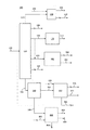
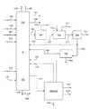
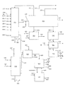
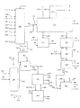
図1及び図2は、原油を石油化学製品及び燃料製品に転化するプロセス及びシステムの実施形態を図示し、これには、混合原料水蒸気分解域及び軽油水蒸気分解域が含まれる。概して、図1は、混合原料水蒸気分解域(「MFSC」)230及び軽油水蒸気分解域250の上流の運転を示し、一方、図2は、原油転化域の下流の運転を、混合原料水蒸気分解域230及び軽油水蒸気分解域250も含めて示す。 1 and 2 illustrate embodiments of processes and systems for converting crude oil to petrochemical and fuel products, including a mixed feed steam cracking zone and a gas oil steam cracking zone. In general, FIG. 1 illustrates operation upstream of a mixed feed steam cracking zone (“MFSC”) 230 and gas oil steam cracking zone 250, while FIG. 2 illustrates operation downstream of a crude oil conversion zone to a mixed feed steam cracking zone. Also shown is 230 and light oil steam cracking zone 250.
混合原料水蒸気分解域及び軽油水蒸気分解域は、簡潔にするため、図2、図3、図4、及び図5において、単一の模式的ブロック230/250で示される。 The mixed feed steam cracking zone and the gas oil steam cracking zone are shown as a single schematic block 230/250 in FIGS. 2, 3, 4, and 5 for simplicity.
本明細書中の説明において、混合原料水蒸気分解域230及び軽油水蒸気分解域250は両方とも、ある特定の場合において、まとめて「水蒸気分解炉複合設備」230/250と称するが、当業者ならお分かりのとおり、水蒸気分解域が異なれば、含まれる炉及び関連する交換機も異なり、それぞれから出る特定の生成物は、下流でのさらなる運転のためまとめられる。ある特定の実施形態において、クエンチシステム及び分留ユニットを組み合わせることが可能である。さらなる実施形態において、別個のクエンチシステム及び分留ユニットを、混合原料水蒸気分解域230及び軽油水蒸気分解域250のそれぞれ用に使用することが可能である。 In the description herein, both the mixed feed steam cracking zone 230 and the light oil steam cracking zone 250 are collectively referred to as a "steam cracking furnace complex" 230/250 in certain cases, as will be understood by those skilled in the art. As described above, different steam cracking zones also include different furnaces and associated exchangers, and the specific products from each are combined for further downstream operation. In certain embodiments, it is possible to combine a quench system and a fractionation unit. In a further embodiment, separate quench systems and fractional distillation units can be used for the mixed feed steam cracking zone 230 and the gas oil steam cracking zone 250, respectively.
図1を参照すると、供給原油102は、ある特定の実施形態においてAXLまたはALであるが、これは、原油処理複合装置100で複数の留分に分離され、複合装置100は、典型的には、常圧蒸留域(「ADU」)110、飽和ガスプラント150、及び減圧蒸留域(「VDU」)160を備える。供給原油102は、ある特定の実施形態においてLPG及び軽質ナフサが除去されたものであるが、これは、常圧蒸留域110で複数の留分に分離される。図1に示すとおり、軽質生成物、例えば、炭素数が6未満の軽質炭化水素などは、混合原料水蒸気分解域230に送られる。詳細には、エタン、プロパン、及びブタンを含むC2−C4炭化水素152は、飽和ガスプラント150を介して、常圧蒸留域110から出る軽留分及びLPG112から分離される。任意選択で、他の軽質生成物、例えば統合システム内の精製ユニットから出る軽質ガス及びある特定の実施形態において装置の境界の外側からくる軽質ガスなどは、破線で示される流156として、飽和ガスプラント150に送られる。分離されたC2−C4炭化水素152は、混合原料水蒸気分解域230に送られる。飽和ガスプラント150から出る排出ガス154ならびに混合原料水蒸気分解域230及び軽油水蒸気分解域250から出る排出ガス208は、典型的に知られているとおりに、取り出し及び回収され、例えば、燃料ガス(「FG」)システムに拠出される。 With reference to FIG. 1, the feed crude oil 102, which in certain embodiments is AXL or AL, is separated into multiple cuts in a crude oil treatment complex 100, which is typically a complex unit 100. , An atmospheric distillation zone (“ADU”) 110, a saturated gas plant 150, and a vacuum distillation zone (“VDU”) 160. The feed crude oil 102, which is LPG and light naphtha removed in certain embodiments, is separated into multiple fractions in an atmospheric distillation zone 110. As shown in FIG. 1, a light product, for example, a light hydrocarbon having a carbon number of less than 6, is sent to the mixed raw material steam cracking zone 230. Specifically, ethane, propane, and butane containing C2-C4 hydrocarbons 152 are separated from the light ends and LPG 112 exiting atmospheric distillation zone 110 via saturated gas plant 150. Optionally, other light products such as light gas exiting the purification unit in the integrated system and light gas coming from outside the boundaries of the device in certain embodiments are saturated gas as stream 156, shown as a dashed line. Sent to plant 150. The separated C2-C4 hydrocarbons 152 are sent to the mixed raw material steam cracking zone 230. Exhaust gas 154 from saturated gas plant 150 and exhaust gas 208 from mixed feed steam cracking zone 230 and gas oil steam cracking zone 250 are withdrawn and recovered, as is typically known, for example, fuel gas (“ FG ”) system.
常圧蒸留域110から出る直留ナフサ136は、混合原料水蒸気分解域230に送られる。ある特定の実施形態において、直留ナフサ136の全部、実施的部分、または相当部分が、混合原料水蒸気分解域230に送られる。残存ナフサ(もしあれば)は、ガソリンプールに加えることが可能である。また、ある特定の実施形態において、直留ナフサ流136は、本明細書中記載されるとおり他の供給源からのナフサを含有し、場合によっては、ワイルドナフサ、例えば、統合された留分、軽油、及び/または残油水素化処理ユニットの1つまたは複数由来のナフサ範囲炭化水素を示す。 The straight run naphtha 136 exiting the atmospheric distillation zone 110 is sent to the mixed raw material steam cracking zone 230. In certain embodiments, all, a substantial portion, or a substantial portion of straight run naphtha 136 is sent to mixed feed steam cracking zone 230. Residual naphtha (if any) can be added to the gasoline pool. Also, in certain embodiments, the straight run naphtha stream 136 contains naphtha from other sources as described herein, and optionally wild naphtha, such as an integrated cut, FIG. 4 illustrates naphtha range hydrocarbons from one or more of light oils and / or resid hydrotreating units.
中質留分は、ディーゼル及び/または灯油の製造に、ならびに混合原料水蒸気分解域230への追加供給に使用される。図1に示す実施形態において、少なくとも3種の異なる中質留分カットが、燃料製品及び石油化学製品の製造用に(水蒸気分解炉を介して)処理される。図1に示す配置を用いた1つの例において、第一常圧蒸留域中質留分116は、ある特定の実施形態において灯油留分と称するが、これは、灯軽油範囲の炭化水素を含有し、第二常圧蒸留域中質留分122は、ある特定の実施形態においてディーゼル留分と称するが、これは、灯重油範囲の炭化水素及び中質AGO範囲の炭化水素を含有し、第三常圧蒸留域中質留分126は、ある特定の実施形態において常圧軽油留分と称するが、これは、重質AGO範囲の炭化水素を含有する。図1に示す配置を用いた別の例において、第一中質留分116は、灯油範囲の炭化水素を含有し、第二中質留分122は、中質AGO範囲の炭化水素を含有し、第三中質留分126は、重質AGO範囲の炭化水素を含有する。図1に示す配置を用いた別の例において、第一中質留分116は、灯軽油範囲の炭化水素及び灯重油範囲の炭化水素の一部を含有し、第二中質留分122は、灯重油範囲の炭化水素の一部及び中質AGO範囲の炭化水素の一部を含有し、第三中質留分126は、中質AGO範囲の炭化水素の一部及び重質AGO範囲の炭化水素を含有する。 The middle distillate is used for diesel and / or kerosene production, as well as for additional feed to the mixed feed steam cracking zone 230. In the embodiment shown in FIG. 1, at least three different middle distillate cuts are processed (via a steam cracking furnace) for the production of fuel and petrochemical products. In one example using the arrangement shown in FIG. 1, the first atmospheric distillation zone middle distillate 116, in certain embodiments referred to as the kerosene fraction, contains kerosene gas range hydrocarbons. However, the second atmospheric distillation zone middle distillate 122, which in certain embodiments is referred to as the diesel fraction, contains kerosene oil range hydrocarbons and medium AGO range hydrocarbons, The three atmospheric distillation zone middle distillate 126, in certain embodiments referred to as the atmospheric gas oil fraction, contains heavy AGO range hydrocarbons. In another example using the arrangement shown in FIG. 1, the first medium distillate 116 contains kerosene range hydrocarbons and the second medium distillate 122 contains medium AGO range hydrocarbons. The third middle distillate 126 contains heavy AGO range hydrocarbons. In another example using the arrangement shown in FIG. 1, the first middle distillate 116 contains some of the kerosene to light oil range hydrocarbons and some of the kerosene to heavy oil range hydrocarbons, and the second medium cut 122 is Contains some of the kerosene oil range hydrocarbons and some of the medium AGO range hydrocarbons, and the third medium distillate 126 contains some of the medium AGO range hydrocarbons and some of the heavy AGO range hydrocarbons. Contains hydrocarbons.
例えば、第一中質留分116は、灯油精製(sweetening)プロセス170で処理して、灯油燃料製品172、例えば、JetAまたはJetA−1仕様を満たすジェット燃料、及び任意選択で他の燃料製品(示さず)を生成することが可能である。本明細書中ある特定の実施形態において、第一中質留分116の全部または一部は、燃料製造に使用されず、その代わりに混合原料水蒸気分解域230への追加供給原料を製造するために、留分水素化処理の供給原料として使用される。 For example, the first middle distillate 116 is treated with a kerosene sweetening process 170 to process a kerosene fuel product 172, such as jet fuel that meets JetA or JetA-1 specifications, and optionally other fuel products ( (Not shown) can be generated. In certain embodiments herein, all or a portion of the first middle distillate 116 is not used for fuel production, but instead to produce additional feedstock to the mixed feed steam cracking zone 230. In addition, it is used as a feedstock for fraction hydrotreatment.
第二中質留分122は、ディーゼル水素化精製域180などの留分水素化処理域で処理されて、ワイルドナフサ184及びディーゼル燃料留分182、例えば、ユーロVディーゼル基準を満たすものを生成する。さらなる実施形態において、第一中質留分116の全部または一部を、破線で示すとおり、第二中質留分122と合わせて精製することが可能である。 Second middle distillate 122 is processed in a fraction hydrotreating zone, such as diesel hydrorefining zone 180, to produce wild naphtha 184 and diesel fuel fraction 182, eg, those that meet Euro V diesel standards. . In a further embodiment, all or part of the first middle distillate 116 can be purified together with the second middle distillate 122, as indicated by the dashed line.
ワイルドナフサ184の全部または一部は、混合原料水蒸気分解域230に送られ;混合原料水蒸気分解域230に送られない任意部分は、ガソリンプールに送ることが可能である。ある特定の実施形態において、ワイルドナフサ184は、単独で、または統合プロセス内由来の他のワイルドナフサ留分と組み合わせて、原油処理複合装置100に送られる。ワイルドナフサ184が原油処理複合装置100を通過する実施形態において、減圧軽油水素化処理域で生成した液化石油ガスの全部または一部は、ワイルドナフサと共に送ることが可能である。ある特定の実施形態において、ワイルドナフサ184の全部、実質的部分、相当部分、または主要部分は、混合原料水蒸気分解域230に送られる(直接または原油処理複合装置100を通じて)。 All or part of the wild naphtha 184 is sent to the mixed feed steam cracking zone 230; any portion not sent to the mixed feed steam cracking zone 230 can be sent to the gasoline pool. In certain embodiments, the wild naphtha 184, alone or in combination with other wild naphtha fractions from within the integrated process, is sent to the crude oil processing complex 100. In the embodiment where the wild naphtha 184 passes through the crude oil treatment complex 100, all or part of the liquefied petroleum gas produced in the vacuum gas oil hydrotreating zone can be sent with the wild naphtha. In certain embodiments, all, substantial portion, substantial portion, or major portion of wild naphtha 184 is sent (directly or through crude oil processing complex 100) to mixed feed steam cracking zone 230.
ある特定の実施形態において(破線で示されるとおり)、第三中質留分126の全部、実質的部分、相当部分、または主要部分は、減圧軽油流162と組み合わせて、減圧軽油水素化処理域に送られ;減圧軽油水素化処理域に送られない任意部分は、水素化処理せずに軽油水蒸気分解域250に送ることが可能である。さらなる実施形態において(破線で示されるとおり)、第三中質留分126の全部、実質的部分、相当部分、または主要部分は、水素化処理域せずに軽油水蒸気分解域250に送られ;軽油水蒸気分解域250に送られない任意部分は、減圧軽油水素化処理域に送ることが可能である。 In certain embodiments (as indicated by the dashed line), all, a substantial portion, a substantial portion, or a major portion of the third middle distillate 126 is combined with the reduced pressure gas oil stream 162 to form a reduced pressure gas oil hydrotreating zone. Any portion that is not sent to the vacuum gas oil hydrotreating zone can be sent to the gas oil steam cracking zone 250 without hydrotreating. In a further embodiment (as indicated by the dashed line), all, a substantial portion, a substantial portion, or a major portion of the third middle distillate 126 is sent to the gas oil steam cracking zone 250 without the hydrotreating zone; Any portion not sent to the gas oil steam cracking zone 250 can be sent to the reduced pressure gas oil hydrotreating zone.
常圧蒸留域110から出る常圧残油留分114は、減圧蒸留域160でさらに分離される。減圧蒸留域160から出る減圧軽油162は、減圧軽油水素化分解域320に送られる。ある特定の実施形態において、減圧軽油162は、減圧軽油水素化分解域320を迂回して、軽油水蒸気分解域250に送ることが可能である(図示せず)。減圧蒸留域160から出る最重質留分168、すなわち減圧残油は、燃料油(「FO」)プールに送る、及び/または任意選択で、破線で示される残油精製域800で処理することが可能である。ある特定の実施形態において、常圧残油留分114の少量部分は、減圧蒸留域160を迂回することが可能であり(図示せず)、任意選択の残油精製域800及び/または軽油水蒸気分解域250に送られる(図示せず)。 The atmospheric residue distillate 114 leaving the atmospheric distillation zone 110 is further separated in the vacuum distillation zone 160. The vacuum gas oil 162 exiting from the vacuum distillation zone 160 is sent to the vacuum gas oil hydrocracking zone 320. In certain embodiments, vacuum gas oil 162 may bypass vacuum gas oil hydrocracking zone 320 and be sent to gas oil steam cracking zone 250 (not shown). The heaviest distillate 168, or vacuum resid, exiting the vacuum distillation zone 160 is sent to a fuel oil (“FO”) pool and / or optionally processed in a resid refinery 800 shown in phantom. Is possible. In certain embodiments, a minor portion of the atmospheric bottoms fraction 114 can bypass the vacuum distillation zone 160 (not shown), with an optional bottoms refinery zone 800 and / or gas oil steam. It is sent to the decomposition zone 250 (not shown).
減圧軽油水素化分解域320は、穏やかな、中度の、または厳しい水素化分解条件下で作動可能であり、一般に、水素化分解ナフサ留分326、ディーゼル燃料留分322、及び未転化油留分324を生成させる。ディーゼル燃料留分322は、燃料として、例えば、ユーロVディーゼル基準を満たす燃料として回収され、ディーゼル水素化精製域180から出るディーゼル燃料留分182とまとめることが可能である。ある特定の実施形態において、合計減圧軽油162の全部、実質的部分、相当部分、または主要部分は、減圧軽油水素化分解域320に送られる。残部(もしあれば)は、減圧軽油水素化分解域を迂回して、軽油水蒸気分解域250に直接送ることが可能である。ある特定の実施形態において、減圧軽油及び任意選択の常圧軽油に加えて、水素化分解域320は、任意選択の減圧残油精製域800から出る常圧及び/または減圧軽油範囲の生成物も処理することが可能である。 The vacuum gas oil hydrocracking zone 320 is operable under mild, moderate, or severe hydrocracking conditions and generally comprises hydrocracking naphtha fraction 326, diesel fuel fraction 322, and unconverted oil fraction. Minute 324 is generated. The diesel fuel fraction 322 can be combined with the diesel fuel fraction 182 recovered from the diesel hydrorefining zone 180 as fuel, eg, fuel that meets Euro V diesel standards. In certain embodiments, all, a substantial portion, a substantial portion, or a major portion of total vacuum gas oil 162 is sent to vacuum gas oil hydrocracking zone 320. The balance (if any) can bypass the vacuum gas oil hydrocracking zone and be sent directly to the gas oil steam cracking zone 250. In certain embodiments, in addition to vacuum gas oil and optional atmospheric gas oil, hydrocracking zone 320 also includes atmospheric and / or vacuum gas oil range products exiting from optional vacuum resid refinery zone 800. It is possible to process.
減圧軽油水素化分解域320から出る水素化分解ナフサ留分326の全部、実質的部分、相当部分、または主要部分は、混合原料水蒸気分解域230に送られる。ワイルドナフサの残部(もしあれば)は、ガソリンプールに加えることが可能である。ある特定の実施形態において、ナフサ留分326は、原油処理複合装置100を通過する。水素化分解ナフサ留分326が原油処理複合装置100を通過する実施形態において、軽油水素化分解域320で生成した液化石油ガスの全部または一部は、水素化分解ナフサ留分326とともに送ることが可能である。 All, a substantial portion, a substantial portion, or a major portion of the hydrocracking naphtha fraction 326 exiting the vacuum gas oil hydrocracking zone 320 is sent to the mixed feed steam cracking zone 230. The rest of Wild naphtha (if any) can be added to the petrol pool. In certain embodiments, the naphtha fraction 326 passes through the crude oil processing complex 100. In an embodiment in which hydrocracked naphtha fraction 326 passes through crude oil treatment complex 100, all or part of the liquefied petroleum gas produced in gas oil hydrocracking zone 320 may be sent with hydrocracked naphtha fraction 326. It is possible.
減圧軽油水素化分解域320から出る未転化油留分324の全部、実質的部分、または相当部分は、軽油水蒸気分解域250に送られる。残部(もしあれば)は、消滅するまで循環使用及び分解すること、及び/またはシステムから排出させること、及び/または任意選択の減圧残油精製域に送ることが可能である。 All, a substantial portion, or a substantial portion of the unconverted oil fraction 324 exiting the vacuum gas oil hydrocracking zone 320 is sent to the gas oil steam cracking zone 250. The balance (if any) can be recycled and decomposed until it disappears, and / or discharged from the system, and / or sent to an optional vacuum resid refinery.
ある特定の実施形態において、減圧蒸留域160から出る減圧残油留分168の少なくとも主要部分が、任意選択の減圧残油精製域800に送られる。ある特定の実施形態において、合計減圧残油168の全部、実質的部分、相当部分、または主要部分は、任意選択の減圧残油精製域800に送られる。残部(もしあれば)は、燃料油プールに送られる(図示せず)。また、ある特定の実施形態において、常圧残油留分114の少量部分は、減圧蒸留域160を迂回して(図示せず)任意選択の減圧残油精製域800に送ることが可能である。ある特定の実施形態において、水蒸気分解炉複合設備から出る熱分解油流218の全部または一部、例えば、流902として示されるものは、任意選択の減圧残油精製域800において処理することが可能である。 In certain embodiments, at least a major portion of the vacuum resid fraction 168 exiting vacuum distillation zone 160 is sent to optional vacuum resid refining zone 800. In certain embodiments, all, substantial portion, substantial portion, or major portion of total vacuum resid 168 is sent to optional vacuum resid refinery 800. The balance (if any) is sent to the fuel oil pool (not shown). Also, in certain embodiments, a minor portion of the atmospheric residue distillate 114 can bypass the vacuum distillation zone 160 (not shown) and be sent to an optional vacuum residue refinery zone 800. . In certain embodiments, all or a portion of pyrolysis oil stream 218 exiting the steam cracker furnace complex, eg, shown as stream 902, can be processed in optional vacuum resid refinery zone 800. Is.
図2を参照すると、混合原料水蒸気分解域230及び軽油水蒸気分解域250は、それぞれの供給原料を、エチレン202、プロピレン204、混合C4 206、熱分解ガソリン212、熱分解油218、及び統合燃料ガスシステムに送ることが可能な排出ガス208に転化するように作動する。さらに、水素210が、分解生成物から回収されて、複合装置の境界内の水素利用部に循環使用することが可能である。エタン及びプロパン循環使用は図示していないが、水蒸気分解運転において典型的なものである。なお、当然のことながら、ある特定の実施形態において、エタン及びプロパンの全部または一部を、流用することが可能である。ある特定の実施形態において、エタンの全部、実質的部分、相当部分、または主要部分は、混合原料水蒸気分解域230に循環使用され、プロパンの全部、実質的部分、相当部分、または主要部分は、混合原料水蒸気分解域230に循環使用される。ある特定の実施形態において、統合プロセス及びシステムの全ての水素利用部用の水素は、分解生成物から回収された水素210に由来し、いったんプロセスが完全に起動して平衡に到達したら、外部からの水素をまったく必要としない。さらなる実施形態において、過剰な水素は、回収することが可能である。 Referring to FIG. 2, the mixed raw material steam cracking zone 230 and the light oil steam cracking zone 250 respectively supply the respective feedstocks with ethylene 202, propylene 204, mixed C4 206, pyrolysis gasoline 212, pyrolysis oil 218, and integrated fuel gas. It operates to convert exhaust gases 208 that can be sent to the system. In addition, hydrogen 210 can be recovered from the cracked products and recycled to the hydrogen utilization within the boundaries of the complex. Recycle of ethane and propane, not shown, is typical of steam cracking operations. It should be understood that, in certain embodiments, all or part of ethane and propane can be diverted. In certain embodiments, all, substantial portion, substantial portion, or major portion of ethane is recycled to mixed feed steam cracking zone 230 and all, substantial portion, substantial portion, or major portion of propane is It is circulated and used in the mixed raw material steam decomposition region 230. In certain embodiments, the hydrogen for all hydrogen utilization parts of the integrated process and system comes from hydrogen 210 recovered from the cracked products, and once the process has fully started and reached equilibrium, externally. Does not need any hydrogen. In a further embodiment, excess hydrogen can be recovered.
簡潔にするため、オレフィン回収トレインでの運転は示さないが、それらは周知であり、図2、図3、図4、及び図5に関して本明細書中記載されるとおり、混合原料水蒸気分解域230及び軽油水蒸気分解域250の一部とみなされる。 For simplicity, operations in the olefin recovery train are not shown, but they are well known and as described herein with respect to FIGS. 2, 3, 4 and 5, mixed feed steam cracking zone 230. And as part of the light oil steam cracking zone 250.
水蒸気分解炉複合設備230/250から出る混合C4を含有する混合C4流206は、粗C4としても知られ、ブタジエン抽出ユニット500に送られて、高純度1,3−ブタジエン生成物502が回収される。ブタン及びブテンを含有する第一抽残液504(「C4−Raff−1」)は、選択的水素化ユニット(「SHU」)及びメチルt−ブチルエーテル(「MTBE」)ユニット、すなわちSHU及びMTBE域510に送られ、ここで、第一抽残液504は、装置の境界外側からの高純度フレッシュメタノール512と混合されて、メチルt−ブチルエーテル514を生成する。 The mixed C4 stream 206 containing mixed C4 exiting the steam cracker complex 230/250, also known as crude C4, is sent to a butadiene extraction unit 500 to recover a high purity 1,3-butadiene product 502. It The first raffinate 504 (“C4-Raff-1”) containing butane and butene comprises a selective hydrogenation unit (“SHU”) and a methyl t-butyl ether (“MTBE”) unit, namely the SHU and MTBE regions. Delivered to 510, where the first raffinate 504 is mixed with high purity fresh methanol 512 from the outside of the device boundary to produce methyl t-butyl ether 514.
SHU及びMTBE域510から出る第二抽残液516(「C4 Raff−2」)は、分離させて1−ブテン生成物流522及び残存C4を含有するアルカン流524(第三抽残液「C4−Raff−3」)にするためにC4蒸留ユニット520に送られ、アルカン流524の全部、実質的部分、相当部分、または主要部分は、混合原料水蒸気分解域230に循環使用されるが、当然のことながら、ある特定の実施形態において、残存C4の全部または一部は、流用することが可能である。エチレン202、プロピレン204、及び混合C4流206の分離は、水蒸気分解域流出油を分離するのに適した既知の分離工程の配置で行われ、その配置は、圧縮段(複数可)、脱プロパン塔、脱ブタン塔、脱メタン塔、及び脱エタン塔を含む。 The second raffinate 516 (“C4 Raff-2”) exiting the SHU and MTBE zone 510 is separated to an alkane stream 524 containing the 1-butene product stream 522 and residual C4 (the third raffinate “C4- Ruff-3 ″) to C4 distillation unit 520 and all, substantial portion, substantial portion, or major portion of alkane stream 524 is recycled to mixed feed steam cracking zone 230, although Of course, in certain embodiments, all or part of the residual C4 can be diverted. Separation of ethylene 202, propylene 204, and mixed C4 stream 206 is performed in a known separation process arrangement suitable for separating steam cracking zone effluents, the arrangement comprising compression stage (s), depropanization. Includes towers, debutanizers, demethanizers, and deethanizers.
水蒸気分解炉複合設備230/250から出る熱分解ガソリン212の全部、実質的部分、または相当部分は、pyガス水素化精製及び回収センター600/620に供給される。ある特定の実施形態において、炭素数5〜12の選抜炭化水素が、未精製熱分解ガソリンから回収され、残部は、芳香族化合物回収のため引き続き水素化精製される。pyガス水素化精製ユニットにおいて、熱分解ガソリンのジオレフィン及びオレフィンは、飽和させられる。 All, a substantial portion, or a substantial portion of the pyrolysis gasoline 212 exiting the steam cracker complex 230/250 is fed to the py gas hydrorefining and recovery center 600/620. In one particular embodiment, selected hydrocarbons having 5 to 12 carbon atoms are recovered from the unrefined pyrolysis gasoline and the balance is subsequently hydrorefined for aromatics recovery. In the py gas hydrorefining unit, the diolefins and olefins of pyrolysis gasoline are saturated.
pyガス水素化精製ユニットから出る水素化精製熱分解ガソリン(ある特定の実施形態において、C5が除去されており、芳香族化合物抽出域620から出るC5の代わりにまたはそのC5と併せて、混合原料水蒸気分解域230に循環使用されている)は、芳香族化合物抽出域620に送られる。pyガス水素化精製域600及び芳香族化合物抽出域620は、簡潔にするため、図2、図3、図4、及び図5において、単一の模式的ブロック600/620で示される。 hydrorefining pyrolysis gasoline exiting the py gas hydrorefining unit (in certain embodiments, C5 has been removed, and instead of or in combination with C5 exiting the aromatics extraction zone 620, a mixed feed (Recycled to steam cracking zone 230) is sent to aromatics extraction zone 620. The py gas hydrotreating zone 600 and aromatics extraction zone 620 are shown in a single schematic block 600/620 in FIGS. 2, 3, 4, and 5 for simplicity.
芳香族化合物抽出域620は、例えば、1つまたは複数の抽出蒸留ユニットを備え、水素化精製熱分解ガソリンを分離して、高純度ベンゼン、トルエン、キシレン、及びC9芳香族化合物を含有する芳香族流622にするように作動する。芳香族流622は、化学製品市場用に回収される。C5抽残液606及び非芳香族化合物646(例えば、C6−C9)は、混合原料水蒸気分解域230に循環使用される。ある特定の実施形態において、C5抽残液606及び非芳香族化合物646の全部、実質的部分、または相当部分は、混合原料水蒸気分解域230に送られる。重質芳香族化合物流642(例えば、C10−C12)は、芳香族溶媒、オクタン上昇剤、または燃料油プールに加えるカッター原液として使用することが可能である。ある特定の実施形態においてエチルベンゼン628は、回収することが可能である。 The aromatic compound extraction zone 620 includes, for example, one or more extractive distillation units, separates hydrorefining pyrolysis gasoline, and contains aromatics containing high-purity benzene, toluene, xylene, and a C9 aromatic compound. Operates to flow 622. Aromatic stream 622 is recovered for the chemical market. The C5 raffinate 606 and the non-aromatic compound 646 (for example, C6-C9) are circulated and used in the mixed raw material steam decomposition zone 230. In certain embodiments, all, a substantial portion, or a substantial portion of C5 raffinate 606 and non-aromatic compound 646 is sent to mixed feed steam cracking zone 230. Heavy aromatics stream 642 (e.g., C10-C12) can be used as an aromatic solvent, an octane booster, or a stock stock cutter added to the fuel oil pool. In certain embodiments, ethylbenzene 628 can be recovered.
ある特定の実施形態において、熱分解油218は、燃料油プールにブレンドすることが可能である。さらなる実施形態において、熱分解油218は、軽質熱分解油及び重質熱分解油に分留することが可能である(図示せず)。例えば、軽質熱分解油は、処理してディーゼル燃料製品を製造するため、及び/または混合原料水蒸気分解域230への追加原料とするため、第一中質留分流116及び/または第二中質留分流122とブレンドすることが可能である。さらなる実施形態において、熱分解油218に由来する軽質熱分解油は、減圧軽油水素化分解域320で処理することが可能である。さらなる実施形態において、熱分解油218に由来する軽質熱分解油は、燃料油プールにブレンドすることが可能である。さらなる実施形態において、熱分解油218に由来する軽質熱分解油は、残油精製域800で処理することが可能である。ある特定の実施形態において、熱分解油218に由来する軽質熱分解油の全部、実質的部分、相当部分、または主要部分は、ディーゼル水素化精製域180及び/または減圧軽油水素化分解域320の一方または両方に送ることが可能であり;任意残部は、燃料油プールにブレンドすることが可能である。重質熱分解油は、燃料油プールにブレンドする、カーボンブラック原料として使用する、及び/または任意選択の残油精製域800で処理することが可能である。ある特定の実施形態において、熱分解油218(軽質及び重質)の全部、実質的部分、相当部分、または主要部分は、任意選択の残油精製域800で処理することが可能である。 In certain embodiments, the pyrolysis oil 218 can be blended into a fuel oil pool. In a further embodiment, pyrolysis oil 218 can be fractionated into light pyrolysis oil and heavy pyrolysis oil (not shown). For example, the light pyrolysis oil may be processed to produce a diesel fuel product and / or as an additional feedstock to the mixed feed steam cracking zone 230 for use in the first middle distillate stream 116 and / or the second middle feedstock. It is possible to blend with the distillate stream 122. In a further embodiment, light pyrolysis oil derived from pyrolysis oil 218 may be processed in vacuum gas oil hydrocracking zone 320. In a further embodiment, light pyrolysis oil from pyrolysis oil 218 can be blended into a fuel oil pool. In a further embodiment, light pyrolysis oil derived from pyrolysis oil 218 can be processed in resid refinery zone 800. In certain embodiments, all, substantial portion, substantial portion, or major portion of the light pyrolysis oil derived from pyrolysis oil 218 is in diesel hydrorefining zone 180 and / or vacuum gas oil hydrocracking zone 320. It can be sent to one or both; any balance can be blended into the fuel oil pool. The heavy pyrolysis oil can be blended into a fuel oil pool, used as a carbon black feedstock, and / or processed in an optional resid refinery 800. In certain embodiments, all, a substantial portion, a substantial portion, or a major portion of pyrolysis oil 218 (light and heavy) can be treated in optional resid refinery zone 800.
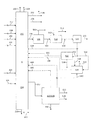
図3は、原油を石油化学製品及び燃料製品に転化するプロセス及びシステムのさらなる実施形態を図示し、この実施形態は、さらなるプロピレンを製造するC4オレフィン及びC5オレフィンのメタセシス転化を伴う。このプロセスは、図1の水蒸気分解運転の上流に関して記載されるとおりに作動する。 FIG. 3 illustrates a further embodiment of the process and system for converting crude oil to petrochemical and fuel products, which involves the metathesis conversion of C4 and C5 olefins to produce additional propylene. The process operates as described for the steam cracking operation upstream of FIG.
水蒸気分解運転の下流で、ブタジエン抽出トレインは、図1においてC4蒸留ユニット520から出てダイバータ(破線による)から直接、混合原料水蒸気分解域230に送られる第三C4抽残液流524として示されるものと同様な様式で、任意選択で作動することが可能である。 Downstream of the steam cracking operation, the butadiene extraction train is shown in FIG. 1 as a third C4 raffinate stream 524 exiting the C4 distillation unit 520 and directly from the diverter (dashed line) to the mixed feed steam cracking zone 230. It is optionally possible to operate in a similar manner.
メタセシス様式の運転において、C4蒸留ユニット520から出る混合C4抽残液流532(「C4 Raff 3」)ならびにpyガス水素化精製及び回収センター600/620から出るC5抽残液540は、メタセシス転化によりさらなるプロピレン534にするため、メタセシスユニット530に送られる。ある特定の実施形態において、pyガス水素化精製装置から出る分解C5の全部、実質的部分、相当部分、または主要部分は、芳香族化合物抽出の前にメタセシスユニット530に送ることが可能である。示されるとおり、エチレン生成物202の一部536は、メタセシスユニット530に送ることが可能である。さらなる実施形態において、メタセシスユニット530用のエチレンは、エチレン生成物202の一部536の代わりに、または536に加えて、複合装置の境界外側から供給される。 In the metathesis mode of operation, the mixed C4 raffinate stream 532 (“C4 Raff 3”) exiting the C4 distillation unit 520 and the C5 raffinate 540 exiting the py gas hydrorefining and recovery center 600/620 are due to metathesis conversion. It is sent to the metathesis unit 530 for further propylene 534. In certain embodiments, all, substantial portion, substantial portion, or major portion of the cracked C5 exiting the py gas hydrorefining unit can be sent to the metathesis unit 530 prior to aromatics extraction. As shown, a portion 536 of the ethylene product 202 can be sent to the metathesis unit 530. In a further embodiment, ethylene for the metathesis unit 530 is supplied from outside the boundary of the composite device, instead of or in addition to the portion 536 of the ethylene product 202.
炭素数4の様々なアルケン及びジエンの熱分解化学製品の選択的回収、及びメタセシス転化によるさらなるプロピレンの生成は、メタセシスユニット530を用いて達成される。メタセシスユニット530から出る大部分が飽和のC4/C5混合物を含有する流538は、混合原料水蒸気分解ユニット230に循環使用される。 Selective recovery of pyrolysis chemicals of various C 4 alkenes and dienes, and further propylene production by metathesis conversion, is accomplished using metathesis unit 530. Stream 538, which contains a mostly saturated C4 / C5 mixture, exiting metathesis unit 530 is recycled to mixed feed steam cracking unit 230.
図2と同様に、図3の配置において、水蒸気分解炉複合設備230/250から出る熱分解ガソリン212は、pyガス水素化精製及び回収センター600/620に送られ;C6−C9芳香族化合物流622、すなわちBTXは、化学製品市場用に回収され;C6−C9非芳香族化合物流646は、混合原料水蒸気分解域230に循環使用され;及び重質芳香族化合物流642(例えば、C10−C12生成物)は、回収される。ある特定の実施形態において、エチルベンゼン628を回収することが可能である。また、メタセシス様式の運転において、C5抽残液は、流540として示されるとおりメタセシスユニット530に送られる。任意選択で、C5抽残液は、図3中、破線で示されるとおり、流606を介して混合原料水蒸気分解域230に循環使用される(図2の実施形態と同様)。ある特定の実施形態において(図示せず)、pyガス水素化精製装置から出る分解C5の全部または一部は、芳香族化合物抽出の前に、メタセシスユニット530に送ることが可能である。 Similar to FIG. 2, in the arrangement of FIG. 3, the pyrolysis gasoline 212 exiting the steam cracker complex 230/250 is sent to the py gas hydrorefining and recovery center 600/620; the C6-C9 aromatics stream. 622, or BTX, is recovered for the chemicals market; C6-C9 non-aromatics stream 646 is recycled to mixed feed steam cracking zone 230; and heavy aromatics stream 642 (eg, C10-C12). Product) is recovered. In certain embodiments, ethylbenzene 628 can be recovered. Also, in the metathesis mode of operation, the C5 raffinate is sent to the metathesis unit 530 as shown as stream 540. Optionally, the C5 raffinate is recycled to the mixed feed steam cracking zone 230 via stream 606, as indicated by the dashed line in FIG. 3 (similar to the embodiment of FIG. 2). In certain embodiments (not shown), all or part of the cracked C5 exiting the py gas hydrorefining unit can be sent to a metathesis unit 530 prior to aromatics extraction.
図3に描かれる配置では、ダイバータ及び破線の流として示される任意選択のダイバータが示されており、これは、第三C4抽残液流524の全部、実質的部分、相当部分、または主要部分を、メタセシス転化プロセスを迂回させ、その結果、混合原料水蒸気分解域230へと流用するためのものである。メタセシス様式において、流れは、メタセシス転化ユニット530に向けることが可能である。さらなる代替様式において、第三C4抽残液流524の流れは、混合原料水蒸気分解域230及びメタセシス転化ユニット530に向けることが可能である。このようにして、製造者は、供給原料の量を変化させて、所望の生産高に調整することが可能である。したがって、第三C4抽残液流524の0〜100%を、メタセシス転化ユニット530に送ることが可能であり、残部(もしあれば)は、混合原料水蒸気分解域230に送られる。その量は、例えば、エチレン需要、プロピレン需要、及び/または設計容量に応じたユニットの作動最小範囲に基づいて、決定することが可能である。 In the arrangement depicted in FIG. 3, a diverter and an optional diverter, shown as a dashed stream, is shown, which includes all, substantial, substantial, or major portions of the third C4 raffinate stream 524. To bypass the metathesis conversion process so that it is diverted to the mixed feed steam cracking zone 230. In the metathesis mode, the stream can be directed to the metathesis conversion unit 530. In a further alternative, the stream of the third C4 raffinate stream 524 can be directed to the mixed feed steam cracking zone 230 and the metathesis conversion unit 530. In this way, the manufacturer can vary the amount of feedstock to adjust to the desired output. Thus, 0-100% of the third C4 raffinate stream 524 can be sent to the metathesis conversion unit 530 and the balance (if any) is sent to the mixed feed steam cracking zone 230. The amount can be determined, for example, based on ethylene demand, propylene demand, and / or minimum operating range of the unit depending on design capacity.
図4は、原油を石油化学製品及び燃料製品に転化するプロセス及びシステムのさらなる実施形態を図示する。このプロセスは、図1の水蒸気分解運転の上流に関して記載されるとおりに作動する。この実施形態において、ブテン混合物を、ガソリンにブレンドする含酸素添加剤として、及びオクタン上昇に適した、混合ブタノールへと転化するための追加工程が提供される。ブテン混合物を混合ブタノールへと転化するのに適切なプロセスは、同一出願人の名義にかかる米国特許出願公開第2016/0115107号明細書、米国特許出願公開第2015/0225320号明細書、米国特許出願公開第2015/0148572号明細書、米国特許出願公開第2013/0104449号明細書、米国特許出願公開第2012/0245397号明細書、ならびに同一出願人の名義にかかる米国特許第9447346号明細書、米国特許第9393540号明細書、米国特許第9187388号明細書、米国特許第8558036号明細書の1つまたは複数に記載されており、これらはすべて、そのまま全体が本明細書中参照として援用される。ある特定の実施形態において、「SuperButol(商標)」技術として知られる特に有効な転化プロセスが取り入れられるが、この技術は、ブテン混合物を混合ブタノールへと転化する一段階プロセスである。 FIG. 4 illustrates a further embodiment of the process and system for converting crude oil to petrochemical and fuel products. The process operates as described for the steam cracking operation upstream of FIG. In this embodiment, an additional step is provided to convert the butene mixture into a mixed butanol suitable as an oxygenate to blend with gasoline and suitable for octane rise. Suitable processes for converting a butene mixture to mixed butanols are described in commonly assigned US Patent Application Publication No. 2016/0115107, US Patent Application Publication No. 2015/0225320, US Patent Application No. Publication No. 2015/0148572, U.S. patent application publication No. 2013/0104449, U.S. patent application publication No. 2012/0245397, and U.S. Pat.No. 9,447,346 in the name of the same applicant, U.S. Pat. No. 9,393,540, US Pat. No. 9,187,388, US Pat. No. 8,558,036, all of which are incorporated herein by reference in their entirety. In one particular embodiment, a particularly effective conversion process known as the "Super Butol ™" technique is incorporated, which is a one-step process for converting a butene mixture to mixed butanols.
水蒸気分解運転の下流で、ブタジエン抽出トレインは、図2の場合と同様に、C4蒸留ユニット520から出てダイバータ(破線による)から直接混合原料水蒸気分解域230に送られる流524として示される様式で、任意選択で作動することが可能である。混合ブタノール生成域550は、様々な炭素数4のアルケン及びジエン熱分解化学製品の選択的回収のため、ならびにある特定の処理配置ではブタノール生成ユニット(「SuperButol(商標)」ユニットなど)でこれらC4の一部を水和させて高価値燃料添加剤を製造するため、統合されている。 Downstream of the steam cracking operation, the butadiene extraction train, in the manner shown in FIG. 2, exits the C4 distillation unit 520 and is shown as stream 524 sent from the diverter (by dashed line) directly to the mixed feed steam cracking zone 230. , Optionally operable. The mixed butanol production zone 550 provides for the selective recovery of various C4 alkenes and diene pyrolysis chemicals, and in certain processing arrangements, butanol production units (such as the "Super Butol ™" unit) of these C4. Has been integrated to hydrate a portion of it to produce high value fuel additives.
例えば、混合ブタノール生成域550は、価値の低い精製/石油化学製品混合オレフィン流由来のブテンをブタノールへと転化するように作動する。ブタノールは、ガソリンブレンドの含酸素添加剤の代替選択肢を提供する。粗C4処理センター550は、例えば、1つまたは複数の高圧接触反応装置中でのブテンからブタノールへの転化反応、続いて沈降分離によるブテン及びブタノールの水からの分離、さらにその後蒸留によるブタノール生成物のブテンからの分離を含む。プロセス段階は、ブテン及び水のメイクアップ及び循環使用、ブタノール反応、高圧分離、低圧分離、脱ブテン塔蒸留(生成物塔)、及び水性蒸留塔を含む。 For example, the mixed butanol production zone 550 operates to convert butene from a low value refinery / petrochemical mixed olefin stream to butanol. Butanol offers an alternative option for oxygenated additives in gasoline blends. The crude C4 processing center 550 may be, for example, a butene to butanol conversion reaction in one or more high pressure catalytic reactors, followed by separation of butene and butanol from water by settling separation, followed by distillation of the butanol product. Including separation from butene. Process steps include butene and water make-up and recycle, butanol reaction, high pressure separation, low pressure separation, debutene column distillation (product column), and aqueous distillation column.
図4は、ブテン混合物を混合ブタノール液554に転化するため、C4蒸留ユニット520から混合ブタノール生成域550に送られるブテンを含有するC4抽残液流552の実施形態を示す。ある特定の実施形態において、流552の全部、実質的部分、相当部分、または主要部分は、ブタノール生成ユニット550に送られる。アルカン556は、混合原料水蒸気分解域230に循環使用される。 FIG. 4 shows an embodiment of a butene-containing C4 raffinate stream 552 that is sent from the C4 distillation unit 520 to the mixed butanol production zone 550 to convert the butene mixture to the mixed butanol liquid 554. In certain embodiments, all, a substantial portion, a substantial portion, or a major portion of stream 552 is sent to butanol production unit 550. The alkane 556 is circulated and used in the mixed material steam decomposition region 230.
図1及び図2と同様に、図4の配置において、水蒸気分解炉複合設備230/250から出る熱分解ガソリン212は、pyガス水素化精製及び回収センター600/620に送られ;C6−C9芳香族化合物流622は、化学製品市場用に回収され、C5抽残液606及び非芳香族化合物646(例えば、C6−C9)は、混合原料水蒸気分解域230に循環使用することが可能であり、重質芳香族化合物流642(例えば、C10−C12生成物)は、回収される。ある特定の実施形態において、エチルベンゼン628を回収することが可能である。 Similar to FIGS. 1 and 2, in the arrangement of FIG. 4, the pyrolysis gasoline 212 exiting the steam cracker complex 230/250 is sent to the py gas hydrorefining and recovery center 600/620; C6-C9 aroma. Group compound stream 622 is recovered for the chemicals market and C5 raffinate 606 and non-aromatic compounds 646 (eg, C6-C9) can be recycled to mixed feed steam cracking zone 230, Heavy aromatics stream 642 (eg, C10-C12 product) is recovered. In certain embodiments, ethylbenzene 628 can be recovered.
図4に描かれる配置では、ダイバータ及び破線の流として示される任意選択のダイバータが示されており、これは、C4 Raff−3 524の全部、実質的部分、相当部分、または主要部分を、ブテン混合物から混合ブタノールに転化するプロセスを迂回させ、したがって、混合原料水蒸気分解域230へと流用するものである。混合ブタノール液体様式の運転において、流れは、ブテン混合物から混合ブタノールに転化するための混合ブタノール生成域550に送ることが可能である。さらなる代替様式において、C4 Raff−3 524の流れは、混合原料水蒸気分解域230及び混合ブタノール生成域550に送ることが可能である。このようにして、製造者は、供給原料の量を変化させて、所望の生産高に調整することが可能である。したがって、第三C4抽残液流524の0〜100%を、混合ブタノール生成域550に送ることが可能であり、残部(もしあれば)は、混合原料水蒸気分解域230に送られる。その量は、例えば、エチレン需要、混合ブタノール需要、及び/または設計容量に応じたユニットの作動最小範囲に基づいて、決定することが可能である。 In the arrangement depicted in FIG. 4, a diverter and an optional diverter, shown as a dashed stream, is shown, which can be used to replace all, substantial, substantial, or major portions of C4 Raff-3 524 with butene. It bypasses the process of converting the mixture to mixed butanol and is therefore diverted to the mixed feed steam cracking zone 230. In mixed butanol liquid mode operation, the stream can be sent to a mixed butanol production zone 550 for conversion of the butene mixture to mixed butanol. In a further alternative, the C4 Raff-3 524 stream may be sent to the mixed feed steam cracking zone 230 and the mixed butanol production zone 550. In this way, the manufacturer can vary the amount of feedstock to adjust to the desired output. Thus, 0-100% of the third C4 raffinate stream 524 can be sent to the mixed butanol production zone 550 and the balance (if any) is sent to the mixed feed steam cracking zone 230. The amount can be determined, for example, based on ethylene demand, mixed butanol demand, and / or minimum operating range of the unit depending on design capacity.
図5は、原油を石油化学製品及び燃料製品に転化するプロセス及びシステムのさらなる実施形態を図示する。この実施形態では、C4オレフィン及びC5オレフィンをメタセシス転化してさらなるプロピレンを製造する、及び/またはブテン混合物をガソリンにブレンドする含酸素添加剤として及びオクタン上昇に適した混合ブタノールに転化する、追加工程(複数可)が統合される。このプロセスは、図1の水蒸気分解運転の上流に関して記載されるとおりに作動する。 FIG. 5 illustrates a further embodiment of the process and system for converting crude oil to petrochemical and fuel products. In this embodiment, an additional step of metathesis converting the C4 and C5 olefins to produce additional propylene and / or converting the butene mixture into a mixed butanol suitable as an oxygenated additive for blending into gasoline and suitable for octane rise. (S) are integrated. The process operates as described for the steam cracking operation upstream of FIG.
水蒸気分解運転の下流で、ブタジエン抽出トレインは、図2の場合と同様に、C4蒸留ユニット520から出てダイバータ(破線による)から直接混合原料水蒸気分解域230に送られる流524として示される様式で、任意選択で作動することが可能である。図5の配置は、様々な炭素数4のアルケン及びジエン熱分解化学製品の選択的回収、メタセシス転化によるさらなるプロピレン生成、及び/またはブテン混合物からガソリンにブレンドする含酸素添加剤として及びオクタン上昇に適した混合ブタノールへの転化を統合する。 Downstream of the steam cracking operation, the butadiene extraction train, in the manner shown in FIG. 2, exits the C4 distillation unit 520 and is shown as stream 524 sent from the diverter (by dashed line) directly to the mixed feed steam cracking zone 230. , Optionally operable. The arrangement of Figure 5 is for selective recovery of various C4 alkenes and diene pyrolysis chemicals, further propylene production by metathesis conversion, and / or as an oxygenate blended into gasoline from butene mixtures and for octane rise. Integrates conversion to a suitable mixed butanol.
図5は、ブテン混合物を混合ブタノール液554に転化するため、混合ブタノール生成域550に送ることが可能な、C4蒸留工程から出るブテンを含有する流552(「C4 Raff−3」)を示す。アルカン556は、混合原料水蒸気分解域230に循環使用される。また、C4蒸留ユニット520から出る濃2−ブテン抽残液−3の一部532は、さらなるプロピレン534へとメタセシス転化するため、メタセシスユニット530に送られる。示されるとおり、エチレン生成物202の一部536は、メタセシスユニット530に送ることが可能である。さらなる実施形態において、メタセシスユニット530用のエチレンは、エチレン生成物202の一部536の代わりに、または536に加えて、複合装置の境界外側から供給される。メタセシスユニットから出る大部分が飽和のC4/C5混合物を含有する流538は、混合原料水蒸気分解域230に循環使用される。 FIG. 5 shows a butene-containing stream 552 (“C4 Raff-3”) exiting the C4 distillation step that can be sent to the mixed butanol production zone 550 to convert the butene mixture to the mixed butanol liquid 554. The alkane 556 is circulated and used in the mixed material steam decomposition region 230. Also, a portion 532 of concentrated 2-butene raffinate-3 leaving C4 distillation unit 520 is sent to metathesis unit 530 for metathesis conversion to additional propylene 534. As shown, a portion 536 of the ethylene product 202 can be sent to the metathesis unit 530. In a further embodiment, ethylene for the metathesis unit 530 is supplied from outside the boundary of the composite device, instead of or in addition to the portion 536 of the ethylene product 202. Stream 538, containing a predominantly saturated C4 / C5 mixture, exiting the metathesis unit is recycled to mixed feed steam cracking zone 230.
図2と同様に、図5の配置において、水蒸気分解炉複合設備230/250から出る熱分解ガソリン212は、pyガス水素化精製及び回収センター600/620に送られ;C6−C9芳香族化合物流622、すなわちBTXは、化学製品市場用に回収され;非芳香族化合物646(例えば、C6−C9)は、混合原料水蒸気分解域230に循環使用され、重質芳香族化合物流642(例えば、C10−C12生成物)は、回収される。ある特定の実施形態において、エチルベンゼン628を回収することが可能である。抽残液流540は、示すとおりメタセシスユニット530に送ることが可能であり、及び/または破線の流606で示すとおり任意選択で混合原料水蒸気分解域230に循環使用することが可能である。ある特定の実施形態において(図示せず)、pyガス水素化精製装置から出る分解C5の全部または一部は、芳香族化合物抽出の前に、メタセシスユニット530に送ることが可能である。 Similar to FIG. 2, in the arrangement of FIG. 5, the pyrolysis gasoline 212 exiting the steam cracker complex 230/250 is sent to the py gas hydrorefining and recovery center 600/620; the C6-C9 aromatics stream. 622, or BTX, is recovered for the chemicals market; the non-aromatic compounds 646 (eg, C6-C9) are recycled to the mixed feed steam cracking zone 230 and the heavy aromatics stream 642 (eg, C10-C9). -C12 product) is recovered. In certain embodiments, ethylbenzene 628 can be recovered. The raffinate stream 540 can be sent to the metathesis unit 530 as shown and / or optionally recycled to the mixed feed steam cracking zone 230 as shown by the dashed stream 606. In certain embodiments (not shown), all or part of the cracked C5 exiting the py gas hydrorefining unit can be sent to a metathesis unit 530 prior to aromatics extraction.
図5に描かれる配置では、ダイバータ及び破線の流として示される任意選択のダイバータが示されており、これは、C4 Raff−3 524の全部、実質的部分、相当部分、または主要部分を、メタセシス転化プロセス及びブテン混合物から混合ブタノールに転化するプロセスを迂回させ、したがって、混合原料水蒸気分解域230へと流用するものである。任意選択の弁もまた、C4 Raff−3の流れを、メタセシス転化ユニット530及び/またはブテン混合物を混合ブタノールに転化するための混合ブタノール生成域550の一方または両方に送るために提供することができる。さらなる代替様式において、C4 Raff−3 524の流れは、混合原料水蒸気分解域230、メタセシス転化ユニット530(流532として)、及び混合ブタノール生成域550(流552として)それぞれに送ることが可能である。このようにして、製造者は、供給原料の量を変化させて、所望の生産高に調整することが可能である。したがって、第三C4抽残液流の全部、実質的部分、相当部分、または主要部分を、メタセシス転化ユニット530に送ることが可能であり、残部(もしあれば)は、混合原料水蒸気分解域230及び/または混合ブタノール生成域550に送られる。ある特定の実施形態において、第三C4抽残液流の全部、実質的部分、相当部分、または主要部分は、メタセシス転化ユニット530に送られ、残部(もしあれば)は、混合原料水蒸気分解域230に送られる。さらなる実施形態において、第三C4抽残液流の全部、実質的部分、相当部分、または主要部分は、メタセシス転化ユニット530に送られ、残部(もしあれば)は、混合ブタノールの製造のため混合ブタノール生成域550に送られる。さらなる実施形態において、第三C4抽残液流の全部、実質的部分、相当部分、または主要部分は、混合ブタノールの製造のため混合ブタノール生成域550に送られ、残部(もしあれば)は、混合原料水蒸気分解域230及びメタセシス転換ユニット530両方に送られる。さらなる実施形態において、第三C4抽残液流の全部、実質的部分、相当部分、または主要部分は、混合ブタノールの製造のため混合ブタノール生成域550に送られ、残部(もしあれば)は、混合原料水蒸気分解域230に送られる。さらなる実施形態において、第三C4抽残液流の全部、実質的部分、相当部分、または主要部分は、混合ブタノールの製造のため混合ブタノール生成域550に送られ、残部(もしあれば)は、メタセシス転化ユニット530に送られる。その量は、例えば、エチレン需要、プロピレン需要、混合ブタノール需要、及び/または設計容量に応じたユニットの作動最小範囲に基づいて、決定することが可能である。 In the arrangement depicted in FIG. 5, a diverter and an optional diverter, shown as a dashed stream, is shown, which allows all, substantial, substantial, or major portions of C4 Raff-3 524 to be metathesized. It bypasses the conversion process and the process of converting the butene mixture to the mixed butanol and is therefore diverted to the mixed feed steam cracking zone 230. An optional valve may also be provided to direct the C4 Raff-3 stream to one or both of the metathesis conversion unit 530 and / or the mixed butanol production zone 550 for converting the butene mixture to mixed butanol. . In a further alternative, a stream of C4 Raff-3 524 can be sent to mixed feed steam cracking zone 230, metathesis conversion unit 530 (as stream 532), and mixed butanol production zone 550 (as stream 552), respectively. . In this way, the manufacturer can vary the amount of feedstock to adjust to the desired output. Thus, all, a substantial portion, a substantial portion, or a major portion of the third C4 raffinate stream can be sent to the metathesis conversion unit 530, with the balance (if any) remaining in the mixed feed steam cracking zone 230. And / or is sent to a mixed butanol production zone 550. In certain embodiments, all, a substantial portion, a substantial portion, or a major portion of the third C4 raffinate stream is sent to the metathesis conversion unit 530 and the balance, if any, to the mixed feed steam cracking zone. Sent to 230. In a further embodiment, all, substantial portion, substantial portion, or major portion of the third C4 raffinate stream is sent to the metathesis conversion unit 530 and the balance (if any) is mixed for the production of mixed butanol. It is sent to the butanol production zone 550. In a further embodiment, all, substantial portion, substantial portion, or major portion of the third C4 raffinate stream is sent to the mixed butanol production zone 550 for the production of mixed butanol and the balance (if any) is It is sent to both the mixed feed steam decomposition zone 230 and the metathesis conversion unit 530. In a further embodiment, all, substantial portion, substantial portion, or major portion of the third C4 raffinate stream is sent to the mixed butanol production zone 550 for the production of mixed butanol and the balance (if any) is It is sent to the mixed raw material steam decomposition region 230. In a further embodiment, all, substantial portion, substantial portion, or major portion of the third C4 raffinate stream is sent to the mixed butanol production zone 550 for the production of mixed butanol and the balance (if any) is It is sent to the metathesis conversion unit 530. The amount can be determined, for example, based on ethylene demand, propylene demand, mixed butanol demand, and / or minimum operating range of the unit depending on design capacity.
図6及び図10は、原油を石油化学製品及び燃料製品に転化するプロセス及びシステムの実施形態を図示し、混合原料水蒸気分解域230及び軽油水蒸気分解域250を含む。 6 and 10 illustrate embodiments of processes and systems for converting crude oil to petrochemical and fuel products, including a mixed feed steam cracking zone 230 and a gas oil steam cracking zone 250.
供給原油102は、原油処理複合装置100に送られ、この複合装置は、一般に、常圧蒸留域110、飽和ガスプラント150、及び減圧蒸留域160を備える。常圧蒸留ユニット及び減圧蒸留ユニットは、周知の配置で使用される。 The feed crude oil 102 is sent to a crude oil treatment complex 100, which generally comprises an atmospheric distillation zone 110, a saturated gas plant 150, and a vacuum distillation zone 160. The atmospheric distillation unit and the vacuum distillation unit are used in a well-known arrangement.
原油処理複合装置100での分離を介して供給原料102から得られる中間体流は、以下を含む:原油処理複合装置100内で飽和ガスプラント150を介して得られる排出ガス154、この精製(sweet)排出ガスは、燃料ガスシステムまたは水蒸気分解炉複合設備に送ることが可能である;原油処理複合装置100内で飽和ガスプラント150を介して得られる軽留分流152、これは混合原料水蒸気分解域230に送られる;1つまたは複数の直留ナフサ流(複数可)、この実施形態では、軽質ナフサ流138及び重質ナフサ流140であり、これらは、混合原料水蒸気分解域230に送られる;第一中質留分流116、これは、メルカプタン酸化域などの灯油精製域170に送られる;第二中質留分流122、これはディーゼル水素化精製域180に送られる;第三中質留分流126、これは軽油水素化分解域320、軽油水蒸気分解域250、または軽油水素化分解域320と軽油水蒸気分解域250の両方に送ることが可能である;常圧残油留分114、これは減圧蒸留域160に送られる;減圧蒸留域160から出る減圧軽質軽油流164及び減圧重質軽油流166、これらは減圧軽油水素化分解域320に送られる;ならびに、減圧蒸留域160から出る減圧残油流168、これの全部または一部は、任意選択で、残油精製域800に、及び/または燃料油プールに送ることが可能である。ある特定の実施形態において、第三中質留分流126は、軽油水素化分解域320及び軽油水蒸気分解域250の両方に送られる。例えば、第三中質留分流126は、原油処理複合装置100から出る常圧軽油流の2つの異なる温度留分であることが可能であり、留分には、軽油水素化分解域320に送られる重質AGO、及び軽油水素化分解域320を迂回して、水素化分解せずに軽油水蒸気分解域250に直接送られる中質AGO(第二中質留分122に含まれていない場合)が含まれる。別の配置において、第三中質留分流126は、例えば、ダイバータを用いて、体積または質量流量に基づき分割することが可能である。 The intermediate stream obtained from the feedstock 102 via separation in the crude oil processing complex 100 includes the following: exhaust gas 154 obtained in the crude oil processing complex 100 via the saturated gas plant 150, this refinement (sweet). ) The exhaust gas can be sent to a fuel gas system or a steam cracking furnace complex; a light ends stream 152 obtained via a saturated gas plant 150 in the crude oil processing complex 100, which is a mixed feed steam cracking zone. 230; one or more straight run naphtha stream (s), in this embodiment, a light naphtha stream 138 and a heavy naphtha stream 140, which are sent to a mixed feed steam cracking zone 230; A first medium distillate stream 116, which is sent to a kerosene refining zone 170, such as a mercaptan oxidation zone; a second medium distillate stream 122, which is diesel. Sent to digestive refining zone 180; third medium distillate stream 126, which is sent to gas oil hydrocracking zone 320, gas oil steam cracking zone 250, or both gas oil hydrocracking zone 320 and gas oil steam cracking zone 250. Atmospheric residue fraction 114, which is sent to vacuum distillation zone 160; vacuum light gas oil stream 164 and vacuum heavy gas oil stream 166 exiting vacuum distillation zone 160, which are vacuum gas oil hydrocracking zones. 320; and a vacuum resid stream 168 exiting the vacuum distillation zone 160, all or a portion of which, may optionally be sent to a resid refinery 800 and / or to a fuel oil pool. is there. In one particular embodiment, the third middle distillate stream 126 is sent to both the gas oil hydrocracking zone 320 and the gas oil steam cracking zone 250. For example, the third medium distillate stream 126 can be two different temperature fractions of the atmospheric gas oil stream exiting the crude oil processing complex 100, the fractions being sent to the gas oil hydrocracking zone 320. Heavy AGO to be recovered and medium AGO bypassing the gas oil hydrocracking zone 320 and directly sent to the gas oil steam cracking zone 250 without hydrocracking (when not included in the second medium fraction 122). Is included. In another arrangement, the third medium distillate stream 126 can be split based on volume or mass flow rate, for example using a diverter.
原油処理複合装置100から出る中間体流は、本明細書中の統合プロセス及びシステムにおいて、効率的な様式で使用される。軽留分流152、及び直留ナフサ流(複数可)、この実施形態では軽質ナフサ138及び重質ナフサ140は、軽質オレフィン及び他の貴重な石油化学製品に転化するための供給原料として、混合原料水蒸気分解域230に送られる。直留ナフサ流、すなわち軽質ナフサ138及び重質ナフサ140の一方または両方は、任意選択で、混合原料水蒸気分解域230に送られる前に、サイドストリッパで蒸気ストリッピングすることが可能である。 The intermediate stream exiting the crude oil processing complex 100 is used in an efficient manner in the integrated processes and systems herein. Light distillate stream 152 and straight run naphtha stream (s), in this embodiment light naphtha 138 and heavy naphtha 140, are mixed feedstocks as feedstocks for conversion to light olefins and other valuable petrochemicals. It is sent to the steam decomposition zone 230. The straight run naphtha stream, one or both of the light naphtha 138 and the heavy naphtha 140, can optionally be steam stripped in a side stripper before being sent to the mixed feed steam cracking zone 230.
原油処理複合装置の要素は、図示しないが周知であり、そのような要素として、供給原料/生成物及びポンプアラウンド熱交換器、原料加熱炉、原料塔(複数可)、生成物ストリッパ、冷却システム、リコンタクタ及び排出ガス圧縮器を備えた熱及び冷オーバーヘッドドラムシステム、ならびにオーバーヘッド冷却システムの水洗用ユニットを挙げることができる。常圧蒸留域110は、周知の設計特性を備えることが可能である。そのうえさらに、ある特定の実施形態において、常圧蒸留塔から出るナフサ、灯油、及び常圧軽油製品の全部または一部は、サイドストリッパで蒸気ストリッピングされ、常圧残油は、常圧蒸留塔の塔底内の小型サイズ缶セクションで蒸気ストリッピングされる。 Elements of the crude oil processing complex are well known, although not shown, and include such feed / product and pumparound heat exchangers, feed furnaces, feed tower (s), product stripper, cooling system. , A hot and cold overhead drum system with a recontactor and an exhaust gas compressor, and a flushing unit of the overhead cooling system. The atmospheric distillation zone 110 can have well-known design characteristics. Furthermore, in certain embodiments, all or part of the naphtha, kerosene, and atmospheric gas oil products exiting the atmospheric distillation column are steam stripped in a side stripper, and the atmospheric residue is the atmospheric distillation column. Steam stripped in a small size can section in the bottom of the tower.
常圧蒸留域110への供給原料は、主に、供給原油102であるが、当然のことながら、ディーゼル水素化精製域180、減圧軽油水素化分解域320、ならびにある特定の実施形態において任意選択の残油精製域から出る、ワイルドナフサ、LPG、及び排出ガス流を常圧蒸留域110に送ることが可能であり、そこでこれらは、分留されてから、分解複合装置に送られる。脱塩ユニット(図示せず)は、典型的には、蒸留域110の上流に備えられている。脱塩に必要な相当量の水は、統合プロセス及びシステム内のサワー水ストリッパから得ることが可能である。 The feedstock to atmospheric distillation zone 110 is predominantly feed crude oil 102, although, of course, diesel hydrorefining zone 180, vacuum gas oil hydrocracking zone 320, as well as optional in certain embodiments. The wild naphtha, LPG, and effluent gas streams exiting the resid refining zone of the can be sent to the atmospheric distillation zone 110, where they are fractionated and then sent to the cracking complex. A desalting unit (not shown) is typically provided upstream of the distillation zone 110. The significant amount of water needed for desalination can be obtained from sour water strippers within the integrated process and system.
脱塩ユニットは、原油の脱塩用によく知られた容器配置を示し、本明細書中使用される場合、塩含有量を目的レベルまで、例えば、約10、5、または3wppm以下のレベルまで低下させるように操作される。ある特定の実施形態において、約3wppm以下の目的塩含有量を達成するために2つ以上の脱塩装置が備えられる。 The desalination unit represents a well-known container arrangement for the desalination of crude oil, and as used herein, brings salt content up to a target level, eg, up to about 10, 5, or 3 wppm. Operated to lower. In certain embodiments, two or more desalting devices are provided to achieve a target salt content of about 3 wppm or less.
本明細書中の原油処理複合装置100の1つの実施形態において、供給原料102は、脱塩ユニットに入る前に、例えば、約105〜165、105〜150、105〜145、120〜165、120〜150、120〜145、125〜165、125〜150、125〜145の範囲、及びある特定の実施形態において約135(℃)の温度に予熱される。適切な脱塩装置は、一段で約0.00285kg/m3(1lb/1000bbl)の典型レベルまで塩を除去して減らすように設計される。ある特定の実施形態において、複数の予熱及び脱塩のトレインが採用される。脱塩装置作動圧は、液相での作動を確実にするため、脱塩装置作動温度での原油及び水の混合蒸気圧より高い圧力限界に基づいていることが可能であり、例えば、約2.75〜4.15、2.75〜3.80、2.75〜3.65、3.10〜4.15、3.10〜3.80、3.10〜3.65、3.25〜4.15、3.25〜3.80、3.25〜3.65の範囲、及びある特定の実施形態において約3.45bargであることが可能である。 In one embodiment of the combined crude oil processing apparatus 100 herein, the feedstock 102 is, for example, about 105-165, 105-150, 105-145, 120-165, 120 prior to entering the desalination unit. Preheated to temperatures in the range of -150, 120-145, 125-165, 125-150, 125-145, and in certain embodiments about 135 (° C). A suitable demineralizer is designed to remove and reduce salt to a typical level of about 0.00285 kg / m 3 (1 lb / 1000 bbl) in one step. In certain embodiments, multiple preheat and desalination trains are employed. The desalinator operating pressure can be based on a pressure limit higher than the mixed vapor pressure of crude oil and water at the desalinator operating temperature to ensure liquid phase operation, for example about 2 .75 to 4.15, 2.75 to 3.80, 2.75 to 3.65, 3.10 to 4.15, 3.10 to 3.80, 3.10 to 3.65, 3.25. ˜4.15, 3.25-3.80, 3.25-3.65, and in certain embodiments about 3.45 barg.
常圧蒸留域110は、脱塩するのに十分な熱を提供するため、分留された生成物及びポンプアラウンドを利用することが可能である。ある特定の実施形態において、脱塩装置作動温度は、ディーゼルポンプアラウンドスイング熱交換器により制御することが可能である。ある特定の実施形態において、脱塩装置ブラインにより、らせん型熱交換器中の脱塩装置メイクアップ水を予熱して、汚染を最小限に抑えるとともに冷却水に対して流送冷却を達成してから、ブラインを排水システムに送る。 The atmospheric distillation zone 110 can utilize the fractionated product and pump around to provide sufficient heat for desalination. In certain embodiments, the desalinator operating temperature can be controlled by a diesel pump around swing heat exchanger. In one particular embodiment, the desalinator brine preheats the desalinator make-up water in the spiral heat exchanger to minimize contamination and achieve flow cooling for the cooling water. Send brine to the drainage system.
ある特定の実施形態において、脱塩原油は、プレフラッシュ塔に入る前に約180〜201、185〜196、または189〜192(℃)の範囲の温度に予熱される。プレフラッシュ塔は、原油が最終予熱交換機に入る前に、原油からLPG及び軽質ナフサを除去する。プレフラッシュ塔は、予熱トレインの作動圧を最小限に抑えて、原油炉通路弁での液相作動を維持するとともに、主原油塔の必須サイズを低下させる。 In certain embodiments, the desalted crude oil is preheated to a temperature in the range of about 180-201, 185-196, or 189-192 (° C) prior to entering the preflash column. The preflash tower removes LPG and light naphtha from crude oil before it enters the final preheat exchanger. The pre-flash tower minimizes the working pressure of the preheat train to maintain liquid phase operation at the crude reactor passage valves and reduce the essential size of the main crude tower.
適切な原油蒸留システムの1つの例において、原油炉は、ある特定のカット温度以下で、例えば約350〜370、355〜365の範囲、または360(℃)(680°F)の温度で材料を気化させてから、原油を原料塔のフラッシュ域に送り入れる。炉は、適切な放出温度に、例えば、約338〜362、344〜354の範囲、または348.9(℃)(660°F)の温度に設計される。原油塔フラッシュ域の条件は、温度が約328〜374、328〜355、337〜374、327〜355の範囲、または346.1(℃)(655°F)であり、圧が約1.35〜1.70、1.35〜1.60、1.44〜1.70、1.44〜1.60の範囲、または1.52(barg)である。 In one example of a suitable crude oil distillation system, a crude oil furnace cuts material at or below a certain cut temperature, for example in the range of about 350-370, 355-365, or at a temperature of 360 ° C (680 ° F). After vaporizing, the crude oil is fed into the flash area of the feed tower. The furnace is designed to a suitable discharge temperature, for example, in the range of about 338-362, 344-354, or a temperature of 348.9 (° C) (660 ° F). The conditions of the crude oil tower flash region are that the temperature is in the range of about 328 to 374, 328 to 355, 337 to 374, 327 to 355, or 346.1 (° C) (655 ° F) and the pressure is about 1.35. ˜1.70, 1.35 to 1.60, 1.44 to 1.70, 1.44 to 1.60, or 1.52 (barg).
ある特定の実施形態において、原料塔は、59のトレイを備え、6つのカットを生成し、各生成物の抜き出し温度は以下のとおりである:軽質ナフサ、104.4℃(220°F)(塔頂蒸気);重質ナフサ、160.6℃(321°F)(側流);灯油、205℃(401°F)(側流);ディーゼル、261.7℃(503°F)(側流);AGO、322.2℃(612°F)(側流);常圧残油、340.6℃(645°F)(塔底)。重質ナフサ抜き出しは、ディーゼルポンプアラウンドで再沸騰したサイドストリッパを備え、185℃(365°F)、D86終点に制御される。灯油抜き出しは、14.54kg/m3(5.1lbの蒸気/bbl)のスチームストリッパを備え;抜き出し速度は、凝固点によりバックエンドに限定される。ディーゼル抜き出しは、14.54kg/m3(5.1lbの蒸気/bbl)のスチームストリッパを備え、この抜き出しは、360℃(680°F)、D86、95%ポイントに制御される。AGO抜き出しは、14.82kg/m3(5.2lbの蒸気/bbl)のスチームストリッパを備え、これは、原油に対して2体積%のオーバーフラッシュに設定される。原料塔は、塔頂、ディーゼル、及びAGO用の3つのポンプアラウンドも備える。ディーゼルポンプアラウンドは、脱塩装置作動温度の制御と併せて、スイング熱を介して、重質ナフサストリッパリボイラー及び脱ブタン塔リボイラーに熱を提供する。常圧塔の塔底流は、28.5kg/m3(10lbの蒸気/bbl)でスチームストリッピングされる。 In one particular embodiment, the feed tower comprises 59 trays, produces 6 cuts, and the withdrawal temperature for each product is as follows: light naphtha, 104.4 ° C. (220 ° F.) ( Top vapor); Heavy naphtha, 160.6 ° C (321 ° F) (sidestream); Kerosene, 205 ° C (401 ° F) (sidestream); Diesel, 261.7 ° C (503 ° F) (side) Stream); AGO, 322.2 ° C (612 ° F) (sidestream); atmospheric residue, 340.6 ° C (645 ° F) (bottom). The heavy naphtha withdrawal is equipped with a side stripper reboiled with a diesel pump around and controlled at 185 ° C (365 ° F), D86 endpoint. The kerosene withdrawal is equipped with a steam stripper of 14.54 kg / m 3 (5.1 lb steam / bbl); the withdrawal rate is limited to the back end by the freezing point. The diesel withdrawal was equipped with a steam stripper of 14.54 kg / m 3 (5.1 lb of steam / bbl) and the withdrawal was controlled at 360 ° C. (680 ° F.), D86, 95% points. The AGO withdrawal was equipped with a steam stripper of 14.82 kg / m 3 (5.2 lb steam / bbl), which was set to 2 vol% overflush with respect to crude oil. The feed tower is also equipped with three pump-arounds for the top, diesel, and AGO. The diesel pump around provides heat to the heavy naphtha stripper reboiler and debutanizer reboiler via swing heat, along with control of the desalinator operating temperature. The bottom stream of the atmospheric column is steam stripped at 28.5 kg / m 3 (10 lb steam / bbl).
常圧蒸留域110から出る常圧残油留分114は、減圧蒸留域160でさらに蒸留され、減圧蒸留域160は、常圧残油留分114を、減圧軽質軽油流164及び減圧重質軽油流166として示す減圧軽油留分、ならびに減圧残油流168に分留する。流164及び流166から出る減圧軽油は、減圧軽油水素化分解域320に送られる。減圧残油流168は、燃料油プール(高硫黄燃料油プールなど)または、ある特定の実施形態において、残油精製域800に送ることが可能である。 The atmospheric residue distillate 114 leaving the atmospheric distillation zone 110 is further distilled in the vacuum distillation zone 160, and the atmospheric distillation zone 160 converts the atmospheric residue distillate 114 into a vacuum light gas oil stream 164 and a vacuum heavy gas oil. A vacuum gas oil fraction, shown as stream 166, and a vacuum resid stream 168 are fractionated. The vacuum gas oil leaving stream 164 and stream 166 is sent to vacuum gas oil hydrocracking zone 320. The vacuum resid stream 168 can be sent to a fuel oil pool (such as a high sulfur fuel oil pool) or, in certain embodiments, a resid refinery 800.
減圧蒸留域160は、例えば、減圧レベル(mmHg絶対圧)、例えば、約30〜40、32〜36の範囲、または34での運転など、周知の設計特性を備えることが可能であり、減圧は、スチームエジェクタまたは機械式真空ポンプにより維持することが可能である。減圧塔底は、コークス化を最小限に抑えるために、例えば約334〜352、334〜371、338〜352、338〜371の範囲、または343.3(℃)(650°F)の温度の原油と交換することにより、クエンチすることが可能である。減圧蒸留は、単一段でも複数段でも達成することが可能である。ある特定の実施形態において、常圧残油留分114は、直火炉で加熱されて、約390〜436、390〜446、380〜436、380〜446、または400〜425(℃)の範囲の温度で減圧分留塔に投入される。 The vacuum distillation zone 160 can have well-known design characteristics such as, for example, vacuum levels (mmHg absolute pressure), for example, in the range of about 30-40, 32-36, or 34, and the vacuum is , A steam ejector or a mechanical vacuum pump. The vacuum tower bottom may have a temperature in the range of, for example, about 334-352, 334-371, 338-352, 338-371, or at a temperature of 343.3 (° C) (650 ° F) to minimize coking. It is possible to quench by exchanging with crude oil. Vacuum distillation can be accomplished in a single stage or multiple stages. In certain embodiments, the atmospheric resid fraction 114 is heated in an open fire furnace to a temperature in the range of about 390-436, 390-446, 380-436, 380-446, or 400-425 (° C). At a temperature, it is charged into a vacuum distillation column.
1つの実施形態において、常圧残油は、減圧炉で、約399〜420、399〜430、389〜420、389〜430の範囲、または409.4(℃)(769°F)の温度に加熱され、フラッシュ域条件である、約392〜412、392〜422、382〜412、382〜422の範囲、または401.7(℃)(755°F)の温度、及び約30〜40、32〜36の範囲、または34(mmHg絶対圧)の圧レベルを達成する。減圧塔は、減圧残油から軽質VGO及び重質VGOを除去することにより、理論上カットポイントが約524〜551、524〜565、511〜551、511〜565の範囲、または537.8(℃)(1000°F)の温度であるように設計される。塔頂減圧システムは、2つの並列ジェットエジェクタトレインを備えることが可能であり、各トレインは3つのジェットを備える。最終段階で、共通真空ポンプが使用される。1つの実施形態において、減圧塔は、0.35のCファクター及び洗浄域の塔底での濡れ率が約14.68lpm/m2(0.3gpm/ft2)であるサイズになっている。洗浄域スロップワックスは、燃料油製造を最小限に抑えるために減圧炉に循環使用される。減圧塔底は、約334〜352、334〜371、338〜352、338〜371の範囲、または343.3℃(650°F)の温度(℃)でコークス化を最小限に抑えるために原油との交換を介してクエンチされる。 In one embodiment, the atmospheric residue is in a vacuum furnace at a temperature in the range of about 399-420, 399-430, 389-420, 389-430, or 409.4 (° C) (769 ° F). Heated and flash zone conditions are in the range of about 392-412, 392-422, 382-412, 382-422, or a temperature of 401.7 (C) (755F) and about 30-40, 32. A pressure level in the range of ~ 36, or 34 (mmHg absolute) is achieved. The decompression tower theoretically has a cut point in the range of about 524 to 551, 524 to 565, 511 to 551, 511 to 565, or 537.8 (° C) by removing light VGO and heavy VGO from the vacuum residue. ) (1000 ° F.) temperature. The overhead decompression system can comprise two parallel jet ejector trains, each train comprising three jets. At the final stage, a common vacuum pump is used. In one embodiment, the vacuum column is sized to have a C factor of 0.35 and a wetting rate at the bottom of the wash zone of about 14.68 lpm / m 2 (0.3 gpm / ft 2 ). The wash zone slop wax is recycled to the vacuum furnace to minimize fuel oil production. The bottom of the vacuum tower should be crude oil to minimize coking at temperatures (° C) in the range of about 334-352, 334-371, 338-352, 338-371, or 343.3 ° C (650 ° F). Quenched through exchange with.
飽和ガスプラント150は、周知のとおり、一般に、分留、及びある特定のシステムにおいて、吸着及び分留を含む一連の運転を含み、その目的は、軽留分を処理して、燃料ガス範囲の成分を、水蒸気分解炉原料として適切なLPG範囲の成分から分離することである。本明細書中の統合システム及びプロセスの実施形態内の1つまたは複数の飽和ガスプラントにおいて処理される軽留分は、粗蒸留分、例えば、軽留分及びLPGに由来する。また、他の軽質生成物、例えば統合システム内の精製ユニットから出る軽質ガス、及びある特定の実施形態において装置の境界の外側からくる軽質ガスなどが、流156として破線で示されるとおり、任意選択で飽和ガスプラント150に送ることが可能である。例えば、流156は、ディーゼル水素化精製域180、軽油水素化分解域320、及び/またはpyガス水素化精製域600から出る排出ガス及び軽留分を含有することが可能である。飽和ガスプラント150から出る生成物は、以下を含む:C1−C2アルカンを含有する排出ガス流154、これは燃料ガスシステム及び/または水蒸気分解炉複合設備に送られる;及びC2+を含有する軽留分流152、これは混合原料水蒸気分解ユニット230に送られる。 Saturated gas plant 150, as is well known, generally involves fractional distillation, and in certain systems, a series of operations including adsorption and fractional distillation, the purpose of which is to process light fractions to reduce fuel gas range. Separation of components from those in the LPG range suitable for steam cracking furnace feed. The light ends processed in one or more saturated gas plants within the embodiments of the integrated systems and processes herein are derived from crude distillates such as light ends and LPG. Also, other light products, such as light gas exiting the purification unit in the integrated system, and light gas coming from outside the boundaries of the device in certain embodiments, are optional, as indicated by the dashed line as stream 156. Can be sent to the saturated gas plant 150. For example, stream 156 may contain exhaust gas and light ends from diesel hydrorefining zone 180, gas oil hydrocracking zone 320, and / or py gas hydrorefining zone 600. The product exiting the saturated gas plant 150 includes: an exhaust gas stream 154 containing C1-C2 alkanes, which is sent to a fuel gas system and / or steam cracker complex; and a light distillate containing C2 +. Split 152, which is sent to the mixed feed steam cracking unit 230.
ある特定の実施形態において、適切な飽和ガスプラント150は、液体供給原料のアミン及び腐食性物質洗浄部、ならびに蒸気供給原料のアミン精製部を、その後の工程前に備える。原料塔塔頂蒸気は、圧縮されナフサと再接触してから、H2S除去用のアミンスクラバに入り、その後、水蒸気分解炉複合設備に送られる。再接触ナフサは、脱ブタン化されてLPGが取り出され、LPGはアミン洗浄されて水蒸気分解炉複合設備に送られる。脱ブタン化ナフサは、重質ナフサとは別に、水蒸気分解炉複合設備に送られる。既知のとおり、軽質ナフサは、吸収塔/脱ブタン塔を上昇通過していくうちに、蒸気から、C4及びそれより重質の炭化水素を吸収する。吸収塔/脱ブタン塔から出る排出ガスは、圧縮されて、精製燃料ガスシステムに送られる。脱ブタン塔塔底流は、供給原料のさらなる供給源として混合原料水蒸気分解炉に送られる。 In certain embodiments, a suitable saturated gas plant 150 comprises a liquid feedstock amine and corrosives scrubbing section and a vapor feedstock amine refining section prior to subsequent processing. The raw material tower overhead vapor is compressed and re-contacted with naphtha, then enters the amine scrubber for H 2 S removal, and is then sent to a steam cracking furnace complex facility. The re-contact naphtha is debutanized and LPG is taken out, and the LPG is washed with amine and sent to the steam cracking furnace complex facility. Debutanized naphtha is sent to a steam cracking furnace complex facility separately from heavy naphtha. As is known, light naphtha absorbs C4 and heavier hydrocarbons from the vapor as it ascends through the absorber / debutanizer. The exhaust gas from the absorber / debutanizer is compressed and sent to the refined fuel gas system. The debutanizer bottoms stream is sent to a mixed feed steam cracking furnace as a further source of feedstock.
示すとおり、第一中質留分116は、灯油精製域170で処理され、周知のとおり、望ましくない硫黄化合物が除去される。精製された灯油は、灯油燃料製品172、例えば、JetAまたはJetA−1仕様を満たすジェット燃料として、及び任意選択で他の燃料製品として回収される。本明細書中ある特定の実施形態において、第一中質留分116の全部または一部は、燃料製造には使用されず、そうではなくて、混合原料水蒸気分解域230用の追加供給原料を製造するように、留分水素化処理用の供給原料として使用される。 As shown, the first middle distillate 116 is processed in a kerosene refining zone 170 to remove unwanted sulfur compounds, as is well known. The refined kerosene is recovered as a kerosene fuel product 172, for example, a jet fuel that meets JetA or JetA-1 specifications, and optionally other fuel products. In certain embodiments herein, all or a portion of the first middle distillate 116 is not used for fuel production, but rather the additional feedstock for the mixed feed steam cracking zone 230. Used as a feedstock for fraction hydrotreating, as produced.
例えば、適切な灯油精製域170は、Merox(商標)技術(Honeywell UOP、US)、Sweetn’K技術(Axens、IFP Group Technologies、FR)、またはThiolex(商標)技術(Merichem Company、US)に基づくシステムを含むことが可能であるが、これらに限定されない。これらの種類のプロセスは、商業的に十分確立されており、燃料製品172及び副生成物としてジスルフィド油を生成するのに適切な作動条件が周知である。ある特定の灯油精製技術において、含浸炭素が、触媒として使用されて、ジスルフィド油への転化を促進する。ある特定の実施形態において、プロセスの統合を最大限にするために、灯油精製域170及び他のユニット運転から出るサワー水の共通処理が採用される。 For example, a suitable kerosene refining zone 170 is based on the Merox ™ technology (Honeywell UOP, US), the Sweetn'K technology (Axens, IFP Group Technologies, FR), or the Thiolex ™ technology (Merichem Company, US). Systems may be included, but are not limited to. These types of processes are well established commercially and the operating conditions suitable for producing fuel product 172 and disulfide oil as a by-product are well known. In one particular kerosene refining technology, impregnated carbon is used as a catalyst to facilitate conversion to disulfide oils. In certain embodiments, a common treatment of sour water from kerosene refinery 170 and other unit operations is employed to maximize process integration.
例えば、灯油精製域の1つの配置は、残留H2S除去のため灯油供給原料の腐食洗浄を備え、そのため静電コアレッサー(例えば、ボーメ度10のものを使用する)を使用する。有効量の活性炭触媒を含有する反応容器は、メルカプタンからジスルフィドへの酸化を実現させるために、空気を腐食性溶液と合わせて利用する。腐食性物質は、反応器の塔底部で、精製された灯油から分離される。水洗浄後、灯油生成物は、2つの平行塩フィルターのうち1つを上昇しながら通過し、自由水及びある溶解性水が除去される。灯油生成物は、灯油生成物が、確実に濁度、色安定性、及び水分離仕様を満たす、例えば、JetA仕様に準拠するように、固形物、水分、乳濁液、及び界面活性剤を除去するため2つの平行粘土フィルターのうち1つを下降しながら通過する。 For example, one arrangement of kerosene refining zone comprises a corrosive cleaning of kerosene feedstock for residual H 2 S removal, thus using an electrostatic coalescer (eg, using a Baume 10). A reaction vessel containing an effective amount of activated carbon catalyst utilizes air in combination with a corrosive solution to effect the oxidation of mercaptans to disulfides. The corrosive material is separated from the refined kerosene at the bottom of the reactor. After washing with water, the kerosene product passes up through one of two parallel salt filters to remove free water and some soluble water. Kerosene products include solids, water, emulsions, and surfactants to ensure that the kerosene product meets turbidity, color stability, and water separation specifications, eg, Jet A specifications. It is passed down one of two parallel clay filters for removal.
第二中質留分122は、ディーゼル水素化精製域180内の循環使用から得られた水素及びメイクアップ水素186による有効量の水素の存在下、ディーゼル水素化精製域180で処理される。ある特定の実施形態において、メイクアップ水素186の全部または一部は、オレフィン回収トレイン270から出る水蒸気分解炉水素流210に由来する。適切な水素化精製域180は、Honeywell UOP、US;Chevron Lummus Global LLC(CLG)、US;Axens、IFP Group Technologies、FR;Haldor Topsoe A/S、DK;から市販されている技術、またはKBR、Inc、USとShell Global Solutions、USを合わせた技術に基づくシステムを含むことが可能であるが、これらに限定されない。 The second middle distillate 122 is treated in the diesel hydrorefining zone 180 in the presence of hydrogen obtained from recycle in the diesel hydrorefining zone 180 and an effective amount of hydrogen with make-up hydrogen 186. In one particular embodiment, all or a portion of make-up hydrogen 186 comes from steam cracker hydrogen stream 210 exiting olefin recovery train 270. Suitable hydrorefining zones 180 are commercially available from Honeywell UOP, US; Chevron Lummus Global LLC (CLG), US; Axens, IFP Group Technologies, FR; Haldor Topsoe A / S, DK; It is possible to include, but is not limited to, systems based on combined technologies of Inc, US and Shell Global Solutions, US.
ディーゼル水素化精製域180は、硫黄及び他の既知の混入物質を相当量除去する、例えば、ディーゼル燃料留分182にとって必要な硫黄仕様を満たす、例えばユーロVディーゼル基準に準拠したディーゼル燃料とするのに有効な条件下で作動する。また、水素化精製ナフサ留分184(場合によっては、ワイルドナフサと称する)は、ディーゼル水素化精製域180から回収され、複数の水蒸気分解供給原料源の1つとして、混合原料水蒸気分解域230に送られる。流出油排出ガスは、ディーゼル水素化精製域180から回収され、オレフィン回収トレインに、他のガス流156の一部として飽和ガスプラントに、及び/または直接、燃料ガスシステムに送られる。液化石油ガスは、ディーゼル水素化精製域180から回収され、混合原料水蒸気分解域に、オレフィン回収トレインに、及び/または飽和ガスプラントに送ることが可能である。ある特定の実施形態において、水素化精製ナフサ留分184は、単独で、または統合プロセス内由来の他のワイルドナフサ留分と組み合わせて、原油処理複合装置100を通じて送られる。水素化精製ナフサ留分184が原油処理複合装置100を通じて送られる実施形態において、ディーゼル水素化精製域180で生成した液化石油ガスの全部または一部は、水素化精製ナフサ留分184とともに送ることが可能である。ある特定の実施形態において、ワイルドナフサ184の全部、実質的部分、または相当部分は、混合原料水蒸気分解域230に送られる(直接、または原油処理複合装置100を通じて)。 The diesel hydrorefining zone 180 removes significant amounts of sulfur and other known contaminants, for example, to meet the sulfur specifications required for the diesel fuel cut 182, for example, a diesel fuel in accordance with the Euro V diesel standard. Operates under effective conditions. In addition, hydrorefined naphtha fraction 184 (in some cases, referred to as wild naphtha) is recovered from diesel hydrorefining zone 180 and fed to mixed feed steam cracking zone 230 as one of a plurality of steam cracking feedstock sources. Sent. The spilled oil exhaust gas is recovered from the diesel hydrorefining zone 180 and sent to an olefin recovery train, a saturated gas plant as part of another gas stream 156, and / or directly to a fuel gas system. Liquefied petroleum gas can be recovered from the diesel hydrorefining zone 180 and sent to the mixed feed steam cracking zone, to an olefin recovery train, and / or to a saturated gas plant. In certain embodiments, hydrorefined naphtha fraction 184, either alone or in combination with other wild naphtha fractions from within the integrated process, is sent through crude oil treatment combined unit 100. In embodiments in which hydrorefined naphtha fraction 184 is routed through crude oil processing complex 100, all or part of the liquefied petroleum gas produced in diesel hydrorefining zone 180 may be routed with hydrorefined naphtha fraction 184. It is possible. In certain embodiments, all, a substantial portion, or a substantial portion of wild naphtha 184 is sent (directly or through crude oil processing complex 100) to mixed feed steam cracking zone 230.
ディーゼル水素化精製域180は、任意選択で、複合装置内から出る他の留分を処理することができる(図示せず)。灯油精製域170が使用される実施形態において、ジスルフィド油の全部または一部は、ディーゼル水素化精製域180への追加供給原料となることが可能である。さらに、第一中質留分116の全部または一部は、ディーゼル水素化精製域180への追加供給原料となることが可能である。さらに、減圧軽油水素化分解域320から出る留分の全部または一部、及び/または任意選択の減圧残油精製域から出る留分の全部または一部は、ディーゼル水素化精製域180に送ることが可能である。ディーゼル水素化精製域180に送られない留分の任意部分は、原油処理複合装置100に送る、または混合原料水蒸気分解域230に送ることが可能である。さらに、軽質熱分解油の全部または一部は、ディーゼル水素化精製域180に送ることが可能である。 The diesel hydrorefining zone 180 can optionally process other fractions exiting the combined unit (not shown). In embodiments where kerosene refining zone 170 is used, all or part of the disulfide oil can be an additional feedstock to diesel hydrorefining zone 180. Additionally, all or a portion of the first middle distillate 116 can be an additional feedstock to the diesel hydrorefining zone 180. Further, all or a portion of the distillate from the vacuum gas oil hydrocracking zone 320 and / or all or a portion of the distillate from the optional vacuum resid refinery zone may be sent to a diesel hydrorefining zone 180. Is possible. Any portion of the fraction that is not sent to the diesel hydrorefining zone 180 can be sent to the crude oil processing complex 100 or to the mixed feed steam cracking zone 230. In addition, all or part of the light pyrolysis oil can be sent to the diesel hydrorefining zone 180.
ディーゼル水素化精製域180は、1つまたは複数の固定床、沸騰床、スラリー床、移動床、連続撹拌槽(CSTR)、または管型反応器を、直列及び/または並列配置で備えることが可能である。ある特定の実施形態において、ディーゼル水素化精製域180は、3つの触媒床を持ち、触媒床間にクエンチガスを有する積層床反応器を備え、水素化精製触媒床間に配置された水素化脱蝋触媒の層を持つ積層型触媒システムを採用する。交換器、炉、供給ポンプ、クエンチポンプ、ならびに反応器(複数可)に供給する及び適切な作動条件を維持するための圧縮機をはじめとする追加設備は、周知であり、ディーゼル水素化精製域180の一部であるものとみなす。また、ポンプ、圧縮機、高温分離容器、低温分離容器などをはじめとする、ディーゼル水素化精製域180内で反応生成物を分離及び水素循環使用を提供するための設備は、周知であり、ディーゼル水素化精製域180の一部であるものとみなす。 The diesel hydrorefining zone 180 can include one or more fixed beds, ebullated beds, slurry beds, moving beds, continuous stirred tanks (CSTR), or tubular reactors in series and / or parallel arrangements. Is. In one particular embodiment, the diesel hydrorefining zone 180 comprises a layered bed reactor having three catalyst beds with quench gas between the catalyst beds, the hydrodehydration located between the hydrorefining catalyst beds. Adopt a layered catalyst system with layers of wax catalyst. Additional equipment, including exchangers, furnaces, feed pumps, quench pumps, and compressors to feed the reactor (s) and maintain proper operating conditions are well known and in the diesel hydrorefining zone. Considered to be part of 180. In addition, facilities for separating reaction products and providing hydrogen recycle use within the diesel hydrorefining zone 180, including pumps, compressors, high temperature separation vessels, low temperature separation vessels, etc., are well known. Considered to be part of hydrotreating zone 180.
ある特定の実施形態において、ディーゼル水素化精製域180作動条件は、以下を含む:
反応器入口温度(℃)が、約296〜453、296〜414、296〜395、336〜453、336〜414、336〜395、355〜453、355〜414、355〜395、または370〜380の範囲;
反応器出口温度(℃)が、約319〜487、319〜445、319〜424、361〜487、361〜445、361〜424、382〜487、382〜445、382〜424、または400〜406の範囲;
初期(SOR)反応温度(℃)が、加重平均床温度(WABT)として、約271〜416、271〜379、271〜361、307〜416、307〜379、307〜361、325〜416、325〜379、325〜361、または340〜346の範囲;
終期(EOR)反応温度(℃)が、WABTとして、約311〜476、311〜434、311〜414、352〜476、352〜434、352〜414、373〜476、373〜434、373〜414、または390〜396の範囲;
反応入口圧(barg)が、約48〜72、48〜66、48〜63、54〜72、54〜66、54〜63、57〜72、57〜66、または57〜63の範囲;
反応出口圧(barg)が、約44〜66、44〜60、44〜58、49〜66、49〜60、49〜58、52〜66、52〜60、または52〜58の範囲;
水素分圧(barg)(出口)が、約32〜48、32〜44、32〜42、36〜48、36〜44、36〜42、38〜48、38〜44、または38〜42の範囲;
水素精製ガス供給速度(標準リットル/炭化水素供給原料のリットル、SLt/Lt)が、最高約400、385、353、または337まで、ある特定の実施形態において約256〜385、256〜353、256〜337、289〜385、289〜353、289〜337、305〜385、305〜353、または305〜337;
水素クエンチガス供給速度(SLt/Lt)が、最高約100、85、78、または75まで、ある特定の実施形態において約57〜85、57〜78、57〜75、64〜85、64〜78、64〜75、68〜85、68〜78、または68〜75;及び
メイクアップ水素供給速度(SLt/Lt)が、最高約110、108、100、または95まで、ある特定の実施形態において約70〜108、70〜100、70〜95、80〜108、80〜100、80〜95、85〜108、85〜100、または85〜95。
In certain embodiments, diesel hydrorefining zone 180 operating conditions include:
The reactor inlet temperature (° C) is about 296-453, 296-414, 296-395, 336-453, 336-414, 336-395, 355-453, 355-414, 355-395, or 370-380. Range of;
The reactor outlet temperature (° C) is about 319-487, 319-445, 319-424, 361-487, 361-445, 361-424, 382-487, 382-445, 382-424, or 400-406. Range of;
The initial (SOR) reaction temperature (° C) is about 271-416, 271-379, 271-361, 307-416, 307-379, 307-361, 325-416, 325 as the weighted average bed temperature (WABT). -379, 325-361, or 340-346 range;
The end (EOR) reaction temperature (° C) is about 311 to 476, 311 to 434, 311 to 414, 352 to 476, 352 to 434, 352 to 414, 373 to 476, 373 to 434, and 373 to 414 as WABT. Or in the range of 390-396;
A reaction inlet pressure (barg) in the range of about 48-72, 48-66, 48-63, 54-72, 54-66, 54-63, 57-72, 57-66, or 57-63;
A reaction outlet pressure (barg) in the range of about 44-66, 44-60, 44-58, 49-66, 49-60, 49-58, 52-66, 52-60, or 52-58;
The hydrogen partial pressure (outlet) is in the range of about 32-48, 32-44, 32-42, 36-48, 36-44, 36-42, 38-48, 38-44, or 38-42. ;
The hydrogen purified gas feed rate (standard liters / liter of hydrocarbon feed, SLt / Lt) up to about 400,385,353, or 337, in certain embodiments about 256-385, 256-353, 256. ~ 337, 289-385, 289-353, 289-337, 305-385, 305-353, or 305-337;
Hydrogen quench gas feed rates (SLt / Lt) up to about 100, 85, 78, or 75, and in certain embodiments about 57-85, 57-78, 57-75, 64-85, 64-78. , 64-75, 68-85, 68-78, or 68-75; and a make-up hydrogen supply rate (SLt / Lt) of up to about 110, 108, 100, or 95, in certain embodiments. 70-108, 70-100, 70-95, 80-108, 80-100, 80-95, 85-108, 85-100, or 85-95.
ディーゼル水素化精製域180には、水素化精製機能を保持するものを含む、有効量の水素化精製触媒が提供され、それら触媒は、一般にIUPACの元素周期表の第6〜10族から選択される金属または金属化合物(酸化物または硫化物)の活性金属成分を1種または複数含有する。ある特定の実施形態において、活性金属成分は、Co、Ni、W、及びMoのうち1種または複数である。活性金属成分は、典型的には、非晶質アルミナ、非晶質シリカアルミナ、ゼオライト、またはそれらの組み合わせなどの担体に担持されているかいずれにしろ組み込まれている。ディーゼル水素化精製域180で使用される触媒は、Co/Mo、Ni/Mo、Ni/W、及びCo/Ni/Moから選択される1種または複数の触媒を含むことが可能である。Co/Mo、Ni/Mo、Ni/W、及びCo/Ni/Moの1種または複数の組み合わせも使用可能である。組み合わせは、単一活性金属種を含有する粒子を多種用いて、または複数の活性種を含有する粒子で構成することが可能である。ある特定の実施形態において、Co/Mo水素化脱硫触媒が適切である。有効液空間速度値(h−1)は、水素化精製触媒に対して新たに供給される原料に基づいて、約0.1〜10.0、0.1〜5.0、0.1〜2.0、0.3〜10.0、0.3〜5.0、0.3〜2.0、0.5〜10.0、0.5〜5.0、0.5〜2.0、または0.8〜1.2の範囲である。ディーゼル水素化精製域180で使用される適切な水素化精製触媒は、予想される触媒寿命が、約28〜44、34〜44、28〜38、または34〜38ヶ月の範囲である。 Diesel hydrorefining zone 180 is provided with an effective amount of hydrorefining catalysts, including those that retain hydrorefining function, which catalysts are generally selected from Groups 6-10 of the IUPAC Periodic Table of Elements. One or more active metal components of a metal or metal compound (oxide or sulfide). In certain embodiments, the active metal component is one or more of Co, Ni, W, and Mo. The active metal component is typically incorporated, whether carried on a carrier such as amorphous alumina, amorphous silica alumina, zeolites, or combinations thereof. The catalyst used in the diesel hydrorefining zone 180 can include one or more catalysts selected from Co / Mo, Ni / Mo, Ni / W, and Co / Ni / Mo. One or more combinations of Co / Mo, Ni / Mo, Ni / W, and Co / Ni / Mo can also be used. The combination can be made up of multiple particles containing a single active metal species or particles containing multiple active species. In certain embodiments, Co / Mo hydrodesulfurization catalysts are suitable. The effective liquid hourly space velocity value (h −1 ) is about 0.1 to 10.0, 0.1 to 5.0, 0.1 to 0.1 based on the raw material newly supplied to the hydrorefining catalyst. 2.0, 0.3-10.0, 0.3-5.0, 0.3-2.0, 0.5-10.0, 0.5-5.0, 0.5-2. It is 0 or in the range of 0.8 to 1.2. Suitable hydrorefining catalysts used in the diesel hydrorefining zone 180 have expected catalyst life in the range of about 28-44, 34-44, 28-38, or 34-38 months.
ある特定の実施形態において、有効量の水素化脱蝋触媒も加えられる。そのような実施形態において、有効な水素化脱蝋触媒として、パラフィン炭化水素供給原料を異性化及び分解して低温流動性を改善するために典型的に使用されるもの、例えば、Ni、Wを含む触媒、またはモレキュラーシーブ、あるいはそれらの組み合わせが挙げられる。Ni/Wを含む触媒、中細孔または大細孔のゼオライト、あるいはそれらの組み合わせが、アルミノケイ酸塩モレキュラーシーブ、例えば中細孔または大細孔のゼオライトなどを含む触媒と合わせて、適切である。有効な市販のゼオライトとして、例えば、ZSM−5、ZSM−11、ZSM−12、ZSM−22、ZSM−23、ZSM35、ならびにベータ型及びY型ゼオライトが挙げられる。水素化脱蝋触媒は、典型的には、酸化物担体、例えばAl2O3、SiO2、ZrO2、ゼオライト、ゼオライト−アルミナ、アルミナ−シリカ、アルミナ−シリカ−ゼオライト、活性炭、及びそれらの混合物などに担持される。有効液空間速度値(h−1)は、水素化脱蝋触媒に対して新たに供給される原料に基づいて、約0.1〜12.0、0.1〜8.0、0.1〜4.0、0.5〜12.0、0.5〜8.0、0.5〜4.0、1.0〜12.0、1.0〜8.0、1.0〜4.0、または1.6〜2.4の範囲である。ディーゼル水素化精製域180で使用される適切な水素化脱蝋触媒は、予想される触媒寿命が、約28〜44、34〜44、28〜38、または34〜38ヶ月の範囲である。 In certain embodiments, an effective amount of hydrodewaxing catalyst is also added. In such embodiments, effective hydrodewaxing catalysts include those typically used to isomerize and crack paraffin hydrocarbon feedstocks to improve low temperature fluidity, such as Ni, W. Included catalysts, molecular sieves, or combinations thereof. Ni / W containing catalysts, medium or large pore zeolites, or combinations thereof, are suitable, along with catalysts containing aluminosilicate molecular sieves such as medium or large pore zeolites. . Effective commercially available zeolites include, for example, ZSM-5, ZSM-11, ZSM-12, ZSM-22, ZSM-23, ZSM35, and beta-type and Y-type zeolites. Hydrodewaxing catalyst is typically an oxide support, e.g., Al 2 O 3, SiO 2, ZrO 2, zeolite, zeolite - alumina, alumina - silica, alumina - silica - zeolites, activated carbon, and mixtures thereof Etc. The effective liquid hourly space velocity value (h −1 ) is about 0.1 to 12.0, 0.1 to 8.0, 0.1 based on the raw material newly supplied to the hydrodewaxing catalyst. -4.0, 0.5-12.0, 0.5-8.0, 0.5-4.0, 1.0-12.0, 1.0-8.0, 1.0-4 0.0, or in the range of 1.6 to 2.4. Suitable hydrodewaxing catalysts used in the diesel hydrorefining zone 180 have expected catalyst life in the range of about 28-44, 34-44, 28-38, or 34-38 months.
大容量運転では、2つ以上の並列反応器トレインが利用される。そのような実施形態において、ディーゼル水素化精製域180における流れは、フィードポンプの後で分割されて並列トレインに入り、各トレインは、供給原料/流出油熱交換器、供給原料加熱器、反応器、及び熱分離装置を備える。各反応器は、3つの触媒床を備え、床間にクエンチガスを有する。水素化精製触媒床の床間に配置された水素化脱蝋触媒層を持つ積層型触媒システムを使用する。トレインは、熱分離装置の後で再合流する。熱分離装置から出る塔頂分は、まとめて、冷分離装置に送られる。熱分離装置及び冷分離装置から出る塔底分は、生成物ストリッパに送られ、安定化超低硫黄ディーゼル及びワイルドナフサを生成する。冷分離装置から出る塔頂分は、吸着及びアミンスクラビングに供される。循環使用水素が回収され、精製ガス及びクエンチガスとして、反応域に送られる(メイクアップ水素とともに)。 In high capacity operation, more than one parallel reactor train is utilized. In such an embodiment, the flow in the diesel hydrorefining zone 180 is split after the feed pump into parallel trains, each train having a feed / spill oil heat exchanger, a feed heater, a reactor. , And a heat separation device. Each reactor comprises three catalyst beds with quench gas between the beds. A layered catalyst system is used with hydrodewaxing catalyst layers located between the beds of the hydrorefining catalyst bed. The trains rejoin after the thermal separator. The overheads leaving the heat separator are combined and sent to a cold separator. The bottoms from the hot and cold separators are sent to a product stripper to produce stabilized ultra low sulfur diesel and wild naphtha. The overhead from the cold separator is subjected to adsorption and amine scrubbing. Recycled hydrogen is recovered and sent to the reaction zone as purification gas and quench gas (along with make-up hydrogen).
減圧軽質軽油流164及び減圧重質軽油流166(または全範囲VGO、図示せず)は、軽油水素化分解域320内の循環使用から得られる水素及びメイクアップ水素302による有効量の水素の存在下、軽油水素化分解域320で処理される。ある特定の実施形態において、メイクアップ水素302の全部または一部は、オレフィン回収トレイン270から出る水蒸気分解炉水素流210に由来する。ある特定の実施形態において(図6において破線で示す)、重質中質留分の全部または一部、例えば常圧蒸留域110から出る常圧軽油としての第三中質留分126の一部などは、軽油水素化分解域で精製することが可能である。重質中質留分は、全範囲常圧軽油、またはその留分、例えば重質常圧軽油などを含むことが可能である。さらに、第三中質留分126の一部は、軽油水素化分解域320に送ることが可能であり、一方で残部は、軽油水素化分解域320を迂回して、水素化処理されることなく直接軽油水蒸気分解域250に送られる。ある特定の実施形態において、まとめられた減圧軽油、流164及び流166の全部、実質的部分、相当部分、または主要部分は、減圧軽油水素化分解域320に送られ;減圧軽油の残部(もしあれば)は、減圧軽油水素化分解域を迂回して、直接軽油水蒸気分解域250に送ることが可能である。 The reduced pressure light gas oil stream 164 and reduced pressure heavy gas oil stream 166 (or full range VGO, not shown) are hydrogen derived from recycle use within the gas oil hydrocracking zone 320 and the presence of an effective amount of hydrogen by make-up hydrogen 302. Below, it is processed in the gas oil hydrocracking zone 320. In certain embodiments, all or a portion of makeup hydrogen 302 comes from steam cracker hydrogen stream 210 exiting olefin recovery train 270. In certain embodiments (shown in dashed lines in FIG. 6) all or a portion of the heavy medium distillate fraction, eg, a portion of the third medium distillate fraction 126 as atmospheric gas oil exiting the atmospheric distillation zone 110. Etc. can be refined in the gas oil hydrocracking zone. The heavy medium distillate can include full range atmospheric gas oil, or fractions thereof, such as heavy atmospheric gas oil. Furthermore, a part of the third middle distillate 126 can be sent to the gas oil hydrocracking zone 320, while the rest bypasses the gas oil hydrocracking zone 320 and is hydrotreated. Instead, it is directly sent to the light oil steam cracking zone 250. In certain embodiments, all, a substantial portion, a substantial portion, or a major portion of the combined vacuum gas oil, streams 164 and 166, are sent to vacuum gas oil hydrocracking zone 320; the balance of the vacuum gas oil (if (If present) can bypass the vacuum gas oil hydrocracking zone and be sent directly to the gas oil steam cracking zone 250.
本明細書中のプロセスに従って、軽油水素化分解運転の過酷度を用いて、複合装置全体からのオレフィン及び芳香族化学製品の相対収率を加減し、及び重質供給原料の分解の経済的閾値を改善することが可能である。化学物質収率制御機構としての軽油水素化分解域の利用は、燃料製品が典型的な目的製品である業界では珍しい。 In accordance with the processes herein, the severity of gas oil hydrocracking operations is used to moderate the relative yields of olefins and aromatic chemicals from the overall complex, and the economic threshold for cracking heavy feedstocks. Can be improved. The use of gas oil hydrocracking zone as a chemical yield control mechanism is unusual in the industry where fuel products are the typical target product.
水素化分解プロセスは、多数の石油精製所で商業使用されている。そうしたプロセスは、常圧軽油範囲より高温(例えば、約370〜520℃の範囲)で沸騰する供給原料を従来型水素化分解ユニットにおいて及び減圧軽油範囲より高温(例えば、約520℃超)で沸騰する供給原料を残油水素化分解ユニットにおいてなど、様々な供給原料を処理するのに使用される。一般に、水素化分解プロセスは、供給原料の分子を、より小さい、すなわち、より軽い、平均揮発度がより高く経済価値もより高い分子へと分割する。さらに、水素化分解プロセスは、典型的には、水素対炭素比を高めることにより、ならびに有機硫黄及び有機窒素化合物を除去することにより、炭化水素原料の品質を改善する。水素化分解プロセスから大きな経済利益が派生することから、プロセス改善及びより活性の高い触媒の実質的な開発が行われてきた。 Hydrocracking processes are used commercially in many oil refineries. Such a process involves boiling a feedstock boiling above the atmospheric gas oil range (eg, in the range of about 370 to 520 ° C.) in conventional hydrocracking units and above the vacuum gas oil range (eg, above about 520 ° C.). The feedstock is used to process a variety of feedstocks, such as in a resid hydrocracking unit. Generally, the hydrocracking process divides the feedstock molecules into smaller, ie lighter, molecules with higher average volatility and higher economic value. Moreover, hydrocracking processes typically improve the quality of hydrocarbon feedstocks by increasing the hydrogen to carbon ratio and by removing organic sulfur and organic nitrogen compounds. The significant economic benefits derived from hydrocracking processes have led to substantial process improvements and substantial development of more active catalysts.
3種の主要な水素化分解プロセススキームとして、貫流一段水素化分解、循環使用を伴うまたは伴わない直列流水素化分解、及び二段循環使用水素化分解が挙げられる。貫流一段水素化分解は、もっとも単純な配置の水素化分解装置であり、典型的には、水素化精製プロセスよりも過酷であるが、従来の高圧水素化分解プロセスほど過酷ではない条件で運転が行われる。これは、処理工程及び分解反応両方のために1つまたは複数の反応器を使用し、そのため、触媒は、水素化精製及び水素化分解の両方が可能なものでなければならない。この配置は、費用効率が高いものの、典型的には、比較的低い生成物収率をもたらす(例えば、最大転化率が約50重量%)。貫流一段水素化分解は、単一または複式触媒システム全体で中質留分収率を最大化するように設計される場合が多い。複式触媒システムは、積層床配置で、または2つの異なる反応器で使用することが可能である。流出油は、分留塔に送られて、H2S、NH3、軽質ガス(C1−C4)、ナフサ、及びディーゼル生成物、常圧軽油範囲以下の温度範囲(例えば、36−370℃の温度範囲)で沸騰する留分が分離される。常圧軽油範囲より高温(例えば370℃)で沸騰する炭化水素は、典型的には、未転化油である。循環使用されないこれら未転化油の任意部分は、濃水素ブリード流として軽油水素化分解域320の塔底留分から抜き出され、本明細書中記載されるとおり軽油水蒸気分解域250への供給原料として有効に統合される。ある特定の実施形態において、未転化油は、潤滑油製造ユニット(図示せず)で処理することが可能である。 The three main hydrocracking process schemes include once-through single-stage hydrocracking, series-flow hydrocracking with or without recycle, and two-stage recycle hydrocracking. Once-through single-stage hydrocracking is the simplest configuration of hydrocrackers, typically more demanding than hydrorefining processes, but operating under less demanding conditions than conventional high pressure hydrocracking processes. Done. It uses one or more reactors for both process steps and cracking reactions, so the catalyst must be capable of both hydrorefining and hydrocracking. This arrangement is cost effective, but typically results in a relatively low product yield (eg, maximum conversion of about 50% by weight). Once-through single-stage hydrocracking is often designed to maximize middle distillate yield over single or dual catalyst systems. The dual catalyst system can be used in a stacked bed arrangement or in two different reactors. The spilled oil is sent to a fractionation tower, where H 2 S, NH 3 , light gas (C 1 -C 4 ), naphtha, and diesel products, a temperature range below atmospheric gas oil range (eg, 36-370). The fraction boiling in the temperature range (° C.) is separated. Hydrocarbons boiling above the atmospheric gas oil range (eg, 370 ° C.) are typically unconverted oils. Any portion of these unconverted oils that are not recycled is withdrawn as a concentrated hydrogen bleed stream from the bottoms fraction of the gas oil hydrocracking zone 320 and used as a feedstock to the gas oil steam cracking zone 250 as described herein. Effectively integrated. In certain embodiments, the unconverted oil can be processed in a lubricating oil production unit (not shown).
軽油水素化分解域320は、穏やか、中度、または厳しい水素化分解条件下で作動し、一般に、排出ガス及び軽留分(図示せず)、ワイルドナフサ流326、ディーゼル燃料留分322、及び未転化油留分324を生成する。流出油排出ガスは、軽油水素化分解域320から回収され、オレフィン回収トレインに、他のガス流156の一部として飽和ガスプラントに、及び/または直接、燃料ガスシステムに送られる。液化石油ガスは、軽油水素化分解域320から回収され、混合原料水蒸気分解域に、オレフィン回収トレインに、及び/または飽和ガスプラント送ることが可能である。ナフサ留分326は、混合原料水蒸気分解域230に送られる。ある特定の実施形態において、ナフサ留分326は、単独で、または統合プロセス内由来の他のワイルドナフサ留分と組み合わせて、原油処理複合装置100を通じて送られる。ナフサ留分326が原油処理複合装置100を通じて送られる実施形態において、軽油水素化分解域320で生成した液化石油ガスの全部または一部は、ナフサ留分326とともに送ることが可能である。未転化油留分324は、軽油水蒸気分解域250に送られる。ディーゼル燃料留分322は、燃料として、例えば、ユーロVディーゼル基準に準拠した燃料として回収され、ディーゼル水素化精製域180から出るディーゼル燃料留分182とまとめることが可能である。 The gas oil hydrocracking zone 320 operates under mild, moderate, or severe hydrocracking conditions and generally comprises exhaust gas and light cuts (not shown), wild naphtha stream 326, diesel fuel cut 322, and An unconverted oil fraction 324 is produced. The spilled oil exhaust gas is recovered from the gas oil hydrocracking zone 320 and sent to an olefin recovery train, a saturated gas plant as part of another gas stream 156, and / or directly to a fuel gas system. Liquefied petroleum gas can be recovered from the gas oil hydrocracking zone 320 and sent to the mixed feed steam cracking zone, to an olefin recovery train, and / or to a saturated gas plant. The naphtha fraction 326 is sent to the mixed raw material steam cracking zone 230. In certain embodiments, the naphtha fraction 326, either alone or in combination with other Wild naphtha fractions from within the integrated process, is sent through the crude oil processing complex 100. In embodiments where the naphtha fraction 326 is routed through the crude oil treatment complex 100, all or part of the liquefied petroleum gas produced in the gas oil hydrocracking zone 320 can be routed with the naphtha fraction 326. The unconverted oil fraction 324 is sent to the light oil steam cracking zone 250. The diesel fuel fraction 322 can be combined as a fuel, for example, as a fuel that complies with the Euro V diesel standard, and combined with the diesel fuel fraction 182 that exits the diesel hydrorefining zone 180.
減圧軽油水素化分解域320は、原料及び所望の転化度合いをはじめとする要因に応じて、穏やか、中度、または過酷な条件下で作動することが可能である。そのような条件は、相当量の硫黄及び他の既知混入物質を除去するのに、ならびに供給原料(複数可)を、主要な割合を占める分解生成物及び半数に満たない割合の排出ガス、軽留分、及び未転化生成物に転化するのに有効であり、未転化生成物は、軽油水蒸気分解域250に送られる。 The reduced pressure gas oil hydrocracking zone 320 can operate under mild, moderate, or harsh conditions depending on factors such as the feedstock and the desired degree of conversion. Such conditions are used to remove significant amounts of sulfur and other known contaminants, as well as feedstock (s), to a major proportion of decomposition products and less than half of the emissions, light. Effective to convert the distillate and unconverted product, which is sent to the gas oil steam cracking zone 250.
例えば、適切な減圧軽油水素化分解装置域320は、Honeywell UOP、US;Chevron Lummus Global LLC(CLG)、US;Axens、IFP Group Technologies、FR;またはShell Global Solutions、USから市販されている技術に基づくシステムを含むことが可能であるが、これらに限定されない。 For example, a suitable vacuum gas oil hydrocracker zone 320 is commercially available from Honeywell UOP, US; Chevron Lummus Global LLC (CLG), US; Axens, IFP Group Technologies, FR; or Shell Global Solutions technology, US. Based systems can be included, but are not limited to.
軽油水素化分解域320は、1つまたは複数の固定床、沸騰床、スラリー床、移動床、連続撹拌槽(CSTR)、または管型反応器を、直列及び/または並列配置で備えることが可能である。交換器、炉、供給ポンプ、クエンチポンプ、ならびに反応器(複数可)に供給する及び適切な作動条件を維持するための圧縮機をはじめとする追加設備は、周知であり、軽油水素化分解域320の一部であるものとみなす。また、ポンプ、圧縮機、高温分離容器、低温分離容器などをはじめとする、軽油水素化分解域320内で反応生成物を分離及び水素循環使用を提供するための設備は、周知であり、軽油水素化分解域320の一部であるものとみなす。 The gas oil hydrocracking zone 320 can be equipped with one or more fixed beds, ebullated beds, slurry beds, moving beds, continuous stirred tanks (CSTR), or tubular reactors in series and / or parallel arrangements. Is. Additional equipment, including exchangers, furnaces, feed pumps, quench pumps, and compressors to feed the reactor (s) and maintain proper operating conditions are well known and in the gas oil hydrocracking zone. Considered to be part of 320. In addition, facilities for separating reaction products and providing hydrogen circulation use in the gas oil hydrocracking zone 320, such as a pump, a compressor, a high temperature separation container, and a low temperature separation container, are well known, and gas oil is well known. Considered to be part of hydrocracking zone 320.
循環使用を伴うまたは伴わない直列流水素化分解は、もっとも一般的に使用される配置の1つである。これは、1つの反応器(精製触媒及び分解触媒の両方を含有する)または精製工程及び分解工程用の2つ以上の反応器を使用する。直列流配置では、第一反応域から出る、軽質ガス(典型的にはC1−C4、H2S、NH3)を含む全水素化分解生成物流及び全ての残存炭化水素は、第二反応域に送られる。分留塔から出る未転化塔底分は、さらに分解するために、第一反応器に戻して循環使用される。この配置は、減圧軽油などの重質原油留分を軽質生成物に転化し、蒸留セクションで使用される循環使用カット点に応じて、ナフサ、灯油、及び他のディーゼル範囲の炭化水素の収率を最大化する可能性を有する。 Series flow hydrocracking, with or without recycling, is one of the most commonly used configurations. It uses one reactor (containing both purification and cracking catalysts) or two or more reactors for purification and cracking steps. The series flow arrangement, exits from the first reaction zone, (C 1 -C 4 typically, H 2 S, NH 3) light gas total hydrogen product stream and any remaining hydrocarbon containing, the second It is sent to the reaction zone. The unconverted bottoms leaving the fractionator are recycled back to the first reactor for further decomposition. This arrangement converts heavy crude oil fractions such as vacuum gas oil to light products, yielding naphtha, kerosene, and other diesel range hydrocarbons depending on the recycle cut point used in the distillation section. Has the potential to maximize
二段循環使用水素化分解は、2つの反応器を使用し、分留塔から出る未転化塔底分は、さらに分解するために、第二反応器に送られる。第一反応器が水素化精製及び水素化分解の両方を達成するため、第二反応器への供給原料は、アンモニア及び硫化水素を事実上含まない。これにより、硫黄または窒素化合物による被毒を受けやすい高性能ゼオライト触媒の使用が可能になる。 Two-stage recycle hydrocracking uses two reactors and the unconverted bottoms exiting the fractionator are sent to a second reactor for further cracking. Since the first reactor achieves both hydrorefining and hydrocracking, the feedstock to the second reactor is virtually free of ammonia and hydrogen sulfide. This allows the use of high performance zeolite catalysts that are susceptible to poisoning by sulfur or nitrogen compounds.
有効な加水分解触媒は、一般に、IUPACの元素周期表の第6〜10族から選択される金属または金属化合物(酸化物または硫化物)の活性金属成分を1種または複数、触媒の重量に基づいて約5〜40重量%含有する。ある特定の実施形態において、活性金属成分は、Mo、W、Co、またはNiのうち1種または複数である。活性金属成分は、典型的には、非晶質アルミナ、非晶質シリカアルミナ、ゼオライト、またはそれらの組み合わせなどの担体に担持されているかいずれにしろ組み込まれている。ある特定の実施形態において、単独で、または上記の金属と組み合わせて、Pt族金属、例えばPt及び/またはPdなどが、水素化成分として存在する場合があり、その量は一般に、触媒の重量に基づいて、約0.1〜2重量%である。適切な水素化分解触媒は、予想される触媒寿命が、18〜30、22〜30、18〜26、または22〜26ヶ月の範囲である。 Effective hydrolysis catalysts are generally based on one or more active metal components of a metal or metal compound (oxide or sulfide) selected from Groups 6-10 of the IUPAC Periodic Table, based on the weight of the catalyst. About 5 to 40% by weight. In certain embodiments, the active metal component is one or more of Mo, W, Co, or Ni. The active metal component is typically incorporated, whether carried on a carrier such as amorphous alumina, amorphous silica alumina, zeolites, or combinations thereof. In certain embodiments, a Pt group metal, such as Pt and / or Pd, may be present as a hydrogenation component, either alone or in combination with the above metals, the amount generally being relative to the weight of the catalyst. Based on about 0.1 to 2% by weight. Suitable hydrocracking catalysts have expected catalyst life in the range of 18-30, 22-30, 18-26, or 22-26 months.
軽油水素化分解域320から出る代表的生成物は、27〜99、27〜90、27〜82、27〜80、27〜75、27〜52、27〜48、30〜99、30〜90、30〜82、30〜80、30〜75、30〜52、30〜48、48〜99、48〜90、48〜82、48〜80、48〜75、48〜52、78〜99、78〜90、78〜85、80〜90、または80〜99重量%の、常圧残油終点以下、例えば370℃で沸騰する流出油(軽油水素化分解域320への供給原料に対して)を含み、流出油にはLPG、灯油、ナフサ、及び常圧軽油範囲の成分が含まれる。残存する塔底留分は、未転化油留分であり、その全部または一部は、本明細書中記載されるとおり軽油水蒸気分解域250への供給原料として有効に統合することが可能である。 Typical products from the gas oil hydrocracking zone 320 are 27-99, 27-90, 27-82, 27-80, 27-75, 27-52, 27-48, 30-99, 30-90, 30-82, 30-80, 30-75, 30-52, 30-48, 48-99, 48-90, 48-82, 48-80, 48-75, 48-52, 78-99, 78- 90, 78-85, 80-90, or 80-99% by weight of an effluent (relative to the feedstock to the gas oil hydrocracking zone 320) boiling below the atmospheric residual oil end point, eg, 370 ° C. The spilled oil contains components in the LPG, kerosene, naphtha, and atmospheric gas oil ranges. The remaining bottoms fraction is the unconverted oil fraction, all or part of which can be effectively integrated as a feedstock to the gas oil steam cracking zone 250 as described herein. .
図7は、反応域332及び分留域342を含む貫流単一反応器水素化分解域330の実施形態を図示し、これは、穏やかな転化または部分転化水素化分解装置であることが可能である。 FIG. 7 illustrates an embodiment of a once-through single reactor hydrocracking zone 330 including a reaction zone 332 and a fractionating zone 342, which can be a mild conversion or partial conversion hydrocracker. is there.
反応域332は、一般に、最初の原料334の供給源及び水素ガス338の供給源と流体連通した1つまたは複数の入口を備える。反応域332の、流出油流340を排出する1つまたは複数の出口は、分留域342の1つまたは複数の入口と流体連通している(典型的には、サイクル水素の回収のため、それらの間に1つまたは複数の高圧及び/または低圧分離段階を備える、図示せず)。 Reaction zone 332 generally comprises one or more inlets in fluid communication with a source of initial feedstock 334 and a source of hydrogen gas 338. One or more outlets of reaction zone 332 that discharge effluent oil stream 340 are in fluid communication with one or more inlets of fractionation zone 342 (typically for recovery of cycle hydrogen, With one or more high pressure and / or low pressure separation stages between them (not shown).
分留域342は、ガス344を排出するための1つまたは複数の出口、ガスは、典型的にはH2、H2S、NH3、及び軽質炭化水素(C1−C4)である;生成物346を回収するための1つまたは複数の出口、例えば、常圧軽油範囲留分以下の温度範囲(例えば、36〜370℃の温度範囲)で沸騰する中質留分ナフサ及びディーゼル製品である;ならびに、常圧軽油範囲より高温(例えば370℃)で沸騰する炭化水素を含む塔底分348を排出するための1つまたは複数の出口を備える。ある特定の実施形態において、塔底分348の温度カット点(及びそれに応じて生成物346の終点)は、下流の運転のため、所望のガソリン、灯油、及び/またはディーゼル製品沸点範囲の上限温度に対応する範囲である。 Fractionation zone 342, one or more outlets for discharging gas 344, gas is typically is H 2, H 2 S, NH 3, and light hydrocarbons (C 1 -C 4) One or more outlets for recovering the product 346, such as a middle distillate naphtha and diesel product boiling in a temperature range below the atmospheric gas oil range cut (eg, 36 to 370 ° C. temperature range). And one or more outlets for discharging a column bottoms 348 containing hydrocarbons boiling above the atmospheric gas oil range (eg, 370 ° C.). In certain embodiments, the temperature cut point for column bottoms 348 (and correspondingly the end point for product 346) is the upper temperature limit of the desired gasoline, kerosene, and / or diesel product boiling range for downstream operation. Is a range corresponding to.
貫流単一反応器水素化分解域330の運転では、原料流334及び水素流338は、反応域332に投入される。水素流338は、必要とされる度合いの水素化分解、供給原料種類、及び他の要因を支援するのに有効な量の水素であり、反応域332に付随する任意選択のガス分離サブシステム(図示せず)から出る循環使用水素336、及び/または、分留塔ガス流344から出るもの、及び必要であればメイクアップ水素302を含む任意の組み合わせが可能である。ある特定の実施形態において、反応域は、複数の触媒床を備えることが可能であり、床間で1つまたは複数のクエンチ水素流を受けることが可能である(図示せず)。 In operation of the once-through single reactor hydrocracking zone 330, the feed stream 334 and hydrogen stream 338 are input to the reaction zone 332. Hydrogen stream 338 is an amount of hydrogen effective to support the required degree of hydrocracking, feedstock type, and other factors, and is an optional gas separation subsystem associated with reaction zone 332. Any combination is possible, including recycled hydrogen 336 from (not shown) and / or from fractionator gas stream 344 and, if desired, make-up hydrogen 302. In certain embodiments, the reaction zone can comprise multiple catalyst beds and can receive one or more quench hydrogen streams between the beds (not shown).
反応流出油流340は、転化、部分転化、及び未転化炭化水素を含有する。反応流出油流340は、一般に、ガス及び液体生成物、ならびに副生成物344、346を回収し、塔底留分348を分離するために、分留域342に送られる(任意選択で、1つまたは複数の高圧及び低圧分離段階で循環使用水素を回収した後)。この流348は、本明細書中記載されるとおり軽油水蒸気分解域250に送られる。 The reaction effluent oil stream 340 contains converted, partially converted, and unconverted hydrocarbons. The reaction effluent oil stream 340 is generally sent to fractionation zone 342 to recover gas and liquid products, as well as by-products 344, 346 and separate bottoms fraction 348 (optionally 1 After recovering recycled hydrogen in one or more high and low pressure separation stages). This stream 348 is sent to the light oil steam cracking zone 250 as described herein.
ガス流344は、典型的には、H2、H2S、NH3、及び軽質炭化水素(C1−C4)を含むものであり、このガス流は排出及び回収されて、さらに処理することが可能である。流出油排出ガスは、オレフィン回収トレインに、他のガス流156の一部として飽和ガスプラントに、及び/または直接、燃料ガスシステムに送られる。液化石油ガスは、回収して、混合原料水蒸気分解域に、オレフィン回収トレインに、及び/または飽和ガスプラントに送ることが可能である。1つまたは複数の分解生成物流346は、分留塔の適切な出口から排出され、下流の精製運転でさらに処理及び/またはブレンドして、ガソリン、灯油及び/またはディーゼル燃料、あるいは他の石油化学生成物を生成することが可能である。 Gas stream 344 is typically, H 2, H 2 S, are those containing NH 3, and and light hydrocarbons (C 1 -C 4), the gas stream is discharged and recovered for further processing It is possible. The spilled oil exhaust gas is sent to an olefins recovery train, to a saturated gas plant as part of another gas stream 156, and / or directly to a fuel gas system. Liquefied petroleum gas can be recovered and sent to a mixed feed steam cracking zone, to an olefin recovery train, and / or to a saturated gas plant. One or more cracked product streams 346 exit the appropriate fractionator outlets and are further processed and / or blended in downstream refining operations to produce gasoline, kerosene and / or diesel fuels, or other petrochemicals. It is possible to produce a product.
ある特定の実施形態において(図示せず)、分留域342は、下流での運転のため、適切なカット点、例えば、所望のガソリン、灯油、及び/またはディーゼル製品の温度範囲の高温側に相当する範囲で、重質成分を分離するためのフラッシュ容器として操作することが可能である。ある特定の実施形態において、適切なカット点は、350〜450℃、360〜450℃、370〜450℃、350〜400℃、360〜400℃、370〜400℃、350〜380℃、または360〜380℃の範囲にある。カット点より高温の流は、本明細書中記載されるとおり軽油水蒸気分解域250に送られる。 In certain embodiments (not shown), the distillate zone 342 is at a suitable cut point for downstream operation, for example, on the hot side of the desired gasoline, kerosene, and / or diesel product temperature range. To the extent that they can be operated as flash vessels for separating heavy components. In certain embodiments, suitable cut points are 350-450 ° C, 360-450 ° C, 370-450 ° C, 350-400 ° C, 360-400 ° C, 370-400 ° C, 350-380 ° C, or 360. ˜380 ° C. The stream above the cut point is sent to the gas oil steam cracking zone 250 as described herein.
例えば、適切な貫流単一反応器水素化分解域330は、Honeywell UOP、US;Chevron Lummus Global LLC(CLG)、US;Axens、IFP Group Technologies、FR;またはShell Global Solutions、USから市販されている技術に基づくシステムを含むことが可能であるが、これらに限定されない。 For example, a suitable once-through single reactor hydrocracking zone 330 is commercially available from Honeywell UOP, US; Chevron Lummus Global LLC (CLG), US; Axens, IFP Group Technologies, FR; or Shell Global Solutions, US. It can include, but is not limited to, technology-based systems.
貫流単一反応器水素化分解域330における反応器配置は、1つまたは複数の固定床、沸騰床、スラリー床、移動床、連続撹拌槽(CSTR)、または管型反応器を備えることが可能であり、これらは、並列配置にあることが可能である。貫流単一反応器水素化分解域330は、穏やかな水素化分解様式の運転または部分転化様式の運転で作動することが可能である。交換器、炉、供給ポンプ、クエンチポンプ、ならびに反応器(複数可)に供給する及び適切な作動条件を維持するための圧縮機をはじめとする追加設備は、周知であり、貫流単一反応器水素化分解域330の一部であるものとみなす。また、ポンプ、圧縮機、高温分離容器、低温分離容器などをはじめとする、貫流単一反応器水素化分解域330内で反応生成物を分離及び水素循環使用を提供するための設備は、周知であり、貫流単一反応器水素化分解域330の一部であるものとみなす。 The reactor arrangement in the once-through single reactor hydrocracking zone 330 can comprise one or more fixed beds, boiling beds, slurry beds, moving beds, continuous stirred tanks (CSTR), or tubular reactors. And these can be in a parallel arrangement. The once-through single reactor hydrocracking zone 330 can operate in mild hydrocracking mode of operation or partial conversion mode of operation. Additional equipment, including exchangers, furnaces, feed pumps, quench pumps, and compressors for feeding reactor (s) and maintaining proper operating conditions are well known and once-through single reactors. Considered to be part of hydrocracking zone 330. In addition, facilities for separating reaction products and providing hydrogen circulation use within the once-through single reactor hydrocracking zone 330, including pumps, compressors, high temperature separation vessels, low temperature separation vessels, etc., are well known. And is considered to be part of the once-through single reactor hydrocracking zone 330.
ある特定の実施形態において、貫流(循環使用のない一段)配置を使用し穏やかな水素化分解様式で作動する水素化分解域330における反応器(複数可)の運転条件は、以下を含む:
反応器入口温度(℃)が、約329〜502、329〜460、329〜440、372〜502、372〜460、372〜440、394〜502、394〜460、394〜440、または412〜420の範囲;
反応器出口温度(℃)が、約338〜516、338〜471、338〜450、382〜516、382〜471、382〜450、400〜516、400〜471、400〜450、または422〜430の範囲;
初期(SOR)反応温度が、加重平均床温度(WABT)として、約310〜475、310〜435、310〜415、350〜475、350〜435、350〜415、370〜475、370〜435、370〜415、または390〜397の範囲;
終期(EOR)反応温度が、WABTとして、約338〜516、338〜471、338〜450、382〜516、382〜471、382〜450、400〜516、400〜471、400〜450、または422〜430の範囲;
反応入口圧(barg)が、約108〜161、108〜148、108〜141、121〜161、121〜148、121〜141、128〜161、128〜148、128〜141、または131〜137の範囲;
反応出口圧(barg)が、約100〜150、100〜137、100〜130、112〜150、112〜137、112〜130、118〜150、118〜137、または118〜130の範囲;
水素分圧(barg)(出口)が、約77〜116、77〜106、77〜101、87〜116、87〜106、87〜101、92〜116、92〜106、92〜101、または94〜98の範囲;
水素精製ガス供給速度(SLt/Lt)が、最高約530、510、470、または450まで、ある特定の実施形態において約340〜510、340〜470、340〜450、382〜510、382〜470、382〜450、400〜510、400〜470、400〜450、または410〜440;
水素クエンチガス供給速度(SLt/Lt)が、最高約470、427、391、または356まで、ある特定の実施形態において約178〜427、178〜214、178〜356、214〜321、または178〜391;
メイクアップ水素速度(SLt/Lt)が、最高約225、215、200、または190まで、ある特定の実施形態において約143〜215、143〜200、143〜190、161〜215、161〜200、161〜190、170〜215、170〜200、または170〜190;及び
液空間速度値(h−1)が、水素化分解触媒に対して新たに供給される原料に基づいて、約0.1〜10.0、0.1〜5.0、0.1〜2.0、0.3〜10.0、0.3〜5.0、0.3〜2.0、0.4〜10.0、0.4〜5.0、または0.5〜3.0の範囲。
In certain embodiments, the operating conditions for the reactor (s) in hydrocracking zone 330 operating in a mild hydrocracking mode using a once-through (single stage without recycle) arrangement include the following:
Reactor inlet temperature (° C) is about 329-502, 329-460, 329-440, 372-502, 372-460, 372-440, 394-502, 394-460, 394-440, or 412-420. Range of;
The reactor outlet temperature (° C) is about 338-516, 338-471, 338-450, 382-516, 382-471, 382-450, 400-516, 400-471, 400-450, or 422-430. Range of;
The initial (SOR) reaction temperature is about 310 to 475, 310 to 435, 310 to 415, 350 to 475, 350 to 435, 350 to 415, 370 to 475, 370 to 435 as a weighted average bed temperature (WABT). A range of 370-415, or 390-397;
The end (EOR) reaction temperature is about 338-516, 338-471, 338-450, 382-516, 382-471, 382-450, 400-516, 400-471, 400-450, or 422 as WABT. A range of to 430;
The reaction inlet pressure (barg) is about 108-161, 108-148, 108-141, 121-161, 121-148, 121-141, 128-161, 128-148, 128-141, or 131-137. range;
A reaction outlet pressure (barg) in the range of about 100-150, 100-137, 100-130, 112-150, 112-137, 112-130, 118-150, 118-137, or 118-130;
Hydrogen partial pressure (barg) (outlet) is about 77-116, 77-106, 77-101, 87-116, 87-106, 87-101, 92-116, 92-106, 92-101, or 94. A range of to 98;
Hydrogen purified gas feed rates (SLt / Lt) up to about 530, 510, 470, or 450, and in certain embodiments about 340-510, 340-470, 340-450, 382-510, 382-470. , 382-450, 400-510, 400-470, 400-450, or 410-440;
Hydrogen quench gas feed rates (SLt / Lt) up to about 470, 427, 391, or 356, and in certain embodiments about 178-427, 178-214, 178-356, 214-321, or 178-. 391;
A make-up hydrogen rate (SLt / Lt) of up to about 225, 215, 200, or 190, in certain embodiments about 143-215, 143-200, 143-190, 161-215, 161-200, 161-190, 170-215, 170-200, or 170-190; and the liquid hourly space velocity value (h- 1 ) is about 0.1 based on the raw material newly supplied to the hydrocracking catalyst. ~ 10.0, 0.1-5.0, 0.1-2.0, 0.3-10.0, 0.3-5.0, 0.3-2.0, 0.4-10 Range of 0.0, 0.4 to 5.0, or 0.5 to 3.0.
上記の条件及び触媒選択の下、穏やかな水素化分解様式で作動する貫流単一反応器水素化分解域330から出る代表的生成物は、27〜52、27〜48、30〜50、または30〜52重量%の、常圧残油終点以下、例えば370℃で沸騰する流出油(軽油水素化精製域330への供給原料に対して)を含み、流出油にはLPG、灯油、ナフサ、及び常圧軽油範囲の成分が含まれる。残存する塔底留分は、未転化油留分であり、その全部または一部は、本明細書中記載されるとおり軽油水蒸気分解域250への供給原料として有効に統合することが可能である。 Under the above conditions and catalyst selection, typical products exiting a once-through single reactor hydrocracking zone 330 operating in a mild hydrocracking mode are 27-52, 27-48, 30-50, or 30. ˜52 wt% effluent boiling below atmospheric residual oil end point, eg, 370 ° C. (relative to feed to light oil hydrorefining zone 330), where effluent is LPG, kerosene, naphtha, and Including components in the atmospheric gas oil range. The remaining bottoms fraction is the unconverted oil fraction, all or part of which can be effectively integrated as a feedstock to the gas oil steam cracking zone 250 as described herein. .
ある特定の実施形態において、貫流(循環使用のない一段)配置を使用し部分転化様式で作動する水素化分解域330における反応器(複数可)の運転条件は、以下を含む:
反応器入口温度(℃)が、約340〜502、340〜460、340〜440、372〜502、372〜460、372〜440、394〜502、394〜460、394〜440、または412〜420の範囲;
反応器出口温度(℃)が、約350〜516、350〜471、350〜450、382〜516、382〜471、382〜450、400〜516、400〜471、400〜450、または422〜430の範囲;
初期(SOR)反応温度が、加重平均床温度(WABT)として、約310〜475、310〜435、310〜415、350〜475、350〜435、350〜415、370〜475、370〜435、370〜415、または390〜397の範囲;
終期(EOR)反応温度が、WABTとして、約338〜516、338〜471、338〜450、382〜516、382〜471、382〜450、400〜516、400〜471、400〜450、または422〜430の範囲;
反応入口圧(barg)が、約100〜165、100〜150、100〜140、120〜165、120〜140、130〜165、130〜150、または130〜140の範囲;
反応出口圧(barg)が、約92〜150、92〜137、92〜130、112〜150、112〜127、112〜130、118〜140、118〜130の範囲;
水素分圧(barg)(出口)が、約80〜120、80〜106、80〜101、90〜120、90〜106、90〜101、100〜120、または100〜115の範囲;
水素精製ガス供給速度(SLt/Lt)が、最高約677、615、587、または573まで、ある特定の実施形態において約503〜615、503〜587、503〜573、531〜615、531〜587、531〜573、545〜615、545〜587、または545〜573;
水素クエンチガス供給速度(SLt/Lt)が、最高約614、558、553、または520まで、ある特定の実施形態において約457〜558、457〜533、457〜520、482〜558、482〜533、482〜520、495〜558、495〜533、または495〜520;
メイクアップ水素速度(SLt/Lt)が、最高約305、277、264、または252まで、ある特定の実施形態において約204〜277、204〜264、204〜252、216〜277、216〜264、216〜252、228〜277、228〜264、または228〜252;及び
液空間速度値(h−1)が、水素化分解触媒に対して新たに供給される原料に基づいて、約0.1〜10.0、0.1〜5.0、0.1〜2.0、0.3〜10.0、0.3〜5.0、0.3〜2.0、0.4〜10.0、0.4〜5.0、0.4〜2.0、または0.5〜3.0の範囲。
In certain embodiments, the operating conditions for the reactor (s) in the hydrocracking zone 330 operating in a partial conversion mode using a once-through (single stage without recycle) arrangement include:
Reactor inlet temperature (° C) is about 340-502, 340-460, 340-440, 372-502, 372-460, 372-440, 394-502, 394-460, 394-440, or 412-420. Range of;
Reactor outlet temperature (° C) is about 350-516, 350-471, 350-450, 382-516, 382-471, 382-450, 400-516, 400-471, 400-450, or 422-430. Range of;
The initial (SOR) reaction temperature is about 310 to 475, 310 to 435, 310 to 415, 350 to 475, 350 to 435, 350 to 415, 370 to 475, 370 to 435 as a weighted average bed temperature (WABT). A range of 370-415, or 390-397;
The end (EOR) reaction temperature is about 338-516, 338-471, 338-450, 382-516, 382-471, 382-450, 400-516, 400-471, 400-450, or 422 as WABT. A range of to 430;
A reaction inlet pressure (barg) in the range of about 100-165, 100-150, 100-140, 120-165, 120-140, 130-165, 130-150, or 130-140;
The reaction outlet pressure (barg) is in the range of about 92 to 150, 92 to 137, 92 to 130, 112 to 150, 112 to 127, 112 to 130, 118 to 140, 118 to 130;
A hydrogen partial pressure (outlet) in the range of about 80-120, 80-106, 80-101, 90-120, 90-106, 90-101, 100-120, or 100-115;
The hydrogen purified gas feed rate (SLt / Lt) is up to about 677, 615, 587, or 573, and in certain embodiments about 503-615, 503-587, 503-573, 531-615, 531-587. , 531-573, 545-615, 545-587, or 545-573;
The hydrogen quench gas feed rate (SLt / Lt) is up to about 614, 558, 553, or 520, and in certain embodiments about 457-558, 457-533, 457-520, 482-558, 482-533. , 482-520, 495-558, 495-533, or 495-520;
A make-up hydrogen rate (SLt / Lt) of up to about 305, 277, 264, or 252, in certain embodiments about 204-277, 204-264, 204-252, 216-277, 216-264, 216-252, 228-277, 228-264, or 228-252; and the liquid hourly space velocity value (h −1 ) is about 0.1 based on the raw material newly supplied to the hydrocracking catalyst. ~ 10.0, 0.1-5.0, 0.1-2.0, 0.3-10.0, 0.3-5.0, 0.3-2.0, 0.4-10 Range of 0.0, 0.4-5.0, 0.4-2.0, or 0.5-3.0.
上記の条件及び触媒選択の下、部分転化水素化分解装置として作動する貫流単一反応器水素化分解域330から出る代表的生成物は、48〜82、50〜80、48〜75、または50〜75重量%の、常圧残油終点以下、例えば370℃で沸騰する流出油(軽油水素化処理域330への供給原料に対して)を含み、流出油にはLPG、灯油、ナフサ、及び常圧軽油範囲の成分が含まれる。残存する塔底留分は、未転化油留分であり、その全部または一部は、本明細書中記載されるとおり軽油水蒸気分解域250への供給原料として有効に統合することが可能である。 Under the above conditions and catalyst selections, typical products exiting a once-through single reactor hydrocracking zone 330 operating as a partial conversion hydrocracker are 48-82, 50-80, 48-75, or 50. ~ 75 wt% effluent boiling below atmospheric residual oil end point, e.g. Including components in the atmospheric gas oil range. The remaining bottoms fraction is the unconverted oil fraction, all or part of which can be effectively integrated as a feedstock to the gas oil steam cracking zone 250 as described herein. .
図8は、直列流水素化分解域350の別の実施形態を図示し、これは、第一反応器域、第二反応器域、または第一及び第二反応器域への循環使用を伴う直列流水素化分解システムとして作動する。一般に、直列流水素化分解域350は、第一反応域352、第二反応域358、及び分留域342を備える。 FIG. 8 illustrates another embodiment of a series flow hydrocracking zone 350, which involves recycle to the first reactor zone, the second reactor zone, or the first and second reactor zones. Operates as a serial flow hydrocracking system. Generally, the series flow hydrocracking zone 350 comprises a first reaction zone 352, a second reaction zone 358, and a fractionation zone 342.
第一反応域352は、一般に、最初の原料334の供給源及び水素ガス338の供給源、ならびにある特定の実施形態において、分留域342塔底流348の全部または一部を含む循環使用流364a、及び任意選択で分留域342生成物流362の一部と流体連通した1つまたは複数の入口を備える。第一反応域352の、流出油流354を排出する1つまたは複数の出口は、第二反応域358の1つまたは複数の入口と流体連通している。ある特定の実施形態において、流出油354は、どのような過剰水素及び軽質ガスも分離することなく第二反応域358に送られる。任意選択の実施形態において、循環使用水素の回収のため、1つまたは複数の高圧及び低圧分離段が、第一及び第二反応器域352、358の間に提供される(図示せず)。 The first reaction zone 352 generally comprises a source of initial feedstock 334 and a source of hydrogen gas 338, and, in certain embodiments, a recycle stream 364a that includes all or a portion of fractionation zone 342 bottoms stream 348. , And optionally one or more inlets in fluid communication with a portion of the fractionation zone 342 product stream 362. One or more outlets of the first reaction zone 352 that discharge the effluent oil stream 354 are in fluid communication with one or more inlets of the second reaction zone 358. In one particular embodiment, the spilled oil 354 is sent to the second reaction zone 358 without separating any excess hydrogen and light gases. In an optional embodiment, one or more high and low pressure separation stages are provided between the first and second reactor zones 352, 358 for recovery of recycled hydrogen (not shown).
第二反応域358は、一般に、第一反応域352の1つまたは複数の出口、任意選択で追加の水素ガス356の供給源、及びある特定の実施形態において分留域342塔底流348の全部または一部を含む循環使用流364b、及び任意選択で分留域342生成物流362の一部と流体連通した、1つまたは複数の入口を備える。流出油流360を排出する第二反応域358の1つまたは複数の出口は、分留域342の1つまたは複数の入口と流体連通している(任意選択で、循環使用水素の回収のため、第二反応域358と分留域342の間に1つまたは複数の高圧及び低圧分離段を備える、図示せず)。 The second reaction zone 358 generally comprises one or more outlets of the first reaction zone 352, optionally a source of additional hydrogen gas 356, and, in certain embodiments, all of the fractionation zone 342 bottoms stream 348. Or a recycle stream 364b containing a portion thereof, and optionally one or more inlets in fluid communication with a portion of the fractionation zone 342 product stream 362. One or more outlets of the second reaction zone 358 that discharges the effluent stream 360 is in fluid communication with one or more inlets of the fractionation zone 342 (optionally for recovery of recycled hydrogen). , One or more high and low pressure separation stages between the second reaction zone 358 and the fractionation zone 342, not shown).
分留域342は、ガス344を排出するための1つまたは複数の出口、ガスは、典型的にはH2、H2S、NH3、及び軽質炭化水素(C1−C4)である;生成物346を回収するための1つまたは複数の出口、生成物は、例えば、常圧軽油範囲留分以下の温度範囲(例えば、36〜370℃の温度範囲)で沸騰する中質留分ナフサ及びディーゼル製品である;ならびに、常圧軽油範囲より高温(例えば370℃)で沸騰する炭化水素を含む塔底分348を排出するための1つまたは複数の出口、100%循環使用を伴う運転ではないプロセスでここからブリード流368が得られる、を備える。ある特定の実施形態において、塔底分348の温度カット点(及びそれに応じて生成物346の終点)は、下流での運転のため、所望のガソリン、灯油、及び/またはディーゼル製品沸点範囲の上限温度に対応する範囲である。 Fractionation zone 342, one or more outlets for discharging gas 344, gas is typically is H 2, H 2 S, NH 3, and light hydrocarbons (C 1 -C 4) One or more outlets for recovering the product 346, the product being, for example, a middle distillate boiling in a temperature range below the atmospheric gas oil range distillate fraction (e.g. 36 to 370 ° C temperature range) Naphtha and diesel products; and one or more outlets to discharge bottoms 348 containing hydrocarbons boiling above atmospheric gas oil range (eg 370 ° C.), operation with 100% recycle From which bleed flow 368 is obtained. In certain embodiments, the temperature cut point at column bottom 348 (and correspondingly the end point of product 346) is the upper end of the desired gasoline, kerosene, and / or diesel product boiling range for downstream operation. It is the range corresponding to the temperature.
直列流水素化分解域350の運転において、原料流334及び水素流338は、第一反応域352に投入される。水素流338は、必要とされる度合いの水素化分解、供給原料種類、及び他の要因を支援するのに有効な量の水素であり、反応域352及び358に付随する任意選択のガス分離サブシステム(図示せず)から出る循環使用水素336、及び/または、分留塔ガス流344から出るもの、及びメイクアップ水素302を含む任意の組み合わせが可能である。ある特定の実施形態において、反応域は、複数の触媒床を備えることが可能であり、床間で1つまたは複数のクエンチ水素流を受けることが可能である(図示せず)。 In operation of the series flow hydrocracking zone 350, the feed stream 334 and hydrogen stream 338 are input to the first reaction zone 352. Hydrogen stream 338 is an amount of hydrogen effective to support the required degree of hydrocracking, feedstock type, and other factors, and is an optional gas separation sub-system associated with reaction zones 352 and 358. Any combination is possible including recycled hydrogen 336 exiting the system (not shown) and / or exiting fractionator gas stream 344 and make-up hydrogen 302. In certain embodiments, the reaction zone can comprise multiple catalyst beds and can receive one or more quench hydrogen streams between the beds (not shown).
第一反応域352は、反応流出油流354の生成に有効な条件下で作動し、反応流出油流354は、第二反応域358に(任意選択で、1つまたは複数の高圧及び低圧分離段で循環使用水素を回収した後)、任意選択で追加水素流356とともに、送られる。第二反応域358は、反応流出油流360の生成に有効な条件下で作動し、反応流出油流360は、転化、部分転化、及び未転化炭化水素を含有する。 The first reaction zone 352 operates under conditions effective to produce a reaction effluent oil stream 354, which reacts to a second reaction zone 358 (optionally with one or more high and low pressure separations). (After recovering recycled hydrogen in the stage), optionally with additional hydrogen stream 356. Second reaction zone 358 operates under conditions effective to produce reaction effluent oil stream 360, which contains reaction effluent oil stream 360, converted, partially converted, and unconverted hydrocarbons.
反応流出油流360は、一般に、ガス及び液体生成物ならびに副生成物344、346を回収し、塔底留分348を分離するために、分留域342に送られる。塔底留分348の一部である流368は、本明細書中記載されるとおり軽油水蒸気分解域250に送られる。 The reaction effluent oil stream 360 is generally sent to a fractionation zone 342 to recover gas and liquid products and byproducts 344, 346 and to separate a bottoms fraction 348. Stream 368, which is part of bottoms fraction 348, is sent to gas oil steam cracking zone 250 as described herein.
ガス流344は、典型的には、H2、H2S、NH3、及び軽質炭化水素(C1−C4)を含むものであり、このガス流は排出及び回収されて、さらに処理することが可能である。流出油排出ガスは、オレフィン回収トレインに、他のガス流156の一部として飽和ガスプラントに、及び/または直接、燃料ガスシステムに送られる。液化石油ガスは、回収して、混合原料水蒸気分解域に、オレフィン回収トレインに、及び/または飽和ガスプラントに送ることが可能である。1つまたは複数の分解生成物流346は、分留塔の適切な出口から排出され、下流の精製運転でさらに処理及び/またはブレンドされて、ガソリン、灯油及び/またはディーゼル燃料、あるいは他の石油化学生成物を生成することが可能である。ある特定の実施形態において、1つまたは複数の分解生成物流346に由来するディーゼル留分362は、循環使用流と統合されて反応器に向かうことが可能である。この統合は、生成物流346から生成させるのがディーゼル燃料であるか石油化学製品であるかの間で配置に柔軟性をもたらす。 Gas stream 344 is typically, H 2, H 2 S, are those containing NH 3, and and light hydrocarbons (C 1 -C 4), the gas stream is discharged and recovered for further processing It is possible. The spilled oil exhaust gas is sent to an olefins recovery train, to a saturated gas plant as part of another gas stream 156, and / or directly to a fuel gas system. Liquefied petroleum gas can be recovered and sent to a mixed feed steam cracking zone, to an olefin recovery train, and / or to a saturated gas plant. One or more cracked product streams 346 exit the appropriate fractionator outlets and are further processed and / or blended in downstream refining operations to produce gasoline, kerosene and / or diesel fuel, or other petrochemicals. It is possible to produce a product. In certain embodiments, the diesel fraction 362 from one or more cracked product streams 346 can be integrated with a recycle stream to a reactor. This integration provides flexibility in placement between whether diesel fuel or petrochemicals are produced from product stream 346.
ある特定の実施形態において(図示せず)、分留域342は、下流での運転のため、適切なカット点、例えば、所望のガソリン、灯油、及び/またはディーゼル製品の温度範囲の高温側に相当する範囲で、重質成分を分離するためのフラッシュ容器として作動することが可能である。ある特定の実施形態において、適切なカット点は、350〜450℃、360〜450℃、370〜450℃、350〜400℃、360〜400℃、370〜400℃、350〜380℃、または360〜380℃の範囲にある。カット点より高温の流は、本明細書中記載されるとおり軽油水蒸気分解域250に送られる。 In certain embodiments (not shown), the distillate zone 342 is located at a suitable cut point for downstream operation, for example, on the hot side of the desired gasoline, kerosene, and / or diesel product temperature range. To the extent that it can be operated as a flash vessel for separating heavy components. In certain embodiments, suitable cut points are 350-450 ° C, 360-450 ° C, 370-450 ° C, 350-400 ° C, 360-400 ° C, 370-400 ° C, 350-380 ° C, or 360. ˜380 ° C. The stream above the cut point is sent to the gas oil steam cracking zone 250 as described herein.
反応流出油から出る分留塔塔底流348の全部または一部は、第一または第二反応域352及び/または358に循環使用される(流364a及び/または流364b)。ある特定の実施形態において、反応流出油から出る分留塔塔底分の一部は、ブリード流368として取り出される。ブリード流368は、分留塔塔底分348の約0〜10体積%、1〜10体積%、1〜5体積%、または1〜3体積%であることが可能である。この流368は、本明細書中記載されるとおり軽油水蒸気分解域250に送られる。 All or part of the fractionating tower bottoms stream 348 from the reaction effluent is recycled to the first or second reaction zone 352 and / or 358 (stream 364a and / or stream 364b). In one particular embodiment, a portion of the fractionator bottoms exiting the reaction effluent is withdrawn as bleed stream 368. The bleed stream 368 can be about 0-10%, 1-10%, 1-5%, or 1-3% by volume of the fractionator bottoms 348. This stream 368 is sent to the gas oil steam cracking zone 250 as described herein.
したがって、分留塔塔底流348の全部または一部は、流364bとして第二反応域358に、流364aとして第一反応域352に、または第一反応域352及び第二反応域358の両方に循環使用される。例えば、反応域352に循環使用される流364aは、流348の0〜100体積%を占め、ある特定の実施形態において0〜約80体積%、及びさらなる実施形態において0〜約50体積%を占め、反応域358に循環使用される流364bは、流348の0〜100体積%を占め、ある特定の実施形態において0〜約80体積%、及びさらなる実施形態において0〜約50体積%を占める。循環使用が100体積%であるまたはそれに近いある特定の実施形態において、未転化油の循環使用は、混合原料水蒸気分解域230への供給原料として適切な生成物の収率を上昇させる。 Thus, all or part of the fractionator bottoms stream 348 may be stream 364b in the second reaction zone 358, stream 364a in the first reaction zone 352, or both in the first reaction zone 352 and the second reaction zone 358. Used in circulation. For example, stream 364a recycled to reaction zone 352 may comprise 0-100% by volume of stream 348, in certain embodiments 0-80% by volume, and in further embodiments 0-50% by volume. Stream 364b, which occupies and is recycled to reaction zone 358, comprises 0-100% by volume of stream 348, in certain embodiments 0 to about 80% by volume, and in further embodiments 0 to about 50% by volume. Occupy. In certain embodiments where the cyclic use is at or near 100% by volume, the cyclic use of unconverted oil increases the yield of products suitable as feedstock to the mixed feed steam cracking zone 230.
例えば、適切な直列流水素化分解域350は、Honeywell UOP、US;Chevron Lummus Global LLC(CLG)、US;Axens、IFP Group Technologies、FR;またはShell Global Solutions、USから市販されている技術に基づくシステムを含むことが可能であるが、これらに限定されない。 For example, a suitable series flow hydrocracking zone 350 is commercially available from Honeywell UOP, US; Chevron Lummus Global LLC (CLG), US; Axens, IFP Group Technologies, FR; or from Shell Global Solutions, US technology. Systems may be included, but are not limited to.
直列流水素化分解域350における反応器配置は、1つまたは複数の固定床、沸騰床、スラリー床、移動床、連続撹拌槽(CSTR)、または管型反応器を備えることが可能であり、これらは、並列配置にあることが可能である。交換器、炉、供給ポンプ、クエンチポンプ、ならびに反応器(複数可)に供給する及び適切な作動条件を維持するための圧縮機をはじめとする追加設備は、周知であり、直列流水素化分解域350の一部であるものとみなす。また、ポンプ、圧縮機、高温分離容器、低温分離容器などをはじめとする、直列流水素化分解域350内で反応生成物を分離及び水素循環使用を提供するための設備は、周知であり、直列流水素化分解域350の一部であるものとみなす。 The reactor arrangement in the series flow hydrocracking zone 350 can comprise one or more fixed beds, boiling beds, slurry beds, moving beds, continuous stirred tanks (CSTR), or tubular reactors, These can be in a side-by-side arrangement. Additional equipment, including exchangers, furnaces, feed pumps, quench pumps, and compressors to feed the reactor (s) and maintain proper operating conditions are well known and are serial flow hydrocrackers. Considered to be part of Region 350. In addition, facilities for separating reaction products and providing hydrogen circulation use within the series flow hydrocracking zone 350, including a pump, a compressor, a high temperature separation vessel, a low temperature separation vessel, etc., are well known, Considered to be part of the series flow hydrocracking zone 350.
ある特定の実施形態において、貫流配置を使用し部分転化様式で作動する水素化分解域350における第一反応器(複数可)の運転条件は、以下を含む:
反応器入口温度(℃)が、約340〜502、340〜460、340〜440、372〜502、372〜460、372〜440、394〜502、394〜460、394〜440、または412〜420の範囲;
反応器出口温度(℃)が、約350〜516、350〜471、350〜450、382〜516、382〜471、382〜450、400〜516、400〜471、400〜450、または422〜430の範囲;
初期(SOR)反応温度が、加重平均床温度(WABT)として、約310〜475、310〜435、310〜415、350〜475、350〜435、350〜415、370〜475、370〜435、370〜415、または390〜397の範囲;
終期(EOR)反応温度が、WABTとして、約338〜516、338〜471、338〜450、382〜516、382〜471、382〜450、400〜516、400〜471、400〜450、または422〜430の範囲;
反応入口圧(barg)が、約100〜165、100〜150、100〜140、120〜165、120〜140、130〜165、130〜150、または130〜140の範囲;
反応出口圧(barg)が、約92〜150、92〜137、92〜130、112〜150、112〜127、112〜130、118〜140、118〜130の範囲;
水素分圧(barg)(出口)が、約80〜120、80〜106、80〜101、90〜120、90〜106、90〜101、100〜120、または100〜115の範囲;
水素精製ガス供給速度(SLt/Lt)が、最高約668、607、580、または566まで、ある特定の実施形態において約497〜607、497〜580、497〜566、525〜607、525〜580、525〜566、538〜607、538〜580、または538〜566;
水素クエンチガス供給速度(SLt/Lt)が、最高約819、744、711、または694まで、ある特定の実施形態において約609〜744、609〜711、609〜694、643〜744、643〜711、643〜694、660〜744、660〜711、または660〜694;
メイクアップ水素速度(SLt/Lt)が、最高約271、246、235、または224まで、ある特定の実施形態において約182〜246、182〜235、182〜224、192〜246、192〜235、192〜224、203〜246、203〜235、または203〜224;及び
液空間速度値(h−1)が、水素化分解触媒に対して新たに供給される原料に基づいて、約0.1〜10.0、0.1〜5.0、0.1〜2.0、0.3〜10.0、0.3〜5.0、0.3〜2.0、0.4〜10.0、0.4〜5.0、0.4〜2.0、または0.5〜1.5の範囲。
In certain embodiments, the operating conditions for the first reactor (s) in the hydrocracking zone 350 operating in a partial conversion mode using a flow-through configuration include:
Reactor inlet temperature (° C) is about 340-502, 340-460, 340-440, 372-502, 372-460, 372-440, 394-502, 394-460, 394-440, or 412-420. Range of;
Reactor outlet temperature (° C) is about 350-516, 350-471, 350-450, 382-516, 382-471, 382-450, 400-516, 400-471, 400-450, or 422-430. Range of;
The initial (SOR) reaction temperature is about 310 to 475, 310 to 435, 310 to 415, 350 to 475, 350 to 435, 350 to 415, 370 to 475, 370 to 435 as a weighted average bed temperature (WABT). A range of 370-415, or 390-397;
The end (EOR) reaction temperature is about 338-516, 338-471, 338-450, 382-516, 382-471, 382-450, 400-516, 400-471, 400-450, or 422 as WABT. A range of to 430;
A reaction inlet pressure (barg) in the range of about 100-165, 100-150, 100-140, 120-165, 120-140, 130-165, 130-150, or 130-140;
The reaction outlet pressure (barg) is in the range of about 92 to 150, 92 to 137, 92 to 130, 112 to 150, 112 to 127, 112 to 130, 118 to 140, 118 to 130;
A hydrogen partial pressure (outlet) in the range of about 80-120, 80-106, 80-101, 90-120, 90-106, 90-101, 100-120, or 100-115;
Hydrogen purified gas feed rate (SLt / Lt) up to about 668, 607, 580, or 566, in certain embodiments about 497-607, 497-580, 497-566, 525-607, 525-580. , 525-566, 538-607, 538-580, or 538-566;
Hydrogen quench gas feed rates (SLt / Lt) up to about 819, 744, 711, or 694, and in certain embodiments about 609-744, 609-711, 609-694, 643-744, 643-711. , 643-694, 660-744, 660-711, or 660-694;
A make-up hydrogen rate (SLt / Lt) of up to about 271, 246, 235, or 224, in certain embodiments, about 182-246, 182-235, 182-224, 192-246, 192-235, 192 to 224, 203 to 246, 203 to 235, or 203 to 224; and the liquid hourly space velocity value (h −1 ) is about 0.1 based on the raw material newly supplied to the hydrocracking catalyst. ~ 10.0, 0.1-5.0, 0.1-2.0, 0.3-10.0, 0.3-5.0, 0.3-2.0, 0.4-10 Range of 0.0, 0.4-5.0, 0.4-2.0, or 0.5-1.5.
ある特定の実施形態において、貫流配置を使用し部分転化様式で作動する水素化分解域350における第二反応器(複数可)の運転条件は、以下を含む: In certain embodiments, the operating conditions for the second reactor (s) in the hydrocracking zone 350 operating in a partial conversion mode using a flow-through configuration include:
ある特定の実施形態において、貫流配置を使用する部分転化水素化分解の運転条件は、以下を含む:
反応器入口温度(℃)が、約340〜502、340〜460、340〜440、372〜502、372〜460、372〜440、394〜502、394〜460、394〜440、または412〜420の範囲;
反応器出口温度(℃)が、約350〜516、350〜471、350〜450、382〜516、382〜471、382〜450、400〜516、400〜471、400〜450、または422〜430の範囲;
初期(SOR)反応温度が、加重平均床温度(WABT)として、約310〜475、310〜435、310〜415、350〜475、350〜435、350〜415、370〜475、370〜435、370〜415、または390〜397の範囲;
終期(EOR)反応温度が、WABTとして、約338〜516、338〜471、338〜450、382〜516、382〜471、382〜450、400〜516、400〜471、400〜450、または422〜430の範囲;
反応入口圧(barg)が、約90〜150、90〜130、90〜140、110〜150、110〜130、110〜145、または130〜150の範囲;
反応出口圧(barg)が、約85〜140、85〜127、100〜140、112〜130、112〜140、または118〜130の範囲;
水素分圧(barg)(出口)が、約80〜130、80〜120、80〜101、90〜130、90〜120、90〜101、100〜130、または100〜115の範囲;
水素精製ガス供給速度(SLt/Lt)が、最高約890、803、767、または748まで、ある特定の実施形態において約657〜803、657〜767、657〜748、694〜803、694〜767、694〜748、712〜803、712〜767、または712〜748;
水素クエンチガス供給速度(SLt/Lt)が、最高約850、764、729、または712まで、ある特定の実施形態において約625〜764、625〜729、625〜712、660〜764、660〜729、660〜712、677〜764、677〜729、または677〜712;
メイクアップ水素速度(SLt/Lt)が、最高約372、338、323、または309まで、ある特定の実施形態において約250〜338、250〜323、250〜309、264〜338、264〜323、264〜309、279〜338、279〜323、または279〜309;及び
液空間速度値(h−1)が、水素化分解触媒に対して新たに供給される原料に基づいて、約0.1〜10.0、0.1〜5.0、0.1〜2.0、0.3〜10.0、0.3〜5.0、1.0〜5.0、2.0〜4.0、または1.0〜3.0の範囲。
In certain embodiments, the operating conditions for partial conversion hydrocracking using a flow-through configuration include:
Reactor inlet temperature (° C) is about 340-502, 340-460, 340-440, 372-502, 372-460, 372-440, 394-502, 394-460, 394-440, or 412-420. Range of;
Reactor outlet temperature (° C) is about 350-516, 350-471, 350-450, 382-516, 382-471, 382-450, 400-516, 400-471, 400-450, or 422-430. Range of;
The initial (SOR) reaction temperature is about 310 to 475, 310 to 435, 310 to 415, 350 to 475, 350 to 435, 350 to 415, 370 to 475, 370 to 435 as a weighted average bed temperature (WABT). A range of 370-415, or 390-397;
The end (EOR) reaction temperature is about 338-516, 338-471, 338-450, 382-516, 382-471, 382-450, 400-516, 400-471, 400-450, or 422 as WABT. A range of to 430;
A reaction inlet pressure (barg) in the range of about 90-150, 90-130, 90-140, 110-150, 110-130, 110-145, or 130-150;
A reaction outlet pressure (barg) in the range of about 85-140, 85-127, 100-140, 112-130, 112-140, or 118-130;
A hydrogen partial pressure (outlet) in the range of about 80-130, 80-120, 80-101, 90-130, 90-120, 90-101, 100-130, or 100-115;
Hydrogen purified gas feed rate (SLt / Lt) up to about 890, 803, 767, or 748, and in certain embodiments about 657-803, 657-767, 657-748, 694-803, 694-767. , 694-748, 712-803, 712-767, or 712-748;
Hydrogen quench gas feed rate (SLt / Lt) up to about 850, 764, 729, or 712, and in certain embodiments about 625-764, 625-729, 625-712, 660-764, 660-729. , 660-712, 677-764, 677-729, or 677-712;
A make-up hydrogen rate (SLt / Lt) of up to about 372, 338, 323, or 309, in certain embodiments about 250-338, 250-323, 250-309, 264-338, 264-323, 264-309, 279-338, 279-323, or 279-309; and the liquid hourly space velocity value (h −1 ) is about 0.1 based on the raw material newly supplied to the hydrocracking catalyst. ~ 10.0, 0.1-5.0, 0.1-2.0, 0.3-10.0, 0.3-5.0, 1.0-5.0, 2.0-4 0.0, or a range of 1.0 to 3.0.
上記の条件及び触媒選択の下、貫流配置を使用する部分転化水素化分解装置として作動する直列流水素化分解域350から出る代表的生成物は、48〜82、50〜80、48〜75、または50〜75重量%の、常圧残油終点以下、例えば370℃で沸騰する流出油(水素化分解域350への供給原料に対して)を含み、流出油にはLPG、灯油、ナフサ、及び常圧軽油範囲の成分が含まれる。残存する塔底留分は、未転化油留分であり、その全部または一部は、本明細書中記載されるとおり軽油水蒸気分解域250への供給原料として有効に統合することが可能である。 Under the above conditions and catalyst selections, typical products from the series flow hydrocracking zone 350 operating as a partial inversion hydrocracker using a flow-through configuration are 48-82, 50-80, 48-75, Or 50 to 75% by weight of an effluent boiling below the atmospheric residual oil end point, for example 370 ° C. (relative to the feedstock to the hydrocracking zone 350), the effluent being LPG, kerosene, naphtha, And components in the atmospheric gas oil range. The remaining bottoms fraction is the unconverted oil fraction, all or part of which can be effectively integrated as a feedstock to the gas oil steam cracking zone 250 as described herein. .
図9は、統合された水素化分解ユニット運転、循環使用を伴う二段の水素化分解域370の別の実施形態を図示し、これは、循環使用を伴う二段水素化分解システムとして作動する。一般に、水素化分解域370は、第一反応域372、第二反応域382、及び分留域342を備える。 FIG. 9 illustrates another embodiment of a two-stage hydrocracking zone 370 with integrated hydrocracking unit operation, recycle use, which operates as a two-stage hydrocracking system with recycle use. . Generally, hydrocracking zone 370 comprises a first reaction zone 372, a second reaction zone 382, and a fractionation zone 342.
第一反応域372は、一般に、最初の原料334の供給源及び水素ガス338の供給源と流体連通した1つまたは複数の入口を備える。流出油流374を排出する第一反応域372の1つまたは複数の出口は、分留域342の1つまたは複数の入口と流体連通している(任意選択で、循環使用水素の回収のため、それらの間に1つまたは複数の高圧及び低圧分離段を備える、図示せず)。 First reaction zone 372 generally comprises one or more inlets in fluid communication with a source of initial feedstock 334 and a source of hydrogen gas 338. One or more outlets of the first reaction zone 372 that discharge the spilled oil stream 374 are in fluid communication with one or more inlets of the fractionation zone 342 (optionally for recovery of recycled hydrogen). , With one or more high and low pressure separation stages between them, not shown).
分留域342は、ガス344を排出するための1つまたは複数の出口、ガスは、典型的には、H2S、NH3、及び軽質炭化水素(C1−C4)である;生成物346を回収するための1つまたは複数の出口、生成物は、例えば、常圧軽油範囲留分以下の温度範囲(例えば、36〜370℃の温度範囲)で沸騰するナフサ及びディーゼル生成物である;ならびに、常圧軽油範囲より高温(例えば約370℃)で沸騰する炭化水素を含む塔底分348を排出するための1つまたは複数の出口、を備えており、100%循環使用で作動するのではないプロセスでは、塔底分348から、ブリード流368が得られる。ある特定の実施形態において、塔底分348の温度カット点(及びそれに応じて生成物346の終点)は、下流での運転のため、所望のガソリン、灯油、及び/またはディーゼル製品沸点範囲の上限温度に対応する範囲である。 Fractionation zone 342 is one or more outlets for discharging gas 344, the gases are typically H 2 S, NH 3 , and light hydrocarbons (C 1 -C 4 ); production One or more outlets for the recovery of the product 346, the products being, for example, naphtha and diesel products boiling in the temperature range below the atmospheric gas oil range cut (eg, temperature range of 36-370 ° C.). And equipped with one or more outlets for discharging bottoms 348 containing hydrocarbons boiling above the atmospheric gas oil range (eg, about 370 ° C.), operating at 100% recycle Bleed stream 368 is obtained from bottoms 348 in a process that does not. In certain embodiments, the temperature cut point at column bottom 348 (and correspondingly the end point of product 346) is the upper end of the desired gasoline, kerosene, and / or diesel product boiling range for downstream operation. It is the range corresponding to the temperature.
分留域342塔底出口は、塔底流348に由来する循環使用流348a用の第二反応域382の1つまたは複数の入口と流体連通している。循環使用流348aは、塔底流348の全部または一部であることが可能である。ある特定の任意選択実施形態において(図9で破線により示すとおり)、部分348bは、第一反応域372の1つまたは複数の入口と流体連通している。 Fractionation zone 342 bottoms outlet is in fluid communication with one or more inlets of second reaction zone 382 for bottoms stream 348a from bottoms stream 348. Recycled stream 348a can be all or part of bottoms stream 348. In certain optional embodiments (as indicated by the dashed line in FIG. 9), portion 348b is in fluid communication with one or more inlets of first reaction zone 372.
第二反応域382は、一般に、塔底分348の分留域342塔底流出部分348a、及び水素ガス384の供給源と流体連通した1つまたは複数の入口を備える。流出油流386を排出する第二反応域382の1つまたは複数の出口は、分留域342の1つまたは複数の入口と流体連通している(任意選択で、循環使用水素の回収のため、それらの間に1つまたは複数の高圧及び低圧分離段を備える、図示せず)。 The second reaction zone 382 generally comprises one or more inlets in fluid communication with the fractionation zone 342 bottoms outlet section 348a of the bottoms 348 and a source of hydrogen gas 384. One or more outlets of the second reaction zone 382 that discharge the effluent stream 386 are in fluid communication with one or more inlets of the fractionation zone 342 (optionally for recovery of recycled hydrogen). , With one or more high and low pressure separation stages between them, not shown).
二段水素化分解域370の運転において、原料流334及び水素流338は、第一反応域372に投入される。水素流338は、必要とされる度合いの水素化分解、供給原料種類、及び他の要因を支援するのに有効な量の水素であり、反応域372及び382に付随する任意選択のガス分離サブシステム(図示せず)から出る循環使用水素336、及び/または、分留塔ガス流344から出るもの、及びメイクアップ水素302を含む任意の組み合わせが可能である。ある特定の実施形態において、反応域は、複数の触媒床を備えることが可能であり、床間で1つまたは複数のクエンチ水素流を受けることが可能である(図示せず)。 In the operation of the two-stage hydrocracking zone 370, the feed stream 334 and the hydrogen stream 338 are input to the first reaction zone 372. Hydrogen stream 338 is an effective amount of hydrogen to support the required degree of hydrocracking, feedstock type, and other factors, and is an optional gas separation sub-categories associated with reaction zones 372 and 382. Any combination is possible including recycled hydrogen 336 exiting the system (not shown) and / or exiting fractionator gas stream 344 and make-up hydrogen 302. In certain embodiments, the reaction zone can comprise multiple catalyst beds and can receive one or more quench hydrogen streams between the beds (not shown).
第一反応域372は、反応流出油流374の生成に有効な条件下で作動し、反応流出油流374は、分留域342に送られて(任意選択で、1つまたは複数の高圧及び低圧分離段で循環使用水素を回収した後)、一般にガス及び液体生成物ならびに副生成物が回収され、塔底留分が分離される。 First reaction zone 372 operates under conditions effective to produce reaction effluent stream 374, which is sent to fractionation zone 342 (optionally one or more high pressure and After recovering the recycled hydrogen in the low pressure separation stage), gas and liquid products and byproducts are generally recovered and the bottoms fraction is separated.
ガス流344は、典型的には、H2、H2S、NH3、及び軽質炭化水素(C1−C4)を含むものであり、このガス流は排出及び回収されて、さらに処理することが可能である。流出油排出ガスは、オレフィン回収トレインに、他のガス流156の一部として飽和ガスプラントに、及び/または直接、燃料ガスシステムに送られる。液化石油ガスは、回収して、混合原料水蒸気分解域に、オレフィン回収トレインに、及び/または飽和ガスプラントに送ることが可能である。1つまたは複数の分解生成物流346は、分留塔の適切な出口から排出され、下流の精製運転でさらに処理及び/またはブレンドされて、ガソリン、灯油及び/またはディーゼル燃料、あるいは他の石油化学生成物を生成することが可能である。ある特定の実施形態において、1つまたは複数の分解生成物流346に由来するディーゼル留分376は、供給原料と統合されて第二段階反応器382に向かうことが可能である。この統合は、生成物流346から生成させるのがディーゼル燃料であるか石油化学製品であるかの間で配置に柔軟性をもたらす。 Gas stream 344 is typically, H 2, H 2 S, are those containing NH 3, and and light hydrocarbons (C 1 -C 4), the gas stream is discharged and recovered for further processing It is possible. The spilled oil exhaust gas is sent to an olefins recovery train, to a saturated gas plant as part of another gas stream 156, and / or directly to a fuel gas system. Liquefied petroleum gas can be recovered and sent to a mixed feed steam cracking zone, to an olefin recovery train, and / or to a saturated gas plant. One or more cracked product streams 346 exit the appropriate fractionator outlets and are further processed and / or blended in downstream refining operations to produce gasoline, kerosene and / or diesel fuel, or other petrochemicals. It is possible to produce a product. In certain embodiments, the diesel fraction 376 from one or more cracked product streams 346 can be combined with the feedstock and directed to the second stage reactor 382. This integration provides flexibility in placement between whether diesel fuel or petrochemicals are produced from product stream 346.
ある特定の実施形態において(図示せず)、分留域342は、下流での運転のため、適切なカット点、例えば、所望のガソリン、灯油、及び/またはディーゼル製品の温度範囲の高温側に相当する範囲で、重質成分を分離するためのフラッシュ容器として作動することが可能である。ある特定の実施形態において、適切なカット点は、350〜450℃、360〜450℃、370〜450℃、350〜400℃、360〜400℃、370〜400℃、350〜380℃、または360〜380℃の範囲にある。カット点より高温の流は、本明細書中記載されるとおり軽油水蒸気分解域250に送られる。 In certain embodiments (not shown), the distillate zone 342 is located at a suitable cut point for downstream operation, for example, on the hot side of the desired gasoline, kerosene, and / or diesel product temperature range. To the extent that it can be operated as a flash vessel for separating heavy components. In certain embodiments, suitable cut points are 350-450 ° C, 360-450 ° C, 370-450 ° C, 350-400 ° C, 360-400 ° C, 370-400 ° C, 350-380 ° C, or 360. ˜380 ° C. The stream above the cut point is sent to the gas oil steam cracking zone 250 as described herein.
反応流出油から出る分留塔塔底流348の全部または一部は、流348aとして第二反応域382に送られる。ある特定の実施形態において、塔底流348の全部または一部は、流348aとして第二反応域382に、流348bとして第一反応域372に、または第一反応域372及び第二反応域382の両方に循環使用される。例えば、反応域372に循環使用される流348bは、流348の0〜100体積%、0〜約80体積%、または0〜約50体積%を占め、反応域382に循環使用される流348aは、流348の0〜100体積%、0〜約80体積%、または0〜約50体積%を占める。循環使用が100体積%であるまたはそれに近いある特定の実施形態において、未転化油の循環使用は、混合原料水蒸気分解域230への供給原料として適切な生成物の収率を上昇させる。 All or a portion of the fractionator bottoms stream 348 from the reaction effluent is sent to the second reaction zone 382 as stream 348a. In certain embodiments, all or a portion of bottoms stream 348 is in stream 348a in second reaction zone 382, stream 348b in first reaction zone 372, or in first reaction zone 372 and second reaction zone 382. Used cyclically for both. For example, stream 348b recycled to reaction zone 372 occupies 0 to 100 volume percent, 0 to about 80 volume percent, or 0 to about 50 volume percent of stream 348 and stream 348a recycled to reaction zone 382. Occupies 0 to 100 volume percent, 0 to about 80 volume percent, or 0 to about 50 volume percent of stream 348. In certain embodiments where the cyclic use is at or near 100% by volume, the cyclic use of unconverted oil increases the yield of products suitable as feedstock to the mixed feed steam cracking zone 230.
ある特定の実施形態において、反応流出油から出る分留塔塔底分の一部は、ブリード流368として取り出される。ブリード流368は、分留塔塔底分348の約0〜10体積%、1〜10体積%、1〜5体積%、または1〜3体積%であることが可能である。 In one particular embodiment, a portion of the fractionator bottoms exiting the reaction effluent is withdrawn as bleed stream 368. The bleed stream 368 can be about 0-10%, 1-10%, 1-5%, or 1-3% by volume of the fractionator bottoms 348.
第二反応域382は、反応流出油流386の生成に有効な条件下で作動し、反応流出油流386は、転化、部分転化、及び未転化炭化水素を含有する。第二段階で、反応流出油流386は、循環使用水素の回収及び特定の軽質ガスの取り出しを行うため任意選択で1つまたは複数のガス分離装置を通過して、分留域342に送られる。 The second reaction zone 382 operates under conditions effective to produce a reaction effluent stream 386, which contains converted, partially converted, and unconverted hydrocarbons. In the second stage, the reaction effluent stream 386 is passed to fractionation zone 342, optionally through one or more gas separators for recovery of recycled hydrogen and removal of certain light gases. .
例えば、適切な二段水素化分解域370は、Honeywell UOP、US;Chevron Lummus Global LLC(CLG)、US;Axens、IFP Group Technologies、FR;またはShell Global Solutions、USから市販されている技術に基づくシステムを含むことが可能であるが、これらに限定されない。 For example, a suitable two-stage hydrocracking zone 370 is commercially available from Honeywell UOP, US; Chevron Lummus Global LLC (CLG), US; Axens, IFP Group Technologies, FR; or from Shell Global Solutions technology, US. Systems may be included, but are not limited to.
循環使用を伴う二段水素化分解域370の反応器配置は、1つまたは複数の固定床、沸騰床、スラリー床、移動床、連続撹拌槽(CSTR)、または管型反応器を備えることが可能であり、これらは、並列配置にあることが可能である。交換器、炉、供給ポンプ、クエンチポンプ、ならびに反応器(複数可)に供給する及び適切な作動条件を維持するための圧縮機をはじめとする追加設備は、周知であり、二段水素化分解域370の一部であるものとみなす。また、ポンプ、圧縮機、高温分離容器、低温分離容器などをはじめとする、二段水素化分解域370内で反応生成物を分離及び水素循環使用を提供するための設備は、周知であり、二段階水素化分解域370の一部であるものとみなす。 The reactor arrangement of the two-stage hydrocracking zone 370 with recycle may comprise one or more fixed beds, ebullated beds, slurry beds, moving beds, continuous stirred tanks (CSTR), or tubular reactors. It is possible and they can be in a parallel arrangement. Additional equipment, including exchangers, furnaces, feed pumps, quench pumps, and compressors for feeding reactor (s) and maintaining proper operating conditions are well known and are two-stage hydrocracking. Considered to be part of Region 370. In addition, facilities for separating reaction products and providing hydrogen circulation use within the two-stage hydrocracking zone 370, including a pump, a compressor, a high temperature separation vessel, a low temperature separation vessel, etc., are well known, Considered to be part of the two-stage hydrocracking zone 370.
ある特定の実施形態において、循環使用を伴う二段配置を使用し完全転化様式で作動する水素化分解域370における第一反応器(複数可)の運転条件は、以下を含む:
反応器入口温度(℃)が、約340〜502、340〜460、340〜440、372〜502、372〜460、372〜440、394〜502、394〜460、394〜440、または412〜420の範囲;
反応器出口温度(℃)が、約350〜516、350〜471、350〜450、382〜516、382〜471、382〜450、400〜516、400〜471、400〜450、または422〜430の範囲;
初期(SOR)反応温度が、加重平均床温度(WABT)として、約310〜475、310〜435、310〜415、350〜475、350〜435、350〜415、370〜475、370〜435、370〜415、または390〜397の範囲;
終期(EOR)反応温度が、WABTとして、約338〜516、338〜471、338〜450、382〜516、382〜471、382〜450、400〜516、400〜471、400〜450、または422〜430の範囲;
反応入口圧(barg)が、約100〜180、100〜160、100〜141、121〜180、121〜160、121〜141、128〜180、128〜160、128〜141、または131〜180の範囲;
反応出口圧(barg)が、約90〜170、90〜137、90〜130、112〜170、112〜137、112〜130、118〜150、118〜137、または118〜170の範囲;
水素分圧(barg)(出口)が、約90〜137、90〜106、90〜120、100〜137、100〜106、または100〜120の範囲;
水素精製ガス供給速度(SLt/Lt)が、最高約1050、940、898、または876まで、ある特定の実施形態において約769〜940、769〜898、769〜876、812〜940、812〜898、812〜876、834〜940、834〜898、または834〜876;
水素クエンチガス供給速度(SLt/Lt)が、最高約1100、980、935、または913まで、ある特定の実施形態において約801〜980、801〜935、801〜913、846〜980、846〜935、846〜913、868〜980、868〜935、または868〜913;
メイクアップ水素速度(SLt/Lt)が、最高約564、512、490、または468まで、ある特定の実施形態において約378〜512、378〜490、378〜468、401〜512、401〜490、401〜468、423〜512、423〜490、または423〜468;及び
液空間速度値(h−1)が、水素化分解触媒に対して新たに供給される原料に基づいて、約0.1〜10.0、0.1〜5.0、0.1〜2.0、0.3〜10.0、0.3〜5.0、0.3〜2.0、0.4〜10.0、0.4〜5.0、0.4〜2.0、または0.5〜1.5の範囲。
In certain embodiments, the operating conditions for the first reactor (s) in the hydrocracking zone 370 operating in a full conversion mode using a two stage arrangement with recycle include:
Reactor inlet temperature (° C) is about 340-502, 340-460, 340-440, 372-502, 372-460, 372-440, 394-502, 394-460, 394-440, or 412-420. Range of;
Reactor outlet temperature (° C) is about 350-516, 350-471, 350-450, 382-516, 382-471, 382-450, 400-516, 400-471, 400-450, or 422-430. Range of;
The initial (SOR) reaction temperature is about 310 to 475, 310 to 435, 310 to 415, 350 to 475, 350 to 435, 350 to 415, 370 to 475, 370 to 435 as a weighted average bed temperature (WABT). A range of 370-415, or 390-397;
The end (EOR) reaction temperature is about 338-516, 338-471, 338-450, 382-516, 382-471, 382-450, 400-516, 400-471, 400-450, or 422 as WABT. A range of to 430;
The reaction inlet pressure (barg) is about 100 to 180, 100 to 160, 100 to 141, 121 to 180, 121 to 160, 121 to 141, 128 to 180, 128 to 160, 128 to 141, or 131 to 180. range;
A reaction outlet pressure (barg) in the range of about 90-170, 90-137, 90-130, 112-170, 112-137, 112-130, 118-150, 118-137, or 118-170;
A hydrogen partial pressure (outlet) in the range of about 90-137, 90-106, 90-120, 100-137, 100-106, or 100-120;
The hydrogen purified gas feed rate (SLt / Lt) is up to about 1050, 940, 898, or 876, and in certain embodiments about 769-940, 769-898, 769-876, 812-940, 812-898. , 812-876, 834-940, 834-898, or 834-876;
The hydrogen quench gas feed rate (SLt / Lt) is up to about 1100, 980, 935, or 913, and in certain embodiments about 801-980, 801-935, 801-913, 846-980, 846-935. , 846-913, 868-980, 868-935, or 868-913;
A make-up hydrogen rate (SLt / Lt) of up to about 564, 512, 490, or 468, in certain embodiments about 378-512, 378-490, 378-468, 401-512, 401-490, 401-468, 423-512, 423-490, or 423-468; and the liquid hourly space velocity value (h −1 ) is about 0.1 based on the raw material newly supplied to the hydrocracking catalyst. ~ 10.0, 0.1-5.0, 0.1-2.0, 0.3-10.0, 0.3-5.0, 0.3-2.0, 0.4-10 Range of 0.0, 0.4-5.0, 0.4-2.0, or 0.5-1.5.
ある特定の実施形態において、循環使用を伴う二段配置を使用し完全転化様式で作動する水素化分解域370における第二段階反応器(複数可)の運転条件は、以下を含む: In certain embodiments, the operating conditions for the second stage reactor (s) in the hydrocracking zone 370 operating in a full conversion mode using a two stage arrangement with recycle include:
ある特定の実施形態において、二段水素化分解域370の第一段階反応域における反応器(複数可)の運転条件は、以下を含む:
反応器入口温度(℃)が、約340〜502、340〜460、340〜440、372〜502、372〜460、372〜440、394〜502、394〜460、394〜440、または412〜420の範囲;
反応器出口温度(℃)が、約350〜516、350〜471、350〜450、382〜516、382〜471、382〜450、400〜516、400〜471、400〜450、または422〜430の範囲;
初期(SOR)反応温度が、加重平均床温度(WABT)として、約310〜475、310〜435、310〜415、350〜475、350〜435、350〜415、370〜475、370〜435、370〜415、または390〜397の範囲;
終期(EOR)反応温度が、WABTとして、約338〜516、338〜471、338〜450、382〜516、382〜471、382〜450、400〜516、400〜471、400〜450、または422〜430の範囲;
反応入口圧(barg)が、約80〜145、80〜100、80〜131、80〜120、120〜145、100〜145、または130〜145の範囲;
反応出口圧(barg)が、約75〜137、75〜130、90〜130、100〜137、100〜122、または112〜137の範囲;
水素分圧(barg)(出口)が、約90〜145、90〜106、90〜120、100〜145、100〜106、または100〜120の範囲;
水素精製ガス供給速度(SLt/Lt)が、最高約910、823、785、または767まで、ある特定の実施形態において約673〜823、673〜785、673〜767、711〜823、711〜785、711〜767、729〜823、729〜785、または729〜767;
水素クエンチガス供給速度(SLt/Lt)が、最高約980、882、842、または822まで、ある特定の実施形態において約721〜882、721〜842、721〜822、761〜882、761〜842、761〜822、781〜882、781〜842、または781〜822;
メイクアップ水素速度(SLt/Lt)が、最高約451、410、392、または374まで、ある特定の実施形態において約303〜410、303〜392、303〜374、321〜410、321〜392、321〜374、338〜410、338〜392、または338〜374;及び
液空間速度値(h−1)が、水素化分解触媒に対して新たに供給される原料に基づいて、約0.1〜10.0、0.1〜5.0、0.1〜2.0、0.3〜10.0、0.3〜5.0、1.0〜5.0、2.0〜4.0、または1.0〜3.0の範囲。
In certain embodiments, the operating conditions of the reactor (s) in the first stage reaction zone of the two-stage hydrocracking zone 370 include:
Reactor inlet temperature (° C) is about 340-502, 340-460, 340-440, 372-502, 372-460, 372-440, 394-502, 394-460, 394-440, or 412-420. Range of;
Reactor outlet temperature (° C) is about 350-516, 350-471, 350-450, 382-516, 382-471, 382-450, 400-516, 400-471, 400-450, or 422-430. Range of;
The initial (SOR) reaction temperature is about 310 to 475, 310 to 435, 310 to 415, 350 to 475, 350 to 435, 350 to 415, 370 to 475, 370 to 435 as a weighted average bed temperature (WABT). A range of 370-415, or 390-397;
The end (EOR) reaction temperature is about 338-516, 338-471, 338-450, 382-516, 382-471, 382-450, 400-516, 400-471, 400-450, or 422 as WABT. A range of to 430;
A reaction inlet pressure (barg) in the range of about 80-145, 80-100, 80-131, 80-120, 120-145, 100-145, or 130-145;
The reaction outlet pressure (barg) is in the range of about 75-137, 75-130, 90-130, 100-137, 100-122, or 112-137;
A hydrogen partial pressure (outlet) in the range of about 90-145, 90-106, 90-120, 100-145, 100-106, or 100-120;
The hydrogen purified gas feed rate (SLt / Lt) is up to about 910, 823, 785, or 767, and in certain embodiments about 673-823, 673-785, 673-767, 711-823, 711-785. , 711-767, 729-823, 729-785, or 729-767;
Hydrogen quench gas feed rate (SLt / Lt) up to about 980, 882, 842, or 822, in certain embodiments about 721-882, 721-842, 721-822, 761-882, 761-842. , 761-822, 781-882, 781-842, or 781-822;
A make-up hydrogen rate (SLt / Lt) of up to about 451, 410, 392, or 374, in certain embodiments about 303-410, 303-392, 303-374, 321-410, 321-392, 321 to 374, 338 to 410, 338 to 392, or 338 to 374; and the liquid hourly space velocity value (h −1 ) is about 0.1 based on the raw material newly supplied to the hydrocracking catalyst. ~ 10.0, 0.1-5.0, 0.1-2.0, 0.3-10.0, 0.3-5.0, 1.0-5.0, 2.0-4 0.0, or a range of 1.0 to 3.0.
上記の条件及び触媒選択の下、完全転化様式で二段水素化分解装置(循環使用を伴う)として作動する水素化分解域370から出る代表的生成物は、78〜99、78〜90、78〜85、80〜90、または80〜99重量%の常圧残油終点以下、例えば370℃で沸騰する流出油(水素化分解域370への供給原料に対して)を含み、流出油にはLPG、灯油、ナフサ、及び常圧軽油範囲の成分が含まれる。残存する塔底留分は、未転化油留分であり、その全部または一部は、本明細書中記載されるとおり軽油水蒸気分解域250への供給原料として有効に統合することが可能である。 Under the above conditions and catalyst selection, typical products from hydrocracking zone 370 operating as a two-stage hydrocracker (with recycle use) in full conversion mode are 78-99, 78-90,78. -85, 80-90, or 80-99 wt% atmospheric residual oil end point or below, for example, effluent boiling at 370 ° C. (relative to feed to hydrocracking zone 370) Includes components in the LPG, kerosene, naphtha, and atmospheric gas oil ranges. The remaining bottoms fraction is the unconverted oil fraction, all or part of which can be effectively integrated as a feedstock to the gas oil steam cracking zone 250 as described herein. .
ある特定の実施形態において、減圧残油流168の0〜100重量%を、残油精製センター800(任意選択の実施形態として破線で示す)で処理することが可能である。さらなる実施形態において、水蒸気分解炉複合設備から出る熱分解油の0〜100重量%を、残油精製センター800に送ることが可能である。残油精製センター800は、以下の1つまたは複数を備えることが可能であるが、それらに限定されない:接触水素添加プロセス、例えば残油水素化分解システムなど;熱コークス化プロセス、例えばディレイドコーカーなど;及び/または溶剤脱れきプロセス。ある特定の実施形態において、残油精製センター800は、留分808、重質留分806、及び/または塔底留分804を1つまたは複数生成する。留分808は、例えば、常圧軽油範囲留分以下の温度範囲(例えば36〜370℃の温度範囲)、または中質常圧軽油範囲留分以下の温度範囲で沸騰する1つまたは複数の中質留分流を含むことが可能である。なお、残油精製センター800が溶剤脱れきするものである場合、留分808は生成しない。留分808の一部は、混合原料水蒸気分解域230への供給原料として、統合された水素化処理域の1つまたは複数への供給原料として、及び/または燃料成分の製造に使用することが可能である。重質留分806の全部または一部は、例えば、常圧軽油範囲(例えば370℃)より高温、または中質常圧軽油範囲より高温で沸騰する精製済の重質範囲の炭化水素流を1つまたは複数;あるいは溶剤脱れきユニットの脱れき油、を含むことが可能である。重質留分806の一部は、軽油水蒸気分解域250への供給原料として、統合された水素化処理域の1つまたは複数への供給原料として使用する、未転化油生成物として回収する、基材油製造域で潤滑油製造に使用する、及び/または燃料油プールに組み込む、ことが可能である。塔底留分804は、例えば、残油水素化分解システムのピッチ、ディレイドコーカーの石油コークス、または溶剤脱れきユニットのアスファルトを含むことが可能である。 In certain embodiments, 0-100% by weight of the vacuum resid stream 168 can be processed at a resid refinery center 800 (shown in dashed lines as an optional embodiment). In a further embodiment, 0-100% by weight of the pyrolysis oil exiting the steam cracker complex can be sent to the resid refinery center 800. Residual oil refining center 800 may include, but is not limited to, one or more of the following: catalytic hydrogenation processes, such as residual oil hydrocracking systems; thermal coking processes, such as delayed cokers. And / or solvent stripping process. In certain embodiments, the bottoms refinery center 800 produces one or more distillates 808, heavy distillates 806, and / or bottoms distillates 804. The distillate 808 is, for example, one or more of those boiling in a temperature range below the atmospheric gas oil range fraction (for example, a temperature range of 36 to 370 ° C.) or a temperature range below the medium atmospheric gas oil range fraction. It is possible to include a distillate stream. In addition, when the residual oil refining center 800 is used for solvent removal, the fraction 808 is not generated. A portion of the fraction 808 may be used as a feed to the mixed feed steam cracking zone 230, as a feed to one or more of the integrated hydrotreating zones, and / or for the production of fuel components. It is possible. All or part of the heavy fraction 806 may be, for example, a refined heavy range hydrocarbon stream boiling above the atmospheric gas oil range (eg, 370 ° C.) or above the medium atmospheric gas oil range. One or more; or the deasphalting oil of the solvent deasphalting unit. A portion of the heavy fraction 806 is recovered as an unconverted oil product for use as a feedstock to the gas oil steam cracking zone 250, as a feedstock to one or more of the integrated hydrotreating zones, It can be used in lube oil production in the base oil production area and / or incorporated into a fuel oil pool. The bottoms fraction 804 can include, for example, the pitch of a resid hydrocracking system, the petroleum coke of a delayed coker, or the asphalt of a solvent deasphalting unit.
ある特定の減圧残油水素化処理域を組み込んだシステム及びプロセスの実施形態は、2017年11月17日出願の米国特許出願番号第[SA3106 AFS 215,409]号、発明の名称「Process and System for Conversion of Crude Oil to Petrochemicals and Fuel Products Integrating Vacuum Residue Hydroprocessing」、及び2017年11月17日出願の米国特許出願番号第[SA3107 AFS 215,410]号、発明の名称「Process and System for Conversion of Crude Oil to Petrochemicals and Fuel Products Integrating Vacuum Residue Conditioning and Base Oil Production」に開示されており、これらは、同一出願人の名義にかかるものであり、そのまま全体が本明細書中参照として援用される。溶剤脱れきを組み込んだシステム及びプロセスの実施形態は、2017年11月17日出願の米国特許出願番号第[SA3108 AFS 215,411]号、発明の名称「Process and System for Conversion of Crude Oil to Petrochemicals and Fuel Products Integrating Solvent Deasphalting of Vacuum Residue」に開示されており、これは、同一出願人の名義にかかるものであり、そのまま全体が本明細書中参照として援用される。熱コークス化を組み込んだシステム及びプロセスの実施形態は、2017年11月17日出願の米国特許出願番号第[SA3109 AFS 215,412]号、発明の名称「Process and System for Conversion of Crude Oil to Petrochemicals and Fuel Products Integrating Delayed Coking of Vacuum Residue」に開示されており、これは、同一出願人の名義にかかるものであり、そのまま全体が本明細書中参照として援用される。 An embodiment of a system and process incorporating a particular vacuum resid hydrotreating zone is described in US Patent Application No. [SA3106 AFS 215,409], filed Nov. 17, 2017, entitled “Process and System”. for Conversation of Crude Oil to Petrochemicals and Fuel Products Integrating Vacuum Residue Hydroprocessing ", and U.S. Pat. Oil to Petrochemicals and Fuel P products Integrating Vacuum Residue Conditioning and Base Oil Production ”, which are in the name of the same applicant, and are hereby incorporated by reference in their entirety. Embodiments of systems and processes incorporating solvent degassing are described in U.S. Patent Application No. [SA3108 AFS 215,411] filed Nov. 17, 2017, entitled "Process and System of Conversation of Crude Oil to Petrochemicals." and Fuel Products Integrating Solvent Deasphalting of Vacuum Residue, "which is in the name of the same applicant and is hereby incorporated by reference in its entirety. Embodiments of systems and processes incorporating thermal coking include US Patent Application No. [SA3109 AFS 215,412] filed Nov. 17, 2017, entitled "Process and System of Convergence Oil to Petrochemicals." and Fuel Products Integrating Delayed Coding of Vacuum Residue, "which is in the name of the same applicant and is hereby incorporated by reference in its entirety.
混合原料水蒸気分解域230は、高過酷度または低過酷度熱分解プロセスとして作動し、一般に、LPG、ナフサ、及びより重質な炭化水素を、主に混合生成物流232に変換し、混合生成物流232は、混合C1−C4パラフィン及びオレフィンを含有する。ある特定の実施形態において、混合原料水蒸気分解域230は、原料ユニットから出る直留液体、エタン及び/またはプロパン(装置の境界の外側から及び/または循環使用によるもの)、ならびに統合プロセス及びシステム内の化学製品製造及び回収領域から出る様々な循環使用流を処理する。適切な混合原料水蒸気分解域230は、Linde AG、DE;TechnipFMC plc、UK;Chicago Bridge & Iron Company N.V.(CB&I)、NL;またはKBR、Inc、USから市販されている技術に基づくシステムを含むことが可能であるが、これらに限定されない。 The mixed feed steam cracking zone 230 operates as a high severity or low severity pyrolysis process, generally converting LPG, naphtha, and heavier hydrocarbons primarily into a mixed product stream 232. 232 contains mixed C1-C4 paraffins and olefins. In certain embodiments, the mixed feed steam cracking zone 230 includes straight run liquids, ethane and / or propane (from outside the boundaries of the equipment and / or by recycle) exiting the feed unit, as well as within integrated processes and systems. Treats various recycle streams from the chemical manufacturing and recovery areas of A suitable mixed feed steam cracking zone 230 is available from Linde AG, DE; Technip FMC plc, UK; Chicago Bridge & Iron Company N.C. V. (CB & I), NL; or systems based on technology commercially available from KBR, Inc, US, but not limited thereto.
例えば、混合原料水蒸気分解域230に送られる複数の供給原料は、以下を含む:原油処理複合装置100から出る軽留分152、軽質ナフサ138、及び重質ナフサ140(または他の実施形態において示されるとおりの全直留ナフサ136);トランスアルキル化域630から出るLPG流634;以下で記載される、メチルアセチレン/プロパジエン(MAPD)飽和及びプロピレン回収域280から出る循環使用流282;以下で記載される、1−ブテン回収域520から出るC4抽残液524;上記で記載される、ディーゼル水素化精製域180から出る(ある特定の実施形態において原料複合装置を介する)ワイルドナフサ184;上記で記載される、軽油水素化分解域320から出る(ある特定の実施形態において原料複合装置を介する)ワイルドナフサ326;以下で記載される、芳香族化合物抽出域620から出る抽残液流646;ある特定の実施形態において、以下で記載される、熱分解ガソリンに由来するC5カット;ならびに任意選択で、プロパン流228(装置の境界の外側から)。ある特定の実施形態において、混合原料水蒸気分解域230は、他の供給源からの代替供給原料、例えば、装置の境界の外側から利用可能になる可能性がある他のナフサ範囲供給原料を受け入れることが可能である。 For example, the plurality of feedstocks sent to the mixed feed steam cracking zone 230 include: light ends 152, light naphtha 138, and heavy naphtha 140 (or shown in other embodiments) exiting the crude oil processing complex 100. Total straight run naphtha 136 as described; LPG stream 634 exiting transalkylation zone 630; Recycle stream 282 from methylacetylene / propadiene (MAPD) saturation and propylene recovery zone 280, described below; C4 raffinate 524 exiting the 1-butene recovery zone 520; exiting the diesel hydrorefining zone 180 (via the feed combiner in certain embodiments) described above, Wild naphtha 184; Exiting the light oil hydrocracking zone 320, as described (in certain embodiments, a feedstock combination) Wild naphtha 326; described below, a raffinate stream 646 exiting aromatics extraction zone 620; in certain embodiments, a C5 cut from pyrolysis gasoline, described below; and Optionally, a propane stream 228 (from outside the boundaries of the device). In certain embodiments, the mixed feed steam cracking zone 230 accepts alternative feedstocks from other sources, such as other naphtha range feedstocks that may be available from outside the boundaries of the equipment. Is possible.
混合原料水蒸気分解域230から出る生成物は、以下を含む:混合C1−C4パラフィン及びオレフィンを含有するクエンチされた分解ガス流232、これはオレフィン回収域270に送られる;原熱分解ガソリン流234、これはpyガス水素化精製域600に送られて、芳香族化合物抽出域620への供給原料としての水素化精製熱分解ガソリン604、及びC5 606を生成する;ならびに熱分解燃料油流236。 The product exiting the mixed feed steam cracking zone 230 includes: a quenched cracked gas stream 232 containing mixed C1-C4 paraffins and olefins, which is sent to an olefins recovery zone 270; raw pyrolysis gasoline stream 234. , Which is sent to py gas hydrotreating zone 600 to produce hydrorefining pyrolysis gasoline 604 as a feedstock to aromatics extraction zone 620, and C5 606; and pyrolysis fuel oil stream 236.
混合原料水蒸気分解域230は、供給原料を分解して、エチレン、プロピレン、ブタジエン、及び混合ブテンを含む所望の生成物にするのに有効なパラメーター下で作動する。熱分解ガソリン及び熱分解油も回収される。ある特定の実施形態において、水蒸気分解炉(複数可)は、プロピレン対エチレン重量比が約0.3〜0.8、0.3〜0.6、0.4〜0.8、または0.4〜0.6である流出油を生成するのに有効な条件下で操作される。 The mixed feed steam cracking zone 230 operates under parameters effective to crack the feedstock into the desired product including ethylene, propylene, butadiene, and mixed butenes. Pyrolysis gasoline and pyrolysis oil are also recovered. In certain embodiments, the steam cracking furnace (s) have a propylene to ethylene weight ratio of about 0.3-0.8, 0.3-0.6, 0.4-0.8, or 0. Operated under conditions effective to produce a spilled oil that is 4-0.6.
混合原料水蒸気分解域230は、一般に、1つまたは複数の炉トレインを備える。例えば、典型的な配置は、周知の蒸気熱分解方法に基づいて作動可能な反応器を備え、周知の蒸気熱分解方法とは、すなわち、原料の温度を上昇させるための蒸気の存在下で熱分解供給原料を対流部に投入すること、及び加熱された供給原料を、分解用炉管を備える熱分解反応器に送ることである。対流部では、混合物は、例えば、1つまたは複数の排熱流または他の適切な加熱配置を用いて、予定された温度に加熱される。 The mixed feed steam cracking zone 230 generally comprises one or more furnace trains. For example, a typical arrangement comprises a reactor operable on the basis of the well-known steam pyrolysis method, i.e. the well-known steam pyrolysis method, i.e. the heat in the presence of steam to raise the temperature of the feedstock. Putting the cracking feedstock into the convection section and sending the heated feedstock to the pyrolysis reactor with the cracking furnace tube. In the convection section, the mixture is heated to a predetermined temperature, for example using one or more waste heat streams or other suitable heating arrangements.
供給原料混合物は、対流部で高温に加熱され、予定された温度より低い沸点の物質は、気化する。加熱された混合物は(ある特定の実施形態において、追加蒸気とともに)さらに上昇した温度で作動する熱分解部に送られ、そこに短い滞留時間、例えば1〜2秒未満滞留して、熱分解を起こして混合生成物流を生成する。ある特定の実施形態において、混合原料水蒸気分解域230に入ってくる異なる供給原料用に、別々になった対流部及び放射部が使用され、それぞれの条件は、特定の供給原料に最適化されている。 The feed mixture is heated to high temperatures in the convection section, and substances with boiling points below the intended temperature are vaporized. The heated mixture is sent (with certain additional embodiments, with additional steam) to a pyrolysis section operating at a further elevated temperature, where it has a short residence time, for example less than 1-2 seconds, for pyrolysis. Awake to produce a mixed product stream. In certain embodiments, separate convection sections and radiating sections are used for different feedstocks entering the mixed feedstock steam cracking zone 230, each condition optimized for a particular feedstock. There is.
ある特定の実施形態において、混合原料水蒸気分解域230での水蒸気分解は、以下の条件を用いて行われる:対流部の温度(℃)が、約400〜600、400〜550、450〜600、または500〜600の範囲;対流部の圧(barg)が、約4.3〜4.8、4.3〜4.45、4.3〜4.6、4.45〜4.8、4.45〜4.6、または4.6〜4.8の範囲;熱分解部の温度(℃)が、約700〜950、700〜900、700〜850、750〜950、750〜900、または750〜850の範囲;熱分解部の圧(barg)が、約1.0〜1.4、1.0〜1.25、1.25〜1.4、1.0〜1.15、1.15〜1.4、または1.15〜1.25の範囲;対流部の蒸気対炭化水素比が、約0.3:1〜2:1、0.3:1〜1.5:1、0.5:1〜2:1、0.5:1〜1.5:1、0.7:1〜2:1、0.7:1〜1.5:1、1:1〜2:1、または1:1〜1.5:1の範囲;及び熱分解部の滞留時間(秒)が、約0.05〜1.2、0.05〜1、0.1〜1.2、0.1〜1、0.2〜1.2、0.2〜1、0.5〜1.2、または0.5〜1の範囲。 In certain embodiments, steam cracking in the mixed feed steam cracking zone 230 is performed using the following conditions: convection temperature (° C.) of about 400-600, 400-550, 450-600, Or in the range of 500 to 600; the convection pressure (barg) is about 4.3 to 4.8, 4.3 to 4.45, 4.3 to 4.6, 4.45 to 4.8, 4. .45 to 4.6, or 4.6 to 4.8; the temperature (° C.) of the pyrolysis part is about 700 to 950, 700 to 900, 700 to 850, 750 to 950, 750 to 900, or Range of 750 to 850; Pyrolysis section pressure (barg) is about 1.0 to 1.4, 1.0 to 1.25, 1.25 to 1.4, 1.0 to 1.15, 1. .15 to 1.4, or 1.15 to 1.25; vapor to hydrocarbon ratio in the convection section is about 0.3: 1. 2: 1, 0.3: 1 to 1.5: 1, 0.5: 1 to 2: 1, 0.5: 1 to 1.5: 1, 0.7: 1 to 2: 1, 0. 7: 1 to 1.5: 1, 1: 1 to 2: 1, or 1: 1 to 1.5: 1; and the residence time (seconds) of the pyrolysis section is about 0.05 to 1. 2, 0.05-1, 0.1-1.2, 0.1-1, 0.2-1.2, 0.2-1, 0.5-1.2, or 0.5-1 Range.
混合原料水蒸気分解域230の運転において、分解炉から出る流出油は、例えば伝熱ライン交換機を用いてクエンチされ、クエンチ塔に送られる。軽質生成物である、クエンチされた分解ガス流232は、オレフィン回収域270に送られる。それより重質の生成物は、熱蒸留部で分離される。原熱分解ガソリン流は、クエンチシステムにおいて回収される。熱分解油236は、クエンチ塔の前の一次分留塔で分離される。 In the operation of the mixed raw material steam cracking region 230, the effluent oil discharged from the cracking furnace is quenched using, for example, a heat transfer line exchanger, and sent to the quench tower. The light product, quenched cracked gas stream 232, is sent to olefin recovery zone 270. The heavier products are separated in the thermal distillation section. The raw pyrolysis gasoline stream is recovered in a quench system. Pyrolysis oil 236 is separated in the primary fractionation tower in front of the quench tower.
混合原料水蒸気分解域230の1つの実施形態の運転において、原料は、希釈蒸気と混合されて炭化水素分圧が低下し、それから予熱される。予熱された供給原料は、分解炉の放射部に取り付けられた管型反応器に供給される。炭化水素は、フリーラジカル熱分解反応を起こして、軽質オレフィンであるエチレン及びプロピレン、並びに他の副生成物を形成する。ある特定の実施形態において、エタン、プロパン、及びブタン/ナフサをはじめとする、主要原料の種類のそれぞれに最適化された分解管形状を持つ専用分解炉が提供される。価値の高くない炭化水素、例えば、エタン、プロパン、C4抽残液、及び芳香族化合物抽残液なども、統合システム及びプロセス内で生成するが、これらは混合原料水蒸気分解域230で消滅するまで循環使用される。 In the operation of one embodiment of the mixed feed steam cracking zone 230, the feed is mixed with diluent steam to reduce the hydrocarbon partial pressure and then preheated. The preheated feedstock is fed to a tubular reactor attached to the radiant section of the cracking furnace. Hydrocarbons undergo free radical pyrolysis reactions to form light olefins, ethylene and propylene, and other by-products. In one particular embodiment, a dedicated cracking furnace is provided having a cracking tube geometry optimized for each of the major feedstock types, including ethane, propane, and butane / naphtha. Non-valued hydrocarbons such as ethane, propane, C4 raffinate, and aromatics raffinate are also produced within the integrated system and process until they are eliminated in the mixed feed steam cracking zone 230. Used in circulation.
ある特定の実施形態において、炉から出る分解ガスは、伝熱ライン交換機(クエンチ冷却器)で冷却されて、例えば、希釈蒸気として適した1800psigの蒸気を生成する。クエンチされた分解ガスは、熱分解燃料油塔底分をより軽質の成分から取り出すため、混合原料水蒸気分解域230に付随した一次分留塔に入る。一次分留塔は、熱分解燃料油の効率的な回収を可能にする。熱分解燃料油は、燃料油ストリッパで、蒸気によりストリッピングされ、生成物蒸気圧が制御されるとともに冷却される。また、熱分解燃料油をクエンチ油として液体炉流出油に直接注入することにより、二次クエンチを行うことが可能である。ストリッピング及び冷却が行われた熱分解燃料油は、燃料油プールまたは生成物貯蔵部に送ることが可能である。一次分留塔塔頂分は、クエンチ水塔に送られ;プロセス水処理用の圧縮希釈蒸気、及び原熱分解ガソリンが回収される。クエンチ水塔塔頂分は、オレフィン回収域270、特に第一圧縮段に送られる。原熱分解ガソリンは、ガソリン安定化装置に送られ、あらゆる軽留分が除去され、また下流の熱分解ガソリン処理における蒸気圧が制御される。閉鎖ループ希釈蒸気/プロセス水システムが可能であり、その場合、希釈蒸気は、一次分留塔クエンチポンプアラウンドループからの熱回収を使用して生成する。一次分留塔は、エネルギーの統合及び軽質留分流中の熱分解燃料油含有量のため、熱分解燃料油の効率的回収を可能にする。 In certain embodiments, the cracked gas exiting the furnace is cooled in a heat transfer line exchanger (quenching cooler) to produce 1800 psig steam, for example, suitable as a dilution steam. The quenched cracked gas enters the primary fractionating column associated with the mixed raw material steam cracking zone 230 in order to take out the thermal cracked fuel oil column bottom from the lighter components. The primary fractionation tower enables efficient recovery of pyrolysis fuel oil. The pyrolysis fuel oil is stripped by steam in a fuel oil stripper to control the product vapor pressure and cool. Further, the secondary quench can be performed by directly injecting the pyrolysis fuel oil as quench oil into the liquid furnace spill oil. The stripped and cooled pyrolysis fuel oil can be sent to a fuel oil pool or product store. The top fraction of the primary fractionating tower is sent to a quench water tower; compressed dilution steam for treating process water and raw pyrolysis gasoline are recovered. The quench water tower overhead is sent to the olefin recovery zone 270, especially the first compression stage. The raw pyrolysis gasoline is sent to a gasoline stabilizer to remove any light ends and to control the vapor pressure in the downstream pyrolysis gasoline treatment. A closed loop dilution steam / process water system is possible, in which case the dilution steam is produced using heat recovery from the primary fractionator quench pump around loop. The primary fractionation tower enables efficient recovery of pyrolysis fuel oil due to energy integration and pyrolysis fuel oil content in the light ends stream.
軽油水蒸気分解域250は、その供給原料を、軽質オレフィン、熱分解ガソリン、及び熱分解油に転化するのに有効な条件下で操作される。本明細書中記載されるとおり、軽油水蒸気分解域250への供給原料は、減圧軽油水素化処理域から出る減圧軽油範囲生成物、例えば、VGO水素化分解域320から出る未転化油324、及びある特定の実施形態において、例えば常圧軽油範囲の、第三中質留分流126の全部または一部を含む。ある特定の実施形態において、軽油水蒸気分解域250は、他の供給源からの代替供給原料、例えば、装置の境界外側から利用可能になり得る他の軽油範囲供給原料を受け入れることが可能である。軽油水蒸気分解域250から出る生成物は、混合C1−C4パラフィン及びオレフィンを含有するクエンチされた分解ガス流252(これはオレフィン回収域270に送られる)、原熱分解ガソリン流254(これはpyガス水素化精製域600に送られて芳香族化合物抽出域620への追加供給原料604を提供する)、及び熱分解燃料油流256を含む。 The light oil steam cracking zone 250 operates under conditions effective to convert its feedstock to light olefins, pyrolysis gasoline, and pyrolysis oil. As described herein, the feedstock to the gas oil steam cracking zone 250 is a vacuum gas oil range product exiting the vacuum gas oil hydrotreating zone, eg, unconverted oil 324 exiting the VGO hydrocracking zone 320, and In certain embodiments, all or part of the third middle distillate stream 126, for example in the atmospheric gas oil range, is included. In certain embodiments, the gas oil steam cracking zone 250 is capable of accepting alternative feedstocks from other sources, such as other gas oil range feedstocks that may be available from outside the boundaries of the equipment. The product exiting the light oil steam cracking zone 250 is a quenched cracked gas stream 252 containing mixed C1-C4 paraffins and olefins, which is sent to an olefins recovery zone 270, a raw pyrolysis gasoline stream 254, which is py. A gas hydrorefining zone 600 to provide additional feed 604 to an aromatics extraction zone 620), and a pyrolysis fuel oil stream 256.
軽油水蒸気分解域250は、供給原料を分解して、エチレン、プロピレン、ブタジエン、及び混合ブテンを含む所望の生成物にするのに有効なパラメーター下で作動する。熱分解ガソリン及び熱分解油も回収される。ある特定の実施形態において、軽油水蒸気分解域250の水蒸気分解炉(複数可)は、プロピレン対エチレン重量比が約0.3〜0.8、0.3〜0.6、0.4〜0.8、または0.4〜0.6である流出油を生成するのに有効な条件下で操作される。 The light oil steam cracking zone 250 operates under parameters effective to crack the feedstock to the desired products including ethylene, propylene, butadiene, and mixed butenes. Pyrolysis gasoline and pyrolysis oil are also recovered. In certain embodiments, the steam cracking furnace (s) in the light oil steam cracking zone 250 have a propylene to ethylene weight ratio of about 0.3-0.8, 0.3-0.6, 0.4-0. Operated under conditions effective to produce a spilled oil that is 0.8, or 0.4-0.6.
軽油水蒸気分解域250の1つの実施形態において、原料は、対流部において、予熱され、希釈蒸気と混合されて炭化水素分圧が低下する。蒸気炭化水素混合物は、さらに加熱されて、分解炉の放射部に取り付けられた管型反応器に供給される。炭化水素は、フリーラジカル熱分解反応を起こして、軽質オレフィンであるエチレン及びプロピレン、並びに他の副生成物を形成する。 In one embodiment of the light oil steam cracking zone 250, the feedstock is preheated and mixed with the diluent vapor in the convection section to reduce the hydrocarbon partial pressure. The steam-hydrocarbon mixture is further heated and fed to a tubular reactor attached to the radiant section of the cracking furnace. Hydrocarbons undergo free radical pyrolysis reactions to form light olefins, ethylene and propylene, and other by-products.
ある特定の実施形態において、軽油水蒸気分解域250での水蒸気分解は、以下の条件を用いて行われる:対流部の温度(℃)が、約300〜450または300〜400の範囲;対流部の圧(barg)が、約7.2〜9.7、7.2〜8.5、7.2〜7.7、7.7〜8.5、7.7〜9.7、または8.5〜9.7の範囲;熱分解部の温度(℃)が、約700〜850、700〜800、700〜820、750〜850、750〜800、または750〜820の範囲;熱分解部の圧(barg)が、約0.9〜1.2、0.9〜1.4、0.9〜1.6、1.2〜1.4、1.2〜1.6、または1.4〜1.6の範囲;対流部の蒸気対炭化水素比が、約0.75:1〜2:1、0.75:1〜1.5:1、0.85:1〜2:1、0.9:1〜1.5:1、0.9:1〜2:1、1:1〜2:1、または1:1〜1.5:1の範囲;及び熱分解部の滞留時間(秒)が、約0.02〜1、0.02〜0.08、0.02〜0.5、0.1〜1、0.1〜0.5、0.2〜0.5、0.2〜1、または0.5〜1の範囲。 In certain embodiments, steam cracking in light oil steam cracking zone 250 is carried out using the following conditions: convection temperature (° C.) in the range of about 300-450 or 300-400; The pressure (barg) is about 7.2 to 9.7, 7.2 to 8.5, 7.2 to 7.7, 7.7 to 8.5, 7.7 to 9.7, or 8. The range of 5 to 9.7; the temperature (° C.) of the thermal decomposition part is about 700 to 850, 700 to 800, 700 to 820, 750 to 850, 750 to 800, or 750 to 820; The pressure (barg) is about 0.9 to 1.2, 0.9 to 1.4, 0.9 to 1.6, 1.2 to 1.4, 1.2 to 1.6, or 1. In the range of 4-1.6; steam to hydrocarbon ratio in the convection section of about 0.75: 1 to 2: 1, 0.75: 1 to 1.5: 1, 0.85: 1 to 2: , 0.9: 1 to 1.5: 1, 0.9: 1 to 2: 1, 1: 1 to 2: 1, or 1: 1 to 1.5: 1; and the residence of the pyrolysis section. Time (sec) is about 0.02-1, 0.02-0.08, 0.02-0.5, 0.1-1, 0.1-0.5, 0.2-0.5 , 0.2 to 1, or 0.5 to 1.
ある特定の実施形態において、軽油水蒸気分解域250の炉から出る分解ガスは、例えば1800psigの蒸気を生成することにより、伝熱ライン交換機においてクエンチされる。クエンチされたガスは、一次分留塔で蒸気を用いてストリッピングされる。より軽質なガスは、塔頂生成物として回収され;側流は、熱分解燃料油を含有する。一次分留塔塔底生成物は、熱分解タールであり、これは、冷却されて生成物貯蔵部に送られる。一次分留塔から出る熱分解燃料油は、燃料油ストリッパで、蒸気によりストリッピングされ、これにより塔頂分としての熱分解ガソリンと塔底生成物としての熱分解燃料油に分離される。一次分留塔塔頂分中のガソリンは、凝縮され、熱分解燃料油ストリッパから出るガソリンとまとめられてから、ガソリン安定化装置に送られる。ガソリン安定化装置は、塔頂分中の軽質生成物を除去し、一方で安定化装置塔底分は、pyガス水素化精製装置に送られる。一次分留塔塔頂分中のC4及びそれより軽質のガスは、例えば二段圧縮で、圧縮されてから、吸収塔、脱プロパン塔、及び脱ブタン塔に入る。 In certain embodiments, the cracked gas exiting the furnace in light oil steam cracking zone 250 is quenched in a heat transfer line exchanger by producing steam at, for example, 1800 psig. The quenched gas is stripped with steam in the primary fractionator. The lighter gas is recovered as overhead product; the sidestream contains pyrolysis fuel oil. The primary fractionator bottom product is pyrolysis tar, which is cooled and sent to the product store. The pyrolysis fuel oil discharged from the primary fractionating tower is stripped by steam in a fuel oil stripper, whereby it is separated into pyrolysis gasoline as a top product and pyrolysis fuel oil as a bottom product. The gasoline in the top of the primary fractionating tower is condensed and combined with the gasoline discharged from the pyrolysis fuel oil stripper, and then sent to the gasoline stabilizer. The gasoline stabilizer removes the light products in the overhead, while the stabilizer bottom is sent to the py gas hydrorefining unit. C4 and lighter gas in the top of the primary fractionating tower are compressed by, for example, two-stage compression before entering the absorption tower, the depropanizer tower, and the debutane tower.
混合原料水蒸気分解域230及び軽油水蒸気分解域250両方から出るC4及びそれより軽質のガスの圧縮は、ある特定の実施形態において、共通工程で行うことが可能であり、その結果、圧縮に関連する資本及び運転費用を減少させ、それにより本明細書中の統合プロセスにおける効率性を向上させる。したがって、C4及びそれより軽質のガス流232ならびにC4及びそれより軽質のガス流252は両方とも、オレフィン回収域270に送られる。 The compression of C4 and lighter gases exiting both the mixed feed steam cracking zone 230 and the light oil steam cracking zone 250 can, in certain embodiments, be performed in a common process, such that compression related It reduces capital and operating costs, thereby increasing efficiency in the integration process herein. Thus, both C4 and lighter gas stream 232 and C4 and lighter gas stream 252 are sent to olefins recovery zone 270.
ある特定の実施形態において、混合原料水蒸気分解域230及び軽油水蒸気分解域250両方の炉から出る分解ガスは、クエンチ、熱分解ガソリン回収、熱分解油回収、ならびにC4及びそれより軽質のガス回収のための共通工程に供される。例えば、1つの実施形態において、両方の水蒸気分解域の炉から出る分解ガスは、まとめて伝熱ライン交換機(クエンチ冷却器)で冷却されて、例えば、希釈蒸気として適した1800psigの蒸気を生成する。クエンチされた分解ガスは、より軽質の成分から熱分解燃料油塔底分を取り出すため一次分留塔に入る。一次分留塔は、熱分解燃料油の効率的な回収を可能にする。熱分解燃料油は、燃料油ストリッパで、蒸気によりストリッピングされ、生成物蒸気圧が制御されるとともに冷却される。また、熱分解燃料油をクエンチ油として液体炉流出油に直接注入することにより、二次クエンチを行うことが可能である。ストリップ及び冷却が行われた熱分解燃料油は、燃料油プールまたは生成物貯蔵部に送ることが可能である。一次分留塔塔頂分は、クエンチ水塔に送られ;プロセス水処理用の圧縮希釈蒸気、及び原熱分解ガソリンが回収される。クエンチ水塔塔頂分は、オレフィン回収域270、特に第一圧縮段に送られる。原熱分解ガソリンは、ガソリン安定化装置に送られ、あらゆる軽留分が除去され、また下流の熱分解ガソリン処理における蒸気圧が制御される。閉鎖ループ希釈蒸気/プロセス水システムが可能であり、その場合、希釈蒸気は、一次分留塔クエンチポンプアラウンドループからの熱回収を使用して生成する。一次分留塔は、エネルギーの統合及び軽質留分流中の熱分解燃料油含有量のため、熱分解燃料油の効率的回収を可能にする。 In certain embodiments, the cracked gas leaving the furnaces of both the mixed feed steam cracking zone 230 and the light oil steam cracking zone 250 is of quench, pyrolysis gasoline recovery, pyrolysis oil recovery, and C4 and lighter gas recovery. Is subjected to a common process for For example, in one embodiment, the cracked gas exiting the furnaces in both steam cracking zones is cooled together in a heat transfer line exchanger (quenching cooler) to produce, for example, 1800 psig steam suitable as a dilution steam. . The quenched cracked gas enters the primary fractionator to take out the bottom of the pyrolysis fuel oil column from the lighter components. The primary fractionation tower enables efficient recovery of pyrolysis fuel oil. The pyrolysis fuel oil is stripped by steam in a fuel oil stripper to control the product vapor pressure and cool. Further, the secondary quench can be performed by directly injecting the pyrolysis fuel oil as quench oil into the liquid furnace spill oil. The stripped and cooled pyrolysis fuel oil can be sent to a fuel oil pool or product store. The top fraction of the primary fractionating tower is sent to a quench water tower; compressed dilution steam for treating process water and raw pyrolysis gasoline are recovered. The quench water tower overhead is sent to the olefin recovery zone 270, especially the first compression stage. The raw pyrolysis gasoline is sent to a gasoline stabilizer to remove any light ends and to control the vapor pressure in the downstream pyrolysis gasoline treatment. A closed loop dilution steam / process water system is possible, in which case the dilution steam is produced using heat recovery from the primary fractionator quench pump around loop. The primary fractionation tower enables efficient recovery of pyrolysis fuel oil due to energy integration and pyrolysis fuel oil content in the light ends stream.
混合原料水蒸気分解域230から出る混合生成物流232流出油及び軽油水蒸気分解域250から出る混合生成物流252流出油は、まとめて流220として示される。流220は、オレフィン回収域270に送られる。例えば、クエンチ工程から出る軽質生成物、C4−、H2、及びH2Sは、オレフィン回収域270に送られる混合生成物流220に含まれている。生成物は、以下を含む:水素210、これは循環使用に使用される、及び/または使用部に送られる;燃料ガス208、これは燃料ガスシステムに送られる;エタン272、これは混合原料水蒸気分解域230に循環使用される;エチレン202、これは生成物として回収される;混合C3流286、これはメチルアセチレン/プロパジエン飽和及びプロピレン回収域280に送られる;ならびに、混合C4流206、これはブタジエン抽出域500に送られる。 The combined product stream 232 effluent from mixed feed steam cracking zone 230 and the mixed product stream 252 effluent from light oil steam cracking zone 250 are collectively shown as stream 220. Stream 220 is sent to olefin recovery zone 270. For example, light product exiting the quench step, C4-, H 2, and H 2 S are contained in the mixed product stream 220 that is sent to an olefin recovery zone 270. The products include: hydrogen 210, which is used for recycling and / or sent to the use section; fuel gas 208, which is sent to the fuel gas system; ethane 272, which is a mixed feed steam. Recycle to cracking zone 230; ethylene 202, which is recovered as product; mixed C3 stream 286, which is sent to methylacetylene / propadiene saturation and propylene recovery zone 280; and mixed C4 stream 206, which is Is sent to the butadiene extraction zone 500.
オレフィン回収域270は、混合生成物流220から、仕様を満たす軽質オレフィン(エチレン及びプロピレン)生成物を生成するように作動する。例えば、水蒸気分解炉から出る冷却されたガス中間生成物は、分解ガス圧縮機、腐食洗浄域、及び蒸留により生成物を分離するための1つまたは複数の分離トレインに供給される。ある特定の実施形態において2つのトレインが提供される。蒸留トレインは、低温蒸留部を備え、より軽質の生成物、例えば、メタン、水素、エチレン、及びエタンなどは、極低温蒸留/分離運転で分離される。水蒸気分解炉から出る混合C2流は、アセチレンを含有し、このアセチレンは、アセチレン選択的水素化ユニットで、水素化されてエチレンを生成する。このシステムは、エチレン、プロパン、及び/またはプロピレン冷却設備も備えることが可能であり、極低温蒸留を可能にする。 Olefin recovery zone 270 operates from mixed product stream 220 to produce light olefin (ethylene and propylene) products that meet specifications. For example, the cooled gas intermediate product exiting a steam cracking furnace is fed to a cracking gas compressor, a corrosive wash zone, and one or more separation trains for separating the product by distillation. Two trains are provided in certain embodiments. The distillation train is equipped with a cryogenic distillation section and lighter products such as methane, hydrogen, ethylene and ethane are separated in a cryogenic distillation / separation operation. The mixed C2 stream exiting the steam cracking furnace contains acetylene, which is hydrogenated in the acetylene selective hydrogenation unit to produce ethylene. The system can also be equipped with ethylene, propane, and / or propylene refrigeration equipment, enabling cryogenic distillation.
1つの実施形態において、混合原料水蒸気分解域230から出る混合生成物流232流出油及び軽油水蒸気分解域250から出る混合生成物流252流出油は、3〜5段の圧縮を通過する。酸性ガスは、腐食洗浄塔で腐食性を用いて除去される。圧縮及び乾燥のさらなる段階後、軽質分解ガスは、冷却されて脱プロパン塔に送られる。ある特定の実施形態において、軽質分解ガスは、極低温分離のため、カスケード式2レベル冷凍システム(プロピレン、混合2元冷媒)で冷却される。フロントエンド脱プロパン塔は、冷却トレイン及び脱メタン塔負荷を最適化する。脱プロパン塔は、C3及びそれより軽質の分解ガスを塔頂流として、C4及びそれより重質の炭化水素を塔底流として、分離する。脱プロパン塔塔底分は、脱ブタン塔に送られ、脱ブタン塔は、粗C4流206及び任意の痕跡量熱分解ガソリンを回収し、これらは、pyガス水素化精製域600に送ることが可能である(図示せず)。 In one embodiment, the mixed product stream 232 effluent exiting the mixed feed steam cracking zone 230 and the mixed product stream 252 effluent exiting the light oil steam cracking zone 250 passes through 3-5 stages of compression. Acid gases are removed corrosively in a corrosive scrubbing tower. After the further stages of compression and drying, the light cracked gas is cooled and sent to the depropanizer. In one particular embodiment, the light cracked gas is cooled in a cascaded two-level refrigeration system (propylene, mixed binary refrigerant) for cryogenic separation. The front-end depropanizer optimizes the cooling train and demethanizer load. The depropanizer separates C3 and lighter cracked gases as the overhead stream and C4 and heavier hydrocarbons as the bottom stream. The depropanizer tower bottoms are sent to a debutanizer, which recovers crude C4 stream 206 and any traces of pyrolysis gasoline, which may be sent to py gas hydrorefining zone 600. It is possible (not shown).
脱プロパン塔塔頂分は、一連のアセチレン転化反応器を通過し、それから脱メタン塔冷却トレインに供給され、脱メタン塔冷却トレインは、濃水素生成物を、水素精製システム、例えば圧スイング吸着などを介して分離する。フロントエンドアセチレン水素化は、温度制御を最適化し、緑油形成を最小限に抑え、及びC2スプリッタパスツリゼーション部を排除することによりエチレン生成物回収を簡素化するように実施され、C2スプリッタパスツリゼーション部は、本発明でなければ、生成物回収に典型的に含まれるものである。また、圧スイング吸着を介した水素精製は、メタン化反応器の必要性も排除し、メタン化反応器は、本発明でなければ、生成物回収に典型的に含まれるものである。 The depropanizer overhead is passed through a series of acetylene conversion reactors and then fed to a demethanizer cooling train, which feeds concentrated hydrogen product to a hydrogen purification system such as pressure swing adsorption. To separate via. Front-end acetylene hydrogenation was performed to optimize temperature control, minimize green oil formation, and eliminate the C2 splitter passurization section to simplify ethylene product recovery. The trituration portion is typically included in product recovery, if not in accordance with the invention. Hydrogen purification via pressure swing adsorption also eliminates the need for a methanation reactor, which would otherwise be typically included in product recovery, if not in accordance with the invention.
脱メタン塔は、塔頂で、燃料ガス用にメタンを回収し、また脱メタン塔塔底で、C2及びそれより重質のガスを回収して、脱エタン塔に送る。脱エタン塔は、エタン及びエチレン塔頂分を分離し、これらはC2スプリッタに供給される。C2スプリッタは、塔頂で、エチレン生成物202を、ある特定の実施形態においてポリマー純度のエチレン生成物を回収する。C2スプリッタ塔底から出るエタン272は、混合原料水蒸気分解域230に循環使用される。脱エタン塔塔底分は、C3を含有し、ここから、プロピレン生成物204が、ある特定の実施形態においてポリマー純度のプロピレン生成物が、C3スプリッタの塔頂分として回収され、C3スプリッタ塔底から出るプロパン282は、混合原料水蒸気分解域230に循環使用される。 The demethanizer tower collects methane at the top of the tower for fuel gas, and collects C2 and heavier gases at the bottom of the demethanizer tower and sends them to the deethanizer tower. The deethanizer column separates the ethane and ethylene overheads, which are fed to the C2 splitter. The C2 splitter recovers ethylene product 202 at the top of the tower, and in certain embodiments, polymer-pure ethylene product. The ethane 272 emerging from the bottom of the C2 splitter column is recycled to the mixed material steam cracking zone 230. The deethanizer bottoms contain C3 from which the propylene product 204, and in certain embodiments the polymer pure propylene product, is recovered as a C3 splitter overhead. Propane 282 exiting from the tank is recycled to the mixed material steam cracking zone 230.
メチルアセチレン/プロパジエン(MAPD)飽和及びプロピレン回収域280は、メチルアセチレン/プロパジエンを転化させ選択的水素化のため、及びオレフィン回収域270から出る混合C3流286からプロピレンを回収するため、提供される。オレフィン回収域270から出る混合C3流286は、相当量のプロパジエン及びプロピレンを含有する。メチルアセチレン/プロパジエン飽和及びプロピレン回収域280は、プロピレン204の生成を可能にし、プロピレン204は、ある特定の実施形態において、ポリマー純度のプロピレンであることが可能である。 Methyl acetylene / propadiene (MAPD) saturation and propylene recovery zone 280 is provided for conversion of methyl acetylene / propadiene for selective hydrogenation and for recovery of propylene from mixed C3 stream 286 exiting olefin recovery zone 270. . The mixed C3 stream 286 exiting the olefin recovery zone 270 contains significant amounts of propadiene and propylene. The methyl acetylene / propadiene saturation and propylene recovery zone 280 enables the production of propylene 204, which in certain embodiments can be polymer pure propylene.
メチルアセチレン/プロパジエン飽和及びプロピレン回収域280は、オレフィン回収域270から水素284及び混合C3流286を受け取る。メチルアセチレン/プロパジエン飽和及びプロピレン回収域280から出る生成物は、プロピレン204及び循環使用C3流282であり、プロピレン204は回収され、循環使用C3流282は水蒸気分解域230に送られる。ある特定の実施形態において、メチルアセチレン及びプロパジエンを飽和させるための水素284は、オレフィン回収域270から得られる水素210に由来する。 Methyl acetylene / propadiene saturation and propylene recovery zone 280 receives hydrogen 284 and mixed C3 stream 286 from olefin recovery zone 270. The product exiting methylacetylene / propadiene saturation and propylene recovery zone 280 is propylene 204 and recycled C3 stream 282, propylene 204 is recovered and recycled C3 stream 282 is sent to steam cracking zone 230. In certain embodiments, hydrogen 284 for saturating methylacetylene and propadiene is derived from hydrogen 210 obtained from olefin recovery zone 270.
オレフィン回収域270から出る、粗C4として知られるC4混合物を含有する流206は、ブタジエン抽出域500に送られて、混合粗C4から高純度1,3−ブタジエン生成物502が回収される。ある特定の実施形態において(図示せず)、ブタジエン抽出域500前の混合C4の水素化工程を、例えば、固定床反応器を使用する適切な接触水素化プロセスと統合して、アセチレン化合物を除去することが可能である。1,3−ブタジエン502は、例えば、溶媒としてn−メチル−ピロリドン(NMP)またはジメチルホルムアミド(DMF)を用いる抽出蒸留により、水素化混合C4流から回収することが可能である。ブタジエン抽出域500は、ブタン/ブテンを含有する抽残液流504も生成させ、これは、メチルt−ブチルエーテル域510に送られる。 Stream 206, containing a C4 mixture known as crude C4, exiting olefins recovery zone 270 is sent to butadiene extraction zone 500 to recover high purity 1,3-butadiene product 502 from the mixed crude C4. In certain embodiments (not shown), the hydrogenation step of the mixed C4 prior to the butadiene extraction zone 500 is integrated with a suitable catalytic hydrogenation process using, for example, a fixed bed reactor to remove acetylene compounds. It is possible to 1,3-Butadiene 502 can be recovered from the hydrogenated mixed C4 stream by, for example, extractive distillation using n-methyl-pyrrolidone (NMP) or dimethylformamide (DMF) as the solvent. Butadiene extraction zone 500 also produces a raffinate stream 504 containing butane / butene, which is sent to methyl t-butyl ether zone 510.
1つの実施形態において、ブタジエン抽出域500における運転では、流206は、予熱され、気化されて、第一抽出蒸留塔に入り、第一抽出蒸留塔は、例えば2つの区画を備える。NMPまたはDMF溶媒は、1,3−ブタジエンを、流504に含まれるその他のC4成分から分離させる。濃縮溶媒を、気化ガスでフラッシュして第二抽出蒸留塔に送り、第二抽出蒸留塔は、高純度1,3−ブタジエン流を塔頂生成物として生成する。フラッシュ及び第二蒸留塔塔底から出る液状溶媒は、一次溶媒回収塔に送られる。塔底液は、抽出装置に再循環させられ、塔頂液は、二次溶媒回収または溶媒精製(polishing)塔に送られる。回収塔から出る気化塔頂分は、循環使用ブタジエン生成物とまとめられて、抽出装置の塔底に入り、1,3−ブタジエンの濃度を上昇させる。1,3−ブタジエン生成物502は、あらゆる痕跡量の溶媒を除去するために水洗浄することが可能である。ある特定の実施形態において、生成物純度(重量%)は、97〜99.8、97.5〜99.7、または98〜99.6の1,3−ブタジエンであり、供給原料の1,3−ブタジエン含有量の94〜99、94.5〜98.5、または95〜98(重量%)が回収される。DMFなどの溶媒の他に、ブタジエン回収率を向上させるために、添加剤化学物質を溶媒にブレンドする。また、抽出蒸留塔及び一次溶媒回収塔は、高圧蒸気(例えば、600psig)及び芳香族化合物抽出域620から出る循環熱油を熱交換流体として使用して、再沸騰させる。 In one embodiment, for operation in the butadiene extraction zone 500, stream 206 is preheated and vaporized into the first extractive distillation column, which comprises, for example, two compartments. The NMP or DMF solvent separates 1,3-butadiene from other C4 components contained in stream 504. The concentrated solvent is flushed with vaporized gas and sent to a second extractive distillation column, which produces a high purity 1,3-butadiene stream as overhead product. The liquid solvent discharged from the flash and the bottom of the second distillation column is sent to the primary solvent recovery column. The bottom liquid is recycled to the extractor and the top liquid is sent to a secondary solvent recovery or solvent polishing column. The vaporization overhead from the recovery column, together with the recycled butadiene product, enters the bottom of the extractor and raises the concentration of 1,3-butadiene. The 1,3-butadiene product 502 can be water washed to remove any traces of solvent. In certain embodiments, the product purity (wt%) is 97-99.8, 97.5-99.7, or 98-99.6 1,3-butadiene, and the feedstock A 3-butadiene content of 94-99, 94.5-98.5, or 95-98 (wt%) is recovered. In addition to solvents such as DMF, additive chemicals are blended into the solvent to improve butadiene recovery. Further, the extractive distillation column and the primary solvent recovery column use the high-pressure steam (for example, 600 psig) and the circulating hot oil discharged from the aromatic compound extraction zone 620 as a heat exchange fluid to reboil.
メチルt−ブチルエーテル域510は、第一C4抽残液流504からメチルt−ブチルエーテル514及び第二C4抽残液516を生成させるために統合される。ある特定の実施形態において、C4抽残液1 504は、選択的水素化に供されて、あらゆる残存ジエンが選択的に水素化され、イソブテンがメタノールと反応するより先に、メチルt−ブチルエーテルを生成させる。 Methyl t-butyl ether zone 510 is combined to produce methyl t-butyl ether 514 and second C4 raffinate 516 from first C4 raffinate stream 504. In certain embodiments, the C4 raffinate 1 504 is subjected to selective hydrogenation to selectively hydrogenate any residual dienes and to remove methyl t-butyl ether prior to reacting isobutene with methanol. To generate.
1−ブテン生成物流522の回収に関する純度仕様は、第二C4抽残液516中のイソブチレンレベルが低下していることを必要とする。一般に、混合ブタン及びブテンを含有する第一C4抽残液流504は、イソブチレンも含んだ状態で、メチルt−ブチルエーテル域510に送られる。メタノール512も加えられ、これは、イソブチレンと反応して、メチルt−ブチルエーテル514を生成する。例えば、メチルt−ブチルエーテル生成物及びメタノールは、一連の分留塔で分離され、第二の反応段に送られる。メタノールは、水洗浄及び最終分留段で取り出される。回収されたメタノールは、固定床ダウンフロー型脱水素化反応器に循環使用される。図11に関して以下で記載されるある特定の実施形態において、追加イソブチレン、例えばメタセシス転化ユニットに由来するものを、メチルt−ブチルエーテル域510に導入することが可能である。 Purity specifications for recovery of the 1-butene product stream 522 require that the isobutylene level in the second C4 raffinate 516 be reduced. Generally, a first C4 raffinate stream 504 containing mixed butanes and butenes is also sent to the methyl t-butyl ether zone 510, also containing isobutylene. Methanol 512 is also added, which reacts with isobutylene to produce methyl t-butyl ether 514. For example, the methyl t-butyl ether product and methanol are separated in a series of fractionation towers and sent to a second reaction stage. Methanol is removed in a water wash and final fractionation stage. The recovered methanol is recycled to the fixed bed downflow type dehydrogenation reactor. In certain embodiments described below with respect to FIG. 11, additional isobutylene, such as that derived from the metathesis conversion unit, can be introduced into the methyl t-butyl ether zone 510.
メチルt−ブチルエーテル域510の1つの実施形態の運転において、抽残液流504は、重量で35〜45%、37〜42.5%、38〜41%、または39〜40%のイソブチレンを含有する。この成分は、必要とされる純度仕様、例えばブテン−1回収域520から出る1−ブテン生成物流522に関して98重量%以上、を達成するため、C4抽残液516から取り出される。メタノール512は、ある特定の実施形態において、装置の境界の外側からくる98重量%以上の純度レベルを有する高純度メタノールであるが、このメタノールと、抽残液流504に含有されるイソブチレン、及びある特定の実施形態においてメタセシスから出るイソブチレン544(任意選択供給原料として破線で示される)が、一次反応器で反応する。ある特定の実施形態において、一次反応器は、固定床ダウンフロー型脱水素化反応器であり、重量基準で約70〜95%、75〜95%、85〜95%、または90〜95%の範囲でイソブチレン転化するように作動する。一次反応器から出る流出油は、反応塔に送られ、ここで反応が完了する。ある特定の実施形態において、反応塔及び一次反応器の発熱による熱は、任意選択で、提供される蒸気とともに塔リボイラーへの補充に使用することが可能である。反応塔塔底分は、一次反応器及び反応塔で生成した、メチルt−ブチルエーテル、痕跡量、例えば2%未満の未反応メタノール、及び重質生成物を含有する。反応塔塔頂分は、未反応メタノール及び無反応性C4抽残液を含有する。この流を水洗浄して、未反応メタノールを取り出してから、C4抽残液516として1−ブテン回収域520に送る。回収されたメタノールは、メタノール回収塔で洗浄水から取り出され、一次反応器に循環使用される。 In the operation of one embodiment of the methyl t-butyl ether zone 510, the raffinate stream 504 contains 35-45%, 37-42.5%, 38-41%, or 39-40% by weight of isobutylene. To do. This component is removed from the C4 raffinate 516 to achieve the required purity specifications, such as 98% or more by weight with respect to the 1-butene product stream 522 exiting the butene-1 recovery zone 520. Methanol 512, in certain embodiments, is high purity methanol having a purity level of 98% by weight or more coming from outside the boundaries of the apparatus, the methanol and isobutylene contained in raffinate stream 504, and In one particular embodiment, isobutylene 544 (shown in dashed lines as an optional feedstock) from metathesis reacts in the primary reactor. In certain embodiments, the primary reactor is a fixed bed downflow dehydrogenation reactor and comprises about 70-95%, 75-95%, 85-95%, or 90-95% by weight. Operates to convert isobutylene in the range. The effluent oil leaving the primary reactor is sent to the reaction tower where the reaction is complete. In certain embodiments, the heat from the exothermic heat of the reaction column and the primary reactor can optionally be used to supplement the column reboiler with the vapor provided. The bottom of the reaction column contains the methyl t-butyl ether produced in the primary reactor and the reaction column, traces, eg less than 2% of unreacted methanol, and heavy products. The top of the reaction tower contains unreacted methanol and non-reactive C4 raffinate. This flow is washed with water to remove unreacted methanol, and then sent to the 1-butene recovery area 520 as a C4 raffinate 516. The recovered methanol is taken out of the wash water in the methanol recovery tower and circulated and used in the primary reactor.
メチルt−ブチルエーテル域510から出るC4抽残液流516は、ブテン−1回収用の分離域520に送られる。ある特定の実施形態において、メチルt−ブチルエーテル域510の上流、またはメチルt−ブチルエーテル域510とブテン−1回収用の分離域520との間に、選択的水素化域も備えることが可能である(図示せず)。例えば、ある特定の実施形態において、メチルt−ブチルエーテル域510から出る抽残液は、選択的水素化ユニットで選択的に水素化されて、ブテン−1を生成する。他のコ−単量体及びパラフィンも同時生成する。選択的水素化域は、選択的水素化域内の循環使用から得られる水素及びメイクアップ水素による有効量の水素の存在下で作動し;ある特定の実施形態において、選択的水素化域用のメイクアップ水素の全部または一部は、オレフィン回収トレイン270から出る水蒸気分解炉水素流210に由来する。例えば、適切な選択的水素化域は、Axens、IFP Group Technologies、FR;Haldor Topsoe A/S、DK;Clariant International Ltd、CH;Chicago Bridge & Iron Company N.V.(CB&I)、NL;Honeywell UOP、US;またはShell Global Solutions、USから市販されている技術に基づくシステムを含むことが可能であるが、これらに限定されない。 The C4 raffinate stream 516 exiting the methyl t-butyl ether section 510 is sent to a separation section 520 for butene-1 recovery. In certain embodiments, a selective hydrogenation zone can also be provided upstream of the methyl t-butyl ether zone 510 or between the methyl t-butyl ether zone 510 and the separation zone 520 for butene-1 recovery. (Not shown). For example, in certain embodiments, the raffinate leaving methyl t-butyl ether zone 510 is selectively hydrogenated in a selective hydrogenation unit to produce butene-1. Other co-monomers and paraffins are also co-produced. The selective hydrogenation zone operates in the presence of an effective amount of hydrogen with hydrogen and makeup hydrogen obtained from recycle use within the selective hydrogenation zone; in certain embodiments, a make-up for the selective hydrogenation zone All or part of the up hydrogen comes from the steam cracker furnace hydrogen stream 210 exiting the olefin recovery train 270. For example, a suitable selective hydrogenation zone is found in Axens, IFP Group Technologies, FR; Haldor Topsoe A / S, DK; Clariant International Ltd, CH; Chicago Bridge & Iron Company. V. (CB & I), NL; Honeywell UOP, US; or systems based on technology commercially available from Shell Global Solutions, US, but not limited thereto.
1−ブテン生成物流522の選択的回収のため、ならびに混合原料水蒸気分解域230及び/または本明細書中記載されるある特定の実施形態においてメタセシス域に送られる循環使用流524を回収するため、1つまたは複数の分離工程が使用される。例えば、1−ブテンは、2つの分離塔を使用して回収することが可能であり、第一塔は、パラフィンからオレフィンを回収し、第二塔は、2−ブテンを含む混合物から1−ブテンを分離し、2−ブテンを含む混合物は、第一塔から出るパラフィンとブレンドされて、循環使用流524として水蒸気分解炉に循環使用される。 For selective recovery of the 1-butene product stream 522, and for recovery of the recycled feed stream 524 sent to the mixed feed steam cracking zone 230 and / or the metathesis zone in certain embodiments described herein. One or more separation steps are used. For example, 1-butene can be recovered using two separation columns, the first column recovering olefins from paraffins and the second column recovering 1-butene from a mixture containing 2-butene. The mixture containing 2-butene is blended with the paraffin leaving the first column and recycled to the steam cracking furnace as a recycled stream 524.
ある特定の実施形態において、メチルt−ブチルエーテル域510から出るC4抽残液流516は、第一スプリッタに送られ、そこで、イソブタン、1−ブテン、及びn−ブタンが、より重質のC4成分から分離される。イソブタン、1−ブテン、及びn−ブタンは、塔頂分として回収され、空気冷却器で凝縮され、第二スプリッタに送られる。第一スプリッタから出る塔底分は、主にcis−及びtrans−2−ブテンを含有し、これは、循環使用流524に加えることが可能であり、または本明細書中記載されるある特定の実施形態において、メタセシスユニットに送ることが可能である。ある特定の配置において、第一スプリッタの塔頂分は、第二スプリッタの中間部に入る。イソブタン生成物526は、任意選択で、塔頂で回収することが可能であり(破線で示す)、1−ブテン生成物522は、側流として回収され、n−ブタンは、塔底流として回収される。両方のスプリッタから出る塔底分は、循環使用流524の全部または一部として回収される。 In certain embodiments, the C4 raffinate stream 516 exiting the methyl t-butyl ether zone 510 is sent to a first splitter where isobutane, 1-butene, and n-butane are the heavier C4 components. Separated from. Isobutane, 1-butene, and n-butane are recovered as an overhead, condensed in an air cooler, and sent to a second splitter. The bottoms exiting the first splitter contains predominantly cis- and trans-2-butenes, which can be added to the recycle stream 524, or to certain specified streams described herein. In embodiments, it can be sent to a metathesis unit. In one particular arrangement, the overhead of the first splitter enters the middle of the second splitter. The isobutane product 526 can optionally be recovered overhead (shown in dashed lines), the 1-butene product 522 is recovered as a side stream and the n-butane is recovered as a bottom stream. It The bottoms exiting both splitters are withdrawn as all or part of recycle stream 524.
水蒸気分解炉から出る原熱分解ガソリン流234及び254は、精製されて、精製ナフサ及び他の留分に分離される。ある特定の実施形態において、熱分解ガソリン流234及び254の全部、実質的部分、または相当部分は、pyガス水素化精製域600に送られる。原熱分解ガソリン流234及び254は、pyガス水素化精製域600内で循環使用から得られる水素及びメイクアップ水素602による有効量の水素の存在下、pyガス水素化精製域600で処理される。流出油燃料ガスは、回収されて、例えば、燃料ガスシステムに送られる。ある特定の実施形態において、メイクアップ水素602の全部または一部は、オレフィン回収トレイン270から出る水蒸気分解炉水素流210に由来する。例えば、適切なpyガス水素化精製域600は、Honeywell UOP、US;Chevron Lummus Global LLC(CLG)、US;Axens、IFP Group Technologies、FR;Haldor Topsoe A/S、DK;またはChicago Bridge & Iron Company N.V.(CB&I)、NLから市販されている技術に基づくシステムを含むことが可能であるが、これらに限定されない。 Raw pyrolysis gasoline streams 234 and 254 exiting the steam cracking furnace are refined and separated into refined naphtha and other fractions. In certain embodiments, all, a substantial portion, or a substantial portion of pyrolysis gasoline streams 234 and 254 are sent to py gas hydrorefining zone 600. Raw pyrolysis gasoline streams 234 and 254 are processed in py gas hydrorefining zone 600 in the presence of hydrogen obtained from recycle in py gas hydrorefining zone 600 and an effective amount of hydrogen by make-up hydrogen 602. . The spilled oil fuel gas is recovered and sent to, for example, a fuel gas system. In certain embodiments, all or part of makeup hydrogen 602 is from steam cracker hydrogen stream 210 exiting olefin recovery train 270. For example, a suitable py gas hydrorefining zone 600 is a Honeywell UOP, US; Chevron Lummus Global LLC (CLG), US; Axens, IFP Group Technologies, FR; N. V. (CB & I), a system based on technology commercially available from NL, but not limited thereto.
pyガス水素化精製域600は、比較的広範囲で変化する可能性がある、条件及び触媒(複数可)を用いて作動する。これらの条件及び触媒(複数可)は、特定オレフィン及びジオレフィン化合物を飽和させるのに有効な、ならびに必要であれば、硫黄及び/または窒素含有化合物を除去する水素化精製に有効な水素化となるように選択される。ある特定の実施形態において、これは、少なくとも2段の触媒段で行われるが、他の反応器配置を利用することも可能である。したがって、pyガス水素化精製域600は、熱分解ガソリン流234及び254を水素化に供して、芳香族化合物抽出域620への供給原料として有効な水素化精製熱分解ガソリン604を生成させる。流出油排出ガスは、pyガス水素化精製域600から回収され、オレフィン回収トレインに、他のガス流156の一部として飽和ガスプラントに、及び/または直接、燃料ガスシステムに送られる。液化石油ガスは、pyガス水素化精製域600から回収して、混合原料水蒸気分解域、オレフィン回収トレイン、及び/または飽和ガスプラントに送ることが可能である。 The py gas hydrorefining zone 600 operates with conditions and catalyst (s) that can vary over a relatively wide range. These conditions and catalyst (s) are effective for saturating the specified olefin and diolefin compounds and, if necessary, for hydrorefining to remove sulfur and / or nitrogen containing compounds. Selected to be. In certain embodiments, this is done with at least two catalyst stages, although other reactor configurations can be utilized. Accordingly, the py gas hydrorefining zone 600 provides the pyrolysis gasoline streams 234 and 254 for hydrogenation to produce hydrorefining pyrolysis gasoline 604 that is effective as a feedstock to the aromatics extraction zone 620. The spilled oil exhaust gas is recovered from the py gas hydrorefining zone 600 and sent to an olefin recovery train, a saturated gas plant as part of another gas stream 156, and / or directly to a fuel gas system. Liquefied petroleum gas can be recovered from the py gas hydrorefining zone 600 and sent to a mixed feed steam cracking zone, an olefin recovery train, and / or a saturated gas plant.
pyガス水素化精製域600において、供給原料中のジオレフィン及び供給原料のC6+部分のオレフィンは、飽和させられて、ナフサ流604、すなわち芳香族化合物抽出域へのC5+供給原料を生成する。ある特定の実施形態において、pyガス水素化精製域600に付随する脱ペンタ化工程は、C5の全部または一部を、例えば、混合原料水蒸気分解域230への追加供給原料606として、及び/またはメタセシスユニット530への供給原料として(例えば、図3、図5、または図11に示すとおり)、分離する。他の実施形態において、芳香族化合物抽出域620に付随する脱ペンタ化工程は、水素化精製ナフサ流604から出るC5の全部または一部を、例えば、混合原料水蒸気分解域230への追加供給原料として、及び/またはメタセシスユニット530への供給原料として分離する。 In the py gas hydrotreating zone 600, the diolefins in the feedstock and the olefins in the C6 + portion of the feedstock are saturated to produce naphtha stream 604, a C5 + feedstock to the aromatics extraction zone. In certain embodiments, the depentanation process associated with py gas hydrorefining zone 600 may include all or a portion of C5, for example, as an additional feed 606 to mixed feed steam cracking zone 230, and / or Separate as a feedstock to the metathesis unit 530 (eg, as shown in FIG. 3, FIG. 5, or FIG. 11). In another embodiment, the depentanation process associated with the aromatics extraction zone 620 may include removing all or part of the C5 from the hydrorefining naphtha stream 604, for example, as an additional feedstock to the mixed feed steam cracking zone 230. And / or as a feedstock to the metathesis unit 530.
ある特定の実施形態において、熱分解ガソリンは、水素化及び安定化用の第一反応段で処理される。ジオレフィンは、第一反応段で、選択的に飽和させられ、残存オレフィンは、第二反応段で、原料硫黄を硫化水素に転化するのと合わせて、飽和させられる。熱分解ガソリンは、冷水素化精製ユニットで精製することが可能であり、その結果、芳香族化合物飽和レベルが低下する。 In certain embodiments, pyrolysis gasoline is treated in a first reaction stage for hydrogenation and stabilization. The diolefins are selectively saturated in the first reaction stage and the residual olefins are saturated in the second reaction stage in conjunction with converting the raw sulfur to hydrogen sulfide. Pyrolysis gasoline can be refined in a cold hydrorefining unit, resulting in reduced aromatics saturation levels.
有効なpyガス水素化精製域600の例において、原熱分解ガソリンは、コアレッサーを通過してから、供給原料サージドラムに入る。第一段反応器は、混合相で作動し、ジオレフィンをモノオレフィンに、及び不飽和芳香族化合物を側鎖飽和芳香族化合物に、選択的に水素化する。Pd系触媒物質が有効である。ある特定の実施形態において、2つの第一段反応器を並列に使用することが可能であり、それにより、連続プロセスにおいて停止せずに再生することが可能になる。ある特定の実施形態において、第一段反応器は、3つの触媒床を備え、各床間は、クエンチ材料として循環使用された第一段分離装置液体で冷却されている。第一段流出油は、温度を下げるためにやや減圧下で作動する塔中で、安定化及び分離される。ある特定の実施形態において、C5がC6+から引き出され、続いて、脱オクタン装置により、C9+が除去され、C6−C8ナフサハートカットが生成する。この塔は、温度を制限するためにやや減圧下で作動する。第一段生成物は、ストリッピングされて、水素、H2S、及び他の軽留分が除去される。ある特定の実施形態において、ストリッピングされた第一段生成物は、脱ペンタ化されて、分解C5が除去され、例えば、メタセシスユニットへの供給原料となる。第二段反応器は、気相で作動し、硫黄を除去し、オレフィンを飽和させる。第二段生成物は、ストリッピングされて、水素、H2S、及び他の軽留分が除去される。ある特定の実施形態において、反応器は両方とも、複数床型であり、反応器の温度上昇を制御するため生成物の循環使用を利用する。 In the example of an effective py gas hydrorefining zone 600, raw pyrolysis gasoline passes through a coalescer before entering a feedstock surge drum. The first stage reactor operates in mixed phase and selectively hydrogenates diolefins to monoolefins and unsaturated aromatics to side chain saturated aromatics. Pd-based catalyst substances are effective. In certain embodiments, it is possible to use two first stage reactors in parallel, which allows regeneration without stopping in a continuous process. In one particular embodiment, the first stage reactor comprises three catalyst beds, with each bed being cooled with a first stage separator liquid recycled as quench material. The first-stage effluent is stabilized and separated in a column that operates under a slight vacuum to reduce the temperature. In certain embodiments, C5 is extracted from C6 +, followed by a deoctane device to remove C9 +, producing a C6-C8 naphtha heart cut. The column operates at a slightly reduced pressure to limit the temperature. The first stage product is stripped to remove hydrogen, H 2 S, and other light ends. In certain embodiments, the stripped first stage product is depentanated to remove cracked C5, for example, as a feed to a metathesis unit. The second stage reactor operates in the gas phase to remove sulfur and saturate olefins. Second stage product, is stripped of hydrogen, H 2 S, and other light ends are removed. In certain embodiments, both reactors are multi-bed and utilize recycled product use to control reactor temperature rise.
ある特定の実施形態において、pyガス水素化精製域600の第一反応段階運転条件は、以下を含む:
反応器入口温度(℃)が、約80〜135、80〜125、80〜115、95〜135、95〜125、95〜115、100〜135、100〜125、100〜115、または107〜111の範囲;
反応器出口温度(℃)が、約145〜230、145〜206、145〜200、165〜230、165〜206、165〜200、175〜230、175〜206、175〜200、または184〜188の範囲;
初期(SOR)反応温度(℃)が、加重平均床温度(WABT)として、約75〜125、75〜115、75〜110、90〜125、90〜115、90〜110、95〜125、95〜115、95〜110、または99〜104の範囲;
終期(EOR)反応温度(℃)が、WABTとして、約124〜195、124〜180、124〜170、140〜195、140〜180、140〜170、150〜195、150〜180、150〜170、または158〜163の範囲;
反応入口圧(barg)が、約25〜40、25〜35、25〜33、28〜40、28〜35、28〜33、30〜40、30〜35、または30〜33の範囲;
反応出口圧(barg)が、約23〜35、23〜33、23〜31、25〜35、25〜33、25〜31、28〜35、28〜33、または28〜31の範囲;
水素分圧(barg)(出口)が、約15〜25、15〜22、15〜21、18〜25、18〜22、18〜21、19〜25、または19〜22の範囲;
水素精製ガス供給速度(SLt/Lt)が、最高約180、165、または156まで、ある特定の実施形態において約120〜180、120〜165、120〜156、134〜180、134〜165、134〜156、140〜180、140〜165、または140〜156;
液体クエンチ供給速度(Ltクエンチ/Lt供給原料)が、最高約0.8、0.7、0.6、または0.5まで、及びある特定の実施形態において、約0.35〜0.6、0.35〜0.55、0.35〜0.5、0.4〜0.6、0.4〜0.55、0.4〜0.5、0.45〜0.6、0.45〜0.55、または0.45〜0.5の範囲;ならびに
メイクアップ水素供給速度(SLt/Lt)が、最高約60、55、47、または45まで、ある特定の実施形態において約34〜55、34〜47、34〜45、40〜55、40〜47、40〜45、42〜55、42〜47、または42〜45。
In certain embodiments, the first reaction stage operating conditions of py gas hydrorefining zone 600 include:
The reactor inlet temperature (° C.) is about 80-135, 80-125, 80-115, 95-135, 95-125, 95-115, 100-135, 100-125, 100-115, or 107-111. Range of;
The reactor outlet temperature (° C.) is about 145-230, 145-206, 145-200, 165-230, 165-206, 165-200, 175-230, 175-206, 175-200, or 184-188. Range of;
The initial (SOR) reaction temperature (° C) is about 75-125, 75-115, 75-110, 90-125, 90-115, 90-110, 95-125, 95 as the weighted average bed temperature (WABT). ~ 115, 95-110, or 99-104 range;
The end (EOR) reaction temperature (° C.) as WABT is about 124 to 195, 124 to 180, 124 to 170, 140 to 195, 140 to 180, 140 to 170, 150 to 195, 150 to 180, 150 to 170. , Or in the range of 158-163;
A reaction inlet pressure (barg) in the range of about 25-40, 25-35, 25-33, 28-40, 28-35, 28-33, 30-40, 30-35, or 30-33;
Reaction outlet pressure (barg) in the range of about 23-35, 23-33, 23-31, 25-35, 25-33, 25-31, 28-35, 28-33, or 28-31;
A hydrogen partial pressure (outlet) in the range of about 15-25, 15-22, 15-21, 18-25, 18-22, 18-21, 19-25, or 19-22;
The hydrogen purified gas supply rate (SLt / Lt) is up to about 180, 165, or 156, and in certain embodiments about 120-180, 120-165, 120-156, 134-180, 134-165, 134. ~ 156, 140-180, 140-165, or 140-156;
Liquid quench feed rate (Lt quench / Lt feed) up to about 0.8, 0.7, 0.6, or 0.5, and in certain embodiments about 0.35-0.6. , 0.35-0.55, 0.35-0.5, 0.4-0.6, 0.4-0.55, 0.4-0.5, 0.45-0.6, 0 .45-0.55, or 0.45-0.5; and make-up hydrogen delivery rates (SLt / Lt) up to about 60, 55, 47, or 45, in certain embodiments about. 34-55, 34-47, 34-45, 40-55, 40-47, 40-45, 42-55, 42-47, or 42-45.
ある特定の実施形態において、pyガス水素化精製域600の第二反応段の運転条件は、以下を含む:
反応器入口温度(℃)が、約225〜350、225〜318、225〜303、255〜350、255〜318、255〜303、270〜350、270〜318、270〜303、または285〜291の範囲;
反応器出口温度(℃)が、約289〜445、289〜405、289〜386、328〜445、328〜405、328〜386、345〜445、345〜405、345〜386、または364〜370の範囲;
初期(SOR)反応温度(℃)が、加重平均床温度(WABT)として、約217〜336、217〜306、217〜291、245〜336、245〜306、245〜291、260〜336、260〜306、260〜291、または274〜280の範囲;
終期(EOR)反応温度(℃)が、WABTとして、約325〜416、325〜380、325〜362、305〜416、305〜380、305〜362、325〜416、325〜380、325〜362、または340〜346の範囲;
反応入口圧(barg)が、約25〜37、25〜34、25〜32、28〜37、28〜34、28〜32、29〜37、29〜34、または29〜32の範囲;
反応出口圧(barg)が、約23〜35、23〜32、23〜30、26〜35、26〜32、26〜30、28〜35、28〜32、または28〜30の範囲;
水素分圧(barg)(出口)が、約6〜10、6〜9、7〜10、または7〜9の範囲;
水素精製ガス供給速度(SLt/Lt)が、最高約135、126、116、または110まで、ある特定の実施形態において約84〜126、84〜116、84〜110、95〜126、95〜116、95〜110、100〜126、100〜116、または100〜110;及び
メイクアップ水素供給速度(SLt/Lt)が、最高約30、27、または24まで、ある特定の実施形態において約18〜30、18〜27、18〜24、21〜30、21〜27、21〜24、22〜30、22〜27、または22〜24。
In certain embodiments, the operating conditions for the second reaction stage of py gas hydrorefining zone 600 include:
Reactor inlet temperature (° C) is about 225-350, 225-318, 225-303, 255-350, 255-318, 255-303, 270-350, 270-318, 270-303, or 285-291. Range of;
The reactor outlet temperature (° C) is about 289-445, 289-405, 289-386, 328-445, 328-405, 328-386, 345-445, 345-405, 345-386, or 364-370. Range of;
The initial (SOR) reaction temperature (° C) is about 217 to 336, 217 to 306, 217 to 291, 245 to 336, 245 to 306, 245 to 291, 260 to 336, 260 as the weighted average bed temperature (WABT). ~ 306, 260-291 or 274-280 range;
The end (EOR) reaction temperature (° C) is about 325 to 416, 325 to 380, 325 to 362, 305 to 416, 305 to 380, 305 to 362, 325 to 416, 325 to 380, 325 to 362 as WABT. , Or in the range of 340 to 346;
A reaction inlet pressure (barg) in the range of about 25-37, 25-34, 25-32, 28-37, 28-34, 28-32, 29-37, 29-34, or 29-32.
The reaction outlet pressure (barg) is in the range of about 23-35, 23-32, 23-30, 26-35, 26-32, 26-30, 28-35, 28-32, or 28-30;
The hydrogen partial pressure (barg) (outlet) is in the range of about 6-10, 6-9, 7-10, or 7-9;
The hydrogen purified gas feed rate (SLt / Lt) is up to about 135, 126, 116, or 110, and in certain embodiments about 84-126, 84-116, 84-110, 95-126, 95-116. , 95-110, 100-126, 100-116, or 100-110; and a make-up hydrogen feed rate (SLt / Lt) of up to about 30, 27, or 24, and in certain embodiments of about 18-. 30, 18-27, 18-24, 21-30, 21-27, 21-24, 22-30, 22-27, or 22-24.
選択的水素化機能を保持する有効量の触媒が提供され、そのような触媒は、一般に、Co、Mo、Pt、Pd、Fe、またはNiから選択される金属または金属化合物(酸化物または硫化物)の活性金属成分を1種または複数含有する。活性金属成分は、典型的には、非晶質アルミナ、非晶質シリカアルミナ、ゼオライト、またはそれらの組み合わせなどの担体に担持されているかいずれにしろ組み込まれている。代表的な選択的水素化触媒は、アルミナ担体に担持されたPdを活性金属成分として主に使用し、そのような触媒として、Olemax(登録商標)600及びOlemax(登録商標)601の登録商標で市販されているものが挙げられる。有効液空間速度値(h−1)は、第一段熱分解ガソリン反応器触媒に対して新たに供給される原料に基づいて、約0.1〜10.0、0.1〜5.0、0.1〜2.0、0.3〜10.0、0.3〜5.0、0.3〜2.0、0.5〜10.0、0.5〜5.0、0.5〜2.0、または0.9〜1.44の範囲である。第一段熱分解ガソリン反応器で使用される適切な触媒は、予想される触媒寿命が、約18〜30、22〜30、18〜26、または22〜26ヶ月の範囲である。 Provided is an effective amount of a catalyst that retains a selective hydrogenation function, such catalyst generally comprising a metal or metal compound (oxide or sulfide) selected from Co, Mo, Pt, Pd, Fe, or Ni. 1) contains one or more active metal components. The active metal component is typically incorporated, whether carried on a carrier such as amorphous alumina, amorphous silica alumina, zeolites, or combinations thereof. A typical selective hydrogenation catalyst mainly uses Pd supported on an alumina support as an active metal component, and such a catalyst is registered under a registered trademark of Olemax (registered trademark) 600 and Olemax (registered trademark) 601. Commercially available products can be mentioned. The effective liquid hourly space velocity value (h −1 ) is about 0.1 to 10.0, 0.1 to 5.0 based on the raw material newly supplied to the first stage pyrolysis gasoline reactor catalyst. , 0.1 to 2.0, 0.3 to 10.0, 0.3 to 5.0, 0.3 to 2.0, 0.5 to 10.0, 0.5 to 5.0, 0 The range is from 0.5 to 2.0, or from 0.9 to 1.44. Suitable catalysts used in the first stage pyrolysis gasoline reactor have an expected catalyst life in the range of about 18-30, 22-30, 18-26, or 22-26 months.
有効量の第二段熱分解ガソリン反応器触媒が提供され、そのような触媒は、水素化機能を有するものを含み、一般にIUPACの元素周期表の第6〜10族から選択される金属または金属化合物(酸化物または硫化物)の活性金属成分を1種または複数含有する。ある特定の実施形態において、活性金属成分は、Co、Ni、W、及びMoのうち1種または複数である。活性金属成分は、典型的には、非晶質アルミナ、非晶質シリカアルミナ、ゼオライト、またはそれらの組み合わせなどの担体に担持されているかいずれにしろ組み込まれている。ある特定の実施形態において、第一段熱分解ガソリン反応器で使用される触媒は、Co/Mo、Ni/Mo、Ni/W、及びCo/Ni/Moから選択される1種または複数の触媒を含む。Co/Mo、Ni/Mo、Ni/W、及びCo/Ni/Moの1種または複数の組み合わせも使用可能である。例えば、Olemax(登録商標)806及びOlemax(登録商標)807の登録商標で市販されている触媒粒子の組み合わせを使用することが可能であり、活性金属成分は、Co及びNi/Moである。組み合わせは、単一活性金属種を含有する粒子を多種用いて、または複数の活性種を含有する粒子で構成することが可能である。有効液空間速度値(h−1)は、第一段熱分解ガソリン反応器触媒に対して新たに供給される原料に基づいて、約0.1〜10.0、0.1〜5.0、0.1〜2.0、0.3〜10.0、0.3〜5.0、0.3〜2.0、0.5〜10.0、0.5〜5.0、0.5〜2.0、または0.8〜1.2の範囲である。第二段熱分解ガソリン反応器で使用される適切な触媒は、予想される触媒寿命が、約18〜30、22〜30、18〜26、または22〜26ヶ月の範囲である。 Provided is an effective amount of a second stage pyrolysis gasoline reactor catalyst, such catalyst comprising a metal having a hydrogenation function, generally selected from Groups 6-10 of the IUPAC Periodic Table of Elements or metals. It contains one or more active metal components of a compound (oxide or sulfide). In certain embodiments, the active metal component is one or more of Co, Ni, W, and Mo. The active metal component is typically incorporated, whether carried on a carrier such as amorphous alumina, amorphous silica alumina, zeolites, or combinations thereof. In certain embodiments, the catalyst used in the first stage pyrolysis gasoline reactor is one or more catalysts selected from Co / Mo, Ni / Mo, Ni / W, and Co / Ni / Mo. including. One or more combinations of Co / Mo, Ni / Mo, Ni / W, and Co / Ni / Mo can also be used. For example, it is possible to use a combination of catalyst particles marketed under the registered trademarks Olemax® 806 and Olemax® 807, the active metal components being Co and Ni / Mo. The combination can be made up of multiple particles containing a single active metal species or particles containing multiple active species. The effective liquid hourly space velocity value (h −1 ) is about 0.1 to 10.0, 0.1 to 5.0 based on the raw material newly supplied to the first stage pyrolysis gasoline reactor catalyst. , 0.1 to 2.0, 0.3 to 10.0, 0.3 to 5.0, 0.3 to 2.0, 0.5 to 10.0, 0.5 to 5.0, 0 The range is 0.5 to 2.0, or 0.8 to 1.2. Suitable catalysts used in the second stage pyrolysis gasoline reactor have an expected catalyst life in the range of about 18-30, 22-30, 18-26, or 22-26 months.
水素化精製熱分解ガソリン604は、芳香族化合物抽出域620に送られる。石油化学製品の製造を最大化するある特定の実施形態において、水素化精製熱分解ガソリン604の全部、実質的部分、または相当部分は、芳香族化合物抽出域620に送られる。ガソリンの製造が目的である運転様式において、水素化精製熱分解ガソリン604の一部は、ガソリンプールに送られる(図示せず)。 The hydrorefined pyrolysis gasoline 604 is sent to the aromatic compound extraction area 620. In certain embodiments that maximize petrochemical production, all, a substantial portion, or a substantial portion of hydrorefined pyrolysis gasoline 604 is sent to aromatics extraction zone 620. In a mode of operation intended to produce gasoline, a portion of the hydrorefined pyrolysis gasoline 604 is sent to a gasoline pool (not shown).
芳香族化合物抽出域620は、例えば、1つまたは複数の抽出蒸留ユニットを備え、水素化精製熱分解ガソリンを、高純度ベンゼン、トルエン、キシレン、及びC9芳香族化合物に分離するように作動する。図10に示すとおり、ベンゼン流624、混合キシレン流626、及び抽残液流646は、芳香族化合物抽出域620から回収され、抽残液流646は、追加供給原料として、混合原料水蒸気分解域230に送られる。また、トルエン流636及びC9+芳香族化合物流638は、さらなるベンゼン及びキシレンの生成のため、芳香族化合物抽出域620から出て、トルエン及びC9+トランスアルキル化域630に送られ、流640として芳香族化合物抽出域620に循環使用される。ある特定の実施形態においてエチルベンゼンは、回収することが可能である(図示せず)。重質芳香族化合物642も、芳香族化合物抽出域620から回収される。 The aromatics extraction zone 620 comprises, for example, one or more extractive distillation units and operates to separate hydrorefined pyrolysis gasoline into high purity benzene, toluene, xylenes, and C9 aromatics. As shown in FIG. 10, the benzene stream 624, the mixed xylene stream 626, and the raffinate stream 646 are recovered from the aromatic compound extraction area 620, and the raffinate stream 646 is used as an additional feed material in the mixed material steam decomposition zone. Sent to 230. Toluene stream 636 and C9 + aromatics stream 638 also exit aromatics extraction zone 620 and are sent to toluene and C9 + transalkylation zone 630 for further benzene and xylene production, and aromatics stream 640. It is recycled to the compound extraction area 620. In certain embodiments, ethylbenzene can be recovered (not shown). The heavy aromatic compound 642 is also recovered from the aromatic compound extraction area 620.
芳香族化合物抽出域620の運転のある特定の実施形態において、芳香族化合物は、例えば、抽出溶媒としてn−ホルミルモルホリン(NFM)を使用する抽出蒸留により、供給原料から分離される。ベンゼン、トルエン、混合キシレン、及びC9+芳香族化合物は、蒸留により分離される。ベンゼン及び混合キシレンは、生成物流624及び626として回収され、トルエン636及びC9+芳香族化合物638は、トルエン及びC9+トランスアルキル化域630に送られる。ベンゼン及び混合キシレンを含有するトランスアルキル化域生成物流640は、芳香族化合物抽出域620の回収部に戻される。パラフィン抽残液流646は、混合原料水蒸気分解域230への供給原料として循環使用される。ある特定の実施形態において、パラフィン抽残液流646は、混合原料水蒸気分解域230と直接流体連通している、すなわち、パラフィン抽残液流646は、水蒸気分解工程の前に、さらなる接触処理を受けない。 In certain embodiments of operation of the aromatics extraction zone 620, aromatics are separated from the feedstock, for example, by extractive distillation using n-formylmorpholine (NFM) as the extraction solvent. Benzene, toluene, mixed xylenes, and C9 + aromatics are separated by distillation. Benzene and mixed xylenes are recovered as product streams 624 and 626, and toluene 636 and C9 + aromatics 638 are sent to toluene and C9 + transalkylation zone 630. The transalkylation zone product stream 640 containing benzene and mixed xylenes is returned to the recovery section of the aromatics extraction zone 620. The paraffin raffinate liquid stream 646 is circulated and used as a feedstock for the mixed feedstock steam cracking zone 230. In certain embodiments, the paraffin raffinate stream 646 is in direct fluid communication with the mixed feed steam cracking zone 230, ie, the paraffin raffinate stream 646 is subjected to further catalytic treatment prior to the steam cracking step. I do not receive it.
溶媒の選択、運転条件、及び溶媒と供給原料の接触機構により、芳香族化合物抽出のレベルの制御が可能になる。例えば、適切な溶媒として、n−ホルミルモルホリン、フルフラール、N−メチル−2−ピロリドン、ジメチルホルムアミド、ジメチルスルホキシド、フェノール、ニトロベンゼン、スルホラン、アセトニトリル、フルフラール、またはグリコールが挙げられ、適切な溶媒は、溶媒対油比を最高約20:1まで、ある特定の実施形態において最高約4:1まで、さらなる実施形態において最高約2:1までとして提供することが可能である。適切なグリコールとして、ジエチレングリコール、エチレングリコール、トリエチレングリコール、テトラエチレングリコール、及びジプロピレングリコールが挙げられる。抽出溶媒は、純グリコールであることも、約2〜10重量%の水で希釈されたグリコールであることも可能である。適切なスルホランとして、炭化水素置換スルホラン(例えば、3−メチルスルホラン)、ヒドロキシスルホラン(例えば、3−スルホラノール及び3−メチル−4−スルホラノール)、スルホラニルエーテル(例えば、メチル−3−スルホラニルエーテル)、及びスルホラニルエステル(例えば、酢酸3−スルホラニル)が挙げられる。 Solvent selection, operating conditions, and solvent / feed contact mechanism allow control of the level of aromatics extraction. For example, a suitable solvent includes n-formylmorpholine, furfural, N-methyl-2-pyrrolidone, dimethylformamide, dimethylsulfoxide, phenol, nitrobenzene, sulfolane, acetonitrile, furfural, or glycol, and a suitable solvent is a solvent. It is possible to provide an oil to oil ratio of up to about 20: 1, in certain embodiments up to about 4: 1 and in further embodiments up to about 2: 1. Suitable glycols include diethylene glycol, ethylene glycol, triethylene glycol, tetraethylene glycol, and dipropylene glycol. The extraction solvent can be pure glycol or glycol diluted with about 2-10% by weight of water. Suitable sulfolanes include hydrocarbon-substituted sulfolanes (eg, 3-methylsulfolane), hydroxysulfolanes (eg, 3-sulfolanol and 3-methyl-4-sulfolanol), sulforanyl ethers (eg, methyl-3-sulfolanyl ether). , And sulforanyl esters (eg, 3-sulfolanyl acetate).
芳香族分離装置は、約40〜200、40〜150、60〜200、60〜150、86〜200、または80〜150℃の温度範囲で作動することが可能である。芳香族分離装置の運転圧は、約1〜20、1〜16、3〜20、3〜16、5〜20、または5〜16bargの範囲が可能である。ある特定の実施形態において本明細書中記載されるシステム及びプロセスの芳香族分離装置として有用な装置の種類は、抽出蒸留塔を含む。 The aromatic separation unit can operate in a temperature range of about 40-200, 40-150, 60-200, 60-150, 86-200, or 80-150 ° C. The operating pressure of the aromatics separator can range from about 1-20, 1-16, 3-20, 3-16, 5-20, or 5-16 barg. A type of equipment useful as an aromatic separation device for the systems and processes described herein in certain embodiments includes extractive distillation columns.
芳香族化合物抽出域620の運転の1つの実施形態において、供給原料は、主にC6+成分を含有し、分留されて、C6−C8の「ハートカット」、及び重質C9+留分が得られる。C6−C8カットは、抽出蒸留システムに送られ、そこで、芳香族化合物が、溶媒蒸留を介して非芳香族化合物(飽和化合物)から分離される。C6−C8から分離された抽残液(非芳香族化合物)は、取り出され、分解複合装置に原料として循環使用され戻される。芳香族化合物は、溶媒に溶解性であり、抽出蒸留塔の塔底から、溶媒ストリッパへと運ばれ、溶媒ストリッパで、芳香族化合物は、溶媒からストリッピングされて、芳香族化合物抽出物及び貧溶媒が回収され、貧溶媒は、抽出蒸留塔に戻され循環使用される。混合芳香族化合物抽出物は、一連の分留塔(ベンゼン塔、トルエン塔、及びキシレン塔)に送られ、そこで、各芳香族化合物種が、順次、例えばベンゼン流624及び混合キシレン流626として取り出される。重質C9+留分からは、さらにC9及びC10+材料が分離される。トルエン及びC9生成物は、トルエン及びC9+トランスアルキル化域630に送られ、そこで、それらは反応して、さらなるベンゼン及び混合キシレンを形成する。この流は、芳香族化合物抽出域620の分留部に戻され循環使用されて、ベンゼン及び混合キシレンが回収されるとともに、未転化トルエン及びC9芳香族化合物が循環使用される。トランスアルキル化流出油は、溶媒蒸留部での再抽出を必要とせず、したがって、ベンゼン塔の入口に送られる。ある特定の実施形態において、トルエンは、消滅するまで循環使用する、すなわち消滅に近づけていくことが可能である。C10及びそれより重質の芳香族化合物は、生成物642として取り出される。ある特定の実施形態において、エチルベンゼンを回収することが可能である。 In one embodiment of operation of the aromatics extraction zone 620, the feedstock contains predominantly C6 + components and is fractionated to obtain a C6-C8 "heart cut" and a heavy C9 + fraction. . The C6-C8 cuts are sent to an extractive distillation system where aromatics are separated from non-aromatics (saturated compounds) via solvent distillation. The raffinate liquid (non-aromatic compound) separated from C6-C8 is taken out, circulated for use as a raw material and returned to the decomposition compound device. The aromatic compound is soluble in the solvent, and is carried from the bottom of the extractive distillation column to the solvent stripper, where the aromatic compound is stripped from the solvent to remove the aromatic compound extract and the poor compound. The solvent is recovered, and the poor solvent is returned to the extractive distillation column for reuse. The mixed aromatic compound extract is sent to a series of fractional distillation columns (benzene column, toluene column, and xylene column), where each aromatic compound species is sequentially removed, for example, as benzene stream 624 and mixed xylene stream 626. Be done. Further C9 and C10 + material is separated from the heavy C9 + fraction. Toluene and C9 products are sent to toluene and C9 + transalkylation zone 630 where they react to form additional benzene and mixed xylenes. This stream is returned to the fractionation section of the aromatic compound extraction zone 620 for circulation and is used to recover benzene and mixed xylene, and unconverted toluene and C9 aromatic compound are used for circulation. The transalkylated effluent does not require reextraction in the solvent distillation section and is therefore sent to the inlet of the benzene column. In certain embodiments, toluene can be recycled, or approaching extinction, until it disappears. C10 and heavier aromatics are removed as product 642. In certain embodiments, it is possible to recover ethylbenzene.
トルエン及びC9+トランスアルキル化域630は、トルエン及びC9+芳香族化合物を不均化して、ベンゼン、混合キシレン、及び重質芳香族化合物を含有する混合流640にするのに有効な条件下で作動する。ベンゼン及びキシレンの生成物比は、触媒、原料、及び運転条件の選択により調整することが可能である。トランスアルキル化域630は、芳香族化合物抽出域620から、供給原料としてトルエン流636及びC9+芳香族化合物流638を受け取る。少量の水素632は、ある特定の実施形態において、その全部または一部がオレフィン回収域270に由来する水素流210から得られるが、これは、トランスアルキル化反応用に供給される。分解副反応が起こり、それにより生成した燃料ガス流は、例えば燃料ガスシステムに送られ、及びLPG流634は、混合原料水蒸気分解域に循環使用される。縮合反応のため、少量の、例えば、芳香族化合物抽出に対する供給原料全体の0.5〜3重量%で、重質芳香族化合物が生成し、それらは他の重質芳香族化合物とともに回収するために、混合流640に送られる。 The toluene and C9 + transalkylation zone 630 operates under conditions effective to disproportionate the toluene and C9 + aromatics into a mixed stream 640 containing benzene, mixed xylenes, and heavy aromatics. . The product ratio of benzene and xylene can be adjusted by selecting the catalyst, raw materials, and operating conditions. Transalkylation zone 630 receives toluene stream 636 and C9 + aromatic stream 638 as feedstocks from aromatics extraction zone 620. A small amount of hydrogen 632, in certain embodiments, comes from hydrogen stream 210, wholly or partially, from olefins recovery zone 270, which is provided for the transalkylation reaction. A cracking side reaction occurs, the fuel gas stream produced thereby is sent to, for example, a fuel gas system, and the LPG stream 634 is recycled to the mixed feed steam cracking zone. Due to the condensation reaction, heavy aromatics are produced in small amounts, for example 0.5 to 3% by weight of the total feed for aromatics extraction, because they are recovered with other heavy aromatics. To the mixed stream 640.
トルエン及びC9+トランスアルキル化域630の1つの実施形態の運転において、トルエン及びC9芳香族化合物は、穏やかな条件下、水素と反応して、C6−C11芳香族化合物混合物を形成する。混合芳香族化合物生成物流640は、芳香族化合物抽出域620に戻され循環使用されて、そこで、ベンゼン及び混合キシレンが、生成物として回収される。C7及びC9芳香族化合物は、トランスアルキル化域630に供給原料として戻され循環使用され、C10+留分は、重質芳香族化合物流642として芳香族化合物抽出域620から取り出される。不均化反応は、有効量の水素の存在下で起こる。反応器条件下での分解反応により、最小量の水素が消費される。パージガスは、成分回収のため、分解複合装置に戻され循環使用される。 In the operation of one embodiment of the toluene and C9 + transalkylation zone 630, the toluene and C9 aromatics react with hydrogen under mild conditions to form a C6-C11 aromatics mixture. The mixed aromatic compound product stream 640 is returned to the aromatic compound extraction zone 620 for recycling where benzene and mixed xylenes are recovered as products. The C7 and C9 aromatics are recycled back to the transalkylation zone 630 as feedstock and the C10 + fraction is withdrawn from aromatics extraction zone 620 as heavy aromatics stream 642. The disproportionation reaction occurs in the presence of an effective amount of hydrogen. The cracking reaction under reactor conditions consumes a minimum amount of hydrogen. The purge gas is returned to the decomposing / combining apparatus and circulated for recovery of the components.
ある特定の実施形態において、熱分解油流236及び256は、低硫黄成分として燃料油プールにブレンドする、及び/またはカーボンブラック原料として使用することが可能である。さらなる実施形態において、熱分解油流236及び256の一方または両方を、分留して(図示せず)軽質熱分解油及び重質熱分解油にすることが可能である。例えば、軽質熱分解油は、1つまたは複数の中質留分流とブレンドすることが可能であり、それにより熱分解油流236及び256の一方または両方に由来する軽質熱分解油の0〜100%を処理して、ディーゼル燃料製品及び/または混合原料水蒸気分解域230への追加供給原料を生成することができる。別の実施形態において、熱分解油流236及び256の一方または両方に由来する軽質熱分解油の0〜100%は、軽油水素化分解域320で処理することが可能である。ある特定の実施形態において、軽質熱分解油の全部、実質的部分、相当部分、または主要部分は、ディーゼル水素化精製域180及び/または減圧軽油水素化処理域の一方または両方に送ることが可能であり;任意残部は、燃料油プールにブレンドすることが可能である。重質熱分解油は、低硫黄成分として燃料油プールにブレンドする、及び/またはカーボンブラック原料として使用することが可能である。さらなる実施形態において、熱分解油流236及び256の一方または両方に由来する、軽質熱分解油の0〜100%及び/または重質熱分解油の0〜100%は、任意選択の残油精製域800で処理することが可能である。ある特定の実施形態において、熱分解油流236、256(軽質及び重質)の全部、実質的部分、相当部分、または主要部分は、任意選択の残油精製域800で処理することが可能である。 In certain embodiments, pyrolysis oil streams 236 and 256 can be blended into a fuel oil pool as low sulfur components and / or used as a carbon black feedstock. In a further embodiment, one or both of the cracked oil streams 236 and 256 can be fractionated (not shown) into a light cracked oil and a heavy cracked oil. For example, the light pyrolysis oil can be blended with one or more medium distillate streams, whereby 0 to 100 of the light pyrolysis oils derived from one or both of the pyrolysis oil streams 236 and 256. % May be processed to produce diesel fuel product and / or additional feedstock to the mixed feed steam cracking zone 230. In another embodiment, 0-100% of the light pyrolysis oil from one or both of the pyrolysis oil streams 236 and 256 can be processed in the gas oil hydrocracking zone 320. In certain embodiments, all, substantial portion, substantial portion, or major portion of the light pyrolysis oil may be sent to one or both of the diesel hydrorefining zone 180 and / or the vacuum gas oil hydrotreating zone. The optional balance can be blended into the fuel oil pool. Heavy pyrolysis oils can be blended into fuel oil pools as low sulfur components and / or used as carbon black feedstocks. In a further embodiment, 0-100% of the light pyrolysis oil and / or 0-100% of the heavy pyrolysis oil from one or both of the pyrolysis oil streams 236 and 256 are optionally resid. It is possible to process in area 800. In certain embodiments, all, a substantial portion, a substantial portion, or a major portion of pyrolysis oil streams 236, 256 (light and heavy) can be processed in optional resid refinery zone 800. is there.
図11は、メタセシス域530の統合を含む実施形態を示す。図11のプロセスは、図6及び図10に関する説明に従って、または全ての他の態様において、本明細書中のその他の実施形態のいずれかに従って、作動する。例えば、適切なメタセシス域530は、Chicago Bridge & Iron Company N.V.(CB&I)、NLから市販されている技術に基づくシステムを含むことが可能であるが、これに限定されない。 FIG. 11 illustrates an embodiment that includes integration of metathesis area 530. The process of FIG. 11 operates according to the description with respect to FIGS. 6 and 10, or in all other aspects according to any of the other embodiments herein. For example, a suitable metathesis region 530 is available from Chicago Bridge & Iron Company N.C. V. (CB & I), a system based on technology commercially available from NL, but not limited thereto.
メタセシス域530への原料は、以下を含む:エチレン生成物202の一部536;1−ブテン回収域520から出るC4抽残液−3流532、及びpyガス水素化精製域600から出るオレフィンC5カット606。C4抽残液−3流532は、1−ブテン回収域520から出るC4抽残液−3全体の0〜100%であり;任意残部524は、混合原料水蒸気分解域230に循環使用することが可能である。メタセシス域530から出る生成物は、プロピレン生成物流534及び流542を含み、メタセシスユニットから出る大部分が飽和のC4/C5の混合物を含有していて、この混合物は混合原料水蒸気分解域に循環使用される。ある特定の実施形態において、イソブチレン544も、回収することが可能であり(破線で示す)、メチルt−ブチルエーテル域510に送られる。イソブチレンを分離せずに作動する実施形態において、イソブチレンは、流542に含まれる。 Feeds to the metathesis zone 530 include: a portion 536 of the ethylene product 202; C4 raffinate-3 stream 532 from the 1-butene recovery zone 520, and olefin C5 from the py gas hydrorefining zone 600. Cut 606. The C4 raffinate-3 stream 532 is 0-100% of the total C4 raffinate-3 exiting the 1-butene recovery zone 520; the optional balance 524 can be recycled to the mixed feed steam cracking zone 230. It is possible. The product exiting the metathesis zone 530 comprises a propylene product stream 534 and stream 542 and contains a predominantly saturated C4 / C5 mixture exiting the metathesis unit, which mixture is recycled to the mixed feed steam cracking zone. To be done. In certain embodiments, isobutylene 544 can also be recovered (shown in dashed lines) and sent to the methyl t-butyl ether zone 510. In embodiments that operate without isobutylene separation, isobutylene is included in stream 542.
本明細書中の統合プロセスで使用されるメタセシス域530の例において、分離域520から出るC4抽残液−3流532及びpyガス水素化精製域600(または芳香族化合物抽出域)から出るC5オレフィン流606は、ガード床を通過してt−ブチルカテコールが除去されてから、モル過剰の新鮮な及び循環使用されたエチレンと混合される。反応器供給原料は、別のガード床を通過して他の痕跡量混入物が除去され、炉で加熱され、そして不均化(メタセシス)反応器に入り、ここでプロピレンが形成される。反応は、転化の平衡に到達する。メタセシス反応器流出油は、プロピレン、エチレン、及びブテン/ブタンの混合物、ならびに副生成物反応に由来するある種のC5及びそれより重質の成分を含有する。C4オレフィンは、不均化反応器中で異性化し、エチレンと反応して、さらなるプロピレンを形成する。ある特定の実施形態において、C5オレフィンの不均化は、さらなるMTBE生成のためのイソブチレン副生成物をもたらす。冷却された反応器流出油は、脱エチレン塔に入り、ここは、塔頂エチレンを不均化反応器に送り循環使用する。脱エチレン塔塔底分は、脱プロピレン塔に送られ、ここは、グレードのプロピレン生成物を塔頂分として回収する。プロピレン生成物純度は、>99.5mol%(ポリマーグレード)である。ある特定の実施形態において、脱プロピレン塔塔底分は、脱イソブチレン塔に入り、ここは、MTBE域510へのさらなる原料にするためのイソブチレンを塔頂分として回収する。脱イソブチレン塔塔底分は、循環使用流と混合されて、オレフィン濃度が希釈され、混合物は、加熱され、水素と混合されて、全水素化反応器に送られ、ここは、あらゆる残存C4/C5またはそれより重質のオレフィンを飽和させ、それにより、軽質オレフィン収率を向上させる。冷却された反応器流出油は、混合原料水蒸気分解域230への原料として循環使用される。 In the example of the metathesis zone 530 used in the integrated process herein, the C4 raffinate-3 stream 532 exiting the separation zone 520 and the C5 exiting the py gas hydrorefining zone 600 (or aromatics extraction zone). Olefin stream 606 is passed through a guard bed to remove t-butylcatechol and then mixed with a molar excess of fresh and recycled ethylene. The reactor feed is passed through another guard bed to remove other trace contaminants, heated in a furnace, and enters the disproportionation (metathesis) reactor where propylene is formed. The reaction reaches an equilibrium of conversion. The metathesis reactor effluent contains propylene, ethylene, and butene / butane mixtures, as well as certain C5 and heavier components derived from the byproduct reaction. The C4 olefin isomerizes in the disproportionation reactor and reacts with ethylene to form additional propylene. In certain embodiments, disproportionation of C5 olefins results in an isobutylene byproduct for further MTBE production. The cooled reactor effluent enters a deethyleneizer where the overhead ethylene is sent to the disproportionation reactor for recycling. The bottom of the deethylene column is sent to a depropylene column where the grade propylene product is recovered as the overhead. Propylene product purity is> 99.5 mol% (polymer grade). In certain embodiments, the depropyleneizer column bottoms enter a deisobutylene column, which collects isobutylene as overhead for further feed to MTBE zone 510. The deisobutylene column bottoms are mixed with the recycle stream to dilute the olefin concentration and the mixture is heated, mixed with hydrogen and sent to the total hydrogenation reactor where any residual C4 / Saturates C5 or heavier olefins, thereby improving light olefin yields. The cooled reactor outflow oil is circulated and used as a raw material for the mixed raw material steam cracking zone 230.
図12は、灯油精製が任意選択ユニット内にある、すなわち、第一中質留分116が、灯油精製域170を通過する、または留分水素化精製域180に送られる、いずれかが可能である実施形態を示す。図12のプロセスは、図6及び図10に関する説明に従って、または全ての他の態様において、本明細書中のその他の実施形態のいずれかに従って、作動する。 FIG. 12 shows that kerosene refining is in an optional unit, that is, the first middle distillate 116 can either pass through kerosene refining zone 170 or be sent to distillate hydrotreating zone 180. 1 illustrates an embodiment. The process of Figure 12 operates according to the description with respect to Figures 6 and 10, or in all other aspects according to any of the other embodiments herein.
燃料留分172の最大化が望まれる期間中、第一中質留分116は、灯油精製域170に送ることが可能である。混合原料水蒸気分解域230に送る原料を最大化しようとする期間中、第一中質留分116は、留分水素化精製域180に送ることが可能であり、そうすることにより、さらなる水素化精製ナフサ184が生成する。追加の代替実施形態において、第一中質留分116は、分割され(体積または重量基準で、例えば、ダイバータを用いて)、それにより、一部を留分水素化精製域180に送り、残部を灯油精製域170に送ることができる。 During the period when maximization of fuel cut 172 is desired, the first medium cut 116 can be sent to kerosene refinery 170. During an attempt to maximize the feed to the mixed feed steam cracking zone 230, the first middle distillate fraction 116 can be sent to the fraction hydrorefining zone 180, thereby further hydrogenating. Purified naphtha 184 is produced. In additional alternative embodiments, the first middle distillate 116 is split (on a volume or weight basis, for example, with a diverter), thereby sending a portion to the distillate hydrorefining zone 180 and the remainder. Can be sent to the kerosene refining zone 170.
図13は、灯油精製を排除した実施形態を示す。したがって、図13の実施形態において、2つの中質留分が使用される。この実施形態において、第一中質留分124は、留分水素化精製域180に送られ、第二中質留分134は、本明細書中他の実施形態において記載される第三中質留分126と同様であることが可能である。図13に示す配置を使用する1つの例において、第一中質留分124は、灯油範囲の炭化水素及び中質AGO範囲の炭化水素を含有し、第二常圧蒸留域中質留分134は、重質AGO範囲の炭化水素を含有する。図13に示す配置を使用する別の例において、第一中質留分124は、灯油範囲の炭化水素及び中質AGO範囲の炭化水素の一部を含有し、第二中質留分134は、中質AGO範囲の炭化水素の一部及び重質AGO範囲の炭化水素を含有する。図13のプロセスは、図6及び図10に関する説明に従って、または全ての他の態様において、本明細書中のその他の実施形態のいずれかに従って、作動する。 FIG. 13 shows an embodiment that excludes kerosene refining. Therefore, in the embodiment of Figure 13, two medium distillates are used. In this embodiment, the first middle distillate fraction 124 is sent to the distillate hydrorefining zone 180 and the second middle distillate fraction 134 is the third middle distillate as described elsewhere herein. It can be similar to fraction 126. In one example using the arrangement shown in FIG. 13, the first middle distillate 124 contains kerosene range hydrocarbons and medium AGO range hydrocarbons and the second atmospheric distillation zone medium cuts 134. Contains hydrocarbons in the heavy AGO range. In another example using the arrangement shown in FIG. 13, the first middle distillate 124 contains some of the kerosene range hydrocarbons and a portion of the medium AGO range hydrocarbons and the second middle distillate 134 is , Some of the medium AGO range hydrocarbons and heavy AGO range hydrocarbons. The process of FIG. 13 operates according to the description with respect to FIGS. 6 and 10, or in all other aspects according to any of the other embodiments herein.
有利なことに、配置によるプロセス動態ならびにユニット及び流の統合は、混合原料水蒸気分解と他のプロセスユニットの間で用役流の非常に高レベルの統合を実現し、効率の上昇及び運転費用全体の低下をもたらす。例えば、水素は、緊密に統合することが可能であり、それにより、装置の境界の外側からくる水素の正味需要は、最小限に抑えられ、排除することさえも可能である。ある特定の実施形態において、装置の境界の外側からくる全水素利用は、統合プロセスの水素利用部により必要とされる全水素に基づいて、約40、30、15、10、または5重量%未満の水素である。水素は、オレフィン回収トレインから回収され、ディーゼル水素化精製装置、軽油水素化精製装置、pyガス水素化精製装置、及びトランスアルキル化を含む、システムの水素利用部に供給され、それにより、用役水素のほとんどまたは全部が装置の境界内側に由来することが可能である。ある特定の実施形態において、外部水素の使用はゼロであり、その中で、作動を開始するためにメイクアップ水素のみが必要とされる;反応が平衡に到達した時点で、混合原料水蒸気分解及び軽油水蒸気分解生成物に由来する水素が、統合プロセスの水素利用部による水素要求を満たすのに十分な水素を提供する。さらなる実施形態において、正味水素益が存在し、そのため、水素を、例えば燃料ガスに加えることが可能であり、燃料ガスは、統合プロセス内の種々の加熱ユニットを作動するのに使用される。 Advantageously, the process dynamics and unit and stream integration due to the placement provides a very high level of integration of the utility stream between the mixed feed steam cracking and other process units, increasing efficiency and overall operating costs. Bring about a decline. For example, hydrogen can be tightly integrated so that the net demand for hydrogen from outside the boundaries of the device is minimized or even eliminated. In certain embodiments, the total hydrogen utilization coming from outside the boundaries of the device is less than about 40, 30, 15, 10, or 5 wt% based on the total hydrogen required by the hydrogen utilization portion of the integrated process. Is hydrogen. Hydrogen is recovered from the olefin recovery train and supplied to the hydrogen utilization portion of the system, which includes a diesel hydrorefiner, a gas oil hydrorefiner, a py gas hydrorefiner, and a transalkylation, thereby providing utility. Most or all of the hydrogen can come from inside the boundaries of the device. In certain embodiments, the use of external hydrogen is zero, in which only make-up hydrogen is needed to initiate operation; once the reaction reaches equilibrium, the mixed feed steam cracking and Hydrogen derived from light oil steam cracking products provides sufficient hydrogen to meet the hydrogen demands of the hydrogen utilization part of the integrated process. In a further embodiment, there is a net hydrogen benefit, so hydrogen can be added to, for example, fuel gas, which is used to operate various heating units in the integrated process.
そのうえさらに、本明細書中記載される統合プロセスは、水素化処理ユニットから出る排出ガス及び軽留分用の有用な出口を提供する。例えば、原油処理複合装置100の飽和ガスプラント150に送られる流156は、水素化処理ユニット、例えば、ディーゼル水素化精製域180、軽油水素化分解域320、及び/またはpyガス水素化精製域600から出る排出ガス及び軽留分を含有することが可能である。他の実施形態において、これら排出ガス及び軽留分を流156に送るのに合わせてまたはその代わりとして、全部または一部を、混合原料水蒸気分解ユニット230に送ることが可能である。例えば、C2は、メタン、水素、及びC2の混合物から、極低温蒸留/分離運転を含む低温蒸留部(「低温ボックス」)を使用して分離することが可能であり、低温蒸留部は、混合原料水蒸気分解ユニット230、飽和ガスプラント150、及び/またはオレフィン回収域270のいずれかまたは全部と統合させることが可能である。メタン及び水素は、燃料ガスシステムに、またはオレフィン回収域270の適切な区画、例えば水素精製システムなどに送ることが可能である。なおさらなる実施形態において、これら排出ガス及び軽留分を流156に送る、及び/またはそれらを混合原料水蒸気分解ユニット230に送るのに合わせてまたはその代わりとして、全部または一部を、オレフィン回収域270の適切な区画、例えば脱プロパン塔などに送ること、またはガスを脱プロパン塔塔頂分とまとめることが可能である。 Furthermore, the integrated process described herein provides a useful outlet for exhaust gas and light ends exiting the hydrotreating unit. For example, stream 156 sent to saturated gas plant 150 of crude oil processing complex 100 is a hydrotreating unit, such as diesel hydrorefining zone 180, gas oil hydrocracking zone 320, and / or py gas hydrorefining zone 600. It is possible to contain the exhaust gas and the light ends coming out of the. In other embodiments, all or a portion of these exhaust gases and light ends may be sent to mixed feed steam cracking unit 230, either in tandem with or instead of being sent to stream 156. For example, C2 can be separated from a mixture of methane, hydrogen, and C2 using a cryogenic distillation section ("cold box") that includes a cryogenic distillation / separation operation, the cryogenic distillation section comprising: It may be integrated with any or all of the feed steam cracking unit 230, the saturated gas plant 150, and / or the olefin recovery zone 270. Methane and hydrogen can be sent to the fuel gas system or to a suitable section of the olefin recovery zone 270, such as a hydrogen purification system. In yet a further embodiment, these exhaust gases and light ends are sent in whole or in part to an olefin recovery zone, either in combination with or instead of sending them to stream 156 and / or sending them to mixed feed steam cracking unit 230. It is possible to send it to a suitable section of 270, such as the depropanizer, or to combine the gas with the depropanizer overhead.
本明細書中提示される独自の配置は、流及びユニットをあるレベルで統合することを示し、これにより、経済的に有効な様式で軽油水蒸気分解炉を使用することが可能になる。本配置は、供給原料として原油を用いる統合プロセスを使用した化学物質転化を支援し向上させる。したがって、これらの配置は、燃料または石油精製副生成物から化学物質を製造する従来アプローチに比べてより少ない資本支出を可能にするだけでなく、軽油分解炉の経済的使用(統合を通じて)という面も有する。したがって、供給原料として原油を使用するにもかかわらず、本明細書中のプロセスは、供給原料としてのエタンの入手しやすさから恩恵を受けているエタン分解炉など、工業界で現在一般的な他の選択肢に引けを取らない。 The unique arrangements presented herein show a level of integration of streams and units, which allows the gas oil steam cracking furnace to be used in an economically efficient manner. The arrangement supports and enhances chemical conversion using an integrated process that uses crude oil as a feedstock. Therefore, these arrangements not only allow less capital outlay compared to traditional approaches to produce chemicals from fuels or petroleum refining by-products, but also in terms of economic use (through integration) of gas oil crackers. Also has. Therefore, despite the use of crude oil as a feedstock, the processes herein are presently commonplace in the industry, such as ethane crackers that benefit from the ready availability of ethane as a feedstock. Comparable to other options.
本明細書中記載される実施形態は、原油から化学製品への転化比を、例えば、最高80、50、または45重量%の範囲、及びある特定の実施形態において約39〜45重量%の範囲で達成する能力を提供する。ある特定の実施形態において、化学製品への転化比は、少なくとも約39重量%であり、ある特定の実施形態において約39〜80、39〜50、または39〜45重量%の範囲である。当然のことながら、原油から化学製品への転化比は、供給原料、選択された技術、触媒選択、及び個々のユニット運転の運転条件などの基準に応じて変化する可能性がある。 Embodiments described herein have conversion ratios of crude oil to chemicals, for example, in the range of up to 80, 50, or 45% by weight, and in certain embodiments in the range of about 39-45% by weight. Provide the ability to achieve in. In certain embodiments, the conversion to chemicals is at least about 39% by weight, and in certain embodiments ranges from about 39-80, 39-50, or 39-45% by weight. Of course, the conversion ratio of crude oil to chemicals can vary depending on such criteria as feedstock, selected technology, catalyst selection, and operating conditions of individual unit operations.
実施形態によっては、個々のユニット運転は、生成物スレートを監視し望みどおりに調整する制御装置を備えることが可能である。制御装置は、個々のユニット運転のいずれかの内部でパラメーターを指示することが可能であり、装置は、所望の運転条件に依存し、所望の運転条件は、例えば、取引先需要及び/または市場価格に基づく場合がある。制御装置は、オペレータによるデータ入力及び/または自動回収されたデータにより発生した1つまたは複数のシグナルに基づいて、1つまたは複数のユニット運転に関連する弁、フィーダー、またはポンプを調節または制御する。 In some embodiments, individual unit operations can be equipped with controls that monitor the product slate and adjust it as desired. The control device can indicate the parameters within any of the individual unit operations, the device depending on the desired operating conditions, which may be, for example, customer demand and / or market. May be based on price. A controller regulates or controls valves, feeders, or pumps associated with one or more unit operations based on one or more signals generated by operator data entry and / or automatically collected data. .
そのような制御装置は、複数の運転様式を備えた汎用ユニットを提供し、このユニットは、回収される生成物の柔軟性を高めるために、複数の入力に応答することが可能である。制御装置は、1つまたは複数のコンピュータシステムを用いて稼働させることが可能であり、コンピュータシステムは、例えば、汎用コンピュータが可能である。あるいは、コンピュータシステムは、専用にプログラミングされた、特殊用途ハードウェア、例えば、特定用途向け集積回路(ASIC)または精製所内の特定ユニット運転を目的とする制御装置を備えることが可能である。 Such a controller provides a general purpose unit with multiple modes of operation, which unit is capable of responding to multiple inputs to increase the flexibility of the recovered product. The controller can be run using one or more computer systems, which can be, for example, general purpose computers. Alternatively, the computer system may comprise specially programmed special purpose hardware, such as an application specific integrated circuit (ASIC) or a controller intended for specific unit operation within the refinery.
コンピュータシステムは、1つまたは複数のプロセッサを備え、プロセッサは、典型的には1つまたは複数のメモリ装置と接続されており、メモリ装置は、例えば、任意の1つまたは複数のディスクドライブメモリ、フラッシュメモリ装置、RAMメモリ装置、あるいは他のデータ記憶用装置を備えることが可能である。メモリは、典型的には、システムの運転中、プログラム及びデータを記憶するために使用される。例えば、メモリは、経時的にパラメーターに関する経過データ、ならびに運転データを記憶するのに使用することが可能である。ソフトウェアは、本発明の実施形態を実行するプログラムコードも含めて、コンピュータで読み込み可能及び/または書き込み可能な不揮発性記録媒体に記憶され、そして、典型的には、メモリにコピーされ、そこでその後1つまたは複数のプロセッサにより実行することが可能である。そのようなプログラムコードは、複数あるプログラム言語のいずれかまたはそれらの組み合わせにより書かれているものが可能である。 A computer system comprises one or more processors, which are typically connected to one or more memory devices, such as any one or more disk drive memory, A flash memory device, a RAM memory device, or other device for storing data may be included. Memory is typically used to store programs and data during system operation. For example, the memory can be used to store historical data regarding parameters over time, as well as operational data. The software, including the program code for carrying out embodiments of the present invention, is stored in a computer readable and / or writable non-volatile storage medium, and is typically copied to memory, whereafter 1 It can be executed by one or more processors. Such program code can be written in any of a number of programming languages or combinations thereof.
コンピュータシステムの構成要素は、1つまたは複数の相互接続機構により連結することが可能であり、相互接続機構として、1つまたは複数のバス、例えば、同一装置内で統合される構成要素間のバス、及び/またはネットワーク、例えば、別個の離散装置に存在する構成要素間のネットワークを挙げることができる。相互接続機構は、典型的には、例えばデータ及び指示などの通信を可能にして、システムの構成要素間で交換されるようにする。 The components of a computer system can be linked together by one or more interconnection mechanisms, and as interconnection mechanism one or more buses, for example a bus between components integrated in the same device. , And / or a network, for example, a network between components residing in separate discrete devices. The interconnection mechanism typically enables communication of, for example, data and instructions to be exchanged between components of the system.
コンピュータシステムは、1つまたは複数の入力装置、例えば、キーボード、マウス、トラックボール、マイク、タッチスクリーン、及び他のマンマシンインターフェース装置など、ならびに1つまたは複数の出力装置、例えば、印刷装置、表示スクリーン、またはスピーカなども備えることが可能である。また、コンピュータシステムは、システムの1つまたは複数の構成要素により形成される可能性があるネットワークに加えて、またはそれの代わりに、コンピュータシステムを通信網に接続することが可能な1つまたは複数のインターフェースを備えることが可能である。 Computer systems include one or more input devices, such as keyboards, mice, trackballs, microphones, touch screens, and other man-machine interface devices, and one or more output devices, such as printing devices, displays. A screen, a speaker, or the like can also be provided. The computer system also includes one or more computers that can connect the computer system to a communications network in addition to, or instead of, a network that may be formed by one or more components of the system. It is possible to provide the interface.
本明細書中記載されるプロセスの1つまたは複数の実施形態に従って、1つまたは複数の入力装置は、装置及び/またはそのユニット運転の任意の1つまたは複数のパラメーターを測定するセンサ及び/またはフローメータを備えることが可能である。あるいは、センサ、フローメータ、ポンプ、または装置の他の構成要素の1つまたは複数を、コンピュータシステムと連動した運転通信網に接続することが可能である。上記のうち任意の1つまたは複数のものを、別のコンピュータシステムまたは構成要素と接続して、1つまたは複数の通信網にまたがりコンピュータシステムと通信させることが可能である。そのような配置により、任意のセンサまたはシグナル生成装置を、コンピュータシステムから相当離れた距離で配置することが可能になり、及び/または任意のセンサを、任意のサブシステム及び/または制御装置から相当離れた距離で配置することが可能になり、それでもなおデータはそれらの間で提供される。そのような通信機構は、任意の適切な技法を利用することにより実現可能であり、そのような技法として、有線ネットワーク及び/または無線ネットワーク及びプロトコルを利用するものが挙げられるが、これらに限定されない。 In accordance with one or more embodiments of the processes described herein, one or more input devices include sensors and / or sensors that measure any one or more parameters of the device and / or its unit operation. A flow meter can be included. Alternatively, one or more of the sensor, flow meter, pump, or other component of the device can be connected to a driving network associated with the computer system. Any one or more of the above can be connected to another computer system or component to communicate with a computer system over one or more communication networks. Such an arrangement allows any sensor or signal generating device to be located at a significant distance from the computer system, and / or any sensor from any subsystem and / or controller. It is possible to place them at a distance, yet the data is provided between them. Such communication mechanisms may be implemented using any suitable technique, including, but not limited to, utilizing wired and / or wireless networks and protocols. .
本明細書中のプロセスの様々な態様を実行可能なコンピュータシステムの1つの種類として、あるコンピュータシステムを、例として上記に説明したものの、当然のことながら、本発明は、例示として説明されたとおりのソフトウェアの実行、またはそれを行うコンピュータシステムに限定されない。実際、例えば、汎用コンピュータシステムで実現されるというのではなく、制御装置、またはその構成要素もしくはサブセクションは、専用システムとして、または専用プログラマブル論理制御装置(PLC)として、または分散型制御システムにおいて、実現することが可能である。さらに、当然のことながら、プロセスの1つまたは複数の特長または態様は、ソフトウェア、ハードウェア、またはファームウェア、あるいはそれらの任意の組み合わせで実行可能である。例えば、制御装置により実行可能なアルゴリズムの1つまたは複数のセグメントは、別個のコンピュータで行うことが可能であり、そしてそれらコンピュータを、1つまたは複数のネットワークを通じて通信させることが可能である。 Although one computer system has been described above by way of example as one type of computer system capable of performing various aspects of the processes herein, it should be understood that the invention is as described by way of example. It is not limited to executing the software of, or a computer system that executes the software. Indeed, for example, rather than being implemented in a general purpose computer system, the controller, or a component or subsection thereof, may be implemented as a dedicated system or as a dedicated programmable logic controller (PLC), or in a distributed control system. It can be realized. Moreover, it will be appreciated that one or more features or aspects of the process may be implemented in software, hardware, or firmware, or any combination thereof. For example, one or more segments of the algorithm executable by the controller can be run on separate computers, and the computers can be in communication through one or more networks.
実施形態によっては、1つまたは複数のセンサ及び/またはフローメータは、プロセス全体にわたって配置させることが可能であり、それらは、手動オペレータまたは自動制御システムと通信していて、プログラミング可能に論理制御されたプロセスにおいて適切なプロセス改変を実行する。1つの実施形態において、プロセスは、制御装置を備え、制御装置は、任意の適切なプログラムされたまたは専用のコンピュータシステム、PLC、あるいは分散型制御システムが可能である。ある特定の生成物流の流速を測定することが可能であり、流れを、要求される生成物スレートを満たすのに必要なとおりに方向転換することが可能である。 In some embodiments, one or more sensors and / or flow meters can be located throughout the process, which are in communication with a manual operator or automatic control system and are programmable and logically controlled. Make appropriate process modifications in the process. In one embodiment, the process comprises a controller, which can be any suitable programmed or dedicated computer system, PLC, or distributed control system. The flow rate of a particular product stream can be measured and the flow can be redirected as needed to meet the required product slate.
様々な調節または制御をもたらす可能性がある要因として、様々な炭化水素製品に対する取引先需要、様々な炭化水素製品の市場価値、原料特性、例えばAPI比重またはヘテロ原子含有量など、及び製品品質(例えば、ガソリン及び中質留分の指標特性、例えば、ガソリンのオクタン価及び中質留分のセタン価など)が挙げられる。 Factors that may result in various adjustments or controls include customer demand for various hydrocarbon products, market value of various hydrocarbon products, feedstock characteristics such as API specific gravity or heteroatom content, and product quality ( For example, there are index characteristics of gasoline and middle distillates such as gasoline octane number and middle distillate cetane number.
開示されるプロセス及びシステムは、原油、例えば、アラブ・エクストラ・ライト(AXL)またはアラブ・ライト(AL)原油などの軽質原油の直接転化のための新たな出口を創造する。さらに、開示されるプロセス及びシステムは、既知のプロセス及びシステムと比べて、燃料または石油精製副生成物から化学製品を製造する従来アプローチよりも少ない設備投資しか必要とせず、かつ精製ユニット及び統合された化学製品複合設備を利用する、新規配置を提供する。開示されるプロセス及びシステムは、従来から高い市場価格に値する高純度化学製品に転化される原油の割合を、実質的に増加させる。商業実績のあるプロセスの能力の閾値を上昇させることにより生じる複雑さは、本明細書中記載されるプロセス及びシステムを用いて最小限に押さえられる、または排除される。 The disclosed processes and systems create new outlets for the direct conversion of crude oil, for example light crude oil such as Arab Extra Light (AXL) or Arab Light (AL) crude oil. Further, the disclosed processes and systems require less capital investment than conventional approaches to produce chemicals from fuel or petroleum refining by-products, and refinery units and integrated systems, as compared to known processes and systems. Providing a new layout that utilizes the combined chemical equipment. The disclosed processes and systems substantially increase the proportion of crude oil that is traditionally converted to high purity chemicals worth high market prices. The complications that result from raising the threshold of commercially proven process capabilities are minimized or eliminated using the processes and systems described herein.
開示されるプロセス及びシステムは、様々な商業実績のあるユニットを、新規配置で配列させて利用する。これらの新規配置は、オレフィン、芳香族化合物、MTBE、及びブタジエンをはじめとする、精製品及び石油化学生成物の製造を可能にする。開示されるプロセス及びシステムは、原料として精製中間体または副生成物を使用する従来の化学製品製造と比べた場合に、化学製品製造業者が、燃料市場から切り離されて、より自由に粗率の分数としての化学製品収率を高めることができるようにする。また、開示されるプロセス及びシステムは、従来から高い市場価格に値する高純度化学製品に転化される原油の割合を、実質的に増加させる。 The disclosed processes and systems utilize various commercially proven units arranged in a new arrangement. These new configurations enable the production of refined products and petrochemical products, including olefins, aromatics, MTBE, and butadiene. The disclosed processes and systems allow chemical manufacturers to be more freely separated from the fuel market and have a fraction of the crude fraction when compared to conventional chemical manufacturing using refined intermediates or by-products as raw materials. As a chemical product yield. Also, the disclosed processes and systems substantially increase the proportion of crude oil that is traditionally converted to high purity chemicals that deserve high market prices.
開示されるプロセス及びシステムは、化学製品製造の代替手段を提供し、この代替手段は、精製ユニット及び統合された化学製品複合設備を利用する従来経路よりも少ない設備投資しか要さない。その上、開示されるプロセス及びシステムは、燃料製品及び化学製品を同時製造する柔軟性を提供する。化学製品対残部の燃料の比は、プロセス運転により調節することが可能であり、燃料及び化学製品市場機会の変化に対応することが可能である。ある特定の実施形態において、プロセス配置は、アラブ・ライトまたはアラブ・エクストラ・ライトなどの原油を処理して、精製燃料製品の製造を最小限に抑えながら、化学製品のより優れた製造を提供することが可能な柔軟性を持つ。本配置は、最適運転を達成する目的で、石油化学製品対精製製品の比を調節する構造的運転の柔軟性を提供するとともに、化学製品対燃料の製造比を移動させ、それにより市場状況に適応することを可能にする。 The disclosed processes and systems provide an alternative to chemical manufacturing, which requires less capital investment than conventional routes utilizing refining units and integrated chemical complex equipment. Moreover, the disclosed processes and systems provide the flexibility to co-manufacture fuel and chemical products. The chemical to balance fuel ratio can be adjusted by process operation to accommodate changing fuel and chemical market opportunities. In certain embodiments, the process arrangement processes a crude oil such as Arab Wright or Arab Extra Light to provide better production of chemical products while minimizing production of refined fuel products. With the flexibility possible. This arrangement provides structural operational flexibility to adjust the petrochemical to refined product ratio for the purpose of achieving optimal operation, as well as shifting the chemical to fuel production ratio, thereby improving market conditions. Allows you to adapt.
例えば、減圧軽油水素化処理において、過酷度を高めると、ナフサ収率が上昇するとともにUCOの収率が低下するが、大部分において、留分収率も同じだけ大きく変化する。なぜなら、ワイルドナフサ製品は、留分分解の産物だからである。UCO製品は、開環反応を通じて、化学的に再構築され、性質がよりパラフィン寄りになるが、軽油沸点範囲の製品のままである。減圧軽油水素化処理の過酷度を調節することにより、ナフサとUCOの間の相対生成物比が移動する。水蒸気分解炉におけるナフサのオレフィン収率は、UCOより高く;一方、UCOからの重質生成物収率(混合C4及び熱分解ガソリン)は、ナフサより高い。したがって、減圧軽油水素化処理転化を調節することの重要な利点は、劇的に揺れ動く可能性があるオレフィン及び芳香族化合物製品に関する市場状況の変化に、経済的及び動的に対応することである。 For example, in the reduced pressure gas oil hydrotreatment, if the severity is increased, the naphtha yield is increased and the UCO yield is decreased, but in most cases, the fraction yield is also changed by the same amount. This is because wild naphtha products are products of distillate decomposition. UCO products are chemically restructured through the ring-opening reaction to become more paraffinic in nature, but remain gas oil boiling range products. Adjusting the severity of vacuum gas oil hydrotreating shifts the relative product ratio between naphtha and UCO. The olefin yield of naphtha in a steam cracking furnace is higher than that of UCO; while the heavy product yield from UCO (mixed C4 and pyrolysis gasoline) is higher than that of naphtha. Therefore, an important advantage of controlling vacuum gas oil hydrotreating conversion is to respond economically and dynamically to changing market conditions for potentially swaying olefin and aromatics products. .
処理ユニットはそれぞれ、そのようなユニットに典型的な条件で操作され、その条件は、ユニット設計の能力内で、所望の製品を最大限にするように、供給原料の種類に基づいて変更可能である。所望の製品として、混合原料水蒸気分解域230または軽油水蒸気分解域250への原料として適切な留分、または燃料製品としての使用に適した留分を挙げることが可能である。同様に、処理ユニットは、供給原料特性及び所望の生成物に応じて、適切な触媒(複数可)を使用する。これらの運転条件及び触媒についてのある特定の実施形態が、本明細書中記載されているものの、当然のことながら、改変形態が当該分野で周知であり、当業者の能力の範囲内にある。 Each processing unit is operated at conditions typical of such units, which conditions can be varied based on the type of feedstock to maximize the desired product within the capabilities of the unit design. is there. The desired product can include a fraction suitable as a feed to the mixed feed steam cracking zone 230 or the gas oil steam cracking zone 250, or a fraction suitable for use as a fuel product. Similarly, the processing unit will use the appropriate catalyst (s) depending on the feedstock characteristics and the desired product. Although certain embodiments of these operating conditions and catalysts are described herein, modifications are, of course, well known in the art and within the ability of one of ordinary skill in the art.
本明細書中の概略図及び説明を簡潔にする目的で、原油センターにおいて慣習的である付随の構成要素、例えば多数の弁、温度センサ、予熱装置(複数可)、脱塩運転(複数可)などは、示していない。 For the purpose of simplifying the schematics and explanations herein, associated components that are customary in crude oil centers, such as multiple valves, temperature sensors, preheater (s), desalination operation (s) Are not shown.
また、従来型水素化処理ユニットにある付随の構成要素、例えば、水素循環使用サブシステム、ブリード流、使用済み触媒排出サブシステム、及び触媒交換サブシステムなどは、示していない。 Also, the attendant components of the conventional hydrotreating unit, such as the hydrogen recycling subsystem, bleed flow, spent catalyst exhaust subsystem, and catalyst exchange subsystem are not shown.
さらに、従来型熱分解システムにある付随の構成要素、例えば、蒸気供給装置、コークス除去サブシステム、熱分解部、対流部などは、示していない。 In addition, the attendant components of a conventional pyrolysis system, such as steam supply, coke removal subsystem, pyrolysis section, convection section, etc., are not shown.
本発明の方法及びシステムは、上記及び添付の図面において説明されてきたものの、修飾が当業者には明らかであり、本発明の保護範囲は、以下の特許請求の範囲により定義されるものとする。
Although the method and system of the present invention have been described above and in the accompanying drawings, modifications will be apparent to those skilled in the art, and the scope of protection of the present invention is defined by the following claims. .
Claims (23)
常圧蒸留ユニット(ADU)において、前記供給原油から、少なくとも
直留ナフサを含む第一ADU留分、
前記供給原油から出る中質留分の少なくとも一部を含む第二ADU留分、及び
常圧残油を含む第三ADU留分
を分離すること、
減圧蒸留ユニット(VDU)において、前記第三ADU留分から、少なくとも
減圧軽油を含む第一VDU留分
を分離すること、
留分水素化処理(DHP)域において、前記第二ADU留分から出る中質留分を水素化処理すること、ならびに少なくとも、第一DHP留分及び第二DHP留分を回収することであって、前記第一DHP留分は、ナフサを含み、前記第二DHP留分は、ディーゼル燃料製造に使用される、前記回収すること、
軽油水素化分解(GOHCK)域において、前記第一VDU留分から出る減圧軽油を水素化分解すること、ならびにLPG、ナフサ、及び中質留分範囲の成分を含む常圧残油終点以下で沸騰する成分を含有する第一GOHCK留分、及び未転化軽油を回収すること、
混合原料水蒸気分解(MFSC)域において、前記第一ADU留分から出るナフサ及び芳香族化合物抽出域に由来する抽残液を、ならびに軽油水蒸気分解(GOSC)域において、未転化油を、水蒸気分解することであって、水蒸気分解は、少なくとも、混合生成物流H2、メタン、エタン、エチレン、混合C3、及び混合C4、熱分解ガス、及び熱分解油を回収するのに有効な条件下で作動する、前記水蒸気分解すること、
前記混合生成物流から、H2、メタン、非オレフィンC2−C4、ならびに石油化学製品であるエチレン、プロピレン、及びブチレンを回収すること、
ナフサ水素化処理域において、水蒸気分解から出た熱分解ガスを水素化処理すること、及び水素化精製された熱分解ガスを回収すること、
芳香族化合物抽出域において、石油化学芳香族化合物製品回収のため、水素化精製熱分解ガスから芳香族化合物を、及び芳香族化合物抽出域抽残液を、分離することであって、芳香族化合物抽出に由来する前記抽残液は、前記芳香族化合物抽出域抽残液の全部または一部である、前記分離すること、
を含む、前記統合プロセス。 An integrated process for producing petrochemical and fuel products from a supply of crude oil,
In an atmospheric distillation unit (ADU), a first ADU fraction containing at least straight run naphtha from the feed crude oil,
Separating a second ADU fraction containing at least a portion of the middle distillate from the feed crude oil and a third ADU fraction containing atmospheric residue.
In a vacuum distillation unit (VDU), separating a first VDU fraction containing at least vacuum gas oil from the third ADU fraction;
Hydrotreating a middle distillate from the second ADU fraction in a fraction hydrotreating (DHP) zone, and recovering at least a first DHP fraction and a second DHP fraction. Said first DHP fraction comprises naphtha and said second DHP fraction is used in diesel fuel production, said recovering,
Hydrocracking vacuum gas oil from the first VDU fraction in a gas oil hydrocracking (GOHCK) region, and boiling below atmospheric pressure residual oil endpoints including LPG, naphtha, and medium distillate range components. Recovering a first GOHCK fraction containing components and unconverted gas oil,
In the mixed raw material steam cracking (MFSC) region, the raffinate derived from the naphtha and aromatic compound extraction region from the first ADU fraction is steam cracked, and in the gas oil steam cracking (GOSC) region, the unconverted oil is steam cracked. Where steam cracking operates at least under conditions effective to recover mixed product stream H2, methane, ethane, ethylene, mixed C3 and mixed C4, pyrolysis gas, and pyrolysis oil, Decomposing the steam,
Recovering H2, methane, non-olefin C2-C4, and petrochemicals ethylene, propylene, and butylene from the mixed product stream;
In the naphtha hydrotreating area, hydrotreating the pyrolysis gas from steam cracking, and recovering the hydrorefined pyrolysis gas;
Separating the aromatic compound from the hydrorefining pyrolysis gas and the aromatic compound extraction area raffinate in order to recover the petrochemical aromatic compound product in the aromatic compound extraction area. The raffinate derived from the extraction is all or a part of the aromatic compound extraction zone raffinate, the separating,
The integration process including.
前記第一段反応器の作動条件は、
反応器入口温度(℃)が、約340〜502の範囲、
反応器出口温度(℃)が、約350〜516の範囲、
初期(SOR)反応温度(℃)が、加重平均床温度(WABT)として、約310〜475の範囲、
終期(EOR)反応温度(℃)が、WABTとして、約338〜516の範囲、
反応入口圧(barg)が、約100〜180の範囲、
反応出口圧(barg)が、約90〜170の範囲、
水素分圧(barg)(出口)が、約90〜137の範囲、
水素精製ガス供給速度(SLt/Lt)が、最高約1050まで、
水素クエンチガス供給速度(SLt/Lt)が、最高約1100まで、
メイクアップ水素供給速度(SLt/Lt)が、最高約564まで、及び
液空間速度値(h−1)が、前記水素化精製触媒に対して新たに供給される原料に基づいて、約0.1〜10.0の範囲、
を含み、かつ、
前記第二段反応器の作動条件は、
反応器入口温度(℃)が、約340〜502の範囲、
反応器出口温度(℃)が、約350〜516の範囲、
初期(SOR)反応温度(℃)が、加重平均床温度(WABT)として、約310〜475の範囲、
終期(EOR)反応温度(℃)が、WABTとして、約338〜516の範囲、
反応入口圧(barg)が、約80〜145の範囲、
反応出口圧(barg)が、約75〜137の範囲、
水素分圧(barg)(出口)が、約90〜145の範囲、
水素精製ガス供給速度(SLt/Lt)が、最高約910まで、
水素クエンチガス供給速度(SLt/Lt)が、最高約980まで、
メイクアップ水素供給速度(SLt/Lt)が、最高約451まで、及び
液空間速度値(h−1)が、前記水素化精製触媒に対して新たに供給される原料に基づいて、約0.1〜10.0の範囲、
を含む、請求項2に記載のプロセス。 The two-stage arrangement with cyclic use comprises a first-stage reactor and a second-stage reactor, and the operating conditions of the first-stage reactor are:
The reactor inlet temperature (° C) is in the range of about 340 to 502,
The reactor outlet temperature (° C) is in the range of about 350 to 516,
The initial (SOR) reaction temperature (° C.) is in the range of about 310 to 475 as the weighted average bed temperature (WABT),
The end (EOR) reaction temperature (° C.) as WABT is in the range of about 338 to 516,
The reaction inlet pressure (barg) is in the range of about 100-180,
The reaction outlet pressure (barg) is in the range of about 90 to 170,
A hydrogen partial pressure (barg) (outlet) in the range of about 90 to 137;
Hydrogen purified gas supply rate (SLt / Lt) up to about 1050,
Hydrogen quench gas supply rate (SLt / Lt) up to about 1100,
The make-up hydrogen supply rate (SLt / Lt) is up to about 564, and the liquid hourly space velocity value (h −1 ) is about 0. 5 based on the raw material newly supplied to the hydrorefining catalyst. A range of 1 to 10.0,
Including, and
The operating conditions of the second stage reactor are
The reactor inlet temperature (° C) is in the range of about 340 to 502,
The reactor outlet temperature (° C) is in the range of about 350 to 516,
The initial (SOR) reaction temperature (° C.) is in the range of about 310 to 475 as the weighted average bed temperature (WABT),
The end (EOR) reaction temperature (° C.) as WABT is in the range of about 338 to 516,
The reaction inlet pressure (barg) is in the range of about 80-145,
The reaction outlet pressure (barg) is in the range of about 75-137,
A hydrogen partial pressure (barg) (outlet) in the range of about 90 to 145;
Hydrogen purified gas supply rate (SLt / Lt) up to about 910,
Hydrogen quench gas supply rate (SLt / Lt) up to about 980,
The make-up hydrogen supply rate (SLt / Lt) is up to about 451 and the liquid hourly space velocity value (h −1 ) is about 0. 5 based on the raw material newly supplied to the hydrorefining catalyst. A range of 1 to 10.0,
The process of claim 2, comprising:
前記第一反応器の作動条件は、
反応器入口温度(℃)が、約340〜502の範囲、
反応器出口温度(℃)が、約350〜516の範囲、
初期(SOR)反応温度(℃)が、加重平均床温度(WABT)として、約310〜475の範囲、
終期(EOR)反応温度(℃)が、WABTとして、約338〜516の範囲、
反応入口圧(barg)が、約100〜165の範囲、
反応出口圧(barg)が、約92〜150の範囲、
水素分圧(barg)(出口)が、約80−120の範囲、
水素精製ガス供給速度(SLt/Lt)が、最高約668まで、
水素クエンチガス供給速度(SLt/Lt)が、最高約819まで、
メイクアップ水素供給速度(SLt/Lt)が、最高約271まで、及び
液空間速度値(h−1)が、前記水素化精製触媒に対して新たに供給される原料に基づいて、約0.1〜10.0の範囲、
を含み、かつ、
前記第二反応器の作動条件は、
反応器入口温度(℃)が、約340〜502の範囲、
反応器出口温度(℃)が、約350〜516の範囲、
初期(SOR)反応温度(℃)が、加重平均床温度(WABT)として、約310〜475の範囲、
終期(EOR)反応温度(℃)が、WABTとして、約338〜516の範囲、
反応入口圧(barg)が、約90〜150の範囲、
反応出口圧(barg)が、約85〜140の範囲、
水素分圧(barg)(出口)が、約80〜130の範囲、
水素精製ガス供給速度(SLt/Lt)が、最高約890まで、
水素クエンチガス供給速度(SLt/Lt)が、最高約850まで、
メイクアップ水素供給速度(SLt/Lt)が、最高約372まで、及び
液空間速度値(h−1)が、前記水素化精製触媒に対して新たに供給される原料に基づいて、約0.1〜10.0の範囲、
を含む、請求項4に記載のプロセス。 The flow-through series arrangement comprises a first reactor and a second reactor, and the operating conditions of said first reactor are
The reactor inlet temperature (° C) is in the range of about 340 to 502,
The reactor outlet temperature (° C) is in the range of about 350 to 516,
The initial (SOR) reaction temperature (° C.) is in the range of about 310 to 475 as the weighted average bed temperature (WABT),
The end (EOR) reaction temperature (° C.) as WABT is in the range of about 338 to 516,
The reaction inlet pressure (barg) is in the range of about 100-165,
The reaction outlet pressure (barg) is in the range of about 92 to 150,
A hydrogen partial pressure (barg) (outlet) in the range of about 80-120,
Hydrogen purified gas supply rate (SLt / Lt) up to about 668,
Hydrogen quench gas supply rate (SLt / Lt) up to about 819,
The make-up hydrogen supply rate (SLt / Lt) is up to about 271 and the liquid hourly space velocity value (h −1 ) is about 0. 0 based on the raw material newly supplied to the hydrorefining catalyst. A range of 1 to 10.0,
Including, and
The operating conditions of the second reactor are:
The reactor inlet temperature (° C) is in the range of about 340 to 502,
The reactor outlet temperature (° C) is in the range of about 350 to 516,
The initial (SOR) reaction temperature (° C.) is in the range of about 310 to 475 as the weighted average bed temperature (WABT),
The end (EOR) reaction temperature (° C.) as WABT is in the range of about 338 to 516,
The reaction inlet pressure (barg) is in the range of about 90-150,
The reaction outlet pressure (barg) is in the range of about 85-140,
A hydrogen partial pressure (barg) (outlet) in the range of about 80 to 130,
Hydrogen purified gas supply rate (SLt / Lt) up to about 890,
Hydrogen quench gas supply rate (SLt / Lt) up to about 850,
The make-up hydrogen supply rate (SLt / Lt) is up to about 372, and the liquid hourly space velocity value (h −1 ) is about 0. 0 based on the raw material newly supplied to the hydrorefining catalyst. A range of 1 to 10.0,
The process of claim 4, comprising:
反応器入口温度(℃)が、約340〜502の範囲、
反応器出口温度(℃)が、約350〜516の範囲、
初期(SOR)反応温度(℃)が、加重平均床温度(WABT)として、約310〜475の範囲、
終期(EOR)反応温度(℃)が、WABTとして、約338〜516の範囲、
反応入口圧(barg)が、約100〜165の範囲、
反応出口圧(barg)が、約92〜150の範囲、
水素分圧(barg)(出口)が、約80〜120の範囲、
水素精製ガス供給速度(SLt/Lt)が、最高約677まで、
水素クエンチガス供給速度(SLt/Lt)が、最高約614まで、
メイクアップ水素供給速度(SLt/Lt)が、最高約305まで、及び
液空間速度値(h−1)が、前記水素化精製触媒に対して新たに供給される原料に基づいて、約0.1〜10.0の範囲、
を含む、請求項6に記載のプロセス。 The once-through (one-stage without circulation use) arrangement operating condition is
The reactor inlet temperature (° C) is in the range of about 340 to 502,
The reactor outlet temperature (° C) is in the range of about 350 to 516,
The initial (SOR) reaction temperature (° C.) is in the range of about 310 to 475 as the weighted average bed temperature (WABT),
The end (EOR) reaction temperature (° C.) as WABT is in the range of about 338 to 516,
The reaction inlet pressure (barg) is in the range of about 100-165,
The reaction outlet pressure (barg) is in the range of about 92 to 150,
A hydrogen partial pressure (barg) (outlet) in the range of about 80 to 120,
Hydrogen purified gas supply rate (SLt / Lt) up to about 677,
Hydrogen quench gas supply rate (SLt / Lt) up to about 614,
The make-up hydrogen supply rate (SLt / Lt) is up to about 305, and the liquid hourly space velocity value (h −1 ) is about 0. 5 based on the raw material newly supplied to the hydrorefining catalyst. A range of 1 to 10.0,
7. The process of claim 6, comprising:
反応器入口温度(℃)が、約329〜502の範囲、
反応器出口温度(℃)が、約338〜516の範囲、
初期(SOR)反応温度(℃)が、加重平均床温度(WABT)として、約310〜475の範囲、
終期(EOR)反応温度(℃)が、WABTとして、約338〜516の範囲、
反応入口圧(barg)が、約108〜161の範囲、
反応出口圧(barg)が、約100〜150の範囲、
水素分圧(barg)(出口)が、約77〜116の範囲、
水素精製ガス供給速度(SLt/Lt)が、最高約530まで、
水素クエンチガス供給速度(SLt/Lt)が、最高約470まで、
メイクアップ水素供給速度(SLt/Lt)が、最高約225まで、及び
液空間速度値(h−1)が、前記水素化精製触媒に対して新たに供給される原料に基づいて、約0.1〜10.0の範囲、
を含む、請求項8に記載のプロセス。 The once-through (one-stage without circulation use) arrangement operating condition is
The reactor inlet temperature (° C) is in the range of about 329-502,
The reactor outlet temperature (° C) is in the range of about 338 to 516,
The initial (SOR) reaction temperature (° C.) is in the range of about 310 to 475 as the weighted average bed temperature (WABT),
The end (EOR) reaction temperature (° C.) as WABT is in the range of about 338 to 516,
The reaction inlet pressure (barg) is in the range of about 108-161;
The reaction outlet pressure (barg) is in the range of about 100-150,
A hydrogen partial pressure (barg) (outlet) in the range of about 77 to 116;
Hydrogen purified gas supply rate (SLt / Lt) up to about 530,
Hydrogen quench gas supply rate (SLt / Lt) up to about 470,
The make-up hydrogen supply rate (SLt / Lt) is up to about 225, and the liquid hourly space velocity value (h −1 ) is about 0. 2 based on the raw material newly supplied to the hydrorefining catalyst. A range of 1 to 10.0,
9. The process of claim 8 including.
さらなる石油化学製品の製造のため、前記回収されたC5を、前記別個の処理域に送ること、
前記回収されたエチレンの一部を、前記別個の処理域に送ること、
をさらに含み、
前記別個の処理域は、メタセシス反応域であり、石油化学プロピレン及びC4/C5抽残液流を生成し、前記C4/C5抽残液流は、前記混合原料流分解域に循環使用される、
請求項18に記載のプロセス。 Recovering C5 from the hydrorefining pyrolysis gas,
Sending said recovered C5 to said separate processing zone for further petrochemical production,
Sending a portion of the recovered ethylene to the separate processing zone;
Further including,
The separate treatment zone is a metathesis reaction zone, which produces petrochemical propylene and a C4 / C5 raffinate stream, and the C4 / C5 raffinate stream is recycled to the mixed feed stream cracking zone,
The process according to claim 18.
前記回収されたC5を、前記MFSC域に、さらなる石油化学製品の製造のため前記別個の処理域に、または前記混合原料流分解域及びさらなる石油化学製品の製造のため前記別個の処理域の両方に送ること、
をさらに含む、請求項1から16のいずれか1項に記載のプロセス。 Recovering C5 from the hydrorefining pyrolysis gas,
The recovered C5 in the MFSC zone, in the separate treatment zone for the production of further petrochemicals, or both in the mixed feed stream cracking zone and the separate treatment zone for the production of further petrochemicals. To send to,
17. The process according to any one of claims 1 to 16, further comprising:
前記別個の処理域は、ブテン混合物を、混合ブタノールに転化する、
請求項20に記載のプロセス。 The recovered C5 is sent to the separate processing zone for further petrochemical production,
The separate processing zone converts the butene mixture into mixed butanol,
The process of claim 20.
Applications Claiming Priority (11)
| Application Number | Priority Date | Filing Date | Title |
|---|---|---|---|
| US201662424883P | 2016-11-21 | 2016-11-21 | |
| US62/424,883 | 2016-11-21 | ||
| US201762450031P | 2017-01-24 | 2017-01-24 | |
| US201762450018P | 2017-01-24 | 2017-01-24 | |
| US201762450062P | 2017-01-24 | 2017-01-24 | |
| US201762450043P | 2017-01-24 | 2017-01-24 | |
| US62/450,043 | 2017-01-24 | ||
| US62/450,018 | 2017-01-24 | ||
| US62/450,031 | 2017-01-24 | ||
| US62/450,062 | 2017-01-24 | ||
| PCT/US2017/062563 WO2018094333A1 (en) | 2016-11-21 | 2017-11-20 | Process and system for conversion of crude oil to petrochemicals and fuel products integrating vacuum gas oil hydrocracking and steam cracking |
Publications (2)
| Publication Number | Publication Date |
|---|---|
| JP2020511558A true JP2020511558A (en) | 2020-04-16 |
| JP2020511558A5 JP2020511558A5 (en) | 2021-01-07 |
Family
ID=60570261
Family Applications (1)
| Application Number | Title | Priority Date | Filing Date |
|---|---|---|---|
| JP2019527425A Withdrawn JP2020511558A (en) | 2016-11-21 | 2017-11-20 | Process and system for converting crude oil to petrochemical and fuel products, integrating vacuum gas oil hydrocracking and steam cracking |
Country Status (6)
| Country | Link |
|---|---|
| US (2) | US10472579B2 (en) |
| EP (1) | EP3541896B1 (en) |
| JP (1) | JP2020511558A (en) |
| KR (1) | KR20190087467A (en) |
| CN (1) | CN110088243B (en) |
| WO (1) | WO2018094333A1 (en) |
Families Citing this family (12)
| Publication number | Priority date | Publication date | Assignee | Title |
|---|---|---|---|---|
| US10711208B2 (en) * | 2017-06-20 | 2020-07-14 | Saudi Arabian Oil Company | Process scheme for the production of optimal quality distillate for olefin production |
| KR20220049488A (en) * | 2019-03-15 | 2022-04-21 | 루머스 테크놀로지 엘엘씨 | Compositions for the production of olefins |
| DE112020003016T5 (en) * | 2019-06-24 | 2022-03-17 | Kellogg Brown & Root Llc | Integrated softening for residues containing solids |
| CA3146793A1 (en) * | 2019-07-15 | 2021-01-21 | Sabic Global Technologies B.V. | System and method for producing un-hydrogenated and hydrogenated c9+ compounds |
| WO2021127322A1 (en) * | 2019-12-19 | 2021-06-24 | Kellogg Brown & Root Llc | Process to prepare feed using dividing-wall column and/or conventional column for catalytic cracking unit targeting olefin production |
| US11142706B2 (en) | 2020-02-11 | 2021-10-12 | Saudi Arabian Oil Company | Processes and systems for petrochemical production integrating fluid catalytic cracking and deep hydrogenation of fluid catalytic cracking reaction products |
| US11142711B2 (en) | 2020-02-11 | 2021-10-12 | Saudi Arabian Oil Company | Processes and systems for petrochemical production integrating deep hydrogenation of middle distillates |
| US11124716B2 (en) | 2020-02-11 | 2021-09-21 | Saudi Arabian Oil Company | Processes and systems for petrochemical production integrating coking and deep hydrogenation of coking reaction products |
| WO2021163352A1 (en) | 2020-02-11 | 2021-08-19 | Saudi Arabian Oil Company | Processes and systems for petrochemical production integrating deep hydrogenation of distillates |
| US11118123B2 (en) | 2020-02-11 | 2021-09-14 | Saudi Arabian Oil Company | Processes and systems for petrochemical production integrating coking and deep hydrogenation of coking products |
| US11142708B2 (en) | 2020-02-11 | 2021-10-12 | Saudi Arabian Oil Company | Processes and systems for petrochemical production integrating deep hydrogenation of hydrotreated diesel |
| CN115304028A (en) * | 2022-06-22 | 2022-11-08 | 山东祥桓环境科技有限公司 | Heat accumulating type pyrolysis gas cracking hydrogen production method |
Family Cites Families (72)
| Publication number | Priority date | Publication date | Assignee | Title |
|---|---|---|---|---|
| US3472909A (en) | 1967-02-27 | 1969-10-14 | Universal Oil Prod Co | Process for producing olefinic hydrocarbons |
| NL161807C (en) | 1969-03-03 | 1980-08-15 | Shell Int Research | PROCESS FOR THE EXTRACTION OF AROMATIC HYDROCARBONS FROM PYROLYSIS PETROL. |
| US3702292A (en) * | 1970-03-10 | 1972-11-07 | Du Pont | Composite hydrocarbon refinery apparatus and process arrangement |
| BE793036A (en) | 1971-12-21 | 1973-04-16 | Pierrefitte Auby Sa | HYDROGEN PRESSURE CRACKING PROCESS FOR THE PRODUCTION OF OLEFINS |
| GB1383229A (en) | 1972-11-08 | 1975-02-05 | Bp Chem Int Ltd | Production of gaseous olefins from petroleum residue feedstocks |
| US3855113A (en) | 1972-12-21 | 1974-12-17 | Chevron Res | Integrated process combining hydrofining and steam cracking |
| GB1537822A (en) | 1975-01-22 | 1979-01-04 | Shell Int Research | Process for the production of normally gaseous olefins |
| GB1504776A (en) | 1975-08-14 | 1978-03-22 | Davy Powergas Ltd | Hydrocracking c3 or higher hydrocarbon feedstock |
| FR2380337A1 (en) | 1977-02-11 | 1978-09-08 | Inst Francais Du Petrole | HEAVY LOAD VAPOCRAQUAGE PROCESS PRECEDED BY A HYDROTREATMENT |
| US5981818A (en) | 1995-03-21 | 1999-11-09 | Stone & Webster Engineering Corp. | Integrated cracking and olefins derivative process utilizing dilute olefins |
| US6210561B1 (en) | 1996-08-15 | 2001-04-03 | Exxon Chemical Patents Inc. | Steam cracking of hydrotreated and hydrogenated hydrocarbon feeds |
| US6190533B1 (en) * | 1996-08-15 | 2001-02-20 | Exxon Chemical Patents Inc. | Integrated hydrotreating steam cracking process for the production of olefins |
| US5906728A (en) | 1996-08-23 | 1999-05-25 | Exxon Chemical Patents Inc. | Process for increased olefin yields from heavy feedstocks |
| US5980732A (en) | 1996-10-01 | 1999-11-09 | Uop Llc | Integrated vacuum residue hydrotreating with carbon rejection |
| DE19813720A1 (en) | 1998-03-27 | 1999-09-30 | Basf Ag | Process for the production of olefins |
| DE19932060A1 (en) | 1999-07-12 | 2001-01-18 | Basf Ag | Process for the production of C¶5¶ / C¶6¶ olefins |
| US7019187B2 (en) | 2002-09-16 | 2006-03-28 | Equistar Chemicals, Lp | Olefin production utilizing whole crude oil and mild catalytic cracking |
| US7128827B2 (en) * | 2004-01-14 | 2006-10-31 | Kellogg Brown & Root Llc | Integrated catalytic cracking and steam pyrolysis process for olefins |
| US20080194900A1 (en) | 2004-12-10 | 2008-08-14 | Bhirud Vasant L | Steam Cracking with Naphtha Dearomatization |
| WO2007047657A1 (en) | 2005-10-20 | 2007-04-26 | Exxonmobil Chemical Patents Inc. | Hydrocarbon resid processing |
| EP1999235B1 (en) | 2006-03-29 | 2018-09-05 | Shell International Research Maatschappij B.V. | Process for producing lower olefins |
| US7550642B2 (en) | 2006-10-20 | 2009-06-23 | Equistar Chemicals, Lp | Olefin production utilizing whole crude oil/condensate feedstock with enhanced distillate production |
| CN101210200B (en) | 2006-12-27 | 2010-10-20 | 中国石油化工股份有限公司 | Hydrogenation treatment and catalytic cracking combined process for residual oil |
| CA2674212C (en) | 2007-02-02 | 2015-04-14 | William George Rhodey | Process and system for extraction of a feedstock |
| JP5105326B2 (en) | 2007-04-19 | 2012-12-26 | 昭和電工株式会社 | Hydrogenation method and petrochemical process |
| US20100285950A1 (en) | 2007-06-18 | 2010-11-11 | Valorbec Societe En Commandite | Co-catalysts for hybrid catalysts, hybrid catalysts comprising same, monocomponent catalysts, methods of manufacture and uses thereof |
| US7938952B2 (en) | 2008-05-20 | 2011-05-10 | Institute Francais Du Petrole | Process for multistage residue hydroconversion integrated with straight-run and conversion gasoils hydroconversion steps |
| CN102143929B (en) | 2008-09-04 | 2014-12-03 | 鲁姆斯科技公司 | Olefin isomerization and metathesis catalyst |
| US8119849B2 (en) | 2008-12-29 | 2012-02-21 | Lyondell Chemical Technology, L.P. | Propylene production |
| US8540870B2 (en) | 2009-06-25 | 2013-09-24 | Uop Llc | Process for separating pitch from slurry hydrocracked vacuum gas oil |
| US8882991B2 (en) | 2009-08-21 | 2014-11-11 | Exxonmobil Chemical Patents Inc. | Process and apparatus for cracking high boiling point hydrocarbon feedstock |
| CA2780575C (en) | 2009-11-24 | 2015-09-22 | Shell Internationale Research Maatschappij B.V. | Process for catalytic hydrotreatment of a pyrolysis oil |
| US8691079B2 (en) | 2010-01-18 | 2014-04-08 | Exxonmobil Chemical Patents Inc. | Compression reactor and process for hydroprocessing |
| US8394900B2 (en) | 2010-03-18 | 2013-03-12 | Syntroleum Corporation | Profitable method for carbon capture and storage |
| US8722950B2 (en) | 2010-04-26 | 2014-05-13 | Saudi Basic Industries Corporation | Process for producing propylene and aromatics from butenes by metathesis and aromatization |
| US8558036B2 (en) | 2010-11-15 | 2013-10-15 | Saudi Arabian Oil Company | Dual phase catalysts system for mixed olefin hydrations |
| JP5774122B2 (en) | 2010-12-10 | 2015-09-02 | エクソンモービル ケミカル パテンツ インコーポレイテッド | Method and apparatus for obtaining aromatic compounds from various raw materials |
| US8629080B2 (en) | 2011-03-21 | 2014-01-14 | Saudi Arabian Oil Company | Hydrated niobium oxide nanoparticle containing catalysts for olefin hydration |
| US9920263B2 (en) | 2011-04-14 | 2018-03-20 | Bechtel Hydrocarbon Technology Solutions, Inc. | Systems and methods for refining corrosive crudes |
| US8936716B2 (en) | 2011-08-19 | 2015-01-20 | Uop Llc | Process for recovering hydroprocessed hydrocarbons with two strippers in series |
| US8686211B2 (en) | 2011-09-07 | 2014-04-01 | Shell Oil Company | Process for preparing ethylene and/or propylene and a butadiene-enriched product |
| US8754277B2 (en) | 2011-09-07 | 2014-06-17 | Shell Oil Company | Process for preparing ethylene and/or propylene |
| SG11201400357YA (en) | 2011-09-07 | 2014-04-28 | Shell Int Research | Process for preparing ethylene and/or propylene and an iso-olefin-depleted c4 olefinic product |
| US8999013B2 (en) | 2011-11-01 | 2015-04-07 | Saudi Arabian Oil Company | Method for contemporaneously dimerizing and hydrating a feed having butene |
| WO2013085964A2 (en) | 2011-12-05 | 2013-06-13 | Saudi Arabian Oil Company | Hydrophilic membrane integrated olefin hydration process |
| SG11201405869PA (en) | 2012-03-20 | 2014-11-27 | Saudi Arabian Oil Co | Integrated hydroprocessing, steam pyrolysis catalytic cracking process to produce petrochemicals from crude oil |
| WO2013150467A2 (en) | 2012-04-04 | 2013-10-10 | Saudi Basic Industries Corporation | Process for production of hydrocarbon chemicals from crude oil |
| CN103374395B (en) | 2012-04-26 | 2015-07-29 | 中国石油化工股份有限公司 | A kind of take petroleum naphtha as the method for raw material production aromatic hydrocarbons and ethene |
| US10155707B2 (en) | 2012-09-05 | 2018-12-18 | Saudi Arabian Oil Company | Olefin hydration process using oscillatory baffled reactor |
| US9187388B2 (en) | 2012-09-05 | 2015-11-17 | Saudi Arabian Oil Company | Olefin hydration process using oscillatory baffled reactor |
| MX360442B (en) | 2012-09-14 | 2018-10-31 | Lummus Technology Inc | Propylene via metathesis with low or no ethylene. |
| US20140221715A1 (en) | 2013-02-05 | 2014-08-07 | Equistar Chemicals, Lp | Aromatics production process |
| DE112014000972T5 (en) | 2013-02-25 | 2015-12-31 | Foster Wheeler Usa Corporation | Improved production of fuels by combined vacuum distillation with solvent deasphalting |
| US9452955B2 (en) | 2013-03-14 | 2016-09-27 | Lummus Technology Inc. | Process for producing distillate fuels and anode grade coke from vacuum resid |
| CN105209580B (en) | 2013-05-02 | 2018-06-08 | 国际壳牌研究有限公司 | The method for preparing weight base oil |
| KR102432492B1 (en) | 2013-07-02 | 2022-08-12 | 사우디 베이식 인더스트리즈 코포레이션 | Process for upgrading refinery heavy residues to petrochemicals |
| ES2721634T3 (en) * | 2013-07-02 | 2019-08-02 | Saudi Basic Ind Corp | Method of production of aromatic compounds and light olefins from a hydrocarbon feedstock |
| EA032112B1 (en) * | 2013-07-02 | 2019-04-30 | Сауди Бейсик Индастриз Корпорейшн | Process for the production of light olefins and aromatics from a hydrocarbon feedstock |
| EP3017022B1 (en) * | 2013-07-02 | 2018-03-07 | Saudi Basic Industries Corporation | Method for cracking a hydrocarbon feedstock in a steam cracker unit |
| SG11201509170PA (en) * | 2013-07-02 | 2016-01-28 | Saudi Basic Ind Corp | Process and installation for the conversion of crude oil to petrochemicals having an improved btx yield |
| CN109593556A (en) * | 2013-07-02 | 2019-04-09 | 沙特基础工业公司 | For the method and facility by converting crude oil at the petrochemical industry product with improved productivity of propylene |
| ES2725609T3 (en) * | 2013-07-02 | 2019-09-25 | Saudi Basic Ind Corp | Process and installation for the conversion of crude oil into petrochemical products that have an improved ethylene yield |
| US20150148572A1 (en) | 2013-11-27 | 2015-05-28 | Saudi Arabian Oil Company | Process for the Dimerization/Oligomerization of Mixed Butenes Over an Ion-Exchange Resin Catalyst |
| US9447346B2 (en) | 2013-12-11 | 2016-09-20 | Saudi Arabian Oil Company | Two-step process for production of RON-enhanced mixed butanols and diisobutenes |
| FR3014894B1 (en) * | 2013-12-17 | 2017-02-10 | Ifp Energies Now | CATALYTIC REFORMING PROCESS |
| FR3014897B1 (en) | 2013-12-17 | 2017-04-07 | Ifp Energies Now | NEW INTEGRATED PROCESS FOR THE TREATMENT OF PETROLEUM LOADS FOR THE PRODUCTION OF LOW SULFUR AND SEDIMENT FIELDS |
| US9732018B2 (en) | 2014-02-11 | 2017-08-15 | Saudi Arabian Oil Company | Process for production of mixed butanols and diisobutenes as fuel blending components |
| US10208261B2 (en) * | 2014-02-12 | 2019-02-19 | Lummus Technology Inc. | Processing vacuum residuum and vacuum gas oil in ebullated bed reactor systems |
| JP6494651B2 (en) | 2014-02-25 | 2019-04-03 | サウジ ベーシック インダストリーズ コーポレイションSaudi Basic Industries Corporaiton | Integrated hydrocracking process |
| US10711207B2 (en) | 2014-10-22 | 2020-07-14 | Uop Llc | Integrated hydrotreating and slurry hydrocracking process |
| CN107075391B (en) | 2014-11-06 | 2020-04-17 | Bp欧洲公司 | Process and apparatus for hydroconversion of hydrocarbons |
| EP3325577A4 (en) | 2015-07-20 | 2019-01-23 | Uop Llc | Fuel composition for gci engines and method of production |
-
2017
- 2017-11-17 US US15/817,128 patent/US10472579B2/en active Active
- 2017-11-20 CN CN201780078205.3A patent/CN110088243B/en not_active Expired - Fee Related
- 2017-11-20 JP JP2019527425A patent/JP2020511558A/en not_active Withdrawn
- 2017-11-20 EP EP17808717.7A patent/EP3541896B1/en active Active
- 2017-11-20 KR KR1020197016775A patent/KR20190087467A/en unknown
- 2017-11-20 WO PCT/US2017/062563 patent/WO2018094333A1/en active Application Filing
-
2019
- 2019-08-29 US US16/555,794 patent/US10760011B2/en active Active
Also Published As
| Publication number | Publication date |
|---|---|
| CN110088243A (en) | 2019-08-02 |
| EP3541896B1 (en) | 2023-12-27 |
| WO2018094333A1 (en) | 2018-05-24 |
| EP3541896A1 (en) | 2019-09-25 |
| US10760011B2 (en) | 2020-09-01 |
| US20180142166A1 (en) | 2018-05-24 |
| KR20190087467A (en) | 2019-07-24 |
| US20200109338A1 (en) | 2020-04-09 |
| US10472579B2 (en) | 2019-11-12 |
| CN110088243B (en) | 2021-10-29 |
Similar Documents
| Publication | Publication Date | Title |
|---|---|---|
| US10793794B2 (en) | Process and system for conversion of crude oil to petrochemicals and fuel products integrating solvent deasphalting of vacuum residue | |
| US10913908B2 (en) | System for conversion of crude oil to petrochemicals and fuel products integrating steam cracking and fluid catalytic cracking | |
| US10800977B2 (en) | System for conversion of crude oil to petrochemicals and fuel products integrating delayed coking of vacuum residue | |
| US10800983B2 (en) | System for conversion of crude oil to petrochemicals and fuel products integrating vacuum residue conditioning and base oil production | |
| US10760011B2 (en) | System for conversion of crude oil to petrochemicals and fuel products integrating vacuum gas oil hydrocracking and steam cracking | |
| JP2020500250A (en) | Process and system for converting crude oil into petrochemical and fuel products, integrating steam cracking and conversion of naphtha to concentrated chemical reformate | |
| US10808187B2 (en) | System for conversion of crude oil to petrochemicals and fuel products integrating vacuum residue hydroprocessing | |
| JP2020500248A (en) | Process and system for converting crude oil into petrochemical and fuel products, integrating vacuum gas oil hydrorefining and steam cracking | |
| JP2020500966A (en) | Process and system for converting crude oil into petrochemical and fuel products, integrating steam cracking, fluid catalytic cracking, and conversion of naphtha to concentrated chemical reformate |
Legal Events
| Date | Code | Title | Description |
|---|---|---|---|
| A521 | Request for written amendment filed |
Free format text: JAPANESE INTERMEDIATE CODE: A523 Effective date: 20201116 |
|
| A621 | Written request for application examination |
Free format text: JAPANESE INTERMEDIATE CODE: A621 Effective date: 20201116 |
|
| A761 | Written withdrawal of application |
Free format text: JAPANESE INTERMEDIATE CODE: A761 Effective date: 20210531 |