JP2020509651A - Uplink beam management - Google Patents
Uplink beam management Download PDFInfo
- Publication number
- JP2020509651A JP2020509651A JP2019541708A JP2019541708A JP2020509651A JP 2020509651 A JP2020509651 A JP 2020509651A JP 2019541708 A JP2019541708 A JP 2019541708A JP 2019541708 A JP2019541708 A JP 2019541708A JP 2020509651 A JP2020509651 A JP 2020509651A
- Authority
- JP
- Japan
- Prior art keywords
- wtru
- trp
- uplink
- correspondence
- management
- Prior art date
- Legal status (The legal status is an assumption and is not a legal conclusion. Google has not performed a legal analysis and makes no representation as to the accuracy of the status listed.)
- Ceased
Links
Images


Classifications
-
- H—ELECTRICITY
- H04—ELECTRIC COMMUNICATION TECHNIQUE
- H04B—TRANSMISSION
- H04B7/00—Radio transmission systems, i.e. using radiation field
- H04B7/02—Diversity systems; Multi-antenna system, i.e. transmission or reception using multiple antennas
- H04B7/04—Diversity systems; Multi-antenna system, i.e. transmission or reception using multiple antennas using two or more spaced independent antennas
- H04B7/06—Diversity systems; Multi-antenna system, i.e. transmission or reception using multiple antennas using two or more spaced independent antennas at the transmitting station
- H04B7/0686—Hybrid systems, i.e. switching and simultaneous transmission
- H04B7/0695—Hybrid systems, i.e. switching and simultaneous transmission using beam selection
-
- G—PHYSICS
- G03—PHOTOGRAPHY; CINEMATOGRAPHY; ANALOGOUS TECHNIQUES USING WAVES OTHER THAN OPTICAL WAVES; ELECTROGRAPHY; HOLOGRAPHY
- G03F—PHOTOMECHANICAL PRODUCTION OF TEXTURED OR PATTERNED SURFACES, e.g. FOR PRINTING, FOR PROCESSING OF SEMICONDUCTOR DEVICES; MATERIALS THEREFOR; ORIGINALS THEREFOR; APPARATUS SPECIALLY ADAPTED THEREFOR
- G03F7/00—Photomechanical, e.g. photolithographic, production of textured or patterned surfaces, e.g. printing surfaces; Materials therefor, e.g. comprising photoresists; Apparatus specially adapted therefor
- G03F7/0002—Lithographic processes using patterning methods other than those involving the exposure to radiation, e.g. by stamping
-
- H—ELECTRICITY
- H01—ELECTRIC ELEMENTS
- H01L—SEMICONDUCTOR DEVICES NOT COVERED BY CLASS H10
- H01L21/00—Processes or apparatus adapted for the manufacture or treatment of semiconductor or solid state devices or of parts thereof
- H01L21/02—Manufacture or treatment of semiconductor devices or of parts thereof
- H01L21/04—Manufacture or treatment of semiconductor devices or of parts thereof the devices having at least one potential-jump barrier or surface barrier, e.g. PN junction, depletion layer or carrier concentration layer
- H01L21/18—Manufacture or treatment of semiconductor devices or of parts thereof the devices having at least one potential-jump barrier or surface barrier, e.g. PN junction, depletion layer or carrier concentration layer the devices having semiconductor bodies comprising elements of Group IV of the Periodic System or AIIIBV compounds with or without impurities, e.g. doping materials
- H01L21/22—Diffusion of impurity materials, e.g. doping materials, electrode materials, into or out of a semiconductor body, or between semiconductor regions; Interactions between two or more impurities; Redistribution of impurities
- H01L21/225—Diffusion of impurity materials, e.g. doping materials, electrode materials, into or out of a semiconductor body, or between semiconductor regions; Interactions between two or more impurities; Redistribution of impurities using diffusion into or out of a solid from or into a solid phase, e.g. a doped oxide layer
- H01L21/2251—Diffusion into or out of group IV semiconductors
- H01L21/2254—Diffusion into or out of group IV semiconductors from or through or into an applied layer, e.g. photoresist, nitrides
-
- H—ELECTRICITY
- H01—ELECTRIC ELEMENTS
- H01L—SEMICONDUCTOR DEVICES NOT COVERED BY CLASS H10
- H01L21/00—Processes or apparatus adapted for the manufacture or treatment of semiconductor or solid state devices or of parts thereof
- H01L21/02—Manufacture or treatment of semiconductor devices or of parts thereof
- H01L21/04—Manufacture or treatment of semiconductor devices or of parts thereof the devices having at least one potential-jump barrier or surface barrier, e.g. PN junction, depletion layer or carrier concentration layer
- H01L21/18—Manufacture or treatment of semiconductor devices or of parts thereof the devices having at least one potential-jump barrier or surface barrier, e.g. PN junction, depletion layer or carrier concentration layer the devices having semiconductor bodies comprising elements of Group IV of the Periodic System or AIIIBV compounds with or without impurities, e.g. doping materials
- H01L21/28—Manufacture of electrodes on semiconductor bodies using processes or apparatus not provided for in groups H01L21/20 - H01L21/268
- H01L21/28008—Making conductor-insulator-semiconductor electrodes
- H01L21/28017—Making conductor-insulator-semiconductor electrodes the insulator being formed after the semiconductor body, the semiconductor being silicon
- H01L21/28158—Making the insulator
- H01L21/28238—Making the insulator with sacrificial oxide
-
- H—ELECTRICITY
- H01—ELECTRIC ELEMENTS
- H01L—SEMICONDUCTOR DEVICES NOT COVERED BY CLASS H10
- H01L21/00—Processes or apparatus adapted for the manufacture or treatment of semiconductor or solid state devices or of parts thereof
- H01L21/02—Manufacture or treatment of semiconductor devices or of parts thereof
- H01L21/04—Manufacture or treatment of semiconductor devices or of parts thereof the devices having at least one potential-jump barrier or surface barrier, e.g. PN junction, depletion layer or carrier concentration layer
- H01L21/18—Manufacture or treatment of semiconductor devices or of parts thereof the devices having at least one potential-jump barrier or surface barrier, e.g. PN junction, depletion layer or carrier concentration layer the devices having semiconductor bodies comprising elements of Group IV of the Periodic System or AIIIBV compounds with or without impurities, e.g. doping materials
- H01L21/30—Treatment of semiconductor bodies using processes or apparatus not provided for in groups H01L21/20 - H01L21/26
- H01L21/302—Treatment of semiconductor bodies using processes or apparatus not provided for in groups H01L21/20 - H01L21/26 to change their surface-physical characteristics or shape, e.g. etching, polishing, cutting
- H01L21/306—Chemical or electrical treatment, e.g. electrolytic etching
- H01L21/30604—Chemical etching
- H01L21/30612—Etching of AIIIBV compounds
- H01L21/30617—Anisotropic liquid etching
-
- H—ELECTRICITY
- H04—ELECTRIC COMMUNICATION TECHNIQUE
- H04B—TRANSMISSION
- H04B7/00—Radio transmission systems, i.e. using radiation field
- H04B7/02—Diversity systems; Multi-antenna system, i.e. transmission or reception using multiple antennas
- H04B7/04—Diversity systems; Multi-antenna system, i.e. transmission or reception using multiple antennas using two or more spaced independent antennas
- H04B7/0408—Diversity systems; Multi-antenna system, i.e. transmission or reception using multiple antennas using two or more spaced independent antennas using two or more beams, i.e. beam diversity
-
- H—ELECTRICITY
- H04—ELECTRIC COMMUNICATION TECHNIQUE
- H04B—TRANSMISSION
- H04B7/00—Radio transmission systems, i.e. using radiation field
- H04B7/02—Diversity systems; Multi-antenna system, i.e. transmission or reception using multiple antennas
- H04B7/04—Diversity systems; Multi-antenna system, i.e. transmission or reception using multiple antennas using two or more spaced independent antennas
- H04B7/06—Diversity systems; Multi-antenna system, i.e. transmission or reception using multiple antennas using two or more spaced independent antennas at the transmitting station
- H04B7/0613—Diversity systems; Multi-antenna system, i.e. transmission or reception using multiple antennas using two or more spaced independent antennas at the transmitting station using simultaneous transmission
- H04B7/0615—Diversity systems; Multi-antenna system, i.e. transmission or reception using multiple antennas using two or more spaced independent antennas at the transmitting station using simultaneous transmission of weighted versions of same signal
- H04B7/0617—Diversity systems; Multi-antenna system, i.e. transmission or reception using multiple antennas using two or more spaced independent antennas at the transmitting station using simultaneous transmission of weighted versions of same signal for beam forming
-
- H—ELECTRICITY
- H04—ELECTRIC COMMUNICATION TECHNIQUE
- H04B—TRANSMISSION
- H04B7/00—Radio transmission systems, i.e. using radiation field
- H04B7/02—Diversity systems; Multi-antenna system, i.e. transmission or reception using multiple antennas
- H04B7/04—Diversity systems; Multi-antenna system, i.e. transmission or reception using multiple antennas using two or more spaced independent antennas
- H04B7/06—Diversity systems; Multi-antenna system, i.e. transmission or reception using multiple antennas using two or more spaced independent antennas at the transmitting station
- H04B7/0686—Hybrid systems, i.e. switching and simultaneous transmission
- H04B7/0695—Hybrid systems, i.e. switching and simultaneous transmission using beam selection
- H04B7/06952—Selecting one or more beams from a plurality of beams, e.g. beam training, management or sweeping
- H04B7/06966—Selecting one or more beams from a plurality of beams, e.g. beam training, management or sweeping using beam correspondence; using channel reciprocity, e.g. downlink beam training based on uplink sounding reference signal [SRS]
-
- H—ELECTRICITY
- H04—ELECTRIC COMMUNICATION TECHNIQUE
- H04L—TRANSMISSION OF DIGITAL INFORMATION, e.g. TELEGRAPHIC COMMUNICATION
- H04L25/00—Baseband systems
- H04L25/02—Details ; arrangements for supplying electrical power along data transmission lines
- H04L25/0202—Channel estimation
- H04L25/0224—Channel estimation using sounding signals
- H04L25/0226—Channel estimation using sounding signals sounding signals per se
-
- H—ELECTRICITY
- H04—ELECTRIC COMMUNICATION TECHNIQUE
- H04L—TRANSMISSION OF DIGITAL INFORMATION, e.g. TELEGRAPHIC COMMUNICATION
- H04L5/00—Arrangements affording multiple use of the transmission path
- H04L5/003—Arrangements for allocating sub-channels of the transmission path
- H04L5/0048—Allocation of pilot signals, i.e. of signals known to the receiver
- H04L5/0051—Allocation of pilot signals, i.e. of signals known to the receiver of dedicated pilots, i.e. pilots destined for a single user or terminal
-
- H—ELECTRICITY
- H04—ELECTRIC COMMUNICATION TECHNIQUE
- H04W—WIRELESS COMMUNICATION NETWORKS
- H04W24/00—Supervisory, monitoring or testing arrangements
- H04W24/10—Scheduling measurement reports ; Arrangements for measurement reports
-
- H—ELECTRICITY
- H04—ELECTRIC COMMUNICATION TECHNIQUE
- H04W—WIRELESS COMMUNICATION NETWORKS
- H04W74/00—Wireless channel access, e.g. scheduled or random access
- H04W74/08—Non-scheduled or contention based access, e.g. random access, ALOHA, CSMA [Carrier Sense Multiple Access]
- H04W74/0833—Non-scheduled or contention based access, e.g. random access, ALOHA, CSMA [Carrier Sense Multiple Access] using a random access procedure
-
- H—ELECTRICITY
- H01—ELECTRIC ELEMENTS
- H01L—SEMICONDUCTOR DEVICES NOT COVERED BY CLASS H10
- H01L21/00—Processes or apparatus adapted for the manufacture or treatment of semiconductor or solid state devices or of parts thereof
- H01L21/70—Manufacture or treatment of devices consisting of a plurality of solid state components formed in or on a common substrate or of parts thereof; Manufacture of integrated circuit devices or of parts thereof
- H01L21/71—Manufacture of specific parts of devices defined in group H01L21/70
- H01L21/76—Making of isolation regions between components
- H01L21/762—Dielectric regions, e.g. EPIC dielectric isolation, LOCOS; Trench refilling techniques, SOI technology, use of channel stoppers
- H01L21/76224—Dielectric regions, e.g. EPIC dielectric isolation, LOCOS; Trench refilling techniques, SOI technology, use of channel stoppers using trench refilling with dielectric materials
Abstract
ULビーム管理のためのシステム、方法、および手段が、開示される。無線送受信ユニット(WTRU)は、ビーム対応インジケーションをネットワークデバイスに送信できる。ビーム対応インジケーションは、WTRUの1つまたは複数の受信ビームおよび1つまたは複数の送信ビームと関連付けられたビーム対応を示せる。WTRUは、WTRUと関連付けられたアップリンク時間同期ステータスを決定できる。アップリンク時間同期ステータスは、WTRUがアップリンク時間同期しているかどうかを示す。WTRUは、決定されたアップリンク時間同期ステータスに従った基準信号タイプを、ネットワークデバイスから受信できる。WTRUは、ビーム対応インジケーションに応答したビーム管理インジケーションを、ネットワークデバイスから受信できる。WTRUは、受信したビーム管理インジケーションに基づいて、アップリンクビーム管理を実行できる。Disclosed are systems, methods, and means for UL beam management. A wireless transmit / receive unit (WTRU) may send beam-enabled indications to a network device. The beam correspondence indication may indicate a beam correspondence associated with one or more receive beams and one or more transmit beams of the WTRU. The WTRU may determine an uplink time synchronization status associated with the WTRU. The uplink time synchronization status indicates whether the WTRU is uplink time synchronized. The WTRU may receive a reference signal type from the network device according to the determined uplink time synchronization status. The WTRU may receive a beam management indication from the network device in response to the beam-enabled indication. The WTRU may perform uplink beam management based on the received beam management indication.
Description
アップリンクビーム管理に関する。 Regarding uplink beam management.
関連出願の相互参照
本出願は、2017年2月3日に出願された米国特許仮出願第62/454568号明細書、および2017年5月3日に出願された米国特許仮出願第62/501021号明細書に基づく優先権を主張し、それらは、その全体が、参照によって本明細書に組み込まれる。
CROSS REFERENCE TO RELATED APPLICATIONS This application is related to US Provisional Application No. 62 / 454,568, filed February 3, 2017, and to US Provisional Application No. 62/501102, filed May 3, 2017. , Claiming priority under the present specification, which are incorporated herein by reference in their entirety.
モバイル(移動)通信は、進化し続けている。第5世代は、5Gと呼ばれることがある。先行(レガシ)世代のモバイル通信は、例えば、第4世代(4G)ロングタームエボリューション(LTE)であることができる。モバイル無線通信は、ニューラジオ(NR)など、様々な無線アクセス技術(RAT)を実施する。NRの使用事例は、例えば、エキストリームモバイルブロードバンド(eMBB)、超高信頼性低遅延通信(URLLC)、および大規模マシンタイプコミュニケーション(mMTC)を含むことができる。 Mobile communications are evolving. The fifth generation is sometimes called 5G. The preceding (legacy) generation of mobile communications can be, for example, a fourth generation (4G) long term evolution (LTE). Mobile radio communications implement various radio access technologies (RATs), such as New Radio (NR). Use cases for NR may include, for example, Extreme Mobile Broadband (eMBB), Ultra Reliable Low Delay Communication (URLLC), and Large Scale Machine Type Communication (mMTC).
ULビーム管理のためのシステム、方法、および手段が、開示される。 Disclosed are systems, methods, and means for UL beam management.
アップリンクビーム管理のためのシステム、方法、および手段が、開示される。無線送受信ユニット(WTRU)は、ビーム対応インジケーション(beam correspondence indication)をネットワークデバイスに送信することができる。WTRUは、メモリ、および/またはプロセッサを含むことができる。ネットワークデバイスは、送受信ポイント(TRP)であることができる。ビーム対応インジケーションは、WTRUの1つまたは複数の受信ビームおよび1つまたは複数の送信ビームと関連付けられたビーム対応(beam correspondence:ビーム対応関係)を示すことができる。ビーム対応インジケーションは、ビーム対応の変化(例えば、一時的な変化)を示すことができる。ビーム対応(beam correspondence)は、WTRU側ビーム対応、および/またはネットワークデバイス側ビーム対応を含むことができる。ビーム対応は、WTRUが、ダウンリンク測定に基づいて、WTRUの送信ビームを決定することが可能であることを示すことができる。ダウンリンク測定は、WTRUの1つまたは複数の受信ビーム上において、WTRUによって測定することができる。ビーム対応は、WTRUが、アップリンク測定に基づいて、WTRUの受信ビームを決定することが可能であることを示すことができる。アップリンク測定は、WTRUの1つまたは複数の送信ビーム上において、WTRUによって測定することができる。 Disclosed are systems, methods, and means for uplink beam management. A wireless transmit / receive unit (WTRU) may send a beam correspondence indication to a network device. A WTRU may include a memory and / or a processor. A network device can be a transmit / receive point (TRP). The beam correspondence indication may indicate a beam correspondence associated with one or more receive beams and one or more transmit beams of the WTRU. The beam correspondence indication may indicate a change in the beam correspondence (eg, a temporary change). The beam correspondence may include a WTRU-side beam correspondence and / or a network device-side beam correspondence. The beam correspondence may indicate that the WTRU may determine the WTRU's transmit beam based on downlink measurements. Downlink measurements may be measured by the WTRU on one or more receive beams of the WTRU. The beam correspondence may indicate that the WTRU may determine the WTRU's receive beam based on uplink measurements. Uplink measurements may be measured by the WTRU on one or more transmit beams of the WTRU.
WTRUは、WTRUと関連付けられたアップリンク時間同期ステータス(uplink time synchronization status)を決定することができる。アップリンク時間同期ステータスは、WTRUが、アップリンク時間同期しているかどうかを示すことができる。WTRUは、基準信号タイプ(a reference signal type)をネットワークデバイスから受信することができる。基準信号タイプは、決定されたアップリンク時間同期ステータスに従ったものであることができる。例えば、基準信号タイプは、WTRUが、アップリンク時間同期しているときは、ニューラジオ(NR)サウンディング基準信号(SRS)であることができる。別の例として、基準信号タイプは、WTRUが、アップリンク時間同期していないときは、NR物理ランダムアクセスチャネル(PRACH)プリアンブルであることができる。 The WTRU may determine an uplink time synchronization status associated with the WTRU. The uplink time synchronization status may indicate whether the WTRU is uplink time synchronized. The WTRU may receive a reference signal type from a network device. The reference signal type may be according to the determined uplink time synchronization status. For example, the reference signal type can be a New Radio (NR) Sounding Reference Signal (SRS) when the WTRU is uplink time synchronized. As another example, the reference signal type can be an NR Physical Random Access Channel (PRACH) preamble when the WTRU is not uplink time synchronized.
WTRUは、例えば、ビーム対応インジケーションに応答したビーム管理インジケーションを、ネットワークデバイスから、受信することができる。ビーム管理インジケーションは、ビーム対応と関連付けられたビーム管理構成(a beam management configuration)を含むことができる。WTRUは、受信したビーム管理インジケーションに基づいて、アップリンクビーム管理を実行することができる。アップリンクビーム管理は、ビーム対応に基づいて、WTRU送信ビームのサブセットからの、1つまたは複数の基準信号(reference signal)を送信することを含むことができる。アップリンクビーム管理において送信される1つまたは複数の基準信号は、ネットワークデバイスから受信した基準信号タイプを有することができる。アップリンクビーム管理は、ビーム対応を用いないアップリンクビーム管理と比較したとき、測定の縮小されたセットを実行することを含むことができる。アップリンクビーム管理は、ビーム対応に基づいて、1つまたは複数のビーム測定をスキップすることを含むことができる。WTRUは、1つまたは複数のスキップされたビーム測定の代わりに、1つまたは複数のダウンリンク測定を使用することができる。 The WTRU may receive, for example, a beam management indication from the network device in response to the beam-enabled indication. The beam management indication may include a beam management configuration associated with the beam correspondence. The WTRU may perform uplink beam management based on the received beam management indication. Uplink beam management may include transmitting one or more reference signals from a subset of the WTRU transmit beams based on the beam correspondence. One or more reference signals transmitted in uplink beam management may have a reference signal type received from a network device. Uplink beam management may include performing a reduced set of measurements when compared to uplink beam management without beam correspondence. Uplink beam management may include skipping one or more beam measurements based on beam correspondence. The WTRU may use one or more downlink measurements instead of one or more skipped beam measurements.
実施形態の実施と関連付けることができる例示的なネットワーク
図1Aは、1つまたは複数の開示される実施形態を実施することができる、例示的な通信システム100を示す図である。通信システム100は、音声、データ、ビデオ、メッセージング、放送などのコンテンツを複数の無線ユーザに提供する、多元接続システムであることができる。通信システム100は、複数の無線ユーザが、無線帯域幅を含むシステムリソースの共用を通して、そのようなコンテンツにアクセスすることを可能にすることができる。例えば、通信システム100は、符号分割多元接続(CDMA)、時分割多元接続(TDMA)、周波数分割多元接続(FDMA)、直交FDMA(OFDMA)、シングルキャリアFDMA(SC−FDMA)、ゼロテールユニークワードDFT拡散OFDM(ZT UW DTS−s OFDM)、ユニークワードOFDM(UW−OFDM)、リソースブロックフィルタードOFDM、およびフィルタバンクマルチキャリア(FBMC)など、1つまたは複数のチャネルアクセス方法を利用することができる。
Exemplary Network that Can Be Associated with Implementation of Embodiments FIG. 1A is a diagram illustrating an
図1Aに示されるように、通信システム100は、無線送受信ユニット(WTRU)102a、102b、102c、102dと、RAN104/113と、CN106/115と、公衆交換電話網(PSTN)108と、インターネット110と、他のネットワーク112とを含むことができるが、開示される実施形態は、任意の数のWTRU、基地局、ネットワーク、および/またはネットワーク要素を企図していることが理解されよう。WTRU102a、102b、102c、102dの各々は、無線環境において動作および/または通信するように構成された任意のタイプのデバイスであることができる。例として、それのどれもが、「局」および/または「STA」と呼ばれることがある、WTRU102a、102b、102c、102dは、無線信号を送信および/または受信するように構成することができ、ユーザ機器(UE)、移動局、固定または移動加入者ユニット、サブスクリクションベースのユニット、ページャ、セルラ電話、パーソナルデジタルアシスタント(PDA)、スマートフォン、ラップトップ、ネットブック、パーソナルコンピュータ、無線センサ、ホットスポットまたはMi−Fiデバイス、モノのインターネット(IoT)デバイス、ウォッチまたは他のウェアラブル、ヘッドマウントディスプレイ(HMD)、乗物、ドローン、医療用デバイスおよびアプリケーション(例えば、遠隔手術)、工業用デバイスおよびアプリケーション(例えば、工業用および/または自動化された処理チェーン状況において動作するロボットおよび/または他の無線デバイス)、家電デバイス、ならびに商業用および/または工業用無線ネットワーク上において動作するデバイスなどを含むことができる。WTRU102a、102b、102c、102dのいずれも、交換可能に、UEと呼ばれることがある。
As shown in FIG. 1A, a
通信システム100は、基地局114aおよび/または基地局114bも含むことができる。基地局114a、114bの各々は、CN106/115、インターネット110、および/または他のネットワーク112など、1つまたは複数の通信ネットワークへのアクセスを容易にするために、WTRU102a、102b、102c、102dのうちの少なくとも1つと無線でインターフェースをとるように構成された任意のタイプのデバイスであることができる。例として、基地局114a、114bは、基地送受信機局(BTS)、ノードB、eノードB、ホームノードB、ホームeノードB、gNB、NRノードB、サイトコントローラ、アクセスポイント(AP)、および無線ルータなどであることができる。基地局114a、114bは、各々が、単一の要素として描かれているが、基地局114a、114bは、任意の数の相互接続された基地局および/またはネットワーク要素を含むことができることが理解されよう。
基地局114aは、RAN104/113の一部であることができ、RAN104/113は、他の基地局、および/または基地局コントローラ(BSC)、無線ネットワークコントローラ(RNC)、中継ノードなどのネットワーク要素(図示せず)も含むことができる。基地局114aおよび/または基地局114bは、セル(図示せず)と呼ばれることがある、1つまたは複数のキャリア周波数上において、無線信号を送信および/または受信するように構成することができる。これらの周波数は、免許要スペクトル、免許不要スペクトル、または免許要スペクトルと免許不要スペクトルとの組み合わせの中にあることができる。セルは、相対的に一定であることができる、または時間とともに変化することができる特定の地理的エリアに、無線サービス用のカバレージを提供することができる。セルは、さらに、セルセクタに分割することができる。例えば、基地局114aと関連付けられたセルは、3つのセクタに分割することができる。したがって、一実施形態においては、基地局114aは、送受信機を3つ、すなわち、セルの各セクタに対して1つずつ含むことができる。実施形態においては、基地局114aは、多入力多出力(MIMO)技術を利用することができ、セルの各セクタに対して複数の送受信機を利用することができる。例えば、所望の空間方向において信号を送信および/または受信するために、ビームフォーミングを使用することができる。
基地局114a、114bは、エアインターフェース116上において、WTRU102a、102b、102c、102dのうちの1つまたは複数と通信することができ、エアインターフェース116は、任意の適切な無線通信リンク(例えば、無線周波(RF)、マイクロ波、センチメートル波、マイクロメートル波、赤外線(IR)、紫外線(UV)、可視光など)であることができる。エアインターフェース116は、任意の適切な無線アクセス技術(RAT)を使用して、確立することができる。
The
より具体的には上で言及されたように、通信システム100は、多元接続システムであることができ、CDMA、TDMA、FDMA、OFDMA、およびSC−FDMAなど、1つまたは複数のチャネルアクセス方式を利用することができる。例えば、RAN104/113内の基地局114aと、WTRU102a、102b、102cは、広帯域CDMA(WCDMA)を使用して、エアインターフェース115/116/117を確立することができる、ユニバーサル移動体通信システム(UMTS)地上無線アクセス(UTRA)などの無線技術を実施することができる。WCDMAは、高速パケットアクセス(HSPA)および/または進化型HSPA(HSPA+)などの通信プロトコルを含むことができる。HSPAは、高速ダウンリンク(DL)パケットアクセス(HSDPA)、および/または高速アップリンク(UL)パケットアクセス(HSUPA)を含むことができる。
More specifically, as mentioned above, the
実施形態においては、基地局114aと、WTRU102a、102b、102cは、ロングタームエボリューション(LTE)、および/またはLTEアドバンスト(LTE−A)、および/またはLTEアドバンストプロ(LTE−A Pro)を使用して、エアインターフェース116を確立することができる、進化型UMTS地上無線アクセス(E−UTRA)などの無線技術を実施することができる。
In embodiments, the
実施形態においては、基地局114aと、WTRU102a、102b、102cは、ニューラジオ(NR)を使用して、エアインターフェース116を確立することができる、NR無線アクセスなどの無線技術を実施することができる。
In embodiments, the
実施形態においては、基地局114aと、WTRU102a、102b、102cは、複数の無線アクセス技術を実施することができる。例えば、基地局114aと、WTRU102a、102b、102cは、例えば、デュアルコネクティビティ(DC)原理を使用して、LTE無線アクセスと、NR無線アクセスとを一緒に実施することができる。したがって、WTRU102a、102b、102cによって利用されるエアインターフェースは、複数のタイプの無線アクセス技術、ならびに/または複数のタイプの基地局(例えば、eNBおよびgNB)に/から送信される送信によって特徴付けることができる。
In embodiments,
他の実施形態においては、基地局114aと、WTRU102a、102b、102cは、IEEE802.11(すなわちワイヤレスフィデリティ(WiFi))、IEEE802.16(すなわちマイクロ波アクセス用世界的相互運用性(WiMAX))、CDMA2000、CDMA2000 1X、CDMA2000 EV−DO、暫定標準2000(IS−2000)、暫定標準95(IS−95)、暫定標準856(IS−856)、移動体通信用グローバルシステム(GSM)、GSMエボリューション用高速データレート(EDGE)、およびGSM EDGE(GERAN)などの無線技術を実施できる。
In other embodiments, the
図1Aにおける基地局114bは、例えば、無線ルータ、ホームノードB、ホームeノードB、またはアクセスポイントであることができ、事業所、自宅、乗物、キャンパス、産業用施設、(例えば、ドローンによって使用される)エアコリド、および車道など、局所化されたエリアにおける無線接続性を容易にするために、任意の適切なRATを利用することができる。一実施形態においては、基地局114bと、WTRU102c、102dは、IEEE802.11などの無線技術を実施して、無線ローカルエリアネットワーク(WLAN)を確立することができる。実施形態においては、基地局114bと、WTRU102c、102dは、IEEE802.15などの無線技術を実施して、無線パーソナルエリアネットワーク(WPAN)を確立することができる。また別の実施形態においては、基地局114bと、WTRU102c、102dは、セルラベースのRAT(例えば、WCDMA、CDMA2000、GSM、LTE、LTE−A、LTE−A Pro、NRなど)を利用して、ピコセルまたはフェムトセルを確立することができる。図1Aに示されるように、基地局114bは、インターネット110への直接的な接続を有することができる。したがって、基地局114bは、CN106/115を介してインターネット110にアクセスする必要がないことがある。
The
RAN104/113は、CN106/115と通信することができ、CN106/115は、音声、データ、アプリケーション、および/またはボイスオーバインターネットプロトコル(VoIP)サービスを、WTRU102a、102b、102c、102dのうちの1つまたは複数に提供するように構成された任意のタイプのネットワークであることができる。データは、異なるスループット要件、待ち時間要件、エラー耐性要件、信頼性要件、データスループット要件、およびモビリティ要件など、様々なサービス品質(QoS)要件を有することができる。CN106/115は、呼制御、ビリングサービス、モバイルロケーションベースのサービス、プリペイド発呼、インターネット接続性、ビデオ配信などを提供することができ、および/またはユーザ認証など、高レベルセキュリティ機能を実行することができる。図1Aには示されていないが、RAN104/113および/またはCN106/115は、RAN104/113と同じRATまたは異なるRATを利用する他のRANと直接的または間接的通信を行うことができることが理解されよう。例えば、NR無線技術を利用していることがあるRAN104/113に接続されていることに加えて、CN106/115は、GSM、UMTS、CDMA2000、WiMAX、E−UTRA、またはWiFi無線技術を利用する別のRAN(図示せず)とも通信することができる。
The
CN106/115は、WTRU102a、102b、102c、102dが、PSTN108、インターネット110、および/または他のネットワーク112にアクセスするためのゲートウェイとしての役割も果たすことができる。PSTN108は、基本電話サービス(POTS)を提供する、回線交換電話網を含むことができる。インターネット110は、TCP/IPインターネットプロトコルスイート内の伝送制御プロトコル(TCP)、ユーザデータグラムプロトコル(UDP)、および/またはインターネットプロトコル(IP)など、共通の通信プロトコルを使用する、相互接続されたコンピュータネットワークおよびデバイスからなる地球規模のシステムを含むことができる。ネットワーク112は、他のサービスプロバイダによって所有および/または運営される、有線および/または無線通信ネットワークを含むことができる。例えば、ネットワーク112は、RAN104/113と同じRATまたは異なるRATを利用することができる1つまたは複数のRANに接続された、別のCNを含むことができる。
通信システム100内のWTRU102a、102b、102c、102dのうちのいくつかまたはすべては、マルチモード機能を含むことができる(例えば、WTRU102a、102b、102c、102dは、異なる無線リンク上において、異なる無線ネットワークと通信するための、複数の送受信機を含むことができる)。例えば、図1Aに示されるWTRU102cは、セルラベースの無線技術を利用することができる基地局114aと通信するように、またIEEE802無線技術を利用することができる基地局114bと通信するように構成することができる。
Some or all of the
図1Bは、例示的なWTRU102を示すシステム図である。図1Bに示されるように、WTRU102は、とりわけ、プロセッサ118、送受信機120、送信/受信要素122、スピーカ/マイクロフォン124、キーパッド126、ディスプレイ/タッチパッド128、非リムーバブルメモリ130、リムーバブルメモリ132、電源134、全地球測位システム(GPS)チップセット136、および/または他の周辺機器138を含むことができる。WTRU102は、実施形態との整合性を保ちながら、上記の要素の任意のサブコンビネーションを含むことができることが理解されよう。
FIG. 1B is a system diagram illustrating an
プロセッサ118は、汎用プロセッサ、専用プロセッサ、従来型プロセッサ、デジタル信号プロセッサ(DSP)、複数のマイクロプロセッサ、DSPコアと連携する1つまたは複数のマイクロプロセッサ、コントローラ、マイクロコントローラ、特定用途向け集積回路(ASIC)、フィールドプログラマブルゲートアレイ(FPGA)回路、他の任意のタイプの集積回路(IC)、および状態機械などであることができる。プロセッサ118は、信号符号化、データ処理、電力制御、入力/出力処理、および/またはWTRU102が無線環境において動作することを可能にする他の任意の機能性を実行することができる。プロセッサ118は、送受信機120に結合することができ、送受信機120は、送信/受信要素122に結合することができる。図1Bは、プロセッサ118と送受信機120を別個の構成要素として描いているが、プロセッサ118と送受信機120は、電子パッケージまたはチップ内に一緒に統合することができることが理解されよう。
送信/受信要素122は、エアインターフェース116上において、基地局(例えば、基地局114a)に信号を送信し、または基地局から信号を受信するように構成することができる。例えば、一実施形態においては、送信/受信要素122は、RF信号を送信および/または受信するように構成されたアンテナであることができる。実施形態においては、送信/受信要素122は、例えば、IR、UV、または可視光信号を送信および/または受信するように構成された放射器/検出器であることができる。また別の実施形態においては、送信/受信要素122は、RF信号および光信号の両方を送信および/または受信するように構成することができる。送信/受信要素122は、無線信号の任意の組み合わせを送信および/または受信するように構成することができることが理解されよう。
Transmit / receive
図1Bにおいては、送信/受信要素122は、単一の要素として描かれているが、WTRU102は、任意の数の送信/受信要素122を含むことができる。より具体的には、WTRU102は、MIMO技術を利用することができる。したがって、一実施形態においては、WTRU102は、エアインターフェース116上において無線信号を送信および受信するための2つ以上の送信/受信要素122(例えば、複数のアンテナ)を含むことができる。
Although the transmit / receive
送受信機120は、送信/受信要素122によって送信されることになる信号を変調し、送信/受信要素122によって受信された信号を復調するように構成することができる。上で言及されたように、WTRU102は、マルチモード機能を有することができる。したがって、送受信機120は、WTRU102が、例えば、NRおよびIEEE802.11など、複数のRATを介して通信することを可能にするための、複数の送受信機を含むことができる。
WTRU102のプロセッサ118は、スピーカ/マイクロフォン124、キーパッド126、および/またはディスプレイ/タッチパッド128(例えば、液晶表示(LCD)ディスプレイユニットもしくは有機発光ダイオード(OLED)ディスプレイユニット)に結合することができ、それらからユーザ入力データを受信することができる。プロセッサ118は、スピーカ/マイクロフォン124、キーパッド126、および/またはディスプレイ/タッチパッド128にユーザデータを出力することもできる。加えて、プロセッサ118は、非リムーバブルメモリ130および/またはリムーバブルメモリ132など、任意のタイプの適切なメモリから情報を入手することができ、それらにデータを記憶することができる。非リムーバブルメモリ130は、ランダムアクセスメモリ(RAM)、リードオンリメモリ(ROM)、ハードディスク、または他の任意のタイプのメモリ記憶デバイスを含むことができる。リムーバブルメモリ132は、加入者識別モジュール(SIM)カード、メモリスティックおよびセキュアデジタル(SD)メモリカードなどを含むことができる。他の実施形態においては、プロセッサ118は、サーバまたはホームコンピュータ(図示せず)上などに配置された、WTRU102上に物理的に配置されていないメモリから情報を入手でき、それらにデータを記憶することができる。
The
プロセッサ118は、電源134から電力を受け取ることができ、WTRU102内の他の構成要素に電力を分配するように、および/またはそれらへの電力を制御するように構成することができる。電源134は、WTRU102に給電するための任意の適切なデバイスであることができる。例えば、電源134は、1つまたは複数の乾電池(例えば、ニッケル−カドミウム(NiCd)、ニッケル−亜鉛(NiZn)、ニッケル水素(NiMH)、リチウム−イオン(Li−ion)など)、太陽電池、および燃料電池などを含むことができる。
プロセッサ118は、GPSチップセット136にも結合することができ、GPSチップセット136は、WTRU102の現在ロケーションに関するロケーション情報(例えば、経度および緯度)を提供するように構成することができる。GPSチップセット136からの情報に加えて、またはそれの代わりに、WTRU102は、基地局(例えば、基地局114a、114b)からエアインターフェース116上においてロケーション情報を受信することができ、および/または2つ以上の近くの基地局から受信している信号のタイミングに基づいて、自らのロケーションを決定することができる。WTRU102は、実施形態との整合性を保ちながら、任意の適切なロケーション決定方法を用いて、ロケーション情報を獲得することができることが理解されよう。
プロセッサ118は、さらに他の周辺機器138に結合することができ、他の周辺機器138は、追加の特徴、機能性、および/または有線もしくは無線接続性を提供する、1つまたは複数のソフトウェアモジュールおよび/またはハードウェアモジュールを含むことができる。例えば、周辺機器138は、加速度計、eコンパス、衛星送受信機、(写真および/またはビデオ用の)デジタルカメラ、ユニバーサルシリアルバス(USB)ポート、バイブレーションデバイス、テレビ送受信機、ハンズフリーヘッドセット、Bluetooth(登録商標)モジュール、周波数変調(FM)ラジオユニット、デジタル音楽プレーヤ、メディアプレーヤ、ビデオゲームプレーヤモジュール、インターネットブラウザ、仮想現実および/または拡張現実(VR/AR)デバイス、ならびにアクティビティトラッカなどを含むことができる。周辺機器138は、1つまたは複数のセンサを含むことができ、センサは、ジャイロスコープ、加速度計、ホール効果センサ、磁力計、方位センサ、近接センサ、温度センサ、時間センサ、ジオロケーションセンサ、高度計、光センサ、タッチセンサ、気圧計、ジェスチャセンサ、バイオメトリックセンサ、および/または湿度センサのうちの1つまたは複数であることができる。
WTRU102は、(例えば、(例えば、送信用の)ULと(例えば、受信用の)ダウンリンクの両方のための特定のサブフレームと関連付けられた)信号のいくつかまたはすべての送信および受信が、並列および/または同時であることができる、全二重無線を含むことができる。全二重無線は、ハードウェア(例えば、チョーク)を介して、またはプロセッサ(例えば、別個のプロセッサ(図示せず)もしくはプロセッサ118)を介する信号処理を介して、自己干渉を低減させ、および/または実質的に除去するために、干渉管理ユニットを含むことができる。実施形態においては、WTRU102は、(例えば、(例えば、送信用の)ULまたは(例えば、受信用の)ダウンリンクのどちらかのための特定のサブフレームと関連付けられた)信号のいくつかまたはすべての送信および受信のための、半二重無線を含むことができる。
The
図1Cは、実施形態に従った、RAN104およびCN106を示すシステム図である。上で言及されたように、RAN104は、E−UTRA無線技術を利用して、エアインターフェース116上において、WTRU102a、102b、102cと通信することができる。RAN104は、CN106とも通信することができる。
FIG. 1C is a system diagram illustrating the
RAN104は、eノードB160a、160b、160cを含むことができるが、RAN104は、実施形態との整合性を保ちながら、任意の数のeノードBを含むことができることが理解されよう。eノードB160a、160b、160cは、各々が、エアインターフェース116上においてWTRU102a、102b、102cと通信するための、1つまたは複数の送受信機を含むことができる。一実施形態においては、eノードB160a、160b、160cは、MIMO技術を実施することができる。したがって、eノードB160aは、例えば、複数のアンテナを使用して、WTRU102aに無線信号を送信し、および/またはWTRU102aから無線信号を受信することができる。
Although the
eノードB160a、160b、160cの各々は、特定のセル(図示せず)と関連付けることができ、無線リソース管理決定、ハンドオーバ決定、ならびにULおよび/またはDLにおけるユーザのスケジューリングなどを処理するように構成することができる。図1Cに示されるように、eノードB160a、160b、160cは、X2インターフェース上において、互いに通信することができる。
Each of the
図1Cに示されるCN106は、モビリティ管理エンティティ(MME)162と、サービングゲートウェイ(SGW)164と、パケットデータネットワーク(PDN)ゲートウェイ(またはPGW)166とを含むことができる。上記の要素の各々はCN106の部分として描かれているが、これらの要素のうちのいずれも、CNオペレータとは異なるエンティティによって所有および/または運営することができることが理解されよう。
The
MME162は、S1インターフェースを介して、RAN104内のeノードB160a、160b、160cの各々に接続することができ、制御ノードとしての役割を果たすことができる。例えば、MME162は、WTRU102a、102b、102cのユーザを認証すること、ベアラアクティブ化/非アクティブ化、およびWTRU102a、102b、102cの初期アタッチ中に特定のサービングゲートウェイを選択することなどを担うことができる。MME162は、RAN104と、GSMおよび/またはWCDMAなどの他の無線技術を利用する他のRAN(図示せず)との間における交換のためのコントロールプレーン機能を提供することができる。
The
SGW164は、S1インターフェースを介して、RAN104内のeノードB160a、160b、160cの各々に接続することができる。SGW164は、一般に、ユーザデータパケットをWTRU102a、102b、102cに/からルーティングおよび転送することができる。SGW164は、eノードB間ハンドオーバ中にユーザプレーンをアンカリングすること、DLデータがWTRU102a、102b、102cに利用可能なときにページングをトリガすること、ならびにWTRU102a、102b、102cのコンテキストを管理および記憶することなど、他の機能を実行することができる。
The
SGW164は、PGW166に接続することができ、PGW166は、インターネット110など、パケット交換ネットワークへのアクセスをWTRU102a、102b、102cに提供して、WTRU102a、102b、102cとIP対応デバイスとの間の通信を容易にすることができる。
The
CN106は、他のネットワークとの通信を容易にすることができる。例えば、CN106は、PSTN108など、回線交換ネットワークへのアクセスをWTRU102a、102b、102cに提供して、WTRU102a、102b、102cと従来の固定電話回線通信デバイスとの間の通信を容易にすることができる。例えば、CN106は、CN106とPSTN108との間のインターフェースとしての役割を果たすIPゲートウェイ(例えば、IPマルチメディアサブシステム(IMS)サーバ)を含むことができ、またはそれと通信することができる。加えて、CN106は、他のネットワーク112へのアクセスをWTRU102a、102b、102cに提供することができ、他のネットワーク112は、他のサービスプロバイダによって所有および/または運営される他の有線および/または無線ネットワークを含むことができる。
The
図1A〜図1Dにおいては、WTRUは、無線端末として説明されるが、ある代表的な実施形態においては、そのような端末は、通信ネットワークとの有線通信インターフェースを(例えば、一時的または永続的に)使用することができることが企図されている。 Although the WTRU is described in FIGS. 1A-1D as a wireless terminal, in certain exemplary embodiments, such a terminal may have a wired communication interface with a communication network (eg, temporary or permanent). It is contemplated that it can be used.
代表的な実施形態においては、他のネットワーク112は、WLANであることができる。
In an exemplary embodiment, the
インフラストラクチャ基本サービスセット(BSS)モードにあるWLANは、BSSのためのアクセスポイント(AP)と、APと関連付けられた1つまたは複数の局(STA)とを有することができる。APは、トラフィックをBSS内および/またはBSS外に搬送する、ディストリビューションシステム(DS)または別のタイプの有線/無線ネットワークへのアクセスまたはインターフェースを有することができる。BSS外部から発信されたSTAへのトラフィックは、APを通って到着することができ、STAに配送することができる。STAからBSS外部の送信先に発信されたトラフィックは、それぞれの送信先に配送するために、APに送信することができる。BSS内のSTA間のトラフィックは、APを通って送信することができ、例えば、送信元STAは、トラフィックをAPに送信することができ、APは、トラフィックを送信先STAに配送することができる。BSS内のSTA間のトラフィックは、ピアツーピアトラフィックと見なすことができ、および/またはピアツーピアトラフィックと呼ばれることがある。ピアツーピアトラフィックは、直接リンクセットアップ(DLS)を用いて、送信元STAと送信先STAとの間で(例えば、直接的に)送信することができる。ある代表的な実施形態においては、DLSは、802.11e DLSまたは802.11zトンネルDLS(TDLS)を使用することができる。独立BSS(IBSS)モードを使用するWLANは、APを有さないことがあり、IBSS内の、またはIBSSを使用するSTA(例えば、STAのすべて)は、互いに直接的に通信することができる。IBSSモードの通信は、本明細書においては、ときに「アドホック」モードの通信と呼ばれることがある。 A WLAN in infrastructure basic service set (BSS) mode may have an access point (AP) for the BSS and one or more stations (STAs) associated with the AP. An AP may have access or interface to a distribution system (DS) or another type of wired / wireless network that carries traffic in and / or out of the BSS. Traffic originating from outside the BSS to the STA can arrive through the AP and be delivered to the STA. Traffic originating from the STA to destinations outside the BSS can be sent to the AP for delivery to each destination. Traffic between STAs in the BSS can be transmitted through the AP, for example, the source STA can send traffic to the AP, and the AP can deliver traffic to the destination STA. . Traffic between STAs in the BSS may be considered as peer-to-peer traffic and / or may be referred to as peer-to-peer traffic. Peer-to-peer traffic may be transmitted (eg, directly) between a source STA and a destination STA using direct link setup (DLS). In certain exemplary embodiments, the DLS may use an 802.11e DLS or an 802.11z tunnel DLS (TDLS). WLANs using the independent BSS (IBSS) mode may not have an AP, and STAs within the IBSS or using the IBSS (eg, all of the STAs) may communicate directly with one another. IBSS mode communication is sometimes referred to herein as "ad hoc" mode communication.
802.11acインフラストラクチャモードの動作または類似したモードの動作を使用するとき、APは、プライマリチャネルなどの固定されたチャネル上において、ビーコンを送信することができる。プライマリチャネルは、固定された幅(例えば、20MHz幅帯域幅)、またはシグナリングを介して動的に設定された幅であることができる。プライマリチャネルは、BSSの動作チャネルであることができ、APとの接続を確立するために、STAによって使用することができる。ある代表的な実施形態においては、例えば、802.11システムにおいては、キャリアセンス多重アクセス/衝突回避(CSMA/CA)を実施することができる。CSMA/CAの場合、APを含むSTA(例えば、あらゆるSTA)は、プライマリチャネルをセンスすることができる。プライマリチャネルが、センス/検出され、および/または特定のSTAによってビジーであると決定された場合、特定のSTAは、バックオフすることができる。与えられたBSS内においては、任意の与えられた時間に、1つのSTA(例えば、ただ1つのSTA)が、送信することができる。 When using the 802.11ac infrastructure mode of operation or a similar mode of operation, the AP may transmit a beacon on a fixed channel, such as a primary channel. The primary channel can be a fixed width (eg, a 20 MHz wide bandwidth) or a width that is dynamically set via signaling. The primary channel may be the working channel of the BSS and may be used by the STA to establish a connection with the AP. In one exemplary embodiment, for example, in an 802.11 system, Carrier Sense Multiple Access / Collision Avoidance (CSMA / CA) may be implemented. For CSMA / CA, the STA including the AP (eg, any STA) can sense the primary channel. If the primary channel is sensed / detected and / or determined to be busy by a particular STA, the particular STA can back off. Within a given BSS, at any given time, one STA (eg, only one STA) may transmit.
高スループット(HT)STAは、例えば、プライマリ20MHzチャネルを隣接または非隣接20MHzチャネルと組み合わせて、40MHz幅のチャネルを形成することを介して、通信のために40MHz幅チャネルを使用することができる。 High throughput (HT) STAs can use 40 MHz wide channels for communication, for example, through combining a primary 20 MHz channel with adjacent or non-adjacent 20 MHz channels to form a 40 MHz wide channel.
超高スループット(VHT)STAは、20MHz、40MHz、80MHz、および/または160MHz幅チャネルをサポートすることができる。40MHzおよび/または80MHzチャネルは、連続する20MHzチャネルを組み合わせることによって形成することができる。160MHzチャネルは、8つの連続する20MHzチャネルを組み合わせることによって形成することができ、または2つの非連続な80MHzチャネルを組み合わせることによって形成することができ、これは、80+80構成と呼ばれることがある。80+80構成の場合、データは、チャネルエンコーディングの後、データを2つのストリームに分割することができるセグメントパーサを通過することができる。各ストリームに対して別々に、逆高速フーリエ変換(IFFT)処理、および時間領域処理を行うことができる。ストリームは、2つの80MHzチャネル上にマッピングすることができ、データは、送信STAによって送信することができる。受信STAの受信機においては、80+80構成のための上で説明された動作を逆転することができ、組み合わされたデータは、媒体アクセス制御(MAC)に送信することができる。 Very high throughput (VHT) STAs can support 20 MHz, 40 MHz, 80 MHz, and / or 160 MHz wide channels. 40 MHz and / or 80 MHz channels can be formed by combining successive 20 MHz channels. A 160 MHz channel can be formed by combining eight consecutive 20 MHz channels, or by combining two non-contiguous 80 MHz channels, which may be referred to as an 80 + 80 configuration. For an 80 + 80 configuration, the data may pass, after channel encoding, a segment parser that can split the data into two streams. Inverse Fast Fourier Transform (IFFT) processing and time domain processing can be performed on each stream separately. The stream can be mapped on two 80 MHz channels, and the data can be transmitted by the transmitting STA. At the receiver of the receiving STA, the operations described above for the 80 + 80 configuration can be reversed and the combined data can be sent to the medium access control (MAC).
1GHz未満モードの動作は、802.11afおよび802.11ahによってサポートされる。チャネル動作帯域幅およびキャリアは、802.11nおよび802.11acにおいて使用されるそれらと比べて、802.11afおよび802.11ahにおいては低減させられる。802.11afは、TVホワイトスペース(TVWS)スペクトルにおいて、5MHz、10MHz、および20MHz帯域幅をサポートし、802.11ahは、非TVWSスペクトルを使用して、1MHz、2MHz、4MHz、8MHz、および16MHz帯域幅をサポートする。代表的な実施形態に従うと、802.11ahは、マクロカバレージエリアにおけるMTCデバイスなど、メータタイプ制御/マシンタイプコミュニケーションをサポートすることができる。MTCデバイスは、一定の機能を、例えば、一定の帯域幅および/または限られた帯域幅のサポート(例えば、それらのサポートだけ)を含む限られた機能を有することができる。MTCデバイスは、(例えば、非常に長いバッテリ寿命を維持するために)閾値を上回るバッテリ寿命を有するバッテリを含むことができる。 Operation in the <1 GHz mode is supported by 802.11af and 802.11ah. Channel operating bandwidth and carrier are reduced in 802.11af and 802.11ah compared to those used in 802.11n and 802.11ac. 802.11af supports 5 MHz, 10 MHz, and 20 MHz bandwidth in the TV white space (TVWS) spectrum, and 802.11ah uses non-TVWS spectrum to support 1 MHz, 2 MHz, 4 MHz, 8 MHz, and 16 MHz bands. Support width. According to an exemplary embodiment, 802.11ah can support meter-type control / machine-type communication, such as MTC devices in a macro coverage area. An MTC device may have certain features, for example, limited features, including certain bandwidth and / or limited bandwidth support (eg, only those supports). MTC devices can include batteries that have a battery life above a threshold (eg, to maintain very long battery life).
802.11n、802.11ac、802.11af、および802.11ahなど、複数のチャネルおよびチャネル帯域幅をサポートすることができる、WLANシステムは、プライマリチャネルとして指定することができるチャネルを含む。プライマリチャネルは、BSS内のすべてのSTAによってサポートされる最大の共通動作帯域幅に等しい帯域幅を有することができる。プライマリチャネルの帯域幅は、BSS内において動作するすべてのSTAの中の、最小帯域幅動作モードをサポートするSTAによって設定および/または制限することができる。802.11ahの例においては、BSS内のAPおよび他のSTAが、2MHz、4MHz、8MHz、16MHz、および/または他のチャネル帯域幅動作モードをサポートする場合であっても、1MHzモードをサポートする(例えば、それだけをサポートする)STA(例えば、MTCタイプデバイス)のために、プライマリチャネルは、1MHz幅であることがある。キャリアセンシングおよび/またはネットワークアロケーションベクトル(NAV)設定は、プライマリチャネルのステータスに依存することができる。例えば、(1MHz動作モードだけをサポートする)STAが、APに送信しているせいで、プライマリチャネルが、ビジーである場合、周波数バンドの大部分が、アイドルのままであり、利用可能であることがあるとしても、利用可能な周波数バンド全体が、ビジーと見なされることがある。 WLAN systems that can support multiple channels and channel bandwidth, such as 802.11n, 802.11ac, 802.11af, and 802.11ah, include channels that can be designated as primary channels. The primary channel may have a bandwidth equal to the maximum common operating bandwidth supported by all STAs in the BSS. The bandwidth of the primary channel may be set and / or limited by the STA that supports the minimum bandwidth mode of operation among all STAs operating in the BSS. In the 802.11ah example, the APs and other STAs in the BSS support the 1 MHz mode even if they support 2 MHz, 4 MHz, 8 MHz, 16 MHz, and / or other channel bandwidth operating modes. For STAs (eg, which only support it) (eg, MTC type devices), the primary channel may be 1 MHz wide. Carrier sensing and / or network allocation vector (NAV) configuration can depend on the status of the primary channel. For example, if the primary channel is busy because the STA (supporting only the 1 MHz mode of operation) is transmitting to the AP, most of the frequency band remains idle and available. Even if there are, the entire available frequency band may be considered busy.
米国においては、802.11ahによって使用することができる利用可能な周波数バンドは、902MHzから928MHzである。韓国においては、利用可能な周波数バンドは、917.5MHzから923.5MHzである。日本においては、利用可能な周波数バンドは、916.5MHzから927.5MHzである。802.11ahのために利用可能な合計帯域幅は、国の規則に応じて、6MHzから26MHzである。 In the United States, the available frequency band that can be used by 802.11ah is 902 MHz to 928 MHz. In Korea, the available frequency band is 917.5 MHz to 923.5 MHz. In Japan, the available frequency band is 916.5 MHz to 927.5 MHz. The total bandwidth available for 802.11ah is between 6 MHz and 26 MHz, depending on national regulations.
図1Dは、実施形態に従った、RAN113およびCN115を示すシステム図である。上で言及されたように、RAN113は、NR無線技術を利用して、エアインターフェース116上において、WTRU102a、102b、102cと通信することができる。RAN113は、CN115とも通信することができる。
FIG. 1D is a system diagram illustrating the
RAN113は、gNB180a、180b、180cを含むことができるが、RAN113は、実施形態との整合性を保ちながら、任意の数のgNBを含むことができることが理解されよう。gNB180a、180b、180cは、各々が、エアインターフェース116上においてWTRU102a、102b、102cと通信するための、1つまたは複数の送受信機を含むことができる。一実施形態においては、gNB180a、180b、180cは、MIMO技術を実施することができる。例えば、gNB180a、108bは、ビームフォーミングを利用して、gNB180a、180b、180cに信号を送信し、および/またはgNB180a、180b、180cから信号を受信することができる。したがって、gNB180aは、例えば、複数のアンテナを使用して、WTRU102aに無線信号を送信し、および/またはWTRU102aから無線信号を受信することができる。実施形態においては、gNB180a、180b、180cは、キャリアアグリゲーション技術を実施することができる。例えば、gNB180aは、WTRU102aに複数のコンポーネントキャリアを送信することができる(図示せず)。これらのコンポーネントキャリアのサブセットは、免許不要スペクトル上にあることができるが、残りのコンポーネントキャリアは、免許要スペクトル上にあることができる。実施形態においては、gNB180a、180b、180cは、多地点協調(CoMP)技術を実施することができる。例えば、WTRU102aは、gNB180aとgNB180b(および/またはgNB180c)から調整された送信を受信することができる。
Although
WTRU102a、102b、102cは、スケーラブルなヌメロロジ(numerology)と関連付けられた送信を使用して、gNB180a、180b、180cと通信することができる。例えば、OFDMシンボル間隔、および/またはOFDMサブキャリア間隔は、異なる送信、異なるセル、および/または無線送信スペクトルの異なる部分ごとに様々であることができる。WTRU102a、102b、102cは、(例えば、様々な数のOFDMシンボルを含む、および/または様々な長さの絶対時間だけ持続する)様々なまたはスケーラブルな長さのサブフレームまたは送信時間間隔(TTI)を使用して、gNB180a、180b、180cと通信することができる。
The
gNB180a、180b、180cは、スタンドアロン構成および/または非スタンドアロン構成で、WTRU102a、102b、102cと通信するように構成することができる。スタンドアロン構成においては、WTRU102a、102b、102cは、(例えば、eノードB160a、160b、160cなどの)他のRANにアクセスすることもなしに、gNB180a、180b、180cと通信することができる。スタンドアロン構成においては、WTRU102a、102b、102cは、gNB180a、180b、180cのうちの1つまたは複数を、モビリティアンカポイントとして利用することができる。スタンドアロン構成においては、WTRU102a、102b、102cは、免許不要バンド内において信号を使用して、gNB180a、180b、180cと通信することができる。非スタンドアロン構成においては、WTRU102a、102b、102cは、eノードB160a、160b、160cなどの別のRANとも通信し/別のRANにも接続しながら、gNB180a、180b、180cと通信し/gNB180a、180b、180cに接続することができる。例えば、WTRU102a、102b、102cは、DC原理を実施して、1つまたは複数のgNB180a、180b、180c、および1つまたは複数のeノードB160a、160b、160cと実質的に同時に通信することができる。非スタンドアロン構成においては、eノードB160a、160b、160cは、WTRU102a、102b、102cのためのモビリティアンカとしての役割を果たすことができ、gNB180a、180b、180cは、WTRU102a、102b、102cにサービスするための追加のカバレージおよび/またはスループットを提供することができる。
The
gNB180a、180b、180cの各々は、特定のセル(図示せず)と関連付けることができ、無線リソース管理決定、ハンドオーバ決定、ULおよび/またはDLにおけるユーザのスケジューリング、ネットワークスライシングのサポート、デュアルコネクティビティ、NRとE−UTRAとの間のインターワーキング、ユーザプレーンデータのユーザプレーン機能(UPF)184a、184bへのルーティング、ならびにコントロールプレーン情報のアクセスおよびモビリティ管理機能(AMF)182a、182bへのルーティングなどを処理するように構成することができる。図1Dに示されるように、gNB180a、180b、180cは、Xnインターフェース上において、互いに通信することができる。
Each of
図1Dに示されるCN115は、少なくとも1つのAMF182a、182bと、少なくとも1つのUPF184a、184bと、少なくとも1つのセッション管理機能(SMF)183a、183bと、おそらくは、データネットワーク(DN)185a、185bとを含むことができる。上記の要素の各々は、CN115の部分として描かれているが、これらの要素のうちのいずれも、CNオペレータとは異なるエンティティによって所有および/または運営することができることが理解されよう。
1D includes at least one
AMF182a、182bは、N2インターフェースを介して、RAN113内のgNB180a、180b、180cのうちの1つまたは複数に接続することができ、制御ノードとしての役割を果たすことができる。例えば、AMF182a、182bは、WTRU102a、102b、102cのユーザを認証すること、ネットワークスライシングのサポート(例えば、異なる要件を有する異なるPDUセッションの処理)、特定のSMF183a、183bを選択すること、レジストレーションエリアの管理、NASシグナリングの終了、およびモビリティ管理などを担うことができる。ネットワークスライシングは、WTRU102a、102b、102cによって利用されるサービスのタイプに基づいて、WTRU102a、102b、102cに対するCNサポートをカスタマイズするために、AMF182a、182bによって使用することができる。例えば、超高信頼低遅延(URLLC)アクセスに依存するサービス、高速大容量モバイルブロードバンド(eMBB)アクセスに依存するサービス、および/またはマシンタイプコミュニケーション(MTC)アクセスのためのサービスなど、異なる使用事例のために、異なるネットワークスライスを確立することができる。AMF162は、RAN113と、LTE、LTE−A、LTE−A Pro、および/またはWiFiのような非3GPPアクセス技術など、他の無線技術を利用する他のRAN(図示せず)との間の交換のためのコントロールプレーン機能を提供することができる。
The
SMF183a、183bは、N11インターフェースを介して、CN115内のAMF182a、182bに接続することができる。SMF183a、183bは、N4インターフェースを介して、CN115内のUPF184a、184bに接続することもできる。SMF183a、183bは、UPF184a、184bを選択および制御し、UPF184a、184bを通したトラフィックのルーティングを構成することができる。SMF183a、183bは、UE IPアドレスの管理および割り当てを行うこと、PDUセッションを管理すること、ポリシ実施およびQoSを制御すること、ならびにダウンリンクデータ通知を提供することなど、他の機能を実行することができる。PDUセッションタイプは、IPベース、非IPベース、およびイーサネットベースなどであることができる。
The
UPF184a、184bは、N3インターフェースを介して、RAN113内のgNB180a、180b、180cのうちの1つまたは複数に接続することができ、それらは、インターネット110など、パケット交換ネットワークへのアクセスをWTRU102a、102b、102cに提供して、WTRU102a、102b、102cとIP対応デバイスとの間の通信を容易にすることができる。UPF184a、184bは、パケットをルーティングおよび転送すること、ユーザプレーンポリシを実施すること、マルチホーミングPDUセッションをサポートすること、ユーザプレーンQoSを処理すること、ダウンリンクパケットをバッファすること、ならびにモビリティアンカリングを提供することなど、他の機能を実行することができる。
The
CN115は、他のネットワークとの通信を容易にすることができる。例えば、CN115は、CN115とPSTN108との間のインターフェースとしての役割を果たすIPゲートウェイ(例えば、IPマルチメディアサブシステム(IMS)サーバ)を含むことができ、またはそれと通信することができる。加えて、CN115は、他のネットワーク112へのアクセスをWTRU102a、102b、102cに提供することができ、他のネットワーク112は、他のサービスプロバイダによって所有および/または運営される他の有線および/または無線ネットワークを含むことができる。一実施形態においては、WTRU102a、102b、102cは、UPF184a、184bへのN3インターフェース、およびUPF184a、184bとDN185a、185bとの間のN6インターフェースを介して、UPF184a、184bを通して、ローカルデータネットワーク(DN)185a、185bに接続することができる。
図1A〜図1D、および図1A〜図1Dについての対応する説明に鑑みて、WTRU102a〜d、基地局114a〜b、eノードB160a〜c、MME162、SGW164、PGW166、gNB180a〜c、AMF182a〜b、UPF184a〜b、SMF183a〜b、DN185a〜b、および/または本明細書において説明される他の任意のデバイスのうちの1つまたは複数に関する、本明細書において説明される機能の1つもしくは複数またはすべては、1つまたは複数のエミュレーションデバイス(図示せず)によって実行することができる。エミュレーションデバイスは、本明細書において説明される機能の1つもしくは複数またはすべてをエミュレートするように構成された、1つまたは複数のデバイスであることができる。例えば、エミュレーションデバイスは、他のデバイスをテストするために、ならびに/またはネットワークおよび/もしくはWTRU機能をシミュレートするために、使用することができる。
1A-1D, and corresponding descriptions for FIGS. 1A-1D,
エミュレーションデバイスは、実験室環境において、および/またはオペレータネットワーク環境において、他のデバイスの1つまたは複数のテストを実施するように設計することができる。例えば、1つまたは複数のエミュレーションデバイスは、通信ネットワーク内の他のデバイスをテストするために、有線および/または無線通信ネットワークの一部として、完全または部分的に実施および/または配備されながら、1つもしくは複数またはすべての機能を実行することができる。1つまたは複数のエミュレーションデバイスは、有線および/または無線通信ネットワークの一部として、一時的に実施/配備されながら、1つもしくは複数またはすべての機能を実行することができる。エミュレーションデバイスは、テストの目的で、別のデバイスに直接的に結合することができ、および/またはオーバザエア無線通信を使用して、テストを実行することができる。 The emulation device can be designed to perform one or more tests of other devices in a laboratory environment and / or in an operator network environment. For example, one or more emulation devices may be implemented and / or deployed as part of a wired and / or wireless communication network, fully or partially, to test other devices in the communication network. One or more or all functions may be performed. One or more emulation devices may perform one or more or all functions while being temporarily implemented / deployed as part of a wired and / or wireless communication network. The emulation device can be directly coupled to another device for testing purposes, and / or can perform the test using over-the-air wireless communication.
1つまたは複数のエミュレーションデバイスは、有線および/または無線通信ネットワークの一部として実施/配備されずに、すべての機能を含む、1つまたは複数の機能を実行することができる。例えば、エミュレーションデバイスは、1つまたは複数の構成要素のテストを実施するために、テスト実験室、ならびに/または配備されていない(例えば、テスト)有線および/もしくは無線通信ネットワークにおける、テストシナリオにおいて利用することができる。1つまたは複数のエミュレーションデバイスは、テスト機器であることができる。データを送信および/または受信するために、直接RF結合、および/または(例えば、1つもしくは複数のアンテナを含むことができる)RF回路を介した無線通信を、エミュレーションデバイスによって使用することができる。
詳細な説明
次世代モバイル通信は、様々な配備シナリオのために、(例えば、700MHzから80GHzまでの範囲の)広い範囲の免許要および免許不要スペクトルバンドを用いて、高速モバイルブロードバンド(eMBB)、大規模マシンタイプコミュニケーション(mMTC)、超高信頼性低遅延通信(URLLC)などの応用例をサポートすることができる。
The one or more emulation devices can perform one or more functions, including all functions, without being implemented / deployed as part of a wired and / or wireless communication network. For example, an emulation device may be utilized in a test laboratory and / or in a test scenario in an undeployed (eg, test) wired and / or wireless communication network to perform testing of one or more components. can do. The one or more emulation devices can be test equipment. Direct RF coupling and / or wireless communication via RF circuitry (which may include, for example, one or more antennas) can be used by the emulation device to transmit and / or receive data. .
DETAILED DESCRIPTION Next generation mobile communications use high-speed mobile broadband (eMBB), large-scale licensing and unlicensed spectrum bands (e.g., ranging from 700 MHz to 80 GHz) for various deployment scenarios. It can support applications such as large-scale machine type communication (mMTC) and ultra-reliable low-latency communication (URLLC).
マルチプルアンテナ送信およびビームフォーミングを提供することができる。多入力多出力(MIMO)送信、ならびに変形(例えば、単入力多出力(SIMO)および多入力単出力(MISO))などの、マルチプルアンテナ技法を、(例えば、6GHz未満送信のために)利用することができる。異なるMIMO技法は、ダイバーシティ利得、多重化利得、ビームフォーミング、アレイ利得など、異なる利益を提供することができる。セルラ通信におけるユーザ端末(UT)は、単一の中央ノードと通信することができる。MU−MIMOは、例えば、時間および/または周波数におけるリソースの同じセットおよび/または重なり合うセット上において、同時に、複数のデータストリームを異なるUTに送信することを容易にすることによって、システムスループットを高めることができる。SU−MIMOを実施する中央ノードは、例えば、MU−MIMOについての複数のUTと比較して、複数のデータストリームを同じUTに送信することができる。 Multiple antenna transmission and beamforming can be provided. Utilizes multiple antenna techniques (eg, for transmission below 6 GHz), such as multiple-input multiple-output (MIMO) transmission and variants (eg, single-input multiple-output (SIMO) and multiple-input single-output (MISO)). be able to. Different MIMO techniques can provide different benefits, such as diversity gain, multiplexing gain, beamforming, array gain, and so on. A user terminal (UT) in cellular communication can communicate with a single central node. MU-MIMO increases system throughput by, for example, facilitating sending multiple data streams to different UTs simultaneously on the same and / or overlapping sets of resources in time and / or frequency. Can be. A central node that implements SU-MIMO may send multiple data streams to the same UT, for example, as compared to multiple UTs for MU-MIMO.
ミリメートル波周波数におけるマルチプルアンテナ送信は、6GHz未満マルチプルアンテナ技法と異なることができる。これは、ミリメートル波周波数における異なる伝搬特性と、アンテナ要素と比較して潜在的に限られた数のRFチェーンしか有さないBTS/WTRUのせいであることができる。 Multiple antenna transmission at millimeter wave frequencies can differ from multiple antenna techniques below 6 GHz. This can be due to the different propagation characteristics at millimeter wave frequencies and the BTS / WTRU which has a potentially limited number of RF chains compared to the antenna element.
図2は、送受信ポイント(TRP)および無線送受信ユニット(WTRU)アンテナモデル200の例である。TRPは、(例えば、セルなど)ネットワークデバイスであることができる。アンテナモデル200(例えば、大規模アンテナモデル)は、垂直次元当たりMg個のアンテナパネルと、水平次元当たりNg個のアンテナパネルとして構成することができる。(例えば、各)アンテナパネルは、(例えば、図2における例によって示されるように)偏波を用いる、または偏波を用いない、N列およびM行のアンテナ要素を用いて構成することができる。同じeNB内に複数のパネルを装備することができるが、パネル間において、タイミングおよび位相が、較正されないことがある。ベースライン大規模アンテナ構成は、例えば、表1に示されるように、動作周波数バンドに従って、変化することができる。表1は、稠密な都市および都市マクロについての、ベースライン大規模アンテナ構成の例を提供する。
FIG. 2 is an example of a transmit / receive point (TRP) and wireless transmit / receive unit (WTRU)

ミリメートル波周波数におけるプリコーディングは、デジタル、アナログ、またはデジタルとアナログのハイブリッドであることができる。デジタルプリコーディングは、正確であることができ、等化と組み合わせることができる。デジタルプリコーディングは、シングルユーザ(SU)、マルチユーザ(MU)、およびマルチセルプリコーディングを可能にすることができ、6GHz未満において(例えば、IEEE802.11nおよびそれ以降において、ならびに3GPP LTEおよびそれ以降において)使用されるそれに類似したものであることができる。アンテナ要素と比較して限られた数のRFチェーンの存在、およびチャネルのスパース性は、(例えば、mmW周波数における)デジタルビームフォーミングの使用を複雑にすることがある。アナログビームフォーミングは、例えば、各アンテナ要素上においてアナログ位相シフタを使用することによって、限られた数のRFチェーンを克服することができる。IEEE802.11adにおいては、(例えば、最良のセクタを識別するための)セクタレベルスイープの実施、(例えば、アンテナビームに合わせてセクタを精細化するための)ビーム精細化の実施、および(例えば、チャネルの変化を考慮して、時間にわたってサブビームを調整するための)ビーム追跡の実施中に、アナログビームフォーミングを使用することができる。ハイブリッドビームフォーミングは、プリコーダをアナログ領域とデジタル領域に分割することができる。各領域は、アナログ領域において行列を結合するための異なる構造制約(例えば、一定の係数制約)を有する、プリコーディング行列と、結合行列とを有することができる。これは、ハードウェアの複雑さとシステム性能との間の妥協点をもたらすことができる。ハイブリッドビームフォーミングは、チャネルのスパース性と、マルチユーザ/マルチストリーム多重化のサポートのおかげで、デジタルプリコーディング性能を達成することができる。ハイブリッドビームフォーミングは、RFチェーンの数によって制限されることがあるが、それは、mmWチャネルが角度領域においてスパースである場合、問題にならないことができる。 Precoding at millimeter wave frequencies can be digital, analog, or a hybrid of digital and analog. Digital precoding can be accurate and can be combined with equalization. Digital precoding can enable single-user (SU), multi-user (MU), and multi-cell precoding, and is available at less than 6 GHz (eg, in IEEE 802.11n and later, and in 3GPP LTE and later). ) Can be similar to that used. The presence of a limited number of RF chains as compared to antenna elements and the sparsity of the channel can complicate the use of digital beamforming (eg, at mmW frequencies). Analog beamforming can overcome a limited number of RF chains, for example, by using an analog phase shifter on each antenna element. In IEEE 802.11ad, performing a sector level sweep (eg, to identify the best sector), performing beam refinement (eg, to refine a sector to an antenna beam), and (eg, Analog beamforming can be used during beam tracking (to adjust sub-beams over time to account for channel changes). Hybrid beamforming can divide the precoder into an analog domain and a digital domain. Each region can have a precoding matrix and a joint matrix, with different structural constraints (eg, constant coefficient constraints) for combining the matrices in the analog domain. This can result in a compromise between hardware complexity and system performance. Hybrid beamforming can achieve digital precoding performance, thanks to the sparsity of the channel and support for multi-user / multi-stream multiplexing. Hybrid beamforming may be limited by the number of RF chains, which may not be a problem if the mmW channel is sparse in the angular domain.
例えば、NRのために、ビーム管理を提供することができる。より高いバンド周波数の使用は、それらの伝搬特性が、システム設計に影響することがあることを暗示することができる。チャネルは、周波数が増加するにつれて、例えば、ほとんどの物体を通過する送信は低減されることができ、反射は増幅されることができ、妨害、WTRU回転および移動が生じることができるという事実に起因する、より高い経路損失、およびより多い突発的変化を経験することがある。 For example, beam management may be provided for NR. The use of higher band frequencies can imply that their propagation characteristics can affect system design. The channel can be reduced as the frequency increases, for example, transmission through most objects can be reduced, reflections can be amplified, and interference, WTRU rotation and movement can occur. May experience higher path loss and more abrupt changes.
例えば、高いビームフォーミング利得を達成して、例えば、高い伝搬損失を補償するために、(例えば、高周波数バンドにおいて)大規模アンテナアレイを使用することができる。結果として生じる結合損失は、例えば、所望のデータスループットまたはカバレージをサポートするために、高いレベルに維持されることがある。指向性ビームベースの通信の使用は、正確なビームペアリングを必要とすることがある。正しいビーム方向は、例えば、方位角および仰角で表した到来角および発射角によって、実チャネルと関連付けることができる。正しいビーム方向は、チャネル変化に伴って、(例えば、動的に)調整することができる。 For example, a large antenna array (eg, in a high frequency band) can be used to achieve high beamforming gain, for example, to compensate for high propagation losses. The resulting coupling loss may be maintained at a high level, for example, to support a desired data throughput or coverage. Use of directional beam-based communication may require accurate beam pairing. The correct beam direction can be associated with the real channel, for example, by the angles of arrival and launch in azimuth and elevation. The correct beam direction can be adjusted (eg, dynamically) with channel changes.
ビーム管理実施は、例えば、ダウンリンク(DL)およびアップリンク(UL)ビーム管理実施を含むことができる。ダウンリンクビーム管理実施は、P−1、P−2、P−3などの、省略参照記号を有することができる。ダウンリンクビーム管理実施は、P−1、P−2、またはP−3のうちの1つまたは複数を含むことができる。DLビーム管理は、P−1、P−2、およびP−3と表される、3つのDLビーム管理手順を含むことができる。DLビーム管理のために、P−1、P−2、またはP−3のうちの1つまたは複数を実施することができる。アップリンクビーム管理実施は、U−1、U−2、U−3などの、省略参照記号を有することができる。ULビーム管理のために、U−1、U−2、またはU−3のうちの1つまたは複数を実施することができる。DLおよびULビーム管理は、以下の属性のうちの1つまたは複数を含むことができる。 Beam management implementations may include, for example, downlink (DL) and uplink (UL) beam management implementations. Downlink beam management implementations may have abbreviated reference symbols, such as P-1, P-2, P-3. A downlink beam management implementation may include one or more of P-1, P-2, or P-3. DL beam management can include three DL beam management procedures, denoted as P-1, P-2, and P-3. One or more of P-1, P-2, or P-3 may be implemented for DL beam management. Uplink beam management implementations may have abbreviated reference symbols, such as U-1, U-2, U-3. One or more of U-1, U-2, or U-3 may be implemented for UL beam management. DL and UL beam management may include one or more of the following attributes.
例においては、例えば、TRP Txビーム/WTRU Rxビームの選択をサポートするために、第1のダウンリンクビーム管理実施(例えば、P−1)を使用して、異なるTRP Txビーム上におけるWTRU測定を可能にすることができる。P−1は、例えば、TRPにおけるビームフォーミングのために、異なるビームのセットからのTRP内/TRP間Txビームスイープを含むことができる。P−1は、例えば、WTRUにおけるビームフォーミングのために、異なるビームのセットからのWTRU Rxビームスイープを含むことができる。TRP TxビームとWTRU Rxビームは、一緒に、または順次的に決定することができる。 In the example, a first downlink beam management implementation (eg, P-1) is used to measure WTRU measurements on different TRP Tx beams, eg, to support TRP Tx beam / WTRU Rx beam selection. Can be made possible. P-1 may include, for example, intra-TRP / inter-TRP Tx beam sweeps from different sets of beams for beamforming in TRP. P-1 may include a WTRU Rx beam sweep from a different set of beams, eg, for beamforming at the WTRU. The TRP Tx beam and the WTRU Rx beam can be determined together or sequentially.
例においては、ビーム精細化のために、例えば、P−1よりも小さいビームのセットに属するように、例えば、TRP間/TRP内Txビームを変更するために、第2のダウンリンクビーム管理実施(例えば、P−2)を使用して、異なるTRP Txビーム上におけるWTRU測定を可能にすることができる。P−2は、P−1の特別なケースであることができる。 In the example, a second downlink beam management implementation for beam refinement, eg, to change the inter-TRP / intra-TRP Tx beam to belong to a set of beams smaller than P-1, for example. (Eg, P-2) can be used to enable WTRU measurements on different TRP Tx beams. P-2 can be a special case of P-1.
例においては、例えば、WTRUがビームフォーミングを使用するときに、WTRU Rxビームを変更するために、第3のダウンリンクビーム管理実施(例えば、P−3)を使用して、同じTRP Txビーム上におけるWTRU測定を可能にすることができる。 In the example, a third downlink beam management implementation (eg, P-3) is used to change the WTRU Rx beam, eg, when the WTRU uses beamforming, on the same TRP Tx beam. WTRU measurement in the WTRU.
例においては、例えば、WTRU Txビーム/TRP Rxビームの選択をサポートするために、第1のアップリンクビーム管理実施(例えば、U−1)を使用して、異なるWTRU Txビーム上におけるTRP測定を可能にすることができる。 In the example, a first uplink beam management implementation (eg, U-1) is used to perform TRP measurements on different WTRU Tx beams, eg, to support WTRU Tx beam / TRP Rx beam selection. Can be made possible.
例においては、例えば、TRP間/TRP内Rxビームを変更/選択するために、第2のアップリンクビーム管理実施(例えば、U−2)を使用して、異なるTRP Rxビーム上におけるTRP測定を可能にすることができる。 In the example, a second uplink beam management implementation (eg, U-2) is used to change TRP measurements on different TRP Rx beams, eg, to change / select the inter-TRP / intra-TRP Rx beams. Can be made possible.
例においては、例えば、WTRUがビームフォーミングを使用するときに、例えばWTRU Txビームを変更するために、第3のアップリンクビーム管理実施(例えば、U−3)を使用して、同じTRP Rxビーム上におけるTRP測定を可能にできる。 In the example, for example, when the WTRU uses beamforming, using a third uplink beam management implementation (eg, U-3) to change the WTRU Tx beam, for example, using the same TRP Rx beam TRP measurements above can be enabled.
CSI−RSは、DL Txビームスイーピング、およびWTRU Rxビームスイーピングをサポートすることができる。CSI−RSは、例えば、実施P−1、P−2、および/またはP−3において、使用することができる。 CSI-RS may support DL Tx beam sweeping and WTRU Rx beam sweeping. CSI-RS can be used, for example, in implementations P-1, P-2, and / or P-3.
NR CSI−RSは、マッピング構造をサポートすることができる。マッピング構造の例においては、(サブ)時間ユニット当たりNP個のCSI−RSポートをマッピングすることができる。1つまたは複数のCSI−RSアンテナポートを、(サブ)時間ユニットにわたって、マッピングすることができる。「時間ユニット」は、構成された/基準ヌメロロジにおける、n≧1であるn個のOFDMシンボルを指すことができる。時間ユニットを構成するOFDMシンボルは、連続的であること、または連続的でないことができる。ポート多重化実施は、例えば、FDM、TDM、および/またはCDMのうちの1つまたは複数であることができる。 NR CSI-RS may support a mapping structure. In the example of the mapping structure, NP CSI-RS ports can be mapped per (sub) time unit. One or more CSI-RS antenna ports may be mapped over (sub) time units. A “time unit” may refer to n OFDM symbols where n ≧ 1 in configured / reference numerology. The OFDM symbols that make up the time unit may be continuous or non-continuous. The port multiplexing implementation can be, for example, one or more of FDM, TDM, and / or CDM.
(例えば、各)時間ユニットは、サブ時間ユニットに区分化することができる。区分化実施は、例えば、TDM、インターリーブされた周波数分割多元接続(IFDMA)、および/またはOFDMであることができる。OFDMシンボルレベル区分化は、基準OFDMシンボル長(例えば、サブキャリア間隔)と比べて、同じ/より短いOFDMシンボル長(例えば、より大きいサブキャリア間隔)を有することができる。 Time units (eg, each) can be partitioned into sub-time units. The partitioning implementation can be, for example, TDM, interleaved frequency division multiple access (IFDMA), and / or OFDM. The OFDM symbol level partitioning may have the same / shorter OFDM symbol length (eg, larger subcarrier spacing) compared to a reference OFDM symbol length (eg, subcarrier spacing).
例えば、複数のパネル/Txチェーンをサポートするために、マッピング構造を使用することができる。 For example, a mapping structure can be used to support multiple panels / Tx chains.
TxおよびRxビームスイーピングのために、CSI−RSをマッピングすることができる。(例えば、第1の)例においては、(例えば、各)時間ユニット内のサブ時間ユニットにわたって、Txビームは、同じであることができる。時間ユニット間で、Txビームは、異なることができる。(例えば、第2の)例においては、(例えば、各)時間ユニット内のサブ時間ユニット間で、Txビームは、異なることができる。時間ユニットにわたって、Txビームは、同じであることができる。(例えば、第3の)例(例えば、上記の例の組み合わせ)においては、例えば、時間ユニット内の、Txビームは、サブ時間ユニットにわたって同じであることができる。例えば、別の時間ユニット内の、Txビームは、サブ時間ユニット間で異なることができる。異なる時間ユニットは、例えば、数および周期の観点から、組み合わせることができる。Txだけ、またはRxだけのスイーピングを実施することができる。 CSI-RS can be mapped for Tx and Rx beam sweeping. In the (eg, first) example, the Tx beam can be the same over sub-time units within (eg, each) time unit. Between time units, the Tx beam can be different. In the (eg, second) example, the Tx beam may be different between sub-time units within (eg, each) time unit. Over time units, the Tx beam can be the same. In the (eg, third) example (eg, a combination of the above examples), the Tx beam, eg, within a time unit, can be the same over sub-time units. For example, in another time unit, the Tx beam may be different between sub-time units. The different time units can be combined, for example, in terms of number and period. Tx only or Rx only sweeping can be performed.
1つまたは複数のCSI−RSリソース構成を用いるように、マッピング構造を構成することができる。 The mapping structure can be configured to use one or more CSI-RS resource configurations.
DLビーム管理は、例えば、実施P−1、P−2、およびP−3を使用することができる。TRPおよび/またはWTRUにおいて、ビーム対応を遂行することができる。ビーム対応は、TRPおよび/またはWTRUの1つまたは複数のRXおよび/またはTXビームと関連付けることができる。例えば、ビーム対応は、WTRUが、1つまたは複数のWTRU RXビーム上における1つまたは複数のダウンリンク測定に基づいて、アップリンク送信のためのWTRU TXビームを決定することが可能であることを示すことができる。別の例として、ビーム対応は、WTRUが、1つまたは複数のWTRU TXビーム上におけるアップリンク測定と関連付けられた(例えば、TRPからの)インジケーションに基づいて、ダウンリンク受信のための(例えば、ダウンリンク送信の受信のために使用する)WTRU RXビームを決定することが可能であることを示すことができる。別の例として、ビーム対応は、TRPが、1つまたは複数のTRP TXビーム上における1つまたは複数のWTRU測定に基づいて、アップリンク受信のための(例えば、アップリンク送信の受信のために使用する)TRP RXビームを決定することが可能であることを示すことができる。別の例として、ビーム対応は、TRPが、1つまたは複数のTRP RXビーム上における1つまたは複数の測定に基づいて、ダウンリンク送信と関連付けられたTRP TXビームを決定することが可能であることを示すことができる。適切なTRP TX/RXビーム、および/またはWTRU TX/RXビームを見つけるために、DLビーム管理を使用することができる。例えば、ビーム対応が、TRPおよび/またはWTRUにおいて遂行されないことがあるとき、DLビーム管理に基づいて、TRP RXビームおよび/またはWTRU TXビームが、決定されないことがある。例えば、ビーム対応が、TRPおよび/またはWTRUにおいて遂行されないことがあるとき、ULビーム管理を使用することができる。 DL beam management may use, for example, implementations P-1, P-2, and P-3. At the TRP and / or WTRU, beam correspondence may be performed. The beam correspondence may be associated with one or more RX and / or TX beams of the TRP and / or WTRU. For example, beam correspondence may indicate that the WTRU may determine a WTRU TX beam for uplink transmission based on one or more downlink measurements on one or more WTRU RX beams. Can be shown. As another example, beam correspondence may be such that a WTRU may receive a signal for downlink reception (eg, from a TRP) based on an indication (eg, from a TRP) associated with an uplink measurement on one or more WTRU TX beams (eg, , WTRU RX beam) (used for receiving downlink transmissions) can be indicated. As another example, beam correspondence may be such that the TRP is configured for uplink reception (eg, for reception of uplink transmissions) based on one or more WTRU measurements on one or more TRP TX beams. It can be shown that it is possible to determine the (use) TRP RX beam. As another example, beam correspondence may allow TRP to determine a TRP TX beam associated with a downlink transmission based on one or more measurements on one or more TRP RX beams. Can be shown. DL beam management can be used to find the appropriate TRP TX / RX beam and / or WTRU TX / RX beam. For example, based on DL beam management, the TRP RX beam and / or the WTRU TX beam may not be determined when beam correspondence may not be performed at the TRP and / or WTRU. For example, UL beam management may be used when beam correspondence may not be performed at the TRP and / or WTRU.
ULビーム管理は、例えば、実施U−1、U−2、およびU−3を使用することができる。TRPは、ULビーム管理を構成することができる。TRPは、WTRUビームスイーピングを構成することができる。TRPは、ULビーム管理および/またはULビームスイーピングから、WTRU Txビームを選択することができる。TRPは、ULビーム管理、ULビームスイーピング、および/またはUL送信のために、選択されたWTRU Txビームを示すことができる。効率的なULビーム管理を容易にするために、基準信号を使用することができる。例えば、WTRUは、1つまたは複数のTxビーム(例えば、スイープされる選択されたWTRU Txビーム)を介して、基準信号をTRPに送信することができる。例えば、ULおよびDLが同じまたは異なるTRPから(例えば、単一のTRPまたはマルチTRPから)であることができるときを含む、ULビーム管理実施を提供することができる。 UL beam management may use, for example, implementations U-1, U-2, and U-3. TRP can configure UL beam management. The TRP may constitute WTRU beam sweeping. The TRP may select a WTRU Tx beam from UL beam management and / or UL beam sweeping. The TRP may indicate a selected WTRU Tx beam for UL beam management, UL beam sweeping, and / or UL transmission. A reference signal can be used to facilitate efficient UL beam management. For example, the WTRU may transmit the reference signal to the TRP via one or more Tx beams (eg, a selected WTRU Tx beam that is swept). For example, a UL beam management implementation can be provided, including when the UL and DL can be from the same or different TRPs (eg, from a single TRP or multiple TRPs).
TRPおよび/またはWTRUにおけるビーム対応は、ULビーム管理実施に影響を与えることができる。ULビーム管理のためのビーム対応ベースの実施は、オーバヘッドおよび待ち時間を短縮することができる。WTRUは、ビーム対応能力を有すること、または有さないことがあり、それは、ハードウェア制限、および/またはTx/Rxアンテナ構成が原因であることができる。WTRUは、WTRUと関連付けられたビーム対応を決定することができる。WTRUは、(例えば、一時的に)ビーム対応を失うことがあり、それは、例えば、アップリンクとダウンリンクとの間の非対称干渉のせいであることができる。WTRUは、ビーム対応の喪失(例えば、一時的な喪失)を検出することができる。WTRU能力関連のビーム対応は、例えば、ULビーム管理のために、報告することができる。例えば、WTRUは、ビーム対応インジケーションを、(例えば、TRPまたはgNBなどの)ネットワークデバイスに送信することができる。ビーム対応インジケーションは、1つまたは複数のWTRU Rxビーム、および1つまたは複数のWTRU Txビームと関連付けられた、ビーム対応を示すことができる。ビーム対応インジケーションは、ビーム対応の一時的な変化を示すことができる。 Beam correspondence at the TRP and / or WTRU may impact UL beam management implementation. A beam-based implementation for UL beam management can reduce overhead and latency. A WTRU may or may not have beam support capabilities, which may be due to hardware limitations and / or Tx / Rx antenna configurations. The WTRU may determine a beam correspondence associated with the WTRU. The WTRU may lose (eg, temporarily) beam correspondence, which may be due to, for example, asymmetric interference between the uplink and the downlink. The WTRU may detect a loss (eg, a temporary loss) of the beam correspondence. WTRU capability related beam correspondence may be reported, eg, for UL beam management. For example, a WTRU may send a beam-enabled indication to a network device (eg, a TRP or gNB). The beam correspondence indication may indicate one or more WTRU Rx beams and a beam correspondence associated with one or more WTRU Tx beams. The beam correspondence indication may indicate a temporary change in the beam correspondence.
TRPは、例えば、ビーム対応についてのWTRU能力、ビーム対応ステータス、および/または他の基準に基づいて、使用することができるULビーム管理実施(例えば、U−1、U−2、および/またはU−3手順)を決定し、構成することができる。 The TRP may use UL beam management implementations (e.g., U-1, U-2, and / or U) based on, for example, WTRU capabilities for beam support, beam support status, and / or other criteria. -3 procedure) can be determined and configured.
TRPは、WTRUステータスをチェックし、決定することができ、例えば、決定されたWTRUステータスに基づいて、ULビーム管理を構成することができる。TRPは、UL時間同期のために、WTRUステータスをチェックし、決定することができる。例えば、TRPは、WTRUと関連付けられた(例えば、WTRUの)UL時間同期ステータスをチェックすること、および/または要求することができる。WTRUは、アップリンク時間同期ステータスをTRPに送信することができる。TRPは、(例えば、WTRUステータスに基づいて)基準信号(RS)タイプを決定することができる。TRPは、決定されたULビーム管理実施のために、基準信号タイプを構成することができる。例えば、TRPは、(例えば、WTRUステータスがUL時間同期しているとき)サウンディング基準信号(SRS)が使用されると決定することができる。TRPは、WTRUと関連付けられたUL時間同期に従って、基準信号タイプを構成することができる。TRPは、ULビーム管理のために、SRSおよびSRSのためのリソースを構成することができる。TRPは、(例えば、さもなければ)NR−PRACHプリアンブルが使用されると決定することができる。TRPは、ULビーム管理のために、NR−PRACHプリアンブルおよびNR−PRACHプリアンブルのためのリソースを構成することができる。WTRUステータスは、UL時間同期していることができる。ULビーム管理のためのSRSの使用は、例えば、ULチャネル状態情報、ならびにTRP RXおよび/またはWTRU TXビームを、SRSによって獲得することができるとすると、ULビーム管理とULデータ送信との間の遅延を短縮することができる。例えば、WTRUステータスが、UL時間同期していないことがあるとき、ULビーム管理のために、NR−PRACHプリアンブルを使用することができる。 The TRP can check and determine the WTRU status, for example, configure UL beam management based on the determined WTRU status. The TRP may check and determine the WTRU status for UL time synchronization. For example, the TRP can check and / or request a UL time synchronization status (eg, of the WTRU) associated with the WTRU. The WTRU may send an uplink time synchronization status to the TRP. The TRP may determine a reference signal (RS) type (eg, based on WTRU status). The TRP may configure a reference signal type for the determined UL beam management implementation. For example, the TRP may determine that a sounding reference signal (SRS) is used (eg, when the WTRU status is UL time synchronized). The TRP may configure the reference signal type according to the UL time synchronization associated with the WTRU. TRP may configure SRS and resources for SRS for UL beam management. The TRP may determine (eg, otherwise) that the NR-PRACH preamble is used. The TRP may configure NR-PRACH preambles and resources for NR-PRACH preambles for UL beam management. The WTRU status may be UL time synchronized. The use of the SRS for UL beam management is based on the assumption that, for example, if UL channel state information and TRP RX and / or WTRU TX beams can be obtained by the SRS, between UL beam management and UL data transmission Delay can be reduced. For example, the NR-PRACH preamble may be used for UL beam management when the WTRU status may not be UL time synchronized.
TRPは、ビーム管理インジケーション(beam management indication)をWTRUに送信することができる。ビーム管理インジケーションは、WTRUから受信したビーム対応インジケーションに応答して、送信することができる。WTRUは、受信したビーム管理インジケーションに基づいて、ULビーム管理を実行することができる。ULビーム管理は、ビーム対応を用いないULビーム管理と比較したとき、ビーム対応インジケーションがビーム対応を示すときに、(例えば、WTRU Txビームのサブセット上において)縮小された測定のセットを実行することを含むことができる。ビーム対応は、WTRUが、Txおよび/またはRxビーム上において縮小された測定のセットを実行することを可能にすることができる。例えば、WTRUは、ビーム対応に基づいて、1つまたは複数のビーム測定をスキップすることができる。WTRUは、1つまたは複数のスキップされたビーム測定のために(例えば、1つまたは複数のスキップされたビーム測定の代わりに)、ULビーム管理において、1つまたは複数のDL測定を使用することができる。WTRUは、1つまたは複数のWTRU Rxビーム上におけるDL測定に基づいて、例えば、WTRUビーム対応に基づいて、WTRU Txビームを決定することができる。WTRUは、1つまたは複数のWTRU Txビーム上におけるUL測定に基づいて、例えば、WTRUビーム対応に基づいて、WTRU Rxビームを決定することができる。 The TRP may send a beam management indication to the WTRU. The beam management indication may be sent in response to a beam-enabled indication received from the WTRU. The WTRU may perform UL beam management based on the received beam management indication. UL beam management performs a reduced set of measurements (eg, on a subset of WTRU Tx beams) when the beam correspondence indication indicates beam correspondence when compared to UL beam management without beam correspondence. Can be included. Beam correspondence may allow the WTRU to perform a reduced set of measurements on the Tx and / or Rx beams. For example, the WTRU may skip one or more beam measurements based on the beam correspondence. The WTRU may use one or more DL measurements in UL beam management for one or more skipped beam measurements (eg, instead of one or more skipped beam measurements). Can be. The WTRU may determine a WTRU Tx beam based on DL measurements on one or more WTRU Rx beams, for example, based on WTRU beam correspondence. The WTRU may determine a WTRU Rx beam based on UL measurements on one or more WTRU Tx beams, for example, based on WTRU beam correspondence.
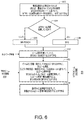
図3は、RSタイプおよび信号フォーマット選択を用いるULビーム管理構成の例である。ULビーム管理のために、NR−PRACHプリアンブル、およびNR−PRACHプリアンブルのためのリソースを構成することができる。302において、ULビーム管理手順を決定することができる。304において、WTRUは、WTRUと関連付けられたステータスを決定することができる。ステータスは、WTRUがUL時間同期しているかどうかを含むことができる。306において、WTRUは、WTRUがUL時間同期していないとき、NR−PRACHを使用することを決定することができる。308において、WTRUは、WTRUがUL時間同期しているとき、SRSを使用することを決定することができる。309において、WTRUは、SRSを使用して、決定されたULビーム管理手順を実行することを決定することができる。310において、WTRUは、U−2および/またはU−3を実行するかどうかを決定することができる。例えば、ULビーム管理のために使用される実施に応じて、信号フォーマットを選択することができる。例においては、312において、例えば、U−2実施が決定されたとき、信号フォーマット(例えば、NR−PRACHプリアンブルフォーマットA)を選択することができる。314において、決定されたU−2実施に基づいて(例えば、決定されたNR−PRACHプリアンブルと、選択されたNR−PRACHプリアンブルフォーマットAとを使用して)、ビーム管理を実行することができる。別の例として、316において、例えば、U−3実施が決定されたとき、信号フォーマット(例えば、NR−PRACHプリアンブルフォーマットB)を選択することができる。318において、決定されたU−3実施に基づいて(例えば、決定されたNR−PRACHプリアンブルと、選択されたNR−PRACHプリアンブルフォーマットBとを使用して)、ビーム管理を実行することができる。TRPは、受信したNR−PRACHプリアンブルフォーマットBに基づいて、WTRU Txビーム(例えば、最良のWTRU Txビーム)を受信し、選択することができる。TRPは、NR−PRACHプリアンブルフォーマットBにおいて使用されるNR−PRACHプリアンブルシーケンスインデックスによって選択または識別されたWTRU Txビーム(例えば、最良のWTRU Txビーム)を含むビーム関連インジケーションを、WTRUに送信することができる。U−1実施は、U−2およびU−3実施の組み合わせであることができ、複数のUL RSリソースと、1つまたは複数のOFDMシンボルから成る各UL RSリソースを、構成することができる。ULビーム管理のためのNR−PRACH信号フォーマットを、図4に示すことができる。 FIG. 3 is an example of a UL beam management configuration using RS type and signal format selection. An NR-PRACH preamble and resources for the NR-PRACH preamble may be configured for UL beam management. At 302, a UL beam management procedure may be determined. At 304, the WTRU may determine a status associated with the WTRU. The status may include whether the WTRU is UL time synchronized. At 306, the WTRU may determine to use the NR-PRACH when the WTRU is not UL time synchronized. At 308, the WTRU may determine to use the SRS when the WTRU is UL time synchronized. At 309, the WTRU may use the SRS to decide to perform the determined UL beam management procedure. At 310, the WTRU may determine whether to execute U-2 and / or U-3. For example, the signal format can be selected depending on the implementation used for UL beam management. In an example, at 312, a signal format (eg, NR-PRACH preamble format A) can be selected, for example, when a U-2 implementation is determined. At 314, beam management can be performed based on the determined U-2 implementation (eg, using the determined NR-PRACH preamble and the selected NR-PRACH preamble format A). As another example, at 316, a signal format (eg, NR-PRACH preamble format B) can be selected, for example, when a U-3 implementation is determined. At 318, beam management can be performed based on the determined U-3 implementation (e.g., using the determined NR-PRACH preamble and the selected NR-PRACH preamble format B). The TRP may receive and select a WTRU Tx beam (eg, the best WTRU Tx beam) based on the received NR-PRACH preamble format B. The TRP sends a beam-related indication to the WTRU that includes the WTRU Tx beam selected or identified by the NR-PRACH preamble sequence index used in the NR-PRACH preamble format B (eg, the best WTRU Tx beam). Can be. The U-1 implementation can be a combination of the U-2 and U-3 implementations, and can configure multiple UL RS resources and each UL RS resource consisting of one or more OFDM symbols. An NR-PRACH signal format for UL beam management can be shown in FIG.
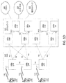
図4は、ULビーム管理のためのNR−PRACH信号フォーマットの例である。ULビーム管理のためのNR−PRACH信号フォーマットは、例えば、(図4における例によって示されるように)NR−PRACHプリアンブルフォーマットA400と、NR−PRACHプリアンブルフォーマットB405とを含むことができる。プリアンブル(例えば、NR−PRACHプリアンブルフォーマットA400、および/またはNF−PRACHプリアンブルフォーマットB405)は、多数のシーケンスを含むことができる。シーケンスの数は、Lによって表すことができる。プリアンブル(例えば、NR−PRACHプリアンブルフォーマットA400、および/またはNF−PRACHプリアンブルフォーマットB405)内のシーケンスは、同じであること、または異なることができる。Lは、TRPまたはWTRUにおいてスイープされるビームの数に基づいて、決定することができる。TRPは、スイープされるTRP Rxビームの数に基づいて、Lを事前定義し、構成し、および/またはNR−PRACHプリアンブルフォーマットA400を使用して、WTRUに伝達することができる。TRPは、Lを構成し、および/またはNR−PRACHプリアンブルフォーマットB405によって、WTRUに伝達することができ、それは、スイープされるWTRU Txビームの数に応じて、WTRUによって無効化されることがある。例えば、WTRUが、ネットワークから伝達されたLよりも小さい値(例えば、L’)を用いる、本明細書において説明されるようなNR−PRACH信号フォーマットで、プリアンブルを送信する場合、WTRUは、ビームスイーピングを容易にするために、更新された値(例えば、L’)をTRPに提供することができる。TRPとWTRUが、同じスイープされるビームを有することができるか、それとも異なるスイープされるビームを有することができるかに応じて、Lは、NR−PRACH信号フォーマットAと、NR−PRACH信号フォーマットBとで、同じであること、または異なることができる。 FIG. 4 is an example of an NR-PRACH signal format for UL beam management. The NR-PRACH signal format for UL beam management may include, for example, an NR-PRACH preamble format A400 (as shown by the example in FIG. 4) and an NR-PRACH preamble format B405. The preamble (eg, NR-PRACH preamble format A400 and / or NF-PRACH preamble format B405) may include multiple sequences. The number of sequences can be represented by L. The sequences in the preamble (eg, NR-PRACH preamble format A400, and / or NF-PRACH preamble format B405) can be the same or different. L can be determined based on the number of beams swept at the TRP or WTRU. The TRP may predefine, configure L, and / or communicate to the WTRU using the NR-PRACH preamble format A400 based on the number of TRP Rx beams swept. The TRP may constitute L and / or be communicated to the WTRU via NR-PRACH preamble format B405, which may be invalidated by the WTRU depending on the number of WTRU Tx beams swept. . For example, if the WTRU transmits a preamble in an NR-PRACH signal format as described herein using a value less than L (eg, L ′) transmitted from the network, the WTRU may transmit the beam An updated value (eg, L ′) can be provided to the TRP to facilitate sweeping. Depending on whether the TRP and the WTRU may have the same swept beam or different swept beams, L may be the NR-PRACH signal format A and the NR-PRACH signal format B And can be the same or different.
UL Txビームを示すために、NR−PRACHプリアンブルリソースを使用することができる。同じまたは異なるプリアンブルリソース上において、同じまたは異なるプリアンブルシーケンスを送信することができる。ある例においては、NR−PRACHプリアンブルフォーマットB405は、同じプリアンブルシーケンスを使用することができ、U3および/またはU1実施におけるWTRU Txビームスイーピングのために、NR−PRACHプリアンブルフォーマットB405を使用するとき、例えば、異なるUL Txビームを示すために、異なるPRACHプリアンブルリソース上において、同じプリアンブルシーケンスを送信することができる。TRPは、異なるNR−PRACHプリアンブルリソース内に割り当てられた同じプリアンブルシーケンスを用いて、受信したNR−PRACHプリアンブルフォーマットB405に基づいて、WTRU Txビーム(例えば、最良のWTRU Txビーム)を受信し、および/または選択することができる。TRPは、選択または識別されたWTRU Txビーム(例えば、最良のWTRU Txビーム)を含むビーム関連インジケーションを、NR−PRACHプリアンブルリソースインジケータによって、WTRUに送信することができる。 An NR-PRACH preamble resource may be used to indicate a UL Tx beam. The same or different preamble sequences can be sent on the same or different preamble resources. In one example, the NR-PRACH preamble format B405 can use the same preamble sequence, and when using the NR-PRACH preamble format B405 for WTRU Tx beam sweeping in U3 and / or U1 implementations, eg, , The same preamble sequence may be transmitted on different PRACH preamble resources to indicate different UL Tx beams. The TRP receives a WTRU Tx beam (eg, the best WTRU Tx beam) based on the received NR-PRACH preamble format B405 using the same preamble sequence allocated in different NR-PRACH preamble resources, and And / or can be selected. The TRP may send a beam-related indication including the selected or identified WTRU Tx beam (eg, the best WTRU Tx beam) to the WTRU via the NR-PRACH preamble resource indicator.
U−1、U−2、およびU−3など、効率的なULビーム管理実施を可能にするために、ULビーム管理のための複数のNR−PRACH信号フォーマットを設計することができる。そのようなNR−PRACH信号フォーマットは、図4に示されるような、NR−PRACHプリアンブルフォーマットA400、およびNR−PRACHプリアンブルフォーマットB405を含むことができる。NR−PRACHプリアンブルフォーマットA400設計においては、連続する複数の、および/または繰り返されるRACH OFDMシンボル、例えば、L個の連続する複数の、および/または繰り返されるRACH OFDMシンボルの各々の先頭において、CPを挿入することができる。CPは、例えば、チャネル遅延拡散に対処するために、RACHシンボル間に挿入することができる。ガードタイム(GT)は、RACHシンボル間に挿入することができない。GTは、例えば、伝搬遅延に対処するために、連続する複数の、および/または繰り返されるRACHシンボルの最後において、使用することができる。NR−PRACHプリアンブルフォーマットB405設計においては、NR−PRACHプリアンブルフォーマットA400設計に類似したものであることができる、複数の、および/または繰り返されるRACHシーケンスまたはプリアンブル送信を使用することができる。NR−PRACHプリアンブルフォーマットB405設計においては、図4に示されるように、異なるシーケンスおよび/またはプリアンブルを使用することができる。U−2実施が実行される場合、固定されたWTRU Txビームのために、TRP Rxビームをスイープすることができる。WTRUは、NR−PRACHプリアンブルフォーマットA設計を使用して、RACH OFDMシンボルにおいて、同じシーケンスまたはプリアンブルを繰り返し送信することができる。U−3実施が実行される場合、TRP Rxビームは、固定されることができるが、異なるWTRU Txビームをスイープすることができる。WTRUは、例えば、図4に示されるような、NR−PRACHプリアンブルフォーマットB405設計を使用して、異なるRACH OFDMシンボルにおいて、異なるTxビームを表す異なるシーケンスおよび/またはプリアンブルを送信することができる。CPは、NR−PRACHプリアンブルフォーマットB405、および/またはNR−PRACHプリアンブルフォーマットA400の異なるシーケンス間に、挿入することができる。GTは、NR−PRACHプリアンブルフォーマットB405、および/またはNR−PRACHプリアンブルフォーマットA400の異なるシーケンスおよび/またはプリアンブルの最後において、使用することができる。U−1およびU−3実施のケースにおいて、シーケンスまたはプリアンブルインデックスは、WTRU TxビームのためのTxビーム情報またはビーム識別を提供することができる。これは、TRPにおいて、WTRU Txビームを識別するために使用することができる。TRPは、識別されたWTRU Txビームを含む、ビーム関連インジケーションを、WTRUに送信することができる。 Multiple NR-PRACH signal formats for UL beam management can be designed to enable efficient UL beam management implementations, such as U-1, U-2, and U-3. Such NR-PRACH signal formats may include NR-PRACH preamble format A400 and NR-PRACH preamble format B405, as shown in FIG. In the NR-PRACH preamble format A400 design, at the beginning of each of a plurality of consecutive and / or repeated RACH OFDM symbols, e.g., L consecutive multiple and / or repeated RACH OFDM symbols, Can be inserted. A CP can be inserted between RACH symbols, for example, to address channel delay spread. A guard time (GT) cannot be inserted between RACH symbols. GTs may be used at the end of consecutive multiple and / or repeated RACH symbols, for example, to address propagation delays. In the NR-PRACH preamble format B405 design, multiple and / or repeated RACH sequences or preamble transmissions, which may be similar to the NR-PRACH preamble format A400 design, may be used. In the NR-PRACH preamble format B405 design, different sequences and / or preambles can be used, as shown in FIG. If a U-2 implementation is performed, the TRP Rx beam may be swept for a fixed WTRU Tx beam. The WTRU may repeatedly transmit the same sequence or preamble in a RACH OFDM symbol using the NR-PRACH preamble format A design. If a U-3 implementation is performed, the TRP Rx beam can be fixed, but can sweep a different WTRU Tx beam. The WTRU may transmit different sequences and / or preambles representing different Tx beams in different RACH OFDM symbols, for example, using the NR-PRACH preamble format B405 design, as shown in FIG. The CP can be inserted between different sequences of the NR-PRACH preamble format B405 and / or the NR-PRACH preamble format A400. GT may be used at the end of different sequences and / or preambles of NR-PRACH preamble format B405 and / or NR-PRACH preamble format A400. In the case of U-1 and U-3 implementations, the sequence or preamble index may provide Tx beam information or beam identification for the WTRU Tx beam. This can be used in TRP to identify the WTRU Tx beam. The TRP may send a beam-related indication to the WTRU, including the identified WTRU Tx beam.
図5は、NR−PRACHプリアンブルフォーマットA500、およびNR−PRACHプリアンブルフォーマットB550を用いる、U2およびU3の例である。図5は、本明細書において説明されるNR−PRACHプリアンブルフォーマットA500を用いるU2実施を使用する、TRP 4Rxビームスイーピング、および本明細書において説明されるNR−PRACHプリアンブルフォーマットB550を用いるU3実施を使用する、WTRU 4Txビームスイーピングの例示的な図を示している。TRPは、WTRU Txビーム(例えば、最良のWTRU Txビーム)を選択すること、および/またはWTRUに示すことができる。図5に示される例においては、U3ビームスイーピング結果に基づいて、TRPによって、WTRU Txビーム(例えば、最良のWTRU Txビーム)を示すために、NR−PRACHプリアンブルフォーマットB550に属するプリアンブルシーケンスインデックス(例えば、4つのNR−PRACHプリアンブルシーケンスインデックスのうちの1つ)を選択すること、および/またはWTRUに送信することができる。 FIG. 5 is an example of U2 and U3 using NR-PRACH preamble format A500 and NR-PRACH preamble format B550. FIG. 5 illustrates TRP 4Rx beam sweeping using a U2 implementation using the NR-PRACH preamble format A500 described herein, and using a U3 implementation using the NR-PRACH preamble format B550 described herein. FIG. 4 illustrates an exemplary diagram of WTRU 4Tx beam sweeping. The TRP may select a WTRU Tx beam (eg, the best WTRU Tx beam) and / or indicate to the WTRU. In the example shown in FIG. 5, based on the U3 beam sweeping result, the preamble sequence index (e.g., the NR-PRACH preamble format B550) belonging to the NR-PRACH preamble format B550 to indicate the WTRU Tx beam (e.g. , One of the four NR-PRACH preamble sequence indices) can be selected and / or transmitted to the WTRU.
SRSが決定され、使用されるとき、アップリンクビーム管理実施のために、UL SRSリソース、およびOFDMシンボルを構成することができる。例えば、U−2実施が決定され、使用されるとき、複数のOFDMシンボルから成るUL SRSリソースを構成することができる。U−3実施が決定され、使用されるとき、複数のUL SRSリソース、および1つのOFDMシンボルを含む(例えば、各)UL SRSリソースを構成することができる。UL Txビーム(例えば、最良のUL Txビーム)を伝達するために、SRSリソースインジケータを使用することができる。 When the SRS is determined and used, UL SRS resources and OFDM symbols can be configured for uplink beam management implementation. For example, when a U-2 implementation is determined and used, an UL SRS resource consisting of multiple OFDM symbols may be configured. When a U-3 implementation is determined and used, a plurality of UL SRS resources and (eg, each) UL SRS resource including one OFDM symbol may be configured. An SRS resource indicator may be used to convey a UL Tx beam (eg, the best UL Tx beam).
大きいサブキャリア間隔、IFDMA、または離散フーリエ変換(DFT)ベースの手段のうちの1つまたは複数によって、U1/U2/U3実施のために、NR−PRACHプリアンブル、NR−SRS、および/またはNR−DMRSなどのサブ時間ユニット(サブTU)基準信号を使用して、例えば、オーバヘッドを節約することができる。例えば、(例えば、1つの)OFDMシンボル内において、1つまたは複数のNR−PRACHプリアンブル反復を生成するために(例えば、増加させるために)、サブTU NR−PRACHプリアンブルおよび/またはNR−SRSを使用することができる。プリアンブルシーケンス(例えば、同じプリアンブルシーケンス)によって示される(例えば、1つの)WTRU TxビームについてのTRP Rxビームスイーピングのために、同じプリアンブルシーケンスを有する1つの反復グループを使用することができる。1つの反復グループを有する繰り返されるプリアンブルシーケンスの数は、ネットワークまたはTRPもしくはgNBによって構成することができる、スイープされるTRP Rxビームの数に基づくこと(例えば、等しいこと)ができる。WTRUは、複数の反復グループから、Txビームスイーピングを実行することができる。 NR-PRACH preamble, NR-SRS, and / or NR- for U1 / U2 / U3 implementation by one or more of large subcarrier spacing, IFDMA, or Discrete Fourier Transform (DFT) based means. A sub-time unit (sub-TU) reference signal such as DMRS can be used, for example, to save overhead. For example, to generate (eg, to increase) one or more NR-PRACH preamble repetitions within an (eg, one) OFDM symbol, the sub-TU NR-PRACH preamble and / or NR-SRS may be used. Can be used. For TRP Rx beam sweeping for a WTRU Tx beam (eg, one) indicated by a preamble sequence (eg, the same preamble sequence), one repetition group having the same preamble sequence may be used. The number of repeated preamble sequences with one repeat group can be based on (eg, equal to) the number of TRP Rx beams that are swept, which can be configured by the network or TRP or gNB. The WTRU may perform Tx beam sweeping from multiple iteration groups.
TRPは、WTRUビームスイープを構成することができる。例えば、TRPおよび/またはWTRUにおいて、粗いビームを識別するために、実施(例えば、U−1実施)を実行することができる。例えば、TRPにおいて、粗いビームを精細化するために、実施(例えば、U−2実施)を実行することができる。例えば、WTRUにおいて、粗いビームを精細化するために、実施(例えば、U−3実施)を実行することができる。ビーム精細化は、例えば、以下のシナリオのうちの1つまたは複数を含むことができ、(i)(例えば、粗いビームが正確でないことがあるとき)より正確なビームを識別する必要があることがあり、(ii)(例えば、粗いビームのビーム幅が広すぎることがあるとき)より狭いビームを識別する必要があることがあり、(iii)(例えば、粗いビームが低い分解能であることがあるとき)(より)高い分解能を有するビームを識別する必要があることがあり、および/または(iv)(例えば、粗いビームが無指向性であることがあるとき)指向性ビームを識別する必要があることがある。 The TRP may constitute a WTRU beam sweep. For example, in a TRP and / or WTRU, an implementation (eg, a U-1 implementation) may be performed to identify a coarse beam. For example, in a TRP, an implementation (eg, a U-2 implementation) may be performed to refine the coarse beam. For example, in a WTRU, an implementation (eg, a U-3 implementation) may be performed to refine the coarse beam. Beam refinement may include, for example, one or more of the following scenarios: (i) need to identify a more accurate beam (eg, when a coarse beam may not be accurate) And (ii) it may be necessary to identify a narrower beam (eg, when the beam width of the coarse beam may be too wide), and (iii) (eg, the coarse beam may have lower resolution). At some times, it may be necessary to identify a beam with (higher) resolution and / or (iv) to identify a directional beam (eg, when a coarse beam may be omni-directional). There may be.
例えば、実施U−3を実行することができるとき、新しいビームを、WTRU Txビームとして識別することができる。WTRUにおいて精細化されたビームは、例えば、正確なビーム、より狭いビーム、または分解能がより高いビームであることができる。例えば、新しいビームを識別するために、ビーム関連インジケーション(beam-related indication)をWTRUに送信することができる。ビーム関連インジケーションは、例えば、NR−PDCCHまたはNR−ePDCCHを介して、例えば、DCIにおいて、搬送することができる。 For example, when implementation U-3 can be performed, the new beam can be identified as a WTRU Tx beam. The beam refined in the WTRU may be, for example, an accurate beam, a narrower beam, or a higher resolution beam. For example, a beam-related indication can be sent to the WTRU to identify a new beam. The beam-related indication may be carried, for example, in the DCI via the NR-PDCCH or NR-ePDCCH.
例えば、実施U−2を実行することができるとき、新しいビームを、(例えば、TRP RXビームとして)識別することができる。異なるロケーションにある(例えば、各)WTRUのために、TRP固有Rxビームが存在することができる。例えば、TRPがWTRUをスケジュールするとき、TRPは、マルチユーザケースをどのように扱うべきかを検討することができる。例えば、WTRUが同じタイムスロットまたはTTI内にスケジュールされるとき、TRPは、複数のTRP Rxビームをアクティブ化することができる。WTRUは、同じタイムスロットまたはTTI内にありながら、周波数領域においては、異なるPRB内にスケジュールすることができる。TRPは、タイムスロットまたはTTI内のスケジュールされたWTRUに基づいて、複数のRxビームをアクティブ化することができる。例えば、異なるタイプのTRP Rxビームを使用して、異なるWTRUにサービスすることができるとき、異なる電力制御ステップサイズが、必要とされることがある。例えば、広いビームのために、より大きい電力制御ステップサイズを使用することができ、一方、狭いビームのために、(より)小さい電力制御ステップサイズを使用することができる。 For example, when implementation U-2 can be performed, a new beam can be identified (eg, as a TRP RX beam). For WTRUs at different locations (eg, each), a TRP specific Rx beam may exist. For example, when the TRP schedules a WTRU, the TRP may consider how to handle a multi-user case. For example, when a WTRU is scheduled in the same time slot or TTI, the TRP may activate multiple TRP Rx beams. A WTRU may be scheduled in a different PRB in the frequency domain while in the same timeslot or TTI. The TRP may activate multiple Rx beams based on time slots or scheduled WTRUs within a TTI. For example, different power control step sizes may be required when different WTRUs can be serviced using different types of TRP Rx beams. For example, for a wide beam, a larger power control step size can be used, while for a narrow beam, a (smaller) smaller power control step size can be used.
TRPは、ビーム管理コマンド内に、ビーム管理タイプ、ビームタイプ、基準信号タイプ、および/またはリソース割り当てを含めることができる。ビーム管理コマンドは、例えば、以下のうちの1つまたは複数、すなわち、(i)ビーム管理タイプ(例えば、U−1、U−2、U−3などのアップリンクビーム管理実施)、(ii)ビームタイプ(例えば、異なるビーム幅および/もしくは分解能)、(iii)基準信号(RS)タイプ(例えば、SRS、PRACHプリアンブル、UL DMRS、および/もしくはSR)、ならびに/または(iv)送信電力レベルのうちの1つまたは複数を含むことができる。 The TRP may include the beam management type, beam type, reference signal type, and / or resource allocation in the beam management command. The beam management command may be, for example, one or more of the following: (i) a beam management type (eg, performing uplink beam management such as U-1, U-2, U-3, etc.), (ii) (Iii) reference signal (RS) type (eg, SRS, PRACH preamble, UL DMRS, and / or SR), and / or (iv) transmit power level. One or more of them may be included.
TRPは、WTRUが、例えば、特定のTxビームタイプ、および/または特定のTx電力レベルを使用して、ビームスイープを実行することを要求することができる。(例えば、実施U−1、U−2、およびU−3のために)異なるビームタイプ、および/または電力レベルを使用すること、または異なるUL実施と関連付けることができる。 The TRP may request that the WTRU perform a beam sweep using, for example, a particular Tx beam type and / or a particular Tx power level. Different beam types and / or power levels may be used (eg, for implementations U-1, U-2, and U-3) or may be associated with different UL implementations.
TRPは、ビームスイープのためのリソースを構成することができる。ULビーム管理実施のために、周波数リソース、時間リソース、および/または符号リソース(例えば、セットまたはグループ)を構成することができる。 The TRP may configure resources for beam sweep. For UL beam management implementation, frequency resources, time resources, and / or code resources (eg, sets or groups) can be configured.
TRPは、(例えば、WTRUに対して)以下のうちの1つまたは複数、すなわち、(i)(例えば、各)UL実施のための信号タイプ関連付け(例えば、SRS、PRACHプリアンブル、および/もしくはUL DMRS)、(ii)ULビーム管理のためのタイムスロットもしくはサブフレーム、(iii)ULステータス(例えば、使用する信号タイプは、タイムアドバンス有効、またはタイムアドバンス無効によってトリガすることができ、例えば、タイムアドバンス有効(もしくは同期)は、SRSおよび/もしくはUL DMRSの使用をトリガすることができ、タイムアドバンス無効(もしくは同期ずれ)は、PRACHプリアンブルの使用をトリガすることができる)、(iv)時間ユニットもしくはサブ時間ユニットベースのビームスイープ(例えば、IFDMA、大きいサブキャリア間隔ベース、もしくはDFTベース)、(v)U−2およびU−3のための局所的もしくは大域的ビームスイープ、(vi)U−3のために必要とされる反復の数、(vii)WTRU Txビーム関連インジケーション、(viii)(例えば、静的方式における)TRPビーム対応能力、ならびに/または(ix)(例えば、動的もしくは半静的方式における)TRPビーム対応ステータスのうちの1つまたは複数を(さらに)構成することができる。 The TRP may include one or more of the following (eg, for a WTRU): (i) signal type association (eg, SRS, PRACH preamble, and / or UL) for UL implementation (eg, each). DMRS), (ii) time slots or subframes for UL beam management, (iii) UL status (eg, the signal type used can be triggered by time advance enabled or time advance disabled; Advance enable (or synchronization) can trigger use of SRS and / or UL DMRS, time advance disable (or out of sync) can trigger use of PRACH preamble), (iv) time unit Or sub-time unit basis Beam sweep (eg, IFDMA, large subcarrier spacing based, or DFT based), (v) local or global beam sweep for U-2 and U-3, (vi) for U-3 The number of iterations required, (vii) a WTRU Tx beam related indication, (viii) TRP beam capability (eg, in a static scheme), and / or (ix) (eg, a dynamic or semi-static scheme) One or more of the TRP beam correspondence statuses can be (further) configured.
TRPは、例えば、要求したビームタイプおよび電力レベルを使用して、WTRUから送信された基準信号を測定することができる。TRPは、WTRU UL送信のために選択されるビームを決定することができ、示すことができる。 The TRP may measure the reference signal transmitted from the WTRU, for example, using the requested beam type and power level. The TRP may determine and indicate which beam is selected for a WTRU UL transmission.
TRPは、例えば、U−1またはU−3実施の後、1つまたは複数のWTRU Txビームを選択することができる。TRPは、ビーム関連インジケーションをWTRUに送信することができる。ビーム関連情報は、例えば、以下のうちの1つまたは複数、すなわち、(i)1つもしくは複数の選択されたWTRU Txビームインデックス、(ii)1つもしくは複数の選択されたWTRU Txビームのための対応するRSRP、SINR、CSI、もしくはCQI、(iii)1つもしくは複数の(例えば、最良の)ULビームペア(例えば、WTRUのTXビームおよび/もしくはTRPのRXビーム)、ならびに/または(iv)1つもしくは複数のバックアップULビームペアなどのうちの1つまたは複数を含むことができる。 The TRP may select one or more WTRU Tx beams, for example, after a U-1 or U-3 implementation. The TRP may send a beam-related indication to the WTRU. The beam related information may include, for example, one or more of the following: (i) one or more selected WTRU Tx beam indices; (ii) one or more selected WTRU Tx beams. A corresponding RSRP, SINR, CSI or CQI, (iii) one or more (eg, best) UL beam pairs (eg, WTRU TX beam and / or TRP RX beam), and / or (iv) One or more of one or more backup UL beam pairs and the like may be included.
TRPは、特定のビームタイプおよび電力レベルに対して、識別されたTxビームを使用するように、WTRUをスケジュールすることができる。TRPは、他のビームタイプおよび電力レベルに対して、識別されたTxビームを使用するように、WTRUをスケジュールすることができる(例えば、スケジュールすることもできる)。WTRUは、別のビームタイプのために、識別されたTxビームを別の新しいTxビームに変換することができ、異なる電力レベルを使用することができる。これは、例えば、ビーム適応、およびジョイントビーム/リンク適応のために役立つことがある。例においては、TRPは、例えば、モビリティ、カバレージの理由から、および/またはアップリンク制御チャネルのために、より高い電力においては、より広いビームを使用して送信するように、WTRUをスケジュールすることができる。 The TRP may schedule the WTRU to use the identified Tx beam for a particular beam type and power level. The TRP may schedule (eg, may schedule) the WTRU to use the identified Tx beam for other beam types and power levels. The WTRU may convert the identified Tx beam to another new Tx beam for another beam type and may use a different power level. This may be useful, for example, for beam adaptation, and joint beam / link adaptation. In an example, the TRP schedules the WTRU to transmit using a wider beam at higher powers, eg, for mobility, coverage reasons, and / or for an uplink control channel. Can be.
TRPは、例えば、データチャネルのためのより高いデータレート、より高いリンク品質の理由から、および/または他のTRPに対する低減された干渉のために、より低い電力においては、より狭いビームを使用して送信するように、WTRUをスケジュールすることができる。 TRP uses narrower beams at lower powers, for example, for higher data rates for data channels, higher link quality, and / or due to reduced interference to other TRPs. The WTRU may be scheduled to transmit.
TRPは、ビームについての柔軟なスケジューリングを有することができる。例えば、TRPは、RSについての元のビームスイープ設定を無効化し、WTRUが、元のビームスイープ設定を、データおよび/または制御送信のための新しいまたは異なる設定に変更することを要求することができる。例えば、ビームタイプおよびTx電力を、1つの設定から別の設定に変換することができるとき、ビーム幅および電力レベルのオフセットを導入することができる。ベースビームタイプおよび電力レベルは、事前決定することができる。他のビームタイプおよび電力レベルを、ベース設定に対するオフセットとして適用することができ、またはベース設定に対するオフセットに適用することができる。オフセットおよびそれらの値は、事前決定することができる。 The TRP may have flexible scheduling for the beam. For example, the TRP may override the original beam sweep setting for the RS and request that the WTRU change the original beam sweep setting to a new or different setting for data and / or control transmission. . For example, beam width and power level offsets can be introduced when beam type and Tx power can be converted from one setting to another. The base beam type and power level can be predetermined. Other beam types and power levels may be applied as offsets to the base setting, or may be applied to offsets to the base setting. The offsets and their values can be predetermined.
TRPは、ビーム関連インジケーション内に(例えば、DCI内に)ビームタイプを含めることができ、それは、例えば、以下のうちの1つまたは複数、すなわち、i)ビームタイプ、(ii)(例えば、アップリンク実施U−1、U−2、U−3などのビーム管理において使用される)元のビームタイプについてのWTRU Txビーム情報、ならびに/または(iii)ビーム幅および/もしくはTx電力レベルのためのオフセット値のうちの1つまたは複数を含むことができる。 The TRP may include a beam type in a beam-related indication (eg, in DCI), for example, one or more of the following: i) beam type, (ii) (eg, WTRU Tx beam information for the original beam type (used in beam management for uplink implementations U-1, U-2, U-3, etc.) and / or (iii) beam width and / or Tx power level One or more of the following offset values:
WTRUは、元のビームタイプ、ビーム情報、および/またはビームIDを、示されたビームタイプ、ビーム情報、および/または示されたビームタイプのためのビームIDに変換することができる。示されたビームタイプは、データまたは制御送信のために使用することができる、(例えば、U−1、U−2、U−3において使用されない)別のビームタイプであることができる。ビームタイプと、それらのビーム情報またはIDとの間の1つまたは複数の関連付けを、使用することができる。WTRUは、例えば、示されたビームタイプに基づいて、ビーム幅および電力レベルにおいて、オフセット値を適用することができる。 The WTRU may convert the original beam type, beam information, and / or beam ID to the indicated beam type, beam information, and / or beam ID for the indicated beam type. The beam type shown may be another beam type (eg, not used in U-1, U-2, U-3) that may be used for data or control transmission. One or more associations between beam types and their beam information or IDs can be used. The WTRU may apply an offset value at the beam width and power level, for example, based on the indicated beam type.
図6は、ビーム対応を用いるULビーム管理構成の例である。ULビーム管理は、例えば、ビーム対応を用いるように構成することができる。602において、TRPは、(例えば、UL時間同期ステータスなど)WTRU状況またはステータスを決定すること、および/または示すことができる。例えば、事前定義または構成されたルールまたはトリガ(例えば、最後のタイムアドバンス(TA)コマンド以降の時間もしくはタイマ、および/またはWTRUスピード)に基づいて、WTRUまたはTRPによって、WTRU UL時間同期ステータスを決定することができる。602において、TRPは、WTRUステータスと関連付けられた時間値(例えば、最後のTA以降の時間、状態にある時間等)を決定することができる。TRPは、WTRUステータスが変化したか、それとも変化していないかを決定することができる。例えば、タイマ(例えば、最後のTA以降の時間)が閾値を超えた場合、WTRUは、同期していないことがある。604において、TRPは、WTRUが時間同期しているかどうかを決定することができる。TRPは、(例えば、WTRU状況またはステータスに基づいて)信号タイプおよび信号フォーマット、例えばRSタイプおよびフォーマットを決定し、構成することができる。WTRUがUL時間同期している場合、606において、TRPは、NR−PRACHを構成することができる。WTRUがUL時間同期していない場合、608において、TRPは、SRSを構成することができる。610において、TRPは、使用されるビーム管理実施、例えばU−1、U−2、またはU−3を決定することができる。612において、例えばビーム対応情報に基づいて、ビーム管理実施を調整することができる。例えば、ULビーム管理手順は、DLビーム管理手順を使用して、調整すること、または部分的に実行することができる。 FIG. 6 is an example of a UL beam management configuration using beam correspondence. UL beam management can be configured, for example, to use beam correspondence. At 602, the TRP can determine and / or indicate a WTRU status or status (eg, UL time synchronization status, etc.). For example, determine the WTRU UL time synchronization status by the WTRU or TRP based on predefined or configured rules or triggers (eg, time or timer since last time advance (TA) command and / or WTRU speed). can do. At 602, the TRP can determine a time value associated with the WTRU status (eg, time since last TA, time in state, etc.). The TRP may determine whether the WTRU status has changed or not. For example, if a timer (eg, time since last TA) exceeds a threshold, the WTRU may not be synchronized. At 604, the TRP can determine whether the WTRU is time synchronized. The TRP may determine and configure the signal type and signal format (eg, based on the WTRU status or status), eg, the RS type and format. If the WTRU is UL time synchronized, at 606, the TRP may configure the NR-PRACH. If the WTRU is not UL time synchronized, at 608, the TRP may configure the SRS. At 610, the TRP can determine the beam management implementation to use, eg, U-1, U-2, or U-3. At 612, the beam management implementation can be adjusted, for example, based on the beam correspondence information. For example, the UL beam management procedure can be adjusted or partially performed using the DL beam management procedure.
調整されたビーム管理実施は、ジョイントULおよびDLビーム管理実施であることができる。UL実施(例えば、U−1、U−2、またはU−3)と、DL実施(例えば、P−1、P−2、またはP−3)は、混合することができ、および/または調整されたビーム管理実施において、一緒に使用することができる。ジョイントUL/DLビーム管理は、ビーム対応情報、1つもしくは複数のDLビーム管理測定、および/または事前決定もしくは構成されたUL/DL結合ルールに基づいて、調整すること、または部分的に実行することができる。ビーム対応情報は、TRPビーム対応情報614、および/またはWTRUビーム対応情報616を含むことができる。ビーム管理実施は、例えば、決定および構成されたUL実施(例えば、U−1、U−2、またはU−3)、決定または構成された信号タイプ、ならびに信号フォーマットを使用して、実行することができる。618において、例えば、決定または構成された信号タイプおよび信号フォーマットを使用する、決定、構成、および調整されたジョイント/混合UL/DL実施(例えば、U−1、U−2、またはU−3、およびP−1、P−2、またはP−3)を使用して、ビーム管理実施を実行することができる。ジョイントUL/DLビーム管理手順は、1つのサブフレーム、1つのTTI、または1つのスロット内において、達成することができ、ジョイントUL/DLビーム管理のために、DL基準信号(例えば、CSI−RSまたはSSブロック)と、UL基準信号(例えば、SRSまたはPRACHプリアンブル)との間の何らかのRS関連付けを、使用または構成することができる。順次ULおよびDL手順のジョイントトリガリングを、ビームトレーニングのために使用して、例えば、待ち時間を短縮し、ULデータ送信を助けることができる。例えば、ビームトレーニングのために、U−2手順とP−3手順を一緒に構成して、例えば、高速ULデータ送信を提供することができる。
The coordinated beam management implementation may be a joint UL and DL beam management implementation. A UL implementation (eg, U-1, U-2, or U-3) and a DL implementation (eg, P-1, P-2, or P-3) can be mixed and / or adjusted. Can be used together in a customized beam management implementation. Joint UL / DL beam management adjusts or partially performs based on beam correspondence information, one or more DL beam management measurements, and / or predetermined or configured UL / DL combination rules. be able to. The beam correspondence information may include TRP
例えば、TRPおよび/またはWTRUにおいて、ビーム対応を遂行することができるとき、1つまたは複数(例えば、すべて)のTRP TX/RXビーム、および/またはWTRU TX/RXビームを決定するために、ULビーム管理を使用することができる。1つまたは複数(例えば、すべて)のTRP TX/RXビーム、および/またはWTRU TX/RXビームを決定するために、(例えば、DLビーム管理の代わりに)ULビーム管理を使用することができる。例えば、使用事例および要件に応じて、DLまたはULビーム管理を使用することができる。 For example, at the TRP and / or WTRU, when beam correspondence can be performed, the UL to determine one or more (eg, all) TRP TX / RX beams and / or WTRU TX / RX beams. Beam management can be used. UL beam management (eg, instead of DL beam management) can be used to determine one or more (eg, all) TRP TX / RX beams and / or WTRU TX / RX beams. For example, depending on the use case and requirements, DL or UL beam management can be used.
ULビーム管理は、ビーム対応に基づくことができる。 UL beam management can be based on beam correspondence.
図7は、ビーム対応ベースのビーム管理の例である。 FIG. 7 shows an example of beam management on a beam basis.
例えば、WTRU Txビーム、および/またはgNBもしくはTRP Rxビームの選択をサポートするために、実施(例えば、U−1実施)を使用して、異なるWTRU Txビーム上におけるgNBまたはTRP測定を可能にすることができる。例えば、TRP間またはTRP内Rxビームを切り換える、変更する、選択する、または再選択するために、実施(例えば、U−2実施)を使用して、異なるgNBまたはTRP Rxビーム上におけるgNBまたはTRP測定を可能にすることができる。例えば、WTRUがビームフォーミングを使用するとき、例えば、WTRU Txビームを切り換える、または変更するために、実施(例えば、U−3実施)を使用して、同じTRP Rxビーム上におけるTRP測定を可能にすることができる。実施(例えば、U−1実施)は、(例えば、ビーム対応または相反性(reciprocity)が利用可能ではないことがあるとき)、例えば、gNBにおけるTxおよびRxビーム、またはTRP RxビームおよびWTRU Txビームについて、フルビームスイープを必要とすることがある。実施(例えば、U−2実施)は、例えば、gNBまたはTRPにおけるRxビームについて、フルビームスイープを必要とすることがある。実施(例えば、U−3実施)は、例えば、WTRUにおけるTxビームについて、フルビームスイープを必要とすることがある。例えば、1つまたは複数の実施(例えば、U−2およびU−3実施)をトリガしたイベントについての(例えば、事前)知識が存在することができるとき、フルビームスイープは、制限されたフルビームスイープ、または局所化されたビームスイーピングにスケールダウンすることができる。gNBまたはTRPは、例えば、以下のうちの1つまたは複数、すなわち、(i)ビームスイープのタイプ(例えば、フルビームスイープ、制限されたビームスイープ、局所化されたビームスイープ、もしくは階層的ビームスイープ)、(ii)ビームスイープのためのタイムスロットもしくはサブフレーム、(iii)ビームスイープをいつ開始するか、(iv)ビームスイープの持続時間、および/または(v)(例えば、規則的な時間ユニットもしくはサブ時間ユニットベースのビームスイーピングを使用する)ビームスイープのスピードのうちの1つまたは複数を、WTRUに示すことができる。 For example, use an implementation (eg, a U-1 implementation) to enable gNB or TRP measurements on different WTRU Tx beams to support the selection of a WTRU Tx beam and / or gNB or TRP Rx beam. be able to. For example, to switch, change, select, or reselect Rx beams between or within TRPs, use an implementation (eg, a U-2 implementation) to use gNB or TRP on a different gNB or TRP Rx beam. Measurement can be enabled. For example, when a WTRU uses beamforming, for example, to switch or change the WTRU Tx beam, use an implementation (eg, a U-3 implementation) to enable TRP measurements on the same TRP Rx beam. can do. Implementations (e.g., U-1 implementations) may be performed (e.g., when beam correspondence or reciprocity may not be available), e.g., Tx and Rx beams in a gNB, or TRP Rx beams and WTRU Tx beams. May require a full beam sweep. An implementation (e.g., a U-2 implementation) may require a full beam sweep, e.g., for an Rx beam at the gNB or TRP. An implementation (eg, a U-3 implementation) may require a full beam sweep, for example, for a Tx beam in a WTRU. For example, a full beam sweep is a limited full beam when there can be (eg, prior) knowledge about the event that triggered one or more implementations (eg, U-2 and U-3 implementations). It can be swept, or scaled down to localized beam sweeping. The gNB or TRP may be, for example, one or more of the following: (i) the type of beam sweep (eg, full beam sweep, limited beam sweep, localized beam sweep, or hierarchical beam sweep) ), (Ii) a time slot or subframe for the beam sweep, (iii) when to start the beam sweep, (iv) the duration of the beam sweep, and / or (v) (eg, a regular time unit). One or more of the beam sweep speeds (or using sub-time unit based beam sweeping) may be indicated to the WTRU.
例えば、ビーム対応(beam correspondence)または相反性(reciprocity)が利用可能であるとき、アップリンク実施(例えば、U−1、U−2、およびU−3)は、簡略化することができる。簡略化されたULビーム管理は、例えば、ビーム対応または相反性のタイプ(例えば、部分的または完全な対応または相反性)に依存することができる。簡略化されたULビーム管理は、例えば、ビーム対応または相反性のタイプ(例えば、片側または両側ビーム対応または相反性)に依存することができる(例えば、依存することもできる)。片側ビーム対応または相反性は、例えば、WTRU側またはTRP側におけるものであることができる。両側ビーム対応または相反性は、例えば、TRPとWTRUの両方が、ビーム対応または相反性を有するときであることができる。 For example, when beam correspondence or reciprocity is available, uplink implementations (eg, U-1, U-2, and U-3) can be simplified. Simplified UL beam management can depend, for example, on the type of beam correspondence or reciprocity (eg, partial or complete correspondence or reciprocity). Simplified UL beam management may, for example, depend on (e.g., may depend on) the type of beam correspondence or reciprocity (e.g., one-sided or two-sided beam correspondence or reciprocity). The one-sided beam correspondence or reciprocity can be, for example, on the WTRU side or the TRP side. Bilateral beam correspondence or reciprocity may be, for example, when both the TRP and the WTRU have beam correspondence or reciprocity.
図7は、ビーム対応ベースのビーム管理の例である。702において、WTRUおよび/またはTRPによって、ビーム対応を示すことができる。704において、ビーム対応は、片側または両側であることができる。706において、ビーム対応が片側である場合、WTRU側またはTRP側ビーム対応を示すことができる。708において、部分的または完全なビーム対応を示すことができる。710において、ULビーム管理手順(例えば、U−1、U−2、またはU−3)を要求することができる。712において、1つまたは複数のUL/DL結合ルールに基づいて、UL手順を決定することができる。例えば、ULビーム管理手順は、ビーム対応の関数であることができる。714において、1つまたは複数の結合ルールに基づいて、(例えば、WTRUまたはTRPによって)ジョイント/混合UL/DLビーム管理を実行することができる。例えば、UL/DLビーム管理は、ジョイント/混合U−1/U−2/U−3および/またはP−1/P−2/P−3を含むことができる。ジョイントUL/DLビーム管理手順は、1つのサブフレーム、1つのTTI、または1つのスロット内において、達成することができ、ジョイントUL/DLビーム管理手順のために、DL基準信号(例えば、CSI−RSまたはSSブロック)と、UL基準信号(例えば、SRSまたはPRACHプリアンブル)との間の何らかのRS関連付けを、使用または構成することができる。 FIG. 7 shows an example of beam management on a beam basis. At 702, a beam correspondence can be indicated by the WTRU and / or TRP. At 704, the beam correspondence can be unilateral or bilateral. At 706, if the beam correspondence is one side, a WTRU side or TRP side beam correspondence may be indicated. At 708, a partial or full beam correspondence can be indicated. At 710, a UL beam management procedure (eg, U-1, U-2, or U-3) can be requested. At 712, a UL procedure can be determined based on one or more UL / DL combining rules. For example, the UL beam management procedure can be a function of beam correspondence. At 714, joint / mixed UL / DL beam management can be performed (eg, by a WTRU or TRP) based on one or more combining rules. For example, UL / DL beam management may include joint / mixed U-1 / U-2 / U-3 and / or P-1 / P-2 / P-3. The joint UL / DL beam management procedure can be achieved within one subframe, one TTI, or one slot, and for the joint UL / DL beam management procedure, a DL reference signal (eg, CSI- Any RS association between the RS or SS block) and the UL reference signal (eg, SRS or PRACH preamble) can be used or configured.
WTRU側ビーム対応が、存在することができる。 A WTRU side beam correspondence may exist.
例えば、ULビーム管理を簡略化するために、(例えば、WTRU側ビーム対応が示されたとき)アップリンク実施(例えば、U−1、U−2、およびU−3)を、ダウンリンク実施(例えば、P−1、P−2、およびP−3)と結合することができる。ビーム管理は、例えば、以下のルールうちの1つまたは複数を使用して、簡略化することができ、すなわち、(i)アップリンク実施(例えば、U−1)は、ダウンリンク実施(例えば、P−1)に基づいて、縮小することができ、および/または(ii)アップリンク実施(例えば、U−3)は、ダウンリンク実施(例えば、P−3)に基づいて、スキップできる。 For example, to simplify UL beam management, uplink implementations (eg, U-1, U-2, and U-3) may be performed (eg, when WTRU side beam correspondence is indicated), and downlink implementations (eg, U-1, U-2, and U-3). For example, it can bind to P-1, P-2, and P-3). Beam management can be simplified, for example, using one or more of the following rules: (i) uplink implementation (eg, U-1) is downlink implementation (eg, U-1) Based on P-1), it can be reduced and / or (ii) an uplink implementation (eg, U-3) can be skipped based on a downlink implementation (eg, P-3).
例えば、アップリンク実施を簡略化するために、アップリンク実施(例えば、U−1)を、ダウンリンク実施(例えば、P−1)と結合することができる。例においては、P−1実施を実行することができる。最良の粗いTRP TxビームとWTRU Rxビームを識別することができる。(例えば、識別されたWTRU Rxビームに基づいて)最良の粗いWTRU Txビームを導出すること、または知ることができる。U−1実施を簡略化して、例えば、半サイクルU−1実施を実行することができる。 For example, an uplink implementation (e.g., U-1) can be combined with a downlink implementation (e.g., P-1) to simplify the uplink implementation. In the example, a P-1 implementation can be performed. The best coarse TRP Tx beam and WTRU Rx beam can be distinguished. The best coarse WTRU Tx beam can be derived or known (eg, based on the identified WTRU Rx beam). The U-1 implementation can be simplified, for example, to perform a half-cycle U-1 implementation.
例えば、以下の例のうちの1つまたは複数に従って、実施を縮小することができる。 For example, implementations may be reduced according to one or more of the following examples.
アップリンク実施(例えば、U−1)は、ダウンリンク実施(例えば、P−1)によって識別されたWTRU Txビームのために、gNBにおけるRxビームまたはTRP Rxビームについてのフルビームスイープを実行することができる。 The uplink implementation (eg, U-1) performs a full beam sweep on the Rx beam or TRP Rx beam in the gNB for the WTRU Tx beam identified by the downlink implementation (eg, P-1). Can be.
アップリンク実施(例えば、U−2)は、(例えば、通常通り)実行することができる。例えば、U−2実施は、ビーム精細化のために、gNBまたはTRPにおけるRxビームについてのフルまたはローカルビームスイープを使用することができる。 An uplink implementation (eg, U-2) may be performed (eg, as usual). For example, a U-2 implementation may use a full or local beam sweep for the Rx beam in gNB or TRP for beam refinement.
ダウンリンク実施(例えば、P−3)の後、アップリンク実施(例えば、U−3)は、スキップすることができる。例えば、U−3実施は、P−1実施から導出することができる、WTRUにおける識別されたTxビーム内部または周囲についてのビーム精細化のために必要とされないことがあり、または(例えば、それだけのために)必要とされることがある。 After a downlink implementation (eg, P-3), an uplink implementation (eg, U-3) can be skipped. For example, a U-3 implementation may not be required for beam refinement within or around the identified Tx beam in the WTRU, which may be derived from a P-1 implementation, or (e.g., May be required).
TRP側対応が、存在することができる。 There can be a TRP side correspondence.
例えば、ULビーム管理を簡略化するために、(例えば、TRP側ビーム対応が示されたとき)アップリンク実施(例えば、U−1、U−2、およびU−3)を、ダウンリンク実施(例えばP−1、P−2、およびP−3)と結合することができる。ビーム管理は、例えば、以下のルールうちの1つまたは複数を使用して、簡略化することができ、すなわち、(i)アップリンク実施(例えば、U−1)は、ダウンリンク実施(例えばP−1)に基づいて、縮小することができ、および/または(ii)アップリンク実施(例えばU−2)は、ダウンリンク実施(例えば、P−2)に基づいて、スキップすることができる。 For example, to simplify UL beam management, uplink implementations (eg, U-1, U-2, and U-3) may be performed (eg, when TRP side beam correspondence is indicated), and downlink implementations (eg, U-1, U-2, and U-3). For example, it can bind to P-1, P-2, and P-3). Beam management can be simplified, for example, using one or more of the following rules: (i) an uplink implementation (eg, U-1) is a downlink implementation (eg, P-1 Based on -1), it can be reduced and / or (ii) an uplink implementation (eg, U-2) can be skipped based on a downlink implementation (eg, P-2).
例えば、アップリンク実施を簡略化するために、アップリンク実施(例えば、U−1)は、(例えば、TRP側ビーム対応のために)ダウンリンク実施(例えば、P−1)と結合することができる。ダウンリンク実施(例えば、P−1)を実行することができる。最良の粗いTRP TxビームとWTRU Rxビームを識別することができる。最良の粗いTRP Rxビームは、例えば、識別されたTRP Txビームに基づいて、導出すること、または知ることができる。アップリンク実施(例えば、U−1)を簡略化または縮小して、半サイクル実施を(例えば、それだけを)実行することができる。例においては、アップリンク実施は、以下の例のうちの1つまたは複数に従って、縮小すること、スキップすること、または通常通り実行することができ、すなわち、(i)縮小されたU−1実施は、P−1実施によって識別されたTRP Rxビームのために、WTRUにおいて、Txビームについてのフルビームスイープを実行することができ、(ii)U−2実施は、P−2実施の後、スキップすることができ(例えば、U−2実施は、P−1またはU−1実施の後、実行することができ)、および/または(iii)U−3実施は、通常通り実行することができる。 For example, to simplify the uplink implementation, the uplink implementation (eg, U-1) may be combined with the downlink implementation (eg, P-1) (eg, for TRP side beam support). it can. Downlink enforcement (eg, P-1) may be performed. The best coarse TRP Tx beam and WTRU Rx beam can be distinguished. The best coarse TRP Rx beam can be derived or known, for example, based on the identified TRP Tx beam. Uplink implementations (e.g., U-1) can be simplified or reduced and half-cycle implementations can be performed (e.g., only). In an example, the uplink implementation can be reduced, skipped, or performed as usual, according to one or more of the following examples: (i) reduced U-1 implementation Can perform a full beam sweep on the Tx beam at the WTRU for the TRP Rx beam identified by the P-1 implementation, and (ii) the U-2 implementation after the P-2 implementation (E.g., a U-2 implementation can be performed after a P-1 or U-1 implementation), and / or (iii) a U-3 implementation can be performed normally. it can.
ULビーム管理を簡略化するために、1つまたは複数のアップリンク実施(例えば、U−1、U−2、およびU−3)を、(例えば、TRP側ビーム対応が示されたとき)1つまたは複数のダウンリンク実施(例えば、P−1、P−2、およびP−3)と結合することができる。ビーム管理は、例えば、1つまたは複数のダウンリンク実施(例えば、P−1、P−2、およびP−3)に基づいて、1つまたは複数のアップリンク実施(例えば、U−1、U−2、およびU−3)をスキップすることによって、簡略化することができる。 To simplify UL beam management, one or more uplink implementations (e.g., U-1, U-2, and U-3) may be combined with one (e.g., when TRP side beam correspondence is indicated). One or more downlink implementations (eg, P-1, P-2, and P-3) may be combined. Beam management may be based on, for example, one or more uplink implementations (eg, U-1, U-2, P-3) based on one or more downlink implementations (eg, P-1, P-2, and P-3). -2 and U-3) can be simplified.
WTRUおよびTRPビーム対応が、存在することができる。 WTRU and TRP beam correspondence can exist.
例えば、ULビーム管理を簡略化するために、アップリンク実施(例えば、U−1、U−2、およびU−3)を、(例えば、TRP側およびWTRU側ビーム対応が示されたとき)ダウンリンク実施(例えば、P−1、P−2、およびP−3)と結合することができる。ビーム管理は、例えば、以下のルールのうちの1つまたは複数を使用して、簡略化することができ、すなわち、(i)P−1実施がすでに実行されているとき、U−1実施は、スキップすることができ、(ii)P−2実施がすでに実行されているとき、U−2実施は、スキップすることができ、および/または(iii)P−3実施がすでに実行されているとき、U−3実施は、スキップすることができる。 For example, to simplify UL beam management, the uplink implementation (eg, U-1, U-2, and U-3) may be down (eg, when TRP and WTRU side beam correspondence is indicated). It can be combined with link implementations (eg, P-1, P-2, and P-3). Beam management can be simplified, for example, using one or more of the following rules: (i) When a P-1 implementation has already been performed, a U-1 implementation is Can be skipped, (ii) when P-2 implementation has already been performed, U-2 implementation can be skipped, and / or (iii) P-3 implementation has already been performed. At times, the U-3 implementation can be skipped.
ビーム管理は、ビーム管理RSタイムスロット利用可能性に基づくことができる。例えば、ビーム対応、および/またはUL/DL結合ルールに基づいて、ULビーム管理実施を支援するために、DLビーム管理実施を使用することができ、その反対も成り立つ。例えば、タイムスロット構成、RS利用可能性、リソース制約、UL/DLトラフィック、干渉、ネットワーク負荷などの条件に応じて、UL実施をDL実施で置き換えることができ、および/またはその反対も成り立つ。置き換えは、例えば、半静的または動的に示すことができる。例えば、U−1→U−2→U−3をトリガし、実行することができる。例えば、DLリソースおよびDL測定が、ULよりも利用可能であり、効率的であるとき、ネットワークは、(例えば、WTRUビーム対応に基づいて)(U−1→U−2→U−3の代わりに)U−1→U−2→P−3を要求することができる。例えば、TRPビーム対応を示すことができ、DLリソースおよびDL測定が、ULよりも利用可能であり、効率的であるとき、ネットワークは、(例えば、加えて、または代替として)例えば、U−1→P−2→U−3を要求することができる。例えば、デュアルTRP/WTRUビーム対応を示すことができるとき、ネットワークは、(例えば、加えて、または代替として)ULビーム管理を実施するために、P−1→P−2→P−3を要求することができる。 Beam management can be based on beam management RS time slot availability. For example, a DL beam management implementation can be used to support a UL beam management implementation based on beam correspondence and / or UL / DL combination rules, and vice versa. For example, depending on conditions such as time slot configuration, RS availability, resource constraints, UL / DL traffic, interference, network load, etc., UL implementations can be replaced with DL implementations, and / or vice versa. The replacement can be indicated, for example, semi-statically or dynamically. For example, U-1 → U-2 → U-3 can be triggered and executed. For example, when the DL resources and DL measurements are more available and efficient than the UL, the network may (e.g., based on WTRU beam support) replace (U-1 → U-2 → U-3) B) U-1 → U-2 → P-3 can be requested. For example, when the TRP beam correspondence can be indicated and the DL resources and DL measurements are more available and efficient than the UL, the network may (e.g., additionally or alternatively), e.g., U-1 → P-2 → U-3 can be requested. For example, when dual TRP / WTRU beam correspondence can be indicated, the network requests P-1 → P-2 → P-3 to implement UL beam management (eg, in addition or alternatively). can do.
TRPは、どの構成に従うべきかを、WTRUに示すことができる。例においては、以下のULビーム管理構成のうちの1つまたは複数を、すなわち、(i)構成1(00):U−1→U−2→U−3、(ii)構成2(01):U−1→U−2→P−3、(iii)構成3(10):U−1→P−2→U−3、および/または(iv)構成4(11):P−1→P−2→P−3のうちの1つまたは複数を提供することができる。 The TRP may indicate to the WTRU which configuration to follow. In the example, one or more of the following UL beam management configurations: (i) Configuration 1 (00): U-1 → U-2 → U-3, (ii) Configuration 2 (01) : U-1 → U-2 → P-3, (iii) Configuration 3 (10): U-1 → P-2 → U-3, and / or (iv) Configuration 4 (11): P-1 → One or more of P-2 → P-3 may be provided.
U−1、U−2、およびU−3を可能にする基準信号は、タイムスロットフォーマットと結合することができる。1つまたは複数のタイムスロットは、ULビーム管理RSを有するように構成することができる。1つまたは複数のタイムスロットは、DLビーム管理RSを有するように構成することができる。ネットワークは、ULビーム管理を開始することができ、アップリンク実施(例えばU−1、U−2、またはU−3)を実行するように、WTRUに要求することができる。WTRUは、以下のルールのうちの1つまたは複数など、1つまたは複数のルールに基づいて、ULビーム管理を実行することができる。 The reference signal enabling U-1, U-2, and U-3 can be combined with the timeslot format. One or more time slots can be configured to have a UL beam management RS. One or more time slots can be configured to have a DL beam management RS. The network may initiate UL beam management and may request the WTRU to perform an uplink implementation (eg, U-1, U-2, or U-3). The WTRU may perform UL beam management based on one or more rules, such as one or more of the following rules.
例示的なルールにおいては、U−1を実行することができ(例えば、すべきであり)、TRP/WTRUビーム対応を示すことができる。例えば、次の機会が、ULビーム管理RSを有するように構成されたタイムスロットであることができるとき、WTRUは、U−1実施を実行することができる。例えば、次の機会が、DLビーム管理RSを有するように構成されたタイムスロットであることができるとき、WTRUは、P−1実施を実行することができる。WTRUは、(例えば、さもなければ)構成されたULまたはDLビーム管理RSを有する次の機会(またはタイムスロット)を待つことができる。 In an exemplary rule, U-1 may be performed (eg, should) and indicate a TRP / WTRU beam correspondence. For example, the WTRU may perform a U-1 implementation when the next opportunity may be a time slot configured to have a UL beam management RS. For example, the WTRU may perform a P-1 implementation when the next opportunity may be a time slot configured to have a DL beam management RS. The WTRU may wait for the next opportunity (or time slot) to have a configured UL or DL beam management RS (eg, otherwise).
例示的なルールにおいては、U−2を実行することができ(例えば、すべきであり)、TRPビーム対応を示すことができる。例えば、次の機会が、ULビーム管理RSを有するように構成されたタイムスロットであることができるとき、WTRUは、U−2実施を実行することができる。例えば、次の機会が、DLビーム管理RSを有するように構成されたタイムスロットであることができるとき、WTRUは、P−2実施を実行することができる。WTRUは、(例えば、さもなければ)構成されたULまたはDLビーム管理RSを有する次の機会(またはタイムスロット)を待つことができる。 In an exemplary rule, U-2 may be performed (eg, should) and indicate a TRP beam correspondence. For example, the WTRU may perform a U-2 implementation when the next opportunity may be a timeslot configured to have a UL beam management RS. For example, the WTRU may perform a P-2 implementation when the next opportunity may be a timeslot configured to have a DL beam management RS. The WTRU may wait for the next opportunity (or time slot) to have a configured UL or DL beam management RS (eg, otherwise).
例示的なルールにおいては、U−3を実行することができ(例えば、すべきであり)、WTRUビーム対応を示すことができる。例えば、次の機会が、ULビーム管理RSを有するように構成されたタイムスロットであることができるとき、WTRUは、U−3実施を実行することができる。例えば、次の機会が、DLビーム管理RSを有するように構成されたタイムスロットであることができるとき、WTRUは、P−3実施を実行することができる。WTRUは、(例えば、さもなければ)構成されたULまたはDLビーム管理RSを有する次の機会(またはタイムスロット)を待つことができる。 In an exemplary rule, U-3 may be performed (eg, should) and may indicate WTRU beam correspondence. For example, the WTRU may perform a U-3 implementation when the next opportunity may be a timeslot configured to have a UL beam management RS. For example, the WTRU may perform a P-3 implementation when the next opportunity can be a time slot configured to have a DL beam management RS. The WTRU may wait for the next opportunity (or time slot) to have a configured UL or DL beam management RS (eg, otherwise).
例えば、ULビーム管理を支援し、構成するために、gNBまたはTRPについてのビーム対応または相反性を決定すること、および/または示すことができる。ビーム対応または相反性の結果は、例えば、WTRUに、伝達すること、または示すことができる。例えば、gNBまたはTRPが、ビーム対応または相反性を決定したとき、gNBまたはTRPは、ビーム対応または相反性の結果をWTRUに伝達すること、または示すことができる。伝達すること、または示すことは、例えば、半静的または動的であることができる。例においては、ビーム対応または相反性の結果は、例えば、初期アップリンク送信、ランダムアクセス応答(RAR)、NR−PRACHメッセージ2、NR−PRACHメッセージ4、NR−PDCCH、NR−ePDCCH、媒体アクセス制御(MAC)もしくはMAC制御要素(CE)、または無線リソース制御(RRC)シグナリングなどに応答することができる、DL応答を介して、伝達すること、または示すことができる。
For example, beam support or reciprocity for gNB or TRP can be determined and / or indicated to support and configure UL beam management. The beam correspondence or reciprocity result may be communicated or indicated to the WTRU, for example. For example, when the gNB or TRP determines the beam correspondence or reciprocity, the gNB or TRP may communicate or indicate the beam correspondence or reciprocity result to the WTRU. Communicating or indicating can be, for example, semi-static or dynamic. In the example, the beam correspondence or reciprocity results include, for example, initial uplink transmission, random access response (RAR), NR-
フィードバックは、周期的であること、非周期的であること、要求ごとであること、および/または要求に基づくことができる。gNBまたはTRPビーム対応または相反性の結果についてのフィードバックは、WTRU、gNB、および/またはTRPのうちの1つまたは複数によって開始することができる。gNBまたはTRPビーム対応または相反性の結果についてのフィードバックは、イベントによってトリガすることができる。gNBまたはTRPは、(例えば、代替として)例えば、gNBまたはTRP能力、アンテナまたはビーム構成の一部として、ビーム対応または相反性の結果を、WTRUに伝達すること、または示すことができる。 Feedback can be periodic, aperiodic, per request, and / or based on request. Feedback on gNB or TRP beam correspondence or reciprocity results may be initiated by one or more of the WTRU, gNB, and / or TRP. Feedback on gNB or TRP beam correspondence or reciprocity results can be triggered by events. The gNB or TRP may (for example, as an alternative) convey or indicate beam correspondence or reciprocity results to the WTRU, eg, as part of a gNB or TRP capability, antenna or beam configuration.
例においては、ビーム対応もしくは相反性の結果、またはビーム対応もしくは相反性の結果を含むことができる、gNBもしくはTRP能力、アンテナもしくはビーム構成は、例えば、初期アップリンク送信、ランダムアクセス応答(RAR)、NR−PRACHメッセージ2、NR−PRACHメッセージ4、またはRRCシグナリングなどに応答する、DL応答を介して、WTRUまたは他のgNBもしくはTRPに伝達すること、または示すことができる。
In an example, gNB or TRP capabilities, antenna or beam configuration, which can include beam correspondence or reciprocity results, or beam correspondence or reciprocity results, for example, initial uplink transmission, random access response (RAR) , NR-
(例えば、代替的な)例においては、ビーム対応もしくは相反性の結果、またはビーム対応もしくは相反性の結果を含むことができる、gNBもしくはTRP能力、アンテナもしくはビーム構成は、例えば、NR−PBCHを介して(例えば、CRCマスキングもしくはスクランブリングを使用して)、WTRUもしくは他のgNBもしくはTRPに伝達すること、もしくは示すことができ、またはNR−PBCHペイロードで(例えば、直接的に)、もしくはCRCマスキングもしくはスクランブリングとNR−PBCHペイロードの組み合わせで搬送することができる。 In an (eg, alternative) example, gNB or TRP capabilities, antenna or beam configuration, which may include beam-corresponding or reciprocal results, or beam-corresponding or reciprocal results, e.g., NR-PBCH Via the WTRU or other gNB or TRP, or via the NR-PBCH payload (eg, directly), or using the CRC (eg, using CRC masking or scrambling). It can be carried in a combination of masking or scrambling and NR-PBCH payload.
例においては、ビーム対応または相反性の結果を含むことができる、gNBまたはTRP能力、アンテナまたはビーム構成の部分は、例えば、NR−PBCHを介して(例えば、CRCマスキングまたはスクランブリングを使用して)、WTRUまたは他のgNBもしくはTRPに伝達すること、または示すことができ、ビーム対応または相反性の結果を含むことができる、gNBまたはTRP能力、アンテナまたはビーム構成の別の部分は、NR−PBCHペイロードで(例えば、直接的に)搬送することができる。 In an example, parts of the gNB or TRP capability, antenna or beam configuration, which can include beam correspondence or reciprocity results, for example, via NR-PBCH (eg, using CRC masking or scrambling) ), Another part of the gNB or TRP capability, antenna or beam configuration, which can communicate or indicate to the WTRU or other gNB or TRP, and can include beam correspondence or reciprocity results. It can be carried (eg, directly) in the PBCH payload.
例においては、ビーム対応または相反性の結果を含むことができる、gNBまたはTRP能力、アンテナまたはビーム構成は、(例えば、周期的に、または要求に基づいて)送信することができる、最小システム情報または他のシステム情報で、WTRUまたは他のgNBもしくはTRPに伝達すること、または示すことができる。 In an example, gNB or TRP capability, antenna or beam configuration, which can include beam correspondence or reciprocity results, minimum system information that can be transmitted (eg, periodically or on demand) Or other system information may be communicated or indicated to the WTRU or other gNB or TRP.
図8は、TRPビーム対応決定およびインジケーションの例である。802において、WTRUは、TRPビーム対応および/または相反性についての情報を要求することができる。804において、gNBまたはTRPは、例えば、WTRUの要求に基づいて、またはWTRUの要求なしに、ビーム対応および/または相反性決定のための実施を実行することができる。806において、gNBまたはTRPは、例えば、ビーム対応および/または相反性決定のための1つまたは複数の実施の結果に従って、ビーム対応/相反性を決定することができる。808において、gNBまたはTRPは、ビーム対応および/または相反性をWTRUに示すことができる。810において、gNBまたはTRPは、ビーム対応および/または相反性を他のgNBまたはTRPに示すことができる。 FIG. 8 is an example of TRP beam correspondence determination and indication. At 802, a WTRU may request information about TRP beam correspondence and / or reciprocity. At 804, the gNB or TRP may perform an implementation for beam correspondence and / or reciprocity determination based on, for example, or without a WTRU request. At 806, the gNB or TRP can determine beam correspondence / reciprocity, eg, according to the results of one or more implementations for beam correspondence and / or reciprocity determination. At 808, the gNB or TRP can indicate beam correspondence and / or reciprocity to the WTRU. At 810, the gNB or TRP can indicate beam correspondence and / or reciprocity to other gNBs or TRPs.
ビーム対応決定を行うことができる。ULビーム管理のために、TRPについてのビーム対応を決定することができる。以下のうちの1つまたは複数を実行することができる。 A beam correspondence decision can be made. For UL beam management, a beam correspondence for TRP can be determined. One or more of the following may be performed.
TRPは、Txビームスイーピングを実行することができる。 The TRP can perform Tx beam sweeping.
WTRUは、1つまたは複数の測定(例えば、ビーム基準信号(BRS))に基づいて、1つまたは複数のTRP Txビームを決定することができる。以下のうちの1つまたは複数を実行することができる。 The WTRU may determine one or more TRP Tx beams based on one or more measurements (eg, a beam reference signal (BRS)). One or more of the following may be performed.
WTRUは、決定されたビームに基づいて、選択されたTRP Txビーム情報についての情報を提供することができる。選択された1つまたは複数のビームインデックスは、例えば、アップリンク制御チャネル、WTRUフィードバック、CSI、NR−PRACHプリアンブル、NR−PRACHリソース、RACH Msg3、NR−PUCCH、NR−PUSCH、またはスケジューリング要求(SR)などのうちの1つまたは複数を介して、TRPにフィードバックすることができる。 The WTRU may provide information about the selected TRP Tx beam information based on the determined beam. The selected one or more beam indices may include, for example, an uplink control channel, WTRU feedback, CSI, NR-PRACH preamble, NR-PRACH resource, RACH Msg3, NR-PUCCH, NR-PUSCH, or scheduling request (SR ) Can be fed back to the TRP via one or more of the following:
TRPは、TRP Rxビームスイーピングを実行することができる。 The TRP can perform TRP Rx beam sweeping.
TRPは、測定に基づいて、1つまたは複数のTRP Rxビームを決定することができる。 The TRP may determine one or more TRP Rx beams based on the measurements.
TRPは、例えば、TRPにおけるビーム対応を仮定して、例えば、決定された1つまたは複数のTRP Rxビームを使用して、1つまたは複数のTRP Txビームを導出することができる。 The TRP may derive one or more TRP Tx beams, for example, assuming beam correspondence at the TRP, for example, using the determined one or more TRP Rx beams.
TRPにおいて、選択されたビーム(例えばWTRUによって決定されたビームと、TRPによって決定されたビーム)を比較することができる。TRPは、ルールまたはルールのセットに基づいて、TRPにおける最終的なビーム対応を決定することができる。例においては、例えば、比較されたビームが同じであることができる(例えば、同じである)とき、TRPにおけるビーム対応を宣言し、決定することができる。例えば、比較されたビームが同じであることができないとき、TRPにおけるビーム対応を宣言し、決定することはできない。ビームまたはビーム対応を決定するための測定またはメトリックは、例えば、SNR、信号強度、電力、ビーム品質またはCSIなどに基づくことができる。 At the TRP, a selected beam (eg, a beam determined by the WTRU and a beam determined by the TRP) can be compared. The TRP may determine a final beam correspondence at the TRP based on a rule or set of rules. In the example, a beam correspondence in TRP can be declared and determined, for example, when the compared beams can be the same (eg, the same). For example, when the compared beams cannot be the same, the beam correspondence in the TRP cannot be declared and determined. Measurements or metrics for determining a beam or beam correspondence can be based on, for example, SNR, signal strength, power, beam quality or CSI, and so on.
WTRUは、例えば、ULビーム管理のために、それの能力をTRPに報告することができる。WTRU能力は、以下のうちの1つまたは複数、すなわち、(i)WTRUビーム対応、ならびに/または(ii)WTRUビームおよびアンテナ構成のうちの1つまたは複数など、ULビーム管理に関連する情報のうちの1つまたは複数(例えば、任意の組み合わせ)を含むことができる。 The WTRU may report its capabilities to the TRP, for example, for UL beam management. The WTRU capabilities may include one or more of the following: (i) WTRU beam support, and / or (ii) one or more of WTRU beam and antenna configurations, information related to UL beam management. One or more of them (eg, any combination) may be included.
WTRUは、ハードウェア制限および/またはTx/Rxアンテナ構成に基づくことができる、ビーム対応能力を有すること、または有さないことがある。WTRUは、ビーム対応能力を有さないことがある。WTRUは、(例えば、WTRU能力の一部として)ビーム対応をTRPに報告することができる。TRPは、例えば、デフォルトまたはベースラインとして、WTRUがビーム対応を有さないと仮定することができる。TRPは、WTRUが、それの接続存続時間中にビーム対応を有すると仮定すること、または仮定しないことがある。WTRUは、(例えば、一時的に)1つまたは複数の理由(例えば、アップリンクとダウンリンクの非対称干渉)のせいで、ビーム対応を失うことがある。例えば、接続中に、WTRUがビーム対応を失っていることがある、または有していないことがあることを示すために、WTRUは、「ビーム対応の喪失」または「ビーム対応確認」を報告することができる。「ビーム対応の喪失」報告、および/または「ビーム対応確認」報告は、例えば、動的および/または半静的に、実行することができる。 A WTRU may or may not have beam capability, which may be based on hardware limitations and / or Tx / Rx antenna configurations. The WTRU may not have beam handling capabilities. The WTRU may report beam correspondence to the TRP (eg, as part of the WTRU capability). The TRP may assume that the WTRU does not have beam correspondence, eg, as a default or baseline. The TRP may or may not assume that the WTRU has beam correspondence during its connection lifetime. A WTRU may lose beam correspondence for one or more reasons (eg, temporarily) (eg, uplink and downlink asymmetric interference). For example, during a connection, the WTRU may report a "loss of beam support" or a "beam correspondence confirmation" to indicate that the WTRU may or may not have beam support. be able to. The “loss of beam correspondence” report and / or the “confirmation of beam correspondence” report may be performed, for example, dynamically and / or semi-statically.
WTRUは、(例えば、WTRU能力の一部として)「ビーム対応」を、また(例えば、RRC構成シグナリング、MAC CE、またはL1制御の一部として)「ビーム対応の喪失」または「ビーム対応確認」を報告することができる。例えば、WTRUステータスは、ビーム対応、ビーム対応の喪失、および/またはビーム対応確認を含むことができる。WTRUは、例えば、より効率的なULビーム管理を可能にするために、情報をネットワークデバイスに報告することができる。例においては、WTRUは、例えば、以下のうちの1つまたは複数、すなわち、(i)(例えば、WTRU能力の一部としての)WTRUビーム対応、ならびに/または(ii)(例えば、WTRU能力の一部としての)WTRUビームおよびアンテナ構成のうちの1つまたは複数を(例えば、静的または半静的に)報告することができる。例においては、WTRUは、例えば、以下のうちの1つまたは複数、すなわち、(i)「ビーム対応の喪失」もしくは「ビーム対応保持/サポート:いいえ」、および/または(ii)「ビーム対応確認」もしくは「ビーム対応保持/サポート:はい」のうちの1つまたは複数を(例えば、半静的または動的に)報告することができる。 The WTRU may provide “beam support” (eg, as part of WTRU capability) and “loss of beam support” or “confirm beam support” (eg, as part of RRC configuration signaling, MAC CE, or L1 control). Can be reported. For example, the WTRU status may include beam correspondence, loss of beam correspondence, and / or beam correspondence confirmation. The WTRU may report information to a network device, for example, to enable more efficient UL beam management. In the example, the WTRU can, for example, include one or more of the following: (i) WTRU beam compatible (eg, as part of WTRU capability) and / or (ii) (eg, WTRU capability). One or more of the WTRU beam and antenna configurations (as part) may be reported (eg, statically or semi-statically). In an example, the WTRU may, for example, perform one or more of the following: (i) "loss of beam support" or "retain / support beam support: no", and / or (ii) "confirm beam support". Or one or more of "Beam enabled retention / support: yes" can be reported (e.g., semi-statically or dynamically).
静的または半静的報告は、例えば、初期アクセス、ランダムアクセス、またはRRC接続要求ステージ中に、TRPに送信することができる。静的または半静的報告は、例えば、RRC接続確立後に、TRPに送信することができる。 The static or semi-static report can be sent to the TRP, for example, during an initial access, random access, or RRC connection request stage. A static or semi-static report can be sent to the TRP, for example, after RRC connection establishment.
WTRUビーム対応能力は、WTRU能力情報要素(IE)で(例えば、明示的に)提供することができる。例えば、WTRU−NR能力IE内に、項目(例えば、シンタックスまたは条項)を追加することができる。項目は、WTRUがビーム対応をサポートするかどうかを指定することができる。項目は、WTRUがビーム対応をサポートするレベルが何かを指定することができる。例えば、項目は、表2に示されるように、WTRU−beamcorrespondence ENUMERATED{full,partial,no}を述べることができる。値「full」は、WTRUが、フルビーム対応を、例えば、WTRUのTxビームとWTRUのRxビームとの間のビーム共用をサポートすることを示すことができる。値「no」は、WTRUが、ビーム対応を、例えば、WTRUのTxビームとWTRUのRxビームとの間のビーム共用をサポートしないことを示すことができる。値「partial」は、ビーム対応が、本明細書において説明される様々な理由のせいで、完全ではないこと、またはフルビーム対応ではないことがあることを示すことができる。例えば、WTRUのTxビームは、WTRUのRxビームからいくらかずれていることがある。WTRUのビーム対応は、ある周波数領域において存在することができ、ある(例えば、他の)周波数領域においては存在すること、または存在しないことがある。部分的ビーム対応は、WTRU−NR能力IEで指定されないこと、または伝達されないことがある。例えば、部分的ビーム対応は、WTRU−NR能力IEで伝達されないことがあり、MAC CEまたはDCIなどのL2またはL1シグナリングによって動的に示すことができる。 The WTRU beam capability may be provided (eg, explicitly) in a WTRU capability information element (IE). For example, an item (eg, syntax or clause) may be added within the WTRU-NR capability IE. An entry may specify whether the WTRU supports beam support. The entry may specify what level the WTRU supports beam support. For example, the item may state WTRU-beamcorrespondence ENUMERATED {full, partial, no}, as shown in Table 2. The value “full” may indicate that the WTRU supports full beam support, eg, beam sharing between the WTRU's Tx beam and the WTRU's Rx beam. A value “no” may indicate that the WTRU does not support beam correspondence, eg, beam sharing between the WTRU's Tx beam and the WTRU's Rx beam. The value "partial" may indicate that the beam correspondence may not be complete or full beam capable for various reasons described herein. For example, the WTRU's Tx beam may be slightly offset from the WTRU's Rx beam. The WTRU's beam correspondence may exist in one frequency domain, may exist in one (eg, other) frequency domain, or may not exist. Partial beam correspondence may not be specified or signaled in the WTRU-NR capability IE. For example, partial beam correspondence may not be signaled in the WTRU-NR capability IE and may be indicated dynamically by L2 or L1 signaling such as MAC CE or DCI.
ビーム対応のWTRU能力は、2値状態(例えば、フルビーム対応またはビーム対応なしのどちらか)を含むことができる。部分的ビーム対応は、値として使用することができない。フルビーム対応またはビーム対応なしは、表3に示されるように、WTRU−beamcorrespondence ENUMERATED {full,no}として(または定義されて)、選択すること、および/またはWTRU−NR能力IEで伝達することができる。ビーム対応は、(例えば、ビーム対応なし)を含まないことがあり、本明細書において説明されるように、部分的ビーム対応とビーム対応「なし」の両方を含むことがある。 Beam-enabled WTRU capabilities may include binary states (eg, either full beam enabled or no beam enabled). Partial beam correspondence cannot be used as a value. The full beam support or no beam support may be selected (or defined) as WTRU-beamcorrespondence ENUMERATED {full, no}, and / or communicated in the WTRU-NR capability IE, as shown in Table 3. it can. Beam correspondence may not include (e.g., no beam correspondence) and may include both partial beam correspondence and beam correspondence "none", as described herein.
WTRUビーム対応能力は、Msg1によるRACH手順中に、報告すること(例えば、暗黙的に報告すること)ができる。例えば、フルビーム対応を示すために、いくつかのRACHリソースまたはプリアンブルを予約しておくことができる。WTRUがフルビーム対応を有さないことを報告するために、いくつかのRACHリソースまたはプリアンブル(例えば、フルビーム対応を示すために予約されていないRACHリソースまたはプリアンブル)を使用することができる。 The WTRU beam support capability may be reported (eg, implicitly reported) during a RACH procedure by Msg1. For example, some RACH resources or preambles may be reserved to indicate full beam support. Some RACH resources or preambles (eg, RACH resources or preambles that are not reserved to indicate full beam support) may be used to report that the WTRU does not have full beam support.
ビーム管理のために、基準信号を使用することができる。例えば、ネットワーク、またはgNBもしくはTRPなど、それの要素によって、ULビーム管理を開始し、制御することができる。ULビーム管理を容易にするために、1つまたは複数の基準信号を使用することができる。ULビーム管理のための1つまたは複数の基準信号は、例えば、サウンディング基準信号(SRS)、UL DMRS、PRACHプリアンブル、および/または他の(例えば、新しい)UL RSであることができる。 A reference signal can be used for beam management. For example, UL beam management can be initiated and controlled by the network or by its elements such as gNB or TRP. One or more reference signals can be used to facilitate UL beam management. The one or more reference signals for UL beam management can be, for example, a sounding reference signal (SRS), a UL DMRS, a PRACH preamble, and / or another (eg, a new) UL RS.
例においては、基準信号系列 In the example, the reference signal sequence
![]()
![]()
は、 Is
![]()
![]()
、 ,
![]()
![]()
に従った、ベース系列 According to the base series
![]()
![]()
のサイクリックシフトαであることができ、 The cyclic shift α of
![]()
![]()
は、基準信号系列の長さであることができ、 Can be the length of the reference signal sequence,
![]()
![]()
である。αの異なる値を通して、単一のベース系列から、複数の基準信号系列を定義することができる。ベース系列 It is. Through different values of α, multiple reference signal sequences can be defined from a single base sequence. Base series
![]()
![]()
は、グループに分割することができ、uは、グループ番号であることができ、vは、グループ内におけるベース系列番号であることができる。(例えば、各)グループは、各長さが Can be divided into groups, u can be a group number, and v can be a base sequence number within a group. Each group (for example, each) has a length
![]()
![]()
、1≦m≦Threである、(例えば、1つの)ベース系列と、
各長さが
A base sequence (eg, one), where 1 ≦ m ≦ Thre;
Each length is
![]()
![]()
、 ,
![]()
![]()
である、2つ以上のベース系列とを含むことができる。SRSおよびUL DMRSについては、グループホッピング、およびグループ内における系列ホッピングが、可能であり得る。 And two or more base sequences. For SRS and UL DMRS, group hopping and sequence hopping within groups may be possible.
ベース系列は、ZC系列から成ることができる。基準信号が、数個のリソースブロック(RB)(例えば、数個のRBだけ)を、例えば、1つまたは2つのRBをカバーする場合、ベース系列を直接的に定義することができる。基準信号が、より多くのRBをカバーする場合、ベース系列は、ZC系列の繰り返しバージョンであることができる。 The base sequence may consist of a ZC sequence. If the reference signal covers several resource blocks (RBs) (eg, only a few RBs), eg, one or two RBs, the base sequence can be defined directly. If the reference signal covers more RBs, the base sequence may be a repeated version of the ZC sequence.
NR−PUSCHについては、DMRSは、 For NR-PUSCH, DMRS is
として定義することができ、 Can be defined as
![]()
![]()
である。NR−PUCCHについては、DMRSは、 It is. For NR-PUCCH, DMRS is
として定義することができ、 Can be defined as
![]()
![]()
である。 It is.
SRSについては、基準信号系列は、 For SRS, the reference signal sequence is
![]()
![]()
であることができ、サイクリックシフトは、ネットワークによって構成することができる。SRSは、ZC系列から成ることができる。ZC系列の長さは、例えば、ネットワーク構成に応じて、いくつかのRBの長さであることができる。 And the cyclic shift can be configured by the network. An SRS may consist of a ZC sequence. The length of the ZC sequence can be, for example, several RB lengths depending on the network configuration.
PRACHプリアンブルは、ZC系列から成ることができ、グループ内におけるベース系列は、xu,v(n)=xu((n+Cv) mod NZC)であることができ、NZCは、ZC系列の長さであり、第uのルートZC系列は、 The PRACH preamble can consist of a ZC sequence, the base sequence in the group can be x u, v (n) = x u ((n + C v ) mod N ZC ), and N ZC is the ZC sequence And the u-th root ZC sequence is
、
0≦n≦NZC−1によって定義することができる。
,
It can be defined by 0 ≦ n ≦ N ZC −1.
SRS、UL DMRS、および/またはPRACHプリアンブルの1つまたは複数の代替を使用することができ、それは、m系列、ゴレイ、ユニークワード(UW)、またはUWライクなどを含むことができる。例えば、異なる長さを有する複数のm系列を生成することができる。ベース系列は、m系列から成ることができる。基準信号が、数個のRBをカバーする(例えば、数個のRBだけをカバーする)場合、ベース系列は、ある長さのm系列として、直接的に定義することができる。基準信号が、より多くのRBをカバーする場合、ベース系列は、繰り返されるm系列であることができ、またはそれは、シンボルレベルにおいて繰り返されるm系列であることができる。ベース系列は、グループに分割することができ、各グループは、長さが、あるm≦Threについて、 One or more alternatives of SRS, UL DMRS, and / or PRACH preamble may be used, which may include m-sequence, Golay, unique word (UW), or UW-like, and the like. For example, a plurality of m-sequences having different lengths can be generated. The base sequence can consist of m sequences. If the reference signal covers several RBs (eg, covers only a few RBs), the base sequence can be defined directly as an m-sequence of some length. If the reference signal covers more RBs, the base sequence can be a repeated m-sequence, or it can be a repeated m-sequence at the symbol level. The base sequence can be divided into groups, each group having a length for some m ≦ Thre:
![]()
![]()
である、1つのベース系列と、各長さが、 One base sequence and each length is
![]()
![]()
、 ,
![]()
![]()
である、2つ以上のベース系列とを含むことができる。グループホッピング、またはグループ内における系列ホッピングを依然としてサポートすることができる。 And two or more base sequences. Group hopping, or sequence hopping within a group, may still be supported.
TRPは、例えば、ネットワーク制御されるULビーム管理環境において、ULビーム管理のために、どの基準信号を使用すべきかを決定することができる。(例えば、各)WTRUのための基準信号についての詳細を、(例えば、各)WTRUに伝達することができる。TRPの決定は、例えば、チャネル状態、WTRU能力、およびQoS要件などに依存することができる。例においては、例えば、低いQoS要件を有するWTRUについては、WTRUに割り当てられる帯域幅は、制限されることがあり、UL DMRSの系列長は、(例えば、その後)制限されることがある。2つのSRS間の時間間隔は(例えば、時間間隔も)、より大きくなることができる。例えば、WTRUとTRPとの間のチャネルが、フラットフェージングを経験することがあるとき、より少ないSRSまたはUL DMRSを使用することができる。(例えば、各)基準信号は、アップリンクビーム管理実施(例えば、U1/U2/U3実施)のための1つまたは複数のビームスイーピング方式と関連付けることができる。 The TRP can determine which reference signal to use for UL beam management, for example, in a network controlled UL beam management environment. Details about the reference signal for the (eg, each) WTRU may be communicated to the (eg, each) WTRU. TRP determination may depend on, for example, channel conditions, WTRU capabilities, QoS requirements, and the like. In an example, for example, for a WTRU with low QoS requirements, the bandwidth allocated to the WTRU may be limited and the UL DMRS sequence length may be limited (eg, thereafter). The time interval between the two SRSs (e.g., also the time interval) can be larger. For example, when the channel between the WTRU and the TRP may experience flat fading, fewer SRSs or UL DMRSs may be used. The (eg, each) reference signal may be associated with one or more beam sweeping schemes for an uplink beam management implementation (eg, a U1 / U2 / U3 implementation).
(例えば、U1またはU3実施についての)例においては、SRS、UL DMRS、またはPRACHを、異なるTxビーム方向に配置することができる。(例えば、U2実施についての)例においては、例えば、バースト送信のために、SRS、UL DMRS、またはPRACHを、(例えば、単一の)Txビーム方向に配置することができる。TXビーム上における送信は、TRPに関連する異なるRXビーム方向において、(例えば、U1およびU2実施のための)必要な測定を可能にすることができる。 In an example (eg, for a U1 or U3 implementation), the SRS, UL DMRS, or PRACH may be located in different Tx beam directions. In an example (eg, for a U2 implementation), an SRS, UL DMRS, or PRACH may be placed in a (eg, single) Tx beam direction, eg, for burst transmission. Transmission on the TX beam may allow for required measurements (eg, for U1 and U2 implementations) in different RX beam directions associated with the TRP.
TRPは、ULビーム管理のためにどの実施を使用すべきかを(例えば、最初に)決定することができる。TRPは、与えられた実施について、ULビーム管理のために、SRS、UL DMRS、またはPRACHを使用することができるかどうかを決定することができる。TRPは、1つまたは複数の基準信号の持続時間および時間/周波数ロケーションを決定することができる。(例えば、各)実施基準信号間の関連付けを確立することができる。例においては、実施(例えば、U−1)は、例えばSRSと関連付けることができ、実施(例えば、U−2およびU−3)は、例えばUL DMRSと関連付けることができる。(例えば、別の)例においては、実施(例えばU−1)は、例えば、PRACHプリアンブルと関連付けることができ、実施(例えばU−2)は、例えば、UL DMRSと関連付けることができ、実施(例えば、U−3)は、例えばSRSと関連付けることができる。例えば、ビーム管理実施(例えば、U−1、U−2、U−3)を決定することができるとき、例えば、関連付けに基づいて、基準信号タイプ(例えばSRS、UL DMRS、PRACHプリアンブル)を決定できる。 The TRP can determine (eg, first) which implementation to use for UL beam management. The TRP may determine, for a given implementation, whether SRS, UL DMRS, or PRACH can be used for UL beam management. The TRP can determine the duration and time / frequency location of one or more reference signals. An association between (e.g., each) performance reference signals may be established. In an example, an implementation (eg, U-1) can be associated with, for example, an SRS, and an implementation (eg, U-2 and U-3) can be associated with, for example, a UL DMRS. In (e.g., another) example, an implementation (e.g., U-1) can be associated with, e.g., a PRACH preamble, and an implementation (e.g., U-2) can be associated with, e.g., a UL DMRS. For example, U-3) can be associated with, for example, an SRS. For example, when a beam management implementation (e.g., U-1, U-2, U-3) can be determined, a reference signal type (e.g., SRS, UL DMRS, PRACH preamble) is determined, e.g., based on association. it can.
図9は、時間および周波数領域上におけるDMRSおよびSRSの分布を描いた例示的なチャート900である。
FIG. 9 is an
例えば、複数のパネルを有する、または有さない、単一のTRPおよびマルチTRPのために、ULビーム管理実施を提供することができる。 For example, a UL beam management implementation can be provided for a single TRP and multiple TRPs, with or without multiple panels.
図10は、単一のTRPのためのULビーム管理実施1000の例である。ULビーム管理を必要とし、構成し、またはアクティブ化することができる。1006において、TRP1002は、ULビーム管理実施(例えば、U1、U2、またはU3)を決定することができる。1008において、TRP1002は、対応するULビーム管理実施のために、どのUL基準信号(例えば、SRS、UL DMRS、PRACH)を使用すべきかを決定することができる。TRP1002は、ULビーム管理コマンド1010をWTRU1004に送信することができる。ULビーム管理コマンド1010は、ULビーム測定のためのUL RSリソース割り当てを、WTRU1004に示すことができる。WTRU1004は、ULビーム管理のためのUL基準信号1012を、TRP1002に送信することができる。1014において、TRP1002は、(例えば、U1、U2、および/またはU3実施に従って)、TRP Rxビームおよび/またはWTRU Txビームを測定することができる。例えば、TRP1002は、(例えば、U1および/またはU3のために)異なるWTRU Txビームを測定して、例えば、WTRU Txビームの選択をサポートすることができる。TRP1002は、(例えば、U1および/またはU3のために)ビーム関連インジケーション1016をWTRU1004に送信することができる。ビーム関連インジケーション1016は、ビーム関連情報を含むことができる。ビーム関連情報は、以下のうちの1つまたは複数など、すなわち、(i)1つまたは複数の選択されたWTRU Txビームインデックス、(ii)1つまたは複数の選択されたWTRU Txビームのための対応するRSRP、(iii)1つまたは複数の最良のULビームペア(例えば、WTRUのTXビームおよび/またはTRPのRXビーム)、(iv)1つまたは複数のバックアップULビームペアなどのうちの1つまたは複数など、1つまたは複数のタイプの情報を含むことができる。
FIG. 10 is an example of a UL
図11は、複数のTRP1102、1106のためのULビーム管理1100の例を示す図である。ULビーム管理は、WTRU1104と、例えば、TRP1102、1106など、1つまたは複数のTRPとの間のものであることができる。例えば、複数TRPシナリオにおいては、ULビーム管理は、WTRU1104と、異なるTRP1102、1106との間のものであることができる。
FIG. 11 is a diagram illustrating an example of
例においては、1108において、第1のTRP1102(例えば、TRP1)は、(例えば、単一TRPシナリオと同様に)従うべきULビーム管理実施(例えば、U1、U2、またはU3)を決定することができる。1110において、第1のTRP1102は、(例えば、やはり)ULビーム測定のために、どの基準信号タイプ(例えば、SRS、UL DMRS、PRACH)と、どのリソースを使用すべきかを決定することができる。第1のTRP1102は、ULビーム測定の助けになることができるリソース割り当てメッセージ1112を、WTRU1104、および/または第2のTRP(例えば、TRP2)に送信(例えば、伝達)することができる。第1のTRP1102は、例えば、TRP1102、1106間のX2ライクのリンクを介して、メッセージ1114(例えば、ULビーム管理要求)を第2のTRP1106に送信することができる。1116、1118において、メッセージ1114は、1つもしくは複数の実施のために、どのULビーム管理実施に従うべきか、および/またはどの基準信号リソースを使用すべきかについての情報を含むことができる。1120Bにおいて、第2のTRP1106は、例えば、WTRU1104からメッセージ1118を受信したとき、ビーム測定を開始することができる。1120Aにおいて、第1のTRP1102は、例えば、WTRU1104からメッセージ1116を受信したとき、ビーム測定を開始することができる。第2のTRP1106は、(例えば、測定の完了時に)例えば、TRP間の直接リンクを介した、ULビーム管理応答1122を使用して、測定結果を第1のTRP1102に報告することができる。1124において、第1のTRP1102は、例えば、両方のTRPからのビーム測定結果に基づいて、決定を行うことができる。第1のTRP1102は、ビーム関連インジケーション1126をWTRU1104に送信することができる。
In an example, at 1108, a first TRP 1102 (eg, TRP1) can determine a UL beam management implementation (eg, U1, U2, or U3) to follow (eg, similar to a single TRP scenario). it can. At 1110, a
特徴、要素、ならびにアクション(例えば、プロセスおよび手段)が、非限定的な例を用いて説明された。例は、LTE、LTE−A、ニューラジオ(NR)、または5Gプロトコルを対象にすることがあるが、本明細書における主題は、他の無線通信、システム、サービス、およびプロトコルに適用可能である。図で提示されたか、それとも文章で提示されたかにかかわらず、説明された主題の各特徴、要素、アクション、または他の態様は、知られているか、それとも知られていないかにかかわらず、他の主題とともに、任意の順序で、本明細書において提示された例と関係なく、単独で、または任意の組み合わせで実施することができる。 Features, elements, and actions (eg, processes and means) have been described using non-limiting examples. Examples may be directed to LTE, LTE-A, New Radio (NR), or 5G protocols, but the subject matter herein is applicable to other wireless communications, systems, services, and protocols. . Each feature, element, action, or other aspect of the described subject matter, whether presented graphically or in writing, may be associated with other features, whether known or unknown. Together with the subject matter, they can be implemented alone or in any combination, in any order, independent of the examples presented herein.
アップリンクビーム管理のためのシステム、方法、および手段が、開示された。単一の送受信ポイント(TRP)および複数のTRPのために、アップリンク(UL)ビーム管理実施を提供することができる。TRPは、アップリンク(UL)ビーム管理を構成することができる。TRPは、無線送受信ユニット(WTRU)ビームスイープを構成することができる。TRPは、WTRU Txビームを選択し、選択されたWTRU Txビームを示すことができる。ULビーム管理は、例えば、ビーム対応、および/またはビーム管理RSタイムスロット利用可能性に基づくことができる。TRP対応、およびビーム管理のために使用される基準信号(RS)を決定し、示すことができる。ULビーム管理のために、WTRU能力報告を提供することができる。 A system, method, and means for uplink beam management have been disclosed. An uplink (UL) beam management implementation can be provided for a single transmit / receive point (TRP) and multiple TRPs. TRP can configure uplink (UL) beam management. The TRP may constitute a wireless transmit / receive unit (WTRU) beam sweep. The TRP may select a WTRU Tx beam and indicate the selected WTRU Tx beam. UL beam management may be based on, for example, beam correspondence and / or beam management RS timeslot availability. A reference signal (RS) used for TRP correspondence and beam management can be determined and indicated. A WTRU capability report may be provided for UL beam management.
WTRUは、物理デバイスの識別情報、またはサブスクリプション関連の識別情報、例えば、MSISDN、SIP URIなどの、ユーザの識別情報を指すことができる。WTRUは、アプリケーションベースの識別情報、例えば、アプリケーションごとに使用することができるユーザ名を指すことができる。 The WTRU may refer to the identity of the physical device or the identity of the user, such as a subscription-related identity, eg, MSISDN, SIP URI. The WTRU may refer to application-based identification, for example, a username that can be used for each application.
上で説明されたプロセスは、コンピュータおよび/またはプロセッサによって実行される、コンピュータ可読媒体内に含まれる、コンピュータプログラム、ソフトウェア、および/またはファームウェアで実施することができる。コンピュータ可読媒体の例は、限定されることなく、(有線および/もしくは無線接続上において送信される)電子信号、ならびに/またはコンピュータ可読記憶媒体を含む。コンピュータ可読記憶媒体の例は、限定されることなく、リードオンリメモリ(ROM)、ランダムアクセスメモリ(RAM)、レジスタ、キャッシュメモリ、半導体メモリデバイス、内蔵ハードディスクおよびリムーバブルディスクなどの、しかし、それらに限定されない、磁気媒体、光磁気媒体、ならびに/またはCD−ROMディスクおよび/もしくはデジタル多用途ディスク(DVD)などの光媒体を含む。WTRU、端末、基地局、RNC、および/または任意のホストコンピュータにおいて使用される、無線周波数送受信機を実施するために、ソフトウェアと関連付けられたプロセッサを使用することができる。 The processes described above can be implemented in a computer program, software, and / or firmware included in a computer-readable medium, executed by a computer and / or a processor. Examples of computer readable media include, but are not limited to, electronic signals (transmitted over a wired and / or wireless connection) and / or computer readable storage media. Examples of computer readable storage media include, but are not limited to, read-only memory (ROM), random access memory (RAM), registers, cache memory, semiconductor memory devices, internal hard disks and removable disks, and the like. And / or optical media such as CD-ROM discs and / or digital versatile discs (DVDs). A processor associated with software can be used to implement a radio frequency transceiver for use in a WTRU, terminal, base station, RNC, and / or any host computer.
Claims (15)
メモリと、
プロセッサであって、
前記WTRUの1つまたは複数の受信ビームおよび1つまたは複数の送信ビームと関連付けられたビーム対応を示すビーム対応インジケーションを、ネットワークデバイスに送信することと、
前記WTRUと関連付けられたアップリンク時間同期ステータスを決定することと、
前記決定されたアップリンク時間同期ステータスを、前記ネットワークデバイスに送信することと、
前記決定されたアップリンク時間同期ステータスに従った基準信号タイプを、前記ネットワークデバイスから受信することと、
前記ビーム対応インジケーションに応答したビーム管理インジケーションを、前記ネットワークデバイスから受信することと、
前記受信したビーム管理インジケーションに基づいて、アップリンクビーム管理を実行することであって、前記アップリンクビーム管理は、前記ビーム対応に基づいて、WTRU送信ビームのサブセットからの、前記基準信号タイプを有する基準信号を送信するように構成されることを含む、実行することと
を行うように構成されたプロセッサと
を備えたWTRU。 A wireless transceiver unit (WTRU),
Memory and
A processor,
Transmitting a beam correspondence indication to a network device indicating a beam correspondence associated with one or more receive beams and one or more transmit beams of the WTRU;
Determining an uplink time synchronization status associated with the WTRU;
Transmitting the determined uplink time synchronization status to the network device;
Receiving a reference signal type according to the determined uplink time synchronization status from the network device;
Receiving a beam management indication in response to the beam-enabled indication from the network device;
Performing uplink beam management based on the received beam management indication, wherein the uplink beam management determines the reference signal type from a subset of WTRU transmit beams based on the beam correspondence. WTRU comprising: a processor configured to perform; and a processor configured to transmit a reference signal.
前記ビーム対応に基づいて、1つまたは複数のビーム測定をスキップすることと、
前記1つまたは複数のスキップされたビーム測定の代わりに、1つまたは複数のダウンリンク測定を使用することと
を行うように前記プロセッサが構成されることを備える請求項1に記載のWTRU。 The uplink beam management includes:
Skipping one or more beam measurements based on the beam correspondence;
The WTRU of claim 1, wherein the processor is configured to: perform one or more downlink measurements instead of the one or more skipped beam measurements.
前記WTRUの1つもしくは複数の受信ビーム上におけるダウンリンク測定に基づいて、送信ビームを決定すること、または
1つもしくは複数の送信ビーム上におけるアップリンク測定に基づいて、受信ビームを決定すること
のうちの1つまたは複数を行うように構成されることを示す請求項1に記載のWTRU。 The beam correspondence, the processor,
Determining a transmit beam based on downlink measurements on one or more receive beams of the WTRU; or determining a receive beam based on uplink measurements on one or more transmit beams. The WTRU of claim 1, wherein the WTRU is configured to perform one or more of the following.
前記WTRUと関連付けられたアップリンク時間同期ステータスを決定するステップと、
前記決定されたアップリンク時間同期ステータスを、前記ネットワークデバイスに送信するステップと、
前記決定されたアップリンク時間同期ステータスに従った基準信号タイプを、前記ネットワークデバイスから受信するステップと、
前記ビーム対応インジケーションに応答したビーム管理インジケーションを、前記ネットワークデバイスから受信するステップと、
前記受信したビーム管理インジケーションに基づいて、アップリンクビーム管理を実行するステップであって、前記アップリンクビーム管理は、前記ビーム対応に基づいて、WTRU送信ビームのサブセットからの、前記基準信号タイプを有する基準信号を送信することを含む、ステップと
を備える方法。 Transmitting a beam correspondence indication from the WTRU to a network device indicating a beam correspondence associated with one or more receive beams and one or more transmit beams of a wireless transmit / receive unit (WTRU);
Determining an uplink time synchronization status associated with the WTRU;
Transmitting the determined uplink time synchronization status to the network device;
Receiving a reference signal type according to the determined uplink time synchronization status from the network device;
Receiving a beam management indication from the network device in response to the beam-enabled indication;
Performing uplink beam management based on the received beam management indication, wherein the uplink beam management determines the reference signal type from a subset of WTRU transmit beams based on the beam correspondence. Transmitting a reference signal having the steps.
前記ビーム対応に基づいて、1つまたは複数のビーム測定をスキップすることと、
前記1つまたは複数のスキップされたビーム測定の代わりに、1つまたは複数のダウンリンク測定を使用することと
を含む請求項9に記載の方法。 The uplink beam management includes:
Skipping one or more beam measurements based on the beam correspondence;
10. The method of claim 9, comprising: using one or more downlink measurements instead of the one or more skipped beam measurements.
前記WTRUの1つもしくは複数の受信ビーム上におけるダウンリンク測定に基づいて、送信ビームを決定すること、または
1つもしくは複数の送信ビーム上におけるアップリンク測定に基づいて、受信ビームを決定すること
のうちの1つまたは複数を行うように構成されることを示す請求項9に記載の方法。 The beam correspondence, the processor,
Determining a transmit beam based on downlink measurements on one or more receive beams of the WTRU; or determining a receive beam based on uplink measurements on one or more transmit beams. 10. The method of claim 9, wherein the method is configured to perform one or more of the following.
Applications Claiming Priority (5)
| Application Number | Priority Date | Filing Date | Title |
|---|---|---|---|
| US201762454568P | 2017-02-03 | 2017-02-03 | |
| US62/454,568 | 2017-02-03 | ||
| US201762501021P | 2017-05-03 | 2017-05-03 | |
| US62/501,021 | 2017-05-03 | ||
| PCT/US2018/016621 WO2018144844A1 (en) | 2017-02-03 | 2018-02-02 | Uplink beam management |
Publications (2)
| Publication Number | Publication Date |
|---|---|
| JP2020509651A true JP2020509651A (en) | 2020-03-26 |
| JP2020509651A5 JP2020509651A5 (en) | 2021-02-18 |
Family
ID=61226679
Family Applications (1)
| Application Number | Title | Priority Date | Filing Date |
|---|---|---|---|
| JP2019541708A Ceased JP2020509651A (en) | 2017-02-03 | 2018-02-02 | Uplink beam management |
Country Status (7)
| Country | Link |
|---|---|
| US (1) | US20200136708A1 (en) |
| EP (1) | EP3577793A1 (en) |
| JP (1) | JP2020509651A (en) |
| KR (1) | KR20190119582A (en) |
| CN (1) | CN110419177A (en) |
| IL (1) | IL268437A (en) |
| WO (1) | WO2018144844A1 (en) |
Families Citing this family (43)
| Publication number | Priority date | Publication date | Assignee | Title |
|---|---|---|---|---|
| KR102543491B1 (en) * | 2017-02-06 | 2023-06-14 | 삼성전자 주식회사 | Method and apparatus for beam searching and management in a wireless communication system |
| AU2017397501B2 (en) * | 2017-02-06 | 2022-02-24 | Guangdong Oppo Mobile Telecommunications Corp., Ltd. | Communication method, terminal device, and network device |
| WO2018155726A1 (en) * | 2017-02-21 | 2018-08-30 | 엘지전자 주식회사 | Method for transmitting srs in wireless communication system and terminal for same |
| US11224068B2 (en) * | 2017-03-24 | 2022-01-11 | Samsung Electronics Co., Ltd. | Method and apparatus for contention-free random access and uplink power control in wireless communication system |
| EP3602831B1 (en) * | 2017-03-31 | 2024-03-13 | Apple Inc. | Beam management procedure triggering and signaling delivery in fall-back mode |
| CN108809369B (en) * | 2017-05-05 | 2023-11-03 | 华为技术有限公司 | Wireless communication method, network equipment and terminal equipment |
| EP3665999B1 (en) * | 2017-08-09 | 2020-11-04 | Telefonaktiebolaget LM Ericsson (publ) | Network node and method in a wireless communications network |
| EP3669587A1 (en) * | 2017-08-16 | 2020-06-24 | Telefonaktiebolaget LM Ericsson (publ.) | Energy efficient camping with optimal beam finding before access |
| US10700748B2 (en) | 2017-10-09 | 2020-06-30 | Qualcomm Incorporated | Uplink beam training |
| CN109587780B (en) * | 2018-01-12 | 2019-11-19 | 华为技术有限公司 | Communication means and device |
| US11671149B2 (en) * | 2018-08-17 | 2023-06-06 | Interdigital Patent Holdings, Inc. | Beam management for multi-TRP |
| CN110838861B (en) * | 2018-08-17 | 2023-03-17 | 大唐移动通信设备有限公司 | Signal transmission method, beam determination method and device thereof |
| CN110912594B (en) * | 2018-09-17 | 2022-12-06 | 华为技术有限公司 | Beam training method and device |
| US11363465B2 (en) | 2018-09-26 | 2022-06-14 | Qualcomm Incorporated | Licensed supplemental uplink as fallback with unlicensed uplink and downlink |
| JP7372317B2 (en) * | 2018-09-28 | 2023-10-31 | 中興通訊股▲ふん▼有限公司 | Random access in wireless communication |
| EP3857717A1 (en) * | 2018-09-28 | 2021-08-04 | Sony Group Corporation | Dynamic control of beam correspondence |
| US11178586B2 (en) | 2018-10-03 | 2021-11-16 | Qualcomm Incorporated | Systems and methods for reporting of beam correspondence state |
| WO2020167201A1 (en) * | 2019-02-14 | 2020-08-20 | Sony Corporation | Methods for beam correspondence signalling, related wireless devices and related network nodes |
| CN113412587A (en) * | 2019-02-14 | 2021-09-17 | 索尼集团公司 | Method of establishing beam reciprocity, related wireless device and related network node |
| CN113439410A (en) * | 2019-02-15 | 2021-09-24 | 苹果公司 | System and method for dynamically configuring user equipment Sounding Reference Signal (SRS) resources |
| US20220201505A1 (en) * | 2019-04-30 | 2022-06-23 | Sony Group Corporation | Methods for enabling beam reference signalling, wireless devices and network nodes |
| US10938459B2 (en) * | 2019-05-10 | 2021-03-02 | Qualcomm Incorporated | Reduction of self-interference in full-duplex communication |
| CN112583463B (en) * | 2019-09-30 | 2023-02-14 | 华为技术有限公司 | Beam indication method and device |
| WO2021096402A1 (en) * | 2019-11-15 | 2021-05-20 | Telefonaktiebolaget Lm Ericsson (Publ) | Method and network node for uplink beam management |
| US11575420B2 (en) * | 2019-12-10 | 2023-02-07 | Qualcomm Incorporated | Channel sounding techniques with analog beamforming |
| US11696333B2 (en) | 2019-12-20 | 2023-07-04 | Qualcomm Incorporated | Beam sweep based random access msg 1 and msg 2 |
| US20210195651A1 (en) * | 2019-12-20 | 2021-06-24 | Qualcomm Incorporated | Beam sweep based random access msg 2 |
| CN114902572A (en) * | 2020-01-07 | 2022-08-12 | Oppo广东移动通信有限公司 | Method for beam selection, terminal equipment and network equipment |
| US11856570B2 (en) * | 2020-01-27 | 2023-12-26 | Qualcomm Incorporated | Dynamic mixed mode beam correspondence in upper millimeter wave bands |
| US11831383B2 (en) | 2020-01-27 | 2023-11-28 | Qualcomm Incorporated | Beam failure recovery assistance in upper band millimeter wave wireless communications |
| US11672006B2 (en) * | 2020-02-21 | 2023-06-06 | Qualcomm Incorporated | Message 3 repetition with receive beam sweep and associated beam refinement for message 4 |
| US11743742B2 (en) | 2020-03-31 | 2023-08-29 | Qualcomm Incorporated | Beam sweep based random access msg 3 and msg 4 |
| US11832115B2 (en) * | 2020-05-04 | 2023-11-28 | Qualcomm Incorporated | Estimating features of a radio frequency band based on an inter-band reference signal |
| US20220046431A1 (en) * | 2020-08-06 | 2022-02-10 | Qualcomm Incorporated | Cell and full duplex beam pair updating |
| CN114126054A (en) * | 2020-08-28 | 2022-03-01 | 大唐移动通信设备有限公司 | Beam indication method, network equipment, terminal, device and storage medium |
| US11363471B2 (en) | 2020-10-06 | 2022-06-14 | Qualcomm Incorporated | Data-aided beam management |
| CN114765860A (en) * | 2021-01-11 | 2022-07-19 | 中国移动通信有限公司研究院 | Transmission method, device, equipment and readable storage medium |
| US11864225B2 (en) * | 2021-04-22 | 2024-01-02 | Qualcomm Incorporated | Managing uplink spatial filter configuration |
| WO2023066498A1 (en) * | 2021-10-22 | 2023-04-27 | Telefonaktiebolaget Lm Ericsson (Publ) | Uplink beamforming at a wireless device |
| KR20230089161A (en) * | 2021-12-13 | 2023-06-20 | 삼성전자주식회사 | Method and apparatus for certification of ue oriented beam management |
| US11949633B2 (en) * | 2022-01-26 | 2024-04-02 | Qualcomm Incorporated | User equipment full duplex capability reporting as a function of transmission power |
| CN117042163A (en) * | 2022-04-29 | 2023-11-10 | 华为技术有限公司 | Communication method and communication device |
| US20240072873A1 (en) * | 2022-08-23 | 2024-02-29 | Samsung Electronics Co., Ltd. | Method and apparatus for composite beam operation and overhead reduction |
Citations (2)
| Publication number | Priority date | Publication date | Assignee | Title |
|---|---|---|---|---|
| US20120281680A1 (en) * | 2011-05-02 | 2012-11-08 | Telefonaktiebolaget Lm Ericsson (Publ) | Prohibition Of Sounding Reference Signal Transmission On Newly Activated Secondary Cells |
| JP2015503888A (en) * | 2012-01-17 | 2015-02-02 | クゥアルコム・インコーポレイテッドQualcomm Incorporated | Method and apparatus for performing random access on a secondary carrier |
Family Cites Families (5)
| Publication number | Priority date | Publication date | Assignee | Title |
|---|---|---|---|---|
| KR102171561B1 (en) * | 2014-04-07 | 2020-10-29 | 삼성전자주식회사 | Method and apparatus for uplink beam tracking in beamforming based cellular systems |
| CN105490719B (en) * | 2014-09-17 | 2020-11-24 | 中兴通讯股份有限公司 | Uplink synchronization method, device and system |
| US9882620B2 (en) * | 2014-09-24 | 2018-01-30 | Mediatek Inc. | Synchronization in a beamforming system |
| US10492161B2 (en) * | 2015-05-06 | 2019-11-26 | Lg Electronics Inc. | Method and device for acquiring uplink synchronism in consideration of beam forming effect in wireless communication system |
| WO2016209055A1 (en) * | 2015-06-26 | 2016-12-29 | 엘지전자 주식회사 | Method and apparatus for transmitting uplink beam scanning signal in wireless communication system |
-
2018
- 2018-02-02 EP EP18705538.9A patent/EP3577793A1/en not_active Withdrawn
- 2018-02-02 US US16/482,307 patent/US20200136708A1/en not_active Abandoned
- 2018-02-02 WO PCT/US2018/016621 patent/WO2018144844A1/en unknown
- 2018-02-02 KR KR1020197022711A patent/KR20190119582A/en active Search and Examination
- 2018-02-02 JP JP2019541708A patent/JP2020509651A/en not_active Ceased
- 2018-02-02 CN CN201880018751.2A patent/CN110419177A/en active Pending
-
2019
- 2019-08-01 IL IL268437A patent/IL268437A/en unknown
Patent Citations (2)
| Publication number | Priority date | Publication date | Assignee | Title |
|---|---|---|---|---|
| US20120281680A1 (en) * | 2011-05-02 | 2012-11-08 | Telefonaktiebolaget Lm Ericsson (Publ) | Prohibition Of Sounding Reference Signal Transmission On Newly Activated Secondary Cells |
| JP2015503888A (en) * | 2012-01-17 | 2015-02-02 | クゥアルコム・インコーポレイテッドQualcomm Incorporated | Method and apparatus for performing random access on a secondary carrier |
Non-Patent Citations (3)
| Title |
|---|
| NTT DOCOMO, INC.: "Beam correspondence information (BCI) acquisition scheme[online]", 3GPP TSG-RAN WG1 MEETING #87 R1-1612732, JPN6020051160, 5 November 2016 (2016-11-05), ISSN: 0004447605 * |
| SAMSUNG: "Discussion on UL beam management[online]", 3GPP TSG RAN WG1 NR AH R1-1700926, JPN6020051159, 10 January 2017 (2017-01-10), ISSN: 0004447604 * |
| VIVO: "Discussion on beam management for NR MIMO[online]", 3GPP TSG RAN WG1 AH_NR MEETING R1-1700274, JPN6020051157, 9 January 2017 (2017-01-09), ISSN: 0004447603 * |
Also Published As
| Publication number | Publication date |
|---|---|
| CN110419177A (en) | 2019-11-05 |
| KR20190119582A (en) | 2019-10-22 |
| EP3577793A1 (en) | 2019-12-11 |
| US20200136708A1 (en) | 2020-04-30 |
| WO2018144844A1 (en) | 2018-08-09 |
| IL268437A (en) | 2019-09-26 |
Similar Documents
| Publication | Publication Date | Title |
|---|---|---|
| JP2020509651A (en) | Uplink beam management | |
| US11716704B2 (en) | Beamformed paging transmission | |
| US11683774B2 (en) | Systems, methods and apparatuses for multiple access point (multi-AP) coordination in wireless local area networks (WLANS) | |
| CN112585882B (en) | Multi-panel wireless transmitting/receiving unit and uplink wave beam management method | |
| CN110089044B (en) | Group-based beam management | |
| KR102636376B1 (en) | Mimo Channel Access | |
| JP6849793B2 (en) | Multi-channel setup mechanism and waveform design for millimeter wave (mmW) systems | |
| US20210159966A1 (en) | Beam indication for 5g new radio | |
| US20220086915A1 (en) | Methods and apparatus for msg-a transmission in two-step rach | |
| WO2018232090A1 (en) | Unified beam management in a wireless network | |
| TW201906466A (en) | Flexible srs-based uplink beam management | |
| CN110832928A (en) | Transmission adaptation and unlicensed access | |
| US11871414B2 (en) | Methods and apparatus for joint multi-AP transmission in WLANs | |
| US20220217770A1 (en) | Methods for supporting bss edge user transmissions | |
| US20230078339A1 (en) | Panel selection for uplink transmission in a multi-transmission-reception point (trp) system | |
| JP2022520805A (en) | How to adjust the contention window size in an unlicensed spectrum | |
| KR20240025696A (en) | Methods, architectures, devices and systems for beam management of intelligent reflective surfaces | |
| WO2022226298A1 (en) | Multi-ap channel sounding feedback procedures for wlan systems | |
| US11252587B2 (en) | Enhanced fragmented sector level sweep procedure in MMW WLAN systems | |
| WO2023212008A1 (en) | Methods and apparatus for multi-trp srs enhancements in tdd | |
| WO2023192394A1 (en) | Methods, architectures, apparatuses and systems for channel state information measurement and reporting in wireless communications |
Legal Events
| Date | Code | Title | Description |
|---|---|---|---|
| A521 | Request for written amendment filed |
Free format text: JAPANESE INTERMEDIATE CODE: A523 Effective date: 20191004 |
|
| A621 | Written request for application examination |
Free format text: JAPANESE INTERMEDIATE CODE: A621 Effective date: 20191114 |
|
| RD02 | Notification of acceptance of power of attorney |
Free format text: JAPANESE INTERMEDIATE CODE: A7422 Effective date: 20190902 |
|
| RD04 | Notification of resignation of power of attorney |
Free format text: JAPANESE INTERMEDIATE CODE: A7424 Effective date: 20190813 |
|
| A977 | Report on retrieval |
Free format text: JAPANESE INTERMEDIATE CODE: A971007 Effective date: 20201126 |
|
| A521 | Request for written amendment filed |
Free format text: JAPANESE INTERMEDIATE CODE: A523 Effective date: 20210105 |
|
| A01 | Written decision to grant a patent or to grant a registration (utility model) |
Free format text: JAPANESE INTERMEDIATE CODE: A01 Effective date: 20210302 |
|
| A601 | Written request for extension of time |
Free format text: JAPANESE INTERMEDIATE CODE: A601 Effective date: 20210330 |
|
| A045 | Written measure of dismissal of application [lapsed due to lack of payment] |
Free format text: JAPANESE INTERMEDIATE CODE: A045 Effective date: 20210727 |