JP2020505985A - Multi-layer abdominal closure dressing with drip function - Google Patents
Multi-layer abdominal closure dressing with drip function Download PDFInfo
- Publication number
- JP2020505985A JP2020505985A JP2019540434A JP2019540434A JP2020505985A JP 2020505985 A JP2020505985 A JP 2020505985A JP 2019540434 A JP2019540434 A JP 2019540434A JP 2019540434 A JP2019540434 A JP 2019540434A JP 2020505985 A JP2020505985 A JP 2020505985A
- Authority
- JP
- Japan
- Prior art keywords
- fluid
- dressing
- layer
- paths
- fluid delivery
- Prior art date
- Legal status (The legal status is an assumption and is not a legal conclusion. Google has not performed a legal analysis and makes no representation as to the accuracy of the status listed.)
- Pending
Links
- 230000003187 abdominal effect Effects 0.000 title abstract description 40
- 239000012530 fluid Substances 0.000 claims abstract description 863
- 238000011282 treatment Methods 0.000 claims abstract description 323
- 239000011159 matrix material Substances 0.000 claims abstract description 66
- 239000010410 layer Substances 0.000 claims description 271
- 238000009826 distribution Methods 0.000 claims description 82
- 210000000683 abdominal cavity Anatomy 0.000 claims description 51
- 238000000034 method Methods 0.000 claims description 29
- 239000011241 protective layer Substances 0.000 claims description 23
- 229920006264 polyurethane film Polymers 0.000 claims description 22
- 239000006260 foam Substances 0.000 claims description 21
- 238000004891 communication Methods 0.000 claims description 20
- 210000001015 abdomen Anatomy 0.000 claims description 16
- 229920005830 Polyurethane Foam Polymers 0.000 claims description 12
- 239000011496 polyurethane foam Substances 0.000 claims description 11
- 239000000853 adhesive Substances 0.000 claims description 7
- 230000001070 adhesive effect Effects 0.000 claims description 7
- 230000002093 peripheral effect Effects 0.000 claims description 7
- 239000011148 porous material Substances 0.000 claims description 7
- 230000037361 pathway Effects 0.000 claims description 6
- 230000002829 reductive effect Effects 0.000 claims description 4
- 238000012546 transfer Methods 0.000 claims description 4
- 230000005484 gravity Effects 0.000 claims description 3
- 229920002529 medical grade silicone Polymers 0.000 claims description 3
- 238000000926 separation method Methods 0.000 claims description 3
- HPXRVTGHNJAIIH-UHFFFAOYSA-N cyclohexanol Chemical compound OC1CCCCC1 HPXRVTGHNJAIIH-UHFFFAOYSA-N 0.000 claims description 2
- 229920001296 polysiloxane Polymers 0.000 claims description 2
- 238000002560 therapeutic procedure Methods 0.000 abstract description 34
- 210000001519 tissue Anatomy 0.000 description 130
- 239000007788 liquid Substances 0.000 description 67
- 239000000463 material Substances 0.000 description 47
- 238000007789 sealing Methods 0.000 description 28
- 210000003200 peritoneal cavity Anatomy 0.000 description 15
- 206010052428 Wound Diseases 0.000 description 14
- 208000027418 Wounds and injury Diseases 0.000 description 14
- 238000010586 diagram Methods 0.000 description 12
- 239000000243 solution Substances 0.000 description 12
- 230000008878 coupling Effects 0.000 description 9
- 238000010168 coupling process Methods 0.000 description 9
- 238000005859 coupling reaction Methods 0.000 description 9
- 238000004513 sizing Methods 0.000 description 9
- 239000011162 core material Substances 0.000 description 8
- 230000036961 partial effect Effects 0.000 description 8
- 238000003466 welding Methods 0.000 description 8
- 230000008901 benefit Effects 0.000 description 7
- 230000009278 visceral effect Effects 0.000 description 6
- 210000000416 exudates and transudate Anatomy 0.000 description 5
- 230000002262 irrigation Effects 0.000 description 5
- 238000003973 irrigation Methods 0.000 description 5
- 230000007246 mechanism Effects 0.000 description 5
- 238000003860 storage Methods 0.000 description 5
- 210000001835 viscera Anatomy 0.000 description 5
- 239000000356 contaminant Substances 0.000 description 4
- 238000005520 cutting process Methods 0.000 description 4
- 239000000945 filler Substances 0.000 description 4
- 230000006870 function Effects 0.000 description 4
- 230000035876 healing Effects 0.000 description 4
- 238000004519 manufacturing process Methods 0.000 description 4
- 210000003491 skin Anatomy 0.000 description 4
- 238000009827 uniform distribution Methods 0.000 description 4
- 239000002699 waste material Substances 0.000 description 4
- 238000013461 design Methods 0.000 description 3
- 230000000694 effects Effects 0.000 description 3
- 230000000968 intestinal effect Effects 0.000 description 3
- 210000004379 membrane Anatomy 0.000 description 3
- 239000012528 membrane Substances 0.000 description 3
- 230000000699 topical effect Effects 0.000 description 3
- 206010030113 Oedema Diseases 0.000 description 2
- 208000025865 Ulcer Diseases 0.000 description 2
- 230000009471 action Effects 0.000 description 2
- 230000003213 activating effect Effects 0.000 description 2
- 230000001580 bacterial effect Effects 0.000 description 2
- 230000004888 barrier function Effects 0.000 description 2
- 230000009286 beneficial effect Effects 0.000 description 2
- 239000004020 conductor Substances 0.000 description 2
- 230000006837 decompression Effects 0.000 description 2
- 210000002615 epidermis Anatomy 0.000 description 2
- 238000000605 extraction Methods 0.000 description 2
- 239000000499 gel Substances 0.000 description 2
- WQYVRQLZKVEZGA-UHFFFAOYSA-N hypochlorite Chemical compound Cl[O-] WQYVRQLZKVEZGA-UHFFFAOYSA-N 0.000 description 2
- 208000015181 infectious disease Diseases 0.000 description 2
- 230000002458 infectious effect Effects 0.000 description 2
- 238000001802 infusion Methods 0.000 description 2
- 208000014674 injury Diseases 0.000 description 2
- 238000005304 joining Methods 0.000 description 2
- 230000000670 limiting effect Effects 0.000 description 2
- 239000006193 liquid solution Substances 0.000 description 2
- 210000004324 lymphatic system Anatomy 0.000 description 2
- 230000015654 memory Effects 0.000 description 2
- 238000012986 modification Methods 0.000 description 2
- 230000004048 modification Effects 0.000 description 2
- 210000000056 organ Anatomy 0.000 description 2
- 230000008569 process Effects 0.000 description 2
- 230000001105 regulatory effect Effects 0.000 description 2
- SQGYOTSLMSWVJD-UHFFFAOYSA-N silver(1+) nitrate Chemical compound [Ag+].[O-]N(=O)=O SQGYOTSLMSWVJD-UHFFFAOYSA-N 0.000 description 2
- 239000000126 substance Substances 0.000 description 2
- 230000001225 therapeutic effect Effects 0.000 description 2
- 230000032258 transport Effects 0.000 description 2
- 230000008733 trauma Effects 0.000 description 2
- 231100000397 ulcer Toxicity 0.000 description 2
- 230000000007 visual effect Effects 0.000 description 2
- 238000005406 washing Methods 0.000 description 2
- XLYOFNOQVPJJNP-UHFFFAOYSA-N water Chemical compound O XLYOFNOQVPJJNP-UHFFFAOYSA-N 0.000 description 2
- 230000029663 wound healing Effects 0.000 description 2
- 206010058808 Abdominal compartment syndrome Diseases 0.000 description 1
- 206010056519 Abdominal infection Diseases 0.000 description 1
- 241000272525 Anas platyrhynchos Species 0.000 description 1
- 206010003445 Ascites Diseases 0.000 description 1
- 229940123208 Biguanide Drugs 0.000 description 1
- 206010056340 Diabetic ulcer Diseases 0.000 description 1
- 206010063560 Excessive granulation tissue Diseases 0.000 description 1
- 208000002623 Intra-Abdominal Hypertension Diseases 0.000 description 1
- 206010023804 Large intestine perforation Diseases 0.000 description 1
- 208000004210 Pressure Ulcer Diseases 0.000 description 1
- 239000004820 Pressure-sensitive adhesive Substances 0.000 description 1
- 229920001247 Reticulated foam Polymers 0.000 description 1
- 206010040047 Sepsis Diseases 0.000 description 1
- NINIDFKCEFEMDL-UHFFFAOYSA-N Sulfur Chemical compound [S] NINIDFKCEFEMDL-UHFFFAOYSA-N 0.000 description 1
- 210000003815 abdominal wall Anatomy 0.000 description 1
- 238000010317 ablation therapy Methods 0.000 description 1
- 230000002745 absorbent Effects 0.000 description 1
- 239000002250 absorbent Substances 0.000 description 1
- 239000003522 acrylic cement Substances 0.000 description 1
- 230000001154 acute effect Effects 0.000 description 1
- 210000000577 adipose tissue Anatomy 0.000 description 1
- 150000004283 biguanides Chemical class 0.000 description 1
- 230000005540 biological transmission Effects 0.000 description 1
- 230000015572 biosynthetic process Effects 0.000 description 1
- 230000000903 blocking effect Effects 0.000 description 1
- 230000017531 blood circulation Effects 0.000 description 1
- 230000036760 body temperature Effects 0.000 description 1
- 210000000988 bone and bone Anatomy 0.000 description 1
- 210000000845 cartilage Anatomy 0.000 description 1
- 150000001768 cations Chemical class 0.000 description 1
- 230000001413 cellular effect Effects 0.000 description 1
- 239000004568 cement Substances 0.000 description 1
- 230000008859 change Effects 0.000 description 1
- 230000001684 chronic effect Effects 0.000 description 1
- 238000004140 cleaning Methods 0.000 description 1
- 239000011248 coating agent Substances 0.000 description 1
- 238000000576 coating method Methods 0.000 description 1
- 230000000295 complement effect Effects 0.000 description 1
- 238000000748 compression moulding Methods 0.000 description 1
- 210000002808 connective tissue Anatomy 0.000 description 1
- 238000011109 contamination Methods 0.000 description 1
- 230000001276 controlling effect Effects 0.000 description 1
- 230000036757 core body temperature Effects 0.000 description 1
- 238000012864 cross contamination Methods 0.000 description 1
- 230000007547 defect Effects 0.000 description 1
- 230000023753 dehiscence Effects 0.000 description 1
- 239000003814 drug Substances 0.000 description 1
- 210000000981 epithelium Anatomy 0.000 description 1
- 238000001704 evaporation Methods 0.000 description 1
- 230000008020 evaporation Effects 0.000 description 1
- 230000001815 facial effect Effects 0.000 description 1
- 210000003195 fascia Anatomy 0.000 description 1
- 238000011049 filling Methods 0.000 description 1
- 238000011010 flushing procedure Methods 0.000 description 1
- 239000006261 foam material Substances 0.000 description 1
- 239000007789 gas Substances 0.000 description 1
- 238000005469 granulation Methods 0.000 description 1
- 230000003179 granulation Effects 0.000 description 1
- 210000001126 granulation tissue Anatomy 0.000 description 1
- 239000000416 hydrocolloid Substances 0.000 description 1
- 239000000017 hydrogel Substances 0.000 description 1
- 230000002209 hydrophobic effect Effects 0.000 description 1
- 230000002706 hydrostatic effect Effects 0.000 description 1
- 230000006872 improvement Effects 0.000 description 1
- 238000002347 injection Methods 0.000 description 1
- 239000007924 injection Substances 0.000 description 1
- 238000009434 installation Methods 0.000 description 1
- 230000010354 integration Effects 0.000 description 1
- 238000001990 intravenous administration Methods 0.000 description 1
- 238000002955 isolation Methods 0.000 description 1
- 239000000644 isotonic solution Substances 0.000 description 1
- 210000003041 ligament Anatomy 0.000 description 1
- 238000012423 maintenance Methods 0.000 description 1
- 230000005012 migration Effects 0.000 description 1
- 238000013508 migration Methods 0.000 description 1
- 238000002156 mixing Methods 0.000 description 1
- 239000000203 mixture Substances 0.000 description 1
- 210000003205 muscle Anatomy 0.000 description 1
- 238000009581 negative-pressure wound therapy Methods 0.000 description 1
- 210000000496 pancreas Anatomy 0.000 description 1
- 206010033675 panniculitis Diseases 0.000 description 1
- 239000006072 paste Substances 0.000 description 1
- 230000002572 peristaltic effect Effects 0.000 description 1
- 229940021222 peritoneal dialysis isotonic solution Drugs 0.000 description 1
- 206010034674 peritonitis Diseases 0.000 description 1
- 230000035699 permeability Effects 0.000 description 1
- 229920000642 polymer Polymers 0.000 description 1
- 229920002635 polyurethane Polymers 0.000 description 1
- 239000004814 polyurethane Substances 0.000 description 1
- 238000012545 processing Methods 0.000 description 1
- 230000001681 protective effect Effects 0.000 description 1
- 230000002441 reversible effect Effects 0.000 description 1
- 230000035939 shock Effects 0.000 description 1
- 229910001961 silver nitrate Inorganic materials 0.000 description 1
- 239000002356 single layer Substances 0.000 description 1
- 230000003068 static effect Effects 0.000 description 1
- 210000004304 subcutaneous tissue Anatomy 0.000 description 1
- 229910052717 sulfur Inorganic materials 0.000 description 1
- 239000011593 sulfur Substances 0.000 description 1
- 238000001356 surgical procedure Methods 0.000 description 1
- 210000002435 tendon Anatomy 0.000 description 1
- 230000025366 tissue development Effects 0.000 description 1
- 238000002834 transmittance Methods 0.000 description 1
- 230000000472 traumatic effect Effects 0.000 description 1
- 238000011144 upstream manufacturing Methods 0.000 description 1
- 230000002792 vascular Effects 0.000 description 1
- 201000002282 venous insufficiency Diseases 0.000 description 1
Images


Classifications
-
- A61F13/05—
-
- A—HUMAN NECESSITIES
- A61—MEDICAL OR VETERINARY SCIENCE; HYGIENE
- A61F—FILTERS IMPLANTABLE INTO BLOOD VESSELS; PROSTHESES; DEVICES PROVIDING PATENCY TO, OR PREVENTING COLLAPSING OF, TUBULAR STRUCTURES OF THE BODY, e.g. STENTS; ORTHOPAEDIC, NURSING OR CONTRACEPTIVE DEVICES; FOMENTATION; TREATMENT OR PROTECTION OF EYES OR EARS; BANDAGES, DRESSINGS OR ABSORBENT PADS; FIRST-AID KITS
- A61F13/00—Bandages or dressings; Absorbent pads
- A61F13/00987—Apparatus or processes for manufacturing non-adhesive dressings or bandages
-
- A61F13/01017—
-
- A61F13/01029—
-
- A—HUMAN NECESSITIES
- A61—MEDICAL OR VETERINARY SCIENCE; HYGIENE
- A61M—DEVICES FOR INTRODUCING MEDIA INTO, OR ONTO, THE BODY; DEVICES FOR TRANSDUCING BODY MEDIA OR FOR TAKING MEDIA FROM THE BODY; DEVICES FOR PRODUCING OR ENDING SLEEP OR STUPOR
- A61M1/00—Suction or pumping devices for medical purposes; Devices for carrying-off, for treatment of, or for carrying-over, body-liquids; Drainage systems
- A61M1/84—Drainage tubes; Aspiration tips
- A61M1/85—Drainage tubes; Aspiration tips with gas or fluid supply means, e.g. for supplying rinsing fluids or anticoagulants
-
- A—HUMAN NECESSITIES
- A61—MEDICAL OR VETERINARY SCIENCE; HYGIENE
- A61M—DEVICES FOR INTRODUCING MEDIA INTO, OR ONTO, THE BODY; DEVICES FOR TRANSDUCING BODY MEDIA OR FOR TAKING MEDIA FROM THE BODY; DEVICES FOR PRODUCING OR ENDING SLEEP OR STUPOR
- A61M1/00—Suction or pumping devices for medical purposes; Devices for carrying-off, for treatment of, or for carrying-over, body-liquids; Drainage systems
- A61M1/90—Negative pressure wound therapy devices, i.e. devices for applying suction to a wound to promote healing, e.g. including a vacuum dressing
- A61M1/91—Suction aspects of the dressing
- A61M1/915—Constructional details of the pressure distribution manifold
-
- A—HUMAN NECESSITIES
- A61—MEDICAL OR VETERINARY SCIENCE; HYGIENE
- A61M—DEVICES FOR INTRODUCING MEDIA INTO, OR ONTO, THE BODY; DEVICES FOR TRANSDUCING BODY MEDIA OR FOR TAKING MEDIA FROM THE BODY; DEVICES FOR PRODUCING OR ENDING SLEEP OR STUPOR
- A61M1/00—Suction or pumping devices for medical purposes; Devices for carrying-off, for treatment of, or for carrying-over, body-liquids; Drainage systems
- A61M1/90—Negative pressure wound therapy devices, i.e. devices for applying suction to a wound to promote healing, e.g. including a vacuum dressing
- A61M1/91—Suction aspects of the dressing
- A61M1/916—Suction aspects of the dressing specially adapted for deep wounds
-
- A—HUMAN NECESSITIES
- A61—MEDICAL OR VETERINARY SCIENCE; HYGIENE
- A61M—DEVICES FOR INTRODUCING MEDIA INTO, OR ONTO, THE BODY; DEVICES FOR TRANSDUCING BODY MEDIA OR FOR TAKING MEDIA FROM THE BODY; DEVICES FOR PRODUCING OR ENDING SLEEP OR STUPOR
- A61M1/00—Suction or pumping devices for medical purposes; Devices for carrying-off, for treatment of, or for carrying-over, body-liquids; Drainage systems
- A61M1/90—Negative pressure wound therapy devices, i.e. devices for applying suction to a wound to promote healing, e.g. including a vacuum dressing
- A61M1/91—Suction aspects of the dressing
- A61M1/918—Suction aspects of the dressing for multiple suction locations
-
- A—HUMAN NECESSITIES
- A61—MEDICAL OR VETERINARY SCIENCE; HYGIENE
- A61M—DEVICES FOR INTRODUCING MEDIA INTO, OR ONTO, THE BODY; DEVICES FOR TRANSDUCING BODY MEDIA OR FOR TAKING MEDIA FROM THE BODY; DEVICES FOR PRODUCING OR ENDING SLEEP OR STUPOR
- A61M1/00—Suction or pumping devices for medical purposes; Devices for carrying-off, for treatment of, or for carrying-over, body-liquids; Drainage systems
- A61M1/90—Negative pressure wound therapy devices, i.e. devices for applying suction to a wound to promote healing, e.g. including a vacuum dressing
- A61M1/92—Negative pressure wound therapy devices, i.e. devices for applying suction to a wound to promote healing, e.g. including a vacuum dressing with liquid supply means
-
- A—HUMAN NECESSITIES
- A61—MEDICAL OR VETERINARY SCIENCE; HYGIENE
- A61M—DEVICES FOR INTRODUCING MEDIA INTO, OR ONTO, THE BODY; DEVICES FOR TRANSDUCING BODY MEDIA OR FOR TAKING MEDIA FROM THE BODY; DEVICES FOR PRODUCING OR ENDING SLEEP OR STUPOR
- A61M39/00—Tubes, tube connectors, tube couplings, valves, access sites or the like, specially adapted for medical use
- A61M39/08—Tubes; Storage means specially adapted therefor
-
- A—HUMAN NECESSITIES
- A61—MEDICAL OR VETERINARY SCIENCE; HYGIENE
- A61F—FILTERS IMPLANTABLE INTO BLOOD VESSELS; PROSTHESES; DEVICES PROVIDING PATENCY TO, OR PREVENTING COLLAPSING OF, TUBULAR STRUCTURES OF THE BODY, e.g. STENTS; ORTHOPAEDIC, NURSING OR CONTRACEPTIVE DEVICES; FOMENTATION; TREATMENT OR PROTECTION OF EYES OR EARS; BANDAGES, DRESSINGS OR ABSORBENT PADS; FIRST-AID KITS
- A61F13/00—Bandages or dressings; Absorbent pads
- A61F2013/00089—Wound bandages
- A61F2013/0017—Wound bandages possibility of applying fluid
-
- A—HUMAN NECESSITIES
- A61—MEDICAL OR VETERINARY SCIENCE; HYGIENE
- A61M—DEVICES FOR INTRODUCING MEDIA INTO, OR ONTO, THE BODY; DEVICES FOR TRANSDUCING BODY MEDIA OR FOR TAKING MEDIA FROM THE BODY; DEVICES FOR PRODUCING OR ENDING SLEEP OR STUPOR
- A61M39/00—Tubes, tube connectors, tube couplings, valves, access sites or the like, specially adapted for medical use
- A61M39/22—Valves or arrangement of valves
- A61M39/24—Check- or non-return valves
- A61M2039/2433—Valve comprising a resilient or deformable element, e.g. flap valve, deformable disc
- A61M2039/244—Hinged closure member, e.g. flap valve
-
- A—HUMAN NECESSITIES
- A61—MEDICAL OR VETERINARY SCIENCE; HYGIENE
- A61M—DEVICES FOR INTRODUCING MEDIA INTO, OR ONTO, THE BODY; DEVICES FOR TRANSDUCING BODY MEDIA OR FOR TAKING MEDIA FROM THE BODY; DEVICES FOR PRODUCING OR ENDING SLEEP OR STUPOR
- A61M2210/00—Anatomical parts of the body
- A61M2210/10—Trunk
- A61M2210/1021—Abdominal cavity
Abstract
組織部位、特に腹部組織部位に陰圧療法および流体滴下処置を適用する処置システムを開示する。いくつかの実施形態では、処置システムは、ドレッシング部材、複数の流体除去経路、流体滴下マトリックス、ドレープ、陰圧源および流体滴下源を含むことができる。流体滴下源から流体滴下マトリックスを通して組織部位に滴下流体を送達することができ、陰圧を伝達し、組織部位から複数の流体除去経路を通って流体を引き出すことができる。【選択図】図2A treatment system for applying negative pressure therapy and fluid drip treatment to a tissue site, particularly an abdominal tissue site, is disclosed. In some embodiments, the treatment system can include a dressing member, a plurality of fluid removal paths, a fluid drip matrix, a drape, a negative pressure source, and a fluid drip source. A drip fluid can be delivered from the fluid drip source through the fluid drip matrix to the tissue site, communicate negative pressure, and withdraw fluid from the tissue site through multiple fluid removal paths. [Selection] Figure 2
Description
関連出願の相互参照
本出願は、全体として参照により本明細書に援用される、2017年1月27日に出願された「Multi−Layer Abdominal Closure Dressing with Instillation Capabilities」と題する米国仮特許出願第62/451,284号明細書の優先権の利益を主張する。
CROSS-REFERENCE TO RELATED APPLICATIONS This application is a US Provisional Patent Application No. 62, entitled "Multi-Layer Abdominal Closure Dressing with Installation Capabilities," filed January 27, 2017, incorporated herein by reference in its entirety. / 451,284 claims the benefit of priority.
添付の特許請求の範囲に記載する発明は、概して、組織処置システムに関し、より詳細には、限定されないが、陰圧および滴下を用いる腹部処置システムに関する。 The claimed invention generally relates to a tissue treatment system, and more particularly, but not exclusively, to an abdominal treatment system using negative pressure and drip.
臨床試験および診療により、組織部位に近接して減圧することにより、組織部位における新たな組織の増殖を高め加速させることができることが示された。この現象の適用は多数あるが、この現象は創傷の処置に特に有利であることが分かった。外傷であるか、手術であるか、または別の原因であるか、創傷の病因に関わらず、創傷の適切なケアは、転帰に対して重要である。創傷または他の組織の減圧による治療は、一般に、「陰圧療法」と呼ぶことができるが、たとえば、「陰圧創傷療法」、「減圧療法」、「真空療法」、「真空補助閉鎖」および「局所陰圧」を含む他の名称によっても知られている。陰圧療法は、上皮組織および皮下組織の移動、血流の改善、ならびに創傷部位における組織の微小変形を含む、多くの利点を提供することができる。これらの利点により、合わせて、肉芽組織の発生を増大させ、治癒時間を短縮することができる。 Clinical trials and practices have shown that depressurization in close proximity to a tissue site can enhance and accelerate the growth of new tissue at the tissue site. Although there are many applications for this phenomenon, it has been found to be particularly advantageous for treating wounds. Regardless of trauma, surgery, or other causes, and the etiology of the wound, proper care of the wound is important to outcome. Treatment by decompression of a wound or other tissue can generally be referred to as "negative pressure therapy", for example, "negative pressure wound therapy", "decompression therapy", "vacuum therapy", "vacuum assisted closure" and It is also known by other names, including “local negative pressure”. Negative pressure therapy can provide a number of benefits, including migration of epithelial and subcutaneous tissue, improved blood flow, and microdeformation of tissue at the wound site. Together, these advantages can increase granulation tissue development and reduce healing time.
組織部位を洗浄することは、新たな組織の増殖のために非常に有益であり得るということも広く許容されている。たとえば、創傷を液体溶液の流れで洗うことができ、または、治療目的で液体溶液を使用して腔を洗うことができる。これらの行為は、一般にそれぞれ「灌注」および「洗浄(lavage)」と呼ばれる。「滴下」は、一般に、組織部位に徐々に流体を導入し、流体を除去する前に所定期間、流体を放置するプロセスを指す、別の行為である。たとえば、創傷床の上への局所治療溶液の滴下を陰圧療法と組み合わせて、創傷床内の可溶性汚染物質を緩めて感染性物質を除去することにより、創傷治癒をさらに促進することができる。その結果、可溶性細菌負荷を低減させ、汚染物質を除去し、創傷を洗浄することができる。 It is also widely accepted that washing tissue sites can be very beneficial for the growth of new tissue. For example, the wound can be washed with a stream of a liquid solution, or the cavity can be washed with a liquid solution for therapeutic purposes. These actions are commonly referred to as "irrigation" and "lavage," respectively. "Drip" is another act that generally refers to the process of gradually introducing fluid to a tissue site and leaving the fluid for a period of time before removing the fluid. For example, instillation of a topical treatment solution onto the wound bed can be combined with negative pressure therapy to further promote wound healing by loosening soluble contaminants in the wound bed and removing infectious material. As a result, the soluble bacterial load can be reduced, contaminants can be removed, and the wound can be washed.
陰圧療法または流体滴下を受けている組織部位に流体を分配しかつそこから流体を抽出することに、難題がある可能性がある。たとえば、組織部位は、体積、サイズ、形状、向きおよび他の要素が変化する可能性がある。さらに、これらの組織部位へのアクセスは制限される可能性がある。これらの要因および他の要因により、組織部位からの廃棄流体の抽出および組織部位への治療流体の分配が、均一にまたは一様に実施することが困難になる可能性がある。さらに、陰圧療法サイクルと滴下流体サイクルとの間の流体流の方向の変化により、陰圧療法サイクル中に抽出されている廃棄流体が、流体滴下サイクルに切り替わるときに組織部位に戻される可能性がある。 Distributing and extracting fluid from tissue sites that are undergoing negative pressure therapy or fluid instillation can be challenging. For example, tissue sites can vary in volume, size, shape, orientation, and other factors. In addition, access to these tissue sites may be restricted. These and other factors can make it difficult to extract the waste fluid from the tissue site and distribute the treatment fluid to the tissue site uniformly or uniformly. Further, changes in the direction of fluid flow between the negative pressure therapy cycle and the drip fluid cycle may cause waste fluid being extracted during the negative pressure therapy cycle to be returned to the tissue site when switching to the fluid drip cycle. There is.
特定の難点を提示する可能性がある組織部位のタイプとしては、腹膜腔、より一般的には腹腔等の場所を挙げることができる。組織部位が腹腔に関連する場合、改善されかつ効率的なケアを可能にすることができ、腹膜炎、腹部コンパートメント症候群、および最終的な治癒を阻止する可能性がある感染等の合併症に対処することができる、処置システムが特に有益であり得る。したがって、さまざまなタイプの組織部位および定位に適合し、排気流体抽出および治療流体分配の均一性を向上させ、効率および治癒時間を向上させることができる、処置システムに対する改善が望ましい可能性がある。 Types of tissue sites that may present particular difficulties can include locations such as the peritoneal cavity, more commonly the peritoneal cavity. If the tissue site is related to the abdominal cavity, it can allow improved and efficient care, addressing complications such as peritonitis, abdominal compartment syndrome, and infections that may prevent eventual healing The treatment system can be particularly beneficial. Accordingly, improvements to treatment systems that can accommodate different types of tissue sites and stereotaxies, improve uniformity of exhaust fluid extraction and treatment fluid distribution, and improve efficiency and healing time may be desirable.
以下の概要および説明において、かつ添付の特許請求の範囲において、陰圧療法環境において腹腔を洗浄する新たなかつ有用なシステム、装置および方法を記載する。当業者が、請求項に係る主題を作成し使用することができるように、例示的な実施形態も提供する。 In the following summary and description, and in the appended claims, a new and useful system, device, and method for irrigating the abdominal cavity in a negative pressure therapy environment is described. Illustrative embodiments are also provided to enable those skilled in the art to make and use the claimed subject matter.
たとえば、いくつかの実施形態では、組織部位を処置するためのシステムは、ドレッシングと、ドレッシングに流体的に結合された陰圧源と、ドレッシングに流体的に結合された流体源とを含むことができる。ドレッシングは、腹腔内で展開するように構成することができる。 For example, in some embodiments, a system for treating a tissue site may include a dressing, a negative pressure source fluidly coupled to the dressing, and a fluid source fluidly coupled to the dressing. it can. The dressing can be configured to deploy in the abdominal cavity.
他の実施形態では、組織部位を処置するためのドレッシングは、第1の保護層と、第2の保護層と、チャンバと、チャンバ内に形成された複数の流体除去経路と、チャンバ内に封入された滴下マトリックスとを有するドレッシング部材を含むことができる。いくつかの実施形態では、第1の保護層および第2の保護層の各々の少なくとも一部は、第1の保護層の一部と第2の保護層の一部との間で密閉されたチャンバを生成するように接合されている。 In another embodiment, a dressing for treating a tissue site includes a first protective layer, a second protective layer, a chamber, a plurality of fluid removal pathways formed in the chamber, and an enclosure in the chamber. And a dressing member having an applied drip matrix. In some embodiments, at least a portion of each of the first protective layer and the second protective layer is sealed between a portion of the first protective layer and a portion of the second protective layer. Joined to create a chamber.
さらに他の実施形態では、組織部位を処置するためのドレッシングは、第1の不透過性層と、第1の不透過性層に接して位置決めされかつ第1の不透過性層と実質的に同一の広がりをもつ第2の不透過性層と、複数の流体除去経路と、複数の流体送達チャネルとを含むことができる。複数の流体除去経路および複数の流体送達チャネルは、第1の不透過性層と第2の不透過性層との間に位置決めすることができる。 In yet another embodiment, a dressing for treating a tissue site is provided with a first impermeable layer, positioned on the first impermeable layer, and substantially with the first impermeable layer. A co-extensive second impermeable layer, a plurality of fluid removal paths, and a plurality of fluid delivery channels may be included. A plurality of fluid removal paths and a plurality of fluid delivery channels can be positioned between the first impermeable layer and the second impermeable layer.
さらに他の実施形態によれば、組織部位を処置するためのドレッシングは、複数の流体除去経路および流体滴下マトリックスを含むことができる。ドレッシングは、第1の不透過性層および第2の不透過性層を含むことができる。流体滴下マトリックスは、複数の流体送達経路を含むことができ、流体滴下マトリックスは、ドレッシングの第1の面に隣接することができる。 According to yet another embodiment, a dressing for treating a tissue site can include a plurality of fluid removal paths and a fluid drip matrix. The dressing may include a first impermeable layer and a second impermeable layer. The fluid drip matrix can include a plurality of fluid delivery paths, and the fluid drip matrix can be adjacent to a first surface of the dressing.
さらなる実施形態では、組織部位を処置するためのドレッシングは、複数の流体除去経路と、流体滴下マトリックスと、マニホールド部材と、ドレープとを含むことができる。ドレッシングは、第1の不透過性層および第2の不透過性層とともに、第1の不透過性層と第2の不透過性層との間の空間を含むことができる。複数の流体除去経路は、第1の不透過性層と第2の不透過性層との間の空間内に位置決めすることができる。流体滴下マトリックスは、ドレッシングに関連付けることができ、複数の流体送達経路を含むことができる。いくつかの実施形態では、マニホールド部材は、ドレッシングの中心部分に隣接して位置決めすることができる。ドレープは、ドレッシングおよびマニホールド部材の周囲に流体シールを形成するように適合させることができる。 In a further embodiment, a dressing for treating a tissue site can include a plurality of fluid removal paths, a fluid drip matrix, a manifold member, and a drape. The dressing may include a first impermeable layer and a second impermeable layer, as well as a space between the first impermeable layer and the second impermeable layer. A plurality of fluid removal paths can be positioned in a space between the first impermeable layer and the second impermeable layer. The fluid drip matrix can be associated with a dressing and can include multiple fluid delivery routes. In some embodiments, the manifold member can be positioned adjacent a central portion of the dressing. The drape can be adapted to form a fluid seal around the dressing and manifold member.
いくつかのさらなる実施形態では、組織処置システムは、腹腔内で展開するように構成された処置デバイスと、処置デバイスに関連付けられた流体滴下マトリックスと、マニホールド部材と、ドレープと、処置デバイスに流体的に接続された陰圧源と、流体滴下マトリックスに流体的に接続された流体源とを含むことができる。処置デバイスは、複数の流体除去経路を含むことができる。流体滴下マトリックスは、複数の流体送達経路を含むことができる。マニホールド部材は、処置デバイスの中心部分に隣接して位置決めすることができる。ドレープは、処置デバイス、流体滴下マトリックスおよびマニホールド部材の周囲に流体シールを形成するように適合させることができる。 In some further embodiments, a tissue treatment system includes a treatment device configured to deploy intraperitoneally, a fluid drip matrix associated with the treatment device, a manifold member, a drape, and a fluid treatment device. And a fluid source fluidly connected to the fluid drip matrix. The treatment device can include multiple fluid removal paths. The fluid drip matrix can include multiple fluid delivery routes. The manifold member can be positioned adjacent a central portion of the treatment device. The drape may be adapted to form a fluid seal around the treatment device, the fluid drip matrix and the manifold member.
他の実施形態では、組織部位を処置するためのドレッシングは、保護層と、組織部位と流体を交換するように構成された流体分配ハブと、複数の処置チューブとを含むことができる。複数の処置チューブの各々は、流体分配ハブから組織部位に流体を送達するように適合された第1の導管と、流体分配ハブに流体を移送するように適合された第2の導管とを含むことができる。 In other embodiments, a dressing for treating a tissue site may include a protective layer, a fluid distribution hub configured to exchange fluid with the tissue site, and a plurality of treatment tubes. Each of the plurality of treatment tubes includes a first conduit adapted to deliver fluid from the fluid distribution hub to the tissue site, and a second conduit adapted to transfer fluid to the fluid distribution hub. be able to.
さらなる実施形態では、組織部位を処置するためのシステムは、閉塞層と、流体除去マニホールドと、流体分配容器とを含むことができる。流体除去マニホールドは、閉塞層の第1の面に隣接して位置決めすることができ、流体分配容器は、閉塞層の第2の面に隣接して位置決めすることができる。 In a further embodiment, a system for treating a tissue site can include an occlusion layer, a fluid removal manifold, and a fluid distribution container. The fluid removal manifold can be positioned adjacent a first surface of the occlusion layer, and the fluid distribution container can be positioned adjacent a second surface of the occlusion layer.
さらなる実施形態では、組織部位を処置するためのデバイスは、第1の側および第2の側を有するフィルム層と、流体収集チャンバと、流体分配チャンバと、導管とを含むことができる。流体収集チャンバは、フィルム層の第1の側に溶接された第2のフィルム層によって形成することができる。流体分配チャンバは、フィルム層の第2の側に外周部で溶接されかつ導管への流体接続のためのインタフェースを備える第3のフィルム層によって形成することができる。導管は、流体収集チャンバから、フィルム層のアパーチャを通って、かつ流体分配チャンバを通ってインタフェースまで延在することができる。 In a further embodiment, a device for treating a tissue site can include a film layer having a first side and a second side, a fluid collection chamber, a fluid distribution chamber, and a conduit. The fluid collection chamber may be formed by a second film layer welded to the first side of the film layer. The fluid distribution chamber may be formed by a third film layer that is welded at the outer periphery to the second side of the film layer and that provides an interface for fluid connection to a conduit. A conduit can extend from the fluid collection chamber, through the aperture of the film layer, and through the fluid distribution chamber to the interface.
さらなる実施形態では、腹部内の組織部位を処置するためのシステムは、ドレッシング部材と、流体送達容器と、ドレープとを含むことができる。ドレッシング部材は、組織部位に陰圧を伝達するように構成された複数の流体経路を含むことができる。流体送達容器は、ドレッシング部材の第1の面に隣接して位置決めされるように適合させることができ、組織部位に流体を送達するための複数の開口部を有する第1の側を含むことができる。ドレープは、複数の流体経路の第2の面の上に配置されるように適合させることができる。 In a further embodiment, a system for treating a tissue site in the abdomen can include a dressing member, a fluid delivery container, and a drape. The dressing member can include a plurality of fluid pathways configured to transmit negative pressure to the tissue site. The fluid delivery container can be adapted to be positioned adjacent a first surface of the dressing member and includes a first side having a plurality of openings for delivering fluid to a tissue site. it can. The drape may be adapted to be disposed on a second surface of the plurality of fluid paths.
請求項に係る主題を作成し使用する目的、利点および好ましい態様は、例示的な実施形態の以下の詳細な説明とともに添付図面を参照することにより最もよく理解することができる。 The objects, advantages and preferred aspects of making and using the claimed subject matter can best be understood by referring to the accompanying drawings in conjunction with the following detailed description of exemplary embodiments.
実施形態例の以下の説明は、当業者が、添付の特許請求の範囲に示す主題を作成し使用することを可能にする情報を提供するが、当技術分野においてすでに周知のいくつかの詳細は省略している場合がある。したがって、以下の詳細な説明は、限定的ではなく例示的なものとして解釈されるべきである。 The following description of example embodiments provides information that will allow one of ordinary skill in the art to make and use the subject matter recited in the claims appended hereto, but for some details already known in the art, May be omitted. Therefore, the following detailed description should be construed as illustrative rather than restrictive.
本明細書では、添付図面に示すさまざまな要素間の空間的な関係またはさまざまな要素の空間的な向きに関連して、実施形態例を記載している場合もある。概して、こうした関係または向きは、処置を受けるために適所にある患者に一致するかまたはそうした患者に対する基準系を想定する。しかしながら、当業者であれば認識されるはずであるように、この基準系は、厳密な規定ではなく、単に説明上の好都合な手段である。 Example embodiments may be described herein in the context of the spatial relationship between the various elements shown in the accompanying drawings, or the spatial orientation of the various elements. In general, such relationships or orientations will be consistent with, or envision a reference system for, a patient in place to receive treatment. However, as one of ordinary skill in the art will recognize, this reference system is not a strict definition and is merely a convenient expedient of explanation.
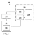
図1は、本明細書による局所処置溶液の滴下とともに陰圧療法を提供することができる治療システム100の実施形態例の簡略化した機能ブロック図である。治療システムは、ヒト患者に適用することができるとともに、他のタイプの対象に使用することができる。治療システム100は、ドレッシング102を含む処置デバイス101と、治療ユニット104とを含むことができる。いくつかの実施形態では、治療ユニット104は、陰圧源106等の陰圧源と、流体源108等の流体源と、コントローラ109とを含むことができる。他の実施形態では、治療ユニット104は、陰圧源106を含むことができ、流体源108および/またはコントローラ109は、自立型の別個のユニットであり得る。治療システム100はまた、容器110等の追加の構成要素も含むことができ、それはまた、処置デバイス101、ドレッシング102及び治療ユニット104と流体連通することができる。
FIG. 1 is a simplified functional block diagram of an example embodiment of a
治療システム100の構成要素は、構成要素の間で流体(すなわち、液体および/または気体)を移送する経路を提供するように、互いに流体的に結合することができる。たとえば、構成要素は、チューブ等の流体伝導体を通して流体的に結合することができる。本明細書における「チューブ」は、チューブ、パイプ、ホース、導管、又は2つの端部の間で流体を搬送するように適合された1つまたは複数の内腔を備えた他の構造体を広く含む。典型的には、チューブは、幾分かの可撓性がある細長い円筒状構造体であるが、形状および剛性は変更することができる。いくつかの実施形態では、構成要素はまた、物理的な近接、単一構造への一体化、または同じ材料片からの形成により、結合することも可能である。さらに、いくつかの流体伝導体は、他の構成要素に成形するか、または他の方法で一体的に結合することができる。結合としては、状況により、機械的結合、熱的結合、電気的結合または化学的結合(化学結合等)を挙げることができる。たとえば、いくつかの実施形態では、チューブは、処置デバイス101を治療ユニット104に機械的にかつ流体的に結合することができる。概して、治療システム100の構成要素は、直接にも間接的にも結合することができる。
The components of the
治療システム100は、ドレッシング等、分配構成要素に結合されるように構成することができる、陰圧源106等の陰圧源を含むことができる。概して、分配構成要素は、陰圧源と組織部位との間の流体路において陰圧源に流体的に結合されるように構成された任意の相補的または補助的構成要素を指すことができる。分配構成要素は、好ましくは取外し可能であり、使い捨て、再使用可能または再生利用可能であり得る。たとえば、処置デバイス101のドレッシング102は、図1に示すように、治療ユニット104の陰圧源106に流体的に結合することができる。いくつかの実施形態では、処置デバイス101は、ドレッシング102とともに、さらなる組織インタフェース、流体導管および/またはカバーを含むことができる。いくつかの実施形態では、ドレッシングインタフェースは、陰圧源106を処置デバイス101のドレッシング102に結合するのを容易にすることができる。たとえば、こうしたドレッシングインタフェースは、テキサス州サンアントニオ(Antonio,Texas)のKCIから入手可能なSENSAT.R.A.C.(商標)パッドであり得る。
The
封止治療環境内等、別の構成要素または場所において減圧するために陰圧源を使用する流体機構は、機械的に複雑である可能性がある。しかしながら、陰圧療法および滴下に適用可能である流体機構の基本原理は、一般に、当業者には周知であり、減圧のプロセスは、本明細書では例示的に、たとえば、陰圧を「送達する」、「分配する」または「発生させる」と記述する場合がある。 Fluid mechanisms that use a negative pressure source to reduce pressure at another component or location, such as within a sealed treatment environment, can be mechanically complex. However, the basic principles of fluid mechanisms that are applicable to negative pressure therapy and instillation are generally well known to those skilled in the art, and the process of depressurization is exemplified herein, for example, by "delivery" of negative pressure "," Distribute "or" generate ".
概して、滲出液および他の流体は、流体路に沿ってより低圧に向かって流れる。したがって、「下流」という用語は、典型的には、流体路における、陰圧源に比較的近いかまたは陽圧源からさらに遠いものを意味する。逆に、「上流」という用語は、比較的陰圧源からさらに遠いかまたは陽圧源により近いものを意味する。同様に、こうした基準系において流体「入口」または「出口」に関していくつかの特徴を説明することが好都合である場合がある。この方向づけは、概して、本明細書においてさまざまな特徴および構成要素を説明する目的で想定される。しかしながら、いくつかの適用では、(陰圧源の代わりに陽圧源を用いること等により)流体路を逆にすることも可能であり、この説明的慣例は、限定的な慣例として解釈されるべきではない。 In general, exudates and other fluids flow toward lower pressures along the fluid path. Thus, the term "downstream" typically means in a fluid path relatively close to a source of negative pressure or further away from a source of positive pressure. Conversely, the term "upstream" means relatively far from the negative pressure source or closer to the positive pressure source. Similarly, it may be advantageous to describe some features with respect to the fluid "inlet" or "outlet" in such a reference system. This orientation is generally envisioned herein for purposes of describing various features and components. However, in some applications, it is also possible to reverse the fluid path (such as by using a positive pressure source instead of a negative pressure source), and this illustrative convention is to be construed as a limiting convention Should not be.
「陰圧」は、概して、処置デバイス101によって提供される封止治療環境の外部の局所環境における周囲圧力等、局所周囲圧力より低い圧力を指す。多くの場合、局所周囲圧力はまた、組織部位が位置する大気圧でもあり得る。別法として、圧力は組織部位において組織に関連する静水圧未満であり得る。別段の指示がない限り、本明細書で述べる圧力の値はゲージ圧である。同様に、陰圧の上昇に言及する場合、それは、典型的には、絶対圧の低下を指し、陰圧の低下は、典型的には、絶対圧の上昇を指す。組織部位にかけられる陰圧の量および性質は、治療要件に従って変更することができるが、圧力は、概して、−5mmHg(−667Pa)〜−500mmHg(−66.7kPa)の低真空(low vacuum)(一般に、低真空(rough vacuum)とも呼ぶ)である。一般的な治療範囲は、−75mmHg(−9.9kPa)〜−300mmHg(−39.9kPa)である。
“Negative pressure” generally refers to a pressure that is lower than the local ambient pressure, such as the ambient pressure in a local environment outside of the sealed treatment environment provided by the
治療ユニット104の陰圧源106等の陰圧供給部は、陰圧での空気のリザーバであり得るか、または、たとえば、真空ポンプ、吸引ポンプ、多くの医療機関で利用可能な壁吸引ポート、またはマイクロポンプ等、封止容積内で減圧することができる手動または電動デバイスであり得る。陰圧供給部は、センサ、処理ユニット、アラームインジケータ、メモリ、データベース、ソフトウェア、表示デバイス、または治療をさらに容易にするユーザインタフェース等、他の構成要素内に収容するかまたはそれらと使用することができる。陰圧源はまた、1つまたは複数の分配構成要素に対して陰圧供給部を結合しかつ分離するのを容易にするように構成された1つまたは複数の供給ポートも有することができる。
The negative pressure supply, such as the
治療システム100はまた、滴下溶液源も含むことができる。たとえば、流体源108は、図1の実施形態例に示すように、処置デバイス101、したがってドレッシング102に流体的に結合することができる。流体源108は、いくつかの実施形態では、陽圧源に流体的に結合することができ、または、陰圧源106に流体的に結合することができる。滴下調節器等の調節器もまた、流体源108および処置デバイス101に流体的に結合することができる。
The
流体源108等の流体源は、流体の移動を容易にするために他の構成要素内に収容するかまたは他の構成要素とともに使用することができる。流体源108は、流体ポンプ、たとえば蠕動ポンプであり得る。別法として、いくつかの実施形態では、流体源108は、流体を貯蔵し送達することができる流体リザーバであり得る。任意の実施形態では、流体ポンプまたは流体リザーバ等の流体源108としては、キャニスタ、パウチまたは他の貯蔵構成要素などの容器を挙げることができる。
A fluid source, such as
流体源108はまた、滴下療法用の溶液を提供することができる、容器、キャニスタ、パウチ、バッグまたは他の貯蔵構成要素を代表するものでもあり得る。溶液の組成は、指示された療法に従って変更することができるが、いくつかの指示に対して好適であり得る溶液の例としては、次亜塩素酸塩系溶液、硝酸銀(0.5%)、硫黄系溶液、ビグアニド、カチオン溶液および等張液が挙げられる。
コントローラ109等のコントローラは、陰圧源106および流体源108等、治療システム100の1つまたは複数の構成要素を動作させるようにプログラムされたマイクロプロセッサまたはコンピュータであり得る。いくつかの実施形態では、たとえば、コントローラ109は、概して、治療システム100の1つまたは複数の動作パラメータを直接または間接的に制御するようにプログラムされた、プロセッサコアおよびメモリを搭載する集積回路を含む、マイクロコントローラであり得る。動作パラメータとしては、たとえば、陰圧源106に印加される電力、陰圧源106によって生成される圧力、または処置デバイス101に分配される圧力を挙げることができる。さらなる動作パラメータとしては、流体源108に印加される電力、流体源108によって提供される滴下流体の流量、または処置デバイス101に分配される流体の容量を挙げることができる。コントローラ109はまた、好ましくは、フィードバック信号等の1つまたは複数の入力信号を受信するように構成され、入力信号に基づいて1つまたは複数の動作パラメータを変更するようにプログラムされている。
A controller, such as
容器110は、組織部位から引き出された滲出液および他の流体を管理するために使用することができる、容器、キャニスタ、パウチまたは他の貯蔵構成要素を代表する。多くの環境において、流体を収集し、貯蔵し、廃棄するために、剛性容器が好ましいかまたは必要であり得る。他の環境では、流体は、剛性容器に貯蔵することなく、適切に廃棄することができ、再使用可能な容器が、陰圧療法に関連する廃棄物を低減させコストを削減することができる。
この文脈において「組織部位」という用語は、限定されないが、骨組織、脂肪組織、筋組織、神経組織、皮膚組織、血管組織、結合組織、軟骨、腱または靭帯を含む、組織上にまたは組織内に位置する創傷、欠損または他の処置標的を広く指す。創傷としては、たとえば、慢性、急性、外傷性、亜急性および離開した創傷、中間層熱傷、潰瘍(糖尿病潰瘍、圧迫潰瘍または静脈不全潰瘍等)、弁およびグラフトを挙げることができる。「組織部位」という用語はまた、必ずしも創傷および欠損していないが、代わりに、さらなる組織を追加するかまたはその増殖を促進することが望ましい可能性がある領域である、任意の組織の領域を指す場合もある。たとえば、採取し移植することができるさらなる組織を増殖させるために、組織部位に陰圧をかけることができる。 In this context, the term “tissue site” is on or within a tissue, including, but not limited to, bone tissue, adipose tissue, muscle tissue, nerve tissue, skin tissue, vascular tissue, connective tissue, cartilage, tendon or ligament. Broadly refers to wounds, defects or other treatment targets located at Wounds can include, for example, chronic, acute, traumatic, subacute, and dehiscence wounds, intermediate layer burns, ulcers (such as diabetic ulcers, pressure ulcers or venous insufficiency ulcers), valves and grafts. The term "tissue site" also refers to a region of any tissue that is not necessarily wounded and missing, but instead is a region where it may be desirable to add more tissue or promote its growth. Sometimes it points. For example, a negative pressure can be applied to a tissue site to grow additional tissue that can be harvested and implanted.
いくつかの実施形態では、陰圧源106、流体源108、コントローラ109および容器110は、治療ユニット104等、単一の治療ユニット内に組み込むことができる。したがって、たとえば、治療システム100は、V.A.C.ULTA(商標)治療ユニット、V.A.C.INSTILL(商標)創傷治療システム、INFOV.A.C.(商標)治療ユニットまたは他の好適な治療ユニット等の治療ユニット104とともに、処置デバイス101を含むことができる。たとえば、いくつかの実施形態では、治療ユニット104は、流体滴下療法と組み合わせて陰圧療法に特有のソフトウェアモジュール、および処置デバイス101の実施形態等、腹部ドレッシングシステムとの使用に特有のソフトウェアモジュールを含むことができる、V.A.C.ULTA(商標)ユニットを含むことができ、または本質的にそれからなり得る。別法として、任意の機械的流体滴下デバイス、または、重力送り流体容器、手動流体ポンプまたはモニタリングされる静脈注射バッグもしくはボトル等、手動管理流体滴下源と組み合わせた任意の陰圧療法デバイスとともに、間欠的陰圧療法を提供することができる他の任意のデバイスが好適であり得る。
In some embodiments, the
ここで主に図2を参照して、腹腔111を処置するための処置デバイス101の例示的な実施形態を提示する。処置デバイス101は、組織部位112を処置するためのものであり得る。この例示的な実施形態では、組織部位112は、体腔、特に腹腔111内の組織を含むことができる。組織部位112は、腹腔内容物113または腹腔111に近接する組織を含むことができる。組織部位112の処置としては、流体、たとえば、腹水の除去、腹腔の保護または陰圧療法を挙げることができる。
2, an exemplary embodiment of a
本明細書における例示的なシステムおよびデバイスは、流体の制御されたかつ調節された導入により、腹腔111等の腹腔の灌注および洗出しを可能にすることができる。いくつかの例では、結腸穿孔または敗血症の結果としての汚染された腹腔を洗うかまたは洗浄する必要がある場合がある。治療システム100は、小腸ループ、すい臓等の到達領域を含む、腹腔内容物を洗浄するために、開放腹部内に流体を滴下する手段を提供することができる。さらに、処置デバイス101および治療システム100は、流体を除去し浮腫を低減させる間、開放腹部に対する一時的な閉鎖を提供することができる。したがって、治療システム100は、患者の組織部位に適用された1つまたは複数のドレッシングを繰り返し除去する必要もなしに、または手動流体導入手順のために患者を手術室に連れてくることなく、腹腔111等の組織部位の洗出しを実施する可能性を提供することができる。したがって、治療システム100は、制御されかつ調節された完全な腹部の洗いを提供するとともに、必要な場合は、腹部内のいくつかの領域に対して標的を定めた洗いを提供する機能を有することができる。開示する実施形態はまた、腹腔111等の腹腔の筋膜領域の支持および維持も提供し、腹腔内容物に対する全体的な保護を提供することができる。
The exemplary systems and devices herein can allow for irrigation and flushing of a peritoneal cavity, such as peritoneal cavity 111, with controlled and regulated introduction of fluid. In some cases, the contaminated abdominal cavity as a result of colon perforation or sepsis may need to be washed or washed. The
図2に示すように、処置デバイス101はドレッシング102を含むことができ、ドレッシング102は、組織部位112を処置するために患者の腹腔111内に配置することができる。ドレッシング102は、腹腔内容物113によって支持することができる。図示するように、ドレッシング102の第1のドレッシング部分114は、第1の結腸傍溝115内にまたはそれに近接して位置決めすることができ、第2のドレッシング部分116は、第2の結腸傍溝117内にまたはそれに近接して配置することができる。第1の結腸傍溝115および第2の結腸傍溝117は、各々、たとえば、腹腔内容物113の間の腹腔111の両側の開放空間であり得る。第1の結腸傍溝115は、第2の結腸傍溝117から横方向に配置され、または、組織部位112の第2の結腸傍溝とは反対側において他の方法で位置決めされ得る。図2は、腹腔111において展開された処置デバイス101を示すが、処置デバイス101および治療システム100は、他のタイプの組織部位で使用することができる。
As shown in FIG. 2, the
ドレッシング102には、複数の液体不透過性層、たとえば、第1の液体不透過性層118および第2の液体不透過性層120を形成することができる。複数の液体不透過性層、たとえば、第1の液体不透過性層118および第2の液体不透過性層120には、それぞれ開窓122および124が形成されている。「液体不透過性層」に関する「液体不透過性」とは、層が液体不透過性材料で形成されていることを意味する。したがって、層は、液体不透過性材料で形成されているが、有窓である場合、液体透過性であり得るが、それにもかかわらず、液体不透過性層と呼ぶ。開窓122および124は、たとえば、円形アパーチャ、矩形開口部または多角形を含む、多くの形状または形状の組合せをとることができる。開窓122および124は、この例示的な実施形態では、スリットまたは直線状切れ目として提示されている。いくつかの実施形態では、第1の液体不透過性層118および第2の液体不透過性層120は、限定なしに、溶接、接合、接着剤、セメントまたは他の接合デバイス等により、任意の好適な方法で互いに封止して結合することができる。第1の液体不透過性層118は、第2の液体不透過性層120と組織部位112および/または腹腔内容物113との間に位置決めされるように適合させることができる。図2の実施形態例では、複数の液体不透過性層のうちの少なくとも2つの層、たとえば第1の液体不透過性層118および第2の液体不透過性層120の間に、チャンバ125が形成されている。ドレッシング102は、第1の側126および第2の側127を有する。第1の液体不透過性層118および第2の液体不透過性層120は、医療用ドレープ等の非粘着性材料を含むことができ、それは、組織が医療用ドレープに付着するのを阻止することができる。たとえば、いくつかの実施形態では、第1の液体不透過性層118および第2の液体不透過性層120は、通気性ポリウレタンフィルムを含むことができる。いくつかの実施形態では、液体不透過性層118および120の間に形成されたチャンバ125は、陰圧を伝達し、組織部位112からの滲出液等の流体を除去する流体除去アセンブリ148とともに、組織部位112に滴下流体を送達する滴下マトリックス152を含むことができる。
The dressing 102 can be formed with a plurality of liquid impermeable layers, for example, a first liquid
いくつかの実施形態では、治療システム100は、腹腔111の上に流体シールを提供する封止部材128をさらに含むことができる。さらに、患者の表皮130の上に、1つまたは複数の皮膚閉鎖デバイスを配置することができる。いくつかの実施形態では、治療システム100はまた、ドレッシング102および処置デバイス101の他の部分を導管134に流体的に接続するインタフェース132も含むことができる。インタフェース132は、コネクタ136を含むことができる。別法として、インタフェース132は、ドレッシング102の一部内に部分的にまたは完全に埋め込むか、または、図1の治療ユニット104等の治療ユニットに処置デバイス101を流体的に接続するために可能である他の任意の方法で構成することができる。導管134は、処置デバイス101に陰圧および/または処置流体をそれぞれ提供するために、治療ユニット104の陰圧源106および/または流体源108に流体的に結合することができる。いくつかの実施形態では、導管134は2つの実質的に平行な流体的に隔離された導管を含むことができ、導管のうちの一方は、処置デバイス101を陰圧源106に流体的に結合するためのものであり、他方は、流体源108に処置デバイス101を流体的に結合するためのものである。したがって、いくつかの実施形態では、導管134は、陰圧内腔135および流体供給内腔137の両方を備えた多腔導管であり得る。他のいくつかの例示的な実施形態では、導管134を2つの別個の導管に置き換えることができ、それらの一方は、陰圧内腔を含み、他方は流体供給内腔を含む。
In some embodiments, the
いくつかの実施形態では、封止部材128は、細菌バリアおよび身体的外傷からの保護を提供することができる。封止部材128はまた、蒸発による損失を低減させ、治療環境と局所外部環境との間等、2つの構成要素または2つの環境の間の流体シールを提供することができる材料から構成することも可能である。封止部材128は、たとえば、所与の陰圧源に対して組織部位において陰圧を維持するために適切なシールを提供することができる、エラストマーフィルムまたは膜であり得る。封止部材128は、いくつかの応用では、高い水蒸気透過率(MVTR)を有することができる。たとえば、いくつかの実施形態では、MVTRは、少なくとも300g/m2/24時間であり得る。いくつかの実施形態例では、封止部材128は、水蒸気に対して透過性であるが液体に対して不透過性である、ポリウレタンフィルム等のポリマードレープであり得る。こうしたドレープは、通常、25〜50ミクロンの範囲の厚さを有する。透過性材料の場合、透過率は、概して、所望の陰圧を維持することができるために十分低くなければならない。
In some embodiments, the sealing
取付デバイス142等の取付デバイスを使用して、患者の表皮130等の取付面に封止部材128を取り付けることができる。取付デバイス142はまた、ガスケットまたは別の封止部材もしくはカバーに封止部材128を取り付けるためにも使用することができる。取付デバイスは多くの形態をとることができる。たとえば、取付デバイスは、周縁部、一部または封止部材全体にわたって延在する、医学的に許容可能な感圧接着剤であり得る。いくつかの実施形態では、たとえば、封止部材128の一部またはすべてに、25〜65グラム/平方メートル(g.s.m)のコーティング重量を有するアクリル接着剤でコーティングすることができる。いくつかの実施形態では、シールを向上させ漏れを低減させるために、より厚い接着剤または接着剤の組合せを塗布することができる。取付デバイスの他の実施形態例としては、両面テープ、ペースト、親水コロイド、ヒドロゲル、シリコーンゲルまたはオルガノゲルを挙げることができる。
The sealing
必ずしも図2には示さないが、いくつかの実施形態では、治療システム100は、第2の液体不透過性層120と封止部材128との間に配置される、フォームの一部等、充填材料をさらに含むことができる。充填材料は、腹腔111の一部等、切開部の真下のもしくは切開部を包囲する、または皮膚層から腹部内に通じる腹部容積の一部を、充填するようなサイズとすることができる。いくつかの実施形態では、充填材料は、陰圧用の分配マニホールドとしての役割を果たすことができる。たとえば、いくつかの実施形態では、充填材料は、第2の液体不透過性層120と封止部材128との間に位置決めすることができ、封止部材128に、陰圧内腔135等、陰圧内腔または導管を空気圧式に接続することができる。その結果、処置デバイス101の層から、第2の液体不透過性層120の上に位置決めされた充填材料を通して、陰圧内腔135内に、流体除去を行うことができる。いくつかの実施形態では、充填材料は、テキサス州サンアントニオ(San Antonio,Texas)のKinetic Concepts,Inc.から入手可能なGRANUFOAM(商標)ドレッシング等、連続気泡、網状ポリウレタンフォームを含むことができる。
Although not necessarily shown in FIG. 2, in some embodiments, the
ここで主に図3を参照すると、処置デバイス101は、治療ユニット104の陰圧源106から、図2の腹腔111の組織部位112等の組織部位に陰圧を提供し、組織部位112から抽出される流体を収集し移送するように適合させることができる。さらに、処置デバイス101はまた、治療ユニット104の流体源108から組織部位112に、処置流体または薬剤等の流体を送達するようにも適合させることができる。図2に関して考察したように、いくつかの実施形態では、処置デバイス101のドレッシング102は、組織部位112の下にある腹腔内容物113を保護する、複数の液体不透過性層または内臓保護層を含むことができる。たとえば、いくつかの実施形態では、ドレッシング102は、ポリウレタン材料から形成されている第1の液体不透過性層118および第2の液体不透過性層120を含むことができ、液体不透過性層の各々は、厚さ20〜400マイクロメートルの寸法をとる。図3に示すように、第2の液体不透過性層120等の液体不透過性層のうちの一方または両方は、腹腔111を通して流体除去を促進するために開窓124を含むことができる。
Referring now primarily to FIG. 3, the
図3に示すように、処置デバイス101のいくつかの実施形態はまた、流体除去アセンブリ148および滴下マトリックス152も含むことができる。たとえば、いくつかの実施形態では、流体除去アセンブリ148は、複数の流体除去経路150を含むことができ、それらの各々は、流体除去ハブ154に流体的に結合されている。流体除去ハブ154は、インタフェース132および陰圧源106から流体除去経路150の各々に陰圧を伝達する分配機構としての役割を果たすことができる。流体除去経路150は、多くの異なる形状の形態をとり、または種々の材料から形成することができる。たとえば、いくつかの実施形態では、流体除去経路150は、合わせて溶接されてチャネルを形成している、第1の液体不透過性層118および第2の液体不透過性層120の部分から形成することができる。別法としてまたはさらに、流体除去経路150は、液体不透過性層118および120のいずれかまたは両方に、折目もしくはひだを含むか、または本質的に折目もしくはひだからなり得る。流体除去経路150の他の実施形態例としては、押出材料によって形成されたチャネル、液体不透過性層118および120の上にエンボス加工されたチャネル、または流体除去経路150として使用するために個々のチューブを形成する別個の管材料を挙げることができる。流体除去経路150に対して、多腔チューブも使用することができる。さまざまな実施形態では、好適であるように、滴下マトリックス152の流体送達チューブに、流体除去経路150の異なる形態および構成の各々もまた適用することができる。
As shown in FIG. 3, some embodiments of the
いくつかの実施形態では、流体除去経路150の各々は、陰圧を伝達し、流体除去経路150を通して流体を引き出す、マニホールド部材156等のマニホールド部材を含むことができる。たとえば、いくつかの実施形態では、各マニホールド部材156は、流体除去経路150の長さにわたって伸びる単一のマニホールド部材材料片であり得るが、いくつかの実施形態は、マニホールド部材材料の別個の部分またはセクションから作製されるマニホールド部材156を含む。いずれの場合も、マニホールド部材156は一連のくぼみ159を含むことができ、それらは、マニホールド部材156および流体除去経路150のサイジングおよび可撓性を含むなじみやすさとともに、陰圧および/または収集された流体の伝達に役立つことができる。
In some embodiments, each of the
マニホールド部材156は、概して、組織部位112または他の場所に陰圧をかけ、流体を送達し、またはそこから流体を除去するのに役立つように設けられている、任意の物質または構造体を含むことができる。マニホールド部材156は、典型的には、マニホールド部材156に提供されかつその周囲で除去された流体を分配する複数の流路または経路を有するマニホールド部材材料であり得る。たとえば、マニホールド部材材料は、陰圧源から陰圧を受け取り、複数のアパーチャを通して組織部位にわたって陰圧を分配するように適合させることができ、それには、組織部位全体から流体を収集し、流体源に向かって流体を引き出すという効果があり得る。いくつかの実施形態では、流体路を反転させることができ、または、組織部位にわたって流体を送達するのを容易にするために二次流路を設けることができる。
いくつかの例示的な実施形態では、マニホールドの経路は、組織部位にわたる流体の分配または収集を改善するように相互接続することができる。いくつかの例示的な実施形態では、マニホールドは、相互接続された気泡または細孔を有する多孔質フォーム材料であり得る。たとえば、セルラフォーム、連続気泡フォーム、網状フォーム、多孔質組織集合体、およびガーゼまたはフェルトマット等の他の多孔質材料は、概して、相互接続された流体チャネルを形成するように適合された、細孔、縁部および/または壁を含む。液体、ゲルおよび他のフォームもまた、アパーチャおよび流体経路を含むか、または含むように硬化させることができる。いくつかの実施形態では、マニホールドは、さらにまたは別法として、相互接続された流体経路を形成する突起を備えることができる。たとえば、相互接続された流体経路を画定する表面突起を提供するように、マニホールドを成形することができる。 In some exemplary embodiments, the manifold paths can be interconnected to improve fluid distribution or collection across the tissue site. In some exemplary embodiments, the manifold can be a porous foam material having interconnected cells or pores. For example, cellular foams, open-cell foams, reticulated foams, porous tissue aggregates, and other porous materials, such as gauze or felt mats, are generally thin, adapted to form interconnected fluid channels. Including holes, edges and / or walls. Liquids, gels and other foams may also include or be cured to include apertures and fluid pathways. In some embodiments, the manifold can further or alternatively include protrusions that form an interconnected fluid path. For example, the manifold can be shaped to provide surface protrusions that define interconnected fluid paths.
いくつかの実施形態では、マニホールド部材156は、多孔質フォームを含み、流路として作用する複数の相互接続された気泡または細孔を含む。フォームの平均細孔サイズは、指示された療法の必要に従って変更することができる。たとえば、いくつかの実施形態では、マニホールド部材156は、400〜600ミクロンの範囲の細孔サイズを有するフォームであり得る。マニホールド部材156の引張強度もまた、指示された療法の必要に従って変更することができる。たとえば、フォームの引張強度は、局所処置溶液の滴下に対して増大させることができる。いくつかの実施形態では、マニホールド部材156は、6mm〜10mmの厚さであり得るポリウレタンフォームを含むことができる。1つの非限定的な例では、マニホールド部材156は、ともにテキサス州サンアントニオ(San Antonio,Texas)のKinetic Concepts,Inc.から入手可能な、GRANUFOAM(商標)ドレッシングまたはV.A.C.VERAFLO(商標)ドレッシング等の連続気泡、網状ポリウレタンフォームであり得る。いくつかの実施形態は、吸収性材料、ウィッキング材料、疎水性材料および親水性材料等、追加の層または材料を有するマニホールド部材156を含むことができる。
In some embodiments, the
滴下マトリックス152は、複数の流体送達チューブ158および分配ハブ160を含むことができる。滴下マトリックス152の構成要素は、種々の異なる材料から構成することができる。たとえば、滴下マトリックス152の構成要素のうちのいくつかまたはすべてを、軟質の医療グレードシリコーンまたはPVC管材料から構成することができる。複数の流体送達チューブ158は、処置デバイス101の特定のサイズおよび用途とともに、処置デバイス101が適用されるべき組織部位112の状態に基づいて、サイズを変更することができる。たとえば、流体送達チューブ158は、各々、0.5mm〜4mmの内径を有することができる。いくつかの実施形態では、流体送達チューブ158は、各々、1mm〜2mmの内径を有することができる。流体送達チューブ158の幾分小さいサイズは、治療中の患者の不快感を回避するとともに、治療の完了に続く処置デバイス101の除去を容易にするために寄与することができる。
The
図3に示すように、ただし再び図2も参照すると、いくつかの実施形態では、滴下マトリックス152は、ドレッシング102の複数の層内に実質的に封入することができる。たとえば、流体送達チューブ158は、流体除去経路150とともに、第1の液体不透過性層118および第2の液体不透過性層120によって形成されたチャンバ125と、位置決めすることができる。場合により、製造時に、たとえば超音波溶接により液体不透過性層118および120が互いに取り付けられる前に、第1の液体不透過性層118と第2の液体不透過性層120との間のチャンバ125内に、流体除去経路150とともに滴下マトリックス152を挿入することができる。溶接線162によって示すように、流体除去経路150および流体送達チューブ158の境界に沿って液体不透過性層118および120を合わせて溶接することにより、液体不透過性層118および120の間の適所に、流体除去経路150および流体送達チューブ158の各々を固定することができる。
As shown in FIG. 3, but again with reference to FIG. 2, in some embodiments, the
ここで主に図4Aおよび図4Bを参照して、図3の処置デバイス101のいくつかの実施形態例に関連付けることができるさらなる特徴を示す。たとえば、図4Aに示すように、各流体除去経路150は、開放端部164とともに、流体除去経路150の長さに沿った、除去経路アパーチャ166等の開口部またはアパーチャを含むことができる。したがって、こうした実施形態では、流体除去経路150は、両端部を通るとともに流体除去経路150の長さに沿って、陰圧を伝達し流体を引き込むことができる。一方で、この実施形態例では、流体送達チューブ158は、送達端部168等の開放端部のみを有することができ、他の方法で、流体送達チューブ158の長さに沿って周囲から流体的に隔離することができる。いくつかの実施形態では、処置デバイス101は、単一サイズで提供することができ、処置デバイス101の一部を切断して除去することによりそのサイズを低減させ、したがって、場合によっては個々の患者ごとに必要に応じて流体送達チューブ158の長さを短くするという選択肢がある。したがって、流体送達チューブ158の開口部が個々のチューブの端部のみにあることにより、流体送達チューブ158および滴下マトリックス152全体が、滴下流体を一様に分配するために、流体送達チューブ158の設定長さまたは流体送達チューブ158の穿孔の数もしくはサイズに頼らないため、より高いレベルのカスタマイズ化を達成することができる。
Referring now primarily to FIGS. 4A and 4B, additional features that can be associated with some example embodiments of the
図5は、図3の処置デバイス101のいくつかの実施形態例に関連付けることができるさらなる特徴を示す。図5の例としての処置デバイス101の構成要素および特徴は、流体送達チューブ158のいくつかの態様を除き、(まとめて)図4に示す処置デバイス101の実施形態のうちのいくつかと、大部分同じであるかまたは同様である。たとえば、図5に示すように、組織部位に滴下流体を送達するために、図4の送達端部168等の開放端部を有するのではなく、流体送達チューブ158は、代わりに、送達チューブ閉鎖端部170等の閉鎖端部を有することができる。代わりに、流体送達チューブ158の各々は、その長さに沿って、送達チューブ穿孔172等の開口部または穿孔を含むことができる。しかしながら、図4および図5に示す実施形態は、単に例示を目的とするものであり、流体送達チューブ158は、両開放端部とともにそれらの長さに沿った穿孔を含むことができることも企図されている。
FIG. 5 illustrates additional features that may be associated with some example embodiments of the
滴下マトリックス152は、組織部位112にわたって実質的に均一に流体を送達するように適合させることができる。たとえば、流体送達チューブ158、送達端部168および送達チューブ穿孔172の各々は、実質的に同じ背圧を提供するように適合させることができる。こうした構成は、流体が、流体送達チューブ158のうちの別のものに比較して流体送達チューブ158のうちの1つを通ってより自由に移動し、または他の方法でそれを優先することを防止することができる。本明細書では、背圧は、内腔またはアパーチャの狭い空間を通る等、流体流に対する抵抗によってもたらされる局所圧力の上昇を指すことができる。背圧は、限定なしに、空間のサイズ、空間内の曲げ部または接合部の存在および形状、空間内の表面仕上げならびに他の特徴等、狭い空間の幾何学的構成および材料特性からもたらすことができる。いくつかの実施形態では、送達チューブ穿孔172等、流体送達チューブ158の長さに沿った穿孔が、腹部を通して流体の実質的に一様な分配を提供するようなサイズである場合、分配ハブ160等の流体ハブは不要とすることができる。
The
流体は、最低抵抗の経路をたどる傾向があり、したがって、不十分な流体分配は、流体送達チューブ158のうちの1つが流体送達チューブ158のうちの別のものより低い背圧または流体流に対する抵抗を有することからもたらされる可能性がある。同様に、不十分な流体分配は、送達端部168または送達チューブ穿孔172等、流体送達アパーチャのうちの1つが、流体送達アパーチャのうちの別のものより低い背圧または流体流に対する抵抗を有することからもたらされる可能性がある。たとえば、流体送達チューブ158のサイズおよび構成、ならびに流体送達チューブ158の各々における送達端部168および送達チューブ穿孔172の数およびサイズの一貫性により、組織部位112に対する流体送達の均一性を向上させることができる。したがって、いくつかの実施形態では、送達端部168および送達チューブ穿孔172等の送達アパーチャは、流体送達チューブ158の各々において数およびサイズが実質的に等しくあり得る。さらに、流体送達チューブ158の各々は、実質的に同じ寸法を有することができる。
Fluid tends to follow the path of least resistance, and thus poor fluid distribution may result in one of the
たとえば、いくつかの実施形態では、流体送達チューブ158は、円筒チューブ形状を有することができ、約2ミリメートル〜約6ミリメートルの内径を有することができる。さらに、いくつかの実施形態では、流体送達チューブ158は、約4ミリメートルの内径を有することができる。他のいくつかの実施形態では、流体送達チューブ158は代替的な管外形を有することができ、そこでは、処置デバイス101が組織部位112の適所にあるとき、使用者の快適さを向上させるために、薄型の、すなわち「より平坦な」管外形を使用することができる。送達端部168および送達チューブ穿孔172等の送達アパーチャは、いくつかの実施形態では、約0.1ミリメートル〜約0.8ミリメートルの直径を有することができる。流体送達チューブ158の内径または断面を送達端部168および送達チューブ穿孔172のサイズ、断面または直径より実質的に大きいサイズとすることにより、流体送達チューブ158の各々内に実質的に均一な圧力を提供することができる。こうした実施形態では、流体送達チューブ158内の流体流速は、送達端部168および送達チューブ穿孔172等の送達アパーチャを通る高い流体流速と比較して、実質的に低いかまたは実質的に静的であり得る。
For example, in some embodiments, the
添付の図には示さないが、いくつかの実施形態では、滴下マトリックス152は、格子または「くもの巣」の形態で配置される流体送達チューブ158の配置を含むことができる。したがって、場合により、滴下マトリックス152は、中心ハブから半径方向に延在する複数の流体送達チューブ158とともに、半径方向に延在する流体送達チューブ158の各々を流体的に接続するさらなる管セグメントを含むことができる。穿孔は、半径方向に延在する流体送達チューブ158とともに、接続する管セグメントの任意の部分またはすべての部分に沿って存在することができる。
Although not shown in the accompanying figures, in some embodiments, the
図6Aは、図3の分配ハブ160等のハブのより詳細な図を示す。いくつかの実施形態では、分配ハブ160の少なくとも一部は、第1の液体不透過性層118と第2の液体不透過性層120との間に位置決めすることができ、流体送達チューブ158等の流体送達経路と流体連通するように位置決めすることができる。いくつかの実施形態では、分配ハブ160の高さは、分配ハブ160が、処置デバイス101の第2の液体不透過性層120の表面の上方で外向きに延在することができるといったものであり得る。分配ハブ160は、分配ハブ160の上面に位置決めすることができるハブポート174を含むことができる。分配ハブ160のサイズおよび寸法は、ハブポート174を第2の液体不透過性層120の上面の上方に位置決めすることができ、ハブポート174が、導管134の流体供給内腔と分配ハブ160との間に流体連通を提供することができるといったものであり得る。いくつかの実施形態では、分配ハブ160は、その下部面の周囲に位置決めされた、分配ポート261等の複数の開口部を含むことができる。いくつかの実施形態では、これらの分配ポート261は、滴下マトリックス152の流体送達チューブ158に流体結合するためのものであり得る。開口部または分配ポート261の所定のサイズは、流体源108等、特定の滴下流体源と、その具体的な設定または設計パラメータとに較正することができる。たとえば、流体源108のいくつかの例は、各々、所定のポンプ流量に起因して所定のサイズの開口部を必要とする可能性がある。いくつかの実施形態では、流体送達チューブ158は、分配ハブ160を中心に円周方向にかつ実質的に対称に位置決めすることができる。したがって、分配ハブ160および流体送達チューブ158は、流体滴下経路を画定することができる。
FIG. 6A shows a more detailed view of a hub, such as
図6Aに示すように、分配ハブ160は、分配部材176等、滴下流体を分配するのに役立つ材料を含むことができる。分配部材176は、たとえばフォーム等、多孔質または流体透過性材料を含むことができる。さらに、分配ハブ160は、概して、形状が細長くかつ円筒状であるかまたはベル形であり得るが、他の形状も有することができる。他の実施形態では、分配ハブ160は、チューブ、管状取付具、パイプ、かかり付き接続部または同様の構造体等の取付具を備えることができる。こうした実施形態では、取付具は、第1の液体不透過性層118または第2の液体不透過性層120に直接、あらかじめ接合するかまたは成形し、導管134の流体供給内腔と流体送達チューブ158との間に流体的に結合されるように構成することができる。
As shown in FIG. 6A,
いくつかの実施形態では、分配ハブ160は、同様に軟質の医療グレードシリコーンまたはPVC材料で鋳造するかまたは射出成形することができる。他のいくつかの実施形態では、分配ハブ160は、合わせて溶接されるポリウレタンフィルムの2枚のシートから製造することができる。いくつかのさらなる実施形態では、分配ハブ160は、実際に、結合された流体滴下および流体除去ハブとしての役割を果たすことができ、その場合、分配ハブ160は、処置デバイス101の流体送達導管および流体除去導管両方に流体的に接続することができる。こうした結合された流体滴下および流体除去ハブの場合、分配ハブ160は、一連の一方向弁を含むことができる。こうした一方向弁は、市販のダックビル弁またはカスタムフラップ弁等、任意の形態の一方向弁であり得る。これらの一方向弁は、流体送達チューブ158へのかつ流体除去経路、たとえば流体除去経路150への、分配ポート261等の分配ハブ160の開口部に配置することができる。結合されたハブのいくつかの実施形態では、別個の流体送達チューブ158および流体除去経路150との流体連通を依然として可能にしながら、ハブの一部として共通の分配材料を含めることができる。
In some embodiments, the
場合により、流体送達チューブ158は、分配ハブ160から別個に形成し、その後、医療グレード接着剤もしくはシクロヘキサノールにより、または溶接により、分配ハブ160に取り付けることができる。他の実施形態例では、滴下マトリックス152の流体送達チューブ158および分配ハブ160は、実質的に単一構造体として形成することができる。
Optionally, the
図6Bを参照するが概して再び図2も参照すると、インタフェース132は、処置デバイス101に対する陰圧接続および流体供給接続の両方を提供することができる。インタフェース132は、導管134の陰圧内腔135および流体供給内腔137を処置デバイス101に任意の好適な方法で流体的に接続するようなサイズとし、形状とし、または他の方法でそのように適合させることができる。いくつかの実施形態では、インタフェース132は、封止部材128を通して陰圧内腔135および流体供給内腔137を流体的に結合することができる。たとえば、封止部材128を通して1つまたは複数の封止部材アパーチャを配置して、封止空間内に位置決めされた処置デバイス101の構成要素に対する流体連通およびアクセスを提供することができる。
Referring to FIG. 6B, and again generally to FIG. 2, the
いくつかの実施形態では、インタフェース132は、陰圧内腔135および流体供給内腔137の一部として形成するかまたは成形することができる。他の実施形態では、陰圧内腔135および流体供給内腔137は、たとえば、インタフェース132への締まり嵌めにより接合しまたは固定することができる。いくつかの実施形態では、封止部材128を通して処置デバイス101と流体連通するようにインタフェース132を位置決めするために、封止部材128に、フランジ等、インタフェース132の一部を結合することができる。インタフェース132は、たとえば、接着剤または他の接合デバイス等により、任意の好適な方法で封止部材128に結合することができる。たとえば、いくつかの実施形態では、インタフェース132を封止部材128に結合する接着剤は、上述した封止部材128用の取付デバイス142に使用されたものと同じであり得る。
In some embodiments,
いくつかの実施形態では、図6Bに示すように、インタフェース132は、多ポートインタフェースとすることができ、多ポートインタフェースは、インタフェース132等の多ポートインタフェース内の個々の流体的に隔離されたポートとして、陰圧接続および流体供給接続の両方を提供する。こうした実施形態では、陰圧接続から流体供給接続を流体的に隔離するために、分配ハブ160に、流体供給内腔137等の個々の内腔のうちの1つの壁を結合することができる。陰圧内腔135および流体供給内腔137の流体隔離を維持する他の構成が可能である。
In some embodiments, as shown in FIG. 6B,
他の実施形態(図示せず)では、インタフェース132は、陰圧接続または流体供給接続のいずれかを提供することができる単一ポートインタフェースであり得る。したがって、第1の単一ポートインタフェースは、陰圧接続を提供することができ、第2の単一ポートインタフェースは、流体供給接続を提供することができる。他の実施形態では、陰圧内腔135は、流体除去ハブ154に直接流体的に結合することができ、流体供給内腔137は、インタフェース132なしに分配ハブ160に直接流体的に結合することができる。
In other embodiments (not shown),
いくつかの代替実施形態では、処置デバイス101は、分配経路を通して滴下流体を分配するとともに、流体除去経路を通して陰圧を分配しかつ流体除去経路から流体を収集する両方の機構として機能することができる、流体ハブを含むことができる。たとえば、流体ハブは、ポリウレタンフィルム膜等のフィルム膜によって分離された2つの層またはチャンバを備えることができる。上部層またはチャンバは、清浄な滴下流体を受け取り、開放経路のマトリックスを通して流体送達チューブに向けることができる。上部チャンバはまた、流体を向けるのに役立つようにぎざぎざまたはひだを有する床も含むことができる。いくつかの実施形態では、床は、治療の流体滴下段階中に連続フィルム層を提供することができるが、陰圧がかけられているときは、床のひだまたはフラップを上向きに引き上げて、流体が下部チャンバから上向きに進んで流体ハブから出るために通過する小さい開口部を提供することができる。上部チャンバはまた、流体滴下経路を通って出る比較的大きい汚染物質に対してフィルタを提供するように、チャンバの内周部にわたって多孔質フォームリングも含むことができる。フォームリングはまた、流体滴下経路を閉鎖するために、陰圧がかけられて圧縮したときにシールとしても機能することができる。流体ハブの下部層またはチャンバは、流体除去経路に接続することができ、下部チャンバは、陰圧がかけられたときに流体経路が開放したままであることを確実にするためにマニホールド材料を含むことができる。陰圧がかけられると、処置デバイス101から流体ハブを通して流体を除去することができ、清浄な滴下流体と組織部位からの汚れた流体とが混合する可能性は最小限でしかない。いくつかの実施形態では、流体ハブは、上部チャンバ内に、Oリングシール弁等の1つまたは複数の弁を含むことができ、それらは、陰圧がかけられたとき、上部チャンバから流体滴下経路への開口部を遮断することができる。
In some alternative embodiments, the
概して図1〜図6Bを参照すると、治療システム100の動作のいくつかの例示的な実施形態では、処置デバイス101は、組織部位112に嵌まるようなサイズとし、腹腔111等、組織部位112にまたはその中に配置することができる。処置デバイス101のサイジングが必要である場合、たとえば、処置デバイス101の第1の液体不透過性層118および第2の液体不透過性層120とともに、流体除去経路150および流体送達チューブ158を通して所望のサイズに対して切断するかまたは引き裂くことにより、処置デバイス101の余分な部分を除去することができる。
Referring generally to FIGS. 1-6B, in some exemplary embodiments of the operation of the
処置デバイス101は、腹腔内容物113と接触するように位置決めすることができ、処置デバイス101の一部は、患者の結腸傍溝内に押し込まれる。具体的には、流体除去経路150は、第1の結腸傍溝115および第2の結腸傍溝117に近接して位置決めすることができる。処置デバイス101は、展開されると、すべての露出した内臓を覆うことができ、腹腔111の壁と接触しないように内臓を分離することができる。処置デバイス101は、こうした覆いを可能にするようなサイズおよび形状とすることができる。
The
処置デバイス101は、処置デバイス101を収容する封止空間を提供するように、組織部位112において封止部材128で覆うことができる。封止部材128は、上述したように、取付デバイス142により組織部位112の周辺に位置決めし流体的に封止することができる。封止部材128のアパーチャは、封止部材128の一部としてまだ設けられていない場合、必要に応じて、封止部材128を通して切断するかまたは他の方法で配置することができる。陰圧接続および流体供給接続は、たとえば、インタフェース132により、または、流体除去アセンブリ148への陰圧内腔135の直接結合および滴下マトリックス152への流体供給内腔137の直接結合を通して、行うことができる。滴下流体は、流体源108等の流体源から流体供給内腔を通して滴下マトリックス152内に独立して供給することができることに留意することが重要である。したがって、いくつかの実施形態では、分配ハブ160等の流体ハブに、滴下流体を直接供給することができ、したがって、流体滴下経路および流体除去経路を別個の要素として制御することができる。したがって、清浄な流体滴下経路の汚染の可能性を低減させるかまたは大幅になくすことができ、より効率的な洗浄サイクルを得ることができる。処置デバイス101の構成要素が具体的にいかに構成されるかに応じて、いくつかの実施形態では、流体滴下管を通して、結腸傍溝、たとえば第1の結腸傍溝115および第2の結腸傍溝117等の腹部の低い部分内に直接、流体を供給することができる。
The
陰圧源106を作動させることにより、導管134の陰圧内腔135を通して流体除去アセンブリ148に陰圧を提供することができる。流体源108は、たとえば、流体源108におけるポンプまたは陽圧源を作動させることにより、または、滴下流体に作用している重力または手動による使用者の力の作用により、流体供給内腔137を通して滴下マトリックス152に滴下流体を提供することができる。陰圧および滴下流体は、処置デバイス101に、同時に、または交互の時点で周期的に提供することができる。さらに、処置デバイス101に陰圧および滴下流体を断続的にまたは連続的に加えることができる。
Activating the
陰圧源106が作動すると、導管134の陰圧内腔135は、陰圧を流体除去ハブ154に、かつ流体除去アセンブリ148の流体除去経路150に分配することができる。図4A〜図5に引出し矢印169によって示すように、組織部位112からの流体は、開放端部164および除去経路アパーチャ166を通して流体除去経路150内に引き込むかまたは抽出することができる。流体除去経路150内の流体は、流体除去経路150を通して流体除去ハブ154内に伝達することができ、そこで、導管134の陰圧内腔135内にかつ最終的に容器110内に流体を引き込むことができる。
When the
流体源108が作動するか、または滴下流体が他の方法で処置デバイス101に送達されているとき、滴下流体は、滴下マトリックス152の分配ハブ160内に進むことができる。矢印161によって示すように、分配ハブ160から、流体送達チューブ158と流体送達チューブ158の送達端部168および/または送達チューブ穿孔172とを通して、組織部位112に滴下流体を伝達することができる。上述したような滴下マトリックス152の構成および関連する背圧により、組織部位112への実質的に均一な滴下流体の送達を促進することができる。
When the
滴下マトリックス152を通して組織部位112に滴下されているかまたは送達されている流体は、組織部位112に達するかまたは組織部位112に直接接触するまで、流体除去アセンブリ148から物理的にかつ流体的に分離したままであり得る。組織部位112に送達されると、滴下流体は、たとえば、先行して滴下された流体、創傷流体、組織流体、および廃棄流体とみなすことができる他の流体と混合される可能性がある。処置デバイス101に陰圧がかけられているとき、組織部位112からの組織または創傷流体、および組織部位112に先行して送達された任意の滴下流体は、別個の流体除去アセンブリ148を通して抽出することができる。流体除去アセンブリ148を通して組織部位112から抽出されている流体は、滴下マトリックス152から物理的にかつ流体的に別個のままであり得る。流体除去アセンブリ148と滴下マトリックス152との間のこうした分離により、たとえば、組織部位112からの抽出後または抽出中、流体除去経路150または流体除去ハブ154に残っている可能性がある流体が、流体滴下中に組織部位112内に押し戻されるのを防止することができる。
Fluid dripped or delivered to the
さらに、滴下マトリックス152からの流体除去アセンブリ148の分離により、滴下流体の効率的な使用を促進することができる。たとえば、上述したように、流体除去ハブ154および流体除去経路150は、フォーム等、多孔質、流体透過性材料を含むことができる。この流体透過性材料は、組織部位112から流体を抽出するために陰圧がかけられている間、開放しまたは流体透過性のままであり得る流体流経路を含むことができる。さらに、組織部位112から抽出される流体は、陰圧内腔135内に引き込まれる前に、処置デバイス101の流体除去アセンブリ148内に貯蔵することができる。陰圧がかけられている間に流体貯蔵および透過性を提供することができるためには、流体除去アセンブリ148が、陽圧がかけられている可能性がある滴下マトリックス152と比較して、より高い体積の流体容量を有することが必要である可能性がある。別個の滴下マトリックス152を通して組織部位112に滴下されまたは送達されている流体は、より高い容積である可能性がある流体除去アセンブリ148等の処置デバイス101の部分を通過することが不要であり得る。こうした構成により、滴下流体の分配および効率的な使用を促進することができる。
Further, separation of the
概して図1〜図6Bを続けて、組織部位において流体滴下および陰圧処置を提供する方法についてさらに説明する。いくつかの実施形態では、組織部位において流体滴下および陰圧処置を提供する方法は、組織部位112に隣接して処置デバイス101を位置決めすることを含むことができる。処置デバイス101は、滴下マトリックス152と滴下マトリックス152とは別個の流体除去アセンブリ148とを含むことができる。上述したように、いくつかの実施形態では、組織部位112は腹腔111とすることができ、組織部位112に隣接して処置デバイス101を位置決めすることは、第1の結腸傍溝115および/または第2の結腸傍溝117等、腹腔111内の結腸傍溝に近接して、処置デバイス101の少なくとも一部を配置することを含むことができる。さらに、いくつかの実施形態では、本方法は、処置デバイス101を封止部材128で覆って、封止部材128と組織部位112との間に封止空間を提供することを含むことができる。いくつかの実施形態では、本方法は、組織部位112に配置するために処置デバイス101をサイジングすることを含むことができる。上述したように、処置デバイス101をサイジングすることは、処置デバイス101を切断するかまたは引き裂くことを含むことができる。場合により、処置デバイス101は、処置デバイスを所望のサイズにカスタマイズするように使用者を誘導する視覚的しるしを含むことができる。
Continuing generally with FIGS. 1-6B, a method for providing fluid drip and negative pressure treatment at a tissue site is further described. In some embodiments, a method of providing a fluid drip and negative pressure treatment at a tissue site can include positioning the
本方法は、滴下マトリックス152と流体連通するように流体源108を結合することと、流体除去アセンブリ148と流体連通するように陰圧源106を結合することとをさらに含むことができる。本方法は、滴下マトリックス152を通して流体源108から組織部位112に滴下流体を供給することをさらに含むことができる。さらに、本方法は、流体除去アセンブリ148を通して陰圧源106から組織部位112に陰圧を提供することと、流体除去アセンブリ148を通して組織部位112から流体を抽出することを含むことができる。陰圧および/または流体滴下療法の完了に続き、使用者は、大部分無傷の構造体として処置デバイス101を除去することができ、したがって、処置デバイス101の使用の容易さを維持することができる。
The method can further include coupling the
ここで図7Aを参照して、治療システム100で使用される処置デバイス201の別の実施形態例を示す。この実施形態では、処置デバイス201は、図3の処置デバイス101に対して実質的に同様の構成要素を含むことができるが、個々の特徴の配置および機能は異なり得る。たとえば、処置デバイス201は、複数の流体除去経路150を含むことができ、それらは、ドレッシング202の複数の液体不透過性層の間に位置決めし、流体除去ハブ154に流体的に接続することができる。しかしながら、この実施形態例では、処置デバイス201は、分配ハブ260に取り付けることができる複数の流体送達チューブ258を有する滴下マトリックス252を含むことができ、流体送達チューブ258は、ドレッシング202の下方に緩く垂れさがることができる。処置デバイス201のこの実施形態では、使用者は、患者の腹腔内に流体送達チューブ258の各々を個々に位置決めすることも可能である。したがって、使用者は、腹腔を通して流体送達チューブ258を一様に広げて、腹部の完全な、均一のすすぎを提供するように選択することができ、または別法として、使用者は、より徹底的な洗いを提供するために、流体送達チューブ258を任意の特定の関心領域に集中させるように選択することができる。処置デバイス201は、使用者が、個別的にこれを決定するのを可能にすることができる。いくつかの実施形態では、複数の流体送達チューブ258は、穿孔があるポリウレタンフィルムまたはフォームバッグを備えることができる。たとえば、流体送達チューブ258は、合わせて縁が溶接されている、厚さが約100マイクロメートルのポリウレタンフィルムの2つの層を使用して構成することができる。流体送達チューブ258は、標的を定めた流体送達のための開放端部を有することができる。同様に、こうした実施形態では、分配ハブ260は、合わせて溶接された約100マイクロメートル厚さのポリウレタンフィルムの2つの層から構成することができる。いくつかの実施形態では、流体送達チューブ258および分配ハブ260の各々内に、開放経路が維持されるのを確実にし、配置中の取扱いで使用者に役立つように適合された、中心コアであり得る。たとえば、この中心コアは、連続気泡網状ポリウレタンフォームであり得る。流体送達チューブ258内に位置決めされた中心コア材料の寸法を変更することができ、たとえば、中心コア材料は、約2mm〜10mm厚さ×約5mm〜15mm幅の範囲であり得る。いくつかの実施形態では、中心コア材料は、約6mm厚さ×10mm幅であり得る。中心コア材料の長さは、処置デバイス201の全体的なサイジング考慮事項に基づいて変更することができる。処置デバイス201のいくつかの実施形態は、長さに沿って変化する幅を有する中心コア材料を含むことができ、それにより、使用者のカスタマイズ化およびサイジングを提供する破断点を可能にすることができる。場合により、流体送達チューブ258は、流体源108による滴下流体の送達に続いて流体送達チューブ258内に残っているいかなる滴下流体も、処置デバイス201に陰圧がかけられるときに流体送達チューブ258から絞り出すことができるように適合させることができ、したがって、流体送達チューブ258から実質的にすべての滴下流体が空けられて、治療サイクル中に提供される滴下流体の容量がより適切に調節されることが確実になる。
Referring now to FIG. 7A, another example embodiment of a
図7Bは、図7Aの実施形態に類似する処置デバイス301の実施形態を示すが、処置デバイス301は、ドレッシング202の液体不透過性層の間に位置決めされる複数の流体除去経路を含むのではなく、個々に位置決めすることができる流体除去経路および流体滴下経路の両方を含む。いくつかの実施形態では、処置デバイス301は、流体除去ハブ254に取り付けられかつドレッシング302の液体不透過性層の下方に自由に延在する流体除去経路250を有するドレッシング302を含むことができる。さらに、いくつかの実施形態では、処置デバイス301はまた、同様にドレッシング302の下側から自由に延在することができる流体送達チューブ258を有する滴下マトリックス252も含むことができる。したがって、こうした実施形態では、使用者は、流体除去経路250とともに流体送達チューブ258を患者の腹腔内の任意の関心領域に集中させるように選択することができる。使用者はまた、流体除去経路250および流体送達チューブ258を患者の腹部内で一様に広げて、腹腔の完全なすすぎを提供するようにも選択することができる。こうした実施形態では、ドレッシング302に、ドレッシング302の液体不透過性層に取り付けられた、または使用者が組み立てるために別個に、流体除去経路250および流体送達チューブ258を提供することができる。
FIG. 7B illustrates an embodiment of a
図7Cもまた、処置デバイス401の別の実施形態を示し、それは、図7Bの処置デバイス301と同様に、複数の流体除去経路350と、ドレッシング402の液体不透過性層に隣接するかまたはその下方に緩く延在する流体送達チューブ358を有する滴下マトリックス352との両方を含むことができる。しかしながら、いくつかの実施形態では、図7Cに示すように、流体除去経路350の各々は、患者の腹腔内の同じ領域に位置決めするために流体送達チューブ358と対にすることができる。こうした実施形態では、流体除去経路350は流体送達チューブ358と対にすることができるが、2つの別個の流体経路は依然として維持される。こうした配置により、腹腔内の場所に滴下される流体を後に同じ領域から除去することができ(それは、腹腔の領域が非常に汚染されている場合に重要であり得る)、腹腔の他の領域との交差汚染を回避することができるという利点を提供することができる。ドレッシング402の液体不透過性層内に流体除去経路350も流体送達チューブ358も位置決めされないため、したがって、処置デバイス401は、液体不透過性層を含む別個のドレッシング402を必要とする可能性があり、それは、結合された流体除去経路350および流体送達チューブ358が位置決めされた後に、患者の腹腔に適用することができる。具体的な製造および使用者要件に応じて、ドレッシング402を流体除去経路350および滴下マトリックス352に取り付けて、または使用者が組み立てるために別個に提供することができる。
FIG. 7C also illustrates another embodiment of a
ここで図8を参照して、処置デバイス501の別の例示的な実施形態例を示す。この実施形態では、滴下マトリックス452の流体除去経路450および流体送達チューブ458は、ドレッシング502の一部として形成されており、各流体除去経路450は、流体送達チューブ458に隣接してかつ平行に伸び、したがって、平行経路590を形成している。いくつかの実施形態では、各々が流体除去経路450および流体送達チューブ458を含むことができる平行経路590は、ドレッシング502の液体不透過性層における穿孔592等の穿孔接合部により、ドレッシング502の液体不透過性層のセグメントの間に接続することができる。したがって、各平行経路590は、その周囲の穿孔592に沿って切断するかまたは引き裂くことにより、個々に移動可能であり、小腸ループ、結腸傍溝、後腹膜腔、リンパ系等に隣接する等、腹腔の所定領域内に配置することができる。さらに、ドレッシング502のいくつかの実施形態はまた、平行経路590内の流体除去経路450の各々と流体送達チューブ458の各々との間に、さらなる穿孔接合部または穿孔線も含むことができる。したがって、流体除去経路450の各々もまた、対応する対になった流体送達チューブ458から別個に移動可能であり、腹腔内の必要に応じて位置決めすることができる。位置に関わらず、流体除去経路450の各々は、流体除去ハブ454に流体的に接続されたままとすることができ、流体送達チューブ458の各々は、分配ハブ460に流体的に接続されたままとすることができる。
Referring now to FIG. 8, another exemplary embodiment of a
図9は、流体除去経路および流体滴下経路を単一経路に結合することができる、処置デバイスのいくつかの実施形態例の特徴を示す。たとえば、単一の流体除去経路および単一の流体滴下経路を、結合チューブ694等、単一のチューブ状構造体に結合することができる。結合チューブ694は、ポリウレタンフィルム等のフィルムであり得る、内側ライニング697によって形成することができる中心ボア696を含むことができる。結合チューブ694はまた、ポリウレタンフィルム等、同様にフィルムであり得る、外側ライニング699によって形成することができる外側内腔698も含むことができる。具体的な実施形態に応じて、流体除去経路または流体滴下経路のいずれかに対して、中心ボア696または外側内腔698のいずれかを使用することができる。
FIG. 9 illustrates features of some example embodiments of a treatment device that can combine a fluid removal path and a fluid drip path into a single path. For example, a single fluid removal path and a single fluid drip path can be coupled to a single tubular structure, such as
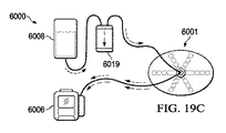
ここで図10A〜図10Cを参照して、治療システム100と使用される処置デバイス701の別の実施形態例の例示を示す。いくつかの実施形態では、処置デバイス701は、第1の液体不透過性層718および第2の液体不透過性層720等、複数の液体不透過性層または内臓保護層から形成することができる、ドレッシング702を含むことができる。処置デバイス701はまた、処置デバイス701に滴下流体を送達する送達コネクタ763も含むことができる。処置デバイスはまた、処置デバイス701の一部に陰圧を伝達し、処置デバイス701および腹腔から流体を除去する流体除去ハブ754も含むことができる。図10Aに示すように、処置デバイス701は、滴下流体を分配する流体送達容器760をさらに含むことができる。流体送達容器760は、治療システム100の流体源108等の滴下源に流体的に接続されている可撓性容器であり得る。いくつかの実施形態では、流体送達容器760の本体は、25マイクロメートル〜500マイクロメートルの範囲の厚さを有するフィルム材料の1つまたは複数の部分から構成することができる。たとえば、流体送達容器760は、50マイクロメートル〜200マイクロメートルの範囲の厚さを有するポリウレタンフィルムから構成することができる。場合により、流体送達容器760は、所定容量を有する周囲溶接構造であり得る。流体送達容器760のいくつかの実施形態は、圧力がかけられたときに容器の膨張を低減させるように、流体送達容器760の本体を形成するポリウレタンフィルムの部分の間に内部溶接部を含むことができる。内部溶接部はまた、流体送達容器760の内部容積を低減させるように、または、流体送達容器760から出る腹腔内への一様な分配を確実にするのに役立つように、流体送達容器760内に滴下流体を向けるのに役立つようにも組み込むことができる。
Referring now to FIGS. 10A-10C, an illustration of another example embodiment of a
図10A〜図10Cに示すように、流体送達容器760は、処置デバイス701の一部としてドレッシング702と一体化することができる。場合により、ドレッシング702および流体送達容器760は、本質的に、2チャンバ構造を形成することができ、2つのチャンバは垂直積層体で配置される。図10A〜図10Cに示すように、流体送達容器760は、第1の液体不透過性層718等、ドレッシング702の下側に接着されまたは溶接される容器層780から形成することができる。いくつかの実施形態では、流体送達容器760は、送達コネクタ763、したがって滴下流体源に、ドレッシング702を通して、ドレッシング702の、内臓保護層、第1の液体不透過性層718および第2の液体不透過性層720を貫通することができる、ドレッシング開口部779等、封止され、溶接された開口部を介して、流体的に結合することができる。
As shown in FIGS. 10A-10C, the
容器層780は、流体送達容器760から出る滴下流体の移送を可能にするために、容器アパーチャ781等の穿孔、開窓または開口部を含むことができる。容器アパーチャ781は、流体送達容器760から出る流量が充填流量未満であることを確実にすることにより、流体送達容器760が充填されている間、背圧を提供するようなサイズとすることができる。たとえば、容器アパーチャ781は、0.2mm〜1.0mmの範囲内の直径を有することができる。容器アパーチャ781はまた、容器層780内の容器アパーチャ781の数および/またはパターンに応じて、この範囲外である直径も有することができる。図10Aに示すように、流体送達容器760の容積またはサイズは、処置の滴下または流体送達段階中に拡張または膨張することができる。
動作中、滴下流体は流体送達容器760に入ることができ、流体送達容器760が充填されると、背圧を生成することができ、したがって、背圧は、滴下流体が実際に流体送達容器760から放出され得る前に、流体送達容器760を加圧する。この機能は、流体が、容器アパーチャ781を通してより均一に分散され、したがって、流体送達容器760の領域全体からの滴下流体の一様な分布を提供することができることを確実にするのに役立つことができる。しかしながら、流体送達容器760が、流体送達容器760によって生成される背圧のレベルが、治療システム100の流体源108等、流体滴下システムにおいてアラームをトリガするための閾値圧力未満であり続けるように、設計することができる。さらに、容器アパーチャ781は、容器アパーチャ781の非対称パターンを含むこと等により、流体送達容器760のいくつかの場所では相対的に高い流量を提供し、他の場所では相対的に低い流量を提供するように配置することができる。したがって、容器アパーチャ781のパターンは、流体分配を左右し、腹腔または他の組織部位のいくつかの領域または器官に標的を定めるように設計されている流体送達容器760の異なるバージョンを製造することができる。さらに、いくつかの実施形態では、流体送達容器760の容器層780は、流体送達容器760の内部容積を低減させ、背圧による膨張をなくし、または流体分配に役立つように、流体送達容器760内にキルティング効果をもたらす溶接部または他の方法を組み込むことができる。したがって、この特徴は、患者の不快感および関連するリスクを低減させるのに役立つことができる。
In operation, the drip fluid can enter the
流体送達容器760から腹腔または他の組織部位内に滴下流体を放出する際のあり得る遅延により、滴下流体の温度が身体の中核体温と平衡して、熱衝撃のリスクを低減させることができるという利点を提供することができる。流体送達容器760から放出されると、滴下流体は、腹腔を通って結腸傍溝内に流れ込み、その経路を通して洗浄する。さらに、滴下サイクルに続いて幾分かの滴下流体が流体送達容器760内に残る可能性があるため、滴下流体に対する滞留時間が発生する可能性がある。処置デバイス701に陰圧がかけられると、滴下流体は、流体除去経路750(図10Bに示す)を通って除去することができ、腹腔から除去される際に腹腔内容物を洗い出し続けることができる。場合により、流体送達容器760内に残っている滴下流体は、上述したように、陰圧がかけられている間に除去され、除去される際に清浄なすすぎ流体のボーラスとして作用することができる。たとえば、腹腔から滴下流体の大部分が除去され、腔内で陰圧が蓄積し始めた後、処置デバイス701の構成要素を下方に引き下げることができ、迅速に移動する流体のボーラスとして、流体送達容器760内の残っている流体が除去され、したがって、最終かつ二次すすぎとして作用することができる。必要および要求に応じて、流体滴下および陰圧サイクルを繰り返すことができる。
A possible delay in releasing the drip fluid from the
ここで、主に、詳細に上述した他の実施形態と同様の図10Bを参照すると、処置デバイス701は、複数の流体除去経路750を含むことができ、それらの各々を流体除去ハブ754に流体的に結合することができる。したがって、流体除去ハブ754は、流体除去経路750の各々に陰圧を伝達する分配機構としての役割を果たすことができる。流体除去経路750の各々は、陰圧を伝達し、流体除去経路750を通して流体を引き出す、マニホールド部材を含むことができる。たとえば、マニホールド部材は、GRANUFOAM(商標)等、連続気泡フォームまたは不織布から構成することができる。流体除去経路750は、ドレッシング702内に、したがって、内臓保護層、第1の液体不透過性層718および第2の液体不透過性層720の間に組み込むことができる。内臓保護層の間に流体除去経路750を組み込むことは、本来は肉芽形成のリスクを示す可能性があるマニホールド部材から、腹腔を保護するのに役立つことができる。いくつかの実施形態では、流体除去経路750は、第1の液体不透過性層718および第2の液体不透過性層720の一部を合わせて溶接して、フィルム層の間に流体チャネルを形成することによって、形成することができる。ここで主に図10Cを参照すると、第1の液体不透過性層718、およびおそらくは第2の液体不透過性層720もまた、流体除去経路750の各々に沿って位置決めすることができる、アパーチャ766等の開窓を含むことができる。流体除去経路750の各々の下側において、第1の液体不透過性層718のアパーチャ766を通して、流体除去経路750内に流体を引き込むことができる。流体除去経路750の各々はまた、その端部に開口部を含むことができ、それにより、患者の結腸傍溝からのかなりの程度の流体除去を可能にすることができる。結腸傍溝等、患者の腹部の低い部分に集中された流体除去を提供することは、滴下および除去療法サイクル中に腹部が完全に洗われることを確実にするのに役立つことができる。
Referring now primarily to FIG. 10B, which is similar to the other embodiments described in detail above,
図11Aおよび図11Bは、多くの点で、図10A〜図10Cに関して考察した処置デバイス701の実施形態と同様であり得る、処置デバイス701の別の実施形態例を示す。しかしながら、図11Aおよび図11Bに示す例示的な実施形態では、処置デバイス701は、容器チャンバ782とともに、腹壁の内側を下って患者の腹部の結腸傍溝内に延在するためのものであり得る半径方向チャネル784を含む、流体送達容器760を組み込むことができる。この実施形態は、特に、清浄な滴下流体による結腸傍溝の集中した洗いを同時に提供しながら、腹腔内への滴下流体の一様な分配を可能にすることができる。半径方向チャネル784は、開放端部785とともに、半径方向チャネル784の各々の長さに沿ったチャネルアパーチャ786を有することができる。いくつかの実施形態では、半径方向チャネル784は、結腸傍溝内への流れを制限するように設計することができる。半径方向チャネル784の開放端部設計により、半径方向チャネル784を個々の患者の必要および比率に適合するように切断し、そうしたサイズとすることも可能にすることができる。
11A and 11B illustrate another example embodiment of a
ここで図12Aおよび図12Bを参照して、処置デバイス701の別の例示的な実施形態を示す。この場合もまた、図12Aおよび図12Bの処置デバイス701の特徴のうちの多くが、図10および図11に関して考察した処置デバイス701の実施形態の特徴と同じかまたは同様であり得る。図12Aおよび図12Bの実施形態例では、流体送達容器760は、陰圧がかけられるとき、送達コネクタ763から流体送達容器760を通り容器アパーチャ781から出る流体滴下経路が、開放し、閉塞も封止もされないままであることを確実にするのに役立つように、内部マニホールドマトリックス788等、内部マニホールドまたはマトリックスを組み込むことができる。内部マニホールドマトリックス788用の材料例としては、ポリウレタンフォーム等のフォーム、Libeltex TDL2、エンボス加工フィルム、または他の何らかの成形構造体を挙げることができる。
Referring now to FIGS. 12A and 12B, another exemplary embodiment of a
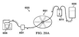
図13Aおよび図13Bは、多くの点で、上述した処置デバイスの実施形態と同様であり得る、治療システム100と使用される処置デバイス801の別の実施形態例を示す。いくつかの実施形態では、処置デバイス801は、適用中に使用者が組み立てるために、ドレッシング702の液体不透過性層に取り付けられずに提供することができる別個の構成要素であり得る、ドレッシング702と流体送達容器860等の流体送達容器とを含むことができる。たとえば、いくつかの実施形態では、流体送達容器860は、下部容器層880および上部容器層883等、2つの層によって形成することができる。いくつかの実施形態では、流体送達容器860は、バッグまたは密閉フォームの形態であり得る。容器層880は、流体送達容器860から出て患者の腹腔内に流体を送達するために、流体送達容器860の下面すなわち下側の容器アパーチャ881等、開口部を含むことができる。いくつかの実施形態では、流体送達容器860は、送達コネクタ763の端部に物理的にかつ流体的に接続することができる、上部容器層883の開口部を通して、流体源108等の滴下源に流体的に接続することができる。上述した他の実施形態と同様に、流体送達容器860は、治療の流体滴下サイクル中、流体が圧力下で流体送達容器860に送達され流体送達容器860を充填することができる際、膨張することができる。
13A and 13B illustrate another example embodiment of a
重要なことには、流体送達容器860が、処置デバイス801のドレッシング702等の他の部分から別個に提供されるのを可能にすることにより、外科医または他の介護者は、個別的に、患者の腹部内の流体滴下要件をより適切に確定し、適切なサイズであるかまたは適切に構成された流体送達容器を適用することができる可能性がある。流体送達容器860等の流体送達容器のいくつかの実施形態が、テキサス州サンアントニオ(San Antonio,Texas)のKinetic Concepts,Inc.から市販されているABThera(登録商標)等、現行の腹部ドレッシングの付属品として提供されることも可能である。
Importantly, by allowing the
図14Aおよび図14Bは、図13Aおよび図13Bに示す処置デバイス801の例示的な実施形態と同様であり得る、処置デバイス801の実施形態例を参照する。しかしながら、図14Aおよび図14Bの実施形態例では、流体送達容器860は、流体送達容器860が滴下流体で充填されるのを可能にすることができる、マニホールドマトリックス884等の折畳み式または非折畳み式マトリックスであり得るさらなる構成要素を組み込むことができる。いくつかの実施形態では、流体送達容器860は、閉塞性であり得る下部層、すなわち容器層880と、容器上部アパーチャ885等、穿孔、開窓または開口部を組み込むことができる、上部容器層883等の上部層とを含むことができる。容器上部アパーチャ885は、流体送達容器860の上面から出る滴下流体の流れを可能にすることができ、これは、流体送達容器860が治療サイクル中に滴下流体で充填された後に発生する可能性がある。場合により、流体が腹腔内に出る前に、流体送達容器860が滴下流体で完全に充填されるのを確実にすることにより、一様な流体分配を確実にするために流体送達容器860内に背圧を生成する必要をなくすことができる。
14A and 14B refer to an example embodiment of a
ここで図15を参照して、治療システム100と使用される処置デバイス1001の別の実施形態例の例示を示す。一実施形態では、処置デバイス1001は、腹腔を2つの垂直に積み重ねられたチャンバまたはコンパートメントに分割する、閉塞層1002等の単層を含むことができる。処置デバイス1001はまた、閉塞層1002の中心部分内に位置決めすることができる流体除去マニホールド1004も含むことができ、それは、腹腔から流体を収集し除去するために、閉塞層1002のチャネルに陰圧を流体的に伝達することができる。さらに、処置デバイス1001は、加圧分配容器1006を含むことができ、それは、閉塞層1002にわたって腹腔の領域に滴下流体を分配することができる。他の実施形態に関して上述したように、インタフェース132において、処置デバイス1001に、陰圧および/または滴下流体を移送する導管134を流体的に接続することができる。
Referring now to FIG. 15, an illustration of another example embodiment of a
動作時、他の実施形態に関して上述したように、好適な流体源により滴下流体を送達することができ、滴下流体は、処置デバイス1001の加圧分配容器1006に送達されると、閉塞層1002の表面にわたるように強制され得る。滴下流体は、閉塞層1002の最も遠い範囲に達し、腹腔内容物、最終的には結腸傍溝と接触するまで、閉塞層1002の上を、形成された経路を通って流れることができる。滴下流体は、閉塞層1002の上面にわたって流れる際、体熱により体温まで加温され、広い領域にわたって広げられ得る。上述したように、滴下流体の滞留時間が発生し、滴下流体の一部は、閉塞層1002の滴下面の上の加圧分配容器1006内に残り、それは、後に、除去される際に清浄な流体のボーラスとして作用することができる。
In operation, as described above with respect to other embodiments, a suitable source of fluid can deliver the drip fluid, which, when delivered to the
陰圧すなわち流体除去サイクル中、滴下流体は、閉塞層1002の下側すなわち底面の形成された経路に沿って引き出されることにより、体腔から引き出すことができる。陰圧がかけられる際、閉塞層1002は、下方に引き下げられ、体腔内容物に対して密に圧迫され得る。この移動により、内臓器官等、腹腔内容物が、閉塞層1002の下側の形成された経路に沿って引き出される滴下流体と接触することができる。他の実施形態に関して上述したように、陰圧がかけられる間、加圧分配容器1006内の残っている流体は、流体の迅速に移動するボーラスとして除去することができ、したがって、最終的なすすぎとして作用することができる。
During a negative pressure or fluid removal cycle, drip fluid can be withdrawn from the body cavity by withdrawing along the path below or at the bottom of the
ここで図16も参照して、図15の処置デバイス1001および導管134の一部の概略断面図を示す。この例示的な図では、閉塞層1002は、腹腔を2つの異なるチャンバまたはコンパートメントにいかに分割することができるかが分かる。たとえば、閉塞層1002の下方に、内臓器官に接して位置する流体除去チャンバ1008があり、閉塞層1002の上方に、患者の皮膚と近接することができる流体滴下チャンバ1010があり得る。このように腹腔を分割することにより、閉塞層1002は、滴下された流体が、除去される前に腹部内の処置デバイス1001の最も遠い範囲に達することができることを確実にすることができる。重要なことには、閉塞層1002はまた、内臓保護バリアとしても作用することができる。いくつかの実施形態では、閉塞層1002は、陰圧がかけられたときに、下方につぶれるようにかつシールを実質的に形成するように付勢することができ、シールは、流体滴下チャンバ1010と流体除去チャンバ1008との間の交差汚染を最小限にするのに役立つことができる。
Referring now also to FIG. 16, a schematic cross-sectional view of a portion of the
再び図15および図16の両方を参照すると、いくつかの実施形態では、ポリウレタンフィルム等のフィルムの単一片またはシートから閉塞層1002を形成することができる。いくつかの実施形態では、閉塞層1002は、流体除去チャンバ1008における閉塞層1002の下方と流体滴下チャンバ1010における閉塞層1002の上方の両方に流体経路を提供することができる。たとえば、流体経路は、高周波溶接技法を用いて生成することができる、閉塞層1002のひだ1012によって形成することができる。たとえば、高周波(HF)または高周波(RF)溶接は、閉塞層1002の一部の材料を融解するように高周波電磁エネルギーを使用して、閉塞層1002の一部を合わせて接合することを含むことができる。ひだ1012は、閉塞層1002の遠位縁まで流体を一様に分配するように配置することができる。ひだ1012の数は、必要または要求に応じて、腹腔内の滴下流体の流れをさらに制御するように変更することができる。
Referring again to both FIGS. 15 and 16, in some embodiments, the
いくつかの実施形態では、流体除去マニホールド1004は、導管134の除去経路を通って容器110および陰圧源106に空気圧式にまたは流体的に接続された可撓性容器であり得る。流体除去マニホールド1004は、外周部で互いに溶接されたポリウレタンフィルムであり得る、合わせて溶接された複数のフィルムから作製することができる。たとえば、流体除去マニホールド1004は、上部マニホールドフィルム1014および下部マニホールドフィルム1016を含むことができる。図16に示すように、いくつかの実施形態では、流体除去マニホールド1004は、下部マニホールドフィルム1016の一部として入口1018として含めることができる、開口部または開窓を含むことができる。流体除去マニホールド1004の下側のこれらの入口1018は、流体除去チャンバ1008に陰圧を分配し、流体除去チャンバ1008から流体を補充するためのものであり得る。入口1018は、特定の吸引の必要に従ってサイズを決めることができる。いくつかの実施形態では、流体除去マニホールド1004は、上部マニホールドフィルム1014および下部マニホールドフィルム1016内に収容することができる、マニホールド材料1019を含むことができる。マニホールド材料1019は、流体を伝達するかまたは移送するのに好適である種々の異なる材料を含むことができる。たとえば、いくつかの実施形態では、マニホールド材料1019は、直径が約6mmの細孔を有する連続気泡フォームを含むことができる。
In some embodiments, the
いくつかの実施形態では、加圧分配容器1006は、導管134の滴下経路を通して、流体源108と流体連通している可撓性容器であり得る。加圧分配容器1006の容積は、変更することができ、いくつかの実施形態では、内部溶接部を使用して低減させることができ、内部溶接部は、さらに、滴下流体の分配を改善するために局所圧力を上昇させるのに役立つことができる。加圧分配容器1006の構造を形成するために好適な材料は、外周部で合わせて溶接することができる、ポリウレタンフィルム等のフィルムのシートを含むことができる。たとえば、加圧分配容器1006は、上部容器フィルム1020および下部容器フィルム1022を含むことができる。図16に示すように、いくつかの実施形態では、加圧分配容器1006は、加圧分配容器1006内の特定の内圧に達したときに、滴下流体が加圧分配容器1006から出るのを可能にするために、下部容器フィルム1022の一部として、標準より小さい出口1024を含むことができる。たとえば、出口1024は、加圧分配容器1006から滴下流体の一様な分配を駆動するのに役立つための背圧を生成するのに十分小さいが、出口1024が治療システム100におけるあり得る閉塞アラームをもたらすようには小さくはないものであり得る。いくつかの実施形態では、出口1024は、約0.2mm〜1mmの直径を有することができる。出口1024は、穿孔または開窓の形態であり得る。出口1024はまた、分配を左右するのに役立つ1つまたは複数のパターンで配置することも可能であり、いくつかの領域または器官に標的を定めるように設計されている出口1024の異なる配置を有する加圧分配容器1006の異なるバージョンを製造することができる。たとえば、いくつかの実施形態では、加圧分配容器1006の外周部に、一様に間隔が開けられたパターンで出口1024を配置することができる。
In some embodiments,
図17は、処置デバイス2001および導管134の別の例示的な実施形態の一部の概略断面図を示す。この例示的な図では、閉塞層2002および腹腔の結腸傍溝の遠位部分および先端から流体除去マニホールド2004までのさらなる経路を生成するために、いかに複数の層を含むことができるかが分かる。こうした、閉塞層2002等、多層閉塞層の場合、構造は、フィルム材料から作製することができ、熱、真空または圧縮成形等により、3次元で形成することができる。
FIG. 17 shows a schematic cross-sectional view of a portion of another exemplary embodiment of a
さらに図17を参照すると、処置デバイス2001のいくつかの実施形態は、閉塞層2002と結合されるかまたはその一部として形成される流体除去マニホールド2004等、マニホールドを含むことができる。たとえば、いくつかの実施形態では、流体除去マニホールド2004は、閉塞層2002の下側に取り付けられるかまたは溶接される下部マニホールドフィルム2016のみから形成することができ、したがって、図16の上部マニホールドフィルム1014等、上部マニホールドフィルムを不要にすることができる。いくつかのさらなる実施形態では、図17に示すように、流体除去マニホールド2004は、多層閉塞層2002の複数の層内に位置決めすることができ、したがって、入口2018を有する下部マニホールドフィルム2016は、実際には、多層閉塞層2002の下部層の一部として形成することができる。こうした実施形態では、流体除去経路は、多層閉塞層2002のさまざまな層の間に流体除去マニホールド2004の外周部入口2026を通して、かつ流体除去マニホールド2004の真下および入口2018を通して多層閉塞層2002の下側に、存在し得る。流体除去マニホールド2004は、陰圧および流体を伝達することができるマニホールド材料2019を含むことができ、3次元形成フィルム、ウィッキング材料および成形マニホールド等の材料を含むことができる。
Still referring to FIG. 17, some embodiments of the
いくつかの実施形態では、加圧分配容器2006は、閉塞層2002と結合するか、または閉塞層2002の一部として形成することができる。たとえば、いくつかの実施形態では、加圧分配容器2006は、閉塞層2002の上面に取り付けられるかまたは溶接される上部容器フィルム2020のみから形成することができ、したがって、図16の下部容器フィルム1022等、下部容器フィルムを不要にすることができる。いくつかの実施形態では、上部容器フィルム2020は、多くの可撓性部品から成形され接合される代わりとして、単一構造として閉塞層2002とともに成形することができる。場合により、上部容器フィルム2020および閉塞層2002は、加圧分配容器2006からの開放経路を確実にするためにキルティングすることができる。たとえば、上部容器フィルム2020および閉塞層2002の一部は、上部容器フィルム2020および閉塞層2002の一部の周囲の溶接外周部等、合わせて溶接することができる。さらに、上部容器フィルム2020および閉塞層2002の一部は、キルティング効果をもたらすように材料層の両方にわたるパターンでスポット溶接することができる。その結果、いくつかの実施形態では、加圧分配容器2006の高さおよび容積は、流体で充填されるときに制限することができる。種々の材料を使用して、限定されないが、小内径管を含む、加圧分配容器2006を形成することができる。いくつかの実施形態例では、滴下流体の流れ分布は、加圧分配容器2006の周縁部に位置決めすることができる外周部出口2024によって制御することができる。他の実施形態と同様に、こうした外周部出口2024は、高周波溶接等の技法によって生成することができる。図17の例示的な実施形態は、閉塞層2002、流体除去マニホールド2004および加圧分配容器2006の変更バージョンを示すが、これらの特徴の任意の組合せを単一実施形態に組み込むことができる。
In some embodiments, the
図18A〜図18Cは、図15の閉塞層1002等の閉塞層のいくつかの例示的な実施形態による特徴に関連するさらなる詳細を示す。たとえば、図18Aに示すように、図15の閉塞層1002のひだ1012に等価であり得る、複数のアコーディオンひだ3012を有するように形成されている、単一ベース層3030から形成することができる。アコーディオンひだ3012は、ベース層3030の下面の下に含めることができる流体除去経路3032、およびベース層3030の上面に沿って延在することができる送達経路3034の両方を形成して、アコーディオンひだ3012を形成することができる。
18A-18C show additional details related to features according to some exemplary embodiments of an occlusion layer, such as
図18Bは、閉塞層4002の別の例示的な実施形態を示し、そこでは、図18Aに示すようなアコーディオンひだ3012から形成された流体経路の代わりに、管状ひだ4012によって流体経路が形成されている。こうした実施形態では、閉塞層4002は、複数の管状ひだ4012があるベース層4030から形成することができ、複数の管状ひだ4012は、別個の細管層4036によりベース層4030の上面に形成されている。別法として、管状ひだ4012は、ベース層4030の一部を合わせて接合するかまたは締め付けて管状ひだ4012を形成すること等により、一体管状構造体で形成される単一ベース層4030から形成することができる。いずれの場合も、管状ひだ4012の内部に流体除去経路4032を設けることができ、流体送達経路4034は、流体除去経路4032を含む管状ひだ4012の間のベース層4030の上面に沿って広がることができる。
FIG. 18B illustrates another exemplary embodiment of an
図18Cは、閉塞層4002の実施形態と同様であるが、流体経路用のアコーディオンひだ5012を含む、閉塞層5002の別の例示的な実施形態を示す。したがって、いくつかの実施形態では、閉塞層5002は、複数のアコーディオンひだ5012があるベース層5030から形成することができ、複数のアコーディオンひだ5012は、別個のひだ層5036によってベース層5030の上面に形成されている。除去経路5032は、ひだ層5036の下方に、またはベース層5030とひだ層5036との間に生成された空間内に含めることができる。流体送達経路5034は、ひだ層5036の上面に沿って延在することができる。
FIG. 18C shows another exemplary embodiment of an
ここで主に図19A〜図19Cを参照して、組織部位において陰圧療法および流体滴下処置を提供する方法のさらなる実施形態についてさらに説明する。たとえば、いくつかの実施形態では、治療システム6000は、処置デバイス6001と、陰圧源6006と、陰圧源6006とは別個の独立型デバイスである流体源6008とを含むことができる。流体源6008は、別個の機械的滴下デバイスであり得る。流体源6008に対して別個の機械的滴下デバイスを含むいくつかの実施形態では、治療システム6000は、処置デバイス6001、最終的に組織部位112に送達される滴下流体の量をモニタリングしかつ/または制御する滴下調節器6019も含むことができる。図19A〜図19Cに示すように、いくつかの開示する方法は、3つの段階または間隔を含む治療サイクルを含むことができる。たとえば、図19Aに示すように、治療サイクルの第1の段階は、処置デバイス6001および組織部位112に陰圧療法を適用するために、陰圧源6006を作動させることを含むことができる。陰圧源6006によってかけられる陰圧は、治療システム6000の流体的に接続された経路を通して伝達され、最終的に滴下調節器6019および流体源6008に達することができる。したがって、この伝達される陰圧は、機械的滴下デバイスであり得る流体源6008をプライミングすることができる。図19Bを続けると、本方法は治療サイクルの第2の段階をさらに含むことができ、それは、所定時間間隔、陰圧源6006から陰圧送達を一時停止するかまたは終了することを含むことができる。この間隔の間、機械的滴下デバイス等の流体源6008は、滴下調節器6019に、最終的に処置デバイス6001に、滴下流体を渡すことができる。図19Cに示すように、流体源6008から処置デバイス6001に滴下流体を送達する指定された間隔に続き、治療サイクルの第3の段階を開始することができる。この第3の段階中、流体滴下を一時停止することができ、陰圧源6006を再作動させて陰圧療法のさらなる間隔を提供することができる。治療サイクルのこの時点で、処置デバイス6001とともに、腹腔111等の組織部位112から、滴下流体を除去することができる。さらに、流体源6008は、治療サイクルの第2の段階が繰り返され得る際に、再度プライミングし、再度処置デバイス6001に滴下流体を送達する用意ができた状態にすることができる。
Referring now primarily to FIGS. 19A-19C, further embodiments of a method for providing negative pressure therapy and fluid drip treatment at a tissue site will be further described. For example, in some embodiments, the
図20A〜図20Cは、組織部位に陰圧療法および流体滴下処置を提供する方法の別の実施形態例を示す。図20A〜図20Cによって例示する方法は、さまざまな変更を含み、図19A〜図19Cに関して上述した方法と実質的に同様であり得る。たとえば、図20Aに示すように、治療システム6000は、処置デバイス6001、陰圧源6006、流体源6008および滴下調節器6019を含むことができる。さらに、治療システム6000は、圧力解放ユニット6021をさらに含むことができる。いくつかの実施形態では、治療サイクルの第1の段階の間、処置デバイス6001に陰圧療法を適用するために、陰圧源6006を作動させることができる。陰圧源6006によってかけられる陰圧は、治療システム6000の流体的に接続された経路を通して伝達され、最終的に、滴下調節器6019および流体源6008に達することができる。この伝達される陰圧は、機械的滴下デバイスであり得る流体源6008をプライミングすることができる。図20Bを続けると、本方法は、治療サイクルの第2の段階をさらに含むことができ、この間、圧力解放ユニット6021が開放し、処置デバイス6001への陰圧送達が停止される。いくつかの実施形態では、圧力解放ユニット6021は、所定のまたは事前に確定されたタイミングスケジュールに従って開放することができる。治療サイクルの第2の段階中、流体源6008は、滴下流体を滴下調節器6019に、最終的に処置デバイス6001に送達することができ、これは、圧力解放ユニット6021が開放されている間に発生することができ、したがって、陰圧が、処置デバイス6001および流体源6008および滴下調節器6019に伝達されるのを防止することができる。図20Cに示すように、治療サイクルの第2の段階に続き、治療サイクルの第3のサイクルを開始することができ、その間、この場合もまたタイミングが決められた間隔スケジュールに従って、圧力解放ユニット6021が閉鎖することができる。治療サイクルの第3の段階中、流体滴下を一時停止することができ、陰圧療法のさらなる間隔を提供するために、陰圧源6006を再作動させることができる。処置デバイス6001から滴下流体を除去することができ、流体源6008は、プライミングし、滴下流体を処置デバイス6001に再度送達する用意ができた状態にすることができる。
20A-20C illustrate another example embodiment of a method for providing a negative pressure therapy and a fluid drip procedure to a tissue site. The method illustrated by FIGS. 20A-20C includes various modifications and may be substantially similar to the method described above with respect to FIGS. 19A-19C. For example, as shown in FIG. 20A, a
組織部位に陰圧療法および流体滴下を提供するいくつかのさらなる方法では、機械的滴下デバイスの自動化または他の形態ではなく、流体バッグ、ボトルまたは他の容器等、手動制御滴下容器を組み込むことができる。したがって、いくつかの実施形態では、治療サイクルの第1の段階中、陰圧源は、処置デバイスおよび組織部位に陰圧療法を適用することができ、その間、クランプ、弁または他の形態の閉鎖デバイスなどのデバイスが、流体が、手動制御滴下容器から処置デバイスおよび組織部位に伝達されるのを防止することができる。いくつかの実施形態では、治療サイクルの後続する段階中、使用者は、クランプまたは他の形態の閉鎖デバイスを開放することができ、滴下されている流体の容量を手動で調節することができる。この滴下段階中、陰圧源は作動状態であり続けることができ、したがって、処置デバイスおよび組織部位からの滴下された流体の即時の除去を提供することができる。したがって、本方法のいくつかの実施形態によれば、組織部位において流体の滞留時間を実質的になくすことができる。そして、使用者は、閉鎖デバイスを再度締め付けるかまたは他の方法で閉鎖することができ、したがって、手動制御滴下容器からの滴下流体の流れを停止することができる。そして、陰圧源は、処置デバイスおよび組織部位から、余分なまたは残っている滴下流体とともに滲出液を除去し続けることができる。開示する方法の他のいくつかの実施形態では、流体が手動制御滴下容器から滴下されている間に陰圧源が作動状態であり続けるのを可能にするのではなく、陰圧源を一時停止させることができ、したがって、所定期間、滴下流体が組織部位に留まるのを可能にする。適切である場合、使用者は、手動制御滴下容器を、滴下流体を送達しないように閉鎖することができる。滴下が停止される前にまたはそれに続き、陰圧療法を再開することができ、その間、処置デバイスおよび組織部位からいかなる余分なまたは残っている流体も除去することができる。 Some additional methods of providing negative pressure therapy and fluid drip at a tissue site include incorporating a manually controlled drip container, such as a fluid bag, bottle or other container, rather than an automated or other form of mechanical drip device. it can. Thus, in some embodiments, during the first phase of the treatment cycle, the source of negative pressure can apply negative pressure therapy to the treatment device and the tissue site, while a clamp, valve or other form of closure is applied. A device, such as a device, can prevent fluid from being transmitted from the manually controlled drip container to the treatment device and the tissue site. In some embodiments, during a subsequent phase of the treatment cycle, the user can open a clamp or other form of closure device and can manually adjust the volume of fluid being dripped. During this drip phase, the negative pressure source can remain active, thus providing for immediate removal of the drip fluid from the treatment device and tissue site. Thus, according to some embodiments of the method, the residence time of the fluid at the tissue site can be substantially eliminated. The user can then re-tighten or otherwise close the closure device, thus stopping the flow of drip fluid from the manually controlled drip container. The source of negative pressure may then continue to remove exudate from the treatment device and tissue site along with excess or remaining drip fluid. In some other embodiments of the disclosed method, rather than allowing the negative pressure source to remain active while fluid is being drip from the manually controlled drip container, the negative pressure source is suspended. And thus allow the drip fluid to remain at the tissue site for a predetermined period of time. If appropriate, the user can close the manually controlled drip container so as not to deliver drip fluid. Negative pressure therapy can be resumed before or following the drip is stopped, while removing any excess or remaining fluid from the treatment device and tissue site.
本明細書に記載したシステム、装置および方法は、重大な利点を提供することができる。上述したように、開示したシステムおよびデバイスは、流体送達管の独立したマトリックスとともに、汚染流体の除去のための陰圧流体除去経路を通る流体滴下機能を備えた、結合された一時的腹部閉鎖ドレッシングシステムを提供することができる。したがって、開示した実施形態は、腹腔内容物を支持しかつ保護するとともに、汚染流体を除去し浮腫を抑制しかつ/または低減させる一方で、腹腔を灌注し洗浄する手段を提供することができる。さらに、開示したドレッシングのさまざまな層および構成要素が腹腔内容物に張力および閉鎖力を加える結果として、腹腔のより迅速な一次顔面閉鎖を容易にすることができる。 The systems, devices and methods described herein can provide significant advantages. As described above, the disclosed systems and devices provide a combined temporary abdominal closure dressing with a separate matrix of fluid delivery tubes and a fluid drip function through a negative pressure fluid removal path for removal of contaminated fluid. A system can be provided. Thus, the disclosed embodiments can provide a means for irrigating and irrigating the peritoneal cavity while supporting and protecting peritoneal contents and removing contaminant fluids to reduce and / or reduce edema. Further, the various layers and components of the disclosed dressing can apply a tension and closing force to the abdominal cavity contents to facilitate faster primary facial closure of the abdominal cavity.
本明細書に記載したように、開示した解決法は、小腸ループ、傍溝、後腹膜腔、リンパ系の一部等を含む、腹腔のすべての領域を、すべてドレッシングシステムが適所にある間、灌注する手段を提供することができ、したがって、手術室において患者および臨床スタッフに必要な時間が短縮される。記載したさまざまな実施形態は、流体滴下療法に対する腹部組織部位の内臓器官の露出を最大限にするように設計された流体経路のさまざまな構成を提供する。開示したドレッシング構成要素はまた、腹部組織部位の筋膜に付着することなく、より長いドレッシング適用時間も可能にすることができる。したがって、組織部位のさまざまな部分に一様に提供することができる、繰り返し可能であるとともに信頼性の高い流体滴下を提供することができる。その結果、流体灌注および洗浄はより一貫したものとすることができ、したがって、敗血性腹腔を患っている患者の死亡率が低下することになる。流体滴下は、患者のベッドサイドで管理することができ、個別的に特別に適合させ調整することができる。 As described herein, the disclosed solution provides all areas of the abdominal cavity, including small intestinal loops, parasulcus, retroperitoneal cavity, parts of the lymphatic system, etc., while the dressing system is in place, A means of irrigation can be provided, thus reducing the time required for patients and clinical staff in the operating room. The various embodiments described provide various configurations of fluid pathways designed to maximize the exposure of internal organs of the abdominal tissue site to fluid instillation therapy. The disclosed dressing components can also allow for longer dressing application times without adhering to the fascia at the abdominal tissue site. Thus, a repeatable and reliable fluid drip can be provided that can be uniformly provided to various portions of the tissue site. As a result, fluid irrigation and irrigation can be more consistent, thus reducing mortality in patients suffering from septic peritoneal cavity. Fluid drip can be managed at the patient's bedside and can be individually tailored and tailored.
開示したシステムおよびデバイスは、腹腔等の組織部位から滲出液および感染性物質を排出することができ、したがって、治癒を促進するために汚染された腹部流体の存在を低減させることができる。さらに、開示した解決法は、汚染されたまたは「汚れた」流体が腹部から完全に除去されるのを確実するように、別個の滴下経路および陰圧経路を提供することができる。さらに、開示したシステムの好ましい実施形態では、滴下流体は、組織部位に戻るように再循環しない。その結果、組織部位を灌注する臨床的利点を増大させることができる。 The disclosed systems and devices can drain exudate and infectious material from a tissue site, such as the abdominal cavity, and thus reduce the presence of contaminated abdominal fluid to promote healing. Further, the disclosed solution can provide a separate drip path and negative pressure path to ensure that contaminated or "dirty" fluid is completely removed from the abdomen. Further, in a preferred embodiment of the disclosed system, the drip fluid does not recirculate back to the tissue site. As a result, the clinical benefit of irrigating the tissue site can be increased.
重要なことには、開示したデバイスの設計は、手術室内で患者に適用される時点での使用者のサイジングおよび/またはカスタマイズ化も可能にすることができる。いくつかの実施形態では、ドレッシングの配置、サイジングおよび除去に対する改善された使用の容易さは、使用者を誘導するための組み込まれたサイジングまたは配置視覚的マークまたはインジケータによって提供することができる。開示したドレッシングシステムのいくつかの実施形態はまた、使用をさらに能率的にしかつ簡略化するように構造的ドレッシング層にすでに事前に取り付けられた流体滴下経路および/または流体除去経路等、さまざまな構成要素も含むことができる。その結果、既存のドレッシングシステムと比較して改善された流体送達および除去を可能にすることができるだけでなく、使用の容易さの向上も促進することができる。 Importantly, the disclosed device design may also allow for user sizing and / or customization as applied to a patient in an operating room. In some embodiments, improved ease of use for dressing placement, sizing and removal may be provided by built-in sizing or placement visual marks or indicators to guide the user. Some embodiments of the disclosed dressing system also have various configurations, such as fluid drip and / or fluid removal paths already pre-attached to the structural dressing layer to further streamline and simplify use. Elements can also be included. As a result, not only can improved fluid delivery and removal compared to existing dressing systems be allowed, but also enhanced ease of use.
少数の例示的な実施形態で示したが、当業者であれば、本明細書に記載したシステム、装置および方法は、さまざまな変形および変更が可能であることを理解するであろう。さらに、「または」等の用語を用いるさまざまな代替物の記載は、文脈から明らかに必要でない限り、相互に排他的である必要はなく、「1つの(a、an)」という不定冠詞は、文脈から明らかに必要でない限り、対象を単一の例に限定するものではない。さらに、任意の1つの実施形態に関連して記載した任意の特徴はまた、他の任意の構成要素にも適用可能であり得る。販売、製造、組立または使用の目的で、構成要素をさまざまな構成で組み合わせるかまたは削除することも可能である。たとえば、いくつかの構成では、ドレッシング102、容器110または両方を含む処置デバイス101をなくすか、または製造もしくは販売のために他の構成要素から分離することができる。
Although shown in a few exemplary embodiments, those skilled in the art will appreciate that the systems, devices, and methods described herein are capable of various modifications and changes. Further, the description of various alternatives using terms such as "or" need not be mutually exclusive, unless the context clearly requires it, and the indefinite article "a (an)" It is not intended to limit an object to a single example unless it is clearly required by context. Further, any features described in connection with any one embodiment may also be applicable to any other component. Components may be combined or removed in various configurations for sale, manufacture, assembly or use. For example, in some configurations,
添付の特許請求の範囲は、上述した主題の新規性がありかつ進歩性がある態様を記載するが、詳細には具体的に記載していないさらなる主題も包含することができる。たとえば、当業者にはすでに既知であることから新規性がありかつ進歩性がある特徴を識別するために必要でない場合は、特許請求の範囲からいくつかの特徴、要素または態様を省略している可能性がある。本明細書に記載した特徴、要素および態様は、添付の特許請求の範囲によって定義される本発明の範囲から逸脱することなく、組み合わせるか、または、同じ、等価なもしくは同様の目的をかなえる代替的な特徴により置き換えることができる。 The appended claims describe novel and inventive aspects of the above-described subject matter, but may also encompass additional subjects that are not specifically described in detail. For example, if it is not necessary to identify a novel and inventive feature as it is already known to those skilled in the art, some features, elements or aspects have been omitted from the claims. there is a possibility. The features, elements and aspects described herein may be combined or substituted for the same, equivalent or similar purposes without departing from the scope of the invention as defined by the appended claims. Can be replaced by various features.
Claims (117)
腹腔内で展開するように構成されたドレッシングと、
前記ドレッシングに流体的に結合された陰圧源と、
前記ドレッシングに流体的に結合された流体源と、
を備えることを特徴とするシステム。 In a system for treating a tissue site,
A dressing configured to deploy in the abdominal cavity,
A source of negative pressure fluidly coupled to the dressing;
A fluid source fluidly coupled to the dressing;
A system comprising:
前記陰圧源と流体連通するように構成された第1の複数の流体チャネルと、
前記流体源と流体連通するように構成された第2の複数の流体チャネルと、
を備えることを特徴とするシステム。 The system of claim 1, wherein the dressing comprises:
A first plurality of fluid channels configured to be in fluid communication with the source of negative pressure;
A second plurality of fluid channels configured to be in fluid communication with the fluid source;
A system comprising:
第1の不透過性層および第2の不透過性層と、前記第1の不透過性層と前記第2の不透過性層との間の密閉された空間とを備えるドレッシング部材と、
前記空間内に形成されかつ前記陰圧源と流体連通するように構成された複数の流体除去経路と、
前記空間内に形成されかつ前記流体源と流体連通するように構成された複数の流体送達経路と、
を備えることを特徴とするシステム。 The system of claim 1, wherein the dressing comprises:
A dressing member comprising: a first impermeable layer and a second impermeable layer; and a sealed space between the first impermeable layer and the second impermeable layer.
A plurality of fluid removal paths formed in the space and configured to be in fluid communication with the negative pressure source;
A plurality of fluid delivery paths formed in the space and configured to be in fluid communication with the fluid source;
A system comprising:
第1の保護層および第2の保護層を備えるドレッシング部材であって、前記第1の保護層および前記第2の保護層の各々の少なくとも一部が、前記第1の保護層と前記第2の保護層との間の密閉されたチャンバを提供するように接合されている、ドレッシング部材と、
前記第1の保護層および前記第2の保護層によって密閉された前記チャンバ内に形成された複数の流体除去経路と、
前記チャンバ内に密封された滴下マトリックスと、
を備えることを特徴とするドレッシング。 In a dressing for treating a tissue site,
A dressing member including a first protective layer and a second protective layer, wherein at least a part of each of the first protective layer and the second protective layer includes the first protective layer and the second protective layer. A dressing member joined to provide a sealed chamber between the protective layer and
A plurality of fluid removal paths formed in the chamber sealed by the first protective layer and the second protective layer;
A drip matrix sealed in the chamber;
A dressing comprising:
前記滴下マトリックスが複数の流体送達チューブを備え、
前記ハブが、前記複数の流体送達チューブ内への流体流を制御するようなサイズでありかつそのように構成された複数の開口部を備える
ことを特徴とするドレッシング。 In the dressing according to claim 20,
Wherein the drip matrix comprises a plurality of fluid delivery tubes;
A dressing, wherein the hub is sized to control fluid flow into the plurality of fluid delivery tubes and includes a plurality of openings so configured.
第1の不透過性層と、
前記第1の不透過性層に接して位置決めされかつ前記第1の不透過性層と実質的に同一の広がりをもつ第2の不透過性層と、
前記第1の不透過性層と前記第2の不透過性層との間に位置決めされた複数の流体除去経路と、
前記第1の不透過性層と前記第2の不透過性層との間に位置決めされた複数の流体送達チャネルと、
を備えることを特徴とするドレッシング。 In a dressing for treating a tissue site,
A first impermeable layer;
A second impermeable layer positioned in contact with the first impermeable layer and substantially coextensive with the first impermeable layer;
A plurality of fluid removal paths positioned between the first impermeable layer and the second impermeable layer;
A plurality of fluid delivery channels positioned between the first impermeable layer and the second impermeable layer;
A dressing comprising:
前記複数の流体除去経路が、前記ドレッシングの中心から半径方向外向きに延在し、
前記複数の流体送達チャネルが、前記ドレッシングの前記中心から半径方向外向きに延在し、
前記複数の流体除去経路が、前記複数の流体送達チャネルと交互配置で位置決めされていることを特徴とするドレッシング。 The dressing of claim 32,
The plurality of fluid removal paths extending radially outward from a center of the dressing;
The plurality of fluid delivery channels extend radially outward from the center of the dressing;
A dressing, wherein the plurality of fluid removal paths are positioned in an alternating manner with the plurality of fluid delivery channels.
第1の一方向弁群であって、前記第1の一方向弁群の各々が、前記複数の流体除去経路のうちの1つの第1の端部に位置決めされている、第1の一方向弁群と、
第2の一方向弁群であって、前記第2の一方向弁群の各々が、前記複数の流体送達チャネルのうちの1つの第1の端部に位置決めされている、第2の一方向弁群と、
をさらに備えることを特徴とするドレッシング。 The dressing of claim 51, wherein the fluid hub comprises:
A first one-way valve group, wherein each of the first one-way valve groups is positioned at a first end of one of the plurality of fluid removal paths. Valve group,
A second one-way valve group, wherein each of the second one-way valve groups is positioned at a first end of one of the plurality of fluid delivery channels. Valve group,
A dressing, further comprising:
第1の不透過性層および第2の不透過性層を備えるドレッシング部材と、
前記ドレッシング部材に関連付けられた複数の流体除去経路と、
複数の流体送達経路を備える流体滴下マトリックスであって、前記ドレッシング部材の第1の面に隣接している流体滴下マトリックスと、
を備えることを特徴とするドレッシング。 In a dressing for treating a tissue site,
A dressing member comprising a first impermeable layer and a second impermeable layer;
A plurality of fluid removal paths associated with the dressing member;
A fluid drip matrix comprising a plurality of fluid delivery paths, wherein the fluid drip matrix is adjacent to a first surface of the dressing member;
A dressing comprising:
第1の不透過性層および第2の不透過性層ならびに前記第1の不透過性層と前記第2の不透過性層との間の空間を備えるドレッシング部材と、
前記ドレッシング部材の前記空間内に位置決めされた複数の流体除去経路と、
前記ドレッシング部材に関連付けられかつ複数の流体送達経路を備える流体滴下マトリックスと、
前記ドレッシング部材の中心部分に隣接して位置決めされた中心マニホールド部材と、
前記ドレッシング部材および前記中心マニホールド部材の周囲に流体シールを形成するように適合されたドレープと、
を備えることを特徴とするドレッシング。 In a dressing for treating a tissue site,
A dressing member including a first impermeable layer and a second impermeable layer, and a space between the first impermeable layer and the second impermeable layer;
A plurality of fluid removal paths positioned within the space of the dressing member;
A fluid drip matrix associated with the dressing member and comprising a plurality of fluid delivery paths;
A central manifold member positioned adjacent to a central portion of the dressing member,
A drape adapted to form a fluid seal around the dressing member and the central manifold member;
A dressing comprising:
前記流体滴下マトリックスが前記ドレッシング部材の第1の側に隣接して位置決めされ、
前記中心マニホールド部材が前記ドレッシング部材の第2の側に隣接して位置決めされていることを特徴とするドレッシング。 The dressing of claim 66,
The fluid drip matrix is positioned adjacent a first side of the dressing member;
A dressing, wherein the central manifold member is positioned adjacent a second side of the dressing member.
腹腔内で展開するように構成されかつ複数の流体除去経路を備える処置デバイスと、
前記処置デバイスに関連付けられかつ複数の流体送達経路を備える流体滴下マトリックスと、
前記処置デバイスの中心部分に隣接して位置決めされたマニホールド部材と、
前記処置デバイス、前記流体滴下マトリックスおよび前記マニホールド部材の周囲に流体シールを形成するように適合されたドレープと、
前記処置デバイスに流体的に接続された陰圧源と、
前記流体滴下マトリックスに流体的に接続された流体源と、
を備えることを特徴とする組織処置システム。 In the tissue treatment system,
A treatment device configured to deploy in the abdominal cavity and comprising a plurality of fluid removal paths;
A fluid drip matrix associated with the treatment device and comprising a plurality of fluid delivery paths;
A manifold member positioned adjacent to a central portion of the treatment device;
A drape adapted to form a fluid seal around the treatment device, the fluid drip matrix and the manifold member;
A source of negative pressure fluidly connected to the treatment device;
A fluid source fluidly connected to the fluid drip matrix;
A tissue treatment system comprising:
保護層と、
前記組織部位と流体を交換するように構成された流体分配ハブと、
複数の処置チューブであって、前記複数の処置チューブの各々が、
前記流体分配ハブから前記組織部位に流体を送達するように適合された中心導管と、
前記流体分配ハブに流体を移送するように適合された周辺チャネルと、
を備える、複数の処置チューブと、
を備えることを特徴とするドレッシング。 In a dressing for treating a tissue site,
A protective layer,
A fluid distribution hub configured to exchange fluid with the tissue site;
A plurality of treatment tubes, wherein each of the plurality of treatment tubes is:
A central conduit adapted to deliver fluid from the fluid distribution hub to the tissue site;
A peripheral channel adapted to transfer fluid to the fluid distribution hub;
A plurality of treatment tubes,
A dressing comprising:
閉塞層と、
前記閉塞層の第1の面に隣接して位置決めされた流体除去マニホールドと、
前記閉塞層の第2の面に隣接して位置決めされた流体分配容器と、
を備えることを特徴とするシステム。 In a system for treating a tissue site,
An obstruction layer,
A fluid removal manifold positioned adjacent a first surface of the occlusion layer;
A fluid distribution container positioned adjacent a second surface of the closure layer;
A system comprising:
前記流体除去マニホールドに流体的に接続されるように構成された陰圧源と、
前記流体分配容器に流体的に接続されるように構成された流体源と、
をさらに備えることを特徴とするシステム。 75. The system of claim 74,
A negative pressure source configured to be fluidly connected to the fluid removal manifold;
A fluid source configured to be fluidly connected to the fluid distribution container;
A system further comprising:
前記流体分配容器および前記閉塞層を通って延在しかつ前記除去マニホールドと流体連通している第1の導管と、
前記流体分配容器と流体連通している第2の導管と、
をさらに備えることを特徴とするシステム。 75. The system of claim 74,
A first conduit extending through the fluid distribution container and the occlusion layer and in fluid communication with the removal manifold;
A second conduit in fluid communication with the fluid distribution container;
A system further comprising:
第1の側および第2の側を有するフィルム層と、
前記フィルム層の前記第1の側に溶接された第2のフィルム層によって形成された流体収集チャンバと、
前記フィルム層の前記第2の側に外周部で溶接されかつ導管への流体接続のためのインタフェースを備える第3のフィルム層によって形成された流体分配チャンバと、
前記流体収集チャンバから、前記フィルム層のアパーチャを通って、かつ前記流体分配チャンバを通って前記インタフェースまで延在する導管と、
を備えることを特徴とするデバイス。 In a device for treating a tissue site,
A film layer having a first side and a second side;
A fluid collection chamber formed by a second film layer welded to the first side of the film layer;
A fluid distribution chamber formed by a third film layer welded at the outer periphery to the second side of the film layer and provided with an interface for fluid connection to a conduit;
A conduit extending from the fluid collection chamber, through the aperture of the film layer, and through the fluid distribution chamber to the interface;
A device comprising:
前記組織部位に陰圧を伝達するように構成された複数の流体経路を備えるドレッシング部材と、
前記ドレッシング部材の第1の面に隣接して位置決めされるように適合され、かつ前記組織部位に流体を送達するための複数の開口部を備える第1の側を有する流体送達容器と、
前記複数の流体経路の第2の面の上に配置されるように適合されたドレープと、
を備えることを特徴とするシステム。 In a system for treating a tissue site in the abdomen,
A dressing member comprising a plurality of fluid pathways configured to communicate a negative pressure to the tissue site;
A fluid delivery container having a first side adapted to be positioned adjacent a first surface of the dressing member and having a plurality of openings for delivering fluid to the tissue site;
A drape adapted to be disposed on a second surface of the plurality of fluid paths;
A system comprising:
前記複数の開口部を備える第1のフィルム層と、
前記第1のフィルム層に隣接して位置決めされた第2のフィルム層と、
を備え、
前記第1のフィルム層の外周部が前記第2のフィルム層の外周部に溶接されて内部容積を形成することを特徴とするシステム。 100. The system of claim 97, wherein the fluid delivery container comprises:
A first film layer comprising the plurality of openings,
A second film layer positioned adjacent to the first film layer;
With
The system of claim 1, wherein an outer periphery of the first film layer is welded to an outer periphery of the second film layer to form an internal volume.
中心チャンバと、
前記中心チャンバに流体的に接続された第1の端部と開放部分を有する第2の端部とを備える複数の半径方向チャネルと、
を備えることを特徴とするシステム。 100. The system of claim 97, wherein the fluid delivery container comprises:
A central chamber;
A plurality of radial channels having a first end fluidly connected to the central chamber and a second end having an open portion;
A system comprising:
前記第1のフィルム層が閉塞フィルムを含み、
前記第2のフィルム層が穿孔を備える
ことを特徴とするシステム。 103. The system of claim 102,
Wherein the first film layer comprises an occlusive film;
The system of claim 2, wherein the second film layer comprises perforations.
Priority Applications (1)
| Application Number | Priority Date | Filing Date | Title |
|---|---|---|---|
| JP2022164160A JP7459209B2 (en) | 2017-01-27 | 2022-10-12 | Multilayer abdominal occlusive dressing with drip function |
Applications Claiming Priority (3)
| Application Number | Priority Date | Filing Date | Title |
|---|---|---|---|
| US201762451284P | 2017-01-27 | 2017-01-27 | |
| US62/451,284 | 2017-01-27 | ||
| PCT/US2018/014816 WO2018140386A2 (en) | 2017-01-27 | 2018-01-23 | Multi-layer abdominal closure dressing with instillation capabilities |
Related Child Applications (1)
| Application Number | Title | Priority Date | Filing Date |
|---|---|---|---|
| JP2022164160A Division JP7459209B2 (en) | 2017-01-27 | 2022-10-12 | Multilayer abdominal occlusive dressing with drip function |
Publications (2)
| Publication Number | Publication Date |
|---|---|
| JP2020505985A true JP2020505985A (en) | 2020-02-27 |
| JP2020505985A5 JP2020505985A5 (en) | 2021-03-04 |
Family
ID=61148534
Family Applications (2)
| Application Number | Title | Priority Date | Filing Date |
|---|---|---|---|
| JP2019540434A Pending JP2020505985A (en) | 2017-01-27 | 2018-01-23 | Multi-layer abdominal closure dressing with drip function |
| JP2022164160A Active JP7459209B2 (en) | 2017-01-27 | 2022-10-12 | Multilayer abdominal occlusive dressing with drip function |
Family Applications After (1)
| Application Number | Title | Priority Date | Filing Date |
|---|---|---|---|
| JP2022164160A Active JP7459209B2 (en) | 2017-01-27 | 2022-10-12 | Multilayer abdominal occlusive dressing with drip function |
Country Status (6)
| Country | Link |
|---|---|
| US (2) | US11766362B2 (en) |
| EP (1) | EP3573677A2 (en) |
| JP (2) | JP2020505985A (en) |
| CN (1) | CN110198747A (en) |
| CA (1) | CA3049447A1 (en) |
| WO (1) | WO2018140386A2 (en) |
Families Citing this family (20)
| Publication number | Priority date | Publication date | Assignee | Title |
|---|---|---|---|---|
| US9168179B2 (en) | 2011-06-24 | 2015-10-27 | Kci Licensing, Inc. | Reduced-pressure dressings employing tissue-fixation elements |
| WO2018085457A1 (en) | 2016-11-02 | 2018-05-11 | Smith & Nephew Inc. | Wound closure devices |
| CN110662516B (en) | 2017-06-13 | 2022-02-22 | 史密夫及内修公开有限公司 | Wound closure devices and methods of use |
| US11324876B2 (en) | 2017-06-13 | 2022-05-10 | Smith & Nephew Plc | Collapsible structure and method of use |
| JP7419072B2 (en) | 2017-06-14 | 2024-01-22 | スミス アンド ネフュー ピーエルシー | Foldable sheet for wound closure and method of use |
| US11395873B2 (en) | 2017-06-14 | 2022-07-26 | Smith & Nephew, Inc. | Control of wound closure and fluid removal management in wound therapy |
| AU2018284233B2 (en) | 2017-06-14 | 2024-01-04 | Smith & Nephew, Inc. | Fluid removal management and control of wound closure in wound therapy |
| WO2018229011A1 (en) | 2017-06-14 | 2018-12-20 | Smith & Nephew Plc | Collapsible structure for wound closure and method of use |
| EP3658090B1 (en) | 2017-07-27 | 2021-11-10 | Smith & Nephew PLC | Customizable wound closure device |
| WO2019030136A1 (en) | 2017-08-07 | 2019-02-14 | Smith & Nephew Plc | Wound closure device with protective layer and method of use |
| WO2019042790A1 (en) | 2017-08-29 | 2019-03-07 | Smith & Nephew Plc | Systems and methods for monitoring wound closure |
| AU2020269760A1 (en) * | 2019-05-07 | 2021-12-09 | Aroa Biosurgery Limited | Negative pressure wound dressing |
| JP2022531850A (en) * | 2019-05-07 | 2022-07-12 | ケーシーアイ ライセンシング インコーポレイテッド | Negative pressure wound therapy system with dynamic liquid delivery |
| US20220288297A1 (en) * | 2019-07-17 | 2022-09-15 | Kci Licensing, Inc. | Wound dressing with multiple treatment zones |
| WO2021024167A1 (en) * | 2019-08-08 | 2021-02-11 | Kci Licensing, Inc. | Tissue interface with fluid bridges between separable sections |
| US20220370255A1 (en) * | 2019-10-08 | 2022-11-24 | Kci Licensing, Inc. | Dressing for breast cavities |
| US11504457B2 (en) * | 2020-01-29 | 2022-11-22 | Travis L. Perry | Wound irrigation system |
| WO2022003463A1 (en) | 2020-07-01 | 2022-01-06 | Kci Licensing, Inc. | Non-silver wound instillation fluid with bio-film reduction properties |
| US20240123135A1 (en) * | 2021-02-18 | 2024-04-18 | Kci Manufacturing Unlimited Company | Negative-pressure dressing with skinned channels |
| WO2022234444A1 (en) | 2021-05-06 | 2022-11-10 | Kci Manufacturing Unlimited Company | Bio-absorbable dispersible rapidly deployable wound interface |
Citations (2)
| Publication number | Priority date | Publication date | Assignee | Title |
|---|---|---|---|---|
| US20100069829A1 (en) * | 2008-09-18 | 2010-03-18 | George Hutchinson | Therapy delivery systems and methods |
| WO2016015001A2 (en) * | 2014-07-24 | 2016-01-28 | Kci Licensing, Inc. | Combination fluid instillation and negative pressure dressing |
Family Cites Families (143)
| Publication number | Priority date | Publication date | Assignee | Title |
|---|---|---|---|---|
| US1355846A (en) | 1920-02-06 | 1920-10-19 | David A Rannells | Medical appliance |
| US2547758A (en) | 1949-01-05 | 1951-04-03 | Wilmer B Keeling | Instrument for treating the male urethra |
| US2632443A (en) | 1949-04-18 | 1953-03-24 | Eleanor P Lesher | Surgical dressing |
| US2682873A (en) | 1952-07-30 | 1954-07-06 | Johnson & Johnson | General purpose protective dressing |
| NL189176B (en) | 1956-07-13 | 1900-01-01 | Hisamitsu Pharmaceutical Co | PLASTER BASED ON A SYNTHETIC RUBBER. |
| US2969057A (en) | 1957-11-04 | 1961-01-24 | Brady Co W H | Nematodic swab |
| US3066672A (en) | 1960-09-27 | 1962-12-04 | Jr William H Crosby | Method and apparatus for serial sampling of intestinal juice |
| US3367332A (en) | 1965-08-27 | 1968-02-06 | Gen Electric | Product and process for establishing a sterile area of skin |
| US3520300A (en) | 1967-03-15 | 1970-07-14 | Amp Inc | Surgical sponge and suction device |
| US3568675A (en) | 1968-08-30 | 1971-03-09 | Clyde B Harvey | Fistula and penetrating wound dressing |
| US3682180A (en) | 1970-06-08 | 1972-08-08 | Coilform Co Inc | Drain clip for surgical drain |
| BE789293Q (en) | 1970-12-07 | 1973-01-15 | Parke Davis & Co | MEDICO-SURGICAL DRESSING FOR BURNS AND SIMILAR LESIONS |
| US3826254A (en) | 1973-02-26 | 1974-07-30 | Verco Ind | Needle or catheter retaining appliance |
| DE2527706A1 (en) | 1975-06-21 | 1976-12-30 | Hanfried Dr Med Weigand | DEVICE FOR THE INTRODUCTION OF CONTRAST AGENTS INTO AN ARTIFICIAL INTESTINAL OUTLET |
| DE2640413C3 (en) | 1976-09-08 | 1980-03-27 | Richard Wolf Gmbh, 7134 Knittlingen | Catheter monitor |
| NL7710909A (en) | 1976-10-08 | 1978-04-11 | Smith & Nephew | COMPOSITE STRAPS. |
| GB1562244A (en) | 1976-11-11 | 1980-03-05 | Lock P M | Wound dressing materials |
| US4080970A (en) | 1976-11-17 | 1978-03-28 | Miller Thomas J | Post-operative combination dressing and internal drain tube with external shield and tube connector |
| US4139004A (en) | 1977-02-17 | 1979-02-13 | Gonzalez Jr Harry | Bandage apparatus for treating burns |
| US4184510A (en) | 1977-03-15 | 1980-01-22 | Fibra-Sonics, Inc. | Valued device for controlling vacuum in surgery |
| US4165748A (en) | 1977-11-07 | 1979-08-28 | Johnson Melissa C | Catheter tube holder |
| US4245637A (en) | 1978-07-10 | 1981-01-20 | Nichols Robert L | Shutoff valve sleeve |
| SE414994B (en) | 1978-11-28 | 1980-09-01 | Landstingens Inkopscentral | VENKATETERFORBAND |
| BR7908937A (en) | 1978-12-06 | 1981-06-30 | Svedman Paul | DEVICE FOR TREATING FABRICS, FOR EXAMPLE, SKIN |
| US4284079A (en) | 1979-06-28 | 1981-08-18 | Adair Edwin Lloyd | Method for applying a male incontinence device |
| US4261363A (en) | 1979-11-09 | 1981-04-14 | C. R. Bard, Inc. | Retention clips for body fluid drains |
| US4569348A (en) | 1980-02-22 | 1986-02-11 | Velcro Usa Inc. | Catheter tube holder strap |
| EP0035583B1 (en) | 1980-03-11 | 1985-08-14 | Schmid, Eduard, Dr.Dr.med. | Skin graft pressure bandage |
| US4297995A (en) | 1980-06-03 | 1981-11-03 | Key Pharmaceuticals, Inc. | Bandage containing attachment post |
| US4333468A (en) | 1980-08-18 | 1982-06-08 | Geist Robert W | Mesentery tube holder apparatus |
| US4465485A (en) | 1981-03-06 | 1984-08-14 | Becton, Dickinson And Company | Suction canister with unitary shut-off valve and filter features |
| US4392853A (en) | 1981-03-16 | 1983-07-12 | Rudolph Muto | Sterile assembly for protecting and fastening an indwelling device |
| US4373519A (en) | 1981-06-26 | 1983-02-15 | Minnesota Mining And Manufacturing Company | Composite wound dressing |
| US4392858A (en) | 1981-07-16 | 1983-07-12 | Sherwood Medical Company | Wound drainage device |
| US4419097A (en) | 1981-07-31 | 1983-12-06 | Rexar Industries, Inc. | Attachment for catheter tube |
| AU550575B2 (en) | 1981-08-07 | 1986-03-27 | Richard Christian Wright | Wound drainage device |
| SE429197B (en) | 1981-10-14 | 1983-08-22 | Frese Nielsen | SAR TREATMENT DEVICE |
| DE3146266A1 (en) | 1981-11-21 | 1983-06-01 | B. Braun Melsungen Ag, 3508 Melsungen | COMBINED DEVICE FOR A MEDICAL SUCTION DRAINAGE |
| US4551139A (en) | 1982-02-08 | 1985-11-05 | Marion Laboratories, Inc. | Method and apparatus for burn wound treatment |
| US4475909A (en) | 1982-05-06 | 1984-10-09 | Eisenberg Melvin I | Male urinary device and method for applying the device |
| NZ206837A (en) | 1983-01-27 | 1986-08-08 | Johnson & Johnson Prod Inc | Thin film adhesive dressing:backing material in three sections |
| US4548202A (en) | 1983-06-20 | 1985-10-22 | Ethicon, Inc. | Mesh tissue fasteners |
| US4540412A (en) | 1983-07-14 | 1985-09-10 | The Kendall Company | Device for moist heat therapy |
| US4543100A (en) | 1983-11-01 | 1985-09-24 | Brodsky Stuart A | Catheter and drain tube retainer |
| US4525374A (en) | 1984-02-27 | 1985-06-25 | Manresa, Inc. | Treating hydrophobic filters to render them hydrophilic |
| US4897081A (en) | 1984-05-25 | 1990-01-30 | Thermedics Inc. | Percutaneous access device |
| US5215522A (en) | 1984-07-23 | 1993-06-01 | Ballard Medical Products | Single use medical aspirating device and method |
| GB8419745D0 (en) | 1984-08-02 | 1984-09-05 | Smith & Nephew Ass | Wound dressing |
| US4872450A (en) | 1984-08-17 | 1989-10-10 | Austad Eric D | Wound dressing and method of forming same |
| US4655754A (en) | 1984-11-09 | 1987-04-07 | Stryker Corporation | Vacuum wound drainage system and lipids baffle therefor |
| US4826494A (en) | 1984-11-09 | 1989-05-02 | Stryker Corporation | Vacuum wound drainage system |
| US4605399A (en) | 1984-12-04 | 1986-08-12 | Complex, Inc. | Transdermal infusion device |
| US5037397A (en) | 1985-05-03 | 1991-08-06 | Medical Distributors, Inc. | Universal clamp |
| US4640688A (en) | 1985-08-23 | 1987-02-03 | Mentor Corporation | Urine collection catheter |
| US4710165A (en) | 1985-09-16 | 1987-12-01 | Mcneil Charles B | Wearable, variable rate suction/collection device |
| US4758220A (en) | 1985-09-26 | 1988-07-19 | Alcon Laboratories, Inc. | Surgical cassette proximity sensing and latching apparatus |
| US4733659A (en) | 1986-01-17 | 1988-03-29 | Seton Company | Foam bandage |
| WO1987004626A1 (en) | 1986-01-31 | 1987-08-13 | Osmond, Roger, L., W. | Suction system for wound and gastro-intestinal drainage |
| US4838883A (en) | 1986-03-07 | 1989-06-13 | Nissho Corporation | Urine-collecting device |
| JPS62281965A (en) | 1986-05-29 | 1987-12-07 | テルモ株式会社 | Catheter and catheter fixing member |
| GB8621884D0 (en) | 1986-09-11 | 1986-10-15 | Bard Ltd | Catheter applicator |
| GB2195255B (en) | 1986-09-30 | 1991-05-01 | Vacutec Uk Limited | Apparatus for vacuum treatment of an epidermal surface |
| US4743232A (en) | 1986-10-06 | 1988-05-10 | The Clinipad Corporation | Package assembly for plastic film bandage |
| DE3634569A1 (en) | 1986-10-10 | 1988-04-21 | Sachse Hans E | CONDOM CATHETER, A URINE TUBE CATHETER FOR PREVENTING RISING INFECTIONS |
| JPS63135179A (en) | 1986-11-26 | 1988-06-07 | 立花 俊郎 | Subcataneous drug administration set |
| GB8628564D0 (en) | 1986-11-28 | 1987-01-07 | Smiths Industries Plc | Anti-foaming agent suction apparatus |
| GB8706116D0 (en) | 1987-03-14 | 1987-04-15 | Smith & Nephew Ass | Adhesive dressings |
| US4787888A (en) | 1987-06-01 | 1988-11-29 | University Of Connecticut | Disposable piezoelectric polymer bandage for percutaneous delivery of drugs and method for such percutaneous delivery (a) |
| US4863449A (en) | 1987-07-06 | 1989-09-05 | Hollister Incorporated | Adhesive-lined elastic condom cathether |
| US5176663A (en) | 1987-12-02 | 1993-01-05 | Pal Svedman | Dressing having pad with compressibility limiting elements |
| US4906240A (en) | 1988-02-01 | 1990-03-06 | Matrix Medica, Inc. | Adhesive-faced porous absorbent sheet and method of making same |
| US4985019A (en) | 1988-03-11 | 1991-01-15 | Michelson Gary K | X-ray marker |
| GB8812803D0 (en) | 1988-05-28 | 1988-06-29 | Smiths Industries Plc | Medico-surgical containers |
| US4919654A (en) | 1988-08-03 | 1990-04-24 | Kalt Medical Corporation | IV clamp with membrane |
| US5000741A (en) | 1988-08-22 | 1991-03-19 | Kalt Medical Corporation | Transparent tracheostomy tube dressing |
| JPH02270874A (en) | 1989-01-16 | 1990-11-05 | Roussel Uclaf | Azabicyclo compounds and their salts, their production, pharmaceutical compound containing them and their use as remedy |
| GB8906100D0 (en) | 1989-03-16 | 1989-04-26 | Smith & Nephew | Laminates |
| US5100396A (en) | 1989-04-03 | 1992-03-31 | Zamierowski David S | Fluidic connection system and method |
| US5527293A (en) | 1989-04-03 | 1996-06-18 | Kinetic Concepts, Inc. | Fastening system and method |
| US5261893A (en) | 1989-04-03 | 1993-11-16 | Zamierowski David S | Fastening system and method |
| US4969880A (en) | 1989-04-03 | 1990-11-13 | Zamierowski David S | Wound dressing and treatment method |
| US5358494A (en) | 1989-07-11 | 1994-10-25 | Svedman Paul | Irrigation dressing |
| JP2719671B2 (en) | 1989-07-11 | 1998-02-25 | 日本ゼオン株式会社 | Wound dressing |
| US5232453A (en) | 1989-07-14 | 1993-08-03 | E. R. Squibb & Sons, Inc. | Catheter holder |
| GB2235877A (en) | 1989-09-18 | 1991-03-20 | Antonio Talluri | Closed wound suction apparatus |
| US5134994A (en) | 1990-02-12 | 1992-08-04 | Say Sam L | Field aspirator in a soft pack with externally mounted container |
| US5092858A (en) | 1990-03-20 | 1992-03-03 | Becton, Dickinson And Company | Liquid gelling agent distributor device |
| US5149331A (en) | 1991-05-03 | 1992-09-22 | Ariel Ferdman | Method and device for wound closure |
| US5278100A (en) | 1991-11-08 | 1994-01-11 | Micron Technology, Inc. | Chemical vapor deposition technique for depositing titanium silicide on semiconductor wafers |
| US5636643A (en) | 1991-11-14 | 1997-06-10 | Wake Forest University | Wound treatment employing reduced pressure |
| US5645081A (en) | 1991-11-14 | 1997-07-08 | Wake Forest University | Method of treating tissue damage and apparatus for same |
| US5279550A (en) | 1991-12-19 | 1994-01-18 | Gish Biomedical, Inc. | Orthopedic autotransfusion system |
| US5167613A (en) | 1992-03-23 | 1992-12-01 | The Kendall Company | Composite vented wound dressing |
| FR2690617B1 (en) | 1992-04-29 | 1994-06-24 | Cbh Textile | TRANSPARENT ADHESIVE DRESSING. |
| DE4306478A1 (en) | 1993-03-02 | 1994-09-08 | Wolfgang Dr Wagner | Drainage device, in particular pleural drainage device, and drainage method |
| US5342376A (en) | 1993-05-03 | 1994-08-30 | Dermagraphics, Inc. | Inserting device for a barbed tissue connector |
| US6241747B1 (en) | 1993-05-03 | 2001-06-05 | Quill Medical, Inc. | Barbed Bodily tissue connector |
| US5344415A (en) | 1993-06-15 | 1994-09-06 | Deroyal Industries, Inc. | Sterile system for dressing vascular access site |
| US5437651A (en) | 1993-09-01 | 1995-08-01 | Research Medical, Inc. | Medical suction apparatus |
| US5549584A (en) | 1994-02-14 | 1996-08-27 | The Kendall Company | Apparatus for removing fluid from a wound |
| US5607388A (en) | 1994-06-16 | 1997-03-04 | Hercules Incorporated | Multi-purpose wound dressing |
| US5556375A (en) | 1994-06-16 | 1996-09-17 | Hercules Incorporated | Wound dressing having a fenestrated base layer |
| US5664270A (en) | 1994-07-19 | 1997-09-09 | Kinetic Concepts, Inc. | Patient interface system |
| ATE172377T1 (en) | 1994-08-22 | 1998-11-15 | Kinetic Concepts Inc | WOUND DRAINAGE DEVICE |
| DE29504378U1 (en) | 1995-03-15 | 1995-09-14 | Mtg Medizinisch Tech Geraeteba | Electronically controlled low-vacuum pump for chest and wound drainage |
| GB9523253D0 (en) | 1995-11-14 | 1996-01-17 | Mediscus Prod Ltd | Portable wound treatment apparatus |
| US6135116A (en) | 1997-07-28 | 2000-10-24 | Kci Licensing, Inc. | Therapeutic method for treating ulcers |
| AU755496B2 (en) | 1997-09-12 | 2002-12-12 | Kci Licensing, Inc. | Surgical drape and suction head for wound treatment |
| GB9719520D0 (en) | 1997-09-12 | 1997-11-19 | Kci Medical Ltd | Surgical drape and suction heads for wound treatment |
| US6071267A (en) | 1998-02-06 | 2000-06-06 | Kinetic Concepts, Inc. | Medical patient fluid management interface system and method |
| US6488643B1 (en) | 1998-10-08 | 2002-12-03 | Kci Licensing, Inc. | Wound healing foot wrap |
| US6287316B1 (en) | 1999-03-26 | 2001-09-11 | Ethicon, Inc. | Knitted surgical mesh |
| US6856821B2 (en) | 2000-05-26 | 2005-02-15 | Kci Licensing, Inc. | System for combined transcutaneous blood gas monitoring and vacuum assisted wound closure |
| US7799004B2 (en) | 2001-03-05 | 2010-09-21 | Kci Licensing, Inc. | Negative pressure wound treatment apparatus and infection identification system and method |
| US6991643B2 (en) | 2000-12-20 | 2006-01-31 | Usgi Medical Inc. | Multi-barbed device for retaining tissue in apposition and methods of use |
| GB9926538D0 (en) * | 1999-11-09 | 2000-01-12 | Kci Medical Ltd | Multi-lumen connector |
| AU2001241761B2 (en) | 2000-02-24 | 2005-06-23 | Venetec International, Inc. | Universal catheter anchoring system |
| US7700819B2 (en) * | 2001-02-16 | 2010-04-20 | Kci Licensing, Inc. | Biocompatible wound dressing |
| US6540705B2 (en) | 2001-02-22 | 2003-04-01 | Core Products International, Inc. | Ankle brace providing upper and lower ankle adjustment |
| US6695824B2 (en) * | 2001-04-16 | 2004-02-24 | The United States Of America As Represented By The Secretary Of The Army | Wound dressing system |
| US7846141B2 (en) | 2002-09-03 | 2010-12-07 | Bluesky Medical Group Incorporated | Reduced pressure treatment system |
| GB0224986D0 (en) | 2002-10-28 | 2002-12-04 | Smith & Nephew | Apparatus |
| GB0409443D0 (en) | 2004-04-28 | 2004-06-02 | Smith & Nephew | Apparatus |
| GB0325120D0 (en) | 2003-10-28 | 2003-12-03 | Smith & Nephew | Apparatus with actives |
| GB0325126D0 (en) | 2003-10-28 | 2003-12-03 | Smith & Nephew | Apparatus with heat |
| US7909805B2 (en) | 2004-04-05 | 2011-03-22 | Bluesky Medical Group Incorporated | Flexible reduced pressure treatment appliance |
| US8529548B2 (en) | 2004-04-27 | 2013-09-10 | Smith & Nephew Plc | Wound treatment apparatus and method |
| US8246590B2 (en) * | 2007-10-11 | 2012-08-21 | Spiracur, Inc. | Closed incision negative pressure wound therapy device and methods of use |
| US8021347B2 (en) | 2008-07-21 | 2011-09-20 | Tyco Healthcare Group Lp | Thin film wound dressing |
| US8007481B2 (en) | 2008-07-17 | 2011-08-30 | Tyco Healthcare Group Lp | Subatmospheric pressure mechanism for wound therapy system |
| US8251979B2 (en) | 2009-05-11 | 2012-08-28 | Tyco Healthcare Group Lp | Orientation independent canister for a negative pressure wound therapy device |
| US8216198B2 (en) | 2009-01-09 | 2012-07-10 | Tyco Healthcare Group Lp | Canister for receiving wound exudate in a negative pressure therapy system |
| US8158844B2 (en) * | 2008-10-08 | 2012-04-17 | Kci Licensing, Inc. | Limited-access, reduced-pressure systems and methods |
| US8608776B2 (en) * | 2008-10-29 | 2013-12-17 | KCI Licencsing, Inc. | Reduced-pressure, abdominal treatment systems and methods |
| EP2464412A4 (en) * | 2009-08-13 | 2014-08-20 | Michael Simms Shuler | Methods and dressing systems for promoting healing of injured tissue |
| US8721606B2 (en) * | 2010-03-11 | 2014-05-13 | Kci Licensing, Inc. | Dressings, systems, and methods for treating a tissue site |
| US8469935B2 (en) * | 2010-03-11 | 2013-06-25 | Kci Licensing, Inc. | Abdominal treatment systems, delivery devices, and methods |
| US20110257611A1 (en) * | 2010-04-16 | 2011-10-20 | Kci Licensing, Inc. | Systems, apparatuses, and methods for sizing a subcutaneous, reduced-pressure treatment device |
| WO2012162287A1 (en) | 2011-05-26 | 2012-11-29 | Kci Licensing, Inc. | Systems and methods of stimulation and activation of fluids for use with instillation therapy |
| RU2615075C2 (en) * | 2011-07-14 | 2017-04-03 | СМИТ ЭНД НЕФЬЮ ПиЭлСи | Wound dressing and methods |
| US9393354B2 (en) * | 2011-11-01 | 2016-07-19 | J&M Shuler Medical, Inc. | Mechanical wound therapy for sub-atmospheric wound care system |
| EP3441051B1 (en) | 2015-01-14 | 2021-07-21 | 3M Innovative Properties Company | Closed abdominal manifold dressing |
| US10583228B2 (en) * | 2015-07-28 | 2020-03-10 | J&M Shuler Medical, Inc. | Sub-atmospheric wound therapy systems and methods |
-
2018
- 2018-01-23 EP EP18702888.1A patent/EP3573677A2/en active Pending
- 2018-01-23 JP JP2019540434A patent/JP2020505985A/en active Pending
- 2018-01-23 CN CN201880008012.5A patent/CN110198747A/en active Pending
- 2018-01-23 US US15/877,836 patent/US11766362B2/en active Active
- 2018-01-23 WO PCT/US2018/014816 patent/WO2018140386A2/en unknown
- 2018-01-23 CA CA3049447A patent/CA3049447A1/en active Pending
-
2022
- 2022-10-12 JP JP2022164160A patent/JP7459209B2/en active Active
-
2023
- 2023-08-18 US US18/235,453 patent/US20230390116A1/en active Pending
Patent Citations (3)
| Publication number | Priority date | Publication date | Assignee | Title |
|---|---|---|---|---|
| US20100069829A1 (en) * | 2008-09-18 | 2010-03-18 | George Hutchinson | Therapy delivery systems and methods |
| WO2016015001A2 (en) * | 2014-07-24 | 2016-01-28 | Kci Licensing, Inc. | Combination fluid instillation and negative pressure dressing |
| JP2017527336A (en) * | 2014-07-24 | 2017-09-21 | ケーシーアイ ライセンシング インコーポレイテッド | Combined fluid instillation and negative pressure dressing |
Also Published As
| Publication number | Publication date |
|---|---|
| US11766362B2 (en) | 2023-09-26 |
| CA3049447A1 (en) | 2018-08-02 |
| JP2023012471A (en) | 2023-01-25 |
| US20180214315A1 (en) | 2018-08-02 |
| US20230390116A1 (en) | 2023-12-07 |
| JP7459209B2 (en) | 2024-04-01 |
| CN110198747A (en) | 2019-09-03 |
| EP3573677A2 (en) | 2019-12-04 |
| WO2018140386A3 (en) | 2018-09-07 |
| WO2018140386A2 (en) | 2018-08-02 |
Similar Documents
| Publication | Publication Date | Title |
|---|---|---|
| JP7459209B2 (en) | Multilayer abdominal occlusive dressing with drip function | |
| EP3661570B1 (en) | Multi-layer compartment dressing | |
| JP7316225B2 (en) | Systems and devices for negative pressure therapy with reduced tissue ingrowth | |
| CN110662517B (en) | Negative pressure wound therapy device | |
| CN107580484B (en) | Fluid connector for negative pressure wound therapy | |
| JP6202692B2 (en) | Open space, decompression therapy device and system | |
| CN106794286B (en) | Combined fluid instillation and negative pressure dressing | |
| US10932954B2 (en) | Customizable closed tissue site dressing for improved postoperative removal | |
| EP2994176B1 (en) | Fluidic connector for irrigation and aspiration of wounds | |
| CN109069708B (en) | Negative pressure wound therapy device for wounds after breast surgery | |
| JP2016013458A (en) | Apparatus and method for negative pressure-closed treatment | |
| JP2017530755A (en) | Dynamic negative pressure therapy with infusion |
Legal Events
| Date | Code | Title | Description |
|---|---|---|---|
| A521 | Request for written amendment filed |
Free format text: JAPANESE INTERMEDIATE CODE: A523 Effective date: 20210119 |
|
| A621 | Written request for application examination |
Free format text: JAPANESE INTERMEDIATE CODE: A621 Effective date: 20210119 |
|
| A711 | Notification of change in applicant |
Free format text: JAPANESE INTERMEDIATE CODE: A711 Effective date: 20210219 |
|
| RD03 | Notification of appointment of power of attorney |
Free format text: JAPANESE INTERMEDIATE CODE: A7423 Effective date: 20210817 |
|
| A131 | Notification of reasons for refusal |
Free format text: JAPANESE INTERMEDIATE CODE: A131 Effective date: 20211026 |
|
| A521 | Request for written amendment filed |
Free format text: JAPANESE INTERMEDIATE CODE: A523 Effective date: 20220126 |
|
| A131 | Notification of reasons for refusal |
Free format text: JAPANESE INTERMEDIATE CODE: A131 Effective date: 20220301 |
|
| A521 | Request for written amendment filed |
Free format text: JAPANESE INTERMEDIATE CODE: A523 Effective date: 20220525 |
|
| A02 | Decision of refusal |
Free format text: JAPANESE INTERMEDIATE CODE: A02 Effective date: 20220614 |