JP2020503985A - Emergency resuscitation device with external volume adjustment - Google Patents
Emergency resuscitation device with external volume adjustment Download PDFInfo
- Publication number
- JP2020503985A JP2020503985A JP2019539994A JP2019539994A JP2020503985A JP 2020503985 A JP2020503985 A JP 2020503985A JP 2019539994 A JP2019539994 A JP 2019539994A JP 2019539994 A JP2019539994 A JP 2019539994A JP 2020503985 A JP2020503985 A JP 2020503985A
- Authority
- JP
- Japan
- Prior art keywords
- volume
- volume control
- plate
- housing
- control arm
- Prior art date
- Legal status (The legal status is an assumption and is not a legal conclusion. Google has not performed a legal analysis and makes no representation as to the accuracy of the status listed.)
- Pending
Links
Images


Classifications
-
- A—HUMAN NECESSITIES
- A61—MEDICAL OR VETERINARY SCIENCE; HYGIENE
- A61M—DEVICES FOR INTRODUCING MEDIA INTO, OR ONTO, THE BODY; DEVICES FOR TRANSDUCING BODY MEDIA OR FOR TAKING MEDIA FROM THE BODY; DEVICES FOR PRODUCING OR ENDING SLEEP OR STUPOR
- A61M16/00—Devices for influencing the respiratory system of patients by gas treatment, e.g. mouth-to-mouth respiration; Tracheal tubes
- A61M16/0057—Pumps therefor
- A61M16/0075—Bellows-type
-
- A—HUMAN NECESSITIES
- A61—MEDICAL OR VETERINARY SCIENCE; HYGIENE
- A61M—DEVICES FOR INTRODUCING MEDIA INTO, OR ONTO, THE BODY; DEVICES FOR TRANSDUCING BODY MEDIA OR FOR TAKING MEDIA FROM THE BODY; DEVICES FOR PRODUCING OR ENDING SLEEP OR STUPOR
- A61M16/00—Devices for influencing the respiratory system of patients by gas treatment, e.g. mouth-to-mouth respiration; Tracheal tubes
- A61M16/0057—Pumps therefor
- A61M16/0084—Pumps therefor self-reinflatable by elasticity, e.g. resuscitation squeeze bags
-
- A—HUMAN NECESSITIES
- A61—MEDICAL OR VETERINARY SCIENCE; HYGIENE
- A61M—DEVICES FOR INTRODUCING MEDIA INTO, OR ONTO, THE BODY; DEVICES FOR TRANSDUCING BODY MEDIA OR FOR TAKING MEDIA FROM THE BODY; DEVICES FOR PRODUCING OR ENDING SLEEP OR STUPOR
- A61M16/00—Devices for influencing the respiratory system of patients by gas treatment, e.g. mouth-to-mouth respiration; Tracheal tubes
- A61M16/06—Respiratory or anaesthetic masks
-
- A—HUMAN NECESSITIES
- A61—MEDICAL OR VETERINARY SCIENCE; HYGIENE
- A61M—DEVICES FOR INTRODUCING MEDIA INTO, OR ONTO, THE BODY; DEVICES FOR TRANSDUCING BODY MEDIA OR FOR TAKING MEDIA FROM THE BODY; DEVICES FOR PRODUCING OR ENDING SLEEP OR STUPOR
- A61M16/00—Devices for influencing the respiratory system of patients by gas treatment, e.g. mouth-to-mouth respiration; Tracheal tubes
- A61M16/0057—Pumps therefor
- A61M16/0078—Breathing bags
-
- A—HUMAN NECESSITIES
- A61—MEDICAL OR VETERINARY SCIENCE; HYGIENE
- A61M—DEVICES FOR INTRODUCING MEDIA INTO, OR ONTO, THE BODY; DEVICES FOR TRANSDUCING BODY MEDIA OR FOR TAKING MEDIA FROM THE BODY; DEVICES FOR PRODUCING OR ENDING SLEEP OR STUPOR
- A61M16/00—Devices for influencing the respiratory system of patients by gas treatment, e.g. mouth-to-mouth respiration; Tracheal tubes
- A61M16/20—Valves specially adapted to medical respiratory devices
- A61M16/208—Non-controlled one-way valves, e.g. exhalation, check, pop-off non-rebreathing valves
- A61M16/209—Relief valves
-
- A—HUMAN NECESSITIES
- A61—MEDICAL OR VETERINARY SCIENCE; HYGIENE
- A61M—DEVICES FOR INTRODUCING MEDIA INTO, OR ONTO, THE BODY; DEVICES FOR TRANSDUCING BODY MEDIA OR FOR TAKING MEDIA FROM THE BODY; DEVICES FOR PRODUCING OR ENDING SLEEP OR STUPOR
- A61M16/00—Devices for influencing the respiratory system of patients by gas treatment, e.g. mouth-to-mouth respiration; Tracheal tubes
- A61M16/0003—Accessories therefor, e.g. sensors, vibrators, negative pressure
- A61M2016/0027—Accessories therefor, e.g. sensors, vibrators, negative pressure pressure meter
-
- A—HUMAN NECESSITIES
- A61—MEDICAL OR VETERINARY SCIENCE; HYGIENE
- A61M—DEVICES FOR INTRODUCING MEDIA INTO, OR ONTO, THE BODY; DEVICES FOR TRANSDUCING BODY MEDIA OR FOR TAKING MEDIA FROM THE BODY; DEVICES FOR PRODUCING OR ENDING SLEEP OR STUPOR
- A61M2202/00—Special media to be introduced, removed or treated
- A61M2202/02—Gases
- A61M2202/0208—Oxygen
-
- A—HUMAN NECESSITIES
- A61—MEDICAL OR VETERINARY SCIENCE; HYGIENE
- A61M—DEVICES FOR INTRODUCING MEDIA INTO, OR ONTO, THE BODY; DEVICES FOR TRANSDUCING BODY MEDIA OR FOR TAKING MEDIA FROM THE BODY; DEVICES FOR PRODUCING OR ENDING SLEEP OR STUPOR
- A61M2202/00—Special media to be introduced, removed or treated
- A61M2202/02—Gases
- A61M2202/0225—Carbon oxides, e.g. Carbon dioxide
-
- A—HUMAN NECESSITIES
- A61—MEDICAL OR VETERINARY SCIENCE; HYGIENE
- A61M—DEVICES FOR INTRODUCING MEDIA INTO, OR ONTO, THE BODY; DEVICES FOR TRANSDUCING BODY MEDIA OR FOR TAKING MEDIA FROM THE BODY; DEVICES FOR PRODUCING OR ENDING SLEEP OR STUPOR
- A61M2205/00—General characteristics of the apparatus
- A61M2205/33—Controlling, regulating or measuring
- A61M2205/3379—Masses, volumes, levels of fluids in reservoirs, flow rates
-
- A—HUMAN NECESSITIES
- A61—MEDICAL OR VETERINARY SCIENCE; HYGIENE
- A61M—DEVICES FOR INTRODUCING MEDIA INTO, OR ONTO, THE BODY; DEVICES FOR TRANSDUCING BODY MEDIA OR FOR TAKING MEDIA FROM THE BODY; DEVICES FOR PRODUCING OR ENDING SLEEP OR STUPOR
- A61M2205/00—General characteristics of the apparatus
- A61M2205/58—Means for facilitating use, e.g. by people with impaired vision
- A61M2205/583—Means for facilitating use, e.g. by people with impaired vision by visual feedback
-
- A—HUMAN NECESSITIES
- A61—MEDICAL OR VETERINARY SCIENCE; HYGIENE
- A61M—DEVICES FOR INTRODUCING MEDIA INTO, OR ONTO, THE BODY; DEVICES FOR TRANSDUCING BODY MEDIA OR FOR TAKING MEDIA FROM THE BODY; DEVICES FOR PRODUCING OR ENDING SLEEP OR STUPOR
- A61M2205/00—General characteristics of the apparatus
- A61M2205/58—Means for facilitating use, e.g. by people with impaired vision
- A61M2205/586—Ergonomic details therefor, e.g. specific ergonomics for left or right-handed users
Abstract
【解決手段】 外部空気量調整部を有する救急蘇生装置(10)は、ハウジング(20)を含み、ハウジング(20)は上部プレート(24)と底部プレート(22)が枢動自在に連結されており、流入口(50)を通して容器内に空気を吸入し、流出口(60)を通して患者へ空気を放出する。容積調整プレート(30)は底部プレート(22)に連結され、第2の端壁の外側に隣接し、複数の容積選択部(32)を備える。容積制御アーム(38)は容積調整プレート(30)に操作可能なように連結されており、容積選択部(32)の間を移動自在であり、かつ選択的に容積選択部(32)に連結される。容積制御アーム(38)と接続された容積制御フランジ(40)は上部プレート(24)と共通する垂直面に位置しており、上部プレート(24)が容積制御アーム(38)の設定を超えて上方移動することを阻止し、それによって空気放出量を調整する。【選択図】 なしAn emergency resuscitation device (10) having an external air amount adjusting unit includes a housing (20), and the housing (20) has a top plate (24) and a bottom plate (22) pivotally connected. It sucks air into the container through the inlet (50) and discharges air to the patient through the outlet (60). The volume adjustment plate (30) is connected to the bottom plate (22) and is adjacent to the outside of the second end wall and comprises a plurality of volume selectors (32). The volume control arm (38) is operably connected to the volume adjustment plate (30), is movable between the volume selectors (32), and is selectively connected to the volume selector (32). Is done. The volume control flange (40) connected to the volume control arm (38) is located on a common vertical plane with the upper plate (24), so that the upper plate (24) moves beyond the setting of the volume control arm (38). Prevents upward movement and thereby regulates air emissions. [Selection diagram] None
Description
本発明は蘇生デバイスに関するものであり、さらに具体的には、救急蘇生装置に関するもので、外部アセンブリを備え、流出口から放出する空気量を、患者のサイズや年齢に基づき適切であるように調整することができるものである。 The present invention relates to resuscitation devices, and more particularly to resuscitation devices, which include an external assembly and adjust the amount of air discharged from the outlet to be appropriate based on the size and age of the patient. Is what you can do.
救急蘇生装置は可搬式装置であり、一般にバッグバルブマスクと呼ばれ、患者の肺を繰り返し膨張させるために手動で操作されるもので、患者とは、心肺停止状態の患者、すなわち自発呼吸していない患者や、不十分な換気に伴う呼吸困難に陥った患者、また人工呼吸器による補助が必要な患者である。可搬式蘇生装置の使用が、病院内または救急医療の現場においてに関わらず、生死の境を分けることもある。 Emergency resuscitation devices are portable devices, commonly referred to as bag-valve masks, which are manually operated to repeatedly inflate a patient's lungs.A patient is a cardiopulmonary arrest patient, i.e. a spontaneously breathing patient. Patients who do not have breathing, have difficulty breathing due to insufficient ventilation, or require mechanical ventilation. The use of portable resuscitation equipment, whether in a hospital or in the setting of an emergency care setting, can make the difference between life and death.
現在の蘇生装置、つまり現在の設計と同じものは1953年に発明され、1956年に初めて販売された。したがって、このデバイスの設計や機能に関して、重要な進歩が60年にわたって何も見られていない。 The current resuscitation device, the same as the current design, was invented in 1953 and first sold in 1956. Therefore, no significant progress has been made in the design and function of this device over the last 60 years.
現在のバッグバルブマスク蘇生デバイスの問題の一つとして、患者に適合した空気量よりもかなり多い量の空気が放出される潜在的な可能性がある点が挙げられる。例えば、成人男性の肺活量は、乳児や子供の肺活量よりもはるかに大きい。現在の技術では、製造業者が、成人用、児童用、乳児用というように3つの異なるサイズの蘇生装置を製造することが一般的である。蘇生装置を使用する間に起こる怪我を防止するために、医療従事者は、患者のおおよそのサイズに適合するように設計された可搬式蘇生装置を選択する、あるいは、蘇生装置バッグをどの程度圧迫するかを単に推測する必要がある。それゆえ、患者が肺の過膨張によって怪我をする可能性があることは明らかである。 One of the problems with current bag-valve mask resuscitation devices is that there is the potential for the release of significantly more air than the patient-fit air volume. For example, the vital capacity of an adult male is much greater than that of an infant or child. With current technology, it is common for manufacturers to produce three different sizes of resuscitation devices, for adults, children and babies. To prevent injuries during use of the resuscitation device, healthcare professionals should select a portable resuscitation device designed to fit the approximate size of the patient, or compress the resuscitation device bag. You just have to guess what to do. Therefore, it is clear that patients can be injured by overinflation of the lungs.
現在の蘇生装置の設計は極めて非効率的である。例として、成人患者に使用することを想定して設計された蘇生装置は、製造業者によって様々であるが、約1600〜1800mlの容積をもつ空気容器を備える。しかしながら、その蘇生装置は一回の圧迫または作動により、500〜700mlしか送達されないように設計されている。これにより、バッグの中に約1000mlの空気が放出されずに残ることになる。それゆえ、不適切に使用された場合、患者は深刻な肺の過膨張や肺胞損傷を引き起こす可能性がある。これと同様に、リザーバの容積と送達される空気量の間の差異は、児童用、乳児用の蘇生装置においても存在する。 Current resuscitation device designs are extremely inefficient. By way of example, resuscitation devices designed for use with adult patients vary from manufacturer to manufacturer, but include an air container having a volume of about 1600-1800 ml. However, the resuscitation device is designed to deliver only 500-700 ml with a single compression or actuation. This leaves approximately 1000 ml of air in the bag without being released. Therefore, if used improperly, patients can cause severe lung hyperinflation and alveolar damage. Similarly, the difference between the volume of the reservoir and the amount of air delivered also exists in child and infant resuscitation devices.
現在の手動蘇生装置の設計コンセプトに関する他の欠点としては、各動作により送達される空気量にばらつきがあり、再現性がないことが挙げられる。その設計(フットボールの形状を有し、人間工学的に極めて不良である)およびその容積と、送達される空気量とに差異があることにより、現在のデバイスでは、様々な状況において仕様書に記載の送達空気量を一貫性および再現性のある態様で送達することが極めて困難で、ほとんど不可能な状況になっている。いくつかの例を引用する。第一に、手の大きさや握力が異なる二人の操作者によって同じ装置が使用される場合、違いが生じる。第二の例は、同じ操作者が同じ装置を繰り返し継続的に使用する場合であって、グリップ疲労と握力の程度が確実に影響する場合にみられる。第三の例としては、蘇生処置の間、操作者の注力が他に向けられており、装置の作動機能に意識的に集中していないという事実が挙げられる。そのうえ、仕様書に記載の送達空気量は、成人用の装置の一作動あたり100〜150ml程度、製造者ごとに異なる。それゆえ、デバイスごとに送達される空気量の不一致が生じる。 Another drawback with current manual resuscitation device design concepts is that the amount of air delivered by each operation varies and is not repeatable. Due to its design (which has the shape of a football and is ergonomically very poor) and its volume and the amount of air delivered, current devices are described in the specifications in various situations Is extremely difficult and almost impossible to deliver in a consistent and reproducible manner. Some examples are quoted. First, differences occur when the same device is used by two operators with different hand sizes and grip strengths. The second example is a case where the same operator repeatedly and continuously uses the same device, and is seen in a case where the degree of grip fatigue and grip strength surely affects. A third example is the fact that during the resuscitation procedure, the operator's focus is on others and is not consciously focused on the operating functions of the device. In addition, the delivery air volume described in the specification is about 100 to 150 ml per operation of the adult device, and varies from manufacturer to manufacturer. Therefore, there is a mismatch in the amount of air delivered from device to device.
米国特許8,936,024号明細書に記載の可搬式蘇生装置は、流出口から放出される空気量を選択的に制限する必要があることを認識している。意図された使用に対しては効果的であるが、当該米国特許は、空隙や複数のコードに設置された無数のインデックスピンや、幼児、児童、成人に合わせて設定しなければいけないコードアンカーを含む複雑な部品を使用している。当該米国特許の空気量の調整設定は、3つの近似的な空気量に制限されており、適合化された使用のための、より多くの漸増的な選択肢を提供しない。当該米国特許に関する別の重大な欠点は、空気量制御機構の内部構造に不具合が生じたとき、それは目視不可能であるため、操作者がそれを発見することができない。それは、装置内部の不具合を示す外面表示がないからであり、それによって、患者に対して不適切な量の空気量を送達することが可能となってしまう。(多すぎる場合と少なすぎる場合のいずれもありうる。) The portable resuscitation device described in U.S. Pat. No. 8,936,024 recognizes the need to selectively limit the amount of air discharged from the outlet. While effective for its intended use, the U.S. patent discloses numerous index pins located in voids and multiple cords and cord anchors that must be set for infants, children, and adults. Use complex parts, including: The air volume adjustment settings of that patent are limited to three approximate air volumes and do not provide more incremental options for tailored use. Another significant drawback with the patent is that when the internal structure of the air flow control mechanism fails, it is invisible and thus cannot be detected by the operator. This is because there is no external indication of a malfunction inside the device, which makes it possible to deliver an inappropriate amount of air to the patient. (There can be too many or too few.)
それゆえ、外部制御機構を備え、じゃばらの各動作によって放出される空気の最大量を制限し、現在の技術よりも正確で再現性のある空気量を送達する救急蘇生装置を有することが望ましい。さらに、放出容積を(ミリリットルで測定される)特定の容積レベルに設定できる救急蘇生装置を有することが望ましい。また、上記米国特許の設計では利用可能な設定が3つのみであることに比べ、多数の容積を設定できる救急蘇生装置を有することが望ましく、これにより、上記米国特許の設計によって提供される設定の間の設定および当該設定を超える設定に存在する個人の様々なサイズに合わせて計算された望ましい空気放出量に調整できる。それに加え、じゃばらの上部プレートが、蘇生装置によって放出される選択空気量に対応する空気量を超えて開口することを阻止する量調整フランジを備える救急蘇生装置を有することが望ましく、これにより、肺の過膨張を防ぐ安全な機構が提供される。 Therefore, it is desirable to have a resuscitation device with an external control mechanism that limits the maximum amount of air released by each action of the bellows and delivers a more accurate and reproducible amount of air than current technology. Further, it is desirable to have a resuscitation device that can set the discharge volume to a specific volume level (measured in milliliters). It would also be desirable to have a resuscitation device capable of setting multiple volumes, as opposed to only three settings available in the U.S. patent design, thereby providing a configuration provided by the U.S. patent design. Can be adjusted to the desired air emission calculated for different sizes of individuals present in settings between and above the setting. In addition, it is desirable to have an emergency resuscitation device with a volume adjustment flange that prevents the bellows upper plate from opening above the air volume corresponding to the selected air volume expelled by the resuscitation device, thereby providing a lung resuscitation device. A safe mechanism is provided to prevent over-inflation.
本発明による外部空気量調整部を有する救急蘇生装置は、対向する側縁部を有する底部プレートおよび対向する側縁部を有する上部プレートを含むハウジングを含み、前記底部プレートの対応する側縁部は前記上部プレートの対応する側縁部に枢動自在に連結され、それにより前記上部および底部プレートが開放形態と閉鎖形態との間でアコーディオン状に選択的に移動自在である。前記ハウジングは対向する第1および第2の端壁を含み、前記上部および底部プレートに対応する前縁部および後縁部にそれぞれ連結されており、それにより、前記ハウジングに内部領域が画定される。前記ハウジングはじゃばらのように動作し、添付の図に示すようにプリーツ型バッグの形態を備える。 An emergency resuscitation device having an external air volume adjustment according to the present invention includes a housing including a bottom plate having opposing side edges and a top plate having opposing side edges, the corresponding side edges of the bottom plate being: The top and bottom plates are pivotally connected to corresponding side edges of the top plate, such that the top and bottom plates are selectively movable in an accordion-like manner between an open configuration and a closed configuration. The housing includes opposing first and second end walls and is connected to front and rear edges, respectively, corresponding to the top and bottom plates, thereby defining an interior area in the housing. . The housing operates like a bellows and has the form of a pleated bag as shown in the accompanying figures.
流入口は動作可能に前記第1の端壁に隣接してハウジングに連結され前記内部領域および内部領域の外側の空気と流体連通するようになっており、上部プレートが底部プレートから離れる方向へ作動することにより外気が前記内部領域へ吸入されるように構成されている。流出口は動作可能に前記第2の端壁に隣接してハウジングに連結され前記内部領域と流体連通するようになっており、前記上部プレートが底部プレートの方向へ作動することにより前記内部領域内の空気が内部領域から放出されるように構成されている。 An inlet is operably connected to the housing adjacent the first end wall for fluid communication with the interior region and air outside the interior region, wherein the top plate operates in a direction away from the bottom plate. By doing so, it is configured that outside air is sucked into the internal area. An outlet is operably connected to the housing adjacent the second end wall and is in fluid communication with the interior region, wherein the top plate is actuated in the direction of the bottom plate to define an interior of the interior region. Is configured to be discharged from the internal region.
容積調整プレートは前記底部プレートに連結されかつ上方向に延在し、前記第2の端壁の外側に隣接するように配置されており、複数の容積選択部を有する。容積制御アームは操作可能に容積調整プレートに連結されており、容積選択部の間を移動自在であり、かつ選択的に容積選択部に連結される。容積制御フランジは前記上部プレートの前記前縁部に隣接し、容積制御アームと共通する垂直面に位置しており、当該容積制御アームの設定を超える上方移動を阻止するようになっている。 A volume adjustment plate is connected to the bottom plate and extends upward, is disposed adjacent to the outside of the second end wall, and has a plurality of volume selection portions. The volume control arm is operably connected to the volume adjustment plate, is movable between the volume selectors, and is selectively coupled to the volume selector. A volume control flange is located adjacent to the leading edge of the top plate and in a common vertical plane with the volume control arm to prevent upward movement of the volume control arm beyond its setting.
本発明の目的は、じゃばら構造を有する救急蘇生装置を提供することであり、この救急蘇生装置は、当該じゃばらの1回の作動ごとに患者用連結口から放出される最大空気量を設定する外部機構を有する。 It is an object of the present invention to provide an emergency resuscitation device having a bellows structure, the emergency resuscitation device having an external rescue device that sets a maximum amount of air discharged from a patient connection port for each actuation of the rosette. Has a mechanism.
本発明の別の目的は、上述したように、じゃばら構造のハウジングがプリーツ型バッグ構成を含む救急蘇生装置を提供することである。 It is another object of the present invention to provide an emergency resuscitation device, as described above, wherein the bellows housing includes a pleated bag configuration.
本発明の別の目的は、上述したように、じゃばら構造のハウジングが側面側から操作される救急蘇生装置を提供することである。 Another object of the present invention is to provide an emergency resuscitation device in which a housing having a bellows structure is operated from the side as described above.
本発明のさらなる別の目的は、上述したように、利用者がじゃばらを連続的に操作する際に、空気量を選択することを可能とする外部容積制御アームを有する救急蘇生装置を提供することである。 It is yet another object of the present invention to provide an emergency resuscitation device having an external volume control arm that allows the user to select the amount of air when continuously operating the rose, as described above. It is.
本発明のさらなる別の目的は、上述したように、じゃばらの上部プレートが開放されて前記容積制御アームによる設定を超える外気を受け入れることを阻止する容積制御フランジを有する救急蘇生装置を提供することである。 It is yet another object of the present invention to provide a resuscitation device having a volume control flange, as described above, that opens the bellows upper plate to prevent receiving outside air above the setting by the volume control arm. is there.
本発明の他の別の目的および利点は、添付の図面とともに、本発明の実施形態を例示的に説明した以下の記載により明らかとなる。 Other objects and advantages of the present invention will become apparent from the following description of exemplary embodiments of the present invention, taken in conjunction with the accompanying drawings.
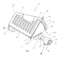
本発明の好適な実施形態による外部空気量調整機構を備える救急蘇生装置を、添付の図面、図1〜図17を参照して詳細に説明する。蘇生装置10は、じゃばらのように枢動自在に連結された上部プレートと底部プレートとを有するハウジング20と、ハウジング20の内部と流体連通する流入口50および流出口60と、容積調整プレート30と、容積制御アーム38と、容積制御フランジ40とを含み、流出口60から放出される空気量は外部設定により調整可能である。
A resuscitation device having an external air amount adjusting mechanism according to a preferred embodiment of the present invention will be described in detail with reference to the accompanying drawings and FIGS. The
本出願で使用する用語を定義すると、「底部プレート」は硬質の底面を指し、「上部プレート」は硬質の上面を指す。言い換えれば、硬質表面は、製造過程で用いられた型や素材に基づいた硬質特性を有する。 To define the terms used in this application, "bottom plate" refers to the rigid bottom surface and "top plate" refers to the rigid top surface. In other words, the hard surface has hard properties based on the mold and material used in the manufacturing process.
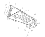
ハウジング20は、流入口50を通して外気を内部空間に吸入し、枢動自在に連結された上部プレートおよび底部プレートを操作することより流出口60を通して内部空間から空気を強制的に押し出すように構成されることから、じゃばらと言及される場合もある。さらに、じゃばらまたはハウジングは、プリーツ型バッグの構成を含む(図16)。より具体的には、ハウジング20は略平面構造の底部プレート22と、略平面構造の上部プレート24とを含む。各プレートは一対の細長い対向する側縁部を含む。底部プレート22および上部プレートの対応する近位側縁部は互いに枢動自在に連結されている。好ましくは、枢動連結部は一体成形型または融合された背部(spine)26であってもよいが、一体成形ヒンジ、従来のヒンジや他の枢動連結技術であってもよい。
The
可撓性があり、選択的に圧縮可能なじゃばら壁部27は底部プレート22および上部プレート24のそれぞれの遠位側縁部に結合され、それらの間に延在している(図2a)。同様に、可撓構造をもつ第1の端壁28および第2の端壁29は、底部プレート22および上部プレート24の後縁部23と前縁部25との間に延在する(参照番号23は底部プレート22と上部プレート24の両方の後縁部を示すのに使用される。参照番号25は底部プレート22と上部プレート24の両方の前縁部を示すのに使用される)。折り畳み式の構造体は、アコーディオン状またはプリートの態様で折り畳まれる形状であってもよい。以下に詳細に説明するように、底部プレート22、上部プレート24、じゃばら壁部27、第1の端壁28、および第2の端壁29は、選択的に外気量を受け取ることができるハウジング20の内部領域を画定する。
Flexible, selectively
一体成形背部26などの、底部プレート22および上部プレート24の近位側縁部の間の枢動連結部により仮想水平軸が画定され、上部プレート24は、当該仮想水平軸の周りを底部プレート22に対して開放形態と閉鎖形態との間で枢動自在である。後述する容積制御アーム38および容積制御フランジ40の制御に従い、上部プレート24は、完全開放形態(図1)および完全閉鎖形態(図6a)との間で動作することができる。以下説明するように、上部プレート24が完全開放形態の方向に移動できる最大の角度は、容積制御アーム38の選択された位置によって変わることが理解できる。
A pivotal connection between the bottom edge of the
上部プレート24が底部プレート22の方向に枢動すると、可撓性じゃばら壁部27、第1の端壁28、および第2の端壁29はアコーディオン状または折りたたみ可能な態様で折りたたまれる。流入口50は動作可能に第1の端壁28に隣接してハウジング20に連結されており、それによってハウジング20の外側の外気およびハウジング20の内側領域に流体連通するようになっている。1実施形態では、底部プレート22は、第1の端壁28に隣接する流入開口部52を画定し、この流入開口部52は流入チャンバ54と連通している(図14)。流入口50は、ハウジング20の外部にある入口と流入チャンバ54と連通する出口とを備える流入導管56を含む。上部プレート24が底部プレート22の上方、または底部プレート22から離れる方向に移動する際に、流入開口部52を通して外気が流入チャンバ54と内部空間に吸入される。さらに、補足的な酸素連結口57が流入導管56に隣接して含まれてもよく、この酸素連結口は富化酸素がハウジング20の内部領域に送達され、最終的には患者へ送達されることが可能となるように構成されている。
As the
同様に、底部プレート22は、第2の端壁29と隣接し、流出チャンバ64と連通する流出開口部62を画定する(図14)。流出口60は流出導管66を含み、流出チャンバ64と連通する。上部プレート24が底部プレート22向かって下方に移動する際に、ハウジング20の内部領域の空気が強制的に流出チャンバ64を通って流出導管66に押し出される。流出導管66は、マスクやチューブなどのデバイスに挿入されるように構成された患者用連結口70と接続されてもよく、それにより、空気または酸素が救急呼吸補助が必要な患者に供給される。この構造については、以下さらに詳細に説明する。
Similarly, the
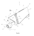
容積調整プレート30はハウジング20、好ましくは底部プレート22に連結され、第2の端壁29隣接して直立形態で延在する。容積調整プレート30はハウジング20の外側に配置され、これにより、上部プレート24が底部プレート22に対して圧縮されるたびに流出口60を介して放出される望ましい空気量を使用者が容易に選択することが可能となる。容積調整プレート30は、間隔を置いて配置された複数の容積選択部32を含み、各容積選択部32は選択される構造を有し、結果として、放出される空気量を制限する。容積調整プレート30は、外側に延びる凸形状を有してもよい。
The
1実施形態では、容積調整プレート30は、外周に沿って間隔を置いて配置された複数の孔部36を画定する。特定の空気量を示す印34は容積調整プレート30の表面に刻印されている。容積制御アーム38は、底部プレート22の枢動点21においてハウジング20に枢動自在に連結され、かつ容積調整プレート30に動作可能に連結されており、複数の容積選択部32の間で移動可能であり、選択された容積選択部32に連結されるように構成されている。容積制御アーム38はつまみまたは取っ手のような形態の平面構造を有していてもよい(中間部分38a)。容積制御アーム38は突起部39として言及する取り付け部材を含み、この突起部39は容積調整プレート30の選択孔部部36へ、選択的に受容されることのできる構造を有する。突起部39が選択孔部部36に係合した状態では、容積制御アーム38は静止状態に保持される。容積制御アーム38は半可撓性材料から作製され、ある程度屈曲させることができるため、突起部39は孔部部36から係合解除され、容積制御アーム38は容積調整プレート30に沿って別の選択位置に自在に動くことができる。容積制御アーム38はポリプロピレンプラスチックのような半硬質材料から作製されるのが好ましいが、アルミニウムやばね鋼などの金属材料でも機能する。
In one embodiment, the
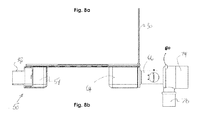
容積制御フランジ40は容積制御アーム38の上部に連結されている。容積制御フランジ40は、少なくとも一点で、上部プレート24の前縁部と共通する垂直面に設置されることで、上部プレート24の上方向への移動を阻止する。換言すると、容積制御フランジ40はハウジング20の上部プレート24の上方向の移動に対する"停止部"である。例えば、上述したように、容積制御アーム38が500ml(図5a)に設定され、上部プレート24が完全開放形態の方向に向かって上方に移動する場合、容積制御フランジ40は、上部プレート24の前縁部25と当該2つの構成要素が共通垂直面を共有する位置で接触する。そのため、上部プレート24のさらなる上方向への移動は阻止される。対照的に、容積制御フランジ40は前記上部プレート24が完全閉鎖形態の方向に向う、底部プレート22に対して下方向の移動については阻止しない(図6a)。
The
容積制御アーム38と容積制御フランジ40の上部は単一または一体化した構造をもつことが理解される(図2c)。さらに、容積制御フランジ40は、細長い直線形状を有し、容積制御プレート30の内側表面とハウジング20の第2の端壁29との間に配置された、容積制御アーム38の上部42に連結されている。容積制御フランジ40は逆L字形状を有し、上部プレート24の前縁部25を受容し、上部プレート24が、容積制御アーム38が設定された位置を超えて上方向に移動することを阻止するように構成されている。それにより、患者の肺の過膨張が回避される。容積制御アーム38はまた、中間部38aに連結された近位端部を有する下方部44を含む。つまり、下方部44は、容積調整プレート30の外周縁部の周りを覆うまたは屈曲した態様で囲む屈曲形状を有する延長部を含む。容積制御アーム38の下方部44の延長部は、容積調整プレート30の前面と隣接するように設けられ、その遠位端部は、容積制御アーム38が操作される際に、容積調整プレート30の外周縁部に沿って、容積制御アーム38を案内するように構成されている。容積調整プレート30、容積制御アーム38、および容積制御フランジ40は共に、容積制御アセンブリと言及される場合がある。
It can be seen that the
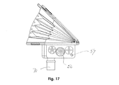
ここで、様々な構成要素の幾何学形状と位置に注目すると、流入口50および流出口60の各導管は仮想長手軸を画定し、各軸は互いに平行である(図7a)。上部プレート24の近位側縁部もまた流入導管、流出導管のそれぞれと平行である。対照的に、第1の端壁28、第2の端壁29、容積制御プレート30は、流入導管および流出導管の長手軸に対して垂直に設けられている。これにより、じゃばら(ハウジング)は、流入口50と流出口60に対して側面方向から操作することができる。蘇生装置10の操作者は、上部プレート24を繰り返し押して操作する際に、じゃばら壁部27に近接して立つことが好ましい。上部プレート24と底部プレート22の両方の外部表面は複数の凹部または凹凸部を有してもよく、それにより使用中に利用者の握りやすさが向上し、人間工学的である。
Turning now to the geometry and location of the various components, each conduit of
別の態様では、患者用連結口70が流出口60の流出導管66から下方向に延在し、上記長手軸に対して垂直に設けられている。患者用連結口70は、マスクやチューブなどのようなデバイスに挿入するのに適した構造を有し、それにより、空気または酸素を医療患者に供給することができる。つまり、内部領域から外側に押し出された空気は、患者用連結口70を介して伝達され、最終的に患者の気道に送達される。
In another aspect, a
さらに、流出口60は付属連結口72を含む。付属連結口72は流出導管66、および流出口60により画定された長手軸と一直線上に配置されるのが好ましい。付属連結口72は、第1の直径を有し、一つの付属品を受容する第1のアダプタリング74と、第1の直径とは異なる第2の直径を有し、第2の付属品を受容する第2のアダプタリング76とを含む。第1および第2のアダプタリングは、同心円状に配置されるのが好ましい(図1)。例えば、付属品は、二酸化炭素を測定するデバイス、または呼気終末陽圧を提供するデバイスを含でもよい。
Further, the
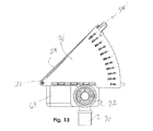
さらに、圧力逃がし弁78および当該圧力逃がし弁78に動作可能に連結された圧力無効化アーム79は、流出口60の流出導管66上に配置される。それに加え、圧力計連結口80は流出導管66から延在し、圧力計(図示せず)が流出口60に連結されて、流出導管66を介して患者に送達される空気の圧力を監視するように構成されている。
Further, a pressure relief valve 78 and a
容積調整プレート30'および容積制御アーム38'の代替設計を図14〜図15cに示す。主な番号は、前述したものと異なる構造を示すのに使われている。この実施形態では、容積調整プレート30'の内部表面は、制御プレート30'によって複数の溝部37、歯、ノッチ、または凹部として画定される複数の容積選択部32'を含む。これに対応して、容積制御アーム38'は複数の歯39aを含み、歯39aは溝37の形状を補完する形状をもつ。容積制御アームを望ましい容積選択部32'の位置に位置決めする機能操作は、複数の孔部36に関して前述したものと実質的に同様であると理解される。この実施形態により、隣接した溝37の間の距離に応じて、選択容積に対してほとんど無限またはアナログ式の選択と調整が可能である。
An alternative design of the volume adjustment plate 30 'and the volume control arm 38' is shown in FIGS. The main numbers are used to indicate different structures than those described above. In this embodiment, the interior surface of the volume adjustment plate 30 'includes a plurality of volume selectors 32' defined by the control plate 30 'as a plurality of
使用に際して、救急蘇生装置10は、患者が呼吸の補助を必要としているとき、例えば、救急治療室や事故の現場などで、医療従事者によって使用される。患者のサイズに対して最も適切な空気量を提供する蘇生装置を複数の蘇生装置のなかから見つけて選択するよりも、本発明の蘇生装置10は利便性が高く、迅速に調整と設定を行うことができる。それにより、あらかじめ選択された正しい空気量が、上部プレート24が底部プレートに対して下方向に強く押圧されるごとに、流出口60を介して放出される。そして、上部プレート24がリセットされると、選択された量の外気が内部領域へ引き込まれる。前述したように、容積制御アーム38の突起部39を対応する孔部36に係合することにより、望ましい空気量が選択され、封じ込まれる。そして、ハウジング20の内部領域が空気で再充填されると容積制御フランジ40の上部42が上部プレート24の上方移動を阻止する。
In use, the
本発明の特定の形態を図示および説明してきたが、以下の特許請求項の範囲および特許請求項の範囲と機能的に均等と許容されるものに含まれない限り、これに限定されるものではないことを理解されたい。 While a particular form of the invention has been illustrated and described, it is not intended to be limited except as by the following claims and what is functionally equivalent and permitted to the scope of the claims. Please understand that there is no.
Claims (21)
ハウジングであって、対向する近位側縁部および遠位側縁部を有する底部プレートを含みかつ対向する近位側縁部および遠位側縁部を有する上部プレートを含むハウジングを有し、前記底部プレートおよび前記上部プレートの各近位側縁部は枢動自在に連結されかつ開放形態と閉鎖形態との間でアコーディオン状に選択的に移動自在である、前記ハウジングを有し;
前記ハウジングは、前記底部プレートおよび前記上部プレートの各前記遠位側縁部に連結されるじゃばら壁部と、前記底部プレートと前記上部プレートの後縁部および前縁部に連結される対向する第1および第2の各端壁とを含み、前記じゃばら壁部および前記第1および第2の各端壁は可撓性のある構造を備えるものであり、;
前記ハウジングは内部領域を画定するものである、
前記ハウジングと;
流入口であって、動作可能なように前記ハウジングに連結され、前記上部プレートが前記底部プレートから離れる方向に移動することにより前記ハウジングの外側の外気が前記内部領域に吸入されるように構成されているものである、前記流入口と;
流出口であって、動作可能なように前記ハウジングに連結され、前記上部プレートが前記底部プレートの方向へ移動することにより前記内部領域内の空気が当該内部領域から放出されるように構成されているものである、前記流出口と;
前記ハウジングに連結された容積調整プレートであって、前記第2の端壁の外側に隣接しかつ上方向に延在しており、複数の容積選択部を備えるものである、前記容積調節プレートと;
容積制御アームであって、前記調整プレートに操作自在なように連結される中間部を含み、前記容積選択部の間を移動自在であり、かつ選択的に容積選択部に連結される、前記容積制御アームと、
を有し、;
前記容積制御アームは、前記上部プレートの前記前縁部と共通する垂直面に配置された容積制御フランジを備える上方部を含み、前記上方部は、前記容積制御フランジが前記上部プレートの当該容積制御フランジを超える上方移動を阻止するように構成されているものである、
前記救急蘇生装置。 An emergency resuscitation device with an external air volume adjustment:
A housing comprising a bottom plate having opposing proximal and distal edges and a top plate having opposing proximal and distal edges; and Having the housing, wherein the bottom plate and each proximal edge of the top plate are pivotally connected and are selectively movable in an accordion-like manner between an open configuration and a closed configuration;
The housing includes a bellows wall connected to each of the distal edges of the bottom plate and the top plate, and an opposing first link connected to a rear edge and a front edge of the bottom plate and the top plate. And a first and second end wall, wherein the bellows wall and the first and second end walls have a flexible structure;
The housing defines an interior area;
Said housing;
An inlet, operably connected to the housing, wherein the top plate moves away from the bottom plate such that outside air outside the housing is drawn into the interior region. Said inlet;
An outlet, operably connected to the housing, wherein the top plate moves toward the bottom plate such that air in the interior region is discharged from the interior region. Said outlet;
A volume adjustment plate connected to the housing, the volume adjustment plate being adjacent to the outside of the second end wall and extending upward, and including a plurality of volume selection portions; ;
A volume control arm, comprising an intermediate portion operably connected to the adjustment plate, movable between the volume selectors, and selectively coupled to the volume selector. A control arm,
Having;
The volume control arm includes an upper portion having a volume control flange disposed on a vertical plane common to the leading edge of the upper plate, wherein the upper portion is configured such that the volume control flange controls the volume control of the upper plate. Is configured to prevent upward movement over the flange,
The emergency resuscitation device.
前記容積調整プレートは外周縁部を画定するものであり、
前記複数の容積選択部は、前記外周縁部に隣接しかつ前記外周縁部に沿って離間して前記容積調整プレートに形成された複数の孔部であり、
前記容積制御アームの前記中間部は、孔部のうちの1つに選択的に受容されるように構成された突起部を含み、これにより、前記容積調整プレートに対して前記容積制御アームが選択された位置に着脱自在に保持されるものである、
救急蘇生装置。 The emergency resuscitation device according to claim 1,
The volume adjustment plate defines an outer peripheral edge,
The plurality of volume selectors are a plurality of holes formed in the volume adjustment plate adjacent to the outer peripheral edge and separated along the outer peripheral edge,
The intermediate portion of the volume control arm includes a protrusion configured to be selectively received in one of the holes, whereby the volume control arm is selected relative to the volume adjustment plate. It is detachably held at the set position,
Emergency resuscitation equipment.
前記容積制御アームの前記上方部における前記容積制御フランジは長細い直線形状を有し、前記上部プレートの前縁部を選択的に受け入れて、前記上部プレートの前記容積制御アームによる設定位置を超える上方移動を阻止するように構成されているものであり、
前記容積制御アームの下方部は、前記中間部に連結されかつ前記中間部から外側に向かって延びる延長部を有する近位端部と、遠位端部であって、前記容積調整プレートの外周縁部に隣接した前面部に対して隣接する屈曲部を有する、前記遠位端部とを含むものである、
救急蘇生装置。 The emergency resuscitation device according to claim 2,
The volume control flange at the upper portion of the volume control arm has an elongated linear shape and selectively receives a leading edge of the upper plate and moves the upper plate above a position set by the volume control arm. Are configured to block movement,
A lower end of the volume control arm having a proximal end having an extension connected to the intermediate portion and extending outwardly from the intermediate portion; and a distal end, and an outer peripheral edge of the volume adjustment plate. The distal end having a bend adjacent to a front portion adjacent the portion.
Emergency resuscitation equipment.
前記上部プレートの前記対向する側縁部は各長手軸に対して平行であり、前記容積調整プレートは各長手軸に対して垂直に設けられており、前記上部プレートは使用時に側面方向下向きに操作されるものである、
救急蘇生装置。 2. The resuscitation device according to claim 1, wherein the inlet and the outlet each define a virtual longitudinal axis, wherein each longitudinal axis is parallel to each other;
The opposed side edges of the upper plate are parallel to each longitudinal axis, the volume adjustment plates are provided perpendicular to each longitudinal axis, and the upper plate is operated sideways downward in use. Is to be
Emergency resuscitation equipment.
前記流出口と流体連通しかつ前記流出口と一直線上にある付属連結口を有し、
前記付属連結口は、第1の直径を有する第1のアダプタリングと、当該第1のアダプタリングの第1の直径とは異なる第2の直径を有する第2のアダプタリングとを含み、
前記第1および第2のアダプタリングは同心上に配置されるものである、
救急蘇生装置。 The resuscitation device according to claim 11, further comprising:
Having an attached connection port in fluid communication with the outlet and in line with the outlet,
The accessory connection port includes a first adapter ring having a first diameter, and a second adapter ring having a second diameter different from the first diameter of the first adapter ring,
The first and second adapter rings are arranged concentrically;
Emergency resuscitation equipment.
前記流入口は、前記第1の端壁に近接した位置において前記ハウジングに動作可能に連結され、前記ハウジングの前記内部領域および当該内部領域の外側の空気と流体連通しており、それにより、前記上部プレートが前記底部プレートから離れる方向に移動する際に外気が当該内部領域内に吸入されるように構成されているものであり、
前記流出口は、前記第2の端壁に近接した位置において前記ハウジングに動作可能に連結され、前記ハウジングの前記内部領域と流体連通しているものであり、それにより、前記上部プレートが前記底部プレートに近づく方向に移動する際に前記内部領域内の空気が前記内部領域から放出されるように構成されているものである、
救急蘇生装置。 The emergency resuscitation device according to claim 1,
The inlet is operatively connected to the housing at a position proximate to the first end wall and is in fluid communication with the interior region of the housing and air outside the interior region, whereby the When the top plate moves in a direction away from the bottom plate, the outside air is configured to be sucked into the internal region,
The outlet is operatively connected to the housing at a position proximate to the second end wall and is in fluid communication with the interior region of the housing, such that the top plate is connected to the bottom portion. When moving in a direction approaching the plate, the air in the internal region is configured to be released from the internal region,
Emergency resuscitation equipment.
前記容積調整プレートは外周縁部を画定し、
前記複数の容積選択部は、前記外周縁部に隣接しかつ前記外周縁部に沿って離間して前記容積調整プレートの内面に形成された複数の溝部であり、
前記容積制御アームは、各溝部に対する補完形状を有しかつ溝部のうちの1つに選択的に受容されるように構成された複数の歯を含んでおり、これにより、前記容積制御アームが選択された位置で着脱自在に保持されるものである、
救急蘇生装置。 The emergency resuscitation device according to claim 1,
The volume adjustment plate defines an outer peripheral edge;
The plurality of volume selectors are a plurality of grooves formed on the inner surface of the volume adjustment plate adjacent to the outer peripheral edge and separated along the outer peripheral edge,
The volume control arm includes a plurality of teeth having complementary shapes for each groove and configured to be selectively received in one of the grooves, whereby the volume control arm is selected. It is held detachably at the set position,
Emergency resuscitation equipment.
前記容積制御アームの前記上方部における前記容積制御フランジは長細い直線形状を有し、前記上部プレートの前縁部を選択的に受け入れて、前記上部プレートの前記容積制御アームによる設定位置を超える上方移動を阻止するように構成されているものであり、
前記容積制御アームは、前記中間部に連結されかつ前記中間部から外側に向かって延びる延長部を有する近位端部と、遠位端部であって、前記容積調整プレートの外周縁部に隣接した前面部に対して隣接する屈曲部を有する、前記遠位端部とを有する下方部を含むものである、
救急蘇生装置。 The resuscitation device according to claim 16,
The volume control flange at the upper portion of the volume control arm has an elongated linear shape and selectively receives a leading edge of the upper plate and moves the upper plate above a position set by the volume control arm. Are configured to block movement,
The volume control arm has a proximal end coupled to the intermediate portion and having an extension extending outwardly from the intermediate portion, and a distal end adjacent an outer peripheral edge of the volume adjustment plate. Comprising a lower portion having a distal end and a bent portion adjacent to the front portion.
Emergency resuscitation equipment.
ハウジングであって、対向する近位側縁部および遠位側縁部を有する底部プレートを含みかつ対向する近位側縁部および遠位側縁部を有する上部プレートを含むハウジングを有し、前記底部プレートおよび前記上部プレートの各近位側縁部は枢動自在に連結されかつ開放形態と閉鎖形態との間でアコーディオン状に選択的に移動自在である、前記ハウジングを有し;
前記ハウジングは、前記底部プレートおよび前記上部プレートの各前記遠位側縁部に連結されるじゃばら壁部と、前記底部プレートと前記上部プレートの後縁部および前縁部に連結される対向する第1および第2の各端壁とを含み、前記じゃばら壁部および前記第1および第2の各端壁は可撓性のある構造を備えるものであり、;
前記ハウジングは外気を受容可能な前記内部領域を画定するものである、
前記ハウジングと;
流入口であって、動作可能なように前記ハウジングに連結され、前記上部プレートが前記底部プレートから離れる方向に移動することにより前記ハウジングの外側の外気が前記内部領域に吸入されるように構成されているものである、前記流入口と;
流出口であって、動作可能なように前記ハウジングに連結され、前記上部プレートが前記底部プレートの方向へ移動することにより前記内部領域内の空気が当該内部領域から放出されるように構成されているものである、前記流出口と;
容積調整アセンブリであって、前記ハウジングの前記第2の端壁に隣接した外面に操作自在に連結され、複数の容積選択部と各容積選択部に選択的に連結される容積制御アームとを備える前記容積調整プレートを含み、これにより、前記内部領域から放出される最大空気量を選択することができるものである、前記容積調整アセンブリと
を有する救急蘇生装置。 An emergency resuscitation device with an external air volume adjustment:
A housing comprising a bottom plate having opposing proximal and distal edges and a top plate having opposing proximal and distal edges; and Having the housing, wherein the bottom plate and each proximal edge of the top plate are pivotally connected and are selectively movable in an accordion-like manner between an open configuration and a closed configuration;
The housing includes a bellows wall connected to each of the distal edges of the bottom plate and the top plate, and an opposing first link connected to a rear edge and a front edge of the bottom plate and the top plate. And a first and second end wall, wherein the bellows wall and the first and second end walls have a flexible structure;
The housing defines the interior region capable of receiving outside air;
Said housing;
An inlet, operably connected to the housing, wherein the top plate moves away from the bottom plate such that outside air outside the housing is drawn into the interior region. Said inlet;
An outlet, operably connected to the housing, wherein the top plate moves toward the bottom plate such that air in the interior region is discharged from the interior region. Said outlet;
A volume adjustment assembly operably connected to an outer surface of the housing adjacent the second end wall, the volume adjustment assembly including a plurality of volume selectors and a volume control arm selectively coupled to each volume selector. An emergency resuscitation device comprising: the volume adjustment plate, wherein the volume adjustment assembly is adapted to select a maximum amount of air discharged from the interior region.
前記容積調整プレートは外周縁部を含み、前記複数の容積選択部は前記外周縁部に沿って離間して形成された複数の孔部であり、
前記容積制御アームは、孔部のうちの1つに選択的に受容されるように構成された突起部を含み、これにより、前記容積制御アームが選択された位置に着脱自在に保持されるものである、
救急蘇生装置。 The emergency resuscitation device according to claim 18,
The volume adjustment plate includes an outer peripheral edge, and the plurality of volume selectors are a plurality of holes formed separately along the outer peripheral edge,
The volume control arm includes a protrusion configured to be selectively received in one of the holes, whereby the volume control arm is removably held at a selected position. Is,
Emergency resuscitation equipment.
前記容積調整アセンブリは、前記容積制御アームに連結された容積制御フランジを有し、
前記容積制御フランジは、前記上部プレートの前縁部と共通の垂直面に配置されており、それにより、前記上部プレートの前記容積制御フランジの配置位置を超える上方移動が阻止されるものである、救急蘇生装置。 The emergency resuscitation device according to claim 18,
The volume adjustment assembly has a volume control flange coupled to the volume control arm;
The volume control flange is disposed on a common vertical plane with a front edge of the upper plate, thereby preventing upward movement of the upper plate beyond a position where the volume control flange is disposed. Emergency resuscitation equipment.
容積制御フランジを含む上方部であって、当該容積制御フランジは、長細い直線形状を有し、前記上部プレートの前縁部を選択的に受け入れて前記上部プレートの前記容積制御アームによるそれぞれの選択位置を超える上方移動を阻止するように構成されているものである、前記上方部と、
外側に向かって延びる延長部と、前記容積調整プレートの外周縁部を取り囲み、前記容積制御アームが移動する際に当該アームを当該外周縁部に沿って案内する屈曲形状部とを有する下方部と
を含むものである、救急蘇生装置。 The emergency resuscitation device according to claim 20, wherein the volume control arm comprises:
An upper portion including a volume control flange, wherein the volume control flange has an elongated linear shape, and selectively receives a leading edge of the upper plate to select each of the upper plates by the volume control arm. Said upper portion being configured to prevent upward movement beyond the position,
An extension extending outwardly, and a lower portion surrounding the outer peripheral edge of the volume adjustment plate, and having a bent portion guiding the arm along the outer peripheral edge when the volume control arm moves. An emergency resuscitation device.
Applications Claiming Priority (3)
| Application Number | Priority Date | Filing Date | Title |
|---|---|---|---|
| US15/411,697 US9861775B1 (en) | 2017-01-20 | 2017-01-20 | Emergency resuscitation apparatus with external volume control |
| US15/411,697 | 2017-01-20 | ||
| PCT/US2017/041342 WO2018136112A1 (en) | 2017-01-20 | 2017-07-10 | Emergency resuscitation apparatus with external volume control |
Publications (2)
| Publication Number | Publication Date |
|---|---|
| JP2020503985A true JP2020503985A (en) | 2020-02-06 |
| JP2020503985A5 JP2020503985A5 (en) | 2020-08-20 |
Family
ID=60813402
Family Applications (1)
| Application Number | Title | Priority Date | Filing Date |
|---|---|---|---|
| JP2019539994A Pending JP2020503985A (en) | 2017-01-20 | 2017-07-10 | Emergency resuscitation device with external volume adjustment |
Country Status (6)
| Country | Link |
|---|---|
| US (1) | US9861775B1 (en) |
| EP (1) | EP3570919A4 (en) |
| JP (1) | JP2020503985A (en) |
| AU (1) | AU2017395011B2 (en) |
| CA (1) | CA3050634A1 (en) |
| WO (1) | WO2018136112A1 (en) |
Families Citing this family (11)
| Publication number | Priority date | Publication date | Assignee | Title |
|---|---|---|---|---|
| CN112546373A (en) * | 2018-07-05 | 2021-03-26 | 高翰哲 | Simple breathing method capable of adjusting air blowing depth |
| US11219738B2 (en) * | 2018-09-11 | 2022-01-11 | Care 2 Innovations Inc. | Adjustable resuscitation device and method for using the same |
| US11224707B2 (en) * | 2018-09-11 | 2022-01-18 | Care 2 Innovations Inc. | Adjustable resuscitation device and method for using the same |
| USD952857S1 (en) | 2019-05-03 | 2022-05-24 | Compact Medical Solutions, Llc | Respiratory assisting device with an expandable bag |
| US10960172B2 (en) * | 2019-05-03 | 2021-03-30 | Compact Medical Solutions, Llc | Bag and valve for advanced respiratory support |
| US11179529B2 (en) | 2019-05-03 | 2021-11-23 | Compact Medical Solutions Llc | Bag and valve for advanced respiratory support |
| US20210016034A1 (en) * | 2019-07-17 | 2021-01-21 | Steve Islava | Apparatus for Adjusting the Tidal Volume Delivered by a Resuscitation Bag and Methods for Using the Same |
| CA3176721A1 (en) * | 2020-03-30 | 2021-10-07 | Airmid Critical Care Products, Inc. | Apparatus and method for convertible volume and pressure-controlled lung-protective ventilation |
| WO2022203676A1 (en) * | 2021-03-25 | 2022-09-29 | Compact Medical Solutions, Llc | Bag and valve for advanced respiratory support |
| US11420010B1 (en) * | 2021-10-01 | 2022-08-23 | Compact Medical Inc. | Bag and valve for advanced respiratory support |
| CA3233561A1 (en) * | 2021-10-01 | 2023-04-06 | Jonathan Merrell | Bag and valve for advanced respiratory support |
Citations (2)
| Publication number | Priority date | Publication date | Assignee | Title |
|---|---|---|---|---|
| US3890967A (en) * | 1973-10-17 | 1975-06-24 | James O Elam | Breathing indicator and ventilator |
| US20140318544A1 (en) * | 2012-01-27 | 2014-10-30 | Combat Madical Systems, LLC | Resuscitator device |
Family Cites Families (11)
| Publication number | Priority date | Publication date | Assignee | Title |
|---|---|---|---|---|
| GB1592548A (en) * | 1977-09-30 | 1981-07-08 | Nat Res Dev | Medical ventilation apparatus |
| US4898166A (en) | 1988-04-14 | 1990-02-06 | Physician Engineered Products, Inc. | Resuscitation bag control apparatus |
| JPH03140165A (en) * | 1989-10-20 | 1991-06-14 | California Medical Prod Inc | Analeptic device |
| SE465704B (en) * | 1990-06-11 | 1991-10-21 | Hans Aake Stoeoep | PUMP TYPE PUMP DEVICE, INTENDED FOR ARTIFICIAL INHALATION |
| US5711295A (en) | 1996-04-19 | 1998-01-27 | Harris, Ii; Robert E. | Resuscitation device |
| US6155257A (en) | 1998-10-07 | 2000-12-05 | Cprx Llc | Cardiopulmonary resuscitation ventilator and methods |
| US7121279B2 (en) * | 2002-01-08 | 2006-10-17 | Dennis Carnell K | Respiratory mask |
| US7658188B2 (en) | 2005-06-06 | 2010-02-09 | Artivent Corporation | Volume-adjustable manual ventilation device |
| US8235043B2 (en) | 2007-12-06 | 2012-08-07 | Artivent Corporation | Volume adjustable manual ventilation device |
| JP5189166B2 (en) | 2007-09-07 | 2013-04-24 | ゲイルメッド コーポレーション | Volume adjustable manual resuscitation bag assembly |
| US8936024B2 (en) | 2009-04-16 | 2015-01-20 | Richard S. Pearce | Manual emergency resuscitator with pre-defined volume control |
-
2017
- 2017-01-20 US US15/411,697 patent/US9861775B1/en active Active
- 2017-07-10 JP JP2019539994A patent/JP2020503985A/en active Pending
- 2017-07-10 AU AU2017395011A patent/AU2017395011B2/en not_active Expired - Fee Related
- 2017-07-10 EP EP17893135.8A patent/EP3570919A4/en not_active Withdrawn
- 2017-07-10 WO PCT/US2017/041342 patent/WO2018136112A1/en unknown
- 2017-07-10 CA CA3050634A patent/CA3050634A1/en not_active Abandoned
Patent Citations (2)
| Publication number | Priority date | Publication date | Assignee | Title |
|---|---|---|---|---|
| US3890967A (en) * | 1973-10-17 | 1975-06-24 | James O Elam | Breathing indicator and ventilator |
| US20140318544A1 (en) * | 2012-01-27 | 2014-10-30 | Combat Madical Systems, LLC | Resuscitator device |
Also Published As
| Publication number | Publication date |
|---|---|
| AU2017395011B2 (en) | 2020-12-10 |
| CA3050634A1 (en) | 2018-07-26 |
| EP3570919A1 (en) | 2019-11-27 |
| EP3570919A4 (en) | 2020-10-28 |
| US9861775B1 (en) | 2018-01-09 |
| WO2018136112A1 (en) | 2018-07-26 |
| AU2017395011A1 (en) | 2019-08-01 |
Similar Documents
| Publication | Publication Date | Title |
|---|---|---|
| JP2020503985A (en) | Emergency resuscitation device with external volume adjustment | |
| US20210030983A1 (en) | Volume-adjustable manual ventilation device | |
| JP7334210B2 (en) | respiratory aid | |
| EP2190511B1 (en) | Adjustable volume manual resuscitation bag assembly | |
| US7658188B2 (en) | Volume-adjustable manual ventilation device | |
| KR101403658B1 (en) | Suction catheter for surgical | |
| US11179529B2 (en) | Bag and valve for advanced respiratory support | |
| US10842959B2 (en) | Foot pedal | |
| US11420010B1 (en) | Bag and valve for advanced respiratory support | |
| WO2022244009A1 (en) | Respiratory support device and cartridge for use therewith | |
| JP2022098193A (en) | Nebulizer kit and nebulizer |
Legal Events
| Date | Code | Title | Description |
|---|---|---|---|
| A521 | Request for written amendment filed |
Free format text: JAPANESE INTERMEDIATE CODE: A523 Effective date: 20200708 |
|
| A621 | Written request for application examination |
Free format text: JAPANESE INTERMEDIATE CODE: A621 Effective date: 20200708 |
|
| A977 | Report on retrieval |
Free format text: JAPANESE INTERMEDIATE CODE: A971007 Effective date: 20210430 |
|
| A131 | Notification of reasons for refusal |
Free format text: JAPANESE INTERMEDIATE CODE: A131 Effective date: 20210601 |
|
| A02 | Decision of refusal |
Free format text: JAPANESE INTERMEDIATE CODE: A02 Effective date: 20220201 |