JP2020201698A - Portable information device and display assembly - Google Patents
Portable information device and display assembly Download PDFInfo
- Publication number
- JP2020201698A JP2020201698A JP2019107891A JP2019107891A JP2020201698A JP 2020201698 A JP2020201698 A JP 2020201698A JP 2019107891 A JP2019107891 A JP 2019107891A JP 2019107891 A JP2019107891 A JP 2019107891A JP 2020201698 A JP2020201698 A JP 2020201698A
- Authority
- JP
- Japan
- Prior art keywords
- sheet
- layer portion
- portable information
- display
- information device
- Prior art date
- Legal status (The legal status is an assumption and is not a legal conclusion. Google has not performed a legal analysis and makes no representation as to the accuracy of the status listed.)
- Pending
Links
Images


Classifications
-
- G—PHYSICS
- G02—OPTICS
- G02F—OPTICAL DEVICES OR ARRANGEMENTS FOR THE CONTROL OF LIGHT BY MODIFICATION OF THE OPTICAL PROPERTIES OF THE MEDIA OF THE ELEMENTS INVOLVED THEREIN; NON-LINEAR OPTICS; FREQUENCY-CHANGING OF LIGHT; OPTICAL LOGIC ELEMENTS; OPTICAL ANALOGUE/DIGITAL CONVERTERS
- G02F1/00—Devices or arrangements for the control of the intensity, colour, phase, polarisation or direction of light arriving from an independent light source, e.g. switching, gating or modulating; Non-linear optics
- G02F1/01—Devices or arrangements for the control of the intensity, colour, phase, polarisation or direction of light arriving from an independent light source, e.g. switching, gating or modulating; Non-linear optics for the control of the intensity, phase, polarisation or colour
- G02F1/0102—Constructional details, not otherwise provided for in this subclass
-
- G—PHYSICS
- G06—COMPUTING; CALCULATING OR COUNTING
- G06F—ELECTRIC DIGITAL DATA PROCESSING
- G06F1/00—Details not covered by groups G06F3/00 - G06F13/00 and G06F21/00
- G06F1/16—Constructional details or arrangements
- G06F1/1613—Constructional details or arrangements for portable computers
- G06F1/1633—Constructional details or arrangements of portable computers not specific to the type of enclosures covered by groups G06F1/1615 - G06F1/1626
- G06F1/1637—Details related to the display arrangement, including those related to the mounting of the display in the housing
- G06F1/1643—Details related to the display arrangement, including those related to the mounting of the display in the housing the display being associated to a digitizer, e.g. laptops that can be used as penpads
-
- H—ELECTRICITY
- H05—ELECTRIC TECHNIQUES NOT OTHERWISE PROVIDED FOR
- H05K—PRINTED CIRCUITS; CASINGS OR CONSTRUCTIONAL DETAILS OF ELECTRIC APPARATUS; MANUFACTURE OF ASSEMBLAGES OF ELECTRICAL COMPONENTS
- H05K5/00—Casings, cabinets or drawers for electric apparatus
- H05K5/0017—Casings, cabinets or drawers for electric apparatus with operator interface units
-
- G—PHYSICS
- G02—OPTICS
- G02F—OPTICAL DEVICES OR ARRANGEMENTS FOR THE CONTROL OF LIGHT BY MODIFICATION OF THE OPTICAL PROPERTIES OF THE MEDIA OF THE ELEMENTS INVOLVED THEREIN; NON-LINEAR OPTICS; FREQUENCY-CHANGING OF LIGHT; OPTICAL LOGIC ELEMENTS; OPTICAL ANALOGUE/DIGITAL CONVERTERS
- G02F1/00—Devices or arrangements for the control of the intensity, colour, phase, polarisation or direction of light arriving from an independent light source, e.g. switching, gating or modulating; Non-linear optics
- G02F1/01—Devices or arrangements for the control of the intensity, colour, phase, polarisation or direction of light arriving from an independent light source, e.g. switching, gating or modulating; Non-linear optics for the control of the intensity, phase, polarisation or colour
- G02F1/13—Devices or arrangements for the control of the intensity, colour, phase, polarisation or direction of light arriving from an independent light source, e.g. switching, gating or modulating; Non-linear optics for the control of the intensity, phase, polarisation or colour based on liquid crystals, e.g. single liquid crystal display cells
- G02F1/133—Constructional arrangements; Operation of liquid crystal cells; Circuit arrangements
- G02F1/1333—Constructional arrangements; Manufacturing methods
- G02F1/133305—Flexible substrates, e.g. plastics, organic film
-
- G—PHYSICS
- G02—OPTICS
- G02F—OPTICAL DEVICES OR ARRANGEMENTS FOR THE CONTROL OF LIGHT BY MODIFICATION OF THE OPTICAL PROPERTIES OF THE MEDIA OF THE ELEMENTS INVOLVED THEREIN; NON-LINEAR OPTICS; FREQUENCY-CHANGING OF LIGHT; OPTICAL LOGIC ELEMENTS; OPTICAL ANALOGUE/DIGITAL CONVERTERS
- G02F1/00—Devices or arrangements for the control of the intensity, colour, phase, polarisation or direction of light arriving from an independent light source, e.g. switching, gating or modulating; Non-linear optics
- G02F1/01—Devices or arrangements for the control of the intensity, colour, phase, polarisation or direction of light arriving from an independent light source, e.g. switching, gating or modulating; Non-linear optics for the control of the intensity, phase, polarisation or colour
- G02F1/165—Devices or arrangements for the control of the intensity, colour, phase, polarisation or direction of light arriving from an independent light source, e.g. switching, gating or modulating; Non-linear optics for the control of the intensity, phase, polarisation or colour based on translational movement of particles in a fluid under the influence of an applied field
- G02F1/1675—Constructional details
-
- G—PHYSICS
- G06—COMPUTING; CALCULATING OR COUNTING
- G06F—ELECTRIC DIGITAL DATA PROCESSING
- G06F1/00—Details not covered by groups G06F3/00 - G06F13/00 and G06F21/00
- G06F1/16—Constructional details or arrangements
- G06F1/1613—Constructional details or arrangements for portable computers
- G06F1/1615—Constructional details or arrangements for portable computers with several enclosures having relative motions, each enclosure supporting at least one I/O or computing function
- G06F1/1616—Constructional details or arrangements for portable computers with several enclosures having relative motions, each enclosure supporting at least one I/O or computing function with folding flat displays, e.g. laptop computers or notebooks having a clamshell configuration, with body parts pivoting to an open position around an axis parallel to the plane they define in closed position
-
- G—PHYSICS
- G06—COMPUTING; CALCULATING OR COUNTING
- G06F—ELECTRIC DIGITAL DATA PROCESSING
- G06F1/00—Details not covered by groups G06F3/00 - G06F13/00 and G06F21/00
- G06F1/16—Constructional details or arrangements
- G06F1/1613—Constructional details or arrangements for portable computers
- G06F1/1626—Constructional details or arrangements for portable computers with a single-body enclosure integrating a flat display, e.g. Personal Digital Assistants [PDAs]
-
- G—PHYSICS
- G06—COMPUTING; CALCULATING OR COUNTING
- G06F—ELECTRIC DIGITAL DATA PROCESSING
- G06F1/00—Details not covered by groups G06F3/00 - G06F13/00 and G06F21/00
- G06F1/16—Constructional details or arrangements
- G06F1/1613—Constructional details or arrangements for portable computers
- G06F1/1633—Constructional details or arrangements of portable computers not specific to the type of enclosures covered by groups G06F1/1615 - G06F1/1626
- G06F1/1637—Details related to the display arrangement, including those related to the mounting of the display in the housing
- G06F1/1641—Details related to the display arrangement, including those related to the mounting of the display in the housing the display being formed by a plurality of foldable display components
-
- G—PHYSICS
- G06—COMPUTING; CALCULATING OR COUNTING
- G06F—ELECTRIC DIGITAL DATA PROCESSING
- G06F1/00—Details not covered by groups G06F3/00 - G06F13/00 and G06F21/00
- G06F1/16—Constructional details or arrangements
- G06F1/1613—Constructional details or arrangements for portable computers
- G06F1/1633—Constructional details or arrangements of portable computers not specific to the type of enclosures covered by groups G06F1/1615 - G06F1/1626
- G06F1/1637—Details related to the display arrangement, including those related to the mounting of the display in the housing
- G06F1/1652—Details related to the display arrangement, including those related to the mounting of the display in the housing the display being flexible, e.g. mimicking a sheet of paper, or rollable
-
- G—PHYSICS
- G06—COMPUTING; CALCULATING OR COUNTING
- G06F—ELECTRIC DIGITAL DATA PROCESSING
- G06F1/00—Details not covered by groups G06F3/00 - G06F13/00 and G06F21/00
- G06F1/16—Constructional details or arrangements
- G06F1/1613—Constructional details or arrangements for portable computers
- G06F1/1633—Constructional details or arrangements of portable computers not specific to the type of enclosures covered by groups G06F1/1615 - G06F1/1626
- G06F1/1656—Details related to functional adaptations of the enclosure, e.g. to provide protection against EMI, shock, water, or to host detachable peripherals like a mouse or removable expansions units like PCMCIA cards, or to provide access to internal components for maintenance or to removable storage supports like CDs or DVDs, or to mechanically mount accessories
-
- G—PHYSICS
- G06—COMPUTING; CALCULATING OR COUNTING
- G06F—ELECTRIC DIGITAL DATA PROCESSING
- G06F3/00—Input arrangements for transferring data to be processed into a form capable of being handled by the computer; Output arrangements for transferring data from processing unit to output unit, e.g. interface arrangements
- G06F3/01—Input arrangements or combined input and output arrangements for interaction between user and computer
- G06F3/03—Arrangements for converting the position or the displacement of a member into a coded form
- G06F3/041—Digitisers, e.g. for touch screens or touch pads, characterised by the transducing means
-
- G—PHYSICS
- G09—EDUCATION; CRYPTOGRAPHY; DISPLAY; ADVERTISING; SEALS
- G09F—DISPLAYING; ADVERTISING; SIGNS; LABELS OR NAME-PLATES; SEALS
- G09F9/00—Indicating arrangements for variable information in which the information is built-up on a support by selection or combination of individual elements
- G09F9/30—Indicating arrangements for variable information in which the information is built-up on a support by selection or combination of individual elements in which the desired character or characters are formed by combining individual elements
- G09F9/301—Indicating arrangements for variable information in which the information is built-up on a support by selection or combination of individual elements in which the desired character or characters are formed by combining individual elements flexible foldable or roll-able electronic displays, e.g. thin LCD, OLED
-
- H—ELECTRICITY
- H04—ELECTRIC COMMUNICATION TECHNIQUE
- H04M—TELEPHONIC COMMUNICATION
- H04M1/00—Substation equipment, e.g. for use by subscribers
- H04M1/02—Constructional features of telephone sets
- H04M1/0202—Portable telephone sets, e.g. cordless phones, mobile phones or bar type handsets
- H04M1/026—Details of the structure or mounting of specific components
- H04M1/0266—Details of the structure or mounting of specific components for a display module assembly
-
- H—ELECTRICITY
- H05—ELECTRIC TECHNIQUES NOT OTHERWISE PROVIDED FOR
- H05K—PRINTED CIRCUITS; CASINGS OR CONSTRUCTIONAL DETAILS OF ELECTRIC APPARATUS; MANUFACTURE OF ASSEMBLAGES OF ELECTRICAL COMPONENTS
- H05K5/00—Casings, cabinets or drawers for electric apparatus
- H05K5/02—Details
- H05K5/0217—Mechanical details of casings
- H05K5/0226—Hinges
-
- G—PHYSICS
- G02—OPTICS
- G02F—OPTICAL DEVICES OR ARRANGEMENTS FOR THE CONTROL OF LIGHT BY MODIFICATION OF THE OPTICAL PROPERTIES OF THE MEDIA OF THE ELEMENTS INVOLVED THEREIN; NON-LINEAR OPTICS; FREQUENCY-CHANGING OF LIGHT; OPTICAL LOGIC ELEMENTS; OPTICAL ANALOGUE/DIGITAL CONVERTERS
- G02F2201/00—Constructional arrangements not provided for in groups G02F1/00 - G02F7/00
-
- G—PHYSICS
- G06—COMPUTING; CALCULATING OR COUNTING
- G06F—ELECTRIC DIGITAL DATA PROCESSING
- G06F2203/00—Indexing scheme relating to G06F3/00 - G06F3/048
- G06F2203/041—Indexing scheme relating to G06F3/041 - G06F3/045
- G06F2203/04102—Flexible digitiser, i.e. constructional details for allowing the whole digitising part of a device to be flexed or rolled like a sheet of paper
-
- G—PHYSICS
- G06—COMPUTING; CALCULATING OR COUNTING
- G06F—ELECTRIC DIGITAL DATA PROCESSING
- G06F2203/00—Indexing scheme relating to G06F3/00 - G06F3/048
- G06F2203/041—Indexing scheme relating to G06F3/041 - G06F3/045
- G06F2203/04107—Shielding in digitiser, i.e. guard or shielding arrangements, mostly for capacitive touchscreens, e.g. driven shields, driven grounds
Abstract
Description
本発明は、折り畳み可能な携帯用情報機器に関する。 The present invention relates to a foldable portable information device.
近年、タッチパネル式の液晶ディスプレイを有し、物理的なキーボードを持たないタブレット型PCやスマートフォン等の携帯用情報機器が急速に普及している。この種の携帯用情報機器のディスプレイは、使用時には大きい方が望ましい反面、携帯時には小型化されることが望まれている。そこで、有機EL(Electro Luminescence)等のフレキシブルディスプレイを用いることで、筐体だけでなくディスプレイまでも折り畳み可能に構成した携帯用情報機器が提案されている(例えば、特許文献1参照)。 In recent years, portable information devices such as tablet PCs and smartphones, which have a touch panel type liquid crystal display and do not have a physical keyboard, have rapidly become widespread. While it is desirable that the display of this type of portable information device be large when used, it is desired that it be miniaturized when it is carried. Therefore, a portable information device has been proposed in which not only the housing but also the display is foldable by using a flexible display such as an organic EL (Electroluminescence) (see, for example, Patent Document 1).
折り畳みされるディスプレイは、繰り返しの折曲動作に耐えることができる必要があるため、設計時の所望の曲率半径で折曲動作される必要がある。また、タッチパネル式のディスプレイは、デジタイザペンや指先による正確なタッチ操作を可能とするため、筐体内に搭載された他の電子部品の電磁ノイズからシールドされている必要がある。従って、折り畳みされるタッチパネル式のフレキシブルディスプレイは、ディスプレイの円滑な折曲動作と、ノイズシールド構造とが両立されている必要がある。 Since the foldable display needs to be able to withstand repeated folds, it needs to be folds with the desired radius of curvature at design time. Further, the touch panel type display needs to be shielded from the electromagnetic noise of other electronic components mounted in the housing in order to enable accurate touch operation with a digitizer pen or a fingertip. Therefore, the foldable touch panel type flexible display needs to have both a smooth folding operation of the display and a noise shield structure.
本発明は、上記従来技術の課題を考慮してなされたものであり、ディスプレイの円滑な折曲動作を確保しつつ、ノイズシールド構造を備えることができる携帯用情報機器を提供することを目的とする。 The present invention has been made in consideration of the above-mentioned problems of the prior art, and an object of the present invention is to provide a portable information device capable of providing a noise shield structure while ensuring smooth bending operation of a display. To do.
本発明の第1態様に係る携帯用情報機器は、携帯用情報機器であって、第1筐体部材と、前記第1筐体部材と折り畳み可能に連結された第2筐体部材と、前記第1筐体部材と前記第2筐体部材の内面間に亘るように設けられ、折り畳み可能且つタッチパネルが積層されたディスプレイと、前記ディスプレイの裏面に固定されたシート状部材と、を備え、前記シート状部材は、少なくとも前記ディスプレイの折曲部と重なる部分に複数の孔部が形成された第1層部と、前記第1層部の全面を覆い、前記第1層部よりも薄い導体で形成され、少なくとも前記タッチパネルの配線領域と重なる位置に孔部のない第2層部と、を有する。 The portable information device according to the first aspect of the present invention is a portable information device, which includes a first housing member, a second housing member foldably connected to the first housing member, and the above. A display provided so as to extend between the inner surfaces of the first housing member and the second housing member, which is foldable and has a touch panel laminated, and a sheet-shaped member fixed to the back surface of the display are provided. The sheet-shaped member is a first layer portion in which a plurality of holes are formed at least in a portion overlapping the bent portion of the display, and a conductor that covers the entire surface of the first layer portion and is thinner than the first layer portion. It has a second layer portion that is formed and has no hole at least at a position overlapping the wiring region of the touch panel.
このような構成によれば、第1層部と、これより薄く且つ導体の第2層部とを有するシート状部材によってディスプレイが支持されている。このため、シート状部材は、厚みのある第1層部が折曲部で均等な円弧形状に折り曲げられることで、ディスプレイの折曲部を設計時の所望の曲率半径で折曲動作させることができる。また、第1層部は、複数の孔部を有するため、折曲動作に要する外力が過度に大きくなることがなく、重量の増加も抑制できる。しかも、当該携帯用情報機器は、薄い導体で形成された少なくともタッチパネルの配線領域と重なる位置に孔部のない第2層部が第1層部を覆っている。このため、筐体内部に収容された電子部品からの電磁ノイズがディスプレイのタッチパネルに影響することを抑制できる。 According to such a configuration, the display is supported by a sheet-like member having a first layer portion and a thinner and second layer portion of the conductor. For this reason, in the sheet-shaped member, the thick first layer portion is bent into a uniform arc shape at the bent portion, so that the bent portion of the display can be bent at a desired radius of curvature at the time of design. it can. Further, since the first layer portion has a plurality of holes, the external force required for the bending operation does not become excessively large, and the increase in weight can be suppressed. Moreover, in the portable information device, a second layer portion having no hole at least at a position overlapping the wiring region of the touch panel formed of a thin conductor covers the first layer portion. Therefore, it is possible to suppress the influence of electromagnetic noise from the electronic components housed inside the housing on the touch panel of the display.
前記複数の前記孔部は前記第1層部全体に形成されていてもよい。そうすると、シート状部材を折り曲げた際の円弧形状を第1層部全体で一層均等な形状にすることができる。さらにシート状部材が一層軽量化される。 The plurality of holes may be formed in the entire first layer portion. Then, the arc shape when the sheet-shaped member is bent can be made more uniform in the entire first layer portion. Further, the weight of the sheet-shaped member is further reduced.
前記シート状部材は、前記第2層部の上面が前記ディスプレイの裏面に固定され、前記第2層部の下面側に前記第1層部が配置された構成としてもよい。そうすると、第1層部の孔部がディスプレイの表面に浮き出るような不具合の発生を抑制できる。 The sheet-like member may have a configuration in which the upper surface of the second layer portion is fixed to the back surface of the display and the first layer portion is arranged on the lower surface side of the second layer portion. Then, it is possible to suppress the occurrence of a problem that the hole portion of the first layer portion is raised on the surface of the display.
前記孔部の内径は、0.5mm以下であるとよい。そうすると、孔部が、ディスプレイの表面に浮き出るような不具合の発生を一層確実に抑制できる。また、孔部の内径が0.5mm以下であると、タッチ操作に用いる一般的なペン入力装置のペン先の外径よりも確実に小さくできる。このため、万一、孔部がディスプレイの表面に浮き出た場合であっても、ペン入力装置のペン先が孔部による段差に引っ掛かることを抑制できる。 The inner diameter of the hole is preferably 0.5 mm or less. Then, it is possible to more reliably suppress the occurrence of defects such as the holes appearing on the surface of the display. Further, when the inner diameter of the hole is 0.5 mm or less, it can be surely made smaller than the outer diameter of the pen tip of a general pen input device used for touch operation. Therefore, even if the hole portion is raised on the surface of the display, it is possible to prevent the pen tip of the pen input device from being caught in the step due to the hole portion.
前記シート状部材は、前記第1層部を形成する第1シートと、前記第2層部を形成する第2シートと、を積層した構成であってもよい。 The sheet-like member may have a configuration in which a first sheet forming the first layer portion and a second sheet forming the second layer portion are laminated.
前記第1シートは、ステンレスシート又はアルミニウムシートであり、前記第2シートは、ステンレスシート、アルミニウムシート、銅シート又はカーボンシートであってもよい。 The first sheet may be a stainless sheet or an aluminum sheet, and the second sheet may be a stainless sheet, an aluminum sheet, a copper sheet or a carbon sheet.
前記シート状部材は、1枚のシートで構成されており、前記シートは、一面に複数の凹部が形成されることで前記第1層部が形成され、前記一面の裏側の他面が前記第2層部を構成したものであってもよい。 The sheet-like member is composed of one sheet, and the first layer portion is formed by forming a plurality of recesses on one surface of the sheet, and the other surface on the back side of the one surface is the first. It may be composed of two layers.
本発明の上記態様によれば、ディスプレイでの不具合の発生を抑制することができる。 According to the above aspect of the present invention, it is possible to suppress the occurrence of defects in the display.
以下、本発明に係る携帯用情報機器について好適な実施形態を挙げ、添付の図面を参照しながら詳細に説明する。 Hereinafter, a suitable embodiment of the portable information device according to the present invention will be described in detail with reference to the accompanying drawings.
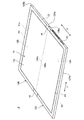
図1は、一実施形態に係る携帯用情報機器10を閉じて収納形態とした状態を示す斜視図である。図2は、図1に示す携帯用情報機器10を開いて使用形態とした状態を模式的に示す斜視図である。図3は、図2に示す携帯用情報機器10の内部構造を模式的に示す側面断面図である。
FIG. 1 is a perspective view showing a state in which the
図1及び図2に示すように、携帯用情報機器10は、第1筐体部材12A及び第2筐体部材12Bと、背表紙部材14と、ディスプレイ16とを備える。本実施形態では、携帯用情報機器10として本のように折り畳み可能なタブレット型PCを例示する。携帯用情報機器10は携帯電話、スマートフォン、電子手帳又は携帯用ゲーム機等であってもよい。
As shown in FIGS. 1 and 2, the
各筐体部材12A,12Bは、それぞれ背表紙部材14に対応する辺以外の3辺に側壁を起立形成した矩形の板状部材である。各筐体部材12A,12Bは、例えばステンレスやマグネシウム、アルミニウム等の金属板、或いは炭素繊維等の強化繊維を含む繊維強化樹脂板等で構成される。ディスプレイ16は、筐体部材12A,12Bの内面12Ac,12Bc間に亘るように設けられている。ディスプレイ16は、内面12Ac,12Bcに対して、第1支持プレート18A及び第2支持プレート18Bと、シート状部材20とを用いて支持されている。
Each of the
筐体部材12A,12Bは、互いに隣接して配置されている。筐体部材12A,12B間は、互いの隣接縁部である一縁部12Aa,12Baの両端部に設けられた一対のヒンジ機構19,19を介して連結されている。ヒンジ機構19は、筐体部材12A,12B間を図1に示す収納形態と図2に示す使用形態とに折り畳み可能に連結している。図3中に1点鎖線で示す線Cは、筐体部材12A,12Bの折り畳み動作の中心となる折曲中心Cを示している。各筐体部材12A,12Bは、背表紙部材14側の一縁部12Aa,12Baがヒンジ側端部となる。各筐体部材12A,12Bは、背表紙部材14側とは反対側の他縁部12Ab,12Bbが開放端部となる。
The
ヒンジ機構19は、例えば各筐体部材12A,12Bの一縁部12Aa,12Baの長手方向(Y方向)両端部のそれぞれに配置され、ディスプレイ16の外周縁部の外側に位置している。本実施形態の携帯用情報機器10は、ヒンジ機構19による筐体部材12A,12B間の回動中心がディスプレイ16の表面16cと一致した構成となっている。
The
以下、図1及び図2に示すように、携帯用情報機器10について、中央の背表紙部材14から他縁部12Ab,12Bbに向かう方向をX方向、背表紙部材14の長手方向に沿う方向をY方向と呼んで説明する。
Hereinafter, as shown in FIGS. 1 and 2, with respect to the
ディスプレイ16は、例えばタッチパネル式の液晶ディスプレイである。図3に示すように、タッチパネル21は、例えばデジタイザペン等のペン入力装置22によるタッチ操作と、人の指先によるタッチ操作とに対応している静電容量方式である。ディスプレイ16は、例えば柔軟性の高いペーパー構造を持った有機EL等のフレキシブルディスプレイである。これによりディスプレイ16は、筐体部材12A,12Bの開閉動作に伴って開閉する。ディスプレイ16は、その表面16cの外周縁部にベゼル部材23が配設される。ベゼル部材23は、ディスプレイ16の表面の表示領域(アクティブ領域)R1を除く外周縁部の非表示領域(非アクティブ領域)R2を覆っている。タッチパネル21は、タッチ操作の有効領域はディスプレイ16の表示領域R1と同一範囲に形成され、表示領域R1の外周部分の非表示領域R2と重なる位置に、例えば5mm程度の幅を持った配線領域21aを有する(図2及び図3参照)。
The
ディスプレイ16は、例えば図3に示すように支持プレート18A,18Bの外周端面に突設された取付片24を介して筐体部材12A,12Bに位置決め固定される。取付片24は、支持プレート18A,18Bの隣接する一縁部18Aa,18Ba以外の外周縁部の適宜箇所に複数設けられている。取付片24は、例えば内面12Ac,12Bcに設けられたボス部25に対してねじ止めされる。これにより各支持プレート18A,18Bは、それぞれ各筐体部材12A,12Bの内面12Ac,内面12Bcに取り付けられる。
As shown in FIG. 3, for example, the
各筐体部材12A,12Bと支持プレート18A,18Bとに挟まれた筐体内部空間には、基板、CPU等の各種半導体チップ、通信モジュール、バッテリ装置、冷却装置等の各種部品が取付固定されている。図3中の参照符号26は、ディスプレイ16の制御基板(コントロールボード)である。図3中の参照符号27は、ディスプレイ16のタッチパネルの制御基板(タッチIC)である。これら制御基板26,27は、図3中に破線で示すフレキシブル基板28を介してディスプレイ16と接続されている。
Various semiconductor chips such as substrates and CPUs, communication modules, battery devices, cooling devices, and other various parts are mounted and fixed in the housing internal space sandwiched between the
背表紙部材14は、可撓性を持った薄い板状部材で形成され、携帯用情報機器10を折り畳んだ際の背表紙となる。背表紙部材14は一縁部12Aa,12Ba間を内側から覆うように筐体部材12A,12B間に亘って設けられている。図1に示すように、携帯用情報機器10は、収納形態では、筐体部材12A,12Bの一縁部12Aa,12Ba間が大きく離間して隙間を生じる。背表紙部材14は、この一縁部12Aa,12Ba間の隙間を覆うことで、内部のディスプレイ16や各種部品が露呈することを防止している。
The
次に、支持プレート18A,18Bの構成例を説明する。図3に示すように、各支持プレート18A,18Bは、薄いプレート状部材である。支持プレート18A,18Bは、その上面18Ab,18Bbでシート状部材20を介してディスプレイ16を支持している。各支持プレート18A,18Bは、それぞれ各筐体部材12A,12Bに支持され、折曲中心Cを中心として本のように開閉される。
Next, a configuration example of the
支持プレート18A,18Bは、例えばステンレス、マグネシウム、アルミニウム等の金属板、或いは炭素繊維等の強化繊維を熱硬化性樹脂や熱可塑性樹脂からなるマトリクス樹脂に含浸させた繊維強化樹脂板等で構成される。支持プレート18A,18Bは、使用形態では、隣接する一縁部18Aa,18Ba同士が当接する(図5A参照)。支持プレート18A,18Bは、収納形態では、一縁部18Aa,18Ba同士が離間する(図5B参照)。
The
次に、シート状部材20の構成例を説明する。図3に示すように、シート状部材20は、ディスプレイ16の裏面16aと、支持プレート18A,18Bの上面18Ab,18Bbとの間に挟まれている。シート状部材20は、上面20aの全域がディスプレイ16の裏面16aと固着される。シート状部材20は、下面20bの大部分が支持プレート18A,18Bの表面18Ac,18Bcと固着される。シート状部材20の下面20bは、ディスプレイ16の折曲部16b(図3参照)に対応する帯状の領域(折曲部20c)だけは表面18Ac,18Bcに固着されず、移動可能な状態にある(図5B参照)。
Next, a configuration example of the sheet-shaped
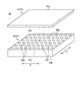
図4は、シート状部材20の構成を模式的に示す分解斜視図である。図5Aは、使用形態でのシート状部材20及びその周辺部の構成を模式的に示す側面断面図である。図5Bは、収納形態でのシート状部材20及びその周辺部の構成を模式的に示す側面断面図である。図4及び図5に示すように、シート状部材20は、第1層部30と、第2層部31とを有し、可撓性を有する。
FIG. 4 is an exploded perspective view schematically showing the configuration of the sheet-shaped
第1層部30は、複数の孔部32aが形成された第1シート32で構成されている。第1シート32は、例えばステンレスシートやアルミニウムシート等の金属シートである。本実施形態の第1シート32は、例えばオーステナイト系ステンレスであるSUS301やSUS304で形成されている。第1シート32の板厚は、例えば150μm程度である。孔部32aの内径は、少なくとも当該携帯用情報機器10に使用するペン入力装置22のペン先の外径(例えば1mm程度)よりも小さいことが好ましい。そこで、本実施形態の場合、孔部32aの内径は、例えば0.5mm以下、好ましくは0.2mm又は0.3mmに設定されている。本実施形態の第1シート32は、その全域に孔部32aが貫通形成されたパンチングメタルシートやメッシュシート等で構成されている。孔部32aは、第1シート32の全域に設けられていなくてもよいが、少なくとも折曲部20cに設けられていることが好ましい。孔部32aの断面形状は、円形の他、矩形や多角形等でもよい。
The
第2層部31は、第2シート33で構成されている。第2シート33は、例えばステンレスシート、アルミニウムシート又は銅シート等の金属シート、或いはカーボンシート等の導体で構成される。カーボンシートは、例えば炭素繊維を熱硬化性樹脂や熱可塑性樹脂からなるマトリクス樹脂に含浸させた炭素繊維強化樹脂シートである。本実施形態の第2シート33は、例えばSUS301やSUS304で形成されている。第2シート33の板厚は、第1シート32の板厚よりも小さく、例えば30μm程度である。
The
シート状部材20は、第1シート32と第2シート33とを貼り合わせることで、第1層部30と第2層部31とが形成されている。第1シート32と第2シート33とは、例えば接着剤或いは両面テープ等によって互いの対向面の全域が接着固定される。これによりシート状部材20は、第1層部30よりも薄い導体で構成され、少なくともタッチ操作の有効領域と重なる位置に孔部のない第2層部31によって第1層部30の孔部32aの上面20a側の開口が塞がれている。すなわち第2層部31は、第1層部30で遮断できなかったノイズがタッチパネル21に影響を及ぼすことを防止する必要がある。このため、第2層部31は、少なくともタッチパネル21のタッチ操作面及びその配線領域21aと重なる位置には孔部のない構成となっている。
In the sheet-shaped
図5A及び図5Bに示すように、シート状部材20は、第2層部31(第2シート33)がディスプレイ16の裏面16aに固定される。さらにシート状部材20は、第1層部30(第1シート32)が支持プレート18A,18Bの上面18Ab,18Bbに固定される。第2層部31とディスプレイ16とは、例えば接着剤或いは両面テープ等で接着固定される。第1層部30と支持プレート18A,18Bとは、例えば接着剤或いは両面テープ等で接着固定される。上記した通り、第1層部30の下面20bは、折曲部20cに対応する部分が支持プレート18A,18Bに固定されず、互いに接離可能な状態にある(図5B参照)。
As shown in FIGS. 5A and 5B, in the sheet-
シート状部材20は、第1層部30と第2層部31の配置を入れ替えてもよい。但し、この構成では、孔部32aを有する第1層部30がディスプレイ16の直下に配置される。その結果、孔部32aの大きさやディスプレイ16の構造によっては、次の2つの不具合を生じる懸念がある。すなわち、第1に、孔部32aの縁部による凹凸形状がディスプレイ16の表面16cに浮かび上がってしまう不具合を生じる懸念がある。第2に、ディスプレイ16の表面16cに浮き上がった凹凸形状に、ペン入力装置22や指先が引っ掛かる不具合を生じる懸念もある。このため、本実施形態のシート状部材20は、図3に示すようにディスプレイ16の直下に第2層部31を配置した構成としている。
In the sheet-
次に、シート状部材20が第1層部30及び第2層部31を有することによる作用効果を説明する。
Next, the action and effect of the sheet-shaped
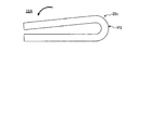
先ず、図6に示すように、シート状部材20が、薄い第2シート33と同一のシート33Aのみで構成されている場合を考える。この場合、シート33Aの折曲部20cは、頂点P1の曲率半径がディスプレイ16の設計曲率反半径よりも小さくなる。薄いシート33Aは、その折曲時の反力が微小であるため、折り曲げた際、図6に示すように頂点P1で屈曲されたような形状となるためである。このため、ディスプレイ16の折曲部16bは、頂点P1に対応する部分が図6に示す折曲部20cと同様な尖った屈曲形状となる。その結果、ディスプレイ16は、設計時の曲率反半径よりも小さい曲率半径で折曲動作し、不具合を生じる懸念がある。但し、このシート33Aは、軽量であるという利点がある。
First, as shown in FIG. 6, consider a case where the sheet-shaped
一方、図7に示すように、シート状部材20が、孔部32aを無くした以外は第1シート32と同一のある程度の厚みを持ったシート32Aのみで構成されている場合を考える。この場合、シート32Aの折曲部20cは、頂点P2の曲率半径がディスプレイ16の設計時の曲率半径と同程度となり、均等な湾曲形状となる。ある程度厚みのあるシート32Aは、断面係数が高く且つある程度の反力を有するため、折り曲げた際、シート33Aのような屈曲形状とならず、図7に示すような均等な円弧を描くことができるためである。このため、ディスプレイ16の折曲部16bは、頂点P2に対応する部分が設計時の所望の曲率半径となり、繰り返しの折曲動作によっても不具合を生じ難くなる。但し、このシート32Aは、図6に示すシート33Aよりも重量が大きい。また、シート32Aは、折曲時の反力が大きいことから、折り曲げに要する力が大きく、筐体部材12A,12Bの開閉動作に大きな力が必要となる懸念もある。
On the other hand, as shown in FIG. 7, consider a case where the sheet-shaped
そこで、本実施形態のシート状部材20は、図7に示すシート32Aと同様にある程度の厚みを持った第1シート32で第1層部30を構成し、図6に示すシート33Aと同様に薄い第2シート33で第2層部31を構成している。そして、第1シート32には、複数の孔部32aを少なくとも折曲部20cに対応する部分に形成している。これにより、シート状部材20は、先ず、厚い第1シート32の作用により、図5Bに示すように、均等な湾曲形状の折曲部20cを得ることができ、ディスプレイ16の折曲部16bの曲率半径を設計仕様と同様に確保することができる。その際、第1シート32は、複数の孔部32aを有することで、重量の増加と、折り曲げに要する力をある程度低減できている。
Therefore, in the sheet-shaped
また、ペンノイズのシールドとして1.8MHzの放射磁界を遮断する必要があるが、第1シート32は孔部32aが形成されているために、第1シート32単体では放射磁界ノイズをシールドするための渦電流が孔部32aの周辺で流れないためにシールド効果が低い。効果的な放射磁界シールドとしては、穴のない導電シートの追加が必要である。そこで、シート状部材20は、第1シート32を、薄くて、少なくともタッチパネル21のタッチ操作面及びその配線領域21aと重なる位置に孔部のない第2シート33で覆っている。これにより第2層部31は、第1層部30を通過する電磁ノイズをシールドするノイズシールド層として機能する。このため、シート状部材20の下方に収納された半導体チップやバッテリ装置等からの電磁ノイズが、孔部32aを通してディスプレイ16のタッチパネル21に影響することを抑制できる。その結果、タッチパネル21は、ペン入力装置22や指先によるタッチ操作が電磁ノイズで妨害されることがなく、円滑なタッチ操作が可能となる。特に、本実施形態では、第2シート33がステンレスシートで構成されているため、渦電流の発生による熱損失による高いノイズシールド効果が得られる。勿論、第2シート33は、ステンレスシートよりも電気抵抗値が低いアルミニウムシート等で構成されてもよい。この場合、第2シート33は、アルミニウムによる磁界の反射による高いノイズシールド効果が得られる。
Further, it is necessary to block the radiated magnetic field of 1.8 MHz as a shield for pen noise, but since the
以上のように、本実施形態の携帯用情報機器10では、ディスプレイ16の裏面16aに固定されるシート状部材20が、第1層部30と第2層部31とを有する。そして、第1層部30は、複数の孔部32aを有する。第2層部31は、第1層部30よりも薄い導体で構成され、第1層部30の孔部32aを閉塞している。
As described above, in the
従って、当該携帯用情報機器10では、ある程度の厚みを持った第1層部30により、ディスプレイ16の折曲部16bを設計時の所望の曲率半径で折曲動作させることができる。この際、第1層部30は、複数の孔部32aを有するため、折曲動作に要する外力が過度に大きくなることがなく、また、重量の増加も抑制できる。しかも、当該携帯用情報機器10では、薄い導体で形成された第2層部31が第1層部30の孔部32aの一方の開口を塞いでいる。このため、筐体内部に収容された電子部品からの電磁ノイズが第1層部30の孔部32aを介してディスプレイ16のタッチパネル21に影響することを抑制できる。
Therefore, in the
シート状部材20は、第1シート32と第2シート33とを積層することで第1層部30と第2層部31とを形成している。このため、シート状部材20は、製造が容易で、構造も簡素なものとなっている。
The sheet-
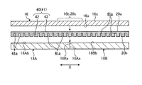
シート状部材は、1枚のシートに複数層を形成した構造としてもよい。図8は、第1変形例に係るシート状部材40の側面断面図であり、その上下に固定されるディスプレイ16及び支持プレート18A,18Bを含めた分解図として図示している。図8に示すように、シート状部材40は、1枚のシート41を有し、シート41に第1層部42及び第2層部43が形成されている。シート41は、例えばステンレスシートやアルミニウムシート等の金属シートである。シート41の板厚は、例えば180μm程度である。
The sheet-like member may have a structure in which a plurality of layers are formed on one sheet. FIG. 8 is a side sectional view of the sheet-shaped
第1層部42は、シート41の下面20b側に形成されている。第1層部42の板厚は、例えば150μm程度である。第1層部42は、下面20bに開口した複数の凹部41aを有する。凹部41aの内径は、上記した孔部32aと同様でよく、例えば例えば0.5mm以下、好ましくは0.2mm又は0.3mmである。凹部41aは、下面20bの全域に凹部41aが形成された構成であるが、凹部41aは、少なくとも折曲部20cに設けられていればよい。第2層部43は、シート41の上面20a側に形成されている。第2層部43板厚は、第1層部42の板厚よりも小さく、例えば30μm程度である。シート状部材40は、例えばシート41にエッチング加工を施すことで、下面20b側に複数の凹部41aを形成したものである。
The
従って、このようなシート状部材40では、実質的に第1層部42を板厚方向に貫通した孔部の一方の開口が第2層部43で塞がれた構造であり、これにより第1層部42には凹部41aが形成されている。このため、シート状部材40においても、第1層部42及び第2層部43を有することで、ディスプレイ16の折曲部16bの形状を適正に保持しつつ、筐体内部に収容された電子部品からの電磁ノイズがタッチパネル21に影響することを抑制できる。しかも当該シート状部材40は、1枚のシート41で構成できるため、製造が一層容易であり、部品点数も削減できる。
Therefore, in such a sheet-
図9は、第2変形例に係るシート状部材50の側面断面図であり、その上下に固定されるディスプレイ16及び支持プレート18A,18Bを含めた分解図として図示している。図9に示すように、シート状部材50は、1枚のシート51を有し、シート51に第1層部52、第2層部53及び第3層部54が形成されている。シート51は、例えばステンレスシート、アルミニウムシート又は銅シート等の金属シートである。シート51の板厚は、例えば180μm程度である。
FIG. 9 is a side sectional view of the sheet-shaped
第1層部52は、シート51の下面20b側に形成されている。第1層部52の板厚は、例えば75μm程度である。第1層部52は、下面20bに開口した複数の凹部52aを有する。凹部52aの内径は、上記した孔部32aと同様でよく、例えば例えば0.1〜0.5mm程度、好ましくは0.2mm又は0.3mmである。第3層部54は、シート51の上面20a側に形成されている。第3層部54の板厚は、例えば75μm程度である。第3層部54は、上面20aに開口した複数の凹部54aを有する。凹部54aの内径は、上記した孔部32aと同様でよく、例えば例えば0.5mm以下、好ましくは0.2mm又は0.3mmである。第2層部53は、第1層部52と第3層部54との間に形成されている。第2層部53板厚は、第1層部52や第3層部54の板厚よりも小さく、例えば30μm程度である。シート状部材50は、例えばシート51にエッチング加工を施すことで、下面20b側に複数の凹部52aを形成し、上面20a側に複数の凹部54aを形成したものである。
The
従って、このようなシート状部材50では、実質的に第1層部52を板厚方向に貫通した孔部の一方の開口が第2層部53で塞がれた構造であり、これにより第1層部52に凹部52aが形成されている。さらにシート状部材50は、複数の凹部54aを持った第3層部54を有することで、第3層部54と第1層部52とが上記したシート状部材20,40の第1層部30,42と同様な効果を発揮する。このため、シート状部材50においても、第1層部52、第2層部53及び第3層部54を有することで、ディスプレイ16の折曲部16bの形状を適正に保持しつつ、筐体内部に収容された電子部品からの電磁ノイズがタッチパネル21に影響することを抑制できる。
Therefore, in such a sheet-shaped
なお、本発明は、上記した実施形態に限定されるものではなく、本発明の主旨を逸脱しない範囲で自由に変更できることは勿論である。 It should be noted that the present invention is not limited to the above-described embodiment, and of course, it can be freely changed without departing from the gist of the present invention.
上記では、ディスプレイ16及びこれに貼り付けたシート状部材20等を、支持プレート18A,18Bを介して筐体部材12A,12Bに取り付けた構成を例示した。しかしながら、支持プレート18A,18Bは、省略してもよい。この場合、シート状部材20等は、例えば筐体部材12A,12Bの内面12Ac,12Bcに突設されたボス状部材や支柱部材等によって支持されればよい。
In the above, the configuration in which the
上記では、第1層部30を構成する第1シート32を金属シートで形成した構成のシート状部材20を例示した。しかしながら、シート状部材20は、導体である第2層部31でノイズシールドは可能であるため、第1シート32は、例えばポリイミド等の樹脂シートで形成されてもよい。
In the above, the sheet-
上記では、本のように二つ折りに折り畳み可能な携帯用情報機器10を例示したが、本発明は、同形の筐体部材同士を二つ折りに折り畳む構成以外、例えば大形の筐体部材の左右縁部にそれぞれ小形の筐体部材を折り畳み可能に連結した観音開きの構成、1つの筐体部材の左右縁部にそれぞれ折り畳み方向の異なる筐体部材を連結したS型の折り畳み構成、大形の筐体部材の左右一方の縁部に小形の筐体部材を折り畳み可能に連結したJ型の折り畳み構成等、各種構成に適用可能であり、筐体部材の連結数は4以上としてもよい。
In the above, the
10 携帯用情報機器
12A 第1筐体部材
12B 第2筐体部材
16 ディスプレイ
20,40,50 シート状部材
21 タッチパネル
21a 配線領域
30,42,52 第1層部
31,43,53 第2層部
32 第1シート
32a 孔部
32A,33A,41,51 シート
33 第2シート
41a,52a,54a 凹部
54 第3層部
10
本発明は、折り畳み可能な携帯用情報機器及びディスプレイアセンブリに関する。 The present invention relates to foldable portable information devices and display assemblies .
本発明は、上記従来技術の課題を考慮してなされたものであり、ディスプレイの円滑な折曲動作を確保しつつ、ノイズシールド構造を備えることができる携帯用情報機器及びディスプレイアセンブリを提供することを目的とする。 The present invention has been made in consideration of the above-mentioned problems of the prior art, and provides a portable information device and a display assembly capable of being provided with a noise shield structure while ensuring smooth bending operation of a display. With the goal.
Claims (7)
第1筐体部材と、
前記第1筐体部材と折り畳み可能に連結された第2筐体部材と、
前記第1筐体部材と前記第2筐体部材の内面間に亘るように設けられ、折り畳み可能且つタッチパネルが積層されたディスプレイと、
前記ディスプレイの裏面に固定されたシート状部材と、
を備え、
前記シート状部材は、
少なくとも前記ディスプレイの折曲部と重なる部分に複数の孔部が形成された第1層部と、
前記第1層部の全面を覆い、前記第1層部よりも薄い導体で形成され、少なくとも前記タッチパネルの配線領域と重なる位置に孔部のない第2層部と、
を有することを特徴とする携帯用情報機器。 It is a portable information device
With the first housing member
A second housing member foldably connected to the first housing member,
A display that is provided so as to extend between the inner surfaces of the first housing member and the second housing member, is foldable, and has a touch panel laminated.
A sheet-like member fixed to the back surface of the display and
With
The sheet-like member is
A first layer portion in which a plurality of holes are formed at least in a portion overlapping the bent portion of the display.
A second layer portion that covers the entire surface of the first layer portion, is formed of a conductor thinner than the first layer portion, and has no hole at least at a position overlapping the wiring region of the touch panel.
A portable information device characterized by having.
前記複数の前記孔部は前記第1層部全体に形成されていることを特徴とする携帯用情報機器。 The portable information device according to claim 1.
A portable information device characterized in that the plurality of holes are formed in the entire first layer portion.
前記シート状部材は、前記第2層部の上面が前記ディスプレイの裏面に固定され、前記第2層部の下面側に前記第1層部が配置されていることを特徴とする携帯用情報機器。 The portable information device according to claim 1 or 2.
The sheet-shaped member is a portable information device, wherein the upper surface of the second layer portion is fixed to the back surface of the display, and the first layer portion is arranged on the lower surface side of the second layer portion. ..
前記孔部の内径は、0.5mm以下であることを特徴とする携帯用情報機器。 The portable information device according to any one of claims 1 to 3.
A portable information device having an inner diameter of 0.5 mm or less.
前記シート状部材は、前記第1層部を形成する第1シートと、前記第2層部を形成する第2シートと、を積層した構成であることを特徴とする携帯用情報機器。 The portable information device according to any one of claims 1 to 4.
The sheet-shaped member is a portable information device having a structure in which a first sheet forming the first layer portion and a second sheet forming the second layer portion are laminated.
前記第1シートは、ステンレスシート又はアルミニウムシートであり、
前記第2シートは、ステンレスシート、アルミニウムシート、銅シート又はカーボンシートであることを特徴とする携帯用情報機器。 The portable information device according to claim 5.
The first sheet is a stainless sheet or an aluminum sheet.
The second sheet is a portable information device characterized by being a stainless sheet, an aluminum sheet, a copper sheet or a carbon sheet.
前記シート状部材は、1枚のシートで構成されており、
前記シートは、一面に複数の凹部が形成されることで前記第1層部が形成され、前記一面の裏側の他面が前記第2層部を構成していることを特徴とする携帯用情報機器。
The portable information device according to any one of claims 1 to 4.
The sheet-like member is composed of one sheet.
The sheet is portable information characterized in that the first layer portion is formed by forming a plurality of recesses on one surface, and the other surface on the back side of the one surface constitutes the second layer portion. machine.
Priority Applications (5)
| Application Number | Priority Date | Filing Date | Title |
|---|---|---|---|
| JP2019107891A JP2020201698A (en) | 2019-06-10 | 2019-06-10 | Portable information device and display assembly |
| US16/856,127 US11096294B2 (en) | 2019-06-10 | 2020-04-23 | Portable information device and display assembly |
| CN202010499646.4A CN112068636A (en) | 2019-06-10 | 2020-06-04 | Portable information device and display assembly |
| DE102020115337.6A DE102020115337A1 (en) | 2019-06-10 | 2020-06-09 | Portable information device and display arrangement |
| GB2008696.3A GB2587693B (en) | 2019-06-10 | 2020-06-09 | Portable information device and display assembly |
Applications Claiming Priority (1)
| Application Number | Priority Date | Filing Date | Title |
|---|---|---|---|
| JP2019107891A JP2020201698A (en) | 2019-06-10 | 2019-06-10 | Portable information device and display assembly |
Publications (1)
| Publication Number | Publication Date |
|---|---|
| JP2020201698A true JP2020201698A (en) | 2020-12-17 |
Family
ID=71615983
Family Applications (1)
| Application Number | Title | Priority Date | Filing Date |
|---|---|---|---|
| JP2019107891A Pending JP2020201698A (en) | 2019-06-10 | 2019-06-10 | Portable information device and display assembly |
Country Status (5)
| Country | Link |
|---|---|
| US (1) | US11096294B2 (en) |
| JP (1) | JP2020201698A (en) |
| CN (1) | CN112068636A (en) |
| DE (1) | DE102020115337A1 (en) |
| GB (1) | GB2587693B (en) |
Families Citing this family (9)
| Publication number | Priority date | Publication date | Assignee | Title |
|---|---|---|---|---|
| KR20210061604A (en) * | 2019-11-20 | 2021-05-28 | 엘지이노텍 주식회사 | Substrate for display |
| KR20210089297A (en) * | 2020-01-07 | 2021-07-16 | 삼성디스플레이 주식회사 | Display device |
| JP6898485B1 (en) * | 2020-02-21 | 2021-07-07 | レノボ・シンガポール・プライベート・リミテッド | Portable information equipment and display assembly |
| CN111816070B (en) * | 2020-07-01 | 2021-08-03 | 武汉华星光电半导体显示技术有限公司 | Display device |
| CN214587744U (en) * | 2020-10-26 | 2021-11-02 | 京东方科技集团股份有限公司 | Support piece for flexible display module, display module and device |
| KR20220063796A (en) * | 2020-11-09 | 2022-05-18 | 삼성디스플레이 주식회사 | Display device |
| KR20220085864A (en) * | 2020-12-15 | 2022-06-23 | 삼성디스플레이 주식회사 | Display device |
| KR20220087193A (en) * | 2020-12-17 | 2022-06-24 | 엘지디스플레이 주식회사 | Foldable display device |
| KR20220106258A (en) * | 2021-01-21 | 2022-07-29 | 삼성디스플레이 주식회사 | Electronic device |
Citations (5)
| Publication number | Priority date | Publication date | Assignee | Title |
|---|---|---|---|---|
| JP2012190321A (en) * | 2011-03-11 | 2012-10-04 | Tamai Co Ltd | Flexural regulation surface material, substantially rectangular surface object coating cover, and support base |
| US20170194580A1 (en) * | 2015-12-30 | 2017-07-06 | Samsung Display Co., Ltd. | Flexible display device |
| US20170263890A1 (en) * | 2016-03-10 | 2017-09-14 | Samsung Display Co., Ltd. | Display device |
| EP3301506A1 (en) * | 2016-09-30 | 2018-04-04 | LG Display Co., Ltd. | Flexible display device |
| JP2019067279A (en) * | 2017-10-04 | 2019-04-25 | レノボ・シンガポール・プライベート・リミテッド | Portable information device |
Family Cites Families (15)
| Publication number | Priority date | Publication date | Assignee | Title |
|---|---|---|---|---|
| US8804349B2 (en) * | 2012-10-19 | 2014-08-12 | Samsung Display Co., Ltd. | Foldable display device |
| US9588549B2 (en) * | 2014-02-28 | 2017-03-07 | Semiconductor Energy Laboratory Co., Ltd. | Electronic device |
| JP6425114B2 (en) * | 2014-07-02 | 2018-11-21 | Tianma Japan株式会社 | Foldable display device and electric device |
| KR20160027679A (en) * | 2014-09-02 | 2016-03-10 | 삼성전자주식회사 | Display device |
| KR102369943B1 (en) * | 2015-06-25 | 2022-03-03 | 삼성디스플레이 주식회사 | Foldable display |
| US10168844B2 (en) * | 2015-06-26 | 2019-01-01 | Samsung Display Co., Ltd. | Flexible display device |
| KR102559839B1 (en) * | 2016-04-12 | 2023-07-27 | 삼성디스플레이 주식회사 | Display apparatus |
| KR102455724B1 (en) * | 2016-04-21 | 2022-10-19 | 삼성디스플레이 주식회사 | Flexible display device |
| KR102637068B1 (en) * | 2016-06-01 | 2024-02-16 | 삼성디스플레이 주식회사 | Display apparatus and fabricating method of the same |
| JP6535353B2 (en) | 2017-01-10 | 2019-06-26 | レノボ・シンガポール・プライベート・リミテッド | Portable information equipment |
| CN108447403B (en) * | 2018-04-03 | 2020-07-03 | 武汉华星光电半导体显示技术有限公司 | Flexible display device and method of manufacturing the same |
| CN109036131A (en) * | 2018-07-19 | 2018-12-18 | 武汉华星光电半导体显示技术有限公司 | Flexible display apparatus |
| CN208607859U (en) * | 2018-07-26 | 2019-03-15 | 京东方科技集团股份有限公司 | Flexible display apparatus |
| CN109118964A (en) * | 2018-09-18 | 2019-01-01 | 京东方科技集团股份有限公司 | A kind of flexible display apparatus |
| CN109345958A (en) * | 2018-09-25 | 2019-02-15 | 武汉华星光电半导体显示技术有限公司 | Cover board and flexible display screen for flexible display screen |
-
2019
- 2019-06-10 JP JP2019107891A patent/JP2020201698A/en active Pending
-
2020
- 2020-04-23 US US16/856,127 patent/US11096294B2/en active Active
- 2020-06-04 CN CN202010499646.4A patent/CN112068636A/en active Pending
- 2020-06-09 GB GB2008696.3A patent/GB2587693B/en active Active
- 2020-06-09 DE DE102020115337.6A patent/DE102020115337A1/en active Pending
Patent Citations (5)
| Publication number | Priority date | Publication date | Assignee | Title |
|---|---|---|---|---|
| JP2012190321A (en) * | 2011-03-11 | 2012-10-04 | Tamai Co Ltd | Flexural regulation surface material, substantially rectangular surface object coating cover, and support base |
| US20170194580A1 (en) * | 2015-12-30 | 2017-07-06 | Samsung Display Co., Ltd. | Flexible display device |
| US20170263890A1 (en) * | 2016-03-10 | 2017-09-14 | Samsung Display Co., Ltd. | Display device |
| EP3301506A1 (en) * | 2016-09-30 | 2018-04-04 | LG Display Co., Ltd. | Flexible display device |
| JP2019067279A (en) * | 2017-10-04 | 2019-04-25 | レノボ・シンガポール・プライベート・リミテッド | Portable information device |
Also Published As
| Publication number | Publication date |
|---|---|
| GB2587693B (en) | 2022-10-26 |
| DE102020115337A1 (en) | 2020-12-10 |
| GB202008696D0 (en) | 2020-07-22 |
| CN112068636A (en) | 2020-12-11 |
| GB2587693A (en) | 2021-04-07 |
| US11096294B2 (en) | 2021-08-17 |
| US20200389986A1 (en) | 2020-12-10 |
Similar Documents
| Publication | Publication Date | Title |
|---|---|---|
| JP2020201698A (en) | Portable information device and display assembly | |
| JP6507183B2 (en) | Portable information equipment | |
| JP2018112834A (en) | Portable information device | |
| JP6898485B1 (en) | Portable information equipment and display assembly | |
| JP2019067279A (en) | Portable information device | |
| JP5000110B2 (en) | Foldable portable device and method of manufacturing the same | |
| JP6758442B2 (en) | Portable information equipment | |
| JP6837106B2 (en) | Portable information equipment | |
| US10908639B2 (en) | Portable information device | |
| US11594710B2 (en) | Method for manufacturing a display device | |
| JP6532972B2 (en) | Portable information equipment | |
| JP6636125B1 (en) | Portable information equipment | |
| JP2021033776A (en) | Portable information device | |
| JP6686115B1 (en) | Portable information equipment | |
| JP6950044B1 (en) | Display assembly and portable information equipment | |
| JP2011091744A (en) | Information processing apparatus | |
| US11089696B2 (en) | Portable information device | |
| JP6793234B1 (en) | Portable information equipment | |
| JP6491770B2 (en) | Portable information equipment | |
| JP6421263B2 (en) | Portable information equipment | |
| JP2021043492A (en) | Electronic device | |
| JP5997095B2 (en) | Housing for portable device and portable device | |
| JP5719693B2 (en) | Electronic equipment unit | |
| JP4852725B2 (en) | Enclosure | |
| JP2022123433A (en) | Electronic apparatus |
Legal Events
| Date | Code | Title | Description |
|---|---|---|---|
| A621 | Written request for application examination |
Free format text: JAPANESE INTERMEDIATE CODE: A621 Effective date: 20190610 |
|
| A521 | Request for written amendment filed |
Free format text: JAPANESE INTERMEDIATE CODE: A523 Effective date: 20190718 |
|
| A131 | Notification of reasons for refusal |
Free format text: JAPANESE INTERMEDIATE CODE: A131 Effective date: 20200728 |
|
| A02 | Decision of refusal |
Free format text: JAPANESE INTERMEDIATE CODE: A02 Effective date: 20210330 |