JP2020200913A - Support part structure of transmission gear, speed reducer, and rotary device - Google Patents
Support part structure of transmission gear, speed reducer, and rotary device Download PDFInfo
- Publication number
- JP2020200913A JP2020200913A JP2019109867A JP2019109867A JP2020200913A JP 2020200913 A JP2020200913 A JP 2020200913A JP 2019109867 A JP2019109867 A JP 2019109867A JP 2019109867 A JP2019109867 A JP 2019109867A JP 2020200913 A JP2020200913 A JP 2020200913A
- Authority
- JP
- Japan
- Prior art keywords
- gear
- transmission gear
- shaft portion
- support
- bearing
- Prior art date
- Legal status (The legal status is an assumption and is not a legal conclusion. Google has not performed a legal analysis and makes no representation as to the accuracy of the status listed.)
- Pending
Links
- 230000005540 biological transmission Effects 0.000 title claims abstract description 123
- 239000003638 chemical reducing agent Substances 0.000 title claims abstract description 39
- 238000006073 displacement reaction Methods 0.000 claims abstract description 38
- 230000001105 regulatory effect Effects 0.000 claims description 19
- 230000002093 peripheral effect Effects 0.000 description 11
- 230000036316 preload Effects 0.000 description 6
- 239000000758 substrate Substances 0.000 description 6
- 238000005096 rolling process Methods 0.000 description 4
- 239000000969 carrier Substances 0.000 description 2
- 238000009434 installation Methods 0.000 description 1
- 238000004519 manufacturing process Methods 0.000 description 1
- 238000000034 method Methods 0.000 description 1
- 238000003825 pressing Methods 0.000 description 1
Images

Classifications
-
- F—MECHANICAL ENGINEERING; LIGHTING; HEATING; WEAPONS; BLASTING
- F16—ENGINEERING ELEMENTS AND UNITS; GENERAL MEASURES FOR PRODUCING AND MAINTAINING EFFECTIVE FUNCTIONING OF MACHINES OR INSTALLATIONS; THERMAL INSULATION IN GENERAL
- F16H—GEARING
- F16H57/00—General details of gearing
- F16H57/0018—Shaft assemblies for gearings
- F16H57/0031—Shaft assemblies for gearings with gearing elements rotatable supported on the shaft
-
- F—MECHANICAL ENGINEERING; LIGHTING; HEATING; WEAPONS; BLASTING
- F16—ENGINEERING ELEMENTS AND UNITS; GENERAL MEASURES FOR PRODUCING AND MAINTAINING EFFECTIVE FUNCTIONING OF MACHINES OR INSTALLATIONS; THERMAL INSULATION IN GENERAL
- F16H—GEARING
- F16H57/00—General details of gearing
- F16H57/02—Gearboxes; Mounting gearing therein
- F16H57/021—Shaft support structures, e.g. partition walls, bearing eyes, casing walls or covers with bearings
- F16H57/022—Adjustment of gear shafts or bearings
-
- F—MECHANICAL ENGINEERING; LIGHTING; HEATING; WEAPONS; BLASTING
- F16—ENGINEERING ELEMENTS AND UNITS; GENERAL MEASURES FOR PRODUCING AND MAINTAINING EFFECTIVE FUNCTIONING OF MACHINES OR INSTALLATIONS; THERMAL INSULATION IN GENERAL
- F16H—GEARING
- F16H57/00—General details of gearing
- F16H57/02—Gearboxes; Mounting gearing therein
- F16H57/023—Mounting or installation of gears or shafts in the gearboxes, e.g. methods or means for assembly
Abstract
Description
本発明は、伝動歯車の支持部構造、減速機、および、回転機器に関する。 The present invention relates to a transmission gear support structure, a speed reducer, and a rotating device.
産業用ロボットや工作機械等の回転機器では、回転駆動源の回転を減速するために減速機が用いられる(例えば、特許文献1参照)。 In rotating equipment such as industrial robots and machine tools, a speed reducer is used to reduce the rotation of the rotation drive source (see, for example, Patent Document 1).
ここで用いられる減速機は、入力側の回転を減速して出力側に伝達する主減速ユニットと、回転駆動源の回転を減速して主減速ユニットに伝達する前段側の歯車機構と、を備えている。 The speed reducer used here includes a main deceleration unit that decelerates the rotation on the input side and transmits it to the output side, and a gear mechanism on the front stage side that decelerates the rotation of the rotation drive source and transmits it to the main deceleration unit. ing.
前段側の歯車機構は、回転駆動源の回転が入力される入力歯車と、主減速ユニットに回転を伝達する出力歯車と、入力歯車の回転を出力歯車に伝達する伝動歯車と、を備えている。
入力歯車と出力歯車が減速機内で平行に配置される場合には、入力歯車と噛み合う第1歯車部と、出力歯車と噛み合う第2歯車部が、軸部の軸方向に離間した二位置に一体に形成された伝動歯車が用いられることがある。この場合、伝動歯車の軸部は、深玉軸受等の軸受によって減速機ケース等の支持ブロックに支持される。
The gear mechanism on the front stage side includes an input gear to which the rotation of the rotation drive source is input, an output gear for transmitting the rotation to the main reduction unit, and a transmission gear for transmitting the rotation of the input gear to the output gear. ..
When the input gear and the output gear are arranged in parallel in the reduction gear, the first gear part that meshes with the input gear and the second gear part that meshes with the output gear are integrated into two positions separated in the axial direction of the shaft part. Transmission gears formed in may be used. In this case, the shaft portion of the transmission gear is supported by a bearing such as a deep ball bearing on a support block such as a speed reducer case.
しかし、上記の伝動歯車の支持部構造では、伝動歯車の軸部の軸方向に離間した二位置に回転トルクの入出部(第1歯車部および第2歯車部)が存在することもあり、動力の伝達時に伝動歯車の軸部に多様な方向の力が加わり、伝動歯車が軸方向に微小に変位することがある。そして、動力の伝達時に伝動歯車が軸方向に変位すると、入力歯車や出力歯車との噛み合い部で騒音を発生することがある。 However, in the above-mentioned transmission gear support portion structure, there may be rotational torque input / output portions (first gear portion and second gear portion) at two positions separated from each other in the axial direction of the transmission gear shaft portion, and the power is supplied. Forces in various directions are applied to the shaft of the transmission gear during transmission, and the transmission gear may be slightly displaced in the axial direction. If the transmission gear is displaced in the axial direction during power transmission, noise may be generated at the meshing portion with the input gear or the output gear.
本発明は、動力伝達時における騒音の発生を抑制することができる伝動歯車の支持部構造、減速機、および、回転機器を提供する。 The present invention provides a transmission gear support structure, a speed reducer, and a rotating device capable of suppressing the generation of noise during power transmission.
本発明の一態様に係る伝動歯車の支持部構造は、軸心回りに回転可能な軸部、前記軸部に形成され入力歯車と噛み合う第1歯車部、および、前記軸部の前記第1歯車部と軸方向に離間した位置に形成され出力歯車と噛み合う第2歯車部を有する伝動歯車と、前記伝動歯車を支持する支持ブロックと、前記伝動歯車を前記支持ブロックに回転可能に支持させる軸受と、前記伝動歯車の軸方向の変位を規制する変位規制部と、を備えている。 The transmission gear support portion structure according to one aspect of the present invention includes a shaft portion that can rotate around the axis, a first gear portion that is formed on the shaft portion and meshes with the input gear, and the first gear portion of the shaft portion. A transmission gear having a second gear portion that is formed at a position axially separated from the portion and meshes with the output gear, a support block that supports the transmission gear, and a bearing that rotatably supports the transmission gear on the support block. A displacement regulating unit that regulates the axial displacement of the transmission gear is provided.
上記の構成により、動力伝達時における伝動歯車の軸方向の変位は、変位規制部によって規制される。この結果、伝動歯車の軸方向の変位に伴う騒音の発生が抑制される。 With the above configuration, the axial displacement of the transmission gear during power transmission is regulated by the displacement regulating unit. As a result, the generation of noise due to the axial displacement of the transmission gear is suppressed.
前記軸部と前記第1歯車部と前記第2歯車部とは一体に形成されるようにしても良い。
この場合、伝動歯車の寸法精度が高まるとともに、煩雑な部品の組付け工程を少なくすることができる。
The shaft portion, the first gear portion, and the second gear portion may be integrally formed.
In this case, the dimensional accuracy of the transmission gear is improved, and the complicated assembly process of parts can be reduced.
前記変位規制部は、前記軸受の外輪の軸方向の端面と前記支持ブロックとの間に介装される介装部材によって構成されるようにしても良い。
この場合、介装部材の厚みの設定により、軸受の外輪に付与する予圧を調整することができる。
The displacement regulating portion may be composed of an intervening member interposed between the axial end surface of the outer ring of the bearing and the support block.
In this case, the preload applied to the outer ring of the bearing can be adjusted by setting the thickness of the interposition member.
前記軸受は、アンギュラ軸受によって構成されるようにしても良い。
この場合、介装部材の厚みの設定により、軸受に軸方向と径方向の予圧を付与することができる。このため、本構成を採用することにより、伝動歯車の軸方向と径方向の変位を規制し、動力伝達時における伝動歯車のダカ付きをより抑制することができる。
The bearing may be composed of an angular bearing.
In this case, by setting the thickness of the interposing member, preload in the axial direction and the radial direction can be applied to the bearing. Therefore, by adopting this configuration, it is possible to regulate the displacement in the axial direction and the radial direction of the transmission gear and further suppress the fluttering of the transmission gear during power transmission.
前記軸受の内輪は、前記伝動歯車の前記軸部に一体に形成されるようにしても良い。
この場合、内歯を伝動歯車の軸部と別体に形成して、その軸部に内歯を組み付ける場合に比較して、軸受の組付誤差を少なくすることができる。この結果、伝動歯車を支持ブロックにより精度良く組み付けることが可能になる。
The inner ring of the bearing may be integrally formed with the shaft portion of the transmission gear.
In this case, the bearing assembly error can be reduced as compared with the case where the internal teeth are formed separately from the shaft portion of the transmission gear and the internal teeth are assembled to the shaft portion. As a result, the transmission gear can be assembled more accurately by the support block.
前記軸受は、前記軸部の軸方向の一端側と他端側とに配置されるようにしても良い。
この場合、伝動歯車を支持ブロックに対して、より安定して支持することが可能になる。
The bearings may be arranged on one end side and the other end side of the shaft portion in the axial direction.
In this case, the transmission gear can be supported more stably with respect to the support block.
本発明の一態様に係る伝動歯車の支持部構造は、軸心回りに回転可能な軸部、前記軸部に形成され入力歯車と噛み合う第1歯車部、および、前記軸部の前記第1歯車部と軸方向に離間した位置に形成され出力歯車と噛み合う第2歯車部を有する伝動歯車と、前記伝動歯車を支持する支持ブロックと、前記伝動歯車を、前記軸部の軸方向の一端側と他端側とで前記支持ブロックに回転可能に支持させる一対の軸受と、を備え、各前記軸受は、アンギュラ軸受によって構成され、一方の前記軸受の外輪の軸方向の端面と前記支持ブロックの間には、前記伝動歯車の軸方向の変位を規制する変位規制部が配置されている。 The transmission gear support portion structure according to one aspect of the present invention includes a shaft portion that can rotate around the axis, a first gear portion that is formed on the shaft portion and meshes with the input gear, and the first gear portion of the shaft portion. A transmission gear having a second gear portion that is formed at a position separated from the portion in the axial direction and meshes with the output gear, a support block that supports the transmission gear, and the transmission gear on one end side of the shaft portion in the axial direction. A pair of gears that rotatably support the support block on the other end side, each of which is composed of an angular gear, is between the axial end face of the outer ring of one of the bearings and the support block. Is provided with a displacement regulating unit that regulates the axial displacement of the transmission gear.
本発明の一態様に係る減速機は、軸心回りに回転可能な軸部、前記軸部に形成され入力歯車と噛み合う第1歯車部、および、前記軸部の前記第1歯車部と軸方向に離間した位置に形成され出力歯車と噛み合う第2歯車部を有する伝動歯車と、前記伝動歯車を支持する支持ブロックと、前記伝動歯車を前記支持ブロックに回転可能に支持させる軸受と、前記伝動歯車の軸方向の変位を規制する変位規制部と、を備えている。 The speed reducer according to one aspect of the present invention includes a shaft portion that can rotate around the axis, a first gear portion that is formed on the shaft portion and meshes with an input gear, and the first gear portion and the axial direction of the shaft portion. A transmission gear having a second gear portion that is formed at a position separated from the output gear and meshes with the output gear, a support block that supports the transmission gear, a bearing that rotatably supports the transmission gear on the support block, and the transmission gear. It is equipped with a displacement control unit that regulates the axial displacement of the gear.
本発明の一態様に係る回転機器は、回転駆動源から動力を入力される減速機と、前記減速機の出力部に連結される被回転体と、を備え、前記減速機は、軸心回りに回転可能な軸部、前記軸部に形成され入力歯車と噛み合う第1歯車部、および、前記軸部の前記第1歯車部と軸方向に離間した位置に形成され出力歯車と噛み合う第2歯車部を有する伝動歯車と、前記伝動歯車の前記軸部を、当該減速機の回転しない固定ブロックと前記被回転体とに回転可能に支持させる複数の軸受と、前記被回転体と前記軸受の一つの間に介装されて、前記伝動歯車の軸方向の変位を規制する変位規制部と、を備えている。
この場合、減速機の固定ブロックと被回転体とによって伝動歯車の軸部を挟み込んだ簡単な構成により、伝動歯車を、軸方向の変位を規制した状態で、減速機の固定ブロックと被回転体とに回転可能に支持させることができる。
The rotating device according to one aspect of the present invention includes a speed reducer to which power is input from a rotary drive source and a rotated body connected to an output portion of the speed reducer, and the speed reducer is provided with a rotation around the axis. A rotatable shaft portion, a first gear portion formed on the shaft portion and meshing with the input gear, and a second gear portion formed on the shaft portion at a position axially separated from the first gear portion and meshing with the output gear. A transmission gear having a portion, a plurality of bearings for rotatably supporting the shaft portion of the transmission gear to a non-rotating fixed block of the speed reducer and the rotating body, and one of the rotating body and the bearing. A displacement regulating unit, which is interposed between the two and regulates the axial displacement of the transmission gear, is provided.
In this case, with a simple configuration in which the shaft portion of the transmission gear is sandwiched between the fixed block of the reduction gear and the rotating body, the transmission gear is regulated to be displaced in the axial direction, and the fixed block of the reduction gear and the rotating body It can be rotatably supported.
上述の伝動歯車の支持部構造は、伝動歯車の軸方向の変位を変位規制部によって規制できるため、伝動歯車の軸方向の変位に伴う騒音の発生を抑制することができる。 Since the above-mentioned transmission gear support portion structure can regulate the axial displacement of the transmission gear by the displacement regulating portion, it is possible to suppress the generation of noise due to the axial displacement of the transmission gear.
次に、本発明の実施形態を図面に基づいて説明する。 Next, an embodiment of the present invention will be described with reference to the drawings.
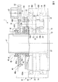
図1は、本実施形態の回転機器1の部分断面正面図であり、図2は、回転機器1の一部(減速機10の一部)の拡大断面図である。
回転機器1は、例えば、工場の製造ライン等で使用される回転移動装置である。回転機器1は、図示しない電動モーター等の回転駆動源と、回転駆動源の回転を減速する減速機10と、減速機10で減速された回転によって回転操作されるターンテーブル等の被回転体11と、を備えている。
FIG. 1 is a partial cross-sectional front view of the
The
減速機10は、下端が使用する設備の設置面上に固定されるベースブロック12と、ベースブロック12に一体に固定された第1キャリアブロック13Aおよび第2キャリアブロック13Bと、第1キャリアブロック13Aと第2キャリアブロック13Bの外周側に軸受14を介して回転可能に支持された略円筒状の外筒17と、第1キャリアブロック13Aと第2キャリアブロック13Bに回転可能に支持された複数のクランク軸18と、各クランク軸18の二つの偏心部18a,18bとともに旋回する第1旋回歯車19Aおよび第2旋回歯車19Bと、を備えている。
The
第1キャリアブロック13Aは、穴あき円板状の基板部13Aaと、当該基板部13Aaの端面から第2キャリアブロック13Bの方向に向かって延びる図示しない複数の支柱部と、を有する。第2キャリアブロック13Bは、第1キャリアブロック13Aの基板部13Aaと略同外径の孔あき円板状に形成されている。第1キャリアブロック13Aは、複数の支柱部が第2キャリアブロック13Bの端面に重ねられ、当該支柱部が第2キャリアブロック13Bにボルト締結によって一体に結合されている。第2キャリアブロック13Bは、ベースブロック12上に重ねられ、ベースブロック12にボルト15によって締結固定されている。第1キャリアブロック13Aの基板部13Aaと、第2キャリアブロック13Bの間には、軸方向の隙間が確保されている。この隙間には、第1旋回歯車19Aと第2旋回歯車19Bが配置されている。
なお、第1旋回歯車19Aと第2旋回歯車19Bには、第1キャリアブロック13Aの各支柱部が貫通する図示しない逃げ孔が形成されている。逃げ孔は、各支柱部が第1旋回歯車19Aと第2旋回歯車19Bの旋回動作を妨げないように、支柱部に対して充分に大きな内径に形成されている。
The
The first
外筒17は、第1キャリアブロック13Aの基板部13Aaの外周面と、第2キャリアブロック13Bの外周面とに跨って配置されている。外筒17の軸方向の両端部は、第1キャリアブロック13Aの基板部13Aaと、第2キャリアブロック13Bとに軸受14を介して回転可能に支持されている。また、外筒17の軸方向の中央領域(第1旋回歯車19Aと第2旋回歯車19Bの外周面に対向する領域)の内周面には、図2に示すように、減速機10の出力側の回転中心軸線c1と平行に延びる複数のピン溝16が形成されている。複数のピン溝16は、外筒17の内周面に円周方向に等間隔に離間して形成されている。各ピン溝16には、円柱状の内歯ピン20が回転可能に収容されている。
The
第1旋回歯車19Aと第2旋回歯車19Bは、外筒17の内径よりも若干小さい外径に形成されている。第1旋回歯車19Aと第2旋回歯車19Bの各外周面には、外筒17のピン溝16内に配置された複数の内歯ピン20と噛み合い状態で接触する外歯19Aa,19Baが形成されている。第1旋回歯車19Aと第2旋回歯車19Bの各外歯19Aa,19Baの歯数は、内歯ピン20の数(ピン溝16の数)よりも僅かに少なく(例えば、一つ少なく)設定されている。
The
複数のクランク軸18は、第1キャリアブロック13Aと第2キャリアブロック13Bの回転中心軸線c1を中心とした同一円周上に配置されている。各クランク軸18は、軸受22を介して第1キャリアブロック13Aと第2キャリアブロック13Bとに回転可能に支持されている。各クランク軸18の偏心部18a,18bは、第1旋回歯車19Aと第2旋回歯車を夫々貫通している。各偏心部18a,18bは、第1旋回歯車19Aと第2旋回歯車19Bに形成された支持孔21に偏心部軸受23を介して回転可能に係合されている。なお、各クランク軸18の二つの偏心部18a,18bは、クランク軸18の軸線回りに位相が相互に180°ずれるように偏心している。
The plurality of
複数のクランク軸18が外力を受けて一方向に回転すると、クランク軸18の偏心部18a,18bが所定の半径で同方向に旋回し、それに伴って第1旋回歯車19Aと第2旋回歯車19Bが同じ旋回半径で同方向に旋回する。このとき、第1旋回歯車19Aと第2旋回歯車19Bの各外歯19Aa,19Baが、外筒17のピン溝16内に配置された複数の内歯ピン20と噛み合うように接触する。
本実施形態の減速機10では、第1旋回歯車19Aと第2旋回歯車19Bの各外歯19Aa,19Baの歯数が、内歯ピン20の数(ピン溝16の数)よりも僅かに少なく設定されているため、第1旋回歯車19Aと第2旋回歯車19Bが一旋回する間に、外筒17が所定のピッチだけ旋回方向と同方向に押し回される。この結果、クランク軸18の回転は大きく減速されて外筒17の回転として出力される。なお、本実施形態では、各クランク軸の18の偏心部18a,18bが軸心回りに相互に180°ずれるように偏心しているため、第1旋回歯車19Aと第2旋回歯車19Bの旋回位相は180°ずれることになる。
When a plurality of
In the
減速機10の回転を受けて回転する被回転体11は、減速機10の外筒17にボルト締結等によって一体に結合されている。したがって、被回転体11は、減速機10の外筒17と一体に回転する。本実施形態では、被回転体11は減速機10の上方側で略水平に回転する。
The rotating
ベースブロック12の略中央部には、円筒状の筒部27が上方に向かって突設されている。筒部27は、第2キャリアブロック13B、第2旋回歯車19B、第1旋回歯車19A、第1キャリアブロック13Aの各内周部を非接触状態で貫通している。筒部27の内側には、回転駆動源に電力を供給するための電気配線等が挿通される。
A
また、各クランク軸18の上部は、第1キャリアブロック13Aを上方に貫通している。第1キャリアブロック13Aから上方に突出した各クランク軸18の端部には、回転駆動源の動力を各クランク軸18に伝達するためのクランク軸歯車31(出力歯車)が一体に取り付けられている。
Further, the upper portion of each
また、外筒17の周縁部の上方には、回転駆動源の出力軸に連結される入力歯車33が配置されている。入力歯車33は、回転中心軸線c2が上下方向を向くように、クランク軸歯車31よりも上方に配置されている。第1キャリアブロック13Aの上部には、入力歯車33の回転を各クランク軸歯車31(出力歯車)に伝達するための伝動歯車40が配置されている。伝動歯車40は、減速機10の出力部の回転中心軸線c1と同軸に配置されている。
Further, above the peripheral edge of the
伝動歯車40は、軸心回りに回転可能な円筒状の軸部40aと、軸部40aの上部寄りの外周面から径方向外側に張り出した第1歯車部40bと、軸部40aの下部寄りの外周面に(第1歯車部40bと軸方向に離間した位置に)形成された第2歯車部40cと、を有する。本実施形態の場合、軸部40a、第1歯車部40b、第2歯車部40cの三者は一体に形成されている。第2歯車部40cは、第1歯車部40bよりも外径が小さく、かつ、歯数が第1歯車部40bよりも少なく設定されている。軸部40aは、第1キャリアブロック13Aの中央位置から上方に突出する筒部27の外側に配置されている。軸部40aは、筒部27に対して非接触状態とされている。軸部40aの上端部は、被回転体11の下端中央に形成された貫通孔41の縁部に軸受42Aを介して回転可能に支持されている。また、軸部40aの下端部は、第1キャリアブロック13Aの上部中央に形成された貫通孔43の縁部に軸受42Bを介して回転可能に支持されている。
なお、本実施形態では、減速機10の第1キャリアブロック13Aと被回転体11が、伝動歯車40を支持する支持ブロックを構成している。また、第1キャリアブロック13Aは、減速機10の回転しない固定ブロックを構成している。
The
In the present embodiment, the
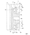
図3は、図1のIII部を拡大して示した図である。
伝動歯車40を支持する各軸受42A,42Bは、伝動歯車40の軸部40aと一体の内輪42iと、被回転体11や第1キャリアブロック13Aに係止される外輪42oと、内輪42iと外輪42oの間で転動する転動体42rと、を備えている。各軸受42A,42Bは、アンギュラ玉軸受によって構成されている。ただし、各軸受42A,42Bは、アンギュラころ軸受等の他の形態の軸受構造を採用することも可能である。各軸受42A,42Bは、外輪42oと転動体42r(玉)の接触点と、内輪42iと転動体42r(玉)の接触点を結ぶ直線が接触角をもち、伝動歯車40に作用する径方向の荷重と軸方向の荷重とを受け止める。なお、二つの軸受42A,42Bは、相反方向の軸方向の荷重を受け止める。
各軸受42A,42Bの内輪42iは、伝動歯車40の軸部40aの両側の端部の外周に一体に形成されている。ただし、各軸受42A,42Bの内輪42iは、伝動歯車40の軸部40aと別体に形成し、伝動歯車40の軸部40aの端部外周に後から嵌合固定することも可能である。
FIG. 3 is an enlarged view of Part III of FIG.
The
The
第1キャリアブロック13Aの貫通孔43の上端部には、段差状の環状溝44が形成されている。この環状溝44には、下部側の軸受42Bの外輪42oが嵌合される。このとき、外輪42oの軸方向の端面は、嵌合溝44の平坦な下壁44aに当接する。
A stepped
また、被回転体11の貫通孔41の下端部には、段差状に環状溝45が形成されている。この環状溝45は、被回転体11がボルト締結等によって減速機10に組付けられるときに、伝動歯車40の上部側の軸受42Aの外輪42oに嵌合される。このとき、外輪42oの軸方向の端面と、環状溝45の平坦な上壁45aとの間には、介装部材である所定厚みのシム46が介装される。シム46は、被回転体11が減速機10に組付けられるときに、上部側の軸受42Aの外輪42oを軸方向内側(図中下方)に押圧する。このシム46から上部側の軸受42Aの外輪42oに作用する荷重は、上下の軸受42A,42Bの内輪42iを兼ねる伝動歯車40の軸部40aを通して下方の軸受42Bにも伝達される。本実施形態の上下の軸受42A,42Bは、アンギュラ玉軸受(アンギュラ軸受)であることから、上記のシム46による外輪42oの押圧によって軸方向と径方向の予圧が付与される。
なお、本実施形態では、シム46が、伝動歯車40の軸方向の変位を規制する変位規制部を構成している。
Further, an
In this embodiment, the
以上のように、本実施形態の回転機器1では、入力歯車33から出力歯車(クランク軸歯車31)に回転を伝達する伝動歯車40が、変位規制部(軸受42Aの外輪42oを軸方向に押圧するシム46)によって軸方向の変位を規制されている。このため、本実施形態で採用する伝動歯車40の支持部構造は、減速機10の作動時に、伝動歯車40が軸方向に変位して、伝動歯車40と入力歯車33の間や、伝動歯車40と出力歯車(クランク軸歯車31)の間で騒音を発生する不具合を抑制することができる。
As described above, in the
また、本実施形態で採用する伝動歯車40の支持部構造は、軸部40a、第1歯車部40b、第2歯車部40cの三者が一体に形成されている。このため、本構成を採用した場合には、伝動歯車40の寸法精度が高まるとともに、煩雑な部品の組付け工程を少なくすることができる。
Further, in the support portion structure of the
また、本実施形態で採用する伝動歯車40の支持部構造は、変位規制部が、軸受42Aの外輪42oの軸方向の端面と支持ブロック(被回転体11)との間に介装される介装部部材(シム46)によって構成されている。このため、介装部材であるシム46の厚みを適切に設定することにより、軸受42A,42Bの外輪42oに付与する予圧を調整することができる。このため、伝動歯車40の軸方向の変位をより少なして、騒音の発生をより抑制することができる。
Further, in the support portion structure of the
特に、本実施形態で採用する伝動歯車40の支持部構造は、伝動歯車40を保持する軸受42A,42Bがアンギュラ軸受によって構成されているため、介装部材であるシム46によって一方の軸受42Aの外輪42oに軸方向の荷重を付与することにより、軸受42A,42Bに軸方向と径方向の予圧を適切に付与することができる。したがって、本実施形態の構成を採用した場合には、伝動歯車40の軸方向と径方向の変位をより確実に規制し、動力伝達時における伝動歯車40のダカ付きをより抑制することができる。
In particular, in the support portion structure of the
また、本実施形態で採用する伝動歯車40の支持部構造では、軸受42A,42Bの各内輪42iが伝動歯車40の軸部40aに一体に形成されている。このため、軸受42A,42Bの内輪42iを伝動歯車40と別体に形成して、伝動歯車40の軸部40aに後から嵌合固定する場合に比較して、軸受42A,42Bの組付誤差をより小さくすることができる。このため、支持ブロックである被回転体11と減速機10の第1キャリアブロック13Aとに、伝動歯車40をより精度良く組み付けることができる。
Further, in the support portion structure of the
さらに、本実施形態で採用する伝動歯車40の支持部構造は、軸受42A,42Bが伝動歯車40の軸部40aの軸方向の一端側と他端側とに配置されているため、伝動歯車40を支持ブロック(被回転体11,第1キャリアブロック13A)により安定して支持させることができる。
Further, in the support portion structure of the
特に、本実施形態では、伝動歯車40の軸部40aの軸方向の一端側と他端側を保持する軸受42A,42Bとして、いずれもアンギュラ軸受を採用しているため、伝動歯車40の軸部40aの両端部において軸方向と径方向の変位を確実に抑制することかできる。したがって、本構成を採用した場合には、伝動歯車40を支持ブロック(被回転体11,第1キャリアブロック13A)にさらに安定して支持させることができる。
In particular, in the present embodiment, since angular bearings are used as
また、本実施形態の回転機器1は、伝動歯車40の軸部40aが、減速機10側の固定ブロックである第1キャリアブロック13Aと、減速機10の外筒17に取り付けられる被回転体11とに軸受42B,42Aを介して支持され、被回転体11の環状溝45の上壁45aと一方の軸受42Aの外輪42oとの間に変位規制部であるシム46が介装されている。したがって、本構成を採用した場合には、減速機10の固定ブロック(第1キャリアブロック13A)と被回転体11とによって伝動歯車40の軸部40aを挟み込んだ簡単な構成により、伝動歯車40を、軸方向の変位を規制した状態で、回転機器1に回転可能に支持させることができる。
さらに、本実施形態の回転機器1では、減速機10に被回転体11を取り付ける際に、被回転体11と軸受42Aの外輪42oの間に介装するシム46の厚みを適宜変更することにより、伝動歯車40ガタ付き調整を容易に行うことができる。
Further, in the
Further, in the
なお、本発明は上記の実施形態に限定されるものではなく、その要旨を逸脱しない範囲で種々の設計変更が可能である。
例えば、上記の実施形態では、伝動歯車40を支持ブロック(被回転体11,第1キャリアブロック13A)に支持させる軸受42A,42Bとして、アンギュラ軸受を採用しているが、伝動歯車40を支持ブロックに支持させる軸受としては、深玉軸受等の他の形態の軸受を採用することも可能である。この場合も、軸受の内輪を伝動歯車の軸部に一体に形成し、外輪にシム等によって軸方向の予圧を付与することが望ましい。
The present invention is not limited to the above embodiment, and various design changes can be made without departing from the gist thereof.
For example, in the above embodiment, angular bearings are used as
また、上記の実施形態では、キャリア(第1キャリアブロック13Aおよび第2キャリアブロック13B)が固定され、外筒17が出力回転体として回転する構成とされているが、逆に外筒17が固定され、キャリア(第1キャリアブロック13Aおよび第2キャリアブロック13B)が出力回転体して回転する構成としても良い。
Further, in the above embodiment, the carriers (
1…回転機器、10…減速機、11…被回転体(支持ブロック)、13A…第1キャリアブロック(支持ブロック,固定ブロック)、31…クランク軸歯車(出力歯車)、33…入力歯車、40…伝動歯車、40a…軸部、40b…第1歯車部、40c…第2歯車部、42A,42B…軸受、42i…内輪、42o…外輪、42r…転動体、46…シム(介装部材) 1 ... Rotating equipment, 10 ... Reducer, 11 ... Rotated body (support block), 13A ... First carrier block (support block, fixed block), 31 ... Crankshaft gear (output gear), 33 ... Input gear, 40 ... Transmission gear, 40a ... Shaft, 40b ... First gear, 40c ... Second gear, 42A, 42B ... Bearing, 42i ... Inner ring, 42o ... Outer ring, 42r ... Rolling element, 46 ... Sim (intermediate member)
Claims (9)
前記伝動歯車を支持する支持ブロックと、
前記伝動歯車を前記支持ブロックに回転可能に支持させる軸受と、
前記伝動歯車の軸方向の変位を規制する変位規制部と、を備えている伝動歯車の支持部構造。 A shaft portion that can rotate around the axis, a first gear portion that is formed on the shaft portion and meshes with the input gear, and a shaft portion that is formed at a position axially separated from the first gear portion of the shaft portion and meshes with the output gear. A transmission gear with a second gear and
A support block that supports the transmission gear and
A bearing that rotatably supports the transmission gear on the support block,
A support portion structure of a transmission gear including a displacement regulation portion that regulates an axial displacement of the transmission gear.
前記伝動歯車を支持する支持ブロックと、
前記伝動歯車を、前記軸部の軸方向の一端側と他端側とで前記支持ブロックに回転可能に支持させる一対の軸受と、を備え、
各前記軸受は、アンギュラ軸受によって構成され、
一方の前記軸受の外輪の軸方向の端面と前記支持ブロックの間には、前記伝動歯車の軸方向の変位を規制する変位規制部が配置されている伝動歯車の支持部構造。 A shaft portion that can rotate around the axis, a first gear portion that is formed on the shaft portion and meshes with the input gear, and a shaft portion that is formed at a position axially separated from the first gear portion and meshes with the output gear. A transmission gear with a second gear and
A support block that supports the transmission gear and
A pair of bearings that rotatably support the transmission gear on the support block on one end side and the other end side in the axial direction of the shaft portion are provided.
Each of the bearings is composed of angular bearings.
A support gear structure in which a displacement regulating portion that regulates the axial displacement of the transmission gear is arranged between the axial end surface of the outer ring of the bearing and the support block.
前記伝動歯車を支持する支持ブロックと、
前記伝動歯車を前記支持ブロックに回転可能に支持させる軸受と、
前記伝動歯車の軸方向の変位を規制する変位規制部と、を備えている減速機。 A shaft portion that can rotate around the axis, a first gear portion that is formed on the shaft portion and meshes with the input gear, and a shaft portion that is formed at a position axially separated from the first gear portion of the shaft portion and meshes with the output gear. A transmission gear with a second gear and
A support block that supports the transmission gear and
A bearing that rotatably supports the transmission gear on the support block,
A speed reducer including a displacement regulating unit that regulates the axial displacement of the transmission gear.
前記減速機の出力部に連結される被回転体と、を備え、
前記減速機は、
軸心回りに回転可能な軸部、前記軸部に形成され入力歯車と噛み合う第1歯車部、および、前記軸部の前記第1歯車部と軸方向に離間した位置に形成され出力歯車と噛み合う第2歯車部を有する伝動歯車と、
前記伝動歯車の前記軸部を、当該減速機の回転しない固定ブロックと前記被回転体とに回転可能に支持させる複数の軸受と、
前記被回転体と前記軸受の一つの間に介装されて、前記伝動歯車の軸方向の変位を規制する変位規制部と、を備えている回転機器。 A reducer that receives power from a rotary drive source,
A rotating body connected to the output unit of the speed reducer is provided.
The speed reducer
A shaft portion that can rotate around the axis, a first gear portion that is formed on the shaft portion and meshes with the input gear, and a shaft portion that is formed at a position axially separated from the first gear portion of the shaft portion and meshes with the output gear. A transmission gear with a second gear and
A plurality of bearings that rotatably support the shaft portion of the transmission gear to the non-rotating fixed block of the speed reducer and the rotating body.
A rotating device including a displacement regulating unit interposed between the rotating body and one of the bearings to regulate the axial displacement of the transmission gear.
Priority Applications (3)
| Application Number | Priority Date | Filing Date | Title |
|---|---|---|---|
| JP2019109867A JP2020200913A (en) | 2019-06-12 | 2019-06-12 | Support part structure of transmission gear, speed reducer, and rotary device |
| CN202010392087.7A CN112081897A (en) | 2019-06-12 | 2020-05-11 | Support portion structure of transmission gear, speed reducer, and rotary device |
| JP2023180416A JP2023174907A (en) | 2019-06-12 | 2023-10-19 | Rotary device |
Applications Claiming Priority (1)
| Application Number | Priority Date | Filing Date | Title |
|---|---|---|---|
| JP2019109867A JP2020200913A (en) | 2019-06-12 | 2019-06-12 | Support part structure of transmission gear, speed reducer, and rotary device |
Related Child Applications (1)
| Application Number | Title | Priority Date | Filing Date |
|---|---|---|---|
| JP2023180416A Division JP2023174907A (en) | 2019-06-12 | 2023-10-19 | Rotary device |
Publications (2)
| Publication Number | Publication Date |
|---|---|
| JP2020200913A true JP2020200913A (en) | 2020-12-17 |
| JP2020200913A5 JP2020200913A5 (en) | 2022-05-12 |
Family
ID=73735570
Family Applications (2)
| Application Number | Title | Priority Date | Filing Date |
|---|---|---|---|
| JP2019109867A Pending JP2020200913A (en) | 2019-06-12 | 2019-06-12 | Support part structure of transmission gear, speed reducer, and rotary device |
| JP2023180416A Pending JP2023174907A (en) | 2019-06-12 | 2023-10-19 | Rotary device |
Family Applications After (1)
| Application Number | Title | Priority Date | Filing Date |
|---|---|---|---|
| JP2023180416A Pending JP2023174907A (en) | 2019-06-12 | 2023-10-19 | Rotary device |
Country Status (2)
| Country | Link |
|---|---|
| JP (2) | JP2020200913A (en) |
| CN (1) | CN112081897A (en) |
Citations (4)
| Publication number | Priority date | Publication date | Assignee | Title |
|---|---|---|---|---|
| JPH07145814A (en) * | 1993-07-30 | 1995-06-06 | Ntn Corp | Shim for power train system gearbox |
| JP2010101366A (en) * | 2008-10-22 | 2010-05-06 | Nabtesco Corp | Gear transmission device |
| JP2011515627A (en) * | 2008-03-04 | 2011-05-19 | ツェットエフ、レンクジステメ、ゲゼルシャフト、ミット、ベシュレンクテル、ハフツング | Helical gear device having an axial elastic bearing and electric power steering equipped therewith |
| JP2016200263A (en) * | 2015-04-14 | 2016-12-01 | ナブテスコ株式会社 | Gear transmission device |
-
2019
- 2019-06-12 JP JP2019109867A patent/JP2020200913A/en active Pending
-
2020
- 2020-05-11 CN CN202010392087.7A patent/CN112081897A/en active Pending
-
2023
- 2023-10-19 JP JP2023180416A patent/JP2023174907A/en active Pending
Patent Citations (4)
| Publication number | Priority date | Publication date | Assignee | Title |
|---|---|---|---|---|
| JPH07145814A (en) * | 1993-07-30 | 1995-06-06 | Ntn Corp | Shim for power train system gearbox |
| JP2011515627A (en) * | 2008-03-04 | 2011-05-19 | ツェットエフ、レンクジステメ、ゲゼルシャフト、ミット、ベシュレンクテル、ハフツング | Helical gear device having an axial elastic bearing and electric power steering equipped therewith |
| JP2010101366A (en) * | 2008-10-22 | 2010-05-06 | Nabtesco Corp | Gear transmission device |
| JP2016200263A (en) * | 2015-04-14 | 2016-12-01 | ナブテスコ株式会社 | Gear transmission device |
Also Published As
| Publication number | Publication date |
|---|---|
| CN112081897A (en) | 2020-12-15 |
| JP2023174907A (en) | 2023-12-08 |
Similar Documents
| Publication | Publication Date | Title |
|---|---|---|
| KR101748177B1 (en) | Wave gear device with composite roller bearing | |
| US10281007B2 (en) | Speed reducer | |
| US9239098B2 (en) | Planet roller speed changer | |
| JP6659232B2 (en) | Gear transmission | |
| US9017206B2 (en) | Gear device | |
| TWI615564B (en) | Friction type continuously variable transmission | |
| JP5083873B2 (en) | Eccentric oscillating gear unit | |
| JP2020200913A (en) | Support part structure of transmission gear, speed reducer, and rotary device | |
| JP7207628B2 (en) | transmission | |
| CN115507155A (en) | Two-stage planetary gear mechanism and wheel drive device | |
| JP6891674B2 (en) | Test equipment for eccentric rotating parts | |
| JP5946710B2 (en) | Eccentric oscillating gear unit | |
| JP6265061B2 (en) | Planetary roller traction drive device | |
| CN112709787A (en) | Shell of speed reducer, speed reducer and industrial robot | |
| WO2020217834A1 (en) | Reduction gear and drive device using reduction gear | |
| JP2021162055A (en) | Reduction gear and reduction gear with motor | |
| JP7444551B2 (en) | Bearing assembly structure of rotating equipment | |
| JP2009275853A (en) | Output part structure of reduction gear | |
| JP7364420B2 (en) | power transmission device | |
| JP2571381B2 (en) | Planetary roller type power transmission device | |
| JP7047301B2 (en) | transmission | |
| JP6713363B2 (en) | transmission | |
| TW202129170A (en) | Speed reducer | |
| US20200056650A1 (en) | Bearing retaining mechanism | |
| KR20150025165A (en) | Speed-reduction transmission bearing |
Legal Events
| Date | Code | Title | Description |
|---|---|---|---|
| A521 | Request for written amendment filed |
Free format text: JAPANESE INTERMEDIATE CODE: A523 Effective date: 20220428 |
|
| A621 | Written request for application examination |
Free format text: JAPANESE INTERMEDIATE CODE: A621 Effective date: 20220428 |
|
| A977 | Report on retrieval |
Free format text: JAPANESE INTERMEDIATE CODE: A971007 Effective date: 20230313 |
|
| A131 | Notification of reasons for refusal |
Free format text: JAPANESE INTERMEDIATE CODE: A131 Effective date: 20230322 |
|
| A601 | Written request for extension of time |
Free format text: JAPANESE INTERMEDIATE CODE: A601 Effective date: 20230522 |
|
| A521 | Request for written amendment filed |
Free format text: JAPANESE INTERMEDIATE CODE: A523 Effective date: 20230531 |
|
| A02 | Decision of refusal |
Free format text: JAPANESE INTERMEDIATE CODE: A02 Effective date: 20230815 |