JP2020184812A - Distributed power system, control device, and control method - Google Patents
Distributed power system, control device, and control method Download PDFInfo
- Publication number
- JP2020184812A JP2020184812A JP2019086555A JP2019086555A JP2020184812A JP 2020184812 A JP2020184812 A JP 2020184812A JP 2019086555 A JP2019086555 A JP 2019086555A JP 2019086555 A JP2019086555 A JP 2019086555A JP 2020184812 A JP2020184812 A JP 2020184812A
- Authority
- JP
- Japan
- Prior art keywords
- power
- power generation
- generated
- executed
- storage device
- Prior art date
- Legal status (The legal status is an assumption and is not a legal conclusion. Google has not performed a legal analysis and makes no representation as to the accuracy of the status listed.)
- Granted
Links
Images



Landscapes
- Supply And Distribution Of Alternating Current (AREA)
- Charge And Discharge Circuits For Batteries Or The Like (AREA)
Abstract
Description
本開示は、分散型電源システム、制御装置および制御方法に関する。 The present disclosure relates to distributed power systems, control devices and control methods.
分散型電源システムが知られている。分散型電源システムは、複数の発電装置を備えていることがある。そのような分散型電源システムの一例が、特許文献1に記載されている。
Distributed generation systems are known. Distributed generation systems may include multiple generators. An example of such a distributed power supply system is described in
特許文献1に記載されている分散型電源システム100を、図7に示す。分散型電源システム100は、発電装置110と、直流母線104と、蓄電装置102と、系統連系装置108と、全体制御装置109と、を備えている。
The distributed
発電装置110は、再生可能エネルギーを利用して発電する。具体的には、発電装置110は、太陽光発電装置である。発電装置110は、太陽電池101と、DC−DCコンバータ103と、を含む。DC−DCコンバータ103は、太陽電池101から出力された直流電圧を、所定の大きさの直流電圧に変換する。
The
蓄電装置102は、直流母線104を介して、DC−DCコンバータ103に接続されている。蓄電装置102には、発電装置110の発電電力が供給され、その電力が充電される。
The power storage device 102 is connected to the DC-DC
系統連系装置108は、DC−ACインバータ107を有する。DC−ACインバータ107は、蓄電装置102からの直流電力を、電力系統105と連系可能な交流電力に逆変換する。逆変換により得られた電力は、負荷106および電力系統105に供給される。
The grid interconnection device 108 has a DC-
制御装置109は、発電量の予想データを受信する。制御装置109は、発電量の予想データおよび消費電力予想に基づいて、蓄電装置102の充電残量の目標値を設定する。制御装置109は、充電残量の目標値および実績値に基づいて、系統連系装置108の出力を、一定時間単位で変化させる。
The
本開示は、電力の安定供給に適した安価な分散型電源システムの実現に寄与し得る技術を提供する。 The present disclosure provides a technique that can contribute to the realization of an inexpensive distributed power supply system suitable for a stable supply of electric power.
本開示は、
第1発電装置を含む複数の発電装置と、
前記複数の発電装置に接続された蓄電装置と、
前記複数の発電装置および前記蓄電装置に接続された電力入力部と、商用電源に接続された電力出力部と、を含む電力出力装置と、
第1検出装置と、
前記電力出力部から出力された電力を表す値であって前記第1検出装置を用いて特定される値である特定電力を一定の目標電力に追従させる制御装置と、を備え、
前記第1発電装置の発電電力を第1発電電力と定義し、正であるときに前記蓄電装置の充電電力を指すとともに負であるときの絶対値が前記蓄電装置の放電電力を指す値を前記蓄電装置の充放電電力と定義したとき、前記制御装置は、
前記複数の発電装置の合計発電電力から指令合計発電電力を差し引いた差分電力を演算し、
前記差分電力がゼロよりも大きいときにおいて、前記充放電電力を増加させる第2処理を実行する場合には前記第2処理を実行する前に前記第1発電電力を減少させる第1処理を実行し、
前記差分電力がゼロよりも小さいときにおいて、前記充放電電力を減少させる第4処理を実行する場合には前記第4処理を実行する前に前記第1発電電力を増加させる第3処理を実行する、
分散型電源システムを提供する。
This disclosure is
Multiple power generation devices including the first power generation device,
A power storage device connected to the plurality of power generation devices and
A power output device including a power input unit connected to the plurality of power generation devices and the power storage device, and a power output unit connected to a commercial power source.
The first detector and
It is provided with a control device that causes a specific power, which is a value representing the power output from the power output unit and is a value specified by using the first detection device, to follow a constant target power.
The power generated by the first power generation device is defined as the first power generation power, and when it is positive, it refers to the charging power of the power storage device, and when it is negative, the absolute value indicates the discharge power of the power storage device. When defined as the charge / discharge power of the power storage device, the control device is defined as
Calculate the differential power obtained by subtracting the command total power generation power from the total power generation power of the plurality of power generation devices.
When the differential power is larger than zero, when the second process of increasing the charge / discharge power is executed, the first process of reducing the first generated power is executed before the second process is executed. ,
When the differential power is smaller than zero, when the fourth process of reducing the charge / discharge power is executed, the third process of increasing the first generated power is executed before the fourth process is executed. ,
Provides a distributed generation system.
本開示に係る技術は、電力の安定供給に適した安価な分散型電源システムの実現に寄与し得る。 The technology according to the present disclosure can contribute to the realization of an inexpensive distributed power supply system suitable for a stable supply of electric power.
(本開示の基礎となった知見)
太陽光等の再生可能エネルギーを利用した発電装置が知られている。そのような発電装置の発電電力は、自然環境によって変動し易い。特許文献1には、発電電力の変動は蓄電装置で吸収されると記載されている。
(Findings underlying this disclosure)
Power generation devices that use renewable energy such as sunlight are known. The generated power of such a power generation device is liable to fluctuate depending on the natural environment.
しかし、再生可能エネルギーを利用した発電装置の発電電力は、大きく変動し得る。このため、特許文献1に従って発電電力の変動を蓄電装置で吸収する場合、大容量の蓄電装置が必要になる。しかし、大容量の蓄電装置は、高価である。
However, the generated power of a power generation device using renewable energy can fluctuate greatly. Therefore, when the fluctuation of the generated power is absorbed by the power storage device according to
特許文献1には、発電量の予想データに基づいて、蓄電装置の充電残量の目標値を設定するとも記載されている。しかし、予想は、当たらない場合がある。予想が外れると、蓄電装置が満充電状態となったり過放電状態となったりし得る。これらの状態では、発電電力の変動を吸収できないことがある。このため、予想データに基づいた制御のみでは、負荷および電力系統等の供給先に電力を安定して供給することは難しい。
以上の理由で、特許文献1の技術には、電力の安定供給に適した安価な分散型電源システムを実現する観点から改善の余地がある。
For the above reasons, the technology of
(本開示に係る一態様の概要)
本開示の第1態様に係る分散型電源システムは、
第1発電装置を含む複数の発電装置と、
前記複数の発電装置に接続された蓄電装置と、
前記複数の発電装置および前記蓄電装置に接続された電力入力部と、商用電源に接続された電力出力部と、を含む電力出力装置と、
第1検出装置と、
前記電力出力部から出力された電力を表す値であって前記第1検出装置を用いて特定される値である特定電力を一定の目標電力に追従させる制御装置と、を備え、
前記第1発電装置の発電電力を第1発電電力と定義し、正であるときに前記蓄電装置の充電電力を指すとともに負であるときの絶対値が前記蓄電装置の放電電力を指す値を前記蓄電装置の充放電電力と定義したとき、前記制御装置は、
前記複数の発電装置の合計発電電力から指令合計発電電力を差し引いた差分電力を演算し、
前記差分電力がゼロよりも大きいときにおいて、前記充放電電力を増加させる第2処理を実行する場合には前記第2処理を実行する前に前記第1発電電力を減少させる第1処理を実行し、
前記差分電力がゼロよりも小さいときにおいて、前記充放電電力を減少させる第4処理を実行する場合には前記第4処理を実行する前に前記第1発電電力を増加させる第3処理を実行する。
(Summary of one aspect relating to this disclosure)
The distributed power supply system according to the first aspect of the present disclosure is
Multiple power generation devices including the first power generation device,
A power storage device connected to the plurality of power generation devices and
A power output device including a power input unit connected to the plurality of power generation devices and the power storage device, and a power output unit connected to a commercial power source.
The first detector and
It is provided with a control device that causes a specific power, which is a value representing the power output from the power output unit and is a value specified by using the first detection device, to follow a constant target power.
The power generated by the first power generation device is defined as the first power generation power, and when it is positive, it refers to the charging power of the power storage device, and when it is negative, the absolute value indicates the discharge power of the power storage device. When defined as the charge / discharge power of the power storage device, the control device is defined as
Calculate the differential power obtained by subtracting the command total power generation power from the total power generation power of the plurality of power generation devices.
When the differential power is larger than zero, when the second process of increasing the charge / discharge power is executed, the first process of reducing the first generated power is executed before the second process is executed. ,
When the differential power is smaller than zero, when the fourth process of reducing the charge / discharge power is executed, the third process of increasing the first generated power is executed before the fourth process is executed. ..
第1態様に係る技術は、電力の安定供給に適した安価な分散型電源システムの実現に寄与し得る。 The technique according to the first aspect can contribute to the realization of an inexpensive distributed power supply system suitable for a stable supply of electric power.
本開示の第2態様において、例えば、第1態様に係る分散型電源システムでは、
前記制御装置は、前記第1発電装置が有する指令第1発電電力をある制御周期で更新してもよく、
前記第1発電電力は、前記第1発電装置が有する前記指令第1発電電力に追従してもよく、
前記制御周期は、1ミリ秒以下であってもよい。
In the second aspect of the present disclosure, for example, in the distributed power supply system according to the first aspect,
The control device may update the command first generated power of the first power generation device at a certain control cycle.
The first generated power may follow the commanded first generated power of the first power generation device.
The control cycle may be 1 millisecond or less.
第2態様は、第1発電電力を高い即応性で制御するのに適している。 The second aspect is suitable for controlling the first generated power with high responsiveness.
本開示の第3態様において、例えば、第1態様または第2態様に係る分散型電源システムでは、
前記第1発電装置は、熱を利用して発電する熱発電装置、または、燃料電池発電装置であってもよい。
In the third aspect of the present disclosure, for example, in the distributed power supply system according to the first or second aspect.
The first power generation device may be a thermoelectric power generation device that generates power by using heat, or a fuel cell power generation device.
第3態様の発電装置は、第1発電装置の具体例である。 The power generation device of the third aspect is a specific example of the first power generation device.
本開示の第4態様において、例えば、第1から第3態様のいずれか1つに係る分散型電源システムでは、
前記複数の発電装置は、第2発電装置を含んでいてもよく、
前記第2発電装置は、再生可能エネルギーを利用した発電装置であってもよい。
In the fourth aspect of the present disclosure, for example, in the distributed power supply system according to any one of the first to third aspects.
The plurality of power generation devices may include a second power generation device.
The second power generation device may be a power generation device that utilizes renewable energy.
第4態様の第2発電装置は、再生可能エネルギーを利用する。そのような第2発電装置には、環境負荷が小さいというメリットと、その発電電力が自然環境によって変動し得るというデメリットと、がある。しかし、第4態様の第2発電装置は、第1態様の技術と組み合わされる。これにより、上記メリットを、上記デメリットを抑えつつ得ることができる。 The second power generation device of the fourth aspect utilizes renewable energy. Such a second power generation device has a merit that the environmental load is small and a demerit that the generated power can fluctuate depending on the natural environment. However, the second power generation device of the fourth aspect is combined with the technique of the first aspect. As a result, the above-mentioned advantages can be obtained while suppressing the above-mentioned disadvantages.
本開示の第5態様において、例えば、第4態様に係る分散型電源システムでは、
前記第2発電装置は、太陽光発電装置、または、風力発電装置であってもよい。
In the fifth aspect of the present disclosure, for example, in the distributed power supply system according to the fourth aspect,
The second power generation device may be a solar power generation device or a wind power generation device.
第5態様の発電装置は、再生可能エネルギーを利用した発電装置の具体例である。 The power generation device of the fifth aspect is a specific example of a power generation device using renewable energy.
本開示の第6態様において、例えば、第1から第5態様のいずれか1つに係る分散型電源システムでは、
前記制御装置は、前記第1発電電力が追従するべき指令第1発電電力の下限である下限電力と、前記指令第1発電電力の上限である上限電力と、を設定してもよく、
前記第1処理によって前記指令第1発電電力が前記下限電力に達したときに、前記第2処理が開始されてもよく、
前記第3処理によって前記指令第1発電電力が前記上限電力に達したときに、前記第4処理が開始されてもよい。
In the sixth aspect of the present disclosure, for example, in the distributed power supply system according to any one of the first to fifth aspects.
The control device may set a lower limit power which is a lower limit of the command first generated power to be followed by the first generated power and an upper limit power which is an upper limit of the command first generated power.
The second process may be started when the command first generated power reaches the lower limit power by the first process.
The fourth process may be started when the command first generated power reaches the upper limit power by the third process.
第6態様によれば、第1発電電力の調整による合計発電電力の調整を第1発電装置にとって無理のない範囲で実行できる。 According to the sixth aspect, the adjustment of the total generated power by the adjustment of the first generated power can be executed within a reasonable range for the first power generation device.
本開示の第7態様において、例えば、第1から第6態様のいずれか1つに係る分散型電源システムでは、
前記制御装置が実行する運転モードは、前記第1処理、前記第2処理、前記第3処理および前記第4処理を含む複数の処理のいずれかを選択して実行する第1モードを含んでいてもよく、
前記第1モードの開始時点における前記第1発電電力は、ゼロよりも大きく前記第1発電電力の定格値よりも小さくてもよい。
In the seventh aspect of the present disclosure, for example, in the distributed power supply system according to any one of the first to sixth aspects.
The operation mode executed by the control device includes a first mode in which any one of a plurality of processes including the first process, the second process, the third process, and the fourth process is selected and executed. Well,
The first generated power at the start of the first mode may be greater than zero and less than the rated value of the first generated power.
第7態様によれば、第1モードが開始されてから、第1発電電力を増加させることも減少させることも可能な状態が継続され易い。このことは、蓄電装置の充放電を抑えるのに適している。充放電を抑え易い運転によれば、容量が抑えられた安価な蓄電装置を用いることが可能となる。 According to the seventh aspect, after the first mode is started, the state in which the first generated power can be increased or decreased is likely to be continued. This is suitable for suppressing the charging / discharging of the power storage device. According to the operation in which charge / discharge can be easily suppressed, it becomes possible to use an inexpensive power storage device having a suppressed capacity.
本開示の第8態様に係る制御装置は、
第1発電装置を含む複数の発電装置と、
前記複数の発電装置に接続された蓄電装置と、
前記複数の発電装置および前記蓄電装置に接続された電力入力部と、商用電源に接続された電力出力部と、を含む電力出力装置と、
第1検出装置と、を備えた分散型電源システムを、前記電力出力部から出力された電力を表す値であって前記第1検出装置を用いて特定される値である特定電力を一定の目標電力に追従させるように制御する制御装置であって、
前記第1発電装置の発電電力を第1発電電力と定義し、正であるときに前記蓄電装置の充電電力を指すとともに負であるときの絶対値が前記蓄電装置の放電電力を指す値を前記蓄電装置の充放電電力と定義したとき、前記制御装置は、
前記複数の発電装置の合計発電電力から指令合計発電電力を差し引いた差分電力を演算し、
前記差分電力がゼロよりも大きいときにおいて、前記充放電電力を増加させる第2処理を実行する場合には前記第2処理を実行する前に前記第1発電電力を減少させる第1処理を実行し、
前記差分電力がゼロよりも小さいときにおいて、前記充放電電力を減少させる第4処理を実行する場合には前記第4処理を実行する前に前記第1発電電力を増加させる第3処理を実行する。
The control device according to the eighth aspect of the present disclosure is
Multiple power generation devices including the first power generation device,
A power storage device connected to the plurality of power generation devices and
A power output device including a power input unit connected to the plurality of power generation devices and the power storage device, and a power output unit connected to a commercial power source.
A distributed power supply system including a first detection device has a specific power target, which is a value representing the power output from the power output unit and is a value specified by using the first detection device. It is a control device that controls to follow the electric power.
The power generated by the first power generation device is defined as the first power generation power, and when it is positive, it refers to the charging power of the power storage device, and when it is negative, the absolute value indicates the discharge power of the power storage device. When defined as the charge / discharge power of the power storage device, the control device is defined as
Calculate the differential power obtained by subtracting the command total power generation power from the total power generation power of the plurality of power generation devices.
When the differential power is larger than zero, when the second process of increasing the charge / discharge power is executed, the first process of reducing the first generated power is executed before the second process is executed. ,
When the differential power is smaller than zero, when the fourth process of reducing the charge / discharge power is executed, the third process of increasing the first generated power is executed before the fourth process is executed. ..
第8態様に係る技術は、電力の安定供給に適した安価な分散型電源システムの実現に寄与し得る。 The technique according to the eighth aspect can contribute to the realization of an inexpensive distributed power supply system suitable for a stable supply of electric power.
本開示の第9態様に係る制御方法は、
第1発電装置を含む複数の発電装置と、
前記複数の発電装置に接続された蓄電装置と、
前記複数の発電装置および前記蓄電装置に接続された電力入力部と、商用電源に接続された電力出力部と、を含む電力出力装置と、
第1検出装置と、を備えた分散型電源システムを、前記電力出力部から出力された電力を表す値であって前記第1検出装置を用いて特定される値である特定電力を一定の目標電力に追従させるように制御する制御方法であって、
前記第1発電装置の発電電力を第1発電電力と定義し、正であるときに前記蓄電装置の充電電力を指すとともに負であるときの絶対値が前記蓄電装置の放電電力を指す値を前記蓄電装置の充放電電力と定義したとき、
前記複数の発電装置の合計発電電力から指令合計発電電力を差し引いた差分電力を演算することと、
前記差分電力がゼロよりも大きいときにおいて、前記充放電電力を増加させる第2処理を実行する場合には前記第2処理を実行する前に前記第1発電電力を減少させる第1処理を実行することと、
前記差分電力がゼロよりも小さいときにおいて、前記充放電電力を減少させる第4処理を実行する場合には前記第4処理を実行する前に前記第1発電電力を増加させる第3処理を実行することと、
を含む。
The control method according to the ninth aspect of the present disclosure is
Multiple power generation devices including the first power generation device,
A power storage device connected to the plurality of power generation devices and
A power output device including a power input unit connected to the plurality of power generation devices and the power storage device, and a power output unit connected to a commercial power source.
A distributed power supply system including a first detection device is provided with a specific power target, which is a value representing the power output from the power output unit and is a value specified by using the first detection device. It is a control method that controls to follow the electric power.
The power generated by the first power generation device is defined as the first power generation power, and when it is positive, it refers to the charging power of the power storage device, and when it is negative, the absolute value indicates the discharge power of the power storage device. When defined as the charge / discharge power of a power storage device,
To calculate the differential power obtained by subtracting the command total power generation power from the total power generation power of the plurality of power generation devices.
When the differential power is larger than zero, when the second process of increasing the charge / discharge power is executed, the first process of reducing the first generated power is executed before the second process is executed. That and
When the differential power is smaller than zero, when the fourth process of reducing the charge / discharge power is executed, the third process of increasing the first generated power is executed before the fourth process is executed. That and
including.
第9態様に係る技術は、電力の安定供給に適した安価な分散型電源システムの実現に寄与し得る。 The technique according to the ninth aspect can contribute to the realization of an inexpensive distributed power supply system suitable for a stable supply of electric power.
以下、本開示の実施の形態について、図面を参照しながら説明する。本発明は、以下の実施の形態に限定されない。 Hereinafter, embodiments of the present disclosure will be described with reference to the drawings. The present invention is not limited to the following embodiments.
(実施の形態1)
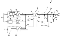
図1に、実施の形態1における分散型電源システム1を示す。
(Embodiment 1)
FIG. 1 shows the distributed
図1に示す分散型電源システム1は、複数の発電装置32と、第1検出装置7と、第2検出装置4と、電力出力装置6と、制御装置8と、蓄電装置9と、を備えている。
The distributed
複数の発電装置32と、蓄電装置9と、電力出力装置6と、は互いに接続されている。具体的には、この接続は、直流電路35を介して行われている。
The plurality of
分散型電源システム1は、商用電源5Aおよび負荷5Bに接続され得る。具体的には、電力出力装置6と、商用電源5Aと、負荷5Bとは、互いに接続され得る。より具体的には、この接続は、交流電路36を介して行われ得る。
The distributed
複数の発電装置32で発電された電力は、蓄電装置9に供給され得る。複数の発電装置32で発電された電力および蓄電装置9に蓄電された電力は、電力出力装置6を介して負荷5Bに供給され得る。負荷5Bには、商用電源5Aからも電力が供給され得る。
The electric power generated by the plurality of
一例では、分散型電源システム1から負荷5Bに電力が供給される。この電力供給では負荷5Bの要求電力を賄えない場合、不足分の電力が商用電源5Aから負荷5Bに供給される。分散型電源システム1から商用電源5Aへと電力が逆潮流することはない。
In one example, power is supplied from the distributed
別例では、分散型電源システム1から商用電源5Aへと電力が逆潮流し得る。
In another example, power can be reverse power flow from the distributed
負荷5Bは、特に限定されない。一例では、負荷5Bは、工場の電気設備である。別例では、負荷5Bは、家庭の電化製品である。
The
以下、分散型電源システム1の構成要素について説明する。
Hereinafter, the components of the distributed
複数の発電装置32は、第1発電装置3および第2発電装置2を含む。本実施の形態では、複数の発電装置32は、第1発電装置3および第2発電装置2の2つの発電装置である。ただし、複数の発電装置32は、他の発電装置をさらに含んでいてもよい。
The plurality of
第1発電装置3は、直流電路35に接続されている。第1発電装置3は、発電調整力を有する。発電調整力を有するとは、自身の発電電力が制御されることにより増加も減少もし得ることを意味する。本実施の形態では、第1発電装置3の発電電力は、制御装置8による制御により、逐次的に増加も減少もし得る。
The first power generation device 3 is connected to the DC
図1の例では、第1発電装置3は、発電電源3Rと、電力変換機3Hと、を含む。
In the example of FIG. 1, the first power generation device 3 includes a power
発電電源3Rは、発電を行う。発電電源3Rは、発電調整力を有する。本実施の形態では、発電電源3Rの発電電力は、制御装置8による制御により、逐次的に増加も減少もし得る。
The power
以下では、第1発電装置3の発電電力を、第1発電電力P1と称することがある。具体的には、第1発電電力P1は、直流電力である。第1発電電力P1は、直流電路35に出力される。図1の例では、第1発電電力P1は、電力変換機3Hの出力電力である。
Hereinafter, the generated power of the first power generation device 3 may be referred to as the first generated power P 1 . Specifically, the first generated power P 1 is DC power. The first generated power P 1 is output to the DC
本実施の形態では、第1発電装置3は、熱を利用して発電する熱発電装置である。具体的には、第1発電装置3は、排熱を利用して発電する排熱発電装置である。また、本実施の形態では、第1発電装置3は、ランキンサイクル発電装置である。 In the present embodiment, the first power generation device 3 is a thermoelectric power generation device that uses heat to generate power. Specifically, the first power generation device 3 is a waste heat power generation device that generates power by utilizing waste heat. Further, in the present embodiment, the first power generation device 3 is a Rankine cycle power generation device.
本実施の形態では、発電電源3Rは、熱を利用して発電する発電電源である。具体的には、発電電源3Rは、排熱を利用して発電する発電電源である。また、本実施の形態では、発電電源3Rは、ランキンサイクル発電電源である。
In the present embodiment, the power
上述の排熱を利用して発電する発電装置および発電電源の説明において、排熱の供給元の例は、工場である。排熱の供給元の具体例は、炉である。この炉は、例えば、鋳物の製造に用いられる炉である。 In the above description of the power generation device and the power generation power source that generate power using the exhaust heat, an example of the exhaust heat supply source is a factory. A specific example of a source of exhaust heat is a furnace. This furnace is, for example, a furnace used for the production of castings.
本実施の形態では、電力変換機3Hは、AC−DCコンバータである。
In the present embodiment, the
以下では、熱発電装置である第1発電装置3を、熱発電装置3と称することがある。排熱発電装置である第1発電装置3を、排熱発電装置3と称することがある。ランキンサイクル発電装置である第1発電装置3を、ランキンサイクル発電装置3と称することがある。ランキンサイクル発電電源である発電電源3Rを、ランキンサイクル発電電源3Rと表記することがある。AC−DCコンバータである電力変換機3Hを、AC−DCコンバータ3Hと表記することがある。
Hereinafter, the first power generation device 3 which is a thermoelectric power generation device may be referred to as a thermoelectric power generation device 3. The first power generation device 3 which is a waste heat power generation device may be referred to as a waste heat power generation device 3. The first power generation device 3 which is a Rankine cycle power generation device may be referred to as a Rankine cycle power generation device 3. The power
別例では、第1発電装置3は、燃料電池発電装置である。発電電源3Rは、燃料電池である。電力変換機3Hは、DC−DCコンバータである。
In another example, the first power generation device 3 is a fuel cell power generation device. The power
上述の説明から理解されるように、本実施の形態では、ランキンサイクル発電装置3は、ランキンサイクル発電電源3Rと、AC−DCコンバータ3Hと、を含む。
As understood from the above description, in this embodiment, the Rankine cycle power generation device 3 includes a Rankine cycle power
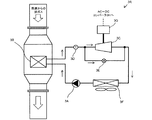
図2Aに、本実施の形態のランキンサイクル発電電源3Rを示す。本実施の形態のランキンサイクル発電電源3Rは、ポンプ3Aと、蒸発器3Bと、温度センサ3Dと、膨張機3Cと、バイパス弁3Eと、凝縮器3Fと、発電機3Gと、を含む。
FIG. 2A shows the Rankine cycle power
ランキンサイクル発電電源3Rでは、冷媒の循環路が形成されている。この循環路では、ポンプ3Aと、蒸発器3Bと、膨張機3Cと、凝縮器3Fとが、この順に現れる。
In the Rankine cycle power
ポンプ3Aは、冷媒を圧送することによって、冷媒を循環させる。蒸発器3Bは、加熱媒体から熱を回収し、その熱により冷媒を加熱する。膨張機3Cは、冷媒を膨張させる。凝縮器3Fは、冷媒の熱を奪うことによって、冷媒を凝縮させる。凝縮器3Fで奪われた熱は、冷却媒体に与えられる。
The pump 3A circulates the refrigerant by pumping the refrigerant. The
本実施の形態では、加熱媒体は、ガスである。具体的には、加熱媒体は、排ガスである。つまり、ランキンサイクル発電電源3Rは、排熱を用いた発電電源である。排ガスの供給元は、例えば工場であり、一具体例では炉であり、この炉は鋳物の製造に用いられる炉であってもよい。蒸発器3Bは、例えば、フィンアンドチューブ熱交換器である。
In this embodiment, the heating medium is a gas. Specifically, the heating medium is exhaust gas. That is, the Rankine cycle power
本実施の形態では、蒸発器3Bにおける加熱により、冷媒は高圧ガスとなる。膨張機3Cは、高圧ガスとなった冷媒を膨張させる。
In the present embodiment, the refrigerant becomes a high-pressure gas by heating in the
本実施の形態では、冷却媒体は、ガスである。具体的には、冷却媒体は、大気中の空気である。ただし、冷却媒体は、水などの液体であってもよい。凝縮器3Fは、ファンを備えていてもよい。凝縮器3Fは、例えば、フィンアンドチューブ熱交換器、プレート熱交換器または二重管式熱交換器である。
In this embodiment, the cooling medium is a gas. Specifically, the cooling medium is air in the atmosphere. However, the cooling medium may be a liquid such as water. The
ランキンサイクル発電電源3Rでは、冷媒のバイパス路が形成されている。バイパス路は、膨張機3Cをバイパスしている。具体的には、バイパス路は、循環路における蒸発器3Bよりも下流側かつ膨張機3Cよりも上流側の部分と、循環路における膨張機3Cよりも下流側かつ凝縮器3Fよりも上流側の部分と、を接続している。
In the Rankine cycle power
バイパス弁3Eは、バイパス路に設けられている。バイパス弁3Eの開度を非ゼロにすることにより、循環路を流れる冷媒の一部または全部を、バイパス弁3Eに流入させることができる。
The
バイパス弁3Eは、流量調整弁であってもよく、開閉弁であってもよい。ここで、流量調整弁は、0%よりも大きく100%よりも小さい開度をとり得る弁である。開閉弁は、開度が0%および100%の2値のいずれかに設定される弁である。
The
温度センサ3Dは、循環路における蒸発器3Bよりも下流側かつ膨張機3Cよりも上流側の部分に設けられている。温度センサ3Dは、この部分における冷媒の温度を検出する。温度センサ3Dは、ランキンサイクル発電装置3の構成要素の制御に用いられ得る。具体的には、温度センサ3Dは、循環路におけるバイパス路への分岐点よりも上流側の部分に設けられている。温度センサ3Dの検出温度は、実質的に、膨張機3Cの入口温度であり得る。
The
発電機3Gは、膨張機3Cに接続されている。膨張機3Cでは、膨張により回転エネルギーが生じる。発電機3Gでは、その回転エネルギーによりロータが回転する。このようにして、発電機3Gにおいて、交流電力が発電される。
The
AC−DCコンバータ3Hは、発電機3Gに接続されている。AC−DCコンバータ3Hには、発電機3Gで発電された交流電力が供給される。AC−DCコンバータ3Hは、この交流電力を直流電力に変換する。
The AC-
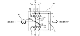
本実施の形態のAC−DCコンバータ3Hの構成を、図2Bに示す。本実施の形態のAC−DCコンバータ3Hは、スイッチング素子16から21と、ダイオード51から56と、コンデンサ22と、を含む。コンデンサ22は、出力コンデンサである。
The configuration of the AC-
AC−DCコンバータ3Hでは、第1相回路61と、第2相回路62と、第3相回路63と、が構成されている。第1相回路61、第2相回路62および第3相回路63は、スイッチング回路60を構成している。第1相回路61と、第2相回路62と、第3相回路63と、コンデンサ22とは、互いに並列に接続されている。第1相回路61、第2相回路62および第3相回路63は、それぞれ、発電機3Gに接続されている。
In the AC-
本実施の形態では、第1相回路61、第2相回路62および第3相回路63は、それぞれ、発電機3Gの第1相、第2相および第3相に接続されている。本実施の形態では、第1相、第2相および第3相は、それぞれ、U相、V相およびW相である。
In the present embodiment, the
第1相回路61は、スイッチング素子16および17と、ダイオード51および52と、を含む。スイッチング素子16および17は、第1接続点66を介して直列に接続されている。スイッチング素子16とダイオード51とは、並列に接続されている。スイッチング素子17とダイオード52とは、並列に接続されている。
The
第2相回路62は、スイッチング素子18および19と、ダイオード53および54と、を含む。スイッチング素子18および19は、第2接続点67を介して直列に接続されている。スイッチング素子18とダイオード53とは、並列に接続されている。スイッチング素子19とダイオード54とは、並列に接続されている。
The
第3相回路63は、スイッチング素子20および21と、ダイオード55および56と、を含む。スイッチング素子20および21は、第3接続点68を介して直列に接続されている。スイッチング素子20とダイオード55とは、並列に接続されている。スイッチング素子21とダイオード56とは、並列に接続されている。
The
本実施の形態では、第1接続点66は、発電機3Gの第1相に接続されている。第2接続点67は、発電機3Gの第2相に接続されている。第3接続点68は、発電機3Gの第3相に接続されている。
In the present embodiment, the
AC−DCコンバータ3Hを用いて、発電機3Gの回転数が制御される。より具体的には、AC−DCコンバータ3Hによって発電機3Gに回生ブレーキがかかり回生電力が得られるように、スイッチング素子16から21のスイッチングが制御される。AC−DCコンバータ3Hを用いた制御は、制御装置8によってなされる。コンデンサ22は、回生電力の瞬時脈動を吸収する。
The rotation speed of the
一具体例では、スイッチング素子16から21は、パルス幅変調(PWM:Pulse Width Modulation)で駆動される。より具体的には、PWM信号が、スイッチング素子16から21に供給される。そして、スイッチング素子16から21は、PWM信号に基づいてスイッチングする。
In one specific example, the switching
図2Bの例では、スイッチング素子16から21は、例えば、絶縁ゲートバイポーラトランジスタ(IGBT:Insulated Gate Bipolar Transistor)である。ただし、スイッチング素子16から21は、MOSFET(Metal Oxide Semiconductor Field Effect Transistor)等の、他のスイッチング素子であってもよい。
In the example of FIG. 2B, the switching
以上の説明から理解されるように、本実施の形態では、第1発電装置3は、ロータの回転により発電する発電機3Gと、スイッチング回路60を含む電力変換機3Hと、を含む。制御装置8は、スイッチング回路60を用いて上記ロータの回転を制御することによって、第1発電電力P1を制御する。本実施の形態は、高い応答性で第1発電電力P1を制御するのに適している。
As understood from the above description, in the present embodiment, the first power generation device 3 includes a
具体的には、第1発電電力P1の制御は、AC−DCコンバータ3Hを用いた発電機3Gの回転数の制御により、実行され得る。この制御は、制御装置8によって実行され得る。
Specifically, the control of the first generated power P 1 can be executed by controlling the rotation speed of the
ポンプ3Aの回転数を制御することによって、上記の循環路を流れる冷媒の流量を制御し、第1発電電力P1を制御する構成も採用され得る。バイパス弁3Eの開度を制御することによって、循環路を流れる冷媒の流量を制御し、第1発電電力P1を制御する構成も採用され得る。また、第1発電装置3内にブレーキ回路を設け、第1発電装置3で得られた直流電力の一部をブレーキ回路で消費することによって、第1発電電力P1を制御する構成も採用され得る。これらの制御もまた、制御装置8によって実行され得る。上記ロータの回転(具体的には回転数)の制御、ポンプ3Aの回転数の制御、バイパス弁3Eの開度の制御およびブレーキ回路による電力消費から選択される2以上を組み合わせて、第1発電電力P1を制御する構成も採用され得る。
By controlling the rotational speed of the pump 3A, to control the flow rate of refrigerant flowing through the circulation path of the above configuration for controlling the first power generating power P 1 may also be employed. By controlling the opening degree of the
図2Bに示すAC−DCコンバータ3Hの構成は、発電電源3Rがランキンサイクル発電電源ではない場合にも採用され得る。
The configuration of the AC-
上述の説明から理解されるように、スイッチング回路を用いたロータの回転の制御は、第1発電装置がランキンサイクル発電装置である場合に採用され得る。その他、この制御は、第1発電装置がロータを有していれば、第1発電装置が他の種類の発電装置である場合に採用され得る。もちろん、この制御は、第1発電装置が排熱発電装置等の熱発電装置でありかつロータを有している場合には、第1発電装置がランキンサイクル発電装置であってもなくても採用され得る。 As can be understood from the above description, control of rotor rotation using a switching circuit can be adopted when the first power generation device is a Rankine cycle power generation device. In addition, this control may be adopted when the first power generation device has a rotor and the first power generation device is another type of power generation device. Of course, this control is adopted regardless of whether the first power generation device is a Rankine cycle power generation device or not when the first power generation device is a heat power generation device such as a waste heat power generation device and has a rotor. Can be done.
第1発電装置3に含まれた発電電源の数は1つに限られない。この数は、複数であってもよい。この場合、第1発電装置3が発電電源の数と同じ数の電力変換機を含み、複数の発電電源と複数の電力変換機が一対一に接続され得る。この場合、発電電源および電力変換機は、発電電源3Rおよび電力変換機3Hとして例示した要素であり得る。ある発電電源がランキンサイクル発電電源であり他の発電電源が燃料電池であるというように、複数の発電電源は、異なる種類の発電電源であってもよい。また、ある発電電源も他の発電電源もランキンサイクル発電電源であるというように、複数の発電電源は、同じ種類の発電電源であってもよい。この点は、複数の電力変換機についても同様である。また、この場合、複数の発電電源の発電によって第1発電装置3が出力する電力を、第1発電電力P1と称することとする。
The number of power generation sources included in the first power generation device 3 is not limited to one. This number may be plural. In this case, the first power generation device 3 includes the same number of power converters as the number of power generation power sources, and a plurality of power generation power sources and a plurality of power converters can be connected one-to-one. In this case, the power generation power source and the power converter can be the elements exemplified as the power
図1に戻って、第2発電装置2は、直流電路35に接続されている。第2発電装置2の運転中において、第2発電装置2の発電電力は、天候等によって変動し得る。具体的には、第2発電装置2は、再生可能エネルギーを利用した発電装置である。
Returning to FIG. 1, the second power generation device 2 is connected to the DC
図1の例では、第2発電装置2は、発電電源2Aと、電力変換機2Bと、を含む。
In the example of FIG. 1, the second power generation device 2 includes a power
本実施の形態では、第2発電装置2は、太陽光発電装置である。具体的には、発電電源2Aは、太陽電池である。電力変換機2Bは、DC−DCコンバータである。
In the present embodiment, the second power generation device 2 is a solar power generation device. Specifically, the power
以下では、太陽光発電装置である第2発電装置2を、太陽光発電装置2と表記することがある。太陽電池である発電電源2Aを、太陽電池2Aと表記することがある。DC−DCコンバータである電力変換機2Bを、DC−DCコンバータ2Bと表記することがある。
Hereinafter, the second power generation device 2 which is a solar power generation device may be referred to as a solar power generation device 2. The power
別例では、第2発電装置2は、風力発電装置である。具体的には、発電電源2Aは、風車である。電力変換機2Bは、AC−DCコンバータおよびDC−DCコンバータを組み合わせた電力変換機である。
In another example, the second power generation device 2 is a wind power generation device. Specifically, the power
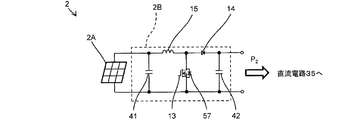
図3に、本実施の形態に係る第2発電装置2の具体例を示す。この具体例では、DC−DCコンバータ2Bは、DCチョッパ回路である。以下では、DCチョッパ回路であるDC−DCコンバータ2Bを、DCチョッパ回路2Bと表記することがある。
FIG. 3 shows a specific example of the second power generation device 2 according to the present embodiment. In this specific example, the DC-
図3に示す具体例では、DCチョッパ回路2Bは、コンデンサ41および42と、スイッチング素子13と、ダイオード57と、整流ダイオード14と、リアクトル15と、を含む。コンデンサ41は、入力コンデンサである。コンデンサ42は、出力コンデンサである。
In the specific example shown in FIG. 3, the
スイッチング素子13とダイオード57とは、並列に接続されている。
The switching
太陽電池2Aと、リアクトル15と、スイッチング素子13とが、この順に接続されている。太陽電池2A、リアクトル15およびスイッチング素子13に、この順で電流が流れ得る。
The
また、太陽電池2Aと、リアクトル15と、整流ダイオード14と、直流電路35とが、この順に接続されている。太陽電池2A、リアクトル15、整流ダイオード14および直流電路35に、この順で電流が流れ得る。
Further, the
具体的には、太陽電池2AからDCチョッパ回路2Bに直流電圧が入力される。スイッチング素子13のスイッチングが制御される。スイッチング素子13がオンであるとき、太陽電池2Aからリアクトル15およびスイッチング素子13にこの順で電流が流れ、リアクトル15にエネルギーが蓄えられる。スイッチング素子13がオフであるとき、太陽電池2Aからリアクトル15およびダイオード14にこの順で電流が流れ、リアクトル15に蓄えられていたエネルギーがダイオード14を介して出力される。このような動作により、DCチョッパ回路2Bは、太陽電池2Aから入力された直流電圧を昇圧し、ダイオード14に電流を通電することで直流電路35に電力を搬送する。DCチョッパ回路2Bを用いた制御は、制御装置8によってなされる。
Specifically, a DC voltage is input from the
一具体例では、スイッチング素子13は、パルス幅変調で駆動される。より具体的には、PWM信号が、スイッチング素子13に供給される。そして、スイッチング素子13は、PWM信号に基づいてスイッチングする。
In one specific example, the switching
一具体例では、太陽電池2AのMPPT(Maximum Power Point Tracking)制御が実行される。より具体的には、DCチョッパ回路2Bを用いて、太陽電池2Aの発電電力が最大となるように、太陽電池2Aの出力電流が制御される。
In one specific example, MPPT (Maximum Power Point Tracking) control of the
図3の例では、スイッチング素子13は、MOSFETである。ただし、スイッチング素子13は、IGBT等の、他のスイッチング素子であってもよい。
In the example of FIG. 3, the switching
図3に示すDCチョッパ回路2Bの構成は、発電電源2Aが太陽電池ではない場合にも採用され得る。
The configuration of the
以下では、第2発電装置2の発電電力を、第2発電電力P2と称することがある。具体的には、第2発電電力P2は、直流電力である。発電電力P2は、直流電路35に出力される。図1の例では、発電電力P2は、電力変換機2Bの出力電力である。
Hereinafter, the generated power of the second power generation device 2 may be referred to as the second generated power P 2 . Specifically, the second generated power P 2 is DC power. The generated power P 2 is output to the DC
第2発電装置2に含まれた発電電源の数は1つに限られない。この数は、複数であってもよい。この場合、第2発電装置2が発電電源の数と同じ数の電力変換機を含み、複数の発電電源と複数の電力変換機が一対一に接続され得る。この場合、発電電源および電力変換機は、発電電源2Aおよび電力変換機2Bとして例示した要素であり得る。複数の発電電源は、異なる種類の発電電源であってもよい。また、複数の発電電源は、同じ種類の発電電源であってもよい。この点は、複数の電力変換機についても同様である。また、この場合、複数の発電電源の発電によって第2発電装置2が出力する電力を、第2発電電力P2と称することとする。
The number of power generation sources included in the second power generation device 2 is not limited to one. This number may be plural. In this case, the second power generation device 2 includes the same number of power converters as the number of power generation power sources, and a plurality of power generation power sources and a plurality of power converters can be connected one-to-one. In this case, the power generation power source and the power converter can be the elements exemplified as the power
図1に戻って、蓄電装置9は、複数の発電装置32に接続されている。蓄電装置9には、複数の発電装置32の発電電力が供給され得る。具体的には、蓄電装置9は、直流電路35を介して複数の発電装置32に接続されている。蓄電装置9は、複数の発電装置32の発電電力に過不足が生じたときに電力バッファとして機能し得る。
Returning to FIG. 1, the
本実施の形態では、蓄電装置9は、第1発電装置3および第2発電装置2に接続されている。このため、蓄電装置9には、第1発電装置3および第2発電装置2の発電電力が供給され得る。具体的には、蓄電装置9は、直流電路35を介して第1発電装置3および第2発電装置2に接続されている。
In the present embodiment, the
図1の例では、蓄電装置9は、蓄電機9Aと、電力変換機9Bと、を含む。
In the example of FIG. 1, the
本実施の形態では、蓄電機9Aは、蓄電池である。以下では、蓄電池である蓄電機9Aを、蓄電池9Aと表記することがある。蓄電機9Aを構成する蓄電池の具体例は、リチウムイオン電池、ニッケル水素電池、鉛蓄電池等である。
In the present embodiment, the
蓄電機9Aの別例は、コンデンサである。蓄電機9Aを構成するコンデンサの具体例は、電気二重層コンデンサである。
Another example of the
本実施の形態では、電力変換機9Bは、DC−DCコンバータである。具体的には、電力変換機9Bは、双方向DC−DCコンバータである。より具体的には、電力変換機9Bは、双方向チョッパ回路である。以下では、双方向DCチョッパ回路である電力変換機9Bを、双方向DCチョッパ回路9Bと表記することがある。
In the present embodiment, the
ここで、双方向DC−DCコンバータは、その第1端子から入力された直流電圧を大きさの異なる直流電圧を変換してその第2端子に出力することと、その第2端子から入力された直流電圧を大きさの異なる直流電圧を変換してその第1端子に出力することと、の両方を実行できるコンバータを指す。 Here, the bidirectional DC-DC converter converts the DC voltage input from the first terminal into a DC voltage having a different magnitude and outputs the DC voltage to the second terminal, and inputs the DC voltage from the second terminal. It refers to a converter that can convert DC voltage of different magnitudes and output it to its first terminal, and can execute both.
同様に、双方向チョッパ回路は、その第1端子から入力された直流電圧を大きさの異なる直流電圧を変換してその第2端子に出力することと、その第2端子から入力された直流電圧を大きさの異なる直流電圧を変換してその第1端子に出力することと、の両方を実行できるチョッパ回路を指す。 Similarly, the bidirectional chopper circuit converts the DC voltage input from the first terminal into a DC voltage of a different magnitude and outputs it to the second terminal, and the DC voltage input from the second terminal. Refers to a chopper circuit that can execute both the conversion of DC voltages of different magnitudes and the output to the first terminal.
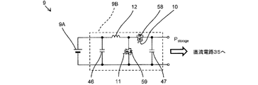
図4に、本実施の形態に係る蓄電装置9の具体例を示す。
FIG. 4 shows a specific example of the
図4に示す具体例では、双方向チョッパ回路9Bは、スイッチング素子10および11と、ダイオード58および59と、リアクトル12と、コンデンサ46および47と、を含む。コンデンサ46および47は、入出力コンデンサである。
In the specific example shown in FIG. 4, the
スイッチング素子10とダイオード58とは、並列に接続されている。スイッチング素子11とダイオード59とは、並列に接続されている。
The switching
直流電路35と、スイッチング素子10と、リアクトル12と、蓄電池9Aとが、この順に接続されている。直流電路35、スイッチング素子10、リアクトル12および蓄電池9Aに、この順で電流が流れ得る。
The DC
ダイオード59と、リアクトル12と、蓄電池9Aとが、この順に接続されている。ダイオード59、リアクトル12および蓄電池9Aに、この順で電流が流れ得る。
The
蓄電池9Aと、リアクトル12と、スイッチング素子11とが、この順に接続されている。蓄電池9A、リアクトル12およびスイッチング素子11に、この順で電流が流れ得る。
The
蓄電池9Aと、リアクトル12と、ダイオード58と、直流電路35とが、この順に接続されている。蓄電池9A、リアクトル12、ダイオード58および直流電路35に、この順で電流が流れ得る。
The
蓄電池9Aに充電する際には、スイッチング素子11は、オフ状態に維持される。スイッチング素子10のスイッチングが制御される。スイッチング素子10がオンであるとき、スイッチング素子10、リアクトル12および蓄電池9Aにこの順に電流が流れる。スイッチング素子10がオフであるとき、リアクトル12は自身を流れる電流を維持しようとし、ダイオード59、リアクトル12および蓄電池9Aにこの順に電流が流れる。このような動作により、双方向チョッパ回路9Bは、降圧チョッパとして機能する。つまり、双方向チョッパ回路9Bは、直流電路35から入力された直流電圧を降圧し、降圧された電圧にてリアクトル12の電流を制御することで蓄電池9Aに充電する。
When charging the
蓄電池9Aから放電する際には、スイッチング素子10は、オフ状態に維持される。スイッチング素子11のスイッチングが制御される。スイッチング素子11がオンであるとき、蓄電池9Aからリアクトル12およびスイッチング素子11にこの順で電流が流れ、リアクトル12にエネルギーが蓄えられる。スイッチング素子11がオフであるとき、蓄電池9Aからリアクトル12およびダイオード58にこの順で電流が流れ、リアクトル12に蓄えられていたエネルギーがダイオード58を介して出力される。このような動作により、双方向チョッパ回路9Bは、昇圧チョッパとして機能する。つまり、双方向チョッパ回路9Bは、蓄電池9Aから入力された直流電圧を昇圧し、ダイオード58に電流を通電することで直流電路35に電力を搬送する。
When discharging from the
双方向チョッパ回路9Bを用いた制御は、制御装置8によってなされる。
The control using the
一具体例では、スイッチング素子10は、パルス幅変調で駆動される。より具体的には、PWM信号が、スイッチング素子10に供給される。そして、スイッチング素子10は、PWM信号に基づいてスイッチングする。スイッチング素子11についても同様である。
In one specific example, the switching
蓄電池9Aから放電する際には、2つのスイッチング素子10および11を用いた同期整流が行われてもよい。同期整流では、スイッチング素子10および11の一方がオン状態であるときに他方はオフ状態であり、一方がオフ状態であるときに他方はオン状態である。同期整流では、2つのスイッチング素子がこのように相補的にオンオフされることにより、ダイオードを用いたダイオード整流に比べ、導電損失を抑制できる。具体的に、上述の説明においてダイオード58に電流が流れる期間においてスイッチング素子10をオン状態にすることにより、同期整流を実現できる。
When discharging from the
なお、図3に示すDCチョッパ回路2Bにおいて、ダイオード14をスイッチング素子Xに変更し、スイッチング素子Xとスイッチング素子13とを用いた同期整流を行ってもよい。具体的に、先の説明においてダイオード14に電流が流れる期間においてスイッチング素子Xをオン状態にすることにより、同期整流を実現できる。
In the
図4の例では、スイッチング素子10および11は、例えば、MOSFETである。ただし、スイッチング素子10および11は、IGBT等の、他のスイッチング素子であってもよい。
In the example of FIG. 4, the switching
図4に示す双方向チョッパ回路9Bの構成は、蓄電機9Aが蓄電池ではない場合にも採用され得る。
The configuration of the
以下では、蓄電装置9の充放電電力を、Pstorageと表記することがある。ここで、正である充放電電力は充電電力を指し、負である充放電電力の絶対値は放電電力を指すものとする。具体的には、充放電電力Pstorageは、直流電力である。充放電電力Pstorageは、直流電路35に入出力される。図1の例では、充放電電力Pstorageは、双方向チョッパ回路9Bの入出力電力である。
In the following, the charge / discharge power of the
蓄電装置9に含まれた蓄電機の数は1つに限られない。この数は、複数であってもよい。この場合、蓄電装置9が蓄電機の数と同じ数の電力変換機を含み、複数の蓄電機と複数の電力変換機が一対一に接続され得る。この場合、蓄電機および電力変換機は、蓄電機9Aおよび電力変換機9Bとして例示した要素であり得る。複数の蓄電機は、異なる種類の蓄電機であってもよい。また、複数の蓄電機は、同じ種類の蓄電機であってもよい。この点は、複数の電力変換機についても同様である。また、この場合、複数の蓄電機の充放電によって第2発電装置2が充放電する電力を、充放電電力Pstorageと称することとする。
The number of power storage devices included in the
図1に戻って、第2検出装置4は、複数の発電装置32の発電電力の合計を検出する。以下では、複数の発電装置32の発電電力の合計を、合計発電電力Psumと称することがある。第2検出装置4は、合計発電電力Psumを検出すると言える。本実施の形態では、合計発電電力Psumは、第1発電装置3の発電電力P1および第2発電装置2の発電電力P2の合計である。
Returning to FIG. 1, the second detection device 4 detects the total generated power of the plurality of
電力出力装置6は、電力入力部6iと、電力出力部6оと、を含む。
The
電力入力部6iは、複数の発電装置32および蓄電装置9に接続されている。具体的には、電力入力部6iは、直流電路35を介して複数の発電装置32および蓄電装置9に接続されている。
The
図1に示すように、分岐部BPに、負荷5Bが接続されている。そして、電力出力部6оは、分岐部BPを介して商用電源5Aに接続されている。具体的には、電力出力部6оは、交流電路36を介して商用電源5Aおよび負荷5Bに接続されている。
As shown in FIG. 1, the
電力入力部6iには、複数の発電装置32および蓄電装置9から直流電力が入力される。電力出力部6оからは、交流電力が出力される。電力は、電力入力部6iと電力出力部6оとの間で、DC−AC変換される。
DC power is input to the
具体的には、電力入力部6iには、合計発電電力Psumから、蓄電装置9の充放電電力Pstorageを差し引いた電力が入力される。つまり、蓄電装置9の充電時において、電力入力部6iには、合計発電電力Psumから蓄電装置9の充電電力を差し引いた電力が入力される。蓄電装置9の放電時において、電力入力部6iには、合計発電電力Psumと蓄電装置9の放電電力とを合計した電力が入力される。なお、先に説明したとおり、合計発電電力Psumは、複数の発電装置32の発電電力の合計である。
Specifically, the
別例では、電力が、電力入力部6iと電力出力部6оとの間で、DC−DC変換され、その後DC−AC変換される。
In another example, the power is DC-DC converted between the
分散型電源システム1は、特定電力Poutを特定できるように構成されている。ここで、特定電力Poutは、電力出力部6оから出力された電力を表す値である。また、特定電力Poutは、第1検出装置7を用いて特定される値である。本実施の形態では、電力出力部6оから商用電源5Aへと、交流電路36が延びている。その交流電路36から、特定電力Poutが得られる。具体的には、交流電路36は、第1部分36aと、第2部分36bと、を含んでいる。第1部分36aは、電力出力部6оと分岐部BPの間の部分である。第2部分36bは、分岐部BPと商用電源5Aの間の部分である。分岐電路37は、分岐部BPから負荷5Bへと延びている。特定電力Poutは、第1部分36aから得られる。本実施の形態では、特定電力Poutは、電力出力部6оから出力された有効電力を表す。
The distributed
上述のように、図1の例では、特定電力Poutは、第1検出装置7を用いて特定される。第1検出装置7は、電流検出器7Aと、電圧検出器7Bと、電力演算部7Cと、を含む。電流検出器7Aおよび電圧検出器7Bは、交流電路36に設けられている。具体的には、電流検出器7Aおよび電圧検出器7Bは、第1部分36aに設けられている。
As described above, in the example of FIG. 1, the specific power P out is specified by using the first detection device 7. The first detection device 7 includes a
電流検出器7Aは、自身が設けられた位置を流れる交流電流を検出する。本実施の形態では、電流検出器7Aは、電力出力装置6から出力された交流電流を検出する。
The
電圧検出器7Bは、自身が設けられた位置に印加されている交流電圧を検出する。本実施の形態では、電力出力装置6から出力された交流電圧を検出する。
The
電圧検出器7Bは、第2部分36bに設けられていてもよい。また、電圧検出器7Bは、分岐電路37に設けられていてもよい。
The
電力演算部7Cは、電流検出器7Aの検出電流と、電圧検出器7Bの検出電圧とを用いて、特定電力Poutを演算する。上述の説明から理解されるように、本実施の形態では、特定電力Poutは、電力出力装置6から出力された有効電力を表す。
The
制御装置8は、特定電力Poutを一定の目標電力Pconstant *に追従させる。制御装置8は、第1発電装置3の第1発電電力P1および蓄電装置9の充放電電力Pstorageを制御できるように構成されている。本実施の形態では、制御装置8は、第2発電装置2の発電電力P2も制御できるように構成されている。
The control device 8 causes the specific power P out to follow a constant target power P constant * . The control device 8 is configured to be able to control the first generated power P 1 of the first power generation device 3 and the charge / discharge power P storage of the
以下、図5のフローチャートを参照しつつ、制御装置8による第1発電装置3の発電電力P1および蓄電装置9の充放電電力Pstorageの制御の例について説明する。
Hereinafter, an example of control of the generated power P 1 of the first power generation device 3 and the charge / discharge power P storage of the
以下の説明では、第1発電電力P1が追従するべき指令値を、指令第1発電電力P1 *と称することがある。蓄電装置9の充放電電力Pstorageが追従するべき指令値を、指令充放電電力Pstorage *と称することがある。合計発電電力Psumが追従するべき指令値を、指令合計発電電力Psum *と称することがある。
In the following description, the command value to the first generated power P 1 to follow, may be referred to as instruction first generated power P 1 *. The command value that the charge / discharge power P storage of the
また、以下の説明では、制御装置8に電力が入力されるという表現を用いることがある。この表現は、制御装置8にその電力を表す情報が入力されることを意味する。 Further, in the following description, the expression that electric power is input to the control device 8 may be used. This expression means that information representing the electric power is input to the control device 8.
この説明に係る例では、制御装置8は、指令第1発電電力P1 *を、下限電力Pmin以上かつ上限電力Pmax以下の範囲の値に設定する。下限電力Pminおよび上限電力Pmaxは、第1発電装置3の能力、運転環境等に基づいて設定され得る。 In the example according to this description, the control device 8 sets the command first generated power P 1 * to a value in the range of the lower limit power P min or more and the upper limit power P max or less. The lower limit power P min and the upper limit power P max can be set based on the capacity of the first power generation device 3, the operating environment, and the like.
図5のフローチャートにおける「開始」から「終了」までが、1つの制御サイクルを構成する。制御装置8は、この制御サイクルを繰り返し実行し得る。 From "start" to "end" in the flowchart of FIG. 5, one control cycle constitutes one. The control device 8 may repeatedly execute this control cycle.
ステップS1において、制御装置8に、合計発電電力Psumが入力される。具体的には、第2検出装置4から制御装置8に、合計発電電力Psumが入力される。 In step S1, the total generated power P sum is input to the control device 8. Specifically, the total generated power P sum is input from the second detection device 4 to the control device 8.
ステップS1の後、ステップS2において、制御装置8に、指令合計発電電力Psum *が入力される。具体的には、上位制御装置から制御装置8に、指令合計発電電力Psum *が入力される。 After step S1, in step S2, the command total generated power P sum * is input to the control device 8. Specifically, the command total generated power P sum * is input from the host control device to the control device 8.
ステップS2の後、ステップS3において、制御装置8は、差分電力Pdeltaを演算する。差分電力Pdeltaは、合計発電電力Psumから指令合計発電電力Psum *を差し引いた差分である。 After step S2, in step S3, the control device 8 calculates the differential power P delta . Differential power P delta is the difference obtained by subtracting the instruction total generated power P sum * from the total generated power P sum.
ステップS3の後、ステップS4において、制御装置8は、第1条件、第2条件、第3条件、第4条件および第5条件のいずれの条件が成立しているのかを判断する。 After step S3, in step S4, the control device 8 determines which of the first condition, the second condition, the third condition, the fourth condition, and the fifth condition is satisfied.
第1条件は、差分電力Pdeltaがゼロであるという条件である。第1条件が成立している場合、ステップS5において、制御装置8は、指令第1発電電力P1 *を現在の値に維持する。数式を用いると、ステップS5で設定されるP1 *は、P1 *(s)=P1 *(s−1)により与えられる。 The first condition is that the differential power P delta is zero. When the first condition is satisfied, in step S5, the control device 8 maintains the command first generated power P 1 * at the current value. Using the mathematical formula, P 1 * set in step S5 is given by P 1 * (s) = P 1 * (s-1).
ここで、P1 *(s−1)は、今回の制御サイクルで更新される前のP1 *を指す。P1 *(s)は、今回の制御サイクルで更新された後のP1 *を指す。Pstorage *についても同様である。 Here, P 1 * (s-1) refers to P 1 * before being updated in the current control cycle. P 1 * (s) refers to P 1 * after being updated in this control cycle. The same applies to P storage * .
また、第1条件が成立している場合、ステップS6において、制御装置8は、指令充放電電力Pstorage *を、ゼロに設定する。数式を用いると、ステップS6で設定されるPstorage *は、Pstorage *(s)=Pdelta=0により与えられる。 Further, when the first condition is satisfied, in step S6, the control device 8 sets the command charge / discharge power P storage * to zero. Using the mathematical formula, the P storage * set in step S6 is given by P storage * (s) = P delta = 0.
第2条件は、差分電力Pdeltaがゼロよりも大きくかつ指令第1発電電力P1 *が下限電力Pminよりも大きいという条件である。第2条件が成立している場合、ステップS7において、制御装置8は、指令第1発電電力P1 *を、第1刻み幅Pwidth1だけ小さくする。数式を用いると、ステップS7で設定されるP1 *は、P1 *(s)=P1 *(s−1)−Pwidth1により与えられる。
The second condition is that the differential power P delta is larger than zero and the command first generated power P 1 * is larger than the lower limit power P min . If the second condition is satisfied, in step S7, the control unit 8, the instruction first generated power P 1 *, to minimize the first step size P WIDTH1. Using the mathematical formula, P 1 * set in step S7 is given by P 1 * (s) = P 1 * (s-1) −
また、第2条件が成立している場合、ステップS8において、制御装置8は、指令充放電電力Pstorage *を現在の値に維持する。数式を用いると、ステップS8で設定されるPstorage *は、Pstorage *(s)=Pstorage *(s−1)により与えられる。 If the second condition is satisfied, in step S8, the control device 8 maintains the command charge / discharge power P storage * at the current value. Using the mathematical formula, the P storage * set in step S8 is given by P storage * (s) = P storage * (s-1).
第3条件は、差分電力Pdeltaがゼロよりも小さくかつ指令第1発電電力P1 *が上限電力Pmaxよりも小さいという条件である。第3条件が成立している場合、ステップS9において、制御装置8は、指令第1発電電力P1 *を、第1刻み幅Pwidth1だけ大きくする。数式を用いると、ステップS9で設定されるP1 *は、P1 *(s)=P1 *(s−1)+Pwidth1により与えられる。
The third condition is that the differential power P delta is smaller than zero and the command first generated power P 1 * is smaller than the upper limit power P max . When the third condition is satisfied, in step S9, the control unit 8, the instruction first generated power P 1 *, is increased by a first step size P WIDTH1. Using a mathematical formula, P 1 * set in step S9 is given by P 1 * (s) = P 1 * (s-1) +
また、第3条件が成立している場合、ステップS10において、制御装置8は、指令充放電電力Pstorage *を現在の値に維持する。数式を用いると、ステップS10で設定されるPstorage *は、Pstorage *(s)=Pstorage *(s−1)により与えられる。 Further, when the third condition is satisfied, in step S10, the control device 8 maintains the command charge / discharge power P storage * at the current value. Using the mathematical formula, the P storage * set in step S10 is given by P storage * (s) = P storage * (s-1).
第4条件は、差分電力Pdeltaがゼロよりも大きくかつ指令第1発電電力P1 *が下限電力Pminであるという条件である。第4条件が成立している場合、ステップS11において、制御装置8は、指令第1発電電力P1 *を、下限電力Pminに維持する。数式を用いると、ステップS11で設定されるP1 *は、P1 *(s)=Pminにより与えられる。 The fourth condition is that the differential power P delta is larger than zero and the command first generated power P 1 * is the lower limit power P min . When the fourth condition is satisfied, in step S11, the control device 8 maintains the command first generated power P 1 * at the lower limit power P min . Using the mathematical formula, P 1 * set in step S11 is given by P 1 * (s) = P min .
また、第4条件が成立している場合、ステップS12において、制御装置8は、指令充放電電力Pstorage *を、第2刻み幅Pwidth2だけ大きくする。数式を用いると、ステップS12で設定されるPstorage *は、Pstorage *(s)=Pstorage *(s−1)+Pwidth2により与えられる。 Also, when the fourth condition is satisfied, in step S12, the control unit 8, the command discharge power P storage *, is increased by a second step size P Width2. Using the mathematical formula, the P storage * set in step S12 is given by P storage * (s) = P storage * (s-1) + P width2 .
第5条件は、差分電力Pdeltaがゼロよりも小さくかつ指令第1発電電力P1 *が上限電力Pmaxであるという条件である。第5条件が成立している場合、ステップS13において、制御装置8は、指令第1発電電力P1 *を、上限電力Pmaxに維持する。数式を用いると、ステップS13で設定されるP1 *は、P1 *(s)=Pmaxにより与えられる。 The fifth condition is that the differential power P delta is smaller than zero and the command first generated power P 1 * is the upper limit power P max . When the fifth condition is satisfied, in step S13, the control device 8 maintains the command first generated power P 1 * at the upper limit power P max . Using the mathematical formula, P 1 * set in step S13 is given by P 1 * (s) = P max .
また、第5条件が成立している場合、ステップS14において、制御装置8は、指令充放電電力Pstorage *を、第2刻み幅Pwidth2だけ小さくする。数式を用いると、ステップS14で設定されるPstorage *は、Pstorage *(s)=Pstorage *(s−1)−Pwidth2により与えられる。 Also, if the fifth condition is satisfied, in step S14, the control unit 8, the command discharge power P storage *, to minimize second step size P Width2. Using the mathematical formula, the P storage * set in step S14 is given by P storage * (s) = P storage * (s-1) −P width2 .
ステップS5およびS6の後、ステップS7およびS8の後、ステップS9およびS10の後、ステップS11およびS12の後、または、ステップS13およびS14の後、ステップS15およびステップS16が行われる。ステップS15において、制御装置8は、指令第1発電電力P1 *を、第1発電装置3に送信する。ステップS16において、制御装置8は、指令充放電電力Pstorage *を、蓄電装置9に送信する。
After steps S5 and S6, after steps S7 and S8, after steps S9 and S10, after steps S11 and S12, or after steps S13 and S14, steps S15 and S16 are performed. In step S15, the control device 8 transmits the command first generated power P 1 * to the first power generation device 3. In step S16, the control device 8 transmits the command charge / discharge power P storage * to the
図5の制御サイクルが繰り返されることにより、指令第1発電電力P1 *および指令充放電電力Pstorage *は、逐次更新され得る。第1発電装置3の第1発電電力P1は、指令第1発電電力P1 *に追従する。蓄電装置9の充放電電力Pstorageは、指令充放電電力Pstorage *に追従する。このようにして、第1発電装置3および蓄電装置9は、制御装置8により制御される。
By repeating the control cycle of FIG. 5, the command first generated power P 1 * and the command charge / discharge power P storage * can be sequentially updated. The first generated power P 1 of the first power generation device 3 follows the command first generated power P 1 * . The charge / discharge power P storage of the
本実施の形態では、制御サイクルが、制御周期Tpで繰り返される。具体的には、制御サイクルは、制御装置8における指令第1発電電力P1 *の更新と、制御装置8から第1発電装置3への指令第1発電電力P1 *の送信と、制御装置8における指令充放電電力Pstorage *の更新と、制御装置8から蓄電装置9への指令充放電電力Pstorage *の送信と、を含む。そして、制御装置8における指令第1発電電力P1 *の更新が、制御周期Tpで繰り返される。制御装置8から第1発電装置3への指令第1発電電力P1 *の送信が、制御周期Tpで繰り返される。制御装置8における指令充放電電力Pstorage *の更新が、制御周期Tpで繰り返される。制御装置8から蓄電装置9への指令充放電電力Pstorage *の送信が、制御周期Tpで繰り返される。
In this embodiment, the control cycle is repeated at the control cycle T p . Specifically, the control cycle includes updating the command first generated power P 1 * in the control device 8, transmitting the command first generated power P 1 * from the control device 8 to the first power generation device 3, and controlling the control device. including a command discharge power P storage * update at 8, and a transmission command discharge power P storage * from the control unit 8 to the
上述の説明から理解されるように、本実施の形態では、制御装置8は、第1発電装置3が有する指令第1発電電力P1 *をある制御周期Tpで更新する。第1発電電力P1は、第1発電装置3が有する指令第1発電電力P1 *に追従する。制御周期Tpは、例えば1ミリ秒以下であり、一具体例では100マイクロ秒以下である。このようにすることは、第1発電電力P1を高い即応性で制御するのに適している。具体的には、このようにすることにより、第2発電電力P2のような第1発電装置3とは別の発電装置の発電電力が瞬時的に変動する場合であっても、その変動に対して高い応答性で第1発電電力P1を制御し、合計発電電力Psumを安定させることができる。このことは、良好な電力需給バランスを維持する観点から有利である。より具体的には、このようにすることにより、10ミリ秒オーダあるいはミリ秒オーダで第1発電電力P1を制御することが可能である。制御周期Tpは、例えば100ナノ秒以上であり、1マイクロ秒以上であってもよい。 As can be understood from the above description, in the present embodiment, the control device 8 updates the command first generated power P 1 * possessed by the first power generation device 3 at a certain control cycle T p . The first generated power P 1 follows the command first generated power P 1 * possessed by the first power generation device 3. The control period T p is, for example, 1 millisecond or less, and in one specific example, it is 100 microseconds or less. This is suitable for controlling the first generated power P 1 with high responsiveness. Specifically, by doing so, even if the generated power of a power generation device other than the first power generation device 3 such as the second generated power P 2 fluctuates instantaneously, the fluctuation can be caused. On the other hand, the first generated power P 1 can be controlled with high responsiveness, and the total generated power P sum can be stabilized. This is advantageous from the viewpoint of maintaining a good power supply-demand balance. More specifically, by doing so, it is possible to control the first generated power P 1 on the order of 10 milliseconds or milliseconds. The control period T p is, for example, 100 nanoseconds or more, and may be 1 microsecond or more.
また、本実施の形態では、制御装置8は、蓄電装置9が有する指令充放電電力Pstorage *をある制御周期Tpで更新する。充放電電力Pstorageは、蓄電装置9が有する指令充放電電力Pstorage *に追従する。制御周期Tpの数値例は、上述のとおりである。
Further, in the present embodiment, the control unit 8 updates the control period T p in the command discharge power P storage * for the
以下、第1処理、第2処理、第3処理および第4処理という用語を用いることがある。第1処理は、第1発電電力P1を減少させる処理である。第2処理は、充放電電力Pstorageを増加させる処理である。第3処理は、第1発電電力P1を増加させる処理である。第4処理は、充放電電力Pstorageを減少させる処理である。 Hereinafter, the terms first process, second process, third process and fourth process may be used. The first process is a process of reducing the first generated power P 1 . The second process is a process for increasing the charge / discharge power P storage . The third process is a process for increasing the first generated power P 1 . The fourth process is a process for reducing the charge / discharge power P storage .
図5を参照した説明から理解されるように、制御装置8は、差分電力Pdeltaがゼロよりも大きいときにおいて、第2処理を実行する場合には第2処理を実行する前に第1処理を実行する。また、制御装置8は、差分電力Pdeltaがゼロよりも小さいときにおいて、第4処理を実行する場合には第4処理を実行する前に第3処理を実行する。 As can be understood from the description with reference to FIG. 5, when the differential power P delta is larger than zero, when the second process is executed, the control device 8 performs the first process before executing the second process. To execute. Further, when the differential power P delta is smaller than zero, the control device 8 executes the third process before executing the fourth process when the fourth process is executed.
上記のように、制御装置8は、第2処理よりも第1処理を優先して実行する。また、制御装置8は、第4処理よりも第3処理を優先して実行する。このようにすると、蓄電装置9の充放電を抑え易い。このことは、容量が抑えられた安価な蓄電装置9を用いることを可能にする。このような理由で、第1処理または第3処理を優先して実行することは、電力の安定供給に適した安価な分散型電源システム1の実現に寄与し得る。また、蓄電装置9の容量を抑えることは、蓄電装置9の小型化の観点から有利である。
As described above, the control device 8 gives priority to the first process over the second process. Further, the control device 8 preferentially executes the third process over the fourth process. In this way, it is easy to suppress the charging / discharging of the
第1処理は、少なくとも1回のステップS7に対応する。第2処理は、少なくとも1回のステップS12に対応する。第3処理は、少なくとも1回のステップS9に対応する。第4処理は、少なくとも1回のステップS14に対応する。 The first process corresponds to at least one step S7. The second process corresponds to at least one step S12. The third process corresponds to at least one step S9. The fourth process corresponds to at least one step S14.
図5の例では、第1処理および第3処理において、第1発電電力P1が追従するべき指令第1発電電力P1 *を第1刻み幅Pwidth1だけ変化させることを、少なくとも一回行う。第2処理および第4処理において、充放電電力Pstorageが追従するべき指令充放電電力Pstorage *を第2刻み幅Pwidth2だけ変化させることを、少なくとも一回行う。 In the example of FIG. 5, in the first process and the third process, altering the command first generated power P 1 * should first generated power P 1 to follow only the first step width P WIDTH1, performed at least once .. In the second process and the fourth process, varying the charge and discharge power P storage command charge-discharge electric power to the tracks P storage * Only second step width P Width2, performed at least once.
第1刻み幅Pwidth1および第2刻み幅Pwidth2は、制御の応答性および安定性の両方を確保できるように設定され得る。典型的には、第1刻み幅Pwidth1および第2刻み幅Pwidth2は、微小幅である。 The first step width P width1 and the second step width P width2 can be set so as to ensure both responsiveness and stability of control. Typically, the first step width P width1 and the second step width P width2 are minute widths.
図5の例では、第1処理によって指令第1発電電力P1 *が下限電力Pminに達したときに、第2処理が開始される。第3処理によって指令第1発電電力P1 *が上限電力Pmaxに達したときに、第4処理が開始される。第1発電装置3に適合した下限電力Pminおよび上限電力Pmaxを設定することにより、第1発電電力P1の調整による合計発電電力Psumの調整を、第1発電装置3にとって無理のない範囲で実行できる。 In the example of FIG. 5, the second process is started when the command first generated power P 1 * reaches the lower limit power P min by the first process. The fourth process is started when the command first generated power P 1 * reaches the upper limit power P max by the third process. By setting the lower limit power P min and the upper limit power P max suitable for the first power generation device 3, it is not unreasonable for the first power generation device 3 to adjust the total generated power P sum by adjusting the first generated power P 1. Can be executed in the range.
図5の例では、第1処理および第3処理は、指令充放電電力Pstorage *を現在の値に維持しつつ行われる。第2処理は、指令第1発電電力P1 *を下限電力Pminに維持しつつ行われる。第4処理は、指令第1発電電力P1 *を上限電力Pmaxに維持しつつ行われる。 In the example of FIG. 5, the first process and the third process are performed while maintaining the command charge / discharge power P storage * at the current value. The second process is performed while maintaining the command first generated power P 1 * at the lower limit power P min . The fourth process is performed while maintaining the command first generated power P 1 * at the upper limit power P max .
第1処理および第3処理は、指令充放電電力Pstorage *をゼロに維持しつつ行われてもよい。このようにすることは、蓄電装置9の充放電を抑えるのに適している。
The first process and the third process may be performed while maintaining the command charge / discharge power P storage * at zero. This is suitable for suppressing the charging / discharging of the
上限電力Pmaxは、例えば、第1発電装置3が現在出力可能な第1発電電力P1の最大値である。下限電力Pminは、例えば、第1発電装置3において発電効率が確保される値に設定される。 The upper limit power P max is, for example, the maximum value of the first generated power P 1 that the first power generation device 3 can currently output. The lower limit power P min is set to, for example, a value at which the power generation efficiency is ensured in the first power generation device 3.
上限電力Pmaxおよび下限電力Pminは、分散型電源システム1の運転中に変更されてもよい。例えば、第1発電装置3が図2Aおよび図2Bに示したランキンサイクル発電装置である場合、第1発電装置3が出力可能な第1発電電力P1は、蒸発器3Bに供給される加熱媒体の温度、流量等によって変わる。これを考慮すると、加熱媒体の温度、流量等に応じて上限電力Pmaxおよび下限電力Pminを変更させることは合理的である。加熱媒体の温度、流量等は、温度センサ3Dの検出温度に反映され得る。そこで、本実施の形態の一例では、制御装置8は、温度センサ3Dの検出温度に基づいて、上限電力Pmaxおよび下限電力Pminを変更させる。
The upper limit power P max and the lower limit power P min may be changed during the operation of the distributed
上限電力Pmaxおよび下限電力Pminは、分散型電源システム1の運転中に一定に維持されてもよい。
The upper limit power P max and the lower limit power P min may be maintained constant during the operation of the distributed
図5から理解されるように、制御装置8が実行する運転モードは、第1処理、第2処理、第3処理および第4処理を含む複数の処理のいずれかを選択して実行する第1モードを含む。第1モードの開始時点における第1発電電力P1は、ゼロよりも大きく第1発電電力P1の定格値よりも小さくてもよい。このようにすれば、第1モードが開始されてから、第1発電電力を増加させることも減少させることも可能な状態が継続され易い。このことは、蓄電装置9の充放電を抑えるのに適している。充放電を抑え易い運転によれば、容量が抑えられた安価な蓄電装置9を用いることが可能となる。
As can be understood from FIG. 5, the operation mode executed by the control device 8 is a first operation mode in which one of a plurality of processes including the first process, the second process, the third process, and the fourth process is selected and executed. Includes mode. The first generated power P 1 at the start of the first mode may be larger than zero and smaller than the rated value of the first generated power P 1 . In this way, after the first mode is started, the state in which the first generated power can be increased or decreased is likely to be continued. This is suitable for suppressing the charging / discharging of the
第1モードの開始時点における第1発電電力P1は、第1発電電力P1の定格値の20%から80%までの範囲内の値であってもよく、定格値の40%から60%までの範囲内の値であってもよい。 The first generated power P 1 at the start of the first mode may be a value in the range of 20% to 80% of the rated value of the first generated power P 1 , and is 40% to 60% of the rated value. The value may be in the range of up to.
第1モードの開始時点における指令第1発電電力P1 *は、ゼロよりも大きく第1発電電力P1の定格値よりも小さい値であってもよく、定格値の20%から80%までの範囲内の値であってもよく、定格値の40%から60%までの範囲内の値であってもよい。 The command first generated power P 1 * at the start of the first mode may be greater than zero and less than the rated value of the first generated power P 1 , ranging from 20% to 80% of the rated value. The value may be in the range, or may be in the range of 40% to 60% of the rated value.
第1モードの開始時点における指令第1発電電力P1 *は、下限電力Pminよりも大きく上限電力Pmaxよりも小さい値であってもよく、上限電力Pmaxと下限電力Pminの間の幅の20%から80%までの範囲内の値を下限電力Pminに足した値であってもよく、該幅の40%から60%までの範囲内の値を下限電力Pminに足した値であってもよい。 First generated power P 1 * is the command at the start of the first mode may be a value smaller than the larger upper power limit P max than the lower limit power P min, between upper power limit P max and the lower limit power P min A value in the range of 20% to 80% of the width may be added to the lower limit power P min, and a value in the range of 40% to 60% of the width is added to the lower limit power P min . It may be a value.
典型的には、第1モードの開始から数日経過した後には、第1発電電力P1の一日の変化に周期性が現れる。一具体例では、第1モードでは、第1モードの開始から2日以上経過した後において、第1発電電力P1が基準電力を跨いで増加するタイミングと第1発電電力P1が基準電力を跨いで低下するタイミングとが1日内に現れる第1発電電力P1の推移が、複数日にわたって繰り返し現れる。ここで、基準電力は、ゼロよりも大きく第1発電電力の定格値よりも小さい電力である。基準電力は、定格値の20%から80%までの範囲内の値であってもよく、定格値の40%から60%までの範囲内の値であってもよい。 Typically, after the lapse of several days from the start of the first mode, periodicity appears in the change of the first generated power P 1 of the day. In one embodiment, in the first mode, the after more than 2 days from the start of the first mode, the timing and the first generated power P 1 of the first generated power P 1 is increased across the reference power is the reference power across in timing and the first transition of the generated power P 1 appearing in the day to decrease, repeatedly appear across days. Here, the reference power is a power larger than zero and smaller than the rated value of the first generated power. The reference power may be a value in the range of 20% to 80% of the rated value, or may be a value in the range of 40% to 60% of the rated value.
本実施の形態では、合計発電電力Psumは、第1発電装置3の発電電力P1および第2発電装置2の発電電力P2の合計である。このため、第1モードにおいて、第2発電電力P2が増加した場合には、第1発電電力P1を減少させることができる。また、第2発電電力P2が減少した場合には、第1発電電力P1を増加させることができる。このように、本実施の形態では、発電電力P1を、発電電力P2と相補的に制御できる。 In this embodiment, the total generated power P sum is the sum of the generated power P 2 of the generated power P 1 and the second power generating apparatus 2 of the first power generating unit 3. Therefore, in the first mode, when the second generated power P 2 increases, the first generated power P 1 can be decreased. Further, when the second generated power P 2 decreases, the first generated power P 1 can be increased. As described above, in the present embodiment, the generated power P 1 can be controlled complementarily with the generated power P 2 .
第2発電装置2が太陽光発電装置である場合、第2発電装置2の発電電力P2は、天候によって変動する。しかし、本実施の形態によれば、そのように発電電力P2が変動する際に、合計発電電力Psumの変動が抑えられるように、第1発電電力P1を制御できる。典型的には、第1発電装置3の発電電力P1の制御の応答性は、電力会社が所有する火力発電所の発電電力の制御の応答性よりも高い。一具体例では、雲が太陽を横切ることにより発電電力P2が短期間にわたり低下するような状況においても、高い応答性で第1発電電力P1を制御でき、合計発電電力Psumの変動が抑えられる。 When the second power generation device 2 is a solar power generation device, the generated power P 2 of the second power generation device 2 fluctuates depending on the weather. However, according to the present embodiment, when the generated power P 2 fluctuates in this way, the first generated power P 1 can be controlled so that the fluctuation of the total generated power P sum is suppressed. Typically, the responsiveness of the control of the generated power P 1 of the first power generating unit 3 is higher than the responsiveness of the control of the generated power of the thermal power plant by the power company owns. In one specific example, even in a situation where the generated power P 2 decreases for a short period of time due to the clouds crossing the sun, the first generated power P 1 can be controlled with high responsiveness, and the fluctuation of the total generated power P sum fluctuates. It can be suppressed.
第1処理から第4処理を実行しても差分電力Pdeltaがゼロにならない場合、第2発電装置2の第2発電電力P2を調節して差分電力Pdeltaをゼロに近づけてもよい。例えば、第2発電装置2が太陽光発電装置であるときに、第1処理および第2処理を実行しても差分電力Pdeltaがゼロにならない場合には、第2発電電力P2を小さくすることによって差分電力Pdeltaをゼロに近づけてもよい。 If the differential power P delta does not become zero even after executing the first to fourth processes, the second generated power P 2 of the second power generation device 2 may be adjusted to bring the differential power P delta closer to zero. For example, when the second power generation device 2 is a photovoltaic power generation device and the differential power P delta does not become zero even if the first processing and the second processing are executed, the second power generation power P 2 is reduced. As a result, the differential power P delta may be brought close to zero.
一例では、第1刻み幅Pwidth1および第2刻み幅Pwidth2は固定値である。このようにすれば、制御が安定し易い。 In one example, the first step width P width1 and the second step width P width2 are fixed values. In this way, the control is easy to stabilize.
別例では、第1刻み幅Pwidth1および第2刻み幅Pwidth2は、Pdeltaの大きさに応じて変更される。具体的には、Pdeltaが大きいときほど第1刻み幅Pwidth1および第2刻み幅Pwidth2を大きくすることができる。このようにすれば、制御の安定性と応答性を両立させることができる。具体的には、制御の安定性を確保しつつ、発電電力P1および充放電電力Pstorageが収束するまでに繰り返される制御サイクルの回数を減らすことができる。これにより、短い時間で発電電力P1および充放電電力Pstorageを収束させることができる。このことは、特定電力Poutを安定させる観点から有利である。 In another example, the first step width P width1 and the second step width P width2 are changed according to the magnitude of P delta . Specifically, it is possible to increase the first step size P WIDTH1 and second step size P Width2 smaller the P delta is large. In this way, it is possible to achieve both control stability and responsiveness. Specifically, it is possible to reduce the number of control cycles repeated until the generated power P 1 and the charge / discharge power P storage converge, while ensuring the stability of control. As a result, the generated power P 1 and the charge / discharge power P storage can be converged in a short time. This is advantageous from the viewpoint of stabilizing the specific power P out .
第1刻み幅Pwidth1および第2刻み幅Pwidth2の一方を、Pdeltaの大きさに応じて変更してもよい。具体的には、Pdeltaが大きいときほど第1刻み幅Pwidth1および第2刻み幅Pwidth2の一方を大きくしてもよい。 One of the first step size P WIDTH1 and second step size P Width2, may be changed according to the size of P delta. Specifically, may be increased one of the first step size P WIDTH1 and second step size P Width2 smaller the P delta is large.
指令合計発電電力Psum *から指令充放電電力Pstorage *を差し引いた値は、目標電力Pconstant *に実質的に等しい値あるいは目標電力Pconstant *に近い値である。具体的には、Psum *、Pstorage *およびPstorage *は、電力出力装置6における電力変換損失等を考慮して、適切に設定され得る。
Minus the command discharge power P storage * from the command total generated power P sum * is a value close to the target power P constant * substantially equal value or target power P constant *. Specifically, P sum * , P storage *, and P storage * can be appropriately set in consideration of the power conversion loss in the
本実施の形態では、電力演算部7Cで演算された特定電力Poutが、制御装置8による制御に反映される。一具体例では、特定電力Poutが目標電力Pconstant *よりも大きい場合、制御装置8は、指令合計発電電力Psum *を小さくする。特定電力Poutが目標電力Pconstant *よりも小さい場合、制御装置8は、指令合計発電電力Psum *を大きくする。現実には、負荷変動によって電力出力装置6における電力変換効率が変動する等、特定電力Poutを目標電力Pconstant *に維持するのを妨げる要因が存在し得る。このように制御装置8による制御に特定電力Poutをフィードバックさせることは、特定電力Poutを目標電力Pconstant *に高い精度で追従させるのに役立つ。
In the present embodiment, the specific power P out calculated by the
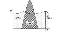
以下、分散型電源システム1における発電電力と、商用電源5Aからの受電電力と、負荷5Bの要求電力と、の関係を、図6Aから6Eを参照しながら説明する。
Hereinafter, the relationship between the generated power in the distributed
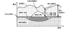
図6Aは、本実施の形態の具体例を示す。図6Aの具体例では、複数の発電装置32は、第1発電装置3および第2発電装置2の2つの発電装置である。第1発電装置3は、排熱を利用して発電する排熱発電装置である。第2発電装置2は、太陽光発電装置である。蓄電機9Aは、蓄電池である。
FIG. 6A shows a specific example of the present embodiment. In the specific example of FIG. 6A, the plurality of
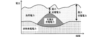
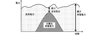
以下の説明では、第1発電装置3の発電電力を、排熱発電電力と称することがある。第2発電装置2の発電電力を、太陽光発電電力と称することがある。負荷5Bの要求電力を、負荷電力と称することがある。負荷5Bが商用電源5Aから受電する電力を、単に受電電力と称することがある。先に述べたように、正であるときに蓄電池9Aの充電電力を指し負であるときの絶対値が蓄電池9Aの放電電力を指す値を充放電電力と称することがある。排熱発電電力および太陽光発電電力の合計から充放電電力を差し引いた値の時間平均を平均出力電力と称することがある。
In the following description, the generated power of the first power generation device 3 may be referred to as waste heat generated power. The generated power of the second power generation device 2 may be referred to as photovoltaic power generation. The required power of the
図6Bの比較例は、蓄電池がない点で、図6Aの例とは異なる。図6Bでは、排熱発電電力および太陽光発電電力の合計は、いつの時間帯においても、負荷電力よりも小さい。昼間時間帯において、太陽光発電電力は大きく、排熱発電電力および太陽光発電電力の合計は最大であり、この合計が負荷電力に最も接近しており、受電電力は最小である。一方、夜間時間帯において、太陽光発電電力はゼロであり、負荷電力が最大であるときに受電電力は最大である。図6Bの比較例では、1日における受電電力の最大値と最小値の偏差が大きい。 The comparative example of FIG. 6B differs from the example of FIG. 6A in that there is no storage battery. In FIG. 6B, the total of the waste heat power generation power and the solar power generation power is smaller than the load power at any time. In the daytime, the photovoltaic power is large, the sum of the exhaust heat generated power and the photovoltaic power is the largest, and this total is the closest to the load power, and the received power is the smallest. On the other hand, in the night time zone, the photovoltaic power generation is zero, and the received power is the maximum when the load power is the maximum. In the comparative example of FIG. 6B, the deviation between the maximum value and the minimum value of the received power in one day is large.
図6Cの比較例は、排熱発電装置がない点で、図6Bの比較例とは異なる。また、図6Cの比較例では、図6Bの比較例に比べ、太陽光発電電力が大きい。図6Cの比較例でも、図6Bの比較例と同様、昼間時間帯において、受電電力は最小である。夜間時間帯において、負荷電力が最大であるときに受電電力が最大である。図6Cの比較例では、図6Bの比較例に比べ、受電電力の最大値が大きく、1日における受電電力の最大値と最小値の偏差が大きい。 The comparative example of FIG. 6C is different from the comparative example of FIG. 6B in that there is no waste heat power generation device. Further, in the comparative example of FIG. 6C, the photovoltaic power generation power is larger than that of the comparative example of FIG. 6B. In the comparative example of FIG. 6C as well as the comparative example of FIG. 6B, the received power is the minimum in the daytime time zone. In the night time zone, the received power is the maximum when the load power is the maximum. In the comparative example of FIG. 6C, the maximum value of the received power is large and the deviation between the maximum value and the minimum value of the received power in one day is large as compared with the comparative example of FIG. 6B.
図6Dの比較例では、図6Cの比較例に比べ、太陽光発電電力が大きい。具体的には、図6Dの比較例では、太陽光発電装置の一日の発電量が図6Bの比較例における排熱発電装置および太陽光発電装置の一日の発電量の合計と同じになるように、太陽光発電電力が得られる場合が想定されている。図6Dの比較例では、太陽光発電電力の最大値が大きい。この最大値が現れる昼間時間帯のある時刻において、この最大値は受電電力よりも大きい。このため、この時刻において、受電電力が負である、つまり、分散型電源システムから商用電源への逆潮流が生じる。また、図6Dの比較例でも、夜間時間帯において、太陽光発電電力はゼロであり、負荷電力が最大である。図6Dの比較例では、図6Cの比較例に比べ、1日における受電電力の最大値と最小値との偏差が大きい。 In the comparative example of FIG. 6D, the photovoltaic power generation is larger than that of the comparative example of FIG. 6C. Specifically, in the comparative example of FIG. 6D, the daily power generation amount of the photovoltaic power generation device is the same as the total daily power generation amount of the exhaust heat power generation device and the photovoltaic power generation device in the comparative example of FIG. 6B. As described above, it is assumed that photovoltaic power generation can be obtained. In the comparative example of FIG. 6D, the maximum value of the photovoltaic power generation is large. At some time during the daytime when this maximum value appears, this maximum value is larger than the received power. Therefore, at this time, the received power is negative, that is, a reverse power flow from the distributed power supply system to the commercial power supply occurs. Further, also in the comparative example of FIG. 6D, the photovoltaic power generation power is zero and the load power is the maximum in the night time zone. In the comparative example of FIG. 6D, the deviation between the maximum value and the minimum value of the received power in one day is larger than that of the comparative example of FIG. 6C.
図6Eの比較例は、排熱発電装置がない点と、図6Dの比較例と同様に太陽光発電電力が大きい点とで、図6Aの例とは異なる。図6Eの比較例では、蓄電池による充放電がなされており、逆潮流は生じていない。また、図6Eの比較例では、図6Bから図6Dの比較例に比べ、1日における受電電力の最大値と最小値との偏差が小さい。しかし、夜間時間帯において太陽光発電電力はゼロであり、昼間時間帯において太陽光発電電力は大きい。このため、蓄電池の充放電電力および蓄電池に蓄電される電力量は大きくなり得る。このため、図6Eの比較例では、大容量の蓄電池が必要となる。 The comparative example of FIG. 6E is different from the example of FIG. 6A in that there is no waste heat power generation device and that the photovoltaic power generation power is large as in the comparative example of FIG. 6D. In the comparative example of FIG. 6E, charging and discharging are performed by the storage battery, and reverse power flow does not occur. Further, in the comparative example of FIG. 6E, the deviation between the maximum value and the minimum value of the received power in one day is smaller than that of the comparative example of FIGS. 6B to 6D. However, the photovoltaic power generation is zero in the night time zone, and the photovoltaic power generation power is large in the daytime zone. Therefore, the charge / discharge power of the storage battery and the amount of power stored in the storage battery can be large. Therefore, in the comparative example of FIG. 6E, a large-capacity storage battery is required.
これに対し、図6Aに示す本実施の形態の具体例では、排熱発電装置3と、太陽光発電装置2と、蓄電池9Aと、を兼ね備えている。また、この具体例では、図5のフローチャートを用いて説明した制御が行われる。このため、蓄電池9Aの充放電電力および蓄電池9Aに蓄電される電力量は抑制され得る。このため、この具体例では、容量の小さい蓄電池9Aを利用しつつ、1日における受電電力の最大値と最小値との偏差を小さくすることができる。
On the other hand, in the specific example of the present embodiment shown in FIG. 6A, the waste heat power generation device 3, the solar power generation device 2, and the
なお、Poutを一定の目標電力に追従させることは、必須ではない。本開示は、
第1発電装置3を含む複数の発電装置32と、
複数の発電装置32に接続された蓄電装置9と、
複数の発電装置32および蓄電装置9に接続された電力入力部6iと、商用電源5Aに接続された電力出力部6оと、を含む電力出力装置6と、
制御装置8と、を備え、
第1発電装置3の発電電力を第1発電電力P1と定義し、正であるときに蓄電装置9の充電電力を指すとともに負であるときの絶対値が蓄電装置9の放電電力を指す値を蓄電装置9の充放電電力Pstorageと定義したとき、制御装置8は、
複数の発電装置32の合計発電電力Psumから指令合計発電電力Psum *を差し引いた差分電力Pdeltaを演算し、
差分電力Pdeltaがゼロよりも大きいときにおいて、充放電電力Pstorageを増加させる第2処理を実行する場合には第2処理を実行する前に第1発電電力P1を減少させる第1処理を実行し、
差分電力Pdeltaがゼロよりも小さいときにおいて、充放電電力Pstorageを減少させる第4処理を実行する場合には第4処理を実行する前に第1発電電力P1を増加させる第3処理を実行する、
分散型電源システム1を提供する、と考えることもできる。このような分散型電源システムは、電力の安定供給に適した安価なシステムとなり得る。
It is not essential to make P out follow a constant target power. This disclosure is
A plurality of
A
A
With a control device 8
The power generated by the first power generation device 3 is defined as the first power generation power P 1, and when it is positive, it indicates the charging power of the
Calculate the differential power P delta by subtracting the command total power generation power P sum * from the total power generation power P sum of the plurality of
When the differential power P delta is larger than zero, when the second process of increasing the charge / discharge power P storage is executed, the first process of decreasing the first generated power P 1 is performed before the second process is executed. Run and
When the differential power P delta is smaller than zero, when the fourth process of reducing the charge / discharge power P storage is executed, the third process of increasing the first generated power P 1 is performed before the fourth process is executed. Run,
It can also be considered to provide the distributed
同様に、本開示は、
第1発電装置3を含む複数の発電装置32と、
複数の発電装置32に接続された蓄電装置9と、
複数の発電装置32および蓄電装置9に接続された電力入力部6iと、商用電源5Aに接続された電力出力部6оと、を含む電力出力装置6と、を備えた分散型電源システム1を制御する制御装置8であって、
第1発電装置3の発電電力を第1発電電力P1と定義し、正であるときに蓄電装置9の充電電力を指すとともに負であるときの絶対値が蓄電装置9の放電電力を指す値を蓄電装置9の充放電電力Pstorageと定義したとき、制御装置8は、
複数の発電装置32の合計発電電力Psumから指令合計発電電力Pstorageを差し引いた差分電力Pdeltaを演算し、
差分電力Pdeltaがゼロよりも大きいときにおいて、充放電電力Pstorageを増加させる第2処理を実行する場合には第2処理を実行する前に第1発電電力P1を減少させる第1処理を実行し、
差分電力Pdeltaがゼロよりも小さいときにおいて、充放電電力Pstorageを減少させる第4処理を実行する場合には第4処理を実行する前に第1発電電力P1を増加させる第3処理を実行する、
制御装置8を提供する、と考えることもできる。
Similarly, this disclosure
A plurality of
A
Controls a distributed
The power generated by the first power generation device 3 is defined as the first power generation power P 1, and when it is positive, it indicates the charging power of the
Calculate the differential power P delta by subtracting the command total power generation power P storage from the total power generation power P sum of the plurality of
When the differential power P delta is larger than zero, when the second process of increasing the charge / discharge power P storage is executed, the first process of decreasing the first generated power P 1 is performed before the second process is executed. Run and
When the differential power P delta is smaller than zero, when the fourth process of reducing the charge / discharge power P storage is executed, the third process of increasing the first generated power P 1 is performed before the fourth process is executed. Run,
It can also be considered to provide the control device 8.
同様に、本開示は、
第1発電装置3を含む複数の発電装置32と、
複数の発電装置32に接続された蓄電装置9と、
複数の発電装置32および蓄電装置9に接続された電力入力部6iと、商用電源5Aに接続された電力出力部6оと、を含む電力出力装置6と、を備えた分散型電源システム1を制御する制御方法であって、
第1発電装置3の発電電力を第1発電電力P1と定義し、正であるときに蓄電装置9の充電電力を指すとともに負であるときの絶対値が蓄電装置9の放電電力を指す値を蓄電装置9の充放電電力Pstorageと定義したとき、
複数の発電装置32の合計発電電力Psumから指令合計発電電力Pstorageを差し引いた差分電力Pdeltaを演算することと、
差分電力Pdeltaがゼロよりも大きいときにおいて、充放電電力Pstorageを増加させる第2処理を実行する場合には第2処理を実行する前に第1発電電力P1を減少させる第1処理を実行することと、
差分電力Pdeltaがゼロよりも小さいときにおいて、充放電電力Pstorageを減少させる第4処理を実行する場合には第4処理を実行する前に第1発電電力P1を増加させる第3処理を実行することと、
を含む、制御方法を提供する、と考えることもできる。
Similarly, this disclosure
A plurality of
A
Controls a distributed
The power generated by the first power generation device 3 is defined as the first power generation power P 1, and when it is positive, it indicates the charging power of the
The difference power P delta obtained by subtracting the command total power generation power P storage from the total power generation power P sum of the plurality of
When the differential power P delta is larger than zero, when the second process of increasing the charge / discharge power P storage is executed, the first process of decreasing the first generated power P 1 is performed before the second process is executed. To do and
When the differential power P delta is smaller than zero, when the fourth process of reducing the charge / discharge power P storage is executed, the third process of increasing the first generated power P 1 is performed before the fourth process is executed. To do and
It can also be thought of as providing a control method, including.
本開示に係る技術によれば、発電調整力を保有する発電装置の発電電力と、再生可能エネルギーを利用した発電装置の発電電力と、の合計を安定させることができる。発電調整力を保有する発電装置としては、排熱を利用した発電装置発電、燃料電池を利用した発電装置等が例示される。再生可能エネルギーを利用した発電装置としては、太陽光を利用した発電装置発電、風力を利用した発電装置等が例示される。 According to the technique according to the present disclosure, it is possible to stabilize the total of the generated power of the power generation device having the power generation adjusting power and the generated power of the power generation device using the renewable energy. Examples of the power generation device having the power generation adjusting power include a power generation device power generation using exhaust heat, a power generation device using a fuel cell, and the like. Examples of the power generation device using renewable energy include a power generation device power generation using sunlight, a power generation device using wind power, and the like.
1 分散型電源システム
2,3 発電装置
2A,3R 発電電源
2B,3H,9B 電力変換機
3A ポンプ
3B 蒸発器
3C 膨張機
3D 温度センサ
3E バイパス弁
3F 凝縮器
3G 発電機
4,7 検出装置
5A 商用電源
5B 負荷
6 電力出力装置
7A 電流検出器
7B 電圧検出器
7C 電力演算部
8 制御装置
9 蓄電装置
9A 蓄電機
10,11,13,16,17,18,19,20,21 スイッチング素子
12,15 リアクトル
14,51,52,53,54,55,56,57,58,59 ダイオード
22,41,42,46,47 コンデンサ
35,36 電路
60 スイッチング回路
61,62,63 相回路
66,67,68 接続点
1 Distributed power supply system 2, 3
Claims (9)
前記複数の発電装置に接続された蓄電装置と、
前記複数の発電装置および前記蓄電装置に接続された電力入力部と、商用電源に接続された電力出力部と、を含む電力出力装置と、
第1検出装置と、
前記電力出力部から出力された電力を表す値であって前記第1検出装置を用いて特定される値である特定電力を一定の目標電力に追従させる制御装置と、を備え、
前記第1発電装置の発電電力を第1発電電力と定義し、正であるときに前記蓄電装置の充電電力を指すとともに負であるときの絶対値が前記蓄電装置の放電電力を指す値を前記蓄電装置の充放電電力と定義したとき、前記制御装置は、
前記複数の発電装置の合計発電電力から指令合計発電電力を差し引いた差分電力を演算し、
前記差分電力がゼロよりも大きいときにおいて、前記充放電電力を増加させる第2処理を実行する場合には前記第2処理を実行する前に前記第1発電電力を減少させる第1処理を実行し、
前記差分電力がゼロよりも小さいときにおいて、前記充放電電力を減少させる第4処理を実行する場合には前記第4処理を実行する前に前記第1発電電力を増加させる第3処理を実行する、
分散型電源システム。 Multiple power generation devices including the first power generation device,
A power storage device connected to the plurality of power generation devices and
A power output device including a power input unit connected to the plurality of power generation devices and the power storage device, and a power output unit connected to a commercial power source.
The first detector and
It is provided with a control device that causes a specific power, which is a value representing the power output from the power output unit and is a value specified by using the first detection device, to follow a constant target power.
The power generated by the first power generation device is defined as the first power generation power, and when it is positive, it refers to the charging power of the power storage device, and when it is negative, the absolute value indicates the discharge power of the power storage device. When defined as the charge / discharge power of the power storage device, the control device is defined as
Calculate the differential power obtained by subtracting the command total power generation power from the total power generation power of the plurality of power generation devices.
When the differential power is larger than zero, when the second process of increasing the charge / discharge power is executed, the first process of reducing the first generated power is executed before the second process is executed. ,
When the differential power is smaller than zero, when the fourth process of reducing the charge / discharge power is executed, the third process of increasing the first generated power is executed before the fourth process is executed. ,
Distributed generation system.
前記第1発電電力は、前記第1発電装置が有する前記指令第1発電電力に追従し、
前記制御周期は、1ミリ秒以下である、
請求項1に記載の分散型電源システム。 The control device updates the command first generated power of the first power generation device at a certain control cycle.
The first generated power follows the commanded first generated power of the first power generation device.
The control cycle is 1 millisecond or less.
The distributed power supply system according to claim 1.
請求項1または2に記載の分散型電源システム。 The first power generation device is a thermoelectric power generation device or a fuel cell power generation device that uses heat to generate power.
The distributed power supply system according to claim 1 or 2.
前記第2発電装置は、再生可能エネルギーを利用した発電装置である、
請求項1から3のいずれか一項に記載の分散型電源システム。 The plurality of power generation devices include a second power generation device.
The second power generation device is a power generation device that uses renewable energy.
The distributed power supply system according to any one of claims 1 to 3.
請求項4に記載の分散型電源システム。 The second power generation device is a solar power generation device or a wind power generation device.
The distributed power supply system according to claim 4.
前記第1処理によって前記指令第1発電電力が前記下限電力に達したときに、前記第2処理が開始され、
前記第3処理によって前記指令第1発電電力が前記上限電力に達したときに、前記第4処理が開始される、
請求項1から5のいずれか一項に記載の分散型電源システム。 The control device sets a lower limit power which is a lower limit of the command first generated power to be followed by the first generated power and an upper limit power which is an upper limit of the command first generated power.
When the command first generated power reaches the lower limit power by the first process, the second process is started.
When the command first generated power reaches the upper limit power by the third process, the fourth process is started.
The distributed power supply system according to any one of claims 1 to 5.
前記第1モードの開始時点における前記第1発電電力は、ゼロよりも大きく前記第1発電電力の定格値よりも小さい、
請求項1から6のいずれか一項に記載の分散型電源システム。 The operation mode executed by the control device includes a first mode in which one of a plurality of processes including the first process, the second process, the third process, and the fourth process is selected and executed.
The first generated power at the start of the first mode is greater than zero and less than the rated value of the first generated power.
The distributed power supply system according to any one of claims 1 to 6.
前記複数の発電装置に接続された蓄電装置と、
前記複数の発電装置および前記蓄電装置に接続された電力入力部と、商用電源に接続された電力出力部と、を含む電力出力装置と、
第1検出装置と、を備えた分散型電源システムを、前記電力出力部から出力された電力を表す値であって前記第1検出装置を用いて特定される値である特定電力を一定の目標電力に追従させるように制御する制御装置であって、
前記第1発電装置の発電電力を第1発電電力と定義し、正であるときに前記蓄電装置の充電電力を指すとともに負であるときの絶対値が前記蓄電装置の放電電力を指す値を前記蓄電装置の充放電電力と定義したとき、前記制御装置は、
前記複数の発電装置の合計発電電力から指令合計発電電力を差し引いた差分電力を演算し、
前記差分電力がゼロよりも大きいときにおいて、前記充放電電力を増加させる第2処理を実行する場合には前記第2処理を実行する前に前記第1発電電力を減少させる第1処理を実行し、
前記差分電力がゼロよりも小さいときにおいて、前記充放電電力を減少させる第4処理を実行する場合には前記第4処理を実行する前に前記第1発電電力を増加させる第3処理を実行する、
制御装置。 Multiple power generation devices including the first power generation device,
A power storage device connected to the plurality of power generation devices and
A power output device including a power input unit connected to the plurality of power generation devices and the power storage device, and a power output unit connected to a commercial power source.
A distributed power supply system including a first detection device has a specific power target, which is a value representing the power output from the power output unit and is a value specified by using the first detection device. It is a control device that controls to follow the electric power.
The power generated by the first power generation device is defined as the first power generation power, and when it is positive, it refers to the charging power of the power storage device, and when it is negative, the absolute value indicates the discharge power of the power storage device. When defined as the charge / discharge power of the power storage device, the control device is defined as
Calculate the differential power obtained by subtracting the command total power generation power from the total power generation power of the plurality of power generation devices.
When the differential power is larger than zero, when the second process of increasing the charge / discharge power is executed, the first process of reducing the first generated power is executed before the second process is executed. ,
When the differential power is smaller than zero, when the fourth process of reducing the charge / discharge power is executed, the third process of increasing the first generated power is executed before the fourth process is executed. ,
Control device.
前記複数の発電装置に接続された蓄電装置と、
前記複数の発電装置および前記蓄電装置に接続された電力入力部と、商用電源に接続された電力出力部と、を含む電力出力装置と、
第1検出装置と、を備えた分散型電源システムを、前記電力出力部から出力された電力を表す値であって前記第1検出装置を用いて特定される値である特定電力を一定の目標電力に追従させるように制御する制御方法であって、
前記第1発電装置の発電電力を第1発電電力と定義し、正であるときに前記蓄電装置の充電電力を指すとともに負であるときの絶対値が前記蓄電装置の放電電力を指す値を前記蓄電装置の充放電電力と定義したとき、
前記複数の発電装置の合計発電電力から指令合計発電電力を差し引いた差分電力を演算することと、
前記差分電力がゼロよりも大きいときにおいて、前記充放電電力を増加させる第2処理を実行する場合には前記第2処理を実行する前に前記第1発電電力を減少させる第1処理を実行することと、
前記差分電力がゼロよりも小さいときにおいて、前記充放電電力を減少させる第4処理を実行する場合には前記第4処理を実行する前に前記第1発電電力を増加させる第3処理を実行することと、
を含む、制御方法。 Multiple power generation devices including the first power generation device,
A power storage device connected to the plurality of power generation devices and
A power output device including a power input unit connected to the plurality of power generation devices and the power storage device, and a power output unit connected to a commercial power source.
A distributed power supply system including a first detection device is provided with a specific power target, which is a value representing the power output from the power output unit and is a value specified by using the first detection device. It is a control method that controls to follow the electric power.
The power generated by the first power generation device is defined as the first power generation power, and when it is positive, it refers to the charging power of the power storage device, and when it is negative, the absolute value indicates the discharge power of the power storage device. When defined as the charge / discharge power of a power storage device,
To calculate the differential power obtained by subtracting the command total power generation power from the total power generation power of the plurality of power generation devices.
When the differential power is larger than zero, when the second process of increasing the charge / discharge power is executed, the first process of reducing the first generated power is executed before the second process is executed. That and
When the differential power is smaller than zero, when the fourth process of reducing the charge / discharge power is executed, the third process of increasing the first generated power is executed before the fourth process is executed. That and
Control methods, including.
Priority Applications (1)
| Application Number | Priority Date | Filing Date | Title |
|---|---|---|---|
| JP2019086555A JP7386470B2 (en) | 2019-04-26 | 2019-04-26 | Distributed power supply system, control device and control method |
Applications Claiming Priority (1)
| Application Number | Priority Date | Filing Date | Title |
|---|---|---|---|
| JP2019086555A JP7386470B2 (en) | 2019-04-26 | 2019-04-26 | Distributed power supply system, control device and control method |
Publications (2)
| Publication Number | Publication Date |
|---|---|
| JP2020184812A true JP2020184812A (en) | 2020-11-12 |
| JP7386470B2 JP7386470B2 (en) | 2023-11-27 |
Family
ID=73045241
Family Applications (1)
| Application Number | Title | Priority Date | Filing Date |
|---|---|---|---|
| JP2019086555A Active JP7386470B2 (en) | 2019-04-26 | 2019-04-26 | Distributed power supply system, control device and control method |
Country Status (1)
| Country | Link |
|---|---|
| JP (1) | JP7386470B2 (en) |
Citations (4)
| Publication number | Priority date | Publication date | Assignee | Title |
|---|---|---|---|---|
| WO2011114422A1 (en) * | 2010-03-15 | 2011-09-22 | 株式会社正興電機製作所 | Power supply system, power supply method, program, recording medium, and power supply controller |
| JP2013110792A (en) * | 2011-11-17 | 2013-06-06 | Fuji Electric Co Ltd | Power stabilization controller, power stabilization program |
| WO2016063517A1 (en) * | 2014-10-23 | 2016-04-28 | 京セラ株式会社 | Power supply device, power supply system, and power supply method |
| JP2017079507A (en) * | 2015-10-19 | 2017-04-27 | 株式会社日立製作所 | Power-supply system of distribution power supply |
-
2019
- 2019-04-26 JP JP2019086555A patent/JP7386470B2/en active Active
Patent Citations (4)
| Publication number | Priority date | Publication date | Assignee | Title |
|---|---|---|---|---|
| WO2011114422A1 (en) * | 2010-03-15 | 2011-09-22 | 株式会社正興電機製作所 | Power supply system, power supply method, program, recording medium, and power supply controller |
| JP2013110792A (en) * | 2011-11-17 | 2013-06-06 | Fuji Electric Co Ltd | Power stabilization controller, power stabilization program |
| WO2016063517A1 (en) * | 2014-10-23 | 2016-04-28 | 京セラ株式会社 | Power supply device, power supply system, and power supply method |
| JP2017079507A (en) * | 2015-10-19 | 2017-04-27 | 株式会社日立製作所 | Power-supply system of distribution power supply |
Also Published As
| Publication number | Publication date |
|---|---|
| JP7386470B2 (en) | 2023-11-27 |
Similar Documents
| Publication | Publication Date | Title |
|---|---|---|
| Shukla et al. | A new analytical MPPT-based induction motor drive for solar PV water pumping system with battery backup | |
| CN102918472B (en) | For the method and apparatus of regulating power converter input voltage | |
| CN104579120A (en) | Control method during photovoltaic power generation off-grid operation | |
| JP2014064451A (en) | Power generation system | |
| CN215830636U (en) | Off-grid wind power generation system | |
| Snyman et al. | Combined low-cost, high-efficient inverter, peak power tracker and regulator for PV applications | |
| JP2006101581A (en) | Grid interconnection inverter | |
| JP7312968B2 (en) | ENERGY SYSTEM AND OPERATION METHOD THEREOF AND VIRTUAL POWER PLANT SYSTEM | |
| Eskander et al. | Energy flow and management of a hybrid wind/PV/fuel cell generation system | |
| CN114977266B (en) | Power conversion module and power supply system | |
| Singh et al. | Solar PV tied electric vehicle charging system using bidirectional DC-DC converter | |
| JP7489648B2 (en) | Distributed power supply system, control device and control method | |
| JP7386470B2 (en) | Distributed power supply system, control device and control method | |
| CN117748581A (en) | Photovoltaic direct-current micro-grid unified control method for off-grid dual mode | |
| JPWO2015005414A1 (en) | Power supply system and heat pump system | |
| CN112600419B (en) | Topological structure of non-isolated three-port converter and control method thereof | |
| US11979021B2 (en) | Electric power system and power conversion device connected to a DC bus | |
| CN104300579B (en) | The control method that a kind of charge controller charges to battery | |
| Ravichandrudu et al. | Design and performance of a bidirectional isolated Dc-Dc converter for renewable power system | |
| Koulali et al. | Control of multi-sources energy PV/fuel cell and battery based multi-level inverter for AC load | |
| CN114844089A (en) | Multi-type energy storage and photovoltaic combined optimization operation control method | |
| Masmoudi et al. | Control and Supervision of a Hybrid Production Unit based on Renewable Energies | |
| TWI903941B (en) | A power distribution and control system for variable frequency compressor | |
| Bhuvaneswari et al. | Hybrid wind–diesel energy systems | |
| JP2015154517A (en) | PV power conditioner |
Legal Events
| Date | Code | Title | Description |
|---|---|---|---|
| A621 | Written request for application examination |
Free format text: JAPANESE INTERMEDIATE CODE: A621 Effective date: 20220325 |
|
| A977 | Report on retrieval |
Free format text: JAPANESE INTERMEDIATE CODE: A971007 Effective date: 20221221 |
|
| A131 | Notification of reasons for refusal |
Free format text: JAPANESE INTERMEDIATE CODE: A131 Effective date: 20230110 |
|
| A521 | Request for written amendment filed |
Free format text: JAPANESE INTERMEDIATE CODE: A523 Effective date: 20230306 |
|
| A131 | Notification of reasons for refusal |
Free format text: JAPANESE INTERMEDIATE CODE: A131 Effective date: 20230627 |
|
| A521 | Request for written amendment filed |
Free format text: JAPANESE INTERMEDIATE CODE: A523 Effective date: 20230821 |
|
| TRDD | Decision of grant or rejection written | ||
| A01 | Written decision to grant a patent or to grant a registration (utility model) |
Free format text: JAPANESE INTERMEDIATE CODE: A01 Effective date: 20231031 |
|
| A61 | First payment of annual fees (during grant procedure) |
Free format text: JAPANESE INTERMEDIATE CODE: A61 Effective date: 20231106 |
|
| R151 | Written notification of patent or utility model registration |
Ref document number: 7386470 Country of ref document: JP Free format text: JAPANESE INTERMEDIATE CODE: R151 |