JP2020181663A - LED lighting device - Google Patents

LED lighting device Download PDF

Info

Publication number
JP2020181663A
JP2020181663A JP2019082655A JP2019082655A JP2020181663A JP 2020181663 A JP2020181663 A JP 2020181663A JP 2019082655 A JP2019082655 A JP 2019082655A JP 2019082655 A JP2019082655 A JP 2019082655A JP 2020181663 A JP2020181663 A JP 2020181663A
Authority
JP
Japan
Prior art keywords
additional function
lighting device
led lighting
fixing
support
Prior art date
Legal status (The legal status is an assumption and is not a legal conclusion. Google has not performed a legal analysis and makes no representation as to the accuracy of the status listed.)
Granted
Application number
JP2019082655A
Other languages
Japanese (ja)
Other versions
JP6704489B1 (en
Inventor
亮 渡邊
Akira Watanabe
亮 渡邊
Current Assignee (The listed assignees may be inaccurate. Google has not performed a legal analysis and makes no representation or warranty as to the accuracy of the list.)
Moyai Co
Original Assignee
Moyai Co
Priority date (The priority date is an assumption and is not a legal conclusion. Google has not performed a legal analysis and makes no representation as to the accuracy of the date listed.)
Filing date
Publication date
Application filed by Moyai Co filed Critical Moyai Co
Priority to JP2019082655A priority Critical patent/JP6704489B1/en
Application granted granted Critical
Publication of JP6704489B1 publication Critical patent/JP6704489B1/en
Publication of JP2020181663A publication Critical patent/JP2020181663A/en
Active legal-status Critical Current
Anticipated expiration legal-status Critical

Links

Images

Landscapes

  • Arrangement Of Elements, Cooling, Sealing, Or The Like Of Lighting Devices (AREA)
  • Non-Portable Lighting Devices Or Systems Thereof (AREA)

Abstract

To provide an LED lighting device that can have, an additional function storage housing part, rotatable reflective to a lighting part, easily attached to and detached from the lighting part, makes it easy to secure a storage space for storing a function part of the additional function storage housing part, and further can stably support the additional function storage housing part.SOLUTION: An LED lighting device has: a lighting part 10 which has a straight tube type cover part 11 including a light-transmissive part, a support part 12 where an LED is installed, and a first ferrule part 13 fixed to one end part of the support part 12; and an additional function storage housing part 40 which has a rotary guide part 30 having a functional part 20, a one end-side fixed part 31 fixing a support part 12, an other end-side fixed part 32 fixing a second ferrule 70, and an intermediate connection part 33 connecting the one end-side fixed part 31 and other end-side fixed part 32 forming an arcuate cross sectional shape, a rotary support part 50, and a storage space enlargement formation part 60 having a storage space of the function part 20 expanded radially outward from an axial center of the rotary guide part 30 to fixedly connect with the rotary support part 50.SELECTED DRAWING: Figure 2

Description

本発明は、直管状蛍光灯のソケットに取り付けられるLED照明装置に関する。 The present invention relates to an LED lighting device attached to a socket of a straight tubular fluorescent lamp.

従来、直管型の蛍光管を有する蛍光灯、いわゆる直管状蛍光灯は、省電力化の流れから光源となるLED(Light Emitting Diode)を光透過部分を含む直管状カバーの内部に設けたLED照明装置に置き換えるようになってきている。
このようなLED照明装置は、電源を交流電源から直流電源に変換するとともに電気配線を変更することによってLEDへの電源供給を可能にしている。
しかも、LED照明装置は、直流電源から給電可能となったことにより、センサー、カメラ等の機能部を照明以外の付加機能として容易に組み込むことができるようになった。
Conventionally, a fluorescent lamp having a straight tube type fluorescent tube, that is, a so-called straight tubular fluorescent lamp, is an LED in which an LED (Light Emitting Diode) as a light source is provided inside a straight tubular cover including a light transmitting portion due to the trend of power saving. It is being replaced with a lighting device.
Such an LED lighting device makes it possible to supply power to the LED by converting the power supply from an AC power supply to a DC power supply and changing the electrical wiring.
Moreover, since the LED lighting device can be supplied with power from a DC power source, functional parts such as sensors and cameras can be easily incorporated as additional functions other than lighting.

例えば、特許文献1には、蛍光灯器具(直管状蛍光灯)のソケットに接続する照明部の一端側の接続部に、外側収容部と、外側収容部の内側において照明部の周方向に回動可能に設けられ、内部に機能部としての撮像部あるいは検出部が設けられた内側収容部と、を有し、これら外側収容部および内側収容部によって機能部が収容される付加機能収容筐体部を構成したLED照明が記載されている。
この特許文献1に記載のLED照明は、内側収容部を外側収容部内で回動させることによって、撮像部による撮影方向、あるいは、検出部による検出位置を変化させるようにしている。
また、特許文献1に記載のLED照明は、照明部に接続した外側収容部に対して内側収容部を容易に着脱することができるようになっているので、結果的に、機能部を内部に収容した内側収容部を照明部に容易に着脱することができる構造になっている。
For example, in Patent Document 1, the outer accommodating portion and the inside of the outer accommodating portion are rotated in the circumferential direction of the illuminating portion at the connection portion on one end side of the illuminating portion connected to the socket of the fluorescent lamp fixture (straight tubular fluorescent lamp). An additional function accommodating housing that is movably provided and has an inner accommodating portion provided with an imaging unit or a detection unit as a functional unit inside, and the functional unit is accommodated by these outer accommodating portions and the inner accommodating portion. The LED lighting that constitutes the unit is described.
In the LED illumination described in Patent Document 1, the inner accommodating portion is rotated in the outer accommodating portion to change the photographing direction by the imaging unit or the detection position by the detection unit.
Further, in the LED lighting described in Patent Document 1, the inner accommodating portion can be easily attached to and detached from the outer accommodating portion connected to the lighting portion, and as a result, the functional portion is placed inside. The structure is such that the housed inner housing part can be easily attached to and detached from the lighting part.

特開2014−110181号公報Japanese Unexamined Patent Publication No. 2014-110181

しかしながら、特許文献1に記載のLED照明は、付加機能収容筐体部が、円筒状の外側収容部、および、円筒状の内側収容部を有する2重の収容構造となっており、内側収容部を収容する外側収容部が内側収容部の回動をガイドする部分として機能するようになっている。
このため、機能部を収容するための収容空間を形成する内側収容部が外側収容部の収容空間の大きさに比して小さく制約され、収容空間を大きく確保することが難しくなり、結果的に、収容できる機能部も限定される問題がある。
However, the LED lighting described in Patent Document 1 has a double accommodating structure in which the additional function accommodating housing portion has a cylindrical outer accommodating portion and a cylindrical inner accommodating portion, and the inner accommodating portion. The outer accommodating portion for accommodating the inner accommodating portion functions as a portion for guiding the rotation of the inner accommodating portion.
For this reason, the inner accommodating portion forming the accommodating space for accommodating the functional portion is restricted to be smaller than the size of the accommodating space of the outer accommodating portion, and it becomes difficult to secure a large accommodating space as a result. There is a problem that the functional parts that can be accommodated are also limited.

この問題を解消するために、特許文献1に記載されたLED照明は、外側収容部の直径を大きく設定し、それに対応して内側収容部の直径を大きく設定することによって内側収容部の収容空間を大きくすることができるが、外側収容部および内側収容部が照明部の軸に対して、天井側領域も含めた外径方向全周にわたって照明部の外径よりも大きく外径を拡大することになるため、取付け先の天井側領域のカバー等に干渉し易くなり、既存のソケット位置を利用して取り付けることが難しくなってしまう問題があった。
また、機能部の性能を上げると、重量が増し、外側収容部が固定される直管状の収容部の端部にかかる重量負荷が大きくなり、回動させる部分ともなる付加機能収容筐体部の支持性能が不安定になるおそれがあった。
In order to solve this problem, in the LED lighting described in Patent Document 1, the diameter of the outer accommodating portion is set to be large, and the diameter of the inner accommodating portion is set to be correspondingly large to accommodate the inner accommodating portion. However, the outer diameter of the outer and inner housings should be larger than the outer diameter of the lighting unit over the entire circumference in the outer diameter direction including the ceiling side area with respect to the axis of the lighting unit. Therefore, there is a problem that it easily interferes with the cover or the like of the ceiling side area of the mounting destination, and it becomes difficult to mount using the existing socket position.
Further, if the performance of the functional portion is improved, the weight increases, the weight load applied to the end of the straight tubular accommodating portion to which the outer accommodating portion is fixed increases, and the additional function accommodating housing portion that also serves as a rotating portion. There was a risk of unstable support performance.

本発明は、上記に鑑みてなされたものであって、照明部に対して回動可能な付加機能収容筐体部を照明部に容易に着脱することができ、かつ、付加機能収容筐体部の機能部を収容するための収容空間を確保し易くすることができ、しかも、付加機能収容筐体部を安定的に支持することがでるLED照明装置を提供することを目的とする。 The present invention has been made in view of the above, and the additional function accommodating housing unit that can be rotated with respect to the lighting unit can be easily attached to and detached from the lighting unit, and the additional function accommodating housing unit can be easily attached to and detached from the lighting unit. It is an object of the present invention to provide an LED lighting device capable of easily securing a storage space for accommodating a functional portion of the above and further stably supporting an additional function accommodating housing portion.

上述した課題を解決し、目的を達成するために、本発明に係るLED照明装置は、内部に設けられたLEDの光を外部に出射する光透過性の部分を含む直管状カバー部と、前記直管状カバー部の一端側から他端側まで延びるように該直管状カバー部の内部に配置され、かつ、前記LEDが設置される支持部と、直管状蛍光灯の一方のソケットから電源供給可能に接続されるように前記支持部の一端部に固定される第一口金部と、を有する照明部と、前記照明部を介して電源が供給される機能部と、一端側に前記支持部の他端部を固定する部分となる一端側固定部と、他端側に直管状蛍光灯の他方のソケットに接続される第二口金部を固定する部分となる他端側固定部と、前記一端側固定部と前記他端側固定部との間を天井側領域を残すように円筒の一部に切欠き部を形成した円弧状の横断面をなして連接する中間連接部と、有する回動ガイド部と、前記回動ガイド部の天井側領域の外周面に沿う円弧状断面部を有し、前記回動ガイド部に対して前記円弧状断面部を支持部分として回動可能に前記外周面に取り付けられる回動支持部と、該回動支持部と連結固定可能に前記中間連接部の内面側に前記切欠き部を含む前記機能部の収容空間を前記回動ガイド部の軸中心から径外方向にさらに拡大させた収容空間拡大形成部と、を有する付加機能収容筐体部と、を有することを特徴とする。 In order to solve the above-mentioned problems and achieve the object, the LED lighting device according to the present invention includes a straight tubular cover portion including a light transmitting portion that emits the light of the LED provided inside and the above. Power can be supplied from the support portion where the LED is installed and one socket of the straight tubular fluorescent lamp, which is arranged inside the straight tubular cover portion so as to extend from one end side to the other end side of the straight tubular cover portion. A lighting unit having a first base portion fixed to one end portion of the support portion so as to be connected to, a functional portion to which power is supplied via the lighting portion, and the support portion on one end side. One end side fixing part which is a part for fixing the other end part of the above, and the other end side fixing part which is a part for fixing the second base part connected to the other socket of the straight tubular fluorescent lamp on the other end side. An intermediate connecting portion that is connected by forming an arc-shaped cross section in which a notch is formed in a part of the cylinder so as to leave a ceiling side region between the fixing portion on one end side and the fixing portion on the other end side. The outer peripheral portion has a motion guide portion and an arc-shaped cross section along the outer peripheral surface of the ceiling side region of the rotation guide portion, and can rotate with the arc-shaped cross section as a support portion with respect to the rotation guide portion. The accommodation space of the rotation support portion attached to the surface and the functional portion including the notch on the inner surface side of the intermediate connecting portion so as to be connected and fixed to the rotation support portion is provided from the axial center of the rotation guide portion. It is characterized by having an additional function accommodating housing portion having an accommodating space expansion forming portion further expanded in the outer diameter direction.

また、本発明に係るLED照明装置は、上記の発明において、前記付加機能収容筐体部が、前記収容空間拡大形成部が、前記機能部による外部情報検出側の面以外の面を絶縁脂材からなる壁で形成され、かつ、絶縁樹材からなる両側壁の少なくとも一方の側壁の内面に無線通信用のアンテナが配置されており、前記回動支持部が、金属薄板材からなり、前記収容空間拡大形成部との連結固定完了状態では、前記収容空間拡大形成部の前記両側壁の外面の少なくとも一部を覆うように前記円弧状断面部の両端が延在しており、前記アンテナに対応した位置の前記外面領域は電波を通し易くするための覆わないように形成されていることを特徴とする。 Further, in the LED lighting device according to the present invention, in the above invention, the additional function accommodating housing portion, the accommodating space expansion forming portion, and the surface other than the surface on the external information detection side by the functional unit are made of an insulating fat material. An antenna for wireless communication is arranged on the inner surface of at least one side wall of both side walls formed of a wall made of an insulating tree material, and the rotation support portion is made of a thin metal plate material and is accommodated. In the state where the connection and fixing with the space expansion forming portion are completed, both ends of the arc-shaped cross section extend so as to cover at least a part of the outer surface of the both side walls of the accommodation space expansion forming portion, which corresponds to the antenna. The outer surface region at the designated position is characterized in that it is formed so as not to cover it so as to facilitate the passage of radio waves.

また、本発明に係るLED照明装置は、上記の発明において、前記付加機能収容筐体部が、内部に収容される前記機能部が光透過性部材を通して外部情報を検出することができるものである場合、前記機能部による外部情報の検出側の面に別体の光透過性部材からなる光透過性壁部を有することを特徴とする。 Further, in the LED lighting device according to the present invention, in the above invention, the additional function accommodating housing portion can detect external information through the light transmissive member. In the case, it is characterized by having a light transmitting wall portion made of a separate light transmitting member on the surface on the detection side of external information by the functional unit.

本発明に係るLED照明装置は、前記付加機能収容筐体部が前記回動ガイド部の天井側領域の外周面に前記回動ガイド部に対して前記円弧状断面部を支持部分として所定の回動位置で取り付け固定できるようになっている。
また、本発明に係るLED照明装置は、前記付加機能収容筐体部が、前記回動支持部が回動ガイド部の天井側領域の外周面に沿うことによって、前記回動ガイド部の軸を中心として回動可能に支持され、前記中間連接部の内面側に前記切欠き部を含む前記機能部の収容空間を前記回動ガイド部の軸中心から径外方向にさらに拡大させるようになっているので、天井側領域に寸法が拡大することを抑えることができるようになっている。
しかも、本発明に係るLED照明装置は、前記回動ガイド部が一端側に前記照明部の前記支持部の端部が連結固定され、他端側に前記第二口金部が固定されることによって、前記第一口金部から前記第二口金部まで略一体型の直管状に構成されているので、前記第一口金部から前記第二口金部まで剛性を有して直管状蛍光灯の両ソケットの間に支持固定されている。
従いまして、本発明に係るLED照明装置は、照明部に対して回動可能な付加機能収容筐体部を照明部に容易に着脱することができ、かつ、付加機能収容筐体部の機能部を収容するための収容空間を確保し易くすることができ、しかも、付加機能収容筐体部を安定的に支持することがでる。
In the LED lighting device according to the present invention, the additional function accommodating housing portion is formed on the outer peripheral surface of the ceiling side region of the rotation guide portion by a predetermined rotation with the arc-shaped cross section as a support portion with respect to the rotation guide portion. It can be installed and fixed in the moving position.
Further, in the LED lighting device according to the present invention, the additional function accommodating housing portion has the axis of the rotation guide portion formed by the rotation support portion along the outer peripheral surface of the ceiling side region of the rotation guide portion. It is rotatably supported as a center, and the accommodation space of the functional portion including the notch on the inner surface side of the intermediate connecting portion is further expanded in the outer diameter direction from the axial center of the rotation guide portion. Therefore, it is possible to prevent the size from expanding to the ceiling side area.
Moreover, in the LED lighting device according to the present invention, the rotation guide portion is connected and fixed to one end side of the support portion of the lighting portion, and the second base portion is fixed to the other end side. Since the straight tubular shape is substantially integrated from the first base portion to the second base portion, the straight tubular fluorescent lamp has rigidity from the first base portion to the second base portion. It is supported and fixed between both sockets.
Therefore, in the LED lighting device according to the present invention, the additional function accommodating housing portion that is rotatable with respect to the illumination portion can be easily attached to and detached from the lighting portion, and the functional portion of the additional function accommodating housing portion. It is possible to easily secure a storage space for accommodating the LED, and it is possible to stably support the additional function accommodating housing portion.

図1は、本発明の実施例に係るLED照明装置の斜視図である。FIG. 1 is a perspective view of an LED lighting device according to an embodiment of the present invention. 図2は、本発明の実施例に係るLED照明装置の分解斜視図である。FIG. 2 is an exploded perspective view of the LED lighting device according to the embodiment of the present invention. 図3は、図1に示したLED照明装置の底面図である。FIG. 3 is a bottom view of the LED lighting device shown in FIG. 図4は、(a)が、図1に示したLED照明装置の上面図であり、(b)が、LED照明装置の側面図である。4A is a top view of the LED lighting device shown in FIG. 1, and FIG. 4B is a side view of the LED lighting device. 図5は、(a)が、図1に示したLED照明装置の照明部側から視た側面図であり、(b)が、LED照明装置の付加機能収容筐体部側から視た側面図である。5A and 5B are side views of the LED lighting device shown in FIG. 1 as viewed from the lighting unit side, and FIG. 5B is a side view of the LED lighting device as viewed from the additional function accommodating housing unit side. Is. 図6は、付加機能収容筐体部を回動ガイド部から離脱した状態を示した分解斜視図である。FIG. 6 is an exploded perspective view showing a state in which the additional function accommodating housing portion is separated from the rotation guide portion. 図7は、収容空間拡大形成部の斜視図である。FIG. 7 is a perspective view of the accommodation space expansion forming portion. 図8は、(a)が、支持部の斜視図であり、(b)が、(a)に示した支持部の回動ガイド部に連結固定される側の端部を拡大した図であり、(c)が、(a)に示した支持部の第一口金部に連結固定される側の端部を拡大した図である。8A is a perspective view of the support portion, and FIG. 8B is an enlarged view of the end portion of the support portion shown in FIG. 8 on the side connected and fixed to the rotation guide portion. , (C) is an enlarged view of the end portion on the side connected and fixed to the first base portion of the support portion shown in (a). 図9は、(a)が、第一口金部の口金本体を外側から視た斜視図であり、(b)が、第一口金部の口金本体を内側から視た斜視図である。9A and 9B are perspective views of the base body of the first base portion as viewed from the outside, and FIG. 9B is a perspective view of the base body of the first base portion as viewed from the inside. 図10は、(a)が、回動ガイド部を第二口金部の固定側端部の斜め下方位置から視た斜視図であり、(b)が、支持部との接続側端部の斜め下方位置から視た斜視図である。10A and 10B are perspective views in which the rotation guide portion is viewed from an obliquely downward position of the fixed side end portion of the second base portion, and FIG. 10B is an oblique view of the connection side end portion with the support portion. It is a perspective view seen from the lower position. 図11は、収容空間拡大形成部の前壁に形成された開口を塞ぐカバーを外した状態の付加機能収容筐体部周辺の斜視図である。FIG. 11 is a perspective view of the periphery of the additional function accommodating housing portion in a state where the cover for closing the opening formed in the front wall of the accommodating space expansion forming portion is removed. 図12は、(a)および(b)が、図5(b)に示した位置にある付加機能収容筐体部を回動ガイド部を支軸として回動した状態を示した図である。12 (a) and 12 (b) are views showing a state in which the additional function accommodating housing portion at the position shown in FIG. 5 (b) is rotated around the rotation guide portion as a support shaft.

以下、図面を参照して、本発明に係るLED照明装置の好適な実施例を詳細に説明する。 Hereinafter, preferred embodiments of the LED lighting device according to the present invention will be described in detail with reference to the drawings.

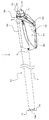
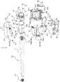
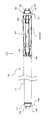
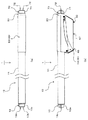
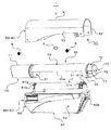
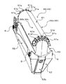
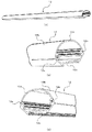
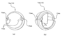
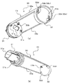
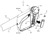
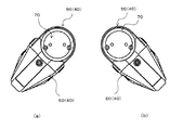
図1は、本発明の実施例に係るLED照明装置1の斜視図である。図2は、本発明の実施例に係るLED照明装置1の分解斜視図である。図3は、図1に示したLED照明装置1の底面図である。図4は、(a)が、図1に示したLED照明装置1の上面図であり、(b)が、LED照明装置1の側面図である。図5は、(a)が、図1に示したLED照明装置1の照明部10側から視た側面図であり、(b)が、LED照明装置1の付加機能収容筐体部40側から視た側面図である。図6は、付加機能収容筐体部40を回動ガイド部30から離脱した状態を示した分解斜視図である。図7は、収容空間拡大形成部60の斜視図である。図8は、(a)が、支持部12の斜視図であり、(b)が、(a)に示した支持部12の回動ガイド部30に連結固定される側の端部を拡大した図であり、(c)が、(a)に示した支持部12の第一口金部13に連結固定される側の端部を拡大した図である。図9は、(a)が、第一口金部13の口金本体13aを外側から視た斜視図であり、(b)が、第一口金部13の口金本体13aを内側から視た斜視図である。図10は、(a)が、回動ガイド部30を第二口金部70の固定側端部の斜め下方位置から視た斜視図であり、(b)が、支持部12との接続側端部の斜め下方位置から視た斜視図である。図11は、収容空間拡大形成部60の前壁63に形成された開口63aを塞ぐカバー63bを外した状態の付加機能収容筐体部40周辺の斜視図である。図12は、(a)および(b)が、図5(b)に示した位置にある付加機能収容筐体部40を回動ガイド部30を支軸として回動した状態を示した図である。
本発明の実施例に係るLED照明装置1は、例えば、電車の天井付近に設置された既存の直管型の蛍光管を有する蛍光灯、いわゆる直管状蛍光灯の2つのソケットに取り付けられるものである。
FIG. 1 is a perspective view of the LED lighting device 1 according to the embodiment of the present invention. FIG. 2 is an exploded perspective view of the LED lighting device 1 according to the embodiment of the present invention. FIG. 3 is a bottom view of the LED lighting device 1 shown in FIG. 4A is a top view of the LED lighting device 1 shown in FIG. 1, and FIG. 4B is a side view of the LED lighting device 1. 5A is a side view of the LED lighting device 1 shown in FIG. 1 as viewed from the lighting unit 10 side, and FIG. 5B is a side view of the LED lighting device 1 from the additional function accommodating housing 40 side. It is a side view as seen. FIG. 6 is an exploded perspective view showing a state in which the additional function accommodating housing portion 40 is separated from the rotation guide portion 30. FIG. 7 is a perspective view of the accommodation space expansion forming portion 60. 8A is a perspective view of the support portion 12, and FIG. 8B is an enlarged view of the end portion of the support portion 12 shown in FIG. 8 on the side connected and fixed to the rotation guide portion 30. FIG. 3C is an enlarged view of an end portion of the support portion 12 shown in FIG. 12 on the side connected and fixed to the first base portion 13. 9A and 9B are perspective views of the base body 13a of the first base portion 13 as viewed from the outside, and FIG. 9B is a perspective view of the base body 13a of the first base portion 13 as viewed from the inside. It is a figure. 10A and 10B are perspective views in which the rotation guide portion 30 is viewed from a diagonally downward position of the fixed side end portion of the second base portion 70, and FIG. 10B is a connection side end portion with the support portion 12. It is a perspective view seen from the diagonally lower position of a portion. FIG. 11 is a perspective view of the periphery of the additional function accommodating housing portion 40 in a state where the cover 63b that closes the opening 63a formed in the front wall 63 of the accommodating space expansion forming portion 60 is removed. 12 (a) and 12 (b) are views showing a state in which the additional function accommodating housing portion 40 at the position shown in FIG. 5 (b) is rotated around the rotation guide portion 30 as a support axis. is there.
The LED lighting device 1 according to the embodiment of the present invention is attached to, for example, two sockets of an existing fluorescent lamp having a straight tube type fluorescent tube installed near the ceiling of a train, that is, a so-called straight tubular fluorescent lamp. is there.

LED照明装置1は、LEDの光を出射する照明部分である照明部10と、カメラ等の照明以外の付加機能を有する機能部20と、回動ガイド部30と、機能部20が収容される部分であり、回動ガイド部の軸を中心として回動角度を変化させた位置で回動ガイド部30に固定される付加機能収容筐体部40と、を有する。 The LED lighting device 1 includes a lighting unit 10 which is a lighting portion that emits LED light, a functional unit 20 having additional functions other than lighting of a camera or the like, a rotation guide unit 30, and a functional unit 20. It is a portion, and has an additional function accommodating housing portion 40 fixed to the rotation guide portion 30 at a position where the rotation angle is changed about the axis of the rotation guide portion.

まず、照明部10について説明する。
照明部10は、内部に設けられたLEDの光を外部に出射する光透過性の部分を含む直管状カバー部11と、直管状カバー部11の一端側から他端側まで延びるように直管状カバー部11の内部に配置され、かつ、LEDが設置される支持部12と、直管状蛍光灯の一方のソケットから電源供給可能に接続されるように支持部12の一端部に固定される第一口金部13と、を有する。
First, the lighting unit 10 will be described.
The illumination unit 10 includes a straight tubular cover portion 11 including a light transmitting portion that emits the light of the LED provided inside, and a straight tubular cover portion 11 extending from one end side to the other end side of the straight tubular cover portion 11. A second unit that is arranged inside the cover portion 11 and is fixed to one end of the support portion 12 so as to be connected to the support portion 12 on which the LED is installed so that power can be supplied from one socket of the straight tubular fluorescent lamp. It has a bite portion 13.

直管状カバー部11は、直管状のガラス部材の外周面をPET(polyethylene terephthalate)等の飛散防止フィルムで覆った光透過性の直管状部分である。
なお、直管状カバー部11は、ガラス部材に限らず、LEDの光を外部に出射する光透過性の部分を含む部材であれば、ポリカーボネート等のその他の材質からなるものであっても構わない。
The straight tubular cover portion 11 is a light-transmitting straight tubular portion in which the outer peripheral surface of the straight tubular glass member is covered with a shatterproof film such as PET (polyethylene terephthalate).
The straight tubular cover portion 11 is not limited to the glass member, and may be made of another material such as polycarbonate as long as it is a member including a light transmitting portion that emits LED light to the outside. ..

この直管状カバー部11は、内部に不図示の複数のLEDが設置された支持部12と、直管状蛍光灯の一方のソケットから供給された交流電圧(例えば、AC100V〜200V)を、所定の直流電圧に変換する回路がボックス内に形成された不図示の電源制御回路部が収容されている。 The straight tubular cover portion 11 has a predetermined support portion 12 in which a plurality of LEDs (not shown) are installed, and an AC voltage (for example, AC100V to 200V) supplied from one socket of the straight tubular fluorescent lamp. A power supply control circuit unit (not shown) in which a circuit for converting to a DC voltage is formed in a box is housed.

電源制御回路部は、第一口金部13および複数のLEDに電気的に接続され、さらに、不図示のコネクタを介して機能部20に電気的に接続可能になっている。
この電源制御回路部は、第一口金部13から供給された電源を、複数のLEDへの所定の直流電圧、および、機能部20への所定の直流電圧(例えば、DC5V)に変換して供給するものである。
電源制御回路部は、例えば、機能部20のコネクタ25に接続されるコネクタが電線を介して直管状カバー部11の外に引き出し可能になっている。
The power supply control circuit unit is electrically connected to the first base unit 13 and a plurality of LEDs, and is also electrically connectable to the functional unit 20 via a connector (not shown).
The power supply control circuit unit converts the power supply supplied from the first base unit 13 into a predetermined DC voltage to the plurality of LEDs and a predetermined DC voltage (for example, DC5V) to the functional unit 20. It is what we supply.
In the power supply control circuit unit, for example, the connector connected to the connector 25 of the functional unit 20 can be pulled out of the straight tubular cover portion 11 via an electric wire.

支持部12は、例えば、放熱性に優れたアルミニウム材からなる筒状部材であり、図8に示すように、回動ガイド部30に連結固定される側の端部(図8(b)参照)、および、第一口金部13に連結固定される側の端部(図8(c)参照)のそれぞれに、回動ガイド部30および第一口金部13にネジ止め固定を可能とするネジ止め固定部12aが設けられている。 The support portion 12 is, for example, a tubular member made of an aluminum material having excellent heat dissipation, and as shown in FIG. 8, the end portion on the side connected and fixed to the rotation guide portion 30 (see FIG. 8B). ) And the end portion (see FIG. 8C) on the side to be connected and fixed to the first base portion 13, each of which can be screwed and fixed to the rotation guide portion 30 and the first base portion 13. A screw fixing portion 12a is provided.

また、支持部12は、直管状カバー部11の内周面を下側から支える面となるカバー支持面12bと、LEDが設置される面となるLED設置面12cと、が形成されている。
この支持部12は、カバー支持面12bを形成する壁と、LED設置面12cを形成する壁とが筒状をなす壁の一部になっているため、LEDの放熱面を広く確保することができるようになっている。
Further, the support portion 12 is formed with a cover support surface 12b that is a surface that supports the inner peripheral surface of the straight tubular cover portion 11 from below, and an LED installation surface 12c that is a surface on which the LED is installed.
Since the wall forming the cover support surface 12b and the wall forming the LED installation surface 12c form a part of the tubular wall, the support portion 12 can secure a wide heat dissipation surface of the LED. You can do it.

また、支持部12は、第一口金部13と、回動ガイド部30の後述する一端側固定部31とに連結固定されることによって、LED照明装置1の一端側となる第一口金部13から、他端側となる第二口金部70まで、付加機能収容筐体部40の回動軸となる回動ガイド部30を含めた軸方向に沿って直線状に連結固定することを可能にしている。 Further, the support portion 12 is connected and fixed to the first base portion 13 and the one end side fixing portion 31 of the rotation guide portion 30, which will be described later, so that the first base portion becomes one end side of the LED lighting device 1. From the portion 13 to the second base portion 70 on the other end side, the additional function accommodating housing portion 40 is linearly connected and fixed along the axial direction including the rotation guide portion 30 which is the rotation axis. It is possible.

第一口金部13は、直管状蛍光灯の一方のソケットに接続されるようになっている。この第一口金部13は、支持部12の一端部に固定される部分となる口金本体13aと、電気接続部分となる2本のピン13bと、を有し、2本のピン13bが直管状蛍光灯のソケットに装着可能な形状になっている。
口金本体13aは、2本のピンを挿通するピン挿通孔13aaと、支持部12の一端部にネジ止め固定するためのネジSを挿通する2つのネジ挿通孔13abが形成されている。
The first base portion 13 is connected to one socket of a straight tubular fluorescent lamp. The first base portion 13 has a base main body 13a which is a portion fixed to one end of a support portion 12 and two pins 13b which are electrical connection portions, and the two pins 13b are directly connected. It is shaped so that it can be attached to the socket of a tubular fluorescent lamp.
The base body 13a is formed with a pin insertion hole 13aa through which two pins are inserted and two screw insertion holes 13ab through which a screw S for screwing and fixing is inserted into one end of the support portion 12.

次に、機能部20について説明する。
機能部20は、照明部10を介して供給される電源の接続部分となるコネクタ25(図2参照)を有し、照明部10を介して電源が供給されるようになっている。
この機能部20は、図2に示すように、カメラ機能、およびそれに関連した機能を実行させる制御回路が形成された第一回路基板21および第二回路基板27と、第二回路基板27を含むカメラモジュール28と、を有する。
Next, the functional unit 20 will be described.
The functional unit 20 has a connector 25 (see FIG. 2) that serves as a connection portion for power supplied via the lighting unit 10, and power is supplied via the lighting unit 10.
As shown in FIG. 2, the functional unit 20 includes a first circuit board 21 and a second circuit board 27 on which a control circuit for executing a camera function and related functions is formed, and a second circuit board 27. It has a camera module 28 and.

第一回路基板21は、照明部10を介して供給される電源の接続部分となるコネクタ25を有し、マイクロSD等の不図示のメモリカードを記憶媒体とする記憶部としての第一カードスロット22、複数のLED照明装置1の各装置を識別するための装置識別情報が記憶された不図示のSIMカードを記憶媒体とする記憶部としての第二カードスロット23、無線通信部としての通信モジュール24、カメラモジュール28と接続されるコネクタ25、機能を拡張するための複数の拡張コネクタ26が実装されている。 The first circuit board 21 has a connector 25 that serves as a connection portion for a power supply supplied via the illumination unit 10, and is a first card slot as a storage unit that uses a memory card (not shown) such as a micro SD as a storage medium. 22. Second card slot 23 as a storage unit using a SIM card (not shown) in which device identification information for identifying each device of the plurality of LED lighting devices 1 is stored as a storage medium, and a communication module as a wireless communication unit. 24, a connector 25 connected to the camera module 28, and a plurality of expansion connectors 26 for expanding functions are mounted.

第一カードスロット22は、メモリカードを記憶媒体として、カメラモジュール28によって撮像された動画、あるいは、静止画を記憶するものである。
この第一カードスロット22、および、第二カードスロット23は、例えば、第一回路基板21の照明部10側とは逆側の端部、すなわち、第二口金部70側の端部に配置されている
なお、この実施例のLED照明装置1は、通常時には、撮像情報をメモリカードに記憶し、必要時には、無線通信経由で直接的に撮像情報のライブデータを抽出することができるようになっている。
The first card slot 22 stores a moving image or a still image captured by the camera module 28 using a memory card as a storage medium.
The first card slot 22 and the second card slot 23 are arranged, for example, at an end portion of the first circuit board 21 opposite to the illumination unit 10 side, that is, an end portion on the second base portion 70 side. The LED lighting device 1 of this embodiment can store image pickup information in a memory card at normal times, and can directly extract live data of image pickup information via wireless communication when necessary. ing.

通信モジュール24は、移動体の内部であっても安定した通信ができる第4世代移動通信システム、例えば、LTE(登録商標)を通信方式として用いている。
この通信モジュール24は、付加機能収容筐体部40に配置されたアンテナ24aに接続されている。
なお、この実施例では、アンテナ24aは、いわゆるフィルムアンテナを用いており、付加機能収容筐体部40の後述する収容空間拡大形成部60の内壁面に貼り付けることができるようになっている。
このような通信モジュール24は、収容空間拡大形成部60に配置されたアンテナ24aによって無線信号の送受信がされるようになっている。
The communication module 24 uses a fourth-generation mobile communication system capable of stable communication even inside a mobile body, for example, LTE (registered trademark) as a communication method.
The communication module 24 is connected to an antenna 24a arranged in the additional function accommodating housing 40.
In this embodiment, the antenna 24a uses a so-called film antenna, and can be attached to the inner wall surface of the accommodation space expansion forming portion 60 described later of the additional function accommodation housing portion 40.
Such a communication module 24 is adapted to transmit and receive radio signals by an antenna 24a arranged in the accommodation space expansion forming unit 60.

なお、この実施例のLED照明装置1は、通信モジュール24が、LTEを通信方式とするものを例示したが、これに限らず、無線通信を可能にするものであればその他の通信方式を用いても構わない。例えば、WiFi(登録商標)を通信方式とした通信モジュールを用いてもよい。あるいは、第5世代移動通信システムを通信方式とした通信モジュールを用いてもよい。さらには、LTEおよびWiFiの両通信の機能制限および切替機能を備えて、LTEおよびWiFiの両通信の通信方式を切り替え可能な通信モジュールを用いても構わない。 In the LED lighting device 1 of this embodiment, the communication module 24 uses LTE as a communication method, but the present invention is not limited to this, and any other communication method may be used as long as it enables wireless communication. It doesn't matter. For example, a communication module using WiFi (registered trademark) as a communication method may be used. Alternatively, a communication module using a 5th generation mobile communication system as a communication method may be used. Further, a communication module capable of switching the communication method of both LTE and WiFi communication may be used, which has a function limitation and switching function of both LTE and WiFi communication.

複数の拡張コネクタ26は、カメラモジュール28以外の機能を有するモジュール、例えば、温度・湿度の検知機能を有するモジュール、3D加速度の検知機能を有するモジュール、照度の検知機能を有するモジュール等を接続することができるコネクタである。
この複数の拡張コネクタ26は、並設され、変化する市場の要求に応じた機能のモジュールを容易に付け替えることができるようにしている。
The plurality of expansion connectors 26 connect a module having a function other than the camera module 28, for example, a module having a temperature / humidity detection function, a module having a 3D acceleration detection function, a module having an illuminance detection function, and the like. It is a connector that can be used.
The plurality of expansion connectors 26 are arranged side by side so that modules having functions according to the changing demands of the market can be easily replaced.

第二回路基板27は、カメラのレンズ28a、および、不図示のCMOSイメージセンサ等が配置されることによってカメラモジュール28を構成している。
なお、第一回路基板21と第二回路基板27とは、第二回路基板27のコネクタから引き出されたフィルムハーネス28bを介してコネクタ接続されるようになっている。
The second circuit board 27 constitutes the camera module 28 by arranging a camera lens 28a, a CMOS image sensor (not shown), and the like.
The first circuit board 21 and the second circuit board 27 are connected to each other via a film harness 28b drawn from the connector of the second circuit board 27.

また、第二回路基板27は、複数のパイロットランプ29が設けられている。
複数のパイロットランプ29は、機能部20の各種実行状態を付加機能収容筐体部40の外部に表示するものである。
この実施例では、第二回路基板27に、電源、通信、録画、その他の実行状態を表示する4つのパイロットランプ29が実装されている。
Further, the second circuit board 27 is provided with a plurality of pilot lamps 29.
The plurality of pilot lamps 29 display various execution states of the functional unit 20 on the outside of the additional function accommodating housing unit 40.
In this embodiment, four pilot lamps 29 for displaying power supply, communication, recording, and other execution states are mounted on the second circuit board 27.

次に、回動ガイド部30について説明する。
回動ガイド部30は、図2および図10に示すように、一端側に支持部12の他端部を固定する部分となる一端側固定部31と、他端側に直管状蛍光灯の他方のソケットに接続される第二口金部70を固定する部分となる他端側固定部32と、一端側固定部31と他端側固定部32との間を天井側領域を残すように円筒の一部に切欠き部を形成した円弧状の横断面をなして連接する中間連接部33と、有する。
Next, the rotation guide unit 30 will be described.
As shown in FIGS. 2 and 10, the rotation guide portion 30 has one end side fixing portion 31 which is a portion for fixing the other end portion of the support portion 12 on one end side and the other end side of the straight tubular fluorescent lamp. The other end side fixing portion 32, which is a portion for fixing the second base portion 70 connected to the socket, and the one end side fixing portion 31 and the other end side fixing portion 32 are cylindrical so as to leave a ceiling side area. It has an intermediate connecting portion 33 which is connected by forming an arc-shaped cross section having a notch portion formed in a part thereof.

一端側固定部31は、支持部12の筒内空間に嵌入される嵌入部31aと、支持部12の端面12dが突き当てられる突き当て面31bと、支持部12にネジ止め固定するためのネジ孔31cと、を有する。
この一端側固定部31は、支持部12の筒内空間に嵌入部31aを嵌入した状態で、内面側からネジ孔31cにネジSを挿入して支持部12の端面12dが突き当て面31bに突き当てられた位置で支持部12に対してネジ止め固されるようになっている。
なお、この一端側固定部31には、照明部10からの引き出した電源線を内部に引き出すための開口31dが形成されている。
The one-end side fixing portion 31 is a fitting portion 31a that is fitted into the in-cylinder space of the support portion 12, an abutting surface 31b to which the end surface 12d of the support portion 12 is abutted, and a screw for screwing and fixing to the support portion 12. It has a hole 31c and.
In the one end side fixing portion 31, the screw S is inserted into the screw hole 31c from the inner surface side in a state where the fitting portion 31a is fitted into the in-cylinder space of the support portion 12, and the end surface 12d of the support portion 12 becomes the abutting surface 31b. It is screwed and fixed to the support portion 12 at the abutted position.
The one end side fixing portion 31 is formed with an opening 31d for drawing out the power supply line drawn from the lighting unit 10 to the inside.

他端側固定部32は、第二口金部70の後述する口金本体71の端面71aが突き当てられる突き当て面32aと、第二口金部70をネジ止め固定するためのネジ孔32bが形成されたネジ固定部32cと、第二口金部70の2つのピン72の端部を通す2つのピン通し孔32dと、を有する。
この他端側固定部32は、第二口金部70の外面側から口金本体71のネジ挿通孔71cを通してネジ孔32bにネジSを螺入して口金本体71の端面71aが突き当て面32aに突き当てられた位置で第二口金部70が固定されるようになっている。
The other end side fixing portion 32 is formed with an abutting surface 32a to which the end surface 71a of the base body 71, which will be described later, of the second base portion 70 is abutted, and a screw hole 32b for screwing and fixing the second base portion 70. It has a screw fixing portion 32c and two pin through holes 32d through which the ends of the two pins 72 of the second base portion 70 are passed.
In the other end side fixing portion 32, the screw S is screwed into the screw hole 32b through the screw insertion hole 71c of the base body 71 from the outer surface side of the second mouthpiece 70, and the end surface 71a of the base body 71 is brought into the abutting surface 32a. The second base portion 70 is fixed at the abutted position.

中間連接部33は、一端側固定部31と他端側固定部32との間を天井側領域を残すように円筒の一部に切欠き部33aを形成した円弧状の横断面をなして連接する部分である。
この中間連接部33は、図10に示すように、内周面の両端部に収容空間拡大形成部60の後述する係合凹部61aに係合する一対の係合凸部33bが設けられている。
一対の係合凸部33bは、中間連接部33の周方向で同一の位置、すなわち、回動ガイド部30の軸方向で向かい合う位置に設けられ、それぞれが収容空間拡大形成部60の係合凹部61aに係合することによって、収容空間拡大形成部60を回動ガイド部30を軸とした所定の角度の回動位置で保持するもようになっている(図12参照)。
The intermediate connecting portion 33 has an arcuate cross section in which a notch portion 33a is formed in a part of the cylinder so as to leave a ceiling side region between the one end side fixing portion 31 and the other end side fixing portion 32. It is the part to do.
As shown in FIG. 10, the intermediate connecting portion 33 is provided with a pair of engaging convex portions 33b that engage with the engaging concave portions 61a described later of the accommodation space expansion forming portion 60 at both ends of the inner peripheral surface. ..
The pair of engaging convex portions 33b are provided at the same position in the circumferential direction of the intermediate connecting portion 33, that is, at positions facing each other in the axial direction of the rotation guide portion 30, and each of them is an engaging concave portion of the accommodation space expansion forming portion 60. By engaging with 61a, the accommodation space expansion forming portion 60 is held at a rotation position at a predetermined angle about the rotation guide portion 30 (see FIG. 12).

LED照明装置1は、回動ガイド部30が一端側に照明部10の支持部12の端部が連結固定され、他端側に第二口金部70の口金本体71が固定されることによって、第一口金部13から第二口金部70まで略一体型の直管状に構成されているので、第一口金部13から第二口金部70まで剛性を有して直管状蛍光灯の両ソケットの間に支持固定されるようになっている。 In the LED lighting device 1, the rotation guide portion 30 is connected and fixed to one end side of the support portion 12 of the lighting portion 10, and the base body 71 of the second base portion 70 is fixed to the other end side. Since the first base portion 13 to the second base portion 70 are formed in a substantially integrated straight tubular shape, both the straight tubular fluorescent lamps have rigidity from the first base portion 13 to the second base portion 70. It is supported and fixed between the sockets.

次に、付加機能収容筐体部40について説明する。
付加機能収容筐体部40は、回動ガイド部30の天井側領域の外周面30aに沿う円弧状断面部51を有し、回動ガイド部30に対して所定の回動位置で回動ガイド部30の外周面30aに取り付けられる回動支持部50と、回動支持部50と連結固定可能に中間連接部33の内面側に切欠き部33aを含む機能部20の収容空間を回動ガイド部30の軸中心から径外方向にさらに拡大させた収容空間拡大形成部60と、を有する。
Next, the additional function accommodating housing 40 will be described.
The additional function accommodating housing portion 40 has an arcuate cross-sectional portion 51 along the outer peripheral surface 30a of the ceiling side region of the rotation guide portion 30, and is a rotation guide at a predetermined rotation position with respect to the rotation guide portion 30. A rotation guide for the accommodation space of the rotation support portion 50 attached to the outer peripheral surface 30a of the portion 30 and the function portion 20 including the notch portion 33a on the inner surface side of the intermediate connecting portion 33 so as to be connected and fixed to the rotation support portion 50. It has a storage space expansion forming portion 60 that is further expanded in the outer diameter direction from the axial center of the portion 30.

回動支持部50は、アルミニウム等の金属薄板材からなり、収容空間拡大形成部60との連結固定完了状態では、収容空間拡大形成部60の両側壁62の外面の少なくとも一部を覆うように円弧状断面部51の両端が延在しており、機能部20のアンテナ24aに対応した位置の外面領域は電波を通し易くするための覆わないように形成されている。 The rotation support portion 50 is made of a thin metal plate material such as aluminum, and covers at least a part of the outer surface of both side walls 62 of the accommodation space expansion formation portion 60 when the connection and fixing with the accommodation space expansion formation portion 60 are completed. Both ends of the arc-shaped cross-sectional portion 51 extend, and the outer surface region of the functional portion 20 at a position corresponding to the antenna 24a is formed so as not to cover it so as to facilitate the passage of radio waves.

この回動支持部50は、図2に示すように、U字状に屈曲された形状になっており、収容空間拡大形成部60の両側壁62の外表面に重ねた状態でネジSによって固定されることによって収容空間拡大形成部60に連結固定されるようになっている。 As shown in FIG. 2, the rotation support portion 50 has a U-shaped bent shape, and is fixed by screws S in a state of being overlapped on the outer surface of both side walls 62 of the accommodation space expansion forming portion 60. By doing so, it is connected and fixed to the accommodation space expansion forming portion 60.

このような回動支持部50は、回動ガイド部30の天井側領域の外周面30aに沿う円弧状断面部51と、円弧状断面部51から略直線状に延びて収容空間拡大形成部60の両側壁62の一部領域を覆うように連結固定される部分となる一対の側壁面連結用延在部52と、を有する。 Such a rotation support portion 50 extends from the arc-shaped cross-section portion 51 along the outer peripheral surface 30a of the ceiling-side region of the rotation guide portion 30 and the arc-shaped cross-section portion 51 substantially linearly, and the accommodation space expansion forming portion 60. It has a pair of extension portions 52 for connecting side wall surfaces, which are portions to be connected and fixed so as to cover a part of a region of both side walls 62.

円弧状断面部51は、付加機能収容筐体部40が回動ガイド部30の軸を中心として回動可能に支持されるように回動ガイド部30の外周面30aに沿う部分になっている。 The arc-shaped cross-sectional portion 51 is a portion along the outer peripheral surface 30a of the rotation guide portion 30 so that the additional function accommodating housing portion 40 is rotatably supported around the axis of the rotation guide portion 30. ..

側壁面連結用延在部52は、付加機能収容筐体部40の最外面、すなわち、意匠面に形成されるものであるため、デザイン性を考慮した形状にするとよい。 Since the extension portion 52 for connecting the side wall surface is formed on the outermost surface of the additional function accommodating housing portion 40, that is, the design surface, it is preferable to have a shape in consideration of design.

収容空間拡大形成部60は、機能部20による外部情報検出側の面以外の面を、ポリフェニレンサンファイド(PPS)等の耐熱性に優れた絶縁脂材からなる壁で形成されている。
より具体的には、収容空間拡大形成部60は、図2および図7に示すように、天井壁61、両側壁62、62、前壁63、および後壁64を有して絶縁樹脂材からなる樹脂製壁部66と、樹脂製壁部66とは別体の光透過性部材からなり、機能部20による外部情報検出側の面となる底面の壁を形成する光透過性壁部67と、を有する。
The accommodation space expansion forming portion 60 is formed with a wall made of an insulating fat material having excellent heat resistance such as polyphenylene sulfide (PPS) on a surface other than the surface on the external information detection side by the functional unit 20.
More specifically, as shown in FIGS. 2 and 7, the accommodation space expansion forming portion 60 has a ceiling wall 61, both side walls 62, 62, a front wall 63, and a rear wall 64, and is made of an insulating resin material. A light-transmitting wall portion 67 which is composed of a resin wall portion 66 and a light-transmitting member separate from the resin wall portion 66 and forms a bottom wall which is a surface on the external information detection side by the functional portion 20. Have.

樹脂製壁部66は、天井壁61が回動ガイド部30の中間連接部33の内周面に沿った断面円弧状をなし、軸方向両端部に周方向に沿って複数の係合凹部61aが設けられている。 In the resin wall portion 66, the ceiling wall 61 has an arcuate cross section along the inner peripheral surface of the intermediate connecting portion 33 of the rotation guide portion 30, and a plurality of engaging recesses 61a are formed at both ends in the axial direction along the circumferential direction. Is provided.

複数の係合凹部61aは、回動ガイド部30の上述した一対の係合凸部33bに、周方向で同一位置となる軸方向両端部の一対の係合凹部61aを選択的に係合することによって、付加機能収容筐体部を回動ガイド部を軸とした所定の角度で保持することを可能にするものである。 The plurality of engaging recesses 61a selectively engage the pair of engaging convex portions 33b of the rotation guide portion 30 at both ends in the axial direction at the same positions in the circumferential direction. This makes it possible to hold the additional function accommodating housing portion at a predetermined angle about the rotation guide portion.

複数の係合凹部61aは、天井壁61の軸方向の各端部に、周方向に沿って22.5度ずつ角度を変化させた5箇所に設けられている。
天井壁61の軸方向の各端部に設けられた5箇所の係合凹部61aは、天井壁61の頂点位置に形成した1つの係合凹部61aを基準として左右両方向にそれぞれ22.5度ずつ角度を変化させた2つの係合凹部61aをそれぞれ設けている。
このため、LED照明装置1は、回動ガイド部30の一対の係合凸部33bに、周方向で同一位置となる軸方向両端部の一対の係合凹部61aを選択的に係合することによって、付加機能収容筐体部40を回動ガイド部30を軸とした左右方向45度の角度の範囲で、22.5度ずつ角度を変化させた合計5段階で角度を調整して保持することが可能になっている(図12参照)。
The plurality of engaging recesses 61a are provided at five positions where the angles are changed by 22.5 degrees along the circumferential direction at each end of the ceiling wall 61 in the axial direction.
The five engaging recesses 61a provided at each end of the ceiling wall 61 in the axial direction are 22.5 degrees in each of the left and right directions with reference to one engaging recess 61a formed at the apex position of the ceiling wall 61. Two engaging recesses 61a having different angles are provided.
Therefore, the LED lighting device 1 selectively engages the pair of engaging convex portions 33b of the rotation guide portion 30 with the pair of engaging concave portions 61a at both ends in the axial direction which are at the same position in the circumferential direction. The additional function accommodating housing portion 40 is held by adjusting the angle in a total of 5 steps in which the angle is changed by 22.5 degrees within a range of an angle of 45 degrees in the left-right direction about the rotation guide portion 30. It is possible (see FIG. 12).

樹脂製壁部66は、図2に示すように、縦割りで2分離されるようになっており、2分割された一方の側の樹脂製壁部66Aには、機能部20の第一回路基板21および第二回路基板27を固定するための不図示の固定部が設けられている。 As shown in FIG. 2, the resin wall portion 66 is vertically divided into two, and the resin wall portion 66A on one side of the two divisions is the first circuit of the functional portion 20. A fixing portion (not shown) for fixing the board 21 and the second circuit board 27 is provided.

また、樹脂製壁部66は、側壁62の内面が凹状に形成されることによって薄肉部分として形成された薄肉部62aを有し、この薄肉部62aの内面にアンテナ24a(図2参照)が配置されるようになっている。
このようにアンテナ24aが薄肉部62aに配置されることによって、樹脂製壁部66を通した電波の透過性を高めることができるようになっている。
Further, the resin wall portion 66 has a thin-walled portion 62a formed as a thin-walled portion by forming the inner surface of the side wall 62 in a concave shape, and an antenna 24a (see FIG. 2) is arranged on the inner surface of the thin-walled portion 62a. It is supposed to be done.
By arranging the antenna 24a on the thin portion 62a in this way, it is possible to improve the transmission of radio waves passing through the resin wall portion 66.

また、樹脂製壁部66は、図11に示すように、前壁63に開口63aが形成されており、この開口63aを塞ぐカバー63bが、開口63aを開閉自在に前壁63の一部となって固定されるようになっている。
この開口63aは、第一カードスロット22および第二カードスロット23のそれぞれからメモリカードおよびSIMカードを抜き挿しすることができる位置に形成されている。
このため、LED照明装置1は、前壁63からカバー63bを外すことによって、作業者は容易に第一カードスロット22および第二カードスロット23のそれぞれからメモリカードおよびSIMカードを抜き挿しすることができるようになっている。
Further, as shown in FIG. 11, the resin wall portion 66 has an opening 63a formed in the front wall 63, and the cover 63b that closes the opening 63a can open and close the opening 63a as a part of the front wall 63. It is designed to be fixed.
The opening 63a is formed at a position where a memory card and a SIM card can be inserted and removed from each of the first card slot 22 and the second card slot 23.
Therefore, in the LED lighting device 1, the operator can easily insert and remove the memory card and the SIM card from the first card slot 22 and the second card slot 23 by removing the cover 63b from the front wall 63. You can do it.

光透過性壁部67は、板状のガラス材であり、樹脂製壁部66の底面側に設けられた係止爪部65に嵌め込まれることによって、収容空間拡大形成部60の底面を塞ぐ壁として固定されるようになっている。
このように、付加機能収容筐体部40は、機能部20による外部情報検出側の面となる底面の壁が板状のガラス材で構成されることによって、光が透過されるようになっている。このため、付加機能収容筐体部40は、カメラモジュールの外部情報検出部分となるレンズを付加機能収容筐体部40の外部に露出するための開口を形成する必要がない。
The light-transmitting wall portion 67 is a plate-shaped glass material, and is a wall that closes the bottom surface of the accommodation space expansion forming portion 60 by being fitted into a locking claw portion 65 provided on the bottom surface side of the resin wall portion 66. It is supposed to be fixed as.
As described above, in the additional function accommodating housing portion 40, light is transmitted by the bottom wall, which is the surface on the external information detection side by the functional portion 20, made of a plate-shaped glass material. There is. Therefore, the additional function accommodating housing 40 does not need to form an opening for exposing the lens, which is the external information detection portion of the camera module, to the outside of the additional function accommodating housing 40.

また、外部情報検出側の面となる底面の壁を形成する光透過性壁部67が、樹脂製壁部66とは別体で設けられることによって、付加機能収容筐体部40内にカメラモジュール28とは異なる種類の機能をなすモジュールを付け替える必要が生じた場合にも、光透過性壁部67のみ新たな仕様に交換する、または、光透過性壁部67のみ加工を施すことによって仕様変更に容易に対応することができるようになっている。 Further, the light transmitting wall portion 67 forming the bottom wall serving as the surface on the external information detection side is provided separately from the resin wall portion 66, so that the camera module is provided in the additional function accommodating housing portion 40. Even if it becomes necessary to replace a module that has a different type of function from 28, the specifications can be changed by replacing only the light transmitting wall portion 67 with a new specification or by processing only the light transmitting wall portion 67. Can be easily dealt with.

なお、この実施例では、光透過性壁部67が、板状のガラス材であるものを例示したが、光透過性壁部67は、光透過性の板状部材であれば、ポリカーボネート等のその他の材質からなるものであっても構わない。 In this embodiment, the light-transmitting wall portion 67 is made of a plate-shaped glass material, but the light-transmitting wall portion 67 is made of polycarbonate or the like as long as it is a light-transmitting plate-shaped member. It may be made of other materials.

第二口金部70は、回動ガイド部30の他端側固定部32に固定される部分となる口金本体71と、2本のピン72と、を有し、2本のピン72が直管状蛍光灯のソケットに装着可能な形状になっている。
口金本体71は、2本のピン72を挿通するピン挿通孔71bと、回動ガイド部30の他端側固定部32にネジ止め固定するためのネジSを挿通する2つのネジ挿通孔71cが形成されている。
The second base portion 70 has a base body 71 and two pins 72 that are fixed to the other end side fixing portion 32 of the rotation guide portion 30, and the two pins 72 are straight tubular. It is shaped so that it can be attached to a fluorescent lamp socket.
The base body 71 has a pin insertion hole 71b for inserting two pins 72 and two screw insertion holes 71c for inserting a screw S for screwing and fixing to the other end side fixing portion 32 of the rotation guide portion 30. It is formed.

以上の説明のように構成されるLED照明装置1は、図6に示すように、回動支持部50と収容空間拡大形成部60とを連結固定するネジを外すことによって、付加機能収容筐体部40を回動ガイド部30から離脱することができる。 As shown in FIG. 6, the LED lighting device 1 configured as described above has an additional function accommodating housing by removing screws for connecting and fixing the rotation support portion 50 and the accommodating space expansion forming portion 60. The portion 40 can be separated from the rotation guide portion 30.

また、LED照明装置1は、金属薄板材からなる回動支持部50が収容空間拡大形成部60の外表面を覆うようになっているので、付加機能収容筐体部40の不燃性を高めることができるようになっている。 Further, in the LED lighting device 1, since the rotation support portion 50 made of a thin metal plate material covers the outer surface of the accommodation space expansion forming portion 60, the nonflammability of the additional function accommodation housing portion 40 is enhanced. Can be done.

さらに、LED照明装置1は、絶縁樹脂材に比して薄厚であっても剛性を保つことができる金属薄板材からなる回動支持部50が回動ガイド部30の天井側領域の外周面30aに沿うことによって付加機能収容筐体部40を回動ガイド部30の軸を中心として回動可能に支持されるようになっているので、天井側領域に寸法が拡大することを抑えることができるようになっている。 Further, in the LED lighting device 1, the rotation support portion 50 made of a thin metal plate material capable of maintaining rigidity even if it is thinner than the insulating resin material is the outer peripheral surface 30a of the ceiling side region of the rotation guide portion 30. Since the additional function accommodating housing portion 40 is rotatably supported around the axis of the rotation guide portion 30, it is possible to prevent the size from expanding to the ceiling side region. It has become like.

次に、LED照明装置1の組み立て手順について説明する。
なお、第一口金部13から第二口金部70まで、回動ガイド部30を含めた略一体型の直管状に構成された部分が、直管状蛍光灯の両ソケットの間に支持固定されているものに対して以下の組み立て手順が実施される。
まず、作業者は、2分割された樹脂製壁部66A、66Bの一方の樹脂製壁部66Aに、第一回路基板21および第二回路基板27を固定する。
Next, the procedure for assembling the LED lighting device 1 will be described.
From the first base portion 13 to the second base portion 70, a substantially integrated straight tubular portion including the rotation guide portion 30 is supported and fixed between both sockets of the straight tubular fluorescent lamp. The following assembly procedure is carried out for what is being used.
First, the operator fixes the first circuit board 21 and the second circuit board 27 to one of the resin wall portions 66A and 66B divided into two.

次に、作業者は、2分割された樹脂製壁部66A、66Bを互いの連結面を重ね合わせることによって1つに合体させる。
この作業では、作業者は、光透過性壁部67を係止爪部65に嵌め込みつつ2分割された樹脂製壁部66A、66Bを互いの連結面を重ね合わせる。
このようにして、内部に機能部20を固定した状態の収容空間拡大形成部60が組み付け完了される。
Next, the operator combines the two divided resin wall portions 66A and 66B into one by overlapping the connecting surfaces with each other.
In this work, the operator fits the light-transmitting wall portion 67 into the locking claw portion 65 and superimposes the connecting surfaces of the resin wall portions 66A and 66B divided into two.
In this way, the accommodation space expansion forming portion 60 in a state where the functional portion 20 is fixed inside is assembled.

次に、作業者は、収容空間拡大形成部60の上部を、回動ガイド部30の切欠き部33aが形成された部分となる中間連接部33の内周面側に嵌め込む。
この作業では、作業者は、中間連接部33の内周面の両端部に設けられた一対の係合凸部33b、33bに、収容空間拡大形成部60の天井壁61の軸方向両端部に周方向に沿って設けられた複数の係合凹部61aのうち、回動ガイド部30を軸として所望の角度となる軸方向両端部の一対の係合凹部61a、61aが係合されるように、収容空間拡大形成部60を、中間連接部33の内周面側に嵌め込む。
Next, the operator fits the upper portion of the accommodation space expansion forming portion 60 into the inner peripheral surface side of the intermediate connecting portion 33 which is the portion where the notch portion 33a of the rotation guide portion 30 is formed.
In this work, the operator attaches the pair of engaging convex portions 33b and 33b provided on both ends of the inner peripheral surface of the intermediate connecting portion 33 to both ends of the ceiling wall 61 of the accommodation space expansion forming portion 60 in the axial direction. Of the plurality of engaging recesses 61a provided along the circumferential direction, a pair of engaging recesses 61a, 61a at both ends in the axial direction at a desired angle about the rotation guide portion 30 are engaged. , The accommodation space expansion forming portion 60 is fitted on the inner peripheral surface side of the intermediate connecting portion 33.

次に、作業者は、回動支持部50を収容空間拡大形成部60に連結固定する。
この作業では、作業者は、U字状に屈曲された回動支持部50を、円弧状断面部51を回動ガイド部30の天井側領域の外周面30aに重ね、かつ、一対の側壁面連結用延在部52、52を、収容空間拡大形成部60の両側壁62の外表面に重ねた状態でネジ止め固定する。
Next, the operator connects and fixes the rotation support portion 50 to the accommodation space expansion forming portion 60.
In this work, the operator superimposes the U-shaped bent rotation support portion 50 on the outer peripheral surface 30a of the ceiling side region of the rotation guide portion 30 with the arc-shaped cross-sectional portion 51, and a pair of side wall surfaces. The connecting extension portions 52, 52 are screwed and fixed in a state of being overlapped with the outer surface of both side walls 62 of the accommodation space expansion forming portion 60.

このようにして内部に機能部20を収容した状態の付加機能収容筐体部40が組み付け完了されることによって、LED照明装置1の組み立て作業を完了する。
LED照明装置1は、一端側の第一口金部13から支持部12および回動ガイド部30を間に通して他端側の第二口金部70まで略直管状、かつ、一体的に構成された部分に、付加機能収容筐体部40が回動ガイド部30の軸を中心として回動角度を調整された状態で配置される。
In this way, the assembly work of the LED lighting device 1 is completed by completing the assembly of the additional function accommodating housing unit 40 in the state where the functional unit 20 is housed inside.
The LED lighting device 1 is substantially straight tubular and integrally configured from the first base portion 13 on one end side to the second base portion 70 on the other end side through the support portion 12 and the rotation guide portion 30. The additional function accommodating housing portion 40 is arranged in the provided portion in a state where the rotation angle is adjusted around the axis of the rotation guide portion 30.

本発明の実施例に係るLED照明装置1は、付加機能収容筐体部40が回動ガイド部30の天井側領域の外周面に回動ガイド部30に対して円弧状断面部51を支持部分として所定の回動位置で取り付け固定できるようになっている。
また、本発明の実施例に係るLED照明装置1は、付加機能収容筐体部40が、回動支持部50が回動ガイド部30の天井側領域の外周面に沿うことによって、回動ガイド部30の軸を中心として回動可能に支持され、中間連接部33の内面側に切欠き部33aを含む機能部20の収容空間を回動ガイド部の軸中心から径外方向にさらに拡大させるようになっているので、天井側領域に寸法が拡大することを抑えることができるようになっている。
しかも、本発明の実施例に係るLED照明装置1は、回動ガイド部30が一端側に照明部10の支持部12の端部が連結固定され、他端側に第二口金部70の口金本体71が固定されることによって、第一口金部13から第二口金部70まで略一体型の直管状に構成されているので、第一口金部13から第二口金部70まで剛性を有して直管状蛍光灯の両ソケットの間に支持固定されている。
従いまして、照明部10に対して回動可能な付加機能収容筐体部40を照明部10に容易に着脱することができ、かつ、付加機能収容筐体部40の機能部20を収容するための収容空間を確保し易くすることができ、しかも、付加機能収容筐体部40を安定的に支持することがでる。
In the LED lighting device 1 according to the embodiment of the present invention, the additional function accommodating housing portion 40 supports the arc-shaped cross-sectional portion 51 with respect to the rotation guide portion 30 on the outer peripheral surface of the ceiling side region of the rotation guide portion 30. It can be attached and fixed at a predetermined rotation position.
Further, in the LED lighting device 1 according to the embodiment of the present invention, the additional function accommodating housing portion 40 has a rotation guide portion 50 along the outer peripheral surface of the ceiling side region of the rotation guide portion 30. The accommodation space of the functional portion 20 which is rotatably supported around the axis of the portion 30 and includes the notch 33a on the inner surface side of the intermediate connecting portion 33 is further expanded in the outer diameter direction from the axial center of the rotation guide portion. Therefore, it is possible to prevent the size from expanding to the ceiling side area.
Moreover, in the LED lighting device 1 according to the embodiment of the present invention, the rotation guide portion 30 is connected and fixed to one end side of the end portion of the support portion 12 of the illumination portion 10, and the other end side is the base of the second base portion 70. By fixing the main body 71, the first base portion 13 to the second base portion 70 are formed in a substantially integrated straight tubular shape, so that the rigidity is increased from the first base portion 13 to the second base portion 70. It has and is supported and fixed between both sockets of a straight tubular fluorescent lamp.
Therefore, the additional function accommodating housing 40 that can be rotated with respect to the lighting unit 10 can be easily attached to and detached from the lighting unit 10, and the functional unit 20 of the additional function accommodating housing 40 can be accommodated. It is possible to easily secure the accommodation space of the above, and it is possible to stably support the additional function accommodation housing portion 40.

また、本発明の実施例に係るLED照明装置1は、収容空間拡大形成部60が、機能部20による外部情報検出側の面以外の面を絶縁脂材からなる壁で形成され、かつ、絶縁樹材からなる両側壁の少なくとも一方の側壁の内面に無線通信用のアンテナが配置されており、回動支持部50が、金属薄板材からなり、収容空間拡大形成部60との連結固定完了状態では、収容空間拡大形成部60の両側壁62の外面の少なくとも一部を覆うように円弧状断面部51の両端が延在しており、アンテナ24aに対応した位置の外面領域は電波を通し易くするための覆わないように形成されている。
このため、本発明の実施例に係るLED照明装置1は、回動ガイド部30の天井側領域の外周面に沿う円弧状断面部41aが金属薄板材であるため、天井側領域への寸法拡大を金属薄板材の厚み分のみに抑えることができ、しかも、円弧状断面部41aの回動支持部分としても強度も十分確保することができ、さらには、アンテナ24aが配置される位置では電波を通し易くすることができる。
Further, in the LED lighting device 1 according to the embodiment of the present invention, the accommodation space expansion forming unit 60 is formed with a wall made of an insulating fat material on a surface other than the surface on the external information detection side by the functional unit 20 and is insulated. An antenna for wireless communication is arranged on the inner surface of at least one side wall of both side walls made of wood, and the rotation support portion 50 is made of a thin metal plate material, and is connected and fixed to the accommodation space expansion forming portion 60. Then, both ends of the arcuate cross-sectional portion 51 extend so as to cover at least a part of the outer surface of both side walls 62 of the accommodation space expansion forming portion 60, and the outer surface region at the position corresponding to the antenna 24a can easily pass radio waves. It is formed so as not to cover it.
Therefore, in the LED lighting device 1 according to the embodiment of the present invention, since the arc-shaped cross-sectional portion 41a along the outer peripheral surface of the ceiling side region of the rotation guide portion 30 is a thin metal plate material, the dimension is expanded to the ceiling side region. Can be suppressed to only the thickness of the thin metal plate, and sufficient strength can be secured as a rotation support portion of the arcuate cross-sectional portion 41a. Furthermore, radio waves are transmitted at the position where the antenna 24a is arranged. It can be easily passed through.

また、本発明の実施例に係るLED照明装置1は、付加機能収容筐体部40が、機能部20による外部情報の検出側の面に別体のガラス材からなる光透過性壁部67を有するので、付加機能収容筐体部40が、内部に収容される機能部20がガラス材を通して外部情報を検出することができるものである場合、光が透過されるため、カメラモジュール28のレンズ28a等の検出部分を付加機能収容筐体部40の外部に露出するための開口を形成する必要がない。
また、本発明の実施例に係るLED照明装置1は、外部情報検出側の面となる底面の壁を形成する光透過性壁部67が、樹脂製壁部66とは別体で設けられることによって、付加機能収容筐体部40内にカメラモジュール28とは異なる種類の機能をなすモジュールを付け替える必要が生じた場合にも、光透過性壁部67のみ新たな仕様に交換する、または、光透過性壁部67のみ加工を施すことによって仕様変更に容易に対応することができるようになっている。
Further, in the LED lighting device 1 according to the embodiment of the present invention, the additional function accommodating housing portion 40 has a light transmitting wall portion 67 made of a separate glass material on the surface on the side where the external information is detected by the functional portion 20. Therefore, when the additional function accommodating housing portion 40 is capable of detecting external information through the glass material, the lens 28a of the camera module 28 transmits light when the functional portion 20 accommodated inside can detect external information. It is not necessary to form an opening for exposing the detection portion such as the above to the outside of the additional function accommodating housing portion 40.
Further, in the LED lighting device 1 according to the embodiment of the present invention, the light transmitting wall portion 67 forming the bottom wall serving as the surface on the external information detection side is provided separately from the resin wall portion 66. Therefore, even if it becomes necessary to replace a module having a function different from that of the camera module 28 in the additional function accommodating housing 40, only the light transmitting wall 67 is replaced with a new specification, or the light is transmitted. By processing only the transparent wall portion 67, it is possible to easily respond to changes in specifications.

また、本発明の実施例に係るLED照明装置1は、付加機能収容筐体部40を回動ガイド部30の軸を中心として25度ずつ角度を5段階で変化させた回動位置で回動ガイド部30に係合することができるものを例示したが、付加機能収容筐体部40の係合位置はこれに限らず、回動ガイド部30の軸を中心として角度を変化させた複数の回動位置であればその他の位置に係合するようにしても構わない。 Further, in the LED lighting device 1 according to the embodiment of the present invention, the additional function accommodating housing portion 40 is rotated around the axis of the rotation guide portion 30 at a rotation position in which the angle is changed in 5 steps by 25 degrees. Although the one that can be engaged with the guide portion 30 is illustrated, the engaging position of the additional function accommodating housing portion 40 is not limited to this, and a plurality of angles are changed around the axis of the rotating guide portion 30. If it is a rotating position, it may be engaged with another position.

以上、本発明者によってなされた発明を、上述した発明の実施例に基づき具体的に説明したが、本発明は、上述した発明の実施例に限定されるものではなく、その要旨を逸脱しない範囲において種々変更可能である。 The invention made by the present inventor has been specifically described above based on the above-mentioned examples of the invention, but the present invention is not limited to the above-mentioned examples of the invention and does not deviate from the gist thereof. Can be changed in various ways.

1 LED照明装置
10 照明部
11 直管状カバー部
12 支持部
12a ネジ止め固定部
12b カバー支持面
12c LED設置面
12d 端面
13 第一口金部
13a 口金本体
13aa ピン挿通孔
13ab ネジ挿通孔
13b ピン
20 機能部
21 第一回路基板
22 第一カードスロット
23 第二カードスロット
24 通信モジュール
24a アンテナ
25 コネクタ
26 拡張コネクタ
27 第二回路基板
28 カメラモジュール
28a レンズ
28b フィルムハーネス
29 パイロットランプ
30 回動ガイド部
30a 外周面
31 一端側固定部
31a 嵌入部
31b 突き当て面
31c ネジ孔
31d 開口
32 他端側固定部
32a 突き当て面
32b ネジ孔
32c ネジ固定部
32d ピン通し孔
33 中間連接部
33a 切欠き部
33b 係合凸部
40 付加機能収容筐体部
50 回動支持部
51 円弧状断面部
52 側壁面連結用延在部
60 収容空間拡大形成部
61 天井壁
61a 係合凹部
62 側壁
62a 薄肉部
63 前壁
63a 開口
63b カバー
64 後壁
65 係止爪部
66、66A、66B 樹脂製壁部
67 光透過性壁部
70 第二口金部
71 口金本体
71a 端面
71b ピン挿通孔
71c ネジ挿通孔
72 ピン
S ネジ
1 LED lighting device 10 Lighting part 11 Straight tubular cover part 12 Support part 12a Screw fixing part 12b Cover support surface 12c LED installation surface 12d End surface 13 First base part 13a Base body 13aa Pin insertion hole 13ab Screw insertion hole 13b Pin 20 Functional unit 21 1st circuit board 22 1st card slot 23 2nd card slot 24 Communication module 24a Antenna 25 Connector 26 Expansion connector 27 2nd circuit board 28 Camera module 28a Lens 28b Film harness 29 Pilot lamp 30 Rotation guide part 30a Outer circumference Surface 31 One end side fixing part 31a Fitting part 31b Abutting surface 31c Screw hole 31d Opening 32 Another side fixing part 32a Abutting surface 32b Screw hole 32c Screw fixing part 32d Pin through hole 33 Intermediate connecting part 33a Notch part 33b Engagement Convex part 40 Additional function accommodating housing part 50 Rotating support part 51 Arc-shaped cross section 52 Extension part for connecting side wall surface 60 Accommodating space expansion forming part 61 Ceiling wall 61a Engagement recess 62 Side wall 62a Thin wall part 63 Front wall 63a Opening 63b Cover 64 Rear wall 65 Locking claws 66, 66A, 66B Resin wall 67 Light transmissive wall 70 Second base 71 Base body 71a End face 71b Pin insertion hole 71c Screw insertion hole 72 pin S screw

Claims (3)

内部に設けられたLEDの光を外部に出射する光透過性の部分を含む直管状カバー部と、前記直管状カバー部の一端側から他端側まで延びるように該直管状カバー部の内部に配置され、かつ、前記LEDが設置される支持部と、直管状蛍光灯の一方のソケットから電源供給可能に接続されるように前記支持部の一端部に固定される第一口金部と、を有する照明部と、
前記照明部を介して電源が供給される機能部と、
一端側に前記支持部の他端部を固定する部分となる一端側固定部と、他端側に直管状蛍光灯の他方のソケットに接続される第二口金部を固定する部分となる他端側固定部と、前記一端側固定部と前記他端側固定部との間を天井側領域を残すように円筒の一部に切欠き部を形成した円弧状の横断面をなして連接する中間連接部と、有する回動ガイド部と、
前記回動ガイド部の天井側領域の外周面に沿う円弧状断面部を有し、前記回動ガイド部に対して前記円弧状断面部を支持部分として回動可能に前記外周面に取り付けられる回動支持部と、該回動支持部と連結固定可能に前記中間連接部の内面側に前記切欠き部を含む前記機能部の収容空間を前記回動ガイド部の軸中心から径外方向にさらに拡大させた収容空間拡大形成部と、を有する付加機能収容筐体部と、
を有することを特徴とするLED照明装置。
Inside the straight tubular cover portion including a light transmitting portion that emits the light of the LED provided inside, and inside the straight tubular cover portion so as to extend from one end side to the other end side of the straight tubular cover portion. A support portion that is arranged and on which the LED is installed, and a first base portion that is fixed to one end of the support portion so that power can be supplied from one socket of a straight tubular fluorescent lamp. Lighting unit with
A functional unit to which power is supplied via the lighting unit and
One end side fixing part which is a part for fixing the other end part of the support part on one end side, and the other end part which is a part for fixing the second base part connected to the other socket of the straight tubular fluorescent lamp on the other end side. An intermediate in which an arc-shaped cross section is formed in which a notch is formed in a part of a cylinder so as to leave a ceiling side region between the side fixing portion, the one end side fixing portion, and the other end side fixing portion. The connecting part, the rotating guide part to have,
A rotation that has an arc-shaped cross section along the outer peripheral surface of the ceiling side region of the rotation guide portion and is rotatably attached to the outer peripheral surface with the arc-shaped cross section as a support portion with respect to the rotation guide portion. The accommodation space of the functional portion including the notch on the inner surface side of the intermediate connecting portion so as to be connected and fixed to the dynamic support portion and the rotation support portion is further extended in the radial direction from the axial center of the rotation guide portion. An additional function accommodating housing portion having an expanded accommodating space expansion forming portion,
An LED lighting device characterized by having.
前記付加機能収容筐体部は、
前記収容空間拡大形成部が、前記機能部による外部情報検出側の面以外の面を絶縁脂材からなる壁で形成され、かつ、絶縁樹材からなる両側壁の少なくとも一方の側壁の内面に無線通信用のアンテナが配置されており、
前記回動支持部が、金属薄板材からなり、前記収容空間拡大形成部との連結固定完了状態では、前記収容空間拡大形成部の前記両側壁の外面の少なくとも一部を覆うように前記円弧状断面部の両端が延在しており、前記アンテナに対応した位置の前記外面領域は電波を通し易くするための覆わないように形成されている
ことを特徴とする請求項1に記載のLED照明装置。
The additional function accommodating housing portion
The accommodation space expansion forming portion is formed by a wall made of an insulating grease material on a surface other than the surface on the side where the external information is detected by the functional part, and is wirelessly formed on the inner surface of at least one side wall of both side walls made of the insulating tree material. An antenna for communication is arranged,
The rotation support portion is made of a thin metal plate material, and when the connection and fixing with the accommodation space expansion formation portion is completed, the arc shape is formed so as to cover at least a part of the outer surfaces of the both side walls of the accommodation space expansion formation portion. The LED illumination according to claim 1, wherein both ends of the cross-sectional portion extend, and the outer surface region at a position corresponding to the antenna is formed so as not to cover the area so as to facilitate the passage of radio waves. apparatus.
前記付加機能収容筐体部は、
内部に収容される前記機能部が光透過性部材を通して外部情報を検出することができるものである場合、前記機能部による外部情報の検出側の面に別体の光透過性部材からなる光透過性壁部を有する
ことを特徴とする請求項1または2に記載のLED照明装置。
The additional function accommodating housing portion
When the functional unit housed inside is capable of detecting external information through a light transmitting member, light transmission composed of a separate light transmitting member on the surface on the detection side of the external information by the functional unit. The LED lighting device according to claim 1 or 2, wherein the LED lighting device has a sex wall portion.
JP2019082655A 2019-04-24 2019-04-24 LED lighting device Active JP6704489B1 (en)

Priority Applications (1)

Application Number Priority Date Filing Date Title
JP2019082655A JP6704489B1 (en) 2019-04-24 2019-04-24 LED lighting device

Applications Claiming Priority (1)

Application Number Priority Date Filing Date Title
JP2019082655A JP6704489B1 (en) 2019-04-24 2019-04-24 LED lighting device

Publications (2)

Publication Number Publication Date
JP6704489B1 JP6704489B1 (en) 2020-06-03
JP2020181663A true JP2020181663A (en) 2020-11-05

Family

ID=70858077

Family Applications (1)

Application Number Title Priority Date Filing Date
JP2019082655A Active JP6704489B1 (en) 2019-04-24 2019-04-24 LED lighting device

Country Status (1)

Country Link
JP (1) JP6704489B1 (en)

Citations (6)

* Cited by examiner, † Cited by third party
Publication number Priority date Publication date Assignee Title
US20100118148A1 (en) * 2008-11-11 2010-05-13 Young Hwan Lee Illumination Apparatus
JP2011154993A (en) * 2009-12-28 2011-08-11 Suzuki Engineering:Kk Led illumination device
JP2014110181A (en) * 2012-12-03 2014-06-12 Eco Trust Japan Co Ltd Led lighting
JP2017228492A (en) * 2016-06-24 2017-12-28 株式会社リコー Lighting device and control system
US20180094801A1 (en) * 2016-09-30 2018-04-05 Ching-Yu Lu Modularized lighting device
JP6473883B1 (en) * 2018-10-17 2019-02-27 株式会社アンノオフィス Straight tube type LED lamp with plug type wireless module cartridge

Patent Citations (6)

* Cited by examiner, † Cited by third party
Publication number Priority date Publication date Assignee Title
US20100118148A1 (en) * 2008-11-11 2010-05-13 Young Hwan Lee Illumination Apparatus
JP2011154993A (en) * 2009-12-28 2011-08-11 Suzuki Engineering:Kk Led illumination device
JP2014110181A (en) * 2012-12-03 2014-06-12 Eco Trust Japan Co Ltd Led lighting
JP2017228492A (en) * 2016-06-24 2017-12-28 株式会社リコー Lighting device and control system
US20180094801A1 (en) * 2016-09-30 2018-04-05 Ching-Yu Lu Modularized lighting device
JP6473883B1 (en) * 2018-10-17 2019-02-27 株式会社アンノオフィス Straight tube type LED lamp with plug type wireless module cartridge

Also Published As

Publication number Publication date
JP6704489B1 (en) 2020-06-03

Similar Documents

Publication Publication Date Title
JP6503331B2 (en) Carrier frame and circuit board for electronic devices
US7520685B2 (en) Security camera
CN109804197A (en) Lighting apparatus
US9167636B2 (en) Variable lighting apparatus
JP2008171584A (en) Illumination device
CN103672777B (en) Lamp holder and lighting device for luminescence component
US20090103329A1 (en) Combination of electrical socket and night lamp
JP4951391B2 (en) lighting equipment
US8749702B2 (en) Network camera assembly
JP6704489B1 (en) LED lighting device
JP6686112B1 (en) LED lighting device
JP4322561B2 (en) Multi-optical axis photoelectric switch, its mounting structure, and fixture
CN105359196B (en) CCTV camera with the CA cable assembly with integrated processing module
CN204231511U (en) Bulb type monitors video camera
KR101559134B1 (en) LED lighting appratus that is easy to adjust the angle of rotation
JP2020057490A (en) Led illuminating device
JP2020057491A (en) Led illuminating device
JP7149491B2 (en) sockets and lighting fixtures
JP6784990B2 (en) lighting equipment
JP7426590B2 (en) Information acquisition device and information acquisition system
TWM498431U (en) Bulb type monitoring camera
US9470374B2 (en) Omnidirectional LED lamp
JP7044352B2 (en) Lighting equipment
JP2023132088A (en) Illuminating device
JP2016091742A (en) Lighting device

Legal Events

Date Code Title Description
A621 Written request for application examination

Free format text: JAPANESE INTERMEDIATE CODE: A621

Effective date: 20190524

A711 Notification of change in applicant

Free format text: JAPANESE INTERMEDIATE CODE: A711

Effective date: 20200106

A521 Request for written amendment filed

Free format text: JAPANESE INTERMEDIATE CODE: A821

Effective date: 20200106

A977 Report on retrieval

Free format text: JAPANESE INTERMEDIATE CODE: A971007

Effective date: 20200305

TRDD Decision of grant or rejection written
A01 Written decision to grant a patent or to grant a registration (utility model)

Free format text: JAPANESE INTERMEDIATE CODE: A01

Effective date: 20200414

A61 First payment of annual fees (during grant procedure)

Free format text: JAPANESE INTERMEDIATE CODE: A61

Effective date: 20200512

R150 Certificate of patent or registration of utility model

Ref document number: 6704489

Country of ref document: JP

Free format text: JAPANESE INTERMEDIATE CODE: R150

R250 Receipt of annual fees

Free format text: JAPANESE INTERMEDIATE CODE: R250