JP2020174987A - Game machine - Google Patents
Game machine Download PDFInfo
- Publication number
- JP2020174987A JP2020174987A JP2019080528A JP2019080528A JP2020174987A JP 2020174987 A JP2020174987 A JP 2020174987A JP 2019080528 A JP2019080528 A JP 2019080528A JP 2019080528 A JP2019080528 A JP 2019080528A JP 2020174987 A JP2020174987 A JP 2020174987A
- Authority
- JP
- Japan
- Prior art keywords
- ball
- unit
- passage
- game
- plate
- Prior art date
- Legal status (The legal status is an assumption and is not a legal conclusion. Google has not performed a legal analysis and makes no representation as to the accuracy of the status listed.)
- Pending
Links
Images


Classifications
-
- Y—GENERAL TAGGING OF NEW TECHNOLOGICAL DEVELOPMENTS; GENERAL TAGGING OF CROSS-SECTIONAL TECHNOLOGIES SPANNING OVER SEVERAL SECTIONS OF THE IPC; TECHNICAL SUBJECTS COVERED BY FORMER USPC CROSS-REFERENCE ART COLLECTIONS [XRACs] AND DIGESTS
- Y02—TECHNOLOGIES OR APPLICATIONS FOR MITIGATION OR ADAPTATION AGAINST CLIMATE CHANGE
- Y02E—REDUCTION OF GREENHOUSE GAS [GHG] EMISSIONS, RELATED TO ENERGY GENERATION, TRANSMISSION OR DISTRIBUTION
- Y02E60/00—Enabling technologies; Technologies with a potential or indirect contribution to GHG emissions mitigation
- Y02E60/10—Energy storage using batteries
Abstract
Description
本発明は、パチンコ機などの遊技機に関するものである。 The present invention relates to a gaming machine such as a pachinko machine.
従来より、パチンコ機などの遊技機は、遊技盤面上に設けられた始動口に遊技球が入球すると、遊技の当否が抽選され、その抽選結果が当たりであった場合には、遊技者に有利となる特典遊技が実行されるものがある。 Conventionally, in gaming machines such as pachinko machines, when a game ball enters a starting port provided on the surface of the game board, a lottery is drawn to win or lose the game, and if the lottery result is successful, the player is notified. There are some that perform advantageous privilege games.
しかしながら、更なる遊技の興趣向上が求められていた。 However, there has been a demand for further improvement in the interest of the game.
本発明は、上記例示した問題点等を解決するためになされたものであり、遊技の興趣を向上できる遊技機を提供することを目的とする。 The present invention has been made to solve the above-exemplified problems and the like, and an object of the present invention is to provide a game machine capable of improving the interest of a game.
この目的を達成するために請求項1記載の遊技機は、判別を実行可能な判別手段と、その判別手段による判別結果を示すための識別情報が動的表示される表示手段と、前記表示手段に特定の前記判別結果を示すための識別情報が表示された場合に遊技者に有利な特典を付与可能な特典付与手段と、を有し、設定情報に基づいて演出を実行可能な演出実行手段と、前記識別情報が動的表示されている期間に成立可能な特定条件が成立することに基づいて情報が記憶される記憶手段と、を有し、前記演出実行手段は、前記記憶手段に記憶されている情報に基づいて前記演出を実行するものである。
In order to achieve this object, the gaming machine according to
請求項2記載の遊技機は、請求項1記載の遊技機において、演出条件の成立に基づいて特定演出が実行することが可能な特定演出実行手段を有し、前記特定条件は、前記特定演出が実行されている期間に成立可能に構成されているものである。
The gaming machine according to
請求項3記載の遊技機は、請求項2記載の遊技機において、前記特定演出実行手段により実行される前記特定演出の演出態様として、複数の演出態様の中から所定の演出態様を決定可能な演出態様決定手段を有し、前記演出態様決定手段は、前記特定条件の成立のし易さを異ならせた前記演出態様を決定可能である。
The gaming machine according to
請求項1記載の遊技機によれば、判別を実行可能な判別手段と、その判別手段による判別結果を示すための識別情報が動的表示される表示手段と、前記表示手段に特定の前記判別結果を示すための識別情報が表示された場合に遊技者に有利な特典を付与可能な特典付与手段と、を有し、設定情報に基づいて演出を実行可能な演出実行手段と、前記識別情報が動的表示されている期間に成立可能な特定条件が成立することに基づいて情報が記憶される記憶手段と、を有し、前記演出実行手段は、前記記憶手段に記憶されている情報に基づいて前記演出を実行するものである。
According to the gaming machine according to
よって、遊技の興趣を向上することができるという効果がある。 Therefore, there is an effect that the interest of the game can be improved.
請求項2記載の遊技機によれば、請求項1記載の遊技機の奏する効果に加え、次の効果を奏する。即ち、演出条件の成立に基づいて特定演出が実行することが可能な特定演出実行手段を有し、前記特定条件は、前記特定演出が実行されている期間に成立可能に構成されているものである。
According to the gaming machine according to
よって、遊技の興趣を向上することができるという効果がある。 Therefore, there is an effect that the interest of the game can be improved.
請求項3記載の遊技機によれば、請求項2記載の遊技機の奏する効果に加え、次の効果を奏する。即ち、前記特定演出実行手段により実行される前記特定演出の演出態様として、複数の演出態様の中から所定の演出態様を決定可能な演出態様決定手段を有し、前記演出態様決定手段は、前記特定条件の成立のし易さを異ならせた前記演出態様を決定可能である。
According to the gaming machine according to
よって、遊技の興趣を向上することができるという効果がある。 Therefore, there is an effect that the interest of the game can be improved.
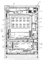
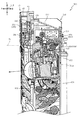
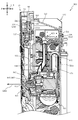
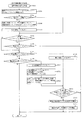
以下、本発明の実施形態について、添付図面を参照して説明する。まず、図1から図16を参照し、第1実施形態として、本発明をパチンコ遊技機(以下、単に「パチンコ機」という)10に適用した場合の一実施形態について説明する。図1は、第1実施形態におけるパチンコ機10の正面図であり、図2はパチンコ機10の遊技盤13の正面図であり、図3はパチンコ機10の背面図である。
Hereinafter, embodiments of the present invention will be described with reference to the accompanying drawings. First, with reference to FIGS. 1 to 16, as a first embodiment, an embodiment in which the present invention is applied to a pachinko gaming machine (hereinafter, simply referred to as “pachinko machine”) 10 will be described. FIG. 1 is a front view of the
なお、以下の説明では、図1に示す状態のパチンコ機10に対して、紙面手前側を前方(正面)側として、紙面奥側を後方(背面)側として説明する。また、図1に示す状態のパチンコ機10に対して、上側を上方(上)側として、下側を下方(下)側として、右側を右方(右)側として、左側を左方(左)側としてそれぞれ説明する。さらに、図中(例えば、図2参照)の矢印U−D,L−R,F−Bは、パチンコ機10の上下方向,左右方向,前後方向をそれぞれ示している。
In the following description, the
図1に示すように、パチンコ機10は、略矩形状に組み合わせた木枠により外殻が形成される外枠11と、その外枠11と略同一の外形形状に形成され外枠11に対して開閉可能に支持された内枠12とを備えている。外枠11には、内枠12を支持するために正面視(図1参照)左側の上下2カ所に金属製のヒンジ18が取り付けられ、そのヒンジ18が設けられた側を開閉の軸として内枠12が正面手前側へ開閉可能に支持されている。
As shown in FIG. 1, the
内枠12には、多数の釘や入賞口63,64等を有する遊技盤13(図2参照)が裏面側から着脱可能に装着される。この遊技盤13の正面を球(遊技球)が流下することにより弾球遊技が行われる。なお、内枠12には、球を遊技盤13の正面領域に発射する球発射ユニット112a(図4参照)やその球発射ユニット112aから発射された球を遊技盤13の正面領域まで誘導する発射レール(図示せず)等が取り付けられている。
A game board 13 (see FIG. 2) having a large number of nails, winning
内枠12の正面側には、その正面上側を覆う正面枠14と、その下側を覆う下皿ユニット15とが設けられている。正面枠14及び下皿ユニット15を支持するために正面視(図1参照)左側の上下2カ所に金属製のヒンジ19が取り付けられ、そのヒンジ19が設けられた側を開閉の軸として正面枠14及び下皿ユニット15が正面手前側へ開閉可能に支持されている。なお、内枠12の施錠と正面枠14の施錠とは、シリンダ錠20の鍵穴21に専用の鍵を差し込んで所定の操作を行うことでそれぞれ解除される。
On the front side of the
正面枠14は、装飾用の樹脂部品や電気部品等を組み付けたものであり、その略中央部には略楕円形状に開口形成された窓部14cが設けられている。正面枠14の裏面側には2枚の板ガラスを有するガラスユニット16が配設され、そのガラスユニット16を介して遊技盤13の正面がパチンコ機10の正面側に視認可能となっている。
The
正面枠14には、球を貯留する上皿17が正面側へ張り出して上面を開放した略箱状に形成されており、この上皿17に賞球や貸出球などが排出される。上皿17の底面は正面視(図1参照)右側に下降傾斜して形成され、その傾斜により上皿17に投入された球が球発射ユニット112a(図4参照)へと案内される。また、上皿17の上面には、枠ボタン22が設けられている。この枠ボタン22は、例えば、第3図柄表示装置81(図2参照)で表示される演出のステージを変更したり、スーパーリーチの演出内容を変更したりする場合などに、遊技者により操作される。
On the
正面枠14には、その周囲(例えばコーナー部分)に各種ランプ等の発光手段が設けられている。これら発光手段は、大当たり時や所定のリーチ時等における遊技状態の変化に応じて、点灯又は点滅することにより発光態様が変更制御され、遊技中の演出効果を高める役割を果たす。窓部14cの周縁には、LED等の発光手段を内蔵した電飾部29〜33が設けられている。パチンコ機10においては、これら電飾部29〜33が大当たりランプ等の演出ランプとして機能し、大当たり時やリーチ演出時等には内蔵するLEDの点灯や点滅によって各電飾部29〜33が点灯または点滅して、大当たり中である旨、或いは大当たり一歩手前のリーチ中である旨が報知される。また、正面枠14の正面視(図1参照)左上部には、LED等の発光手段が内蔵され賞球の払い出し中とエラー発生時とを表示可能な表示ランプ34が設けられている。
The
また、右側の電飾部32下側には、正面枠14の裏面側を視認できるように裏面側より透明樹脂を取り付けて小窓35が形成され、遊技盤13正面の貼着スペースK1(図2参照)に貼付される証紙等がパチンコ機10の正面から視認可能とされている。また、パチンコ機10においては、より煌びやかさを醸し出すために、電飾部29〜33の周りの領域にクロムメッキを施したABS樹脂製のメッキ部材36が取り付けられている。
Further, on the lower side of the illuminated
窓部14cの下方には、貸球操作部40が配設されている。貸球操作部40には、度数表示部41と、球貸しボタン42と、返却ボタン43とが設けられている。パチンコ機10の側方に配置されるカードユニット(球貸しユニット)(図示せず)に紙幣やカード等を投入した状態で貸球操作部40が操作されると、その操作に応じて球の貸出が行われる。具体的には、度数表示部41はカード等の残額情報が表示される領域であり、内蔵されたLEDが点灯して残額情報として残額が数字で表示される。球貸しボタン42は、カード等(記録媒体)に記録された情報に基づいて貸出球を得るために操作されるものであり、カード等に残額が存在する限りにおいて貸出球が上皿17に供給される。返却ボタン43は、カードユニットに挿入されたカード等の返却を求める際に操作される。なお、カードユニットを介さずに球貸し装置等から上皿17に球が直接貸し出されるパチンコ機、いわゆる現金機では貸球操作部40が不要となるが、この場合には、貸球操作部40の設置部分に飾りシール等を付加して部品構成は共通のものとしても良い。カードユニットを用いたパチンコ機と現金機との共通化を図ることができる。
A ball
上皿17の下側に位置する下皿ユニット15には、その左側部に上皿17に貯留しきれなかった球を貯留するための下皿50が上面を開放した略箱状に形成されている。下皿50の右側には、球を遊技盤13の正面へ打ち込むために遊技者によって操作される操作ハンドル51が配設される。
In the
操作ハンドル51の内部には、球発射ユニット112aの駆動を許可するためのタッチセンサ51aと、押下操作している期間中には球の発射を停止する発射停止スイッチ51bと、操作ハンドル51の回動操作量(回動位置)を電気抵抗の変化により検出する可変抵抗器(図示せず)などが内蔵されている。操作ハンドル51が遊技者によって右回りに回動操作されると、タッチセンサ51aがオンされると共に可変抵抗器の抵抗値が回動操作量に対応して変化し、その可変抵抗器の抵抗値に対応した強さ(発射強度)で球が発射され、これにより遊技者の操作に対応した飛び量で遊技盤13の正面へ球が打ち込まれる。また、操作ハンドル51が遊技者により操作されていない状態においては、タッチセンサ51aおよび発射停止スイッチ51bがオフとなっている。
Inside the
下皿50の正面下方部には、下皿50に貯留された球を下方へ排出する際に操作するための球抜きレバー52が設けられている。この球抜きレバー52は、常時、右方向に付勢されており、その付勢に抗して左方向へスライドさせることにより、下皿50の底面に形成された底面口が開口して、その底面口から球が自然落下して排出される。この球抜きレバー52の操作は、通常、下皿50の下方に下皿50から排出された球を受け取る箱(一般に「千両箱」と称される)を置いた状態で行われる。下皿50の右方には、上述したように操作ハンドル51が配設され、下皿50の左方には灰皿(図示せず)が取り付けられている。
A
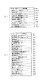
図2に示すように、遊技盤13は、正面視略正方形状に切削加工したベース板60に、球案内用の多数の釘(センターフレーム86の下方において図示し、遊技領域の上半部においては図示せず)や風車(図示せず)の他、レール61,62、一般入賞口63、第1入賞口64、第2入賞口140、可変入賞装置65、スルーゲート67、可変表示装置ユニット80等を組み付けて構成され、その周縁部が内枠12(図1参照)の裏面側に取り付けられる。
As shown in FIG. 2, the
ベース板60は、光透過性の樹脂材料から形成されており、その正面側からベース板60の背面側に配設された各種構造体を遊技者に視認させることが可能となっている。一般入賞口63、第1入賞口64、第2入賞口140及び可変入賞装置65は、ルータ加工によってベース板60に形成された貫通穴に配設され、遊技盤13の正面側からタッピングネジ等により固定されている。
The
なお、ベース板60を木製の板部材から形成しても良い。この場合、センターフレーム86の外側において、その正面側からベース板60の背面側に配設された各種構造体を遊技者に視認不能に遮蔽することが可能となる。
The
遊技盤13の正面中央部分は、正面枠14の窓部14c(図1参照)を通じて内枠12の正面側から視認することができる。以下に、主に図2を参照して、遊技盤13の構成について説明する。
The front central portion of the
遊技盤13の正面には、帯状の金属板を略円弧状に屈曲加工して形成した外レール62が植立され、その外レール62の内側位置には外レール62と同様に帯状の金属板で形成した円弧状の内レール61が植立される。この内レール61と外レール62とにより遊技盤13の正面外周が囲まれ、遊技盤13とガラスユニット16(図1参照)とにより前後が囲まれることにより、遊技盤13の正面には、球の挙動により遊技が行われる遊技領域が形成される。遊技領域は、遊技盤13の正面であって2本のレール61,62とレール間を繋ぐ樹脂製の外縁部材73とにより区画して形成される領域(入賞口等が配設され、発射された球が流下する領域)である。
An
2本のレール61,62は、球発射ユニット112a(図4参照)から発射された球を遊技盤13上部へ案内するために設けられたものである。内レール61の先端部分(図2の左上部)には戻り球防止部材68が取り付けられ、一旦、遊技盤13の上部へ案内された球が再度球案内通路内に戻ってしまうといった事態が防止される。外レール62の先端部(図2の右上部)には、球の最大飛翔部分に対応する位置に返しゴム69が取り付けられ、所定以上の勢いで発射された球は、返しゴム69に当たって、勢いが減衰されつつ中央部側へ跳ね返される。
The two
遊技領域の正面視左側下部(図2の左側下部)には、発光手段である複数のLED及び7セグメント表示器を備える第1図柄表示装置37A,37Bが配設されている。第1図柄表示装置37A,37Bは、主制御装置110(図4参照)で行われる各制御に応じた表示がなされるものであり、主にパチンコ機10の遊技状態の表示が行われる。本実施形態では、第1図柄表示装置37A,37Bは、球が、第1入賞口64へ入賞したか、第2入賞口140へ入賞したかに応じて使い分けられるように構成されている。具体的には、球が、第1入賞口64へ入賞した場合には、第1図柄表示装置37Aが作動し、一方で、球が、第2入賞口140へ入賞した場合には、第1図柄表示装置37Bが作動するように構成されている。
In the lower left side of the front view (lower left side of FIG. 2) of the game area, first
また、第1図柄表示装置37A,37Bは、LEDにより、パチンコ機10が確変中か時短中か通常中であるかを点灯状態により示したり、変動中であるか否かを点灯状態により示したり、停止図柄が確変大当たりに対応した図柄か普通大当たりに対応した図柄か外れ図柄であるかを点灯状態により示したり、保留球数を点灯状態により示すと共に、7セグメント表示装置により、大当たり中のラウンド数やエラー表示を行う。なお、複数のLEDは、それぞれのLEDの発光色(例えば、赤、緑、青)が異なるよう構成され、その発光色の組み合わせにより、少ないLEDでパチンコ機10の各種遊技状態を示唆することができる。
In addition, the first
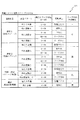
尚、本パチンコ機10では、第1入賞口64及び第2入賞口140へ入賞があったことを契機として抽選が行われる。パチンコ機10は、その抽選において、大当たりか否かの当否判定(大当たり抽選)を行うと共に、大当たりと判定した場合はその大当たり種別の判定も行う。ここで判定される大当たり種別としては、15R確変大当たり、4R確変大当たり、4R通常大当たりが用意されている。第1図柄表示装置37A,37Bには、変動終了後の停止図柄として抽選の結果が大当たりであるか否かが示されるだけでなく、大当たりである場合はその大当たり種別に応じた図柄が示される。
In the
ここで、「15R確変大当たり」とは、最大ラウンド数が15ラウンドの大当たりの後に高確率状態へ移行する確変大当たりのことであり、「4R確変大当たり」とは、最大ラウンド数が4ラウンドの大当たりの後に高確率状態へ移行する確変大当たりのことである。また、「4R通常大当たり」は、最大ラウンド数が4ラウンドの大当たりの後に、低確率状態へ移行すると共に、所定の変動回数の間(例えば、100変動回数)は時短状態となる大当たりのことである。 Here, the "15R probability variation jackpot" is a probability variation jackpot in which the maximum number of rounds shifts to a high probability state after the jackpot of 15 rounds, and the "4R probability variation jackpot" is a jackpot with a maximum number of rounds of 4 rounds. It is a probabilistic jackpot that shifts to a high probability state after. Further, "4R normal jackpot" is a jackpot in which the maximum number of rounds is 4 rounds, and then the probability shifts to a low probability state, and the time is shortened during a predetermined number of fluctuations (for example, 100 fluctuations). is there.
また、「高確率状態」とは、大当たり終了後に付加価値としてその後の大当たり確率がアップした状態、いわゆる確率変動中(確変中)の時をいい、換言すれば、特別遊技状態へ移行し易い遊技の状態のことである。本実施形態における高確率状態(確変中)は、所定の変動回数の間(本実施形態では、100変動回数)、大当たり確率がアップし、後述する第2図柄の当たり確率がアップして第2入賞口140へ球が入賞し易い遊技の状態を含む。「低確率状態」とは、確変中でない時をいい、大当たり確率が通常の状態、即ち、確変の時より大当たり確率が低い状態をいう。また、「低確率状態」のうちの時短状態(時短中)とは、大当たり確率が通常の状態であると共に、大当たり確率がそのままで第2図柄の当たり確率のみがアップして第2入賞口140へ球が入賞し易い遊技の状態のことをいう。一方、パチンコ機10が通常中とは、確変中でも時短中でもない遊技の状態(大当たり確率も第2図柄の当たり確率もアップしていない状態)である。
In addition, the "high probability state" refers to a state in which the subsequent jackpot probability increases as an added value after the jackpot ends, that is, during a so-called probability fluctuation (probability change), in other words, a game in which it is easy to shift to a special gaming state. It is the state of. In the high probability state (during probability change) in the present embodiment, the jackpot probability increases during a predetermined number of fluctuations (100 fluctuations in the present embodiment), and the hit probability of the second symbol described later increases and the second Includes a game state in which a ball can easily win a prize in the winning
本実施形態では、後述する振分装置300の確変検出センサSE11の貫通孔を、大当たり遊技の1ラウンド目に遊技球が通過したと判定された時に、その大当たり遊技終了後の遊技状態が100変動回数の間、高確率状態となる。なお、確変検出センサSE11の貫通孔に遊技球が通過したと判定されなかったら大当たり遊技終了後の遊技状態が100変動回数の間、時短状態となる。
In the present embodiment, when it is determined that the game ball has passed through the through hole of the probability variation detection sensor SE11 of the
確変中や時短中は、第2図柄の当たり確率がアップするだけではなく、第2入賞口140に付随する電動役物140a(電動役物)が開放される時間も変更され、通常中と比して長い時間が設定される。電動役物140aが開放された状態(開放状態)にある場合は、その電動役物140aが閉鎖された状態(閉鎖状態)にある場合と比して、第2入賞口140へ球が入賞しやすい状態となる。よって、確変中や時短中は、第2入賞口140へ球が入賞し易い状態となり、大当たり抽選が行われる回数を増やすことができる。
During the probability change and the time reduction, not only the hit probability of the second symbol increases, but also the time when the
なお、確変中や時短中において、第2入賞口140に付随する電動役物140aの開放時間を変更するのではなく、または、その開放時間を変更することに加えて、1回の当たりで電動役物140aが開放する回数を通常中よりも増やす変更を行うものとしてもよい。また、確変中や時短中において、第2図柄の当たり確率は変更せず、第2入賞口140に付随する電動役物140aが開放される時間および1回の当たりで電動役物140aが開放する回数の少なくとも一方を変更するものとしてもよい。また、確変中や時短中において、第2入賞口140に付随する電動役物140aが開放される時間や、1回の当たりで電動役物140aを開放する回数はせず、第2図柄の当たり確率だけを、通常中と比してアップするよう変更するものであってもよい。
In addition, during the probability change or the time reduction, the opening time of the
遊技領域には、球が入賞することにより5個から15個の球が賞球として払い出される複数の一般入賞口63が配設されている。また、遊技領域の中央部分には、可変表示装置ユニット80が配設されている。可変表示装置ユニット80には、第1入賞口64及び第2入賞口140への入賞(始動入賞)をトリガとして、第1図柄表示装置37A,37Bにおける変動表示と同期させながら、第3図柄の変動表示を行う液晶ディスプレイ(以下単に「表示装置」と略す)で構成された第3図柄表示装置81と、スルーゲート67の球の通過をトリガとして第2図柄を変動表示するLEDで構成される第2図柄表示装置(図示せず)とが設けられている。また、正面視において可変表示装置ユニット80の第3図柄表示装置81の外周を囲むようにして、センターフレーム86が配設されている。
In the game area, a plurality of general winning
なお、本実施形態では、第3図柄表示装置81は遊技盤13の背面に固定される背面ケースに締結固定され、センターフレーム86はベース板60の窓部(中央開口60b)を縁取るように配設されている。即ち、正面視では第3図柄表示装置81の外周を囲むようにセンターフレーム86が配設されているように見えるが、実際は、第3図柄表示装置81とセンターフレーム86とは前後に離れて配置されている。
In the present embodiment, the third
第3図柄表示装置81は、例えば9インチサイズの大型の液晶ディスプレイで構成されるものであり、表示制御装置114(図4参照)によって表示内容が制御されることにより、例えば上、中及び下の3つの図柄列が表示される。各図柄列は複数の図柄(第3図柄)によって構成され、これらの第3図柄が図柄列毎に横スクロールして第3図柄表示装置81の表示画面上にて第3図柄が可変表示されるようになっている。本実施形態の第3図柄表示装置81は、主制御装置110(図4参照)の制御に伴った遊技状態の表示が第1図柄表示装置37A,37Bで行われるのに対して、その第1図柄表示装置37A,37Bの表示に応じた装飾的な表示を行うものである。なお、表示装置に代えて、例えばリール等を用いて第3図柄表示装置81を構成するようにしても良い。
The third
第2図柄表示装置は、球がスルーゲート67を通過する毎に表示図柄(第2図柄(図示せず))としての「○」の図柄と「×」の図柄とを所定時間交互に点灯させる変動表示を行うものである。パチンコ機10では、球がスルーゲート67を通過したことが検出されると、当たり抽選が行われる。その当たり抽選の結果、当たりであれば、第2図柄表示装置において、第2図柄の変動表示後に「○」の図柄が停止表示される。また、当たり抽選の結果、外れであれば、第2図柄表示装置において、第3図柄の変動表示後に「×」の図柄が停止表示される。
The second symbol display device alternately lights the “○” symbol and the “×” symbol as the display symbol (second symbol (not shown)) each time the sphere passes through the through
パチンコ機10は、第2図柄表示装置における変動表示が所定図柄(本実施形態においては「○」の図柄)で停止した場合に、第2入賞口140に付随された電動役物140aが所定時間だけ作動状態となる(開放される)よう構成されている。
In the
第2図柄の変動表示にかかる時間は、遊技状態が通常中の場合よりも、確変中または時短中の方が短くなるように設定される。これにより、確変中および時短中は、第2図柄の変動表示が短い時間で行われるので、当たり抽選を通常中よりも多く行うことができる。
よって、当たり抽選において当たりとなる機会が増えるので、第2入賞口140の電動役物140aが開放状態となる機会を遊技者に多く与えることができる。よって、確変中および時短中は、第2入賞口140へ球が入賞しやすい状態とすることができる。
The time required for the variation display of the second symbol is set to be shorter during the probability change or the time reduction than when the game state is normal. As a result, during the probability change and the time reduction, the variation display of the second symbol is performed in a short time, so that the winning lottery can be performed more than during the normal time.
Therefore, since the chances of winning in the winning lottery increase, it is possible to give the player many opportunities to open the
なお、確変中または時短中において、当たり確率を高める、1回に当たりに対する電動役物140aの開放時間や開放回数を増やすなど、その他の方法によっても、確変中または時短中に第2入賞口140へ球が入賞しやすい状態としている場合は、第2図柄の変動表示にかかる時間を遊技状態にかかわらず一定としてもよい。一方、第2図柄の変動表示にかかる時間を、確変中または時短中において通常中よりも短く設定する場合は、当たり確率を遊技状態にかかわらず一定にしてもよいし、また、1回の当たりに対する電動役物140aの開放時間や開放回数を遊技状態にかかわらず一定にしてもよい。
In addition, during the probability change or the time reduction, the second winning
スルーゲート67は、可変表示装置ユニット80の左右の領域において遊技盤13に組み付けられ、遊技盤13に発射された球の一部が通過可能に構成されている。スルーゲート67を球が通過すると、第2図柄の当たり抽選が行われる。当たり抽選の後、第2図柄表示装置にて変動表示を行い、当たり抽選の結果が当たりであれば、変動表示の停止図柄として「○」の図柄を表示し、当たり抽選の結果が外れであれば、変動表示の停止図柄として「×」の図柄を表示する。
The through
球のスルーゲート67の通過回数は、合計で最大4回まで保留され、その保留球数が上述した第1図柄表示装置37A,37Bにより表示されると共に第2図柄保留ランプ(図示せず)においても点灯表示される。第2図柄保留ランプは、最大保留数分の4つ設けられ、第3図柄表示装置81の下方に左右対称に配設されている。
The number of times the ball has passed through the through
なお、第2図柄の変動表示は、本実施形態のように、第2図柄表示装置において複数のランプの点灯と非点灯を切り換えることにより行うものの他、第1図柄表示装置37A,37B及び第3図柄表示装置81の一部を使用して行うようにしても良い。同様に、第2図柄保留ランプの点灯を第3図柄表示装置81の一部で行うようにしても良い。また、スルーゲート67の球の通過に対する最大保留球数は4回に限定されるものでなく、3回以下、又は、5回以上の回数(例えば、8回)に設定しても良い。また、スルーゲート67の組み付け数は2つに限定されるものではなく、例えば1つであっても良い。また、スルーゲート67の組み付け位置は可変表示装置ユニット80の左右に限定されるものではなく、例えば、可変表示装置ユニット80の下方でも良い。また、第1図柄表示装置37A,37Bにより保留球数が示されるので、第2図柄保留ランプにより点灯表示を行わないものとしてもよい。
The variation display of the second symbol is performed by switching the lighting and non-lighting of a plurality of lamps in the second symbol display device as in the present embodiment, as well as the first
可変表示装置ユニット80の下方には、球が入賞し得る第1入賞口64が配設されている。この第1入賞口64へ球が入賞すると遊技盤13の裏面側に設けられる第1入賞口スイッチ(図示せず)がオンとなり、その第1入賞口スイッチのオンに起因して主制御装置110(図4参照)で大当たりの抽選がなされ、その抽選結果に応じた表示が第1図柄表示装置37Aで示される。
Below the variable
一方、第1入賞口64の正面視下方には、球が入賞し得る第2入賞口140が配設されている。この第2入賞口140へ球が入賞すると遊技盤13の裏面側に設けられる第2入賞口スイッチ(図示せず)がオンとなり、その第2入賞口スイッチのオンに起因して主制御装置110(図4参照)で大当たりの抽選がなされ、その抽選結果に応じた表示が第1図柄表示装置37Bで示される。
On the other hand, below the front view of the first winning
また、第1入賞口64および第2入賞口140は、それぞれ、球が入賞すると5個の球が賞球として払い出される入賞口の1つにもなっている。なお、本実施形態においては、第1入賞口64へ球が入賞した場合に払い出される賞球数と第2入賞口140へ球が入賞した場合に払い出される賞球数とを同じに構成したが、第1入賞口64へ球が入賞した場合に払い出される賞球数と第2入賞口140へ球が入賞した場合に払い出される賞球数とを異なる数、例えば、第1入賞口64へ球が入賞した場合に払い出される賞球数を3個とし、第2入賞口140へ球が入賞した場合に払い出される賞球数を5個として構成してもよい。
Further, each of the first winning
第2入賞口140には電動役物140aが付随されている。この電動役物140aは開閉可能に構成されており、通常は電動役物140aが閉鎖状態(縮小状態)となって、球が第2入賞口140へ入賞しにくい状態となっている。一方、スルーゲート67への球の通過を契機として行われる第2図柄の変動表示の結果、「○」の図柄が第2図柄表示装置に表示された場合、電動役物140aが開放状態(拡大状態)となり、球が第2入賞口140へ入賞しやすい状態となる。
An
上述した通り、確変中および時短中は、通常中と比して第2図柄の当たり確率が高く、また、第2図柄の変動表示にかかる時間も短いので、第2図柄の変動表示において「○」の図柄が表示され易くなって、電動役物140aが開放状態(拡大状態)となる回数が増える。更に、確変中および時短中は、電動役物140aが開放される時間も、通常中より長くなる。よって、確変中および時短中は、通常時と比して、第2入賞口140へ球が入賞しやすい状態を作ることができる。
As described above, during the probability change and the time reduction, the probability of hitting the second symbol is higher than during the normal time, and the time required for the variation display of the second symbol is short. Therefore, in the variation display of the second symbol, "○" The symbol “” is easily displayed, and the number of times the
ここで、第1入賞口64に球が入賞した場合と第2入賞口140へ球が入賞した場合とで、大当たりとなる確率は、低確率状態であっても高確率状態でも同一である。しかしながら、大当たりとなった場合に選定される大当たりの種別として15R確変大当たりとなる確率は、第2入賞口140へ球が入賞した場合のほうが第1入賞口64へ球が入賞した場合よりも高く設定されている。一方、第1入賞口64は、第2入賞口140にあるような電動役物は有しておらず、球が常時入賞可能な状態となっている。
Here, the probability of winning a jackpot is the same in both the low probability state and the high probability state when the ball wins in the first winning
よって、通常中においては、第2入賞口140に付随する電動役物が閉鎖状態にある場合が多く、第2入賞口140に入賞しづらいので、電動役物のない第1入賞口64へ向けて、可変表示装置ユニット80の左方を球が通過するように球を発射し(所謂「左打ち」)、第1入賞口64への入賞によって大当たり抽選の機会を多く得て、大当たりとなることを狙った方が、遊技者にとって有利となる。
Therefore, in normal times, the electric accessory attached to the second winning
一方、確変中や時短中は、スルーゲート67に球を通過させることで、第2入賞口140に付随する電動役物140aが開放状態となりやすく、第2入賞口140に入賞しやすい状態であるので、第2入賞口140へ向けて、可変表示装置80の右方を球が通過するように球を発射し(所謂「右打ち」)、スルーゲート67を通過させて電動役物を開放状態にすると共に、第2入賞口140への入賞によって15R確変大当たりとなることを狙った方が、遊技者にとって有利となる。
On the other hand, during the probability change or the time saving, by passing the ball through the through
なお、本実施形態におけるパチンコ機10は、遊技盤13の構成が左右対称とされるため、「右打ち」で第1入賞口64を狙うことも、「左打ち」で第2入賞口140を狙うこともできる。そのため、本実施形態のパチンコ機10は、パチンコ機10の遊技状態(確変中であるか、時短中であるか、通常中であるか)に応じて、遊技者に対し、球の発射の仕方を「左打ち」と「右打ち」とに変えさせることを不要にできる。よって、球の打ち方を変化させる煩わしさを解消することができる。
In the
第1入賞口64の下方には可変入賞装置65(図2参照)が配設されており、その略中央部分に特定入賞口65aが設けられている。パチンコ機10においては、第1入賞口64又は第2入賞口140への入賞に起因して行われた大当たり抽選が大当たりとなると、所定時間(変動時間)が経過した後に、大当たりの停止図柄となるよう第1図柄表示装置37A又は第1図柄表示装置37Bを点灯させると共に、その大当たりに対応した停止図柄を第3図柄表示装置81に表示させて、大当たりの発生が示される。その後、球が入賞し易い特別遊技状態(大当たり)に遊技状態が遷移する。この特別遊技状態として、通常時には閉鎖されている特定入賞口65aが、所定時間(例えば、30秒経過するまで、或いは、球が10個入賞するまで)開放される。
A variable winning device 65 (see FIG. 2) is arranged below the first winning
この特定入賞口65aは、所定時間が経過すると閉鎖され、その閉鎖後、再度、その特定入賞口65aが所定時間開放される。この特定入賞口65aの開閉動作は、最高で例えば15回(15ラウンド)繰り返し可能にされている。この開閉動作が行われている状態が、遊技者にとって有利な特別遊技状態の一形態であり、遊技者には、遊技上の価値(遊技価値)の付与として通常時より多量の賞球の払い出しが行われる。
The
なお、上記した形態に特別遊技状態は限定されるものではない。特定入賞口65aとは別に開閉される大開放口を遊技領域に設け、第1図柄表示装置37A,37Bにおいて大当たりに対応したLEDが点灯した場合に、特定入賞口65aが所定時間開放され、その特定入賞口65aの開放中に、球が特定入賞口65a内へ入賞することを契機として特定入賞口65aとは別に設けられた大開放口が所定時間、所定回数開放される遊技状態を特別遊技状態として形成するようにしても良い。また、特定入賞口65aは1つに限るものではなく、1つ若しくは2以上の複数(例えば3つ)を配置しても良く、また配置位置も第1入賞口64の下方右側や、第1入賞口64の下方左側に限らず、例えば、可変表示装置ユニット80の左方でも良い。
The special gaming state is not limited to the above-described form. A large opening that opens and closes separately from the specific winning
遊技盤13の下側における右隅部には、証紙や識別ラベル等を貼着するための貼着スペースK1が設けられ、貼着スペースK1に貼られた証紙等は、正面枠14の小窓35(図1参照)を通じて視認することができる。
A sticking space K1 for sticking a certificate stamp, an identification label, or the like is provided in the right corner on the lower side of the
遊技盤13には、アウト口71が設けられている。遊技領域を流下する球であって、いずれの入賞口63,64,65a,140にも入賞しなかった球は、アウト口71を通って図示しない球排出路へと案内される。
The
遊技盤13には、球の落下方向を適宜分散、調整等するために多数の釘が植設されているとともに、風車等の各種部材(役物)とが配設されている(図2では不図示)。
A large number of nails are planted on the
図3に示すように、パチンコ機10の背面側には、制御基板ユニット90,91と、裏パックユニット94とが主に備えられている。制御基板ユニット90は、主基板(主制御装置110)と音声ランプ制御基板(音声ランプ制御装置113)と表示制御基板(表示制御装置114)とが搭載されてユニット化されている。制御基板ユニット91は、払出制御基板(払出制御装置111)と発射制御基板(発射制御装置112)と電源基板(電源装置115)とカードユニット接続基板116とが搭載されてユニット化されている。
As shown in FIG. 3, the
裏パックユニット94は、保護カバー部を形成する裏パック92と払出ユニット93とがユニット化されている。また、各制御基板には、各制御を司る1チップマイコンとしてのMPU、各種機器との連絡をとるポート、各種抽選の際に用いられる乱数発生器、時間計数や同期を図る場合などに使用されるクロックパルス発生回路等が、必要に応じて搭載されている。
In the
なお、主制御装置110、音声ランプ制御装置113及び表示制御装置114、払出制御装置111及び発射制御装置112、電源装置115、カードユニット接続基板116は、それぞれ基板ボックス100〜104に収納されている。基板ボックス100〜104は、ボックスベースと該ボックスベースの開口部を覆うボックスカバーとを備えており、そのボックスベースとボックスカバーとが互いに連結されて、各制御装置や各基板が収納される。
The
また、基板ボックス100(主制御装置110)及び基板ボックス102(払出制御装置111及び発射制御装置112)は、ボックスベースとボックスカバーとを封印ユニット(図示せず)によって開封不能に連結(かしめ構造による連結)している。また、ボックスベースとボックスカバーとの連結部には、ボックスベースとボックスカバーとに亘って封印シール(図示せず)が貼着されている。この封印シールは、脆性な素材で構成されており、基板ボックス100,102を開封するために封印シールを剥がそうとしたり、基板ボックス100,102を無理に開封しようとすると、ボックスベース側とボックスカバー側とに切断される。よって、封印ユニット又は封印シールを確認することで、基板ボックス100,102が開封されたかどうかを知ることができる。
Further, in the board box 100 (main control device 110) and the board box 102 (
払出ユニット93は、裏パックユニット94の最上部に位置して上方に開口したタンク130と、タンク130の下方に連結され下流側に向けて緩やかに傾斜するタンクレール131と、タンクレール131の下流側に縦向きに連結されるケースレール132と、ケースレール132の最下流部に設けられ、払出モータ216(図4参照)の所定の電気的構成により球の払出を行う払出装置133とを備えている。タンク130には、遊技ホールの島設備から供給される球が逐次補給され、払出装置133により必要個数の球の払い出しが適宜行われる。タンクレール131には、当該タンクレール131に振動を付加するためのバイブレータ134が取り付けられている。
The
また、払出制御装置111には状態復帰スイッチ120が設けられ、発射制御装置112には可変抵抗器の操作つまみ121が設けられ、電源装置115にはRAM消去スイッチ122が設けられている。状態復帰スイッチ120は、例えば、払出モータ216(図4参照)部の球詰まり等、払出エラーの発生時に球詰まりを解消(正常状態への復帰)するために操作される。操作つまみ121は、発射ソレノイドの発射力を調整するために操作される。RAM消去スイッチ122は、パチンコ機10を初期状態に戻したい場合に電源投入時に操作される。
Further, the
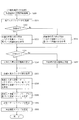
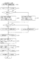
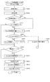
次に、図4を参照して、本パチンコ機10の電気的構成について説明する。図4は、パチンコ機10の電気的構成を示すブロック図である。
Next, the electrical configuration of the
主制御装置110には、演算装置である1チップマイコンとしてのMPU201が搭載されている。MPU201には、該MPU201により実行される各種の制御プログラムや固定値データを記憶したROM202と、そのROM202内に記憶される制御プログラムの実行に際して各種のデータ等を一時的に記憶するためのメモリであるRAM203と、そのほか、割込回路やタイマ回路、データ送受信回路などの各種回路が内蔵されている。主制御装置110では、MPU201によって、大当たり抽選や第1図柄表示装置37A,37B及び第3図柄表示装置81における表示の設定、第2図柄表示装置における表示結果の抽選といったパチンコ機10の主要な処理を実行する。
The
なお、払出制御装置111や音声ランプ制御装置113などのサブ制御装置に対して動作を指示するために、主制御装置110から該サブ制御装置へ各種のコマンドがデータ送受信回路によって送信されるが、かかるコマンドは、主制御装置110からサブ制御装置へ一方向にのみ送信される。
In order to instruct the operation of the sub control device such as the
RAM203は、各種エリア、カウンタ、フラグのほか、MPU201の内部レジスタの内容やMPU201により実行される制御プログラムの戻り先番地などが記憶されるスタックエリアと、各種のフラグおよびカウンタ、I/O等の値が記憶される作業エリア(作業領域)とを有している。なお、RAM203は、パチンコ機10の電源の遮断後においても電源装置115からバックアップ電圧が供給されてデータを保持(バックアップ)できる構成となっており、RAM203に記憶されるデータは、すべてバックアップされる。
The
停電などの発生により電源が遮断されると、その電源遮断時(停電発生時を含む。以下同様)のスタックポインタや、各レジスタの値がRAM203に記憶される。一方、電源投入時(停電解消による電源投入を含む。以下同様)には、RAM203に記憶される情報に基づいて、パチンコ機10の状態が電源遮断前の状態に復帰される。RAM203への書き込みはメイン処理(図示せず)によって電源遮断時に実行され、RAM203に書き込まれた各値の復帰は電源投入時の立ち上げ処理(図示せず)において実行される。なお、MPU201のNMI端子(ノンマスカブル割込端子)には、停電等の発生による電源遮断時に、停電監視回路252からの停電信号SG1が入力されるように構成されており、その停電信号SG1がMPU201へ入力されると、停電時処理としてのNMI割込処理(図示せず)が即座に実行される。
When the power supply is cut off due to the occurrence of a power failure or the like, the stack pointer at the time of the power failure (including the time when the power failure occurs; the same applies hereinafter) and the value of each register are stored in the
主制御装置110のMPU201には、アドレスバス及びデータバスで構成されるバスライン204を介して入出力ポート205が接続されている。入出力ポート205には、払出制御装置111、音声ランプ制御装置113、第1図柄表示装置37A,37B、第2図柄表示装置、第2図柄保留ランプ、特定入賞口65aの開閉板65b(図2参照)の下辺を軸として正面側に開閉駆動するための大開放口ソレノイドや電動役物を駆動するためのソレノイドなどからなるソレノイド209が接続され、MPU201は、入出力ポート205を介してこれらに対し各種コマンドや制御信号を送信する。
An input /
また、入出力ポート205には、図示しないスイッチ群およびスライド位置検出センサSや回転位置検出センサRを含むセンサ群などからなる各種スイッチ208、電源装置115に設けられた後述のRAM消去スイッチ回路253が接続され、MPU201は各種スイッチ208から出力される信号や、RAM消去スイッチ回路253より出力されるRAM消去信号SG2に基づいて各種処理を実行する。
Further, the input /
払出制御装置111は、払出モータ216を駆動させて賞球や貸出球の払出制御を行うものである。演算装置であるMPU211は、そのMPU211により実行される制御プログラムや固定値データ等を記憶したROM212と、ワークメモリ等として使用されるRAM213とを有している。
The
払出制御装置111のRAM213は、主制御装置110のRAM203と同様に、MPU211の内部レジスタの内容やMPU211により実行される制御プログラムの戻り先番地などが記憶されるスタックエリアと、各種のフラグおよびカウンタ、I/O等の値が記憶される作業エリア(作業領域)とを有している。RAM213は、パチンコ機10の電源の遮断後においても電源装置115からバックアップ電圧が供給されてデータを保持(バックアップ)できる構成となっており、RAM213に記憶されるデータは、すべてバックアップされる。なお、主制御装置110のMPU201と同様、MPU211のNMI端子にも、停電等の発生による電源遮断時に停電監視回路252から停電信号SG1が入力されるように構成されており、その停電信号SG1がMPU211へ入力されると、停電時処理としてのNMI割込処理(図示せず)が即座に実行される。
Like the
払出制御装置111のMPU211には、アドレスバス及びデータバスで構成されるバスライン214を介して入出力ポート215が接続されている。入出力ポート215には、主制御装置110や払出モータ216、発射制御装置112などがそれぞれ接続されている。また、図示はしないが、払出制御装置111には、払い出された賞球を検出するための賞球検出スイッチが接続されている。なお、該賞球検出スイッチは、払出制御装置111に接続されるが、主制御装置110には接続されていない。
An input /
発射制御装置112は、主制御装置110により球の発射の指示がなされた場合に、操作ハンドル51の回動操作量に応じた球の打ち出し強さとなるよう球発射ユニット112aを制御するものである。球発射ユニット112aは、図示しない発射ソレノイドおよび電磁石を備えており、その発射ソレノイドおよび電磁石は、所定条件が整っている場合に駆動が許可される。具体的には、遊技者が操作ハンドル51に触れていることをタッチセンサ51aにより検出し、球の発射を停止させるための発射停止スイッチ51bがオフ(操作されていないこと)を条件に、操作ハンドル51の回動操作量(回動位置)に対応して発射ソレノイドが励磁され、操作ハンドル51の操作量に応じた強さで球が発射される。
The
音声ランプ制御装置113は、音声出力装置(図示しないスピーカなど)226における音声の出力、ランプ表示装置(電飾部29〜33、表示ランプ34など)227における点灯および消灯の出力、変動演出(変動表示)や予告演出といった表示制御装置114で行われる第3図柄表示装置81の表示態様の設定などを制御するものである。演算装置であるMPU221は、そのMPU221により実行される制御プログラムや固定値データ等を記憶したROM222と、ワークメモリ等として使用されるRAM223とを有している。
The audio
音声ランプ制御装置113のMPU221には、アドレスバス及びデータバスで構成されるバスライン224を介して入出力ポート225が接続されている。入出力ポート225には、主制御装置110、表示制御装置114、音声出力装置226、ランプ表示装置227、その他装置228、枠ボタン22などがそれぞれ接続されている。その他装置228には駆動モータ648,820、ソレノイド651等が含まれる。
An input /
音声ランプ制御装置113は、主制御装置110から受信した各種のコマンド(変動パターンコマンド、停止種別コマンド等)に基づいて、第3図柄表示装置81の表示態様を決定し、決定した表示態様をコマンド(表示用変動パターンコマンド、表示用停止種別コマンド等)によって表示制御装置114へ通知する。また、音声ランプ制御装置113は、枠ボタン22からの入力を監視し、遊技者によって枠ボタン22が操作された場合は、第3図柄表示装置81で表示されるステージを変更したり、スーパーリーチ時の演出内容を変更したりするように、表示制御装置114へ指示する。ステージが変更される場合は、変更後のステージに応じた背面画像を第3図柄表示装置81に表示させるべく、変更後のステージに関する情報を含めた背面画像変更コマンドを表示制御装置114へ送信する。ここで、背面画像とは、第3図柄表示装置81に表示させる主要な画像である第3図柄の背面側に表示される画像のことである。表示制御装置114は、この音声ランプ制御装置113から送信されるコマンドに従って、第3図柄表示装置81に各種の画像を表示する。
The voice
また、音声ランプ制御装置113は、表示制御装置114から第3図柄表示装置81の表示内容を表すコマンド(表示コマンド)を受信する。音声ランプ制御装置113では、表示制御装置114から受信した表示コマンドに基づき、第3図柄表示装置81の表示内容に合わせて、その表示内容に対応する音声を音声出力装置226から出力し、また、その表示内容に対応させてランプ表示装置227の点灯および消灯を制御する。
Further, the voice
表示制御装置114は、音声ランプ制御装置113及び第3図柄表示装置81が接続され、音声ランプ制御装置113より受信したコマンドに基づいて、第3図柄表示装置81における第3図柄の変動演出などの表示を制御するものである。また、表示制御装置114は、第3図柄表示装置81の表示内容を通知する表示コマンドを適宜音声ランプ制御装置113へ送信する。音声ランプ制御装置113は、この表示コマンドによって示される表示内容にあわせて音声出力装置226から音声を出力することで、第3図柄表示装置81の表示と音声出力装置226からの音声出力とをあわせることができる。
In the
電源装置115は、パチンコ機10の各部に電源を供給するための電源部251と、停電等による電源遮断を監視する停電監視回路252と、RAM消去スイッチ122(図3参照)が設けられたRAM消去スイッチ回路253とを有している。電源部251は、図示しない電源経路を通じて、各制御装置110〜114等に対して各々に必要な動作電圧を供給する装置である。その概要としては、電源部251は、外部より供給される交流24ボルトの電圧を取り込み、各種スイッチ208などの各種スイッチや、ソレノイド209などのソレノイド、モータ等を駆動するための12ボルトの電圧、ロジック用の5ボルトの電圧、RAMバックアップ用のバックアップ電圧などを生成し、これら12ボルトの電圧、5ボルトの電圧及びバックアップ電圧を各制御装置110〜114等に対して必要な電圧を供給する。
The
停電監視回路252は、停電等の発生による電源遮断時に、主制御装置110のMPU201及び払出制御装置111のMPU211の各NMI端子へ停電信号SG1を出力するための回路である。停電監視回路252は、電源部251から出力される最大電圧である直流安定24ボルトの電圧を監視し、この電圧が22ボルト未満になった場合に停電(電源断、電源遮断)の発生と判断して、停電信号SG1を主制御装置110及び払出制御装置111へ出力する。停電信号SG1の出力によって、主制御装置110及び払出制御装置111は、停電の発生を認識し、NMI割込処理を実行する。なお、電源部251は、直流安定24ボルトの電圧が22ボルト未満になった後においても、NMI割込処理の実行に充分な時間の間、制御系の駆動電圧である5ボルトの電圧の出力を正常値に維持するように構成されている。よって、主制御装置110及び払出制御装置111は、NMI割込処理(図示せず)を正常に実行し完了することができる。
The power
RAM消去スイッチ回路253は、RAM消去スイッチ122(図3参照)が押下された場合に、主制御装置110へ、バックアップデータをクリアさせるためのRAM消去信号SG2を出力するための回路である。主制御装置110は、パチンコ機10の電源投入時に、RAM消去信号SG2を入力した場合に、バックアップデータをクリアすると共に、払出制御装置111においてバックアップデータをクリアさせるための払出初期化コマンドを払出制御装置111に対して送信する。
The RAM erase
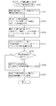
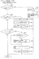
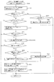
図5及び図6を参照して、第1実施形態における遊技盤13のベース板に配設される入賞口ユニット930及び送球ユニット970について説明する。なお、図5及び図6の説明では図2を適宜参照する。
The winning
図5は、遊技盤13の分解斜視正面図である。なお、図5では、ベース板60に配設される入賞口ユニット930及び送球ユニット970以外のユニット(例えば、センターフレーム86(図2参照)など)の図示が省略される。
FIG. 5 is an exploded perspective front view of the
図5に示すように、ベース板60には、センターフレーム86(図2参照)が取り付けられる中央開口の重力方向下側(図5下側)にベース板60の厚み方向に貫通する貫通孔60aがルータ加工によって形成される。
As shown in FIG. 5, in the
貫通孔60aは、後述する正面ユニット940の正面視における外形よりも若干小さく形成され、内側に正面ユニット940に配設される駆動ユニット960及び特定入賞口ユニット950が挿入される。
The through
ベース板60には、遊技領域(正面)側から入賞口ユニット930が配設され、遊技領域と反対(背面)側から送球ユニット970が配設され、それぞれタッピングネジ等により締結固定される。なお、入賞口ユニット930及び送球ユニット970の詳細な構成については後述する。
The winning
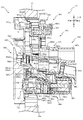
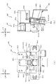
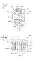
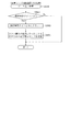
図6は、図2のVI−VI線における遊技盤13の断面図である。図6では、組立状態における入賞口ユニット930及び送球ユニット970の配置について図示される。
FIG. 6 is a cross-sectional view of the
図6に示すように、正面ユニット940及び送球ユニット970の各通路の連結は、前後方向(図6左右方向)に当接した状態とされると共に、送球ユニット970に形成される凸部が、正面ユニット940に形成される突部に挿入される。
As shown in FIG. 6, the passages of the
詳しく説明すると、第1送球部942gと流入口982dとは、第1送球部942gに形成される第1凹欠部942g1の内側に流入口982dに形成される第2突起982d1が配置される。また、第2送球部942cと側壁部981bとは、第2送球部942cに形成される第2凹欠部942c1の内側に、側壁部981bに形成される突起981b1が配置される。これにより、ベース板60に組み付ける際の正面ユニット940及び送球ユニット970の位置合わせを容易に行うことができる。
More specifically, the
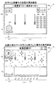
次いで、図7及び図8を参照して、送球ユニット970の全体構成について説明する。
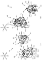
図7(a)は、送球ユニット970の正面図であり、図7(b)は、送球ユニット970の側面図である。図8(a)は、送球ユニット970の分解斜視正面図であり、図8(b)は、送球ユニット970の分解斜視背面図である。
Next, the overall configuration of the throwing
FIG. 7A is a front view of the throwing
図7及び図8に示すように、送球ユニット970は、遊技者側(遊技領域側)に配設され内部に遊技球を挿通可能な空間を備える振分けユニット980と、その振分けユニット980の遊技領域と反対側に配設される通路ユニット990とを備えて形成される。
As shown in FIGS. 7 and 8, the throwing
振分けユニット980は、上述した入賞口ユニット930の第1入賞口64及び第2入賞口140と連なる開口(流入口982d及び側壁部981b)を備えており、その開口(流入口982d及び側壁部981b)から第1入賞口64及び第2入賞口140の介して遊技領域と反対側に送球される遊技球を内部に受け入れることができる。なお、振分けユニット980についての詳しい説明は後述する。
The
通路ユニット990は、振分けユニット980の重力方向一側(重力方向下側)に配設される。通路ユニット990は、振分けユニット980との対向面に複数の開口(第1挿通孔991a〜第2挿通孔991dを備えており、振分けユニット980の内部を送球される遊技球をその開口から受け入れることができる。なお、通路ユニット990についての詳しい説明は後述する。
The
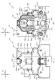
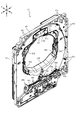
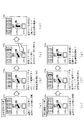
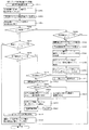
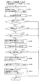
次いで、図9から図12を参照して、振分けユニット980の構成について詳細な説明をする。図9(a)は、振分けユニット980の正面図であり、図9(b)は、振分けユニット980の側面図である。図10は、振分けユニット980の分解斜視正面図であり、図11は、振分けユニット980の分解斜視背面図である。図12(a)は、図9(a)のXIIa−XIIa線における振分けユニット980の断面図であり、図12(b)は、図12(a)のXIIb−XIIbにおける振分けユニット980の断面図である。
Next, the configuration of the
図9から図12に示すように、振分けユニット980は、背面ベース985と、その背面ベース985の遊技者側に配設される正面ベース981と、その正面ベース981と背面ベースとの間に回転可能な状態で配設される振分け部983と、背面ベース985の背面側に振分け部983と対応する位置に配設されるカバー部材987とを主に備えて形成される。
As shown in FIGS. 9 to 12, the
背面ベース985は、有色半透明(本実施形態では、青色)の樹脂材料から形成され、板状体に形成されるベース部985aと、そのベース部985aの厚み方向に貫通する複数の開口(開口985b〜985g)と、その複数の開口の重力方向他側(重力方向上側)に凹設される凹部985hと、その凹部985hの反対面から突出する収容部986b及び突設部986eとを主に備えて形成される。
The
ベース部985aは、正面視縦長矩形に形成され、その外縁部に円形状に貫通する複数の締結孔986c及び986dと、正面ベース981側と反対側に重力方向一側に向かって傾斜する傾斜面986aとを備えて形成される。締結孔986cは、後述する正面ベース981を挿通したネジを螺合する孔である。これにより、正面ベース981及び背面ベース985を締結固定することができる。また、締結孔986dは、後述する通路ユニット990を挿通するネジを螺合する孔である。これにより、背面ベース985(振分けユニット980)及び通路ユニット990を締結固定することができる。
The
傾斜面986aは、後述する開口985b〜985fの重力方向他側の一部と重なる位置に形成される。また、傾斜面986aは、正面ベース981及び背面ベース985が組み合わされた状態において、正面ベース981の傾斜部982bと対向する位置に形成される。これにより、重力方向に流下する遊技球の流下方向を開口985b〜985f側に案内することができる。その結果、遊技球を開口985b〜985fに流入させやすくできる。
The
凹部985hは、正面ベース981と反対側(図9(b)紙面手前側)に向かって凹設されると共に、ベース部985aの短手方向(図9(b)左右方向)略中央位置に形成される。また、凹部985hは、内側に後述する振分け部983の一部を収容可能な大きさに形成されると共に、底面に円環状に突出する軸受部985jを備える。軸受部985jは、振分け部983を軸支する軸部材988aの一端が挿入される孔であり、軸部材988aの外径よりも大きい内径に形成される。
The
開口985b及び開口985cは、それぞれベース部985aの短手方向両端部に形成されるとともに、内縁の寸法が遊技球の直径よりも大きく設定される。また、開口985b及び開口985cは、重力方向一側(重力方向下側)の内面が正面ベース981側と反対側に向かうにつれて下降傾斜して形成される。これにより、正面ベース981側から流入する遊技球を正面ベース981側と反対側に転動させることができる。
The
開口985dは、ベース部985aの短手方向(図9(b)左右方向)略中央位置に形成され、重力方向(図9(b)上下方向)における位置が開口985b及び開口985cと略同一の位置に設定される。また、開口985dは、開口985b及び開口985cと同様に、重力方向一側(重力方向下側)の内面が正面ベース981側と反対側に向かうにつれて下降傾斜して形成される。これにより、正面ベース981側から流入する遊技球を正面ベース981側と反対側に転動させることができる。
The
開口985eは、開口985b及び開口985dの間に形成され、開口985fは、開口985c及び開口985dの間に形成される。また、開口985e,985fは、正面ベース981側に開口する空間の流入通路985e1,985f1と、正面ベース981側と反対側に開口する空間の排出通路985e3,985f3と、重力方向に延設され流入通路985e1,985f1及び排出通路985e3,985f3を連通する中間通路985e2,985f2と,を主に備えて形成される。
The
流入通路985e1,985f1は、後述する正面ベース981と背面ベース985との対向間に形成される第1通路TR1及び第2通路TR2に連結されると共に、遊技球が通過可能な大きさに形成される。これにより、第1通路TR1及び第2通路を流下する遊技球を流入通路985e1,985f1に流入させることができる。
The inflow passages 985e1 and 985f1 are connected to the first passage TR1 and the second passage TR2 formed between the
中間通路985e2,985f2は、重力方向に延設して形成され、重力方向他側(重力方向上側)が流入通路985e1,985f1に連通されると共に、遊技球が通過可能な大きさに形成される。これにより、流入通路985e1,985f1を通過する遊技球を中間通路985e2,985f2に流入させることができる。 The intermediate passages 985e2 and 985f2 are formed so as to extend in the gravity direction, and the other side in the gravity direction (upper side in the gravity direction) is communicated with the inflow passage 985e1,985f1 and is formed in a size that allows the game ball to pass through. .. As a result, the game ball passing through the inflow passage 985e1,985f1 can flow into the intermediate passage 985e2,985f2.
また、中間通路985e2,985f2には、遊技球の送球方向(重力方向)と略直交する方向に凹設される凹設部985f4が形成される。凹設部985f4は、その内側に後述する検出装置SE3を配設するための切り欠きであり、背面視において検出装置SE3の外形と略同一に設定される。これにより、検出装置SE3をベース部985aの背面側(正面ベース981と反対側)から挿入して配設することができる。
Further, in the intermediate passages 985e2 and 985f2, recessed portions 985f4 are formed which are recessed in a direction substantially orthogonal to the throwing direction (gravity direction) of the game ball. The recessed portion 985f4 is a notch for disposing the detection device SE3 described later inside the recessed portion 985f4, and is set substantially the same as the outer shape of the detection device SE3 in rear view. As a result, the detection device SE3 can be inserted and arranged from the back side (opposite side to the front base 981) of the
検出装置SE3は、遊技球の通過を検知する装置であり、その厚み方向に遊技球よりも若干大きい内径の検出孔SE1aが貫通形成される。検出孔SE1aは、背面視横長矩形の状態で配設される検出装置SE3の長手方向のどちらか一方または他方に偏って形成されており、検出孔SE1aが形成されていない長手方向のどちらか他方または一方に検出装置SE3を制御する検出基板SE1bが配設される。 The detection device SE3 is a device that detects the passage of the game ball, and a detection hole SE1a having an inner diameter slightly larger than that of the game ball is formed through the detection device SE1a in the thickness direction thereof. The detection hole SE1a is formed unevenly in either one or the other of the longitudinal direction of the detection device SE3 arranged in a horizontally long rectangular shape in the rear view, and the detection hole SE1a is not formed in either of the longitudinal directions. Alternatively, a detection board SE1b that controls the detection device SE3 is arranged on one side.
本実施形態では、検出装置SE3により遊技球の通過が検知されると、5個の賞球が払い出されると共に、第1図柄の抽選が実行される。この抽選に対応して、第3図柄表示装置81で第3図柄の変動表示が実行される。
In the present embodiment, when the detection device SE3 detects the passage of the game ball, five prize balls are paid out and the lottery of the first symbol is executed. In response to this lottery, the third
また、検出装置SE3は、検出孔SE1aの軸方向が中間通路985e2,985f2の延設方向に平行に設定されると共に、検出孔SE1aの内部空間と中間通路985e2,985f2の空間とが略一致する位置に配置される。これにより、遊技球が中間通路985e2,985f2の重力方向他側(重力方向上側)から重力方向一側(重力方向下側)に流下する場合に、検出装置SE3の検出孔SE1aを通過させることができる。これにより、第1通路TR1及び第2通路TR2を通過する遊技球を検出することができる。 Further, in the detection device SE3, the axial direction of the detection hole SE1a is set parallel to the extension direction of the intermediate passage 985e2, 985f2, and the internal space of the detection hole SE1a and the space of the intermediate passage 985e2, 985f2 substantially coincide with each other. Placed in position. As a result, when the game ball flows down from the other side in the gravity direction (upper side in the gravity direction) to the one side in the gravity direction (lower side in the gravity direction) in the intermediate passages 985e2 and 985f2, it can pass through the detection hole SE1a of the detection device SE3. it can. Thereby, the game ball passing through the first passage TR1 and the second passage TR2 can be detected.
また、検出装置SE3は、検出孔SE1aの軸方向が重力方向と平行に形成されるので、遊技球を検出孔SE1aに送球する際に、遊技球の自重を利用しやすくできる。その結果、遊技球が中間通路985e2,985f2及び検出孔SE1aとの連結部分に引っ掛ることを抑制できる。 Further, since the detection device SE3 is formed so that the axial direction of the detection hole SE1a is parallel to the direction of gravity, the weight of the game ball can be easily used when the game ball is sent to the detection hole SE1a. As a result, it is possible to prevent the game ball from being caught in the connecting portion between the intermediate passages 985e2 and 985f2 and the detection hole SE1a.
凹設部985e4,985f4は、流入通路985e1,985f1及び排出通路985e3,985f3の空間と連なって形成される。即ち、中間通路985e2,985f2は、検出装置SE3を利用して形成される。これにより、中間通路985e2,985f2の重力方向の長さ寸法が大きくなることを抑制できる。その結果、背面ベース985が重力方向に大型化することを抑制できる。
The recessed portions 985e4, 985f4 are formed so as to be connected to the spaces of the inflow passage 985e1,985f1 and the discharge passage 985e3,985f3. That is, the intermediate passages 985e2 and 985f2 are formed by using the detection device SE3. As a result, it is possible to prevent the intermediate passages 985e2 and 985f2 from increasing in length in the gravity direction. As a result, it is possible to prevent the
排出通路985e3,985f3は、中間通路985e2,985f2の重力方向一側(重力方向下側)に連結されると共に、遊技球が通過可能な大きさに形成される。また、排出通路985e3,985f3は、振分けユニット980及び通路ユニット990が組み合わされた状態において、後述する通路ユニット990の第3挿通孔991c及び第4挿通孔991dに連結される。これにより、中間通路985e2,985f2を通過する遊技球を、排出通路985e3,985f3に流入させることができると共に、その空間を通過させて通路ユニット990に送球できる。
The discharge passages 985e3 and 985f3 are connected to one side in the gravity direction (lower side in the gravity direction) of the intermediate passages 985e2 and 985f2, and are formed in a size that allows the game ball to pass through. Further, the discharge passages 985e3 and 985f3 are connected to the
開口985gは、開口985dの重力方向一側(重力方向下側)に形成される。また、開口985gは、開口985dと同様に、重力方向一側(重力方向下側)の内面が正面ベース981側と反対側に向かうにつてれて下降傾斜して形成される。これにより、正面ベース981側から流入する遊技球を正面ベース981と反対側に転動させることができる。
The
流入通路985e1,985f1は、後述する正面ベース981と背面ベース985との対向間に形成される第1通路TR1及び第2通路TR2に連結されると共に、遊技球が通過可能な大きさに形成される。これにより、第1通路TR1及び第2通路TR2を流下する遊技球を流入通路985e1,985f1に流入させることができる。
The inflow passages 985e1 and 985f1 are connected to the first passage TR1 and the second passage TR2 formed between the
収容部986bは、一対の半円環体から形成される。また、収容部986bは、後述する磁性体988bを内側に収容する部分であり、その内径が、円柱体に形成される磁性体988bの外径と略同一に設定される。また、収容部986bの突設寸法は、磁性体988bの軸方向寸法よりも大きく設定される。これにより、収容部986bの内側に磁性体988bを収容できる。また、収容部986bは、一対の半円環体から形成されるので、磁性体988bの外径が製造の誤差により微小に大きく形成された場合でも、一対の半円環体を弾性変形させて磁性体988bを配設できる。
The
突設部986eは、上述した軸受部985jとベース部985aを挟んで反対側の位置から円柱状に突設される。また、突設部986eは、その軸に円形状に凹設される締結孔を備える。締結孔は、後述するカバー部材987を挿通するネジの先端を螺合させる孔であり、カバー部材987を当接させた状態でネジを螺合することで、カバー部材987を背面ベース985に締結固定できる。
The projecting
磁性体988bは、磁石から形成されており、収容部986bに配設されることで、ベース部985aを介して正面ベース981側に磁界を発生させることができる。これにより、後述する振分け部983に配設される磁性体988cを反発させて振分け部983を変位させやすくできる。
The
正面ベース981は、有色半透明(本実施形態では、青色)の樹脂材料から形成される。また、正面ベース981は、正面視において背面ベース985よりも大きい略矩形状に形成されると共に、ベース板981aとそのベース板981aから遊技者側(背面ベース986と反対側)に膨出する膨出部982とを主に備えて形成される。
The
ベース板981aは、正面視略矩形状の板部材に形成され、その外周縁部に板厚方向に貫通する複数の挿通孔981gと、背面ベース985側に向けて突設される第1ガイド壁981f及び第2ガイド壁981dと、その第1ガイド壁981f及び第2ガイド壁981dの近傍に貫通する第2挿通孔981eと、膨出部982の重力方向一側(重力方向下側)に板厚方向に貫通する貫通孔981cとを主に備えて形成される。
The
挿通孔981gは、組み立て状態の送球ユニット970をベース板60(図5参照)に締結するネジ(図示しない)を挿通する孔であり、ネジの先端部分の外径よりも大きい内径に設定される。
The
第1ガイド壁981fは、半円の円環形状に形成されると共に、後述する膨出部982を間に挟む状態で短手方向に一対形成される。また、第1ガイド壁981fは、半円の開放部分をベース板981aの短手方向略中央側に向けて形成される。
The
第2ガイド壁981dは、円環形状に形成されると共に、ベース板981aの短手方向に2箇所形成される。また、第2ガイド壁981dは、後述する膨出部982の重力方向下側に形成されると共に、2箇所の間に貫通孔981cが形成される。
The
第1ガイド壁981f及び第2ガイド壁981dは、その内縁形状が上述した背面ベース985の締結孔986cの周囲の外形形状と略同一に形成される。これにより、正面ベース981及び背面ベース985を組み合わせた場合に、第1ガイド壁981f及び第2ガイド壁981dの内側に締結孔986cの周囲の壁部を挿入でき、第1ガイド壁981f及び第2ガイド壁981dを位置決めすることができる。
The inner edge shape of the
第2挿通孔981eは、第1ガイド壁981fの半円の中心および第2ガイド壁981dの中心に形成される。第2挿通孔981eは、正面ベース981及び背面ベース985が組み立られた状態において、締結孔986cと同軸上に形成されており、正面ベース981側からネジを挿通して締結孔986dに螺合させることで、正面ベース981と背面ベース985とを締結できる。
The
貫通孔981cは、一辺が遊技球の直径よりも大きい正方形に貫通形成される。また、貫通孔981cは、その縁部に沿って背面ベース985側と反対側(図9(a)紙面手前側)に立設される側壁部981bを備えて形成される。また、貫通孔981cは、上述した入賞口ユニット930の第2入賞口140に連通する部分であり、入賞口ユニット930及び送球ユニット970がベース板60に装着された状態において、第2入賞口140に流入した遊技球の転動方向と重なる位置に形成される。
The through
側壁部981bは、入賞口ユニット930及び送球ユニット970がベース板60に装着された状態において、立設先端面が入賞口ユニット930の第2送球部942cと当接する寸法に形成される。また、側壁部981bは、重力方向一側(重力方向下側)の内面の転動面981c1が、転動部943aの端面943a1よりも重力方向一側に位置されると共に、背面ベース985側に向かって下降傾斜して形成される(図6参照)。
The
さらに、側壁部981bは、立設先端面から突設される突起981b1を備える。突起981b1は、転動面981c1から重力方向へ遊技球の半径分離間した位置に形成される。これにより、転動部943aの端面943a1から貫通孔981cの転動面981c1に遊技球が送球される場合に、遊技球が転動部943aと貫通孔981cとの間に挟まりにくくできる。なお、転動部943aの端面943a1から貫通孔981cの転動面981c1に遊技球が送球される場合についての詳しい説明は後述する。
Further, the
膨出部982は、ベース板981aから膨出するドーム状に形成されると共に、その内側に遊技球を挿通可能な大きさに設定され、その内側に流入口982dから流入される遊技球が通過する送球通路TR0と、その送球通路TR0から分岐する第1通路TR1及び第2通路TR2とを備えて形成される。膨出部982は、正面視縦長矩形に形成されると共に、重力方向上端部を切り欠いて形成される流入口982dと、正面視略中間位置に背面ベース985側に向かって屈曲して立設する立設壁982aと、重力方向他側の複数箇所に凹設される凹部982e〜982jとを主に備えて形成される。
The bulging
流入口982dは、正面視略U字状に切り欠き形成される。また、流入口982dは、入賞口ユニット930及び送球ユニット970がベース板60に装着された状態において、内縁部分が、入賞口ユニット930の第1入賞口64に流入した遊技球の転動方向と重なる位置に形成される。
The
また、流入口982dは、重力方向他側(重力方向上側)の縁部に背面ベース985側と反対側に突出する第2突起982d1を備える。第2突起982d1は、上述した入賞口ユニット930の第1凹欠部942g1の内縁形状に形成されており、入賞口ユニット930及び送球ユニット970がベース板60に配設された場合に、第1凹欠部942g1の内縁に第2突起982d1が当接される。
Further, the
また、第2突起982d1から流入口982dの重力方向一側(重力方向下側)の端面までの距離寸法L14(図9(a)参照)は、第1凹欠部942g1の内縁から第1送球部942gの重力方向一側の内縁までの距離寸法L35(図87(b)参照)までの距離寸法よりも大きく設定される。これにより、第1入賞口64を介して第1送球部942gに送球された遊技球が、流入口982dに流入する際に、流入口982d(膨出部982)と第1送球部942gとの間に挟まりにくくできる。
Further, the distance dimension L14 (see FIG. 9A) from the second protrusion 982d1 to the end surface of the
立設壁982aは、正面視において膨出部982の外縁形状と所定の間隔を隔てる矩形状に形成される。また、立設壁982aは、流入口982dの重力方向下側に形成されると共に、重力方向上側に立設方向視三角形状に形成される当接部982a1を備えて形成される。
The
立設壁982aは、膨出部982の外周部分の内縁と水平方向における離間距離L16(図12(b)参照)が、遊技球の直径よりも大きく設定されており、その対向間に遊技球が通過可能な空間の第1通路TR1及び第2通路TR2が形成される。
In the
第1通路TR1及び第2通路TR2は、後述する振分け部983の下流側に形成されており、振分け部983を通過する遊技球がどちらかに送球される。振分け部983は、流入口982dに流入する遊技球を、第1通路TR1及び第2通路TR2に交互に送球可能に設定される。これにより、第1入賞口64に流入する遊技球の送球が単調になることを抑制できる。その結果、遊技者の興趣が損なわれることを抑制できる。
The first passage TR1 and the second passage TR2 are formed on the downstream side of the
立設壁982aの重力方向他側(重力方向上側)には、膨出部982の内側面から背面ベース985側に円環状に突出する軸受部982cが形成される。軸受部982cは、後述する振分け部983を軸支する軸部材988aの他端側を支持する部分であり、内径が軸部材988aの外径と略同一に設定される。よって、軸部材988aを軸受部982cに挿入することで、軸部材988aの他端側を支持できる。
On the other side of the
また、上述したように、軸部材988aの一端側は、背面ベース985の軸受部985jに挿入されるので、正面ベース981及び背面ベース985を組み合わせる際に、軸部材988aの一端を軸受部985jに挿入すると共に、軸部材988aの他端側を軸受部982cに挿入することで、軸部材988aを正面ベース981及び背面ベース985の間に支持できる。
Further, as described above, since one end side of the
当接部982a1は、後述する振分け部983の回転軌跡上に形成されており、振分け部983の作用部983aが当接することで、振分け部983の回転変位量が規制される。なお、当接部982a1と振分け部983との当接状態についての詳しい説明は後述する。
The contact portion 982a1 is formed on the rotation locus of the
凹部982e及び凹部982fは、膨出部982の重力方向一側(重力方向下側)の内側面から第1通路TR1及び第2通路TR2の延設方向と略直交する方向に凹設される。
また、凹部982e及び凹部982fの内側には、第1通路TR1又は第2通路TR2と連通する空間の第1分岐通路BK1又は第2分岐通路BK2が形成される。
The
Further, inside the
第1分岐通路BK1は、正面ベース981及び背面ベース985が組み合わされた状態において背面ベース985の開口985bと連通される。従って、第1分岐通路BK1は、第1通路TR1を流下する遊技球を受け入れ可能に形成されると共に、その受け入れた遊技球を背面ベース985の開口985bに流入可能とされる。
The first branch passage BK1 communicates with the
第2分岐通路BK2は、正面ベース981及び背面ベース985が組み合わされた状態において背面ベース985の開口985cと連通される。従って、第2分岐通路BK2は、第2通路TR2を流下する遊技球を受け入れ可能に形成されると共に、その受け入れた遊技球を背面ベース985の開口985cに流入可能とされる。
The second branch passage BK2 communicates with the
凹部982h及び凹部982jは、膨出部982の重力方向一側(重力方向下側)の内側面から第1通路TR1及び第2通路TR2の延設方向に凹設される。即ち、第1通路TR1及び第2通路TR2は、凹部982h及び凹部982jの分、重力方向一側に延設される。
The
第1通路TR1は、正面ベース981及び背面ベース985が組み合わされた状態において背面ベース985の開口985eと連通される。従って、第1通路TR1は、流入口982dに流入した遊技球が流入されると共に、その流入された遊技球を背面ベース985の開口985eに流入可能とされる。
The first passage TR1 communicates with the
第2通路TR2は、正面ベース981及び背面ベース985が組み合わされた状態において背面ベース985の開口985fと連通される。従って、第2通路TR2は、流入口982dに流入した遊技球が流入されると共に、その流入された遊技球を背面ベース985の開口985fに流入可能とされる。
The second passage TR2 communicates with the
凹部982gは、凹部982h及び凹部982jの間に形成されると共に、凹設方向が第1通路TR1及び第2通路TR2の延設方向と平行に設定される。また、凹部982gの内側には、第1通路TR1及び第2通路TR2と連通する空間の第3分岐通路BK3が形成される。よって、第1通路TR1及び第2通路TR2に連通する第3分岐通路BK3が、第1通路TR1及び第2通路TR2との間に形成されるので、振分けユニット980の小型化を図ることができる。
The
第3分岐通路BK3は、正面ベース981及び背面ベース985が組み合わされた状態において背面ベース985の開口985dと連通される。従って、第3分岐通路BK3は、第1通路TR1又は第2通路TR2を流下する遊技球を受け入れ可能に形成されると共に、その受け入れた遊技球を背面ベース985の開口985dに流入可能とされる。
The third branch passage BK3 communicates with the
傾斜部982bは、膨出部982の重力方向一側(重力方向下側)に形成されると共に、重力方向一側に向かって背面ベース985側に傾斜して延設される。また、傾斜部982bは、正面ベース981及び背面ベース985を組み合わせた状態において、開口985bから開口985fと対向する位置に形成される。これにより、第1通路TR1、第2通路TR2、第1分岐通路BK1、第2分岐通路BK2及び第3分岐通路BK3を流下する遊技球を傾斜部982bに当接させることで、流下する遊技球を開口985b〜985f側に案内して開口985b〜985fに流入させ易くできる。
The
案内部982h1,982j1は、凹部982h及び凹部982jと傾斜部982bとに連結されると共に、立設先端面が背面ベース985側(図9(b)紙面手前側)に向かって下降傾斜される。これにより、第1通路TR1及び第2通路TR2を流下する遊技球を、案内部982h1,982j1の立設先端面に当接させて、開口985e及び開口985f側に案内して、開口985e及び開口985fに流入しやすくできる。
The guide portions 982h1 and 982j1 are connected to the
また、案内部982h1,982j1は、傾斜部982bと連結して形成される。これにより、第1通路TR1及び第2通路TR2を流下する遊技球を傾斜部982bに当接させて背面ベース985側に案内しつつ案内部982h1,982j1に衝突させることで、遊技球を開口985e及び開口985fに流入させすくできる。さらに、傾斜部982bの傾斜の分、案内部982h1,982j1の立設距離を小さくすることができるので、案内部982h1,982j1の剛性を高めて耐久性の向上を図ることができる。
Further, the guide portions 982h1, 982j1 are formed by connecting with the
ここで、上述したように、振分けユニット980(送球ユニット970)は、遊技者側に配設される正面ユニット940(入賞口ユニット930)を介して遊技者から視認可能とされる。そのため、正面ユニット940を介す分、第1通路TR1及び第2通路TR2を流下する遊技球は、遊技者側から視認し難くなる。さらに、開口985e及び開口985fの正面側に案内部982h1,982j1が立設されると、その案内部982h1,982j1の厚みの分、第1通路TR1及び第2通路TR2を流下する遊技球が遊技者から視認し難くなるという問題点があった。
Here, as described above, the distribution unit 980 (ball throwing unit 970) is visible to the player via the front unit 940 (winning opening unit 930) arranged on the player side. Therefore, the game ball flowing down the first passage TR1 and the second passage TR2 through the
これに対し、本実施形態では、案内部982h1,982j1は、傾斜部982bと連結して形成されるので、傾斜部982bの立設寸法を小さくできる。従って、開口985e及び開口985fに送球される遊技球(第1通路TR1及び第2通路TR2を流下する遊技球)を、正面ユニット940を介した状態であっても視認させやすくすることができる。即ち、本実施形態では、傾斜部982bが、遊技球の流下方向へ向かうに従って背面ベース985側に位置するように傾斜されることで、剛性の確保と遊技球の案内とを可能としつつ、案内部982h1,982j1の前後方向の厚みを薄くすることができるので、遊技球の視認性を確保できる。
On the other hand, in the present embodiment, since the guide portions 982h1 and 982j1 are formed in connection with the
振分け部983は、正面ベース981及び背面ベース985の対向間の寸法よりも若干小さい厚みに設定されると共に、正面視略T字状に形成される。また、振分け部983は、T字状の一辺側の作用部983aと、その作用部983aの延設方向略中央位置から突出する中間板983bと、作用部983a及び中間板983bの連結部分に貫通される貫通孔983cと、その貫通孔983cの軸を中心に円形状に膨出する当接部983dと、作用部983a及び中間板983bの背面ベース985側に連結して形成される壁部983eとを主に備えて形成される。
The
貫通孔983cは、正面ベース981及び背面ベース985の対向間に支持される軸部材988aが挿入される孔であり、軸部材988aの外径よりも若干大きく形成される。
これにより、正面ベース981及び背面ベース985を組み上げる場合に、軸部材988aを振分け部983の貫通孔983cに挿入した状態とすることで、振分け部983が回転可能な状態で正面ベース981及び背面ベース985の対向間に配設される。
The through
As a result, when assembling the
中間板983bは、貫通孔983cの径方向外側に向かって延設して形成されると共に、振分け部983の変位が一方または他方に回転して規制された状態において、その先端から中間板983bの内側までの離間距離L17(図12(b)参照)が遊技球の直径よりも小さい寸法とされる。これにより、遊技球の送球が第1通路TR1又は第2通路TR2の一方または他方のどちらかに規制される。また、中間板983bは、振分け部983が貫通孔983cを中心に回転されることで、第1通路TR1の一方に遊技球の送球を規制した状態から第2通路TR2の他方に遊技球の送球を規制した状態に切り換えられる。
The
作用部983aは、正面視において中間板983bの延設方向と略直交する方向に延設して形成される。また、作用部983aは、当接部983dとの連結位置が、中間板983bの当接部983dとの連結位置よりも重力方向一側(重力方向下側)に設定される。
これにより、流入口982dを介して振分け部983に送球される遊技球は、作用部983a側に荷重をかけた状態とされる。その結果、振分け部983は、貫通孔983cを中心に回転変位される。
The working
As a result, the game ball sent to the
壁部983eは、作用部983a及び中間板983bに連結されると共に、貫通孔983cの軸方向視において略半円状の板状に形成される。壁部983eは、貫通孔983cの軸と直交する方向において作用部983a及び中間板983bよりも外側に突出して形成されると共に、厚み寸法が上述した背面ベース985の凹部985hの凹設寸法よりも小さく設定される。よって、背面ベース985及び正面ベース981の対向間に振分け部983を配設した状態において、凹部985hの内部に壁部983eを配置できる。これにより、流入口982dから振分けユニット980の内部に送球される遊技球が、凹部985hの内部に引っ掛ることで、その遊技球の流下が阻害されることを抑制できる。
The
また、壁部983eは、中間板983bの背面側であって、貫通孔983cから径方向外側端部に、中間板983b側に向かって凹設される収容部983e1を備える。収容部983e1は、円柱状体に形成される磁性体988cを内側に収容する部分であり、磁性体988cの外径と略同一の内径の円形に凹設される。また、収容部983e1は、背面ベース985側から正面ベース981側に向かって凹設されており、磁性体988cが背面ベース985側から内部に収容される。
Further, the
磁性体988cは、磁石から形成されており、背面ベース985に配設される磁性体988bと反発する状態で配設される。これにより、振分け部983は、磁性体988cが背面ベース985に配設される磁性体988bから磁力が作用されて、貫通孔983cを軸に回転して作用部983aの延設方向を一方または他方に傾いた状態にできる。
The
また、磁性体988cと磁性体988bとが反発される状態に配設されると共に、収容部983e1が正面側に向かって凹設されるので、収容部983e1に挿入する磁性体988cが収容部983e1から抜け出ることを抑制できる。即ち、収容部983e1に挿入される磁性体988cを係止する部分を必要としないので、振分け部983の構造を簡易にできると共に、振分け部983への磁性体988cの配設を簡易にできる。
Further, since the
なお、磁性体988b及び磁性体988cの磁力は、遊技球の荷重よりも小さい磁着力に設定される。これにより、振分けユニット980の内側を送球される遊技球が磁性体988b及び磁性体988cに磁着して、振分けユニット980の内側に停滞することを抑制できる。
The magnetic force of the
カバー部材987は、上面視縦長矩形に形成されると共に、背面ベース985の凹部985hの正面ベース981側と反対側に配設される。また、カバー部材987は、正面視円形状に重力方向に並んで凹設される2つの第1凹部987a及び第2凹部987bを備えて形成される。
The
第1凹部987aは、内側に上述した背面ベース985の収容部986bを収容する部分であり、収容部986bの外径と略同一の内径に設定される。よって、上述したように収容部986bの内部に磁性体988bを収容した状態で、第1凹部987aに収容部986bの先端を収容することで、収容部986bの内側に収容した磁性体988bが収容部986bから抜け出ることを抑制できる。
The
第2凹部987bは、その凹設底面に背面ベース985に締結固定するための貫通孔987b1を備える。また、第2凹部987bは、凹設部分の内形が、上述した背面ベース985の突設部986eの外径と略同一の内径に形成される。これにより、カバー部材987は、背面ベース985の突設部986eに第2凹部987bを収容して位置決め配置できると共に、位置決めした状態で貫通孔987b1を介してネジを突設部986eの締結孔に締結できる。
The
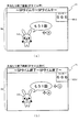
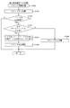
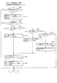
次いで、図13を参照して、流入口982dから遊技球が振分けユニット980に流入した場合の振り分け部983の動作について説明する。図13(a)及び図13(b)は、図12(b)の範囲XIIIaにおける振分けユニット980の部分拡大断面図である。なお、以下では、振分け部983の作用部983aが第1通路TR1の一方へ遊技球の送球を規制する状態から、第2通路TR2の他方への遊技球の送球を規制する状態へ変位される場合のみを説明し、第2通路TR2の他方への遊技球の送球を規制する状態から、第1通路TR1の一方への遊技球の送球を規制する場合の説明は省略する。
Next, with reference to FIG. 13, the operation of the
図13(a)及び図13(b)に示すように、振分け部983に遊技球が送球される前(作用部983aに遊技球が当接する前)では、上述したように、振分け983に配設される磁性体988cが磁性体988b(図10参照)と反発することで、貫通孔983cから径方向外側の中間板983bが、第2通路TR2側へ傾いた状態とされる。なお、第2通路TR2側の作用部983aが正面ベース981の当接部982a1に当接することで、その回転量が規制される(図13(a)参照)。
As shown in FIGS. 13 (a) and 13 (b), before the game ball is thrown to the distribution unit 983 (before the game ball comes into contact with the
この状態で遊技球が振分け部983に送球されると、遊技球は、中間板983b及び第1通路TR1側の作用部983aとの間に送球される。上述したように、作用部983aは、当接部983dとの連結位置が、中間板983bの当接部983dとの連結位置よりも重力方向一側(重力方向下側)に設定されるので、遊技球の荷重を第1通路TR1側の作用部983aに作用させることができる。
When the game ball is thrown to the
これにより、振分け部983は、図13(b)に示すように、貫通孔983cを軸に回転変位され、貫通孔983cから径方向外側の中間板983bが、第1通路TR1側へ傾いた状態とされる。なお、第1通路TR1側の作用部983aが正面ベース981の当接部982a1に当接することで、その回転量が規制される。また、この場合、磁性体988cの反発方向が、貫通孔983cから径方向外側の中間板983bを第2通路TR2側へ作用する状態から第1通路TR1側へ作用する状態に切り換えられる。
As a result, as shown in FIG. 13B, the
従って、振分け部983は、遊技球の荷重および磁性体988cの反発力を利用して、貫通孔983cを軸に回転変位させることができる。また、磁性体988cの反発力の方向が切り替わるので、振分け部983が回転した状態を維持させることができる。従って、振分け部983は、遊技球が送球される都度、中間板983bの傾き方向を変位させて、遊技球を第1通路TR1及び第2通路TR2に一球ずつ送球できる。
Therefore, the
次いで、図14から図16を参照して、通路ユニット990の構成について説明する。
図14(a)は、通路ユニット990の正面図であり、図14(b)は、通路ユニット990の側面図である。図15は、通路ユニット990の分解斜視正面図であり、図16は、通路ユニット990の分解斜視背面図である。
Next, the configuration of the
14 (a) is a front view of the
図14から図16に示すように、通路ユニット990は、振分けユニット980側が開口する複数の開口を備える第1通路部材991と、その第1通路部材991に配設される第1通路部材991を通過する遊技球を送球する第2通路部材992と、第2通路部材992に配設され第2通路部材992を通過した遊技球を送球する第3通路部材993と、第2通路部材992及び第3通路部材993の間に配設される検出装置SE4とを主に備えて形成される。
As shown in FIGS. 14 to 16, the
第1通路部材991は、正面視横長矩形に形成されると共に第2通路部材992側に所定の幅を備えて形成される。また、第1通路部材991は、振分けユニット980側の重力方向他側(重力方向上側)に貫通形成される第1挿通孔991aと、その第1挿通孔991aの重力方向一側(重力方向下側)に貫通形成される第2挿通孔991bと、その第2挿通孔991bの水平方向両隣に形成される貫通形成される第3挿通孔991c及び第4挿通孔991dと、正面視における外側周囲に円形状に複数個貫通形成される貫通孔991fとを主に備えて形成される。
The
第1挿通孔991aは、正面視において一辺が遊技球の直径よりも大きい正方形に形成される。また、第1挿通孔991aは、振分けユニット980及び通路ユニット990を組み合わせた状態において、振分けユニット980の開口985dと内部空間が連なる位置に形成される。これにより、振分けユニット980の内部を流下して開口985dを通過する遊技球を第1挿通孔991aに受け入れることができる。
The
また、第1挿通孔991aは、重力方向一側(重力方向下側)の内面が第2通路部材992側に向かって下降傾斜して形成される。これにより、第1挿通孔991aに送球される遊技球を第2通路部材992側に転動させることができる。
Further, the
さらに、第1挿通孔991aには、第2通路部材992を挿通するネジを螺合する締結孔991g1を備える円環状の円環突起991gが外周部分に連結して形成される。これにより、第1通路部材991及び第2通路部材992を締結固定することができる。
Further, the
第2挿通孔991bは、正面視において縦長矩形に形成され、短手方向の幅寸法が遊技球の直径よりも大きく設定される。また、第2挿通孔991bは、振分けユニット980及び通路ユニット990が組み合わされた状態において、振分けユニット980の開口985gと内部空間が連なる位置に形成される。これにより、振分けユニット980の内部を流下して開口985gを通過する遊技球を第2挿通孔991bに受け入れることができる。
The
また、第2挿通孔991bは、重力方向一側(重力方向下側)の内面が第2通路部材992側に向かって下降傾斜して形成される。これにより、第2挿通孔991bに送球される遊技球を第2通路部材992側に転動させることができる。
Further, the
第3挿通孔991cは、正面視において縦長矩形に形成され、短手方向の幅寸法が遊技球の直径よりも大きく設定される。また、第3挿通孔991cは、振分けユニット980及び通路ユニット990が組み合わされた状態において、振分けユニット980の開口985eの内部空間が連なる位置に形成される。これにより、振分けユニット980の内部(第1通路TR1)を流下して開口985eを通過する遊技球を第3挿通孔991cに受け入れることができる。
The
また、第3挿通孔991cは、重力方向他側(重力方向上側)に水平方向両側に凹設される凹設部991c1を備える。凹設部991c1は、振分けユニット980に配設される検出装置SE3の検出基板SE1bを内部に収容する部分であり、検出装置SE3の外形と略同一の寸法に形成される。これにより、検出装置SE3の検出基板SE1b側を凹設部991c1により保護することができると共に、検出装置SE3が振分けユニット980及び通路ユニット990を組み合わせた状態で外部から不正に操作されることを抑制できる。
Further, the
さらに、振分けユニット980と通路ユニット990とを組み合わせる場合に、振分けユニット980に配設する検出装置SE3の検出基板SE1bを通路ユニット990の凹設部991c1の内部に受け入れることができるので、振分けユニット980と通路ユニット990との位置決めとすることができる。これにより、検出装置SE3の一部が外部に張り出すことを抑制して、送球ユニット970の全体としての小型化を図ることができる。
Further, when the
第3挿通孔991cは、第2通路部材992側の内縁に第2挿通孔991b側から突出する突設部991c2を備えると共に、重力方向一側(重力方向下側)の内面が水平方向に隣り合う第2挿通孔991bから離間する方向に下降傾斜して形成される。これにより、第3挿通孔991cに流入した遊技球を突設部991c2に衝突させると共に、第2挿通孔991bから離間する方向(図14(a)左方向)に転動させることができる。
The
第4挿通孔991dは、正面視において縦長矩形に形成され、短手方向の幅寸法が遊技球の直径よりも大きく設定される。また、第4挿通孔991dは、振分けユニット980及び通路ユニット990が組み合わされた状態において、振分けユニット980の開口985fの内部空間が連なる位置に形成される。これにより、振分けユニット980の内部(第2通路TR2)を流下して開口985fを通過する遊技球を第4挿通孔991dに受け入れることができる。
The
また、第4挿通孔991dは、重力方向他側(重力方向上側)に水平方向両側に凹設される凹設部991d1を備える。凹設部991d1は、振分けユニット980に配設される検出装置SE3の検出基板SE1bを内部に収容する部分であり、検出装置SE3の外形と略同一の寸法に形成される。これにより、検出装置SE3の検出基板SE1b側を凹設部991d1により保護することができると共に、検出装置SE3が振分けユニット980及び通路ユニット990を組み合わせた状態で外部から不正に操作されることを抑制できる。
Further, the
さらに、第4挿通孔991dは、第2通路部材992側の内縁に第2挿通孔991b側から突出する突設部991d2を備えると共に、重力方向一側(重力方向下側)の内面が水平方向に隣り合う第2挿通孔991bから離間する方向に下降傾斜して形成される。これにより、第4挿通孔991dに流入した遊技球を突設部991d2に衝突させると共に、第2挿通孔991bから離間する方向(図14(a)右方向)に転動させることができる。
Further, the
第2通路部材992は、正面視において上下反対の略T字状の板状に形成されると共に、重力方向他側(重力方向上側)に貫通する第5挿通孔992bと、その第5挿通孔992bの重力方向一側(重力方向下側)に貫通する第6挿通孔992cと、第5挿通孔992bの内周縁に立設される立設壁992aとを主に備えて形成される。
The
第5挿通孔992bは、正面視において縦長矩形に形成され、短手方向の幅寸法が遊技球の直径よりも大きく設定される。また、第5挿通孔992bは、第1通路部材991及び第2通路部材992が組み合わされた状態において、第1通路部材991の第1挿通孔991aの内部空間が連なる位置に形成される。これにより、第1通路部材991の第1挿通孔991aを通過する遊技球を第5挿通孔992bに受け入れることができる。
The
立設壁992aは、第5挿通孔992bの縁部全域から第3通路部材993側に向かって立設される。また、立設壁992aは、重力方向一側(重力方向下側)の内面が第3通路部材993側に向かって下降傾斜して形成される。これにより、第5挿通孔992bに送球された遊技球を第3通路部材993側(図14(b)右側)に転動させることができる。
The
立設壁992aの外周面には、水平方向に突出する係合部992dと、第1通路部材991側の端部から水平方向に突出する突設壁992eとを備えて形成される。係合部992dは、水平方向に突出すると共に、その先端が第3通路部材993側に屈曲するL字状に形成される。係合部992dは、立設壁992aとの対向間に後述する検出装置SE4及び振分けユニット980に配設される検出装置SE3の配線が挿入される。これにより、検出装置SE3及び検出装置SE4の配線を係止することができるので、検出装置SE3及び検出装置SE4が振分けユニット980及び通路ユニット990から抜け出ることを抑制できる。
The outer peripheral surface of the
突設壁992eは、立設壁992aの水平方向両側に正面視半円状に突出して形成され、その半円の軸に貫通する貫通孔992e1を備える。また、突設壁992eは、第1通路部材991及び第2通路部材992が組み合わされた状態において、第1通路部材991の円環突起991gと対向する位置に形成されると共に、貫通孔992e1が締結孔991g1と同軸上に位置される。これにより、第2通路部材992側から貫通孔992e1にネジを挿通すると共に、そのネジを締結孔991g1に螺合することで、第1通路部材991及び第2通路部材992を締結固定できる。
The projecting
第6挿通孔992cは、正面視において一辺が遊技球の直径よりも大きい正方形に形成される。また、第6挿通孔992cは、第1通路部材991及び第2通路部材992を組み合わせた状態において、その内部空間が第1通路部材991の第2挿通孔991bの内部空間と連なる位置に形成される。これにより、第1通路部材991の第2挿通孔991bを通過する遊技球を第6挿通孔992cに受け入れることができる。
The
また、第6挿通孔992cの周囲には、第3通路部材993側に向かって立設されるガイド壁992c1が形成される。ガイド壁992c1は、第6挿通孔992cの重力方向一側(重力方向下側)に立設される第1壁部992c2と、その第1壁部992c2の延設方向の端部と連なると共に重力方向に延設される第2壁部992c3とから形成される。
Further, around the
第1壁部992c2及び第2壁部992c3は、検出装置SE4を配設する位置決めとなる壁面であり、第3通路部材993に形成される立設壁993e及び係合部993dとの対向間における寸法が検出装置SE4の対向における寸法と略同一に設定される。
The first wall portion 992c2 and the second wall portion 992c3 are positioning wall surfaces for arranging the detection device SE4, and are located between the standing
また、検出装置SE4は、検出孔SE1aの内部空間が第6挿通孔992cの内部空間と連なる位置に配置される。これにより、第6挿通孔992cを通過する遊技球は、検出孔SE1aを通過して検出装置SE4に検出されると共に、第3通路部材993側に送球される。
Further, the detection device SE4 is arranged at a position where the internal space of the detection hole SE1a is connected to the internal space of the
また、第2通路部材992は、第6挿通孔992cから水平方向(図14(a)左右方向)に離間した位置に、第3通路部材993側に突設される円環突起992fを備える。
円環突起992fは、その軸に円形状の孔の締結孔992f1を備える。締結孔992f1は、第3通路部材993を挿通したネジを螺合する孔であり、これにより、第2通路部材992及び第3通路部材993を締結固定できる。
Further, the
The
第1挿通孔991aは、正面視において一辺が遊技球の直径よりも大きい正方形に形成される。また、第1挿通孔991aは、振分けユニット980及び通路ユニット990を組み合わせた状態において、振分けユニット980の開口985dと内部空間が連なる位置に形成される。これにより、振分けユニット980の内部を流下して開口985dを通過する遊技球を第1挿通孔991aに受け入れることができる。
The
また、第1挿通孔991aは、重力方向一側(重力方向下側)の内面が第2通路部材992側に向かって下降傾斜して形成される。これにより、第1挿通孔991aに送球される遊技球を第2通路部材992側に転動させることができる。
Further, the
さらに、第1挿通孔991aには、第2通路部材992を挿通するネジを螺合する締結孔991g1を備える円環状の円環突起991gが外周部分に連結して形成される。これにより、第1通路部材991及び第2通路部材992を締結固定することができる。
Further, the
第2挿通孔991bは、正面視において縦長矩形に形成され、短手方向の幅寸法が遊技球の直径よりも大きく設定される。また、第2挿通孔991bは、振分けユニット980及び通路ユニット990が組み合わされた状態において、振分けユニット980の開口985gと内部空間が連なる位置に形成される。これにより、振分けユニット980の内部を流下して開口985gを通過する遊技球を第2挿通孔991bに受け入れることができる。
The
また、第2挿通孔991bは、重力方向一側(重力方向下側)の内面が第2通路部材992側に向かって下降傾斜して形成される。これにより、第2挿通孔991bに送球される遊技球を第2通路部材992側に転動させることができる。
Further, the
第3通路部材993は、正面視横長矩形の板状に形成される。第3通路部材993は、長手方向略中間位置に貫通形成される第7挿通孔993aと、その第7挿通孔993aの縁部から立設される案内壁993bと、重力方向他側の縁部から第2通路部材992側に立設される立設壁993eと、長手方向に突出する係合部993dと、第2通路部材992側の側面に凹設される凹部993cとを主に備えて形成される。
The
第7挿通孔993aは、正面視において一辺が遊技球の直径よりも多きい正方形に形成される。また、第7挿通孔993aは、第2通路部材992及び第3通路部材993を組み合わせた状態において、第2通路部材992に配設される検出装置SE4の内部空間と連なる位置に形成される。これにより、第2通路部材992の第7挿通孔993a及び検出装置SE4の検出孔SE1aを通過した遊技球を第7挿通孔993aに受け入れることができる。
The
案内壁993bは、第7挿通孔993aの重力方向他側(重力方向上側)を除く3方向の縁部から第2通路部材992側と反対側に向かって立設される。また、案内壁993bは、重力方向一側(重力方向下側)の内面が第2通路部材992側に向かって上方傾斜(第2通路部材992側と反対側に向かって下降傾斜)して形成される。これにより、第7挿通孔993aに送球された遊技球を第2通路部材992側と反対側(図14(b)右側)に転動させることができる。
The
また、第3通路部材993は、図14(b)に示すように、第2通路部材992の立設壁992aの重力方向一側(図14(b)下側)に配設される。上述したように、第3通路部材993は、重力方向他側(図14(b)上側)が開放されるので、その分、第3通路部材993を立設壁992aに近づけて配設できる。その結果、上述した振分けユニット980の開口985dと開口985gとを近づけることができ、振分けユニット980及び通路ユニット990の重力方向における外形を小型化することができる。
Further, as shown in FIG. 14B, the
立設壁993eは、第2通路部材992及び第3通路部材993が組み合わされた状態において、第2通路部材992の第1壁部992c2との対向間の距離寸法が、検出装置SE4の検出孔SE1aの軸と直交する方向における短手側の距離寸法と略同一に設定される。これにより、検出装置SE4の重力方向における位置決めをすることができる。
In the standing
また、遊技球が送球される上流側(第2通路部材992側)に、検出装置SE4の重力方向下側の位置決めをする第1壁部992c2が形成される。これにより、第6挿通孔992cを通過する遊技球を検出装置SE4の検出孔SE1aに挿通させやすくできる。
Further, on the upstream side (
即ち、検出孔SE1aは、遊技者の不正を防止する目的で、遊技球の直径よりも若干大きい寸法に形成されるため、遊技球の転動面の高さの微小な位置ずれにより、その内部に遊技球が挿通できなくなるところ、本実施形態では、遊技球が送球される上流側(第2通路部材992側)に、検出装置SE4の重力方向下側の位置決めをする第1壁部992c2が形成されるので、第6挿通孔992cと検出孔SE1aと転動面の高さが位置ずれすることを抑制できる。その結果、第6挿通孔992cを挿通する遊技球を検出孔SE1aに挿通させやすくできる。
That is, since the detection hole SE1a is formed in a size slightly larger than the diameter of the game ball for the purpose of preventing the player from cheating, the inside thereof is caused by a slight misalignment of the height of the rolling surface of the game ball. In the present embodiment, the first wall portion 992c2 that positions the lower side of the detection device SE4 in the direction of gravity is located on the upstream side (
係合部993dは、第3通路部材993の長手方向に突出して形成されると共に、その突出先端に第2通路部材992側に屈曲する屈曲部993d1を備える。屈曲部993d1は、第2通路部材992及び第3通路部材993が組み合わされた状態において、第2通路部材992の第2壁部992c3との対向間の距離寸法が、検出装置SE4の検出孔SE1aの軸と直交する方向における長手側の距離寸法と略同一に設定される。これにより、検出装置SE4の水平方向における位置決めをすることができる。
The engaging
凹部993cは、第2通路部材992と第3通路部材993とが組み合わされた状態において、第2通路部材992の円環突起992fと対向する位置に形成されると共に、円環突起992fの外径よりも大きい内縁形状に形成される。また、凹部993cは、その凹設底面に円環突起992fの締結孔992f1と同軸上に貫通形成される貫通孔993c1を備える。これにより、凹部993cに第2通路部材992の円環突起992fを挿入すると共に、ネジを第3通路部材993側から貫通孔993c1を挿通させて締結孔992f1に螺合させることで、第2通路部材992及び第3通路部材993を締結固定できる。
The
以上のように構成される送球ユニット970によれば、送球ユニット970が、第1入賞口64及び第2入賞口140と異なるユニットから形成されると共に、第1入賞口64及び第2入賞口140を備える正面ユニット940の背面側(遊技領域と反対側)に配設されるので、送球ユニット970(振分けユニット980)を交換して別のユニットを配設することで、遊技領域を流下する遊技球の流下に影響することなく、別の遊技形態とできる。
According to the
次いで、図17から図69を参照して、第2実施形態について説明する。第1実施形態では、振分ユニット980の第1通路TR1及び第2通路TR2が球を前戻りさせずに後方へ案内する通路として形成される場合を説明したが、第2実施形態の振分ユニット300では、球の前戻りを許容するように構成される。なお、上述した各実施形態と同一の部分には同一の符号を付して、その説明は省略する。
Next, the second embodiment will be described with reference to FIGS. 17 to 69. In the first embodiment, the case where the first passage TR1 and the second passage TR2 of the
まず、図17から図35を参照して遊技盤13の構成の詳細を説明し、その後で、図36から図69を参照して動作ユニット500の構成の詳細を説明する。
First, the details of the configuration of the
図17は、第2実施形態における遊技盤13及び動作ユニット500の正面分解斜視図である。図17に示すように、遊技盤13の内部に配設されるセンターフレーム86には内部開口が形成されており、遊技者は、このセンターフレーム86の内部開口を通して動作ユニット500を視認可能となる。
FIG. 17 is a front exploded perspective view of the
これに加えて、本実施形態では、遊技盤13のベース板60が光透過性の樹脂材料から形成されているので、センターフレーム86の内部開口を通した視認態様に限定されず、センターフレーム86の外側に位置するベース板60を介して動作ユニット500を視認可能となる。
In addition to this, in the present embodiment, since the
図18は、遊技盤13の正面図であり、図19は、遊技盤13の背面図であり、図20は、遊技盤13の正面斜視図であり、図21は、遊技盤13の背面斜視図である。図18では、図2においては図示を省略していた風車FS1や釘KG1についても図示されている。
FIG. 18 is a front view of the
本実施形態では、後述するように、球の流下経路を振り分けるという釘の機能を代替する上部連結部材270を備えており、上部連結部材270が配設される範囲では、釘KG1が配置されていない。
In the present embodiment, as will be described later, an upper connecting
これにより、釘KG1の非透過性が欠点として作用することを回避することができる。
換言すれば、上部連結部材270が配設されるセンターフレーム86の上方位置(センターフレーム86の上方かつ外レール62の下方である位置)から釘KG1を排除することで、センターフレーム86の上方位置を通過する光が釘KG1により様々な方向に反射したり、遮られたりすることを回避することができるので、センターフレーム86の上方位置における光演出の視認性を向上することができる。なお、センターフレーム86の上方位置における光演出の態様については後述する。
This makes it possible to avoid the impermeable nature of the nail KG1 acting as a drawback.
In other words, by removing the nail KG1 from the position above the center frame 86 (the position above the
図19では、ベース板60の中央開口60bの形状が、左右中央位置において上方に凹設される形状から形成されることや、その凹設部分に配置される電飾基板251に接続される電気配線DH1を保持するためにも利用されるセンサカバー254が図示されている。
In FIG. 19, the shape of the
図19に示すように、センターフレーム86の下方位置において、ベース板60の背面側には、一般入賞口63に入球した球の流下経路を構成する集合樋480と、その集合樋480の上方に配設されると共に第1入賞口64の後側を跨ぐような形状で形成される幅広装飾部材490と、が締結固定される。
As shown in FIG. 19, at the lower position of the
集合樋480は、無色透明の樹脂材料から形成される。これにより、集合樋480が背面側からの光の入射を遮ることを防止することができる。また、正面視で、一般入賞口63に入球して集合樋480を流下する球の視認性を向上することができる。
The
幅広装飾部材490は、有色透明(本実施形態では青色)の樹脂材料から形成される。
これにより、遊技領域を正面視で視認する遊技者に対して、幅広装飾部材490を目立たせることができる。
The wide
As a result, the wide
幅広装飾部材490は、左右端部に締結ネジの挿通孔491を備える。その挿通孔491には、集合樋480に螺入される締結ネジが挿通され、その締結ネジにより幅広装飾部材490が集合樋480に締結固定される。これにより、幅広装飾部材490に対する注目力を、集合樋480を流下する球に対する注目力に繋げることができる。
The wide
幅広装飾部材490は、一般入賞口63の上方において球を転動させる板状部(天井板部455)の背後において、その板状部と同様の傾斜角度で形成される左右一対の傾斜形成部492と、その傾斜形成部492の左右内側において左右方向に延設される中央形成部493と、を備える。
The wide
傾斜形成部492は、部材の上面が、正面視において、一般入賞口63の上方において球を転動させる板状部(天井板部455)に沿うように配置される。そのため、球を転動させる板状部が無色透明の樹脂材料から形成される場合であっても、正面視において、あたかも球が傾斜形成部492を転がっているように見せることができ、球の流下経路の把握をさせ易くすることができる。
The
中央形成部493は、第1入賞口64に入球した球の流下経路(後述する傾斜延設部315)の天井部を構成する。これにより、球が流下経路から脱落することを防止することができると共に、第1入賞口64に入球した球の流下経路が無色透明の樹脂材料から形成される場合であっても、有色透明の樹脂材料から形成される中央形成部493により球の流下経路を正面視で把握し易くすることができる。
The central forming
図20では、センターフレーム86の上方および下方において、遊技領域に張り出す部分を有し光透過性の樹脂材料から形成される上部連結部材270や、入賞口構成部材400等の樹脂部材が図示されている。これらの樹脂部材により、球の流下態様を安定的に維持する効果を生じさせることができるが、詳細は後述する。なお、図20では、釘KG1および風車FS1の図示は省略されている。
In FIG. 20, a resin member such as an upper connecting
先に概要を説明すると、上部連結部材270や入賞口構成部材400等の樹脂部材の共通の効果として、割れたり欠けたりした時の修理が容易であることが挙げられる。この効果は、通常用いられる金属製の釘を利用する場合には奏しない効果である。
To explain the outline first, one of the common effects of the resin members such as the upper connecting
ベース板60に植設される釘の場合、球が衝突したり、作業者が釘に誤って過負荷をかけたりした場合等に、釘が曲がったり折れたりする可能性がある。曲がった場合には同じだけ逆側に曲げれば元通りにできる可能性があるが、折れた場合には元通りにすることは困難である。
In the case of nails planted on the
そもそも、ベース板60への釘の打ち込みは自動機で行うものであり、一本ずつ単独で打ち込むものではなく、遊技盤全体にまとめて打ち込む方法が一般的である。そのため、一本の釘が欠損しただけであっても、他の釘が植設されている状態で欠損した単独の釘を新たに打ち直すことは困難であり、ベース板60ごと交換する必要が生じる可能性がある。
In the first place, the nails are driven into the
この際、ベース板60には、レール61,62や外縁部材73等が組み付けられているので、これらの組み付けられていた部材を、交換先のベース板60に組み付け直すか、又は、これらの部材ごと交換する必要があり、いずれにせよ、修理費用が嵩み易い。
At this time, since the
これに対し、上部連結部材270や入賞口構成部材400等の樹脂部材の一部が割れたり欠けたりした場合、新たな部材と交換することにより修理を完了することができ、ベース板60を交換する必要がない。また、樹脂部材は、レール61,62や外縁部材73等とは独立しているので、樹脂部材の交換の際にレール61,62や外縁部材73等に関連する費用は生じないので、修理費用を抑制することができる。
On the other hand, if a part of the resin member such as the upper connecting
図21では、センターフレーム86の上部に配置される電飾基板251及び基板保持板252について、基板保持板252がベース板60の板厚寸法内に入り込むように配置されており、基板保持板252の前側に配置される電飾基板251に至ってはベース板60の厚み寸法の内側位置に収まるように配置されることが図示されているが、詳細は後述する。
In FIG. 21, with respect to the illuminated
図21に示すように、ベース板60の板背面から背面側へ向けて外形部が先細りする円筒状に突設形成される複数の嵌合部60cを備える。嵌合部60cは、内径側に雌ネジが形成されており、動作ユニット500をベース板60に締結固定する際に締結ネジが螺入される部分として機能する。
As shown in FIG. 21, a plurality of
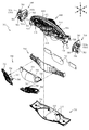
図22は、遊技盤13の分解正面斜視図であり、図23は、遊技盤13の分解背面斜視図である。図22及び図23に示すように、遊技盤13は、ベース板60と、そのベース板60の内側に配置されると共にセンターフレーム86を有する中央構成ユニット240と、その中央構成ユニット240の上部とベース板60とを連結すると共に遊技領域を流下する球の流下方向を制限する上部連結部材270と、その上部連結部材270と中央構成ユニット240との間に配置される薄板部材290と、を備える。
FIG. 22 is an exploded front perspective view of the
中央構成ユニット240の詳細については後述するが、図22で拡大図として示すように、中央構成ユニット240には、薄板部材290の位置決め及び固定に利用される固定用部244が形成される。
The details of the
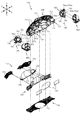
図24は、中央構成ユニット240の分解正面斜視図であり、図25は、中央構成ユニット240の分解背面斜視図である。中央構成ユニット240は、ベース板60の中央開口60bに配設される際に環状に組み立てられるユニットであって、センターフレーム86を有しており、球の流下を案内する。
FIG. 24 is an exploded front perspective view of the
中央構成ユニット240は、センターフレーム86の上側部を構成する上側構成部材241と、センターフレーム86の下側部を構成する下側構成部材261と、を備える。上側構成部材241及び下側構成部材261が、光透過性の樹脂材料から、それぞれ環形状の上下半分を構成することで、組立状態(図18参照)において正面視で第3図柄表示装置を囲むセンターフレーム86を構成する。
The central
このように、センターフレーム86を単品で環状に構成するのではなく、複数部材を組み合わせて環状に構成することにより、樹脂部材の成形に必要となる樹脂金型の大きさを小さくすることができる。これにより、樹脂金型の製造コストを抑えることができる。
In this way, the size of the resin mold required for molding the resin member can be reduced by forming the
例えば、ベース板60の中央開口60bの上縁部の形状が、本実施形態のように左右中央部において薄板部242の形状に対応して上向きに凹設される形状ではなく、略円弧形状で形成されるようにベース板60の設計変更を行う場合、上半分(上側構成部材241)のみ対応して設計変更すればベース板60にセンターフレーム86を組み付けることができることから、下半分(下側構成部材261)については本実施形態に対応させて設計した部材を流用することができる。
For example, the shape of the upper edge portion of the
これにより、ベース板60の設計変更や、センターフレーム86の形状を変えて見映えを変えることにより行うマイナーチェンジのために、センターフレーム86の全体を包含するような大きな金型を新たに製造する必要がないので、金型費用の削減を図ることができる。
As a result, it is necessary to newly manufacture a large mold that covers the
上側構成部材241は、組立状態(図18参照)においてベース板60の板正面と面一で配置される薄板部242と、その薄板部242の正面側に帯状に延設され、遊技中においてガラスユニット16(図1参照)との間に球を通さない寸法で形成されると共に球の流下を案内可能に形成される帯状フレーム部245と、その帯状フレーム部245の下側および左右内側に配設され略円弧形状を形成する装飾部247と、を備える。
The
薄板部242は、左右および上側の縁部において補強のために背面側に延設される延設部243と、上部連結部材270(図22及び図23参照)との位置決め及び固定に利用される固定用部244と、を備える。
The
延設部243は、前後幅がベース板60の板厚と同程度の長さとなるように設計される。即ち、延設部243よりも前後幅が短い薄板部242の前後厚みは、ベース板60の板厚よりも薄く設計されている。これにより、薄板部242の背面側にスペースを確保し易くすることができる。
The
固定用部244は、上部連結部材270(図22及び図23参照)との位置決めのために凹設される凹設部244aと、その凹設部244aに近接配置され正面側に突設される突設部244bと、上部連結部材271に正面側から挿通される締結ネジが螺入される締結部244cと、を左右対称位置に備えている。
The fixing
薄板部242はベース板60と面一で配置され、突設部244bを正面側の任意の位置から形成することができる。そのため、上部連結部材270(図22及び図23参照)との位置決めの設計自由度を向上することができる。なお、固定用部244を利用した上部連結部材270の組み付けについては後述する。
The
装飾部247は、複数の立体的な模様や図形が形成されており、薄板部242に比較して光透過性が低くなるように形成されている。これにより、装飾部247を、光透過性を若干残しながら、視界を分断する部分として利用することができる。
A plurality of three-dimensional patterns and figures are formed in the
ここまでは、上側構成部材241の正面側の構成を主に説明した。次に、上側構成部材241の背面側に配設される構成について説明する。上側構成部材241は、薄板部242の背面側に形成される締結部に締結固定される電飾基板251と、その電飾基板251を締結固定する締結ネジで共締めされる基板保持板252と、電飾基板251と薄板部242とに挟持されると共に正面側に末広がりとなる皿形状に形成される皿状部材253と、上側構成部材241の左右片側(本実施形態では右側)において装飾部247の背面側となる位置に締結固定されるセンサカバー254と、を備える。
Up to this point, the configuration on the front side of the
基板保持板252は、左右対称形状ではなく、左側部と比較して右下部の形成が省略されている。これにより、センサカバー254側から通される電気配線DH1(図19参照)の接続を容易にすることができる。即ち、電飾基板251の接続端子251aは、基板の右下側部の板背面に配置されており、この位置への電気配線DH1の接続が容易となるように基板保持板252の形状が設計されている。
The
更に、基板保持板252は、左右中央位置において上に凸の湾曲形状で凹設形成される凹設部252aを備える。凹設部252aは、動作ユニット500の配置の自由度を向上させる目的で形成される部分であるが、詳細は後述する。
Further, the
センサカバー254は、内部に静電容量センサ(例えば、遊技者がガラスユニット16の正面側に手をかざしたことを検知可能なセンサ)を配置し、その静電容量センサを固定するための固定部材である。本実施形態では、静電容量センサの固定だけではなく、電飾基板251に接続される電気配線DH1の中継部分としても兼用されている。
The
即ち、電飾基板251に形成される鉤形状部に結束バンド等で電気配線DH1を固定することで、電気配線DH1を装飾部247の背面位置に保持することができる。これにより、電気配線DH1を遊技者の視界に入り難いように隠すことができる。このように、センサカバー254を利用して電気配線DH1の配置を保持することで、電気配線DH1の配置を保持するための専用部材を用意する場合に比較して、組み付け工数を削減したり、材料コストを低減したりすることができる。
That is, by fixing the electric wiring DH1 to the hook-shaped portion formed on the illuminated
下側構成部材261は、組立状態(図18参照)においてベース板60の板正面に締結固定される薄板部262と、その薄板部262から背面側へ帯状に延設される帯状延設部263と、その帯状延設部263の延設端部に形成される締結部に締結固定されると共に帯状延設部263の背面側を塞ぐように覆う背面覆設部264と、薄板部262の左右下端部の正面側に締結固定され薄板部262との間で球を背面側へ流すための流下経路を構成する左右一対の流路前構成部265と、薄板部262の左右下端部の背面側に締結固定され流路前構成部265の薄板部262から左右内側にはみ出した半構成部と合体することで球を帯状延設部263の上面に案内する流下経路を構成する左右一対の流路後構成部266と、を備える。
The
帯状延設部263は、左右中央部へ向けて下降傾斜する上面部を備えており、転動した球をベース板60の正面側へ戻すように機能する。帯状延設部263の左右中央部には、左右方向の速度が収まった球を背面側へ流し易いよう背面側へ下降傾斜する中央後傾斜部263aと、その中央後傾斜部263aの左右両側において中央後傾斜部263aよりも若干下側に配置され左右方向の速度が収まった球を正面側へ流し易いよう正面側へ下降傾斜する一対の左右前傾斜部263bと、中央後傾斜部263aにより背面側へ流され流下した後で背面覆設部264に正面側へ案内された球をベース板60の正面側へ排出可能に貫通形成される球排出孔263cと、を備える。
The strip-shaped
帯状延設部263との関係において、背面覆設部264は基本的には帯状延設部263の背面側端部からの球の脱落を防止するように塞ぐが、中央後傾斜部263aの後方に限っては、帯状延設部263との間で球を下方に流下させることができる隙間を形成する。
この隙間を通り正面側へ案内された球が球排出孔263cから排出される。
In relation to the strip-shaped
A ball guided to the front side through this gap is discharged from the
球排出孔263cは左右中央位置に配置され、その下方には第1入賞口64が配設されているので(図18参照)、球排出孔263cから排出された球は、高確率で(釘KG1に弾かれながら第1入賞口64に近づく球よりも高確率で)第1入賞口64に入球する。
そのため、帯状延設部263に球が案内された場合に、その球に対する注目力を向上させることができる。
Since the
Therefore, when the ball is guided to the strip-shaped
流路前構成部265は、薄板部262の正面側を流下する球を背面側に案内する案内経路を形成し、流路後構成部266は、その案内経路の後端面を形成することで球を帯状延設部263の上面に案内する。換言すれば、流路前構成部265及び流路後構成部266によって、ベース板60の正面側から流入した球を、帯状延設部263の上面に排出するトンネル状部が形成される。
The flow path
図22及び図23に戻って説明する。上部連結部材270は、光透過性の樹脂材料から形成される部材であって、薄肉の板状部271と、その板状部271を基端として背面側から正面側に押し出されるように張り出す張出部272〜277と、板状部271の背面側において部分的に肉薄に形成される肉薄部278と、その肉薄部278において背面側に突設するように形成される突設部279と、を備える。
A description will be given by returning to FIGS. 22 and 23. The upper connecting
板状部271は、正面視で左右に長い左右対称の弓形状に形成され、下縁部の形状がセンターフレーム86の上縁部の形状に沿う形状とされる。また、板状部271は、上縁部が湾曲形状とされており、詳細には、板状部271の上縁部の特定の点における接線が、その特定の点に近接配置される外レール62の対応する点の接線と平行となる形状とされる。
The plate-shaped
外レール62と板状部271とは、球(遊技球)の直径程度の間隔が空けられている(図18参照)。これにより、外レール62に沿って転動する球が板状部271と衝突して勢いが減衰される事態の発生を回避し易くすることができる。
The
即ち、遊技領域に導入された球が板状部271に衝突する前に、球は外レール62から離れるよう構成される。換言すれば、外レール62に接触している限り、球が板状部271と衝突することは無いので、最大の発射強度で発射させる球(例えば、返しゴム69に衝突するまで外レール62に接触して転動する球)が板状部271に衝突して勢いが減衰されることを回避することができる。
That is, the ball is configured to separate from the
これにより、球の不要な減衰を避けることができると共に、最大の発射強度の球が板状部271と衝突することで板状部271が割れたり欠けたりすることを回避することができる。
As a result, unnecessary attenuation of the sphere can be avoided, and it is possible to prevent the plate-shaped
なお、外レール62と板状部271との間隔については、球の直径程度の間隔に限られるものではなく、種々の態様が例示される。例えば、球の形状を考慮して、球と板状部271との衝突を避けられるように、前後方向で間隔を変化させる(ベース板60から離れるほど間隔が広くなる)ようにしても良い。この場合において、ベース板60に近い側における板状部271と外レール62との間隔を狭めることができるので、板状部271に装飾を施す場合に、その装飾の形成面積を広げることができる。
The distance between the
張出部272〜277は、板状部271の左右中心を基準として左右対称となる位置から、板状部271の左右中心を基準とする左右対称形状で、板状部271の背面側から正面側へ向けて張り出される部分であり、それぞれが、釘の機能を代替する。
The overhanging
左右中央側から、第1張出部272、第2張出部273、第3張出部274、第4張出部275、第5張出部276、第6張出部277と称して説明する。
From the left and right center side, it is described as the first overhanging
第1張出部272及び第2張出部273は、薄板部材290を介して中央構成ユニット240の正面に配置される。第3張出部274は、中央構成ユニット240とベース板60とを跨ぐように配置される。第4張出部275、第5張出部276及び第6張出部277は、ベース板60の正面に配置される。
The
このように、各張出部272〜277は、どの部材の正面側に配置されるかが異なるので、その機能や、設計思想に違いが生じ得るが、詳細は後述する。
As described above, since each of the overhanging
肉薄部278は、薄板部材290を配置するために、板背面が薄板部材290の厚み寸法分または厚み寸法を若干超えた寸法分だけ正面側にずれることで、肉薄に形成される部分である。本実施形態では、肉薄部278から薄板部材290に押圧力が負荷されることで薄板部材290を保持する態様ではなく、固定用部244(図22参照)によって薄板部材290を保持する態様を採用している。
The
なお、肉薄部278における板背面の正面側へのずれ寸法は、薄板部材290の厚み寸法以上で形成される場合に限られるものではなく、種々の態様が例示される。例えば、板背面の正面側へのずれが、薄板部材290の厚み寸法未満の寸法で設計されても良い。この場合、薄板部材290が厚み方向に伸縮可能(圧縮可能)に形成されることで、薄板部材290に過度な圧力が加えられることを回避しながら、薄板部材290の配置を固定し易くすることができる。
The deviation dimension of the
また、例えば、薄板部材290の縁部に対応する部分だけ、肉薄部278の板背面の正面側へのずれを小さくするようにしても良い。この場合、薄板部材290に圧力が加えられる範囲を薄板部材290の縁部に限定することができる。
Further, for example, the deviation of the
突設部279は、薄板部材290に穿設される位置決め孔291に挿通される部分であって、薄板部材290を位置決めするための突状部分である。肉薄部278における第1張出部272又は第2張出部273の配置位置の裏側には、張出部272,273の形状に対応した凹部(窪み)が形成されることから、この位置から突設部279を突設させることはできない。即ち、突設部279は、肉薄部278の内、第1張出部272や、第2張出部273の配置を避けた位置から突設される。
The projecting
薄板部材290は、光透過性の樹脂材料から薄板状(シート状)に形成される部材であって、組み付け時の位置決め用に穿設される複数の位置決め孔291と、上部連結部材270を中央構成ユニット240に締結固定する締結ネジを挿通させるための孔として穿設される複数の挿通孔292と、を備える。
The
位置決め孔291は、左右外側に穿設され中央構成ユニット240の突設部244bが挿通される孔291aと、左右内側に穿設され上部連結部材270の突設部279が挿通される孔291bと、を備える。即ち、薄板部材290は、中央構成ユニット240及び上部連結部材270の双方との位置決めに利用される。
The positioning holes 291 are
なお、本実施形態において、左右外側とは、正面視における遊技盤13又は動作ユニット500の左右縁側を意味し、左右内側とは、正面視における遊技盤13又は動作ユニット500の左右中央部側を意味する。
In the present embodiment, the left and right outside means the left and right edge sides of the
図22及び図23に示すように、突設部244bは、第2張出部273の背面側の凹設部と対向配置される位置に形成される。そのため、正面視において、突設部244bは第2張出部273に目隠しされる。これにより、突設部244bの視認性は低下させながら、突設部244bによる薄板部材290の位置決め(位置安定)作用を生じさせることができる。
As shown in FIGS. 22 and 23, the projecting
図22及び図23に示すように、上部連結部材270に形成する部分を孔部ではなく突設部279とすることで、張出部272,273の境界位置という狭い範囲においても問題なく位置決め用の部分を構成することができる。換言すれば、狭い範囲において貫通孔や凹部を形成する際には、部材肉厚が過度に薄くなり強度が不足する事態となる可能性があるが、その事態を回避することができる。
As shown in FIGS. 22 and 23, by forming the portion formed in the upper connecting
換言すれば、薄板部材290の位置決め用の部分のために、張出部272,273の配置が制限されたり、強度が低下したりすることを回避し易くすることができる。即ち、張出部272,273の境界位置に位置決め用の孔部を形成する場合には、張出部272,273の境界位置の幅長さを孔部の幅長さ以上(孔部が円形状であれば直径以上)にする必要が生じるし、孔部により材料が削られる分、張出部272,273の強度低下が生じる可能性があるところ、本実施形態によれば、これらの問題点を解消し易くすることができる。
In other words, it is possible to easily avoid that the arrangement of the overhanging
一方で、上述のように、張出部272,273の背面は窪んでいるので突設部279を形成することができないところ、この位置については、図22に示すように、中央構成ユニット240から突設部244bを突設させることで対応できるので、張出部272,273の配置に制限されることなく薄板部材290の位置決め用の部分(突設部244b,279)を配置することができる。
On the other hand, as described above, since the back surfaces of the overhanging
このように、本実施形態によれば、薄板部材290の位置決め用の突設部244b,279を、中央構成ユニット240及び上部連結部材270の双方に形成させることにより、上部連結部材270の設計自由度や強度を高く維持しながら、薄板部材290の位置決め用部分の配置が制限されることを回避することができるので、薄板部材290の位置を安定させることができる。
As described above, according to the present embodiment, the projecting
更に、薄板部材290に挿通した突設部279が中央構成ユニット240の凹設部244aに挿通可能となるように設計されることで、中央構成ユニット240及び上部連結部材270に対して薄板部材290を位置決めするのと同時に、中央構成ユニット240に対する上部連結部材270の位置決めを行うことができる。
Further, the protruding
薄板部材290は、上部連結部材270を介して遊技者が視認可能となる部材である。
敢えて図示はしないが、本実施形態では、薄板部材290の板正面に模様、図形、文字またはキャラクターが色彩豊かに描かれており、中央構成ユニット240の電飾基板251に配置されるLEDから照射される光の発光態様の違い(色味や明暗の態様の違い)に応じて、薄板部材290を通して視認される色彩や明暗の態様が様々に変化する。
The
Although not shown, in the present embodiment, patterns, figures, characters or characters are colorfully drawn on the front surface of the
模様、図形、文字またはキャラクターをベース板60に直接描く場合と異なり、本実施形態によれば、薄板部材290を取り外せば薄板部材290に描かれた模様、図形、文字またはキャラクターを遊技盤13から取り去ることができるので、遊技盤13の見映えを容易に異ならせることができる。
Unlike the case where the pattern, graphic, character or character is drawn directly on the
例えば、遊技盤13の形状は同じものを流用しながら、遊技性を変える場合に(所謂、スペック違い)、遊技盤13に描かれる模様、図形、文字またはキャラクターや、色彩等を異ならせて、遊技者が遊技性を把握し易いようにする場合がある。
For example, when the
模様、図形、文字またはキャラクターがベース板60に直接描かれている場合には、ベース板60ごと取り替える必要が生じるので、実質、遊技盤13全体を取り替えることになり易く、遊技性変更にあたりコストが嵩み易い。
When a pattern, a figure, a character, or a character is drawn directly on the
一方、本実施形態によれば、薄板部材290を、描かれる模様、図形、文字またはキャラクターや、色彩等が異なる別の薄板部材290と交換することで足りるので、遊技盤13全体を取り替える必要は無い。従って、遊技性変更のためのコストを抑制し易くすることができる。
On the other hand, according to the present embodiment, it is sufficient to replace the
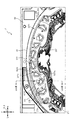
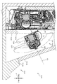
図26は、図18の範囲XXVIにおける遊技盤13の拡大正面図であり、図27は、図26のXXVII−XXVII線における遊技盤13の部分断面図であり、図28は、図26のXXVIII−XXVIII線における遊技盤13の部分断面図である。
26 is an enlarged front view of the
図26に図示されるように、張出部272〜277は、それぞれ個別の形状で形成される一方で、遊技領域に導入された球が衝突した場合には、その球の勢いを落としながら、その球をセンターフレーム86の左右側へ流下させるという共通の目的を有する。
As shown in FIG. 26, the overhanging
従来から、同様の配置で植設されることのあった釘の代替品として張出部272〜277を形成している。即ち、植設される複数の釘を正面視で囲むような形状から各張出部272〜277が設計されている。
Conventionally, overhanging
第1張出部272、第2張出部273及び第3張出部274で共通してみられるように、上側面が他の側面に比較して広く形成されている。これにより、上側面のどの位置に乗るかに寄らず、乗った球を上側面の傾斜に沿って同一の方向に流すよう構成することができる。これにより、発射力の調整が多少ずれても、球を類似の流下経路で流下させ易くなるので、同様の経路で球を流下させたい遊技者の遊技中のストレスを緩和することができる。
As can be seen in common with the first overhanging
第3張出部274と第4張出部275は、隣り合って配設されているため、球の発射力調整が少しずれるだけでどちらに球が到達するかが変化することになるが、上側面の傾斜が大きく異なる。即ち、第3張出部274の上側面は、左右内側に向かって緩く傾斜する下降傾斜面であるのに対し、第4張出部275の上側面は、左右内側に向かって急激に傾斜する下降傾斜面として形成される。
Since the third overhanging
そのため、第4張出部275の上側面に到達して流下する球は、センターフレーム86との衝突時に上向きに大きく跳ね返ることになり、勢いが失われ易い。そのため、遊技領域の下流側において第1入賞口64まで到達せずに、アウト口71へ向かって流下したり、一般入賞口63へ向かって流下したり、しやすい。
Therefore, the ball that reaches the upper side surface of the fourth overhanging
一方で、第3張出部274の上側面に到達して流下する球は、センターフレーム86と左右方向で衝突し、跳ね返り方向の負荷も流下の勢いとして利用できるので、遊技領域の下流側において第1入賞口64まで到達し易い。
On the other hand, the ball that reaches the upper side surface of the third overhanging
即ち、どの張出部272〜276に球が到達するかによって、遊技領域の下流側における球の流下態様が変化するように張出部272〜276の形状を設計している。これにより、遊技者に球の発射力の調整を意欲的に行わせることができる。
That is, the shape of the overhanging
図27及び図28に図示されるように、ベース板60と中央構成ユニット240の延設部243とは、上下間に中央構成ユニット240の薄板部242の板厚程度の隙間CL1,CL2を空けて配置されるよう設計される。
As shown in FIGS. 27 and 28, a gap CL1 and CL2 of about the thickness of the
即ち、ベース板60の中央開口60bに中央構成ユニット240が位置決めされる設計思想ではなく、ベース板60の中央開口60bと中央構成ユニット240との間には隙間を空けておき、上部連結部材270による締結固定(連結)の際にベース板60に対する中央構成ユニット240の位置合わせを同時に行うという設計思想から設計される。
That is, it is not a design concept in which the central
図27及び図28に図示されるように、第1張出部272の背面には薄板部材290及び中央構成ユニット240が配置される一方で、第3張出部274の背面にはベース板60が配置される。このように、張出部272〜277の背面に配置される部材は全て同じでは無く、異なる場合がある。
As shown in FIGS. 27 and 28, the
図27に示すように、中央構成ユニット240の薄板部242が薄肉で形成されることから、例えば、第1張出部272に負荷が与えられることで第1張出部272に撓み変形が生じる場合、中央構成ユニット240の薄板部242も撓み変形することができるので、第1張出部272に加えられる負荷を吸収することができる。これにより、第1張出部272が割れたり欠けたりする可能性を低くすることができる。
As shown in FIG. 27, since the
そのため、例えば、第1張出部272に球が衝突する際に、その球の勢いが非常に大きかったとしても、第1張出部272の撓み変形や、その撓み変形の影響で生じる薄板部242の撓み変形によって、球の勢いを十分に低下させることができるので、第1張出部272に衝突した後の球の流下を落ち着かせることができる。
Therefore, for example, when a sphere collides with the first overhanging
薄板部242の撓み変形は、上述のように、薄板部242とベース板60とが嵌合される構成ではなく、間に隙間CL1,CL2が設けられる構成を採用したことによって生じ易くなっている。即ち、本実施形態では、薄板部242とベース板60との間に隙間CL1,CL2を設けることにより、中央構成ユニット240を撓み変形させることによって、第1張出部272に与えられる負荷を逃がすことができる。
The bending deformation of the
同様の作用が、第2張出部273にも期待できる。なお、第1張出部272に与えられる負荷としては、遊技球の衝突による負荷や、遊技領域における球詰まりを解消する際に遊技機店の店員から加えられる負荷や、メンテナンス作業を行う作業者から加えられる負荷等が想定される。
A similar effect can be expected for the second overhanging
一方、図28に示すように、ベース板60は、撓みが生じない程度に厚肉で形成されるので、例えば、第3張出部274に負荷が与えられた場合に、ベース板60の撓み変形により負荷を逃がす作用を期待することはできないが、第3張出部274の高さ位置は、張出部272,273よりも低い位置にあるので、衝突する球の勢いは比較的小さい。そのため、第3張出部274をベース板60の正面に配置する構成でも、第3張出部274が割れたり欠けたりする可能性を低くすることができる。
On the other hand, as shown in FIG. 28, the
更に、衝突する球の勢いが比較的小さい箇所で、第3張出部274に衝突した球の勢いを過度に低下させると、球の流下が停止する可能性があることを考慮して、本実施形態では、第3張出部274をベース板60の正面に配置する構成を採用している。
Furthermore, considering that if the momentum of the ball colliding with the third overhanging
また、第3張出部274の撓みは抑えられ、状態が安定していることから、センターフレーム86の左右側に振り分けられて、釘が植設されている遊技領域としての、センターフレーム86の左右側領域や下側領域に近い配置において、球の案内を安定化させることができるので、球の発射強度と、球の流下態様との対応を安定させることができる。
Further, since the bending of the third overhanging
なお、第3張出部274が割れたり欠けたりすることを確実に避けるためには、球との衝突角度や、第3張出部274の形状等を、第3張出部274に与えられる負荷が小さくなるように(負荷が逃げやすくなるように)設計することが好ましい。第4張出部275〜第6張出部277についても、同様の設計思想を採用することが好ましい。
In order to prevent the third overhanging
張出部272〜277を、ベース板60に植設される釘KG1の代替品として利用することの利点について説明する。特に、演出効果の向上を図ることができる。即ち、光透過性の樹脂材料から形成される張出部272〜277の場合、金属製の釘KG1に比較して、遊技者にとって目隠しとなる部分が少ない。
The advantages of using the overhanging
例えば、本実施形態のように、張出部272,273の背面側に電飾基板251や薄板部材290を配置する構成であっても(図27参照)、張出部272,273が光を透過させるので、電飾基板251に配設されるLED等の発光手段から照射される光や、薄板部材290に描かれた模様、図形、文字またはキャラクターを遊技者が視認し易いようにすることができる。
For example, even in the configuration in which the
電飾基板251は、下側部中央位置に配置される4個のLEDから構成される中央発光手段251bと、その中央発光手段251bの左右側および上側を囲むように配設される7個のLEDから構成される周囲発光手段251cと、左右両端部付近に2個ずつ配設されるLEDから構成される遠方発光手段251dと、を備えており、図26において本実施形態における配置が隠れ線で図示される。各発光手段251b,251c,251dは、光の照射方向が必ずしも統一されておらず、光らせようとする対象がそれぞれ異なる。
The
中央発光手段251bは、光の照射方向が前方向(光軸が前後方向)であり、中央構成ユニット240の装飾部247の左右中央部におけるシンボルマーク(図26において白塗で図示)を照らす。そのシンボルマークの全体を淡く発光させるために、中央発光手段251bから照射される光の光軸を基準とした照射方向の幅角度が大きくなるように設計される。
The central
周囲発光手段251cは、光の照射方向が前方向(光軸が前後方向)であり、帯状フレーム部245や、張出部272,273の縁部等、前後方向に幅を持つ部分に光を導入させるように配置されている。前後方向の幅が長い部分を通過した後において遊技者に視認される光が弱弱しくならないように、光のエネルギーを光軸に集めるために、周囲発光手段251cから照射される光の光軸を基準とした照射方向の幅角度は小さくなるように設計される。
The ambient
これにより、光の明暗の付け方や、色の変化により、光の経路(帯状フレーム部245や張出部272,273を通過する光の経路)を直接的に目立たせ、その目立たせ方に差をつける演出を行うことができる。例えば、左右で光の明暗に差をつけることで、球を発射する方向を暗に示唆する発光演出を実行することができる。
As a result, the path of light (the path of light passing through the strip-shaped
例えば、第1張出部272の下縁部272aの後方に配置されている周囲発光手段251cのLEDは、第1張出部272の下縁部272aから、左右外側縁部272bに光を導光させるように配置されている。これにより、遊技者は、第1張出部272の光を目印に球を発射することで、第1張出部272の左右外側縁部272bに球を到達させ易くなる。光の光軸は第1張出部272の前後幅が長い位置を通過しており、第1張出部272の内部で光を全反射させ易くすることができる。
For example, the LED of the ambient light emitting means 251c arranged behind the
また、第1張出部272の内部形状は、後方が内側に突設されるように湾曲形成されているので、第1張出部272の内側に進行した光を第1張出部272の内部で繰り返し反射させ、第1張出部272の内側に光を集め易くすることができる。これにより、正面視において第1張出部272を周囲に比較して明るく発光させることができる。
Further, since the internal shape of the first overhanging
図27に図示されるように、中央構成ユニット240の薄板部242の背面側に電飾基板251が配置される。本実施形態では、正面側で球が案内される範囲における上部連結部材270の背面において、ベース板60の肉厚部分(釘KG1を打ち込むために必要となる厚み部分)の厚み寸法内(前後方向寸法内)に電飾基板251を配置している。即ち、ベース板60の肉厚部分の背側面の前後位置よりも、電飾基板251の前後位置の方が正面側に設定される。
As shown in FIG. 27, the
これは、球を案内するための部品としての釘KG1をベース板60に打ち込んでいる範囲においては、不可能な基板配置である。換言すれば、釘KG1が打ち込まれる範囲においては、ベース板60を十分に肉厚に形成せざるを得ないので、ベース板60の厚み寸法内(ベース板60の肉厚部分の背側面の前後位置よりも正面側)に電飾基板251を配置するスペースを確保することができない。
This is an impossible substrate arrangement in the range in which the nail KG1 as a component for guiding the ball is driven into the
これに対し、本実施形態では、球を案内するための部品として、釘KG1ではなく薄肉の上部連結部材270を採用し、その背面にベース板60の中央開口60bを配置してベース板60の代わりに中央構成ユニット240の薄板部242を配置することで、球が案内される範囲の背面側において電飾基板251を配置するためのスペースを確保するようにしている。
On the other hand, in the present embodiment, as a part for guiding the ball, a thin-walled
これにより、電飾基板251をベース板60の背面側に配置せざるを得ない場合に比較して、電飾基板251の配置の設計自由度を向上することができると共に、電飾基板251の配置を前側に寄せることができる。
As a result, the degree of freedom in designing the arrangement of the
電飾基板251の配置を前側に寄せることで、遊技盤13の背面側に配置される動作ユニット500の回転演出装置800(図17参照)の配置を前側に寄せ易くすることができると共に、電飾基板251に配設される中央発光手段251bや周囲発光手段251cや、回転演出装置800に配設される光源が、前側に配置されることになるので、遊技者に視認させる光をより明るくすることができる。
By moving the
遠方発光手段251dは、光の照射方向(光軸方向)が前後方向と交差する方向(図26において矢印で図示される方向)であり、左右外側に配設される張出部274〜276や、帯状フレーム部245や、外レール62等に光を照射するように配置されている。
The distant
これにより、強度確保のためにベース板60の板厚部分を形成し、その板厚部分の正面に張出部274〜276を配設する本実施形態のような構成であっても、遠方発光手段251dからの光照射を利用して張出部274〜276を十分に照らすことができる。
As a result, even in the configuration as in this embodiment in which a plate-thick portion of the
特に、本実施形態では、電飾基板251がベース板60の板厚後端よりも前端側に寄せられている(板厚寸法内に配設されている)ことから、遠方発光手段251dから前後方向と交差する方向に照射される光を、左右外側に離れた第5張出部276まで到達させ易くすることができる。
In particular, in the present embodiment, since the illuminated
遠方発光手段251dからの光を受ける張出部274〜276の形状は、光量を確保し易くなるように形状が工夫されている。即ち、例えば、第3張出部274において、遠方発光手段251d側の側面274a(左右内側かつ上側の側面)が広く形成され、遠方発光手段251dからの光を面で受けるように形成されている。
The shapes of the overhanging
また、遠方発光手段251dの反対側(左右外側かつ下側)においては、面と面との連結位置に角部274bが形成され、張出部274に形成されるカットをこの角部274bに光を集中させるような形状から形成している。これにより、遠方発光手段251dから離れた角部274bにおいても、発光強度を確保することができる。
Further, on the opposite side (left and right outer side and lower side) of the distant light emitting means 251d, a
なお、第6張出部277への光照射については、電飾基板251からの光照射ではなく、第6張出部277の正面視左右内側に配置される薄板部242(左右中央ではなく左右外側の薄板部242)を正面側へ透過する光により行っている。
Regarding the light irradiation to the 6th overhanging
また、第6張出部277の発光演出は、後述する回転演出装置800の回転部材810から照射される光によっても実行されるが、回転部材810から照射される光が正面側へ向かうための構成や、その強弱の設定については、後述する。
Further, the light emitting effect of the sixth overhanging
図20に戻って説明する。図20に示すように、センターフレーム86の下方に配設される入賞口63,64等は、光透過性の樹脂材料から形成される入賞口構成部材400の一部として形成される。
It will be described back to FIG. As shown in FIG. 20, the winning
図29は、遊技盤13の分解正面斜視図であり、図30は、遊技盤13の分解背面斜視図である。図29及び図30では、入賞口構成部材400が分解された状態が図示される。
FIG. 29 is an exploded front perspective view of the
入賞口構成部材400は、遊技盤13の左右中央部においてベース板60に締結固定される中央構成部材410と、その中央構成部材410の下部を正面側から覆う形状で構成される覆設部材430と、中央構成部材410の左側に配置されベース板60に締結固定される左部構成部材450と、中央構成部材410の右側に配置されベース板60に締結固定される右部構成部材470と、を備える。なお、右部構成部材470は、左部構成部材450と概略左右対称形状で形成される。
The winning
中央構成部材410は、ベース板60に面で接触した状態で締結固定される平板状の本体板部411と、特定入賞口65aを構成する開口部として形成される横長開口412と、その横長開口412の左右側部に上方において球の流下経路を振分可能に張出形成される左右一対の振分部413と、その振分部413の上方において上側面が湾曲板状に形成されると共に球の流下経路を振分可能に正面側に突設される左右一対の湾曲状突設部414と、横長開口412の左右端部から左右外側に離れた位置に球を排出可能な大きさで穿設される左右一対のアウト口415と、を備える。
The central
本体板部411は、左右両側において背面側から板厚を薄くするように凹設されるシート配設用凹部411aを備える。シート配設用凹部411aは、演出用のシート部材(薄板部材380)の外形に応じた形状で凹設され、そのシート部材の厚みと略同等の凹設深さで形成される。
The main
振分部413と湾曲状突設部414との間の隙間は、球の直径よりも大きく形成される。これにより、振分部413と湾曲状突設部414との間の隙間を通して球を流下させることができるので、球の流下のランダム性を高めることができ、球への注目力を向上させることができる。
The gap between the
振分部413は、左右内側(第2入賞口140側)の側面から突設される複数の突条部413aを備える。突条部413aは、流下する球に当接することで球の流下速度を減速させるために設けられる形状部であり、突条部413aによる減速効果によって、特定入賞口65aの開閉板65bに球から与えられる衝突力を低減することができる。これにより、開閉板65bの破損を防止することができる。
The
湾曲状突設部414の湾曲面の下端部を通る湾曲面の接線HL1(図31参照)は、振分部413の左右内側側面(第1入賞口64側の側面)を通るように設計されている。そのため、湾曲状突設部414の湾曲面を下端部まで転動した球が、振分部413の左右内側側面に到達する事態が生じやすい。
The tangent line HL1 (see FIG. 31) of the curved surface passing through the lower end of the curved surface of the curved projecting
覆設部材430は、光透過性の樹脂材料から形成され、薄板状に形成される本体板部431と、その本体板部431の左右側端部から左右内側部へ向けて延びる帯形状で背面側へ延設される左右一対の帯状部432と、その帯状部432の左右内側端部と連結されると共に鉛直方向に長尺の板形状で背面側へ延設される左右一対の鉛直板部433と、その鉛直板部433の上端部から左右内側へ向かう程に上昇傾斜する姿勢の長尺板形状で背面側へ延設される左右一対の傾斜板部434と、電動役物140aの回転角度を規制するように電動役物140aの下側において本体板部431から背面側に立設形成される立設部435と、を備える。
The lining
帯状部432、鉛直板部433、傾斜板部434及び立設部435は、覆設部材430が中央構成部材410に締結固定された状態において、その先端部が中央構成部材410の本体板部411に当接可能な長さで形成される。即ち、帯状部432、鉛直板部433、傾斜板部434及び立設部435により球の流下経路が変化されると共に、球の流下経路が振り分けられる。
The strip-shaped
帯状部432は、アウト口415の左右外側および下側に沿うように配設され、帯状部432に転動して流下する球は、アウト口415に案内され、遊技領域から排出される。
The band-shaped
傾斜板部434は、アウト口415よりも特定入賞口65a側に配置されているが、上側面の傾斜方向がアウト口415側へ下降傾斜する方向なので、傾斜板部434に転動した流下する球も、アウト口415に案内され、遊技領域から排出される。
The
立設部435は、中央構成部材410と覆設部材430との組立状態(図17参照)において中央構成部材410の振分部413の左右内側に、球の直径以上の隙間を空けて配置される。これにより、振分部413と立設部435との間を球が流下可能となっている。
The
左部構成部材450は、無色透明の樹脂材料から形成され、ベース板60に面で接触した状態で締結固定される平板状の本体板部451と、その本体板部451の左部広範囲で正面側に張出形成される張出部453と、その張出部453との間に球が通過可能な大きさの隙間を空けて左端部が配置される板状部であり、右側へ向かうほど下降傾斜する形状から形成される天井板部455と、その天井板部455よりも下側において一般入賞口63へ球を案内可能な形状で形成される複数の球案内部457,459と、を備える。
The
天井板部455は、張出部453と天井板部455との間の隙間を通過した球のみが球案内部457,459を流下可能となるようにするために、途中で分断されることない板状に形成される。
The
左部構成部材450の背面側および右部構成部材470の背面側には、背面側から板厚を薄くするように凹設されるシート配設用凹部451b,471bが形成される。シート配設用凹部451b,471bは、演出用のシート部材(図示せず)の外形に応じた形状で凹設され、そのシート部材の厚みと略同等の凹設深さで形成される。なお、このシート部材の装飾の例は、薄板部材380における説明で代用する。
図31は、図18の範囲XXXIにおける遊技盤13の拡大正面図である。張出部453と天井板部455との間の隙間を通過せず、天井板部455の上面を転動して流下する球は、案内部457,459へ案内されることはなく、中央構成部材410側へ案内されるように流下する。左部構成部材450や中央構成部材410の上流側からの球の流下経路について説明する。
FIG. 31 is an enlarged front view of the
図31に示すように、ベース板60に植設される複数の釘KG1は、左右方向内側へ向かう程に下降傾斜する直線に沿って球の直径未満の隙間を空けて並べられることで、左右中央側へ向かって流下する球の道筋(主経路FL1)が形成される一方、所々で球の直径を超える隙間を空けていることで、その隙間を通過して主経路から外れる球の脱落経路FL2,FL3が形成される。
As shown in FIG. 31, the plurality of nails KG1 planted on the
天井板部455は、球が上面を転動可能となるように形成されるが、天井板部455を転動する球の転動速度は、主経路FL1から下方へ脱落するタイミングにより異なる。詳述すると、主経路FL1から脱落経路FL2に球の経路が変化する場合、球の流下速度は、主に左右方向を向く状態から、主に上下方向を向く状態に切り替えられる。
The
そして、天井板部455に到達してから再び速度が左右方向を向く状態に切り替えられるので、天井板部455に球が到達するタイミングが早いほど(流下経路の上流側であるほど)、天井板部455を流下する際の球の転動速度(勢い)が大きくなり、遊技領域の左右内側(特定入賞口65a側)に到達し易い。
Then, after reaching the
また、天井板部455の上面の左右内側端部(下端部)は、隣り合う湾曲状突設部414の上端部よりも上方に配置されていることから、天井板部455を転動し左右内側に過ぎる球が湾曲状突設部414の左右外側側面にせき止められることを回避し易い。
Further, since the left and right inner end portions (lower end portions) of the upper surface of the
天井板部455を流下する際の球の転動速度を大きくし、その速度のまま特定入賞口65aに到達すると、球から開閉板65bに大きな衝撃力が伝えられることによる開閉板65bの破損が危惧されるが、本実施形態では、開閉板65bまでの球の流下経路に突条部413aが配設されており、球の流下速度を減速させている。
When the rolling speed of the ball when flowing down the
加えて、突条部413aの左右内側には立設部435が対向配置されており、複数の球が横並びで流下することを防止している。これにより、突条部413aと立設部435との間で球詰まりが生じることを回避することができる(整流作用)と共に、球が開閉板65bに同時に着地する事態の発生を回避し易くすることができることから開閉板65bの破損を防止し易くすることができる(耐久性向上)。
In addition, standing
このように、球の流下速度が落とされつつ、球の流下経路が制限されている。これにより、開閉板65bに球が衝突する際に生じる衝突力を低減することができるので、開閉板65bが破損する不具合の発生を抑制することができる。
In this way, the flow path of the ball is restricted while the flow speed of the ball is reduced. As a result, the collision force generated when the ball collides with the opening /
なお、本実施形態では、突条部413aは立設部435を基準として左右対称位置に配置されるので、左右一対の突条部413aと立設部435とにより形成される一対の流下経路において、球が同時に流下した場合には、開閉板65bに複数の球が同時に着地することは生じ得る。
In the present embodiment, since the
そのため、特別遊技状態において、球を左右に打ち分けることにより、特定入賞口65aに複数の球を同時に入球させ易くすることができる。これにより、特別遊技状態の進行が遅くなりすぎる事態を回避し易くすることができる。
Therefore, in the special game state, by striking the balls to the left and right, it is possible to facilitate the simultaneous entry of a plurality of balls into the specific winning
天井板部455の上面は左右に幅広の傾斜面として形成されているので、天井板部455で複数の球を同時に受け入れることができ、それらの球を整列させた状態で勢いよく左右内側(特定入賞口65a側)に流すことができる。
Since the upper surface of the
そして、左右内側に流された球は振分部413の左右内側(突条部413aが形成される側)を順番に通り、開放状態の開閉板65bに順番に到達する。このように、本実施形態によれば、開閉板65bに到達する球の道筋が振分部413の左右内側を通る道筋にまとめられているので、開閉板65bの上流側において球同士が衝突して、球が特定入賞口65aから逸れてしまう事態の発生を抑制することができる。
Then, the balls swept inward on the left and right pass in order on the left and right inside of the distribution portion 413 (the side on which the
更に、振分部413の突条部413aに当接しながら流下し開閉板65bに到達する位置よりも、特定入賞口65a及び開閉板65bの左右端が左右外側に位置するように設計することで、開閉板65bの上で球同士が衝突して左右に跳ねた場合であっても、球が開閉板65bの上面に乗っている状態を依然として維持することができる。従って、開閉板65bから球が零れる事態の発生を抑制することができる。
Furthermore, the position where it reaches the
なお、球が開閉板65bの左右端部から密に複数個滞留した場合であっても、本実施形態では傾斜板部434の下方に空間が形成されており、球を開閉板65bの左右外側に流せるようになっているので、振分部413の左右内側を通る球の経路が詰まる事態は回避することができる。
Even when a plurality of balls are densely retained from the left and right ends of the opening /
本実施形態では、天井板部455と湾曲状突設部414との間に球の直径を超える隙間を配置することで、この隙間を通る球の流下を許容している。例えば、天井板部455を転動し流下する球が、内側脱落経路FL3を通り流下する球に衝突すると、天井板部455を転動してきた球が左右方向速度を低下され、天井板部455と湾曲状突設部414との間の隙間に入り込み易い。
In the present embodiment, by arranging a gap exceeding the diameter of the sphere between the
主経路FL1を流下する球が、外側脱落経路FL2で流下する頻度や、内側脱落経路FL3で流下する頻度は、釘KG1の状態(汚れの付着、生産ロット)により変わり得る。
そのため、対策なしでは、釘KG1の状態により遊技効率や遊技利益が左右され、平等な条件での遊技を提供することができない。
The frequency with which the sphere flowing down the main path FL1 flows down with the outer dropout path FL2 and the frequency with which it flows down with the inner dropout path FL3 may change depending on the state of the nail KG1 (dirt adhesion, production lot).
Therefore, without countermeasures, the game efficiency and game profit are affected by the state of the nail KG1, and it is not possible to provide the game under equal conditions.
これに対し、本実施形態では、外側脱落経路FL2を通り天井板部455を転動する球の方が、内側脱落経路FL3で流下する球よりも高頻度で生じる場合、第1入賞口64まで到達する球が少なくなるので、抽選を受けて大当たりを目指す遊技状態(通常状態、時短状態、高確率状態など)の場合には不利だが、特定入賞口65aが開閉する大当たり遊技状態では、天井板部455と湾曲状突設部414との間の隙間に球が入り込む可能性を少なくでき、天井板部455に到達したほとんどの球を特定入賞口65aへ案内することができるので、遊技効率を向上させることができる(例えば、大当たり遊技に要する時間を短縮できる)。
On the other hand, in the present embodiment, when a ball that rolls on the
一方、内側脱落経路FL3を流下する球の方が、外側脱落経路FL2を通り天井板部455を転動する球よりも高頻度で生じる場合、第1入賞口64まで到達する球は多くなるので、抽選を受けて大当たりを目指す遊技状態(通常状態、時短状態、高確率状態など)の場合には有利だが、特定入賞口65aが開閉する大当たり遊技状態では、天井板部455を転動して流下する球の経路に内側脱落経路FL3から下方へ流下した球が衝突し、天井板部455と湾曲状突設部414との間の隙間に落下する球や、振分部413と湾曲状突設部414との間の隙間を通過してアウト口415側へ流れる球が頻発する。これにより、特定入賞口65aから逸れる球が増えるので、大当たり遊技の遊技効率は低下することになる。
On the other hand, if the spheres flowing down the inner dropout path FL3 occur more frequently than the spheres rolling down the
このように、本実施形態では、外側脱落経路FL2を通り天井板部455を転動する球の発生頻度と内側脱落経路FL3を流下する球の発生頻度との大小関係が切り替わると、遊技状態として有利な状態と不利な状態とが切り替わるのであって、遊技者が一方的に有利になったり、一方的に不利になったりするものではなくなるように設計されている。
As described above, in the present embodiment, when the magnitude relationship between the frequency of occurrence of balls rolling down the
即ち、釘KG1の状態が異なることは許容しながら、どのような釘KG1の状態であったとしても、ある状態では遊技者に有利となり、他のある状態では遊技者に不利となる関係を保つようにすることで、平等な条件での遊技の提供を図っている。 That is, while allowing the state of the nail KG1 to be different, regardless of the state of the nail KG1, the relationship is maintained to be advantageous to the player in a certain state and disadvantageous to the player in another state. By doing so, we are trying to provide games under equal conditions.
外側脱落経路FL2で流下して、天井板部455の左端部において上方向に延設される延設板部455aと、その延設板部455aと対向配置される張出部453の左右内側において左右外側下方へ向けて湾曲形成される側壁部453aとの間を流下する球の流下経路について説明する。
On the left and right inside of the
この流下経路へ球が案内される割合は、近接する釘KG2の状態(球が流下する位置における間隔)により、変動する。釘KG2は、球の衝突や、遊技機店の店員が触れること等により、状態が変動する場合がある。 The rate at which the ball is guided to this flow path varies depending on the state of the adjacent nails KG2 (interval at the position where the ball flows down). The state of the nail KG2 may change due to a collision of a ball, a clerk of a game machine store, or the like.
また、釘KG2の直前まで球が到達するか割合は、球が側壁部453の上面を転動するかによって変動する。球が側壁部453の上面に到達するかどうかは、側壁部453の上方に配置される風車FS1の状態によって変動する。風車FS1も、回転軸が釘KG2と同様にベース板60に打ち込まれているので、球の衝突や、遊技機店の店員が触れること等により、状態が変動する場合がある。
Further, the ratio of whether the ball reaches immediately before the nail KG2 varies depending on whether the ball rolls on the upper surface of the
延設板部455aと側壁部453aとの間の流下経路の真下には第1球案内部457が配設されているので、通常は、流下した球は第1球案内部457を通り遊技領域から排出される。第1球案内部457は一般入賞口63を構成しており、第1球案内部457に球が案内されると、遊技者に対して賞球の払い出しが実行される。
Since the first
本実施形態では、延設板部455aと側壁部453aとの間を球が真下に流下する場合、その球は、8割の確率で第1球案内部457に入球し、1割の確率で左に逸れ、1割の確率で右に逸れるように構成されている。なお、この割合は、延設板部455a及び側壁部453aの形状(傾斜や間隔等)や、第1球案内部457の配置により、異なるように設計することが可能である。
In the present embodiment, when a ball flows directly below between the
これに対し、例えば、第1球案内部457に到達した球が未だ第1球案内部457に留まっている間に、次の球が第1球案内部457に到達した場合には、次の球は第1球案内部457の左右に逸れて流下し易くなる。また、例えば、第1球案内部457へ向けて複数の球が集まった状態で流れると、その複数の球の内の数個は第1球案内部457の左右に逸れて流下し易くなる。
On the other hand, for example, when the next ball reaches the first
第1球案内部457から左右外側に逸れると、その下流側には入賞口は配設されておらず、アウト口415から排出される。一方、第1球案内部457から左右内側に逸れると、第1球案内部457から左右内側へ突設される傾斜案内部458を転動して第2球案内部459に到達し得る。第2球案内部459は一般入賞口63を構成しており、第2球案内部459に球が案内されると、遊技者に対して賞球の払い出しが実行される。
When the
第1球案内部457に球が案内されることに伴って払い出される賞球個数と、第2球案内部459に球が案内されることに伴って払い出される賞球個数とは、任意に設定可能であるが、本実施形態では、下流側に球が案内された方が払い出される賞球個数が多くなるように設定している。
The number of prize balls paid out when the ball is guided to the first
即ち、第2球案内部459に球が案内されることに伴って払い出される賞球個数の方が、第1球案内部457に球が案内されることに伴って払い出される賞球個数よりも多くなるように設定されている。
That is, the number of prize balls paid out when the ball is guided to the second
これにより、天井坂部455の左端よりも左側に球が流下した場合に、その球が第1球案内部457には入らずに、右側(第2球案内部459側)に逸れることを、遊技者が望むような遊技性を作ることができ、左部構成部材450への注目力を向上させることができる。
As a result, when a ball flows down to the left side of the left end of the
例えば、第1球案内部457に球が案内されることに伴い、賞球が1個払い出されるよう設定される場合には、第1案内部457へ向かう球が、左右外側(図31左側)に逸れると遊技者の手持ちの球数が減り、第1案内部457に案内されると球数は現状維持(発射1個に対して賞球1個)、左右内側(図31右側)に逸れると第2球案内部459に球が案内されて賞球(1個よりも多い個数、一般的に、2個〜15個)が払い出されることにより、手持ちの球数が増える可能性があるという遊技性を構成することができる。
For example, when one prize ball is set to be paid out as the ball is guided to the
これにより、第1案内部457付近の球の流れと遊技者が得られる利益の大小とを分かり易く対応づけることができるので、第1案内部457付近の球の流れに対する注目力を向上させることができる。
As a result, the flow of the ball near the
第1案内部457の右方に延びる傾斜案内部458は、樹脂材料から形成されているので、曲げなどが生じた場合には容易に折れ損する。そのため、釘KG1と異なり状態の変化が把握し易い。折れ損した状態を把握できれば、部材を交換するまでパチンコ機10を稼働停止することで、遊技者が不測の不利益を被ることを回避することができる。
Since the
本実施形態では、傾斜案内部458を転動した球が第2球案内部459に高確率で案内されるように、種々の形状的工夫がされている。第1に、第2球案内部459の左上位置において天井板部455の下面側に膨らむ膨出部456が形成される。
In the present embodiment, various shapes have been devised so that the ball that has rolled the
傾斜案内部458の上面を転動開始し、上下への跳ねが十分には収まっていない球は膨出部456に左右方向で当接することになり、球の速度方向が下方に向き変えられる。これにより、傾斜案内部458の上面を転動した球が、勢いのままに第2球案内部459の右側へ逸れることを防止することができる。
The ball that starts rolling on the upper surface of the
第2に、傾斜案内部458が、第2球案内部459との間の左右方向間隔が球の半径よりも短い間隔となると共に、第2球案内部459との間の上下方向間隔が球の直径よりも短い間隔となる位置まで第2球案内部459側へ張り出している(傾斜案内部458と第2球案内部459との間の球の通過を許容しない寸法関係で形成されている)ので、傾斜案内部458により、第2球案内部459の左側へ球が逸れることを防止し易くすることができる。
Secondly, the horizontal distance between the
入賞口構成部材400は、樹脂成形部材であり、ベース板60への組み付けは締結ネジによる締結固定なので、不良が生じた場合の交換は、釘KG1を交換(打ち直し)する場合に比較して容易である。
Since the winning
例えば、釘KG1が折れた場合には長期間に亘り遊技機の稼働を停止することになる可能性が高いところ、通常、釘KG1の打ち込みは一本ごとに打ち込むのではなく、多数の釘KG1を自動機で打ち込むことから、一部の釘KG1が折れたからといって釘KG1を打ち込み直すことは容易では無い。 For example, if the nail KG1 is broken, there is a high possibility that the operation of the game machine will be stopped for a long period of time. Normally, the nail KG1 is not driven individually but a large number of nails KG1. It is not easy to re-drive the nail KG1 just because a part of the nail KG1 is broken because the nail KG1 is driven by an automatic machine.
そのため、修復のためには、遊技盤全体の取り換えが必要になることが多いが、取り替え費用を賄えないと判断した場合には、釘KG1の他に故障している箇所が無いにも関わらず、再稼働することなく倉庫にしまわれる可能性がある。即ち、メンテナンス性および遊技機の稼働期間向上の観点から改良の余地があった。 Therefore, it is often necessary to replace the entire game board for repair, but if it is judged that the replacement cost cannot be covered, even though there is no faulty part other than the nail KG1. There is a possibility that it will be stored in the warehouse without restarting. That is, there was room for improvement from the viewpoint of maintainability and improvement of the operating period of the game machine.
本実施形態では、釘KG1の不良が極力生じないようにするために、上下方向に落下してくる球の受け止めを左部構成部材450の張出部453で行い、受け止めた球を張出部453の上面で左右に転動させることで上下方向の勢いを低減してから、その下流側の釘KG1に当接させるようにしている。これにより、球から釘KG1へ与えられる負荷を低減することができ、釘KG1の不良の発生を抑制することができる。
In the present embodiment, in order to prevent the nail KG1 from being defective as much as possible, the ball falling in the vertical direction is received by the overhanging
また、外側脱落経路FL2の左右外側に配置される釘KG1に着目すると、その左右外側は張出部453に覆われているので、これらの釘KG1に球が左右外側から衝突することはない。そのため、釘KG1がランダムな方向から負荷を受ける場合に比較して、釘KG1が折れるまでの期間を長くすることができる。
Further, paying attention to the nails KG1 arranged on the left and right outer sides of the outer dropout path FL2, since the left and right outer sides are covered with the overhanging
左部構成部材450の正面側を流下した球はアウト口415を通りベース板60の背面側に排出される。この時、鉛直板部433により左右内側(開閉板65bに近接する側)への球の通過が規制されていることから、アウト口415を通らずに、開閉板65b側へ球が流れることを防止することができる。
The ball that has flowed down the front side of the
そのため、開閉板65bの回動軸は左部構成部材450側から球が流れ込むことを防止することができるので、球詰まりに対する対策として開閉板65bと内レール61との間を常に球が通過可能に空けておく必要が無く、内レール61と開閉板65bの回動軸(下縁部)との上下間隔を球の直径未満に設定することができる。
Therefore, the rotation shaft of the opening /
また、そのように構成したとしても、開閉板65bに乗っていた球が左右に零れた場合には、鉛直板部433と開閉板65bとの間に仮置きすることができ、開閉板65bが閉鎖状態となれば、球の流下経路を遮っていた開閉板65bが球の流下経路から退避するので、仮置きされていた球はアウト口71へ向けて流下することになる。従って、球詰まりが生じる可能性を低くすることができる。
Even with such a configuration, if the ball on the opening /
図32は、図31のXXXII−XXXII線における遊技盤13の部分断面図である。左部構成部材450の本体板部451は、左右内側縁部からベース板60の前面に沿って薄肉板状(本体板部451の厚みよりも薄い板状)で延設される延設部451aを備え、中央構成部材410の本体板部411は、左右外側縁部から正面側側面に沿って延設される覆設延設部411bを備える。
FIG. 32 is a partial cross-sectional view of the
本実施形態では、覆設延設部411bとベース板60とにより延設部451aが挟持される。これにより、挟持される側である左部構成部材450の左右内側端部から固定用の締結ネジを取り払うことができるので、その分、左部構成部材450に装飾を施す場合に締結ネジの存在が目立ってしまうことで演出効果を低下させるという不具合を生じさせないようにし易くすることができる。加えて、部材を締結固定するための締結ネジの本数を削減することができるので、組立の工数や、材料コストを削減することができる。
In the present embodiment, the
延設部451aをベース板60との間で挟持している状態における覆設延設部411bの前端部の前後位置は、本体板部451の前端部の前後位置よりも背面側に位置している。これにより、本体板部451の前面側を流下する球が本体板部411の前面側へ向けて流れる際に、覆設延設部411bの前端部と球とが衝突して、球が左右外側に跳ね返される事態の発生を防止することができる。
The front-rear position of the front end portion of the overlaid
図33は、振分ユニット300の分解正面斜視図であり、図34は、振分ユニット300の分解背面斜視図である。図33及び図34に図示されるように、振分ユニット300の内部には上述した振分け部983が回転可能な状態で配設されており、第1入賞口64を通り振分ユニット300の内部に案内された球が交互に左右に振り分けられるように構成される。
FIG. 33 is an exploded front perspective view of the
振分ユニット300は、背面側から振分け部983が回転可能な状態で配設される部材であって第1入賞口64を通過した球を左右に振分けて流下させる流下経路を構成する第1構成部材310と、第1入賞口64を通過した球が後方に流下する経路の天井を構成する天井構成部材330と、第1構成部材310と共に振分け部983の軸部材988aを両持ちで支持すると共に振分け部983に当接して流れる球の背面側への脱落を規制する第1補助部材340と、第1構成部材310の下流側から後方に排出された球の排出経路を構成する第2構成部材350と、その第2構成部材350が締結固定される部材であって第2構成部材350により構成される排出経路の後方および上方を覆うように配設され第1構成部材310に締結固定される左右一対の第2補助部材370と、第1構成部材310の正面側に配置され第1構成部材310と中央構成部材410の本体板部411との間に左右一対で配設される薄板部材380と、を備える。
The
第1構成部材310は、無色半透明の樹脂材料から形成され、前後方向と直交する面に沿って形成される板状の中央板部311と、その中央板部311の上端から正面側に延設される延設板部313と、中央板部311の背面側に延設され左右外側へ向けて下降傾斜する方向に帯状に延びる一対の傾斜延設部315と、その傾斜延設部315の左右外側端部に連接され球の流下方向を切り替える(本実施形態では左右方向から前後方向に90度切り替える)一対の方向切替部317と、中央板部311の正面側において球が通過可能な大きさの開口が左右に複数並べられる左右一対の開口形成部320と、を備える。
The
中央板部311は、延設板部313の後端部の真下において、振分け部983を軸支する軸部材988aの一端が挿入される略円筒状の軸受部312を備える。軸受部312は軸部材988aの外径よりも大きい内径に形成される。
The
延設板部313は、左右中央部に沿って上端面が後方へ向かうほど下降傾斜する突条として形成され球の転動路を形成する突条部313aと、左右縁部から立設され球を後方に案内する左右一対の壁状部314と、を備える。
The
傾斜延設部315を流下する球は、第2補助部材370の前板部371に背面側への脱落を規制されながら、左右外側に流下する。なお、第2補助部材370は、検出装置SE3の抜け止め用の部材としても利用される。
The ball that flows down the
方向切替部317は、傾斜延設部315の左右端部の左右外側において傾斜延設部315よりも一段下がった位置で球が転動可能な板面として形成され正面側へ向けて下降傾斜する傾斜面部318と、その傾斜面部318の後側縁部および左右外側縁部から立設され球を正面側に案内可能な形状で正面側へ向けて湾曲形成される立設湾曲部319と、を備える。
The
開口形成部320は、検出装置SE3が背面側から挿通されるセンサ配置用開口321と、そのセンサ配置用開口321の左右側面に沿って正面側に延設され検出センサSE3の左右端部を支持する左右一対の支持延設部322と、その支持延設部322の間において球が通過可能に開口形成される入賞用開口部323と、支持延設部322を基準とした入賞用開口部323の左右反対側において球が通過可能に開口形成される一対の排出用開口部325と、入賞用開口部323及び排出用開口部325を通過した球を受け止めて背面側へ案内可能な形状で底面部が後方へ向けて湾曲形成される底面構成部327と、その底面構成部327の上面側を仕切るように支持延設部322の下縁から底面構成部327に向けて延設される一対の仕切り壁部328と、を備える。
The
センサ配置用開口321に検出装置SE3を挿通する際に、検出孔SE1aが入賞用開口部323の内側に配置されるように設計されている。支持延設部322の前縁部から突設される位置決め突部322aと検出装置SE3の前端部とが当接することで検出装置SE3の前後位置を容易に位置決めすることができる。
When the detection device SE3 is inserted into the sensor arrangement opening 321, the detection hole SE1a is designed to be arranged inside the winning
方向切替部317を通過し開口形成部320に到達した球は、入賞用開口部323又は排出用開口部325のいずれかを通過して、底面構成部327の上面を転動して背面側へ案内される。各転動経路は仕切り壁部328によって分断されているので、底面構成部327の上面で球が交差したり、衝突したりする可能性を低くすることができる。これにより、球の流れを整流化することができるので、球詰まりや、球が停滞することを防止することができる。
The ball that has passed through the
底面構成部327の上面を転動する球の内、入賞用開口部323を通過した球は検出装置SE3に通過を検知される。一方、排出用開口部325を通過した球は検出装置SE3には通過を検知されない。なお、いずれにしても、底面構成部327の上面を転動した球は、球の排出を検知する検出装置(図示せず)に検知された後、図示しない球排出路へと案内される。
Among the spheres that roll on the upper surface of the
図示しない球排出路へは、球は第2補助部材370に背面側への脱落を規制されながら、第2構成部材350の転動面351を左右内側へ向けて転動し、左右それぞれに配設される共通落下流路352を流れて案内される。
To the ball discharge path (not shown), the ball rolls the rolling
第2補助部材370は、傾斜延設部315の背面側に開いている空間に蓋をして球の脱落を防止する前板部371と、第2構成部材350の転動面351及び共通落下流路352に沿って流下する球の流下経路の上面側および背面側を塞いで球の脱落を防止する後板部372と、第1構成部材310の締結部329に螺入される締結ネジを挿通可能に前板部371に穿設される挿通孔373と、第2構成部材350の締結部353に螺入される締結ネジを挿通可能に後板部372に穿設される挿通孔374と、を備える。
The second
なお、第2構成部材350及び第2補助部材370を形成する材料は任意に設定可能であるが、本実施形態では、第2構成部材350を有色不透明の樹脂材料から形成し、第2補助部材370を無色透明の樹脂材料から形成している。
The material forming the second
これにより、共通落下流路352を流れる球の視認性を落とし排出された球に対する注目力を下げることができると共に、第2補助部材370の背面側から光を取り入れることができるので、取り入れられる光によって手前側に配設される第1構成部材310を明るく照らすことができ、第1構成部材310を流下する球の視認性を向上することができる。
As a result, the visibility of the sphere flowing through the common
薄板部材380は、本体板部411のシート配設用凹部411a(図30参照)に収容されることで位置決めされる。このように位置決めされた状態で、遊技盤13の組立が行われ、薄板部材380は本体板部411と第1構成部材310とに前後方向で挟持される。
The
第1入賞口64に入球した球の流下の過程における前後左右の変位(配置変化)について説明する。まず、第1入賞口64に入球した球は、延設板部313に沿って後方に変位する。その後、第1実施形態で説明した振分け部983の回転変位によって左右に振り分けられ、傾斜延設部315に沿って左右外側へ変位する。
The front-back and left-right displacements (arrangement changes) in the process of flowing down the ball that has entered the first winning
その後、方向切替部317によって流下方向を正面側へ切り替えられ、前方に変位する。球の流下方向を切り替えるための湾曲面が形成される案内部が流下する球の正面側に配置される場合には、その案内部が球への視線を遮り易く、視認性が低下する可能性があるが、本実施形態では、案内部としての立設湾曲部319は球の背面側に配置されるので、立設湾曲部319が球への視線を遮る可能性は低い。これにより、球の視認性を確保し易くすることができる。
After that, the flow direction is switched to the front side by the
その後、入賞用開口部323を真下に流下する球は、検出装置SE3に検知された後で、底面構成部327に沿って後方へ変位する。また、入賞用開口部323の上方において左右いずれかに変位し、排出用開口部325の真上に到達した球は、排出用開口部325を通過して底面構成部327に沿って後方へ変位する。
After that, the ball flowing directly below the winning
このように、本実施形態では、第1入賞口64に入球した球の配置を、入球当初は後側に寄せ、左右に流し、検出装置SE3を通過する直前で手前側に寄せるようにしている。
これにより、第1実施形態の構成に比較して、振分け部983の配置を後方に寄せることができると共に、延設板部313の下側にスペースを空けることができる。
As described above, in the present embodiment, the arrangement of the balls that have entered the first winning
As a result, as compared with the configuration of the first embodiment, the arrangement of the
この空いたスペースは、第2入賞口140の電動役物140aを動作させるための駆動機構を配置するためのスペースとして利用することができる。これにより、本実施形態では、第1実施形態に比較して、第2入賞口140の配置を第1入賞口64に近づけることができる。
This vacant space can be used as a space for arranging a drive mechanism for operating the
また、振り分けられた後の球が流下する経路を、前後方向へ経路を切り替えるようにして構成することで、流路を一貫して上下方向に並べて構成する場合(例えば、振分ユニット980で上述した構成の場合)に比較して、流路の正面視における上下幅を短縮することができる。これにより、第1入賞口64に対する検出装置SE3の相対的な上下配置の設計自由度を向上することができる。
Further, when the path through which the spheres after being sorted flows down is configured so as to switch the path in the front-rear direction so that the paths are consistently arranged in the vertical direction (for example, the
図35は、図18の範囲XXXVにおける遊技盤13の部分拡大正面図である。図35では、中央構成部材410及び薄板部材380が半透明に図示され、振分ユニット300が視認可能とされる。また、図35では、説明の便宜のために、電動役物140aの閉鎖状態および開放状態における外形が共に図示されている。なお、図35の説明では、図33及び図34を適宜参照する。
FIG. 35 is a partially enlarged front view of the
薄板部材380は、光透過性の樹脂材料から薄板状(シート状)に形成される部材であって、中央構成部材410を介して遊技者が視認可能となる部材である。敢えて図示はしないが、本実施形態では、薄板部材380の板正面に模様、図形、文字またはキャラクターが色彩豊かに描かれており、照射される光の態様の違い(色味や明暗の態様の違い)に応じて、薄板部材380を通して視認される色彩や明暗の態様が様々に変化する。
The
模様、図形、文字またはキャラクターをベース板60に直接描く場合と異なり、本実施形態によれば、薄板部材380を取り外せば薄板部材380に描かれた模様、図形、文字またはキャラクターを遊技盤13から取り去ることができるので、遊技盤13の見映えを容易に異ならせることができる。
Unlike the case where the pattern, graphic, character or character is drawn directly on the
例えば、遊技盤13の形状は同じものを流用しながら、遊技性を変える場合に(所謂、スペック違い)、遊技盤13に描かれる模様、図形、文字またはキャラクターや、色彩等を異ならせて、遊技者が遊技性を把握し易いようにする場合がある。
For example, when the
模様、図形、文字またはキャラクターがベース板60に直接描かれている場合には、ベース板60ごと取り替える必要が生じるので、実質、遊技盤13全体を取り替えることになり易く、遊技性変更にあたりコストが嵩み易い。
When a pattern, a figure, a character, or a character is drawn directly on the
一方、本実施形態によれば、薄板部材380を、描かれる模様、図形、文字またはキャラクターや、色彩等が異なる別の薄板部材380と交換することで足りるので、遊技盤13全体を取り替える必要は無い。従って、遊技性変更のためのコストを抑制し易くすることができる。
On the other hand, according to the present embodiment, it is sufficient to replace the
薄板部材380に施す装飾の態様は何ら限定されるものではなく、種々の態様が例示される。例えば、検出装置SE3の上方において無色透明な範囲を形成することで傾斜面部318を転動する球の視認性を向上させ、その他の部分においては図形や模様を密に描画して装飾性を向上させるようにしても良い。また、例えば、正面視で入賞用開口部323や、排出用開口部325に対応する箇所に数字等で目印をそれぞれ描き、どの目印に近接して球が流下したかによって遊技者が得られる利益を把握し易くするようにしても良い。
The mode of decoration applied to the
薄板部材380は、貫通孔60aよりも左右外側に張り出すように大きな形状で設計されており、ベース板60と中央構成部材410の本体板部411との間に挟まれるようにして配設される。
The
本実施形態では、薄板部材380の後端面と、第1構成部材310の前端部(例えば、支持延設部322の前端部)とが当接するように配置される。即ち、検出装置SE3が薄板部材380と近接配置されるので、検出装置SE3の検出孔SE1aを遊技者側に寄せることができる。これにより、検出装置SE3を通過する球の視認性を向上することができ、検出装置SE3を通過する球を見逃す事態が発生することを回避し易くすることができる。
In the present embodiment, the rear end surface of the
また、検出装置SE3は、正面視において電動役物140aよりも左右外側に配置されており、電動役物140aに隠されることが無い。これにより、球の流下経路が電動役物140aに隠される場合(図5参照)に比較して、電動役物140aの状態(開放状態、閉鎖状態)に関わらず、検出装置SE3を通過する球の視認性を向上させることができる。
Further, the detection device SE3 is arranged on the left and right outside of the
また、検出装置SE3は、中央構成部材410の本体板部411よりも後方に配置されているので、本体板部411の正面側における球の流下態様に影響を与えるものではない。即ち、検出装置SE3が本体板部411よりも前側(ベース板60の前端面よりも前側)に張り出して配置される場合に比較して、遊技領域の設計自由度を向上させることができる。
Further, since the detection device SE3 is arranged behind the main
強度の関係で、本体板部411に釘を配設することはされないが、本実施形態では、釘の代替品として振分部413や湾曲状突設部414により球の経路を振り分けるよう構成されている。これにより、本体板部411の正面側における球の流下経路が単調となることを回避することができる。
Due to the strength, the nail is not arranged on the main
検出装置SE3の検出孔SE1aを通って検出装置SE3に検知される球(入賞用開口部323を通過する球)と、排出用開口部325を通過する球とは、双方共に、傾斜面部318を転動して正面側へ変位する経路を通る。そのため、傾斜面部318に到達した球の個数と、検出装置SE3に検知される球の個数とには、差異が生じる場合がある。
The sphere detected by the detection device SE3 through the detection hole SE1a of the detection device SE3 (the sphere passing through the winning opening 323) and the sphere passing through the
傾斜面部318により球が手前側に変位することで球の視認性を向上することができるものの、入賞用開口部323を通ったのか、排出用開口部325を通ったのかの識別がし難い構成では、球が検出装置SE3を本当に通っていないのか、検出装置SE3を通っているのに検知不良が生じているのかの判別ができず、遊技者が不満を感じる可能性があった。
Although the visibility of the ball can be improved by displacing the ball toward the front side by the
これに対し、本実施形態では、傾斜面部318から入賞用開口部323を通過する球は、入賞時流下経路FL31に沿って、正面視で下方へ流下するように視認されるのに対し、傾斜面部318から排出用開口部325を通過する球は、非入賞時流下経路FL32に沿って、正面視における流下方向が下向きから左右向きに90度切り替えられる。
On the other hand, in the present embodiment, the ball passing from the
即ち、球の流下方向に左右方向成分があるか、否かで、球が検出装置SE3を通過するか、否かの判別を行うことができるので、球の通過箇所を見間違う可能性を低くすることができる。これにより、検出装置SE3の検出孔SE1aを球が通過したか否かの判別を容易とすることができる。 That is, it is possible to determine whether or not the sphere passes through the detection device SE3 depending on whether or not there is a left-right component in the flow direction of the sphere, so that the possibility of mistaking the passing location of the sphere is low. can do. This makes it easy to determine whether or not the sphere has passed through the detection hole SE1a of the detection device SE3.
入賞時流下経路FL31に沿って流下する遊技球も、非入賞時流下経路FL32に沿って流下する遊技球も、正面視において振分部413や湾曲状突設部414の付近を流下することから、その流下経路は特定入賞口65aへ向けて流下する遊技球の流下経路と重なるように視認される。
Because both the game ball that flows down along the flow-down path FL31 at the time of winning and the game ball that flows down along the flow-down path FL32 at the time of non-winning flow down in the vicinity of the
そのため、傾斜面部318を経て流下する遊技球が、あたかも特定入賞口65aへ向けて流下しているように遊技者に見せることができる。遊技者は、発射した遊技球の内、開閉板65bの上方までは到達したが特定入賞口65aに入らなかった遊技球(開閉板65bが閉鎖状態の時に通り過ぎた遊技球)の個数を、アウト口71に向けて内レール61を転動する遊技球を目視で確認して把握することが多い。しかし、傾斜面部318を経て流下する遊技球は入賞時流下経路FL31又は非入賞時流下経路FL32を流下した後は底面構成部327(図34参照)に沿って後方に流されるので、遊技球はアウト口71の手前には登場しない。
Therefore, it is possible to make the player look as if the game ball flowing down through the
これにより、大当たり遊技実行中において第1入賞口64に入球した遊技球を、特定入賞口65aへ向けて流下しているように見える遊技球の個数に加算させることができるので、第1入賞口64に入球した遊技球の個数に関わらず、発射した遊技球のほとんどが特定入賞口65aに入球しているように錯覚させることができる。
As a result, the game balls that have entered the first winning
更に、傾斜面部318を経て流下する遊技球と、実際に特定入賞口65aへ向けて流下している遊技球とは、配置が薄板部材380により前後で分断されているので、互いに衝突することは無い。これにより、特定入賞口65aへ向けて流下している遊技球の流下を阻害することなく、上述の錯覚を生じさせることができる。
Further, the game ball flowing down through the
なお、本実施形態では、非入賞時流下経路FL32が左右方向に流れる流路として形成される場合を説明したが、必ずしもこれに限られるものではない。例えば、検出装置SE3へ向けて傾斜面部318を流下した球が流れる経路において本体板部411及び薄板部材380に開口が前後方向に穿設されるように構成し、この開口を通ることで、非入賞時流下経路FL32が正面側に球が流れる流路として形成しても良い。
In the present embodiment, the case where the non-winning flow path FL32 is formed as a flow path in the left-right direction has been described, but the present invention is not necessarily limited to this. For example, in the path through which the ball flowing down the
即ち、非入賞時流下経路FL32を流れる球が、本体板部411の正面側に再び戻り、アウト口71へ向けて流下するようにしても良い。この場合、開閉板65bが開放状態となっていれば、非入賞時流下経路FL32を流れた球が開閉板65bに拾われて、特定入賞口65aに入球し得る。
That is, the ball flowing through the flow path FL32 at the time of non-winning may return to the front side of the main
即ち、第1入賞口64に入球した球が本体板部411の前側に再び戻った後で、特定入賞口65aに入球し得るという遊技性を構成することができるので、第1入賞口64に入球した球に対する注目力(特に、開閉板65bが開閉動作する大当たり遊技中における注目力)を向上させることができる。
That is, since it is possible to configure the game property that the ball that has entered the first winning
次いで、遊技盤13の背面側に締結固定される動作ユニット500(図17参照)の構造について説明する。動作ユニット500は、遊技盤13のベース板60(図2参照)に背面側から締結固定される。
Next, the structure of the operation unit 500 (see FIG. 17) that is fastened and fixed to the back side of the
図36、図37、図38及び図39は、動作ユニット500の正面図である。図36では、動作ユニット500の内部動作ユニット600の退避状態が図示され、図37では、内部動作ユニット600の中間状態が図示され、図38では、内部動作ユニット600の張出状態が図示され、図39では、内部動作ユニット600の一の動作誤差限界状態が図示される。
36, 37, 38 and 39 are front views of the
本実施形態において、退避状態は、内部動作ユニット600の発光動作演出ユニット700が上下動作範囲の上側端位置に配置された状態であり、中間状態は、発光動作演出ユニット700が退避状態から前後傾倒方向の姿勢が維持されたまま動作可能な範囲の下側端位置に配置された状態であり、張出状態は、発光動作演出ユニット700が上下動作範囲の下側端位置に配置され、回転演出装置800の回転軸RJ1が前後方向を向いた状態である。
In the present embodiment, the retracted state is a state in which the light emitting
中間状態から張出状態への状態変化では、発光動作演出ユニット700の前後方向の姿勢変化(傾倒動作)が生じる。この姿勢変化は、所定の回転軸線(後述する中心軸J1)を中心とする回転動作として実行される。
In the state change from the intermediate state to the overhanging state, the posture change (tilting operation) of the light emitting
本実施形態において、一の動作誤差限界状態は、発光動作ユニット700に設計上許容される左右方向の傾きが限界となった状態の内の一つの状態である。図39では、便宜上、発光動作ユニット700の右側部が退避状態と同じ位置に配置され、左側部が下方に位置ずれした状態として図示される。本実施形態では、一の動作誤差限界状態の傾斜角度を保ったまま、発光動作ユニット700を上下方向に動作させることが可能となるように、動作ユニット500が構成されているが、詳細は後述する。
In the present embodiment, one operation error limit state is one of the states in which the tilt in the left-right direction allowed for the light emitting
図36に示すように、内部動作ユニット600の退避状態では、回転演出装置800の回転部材810は、装飾用の図形や模様が形成される装飾板811を正面側へ向けた姿勢とされる。
As shown in FIG. 36, in the retracted state of the
装飾板811に形成される図形や模様は、図37に示すように、背面ケース510の底壁部511に形成される図形や模様と関連する態様で形成され、内部動作ユニット600の中間状態において一体的に視認される(放射状に延びる直線形状および左右外側に形成される波模様の内、直線形状も含めて回転部材810に形成された状態で視認される)。
As shown in FIG. 37, the figures and patterns formed on the
即ち、装飾板811に形成される図形や模様を、底壁部511と一体的に視認される図形の一部として設計することができるので、回転部材810の大きさが、回転部材810に形成される図形や模様を限定することを避けることができる。
That is, since the figure or pattern formed on the
また、図38に示すように、内部動作ユニット600の張出状態においては、発光動作演出ユニット700が前転方向に傾倒し、発光動作演出ユニット700の本体部材710に形成される図形や模様が正面視で視認される。
Further, as shown in FIG. 38, in the overhanging state of the
この図形や模様についても、背面ケース510の底壁部511に形成される図形や模様と関連する態様で形成され、内部動作ユニット600の張出状態において一体的に視認される(放射状に延びる直線形状および左右外側に形成される波模様の内、直線形状は底壁部511のみに形成され、本体部材710には波模様が形成された状態で視認される)。
These figures and patterns are also formed in a manner related to the figures and patterns formed on the
即ち、本体部材710に形成される図形や模様を、底壁部511と一体的に視認される図形の一部として設計することができるので、本体部材710の大きさが、本体部材710に形成される図形や模様を限定することを避けることができる。
That is, since the figure or pattern formed on the
退避状態から張出状態へ向けて発光動作演出ユニット700は上下方向に変位するので、固定の底壁部511との関係において、退避状態で図形や模様が一体的に視認される状態から、底壁部511に形成される図形や模様と、回転部材810に形成される図形や模様とが、ずれ始める。
Since the light emitting
このずれは、上下方向の変位量が大きくなるほど目立つことになる。これに対し、本実施形態では、張出状態において発光動作演出ユニット700が傾倒変位することで遊技者に視認させる面を切り替え、底壁部511と一体的に視認される図形や模様を新たに遊技者に視認させることができる。従って、底壁部511に形成される図形や模様と、上下方向に変位する発光動作演出ユニット700(本体部材710、回転部材810)に形成される図形や模様とを、退避状態および張出状態において一体的に視認させるよう構成することができる。
This deviation becomes more noticeable as the amount of displacement in the vertical direction increases. On the other hand, in the present embodiment, the light emitting
ここで説明した発光動作演出ユニット700の上下方向変位中に、発光動作演出ユニット700の正面視における外形が変化する。これにより、単一の演出ユニットを、あたかも複数の異なる演出ユニットのように錯覚させることができ、動作演出の設計自由度を向上させることができる。
During the vertical displacement of the light emitting
図40は、動作ユニット500の分解正面斜視図であり、図41は、動作ユニット500の分解背面斜視図である。なお、図40及び図41では、背面ケース510の開口511aに配設される液晶表示装置(第3図柄表示装置81)の図示が省略され、開口511aを通して奥側を視認可能に図示される。
FIG. 40 is an exploded front perspective view of the
動作ユニット500は、底壁部511と、その底壁部511の外縁から立設される外壁部512とから正面側が開放された箱状に形成される背面ケース510を備える。背面ケース510は、底壁部511の中央に矩形状の開口511aが開口形成されることで、正面視矩形の枠状に形成される。開口511aは、第3図柄表示装置81の表示領域の外形(外縁)に対応した(即ち、第3図柄表示装置81の表示領域を正面視で区切ることが可能な)大きさに形成される。
The
背面ケース510は、外壁部512の正面側端部に遊技盤13の背面に沿う(例えば、平行に配置される)平面板として延設され、組立状態(図2参照)において遊技盤13を面支持する支持板部513を備える。
The
支持板部513は、遊技盤13のベース板60に形成される嵌合凹部(図示せず)と嵌合可能な形状で正面側へ向けて円環状に突設される複数の位置決め凸部513aと、その位置決め凸部513aの中心部においてベース板60に締結される締結ネジを挿通可能に穿設される挿通孔513bと、をそれぞれ複数備える。
The
ベース板60の嵌合部60c(図21参照)に位置決め凸部513aを嵌合させることによりベース板60に対して背面ケース510を位置決めし、締結ネジを挿通孔513bに挿通し、嵌合部60cの雌ネジに螺入することにより、遊技盤13と動作ユニット500とを一体的に固定することができるので、遊技盤13及び動作ユニット500の全体としての剛性の向上を図ることができる。
The
なお、位置決め凸部513aの形状は何ら限定されるものではなく、種々の態様が例示される。例えば、ベース板60の嵌合部60cの外形(本実施形態では、円形)よりも若干小さな外形の環状の凸部でも良いし、組み付け時の作業性を考慮して、嵌合隙間が大きくなるような形状(大径の環形状)の突部でも良い。また、嵌合部60cの外形が矩形状に形成される場合には、それに対応して位置決め凸部513aの形状も矩形状とされることは当然想定される。
The shape of the positioning
動作ユニット500は、遊技盤13の背面側に配置され、発光手段や、動作ユニットが内部に配設されている。即ち、動作ユニット500は、背面ケース510と、その背面ケース510に正面側から差し込まれて締結固定される装飾固定部材520と、背面ケース510の内側上部に配設される内部動作ユニット600と、背面ケース510の内側下部に配設される発光演出ユニット518と、を備える。
The
発光演出ユニット518は、振分ユニット300や入賞口構成部材400(図29参照)の後方から、前方に光を照射するユニットであって、振分ユニット300や入賞口構成部材400により形成される球の通過経路を明るく照らすよう機能する。
The light emitting
装飾固定部材520は、光透過性の樹脂材料から形成され、左右両位置に対称配置されると共にそれぞれ上下に分割可能な複数の薄板状部材から構成されるものであって、左上側に配置される第1固定部材530と、左下側に配置される第2固定部材540と、右上側に配置される第3固定部材550と、右下側に配置される第4固定部材560と、第1固定部材530及び第2固定部材540の背面側に配設される左側電飾基板570と、第3固定部材550及び第4固定部材560の背面側に配設される右側電飾基板580と、を備える。各部分の構成および役割について、図42及び図43を参照して説明する。
The
図42は、動作ユニット500の分解正面斜視図であり、図43は、動作ユニット500の分解背面斜視図である。図42及び図43では、背面ケース510から装飾固定部材520が分解されて前方に配置され、背面ケース510から内部動作ユニット600が分解されて背面ケース510と装飾固定部材520との間に配置される状態が図示される。
FIG. 42 is an exploded front perspective view of the
第1固定部材530は、前後方向に延びる薄板状の差し込み板部531と、その差し込み板部531の前側部から右方に延設される前板部534と、差し込み板部531の前側部から左方に延設される外板部537と、を備える。
The
差し込み板部531は、内部動作ユニット600の受入孔623に差し込み可能な形状および配置で延設先端部から背面側に突設される複数の差し込み突部532を備え、内部動作ユニット600の外側部材610の外側傾斜変位を防止する役割がある。差し込み板部531と外側部材610との相対的な機能の説明は後述する。
The
前板部534は、左側電飾基板570の正面に配置され左側電飾基板570の外形に対応した形状から形成される(左側電飾基板570を覆うように形成される)板状部であって、左側電飾基板570の正面側に配設されるLED等の発光手段からの光を拡散させるために裏側に光拡散加工が形成される。尚且つ、内部動作ユニット600の外側部材610に締結固定される締結ネジを挿通可能に穿設される挿通孔535を備える。
The
外板部537は、背面ケース510の外壁部512の前面部に当接可能な部分であって、外壁部512に形成される締結部512aに螺入される締結ネジを挿通可能に穿設される挿通孔538を備える。
The
即ち、第1固定部材530は、動作ユニット500の組立状態(図36参照)において、背面ケース510の外壁部512と内部動作ユニット600の外側部材610とを連結固定する。
That is, the first fixing
第2固定部材540は、第1固定部材530の前板部534と同様の前後位置で配置される板状部であって前板部534の下端から若干間隔を空けて配置される前板部541と、その前板部541の右下側部から右方に延設される締結用延設部544と、前板部541の左端部から左側へ延設される外板部547と、を備える。
The
前板部541は、左側電飾基板570の正面に配置され左側電飾基板570の外形に対応した形状から形成される(左側電飾基板570を覆うように形成される)板状部であって、左側電飾基板570の正面側に配設されるLED等の発光手段からの光を拡散させるために裏側に光拡散加工が形成される。
The
尚且つ、内部動作ユニット600の外側部材610に締結固定される締結ネジを挿通可能に穿設される挿通孔542と、内部動作ユニット600の内側部材670に締結固定される締結ネジを挿通可能に穿設される挿通孔543と、を備える。即ち、前板部541を介した締結固定によって、内部動作ユニット600の外側部材610と内側部材670との連結固定することができる。
In addition, an
連結用延設部544は、発光演出ユニット518の締結部518aに螺入される締結ネジを挿通可能に穿設される挿通孔545を備える。外板部547は、背面ケース510の外壁部512の前面部に当接可能な部分であって、外壁部512に形成される締結部512bに螺入される締結ネジを挿通可能に穿設される挿通孔548を備える。
The connecting
即ち、第2固定部材540は、動作ユニット500の組立状態(図36参照)において、背面ケース510の外壁部512と、内部動作ユニット600の外側部材610及び内側部材670と、発光演出ユニット518と、を連結固定する。
That is, the second fixing
第3固定部材550、第4固定部材560及び右側電飾基板580は、背面側に配置され覆われる対象となる内部動作ユニット600の内側部材670の形状の違いに起因して、第1固定部材530、第2固定部材540及び左側電飾基板570と形状が多少異なるが、基本的には第1固定部材530及び第2固定部材540と左右対称に形成され、有する構成と、各構成の役割は同様なので、重複する部分についての説明は省略すると共に第1固定部材530及び第2固定部材540の説明で上述した符号を便宜上図示する。
The
内部動作ユニット600及び装飾固定部材520の背面ケース510への組み付け順序について説明する。背面ケース510への組み付けは、まず内部動作ユニット600を先に背面ケース510に組み付けて(図40参照)、その後で装飾固定部材520を背面ケース510に組み付ける。
The order of assembling the
概要として、内部動作ユニット600の背面ケース510への組み付け工程は、まず左右の外側部材610及び内側部材670を背面ケース510に締結固定し、その後で背面ケース510の内側に正面側から発光動作演出ユニット700を入れて左右の外側部材610及び内側部材670の間に配置し、発光動作演出ユニット700を変位部材680との組み付け位置に配置し、脱落防止のための部材(ネジやカラー等)を正面側から締結部682に組み付けるという順序で作業を行う。
As an outline, in the process of assembling the
本実施形態では、発光動作演出ユニット700の組み付け作業時において、装飾固定部材520を背面ケース510に組み付けることを要しないので、背面ケース510の正面側を広く開け放つことができ、装飾固定部材520に作業者の手の動線が遮られることを回避することができる。これにより、作業効率を向上することができる。
In the present embodiment, since it is not necessary to assemble the decorative fixing
尚且つ、装飾固定部材520の挿通孔535,538,542,543,545,548に締結ネジを挿通して締結固定する作業は、背面ケース510の正面側から行うことができるので、発光動作演出ユニット700を変位部材680に組み付ける作業の終了後に、背面ケース510の姿勢を変えずに、続けて装飾固定部材520の締結固定のための作業を行うことができる。これにより、作業効率を更に向上させることができる。次いで、組み付け作業の詳細について説明する。
Moreover, since the work of inserting the fastening screw into the insertion holes 535, 538, 542, 543, 545, 548 of the decorative fixing
図44は、図36のXLIV−XLIV線における動作ユニット500の断面図であり、図45は、図44の範囲XLVにおける動作ユニット500の部分拡大断面図であり、図46は、図36のXLIV−XLIV線における動作ユニット500の断面図である。
44 is a sectional view of the
図44及び図45では、発光動作演出ユニット700が背面ケース510から分解されると共に、装飾固定部材520を組み付ける前の状態として装飾固定部材520の図示が省略される。一方、図46では、発光動作演出ユニット700及び装飾固定部材520が背面ケース510に組み付けられた状態(図36参照)が図示される。
In FIGS. 44 and 45, the light emitting
本実施形態では、内部動作ユニット600と背面ケース510との固定のみでは十分な剛性を発揮しないように、締結位置が設計されており(例えば、締結位置が上下一方の端部のみに配置されており)、内部動作ユニット600は背面ケース510に対して左右外側に撓み変形可能(姿勢変化可能)に構成される(図45の想像線を参照)。
In the present embodiment, the fastening position is designed so that sufficient rigidity is not exhibited only by fixing the
この撓み変形を利用して、発光動作演出ユニット700の組み付けを迅速に行うことが可能である。即ち、発光動作演出ユニット700の組み付けは、締結部682を発光動作演出ユニット700の被連結孔764に挿通させた状態で締結部682に締結ネジを螺入することで行われるところ、内部動作ユニット600が左右外側に撓み変形することで、発光動作演出ユニット700を締結部682へ向けて進入させる経路の寸法を固定時幅寸法W1から撓み時幅寸法W2に左右に広げることができるので、組み付け作業の作業性の向上を図ることができる。
By utilizing this bending deformation, it is possible to quickly assemble the light emitting
この際、内部動作ユニット600が左右外側に撓み変形することにより、締結部682への締結ネジの進入方向が、背面側へ向かう程に左右内側へ向くような傾斜方向(正面側が左右外側に広がる傾斜方向)となる。
At this time, the
この場合、締結ネジを前後方向で進入させる場合に比較して、締結ネジを螺入するためのドライバーを発光動作演出ユニット700の装飾部材750から離した(避けた)状態(前後方向に対して傾斜した方向)で背面ケース510内に締結ネジを進入させることができる。
In this case, as compared with the case where the fastening screw is inserted in the front-rear direction, the driver for screwing the fastening screw is separated (avoided) from the
そのため、締結作業を容易とすることができると共に、ドライバーとの接触を避けることを目的の一つとして形状が設計される発光動作演出ユニット700の装飾部材750の設計自由度を向上させることができる。即ち、発光動作演出ユニット700の組み付け作業の作業効率を向上させると共に、装飾部材750の設計自由度を向上させることができる。
Therefore, the fastening work can be facilitated, and the degree of freedom in designing the
この効果を発揮可能とするために、本実施形態では、締結ネジが挿通される被連結孔764の長孔764aの左右方向寸法は、内部動作ユニット600の撓み変形による締結部682の配置ずれに対応可能な寸法(十分な左右長さ)で設計される。
In order to make this effect possible, in the present embodiment, the left-right dimension of the
なお、左右内側への内部動作ユニット600の撓み変形は、筒状部材695が背面ケース510の底壁部511に当接し抵抗が生じることから、左右外側への撓み変形に比較して生じ難いように構成されている。
It should be noted that the bending deformation of the
本実施形態では、装飾固定部材520が組み付けられることにより、内部動作ユニット600の左右外側への撓み変形が抑制されるよう構成される。これは、内部動作ユニット600と背面ケース510との締結位置(背面ケース510の底壁部511に配置される締結位置、背面側寄りに配置される締結位置)よりも、内部動作ユニット600、装飾固定部材520及び背面ケース510の締結位置(背面ケース510の外壁部512や内部動作ユニット600の正面側に配置される締結位置、正面側寄りに配置される締結位置)の方が多いことや、装飾固定部材520の形状的工夫から効果が発揮される。
In the present embodiment, by assembling the decorative fixing
第1に、装飾固定部材520は、外壁部512又は支持板部513に締結固定される外板部547を備え、外壁部512と一体的に構成されている支持板部513はベース板60に締結固定される(図42参照)。即ち、支持板部513を介してベース板60に装飾固定部材520は変位を規制される。これにより、ベース板60の剛性を利用して、装飾固定部材520及び内部動作ユニット600の剛性を向上させることができることから、内部動作ユニット600の左右外側への撓み変形を抑制することができる。
First, the decorative fixing
第2に、装飾固定部材520の差し込み板部531が、内部動作ユニット600の左右外側に当接配置される。即ち、差し込み板部531により内部動作ユニット600の左右外側への撓み変形を抑制することができる。
Secondly, the
これら第1の構成および第2の構成から、装飾固定部材520が組み付けられた状態において内部動作ユニット600が左右外側に撓み変形することを防止することができる。
From these first configuration and the second configuration, it is possible to prevent the
加えて、装飾固定部材520は背面ケース510に正面側から組み付けられるよう構成されており、発光動作演出ユニット700は背面ケース510に正面側から組み付けられるよう構成されているので、背面ケース510の姿勢を変えることなく、発光動作演出ユニット700の組み付けに続いて装飾固定部材520を組み付けるように一連の流れで組み付け作業を行うことができる。従って、組み付け作業の効率化を図ることができる。
In addition, the decorative fixing
一方、メンテナンス等で発光動作演出ユニット700を締結部682から取り外す作業が、装飾固定部材520を取り外すことなく実行可能に構成した方が、メンテナンス作業の工数を減らすことができ効率が良い。
On the other hand, if the work of removing the light emitting
ここで、装飾固定部材520の背面側には電飾基板570,580が配設されており(図42参照)、電飾基板570,580を左右内側に張り出すように構成した方が、発光演出の演出範囲を広げることができ、演出効果を向上させることができる。
Here, the illuminated
これに対し、本実施形態のように電飾基板570,580が左右内側に張り出して配置されていると、メンテナンス作業者が発光動作演出ユニット700を正面側に移動させる際に、発光動作演出ユニット700の左右端部に形成される連結板部765が電飾基板570,580と衝突し、電飾基板570,580が破損する可能性がある。
On the other hand, if the
これに対し、本実施形態では、後述する内側部材670の延設壁部677の正面側縁部から左右内側へ向けて、電飾基板570,580の背面を覆うために十分な形状で保護延設部677bが延設される(図42参照)。
On the other hand, in the present embodiment, the protective extension is provided in a shape sufficient to cover the back surface of the illuminated
保護延設部677bは、電飾基板570,580の上側部における左右内側の縁部の形状に対応した形状線S51(図42参照)と同様の形状で左右内側端部が形成され、形状線S51に対応する位置まで延設される。
The
これにより、電飾基板570,580を背面側から支える面積を大きくすることができると共に、電飾基板570,580の上側部の背面を保護延設部677bにより防護することができるので、メンテナンス作業時に電飾基板570,580と発光動作演出ユニット700とが接触することを回避することができる。
As a result, the area for supporting the
一方、形状線S51の下端よりも下方では、電飾基板570,580の形状によらず、左右内側への延設部分の形成が省略される。従って、この位置において発光動作演出ユニット700を取り外す作業を行う場合には、発光動作演出ユニット700と電飾基板570,580とが接触する可能性が残る。
On the other hand, below the lower end of the shape line S51, the formation of the extending portion inward to the left and right is omitted regardless of the shapes of the illuminated
これに対し、本実施形態では、発光動作演出ユニット700が下降変位すると共に姿勢変化するよう構成されており(図37及び図38参照)、姿勢変化により締結部682の向きが前後方向から上下方向に変化して締結ネジにドライバーを差しこむことができなくなるので、発光動作演出ユニット700を取り外す作業は、発光動作演出ユニット700の姿勢が変化する前に実行されるよう構成される。従って、保護延設部677bは、発光動作演出ユニット700の姿勢が変化する前に配置される位置において形成すれば十分であり、本実施形態では、そのように設計されている(図37参照)。
On the other hand, in the present embodiment, the light emitting
このように、保護延設部677bを上下全範囲に亘り形成するのではなく、発光動作演出ユニット700と電飾基板570,580との接触を避けるための必要最小限の範囲の形成に留めることにより、保護延設部677bの形成範囲を狭めることができる。
In this way, the
換言すれば、本実施形態では、発光動作演出ユニット700を取り外す作業を行うことができる発光動作演出ユニット700の配置を内部動作ユニット600の退避状態と中間状態との間の配置に制限するように構成することで、保護延設部677bの形成範囲の縮小を図っている。
In other words, in the present embodiment, the arrangement of the light emitting
なお、本実施形態では、装飾固定部材520を背面ケース510から取り外した後で発光動作演出ユニット700を取り外すことも当然可能である。この場合には、組み付け作業時と同様に、内部動作ユニット600を左右外側に撓み変形させることで、発光動作演出ユニット700を取り出す経路の左右幅を広くすることができるので、発光動作演出ユニット700が保護延設部677bと接触することを回避することができる。
In this embodiment, it is of course possible to remove the light emitting
図47は、動作ユニット500の分解正面斜視図であり、図48は、動作ユニット500の分解背面斜視図である。図47及び図48では、主に内部動作ユニット600を分解した状態が図示されており、装飾固定部材520の図示が省略される。
FIG. 47 is an exploded front perspective view of the
図47及び図48に示すように、内部動作ユニット600は、背面ケース510の底板部511に締結固定される外側部材610と、その外側部材610に上下方向へ変位可能に支持されると共に左右方向内側に配置される昇降板部材630と、その昇降板部材630を昇降させるための駆動力を発生させる装置であって外側部材610に締結固定される駆動モータ648と、その駆動モータ648の駆動軸に固定され昇降板部材630に駆動力を伝達する伝達ギア649と、昇降板部材630に上向きの付勢力(引っ張り方向の負荷)を与えるコイルスプリングSP1と、を備える。
As shown in FIGS. 47 and 48, the
また、内部動作ユニット600は、昇降板部材630の移動の抵抗力を発生可能に構成される抵抗発生装置650と、外側部材610との間に昇降板部材630を配置させるよう左右方向内側に配置され外側部材610に左右方向で挿通される締結ネジによって外側部材610に締結固定される内側部材670と、その内側部材670に変位可能に支持されると共に左右方向内側に配置される変位部材680と、内側部材670の上端部背面側において左右内側から締結固定される回転姿勢補助部材690と、変位部材680に両端部を連結される発光動作演出ユニット700と、を備える。
Further, the
内部動作ユニット600は、概略左右対称に構成されるユニットであって、発光動作演出ユニット700が左右中心に配置され、発光動作演出ユニット700の左右両側において背面ケース510側に固定配置される略共通の構成により発光動作演出ユニット700が動作可能に支持される。
The
以下、内部動作ユニット600の各構成の詳細について、図47の各範囲を拡大して図示した図49及び図50を参照して説明する。なお、図49及び図50の説明では、図47及び図48を適宜参照する。
Hereinafter, details of each configuration of the
図49(a)は、図47の範囲XLIXaにおける外側部材610、昇降板部材630及び抵抗発生装置650の分解正面斜視図であり、図49(b)は、図47の範囲XLIXbにおける外側部材610の正面斜視図であり、図50(a)は、図47の範囲Laにおける昇降板部材630、内側部材670、変位部材680及び回転姿勢補助部材690の分解正面斜視図であり、図50(b)は、図47の範囲Lbにおける変位部材680及び回転姿勢補助部材690の分解正面斜視図である。
49 (a) is an exploded front perspective view of the
図49(a)及び図49(b)に示すように、外側部材610は、上下方向に長尺の板状に形成される板状部611と、その板状部611の左右外側(背面ケース510の外壁部512であって組立状態において近接する外壁部512側)に壁状に延設されると共に板状部611の左右外側の領域を区画するように形成される延設壁部621と、を備える。
As shown in FIGS. 49 (a) and 49 (b), the
板状部611は、上下方向に長尺の長円形で穿設される上下一対の長孔612と、上側の長孔612の後方において上下方向に長尺で幅広(長孔612よりも幅広)の長円形で穿設される配線通し孔613と、下側の長孔612の後方において左右外側に円柱状に突設される上下一対の案内突設部614と、を備える。
The plate-shaped
長孔612は、昇降板部材630の変位方向を制限するための長孔であり、上側と下側とに一対が配置される。長孔612の前後幅は、挿通される昇降板部材630の上締結部632及び下締結部633の直径よりも若干広く形成されているので、昇降板部材630の前後方向への変位は小さくなる。これら一対の長孔612は、前後配置を敢えてずらして形成されている。即ち、下側の長孔612の方が、上側の長孔612に比較して前側に配置されている。
The
これにより、昇降板部材630の上側部の支持位置が昇降板部材630の下側部の支持位置に比較して後側となるので、昇降板部材630の上側部に吊り下げられる態様の昇降板部材630の下側部は、重力により後側に付勢される。
As a result, the support position of the upper portion of the elevating
これにより、昇降板部材630のラックギア部634を伝達ギア649側に寄せることができるので、ラックギア部634が伝達ギア649から脱落することを回避することができ、歯合関係の適正化を図ることができる。
As a result, the
配線通し孔613は、発光動作演出ユニット700の内部において接続される電気配線であって、脱落防止カラー部材685の異形開口部685aを通り内側部材670の左右外側に位置した電気配線を通し、外側部材610の左右外側へ排出するための開口部である。
The wiring through
案内突設部614は、抵抗発生装置650の前後変位部材653の変位を案内する部分として機能する。即ち、前後変位部材653が前後方向に変位できるよう案内すると共に、前後変位部材653が前後に傾倒して姿勢変化することを防止するように機能するが、詳細は後述する。
The
延設壁部621は、正面側端部に配置され装飾固定部材520に挿通される締結ネジを螺入可能に構成される複数の締結部622と、背面側に配置され装飾固定部材520の差し込み板部531の差し込み突部532(図43参照)を差し込み可能に形成される上下一対の受入孔623と、を備える。なお、正面側端部に配置される締結部622以外の締結部は、主に電飾基板570,580(図40参照)を締結固定するための締結部である。
The
昇降板部材630は、長尺方向を上下方向に向ける長尺本体部631と、その長尺本体部631から左右外側に突設形成され外側部材610の上側の長孔612に挿通されると共に締結ネジを螺入可能に形成される一対の上締結部632と、長尺本体部631から左右外側に突設形成され外側部材610の下側の長孔612に挿通されると共に締結ネジを螺入可能に形成される一対の下締結部633と、長尺本体部631の背面側にギア歯状に形成され伝達ギア649と歯合されるラックギア部634と、を備える。
The elevating
また、昇降板部材630は、長尺本体部631の下端部から背面側に延設され不図示の位置検出装置の検出溝に配置されることで長尺本体部631の位置を検出可能に構成される被検出部635と、一対の上締結部632の中間位置において前後方向に長尺の長孔として長尺本体部631に穿設される前後長孔636と、板状部611の左右外側に配置され挿通されている締結ネジにより上締結部632に締結固定される脱落防止板637と、板状部611の左右外側に配置され挿通されている締結ネジにより下締結部633に締結固定される被当接板638と、動作時の摩擦抵抗の低減のために上締結部632及び下締結部633に組み付けられるリング部材C1と、を備える。
Further, the elevating
上締結部632と下締結部633とは、外側部材610の長孔612の前後配置に対応して配置される。そのため、下締結部633は、上締結部632よりも前側に配置される。
The
前後長孔636は、内側部材670の第2長孔673や湾曲長孔674に挿通される金属棒状部材686の前後移動を案内する長孔であり、第2長孔673及び湾曲長孔674が形成される範囲の前後幅以上の前後長さで形成される。
The front-rear
昇降板部材630の上締結部632が上側の長孔612に挿通された状態で上締結部632の先端側に脱落防止板637が締結固定され、且つ、下締結部633が下側の長孔612に挿通された状態で下締結部633の先端側に被当接板638が締結固定されることにより、外側部材610に昇降動作可能に支持される昇降板部材630の外側部材610からの脱落を防止し易くすることができる。
With the
被当接板638は、左右外側にコイルスプリングSP1の下端部を係止するための係止部を備える。コイルスプリングSP1の上端部は外側部材610の板状部611の左右外側に形成される係止部638aに係止される。即ち、コイルスプリングSP1は、被当接板638を上方に付勢する付勢力(引っ張り力)を生じる。
The contacted
脱落防止板637が長円形で形成されているのに対して、被当接板638は、矩形状に形成されている。これにより、抵抗発生装置650との当接面積を大きくすることができ、衝突時に生じる単位面積当たりの負荷の大きさを低減することができるが、詳細は後述する。
The
抵抗発生装置650は、プランジャーの出没方向を前後方向とするソレノイド651と、そのソレノイド651を収容し外側部材610の左右外側に固定するための固定カバー652と、ソレノイド651のプランジャーに係止されると共に外側部材610の案内突設部614に案内されることで前後方向に変位可能に構成される前後変位部材653と、を備える。
The
固定カバー652は、外側部材610に螺入される締結ネジを挿通可能な挿通孔としてソレノイド651の上下両位置に穿設される複数の挿通孔652aと、外側部材610の案内突設部614の先端部が嵌合可能な配置寸法で凹設される上下一対の嵌合部652bと、を備える。
The fixed
前後変位部材653は、上下両側において案内突設部614が挿通される長孔として前後長尺で穿設される一対の被案内長孔653aを備える。被案内長孔653aが案内突設部614に挿通された状態で、案内突設部614の先端部に固定カバー652の嵌合部652bが嵌合されることにより、前後変位部材653の案内突設部614からの脱落防止を図ることができる。
The front-
内側部材670は、図50(a)及び図50(b)に示すように、外側部材610の板状部611と左右方向で対向配置される板状部671と、その板状部671の左右外側に壁状に延設される延設壁部677と、板状部671の上端側後方部において左右内側に矩形状に張出形成される矩形張出部678と、を備える。
As shown in FIGS. 50 (a) and 50 (b), the
板状部671は、昇降板部材630の前後位置よりも背面側において上下方向に長尺の長孔として穿設される第1長孔672と、その第1長孔672よりも正面側で第1長孔672の上端部よりも上側に位置ずれした上端部から第1長孔672と平行に延びる長孔として穿設される第2長孔673と、その第2長孔673の下端部に連結される湾曲形状の長孔として穿設される湾曲長孔674と、を備える。
The plate-shaped
板状部671の背面ケース510との連結部として、図48では左側の内側部材670の上端部背面側においてのみ締結部が図示されており、その他に内側部材670の背面側に締結部の図示は無い。このことからも分かるように、板状部671の位置固定は、主には背面ケース510との直接の締結固定ではなく、背面ケース510に締結固定される外側部材610や装飾固定部材520(図40参照)を介しての締結固定によるものである。換言すれば、板状部671は背面ケース510との間接的な締結固定により、背面ケース510との固定力が生じている。
As a connecting portion of the plate-shaped
板状部671は、外側部材610の板状部611に左右外側から左右方向に挿通される締結ネジが螺入される締結部671aを複数備えており、締結ネジの螺入により内側部材670が外側部材610に締結固定される。
The plate-shaped
第1長孔672は、第2長孔673及び湾曲長孔674の幅よりも幅が太く形成される。これにより、本実施形態では、第1長孔672を電気配線の通し孔として利用することができ、発光動作演出ユニット700に接続される電気配線が左右一対の内側部材670の左右内側領域に露出することを防止することができるが、詳細は後述する。
The first
第2長孔673及び湾曲長孔674は、同一幅で形成されている。湾曲長孔674の湾曲形状は、第1長孔672に案内される変位部材680の筒状部684が第1長孔672の下端に位置する状態で筒状部684の中心を軸とする円弧形状として形成される。
The second
延設壁部677は、板状部671から左右外側へ第1長孔672を囲むように形成される区画壁部677aと、正面側縁部から左右内側へ向けて電飾基板570,580の背面を覆うために十分な形状で延設される保護延設部677bと、を備える。
The
変位部材680は、左右内側が開放される略矩形の箱形状に形成される箱状本体部681と、その箱状本体部681の短手方向側壁部から外側に突設形成される一対の締結部682と、箱状本体部681の左右外側側面に沿って延設される延設部683と、箱状本体部681の隅部から左右外側方向に円筒状に張り出す筒状部684と、その筒状部684の先端側に締結固定される脱落防止カラー部材685と、延設部683の基端側において円形の凹部として形成される嵌合凹部683aに嵌合固定される金属棒状部材686と、相対変位する部材間の隙間に配置され金属棒状部材686が挿通される複数のリング部材687と、筒状部684が挿通される大径リング部材688と、発光動作演出ユニット700を前後で挟むように配置された状態で(図46参照)、締結部682に挿通される前後リング部材689と、を備える。
The
締結部682は、発光動作演出ユニット700の被連結孔764に挿通される締結ネジが螺入される雌ネジ部を有しており、この締結ネジにより、発光動作演出ユニット700が変位部材680に連結される。
The
延設部683は、発光動作演出ユニット700を変位部材680に組み付ける際に、発光動作演出ユニット700が内側部材670に接触しないように防護する部分として機能する(延設部683及び発光動作演出ユニット700の配置関係について図45及び図46参照)。
The
筒状部684は、内周側において箱状単体部681を左右方向に貫通するように形成される異形開口部684bと、その異形開口部684aを通る中心軸を挟んだ両位置に脱落防止カラー部材685に挿通された締結ネジを螺入可能に形成される締結部684aを備える。
The
筒状部684は、内側部材670の第1長孔672に挿通された状態で、脱落防止カラー部材685が締結固定される。脱落防止カラー部材685の中央部には、筒状部684の異形開口部684bと同程度の大きさの開口として異形開口部685aが形成されている。
The fall-
即ち、脱落防止カラー部材685が筒状部684に締結固定された状態において、筒状部684及び脱落防止カラー部材685の内周側には左右方向に貫通する開口が形成される。この開口は、発光動作演出ユニット700に接続される電気配線の通し孔としての機能を有する。このことについて、ここで説明する。
That is, in a state where the fall
発光動作演出ユニット700に一端が接続されている電気配線の他端側は、発光動作演出ユニット700の配線通し孔762(図48参照)から外側に出され、変位部材680の筒状部684の異形開口部684bおよび脱落防止カラー部材685の異形開口部685aを通って内側部材670の第1長孔672よりも左右外側に出され、更に、外側部材610の配線通し孔613を通って板状部611よりも左右外側に出される。
The other end of the electrical wiring whose one end is connected to the light emitting
異形開口部685aは、単純な円形開口ではなく、円形状の直径位置から内側に突設される突設部(締結ネジが挿通される部分)を備えており、異形開口部685aが周方向で回転した場合に突設部が電気配線を引っ掛けることで、電気配線を周方向に変位させる。
これにより、異形開口部685aと電気配線との間で生じる擦れを抑制できるので、電気配線の断線を防止し易くすることができる。
The
As a result, it is possible to suppress the rubbing that occurs between the
電気配線の他端側は板状部611よりも左右外側から背面ケース510の背面側に這わされ、個別の中継基板に接続される。板状部611よりも左右外側の領域は、少なくとも装飾固定部材520に隠される(図40参照)。
The other end side of the electrical wiring is laid from the left and right outside of the plate-shaped
電気配線の一端側において、発光動作演出ユニット700と変位部材680との間の位置において電気配線が露見する可能性が考えられるが、本実施形態では、箱状本体部681が電気配線を覆い隠すように左右内側に延設されていると共に、発光動作演出ユニット700の延設板部763が配線通し孔762よりも前側において電気配線を正面視で覆うように延設されている(図48参照)。これにより、発光動作演出ユニット700と変位部材680との間の位置において電気配線が露見することを防止し易くすることができる。
It is conceivable that the electric wiring may be exposed at the position between the light emitting
このように電気配線を通すことによって、左右一対の内側部材670の左右内側の領域に電気配線が露見する事態を回避することができる。そのため、遊技者に電気配線が視認される場合に生じがちな問題点として、電気配線が第3図柄表示装置81の手前側に配置され表示を隠すことにより視認性を低下させるという問題点や、電気配線がまとまりなく配置されることで汚く見えてしまい演出効果を低下させるという問題点を、解消することができる。即ち、第3図柄表示装置81の視認性を向上することができると共に電気配線を遊技者から隠すことができる。
By passing the electrical wiring in this way, it is possible to avoid a situation in which the electrical wiring is exposed in the left and right inner regions of the pair of left and right
この時、区画壁部677aによって、外側部材610と内側部材670との間の隙間における電気配線の配置を制限することができるので、区画壁部677aよりも正面側に配置される昇降板部材630と電気配線とが接触する事態を回避することができる。
At this time, since the arrangement of the electric wiring in the gap between the
金属棒状部材686は、左右外側の端部にEリングが嵌め込まれることで鍔付きの棒形状とされることで、左右外側端部から部材が脱落することを防止している。金属棒状部材686の挿通順序としては、左右内側の端部が、リング部材687、昇降板部材630の前後長孔636、リング部材687、内側部材670の第2長孔673(湾曲長孔674)、リング部材687、変位部材680の嵌合凹部683aの順に差し込まれ、延設部683の嵌合凹部683aに嵌合固定される。
The metal rod-shaped
このように、金属棒状部材686は、昇降板部材630及び内側部材670に挿通される部材であって、上下方向配置は昇降板部材630の昇降動作による配置変化に依存し、前後方向配置は第2長孔673及び湾曲長孔674の配置に依存する。この金属棒状部材686の配置の変化により、金属棒状部材686が嵌合固定される変位部材680及び発光動作演出ユニット700の配置や姿勢が変化するよう構成されているが、変位部材680及び発光動作演出ユニット700の配置や姿勢の変化については後述する。
As described above, the metal rod-shaped
前後リング部材689は、箱状本体部681側に配置される板状リング部材689aと、円筒の端部に外側に広がる鍔が形成される鍔付きリング部材689bと、を備える。
The front-
板状リング部材689aと鍔付きリング部材689bは、前後に並ぶそれぞれの板状部によって発光動作演出ユニット700を挟むように構成され、鍔付きリング部材689bの円筒状部689b1が、後述する中間連結部材760の被連結孔764の内周側に配置される。
The plate-shaped
回転姿勢補助部材690は、内側部材670の矩形張出部678の左右内側に配置され、左右内側から挿通される締結ネジが矩形張出部678の締結部に螺入されることにより矩形張出部678に締結固定される。
The rotary
回転姿勢補助部材690は、左右内側が開放される箱状に形成され矩形張出部678に締結固定される箱状本体部691と、その箱状本体部691の左右内側に配置され箱状本体部691に回転可能に軸支される筒状部材695と、を備える。
The rotary
箱状本体部691は、背面側の左右内側端部から下方へ延設される延設部692を備え、その延設部692の左右内側において左右方向に延びる回転軸で筒状部材695が支持されている。即ち、筒状部材695は、箱状本体部691の背面側端部および下側位置に配置されており、遊技者から遠ざけられた配置であるので、筒状部材695が過度に目立つことを避けることができる。
The box-shaped
発光動作演出ユニット700は、左右両側に配置される変位部材680の締結部682に連結されるユニットであり、左右両側の変位部材680の配置や姿勢が変化することによって配置や姿勢が変化する。
The light emitting
図51は、発光動作演出ユニット700の分解正面斜視図であり、図52は、発光動作演出ユニット700の背面分解斜視図であり、図53は、発光動作演出ユニット700の分解正面斜視図である。なお、図53では、発光動作演出ユニット700を見上げる方向視における分解図が図示される。また、図53では、発光動作演出ユニット700に加えて、変位部材680が対応する配置で図示される。
FIG. 51 is an exploded front perspective view of the light emitting
発光動作演出ユニット700は、回転演出装置800が配設される本体部材710と、その本体部材710の下側に配置され本体部材710に締結固定される下板部材730と、本体部材710と下板部材730との間に配置され空間の正面側を塞ぐ中間板部材740と、その中間板部材740の正面側に固定される複数の装飾部材750と、本体部材710の左右両側に配置され左右外側から挿通される締結ネジにより本体部材710に締結固定される左右一対の中間連結部材760と、を備える。
The light emitting
本体部材710は、下側および正面側が開放される箱形状に形成され、下板部材730に下方から挿通される締結ネジが螺入可能に形成される複数の締結部711と、天板の正面側縁から下方に延設される前縁部712と、その前縁部712との間に中間板部材740を挟持可能な寸法で前縁部712に対向配置される複数の挟持部713と、左右両側において天板と背面側壁部とを連結するように形成される左右一対の被固定板部720と、を備える。
The
被固定板部720は、中間連結部材760を面で支持可能となるように左右方向軸と交差する平面に沿う平板形状で形成され、中間連結部材760に左右外側から挿通される締結ネジが螺入可能に形成され中間部材760の締結固定に利用される複数の締結部721と、背面側下端部において略半円形状に凹設される凹設部722と、を備える。
The fixed
凹設部722は、半円形状の中心軸が、中間連結部材760に穿設される配線通し孔762の中心軸と揃うように形成される。これにより、凹設部722と下板部材730とで形成される開口部と、配線通し孔762とを左右一直線に並べることができるので、電気配線を配線通し孔762に通し易くすることができる。
The recessed
下板部材730は、本体部材710の締結部711に螺入される締結ネジを挿通するための複数の挿通孔731と、前縁部付近において、前後に対向配置される複数の突条部732と、を備える。
The
下板部材730は、下面左右外側部に光拡散加工が施されており、部材を通して奥側を見る際の視認性が低下するように形成されている。これにより、見上げる方向視(図53参照)で下板部材730側から発光動作演出ユニット700を視認する場合であっても、その内部に配置される電気配線や、駆動装置等を視認し難くすることができる。
The
また、下板部材730の下面左右内側部(図53において略円形の白塗り部)には、模様や図形等を描くようにしても良い。これにより、発光動作演出ユニット700が内部動作ユニット600の退避状態(図36参照)において、第3図柄表示装置81の前方上側に配置されることで遊技者に下面が視認される状況においても、発光動作演出ユニット700の模様や図形を遊技者に視認させることで、演出効果を維持することができる。
Further, a pattern, a figure or the like may be drawn on the left and right inner portions of the lower surface of the lower plate member 730 (the substantially circular white-painted portion in FIG. 53). As a result, even in a situation where the light emitting
突条部732は、本体部材710の前縁部712及び挟持部713と同様の機能を奏するように形成される。即ち、中間板部材740を挟持可能な寸法で前後に並べて併設される。
The
中間板部材740は、下板部材730の前縁部の形状に沿って左右中央部が正面側に張り出すように湾曲する薄板形状に形成され、背面側に複数の電飾基板741が締結固定される。
The
中間板部材740は、本体部材710と下板部材730とに挟まれることにより保持される。即ち、中間板部材740の上縁部は本体部材710の前縁部712と挟持部713とに挟持され、中間板部材740の下縁部は下板部材730の突条部732に挟持されることにより保持される。従って、中間板部材740を本体部材710や下板部材730に締結固定する場合に比較して、組立用の締結ネジの本数を削減することができる。
The
電飾基板741は、左右中央と、左右両側とに配置され、正面側に配置されるLED等の発光手段から正面側に光を照射可能に構成される。これにより、装飾部材750を発光させる発光演出を実行することができる。
The
電飾基板741に配置される発光手段からは正面側へ光が照射されるのみであり、下方(下板部材730側)に光を照射する発光手段が配置されてはいないが、下板部材730を遊技者が視認する場合、発光動作演出ユニット700の配置は第3図柄表示装置81の斜め前上側(図36参照)となるので、第3図柄表示装置81から照射される光が下板部材730に照射されることになる。即ち、下板部材730の明るさを第3図柄表示装置81から照射される光により確保することができるので、下板部材730の演出効果が低下する可能性を低くできる。
The light emitting means arranged on the
装飾部材750は、中間板部材740の左右中央位置に配置される装飾部材であって薄肉形成される樹脂材料によって立体形状を構成した中央装飾部材751と、その中央装飾部材751の左右両側に配置され中間板部材740に背面側から挿通される締結ネジが螺入されることで中間板部材740に締結固定される左右一対の被締結部材755と、を備える。
The
被締結部材755は、締結ネジが螺入される複数の締結部756を備えており、中央装飾部材751は、締結部756の外径よりも若干大きな内径で締結部756に対応する位置に穿設される複数の位置保持用孔752を備える。
The fastened
中央装飾部材751の中間板部材740への固定は、中央装飾部材751専用の固定手段によるものではなく、被締結部材755を中間板部材740に締結固定するための締結部756を挿通させることで行われている。そのため、中央装飾部材751を中間板部材740に組み付けるための作業工数を削減することができると共に締結ネジの本数を削減することができる。
The fixing of the central
また、本実施形態では、複数の締結部756の間が断面湾曲形状の板状部757により連結されるよう形成されている。板状部757は、中央装飾部材751の縁部であって中間板部材740の前面に面で当接する基端側当接面部753に対応する形状とされる。
Further, in the present embodiment, the plurality of
これにより、締結部756に締結ネジが螺入されることで被締結部材755が中間板部材740に締結固定された状態において、基端側当接面部753を、板状部757と中間板部材740とで挟むようにして支持することができるので、中央装飾部材751の配置を安定させることができる。
As a result, in a state where the
図54(a)から図54(d)を参照して、中間連結部材760について説明する。なお、図54(a)から図54(d)の説明では、図51から図53を適宜参照する。
The intermediate connecting
図54(a)は、右側の中間連結部材760の正面図であり、図54(b)は、図54(a)の矢印LIVb方向視における中間連結部材760の側面図であり、図54(c)は、図54(a)の矢印LIVc方向視における中間連結部材760の側面図であり、図54(d)は、図54(a)のLIVd−LIVd線における中間連結部材760の断面図である。
54 (a) is a front view of the intermediate connecting
中間連結部材760は、本体部材710の被固定板部720と対向配置される部分であって締結部721に螺入される締結ネジが挿通される複数の挿通孔761aを有する板状部761と、その板状部761の背面側下部において左右方向に穿設される配線通し孔762と、板状部761から左右方向に平面板状に延設される延設板部763と、その延設板部763の幅方向外側部において穿設される被連結孔764と、延設板部763の幅方向中央部において板状部761と連結するように延設される一対の連結板部765と、延設板部763の幅方向片側端部(下板部材730側端部)から正面側(中間板部材740側)に延設される遮蔽延設板766と、を備える。
The intermediate connecting
中間連結部材760の上下方向略中央部において前後に配置される2つの挿通孔761aを結ぶ直線と、水平に向く水平直線HL71との間の角度は、傾斜角度θ71として設計されている。傾斜角度θ71の角度は何ら限定されるものではないが、本実施形態では、傾斜角度θ71は約5度とされる。
The angle between the straight line connecting the two
延設板部763が形成される平面は、重力の方向に向く(水平直線HL71に対して直角な方向を向く)鉛直直線VL71上に配置される(角度が0とされる)。延設板部763が鉛直直線VL71上に配置されることで、上述したような、発光動作演出ユニット700を変位部材680へ前側から組み付ける際の作業を行い易くすることができる。
The plane on which the
挿通孔761aの傾斜角度θ71は、変位部材680に発光動作演出ユニット700が組み付けられた状態における回転演出装置800の回転部材810の傾斜角度に対応する。従って、中間連結部材760を変位部材680に組み付ける作業の作業性は維持しながら、発光動作演出ユニット700の回転演出装置800の初期姿勢を傾斜させるという設計(図55参照)を実現することができる。
The inclination angle θ71 of the
この場合、内部動作ユニット600の退避状態または中間状態においても、回転演出装置800の回転部材810から照射される光の光軸を斜め前方向に向けることができる。
これにより、回転部材810から照射される光によって、遊技盤13の周縁部付近(例えば、第3図柄表示装置81からの光が届きにくい箇所)を照らすことができるので、遊技盤13の全体を明るく視認させ易くすることができる。
In this case, even in the retracted state or the intermediate state of the
As a result, the light emitted from the rotating
被連結孔764は、延設板部763に2箇所ずつ形成されるが、左右で形状が異なるように形成されている。即ち、左側の中間連結部材760では、延設板部763の幅方向両側共に、左右に長尺の長孔764aが形成される。一方、右側の中間連結部材760では、延設板部763の幅方向片側(図36上側)においては長孔764aが形成され、幅方向反対側(図36下側)においては略円形状で穿設される支持孔764bが形成される(図36参照)。
Two
連結板部765は、板状部761と延設板部763との角度関係(位置関係)を保持可能に補強するための部分である。図53に示す姿勢では、板状部761を支える延設板部763の幅方向が上下方向(重力方向)に沿うので、発光動作演出ユニット700の自重によって板状部761に対して延設板部763が折れ難い。
The connecting
一方で、後述するように、中間連結部材760は傾倒動作可能に構成されており、約90度前倒れした場合には延設板部763の幅方向が前後方向(重力方向と直交する方向)に沿うので、発光演出ユニット700の自重によって板状部761に対して延設板部763が折れ易い。
On the other hand, as will be described later, the intermediate connecting
これに対し、本実施形態では、連結板部765によって補強がされているので、板状部761に対して延設板部763が折れる事態の発生を防止し易くすることができる。即ち、中間連結部材760が姿勢変化することにより生じる不具合(折れ損の発生)を回避し易くすることができる。
On the other hand, in the present embodiment, since the connecting
遮蔽延設板766は、見上げる方向視において被連結孔764への視界を遮る機能(図53参照)と、外側面(図53下面)に装飾模様が形成されていることで装飾による演出面積を広げる機能と、を備える。
The shielding
図53に示すように、中間連結部材760の遮蔽延設板766の下側面に装飾模様が形成されているのと同様に、変位部材680の箱状本体部681の下側面にも縞模様が形成されている。そのため、遮蔽延設板766の下側面と箱状本体部681の下側面とを一体的に視認させ易くすることができるので、装飾用の模様(装飾模様、縞模様)が形成されている面積を広げて視認させることができる。
As shown in FIG. 53, a striped pattern is formed on the lower side surface of the box-shaped
これにより、動作ユニット500の組立状態(図36参照)において、発光動作演出ユニット700を見上げる方向視における中間連結部材760及び変位部材680の演出効果を向上させることができる。
As a result, in the assembled state of the operation unit 500 (see FIG. 36), the effect of the intermediate connecting
従って、見上げる方向視において、発光動作演出ユニット700の左右中央部を視認される場合だけでなく、左右端部を視認される場合においても、発光動作演出ユニット700を利用した演出効果を向上することができる。
Therefore, it is possible to improve the effect of using the light emitting
回転演出装置800は、回転部材810と、その回転部材810を回転変位させるための駆動力を発生する駆動モータ820と、回転部材810と同期回転し回転部材810の姿勢を検出する姿勢検出手段830と、を備える。
The
回転部材810は、発光動作演出ユニット700の本体部材710に回転可能に支持されるところ、その支持には低摩擦のベアリングを利用している。これにより、回転部材810が回転駆動される場合においても、回転部材810の回転に伴う負荷の内、発光動作演出ユニット700に伝達される程度を低減することができる。
The rotating
回転部材810は、装飾が形成される装飾板811と、装飾板811と対応する外形形状で形成され装飾板811と対向配置される放熱板812と、装飾板811及び放熱板812が締結固定され断面円形で形成されると共にその断面円形状の中心位置で円周方向に回転可能となるように本体部材710に支持される回転基礎部材813と、装飾板811と放熱板812との間に配置されるアーチ形状透過部材814と、を備える。
The rotating
装飾板811及び放熱板812は、有色(本実施形態では黒色)の樹脂材料から形成される類似形状の部材であって、装飾板811には主に図形や模様などの装飾が形成される一方、放熱板812には回転基端側としての回転基礎部材813側から、回転先端側(回転部材810の長手方向端側)へ向けて列設される吸気用開口812aが穿設される。
The
アーチ形状透過部材814は、無色透明の樹脂材料から形成されると共に装飾板811及び放熱板812の湾曲面に沿った形状のアーチ形状とされており、装飾板811と放熱板812との間に固定されている。アーチ形状透過部材814を通して、装飾板811と放熱板812との間に配設される電飾基板(図示せず)に配置されるLED等の発光手段から照射される光が、回転部材810の回転軸と平行な方向に進行する。
The arch-shaped
電飾基板に配設されるLED等の発光手段は、吸気用開口812aと同様に回転部材810の湾曲形状に沿って列設され、その列設の間隔は吸気用開口812aよりも狭く設定される。この複数のLEDの点灯消灯を、回転部材810の回転(回転発光演出)に合わせて実行することで、光の残像によって特定の表示を視認させる残像表示(残像効果による残像表示)を実行可能となる。
Light emitting means such as LEDs arranged on the illumination substrate are arranged in a row along the curved shape of the rotating
各LEDから照射される光は、回転部材810の内部において回転径方向で隣り合わせとなるように仕切られると共に回転軸と平行な方向に延びる各通路を進行するように構成され、他の通路に入り込まないように形成される。これにより、各LEDから照射される光の進行経路(回転発光演出におけるLED光の変位軌跡の直径)を明確とすることができるので、残像表示を明確な表示として視認させることができる。
The light emitted from each LED is partitioned inside the rotating
アーチ形状透過部材814の凹側面には、粗面加工(拡散加工)が形成される。これにより、LED光を乱反射させて拡散させることができるので、LED光を直接視認する場合に比較して、眩しさが抑えられる。
Rough surface processing (diffusion processing) is formed on the concave side surface of the arch-shaped
放熱板812の吸気用開口812aについて説明する。吸気用開口812aは、回転部材810の回転周方向の接線方向に穿設されており、回転部材810の回転変位時に装飾板811と放熱板812との間に空気を取り込むように作用する。
The
装飾板811及び放熱板812の間の位置の構成の内、アーチ形状透過部材814の反対側(図51下側)は開放されており、空気を排出することが可能となっている。また、装飾板811と放熱板812との間には、回転径方向に延びるアーチ形状に沿って連続的に延びる凹部が空気の通り道として形成される。
Of the configuration of the position between the
即ち、回転部材810の回転実行時において、吸気用開口812aから吸気された空気は、アーチ形状透過部材814のアーチ形状に沿う凹部を通り回転径方向外側へ流れ、背面側へ排出されることで、空気を大気中に排出することができる。この空気の流れにより、回転部材810の内側の熱を外部に放散(放熱)させることができるので、電飾基板が高温となることによる不具合を避け易くすることができる。
That is, when the rotating
アーチ形状透過部材814のアーチ形状により、空気を滑らかに背面側へ送ることができ、渦が発生することを回避することができる。これにより、回転基礎部材813側の背面側からの空気の取込をスムーズに行うことができるので、回転軸付近における冷却を実行することができる。
Arch shape The arch shape of the
換言すれば、径方向外側へ空気を流すと、径方向内側の気圧が下がるので、背面側から空気を取り込むことができ、回転中において空気の流れを循環させることができる。これにより、放熱効果を持続的に生じさせることができる。 In other words, when air is flowed outward in the radial direction, the air pressure inside the radial direction is lowered, so that air can be taken in from the back side and the air flow can be circulated during rotation. As a result, the heat dissipation effect can be continuously generated.
空気の流れによる冷却作用は、回転発光演出の実行時にのみ期待されるものではなく、種々の態様が例示される。例えば、内部動作ユニット600の退避状態や中間状態において、回転部材810を首振り往復動作させる場合にも、吸気用開口812aを通る空気の循環が発生し、電飾基板の冷却を実行することができる。
The cooling action due to the flow of air is not expected only when the rotational light emission effect is executed, and various aspects are exemplified. For example, even when the rotating
本実施形態では、装飾性を考慮して、装飾板811には吸気用開口812aは形成されていない(図37参照)。吸気用開口812aを通した空気の取込は、吸気用開口812aの進行方向にある空気を取り込むように作用するので、回転方向が一方向で固定とされると、空気を取り込む側が、回転部材810の長手方向一側に偏ることになり、電飾基板の冷却効果が半減する可能性がある。
In the present embodiment, the
そのため、本実施形態では、回転部材810の回転方向を一方向で固定するのではなく、第1の演出態様では一の回転方向で回転し、異なる第2の演出態様では他の回転方向で回転するように制御している。これにより、空気の取り込む側が回転部材810の長手方向一側に偏ることを回避することができ、十分な電飾基板の冷却効果を期待することができる。
Therefore, in the present embodiment, the rotation direction of the rotating
姿勢検出手段830は、回転部材810の回転軸に軸支されるギア部と歯合して回転部材810と同期回転する検出用ギア831と、検出用ギア831の径方向外側部から軸方向と平行に延設される延設部が進入可能な位置に検出溝が配置され、その延設部が検出溝に進入したことを検知して検出用ギア831の位相を検出可能な検出センサ832と、を備える。
The attitude detecting means 830 includes a detecting
姿勢検出手段830の設計として、回転部材810がどの姿勢である場合を検出するかを任意に設計することができるが、本実施形態では、回転部材810が、装飾部材750側に装飾板811を配置させた状態において回転部材810の長手方向が左右方向に沿う姿勢であって装飾板811が正面側に配置されている姿勢(適正姿勢、図51参照)となっていることを少なくとも検出することができるように検出用ギア831の延設部の形成位置が設計される。
As a design of the
図55から図57は、図36のLV−LV線における遊技盤13及び動作ユニット500の断面図である。図36では遊技盤13は図示されていないが、図55から図57では組立状態における配置での遊技盤13の断面図が図示される。図55から図57では、内部動作ユニット600が退避状態から張出状態へ変化する様子が時系列で図示される。
55 to 57 are cross-sectional views of the
即ち、図55では、内部動作ユニット600が退避状態で図示され、図56では、内部動作ユニット600が中間状態で図示され、図57では、内部動作ユニット600が張出状態で図示される。
That is, in FIG. 55, the
図55から図57に示すように、内部動作ユニット600は、退避状態から張出状態へ状態が変化する過程で、発光動作演出ユニット700及び回転演出装置800が変位するよう構成される。発光動作演出ユニット700及び回転演出装置800の変位は、上下方向の変位と、前転方向の変位とが、段階的に生じるように構成されるが、詳細は後述する。
As shown in FIGS. 55 to 57, the
本実施形態における構成において、特に注目力の高い回転演出装置800の配置について、説明する。発光動作演出ユニット700及び回転演出装置800が前転方向に姿勢変化することから、退避状態および中間状態における回転演出装置800の前後方向配置に比較して、張出状態における回転演出装置800の前後方向配置の方が、正面側に位置する。
In the configuration of the present embodiment, the arrangement of the
これにより、退避状態においては回転演出装置800を背面側に位置させることで、回転演出装置800の正面側にスペースを確保できることで、装飾部247や電飾基板251を前寄りに配置して演出効果を向上させることが可能である一方、張出状態において回転演出装置800を回転させる回転発光演出を実行させる際の回転演出装置800の位置を遊技者側に近づけることができるので、回転発光演出の迫力を増加させることができる。従って、退避状態における演出効果も、張出状態における演出効果も、双方共に向上させることができる。
As a result, by locating the
本実施形態では、回転演出装置800からの光の照射方向LD81は、張出状態では正面側に設定される。一方で、中間状態および退避状態においても光演出に利用することを考慮して、光の照射方向LD81を真上ではなく、斜め前方に向けた方向に設定している。これにより、中間状態および退避状態において回転演出装置800の光演出手段としての利用価値が極端に低下することを避けることができる。なお、光演出の詳細については後述する。
In the present embodiment, the light irradiation direction LD81 from the
内部動作ユニット600の退避状態における回転演出装置800の光の照射方向LD81を斜め前方に設定したことに伴って、内部動作ユニット600の中間状態から張出状態への発光動作演出ユニット700の姿勢変化に要する前転方向の姿勢変化角度は、90度よりも小さくなる。これにより、姿勢変化角度が90度で構成される場合に比較して、姿勢変化に要する時間やスペースを短縮することができる。
As a result of setting the light irradiation direction LD81 of the
内部動作ユニット600の退避状態において、回転演出装置800を支える発光動作演出ユニット700が前転方向に傾斜した姿勢となるので、前後幅が若干嵩むことになる。
そのため、通常であれば、発光動作演出ユニット700を背面側寄りに配置したり、発光動作演出ユニット700の変位を正面視でベース板60の中央開口60bの内側で抑えるように設計したりして、発光動作演出ユニット700とベース板60との衝突の回避を図ることになる。
In the retracted state of the
Therefore, normally, the light emitting
しかし、発光動作演出ユニット700が背面側寄りに配置される場合には、発光動作演出ユニット700が遊技者から遠いため、演出の迫力が半減する可能性がある。また、発光動作演出ユニット700の変位を中央開口60bの内側で抑える場合には、動作が小さくなりがちになり演出の迫力が半減する可能性がある。
However, when the light emitting
これに対し、本実施形態では、ベース板60よりも薄肉の中央構成ユニット240を利用することで背面側のスペース確保を図っている。更に、演出効果向上のための電飾基板251の前後方向配置はベース板60の厚み寸法内に収め、更に基板保持板252に凹設部252aを形成して発光動作演出ユニット700との間に隙間を形成するよう図っている。これにより、発光動作演出ユニット700の姿勢や配置の自由度向上を図りながら、発光動作演出ユニット700が、遊技盤13の構成と衝突することを避けている。
On the other hand, in the present embodiment, the space on the back side is secured by using the
発光動作演出ユニット700及び回転演出装置800の前転方向の姿勢変化は、退避状態において開始されるものではなく、中間状態までは同一姿勢のまま下降し、中間状態から姿勢変化が開始される。この姿勢変化の開始位置は、後述するように第1長孔672、第2長孔673及び湾曲長孔674の形状により規定されるものであって、駆動装置(駆動モータ648、ソレノイド651)の制御態様によっては変更されないように構成される。
The posture change in the forward rotation direction of the light emitting
中間状態では、左右中央の断面における装飾部247の下縁部の上下位置H1(図56参照)よりも回転演出装置800が下側に位置していることからわかるように、発光動作演出ユニット700及び回転演出装置800の前方には中央開口60bが位置し、遊技盤13のベース板60は配設されないので、衝突の可能性が無い。
In the intermediate state, as can be seen from the fact that the
この衝突の可能性が無い状態から発光動作演出ユニット700の前転方向の姿勢変化が開始されることにより、発光動作演出ユニット700及び回転演出装置800が遊技盤13に衝突する可能性を低くすることができる。
By starting the posture change of the light emitting
これにより、電飾基板251及び装飾部247を配設するスペースが、発光動作演出ユニット700及び回転演出装置800の前転方向変位の変位軌跡と重なることで制限されることを避けることができる。従って、電飾基板251及び装飾部247の配設位置の設計自由度を向上することができる。
As a result, it is possible to avoid that the space for arranging the
次いで、発光動作演出ユニット700及び回転演出装置800の変位態様を段階的に分けるための構成について説明する。本実施形態では、発光動作演出ユニット700の変位が、形状の異なる2本の長孔に案内されるように構成されている。
Next, a configuration for stepwisely dividing the displacement modes of the light emitting
図58(a)から図58(c)は、第1長孔672、第2長孔673及び湾曲長孔674を模式的に示す第1長孔672、第2長孔673及び湾曲長孔674の模式側面図である。
58 (a) to 58 (c) show the first
図58(a)では、内部動作ユニット600の退避状態における構成の配置が図示され、図58(b)では、内部動作ユニット600の中間状態における構成の配置が図示され、図58(c)では、内部動作ユニット600の張出状態における構成の配置が図示される。
FIG. 58 (a) shows the arrangement of the configuration of the
図58(a)から図58(c)では、理解を容易とするために、昇降板部材630の前後長孔636、変位部材680の箱状本体部681及び延設部683の外形が想像線で図示され、変位部材680の筒状部684及び金属棒状部材686の外形線(第1長孔672、第2長孔673及び湾曲長孔674に周囲を囲まれる部分の外形線)が実線で図示される。
In FIGS. 58 (a) to 58 (c), in order to facilitate understanding, the outer shapes of the front and rear
図58(a)から図58(c)に示すように、本実施形態では、第1長孔672と、第2長孔673及び湾曲長孔674とが、異なる形状から形成され、発光動作演出ユニット700の上下位置および姿勢に対応する筒状部684及び金属棒状部材686の案内のされ方が配置により変化することで、発光演出ユニット700が段階的に変位するよう構成される。以下、詳述する。
As shown in FIGS. 58 (a) to 58 (c), in the present embodiment, the first
発光演出ユニット700を保持する変位部材680への駆動力の伝達は、昇降板部材630を介して行われる。即ち、図58(a)から図58(c)においては、前後長孔636が、駆動モータ648(図47参照)で生じる駆動力の伝達経路の最上流側となる。
The driving force is transmitted to the
即ち、昇降板部材630が上下方向に昇降変位することに伴い、前後長孔636の内側に配置される金属棒状部材686が許容される方向に変位し、金属棒状部材686の変位に他の部分が追従して変位する。
That is, as the elevating
まず、第1長孔672及び第2長孔673は、長尺方向が上下方向に合致し、互いに平行となるように配置される。そのため、第2長孔673に金属棒状部材686が案内され、第1長孔672に筒状部684が案内される間(退避状態と中間状態との間)は、変位部材680に連結される発光演出ユニット700の前転方向の変位は抑制され、上下方向に平行変位する。
First, the first
次いで、金属棒状部材686が湾曲長孔674に案内されるが、湾曲長孔674は、内部動作ユニット600の中間状態(筒状部684が第1長孔672の下端に当接している状態)における筒状部684の中心を中心軸J1とする円弧に沿って形成され、第2長孔673の下端と連結される。
Next, the metal rod-shaped
そのため、湾曲長孔674に金属棒状部材686が案内される間(中間状態と張出状態との間)は、筒状部684の上下位置は維持され、金属棒状部材686が中心軸J1を中心に回転変位することで、発光演出ユニット700が中心軸J1を中心に前転方向に変位する。
Therefore, while the metal rod-shaped
図58(c)の状態から、昇降板部材630を上昇移動させる場合において、金属棒状部材686には前後長孔636を介して駆動力が伝達されるが、筒状部684へは昇降板部材630からの直接的な駆動力伝達は生じない。
When the elevating
そのため、内部動作ユニット600の中間状態(図58(b)参照)となるまでは筒状部684の配置は、第1長孔672の下端に当接している状態で維持される。そして、内部動作ユニット600の中間状態から退避状態(図58(a)参照)へ向けて移動する際には、金属棒状部材686が固定される箱状本体部681を介して筒状部684が昇降板部材630に吊り上げられる態様で、筒状部684が上昇移動する。
Therefore, the arrangement of the
即ち、昇降板部材630が下降することに伴う変位部材680の変位は、図58(a)の状態から、図58(b)の状態を経て、図58(c)の状態に至る変位として設計され、昇降板部材630が上昇することに伴う変位部材680の変位は、図58(c)の状態から、図58(b)の状態を経て、図58(a)の状態に至る変位として設計される。
That is, the displacement of the
これらの変位の駆動力を伝達するのは前後長孔636であり、その変位方向は上下方向(直線方向)として規定されており、前後長さは金属棒状部材686が湾曲長孔674を通ることを許容するのに十分な長さとして設定される。即ち、発光演出ユニット700の変位態様の変化に合わせて前後長孔636の変位方向を切り替える必要がないので、昇降板部材630の設計を単純化することができる。
It is the front and rear
なお、退避状態における回転演出装置800の光の照射方向LD81が斜め前方に設定される一方で、張出状態における回転演出装置800の光の照射方向LD81が前方に設定されるので、発光演出ユニット700の前転方向の変位角度は90度よりも若干小さい角度として設計される。
The light irradiation direction LD81 of the
図58(a)から図58(c)に図示されるように、第1長孔672が幅広に形成されているのは、筒状部684の異形開口部684b(図50(a)参照)が電気配線を通す配線通し孔として機能するので、電気配線を通すのに十分大きな隙間を形成することが一つの目的である。
As shown in FIGS. 58 (a) to 58 (c), the wide first
また、他の目的として、発光演出ユニット700の前転方向への変位時に支持される軸が大径である方が、支持面積(周面の面積)を増大させることができる。これにより、姿勢変化の伴う変位時に支持部(第1長孔672)の単位面積当たりに生じる負荷(摩擦力)を低減することができるので、局所的に摩耗することを避けることができ、筒状部684及び第1長孔672の耐久性を向上させることができる。これにより、部材の材料の設計自由度を向上することができ、例えば、筒状部684が樹脂材料により形成されていても、十分な耐久性を持たせることができる。
Further, for another purpose, the support area (area of the peripheral surface) can be increased when the shaft supported when the light emitting
第2長孔673及び湾曲長孔674は、金属棒状部材686の変位を案内するための長孔であり、第1長孔672に比較して幅が狭い。駆動モータ648で発生した駆動力は、昇降板部材630を介して金属棒状部材686に伝達される。金属棒状部材686は細径ではあるが、金属製であり、内部に電気配線を通すことが不要であり内部が充填されているので、十分な強度を発揮できる。
The second
第2長孔673及び湾曲長孔674の幅が狭く形成されていることで、金属棒状部材686との間のクリアランスを小さくすることができるので、発光動作演出ユニット700の変位を安定させることができる。
Since the widths of the second
そのため、内部動作ユニット600の中間状態(上下方向の変位と、前転方向の変位とが切り替えられる状態)における金属棒状部材686の配置ずれを小さくすることができる。これにより、発光動作演出ユニット700の変位の段階的な切替を滑らかに実行することができる。
Therefore, the misalignment of the metal rod-shaped
発光動作演出ユニット700の自重が、変位の過程において、どの方向に作用するかについて説明する。図58(a)から図58(c)では、発光動作演出ユニット700の重心位置G1が図示される。
The direction in which the weight of the light emitting
変位部材680の上下方向変位を規制するのは昇降板部材630であるが、その昇降板部材630に筒状部684は直接的には支えられていない。そのため、筒状部684は、箱状本体部681、延設部683及び金属棒状部材686を介して昇降板部材630に吊り下げられており、第1長孔672に変位が制限されることで配置が維持されている。
It is the elevating
従って、内部動作ユニット600の退避状態から中間状態までは、発光動作演出ユニット700の自重によって、金属棒状部材686を回転軸とする方向に沿って筒状部684を下向きに変位させる負荷(金属棒状部材686を中心とする後転方向の負荷)が生じるので、発光動作演出ユニット700の自重によって筒状部684は前斜め下方向に付勢される。
Therefore, from the retracted state to the intermediate state of the
これにより、筒状部684を第1長孔672の前側面に当接させ、大径リング部材688(図50(a)参照)を一方向に転動させるように構成することができるので、回転方向が定まらずに摺動する場合に比較して、筒状部684、大径リング部材688及び第1長孔672の摩耗を抑制することができる。
As a result, the
一方、内部動作ユニット600の中間状態から張出状態までは、筒状部684が第1長孔672に下支えされる(下方への変位が規制される)。そのため、発光動作演出ユニット700の自重によって、筒状部684の配置が第1長孔672の下端に維持されると共に、筒状部684を回転軸とする方向に沿って金属棒状部材686を下向きに変位させる負荷(筒状部684を中心とする前転方向の負荷)が生じるので、発光動作演出ユニット700の自重によって金属棒状部材686は中心軸J1を中心とする円弧に沿う方向で付勢される。
On the other hand, from the intermediate state to the overhanging state of the
従って、内部動作ユニット600が中間状態から張出状態への状態変化を開始する場合の負荷が自重により生じるので、変位を滑らかに生じさせることができる。なお、本実施形態では、重心位置G1が前後方向において金属棒状部材686と筒状部684との間に配置されているので、軸となる金属棒状部材686及び筒状部684から重心位置G1までの距離が過度に長くなることを避けることができる。
Therefore, since the load when the
これにより、金属棒状部材686を中心とする回転方向の負荷も、筒状部684を中心とする回転方向の負荷も、それぞれ過大となることを避け、適正な大きさで生じさせることができる。
As a result, both the load in the rotation direction centered on the metal rod-shaped
変位部材680の上下方向変位中において、金属棒状部材686が筒状部684を追い抜くように構成される。この構成により、筒状部684は停止させて金属棒状部材686のみを上下方向変位させることができる。
The metal rod-shaped
内部動作ユニット600の張出状態からの金属棒状部材686の上昇変位開始時に筒状部684を共に上昇変位させる場合に比較して、変位部材680の上昇変位を開始させるために必要となる駆動力を低減することができる。これにより、駆動モータ648の小形化を図ることができる。
The driving force required to start the upward displacement of the
また、筒状部684の上下変位幅を短くすることで、筒状部684に挿通されている電気配線の上下方向変位幅を短くすることができる。そのため、電気配線の断線の発生を防止し易くすることができる。
Further, by shortening the vertical displacement width of the
正面視における発光動作演出ユニット700及び回転演出装置800の見え方について説明する。本実施形態では、発光動作演出ユニット700を前転方向に変位させることにより、異なる態様の発光演出を実行するように構成されている。
The appearance of the light emitting
図59から図61は、動作ユニット500の正面図である。なお、図59から図61では、説明の便宜上、外レール62、中央構成ユニット240の装飾部247及び電飾基板251の外形が模式的に図示され、装飾部247及び電飾基板251の内側が白塗りされた状態で図示される。
59 to 61 are front views of the
図59から図61において装飾部247及び電飾基板251の内側を白塗りとすることで、光透過性が低くなることを表現している。なお実際は、電飾基板251は不透過性の材料から形成されており遊技者の視界を遮るが、装飾部247は光透過性の材料から形成されているので、光透過性が低いとは言え、遊技者の視界は通る(装飾部247を介して背面側の構成を視認することが可能となる)。
In FIGS. 59 to 61, the inside of the
図59では、内部動作ユニット600の退避状態が図示され、図60では、内部動作ユニット600の中間状態が図示され、図61では、内部動作ユニット600の張出状態が図示される。
FIG. 59 shows the retracted state of the
図59に示すように、内部動作ユニット600の退避状態では、回転演出装置800は、装飾部247や電飾基板251の後ろに配置され、正面視ではその大部分が隠される。
そのため、回転演出装置800自体の視認性は低くなる。この状態において、被検出部635が検出装置(図示せず)の検出溝に進入することで検出装置に検出されることで、昇降板部材630が上下方向変位の上端に配置されていることが音声ランプ制御装置113(図4参照)で判定される。
As shown in FIG. 59, in the retracted state of the
Therefore, the visibility of the
また、内部動作ユニット600の退避状態では、発光動作演出ユニット700及び回転演出装置800が装飾部247により分断された状態で視認される。そのため、発光動作ユニット700は装飾部材750に電飾基板741(図51参照)から照射される光を当てることにより実行される正面側向きの光演出を実行し、回転演出装置800は外レール62へ向けて光を照射する上側向きの光演出を実行する場合に、それぞれの光演出を分けて視認させることができるので、それぞれの光演出を際立たせることができる。
Further, in the retracted state of the
本実施形態では、回転演出装置800から光を照射する部分として弓なりに湾曲する面(正面視で外レール62と上下方向で対向配置される面)と、外レール62とが、上に凸の湾曲形状として類似の形状で設計される。
In the present embodiment, the surface curved in a bow shape (the surface arranged so as to face the
そのため、回転演出装置800が、後述する回転発光演出を実行する姿勢とは異なる姿勢とされる場合に、回転演出装置800を、あたかも外レール62を照らすための部材であるかのように視認させることができる。これにより、内部動作ユニット600の退避状態における回転演出装置800の利用価値を高めることができ、内部動作ユニット600の退避状態における遊技盤13及び動作ユニット500の見映えを良くすることができる。
Therefore, when the
回転演出装置800から外レール62へ照射される光により行うことで効果的な演出として、光が球の経路で移動しているように光を視認させる右打ち示唆演出が想定される。
例えば、回転演出装置800から光を照射する順番を、左端のLEDで上方に配置される外レール62の範囲E1に光を照射する時を起点として、右隣のLEDで外レール62の範囲E2に光を照射するように変化させ、順に範囲E3,E4と変化させると共に、光照射したLEDは照射タイミングから一定時間(例えば、1秒)経過したら消灯する第1発光制御態様に設定することで、あたかも、光が外レール62に沿って右に移動しているように見せることができ、これにより右打ちを行うタイミングであることを遊技者に報知することができる。
As an effective effect by performing the light emitted from the
For example, the order of irradiating light from the
この場合、右打ち示唆演出を行うために、遊技盤13(図18参照)に電飾基板を点在させたり、第3図柄表示装置81で表示する右打ち示唆用の図形や絵を設計したりする労力を省くことができる。
In this case, in order to produce a right-handed suggestion effect, the illumination boards are scattered on the game board 13 (see FIG. 18), or a figure or a picture for right-handed suggestion to be displayed on the third
なお、右打ち示唆演出としては、回転演出装置800による発光演出のみで実行する場合に限られるものではなく、種々の態様が例示される。例えば、回転演出装置800による発光演出に加えて、遊技盤13に点在される電飾基板に配置される発光手段を発光させるようにしても良いし、回転演出装置800による発光演出に加えて、第3図柄表示装置81で右打ち示唆用の図形や絵を表示しても良い。
It should be noted that the right-handed suggestion effect is not limited to the case where the right-handed suggestion effect is executed only by the light emission effect by the
内部動作ユニット600の退避状態における回転演出装置800の配置位置は、透明樹脂からなる上部連結部材270の背面側に設定されているので、回転演出装置800の前方に釘は配置されていない。これにより、釘による反射の影響を受けることが無いので、回転演出装置800から照射される光を遊技者に視認させ易くすることができる。
Since the arrangement position of the
加えて、回転演出装置800は、後述するように、内部動作ユニット600の張出状態における回転発光演出を実行可能であるにも関わらず、内部動作ユニット600の張出状態とは姿勢の異なる退避状態において外レール62に光を当てて右打ち示唆演出を実行可能な装置として利用される。即ち、回転演出装置800を異なる目的の演出に兼用することができる。
In addition, as will be described later, although the
なお、回転演出装置800により実行される光演出は、右打ち示唆演出に限られるものではない。例えば、演出装置としての電飾基板251の中央発光手段251bが発光演出を実行する予告演出として、上向きの矢印を遊技者に視認させるような光演出を実行しても良い。
The light effect executed by the
図60に示すように、内部動作ユニット600の中間状態では、回転演出装置800が装飾部247の下側に配置される。これにより、退避状態に比較して、装飾部247に遮蔽されていない分だけ発光動作演出ユニット700及び回転演出装置800の視認性が高くなる。
As shown in FIG. 60, in the intermediate state of the
更に、退避状態に比較して、発光動作演出ユニット700及び回転演出装置800が一体的に構成されることを把握し易くなると共に、外レール62と回転演出装置800との上下間隔が広くなる。
Further, as compared with the retracted state, it becomes easier to understand that the light emitting
従って、回転演出装置800の役割として、外レール62を照らすための部材ではなく、発光動作演出ユニット700の装飾部材750と一体的に光演出を実行する部材として認識され易くすることができる。
Therefore, as the role of the
これにより、内部動作ユニット600の退避状態では中央装飾部材751が何とか視認される程度の小さな演出体だったものが、中間状態では中央装飾部材751のみではなく回転演出装置800を含む大きな演出体に変化したかのような錯覚を遊技者に与えることができる。
As a result, in the retracted state of the
図61に示すように、回転演出装置800は、内部動作ユニット600の張出状態において光の照射方向LD81が正面側を向く姿勢とされる。この状態で、上述の第1発光制御態様で回転演出装置800から光を照射する場合、左右方向に沿って光が右方に移動するように視認させることができる。この手法によっても、右打ち示唆演出として遊技者に把握させることができる。
As shown in FIG. 61, the
なお、本実施形態における遊技領域における特定入賞口65aの配置(図31参照)とは異なり、特定入賞口65aが遊技領域の右下側に配置される場合には、回転演出装置800の長手方向が右下がりの傾斜姿勢となるように回転演出装置800の姿勢を変化させ、その姿勢で上述の第1発光制御態様で光を照射しても良い。この場合、光の移動する先に特定入賞口65aが配置されているので、特定入賞口65aに向けて球を発射すべき状態であることを遊技者が理解し易くすることができる。
In addition, unlike the arrangement of the specific winning
回転演出装置800は、内部動作ユニット600の張出状態において1回転以上の回転動作を実行可能となるように配置される。回転動作の動作速度について特に限定されるものではないが、例えば、高速回転させる際に、回転演出装置800から照射される光の配置毎の点滅を細かく制御することで、回転中に図形や絵柄が視認されるように構成しても良い(所謂、バーサライタ装置として構成しても良い)。
The
図61では、昇降板部材630が上下方向変位の下端に配置されたことが被検出部635が検出装置(図示せず)の検出溝に進入することで検出装置に検出されることにより、回転部材810の回転軸RJ1が前後方向に向いた状態であることを音声ランプ制御装置113(図4参照)で判定可能となる。
In FIG. 61, the fact that the elevating
この検出をフラグとして、回転部材810の回転発光演出を実行可能となるように制御しても良い。即ち、昇降板部材630の移動終端を検出する検出装置を、回転部材810の回転発光演出の開始可能タイミングを検出する検出装置として兼用することができる。
With this detection as a flag, it may be controlled so that the rotation light emitting effect of the rotating
図62は、動作ユニット500の正面図である。なお、図62では、説明の便宜上、外レール62、中央構成ユニット240の装飾部247及び電飾基板251の外形が模式的に図示され、装飾部247及び電飾基板251の内側が白塗りされた状態で図示される。
図62では、内部動作ユニット600の張出状態において、回転演出装置800の回転部材810が高速回転している状態における残像の外形線が想像線で図示される。
FIG. 62 is a front view of the
In FIG. 62, the outline of the afterimage in the state where the rotating
なお、回転部材810の高速回転の速度は、何ら限定されるものではなく、種々の態様が例示される。例えば、残像により背面側の構成が視認し難くなるほどの回転速度でも良いし、残像は生じるものの、回転部材810が配置されていない位置を通して背面側の構成を視認できる程度の回転速度でも良い。
The speed of high-speed rotation of the rotating
図62では、回転演出装置800の光演出(回転発光演出)として、残像により背面側の構成が視認し難くなるほどの回転速度で回転部材810が回転されると共に、回転中に視認可能に制御される図形の一例(右向きの大きな矢印)が図示される状態が図示される。
In FIG. 62, as a light effect (rotational light emission effect) of the
なお、図62では、理解を容易とするために、回転部材810の取り得る配置が45度ずつ角度ずれして図示されるが、実際は残像が見えるのみであり、回転部材810の外形を明確に視認することは困難となる程度の回転速度で回転する。図62に示すように図形が視認可能となるようにすることで、遊技者に対して報知を実行することができる(右打ちすべきタイミングであることを把握させることができる)。
In addition, in FIG. 62, in order to facilitate understanding, the possible arrangement of the rotating
回転発光演出の具体的な実施方法について説明する。回転部材810の内部には、アーチ形状透過部材814を介して正面側へ向けて光を進行させるよう配置されるLEDが回転部材810の長手方向に沿って複数並べられている。そのため、回転軸RJ1を中心に回転部材810を回転させる際にLEDが移動する軌跡(円形経路)の直径は、回転軸RJ1からの距離に応じて異なる。
A specific method of implementing the rotary light emission effect will be described. Inside the rotating
図62において、回転部材810の高速回転に伴う移動中の各LEDの配置が、表示しようとしている図形(図62では、右向きの矢印)の内側にあるか、外側にあるかに応じて、各LEDのオンオフを切り替えると、アーチ形状透過部材814を通して視認される光の残像が一体的に視認されることで、特定の図形(図62では、右向きの矢印)を遊技者に視認させることができる。
In FIG. 62, the arrangement of the moving LEDs accompanying the high-speed rotation of the rotating
表示される図形は、回転部材810の回転に対応して各LEDのオンオフ制御のタイミングを切り替えることで多様に変化させることができるので、回転部材810を利用した発光演出の演出自由度を向上することができる。
Since the displayed figure can be changed in various ways by switching the on / off control timing of each LED in response to the rotation of the rotating
このように、本実施形態によれば、回転演出装置800を利用して、同様の目的の報知演出(右打ち示唆演出)を様々な態様で実行することができる。即ち、内部動作ユニット600の退避状態では、外レール62に光を照射する態様で実行でき、内部動作ユニット600の張出状態では、回転演出装置800を回転させない態様または回転させる態様の双方で実行することができる。
As described above, according to the present embodiment, the
従って、報知演出のバリエーションが少ない(例えば、一つである)場合に比較して、演出の予想をされ難くすることができる。これにより、遊技者の興趣の向上を図ることができる。 Therefore, it is possible to make it difficult to predict the effect as compared with the case where the variation of the notification effect is small (for example, one). As a result, it is possible to improve the interest of the player.
なお、本実施形態では、右打ち示唆の報知演出を一例として説明したが、必ずしもこれに限られるものでは無く、種々の演出が例示される。例えば、光の向きや矢印の向きを左右交互に入れ替え、球の発射を左右交互に切り替えることを示唆する報知演出でも良いし、左の向きや矢印の向きを左向きとすることで、左打ちに戻すことを示唆する報知演出を行っても良い。 In the present embodiment, the right-handed suggestion notification effect has been described as an example, but the present invention is not limited to this, and various effects are exemplified. For example, it may be a notification effect that suggests that the direction of the light and the direction of the arrow are switched alternately left and right to switch the firing of the ball alternately left and right, or the direction of the left and the direction of the arrow are set to the left to hit left. A notification effect suggesting that the device should be returned may be performed.
また、例えば、張出状態における回転発光演出における高速回転中に外レール62と同心の円弧形状を表示するように発光演出を行うことで、退避状態における回転演出装置800と同様に、外レール62の形状に合わせた発光演出を張出状態においても継続させることができる。これにより、発光演出に一貫性を持たせることができる。
Further, for example, by performing the light emitting effect so as to display the arc shape concentric with the
図62に示すように、回転演出装置800は、内部動作ユニット600の張出状態において高速回転可能とされるが、回転発光演出は、回転演出装置800の回転軸が維持されることを前提に設計されるので、高速回転により回転軸に対して直角方向に生じる負荷で回転演出装置800が変位しないように支える構成を本実施形態では採用している。
As shown in FIG. 62, the
まず、回転演出装置800の左右方向の変位の規制について説明する。発光動作演出ユニット700の保持は、変位部材680の締結部682に中間連結部材760の被連結孔764が連結されることで行われるところ、左右一対ずつの被連結孔764の内、右下の一つのみが長孔では無く略円形状の支持孔764bとして形成され、その他は、長孔764aとして形成される。
First, the regulation of the displacement of the
ここで、締結部682が連結される被連結孔764を長孔764aとすることで、発光動作演出ユニット700を上下方向に変位させる際の左右両側の変位部材680の上下位置ずれを許容することができる(図39参照)。一方で、長孔764aのみで構成すると、回転演出装置800が高速回転する際に回転演出装置800が左右方向に配置ずれする可能性がある。
Here, by making the
これに対し、本実施形態のように、少なくとも一つの孔を支持孔764bとすることにより、支持孔764bにより締結部682の左右方向の移動を規制することができるので、回転発光演出において回転演出装置800が高速回転したとしても、回転演出装置800の左右方向への位置ずれを抑制することができる。
On the other hand, as in the present embodiment, by making at least one hole a
図63(a)から図63(c)は、変位部材680の締結部682と、被連結孔764の長孔764a及び支持孔764bと、の模式正面図である。図63(a)から図63(c)では、発光動作演出ユニット700の長手方向(左右幅方向)が模式直線700Lとして模式的に図示される。
63 (a) to 63 (c) are schematic front views of the
即ち、図63(a)では、模式直線700Lが左右方向に沿うように配置されることから発光動作演出ユニット700が水平な姿勢で保たれる状態が図示され、図63(b)では、模式直線700Lが左上りで傾斜することから発光動作演出ユニット700が傾斜した姿勢の状態が、許容される最大の傾斜角度で図示され、図63(c)では、模式直線700Lが右上りで傾斜することから発光動作演出ユニット700が傾斜した姿勢の状態が、許容される最大の傾斜角度で図示される。なお、図63(a)に示す状態は、図36及び図37に示す状態に対応し、図63(c)に示す状態は、図39に示す状態に対応する。
That is, FIG. 63 (a) shows a state in which the light emitting
図63(a)から図63(c)に図示されるように、模式直線700Lの傾斜は、支持孔764bを支点とする回動変位により生じる。図63(b)では、図面左上に配置される長孔764aの左端部に前後リング部材689の円筒状部689b1が当接する位置が図示されており、この状態まで模式直線700L(発光動作演出ユニット700に対応)の回動(正面視時計回り方向の回動)は許容される。
As shown in FIGS. 63 (a) to 63 (c), the inclination of the schematic
図63(c)では、図面右上に配置される長孔764aの右端部に前後リング部材689の円筒状部689b1が当接する位置が図示されており、この状態まで模式直線700L(発光動作演出ユニット700に対応)の回動(正面視反時計回り方向の回動)は許容される。
FIG. 63 (c) shows a position where the cylindrical portion 689b1 of the front-
このように、本実施形態では、支持孔764bを複数位置で採用する場合と異なり、左右に配置される締結部682の上下方向に沿う直線UD71方向の位置ずれを許容することができる。そのため、発光動作演出ユニット700の昇降動作が、左右にそれぞれ配置される駆動モータ648を同時に駆動させることにより実行される構成において、駆動モータ648同士の動作タイミングのずれや、回転速度がばらつきの発生を許容することができる。
As described above, in the present embodiment, unlike the case where the support holes 764b are adopted at a plurality of positions, the displacement in the straight line UD71 direction along the vertical direction of the
支持孔764bを起点とする模式直線700Lの回動は、図63に示されるように支持孔764bの開口方向が前後方向とされる場合(内部動作ユニット600の退避状態や中間状態)では、昇降板部材630の移動方向(直線UD71に沿う方向、上下方向)に向けた変位として許容される。
The rotation of the schematic
一方、発光動作演出ユニット700が傾倒変位して支持孔764bの開口方向が略上下方向とされる場合(本実施形態では上下方向に対する角度が5度となる方向とされる場合、即ち、内部動作ユニット600の張出状態の場合、図62参照)、支持孔764bを起点とする模式直線700Lの回動方向は直線UD71と略直交する平面に沿う方向(本実施形態では、前後方向に対する角度が5度となる平面に沿う方向)となり、直線UD71と略直角に交差する。
On the other hand, when the light emitting
昇降板部材630は、長孔612(図49参照)により直線UD71方向に変位するように案内される一方、前後方向変位が規制されていることから、発光動作演出ユニット700の前後方向変位は抑制されている。そのため、支持孔764bを起点とする模式直線700Lの回動方向が直線UD71と略直交する平面に沿う方向である場合、模式直線700Lの回動の許容幅は抑制される。
The elevating
即ち、長孔764aが形成されている条件下においても、内部動作ユニット600の張出状態において発光動作演出ユニット700の昇降板部材630に対する位置ずれを抑制することができる。
That is, even under the condition that the
この場合、上述したように、回転部材810が高速回転する回転発光演出を、内部動作ユニット600の張出状態で実行するように制御することで、回転部材810の回転軸RJ1の配置が回転発光演出中にずれることを防止することができる。これにより、回転部材810の回転軸RJ1の配置を固定するための別部材の配設を省略することができる。
In this case, as described above, by controlling the rotation light emitting effect in which the rotating
また、本実施形態では、支持孔764bが回転部材810の逆側(図62の状態において後側)に配置されるので、回転部材810に近い側に支持孔764bが配設される場合に比較して、回転部材810の回転により生じる配置ずれ(発光動作演出ユニット700の正面側で生じる配置ずれ)を制限し易くすることができる。
Further, in the present embodiment, since the
発光動作演出ユニット700が傾倒変位する場合、回転方向の負荷によって、中間連結部材760に対して変位部材680から離れる方向(締結部682(図50参照)が張り出す方向)に負荷が生じる(図53参照)。そのため、対策なしでは、締結部682に過負荷が生じ破損する可能性がある。
When the light emitting
これに対し、本実施形態では、発光動作演出ユニット700が若干傾倒する姿勢(図55参照)を初期姿勢とすることで、傾倒変位前から中間連結部材760が変位部材680の下縁部側に近接する方向に付勢される。即ち、変位部材680の回転軸としての筒状部684(図50(a)参照)に近い側で中間連結部材760が変位部材680に近接配置されるので、中間連結部材760に対して変位部材680から離れる方向に生じる負荷を変位部材680の回転方向の負荷として生じさせ易くすることができ、締結部682に加えられる負荷を低減することができる。
On the other hand, in the present embodiment, by setting the posture in which the light emitting
次に、回転演出装置800の上下方向の変位の規制について説明する。本実施形態では、昇降板部材630の被当接板638の上下方向の変位を抵抗発生装置650により規制可能に構成されており、その規制を内部動作ユニット600の張出状態において実行可能に構成される。
Next, regulation of vertical displacement of the
図64から図66は、図36のLXIV−LXIV線における動作ユニット500の断面図である。LXIV−LXIV線は、昇降板部材630の被当接板638(図49参照)の板厚の中心を通る線として設定される。図36では遊技盤13は図示されていないが、図64から図66では組立状態における配置での遊技盤13の断面図が図示される。
64 to 66 are cross-sectional views of the
図64では、内部動作ユニット600の退避状態が図示され、図65では、内部動作ユニット600の中間状態が図示され、図66では、内部動作ユニット600の張出状態が図示される。
FIG. 64 shows the retracted state of the
また、図64から図66では、ソレノイド651に通電されておらず、ソレノイド651が非励磁の状態が図示される。加えて、図65では、参考としてソレノイド651に通電されソレノイド651が励磁された状態が部分的に切り取られて図示される。
Further, in FIGS. 64 to 66, the state in which the
図64及び図66に示すように、ソレノイド651が非励磁の状態では、抵抗発生装置650の前後変位部材653が正面側に位置し、昇降板部材630の被当接板638の移動経路に入り込む。
As shown in FIGS. 64 and 66, when the
被当接板638の上下両側面および前後変位部材653の上下両側面は、上下方向と直交する平面状に形成される。これにより、被当接板638の移動方向(上下方向)と、その移動方向で被当接板638が前後変位部材653の上下両側面から受ける負荷の方向とを合致させることができる。
The upper and lower side surfaces of the contacted
そのため、被当接板638から前後変位部材653に与えられる負荷が後方へ向く成分を持たないので、前後変位部材653が背面側に押し出されることを回避できる。従って、前後変位部材653が正面側に位置する状態をが維持される。
Therefore, since the load applied to the front-
図64に示す状態では、前後変位部材653は、被当接板638と上下方向で当接し、被当接板638の下降変位を防止するように機能する。即ち、駆動モータ648に通電させずとも、前後変位部材653によって昇降板部材630が自重で下降変位することを防止することができるので、内部動作ユニット600を退避状態で維持することができる。
In the state shown in FIG. 64, the front-
なお、本実施形態では昇降板部材630に対してコイルスプリングSP1(図47参照)から上方向への付勢力が生じているので、コイルスプリングSP1の付勢力を、内部動作ユニット600を退避状態で維持するために十分な大きさで設計することで、前後変位部材653を機能させずとも内部動作ユニット600を退避状態で維持することが可能である。
In this embodiment, since the coil spring SP1 (see FIG. 47) exerts an upward urging force on the elevating
一方、この場合には、コイルスプリングSP1の付勢力が大きくなり、昇降板部材630を下降変位させるために駆動モータ648に発生させる駆動力が大きくなることから、駆動モータ648を大型化することが必要になる可能性がある。これに対し、本実施形態のように前後変位部材653により内部動作ユニット600を退避状態に維持する構成を採用することにより、コイルスプリングSP1の付勢力は、あくまで補助的なものとして小さくすることができるので、駆動モータ648の小形化を図ることができる。
On the other hand, in this case, the urging force of the coil spring SP1 becomes large, and the driving force generated in the
図66に示す状態では、前後変位部材653は、被当接板638と上下方向で当接し、被当接板638の上昇変位を防止するように機能する。即ち、駆動モータ648に通電させずとも、前後変位部材653によって昇降板部材630が上昇変位することを防止することができるので、内部動作ユニット600を張出状態で維持することができる。
In the state shown in FIG. 66, the front-
昇降板部材630を上昇変位させる負荷としては、回転演出装置800(図62参照)の回転発光演出の際の慣性による負荷が想定される。即ち、回転演出装置800が高速回転する際に回転演出装置800が回転軸と直角な方向に変位する可能性があるが、上下方向の変位については前後変位部材653によって防止することができる。
As the load for ascending and displacementing the elevating
このように、本実施形態では、前後変位部材653によって、内部動作ユニット600の退避状態における昇降板部材630の下降変位のみならず、内部動作ユニット600の張出状態における昇降板部材630の上昇変位をも防止することができる。
As described above, in the present embodiment, the front-
図65に示す状態は、ソレノイド651に通電され励磁された状態(図65において切り取られた範囲を参照)において昇降板部材630が下降変位し、その後でソレノイド651への通電が解除された非励磁の状態に対応する。
In the state shown in FIG. 65, the elevating
即ち、本実施形態では、ソレノイド651が励磁された状態となると、前後変位部材653が被当接板638の変位軌跡から退避することで、昇降板部材630の上下変位が許容されるところ、昇降板部材630の上下変位の途中でソレノイド651が非励磁の状態となったとしても、直ちに昇降板部材630の上下変位が規制されるものではなく、被当接板638が前後変位部材653の前側面に摺動する状態で上下変位を継続させることができる。
That is, in the present embodiment, when the
換言すれば、昇降板部材630が上下変位中に受ける負荷の態様として、前後変位部材653が被当接板638と接触しないことから前後変位部材653からの負荷は受けない態様と、前後変位部材653と接触することで摩擦力を受ける態様とを構成可能であり、これらをソレノイド651への通電の有無により切り替えることができる。
In other words, as the mode of the load that the elevating
被当接板638と当接する前後変位部材653の前側面の形状は何ら限定されるものではないが、本実施形態では、上下一対の案内突設部614に亘って前後方向と直交する平面形状とされ、案内突設部614よりも上下外側において被当接板638から逃げる側に湾曲する湾曲面形状とされる。
The shape of the front side surface of the front-
これにより、背面側側面が前後方向と直交する平面形状とされる被当接板638との接触面の上下幅を広げることができ、接触面積を確保することができるので、前後変位部材653から昇降板部材630が受ける摩擦力を大きくすることができ、昇降板部材630を制動させる程度を上下両方向で大きくすることができる。
As a result, the vertical width of the contact surface with the contacted
このように、本実施形態では、前後変位部材653によって、上下変位中の昇降板部材630を制動(又は停止)させることができる。即ち、前後変位部材653を、昇降板部材630の配置を上下端(内部動作ユニット600の退避状態および張出状態)で維持するための部材と、変位中の昇降板部材630を制動させるための部材として、兼用することができる。
As described above, in the present embodiment, the elevating
昇降板部材630のラックギア部634へは、歯合される伝達ギア649を介して駆動力が伝達されるところ、上述したように、昇降板部材630のラックギア部634が自重により後方へ付勢されることでラックギア634と伝達ギア649との歯合状態が適正化され、駆動力の伝達効率が向上している。
When the driving force is transmitted to the
これに対し、昇降板部材630を制動させる際に、前後変位部材653から被当接板638へ加えられる負荷は正面側向きの負荷であり、ラックギア634を伝達ギア649から離すように作用する。
On the other hand, when braking the elevating
そのため、前後変位部材653が被当接板638に当接することで、当接位置で生じる摩擦力により制動されることによる減速の効果だけではなく、ラックギア634と伝達ギア649との歯合状態を悪くする(噛み合いの程度を低くして駆動力の伝達効率を悪くする)ことによる減速の効果を生じさせることができる。これにより、昇降板部材630を効率的に制動(減速)させることができる。
Therefore, when the front-
ソレノイド651の通電の切り替え制御の一例について説明する。内部動作ユニット600の退避状態を基準として説明する。まず、駆動モータ648を駆動開始するよりも前にソレノイド651に通電し、前後変位部材653を被当接板638の変位軌跡から退避させる。
An example of energization switching control of the
これにより、昇降板部材630が上下方向に変位可能となるので、駆動モータ648を駆動開始し、内部動作ユニット600を張出状態へ向けて下降変位させる。張出状態となる前の状態(例えば、内部動作ユニット600の中間状態)においてソレノイド651への通電を解除することで、前後変位部材653が被当接板638に押し当てられるので(図65参照)、摩擦力により昇降板部材630を制動させることができる。
As a result, the elevating
この状態で内部動作ユニット600の張出状態に到達すると、被当接板638が前後変位部材653の変位軌跡よりも下側に配置されるので、前後変位部材653はソレノイド651の戻りバネにより正面側の位置に変位する(図66参照)。
When the overhanging state of the
従って、前後変位部材653から被当接板638に与えられる作用を、ソレノイド651の通電の有無の切り替えを行うことなく、制動から、位置の規制に、滑らかに変化させることができる。
Therefore, the action given to the contacted
一方、内部動作ユニット600の張出状態からの上昇変位の際には、昇降板部材630の上下方向の変位中はソレノイド651への通電を維持することで、前後変位部材653が被当接板638に接触しない状態を維持することができる。これにより、前後変位部材653と被当接板638との間の摩擦抵抗を発生させないようにすることができるので、昇降板部材630の上昇変位に必要な駆動力を低減することができ、駆動モータ648の小形化を図ることができる。
On the other hand, when the
内部動作ユニット600の状態変化に対応して、回転演出装置800の回転動作の態様が変化することについて説明する。本実施形態では、発光動作演出ユニット700の姿勢が前転方向または後転方向に変化することで回転演出装置800の姿勢も変化するが、この姿勢ごとに許容される回転動作(回転角度)が変化する。
It will be described that the mode of the rotation operation of the
図67から図69は、図36のLXVII−LXVII線における遊技盤13及び動作ユニット500の断面図である。LXVII−LXVII線は、回転姿勢補助部材690の筒状部材695(図37参照)の幅寸法の中央を通る線に対応する。図36では遊技盤13は図示されていないが、図67から図69では組立状態における配置での遊技盤13の断面図が図示される。
67 to 69 are cross-sectional views of the
図67では、内部動作ユニット600の張出状態が図示され、図68(a)及び図68(b)では、内部動作ユニット600の中間状態が図示され、図69(a)及び図69(b)では、内部動作ユニット600の退避状態が図示される。即ち、図67から図69では、内部動作ユニット600が張出状態から中間状態を経て退避状態へ変化する様子が時系列で図示される。
FIG. 67 shows the overhanging state of the
なお、図68(a)及び図69(a)では、回転部材810の長手方向が左右方向に沿う適正姿勢における回転部材810が図示され、図68(b)及び図69(b)では、回転部材810の図面手前側端部が、許容される背面側への移動終端に到達した状態が図示される。
Note that FIGS. 68 (a) and 69 (a) show the rotating
即ち、図68(b)では、回転部材810の端部が背面ケース510の底壁部511と当接している状態が図示され(図68(b)においては非当接で図示されるが、図示された断面よりも右方(図68(b)紙面手前側)において当接している)、図69(b)では、回転部材810の端部が回転姿勢補助部材690の筒状部材695と当接している状態が図示される(図69(b)においては非当接で図示されるが、図示された断面よりも右方(図69(b)紙面手前側)において当接している)。
That is, in FIG. 68 (b), a state in which the end portion of the rotating
図67に示す内部動作ユニット600の張出状態では、回転演出装置800の回転部材810が、回転発光演出を一例とする、回転軸RJ1を中心とした回転方向RD1に一周以上(360度以上)の回転動作を可能となるように構成される。即ち、センターフレーム86に配設される装飾部247等が、回転演出装置800の回転部材810の動作軌跡に入り込まない位置に配置される。
In the overhanging state of the
図68では、回転演出装置800の回転部材810の背面側に背面ケース510の底壁部511が配設されるので、回転演出装置800の回転部材810の回転可能な角度は、回転部材810が回転方向RD1で変位して背面ケース510と当接するまでの角度に制限される(図68(b)参照)。
In FIG. 68, since the
基本的には、内部動作ユニット600の張出状態から中間状態へ向けて状態変化する前に、回転演出装置800の回転部材810の長手方向が左右方向に沿うように回転部材810の姿勢が制御され(適正姿勢に制御され)、その上で中間状態へ向けて状態変化させるように制御されるので、回転部材810と底壁部511とが衝突する可能性は低い。
Basically, the posture of the rotating
本実施形態では、誤制御により回転演出装置800の回転部材810が底壁部511と衝突する事態が生じたとしても、回転部材810が底壁部511の開口511aの上縁よりも上側において底壁部511と衝突するように配置されているので、回転部材810が第3図柄表示装置81と衝突する事態を回避することができる。
In the present embodiment, even if the rotating
図69では、回転演出装置800の回転部材810の背面側に回転姿勢補助部材690の筒状部材695が配設されるので、回転演出装置800の回転部材810の回転可能な角度は、回転部材810が回転方向RD1で変位して筒状部材695と当接するまでの角度に制限される。即ち、回転演出装置800の回転部材810の回転可能な角度は、中間状態(図68(b)参照)における角度よりも、退避状態における角度の方が小さくなる(図69(b)参照)。
In FIG. 69, since the
本実施形態では、内部動作ユニット600の中間状態において回転部材810が底壁部511と当接するまで回転変位している場合に、そのまま内部動作ユニット600の退避状態まで状態変化が継続した場合であっても、その状態変化(発光動作演出ユニット700の上昇変位)の過程において回転部材810が筒状部材695に当接することで前側に押し出されることで、回転部材810の適正姿勢との姿勢差が小さくなるように回転部材810の姿勢が修正されるよう構成される。
In the present embodiment, when the rotating
回転部材810が、適正姿勢において左右対称形状とされており(図61参照)、筒状部材695が左右対称位置に配置されていることから、回転部材810の姿勢差が左右どちらで生じたとしても(回転軸RJ1を中心とする何れの回転方向で生じたとしても)、回転部材810の適正姿勢との姿勢差が小さくなるように回転部材810の姿勢が修正される。
Since the rotating
回転部材810は回転軸RJ1を中心に回転動作しているので、回転部材810が背面側に変位して筒状部材695と当接する側(左右一側、図69参照)の反対側(左右他側)では、回転部材810がベース板60に近接することになる。適正姿勢からの姿勢ずれが大きいと、回転部材810とベース板60とが擦れることで回転部材810が摩耗したり、衝突により破損したりする可能性がある。
Since the rotating
これに対し、上述のように筒状部材695が機能することで、内部動作ユニット600が退避状態へ向けて状態変化する過程で、適正姿勢に戻る側に回転部材810の姿勢が変化するので、左右他側の回転部材810をベース板60から離す方向に変位させることができる。これにより、回転部材810とベース板60との接触を回避することができる。
On the other hand, when the
筒状部材695は、上述のように、回転部材810と当接して回転部材810を正面側に押し出すように機能する部材であって、回転部材810の摩耗を避けるために転動可能な真円形状の筒状に形成されている。即ち、回転部材810との接触時に筒状部材695が回転することで、回転部材810に摺れ傷を残さないように構成されている。
As described above, the
この機能を維持するために、装飾形状は極力省くことが好ましいところ、筒状部材695が遊技者に視認されると、他の装飾部分と同時に見た場合に形状が簡素過ぎて、違和感を与える可能性がある。
In order to maintain this function, it is preferable to omit the decorative shape as much as possible. However, when the
これに対し、本実施形態では、筒状部材695は内部動作ユニット600の張出状態における回転部材810の配置よりも退避位置側(上側かつ背面側)に配置されているので、筒状部材695に対する注目力を低くすることができる。
On the other hand, in the present embodiment, since the
更に、内部動作ユニット600の退避状態では、筒状部材695は回転部材810の背面側に配置されるよう設計されているので(図36参照)、回転部材810によって筒状部材695の視認性を低下させることができる。
Further, in the retracted state of the
従って、筒状部材695の形状は回転部材810の摩耗を回避するために最適な形状に設計しながら、筒状部材695の視認性を下げることで、筒状部材695が遊技者に見られる可能性を低下させることができ、違和感なく遊技を継続させることができる。
Therefore, while the shape of the
内部動作ユニット600の退避状態において回転部材810に許容される姿勢変化により可能となる光演出について説明する。上述のように、内部動作ユニット600の退避状態においては、回転演出装置800から照射される光が外レール62に照射され、外レール62を発光させる演出が可能となっている。
The light effect made possible by the posture change allowed in the rotating
これに加え、回転部材810が回転軸RJ1を中心として姿勢変化することで、回転部材810の回転先端部の片方を前側に変位させることができる。例えば、図69(b)において、紙面奥側(左側)の回転先端部を正面側に寄せることができるので、外レール62の左側をより明るく発光させ、右側は若干暗く発光させることができる。また、回転部材810の姿勢変化の方向を逆にすれば、左右の明暗の違いを逆転させることができる。
In addition to this, by changing the posture of the rotating
これにより、外レール62の発光強度を部位ごとに変化させる演出を実行することができる。例えば、回転部材810からの光照射の発光強度は変化させずに、回転部材810を回転軸RJ1中心の回転方向で往復させるように繰り返し姿勢変化させることで、外レール62の左右に照射された光による見かけの明るさを、左右交互に切り替えることができる。
As a result, it is possible to execute an effect of changing the light emitting intensity of the
内部動作ユニット600の中間状態において回転部材810に許容される姿勢変化により可能となる光演出について説明する。上述のように、内部動作ユニット600の中間状態においては、退避状態における姿勢変化角度よりも大きな角度で回転部材810が姿勢変化可能となっている。そのため、回転演出装置800から照射される光が外レール62に照射され、外レール62を発光させる演出における光の到達位置を、より正面側に位置させることができる。
The light effect enabled by the posture change allowed in the rotating
これにより、LED等の発光手段を備える回転部材810が外レール62から遠ざかったとしても、外レール62で光が反射する位置を正面側(遊技者側)に変化させることで、外レール62に照射され反射する光の強度の変化が、遊技者から見て目立たないようにすることができる。
As a result, even if the rotating
また、光の到達範囲を外レール62に限定されるものではなく、上部連結部材270の第6張出部277等(図26参照)の外レール62から離れて配置される部分へも光を到達させることができる。
Further, the reachable range of the light is not limited to the
回転部材810は左右中央位置に配設される回転軸RJ1を中心として首振り動作することで、左右外側に配置される長手方向端部を片側ずつ前寄せ配置させることができるので、ベース板60の強度面から配置が左右中央位置に設計された電飾基板251ではカバーし難い範囲(左右外側位置)における光演出を補助することができる。
By swinging the rotating
これにより、電飾基板251の配置が限定される場合であっても、電飾基板251が配置されていない箇所における光演出の演出性能を、動作ユニット500に配設される回転演出装置800の発光演出により向上させることができる。
As a result, even when the arrangement of the
次いで、図70を参照して第3実施形態について説明する。第1実施形態では、遊技球を第1通路TR1又は第2通路TR2から排出するための凹部982e,982f,982gが、第1通路TR1又は第2通路TR2の左右に配置される場合を説明したが、第3実施形態の振分ユニット3980では、球の排出経路が、第1通路TR1及び第2通路TR2を形成する膨出部3982の前側に形成される。なお、上述した各実施形態と同一の部分には同一の符号を付して、その説明は省略する。
Next, the third embodiment will be described with reference to FIG. 70. In the first embodiment, the case where the
図70(a)は、第3実施形態における振分ユニット3980の正面図であり、図70(b)は、振分ユニット3980の背面図である。図70(a)及び図70(b)に示すように、振分ユニット3980では、開口985e,985fの上流側において球を正面側に排出可能に構成される。
FIG. 70 (a) is a front view of the
即ち、振分ユニット3980の正面ベース3981は、膨出部982に貫通形成される一対の開口3982kと、その開口3982kを通過して膨出部982の正面側に排出された球を左方向に流下させ背面側へ排出する排出樋3982lと、を備える。
That is, the front base 3891 of the
開口3982kは、第1通路TR1又は第2通路TR2の正面側に配置され、第1通路TR1又は第2通路TR2を流下している球が通過可能となる大きさの矩形状で貫通形成される。
The
排出樋3982lは、左右に長い部分は左方へ向けて下降傾斜しており、その左端に形成される前後に長い部分は後方へ向けて下降傾斜する。そのため、第1通路TR1又は第2通路TR2から開口3982kを通過して排出樋3982lに乗った球は、排出樋3982lに沿って左方へ流され、左端位置において流下方向が後方側へ切り替わり、後方へ流される。
The left and right long portions of the discharge gutter 3982l are inclined downward to the left, and the front and rear long portions formed at the left end thereof are inclined downward to the rear. Therefore, the ball that has passed through the
なお、本実施形態では、排出樋3982lは、一対の開口3982kの両側において球を受け入れるよう構成されることで、部品数を抑える形で部品コストを低減しているが、各開口3982kにそれぞれ排出樋3982lを設けるようにしても良い。この場合、左の開口3982kの正面側に配設される排出樋3982lは左方へ向けて下降傾斜し、右の開口3982kの正面側に配設される排出樋3982lは右方へ向けて下降傾斜するよう構成することで、排出樋3982l単体の長さを短くすることができる。
In the present embodiment, the discharge gutter 3982l is configured to receive spheres on both sides of the pair of openings 3892k to reduce the component cost by reducing the number of parts, but discharges to each opening 3892k. A gutter 3982 liter may be provided. In this case, the discharge gutter 3982l arranged on the front side of the left opening 3892k is inclined downward to the left, and the discharge gutter 3982l arranged on the front side of the
流入口982dを通過した球の見え方について説明する。正面ベース3981は、有色半透明(本実施形態では、青色)の樹脂材料から形成されており、流入口982dを通過して膨出部982の背面側を流下する球を膨出部982を通して視認することができる。
The appearance of the sphere that has passed through the
一方で、球が流下する第1通路TR1及び第2通路TR2は電動役物140aの後方まで延びて形成されているので、電動役物140aの後方の範囲においては電動役物140aが遮蔽物として作用して、球の視認性が悪くなる。
On the other hand, since the first passage TR1 and the second passage TR2 through which the ball flows down are formed so as to extend to the rear of the
検出装置SE3に球が検知されるか否かの差が、電動役物140aの後方の範囲における球の流下方向で生じるとなると、視認性の悪い範囲における球に注目する必要があり、遊技者に疲労感を与える可能性がある。
If the difference in whether or not the ball is detected by the detection device SE3 occurs in the flow direction of the ball in the range behind the
これに対し、本実施形態では、検出装置SE3へ向かう経路から逸れる球は開口3982kを通って正面側に流れることから遊技者目線で球が近づいてくるだけでなく、正面側への流れが電動役物140aに隠される範囲よりも上方において生じることから、流入口982dを通過した球の内、検出装置SE3から逸れる方向に流れる球の視認性を確保することができる。
On the other hand, in the present embodiment, since the ball deviating from the path toward the detection device SE3 flows to the front side through the opening 3892k, not only the ball approaches from the player's point of view, but also the flow to the front side is electric. Since it occurs above the range hidden by the
これにより、流入口982dを球が通過しているのに特別図柄の抽選が生じなかった場合に、球が検出装置SE3から逸れたことによる結果であることを容易に把握することができる。
Thereby, when the lottery of the special symbol does not occur even though the ball has passed through the
振分けユニット3980の形状的な他の工夫について説明する。本実施形態では、開口3982kを形成して球の排出経路を確保した代わりに、背面ベース3985では、第1実施形態における背面ベース985から開口985b,985c(図8参照)の形成が省略されており、それに対応して膨出部982の下端付近における左右幅が短縮されている。
Other modifications in shape of the
これにより、振分ユニット3980の左右幅を短縮することができるので、ベース板60の貫通孔60a(図5参照)の形状を小さくすることができることにより、ベース板60の厚肉部(釘を植設可能な部分)の面積を確保することができる。これにより、釘の配置自由度を向上することができる。
As a result, the left-right width of the
また、電動役物140aの近傍に釘を配置できるようになるので、電動役物140aに球を案内するための釘の配置自由度を向上することができる。
Further, since the nails can be arranged in the vicinity of the
次いで、図71を参照して第4実施形態について説明する。第1実施形態では、遊技球を第1通路TR1又は第2通路TR2から排出するための凹部982e,982f,982gが、第1通路TR1又は第2通路TR2の左右に配置される場合を説明したが、第4実施形態の振分ユニット4980では、球の排出経路が、第1通路TR1及び第2通路TR2の背面側を形成する背面ベース4985の後側に形成される。なお、上述した各実施形態と同一の部分には同一の符号を付して、その説明は省略する。
Next, a fourth embodiment will be described with reference to FIG. 71. In the first embodiment, the case where the
図71(a)は、第4実施形態における振分ユニット4980の正面図であり、図71(b)は、振分ユニット4980の背面図である。図71(a)及び図71(b)に示すように、振分ユニット4980では、開口985e,985fの上流側において球を背面側に排出可能に構成される。
FIG. 71 (a) is a front view of the
即ち、振分ユニット4980の背面ベース4985は、左右一対で貫通形成される開口4985kと、その開口4985kを通過して背面ベース4985の背面側に排出された球を左方向に流下させ背面側へ排出する排出樋4985lと、を備える。
That is, the
開口4985kは、第1通路TR1又は第2通路TR2の背面側に配置され、第1通路TR1又は第2通路TR2を流下している球が通過可能となる大きさの矩形状で貫通形成される。 The opening 4985k is arranged on the back side of the first passage TR1 or the second passage TR2, and is formed through a rectangular shape having a size that allows a ball flowing down the first passage TR1 or the second passage TR2 to pass through. ..
排出樋4985lは、左右に長い部分は左方へ向けて下降傾斜しており、その左端に形成される前後に長い部分は後方へ向けて下降傾斜する。そのため、第1通路TR1又は第2通路TR2から開口4985kを通過して排出樋4985lに乗った球は、排出樋4985lに沿って左方へ流され、左端位置において流下方向が後方側へ切り替わり、後方へ流される。 The left and right long portions of the discharge gutter 4985l are inclined downward to the left, and the long front and rear portions formed at the left end thereof are inclined downward to the rear. Therefore, the ball that has passed through the opening 4985k from the first passage TR1 or the second passage TR2 and is on the discharge gutter 4985l is flowed to the left along the discharge gutter 4985l, and the flow direction is switched to the rear side at the left end position. It is swept backwards.
排出樋4985lは背面ベース4985の背面側に配置されており、遊技者から離れて配置されているが、その手前側に配置される正面ベース981及び背面ベース4985は、半透明の樹脂材料から形成されているので、遊技者は正面ベース981及び背面ベース4985を介して、排出樋4985l及び排出樋4985lを転動する球を視認可能である。
The drain gutter 4985l is arranged on the back side of the
なお、本実施形態では、排出樋4985lは、一対の開口4985kの両側において球を受け入れるよう構成されることで、部品数を抑える形で部品コストを低減しているが、各開口4985kにそれぞれ排出樋4985lを設けるようにしても良い。この場合、各開口4985lから少なくとも後側に球を流せば、球を排出することができるので、排出樋4985lを左右に長く形成することを不要とすることができる。これにより、排出樋4985lの形状を単純化することができる。
In the present embodiment, the discharge gutter 4985l is configured to receive balls on both sides of the pair of
排出樋4985lを背面側に形成する本実施形態の構成によれば、排出樋4985lが目立つことを避けることができるので、ベース板60(図5参照)の貫通孔60a付近におけるベース板60のデザインに排出樋4985lが影響を与えることを避けることができる。従って、ベース板60の装飾模様の設計自由度を向上することができる。
According to the configuration of the present embodiment in which the discharge gutter 4985 l is formed on the back side, it is possible to prevent the discharge gutter 4985 l from being conspicuous. Therefore, the design of the
振分けユニット4980の形状的な他の工夫について説明する。本実施形態では、開口4985kを形成して球の排出経路を確保した代わりに、背面ベース4985では、第1実施形態における背面ベース985から開口985b,985c(図8参照)の形成が省略されており、それに対応して膨出部982の下端付近における左右幅が短縮されている。
Other modifications in shape of the
これにより、振分ユニット4980の左右幅を短縮することができるので、ベース板60の貫通孔60a(図5参照)の形状を小さくすることができることにより、ベース板60の厚肉部(釘を植設可能な部分)の面積を確保することができる。これにより、釘の配置自由度を向上することができる。
As a result, the left-right width of the
また、電動役物140aの近傍に釘を配置できるようになるので、電動役物140aに球を案内するための釘の配置自由度を向上することができる。
Further, since the nails can be arranged in the vicinity of the
開口4985kを背面側に形成する構成によれば、開口を正面側に形成する構成(図70参照)に比較して、開口4985kの上下配置を電動役物140aの配置によらずに任意に設計可能となる。そのため、第1通路TR1又は第2通路TR2を流下する球が逸れることなく検出装置SE3に検知される(検出孔SE1aを通過する)確率を形状から調整することができる。
According to the configuration in which the opening 4985k is formed on the back side, the vertical arrangement of the opening 4985k is arbitrarily designed regardless of the arrangement of the
例えば、開口4985kの上下幅を球の直径と同等の幅長さで設計する場合、第1通路TR1又は第2通路TR2を流下する球のほとんどは開口4985kを通過せず、検出装置SE3の検出孔SE1aを通過することになる。 For example, when the vertical width of the opening 4985k is designed to be the same width as the diameter of the sphere, most of the spheres flowing down the first passage TR1 or the second passage TR2 do not pass through the opening 4985k, and the detection device SE3 detects. It will pass through the hole SE1a.
一方、開口4985kの上下幅を球の直径の1.5倍の幅長さで設計する場合、第1通路TR1又は第2通路TR2を流下する球の20%程度が開口4985kを通過し、残りの80%程度が検出装置SE3の検出孔SE1aを通過することになる。即ち、開口4985kの上下幅の長さを任意に設計することで、検出装置SE3に検知される確率を調整することができる。 On the other hand, when the vertical width of the opening 4985k is designed to be 1.5 times the diameter of the sphere, about 20% of the spheres flowing down the first passage TR1 or the second passage TR2 pass through the opening 4985k, and the rest. About 80% of the above passes through the detection hole SE1a of the detection device SE3. That is, the probability of being detected by the detection device SE3 can be adjusted by arbitrarily designing the vertical width of the opening 4985k.
次いで、図72及び図73を参照して、第5実施形態について説明する。第2実施形態では、上部連結部材270に到達した球は滑らかに左右に案内される場合を説明したが、第5実施形態の上部連結部材5270では、球の左右方向への滑らかな案内が抑制される種々の工夫が施されている。なお、上述した各実施形態と同一の部分には同一の符号を付して、その説明は省略する。
Next, a fifth embodiment will be described with reference to FIGS. 72 and 73. In the second embodiment, the case where the sphere reaching the upper connecting
図72は、第5実施形態における遊技盤13の部分拡大正面図であり、図73は、図72のLXXIII−LXXIII線における遊技盤13の部分断面図である。
FIG. 72 is a partially enlarged front view of the
図72に示すように、センターフレーム86を構成する上側構成部材5241は、帯状フレーム部245から第2張出部5273へ向けて突設形成される左右突設部5246を備える。第2張出部5273は、下端部から、減速突設部5246の左右位置へ向けて突設される減速突設部5273aを備える。
As shown in FIG. 72, the upper component member 5241 constituting the
本実施形態によれば、左右一対の第1張出部272の間や、第1張出部272と第2張出部5273との間を流下した球が帯状フレーム部245に到達し、左右に転動する場合、左右突設部5246から左右外側へ射出されるように流下し、減速突設部5273aに衝突して減速される。
According to the present embodiment, a ball flowing down between the pair of left and right first
即ち、左右一対の第1張出部272の間や、第1張出部272と第2張出部5273との間にまで到達する程に発射の勢いが大きく、大きな運動エネルギーを有する球の速度を、減速突設部5273aとの衝突により減速させることができる。
That is, the momentum of launch is so great that it reaches between the pair of left and right first overhangs 272 and between the
減速突設部5273aへの球の当接に係る重なり幅(上下寸法)は、左右突設部5246を通過する際の球の速度の大小によって異なる。即ち、高速で左右突設部5246を通過する球は、より高い位置で減速突設部5273aと広範囲で当接する一方、左右突設部5246を通過する際の速度が遅い球は、減速突設部5273aとの当接前から低い位置に変位し、減速突設部5273aと擦れる程度の当接に留められる。
The overlapping width (vertical dimension) related to the contact of the ball with the
従って、左右突設部5246を通過する際の速度が高速である場合には、大きな減速作用を期待できる一方、左右突設部5246を通過する際の速度が遅い場合には、減速作用を抑えることができ、球が停留することを回避することができる。
Therefore, when the speed when passing through the left and right projecting
本実施形態によれば、強めの発射力で発射経路HL51に沿って発射され左右突設部5246よりも上流側(左右内側)で帯状フレーム部245に到達した球には、転動の過程で減速突設部5273aに当接することによる減速作用が生じる一方、弱めの発射力で発射経路HL52に沿って発射され左右突設部5246の下流側(左右外側)で帯状フレーム部245に到達した球には、減速突設部5273aによる減速作用は生じないように構成している。
According to the present embodiment, a ball that is launched along the launch path HL51 with a strong firing force and reaches the band-
即ち、遊技領域の左右中央にまで届く強めの発射力で発射された球には減速突設部5273aによる減速作用が生じ、遊技領域の左右外側(左側)に到達する弱めの発射力で発射された球には減速突設部5273aによる減速作用が生じない。これにより、発射力の大小(運動エネルギーの大小)による球の流下(帯状フレーム部245の下端側を通過する時の流下)の速度差を小さくすることができる。
That is, the ball launched with a strong firing force reaching the center of the left and right of the game area is decelerated by the
図73に示すように、第3張出部5274の上面には、球が通過可能な大きさで開口5274aが貫通形成される。開口5274aは、球の直径程度の左右幅で形成され、板状部271が切り欠かれる態様で形成される凹設部5271aと合同で球の通路を形成する。凹設部5271aにより球を開口5274a側に案内し易くすることができる。
As shown in FIG. 73, an
ベース板60には、開口5274aに入球した球の通路として貫通路5060dが前後方向に貫通形成される。ベース板60の背面側には、貫通路5060dを通過した球を受け入れ、左右外側かつ下方へ向けて球を案内する案内流路5295aを備える流路構成部材5295が締結固定される。
A through-
案内流路5295aは、帯状延設部263の上面に球を送る部材としての流路後構成部266(図25参照)に内部経路を連通させるようにして連結される。これにより、ベース板60の背面側へ流れた球を、帯状延設部263の上面に再び登場させるように球の経路を構成することができる。
The
帯状延設部263(図24参照)を転動する球は、中央後傾斜部263aを通り球排出孔263cから排出されると、第1入賞口64へ向けて落下する(図18参照)。このような配置関係から、帯状延設部263を転動する球は第1入賞口64に入球する可能性が著しく高まる。
When the ball rolling through the strip-shaped extension portion 263 (see FIG. 24) passes through the central rear inclined
そのため、開口5274aを通りベース板60の背面側に流れた球に対する注目力を向上させることができる。加えて、開口5274aを球が通るように発射力を調整する遊技者の意欲を高めることができる。
Therefore, it is possible to improve the attention to the sphere that has flowed to the back side of the
なお、背面側に流れた球のその後の流下経路については、何ら限定されるものではなく、種々の態様が例示される。例えば、流路前構成部265(図18参照)の左右外側位置においてベース板60の正面側に戻るようにベース板60に貫通孔が形成されていても良いし、左部構成部材450や右部構成部材470の背後を流下するように流下経路が下方に延設されても良い。
The subsequent flow path of the sphere that has flowed to the back side is not limited in any way, and various aspects are exemplified. For example, a through hole may be formed in the
左部構成部材450や右部構成部材470の背後を流下するように流下経路が下方に延設されている場合、その流下経路が、外側脱落経路FL2(図31参照)と正面視で少なくとも部分的に重なるように配置することで、ベース板60の背面側を流下する球が、あたかも第1球案内部457へ向けて流下するように見せることができる。これにより、ベース板60の背面側を流下する球に対する注目力を向上することができる。
When the flow path extends downward so as to flow down behind the
次いで、図74及び図75を参照して第6実施形態について説明する。第2実施形態では、発光動作演出ユニット700が遊技盤13の背面側に配置される場合を説明したが、第6実施形態では、発光動作演出ユニット6700が遊技盤13の正面側に配置される。
なお、上述した各実施形態と同一の部分には同一の符号を付して、その説明は省略する。
Next, the sixth embodiment will be described with reference to FIGS. 74 and 75. In the second embodiment, the case where the light emitting
The same parts as those of the above-described embodiments are designated by the same reference numerals, and the description thereof will be omitted.
図74及び図75は、図36のLV−LV線に対応する線における第6実施形態におけるパチンコ機6010の部分断面図である。図74では、発光動作演出ユニット6700が上端位置に配置された状態が図示され、図75では、発光動作演出ユニット6700が下端位置に配置された状態が図示される。
74 and 75 are partial cross-sectional views of the
図74及び図75に示すように、パチンコ機6010は、遊技盤13の正面側に正面枠6014を備えており、その正面枠6014が外枠11に施錠された状態で第1ガラスユニット6016aが遊技領域の正面側を塞ぐよう構成される。
As shown in FIGS. 74 and 75, the
正面枠6014は、上述の第1ガラスユニット6016aと、正面側へ向かう程上昇傾斜する傾斜姿勢とされ正面側寄りに配置される第2ガラスユニット6016bと、を備える。
The
第1ガラスユニット6016aは、センターフレーム86を基準として、遊技領域側に板状ガラス部が形成され、その反対側に開口部6016cが貫通形成される。即ち、第1ガラスユニット6016aは、センターフレーム86の正面が開放されているので、正面視においてガラスユニット6016aが視界を遮らない分、センターフレーム86及びその内側に配設される第3図柄表示装置81の表示の視認性を向上することができる。
In the
第2ガラスユニット6016bは、正面枠6014の周囲を構成する支持部6014aの内側に嵌め込まれる形で固定される。第2ガラスユニット6016bが遊技者と動作ユニット500とを隔絶するので、第1ガラスユニット6016aに開口部6016cが形成されている場合であっても、遊技者が動作ユニット500に触れるという事態を避けることができる。
The
支持部6014aは、不透過性の樹脂材料および金属材料から形成されており、その背面側に配置される構成を隠すように機能する。
The
発光動作演出ユニット6700は、配置が違うことを除いては、第2実施形態で説明した発光動作演出ユニット700と同一である。即ち、発光動作演出ユニット6700には、回転演出装置800が回転可能に配設されている。
The light emitting
正面枠6014の内側には、第2実施形態で説明した第1長孔672、第2長孔673及び湾曲長孔674と同一形状の第1長孔6672、第2長孔6673及び湾曲長孔6674が、第2実施形態における姿勢に対して前転方向に約25度傾斜した状態で形成される。
Inside the
配置の変化に伴う、発光動作演出ユニット6700の見え方の変化について説明する。
図74に示すように、発光動作演出ユニット6700が上端位置に配置されると、中央装飾部材751が、辛うじて視認され、回転部材810の全貌は正面枠6014の支持部6014aに目隠しされる。即ち、発光動作演出ユニット6700が上端位置に配置されると、発光動作演出ユニット6700の視認性は低下する。
The change in the appearance of the light emitting
As shown in FIG. 74, when the light emitting
一方、発光動作演出ユニット6700が斜め後ろ方向へ向けて下降変位すると、支持部6014aに隠されていた部分が第2ガラスユニット6016bの後方に配置され、回転部材810の全貌を視認可能となる。また、回転部材810が回転軸RJ1を中心に高速回転して回転発光演出を実行した場合であっても、回転部材810の回転先端側まで遊技者に視認させることができる。即ち、発光動作演出ユニット6700が下端位置に配置されると、発光動作演出ユニット6700の視認性は向上する。
On the other hand, when the light emitting
なお、図75に想像線で示すように、回転部材810の回転軌跡は、第1ガラスユニット6014aの厚み寸法内に進入しているが、その進入した位置には開口部6016cが形成されており、第1ガラスユニット6014aと回転部材810との接触を回避している。即ち、開口部6016cは、回転部材810との接触を避けることで、回転部材810の配置自由度を向上させるように機能する。
As shown by an imaginary line in FIG. 75, the rotation locus of the rotating
本実施形態では、遊技盤13の正面側には発光動作演出ユニット6700が配設される一方、遊技盤13の背面側には発光動作演出ユニット700が配設される。発光動作演出ユニット700の動作態様は第2実施形態で上述した通りである。
In the present embodiment, the light emitting
そのため、本実施形態によれば、第3図柄表示装置81の表示領域の正面側に可動ユニットが張り出す演出動作として、発光動作演出ユニット6700を下端位置へ向けて移動させても良いし、発光動作演出ユニット700を内部動作ユニット600の張出状態とするようにしても良い。
Therefore, according to the present embodiment, the light emitting
また、回転演出装置800の回転発光演出を、発光動作演出ユニット700の回転部材810で実行しても良いし、発光動作演出ユニット6700の回転部材810で実行しても良い。これにより、回転発光演出の実行位置の設定自由度を向上することができると共に、実行のバリエーション(発光動作演出ユニット700又は発光動作演出ユニット6700の片方で回転発光演出を実行するか、交互に回転発光演出を実行するか、同時に回転発光演出を実行するか、等のバリエーション)の設計自由度を向上させることができる。
Further, the rotation light emission effect of the
なお、背面ケース510内にも発光動作演出ユニット700が配設される場合を説明したが、必ずしもこれに限られるものではない。例えば、背面ケース510の内部に発光動作演出ユニット700を配置しないように構成しても良い。
Although the case where the light emitting
この場合、内部動作ユニット600の退避状態において発光動作演出ユニット700によって視界が遮られることが無くなるので、第3図柄表示装置81の上縁部を上方に引き上げて、第3図柄表示装置81の表示領域の面積を増加させることができる。また、発光動作演出ユニット700を収容するために必要だった背面ケース510の前後幅を短縮することができるので、センターフレーム86と第3図柄表示装置81との前後間隔を短縮することができ、第3図柄表示装置81による表示の視認性を向上することができる。
In this case, since the field of view is not obstructed by the light emitting
次いで、図76を参照して第7実施形態について説明する。第2実施形態では、金属棒状部材686が、直線形状の第2長孔673と、湾曲形成される湾曲長孔674とに案内されることで、発光動作演出ユニット700が平行移動する状態と、筒状部684の中心軸J1を中心として発光動作演出ユニット700が回動する状態とが切り替えられる場合を説明したが、第7実施形態のガイド部7673は、上下方向に沿って直線的に延びる突条形状で形成される。なお、上述した各実施形態と同一の部分には同一の符号を付して、その説明は省略する。
Next, the seventh embodiment will be described with reference to FIG. 76. In the second embodiment, the metal rod-shaped
図76(a)から図76(c)は、第7実施形態におけるガイド部7673及びL字長孔7674を模式的に示すガイド部7673及びL字長孔7674の模式側面図である。
図76(a)では、内部動作ユニット600の退避状態における高さにおける構成の配置が図示され、図76(b)では、内部動作ユニット600の中間状態における高さにおける構成の配置が図示され、図76(c)では、内部動作ユニット600の張出状態における高さにおける構成の配置が図示される。
76 (a) to 76 (c) are schematic side views of the
FIG. 76 (a) shows the arrangement of the configuration at the height of the
なお、張出状態における発光動作演出ユニット700の配置は、筒状部684の配置が後方に位置ずれしていることからも分かるように、第2実施形態で説明した内部動作ユニット600の張出状態における発光動作演出ユニット700の配置よりも後方にずれる。
The arrangement of the light emitting
ガイド部7673は、第2実施形態で説明した第2長孔673の延設方向に沿って形成され、更に下方に向けて延設される板状部として外側部材610の左右内側面に形成され、金属棒状部材686の前後方向変位を規制するように配設される。L字長孔7674は、第2実施形態で説明した湾曲長孔674の下端部から後方に向けて筒状部684を受け入れられる幅の凹設部7674aが形成される。
The
変位部材680の下降変位について説明する。図76(a)から図76(b)までの変位は、変位部材680の姿勢を維持したまま行われる平行移動である。図76(b)から図76(c)までの変位では、筒状部684を中心として金属棒状部材686が回転変位することで、変位部材680が前転方向に傾倒する。
The downward displacement of the
この時、筒状部684は、金属棒状部材686との距離が維持される関係から、凹設部7674aに進入および退避する態様で前後方向に変位する。即ち、変位部材680の姿勢変化中において、筒状部684は配置が維持されるものではなく、筒状部684の前後方向への変位が生じたままの状態で、変位部材680を傾倒変位させることができる。
At this time, the
次いで、図77を参照して第8実施形態について説明する。第2実施形態では、金属棒状部材686を案内する第2長孔673が上下方向に沿って延設される場合を説明したが、第8実施形態の第2長孔8673は、上下方向に対して傾斜した方向に沿って延設される。なお、上述した各実施形態と同一の部分には同一の符号を付して、その説明は省略する。
Next, the eighth embodiment will be described with reference to FIG. 77. In the second embodiment, the case where the second
図77(a)から図77(c)は、第8実施形態における第2長孔8673、湾曲長孔8674、第3長孔8675、第1長孔上部8672a及び第1長孔下部8672bを模式的に示す第2長孔8673、湾曲長孔8674、第3長孔8675、第1長孔上部8672a及び第1長孔下部8672bの模式側面図である。
77 (a) to 77 (c) schematically show the second
図77(a)では、金属棒状部材686及び筒状部684が変位範囲の上端位置に配置された状態が図示され、図77(b)では、金属棒状部材686が第2長孔8673と湾曲長孔8674との連結位置に配置された状態が位置され、図77(c)では、金属棒状部材686が湾曲長孔8674と第3長孔8675との連結位置に配置された状態が図示される。
FIG. 77 (a) shows a state in which the metal rod-shaped
第1長孔上部8672a及び第2長孔8673は、後方に向けて前後方向に対して約70度の傾斜角度で下降傾斜する方向に延設される。第2長孔8673の下端部に湾曲長孔8674が連結される。
The first elongated hole
湾曲長孔8674は、筒状部684が第1長孔上部8672aと第1長孔下部8672bとの連結位置に配置された状態における筒状部684の中心軸J81を中心とする円弧に沿う湾曲形状で延設される。
The curved
湾曲長孔8674の下端部に第3長孔8675の上端部が連結される。第1長孔上部8672aの下端部に連結される第1長孔下部8672bと第3長孔8675は、前方に向けて前後方向に対して約70度の傾斜角度で下降傾斜する方向に延設される。
The upper end of the third
金属棒状部材686は、昇降板部材630の前後長孔636に挿通されており、昇降板部材630が上下方向に移動することに伴って上下位置が変化する。金属棒状部材686の配置変化に伴う変位部材680の変位について説明する。
The metal rod-shaped
図77(a)から図77(b)までの変位は、変位部材680の姿勢を維持したまま行われる平行移動である。この時、変位部材680の変位方向は鉛直方向ではなく、前後方向の成分を有する方向となる。遊技者から見ると、変位部材680が下がりながら後方へ向けて退避しているように見えるので、発光動作演出ユニット700が下降して現れるにつれて、発光動作演出ユニット700の大きさが小さくなっている(遠ざかっている)用に見せることができる。
The displacement from FIG. 77 (a) to FIG. 77 (b) is a translation performed while maintaining the posture of the
図77(b)から図77(c)までの変位では、筒状部684を中心として金属棒状部材686が回転変位することで、変位部材680が前転方向に傾倒する。これに伴い、発光動作演出ユニット700の視認される面を切り替えることができる。本実施形態では、第2実施形態に比較して傾倒角度が大きいので、回転部材810(図51参照)の裏面側を遊技者に視認させることができる。
In the displacement from FIG. 77 (b) to FIG. 77 (c), the metal rod-shaped
この時、筒状部684は、金属棒状部材686との距離が維持される関係から、凹設部7674aに進入および退避する態様で前後方向に変位する。即ち、変位部材680の姿勢変化中において、筒状部684は配置が維持されるものではなく、筒状部684の前後方向への変位が生じたままの状態で、変位部材680を傾倒変位させることができる。
At this time, the
図77(c)に示す状態から、更に金属棒状部材686が下降変位すると、変位部材680は第3長孔8675に沿って前方へ向けて変位する。そのため、遊技者に対して変位部材680が下がりながら前方へ向けて張り出してきているように見せることができる。
この際、第2長孔8673に沿って一旦後方に変位している分、前方への張り出しを際立たせることができる。
When the metal rod-shaped
At this time, the forward overhang can be emphasized by the amount that is once displaced rearward along the second
本実施形態では、第1長孔上部8672aと第1長孔下部8672bとの連結位置に筒状部684が配置された状態において、筒状部684の変位抵抗が増加するように構成している。即ち、図77(b)において筒状部684の後側部と当接する第1長孔下部8672bの内面が、第1長孔下部8672bのその他の部分や第1長孔上部8672aの内面の摩擦係数に比較して、摩擦係数が大きな材料から形成されている。
In the present embodiment, the displacement resistance of the
これにより、金属棒状部材686が湾曲長孔8674の終端位置に到達するまで、第1長孔上部8672aと第1長孔下部8672bとの連結位置に筒状部684を維持し易くすることができる。
As a result, it is possible to easily maintain the
なお、筒状部684を第1長孔上部8672aと第1長孔下部8672bとの連結位置に維持する手法は、摩擦係数の大きな材料を採用することに限られるものではなく、種々の態様が例示される。例えば、第1長孔上部8672a又は第1長孔下部8672bの内面の形状を摩擦係数の大きな形状(例えば、シボ加工形状)から形成するようにしても良い。
The method of maintaining the
次いで、図78を参照して第9実施形態について説明する。第2実施形態では、締結部682が挿通される長孔764aが左右方向に長く上下方向に短い場合を説明したが、第9実施形態の大径孔9764aは、鍔付きリング部材9689bの円筒状部689b1の外径よりも十分に大きな内径の円形孔とされる。なお、上述した各実施形態と同一の部分には同一の符号を付して、その説明は省略する。
Next, the ninth embodiment will be described with reference to FIG. 78. In the second embodiment, the case where the
図78(a)及び図78(b)は、図37のLXXVIIIa−LXXVIIIa線に対応する線における第9実施形態における変位部材9680及び発光動作演出ユニット9700の部分断面図である。
78 (a) and 78 (b) are partial cross-sectional views of the
図78(a)では、締結部682が略前後方向(前方に向けて3度上昇傾斜する方向)に向き、大径孔9764aの上縁部が円筒状部689b1と当接して支えられている状態が図示される。図78(b)では、締結部682が下向きとなる姿勢に変位部材9680の姿勢が切り替えられ、締結部682に締結される締結ビスB91の頭部に鍔付きリング部材9689b及び発光動作演出ユニット9700が下支えされている状態が図示される。
In FIG. 78 (a), the
本実施形態では、大径孔9764aを両側から挟む板状リング部材689aと、鍔付きリング部材9689bとでは、発光動作演出ユニット9700との当接の態様が異なる。
即ち、板状リング部材689aは、板平面部で発光動作演出ユニット9700と当接する。一方、鍔付きリング部材9689bは鍔部の先端から円筒状部689b1側へ向けて360度に亘って形成される傾斜面部9689b2が、大径孔9764aの端部に360度に亘って形成される面取り傾斜部9764a1に面で当接する。
In the present embodiment, the plate-shaped
That is, the plate-shaped
図78(a)に示す状態(内部動作ユニット600の退避状態や中間状態に相当する状態)では、締結部682が後倒れ方向に傾斜しているので、発光動作演出ユニット9700は後方に寄ることになり、板状リング部材989aと当接する。
In the state shown in FIG. 78 (a) (the state corresponding to the retracted state or the intermediate state of the internal operation unit 600), the
この当接は平面上における当接なので、締結部682を中心とする発光動作演出ユニット9700の回動変位に対する摺動摩擦力は小さくされており、少なくとも大径孔9764aと円筒状部689b1との間の隙間分だけ発光動作演出ユニット9700は変位できる。従って、発光動作演出ユニット9700の回動変位を許容することができる。
Since this contact is a contact on a flat surface, the sliding frictional force with respect to the rotational displacement of the light emitting
一方、図78(b)に示す状態(内部動作ユニット600の張出状態に相当する状態)では、締結部682の先端が下向きとなることで発光動作演出ユニット9700は下方に沈み込み、鍔付きリング部材9689bと当接する。
On the other hand, in the state shown in FIG. 78 (b) (corresponding to the overhanging state of the internal operation unit 600), the tip of the
この当接は、360度に亘って形成される傾斜面部9689b2と、360度に亘って形成される面取り傾斜部9764a1との当接なので、大径孔9764aの中心が締結部682の中心と合うように発光動作演出ユニット9700が配置されると共に、大径孔9764aの面取り傾斜部9764a1と鍔付きリング部材9689bの傾斜面部9689b2との間の、締結部682の中心軸と直交する方向における隙間を埋めることで発光動作演出ユニット9700の変位を制限(規制)することができる。
Since this contact is between the inclined surface portion 9689b2 formed over 360 degrees and the chamfered inclined portion 9764a1 formed over 360 degrees, the center of the large-
発光動作演出ユニット9700の自重は、面取り傾斜部9764a1が傾斜面部9689b2に押し付けられる方向に作用するので、重力を利用して、発光動作演出ユニット9700の変位の制限の度合いを強めることができる。
Since the weight of the light emitting
このように、本実施形態では、変位部材9680の姿勢の変化に伴って、発光動作演出ユニット9700の変位の許容(制限)の度合いを切り替えることができる。そのため、断面が単純な円形状の貫通孔である大径孔9764aを採用した場合であっても、変位部材9680が傾倒変位した状態(図78(b)参照)において発光動作演出ユニット9700が前後方向および左右方向に位置ずれすることを防止することができる。
As described above, in the present embodiment, the degree of allowable (limitation) of displacement of the light emitting
これにより、回転部材810(図62参照)の高速回転時に発光動作演出ユニット9700の配置がずれることを防止することができるので、回転部材810による残像表示を有利に実行可能となる。
As a result, it is possible to prevent the arrangement of the light emitting
次いで、図79を参照して第10実施形態について説明する。第2実施形態では、検出センサ832により回転部材810が適正姿勢となったことが検知され、これにより回転演出装置800の前後方向の傾倒変位を容易とする場合を説明したが、第10実施形態の回転部材810は、姿勢検出手段10830により適正姿勢に付勢される。なお、なお、上述した各実施形態と同一の部分には同一の符号を付して、その説明は省略する。
Next, the tenth embodiment will be described with reference to FIG. 79. In the second embodiment, the case where the
図79(a)及び図79(b)は、第10実施形態における回転部材810及び姿勢検出手段10830の正面図である。図79(a)及び図79(b)では、内部動作ユニット600の張出状態における配置で図示されており、回転部材810の外径が想像線で図示され、回転部材810に固定される固定ギア10815が実線で図示される。また、図79(b)では、回転部材810の適正姿勢が図示され、図79(a)では、回転部材810が適正姿勢から角度ずれ(回転軸RJ1を中心に約15度回転方向に変位)した状態が図示されており、図79(b)に示す状態へ向けての各ギア10815,10821,10831の回転方向が矢印で図示される。
79 (a) and 79 (b) are front views of the rotating
図79(a)及び図79(b)に示すように、回転部材810は、駆動モータ820の駆動軸に固着される駆動ギア10821の駆動力がギアの噛み合いで固定ギア10815に伝達されることで回転可能に構成され、その固定ギア10815は、姿勢検出手段10830の検出用ギア10831と歯合されている。
As shown in FIGS. 79 (a) and 79 (b), in the rotating
検出用ギア10831は、回転軸を中心とする180度の角度範囲に亘って圧肉形成される錘部10831aを備える。錘部10831aは、本実施形態では、金属製の部材が検出用ギア10831に嵌合されるが、樹脂材料から一体形成するようにしても良い。
The
この構成によれば、検出用ギア10831の重心は錘部10831aの中心側(回転軸と円弧の中心とを結ぶ線上)に配置されることから、回転部材810の回転が適正姿勢と異なる姿勢(図79(a)参照)で停止した場合であっても、検出用ギア10831が重力で付勢されることにより、回転部材810が適正姿勢となるまで回転して姿勢を戻すことができる。
According to this configuration, since the center of gravity of the
従って、内部動作ユニット600の張出状態(図61参照)において回転発光演出を実行した後の、駆動モータ820の停止姿勢として、回転部材810を適正姿勢で正確に停止させることができなくとも、その後で回転部材810を適正姿勢に戻すことができるので、回転部材810の姿勢検出の正確さを緩和することができる。これにより、製品コストを低減させることができる。
Therefore, even if the rotating
本実施形態では、内部動作ユニット600の中間状態および張出状態における回転軸RJ1は、鉛直方向を向くのではなく前傾方向を向いている(図68及び図69参照)。そのため、錘部10831aを利用した重力による付勢を、回転部材810の前傾方向の姿勢に関わらず生じさせることができる。
In the present embodiment, the rotation axis RJ1 in the intermediate state and the overhanging state of the
これにより、内部動作ユニット600の張出状態において回転部材810を適正姿勢としてから回転演出装置800を起き上がり方向に姿勢変化させる移動態様のみならず、回転演出装置800の起き上がり動作中や、上下方向変位中において回転部材810を適正姿勢に戻しながら移動させる移動態様を実現可能である。
As a result, not only the movement mode in which the
また、図79(a)の姿勢から、回転演出装置800が起き上がり動作する場合(図67から図69の時系列を参照)、回転部材810が背面側で空気抵抗を受けて、適正姿勢に戻され得る。即ち、本実施形態では、回転部材810が短手方向側側面から空気抵抗を受けやすい形状とされていることで、起き上がり動作する場合に回転部材810を適正姿勢に戻しやすくすることができる。
Further, when the
なお、回転部材810の短手方向側側面が空気抵抗を受け難い細幅形状から形成されても良い。この場合、回転部材810の回転発光演出の動作抵抗を低減することができる。
適正姿勢に回転部材810を戻す作用は、錘部10831aにより生じさせることができる。
The side surface of the rotating
The action of returning the rotating
以上、上記実施形態に基づき本発明を説明したが、本発明は上記形態に何ら限定されるものではなく、本発明の趣旨を逸脱しない範囲内で種々の変形改良が可能であることは容易に推察できるものである。 Although the present invention has been described above based on the above-described embodiment, the present invention is not limited to the above-described embodiment, and it is easy to make various modifications and improvements within a range that does not deviate from the gist of the present invention. It can be inferred.
上記各実施形態において、一の実施形態における構成の一部または全部を、他の実施形態における構成の一部または全部の構成と組み合わせて或いは置き換えて、別の実施形態としても良い。 In each of the above embodiments, a part or all of the configurations in one embodiment may be combined with or replaced with a part or all of the configurations in another embodiment to form another embodiment.
上記第2実施形態では、センターフレーム86とベース板60とを連結する上部連結部材270に、球の流下経路の振分を行う張出部272〜277が形成される場合を説明したが、必ずしもこれに限られるものではない。
In the second embodiment, the case where the upper connecting
例えば、球の流下経路の振分を行う部分が、張り出すのではなく、凹部として形成されても良い。また、その凹部を介して球を案内する流路が形成され、球を遊技領域の他の箇所へ案内できるようにしても良い。 For example, the portion that distributes the flow path of the sphere may be formed as a recess instead of overhanging. Further, a flow path for guiding the ball may be formed through the recess so that the ball can be guided to another part of the game area.
例えば、センターフレーム86とベース板60とを連結する部材が、センターフレーム86の下側に配設される等して、いずれかの入賞口63,64,65a,140に球を案内する受入部を備えるように構成しても良い。また、例えば、センターフレーム86とベース板60とを連結する部材が、スルーゲート67が配設されるように構成しても良い。
For example, a member that connects the
また、上部連結部材270は、ベース板60の表面側に沿って延設され、ガラスユニット16との間に遊技領域が構成されたが、必ずしもこれに限られるものではない。例えば、正面枠14が閉じられた状態におけるガラスユニット16の裏面側に沿うように延設され、ベース板60との間に遊技領域が構成されるようにしても良い。この場合、ベース板60側に張り出す張出部を形成し、球の流下経路の振分を行うようにしても良い。
Further, the upper connecting
この場合、ベース板60との締結位置が重要となるが、例えば、内レール61付近で球の流下に影響を与えにくい箇所(戻り球防止部材68の左下方等)に締結位置を配置すれば、遊技領域の広さを十分に確保することができる。
In this case, the fastening position with the
上記第2実施形態では、上部連結部材270が左右対称な形状から形成される場合を説明したが、必ずしもこれに限られるものではない。例えば、センターフレーム86の形状が、左側は球の流下経路を確保するために内レール61から離れて内レール61との間に大きなスペースを形成する一方、右側は外レール62との間に球の直径よりも若干長い程度のスペースを空けるように設計される場合(一般的な右打ち機の場合)、上部連結部材270が遊技領域の左側にのみ形成することは十分に想定される。また、左右逆で設計することもあり得る。
In the second embodiment, the case where the upper connecting
また、上部連結部材270の背面に、ベース板60又はセンターフレーム86の少なくとも一方が配設される構成に限定されるものではなく、上部連結部材270に十分な剛性を持たせれば、上部連結部材270が、背面側にベース板60もセンターフレーム86も配置されない部分を有することは十分に想定される。
Further, the configuration is not limited to the configuration in which at least one of the
また、センターフレーム86が薄板部242を構成して張り出す位置は、左右中央である必要はない。例えば、左右両側に形成されるようにしても良いし、複数位置で薄板部242として張り出してベース板60と噛み合う(隙間を空けて交互に進入し合う)ように構成しても良い。
Further, the position where the
また、薄板部242が、上部連結部材270の左右幅のほとんどを占める大きさで形成されるようにしても良い。この場合、電飾基板251を配設可能な左右幅を拡大することができる。
Further, the
また、電飾基板251が薄板部242の背面側に配置されベース板60の厚み寸法内に収まる構成について、電飾基板251の配置はセンターフレーム86の上側に限定されるものではない。例えば、上部連結部材270のように、ベース板60の前面と連なって遊技領域の一面を構成する薄板部材がセンターフレーム86の左右側に形成されれば、センターフレーム86の左右側に電飾基板251を配置することが可能となるし、ベース板60の下方に配設される振分ユニット300や入賞口構成部材400に電飾基板251を組み込んで、ベース板60の厚み寸法内に収めるように構成しても良い。
Further, the arrangement of the illuminated
上記第2実施形態では、上部連結部材270の背面側に、ベース板60に固定される形で電飾基板251が配設される場合を説明したが、必ずしもこれに限られるものではない。例えば、背面ケース510に配設される発光演出ユニット518と同様の構成(機種に対応するロゴ等が形成され、内部に配設される電飾基板のLEDにより発光演出を行う構成)が、上部連結部材270の背後位置に配設され、上部連結部材270側を照らすようにしても良いし、敢えて電飾基板251の配設を省略して回転演出装置800からの光が上部連結部材270を通して遊技者側に通り易くしても良い。
In the second embodiment, the case where the illuminated
上記第2実施形態では、周囲発光手段251cのLEDからの光が、第1張出部272の下縁部272aに照射される場合を説明したが、必ずしもこれに限られるものではない。例えば、LEDが正面視における第1張出部272の内側に配置されても良い。この場合、第1張出部272の凹部側に光拡散加工を設けたり、凹設方向に深くなるほど先細りする形状で凹設したりすることにより、第1張出部272の内側に照射された光を拡散させることができ、LEDの外形の視認性を低下させると共に、LEDから照射された光の視認性を向上することができる。
In the second embodiment, the case where the light from the LED of the ambient
上記第2実施形態では、薄板部材290は、板正面に模様、図形、文字またはキャラクターが色彩豊かに描かに描かれる場合を説明したが、必ずしもこれに限られるものではない。例えば、薄板部材290の少なくとも一部に光拡散加工やシボ加工を形成しても良いし、第1張出部272や第2張出部273の窪みに入り込むような形状(例えば、凸レンズ形状や、立体的な形状)で薄板部材290の表面を形成しても良い。
In the second embodiment, the case where the
上記第2実施形態では、薄板部材290に形成される孔291a,291bが、センターフレーム86側から突設される突設部244bと、上部連結部材270から突設される突設部279とを受け入れることで、薄板部材290の位置ずれが抑制される場合を説明したが、必ずしもこれに限られるものではない。
In the second embodiment, the
例えば、薄板部材290の孔291a,291bに挿通される突設部は、センターフレーム86又は上部連結部材270のいずれか一方から突設されるように構成しても良い。
また、突設部244bと突設部279とが異なる孔291a,291bに挿通されるのではなく、薄板部材290に形成される単一の孔に共通で挿通されるようにしても良い。これにより、薄板部材290の位置決めになると共に、センターフレーム86及び上部連結部材270の連結にも利用することができる。
For example, the projecting portion inserted into the
Further, the projecting
上記第2実施形態では、センターフレーム86側から突設される突設部244bが、第2張出部273の背面側の凹部の内側に形成されたが、必ずしもこれに限られるものではない。例えば、突設部244bが板状部271の背面側に(板状部271と前後方向で対向配置されるように)配設されても良い。なお、第2張出部273の背面側の凹部の内側に突設部244bが形成される場合には、第2張出部273が突設部244bの目隠しとして機能する。
In the second embodiment, the projecting
上記第2実施形態では、側壁部453aと延設板部455aとの間を流下した球が第1球案内部457に確率で流れこむ場合を説明したが、必ずしもこれに限られるものではない。例えば、側壁部453a及び延設板部455aと、球案内部457との間隔が空けられ、間に振分け部983が配設されることで、2個の内の1個は、確実に球案内部457に流れ込むようにしても良い。即ち、振分け部983の2姿勢の内、どちらの姿勢の状態で球が案内されるかによって、球案内部457に入球する割合が変わるように構成しても良い。
In the second embodiment, the case where the ball flowing down between the
上記第2実施形態では、傾斜案内部458が一方向(右下方向)に傾斜して、第2球案内部459に直接的に球を案内する場合を説明したが、必ずしもこれに限られるものではない。例えば、傾斜案内部458が球案内部457の左右両方から左右反対方向に延設されても良いし、例えば、傾斜案内部458が、球を左右に蛇行させて案内するよう構成され、左右への切り返し位置で一定の確率で球を第2球案内部459から逸らすように構成されても良い。
In the second embodiment, the case where the
また、例えば、傾斜案内部458が、単一の球を案内する場合と複数の球を同時に案内する場合とで第2球案内部459への球の到達確率を変更するように構成しても良い。例えば、第2球案内部459の配置を現状よりも左右方向で傾斜案内部458に近づく方向に変位させることで、先に第2球案内部459に到達した球が流下しきる前に後追いの球が第2球案内部459に到達すると、先の球に行く手を阻まれて第2球案内部459から逸れやすくなるという構成を実現することができる。
Further, for example, the
逆に、例えば、第2球案内部459の配置を現状よりも左右方向で傾斜案内部458から若干離す方向に変位させることで、先に第2球案内部459に到達しそうな球であって傾斜案内部458との間から落下しかけた球が落下しきる前に後追いの球が第2球案内部459に到達すると、先の球の上を転がって第2球案内部459に到達し易くなるという構成を実現することができる。
On the contrary, for example, by displacing the arrangement of the second
単一の球を案内する場合の方が第2球案内部459への球の到達確率が低ければ、第2球案内部459に複数球が入球して一度に払い出される賞球が過剰となる事態を避けることができる。一方で、複数の球を案内する場合の方が第2球案内部459への球の到達確率が高ければ、傾斜案内部458に複数の球が到達した場合における傾斜案内部458周辺に対する注目力を向上させることができる。
If the probability of the ball reaching the
上記第2実施形態では、傾斜案内部458が固定されている場合を説明したが、必ずしもこれに限られるものではない。例えば、傾斜案内部458が前後に出没可能に構成されても良い。この場合、突出状態では、第2実施形態と同様に球を第2球案内部459に流れ込ませることができる一方で、退避状態では、第1球案内部457の上流で右側に流れた球が第2球案内部459に到達する割合を低下させる。また、傾斜案内部458が出没変位する場合に限られるものではなく、傾斜角度が変化するように前後方向に延びる回転軸を中心に、一定間隔で傾倒動作可能に構成しても良い。
In the second embodiment, the case where the
上記第2実施形態では、第1球案内部457に入球した場合の賞球個数よりも、第2球案内部459に入球した場合の賞球個数の方が多い場合を説明したが、必ずしもこれに限られるものではない。例えば、賞球個数を同じとしても良いし、入球により遊技者が得られる利益の質が違うように構成しても良い。
In the second embodiment, the case where the number of prize balls when entering the second
例えば、利益として、賞球の払い出しではなく、図柄の抽選の利益を得られるようにしても良いし、大当たり遊技開始前に入球することで大当たり遊技のラウンド数を選択(変動)可能な利益でも良いし、大当たり遊技中に入球することで大当たり遊技後の図柄の当たり確率が変化(上昇)する利益を得られるようにしても良い。これらの利益を、第1球案内部457や第2球案内部459に任意に設定することができる。
For example, as a profit, it is possible to obtain the profit of the lottery of the symbol instead of paying out the prize ball, or the profit that the number of rounds of the jackpot game can be selected (variable) by entering the ball before the start of the jackpot game. However, it may be possible to obtain a profit that the hit probability of the symbol after the big hit game changes (increases) by entering the ball during the big hit game. These benefits can be arbitrarily set in the first
上記第2実施形態では、天井板部455の傾斜がほぼ一定である場合を説明したが、必ずしもこれに限られるものではない。例えば、天井板部455の傾斜角度が、途中位置から上流側において水平に対して大きな角度とされ、同じ途中位置から下流側において水平に対して小さな角度とされても良い。この場合、途中位置の上流側で球が天井板部455に着地するか、途中位置の下流側で球が天井板部455に着地するかで球の転動速度が変化し易くなるので、その後の球の流下経路を予想し易い。即ち、天井板部455の途中位置に対する注目力を向上させることができる。
In the second embodiment, the case where the inclination of the
また、天井板部455の上面に、球の転動速度を減速させるための複数の突条を形成するようにしても良い。この場合において、突条の形成位置は、天井板部455の左右幅の全域に形成される必要はなく、傾斜の変化と同様に、一部範囲に形成するようにしても良い。
Further, a plurality of ridges for reducing the rolling speed of the sphere may be formed on the upper surface of the
また、減速用の複数の突条は、天井板部455の上面に限定されるものではない。例えば、第1球案内部457へ向けて球を下方に案内する案内流路を構成する樹脂壁から案内流路側に突設されても良いし、膨出部456の下面側や傾斜案内部458の上面側から球の流下経路側に突設されても良い。
Further, the plurality of ridges for deceleration are not limited to the upper surface of the
また、突条の形成方向は前後方向と交差する方向に限定されるものではない。例えば、本体板部451から正面側に突条が突設されても良いし、本体板部451の正面側に本体板部451と平行な平面に沿う平板形状から形成される前板部材が配設され、本体板部451との間に球の流下経路を構成する場合、前板部材から背面側に突条が突設されるようにしても良い。
Further, the forming direction of the ridge is not limited to the direction intersecting the front-rear direction. For example, a ridge may be projected from the main
上記第2実施形態では、第1球案内部457に落下した球が一般入賞口63に円滑に案内される場合を説明したが、必ずしもこれに限られるものではない。例えば、第1球案内部457の内部形状がすり鉢状に形成され、下端部の開口が球の直径よりも若干大きい程度の大きさで形成される場合、第1球案内部457を球が通過するまでの時間を引き延ばすことができる。
In the second embodiment, the case where the ball that has fallen on the first
この場合、第1球案内部457に球が留まっている間に第1球案内部457に後追いの球が到達すれば、その球を傾斜案内部458側へ案内し易く、第2案内部459への球の入球確率を増加させることができる。従って、複数の球が連なって第1球案内部457に到達するという稀な状況を待たずとも、球が第2案内部459側に案内されるという状況が生じるように構成することができる。
In this case, if the trailing ball reaches the first
また、第1球案内部457の形状を工夫する以外の手法として、球の重みで変位する可動部材を配設しても良い。その可動部材は、球が第1球案内部457に入球してから所定期間において第1球案内部457への入球を塞ぐよう構成され、可動部材に到達した球を傾斜案内部458側に案内するように構成される。これにより、先の球が第1球案内部457を通過してから所定期間において、第2球案内部459へ球が到達する確率を向上させることができる。
Further, as a method other than devising the shape of the first
上記第2実施形態では、左部構成部材450が固定の樹脂部材から形成される場合を説明したが、必ずしもこれに限られるものではない。例えば、電動の可動役物により球の流下経路が変更されるようにしても良い。この場合において、傾斜案内部458が前後に出没可能に構成されても良い。即ち、前方に突出した状態においては球を第2球案内部459側へ案内するが、後方に没入した状態では球が第2球案内部459側に案内されず、落下するようにしても良い。
In the second embodiment, the case where the
また、例えば、第1球案内部457を塞ぐように配置される板状部材が前後に出没可能に配設されても良い。即ち、板状部材が前方に突出した状態においては、板状部材に到達した球は傾斜案内部458側に案内され第2球案内部459に入球し易くなるが、板状部材が後方に没入した状態では、球が第1球案内部457に落下し易い構成とすることができる。
Further, for example, a plate-shaped member arranged so as to close the first
また、例えば、傾斜板部434が、開閉板65bの開閉と同期して、傾斜方向が左右反転するように動作するよう構成しても良い。開閉板65bが開放状態となった場合に傾斜板部434の傾斜方向を左右内側へ向けた下降傾斜とすることで、第2球案内部459を左右内側に逸れた球や、天井板部455と湾曲状突設部414との間に落下した球を、開閉板65b側に流れ込ませる構成とすることができる。これにより、球が広範囲から開閉板65b側へ案内されるよう構成することができる。
Further, for example, the
なお、傾斜板部434の傾斜は、電動の有無とは関係なく、左右内側に下降傾斜するよう構成しても良い。この場合であっても、開閉板65bが閉鎖状態の時に傾斜板部434の上面を転動した球が行きつく先は変わらずアウト口71なので、遊技性を維持することができる。
The inclination of the
上記第2実施形態では、アウト口415を通して遊技領域から球を排出可能に構成したが、必ずしもこれに限られるものではない。例えば、鉛直板部433の形成を省略し、アウト口415の形成を省略して、左部構成部材450を通過した球が開閉板65b側に流下するように構成しても良い。これにより、開閉板65bへ向かう球の流下経路のバリエーションを増やすことができる。
In the second embodiment, the ball can be discharged from the game area through the
上記第2実施形態では、開閉板65bが下縁に沿って左右に延びる回転軸で回転変位する正面視長方形形状の板部材から形成される場合を説明したが、必ずしもこれに限られるものではない。例えば、正面視で上縁部が左右中央部へ向けて上昇傾斜するよう形成されることによる正面視5角形形状(ホームベースに類似の形状)で構成されても良い。これにより、上縁部に球が当接した場合に、球を上縁部の形状に沿って左右外側に流し易くすることができる。
In the second embodiment, the case where the opening /
なお、開閉板65bの上縁部で左右外側に流された球の流下態様を調整するための調整手段を備えても良い。例えば、傾斜板部434の左右内側先端部から鉛直板部433と平行に下方に延びる延設板と、その延設板に球が通過可能な大きさで左右方向に貫通形成される球通過孔と、を備えるようにしても良い。
It should be noted that an adjusting means for adjusting the flow mode of the ball flowed to the left and right outside at the upper edge of the opening /
例えば、球通過孔の配置を、開閉板65bの開放状態において開閉板65bの上縁部65bに左右外側に流された球の配置とずれた位置とし(上側にずれた位置とし)、開閉板65bが開放状態と閉鎖状態との間の状態において開閉板65bの上縁部65bに左右外側に流された球の通過を許容する位置として設計しても良い。
For example, the arrangement of the ball passage holes is set to a position deviated from the arrangement of the balls flowed to the left and right outside on the
この場合、延設板および球通過孔により、開閉板65bの開放状態においては球を開閉板65bの上側に留めて左右漏れを防止する一方、閉鎖途中においては開閉板65bが球を左右に流す(こぼす)ことができるように構成することができる。
In this case, the extension plate and the ball passage hole keep the ball on the upper side of the opening /
なお、開閉板65bの開放状態における姿勢を維持するために下支え可能な位置で覆設部材430の本体板部431の背面側から背面側へ向けて突設される突設部を覆設部材430に形成しても良い。更に、突設部が開閉板65bの左右幅方向両端部において開閉板65bを傾倒方向で当接するようにしても良い。この場合、開閉板65bの開放状態における姿勢を維持し易くなる。
In addition, in order to maintain the posture of the opening /
上記第2実施形態では、振分ユニット300が、方向切替部317で前方に案内された球が検出装置SE3の上方で左右方向に流下方向が切り替えられてから排出用開口部325を通過する場合を説明したが、必ずしもこれに限られるものではない。例えば、入賞用開口部323を排出用開口部として利用して球を排出するようにしても良い。この場合、方向切替部317の下面に球が落下可能な大きさの貫通孔を形成し、その貫通孔に落下した球が検出装置SE3に検知されるように構成するようにすれば良い。また、同様の構成として、排出用開口部と、検出装置SE3との配置を逆としても良い。
In the second embodiment, when the
また、方向切替部317による流路の切り替え方向が、前方側ではなく後方側として、同様の構成を採用しても良いし、入賞用開口部323の上方から前方に球が通過してベース板60の前側に排出されるよう構成しても良い。
Further, the same configuration may be adopted in which the switching direction of the flow path by the
この場合、排出用開口部325を検出装置SE3の左右側に配設する必要が無いので、左右一対の検出装置SE3の左右間隔を狭めることができたり、検出装置SE3の左右のスペースを釘の植設スペース等に有効利用したりすることができる。 In this case, since it is not necessary to dispose the discharge opening 325 on the left and right sides of the detection device SE3, the left-right distance between the pair of left and right detection devices SE3 can be narrowed, or the left and right spaces of the detection device SE3 can be nailed. It can be effectively used as a planting space.
また、これらの構成は、左右の検出装置SE3周りで同一とする必要は無く、左右別々の構成を採用しても良い。例えば、大当たり遊技中において、入賞用開口部323の上方から前方に通過した球が開閉板65bに拾われ得る構成を左右片側で採用するようにしてもよく、この場合、入賞用開口部323の上方から前方に球が通過する構成の側に球が案内される場合と、逆の場合とで、第1入賞口64に入球した球がベース板60の正面側に戻って開閉板65bに拾われる確率が変化する。そのため、第1入賞口64に入球した球に対する注目力を向上することができる。
Further, these configurations do not have to be the same around the left and right detection devices SE3, and separate left and right configurations may be adopted. For example, during the jackpot game, a configuration may be adopted in which a ball passing forward from above the winning
上記第2実施形態では、センターフレーム86の上方において発光動作演出ユニット700が退避して、張出状態では第3図柄表示装置81の前方に発光動作演出ユニット700が配置される場合を説明したが、必ずしもこれに限られるものではない。例えば、発光動作演出ユニット700を縦長に構成して、センターフレーム86の左右側に退避するように構成しても良い。
In the second embodiment, the case where the light emitting
また、正面枠14の上縁部から前方に張り出すよう構成されることに倣って、正面枠14の左右縁部から前方に張り出すような構成を採用し、その張り出した部分に発光動作演出ユニット700を退避させるように構成しても良い。この場合、左右両縁の前側に退避しておき、張出状態では第3図柄表示装置81の正面側に発光動作演出ユニット700が後退しながら配置されるよう構成することができる。
Further, following the configuration in which the
上記第2実施形態では、回転部材810と当接する部材として、筒状部材695について説明したが、筒状部材695の材質は何ら限定されるものではない。例えば、回転部材810から与えられる負荷程度では形状変形しない硬質の樹脂材料から形成されるようにしても良い。この場合、回転部材810の過度な変位を抑制することができる。
In the second embodiment, the
また、回転部材810から与えられる負荷程度であっても変形(径方向で潰れる変形)可能な軟質の樹脂材料から形成されるようにしても良い。この場合、筒状部材695が緩衝材として機能し、回転部材810の破損を回避し易くすることができる。
Further, it may be formed from a soft resin material that can be deformed (deformed in the radial direction) even with a load given by the rotating
上記第2実施形態では、装飾板811に形成される図形や模様を、内部動作ユニット600の中間状態において底壁部511に形成される図形や模様と一体的に視認されるよう設計したが、必ずしもこれに限られるものではない。例えば、発光動作演出ユニット700が特定の上下配置で左右どちらかに傾く傾斜姿勢となった場合に、底壁部511に形成される図形や模様と一体的に視認されるように装飾板811に形成される図形や模様を設計しても良い。この場合、一体的に視認される内容が、発光動作演出ユニット700が左側に傾く場合と、右側に傾く場合とで異なるように設計することで、底壁部511及び装飾板811の演出効果を向上させることができる。
In the second embodiment, the figures and patterns formed on the
上記第2実施形態では、発光動作演出ユニット700が、上下に昇降変位しながら傾倒することで、正面視における発光動作演出ユニット700の外形の変化と、発光動作演出ユニット700の上下位置の変化とが同時に生じる場合について説明したが、必ずしもこれに限られるものではない。
In the second embodiment, the light emitting
例えば、発光動作演出ユニット700の上下配置は維持したまま、発光動作演出ユニット700の正面視における外形が変化するように構成しても良い。上記第2実施形態においても、例えば、発光動作演出ユニット700が内部動作ユニット600の中間状態において回転部材810が回転軸RJ1を中心に所定角度回転変位することで、回転部材810の投影方向が変わることから、回転部材810の正面視における外形を変化させることができる。
For example, the outer shape of the light emitting
上記第2実施形態では、昇降板部材630の昇降変位に対する抵抗を生じさせる前後変位部材653が、ソレノイド651によって前後方向変位する部材として構成したが、必ずしもこれに限られるものではない。例えば、駆動モータの駆動力で変位する回動アームが、被当接板638に対して近接または離間する方向に変位可能とされ、被当接板638との間で摩擦力を生じたり、移動方向を遮ったりすることで、昇降板部材630の変位抵抗を生じさせても良い。
In the second embodiment, the front-
上記第2実施形態では、前後変位部材653の変位方向が昇降板部材630の変位方向と直交する方向(昇降板部材630の移動方向と直交する平面上の方向)で設計される場合を説明したが、必ずしもこれに限られるものではない。即ち、前後変位部材653の変位方向と、昇降板部材630の変位方向(上下方向)との成す角度が直角でなくても良い。
In the second embodiment, the case where the displacement direction of the front-
例えば、前後変位部材653の変位方向が、前方に向かうにつれて上昇傾斜するように設計される場合、前後変位部材653が前方に変位する際には、昇降板部材630が下降変位していれば、摺動摩擦の他に、上向きの負荷を加えることで昇降板部材630の停止までの時間を短くすることができる。一方で、昇降板部材630が上昇変位していれば、摺動摩擦の他に、上向きの負荷を加えることで昇降板部材630の急な減速を避けつつ、昇降板部材630の運動エネルギーを削ぐことができる。
For example, when the displacement direction of the front-
また、前後変位部材653の変位方向を、前方に向かうにつれて下降傾斜するように設計する場合、前後変位部材653が前方に変位する際には、昇降板部材630が上昇変位していれば、摺動摩擦の他に、下向きの負荷を加えることで昇降板部材630の停止までの時間を短くすることができる。一方で、昇降板部材630が下降変位していれば、摺動摩擦の他に、下向きの負荷を加えることで昇降板部材630の急な減速を避けつつ、昇降板部材630の運動エネルギーを削ぐことができる。
Further, when the displacement direction of the front-
上記第2実施形態では、内部動作ユニット600の退避状態においても、張出状態においても、被当接板638と前後変位部材653との上下方向視における重なり前後幅はほぼ同じとなるように構成されたが、必ずしもこれに限られるものではない。
In the second embodiment, the
例えば、前後変位部材653の前端面の形状が、上方へ向かう程に後傾斜する傾斜面で形成されるようにしても良い。この場合、被当接板638が下降変位する際に前後変位部材653が前方へ向けて変位すると、被当接板638に対して前後変位部材653の前端面から拾い上げるような方向の負荷を生じさせることができるので、昇降板部材630を制動させる作用を強化することができる。
For example, the shape of the front end surface of the front-
また、例えば、前後変位部材653の前端面の形状が、下方へ向かう程に後傾斜する傾斜面で形成されるようにしても良い。この場合、被当接板638が上昇変位する際に前後変位部材653が前方へ向けて変位すると、被当接板638に対して前後変位部材653の前端面から下に押し付けるような方向の負荷を生じさせることができるので、昇降板部材630を制動させる作用を強化することができる。
Further, for example, the shape of the front end surface of the front-
また、例えば、前後変位部材653の前端面の形状が、下端位置から上方へ向かう程に後傾斜する傾斜面と、上端位置から下方へ向かう程に後傾斜する傾斜面とが、所定の中間位置で合体するように形成され、これに対応して、被当接板638の後端面の中間位置に後方へ張り出す張出部が形成されるようにしても良い。
Further, for example, the shape of the front end surface of the front-
この場合、前後変位部材653の正面側に被当接板638が配置された状態で前後変位部材653が前方に変位されると、前後変位部材653の前端面の所定の中間位置に被当接板638の張出部が収容される態様で昇降板部材630の上下位置を安定させることができる。
In this case, when the front-
この場合において、下側に向けて後方傾斜する傾斜面と、上側に向けて後方傾斜する傾斜面とが合体する部分の個数は、前後変位部材653の前端面において限定されるものではない。例えば、合体する部分を複数構成するような形状(例えば、鋸刃形状、ギザギザ形状)としても良い。この場合、昇降板部材630の上下位置を複数位置で安定させることができる。
In this case, the number of portions where the inclined surface inclined backward toward the lower side and the inclined surface inclined backward toward the upper side are united is not limited to the front end surface of the front-
上記第2実施形態では、左右一対の昇降板部材630が上下位置ずれ可能に構成される場合を説明したが、必ずしもこれに限られるものではない。例えば、発光動作演出ユニット700に対して左右の昇降板部材630が締結固定され、左右一対の昇降板部材630の上下位置ずれが許容されないような構成としても良い。この場合、昇降板部材630の変位抵抗を生じさせるための抵抗発生装置650は左右片側にのみ構成すれば十分となる。
In the second embodiment, the case where the pair of left and right elevating
一方で、本実施形態では、左右一対の昇降板部材630の上下位置ずれが許容されているので、抵抗発生装置650を左右両側に配置することが好ましい。この構成を利用して、左右のソレノイド651の励磁のタイミングをずらす制御を行っても良い。
On the other hand, in the present embodiment, since the vertical position deviation of the pair of left and right lifting
例えば、内部動作ユニット600の退避状態から中間状態へ向けて下降変位させる際に、左右一対のソレノイド651を励磁して前後変位部材653を後方に配置した状態で実行される駆動モータ648の駆動制御と同様の駆動制御を、左側のソレノイド651は励磁して、右側のソレノイド651は非励磁とした状態で実行すると、発光動作演出ユニット700が右側に対して左側が下方に配置される傾斜姿勢となるような演出動作を実行することができる。
For example, when the
この演出動作は、内部動作ユニット600の動作誤差限界状態までは、内部動作ユニット600に負荷を与えることなく実行することができる。また、この演出動作用に駆動モータ648の駆動パターンを増やすのではなく、内部動作ユニット600の下降変位の際に利用される駆動モータ648の駆動パターンを流用し、ソレノイド651の励磁を異なる励磁パターンで実行することで、演出動作を実行するようにしている。そのため、駆動モータ648に要求される駆動パターンを低減することができる。
This effect operation can be executed without imposing a load on the
また、右側のソレノイド651を非励磁とするタイミングは、内部動作ユニット600の退避状態からに限定されるものではない。例えば、内部動作ユニット600の退避状態では左右両側のソレノイド651が励磁され、内部動作ユニット600が退避状態から中間状態となる途中で右側のソレノイド651を非励磁としても良い。この場合、摩擦力により右側の昇降板部材630の下降変位を遅らせることができ、発光動作演出ユニット700が右側に対して左側が下方に配置される傾斜姿勢となるような演出動作を実行することができる。
Further, the timing for de-energizing the
なお、演出動作として、内部動作ユニット600の退避状態からの例を説明したが、上下方向を逆とすることが当然に想定される。即ち、上述した左右一対のソレノイド651の励磁のパターンを、内部動作ユニット600の張出状態からの変位に合わせて実行するようにしても良い。
As an effect operation, an example from the retracted state of the
上記第2実施形態では、内部動作ユニット600の張出状態において、昇降板部材630の被当接板638の上方向の変位が前後変位部材653に規制された状態で、回転演出装置800の回転発光演出が実行される場合を説明したが、必ずしもこれに限られるものではない。
In the second embodiment, in the overhanging state of the
例えば、内部動作ユニット600の張出状態で実行される回転発光演出の種類として、回転軸RJ1を固定した状態で実行される大当たり報知のための演出とは異なる、抽選のはずれ演出として、左右両側または左右片側のソレノイド651を励磁した状態において回転演出装置800の回転発光演出を実行するようにしても良い。
For example, as a type of rotary light emitting effect executed in the overhanging state of the
この場合、ソレノイド651が励磁された側では前後変位部材653が被当接板638の移動経路から退避しているので、回転部材810の回転の遠心力により発光動作演出ユニット700や昇降板部材630が上昇変位したとしても、その上昇変位を前後変位部材653が押さえる作用は生じない。
In this case, since the front-
そのため、回転部材810の回転軸RJ1は容易に位置ずれすることになる。これにより、回転部材810の回転発光演出を回転軸RJ1が固定されない状態で実行する動作演出を行うことができるので、回転発光演出における回転部材810の回転速度と回転部材810から照射される光の発光パターンは同じとしながら、回転部材810の残像表示により視認される図形を異ならせることができる。
Therefore, the rotation shaft RJ1 of the rotating
なお、回転軸RJ1が固定されない状態を形成するためには、左右両側のソレノイド651を励磁した状態としても、左右片側のソレノイド651を励磁した状態としても良いが、左右片側のソレノイド651を励磁して、もう片側のソレノイド651は非励磁とすることで、非励磁とした側の上昇板部材630の上下方向変位を規制することができるので、発光動作演出ユニット700や昇降板部材630が過度に上昇変位することを抑制することができ、発光動作演出ユニット700や昇降板部材630の破損を回避することができる。
In order to form a state in which the rotating shaft RJ1 is not fixed, the
上記第2実施形態では、ラックギア部634が伝達ギア649に対して近接離反することで、伝達効率が変化する場合を説明したが、必ずしもこれに限られるものではない。例えば、駆動モータ648及び駆動軸を前後に変位可能に構成して、ラックギア部634に対して伝達ギア649が前後に変位可能としても良い。
In the second embodiment, the case where the
また、伝達ギア649の直径長さが軸方向で変化するように伝達ギア649を形成しても良い。この場合、伝達ギア649又は昇降板部材630を駆動軸方向に変位させることで、伝達効率を変化させることができる。
Further, the
ラックギア部634と伝達ギア649との噛み合いが維持された状態におけるラックギア部634の変位について説明したが、必ずしもこれに限られるものではない。例えば、ラックギア部634が伝達ギア649から噛み合いが外れる程度まで離れられるように構成しても良い。この場合、駆動モータ648が暴走した場合であっても、ラックギア部634に過負荷が生じる前にラックギア部634が伝達ギア649から離れるように構成することで、ラックギア部634及び伝達ギア649の破損を回避することができる。
Although the displacement of the
上記第2実施形態では、ラックギア部634が昇降板部材630の自重で伝達ギア649側に押し付けられ、ギアの歯合状態が適正化される一方、ソレノイド651の駆動力によってラックギア部634が伝達ギア649から離れる側に押される場合を説明したが、必ずしもこれに限られるものではない。例えば、ラックギア部634の変位の方向によらず、両方向とも、ソレノイド651の駆動力で変位するように構成しても良い。また、ソレノイド651の駆動力の発生方向を逆にしても良い。また、伝達ギア649又は駆動モータ648が駆動軸の軸直角方向に変位可能に構成しても良い。
In the second embodiment, the
上記第2実施形態では、長孔672〜674に案内される筒状部684及び金属棒状部材686の太さについて、筒状部684の内部に電気配線が挿通されることを理由に筒状部684の方が金属棒状部材686よりも太い場合を説明したが、必ずしもこれに限られるものではない。例えば、内部が空洞ではなく閉塞される構成であっても、筒状部684の方が金属棒状部材686よりも太く形成されても良いし、筒状部684よりも金属棒状部材686の方が太く形成されても良い。
In the second embodiment, the thickness of the
金属棒状部材686(前側の部材)を太く形成することで、発光動作演出ユニット700の傾倒変位時に、中心軸J1から遠い位置で生じる負荷を大面積で耐えることができる。これにより、金属棒状部材686の耐久性を向上することができるので、例えば、同部材を樹脂材料から形成した場合の耐久性を向上することができる。
By forming the metal rod-shaped member 686 (member on the front side) thickly, it is possible to withstand a large area of a load generated at a position far from the central axis J1 when the light emitting
また、筒状部684と金属棒状部材686とが同様の太さで形成されても良い。この場合、長孔672〜674に設定されるクリアランスを同様の数値で設計することができ、長孔672〜674の摩耗の度合いを均一化することができる。
Further, the
上記第2実施形態では、上下一対の長孔612が、昇降板部材630の締結部632,633との前後方向のクリアランスを同等で設計される場合を説明したが、必ずしもこれに限られるものではない。例えば、上の長孔612と昇降板部材630の上締結部632とのクリアランスよりも、下の長孔612と昇降板部材630の下締結部633とのクリアランスの方が大きくなるように形成しても良い。この場合、昇降板部材630の下側部が前後方向に変位する許容幅を大きくすることができるので、ラックギア部634と伝達ギア649との歯合状態を、昇降板部材630の前後変位によって変化させ易くすることができる。
In the second embodiment, the case where the pair of upper and lower
上記第2実施形態では、第2長孔673が上下に延びる長孔として形成される場合を説明したが、必ずしもこれに限られるものではない。例えば、湾曲長孔674と連結される第2長孔673が、湾曲長孔674に近い側ほど前方に配置されるように前側へ向けて下降傾斜して延設されるように構成しても良い。この場合、金属棒状部材686が第2長孔673に案内されている状態において、金属棒状部材686を前後方向に変位させることができる。
In the second embodiment, the case where the second
即ち、内部動作ユニット600の退避状態から中間状態に到達する前の状態において、発光動作演出ユニット700の姿勢を傾倒方向に徐々に変化させるような動作を実現させることができる。
That is, it is possible to realize an operation in which the posture of the light emitting
なお、第2長孔673の傾斜は、上端部から形成される必要はなく、上端部から途中までは上下方向に長い長孔として形成し、途中から下降傾斜する方向に延設されるように構成しても良い。この場合、内部動作ユニット600の退避状態からの昇降板部材630の始動時においては発光動作演出ユニット700の姿勢を維持することができるので、ベース板60と発光動作演出ユニット700とが衝突することを回避することができる。
The inclination of the second
上記第2実施形態では、発光動作演出ユニット700の重心位置G1が筒状部684と金属棒状部材686との間に配置される場合を説明したが、必ずしもこれに限られるものではない。例えば、重心位置G1が、金属棒状部材686を基準として筒状部684の反対側に配置されても良いし、筒状部684を基準として金属棒状部材686の反対側に配置されても良い。
In the second embodiment, the case where the center of gravity position G1 of the light emitting
上記第2実施形態では、筒状部684を支持する形状部が長孔で形成される場合を説明したが、必ずしもこれに限られるものではない。例えば、固定の軸で軸回転可能に筒状部684を構成しても良い。
In the second embodiment, the case where the shape portion supporting the
上記第2実施形態では、発光動作演出ユニット700を支持する変位部材680が発光動作演出ユニット700の左右両側に配設され、上下方向に変位する場合を説明したが、必ずしもこれに限られるものではない。例えば、発光動作演出ユニット700が前後方向または前後方向および上下方向が合成された方向に変位するように構成しても良いし、発光動作演出ユニット700の左右片側に変位部材680が配設されるように構成しても良いし、変位部材680が発光動作演出ユニット700の上下に配置され、左右方向または前後方向に変位するように構成しても良い。
In the second embodiment, the case where the
上記第2実施形態では、発光動作演出ユニット700に配設される可動部材として、回転動作する回転演出装置800が採用された場合を説明したが、必ずしもこれに限られるものではない。例えば、直線方向で往復動作する可動部材を採用しても良いし、振動する可動部材を採用しても良い。
In the second embodiment, the case where the
上記第2実施形態では、上下2個の被連結孔764の内、支持孔764bが下側に配置される場合を説明したが、必ずしもこれに限られるものではない。例えば、上側に支持孔764bが配設されても良いし、上下とも支持孔764bとしても良い。
In the second embodiment, the case where the
右側の被連結孔764の内、上下とも支持孔764bとして、左側の被連結孔764の上下ともを長孔764aとする場合、変位部材680に対する発光動作演出ユニット700の左右方向の配置ずれのみが許容され、発光動作演出ユニット700の締結部682を軸とした回動方向の姿勢変化を抑制することができる。
When both the top and bottom of the
また、長孔764aに限定されるものではなく、支持孔764bよりもクリアランスの大きな形状の貫通孔を任意に設計することができる。例えば、締結部684の外径よりも十分に内径の大きな真円形状の貫通孔として形成するようにしても良い。また、例えば、支持孔764bとして、長孔764aよりも長手方向の長さが短い長孔を採用しても良い。この場合、発光動作演出ユニット700が左右方向の水平動作をすることが可能となる。
Further, the through hole is not limited to the
なお、左右の被連結孔764の形状の設定の内、対角線上の被連結孔764を共に支持孔764bとすると、発光動作演出ユニット700の左右方向の配置ずれも、締結部682を軸とした回動方向の姿勢変化も抑制される。そのため、配置ずれが生じないように、十分な強度で形成し、動作制御も精密に行う場合には良いが、そうでない場合には、少しの動作不良が発光動作演出ユニット700の破損につながるので、注意が必要となる。
Of the shapes of the left and right
上記第3実施形態では第1通路TR1及び第2通路TR2の前側に開口3982kが形成される場合を説明し、上記第4実施形態では第1通路TR1及び第2通路TR2の後側に開口4985kが形成される場合を説明したが、必ずしもこれに限られるものではない。例えば、開口3982k,4985kの双方が形成されるように構成しても良い。この場合、球詰まりにおける耐性を向上させることができる。
In the third embodiment, the case where the opening 3892k is formed on the front side of the first passage TR1 and the second passage TR2 will be described, and in the fourth embodiment, the
また、例えば、第1通路TR1の前側に開口が形成され、第2通路TR2の後側に開口が形成されるようにしても良い。更に、これら開口から排出された球を下流側で合流させる合流流路が形成されても良い。この場合、左右に流下する球の見え方を変化させることができるので、球を利用した演出の演出効果を向上させることができる。 Further, for example, an opening may be formed on the front side of the first passage TR1 and an opening may be formed on the rear side of the second passage TR2. Further, a merging flow path may be formed in which the spheres discharged from these openings are merged on the downstream side. In this case, since the appearance of the sphere flowing down to the left and right can be changed, it is possible to improve the effect of the effect using the sphere.
また、例えば、第1通路TR1からは、前側または後側の少なくとも一方に開口が形成され、第2通路TR2からは、左側または右側の少なくとも一方に開口が形成され、それぞれの開口を通して第1通路TR1や第2通路TR2から球が排出されるように構成しても良い。 Further, for example, an opening is formed in at least one of the front side and the rear side from the first passage TR1, and an opening is formed in at least one of the left side or the right side from the second passage TR2, and the first passage is formed through each opening. The ball may be configured to be discharged from TR1 or the second passage TR2.
上記第3実施形態および上記第4実施形態では、開口985dがある場合を説明したが、必ずしもこれに限られるものではない。例えば、開口985dの形成を省略して、検出装置SE3の真上における第1通路TR1と第2通路TR2との間の間隔を狭め、これに伴い検出装置SE3の左右間隔を狭め、開口985e,985fの左右間隔を狭めるようにしても良い。この場合、膨出部982の下端部における左右幅を更に短縮することができる。
In the third embodiment and the fourth embodiment, the case where the
上記第3実施形態および上記第4実施形態では、第1通路TR1と第2通路TR2との間に配設される立設壁982aの間に空間が形成される場合を説明したが、必ずしもこれに限られるものではない。例えば、7セグ表示装置を配置して7セグによる演出範囲として利用しても良いし、小型の液晶表示装置を配置するようにしても良い。
In the third embodiment and the fourth embodiment, the case where a space is formed between the
上記第5実施形態では、遊技領域の裏側に遊技球を案内する通路が、ベース板60及び上部連結部材5270に形成される場合を説明したが、必ずしもこれに限られるものではない。例えば、遊技球を案内する通路が、上部連結部材270及びセンターフレーム86に形成されるようにしても良いし、センターフレーム86及びベース板60に形成されるようにしても良いし、ベース板60、センターフレーム86及び上部連結部材5270を通るように形成しても良いし、ベース板60、センターフレーム86及び上部連結部材5270の何れかに形成されるようにしても良い。
In the fifth embodiment, the case where the passage for guiding the game ball is formed on the
上記第5実施形態では、第3張出部5274に開口5274aが形成される場合を説明したが、必ずしもこれに限られるものではない。例えば、他の張出部272,5273,275〜277のいずれに形成されるようにしても良い。また、開口ごとに流下後の球の行先を異ならせても良い。
In the fifth embodiment, the case where the
例えば、第1の開口を通過した球は帯状延設部263の上面に到達し、第2の開口を通過した球は釘KG2の真上からベース板60の正面側に戻り、第3の開口を通過した球は湾曲状突設部414の真上からベース板60の正面側に戻るようにしても良い。この場合、第1の開口を狙えば球を第1入賞口64に入球させ易い一方で、第2の開口または第3の開口を狙えば球は第1入賞口64へは向かい難できると共に、球案内部457,459や特定入賞口65aへ球を案内させ易くすることができる。
For example, the ball that has passed through the first opening reaches the upper surface of the strip-shaped
第6実施形態では、遊技盤13の前側で発光動作演出ユニット6700が往復動作する場合を説明したが、必ずしもこれに限られるものではない。例えば、第2実施形態で説明した内部動作ユニット600の退避状態における位置(遊技盤13の背面側の位置)にまで発光動作演出ユニット6700が移動可能に構成されるように構成しても良い。
In the sixth embodiment, the case where the light emitting
この場合、遊技者から見え難い状態を、遊技盤13の背面側に配置される退避状態における位置と、発光動作演出ユニット6700の上端位置との、2位置で構成することができる。そのため、遊技者の視界を遮るためのシャッターや導光板等を第2ガラスユニット6016bに配設し、遊技者の視界を遮っている状態で発光動作演出ユニット6700を移動させ、見え難い状態とすることで、発光動作演出ユニット6700が2位置の内のどちらの位置に配置されているか分からないようにできる。これにより、発光動作演出ユニット6700による動作演出を予想させ難くすることができる。
In this case, a state that is difficult for the player to see can be configured at two positions: a position in the retracted state arranged on the back side of the
上記第7実施形態では、L字長孔7674が途中まで上下方向に延びる長孔として形成される場合を説明したが、必ずしもこれに限られるものではない。例えば、上下方向ではなく、凹設部7674aに近接するほど後方に向かう方向に傾斜または湾曲しているように構成しても良い。この場合、筒状部684が下降変位する期間に、同時に後方へも変位されるので、変位部材680が、下降変位すると同時に、変位部材680が前転方向へ姿勢変化するように構成できる。
In the seventh embodiment, the case where the L-shaped
第7実施形態では、L字長孔7674が下端部で後方に延びる形でL字形状に形成される場合を説明したが、必ずしもこれに限られるものではない。例えば、凹設部7674aの上下位置から、更に下方に延びるように形成しても良い。この場合、凹設部7674aに進入させることで、筒状部684の上下方向変位可能範囲の途中位置で筒状部684の上下方向変位を規制することができる。規制による負荷が生じても、筒状部684が太く形成されているので、破損を回避し易くすることができる。
In the seventh embodiment, the case where the L-shaped
上記第8実施形態では、金属棒状部材686が湾曲長孔8674の途中位置に配置される状態で、回転部材810の回転軸RJ1が前後方向と一致する姿勢となる。その状態で、回転部材810を高速回転させ、回転発光演出を実行するようにしても良い。金属棒状部材686が湾曲長孔8674の途中位置に配置されていても、抵抗発生装置650により昇降板部材630の上下変位を規制することで、発光動作演出ユニット700の姿勢を維持することができ、回転軸RJ1の配置ずれを抑制することができる。
In the eighth embodiment, the rotation axis RJ1 of the
上記第8実施形態では、傾倒前において変位部材680が前転方向に傾斜する姿勢となっているので、傾倒変位後には、回転部材810の裏面側(放熱板812側)を遊技者側に向ける姿勢となっている。この場合であっても、回転部材810の裏面側は放熱板812により蓋をされており、電飾基板も内側に収容されており露見することがない。
In the eighth embodiment, since the
上記第8実施形態では、変位部材680が下降変位しながら前後方向変位する場合を説明したが、この場合において、回転演出装置800の前後位置が、変位部材680が傾倒変位する前と、傾倒変位した後とで同様の位置となるように設計しても良い。これにより、例えば、変位部材680、発光動作演出ユニット700及び回転演出装置800のセットを前後方向で複数個積層配置させる場合の設計難易度を低くすることができる。
In the eighth embodiment, the case where the
なお、長孔8672a,8672b,8673,8674,8675の形状は、何ら限定されるものではない。例えば、波形状でも良いし、直線形状の孔と波形状(湾曲形状)の孔との組み合わせでも良い。
The shapes of the
上記第9実施形態では、傾斜面部9689b2と面取り傾斜部9764a1との間の負荷が変位部材9680の姿勢により変化することで、発光動作演出ユニット9700の位置ずれのし易さが変化するように構成する場合を説明したが、必ずしもこれに限られるものではない。例えば、傾斜面部9689b2と面取り傾斜部9764a1との設計に寄らずとも、押し付け合う箇所に高摩擦の樹脂材料を配置しても良いし、押し付け合う箇所に高粘度のシート部材を配置しても良いし、押し付け合う箇所に互いに嵌合する単数または複数の凹部および凸部を形成しても良い。
In the ninth embodiment, the load between the inclined surface portion 9689b2 and the chamfered inclined portion 9764a1 changes depending on the posture of the
なお、凹部および凸部の形状は、点を中心として凹凸形成されるものでも良いし、直線や曲線を中心として形成される突条や凹溝でも良い。突条や凹溝の場合は、その延設方向に沿う方向の発光動作演出ユニット9700の位置ずれは許容し易い一方で、延設方向と交差する方向の発光動作演出ユニット9700の位置ずれは制限し易くすることができる。
The shape of the concave portion and the convex portion may be an uneven shape formed around a point, or may be a ridge or a concave groove formed around a straight line or a curved line. In the case of a ridge or a concave groove, the misalignment of the light emitting
上記第10実施形態では、回転部材810を適正姿勢にする作用が、検出用ギア10831の自重による付勢によって生じる場合を説明したが、必ずしもこれに限られるものではない。例えば、回転部材810の姿勢を厳格に制御するようにしても良い。
In the tenth embodiment, the case where the action of setting the rotating
また、回転部材810が適正姿勢となるまでは回転部材810が後転方向に起き上がり動作しないようにしても良い。例えば、回転部材810が適正姿勢の時には左右内側に退避し、回転部材810が適正姿勢から外れている時には左右外側に突出する係合部が回転演出装置800に配設され、突出時には係合部が内側部材670に嵌合可能(挿通可能)とされ、嵌合時には回転部材810の起き上がり方向の動作が規制されるようにしても良い。この場合、回転部材810が適正姿勢にならずに起き上がり動作することを機械的に防止できるので、予期せず回転部材810が破損することを回避することができる。
Further, the rotating
上記各実施形態では、第1入賞口64の下流側に配設される検出装置SE3の前後位置が同一となるようにして左右に配置される場合を説明したが、必ずしもこれに限られるものではない。例えば、検出装置SE3の配置が前後にずれていても良い。
In each of the above embodiments, the case where the detection devices SE3 arranged on the downstream side of the first winning
<第1実施形態>
以下、本発明の第1の実施形態について、添付図面を参照して説明する。図80は、第1の実施形態におけるパチンコ機10の正面図であり、図81はパチンコ機10の遊技盤13の正面図であり、図82は遊技盤13に設けられる振分装置700の正面図であり、図83はパチンコ機10の背面図である。
<First Embodiment>
Hereinafter, the first embodiment of the present invention will be described with reference to the accompanying drawings. 80 is a front view of the
パチンコ機10は、図80に示すように、略矩形状に組み合わせた木枠により外殻が形成される外枠11と、その外枠11と略同一の外形形状に形成され外枠11に対して開閉可能に支持された内枠12とを備えている。外枠11には、内枠12を支持するために正面視(図80参照)左側の上下2カ所に金属製のヒンジ18が取り付けられ、そのヒンジ18が設けられた側を開閉の軸として内枠12が正面手前側へ開閉可能に支持されている。
As shown in FIG. 80, the
内枠12には、多数の釘や入賞口63,64等を有する遊技盤13(図81参照)が裏面側から着脱可能に装着される。この遊技盤13の前面を球が流下することにより弾球遊技が行われる。なお、内枠12には、球を遊技盤13の前面領域に発射する球発射ユニット112a(図99参照)やその球発射ユニット112aから発射された球を遊技盤13の前面領域まで誘導する発射レール(図示せず)等が取り付けられている。
A game board 13 (see FIG. 81) having a large number of nails, winning
内枠12の前面側には、その前面上側を覆う前面枠14と、その下側を覆う下皿ユニット15とが設けられている。前面枠14及び下皿ユニット15を支持するために正面視(図80参照)左側の上下2カ所に金属製のヒンジ19が取り付けられ、そのヒンジ19が設けられた側を開閉の軸として前面枠14及び下皿ユニット15が正面手前側へ開閉可能に支持されている。なお、内枠12の施錠と前面枠14の施錠とは、シリンダ錠20の鍵穴21に専用の鍵を差し込んで所定の操作を行うことでそれぞれ解除される。
On the front side of the
前面枠14は、装飾用の樹脂部品や電気部品等を組み付けたものであり、その略中央部には略楕円形状に開口形成された窓部14cが設けられている。前面枠14の裏面側には2枚の板ガラスを有するガラスユニット16が配設され、そのガラスユニット16を介して遊技盤13の前面がパチンコ機10の正面側に視認可能となっている。
The
前面枠14には、球を貯留する上皿17が前方へ張り出して上面を開放した略箱状に形成されており、この上皿17に賞球や貸出球などが排出される。上皿17の底面は正面視(図80参照)右側に下降傾斜して形成され、その傾斜により上皿17に投入された球が球発射ユニット112aへと案内される。また、上皿17の上方には、枠ボタン22が設けられている。この枠ボタン22は、例えば、後述する第3図柄表示装置81(図81参照)で表示される演出のステージ(背景画像)を変更したり、スーパーリーチの演出内容を変更したりする場合などに、遊技者により操作される。
On the
ステージとは、第3図柄表示装置81に表示される各種演出に統一性を持たせた演出モードのことで、本パチンコ機10では「砂浜ステージ」,「深海ステージ」の2つのステージが設けられている。そして、後述する第1入球口64への入球(始動入賞)に伴って行われる変動演出やリーチ演出などの各種演出は、それぞれのステージに与えられたテーマに合わせて行われるように設計されている。ステージの変更は、変動演出が行われていない期間や高速変動中に遊技者によって枠ボタン22が操作された場合に行われ、枠ボタン22が操作される度に「砂浜ステージ」→「深海ステージ」→「砂浜ステージ」→・・・の順で繰り返し変更される。また、電源投入後の直後は、初期ステージとして「砂浜ステージ」が設定される。
The stage is an effect mode in which various effects displayed on the third
なお、詳細な説明は後述するが、本実施形態におけるパチンコ機10では、上述したステージ(背景画像)以外にも、遊技状況に応じて様々なステージ(背景画像)を表示可能に構成している。例えば、計時された時間が予め定められた時間となった場合に所定期間(3分)の間、専用の演出(SP演出)を実行可能に構成しており、そのSP演出が実行されている期間はSP演出専用のステージ(背景画像)が表示される。また、始動入賞に基づいて実行される特別図柄抽選の結果が大当たりとなることを遊技者に事前に報知するための事前演出(先読み演出)を実行可能に構成しており、その先読み演出が実行されている期間は先読み演出専用のステージ(背景画像)が表示される。
Although detailed description will be described later, the
このように、本実施形態におけるパチンコ機10では、演出のステージ(背景画像)を、遊技者による枠ボタン22への操作に基づいて変更する機能と、実行される遊技の状況に応じて、遊技者による枠ボタン22への操作に関わらず変更する機能と、を有しているため、遊技者が意図的にステージを変更することで実行される演出内容を異ならせることにより遊技(実行される演出)が単調になることを抑制し、遊技者が遊技に早期に飽きてしまうことを抑制することができると共に、遊技者の意図しないタイミングでもステージが変更されるため、遊技者に意外性のある演出を実行することができる。
As described above, in the
なお、演出のステージ(背景画像)を変更するための変更条件として、本実施形態におけるパチンコ機10では、遊技者の操作に基づいて成立し得る変更条件と、計時時間に基づいて成立し得る変更条件と、特別図柄抽選の結果に基づいて成立し得る変更条件と、を設けているが、これに限ること無く、例えば、特別図柄抽選が実行された回数が所定回数に到達した場合に成立し得る変更条件や、特別図柄抽選によって大当たり当選した回数が所定回数に到達した場合に成立し得る変更条件や、ステージを変更するか否かを決定するための変更抽選を実行可能に構成し、その変更抽選の結果に基づいて成立する変更条件を設けても良い。
As a change condition for changing the stage (background image) of the production, in the
また、本実施形態におけるパチンコ機10では、遊技者が枠ボタン22を操作することにより変更可能なステージの種別と、遊技状況に応じて変更されるステージの種別と、を異ならせることにより、ステージが変更された場合に、成立した変更条件が何であるかを遊技者に把握させ易くするように構成しているが、これに限ること無く、遊技者が枠ボタン22を操作することにより変更可能なステージの種別と、遊技状況に応じて変更されるステージの種別との全部、或いは、一部において、共通の種別となるように構成しても良い。このように構成することで、ステージが変更された場合に、何を契機にステージが変更されたのかを遊技者に分かり難くすることができるため、ステージが変更された後の遊技内容(特別図柄抽選の結果を示すための変動演出内容)に興味を持たせることができる。
Further, in the
一方、第3図柄表示装置81には、ノーマルリーチ演出が開始された場合に、ノーマルリーチからスーパーリーチに発展させるときは、ノーマルリーチ中にスーパーリーチの演出態様の選択画面が表示されるように構成されており、その選択画面が表示されている間に、枠ボタン22が遊技者に操作されると、スーパーリーチ時の演出内容が変更される。
On the other hand, the third
前面枠14には、その周囲(例えばコーナー部分)に各種ランプ等の発光手段が設けられている。これら発光手段は、大当たり時や所定のリーチ時等における遊技状態の変化に応じて、点灯又は点滅することにより発光態様が変更制御され、遊技中の演出効果を高める役割を果たす。窓部14cの周縁には、LED等の発光手段を内蔵した電飾部29〜33が設けられている。パチンコ機10においては、これら電飾部29〜33が大当たりランプ等の演出ランプとして機能し、大当たり時やリーチ演出時等には内蔵するLEDの点灯や点滅によって各電飾部29〜33が点灯または点滅して、大当たり中である旨、或いは大当たり一歩手前のリーチ中である旨が報知される。また、前面枠14の正面視(図80参照)左上部には、LED等の発光手段が内蔵され賞球の払い出し中とエラー発生時とを表示可能な表示ランプ34が設けられている。
The
また、右側の電飾部32下側には、前面枠14の裏面側を視認できるように裏面側より透明樹脂を取り付けて小窓35が形成され、遊技盤13前面の貼着スペースK1(図81参照)に貼付される証紙等はパチンコ機10の前面から視認可能とされている。また、パチンコ機10においては、より煌びやかさを醸し出すために、電飾部29〜33の周りの領域にクロムメッキを施したABS樹脂製のメッキ部材36が取り付けられている。
Further, on the lower side of the illuminated
窓部14cの下方には、貸球操作部40が配設されている。貸球操作部40には度数表示部41と、球貸しボタン42と、返却ボタン43とが設けられている。パチンコ機10の側方に配置されるカードユニット(球貸しユニット)(図示せず)に紙幣やカード等を投入した状態で貸球操作部40が操作されると、その操作に応じて球の貸出が行われる。具体的には、度数表示部41はカード等の残額情報が表示される領域であり、内蔵されたLEDが点灯して残額情報として残額が数字で表示される。球貸しボタン42は、カード等(記録媒体)に記録された情報に基づいて貸出球を得るために操作されるものであり、カード等に残額が存在する限りにおいて貸出球が上皿17に供給される。返却ボタン43は、カードユニットに挿入されたカード等の返却を求める際に操作される。なお、カードユニットを介さずに球貸し装置等から上皿17に球が直接貸し出されるパチンコ機、いわゆる現金機では貸球操作部40が不要となるが、この場合には、貸球操作部40の設置部分に飾りシール等を付加して部品構成は共通のものとしても良い。カードユニットを用いたパチンコ機と現金機との共通化を図ることができる。
A ball
上皿17の下側に位置する下皿ユニット15には、その中央部に上皿17に貯留しきれなかった球を貯留するための下皿50が上面を開放した略箱状に形成されている。下皿50の右側には、球を遊技盤13の前面へ打ち込むために遊技者によって操作される操作ハンドル51が配設され、かかる操作ハンドル51の内部には球発射ユニット112aの駆動を許可するためのタッチセンサ51aと、押下操作している期間中には球の発射を停止する押しボタン式の打ち止めスイッチ51bと、操作ハンドル51の回動操作量を電気抵抗の変化により検出する可変抵抗器(図示せず)とが内蔵されている。操作ハンドル51が遊技者によって右回りに回転操作されると、タッチセンサ51aがオンされると共に可変抵抗器の抵抗値が操作量に対応して変化し、操作ハンドル51の回動操作量に応じて変化する可変抵抗器の抵抗値に対応した強さで球が発射され、これにより遊技者の操作に対応した飛び量で遊技盤13の前面へ球が打ち込まれる。また、操作ハンドル51が遊技者により操作されていない状態においては、タッチセンサ51aおよび打ち止めスイッチ51bがオフとなっている。
In the
下皿50の正面視下方部には、下皿50に貯留された球を下方へ排出する際に操作するための球抜きレバー52が設けられている。この球抜きレバー52は、常時、右方向に付勢されており、その付勢に抗して左方向へスライドさせることにより、下皿50の底面に形成された底面口が開口して、その底面口から球が自然落下して排出される。かかる球抜きレバー52の操作は、通常、下皿50の下方に下皿50から排出された球を受け取る箱(一般に「千両箱」と称される)を置いた状態で行われる。下皿50の右方には、上述したように操作ハンドル51が配設され、下皿50の左方には灰皿53が取り付けられている。
A
図81は第1実施形態におけるパチンコ機10の遊技盤13の正面図である。図81に示すように、第1実施形態における遊技盤13は、正面視略正方形状に切削加工したベース板60に、球案内用の多数の釘(図示せず)や風車の他、レール76,77、一般入球口63、第2入球口640、可変入賞装置65、スルーゲート67、可変表示装置ユニット80、振分装置700等を組み付けて構成され、その周縁部が内枠4(図80参照)の裏面側に取り付けられる。ベース板60は薄い板材を張り合わせた木材からなり、その正面側からベース板60の背面側に配設された各種構造体を遊技者に目視できないように形成される。一般入球口63、第2入球口640、可変入賞装置65、可変表示装置ユニット80、振分装置700は、ルータ加工によってベース板60に形成された貫通穴に配設され、遊技盤13の前面側からタッピングネジ等により固定されている。また、詳細については後述するが、振分装置700の内部には、球が入球し得る第1入球口64、および右第2入球口640rが設けられている。詳細は図82を参照して後述するが、振分装置700の開口部710aへと入球した球は、振分装置700によって第1入球口64、および右第2入球口640rのいずれかに振り分けられる(図82参照)。
FIG. 81 is a front view of the
遊技盤13の前面中央部分は、前扉5の窓部5c(図80参照)を通じて内枠4の前面側から視認することができる。以下に、主に図81を参照して、遊技盤13の構成について説明する。
The front central portion of the
遊技盤13の前面には、帯状の金属板を略円弧状に屈曲加工して形成した外レール77が植立され、その外レール77の内側位置には外レール77と同様に帯状の金属板で形成した円弧状の内レール76が植立される。この内レール76と外レール77とにより遊技盤13の前面外周が囲まれ、遊技盤13とガラスユニット16(図80参照)とにより前後が囲まれることにより、遊技盤13の前面には、球の挙動により遊技が行われる遊技領域が形成される。遊技領域は、遊技盤13の前面であって2本のレール76,77とレール間を繋ぐ樹脂製の外縁部材73とにより区画して形成される領域(入賞口等が配設され、発射された球が流下する領域)である。
An
2本のレール76,77は、球発射ユニット112a(図99参照)から発射された球を遊技盤13上部へ案内するために設けられたものである。内レール76の先端部分(図81の左上部)には戻り球防止部材68が取り付けられ、一旦、遊技盤13の上部へ案内された球が再度球案内通路内に戻ってしまうといった事態が防止される。外レール77の先端部(図81の右上部)には、球の最大飛翔部分に対応する位置に返しゴム69が取り付けられ、所定以上の勢いで発射された球は、返しゴム69に当たって、勢いが減衰されつつ中央部側へ跳ね返される。
The two
遊技領域の正面視左側下部(図81左側下部)には、発光手段である複数のLEDおよび7セグメント表示器を備える第1図柄表示装置37a,37bが配設されている。第1図柄表示装置37a,37bは、主制御装置110(図99参照)で行われる各制御に応じた表示がなされるものであり、主にパチンコ機10の遊技状態の表示が行われる。本第1実施形態では、第1図柄表示装置37a,37bは、球が、第1入球口64へ入賞したか、第2入球口640または右第2入球口640rへ入賞したかに応じて使い分けられるように構成されている。具体的には、球が、第1入球口64へ入賞した場合には、第1図柄表示装置37aが作動し、一方で、球が、第2入球口640または右第2入球口640rへ入賞した場合には、第1図柄表示装置37bが作動するように構成されている。
In the lower left side of the front view (lower left side of FIG. 81) of the game area, first
また、第1図柄表示装置37a,37bは、LEDにより、パチンコ機10が確変中か時短中か通常中であるかを点灯状態により示したり、変動中であるか否かを点灯状態により示したり、停止図柄が確変大当たり(大当たりA1〜D1)に対応した図柄か通常大当たり(大当たりE1)に対応した図柄か外れ図柄であるかを点灯状態により示したり、保留球数を点灯状態により示すと共に、7セグメント表示装置により、大当たり中のラウンド数やエラー表示を行う。なお、複数のLEDは、それぞれのLEDの発光色(例えば、赤、緑、青)が異なるよう構成され、その発光色の組み合わせにより、少ないLEDでパチンコ機10の各種遊技状態を示唆することができる。
Further, the first
なお、本パチンコ機10では、第1入球口64,第2入球口640,右第2入球口640rのいずれかに入賞があったことを契機として抽選が行われる。パチンコ機10は、その抽選において、大当たりか否かの当否判定(大当たり抽選)を行うと共に、大当たりと判定した場合はその大当たり種別の判定も行う。ここで判定される大当たり種別としては、10R確変大当たり(大当たりA1)、10R確変大当たり(大当たりB1)、5R確変大当たり(大当たりC1)、2R確変大当たり(大当たりD1)、10R時短100回大当たり(大当たりE1)が用意されている。第1図柄表示装置37a,37bには、変動終了後の停止図柄として抽選の結果が大当たりであるか否かが示されるだけでなく、大当たりである場合はその大当たり種別に応じた図柄が示される。
In the
「10R確変大当たり」(大当たりA1)とは、第3図柄が同一図柄のぞろ目で停止表示することで大当たりであることが報知された後に、最大ラウンド数が10ラウンドの大当たり遊技の後に、確変状態が設定される大当たりのことである。ここで、確変状態とは特別図柄抽選により大当たり当選する確率が通常状態(低確率状態)よりも高い状態(特別図柄の高確率状態)となり、さらに、特別図柄抽選が通常状態よりも実行され易い状態(普通図柄の高確率状態)となる遊技状態のことである。つまり、確変状態は、特別図柄抽選が実行され易く、且つ、特別図柄抽選で大当たり当選し易い遊技状態であり、遊技者にとって最も有利な遊技状態となる。「10R確変大当たり」(大当たりB1)とは、上述した(大当たりA1)と同一の大当たりであり、「5R確変大当たり」(大当たりC1)とは、上述した(大当たりA1)に対して、大当たり遊技の最大ラウンド数が5ラウンドに規定されている点でのみ相違する大当たりであり、「2R確変大当たり」(大当たりD1)とは、上述した(大当たりA1)に対して、大当たり遊技の最大ラウンド数が2ラウンドに規定されている点でのみ相違する大当たりである。そして、「10R時短100回大当たり」(大当たりE1)とは、最大ラウンド数が10ラウンドの大当たり遊技の後に、時短状態が設定される大当たりのことである。ここで、時短状態とは特別図柄抽選により大当たり当選する確率は通常状態(低確率状態)であるが、特別図柄抽選が通常状態よりも実行され易い状態(普通図柄の高確率状態)となる遊技状態のことである。つまり、時短状態は、通常状態よりも特別図柄抽選が実行され易い遊技状態であり、遊技者にとって、通常状態よりは有利となり、且つ、確変状態よりは不利となる遊技状態である。 "10R probability variation jackpot" (big hit A1) means that after being notified that the third symbol is a jackpot by stopping and displaying in the same doublet, after the jackpot game with a maximum number of rounds of 10 rounds, It is a big hit in which the probability change state is set. Here, the probability variation state is a state in which the probability of winning a big hit by a special symbol lottery is higher than in the normal state (low probability state) (high probability state of the special symbol), and further, the special symbol lottery is easier to be executed than in the normal state. It is a gaming state that is in a state (a high-probability state of a normal symbol). That is, the probabilistic state is a gaming state in which the special symbol lottery is easily executed and the big hit is easily won in the special symbol lottery, which is the most advantageous gaming state for the player. The "10R probability variation jackpot" (big hit B1) is the same jackpot as the above-mentioned (big hit A1), and the "5R probability variation jackpot" (big hit C1) is a jackpot game with respect to the above-mentioned (big hit A1). It is a big hit that differs only in that the maximum number of rounds is specified as 5 rounds, and the "2R probability variation big hit" (big hit D1) means that the maximum number of rounds of the big hit game is 2 with respect to the above-mentioned (big hit A1). It is a jackpot that differs only in the points specified in the round. And, "10R time saving 100 times jackpot" (big hit E1) is a jackpot in which a time saving state is set after a jackpot game with a maximum number of rounds of 10 rounds. Here, the time saving state is a game in which the probability of winning a big hit by a special symbol lottery is a normal state (low probability state), but the special symbol lottery is easier to be executed than the normal state (high probability state of a normal symbol). It is a state. That is, the time saving state is a gaming state in which the special symbol lottery is more easily executed than in the normal state, and is a gaming state in which the player is more advantageous than the normal state and more disadvantageous than the probabilistic state.
本第1実施形態では、大当たり遊技の終了後に確変状態が設定された場合には、次に特別図柄抽選で大当たり当選するまで確変状態が継続するように構成しており、時短状態が設定された場合には、時短状態中に実行される特別図柄抽選の回数が100回(所定回数)に到達するまで継続するように構成している。なお、各遊技状態が継続する期間はこれに限ること無く、例えば、確変状態が設定された場合において、確変状態中に実行される特別図柄抽選の回数が100回(所定回数)に到達するまで確変状態が継続するように構成しても良いし、次に特別図柄抽選で大当たり当選するまで時短状態が継続するように構成しても良い。また、確変状態が設定された場合において、特別図柄の高確率状態が終了する条件と、普通図柄の高確率状態が終了する条件と、を異ならせても良く、例えば、特別図柄の高確率状態が終了する条件として特別図柄抽選の実行回数が50回、普通図柄の高確率状態が終了する条件として特別図柄抽選の実行回数が100回と規定しても良い。 In the first embodiment, when the probability change state is set after the end of the big hit game, the probability change state is continued until the next big hit is won in the special symbol lottery, and the time saving state is set. In this case, it is configured to continue until the number of special symbol lottery executed during the time saving state reaches 100 times (predetermined number of times). The period during which each game state continues is not limited to this, for example, when the probability change state is set, until the number of special symbol lottery executed during the probability change state reaches 100 times (predetermined number of times). It may be configured so that the probabilistic state continues, or it may be configured so that the time saving state continues until the next big hit is won in the special symbol lottery. Further, when the probability variation state is set, the condition for ending the high probability state of the special symbol and the condition for ending the high probability state of the normal symbol may be different. For example, the high probability state of the special symbol may be different. The special symbol lottery may be executed 50 times as a condition for ending, and the special symbol lottery may be executed 100 times as a condition for ending the high probability state of the normal symbol.
このように構成することで、確変状態が設定されてから特別図柄抽選が50回実行されるまでは、確変状態中の遊技が実行され、その後、特別図柄抽選が50回実行されるまでは、時短状態中の遊技が実行され、その後、通常状態中の遊技が実行される。これにより、遊技者に対して有利度合いが段階的に低下するように複数の遊技状態で遊技を行わせることができるため、確変状態が設定された場合に、いち早く大当たり当選することを期待させながら遊技者に遊技を行わせることができる。 With this configuration, the game in the probabilistic state is executed from the time the probabilistic state is set until the special symbol lottery is executed 50 times, and then until the special symbol lottery is executed 50 times. The game in the time saving state is executed, and then the game in the normal state is executed. As a result, it is possible to make the player play the game in a plurality of game states so that the degree of advantage gradually decreases, so that when the probability change state is set, the player is expected to win the big hit as soon as possible. You can let the player play the game.
また、大当たり遊技が終了してから実行される特別図柄抽選の回数が増加するほど遊技者に対する有利度合いが高まるように段階的に遊技状態が変更するように構成しても良い。これにより、大当たり当選しない期間が長時間継続してしまい、遊技者の遊技に対する意欲が低下してしまうことを抑制することができる。 Further, the game state may be changed stepwise so that the degree of advantage to the player increases as the number of special symbol lottery executed after the jackpot game ends increases. As a result, it is possible to prevent the player from being less motivated to play because the period during which the jackpot is not won continues for a long time.
また、本実施形態におけるパチンコ機10では、大当たり遊技中に第3図柄表示装置81の表示面を用いて実行される演出(大当たり中演出)として、上述した各大当たり種別(大当たりA1〜大当たりE1)に応じて異なる演出を実行するように構成している。具体的には、大当たり種別が大当たりB1,C1,D1の何れかである場合には、大当たり中演出として、大当たり遊技の終了後に確変状態が設定されることを予め報知した上で、大当たり遊技が何ラウンド継続するのかを遊技者に楽しませるための大当たり中演出(ランクアップ演出)が実行される。また、大当たり種別が大当たりA1,E1である場合には、大当たり遊技が10ラウンド継続することを予め報知した上で、大当たり遊技の終了後に設定される遊技状態を大当たり遊技中に遊技者に報知可能な大当たり中演出(確変昇格演出)が実行される。
Further, in the
このように構成することで、設定される大当たり種別に応じて、大当たり遊技中に実行される大当たり中演出に対して、遊技者が様々な期待感を持つことができるため、大当たり中演出の演出効果を高めることができる。 By configuring in this way, the player can have various expectations for the jackpot medium effect executed during the jackpot game according to the set jackpot type, so that the jackpot medium effect is produced. The effect can be enhanced.
ここで、本実施形態におけるパチンコ機10において設定される遊技状態の種別について説明をする。本実施形態では、遊技状態として通常状態(特別図柄の低確率状態、普通図柄の低確率状態)と、時短状態(特別図柄の低確率状態、普通図柄の高確率状態)と、確変状態(特別図柄の高確率状態、普通図柄の高確率状態)と、を設定可能に構成している。
Here, the types of gaming states set in the
「特別図柄の高確率状態」とは、大当たり遊技終了後の付加価値として、その後の大当たり確率がアップした状態をいう。換言すれば、遊技者に有利な大当たり遊技状態(特別遊技状態)へ移行し易い状態のことである。また、「普通図柄の高確率状態」とは、第2図柄抽選の当たり当選確率が高く設定され、第2図柄の変動時間も短く設定される状態をいう。第2図柄抽選で当たり当選した場合には、第2入球口640へと球が入球し易い状態(第2入球口640に付随する電動役物640aが開放される状態)となる普図当たり遊戯が実行される。つまり、「普通図柄の高確率状態」とは、第2入球口640へと球が入球し易くなることにより、特別図柄抽選が実行され易くなる状態のことである。
The "high probability state of the special symbol" means a state in which the subsequent jackpot probability is increased as an added value after the jackpot game is completed. In other words, it is a state in which it is easy to shift to a jackpot game state (special game state) that is advantageous to the player. Further, the "high probability state of the normal symbol" means a state in which the winning probability of the second symbol lottery is set high and the fluctuation time of the second symbol is also set short. If the ball is won in the second symbol lottery, the ball can easily enter the second entrance 640 (the
一方、「特別図柄の低確率状態」とは、大当たり確率が通常の状態、即ち、「特別図柄の高確率状態」より大当たり確率が低い状態をいう。また、「普通図柄の低確率状態」とは、第2図柄抽選(普通図柄抽選)の当たり確率が通常の状態、即ち、「普通図柄の高確率状態」より当たり確率が低い状態をいう。 On the other hand, the "low probability state of the special symbol" means a state in which the jackpot probability is lower than the normal state, that is, the "high probability state of the special symbol". Further, the "low probability state of the normal symbol" means a state in which the winning probability of the second symbol lottery (normal symbol lottery) is lower than that of the normal state, that is, the "high probability state of the normal symbol".
「普通図柄の高確率状態」では、第2図柄抽選の当たり確率がアップするだけではなく、第2入球口640に付随する電動役物640aが開放される時間も変更され、「普通図柄の低確率状態」と比して長い時間が設定される。電動役物640aが開放された状態(開放状態)にある場合は、その電動役物640aが閉鎖された状態(閉鎖状態)にある場合と比して、第2入球口640へ球が入賞しやすい状態となる。よって、「普通図柄の高確率状態」が設定される確変状態中や時短状態中は、第2入球口640へ球が入賞し易い状態となり、特別図柄抽選が行われる回数を増やすことができる。
In the "high probability state of the normal symbol", not only the winning probability of the second symbol lottery is increased, but also the time when the
なお、「普通図柄の高確率状態」中の普図当たり遊技における電動役物640aに対する制御内容としては、「普通図柄の低確率状態」中の普図当たり遊技よりも、第2入球口640へと球が入球し易くなるように制御されていれば良く、例えば、第2入球口640に付随する電動役物640aの開放時間を変更するのではなく、1回の普図当たり遊技にて電動役物640aが開放される回数を「普通図柄の低確率状態」よりも増やすように構成しても良いし、普図当たり遊技中に電動役物640aが開放されるタイミングを変更することにより「普通図柄の低確率状態」中の普図当たり遊技よりも、第2入球口640へと球が入球し易くなるように構成してもよい。また、第2図柄抽選の当たり確率を変更することなく、第2入球口640に付随する電動役物640aが開放される時間および1回の当たりで電動役物640aが開放する回数の少なくとも一方を変更するものとしてもよい。また、第2入球口640に付随する電動役物640aが開放される時間や、1回の当たりで電動役物640aを開放する回数はせず、第2図柄抽選の当たり確率を「普通図柄の低確率状態」と比してアップするよう変更したり、第2図柄抽選の変動時間を「普通図柄の低確率状態」と比して短縮するよう変更したりしてもよい。
It should be noted that the control content for the
遊技領域には、球が入賞することにより5個から15個の球が賞球として払い出される複数の一般入球口63が配設されている。また、遊技領域の中央部分には、可変表示装置ユニット80が配設されている。可変表示装置ユニット80には、第1入球口64、第2入球口640、右第2入球口640rのいずれかの入賞(始動入賞)をトリガとして、第1図柄表示装置37a,37bにおける変動表示と同期させながら、第3図柄の変動表示を行う液晶ディスプレイ(以下単に「表示装置」と略す)で構成された第3図柄表示装置81と、スルーゲート67の球の通過をトリガとして第2図柄を変動表示するLEDで構成される第2図柄表示装置(図示せず)とが設けられている。
In the game area, a plurality of
また、可変表示装置ユニット80には、第3図柄表示装置81の外周を囲むようにして、センターフレーム86が配設されている。このセンターフレーム86の中央に開口される開口部から第3図柄表示装置81が視認可能とされる。また、センターフレーム86は、遊技盤13の前面側に突出して第3図柄表示装置81の周囲を囲んでおり、第3図柄表示装置81に遊技球が当接することを防止している。
Further, in the variable
第3図柄表示装置81は15インチサイズの大型の液晶ディスプレイで構成されるものであり、表示制御装置114(図99参照)によって表示内容が制御されることにより、例えば上、中および下の3つの図柄列が表示される。各図柄列は複数の図柄(第3図柄)によって構成され、これらの第3図柄が図柄列毎に縦スクロールして第3図柄表示装置81の表示画面上にて第3図柄が可変表示されるようになっている。本実施形態の第3図柄表示装置81は、主制御装置110(図99参照)の制御に伴った遊技状態の表示が第1図柄表示装置37a,37bで行われるのに対して、その第1図柄表示装置37a,37bの表示に応じた装飾的な表示を行うものである。なお、表示装置に代えて、例えばリール等を用いて第3図柄表示装置81を構成するようにしても良い。
The third
第2図柄表示装置83は、球がスルーゲート67を通過する毎に表示図柄(第2図柄)としての「○」の図柄と「×」の図柄とを所定時間交互に点灯させる変動表示を行うものである。パチンコ機10では、球がスルーゲート67を通過したことが検出されると、当たり抽選が行われる。その当たり抽選の結果、当たりであれば、第2図柄表示装置において、第2図柄の変動表示後に「○」の図柄が停止表示される。また、当たり抽選の結果、外れであれば、第2図柄表示装置において、第3図柄の変動表示後に「×」の図柄が停止表示される。
The second
パチンコ機10は、第2図柄表示装置83における変動表示が所定図柄(本実施形態においては「○」の図柄)で停止した場合に、第2入球口640に付随された電動役物640aが所定時間だけ作動状態となる(開放される)よう構成されている。
In the
第2図柄の変動表示にかかる時間は、遊技状態が通常状態(普通図柄の低確率状態)の場合よりも、確変状態や時短状態(普通図柄の高確率状態)の方が短くなるように設定される。これにより、確変状態や時短状態は、第2図柄の変動表示が短い時間で行われるので、普図当たり抽選を通常状態よりも多く行うことができる。よって、普図当たり抽選において当たり当選となる機会が増えるので、第2入球口640の電動役物640aが開放状態となる機会を遊技者に多く与えることができる。よって、確変状態や時短状態は、特別図柄抽選を実行させる観点において遊技者に有利な遊技状態となる。
The time required for the variable display of the second symbol is set to be shorter in the probability variation state and the time saving state (high probability state of the normal symbol) than in the game state of the normal state (low probability state of the normal symbol). Will be done. As a result, in the probabilistic state and the time saving state, the variation display of the second symbol is performed in a short time, so that the lottery per normal figure can be performed more than in the normal state. Therefore, since the chances of winning the lottery per drawing increase, it is possible to give the player many chances that the
なお、確変状態や時短状態において、普図当たり確率を高める、1回に普図当たりに対する電動役物640aの開放時間や開放回数を増やすなど、その他の方法によっても、確変状態や時短状態中に第2入球口640へと球が入球しやすい状態としている場合は、第2図柄の変動表示にかかる時間を遊技状態にかかわらず一定としてもよい。一方、第2図柄の変動表示にかかる時間を、確変状態や時短状態において通常状態よりも短く設定する場合は、普図当たり確率を遊技状態にかかわらず一定にしてもよいし、また、1回の当たりに対する電動役物640aの開放時間や開放回数を遊技状態にかかわらず一定にしてもよい。
In addition, in the probabilistic state or the time saving state, the probability of hitting the normal figure is increased, and the opening time or the number of times of opening the
スルーゲート67は、可変表示装置ユニット80の両側の領域において遊技盤に組み付けられる。スルーゲート67は、遊技盤に発射された球のうち、遊技盤13を流下する球の一部が通過可能に構成されている。スルーゲート67を球が通過すると、第2図柄の当たり抽選が行われる。当たり抽選の後、第2図柄表示装置にて変動表示を行い、当たり抽選の結果が当たりであれば、変動表示の停止図柄として「○」の図柄を表示し、当たり抽選の結果が外れであれば、変動表示の停止図柄として「×」の図柄を表示する。
The through
球のスルーゲート67の通過回数は、合計で最大4回まで保留され、その保留球数が上述した第1図柄表示装置37a,37bにより表示されると共に第2図柄保留ランプ84においても点灯表示される。第2図柄保留ランプ84は、最大保留数分の4つ設けられ、第3図柄表示装置81の下方に左右対称に配設されている。
The number of times the ball has passed through the through
なお、第2図柄の変動表示は、本実施形態のように、第2図柄表示装置において複数のランプの点灯と非点灯を切り換えることにより行うものの他、第1図柄表示装置37a,37bおよび第3図柄表示装置81の一部を使用して行うようにしても良い。同様に、第2図柄保留ランプの点灯を第3図柄表示装置81の一部で行うようにしても良い。また、スルーゲート67の球の通過に対する最大保留球数は4回に限定されるものでなく、3回以下、又は、5回以上の回数(例えば、8回)に設定しても良い。また、スルーゲートの組み付け数は2つに限定されるものではなく、3つ以上の複数であっても良い。また、スルーゲートの組み付け位置は可変表示装置ユニット80の左右両側に限定されるものではなく、例えば、可変表示装置ユニット80の下方でも良い。また、第1図柄表示装置37a,37bにより保留球数が示されるので、第2図柄保留ランプにより点灯表示を行わないものとしてもよい。
The variation display of the second symbol is performed by switching the lighting and non-lighting of a plurality of lamps in the second symbol display device as in the present embodiment, as well as the first
可変表示装置ユニット80の下方には、球が入賞し得る振分装置700が配設されている。この振分装置700に対して、開口部710aを介して球が入賞(入球)すると、その入球した球が第1入球口64、または右第2入球口640rへと交互に振り分けられる。球が第1入球口64へ入賞(入球)すると、遊技盤13の裏面側に設けられる第1入球口スイッチ(図示せず)がオンとなり、その第1入球口スイッチのオンに起因して主制御装置110(図99参照)で大当たりの抽選がなされ、その抽選結果に応じた表示が第1図柄表示装置37aで示される。また、球が第2入球口640rへ入賞すると、第2入球口640の場合と同様に、遊技盤13の裏面側に設けられる第2入球口スイッチ(図示せず)がオンとなり、その第2入球口スイッチのオンに起因して主制御装置110(図99参照)で大当たりの抽選がなされ、その抽選結果に応じた表示が第1図柄表示装置37bで示される。
Below the variable
一方、振分装置700の正面視下方には、球が入賞し得る第2入球口640が配設されている。第2入球口640へ球が入賞すると遊技盤13の裏面側に設けられる第2入球口スイッチ(図示せず)がオンとなり、その第2入球口スイッチのオンに起因して主制御装置110(図99参照)で大当たりの抽選がなされ、その抽選結果に応じた表示が第1図柄表示装置37bで示される。この第2入球口640は、通常時は羽根形状で構成された左右の電動役物640aが直立した状態で遊技球が入球することを規制することにより遊技球が入球しない(し難い)構成とされ、後述する普通図柄の当たりとなった場合に、一定の動作パターンで電動役物640aが開放動作として外側方向に約45度回動して逆八の字となることで、第2入球口640へと遊技球を誘導して、第2入球口640へ遊技球が入球し易く構成している。
On the other hand, a second
また、第1入球口64および右第2入球口640rは、それぞれ、球が入賞すると5個の球が賞球として払い出され、第2入球口640は、2個の球が賞球として払い出される入賞口の1つにもなっている。なお、本実施形態においては、第1入球口64へ球が入賞した場合に払い出される賞球数と、第2入球口640へ球が入賞した場合に払い出される賞球数と、右第2入球口640rへ球が入賞した場合に払い出される賞球数とを異なる数に構成したが、第1入球口64へ球が入賞した場合に払い出される賞球数と第2入球口640へ球が入賞した場合に払い出される賞球数と右第2入球口640rへ球が入賞した場合に払い出される賞球数とを同じ数として構成してもよい。
In addition, 5 balls are paid out as prize balls at the
また、本実施形態では、振分装置700の開口部710aへと流入した球が第1入球口64および右第2入球口640rへと入賞した場合に賞球が払い出されるように構成しているが、これに限ること無く、例えば、第1入球口64に球が入賞した場合と、右第2入球口640rに球が入賞した場合と、で同一数の賞球が払い出されるように構成している場合には、開口部710aへと球が流入したことを検知するための検知スイッチを開口部710aの近傍に設け、その検知スイッチが球を検知した場合に賞球を払い出すように構成しても良い。このように構成することで、振分装置700の開口部710aへと球が流入してから実際に賞球が払い出されるまでのタイムラグを軽減することができる。さらに、上述した検知スイッチが球を検知してから、第1入球口64または右第2入球口640rへと球が入賞するまでの流下期間を計測することで振分装置700内の球流路の状況を判別可能に構成しても良い。
Further, in the present embodiment, the prize ball is paid out when the ball flowing into the
さらに、その流下期間を用いた演出を実行するように構成しても良い。この場合、本実施形態のように振分装置700へと流入した球が第1入球口64と、右第2入球口640rとに交互に振り分けられる構成よりも、振分装置700へと流入した球が何れの入球口へと入球するのかを遊技者が把握困難な構成を採用したり、振分装置700の開口部710aへと流入した球が第1入球口64へと入賞するのに要する期間(第1球流下期間)と、振分装置700の開口部710aへと流入した球が右第2入球口640rへと入賞するのに要する期間(第2球流下期間)と、が異なるように構成したりすると良い。これにより、振分装置700へと流入した球の流下期間を用いた演出によって、次に入球する入球口の種別を遊技者に予測させる楽しみを提供することができる。また、この場合、流下期間が長いほど遊技者に有利となる入球口へと球が入球し易くなるように振分装置700を構成すると良い。
Further, it may be configured to execute an effect using the flow period. In this case, the ball that has flowed into the
加えて、本実施形態では、振分装置700へと流入した球が第1入球口64または右第2入球口640rの何れかに必ず入球する構成、即ち、振分装置700へと球が流入することで、賞球が払い出され、且つ、特別図柄抽選が実行されるという特典が付与される構成としているが、これに限ること無く、振分装置700内の球の流下結果に応じて、賞球が払い出される特典以外の特典(例えば、特別図柄抽選の実行)が付与される場合と、付与されない場合と、が発生するように構成しても良い。このように構成することで、振分装置700へと球が流入した場合において遊技者に付与される特典の有利度合いを大きく異ならせることができるため、振分装置700へと流入した球の流下状況に対して遊技者により興味を持たせることができる。
In addition, in the present embodiment, the ball that has flowed into the
第2入球口640には電動役物640aが付随されている。この電動役物640aは開閉可能に構成されており、通常は電動役物640aが閉鎖状態(縮小状態)となって、球が第2入球口640へ入賞しにくい状態となっている。一方、スルーゲート67への球の通過を契機として行われる第2図柄の変動表示の結果、「○」の図柄が第2図柄表示装置に表示された場合、電動役物640aが開放状態(拡大状態)となり、球が第2入球口640へ入賞しやすい状態となる。
An
上述した通り、確変状態や時短状態は、通常状態と比して第2図柄の当たり確率が高く、また、第2図柄の変動表示にかかる時間も短いので、第2図柄の変動表示において「○」の図柄が表示され易くなって、電動役物640aが開放状態(拡大状態)となる回数が増える。更に、確変状態や時短状態は、電動役物640aが開放される時間も、通常状態より長くなる。よって、確変状態や時短状態は、通常状態と比して、第2入球口640へ球が入賞しやすい状態を作ることができる。
As described above, in the probabilistic state and the time saving state, the probability of hitting the second symbol is higher than that in the normal state, and the time required for the variation display of the second symbol is short. Therefore, in the variation display of the second symbol, "○" ”Is easy to display, and the number of times that the
よって、通常状態においては、第2入球口640に付随する電動役物が閉鎖状態にある場合が多く、第2入球口640に入賞しづらいので、基本的に開口部710aへと球が入球し、その入球した球が第1入球口64、または右第2入球口640rへと振り分けられることで大当たり抽選(特別図柄抽選)が実行される。
Therefore, in the normal state, the electric accessory attached to the
一方、確変状態や時短状態は、左右どちらかのスルーゲート67に球を通過させることで、第2入球口640に付随する電動役物640aが開放状態となりやすく、第2入球口640に入賞しやすい状態であるので、開口部710aへと入球した球が第1入球口64、または右第2入球口640rへと振り分けられることに加えて、第2入球口640へと入球したことに伴う大当たり抽選も実行され易くなる。従って、通常状態よりも大当たり抽選(特別図柄抽選)の実行機会が多くなるので、通常状態に比較して遊技者に有利となる。
On the other hand, in the probabilistic state or the time saving state, by passing the ball through either the left or right through
このように、遊技盤13に設けられた遊技領域のうち、可変表示ユニット80の下方位置に振分装置700、第2入球口640、可変入賞装置65を配設しており、左側の遊技領域(可変表示ユニット80の左側に形成される遊技領域)に向けて球を発射する遊技(左打ち遊技)を行った場合も、右側の遊技領域(可変表示ユニット80の右側に形成される遊技領域)に向けて球を発射する遊技(右打ち遊技)を行った場合も、振分装置700、第2入球口640、可変入賞装置65へと到達する球の割合が同一となるように構成している。よって、どのような遊技方法で遊技を行ったとしても遊技者に対して同一の有利度合いを付与することができるため、遊技者に安心して遊技を行わせることができる。
In this way, in the game area provided on the
なお、本実施形態では、図81に示した通り、遊技盤13に設けられた遊技領域のうち、可変表示ユニット80の下方位置に振分装置700、第2入球口640、可変入賞装置65を配設しており、左側の遊技領域(可変表示ユニット80の左側に形成される遊技領域)に向けて球を発射する遊技(左打ち遊技)を行った場合も、右側の遊技領域(可変表示ユニット80の右側に形成される遊技領域)に向けて球を発射する遊技(右打ち遊技)を行った場合も、振分装置700、第2入球口640、可変入賞装置65へと到達する球の割合が同一となるように構成しているが、これに限ること無く、例えば、左打ち遊技を行った場合のほうが、右打ち遊技を行った場合よりも振分装置700へと球を流入させ易く、且つ、右打ち遊技を行った場合のほうが、左打ち遊技を行った場合よりも第2入球口640、可変入賞装置65へと球を到達させ易くなるように構成しても良い。つまり、設定されている遊技状態に応じて、遊技者に対して有利となる遊技方法(左打ち遊技、右打ち遊技)が切り替わるように構成しても良い。このように構成することで、遊技者に対して、球の打ち方に変化をもたらすことができるので、遊技を楽しませることができる。
In the present embodiment, as shown in FIG. 81, the
振分装置700の下側には可変入賞装置65が配設されており、その略中央部分に横長矩形状の特定入賞口(大開放口)65aが設けられている。パチンコ機10においては、第1入球口64、第2入球口640、右第2入球口640rのいずれかの入賞に起因して行われた大当たり抽選(特別図柄抽選)で大当たり当選すると、所定時間(変動時間)が経過した後に、大当たりの停止図柄となるよう第1図柄表示装置37a又は第1図柄表示装置37bを点灯させると共に、その大当たりに対応した停止図柄を第3図柄表示装置81に表示させて、大当たりの発生が示される。その後、球が入賞し易い特別遊技状態(大当たり)に遊技状態が遷移する。この特別遊技状態として、通常時には閉鎖されている特定入賞口65aが、所定時間(例えば、30秒経過するまで、或いは、球が10個入賞するまで)開放される。
A variable winning
この特定入賞口65aは、所定時間が経過すると閉鎖され、その閉鎖後、再度、その特定入賞口65aが所定時間開放される。この特定入賞口65aの開閉動作は、最高で例えば16回(16ラウンド)繰り返し可能にされている。この開閉動作が行われている状態が、遊技者にとって有利な特別遊技状態の一形態であり、遊技者には、遊技上の価値(遊技価値)の付与として通常時より多量の賞球の払い出しが行われる。
The
可変入賞装置65は、具体的には、特定入賞口65aを覆う横長矩形状の開閉板と、その開閉板の下辺を軸として前方側に開閉駆動するための大開放口ソレノイド(図示せず)とを備えている。特定入賞口65aは、通常時は、球が入賞できないか又は入賞し難い閉状態になっている。大当たりの際には大開放口ソレノイドを駆動して開閉板を前面下側に傾倒し、球が特定入賞口65aに入賞しやすい開状態を一時的に形成し、その開状態と通常時の閉状態との状態を交互に繰り返すように作動する。
Specifically, the variable winning
なお、上記した形態に特別遊技状態は限定されるものではない。特定入賞口65aとは別に開閉される大開放口を遊技領域に設け、第1図柄表示装置37a,37bにおいて大当たりに対応したLEDが点灯した場合に、特定入賞口65aが所定時間開放され、その特定入賞口65aの開放中に、球が特定入賞口65a内へ入賞することを契機として特定入賞口65aとは別に設けられた大開放口が所定時間、所定回数開放される遊技状態を特別遊技状態として形成するようにしても良い。また、特定入賞口65aは1つに限るものではなく、1つ若しくは2以上の複数(例えば3つ)を配置しても良く、また配置位置も振分装置700の正面視下側に限らず、例えば、可変表示装置ユニット80の左方でも良い。
The special gaming state is not limited to the above-described form. A large opening that opens and closes separately from the specific winning
遊技盤13の下側における右隅部には、証紙や識別ラベル等を貼着するための貼着スペースK1が設けられ、貼着スペースK1に貼られた証紙等は、前扉5の小窓35(図80参照)を通じて視認することができる。
In the right corner on the lower side of the
遊技盤13には、アウト口66が設けられている。遊技領域を流下する球であって、いずれの入球口63,64,65a,640,640rにも入賞しなかった球は、アウト口66を通って図示しない球排出路へと案内される。アウト口66は、振分装置700の下方に配設される。
The
遊技盤13には、球の落下方向を適宜分散、調整等するために多数の釘が植設されているとともに、風車等の各種部材(役物)とが配設されている。
A large number of nails are planted on the
次いで、図82を参照して、振分装置700について説明する。図82は、振分装置700の部分拡大正面図である。図81に示すように、振分装置700は、遊技盤13の可変表示装置ユニット80の下側に配設される。遊技盤13に形成された貫通孔に開口部710aに入球した遊技球が流下する流路部と、第2入球口640に入球した遊技球が流下する流路部とが納められて振分装置700のベース部材により遊技盤13に前面側よりビス留めされるように構成されている。
Next, the
入賞部材730は、正面視横長矩形に形成されると共に、左右方向中央上部に位置する上述した開口部710aと、開口部710aの下側に位置する電動役物640aと、その電動役物640aの左右方向両側に位置し前後方向に貫通形成される貫通孔(図示せず)と、その貫通孔の下側に位置し前後方向に貫通形成される下側挿通孔(図示せず)と、を主に備えて形成される。
The winning
振分け部材760は、正面視横長矩形に形成されると共に、正面側が開放された箱状体に形成される。また、振分け部材760は、正面視において左右方向略中央位置で屈曲されており、左右方向略中央位置から左右方向外側に向かうに従って下側に傾斜して形成される。また、振分け部材760の左右方向の両端部は、上述した入賞部材730の貫通孔と対向する位置に設定される。
The
振分け部材760は、正面視における左右方向中央位置から左右両側へ向けて下方傾斜する一対の傾斜面761と、その互いの傾斜面761の中央に配置される振分部材762と、振分部材762の上方に形成される送球口と、を主に備えて形成される。
The
振分部材762は、円環形状に形成されると共に、その外縁部から軸周りに90度の間隔を隔てて外側に突設される3つの突起762aと、円環形状の内側に挿通される軸部762bと、を備えて形成される。
The
軸部762bは、振分部材762を軸周りに回転させるための軸支部であり、円柱形状に形成されると共に、振分部材762の円環内側に挿通される。この状態で、軸部762bが、介設部材と振分部材760との間に挟持されることで、振分部材762は軸部762bを軸に回転可能に配置される。
The
突起762aは、開口部710aを通過した球が送球される際に、球を左右の傾斜面761に交互に一球ずつ振り分けるための突起であり、中央部の突起762aの先端が位置する方向と左右方向反対側に球が送球される。即ち、中央部の突起762aにより開口部710aより送球される球を左右方向に送球することができる。両端に突設される突起762aは、振分部材762の変位を規制すると共に、球の通過した際にかかる重みにより、中央部の突起762aの先端が位置する方向を変位させる(振分部材762を回転させる)部材であり、突起762aの先端面と傾斜面とが当接することで振分部材762の回転が規制される。一方、傾斜面と当接していない突起762aは、球が中央部の突起762aに案内されると、案内された球がその突起762aと衝突して下方に押し下げられる。これにより反対側の突起762aが上方に変位されると共に、下方に変位された突起762aの先端が傾斜面と当接してその変位が規制される。
The
傾斜面は、上述した振分部材762によって左右に振り分けられた球が転動して送球される経路(以下、「第3送球経路KR3」と称す)の転動面であり、振分け部材760の左右方向中央位置から外側に向かって下降傾斜して形成される。これにより、振分け部材760の振分部材762によって左右に振り分けられた球は、傾斜面761上を転動されて、傾斜面761の下降側の端部に送球(転動)される。
The inclined surface is a rolling surface of a path (hereinafter, referred to as "third throwing path KR3") in which a ball distributed to the left and right by the
傾斜面761の下降側の端部には、その端部に向かうに従って、背面側の側面が前方に厚みを増すように介設部材へ近接する方向へ傾斜して形成される。これにより、傾斜面761を転動してその端部まで送球された球を、振分け部材760の前方に配設される介設部材の第1入球口64、または右第2入球口640rに送球することができる。より具体的には、振分部材762によって正面視左側に振り分けられ、傾斜面761を転動した球が、第1入球口64へと送球される(入球する)。一方、振分部材762によって正面視右側に振り分けられ、傾斜面761を転動した球が、右第2入球口640rへと送球される(入球する)。
The lower end of the
第1入球口64、および右第2入球口640rは、それぞれ振分け部材760の左右両端部の正面側に形成されると共に、入賞部材730の貫通孔の背面側に形成される。よって、振分け部材760の左右両端部の空間と、入賞部材730の貫通孔の内部空間とが第1入球口64、および右第2入球口640rを介して連結される。従って、上述した振分け部材760の傾斜面761の上部を転動する球を、第1入球口64を通過させて、入賞部材730の貫通孔に送球する経路と、右第2入球口640rを通過させて、入賞部材730の貫通孔に送球する経路とを形成することができる。
The first
さらに、本実施形態では、振分装置700の開口部710aへと流入した球が、振分部材462aによって左右方向へと振り分けられ、左右いずれかの第3送球経路KR3を転動し、第1入球口64、或いは右第2入球口640rへと入球するまでの球の転動状況を遊技者が視認可能となるように構成している。具体的には、振分装置700の一部を透過性の高い材料(例えば、ポリカーボネート)で構成しており、振分装置700の内部を視認可能に構成している。これにより、振分装置700の内部を転動する球の状況を遊技者に把握させ易くすることができる。加えて、振分装置700の内部構造を破壊することで振分装置700の開口部710aへと流入した球が遊技者に有利となる領域に向けてのみ転動するように不正行為が行われた場合、例えば、振分部材762aを破壊し、一方の第3送球経路KR3のみに球を転動させるように不正行為が行われた場合において、遊技場の店員がその破壊状況を容易に確認することができるため不正行為によって発生し得る被害を最低限に抑え易くすることができる。
Further, in the present embodiment, the sphere that has flowed into the
以上のように構成される振分装置700は、次のように送球される。開口部710aから入る球は、振分け部材760に送球されて振分け部材760の振分部材762により左右方向どちらか一方の第3送球経路KR3に送球される。左方向の第3送球経路KR3を送球される球は、その第3送球経路KR3の端部まで送球されると第1入球口64に送球される。ここで、第1入球口64に入球した遊技球は、検出スイッチ(センサ)により検出されて、第1入球口64に遊技球が入球したことが検出される。
The
一方、左方向の第3送球経路KR3を送球される球は、その第3送球経路KR3の端部まで送球されると右第2入球口640rに送球される。ここで、第2入球口640に入球した遊技球は、検出スイッチ(センサ)により検出されて、右第2入球口640rに遊技球が入球したことが検出される。
On the other hand, the ball thrown through the third throwing path KR3 in the left direction is thrown to the right
このように、開口部710aに入球した遊技球は、振分部材762により交互に第1入球口64と右第2入球口640とに振分けられるので、均等に第1入球口64と右第2入球口640rとに遊技球を入球させて、保留球を均一に発生させることが可能となる。これにより、第1特別図柄の保留球と第2特別図柄の保留球とを均等に発生させることができ、一方の保留球数が上限となり、保留球として記憶されないオーバーフローを抑制できる。
In this way, the game balls that have entered the
なお、本実施形態では、特定の流路(振分装置700の開口部710aから振分部材762aまでの流離)を流下した球が振分手段(振分部材762a)によって2つの流路(左側の第3送球経路KR3と、右側の第3送球経路KR3)に向けて交互に振り分けられる構成を用いているが、特定の流路を流下した球を振り分ける構成はこれに限ること無く、例えば、3つ以上の流路に振り分け可能な構成を用いても良い。さらに、各流路に対して球を均等に振り分けることの無い構成を用いても良く、例えば、振分部材762aが電気的駆動源により駆動される構成を用いることにより、球が振分手段へと到達したタイミングによって振り分け先が切り替わるように構成しても良い。
In the present embodiment, a sphere that has flowed down a specific flow path (flow from the
図83に示すように、パチンコ機10の背面側には、制御基板ユニット90,91と、裏パックユニット94とが主に備えられている。制御基板ユニット90は、主基板(主制御装置110)と音声ランプ制御基板(音声ランプ制御装置113)と表示制御基板(表示制御装置114)とが搭載されてユニット化されている。制御基板ユニット91は、払出制御基板(払出制御装置111)と発射制御基板(発射制御装置112)と電源基板(電源装置115)とカードユニット接続基板116とが搭載されてユニット化されている。
As shown in FIG. 83, the
裏パックユニット94は、保護カバー部を形成する裏パック92と払出ユニット93とがユニット化されている。また、各制御基板には、各制御を司る1チップマイコンとしてのMPU、各種機器との連絡をとるポート、各種抽選の際に用いられる乱数発生器、時間計数や同期を図る場合などに使用されるクロックパルス発生回路等が、必要に応じて搭載されている。
In the
なお、主制御装置110、音声ランプ制御装置113および表示制御装置114、払出制御装置111および発射制御装置112、電源装置115、カードユニット接続基板116は、それぞれ基板ボックス100〜104に収納されている。基板ボックス100〜104は、ボックスベースと該ボックスベースの開口部を覆うボックスカバーとを備えており、そのボックスベースとボックスカバーとが互いに連結されて、各制御装置や各基板が収納される。
The
また、基板ボックス100(主制御装置110)および基板ボックス102(払出制御装置111および発射制御装置112)は、ボックスベースとボックスカバーとを封印ユニット(図示せず)によって開封不能に連結(かしめ構造による連結)している。また、ボックスベースとボックスカバーとの連結部には、ボックスベースとボックスカバーとに亘って封印シール(図示せず)が貼着されている。この封印シールは、脆性な素材で構成されており、基板ボックス100,102を開封するために封印シールを剥がそうとしたり、基板ボックス100,102を無理に開封しようとすると、ボックスベース側とボックスカバー側とに切断される。よって、封印ユニット又は封印シールを確認することで、基板ボックス100,102が開封されたかどうかを知ることができる。
Further, in the board box 100 (main control device 110) and the board box 102 (
払出ユニット93は、裏パックユニット94の最上部に位置して上方に開口したタンク130と、タンク130の下方に連結され下流側に向けて緩やかに傾斜するタンクレール131と、タンクレール131の下流側に縦向きに連結されるケースレール132と、ケースレール132の最下流部に設けられ、払出モータ216(図99参照)の所定の電気的構成により球の払出を行う払出装置133とを備えている。タンク130には、遊技ホールの島設備から供給される球が逐次補給され、払出装置133により必要個数の球の払い出しが適宜行われる。タンクレール131には、当該タンクレール131に振動を付加するためのバイブレータ134が取り付けられている。
The
また、払出制御装置111には状態復帰スイッチ120が設けられ、発射制御装置112には可変抵抗器の操作つまみ121が設けられ、電源装置115にはRAM消去スイッチ122が設けられている。状態復帰スイッチ120は、例えば、払出モータ216(図99参照)部の球詰まり等、払出エラーの発生時に球詰まりを解消(正常状態への復帰)するために操作される。操作つまみ121は、発射ソレノイドの発射力を調整するために操作される。RAM消去スイッチ122は、パチンコ機10を初期状態に戻したい場合に電源投入時に操作される。
Further, the
さらに、本実施形態では、主制御装置110に対して、設定値を表示させることが可能な設定値表示装置110aと、設定変更動作(および設定確認動作)を受け付ける状態と、受け付けない状態(通常遊技状態)とを切り替えることが可能な設定キー110bと、設定変更動作を受け付ける状態(設定変更状態)において操作者(例えば、パチンコ機10を設置しているホールの店員)の操作に応じてパチンコ機10の設定値を変更することが可能な設定スイッチ110cと、で少なくとも構成されている設定変更機構が設けられている。この設定変更機構を用いた設定変更の方法、および設定確認の方法について、図84を参照して詳細に説明する。
Further, in the present embodiment, the
まず、図84(a)〜(d)を参照して、設定変更機構を用いたパチンコ機10の設定変更手順について説明する。図84(a)〜(d)に示した通り、パチンコ機10の設定を変更するためには、まず、パチンコ機10の電源が遮断された状態において、設定キー110bを時計回りに回動することによりON位置へと回動させる(図84(a)参照)。つまり、設定変更を行うためには、まず、パチンコ機10の電源を遮断しておく必要がある。次に、設定キー110bをON側に回動させた状態でRAMクリアスイッチ122をオンにしてパチンコ機10の電源を投入する(図84(b)参照)。これにより、電源投入後のパチンコ機10の状態が設定変更中であることを示す設定変更状態に設定される。設定変更状態になると、4桁の7セグメントディスプレイで構成された設定値表示装置110aの各桁に対して、「−」が表示される。この表示内容により、設定変更状態に正常に遷移したということを操作者(例えば、ホールの店員)に対して容易に理解させることができる。
First, the setting change procedure of the
設定変更状態に移行すると、設定スイッチ110cを押下する毎に、設定値が1ずつ切り替わる(図84(c)参照)。なお、本第1実施形態では、設定1〜3の3種類の設定値が設けられており、数値が大きくなる程大当たり確率が高くなるように構成されている。即ち、設定1の大当たり確率が最も低く(例えば、低確率状態で1/262、高確率(確変)状態で1/65)、設定3の大当たり確率が最も高くなる(例えば、低確率状態で1/218、高確率状態で1/55)ように構成されている。設定変更状態では、設定スイッチ110cを押下する毎に、設定が1→2→3→1・・・といった具合に変更されていく。また、設定値が3の状態で設定スイッチ110cが押下された場合は、設定値が1に戻るようにロータリー式で構成されている。また、設定スイッチ110cが押下される毎に、設定値表示装置110aに対して現在の設定値を示す数字が表示される。なお、図84(c)は、設定値が「3」に設定されている状態における表示態様を示した図である。図84(c)に示した通り、設定スイッチ110cに対する押下操作によって設定値が3に切り替えられると、設定値表示装置110aにおける下1桁に対して、設定3を示す「3」という数字が表示される。
When the setting change state is entered, the set value is switched by 1 each time the setting
操作者が所望の設定値への切り替え動作を完了した後は、設定キー110bを反時計回りに回動させて設定キー110bをOFF位置に配置させることにより、設定変更状態が終了する(図84(d)参照)。なお、設定キー110bは、鍵型のキー部と、キー部に合致する鍵穴形状の鍵穴部と、で構成されており、キー部を取り外すことができる。これにより、操作者(例えば、ホールの店員)が設定変更動作を行う際にのみキー部を鍵穴部に挿入し、設定変更動作を終了した際にはキー部を取り外して保管しておくことができる。これにより、不正遊技者等が営業中にパチンコ機10の設定を不正に変更することを抑制することができるので、ホールに対して不測の不利益を被らせてしまうことを防止することができる。
After the operator completes the operation of switching to the desired set value, the setting change state ends by rotating the setting key 110b counterclockwise and arranging the setting key 110b in the OFF position (FIG. 84). (D)). The setting key 110b is composed of a key-shaped key portion and a keyhole-shaped keyhole portion that matches the key portion, and the key portion can be removed. As a result, the key part can be inserted into the keyhole part only when the operator (for example, a clerk in the hall) performs the setting change operation, and the key part can be removed and stored when the setting change operation is completed. it can. As a result, it is possible to prevent an unauthorized player or the like from illegally changing the settings of the
そして、設定変更動作が終了することで、主制御装置110の初期設定処理が再開される。再開後の初期設定処理では、設定変更動作が完了したことを示す設定変更完了コマンドや、設定変更動作によって決定した設定値を示す設定値コマンドを音声ランプ制御装置113へと送信するための処理が実行される。また、設定変更動作が終了するまで待機される音声ランプ制御装置113の初期設定処理を再開させるためのコマンド(初期化コマンド)を送信するための処理が実行される。
Then, when the setting change operation is completed, the initial setting process of the
上述した通り、本実施形態では、パチンコ機10の設定値を変更する場合に、RAMクリアスイッチ122をオンにした状態で電源を投入する必要がある。即ち、設定値を変更する場合には、パチンコ機10に設けられた各種制御装置(主制御装置110、音声ランプ制御装置113等)が初期化処理を実行することになる。そして、設定変更動作は操作者が手動で設定スイッチ110cを押下することにより行われることから、設定変更動作に要する期間は、操作者の操作熟練度や、変更する設定値に応じて大きく異なる。
As described above, in the present embodiment, when changing the set value of the
このような状況において、各種制御装置がパチンコ機10の電源投入を契機に初期設定処理を実行してしまうと、設定変更動作の有無や、設定変更動作に要する期間の長さによって、各種制御装置における初期設定処理の終了順序が異なる事象が発生する場合がある。例えば、設定変更動作を実行すること無くパチンコ機10の電源を投入した場合には、主制御装置110の初期設定処理が音声ランプ制御装置113の初期設定処理よりも先に終了し、設定変更動作を実行するためにパチンコ機10の電源を投入した場合には、主制御装置110の初期設定処理よりも先に音声ランプ制御装置113の初期設定処理が終了する事象が発生する場合がある。
In such a situation, if various control devices execute the initial setting process when the power of the
近年のパチンコ機10では、適切では無い方法でパチンコ機10から賞球を獲得しようとする行為(不正行為)が行われることを防ぐために様々な監視処理が実行されるように構成されており、特に、電源を遮断させたり、電源と投入したりする行為に対して厳しい監視処理が実行されるように構成している。つまり、不正行為としてパチンコ機10に対して特殊な制御手段(不正基板)を取り付ける場合には、パチンコ機10の電源を一度遮断させる必要があり、不正基板を用いた遊技を行うためには、パチンコ機10の電源を投入する必要があるため、パチンコ機10の電源遮断、電源投入に対しては厳しい監視処理が実行される。
In recent years, the
このように構成されたパチンコ機10では、適正にパチンコ機10の電源遮断、電源投入が為された場合に実行される初期化処理の内容(処理の流れ)を固定化することにより、パチンコ機10の電源遮断、電源投入が為された場合に実行される初期化処理の内容(処理の流れ)が適正であるか否かを判別し易くすることができる。しかしながら、上述した通り、設定変更動作の有無や、設定変更動作に要する期間の長さによって、各種制御装置における初期設定処理の終了順序が異なる事象が発生してしまうと、適正にパチンコ機10の電源遮断、電源投入を行った場合において実行される初期化処理の内容(処理の流れ)に複数のパターンが発生することになり、パチンコ機10の電源遮断、電源投入が為された場合に実行される初期化処理の内容(処理の流れ)が適正であるか否かを判別し難くなるという問題があった。
In the
また、従来より、パチンコ機10では、遊技結果に影響を与える主制御処理(遊技者に賞球を付与するか否かを決定したり、賞球を付与し易い遊技状態を設定するか否かを決定するための処理等)を主制御手段である主制御装置110が実行し、その主制御手段にて実行された各種制御処理の結果を示すための各種コマンドが、従制御手段である音声ランプ制御装置113へと送信され、音声ランプ制御装置113にて受信した各種コマンドに基づく演出を実行することにより、遊技者に対して主制御手段にて実行された各種制御処理の結果を分かり易く報知するように構成されている。
Further, conventionally, in the
そして、主制御手段(主制御装置110)にて実行される各種制御処理の内容、即ち、主制御処理の内容が改ざんされることを防止するために、コマンドの送信方向が主制御手段から従制御手段へと一方向に構成されている。よって、主制御手段側では、従制御手段側の初期設定処理の進行状況を把握することが出来ない。このように構成されたパチンコ機10において、設定変更動作の有無や、設定変更動作に要する期間の長さによって、各種制御装置における初期設定処理の終了順序が異なる事象が発生してしまうと、主制御手段(主制御装置110)の初期設定処理が完了した状態において、音声ランプ制御装置113へと主制御処理の結果を示すためのコマンドを送信したとしても、従制御手段(音声ランプ制御装置113)の初期設定処理が完了していなければ送信されたコマンドに対して適正な処理を実行することが出来ず、主制御処理の処理内容とは異なる演出が実行されてしまい遊技者を困惑させてしまうという問題があった。
Then, in order to prevent the contents of various control processes executed by the main control means (main control device 110), that is, the contents of the main control process from being tampered with, the command transmission direction is subordinated from the main control means. It is configured in one direction to the control means. Therefore, the main control means side cannot grasp the progress of the initial setting process on the sub control means side. In the
これに対して、本実施形態では、設定変更動作が実行される場合も、設定変更動作が実行されない場合も、主制御装置110の初期設定処理が完了するタイミングと、音声ランプ制御装置113の初期設定処理が完了するタイミングとの関係が一定となるように構成している。具体的には、主制御装置110の初期設定処理として、設定変更動作の有無に関わらず実行される処理であって、設定変更動作を実行する場合にはその設定変更動作が完了した後に実行される特定処理を実行する段階で音声ランプ制御装置113へと特定処理が実行されたことを示す特定コマンドを送信し、音声ランプ制御装置113側ではパチンコ機10の電源投入に基づいて初期設定処理の一部を実行し、その後、主制御装置110から送信される特定コマンドを受信するまで残りの初期設定処理の実行を待機させるように構成している。
On the other hand, in the present embodiment, the timing at which the initial setting process of the
このように構成することで、適正にパチンコ機10の電源を投入した場合に実行される各種制御装置の初期設定処理の処理内容(処理完了順序)を固定化することができる。また、主制御手段(主制御装置110)から従制御手段(音声ランプ制御装置113)へと一方向の通信形態を用いた場合であっても、各種制御装置にて適正な処理を実行させることができる。
With this configuration, it is possible to fix the processing content (processing completion order) of the initial setting processing of various control devices that is executed when the power of the
本実施形態では、表示制御装置114(図99参照)によって、液晶ディスプレイで形成される第3図柄表示装置81の表示制御を実行するように構成しており、パチンコ機10の電源が投入された場合には、その電源投入に基づいて、液晶ディスプレイを起動させるためのブート処理が実行されるように構成している。この第3図柄表示装置81には、音声ランプ制御装置113から送信される表示用コマンドを表示制御装置114が受信し、その受信した表示用コマンドに基づいた画像が表示されるように構成している。第3図柄表示装置81に表示される画像としては、例えば、遊技者によって枠ボタン22(図99参照)が操作されたことを音声ランプ制御装置113が判別し、その判別結果に基づいてステージ(背景画像)の表示態様を変更させるための表示用コマンドを表示制御装置114へと送信し、表示制御装置114では受信した表示用コマンドに基づいてステージ(背景画像)変化させて表示させるものがある。
In the present embodiment, the display control device 114 (see FIG. 99) is configured to execute the display control of the third
ここで、上述した通り、本実施形態におけるパチンコ機10は、設定値(大当たり確率)を変更可能の機能(設定機能)を有しており、設定変更動作の有無や、設定変更動作に要する期間の長さによって、主制御装置110の初期設定処理の処理期間の長さが異なるように構成している。そして、主制御装置110の初期設定処理が完了するタイミングと、音声ランプ制御装置113の初期設定処理が完了するタイミングとの関係性が同一となるように構成しているため、主制御装置110の初期設定処理の処理期間の長さに応じて、パチンコ機10に電源が投入されてから音声ランプ制御装置113の初期設定処理が完了するまでの期間の長さも、設定変更動作の有無や、設定変更動作に要する期間の長さによって異なることになる。
Here, as described above, the
このように構成されたパチンコ機10では、音声ランプ制御装置113の初期設定処理が完了するタイミングと、第3図柄表示装置81のブート処理が完了するタイミングとに一定の関係性を持たせることができず、例えば、音声ランプ制御装置113の初期設定処理が第3図柄表示装置81のブート処理よりも早く完了する場合や、音声ランプ制御装置113の初期設定処理よりも第3図柄表示装置81のブート処理のほうが早く完了する場合が発生し得る。
In the
よって、音声ランプ制御装置113にて、ステージ(背景画像)の表示態様を変更させるための表示用コマンドを表示制御装置114へと送信した場合であっても、第3図柄表示装置81のブート処理が完了していない状態では、送信した表示用コマンドに応じたステージ(背景画像)での表示を実行することができず、音声ランプ制御装置113にて把握している表示中のステージを示すためのステージ情報と、実際に第3図柄表示装置81にて表示されているステージとが相違してしまうという問題があった。
Therefore, even when the voice
また、上述した問題を解決するために、パチンコ機10に電源が投入された場合において、音声ランプ制御装置113から表示制御装置114へと表示用コマンドを送信することを禁止する禁止期間を、第3図柄表示装置81のブート処理が終了するまでの期間よりも長い特定期間実行するように構成することで、第3図柄表示装置81が起動していない状態(ブート処理が完了していない状態)で、音声ランプ制御装置113から表示制御装置114へと表示用コマンドを送信しないようにすることは可能であるが、このように構成した場合、例えば、音声ランプ制御装置113の初期設定処理が完了するまでに長時間を要する場合、即ち、設定変更動作が実行された場合において、第3図柄表示装置81が起動中であるにも関わらず、音声ランプ制御装置113から表示制御装置114へと表示用コマンドを送信することが禁止される禁止期間が継続してしまうため、第3図柄表示装置81を用いることで演出効果を高めることができないという問題があった。
Further, in order to solve the above-mentioned problem, when the power is turned on to the
これに対して、本実施形態におけるパチンコ機10では、音声ランプ制御装置113の初期設定処理の完了タイミングと、第3図柄表示装置81を起動させるためのブート処理が完了するタイミングと、に基づいて、音声ランプ制御装置113から表示制御装置114へと表示用コマンドが送信されることを禁止する禁止区間の設定の有無、及び、禁止区間の長さを決定可能に構成している。
On the other hand, in the
このように構成することで、第3図柄表示装置81にて実行される演出の精度を高めることができると共に、主制御手段(主制御手段)により実行される主制御処理の内容に応じた演出を第3図柄表示装置81にて実行することができる。
With this configuration, the accuracy of the effect executed by the third
次に、図84(e)〜(g)を参照して、設定確認を行ための手順(設定確認動作)について説明する。設定確認を行うためには、まず、設定変更動作と同様に、パチンコ機10の電源が遮断された状態において、設定キー110bをON位置に回動させる(図84(e)参照)。そして、RAMクリアスイッチ122をオンにせずに(即ち、オフの状態のままで)パチンコ機10の電源を投入することにより、設定確認状態に設定される(図84(f)参照)。設定確認状態に移行すると、設定値表示装置110aに対して現在設定されている設定値が表示される。図84(f)の例では、設定値として「3」が設定されている状態を示している。操作者による設定の確認が終了すると、設定キー110bをON側に回動することで設定確認状態が終了されて通常遊技が可能な状態に移行される(図82(g)参照)。
Next, a procedure (setting confirmation operation) for confirming the setting will be described with reference to FIGS. 84 (e) to 84 (g). In order to confirm the setting, first, the setting key 110b is rotated to the ON position in the state where the power of the
なお、本第1実施形態では、設定キー110bと設定スイッチ110cとを別々に設ける構成としていたが、これに限られるものではない。例えば、設定スイッチ110cを削除して、設定キー110bの回動量に応じて設定を変更することができるように構成してもよい。より具体的には、設定キー110bを60度回動させる毎に、設定が1→2→3→1・・・設定キー110bのキー部を鍵穴部から引き抜くことで通常遊技が可能な状態に戻すように構成してもよい。このように構成することで、設定変更機構の構成を簡素化することができるので、部品点数の削減を図ることができる。よって、パチンコ機10の原価率を低減させることができる。
In the first embodiment, the setting key 110b and the setting
本第1実施形態では、図83に示した通り、パチンコ機10の背面側、即ち、遊技中の遊技者が視認し得ない位置に設定変更機構を設けている。よって、遊技中に設定変更機構が操作されてしまうことを確実に抑制することができる。また、実際に設定変更動作を行う場合には、パチンコ機10の背面側に設けられている設定キー110bや設定スイッチ110cを操作するために内枠12および正面枠14を開放する必要があるが、これらが開放した状態においては、内枠12および外枠14が開閉軸のみによって支持された比較的不安定な状態となる。このような状況にてパチンコ機10の電源を投入し、パチンコ機10に設けられた装飾用の役物の復帰動作が実行してしまうと、開閉軸等に過剰な負荷が掛ってしまい破損を招来してしまう可能性がある。
In the first embodiment, as shown in FIG. 83, the setting changing mechanism is provided on the back side of the
これに対して、本実施形態では、音声ランプ制御装置113の初期設定処理が待機される待機処理が終了した後に、役物の復帰動作が実行されるように構成している。つまり、設定変更動作中に役物の復帰動作が実行されることが無いように構成している。このように構成することで、設定変更動作中に役物の復帰動作が実行されてしまい、パチンコ機10が破損してしまう事態が発生することを抑制することができる。また、操作者が設定スイッチ110cを操作している最中に役物の復帰動作が実行される場合に比べて、設定変更動作中にパチンコ機10が振動し難くすることができるため、設定スイッチ110cの誤操作が発生し難くすることができる。
On the other hand, in the present embodiment, the return operation of the accessory is executed after the standby process of waiting for the initial setting process of the voice
本実施形態では設定変更動作を実行する場合に、必ずRAMクリアスイッチ122をオンに設定するように構成しているため、例えば、遊技者に有利な確変状態が設定されている状態を維持したまま設定変更動作を行うことができない。つまり、設定変更操作が実行された後に設定される遊技状態が初期状態(通常状態)となる。よって、設定変更動作が行われた後に実行される遊技に対して、設定値に基づく大当たり確率の相違以外の遊技条件を統一することができるため、遊技者に対して公平な遊技を提供し易くすることができる。
In the present embodiment, the RAM
次に、図85〜図98を参照して、本第1実施形態における第3図柄表示装置81で表示される演出表示態様について説明する。図85(a)に示すように、第3図柄表示装置81の表示画面は、大きくは上下に2分割され、上側の2/3が主に第3図柄を変動表示する主表示領域Dm、それ以外の下側の1/3が予告演出、キャラクタおよび保留球数などを表示する副表示領域Dsとなっている。
Next, with reference to FIGS. 85 to 98, an effect display mode displayed by the third
主表示領域Dmは、左・中・右の3つの表示領域Dm1〜Dm3に区分けされており、その3つの表示領域Dm1〜Dm3に、それぞれ3つの図柄列Z1,Z2,Z3が表示される。各図柄列Z1〜Z3には、上述した第3図柄が規定の順序で表示される。即ち、各図柄列Z1〜Z3には、数字の昇順に主図柄が配列され、各図柄列Z1〜Z3毎に周期性をもって上から下へとスクロールして変動表示が行われる。この主表示領域Dmの略中央が有効ラインL1として設定されており、毎回の遊技に際して、左図柄列Z1→右図柄列Z3→中図柄列Z2の順に、有効ラインL1上に第3図柄が停止表示される。その第3図柄の停止時に有効ラインL1上に大当たり図柄の組合せ(本実施形態では、同一の主図柄の組合せ)で揃えば大当たりとして大当たり動画が表示される。 The main display area Dm is divided into three display areas Dm1 to Dm3 on the left, middle, and right, and three symbol columns Z1, Z2, and Z3 are displayed in the three display areas Dm1 to Dm3, respectively. In each of the symbol rows Z1 to Z3, the above-mentioned third symbols are displayed in a specified order. That is, the main symbols are arranged in the ascending order of the numbers in each of the symbol rows Z1 to Z3, and the variable display is performed by scrolling from top to bottom with periodicity for each of the symbol rows Z1 to Z3. The substantially center of this main display area Dm is set as the effective line L1, and the third symbol stops on the effective line L1 in the order of left symbol row Z1 → right symbol row Z3 → middle symbol row Z2 in each game. Is displayed. When the third symbol is stopped, if the jackpot symbols are aligned on the effective line L1 (in the present embodiment, the same combination of main symbols), the jackpot moving image is displayed as a jackpot.
本実施形態では、上述した通り、各図柄列Z1〜Z3が上から下へとスクロールして変動表示した後、予め定められた図柄の組合せ(表示態様)で停止表示される構成を用いることで、特別図柄抽選が実行されてから特別図柄抽選の結果が表示されるまでの期間(変動表示期間)において、第3図柄がどの表示態様で停止表示されるかを遊技者に予測させる楽しみを提供することが可能としているが、特別図柄抽選の結果を示すための第3図柄(識別情報)が停止表示されるまで第3図柄を動的表示させていれば良く、例えば、有効ラインL1上にて複数の識別情報が切り替わって表示される動的表示態様を用いても良いし、複数(4つ以上)の識別情報が表示領域内を漂うように移動させる動的表示態様を用いても良い。 In the present embodiment, as described above, by using a configuration in which each symbol sequence Z1 to Z3 scrolls from top to bottom to display a variable display, and then is stopped and displayed in a predetermined combination of symbols (display mode). , Provides the enjoyment of letting the player predict in which display mode the third symbol will be stopped and displayed in the period from the execution of the special symbol lottery to the display of the result of the special symbol lottery (variable display period). However, it is sufficient to dynamically display the third symbol until the third symbol (identification information) for showing the result of the special symbol lottery is stopped and displayed. For example, on the effective line L1. A dynamic display mode in which a plurality of identification information is switched and displayed may be used, or a dynamic display mode in which a plurality of (four or more) identification information is moved so as to float in the display area may be used. ..
また、図85を用いて示した例によれば、第3図柄として数字を模した図柄が変動表示(動的表示)する態様を用いているが、遊技者に対して特別図柄抽選の結果を示すことが可能な態様であればそれ以外の態様を用いても良く、例えば、数字に代えてキャラクタを模した複数の画像が動的表示するように構成しても良いし、主表示領域Dmにてストーリー性のある動画像を表示し、そのストーリーの結果によって特別図柄抽選の結果を遊技者に報知するように構成しても良い。つまり、特別図柄抽選が実行されてから、その抽選結果が表示されるまでの期間を用いて、遊技者に対して特別図柄抽選の結果を予測させる楽しみを提供可能な態様であればどのような態様を用いても良い。 Further, according to the example shown with reference to FIG. 85, a mode in which a symbol imitating a number is variablely displayed (dynamically displayed) is used as the third symbol, but the result of a special symbol lottery is displayed to the player. Other modes may be used as long as they can be shown. For example, a plurality of images imitating characters may be dynamically displayed instead of numbers, or the main display area Dm may be used. A moving image with a story may be displayed in the above, and the result of the special symbol lottery may be notified to the player based on the result of the story. That is, any mode can provide the player with the enjoyment of predicting the result of the special symbol lottery by using the period from the execution of the special symbol lottery to the display of the lottery result. Aspects may be used.
一方、副表示領域Dsは、主表示領域Dmよりも下方に横長に設けられており、さらに左右方向に2つの小領域Ds1〜Ds2に区分されている。このうち、小領域Ds1は、主表示領域Dmにおいて保留されていた保留球が変動表示(動的表示)される場合に、変動が実行される保留図柄が移動して表示される実行表示領域である。実行表示領域へと移動された保留図柄は、対応する特別図柄の変動が実行中であることが識別できるように、保留図柄よりも大きい図柄で表示される。なお、変動が実行される場合に、図柄の色を可変させたり、図柄の模様を可変させたりすることで、変動している特別図柄の抽選結果を示唆するように構成されている。 On the other hand, the sub-display area Ds is provided horizontally below the main display area Dm, and is further divided into two small areas Ds1 to Ds2 in the left-right direction. Of these, the small area Ds1 is an execution display area in which the hold symbol on which the change is executed is moved and displayed when the hold ball held in the main display area Dm is displayed in a variable manner (dynamic display). is there. The reserved symbol moved to the execution display area is displayed with a symbol larger than the reserved symbol so that the variation of the corresponding special symbol can be identified as being executed. It should be noted that, when the fluctuation is executed, the color of the symbol is changed or the pattern of the symbol is changed to suggest the lottery result of the fluctuating special symbol.
小領域Ds2は、第1入球口64または右第2入球口640r、第2入球口640に入球された球のうち変動が未実行である球(保留球)の数である保留球数や予告演出画像を表示する領域である。さらに、小領域Ds2には、遊技内容を案内するためのキャラクタ画像が表示されるキャラクタ表示領域Cが設定されている。このキャラクタ表示領域では、今後実行される遊技の内容や、今後実行される演出の内容を遊技者に分かり易く案内するための案内表示態様として、キャラクタのコメントが表示されたり、キャラクタの表情や仕草を可変表示したりするように構成している。このように、第3図柄表示装置81の表示画面の特定領域を遊技(演出)の案内領域として用いることにより、複数の情報が期間を重複して表示される場合であっても分かり易い遊技を提供することができる。なお、キャラクタ表示領域Cを用いた詳細な案内表示態様については、図86〜図98を参照して後述する。
The small area Ds2 is the number of balls (holding balls) whose fluctuation has not been executed among the balls entered into the
実際の表示画面では、図85(b)に示すように、主表示領域Dmに第3図柄の主図柄が合計3個停止表示される。なお、変動表示される場合には、中央部に表示される主図柄以外にも、その前後に配置された主図柄が視認可能に表示されるので、最大で合計9個主図柄が表示される場合もある。副表示領域Dsにおいては、小領域Ds1には、実行中の特別図柄に対応する保留球が移動して表示されるエリアであることを示す実行中図柄用台座m0が表示されており、図86(a)に示すように特別図柄(第1特別図柄または第2特別図柄)の変動が実行される場合には、丸図柄が表示される。なお、小領域Ds2に表示されていた保留図柄(丸図柄)のうち、最も保留された順序が先であることを示す一番左側に表示されている丸図柄が非表示となり、その後に小領域Ds1に保留図柄よりも直径が大きい丸図柄が表示される。この場合、小領域Ds2に表示されていた保留図柄は、非表示となった一番左側の保留図柄が表示されていた位置へとその後に続けて並べて表示されている保留図柄が移動して表示される。保留図柄が小領域Ds1へと移動して実行中の図柄として表示される場合には、変動開始される特別図柄の抽選結果や、選択されている変動パターン等に基づいて所定の演出抽選が実行されて、実行中の図柄の色や図柄が決定されて表示される。このように構成することで、小領域Ds1に表示される実行中の図柄により、変動開始される特別図柄の抽選結果や選択されている変動パターンを早期に遊技者が判別することができ、遊技の興趣を向上できる。なお、小領域Ds1に表示される実行中の図柄は、変動開始時に色や模様等を可変させる演出に限らず、特別図柄が変動している期間内に可変させる演出も実行される。例えば、第3図柄が高速変動から低速変動に切り替わるタイミングや、リーチ表示態様(左図柄と右図柄とが同一の図柄で仮停止表示されて中図柄がスクロール表示されている表示態様)となったタイミングや、特定の演出(例えば、所定のムービー演出が実行される場合等)が実行されるタイミング等に実行される。 On the actual display screen, as shown in FIG. 85 (b), a total of three main symbols of the third symbol are stopped and displayed in the main display area Dm. In the case of variable display, in addition to the main symbols displayed in the center, the main symbols arranged before and after the main symbols are visibly displayed, so a total of nine main symbols are displayed at the maximum. In some cases. In the sub-display area Ds, the small area Ds1 displays the pedestal m0 for the running symbol indicating that the reserved ball corresponding to the special symbol being executed is an area to be moved and displayed. As shown in (a), when the special symbol (first special symbol or second special symbol) is changed, a round symbol is displayed. Of the reserved symbols (round symbols) displayed in the small area Ds2, the round symbol displayed on the leftmost side indicating that the most reserved order is first is hidden, and then the small area is displayed. A round symbol having a diameter larger than that of the reserved symbol is displayed in Ds1. In this case, the reserved symbols displayed in the small area Ds2 are displayed by moving the reserved symbols displayed side by side to the position where the hidden leftmost reserved symbol was displayed. Will be done. When the reserved symbol moves to the small area Ds1 and is displayed as a symbol being executed, a predetermined effect lottery is executed based on the lottery result of the special symbol whose fluctuation is started, the selected fluctuation pattern, and the like. Then, the color and the symbol of the running symbol are determined and displayed. With this configuration, the player can quickly determine the lottery result of the special symbol to be changed and the selected fluctuation pattern from the running symbol displayed in the small area Ds1, and the game Can improve the interest of. The symbol being executed displayed in the small area Ds1 is not limited to the effect of changing the color, the pattern, etc. at the start of the fluctuation, and the effect of changing the special symbol within the period of the change is also executed. For example, the timing at which the third symbol switches from high-speed fluctuation to low-speed fluctuation and the reach display mode (display mode in which the left symbol and the right symbol are temporarily stopped and the middle symbol is scrolled). It is executed at the timing or at the timing when a specific effect (for example, when a predetermined movie effect is executed) is executed.
図85(b)に示すように、小領域Ds2には、最も変動順序が先となる保留順序であることを示す保留図柄が表示されるエリアであることを示す第1保留図柄用台座m1が左端に表示されている。第1保留図柄用台座m1の右側には、保留順序が2番目であることを示す第2保留図柄用台座m2、保留順序が3番目であることを示す第3保留図柄用台座m3、保留順序が4番目であることを示す第4保留図柄用台座m4、保留順序が5番目であることを示す第5保留図柄用台座m5、保留順序が6番目であることを示す第6保留図柄用台座m6、保留順序が7番目であることを示す第7保留図柄用台座m7、保留順序が8番目であることを示す第8保留図柄用台座m8がそれぞれ保留図柄の表示されていない状態であっても表示されている。 As shown in FIG. 85 (b), in the small area Ds2, a first reserved symbol pedestal m1 indicating that the reserved symbol indicating that the variation order is the first reserved symbol is displayed is an area. It is displayed on the far left. On the right side of the first reserved symbol pedestal m1, the second reserved symbol pedestal m2 indicating that the reserved order is second, the third reserved symbol pedestal m3 indicating that the reserved order is third, and the reserved order. The 4th reserved symbol pedestal m4 indicating that is the 4th, the 5th reserved symbol pedestal m5 indicating that the holding order is the 5th, and the 6th reserved symbol pedestal indicating that the holding order is the 6th. m6, the 7th reserved symbol pedestal m7 indicating that the holding order is the 7th, and the 8th reserved symbol pedestal m8 indicating that the holding order is the 8th are in a state where the reserved symbols are not displayed. Is also displayed.
第5保留図柄用台座m5〜第8保留図柄用台座m8の上部には、保留図柄が所定個数以上表示されていない状態である場合には、それぞれ保留個数示唆図柄Pが表示されている。保留個数示唆図柄Pは、第5保留図柄用台座m5の上部には、保留順序が5番目である事を示す「5」の文字が表示された可変蓋形状で構成されている。同様に、第6保留図柄用台座m6の上部には、保留順序が6番目である事を示す「6」の文字が表示され、第7保留図柄用台座m7の上部には、保留順序が7番目である事を示す「7」の文字が表示され、第8保留図柄用台座m8の上部には、保留順序が8番目である事を示す「8」の文字がそれぞれ表示された可変蓋形状の図柄で構成されている。 When the number of reserved symbols is not displayed in excess of a predetermined number, the reserved number suggestion symbol P is displayed on the upper part of the fifth reserved symbol pedestal m5 to the eighth reserved symbol pedestal m8. The reserved number suggestion symbol P is formed in a variable lid shape in which the character "5" indicating that the reserved order is the fifth is displayed on the upper part of the fifth reserved symbol pedestal m5. Similarly, the character "6" indicating that the holding order is the sixth is displayed on the upper part of the 6th reserved symbol pedestal m6, and the holding order is 7 on the upper part of the 7th reserved symbol pedestal m7. A variable lid shape in which the character "7" indicating that it is the second is displayed, and the character "8" indicating that the holding order is the eighth is displayed on the upper part of the pedestal m8 for the eighth reserved symbol. It is composed of the symbols of.
図85(b)に示すように、保留個数が0個である場合には、第5保留図柄用台座m5から第8保留図柄用台座m8までの領域に跨がって保留個数示唆図柄Pが表示されており、遊技者が最大の保留個数は、第1特別図柄と第2特別図柄とを合わせて8個であることを認識できるように構成されている。なお、本実施形態では、第1特別図柄に対して最大4個、第2特別図柄に対して最大4個が設定されている。また、本実施形態では、第1特別図柄と第2特別図柄とにそれぞれ最大個数を設定したが、それに限らず、第1特別図柄と第2特別図柄との保留数を合わせた最大個数を設定するようにして、オーバーフローが発生するのを抑制されるように構成してもよい。 As shown in FIG. 85 (b), when the number of reserved symbols is 0, the number of reserved symbols suggesting symbol P spans the area from the 5th reserved symbol pedestal m5 to the 8th reserved symbol pedestal m8. It is displayed so that the player can recognize that the maximum number of reserved symbols is eight in total of the first special symbol and the second special symbol. In the present embodiment, a maximum of 4 is set for the first special symbol and a maximum of 4 is set for the second special symbol. Further, in the present embodiment, the maximum number is set for each of the first special symbol and the second special symbol, but the maximum number is set by combining the reserved number of the first special symbol and the second special symbol. It may be configured to suppress the occurrence of overflow.
なお、本実施形態では、図85(b)に示した通り、表示可能な保留図柄の最大個数が8個であることを遊技者に報知するために保留図柄用台座m1〜m8を表示しているが、これに限ること無く、保留図柄用台座m1〜m8を表示しないように構成しても良い。 In the present embodiment, as shown in FIG. 85B, the reserved symbol pedestals m1 to m8 are displayed in order to notify the player that the maximum number of reserved symbols that can be displayed is eight. However, the present invention is not limited to this, and the reserved symbol pedestals m1 to m8 may not be displayed.
第8保留図柄用台座m8の右側には、予告用キャラクタが表示される領域であることを示すキャラクタ表示台座C1が表示されている。このように構成することで、予告用キャラクタが表示されていない場合にも、遊技者がキャラクタの表示されるエリアを事前に確認することができ、分かりやすく遊技を行うことができる。 On the right side of the eighth reserved symbol pedestal m8, a character display pedestal C1 indicating that the area is for displaying the advance notice character is displayed. With this configuration, even when the advance notice character is not displayed, the player can confirm the area where the character is displayed in advance, and the game can be played in an easy-to-understand manner.
次に、図86を参照して、本実施形態のパチンコ機10において実行される演出の1つである保留先読み演出について説明をする。この保留先読み演出とは、新たな特別図柄変動を開始することが出来ない状態、例えば、特別図柄変動が実行されている状態や、大当たり遊技が実行されている状態で、第1入球口64または右第2入球口640r、第2入球口640に遊技球が入球したことに基づいて獲得した保留球(入賞情報)の内容を、実際に特別図柄抽選が実行されるよりも前に判別し(先読みし)、その判別結果(先読み結果)を用いて、遊技者に対して今後実行される特別図柄抽選の結果を事前に示唆するための演出である。
Next, with reference to FIG. 86, a hold look-ahead effect, which is one of the effects executed in the
この保留先読み演出を実行することにより、実際に特別図柄抽選が実行されるよりも前の時点から特別図柄抽選の結果を遊技者に示唆することができるため、例えば、先読み結果が大当たり当選である場合には、より長い期間遊技者に対して大当たり当選する可能性が高いことを示唆することが可能となる。これにより、遊技者に対して大当たり当選の期待感を長期間高めることができると共に、実際に特別図柄抽選が実行されてからその抽選結果が停止表示されるまでの期間(変動期間)よりも長い先読み演出期間を用いて先読み演出を実行することができるため、実行する演出のバリエーションを増加させ易くすることができる。 By executing this hold look-ahead effect, the result of the special symbol lottery can be suggested to the player from a time before the special symbol lottery is actually executed. Therefore, for example, the look-ahead result is a big hit. In some cases, it is possible to suggest that the player is likely to win the jackpot for a longer period of time. As a result, it is possible to raise the expectation of the jackpot winning for the player for a long period of time, and it is longer than the period (variable period) from the actual execution of the special symbol lottery to the stop display of the lottery result. Since the look-ahead effect can be executed using the look-ahead effect period, it is possible to easily increase the variation of the effect to be executed.
先読み結果に基づいて保留先読み演出を実行すると判別された場合には、その保留先読み演出の対象となる保留図柄を遊技者に報知するために副表示領域Dsの小領域Ds2に表示される保留図柄のうち、特定の保留図柄の表示態様が可変される。図86(a)に示した表示画面では、第4保留図柄用台座m4に表示されている保留図柄(4の数字が付された保留図柄)の表示態様が可変表示されている。 When it is determined that the hold look-ahead effect is to be executed based on the look-ahead result, the hold symbol displayed in the small area Ds2 of the sub-display area Ds in order to notify the player of the hold symbol that is the target of the hold look-ahead effect. Of these, the display mode of a specific reserved symbol is changed. On the display screen shown in FIG. 86A, the display mode of the reserved symbol (reserved symbol with the number 4) displayed on the pedestal m4 for the fourth reserved symbol is variably displayed.
そして、保留先読み演出の対象となる保留図柄の表示態様は、様々なタイミングで表示態様が可変されていき、保留先読み演出の対象となる保留図柄(4の数字が付された保留図柄)が実行中図柄用台座m0まで移動すると、図86(b)に示した通り、保留先読み演出の対象となる保留図柄に対応する変動演出が実行される。つまり、図86を用いた例では、保留先読み演出の対象となる保留図柄が第4保留図柄用台座m4に表示されてから、実際に特別図柄抽選が実行されるまでの期間となるため、対象の特別図柄抽選が実行されてから停止表示されるまでお期間よりも長い期間を用いて保留先読み演出を実行することができる。 Then, the display mode of the hold symbol that is the target of the hold look-ahead effect is changed at various timings, and the hold symbol (the hold symbol with the number 4) that is the target of the hold look-ahead effect is executed. When the pedestal for the middle symbol is moved to m0, as shown in FIG. 86 (b), the variable effect corresponding to the reserved symbol to be the target of the reserved look-ahead effect is executed. That is, in the example using FIG. 86, the period from when the reserved symbol to be the pending look-ahead effect is displayed on the pedestal m4 for the 4th reserved symbol until the special symbol lottery is actually executed is the target. It is possible to execute the hold look-ahead effect for a period longer than the period from the execution of the special symbol lottery to the stop display.
なお、詳細な説明は省略するが、保留先読み演出の対象となる保留図柄の表示態様を変更させる演出態様は、先読み処理の結果(事前当否判定結果)と、保留球数と、に基づいて決定されるように構成していおり、例えば、保留先読み演出の対象となる保留図柄が表示されるタイミングや、保留図柄の表示位置がシフト(移行)するタイミングや、保留先読み演出中に実行される他の特別図柄抽選結果を示すための変動演出にて特定演出が実行されたタイミングや、遊技者が枠ボタン22を操作したタイミングに対して、どの表示態様へと可変表示させるかが決定される。このように長期間に渡って実行される保留先読み演出において、その演出期間中のどのタイミングでどの表示態様へと可変させるかを規定した演出態様を決定することにより、遊技者に対して違和感を与えること無い一連の演出を実行し易くすることができる。
Although detailed description is omitted, the effect mode for changing the display mode of the hold symbol to be the hold look-ahead effect is determined based on the result of the look-ahead process (preliminary hit / fail judgment result) and the number of reserved balls. For example, the timing at which the reserved symbol that is the target of the hold look-ahead effect is displayed, the timing at which the display position of the hold symbol shifts (shifts), and the execution during the hold look-ahead effect. It is determined in which display mode the specific effect is variably displayed with respect to the timing when the specific effect is executed in the variable effect for showing the special symbol lottery result of the above and the timing when the player operates the
次に、図87を参照して、獲得した保留球が上限数(8個)に到達した場合に実行される演出の内容について説明をする。図87(a)は、保留球が上限数(8個)に到達した場合に表示される表示画面の一例を示した図であり、図87(b)は、保留上限時演出が実行された場合に表示される表示画面の一例を示した図である。 Next, with reference to FIG. 87, the content of the effect executed when the acquired reserved balls reach the upper limit number (8 pieces) will be described. FIG. 87 (a) is a diagram showing an example of a display screen displayed when the number of reserved balls reaches the upper limit (8), and FIG. 87 (b) is a diagram showing an effect at the upper limit of hold. It is a figure which showed an example of the display screen which is displayed in case.
本実施形態では、保留球数が上限に到達した場合に、獲得済みの保留球内に大当たり当選を示す入賞情報が含まれているかを判別し、その判別結果に基づいて保留上限時演出を実行するように構成している。そして、大当たり当選を示す入賞情報が含まれていることを報知する(大当たり当選することを報知する)演出態様(魚群まつり)と、大当たり当選する期待度が高いことを報知する演出態様(チャンス告知)と、で保留上限時演出を実行可能に構成している。 In the present embodiment, when the number of reserved balls reaches the upper limit, it is determined whether or not the acquired reserved balls include winning information indicating a jackpot winning, and based on the determination result, the holding upper limit time effect is executed. It is configured to do. Then, a production mode (fish school festival) for notifying that the winning information indicating the jackpot winning is included (notifying that the jackpot is won) and a production mode (chance notification) for notifying that the expectation for winning the jackpot is high. ) And, it is configured so that the effect at the upper limit of hold can be executed.
より具体的には、保留球を獲得したことを示す保留球数コマンドが主制御装置110から出力され、音声ランプ制御装置113にて保留球数コマンドを受信した場合に実行される保留球数コマンド受信処理(図145のS2208参照)において、今回受信した保留球数コマンドに基づいて、保留球数が上限に到達したかが判別され(S2304)、上限に到達した場合に、保留上限時演出選択テーブル222e(図110(b)参照)を参照して、実行する演出態様(演出パターン)を決定する。そして、決定された演出態様にて保留上限時演出を実行可能な状況であるかを判別し、実行可能な状態であれば保留上限時演出が実行される。
More specifically, a hold ball number command indicating that a hold ball has been acquired is output from the
ここで、本実施形態では、特別図柄抽選が行われることに基づいて実行される各種演出に加え、時刻情報に基づいて電源投入されてからの経過時間を判別し、その経過時間に基づいて異なる態様の演出(期間演出)を実行可能に構成している。このように構成することで、複数のパチンコ機10に対して、同一タイミングで期間演出を実行させることが可能となるため、複数のパチンコ機10を用いた一体的な演出を実行することにより、1台のパチンコ機10のみで演出が実行される場合よりも演出効果を高めることができる。
Here, in the present embodiment, in addition to various effects executed based on the special symbol lottery, the elapsed time since the power is turned on is determined based on the time information, and the elapsed time is different based on the elapsed time. It is configured so that the effect of the aspect (period effect) can be executed. With this configuration, it is possible to have a plurality of
しかしながら、この期間演出が実行される期間と、上述した保留上限時演出が実行される期間とが重複してしまうと、各演出の表示態様が混在してしまい、遊技者に分かり難い演出が実行されてしまうという問題があった。また、期間演出は上述した通り、複数のパチンコ機10に対して同一タイミングで同一の演出を実行させるものであるため、各パチンコ機10の遊技状況に応じて、期間演出の実行の有無を決定したり、期間演出の実行タイミングを遅らせたりしてしまうと、期間演出の演出効果が著しく低下してしまうという問題があった。
However, if the period during which this period effect is executed and the period during which the above-mentioned hold upper limit effect is executed overlap, the display modes of each effect are mixed, and the effect that is difficult for the player to understand is executed. There was a problem that it would be done. Further, as described above, since the period effect is to execute the same effect on a plurality of
そこで、本実施形態では、先読み演出(保留先読み演出、保留上限時演出)が実行される条件が成立した場合に、実行し得る先読み演出の演出態様を決定し、その後、先読み演出を実行可能な状況であるか否かを時刻情報に基づいて判別し、実行できない状況である場合には先読み演出の実行を禁止するように構成している。このように構成することで、期間演出の実行期間と、先読み演出の実行期間と、が重複してしまい遊技者に分かり難い演出が実行されてしまうことを抑制することができる。 Therefore, in the present embodiment, when the condition for executing the look-ahead effect (hold look-ahead effect, hold upper limit time effect) is satisfied, the effect mode of the look-ahead effect that can be executed is determined, and then the look-ahead effect can be executed. Whether or not it is a situation is determined based on the time information, and if the situation cannot be executed, the execution of the look-ahead effect is prohibited. With this configuration, it is possible to prevent the execution period of the period effect and the execution period of the look-ahead effect from overlapping, and the effect that is difficult for the player to understand is executed.
さらに、先読み演出の対象となる保留球数や、先読み演出が終了するまでに実行される特別図柄抽選の結果に基づいて、実行され得る先読み演出の演出期間の上限期間を算出し、その算出された上限期間と期間演出が実行される期間と、が重複するか否かを判別するように構成している。これにより、先読み演出の実行を禁止する禁止期間を期間演出の実行タイミングに基づいて一義的に規定する場合に比べて、先読み演出を実行させ易くすることができる。 Furthermore, based on the number of reserved balls to be the target of the look-ahead effect and the result of the special symbol lottery executed until the end of the look-ahead effect, the upper limit period of the effect period of the look-ahead effect that can be executed is calculated and calculated. It is configured to determine whether or not the upper limit period and the period during which the period effect is executed overlap. As a result, it is possible to facilitate the execution of the look-ahead effect as compared with the case where the prohibition period for prohibiting the execution of the look-ahead effect is uniquely defined based on the execution timing of the period effect.
つまり、先読み演出とは、獲得した保留球に対して先読み処理を実行し、その先読み結果に基づく演出を実際に特別図柄抽選が実行されるよりも前に遊技者に対して事前に報知(示唆)するための演出であり、先読み演出の対象となる保留球数に応じて実行期間が大きく異なるものである。よって、実際に実行される先読み演出の内容(演出期間)を特定すること無く、先読み演出の実行を禁止する禁止期間を規定する場合には、最も長い演出期間となる先読み演出、即ち、保留球の上限個数(本実施形態では8個)分の特別図柄抽選が実行される期間に跨がって実行される先読み演出であって、各特別図柄抽選の結果が表示されるまでの期間(特別図柄の変動表示期間)として、最も長い期間(例えば、60秒)が設定された場合であっても、先読み演出が実行される期間と、期間演出が実行される期間とが重複しないように禁止期間を規定する必要があった。 That is, the look-ahead effect is to execute the look-ahead process on the acquired reserved ball and notify (suggest) the player of the effect based on the look-ahead result in advance before the special symbol lottery is actually executed. ), And the execution period varies greatly depending on the number of reserved balls that are the target of the look-ahead effect. Therefore, when the prohibition period for prohibiting the execution of the look-ahead effect is specified without specifying the content (effect period) of the look-ahead effect that is actually executed, the look-ahead effect that is the longest effect period, that is, the hold ball This is a look-ahead effect that is executed over the period during which the special symbol lottery for the maximum number of (8 in this embodiment) is executed, and the period until the result of each special symbol lottery is displayed (special). Even if the longest period (for example, 60 seconds) is set as the variable display period of the symbol, it is prohibited so that the period in which the look-ahead effect is executed and the period in which the period effect is executed do not overlap. It was necessary to specify the period.
このように禁止期間を規定することにより、先読み演出と期間演出とが重複して実行されてしまうことを確実に防ぐことが可能となるが、禁止期間が無用に長くなってしまい、先読み演出の実行頻度が著しく低下してしまうという問題があった。 By defining the prohibition period in this way, it is possible to surely prevent the look-ahead effect and the period effect from being executed in duplicate, but the prohibition period becomes unnecessarily long, and the look-ahead effect There was a problem that the execution frequency was significantly reduced.
これに対して、本実施形態では、実際に実行され得る先読み演出の演出期間を特定し、その特定した演出期間が期間演出と重複するか否かを判別し、重複すると判別した場合にのみ先読み演出の実行を禁止するように構成している。このように構成することで、特定の禁止期間を規定する場合に比べて、短い演出期間が設定される先読み演出を実行させ易くすることができる。 On the other hand, in the present embodiment, the effect period of the look-ahead effect that can be actually executed is specified, it is determined whether or not the specified effect period overlaps with the period effect, and only when it is determined that the period effect overlaps, the look-ahead It is configured to prohibit the execution of the production. With this configuration, it is possible to facilitate the execution of the look-ahead effect in which a shorter effect period is set, as compared with the case where a specific prohibited period is specified.
ここで、図89(b)を参照して、先読み演出の種別と先読み禁止期間との関係について説明をする。図89(b)は、先読み演出の種別と先読み禁止期間との関係を示した図である。図89(b)に示した通り、期間演出(SPタイム演出)が実行される期間に対して、先読み演出の実行を禁止する禁止期間を設定可能に構成し、先読み演出を実行すると判別されたタイミングが上述した禁止期間に該当する場合には、先読み演出の実行を禁止するように構成している。そして、先読み演出の種別として、大当たり遊技期間を介さない通常先読み(先読み演出期間が比較的短い先読み)と、大当たり遊技期間を介する大当たり時先読み(先読み演出期間が比較的長い先読み)と、を有しており、実行される先読み演出として設定され得る先読み演出の種別に応じて先読み禁止期間の長さを異ならせている。このように構成することで、特定の禁止期間を規定する場合に比べて、短い演出期間が設定される先読み演出を実行させ易くすることができる。 Here, with reference to FIG. 89B, the relationship between the type of look-ahead effect and the look-ahead prohibition period will be described. FIG. 89B is a diagram showing the relationship between the type of look-ahead effect and the look-ahead prohibition period. As shown in FIG. 89B, it was determined that a prohibition period for prohibiting the execution of the look-ahead effect can be set for the period during which the period effect (SP time effect) is executed, and that the look-ahead effect is executed. When the timing corresponds to the above-mentioned prohibition period, the execution of the look-ahead effect is prohibited. The types of look-ahead effect include normal look-ahead that does not go through the jackpot game period (look-ahead with a relatively short look-ahead effect period) and jackpot time look-ahead through the jackpot game period (look-ahead with a relatively long look-ahead effect period). Therefore, the length of the look-ahead prohibition period is different depending on the type of look-ahead effect that can be set as the look-ahead effect to be executed. With this configuration, it is possible to facilitate the execution of the look-ahead effect in which a shorter effect period is set, as compared with the case where a specific prohibited period is specified.
なお、先読み演出の種別を3つ以上設けても良く、この場合、先読み演出の演出期間を大まかに特定するための要素として、大当たり遊技の有無以外に、先読み演出中に実行される特別図柄変動回数や、特別図柄変動時間を要素としても良い。 In addition, three or more types of look-ahead effects may be provided. In this case, as an element for roughly specifying the effect period of the look-ahead effects, a special symbol variation executed during the look-ahead effects is performed in addition to the presence or absence of the jackpot game. The number of times and the special symbol fluctuation time may be used as factors.
図87(b)に戻り、説明を続ける。保留上限時演出として「魚群まつり」が決定された場合には、8個の保留図柄(図87(a)の小領域Ds2に表示される1〜8の数字が付された8個の保留図柄)が消化される期間を用いた一連の演出として魚群まつり演出が実行される。図87(b)に示した通り、魚群まつり演出が実行されると、主表示領域Dmの上部に表示領域HR1が形成され、「魚群まつり突入」の文字がテロップ表示される。そして、主表示領域Dmの右側に、魚群が待機している表示態様が表示される。また、主表示領域Dmの中央部には、魚群まつり演出が終了するまで(大当たり当選した特別図柄が停止表示されるまで)、継続して変動表示される疑似図柄変動が実行される。
Returning to FIG. 87 (b), the description will be continued. When the "fish school festival" is decided as the effect at the upper limit of the hold, the eight hold symbols (8 hold symbols with the
さらに、魚群まつり演出が実行されている期間中は、小領域Ds2に保留図柄が表示されず、小領域Ds1の実行中図柄用台座m0には、魚群まつり演出が終了するまで継続して表示される疑似保留図柄tm0が表示される。つまり、魚群まつり演出中は、特別図柄抽選が何回実行されたのかを遊技者に把握させ難くするように構成している。このように構成することで、魚群まつり演出がいつまで継続するのかを分かり難くすることができる。また、どの保留図柄で大当たり当選したのかを分かり難くすることができる。 Further, during the period when the fish school festival effect is being executed, the reserved symbol is not displayed in the small area Ds2, and is continuously displayed on the pedestal m0 for the executing symbol in the small area Ds1 until the fish school festival effect is completed. Pseudo-holding symbol tm0 is displayed. That is, it is configured so that it is difficult for the player to grasp how many times the special symbol lottery has been executed during the fish school festival production. With this configuration, it is possible to make it difficult to understand how long the fish school festival production will continue. In addition, it is possible to make it difficult to understand which reserved symbol was used to win the jackpot.
図87(b)に示した図では、主表示領域Dmに表示領域HR2と表示領域HR3を形成し、実際の特別図柄変動と同期して変動表示される第3図柄が表示領域HR3に、実際の保留図柄数を示す情報が表示領域HR2に表示されている。これにより、疑似的な変動表示と、疑似的な実行中図柄表示とが実行される魚群まつり演出中においても、実際の遊技状況を報知することができる。なお、表示領域HR2と表示領域HR3を形成する場合においては、各表示領域にて表示される情報(実際の保留図柄数、及び、第3図柄の変動状況)を遊技者が視認し難い態様で表示すると良い。このように構成することで、疑似的な変動表示と、疑似的な実行中図柄表示とが実行される魚群まつり演出の演出効果が低下してしまうことを抑制することができる。 In the figure shown in FIG. 87 (b), the display area HR2 and the display area HR3 are formed in the main display area Dm, and the third symbol that is variablely displayed in synchronization with the actual special symbol fluctuation is actually displayed in the display area HR3. Information indicating the number of reserved symbols is displayed in the display area HR2. As a result, the actual game situation can be notified even during the fish school festival production in which the pseudo fluctuation display and the pseudo execution symbol display are executed. When the display area HR2 and the display area HR3 are formed, it is difficult for the player to visually recognize the information displayed in each display area (the actual number of reserved symbols and the fluctuation status of the third symbol). It is good to display it. With such a configuration, it is possible to prevent the effect of the fish school festival effect in which the pseudo variable display and the pseudo running symbol display are executed from being lowered.
また、魚群まつり演出中において実際の保留図柄数、及び、第3図柄の変動状況を報知可能に構成する場合は、第3図柄表示装置81の表示画面とは異なる領域、例えば、遊技盤13に設けられたLEDの点灯態様によって実際の保留図柄数、及び、第3図柄の変動状況を報知するように構成しても良い。これにより、魚群まつり演出中に第3図柄表示装置81の表示画面を注視している遊技者が、実際の保留図柄数の変化や第3図柄の変動状況を把握してしまうことを確実に防止することができる。さらに、魚群まつり演出が実行されている期間中は、実際の保留図柄数、及び、第3図柄の変動状況を報知しないように構成しても良い。
Further, in the case where the actual number of reserved symbols and the fluctuation status of the third symbol can be notified during the fish school festival production, the area different from the display screen of the third
図87(b)に示した通り、魚群まつり演出中に、小領域Ds1の実行中図柄用台座m0に表示される疑似保留図柄tm0は、複数の星印が付された表示態様で表示されている。詳細な説明は省略するが、この疑似保留図柄tm0の表示態様は、保留上限時演出の演出態様を決定する際に参照した情報(保留内に含まれる大当たり個数)に基づいて決定されるものであって、星印の個数が多いほど、保留内に多くの大当たりが含まれている可能性が高くなるように構成している。なお、疑似保留図柄tm0の表示態様を、魚群まつり演出の演出期間中に可変表示するように構成しても良く、この場合、魚群まつり演出の演出期間中に星印の個数が増加するように可変表示させると良い。これにより、魚群まつり演出が実行された後、即ち、間もなく大当たり当選することが報知された後も、実行される魚群まつり演出に対して遊技者に興味を持たせることができる。また、魚群まつり演出の演出期間中に疑似保留図柄tm0の表示態様として、星印の個数が減少する可変表示パターンを設けても良い。この場合、星印の個数が多い状態で魚群まつり演出が終了することを期待させるという新たな遊技性を提供することができる。さらに、本実施形態におけるパチンコ機10のように、魚群まつり演出の終了タイミングを分かり難くした構成に、疑似保留図柄tm0の表示態様として、星印の個数が増減する可変パターンを設けた場合には、魚群まつり演出の終了タイミングを予測することも、星印の個数の推移を予測することも困難となるため、魚群まつり演出が終了するまで常に星印の個数の推移状況に興味を持たせることができる。
As shown in FIG. 87 (b), the pseudo-holding symbol tm0 displayed on the executing symbol pedestal m0 of the small area Ds1 during the fish school festival production is displayed in a display mode with a plurality of stars. There is. Although detailed description is omitted, the display mode of the pseudo-holding symbol tm0 is determined based on the information (the number of jackpots included in the hold) referred to when determining the effect mode of the effect at the time of the upper limit of hold. Therefore, the larger the number of stars, the higher the possibility that many jackpots are included in the hold. In addition, the display mode of the pseudo-holding symbol tm0 may be configured to be variably displayed during the production period of the fish school festival production, and in this case, the number of stars is increased during the production period of the fish school festival production. It is good to make it variable display. As a result, the player can be interested in the fish school festival effect to be executed even after the fish school festival effect is executed, that is, even after it is notified that the jackpot will be won soon. Further, as a display mode of the pseudo-holding symbol tm0 during the production period of the fish school festival effect, a variable display pattern in which the number of stars is reduced may be provided. In this case, it is possible to provide a new playability in which the fish school festival production is expected to end with a large number of stars. Further, when a variable pattern in which the number of stars is increased or decreased is provided as a display mode of the pseudo-holding symbol tm0 in a configuration such as the
なお、魚群まつり演出中に表示される疑似保留図柄tm0の表示態様を、保留内の大当たり個数以外の情報に基づいて決定しても良く、例えば、魚群まつり演出が実行されてから最初に大当たり当選するまでに消費される保留図柄の個数に基づいて決定しても良いし、パチンコ機10に設定されている設定値(「1」〜「3」)に基づいて決定しても良い。また、上述した各要件を組み合わせて決定しても良い。ここで、複数の要件を組み合わせて疑似保留図柄tm0の表示態様を決定する場合には、1の要件が遊技者に有利であって、他の要件が遊技者に不利である場合と、1の要件が遊技者に不利であって、他の要件が遊技者に有利である場合と、で同一の表示態様が決定され易くなるように構成すると良い。
The display mode of the pseudo-holding symbol tm0 displayed during the fish school festival production may be determined based on information other than the number of jackpots in the hold. For example, the jackpot winning is first performed after the fish school festival production is executed. It may be determined based on the number of reserved symbols consumed by the time, or it may be determined based on the set values (“1” to “3”) set in the
具体的には、疑似保留図柄tm0の表示態様として星印の個数が「3」個の表示態様が決定され易い状況として、保留内の大当たり個数が1個であって、パチンコ機10に設定されている設定値が3である場合、即ち、保留内の大当たり個数を示す要件が遊技者に不利な状況であって、設定値を示す要件が遊技者に有利な状況である場合と、保留内の大当たり個数が3個であって、パチンコ機10に設定されている設定値が1である場合、即ち、保留内の大当たり個数を示す要件が遊技者に有利な状況であって、設定値を示す要件が遊技者に不利な状況である場合と、を規定するように構成すると良い。このように構成することで、魚群まつり演出中に疑似保留図柄tm0の表示態様として星印の個数が3個の表示態様が表示された場合に、遊技者は、設定値は低いが多くの大当たりが保留内に存在する状況であるか、保留内の大当たり個数は少ないが設定値が高い状況であるかを想定しながら実際に大当たり当選するまで魚群まつり演出を注視することになる。
Specifically, as a display mode of the pseudo-holding symbol tm0, a display mode in which the number of stars is "3" is easily determined, and the number of jackpots in the hold is one, which is set in the
よって、魚群まつり演出が実行されてから大当たり当選するまでの期間が長くなるほど、保留内の大当たり個数が少ないのではと予測することになり、設定値が高いことに期待することになる。これにより、複数の要件の有利度合いを複合的に予測しながら演出の進行状況に対して遊技者を注視させることができるため、演出効果を高めることができる。 Therefore, it is predicted that the longer the period from the execution of the fish school festival production to the winning of the jackpot, the smaller the number of jackpots in the hold, and the higher the set value is expected. As a result, the player can be made to pay close attention to the progress of the production while predicting the advantageous degree of the plurality of requirements in a complex manner, so that the production effect can be enhanced.
なお、魚群まつり演出中に表示される疑似保留図柄tm0の表示態様はそれ以外の条件で決定しても良く、例えば複数の要件が有利な状況である場合にのみ表示される特定表示態様(例えば、星印の個数が7個)を規定しても良い。このように構成することで、特定表示態様が表示された遊技者に対して安心して魚群まつり演出を楽しませることができる。 The display mode of the pseudo-holding symbol tm0 displayed during the fish school festival production may be determined under other conditions, for example, a specific display mode displayed only when a plurality of requirements are advantageous (for example). , The number of stars is 7) may be specified. With this configuration, it is possible to entertain the fish school festival production with peace of mind for the player who has displayed the specific display mode.
詳細な図示は省略したが、図87(b)に示した表示画面が表示された後に魚群まつり演出が進行し、大当たり当選した特別図柄変動が実行されると、主表示領域Dmの右側位置にて待機していた魚群が主表示領域Dmの全面を覆うように左方向へと移動する魚群演出が実行され、その後、大当たり当選したことを示す表示態様で図柄が停止表示されることで、大当たり当選したことを遊技者に報知する演出が実行される。 Although detailed illustration is omitted, when the fish school festival production progresses after the display screen shown in FIG. 87 (b) is displayed and the special symbol change in which the jackpot is won is executed, the position is on the right side of the main display area Dm. A school of fish effect is executed in which the waiting school of fish moves to the left so as to cover the entire surface of the main display area Dm, and then the symbol is stopped and displayed in a display mode indicating that the jackpot has been won. An effect of notifying the player that the winner has been won is executed.
なお、本実施形態では、魚群まつり演出中に大当たり当選したことを示す表示態様で図柄が停止表示されるまで疑似的な図柄変動表示を実行するように構成しているが、これに限ること無く、例えば、特別図柄の大当たり変動が実行されるタイミングに合わせて、主表示領域Dmにて変動表示される対象を疑似的な図柄から第3図柄へと切り替えるように構成しても良い。このように構成することで、疑似的な図柄を変動表示させるための演出データとして、図柄を停止表示させる態様に対応させた演出データを設ける必要が無くなり、演出データのデータ量を削減することができる。 In the present embodiment, the pseudo symbol variation display is executed until the symbol is stopped and displayed in the display mode indicating that the jackpot was won during the fish school festival production, but the present invention is not limited to this. For example, the target to be variablely displayed in the main display area Dm may be switched from the pseudo symbol to the third symbol according to the timing when the jackpot variation of the special symbol is executed. With this configuration, it is not necessary to provide the effect data corresponding to the mode in which the symbol is stopped and displayed as the effect data for variablely displaying the pseudo symbol, and the amount of the effect data can be reduced. it can.
つまり、魚群まつり演出が実行された場合に、主表示領域Dmにて実行される疑似図柄の変動表示に対応した演出データとして、変動表示されている各図柄を遊技者が識別困難な程度の速度(高速度)で変動表示させる態様に対応した演出データのみを容易しておき、特別図柄の大当たり変動が実行されるまで疑似図柄を高速変動させる。そして、特別図柄の大当たり変動が実行された場合には、高速変動中の疑似図柄に代えて、高速変動中の第3図柄の変動表示を実行するように構成する。この場合、第3図柄の変動表示は、通常の状態においても、特別図柄変動の開始に合わせて高速変動を開始する変動演出が用いられるため、通常状態における第3図柄の変動演出(大当たり変動演出)に用いる演出データが適用される。これにより、専用の演出データを用いること無く魚群まつり演出において大当たり当選を示す図柄を停止表示させることができる。さらに、疑似図柄から第3図柄へと切り替えるタイミングを、図柄の高速変動中としているため、切り替わる瞬間に主表示領域Dmに表示される図柄の種別が異なったとしても、その状況を遊技者に気付かれ難くすることができるため、遊技者に違和感を与える演出が実行されることを抑制することができる。 That is, when the fish school festival effect is executed, the speed is such that it is difficult for the player to identify each symbol displayed in the variable display as the effect data corresponding to the variable display of the pseudo symbol executed in the main display area Dm. Only the effect data corresponding to the mode of variable display at (high speed) is facilitated, and the pseudo symbol is fluctuated at high speed until the jackpot fluctuation of the special symbol is executed. Then, when the jackpot fluctuation of the special symbol is executed, the variation display of the third symbol during the high-speed fluctuation is executed instead of the pseudo symbol during the high-speed fluctuation. In this case, since the variation display of the third symbol uses the variation effect that starts the high-speed variation at the start of the special symbol variation even in the normal state, the variation effect of the third symbol in the normal state (big hit variation effect). ) Is applied. As a result, it is possible to stop and display the symbol indicating the jackpot winning in the fish school festival production without using the dedicated production data. Furthermore, since the timing of switching from the pseudo symbol to the third symbol is set during high-speed fluctuation of the symbol, even if the type of symbol displayed in the main display area Dm is different at the moment of switching, the player will notice the situation. Since it is possible to make it difficult to perform, it is possible to suppress the execution of an effect that gives the player a sense of discomfort.
なお、上述した例では、疑似的な図柄の変動表示と、第3図柄の変動表示とを切り替える際に遊技者に違和感を与えることが無いように構成した例を示したが、これに限ること無く、意図的に違和感を与えるように疑似的な図柄の変動表示と、第3図柄の変動表示とを切り替えるように構成しても良く、例えば、変動表示速度が上述した高速度よりも低く、遊技者が変動表示中の各図柄を識別可能な程度の低速度で図柄が変動表示されている状況、或いは、少なくとも1の図柄が停止表示されている状況において疑似的な図柄の変動表示から第3図柄の変動表示へと切り替えるように構成しても良い。このように構成することで、遊技者に対して、第3図柄の変動表示が実行されたこと(特別図柄の大当たり変動が開始されたこと)を把握させることが可能となるため、特別図柄の大当たり当選タイミングをいち早く知りたい遊技者に対して、図柄の切り替わりタイミングを見つけるために魚群まつり演出中に実行される図柄の変動表示内容に注視させることができる。 In the above-mentioned example, an example is shown in which the player is configured so as not to give a sense of discomfort when switching between the pseudo-symbol variation display and the third symbol variation display, but the present invention is limited to this. Instead, it may be configured to switch between the pseudo-symbol variation display and the third symbol variation display so as to intentionally give a sense of discomfort. For example, the variation display speed is lower than the above-mentioned high speed. In a situation where the symbols are variablely displayed at a low speed so that the player can identify each symbol in the variable display, or in a situation where at least one symbol is stopped and displayed, the pseudo symbolic variable display is changed. It may be configured to switch to the variable display of three symbols. With this configuration, it is possible for the player to know that the variation display of the third symbol has been executed (the jackpot variation of the special symbol has started), so that the special symbol can be displayed. A player who wants to know the jackpot winning timing as soon as possible can pay attention to the variable display contents of the symbols executed during the fish school festival production in order to find the switching timing of the symbols.
本実施形態では、保留内に大当たり当選する保留図柄が少なくとも1個含まれている状況でのみ魚群まつり演出が実行されるように構成しているが、これに限ること無く、保留内に大当たり当選する保留図柄が2個以上ある場合にのみ実行可能に構成しても良い。このように構成することで、魚群まつり演出が実行されることによる付加価値をより高めることができる。また、保留内に大当たり保留が存在しない場合の一部(例えば1%)においても魚群まつり演出が実行されるように構成しても良い。これにより、魚群まつり演出が実行された場合に、大当たり当選しない可能性を若干残すことができるため、大当たり当選するまでの間、遊技者に緊張感を持たせた遊技を行わせることができる。 In the present embodiment, the fish school festival effect is executed only in the situation where at least one pending symbol for winning the jackpot is included in the hold, but the jackpot is not limited to this and the jackpot is won in the hold. It may be configured to be executable only when there are two or more reserved symbols to be executed. With this configuration, the added value of the fish school festival production can be further increased. Further, the fish school festival effect may be executed even in a part (for example, 1%) when there is no jackpot hold in the hold. As a result, when the fish school festival effect is executed, there is a slight possibility that the jackpot will not be won, so that the player can play a game with a sense of tension until the jackpot is won.
次に、図88、及び図89を参照して、パチンコ機10に電源が投入されてからの経過時間が所定期間となった場合に実行される期間演出の演出内容について説明をする。本実施形態におけるパチンコ機10は、現在の時刻を計時するためのRTC(リアルタイムクロック)を有しており、RTCが計時する時刻情報に基づいて、パチンコ機10に電源が投入されてからの経過時間が所定時間(約2時間)が経過すると、約3分間の期間演出(SPタイム)を実行するように構成している。通常、パチンコホールにおいては、複数のパチンコ機10に対して一斉に電源を投入する作業を実行しているため、同一種類のパチンコ機10が複数設置されているパチンコホールでは、特定タイミングに合わせて一斉に期間演出(SPタイム)が実行される。このように複数のパチンコ機10が同一の期間演出を同一のタイミングで実行するように構成することでパチンコホールにおける演出効果を著しく向上させることができる。
Next, with reference to FIGS. 88 and 89, the content of the period effect to be executed when the elapsed time from the power on to the
なお、本実施形態では、電源が投入されてからの経過時間に基づいて期間演出を実行するように構成しているが、これに限ること無く、RTCが計時する時刻が所定時刻となった場合に、期間演出を実行するように構成しても良い。このように構成することで、パチンコ機10に対して電源を投入するタイミングが相違した場合や、パチンコ機10に不具合が発生し電源を一旦遮断する必要があった場合においても、複数のパチンコ機10が同一の期間演出を同一のタイミングで実行するように構成することでパチンコホールにおける演出効果を著しく向上させることができる。
In the present embodiment, the period effect is executed based on the elapsed time since the power is turned on, but the present invention is not limited to this, and the time measured by the RTC becomes a predetermined time. In addition, it may be configured to execute a period effect. With this configuration, even if the timing to turn on the power to the
詳細は、図108を参照して後述するが、本実施形態では、RTCが計時する時刻情報に基づいて、パチンコ機10における演出期間を、通常演出期間と、SPタイム期間と、SPタイム期間が間もなく到来することを示すSPタイム準備期間と、切り替え可能に構成している。演出期間として通常演出期間が設定されている場合には、RTCが計時する時刻情報に関わらず通常の演出が実行される。また、SPタイム準備期間が設定されている場合には、通常演出期間と同一態様の演出が実行されると共に、SPタイム期間が間もなく到来することを示す表示態様として、「SPタイムが間もなく始まります」とのコメントを第3図柄表示装置81の表示画面の表示領域HR1にてテロップ表示すると共に、SPタイム期間が到来するまでの残時間が30秒となった時点で、SPタイム期間が到来するまでの秒数を示すためのカウントダウン表示が実行される。
Details will be described later with reference to FIG. 108, but in the present embodiment, the effect period in the
そして、SPタイム期間が設定されている場合には、専用のステージ(背景画像)が表示されると共に、専用の楽曲が音声出力装置226から出力される。本実施形態では、通常演出期間、SPタイム準備期間、SPタイム期間の切替タイミングが予め規定されており、90分〜120分の通常演出期間を経て、約2分間のSPタイム準備期間が設定され、その後、約3分間のSPタイム期間が設定される。つまり、通常演出期間に対してSPタイム期間が短くなるように規定されている。このように構成することで、SPタイム期間中に実行される各種演出に対して付加価値を持たせることができるため、パチンコ機10の遊技を行っている遊技者に対して、次のSPタイム期間が設定されるまで遊技を継続しようと思わせることができる。
Then, when the SP time period is set, the dedicated stage (background image) is displayed, and the dedicated music is output from the
加えて、本実施形態では、通常演出期間中に実行される変動演出(特別図柄抽選に基づいて実行される演出)よりも、SPタイム期間中に実行される変動演出のほうが、対応する特別図柄抽選の結果に関わらず、遊技者に有利な特典を付与可能に構成している。具体的には、SPタイム期間中に変動演出が実行された場合のほうが、通常演出期間中に変動演出が実行される場合よりも、現状の設定値を示唆するための設定示唆演出が実行され易くなるように構成している。このように構成することで、SPタイム期間中における遊技者の遊技意欲をより高めることができる。 In addition, in the present embodiment, the variable effect executed during the SP time period corresponds to the variable effect corresponding to the variable effect executed during the normal effect period (the effect executed based on the special symbol lottery). Regardless of the result of the lottery, it is possible to give a privilege that is advantageous to the player. Specifically, when the variable effect is executed during the SP time period, the setting suggestion effect for suggesting the current set value is executed as compared with the case where the variable effect is executed during the normal effect period. It is configured to be easy. With this configuration, the player's willingness to play during the SP time period can be further enhanced.
また、上述した通り、本実施形態ではSPタイム期間中に実行される変動演出にて設定示唆演出が実行され易くなるように構成している。よって、SPタイム期間が設定された状態において、球を発射していない遊技者(特別図柄抽選が実行されていない遊技者)は、設定示唆演出を実行させることができないように構成している。このように構成することで、SPタイム期間中における遊技者の遊技意欲をより高めることができる。 Further, as described above, in the present embodiment, the setting suggestion effect is easily executed by the variable effect executed during the SP time period. Therefore, in the state where the SP time period is set, the player who has not fired the ball (the player who has not executed the special symbol lottery) is configured so that the setting suggestion effect cannot be executed. With this configuration, the player's willingness to play during the SP time period can be further enhanced.
このように構成された遊技機では、SPタイム期間中に特別図柄抽選を多く実行することで、多くの設定示唆演出を実行させることができるため、遊技者に意欲的に遊技を行わせることができるものであったが、例えば、SPタイム期間が設定された直後に大当たり当選した場合は、SPタイム期間中に特別図柄抽選を多く実行することができず、遊技者に対して現状の設定値を推測するための情報を提供し難くなるという問題があった。つまり、特別図柄抽選で大当たり当選するという遊技者に有利な状況が発生したことによって、遊技者に不利な状況(設定値を推測するための情報を集め難い状況)が創出されてしまい、大当たり当選するタイミングによって遊技者の遊技意欲が低下してしまうという問題があった。 In the game machine configured in this way, by executing many special symbol lottery during the SP time period, many setting suggestion effects can be executed, so that the player can enthusiastically play the game. It was possible, but for example, if a big hit is won immediately after the SP time period is set, many special symbol lottery cannot be executed during the SP time period, and the current set value for the player. There was a problem that it became difficult to provide information for guessing. In other words, a situation that is advantageous to the player, such as winning a big hit in a special symbol lottery, creates a situation that is disadvantageous to the player (a situation where it is difficult to collect information for estimating the set value), and the big hit is won. There is a problem that the player's willingness to play is reduced depending on the timing of the game.
これに対して、本実施形態では、大当たり遊技の実行タイミング(開始タイミング)においてパチンコ機10に設定されている演出期間(通常演出期間、SPタイム準備期間、SPタイム期間)や、大当たり遊技の終了タイミングにおいてパチンコ機10に設定されている演出期間(通常演出期間、SPタイム準備期間、SPタイム期間)に基づいて、大当たり遊技中に実行される大当たり遊技演出の演出態様や、大当たり遊技の終了画面に表示される表示態様を決定するように構成している。
On the other hand, in the present embodiment, the effect period (normal effect period, SP time preparation period, SP time period) set in the
具体的には、大当たり遊技が実行されることにより、変動演出を用いた設定示唆演出が実行され難い状況である場合には、大当たり遊技演出として設定示唆演出が実行され易くなるように構成している。このように構成することで、SPタイム期間を少なくとも含む期間において大当たり遊技が実行された場合であっても、遊技者の遊技意欲が低下してしまうことを抑制することができる。 Specifically, when it is difficult to execute the setting suggestion effect using the variable effect due to the execution of the jackpot game, the setting suggestion effect is easily executed as the jackpot game effect. There is. With this configuration, it is possible to prevent the player's motivation to play even if the jackpot game is executed during a period including at least the SP time period.
ここで、図88(a)を参照して、SPタイム期間中(SPタイム中)に実行される演出(期間演出)の演出内容について説明をする。図88(a)は、SPタイムが設定されてから約50秒が経過した時点における表示画面の一例を示した図である。図88(a)に示した通り、SPタイムが設定されると、期間演出として、主表示領域Dmの背景画像(ステージ)として通常演出期間よりも煌びやかな背景画像(ステージ)が表示され、表示領域HR1には、現在がSPタイム期間中であることを遊技者に報知するための報知態様として「SPタイム中」のコメントがテロップ表示される。さらに、主表示領域Dmの左上部に形成された表示領域HR4には、SPタイム期間の残時間を示すための残時間表示態様が表示されており、図88(a)では、残時間が2分10秒であることを示す表示態様が表示されている。 Here, with reference to FIG. 88 (a), the production content of the effect (period effect) executed during the SP time period (SP time) will be described. FIG. 88A is a diagram showing an example of a display screen when about 50 seconds have elapsed since the SP time was set. As shown in FIG. 88 (a), when the SP time is set, a background image (stage) that is more brilliant than the normal production period is displayed and displayed as a background image (stage) of the main display area Dm as a period effect. In the area HR1, a comment "during SP time" is displayed as a telop as a notification mode for notifying the player that the current SP time period is in progress. Further, in the display area HR4 formed in the upper left portion of the main display area Dm, the remaining time display mode for indicating the remaining time of the SP time period is displayed, and in FIG. 88A, the remaining time is 2 A display mode indicating that the time is 10 minutes is displayed.
また、主表示領域Dmの右上側には、表示領域HR5,HR6が形成され、SPタイム期間中に実行すべき指令内容(ミッション内容)と、そのミッション内容に対する現状の達成度と、が表示される。ここで、本実施形態では、SPタイム期間中に遊技者に付与可能な付加価値として、現状の設定値を示唆可能な設定示唆演出を実行可能に構成している。そして、表示領域HR5,HR6に表示されているミッション内容をクリアした場合に、設定示唆演出を実行可能に構成している。 In addition, display areas HR5 and HR6 are formed on the upper right side of the main display area Dm, and the command content (mission content) to be executed during the SP time period and the current achievement level for the mission content are displayed. To. Here, in the present embodiment, as an added value that can be given to the player during the SP time period, a setting suggestion effect that can suggest the current set value can be executed. Then, when the mission content displayed in the display areas HR5 and HR6 is cleared, the setting suggestion effect can be executed.
さらに、本実施形態では、SPタイム期間中に設定されるミッション内容として、達成し易いミッション内容(第1ミッション内容)と、第1ミッション内容よりも達成し難いミッション内容(第2ミッション内容)と、を含む複数のミッション内容の中から1のミッション内容を選択可能に構成している。そして、パチンコ機10の設定値に応じて各ミッション内容の選択割合を異ならせるように構成している。
Further, in the present embodiment, the mission contents set during the SP time period are a mission content that is easy to achieve (first mission content) and a mission content that is harder to achieve than the first mission content (second mission content). It is configured so that one mission content can be selected from a plurality of mission contents including ,. Then, the selection ratio of each mission content is configured to be different according to the set value of the
つまり、SPタイム期間中に設定されるミッション内容自体も設定値を推測するための要素が含まれており、且つ、設定されたミッションを達成することにより、設定値を推測するための新たな情報を獲得できるように構成している。このように構成することで、ミッションを達成することが出来なかった遊技者に対してもSPタイム期間中において付加価値(設定推測要素)を付与することができるため、SPタイム期間中に遊技を行おうと意欲的に遊技を行わせることができる。加えて、ミッションを達成することにより更に付加価値(設定推測要素)を付与することができるため、より意欲的に遊技者に遊技を行わせることができる。 That is, the mission content itself set during the SP time period also includes an element for estimating the set value, and new information for estimating the set value by achieving the set mission. It is configured so that you can acquire. With this configuration, it is possible to add value (setting guessing factor) to the player who could not complete the mission during the SP time period, so that the game can be played during the SP time period. You can enthusiastically play games to go. In addition, by completing the mission, it is possible to add more value (setting guessing factor), so that the player can play the game more enthusiastically.
図88(a)に示した表示画面では、ミッション内容として、SPタイム期間中に実行される特別図柄変動の回数が30回に到達した場合、或いは、SPタイム期間中に実行されるリーチ演出回数が5回に到達した場合に達成するミッションが設定されていることを示しており、表示領域HR5には特別図柄変動の回数が対象であることを示す「変動数」の文字が表示され、ミッションを達成するための回数を示す達成回数Pbに「30」が表示され、現時点で実行されている回数(特別図柄変動の回数)を示す現状回数Paに「5」が表示されている。そして、表示領域HR6にはリーチ演出の回数が対象であることを示す「リーチ数」の文字が表示され、ミッションを達成するための回数を示す達成回数Pdに「5」が表示され、現時点で実行されている回数(リーチ演出の回数)を示す現状回数Pcに「0」が表示されている。 On the display screen shown in FIG. 88 (a), as the mission content, when the number of special symbol changes executed during the SP time period reaches 30 times, or the number of reach effects executed during the SP time period. Indicates that the mission to be achieved when the number reaches 5 times is set, and the character "number of fluctuations" indicating that the number of special symbol changes is the target is displayed in the display area HR5, and the mission "30" is displayed in the achievement number Pb indicating the number of times to achieve the above, and "5" is displayed in the current number Pa indicating the number of times executed at the present time (the number of special symbol changes). Then, the character "reach number" indicating that the number of reach effects is the target is displayed in the display area HR6, and "5" is displayed in the achievement number Pd indicating the number of times to complete the mission. "0" is displayed in the current number of times Pc indicating the number of times of execution (the number of times of reach effect).
つまり、図88(a)に示した表示画面は、SPタイム期間が設定されてから5回目の特別図柄変動が実行されている状態であって、SPタイム期間中に一度もリーチ演出が実行されていない状態であることを示す表示画面である。 That is, the display screen shown in FIG. 88A is in a state in which the fifth special symbol change is executed after the SP time period is set, and the reach effect is executed even once during the SP time period. It is a display screen which shows that it is not in the state.
図88(a)に示した表示画面が表示されてから、1分5秒が経過した状態の一例を、図88(b)を参照して説明をする。図88(b)は、SPタイム期間が設定されてから2分55秒が経過した場合に表示される表示画面の一例を示した図である。図88(b)に示した状態は、表示領域HR5に示した通り、SPタイム期間中に実行された特別図柄変動の回数が30回となりミッションを達成した状態である。そして、主表示領域Dmの中央部には、ミッションを達成した場合に付与される付加価値演出として、宝箱801と、遊技者に枠ボタン22を押下させることを案内するためのボタンアイコン802と、が表示される。この状態で遊技者が枠ボタン22を押下すると、宝箱801が開放する演出が実行される。
An example of a state in which 1 minute and 5 seconds have passed since the display screen shown in FIG. 88 (a) is displayed will be described with reference to FIG. 88 (b). FIG. 88B is a diagram showing an example of a display screen displayed when 2 minutes 55 seconds have elapsed since the SP time period was set. As shown in the display area HR5, the state shown in FIG. 88 (b) is a state in which the number of special symbol changes executed during the SP time period is 30 and the mission is achieved. Then, in the central part of the main display area Dm, as a value-added effect given when the mission is achieved, a
次に、図89を参照して、図88(b)に示した表示画面が表示された状態で枠ボタン22を押下した場合の演出内容について説明をする。図89(a)は、SPタイム期間中にミッションを達成したことに基づいて特典(設定推測要素)が付与された場合に表示される表示画面の一例を示した図である。図89(a)は、上述した図88(b)の表示画面が表示されている状態にて枠ボタン22を押下し、2秒が経過した状態を示したものであり、表示領域HR4には残り時間が2秒であることを示す残時間表示態様が表示されている。
Next, with reference to FIG. 89, the effect content when the
そして、宝箱801が開放し、設定推測要素801aとして「A」が表示されている。また、表示領域HR5に示した特別図柄変動の回数を対象としたミッションを達成したことを示す「クリア」の文字が表示されている。
Then, the
SPタイム期間中にミッションを達成し、設定推測要素801aが付与された(表示された)場合には、表示領域HR7が形成され、既に獲得した設定推測要素801aが履歴として表示されるように構成している。このように構成することで、1回のSPタイム期間中に複数の設定推測要素801aを獲得した場合に、表示領域HR7に表示される履歴表示を見ることで、実際に設定されている設定値を予測し易くすることができる。
When the mission is completed during the SP time period and the setting
ここで、設定示唆演出が実行される場合に遊技者に付与される設定推測要素の内容について説明をする。本実施形態では、遊技者に対して付与可能な設定推測要素の態様として、何れの設定値であっても略同一の割合で選択される設定推測効果の低い態様「A」と、現在設定されている設定値が、遊技者にとって最も不利な設定値(設定1)では無いことを示す態様「B」と、現在設定されている設定値が高設定(設定3)である可能性を若干高いことを示す態様「C」と、現在設定されている設定値が高設定(設定3)である可能性が高いことを示す態様「D」と、現在設定されている設定値が高設定(設定3)であることを示す態様「E」と、を決定可能に構成している。 Here, the contents of the setting estimation element given to the player when the setting suggestion effect is executed will be described. In the present embodiment, as the mode of the setting guessing element that can be given to the player, the mode "A" having a low setting guessing effect, which is selected at substantially the same ratio regardless of the set value, is currently set. There is a slight possibility that the set value being set is not the most disadvantageous setting value (setting 1) for the player, and the currently set setting value is a high setting (setting 3). The mode "C" indicating that, the mode "D" indicating that the currently set setting value is likely to be a high setting (setting 3), and the currently set setting value are set high (setting). Aspect "E" indicating that 3) is determinable.
また、設定示唆演出として実行される各種演出態様のそれぞれに対して、設定推測要素「A」〜「E」に対応した表示態様が規定されている。よって、設定示唆演出が実行される場合には、まず、今回の設定示唆演出によって付与される設定推測要素が決定され、その後、決定された設定推測要素に対応する設定示唆演出の演出態様が決定されるように構成している。なお、1の設定示唆演出において複数個の設定推測要素を付与可能に構成した場合には、複数個の設定推測要素の組合せに対応させて設定示唆演出の演出態様を予め規定しておくと良い。このように構成することで、例えば、複数個の設定推測要素として態様「D」が2個決定された場合には、態様「D」と態様「C」が1個ずつ決定された場合よりも、高設定が設定されている可能性が高いことを示す複合演出態様で設定示唆演出を実行することが可能となる。よって、1の設定示唆演出に単数の設定推測要素が付与される場合よりも、複数の設定推測要素が付与される場合のほうが遊技者に対して設定されている設定値を把握させ易い演出を実行することができる。 In addition, display modes corresponding to the setting estimation elements "A" to "E" are defined for each of the various effect modes executed as the setting suggestion effect. Therefore, when the setting suggestion effect is executed, the setting suggestion element given by the current setting suggestion effect is first determined, and then the effect mode of the setting suggestion effect corresponding to the determined setting suggestion element is determined. It is configured to be done. When a plurality of setting suggestion elements can be added in one setting suggestion effect, it is preferable to predefine the effect mode of the setting suggestion effect corresponding to the combination of the plurality of setting suggestion elements. .. With this configuration, for example, when two aspects "D" are determined as a plurality of setting estimation elements, it is more than when one aspect "D" and one aspect "C" are determined. , It is possible to execute the setting suggestion effect in the composite effect mode indicating that the high setting is likely to be set. Therefore, it is easier for the player to grasp the set value set when a plurality of setting guessing elements are given than when a single setting guessing element is given to the setting suggestion effect of 1. Can be executed.
なお、設定推測要素の態様種別としては、上述した態様「A」〜「E」に限られること無く、例えば、設定値が奇数であることを示す態様種別や、設定値が偶数であることを示す態様種別や、設定変更動作が実行されたことを示す態様種別や、前回設定された設定値を記憶可能な記憶手段を設け、前回設定された設定値よりも現在の設定値のほうが高いことを示す態様種別や、前回設定された設定値よりも現在の設定値のほうが低いことを示す態様種別等を決定可能に構成しても良い。また、パチンコ機10の設定値として本実施形態では3種類の設定値を設けているがこれに限ること無く、4種類以上の設定値を設定可能に構成しても良い。このように4種類以上の設定値を設定可能に構成し、且つ、設定推測要素の態様種別を増加させることにより、設定示唆演出の演出態様にバリエーションを持たせることが出来ると共に、獲得した設定推測要素の態様種別に基づいて、様々な視点から現在の設定値を推測する楽しみを提供することができる。
The mode type of the setting estimation element is not limited to the above-mentioned modes "A" to "E", and for example, a mode type indicating that the set value is odd and an even number of set values. The mode type shown, the mode type indicating that the setting change operation has been executed, and the storage means that can store the previously set setting value are provided, and the current setting value is higher than the previously set setting value. The mode type indicating that the current set value is lower than the previously set value, the mode type indicating that the current set value is lower than the previously set value, and the like may be determinable. Further, although three types of setting values are provided as the setting values of the
本実施形態では、図89(a)に示した通り、所定期間内(SPタイム期間内)に獲得した設定推測要素を履歴表示可能に構成しているが、この機能に加え、複数の設定推測要素を獲得した場合に、所定の法則性に基づいて各設定推測要素を相殺し、余った設定推測要素のみを表示するように構成しても良いし、獲得した複数の設定推測要素に基づいて解析された設定値予測情報を表示するように構成しても良い。このように構成することで、設定推測要素を多く獲得し過ぎたことにより、遊技者が混乱してしまうことを抑制することができると共に、設定推測要素を獲得すればするほど精度の高い設定推測を実行し易くすることができるため、設定推測要素を獲得しようと意欲的に遊技を行わせることができる。 In the present embodiment, as shown in FIG. 89A, the setting estimation element acquired within a predetermined period (within the SP time period) is configured to be able to display the history. In addition to this function, a plurality of setting estimation elements are estimated. When an element is acquired, each setting guess element may be offset based on a predetermined rule so that only the surplus setting guess element is displayed, or based on a plurality of acquired setting guess elements. It may be configured to display the analyzed set value prediction information. By configuring in this way, it is possible to prevent the player from being confused due to the acquisition of too many setting estimation elements, and the more the setting estimation element is acquired, the more accurate the setting estimation is. Since it is possible to easily execute the game, it is possible to enthusiastically play a game in order to acquire a setting guessing element.
また、過去に獲得した設定推測要素を履歴表示可能な機能を有するパチンコ機10においては、遊技者が遊技を終了する際に、過去に獲得した設定推測要素の履歴情報を消去可能な消去手段を設けると良い。このように構成することで、獲得した設定推測要素を他の遊技者に知られてしまうことを確実に抑制することができる。
Further, in the
次に、図90を参照して、期間演出であるSPタイム期間が終了する場合に実行される演出の内容について説明をする。上述した通り、SPタイム期間は、RTCが計時する時刻情報に基づいて設定されるものである。よって、特別図柄変動の変動状況によって、実行中の特別図柄変動の残変動時間が短い状態でSPタイム期間が終了する場合、実行中の特別図柄変動の残変動時間が長い状態でSPタイム期間が終了する場合、特別図柄変動が実行されていない状態でSPタイム期間が終了する場合と、が発生する。 Next, with reference to FIG. 90, the content of the effect executed when the SP time period, which is the period effect, ends will be described. As described above, the SP time period is set based on the time information measured by the RTC. Therefore, if the SP time period ends when the remaining fluctuation time of the special symbol fluctuation during execution is short due to the fluctuation status of the special symbol fluctuation, the SP time period is set when the residual fluctuation time of the special symbol fluctuation during execution is long. When it ends, there are cases where the SP time period ends without the special symbol change being executed.
ここで、上述した通り、SPタイム期間中は、他の期間とは異なる演出(期間演出)を実行するように構成しており、その期間演出は、開始タイミングおよび終了タイミングが特定時刻(特定時間)となるように規定することで複数のパチンコ機10に対して同期して同一の演出を実行することで演出効果を高めるものであった。
Here, as described above, during the SP time period, the effect (period effect) different from that of other periods is executed, and the start timing and end timing of the period effect are specific times (specific time). ), The effect of the effect is enhanced by simultaneously executing the same effect on the plurality of
よって、例えば、SPタイム期間の終了タイミングにて実行中の特別図柄変動が終了するまで期間演出を継続するように構成した場合、各パチンコ機10における期間演出の終了タイミングが異なってしまい、演出効果が低下するという問題があった。そこで、SPタイム期間の終了タイミングにて実行中の特別図柄変動の残変動時間に関わらず、SPタイム期間が終了したタイミングにおいて、SPタイム期間が終了したことを示す終了態様で期間演出を実行し、その終了態様を実行中の特別図柄変動が終了するまで継続する技術が考えられる。
Therefore, for example, if the period effect is continued until the special symbol variation being executed ends at the end timing of the SP time period, the end timing of the period effect in each
上述した技術を用いることにより、終了態様の期間演出が実行されるタイミングを各パチンコ機10で同期させることが可能となり、複数のパチンコ機10にて一体感のある演出を実行させることが可能となるが、例えば、SPタイム期間の終了タイミングにおいて実行中の特別図柄変動の残変動時間が長い場合には、終了態様の期間演出が継続する時間が単に長くなるだけであり、遊技者に対して単調な演出を低下してしまい遊技に早期に飽きてしまうという問題があった。
By using the above-mentioned technique, it is possible to synchronize the timing at which the period effect of the end mode is executed in each
これに対して、本実施形態では、SPタイム期間の終了タイミングにおいて実行中の特別図柄変動の残変動時間が所定時間(20秒)よりも長い場合に、専用の演出(特殊残変動演出)を実行可能に構成している。このように、期間演出の終了タイミングにおいて所定条件を満たしている場合に、専用の演出を実行可能に構成することで、期間演出による演出効果の向上を図りながらも、期間演出が終了した後の遊技に対しても演出効果を高めることができる。 On the other hand, in the present embodiment, when the residual variation time of the special symbol variation being executed at the end timing of the SP time period is longer than the predetermined time (20 seconds), a dedicated effect (special residual variation effect) is provided. It is configured to be executable. In this way, when the predetermined conditions are satisfied at the end timing of the period production, the special production can be executed, so that the effect of the period production can be improved, but after the period production is completed. The effect of the production can be enhanced even for the game.
また、本実施形態では、SPタイム期間の終了タイミングにおける実行中の特別図柄変動の残変動時間の長さによって、特殊残変動演出を実行するように構成している。つまり、SPタイム期間が終了してしまうことを察知した遊技者が、SPタイム期間の終了間際に遊技を止めてしまうと、SPタイム期間の終了タイミングを跨ぐ様に特別図柄変動が実行され難くなることから、特殊変動演出が実行され難くなるように構成している。 Further, in the present embodiment, the special residual variation effect is executed according to the length of the residual variation time of the special symbol variation during execution at the end timing of the SP time period. That is, if the player who senses that the SP time period ends and stops the game just before the end of the SP time period, it becomes difficult to execute the special symbol change so as to straddle the end timing of the SP time period. Therefore, it is configured so that it is difficult to execute the special fluctuation effect.
このように構成することで、期間演出が実行されるSPタイム期間が終了するまで遊技者に対して意欲的に遊技を継続させることができる。 With this configuration, the player can enthusiastically continue the game until the end of the SP time period in which the period effect is executed.
さらに、本実施形態では、特殊残変動演出として、現在設定されている設定値を示唆するための設定示唆演出、即ち、遊技者に有利となる情報を含む演出を実行可能に構成している。よって、SPタイム期間が終了する場合において、有利な情報を獲得しようと意欲的遊技者に対してSPタイム期間の終了タイミングを跨いで実行される特別図柄変動の変動時間に対して興味を持たせることができ、遊技者に遊技に対する興趣を向上させることができる。 Further, in the present embodiment, as a special residual variation effect, a setting suggestion effect for suggesting a set value currently set, that is, an effect including information advantageous to the player is configured to be feasible. Therefore, when the SP time period ends, the player who is motivated to acquire advantageous information is interested in the fluctuation time of the special symbol variation executed across the end timing of the SP time period. It is possible to improve the player's interest in the game.
ここで、図90(a)を参照して、特殊残変動演出が実行される場合の表示画面について説明をする。図90(a)は、期間演出(SPタイム)が終了した時点において第3図柄表示装置81の表示画面に表示される表示内容の一例を示した図であって、期間演出が終了した後に特殊残変動演出が実行される場合における表示内容の一例を示した図である。
Here, with reference to FIG. 90A, a display screen when the special residual variation effect is executed will be described. FIG. 90A is a diagram showing an example of the display contents displayed on the display screen of the third
図90(a)に示した通り、表示領域HR1にはSPタイム期間が終了したことを示すための終了案内態様として「SPタイム終了」の文字がテロップ表示されると共に、表示領域HR4には残り時間が0秒(終了)であることを示す残時間表示態様が表示されている。そして、現在実行中の特別図柄変動が終了するまで(残変動時間が0秒になるまで)の期間が、設定示唆演出が高確率(他の期間よりも高確率)で実行される示唆演出高確期間であることを示すための案内報知態様として「示唆演出大量GETチャンス」のコメントが、副表示領域Dsの小領域Ds2に表示されたキャラクタJ0が話しかけるような態様で表示される。 As shown in FIG. 90A, the character "SP time end" is displayed as a telop in the display area HR1 as an end guidance mode for indicating that the SP time period has ended, and remains in the display area HR4. The remaining time display mode indicating that the time is 0 seconds (end) is displayed. Then, the period until the end of the special symbol variation currently being executed (until the remaining variation time reaches 0 seconds) is the suggestion effect height at which the setting suggestion effect is executed with a high probability (higher probability than other periods). As a guidance notification mode for indicating that it is a certain period, the comment of "suggestion effect mass GET chance" is displayed in a mode in which the character J0 displayed in the small area Ds2 of the sub-display area Ds speaks.
また、主表示領域Dmの右側には設定示唆演出として実行された演出結果(演出態様)の履歴を表示するための履歴表示領域として表示領域HR7が形成される。図90(a)に示した表示画面は、示唆演出高確期間に到達した直後に表示される表示画面であるため、表示領域HR7には演出結果の履歴が表示されていないが、示唆演出高確期間中に実行された複数の設定示唆演出の履歴を表示することができる。 Further, on the right side of the main display area Dm, a display area HR7 is formed as a history display area for displaying the history of the effect result (effect mode) executed as the setting suggestion effect. Since the display screen shown in FIG. 90 (a) is a display screen displayed immediately after reaching the suggestion effect high accuracy period, the history of the effect result is not displayed in the display area HR7, but the suggestion effect height It is possible to display the history of a plurality of setting suggestion effects executed during the certain period.
このように構成することで、短期間で複数の設定示唆演出が実行された場合、特に、1の設定示唆演出と、その1設定示唆演出とは異なる他の設定示唆演出との実行期間の少なくとも一部が重複して実行された場合において、遊技者が実行中の複数の設定示唆演出の全てを把握出来なかったとしても、履歴表示領域に表示された内容(演出結果)を把握することにより既に実行された設定示唆演出の内容を容易に把握することができる。 With this configuration, when a plurality of setting suggestion effects are executed in a short period of time, at least the execution period of 1 setting suggestion effect and another setting suggestion effect different from the 1 setting suggestion effect is at least. Even if the player cannot grasp all of the plurality of setting suggestion effects being executed when a part is executed in duplicate, by grasping the contents (effect results) displayed in the history display area. It is possible to easily grasp the contents of the setting suggestion effect that has already been executed.
なお、この履歴表示領域に表示される表示態様としては、実際に実行された設定示唆演出の演出態様を示すための表示態様でも良いし、実際に実行された設定示唆演出に含まれる設定示唆内容を示すための表示態様でも良い。ここで、実際に実行された設定示唆演出の演出態様としては、例えば、設定示唆演出として複数のキャラクタの中から1のキャラクタを表示可能とし、表示されたキャラクタの種別に応じて設定示唆内容(例えば、設定されている設定値が偶数であることを示唆したり、奇数であることを示唆したり、特定の設定値では無いことを示唆したりする示唆内容)が異なるものである場合には、設定示唆演出として表示されたキャラクタの種別を遊技者が識別可能な表示態様(例えば、キャラクタ画像を模したアイコン態様)を履歴表示領域に表示するように構成すると良い。 The display mode displayed in this history display area may be a display mode for showing the effect mode of the actually executed setting suggestion effect, or the setting suggestion content included in the actually executed setting suggestion effect. It may be a display mode for showing. Here, as an effect mode of the setting suggestion effect actually executed, for example, one character can be displayed from a plurality of characters as the setting suggestion effect, and the setting suggestion content (setting suggestion content according to the type of the displayed character). For example, if the set values are different, suggesting that they are even numbers, suggesting that they are odd numbers, or suggesting that they are not specific setting values). , It is preferable to configure the history display area to display a display mode in which the player can identify the type of the character displayed as the setting suggestion effect (for example, an icon mode imitating a character image).
このような設定示唆演出を実行する場合には、同一の設定示唆内容を示すための演出態様が複数種類あるため、履歴表示領域に表示された複数の表示態様に基づいて遊技者に対して設定値を予測させる楽しみを提供することができる。 When executing such a setting suggestion effect, since there are a plurality of types of effect modes for showing the same setting suggestion content, the player is set based on the plurality of display modes displayed in the history display area. It can provide fun to predict values.
なお、本実施形態では、表示領域HR7(履歴表示領域)に表示される表示態様を所定期間が経過するまで(示唆演出高確期間が終了するまで)表示するように構成しているが、これに限ること無く、遊技者が操作手段(操作ボタン22)を操作することにより表示領域HR7(履歴表示態様)に表示される表示態様の全て或いは一部を任意に削除(非表示)可能に構成しても良い。このように構成することで、遊技者が把握済みの設定示唆演出に対応する履歴表示が表示領域HR7に継続して表示されることを防ぐことができるため、例えば、設定示唆演出の演出態様として、遊技者に最も有利な演出態様(最高設定であることを報知する演出態様)で設定示唆演出が実行された場合に、その演出態様を示す表示態様が履歴表示領域に継続して表示されてしまうことにより、遊技を行っていない遊技者に設定値を容易に把握されてしまうことを抑制することができる。 In this embodiment, the display mode displayed in the display area HR7 (history display area) is displayed until a predetermined period elapses (until the end of the suggestion effect high accuracy period). All or part of the display mode displayed in the display area HR7 (history display mode) can be arbitrarily deleted (hidden) by the player operating the operation means (operation button 22). You may. With this configuration, it is possible to prevent the history display corresponding to the setting suggestion effect that the player has already grasped from being continuously displayed in the display area HR7. Therefore, for example, as an effect mode of the setting suggestion effect. , When the setting suggestion effect is executed in the effect mode most advantageous to the player (the effect mode for notifying that the setting is the highest setting), the display mode indicating the effect mode is continuously displayed in the history display area. By doing so, it is possible to prevent a player who is not playing the game from easily grasping the set value.
さらに、本実施形態では、表示領域HR7を主表示領域Dmの特定箇所に形成するように構成しているが、これに限ること無く、遊技者が任意の位置を選択可能となるように構成しても良い。このように構成することで、遊技者自信は表示態様を把握し易く、且つ、他の遊技者には把握され難い箇所に履歴表示領域を形成することができる。 Further, in the present embodiment, the display area HR7 is configured to be formed at a specific position in the main display area Dm, but the present invention is not limited to this, and the display area HR7 is configured to be able to select an arbitrary position. You may. With this configuration, the player's self-confidence can easily grasp the display mode, and the history display area can be formed in a place that is difficult for other players to grasp.
なお、本実施形態では履歴表示領域には実行された設定示唆演出の演出態様に基づく表示態様が表示されるように構成しているが、これに限ること無く、例えば、履歴表示領域に表示された複数の表示態様が所定条件を満たした場合に、所定条件を満たしたことに基づいた新たな表示態様を表示するように構成しても良く、例えば、履歴表示領域に表示された表示態様として、実際の設定値を把握し難い表示態様(弱示唆態様)が所定個数(例えば、3個)表示された場合に、その弱示唆態様よりも実際の設定値を把握し易い表示態様(強示唆態様)が表示されるように構成しても良い。このように構成することで、示唆演出高確期間中に多くの設定示唆演出が実行された方が、設定値を把握し易くすることができるため、遊技者に対して、示唆演出高確期間中に多くの設定示唆演出が実行されることを期待させながら遊技を行わせることができる。 In the present embodiment, the history display area is configured to display a display mode based on the effect mode of the executed setting suggestion effect, but the present invention is not limited to this, and is displayed in, for example, the history display area. When a plurality of display modes satisfy a predetermined condition, a new display mode based on the satisfaction of the predetermined condition may be displayed. For example, as a display mode displayed in the history display area. When a predetermined number (for example, 3) of display modes (weak suggestion modes) for which it is difficult to grasp the actual set values are displayed, the display mode (strong suggestion) is easier to grasp the actual set values than the weak suggestion modes. Aspects) may be displayed. By configuring in this way, it is possible to make it easier to grasp the set value when many setting suggestion effects are executed during the suggestion effect high accuracy period. Therefore, the suggestion effect high accuracy period is given to the player. It is possible to play the game while expecting that many setting suggestion effects are executed inside.
加えて、履歴表示領域に表示させることが可能な表示態様の個数に上限(例えば5個)を設け、示唆演出高確期間中における設定示唆演出の実行順に対応させて表示態様が上限数まで表示されるように構成し、複数の弱示唆態様が表示されたことに基づいて強示唆態様が表示された場合には、その複数の弱示唆態様が消去され、新たな表示態様を履歴表示領域に表示させることができるように構成しても良い。 In addition, an upper limit (for example, 5) is set for the number of display modes that can be displayed in the history display area, and the display modes are displayed up to the upper limit in correspondence with the execution order of the setting suggestion effect during the suggestion effect high accuracy period. When a strong suggestion mode is displayed based on the display of a plurality of weak suggestion modes, the plurality of weak suggestion modes are deleted and a new display mode is displayed in the history display area. It may be configured so that it can be displayed.
また、この場合、強示唆態様の表示条件とは異なる消去条件を設定可能に構成し、消去条件が成立した場合に弱示唆態様が消去されるように構成しても良く、例えば、示唆演出高確期間中に特定の演出が実行された場合や、遊技者が枠ボタン22に対して特定の操作を実行した場合に消去条件が成立するように構成すると良い。これにより、消去条件が成立したことに基づいてより多くの表示態様を履歴表示領域に表示させることができるため、遊技者に設定値を予測させ易くすることができる。
Further, in this case, an erasing condition different from the display condition of the strong suggestion mode may be set so as to be configured so that the weak suggestion mode is erased when the erasure condition is satisfied. It is preferable to configure so that the erasing condition is satisfied when a specific effect is executed during the certain period or when the player executes a specific operation on the
消去条件が成立したことに基づいて履歴表示領域から消去される表示態様は、履歴表示領域に表示されている表示期間が長い順、即ち、先に表示された表示態様から順に消去されるように構成すると良い。これにより、長時間履歴表示領域に表示された表示態様、即ち、遊技者が把握済の可能性が高い表示態様から順に消去されていき、新たな表示態様を表示させることができるため、履歴表示領域に表示された直後に表示態様が消去されてしまい遊技者が設定示唆演出の設定示唆内容を把握し難くなってしまうことを抑制することができる。 The display modes that are deleted from the history display area based on the fact that the deletion condition is satisfied are deleted in order from the longest display period displayed in the history display area, that is, from the display mode displayed first. It is good to configure. As a result, the display mode displayed in the long-time history display area, that is, the display mode that is likely to be grasped by the player is deleted in order, and a new display mode can be displayed. It is possible to prevent the player from being difficult to grasp the setting suggestion content of the setting suggestion effect because the display mode is erased immediately after being displayed in the area.
また、履歴表示領域に表示されている表示態様の種別を判別し、実際の設定値を把握し難い表示態様の種別(例えば、弱示唆態様)から順に消去するように構成しても良い。このように構成することで、示唆演出高確期間が進行するにつれて設定値を予測し易い表示態様が表示され易くなる。よって、示唆演出高確期間が長く継続し、その期間中に設定示唆演出が多く実行されることを遊技者に期待させながら遊技を行わせることができる。 Further, the type of the display mode displayed in the history display area may be determined, and the type of the display mode in which it is difficult to grasp the actual set value (for example, the weak suggestion mode) may be deleted in order. With this configuration, it becomes easier to display a display mode in which the set value can be easily predicted as the suggestion effect high accuracy period progresses. Therefore, it is possible to make the player perform the game while expecting that the suggestion effect high accuracy period continues for a long time and that many setting suggestion effects are executed during that period.
次に、図90(b)を参照して、示唆演出高確期間中における第3図柄表示装置81の表示面に表示される演出内容について説明をする。図90(b)は、示唆演出高確期間中に表示される表示画面の一例を示した図である。
Next, with reference to FIG. 90B, the effect content displayed on the display surface of the third
図90(b)に示した通り、示唆演出高確期間中には、様々な演出を用いて設定示唆演出が実行される。具体的には、主表示領域Dmにて実行される変動演出に対応させた設定示唆演出801a,801bや、副表示領域Dsの小領域Ds1に表示される実行中図柄用台座m0に表示される保留図柄に対応させた設定示唆演出801cや、キャラクタJ0に対応させた設定示唆演出801dが実行されるように構成している。
As shown in FIG. 90B, during the suggestion effect high accuracy period, the setting suggestion effect is executed using various effects. Specifically, it is displayed on the
そして、示唆演出高確期間中に実行された各種設定示唆演出に含まれる設定示唆内容(A〜D)が表示領域HR7の履歴表示領域に表示される。また、主表示領域Dmの中央上部には示唆演出高確期間の残期間を示すための残期間表示態様として「特化ゾーン終了まであと5秒」の文字が表示される。つまり、図90(b)は、実行中の特別図柄変動の残変動時間が5秒の状態における表示画面となる。 Then, the setting suggestion contents (A to D) included in the various setting suggestion effects executed during the suggestion effect high accuracy period are displayed in the history display area of the display area HR7. Further, in the upper center of the main display area Dm, the characters "5 seconds until the end of the special zone" are displayed as the remaining period display mode for indicating the remaining period of the suggestion effect high accuracy period. That is, FIG. 90B is a display screen in a state where the remaining variation time of the special symbol variation during execution is 5 seconds.
ここで、本実施形態における設定示唆演出の各演出態様に含まれる設定示唆内容について説明をする。本実施形態におけるパチンコ機10では、上述した通り、特別図柄抽選で大当たり当選する確率を異ならせた設定値を3段階(設定1〜3)で設定可能に構成しており、パチンコ機10に対して電源が投入されていない状態にて特定の操作条件を成立させた状態で電源を投入することにより、設定値を変更可能な設定変更状態へ移行可能に構成している。そして、設定変更状態にて任意の設定値を決定するための決定操作を行うことで設定値を決定することにより、決定された設定値に対応する遊技仕様(特別図柄の大当たり確率)で遊技が実行される。
Here, the setting suggestion contents included in each effect mode of the setting suggestion effect in the present embodiment will be described. As described above, the
上述した通り、設定値に応じて特別図柄の大当たり確率を異ならせているため、設定変更状態にて実行される設定値を変更させる操作は、遊技者への有利度合いを可変させるための遊技度合い可変操作となる。なお、本実施形態では設定値に応じて特別図柄の大当たり確率を異ならせるように構成しているが、遊技者への有利度合いを可変させるための要素(設定差要素)として特別図柄の大当たり確率以外の要素を用いても良く、例えば、大当たり遊技終了後に設定される遊技状態として遊技者に有利な有利遊技状態(例えば、確変状態)が設定される割合を設定差要素としても良いし、特別図柄抽選の結果が、大当たり以外であり、大当たり遊技とは異なる当たり遊技が実行される小当たりとなる確率(小当たり確率)を設定差要素としても良いし、遊技者に有利な有利遊技状態(例えば、確変状態)を終了させるための終了抽選(転落抽選)の当選確率(確変状態を終了させて他の遊技状態へと移行させる確率)を設定差要素としても良い。また、特別図柄抽選の実行のさせ易さを設定差要素としても良く、例えば、普通図柄抽選で当たり当選する確率に設定差を設けたり、普図当たり遊技中の電動役物640aの開放動作パターンを設定毎に異ならせたりすることで、電動役物640aが付随する第2入球口640への球の入球のし易さを異ならせても良い。
As described above, since the jackpot probability of the special symbol is different depending on the set value, the operation of changing the set value executed in the setting change state is a game degree for changing the degree of advantage to the player. It is a variable operation. In the present embodiment, the jackpot probability of the special symbol is configured to be different according to the set value, but the jackpot probability of the special symbol is used as an element (setting difference element) for varying the degree of advantage to the player. Elements other than the above may be used. For example, the ratio at which the advantageous gaming state (for example, the probability variation state) that is advantageous to the player is set as the gaming state that is set after the jackpot game is completed may be used as the setting difference factor. The probability that the result of the symbol lottery is a small hit other than the big hit and the winning game different from the big hit game is executed (small hit probability) may be used as a setting difference factor, and the advantageous gaming state (advantageous gaming state) that is advantageous to the player. For example, the winning probability of the end lottery (falling lottery) for ending the probability change state (probability of ending the probability change state and shifting to another game state) may be a setting difference element. Further, the ease of executing the special symbol lottery may be used as a setting difference factor. For example, a setting difference may be provided for the probability of winning in the normal symbol lottery, or the opening operation pattern of the
また、本実施形態では、設定される設定値によって遊技者の有利度合いを異ならせる技術思想の基、設定値を変更可能に構成しているがこれに限ること無く、遊技者の有利度合いは同程度であるが遊技者に付与され易い特典種別を異ならせることができるように設定差要素を設けても良く、例えば、第1設定値が設定された場合には、特別図柄抽選の大当たり確率が第1値となり、且つ、大当たり遊技終了後に確変状態が設定される割合(確変移行割合)が第1割合となるように構成し、第1設定値とは異なる第2設定値が設定された場合には、特別図柄抽選の大当たり確率が第1値よりも低い(当たり難い)第2値となり、且つ、大当たり遊技終了後に確変状態が設定される割合(確変移行割合)が第1割合よりも高い(確変状態が設定され易い)第2割合となるように構成すると良い。 Further, in the present embodiment, the set value can be changed based on the technical idea that the degree of advantage of the player differs depending on the set value set, but the setting value is not limited to this, and the degree of advantage of the player is the same. A setting difference element may be provided so that the privilege types that are easily given to the player can be different, although the degree is high. For example, when the first set value is set, the jackpot probability of the special symbol lottery is high. When the first value is set and the rate at which the probability change state is set after the jackpot game ends (probability change transition rate) is set to be the first rate, and a second set value different from the first set value is set. The jackpot probability of the special symbol lottery is lower than the first value (hard to win), and the rate at which the probability change state is set after the jackpot game ends (probability change transition rate) is higher than the first rate. It is preferable to configure it so that it has a second ratio (the probability change state is easily set).
このように構成することで、同一の有利度合いを遊技者に付与可能な遊技仕様として、異なる遊技性を提供することが可能となるため、遊技者が遊技に早期に飽きてしまうことを抑制することができる。 With this configuration, it is possible to provide different game characteristics as game specifications that can give the same degree of advantage to the player, so that the player is prevented from getting bored with the game at an early stage. be able to.
図91に戻り、説明を続ける。本実施形態では、様々な演出の一部、或いは全部を用いて設定値を示唆するための示唆態様を含んだ設定示唆演出を実行可能に構成しており、具体的には、図90(b)に示した通り、主表示領域Dmにて実行される変動演出に対応させた設定示唆演出801a,801bや、副表示領域Dsの小領域Ds1に表示される実行中図柄用台座m0に表示される保留図柄に対応させた設定示唆演出801cや、キャラクタJ0に対応させた設定示唆演出801dが実行されるように構成している。
Returning to FIG. 91, the description continues. In the present embodiment, a setting suggestion effect including a suggestion mode for suggesting a set value by using a part or all of various effects can be executed. Specifically, FIG. 90 (b) ), The setting
それぞれの設定示唆演出は、基となる演出の態様に応じて演出態様が予め規定されているものであり、例えば、変動演出に対応させた設定示唆演出801a,801bは、変動中の第3図柄や停止表示されている第3図柄から設定値を示唆するための示唆アイコンが飛び出す演出であって、設定示唆内容に応じて異なる種別の示唆アイコン(図ではアルファベット種別で表示)が表示される。
The effect mode of each setting suggestion effect is predetermined according to the mode of the base effect. For example, the setting
実行中図柄用台座m0に対応させた設定示唆演出801cは、実行中図柄用台座m0に表示される実行中図柄(図では丸形図柄で表示)の表示態様を可変させる過程にて示唆アイコンが表示される演出であって、設定示唆内容に応じて異なる種別の示唆アイコン(図ではアルファベット種別で表示)が表示される。また、キャラクタJ0に対応させた設定示唆演出801dは、キャラクタJ0がコメントを発する演出であって、設定示唆内容に応じて異なるコメント(図ではアルファベット種別で表示)が表示される。
The setting
つまり、実行される設定示唆演出の演出態様が、設定示唆内容と、対応する演出の種別とに応じて予め規定されている。このように構成することで、対応する演出の種別に関わらず同一態様の設定示唆演出が実行される場合よりも、各演出(特別図柄抽選の結果を示すための演出)と対応する設定示唆演出とに関連性を持たせ易くすることができ、演出効果を高めることができる。 That is, the effect mode of the setting suggestion effect to be executed is defined in advance according to the setting suggestion content and the type of the corresponding effect. By configuring in this way, the setting suggestion effect corresponding to each effect (the effect for showing the result of the special symbol lottery) is more than the case where the setting suggestion effect of the same mode is executed regardless of the type of the corresponding effect. It is possible to easily have a relationship with and, and it is possible to enhance the effect of production.
なお、このように特別図柄抽選の結果を示すための演出と、対応する設定示唆演出との演出態様に関連性を持たせた場合には、実行中の演出に対応する演出が実行された場合に、その演出が設定示唆演出であるか、それとも特別図柄抽選の結果を示すための演出の一部であるかを遊技者に分かり難くするように構成すると良い。このように構成することで、実行中の演出に対して追加演出が実行された場合に、その追加演出の演出態様に基づいてパチンコ機10の設定値を予測する楽しみと、実行中の特別図柄抽選の結果を予測する楽しみと、を遊技者に重複して提供することができるため、遊技の興趣を向上させることができる。
In addition, when the effect for showing the result of the special symbol lottery and the effect of the corresponding setting suggestion effect are related to each other, the effect corresponding to the effect being executed is executed. In addition, it is preferable to make it difficult for the player to understand whether the effect is a setting suggestion effect or a part of the effect for showing the result of the special symbol lottery. With this configuration, when an additional effect is executed for the effect being executed, the fun of predicting the set value of the
さらに、この場合、追加演出の演出態様として、特別図柄抽選で大当たり当選した場合、或いは、パチンコ機10の設定値として高設定(例えば、設定3)が設定されている場合に選択され易い(実行され易い)特殊演出態様を設定可能に構成すると良い。このように構成することで、特殊演出態様で追加演出が実行された場合には、実行中の特別図柄抽選で大当たり当選している可能性、または、パチンコ機10に設定されている設定値が遊技者に有利な設定値(高設定)である可能性が高くなる。
Further, in this case, as an effect mode of the additional effect, it is easy to be selected (execution) when a big hit is won in a special symbol lottery or when a high setting (for example, setting 3) is set as a setting value of the
よって、次の大当たり遊技が実行され難い(特別図柄抽選で外れ当選した可能性が高い)状態(例えば、特別図柄の低確率状態)で特殊演出態様の追加演出が実行された場合には、遊技者に対して大当たり当選を期待させ、次の大当たり遊技が実行され易い(特別図柄抽選で大当たり当選する可能性が高い)状態(例えば、確変状態)が次の大当たり遊技が実行されるまで(大当たり遊技を実行させるための条件が成立するまで)の間は、大当たり遊技終了。 Therefore, if the next jackpot game is difficult to be executed (there is a high possibility that the special symbol will be won by losing the lottery) (for example, a low probability state of the special symbol), the additional effect of the special effect mode is executed. It is expected that a person will win a big hit, and the next big hit game is likely to be executed (there is a high possibility that a big hit will be won in a special symbol lottery) (for example, a probability change state) until the next big hit game is executed (big hit). Until the conditions for executing the game are satisfied), the jackpot game ends.
次に、図91を参照して、設定示唆演出の内容について説明をする。図91は、設定示唆演出に含まれる示唆態様の種別を示した図である。図91に示した通り、設定示唆演出の演出パターン(示唆態様)として本実施形態では、5種類(A〜D)の演出パターン(示唆態様)を設定可能に構成しており、設定されている設定値に基づいて後述する設定示唆演出選択テーブル222cを参照することで演出パターン(示唆態様)が決定される。 Next, the content of the setting suggestion effect will be described with reference to FIG. 91. FIG. 91 is a diagram showing the types of suggestion modes included in the setting suggestion effect. As shown in FIG. 91, as the effect pattern (suggestion mode) of the setting suggestion effect, in the present embodiment, five types (A to D) of effect patterns (suggestion mode) can be set and set. The effect pattern (suggestion mode) is determined by referring to the setting suggestion effect selection table 222c described later based on the set value.
設定示唆演出選択テーブル222cは、設定値に応じて各演出パターン(示唆態様)の選択割合が設定値に応じて異なるように規定されている。これにより、特定の設定値のみ選択割合が高い演出パターン(示唆態様)や、所定条件を満たした複数の設定値のほうが他の設定値よりも選択割合が高い演出パターン(示唆態様)や、何れの設定値であっても選択割合が高い演出パターン(示唆態様)といった演出パターンを創出することができる。 The setting suggestion effect selection table 222c is defined so that the selection ratio of each effect pattern (suggestion mode) differs according to the set value. As a result, an effect pattern (suggestion mode) in which only a specific setting value has a high selection ratio, or an effect pattern (suggestion mode) in which a plurality of setting values satisfying a predetermined condition have a higher selection ratio than other setting values. It is possible to create an effect pattern such as an effect pattern (suggestion mode) in which the selection ratio is high even with the set value of.
図91に示した通り、演出パターンA(示唆態様A)は、何れの設定値であっても選択割合が高い、換言すれば設定値を予測し難い演出パターン(示唆態様)である。この演出パターンAの態様を含む設定示唆演出が実行された場合には、遊技者が設定値を予測することが困難であるため本示唆態様は、遊技者に不利となる示唆態様(弱示唆態様)となる。なお、この弱示唆態様は、選択割合が各設定値に対して同一となるように規定されている示唆態様は勿論のこと、遊技者がその差分を識別することが困難である程度の誤差で規定されている示唆態様も、当該示唆態様が表示された場合に遊技者が設定値を予測することが他の示唆態様が表示される場合よりも困難となるため弱示唆態様に該当する。 As shown in FIG. 91, the effect pattern A (suggestion mode A) is an effect pattern (suggestion mode) in which the selection ratio is high regardless of the set value, in other words, the set value is difficult to predict. When the setting suggestion effect including the aspect of the effect pattern A is executed, it is difficult for the player to predict the set value. Therefore, this suggestion mode is a suggestion mode (weak suggestion mode) that is disadvantageous to the player. ). It should be noted that this weak suggestion mode is defined by a certain error because it is difficult for the player to identify the difference as well as the suggestion mode in which the selection ratio is defined to be the same for each set value. The suggested mode is also a weak suggestion mode because it is more difficult for the player to predict the set value when the suggested mode is displayed than when other suggested modes are displayed.
演出パターンB(示唆態様B)は、特定の設定値(設定1)のみ選択されることが無いように選択割合が規定されている演出パターン(示唆態様)である。この演出パターンBの態様を含む設定示唆演出が実行された場合には、設定値が設定1、即ち、遊技者に最も不利となる設定値では無いことを把握することができる。このように、特定の設定値では無いことを遊技者に示す場合であっても、複数の候補(設定値)の中から候補を1つ排除することにより、設定されている設定値を遊技者に予測させ易くすることができる。 The effect pattern B (suggestion mode B) is an effect pattern (suggestion mode) in which the selection ratio is defined so that only a specific set value (setting 1) is not selected. When the setting suggestion effect including the aspect of the effect pattern B is executed, it can be grasped that the set value is set 1, that is, the set value is not the setting value most disadvantageous to the player. In this way, even when indicating to the player that it is not a specific set value, the player can set the set value by excluding one candidate from a plurality of candidates (set values). Can be easily predicted.
本実施形態では、示唆態様Bの設定示唆演出が実行されることで、遊技者に最も不利となる設定値(設定1)が否定されるため、遊技者に対して、最も不利な遊技状況では無いことを把握させることができる。よって、設定示唆演出として最初に示唆態様Bが表示された場合には、遊技者に対して継続して遊技を行わせながら設定値を予測させることができる。また、他の示唆態様(例えば、設定値が奇数であることを報知する示唆態様)の設定示唆演出が実行された後に、示唆態様Bが表示された場合には、表示された示唆態様の内容を組み合わせることにより、設定値の予測精度を高めることができる。 In the present embodiment, the setting suggestion effect of the suggestion mode B is executed, so that the setting value (setting 1) that is most disadvantageous to the player is denied. Therefore, in the game situation that is most disadvantageous to the player. It is possible to grasp that there is no such thing. Therefore, when the suggestion mode B is first displayed as the setting suggestion effect, the set value can be predicted while the player is continuously playing the game. Further, when the suggestion mode B is displayed after the setting suggestion effect of another suggestion mode (for example, the suggestion mode for notifying that the set value is an odd number) is executed, the content of the displayed suggestion mode is displayed. By combining the above, the prediction accuracy of the set value can be improved.
なお、本実施形態では、演出パターン(示唆態様)Bが遊技者に最も不利となる設定値(設定1)を否定するように構成しているが、特定の設定値(中間設定や最も有利となる設定等)、或いは、特定範囲(例えば、設定1〜2)を否定するように構成しても良いし、示唆態様Bを複数種類(例えば、設定1を否定する示唆態様B1と、設定2を否定する示唆態様B2等)設けても良く、例えば、遊技者に最も有利となる設定(設定3)を否定する示唆態様で設定示唆演出が実行された場合には、それを把握した遊技者は早急に他のパチンコ機10へと移動し易くなる。よって、遊技者が無駄に長時間遊技を実行してしまう事態が発生することを抑制することができる。
In the present embodiment, the effect pattern (suggestion mode) B is configured to deny the setting value (setting 1) that is most disadvantageous to the player, but the specific setting value (intermediate setting or most advantageous) is considered. It may be configured to deny a specific range (for example,
演出パターンC(示唆態様C)、及び演出パターンD(示唆態様D)は、設定値が高いほど多く選択されるように選択割合が規定されている演出パターン(示唆態様)であり、示唆態様Cよりも示唆態様Dのほうが、選択割合における設定差が大きくなるように規定されている。つまり、低い設定値(設定1)よりも高い設定値(設定3)のほうが、示唆態様Cの設定示唆演出も、示唆態様Dの設定示唆演出も実行され易くなるように規定している。 The effect pattern C (suggestion mode C) and the effect pattern D (suggestion mode D) are effect patterns (suggestion modes) in which the selection ratio is defined so that the higher the set value, the more the selection ratio is defined. It is defined that the suggestion mode D has a larger setting difference in the selection ratio than the suggestion mode D. That is, it is stipulated that a higher setting value (setting 3) is easier to execute both the setting suggestion effect of the suggestion mode C and the setting suggestion effect of the suggestion mode D than the low setting value (setting 1).
さらに、示唆態様Cよりも示唆態様Dのほうが選択割合における設定差が大きくなるように規定されているため、示唆態様Cの設定示唆演出の実行回数に対して示唆態様Dの設定示唆演出の実行回数が多くなるほど高い設定値が設定されている可能性が高くなる。 Further, since it is defined that the setting difference in the selection ratio is larger in the suggestion mode D than in the suggestion mode C, the setting suggestion effect of the suggestion mode D is executed with respect to the number of times the setting suggestion effect of the suggestion mode C is executed. As the number of times increases, it is more likely that a higher setting value is set.
このように、何れの設定値が設定されている場合であっても選択され得る複数の示唆態様として、各設定における選択割合を異ならせることにより、各示唆態様の設定示唆演出の実行回数を複合的に判別することで設定値を遊技者に予測させることができる。 In this way, as a plurality of suggestion modes that can be selected regardless of which setting value is set, the number of executions of the setting suggestion effect of each suggestion mode is compounded by making the selection ratio in each setting different. It is possible to make the player predict the set value by making a specific determination.
なお、上述した示唆態様C、及び示唆態様Dのように、高い設定値が設定されているほど選択割合が高くなる示唆態様を複数設けた場合において、各設定値における示唆態様Cの選択割合と示唆態様Dの選択割合と、の差分が高い設定値になるほど大きくなるように各選択割合を規定すると良い。これにより、高い設定値が設定されるほど、示唆態様Cと、示唆態様Dとの実行回数に差が生じやすくすることができるため、遊技者に設定値を予測させ易くすることができる。 In addition, when a plurality of suggestion modes are provided such that the suggestion mode C and the suggestion mode D described above have a higher selection ratio as the higher setting value is set, the selection ratio of the suggestion mode C in each setting value is used. It is preferable to specify each selection ratio so that the difference between the selection ratio of the suggestion mode D and the higher the set value becomes larger. As a result, the higher the set value is set, the more likely it is that a difference will occur in the number of executions between the suggestion mode C and the suggestion mode D, so that the player can easily predict the set value.
一方、各設定値における示唆態様Cの選択割合と示唆態様Dの選択割合との差分が均等となるように各選択割合を規定しても良い。このように構成することで、示唆態様Cの設定示唆演出と示唆態様Dの設定示唆演出との合算実行回数が、設定値が低い場合よりも高い場合のほうが多くなる。よって、遊技者に対して、示唆態様Dの設定示唆演出の実行回数のみを参考にして設定値を予測するか、示唆態様Cの設定示唆演出と示唆態様Dの設定示唆演出との合算実行回数を参考にして設定値を予測するか、両方の回数を複合的に判断して設定値を予測するかを遊技者に選択させることができるため、設定値を予測するためのバリエーションを増加させることができ、遊技者が遊技に早期に飽きてしまうことを抑制することができる。 On the other hand, each selection ratio may be defined so that the difference between the selection ratio of the suggestion mode C and the selection ratio of the suggestion mode D in each set value is equal. With this configuration, the total number of executions of the setting suggestion effect of the suggestion mode C and the setting suggestion effect of the suggestion mode D is higher in the case where the set value is higher than in the case where the set value is low. Therefore, for the player, the set value is predicted by referring only to the number of executions of the setting suggestion effect of the suggestion mode D, or the total number of executions of the setting suggestion effect of the suggestion mode C and the setting suggestion effect of the suggestion mode D. Since the player can select whether to predict the set value by referring to the above, or to predict the set value by judging both times in combination, increase the variation for predicting the set value. It is possible to prevent the player from getting bored with the game at an early stage.
演出パターンE(示唆態様E)は、本パチンコ機10において遊技者に最も有利な設定値である設定3が設定されている場合のみ選択され得る(設定3以外の場合においてごく稀に選択される場合も含む概念)演出パターン(示唆態様)である。つまり、示唆態様Eの設定示唆演出が実行された場合には、遊技者に対して最も有利となる設定値(設定3)が設定されていることを分かり易く報知することができる。 The effect pattern E (suggestion mode E) can be selected only when the setting 3 which is the most advantageous setting value for the player is set in the pachinko machine 10 (very rarely selected in cases other than the setting 3). It is a production pattern (suggestion mode). That is, when the setting suggestion effect of the suggestion mode E is executed, it is possible to easily notify that the setting value (setting 3) that is most advantageous to the player is set.
なお、詳細な説明は後述するが、この示唆態様Eは、選択割合が他の示唆態様に比べて極端に低くなるように規定されており、設定3のパチンコ機10を1日中遊技した場合であっても示唆態様Eの設定示唆演出が実行される確率が50%程度となるように選択割合が規定されている。このように選択割合を低く規定することにより、示唆態様Eの設定示唆演出が実行された遊技者に対して、遊技者に最も有利な設定値(設定3)が設定されていることを報知(示唆)するともに、実行確率が低い演出を実行させたことについて優越感を提供することができる。
Although detailed description will be described later, this suggestion mode E is defined so that the selection ratio is extremely low as compared with other suggestion modes, and when the
また、示唆態様Eの設定示唆演出が実行される割合を低くすることにより、示唆態様Eの設定示唆演出が実行されていないパチンコ機10でも設定3が設定されている可能性を残すことができるため、遊技者に意欲的に遊技を行わせることができる。
Further, by lowering the rate at which the setting suggestion effect of the suggestion mode E is executed, it is possible to leave the possibility that the setting 3 is set even in the
次に、図92を参照して、本実施形態におけるパチンコ機10における電源投入からの時間経過と実行される期間演出の流れについて説明をする。図92は、電源投入からの時間経過と変動演出の流れを示した図であって、図92(a)は、電源投入からの時間経過を示した遷移図であって、図92(b)は、各時間における演出期間を示した図であって、図92(c)は、特別図柄変動が実行される期間と、演出期間との関係性を示す一例として変動パターンAを示した図であり、図92(d)は、特別図柄変動が実行される期間と、演出期間との関係性を示す一例として変動パターンBを示した図である。
Next, with reference to FIG. 92, the passage of time from the power-on of the
本実施形態におけるパチンコ機10では、電源投入からの経過時間に基づいて異なる演出期間が設定されるように構成しており、演出期間として、所定期間(3分間)の間、期間演出(SPタイム演出)が実行される演出期間(SPタイム期間)を設定可能に構成している。この期間演出(SPタイム演出)は、特別図柄変動の有無に関わらず電源投入からの経過時間に基づいて実行される演出であるため、複数のパチンコ機10が一斉に期間演出を実行することになる。このように複数のパチンコ機10が一体感のある演出を実行することにより、遊技者に対してインパクトのある演出を実行することができ、演出効果を高めることができる。
The
なお、本実施形態では、期間演出として実行される演出態様がパチンコ機10単体で完結する演出態様であるため、複数のパチンコ機10にて一斉に期間演出が実行された場合に、各パチンコ機10で同一の演出態様が実行されるが、これに限ること無く、例えば、期間演出の演出態様として、複数(3種類)の演出態様種別を設定可能に構成し、隣接するパチンコ機10を3台用いて1つの期間演出が実行されるように構成しても良い。この場合、期間演出の演出態様種別として、3台のうち左側のパチンコ機10に対応する第1演出態様種別と、3台のうち中央のパチンコ機10に対応する第2演出態様種別と、3台のうち右側のパチンコ機10に対応する第3演出態様種別と、を予め用意しておき、設置されるパチンコ機10の設置状況に応じて個々に演出態様種別を決定可能に構成すると良い。
In this embodiment, since the effect mode executed as the period effect is the effect mode in which the
これにより、設置されているパチンコ機10に対して演出態様種別を設定することが可能となり、パチンコ機10を3台分用いて1の期間演出を実行する場合に、演出態様種別が順序良く設定されておらず期間演出の演出効果が低下してしまう事態が発生することを抑制することができる。
As a result, it is possible to set the effect mode type for the installed
なお、この場合、期間演出の演出態様種別として、1台で完結する期間演出に対応した演出態様種別と、少数台(例えば、3台)で完結する期間演出に対応した演出態様種別と、多数台(例えば、20台)で完結する期間演出に対応した演出態様種別と、を選択可能に構成すると良い。このように構成することで、複数のパチンコ機10の設置状況に応じて期間演出の演出態様を設定することができ、設置状況に応じて演出効果を高めることができる。
In this case, as the production mode type of the period production, there are a large number of production mode types corresponding to the period production completed by one unit and a production mode type corresponding to the period production completed by a small number of units (for example, three units). It is preferable to configure the production mode type corresponding to the period production completed by the units (for example, 20 units) so as to be selectable. With this configuration, it is possible to set the effect mode of the period effect according to the installation status of the plurality of
また、本実施形態では、上述したSPタイム期間が到来することを遊技者に事前に報知するための演出期間としてSPタイム準備期間が設定されるように構成している。具体的には、電源投入からの経過時間がSPタイム期間の開始タイミングの2分前となってからSPタイム期間が設定されるまでの期間においてSPタイム準備期間が設定される。このSPタイム準備期間は、遊技者に対して、間もなくSPタイム期間が設定されることを分かり易く事前報知するものである。 Further, in the present embodiment, the SP time preparation period is set as an effect period for notifying the player in advance that the SP time period has arrived. Specifically, the SP time preparation period is set in the period from when the elapsed time from the power-on is 2 minutes before the start timing of the SP time period until the SP time period is set. This SP time preparation period informs the player in advance that the SP time period will be set soon in an easy-to-understand manner.
このSPタイム準備期間中は、第3図柄表示装置81の表示画面の主表示領域Dmでは、通常の演出期間にて実行される通常演出と同様の演出が実行されるものであって、その通常演出の実行画面にてSPタイム期間が設定されるまでの残期間(残時間)が表示される。このように構成することで、遊技者に対して、期間演出が実行されるまでの残時間を分かり易く把握させることが可能となり、例えば、期間演出が実行されるまでの残時間内に休憩を取ることができるため、遊技者に優しい遊技性を提供することができる。
During this SP time preparation period, in the main display area Dm of the display screen of the third
図92(a)に示した通り、パチンコ機10に電源が投入されると、計時装置(RTC)292に基づいて経過時間が計測される。そして、経過時間が88分を経過すると、経過時間が90分〜93分の間に設定される演出期間(SPタイム期間)が到来することを遊技者に示すためのSPタイム準備期間が経過時間88分〜経過時間90分の範囲内に設定される。そして、1回目の演出期間(SPタイム期間)が終了すると、再度、通常演出が実行される演出期間が設定される。以降、経過時間に基づいて、SP準備期間、SPタイム期間、通常期間が順に設定される。
As shown in FIG. 92A, when the power is turned on to the
なお、経過時間に基づいて設定される各主演出期間は、後述した演出切替テーブル222b(図108参照)に基づいて設定されるように構成している。つまり、演出切替テーブル222bには、計時装置292にて計時された情報に対応させて複数の演出態様が規定されており、選択された演出態様に基づく演出が実行されるよう構成している。
It should be noted that each main effect period set based on the elapsed time is configured to be set based on the effect switching table 222b (see FIG. 108) described later. That is, the effect switching table 222b defines a plurality of effect modes corresponding to the information timed by the
次に、図92(b)を参照して、電源投入からの経過時間に基づいて設定される各種演出期間と、その演出期間にて実行される演出の内容について説明をする。図92(a)を参照して上述した通り、本実施形態では、電源投入からの経過時間に基づいて通常期間、SPタイム準備期間、SPタイム期間の順で演出期間が繰り返し設定されるように構成しており、演出期間として通常期間が設定されている場合には、各パチンコ機10にて実行される特別図柄抽選の結果を示すための通常演出(図86、図87参照)が実行される。
Next, with reference to FIG. 92B, various effect periods set based on the elapsed time from the power-on and the contents of the effect executed in the effect period will be described. As described above with reference to FIG. 92A, in the present embodiment, the production period is repeatedly set in the order of the normal period, the SP time preparation period, and the SP time period based on the elapsed time from the power-on. When the normal period is set as the effect period, the normal effect (see FIGS. 86 and 87) for showing the result of the special symbol lottery executed by each
そして、SPタイム準備期間中は、通常期間中と同一の通常演出が実行される期間であるが、その表示画面の一部を用いて、間もなくSPタイム期間が到来することを遊技者に案内するための案内態様として「間もなくSPタイム突入」のコメントが表示される。また、SPタイム準備期間の残時間が30秒となった場合には、上述した案内態様に加え、その案内態様よりもSPタイム期間が到来するまでの残時間を具体的に示した残時間報知態様であるカウントダウン表示が実行される。 Then, during the SP time preparation period, the same normal effect as during the normal period is executed, but a part of the display screen is used to inform the player that the SP time period will soon come. As a guidance mode for this, the comment "Soon to enter SP time" is displayed. Further, when the remaining time of the SP time preparation period is 30 seconds, in addition to the above-mentioned guidance mode, the remaining time notification that specifically indicates the remaining time until the SP time period arrives rather than the guidance mode. The countdown display, which is an aspect, is executed.
このカウントダウン表示は、実際にSPタイム期間が設定されるまでの残時間を秒単位で示すための表示であって、計時装置292にて計時された時間情報に基づいて、SPタイム期間が設定されるタイミングでカウントダウン表示が0秒となるように30秒間のカウントダウン表示が実行される。
This countdown display is a display for showing the remaining time in seconds until the SP time period is actually set, and the SP time period is set based on the time information timed by the
このようにカウントダウン表示を実行することにより、SPタイム期間中の期間演出(SPタイム演出)が開始されるタイミングを見逃してしまい、複数のパチンコ機10を用いた一体感のある演出を好適に体感することができない事態が発生することを抑制することができる。
By executing the countdown display in this way, the timing at which the period effect (SP time effect) during the SP time period is started is overlooked, and the effect with a sense of unity using the plurality of
また、SPタイム準備期間中は、第3図柄表示装置81の表示画面の一部分(例えば、上部)に現在がSPタイム準備期間中であることを示す「SPタイム準備中」の文字がテロップ表示される。このテロップ表示は、特別図柄変動が実行されている特図変動中画面でも、特別図柄変動が実行されていないデモ待機画面でも表示されるように構成している。これにより、遊技者が遊技を行っていないパチンコ機10でも間もなくSPタイム期間が設定される(期間演出が実行される)ことを報知することができるため、期間演出中の遊技が行いたい遊技者が、期間演出が実行されるパチンコ機10を容易に見つけ出すことができる。
In addition, during the SP time preparation period, the characters "SP time preparation in progress" indicating that the SP time preparation period is currently in progress are displayed as telops on a part (for example, the upper part) of the display screen of the third
そして、SPタイム期間が設定されると期間演出(SPタイム演出)が実行される。本実施形態ではSPタイム演出として、特殊背景(図88参照)が表示されると共に、設定値を示唆するための設定示唆演出が他の演出期間よりも実行され易くなる演出が実行されるように構成している。このSPタイム期間中は、第3図柄表示装置81の表示画面の一部分(例えば、上部)に現在がSPタイム期間中であることを示す「SPタイム中」の文字がテロップ表示される(図88(a)の表示領域HR1参照)。 Then, when the SP time period is set, the period effect (SP time effect) is executed. In the present embodiment, as the SP time effect, a special background (see FIG. 88) is displayed, and an effect that makes the setting suggestion effect for suggesting the set value easier to execute than other effect periods is executed. It is configured. During this SP time period, the characters "SP time in progress" indicating that the current SP time period is in progress are displayed as telops on a part (for example, the upper part) of the display screen of the third symbol display device 81 (FIG. 88). (A) Display area HR1).
次に、SPタイム期間の終了タイミングと、特別図柄抽選の結果を示すための変動演出の終了タイミングと、実行される演出の内容と、の関係について図92(c),(d)を参照して説明する。上述した通り、SPタイム期間は電源投入からの経過時間に基づいて設定されるものであり、特別図柄変動の実行の有無や、残時間に応じてその期間が可変するものでは無い。よって、特別図柄変動の実行中にSPタイム期間が終了する可能性がある。この場合、SPタイム期間が終了したタイミング(通常期間が設定されたタイミング)において、通常演出を開始してしまうと、実行中の特別図柄変動に対応する変動演出が急に切り替わってしまったと遊技者を困惑させてしまうという問題があった。また、SPタイム期間が終了した時点において実行中の特別図柄変動が終了するまでの間、期間演出(SPタイム演出)を継続させる(延長させる)ことも考えられるが、この場合、複数のパチンコ機10にて一体感のある演出として実行される期間演出の終了タイミングが各パチンコ機10の特別図柄変動の状況に応じて異なってしまい演出効果が低下してしまうという問題があった。
Next, refer to FIGS. 92 (c) and 92 (d) for the relationship between the end timing of the SP time period, the end timing of the variable effect for showing the result of the special symbol lottery, and the content of the effect to be executed. Will be explained. As described above, the SP time period is set based on the elapsed time from the power-on, and the period does not change depending on whether or not the special symbol change is executed and the remaining time. Therefore, there is a possibility that the SP time period will end during the execution of the special symbol change. In this case, if the normal production is started at the timing when the SP time period ends (the timing when the normal period is set), the player says that the fluctuation production corresponding to the special symbol fluctuation during execution is suddenly switched. There was a problem that it confused. It is also conceivable to continue (extend) the period effect (SP time effect) until the special symbol change that is being executed ends when the SP time period ends. In this case, a plurality of pachinko machines There is a problem that the end timing of the period production executed as the production with a sense of unity in 10 is different depending on the situation of the special symbol fluctuation of each
これに対して本実施形態では、SPタイム期間の終了タイミングにて特別図柄変動が実行されている状態において、その特別図柄変動の残時間(残変動時間)を判別し、その残変動時間の長さに応じて異なる演出態様を決定するように構成している。具体的には、SPタイム期間の終了タイミングにおける残変動時間が所定時間未満(例えば、5秒未満)である場合には、SPタイム期間の終了を示す表示態様を継続して表示し、残変動時間が所定時間以上(例えば、5秒以上)である場合には、その残変動時間が経過するまでの期間が特化ゾーン(図90(b)参照)となり、設定示唆演出が実行され易くなるように構成している。このように構成することで、実行中の特別図柄変動に対応する変動演出が急に切り替わってしまう事態が発生することを抑制することができる。また、期間演出(SPタイム演出)を長時間継続(延長)させてしまい、複数のパチンコ機10にて一体感のある演出として実行される期間演出の演出効果が低下してしまうことを抑制することができる。
On the other hand, in the present embodiment, in a state where the special symbol change is executed at the end timing of the SP time period, the remaining time (remaining fluctuation time) of the special symbol change is determined, and the length of the remaining fluctuation time is long. It is configured to determine different production modes according to the situation. Specifically, when the residual variation time at the end timing of the SP time period is less than a predetermined time (for example, less than 5 seconds), the display mode indicating the end of the SP time period is continuously displayed, and the residual variation is displayed. When the time is a predetermined time or more (for example, 5 seconds or more), the period until the remaining fluctuation time elapses becomes a special zone (see FIG. 90B), and the setting suggestion effect is easily executed. It is configured as follows. With this configuration, it is possible to prevent a situation in which the variation effect corresponding to the special symbol variation during execution is suddenly switched. In addition, it is possible to prevent the period effect (SP time effect) from being continued (extended) for a long time and the effect of the period effect executed as a united effect on the plurality of
さらに、SPタイム期間の終了タイミングにおいて実行中の特別図柄変動の残変動時間が所定時間(例えば、20秒)以上である場合には、その残変動時間を用いて設定示唆演出が他の期間よりも実行され易い特化モードを設定することができるため、期間演出(SPタイム演出)が実行されるSPタイム期間が終了するタイミング、即ち、遊技者に有利となる特典が付与される特定期間が終了するタイミングであって、従来であれば遊技者の遊技意欲が低下し得るタイミングであっても、特別図柄変動の残変動時間によっては遊技者に有利となる特典が付与される特化モードが設定されるため、遊技者の遊技意欲が低下してしまうことを抑制することができる。 Further, when the residual fluctuation time of the special symbol variation being executed at the end timing of the SP time period is equal to or longer than a predetermined time (for example, 20 seconds), the setting suggestion effect is performed by using the residual fluctuation time from other periods. Since it is possible to set a specialized mode that is easy to execute, the timing at which the SP time period in which the period effect (SP time effect) is executed ends, that is, the specific period in which the privilege that is advantageous to the player is given There is a special mode in which a privilege that is advantageous to the player is given depending on the remaining fluctuation time of the special symbol fluctuation, even if it is the timing to end and the player's motivation to play may decrease in the past. Since it is set, it is possible to suppress a decrease in the player's willingness to play.
なお、この場合、SPタイム期間が終了するタイミングを示すための終了情報と、実行中の特別図柄変動の残変動時間を示すための残変動時間情報と、を遊技者に報知可能に構成すると良い。このように構成することで、SPタイム期間の終了時における特別図柄変動の残変動時間を、SPタイム期間中に予測し易くすることができるため、遊技者に対して後に実行される演出の内容を予測させ易くすることができ、分かり易い遊技を提供することができる。また、SPタイム期間の終了タイミングの直前に実行中の特別図柄変動が停止表示されることを遊技者が把握した場合には、次に実行される特別図柄変動の期間中にSPタイム期間が終了する可能性が高いことを遊技者が事前に認識できるため、次に実行される特別図柄変動の変動時間として長い変動時間が設定されることを期待する楽しみを提供することができる。 In this case, it is preferable to configure the player to be able to notify the end information for indicating the timing at which the SP time period ends and the residual variation time information for indicating the residual variation time of the special symbol variation during execution. .. With this configuration, it is possible to easily predict the remaining fluctuation time of the special symbol variation at the end of the SP time period during the SP time period, so that the content of the effect to be executed later for the player Can be easily predicted, and an easy-to-understand game can be provided. Further, when the player grasps that the special symbol change being executed is stopped and displayed immediately before the end timing of the SP time period, the SP time period ends during the period of the next special symbol change to be executed. Since the player can recognize in advance that there is a high possibility of this, it is possible to provide the enjoyment of expecting that a long fluctuation time is set as the fluctuation time of the special symbol fluctuation to be executed next.
さらに、特化モードが設定され易くするために、SPタイム期間中に遊技を中断し、SPタイム期間の終了間際に特別図柄変動が開始されるように調整をした遊技を遊技者に行わせることが可能となる。よって、SPタイム期間中に多くの特別図柄抽選を実行することで設定示唆演出を多く実行させる遊技と、特化モードが設定され易くするためにSPタイム期間中に実行される特別図柄変動回数を減らし(SPタイム期間中に設定示唆演出が実行され難く)、特化モード期間中に多くの設定示唆演出が実行させる遊技と、を遊技者に選択させることが可能となり、遊技の興趣を向上させることができる。 Furthermore, in order to make it easier to set the special mode, the game is interrupted during the SP time period, and the player is allowed to perform the game adjusted so that the special symbol change is started just before the end of the SP time period. Is possible. Therefore, the game in which a lot of setting suggestion effects are executed by executing many special symbol lottery during the SP time period, and the number of special symbol fluctuations executed during the SP time period to make it easier to set the special mode are selected. It is possible to reduce the number (it is difficult to execute the setting suggestion effect during the SP time period), and to let the player select the game to be executed by many setting suggestion effects during the special mode period, which improves the interest of the game. be able to.
次に、図93から図95を参照して、特別図柄変動の変動時間として、短い変動時間(例えば、1.5秒)が選択され易くなる高速変動モード中における演出内容について説明をする。本実施形態におけるパチンコ機10では、普通図柄の高確率状態(時短状態、確変状態)のほうが、普通図柄の低確率状態(通常状態)よりも特別図柄変動の変動時間として短い変動時間が選択され易くなるように構成している。
Next, with reference to FIGS. 93 to 95, the effect contents in the high-speed fluctuation mode in which a short fluctuation time (for example, 1.5 seconds) can be easily selected as the fluctuation time of the special symbol fluctuation will be described. In the
より具体的に説明をすると、普通図柄の高確率状態が設定されている遊技状態は、普通図柄の低確率状態が設定されている遊技状態よりも電動役物640が開放し、第2入球口640へと球が入球し易くなるように構成している。つまり、普通図柄の高確率状態は、普通図柄の低確率状態よりも特別図柄抽選の実行権利を獲得し易くなるように構成している。特別図柄抽選の実行権利は所定数を上限に記憶可能(保留記憶可能)となるように構成している。
More specifically, in the game state in which the high probability state of the normal symbol is set, the
よって、普通図柄の高確率状態が設定されている間は、保留記憶数が上限に到達している状態で第2入球口640へと球が入球する事態、即ち、特別図柄抽選の実行権利を獲得可能な契機が成立したにも関わらず、新たな実行権利を記憶することが出来ない状態が発生し、遊技者に不快な思いをさせてしまうことを抑制するために、短い時間の特別図柄変動が選択され易くすることで、単位時間当たりに実行可能な特別図柄抽選の回数を増加させるように構成している。
Therefore, while the high probability state of the normal symbol is set, the situation where the ball enters the
なお、普通図柄の低確率状態が設定されている状態、即ち、第2入球口640へと球を入球させ難い状態においても特別図柄変動の変動時間として短い変動時間が選択され易くしてしまうと、特別図柄抽選の実行権利を獲得していない(保留記憶されていない)状態で特別図柄変動が終了してしまう事態が発生し易くなり、遊技者の遊技意欲が低下してしまうため、本実施形態では、普通図柄の高確率状態が設定されている状態のほうが、普通図柄の低確率状態が設定されている状態よりも短い変動時間の特別図柄変動が実行され易くしている。このように構成することで、単位時間当たりに実行可能な特別図柄抽選の回数を増加させ易くすることができると共に、特別図柄変動が実行されていない期間が無用に長くなり遊技者の遊技意欲が低下してしまうことを抑制することができる。
It should be noted that even in a state in which a low probability state of a normal symbol is set, that is, a state in which it is difficult for a ball to enter the
加えて、本実施形態では普通図柄の高確率状態が設定されている状態において、大当たり遊技が終了してから所定期間(特別図柄変動が80回実行される期間)が経過した場合のほうが、所定期間が経過していない場合よりもさらに短い変動時間が選択され易くなるように構成している。このように構成することで、大当たり遊技の終了後に普通図柄の高確率状態(時短状態、確変状態)が設定された場合において、大当たり遊技終了直後から短時間の特別図柄変動が実行されることにより短期間で複数回の大当たり遊技が実行されてしまい遊技者に過剰に特典(賞球)が付与されてしまうことを抑制することができる。 In addition, in the present embodiment, in a state where a high probability state of a normal symbol is set, a predetermined period (a period in which the special symbol variation is executed 80 times) elapses after the jackpot game is completed. It is configured so that a shorter fluctuation time is more likely to be selected than when the period has not passed. With this configuration, when a high probability state (time saving state, probability change state) of a normal symbol is set after the end of the jackpot game, a short-time special symbol change is executed immediately after the end of the jackpot game. It is possible to prevent the player from being excessively given a privilege (prize ball) due to the execution of a plurality of jackpot games in a short period of time.
また、本実施形態では遊技者に有利な遊技状態(確変状態)が設定された場合には、確変状態が次の大当たり遊技が実行されるまで継続する遊技仕様でパチンコ機10が構成されているため、確変状態が設定された場合には、特別図柄の高確率状態が大当たり当選するまで継続することが確定する。この状態において特別図柄抽選で大当たり当選しない期間が長くなると、遊技者に対して無駄に時間を掛けさせた遊技を実行させることになり、遊技者の遊技意欲が低下してしまうという問題があった。
Further, in the present embodiment, when a game state (probability change state) advantageous to the player is set, the
これに対して、本実施形態では、確変状態が設定されてから特別図柄抽選が80回実行された場合、即ち、確変状態中に実行される特別図柄抽選で大当たり当選すること無く、所定期間が経過した場合には、所定期間が経過するよりも前の期間(確変状態が設定されてから特別図柄抽選が80回実行されるまでの期間)と比較して、特別図柄変動の変動時間として短い変動時間が選択され易くなるように構成している。このように構成することで、遊技者に有利な遊技状態である確変状態が無用に長時間継続することを抑制することができる。
On the other hand, in the present embodiment, when the special symbol lottery is executed 80 times after the probability change state is set, that is, the predetermined period is set without winning a big hit in the special symbol lottery executed during the probability change state. If it has passed, the fluctuation time of the special symbol fluctuation is shorter than the period before the predetermined period elapses (the period from the setting of the probability variation state to the execution of the
図93(a)は、確変状態が設定されてから所定期間(特別図柄抽選が80回実行される期間)が経過した場合に設定される高速変動期間中に表示される表示画面の一例を示した図である。図93(a)に示した通り、表示領域HR1には、特別図柄変動の変動時間として短い変動時間が選択され易い高速変動期間中であることを示すための案内態様として「高速変動中」の文字がテロップ表示される。そして、副表示領域Dsの小領域Ds2には、特別図柄変動が短変動となることを示すための態様として「スピードアップ」のセリフをキャラクタJ0が発している表示態様が表示される。このように高速変動期間が設定されたことを遊技者に案内することにより、特別図柄変動の変動時間が急に短くなり遊技者が困惑してしまう事態が発生することを抑制することができる。 FIG. 93A shows an example of a display screen displayed during the high-speed fluctuation period set when a predetermined period (the period during which the special symbol lottery is executed 80 times) elapses after the probability change state is set. It is a figure. As shown in FIG. 93 (a), in the display area HR1, “high-speed fluctuation” is used as a guidance mode for indicating that a short fluctuation time is easily selected as the fluctuation time of the special symbol fluctuation. Characters are displayed as telop. Then, in the small area Ds2 of the sub-display area Ds, a display mode in which the character J0 emits a "speed-up" line is displayed as a mode for showing that the special symbol variation becomes a short variation. By informing the player that the high-speed fluctuation period has been set in this way, it is possible to prevent the player from being confused due to the sudden shortening of the fluctuation time of the special symbol fluctuation.
図93(a)に示した図では、高速変動期間が設定されている状態(確変状態設定後における81回目の特別図柄変動が開始される状態)において高速変動期間が設定されていることを遊技者に報知するための表示画面を示しているが、高速変動期間への移行に関する情報を遊技者に報知するタイミングはこれに限ること無く、例えば、確変状態設定後における75回目の特別図柄変動が開始される場合、即ち、高速変動期間へと移行する(高速変動期間が設定される)よりも所定期間前のタイミングにて、間もなく高速変動期間へと移行することを遊技者に事前に報知するように構成しても良い。このように構成することで、高速変動期間への突入を遊技者が事前に把握することができるため、特別図柄変動の変動時間が急に短くなり遊技者が困惑してしまう事態が発生することを抑制することができる。 In the figure shown in FIG. 93 (a), the game is that the high-speed fluctuation period is set in the state where the high-speed fluctuation period is set (the state in which the 81st special symbol fluctuation is started after the probability change state is set). Although the display screen for notifying the person is shown, the timing of notifying the player of the information regarding the transition to the high-speed fluctuation period is not limited to this, for example, the 75th special symbol change after the probability change state is set. When it is started, that is, at a timing prior to the transition to the high-speed fluctuation period (the high-speed fluctuation period is set), the player is notified in advance that the transition to the high-speed fluctuation period will soon occur. It may be configured as follows. With this configuration, the player can grasp in advance the entry into the high-speed fluctuation period, so that the fluctuation time of the special symbol fluctuation suddenly shortens and the player may be confused. Can be suppressed.
なお、高速変動期間へと移行することを事前に遊技者に報知可能な事前報知構成を用いた場合には、例えば、特図保留を先読みし、その先読み結果に基づいて高速変動期間へと移行することが確定した場合に事前報知を実行するように構成すると良い。具体的には、高速変動期間への移行条件(80回の特別図柄抽選の実行)が成立することを、特図保留の先読み結果に基づいて判別し、高速変動期間への移行条件が成立すると事前判別した場合(移行条件が成立するまでに実行される特別図柄抽選の結果が全部外れであると事前判別した場合)に、高速変動期間への移行を報知可能に構成しても良い。 When a prior notification configuration that can notify the player of the transition to the high-speed fluctuation period in advance is used, for example, the special figure hold is pre-read and the transition to the high-speed fluctuation period is performed based on the pre-reading result. It is preferable to configure it so that advance notification is executed when it is confirmed that the operation is to be performed. Specifically, it is determined based on the pre-reading result of holding the special figure that the transition condition to the high-speed fluctuation period (execution of 80 special symbol lottery) is satisfied, and the transition condition to the high-speed fluctuation period is satisfied. If it is determined in advance (when it is determined in advance that the results of the special symbol lottery executed before the transition condition is satisfied are all out of order), the transition to the high-speed fluctuation period may be notified.
このように構成することで、高速変動期間へと移行し得ることを遊技者に報知(事前報知)したにも関わらず、高速変動期間が設定されない事態(大当たり当選する事態)が発生することを抑制することができる。 With this configuration, a situation occurs in which the high-speed fluctuation period is not set (a situation in which a big hit is won) even though the player is notified (advance notification) that the high-speed fluctuation period can be entered. It can be suppressed.
また、本実施形態では、高速変動期間中は他の期間よりも短い変動時間(例えば1.5秒〜12秒)を設定可能に構成しており、対応する特別図柄抽選の結果や、取得した変動パターンの種別に応じて異なる変動時間が選択されるように構成している。このように構成することで、高速変動期間中において実行される特別図柄変動に対しても当たり期待度を異ならせた変動演出(変動時間に対応する変動演出)を実行することが可能となる。 Further, in the present embodiment, the fluctuation time (for example, 1.5 seconds to 12 seconds) shorter than other periods can be set during the high-speed fluctuation period, and the result of the corresponding special symbol lottery or the acquisition is obtained. It is configured so that different fluctuation times are selected according to the type of fluctuation pattern. With this configuration, it is possible to execute a variation effect (variation effect corresponding to the variation time) having a different hit expectation even for a special symbol variation executed during the high-speed fluctuation period.
ここで、例えば、特別図柄変動として短時間(例えば、変動時間1.5秒)の変動パターンが選択され易い高速変動期間が設定されてから実行される1回目の特別図柄変動として短時間以外の変動パターン(例えば、変動時間6秒)が選択された場合には、図93(a)に示した表示画面が表示された状態、即ち、高速変動期間に移行したことを遊技者に報知した状態において高速変動(1.5秒変動)が実行されない状況が発生する。 Here, for example, as the first special symbol variation executed after a high-speed fluctuation period in which a variation pattern of a short time (for example, a variation time of 1.5 seconds) is easily selected as a special symbol variation is set, other than a short time. When a fluctuation pattern (for example, a fluctuation time of 6 seconds) is selected, a state in which the display screen shown in FIG. 93 (a) is displayed, that is, a state in which the player is notified that the high-speed fluctuation period has been entered. In, a situation occurs in which high-speed fluctuation (1.5-second fluctuation) is not executed.
つまり、本実施形態では、高速変動期間中であっても、選択される変動パターンに応じて遊技者に対して大当たり当選を期待させる変動演出を実行するために、異なる長さの変動時間(例えば、6秒や12秒)を選択可能に構成していることから、上述した状況(高速変動期間に移行したことを遊技者に報知した状態において高速変動(1.5秒変動)が実行されない状況)が発生し得る。この場合、特別図柄の高速変動が実行されると報知したにも関わらず、特別図柄の高速変動が実行されないため、パチンコ機10が故障しているのでは?と遊技者に不信感を与えてしまい、遊技意欲が低下してしまうという問題があった。
That is, in the present embodiment, even during the high-speed fluctuation period, a fluctuation time of a different length (for example,) is used in order to execute a fluctuation effect that causes the player to expect a jackpot winning according to the selected fluctuation pattern. , 6 seconds or 12 seconds) can be selected, so the above-mentioned situation (high-speed fluctuation (1.5-second fluctuation) is not executed in the state of notifying the player that the transition to the high-speed fluctuation period has occurred). ) Can occur. In this case, the
これに対して、本実施形態では、高速変動期間が設定されてから1回目の特別図柄変動が実行される場合に、その特別図柄変動の変動パターンを判別可能に構成し、その判別結果に基づいて高速変動期間が設定されたこと(高速変動期間へと移行したこと)を報知するタイミングを異ならせるように構成している。具体的には、高速変動期間が設定されてから1回目の特別図柄変動が高速変動(1.5秒変動)では無い場合には、高速変動期間が設定されたことを報知しないように構成している。 On the other hand, in the present embodiment, when the first special symbol variation is executed after the high-speed fluctuation period is set, the variation pattern of the special symbol variation can be discriminated, and based on the discrimination result. The timing of notifying that the high-speed fluctuation period has been set (shifting to the high-speed fluctuation period) is configured to be different. Specifically, if the first special symbol fluctuation after the high-speed fluctuation period is set is not a high-speed fluctuation (1.5-second fluctuation), it is configured so as not to notify that the high-speed fluctuation period has been set. ing.
このように構成することで、高速変動期間が設定されたことを報知したにも関わらず、特別図柄の高速変動が実行されないことにより発生する不具合を抑制することができる。 With this configuration, it is possible to suppress a problem caused by the fact that the high-speed fluctuation of the special symbol is not executed even though the notification that the high-speed fluctuation period has been set has been notified.
加えて、本実施形態では、高速変動期間が設定されてから1回目の特別図柄抽選で大当たり当選した場合、即ち、1回目の特別図柄変動が大当たり変動である場合には、その大当たり変動の変動時間(例えば、12秒)を用いて、疑似的に複数回の特別図柄変動(変動演出)を実行するように構成している。具体的には、12秒間の特別図柄変動に対して、疑似高速変動(1.5秒)を4回実行した後に、6秒間の大当たり変動を実行するように構成している。 In addition, in the present embodiment, when the jackpot is won in the first special symbol lottery after the high-speed fluctuation period is set, that is, when the first special symbol fluctuation is the jackpot fluctuation, the fluctuation of the jackpot fluctuation It is configured to execute a special symbol variation (variation effect) a plurality of times in a pseudo manner using a time (for example, 12 seconds). Specifically, for a special symbol fluctuation of 12 seconds, a pseudo high-speed fluctuation (1.5 seconds) is executed four times, and then a jackpot fluctuation of 6 seconds is executed.
このように構成することで、高速変動期間が設定されてから1回目の特別図柄抽選で大当たり当選した場合であっても、第3図柄表示装置81の表示画面にて複数回(4回)の疑似高速変動が実行された後に、疑似大当たり変動(6秒)が実行されることになる。よって、遊技者に対して高速変動期間が設定されたことを分かり易く報知することができると共に、高速変動期間中に特別図柄の高速変動が実行されたと思わせることができる。
With this configuration, even if a big hit is won in the first special symbol lottery after the high-speed fluctuation period is set, the display screen of the third
ここで、図93(b)を参照して、高速変動期間が設定されてから1回目の特別図柄変動が高速変動(1.5秒)以外であった場合に表示される表示内容について説明をする。図93(b)は、確変状態中における81回目の特別図柄変動(高速変動期間が設定される特別図柄変動)にて、高速変動(1.5秒)以外の変動時間(6秒)が選択された場合に表示される表示画面の一例を示した図である。 Here, with reference to FIG. 93 (b), the display contents displayed when the first special symbol fluctuation after the high-speed fluctuation period is set is other than the high-speed fluctuation (1.5 seconds) will be described. To do. In FIG. 93 (b), the variation time (6 seconds) other than the high-speed variation (1.5 seconds) is selected in the 81st special symbol variation (special symbol variation in which the high-speed variation period is set) in the probability variation state. It is a figure which showed an example of the display screen which is displayed when it is done.
図93(b)に示した通り、高速変動期間が設定されてから最初に実行される特別図柄変動が高速変動(1.5秒変動)では無い場合には、高速変動期間が設定されたことを遊技者に報知する表示態様(図93(a)参照)に代えて、高速変動期間が間もなく設定されることを遊技者に案内するための案内態様として表示領域HR1に「高速変動準備中」の文字がテロップ表示される。 As shown in FIG. 93 (b), if the special symbol fluctuation that is executed first after the high-speed fluctuation period is set is not the high-speed fluctuation (1.5-second fluctuation), the high-speed fluctuation period is set. Is "preparing for high-speed fluctuation" in the display area HR1 as a guidance mode for guiding the player that the high-speed fluctuation period will be set soon, instead of the display mode for notifying the player (see FIG. Character is displayed as a telop.
このように、実際には高速変動期間へと移行している場合であっても、最初に高速変動が実行されるまでは「高速変動準備中」と表示することにより、高速変動期間が設定されたことを報知したにも関わらず、特別図柄の高速変動が実行されないことにより発生する不具合を抑制することができる。なお、図93(b)に示した案内態様を、実際に高速変動期間が設定されるよりも前の時点から表示するように構成しても良い。 In this way, even when the transition to the high-speed fluctuation period is actually performed, the high-speed fluctuation period is set by displaying "Preparing for high-speed fluctuation" until the first high-speed fluctuation is executed. Despite notifying that, it is possible to suppress a problem caused by the fact that the high-speed fluctuation of the special symbol is not executed. In addition, the guidance mode shown in FIG. 93B may be configured to be displayed from a time point before the high-speed fluctuation period is actually set.
さらに、図93(b)に示した状況は、高速変動期間が設定されてから1回目の特別図柄変動にて高速変動以外の変動パターンが設定された場合にのみ発生する状況であるため、この状況が発生した場合(「高速変動準備中」のテロップ表示が実行されている場合)には設定示唆演出が他の高速変動期間中よりも実行され易くなるように構成しても良い。このように、特定の変動パターンが選択され易い特定期間において、特定の変動パターン以外の変動パターンが選択された場合に、特定の変動パターンが選択された場合よりも、遊技者に付与され易い特典を設けることにより、何れの変動パターンが選択された場合であっても遊技者に不快感を与えてしまうことを抑制することができる。 Further, the situation shown in FIG. 93B is a situation that occurs only when a fluctuation pattern other than the high-speed fluctuation is set in the first special symbol fluctuation after the high-speed fluctuation period is set. When a situation occurs (when the telop display of "preparing for high-speed fluctuation" is executed), the setting suggestion effect may be configured to be more easily executed than during other high-speed fluctuation periods. In this way, in a specific period in which a specific fluctuation pattern is easily selected, when a fluctuation pattern other than the specific fluctuation pattern is selected, a privilege that is more likely to be given to the player than when a specific fluctuation pattern is selected. By providing the above, it is possible to prevent the player from being uncomfortable regardless of which variation pattern is selected.
次に、図94を参照して、高速変動期間が設定されてから1回目の特別図柄抽選で大当たり当選した場合に実行される演出内容について説明をする。図94(a)は、確変状態中における81回目の特別図柄変動(高速変動期間が設定される特別図柄変動)にて、大当たり変動(12秒)が選択された場合に実行される疑似高速変動演出(1.5秒)の表示画面の一例を示した図であり、図94(b)は、疑似高速変動終了後に実行される疑似当たり変動演出(6秒)の表示画面の一例を示した図である。 Next, with reference to FIG. 94, the content of the effect executed when the big hit is won in the first special symbol lottery after the high-speed fluctuation period is set will be described. FIG. 94 (a) shows a pseudo-high-speed fluctuation executed when a jackpot fluctuation (12 seconds) is selected in the 81st special symbol fluctuation (special symbol fluctuation in which a high-speed fluctuation period is set) in the probability variation state. It is a figure which showed an example of the display screen of the effect (1.5 seconds), and FIG. It is a figure.
図94(a)に示した通り、高速変動期間が設定されてから1回目の特別図柄変動が、変動時間12秒の大当たり変動である場合には、1.5秒の疑似高速変動演出が4回実行された後、6秒の疑似当たり変動演出が実行されるように構成している。つまり、12秒の特別図柄変動が1回実行される期間に対して、1.5秒の疑似変動が4回、6秒の疑似変動が1回実行されたと遊技者に思わせるように疑似変動演出が実行されるように構成している。 As shown in FIG. 94 (a), when the first special symbol fluctuation after the high-speed fluctuation period is set is a jackpot fluctuation with a fluctuation time of 12 seconds, a pseudo high-speed fluctuation effect of 1.5 seconds is 4 After being executed once, the pseudo-hit fluctuation effect for 6 seconds is executed. That is, the pseudo-variation is performed so as to make the player think that the pseudo-variation of 1.5 seconds is executed four times and the pseudo-variation of 6 seconds is executed once for the period in which the special symbol variation of 12 seconds is executed once. It is configured so that the production is executed.
よって、図94(a)に示した通り、主表示領域Dmの表示領域HR1には、図93(a)と同様に「高速変動中」の文字がテロップ表示される。そして、1.5秒経過後に疑似的に第3図柄変動が疑似停止表示(図では、第3図柄の左右に波線を付して表示)される。つまり、実際に1.5秒の高速変動が実行された場合に対して、第3図柄の停止表示態様を若干(遊技者が容易に識別することが困難な程度)異ならせている以外は同一の変動演出が実行される。 Therefore, as shown in FIG. 94 (a), in the display area HR1 of the main display area Dm, the characters “during high-speed fluctuation” are displayed as telops as in FIG. 93 (a). Then, after 1.5 seconds have elapsed, the third symbol variation is pseudo-stop displayed (in the figure, wavy lines are attached to the left and right of the third symbol). That is, it is the same except that the stop display mode of the third symbol is slightly different (to the extent that it is difficult for the player to easily identify it) with respect to the case where the high-speed fluctuation of 1.5 seconds is actually executed. Fluctuation production is executed.
なお、本実施形態では、実際の特別図柄変動が停止表示されていない期間において第3図柄を完全に停止表示させてしまうと遊技者が混乱してしまう虞があるため、疑似停止表示するように構成しているが、これに限ること無く、疑似高速変動演出の停止タイミングにおいて、第3図柄を完全に停止させた停止表示態様を表示するように構成しても良く、この場合、主表示領域Dmの中央付近にて変動している図柄として第3図柄(特別図柄の変動状況に対応させて変動表示させる図柄)に代えて、演出用の演出図柄を用いるように構成し、実際の第3図柄は異なる領域(例えば、第3図柄表示装置81の表示面以外の領域)にて変動表示されるように構成しても良い。 In the present embodiment, if the third symbol is completely stopped and displayed during the period when the actual special symbol fluctuation is not stopped and displayed, the player may be confused. Therefore, the pseudo stop display is performed. However, the present invention is not limited to this, and a stop display mode in which the third symbol is completely stopped may be displayed at the stop timing of the pseudo high-speed fluctuation effect. In this case, the main display area may be displayed. As a symbol that fluctuates near the center of Dm, instead of the third symbol (the symbol that is displayed in a variable manner in response to the fluctuation status of the special symbol), the effect symbol for production is used, and the actual third symbol is used. The symbols may be configured to be variablely displayed in different regions (for example, regions other than the display surface of the third symbol display device 81).
そして、疑似高速変動演出(4回)が終了すると、次に、図94(b)に示した通り、6秒間の疑似当たり変動演出が実行される。よって、実際には1回の特別図柄変動が実行されるだけの期間に対して、疑似的に5回分の変動演出を実行可能となるため、遊技者に対して、高速変動期間が設定された場合に、高速変動演出(疑似高速変動演出)を確実に実行することができる。また、6秒間に渡って4回の疑似高速変動が実行されるため、表示領域HR1に表示される「高速変動中」の文字を遊技者が認識するための時間を確保することができる。 Then, when the pseudo high-speed fluctuation effect (4 times) is completed, next, as shown in FIG. 94 (b), the pseudo-hit variation effect for 6 seconds is executed. Therefore, since it is possible to execute the variation effect for five times in a pseudo manner for the period in which only one special symbol variation is actually executed, a high-speed fluctuation period is set for the player. In this case, the high-speed fluctuation effect (pseudo-high-speed variation effect) can be reliably executed. Further, since the pseudo high-speed fluctuation is executed four times over 6 seconds, it is possible to secure a time for the player to recognize the character "high-speed fluctuation in progress" displayed in the display area HR1.
なお、図94に示した通り、本実施形態では、疑似高速変動演出を4回実行するように構成しているが、疑似高速変動演出の実行回数はこれに限ること無く、例えば、実行回数が3回以下や、4回よりも多くなるように疑似高速変動演出を実行するように構成して良い。また、高速変動以外の変動パターンとして複数の変動時間(例えば、15秒、20秒)を選択可能に構成している場合には、選択された変動パターンに対応する変動時間の長さに応じて疑似高速変動演出の実行回数や演出内容を決定するように構成すると良い。 As shown in FIG. 94, in the present embodiment, the pseudo-high-speed fluctuation effect is configured to be executed four times, but the number of executions of the pseudo-high-speed variation effect is not limited to this, for example, the number of executions It may be configured to execute the pseudo high-speed fluctuation effect so as to be 3 times or less or more than 4 times. Further, when a plurality of fluctuation times (for example, 15 seconds and 20 seconds) can be selected as a fluctuation pattern other than the high-speed fluctuation, the fluctuation time corresponding to the selected fluctuation pattern is lengthened. It is preferable to configure so as to determine the number of executions of the pseudo high-speed fluctuation effect and the content of the effect.
次に、図95を参照して、本実施形態における高速変動期間が設定される場合において実行される演出の流れについて説明をする。図95(a−1)は、大当たり遊技終了後に確変状態が設定される場合における特別図柄変動回数(特別図柄抽選回数)と、選択される変動時間との関係性を示した図であって、高速変動期間中に高速変動(1.5秒)が実行された場合を示した図であり、図95(a−2)は、図95(a−1)に示した状況で設定される演出モードの推移を示した図である。図95(b−1)は、大当たり遊技終了後に確変状態が設定される場合における特別図柄変動回数(特別図柄抽選回数)と、選択される変動時間との関係性を示した図であって、高速変動期間の1回目に非高速変動(6秒)が実行された場合を示した図であり、図95(b−2)は、図95(b−1)に示した状況で設定される演出モードの推移を示した図である。図95(c−1)は、大当たり遊技終了後に確変状態が設定される場合における特別図柄変動回数(特別図柄抽選回数)と、選択される変動時間との関係性を示した図であって、高速変動期間の1回目に大当たり変動(12秒)が実行された場合を示した図であり、図95(c−2)は、図95(c−1)に示した状況で設定される演出モードの推移を示した図である。 Next, with reference to FIG. 95, the flow of the effect executed when the high-speed fluctuation period in the present embodiment is set will be described. FIG. 95 (a-1) is a diagram showing the relationship between the number of special symbol fluctuations (number of special symbol lottery) and the selected fluctuation time when the probability variation state is set after the jackpot game is completed. It is a figure which showed the case where the high-speed fluctuation (1.5 seconds) was executed during the high-speed fluctuation period, and FIG. 95 (a-2) shows the effect set in the situation shown in FIG. 95 (a-1). It is a figure which showed the transition of a mode. FIG. 95 (b-1) is a diagram showing the relationship between the number of special symbol fluctuations (number of special symbol lottery) and the selected fluctuation time when the probability variation state is set after the jackpot game is completed. It is a figure which showed the case where the non-high-speed fluctuation (6 seconds) was executed at the first time of the high-speed fluctuation period, and FIG. 95 (b-2) is set in the situation shown in FIG. 95 (b-1). It is a figure which showed the transition of the production mode. FIG. 95 (c-1) is a diagram showing the relationship between the number of special symbol fluctuations (number of special symbol lottery) and the selected fluctuation time when the probability variation state is set after the jackpot game is completed. It is a figure which showed the case where the jackpot fluctuation (12 seconds) was executed at the first time of the high-speed fluctuation period, and FIG. 95 (c-2) is the effect set in the situation shown in FIG. 95 (c-1). It is a figure which showed the transition of a mode.
図95(a−1)に示した通り、本実施形態では確変状態が設定されてから特別図柄変動が80回実行されるまでの期間(確変第1期間)と、81回以降の特別図柄変動が実行される期間(確変第2期間)と、で特別図柄変動の変動パターンを選択する際に参照される変動パターンテーブルを異ならせるように構成しており、確変第1期間においては、通常状態が設定されている場合よりは短い変動時間であるが、後述する確変第2期間中よりも比較的長い変動時間が選択され易い変動パターンテーブルが参照され、確変第2期間においては、確変第1期間中よりも短い変動時間が選択され易い変動パターンテーブルが参照されるように構成している。なお、各期間において参照される変動パターンテーブルの詳細については、図104を参照して後述する。
As shown in FIG. 95 (a-1), in the present embodiment, the period from the setting of the probability variation state to the execution of the
つまり、確変状態が設定されてから所定期間が経過するまでの確変第1期間は、所定期間が経過した後の確変第2期間よりも比較的長い変動時間で特別図柄変動が実行されるように構成している。このように構成することで、大当たり遊技終了後に確変状態が設定された直後から確変第2期間と同様の変動時間が選択される場合に比べて、大当たり遊技間を長くすることができる。よって、短時間で複数回の大当たり遊技が実行されることにより、短時間で遊技者に過剰に特典(賞球)を付与してしまうことを抑制することができる。換言すれば、遊技者に有利な遊技状況(確変状態)が短時間で終了してしまうことを抑制することができる。 That is, in the probabilistic first period from the setting of the probabilistic state to the elapse of the predetermined period, the special symbol variation is executed in a relatively longer fluctuation time than the probabilistic second period after the predetermined period elapses. It is configured. With this configuration, the interval between jackpot games can be lengthened as compared with the case where the same fluctuation time as in the second probability variation period is selected immediately after the probability variation state is set after the jackpot game ends. Therefore, it is possible to prevent the player from being excessively given a privilege (prize ball) in a short time by executing the jackpot game a plurality of times in a short time. In other words, it is possible to prevent the gaming situation (probability change state), which is advantageous to the player, from ending in a short time.
図95(a−2)に示した通り、確変第2期間(81回目以降の特別図柄変動期間)にて高速変動(1.5秒)が実行される場合には、81回目の特別図柄変動の開始タイミングにて高速変動期間が設定されることを遊技者に報知するための案内態様(図93(a)参照)が表示される。この高速変動期間は特別図柄変動が1000回実行されるまでの間設定されるため、実質、次回の大当たりに当選するまで特別図柄変動が高速変動することになる。よって、特別図柄の高確率状態である確変状態が設定されたにも関わらず、特別図柄抽選で大当たり当選すること無く80回以上の特別図柄抽選が実行された遊技者に対して、単位時間当たりの特別図柄抽選回数を増加させることができるため、遊技者の遊技意欲が低下してしまうことを抑制することができる。
As shown in FIG. 95 (a-2), when the high-speed fluctuation (1.5 seconds) is executed in the second probable change period (the 81st and subsequent special symbol fluctuation periods), the 81st special symbol fluctuation A guidance mode (see FIG. 93A) for notifying the player that the high-speed fluctuation period is set at the start timing of the above is displayed. Since this high-speed fluctuation period is set until the special symbol fluctuation is executed 1000 times, the special symbol fluctuation will fluctuate at high speed until the next big hit is actually won. Therefore, even though the probability variation state, which is a high probability state of the special symbol, is set, the player who has executed the
また、図95(b−1)は、確変第2期間における最初の特別図柄変動(高速変動期間における1回目の特別図柄変動)、即ち、81回転目の特別図柄変動の変動パターンが変動時間6秒の外れ変動であり、82回転目に高速変動(1.5秒)が実行されるパターンを示している。
Further, in FIG. 95 (b-1), the fluctuation pattern of the first special symbol fluctuation in the second period of probability variation (the first special symbol variation in the high-speed fluctuation period), that is, the variation pattern of the special symbol variation in the 81st rotation is the
この場合、図95(b−2)に示した通り、81回転目の特別図柄変動開始タイミングで高速変動期間が設定されることを遊技者に報知するための案内態様(図93(a)参照)を表示してしまうと、高速変動期間に突入したにも関わらず、高速変動が実行される遊技者に違和感を与えてしまう虞があるため、高速変動期間が設定されてから実際に高速変動が実行されるまでの間(82回目の特別図柄変動が実行されるまでの期間)、間もなく高速変動期間が設定される(高速変動期間へと移行する)ことを遊技者に案内するための準備報知として事前案内態様(図93(b)参照)が表示される。そして、82回目の特別図柄変動開始タイミング、即ち、高速変動期間が設定されてから最初に高速変動が実行されるタイミングにて高速変動期間が設定されることを遊技者に報知するための案内態様(図93(a)参照)が表示される。 In this case, as shown in FIG. 95 (b-2), a guidance mode for notifying the player that the high-speed fluctuation period is set at the 81st rotation special symbol fluctuation start timing (see FIG. 93 (a)). ) Is displayed, even though the high-speed fluctuation period has been entered, the player who executes the high-speed fluctuation may feel uncomfortable. Therefore, the high-speed fluctuation is actually performed after the high-speed fluctuation period is set. Preparation for informing the player that the high-speed fluctuation period will be set (shifting to the high-speed fluctuation period) soon until the execution of (the period until the 82nd special symbol change is executed). The advance guidance mode (see FIG. 93B) is displayed as the notification. Then, a guidance mode for notifying the player that the high-speed fluctuation period is set at the 82nd special symbol fluctuation start timing, that is, at the timing when the high-speed fluctuation is first executed after the high-speed fluctuation period is set. (See FIG. 93 (a)) is displayed.
これにより、高速変動期間への突入報知が、実際に高速変動が実行されるタイミングに合わせて実行されるため、遊技者に分かり易い報知をすることができる。なお、本実施形態では、高速変動期間が設定されてから実際に高速変動が実行されるまでの期間を用いて準備報知を行うように構成し、遊技者に対して高速変動が急に実行されてしまうことで特別図柄抽選の結果を把握し難くなる事態の発生を抑制しているが、これに限ること無く、高速変動期間が設定されてから実際に高速変動が実行されるまでの期間は、確変第1期間と同一の変動演出を実行するように構成しても良い。このように構成することで、どのタイミングから高速変動期間へと突入報知が実行されるのかを遊技者に分かり難くすることができる。 As a result, the notification of entry into the high-speed fluctuation period is executed at the timing when the high-speed fluctuation is actually executed, so that the player can be easily notified. In this embodiment, the preparation notification is performed using the period from the setting of the high-speed fluctuation period to the actual execution of the high-speed fluctuation, and the high-speed fluctuation is suddenly executed for the player. This suppresses the occurrence of situations where it becomes difficult to grasp the result of the special symbol lottery, but it is not limited to this, and the period from the setting of the high-speed fluctuation period to the actual execution of the high-speed fluctuation is , It may be configured to execute the same variation effect as the first period of probability variation. With such a configuration, it is possible to make it difficult for the player to understand from which timing the rush notification is executed to the high-speed fluctuation period.
次に、図95(C−1)は、確変第2期間における最初の特別図柄変動(高速変動期間における1回目の特別図柄変動)、即ち、81回転目の特別図柄変動の変動パターンが変動時間12秒の大当たり変動であるパターンを示している。 Next, in FIG. 95 (C-1), the fluctuation time of the first special symbol fluctuation in the second period of probability variation (the first special symbol variation in the high-speed fluctuation period), that is, the variation pattern of the special symbol variation in the 81st rotation is the fluctuation time. It shows a pattern of 12-second jackpot fluctuations.
この場合、図95(c−2)に示した通り、81回転目の特別図柄変動開始タイミングで高速変動期間が設定されることを遊技者に報知するための案内態様(図93(a)参照)を表示し、81回転目の特別図柄変動期間(12秒)を用いて、疑似変動演出が実行される。具体的には、前半の6秒間を用いて疑似的に高速変動演出(図94(a)参照)を4回実行し、後半の6秒間を用いて疑似的に大当たり変動演出(図94(b)参照)を実行する。つまり、12秒間の特別図柄変動1回の変動期間中に、4回の高速変動(1.5秒)と、1回の大当たり変動(6秒)が実行されたかのような疑似変動演出を実行し、12秒の特別図柄変動(大当たり変動)が停止表示された場合に大当たり遊技が実行される。 In this case, as shown in FIG. 95 (c-2), a guidance mode for notifying the player that the high-speed fluctuation period is set at the 81st rotation special symbol fluctuation start timing (see FIG. 93 (a)). ) Is displayed, and the pseudo-variation effect is executed using the special symbol variation period (12 seconds) at the 81st rotation. Specifically, the pseudo high-speed fluctuation effect (see FIG. 94 (a)) is executed four times using the first six seconds, and the pseudo jackpot variation effect (see FIG. 94 (b)) is used for the latter six seconds. )) Is executed. In other words, during the 12-second special symbol fluctuation period, a pseudo-variation effect is executed as if four high-speed fluctuations (1.5 seconds) and one jackpot fluctuation (6 seconds) were executed. , The jackpot game is executed when the special symbol fluctuation (big hit fluctuation) of 12 seconds is stopped and displayed.
このように構成することで、確変第2期間における最初の特別図柄変動が大当たり変動である場合も、確変第2期間における変動演出(高速変動演出)を遊技者に体感させることができるため、演出効果を高めることができる。 With this configuration, even if the first special symbol variation in the second period of probability variation is a jackpot variation, the player can experience the variation effect (high-speed variation effect) in the second period of probability variation. The effect can be enhanced.
なお、本実施形態では、確変第2期間の最初の特別図柄変動の変動パターンに基づいて上述した通り、高速変動期間の突入報知タイミングを異ならせるように構成しているが、これ以外の構成を用いても良く、例えば、確変第2期間の最初の特別図柄変動(81回目の特別図柄変動)に加え、事前判別の結果、82回目の特別図柄変動も変動時間が6秒の外れ変動であると判別した場合には、81回目の特別図柄変動と82回目の特別図柄変動との合算時間である12秒間を用いて、疑似高速変動演出を8回実行するように構成し、81回目の特別図柄変動の開始タイミングにて高速変動期間に突入したことを遊技者に案内するための案内報知(図93(a)参照)を実行するように構成しても良い。 In the present embodiment, as described above, the inrush notification timing of the high-speed fluctuation period is different based on the fluctuation pattern of the first special symbol fluctuation in the second period of the probability variation, but other configurations are used. It may be used. For example, in addition to the first special symbol variation (81st special symbol variation) in the second period of probability variation, the 82nd special symbol variation also has a variation time of 6 seconds as a result of prior determination. If it is determined that, the pseudo high-speed fluctuation effect is executed eight times using 12 seconds, which is the total time of the 81st special symbol variation and the 82nd special symbol variation, and the 81st special symbol variation is performed. It may be configured to execute a guidance notification (see FIG. 93 (a)) for informing the player that the high-speed fluctuation period has been entered at the start timing of the symbol fluctuation.
また、確変第2期間の最初の特別図柄変動(81回目の特別図柄変動)の変動期間中における特定タイミングにて案内報知を実行するように構成しても良く、例えば、81回目の特別図柄変動の変動時間が長時間(例えば、30秒)である場合に、最初の24秒間は、確変第1期間と同様の変動演出を実行し、残りの6秒間にて疑似高速変動演出を4回実行するように構成し、81回目の特別図柄変動が開始されてから24秒後に案内報知を実行するように構成しても良い。このように特別図柄変動中の特定タイミングにて案内報知を実行可能に構成することで、疑似高速変動演出の回数を任意に設定することができるため、無用に疑似高速変動演出が多く実行されてしまうことを抑制することができる。 Further, the guidance notification may be executed at a specific timing during the fluctuation period of the first special symbol variation (81st special symbol variation) in the second probabilistic variation period. For example, the 81st special symbol variation may be executed. When the fluctuation time of is long (for example, 30 seconds), the same fluctuation effect as in the first probability variation period is executed for the first 24 seconds, and the pseudo high-speed fluctuation effect is executed four times in the remaining 6 seconds. It may be configured to execute the guidance notification 24 seconds after the start of the 81st special symbol change. By configuring the guidance notification to be executable at a specific timing during the special symbol fluctuation in this way, the number of pseudo-high-speed fluctuation effects can be arbitrarily set, so that many pseudo-high-speed fluctuation effects are unnecessarily executed. It is possible to suppress the storage.
本実施形態では、確変第2期間が設定された場合において高速変動期間に突入したことを遊技者に案内するための案内報知を実行する構成を用いているが、これに限ること無く、例えば、確変第1期間の終盤(79回目や80回目の特別図柄変動)において短い変動時間が選択された場合に、その特別図柄変動の開始タイミングにて高速変動期間に突入したことを報知するための案内報知を実行するように構成しても良い。 In the present embodiment, when the second probability variation period is set, a configuration is used in which a guidance notification is executed to notify the player that the high-speed fluctuation period has been entered, but the present embodiment is not limited to this, for example. Guidance for notifying that a high-speed fluctuation period has been entered at the start timing of the special symbol fluctuation when a short fluctuation time is selected at the end of the first probability variation period (79th or 80th special symbol fluctuation). It may be configured to execute the notification.
このように、実際に変動パターンを選択する際に参照される変動パターンテーブルが切り替わるタイミングでは無く、特別図柄変動の変動時間として第1変動時間が選択され易い状態から第1変動時間とは異なる第2変動時間が選択され易くなる条件が成立し易い状態、或いは、成立した状態において、第2変動時間、或いは、第1変動時間よりも第2変動時間に近似する変動時間が選択されたことに基づいて第2変動時間が選択され易い期間に突入したことを遊技者に報知することで、報知内容と実際の特別図柄変動時間とが合致し、遊技者に違和感の無い演出を実行することができる。 In this way, the first fluctuation time is different from the first fluctuation time from the state in which the first fluctuation time is easily selected as the fluctuation time of the special symbol fluctuation, not the timing at which the fluctuation pattern table referred to when actually selecting the fluctuation pattern is switched. 2 In a state where the condition for easily selecting the fluctuation time is easily satisfied, or in a state where the condition is satisfied, the second fluctuation time or the fluctuation time closer to the second fluctuation time than the first fluctuation time is selected. By notifying the player that the second fluctuation time has entered a period in which the second fluctuation time is likely to be selected based on this, the notification content and the actual special symbol fluctuation time can be matched, and the player can perform an effect that does not cause discomfort. it can.
さらに、本実施形態では、高速変動モードが設定された状態において高速変動モードに突入したことを遊技者に案内するための案内報知を実行するタイミングを遅延した場合に、間もなく高速変動モードが設定されることを示すための準備報知を実行するように構成しているが、これに限ること無く、高速変動モードが設定されたタイミングで高速変動モードに突入したことを遊技者に案内するための案内報知が実行される場合において、高速変動モードが設定されるよりも前に準備報知を実行するように構成しても良い。 Further, in the present embodiment, when the timing of executing the guidance notification for informing the player that the high-speed fluctuation mode has been entered is delayed in the state where the high-speed fluctuation mode is set, the high-speed fluctuation mode is set soon. It is configured to execute a preparatory notification to indicate that, but it is not limited to this, and guidance for informing the player that the high-speed fluctuation mode has been entered at the timing when the high-speed fluctuation mode is set. When the notification is executed, the preparation notification may be executed before the high-speed fluctuation mode is set.
次に、図96から図98を参照して、本実施形態におけるパチンコ機10にて実行される大当たり遊技中の演出内容について説明をする。本実施形態では、大当たり遊技中に実行される大当たり遊技演出として、大当たり遊技の進行度合いを遊技者に示すための基本演出を実行する。この基本演出の内容については図96(a)を参照して後述する。さらに、遊技者に有利な状態(時短状態、確変状態、大当たり遊技中)が継続している有利期間中に払い出された賞球数の量が所定数(200個単位)に到達した場合に、遊技者を祝福するための演出として所定数獲得演出を実行する。この所定数獲得演出の内容については、図96(b)を参照して後述する。さらに、この所定数獲得演出が実行される際に所定条件(ラウンド数と、賞球数との関係が特定条件を満たした場合)に追加特典を付与するための追加特典演出を実行する。この追加特典演出の内容については図97を参照して後述する。加えて、大当たり遊技の終了画面(エンディング画面)にて、大当たり遊技終了後に設定される遊技状態や、設定値を示唆する終了画面演出を実行する。この終了画面演出は、大当たり遊技が実行されるタイミング(期間演出と重複しているか否か)に応じて演出態様を異ならせるように構成しており、詳細な内容については、図98を参照して後述する。
Next, with reference to FIGS. 96 to 98, the contents of the effect during the jackpot game executed by the
まず、図96(a)を参照して、大当たり遊技中における基本演出の内容について説明をする。図96(a)は、大当たり遊技中に表示される表示画面の一例を示した図である。図96(a)に示した通り、大当たり遊技中は、主表示領域Dmの左上側に表示領域HR11、表示領域HR12が形成される。表示領域HR11は、現在のラウンド数を示すための表示領域であって、ラウンド数報知態様として、現在のラウンド数(図では「2」を表示)が表示されている。つまり、図96(a)に示した表示画面は、大当たり遊技の2ラウンド目が実行されている状態の表示画面である。なお、本実施形態では、ラウンド数報知態様として現在のラウンド数のみを表示するように構成している。 First, with reference to FIG. 96A, the contents of the basic effect during the jackpot game will be described. FIG. 96A is a diagram showing an example of a display screen displayed during the jackpot game. As shown in FIG. 96A, the display area HR11 and the display area HR12 are formed on the upper left side of the main display area Dm during the jackpot game. The display area HR11 is a display area for indicating the current number of rounds, and the current number of rounds (“2” is displayed in the figure) is displayed as the round number notification mode. That is, the display screen shown in FIG. 96A is a display screen in which the second round of the jackpot game is being executed. In this embodiment, only the current number of rounds is displayed as the round number notification mode.
よって、今回の大当たり遊技が何ラウンド目まで継続するのかを遊技者に分かり難くすることができるが、これに限ること無く、表示領域HR11に最大ラウンド数、即ち、今回の大当たり遊技にて実行されるラウンド数(ラウンド遊技の数)も報知可能に構成しても良い。これにより、遊技者に対して、大当たり遊技がどこまで継続するのかを分かり易く報知することができるため、安心して大当たり遊技を実行されることができる。なお、この場合、今回の大当たり遊技にて実行されるラウンド数の最大値(例えば、10ラウンド)の一部(例えば5ラウンド)を最大ラウンド数として表示しておき、大当たり遊技中に更新条件(例えば、4ラウンド目が終了した場合に成立する更新条件)が成立したことに基づいて、最大ラウンド数を10ラウンドへと更新表示するように構成しても良い。このように構成することで、遊技者に対して意外性のある演出を実行することができる。 Therefore, it is possible to make it difficult for the player to understand how many rounds the current jackpot game will continue, but the maximum number of rounds in the display area HR11, that is, the current jackpot game is executed without limitation. The number of rounds (the number of round games) may also be configured to be noticeable. As a result, it is possible to inform the player of how long the jackpot game will continue in an easy-to-understand manner, so that the jackpot game can be executed with peace of mind. In this case, a part (for example, 5 rounds) of the maximum number of rounds (for example, 10 rounds) executed in this jackpot game is displayed as the maximum number of rounds, and the update condition (for example, 5 rounds) is displayed during the jackpot game. For example, the maximum number of rounds may be updated and displayed to 10 rounds based on the fact that the update condition (update condition that is satisfied when the fourth round is completed) is satisfied. With this configuration, it is possible to perform an unexpected effect on the player.
表示領域HR12は、今回の大当たり遊技中に獲得した賞球数を示すための表示領域であって、大当たり遊技中賞球数報知態様として、今回の大当たり遊技中に獲得した賞球数(図では「255GET」を表示)が表示されている。つまり、図96(a)に示した表示画面は、2ラウンド目の途中であって、今回の大当たり遊技中に255個の賞球が払い出された状態の表示画面である。この表示領域HR12においても、今回の大当たり遊技にて想定される想定総賞球数、即ち、今回の大当たり遊技にて実行されるラウンド数の最大値と、1回のラウンド遊技にて獲得可能な賞球数とに基づいて算出した総賞球数を予め表示画面に表示するように構成しても良い。このように構成することで、今回の大当たり遊技にて獲得可能な賞球数を事前に把握することができると共に、実際に獲得した賞球数が、想定される賞球数よりも多いか少ないかを遊技者が分析することが可能となる。よって、想定される賞球数よりも実際に獲得した賞球数のほうが多い場合には、遊技者により有利なパチンコ機10であると考え、遊技者に意欲的に遊技を行わせることができる。また、想定される賞球数のほうが実際に獲得した賞球数よりも多い場合には、他のパチンコ機10への移動も考えながら今後の遊技を遊技者に検討させることができる。
The display area HR12 is a display area for indicating the number of prize balls acquired during the current jackpot game, and as a mode for notifying the number of prize balls during the jackpot game, the number of prize balls acquired during the current jackpot game (in the figure). "Displaying" 255 GET ") is displayed. That is, the display screen shown in FIG. 96A is a display screen in the middle of the second round, in which 255 prize balls have been paid out during the current jackpot game. Also in this display area HR12, the estimated total number of prize balls assumed in this jackpot game, that is, the maximum number of rounds executed in this jackpot game and the maximum number of rounds executed in this jackpot game can be obtained in one round game. The total number of prize balls calculated based on the number of prize balls may be displayed in advance on the display screen. With this configuration, the number of prize balls that can be obtained in this jackpot game can be grasped in advance, and the number of prize balls actually obtained is larger or smaller than the expected number of prize balls. It becomes possible for the player to analyze the prize. Therefore, when the number of prize balls actually acquired is larger than the expected number of prize balls, it is considered that the
主表示領域Dmの右上側には、表示領域HR13が形成され、大当たり当選した場合に停止表示された第3図柄の組合せが表示されている。つまり、表示領域HR13には、大当たり図柄の履歴(図では「666」を表示)が表示されている。表示領域HR13の下方には、表示領域HR14と、表示領域HR15が形成され、有利期間において払い出された賞球の総獲得量を示す総獲得賞球報知態様として表示領域HR14に「960」が表示されている。この総獲得賞球数とは、遊技者に有利な状態(時短状態、確変状態、大当たり遊技中)が継続している有利期間中に払出制御装置111から払い出された賞球の総数を示すものであり、例えば、大当たり遊技(1回目)の終了後に確変状態が設定され、その確変状態中に大当たり当選し、再度大当たり遊技(2回目)が実行された場合には、2回目の大当たり遊技中に表示される総獲得賞球報知態様として、1回目の大当たり遊技で払い出された賞球数と、確変状態中に払い出された賞球数と、2回目の大当たり遊技中に払い出された賞球数との合算値を示す情報が表示される。
A display area HR13 is formed on the upper right side of the main display area Dm, and a combination of third symbols stopped and displayed when a big hit is won is displayed. That is, in the display area HR13, the history of the jackpot symbol (“666” is displayed in the figure) is displayed. Below the display area HR13, a display area HR14 and a display area HR15 are formed, and "960" is set in the display area HR14 as a total winning prize ball notification mode indicating the total amount of winning balls paid out during the advantageous period. It is displayed. The total number of prize balls won indicates the total number of prize balls paid out from the
このように構成することで、有利期間中に大当たり遊技が複数回実行された場合には、その複数回の大当たり遊技にて払い出された賞球数が合算して表示されるため、1回の大当たり遊技では獲得し得ない量の賞球数を表示することが可能となる。よって、有利期間を長時間継続させた遊技者に対して、多くの賞球数が表示されることで優越感を提供することができる。 With this configuration, if the jackpot game is executed multiple times during the advantageous period, the number of prize balls paid out in the multiple jackpot games is displayed in total, so that once. It is possible to display the number of prize balls that cannot be obtained in the jackpot game. Therefore, it is possible to provide a superiority complex by displaying a large number of prize balls to the player who has continued the advantageous period for a long time.
本実施形態では、有利期間中に払い出された全ての賞球数、即ち、確変状態や時短状態中に一般入球口63や第1入球口64や第2入球口640等に球が入球したことに基づいて払い出された賞球数も加算して総獲得賞球数が表示されるように構成しているため、大当たりに当選すること無く確変状態が長時間経過した場合に総獲得賞球数を多くすることができるため、確変状態中に実行される特別図柄抽選にて大当たり当選しない期間が長く継続している遊技者の遊技意欲が低下してしまうことを抑制することができる。
In the present embodiment, all the prize balls paid out during the advantageous period, that is, balls to the
なお、総獲得賞球数に加算される賞球数を有利期間中に実行された大当たり遊技中に払い出された賞球数のみとするように構成しても良い。これにより、大当たり遊技中に払い出された賞球数の合算値を遊技者に容易に把握させることができる。 In addition, the number of prize balls added to the total number of prize balls may be configured to be only the number of prize balls paid out during the jackpot game executed during the advantageous period. As a result, the player can easily grasp the total value of the number of prize balls paid out during the jackpot game.
さらに、本実施形態では、払出制御装置111により実際に払い出された賞球数を表示可能に構成しているが、これに限ること無く、例えば、払出制御装置111によって払い出されることが確定した賞球数、即ち、主制御装置110から払出制御装置111へと賞球を払い出すための払出指示(払出コマンド)が出力されることに基づいて賞球数を加算させるように構成しても良い。この場合、実際に賞球が払い出された後に賞球数を加算表示させる場合に比べて、賞球の払出条件が成立(入球口へと球が入球したことを検知)してから賞球数を加算表示させるまでのタイムラグを少なくすることができるため、遊技盤13上の球の流下状況(各入球口(入賞口)への球の入球(入賞)状況)を注視している遊技者に対して、違和感を与える事無く総獲得賞球数を加算表示させることができる。
Further, in the present embodiment, the number of prize balls actually paid out by the
また、本実施形態では、賞球数に基づく表示を実行可能に構成しているが、これに限ること無く、賞球数から球の発射数を差し引いた数、即ち、遊技者の持ち玉の増加分に対応する球数を表示可能に構成しても良い。このように構成することで、実際に増加した分の球量を遊技者に分かり易く報知することができる。 Further, in the present embodiment, the display based on the number of prize balls can be executed, but the display is not limited to this, and the number obtained by subtracting the number of fired balls from the number of prize balls, that is, the number of balls possessed by the player The number of balls corresponding to the increase may be displayed. With this configuration, it is possible to inform the player of the amount of balls actually increased in an easy-to-understand manner.
また、表示領域HR15には、有利期間中における大当たり遊技の実行回数(連チャン回数)を示すための連チャン回数表示態様として「2回目」が表示されている。つまり、図96(a)は、有利期間中における2回目(2連チャン目)の大当たり遊技中における表示画面を示している。 Further, in the display area HR15, "second time" is displayed as a continuous chan number display mode for indicating the number of times the jackpot game is executed (number of consecutive chans) during the advantageous period. That is, FIG. 96A shows a display screen during the second (second consecutive chan) jackpot game during the advantageous period.
なお、本実施形態では、有利期間中に実行された全ての大当たり遊技回数を連チャン回数として加算表示するように構成しているが、これに限ること無く、例えば、複数種類の大当たり遊技を実行可能なパチンコ機10において、遊技者に付与可能な特典の量が所定量以上である大当たり遊技(5ラウンド以上の大当たり遊技)の実行回数のみを加算表示するように構成しても良い。また、連チャン回数表示態様に対して、実行済の大当たり遊技の内容を示す情報を追加して表示するように構成しても良い。
In the present embodiment, all the jackpot games executed during the advantageous period are added and displayed as the number of consecutive chans, but the present invention is not limited to this, and for example, a plurality of types of jackpot games are executed. In the
以上、図96(a)を参照して、大当たり遊技中に表示画面に表示される基本演出(基本表示)の内容について説明をしたが、上述した基本演出の各要素を示す情報に関わる表示態様を大当たり遊技中以外の期間、例えば、有利期間中であって大当たり遊技が実行されていない期間(特別図柄変動を実行可能な期間)において、上述した基本演出の各要素のうち、総獲得賞球数を示す情報に関わる表示態様を表示するように構成しても良い。 The content of the basic effect (basic display) displayed on the display screen during the jackpot game has been described above with reference to FIG. 96 (a), but the display mode related to the information indicating each element of the above-mentioned basic effect. In a period other than the jackpot game, for example, during the advantageous period and the jackpot game is not executed (the period during which the special symbol change can be executed), among the above-mentioned elements of the basic effect, the total winning prize ball It may be configured to display a display mode related to information indicating a number.
次に、図96(b)を参照して、大当たり遊技中に実行される所定数獲得演出の演出内容について説明をする。本実施形態では大当たり遊技中に実行される大当たり遊技演出として、大当たり遊技のオープニング期間に対応して実行されるオープニング演出と、大当たり遊技のラウンド遊技期間に対応して実行されるラウンド演出と、大当たり遊技のエンディング期間に対応して実行されるエンディング演出と、を少なくとも実行可能に構成している。 Next, with reference to FIG. 96 (b), the production content of the predetermined number acquisition effect executed during the jackpot game will be described. In the present embodiment, as the jackpot game effect executed during the jackpot game, an opening effect executed corresponding to the opening period of the jackpot game, a round effect executed corresponding to the round game period of the jackpot game, and a jackpot The ending effect, which is executed according to the ending period of the game, is configured to be at least feasible.
そして、ラウンド演出が実行される期間であるラウンド遊技期間は、大当たり遊技中において可変入賞装置65の特定入賞口65aへと球を入賞させることが可能な期間である。本実施形態では、このラウンド遊技期間中に実行されるラウンド演出の一部で、有利期間中に獲得した総獲得賞球数が所定数に到達したことを祝福するための所定数獲得演出を実行可能に構成している。具体的には、ラウンド遊技が開始されるタイミングにおいて、既に獲得済みの総獲得賞球数を読み出し、今回実行されるラウンド遊技中に総獲得賞球数が所定数に到達し得るかを判別する。そして所定数に到達し得ると判別した場合に、所定数獲得演出に対応させたラウンド演出の演出態様を決定する。このように、実際に総獲得賞球数が所定数に到達するよりも前に、総獲得賞球数が所定数に到達し得るタイミングを判別することで、次に実行されるラウンド遊技中に所定数獲得演出を実行する必要があるか否かを特定することが可能となる。
The round game period, which is the period during which the round effect is executed, is a period during which the ball can be won in the specific winning
よって、ラウンド演出の演出態様を決定する際に、所定数獲得演出の有無に対応させた演出態様を決定し易くすることができる。 Therefore, when determining the effect mode of the round effect, it is possible to easily determine the effect mode corresponding to the presence or absence of the predetermined number acquisition effect.
図96(b)に示した通り、所定数獲得演出が実行されると、主表示領域Dmの略中央にてウサギを模したキャラクタ810がプラカード811を持って登場する演出態様が表示される。そして、総獲得賞球数が所定個数(図では1000個)に到達した場合に、プラカード811を上に掲げ「1000」と表示された表示面が表示される。
As shown in FIG. 96B, when the predetermined number acquisition effect is executed, the effect mode in which the
つまり、所定数獲得演出が実行され得るラウンド遊技に対応したラウンド演出では、キャラクタ810が登場する演出が予め実行されるため、遊技者に対して違和感を与えることなく所定数獲得演出(「1000」の文字が記されたプラカード811を掲げる演出)を実行することができる。また、所定数獲得演出が実行され得ないラウンド遊技を特定することが可能となるため、例えば、所定数獲得演出が実行され得ないラウンド遊技に対応したラウンド演出の演出態様として、キャラクタ810が登場しない演出態様を決定することができるため、ラウンド演出のバリエーションを増加させることで演出効果を高めることができる。
That is, in the round effect corresponding to the round game in which the predetermined number acquisition effect can be executed, the effect in which the
さらに、本実施形態では、所定数獲得演出にて表示される総獲得賞球数と、所定数獲得演出が実行されるラウンド数との組合せに応じて追加特典が付与される追加特典演出を実行可能に構成しており、図96(b)に示した例によれば、ラウンド数が「3」、総獲得賞球数が「1000」の組合せが追加特典演出の実行条件を満たしているため、追加特典演出が実行されることを示唆するための宝袋811aがプラカード811と連結して表示されている。
Further, in the present embodiment, an additional privilege effect is executed in which an additional privilege is given according to a combination of the total number of prize balls displayed in the predetermined number acquisition effect and the number of rounds in which the predetermined number acquisition effect is executed. According to the example shown in FIG. 96 (b), the combination of the number of rounds is "3" and the total number of prize balls won is "1000" satisfies the execution condition of the additional privilege effect. , The
その後、図97(a)に示した通り、宝袋811aの中身として追加特典を示すための追加特典態様として「確」の文字が付されたボール812が出現する追加特典演出が実行される。この「確」の文字が付されたボール812で示される追加特典態様は、今回の大当たり遊技終了後に遊技者に有利な有利遊技状態である確変状態が設定されることを示すものである。なお、本実施形態では、追加特典態様として様々な種別の特典を遊技者に付与可能に構成しており、その内容については図97(b)を参照して後述する。
After that, as shown in FIG. 97A, an additional privilege effect is executed in which the
このように、大当たり遊技のラウンド数と、総獲得賞球数との組合せに応じて追加特典を遊技者に付与するか否かを決定することで、遊技者に対して追加特典遊技が実行されるタイミングを分かり難くすることができるため、大当たり遊技中の各ラウンド演出に対して、追加特典演出が実行されることを期待させることができる。 In this way, by deciding whether or not to grant the additional privilege to the player according to the combination of the number of rounds of the jackpot game and the total number of winning prize balls, the additional privilege game is executed for the player. Since it is possible to make it difficult to understand the timing of the game, it is possible to expect that an additional bonus effect will be executed for each round effect during the jackpot game.
また、本実施形態では、少なくとも所定数獲得演出が実行されるラウンド演出中に追加特典演出を実行可能に構成しているため、遊技者に対して大当たり遊技中に多くの球を入賞させようと意欲的に遊技を行わせることができる。さらに、本実施形態では総獲得賞球数として確変状態や時短状態が設定されている状態において各入球口へと球を入球させた場合に払い出される賞球数も加算するように構成しているため、例えば、大当たり遊技が実行されるまで(特別図柄抽選で大当たり当選するまで)に、総獲得賞球数を調整することが可能となる。 Further, in the present embodiment, since the additional privilege effect can be executed during the round effect in which at least a predetermined number of acquisition effects are executed, the player is attempted to win a large number of balls during the jackpot game. You can enthusiastically play games. Further, in the present embodiment, the number of prize balls to be paid out when a ball is inserted into each entry port in a state where a probability change state or a time saving state is set as the total number of prize balls to be won is also added. Therefore, for example, it is possible to adjust the total number of winning prize balls until the jackpot game is executed (until the jackpot is won in the special symbol lottery).
よって、特別図柄抽選の結果が大当たりである可能性が高い変動演出が実行されている間、或いは、特別図柄の保留記憶数が上限数である間といった、従来であれば遊技者が遊技(球の発射)を一時的に中断し易い期間においても、総獲得賞球数を調整することを目的として、継続して遊技を行わせ易くすることができ、遊技の稼働を向上させることができる。 Therefore, in the past, the player played a game (ball) while the variable effect in which the result of the special symbol lottery is likely to be a big hit is being executed, or while the number of reserved memories of the special symbol is the upper limit. It is possible to facilitate continuous game play for the purpose of adjusting the total number of winning prize balls even during a period in which the game is likely to be temporarily interrupted, and the operation of the game can be improved.
また、この場合、大当たり遊技中に追加特典演出が実行され易い状況を、大当たり遊技が実行されるよりも前に遊技者に案内可能な案内演出を実行可能に構成すると良く、例えば、確変状態や時短状態における特別図柄変動期間中に総獲得賞球数を表示するように構成し、大当たり遊技が開始されるタイミングにおける総獲得賞球数が特定範囲である場合に、追加特典演出が実行され易くなることを遊技者に報知するように構成すると良い。より具体的には、総獲得賞球数が1000個に到達するタイミングが大当たり遊技の1ラウンド目である場合に追加特典演出が実行されるように規定されている場合において、大当たり遊技が実行されるよりも前である特別図柄変動期間中において、総獲得賞球数が「910〜990個」の範囲で大当たり遊技が実行されることにより、追加特典演出が実行され易くなることを報知するように構成すると良い。このように構成することで、大当たり遊技が開始されるまでの期間を用いて総獲得賞球数を増加させるための遊技を遊技者に行わせることができる。 Further, in this case, it is preferable to configure a situation in which the additional privilege effect is likely to be executed during the jackpot game so that the guide effect that can be guided to the player before the jackpot game is executed can be executed. It is configured to display the total number of prize balls won during the special symbol change period in the time saving state, and when the total number of prize balls won at the timing when the jackpot game starts is within a specific range, it is easy to execute the additional privilege effect. It is preferable to configure the player to be notified of the fact. More specifically, the jackpot game is executed when it is specified that the additional privilege effect is executed when the timing when the total number of winning prize balls reaches 1000 is the first round of the jackpot game. During the special symbol fluctuation period, which is prior to the above, the jackpot game is executed in the range where the total number of prize balls won is "910-990", so that the additional privilege effect is likely to be executed. It is good to configure it to. With this configuration, the player can be made to play a game for increasing the total number of prize balls won by using the period until the jackpot game is started.
なお、上述した追加特典演出が実行され易くするための案内報知を大当たり遊技中に実行しても良い。このように構成することで、追加特典演出が実行されるラウンド数と総獲得賞球数との組合せが創出されるように、ラウンド遊技中に球を可変入賞装置65の特定入賞口65aへと入賞させない(これ以上賞球が払い出されない)ように遊技を行うという斬新な遊技性を提供することができる。また、ラウンド遊技間に設定されるインターバル期間中に賞球数を増加させるための遊技を行わせることで遊技の稼働を向上させることができる。
In addition, the guidance notification for facilitating the execution of the above-mentioned additional privilege effect may be executed during the jackpot game. With this configuration, the balls are moved to the specific winning
ここで、追加特典演出中に遊技者に付与される特典の種別について図97(b)を参照して説明をする。上述した図97(a)に示した表示画面では、追加特典態様として「確」の文字が付されたボール812が表示され、大当たり遊技の終了後に確変状態が設定されることを示した態様(確変昇格態様)を表示しているが、それ以外に、「10」の文字が付されたボール812が表示された場合には、今回の大当たり遊技中に実行されるラウンド遊技の数が遊技者に最も有利なラウンド数である「10ラウンド」であることを示した態様(ラウンド昇格態様)や、「高」の文字が付されたボール812が表示された場合には、パチンコ機10に設定されている設定値が遊技者に有利な設定値(高設定)であることを示した態様(高設定報知態様)や、「連」の文字が付されたボール812が表示された場合には、獲得済みの特別図柄の保留記憶(特図保留)内に抽選結果が大当たりであることを示す情報が含まれていることを示した態様(保留連態様)を設定可能に構成している。
Here, the types of benefits given to the player during the additional privilege production will be described with reference to FIG. 97 (b). On the display screen shown in FIG. 97 (a) described above, the
このように追加特典態様として複数の種別を設定可能に構成することにより、追加特典演出の実行条件が成立したにも関わらず、遊技者に付与すべき特典が存在しない事態が発生することを抑制することができる。なお、本実施形態では、追加特典演出が実行された場合に遊技者に付与される追加特典として、遊技者に有利な遊技状況を示すための特典のみを対象としているが、これに限ること無く、例えば、追加特典演出が実行された場合にのみ遊技者に提供可能な特典画像を付与可能に構成したり、パチンコ機10の演出態様を切り替えるための権利を付与可能に構成したりするように構成しても良い。また、遊技者に不利となる遊技状況を示すための情報を追加特典として付与可能に構成しても良い。
By configuring the additional privilege mode so that multiple types can be set in this way, it is possible to prevent a situation in which there is no privilege to be given to the player even though the execution condition of the additional privilege effect is satisfied. can do. In addition, in this embodiment, as the additional privilege given to the player when the additional privilege production is executed, only the privilege for showing the game situation advantageous to the player is targeted, but the present invention is not limited to this. For example, the privilege image that can be provided to the player can be given only when the additional privilege effect is executed, or the right to switch the effect mode of the
次に、図98を参照して、大当たり遊技の終了画面(エンディング画面)にて表示される終了画面演出の内容について説明をする。図98(a)は、SPタイム中(SPタイム期間中)に大当たり遊技の終了画面が表示される場合における終了画面演出の一例を示した図であり、図98(b)は、大当たり遊技中にSPタイム(SPタイム期間)が終了した場合における終了画面演出の一例を示した図である。 Next, with reference to FIG. 98, the content of the end screen effect displayed on the end screen (ending screen) of the jackpot game will be described. FIG. 98 (a) is a diagram showing an example of the end screen effect when the end screen of the jackpot game is displayed during the SP time (during the SP time period), and FIG. 98 (b) is a diagram showing an example of the end screen effect during the jackpot game. It is a figure which showed an example of the end screen effect when the SP time (SP time period) ends.
本実施形態では、上述した通り、SPタイム期間中に特別図柄抽選(特別図柄変動)が実行されるほど、設定示唆演出が実行され易くなるように構成している。つまり、SPタイム期間中に大当たり遊技が実行されている場合は、SPタイム期間中に大当たり遊技が実行されていない場合よりも、特別図柄抽選(特別図柄変動)が実行され難くなるため、SPタイム期間中における設定示唆演出が実行され難くなる。 In the present embodiment, as described above, the more the special symbol lottery (special symbol variation) is executed during the SP time period, the easier it is to execute the setting suggestion effect. That is, when the jackpot game is executed during the SP time period, it is more difficult to execute the special symbol lottery (special symbol variation) than when the jackpot game is not executed during the SP time period, so that the SP time It becomes difficult to execute the setting suggestion effect during the period.
この場合、遊技者に有利な遊技状況である大当たり遊技が実行された場合であっても、その大当たり遊技の実行期間がSPタイム期間と重複した場合において、遊技者に不利な状況(設定示唆演出が実行され難い状況)が発生するため、遊技者の遊技意欲が低下してしまうという問題があった。特に、通常であれば遊技者に有利となるラウンド数の多い大当たり遊技が実行された場合には、大当たり遊技期間が長くなる分、SPタイム期間と大当たり遊技期間とが重複する可能性が高くなることから上述した問題が発生し易くなるため、大当たり遊技の中でも、遊技者により有利となる大当たり遊技(ラウンド数が多い大当たり遊技)が実行された場合のほうが、他の大当たり遊技(ラウンド数が比較的少ない大当たり遊技)が実行された場合よりも遊技者の遊技意欲が低下してしまうという従来には無い新たな問題が発生してしまう虞があった。 In this case, even if the jackpot game, which is a game situation that is advantageous to the player, is executed, if the execution period of the jackpot game overlaps with the SP time period, the situation is disadvantageous to the player (setting suggestion effect). There is a problem that the player's willingness to play is reduced due to the occurrence of a situation in which it is difficult to execute. In particular, when a jackpot game with a large number of rounds, which is normally advantageous to the player, is executed, there is a high possibility that the SP time period and the jackpot game period overlap as the jackpot game period becomes longer. Therefore, since the above-mentioned problems are likely to occur, among the jackpot games, when the jackpot game (big hit game with many rounds) that is more advantageous to the player is executed, other jackpot games (comparison of the number of rounds) are performed. There is a risk that a new problem that has never existed in the past will occur, in which the player's willingness to play is lower than when a small number of jackpot games are executed.
これに対して、本実施形態では、大当たり遊技の終了時に実行される終了画面演出として設定示唆演出を実行可能に構成し、さらに、大当たり遊技期間とSPタイム期間との重複状況に応じて終了画面演出として実行される設定示唆演出の演出態様を異ならせることができるように構成している。 On the other hand, in the present embodiment, the setting suggestion effect can be executed as the end screen effect executed at the end of the jackpot game, and the end screen is further configured according to the overlapping situation between the jackpot game period and the SP time period. It is configured so that the effect mode of the setting suggestion effect executed as the effect can be different.
具体的には、大当たり遊技が実行されたことによってSPタイム期間中に設定示唆演出が実行され難い状況(特別図柄変動の実行回数が少なくなった状況)である場合には、他の状況である場合よりも、終了画面演出として実行される設定示唆演出(終了画面設定示唆演出)の演出態様が、遊技者に有利な演出態様となり易くなるように構成している。より具体的には、終了画面設定示唆演出の演出態様として、複数の設定示唆演出を重複させて実行させ易くなるように構成している。 Specifically, if it is difficult to execute the setting suggestion effect during the SP time period due to the execution of the jackpot game (the situation in which the number of executions of the special symbol change is reduced), it is another situation. More than in the case, the effect mode of the setting suggestion effect (end screen setting suggestion effect) executed as the end screen effect is configured to be more likely to be an effect mode advantageous to the player. More specifically, as an effect mode of the end screen setting suggestion effect, a plurality of setting suggestion effects are configured to be easily executed in duplicate.
このように構成することで、SPタイム期間中に設定示唆演出が実行され難くなるタイミングで大当たり遊技が実行された場合であっても、その大当たり遊技の終了画面演出にて設定示唆演出を補完することができるため、大当たり遊技が実行されたことに基づいて遊技者の遊技意欲が低下してしまうという問題が発生することを抑制することができる。 With this configuration, even if the jackpot game is executed at a timing when it becomes difficult to execute the setting suggestion effect during the SP time period, the setting suggestion effect is complemented by the end screen effect of the jackpot game. Therefore, it is possible to suppress the occurrence of a problem that the player's willingness to play is reduced based on the execution of the jackpot game.
大当たり遊技の終了画面演出が実行されると、第3図柄表示装置81の表示画面にて当たり遊技終了後に設定される遊技状態を遊技者に報知するための遊技状態報知態様と、設定値を示唆するための設定示唆態様と、が表示されるように構成しており、図98(a)に示した図では、遊技状態報知態様として、大当たり遊技終了後に確変状態が設定されることを遊技者に報知するための態様として「もう1回」のコメントが表示される。つまり、もう一度大当たり遊技が実行されるまで特別図柄の高確率状態が設定されることを遊技者に報知するための遊技状態報知態様が表示されている。
When the end screen effect of the big hit game is executed, the game state notification mode for notifying the player of the game state set after the end of the hit game on the display screen of the third
なお、遊技状態報知態様として、大当たり遊技終了後に時短状態(時短100回)が設定されることを示す場合には、「チャンス100回」のコメントが表示される。つまり、通常状態よりも遊技者に有利な遊技状態(時短状態)であって、さらに、その遊技状態が継続する期間が100回(特図変動100回)であることを遊技者に報知するための態様が表示される。このように、大当たり遊技終了後に設定される遊技状態を、遊技者にとって最も不利な遊技状態(通常状態)と比較した場合の有利度合いを報知することにより、大当たり遊技終了後に設定される遊技状態を遊技者に分かり易く予測させることができる。
If it is indicated that the time saving state (time saving 100 times) is set after the jackpot game is completed as the game state notification mode, the comment "
ここで、終了画面演出にて表示される遊技状態報知態様として「チャンス100回」、即ち、時短状態が設定される場合に対応する報知態様が表示された場合であっても、その報知対象となる遊技状態よりも遊技者に有利となる遊技状態(確変状態)が設定される可能性を残すように構成すると良い。このように構成することで、遊技状態報知態様として「チャンス100回」が表示された遊技者に対して、最後まで(時短状態の終了条件(特別図柄変動が100回に到達した場合に成立する終了条件)が成立するまで)確変状態が設定されていることに期待を持たせながら遊技を行わせることができる。この場合、時短状態の終了条件が成立し得る段階において、実際に設定されている遊技状態が時短状態では無く、確変状態であることを遊技者に報知するように構成すると良い。これにより、時短状態が終了するまで確変状態が設定されていることに期待を持たせながら遊技を行わせることができる。なお、大当たり遊技終了後に確変状態が設定される場合において、遊技状態報知態様として時短状態に対応する報知態様が表示された場合には、実際の遊技状態が確変状態であることを示唆するための示唆演出を、時短状態の終了条件が成立し得るまでの期間内にて実行可能に構成すると良い。これにより、確変状態が設定されていることを期待しながら遊技を行っている遊技者が実行される演出を注視することになるため、演出効果を高めることができる。
Here, even if the game state notification mode displayed in the end screen effect is "
なお、実際に設定される遊技状態とは異なる遊技状態に対応した報知態様が表示される頻度をパチンコ機10に設定されている設定値に応じて異ならせるように構成しても良く、例えば、遊技者に有利な設定値(例えば、設定3)が設定されているほうが、遊技者に不利な設定値(例えば、設定1)が設定されている場合よりも、実際に設定される遊技状態とは異なる遊技状態に対応した報知態様が表示される頻度が低くなるように構成すると良い。このように構成することで、遊技状態報知態様として時短状態に対応する報知態様が表示された場合に、実際に時短状態が設定される可能性が遊技者に有利な設定値(例えば、設定3)が設定されている場合のほうが高くなる。
It should be noted that the frequency at which the notification mode corresponding to the game state different from the actually set game state is displayed may be configured to be different depending on the set value set in the
よって、遊技状態報知態様として時短状態に対応する報知態様が表示された後に、時短終了条件が成立し、通常状態へと遊技状態が移行する事象が多く発生するほど、遊技者に有利な設定値(例えば、設定3)が設定されている可能性を高くすることができる。このように、パチンコ機10において実行される遊技として、遊技者に不利な条件(例えば、時短状態の終了)が成立した場合に、遊技者に有利な情報(例えば、高設定報知(示唆))が提供され易くなるように構成することで、遊技者に不利な状況が重複して発生してしまい、遊技者の遊技意欲が著しく低下してしまうことを抑制することができる。
Therefore, after the notification mode corresponding to the time saving state is displayed as the game state notification mode, the time saving end condition is satisfied, and the more events occur in which the game state shifts to the normal state, the more advantageous the setting value is for the player. It is possible to increase the possibility that (for example, setting 3) is set. In this way, when a condition disadvantageous to the player (for example, the end of the time saving state) is satisfied as the game executed in the
なお、これに限ること無く、遊技者に有利な設定値(例えば、設定3)が設定されている場合よりも、遊技者に不利な設定値(例えば、設定1)が設定されている場合のほうが、実際に設定される遊技状態とは異なる遊技状態に対応した報知態様が表示される頻度が低くなるように構成すると良い。このように構成することで、遊技者に有利な条件(例えば、確変状態が設定されていることを報知するための条件、高設定報知(示唆)を実行する条件)が重複して実行され得るため、例えば、高設定値が設定されている遊技者に対して、より有利な特典を付与することができる。よって、遊技者に対して、有利な特典が多く付与されることを期待させながら意欲的に遊技を行わせることができる。 Not limited to this, when a setting value that is more disadvantageous to the player (for example, setting 1) is set than when a setting value that is advantageous to the player (for example, setting 3) is set. It is preferable that the notification mode corresponding to the game state different from the actually set game state is displayed less frequently. With this configuration, conditions advantageous to the player (for example, a condition for notifying that a probability change state is set, a condition for executing a high setting notification (suggestion)) can be executed in duplicate. Therefore, for example, a more advantageous privilege can be given to a player who has a high setting value set. Therefore, it is possible to enthusiastically play the game while expecting the player to be given many advantageous benefits.
図98(b)に戻り、説明を続ける。大当たり遊技の終了期間がSPタイム期間を経過していると判別した場合、即ち、大当たり遊技中、或いは、大当たり遊技前にSPタイム期間が設定され、そのSP期間を終了するタイミングが大当たり遊技中である場合には、大当たり遊技終了後にSPタイム期間中の特別図柄変動を実行することが出来ない(困難である)ため、終了画面演出中にて複数の設定示唆演出が設定される(図98(b)参照)。 Returning to FIG. 98 (b), the description will be continued. When it is determined that the end period of the jackpot game has passed the SP time period, that is, the SP time period is set during the jackpot game or before the jackpot game, and the timing of ending the SP period is during the jackpot game. In some cases, it is not possible (difficult) to execute the special symbol change during the SP time period after the jackpot game ends, so a plurality of setting suggestion effects are set during the end screen effect (FIG. 98 (Fig. 98). b) See).
<第1実施形態におけるパチンコ機10の電気的構成について>
次に、図99を参照して、本パチンコ機10の電気的構成について説明する。図99は、パチンコ機10の電気的構成を示すブロック図である。
<About the electrical configuration of the
Next, the electrical configuration of the
主制御装置110には、演算装置である1チップマイコンとしてのMPU201が搭載されている。MPU201には、該MPU201により実行される各種の制御プログラムや固定値データを記憶したROM202と、そのROM202内に記憶される制御プログラムの実行に際して各種のデータ等を一時的に記憶するためのメモリであるRAM203と、そのほか、割込回路やタイマ回路、データ送受信回路などの各種回路が内蔵されている。主制御装置110では、MPU201によって、大当たり抽選や第1図柄表示装置37a,37bおよび第3図柄表示装置81における表示の設定、第2図柄表示装置における表示結果の抽選といったパチンコ機10の主要な処理を実行する。
The
なお、払出制御装置111や音声ランプ制御装置113などのサブ制御装置に対して動作を指示するために、主制御装置110から該サブ制御装置へ各種のコマンドがデータ送受信回路によって送信されるが、かかるコマンドは、主制御装置110からサブ制御装置へ一方向にのみ送信される。
In order to instruct the operation of the sub control device such as the
RAM203は、各種エリア、カウンタ、フラグのほか、MPU201の内部レジスタの内容やMPU201により実行される制御プログラムの戻り先番地などが記憶されるスタックエリアと、各種のフラグおよびカウンタ、I/O等の値が記憶される作業エリア(作業領域)とを有している。なお、RAM203は、パチンコ機10の電源の遮断後においても電源装置115からバックアップ電圧が供給されてデータを保持(バックアップ)できる構成となっており、RAM203に記憶されるデータは、すべてバックアップされる。
The
停電などの発生により電源が遮断されると、その電源遮断時(停電発生時を含む。以下同様)のスタックポインタや、各レジスタの値がRAM203に記憶される。一方、電源投入時(停電解消による電源投入を含む。以下同様)には、RAM203に記憶される情報に基づいて、パチンコ機10の状態が電源遮断前の状態に復帰される。RAM203への書き込みはメイン処理(図138参照)によって電源遮断時に実行され、RAM203に書き込まれた各値の復帰は電源投入時の立ち上げ処理(図135参照)において実行される。なお、MPU201のNMI端子(ノンマスカブル割込端子)には、停電等の発生による電源遮断時に、停電監視回路252からの停電信号SG1が入力されるように構成されており、その停電信号SG1がMPU201へ入力されると、停電時処理としてのNMI割込処理(図134参照)が即座に実行される。
When the power supply is cut off due to the occurrence of a power failure or the like, the stack pointer at the time of the power failure (including the time when the power failure occurs; the same applies hereinafter) and the value of each register are stored in the
ここで、図100を参照して、主制御装置110のRAM203内に設けられるカウンタ等について説明する。これらのカウンタ等は、特別図柄の抽選、普通図柄の抽選、第1図柄表示装置37における表示の設定、第2図柄表示装置83における表示の設定、および、第3図柄表示装置81における表示の設定などを行うために、主制御装置110のMPU201で使用される。
Here, with reference to FIG. 100, a counter and the like provided in the
特別図柄の抽選や、第1図柄表示装置37および第3図柄表示装置81の表示の設定には、特別図柄の抽選に使用する特別当たり乱数カウンタC1と、特別図柄の大当たり種別を選択するために使用する特別当たり種別カウンタC2と、特別図柄の停止種別(リーチ当たり種別、リーチ以外外れ(外れ長A、外れ短A)、リーチ外れ種別)を決定するための停止種別選択カウンタC3、変動パターン選択に使用する変動種別カウンタCS1と、特別当たり乱数カウンタC1の初期値設定に使用する初期値乱数カウンタCINI1と、が用いられる。また、普通図柄の抽選には、普通当たり乱数カウンタC4が用いられ、普通当たり乱数カウンタC4の初期値設定には普通初期値乱数カウンタCINI2が用いられる。これら各カウンタは、更新の都度、前回値に1が加算され、最大値に達した後0に戻るループカウンタとなっている。
To set the display of the special symbol lottery and the display of the first
各カウンタは、例えば、タイマ割込処理(図124参照)の実行間隔である2ミリ秒間隔で更新され、また、一部のカウンタは、メイン処理(図138参照)の中で不定期に更新されて、その更新値がRAM203の所定領域に設定されたカウンタ用バッファに適宜格納される。RAM203には、第1特別図柄の保留球を記憶するための4つの保留エリア(保留第1〜第4エリア)からなる特別図柄1保留球格納エリア203aと、第2特別図柄の保留球を記憶するための4つの保留エリア(保留第1〜第4エリア)からなる特別図柄2保留球格納エリア203bとがそれぞれ設けられており、第1特別図柄と第2特別図柄との共通の特別図柄保留球実行エリアが設けられている。特別図柄1保留球格納エリア203aの各エリアには、第1入球口64への入球タイミングに合わせて、特別当たり乱数カウンタC1、特別当たり種別カウンタC2、停止種別選択カウンタC3、変動種別カウンタCS1の各値がそれぞれ格納される。同様に、特別図柄2保留球格納エリア203bの各エリアについても、右第2入球口640rへの入球タイミングに合わせて、同様の値がそれぞれ格納される。
Each counter is updated, for example, at intervals of 2 milliseconds, which is the execution interval of the timer interrupt process (see FIG. 124), and some counters are updated irregularly in the main process (see FIG. 138). Then, the updated value is appropriately stored in the counter buffer set in the predetermined area of the
また、RAM203には、1つの実行エリアと4つの保留エリア(保留第1〜第4エリア)とからなる普通図柄保留球格納エリア203cが設けられており、これらの各エリアには、球が左右何れかの第2入球口(スルーゲート)67を通過したタイミングに合わせて、普通当たり乱数カウンタC4の値が格納される。
Further, the
各カウンタについて詳しく説明する。特別当たり乱数カウンタC1は、所定の範囲(例えば、0〜65535)内で順に1ずつ加算され、最大値(例えば、0〜65535の値を取り得るカウンタの場合は65535)に達した後0に戻る構成となっている。特に、特別当たり乱数カウンタC1が1周した場合、その時点の初期値乱数カウンタCINI1の値が当該特別当たり乱数カウンタC1の初期値として読み込まれる。 Each counter will be described in detail. The special hit random number counter C1 is incremented by 1 in order within a predetermined range (for example, 0 to 65535) and reaches 0 after reaching the maximum value (for example, 65535 in the case of a counter that can take a value of 0 to 65535). It is configured to return. In particular, when the special hit random number counter C1 makes one round, the value of the initial value random number counter CINI1 at that time is read as the initial value of the special hit random number counter C1.
また、初期値乱数カウンタCINI1は、特別当たり乱数カウンタC1と同一範囲で更新されるループカウンタとして構成される。即ち、例えば、特別当たり乱数カウンタC1が0〜65535の値を取り得るループカウンタである場合には、初期値乱数カウンタCINI1もまた、0〜65535の範囲のループカウンタである。この初期値乱数カウンタCINI1は、タイマ割込処理(図124参照)の実行毎に1回更新されると共に、メイン処理(図138参照)の残余時間内で繰り返し更新される。 Further, the initial value random number counter CINI1 is configured as a loop counter updated in the same range as the special hit random number counter C1. That is, for example, when the special hit random number counter C1 is a loop counter that can take a value of 0 to 65535, the initial value random number counter CINI1 is also a loop counter in the range of 0 to 65535. The initial value random number counter CINI1 is updated once for each execution of the timer interrupt process (see FIG. 124), and is repeatedly updated within the remaining time of the main process (see FIG. 138).
特別当たり乱数カウンタC1の値は、例えば定期的に(本実施形態ではタイマ割込処理毎に1回)更新され、球が第1入球口64または右第2入球口640rに入賞したタイミングでRAM203の特別図柄1保留球格納エリア203aまたは特別図柄2保留球格納エリア203bに格納される。そして、特別図柄の大当たりとなる乱数の値は、主制御装置110のROM202に格納される特別図柄大当たり乱数テーブル202a(図102(a)参照)によって設定されており、特別当たり乱数カウンタC1の値が、特別図柄大当たり乱数テーブル202aによって設定された大当たりとなる乱数の値と一致する場合に、特別図柄の大当たりと判定する。また、この特別図柄大当たり乱数テーブル202aは、特別図柄の低確率時(特別図柄の低確率状態である期間)用と、その低確率時より特別図柄の大当たりとなる確率の高い高確率時(特別図柄の高確率状態である期間)用との2種類に分けられ、それぞれに含まれる大当たりとなる乱数の個数が異なって設定されている。このように、大当たりとなる乱数の個数を異ならせることにより、特別図柄の低確率時と特別図柄の高確率時とで、大当たりとなる確率が変更される。なお、特別図柄の高確率時用の特別図柄大当たり乱数テーブル202a(図102(a)参照)と、特別図柄の低確率時用の特別図柄大当たり乱数テーブル202a(図102(a)参照)とは、主制御装置110のROM202内に設けられている。
The value of the special hit random number counter C1 is updated periodically (once for each timer interrupt process in this embodiment), and the timing at which the ball wins the first
特別当たり種別カウンタC2は、特別図柄の大当たりとなった場合に、第1図柄表示装置37の表示態様を決定するものであり、所定の範囲(例えば、0〜99)内で順に1ずつ加算され、最大値(例えば、0〜99の値を取り得るカウンタの場合は99)に達した後0に戻る構成となっている。特別当たり種別カウンタC2の値は、例えば、定期的に(本実施形態ではタイマ割込処理毎に1回)更新され、球が第1入球口64または右第2入球口640rに入賞したタイミングでRAM203の特別図柄1保留球格納エリア203aまたは特別図柄2保留球格納エリア203bに格納される。
The special hit type counter C2 determines the display mode of the first
ここで、特別図柄1保留球格納エリア203aまたは特別図柄2保留球格納エリア203bに格納された特別当たり乱数カウンタC1の値が、特別図柄の大当たりとなる乱数でなければ、即ち、特別図柄の外れとなる乱数であれば、第1図柄表示装置37に表示される停止図柄に対応した表示態様は、特別図柄の外れ時のものとなる。
Here, the value of the special hit random number counter C1 stored in the
一方で、特別図柄1保留球格納エリア203aまたは特別図柄2保留球格納エリア203bに格納された特別当たり乱数カウンタC1の値が、特別図柄の大当たりとなる乱数であれば、第1図柄表示装置37に表示される停止図柄に対応した表示態様は、特別図柄の大当たり時のものとなる。この場合、その大当たり時の具体的な表示態様は、同じ特別図柄1保留球格納エリア203aまたは特別図柄2保留球格納エリア203bに格納されている特別当たり種別カウンタC2の値が示す表示態様となる。本実施形態では、大当たり種別は、「大当たりA1」、「大当たりB1」、「大当たりC1」、「大当たりD1」、「大当たりE1」との5種類が設定されており、特別当たり種別カウンタC2によって、「大当たりA1」、「大当たりB1」、「大当たりC1」、「大当たりD1」、「大当たりE1」のうちいずれかが決定される。そして、その大当たり種別を示す表示態様が大当たり図柄として第1図柄表示装置37に表示される。なお、本実施形態の特別図柄抽選における大当たり当選確率の詳細については、特別図柄大当たり乱数テーブル202a(図102(a))を参照して後述する。
On the other hand, if the value of the special hit random number counter C1 stored in the
また、本実施形態のパチンコ機10における特別当たり種別カウンタC2の値は、0〜99の範囲のループカウンタとして構成されている。そして、図103に示すように、大当たり種別を決定するための大当たり種別選択テーブル202dには、第1特別図柄の抽選と第2特別図柄の抽選とで同一の(共通の)内容が規定されている。つまり、本実施形態のパチンコ機10では、第1特別図柄抽選が実行された場合と、第2特別図柄抽選が実行された場合とで、遊技者への有利度合いが同一の特別図柄抽選が実行されるように構成している。このように構成することで、何れの特別図柄抽選が実行されたとしても遊技者に付与される特典(大当たり遊技の提供)に差が生じることが無いため、遊技者に安心して遊技を行わせることができる。
Further, the value of the special hit type counter C2 in the
なお、これに限ること無く、大当たり種別選択テーブル202dとして、第1特別図柄の抽選に対応して参照される特図1大当たり種別選択テーブル202d1と第2特別図柄の抽選に対応して参照される特図2大当たり種別選択テーブル202d2とを規定し、第1特別図柄抽選と第2特別図柄抽選とで選択され得る大当たり種別を異ならせたり、選択割合を異ならせたりすることで、第1特別図柄抽選と、第2特別図柄抽選とで、有利度合いを異ならせるように構成しても良い。この場合、遊技状態として初期状態である通常状態(特別図柄の低確率状態、普通図柄の低確率状態)が設定されている場合に、実行契機が比較的成立し難い第2特別図柄抽選のほうが、第1特別図柄抽選よりも有利度合いが高くなるように構成すると良い。これにより、初期状態の遊技を行っている遊技者に対して、異なる遊技状態(第2特別図柄抽選の実行契機が通常状態よりも成立し易い遊技状態)が設定されることを目指しながら意欲的に遊技を行わせることができる。 Not limited to this, as the jackpot type selection table 202d, the special figure 1 jackpot type selection table 202d1 and the second special symbol are referred to in response to the lottery of the first special symbol. Special figure 2 The jackpot type selection table 202d2 is defined, and the jackpot type that can be selected in the first special symbol lottery and the second special symbol lottery is different, or the selection ratio is different, so that the first special symbol is different. The lottery and the second special symbol lottery may be configured so that the degree of advantage is different. In this case, when the normal state (low probability state of the special symbol, low probability state of the normal symbol) which is the initial state is set as the game state, the second special symbol lottery in which the execution opportunity is relatively difficult to be established is better. , It is preferable to configure it so that the degree of advantage is higher than that of the first special symbol lottery. As a result, the player who is playing the game in the initial state is ambitious while aiming to set a different game state (a game state in which the execution trigger of the second special symbol lottery is more likely to be established than in the normal state). Can be made to play a game.
変動種別カウンタCS1は、0〜198の範囲内で順に1ずつ加算され、最大値(つまり198)に達した後0に戻る構成となっている。上述した停止種別選択カウンタC3と変動種別カウンタCS1とによって、いわゆる短時間外れ、長時間外れ、ノーマルリーチ、スーパーリーチ等の大まかな表示態様が決定される。表示態様の決定は、具体的には、図柄変動の変動時間の決定である。停止種別選択カウンタC3、変動種別カウンタCS1により決定された変動時間に基づいて、音声ランプ制御装置113や表示制御装置114により第3図柄表示装置81で表示される第3図柄のリーチ種別や細かな図柄変動態様が決定される。変動種別カウンタCS1の値は、後述するメイン処理(図138参照)が1回実行される毎に1回更新され、当該メイン処理内の残余時間内でも繰り返し更新される。なお、停止種別選択カウンタC3、変動種別カウンタCS1の値(乱数値)から、図柄変動の変動時間を決定する乱数値を格納した変動パターン選択テーブル202b(図104参照)は、主制御装置110のROM202内に設けられている。
The variation type counter CS1 is configured to be incremented by 1 in order within the range of 0 to 198, reach the maximum value (that is, 198), and then return to 0. The stop type selection counter C3 and the variable type counter CS1 described above determine a rough display mode such as so-called short-time disconnection, long-term disconnection, normal reach, and super reach. Specifically, the determination of the display mode is the determination of the fluctuation time of the symbol variation. The reach type and details of the third symbol displayed on the third
普通当たり乱数カウンタC4は、例えば0〜239の範囲内で順に1ずつ加算され、最大値(つまり239)に達した後0に戻るループカウンタとして構成されている。また、普通当たり乱数カウンタC4が1周した場合、その時点の普通初期値乱数カウンタCINI2の値が当該普通当たり乱数カウンタC4の初期値として読み込まれる。普通当たり乱数カウンタC4の値は、本実施形態ではタイマ割込処理毎に、例えば定期的に更新され、球が左右何れかの第2入球口(スルーゲート)67を通過したことが検知された時に取得され、RAM203の普通図柄保留球格納エリア203cに格納される。
The normal hit random number counter C4 is configured as a loop counter in which, for example, 1 is sequentially added in the range of 0 to 239, and after reaching the maximum value (that is, 239), the counter returns to 0. Further, when the normal hit random number counter C4 makes one round, the value of the normal initial value random number counter CINI2 at that time is read as the initial value of the normal hit random number counter C4. In the present embodiment, the value of the normal hit random number counter C4 is updated periodically, for example, for each timer interrupt process, and it is detected that the ball has passed through either the left or right second entry port (through gate) 67. At that time, it is acquired and stored in the normal symbol holding
そして、普通図柄の当たりとなる乱数の値は、主制御装置のROM202に格納される普通当たり乱数テーブル202c(図102(b)参照)によって設定されており、普通当たり乱数カウンタC4の値が、普通当たり乱数テーブル202cによって設定された当たりとなる乱数の値と一致する場合に、普通図柄の当たりと判定する。また、この普通当たり乱数テーブル202c(図102(b)参照)は、普通図柄の低確率時(普通図柄の通常状態である期間)用と、その低確率時より普通図柄の当たりとなる確率の高い高確率時(普通図柄の時短状態である期間)用との2種類に分けられ、それぞれに含まれる大当たりとなる乱数の個数が異なって設定されている。さらに、普通図柄の当たりの種別は、通常当たりと長時間当たりとが設定されており、それぞれ普通当たり乱数カウンタC4の値が設定されている。
The value of the random number that is the hit of the normal symbol is set by the normal hit random number table 202c (see FIG. 102 (b)) stored in the
ここで、普通図柄の通常当たりは、通常遊技状態(低確率遊技状態)、大当たり遊技状態では、0.2秒の開放時間で電動役物640aが開放状態に作動される動作が、1回実行される当たりである。また、時短中、確変期間においては、2秒間の開放時間で電動役物640aが開放状態に作動される動作が、2回繰り返される当たりである。一方、長時間当たりは、遊技状態に関わらず、2秒間の開放時間で電動役物640aが開放状態に作動される動作が、2回繰り返される当たりである。
Here, in the normal game state (low probability game state) for the normal hit of the normal symbol, and in the big hit game state, the operation in which the
なお、本実施形態では、通常当たりにおける時短中、確変期間で実行される電動役物640aの開放動作と長時間当たりにおける開放動作とを同じに設定したが、それに限らず、長時間当たりを別の開放動作としてもよい。具体的には、例えば3秒間の間、開放状態となる動作を1回行うようにしてもよい。このように構成することで、長時間当たり時に、より第1入球口64または右第2入球口640rへ球を入球させることができ、通常遊技中に、第2特別図柄での変動表示を実行させ易くすることができ、新鮮味のある予告表示等が表示される第2特別図柄の変動表示により遊技者に遊技演出の変化を楽しませることができる。
In the present embodiment, the opening operation of the
なお、本実施形態では、図102(b)に示すように、普通図柄の低確率時において、取得した普通当たり乱数カウンタC4の値が5から6のいずれかであれば、普通図柄の当たりであると判別される。一方、普通図柄の高確率時において、取得した普通当たり乱数カウンタC4の値が5から204のいずれかであれば、普通図柄の当たりであると判別される。なお、本実施形態では普通図柄抽選で当たり当選した場合に、設定されている遊技状態に応じて異なる普図当たり遊技が実行されるように構成しているが、これに限ること無く、例えば、普通図柄の低確率状態が設定されている状態で普図当たり当選した場合に、球を第2入球口640へと入球困難な普図当たり遊技(短当たり)と、その短当たりよりも第2入球口640へと球を入球させ易い普図当たり遊技(長当たり)と、を実行可能に構成しても良い。
In this embodiment, as shown in FIG. 102 (b), if the value of the acquired random number counter C4 for normal hit is any of 5 to 6 at the time of low probability of the normal symbol, the hit of the normal symbol is obtained. It is determined that there is. On the other hand, at the time of high probability of the normal symbol, if the value of the acquired normal hit random number counter C4 is any of 5 to 204, it is determined that the normal symbol is a hit. In the present embodiment, when a winning game is won in a normal symbol lottery, a different game per game is executed according to a set game state, but the game is not limited to this, for example. If you win a game per game with a low probability state of a normal symbol set, it is difficult to enter the ball into the
パチンコ機10が普通図柄の低確率時である場合に、球がスルーゲート67を通過すると、普通当たり乱数カウンタC4の値が取得されると共に、第2図柄表示装置83において普通図柄の変動表示が30秒間実行される。そして、取得された普通当たり乱数カウンタC4の値が「5,6」の範囲であれば当選と判定されて、第2図柄表示装置83における変動表示が終了した後に、停止図柄(第2図柄)として「○」の図柄が点灯表示される。そして、普通当たり乱数カウンタC4の値が「5,6」であれば、当たりとして、電動役物640aが「0.2秒間×1回」だけ開放(開放作動)される。なお、本実施形態では、パチンコ機10が普通図柄の低確率時である場合に、普通図柄の当たりとなったら電動役物640aが「0.2秒間×1回」だけ開放されるが、開放時間や回数は任意に設定すれば良い。例えば、「0.5秒間×2回」開放しても良い。
When the
一方で、普通図柄の高確率時に、普通図柄の大当たりとなる乱数値は200個あり、その範囲は「5〜204」となっている。これらの乱数値は、高確率時用の普通当たり乱数テーブル202c(図102(b)参照)に格納されている。このように特別図柄の低確率時には、乱数値の総数が240ある中で、大当たりとなる乱数値の総数が200なので、特別図柄の大当たりとなる確率は、「1/1.2」となる。 On the other hand, when there is a high probability of a normal symbol, there are 200 random values that are big hits of the normal symbol, and the range is "5 to 204". These random numbers are stored in the normal hit random number table 202c (see FIG. 102 (b)) for high probability. As described above, when the probability of the special symbol is low, the total number of random numbers that will be the jackpot is 200 while the total number of random numbers is 240, so the probability of the special symbol being the jackpot is "1 / 1.2".
パチンコ機10が普通図柄の高確率時である場合に、球がスルーゲート67を通過すると、普通当たり乱数カウンタC4の値が取得されると共に、第2図柄表示装置83において普通図柄の変動表示が3秒間実行される。そして、取得された普通当たり乱数カウンタC4の値が「5〜204」の範囲であれば当選と判定されて、第2図柄表示装置83における変動表示が終了した後に、停止図柄(第2図柄)として「○」の図柄が点灯表示されると共に、電動役物640aが「2秒間×2回」開放される。このように、普通図柄の高確率時には、普通図柄の低確率時と比較して、変動表示の時間が「30秒→3秒」と非常に短くなり、更に、第2入球口640の開放期間が「0.2秒×1回→2秒間×2回」と非常に長くなるので、右第2入球口640へ球が入球し易い状態となる。尚、本実施形態では、パチンコ機10が普通図柄の高確率時である場合に、普通図柄の当たりとなったら第2入球口640が「2秒間×2回」だけ開放されるが、開放時間や回数は任意に設定すれば良い。例えば、「3秒間×3回」開放しても良い。
When the
普通初期値乱数カウンタCINI2は、普通当たり乱数カウンタC4と同一範囲で更新されるループカウンタとして構成され(値=0〜239)、タイマ割込処理(図124参照)毎に1回更新されると共に、メイン処理(図138参照)の残余時間内で繰り返し更新される。 The normal initial value random number counter CINI2 is configured as a loop counter that is updated in the same range as the normal hit random number counter C4 (value = 0 to 239), and is updated once for each timer interrupt process (see FIG. 124). , Is repeatedly updated within the remaining time of the main process (see FIG. 138).
このように、RAM203には種々のカウンタ等が設けられており、主制御装置110では、このカウンタ等の値に応じて大当たり抽選や第1図柄表示装置37および第3図柄表示装置81における表示の設定、第2図柄表示装置83における表示結果の抽選といったパチンコ機10の主要な処理を実行することができる。
As described above, the
図99に戻り説明を続ける。主制御装置110のMPU201には、アドレスバスおよびデータバスで構成されるバスライン204を介して入出力ポート205が接続されている。入出力ポート205には、払出制御装置111、音声ランプ制御装置113、第1図柄表示装置37a,37b、第2図柄表示装置、第2図柄保留ランプ、特定入賞口65aの開閉板の下辺を軸として前方側に開閉駆動するための大開放口ソレノイドや電動役物を駆動するためのソレノイドなどからなるソレノイド209が接続され、MPU201は、入出力ポート205を介してこれらに対し各種コマンドや制御信号を送信する。
Returning to FIG. 99, the description will be continued. The input /
また、入出力ポート205には、図示しないスイッチ群およびスライド位置検出センサSや回転位置検出センサRを含むセンサ群などからなる各種スイッチ208、電源装置115に設けられた後述のRAM消去スイッチ回路253が接続され、MPU201は各種スイッチ208から出力される信号、RAM消去スイッチ回路253より出力されるRAM消去信号SG2に基づいて各種処理を実行する。
Further, the input /
さらに、入出力ポート205には、設定スイッチ110cと設定キー110bが接続され、MPU201は設定キー110bや設定スイッチ110cへの操作に応じて出力される信号に基づいて設定値を変更する処理や、設定値を表示する処理を実行する。なお、設定キー110bや設定スイッチ110cを用いた各種操作の内容については、図84を参照して上述したため、その説明を省略する。
Further, the setting
払出制御装置111は、払出モータ216を駆動させて賞球や貸出球の払出制御を行うものである。演算装置であるMPU211は、そのMPU211により実行される制御プログラムや固定値データ等を記憶したROM212と、ワークメモリ等として使用されるRAM213とを有している。
The
払出制御装置111のRAM213は、主制御装置110のRAM203と同様に、MPU211の内部レジスタの内容やMPU211により実行される制御プログラムの戻り先番地などが記憶されるスタックエリアと、各種のフラグおよびカウンタ、I/O等の値が記憶される作業エリア(作業領域)とを有している。RAM213は、パチンコ機10の電源の遮断後においても電源装置115からバックアップ電圧が供給されてデータを保持(バックアップ)できる構成となっており、RAM213に記憶されるデータは、すべてバックアップされる。なお、主制御装置110のMPU201と同様、MPU211のNMI端子にも、停電等の発生による電源遮断時に停電監視回路252から停電信号SG1が入力されるように構成されており、その停電信号SG1がMPU211へ入力されると、停電時処理としてのNMI割込処理(図示せず)が即座に実行される。
Like the
払出制御装置111のMPU211には、アドレスバスおよびデータバスで構成されるバスライン214を介して入出力ポート215が接続されている。入出力ポート215には、主制御装置110や払出モータ216、発射制御装置112などがそれぞれ接続されている。また、図示はしないが、払出制御装置111には、払い出された賞球を検出するための賞球検出スイッチが接続されている。なお、該賞球検出スイッチは、払出制御装置111に接続されるが、主制御装置110には接続されていない。
An input /
発射制御装置112は、主制御装置110により球の発射の指示がなされた場合に、操作ハンドル51の回動操作量に応じた球の打ち出し強さとなるよう球発射ユニット112aを制御するものである。球発射ユニット112aは、図示しない発射ソレノイドおよび電磁石を備えており、その発射ソレノイドおよび電磁石は、所定条件が整っている場合に駆動が許可される。具体的には、遊技者が操作ハンドル51に触れていることをタッチセンサ290により検出し、球の発射を停止させるための打ち止めスイッチ51bがオフ(操作されていないこと)を条件に、操作ハンドル51の回動操作量(回動位置)に対応して発射ソレノイドが励磁され、操作ハンドル51の操作量に応じた強さで球が発射される。
The
音声ランプ制御装置113は、音声出力装置(図示しないスピーカなど)226における音声の出力、ランプ表示装置(電飾部29〜33、表示ランプ34など)227における点灯および消灯の出力、変動演出(変動表示)や予告演出といった表示制御装置114で行われる第3図柄表示装置81の表示態様の設定などを制御するものである。演算装置であるMPU221は、そのMPU221により実行される制御プログラムや固定値データ等を記憶したROM222と、ワークメモリ等として使用されるRAM223とを有している。
The audio
音声ランプ制御装置113のMPU221には、アドレスバスおよびデータバスで構成されるバスライン224を介して入出力ポート225が接続されている。入出力ポート225には、主制御装置110、表示制御装置114、音声出力装置226、ランプ表示装置227、タッチセンサ290、発射センサ293、枠ボタン22などがそれぞれ接続されている。
An input /
音声ランプ制御装置113は、主制御装置110から受信した各種のコマンド(変動パターンコマンド、停止種別コマンド等)に基づいて、第3図柄表示装置81の表示態様を決定し、決定した表示態様をコマンド(表示用変動パターンコマンド、表示用停止種別コマンド等)によって表示制御装置114へ通知する。また、音声ランプ制御装置113は、枠ボタン22からの入力を監視し、遊技者によって枠ボタン22が操作された場合は、第3図柄表示装置81で表示されるステージを変更したり、スーパーリーチ時の演出内容を変更したりするように、表示制御装置114へ指示する。ステージが変更される場合は、変更後のステージに応じた背面画像を第3図柄表示装置81に表示させるべく、変更後のステージに関する情報を含めた背面画像変更コマンドを表示制御装置114へ送信する。ここで、背面画像とは、第3図柄表示装置81に表示させる主要な画像である第3図柄の背面側に表示される画像のことである。表示制御装置114は、この音声ランプ制御装置113から送信されるコマンドに従って、第3図柄表示装置81に各種の画像を表示する。
The voice
また、音声ランプ制御装置113は、表示制御装置114から第3図柄表示装置81の表示内容を表すコマンド(表示コマンド)を受信する。音声ランプ制御装置113では、表示制御装置114から受信した表示コマンドに基づき、第3図柄表示装置81の表示内容に合わせて、その表示内容に対応する音声を音声出力装置226から出力し、また、その表示内容に対応させてランプ表示装置227の点灯および消灯を制御する。
Further, the voice
表示制御装置114は、音声ランプ制御装置113および第3図柄表示装置81が接続され、音声ランプ制御装置113より受信したコマンドに基づいて、第3図柄表示装置81における第3図柄の変動演出などの表示を制御するものである。また、表示制御装置114は、第3図柄表示装置81の表示内容を通知する表示コマンドを適宜音声ランプ制御装置113へ送信する。音声ランプ制御装置113は、この表示コマンドによって示される表示内容にあわせて音声出力装置226から音声を出力することで、第3図柄表示装置81の表示と音声出力装置226からの音声出力とをあわせることができる。
In the
電源装置115は、パチンコ機10の各部に電源を供給するための電源部251と、停電等による電源遮断を監視する停電監視回路252と、RAM消去スイッチ122(図83参照)が設けられたRAM消去スイッチ回路253とを有している。電源部251は、図示しない電源経路を通じて、各制御装置110〜114等に対して各々に必要な動作電圧を供給する装置である。その概要としては、電源部251は、外部より供給される交流24ボルトの電圧を取り込み、各種スイッチ208などの各種スイッチや、ソレノイド209などのソレノイド、モータ等を駆動するための12ボルトの電圧、ロジック用の5ボルトの電圧、RAMバックアップ用のバックアップ電圧などを生成し、これら12ボルトの電圧、5ボルトの電圧およびバックアップ電圧を各制御装置110〜114等に対して必要な電圧を供給する。
The
停電監視回路252は、停電等の発生による電源遮断時に、主制御装置110のMPU201および払出制御装置111のMPU211の各NMI端子へ停電信号SG1を出力するための回路である。停電監視回路252は、電源部251から出力される最大電圧である直流安定24ボルトの電圧を監視し、この電圧が22ボルト未満になった場合に停電(電源断、電源遮断)の発生と判断して、停電信号SG1を主制御装置110および払出制御装置111へ出力する。停電信号SG1の出力によって、主制御装置110および払出制御装置111は、停電の発生を認識し、NMI割込処理を実行する。なお、電源部251は、直流安定24ボルトの電圧が22ボルト未満になった後においても、NMI割込処理の実行に充分な時間の間、制御系の駆動電圧である5ボルトの電圧の出力を正常値に維持するように構成されている。よって、主制御装置110および払出制御装置111は、NMI割込処理(図示せず)を正常に実行し完了することができる。
The power
RAM消去スイッチ回路253は、RAM消去スイッチ122(図83参照)が押下された場合に、主制御装置110へ、バックアップデータをクリアさせるためのRAM消去信号SG2を出力するための回路である。主制御装置110は、パチンコ機10の電源投入時に、RAM消去信号SG2を入力した場合に、バックアップデータをクリアすると共に、払出制御装置111においてバックアップデータをクリアさせるための払出初期化コマンドを払出制御装置111に対して送信する。
The RAM erase
<第1実施形態における主制御装置110の電気的構成について>
次に、図101(a)を参照して、本第1実施形態における主制御装置110内に設けられているROM202の詳細について説明する。図101(a)は、本第1実施形態におけるROM202の構成を示したブロック図である。図101(a)に示した通り、本第1実施形態におけるROM202は、特別図柄大当たり乱数テーブル202aと、変動パターン選択テーブル202bと、普通図柄当たり乱数テーブル202cと、大当たり種別選択テーブル202dと、変動パターンシナリオテーブル202eと、で少なくとも構成されている。
<About the electrical configuration of the
Next, with reference to FIG. 101 (a), the details of the
まず、図102(a)を参照して、特別図柄大当たり乱数テーブル202aの詳細について説明する。この特別図柄大当たり乱数テーブル202aは、特別図柄の抽選を実行する際に参照されるデータテーブルであり、大当たりと判定される第1当たり乱数カウンタC1の値の範囲が、特別図柄の状態、および設定値毎に規定されている。図102(a)は、この特別図柄大当たり乱数テーブル202aの規定内容を示した図である。 First, the details of the special symbol jackpot random number table 202a will be described with reference to FIG. 102 (a). The special symbol jackpot random number table 202a is a data table that is referred to when executing a special symbol lottery, and the range of the value of the first hit random number counter C1 determined to be a jackpot is the state and setting of the special symbol. It is specified for each value. FIG. 102A is a diagram showing the defined contents of the special symbol jackpot random number table 202a.
図102(a)に示した通り、特別図柄の低確率状態において特別図柄の大当たりと判定される乱数値(カウンタ値)として、設定値「1」に対して「0〜249」の250個が設定され、設定値「2」に対して「0〜274」の275個が設定され、設定値「3」に対して、「0〜299」の300個が設定されている。一方、図102(a)に示した通り、確変遊技状態(特別遊技状態)において特別図柄の大当たりと判定される乱数値(カウンタ値)としては、設定値「1」に対して「0〜999」の1000個が設定され、設定値「2」に対して「0〜1099」の1100個が設定され、設定値「3」に対して「0〜1199」の1200個が設定されている。 As shown in FIG. 102 (a), 250 random values (counter values) of "0 to 249" are set for the set value "1" as random values (counter values) determined to be jackpots of the special symbol in the low probability state of the special symbol. It is set, and 275 pieces of "0 to 274" are set for the set value "2", and 300 pieces of "0 to 299" are set for the set value "3". On the other hand, as shown in FIG. 102 (a), the random number value (counter value) determined to be a big hit of the special symbol in the probabilistic game state (special game state) is "0 to 999" with respect to the set value "1". 1000 pieces of "" are set, 1100 pieces of "0 to 1099" are set for the set value "2", and 1200 pieces of "0 to 1199" are set for the set value "3".
本実施形態では、第1当たり乱数カウンタの取り得る値が「0〜65535」の65536通りであることから、設定「1」が設定されている場合であって、特別図柄の低確率状態では大当たり当選する確率(大当たり確率)が約1/262となり、特別図柄の高確率状態では大当たり確率が約1/65となる。また、設定「2」が設定されている場合であって、特別図柄の低確率状態では大当たり確率が約1/238となり、特別図柄の高確率状態では大当たり確率が約1/60となる。また、設定「3」が設定されている場合であって、特別図柄の低確率状態では大当たり確率が約1/218となり、特別図柄の高確率状態では大当たり確率が約1/55となる。 In the present embodiment, since the possible values of the random number counter per first are 65536 of "0 to 65535", it is a case where the setting "1" is set, and a big hit in the low probability state of the special symbol. The probability of winning (big hit probability) is about 1/262, and the big hit probability is about 1/65 in the high probability state of the special symbol. Further, when the setting "2" is set, the jackpot probability is about 1/238 in the low probability state of the special symbol, and the jackpot probability is about 1/60 in the high probability state of the special symbol. Further, when the setting "3" is set, the jackpot probability is about 1/218 in the low probability state of the special symbol, and the jackpot probability is about 1/55 in the high probability state of the special symbol.
よって、設定「1」が最も大当たり当選し難い設定値(不利設定値)となり、設定「3」が最も大当たり当選し易い設定値(有利設定値)となる。そして、上述した通り、本実施形態では、何れの設定値が設定されている場合であっても、特別図柄の低確率状態における大当たり確率に対して特別図柄の高確率状態における大当たり確率が4倍となるように構成している。つまり、何れの設定値が設定されている場合であっても、特別図柄の低確率状態から特別図柄の高確率状態へと移行した場合に、同一の特典(大当たり当選し易くするための特典)を遊技者に提供するように構成している。このように構成することで、複数段階の設定値を設定可能に構成したパチンコ機10において、特別図柄の確率状態が切り替わる際に付与される特典を設定値に関わらず均一にすることができるため、設定値に応じて遊技内容が過剰に異なってしまうことを抑制することができる。
Therefore, the setting "1" is the setting value (disadvantageous setting value) that is the most difficult to win the big hit, and the setting "3" is the setting value (advantageous setting value) that is the easiest to win the big hit. As described above, in the present embodiment, the jackpot probability in the high probability state of the special symbol is four times higher than the jackpot probability in the low probability state of the special symbol regardless of which setting value is set. It is configured to be. In other words, regardless of which setting value is set, the same privilege (a privilege to make it easier to win a big hit) when the transition from the low probability state of the special symbol to the high probability state of the special symbol is made. Is configured to be provided to the player. With this configuration, in the
なお、設定値に応じて、特別図柄の低確率状態から特別図柄の高確率状態へと移行した場合に付与される特典内容を異ならせても良く、例えば、設定「1」よりも設定「3」のほうが、特別図柄の低確率状態から特別図柄の高確率状態へと移行した場合における大当たり確率の可変度合いが大きくなるように構成しても良く、設定「1」の場合は、特別図柄の低確率状態における大当たり確率に対して特別図柄の高確率状態における大当たり確率が4倍となり、設定「3」の場合は、特別図柄の低確率状態における大当たり確率に対して特別図柄の高確率状態における大当たり確率が6倍となるように構成しても良い。このように構成することで、不利設定である設定「1」に対する有利設定である設定「3」の有利度合いをより大きくすることができるため、遊技者に対して、有利な設定値が設定されているパチンコ機10にて遊技を行おうと意欲的に遊技を行わせることができる。
Depending on the set value, the privilege content given when the transition from the low probability state of the special symbol to the high probability state of the special symbol may be different. For example, the setting "3" may be different from the setting "1". May be configured so that the degree of variability of the jackpot probability when shifting from the low probability state of the special symbol to the high probability state of the special symbol is larger, and in the case of the setting "1", the special symbol The jackpot probability in the high probability state of the special symbol is quadrupled with respect to the jackpot probability in the low probability state, and when the setting is "3", the jackpot probability in the low probability state of the special symbol is in the high probability state of the special symbol. It may be configured so that the jackpot probability is 6 times. With this configuration, the degree of advantage of the setting "3", which is an advantageous setting for the disadvantage setting "1", can be further increased, so that an advantageous setting value is set for the player. It is possible to enthusiastically play a game with the
本実施形態では、パチンコ機10に設けられた設定値を3段階としているが、これに限ること無く、設定値を2段階にしても良いし、4段階以上(例えば、6段階)にしても良い。さらに、本実施形態では、特別図柄の大当たり確率に設定差を設けているが、これに限ること無く、例えば、大当たり確率や小当たり確率や確変状態の設定確率や確変状態が継続する期間や、大当たり遊技の遊技内容といった遊技の有利度合いを可変可能な各種要素に対して設定差を設けるように構成しても良い。このような場合であっても、設定される設定値に応じて遊技者に異なる有利度合いを提供することができるため、遊技者に対して、有利な設定値が設定されているパチンコ機10にて遊技を行おうと意欲的に遊技を行わせることができる。
In the present embodiment, the set value provided in the
次に、図102(b)を参照して、上述した普通図柄当たり乱数テーブル202cの詳細について説明する。図102(b)は、この普通図柄当たり乱数テーブル202cの規定内容を示した図である。図102(b)に示した通り、普通図柄の低確率状態である場合は、普通当たり乱数カウンタC4の値が「5,6」が普通図柄の当たりに対応する乱数値(カウンタ値)として規定されている。一方、普通図柄の高確率状態である場合は、普通当たり乱数カウンタC4の値が「5〜204」の範囲が普通図柄の当たりに対応する乱数値(カウンタ値)として規定されている。 Next, with reference to FIG. 102 (b), the details of the above-mentioned random number table 202c per ordinary symbol will be described. FIG. 102 (b) is a diagram showing the defined contents of the random number table 202c per ordinary symbol. As shown in FIG. 102 (b), when the normal symbol is in a low probability state, the value of the normal hit random number counter C4 is defined as "5, 6" as the random number value (counter value) corresponding to the hit of the normal symbol. Has been done. On the other hand, in the case of a high probability state of the normal symbol, the range in which the value of the normal hit random number counter C4 is "5 to 204" is defined as the random number value (counter value) corresponding to the hit of the normal symbol.
つまり、本実施形態では、普通図柄の低確率状態が設定されている場合には、普通図柄の抽選で当たりとなる確率が低確率(1/120)に設定されている。一方、普通図柄の高確率状態が設定されている場合には、普通図柄の抽選で当たりとなる確率が高確率(1/1.2)に設定されている。これにより、時短状態中において普通図柄の当たり当選に基づく普図当たり遊技を実行し易くすることができる。 That is, in the present embodiment, when the low probability state of the normal symbol is set, the probability of winning in the lottery of the normal symbol is set to the low probability (1/120). On the other hand, when the high probability state of the normal symbol is set, the probability of winning in the lottery of the normal symbol is set to the high probability (1 / 1.2). As a result, it is possible to facilitate the execution of the game per game based on the winning of the normal symbol in the time saving state.
次に、図103を参照して、大当たり種別選択テーブル202dの詳細について説明する。図103は、この大当たり種別選択テーブル202dの規定内容を示した図である。図103に示した通り、特別当たり種別カウンタC2の値が「0〜39」の範囲に対して、大当たりA1(10R確変大当たり)が対応付けて規定され、「40,41」の範囲に対して、大当たりB1(10R確変大当たり)が対応付けて規定され、「42〜47」の範囲に対して、大当たりC1(5R確変大当たり)が対応付けて規定され、「48〜59」の範囲に対して、大当たりD1(2R確変大当たり)が対応付けて規定され、「60〜99」の範囲に対して、大当たりE1(10R通常大当たり、時短100回)が対応付けて規定されている。よって、60%の割合で確変大当たりとなって大当たり終了後の遊技状態が遊技者に最も有利な確変遊技状態に設定され、40%の割合で通常大当たりとなって大当たり終了後の遊技状態が確変遊技状態よりも有利度合いが低い時短遊技状態に設定される。 Next, the details of the jackpot type selection table 202d will be described with reference to FIG. 103. FIG. 103 is a diagram showing the specified contents of the jackpot type selection table 202d. As shown in FIG. 103, the value of the special hit type counter C2 is defined in association with the range of "0 to 39", and the jackpot A1 (10R probability variation jackpot) is defined in association with the range of "40, 41". , The jackpot B1 (10R probability variation jackpot) is defined in association with the range of "42 to 47", and the jackpot C1 (5R probability variation jackpot) is defined in association with the range of "48 to 59". , The jackpot D1 (2R probability variation jackpot) is defined in association with each other, and the jackpot E1 (10R normal jackpot, time saving 100 times) is associated with the range of "60 to 99". Therefore, the probabilistic jackpot at a rate of 60% and the gaming state after the jackpot ends are set to the most advantageous probabilistic gaming state for the player, and the normal jackpot at a rate of 40% and the gaming state after the jackpot ends. It is set to a time-saving gaming state in which the degree of advantage is lower than that of the gaming state.
ここで、図103に示して上述した通り、同一内容の大当たり遊技(10R確変大当たり)が実行される大当たり種別として大当たりA1と大当たりB1とを規定している。つまり、大当たり種別として大当たりA1が選択された場合も、大当たりB1が選択された場合も、同一の大当たり遊技が実行されるように構成している。このように同一の大当たり遊技に対して異なる大当たり種別を規定することにより、大当たり種別を示すためのコマンド(入賞コマンド、当たり関連コマンド等)を音声ランプ制御装置113にて受信した場合に、大当たり種別に応じて異なる大当たり遊技演出を実行することが可能となる。
Here, as shown in FIG. 103 and described above, the jackpot A1 and the jackpot B1 are defined as the jackpot types in which the jackpot game (10R probability variation jackpot) having the same contents is executed. That is, the same jackpot game is executed regardless of whether the jackpot A1 is selected as the jackpot type or the jackpot B1 is selected. By defining different jackpot types for the same jackpot game in this way, when a command (winning command, hit-related command, etc.) for indicating the jackpot type is received by the voice
詳細な説明は省略するが、本実施形態では、大当たり種別として大当たりA1が選択された場合と、大当たりE1が選択された場合には、大当たり遊技演出として、10ラウンドの大当たり遊技であることを報知した後に、大当たり遊技終了後に設定される遊技状態を示唆するための演出(確変昇格演出)を実行可能な大当たり遊技演出が実行されるように構成している。 Although detailed description is omitted, in the present embodiment, when the jackpot A1 is selected as the jackpot type and when the jackpot E1 is selected, it is notified that the jackpot game is a 10-round jackpot game. After that, the jackpot game effect that can execute the effect (probability change promotion effect) for suggesting the game state set after the end of the jackpot game is executed.
一方、大当たり種別として大当たりB1、大当たりC1、大当たりD1が選択された場合には、大当たり遊技終了後に確変状態が設定されることを報知した後に、今回の大当たり遊技が何ラウンド継続するかを示唆するための演出(ラウンド昇格演出)を実行可能な大当たり遊技演出が実行されるように構成している。 On the other hand, when jackpot B1, jackpot C1, or jackpot D1 is selected as the jackpot type, it suggests how many rounds the jackpot game will continue after notifying that the probability change state will be set after the jackpot game ends. It is configured so that a jackpot game effect that can execute the effect (round promotion effect) is executed.
このように、大当たり遊技演出として意味合いを異ならせた複数種類の大当たり遊技演出(確変昇格演出、ラウンド昇格演出)を実行するように構成した場合において、何れの大当たり遊技演出も実行可能な大当たり遊技(10R確変大当たり)を1の大当たり種別で規定してしまうと、10R確変大当たりに対応する大当たり種別を示すためのコマンド(入賞コマンド、当たり関連コマンド等)を音声ランプ制御装置113が受信した場合に、何れの大当たり遊技演出を実行するかがランダムに決定されることになり、各大当たり遊技演出における10R確変大当たりの占める割合を固定し難いという問題があった。
In this way, when a plurality of types of jackpot game effects (probability change promotion effect, round promotion effect) having different meanings are executed as the jackpot game effects, any of the jackpot game effects can be executed. If the 10R probability variation jackpot) is specified by one jackpot type, when the voice
これに対して、本実施形態では、10R確変大当たりを示す大当たり種別を2種類(大当たりA1、大当たりB1)設け、大当たりA1が選択された場合には確変昇格演出が実行される大当たり遊技演出が、大当たりB1が選択された場合にはラウンド昇格演出が実行されるように音声ランプ制御装置113側の処理規則を規定している。
On the other hand, in the present embodiment, two types of jackpots (big hit A1 and jackpot B1) indicating a 10R probability variation jackpot are provided, and when the jackpot A1 is selected, the probability variation promotion effect is executed. The processing rule on the voice
このように構成することで、各大当たり遊技演出における各大当たり遊技の占める割合を、大当たり種別選択テーブル202dに規定されている各大当たり種別の選択割合に合わせることができる。具体的には、確変昇格演出が実行される場合には(大当たりA1、大当たりE1が選択された場合には)、大当たり遊技終了後に確変状態が設定される割合が50%となる。また、ラウンド昇格演出が実行される場合には(大当たりB1、大当たりC1、大当たりD1が選択された場合には)、10%の割合で10R大当たりが実行され、30%の割合で5R大当たりが実行され、60%の割合で2R大当たりが実行されることになる。 With this configuration, the ratio of each jackpot game in each jackpot game production can be matched with the selection ratio of each jackpot type defined in the jackpot type selection table 202d. Specifically, when the probability variation promotion effect is executed (when jackpot A1 and jackpot E1 are selected), the percentage at which the probability variation state is set after the jackpot game ends is 50%. In addition, when the round promotion effect is executed (when jackpot B1, jackpot C1, and jackpot D1 are selected), 10R jackpot is executed at a rate of 10%, and 5R jackpot is executed at a rate of 30%. Then, the 2R jackpot will be executed at a rate of 60%.
次に、図104(a)を参照して、本第1実施形態における変動パターン選択テーブル202bの詳細について説明する。図104(a)は、本第1実施形態における変動パターンテーブル202bの構成を示したブロック図である。図104(a)に示した通り、本第1実施形態における変動パターン選択テーブル202bは、通常状態において特別図柄の抽選が実行された場合に、当該抽選結果に応じて変動パターンを選択するために参照される通常用変動パターン選択テーブル202b1と、確変状態および時短状態において特別図柄の抽選が実行された場合に、当該抽選結果に応じて変動パターンを選択するために参照される時短・確変用変動パターンテーブル202b2と、確変状態において特別図柄の抽選が実行された場合に参照されるものであって、時短・確変用変動パターンテーブル202b2よりも短い変動時間が選択され易く規定されている高速変動用変動パターンテーブル202b3と、で少なくとも構成されている。 Next, the details of the variation pattern selection table 202b in the first embodiment will be described with reference to FIG. 104 (a). FIG. 104A is a block diagram showing the configuration of the variation pattern table 202b according to the first embodiment. As shown in FIG. 104 (a), the variation pattern selection table 202b in the first embodiment is used to select a variation pattern according to the lottery result when a lottery of special symbols is executed in a normal state. When the lottery of the special symbol is executed in the reference variation pattern selection table 202b1 and the probability variation state and the time reduction state, the time reduction / probability variation variation referred to for selecting the variation pattern according to the lottery result. It is referred to when the lottery of the special symbol is executed in the pattern table 202b2 and the probability variation state, and is specified for high-speed variation in which the variation time shorter than the time saving / probability variation variation pattern table 202b2 is easily selected. It is composed of at least a variation pattern table 202b3.
まず、図104(b)を参照して、上述した通常用変動パターンテーブル202b1の詳細について説明する。図104(b)は、この通常用変動パターン選択テーブル202b1の内容を模式的に示したデータテーブルである。通常用変動パターン選択テーブル202b1では、特別図柄の抽選結果に対応させて、各種変動パターンがそれぞれ設定されており、その変動パターンのそれぞれに対して、変動種別カウンタCS1の値の範囲が対応付けて規定されている。 First, the details of the above-described conventional variation pattern table 202b1 will be described with reference to FIG. 104 (b). FIG. 104 (b) is a data table schematically showing the contents of the normal variation pattern selection table 202b1. In the normal variation pattern selection table 202b1, various variation patterns are set corresponding to the lottery results of special symbols, and the value range of the variation type counter CS1 is associated with each of the variation patterns. It is stipulated.
より具体的には、図104(b)に示すように、当否判定結果が当たりである場合には、変動種別カウンタCS1の値が「0〜49」の範囲に対して、変動時間が20秒間の当たり変動Aが対応付けて規定され、「50〜99」の範囲に対して、変動時間が60秒間の当たり変動Bが対応付けて規定され、「100〜198」の範囲に対して、変動時間が90秒間の当たり変動Cが対応付けて規定されている。このため、通常遊技状態において大当たりに当選した場合は、約25%の割合(50/199)で変動時間が20秒間に設定され、約25%の割合(50/199)で変動時間が60秒に設定され、約50%の割合(99/199)で変動時間が90秒間に設定される。 More specifically, as shown in FIG. 104 (b), when the hit / fail determination result is correct, the fluctuation time is 20 seconds with respect to the range where the value of the fluctuation type counter CS1 is "0 to 49". The hit variation A is defined in association with each other, and the hit variation B with a fluctuation time of 60 seconds is associated with the range of "50 to 99", and the variation is defined in the range of "100 to 198". The hit variation C for 90 seconds is specified in association with the time. Therefore, when the jackpot is won in the normal game state, the fluctuation time is set to 20 seconds at a rate of about 25% (50/199), and the fluctuation time is 60 seconds at a rate of about 25% (50/199). Is set to, and the fluctuation time is set to 90 seconds at a rate of about 50% (99/199).
一方、当否判定結果が外れである場合には、変動種別カウンタCS1の値が「0〜149」の範囲に対して、変動時間が5秒間の外れ変動Aが対応付けて規定され、「150〜194」の範囲に対して、変動時間が20秒間の外れ変動Bが対応付けて規定され、「195〜198」の範囲に対して、変動時間が60秒間の外れ変動Cが対応付けて規定されている。このため、通常遊技状態において特別図柄の抽選で外れとなった場合は、約75%の割合(150/199)で変動時間が5秒間に設定され、約23%の割合(45/199)で変動時間が20秒に設定され、約2%の割合(4/199)で変動時間が60秒間に設定される。 On the other hand, when the hit / fail judgment result is out of order, the value of the variation type counter CS1 is defined in association with the deviation variation A of 5 seconds with respect to the range of "0 to 149", and "150 to". The deviation time B of 20 seconds is associated with the range of "194", and the deviation variation C of 60 seconds is associated with the range of "195-198". ing. For this reason, if the player loses the lottery for a special symbol in the normal game state, the fluctuation time is set to 5 seconds at a rate of about 75% (150/199), and at a rate of about 23% (45/199). The fluctuation time is set to 20 seconds, and the fluctuation time is set to 60 seconds at a rate of about 2% (4/199).
このように、当否判定結果が当たりである場合は、外れである場合にに比較して長い変動時間の変動パターンが選択され易くなるように構成されているため、第1図柄や第3図柄が長く変動表示を行っているほど、大当たりに対する期待感を高めることができる。よって、遊技者の遊技に対する興趣を向上させることができる。 In this way, when the hit / fail judgment result is a hit, it is configured so that a fluctuation pattern having a long fluctuation time is more easily selected than when it is a miss, so that the first symbol and the third symbol are selected. The longer the variable display is, the higher the expectation for the big hit. Therefore, it is possible to improve the interest of the player in the game.
次に、図104(c)を参照して、上述した時短・確変用変動パターンテーブル202b2の詳細について説明する。図104(c)は、この時短・確変用変動パターンテーブル202b2の内容を模式的に示したデータテーブルである。図104(c)に示したように、当否判定結果が当たりである場合には、変動種別カウンタCS1の値が「0〜49」の範囲に対して、変動時間が20秒間の当たり変動Aが対応付けて規定され、「50〜198」の範囲に対して、変動時間が60秒間の当たり変動Bが対応付けて規定されている。このため、通常遊技状態において大当たりに当選した場合は、約25%の割合(50/199)で変動時間が20秒間に設定され、約75%の割合(149/199)で変動時間が60秒に設定される。 Next, with reference to FIG. 104 (c), the details of the time saving / probability variation variation pattern table 202b2 described above will be described. FIG. 104 (c) is a data table schematically showing the contents of the time saving / probability variation variation pattern table 202b2. As shown in FIG. 104 (c), when the hit / fail determination result is a hit, the hit fluctuation A with a fluctuation time of 20 seconds is generated with respect to the range of the value of the fluctuation type counter CS1 being “0 to 49”. It is defined in association with each other, and the fluctuation time B per 60 seconds is associated with the range of "50 to 198". Therefore, when the jackpot is won in the normal game state, the fluctuation time is set to 20 seconds at a rate of about 25% (50/199), and the fluctuation time is 60 seconds at a rate of about 75% (149/199). Is set to.
一方、当否判定結果が外れである場合には、変動種別カウンタCS1の値が「0〜179」の範囲に対して、変動時間が3秒間の外れ変動Dが対応付けて規定され、「180〜197」の範囲に対して、変動時間が20秒間の外れ変動Bが対応付けて規定され、「198」に対して、変動時間が60秒間の外れ変動Cが対応付けて規定されている。このため、通常遊技状態において特別図柄の抽選で外れとなった場合は、約90%の割合(150/199)で変動時間が3秒間に設定され、約9%の割合(18/199)で変動時間が20秒に設定され、約0.5%の割合(1/199)で変動時間が60秒間に設定される。 On the other hand, when the hit / fail judgment result is out of order, the value of the variation type counter CS1 is defined in association with the deviation variation D of 3 seconds with respect to the range of "0 to 179", and "180 to". A deviation variation B having a fluctuation time of 20 seconds is associated with the range of "197", and an deviation variation C with a variation time of 60 seconds is associated with "198". For this reason, if the player loses the lottery for a special symbol in the normal game state, the fluctuation time is set to 3 seconds at a rate of about 90% (150/199), and at a rate of about 9% (18/199). The fluctuation time is set to 20 seconds, and the fluctuation time is set to 60 seconds at a rate of about 0.5% (1/199).
このように、時短・確変用変動パターンテーブル202b2が参照された場合は、通常用変動パターンテーブル202b1が参照された場合に比較して短い変動時間が選択され易くなる。よって、普通図柄の時短状態に設定される高確率遊技状態や時短遊技状態における遊技効率を向上させることができる。よって、遊技にメリハリをつけることができる。 In this way, when the time saving / probability variation variation pattern table 202b2 is referred to, a shorter variation time is more likely to be selected as compared with the case where the normal variation pattern table 202b1 is referenced. Therefore, it is possible to improve the gaming efficiency in the high-probability gaming state or the time-saving gaming state in which the time-saving state of the normal symbol is set. Therefore, the game can be sharpened.
次に、図105を参照して、上述した高速変動用変動パターンテーブル202b3の詳細について説明をする。図105は、本第1実施形態における高速変動用変動パターンテーブル202b3の規定内容を示した図である。図105に示した通り、当否判定結果が当たりである場合には、変動種別カウンタCS1の値が「0〜99」の範囲に対して、変動時間が6秒間の短当たり変動Aが対応付けて規定され、「100〜198」の範囲に対して、変動時間が12秒間の短当たり変動Bが対応付けて規定されている。このため、確変状態であって、高速変動用変動パターンテーブル202b3が参照される状態において特別図柄の抽選で当たり(大当たり)となった場合は、約50%の割合(100/199)で変動時間が6秒間に設定され、約50%の割合(99/199)で変動時間が12秒に設定される。 Next, the details of the above-mentioned fluctuation pattern table 202b3 for high-speed fluctuation will be described with reference to FIG. 105. FIG. 105 is a diagram showing the specified contents of the fluctuation pattern table 202b3 for high-speed fluctuation in the first embodiment. As shown in FIG. 105, when the hit / fail determination result is a hit, the short hit fluctuation A having a fluctuation time of 6 seconds is associated with the range in which the value of the fluctuation type counter CS1 is “0 to 99”. It is defined, and a short hit variation B with a variation time of 12 seconds is associated with the range of "100 to 198". Therefore, in the probabilistic state, if the special symbol lottery wins (big hit) in the state where the fluctuation pattern table 202b3 for high-speed fluctuation is referred to, the fluctuation time is about 50% (100/199). Is set to 6 seconds, and the fluctuation time is set to 12 seconds at a rate of about 50% (99/199).
一方、当否判定結果が外れである場合には、変動種別カウンタCS1の値が「0〜189」の範囲に対して、変動時間が1.5秒間の短外れ変動Aが対応付けて規定され、「190〜198」の範囲に対して、変動時間が6秒間の短外れ変動Bが対応付けて規定されている。このため、確変状態であって、高速変動用変動パターンテーブル202b3が参照される状態において特別図柄の抽選で外れとなった場合は、約50%の割合(100/199)で変動時間が6秒間に設定され、約50%の割合(99/199)で変動時間が12秒に設定される。 On the other hand, when the hit / fail determination result is out of alignment, the value of the variation type counter CS1 is defined in association with the short deviation variation A of 1.5 seconds with respect to the range of "0 to 189". A short deviation variation B with a variation time of 6 seconds is defined in association with the range of "190 to 198". Therefore, in the probabilistic state, when the fluctuation pattern table 202b3 for high-speed fluctuation is referred to and the special symbol is not drawn by lottery, the fluctuation time is 6 seconds at a rate of about 50% (100/199). Is set to, and the fluctuation time is set to 12 seconds at a rate of about 50% (99/199).
本実施形態では、確変状態が設定されている状態において、確変状態が設定される契機となる大当たり種別、および、特別図柄抽選(変動)の実行回数に応じて特別図柄変動の変動パターンを選択する際に参照される変動パターンテーブルを、時短・確変用変動パターンテーブル202b2、或いは、高速変動用変動パターンテーブル202b3を切り替えて用いるように構成しており、後述する変動パターンシナリオテーブル202f(図106参照)の規定内容に対応して変動パターンテーブルを切り替えるように構成している。 In the present embodiment, in the state where the probability change state is set, the change pattern of the special symbol change is selected according to the jackpot type that triggers the setting of the probability change state and the number of executions of the special symbol lottery (variation). The variation pattern table referred to at the time is configured to switch between the variation pattern table 202b2 for time saving / probability variation and the variation pattern table 202b3 for high-speed variation, and the variation pattern scenario table 202f (see FIG. 106) described later. ) Is configured to switch the fluctuation pattern table according to the specified contents.
これにより、確変状態が設定されている期間を、比較的長い変動時間の変動パターンが選択され易い確変第1期間と、その確変第1期間よりも比較的短い変動時間の変動パターンが選択され易い確変第2期間と、を設定することが可能となる。よって、大当たり遊技が終了した後に短い変動時間の変動パターンが連続して選択されることにより、単位時間当たりにおける大当たり遊技の実行回数が過剰に増加してしまう事態を抑制するように変動パターンテーブルを切り替えたり、大当たり当選することなく確変状態が長く継続した場合に、単位時間当たりにおける特別図柄抽選回数を増加させるように変動パターンを切り替えたりすることができる。 As a result, it is easy to select the first probability variation period in which the fluctuation pattern of the relatively long fluctuation time is easily selected and the fluctuation pattern of the fluctuation time relatively shorter than the first probability variation period for the period in which the probability variation state is set. It is possible to set the probability change second period. Therefore, the fluctuation pattern table is set so as to suppress a situation in which the number of executions of the jackpot game per unit time is excessively increased by continuously selecting the fluctuation pattern of the short fluctuation time after the jackpot game is completed. It is possible to switch or switch the fluctuation pattern so as to increase the number of special symbol lottery per unit time when the probability change state continues for a long time without winning the big hit.
なお、本実施形態では、確変状態が設定されている場合において、上述した2種類の変動パターンテーブルを参照可能に構成しているが、これに限ること無く、3種類以上の変動パターンテーブルを参照可能に構成しても良い。また、複数種類の変動パターンテーブルを参照可能な遊技状態も確変状態に限定されるものでは無く、他の遊技状態において複数種類の変動パターンテーブルを参照可能に構成しても良い。 In the present embodiment, when the probability variation state is set, the above-mentioned two types of fluctuation pattern tables can be referred to, but the present invention is not limited to this, and three or more types of fluctuation pattern tables can be referred to. It may be configured as possible. Further, the gaming state in which a plurality of types of variation pattern tables can be referred to is not limited to the probability variation state, and a plurality of types of variation pattern tables may be configured to be referenceable in other gaming states.
次に、図106を参照して、変動パターンシナリオテーブル202fの詳細について説明する。この変動パターンシナリオテーブル202fは、大当たり遊技が終了後に実行される特別図柄抽選の実行回数に応じて参照される変動パターンテーブルが規定されているものであって、前回実行された大当たり遊技に対応する大当たり種別、及び、前回大当たり当選した時点で設定されていた遊技状態に応じて異なるシナリオが規定されている。 Next, the details of the variation pattern scenario table 202f will be described with reference to FIG. 106. The variation pattern scenario table 202f defines a variation pattern table that is referred to according to the number of times the special symbol lottery is executed after the jackpot game is completed, and corresponds to the previously executed jackpot game. Different scenarios are defined according to the jackpot type and the game state set at the time of the previous jackpot winning.
具体的には、大当たりA1に基づいて確変状態が設定された場合には、大当たり当選時の遊技状態に関わらず、大当たり遊技終了後に実行される特別図柄抽選回数「1回〜80回」の範囲は、時短・確変用変動パターンテーブル202b2が参照され、「81回〜999回」の範囲は、高速変動用変動パターンテーブル202b3が参照され、「1000回〜」の範囲は、時短・確変用変動パターンテーブル202b2が参照される変動パターンシナリオが規定されている。 Specifically, when the probability change state is set based on the jackpot A1, the range of the number of special symbol lottery "1 to 80 times" executed after the jackpot game is completed, regardless of the game state at the time of winning the jackpot. Refers to the time saving / probability variation variation pattern table 202b2, the range of "81 times to 999 times" refers to the high speed variation variation pattern table 202b3, and the range of "1000 times to" is the time reduction / probability variation variation. A variation pattern scenario with which the pattern table 202b2 is referenced is defined.
また、大当たりB1,C1、D1に基づいて確変状態が設定された場合であって、大当たり当選時の遊技状態が通常状態である場合には、大当たり遊技終了後に実行される特別図柄抽選回数「1回〜80回」の範囲で、時短・確変用変動パターンテーブル202b2が参照され、「81回〜999回」の範囲で、高速変動用変動パターンテーブル202b3が参照され、「1000回〜」の範囲で、時短・確変用変動パターンテーブル202b2が参照される変動パターンシナリオが規定されており、大当たり当選時の遊技状態が時短状態或いは確変状態である場合には、大当たり遊技終了後に実行される特別図柄抽選回数「1回〜999回」の範囲で、高速変動用変動パターンテーブル202b3が参照され、「1000回〜」の範囲で、時短・確変用変動パターンテーブル202b2が参照される変動パターンシナリオが規定されている。 Further, when the probability variation state is set based on the jackpots B1, C1 and D1, and the gaming state at the time of winning the jackpot is the normal state, the number of special symbol lottery "1" executed after the jackpot game is completed. The variation pattern table 202b2 for time saving / probability variation is referred to in the range of "80 times to 80 times", and the variation pattern table 202b3 for high speed variation is referred to in the range of "81 times to 999 times", and the range of "1000 times to". The variation pattern scenario in which the variation pattern table 202b2 for time reduction / probability variation is referred to is defined, and when the game state at the time of winning the jackpot is the time reduction state or the probability variation state, a special symbol executed after the end of the jackpot game is specified. The fluctuation pattern scenario in which the fluctuation pattern table 202b3 for high-speed fluctuation is referred to in the range of the number of lottery "1 to 999 times" and the fluctuation pattern table 202b2 for time saving / probability variation is referred to in the range of "1000 times to" is defined. Has been done.
さらに、大当たりE1に基づいて時短状態が設定された場合は、大当たり当選時の遊技状態に関わらず、大当たり遊技終了後に実行される特別図柄抽選回数「1回〜100回」の範囲で、時短・確変用変動パターンテーブル202b2が参照され、「101回〜」の範囲で、通常用変動パターンテーブル202b1が参照される変動パターンシナリオが規定されている。 Furthermore, when the time saving state is set based on the jackpot E1, the time saving is within the range of the number of special symbol lottery "1 to 100 times" executed after the jackpot game is completed, regardless of the game state at the time of winning the jackpot. The variation pattern table 202b2 for probability variation is referred to, and the variation pattern scenario in which the variation pattern table 202b1 for normal use is referred to is defined in the range of "101 times to".
なお、図示は省略しているが、パチンコ機10の電源投入時にRAMクリアスイッチ122を操作している場合、即ち、パチンコ機10の初期化処理を実行した場合には、専用の変動パターンシナリオ(リセット時用変動パターンテーブル)が参照されるように構成しており、初期化処理後に実行される特別図柄抽選回数「1回〜100回」の範囲で、通常用変動パターンテーブル202b1が参照され、「101回〜110回」の範囲で、高速変動用変動パターンテーブル202b3が参照され、「111回〜」の範囲で、通常用変動パターンテーブル202b1が参照される変動パターンシナリオが規定されている。つまり、設定変更操作を実行した場合等、RAMクリアスイッチ122が操作された場合には、遊技状態として初期状態である通常状態が設定され、その通常状態において実行される特別図柄抽選の回数が100回を越えると、高速変動用変動パターンテーブル202b3が参照されて短い変動時間の変動パターンが選択される特定期間へと移行するように構成している。
Although not shown, when the RAM
このように構成することで、設定変更された後のパチンコ機10では、大当たり当選すること無く実行された特別図柄抽選の回数が100回を越えた場合に、高速変動が実行されることになる。よって、通常状態が設定されているパチンコ機10にて特別図柄変動の変動パターンとして高速変動が実行される変動パターンが設定された場合に、遊技者に対して設定値が変更されたのでは?と予測させることができる。
With this configuration, the
なお、初期化処理した後に選択され得る変動パターンシナリオ(初期時変動パターンシナリオ)を複数設け、例えば、設定値「1」が設定された場合と、設定値「3」が設定された場合とで、異なる初期時変動パターンシナリオが選択される(選択され易くする)ように構成しても良い。このように構成することで、初期時変動パターンシナリオが設定されていることを把握することで設定変更が行われたことを予測すると共に、設定されている初期時変動パターンシナリオの種別に基づいて設定値を予測することが可能となる。 It should be noted that a plurality of fluctuation pattern scenarios (initial fluctuation pattern scenarios) that can be selected after the initialization processing are provided, and for example, there are cases where the set value "1" is set and cases where the set value "3" is set. , Different initial time variation pattern scenarios may be configured to be selected (easily selected). By configuring in this way, it is predicted that the setting has been changed by grasping that the initial time fluctuation pattern scenario is set, and based on the type of the set initial time fluctuation pattern scenario. It is possible to predict the set value.
さらに、本実施形態では、電源投入時にRAMクリアスイッチ122を操作した場合(初期化処理が実行された場合)に、初期時変動パターンシナリオが設定されるように構成しているが、これに限ること無く、設定変更操作が行われた場合に初期時変動パターンシナリオが設定されるように構成しても良い。これにより、設定変更操作を行うこと無くRAMクリアスイッチ122を操作した場合には、設定変更操作が行われた場合とは異なる変動パターンシナリオが設定されることになるため、遊技者に対して実行される特別図柄変動の変動パターンを把握することで設定変更の有無をより予測し易くすることができる。
Further, in the present embodiment, when the RAM
次に、図101(b)を参照して、本第1実施形態における主制御装置110内に設けられているRAM203の詳細について説明する。図101(b)は、RAM203の構成を示したブロック図である。図101(b)に示した通り、本第1実施形態におけるRAM203は、特別図柄1保留球格納エリア203aと、特別図柄2保留球格納エリア203bと、普通図柄保留球格納エリア203cと、特別図柄1保留球数カウンタ203dと、特別図柄2保留球数カウンタ203eと、普通図柄保留球数カウンタ203fと、設定値格納エリア203gと、当選時状態格納エリア203hと、変動回数カウンタ203iと、時短中カウンタ203jと、変動実行フラグ203kと、確変フラグ203mと、大当たり中フラグ203nと、変動順格納エリア203pと、その他メモリエリア203zと、を有している。
Next, with reference to FIG. 101 (b), the details of the
特別図柄1保留球格納エリア203aは、第1特別図柄に対する1つの実行エリアと、4つの保留エリア(保留第1エリア〜保留第4エリア)とを有しており、これらの各エリアには、特別当たり乱数カウンタC1、特別当たり種別カウンタC2、及び停止種別選択カウンタC3の各値がそれぞれ格納される。
The
より具体的には、球が第1入球口64へ入賞(始動入賞)したタイミングで、各カウンタC1〜C3の各値が取得され、その取得されたデータが、4つの保留エリア(保留第1エリア〜保留第4エリア)の空いているエリアの中で、エリア番号(第1〜第4)の小さいエリアから順番に記憶される。つまり、エリア番号の小さいエリアほど、時間的に古い入賞に対応するデータが記憶され、保留第1エリアには、時間的に最も古い入賞に対応するデータが記憶される。尚、4つの保留エリアの全てにデータが記憶されている場合には、新たに何も記憶されない。 More specifically, at the timing when the ball wins the first ball opening 64 (starting winning), each value of each counter C1 to C3 is acquired, and the acquired data is stored in four holding areas (holding number). Among the vacant areas (1st area to 4th area on hold), the areas with the smallest area numbers (1st to 4th) are stored in order. That is, the smaller the area number, the data corresponding to the time-old winning prize is stored, and the data corresponding to the time-oldest winning prize is stored in the reserved first area. If data is stored in all four holding areas, nothing is newly stored.
その後、主制御装置110において、特別図柄の抽選が行われる場合には、特別図柄1保留球格納エリア203aの保留第1エリアに記憶されている各カウンタC1〜C3の各値が、実行エリアへシフトされ(移動させられ)、その実行エリアに記憶された各カウンタC1〜C3の各値に基づいて、特別図柄の抽選などの判定が行われる。
After that, when the special symbol lottery is performed in the
尚、保留第1エリアから実行エリアへデータをシフトすると、保留第1エリアが空き状態となる。そこで、他の保留エリア(保留第2エリア〜保留第4エリア)に記憶されている入賞のデータを、エリア番号の1小さい保留エリア(保留第1エリア〜保留第3エリア)に詰めるシフト処理が行われる。本実施形態では、特別図柄1保留球格納エリア203aにおいて、入賞のデータが記憶されている保留エリア(第2保留エリア〜第4保留エリア)についてのみデータのシフトが行われる。また、特別図柄2保留球格納エリア203bは、特別図柄1保留球格納エリア203aに対して、第2特別図柄に対応する記憶エリアであることが相違するのみである。
When the data is shifted from the hold 1st area to the execution area, the hold 1st area becomes empty. Therefore, a shift process is performed in which the winning data stored in the other holding areas (holding 2nd area to holding 4th area) is packed into the holding area (holding 1st area to holding 3rd area) having the smaller area number. Will be done. In the present embodiment, in the
普通図柄保留球格納エリア203cは、特別図柄1保留球格納エリア203aと同様に、1つの実行エリアと、4つの保留エリア(保留第1エリア〜保留第4エリア)とを有している。これらの各エリアには、普通当たり乱数カウンタC4が格納される。
The normal symbol holding
より具体的には、球が左右何れかのスルーゲート67を通過したタイミングで、カウンタC4の値が取得され、その取得されたデータが、4つの保留エリア(保留第1エリア〜保留第4エリア)の空いているエリアの中で、エリア番号(第1〜第4)の小さいエリアから順番に記憶される。つまり、特別図柄1保留球格納エリア203aと同様に、入賞した順序が保持されつつ、入賞に対応するデータが格納される。尚、4つの保留エリアの全てにデータが記憶されている場合には、新たに何も記憶されない。
More specifically, the value of the counter C4 is acquired at the timing when the sphere passes through either the left or right through
その後、主制御装置110において、普通図柄の当たりの抽選が行われる場合には、普通図柄保留球格納エリア203cの保留第1エリアに記憶されているカウンタC4の値が、実行エリアへシフトされ(移動させられ)、その実行エリアに記憶されたカウンタC4の値に基づいて、普通図柄の当たりの抽選などの判定が行われる。
After that, when the lottery for winning the normal symbol is performed in the
尚、保留第1エリアから実行エリアへデータをシフトすると、保留第1エリアが空き状態となるので、特別図柄1保留球格納エリア203aの場合と同様に、他の保留エリアに記憶されている入賞のデータを、エリア番号の1小さい保留エリアに詰めるシフト処理が行われる。また、データのシフトも、入賞のデータが記憶されている保留エリアについてのみ行われる。
When the data is shifted from the hold 1st area to the execution area, the hold 1st area becomes empty. Therefore, as in the case of the
特別図柄1保留球数カウンタ203dは、第1入球口64への入球(始動入賞)に基づいて第1図柄表示装置37で行われる特別図柄(第1図柄)の変動表示(第3図柄表示装置81で行われる変動表示)の保留球数(待機回数)を最大4回まで計数するカウンタである。この特別図柄1保留球数カウンタ203dは、初期値がゼロに設定されており、第1入球口64へ球が入球して変動表示の保留球数が増加する毎に、最大値4まで1加算される。一方、特別図柄1保留球数カウンタ203dは、新たに特別図柄の変動表示が実行される毎に、1減算される。
The
この特別図柄1保留球数カウンタ203dの値(特別図柄における変動表示の保留回数N)は、保留球数コマンドによって音声ランプ制御装置113に通知される。保留球数コマンドは、特別図柄1保留球数カウンタ203dの値が変更される度に、主制御装置110から音声ランプ制御装置113に対して送信されるコマンドである。
The value of the
特別図柄2保留球数カウンタ203eは、右第2入球口640rに入賞したことに基づく保留球をカウントするカウンタであり、その他の構成については、特別図柄1保留球数カウンタ203dと同一であるのでその詳細な説明は省略する。
The
音声ランプ制御装置113は、特別図柄1保留球数カウンタ203d、特別図柄2保留球数カウンタ203eの値が変更される度に、主制御装置110より送信される保留球数コマンドによって、主制御装置110に保留された変動表示の保留球数そのものの値を取得することができる。これにより、音声ランプ制御装置113の特別図柄1保留球数カウンタ223a、特別図柄2保留球数カウンタ223bによって管理される変動表示の保留球数が、ノイズ等の影響によって、主制御装置110に保留された実際の変動表示の保留球数からずれてしまった場合であっても、次に受信する保留球数コマンドによって、そのずれを修正することができる。
The voice
尚、音声ランプ制御装置113は、保留球数コマンドに基づいて保留球数を管理し、保留球数が変化する度に表示制御装置114に対して、保留球数を通知するための表示用保留球数コマンドを送信する。表示制御装置114は、この表示用保留球数コマンドによって通知された保留球数を基に、第3図柄表示装置81の小領域Ds1に保留球数図柄を表示する。
The voice
普通図柄保留球数カウンタ203fは、スルーゲート67における球の通過に基づいて第2図柄表示装置83で行われる普通図柄(第2図柄)の変動表示の保留球数(待機回数)を最大4回まで計数するカウンタである。この普通図柄保留球数カウンタ203fは、初期値がゼロに設定されており、球がスルーゲート67を通過して変動表示の保留球数が増加する毎に、最大値4まで1加算される。一方、普通図柄保留球数カウンタ203fは、新たに普通図柄(第2図柄)の変動表示が実行される毎に、1減算される。
The normal symbol reserved
球が左右何れかのスルーゲート67を通過した場合に、この普通図柄保留球数カウンタ203fの値(普通図柄における変動表示の保留回数M)が4未満であれば、普通当たり乱数カウンタC4の値が取得され、その取得されたデータが、普通図柄保留球格納エリア203cに記憶される。一方、球が左右何れかのスルーゲート67を通過した場合に、この普通図柄保留球数カウンタ203fの値が4であれば、普通図柄保留球格納エリア203cには新たに何も記憶されない。
When the ball passes through either the left or right through
設定値格納エリア203gは、パチンコ機10の設定値に対応するデータを格納しておくための記憶領域である。より具体的には、設定値格納エリア203gにデータとして「00H」が格納されていれば、設定値「1」が設定されていることを示し、データとして「01H」が格納されていれば、設定値「2」が設定されていることを示し、データとして「02H」が格納されていれば、設定値「3」が設定されていることを示す。特別図柄の抽選を実行する際は、この設定値格納エリア203gのデータを読み出して、その読み出したデータが示す設定値に対応する抽選確率で特別図柄の抽選(大当たり抽選)を実行する。即ち、特別図柄大当たり乱数テーブル202a(図102(a)参照)のうち、設定値格納エリア203gのデータが示す設定値に対応する乱数値の範囲と、実行エリアに格納されている第1当たり乱数カウンタC1の値とを比較することにより特別図柄の抽選を実行する。なお、設定値格納エリア203gの値は、初期値が「00H」に設定されており、設定変更状態において設定スイッチ110cが押下(操作)される毎に、「01H」→「02H」と「01H」ずつ値が更新され、データが「02H」の状態で更に設定スイッチ110cが押下されると、データが「01H」に更新される。なお、RAMクリアスイッチ122の押下を伴って電源が投入されると、RAM203のデータは全て初期値にリセット(クリア)される。よって、単にRAMクリア操作のみを行った場合、設定値格納エリア203gの値も初期値である「00H」にリセットされる。即ち、設定変更動作を実行せずに、単にRAMクリア動作のみを行ったとしても、設定1には変更することができる。これにより、ホールの利便性を向上させることができる。
The set
当選時状態格納エリア203hは、大当たりに当選した時点における遊技状態を示す情報を格納するための記憶領域である。具体的には、大当たりに当選した時点の遊技状態が通常状態であれば(時短中カウンタ203jの値が0で、確変フラグ203mがオフであれば)、この当選時状態格納エリア203hに、通常状態を示す情報として「00H」が格納される。一方、大当たりに当選した時点の遊技状態が時短状態であれば(時短中カウンタ203jの値が1以上で、確変フラグ203mがオフであれば)、この当選時状態格納エリア203hに、時短状態を示す情報として「01H」が格納される。また、大当たりに当選した時点の遊技状態が確変状態であれば(時短中カウンタ203jの値が1以上で、確変フラグ203mがオンであれば)、この当選時状態格納エリア203hに、確変状態を示す情報として「02H」が格納される。この当選時状態格納エリア203hに格納された情報は、大当たりの終了時まで保持され、大当たりが終了した後の遊技状態を設定する際に参照される。
The winning
変動回数カウンタ203iは、特別図柄変動の変動回数を計測するためのカウンタであって、特別図柄変動が実行されたことに基づいてそのカウンタ値が更新されるものである。
The
時短中カウンタ203jは、パチンコ機10が普通図柄の時短状態であるか否かを示すカウンタであり、時短中カウンタ203jの値が1以上であれば、パチンコ機10が普通図柄の時短状態であることを示し、時短中カウンタ203jの値が0であれば、パチンコ機10が普通図柄の通常状態であることを示す。この時短中カウンタ203jは、初期値がゼロに設定されており、主制御装置110において特別図柄の抽選が行われ、特別図柄の大当たりと判定される度に、その大当たり種別に応じた値が設定される。即ち、特別図柄の大当たりになった場合には、時短中カウンタ203jの値が幾つであるかに関わらず、大当たり種別に応じた値が新たに設定される。
The time saving medium counter 203j is a counter indicating whether or not the
変動実行フラグ203kは、第1特別図柄の変動を実行するか、第2特別図柄の変動を実行するかを識別するためのフラグである。本実施形態では、第1入球口64と右第2入球口640rとにそれぞれ入球した順序(保留記憶された順序)に従って変動が開始される。ここで、特別図柄の変動が停止して、保留球に対応する次の特別図柄の変動が開始される場合には、主制御装置110のMPU201が実行する変動実行判定処理により後述する変動順格納エリア203pに記憶されている保留記憶の順序データに基づいて次に記憶されている変動が第1特別図柄と第2特別図柄とのどちらに対応した保留データであるか判別されて、その判別結果に従って対応する変動実行フラグ203kがオンに設定される。
The
確変フラグ203mは、現在の遊技状態が確変状態であるかを判別するためのフラグである。この確変フラグ203mは、確変状態が設定されている場合にオンに設定される。この確変フラグ203mは、主制御装置110のMPU201により実行される大当たり制御処理(図139参照)内のS1113の処理において、実行されていた大当たり遊技が大当たりE以外であると判別された場合(S1113:No)に、オンに設定される。また、主制御装置110のMPU201が実行する特別図柄変動処理(図125参照)内のS220の処理において、大当たりとなる特別図柄の変動表示を停止する場合にオフに設定される。
The
大当たり中フラグ203nは、遊技状態が大当たり遊技中であることを示すフラグである。この大当たり中フラグ203nは、主制御装置110のMPU201が実行する特別図柄変動処理(図125参照)のS221の処理において、大当たり遊技の開始が設定されるとオンに設定される。また、主制御装置110のMPU201により実行される大当たり制御処理(図139参照)の中で、大当たりの終了タイミングとなった場合(S1110:Yes)に実行されるS1117の処理においてオフに設定される。
The jackpot flag 203n is a flag indicating that the gaming state is in the jackpot game. The jackpot middle flag 203n is set to on when the start of the jackpot game is set in the process of S221 of the special symbol variation process (see FIG. 125) executed by the
変動順格納エリア203pは、第1入球口64または右第2入球口640rや第2入球口640に遊技球が入球し、保留球として記憶(保留記憶)される場合に、その保留記憶された順序が記憶されるエリアである。本実施形態では、特別図柄の変動は、保留記憶された順に実行されるように構成されており、どちらか一方の特別図柄が優先して実行されるものではない。また、本実施形態では、振分装置700により、第1入球口64と右第2入球口640rとに交互に振分けられるように構成されているので、保留記憶された順に変動を開始することで、特別図柄の変動においても、第1特別図柄と第2特別図柄とが交互に実行されることとなり、どちらか一方の保留球のみが消化されることで、その特別図柄の保留球がオーバーフローしてしまう不具合を抑制することができる。
The variable
その他メモリエリア203zには、主制御装置110のMPUが実行するその他の制御処理における必要なフラグ、カウンタ、記憶データ等が設定されるが、詳細については省略する。
In the other memory area 203z, flags, counters, stored data, and the like necessary for other control processing executed by the MPU of the
主制御装置110のMPU201には、アドレスバス及びデータバスで構成されるバスライン204を介して入出力ポート205が接続されている。入出力ポート205には、払出制御装置111、音声ランプ制御装置113、第1図柄表示装置37、第2図柄表示装置83、第2図柄保留ランプ84、特定入賞口65aの開閉板の下辺を軸として前方側に開閉駆動するための大開放口ソレノイドや電動役物を駆動するためのソレノイドなどからなるソレノイド209が接続され、MPU201は、入出力ポート205を介してこれらに対し各種コマンドや制御信号を送信する。
An input /
また、入出力ポート205には、図示しないスイッチ群やセンサ群などからなる各種スイッチ208や、電源装置115に設けられた後述のRAM消去スイッチ回路253が接続され、MPU201は各種スイッチ208から出力される信号や、RAM消去スイッチ回路253より出力されるRAM消去信号SG2に基づいて各種処理を実行する。
Further,
払出制御装置111は、払出モータ216を駆動させて賞球や貸出球の払出制御を行うものである。演算装置であるMPU211は、そのMPU211により実行される制御プログラムや固定値データ等を記憶したROM212と、ワークメモリ等として使用されるRAM213とを有している。
The
払出制御装置111のRAM213は、主制御装置110のRAM203と同様に、MPU211の内部レジスタの内容やMPU211により実行される制御プログラムの戻り先番地などが記憶されるスタックエリアと、各種のフラグおよびカウンタ、I/O等の値が記憶される作業エリア(作業領域)とを有している。RAM213は、パチンコ機10の電源の遮断後においても電源装置115からバックアップ電圧が供給されてデータを保持(バックアップ)できる構成となっており、RAM213に記憶されるデータは、すべてバックアップされる。なお、主制御装置110のMPU201と同様、MPU211のNMI端子にも、停電等の発生による電源遮断時に停電監視回路252から停電信号SG1が入力されるように構成されており、その停電信号SG1がMPU211へ入力されると、停電時処理としてのNMI割込処理(図134参照)が即座に実行される。
Like the
払出制御装置111のMPU211には、アドレスバス及びデータバスで構成されるバスライン214を介して入出力ポート215が接続されている。入出力ポート215には、主制御装置110や払出モータ216、発射制御装置112などがそれぞれ接続されている。また、図示はしないが、払出制御装置111には、払い出された賞球を検出するための賞球検出スイッチが接続されている。なお、該賞球検出スイッチは、払出制御装置111に接続されるが、主制御装置110には接続されていない。
An input /
発射制御装置112は、主制御装置110により球の発射の指示がなされた場合に、操作ハンドル51の回転操作量に応じた球の打ち出し強さとなるよう球発射ユニット112aを制御するものである。球発射ユニット112aは、図示しない発射ソレノイドおよび電磁石を備えており、その発射ソレノイドおよび電磁石は、所定条件が整っている場合に駆動が許可される。具体的には、遊技者が操作ハンドル51に触れていることをタッチセンサ290により検出し、球の発射を停止させるための打ち止めスイッチ51bがオフ(操作されていないこと)を条件に、操作ハンドル51の回動量に対応して発射ソレノイドが励磁され、操作ハンドル51の操作量に応じた強さで球が発射される。
The
音声ランプ制御装置113は、音声出力装置(図示しないスピーカなど)226における音声の出力、ランプ表示装置(電飾部29〜33、表示ランプ34など)227における点灯および消灯の出力、変動演出(変動表示)や連続予告演出といった表示制御装置114で行われる第3図柄表示装置81の表示態様の設定などを制御するものである。演算装置であるMPU221は、そのMPU221により実行される制御プログラムや固定値データ等を記憶したROM222と、ワークメモリ等として使用されるRAM223とを有している。
The audio
音声ランプ制御装置113のMPU221には、アドレスバス及びデータバスで構成されるバスライン224を介して入出力ポート225が接続されている。入出力ポート225には、主制御装置110、表示制御装置114、音声出力装置226、ランプ表示装置227、枠ボタン22などがそれぞれ接続されている。
An input /
音声ランプ制御装置113は、枠ボタン22からの入力を監視し、遊技者によって枠ボタン22が操作された場合は、第3図柄表示装置81で表示される背景モードを変更したり、スーパーリーチ時の演出内容を変更したりするように、音声出力装置226、ランプ表示装置227を制御し、また、表示制御装置114へ指示する。
The voice
音声ランプ制御装置113は、主制御装置110からのコマンドや、音声ランプ制御装置113に接続された各種装置等の状況に応じてエラーを判定し、そのエラーの種別を含めてエラーコマンドを表示制御装置114へ送信する。表示制御装置114では、受信したエラーコマンドによって示されるエラー種別(例えば、振動エラー)に応じたエラーメッセージ画像を第3図柄表示装置81に遅滞無く表示させる制御が行われる。
The voice
音声ランプ制御装置113のROM222には、図101(a)に示すように、変動パターン選択テーブル222a、演出切替テーブル222b、設定示唆演出選択テーブル222c、先読み禁止期間選択テーブル222d、保留上限時演出選択テーブル222e、演出実行数選択テーブル222f、ミッション選択テーブル222g、昇格ポイント選択テーブル222h、昇格演出選択テーブル222iと、が少なくとも格納されている。
As shown in FIG. 101A, the
変動パターン選択テーブル222aは、主制御装置110より出力された変動パターンコマンドに基づいて変動パターンを決定するための選択テーブルである。変動パターンコマンドに対応した変動時間、変動パターン種別に対応してそれぞれ複数の変動パターンが設定されており、図示しない選択用のカウンタ値を取得して1の変動パターンを決定する。
The variation pattern selection table 222a is a selection table for determining the variation pattern based on the variation pattern command output from the
主制御装置110より出力された変動パターンコマンドには、例えば、特別図柄抽選の結果を示すための情報や、特別図柄の変動パターン(変動時間、停止図柄、リーチ演出の有無、抽選結果に基づいて実行される当たり遊技種別)を示すための情報が含まれている。そして、音声ランプ制御装置113では、対応する特別図柄変動に対応する変動パターンで第3図柄の変動演出を実行するために、変動パターンコマンドを受信した場合に、変動パターン選択テーブル222aを参照して変動パターン(演出用変動パターン)を決定する。
The variation pattern command output from the
演出切替テーブル222bは、計時装置292の時刻情報(計時情報)に基づいて、演出期間を切り替える際に参照されるデータテーブルである。本実施形態では、設定されている演出期間に応じて異なる演出を実行可能に構成している。そして、演出切替テーブル222bは、第3図柄表示装置81、音声出力装置226、ランプ表示装置227により行われる演出(演出態様)を実行するための演出期間を選択するために用いられる。
The effect switching table 222b is a data table that is referred to when switching the effect period based on the time information (timekeeping information) of the
この演出態様の決定は、音声ランプ制御装置113のMPU221で実行されるメイン処理の経過時間確認処理(図158のS2111参照)の中で行われ、図108に示す演出切替テーブル222bの判定値と、計時装置292の時刻情報(計時情報)に基づいて判断される経過時間T(図158のS3602参照)とに応じて演出期間が特定される(図158のS3603参照)。
The determination of the effect mode is performed in the elapsed time confirmation process (see S2111 of FIG. 158) of the main process executed by the
図108は、ROM222に記憶される演出切替テーブル222bの一例を模式的に示した図である。図108に示すように、演出切替テーブル222bでは、演出期間の種別が、遊技機に対する電源投入を行った後の経過時間Tの値に対応付けられて規定されている。
FIG. 108 is a diagram schematically showing an example of the effect switching table 222b stored in the
本実施形態では、演出期間として、通常演出期間と、SPタイム準備期間と、SPタイム期間とを設定可能に構成している。SPタイム期間は、計時時間に基づく専用の演出態様が決定される演出期間であって、複数のパチンコ機10において一体感のある演出(期間演出)が実行される期間となる。そして、通常演出期間は、各パチンコ機10において特別図柄抽選の結果に応じて独立した演出が実行される期間となる。また、SPタイム準備期間は、通常演出期間と同様の演出が実行される期間であり、且つ、SPタイム期間が間もなく設定されることを遊技者に報知するための準備期間となる。よって、SPタイム準備期間中は、通常演出期間と同様の演出が実行される第3図柄表示装置81の表示画面の一部において、SPタイム期間が近付いていることを案内するための案内態様が表示される。
In the present embodiment, the normal production period, the SP time preparation period, and the SP time period can be set as the production period. The SP time period is an effect period in which a dedicated effect mode is determined based on the timed time, and is a period in which an effect with a sense of unity (period effect) is executed in the plurality of
図158の経過時間確認処理(S2111参照)において経過時間Tの値が通常演出期間を示すものであった場合は、後述する音声ランプ制御装置113のRAM223内に設けられた期間演出中フラグ223pがオフとなり、表示制御装置114のワークRAM233内に設けられた記憶領域に格納されているSPタイム期間中であることを示すための情報がクリアされる。そして、これらの処理結果に基づいて、第3図柄表示装置81、音声出力装置226、ランプ表示装置227により行われる演出が通常の演出態様(通常演出期間中に実行される演出の演出態様)で行われる。一方、経過時間Tの値がSPタイム期間を示すものであった場合は、音声ランプ制御装置113のRAM223内に設けられた期間演出中フラグ223pがオンに設定され、さらに、表示制御装置114のワークRAM233内に設けられた記憶領域にSPタイム期間中であることを示す情報が格納される。そして、これらの処理結果に基づいて、第3図柄表示装置81、音声出力装置226、ランプ表示装置227により行われる演出が特別な演出態様で行われる。
In the elapsed time confirmation process (see S2111) of FIG. 158, when the value of the elapsed time T indicates the normal effect period, the period effect in-
図108に示す通り、本実施形態では、計時装置292により計時される時間の大半に対して通常演出期間が設定され、SPタイム期間が設定される期間が短くなるように構成している。このように構成することで、SPタイム期間中に実行される期間演出(SPタイム演出)を遊技者に体験させ難くすることができるため、SPタイム期間中に遊技を行おうと意欲的に遊技を行わせることができる。また、詳細な説明は後述するが、本実施形態では、計時装置292が計時を開始してからSPタイム期間が設定された回数に応じて、SPタイム期間中に異なる演出を実行するように構成しており、計時装置292が計時を開始してから1回目のSPタイム期間では楽曲Aが再生されると共に、楽曲Aに応じて演出態様で期間演出(SPタイム演出)が実行される。そして、計時装置292が計時を開始してから2回目のSPタイム期間では楽曲Aとは異なる楽曲Bが再生されると共に、楽曲Bに応じた演出態様で期間演出(SPタイム演出)が実行される。
As shown in FIG. 108, in the present embodiment, the normal effect period is set for most of the time measured by the
よって、様々なタイミングでSPタイム演出を実行しようと遊技者に意欲的に遊技を行わせることができる。 Therefore, it is possible to enthusiastically play the game in order to execute the SP time effect at various timings.
演出切替テーブル222bに規定されている内容について詳細に説明をすると、演出切替テーブル222bには、計時装置292の計時内容に基づいて算出された経過時間T(電源が投入されてからの経過時間)に応じて演出期間が規定されており、経過時間Tが88分以内の範囲には通常演出期間が規定され、88分〜90分の範囲にはSPタイム準備期間が規定され、90分〜93分の範囲にはSPタイム期間(楽曲A用)が規定されている。そして、93分〜213分の範囲には、再度、通常演出期間が規定され、213分〜215分の範囲にはSPタイム準備期間が規定され、215分〜219分の範囲にはSPタイム期間(楽曲B用)が規定されている。
Explaining in detail the contents defined in the effect switching table 222b, the effect switching table 222b has an elapsed time T (elapsed time since the power is turned on) calculated based on the timed contents of the
以降、経過時間に対して、通常演出期間、SPタイム準備期間、SPタイム期間とがそれぞれ規定されている。 After that, the normal production period, the SP time preparation period, and the SP time period are defined for the elapsed time.
上述した通り、本実施形態では、SPタイム期間の長さが、実行される演出の態様に応じて異なるように規定されている。つまり、楽曲A用のSPタイム期間が設定された場合にはSPタイム期間が3分間、楽曲B用のSPタイム期間が設定された場合にはSPタイム期間が4分間となるように規定している。このように構成することで、再生される楽曲の長さに対応したSPタイム期間を容易に設定することができる。 As described above, in the present embodiment, the length of the SP time period is defined to be different depending on the mode of the effect to be performed. That is, it is specified that the SP time period is 3 minutes when the SP time period for the music A is set, and the SP time period is 4 minutes when the SP time period for the music B is set. There is. With this configuration, the SP time period corresponding to the length of the music to be played can be easily set.
一方で、SPタイム準備期間の長さは、何れのSPタイム期間が設定される場合であっても同一の長さ(2分間)としている。このように構成することで、SPタイム準備期間専用の演出態様(例えば、「間もなくSP期間突入」のテロップ表示等)を設定するための演出データを共通化することができる。 On the other hand, the length of the SP time preparation period is the same (2 minutes) regardless of which SP time period is set. With this configuration, it is possible to standardize the effect data for setting the effect mode dedicated to the SP time preparation period (for example, the telop display of "soon to enter the SP period").
また、SPタイム準備期間中には、SPタイム期間が設定される期間が近付いていることを遊技者に案内するための案内態様に加え、次に設定されるSPタイム期間中に実行されるSPタイム演出の演出態様を遊技者に予告するための予測態様も設定されるように構成しても良い。この場合、予告態様としては例えば、「次回、楽曲Bスタート」のように、次回のSPタイム期間中に実行される演出の一部(再生される楽曲)を遊技者が把握可能な態様が用いられる。 Further, during the SP time preparation period, in addition to the guidance mode for informing the player that the period for which the SP time period is set is approaching, the SP executed during the SP time period set next. A prediction mode for notifying the player of the production mode of the time effect may also be set. In this case, as the advance notice mode, for example, a mode such as "next time, music B start" is used in which the player can grasp a part of the production (music to be played) to be executed during the next SP time period. Be done.
なお、本実施形態では、SPタイム期間が設定されるよりも所定期間(2分間)前の期間にSPタイム準備期間を設定可能に構成しているが、これに限ること無く、SPタイム準備期間を設定すること無く、通常演出期間中において常にSPタイム期間が設定されるまでの残時間を遊技者に報知するための報知態様を表示するように構成しても良い。この場合、次にSPタイム期間が設定されるまでの残時間が長いことを遊技者に把握させることが可能となるため、SPタイム期間中の遊技を所望する遊技者に対して、そのSPタイム期間中に遊技を行うための準備期間を長く確保させることができる。よって、SPタイム期間中に遊技を行うことができず遊技意欲が低下してしまうことを抑制し易くすることができる。 In the present embodiment, the SP time preparation period can be set in a period (2 minutes) before the SP time period is set, but the SP time preparation period is not limited to this. It may be configured to always display the notification mode for notifying the player of the remaining time until the SP time period is set during the normal production period without setting. In this case, since it is possible for the player to know that the remaining time until the next SP time period is set is long, the SP time is given to the player who desires to play during the SP time period. It is possible to secure a long preparation period for playing a game during the period. Therefore, it is possible to easily suppress that the game cannot be played during the SP time period and the motivation for the game is lowered.
一方、本実施形態のように、通常演出期間中はSPタイム期間が設定されるまでの残時間を表示すること無く、SPタイム準備期間中にSPタイム期間が設定されるまでの残時間を表示するように構成することで、遊技者に対してどのタイミングでSPタイム期間が設定されるのかを把握させ難くすることができる。よって、通常演出期間中の遊技を行っている遊技者に対して、SPタイム期間が設定されることを期待させながら継続して遊技を行わせることができる。 On the other hand, as in the present embodiment, the remaining time until the SP time period is set is displayed during the SP time preparation period without displaying the remaining time until the SP time period is set during the normal production period. By configuring so as to do so, it is possible to make it difficult for the player to grasp at what timing the SP time period is set. Therefore, it is possible to have the player who is playing the game during the normal production period continue to play the game while expecting that the SP time period is set.
また、本実施形態では、複数のパチンコ機10において一体感のある演出(期間演出)が実行される期間と、各パチンコ機10において独立した演出(通常演出)とが実行される期間と、を設定可能に構成し、さらに、期間演出の演出態様として複数種類の演出態様を設定可能に構成しているが、これに限ること無く、通常演出に対しても複数種類の演出態様を設定可能に構成しても良い。
Further, in the present embodiment, a period in which a unified effect (period effect) is executed in the plurality of
この場合、通常演出期間が設定される際に所定の演出抽選を実行し、その演出結果に基づいて演出内容が決定されるように構成しても良い。このように構成することで、通常演出に対しても、計時装置292にて計時された情報に基づいて異なる演出を実行することが可能となるため、遊技者の遊技意欲をたかめることができる。
In this case, a predetermined effect lottery may be executed when the normal effect period is set, and the effect content may be determined based on the effect result. With this configuration, it is possible to execute different effects based on the information timed by the
また、本実施形態では、複数のパチンコ機10にて一体感のある期間演出を実行するために、どのパチンコ機10に対しても電源投入からの経過時間Tに応じて同一の演出期間が設定されるように演出切替テーブル222bの内容が規定されているが、これに限ること無く、例えば、設定値に応じてSPタイム準備期間が設定されるタイミングを異ならせたり、SPタイム期間が設定されるタイミングを異ならせたりするように構成しても良い。
Further, in the present embodiment, in order to execute the period production with a sense of unity in the plurality of
より具体的には、設定されている設定値が高設定である場合のほうが、低設定である場合よりも、SPタイム準備期間中において案内態様(テロップ表示)が表示されるタイミングや、報知音声の出力タイミングが遅れ易くなるように演出切替テーブル222bの規定内容を設定値に応じて異ならせるように構成しても良い。 More specifically, when the set value is set high, the timing at which the guidance mode (telop display) is displayed and the notification voice are displayed during the SP time preparation period, as compared with the case where the set value is low. The specified contents of the effect switching table 222b may be configured to be different according to the set value so that the output timing of the above is likely to be delayed.
このように構成することで、複数のパチンコ機10にて一体感のある期間演出を実行することを前提とし、意図的に一体感の無い演出(遅れ演出)を実行することにより、遊技者に対して何らかの違和感を与えることが可能となる。なお、上述した例では、高設定である場合のほうが、低設定である場合よりも遅れ演出が実行され易くなるように構成しているため、SPタイム準備期間が設定されるタイミングから遊技者に実行される演出を注視させることができる。
With this configuration, on the premise that a plurality of
また、1のパチンコ機10だけでは、期間演出が遅れて実行されたことを把握するのは困難であるが、隣接する複数のパチンコ機10にて実行される期間演出と比較することにより期間演出の実行タイミングが遅れたことを把握し易くすることができる。よって、複数のパチンコ機10にて実行される期間演出に対して興味を持たせることができる。
Further, it is difficult to grasp that the period effect is executed with a delay only by one
なお、上述した遅れ演出を実行する場合には、実行される全ての演出を遅らせるのでは無く、演出の実行タイミングとしては通常の演出タイミングを設定しておき、一部の演出(例えば、音声)のみ実行タイミングをずらす(遅らせる)ように構成しても良いし、一部の演出の実行タイミングを速めるように構成しても良い。 When executing the above-mentioned delayed effect, instead of delaying all the effects to be executed, a normal effect timing is set as the execution timing of the effect, and a part of the effect (for example, audio) is set. It may be configured to shift (delay) the execution timing only, or it may be configured to accelerate the execution timing of some of the effects.
なお、図108において経過時間Tが339分以降における経過時間Tと演出期間との対応関係を省略して記載しているが、実際には339分以降も、2分間分間の特別演出期間と50分の通常演出期間とが交互に繰り返されるように設定される。この演出切替テーブル222bにおける経過時間Tの範囲は最低限ホールの1日の営業時間分だけ設定されていればよく、例えば経過時間Tが1440分(24時間)未満の範囲で経過時間Tと演出期間との対応関係を設定しておいても良いし、数日分の対応関係を設定しておいてもよい。また、演出期間の種類は必ずしも通常演出期間とSPタイム準備期間とSPタイム期間との3種類に限られるものではなく、実行される演出の態様が互いに異なる4種類以上の演出期間を設けても良い。 In FIG. 108, the correspondence between the elapsed time T and the production period when the elapsed time T is 339 minutes or later is omitted, but in reality, even after 339 minutes, the special production period of 2 minutes and 50 It is set so that the normal production period of minutes is repeated alternately. The range of the elapsed time T in the effect switching table 222b needs to be set at least for the business hours of one day in the hall. For example, the elapsed time T and the effect are set in the range of less than 1440 minutes (24 hours). The correspondence with the period may be set, or the correspondence with several days may be set. Further, the types of the production period are not necessarily limited to the three types of the normal production period, the SP time preparation period, and the SP time period, and even if four or more types of production periods having different modes of the performance to be executed are provided. good.
更に、本実施形態では経過時間Tの値毎に演出期間の種別を規定したテーブルを規定しているが、必ずしも全てのTの値に対応させたテーブルを用意しておかなくても良い。例えば、通常演出期間となる経過時間Tの値の範囲と、SPタイム期間となる経過時間Tの値の範囲とを1種類ずつ規定しておき、経過時間Tの値が規定されている値の範囲外となる際は、規定されている経過時間Tの値の範囲に所定の値を加算するように構成しても良い。具体例としては、例えば、通常演出期間となる経過時間Tの値の範囲を0分00秒〜50分00秒、SPタイム期間となる経過時間Tの値の範囲を50分00秒〜60分00秒と規定しておき、経過時間Tの値が60分00秒に達する際に、通常演出期間となる経過時間Tの値の範囲と、SPタイム期間となる経過時間Tの値の範囲とにそれぞれ60分00秒を加算し、60分00秒〜120分00秒までの経過時間Tの値の範囲における演出期間の種別を再設定するように制御しても良い。
Further, although the present embodiment defines a table in which the type of the effect period is specified for each value of the elapsed time T, it is not always necessary to prepare a table corresponding to all the values of T. For example, the range of the value of the elapsed time T, which is the normal production period, and the range of the value of the elapsed time T, which is the SP time period, are defined one by one, and the value of the elapsed time T is defined. When it is out of the range, a predetermined value may be added to the specified range of the value of the elapsed time T. As a specific example, for example, the range of the value of the elapsed time T that is the normal production period is 0
より詳述すると、演出切替テーブル222bには、通常演出期間となる経過時間Tの値の範囲は0分00秒〜50分00秒であり、SPタイム期間となる経過時間Tの値の範囲は50分00秒〜60分00秒であるとの情報のみが規定される。そして、電源投入に基づいて、演出切替テーブル222bに規定された情報がRAM223の所定の領域に複製され、その複製された情報に基づいて演出期間の種別が判別される。そして、経過時間Tが、複製された情報に規定されている経過時間Tの値の最大値である60分00秒に達する場合には、複製された情報に60分00秒を加えて新たな情報に更新する。即ち、通常演出期間となる経過時間Tの値の範囲は60分00秒〜110分00秒であり、特別演出期間となる経過時間Tの値の範囲は110分00秒〜120分00秒であるとの情報に更新される。以降、60分00秒が経過する毎に、複製された情報に60分00秒を加えて新たな情報に更新するように制御し、更新された情報と、経過時間Tとに基づいて演出期間の種別を判別する。
More specifically, in the effect switching table 222b, the range of the value of the elapsed time T which is the normal effect period is 0
この場合、演出切替テーブル222bのデータ量が少なくなるため、ROM222の容量を削減することができる。よって、ROM222の低価格化を図ることができる。
In this case, since the amount of data in the effect switching table 222b is reduced, the capacity of the
設定示唆演出選択テーブル222cは、設定示唆演出を実行する際に、その演出態様(演出パターン)を選択するために参照されるデータテーブルであって、設定されている設定値と、取得した演出カウンタ223gの値とに応じて異なる演出パターン(演出態様)が規定されている。 The setting suggestion effect selection table 222c is a data table that is referred to for selecting the effect mode (effect pattern) when executing the setting suggestion effect, and is a set value and an acquired effect counter. Different effect patterns (effect modes) are defined according to the value of 223 g.
この設定示唆演出選択テーブル222cには、演出パターンが規定されているのみであり、設定示唆演出の種別と、選択された演出パターンと、に基づいて実際に実行される設定示唆演出の演出態様が決定される。本実施形態では、様々な演出によって設定示唆演出が実行されるように構成しており(図90(b)参照)、各演出に応じた態様で設定示唆演出を実行可能に構成している。よって、設定示唆演出選択テーブル222cに具体的な演出態様まで規定してしまうと、規定する演出量が増加してしまい、RAM222のデータ量が増加してしまうという問題があった。また、設定示唆演出選択テーブル222cにて具体的な演出態様、即ち、どの演出を用いて設定示唆演出をどの態様で実行するかを決定してしまうと、設定示唆演出を別の演出に切り替えて実行することが困難となり、演出のバリエーションを増加させ難いという問題があった。
The setting suggestion effect selection table 222c only defines the effect pattern, and the effect mode of the setting suggestion effect actually executed based on the type of the setting suggestion effect and the selected effect pattern is determined. It is determined. In the present embodiment, the setting suggestion effect is executed by various effects (see FIG. 90B), and the setting suggestion effect can be executed in a mode corresponding to each effect. Therefore, if the setting suggestion effect selection table 222c is specified to a specific effect mode, there is a problem that the specified effect amount increases and the data amount of the
これに対して、本実施形態では、設定示唆演出の演出パターン(設定示唆内容)のみを選択するように構成している。このように構成することで、設定示唆演出が実行される演出に対して、決定された設定示唆演出の演出パターンに応じた演出態様を設定することができるため、例えば、設定示唆演出を実行権利のみを予め獲得可能に構成し、獲得した実行権利を遊技者が任意の演出に対して用いることが可能となる。よって、演出のバリエーションを増加させる場合において、その処理負荷を軽減させることができる。 On the other hand, in the present embodiment, only the effect pattern (setting suggestion content) of the setting suggestion effect is selected. With this configuration, it is possible to set an effect mode according to the determined effect pattern of the setting suggestion effect for the effect on which the setting suggestion effect is executed. Therefore, for example, the right to execute the setting suggestion effect. Only can be acquired in advance, and the acquired execution right can be used by the player for any production. Therefore, when increasing the variation of the effect, the processing load can be reduced.
本実施形態では、設定示唆演出選択テーブル222cにて選択された演出パターンを用いて設定示唆演出が実行されるように構成しているがこれに限ること無く、例えば、設定示唆演出選択テーブル222cにて選択された演出パターンを複数個記憶可能な記憶手段と、その記憶手段に記憶されている複数の演出パターンを合算することで新たな演出パターンを生成可能な生成手段と、を設け、その生成手段により生成された演出パターンに基づいた設定示唆演出を実行可能に構成しても良い。 In the present embodiment, the setting suggestion effect is executed using the effect pattern selected in the setting suggestion effect selection table 222c, but the present invention is not limited to this, and for example, the setting suggestion effect selection table 222c can be used. A storage means capable of storing a plurality of the selected effect patterns and a generation means capable of generating a new effect pattern by adding up the plurality of effect patterns stored in the storage means are provided, and the generation thereof is provided. The setting suggestion effect based on the effect pattern generated by the means may be configured to be executable.
この場合、生成手段により生成される演出パターンは、設定示唆演出選択テーブル222cに規定されている演出パターンよりも設定値を具体的に示唆可能な演出パターンとなるように構成すると良く、例えば、パチンコ機10の設定値として6段階の設定値を設定可能に構成している場合では、設定示唆演出選択テーブル222cには、設定値を最高でも2種類までしか絞ることの出来ない演出パターン(例えば、設定1又は6を示す演出パターン、設定2又は6を示す演出パターン等)を規定し、生成される演出パターンとしては設定値を具体的に報知可能な演出パターン(例えば、設定6等)が生成されるように構成すると良い。このように構成することで、生成手段により新たな演出パターンが生成されることにより、遊技者が設定値を把握し易くなるため、生成手段により新たな演出パターンが生成されることを期待しながら意欲的に遊技(設定示唆演出の実行権利を獲得するための遊技)を行わせることができる。
In this case, the effect pattern generated by the generation means may be configured to be an effect pattern that can specifically suggest a set value rather than the effect pattern defined in the setting suggestion effect selection table 222c. For example, pachinko. When the setting value of the
また、この場合、記憶手段に記憶されている実行権利を用いて、設定示唆演出選択テーブル222cにて選択された演出パターンで設定示唆演出を実行するか否かを遊技者が選択可能に構成しても良い。このように構成することで、設定値を具体的に報知することの出来ない設定示唆演出(分かり難い設定示唆演出)を多く実行させることにより、現在の設定値を複合的に判別するか、設定示唆演出の実行回数を減らすことで設定値を具体的に報知し得る設定示唆演出(分かり易い設定示唆演出)の実行を目指すのかを遊技者に選択させることができる。 Further, in this case, the player can select whether or not to execute the setting suggestion effect with the effect pattern selected in the setting suggestion effect selection table 222c by using the execution right stored in the storage means. You may. With this configuration, the current setting value can be determined or set in a complex manner by executing many setting suggestion effects (setting suggestion effects that are difficult to understand) that cannot specifically notify the set value. By reducing the number of times the suggestion effect is executed, the player can select whether to aim for the execution of the setting suggestion effect (easy-to-understand setting suggestion effect) that can specifically notify the set value.
さらに、記憶手段に設定示唆演出の実行権利を記憶可能な期間に上限を設けると良く、例えば、記憶手段に記憶されている情報(実行権利)を消去可能な消去手段を設け、消去抽選に当選した場合に消去手段により実行権利を消去したり、記憶されてからの経過期間を判別可能な判別手段を設け、その判別手段により所定の経過期間(例えば、1時間経過や、特別図柄抽選の実行回数が100回の到達)が経過したことを判別した場合に消去手段により実行権利を消去したりするように構成しても良い。このように構成することで、生成手段により新たな演出パターンを生成するか否かの選択に対してゲーム性を持たせることができる。つまり、消去手段により実行権利が消去されてしまう可能性を持たせることで、設定値を具体的に報知し得る設定示唆演出(分かり易い設定示唆演出)を実行させ難くすることができるため、遊技者が何れの設定示唆演出を実行させるかの選択結果に大きな意味を持たせることができる。 Further, it is preferable to set an upper limit on the period in which the execution right of the setting suggestion effect can be stored in the storage means. For example, an erasing means capable of erasing the information (execution right) stored in the storage means is provided, and the erasure lottery is won. In that case, the execution right is erased by the erasing means, or a discriminating means capable of discriminating the elapsed period from being stored is provided, and the predetermined elapsed period (for example, 1 hour elapse or execution of a special symbol lottery) is executed by the discriminating means. When it is determined that the number of times of reaching 100 times has passed, the execution right may be deleted by the erasing means. With such a configuration, it is possible to give a game property to the selection of whether or not to generate a new effect pattern by the generation means. That is, by giving the possibility that the execution right is erased by the erasing means, it is possible to make it difficult to execute the setting suggestion effect (easy-to-understand setting suggestion effect) that can specifically notify the set value. It is possible to give a great meaning to the selection result of which setting suggestion effect is to be executed by the person.
図109に示した通り、設定示唆演出選択テーブル222cには、演出パターンA〜演出パターンEの5種類の演出パターンが規定されており、設定1が設定されている場合には、取得した演出カウンタ223gの値が「35〜79」の範囲で「演出パターンA」が、「80〜94」の範囲で「選出パターンC」が、「95〜99」の範囲で「演出パターンD」が選択されるように規定されている。なお、取得した演出カウンタ223gの値が「0〜34」の範囲である場合には、設定示唆演出が実行されないように規定している。 As shown in FIG. 109, the setting suggestion effect selection table 222c defines five types of effect patterns A to effect pattern E, and when setting 1 is set, the acquired effect counter. "Production pattern A" is selected in the range of "35-79", "Selection pattern C" is selected in the range of "80-94", and "Production pattern D" is selected in the range of "95-99". Is stipulated to be. It is stipulated that the setting suggestion effect is not executed when the acquired value of the effect counter 223 g is in the range of "0 to 34".
また、設定2が設定されている場合には、取得した演出カウンタ223gの値が「5〜49」の範囲で「演出パターンA」が、「50〜74」の範囲で「演出パターンB」が、「75〜89」の範囲で「演出パターンC」が、「90〜99」の範囲で「演出パターンD」が選択されるように規定されている。なお、取得した演出カウンタ223gの値が「0〜4」である場合には、設定示唆演出が実行されないように規定している。
When setting 2 is set, the acquired effect counter 223 g has an "effect pattern A" in the range of "5 to 49" and a "effect pattern B" in the range of "50 to 74". , "Production pattern C" is selected in the range of "75 to 89", and "Production pattern D" is selected in the range of "90 to 99". In addition, when the value of the acquired
さらに、設定3が設定されている場合には、取得した演出カウンタ223gの値が「0〜44」の範囲で「演出パターンA」が、「45〜64」の範囲で「演出パターンB」が、「65〜84」の範囲で「演出パターンC」が、「85〜96」の範囲で「演出パターンD」が、「99〜99」の範囲で「演出パターンE」が選択されるように規定されている。 Further, when setting 3 is set, the acquired effect counter 223 g has an "effect pattern A" in the range of "0 to 44" and a "effect pattern B" in the range of "45 to 64". , "Direction pattern C" is selected in the range of "65-84", "Direction pattern D" is selected in the range of "85-96", and "Direction pattern E" is selected in the range of "99-99". It is stipulated.
つまり、演出パターンAは、何れの設定値が設定されている場合であっても同一の選択割合(45%)で選択される演出パターン(デフォルト演出パターン)となる。このデフォルト演出パターンに基づく演出が実行された場合には、その演出態様から設定を示唆することが出来ないが、設定示唆演出が実行されたことを把握することはできる。よって、設定示唆演出が実行された回数を判別することにより、例えば、所定期間内における設定示唆演出の実行回数に基づいて設定値を予測したり、設定示唆演出が実行された総回数に対して特定の演出パターンで実行された設定示唆演出の回数を分析することにより設定値を予測したりする際に参考となる情報を提供するものである。 That is, the effect pattern A is an effect pattern (default effect pattern) that is selected at the same selection ratio (45%) regardless of which set value is set. When an effect based on this default effect pattern is executed, it is not possible to suggest the setting from the effect mode, but it is possible to grasp that the setting suggestion effect has been executed. Therefore, by determining the number of times the setting suggestion effect is executed, for example, the set value can be predicted based on the number of times the setting suggestion effect is executed within a predetermined period, or the total number of times the setting suggestion effect is executed can be predicted. It provides information that can be used as a reference when predicting a set value by analyzing the number of setting suggestion effects executed in a specific effect pattern.
また、演出パターンBは、設定1では選択され得ない演出パターン、即ち、実行された時点で設定1が否定される演出パターンとなる。この演出パターンBは、設定されていない設定値を遊技者に報知するための演出パターンである。つまり、演出パターンBが直接設定値を報知することは無いが、他に実行された設定示唆演出の情報と複合的に組み合わせることにより設定推測を捗らせることが可能な演出パターンとなる。
Further, the effect pattern B is an effect pattern that cannot be selected in the
演出パターンCは、低設定よりも高設定のほうが選択され易い演出パターンではあるが、選択割合の差が少ないため、設定値を予測し難い演出態様となる。演出パターンDは、上述した演出パターンCと同様に、低設定よりも高設定のほうが選択され易い演出パターンであるとともに、上述した演出パターンCよりも選択割合に大きな差が生じるように規定している。つまり、設定パターンCと演出パターンDとは、実行されればされるほどこ高設定に期待が持てる演出となる。 The effect pattern C is an effect pattern in which the high setting is easier to select than the low setting, but the difference in the selection ratio is small, so that the set value is difficult to predict. Similar to the above-mentioned effect pattern C, the effect pattern D is an effect pattern in which the high setting is easier to select than the low setting, and the selection ratio is defined to be larger than that of the above-mentioned effect pattern C. There is. That is, the setting pattern C and the effect pattern D are the effects that can be expected to be set higher as they are executed.
最後に、演出パターンEは、高設定(設定3)が設定されている状態のみ選択可能な演出パターンである。この演出パターンに基づく演出が実行された場合には、最高設定(設定「3)が確定するため、その出現率が他の演出パターンよりも低くなるように構成している。これにより、遊技者に即座に設定値が把握されてしまうという問題を解決することができる。 Finally, the effect pattern E is an effect pattern that can be selected only when the high setting (setting 3) is set. When the effect based on this effect pattern is executed, the maximum setting (setting "3) is fixed, so that the appearance rate is set to be lower than that of other effect patterns. It is possible to solve the problem that the set value is immediately grasped.
先読み禁止期間選択テーブル222dは、先読み演出の実行を禁止する期間を選択する際に参照されるデータテーブルであって、主制御装置110から出力された入賞情報コマンドに基づいて先読み演出の実行条件が成立したと判別した場合に参照される。そして選択された先読み禁止期間とSPタイム期間とが重複すると判別された場合には、先読み演出の実行が禁止される。
The look-ahead prohibition period selection table 222d is a data table that is referred to when selecting a period for which execution of the look-ahead effect is prohibited, and the execution condition of the look-ahead effect is set based on the winning information command output from the
この先読み禁止期間選択テーブル222dには、先読み演出の実行対象となる保留図柄(演出対象保留)の保留位置と、先読み演出期間内における大当たり当選の有無と、大当たり当選数とに基づいて異なる禁止期間が規定されている。このように構成することで、先読み演出期間が長くなり易い大当たり当選を含む第1先読み演出と、大当たり当選が含まれないため第1先読み演出よりも先読み演出期間が短くなり易い第2先読み演出とで先読み禁止期間を異ならせることができる。 In this look-ahead prohibition period selection table 222d, a prohibition period that differs based on the hold position of the reserved symbol (holding the effect target) for which the look-ahead effect is executed, the presence or absence of a jackpot winning within the look-ahead effect period, and the number of jackpot wins. Is stipulated. With this configuration, the first look-ahead effect including the jackpot winning effect, which tends to lengthen the look-ahead effect period, and the second look-ahead effect, which tends to shorten the look-ahead effect period compared to the first look-ahead effect because the jackpot winning is not included. You can change the look-ahead prohibition period with.
ここで、従来より、異なる実行契機に基づいて様々な演出を実行させることにより、実行される演出のバリエーションを増加し、演出効果を高めたパチンコ機10がある。このようなパチンコ機10では、複数の演出が異なる契機の成立によって実行されるため、各演出の実行タイミングによっては、複数の演出が重複して実行されてしまい遊技者に分かり難い演出が実行されてしまうという問題があった。そこで従来型のパチンコ機10では、特定の演出を実行させるための実行契機が成立した場合に、他の演出の実行状況を判別し、その判別結果に基づいて特定の演出の実行の有無を決定することで遊技者に分かり難い演出が実行されることを抑制するものがある。
Here, conventionally, there is a
しかしながら、上述した従来型のパチンコ機10では、遊技者に分かり難い演出が実行されることを抑制するために、必要以上に特定の演出の実行を禁止してしまい、演出効果を好適に高めることができないという問題があった。これに対して、本実施形態では、特定の演出の実行契機が成立した場合に、その特定の演出の実行期間を算出し、その算出結果に基づいて他の演出との重複期間を予測し、その予測結果に基づいて特定の演出の実行の有無を決定するように構成している。さらに、特定の演出の実行期間を算出する際に、特定の演出(先読み演出)の演出期間に大きな差を生み出すこととなる要素として、大当たり当選の有無と、演出対象保留と、を含ませるように構成している。
However, in the above-mentioned
よって、特定の演出(先読み演出)の実行期間を算出する際の精度を高めることができ、従来では特定の演出の実行が禁止されてしまうようなタイミングにおいても特定の演出(先読み演出)を実行させることが可能となり、パチンコ機10の演出効果を好適に高めることができる。
Therefore, it is possible to improve the accuracy when calculating the execution period of a specific effect (look-ahead effect), and execute the specific effect (look-ahead effect) even at the timing when the execution of the specific effect is conventionally prohibited. This makes it possible to preferably enhance the effect of the
図110(a)を参照して先読み禁止期間選択テーブル222dに規定されている内容について具体的に説明をすると、演出対象保留が「1」で、先読み演出期間中の大当たりが「あり」で、その大当たり数が「1」の場合には禁止期間として「460秒」が、演出対象保留が「1」で、先読み演出期間中の大当たりが「なし」の場合には禁止期間として「110秒」が規定されている。また、演出対象保留が「2」で、先読み演出期間中の大当たりが「あり」で、その大当たり数が「1」の場合には禁止期間として「480秒」が、大当たり数が「2」の場合には禁止期間として「830秒」が規定されており、演出対象保留が「2」で、先読み演出期間中の大当たりが「なし」の場合には禁止期間として「130秒」が規定されている。 When the contents specified in the look-ahead prohibition period selection table 222d are specifically explained with reference to FIG. 110 (a), the effect target hold is "1", and the jackpot during the look-ahead effect period is "Yes". When the number of jackpots is "1", the prohibition period is "460 seconds", and when the production target hold is "1" and the jackpot during the look-ahead production period is "none", the prohibition period is "110 seconds". Is stipulated. In addition, when the production target hold is "2", the jackpot during the look-ahead production period is "Yes", and the number of jackpots is "1", the prohibited period is "480 seconds" and the number of jackpots is "2". In the case, "830 seconds" is specified as the prohibited period, and "130 seconds" is specified as the prohibited period when the production target hold is "2" and the jackpot during the look-ahead production period is "none". There is.
さらに、演出対象保留が「3」で、先読み演出期間中の大当たりが「あり」で、その大当たり数が「1」の場合には禁止期間として「500秒」が、大当たり数が「2以上」の場合には無条件で先読み演出の実行を禁止し、演出対象保留が「3」で、先読み演出期間中の大当たりが「なし」の場合には禁止期間として「150秒」が規定されている。そして、演出対象保留が「4」で、先読み演出期間中の大当たりが「あり」で、その大当たり数が「1」の場合には禁止期間として「520秒」が、大当たり数が「2以上」の場合には無条件で先読み演出の実行を禁止し、演出対象保留が「4」で、先読み演出期間中の大当たりが「なし」の場合には禁止期間として「170秒」が規定されている。 Furthermore, if the production target hold is "3", the jackpot during the look-ahead production period is "Yes", and the number of jackpots is "1", the prohibited period is "500 seconds" and the number of jackpots is "2 or more". In the case of, the execution of the look-ahead effect is unconditionally prohibited, and if the effect target hold is "3" and the jackpot during the look-ahead effect period is "none", "150 seconds" is specified as the prohibited period. .. If the production target hold is "4", the jackpot during the look-ahead production period is "Yes", and the number of jackpots is "1", the prohibited period is "520 seconds" and the number of jackpots is "2 or more". In the case of, the execution of the look-ahead effect is unconditionally prohibited, and if the effect target hold is "4" and the jackpot during the look-ahead effect period is "none", "170 seconds" is specified as the prohibited period. ..
つまり、受信した入賞コマンドに含まれる情報に基づいて先読み演出の実行契機が成立した場合において、その実行契機が成立した特図保留の保留位置が大きいほど、即ち、先読み演出が実行される先読み演出期間中に実行される特別図柄抽選の回数が多いほど、必然的に先読み演出期間が長くなり易いことから、禁止期間が長く規定されている。より具体的には、先読み演出期間中に実行され得る特別図柄変動の最大変動時間(20秒)が設定された場合であっても問題が無いように禁止期間が規定されている。 That is, when the execution trigger of the look-ahead effect is established based on the information included in the received winning command, the larger the hold position of the special figure hold for which the execution trigger is established, that is, the look-ahead effect in which the look-ahead effect is executed. As the number of special symbol lottery executed during the period increases, the look-ahead effect period tends to be longer inevitably, so the prohibition period is stipulated longer. More specifically, the prohibition period is defined so that there is no problem even when the maximum fluctuation time (20 seconds) of the special symbol variation that can be executed during the look-ahead effect period is set.
さらに、先読み演出期間中に大当たり遊技が実行され得る場合には、即ち、大当たり遊技を挟んで先読み演出が実行される場合には、特別図柄変動期間に加え、大当たり遊技期間も考慮して禁止期間が規定されており、大当たり遊技が実行される場合のほうが、大当たり遊技が実行されない場合よりも長い禁止期間が規定されている。このように、大当たり遊技の実行の有無に応じて、先読み演出の禁止期間の長さを大きく異ならせることができる。また、先読み演出期間内に複数の大当たり当選が含まれている場合には、先読み演出禁止期間とSPタイム期間との重複度合いを判別すること無く、先読み演出の実行が禁止されるように構成している。これにより、先読み禁止期間が長くなり得る状況が発生した場合には、SPタイム期間との重複度合いを判別することなく先読み演出の実行を禁止することが可能となるため音声ランプ制御装置113のMPU221にて実行される制御処理の処理負荷を軽減させることができる。
Further, when the jackpot game can be executed during the look-ahead effect period, that is, when the look-ahead effect is executed with the jackpot game in between, the prohibition period is taken into consideration in consideration of the jackpot game period in addition to the special symbol variation period. Is stipulated, and a longer prohibition period is stipulated when the jackpot game is executed than when the jackpot game is not executed. In this way, the length of the pre-reading effect prohibition period can be greatly different depending on whether or not the jackpot game is executed. In addition, when a plurality of big hits are included in the look-ahead effect period, the execution of the look-ahead effect is prohibited without determining the degree of overlap between the look-ahead effect prohibition period and the SP time period. ing. As a result, when a situation occurs in which the look-ahead prohibition period can be lengthened, it is possible to prohibit the execution of the look-ahead effect without determining the degree of overlap with the SP time period. Therefore, the
なお、本実施形態では、上述した通り、先読み演出の実行契機が成立した場合において、実行され得る先読み演出の最大時間を算出し、その最大時間が経過するまでの間にSPタイム期間が設定される場合において、先読み演出の実行を禁止することにより、先読み演出中にSPタイム期間が設定されてしまい、遊技者に分かり難い演出が実行されることを抑制することができる構成を用いているが、これに限ること無く、算出された先読み演出の最大時間を補正する補正処理を実行可能に構成しても良い。つまり、最大時間に基づいて算出された先読み演出の実行期間に対して、実際に実行された先読み演出の演出期間(先読み演出の一部期間)を示す情報に基づいて、先読み演出の最大時間を徐々に補正するように構成しても良い。これにより、実際に実行され得る先読み演出の最大時間の算出精度を高めることができるため、他の演出に重複すること無く、先読み演出を実行させることが可能な期間を特定し易くすることができる。 In the present embodiment, as described above, when the execution trigger of the look-ahead effect is established, the maximum time of the look-ahead effect that can be executed is calculated, and the SP time period is set until the maximum time elapses. In this case, by prohibiting the execution of the look-ahead effect, the SP time period is set during the look-ahead effect, and a configuration that can suppress the execution of the effect that is difficult for the player to understand is used. However, the present invention is not limited to this, and a correction process for correcting the calculated maximum time of the look-ahead effect may be made executable. That is, with respect to the execution period of the look-ahead effect calculated based on the maximum time, the maximum time of the look-ahead effect is set based on the information indicating the effect period of the look-ahead effect actually executed (a part of the period of the look-ahead effect). It may be configured to be corrected gradually. As a result, the accuracy of calculating the maximum time of the look-ahead effect that can be actually executed can be improved, so that it is possible to easily specify the period during which the look-ahead effect can be executed without overlapping with other effects. ..
保留上限値演出選択テーブル222eは、保留図柄の記憶数が上限数(8個)に到達した場合に実行される保留上限時演出の演出態様を決定する際に参照されるデータテーブルであって、保留記憶されている保留図柄内に大当たり当選する保留図柄(当たり保留)が存在しているか否か、また、当たり保留の存在数と、取得した演出カウンタ223gの値とに基づいて、異なる演出パターン(演出態様)が規定されている。 The hold upper limit value effect selection table 222e is a data table that is referred to when determining the effect mode of the hold upper limit effect effect to be executed when the number of stored symbols reaches the upper limit number (8). Different effect patterns based on whether or not there is a hold symbol (win hold) that wins a big hit in the hold stored symbols, the number of hit hold exists, and the value of the acquired effect counter 223 g. (Direction mode) is specified.
具体的には、当たり保留がある場合で、その当たり保留の個数が1個の場合は、取得した演出カウンタ223gの値が「0〜44」の範囲にて、「上限報知」の演出パターンが、「45〜69」の範囲にて、「チャンス告知」の演出パターンが、「70〜99」の範囲にて、「魚群祭り」の演出パターンが、それぞれ規定されている。また、当たり保留がある場合で、その当たり保留の個数が2個の場合は、取得した演出カウンタ223gの値が「0〜39」の範囲にて、「チャンス告知」の演出パターンが、「40〜99」の範囲にて、「魚群祭り」の演出パターンが、それぞれ規定されている。さらに、当たり保留がある場合で、その当たり保留の個数が3個以上の場合は、取得した演出カウンタ223gの値が「0〜99」の範囲にて、「魚群祭り」の演出パターンが、それぞれ規定されている。 Specifically, when there is a hit hold and the number of hit holds is 1, the effect pattern of "upper limit notification" is set in the range where the value of the acquired effect counter 223 g is "0 to 44". , The production pattern of "chance announcement" is defined in the range of "45 to 69", and the production pattern of "fish school festival" is defined in the range of "70 to 99". In addition, when there is a hit hold and the number of hit holds is 2, the value of the acquired effect counter 223 g is in the range of "0 to 39", and the effect pattern of "chance notification" is "40". In the range of "~ 99", the production pattern of "Fish School Festival" is defined respectively. Further, when there is a hit hold and the number of hit holds is 3 or more, the effect pattern of the "fish school festival" is set in the range of "0 to 99" in the value of the acquired effect counter 223 g. It is stipulated.
一方、当たり保留が無い場合は、取得した演出カウンタ223gの値が「0〜64」の範囲にて、「上限報知」の演出パターンが、「65〜99」の範囲にて、「チャンス告知」の演出パターンが、それぞれ規定されている。 On the other hand, when there is no hit hold, the acquired effect counter 223 g value is in the range of "0 to 64", and the effect pattern of "upper limit notification" is in the range of "65 to 99", "chance notification". The production patterns of are specified respectively.
演出実行数選択テーブル222fは、特化モードに突入した際に、その特化モード期間中に実行される設定示唆演出の個数(演出実行数)を決定する際に参照されるデータテーブルであって、特化モード突入時における特化モード残期間(特図残変動時間)の長さと、設定値と、取得した演出カウンタ223gの値とに基づいて様々な数が規定されている。 The effect execution number selection table 222f is a data table that is referred to when the number of setting suggestion effects (effect execution number) to be executed during the specialization mode is determined when the specialization mode is entered. , Various numbers are defined based on the length of the special mode remaining period (special figure remaining fluctuation time) at the time of entering the special mode, the set value, and the acquired value of the effect counter 223 g.
ここで、図111を参照して演出実行数選択テーブル222fに規定されている内容について詳細な説明をする。図111は、演出実行数選択テーブル222fに規定されている内容を模式的に示した図である。図111に示した通り、演出実行数選択テーブル222fには、設定値と、特化モードの残期間と、取得した演出カウンタ223gの値とに基づいて、演出実行数として異なる数が規定されている。 Here, the contents defined in the effect execution number selection table 222f will be described in detail with reference to FIG. 111. FIG. 111 is a diagram schematically showing the contents defined in the effect execution number selection table 222f. As shown in FIG. 111, in the effect execution number selection table 222f, a different number is defined as the effect execution number based on the set value, the remaining period of the specialization mode, and the acquired value of the effect counter 223 g. There is.
ミッション選択テーブル222gは、SPタイム期間中に実行されるミッション内容を決定する際に参照されるデータテーブルであって、設定値と取得した演出カウンタ223gの値とに応じて異なるミッション(演出パターン)が規定されている。つまり、SPタイム期間中に実行されるミッションの内容によって、遊技者に設定値を予測させることが可能となる。さらに、本実施形態では選択されたミッションの内容を達成した場合にも、設定値を示唆するための設定示唆演出を実行するように構成している。 The mission selection table 222g is a data table that is referred to when determining the mission content to be executed during the SP time period, and is a different mission (effect pattern) depending on the set value and the acquired value of the effect counter 223 g. Is stipulated. That is, it is possible to make the player predict the set value according to the content of the mission executed during the SP time period. Further, in the present embodiment, even when the content of the selected mission is achieved, the setting suggestion effect for suggesting the set value is executed.
よって、一連の演出(ミッション演出)において、複数のタイミング、即ち、ミッション内容が表示された時点と、そのミッションを達成した時点で設定示唆演出を実行することが可能となる。 Therefore, in a series of effects (mission effects), it is possible to execute the setting suggestion effect at a plurality of timings, that is, when the mission content is displayed and when the mission is achieved.
ここで、図112を参照してミッション選択テーブル222gの内容について詳細な説明をする。図112は、ミッション選択テーブル222gに規定されている内容を模式的に示した図である。図112に示した通り、ミッション選択テーブル222gには、設定値と、取得した演出カウンタ223gの値とに応じて4種類の演出パターン(ミッション内容)が規定されている。そして、規定されている4種類のミッション内容は、設定値に応じて選択率を異ならせると共に、ミッションの達成難易度が異なる内容が規定されている。
Here, the contents of the mission selection table 222g will be described in detail with reference to FIG. 112. FIG. 112 is a diagram schematically showing the contents defined in the mission selection table 222g. As shown in FIG. 112, in the mission selection table 222g, four types of production patterns (mission contents) are defined according to the set value and the value of the acquired
昇格ポイント選択テーブル222hは、大当たり遊技中演出におけるラウンド演出の演出態様を選択する際に参照されるデータテーブルであって、図113に示した通り、大当たり種別と、表示獲得球数と、ラウンド数とに対応させて異なるポイント数(付与ポイント数)が規定されている。ここで付与されたポイント数に基づいて、後述する昇格演出選択テーブル222iを参照することでラウンド演出中におけるラウンド演出の演出態様が決定される(図114参照)。 The promotion point selection table 222h is a data table that is referred to when selecting the production mode of the round production in the jackpot game production, and as shown in FIG. 113, the jackpot type, the number of displayed acquired balls, and the number of rounds. A different number of points (number of points granted) is specified in correspondence with. Based on the number of points given here, the effect mode of the round effect during the round effect is determined by referring to the promotion effect selection table 222i described later (see FIG. 114).
昇格演出選択テーブル222iは、昇格ポイント選択テーブル222hを参照して獲得した付与ポイント数と演出カウンタ223gの値とに基づいて、実行される昇格演出の演出内容を決定する際に参照されるデータテーブルであって、付与ポイント数の合算値(合算ポイント)が大きいほど、遊技者にとって付与される特典量が大きな演出内容で昇格演出が実行されるように構成している(図114参照)。 The promotion effect selection table 222i is a data table that is referred to when determining the effect content of the promotion effect to be executed based on the number of granted points acquired by referring to the promotion point selection table 222h and the value of the effect counter 223 g. Therefore, the larger the total value (total points) of the number of points to be granted, the larger the amount of benefits given to the player, and the promotion effect is executed with the effect content (see FIG. 114).
また、音声ランプ制御装置113のRAM223には、図107(b)に示すように、特別図柄1保留球数カウンタ223a、特別図柄2保留球数カウンタ223b、変動開始フラグ223d、停止種別選択フラグ223e、入賞情報格納エリア223f、演出カウンタ223g、演出状態記憶エリア223h、設定値格納エリア223i、設定変更中フラグ223j、実行済設定示唆演出記憶エリア223k、獲得球数格納エリア223n、期間演出中フラグ223p、ミッション情報記憶エリア223q、時刻情報記憶エリア223r、操作無効タイマ223s、連続予告実行フラグ223t、連続予告カウンタ223u、背景モード記憶エリア223v、特化モード中フラグ223w、ラウンド数カウンタ223x、キャラ表示フラグ223y、その他メモリエリア223zが少なくとも設けられている。
Further, as shown in FIG. 107 (b), the
特別図柄1保留球数カウンタ223aは、第1図柄表示装置37(および第3図柄表示装置81)で行われる第1特別図柄の変動表示であって、主制御装置110において保留されている第1特別図柄の変動演出の保留球数(待機回数)を特別図柄の種別毎に最大4回まで計数するカウンタで、入賞情報コマンドを受信した場合や、変動パターンコマンドを受信した場合といった保留球数が増減するタイミングに合わせて更新する。
The
特別図柄2保留球数カウンタ223bは、特別図柄1保留球数カウンタ223aと同様に、第1図柄表示装置37(および第3図柄表示装置81)で行われる第2特別図柄の変動表示であって、主制御装置110において保留されている第2特別図柄の変動演出の保留球数(待機回数)を特別図柄の種別毎に最大4回まで計数するカウンタで、入賞情報コマンドを受信した場合や、変動パターンコマンドを受信した場合といった保留球数が増減するタイミングに合わせて更新する。
The
上述したように、音声ランプ制御装置113は、主制御装置110に直接アクセスして、主制御装置110のRAM203に格納されている特別図柄1保留球数カウンタ203dや特別図柄2保留球数カウンタ203eの値を取得することができない。よって、音声ランプ制御装置113では、主制御装置110から送信される保留球数コマンドに基づいて保留球数をカウントし、特別図柄1保留球数カウンタ223a、および特別図柄2保留球数カウンタ223bにて、その保留球数を特別図柄の種別毎に管理するようになっている。
As described above, the voice
具体的には、主制御装置110では、始動入賞を検出して変動表示の保留球数が加算された場合、又は、主制御装置110において特別図柄における変動表示が実行されて保留球数が減算された場合に、加算後または減算後の特別図柄1保留球数カウンタ203d、または特別図柄2保留球数カウンタ203eの値を示す保留球数コマンドを、音声ランプ制御装置113へ送信する。
Specifically, when the
音声ランプ制御装置113は、主制御装置110より送信される保留球数コマンドを受信すると、その保留球数コマンドから、主制御装置110の特別図柄1保留球数カウンタ203d、または特別図柄2保留球数カウンタ203eの値を取得して、特別図柄1保留球数カウンタ223a、または特別図柄2保留球数カウンタ223bのうち、コマンドに対応するカウンタに格納する。このように、音声ランプ制御装置113では、主制御装置110より送信される保留球数コマンドに従って、特別図柄1保留球数カウンタ223a、および特別図柄2保留球数カウンタ223bの値を更新するので、主制御装置110の特別図柄1保留球数カウンタ203d、および特別図柄2保留球数カウンタ203eの値と同期させながら、その値を更新することができる。
When the voice
特別図柄1保留球数カウンタ223a、および特別図柄2保留球数カウンタ223bの値は、第3図柄表示装置81における保留球数図柄の表示に用いられる。即ち、音声ランプ制御装置113は、保留球数コマンドの受信に応じて、そのコマンドにより示される保留球数を特別図柄1保留球数カウンタ223a、または特別図柄2保留球数カウンタ223bに格納すると共に、格納後の特別図柄1保留球数カウンタ223a、または特別図柄2保留球数カウンタ223bの値を表示制御装置114に通知するべく、表示用保留球数コマンドを表示制御装置114に対して送信する。
The values of the
表示制御装置114では、この表示用保留球数コマンドを受信すると、そのコマンドにより示される保留球数の値、即ち、音声ランプ制御装置113の特別図柄1保留球数カウンタ223a、または特別図柄2保留球数カウンタ223bの値分の保留球数図柄を第3図柄表示装置81の副表示領域Dsに表示するように、画像の描画を制御する。上述したように、特別図柄1保留球数カウンタ223aは、主制御装置110の特別図柄1保留球数カウンタ203dと同期しながら、その値が変更され、特別図柄2保留球数カウンタ223bは、主制御装置110の特別図柄2保留球数カウンタ203eと同期しながら、その値が変更される。従って、第3図柄表示装置81の副表示領域Dsに表示される保留球数図柄の数も、主制御装置110の特別図柄1保留球数カウンタ203d、特別図柄2保留球数カウンタ203eの値に同期させながら、変化させることができる。よって、第3図柄表示装置81には、変動表示が保留されている保留球の数を正確に表示させることができる。
When the
変動開始フラグ223dは、主制御装置110から送信される第1特別図柄の変動パターンコマンド、または第2特別図柄の変動パターンコマンドを受信した場合にオンされ、第3図柄表示装置81における変動表示の設定がなされるときにオフされる。変動開始フラグ223dがオンになると、受信した変動パターンコマンドから抽出された変動パターンに基づいて、表示用変動パターンコマンドが設定される。
The
ここで設定された表示用変動パターンコマンドは、RAM223に設けられたコマンド送信用のリングバッファに記憶され、MPU221により実行されるメイン処理のコマンド出力処理の中で、表示制御装置114に向けて送信される。表示制御装置114では、この表示用変動パターンコマンドを受信することによって、表示用変動パターンコマンドによって示される変動パターンで、第3図柄表示装置81において第3図柄の変動表示が行われるように、その変動演出の表示制御が開始される。
The display variation pattern command set here is stored in the command transmission ring buffer provided in the
停止種別選択フラグ223eは、主制御装置110から送信される特別図柄の停止種別コマンドを受信した場合にそれぞれオンされ、第3図柄表示装置81における停止種別の設定がなされるときにオフされる。停止種別選択フラグ223eがオンになると、受信した停止種別コマンドから抽出された停止種別(大当たりの場合には大当たり種別)に基づいて、停止種別が決定される。
The stop
入賞情報格納エリア223fは、1つの実行エリアと、第1特別図柄に対応する4つのエリア(第1エリア〜第4エリア)と、第2特別図柄に対応する4つのエリア(第1エリア〜第4エリア)とを有しており、これらの各エリアには、入賞情報がそれぞれ格納される。本パチンコ機10では、主制御装置110において第1入球口64、または第2入球口640に対する始動入賞が検出された場合に、その始動入賞に応じて取得された特別当たり乱数カウンタC1、特別当たり種別カウンタC2、及び変動種別カウンタCS1の各値から、その始動入賞に対応する特別図柄の抽選が行われた場合に得られる各種情報(当否、大当たりの場合の大当たり種別、変動パターン)が主制御装置110において予測(推定)され、その予測された各種情報が、主制御装置110から音声ランプ制御装置113へ入賞情報コマンドによって通知される。
The prize
音声ランプ制御装置113では、入賞情報コマンドが受信されると、その入賞情報コマンドにより通知された各種情報(当否、大当たりの場合の大当たり種別、変動パターン)が入賞情報として抽出されて、その入賞情報が、入賞情報格納エリア223fに記憶される。より具体的には、抽出された入賞情報が、入球を検出した入球口の種別(第1入球口64、または第2入球口640)に対応する4つのエリア(第1エリア〜第4エリア)の空いているエリアの中で、エリア番号(第1〜第4)の小さいエリアから順番に記憶される。つまり、エリア番号の小さいエリアほど、時間的に古い入賞に対応するデータが記憶され、第1エリアには、時間的に最も古い入賞に対応するデータが記憶される。
When the winning information command is received, the voice
なお、本第1実施形態では、主制御装置110において、始動入賞に対応する特別図柄の抽選が行われた場合に得られる各種情報(当否、大当たりの場合の大当たり種別、変動パターン)に基づいて入賞情報コマンドを設定し、音声ランプ制御装置113へ通知する構成を用いているが、それ以外の構成を用いても良い。
In the first embodiment, the
例えば、始動入賞が発生した場合に、その始動入賞に対応して予測された各種情報に、既に、特別図柄1保留球格納エリア203a或いは特別図柄2保留球格納エリア203bに格納されている各種情報を加えて入賞情報コマンドを設定する設定手段と、入賞情報コマンドを受信した場合に、既に、入賞情報格納エリア223fに格納されている各種情報(入賞情報)と、受信した入賞情報コマンドに含まれる各種情報(入賞情報)とが合致するかを判別する判別手段とを設ける構成としてもよい。これにより、入賞情報格納エリア223fに格納されている各種情報(入賞情報)が適切に格納されているかを判別することが可能となる。
For example, when a start winning is generated, various information already stored in the
また、本第1実施形態では、新たな始動入賞が発生した場合に入賞情報コマンドを設定し、音声ランプ制御装置113へ通知する構成を用いているが、入賞情報コマンドを音声ランプ制御装置113へ通知するタイミングは、上述したタイミング(入賞情報コマンドを設定したタイミング)に限定されるものでは無く、例えば、入賞情報コマンドを一時的に記憶する記憶手段を設け、始動入賞したタイミングに加え、定期的(例えば、5秒間隔)、遊技条件可変時(例えば、遊技状態が時短状態から通常状態へと移行した場合や、大当たり遊技が開始又は終了した場合等)、または、特別図柄の変動開始(又は停止)時に、記憶手段に記憶されている入賞情報コマンドを音声ランプ制御装置113へ通知する構成を用いても良い。このように構成することで、入賞情報格納エリア223fに格納されている入賞情報を用いた演出(所謂、先読み演出)を適切に実行することができる。
Further, in the first embodiment, a configuration is used in which a winning information command is set and notified to the voice
本実施形態では、入賞情報格納エリア223fに格納された各入賞情報に基づいて、先読み演出として、保留図柄の表示色の変更等の演出態様の設定等が実行される。このように、入賞情報格納エリア223fに格納された各入賞情報に基づいて各種演出(先読み演出)を実行することで、変動表示が開始されるよりも前から各保留球に対して遊技者に大当たりとなる期待感を抱かせることができる。また、複数回の変動表示期間を用いた長期間の演出を実行することも可能となる。
In the present embodiment, based on each winning information stored in the winning
演出カウンタ223gは、変動パターンの選択や、各種演出の選択等に使用されるカウンタであって、0から98の範囲で繰り返し更新される。なお、音声ランプ制御装置113のMPU221により実行されるメイン処理が実行される毎に1ずつ加算されて更新される。
The effect counter 223 g is a counter used for selecting a variation pattern, selecting various effects, and the like, and is repeatedly updated in the range of 0 to 98. It should be noted that each time the main process executed by the
なお、本実施形態では、変動パターンの選択や、各種演出の選択等に使用されるカウンタを総称して演出カウンタ223gと称しているが、この演出カウンタ223gは、複数のカウンタで構成されており、各カウンタは音声ランプ制御装置113のMPU221により実行されるメイン処理によって、定期的にその値が更新されるように構成しているが、更新後の値が重複しないように、各カウンタの更新内容が同期しないように構成している。つまり、同一条件で値の更新が実行されるが、その更新後の値に関連性が発生しない複数のカウンタによって構成されている。そして、各種演出の態様を選択する際に、異なるカウンタの値を参照するように構成している。このように構成することで、同一の処理内で複数の演出態様を決定する場合において、同一のカウンタ値に基づいて複数の演出の演出態様が決定されてしまい、演出のバリエーションが少なくなることを抑制することができる。
In the present embodiment, the counters used for selecting the fluctuation pattern, selecting various effects, etc. are collectively referred to as the effect counter 223 g, and the effect counter 223 g is composed of a plurality of counters. , Each counter is configured so that its value is periodically updated by the main process executed by the
本実施形態では、演出カウンタ223gが複数のカウンタを設けた構成としているが、これに限ること無く、例えば、取得した演出カウンタ223gの値に対して所定の演算処理を実行し、その演算結果に基づいて、各種演出の態様を選択するように構成しても良く、この場合、演出カウンタ223gの値を読み出す場合に所定の演算処理を実行するように構成すれば良い。このように構成することで、演出カウンタ223gが有する同一のカウンタの値に基づいて複数の演出の演出態様を選択する場合であっても、演出のバリエーションが少なくなることを抑制することができる。 In the present embodiment, the effect counter 223 g is provided with a plurality of counters, but the present invention is not limited to this, and for example, a predetermined calculation process is executed for the acquired value of the effect counter 223 g, and the calculation result is obtained. Based on this, it may be configured to select various modes of effect, and in this case, it may be configured to execute a predetermined arithmetic process when reading the value of the effect counter 223 g. With this configuration, it is possible to prevent the variation of the effect from being reduced even when a plurality of effect modes are selected based on the same counter value of the effect counter 223 g.
演出状態記憶エリア223hは、音声ランプ制御装置113のMPU221により実行される各種制御処理によって決定された演出状態(演出内容)を一時的に記憶するための記憶領域であって、各種制御処理によって決定された内容(情報)が記憶される。そして、演出状態記憶エリア223hに記憶されている情報を読み出すことにより、決定された演出状態に対応した演出態様が設定される。
The effect
この演出状態記憶エリア223hに演出状態(演出内容)を記憶させることにより、演出状態(演出内容)を決定するタイミングと、演出態様を設定するタイミングとが異なる場合であっても、決定された演出状態(演出内容)に対応する演出態様を確実に設定することができる。
By storing the effect state (effect content) in the effect
設定値格納エリア223iは、主制御装置110から出力される設定値に関する情報を受信した場合に、その情報に基づいた設定値を格納するための記憶領域である。具体的には、主制御装置110の立ち上げ処理(図135参照)にて設定値に関する情報を含む状態コマンドが設定され(図135のS913参照)、その状態コマンドを受信した場合に、受信した状態コマンドに含まれる情報に基づいて設定値を特定し、特定した設定値を示す情報が設定値格納エリア223iに格納される。
The set
そして、設定値格納エリア223iに格納された情報が、設定示唆演出の演出態様を決定する際に参照される。詳細な説明は後述するが、本実施形態では、設定値を変更するための設定変更操作を実行する場合に、必ずパチンコ機10の電源を投入する動作を必要とするように構成し、且つ、設定変更操作が完了した後に、設定値に関する情報を含む状態コマンドが設定されるように構成している。さらに、パチンコ機10に電源が投入される毎に(主制御装置110の立ち上げ処理(図135参照)が実行される毎に)、設定値に関する情報を含む状態コマンドが主制御装置110から音声ランプ制御装置113へと出力されるように構成している。このように構成することで、電源投入時という限定されたタイミングでのみ設定値に関する情報を主制御装置110から音声ランプ制御装置113へと出力するように構成したとしても、音声ランプ制御装置113側で現在の設定値を確実に把握させることができる。
Then, the information stored in the set
また、設定値に関する情報が出力される機会を最小限に抑えることにより、設定値に関する情報を不正に取得する行為が行われることを抑制することができる。さらに、本実施形態では、パチンコ機10に設定される設定値を示す信号を直接外部に出力するのでは無く、設定値に関する情報を出力するように構成しているため、万が一、不正に取得されたとしても、その情報が示す設定値を特定し難くなるため、設定値に関する情報を不正に取得する行為が行われることを抑制することができる。加えて、本実施形態では、遊技状態を示すための状態コマンドの一部(例えば、状態コマンドを生成するための8ビットのうち空きビットとなり易い上位ビット)を用いて設定値に関する情報を設定するように構成しているため、設定値に関する情報を単独で出力する場合よりも、出力された情報が示す設定値を特定し難くなるため、設定値に関する情報を不正に取得する行為が行われることを抑制することができる。
Further, by minimizing the chance that the information related to the set value is output, it is possible to suppress the act of illegally acquiring the information related to the set value. Further, in the present embodiment, the signal indicating the set value set in the
さらに、設置値を示す値では無く、設定値を示すための情報を、設定値格納エリア223iに格納するように構成しているため、設定値格納エリア223iに格納されている情報を不正に取得された場合であっても、出力された情報が示す設定値を特定し難くなるため、設定値に関する情報を不正に取得する行為が行われることを抑制することができる。
Further, since the information for indicating the set value is stored in the set
なお、本実施形態では、設定値に関する情報(設定値を示すための情報)を格納するための記憶領域として設定値格納エリア223iという専用の記憶領域を設けているが、これに限ること無く、他の記憶エリアの一部(空き領域)を用いて設定値を示すための情報を記憶するように構成し、設定値に関する情報(設定値を示すための情報)が格納されている記憶領域を示すアドレスを特定の領域に記憶させるように構成しても良く、この場合、定期的、或いは不規則に設定値に関する情報(設定値を示すための情報)を記憶する領域を変更させるように構成すると良い。
In the present embodiment, a dedicated storage area called the set
また、設定値に関する情報(設定値を示すための情報)を記憶する記憶領域の仕様に対応させて予め定められた規則に従って設定値に関する情報を加工するように構成すると良い。このように構成することで、音声ランプ制御装置113のRAM223に記憶されている情報に基づいて設定値を不正に取得されてしまう事態が発生し難くすることができる。
Further, it is preferable that the information related to the set value is processed according to a predetermined rule in accordance with the specifications of the storage area for storing the information related to the set value (information for indicating the set value). With such a configuration, it is possible to prevent a situation in which a set value is illegally acquired based on the information stored in the
設定変更中フラグ223jは、現在が設定変更中であることを示すためのフラグであって、設定変更中であることを示す変更中コマンドが主制御装置110から出力された場合に、オンに設定される(図142のS2073参照)。そして、待機処理(図142のS2012参照)において参照され(図142のS2071参照)、設定変更が完了したことを示す変更完了コマンドを受信したと判別した場合にオフに設定される(図142のS2077参照)。
The
この設定変更中フラグ223jを設けることにより、主制御装置110にて実行される設定変更操作の操作状況を音声ランプ制御装置113側で把握することが可能となるため、設定変更操作が完了するまでの間実行される待機処理(図142のS2012参照)の処理を設定変更操作の操作状況に応じて切り替えることができる。よって、音声ランプ制御装置113のMPU221により実行される制御処理の処理負荷を軽減させることができる。
By providing the
実行済設定示唆演出記憶エリア223kは、大当たり遊技中に実行された設定示唆演出の内容を一時的に記憶するための記憶領域であって、ラウンド演出の一部として設定示唆演出が設定された場合に、その演出態様(演出内容)を示す情報が記憶される。そして、大当たり遊技のエンディング期間にて実行される終了画面演出の演出態様を選択する際に記憶されている情報が参照される。本実施形態では、大当たり遊技中に実行される設定示唆演出によって遊技者に付与される情報を均等にするために、大当たり遊技中に実行された設定示唆演出の内容に基づいて、終了画面演出にて実行される設定示唆演出の内容を決定するように構成している。このように構成することで、1回の大当たり遊技にて遊技者に提供される設定示唆演出の演出量(設定値を予測するための情報量)を調整することができ、1回の大当たり遊技にて設定示唆演出が全く実行されず、遊技者の遊技意欲が低下してしまったり、1回の大当たり遊技にて過剰に設定示唆演出が実行されてしまうことを抑制することができる。
The executed setting suggestion
そして、終了画面演出の演出態様を決定した後に、実行済設定示唆演出記憶エリア223kに記憶されている情報がクリアされる。
Then, after determining the effect mode of the end screen effect, the information stored in the executed setting suggestion
獲得球数格納エリア223nは、払い出された賞球を累積記憶するための記憶領域であって、主制御装置110から賞球数を示す情報が含まれる入賞情報コマンドを受信した場合に、そのコマンドに含まれる情報に基づいて賞球数が累積記憶される。この獲得球数格納エリア223nには、時短状態、確変状態、大当たり遊技中といった遊技者に有利な有利期間中に払い出された賞球の数が累積記憶される。そして、有利期間が終了した場合、即ち、遊技状態が通常状態へと移行した場合に記憶されている情報がクリアされる。
The acquired ball
この獲得球数格納エリア223nに格納されている情報は、有利期間中に遊技者に払い出された球数を報知するための獲得球数表示の態様を更新する際に参照される。なお、本実施形態では有利期間が終了した場合に獲得球数格納エリア223nに記憶されている情報がクリアされるように構成しているが、これに限ること無く、例えば、有利期間が終了した後、所定条件(特別図柄抽選が10回実行された場合に成立する条件)が成立したことに基づいて情報をクリアするように構成しても良い。このように構成することで、1回の有利期間が終了した直後に再度有利期間が設定された場合には、前回の有利期間中に獲得した賞球数を引き継いだ内容で獲得球数を表示(引き戻し表示)することが可能となる。よって、獲得数表示として多くの球数を表示させたい遊技者に対して、有利期間が終了した後でも次の大当たり遊技を目指して意欲的に遊技を行わせることができる。
The information stored in the acquired ball
期間演出中フラグ223pは、SPタイム演出が実行されていることを示すためのフラグであって、計時装置292にて計時される時刻情報に基づいて算出される経過時間TがSPタイム期間となった場合にオンに設定される。そして、経過時間がSPタイム期間を経過した場合であって、SPタイム演出の終了条件が成立した場合にオフに設定される。
The period effect during
この期間演出中フラグ223pがオンに設定されている場合には、変動演出の演出態様を設定する際に、期間演出(SPタイム演出)専用の演出態様が設定されたり、第3図柄表示装置81の表示面に表示される背景画像が専用の背景画像となる。
When the period effect during
ミッション情報記憶エリア223qは、SPタイム演出として実行されるミッション演出の演出態様(ミッション内容)及び、ミッションの到達度合いを記憶するための記録領域であって、SPタイム演出が実行される場合にミッション選択テーブル222gを参照して決定された演出内容を記憶される。そして、SPタイム期間中に特別図柄抽選が実行される毎に(変動演出が実行される毎に)更新されるミッションの到達度合いを示すための情報が更新記憶される。
The mission
時刻情報記憶エリア223rは、パチンコ機10への電源を投入した際に、計時装置292の時刻情報(計時情報)が格納される領域である。MPU221により実行される立ち上げ処理の時刻取得処理(図141のS2011参照)の中で、計時装置292より取得した現在の時刻情報(計時情報)が格納される。格納された計時情報は、MPU221により実行されるメイン処理の経過時間確認処理(図158のS2111参照)の中で、電源投入からの経過時間Tを算出し、通常演出期間であるかSP期間(SPタイム期間)であるかを判別するために用いられる(図158のS3604参照)。なお、RAM223に記憶された内容はバックアップされないため、パチンコ機10の電源供給が断された電断状態となった場合、時刻情報格納エリア223fに格納された計時情報はクリアされる。
The time
本実施形態のパチンコ機10では、立ち上げ処理の際に計時装置292より取得され、時刻情報記憶エリア223rに格納された時刻情報に基づいて演出期間の種別を判断するので、ホールの複数のパチンコ機10において、立ち上げ処理が行われるタイミングを合わせておけば、各パチンコ機10の時刻情報記憶エリア223rに時刻情報が格納されるタイミングも合わせることができる。時刻情報記憶エリア223rに時刻情報が格納されるタイミングが合っていれば、各パチンコ機10において経過時間確認処理(S2111)の中で算出される経過時間Tも合わせることができるので、その経過時間Tに基づいて通常演出期間からSPタイム期間へ切り替えさせるタイミング及び経過時間Tに基づいて特別演出期間からSPタイム期間へ切り替えさせるタイミングを合わせることができる。これにより、ホールの関係者は、複数のパチンコ機10に対して一斉に電源投入をしておくだけで、各パチンコ機10の演出期間を揃えることができる。よって、一部のパチンコ機10は通常演出期間となり、その他のパチンコ機10はSPタイム期間となることで、遊技を行っている遊技者が他のパチンコ機10と異なる演出態様で演出が実行されていることに対して違和感を抱いてしまうことを抑制することができる。なお、複数のパチンコ機10に対して一斉に電源を投入する方法としては、例えば、複数のパチンコ機10で構成される島を設けておき、島単位で電源を投入することのできる外部電源を設けておけばよい。
In the
また、本実施形態では、計時装置292の時刻情報から時刻を判断し、時間帯に応じて演出期間の種別を切り替えるのではなく、立ち上げ処理の際に取得した時刻情報と経過時間確認処理(S2111)の中で取得される時刻情報とから経過時間Tを算出し、その経過時間Tに基づいて演出期間の種別を判断している。これにより、各パチンコ機10の計時装置292の時刻情報が、経年劣化等で互いにずれてしまっていたとしても、その互いにずれた計時情報を演出期間の種別の判断に直接用いるのではなく、経過時間Tという相対的な値に変換して演出期間の種別の判断に用いることができるので、ずれの影響を少なくすることができる。よって、複数のパチンコ機10において、経過時間Tに基づいて通常演出期間からSPタイム期間へ切り替えさせるタイミング及び経過時間Tに基づいてSPタイム期間から通常演出期間へ切り替えさせるタイミングを合わせることができる。従って、各パチンコ機10の演出期間を揃えることができるので、一部のパチンコ機10は通常演出期間となり、その他のパチンコ機10はSPタイム期間となることで、遊技を行っている遊技者が他のパチンコ機10と異なる演出態様で演出が実行されていることに対して違和感を抱いてしまうことを抑制することができる。
Further, in the present embodiment, the time is determined from the time information of the
操作無効タイマ223sは、枠ボタン22への操作を有効に判別しない期間を設定するためのカウンタであって、操作無効タイマ223sに値がセットされている期間は枠ボタン22への操作が有効に判別されない(無効になる)。この操作無効タイマ223sは、音声ランプ制御装置113の立ち上げ処理の終了タイミングが第3図柄表示装置81のブート処理の終了タイミングよりも早い場合に所定期間(5秒)を示す値がセットされる。
The operation
このように構成することで、ブート処理が完了していない状態、即ち、第3図柄表示装置81の表示面に必要な情報を表示することができない状態において枠ボタン22への操作を有効に判別してしまい、音声ランプ制御装置113側で特定した枠ボタン22への操作結果と、表示制御装置114側(第3図柄表示装置81側)で特定した枠ボタン22への操作結果とが相違してしまうことを抑制することができる。
With this configuration, the operation of the
連続予告実行フラグ223tは、先読み演出が実行されていることを示すためのフラグであって、先読み演出が実行される場合にオンに設定される。そして、先読み演出の対象となる特別図柄変動が実行されることでオフに設定される。
The continuous advance
その他メモリエリア223zは、音声ランプ制御装置113のMPU221が実行する制御処理における各種データ、フラグ、カウンタ等が設定または記憶される領域である。
The
RAM223は、その他、主制御装置110より受信したコマンドを、そのコマンドに対応した処理が行われるまで一時的に記憶するコマンド記憶領域(図示せず)などを有している。なお、コマンド記憶領域はリングバッファで構成され、FIFO(First In First Out)方式によってデータの読み書きが行われる。音声ランプ制御装置113のコマンド判定処理(図144参照)が実行されると、コマンド記憶領域に記憶された未処理のコマンドのうち、最初に格納されたコマンドが読み出され、コマンド判定処理によって、そのコマンドが解析されて、そのコマンドに応じた処理が行われる。
The
表示制御装置114は、音声ランプ制御装置113及び第3図柄表示装置81が接続され、音声ランプ制御装置113より受信したコマンドに基づいて、第3図柄表示装置81における第3図柄の変動表示(変動演出)を制御するものである。この表示制御装置114の詳細については、図117を参照して後述する。
The
電源装置115は、パチンコ機10の各部に電源を供給するための電源部251と、停電等による電源遮断を監視する停電監視回路252と、RAM消去スイッチ122(図83参照)が設けられたRAM消去スイッチ回路253とを有している。電源部251は、図示しない電源経路を通じて、各制御装置110〜114等に対して各々に必要な動作電圧を供給する装置である。その概要としては、電源部251は、外部より供給される交流24ボルトの電圧を取り込み、各種スイッチ208などの各種スイッチや、ソレノイド209などのソレノイド、モータ等を駆動するための12ボルトの電圧、ロジック用の5ボルトの電圧、RAMバックアップ用のバックアップ電圧などを生成し、これら12ボルトの電圧、5ボルトの電圧及びバックアップ電圧を各制御装置110〜114等に対して必要な電圧を供給する。
The
停電監視回路252は、停電等の発生による電源遮断時に、主制御装置110のMPU201及び払出制御装置111のMPU211の各NMI端子へ停電信号SG1を出力するための回路である。停電監視回路252は、電源部251から出力される最大電圧である直流安定24ボルトの電圧を監視し、この電圧が22ボルト未満になった場合に停電(電源断、電源遮断)の発生と判断して、停電信号SG1を主制御装置110及び払出制御装置111へ出力する。停電信号SG1の出力によって、主制御装置110及び払出制御装置111は、停電の発生を認識し、NMI割込処理を実行する。なお、電源部251は、直流安定24ボルトの電圧が22ボルト未満になった後においても、NMI割込処理の実行に充分な時間の間、制御系の駆動電圧である5ボルトの電圧の出力を正常値に維持するように構成されている。よって、主制御装置110及び払出制御装置111は、NMI割込処理(図134参照)を正常に実行し完了することができる。
The power
RAM消去スイッチ回路253は、RAM消去スイッチ122(図83参照)が押下された場合に、主制御装置110へ、バックアップデータをクリアさせるためのRAM消去信号SG2を出力するための回路である。主制御装置110は、パチンコ機10の電源投入時に、RAM消去信号SG2を入力した場合に、バックアップデータをクリアすると共に、払出制御装置111においてバックアップデータをクリアさせるための払出初期化コマンドを払出制御装置111に対して送信する。
The RAM erase
計時装置292は、主制御装置110に接続され、現在時刻を計時することができるリアルタイムクロック(RTC)を有して構成されている。ここで、計時装置292の構成について、図115及び図116を参照して説明をする。図115は、計時装置292の電気的構成を示すブロック図である。計時装置292は、入出力ポート350と、装置制御部351と、レジスタ352とを有している。また、計時装置292には、計時装置用電源293が接続されている。この計時装置用電源293は、パチンコ機10の電源とは異なる計時装置292専用の電源であり、パチンコ機10の電源が断された電断状態でも計時装置292に電力を供給することができる。この計時装置用電源293には、ボタン型電池が用いられている。
The
計時装置292の装置制御部351には、入出力ポート350と、レジスタ352とが接続されている。入出力ポート350は音声ランプ制御装置113と相互通信可能に接続されている。装置制御部351は、レジスタ352を利用(制御)して、現在時刻の計時や設定時刻でのアラームの実行など各種の制御を行う。ここで、レジスタ352は、図116に示すように、複数のレジスタからなるレジスタテーブルを有している。このレジスタテーブルには、計時レジスタ352aと、投入時刻格納エリア352bとが含まれている。即ち、図115に示す通り、計時装置292のレジスタ352には、計時レジスタ352aと、投入時刻格納エリア352bとが少なくとも設けられている。
An input /
計時レジスタ352aは、現在時刻を計時するためのレジスタであり、1秒毎にレジスタ値が更新される。また、投入時刻格納エリア352bは、計時情報等の様々な情報を書き込むことができ、記憶された情報を上書きすることができる記憶領域である。投入時刻格納エリア352bには、MPU221により実行されるメイン処理の中で、電源断の発生情報があった場合にRAM203の時刻情報格納エリア223baに格納された計時情報が書き込まれるエリアである。
The
ここで、図116を参照して、レジスタ352の有するレジスタテーブルについて詳細に説明する。図116は、レジスタ352のレジスタテーブルの一部を模式的に表した図である。図116に示す通り、レジスタ352は、レジスタテーブルの0H〜EHの15のアドレスのそれぞれに最大8ビットのデータを保持することができる。これらのアドレスのうち、アドレス0H〜6Hが計時レジスタ352aに相当し、各アドレスは、秒、分、時間、曜日、日、月、年をそれぞれ表している。
Here, the register table included in the
計時レジスタ352bの詳細について、秒を表すアドレス0Hを例に取って説明する。アドレス0Hのbit7はL固定の書き換え不能なbitとなっており、bit0〜bit6を用いて現在の秒数が表現される。なお、図116のbit7に付された”○”との記号は、書き換え不能なbitであることを示す記号であり、他のアドレスにおいても同一の意味を示すものである。また、bit0〜bit6は、それぞれ1秒、2秒、4秒、8秒、10秒、20秒、40秒に対応しており、各bitがHかLかによって現在時刻の秒数がいくつであるかが示される。
The details of the
例えば、現在時刻の秒数が5秒である場合は、1秒を表すbit0と、4秒を表すbit2とが共にHとなり、bit1,3,4,5,6は全てLとなる。これにより、Hのbitにより表される秒数の和である5秒が現在時刻の秒数であると表現することができる。また、現在時刻の秒数が29秒である場合は、1秒を表すbit0と、8秒を表すbit3と、20秒を表すbit5とがHとなり、bit1,2,4,6は全てLとなる。これにより、Hのbitにより表される秒数の和である29秒が現在時刻の秒数であると表現することができる。
For example, when the number of seconds in the current time is 5 seconds, bit0 representing 1 second and bit2 representing 4 seconds are both H, and
分を表すアドレス1H、時間を表すアドレス2H、日を表すアドレス4H、月を表すアドレス5H、年を表すアドレス6Hに関しても、秒を表すアドレス0Hと同様に、Hとなっているbitに対応した数値の総和によって現在時刻が表現される。なお、年を表すアドレス6Hに関しては、西暦の下2桁を表しており、西暦の上2桁は20固定となっている。つまり、年を表すアドレス6Hでは、2000年〜2099年の間のみを表現することができる。 Address 1H representing minutes, address 2H representing hours, address 4H representing days, address 5H representing months, and address 6H representing years also correspond to bits that are H, as with address 0H that represents seconds. The current time is represented by the sum of the numbers. Regarding the address 6H representing the year, the last two digits of the Christian era are represented, and the first two digits of the Christian era are fixed at 20. That is, the address 6H representing the year can represent only the period between 2000 and 2099.
また、曜日を表すアドレス3Hに関しては、bit0〜bit6が、それぞれ日曜日、月曜日、火曜日、水曜日、木曜日、金曜日、土曜日に対応しており、いずれか1つのbitがHとなり、その他のbitがLとなることで特定の曜日を表現することができる。例えば、現在が水曜日であれば、bit3がHとなり、bit0,1,2,4,5,6,はLとなる。
Regarding the address 3H indicating the day of the week,
アドレス7H〜9Hは投入時刻格納エリア352bに相当し、最大3バイトのデータを格納することができる。投入時刻格納エリア352bには、秒を格納するレジスタ(アドレス7Hに対応)、分を格納するレジスタ(アドレス8Hに対応)、時間を格納するレジスタ(アドレス9Hに対応)がそれぞれ1バイトずつ割り当てられている。また、各bitと秒、分、時間との対応関係は、アドレス0H〜2Hと同様の対応関係となっている。
The addresses 7H to 9H correspond to the input
即ち、秒を格納するレジスタのbit0〜bit6は、それぞれ1秒、2秒、4秒、8秒、10秒、20秒、40秒に対応しており、分を格納するレジスタのbit0〜bit6は、それぞれ1分、2分、4分、8分、10分、20分、40分に対応しており、時間を格納するレジスタのbit0〜bit5は、それぞれ1時間、2時間、4時間、3時間、10時間、20時間に対応している。なお、図116に置いては、全てのbitに”●”との記号が付されているが、これは情報の書き換え及び読み出しが可能なbitであることを示す記号であり、他のアドレスにおいても同一の意味を示すものである。
That is,
計時レジスタ352aおよび投入時刻格納エリア352bの各bitと秒数や分数等との対応関係は本実施形態の形態に限られるものではない。例えば、各bitの数値に2のべき乗を対応付けても良い。また、本実施形態では、投入時刻格納エリア352bを3バイトで構成しているが、例えば記憶する時間の情報として、時間と分の値のみを格納することによりバイト数を減らしても良い。また、秒、分、時間に加えてミリ秒が格納可能なレジスタを加えることでバイト数を増やしても良い。更に、計時情報を投入時刻格納エリア352bに記憶させるのではなく、計時装置292の外部にRAM等の記憶手段を設けるようにしても良い。この場合、記憶手段への電源供給を計時装置用電源293により行うよう構成しても良いし、記憶手段専用の電源を別個に設けても良い。
The correspondence between each bit of the
アドレスAH〜CHは設定した時刻にアラーム信号を出力させるために用いられるレジスタであり、アドレスDH,EHは設定した周期毎に割込信号を出力させることができるレジスタである。なお、アラーム機能や割込機能を使用しない場合は、アドレス7H〜9Hの代わりにアドレスAH〜EHを投入時刻格納エリア352bとして使用することもできる。この場合、アドレス7H〜9Hの3バイトを削減することができるので、レジスタが少なくて済むため、計時装置262の低価格化を図ることができる。
The addresses AH to CH are registers used to output an alarm signal at a set time, and the addresses DH and EH are registers capable of outputting an interrupt signal at each set cycle. When the alarm function and the interrupt function are not used, the addresses AH to EH can be used as the input
なお、図116にはアドレス0H〜EHに割り当てられたレジスタのみが記載されているが、これらの他に、0H〜EH以外のアドレスが割り当てられたレジスタが設けられており、例えば、アラーム機能や割込機能等の設定を変更するためのレジスタ等が設けられている。 Note that FIG. 116 shows only the registers assigned to the addresses 0H to EH, but in addition to these, registers assigned addresses other than 0H to EH are provided, for example, an alarm function or an alarm function. A register or the like for changing the setting of the interrupt function or the like is provided.
<第1実施形態における表示制御装置114の電気的構成について>
次に、図117を参照して、表示制御装置114の電気的構成について説明する。図117は、表示制御装置114の電気的構成を示すブロック図である。表示制御装置114は、MPU231と、ワークRAM233と、キャラクタROM234と、常駐用ビデオRAM235と、通常用ビデオRAM236と、画像コントローラ237と、入力ポート238と、出力ポート262と、バスライン240,241とを有している。
<About the electrical configuration of the
Next, the electrical configuration of the
入力ポート238の入力側には音声ランプ制御装置113の出力側が接続され、入力ポート238の出力側には、MPU231、ワークRAM233、キャラクタROM234、画像コントローラ237がバスライン240を介して接続されている。画像コントローラ237には、常駐用ビデオRAM235及び通常用ビデオRAM236が接続されると共に、バスライン241を介して出力ポート262が接続されている。また、出力ポート262の出力側には、第3図柄表示装置81が接続されている。
The output side of the voice
なお、パチンコ機10は、特別図柄の大当たりとなる抽選確率や、1回の特別図柄の大当たりで払い出される賞球数が異なる別機種であっても、第3図柄表示装置81で表示される図柄構成が全く同じ仕様の機種があるので、表示制御装置114は共通部品化されコスト低減が図られている。
Even if the
以下では、先にMPU231、キャラクタROM234、画像コントローラ237、常駐用ビデオRAM235、通常用ビデオRAM236について説明し、次いで、ワークRAM233について説明する。
In the following, the
まず、MPU231は、主制御装置110の変動パターンコマンドに基づく音声ランプ制御装置113から出力された表示用変動パターンコマンドに基づいて、第3図柄表示装置81の表示内容を制御するものである。MPU231は、命令ポインタ231aを内蔵しており、命令ポインタ231aで示されるアドレスに格納された命令コードを読み出してフェッチし、その命令コードに従って各種処理を実行する。MPU231には、電源投入(停電からの復電を含む。以下、同じ。)直後に、電源装置115からシステムリセットがかけられるようになっており、そのシステムリセットが解除されると、命令ポインタ231aは、MPU231のハードウェアによって自動的に「0000H」に設定される。そして、命令コードがフェッチされる度に、命令ポインタ231aは、その値が1ずつ加算される。また、MPU231が命令ポインタの設定命令を実行した場合は、その設定命令により指示されたポインタの値が命令ポインタ231aにセットされる。
First, the
なお、詳細については後述するが、本実施形態において、MPU231によって実行される制御プログラムや、その制御プログラムで使用される各種の固定値データは、従来の遊技機のように専用のプログラムROMを設けて記憶させるのではなく、第3図柄表示装置81に表示させる画像のデータを記憶させるために設けられたキャラクタROM234に記憶させている。
Although the details will be described later, in the present embodiment, the control program executed by the
詳細については後述するが、キャラクタROM234は、小面積で大容量化を図ることが可能なNAND型フラッシュメモリ234aによって構成されている。これにより、画像データだけでなく制御プログラム等を十分に記憶させておくことができる。そして、キャラクタROM234に制御プログラム等を記憶させておけば、制御プログラム等を記憶する専用のプログラムROMを設ける必要がない。よって、表示制御装置114における部品点数を削減することができ、製造コストを削減できるほか、部品数増加による故障発生率の増加を抑制することができる。
Although the details will be described later, the
一方で、NAND型フラッシュメモリは、特にランダムアクセスを行う場合において読み出し速度が遅くなるという問題点がある。例えば、複数のページに連続して並んだデータの読み出しを行う場合において、2ページ目以降のデータは高速読み出しが可能であるが、最初の1ページ目のデータの読み出しには、アドレスが指定されてからデータが出力されるまでに大きな時間を要する。また、連続していないデータを読み出す場合は、そのデータを読み出す度に大きな時間を要する。このように、NAND型フラッシュメモリは、その読み出しに係る速度が遅いため、MPU231が直接キャラクタROM234から制御プログラムを読み出して各種処理を実行するように構成すると、制御プログラムを構成する命令の読み出しに時間がかかる場合が発生し、MPU231として高性能のプロセッサを用いても、表示制御装置114の処理性能を悪化させてしまうおそれがある。
On the other hand, the NAND flash memory has a problem that the read speed becomes slow, especially when random access is performed. For example, when reading data arranged continuously on a plurality of pages, the data on the second and subsequent pages can be read at high speed, but an address is specified for reading the data on the first page. It takes a long time to output the data. Further, when reading non-continuous data, it takes a long time to read the data. As described above, since the speed of reading the NAND flash memory is slow, if the
そこで、本実施形態では、MPU231のシステムリセットが解除されると、まず、キャラクタROM234のNAND型フラッシュメモリ234aに記憶されている制御プログラムを、各種データの一時記憶用に設けたワークRAM233に転送して格納する。そして、MPU231はワークRAM233に格納された制御プログラムに従って、各種処理を実行する。ワークRAM233は、後述するようにDRAM(Dynamic RAM)によって構成され、高速でデータの読み書きが行われるので、MPU231は遅滞なく制御プログラムを構成する命令の読み出しを行うことができる。よって、表示制御装置114において高い処理性能を保つことができ、第3図柄表示装置81を用いて、多様化、複雑化させた演出を容易に実行することができる。
Therefore, in the present embodiment, when the system reset of the
キャラクタROM234は、MPU231において実行される制御プログラムや、第3図柄表示装置81に表示される画像のデータを記憶したメモリであり、MPU231とバスライン240を介して接続されている。MPU231は、バスライン240を介してシステムリセット解除後にキャラクタROM234に直接アクセスし、そのキャラクタROM234の後述する第2プログラム記憶エリア234a1に記憶された制御プログラムを、ワークRAM233のプログラム格納エリア233aへ転送する。また、バスライン240には画像コントローラ237も接続されており、画像コントローラ237はキャラクタROM234の後述するキャラクタ記憶エリア234a2に格納された画像データを、画像コントローラ237に接続されている常駐用ビデオRAM235や通常用ビデオRAM236へ転送する。
The
このキャラクタROM234は、NAND型フラッシュメモリ234a、ROMコントローラ234b、バッファRAM234c、NOR型ROM234dをモジュール化して構成されている。
The
NAND型フラッシュメモリ234aは、キャラクタROM234におけるメインの記憶部として設けられる不揮発性のメモリであり、MPU231によって実行される制御プログラムの大部分や第3図柄表示装置81を駆動させるための固定値データを記憶する第2プログラム記憶エリア234a1と、第3図柄表示装置81に表示させる画像(キャラクタ等)のデータを格納するキャラクタ記憶エリア234a2とを少なくとも有している。
The
ここで、NAND型フラッシュメモリは、小さな面積で大きな記憶容量が得られる特徴を有しており、キャラクタROM234を容易に大容量化することができる。これにより、本パチンコ機において、例えば2ギガバイトの容量を持つNAND型フラッシュメモリ234aを用いることにより、第3図柄表示装置81に表示させる画像として、多くの画像をキャラクタ記憶エリア234a2に記憶させることができる。よって、遊技者の興趣をより高めるために、第3図柄表示装置81に表示される画像を多様化、複雑化することができる。
Here, the NAND flash memory has a feature that a large storage capacity can be obtained in a small area, and the
また、NAND型フラッシュメモリ234aは、多くの画像データをキャラクタ記憶エリア234a2に記憶させた状態で、更に、制御プログラムや固定値データも第2プログラム記憶エリア234a1に記憶させることができる。このように、制御プログラムや固定値データを、従来の遊技機のように専用のプログラムROMを設けて記憶させることなく、第3図柄表示装置81に表示させる画像のデータを記憶させるために設けられたキャラクタROM234に記憶させることができるので、表示制御装置114における部品点数を削減することができ、製造コストを削減できるほか、部品数増加による故障発生率の増加を抑制することができる。
Further, the
ROMコントローラ234bは、キャラクタROM234の動作を制御するためのコントローラであり、例えば、バスライン240を介してMPU231や画像コントローラ237から伝達されたアドレスに基づいて、NAND型フラッシュメモリ234a等から該当するデータを読み出し、バスライン240を介してMPU231又は画像コントローラ237へ出力する。
The
ここで、NAND型フラッシュメモリ234aは、その性質上、データの書き込み時にエラービット(誤ったデータが書き込まれたビット)が比較的多く発生したり、データを書き込むことができない不良データブロックが発生したりする。そこで、ROMコントローラ234bは、NAND型フラッシュメモリ234aから読み出したデータに対して公知の誤り訂正を施し、また、不良データブロックを避けてNAND型フラッシュメモリ234aへのデータの読み書きが行われるように公知のデータアドレスの変換を実行する。
Here, due to the nature of the
このROMコントローラ234bにより、エラービットを含むNAND型フラッシュメモリ234aから読み出されたデータに対して誤り訂正が行われるので、キャラクタROM234としてNAND型フラッシュメモリ234aを用いたとしても、誤ったデータに基づいてMPU231が処理を行ったり、画像コントローラ237が各種画像を生成したりすることを抑制することができる。
Since the
また、ROMコントローラ234bによってNAND型フラッシュメモリ234aの不良データブロックが解析され、その不良データブロックへのアクセスが回避されるので、MPU231や画像コントローラ237は、個々のNAND型フラッシュメモリ234aで異なる不良データブロックのアドレス位置を考慮することなく、キャラクタROM234へのアクセスを容易に行うことができる。よって、キャラクタROM234にNAND型フラッシュメモリ234aを用いても、キャラクタROM234へのアクセス制御が複雑化することを抑制することができる。
Further, since the defective data block of the
バッファRAM234cは、NAND型フラッシュメモリ234aから読み出したデータを一時的に記憶するバッファとして用いられるメモリである。MPU231や画像コントローラ237からバスライン240を介してキャラクタROM234に割り振られたアドレスが指定されると、ROMコントローラ234bは、その指定されたアドレスに対応するデータを含む1ページ分(例えば、2キロバイト)のデータがバッファRAM234cにセットされているか否かを判断する。そして、セットされていなければ、その指定されたアドレスに対応するデータを含む1ページ分(例えば、2キロバイト)のデータをNAND型フラッシュメモリ234a(またはNOR型ROM234d)より読み出してバッファRAM234cに一旦セットする。そして、ROMコントローラ234bは、公知の誤り訂正処理を施した上で、指定されたアドレスに対応するデータを、バスライン240を介してMPU231や画像コントローラ237に出力する。
The
このバッファRAM234cは、2バンクで構成されており、1バンク当たりNAND型フラッシュメモリ234aの1ページ分のデータがセットできるようになっている。これにより、ROMコントローラ234bは、例えば、一方のバンクにデータをセットした状態のまま他方のバンクを使用して、NAND型フラッシュメモリ234aのデータを外部に出力したり、MPU231や画像コントローラ237より指定されたアドレスに対応するデータを含む1ページ分のデータをNAND型フラッシュメモリ234aから一方のバンクに転送してセットする処理と、MPU231や画像コントローラ237によって指定されたアドレスに対応するデータを他方のバンクから読み出してMPU231や画像コントローラ237に対して出力する処理とを、並列して処理したりすることができる。よって、キャラクタROM234の読み出しにおける応答性を向上させることができる。
The
NOR型ROM234dは、キャラクタROM234におけるサブの記憶部として設けられる不揮発性のメモリであり、NAND型フラッシュメモリ234aを補完することを目的にそのNAND型フラッシュメモリ234aよりも極めて小容量(例えば、2キロバイト)に構成されている。このNOR型ROM234dには、キャラクタROM234に記憶される制御プログラムのうち、NAND型フラッシュメモリ234aの第2プログラム記憶エリア234a1に記憶されていないプログラム、具体的には、MPU231においてシステムリセット解除後に最初に実行されるブートプログラムの一部を格納する第1プログラム記憶エリア234d1が少なくとも設けられている。
The NOR
ブートプログラムは、第3図柄表示装置81に対する各種制御が実行可能となるように表示制御装置114を起動するための制御プログラムであり、システムリセット解除後にMPU231が先ずこのブートプログラムを実行する。これにより、表示制御装置114において各種制御が実行可能に状態とすることができる。第1プログラム記憶エリア234d1は、このブートプログラムのうち、バッファRAM234cの1バンク分(即ち、NAND型フラッシュメモリ234aの1ページ分)の容量の範囲で、システムリセット解除後にMPU231によって最初に処理すべき命令から所定数の命令(例えば、1ページの容量が2キロバイトであれば、1024ワード(1ワード=2バイト)分の命令)を格納する。なお、第1プログラム記憶エリア234d1に格納されるブートプログラムの命令数は、バッファRAM234cの1バンク分の容量以下に収まっていればよく、表示制御装置114の仕様に合わせて適宜設定されるものであってもよい。
The boot program is a control program for starting the
MPU231は、システムリセットが解除されると、ハードウェアによって命令ポインタ231aの値を「0000H」に設定すると共に、バスライン240に対して命令ポインタ231aにて示されるアドレス「0000H」を指定するように構成されている。一方、キャラクタROM234のROMコントローラ234bは、バスライン240にアドレス「0000H」が指定されたことを検知すると、NOR型ROM234dの第1プログラム記憶エリア234d1に記憶されたブートプログラムをバッファRAM234cの一方のバンクにセットして、対応するデータ(命令コード)をMPU231へ出力する。
When the system reset is released, the
MPU231は、キャラクタROM234から受け取った命令コードをフェッチすると、そのフェッチした命令コードに従って各種処理を実行するとともに、命令ポインタ231aを1だけ加算し、命令ポインタ231aにて示されるアドレスをバスライン240に対して指定する。そして、キャラクタROM234のROMコントローラ234bは、バスライン240によって指定されたアドレスがNOR型ROM234dに記憶されたプログラムを指し示すアドレスである間、先にNOR型ROM234dからバッファRAM234cにセットされたプログラムの中から、対応するアドレスの命令コードをバッファRAM234cより読み出して、MPU231に対して出力する。
When the
ここで、本実施形態において、制御プログラムを全てNAND型フラッシュメモリ234aに格納するのではなく、ブートプログラムのうち、システムリセット解除後にMPU231によって最初に処理すべき命令から所定数の命令をNOR型ROM234dに格納するのは、次の理由による。即ち、NAND型フラッシュメモリ234aは、上述したように、最初の1ページ目のデータの読み出しにおいて、アドレスを指定してからデータが出力されるまでに大きな時間を要する、というNAND型フラッシュメモリ特有の問題がある。
Here, in the present embodiment, instead of storing all the control programs in the
このようなNAND型フラッシュメモリ234aに対して制御プログラムを全て格納すると、システムリセット解除後にMPU231が最初に実行すべき命令コードをフェッチするためにMPU231からバスライン240を介してアドレス「0000H」が指定された場合、キャラクタROM234はアドレス「0000H」に対応するデータ(命令コード)を含む1ページ分のデータをNAND型フラッシュメモリ234aから読み出してバッファRAM234cにセットしなければならい。そして、NAND型フラッシュメモリ234aの性質上、その読み出しからバッファRAM234cへのセットに多大な時間を要することになるので、MPU231は、アドレス「0000H」を指定してからアドレス「0000H」に対応する命令コードを受け取るまでに多くの待ち時間を消費する。よって、MPU231の起動にかかる時間が長くなるので、結果として、表示制御装置114における第3図柄表示装置81の制御が即座に開始されないおそれがあるという問題点が生じる。
When all the control programs are stored in such a
これに対し、NOR型ROMは高速にデータを読み出すことが可能なメモリであるので、ブートプログラムのうち、システムリセット解除後にMPU231によって最初に処理すべき命令から所定数の命令をNOR型ROM234dに格納することによって、システムリセット解除後にMPU231からバスライン240を介してアドレス「0000H」が指定されると、キャラクタROM234は即座にNOR型ROM234dの第1プログラム記憶エリア234d1に記憶されたブートプログラムをバッファRAM234cにセットして、対応するデータ(命令コード)をMPU231へ出力することができる。よって、MPU231は、アドレス「0000H」を指定してから短い時間でアドレス「0000H」に対応する命令コードを受け取ることができ、MPU231の起動を短時間で行うことができる。従って、読み出し速度の遅いNAND型フラッシュメモリ234aで構成されたキャラクタROM234に制御プログラムを格納しても、表示制御装置114における第3図柄表示装置81の制御を即座に開始することができる。
On the other hand, since the NOR type ROM is a memory capable of reading data at high speed, a predetermined number of instructions from the instruction to be processed first by the
さて、ブートプログラムは、NAND型フラッシュメモリ234aの第2プログラム記憶エリア234a1に記憶されている制御プログラム、即ち、NOR型ROM234dの第1プログラム記憶エリア234d1に記憶されているブートプログラムを除く制御プログラムや、その制御プログラムで用いられる固定値データ(例えば、後述する表示データテーブル、転送データテーブルなど)を、所定量(例えば、NAND型フラッシュメモリ234aの1ページ分の容量)ずつワークRAM233のプログラム格納エリア233aやデータテーブル格納エリア233bへ転送するようにプログラミングされている。そして、MPU231は、まず、システムリセット解除後に第1プログラム記憶エリア234d1から読み出したブートプログラムに従って、第2プログラム記憶エリア234a1に記憶されている制御プログラムを、第1プログラム記憶エリア234d1のブートプログラムがセットされているバッファRAM234cのバンクとは異なるバンクを使用しながら、所定量だけプログラム格納エリア233aに転送し、格納する。
The boot program includes a control program stored in the second program storage area 234a1 of the
ここで、第1プログラム記憶エリア234d1に記憶されているブートプログラムは、上述したように、バッファRAM234cの1バンク分に相当する容量で構成されているので、内部バスのアドレスが「0000H」に指定されたことを受けて第1プログラム記憶エリア234d1のブートプログラムがバッファRAM234cにセットされる場合、そのブートプログラムはバッファRAM234cの一方のバンクにのみセットされる。よって、第1プログラム記憶エリア234d1のブートプログラムに従って、第2プログラム記憶エリア234a1に記憶されている制御プログラムをプログラム格納エリア233aに転送する場合は、バッファRAM234cの一方のバンクにセットされた第1プログラム記憶エリア234d1のブートプログラムを残したまま、他方のバンクを使用してその転送処理を実行することができる。従って、その転送処理後に、第1プログラム記憶エリア234d1のブートプログラムを再度バッファRAM234cにセットし直すといった処理が不要であるので、ブート処理に係る時間を短くすることができる。
Here, since the boot program stored in the first program storage area 234d1 is configured with a capacity corresponding to one bank of the
第1プログラム記憶エリア234d1に記憶されているブートプログラムは、第2プログラム記憶エリア234a1に記憶されている制御プログラムを所定量だけプログラム格納エリア233aに転送すると、命令ポインタ231aをプログラム格納エリア233a内の第1の所定番地に設定するようにプログラミングされている。これにより、システムリセット解除後、MPU231によって第2プログラム記憶エリア234a1に記憶されている制御プログラムが所定量だけプログラム格納エリア233aに転送されると、命令ポインタ231aがプログラム格納エリア233aの第1の所定番地に設定される。
When the boot program stored in the first program storage area 234d1 transfers the control program stored in the second program storage area 234a1 to the
よって、第2プログラム記憶エリア234a1に記憶されている制御プログラムのうち所定量のプログラムがプログラム格納エリア233aに格納されると、MPU231は、そのプログラム格納エリア233aに格納された制御プログラムを読み出して、各種処理を実行することができる。即ち、MPU231は、第2プログラム記憶エリア234a1を有するNAND型フラッシュメモリ234aから制御プログラムを読み出して命令フェッチするのではなく、プログラム格納エリア233aを有するワークRAM233に転送された制御プログラムを読み出して命令フェッチし、各種処理を実行することになる。後述するように、ワークRAM233はDRAMによって構成されるため、高速に読み出し動作が行われる。よって、制御プログラムの殆どを読み出し速度の遅いNAND型フラッシュメモリ234aに記憶させた場合であっても、MPU231は高速に命令をフェッチし、その命令に対する処理を実行することができる。
Therefore, when a predetermined amount of the control programs stored in the second program storage area 234a1 are stored in the
ここで、第2プログラム記憶エリア234a1に記憶されている制御プログラムには、第1プログラム記憶エリア234d1に記憶されていない残りのブートプログラムが含まれている。一方、第1プログラム記憶エリア234d1に記憶されているブートプログラムは、ワークRAM233のプログラム格納エリア233aに所定量だけ第2プログラム記憶エリア234a1から転送される制御プログラムの中に、その残りのブートプログラムが含まれるようにプログラミングされていると共に、プログラム格納エリア233aに格納されたその残りのブートプログラムの先頭アドレスを第1の所定番地として命令ポインタ231aを設定するようにプログラミングされている。
Here, the control program stored in the second program storage area 234a1 includes the remaining boot programs that are not stored in the first program storage area 234d1. On the other hand, the boot program stored in the first program storage area 234d1 has the remaining boot programs in the control program transferred from the second program storage area 234a1 by a predetermined amount to the
これにより、MPU231は、第1プログラム記憶エリア234d1に記憶されているブートプログラムによって、第2プログラム記憶エリア234a1に記憶されている制御プログラムを所定量だけプログラム格納エリア233aに転送した後、その転送した制御プログラムに含まれる残りのブートプログラムを実行する。
As a result, the
この残りのブートプログラムでは、プログラム格納エリア233aに転送されていない残りの制御プログラムやその制御プログラムで用いられる固定値データ(例えば、後述する表示データテーブル、転送データテーブルなど)を全て第2プログラム記憶エリア234a1から所定量ずつプログラム格納エリア233a又はデータテーブル格納エリア233bに転送する処理を実行する。また、ブートプログラムの最後で、命令ポインタ231aをプログラム格納エリア233a内の第2の所定番地に設定する。具体的には、この第2の所定番地として、プログラム格納エリア233aに格納された、ブートプログラムによるブート処理(図161のS6001参照)の終了後に実行される初期化処理(図160のS6002参照)に対応するプログラムの先頭アドレスを設定する。
In this remaining boot program, the remaining control program that has not been transferred to the
MPU231は、この残りのブートプログラムを実行することによって、第2プログラム記憶エリア234a1に記憶されている制御プログラムや固定値データが全てプログラム格納エリア233a又はデータテーブル格納エリア233bに転送される。そして、ブートプログラムがMPU231により最後まで実行されると、命令ポインタ231aが第2の所定番地に設定され、以後、MPU231は、NAND型フラッシュメモリ234aを参照することなく、プログラム格納エリア233aに転送された制御プログラムを用いて各種処理を実行する。
By executing the remaining boot program, the
よって、制御プログラムの殆どを読み出し速度の遅いNAND型フラッシュメモリ234aによって構成されるキャラクタROM234に記憶させた場合であっても、システムリセット解除後にその制御プログラムをワークRAM233のプログラム格納エリア233aに転送することで、MPU231は、読み出し速度が高速なDRAMによって構成されるワークRAMから制御プログラムを読み出して各種制御を行うことができる。従って、表示制御装置114において高い処理性能を保つことができ、第3図柄表示装置81を用いて、多様化、複雑化させた演出を容易に実行することができる。
Therefore, even when most of the control programs are stored in the
また、上述したように、NOR型ROM234dにブートプログラムを全て格納せずに、システムリセット解除後にMPU231によって最初に処理すべき命令から所定数の命令を格納しておき、残りのブートプログラムについては、NAND型フラッシュメモリ234aの第2プログラム記憶エリア234a1に記憶させても、第2プログラム記憶エリア234a1に記憶されている制御プログラムを確実にプログラム格納エリア233aに転送することができる。よって、キャラクタROM234は、極めて小容量のNOR型ROM234dを追加するだけで、MPU231の起動を短時間で行うことができるようになるので、その短時間化に伴うキャラクタROM234のコスト増加を抑制することができる。
Further, as described above, instead of storing all the boot programs in the NOR
画像コントローラ237は、画像を描画し、その描画した画像を所定のタイミングで第3図柄表示装置81に表示させるデジタル信号プロセッサ(DSP)である。画像コントローラ237は、MPU231から送信される後述の描画リスト(図123参照)に基づき1フレーム分の画像を描画して、後述する第1フレームバッファ236bおよび第2フレームバッファ236cのいずれか一方のフレームバッファに描画した画像を展開すると共に、他方のフレームバッファにおいて先に展開された1フレーム分の画像情報を第3図柄表示装置81へ出力することによって、第3図柄表示装置81に画像を表示させる。画像コントローラ237は、この1フレーム分の画像の描画処理と1フレーム分の画像の表示処理とを、第3図柄表示装置81における1フレーム分の画像表示時間(本実施形態では、20ミリ秒)の中で並列処理する。
The
画像コントローラ237は、1フレーム分の画像の描画処理が完了する20ミリ秒毎に、MPU231に対して垂直同期割込信号(以下、「V割込信号」と称す)を送信する。MPU231は、このV割込信号を検出する度に、V割込処理(図162(b)参照)を実行し、画像コントローラ237に対して、次の1フレーム分の画像の描画を指示する。この指示により、画像コントローラ237は、次の1フレーム分の画像の描画処理を実行すると共に、先に描画によって展開された画像を第3図柄表示装置81に表示させる処理を実行する。
The
このように、MPU231は、画像コントローラ237からのV割込信号に伴ってV割込処理を実行し、画像コントローラ237に対して描画指示を行うので、画像コントローラ237は、画像の描画処理および表示処理間隔(20ミリ秒)毎に、画像の描画指示をMPU231より受け取ることができる。よって、画像コントローラ237では、画像の描画処理や表示処理が終了していない段階で、次の画像の描画指示を受け取ることがないので、画像の描画途中で新たな画像の描画を開始したり、表示中の画像情報が格納されているフレームバッファに、新たな描画指示に伴って画像が展開されたりすることを防止することができる。
In this way, the
画像コントローラ237は、また、MPU231からの転送指示や、描画リストに含まれる転送データ情報に基づいて、画像データをキャラクタROM234から常駐用ビデオRAM235や通常用ビデオRAM236に転送する処理も実行する。
The
尚、画像の描画は、常駐用ビデオRAM235および通常用ビデオRAM236に格納された画像データを用いて行われる。即ち、描画の際に必要となる画像データは、その描画が行われる前に、MPU231からの指示に基づき、キャラクタROM234から常駐用ビデオRAM235または通常用ビデオRAM236へ転送される。
The drawing of the image is performed using the image data stored in the
ここで、NAND型フラッシュメモリは、ROMの大容量化を容易にする一方、読み出し速度がその他のROM(マスクROMやEEPROMなど)と比して遅い。これに対し、表示制御装置114では、MPU231が、キャラクタROM234に格納されている画像データのうち一部の画像データを電源投入後に常駐用ビデオRAM235に転送するように、画像コントローラ237に対して指示するよう構成されている。そして、後述するように、常駐用ビデオRAM235に格納された画像データは、上書きされることなく常駐されるように制御される。
Here, the NAND flash memory facilitates a large capacity of the ROM, but has a slower read speed than other ROMs (mask ROM, EEPROM, etc.). On the other hand, in the
これにより、電源が投入されてから常駐用ビデオRAM235に常駐すべき画像データの転送が終了した後は、常駐用ビデオRAM235に常駐された画像データを使用しながら、画像コントローラ237にて画像の描画処理を行うことができる。よって、描画処理に使用する画像データが常駐用ビデオRAM235に常駐されていれば、画像描画時に読み出し速度の遅いNAND型フラッシュメモリ234aで構成されたキャラクタROM234から対応する画像データを読み出す必要がないため、その読み出しにかかる時間を省略でき、画像の描画を即座に行って第3図柄表示装置81に描画した画像を表示することができる。
As a result, after the transfer of the image data that should be resident in the
特に、常駐用ビデオRAM235には、頻繁に表示される画像の画像データや、主制御装置110または表示制御装置114によって表示が決定された後、即座に表示すべき画像の画像データを常駐させるので、キャラクタROM234をNAND型フラッシュメモリ234aで構成しても、第3図柄表示装置81に何らかの画像を表示させるまでの応答性を高く保つことができる。
In particular, since the
また、表示制御装置114は、常駐用ビデオRAM235に非常駐の画像データを用いて画像の描画を行う場合は、その描画が行われる前に、キャラクタROM234から通常用ビデオRAM236に対して描画に必要な画像データを転送するように、MPU231が画像コントローラ237に対して指示するよう構成されている。後述するように、通常用ビデオRAM236に転送された画像データは、画像の描画に用いられた後、上書きによって削除される可能性はあるものの、画像描画時には、読み出し速度の遅いNAND型フラッシュメモリ234aで構成されたキャラクタROM234から対応する画像データを読み出す必要がなく、その読み出しにかかる時間を省略できるので、画像の描画を即座に行って第3図柄表示装置81に描画した画像を表示することができる。
Further, when drawing an image using non-resident image data in the
また、通常用ビデオRAM236にも画像データを格納することによって、全ての画像データを常駐用ビデオRAM235に常駐させておく必要がないため、大容量の常駐用ビデオRAM235を用意する必要がない。よって、常駐用ビデオRAM235を設けたことによるコスト増大を抑えることができる。
Further, since it is not necessary to make all the image data resident in the
画像コントローラ237は、NAND型フラッシュメモリ234aの1ブロック分の容量である132キロバイトのSRAMによって構成されたバッファRAM237aを有している。
The
MPU231が、転送指示や描画リストの転送データ情報によって画像コントローラ237に対して行う画像データの転送指示には、転送すべき画像データが格納されているキャラクタROM234の先頭アドレス(格納元先頭アドレス)と最終アドレス(格納元最終アドレス)、転送先の情報(常駐用ビデオRAM235及び通常用ビデオRAM236のいずれに転送するかを示す情報)、及び転送先(常駐用ビデオRAM235又は通常用ビデオRAM236)の先頭アドレスが含まれる。なお、格納元最終アドレスに代えて、転送すべき画像データのデータサイズを含めてもよい。
The image data transfer instruction given by the
画像コントローラ237は、この転送指示の各種情報に従って、キャラクタROM234の所定アドレスから1ブロック分のデータを読み出して一旦バッファRAM237aに格納し、常駐用ビデオRAM235または通常用ビデオRAM236の未使用時に、バッファRAM237aに格納された画像データを常駐RAM235または通常用ビデオRAM236に転送する。そして、転送指示により示された格納元先頭アドレスから格納元最終アドレスに格納された画像データが全て転送されるまで、その処理を繰り返し実行する。
The
これにより、キャラクタROM234から時間をかけて読み出された画像データを一旦そのバッファRAM237aに格納し、その後、その画像データをバッファRAM237aから常駐用ビデオRAM235又は通常用ビデオRAM236へ短時間で転送することができる。よって、キャラクタROM234から画像データが常駐用ビデオRAM235又は通常用ビデオRAM236へ転送される間に、常駐用ビデオRAM235又は通常用ビデオRAM236が、その画像データの転送で長時間占有されるのを防止することができる。従って、画像データの転送により常駐用ビデオRAM235や通常用ビデオRAM236が占有されることで、画像の描画処理にそれらのビデオRAM235,236が使用できず、結果として必要な時間までに画像の描画や、第3図柄表示装置81への表示が間に合わないことを防止することができる。
As a result, the image data read from the
また、バッファRAM234cから常駐用ビデオRAM235又は通常用ビデオRAM236への画像データへの転送は、画像コントローラ237によって行われるので、常駐用ビデオRAM235及び通常用ビデオRAM236が画像の描画処理や第3図柄表示装置81への表示処理に未使用である期間を容易に判定することができ、処理の単純化を図ることができる。
Further, since the transfer of the image data from the
常駐用ビデオRAM235は、キャラクタROM234より転送された画像データが、電源投入中、上書きされることがなく保持され続けるように用いられ、電源投入時主画像エリア235a、背面画像エリア235c、キャラクタ図柄エリア235e、エラーメッセージ画像エリア235fが設けられているほか、電源投入時変動画像エリア235b、第3図柄エリア235dが少なくとも設けられている。
The
電源投入時主画像エリア235aは、電源が投入されてから常駐用ビデオRAM235に常駐すべき全ての画像データが格納されるまでの間に第3図柄表示装置81に表示する電源投入時主画像に対応するデータを格納する領域である。また、電源投入時変動画像エリア235bは、第3図柄表示装置81に電源投入時主画像が表示されている間に遊技者によって遊技が開始され、第1入球口64への入球が検出された場合に、主制御装置110において行われた抽選結果を変動演出によって表示する電源投入時変動画像に対応する画像データを格納する領域である。
The
MPU231は、電源部251から電源供給が開始されたときに、キャラクタROM234から電源投入時主画像および電源投入時変動画像に対応する画像データを電源投入時主画像エリア235aへ転送するように、画像コントローラ237へ転送指示を送信する(図160参照)。
When the power supply is started from the
ここで、電源投入時変動画像について説明する。表示制御装置114は、電源投入直後に、キャラクタROM234から電源投入時主画像および電源投入時変動画像に対応する画像データを、電源投入時主画像エリア235aおよび電源投入時変動画像エリア235bへ転送すると、続いて、常駐用ビデオRAM235に格納すべき残りの画像データを、キャラクタROM234から常駐用ビデオRAM235に対して転送する。この残りの画像データの転送が行われている間、表示制御装置114は、先に電源投入時主画像エリア235aに格納された画像データを用いて、電源投入時主画像(図118参照)を第3図柄表示装置81に表示させる。
Here, the fluctuation image when the power is turned on will be described. Immediately after the power is turned on, the
このとき、変動開始の指示コマンドである主制御装置110からの変動パターンコマンドに基づき音声ランプ制御装置113から送信される表示用変動パターンコマンドを受信すると、表示制御装置114は、電源投入時主画像の表示画面上に、画面に向かって右下の位置に「○」図柄の電源投入時変動画像と、「○」図柄と同位置に「×」図柄の電源投入時変動画像とを、変動期間中、交互に繰り返して表示する。そして、主制御装置110からの変動パターンコマンドや停止種別コマンドに基づき音声ランプ制御装置113から送信される表示用変動パターンコマンドおよび表示用停止種別コマンドから、主制御装置110にて行われた抽選の結果を判断し、「特別図柄の大当たり」である場合は、それを示す画像を変動演出の停止後に一定期間表示させ、「特別図柄の外れ」である場合はそれを示す画像を変動演出の停止後に一定期間表示させる。
At this time, when the display fluctuation pattern command transmitted from the voice
MPU231は、常駐用ビデオRAM235に常駐すべき全ての画像データが常駐用ビデオRAM235に対して転送されるまで、画像コントローラ237に対し、電源投入時主画像エリア235aに格納された画像データを用いて電源投入時主画像の描画を行うよう指示する。これにより、残りの常駐すべき画像データが常駐用ビデオRAM235に転送されている間、遊技者やホール関係者は、第3図柄表示装置81に表示された電源投入時主画像を確認することができる。よって、表示制御装置114は、電源投入時主画像を第3図柄表示装置81に表示させている間に、時間をかけて残りの常駐すべき画像データをキャラクタROM234から常駐用ビデオRAM235に転送することができる。また、遊技者等は、電源投入時主画像が第3図柄表示装置81に表示されている間、何らかの処理が行われていることを認識できるので、残りの常駐用ビデオRAM235に常駐すべき画像データが、キャラクタROM234から常駐用ビデオRAM235に転送されるまでの間、動作が停止していないか、といった不安を持つことなく、常駐用ビデオRAM235への画像データの転送が完了するまで待機することができる。
The
また、製造時の工場等における動作チェックにおいても、電源投入時主画像がすぐに第3図柄表示装置81に表示されることによって、第3図柄表示装置81が電源投入によって問題なく動作が開始されていることをすぐに確認することができ、更に、キャラクタROM234に読み出し速度の遅いNAND型フラッシュメモリ234aを用いることにより動作チェックの効率が悪化することを抑制できる。
Further, even in the operation check in a factory or the like at the time of manufacturing, the main image at the time of turning on the power is immediately displayed on the third
また、電源投入時主画像が第3図柄表示装置81に表示されている間に遊技者が遊技を開始し、第1入球口64に入球が検出された場合は、電源投入時変動画像エリア235bに常駐された電源投入時変動画像に対応する画像データを用いて電源投入時変動画像が描画され、「○」、「×」を示す画像が交互に第3図柄表示装置81に表示されるように、MPU231から画像コントローラ237に対して指示される。これにより、電源投入時変動画像を用いて簡単な変動演出を行うことができる。よって、遊技者は、電源投入時主画像が第3図柄表示装置81に表示されている間であっても、その簡単な変動演出によって確実に抽選が行われたことを確認することができる。
Further, if the player starts the game while the main image at power-on is displayed on the third
また、電源投入時主画像が第3図柄表示装置81に表示される段階で、すでに電源投入時変動演出画像に対応する画像データが電源投入時変動画像エリア235bに常駐されているので、電源投入時主画像が第3図柄表示装置81に表示されている間に第1入球口64に入球が検出された場合は、対応する変動演出を第3図柄表示装置81に即座に表示させることができる。
Further, since the image data corresponding to the power-on fluctuation effect image is already resident in the power-on
図117に戻って、説明を続ける。背面画像エリア235cは、第3図柄表示装置81に表示される背面画像に対応する画像データを格納する領域である。ここで、図120を参照して、背面画像と、その背面画像のうち、背面画像エリア235cに格納される背面画像の範囲について説明する。図120は、4種類の背面画像と、各背面画像に対して常駐用ビデオRAM235の背面画像エリア235cに格納される背面画像の範囲を説明する説明図であり、図120(a)は、「砂浜ステージ」に対応する背面Aに対して、図120(b)は、「深海ステージ」に対応する背面Bに対してそれぞれ示したものである。
Returning to FIG. 117, the description will be continued. The
各背面A,Bに対応する背面画像は、図120に示すように、いずれも第3図柄表示装置81において表示される表示領域よりも水平方向に長い画像が、キャラクタROM234に用意されている。画像コントローラ237は、その画像を水平方向に左から右へスクロールさせながら背面画像が第3図柄表示装置81に表示されるように、画像の描画をおこなう。
As shown in FIG. 120, as the rear image corresponding to each of the rear surfaces A and B, an image longer in the horizontal direction than the display area displayed on the third
各背面A,Bに用意された画像(以下、「スクロール用画像」と称す。)は、いずれも位置aおよび位置cのところで背面画像が連続するように画像が構成されている。そして、位置cから位置dの間の画像および位置aから位置a’の間の画像は、表示領域の水平方向の幅分の画像によって構成されており、位置cから位置dの間にある画像が表示領域として第3図柄表示装置81に表示された後に、位置aから位置a’の間にある画像を表示領域として第3図柄表示装置81に表示させると、第3図柄表示装置81にスムーズなつながりで背面画像がスクロール表示されるようになっている。
The images prepared on the back surfaces A and B (hereinafter, referred to as "scrolling images") are configured so that the back image is continuous at the positions a and c. The image between the position c and the position d and the image between the position a and the position a'are composed of an image corresponding to the width of the display area in the horizontal direction, and the image between the position c and the position d. Is displayed on the third
背面種別の変更が決定され、ステージが「砂浜ステージ」または「深海ステージ」に変更されると、MPU231は、対応する背面画像のまず位置aから位置a’の間を表示領域の初期位置として設定し、その初期位置の画像が第3図柄表示装置81に表示されるように、画像コントローラ237を制御する。そして、時間の経過とともに、表示領域をスクロール用画像に対して左から右に移動させ、順次その表示領域が第3図柄表示装置81に表示されるように画像コントローラ237を制御し、更に、表示領域が位置cから位置dの間の画像に到達した場合、再び表示領域を位置aから位置a’の画像として第3図柄表示装置81に表示されるように画像コントローラ237を制御する。よって、第3図柄表示装置81には、位置a〜位置cの間の画像を、左方向に向かって流れるように、スムーズなつながりで繰り返しスクロールされて表示させることができる。
When the change of the back type is decided and the stage is changed to "sandy beach stage" or "deep sea stage", the
次いで、各背面画像において、背面画像エリア235cに格納される背面画像の範囲について説明する。初期ステージである砂浜ステージに対応する背面Aは、図120(a)に示すように、その背面Aの全範囲、即ち、位置aから位置dに対応する画像データが全て常駐用ビデオRAM235の背面画像エリア235cに格納される。通常、初期ステージである「砂浜ステージ」を表示させたまま、ステージを変更せずに遊技が行われる場合が多いので、多頻度で表示される「砂浜ステージ」に対応する背面Aの画像データを全て背面画像エリア235cに常駐させておくことで、キャラクタROM234へのデータアクセス回数を減らすことができる。よって、表示制御装置114にかかる処理負荷を軽減することができる。
Next, in each back image, the range of the back image stored in the
一方、「深海ステージ」に対応する背面Bは、図120(b)に示すように、その背面の一部領域、即ち、位置aから位置bの間の画像に対応する画像データだけが常駐用ビデオRAM235の背面画像エリア235cに格納される。
On the other hand, as shown in FIG. 120 (b), the back surface B corresponding to the "deep sea stage" is resident only in a part of the back surface, that is, the image data corresponding to the image between the position a and the position b. It is stored in the
ここで、即座に背面画像を変更するためには、全ての背面画像について全範囲の画像データを常駐用ビデオRAM235に常駐させておくことが理想的であるが、そのようにすると常駐用ビデオRAM235として非常に大きな容量のRAMを用いなければならず、コストの増大につながるおそれがある。
Here, in order to change the rear image immediately, it is ideal to make the entire range of image data resident in the
これに対し、本パチンコ機10では、ステージが変更された場合に最初に表示される背面画像の初期位置を、位置aから位置a’の範囲(または図120(a)〜(b)の範囲)に固定し、その初期位置を含む位置aから位置bの間の画像(または図120(a)〜(b)の間の画像)に対応する画像データを常駐用ビデオRAM235の背面画像エリア235cに格納しておく構成としているので、キャラクタROM234を読み出し速度の遅いNAND型フラッシュメモリ234aで構成しても、変動開始時の抽選によりステージの変更が決定された場合に、常駐用ビデオRAM235の背面画像エリア235cに常駐されている画像データを用いることによって、即座にその背面Bの初期位置を第3図柄表示装置81に表示させることができ、また、時間経過とともにスクロール表示または色調を変化させながら表示させることができる。また、背面Bについては、一部範囲の画像に対応する画像データだけを格納するので、常駐用ビデオRAM235の記憶容量の増大を抑制でき、コストの増大を抑えることができる。
On the other hand, in the
また、背面Bは、初期位置の画像が表示された後、常駐用ビデオRAM235の背面画像エリア235cに常駐された画像データを用いて位置aから位置bの範囲を左から右に向けてスクロールさせている間に、位置b’から位置dの画像に対応する画像データをキャラクタROM234から通常用RAM236へ転送完了できるように、その位置aから位置bの範囲が設定されている。これにより、位置aから位置bの範囲をスクロールさせる間に位置b’から位置dの画像データを通常用ビデオRAM236へ転送できるので、常駐用ビデオRAM235の背面画像エリア235cに格納された画像データを用いて位置aから位置bの範囲をスクロールさせた後、遅滞なく通常用ビデオRAM236に格納された背面画像に対応する画像データを用いて、位置b’から位置dの範囲をスクロールさせて第3図柄表示装置81に表示させることができる。
Further, on the back surface B, after the image at the initial position is displayed, the range from the position a to the position b is scrolled from left to right using the image data resident in the
なお、背面Bにおいて、通常用ビデオRAM236に格納される画像データは、通常用ビデオRAM236の画像格納エリア236a(図117参照)に設けられた背面画像専用のサブエリアに格納される。これにより、背面画像専用のサブエリアに格納された背面画像データが、他の画像データによって上書きされることがないので、背面画像を確実に表示させることができる。
On the back surface B, the image data stored in the
また、背面Bにおいて、常駐用ビデオRAM235の背面画像エリア235cに格納される画像データと、通常用ビデオRAM236に格納される画像データとでは、位置b’から位置bの間の画像に対応する画像データが重複して格納される。そして、MPU231による画像コントローラ237の制御により、常駐用ビデオRAM235の背面画像エリア235cに格納された画像データを用いて位置bまでの画像を第3図柄表示装置81に表示させ、次いで、通常用ビデオRAM236に格納された画像データを用いて位置b’からの画像を第3図柄表示装置81に表示させることで、第3図柄表示装置81にスムーズなつながりで背面画像がスクロール表示されるようになっている。
Further, on the back surface B, the image data stored in the
更に、MPU231は、通常用ビデオRAM236の画像データを用いて、位置cから位置dの間の画像を表示領域として第3図柄表示装置81に表示されるように画像コントローラ237を制御すると、次いで、MPU231は、常駐用ビデオRAM235の背面画像エリア235cの画像データを用いて、位置aから位置a’の間の画像を表示領域として第3図柄表示装置81に表示されるように画像コントローラ237を制御する。これにより、第3図柄表示装置81には、位置a〜位置cの間の画像が、左方向に向かって流れるように、スムーズなつながりで繰り返しスクロールされて表示させることができる。
Further, the
図117に戻って、説明を続ける。第3図柄エリア235dは、第3図柄表示装置81に表示される変動演出において使用される第3図柄を常駐するためのエリアである。即ち、第3図柄エリア235dには、第3図柄である「0」から「9」の数字を付した上述の10種類の主図柄(図85参照)に対応する画像データが常駐される。これにより、第3図柄表示装置81にて変動演出を行う場合、逐一キャラクタROM234から画像データを読み出す必要がないので、キャラクタROM234にNAND型フラッシュメモリ234aを用いても、第3図柄表示装置81において素早く変動演出を開始することができる。よって、第1入球口64または右第2入球口640rまたは第2入球口640への入球が発生してから、第1図柄表示装置37では変動演出が開始されているにも関わらず、第3図柄表示装置81において変動演出が即座に開始されないような状態が発生するのを抑制することができる。
Returning to FIG. 117, the description will be continued. The
キャラクタ図柄エリア235eは、第3図柄表示装置81に表示される各種演出で使用されるキャラクタ図柄に対応する画像データを格納する領域である。本パチンコ機10では、「少年」、「女の子」をはじめとする様々なキャラクタが各種演出にあわせて表示されるようになっており、これらに対応するデータがキャラクタ図柄エリア235eに常駐されることにより、表示制御装置114は、音声ランプ制御装置113より受信したコマンドの内容に基づいてキャラクタ図柄を変更する場合、キャラクタROM234から対応の画像データを新たに読み出すのではなく、常駐用ビデオRAM235のキャラクタ図柄エリア235eに予め常駐されている画像データを読み出すことによって、画像コントローラ237にて所定の画像を描画できるようになっている。これにより、キャラクタROM234から対応の画像データを読み出す必要がないので、キャラクタROM234に読み出し速度の遅いNAND型フラッシュメモリ234aを用いても、キャラクタ図柄を即座に変更することができる。
The
エラーメッセージ画像エリア235fは、パチンコ機10内にエラーが発生した場合に表示されるエラーメッセージに対応する画像データを格納する領域である。本パチンコ機10では、例えば、遊技盤13の裏面に取り付けられた振動センサ(図示せず)の出力から、音声ランプ制御装置113によって振動を検出すると、音声ランプ制御装置113は振動エラーの発生をエラーコマンドによって表示制御装置114に通知する。また、音声ランプ制御装置113により、その他のエラーの発生が検出された場合にも、音声ランプ制御装置113は、エラーコマンドによって、そのエラーの発生をそのエラー種別と共に表示制御装置114へ通知する。表示制御装置114では、エラーコマンドを受信すると、その受信したエラーに対応するエラーメッセージを第3図柄表示装置81に表示させるように構成されている。
The error
ここで、エラーメッセージは、遊技者の不正防止やエラーに対する遊技者の保護の観点から、エラーの発生とほぼ同時に表示されることが求められる。本パチンコ機10では、エラーメッセージ画像エリア235fに、各種エラーメッセージに対応する画像データが予め常駐されているので、表示制御装置114は、受信したエラーコマンドに基づいて、常駐用ビデオRAM235のエラーメッセージ画像エリア235fに予め常駐されている画像データを読み出すことによって、画像コントローラ237にて各エラーメッセージ画像を即座に描画できるようになっている。これにより、キャラクタROM234から逐次エラーメッセージに対応する画像データを読み出す必要がないので、キャラクタROM234に読み出し速度の遅いNAND型フラッシュメモリ234aを用いても、エラーコマンドを受信してから対応するエラーメッセージを即座に表示させることができる。
Here, the error message is required to be displayed almost at the same time as the occurrence of the error from the viewpoint of preventing fraud of the player and protecting the player against the error. In the
通常用ビデオRAM236は、データが随時上書きされ更新されるように用いられるもので、画像格納エリア236a、第1フレームバッファ236b、第2フレームバッファ236cが少なくとも設けられている。
The
画像格納エリア236aは、第3図柄表示装置81に表示させる画像の描画に必要な画像データのうち、常駐用ビデオRAM235に常駐されていない画像データを格納するためのエリアである。画像格納エリア236aは、複数のサブエリアに分割されており、各サブエリア毎に、そのサブエリアに格納される画像データの種別が予め定められている。
The
MPU231は、常駐用ビデオRAM235に常駐されていない画像データのうち、その後の画像の描画で必要となる画像データを、キャラクタROM234から通常用ビデオRAM236の画像格納エリア236aに設けられたサブエリアのうち、その画像データの種別を格納すべき所定のサブエリアに転送するように、画像コントローラ237に対して指示をする。これにより画像コントローラ237は、MPU231により指示された画像データをキャラクタROM234から読み出し、バッファRAM237aを介して、画像格納エリア236aの指定された所定のサブエリアにその読み出した画像データを転送する。
Of the image data that is not resident in the
尚、画像データの転送指示は、MPU231が画像コントローラ237に対して画像の描画を指示する後述の描画リストの中に、転送データ情報を含めることによって行われる。これにより、MPU231は、画像の描画指示と、画像データの転送指示とを、描画リストを画像コントローラ237に送信するだけで行うことができるので、処理負荷を低減することができる。
The image data transfer instruction is given by including the transfer data information in the drawing list described later, in which the
第1フレームバッファ236bおよび第2フレームバッファ236cは、第3図柄表示装置81に表示すべき画像を展開するためのバッファである。画像コントローラ237は、MPU231からの指示に従って描画した1フレーム分の画像を、第1フレームバッファ236bおよび第2フレームバッファ236cのいずれか一方のフレームバッファに書き込むことによって、そのフレームバッファに1フレーム分の画像を展開すると共に、その一方のフレームバッファに画像を展開している間、他方のフレームバッファから先に展開された1フレーム分の画像情報を読み出し、駆動信号と共に第3図柄表示装置81に対してその画像情報を送信することによって、第3図柄表示装置81に、その1フレーム分の画像を表示させる処理を実行する。
The
このように、フレームバッファとして、第1フレームバッファ236bおよび第2フレームバッファ236cの2つを設けることによって、画像コントローラ237は、一方のフレームバッファに描画した1フレーム分の画像を展開しながら、同時に、他方のフレームバッファから先に展開された1フレーム分の画像を読み出して、第3図柄表示装置81にその読み出した1フレーム分の画像を表示させることができる。
In this way, by providing two frame buffers, the
そして、1フレーム分の画像を展開するフレームバッファと、第3図柄表示装置81に画像を表示させるために1フレーム分の画像情報が読み出されるフレームバッファとは、1フレーム分の画像の描画処理が完了する20ミリ秒毎に、MPU231によって、それぞれ第1フレームバッファ236bおよび第2フレームバッファ236cのいずれかが交互に入れ替えて指定される。
Then, the frame buffer that expands the image for one frame and the frame buffer for reading the image information for one frame in order to display the image on the third
即ち、あるタイミングで、1フレーム分の画像を展開するフレームバッファとして第1フレームバッファ236bが指定され、1フレーム分の画像情報が読み出されるフレームバッファとして第2フレームバッファ236cが指定されて、画像の描画処理および表示処理が実行されると、1フレーム分の画像の描画処理が完了する20ミリ秒後に、1フレーム分の画像を展開するフレームバッファとして第2フレームバッファ236cが指定され、1フレーム分の画像情報が読み出されるフレームバッファとして第1フレームバッファ236bが指定される。これにより、先に第1フレームバッファ236bに展開された画像の画像情報が読み出されて第3図柄表示装置81に表示させることができると同時に、第2フレームバッファ236cに新たな画像が展開される。
That is, at a certain timing, the
そして、更に次の20ミリ秒後には、1フレーム分の画像を展開するフレームバッファとして第1フレームバッファ236bが指定され、1フレーム分の画像情報が読み出されるフレームバッファとして第2フレームバッファ236cが指定される。これにより、先に第2フレームバッファ236cに展開された画像の画像情報が読み出されて第3図柄表示装置81に表示させることができると同時に、第1フレームバッファ236bに新たな画像が展開される。以後、1フレーム分の画像を展開するフレームバッファと、1フレーム分の画像情報が読み出されるフレームバッファとを、20ミリ秒毎に、それぞれ第1フレームバッファ236bおよび第2フレームバッファ236cのいずれかを交互に入れ替えて指定することによって、1フレーム分の画像の描画処理を行いながら、1フレーム分の画像の表示処理を20ミリ秒単位で連続的に行わせることができる。
Then, after the next 20 milliseconds, the
ワークRAM233は、キャラクタROM234に記憶された制御プログラムや固定値データを格納したり、MPU231による各種制御プログラムの実行時に使用されるワークデータやフラグを一時的に記憶するためのメモリであり、DRAMによって構成される。このワークRAM233は、プログラム格納エリア233a、データテーブル格納エリア233b、簡易画像表示フラグ233c、表示データテーブルバッファ233d、転送データテーブルバッファ233e、ポインタ233f、描画リストエリア233g、計時カウンタ233h、格納画像データ判別フラグ233i、描画対象バッファフラグ233j、背景モード記憶エリア233k、実行演出記憶エリア233l、設定値記憶エリア233m、表示更新フラグ233n、背面画像変更フラグ233w、背面画像判別フラグ233xを少なくとも有している。
The
プログラム格納エリア233aは、MPU231によって実行される制御プログラムを格納するためのエリアである。MPU231は、システムリセットが解除されると、キャラクタROM234から制御プログラムを読み出してワークRAM233へ転送し、このプログラム格納エリア233aに格納する。そして、全ての制御プログラムをプログラム格納エリア233aに格納すると、以後、MPU231はプログラム格納エリア233aに格納された制御プログラムを用いて各種制御を実行する。上述したように、ワークRAM233はDRAMによって構成されるため、高速に読み出し動作が行われる。よって、制御プログラムを読み出し速度の遅いNAND型フラッシュメモリ234aによって構成されるキャラクタROM234に記憶させた場合であっても、表示制御装置114において高い処理性能を保つことができ、第3図柄表示装置81を用いて、多様化、複雑化させた演出を容易に実行することができる。
The
データテーブル格納エリア233bは、主制御装置110からのコマンドに基づき表示させる一の演出に対し、時間経過に伴い第3図柄表示装置81に表示すべき表示内容を記載した表示データテーブルと、表示データテーブルにより表示される一の演出において使用される画像データのうち常駐用ビデオRAM235に常駐されていない画像データの転送データ情報ならびに転送タイミングを規定した転送データテーブルとが格納される領域である。
The data
これらのデータテーブルは、通常、キャラクタROM234のNAND型フラッシュメモリ234aに設けられた第2プログラム記憶エリア234a1に固定値データの一種として記憶されており、システムリセット解除後にMPU231によって実行されるブートプログラムに従って、これらのデータテーブルがキャラクタROM234からワークRAM233へ転送され、このデータテーブル格納エリア233bに格納される。そして、全てのデータテーブルがデータテーブル格納エリア233bに格納されると、以後、MPU231は、データテーブル格納エリア233bに格納されたデータテーブルを用いて第3図柄表示装置81の表示を制御する。上述したように、ワークRAM233はDRAMによって構成されるため、高速に読み出し動作が行われる。よって、各種データテーブルを読み出し速度の遅いNAND型フラッシュメモリ234aによって構成されるキャラクタROM234に記憶させた場合であっても、表示制御装置114において高い処理性能を保つことができ、第3図柄表示装置81を用いて、多様化、複雑化させた演出を容易に実行することができる。
These data tables are usually stored as a type of fixed value data in the second program storage area 234a1 provided in the
ここで、各種データテーブルの詳細について説明する。まず、表示データテーブルは、主制御装置110からのコマンドに基づいて第3図柄表示装置81に表示される各演出の演出態様毎に1つずつ用意されるもので、例えば、変動演出、ラウンド演出、エンディング演出、デモ演出に対応する表示データテーブルが用意されている。
Here, the details of various data tables will be described. First, one display data table is prepared for each effect mode displayed on the third
変動演出は、音声ランプ制御装置113からの表示用変動パターンコマンドを受信した場合に、第3図柄表示装置81おいて開始される演出である。尚、表示用変動パターンコマンドが受信される場合には、変動演出の停止種別を示す表示用停止種別コマンドも受信される。例えば、変動演出が開始された場合に、その変動演出の停止種別が外れであれば、外れを示す停止図柄が最終的に停止表示される一方、その変動演出の停止種別が大当たりA、大当たりBのいずれかであれば、それぞれの大当たり示す停止図柄が最終的に停止表示される。遊技者は、この変動演出における停止図柄を視認することで大当たり種別を認識でき、大当たり種別に応じて付与される遊技価値を容易に判断することができる。
The variation effect is an effect that is started by the third
また、第1入球口64は、球が入球すると5個の球が賞球として払い出される入賞口であるので、普通図柄の大当たりとなって電動役物が開放され、球が第2入球口640へ入り易くなると賞球が多くなる。これにより、パチンコ機10は、遊技を行っても、持ち玉が減りにくい状態、又は、持ち玉が減らない状態になるので、遊技者は、持ち玉が減りにくい状態、又は、持ち玉が減らない状態で特別図柄の大当たりを得られるという期待感を得ることができる。従って、遊技者の遊技への参加意欲を高めることができるので、遊技者に遊技への参加意欲を継続して持たせることができる。
Further, since the
尚、デモ演出は、上述したように、一の変動演出が停止してから所定時間経過しても、始動入賞に伴う次の変動演出が開始されない場合に、第3図柄表示装置81に表示される演出であり、「0」から「9」の数字が付されている主図柄からなる第3図柄が停止表示されると共に、背面画像のみが変化する。第3図柄表示装置81にデモ演出が表示されていれば、遊技者やホール関係者が、当該パチンコ機10において遊技が行われていないことを認識することができる。
As described above, the demo effect is displayed on the third
データテーブル格納エリア233bには、ラウンド演出、エンディング演出およびデモ演出に対応する表示データテーブルをそれぞれ1つずつ格納する。また、変動演出用の表示データテーブルである変動表示データテーブルは、設定される変動演出パターンが32パターンあれば、1変動演出パターンに1テーブル、合計で32テーブルが用意される。
In the data
ここで、図121を参照して、表示データテーブルの詳細について説明する。図121は、表示データテーブルのうち、変動表示データテーブルの一例を模式的に示した模式図である。表示データテーブルは、第3図柄表示装置81において1フレーム分の画像が表示される時間(本実施形態では、20ミリ秒)を1単位として表したアドレスに対応させて、その時間に表示すべき1フレーム分の画像の内容(描画内容)を詳細に規定したものである。
Here, the details of the display data table will be described with reference to FIG. 121. FIG. 121 is a schematic diagram schematically showing an example of a variable display data table among the display data tables. The display data table should be displayed at the time corresponding to the address represented by the time (20 milliseconds in the present embodiment) in which the image for one frame is displayed on the third
描画内容には、1フレーム分の画像を構成する表示物であるスプライト毎に、そのスプライトの種別を規定すると共に、そのスプライトの種別に応じて、表示位置座標、拡大率、回転角度、半透明値、αブレンディング情報、色情報、フィルタ指定情報といった、スプライトを第3図柄表示装置81に描画させるための描画情報が規定されている。
In the drawing content, the type of sprite is specified for each sprite that is a display object that constitutes an image for one frame, and the display position coordinates, enlargement ratio, rotation angle, and translucency are specified according to the type of sprite. Drawing information for causing the third
スプライトの種別は、表示すべきスプライトを特定するための情報である。表示位置座標は、そのスプライトを表示すべき第3図柄表示装置81上の座標を特定するための情報である。拡大率は、そのスプライトに対して予め設定された標準的な表示サイズに対する拡大率を指定するための情報で、その拡大率に従って表示されるスプライトの大きさが特定される。尚、拡大率が100%より大きい場合は、そのスプライトが標準的な大きさよりも拡大されて表示され、拡大率が100%未満の場合は、そのスプライトが標準的な大きさもよりも縮小されて表示される。
The sprite type is information for identifying the sprite to be displayed. The display position coordinates are information for specifying the coordinates on the third
回転角度は、スプライトを回転させて表示させる場合の回転角度を特定するための情報である。半透明値は、スプライト全体の透明度を特定するためのものであり、半透明値が高いほど、スプライトの背面側に表示される画像が透けて見えるように画像が表示される。αブレンディング情報は、他のスプライトとの重ね合わせ処理を行う場合に用いられる既知のαブレンディング係数を特定するための情報である。色情報は、表示すべきスプライトの色調を指定するための情報である。そして、フィルタ指定情報は、指定されたスプライトを描画する場合に、そのスプライトに対して施すべき画像フィルタを指定するための情報である。 The rotation angle is information for specifying the rotation angle when the sprite is rotated and displayed. The translucency value is for specifying the transparency of the entire sprite, and the higher the translucency value, the more the image displayed on the back side of the sprite can be seen through. The α-blending information is information for identifying a known α-blending coefficient used when performing a superposition process with another sprite. The color information is information for designating the color tone of the sprite to be displayed. Then, the filter designation information is information for designating an image filter to be applied to the sprite when drawing the designated sprite.
変動表示データテーブルでは、各アドレスに対応して規定される1フレーム分の描画内容として、1つの背面画像、9個の第3図柄(図柄1,図柄2,・・・)、その画像において光の差し込みなどを表現するエフェクト、少年画像や文字などの各種演出に用いられるキャラクタといった各スプライトに対する描画情報が、アドレス毎に規定されている。尚、エフェクトやキャラクタに関する情報は、そのフレームに表示すべき内容に合わせて、1つ又は複数規定される。
In the variable display data table, one back image, nine third symbols (
ここで、背面画像は、表示位置は第3図柄表示装置81の画面全体に固定され、拡大率、回転角度、半透明値、αブレンディング情報、色情報およびフィルタ指定情報は、時間経過に対して一定とされるので、変動表示データテーブルでは、背面画像の種別を特定するための情報である背面種別のみが規定されている。
Here, the display position of the rear image is fixed to the entire screen of the third
MPU231は、この背面種別によって、背景モードに対応した背景(海中、浜辺、準備期間の背景、時間演出専用の背景)のいずれかを表示させることが特定される場合は、背景のうち遊技者によって指定されたステージに対応する背面画像を描画対象として特定し、また、そのフレームに対して表示すべき背面画像の範囲を時間経過に合わせて特定する。
When it is specified that the
尚、本実施形態では、表示データテーブルにおいて、背面画像の描画内容として背面種別のみを規定する場合について説明するが、これに代えて、背面種別と、その背面種別に対応する背面画像のどの範囲を表示すべきかを示す位置情報とを規定するようにしてもよい。この位置情報は、例えば、初期位置に対応する範囲の背面画像が表示されてからの経過時間を示す情報であってもよい。この場合、MPU231は、そのフレームに対して表示すべき背面画像の範囲を、位置情報により示される初期位置に対応する範囲の背面画像が表示されてからの経過時間に基づいて特定する。
In the present embodiment, a case where only the back type is specified as the drawing content of the back image in the display data table will be described. Instead, the back type and the range of the back image corresponding to the back type are described. May be specified as position information indicating whether or not to be displayed. This position information may be, for example, information indicating the elapsed time since the back image of the range corresponding to the initial position is displayed. In this case, the
また、位置情報は、この表示データテーブルに基づく画像の描画(もしくは、第3図柄表示装置81の表示)が開始されてからの経過時間を示す情報であってもよい。この場合、MPU231は、そのフレームに対して表示すべき背面画像の範囲を、表示用データベースに基づき画像の描画(もしくは、第3図柄表示装置81の表示)が開始された段階で表示されていた背面画像の位置と、位置情報により示される該画像の描画(もしくは、第3図柄表示装置81の表示)が開始されてからの経過時間とに基づいて特定する。
Further, the position information may be information indicating the elapsed time from the start of drawing the image (or the display of the third symbol display device 81) based on the display data table. In this case, the
更に、位置情報は、背面種別に応じて、初期位置に対応する範囲の背面画像が表示されてからの経過時間を示す情報および表示データテーブルに基づく画像の描画(もしくは、第3図柄表示装置81の表示)が開始されてからの経過時間を示す情報のいずれかを示すものであってもよいし、背面種別および位置情報とともに、その位置情報の種別情報(例えば、初期位置に対応する範囲の背面画像が表示されてからの経過時間を示す情報であるか、表示用データベースに基づく画像の描画(もしくは、第3図柄表示装置81の表示)が開始されてからの経過時間を示す情報であるかを示す情報)を、背面画像の描画内容として規定してもよい。その他、位置情報は、経過時間を示す情報ではなく、表示すべき背面画像の範囲が格納されたアドレスを示す情報であってもよい。 Further, the position information is information indicating the elapsed time since the rear image of the range corresponding to the initial position is displayed and the drawing of the image based on the display data table (or the third symbol display device 81) according to the rear type. It may indicate any of the information indicating the elapsed time since the start of the display), and the type information of the position information (for example, the range corresponding to the initial position) together with the back type and the position information. It is information indicating the elapsed time since the back image is displayed, or information indicating the elapsed time since the drawing of the image based on the display database (or the display of the third symbol display device 81) is started. Information indicating the above) may be specified as the drawing content of the back image. In addition, the position information may not be information indicating the elapsed time, but may be information indicating an address in which the range of the rear image to be displayed is stored.
第3図柄(図柄1,図柄2,・・・)は、表示すべき第3図柄を特定するための図柄種別情報として、図柄種別オフセット情報が記載されている。このオフセット情報は、各第3図柄に付された数字の差分を表す情報である。第3図柄の種別を直接特定するのではなく、オフセット情報を特定するのは、変動演出における第3図柄の表示は、1つ前に行われた変動演出の停止図柄および今回行われる変動演出の停止図柄に応じて変わるためであり、変動が開始されてから所定時間経過するまでの図柄オフセット情報では、1つ前に行われた変動演出の停止図柄からのオフセット情報を記載する。これにより、1つ前の変動演出における停止図柄から変動演出が開始される。
In the third symbol (
一方、変動が開始されてから所定時間経過後は、音声ランプ制御装置113を介して主制御装置110より受信した停止種別コマンド(表示用停止種別コマンド)に応じて設定される停止図柄からのオフセット情報を記載する。これにより、変動演出を、主制御装置110より指定された停止種別に応じた停止図柄で停止させることができる。
On the other hand, after a predetermined time has elapsed from the start of the fluctuation, the offset from the stop symbol set according to the stop type command (display stop type command) received from the
なお、各第3図柄には固有の数字が付されているので、1つ前の変動演出における変動図柄や、主制御装置110より指定された停止種別に応じた停止図柄を、その第3図柄に付された数字で管理し、また、オフセット情報を、各第3図柄に付された数字の差分で表すことにより、そのオフセット情報から容易に表示すべき第3図柄を特定することができる。
Since each third symbol has a unique number, the fluctuation symbol in the previous variation effect and the stop symbol according to the stop type specified by the
また、図柄オフセット情報において、1つ前に行われた変動演出の停止図柄のオフセット情報から今回行われている変動演出の停止図柄のオフセット情報に切り替えられる所定時間は、第3図柄が高速に変動表示されている時間となるように設定されている。第3図柄が高速に変動表示されている間は、その第3図柄が遊技者に視認不能な状態であるので、その間に、図柄オフセット情報を1つ前に行われた変動演出の停止図柄のオフセット情報から今回行われている変動演出の停止図柄のオフセット情報に切り替えることによって、第3図柄の数字の連続性が途切れても、その数字の連続性の途切れを遊技者に認識させないようにすることができる。 Further, in the symbol offset information, the third symbol fluctuates at high speed for a predetermined time during which the offset information of the stop symbol of the fluctuation effect performed immediately before is switched to the offset information of the stop symbol of the fluctuation effect performed this time. It is set to be the displayed time. While the third symbol is fluctuating at high speed, the third symbol is invisible to the player. Therefore, during that time, the stop symbol of the fluctuation effect performed immediately before the symbol offset information is displayed. By switching from the offset information to the offset information of the stop symbol of the fluctuation effect that is being performed this time, even if the continuity of the numbers of the third symbol is interrupted, the player is prevented from recognizing the interruption of the continuity of the numbers. be able to.
表示データテーブルの先頭アドレスである「0000H」には、データテーブルの開始を示す「Start」情報が記載され、表示データテーブルの最終アドレス(図121の例では、「02F0H」)には、データテーブルの終了を示す「End」情報が記載されている。そして、「Start」情報が記載されたアドレス「0000H」と「End」情報が記載されたアドレスとの間の各アドレスに対して、その表示データテーブルで規定すべき演出態様に対応させた描画内容が記載されている。 The start address "0000H" of the display data table is described with "Start" information indicating the start of the data table, and the final address of the display data table ("02F0H" in the example of FIG. 121) is the data table. "End" information indicating the end of is described. Then, for each address between the address "0000H" in which the "Start" information is described and the address in which the "End" information is described, the drawing content corresponding to the effect mode to be specified in the display data table is obtained. Is described.
MPU231は、主制御装置110からのコマンド等に基づき音声ランプ制御装置113から送信されるコマンド(例えば、表示用変動パターンコマンド)等に応じて、使用する表示データテーブルを選定し、その選定した表示データテーブルをデータテーブル格納エリア233bから読み出して、表示データテーブルバッファ233dに格納すると共に、ポインタ233fを初期化する。そして、1フレーム分の描画処理が完了する度にポインタ233fを1加算し、表示データテーブルバッファ233dに格納された表示データテーブルにおいて、ポインタ233fが示すアドレスに規定された描画内容に基づき、次に描画すべき画像内容を特定して後述する描画リスト(図123参照)を作成する。この描画リストを画像コントローラ237に送信することで、その画像の描画指示を行う。これにより、ポインタ233fの更新に従って、表示データテーブルで規定された順に描画内容が特定されるので、その表示データテーブルで規定された通りの画像が第3図柄表示装置81に表示される。
The
このように、本パチンコ機10では、表示制御装置114において、主制御装置110からのコマンド等に基づき音声ランプ制御装置113から送信されるコマンド(例えば、表示用変動パターンコマンド)等に応じて、MPU231により実行すべきプログラムを変更するのではなく、表示データテーブルを表示データテーブルバッファ233dに適宜置き換えるという単純な操作だけで、第3図柄表示装置81に表示すべき演出画像を変更することができる。
As described above, in the
ここで、従来のパチンコ機のように、第3図柄表示装置81に表示させる演出画像を変更する度にMPU231で実行されるプログラムを起動するように構成した場合、演出画像の多種多様化に伴って複雑かつ膨大化するプログラムの起動や実行の処理に多大な負荷がかかるため、表示制御装置114における処理能力が制限となって、制御可能な演出画像の多様化に限界が生じてしまうおそれがあった。これに対し、本パチンコ機10では、表示データテーブルを表示データテーブルバッファ233dに適宜置き換えるという単純な操作だけで、第3図柄表示装置81に表示すべき演出画像を変更することができるので、表示制御装置114の処理能力に関係なく、多種態様な演出画像を第3図柄表示装置81に表示させることができる。
Here, when the program executed by the
また、このように各演出態様に対応して表示データテーブルを用意し、表示すべき演出態様に応じた表示データテーブルバッファを設定して、その設定されたデータテーブルに従い、1フレームずつ描画リストを作成することができるのは、パチンコ機10では、始動入賞に基づいて行われる抽選の結果に基づいて、予め第3図柄表示装置81に表示させる演出が決定されるためである。これに対し、パチンコ機といった遊技機を除くゲーム機などでは、ユーザの操作に基づいてその場その場で表示内容が変わるため、表示内容を予測することができず、よって、上述したような各演出態様に対応する表示データテーブルを持たせることはできない。このように、各演出態様に対応して表示データテーブルを用意し、表示すべき演出態様に応じた表示データテーブルバッファを設定して、その設定されたデータテーブルに従い、1フレームずつ描画リストを作成する構成は、パチンコ機10が、始動入賞に基づいて行われる抽選の結果に基づき予め第3図柄表示装置81に表示させる演出態様を決定する構成であることに基づいて初めて実現できるものである。
Further, in this way, a display data table is prepared corresponding to each effect mode, a display data table buffer is set according to the effect mode to be displayed, and a drawing list is drawn frame by frame according to the set data table. This can be created because, in the
次いで、図122を参照して、転送データテーブルの詳細について説明する。図122は、転送データテーブルの一例を模式的に示した模式図である。転送データテーブルは、各演出毎に用意された表示データテーブルに対応して用意されるもので、上述したように、表示データテーブルで規定されている演出において使用されるスプライトの画像データのうち、常駐用ビデオRAM235に常駐されていない画像データをキャラクタROM234から通常用ビデオRAM236の画像格納エリア236aに転送するための転送データ情報ならびにその転送タイミングが規定されている。
Next, the details of the transfer data table will be described with reference to FIG. 122. FIG. 122 is a schematic diagram schematically showing an example of a transfer data table. The transfer data table is prepared corresponding to the display data table prepared for each effect, and as described above, among the sprite image data used in the effect specified by the display data table, the transfer data table is prepared. The transfer data information for transferring the image data not resident in the
尚、表示データテーブルに規定された演出において使用されるスプライトの画像データが、全て常駐用ビデオRAM235に格納されていれば、その表示データテーブルに対応する転送データテーブルは用意されていない。これにより、データテーブル格納エリア233bの容量増大を抑制することができる。
If all the sprite image data used in the effect specified in the display data table is stored in the
転送データテーブルは、表示データテーブルにおいて規定されるアドレスに対応させて、そのアドレスで示される時間に転送を開始すべきスプライトの画像データ(以下、「転送対象画像データ」と称す)の転送データ情報が記載されている(図122のアドレス「0001H」及び「0097H」が該当)。ここで、表示データテーブルに従って所定のスプライトの描画が開始されるまでに、その所定のスプライトに対応する画像データが画像格納エリア236aに格納されるように、その転送対象画像データの転送開始タイミングが設定されており、転送データテーブルでは、その転送開始タイミングに対応するアドレスに対応させて、転送対象画像データの転送データ情報が規定される。
The transfer data table corresponds to the address specified in the display data table, and the transfer data information of the sprite image data (hereinafter referred to as "transfer target image data") for which transfer should be started at the time indicated by the address. (Corresponding to the addresses "0001H" and "097H" in FIG. 122). Here, the transfer start timing of the transfer target image data is set so that the image data corresponding to the predetermined sprite is stored in the
一方、表示データテーブルにおいて規定されるアドレスで示される時間に、転送を開始すべき転送対象画像データが存在しない場合は、そのアドレスに対応して転送を開始すべき転送対象画像データが存在しないことを意味するNullデータが規定される(図122のアドレス「0002H」が該当)。 On the other hand, if there is no transfer target image data to start transfer at the time indicated by the address specified in the display data table, there is no transfer target image data to start transfer corresponding to that address. Null data is defined (corresponding to the address "0002H" in FIG. 122).
転送データ情報としては、その転送対象画像データが格納されているキャラクタROM234の先頭アドレス(格納元先頭アドレス)と最終アドレス(格納元最終アドレス)、及び、転送先(通常用ビデオRAM236)の先頭アドレスが含まれる。
The transfer data information includes the start address (storage source start address) and end address (storage source final address) of the
尚、転送データテーブルの先頭アドレスである「0000H」には、表示データテーブルと同様に、データテーブルの開始を示す「Start」情報が記載され、転送データテーブルの最終アドレス(図122の例では、「02F0H」)には、データテーブルの終了を示す「End」情報が記載されている。そして、「Start」情報が記載されたアドレス「0000H」と「End」情報が記載されたアドレスとの間の各アドレスに対して、その転送データテーブルで規定すべき転送対象画像データの転送データ情報が記載されている。 In the "0000H" which is the start address of the transfer data table, "Start" information indicating the start of the data table is described as in the display data table, and the final address of the transfer data table (in the example of FIG. 122, in the example of FIG. 122). In "02F0H"), "End" information indicating the end of the data table is described. Then, for each address between the address "0000H" in which the "Start" information is described and the address in which the "End" information is described, the transfer data information of the image data to be transferred that should be specified in the transfer data table. Is described.
MPU231は、主制御装置110からのコマンド等に基づき音声ランプ制御装置113から送信されるコマンド(例えば、表示用変動パターンコマンド)等に応じて、使用する表示データテーブルを選定すると、その表示データテーブルに対応する転送データテーブルが存在する場合は、その転送データテーブルをデータテーブル格納エリア233bから読み出して、後述するワークRAM233の転送データテーブルバッファ233eに格納する。そして、ポインタ233fの更新毎に、表示データテーブルバッファ233dに格納された表示データテーブルから、ポインタ233fが示すアドレスに規定された描画内容を特定して、後述する描画リスト(図123参照)を作成すると共に、転送データテーブルバッファ233eに格納された転送データテーブルから、その時点において転送を開始すべき所定のスプライトの画像データの転送データ情報を取得して、その転送データ情報を作成した描画リストに追加する。
When the display data table to be used is selected by the
例えば、図123の例では、ポインタ233fが「0001H」や「0097H」となった場合に、MPU231は、転送データテーブルの当該アドレスに規定された転送データ情報を、表示データテーブルに基づいて作成した描画リストに追加して、その追加後の描画リストを画像コントローラ237へ送信する。一方、ポインタ233fが「0002H」である場合、転送データテーブルのアドレス「0002H」には、Nullデータが規定されているので、転送を開始すべき転送対象画像データが存在しないと判断し、生成した描画リストに転送データ情報を追加せずに、描画リストを画像コントローラ237へ送信する。
For example, in the example of FIG. 123, when the
そして、画像コントローラ237は、MPU231より受信した描画リストに転送データ情報が記載されていた場合、その転送データ情報に従って、転送対象画像データを、キャラクタROM234から画像格納エリア236aの所定のサブエリアに転送する処理を実行する。
Then, when the transfer data information is described in the drawing list received from the
ここで、上述したように、表示データテーブルに従って所定のスプライトの描画が開始されるまでに、その所定のスプライトに対応する画像データが画像格納エリア236aに格納されるように、転送データテーブルでは、転送対象画像データの転送データ情報が所定のアドレスに対して規定されているので、この転送データテーブルに規定された転送データ情報に従って、画像データをキャラクタROM234から画像格納エリア236aに転送することにより、表示データテーブルに従って所定のスプライトを描画する場合に、そのスプライトの描画に必要な常駐用ビデオRAM235に常駐されていない画像データを、必ず画像格納エリア236aに格納させておくことができる。そして、その画像格納エリア236aに格納された画像データを用いて、表示データテーブルに基づき、所定のスプライトの描画を行うことができる。
Here, as described above, in the transfer data table, the image data corresponding to the predetermined sprite is stored in the
これにより、読み出し速度の遅いNAND型フラッシュメモリ234aによってキャラクタROM234を構成しても、遅滞なく表示に必要な画像を予めキャラクタROM234から読み出し、通常用ビデオRAM236へ転送しておくことができるので、表示データテーブルで指定された各スプライトの画像を描画しながら、対応する演出を第3図柄表示装置81に表示させることができる。また、転送データテーブルの記載によって、常駐用ビデオRAM235に非常駐の画像データだけを容易に且つ確実にキャラクタROM234から通常用ビデオRAM236へ転送することができる。
As a result, even if the
また、本パチンコ機10では、表示制御装置114において、主制御装置110からのコマンド等に基づき音声ランプ制御装置113から送信されるコマンド(例えば、表示用変動パターンコマンド)等に応じて、表示データテーブルを表示データテーブルバッファ233dに設定するのに合わせて、その表示データテーブルに対応する転送データテーブルが転送データテーブルバッファ233eに設定されるので、その表示データテーブルで用いられるスプライトの画像データを、所望のタイミングで確実にキャラクタROM234から通常用ビデオRAM236へ転送することができる。
Further, in the
また、転送データテーブルでは、スプライトに対応する画像データ毎にキャラクタROM234から通常用ビデオRAM236へ画像データが転送されるように、その転送データ情報を規定する。これにより、その画像データの転送をスプライト毎に管理し、また、制御することができるので、その転送に係る処理を容易に行うことができる。そして、スプライト単位でキャラクタROM234から通常用ビデオRAM236への画像データの転送を制御することにより、その処理を容易にしつつ、詳細に画像データの転送を制御できる。よって、転送にかかる負荷の増大を効率よく抑制することができる。
Further, in the transfer data table, the transfer data information is defined so that the image data is transferred from the
また、転送データテーブルは、表示データテーブルと同様のデータ構造を有し、表示データテーブルにおいて規定されるアドレスに対応させて、そのアドレスで示される時間に転送を開始すべき転送対象画像データの転送データ情報が規定されているので、表示データテーブルバッファ233dに設定された表示データテーブルに基づいて所定のスプライトの画像データが用いられる前に、確実にその画像データが通常用ビデオRAM236へ格納されるように、転送開始のタイミングを指示することができるので、読み出し速度の遅いNAND型フラッシュメモリ234aによってキャラクタROM234を構成しても、多種多様な演出画像を容易に第3図柄表示装置81に表示させることができる。
Further, the transfer data table has the same data structure as the display data table, and is associated with the address specified in the display data table, and the transfer of the transfer target image data to be started at the time indicated by the address is transferred. Since the data information is specified, the image data of a predetermined sprite is surely stored in the
簡易画像表示フラグ233cは、第3図柄表示装置81に、図118に示す電源投入時画像(電源投入時主画像および電源投入時変動画像)を表示するか否かを示すフラグである。この簡易画像表示フラグ233cは、電源投入時主画像および電源投入時変動画像に対応する画像データが常駐用ビデオRAMの電源投入時主画像エリア235a又は電源投入時変動画像エリア235bに転送された後に、MPU231により実行されるメイン処理(図160参照)の中でオンに設定される(図160のS6005参照)。そして、画像転送処理の常駐画像転送処理によって、全ての常駐対象画像データが常駐用ビデオRAM235に格納された段階で、第3図柄表示装置81に電源投入時画像以外の画像を表示させるために、オフに設定される(図172(b)のS7605参照)。
The simple
この簡易画像表示フラグ233cは、画像コントローラ237から送信されるV割込信号を検出する毎にMPU231によって実行されるV割込処理の中で参照され(図162(b)のS6301参照)、簡易画像表示フラグ233cがオンである場合は、電源投入時画像が第3図柄表示装置81に表示されるように、簡易コマンド判定処理(図162(b)のS6308参照)および簡易表示設定処理(図162(b)のS6309参照)が実行される。一方、簡易画像表示フラグ233cがオフである場合は、主制御装置110からのコマンド等に基づき音声ランプ制御装置113から送信されるコマンドに応じて、種々の画像が表示されるように、コマンド判定処理(図163〜図168参照)および表示設定処理(図169〜図171参照)が実行される。
This simple
また、簡易画像表示フラグ233cは、V割込処理の中でMPU231により実行される転送設定処理の中で参照され(図172(a)のS6305参照)、簡易画像表示フラグ233cがオンである場合は、常駐用ビデオRAM235に格納されていない常駐対象画像データが存在するため、常駐対象画像データをキャラクタROM234から常駐用ビデオRAM235へ転送する常駐画像転送設定処理(図172(b)参照)を実行し、簡易画像表示フラグ233cがオフである場合は、描画処理に必要な画像データをキャラクタROM234から通常用ビデオRAM236へ転送する通常画像転送設定処理(図173参照)を実行する。
Further, the simple
表示データテーブルバッファ233dは、主制御装置110からのコマンド等に基づき音声ランプ制御装置113から送信されるコマンド等に応じて第3図柄表示装置81に表示させる演出態様に対応する表示データテーブルを格納するためのバッファである。MPU231は、その音声ランプ制御装置113から送信されるコマンド等に基づいて、第3図柄表示装置81に表示させる演出態様を判断し、その演出態様に対応する表示データテーブルをデータテーブル格納エリア233bから選定して、その選定された表示データテーブルを表示データテーブルバッファ233dに格納する。そして、MPU231は、ポインタ233fを1ずつ加算しながら、表示データテーブルバッファ233dに格納された表示データテーブルにおいてそのポインタ233fで示されるアドレスに規定された描画内容に基づき、1フレーム毎に画像コントローラ237に対する画像描画の指示内容を記載した後述の描画リスト(図123参照)を生成する。これにより、第3図柄表示装置81には、表示データテーブルバッファ233dに格納された表示データテーブルに対応する演出が表示される。
The display
MPU231は、ポインタ233fを1ずつ加算しながら、表示データテーブルバッファ233dに格納された表示データテーブルにおいてそのポインタ233fで示されるアドレスに規定された描画内容に基づき、1フレーム毎に画像コントローラ237に対する画像描画の指示内容を記載した後述の描画リスト(図123参照)を生成する。これにより、第3図柄表示装置81には、表示データテーブルに対応する演出が表示される。
The
転送データテーブルバッファ233eは、主制御装置110からのコマンド等に基づき音声ランプ制御装置113から送信されるコマンド等に応じて、表示データテーブルバッファ233dに格納された表示データテーブルに対応する転送データテーブルを格納するためのバッファである。MPU231は、表示データテーブルバッファ233dに表示データテーブルを格納するのに合わせて、その表示データテーブルに対応する転送データテーブルをデータテーブル格納エリア233bから選定して、その選定された転送データテーブルを転送データテーブルバッファ233eに格納する。尚、表示データテーブルバッファ233dに格納される表示データテーブルにおいて用いられるスプライトの画像データが全て常駐用ビデオRAM235に格納されている場合は、その表示データテーブルに対応する転送データテーブルが用意されていないので、MPU231は、転送データテーブルバッファ233eに転送対象画像データが存在しないことを意味するNullデータを書き込むことで、その内容をクリアする。
The transfer
そして、MPU231は、ポインタ233fを1ずつ加算しながら、転送データテーブルバッファ233eに格納された転送データテーブルにおいてそのポインタ233fで示されるアドレスに規定された転送対象画像データの転送データ情報が規定されていれば(即ち、Nullデータが記載されていなければ)、1フレーム毎に生成される画像コントローラ237に対する画像描画の指示内容を記載した後述の描画リスト(図123参照)に、その転送データ情報を追加する。
Then, the
これにより、画像コントローラ237は、MPU231より受信した描画リストに転送データ情報が記載されていた場合、その転送データ情報に従って、転送対象画像データを、キャラクタROM234から画像格納エリア236aの所定のサブエリアに転送する処理を実行する。ここで、上述したように、表示データテーブルに従って所定のスプライトの描画が開始されるまでに、その所定のスプライトに対応する画像データが画像格納エリア236aに格納されるように、転送データテーブルでは、転送対象画像データの転送データ情報が所定のアドレスに対して規定されている。よって、この転送データテーブルに規定された転送データ情報に従って、画像データをキャラクタROM234から画像格納エリア236aに転送することにより、表示データテーブルに従って所定のスプライトを描画する場合に、そのスプライトの描画に必要な常駐用ビデオRAM235に常駐されていない画像データを、必ず画像格納エリア236aに格納させておくことができる。
As a result, when the transfer data information is described in the drawing list received from the
これにより、読み出し速度の遅いNAND型フラッシュメモリ234aによってキャラクタROM234を構成しても、遅滞なく表示に必要な画像を予めキャラクタROM234から読み出し、通常用ビデオRAM236へ転送しておくことができるので、表示データテーブルで指定された各スプライトの画像を描画しながら、対応する演出を第3図柄表示装置81に表示させることができる。また、転送データテーブルの記載によって、常駐用ビデオRAM235に非常駐の画像データだけを容易に且つ確実にキャラクタROM234から通常用ビデオRAM236へ転送することができる。
As a result, even if the
ポインタ233fは、表示データテーブルバッファ233dおよび転送データテーブルバッファ233eの各バッファにそれぞれ格納された表示データテーブルおよび転送データテーブルから、対応する描画内容もしくは転送対象画像データの転送データ情報を取得すべきアドレスを指定するためのものである。MPU231は、表示データテーブルバッファ233dに表示データテーブルが格納されるのに合わせて、ポインタ233fを一旦0に初期化する。そして、画像コントローラ237から1フレーム分の画像の描画処理が完了する20ミリ秒ごとに送信されるV割込信号に基づいてMPU231により実行されるV割込処理の表示設定処理(図169のS6303参照)の中で、ポインタ更新処理(図171のS7205参照)が実行され、ポインタ233fの値が1ずつ加算される。
The
MPU231は、このようなポインタ233fの更新が行われる毎に、表示データテーブルバッファ233dに格納された表示データテーブルから、ポインタ233fが示すアドレスに規定された描画内容を特定して、後述する描画リスト(図123参照)を作成すると共に、転送データテーブルバッファ233eに格納された転送データテーブルから、その時点において転送を開始すべき所定のスプライトの画像データの転送データ情報を取得して、その転送データ情報を作成した描画リストに追加する。
Each time the
これにより、表示データテーブルバッファ233dに格納された表示データテーブルに対応する演出が第3図柄表示装置81に表示される。よって、表示データテーブルバッファ233dに格納する表示データテーブルを変更するだけで、容易に第3図柄表示装置81に表示させる演出を変更することができる。従って、表示制御装置114の処理能力に関わらず、多種多様な演出を表示させることができる。
As a result, the effect corresponding to the display data table stored in the display
また、転送データテーブルバッファ233eに格納された転送データテーブルが格納されている場合は、その転送データテーブルに基づいて、対応する表示データテーブルによって所定のスプライトの描画が開始されるまでに、そのスプライトの描画で用いられる常駐用ビデオRAM235に常駐されていない画像データを、必ず画像格納エリア236aに格納させておくことができる。これにより、読み出し速度の遅いNAND型フラッシュメモリ234aによってキャラクタROM234を構成しても、遅滞なく表示に必要な画像を予めキャラクタROM234から読み出し、通常用ビデオRAM236へ転送しておくことができるので、表示データテーブルで指定された各スプライトの画像を描画しながら、対応する演出を第3図柄表示装置81に表示させることができる。また、転送データテーブルの記載によって、常駐用ビデオRAM235に非常駐の画像データだけを容易に且つ確実にキャラクタROM234から通常用ビデオRAM236へ転送することができる。
When the transfer data table stored in the transfer
描画リストエリア233gは、表示データテーブルバッファ233dに格納された表示データテーブル、及び、転送データテーブルバッファ233eに格納された転送データテーブルに基づいて生成される、1フレーム分の画像の描画を画像コントローラ237に指示する描画リストを格納するためのエリアである。
The
ここで、図123を参照して、描画リストの詳細について説明する。図123は、描画リストの内容を模式的に示した模式図である。描画リストは、画像コントローラ237に対して、1フレーム分の画像の描画を指示する指示表であり、図123に示すように、1フレームの画像で使用する背面画像、第3図柄(図柄1,図柄2,・・・)、エフェクト(エフェクト1,エフェクト2,・・・)、キャラクタ(キャラクタ1,キャラクタ2,・・・,保留球数図柄1,保留球数図柄2,・・・,エラー図柄)といった各スプライト毎に、そのスプライトの詳細な描画情報(詳細情報)を記述したものである。また、描画リストには、画像コントローラ237に対して所定の画像データをキャラクタROM234から通常用ビデオRAM236へ転送させるための転送データ情報もあわせて記述される。
Here, the details of the drawing list will be described with reference to FIG. 123. FIG. 123 is a schematic diagram schematically showing the contents of the drawing list. The drawing list is an instruction table for instructing the
各スプライトの詳細な描画情報(詳細情報)には、対応するスプライト(表示物)の画像データが格納されているRAM種別(常駐用ビデオRAM235か、通常用ビデオRAM236か)を示す情報と、そのアドレスとが記述されており、画像コントローラ237は、そのRAM種別およびアドレスによって指定されるメモリ領域から、当該スプライトの画像データを取得する。また、その詳細な描画情報(詳細情報)には、表示位置座標、拡大率、回転角度、半透明値、αブレンディング情報、色情報およびフィルタ指定情報が含まれており、画像コントローラ237は、各種ビデオRAMより読み出した当該スプライトの画像データにより生成される標準的な画像に対し、拡大率に応じて拡大縮小処理を施し、回転角度に応じて回転処理を施し、半透明値に応じて半透明化処理を施し、αブレンディング情報に応じて他のスプライトとの合成処理を施し、色情報に応じて色調補正処理を施し、フィルタ指定情報に応じてその情報により指定された方法でフィルタリング処理を施した上で、表示位置座標に示される表示位置に各種処理を施して得られた画像を描画する。そして、描画した画像は、画像コントローラ237によって、描画対象バッファフラグ233jで指定される第1フレームバッファ236b又は第2フレームバッファ236cのいずれかに展開される。
The detailed drawing information (detailed information) of each sprite includes information indicating the RAM type (
MPU231は、表示データテーブルバッファ233dに格納された表示データテーブルにおいて、ポインタ233fによって示されるアドレスに規定された描画内容と、その他の描画すべき画像の内容(例えば、保留球数図柄を表示する保留画像や、エラーの発生を通知する警告画像など)とに基づき、1フレーム分の画像の描画に用いられる全スプライトに対する詳細な描画情報(詳細情報)を生成すると共に、その詳細情報をスプライト毎に並び替えることによって描画リストを作成する。
In the display data table stored in the display
ここで、各スプライトの詳細情報のうち、スプライト(表示物)のデータの格納RAM種別とアドレスとは、表示データテーブルに規定されるスプライト種別や、その他の画像の内容から特定されるスプライト種別に応じて生成される。即ち、スプライト毎に、そのスプライトの画像データが格納される常駐用ビデオRAM235のエリア、又は、通常用ビデオRAM236の画像格納エリア236aのサブエリアが固定されているので、MPU231は、スプライト種別に応じて、そのスプライトの画像データが格納されている格納RAM種別とアドレスとを即座に特定し、それらの情報を描画リストの詳細情報に容易に含めることができる。
Here, among the detailed information of each sprite, the storage RAM type and address of the sprite (display object) data are the sprite type specified in the display data table and the sprite type specified from the contents of other images. Generated accordingly. That is, for each sprite, the area of the
また、MPU231は、各スプライトの詳細情報のうち、その他の情報(表示位置座標、拡大率、回転角度、半透明値、αブレンディング情報、色情報およびフィルタ指定情報)について、表示データテーブルに規定されるそれらの情報をそのままコピーする。
Further, the
また、MPU231は、描画リストを生成するにあたり、1フレーム分の画像の中で、最も背面側に配置すべきスプライトから前面側に配置すべきスプライト順に並び替えて、それぞれのスプライトに対する詳細な描画情報(詳細情報)を記述する。即ち、描画リストでは、最初に背面画像に対応する詳細情報が記述され、次いで、第3図柄(図柄1,図柄2,・・・)、エフェクト(エフェクト1,エフェクト2,・・・)、キャラクタ(キャラクタ1,キャラクタ2,・・・,保留球数図柄1,保留球数図柄2,・・・,エラー図柄)の順に、それぞれのスプライトに対応する詳細情報が記述される。
Further, when generating the drawing list, the
画像コントローラ237では、描画リストに記述された順番に従って、各スプライトの描画処理を実行し、フレームバッファにその描画されたスプライトを上書きによって展開していく。従って、描画リストによって生成した1フレーム分の画像において、最初に描画したスプライトが最も背面側に配置させ、最後に描画したスプライトが最も前面側に配置させることができるのである。
The
また、MPU231は、転送データテーブルバッファ233eに格納された転送データテーブルにおいて、ポインタ233fによって示されるアドレスに転送データ情報が記載されている場合、その転送データ情報(転送対象画像データが格納されたキャラクタROM234における格納元先頭アドレスおよび格納元最終アドレスと、その転送対象画像データを格納すべき画像格納エリア236aに設けられたサブエリアの格納先先頭アドレス)を、描画リストの最後に追加する。画像コントローラ237は、描画リストにこの転送データ情報が含まれていれば、その転送データ情報に基づいて、キャラクタROM234の所定の領域(格納元先頭アドレスおよび格納元最終アドレスによって示される領域)から画像データを読み出して、通常用ビデオRAM236の画像格納エリア236aに設けられた所定のサブエリア(格納先アドレス)に、転送対象となる画像データを転送する。
Further, when the transfer data information is described in the transfer data table stored in the transfer
計時カウンタ233hは、表示データテーブルバッファ233dに格納された表示データテーブルにより第3図柄表示装置81にて表示される演出の演出時間をカウントするカウンタである。MPU231は、表示データテーブルバッファ233dに一の表示データテーブルを格納するのに合わせて、その表示データテーブルに基づいて表示される演出の演出時間を示す時間データを設定する。この時間データは、演出時間を第3図柄表示装置81における1フレーム分の画像表示時間(本実施形態では、20ミリ秒)で割った値である。
The
そして、1フレーム分の画像の描画処理および表示処理が完了する20ミリ秒毎に画像コントローラ237から送信されるV割込信号に基づいて、MPU231により実行されるV割込処理(図162(b)参照)の表示設定処理が実行される度に、計時カウンタ233hが1ずつ減算される(図169のS7207参照)。その結果、計時カウンタ233hの値が0以下となった場合、MPU231は、表示データテーブルバッファ233dに格納された表示データテーブルにより表示される演出が終了したことを判断し、演出終了に合わせて行うべき種々の処理を実行する。
Then, the V interrupt process executed by the
格納画像データ判別フラグ233iは、対応する画像データが常駐用ビデオRAM235に常駐されない全てのスプライトに対して、それぞれ、そのスプライトに対応する画像データが通常用ビデオRAM236の画像格納エリア236aに格納されているか否かを表す格納状態を示すフラグである。
The stored image data discrimination flag 233i stores the image data corresponding to the sprite in the
この格納画像データ判別フラグ233iは、電源投入時にメイン処理の中でMPU231により実行される初期設定処理(図160のS6002参照)によって生成される。ここで生成される格納画像データ判別フラグ233iは、全てのスプライトに対する格納状態が、画像格納エリア236aに格納されていないことを示す「オフ」に設定される。
The stored image data discrimination flag 233i is generated by the initial setting process (see S6002 in FIG. 160) executed by the
そして、格納画像データ判別フラグ233iの更新は、MPU231により実行される通常画像転送設定処理(図173参照)の中で、一のスプライトに対応する転送対象画像データの転送指示を設定した場合に行われる。この更新では、転送指示が設定された一のスプライトに対応する格納状態を、対応する画像データが画像格納エリア236aに格納されていることを示す「オン」に設定する。また、その一のスプライトと同じ画像格納エリア236aのサブエリアに格納されることになっているその他のスプライトの画像データは、一のスプライトの画像データが格納されることによって必ず未格納状態となるので、その他のスプライトに対応する格納状態を「オフ」に設定する。
Then, the stored image data discrimination flag 233i is updated when a transfer instruction of the transfer target image data corresponding to one sprite is set in the normal image transfer setting process (see FIG. 173) executed by the
また、MPU231は、常駐用ビデオRAM235に画像データが常駐されていないスプライトの画像データをキャラクタROM234から通常用ビデオRAM236へ転送する際に、格納画像データ判別フラグ233iを参照し、転送対象のスプライトの画像データが、既に通常用ビデオRAM235の画像格納エリア236aに格納されているか否かを判断する(図173のS7713参照)。そして、転送対象のスプライトに対応する格納状態が「オフ」であり、対応する画像データが画像格納エリア236aに格納されていなければ、その画像データの転送指示を設定し(図173のS7714参照)、画像コントローラ237に対して、その画像データをキャラクタROM234から画像格納エリア236aの所定サブエリアに転送させる。一方、転送対象のスプライトに対応する格納状態が「オン」であれば、既に対応する画像データが画像格納エリア236aに格納されているので、その画像データの転送処理を中止する。これにより、無駄にキャラクタROM234から通常用ビデオRAM236に対して転送されるのを抑制することができ、表示制御装置114の各部における処理負担の軽減や、バスライン240におけるトラフィックの軽減を図ることができる。
Further, the
描画対象バッファフラグ233jは、2つのフレームバッファ(第1フレームバッファ236bおよび第2フレームバッファ236c)の中から、画像コントローラ237によって描画された画像を展開するフレームバッファ(以下、「描画対象バッファ」と称す)を指定するためのフラグで、描画対象バッファフラグ233jが0である場合は描画対象バッファとして第1フレームバッファ236bを指定し、1である場合は第2フレームバッファ236cを指定する。そして、この指定された描画対象バッファの情報は、描画リストと共に画像コントローラ237に送信される(図174のS7802参照)。
The drawing
これにより、画像コントローラ237は、描画リストに基づいて描画した画像を、指定された描画対象バッファ上に展開する描画処理を実行する。また、画像コントローラ237は、描画処理と同時並列的に、描画対象バッファとは異なるフレームバッファから先に展開済みの描画画像情報を読み出し、駆動信号と共に第3図柄表示装置81に対して、その画像情報を転送することで、第3図柄表示装置81に画像を表示させる表示処理を実行する。
As a result, the
描画対象バッファフラグ233jは、描画対象バッファ情報が描画リストと共に画像コントローラ237に対して送信されるのに合わせて、更新される。この更新は、描画対象バッファフラグ233jの値を反転させることにより、即ち、その値が「0」であった場合は「1」に、「1」であった場合は「0」に設定することによって行われる。これにより、描画対象バッファは、描画リストが送信される度に、第1フレームバッファ236bと第2フレームバッファ236cとの間で交互に設定される。また、描画リストの送信は、1フレーム分の画像の描画処理および表示処理が完了する20ミリ秒毎に画像コントローラ237から送信されるV割込信号に基づいて、MPU231により実行されるV割込処理(図162(b)参照)の描画処理が実行される度に、行われる(図174のS7802参照)。
The drawing
即ち、あるタイミングで、1フレーム分の画像を展開するフレームバッファとして第1フレームバッファ236bが指定され、1フレーム分の画像情報が読み出されるフレームバッファとして第2フレームバッファ236cが指定されて、画像の描画処理および表示処理が実行されると、1フレーム分の画像の描画処理が完了する20ミリ秒後に、1フレーム分の画像を展開するフレームバッファとして第2フレームバッファ236cが指定され、1フレーム分の画像情報が読み出されるフレームバッファとして第1フレームバッファ236bが指定される。これにより、先に第1フレームバッファ236bに展開された画像の画像情報が読み出されて第3図柄表示装置81に表示させることができると同時に、第2フレームバッファ236cに新たな画像が展開される。
That is, at a certain timing, the
そして、更に次の20ミリ秒後には、1フレーム分の画像を展開するフレームバッファとして第1フレームバッファ236bが指定され、1フレーム分の画像情報が読み出されるフレームバッファとして第2フレームバッファ236cが指定される。これにより、先に第2フレームバッファ236cに展開された画像の画像情報が読み出されて第3図柄表示装置81に表示させることができると同時に、第1フレームバッファ236bに新たな画像が展開される。以後、1フレーム分の画像を展開するフレームバッファと、1フレーム分の画像情報が読み出されるフレームバッファとを、20ミリ秒毎に、それぞれ第1フレームバッファ236bおよび第2フレームバッファ236cのいずれかを交互に入れ替えて指定することによって、1フレーム分の画像の描画処理を行いながら、1フレーム分の画像の表示処理を20ミリ秒単位で連続的に行わせることができる。
Then, after the next 20 milliseconds, the
背面画像変更フラグ233wは、第3図柄表示装置81に表示される背面画像の種別を変更するか否かを判別するためのフラグである。この背面画像変更フラグ233wがオンであれば、背面画像の種別を変更することを意味し、オフであれば変更を行わないことを意味する。背面画像変更フラグ233wは、音声ランプ制御装置113から送信される背面画像変更コマンドを受信した場合にオンに設定される(図168(a)のS7001参照)。また、この背面画像変更フラグ233wは、通常画像転送設定処理において参照され(図173のS7709参照)、背面画像の変更処理が実行される際にオフに設定される(図173のS7710参照)。これにより、音声ランプ制御装置113から受信した背面画像変更コマンドや演出モード変更コマンドに対応した背面画像を表示することができる。
The rear
背面画像判別フラグ233xは、設定されている背面画像種別を示すフラグである。このフラグは、例えば1バイトで構成されており、各ビットに対して各背面種別が対応付けられている。この背面画像判別フラグ233xのうち、いずれかのビットがオンであれば、そのオンのビットに対応する背面種別が現在の背面種別として設定されていることを意味する。例えば、背面画像判別フラグ233xの0ビット目がオンであれば、背面Aが設定されていることを意味する。この背面画像判別フラグ233xは、音声ランプ制御装置113から送信される背面画像変更コマンドを受信した場合に、そのコマンドにより通知された背面画像に対応するビットがオンに設定される(図168(a)のS7002参照)。この際、他のビットは全てオフに設定される。この背面画像判別フラグ233xにより、容易に現在設定されている背面種別を特定することができる。
The rear image discrimination flag 233x is a flag indicating the set rear image type. This flag is composed of, for example, 1 byte, and each back type is associated with each bit. If any bit of the back image discrimination flag 233x is on, it means that the back type corresponding to the on bit is set as the current back type. For example, if the 0th bit of the rear image discrimination flag 233x is on, it means that the rear surface A is set. When the rear image change command transmitted from the voice
次に、図119を参照して、パチンコ機10の設定値を変更するための設定変更操作を実行している場合の第3図柄表示装置81の表示画面の表示内容について説明をする。本実施形態では、上述した通り、特別図柄抽選による大当たり当選確率を異ならせた複数の設定値の中から1の設定値を設定可能に構成しており、パチンコ機10に対して特定の操作(設定キー110bの回動操作)を実行した状態で電源を投入することで、主制御装置110の立ち上げ処理中に設定値を変更するための設定変更操作を実行可能に構成している。
Next, with reference to FIG. 119, the display contents of the display screen of the third
パチンコ機10に対して電源が供給されると、電源装置115(図99参照)から、各種制御装置へと電力が供給され、各制御装置にて立ち上げ処理が実行されるように構成している。ここで従来型のパチンコ機10、即ち、電源投入時に設定変更操作が実行されることの無いパチンコ機10では、各制御装置の立ち上げ処理中に操作者の操作に基づく処理(設定変更操作を実行する処理)が実行されることが無いため、各制御装置の立ち上げ処理が正常に実行された場合には、その所要時間が略一定となる。よって、各制御装置の立ち上がり順序(立ち上がり処理が終了する順序)を規定することができるため、その規定された順序に沿った処理を実行するだけでよかったが、本実施形態では、主制御装置110の立ち上げ処理中に設定変更操作を実行可能としているため、その設定変更操作に要する期間によって、主制御装置110の立ち上げ処理のほうが、表示制御装置114の立ち上げ処理(第3図柄表示装置81のブート処理)よりも先に終了する場合と、後に終了する場合と、が発生し得る。
When power is supplied to the
そこで、本実施形態では、表示制御装置114によるブート処理が終了した時点における他の制御装置の処理状況に応じて異なる表示画面を表示可能に構成している。このように構成することで、第3図柄表示装置81の表示画面を視認することにより、現状の処理状況を分かりやすく報知することができる。
Therefore, in the present embodiment, different display screens can be displayed according to the processing status of other control devices at the time when the boot processing by the
図119(a)は、表示制御装置114のブート処理が実行されている場合に表示される表示画面の一例を示した図であって、図119(b)は、表示制御装置114のブート処理が完了した状態であって、設定変更操作の実行中である場合に表示される表示画面の一例を示した図であって、図119(c)は、表示制御装置114のブート処理が完了した状態であって、設定変更操作は終了したが主制御装置110の立ち上げ処理が実行されている場合に表示される表示画面の一例を示した図であって、図119(d)は、表示制御装置114のブート処理が完了した状態であって、主制御装置110および音声ランプ制御装置113の立ち上げ処理が完了している場合に表示される表示画面の一例を示した図である。
FIG. 119 (a) is a diagram showing an example of a display screen displayed when the boot process of the
図119(a)に示した通り、表示制御装置114によるブート処理が実行されると、第3図柄表示装置81の表示領域全面に対して、カラーバーが表示される表示画像が表示されるこの、カラーバーは、液晶ディスプレイに表示される色調を正しく調整するために表示されるものであって、例えば、白、黄、シアン、マゼンタ、赤、青、黒の順、即ち、輝度の高い順に並び、RGB3原色とその補色で構成されるSMPTEカラーバー等が表示される。
As shown in FIG. 119 (a), when the boot process by the
そして、表示画面に表示された表示内容は、伝送系の直線性やカラー信号周波数帯域の振幅、位相特性のチェックに用いられる。これにより、表示制御装置114のブート処理を適正に実行することができる。尚、図119(a)に示した例では、テスト用のカラーバーを静止画像で表示しているが、これに限ること無く定期的にカラーバーの表示位置が切り替わる動画像を表示するように構成しても良い。このように構成することで、作業者が第3図柄表示装置81の表示画面を視認することで定期的に切り替わる画像情報が正常に表示されているか(フリーズしてないか)を容易に把握することができる。
The display contents displayed on the display screen are used for checking the linearity of the transmission system, the amplitude of the color signal frequency band, and the phase characteristics. As a result, the boot process of the
そして、表示制御装置114がブート処理を終えると、ブート処理を終えたことを示すためのコマンド(ブート完了コマンド)を音声ランプ制御装置113へと出力する。音声ランプ制御装置113は、主制御装置110から出力される設定変更中であることを示すためのコマンドや、設定変更完了を示すためのコマンドを受信することで現在の設定変更状況を判別し、表示制御装置114から出力されたブート完了コマンドの受信に基づいて、第3図柄表示装置81の表示画面に表示させる表示画像を示すための情報を決定する。
Then, when the
なお、音声ランプ制御装置113の立ち上げ処理が完了していない状態では、音声ランプ制御装置113から表示制御装置114へと表示画像を示すための情報(表示用コマンド)を出力することができない状態であるため、表示制御装置114のブート処理が完了した後、音声ランプ制御装置113から何れの表示用コマンドも受信していない場合は、図119(b)に示した画像が表示される。つまり、表示制御装置114には、ブート処理完了後に第3図柄表示装置81の表示面に表示させる初期表示画像として「設定変更中」の文字が付された初期表示画像データが記憶されており、ブート処理が完了したと判別した後に、音声ランプ制御装置113から表示用コマンドを受信しているか判別する。そして、表示用コマンドを受信していないと判別した場合は、音声ランプ制御装置113の立ち上げ処理が完了していない場合であるため、図119(b)に示した通り、「設定変更中」の文字が付された初期表示画像データが表示される。
In the state where the start-up process of the voice
ここで、例えば、パチンコ機10の電源投入時に設定変更操作を実行しない場合は、主制御装置110及び音声ランプ制御装置113では、各MPUによって各RAMの初期化処理や、各ROMに記憶されている情報に基づく初期制御処理を実行するための立ち上げ処理が実行されることになるが、この初期制御処理を実行する際に費やす時間は、表示制御装置114のブート処理、つまり、液晶ディスプレイで構成されている第3図柄表示装置81を起動させるための処理に費やす時間よりも遙かに短い時間となる。
Here, for example, when the setting change operation is not executed when the power of the
よって、表示制御装置114にてブート処理が完了した時点で音声ランプ制御装置113から表示用コマンド(初期設定中(立ち上げ処理中)を示す表示用コマンドや、初期設定完了(立ち上げ処理完了)を示す表示用コマンド)が出力されていない場合は、設定変更操作が実行されている場合となる。そこで、本実施形態では、図119(b)に示した表示画像が初期表示画像となるように構成している。
Therefore, when the boot process is completed by the
このように構成することで、表示制御装置114にてブート処理が完了した時点で音声ランプ制御装置113から表示用コマンドが出力されていない場合において、現在の状況を示すための報知態様を表示することができる。
With this configuration, when the display command is not output from the voice
また、表示制御装置114にてブート処理が完了した時点で音声ランプ制御装置113から設定変更が完了したことを示す表示用コマンドが出力された場合には、図119(c)に示す表示画像が表示され、表示制御装置114にてブート処理が完了した時点で音声ランプ制御装置113から初期設定が完了したことを示す表示用コマンドが出力された場合は、図119(d)に示した正常の待機画面(デモ画面)が表示される。
Further, when a display command indicating that the setting change is completed is output from the voice
<主制御装置110の制御処理について>
次に、図124から図139のフローチャートを参照して、主制御装置110内のMPU201により実行される各制御処理を説明する。かかるMPU201の処理としては大別して、電源投入に伴い起動される立ち上げ処理と、その立ち上げ処理後に実行されるメイン処理と、定期的に(本実施形態では2m秒間隔で)起動されるタイマ割込処理と、NMI端子への停電信号SG1の入力により起動されるNMI割込処理とがあり、説明の便宜上、はじめにタイマ割込処理とNMI割込処理とを説明し、その後、立ち上げ処理とメイン処理とを説明する。
<Regarding the control processing of the
Next, each control process executed by the
図124は、主制御装置110内のMPU201により実行されるタイマ割込処理を示すフローチャートである。タイマ割込処理は、例えば2ミリ秒毎に実行される定期処理である。タイマ割込処理では、まず各種入賞スイッチの読み込み処理を実行する(S101)。即ち、主制御装置110に接続されている各種スイッチの状態を読み込むと共に、当該スイッチの状態を判定して検出情報(入賞検知情報)を保存する。
FIG. 124 is a flowchart showing a timer interrupt process executed by the
次に、初期値乱数カウンタCINI1と普通初期値乱数カウンタCINI2の更新を実行する(S102)。具体的には、初期値乱数カウンタCINI1を1加算すると共に、そのカウンタ値が最大値(本実施形態では299)に達した際、0にクリアする。そして、初期値乱数カウンタCINI1の更新値を、RAM203の該当するバッファ領域に格納する。同様に、普通初期値乱数カウンタCINI2を1加算すると共に、そのカウンタ値が最大値(本実施形態では239)に達した際、0にクリアし、その普通初期値乱数カウンタCINI2の更新値をRAM203の該当するバッファ領域に格納する。
Next, the initial value random number counter CINI1 and the normal initial value random number counter CINI2 are updated (S102). Specifically, the initial value random number counter CINI1 is added by 1, and when the counter value reaches the maximum value (299 in the present embodiment), it is cleared to 0. Then, the updated value of the initial value random number counter CINI1 is stored in the corresponding buffer area of the
更に、特別当たり乱数カウンタC1、特別当たり種別カウンタC2、停止種別選択カウンタC3、普通当たり乱数カウンタC4の更新を実行する(S103)。具体的には、特別当たり乱数カウンタC1、特別当たり種別カウンタC2、停止種別選択カウンタC3、普通当たり乱数カウンタC4をそれぞれ1加算すると共に、それらのカウンタ値が最大値(本実施形態ではそれぞれ、299,99,239)に達した際、それぞれ0にクリアする。そして、各カウンタC1〜C4の更新値を、RAM203の該当するバッファ領域に格納する。
Further, the special hit random number counter C1, the special hit type counter C2, the stop type selection counter C3, and the normal hit random number counter C4 are updated (S103). Specifically, the special hit random number counter C1, the special hit type counter C2, the stop type selection counter C3, and the normal hit random number counter C4 are each added by 1, and their counter values are the maximum values (299 in the present embodiment, respectively). , 99, 239), clear to 0 respectively. Then, the updated values of the counters C1 to C4 are stored in the corresponding buffer area of the
次に、第1図柄表示装置37において表示を行うための処理であると共に、第3図柄表示装置81による第3図柄の変動パターンなどを設定する特別図柄変動処理を実行し(S104)、その後、第1入球口64への入賞(始動入賞)に伴う始動入賞処理を実行する(S105)。尚、特別図柄変動処理、始動入賞処理の詳細は、図125〜図130を参照して後述する。
Next, a process for displaying on the first
始動入賞処理を実行した後は、第2図柄表示装置83において表示を行うための処理である普通図柄変動処理を実行し(S106)、スルーゲート67における球の通過に伴うスルーゲート通過処理を実行する(S107)。尚、普通図柄変動処理、及び、スルーゲート通過処理の詳細は、図131および図133を参照して後述する。スルーゲート通過処理を実行した後は、発射制御処理を実行し(S108)、更に、定期的に実行すべきその他の処理を実行して(S109)、タイマ割込処理を終了する。なお、発射制御処理は、遊技者が操作ハンドル51に触れていることをタッチセンサ290により検出し、且つ、発射を停止させるための打ち止めスイッチ51bが操作されていないことを条件に、球の発射のオン/オフを決定する処理である。主制御装置110は、球の発射がオンである場合に、発射制御装置112に対して球の発射指示をする。
After executing the start winning process, the normal symbol variation process, which is a process for displaying on the second
次に、図125を参照して、主制御装置110内のMPU201により実行される特別図柄変動処理(S104)について説明する。図125は、この特別図柄変動処理(S104)を示すフローチャートである。この特別図柄変動処理(S104)は、タイマ割込処理(図124参照)の中で実行され、第1図柄表示装置37において行う特別図柄(第1図柄)の変動表示や、第3図柄表示装置81において行う第3図柄の変動表示などを制御するための処理である。
Next, the special symbol variation processing (S104) executed by the
この特別図柄変動処理では、まず、今現在が、特別図柄の大当たり中であるか否かを判別する(S201)。ここでは、大当たり中フラグ203nがオンであるか判別され、オンであれば、大当たり中であると判別される。特別図柄の大当たり中としては、第1図柄表示装置37及び第3図柄表示装置81において特別図柄の大当たり(特別図柄の大当たり遊技中も含む)を示す表示がなされている最中と、特別図柄の大当たり遊技終了後の所定時間の最中とが含まれる。判別の結果、特別図柄の大当たり中であれば(S201:Yes)、そのまま本処理を終了する。
In this special symbol variation processing, first, it is determined whether or not the special symbol is currently in the jackpot (S201). Here, it is determined whether or not the jackpot flag 203n is on, and if it is on, it is determined that the jackpot is on. The special symbol jackpots include those during which the first
特別図柄の大当たり中でなければ(S201:No)、第1図柄表示装置37の表示態様が変動中であるか否かを判別し(S202)、第1図柄表示装置37の表示態様が変動中でなければ(S202:No)、特別図柄1保留球数カウンタ203dの値(特別図柄における変動表示の保留回数N1)と特別図柄2保留球数カウンタ203eの値(N2)を取得する(S203)。各カウンタの値を取得した後、変動実行判定処理を実行する(S204)。尚、変動実行判定処理の詳細は図126を参照して、後述するが、この変動実行判定処理(S204)では、次に変動する順序となる特別図柄が判別される処理が実行される。
If it is not during the big hit of the special symbol (S201: No), it is determined whether or not the display mode of the first
次に、変動実行判定処理(S204)で判定された次の変動順序が特図1(第1特別図柄)であるか判断し(S205)、特図1(第1特別図柄)での変動実行であれば、特別図柄1保留球数カウンタ203dの値(N1)を1減算し(S206)、演算により変更された特別図柄1保留球数カウンタ203dの値を示す保留球数コマンドを設定する(S207)。ここで設定された保留球数コマンドは、RAM203に設けられたコマンド送信用のリングバッファに記憶され、MPU201により実行される後述のメイン処理(図138参照)の外部出力処理(S1001)の中で、音声ランプ制御装置113に向けて送信される。音声ランプ制御装置113は、保留球数コマンドを受信すると、その保留球数コマンドから特別図柄1保留球数カウンタ203dの値を抽出し、抽出した値をRAM223の特別図柄1保留球数カウンタ223aに格納する。
Next, it is determined whether the next fluctuation order determined by the variation execution determination process (S204) is the special figure 1 (first special symbol) (S205), and the variation execution in the special figure 1 (first special symbol). If so, the value (N1) of the
S207の処理により、保留球数コマンドを設定した後は、特別図柄1保留球格納エリア203aに格納されたデータをシフトする(S208)。S208の処理では、特別図柄1保留球格納エリア203aの保留エリア1〜保留エリア4に格納されているデータを実行エリア側に順にシフトさせる処理を行う。より具体的には保留エリア1→実行エリア、保留エリア2→保留エリア1、保留エリア3→保留エリア2、保留エリア4→保留エリア3といった具合に各エリア内のデータをシフトする。データをシフトした後は、第一図柄表示装置にて変動表示を開始するための特別図柄1変動開始処理を実行する(S209)。尚、特別図柄1変動開始処理(S209)については、図127を参照して後述する。特別図柄1変動開始処理(S209)では、第1特別図柄の変動を開始する上で必要な変動パターン(変動期間)の選択等の処理が実行される。
After setting the hold ball number command by the process of S207, the data stored in the
S205の処理で、変動実行判定処理(S204)において判別された次の変動順序が特図1での変動実行ではないと判別された場合には(S205:No)、特図2(第2特別図柄)での変動実行か否か判別する(S210)。尚、特図2の変動実行でなければ(S210:No)、即ち、第1特別図柄、第2特別図柄共に保留球が記憶されていない状態であるので、本処理は終了する。一方、特図2での変動実行であれば(S210:Yes)、特別図柄2の保留球について、上述した特別図柄1の保留球についての処理と同様の処理を行う。
When it is determined in the process of S205 that the next variation sequence determined in the variation execution determination process (S204) is not the variation execution in the special figure 1 (S205: No), the special figure 2 (second special). It is determined whether or not the variation is executed in the symbol) (S210). If it is not the variable execution of the special figure 2 (S210: No), that is, the reserved ball is not stored in both the first special symbol and the second special symbol, this process ends. On the other hand, in the case of the variable execution in the special figure 2 (S210: Yes), the same processing as that for the holding ball of the
具体的には、特別図柄2保留球数カウンタ203eの値(N2)の値を1減算し(S211)、演算により変更された特別図柄2保留球数カウンタ203eの値(N2)を示す保留球数コマンドを設定する(S212)。ここで設定された保留球数コマンドにより、RAM223に設けられたコマンド送信用のリングバッファに記憶され、MPU201により実行される後述のメイン処理(図138参照)の外部出力処理(S1001)の中で、音声ランプ制御装置113に向けて送信される。音声ランプ制御装置113は、保留球数コマンドを受信すると、その保留球数コマンドから特別図柄2保留球数カウンタ203eの値を抽出し、抽出した値をRAM223の特別図柄2保留球数カウンタ223bに格納する。
Specifically, the value of the
S212の処理により、保留球数コマンドを設定した後は、特別図柄2保留球格納エリア203bに格納されたデータをシフトする(S213)。S213の処理では、特別図柄2保留球格納エリア203bの保留エリア1〜保留エリア4に格納されているデータを実行エリア側に順にシフトさせる処理を行う。より具体的には保留エリア1→実行エリア、保留エリア2→保留エリア1、保留エリア3→保留エリア2、保留エリア4→保留エリア3といった具合に各エリア内のデータをシフトする。データをシフトした後は、第一図柄表示装置にて変動表示を開始するための特別図柄2変動開始処理を実行する(S214)。尚、特別図柄2変動開始処理については、図128を参照して後述する。
After setting the hold ball number command by the process of S212, the data stored in the
S202の処理において、第1図柄表示装置37の表示態様が変動中であれば(S202:Yes)、第1図柄表示装置37において実行している変動表示の変動時間が経過したか否かを判別する(S215)。第1図柄表示装置37において実行される変動表示の変動時間は、変動種別カウンタCS1により選択された変動パターンに応じて決められており(変動パターンコマンドに応じて決められており)、この変動時間が経過していなければ(S215:No)、第1図柄表示装置の表示を更新し(S216)、本処理を終了する。
In the process of S202, if the display mode of the first
一方、S215の処理において、実行している変動表示の変動時間が経過していれば(S215:Yes)、第1図柄表示装置37の停止図柄に対応した表示態様を設定する(S217)。停止図柄の設定は、図127を参照して後述する特別図柄1変動開始処理(S209)または、図128を参照して後述する特別図柄2変動開始処理(S214)によって予め行われる。この特別図柄変動開始処理が実行されると、特別図柄1保留球格納エリア203aと特別図柄2保留球格納エリア203bとに共通して設けられた実行エリアに格納された各種カウンタの値に基づいて、特別図柄の抽選が行われる。より具体的には、特別当たり乱数カウンタC1の値に応じて特別図柄の大当たりか否かが決定されると共に、第1特別図柄および第2特別図柄の大当たりである場合には、特別当たり種別カウンタC2の値に応じて大当たりA1、大当たりB1、大当たりC1、大当たりD1、大当たりE1となるかが決定される。
On the other hand, in the process of S215, if the fluctuation time of the variable display being executed has elapsed (S215: Yes), the display mode corresponding to the stop symbol of the first
尚、本実施形態では、抽選結果に基づいて、第1図柄表示装置37で点灯させるLEDの色を異ならせるよう構成している。例えば、大当たりAになる場合には、第1図柄表示装置37において青色のLEDを点灯させ、大当たりBになる場合には赤色のLEDを点灯させる。大当たりCになる場合には赤色のLEDと青色のLEDとを点灯させる。また、外れである場合には赤色のLEDと緑色のLEDとを点灯させる。なお、各LEDの表示は、次の変動表示が開始される場合に点灯が解除されるが、変動の停止後数秒間のみ点灯させるものとしても良い。
In this embodiment, the colors of the LEDs to be lit by the first
S217の処理が終了した後は、第1図柄表示装置37において実行中の変動表示が開始されたときに、特別図柄変動開始処理によって行われた特別図柄の抽選結果(今回の抽選結果)が、特別図柄の大当たりであるかを判別する(S218)。今回の抽選結果が特別図柄の大当たりであれば(S218:Yes)、大当たりの開始を設定し(S219)、確変フラグ203mをオフにし、時短中カウンタ203jおよび変動回数カウンタ203iの値を0に設定する(S220)。その後、大当たり中フラグ203nをオンに設定し(S221)、停止コマンドを設定し(S225)、本処理を終了する。即ち、大当たり遊技中には、低確率の遊技状態が設定されて、電サポ遊技状態(時短遊技状態)も解除されて非電サポ遊技状態が設定される。
After the processing of S217 is completed, when the variation display being executed by the first
一方、S218の処理において、今回の抽選結果が特別図柄の外れであれば(S218:No)、時短中カウンタ203jの値が1以上であるかを判別し(S222)、時短中カウンタ203jの値が1以上であれば(S222:Yes)、時短中カウンタ203jの値を1減算して(S223)、変動回数カウンタ203iの値を1加算する(S224)。次に、上述したS225の処理を実行し、本処理を終了する。一方、時短中カウンタ203jの値が0であれば(S222:No)、S223の処理をスキップして、S225の処理を実行し、本処理を終了する。
On the other hand, in the processing of S218, if the result of the lottery this time is out of the special symbol (S218: No), it is determined whether the value of the time saving medium counter 203j is 1 or more (S222), and the value of the time saving medium counter 203j. If is 1 or more (S222: Yes), the value of the time saving / medium counter 203j is subtracted by 1 (S223), and the value of the
次に、図126を参照して、主制御装置110内のMPU201により実行される変動実行判定処理(S204)について説明する。図126は変動実行判定処理(S204)を示したフローチャートである。この変動実行判定処理(S204)は、タイマ割込処理(図124参照)の特別図柄変動処理(図125参照)の中で実行される処理であり、第1図柄表示装置37および第3図柄表示装置81で行われる変動演出の演出パターン(変動演出パターン)を、特別図柄1保留球格納エリア203aまたは特別図柄2保留球格納エリア203bの、どちらの実行エリアに格納された各種カウンタの値に基づいて実行するかを判定するための処理である。
Next, the variation execution determination process (S204) executed by the
変動実行判定処理(S204)では、まず、変動実行フラグ203kをオフ(値として「0」)に設定することで、初期化を行い(S241)、RAM203内に格納された変動順格納エリア203pのデータを取得する(S242)。次に、変動順格納エリア203pのデータをシフトする(S243)。次に、実行エリアのデータは特図1であるか否かを判別する(S244)。実行エリアのデータが特図1であれば(S244:Yes)、変動実行フラグ203kを特図1で変動実行に設定し(S245)、本処理を終了する。
In the variation execution determination process (S204), first, the
一方、S244の処理において、実行エリアのデータが特図1での変動実行ではないと判別した場合には(S244:No)、実行エリアのデータは特図2での変動実行であるか判別し(S246)、特図2での変動実行であると判別された場合には(S246:Yes)、変動実行フラグ203kを特図2で変動実行に設定し(S247)、本処理を終了する。尚、S246の処理で、実行エリアのデータは特図2での変動実行ではないと判別された場合には(S246:No)、そのまま本処理を終了する。
On the other hand, in the process of S244, when it is determined that the data in the execution area is not the variable execution in the special figure 1 (S244: No), it is determined whether the data in the execution area is the variable execution in the special figure 2. (S246), when it is determined that the variable execution is performed in the special figure 2 (S246: Yes), the
次に、図127を参照して、主制御装置110内のMPU201により実行される特別図柄1変動開始処理(S209)について説明する。図127は、特別図柄1変動開始処理(S209)を示したフローチャートである。この特別図柄1変動開始処理(S209)は、タイマ割込処理(図124参照)の特別図柄変動処理(図125参照)の中で実行される処理であり、特別図柄1保留球格納エリア203aの実行エリアに格納された各種カウンタの値に基づいて、「特別図柄の大当たり」又は「特別図柄の外れ」の抽選(当否判定)を行うと共に、第1図柄表示装置37および第3図柄表示装置81で行われる変動演出の演出パターン(変動演出パターン)を決定するための処理である。
Next, the
特別図柄1変動開始処理(S209)では、まず、特別図柄1保留球格納エリア203aの実行エリアに格納されている特別当たり乱数カウンタC1、特別当たり種別カウンタC2、変動種別カウンタCS1の各値を取得する(S251)。次に、現在、遊技状態が確変期間中(高確率遊技状態)であるか判別する(S252)。なお、確変期間であるか否かの判断は、確変フラグ203mがオンであるか判別することにより実行される。この確変フラグ203mは、大当たりA1、大当たりB1、大当たりC1、大当たりD1に基づく大当たり遊技が終了したことに基づいて、オンに設定される(S1113:図139参照)。一方、大当たり遊技の開始に基づいて、オフに設定される(S220:図125参照)。
In the
S252の処理において、現在の遊技状態が確変中であると判別された場合には(S252:Yes)、パチンコ機10が特別図柄の確変状態であるので、S253の処理に移行する。S253の処理では、S251の処理で取得した特別当たり乱数カウンタC1の値と、特別図柄大当たり乱数テーブル202a(図102(a)参照)とに基づいて、特別図柄の大当たりか否かの抽選結果を取得する(S253)。具体的には、特別当たり乱数カウンタC1の値を、特別図柄大当たり乱数テーブル202aに格納されている65536個の乱数値と1つ1つ比較する。上述したように、確変遊技状態(特別遊技状態)における特別図柄の大当たりとなる乱数値としては、現在の設定値が「1」に設定されている場合には、「0〜999」の1000個が設定されており、現在の設定値が「2」に設定されている場合には「0〜1099」の1100個が設定されている。そして、現在の設定値が「3」に設定されている場合には、「0〜1199」の1200個が特別図柄の大当たりとなる乱数値として設定されている。特別当たり乱数カウンタC1の値と、これらの当たりとなる乱数値とが一致する場合に、特別図柄の大当たりであると判定する。特別図柄の抽選結果を取得したら、S255の処理へ移行する。
If it is determined in the process of S252 that the current gaming state is in the probable change state (S252: Yes), the
一方、S252の処理において、パチンコ機10が特別図柄の通常遊技状態(低確率遊技状態)であると判別した場合には(S252:No)、S254の処理を実行する。S254の処理では、S251の処理で取得した特別当たり乱数カウンタC1の値と、特別図柄大当たり乱数テーブル202aとに基づいて、特別図柄の大当たりか否かの抽選結果を取得する(S254)。具体的には、特別当たり乱数カウンタC1の値を、特別図柄大当たり乱数テーブル202aに格納されている65535個の乱数値と1つ1つ比較する。通常遊技状態(低確率遊技状態)における特別図柄の大当たりとなる乱数値としては、現在の設定値が「1」に設定されている場合には、「0〜249」の250個が設定されており、現在の設定値が「2」に設定されている場合には、「0〜274」の275個が設定されている。そして、現在の設定値が「3」に設定されている場合には、「0〜299」の300個が特別図柄の大当たりとなる乱数値として設定されている。特別当たり乱数カウンタC1の値と、これらの当たりとなる乱数値とが一致する場合に、特別図柄の大当たりであると判定する。特別図柄の抽選結果を取得したら、S255の処理へ移行する。
On the other hand, in the process of S252, when it is determined that the
S255の処理では、S253またはS254の処理によって取得した特別図柄の抽選結果が、特別図柄の大当たりであるか(即ち、取得している特別当たり乱数カウンタC1の値と、特別図柄大当たり乱数テーブル202aに設定されている判定値と一致するか)を判別し(S255)、特別図柄の大当たりであると判別された場合には(S255:Yes)、S251の処理で取得した特別当たり種別カウンタC2の値に基づいて、大当たり時の表示態様を設定する(S256)。より具体的には、S251の処理で取得した特別当たり種別カウンタC2の値と、大当たり種別選択テーブル202dに格納されている乱数値とを比較し、5種類ある特別図柄の大当たり(大当たりA1、大当たりB1、大当たりC1、大当たりD1、大当たりE1)のうち、大当たり種別が何であるかを判別する。上述したように、特別当たり種別カウンタC2の値が「0〜39」の範囲にあれば、大当たりA(10R確変大当たり)であると判別し、「40,41」であれば、大当たりB1(10R確変大当たり)であると判別し、「42〜47」の範囲にあれば、大当たりC1(5R確変大当たり)であると判別し、「48〜59」の範囲にあれば、大当たりD1(2R確変大当たり)であると判別し、「60〜99」の範囲にあれば、大当たりE1(10R通常大当たり、時短100回)であると判別する(図103参照)。 In the processing of S255, whether the lottery result of the special symbol acquired by the processing of S253 or S254 is the jackpot of the special symbol (that is, the value of the acquired special hit random number counter C1 and the special symbol jackpot random number table 202a are displayed. (S255), and if it is determined that the special symbol is a big hit (S255: Yes), the value of the special hit type counter C2 acquired in the process of S251. Based on the above, the display mode at the time of a big hit is set (S256). More specifically, the value of the special hit type counter C2 acquired in the process of S251 is compared with the random number value stored in the jackpot type selection table 202d, and the jackpots of five types of special symbols (big hit A1, jackpot). Among B1, jackpot C1, jackpot D1, jackpot E1), it is determined what the jackpot type is. As described above, if the value of the special hit type counter C2 is in the range of "0 to 39", it is determined that it is a jackpot A (10R probability variation jackpot), and if it is "40,41", it is a jackpot B1 (10R). If it is in the range of "42 to 47", it is determined that it is a jackpot C1 (5R probability variation jackpot), and if it is in the range of "48 to 59", it is a jackpot D1 (2R probability variation jackpot). ), And if it is in the range of "60 to 99", it is determined that the jackpot is E1 (10R normal jackpot, 100 times shorter time) (see FIG. 103).
このS256の処理では、判別された大当たり種別(大当たりA1、大当たりB1、大当たりC1、大当たりD1、大当たりE1)に応じて、第1図柄表示装置37の表示態様(LED37aの点灯状態)が設定される。また、大当たり種別に対応した停止図柄を、第3図柄表示装置81において停止表示させるべく、大当たり種別(大当たりA1、大当たりB1、大当たりC1、大当たりD1、大当たりE1)が停止種別として設定される。
In the process of S256, the display mode (lighting state of
一方、S255の処理において、特別図柄の外れであると判別された場合には(S255:No)、外れ時の表示態様を設定する(S257)。S257の処理では、第1図柄表示装置37の表示態様を外れ図柄に対応した表示態様に設定すると共に、特別図柄1保留球格納エリア203aの実行エリアに格納されている停止種別選択カウンタC3の値に基づいて、第3図柄表示装置81において表示する変動時間(変動パターン)を設定する。
On the other hand, in the process of S255, when it is determined that the special symbol is out of alignment (S255: No), the display mode at the time of deviation is set (S257). In the process of S257, the display mode of the first
S256、或いは、S257の処理を実行した後、次に、変動回数カウンタ203iの値を取得し(S258)、取得した変動回数カウンタ203iの値と、変動パターンシナリオテーブル202eとに基づいて、参照する変動パターンテーブルを決定する(S259)。本実施形態では、上述したように、変動回数カウンタ203iの値と変動パターンシナリオテーブル202eとに基づいて、変動パターン選択テーブル202b内の参照する変動パターンテーブルを決定する。S259の処理において、変動パターンが設定されると、第1図柄表示装置37における変動演出の変動時間(表示時間)が設定されると共に、第3図柄表示装置81においてS253、或いは、S254の処理において取得した抽選結果を示すための表示態様で第3図柄が停止するまでの変動時間が決定される。
After executing the process of S256 or S257, the value of the
例えば、前回の大当たり種別が、大当たりB1(10R確変大当たり)、大当たりC1(5R確変大当たり)、大当たりD1(2R確変大当たり)のいずれかであり、その大当たり時の遊技状態が、通常遊技状態であり、S258の処理で取得した変動回数カウンタ203iの値が1〜80回の範囲値であれば、時短・確変用テーブル202b2を参照して変動パターン(変動時間)を決定する。そして、S253の処理において取得した当否判定結果と変動種別カウンタCS1とに基づいて変動時間(変動パターン)を決定する。例えば、S259の処理において、時短・確変用変動パターンテーブル202b2を参照する変動パターンテーブルとして決定した場合に、S253の処理で取得した当否判定結果が当たりであり、変動種別カウンタCS1の値が、「0〜49」の範囲値である場合には、変動パターンとして、「当たり変動A」が設定され、変動時間として「20秒」が設定される。(図104(c)参照)。
For example, the previous jackpot type is one of jackpot B1 (10R probability variation jackpot), jackpot C1 (5R probability variation jackpot), and jackpot D1 (2R probability variation jackpot), and the gaming state at the time of the jackpot is the normal gaming state. If the value of the
なお、変動パターンにおいて、主制御装置110では、当否判定結果を報知する第3図柄の変動時間を決定し、音声ランプ制御装置113に対して通知する。音声ランプ制御装置113では、その変動時間と当否判定結果に従い、実際に第3図柄表示装置81に表示する変動表示態様の内容(変動パターン)を決定する。主制御装置110では、外れリーチの表示態様であっても、音声ランプ制御装置113では、リーチ表示態様としない外れの表示態様に同じ変動時間であれば切り替えることもできるように構成されている。これにより、多様な表示態様を表示させることができ、演出を多様化することができる。
In the fluctuation pattern, the
次に、S259の処理で決定した変動パターンテーブルに基づいて、変動パターンを決定する(S260)。次に、S260の処理で決定した変動パターンを表示制御装置114へ通知するための変動パターンコマンドを設定する(S261)。次いで、S261の処理で設定された停止種別を表示制御装置114へ通知するための停止種別コマンドを設定する(S262)。S262の処理が終わると、特別図柄変動処理(S104)へ戻る。
Next, the variation pattern is determined based on the variation pattern table determined in the process of S259 (S260). Next, a variation pattern command for notifying the
次に、図128を参照して、主制御装置110内のMPU201により実行される特別図柄2変動開始処理(S214)について説明する。図128は、特別図柄2変動開始処理(S214)を示したフローチャートである。この特別図柄2変動開始処理(S214)は、タイマ割込処理(図124参照)の特別図柄変動処理(図125参照)の中で実行される処理であり、特別図柄2保留球格納エリア203bの実行エリアに格納された各種カウンタの値に基づいて、「特別図柄の大当たり」又は「特別図柄の外れ」の抽選(当否判定)を行うと共に、第1図柄表示装置37および第3図柄表示装置81で行われる変動演出の演出パターン(変動演出パターン)を決定するための処理である。
Next, the
この特別図柄2変動開始処理(S214)では、特別図柄1変動開始処理(S209)と同様に、まずS271の処理によって取得した、特別図柄2保留球格納エリア203bの実行エリアに格納されている特別当たり乱数カウンタC1、特別当たり種別カウンタC2の各値を取得する(S271)。
In this
次に、現在、遊技状態が確変期間中(高確率遊技状態)であるか判別する(S272)確変期間中であると判別された場合には(S272:Yes)、パチンコ機10が特別図柄の確変状態であるので、S273の処理に移行する。S273の処理では、S271の処理で取得した特別当たり乱数カウンタC1の値と、特別図柄大当たり乱数テーブル202aとに基づいて、特別図柄の大当たりか否かの抽選結果を取得する(S273)。具体的には、特別当たり乱数カウンタC1の値を、特別図柄大当たり乱数テーブル202aに格納されている65536個の乱数値と1つ1つ比較する。上述したように、遊技状態が確変期間中(高確率遊技状態)である場合に、特別図柄の大当たりとなる乱数値としては、現在の設定値として、「1」が設定されている場合には、「0〜999」の1000個が設定されており、「2」が設定されている場合には、「0〜1099」の1100個が設定されている。そして、現在の設定値として「3」が設定されている場合には、「0〜1199」の1200個が特別図柄の大当たりとなる乱数値として設定されている。特別当たり乱数カウンタC1の値と、これらの当たりとなる乱数値とが一致する場合に、特別図柄の大当たりであると判別する。特別図柄の抽選結果を取得したら、S275の処理へ移行する。
Next, it is determined whether the gaming state is currently in the probability variation period (high probability gaming state) (S272). If it is determined that the gaming state is in the probability variation period (S272: Yes), the
一方、S272の処理において、パチンコ機10が確変状態でないと判別した場合には(S272:No)、S274の処理を実行する。S274の処理では、S271の処理で取得した特別当たり乱数カウンタC1の値と、低確率時用の特別図柄大当たり乱数テーブル202aとに基づいて、特別図柄の大当たりか否かの抽選結果を取得する(S274)。具体的には、特別当たり乱数カウンタC1の値を、特別図柄大当たり乱数テーブル202aに格納されている65536個の乱数値と1つ1つ比較する。遊技状態が通常期間中(低確率遊技状態)である場合に、特別図柄の大当たりとなる乱数値としては、現在の設定値として「1」が設定されている場合には、「0〜249」の250個が設定されており、「2」が設定されている場合には、「0〜274」の275個が設定されている。そして、現在の設定値が「3」である場合には、「0〜299」の300個が特別図柄の大当たりとなる乱数値として設定されている。特別当たり乱数カウンタC1の値と、これらの当たりとなる乱数値とが一致する場合に、特別図柄の大当たりであると判別する。特別図柄の抽選結果を取得したら、S275の処理へ移行する。
On the other hand, in the process of S272, when it is determined that the
S275の処理では、S273またはS274の処理によって取得した特別図柄の抽選結果が、特別図柄の大当たりであるかを判別し(S275)、特別図柄の大当たりであると判別された場合には(S275:Yes)、S271の処理で取得した特別当たり種別カウンタC2の値に基づいて、大当たり時の表示態様を設定する(S276)。より具体的には、S271の処理で取得した特別当たり種別カウンタC2の値と、大当たり種別選択テーブル202dに格納されている乱数値とを比較し、5種類ある特別図柄の大当たり(大当たりA1、大当たりB1、大当たりC1、大当たりD1、大当たりE1)のうち、大当たり種別が何であるかを判別する。上述したように、特別当たり種別カウンタC2の値が「0〜39」の範囲にあれば、大当たりA1(10R確変大当たり)であると判別し、「40,41」の範囲にあれば、大当たりB1(10R確変大当たり)であると判別し、「42〜47」の範囲にあれば、大当たりC1(5R確変大当たり)であると判別し、「48〜59」の範囲にあれば、大当たりD1(2R確変大当たり)であると判別し、「60〜99」の範囲にあれば、大当たりE1(10R通常大当たり、時短100回)であると判別する(図103参照)。 In the processing of S275, it is determined whether the lottery result of the special symbol acquired by the processing of S273 or S274 is a jackpot of the special symbol (S275), and if it is determined to be a jackpot of the special symbol (S275: Yes), the display mode at the time of a big hit is set based on the value of the special hit type counter C2 acquired in the processing of S271 (S276). More specifically, the value of the special hit type counter C2 acquired in the process of S271 is compared with the random number value stored in the jackpot type selection table 202d, and the jackpots of five types of special symbols (big hit A1, jackpot). Among B1, jackpot C1, jackpot D1, jackpot E1), it is determined what the jackpot type is. As described above, if the value of the special hit type counter C2 is in the range of "0 to 39", it is determined that it is a jackpot A1 (10R probability variation jackpot), and if it is in the range of "40,41", the jackpot B1 It is determined that it is (10R probability variation jackpot), and if it is in the range of "42 to 47", it is determined that it is jackpot C1 (5R probability variation jackpot), and if it is in the range of "48 to 59", it is jackpot D1 (2R). It is determined that it is a probabilistic jackpot), and if it is in the range of "60 to 99", it is determined that it is a jackpot E1 (10R normal jackpot, 100 times shorter time) (see FIG. 103).
一方、S275の処理において、特別図柄の外れであると判別された場合には(S275:No)、外れ時の表示態様を設定する(S277)。S277の処理では、第1図柄表示装置37の表示態様を外れ図柄に対応した表示態様に設定すると共に、特別図柄1保留球格納エリア203aの実行エリアに格納されている停止種別選択カウンタC3の値に基づいて、第3図柄表示装置81において表示する変動時間(変動パターン)を設定する。
On the other hand, in the process of S275, when it is determined that the special symbol is out of alignment (S275: No), the display mode at the time of deviation is set (S277). In the process of S277, the display mode of the first
S276、或いは、S277の処理を実行した後、次に、変動回数カウンタ203iの値を取得し(S278)、S278の処理において取得した変動回数カウンタ203iの値と、変動パターンシナリオテーブル202eとに基づいて、参照する変動パターンテーブルを決定する(S279)。本実施形態では、上述したように、変動回数カウンタ203iの値と変動パターンシナリオテーブル202eとに基づいて、変動パターン選択テーブル202b内の参照する変動パターンテーブルを決定する。S279の処理において、変動パターンが設定されると、第1図柄表示装置37における変動演出の変動時間(表示時間)が設定されると共に、第3図柄表示装置81においてS273、或いは、S274の処理において取得した抽選結果を示すための表示態様で第3図柄が停止するまでの変動時間が決定される。
After executing the process of S276 or S277, the value of the
例えば、前回の大当たり種別が、大当たりB1(10R確変大当たり)、大当たりC1(5R確変大当たり)、大当たりD1(2R確変大当たり)いずれかであり、その大当たり時の遊技状態が、通常遊技状態であり、S258の処理で取得した変動回数カウンタ203iの値が1〜80回の範囲値であれば、時短・確変用テーブル202b2を参照して変動パターン(変動時間)を決定する。そして、S253の処理において取得した当否判定結果と変動種別カウンタCS1とに基づいて変動時間(変動パターン)を決定する。例えば、S259の処理において、時短・確変用変動パターンテーブル202b2を参照する変動パターンテーブルとして決定した場合に、S253の処理で取得した当否判定結果が当たりであり、変動種別カウンタCS1の値が、「0〜49」の範囲値である場合には、変動パターンとして、「当たり変動A」が設定され、変動時間として「20秒」が設定される。
For example, the previous jackpot type is either jackpot B1 (10R probability variation jackpot), jackpot C1 (5R probability variation jackpot), or jackpot D1 (2R probability variation jackpot), and the gaming state at the time of the jackpot is the normal gaming state. If the value of the
なお、変動パターンにおいて、主制御装置110では、当否判定結果を報知する第3図柄の変動時間を決定し、音声ランプ制御装置113に対して通知する。音声ランプ制御装置113では、その変動時間と当否判定結果に従い、実際に第3図柄表示装置81に表示する変動表示態様の内容(変動パターン)を決定する。主制御装置110では、外れリーチの表示態様であっても、音声ランプ制御装置113では、リーチ表示態様としない外れの表示態様に同じ変動時間であれば切り替えることもできるように構成されている。これにより、多様な表示態様を表示させることができ、演出を多様化することができる。
In the fluctuation pattern, the
次に、S279の処理において、決定した変動パターンテーブルに基づいて変動パターンを決定し(S280)、S280の処理で決定した変動パターンを表示制御装置114へ通知するための変動パターンコマンドを設定する(S281)。次いで、S281の処理で設定された停止種別を表示制御装置114へ通知するための停止種別コマンドを設定する(S282)。S282の処理が終わると、特別図柄変動処理(S104)へ戻る。
Next, in the process of S279, the variation pattern is determined based on the determined variation pattern table (S280), and the variation pattern command for notifying the
次に、図129を参照して、主制御装置110のMPU201により実行される始動入賞処理(S105)を説明する。図129は、この始動入賞処理(S105)を示すフローチャートである。この始動入賞処理(S105)は、タイマ割込処理(図124参照)の中で実行され、第1入球口64への入賞(始動入賞)の有無を判断し、始動入賞があった場合に、各種乱数カウンタが示す値の保留処理と、その保留された各種乱数カウンタが示す値から、特別図柄における抽選結果の先読みを実行するための処理である。
Next, the start winning process (S105) executed by the
始動入賞処理(S105:図129参照)が実行されると、まず、球が第1入球口64に入賞(始動入賞)したか否かを判別する(S301)。ここでは、第1入球口64への入球を3回のタイマ割込処理にわたって検出する。そして、球が第1入球口64に入賞したと判別されると(S301:Yes)、特別図柄1保留球数カウンタ203dの値(特別図柄における変動表示の保留回数N1)を取得する(S302)。そして、特別図柄1保留球数カウンタ203dの値(N1)が上限値(本実施形態では4)未満であるか否かを判別する(S303)。一方、S301の処理において、球が第1入球口64へ入球していないと判別された場合には(S301:No)、S302〜S308およびS320の処理をスキップし、S309の処理に移行する。
When the start winning process (S105: see FIG. 129) is executed, first, it is determined whether or not the ball has won a prize (starting prize) in the first ball opening 64 (S301). Here, the ball entering the first
そして、S303の処理において、特別図柄1保留球数カウンタ203dの値(N1)が4未満でなければ(S303:No)、オーバー入賞情報コマンドを設定し(S304)、S309の処理へ移行する。一方、S303の処理において、特別図柄1保留球数カウンタ203dの値(N1)が4未満であれば(S303:Yes)、特別図柄1保留球数カウンタ203dの値(N1)を1加算する(S305)。そして、演算により変更された特別図柄1保留球数カウンタ203dの値を示す第1特別図柄の保留球数コマンドを設定する(S306)。
Then, in the process of S303, if the value (N1) of the
ここで設定された保留球数コマンドは、RAM203に設けられたコマンド送信用のリングバッファに記憶され、MPU201により実行される後述のメイン処理(図138参照)の外部出力処理(S1001)の中で、音声ランプ制御装置113に向けて送信される。音声ランプ制御装置113は、保留球数コマンドを受信すると、その保留球数コマンドから特別図柄1保留球数カウンタ203dの値を抽出し、抽出した値をRAM223の特別図柄1保留球数カウンタ223aに格納する。
The reserved ball count command set here is stored in the ring buffer for command transmission provided in the
S306の処理により保留球数コマンドを設定した後は、上述したタイマ割込処理(図124参照)のS103で更新した特別当たり乱数カウンタC1、特別当たり種別カウンタC2、停止種別選択カウンタC3、変動種別カウンタCS1の各値を、RAM203の特別図柄1保留球格納エリア203aの空き保留エリア(保留エリア1〜保留エリア4)のうち最初のエリアに格納する(S307)。尚、S307の処理では、特別図柄1保留球数カウンタ203dの値を参照し、その値が0であれば、保留エリア1を最初のエリアとする。同様に、その値が1であれば保留エリア2を、その値が2であれば保留エリア3を、その値が3であれば保留エリア4を、それぞれ最初のエリアとする。次に変動順格納エリア203pの最下位に特図1を設定し(S308)、先読み処理(S320)を実行する。先読み処理(S320)については、図130を参照して後述する。
After setting the hold ball number command by the processing of S306, the special hit random number counter C1, the special hit type counter C2, the stop type selection counter C3, and the variation type updated in S103 of the timer interrupt processing (see FIG. 124) described above. Each value of the counter CS1 is stored in the first free holding area (holding
次に、S309〜S316については、上記説明したS301〜S308およびS320の各処理について、第1入球口64に入賞したことに対する処理が右第2入球口640rまたは第2入球口640に入賞したことに対する処理に変更されるのみで、同様の処理が実行されるので、その詳細な説明は省略する。なお、右第2入球口640rまたは第2入球口640に遊技球が入賞した場合に、保留球として記憶される場合にも、特別当たり乱数カウンタC1、特別当たり種別カウンタC2の各値が取得されて、対応する特別図柄2保留球格納エリア203bの空き保留エリアに記憶される。
Next, with respect to S309 to S316, for each of the processes of S301 to S308 and S320 described above, the process for winning the first ball opening 64 is applied to the right second ball opening 640r or the second ball opening 640. Since the same process is executed only by changing the process for winning a prize, the detailed description thereof will be omitted. When a game ball wins in the right
このように、右第2入球口640rまたは第2入球口640への入球に基づく、第2特別図柄に対しても第1特別図柄と同様の特別当たり乱数カウンタC1、特別当たり種別カウンタC2、停止種別選択カウンタC3、変動種別選択カウンタCS1の各値を取得することで、第1特別図柄と第2特別図柄とで共通の乱数を用いて抽選が実行できるので、第1特別図柄と第2特別図柄とでも当たり確率を一定にすることができる。
In this way, the special hit random number counter C1 and the special hit type counter similar to the first special symbol are also applied to the second special symbol based on the entry into the right
S308の処理、または、S316の処理を実行した後には、先読み処理(S320)を実行する。先読み処理(S320)についての詳細は、上述したように、図130を参照して、詳細について説明するが、第1入球口64または右第2入球口640r、第2入球口640への入球に対して取得された各種カウンタの値に基づいて、変動開始時に実行される各抽選結果を事前に判定する処理を実行する。
After executing the process of S308 or the process of S316, the look-ahead process (S320) is executed. The details of the look-ahead process (S320) will be described in detail with reference to FIG. 130 as described above, but to the
なお、本実施形態では、各カウンタの値を入球に基づいて、選択するように構成したが、変動開始時に選択するように構成してもよい。このように構成することで、変動開始時まで、各カウンタの値を記憶しておく記憶領域が必要なく、RAM203の記憶領域の使用を抑制できる。また、各カウンタのうち、一部のカウンタ(例えば、変動種別カウンタCS1のみ)を変動開始時に取得するように構成してもよい。このように構成することで、入球時に当否判定に関わるカウンタを取得し、当否判定に関わらないカウンタについては、後から取得することができ、遊技の公平性を保ちつつ、記憶するデータ量を抑制することができる。
In the present embodiment, the value of each counter is configured to be selected based on the incoming ball, but it may be configured to be selected at the start of fluctuation. With this configuration, the storage area for storing the value of each counter is not required until the start of fluctuation, and the use of the storage area of the
次に、図130を参照して、主制御装置110のMPU201により実行される始動入賞処理(S105)内の一処理である先読み処理(S320)について説明する。図130は、この先読み処理(S320)を示したフローチャートである。
Next, the look-ahead process (S320), which is one of the start winning processes (S105) executed by the
先読み処理(S320)では、まず、取得した特別当たり乱数カウンタC1の値に基づいて、変動開始時の当否判定を判定する(S351)。この当否判定では、上述した特別図柄1変動開始処理(S209:図127参照)におけるS255の処理、特別図柄2変動開始処理(S214:図128参照)におけるS275の処理と同様の処理が実行される。なお、この当否判定は、変動開始時の当否判定(判別)(特別図柄1変動開始処理(S209:図127参照)におけるS255の処理、特別図柄2変動開始処理(S214:図128参照)におけるS275の処理)よりも先に実行される事前当否判定(事前判別)に該当する。次に、S351の処理において実行した判別結果が当たり(特定の判別結果とも言う)であるか判別する(S352)。判別結果が当たりであると判別した場合には(S352:Yes)、取得した停止種別カウンタC3と変動種別カウンタCS1とに基づいて、変動パターン選択テーブル202bより変動パターン種別を取得(判別)する(S353)。次に取得した変動パターン種別に基づいて、入賞コマンドテーブル202eより当たり入賞情報コマンドを設定(選択または生成)し(S354)、本処理を終了する。一方、S352の処理で、当否判定結果は外れと判別した場合には(S352:No)、取得した停止種別カウンタC3と変動種別カウンタCS1とに基づいて、変動パターン選択テーブル202bより変動パターン種別を取得する(S355)。次に取得した変動パターン種別に基づいて、入賞コマンドテーブル202eより外れ入賞情報コマンドを設定し(S356)、本処理を終了する。
In the look-ahead process (S320), first, the hit / fail determination at the start of fluctuation is determined based on the acquired value of the special hit random number counter C1 (S351). In this pass / fail determination, the same processing as the processing of S255 in the above-mentioned
このように、変動開始となる前に、事前に当否判定をした結果が、保留球が成立した毎に音声ランプ制御装置113に対して入賞コマンドとして出力されるので、音声ランプ制御装置113は、事前に当否判定結果とその当たり種別を認識できる。よって、音声ランプ制御装置113によって、入賞コマンドに基づいて、遊技者に事前に保留球に対する当否判定結果を報知する予告演出(例えば、保留図柄の色について当否判定結果を報知する色に可変させる、保留球の中の当否判定結果を報知するための報知音を出力する等の演出)を実行させることができる。また、入賞コマンドは、保留球が成立した毎にその保留球に対して一つの入賞コマンドが出力されるので、音声ランプ制御装置113では、保留球の成立に対しても認識することができる。
In this way, the result of the hit / fail determination in advance before the start of fluctuation is output as a winning command to the voice
次に、図131を参照して、主制御装置110内のMPU201により実行される普通図柄変動処理(S106)について説明する。図131は、この普通図柄変動処理(S106)を示すフローチャートである。この普通図柄変動処理(S106)は、タイマ割込処理(図124参照)の中で実行され、第2図柄表示装置83において行う第2図柄の変動表示や、第2入球口640に付随する電動役物640aの開放時間などを制御するための処理である。
Next, the normal symbol variation process (S106) executed by the
この普通図柄変動処理(S106)では、まず、今現在が、普通図柄(第2図柄)の当たり中であるか否かを判別する(S401)。普通図柄(第2図柄)の当たり中としては、第2図柄表示装置83において当たりを示す表示がなされている最中と、第2入球口640に付随する電動役物640aの開閉制御がなされている最中とが含まれる。判別の結果、普通図柄(第2図柄)の当たり中であれば(S401:Yes)、そのまま本処理を終了する。
In this normal symbol variation processing (S106), first, it is determined whether or not the normal symbol (second symbol) is currently being hit (S401). As for the hitting of the normal symbol (second symbol), the opening / closing control of the
一方、普通図柄(第2図柄)の当たり中でなければ(S401:No)、第2図柄表示装置83の表示態様が変動中であるか否かを判別し(S402)、第2図柄表示装置83の表示態様が変動中でなければ(S402:No)、普通図柄保留球数カウンタ203fの値(普通図柄における変動表示の保留回数M)を取得する(S404)。次に、普通図柄保留球数カウンタ203fの値(M)が0よりも大きいか否かを判別し(S405)、普通図柄保留球数カウンタ203fの値(M)が0であれば(S405:No)、そのまま本処理を終了する。一方、普通図柄保留球数カウンタ203fの値(M)が0でなければ(S405:Yes)、普通図柄保留球数カウンタ203fの値(M)を1減算する(S406)。
On the other hand, if the normal symbol (second symbol) is not hit (S401: No), it is determined whether or not the display mode of the second
次に、普通図柄保留球格納エリア203cに格納されたデータをシフトする(S407)。S407の処理では、普通図柄保留球格納エリア203cの保留第1エリア〜保留第4エリアに格納されているデータを、実行エリア側に順にシフトさせる処理を行う。より具体的には、保留第1エリア→実行エリア、保留第2エリア→保留第1エリア、保留第3エリア→保留第2エリア、保留第4エリア→保留第3エリアといった具合に各エリア内のデータをシフトする。データをシフトした後は、普通図柄保留球格納エリア203cの実行エリアに格納されている普通当たり乱数カウンタC4の値を取得する(S408)。
Next, the data stored in the normal symbol holding
次に、普通図柄変動開始処理を実行して(S409)、本処理を終了する。尚、普通図柄変動開始処理は図132を参照して後述するが、普通図柄(第2図柄)の当否判定を実行して、その当否判定結果に基づいて、普通図柄の変動期間(変動時間または動的表示時間)を決定して、当否判定結果が当たりである場合には、その当たり種別に対応して電動役物640aの開放動作(普図当たり遊技の動作パターン)を設定する処理等が実行する。
Next, the normal symbol variation start process is executed (S409), and this process is terminated. The normal symbol fluctuation start processing will be described later with reference to FIG. 132, but the normal symbol (second symbol) is determined to be correct or not, and the fluctuation period (variable time or time) of the ordinary symbol is based on the result of the determination. (Dynamic display time) is determined, and if the hit / fail judgment result is a hit, a process of setting the opening operation of the
S402の処理において、第2図柄表示装置83の表示態様が変動中であれば(S402:Yes)、第2図柄表示装置83において実行している変動表示の変動時間が経過したか否かを判別する(S410)。尚、ここでの変動時間は、第2図柄表示装置83において変動表示が開始される前に、図132のS432の処理またはS433の処理によって予め設定された時間である。
In the process of S402, if the display mode of the second
S410の処理において、変動時間が経過していなければ(S410:No)、本処理を終了する。一方、S410の処理において、実行している変動表示の変動時間が経過していれば(S410:Yes)、第2図柄表示装置83の停止表示を設定する(S411)。S411の処理では、普通図柄の抽選が当たりとなって、図132のS426の処理により表示態様が設定されていれば、第2図柄としての「○」図柄が、第2図柄表示装置83において停止表示(点灯表示)されるように設定される。一方、普通図柄の抽選が外れとなって、図132のS434の処理により表示態様が設定されていれば、第2図柄としての「×」図柄が、第2図柄表示装置83において停止表示(点灯表示)されるように設定される。S411の処理により、停止表示が設定されると、次にメイン処理(図138参照)の第2図柄表示更新処理(S1007参照)が実行された場合に、第2図柄表示装置83における変動表示が終了し、図132のS426の処理またはS434の処理で設定された表示態様で、停止図柄(第2図柄)が第2図柄表示装置83に停止表示(点灯表示)される。なお、本実施形態では、普通図柄の当たり種別として、1種類を設定しているが、長時間当たりや短時間当たりなどの1種類以上の当たり種別を設定するよう構成してもよい。このように構成する場合には、第2図柄表示装置83に点灯表示される当たりを示す「○」図柄を、普通図柄の当たり種別に応じた図柄を点灯表示(例えば、長時間当たりであれば「◎」、通常当たりであれば「○」、短時間当たりである場合には「△」)するように構成するといい。このように構成することで、遊技者は表示態様で普通図柄の当たり種別を判別することができ、分かり易い遊技を提供することができる。
If the fluctuation time has not elapsed in the process of S410 (S410: No), this process ends. On the other hand, in the process of S410, if the fluctuation time of the fluctuation display being executed has elapsed (S410: Yes), the stop display of the second
次に、第2図柄表示装置83において実行中の変動表示が開始されたときに、普通図柄変動処理によって行われた普通図柄の抽選結果(今回の抽選結果)が、普通図柄の当たりであるかを判別する(S412)。今回の抽選結果が普通図柄の当たりであれば(S412:Yes)、第2入球口640に付随する電動役物640aの開閉制御開始を設定し(S413)、本処理を終了する。S412の処理によって、電動役物640aの開閉制御開始が設定されると、次にメイン処理(図138参照)の電動役物開閉処理(S1005参照)が実行された場合に、電動役物640aの開閉制御が開始され、図132のS429の処理またはS430の処理で設定された開放時間および開放回数が終了するまで電動役物640aの開閉制御が継続される。一方、S412の処理において、今回の抽選結果が普通図柄の外れであれば(S412:No)、S413の処理をスキップして、本処理を終了する。
Next, when the variable display being executed by the second
次に、図132のフローチャートを参照して、主制御装置110内のMPU201により実行される普通図柄変動開始処理(S408)を説明する。図132は、この普通図柄変動開始処理(S408)を示すフローチャートである。この普通図柄変動開始処理(S408)は、タイマ割込処理(図124参照)の中で実行される普通図柄変動処理(図132参照)の中で実行される普通図柄の変動開始時の設定を実行するための処理である。
Next, the normal symbol variation start process (S408) executed by the
今現在が、特別図柄の大当たり中であるか否かを判別する(S421)。特別図柄の大当たり中としては、第1図柄表示装置37及び第3図柄表示装置81において特別図柄の大当たり(特別図柄の大当たり遊技中も含む)を示す表示がなされている最中と、特別図柄の大当たり遊技終了後の所定時間の最中とが含まれる。判別の結果、特別図柄の大当たり中であれば(S421:Yes)、S424の処理に移行する。S421の処理において、特別図柄の大当たり中でなければ(S421:No)、確変中または時短中であるか否かを判別する(S422)。確変中でも時短中でもなければ(S422:No)、S424の処理に移行する。
It is determined whether or not the special symbol is currently being hit (S421). The special symbol jackpots include those during which the first
確変中または時短中であれば(S422:Yes)、パチンコ機10が特別図柄の大当たり中でなくて、パチンコ機10が普通図柄の時短状態であるので、図131のS408の処理で取得した普通当たり乱数カウンタC4の値と、普通図柄当たり乱数テーブル202c(図102(b)参照)と基づいて、普通図柄の当たりか否かの抽選結果を取得する(S423)。具体的には、普通当たり乱数カウンタC4の値と、普通図柄当たり乱数テーブル202c(図102(b)参照)に格納されている乱数値と比較する。上述したように、第2当たり種別カウンタC4の値が「5〜204」の範囲にあれば、普通図柄の当たりであると判別し、「0〜4,205〜239」の範囲にあれば、普通図柄の外れであると判別する(図102(b)参照)。
If the probability change is in progress or the time is shortened (S422: Yes), the
S424の処理では、パチンコ機10が特別図柄の大当たり中であるか、又は、パチンコ機10が普通図柄の通常状態であるので、図131のS408の処理で取得した普通当たり乱数カウンタC4の値と、普通図柄当たり乱数テーブル202c(図102(b)参照)とに基づいて、普通図柄の当たりか否かの抽選結果を取得する(S424)。具体的には、普通当たり乱数カウンタC4の値と、低確率時用の普通図柄当たり乱数テーブル202c(図102(b)参照)に格納されている乱数値と比較する。上述したように、第2当たり種別カウンタC4の値が「5〜6」の範囲にあれば、普通図柄の通常当たりであると判別し、「0〜4,7〜239」の範囲にあれば、普通図柄の外れであると判別する(図102(b)参照)。
In the processing of S424, the
本実施形態では、特別図柄の大当たり中は、普通図柄の抽選が当たりとなりにくくなるように構成されている。これは、特別図柄の大当たり中(即ち、特別遊技状態中)は、遊技者が特定入賞口65aに入賞させようとして球を打つので、第2入球口640に付随する電動役物640aが開放されて、特定入賞口65aに入賞させようとした球が、第2入球口640に入ることをできるだけ抑制するためである。尚、特定入賞口65aは、第2入球口640の直ぐ下に設けられているので、特別図柄の大当たり中に第2入球口640に球が入ることを抑制していても、第2入球口640には球が多く入球する。その結果、殆どの場合、パチンコ機10が特別遊技状態に移行している間に、第2入球口640についての保留球数は最大(4回)になる。
In the present embodiment, during the big hit of the special symbol, the lottery of the ordinary symbol is less likely to be a hit. This is because during the jackpot of the special symbol (that is, during the special gaming state), the player hits the ball in an attempt to win the specific winning
次に、S423またはS424の処理によって取得した普通図柄の抽選結果が、普通図柄の当たりであるかを判別し(S425)、普通図柄の当たりであると判別された場合には(S425:Yes)、当たり時の表示態様を設定する(S426)。このS425の処理では、第2図柄表示装置83における変動表示が終了した後に、停止図柄(第2図柄)として「○」の図柄が点灯表示されるように設定する。次に、現在の遊技状態が確変中または時短中であるか判別する(S427)。現在の遊技状態が、確変中または時短中であると判別した場合には(S427:Yes)、特別図柄の大当たり中であるか判別する(S428)。判別の結果、特別図柄の大当たり中であれば(S428:Yes)、第2入球口640に付随する電動役物640aの開放時間を0.2秒間に設定すると共に、その開放回数を1回に設定し(S429)、S431の処理に移行する。本実施形態では、特別図柄の大当たり中は、球が第2入球口640に入ることをできるだけ抑制するために、普通図柄の当たりになった場合でも、普通図柄の外れとなった場合と同様に、電動役物640aの開放回数および開放時間が設定される。また、S427の処理において、現在の遊技状態が確変又は時短中ではないと判別した場合にも(S427:No)、第2入球口640に付随する電動役物640aの開放時間を0.2秒間に設定すると共に、その開放回数を1回に設定し(S429)、S431の処理に移行する。
Next, it is determined whether the lottery result of the ordinary symbol acquired by the processing of S423 or S424 is a hit of the ordinary symbol (S425), and if it is determined to be a hit of the ordinary symbol (S425: Yes). , The display mode at the time of hit is set (S426). In the process of S425, after the variation display in the second
一方、S428の処理において、特別図柄の大当たり中でなければ(S428:No)、第2入球口640に付随する電動役物640aの開放期間を2秒間に設定すると共に、その開放回数を2回に設定し(S430)、S431の処理へ移行する。
On the other hand, in the processing of S428, if the special symbol is not a big hit (S428: No), the opening period of the
一方、S425の処理において、普通図柄の外れであると判別された場合には(S425:No)、外れ時の表示態様を設定する(S434)。このS434の処理では、第2図柄表示装置83における変動表示が終了した後に、停止図柄(第2図柄)として「×」の図柄が点灯表示されるように設定する。外れ時の表示態様の設定が終了したら、S431の処理へ移行する。
On the other hand, in the process of S425, when it is determined that the normal symbol is out of alignment (S425: No), the display mode at the time of deviation is set (S434). In the process of S434, after the variation display in the second
S431の処理では、確変中か否かを判別し(S431)、確変中であれば(S431:Yes)、第2図柄表示装置83における変動表示の変動時間を3秒間に設定して(S432)、本処理を終了する。一方、S431の処理で確変中ではないと判別された場合には(S431:No)、第2図柄表示装置83における変動表示の変動時間を30秒間に設定して(S433)、本処理を終了する。このように、特別図柄の大当たり中を除き、普通図柄の高確率時には、普通図柄の低確率時と比較して、変動表示の時間が「30秒→3秒」と非常に短くなり、更に、第2入球口640の開放期間が「0.2秒×1回→2秒間×2回」と非常に長くなるので、第2入球口640へ球が入球し易い状態となる。
In the process of S431, it is determined whether or not the probability change is in progress (S431), and if the probability change is in progress (S431: Yes), the fluctuation time of the fluctuation display in the second
次に、図133を参照して、主制御装置110内のMPU201により実行されるスルーゲート通過処理(S107)を説明する。図133は、このスルーゲート通過処理(S107)のを示すフローチャートである。このスルーゲート通過処理(S107)は、タイマ割込処理(図124参照)の中で実行され、スルーゲート67における球の通過の有無を判断し、球の通過があった場合に、普通当たり乱数カウンタC4が示す値を取得し保留するための処理である。
Next, the through-gate passage process (S107) executed by the
スルーゲート通過処理では、まず、球がスルーゲート67を通過したか否かを判別する(S501)。ここでは、スルーゲート67における球の通過を3回のタイマ割込処理にわたって検出する。そして、球がスルーゲート67を通過したと判別されると(S501:Yes)、普通図柄保留球数カウンタ203fの値(普通図柄における変動表示の保留回数M)を取得する(S502)。そして、普通図柄保留球数カウンタ203fの値(M)が上限値(本実施形態では4)未満であるか否かを判別する(S503)。
In the through gate passing process, first, it is determined whether or not the ball has passed through the through gate 67 (S501). Here, the passage of the sphere at the through
球がスルーゲート67を通過していないか(S501:No)、或いは、球がスルーゲート67を通過していても普通図柄保留球数カウンタ203fの値(M)が4未満でなければ(S503:No)、本処理を終了する。一方、球がスルーゲート67を通過し(S501:Yes)、且つ、普通図柄保留球数カウンタ203fの値(M)が4未満であれば(S503:Yes)、普通図柄保留球数カウンタ203fの値(M)を1加算する(S504)。そして、上述したタイマ割込処理のS103で更新した普通当たり乱数カウンタC4の値を、RAM203の普通図柄保留球格納エリア203cの空き保留エリア(保留第1エリア〜保留第4エリア)のうち最初のエリアに格納して(S505)、本処理は終了する。尚、S505の処理では、普通図柄保留球数カウンタ203fの値を参照し、その値が0であれば、保留第1エリアを最初のエリアとする。同様に、その値が1であれば保留第2エリアを、その値が2であれば保留第3エリアを、その値が3であれば保留第4エリアを、それぞれ最初のエリアとする。
If the ball has not passed through the through gate 67 (S501: No), or if the value (M) of the normal symbol reserved
図134は、主制御装置110内のMPU201により実行されるNMI割込処理を示すフローチャートである。NMI割込処理は、停電の発生等によるパチンコ機10の電源遮断時に、主制御装置110のMPU201により実行される処理である。このNMI割込処理により、電源断の発生情報がRAM203に記憶される。即ち、停電の発生等によりパチンコ機10の電源が遮断されると、停電信号SG1が停電監視回路252から主制御装置110内のMPU201のNMI端子に出力される。すると、MPU201は、実行中の制御を中断してNMI割込処理を開始し、電源断の発生情報の設定として、電源断の発生情報をRAM203に記憶し(S801)、NMI割込処理を終了する。
FIG. 134 is a flowchart showing an NMI interrupt process executed by the
なお、上記のNMI割込処理は、払出制御装置111でも同様に実行され、かかるNMI割込処理により、電源断の発生情報がRAM213に記憶される。即ち、停電の発生等によりパチンコ機10の電源が遮断されると、停電信号SG1が停電監視回路252から払出制御装置111内のMPU211のNMI端子に出力され、MPU211は実行中の制御を中断して、NMI割込処理を開始するのである。
The above NMI interrupt process is also executed in the
次に、図135を参照して、主制御装置110に電源が投入された場合に主制御装置110内のMPU201により実行される立ち上げ処理について説明する。図135は、この立ち上げ処理を示すフローチャートである。この立ち上げ処理は電源投入時のリセットにより起動される。立ち上げ処理では、まず、電源投入に伴う初期設定処理を実行する(S901)。初期設定処理(S901)の説明については図136を参照し、後述するが、例えば、スタックポインタに予め決められた所定値を設定する。次いで、サブ側の制御装置(音声ランプ制御装置113、払出制御装置111等の周辺制御装置)が動作可能な状態になるのを待つために、ウエイト処理(本実施形態では1秒)を実行する(S902)。そして、RAM203のアクセスを許可する(S903)。
Next, with reference to FIG. 135, the start-up process executed by the
次に、設定キー110bがオン位置に配置されているか否かを判別する(S904)。S904の処理において、設定キー110bがオン位置に配置されていると判別した場合は(S904:Yes)、設定変更状態、若しくは設定確認状態に設定されていることを意味するため、これらの状態に対応する制御を行うための設定値制御処理を実行し(S905)、後述するS912の処理へ移行する。この設定値制御処理(S905)の詳細については、図137を参照して後述する。一方、S904の処理において、設定キー110bがオン位置ではないと判別した場合には(S904:No)、S906の処理に移行する。 Next, it is determined whether or not the setting key 110b is arranged in the on position (S904). When it is determined in the process of S904 that the setting key 110b is arranged in the on position (S904: Yes), it means that the setting change state or the setting confirmation state is set. The set value control process for performing the corresponding control is executed (S905), and the process proceeds to the process of S912 described later. Details of this set value control process (S905) will be described later with reference to FIG. 137. On the other hand, when it is determined in the process of S904 that the setting key 110b is not in the on position (S904: No), the process proceeds to the process of S906.
S906の処理では、電源装置115に設けたRAM消去スイッチ122(図83参照)がオンされているか否かを判別し(S906)、オンされていれば(S906:Yes)、処理をS915へ移行する。一方、RAM消去スイッチ122がオンされていなければ(S906:No)、更にRAM203に電源断の発生情報が記憶されているか否かを判別し(S907)、電源断の発生情報が記憶されていなければ(S907:No)、前回の電源遮断時の処理が正常に終了しなかった可能性があるので、この場合も、処理をS915へ移行する。
In the process of S906, it is determined whether or not the RAM erase switch 122 (see FIG. 83) provided in the
RAM203に電源断の発生情報が記憶されていれば(S907:Yes)、RAM判定値を算出し(S908)、算出したRAM判定値が正常でなければ(S909:No)、即ち、算出したRAM判定値が電源遮断時に保存したRAM判定値と一致しなければ、バックアップされたデータは破壊されているので、かかる場合にも処理をS915へ移行する。なお、図138のS1014の処理で後述する通り、RAM判定値は、例えばRAM203の作業領域アドレスにおけるチェックサム値である。このRAM判定値に代えて、RAM203の所定のエリアに書き込まれたキーワードが正しく保存されているか否かによりバックアップの有効性を判断するようにしても良い。
If the power outage occurrence information is stored in the RAM 203 (S907: Yes), the RAM determination value is calculated (S908), and if the calculated RAM determination value is not normal (S909: No), that is, the calculated RAM If the determination value does not match the RAM determination value saved when the power is cut off, the backed up data has been destroyed, and the process is shifted to S915 even in such a case. As will be described later in the process of S1014 in FIG. 138, the RAM determination value is, for example, a checksum value at the work area address of the
S915の処理では、サブ側の制御装置(周辺制御装置)となる払出制御装置111を初期化するために払出初期化コマンドを送信する(S915)。払出制御装置111は、この払出初期化コマンドを受信すると、RAM213のスタックエリア以外のエリア(作業領域)をクリアし、初期値を設定して、遊技球の払い出し制御を開始可能な状態となる。主制御装置110は、払出初期化コマンドの送信後は、RAM203の初期化処理(S916,S917)を実行する。
In the process of S915, a payout initialization command is transmitted in order to initialize the
上述したように、本パチンコ機10では、例えばホールの営業開始時など、電源投入時にRAMデータを初期化する場合にはRAM消去スイッチ122を押しながら電源が投入される。従って、立ち上げ処理の実行時にRAM消去スイッチ122が押されていれば、RAMの初期化処理(S916,S917)を実行する。また、電源断の発生情報が設定されていない場合や、RAM判定値(チェックサム値等)によりバックアップの異常が確認された場合も同様に、RAM203の初期化処理(S916,S917)を実行する。RAMの初期化処理(S916,S917)では、RAM203の使用領域を0クリアし(S916)、その後、RAM203の初期値を設定する(S917)。RAM203の初期化処理の実行後は、S912の処理へ移行する。
As described above, in the
一方、RAM消去スイッチ122がオンされておらず(S906:No)、電源断の発生情報が記憶されており(S907:Yes)、更にRAM判定値(チェックサム値等)が正常であれば(S909:Yes)、RAM203にバックアップされたデータを保持したまま、電源断の発生情報をクリアする(S910)。次に、サブ側の制御装置(周辺制御装置)を駆動電源遮断時の遊技状態に復帰させるための復電時の払出復帰コマンドを送信し(S911)、S912の処理へ移行する。払出制御装置111は、この払出復帰コマンドを受信すると、RAM213に記憶されたデータを保持したまま、遊技球の払い出し制御を開始可能な状態となる。
On the other hand, if the RAM erase
S912の処理では、演出許可を示す初期化コマンドを音声ランプ制御装置113へ送信し、音声ランプ制御装置113および表示制御装置114に対して各種演出の実行を許可する。次いで、現在の遊技状態を示す状態コマンドを設定し(S913)、割込み許可を設定し(S914)、メイン処理に移行する。
In the process of S912, an initialization command indicating the effect permission is transmitted to the voice
次に、図136を参照して、主制御装置110内のMPU201により実行される立ち上げ処理(図135参照)の中の一処理である初期設定処理(S901)について説明する。図136は、この初期設定処理(S901)の内容を示すフローチャートである。
Next, the initial setting process (S901), which is one of the start-up processes (see FIG. 135) executed by the
初期設定処理(S901)では、まず、電源が投入されたことを示すための立ち上げコマンドを音声ランプ制御装置113に送信する(S951)。音声ランプ制御装置113は、ここで設定された立ち上げコマンドを受信したと判別するまで、立ち上げ処理を実行しない。次に、その他初期設定処理を実行し(S952)、本処理を終了する。
In the initial setting process (S901), first, a start-up command for indicating that the power has been turned on is transmitted to the voice lamp control device 113 (S951). The voice
次に、図137を参照して、主制御装置110内のMPU201により実行される立ち上げ処理(図135参照)の中の一処理である設定値制御処理(S905)の内容について説明をする。図137は、設定値制御処理(S905)の詳細な内容を示したフローチャートである。
Next, with reference to FIG. 137, the content of the set value control process (S905), which is one of the start-up processes (see FIG. 135) executed by the
図137に示した通り、設定値制御処理(S905)では、まず、RAM消去スイッチ122(図83参照)がオンされているか否かを判別し(S971)、オンされていれば(S971:Yes)、サブ側の制御装置(周辺制御装置)となる払出制御装置111を初期化するために払出初期化コマンドを送信する(S972)。払出制御装置111は、この払出初期化コマンドを受信すると、RAM213のスタックエリア以外のエリア(作業領域)をクリアし、初期値を設定して、遊技球の払い出し制御を開始可能な状態となる。主制御装置110は、払出初期化コマンドの送信後は、RAM203の初期化処理(S973、S974)を実行する。RAMの初期化処理(S973、S974)では、RAM203の使用領域をクリアし(S973)、その後、RAM203の初期値を設定する(S974)。RAM203の初期化処理の実行後は、設定変更中を示す変更中コマンドを送信し(S975)、処理をS976へと移行する。
As shown in FIG. 137, in the set value control process (S905), first, it is determined whether or not the RAM erase switch 122 (see FIG. 83) is turned on (S971), and if it is turned on (S971: Yes). ), A payout initialization command is transmitted to initialize the
S976の処理では、設定スイッチ110cがオンさたか(押下されたか)否かを判別する(S976)。S976の処理において、設定スイッチ110cがオンされた(押下された)と判別した場合は(S976:Yes)、設定値格納エリア203gのデータを1加算することにより更新し(S977)、S978の処理へ移行する。一方、S976の処理において、設定スイッチがオフであると判別した場合は(S976:No)、S977の処理をスキップし、S978の処理へ移行する。
In the process of S976, it is determined whether or not the setting
S978の処理では、設定キー110bがオフ位置に配置されているか否かを判別し(S978)。設定キー110bがオフ位置に配置されていると判別した場合は(S978:Yes)、設定変更完了を示す変更完了コマンドを音声ランプ制御装置113に送信し(S979)、本処理を終了する。即ち、設定変更状態を終了して、立ち上げ処理(図135参照)へと戻る。これにより、通常の遊技が可能な遊技可能状態に移行させることができる。 In the process of S978, it is determined whether or not the setting key 110b is arranged at the off position (S978). When it is determined that the setting key 110b is arranged in the off position (S978: Yes), a change completion command indicating the completion of the setting change is transmitted to the voice lamp control device 113 (S979), and this process ends. That is, the setting change state is terminated, and the process returns to the start-up process (see FIG. 135). As a result, it is possible to shift to a playable state in which normal games can be played.
一方、S978の処理において、設定キー110bがオフ位置に配置されていないと判別した場合は(S978:No)、S976の処理へと戻る。つまり、S978の処理において設定キー110bがオフ位置に配置されたと判別されるまで、S976〜S978の各処理が繰り返される。 On the other hand, if it is determined in the process of S978 that the setting key 110b is not arranged at the off position (S978: No), the process returns to the process of S976. That is, each process of S976 to S978 is repeated until it is determined that the setting key 110b is arranged at the off position in the process of S978.
また、S971の処理において、RAM消去スイッチ122がオンされていないと判別した場合は(S971:No)、まず、払出制御装置111へ払出復帰コマンドを送信し(S980)、次いで、設定値格納エリア203gのデータを読み出す(S981)。S981の処理が終了すると、次に、読み出したデータに対応する設定値を設定値表示装置110aに表示させ(S982)、設定確認状態を示す状態コマンドを設定して(S983)、設定キー110bがオフ位置に配置されているか否かを判別する(S984)。S984の処理において、設定キー110bがオフ位置に配置されていると判別した場合には(S984:Yes)、そのまま本処理を終了する。つまり、遊技可能状態に移行させる。一方、S984の処理において、設定キー110bがオフ位置に配置されていないと判別した場合は(S984:No)、S984の処理を繰り返し実行する。つまり、設定キー110bがオフ位置に配置されるまで、設定確認状態を継続させる。
If it is determined in the process of S971 that the RAM erase
この設定値制御処理(S905:図137参照)を実行することにより、設定変更状態において設定スイッチ110cに対する操作に応じて設定値を可変させることができる。また、設定確認状態において、設定スイッチ110bがオフ位置に配置されるまで、設定値表示装置110aに対して設定値を表示させ続けることができる。
By executing this set value control process (S905: see FIG. 137), the set value can be changed according to the operation of the setting
次に、図138を参照して、上記した立ち上げ処理後に主制御装置110内のMPU201により実行されるメイン処理について説明する。図138は、このメイン処理を示すフローチャートである。このメイン処理では遊技の主要な処理が実行される。その概要として、4m秒周期の定期処理としてS1001〜S1007およびS1021の各処理が実行され、その残余時間でS1010,S1011のカウンタ更新処理が実行される構成となっている。
Next, with reference to FIG. 138, the main process executed by the
メイン処理においては、まず、タイマ割込処理(図124参照)の実行中に、RAM203に設けられたコマンド送信用のリングバッファに記憶されたコマンド等の出力データをサブ側の各制御装置(周辺制御装置)に送信する外部出力処理を実行する(S1001)。具体的には、タイマ割込処理(図124参照)におけるS101のスイッチ読み込み処理で検出した入賞検知情報の有無を判別し、入賞検知情報があれば払出制御装置111に対して獲得球数に対応する賞球コマンドを送信する。また、特別図柄変動処理(図125参照)や始動入賞処理(図129参照)で設定された保留球数コマンドを音声ランプ制御装置113に送信する。また、始動入賞処理や先読み処理(図130参照)で設定された入賞コマンドを音声ランプ制御装置113に送信する。更に、この外部出力処理により、第3図柄表示装置81による第3図柄の変動表示に必要な変動パターンコマンド、停止種別コマンド等を音声ランプ制御装置113に送信する。
In the main process, first, during the execution of the timer interrupt process (see FIG. 124), the output data such as commands stored in the ring buffer for command transmission provided in the
次に、変動種別カウンタCS1の値を更新する(S1002)。具体的には、変動種別カウンタCS1を1加算すると共に、そのカウンタ値が最大値(本実施形態では198)に達した際、0にクリアする。そして、変動種別カウンタCS1の更新値を、RAM203の該当するバッファ領域に格納する。
Next, the value of the fluctuation type counter CS1 is updated (S1002). Specifically, the variation type counter CS1 is added by 1, and when the counter value reaches the maximum value (198 in the present embodiment), it is cleared to 0. Then, the update value of the variation type counter CS1 is stored in the corresponding buffer area of the
変動種別カウンタCS1の更新が終わると、払出制御装置111より受信した賞球計数信号や払出異常信号を読み込み(S1003)、読み出した賞球計数を示す入賞賞球コマンドを設定する(S1021)。次いで、特別図柄の大当たり状態である場合に、大当たり演出の実行や、可変入賞装置65の特定入賞口(大開放口)65aを開放又は閉鎖するための大当たり制御処理を実行する(S1004)。尚、大当たり制御処理(S1004)の詳細については、図139を参照して後述する。
When the update of the variation type counter CS1 is completed, the prize ball count signal and the payout abnormality signal received from the
次に、第2入球口640に付随する電動役物640aの開閉制御を行う電動役物開閉処理を実行する(S1005)。電動役物開閉処理(S1005)では、普通図柄変動処理(S106:図131参照)のS413の処理によって電動役物640aの開閉制御開始が設定された場合に、電動役物640aの開閉制御を開始する。
Next, the electric accessory opening / closing process for controlling the opening / closing of the
次に、第1図柄表示装置37の表示を更新する第1図柄表示更新処理を実行する(S1006)。第1図柄表示更新処理では、特別図柄1変動開始処理(S209:図127参照)のS260の処理、または特別図柄2変動開始処理(S214:図128参照)のS280の処理によって変動パターンが設定された場合に、その変動パターンに応じた変動表示を、第1図柄表示装置37において開始する。本実施形態では、第1図柄表示装置37のLED37aの内、変動が開始されてから変動時間が経過するまでは、例えば、現在点灯しているLEDが赤であれば、その赤のLEDを消灯すると共に緑のLEDを点灯させ、緑のLEDが点灯していれば、その緑のLEDを消灯すると共に青のLEDを点灯させ、青のLEDが点灯していれば、その青のLEDを消灯すると共に赤のLEDを点灯させる。
Next, the first symbol display update process for updating the display of the first
なお、メイン処理は4ミリ秒毎に実行されるが、そのメイン処理の実行毎にLEDの点灯色を変更すると、LEDの点灯色の変化を遊技者が確認することができない。そこで、遊技者がLEDの点灯色の変化を確認することができるように、メイン処理が実行される毎にカウンタ(図示せず)を1カウントし、そのカウンタが100に達した場合に、LEDの点灯色の変更を行う。即ち、0.4s毎にLEDの点灯色の変更を行う。尚、カウンタの値は、LEDの点灯色が変更されたら、0にリセットされる。 The main process is executed every 4 milliseconds, but if the LED lighting color is changed each time the main process is executed, the player cannot confirm the change in the LED lighting color. Therefore, a counter (not shown) is counted by 1 each time the main process is executed so that the player can confirm the change in the lighting color of the LED, and when the counter reaches 100, the LED is displayed. Change the lighting color of. That is, the lighting color of the LED is changed every 0.4 s. The value of the counter is reset to 0 when the lighting color of the LED is changed.
また、第1図柄表示更新処理(S1006)では、特別図柄1変動開始処理(S209:図127参照)のS260の処理、または特別図柄2変動開始処理(S214:図128参照)のS280の処理によって設定された変動パターンに対応する変動時間が終了した場合に、第1図柄表示装置37において実行されている変動表示を終了し、特別図柄1変動開始処理(S209:図127参照)のS256の処理またはS257の処理、または特別図柄2変動開始処理(S214:図128参照)のS276の処理またはS277の処理によって設定された表示態様で、停止図柄(第1図柄)を第1図柄表示装置37に停止表示(点灯表示)する。
Further, in the first symbol display update process (S1006), by the process of S260 of the
次に、第2図柄表示装置83の表示を更新する第2図柄表示更新処理を実行する(S1007)。第2図柄表示更新処理(S1007)では、普通図柄変動開始処理(S408:図132参照)のS432の処理またはS433の処理によって第2図柄の変動時間が設定された場合に、第2図柄表示装置83において変動表示を開始する。これにより、第2図柄表示装置83では、第2図柄としての「○」の図柄と「×」の図柄とを交互に点灯させる変動表示が行われる。また、第2図柄表示更新処理では、普通図柄変動処理(S106:図131参照)のS411の処理によって第2図柄表示装置83の停止表示が設定された場合に、第2図柄表示装置83において実行されている変動表示を終了し、普通図柄変動開始処理(S408:図132参照)のS426の処理またはS434の処理によって設定された表示態様で、停止図柄(第2図柄)を第2図柄表示装置83に停止表示(点灯表示)する。
Next, the second symbol display update process for updating the display of the second
その後は、RAM203に電源断の発生情報が記憶されているか否かを判別し(S1008)、RAM203に電源断の発生情報が記憶されていなければ(S1008:No)、停電監視回路252から停電信号SG1は出力されておらず、電源は遮断されていない。よって、かかる場合には、次のメイン処理の実行タイミングに至ったか否か、即ち今回のメイン処理の開始から所定時間(本実施形態では4m秒)が経過したか否かを判別し(S1009)、既に所定時間が経過していれば(S1009:Yes)、処理をS1001へ移行し、上述したS1001以降の各処理を繰り返し実行する。
After that, it is determined whether or not the power outage occurrence information is stored in the RAM 203 (S1008), and if the power outage occurrence information is not stored in the RAM 203 (S1008: No), the power failure signal from the power
一方、今回のメイン処理の開始から未だ所定時間が経過していなければ(S1009:No)、所定時間に至るまでの間、即ち、次のメイン処理の実行タイミングに至るまでの残余時間内において、初期値乱数カウンタCINI1、普通初期値乱数カウンタCINI2及び変動種別カウンタCS1の更新を繰り返し実行する(S1010,S1011)。 On the other hand, if the predetermined time has not yet elapsed from the start of the main process this time (S1009: No), the period until the predetermined time is reached, that is, within the remaining time until the execution timing of the next main process is reached. The initial value random number counter CINI1, the normal initial value random number counter CINI2, and the variation type counter CS1 are repeatedly updated (S1010, S1011).
まず、初期値乱数カウンタCINI1と普通初期値乱数カウンタCINI2との更新を実行する(S1010)。具体的には、初期値乱数カウンタCINI1と普通初期値乱数カウンタCINI2を1加算すると共に、そのカウンタ値が最大値(本実施形態では299、239)に達した際、0にクリアする。そして、初期値乱数カウンタCINI1と普通初期値乱数カウンタCINI2の更新値を、RAM203の該当するバッファ領域にそれぞれ格納する。次に、変動種別カウンタCS1の更新を、S1002の処理と同一の方法によって実行する(S1011)。
First, the initial value random number counter CINI1 and the normal initial value random number counter CINI2 are updated (S1010). Specifically, the initial value random number counter CINI1 and the normal initial value random number counter CINI2 are added by 1, and when the counter value reaches the maximum value (299, 239 in this embodiment), it is cleared to 0. Then, the updated values of the initial value random number counter CINI1 and the normal initial value random number counter CINI2 are stored in the corresponding buffer areas of the
ここで、S1001〜S1007の各処理の実行時間は遊技の状態に応じて変化するため、次のメイン処理の実行タイミングに至るまでの残余時間は一定でなく変動する。故に、かかる残余時間を使用して初期値乱数カウンタCINI1と普通初期値乱数カウンタCINI2の更新を繰り返し実行することにより、初期値乱数カウンタCINI1と普通初期値乱数カウンタCINI2(即ち、特別当たり乱数カウンタC1の初期値、普通当たり乱数カウンタC4の初期値)をランダムに更新することができ、同様に変動種別カウンタCS1についてもランダムに更新することができる。 Here, since the execution time of each process of S1001 to S1007 changes according to the state of the game, the remaining time until the execution timing of the next main process is not constant and fluctuates. Therefore, by repeatedly updating the initial value random number counter CINI1 and the normal initial value random number counter CINI2 using the remaining time, the initial value random number counter CINI1 and the normal initial value random number counter CINI2 (that is, the special hit random number counter C1). The initial value of the random number counter C4) can be updated at random, and similarly, the variable type counter CS1 can be updated at random.
また、S1008の処理において、RAM203に電源断の発生情報が記憶されていれば(S1008:Yes)、停電の発生または電源のオフにより電源が遮断され、停電監視回路252から停電信号SG1が出力された結果、図134のNMI割込処理が実行されたということなので、S1012以降の電源遮断時の処理が実行される。まず、各割込処理の発生を禁止し(S1012)、電源が遮断されたことを示す電源断コマンドを他の制御装置(払出制御装置111や音声ランプ制御装置113等の周辺制御装置)に対して送信する(S1013)。そして、RAM判定値を算出して、その値を保存し(S1014)、RAM203のアクセスを禁止して(S1015)、電源が完全に遮断して処理が実行できなくなるまで無限ループを継続する。ここで、RAM判定値は、例えば、RAM203のバックアップされるスタックエリア及び作業エリアにおけるチェックサム値である。
Further, in the process of S1008, if the power outage occurrence information is stored in the RAM 203 (S1008: Yes), the power is cut off due to the occurrence of a power failure or the power is turned off, and the power failure signal SG1 is output from the power
なお、S1008の処理は、S1001〜S1007で行われる遊技の状態変化に対応した一連の処理の終了時、又は、残余時間内に行われるS1010とS1011の処理の1サイクルの終了時となるタイミングで実行されている。よって、主制御装置110のメイン処理において、各設定が終わったタイミングで電源断の発生情報を確認しているので、電源遮断の状態から復帰する場合には、立ち上げ処理の終了後、処理をS1001の処理から開始することができる。即ち、立ち上げ処理において初期化された場合と同様に、処理をS1001の処理から開始することができる。よって、電源遮断時の処理において、MPU201が使用している各レジスタの内容をスタックエリアへ退避したり、スタックポインタの値を保存しなくても、初期設定の処理(S901)において、スタックポインタが所定値(初期値)に設定されることで、S1001の処理から開始することができる。従って、主制御装置110の制御負担を軽減することができると共に、主制御装置110が誤動作したり暴走することなく正確な制御を行うことができる。
The processing of S1008 is performed at the end of a series of processing corresponding to the state change of the game performed in S1001 to S1007, or at the end of one cycle of the processing of S1010 and S1011 performed within the remaining time. It is running. Therefore, in the main process of the
次に、図139のフローチャートを参照して、主制御装置110内のMPU201により実行される大当たり制御処理(S1004)を説明する。図139は、この大当たり制御処理(S1004)を示すフローチャートである。この大当たり制御処理(S1004)は、メイン処理(図138)の中で実行され、パチンコ機10が特別図柄の大当たり状態である場合に、大当たりに応じた各種演出の実行や、特定入賞口(大開放口)65aを解放または閉鎖するための処理である。
Next, the jackpot control process (S1004) executed by the
大当たり制御処理(S1104:図139参照)では、まず、特別図柄の大当たりが開始されるかを判別する(S1101)。特別図柄変動処理(図125参照)のS219の処理が実行され、特別図柄の大当たりの開始を設定し、特別図柄の大当たりが開始される場合には(S1101:Yes)、オープニングコマンドを設定して(S1116)、本処理を終了する。 In the jackpot control process (S1104: see FIG. 139), first, it is determined whether or not the jackpot of the special symbol is started (S1101). When the processing of S219 of the special symbol variation processing (see FIG. 125) is executed, the start of the jackpot of the special symbol is set, and the jackpot of the special symbol is started (S1101: Yes), the opening command is set. (S1116), this process is terminated.
ここで設定されたオープニングコマンドは、RAM203に設けられたコマンド送信用のリングバッファに記憶され、MPU201により実行されるメイン処理(図138参照)の外部出力処理の中で、音声ランプ制御装置113に向けて送信される。音声ランプ制御装置113は、オープニングコマンドを受信すると、表示用オープニングコマンドを表示制御装置114へ送信する。表示制御装置114によって、表示用オープニングコマンドを受信されると、第3図柄表示装置81においてオープニング演出が開始される。
The opening command set here is stored in the ring buffer for command transmission provided in the
一方、S1101の処理において、特別図柄の大当たりが開始されない場合には(S1101:No)、特別図柄の大当たり中であるかを判別する(S1102)。特別図柄の大当たり中としては、第1図柄表示装置37および第3図柄表示装置81において特別図柄の大当たり(特別図柄の大当たり遊技中も含む)を示す表示がなされている最中と、特別図柄の大当たり遊技終了後の所定時間の最中とが含まれる。S1102の処理において、特別図柄の大当たり中でなければ(S1102:No)、そのまま本処理を終了する。
On the other hand, in the process of S1101, when the jackpot of the special symbol is not started (S1101: No), it is determined whether the jackpot of the special symbol is in progress (S1102). Among the special symbol jackpots, the first
一方、S1102の処理において、特別図柄の大当たり中であれば(S1102:Yes)、新たなラウンドの開始タイミングであるかを判別する(S1103)。新たなラウンドの開始タイミングであれば(S1103:Yes)、特定入賞口(大開放口)65aを解放し(S1104)、新たに開始するラウンド数を示すラウンド数コマンドを設定する(S1105)。ラウンド数コマンドを設定した後は、本処理を終了する。ここで設定されたラウンド数コマンドは、RAM203内に設けられたコマンド送信用のリングバッファに記憶され、MPU201により実行されるメイン処理(図138参照)の外部出力処理(S1001)の中で、音声ランプ制御装置113に向けて送信される。音声ランプ制御装置113は、ラウンド数コマンドを受信すると、そのラウンド数コマンドからラウンド数を抽出する。そして、抽出したラウンド数に応じた表示用ラウンド数コマンドを表示制御装置114へ送信する。表示制御装置114によって表示用ラウンド数コマンドが受信されると、第3図柄表示装置81において新たなラウンド演出が開始される。
On the other hand, in the processing of S1102, if the special symbol is in the big hit (S1102: Yes), it is determined whether it is the start timing of a new round (S1103). If it is the start timing of a new round (S1103: Yes), the specific winning opening (large opening opening) 65a is released (S1104), and a round number command indicating the number of newly started rounds is set (S1105). After setting the number of rounds command, this process ends. The round number command set here is stored in the ring buffer for command transmission provided in the
一方、S1103の処理において、新たなラウンド数開始のタイミングでなければ(S1103:No)、特定入賞口(大開放口)65aの閉鎖条件が成立したかを判別する(S1106)。具体的には、特定入賞口(大開放口)65aを開放した後に所定時間(例えば、30秒)が経過した場合、または、特定入賞口(大開放口)65aを開放した後に球が所定数(例えば、10個)入賞した場合に、閉鎖条件が成立したと判別する。 On the other hand, in the process of S1103, if it is not the timing to start a new number of rounds (S1103: No), it is determined whether the closing condition of the specific winning opening (large opening opening) 65a is satisfied (S1106). Specifically, when a predetermined time (for example, 30 seconds) elapses after opening the specific winning opening (large opening) 65a, or after opening the specific winning opening (large opening) 65a, a predetermined number of balls are formed. When a prize is won (for example, 10 pieces), it is determined that the closing condition is satisfied.
S1106の処理において、特定入賞口(大開放口)65aの閉鎖条件が成立した場合には(S1106:Yes)、特定入賞口(大開放口)65aを閉鎖して(S1107)、本処理を終了する。一方、特定入賞口(大開放口)65aの閉鎖条件が成立していない場合には(S1106:No)、エンディング演出の開始タイミングであるかを判別する(S1108)。具体的には、通常時より多量の賞球の払い出しが行われる特別遊技状態(10ラウンド、5ラウンドまたは2ラウンド全て)が終了した場合に、エンディング演出の開始タイミングであると判別する。 In the process of S1106, if the closing condition of the specific winning opening (large opening) 65a is satisfied (S1106: Yes), the specific winning opening (large opening) 65a is closed (S1107), and this processing is completed. To do. On the other hand, when the closing condition of the specific winning opening (large opening opening) 65a is not satisfied (S1106: No), it is determined whether it is the start timing of the ending effect (S1108). Specifically, when the special gaming state (10 rounds, 5 rounds, or all 2 rounds) in which a larger amount of prize balls is paid out than in the normal state is completed, it is determined that the ending effect is started.
S1108の処理において、エンディング演出の開始タイミングである場合には(S1108:Yes)、エンディングコマンドを設定し(S1109)、本処理を終了する。ここで設定されたエンディングコマンドは、RAM203に設けられたコマンド送信用のリングバッファに記憶され、MPU201により実行されるメイン処理(図138参照)の外部出力処理(S1001)の中で、音声ランプ制御装置113に向けて送信される。音声ランプ制御装置113は、エンディングコマンドを受信すると、RAM223の入賞情報格納エリア223fに格納されている入賞情報に基づいて、エンディング演出の表示態様を選択する。そして、選択したエンディング演出の表示態様に応じた表示用エンディングコマンドを表示制御装置114へ送信する。表示制御装置114によって表示用エンディングコマンドが受信されると、第3図柄表示装置81においてエンディング演出が開始される。
In the process of S1108, if it is the start timing of the ending effect (S1108: Yes), the ending command is set (S1109), and the present process is ended. The ending command set here is stored in the ring buffer for command transmission provided in the
一方、S1108の処理において、エンディング開始タイミングではなければ(S1108:No)、大当たり終了のタイミングかどうか判別される(S1110)。大当たり終了タイミングとは、所定のエンディング期間(例えば、10秒)が経過したタイミングである。大当たり終了のタイミングではないと判別された場合には(S1110:No)、そのまま本処理を終了する。 On the other hand, in the process of S1108, if it is not the ending start timing (S1108: No), it is determined whether it is the jackpot end timing (S1110). The jackpot end timing is the timing at which a predetermined ending period (for example, 10 seconds) has elapsed. If it is determined that it is not the timing of the end of the jackpot (S1110: No), this process is terminated as it is.
一方、S1110の処理において、大当たり終了のタイミングであると判別された場合には(S1110:Yes)、S1111の処理において、今回の大当たり種別が大当たりE1であるか判別する(S1111)。今回の大当たり種別が大当たりE1(10R時短100回大当たり)であれば(S1111:Yes)、時短中カウンタ203jの値を100に設定する(S1112)。次に、大当たり中フラグ203nをオフに設定し(S1115)、本処理を終了する。
On the other hand, when it is determined in the processing of S1110 that it is the timing of the end of the jackpot (S1110: Yes), in the processing of S1111, it is determined whether the jackpot type this time is the jackpot E1 (S1111). If the jackpot type this time is jackpot E1 (
一方、今回の大当たり種別が、大当たりE1ではない場合には(S1111:No)、確変フラグ203mをオンに設定し(S1113)、時短中カウンタ203jの値に65536を設定する(S1114)。次に、大当たり中フラグ203nをオフに設定し(S1115)、本処理を終了する。
On the other hand, when the jackpot type this time is not the jackpot E1 (S1111: No), the
<音声ランプ制御装置113により実行される制御処理>
次に、図140から図159を参照して、音声ランプ制御装置113内のMPU221により実行される各制御処理を説明する。かかるMPU221の処理としては大別して、電源投入に伴い起動される立ち上げ処理と、その立ち上げ処理後に実行されるメイン処理とがある。
<Control processing executed by the voice
Next, each control process executed by the
まず、図140を参照して、音声ランプ制御装置113内のMPU221により実行される立ち上げ処理を説明する。図140は、この立ち上げ処理を示したフローチャートである。この立ち上げ処理は電源投入時に起動される。
First, the start-up process executed by the
立ち上げ処理が実行されると、まず、主制御装置110より立ち上げコマンドを受信したか判別する(S2001)。立ち上げコマンドを受信していないと判別した場合には(S2001:No)、S2001の処理を繰り返す。即ち、主制御装置110より立ち上げコマンドを受信するまで立ち上げ処理を実行しない。一方、立ち上げコマンドを受信したと判別した場合には(S2001:Yes)、電源投入に伴う初期設定処理を実行する(S2002)。具体的には、スタックポインタに予め決められた所定値を設定する。その後、電源断処理中フラグがオンしているか否かによって、今回の立ち上げ処理が瞬間的な電圧降下(瞬間的な停電、所謂「瞬停」)によって、S2118の電源断処理(図143参照)の実行途中に開始されたものであるか否かが判断される(S2003)。図143を参照して後述する通り、音声ランプ制御装置113は、主制御装置110から電源断コマンドを受信すると(図143のS2115参照)、S2118の電源断処理を実行する。かかる電源断処理の実行前に、電源断処理中フラグがオンされ、該電源断処理の終了後に、電源断処理中フラグはオフされる。よって、S2118の電源断処理が実行途中であるか否かは、電源断処理中フラグの状態によって判断できる。
When the start-up process is executed, first, it is determined whether or not a start-up command has been received from the main control device 110 (S2001). If it is determined that the start-up command has not been received (S2001: No), the process of S2001 is repeated. That is, the start-up process is not executed until the start-up command is received from the
電源断処理中フラグがオフであれば(S2003:No)、今回の立ち上げ処理は、電源が完全に遮断された後に開始されたか、瞬間的な停電が生じた後であってS2118の電源断処理の実行を完了した後に開始されたか、或いは、ノイズなどによって音声ランプ制御装置113のMPU221にのみリセットがかかって(主制御装置110からの電源断コマンドを受信することなく)開始されたものである。よって、これらの場合には、RAM223のデータが破壊されているか否かを確認する(S2004)。
If the power-off processing flag is off (S2003: No), the startup process this time is started after the power is completely cut off, or after a momentary power failure occurs and the power of S2118 is turned off. It was started after the execution of the process was completed, or it was started by resetting only the
RAM223のデータ破壊の確認は、次のように行われる。即ち、RAM223の特定の領域には、S2005の処理によって「55AAh」のキーワードとしてのデータが書き込まれている。よって、その特定領域に記憶されるデータをチェックし、該データが「55AAh」であればRAM223のデータ破壊は無く、逆に「55AAh」でなければRAM223のデータ破壊を確認することができる。RAM223のデータ破壊が確認されれば(S2004:Yes)、S2005へ移行して、RAM223の初期化を開始する。一方、RAM223のデータ破壊が確認されなければ(S2004:No)、S2009の処理へ移行する。
Confirmation of data corruption in
なお、今回の立ち上げ処理が、電源が完全に遮断された後に開始された場合には、RAM223の特定領域に「55AAh」のキーワードは記憶されていないので(電源断によってRAM223の記憶は喪失するから)、RAM223のデータ破壊と判断され(S2004:Yes)、S2005へ移行する。一方、今回の立ち上げ処理が、瞬間的な停電が生じた後であってS2118の電源断処理の実行を完了した後に開始されたか、或いは、ノイズなどによって音声ランプ制御装置113のMPU221にのみリセットがかかって開始された場合には、RAM223の特定領域には「55AAh」のキーワードが記憶されているので、RAM223のデータは正常と判断されて(S2004:No)、S2209の処理へ移行する。
If the start-up process is started after the power is completely cut off, the keyword "55AAh" is not stored in the specific area of the RAM 223 (the memory of the
電源断処理中フラグがオンであれば(S2003:Yes)、今回の立ち上げ処理は、瞬間的な停電が生じた後であって、S2118の電源断処理の実行途中に、音声ランプ制御装置113のMPU221にリセットがかかって開始されたものである。かかる場合は電源断処理の実行途中なので、RAM223の記憶状態は必ずしも正しくない。よって、かかる場合には制御を継続することはできないので、処理をS2004へ移行して、RAM223の初期化を開始する。
If the power off processing flag is on (S2003: Yes), the start-up process this time is after a momentary power failure occurs, and during the execution of the power off process of S2118, the voice
S2004の処理では、RAM223の全範囲の記憶領域をチェックする(S2004)。チェック方法としては、まず、1バイト毎に「0FFh」を書き込み、それを1バイト毎に読み出して「0FFh」であるか否かを確認し、「0FFh」であれば正常と判別する。かかる1バイト毎の書き込み及び確認を、「0FFh」に次いで、「55h」、「0AAh」、「00h」の順に行う。このRAM223の読み書きチェックにより、RAM223のすべての記憶領域が0クリアされる。
In the process of S2004, the storage area of the entire range of the
RAM223のすべての記憶領域について、読み書きチェックが正常と判別されれば(S2006:Yes)、RAM223の特定領域に「55AAh」のキーワードを書き込んで、RAM破壊チェックデータを設定する(S2007)。この特定領域に書き込まれた「55AAh」のキーワードを確認することにより、RAM223にデータ破壊があるか否かがチェックされる。一方、RAM223のいずれかの記憶領域で読み書きチェックの異常が検出されれば(S2006:No)、RAM223の異常を報知して(S2008)、電源が遮断されるまで無限ループする。RAM223の異常は、表示ランプ34により報知される。なお、音声出力装置226により音声を出力してRAM223の異常報知を行うようにしても良いし、表示制御装置114にエラーコマンドを送信して、第3図柄表示装置81にエラーメッセージを表示させるようにしてもよい。
If it is determined that the read / write check is normal for all the storage areas of the RAM 223 (S2006: Yes), the keyword "55AAh" is written in the specific area of the
S2008の処理では、電源断フラグがオンされているか否かを判別する(S2009)。電源断フラグはS2118の電源断処理の実行時にオンされる(図143のS2117参照)。つまり、電源断フラグは、S2118の電源断処理が実行される前にオンされるので、電源断フラグがオンされた状態でS2008の処理に至るのは、今回の立ち上げ処理が、瞬間的な停電が生じた後であってS2118の電源断処理の実行を完了した状態で開始された場合である。従って、かかる場合には(S2009:Yes)、音声ランプ制御装置113の各処理を初期化するためにRAMの作業エリアをクリアし(S2010)、S2011の処理に移行する。
In the process of S2008, it is determined whether or not the power off flag is turned on (S2009). The power-off flag is turned on when the power-off process of S2118 is executed (see S2117 in FIG. 143). That is, since the power-off flag is turned on before the power-off process of S2118 is executed, the process of S2008 is reached with the power-off flag turned on because the start-up process is instantaneous. This is a case where the operation is started after the power failure of S2118 is completed after the power failure occurs. Therefore, in such a case (S2009: Yes), the work area of the RAM is cleared (S2010) in order to initialize each process of the voice
S2011の処理では、時刻取得処理(S2011)の処理を実行する。この時刻取得処理(S2011)の詳細な説明については、図141を参照して後述するが、電源投入を行った時刻を記憶するための処理であり、記憶した時刻情報と記憶した時刻情報からの経過期間とに基づいて、SPタイム期間などの期間演出が設定される。次に、待機処理を実行する(S2012)。待機処理(S2012)の詳細な説明については、図142を参照して後述するが、主制御装置110より設定変更完了S2012の処理を実行した後、RAM223の初期値を設定し(S2010)、割込み許可を設定して(S2011)、メイン処理へ移行する。なお、RAM223の作業エリアとしては、主制御装置110から受信したコマンド等を記憶する領域以外の領域をいう。
In the process of S2011, the process of the time acquisition process (S2011) is executed. A detailed description of this time acquisition process (S2011) will be described later with reference to FIG. 141, but it is a process for storing the time when the power is turned on, and is based on the stored time information and the stored time information. A period effect such as an SP time period is set based on the elapsed period. Next, the standby process is executed (S2012). A detailed description of the standby process (S2012) will be described later with reference to FIG. 142, but after executing the process of setting change completion S2012 from the
一方、電源断フラグがオフされた状態でS2009の処理に至るのは、今回の立ち上げ処理が、例えば電源が完全に遮断された後に開始されたためにS2005からS2007の処理を経由してS2009の処理へ至ったか、或いは、ノイズなどによって音声ランプ制御装置113のMPU221にのみリセットがかかって(主制御装置110からの電源断コマンドを受信することなく)開始された場合である。よって、かかる場合には(S2009:No)、RAM223の作業領域のクリア処理であるS2010をスキップして、上述したS2011およびS2012の処理を実行し、RAM223の初期値を設定した後(S2013)、割込み許可を設定して(S2014)、メイン処理へ移行する。
On the other hand, the reason why the processing of S2009 is reached with the power off flag turned off is that the startup processing of this time is started after the power is completely cut off, for example, so that the processing of S2009 is performed via the processing of S2005 to S2007. This is the case when the processing is reached, or only the
なお、S2010のクリア処理をスキップするのは、S2005からS2007の処理を経由してS2009の処理へ至った場合には、S2005の処理によって、既にRAM223のすべての記憶領域はクリアされているし、ノイズなどによって音声ランプ制御装置113のMPU221にのみリセットがかかって、立ち上げ処理が開始された場合には、RAM223の作業領域のデータをクリアせず保存しておくことにより、音声ランプ制御装置113の制御を継続できるからである。
The reason for skipping the clearing process of S2010 is that when the processing of S2009 is reached via the processing of S2005 to S2007, all the storage areas of the
次に、図141を参照して、音声ランプ制御装置113の立ち上げ処理の中でMPU221により実行される時刻取得処理(S2011)について説明する。この時刻取得処理(S2011)は、電源投入を行った時刻を記憶するための処理である。本処理により取得された時刻情報が、後述する音声ランプ制御装置113のメイン処理の中で行われる経過時間確認処理(図158のS2111参照)において、電源投入からの経過時間を判断するために用いられる。
Next, the time acquisition process (S2011) executed by the
図141は、この時刻取得処理(S1011)を示したフローチャートである。時刻取得処理(S1011)が実行されると、まず、RAM消去スイッチ122(図83参照)がオンされているか否かを判別し(S2051)、オンされていなければ(S2051:No)、計時装置262の計時レジスタ352aから現在時刻の情報を取得して(S2054)、処理をS2055に移行する。
FIG. 141 is a flowchart showing this time acquisition process (S1011). When the time acquisition process (S1011) is executed, first, it is determined whether or not the RAM erase switch 122 (see FIG. 83) is turned on (S2051), and if it is not turned on (S2051: No), the timekeeping device. The current time information is acquired from the
一方、RAM消去スイッチ122がオンされていれば(S2051:Yes)、計時装置262のレジスタ352に設けられた投入時刻格納エリア352bに記憶された時刻情報を読み出し(S2052)、投入時刻格納エリア352bに時刻情報が格納されているかを判別する(S2053)。その結果、時刻情報が格納されていないと判別した場合は(S2053:No)、計時装置262の計時レジスタ352aから現在時刻の情報を取得して(S2054)、処理をS2055に移行する。これに対し、計時装置262の投入時刻格納エリア352bに時刻情報が格納されていると判別した場合は(S2053:Yes)、S2054の処理をスキップして処理をS2055に移行する。
On the other hand, if the RAM erase
S2055の処理では、S2052の処理又はS2054の処理で読み出した時刻情報をRAM223の時刻情報記憶エリア223rへ格納し(S2055)、本処理を終了する。
In the process of S2055, the time information read in the process of S2052 or the process of S2054 is stored in the time
このように、本処理によって、演出期間の種別を判断するための時刻情報がRAM223の時刻情報記憶エリア223rへ格納されるので、ホールの複数のパチンコ機10において、立ち上げ処理が行われるタイミングを合わせておけば、各パチンコ機10の時刻情報記憶エリア223rに時刻情報が格納されるタイミングも合わせることができる。時刻情報記憶エリア223rに時刻情報が格納されるタイミングが合っていれば、各パチンコ機10において経過時間確認処理(図158のS2111参照)の中で算出される経過時間Tも合わせることができるので、その経過時間Tに基づいて通常演出期間から特別演出期間へ切り替えさせるタイミング及び経過時間Tに基づいて特別演出期間から通常演出期間へ切り替えさせるタイミングを合わせることができる。これにより、ホールの関係者は、ホールの複数のパチンコ機10に対して一斉に電源投入をしておくだけで、各パチンコ機10の演出期間を揃えることができる。よって、一部のパチンコ機10は通常演出期間となり、その他のパチンコ機10は特別演出期間となることで、遊技を行っている遊技者が他のパチンコ機10と異なる演出態様で演出が実行されていることに対して違和感を抱いてしまうことを抑制することができる。
In this way, since the time information for determining the type of the effect period is stored in the time
また、本実施形態では、計時装置262の時刻情報から時刻を判断し、時間帯に応じて演出期間の種別を切り替えるのではなく、立ち上げ処理の際に取得した時刻情報と経過時間確認処理の中で取得される時刻情報とから経過時間Tを算出し、その経過時間Tに基づいて演出期間の種別を判断している。これにより、各パチンコ機10の計時装置262の時刻情報が、経年劣化等で互いにずれてしまっていたとしても、その互いにずれた計時情報を演出期間の種別の判断に直接用いるのではなく、経過時間Tという相対的な値に変換して演出期間の種別の判断に用いることができるので、ずれの影響を少なくすることができる。よって、複数のパチンコ機10において、経過時間Tに基づいて通常演出期間から特別演出期間へ切り替えさせるタイミング及び経過時間Tに基づいて特別演出期間から通常演出期間へ切り替えさせるタイミングを合わせることができる。従って、各パチンコ機10の演出期間を揃えることができるので、一部のパチンコ機10は通常演出期間となり、その他のパチンコ機10は特別演出期間となることで、遊技を行っている遊技者が他のパチンコ機10と異なる演出態様で演出が実行されていることに対して違和感を抱いてしまうことを抑制することができる。
Further, in the present embodiment, the time is determined from the time information of the
更に、本実施形態のパチンコ機10では、RAM消去スイッチ122がオンされていない状態(即ち、オフ状態)でパチンコ機10の電源が投入された場合に、電源投入を行った際の時刻情報がRAMの時刻情報記憶エリア223rへ格納されるが、その時刻情報記憶エリア223rへ格納された時刻情報は、後述するメイン処理(図143)において、パチンコ機10が電断状態とされる場合に、計時装置262の投入時刻格納エリア352bへ記憶される。計時装置262は、パチンコ機10が電断状態であっても、計時装置用電源263からの電源供給に基づいて動作するため、投入時刻格納エリア352bへ記憶された時刻情報は、パチンコ機10が電断状態中であっても保持される。そして、電源投入の際にRAM消去スイッチ122がオンされた状態でパチンコ機10へ電源が投入された場合は、現在の時刻情報の代わりに、計時装置262の投入時刻格納エリア352bに記憶され、電断状態中も保持されていた時刻情報が読み出され、RAM223の時刻情報記憶エリア223rへ格納される。
Further, in the
これにより、例えばパチンコ機10の故障により基板交換が必要になったり、立ち入り検査が行われる等の理由により、営業中に一のパチンコ機10を電断状態とする必要が生じた場合であっても、RAM消去スイッチ122をオンとした状態で電源を再度投入するだけで、前回RAM消去スイッチ122をオフした状態で電源を投入した際に時刻取得処理によりRAM223の時刻情報記憶エリア223rへ格納され、電断状態とする際に計時装置262の投入時刻格納エリア352bへ記憶された時刻情報を、再度RAM223の時刻情報記憶エリア223rへ格納させることができる。よって、ホールの複数のパチンコ機10に対して、RAM消去スイッチ122をオフした状態で一斉に電源を投入しておけば、その後に一のパチンコ機10が電断状態とされた場合であっても、そのパチンコ機10へ電源を再投入する際にRAM消去スイッチ122をオンしておくだけで、一斉に電源を投入した際の時刻情報を時刻情報記憶エリア223rに格納させることができるので、電源投入の前後で、同一の時刻情報に基づいて経過時間Tを判別することができる。従って、他の遊技機と同じ経過時間Tに基づいて通常演出期間から特別演出期間へ切り替えさせるタイミング及び特別演出期間から通常演出期間へ切り替えさせるタイミングを合わせることができるので、電断状態とされたパチンコ機10のみ演出態様を切り替えられるタイミングがずれてしまうことを抑制でき、遊技を行っている遊技者が他のパチンコ機10と異なる演出態様で演出が実行されていることに対して違和感を抱いてしまうことを抑制することができる。
As a result, for example, when the
なお、本実施形態のパチンコ機10では、時刻取得処理において(図141のS1011参照)、RAM消去スイッチ122がオンされていると検出された場合に計時装置262の投入時刻格納エリア352bに記憶された時刻情報を読み出して(S2052参照)、RAM223の時刻情報記憶エリア223rへ格納するように制御しているが(S2055参照)、この形態に限られるものではない。例えば、RAM消去スイッチ122とは異なる時刻取得処理に専用に用いられるスイッチ手段を設けておき、時刻取得処理(S1011)において、そのスイッチ手段がオンであった場合に計時装置262の投入時刻格納エリア352bに記憶された時刻情報を読み出すように構成しても良い。
In the
これにより、電断状態とされる前にRAM203に記憶されていた情報を保持したまま、計時装置262の投入時刻格納エリア352bに記憶された時刻情報をRAM223の時刻情報記憶エリア223rへ格納することができる。よって、保留球が残っている状態で電断状態とされた場合や、特別図柄の高確率状態中に電断状態とされた場合であっても、電源の再投入に基づいて、残っていた保留球が消滅したり、特別図柄の高確率状態から低確率状態へ移行してしまうことを抑制することができるので、遊技者に不利益が発生することを抑制することができる。
As a result, the time information stored in the input
また、RAM消去スイッチ122等のスイッチ手段を用いるのではなく、計時装置262の計時する時刻が所定の時間帯であった場合に、計時装置262の投入時刻格納エリア352bに記憶された時刻情報を読み出すように構成しても良い。この場合において、所定の時間帯としては、例えば10:00〜22:45のようにホールの営業時間を設定しても良い。
Further, instead of using a switch means such as the RAM erase
これにより、ホールの従業員が、営業時間中に電断状態とされたパチンコ機10に対し、ミスによりRAM消去スイッチ122をオンとしないまま再度電源を投入してしまうことで、その電源の再投入を行った時刻がRAM233の時刻情報記憶エリア223rに格納されてしまい、経過時間Tが電断状態とされなかった他のパチンコ機10とずれてしまうことを抑制できる。よって、営業時間中に電断状態とされたパチンコ機10と、電断状態とされなかったパチンコ機10とで、演出期間が切り替えられるタイミングを確実に合わせることができる。また、計時装置262の計時する時刻情報(計時情報)に応じて、時刻情報格納エリア233fに格納される時刻情報が選択されるので、ホールの従業員は、電源投入の際に特別な操作をする必要がなく、ホールの従業員の手間を軽減することができる。
As a result, the employee of the hall turns on the
更に、本実施形態のパチンコ機10では、S2052の処理又はS2054の処理で読み出した時刻情報を時刻情報記憶エリア223rに格納するように構成されているが、これに代えて、レジスタ352に設けられたレジスタテーブル(図116参照)の使用していないbitに記憶させるように構成しても良い。ここで言う使用していないbitとは、例えば、アドレスBHのbit6や、アドレスEHのbit4〜bit7を指し、図116において”●”の符号が付されたbitのうち、投入時刻格納エリア352b以外のbitを指す。前述の通り、これらのbitは情報の書き換え、及び読み出しが可能なbitであり、データを書き換えたとしても、計時装置262の動作には一切の影響を与えないbitである。これにより、レジスタ352に設けられたレジスタテーブルを効率的に用いることができるので、投入時刻格納エリア352bに割り当てるアドレスを減らすことができる。
Further, the
具体的には、例えば、アドレス7Hのbit0〜bit6に秒を表す情報を記憶させ、アドレス7Hのbit7、及びアドレス8Hのbit0〜bit5に分を表す情報を記憶させ、アドレス8Hのbit6、bit7、及びアドレスEHのbit4〜bit7に時間を表す情報を記憶させても良い。これにより、データの記憶に使用しないアドレス9Hを削減することができ、レジスタ352の容量を削減することができるので、計時装置262の低価格化を図ることができる。
Specifically, for example, information representing seconds is stored in
なお、本実施形態のレジスタ352に設けられたレジスタテーブルでは、図116において、”○”の符号が付されたbitはL固定の書き換え不能なbitとされていたが、これら”○”の符号が付されたbitを書き換え可能に構成し、S2052の処理又はS2054の処理で読み出した時刻情報を、”○”の符号が付されたbitにも記憶させるように構成しても良い。これにより、”●”の符号が付されたbitのみに時刻情報を記憶させるよりも、更にレジスタテーブルを効率的に用いることができるので、レジスタ352の容量を更に削減することができ、計時装置262の更なる低価格化を図ることができる。
In the register table provided in the
次に、図142を参照して、音声ランプ制御装置113の立ち上げ処理の中でMPU221により実行される待機処理(S2012)について説明する。図142は、待機処理(S2012)の詳細な内容を示したフローチャートである。この待機処理(S2012)は、主制御装置110より設定を変更していることを示す変更中コマンドを受信した場合に、設定の変更が完了したことを示す変更完了コマンドを受信するまで、立ち上げ処理の完了を待機させるための処理である。
Next, with reference to FIG. 142, the standby process (S2012) executed by the
待機処理(S2012)では、まず、設定変更中フラグ223jがオンであるか判別する(S2071)。設定変更中フラグ223jがオンではないと判別した場合には(S2071:No)、変更中コマンドを受信したか判別する(S2072)。この変更中コマンドは、主制御装置110より、設定キー110bがオン位置である場合に、RAMの初期設定が実行された後、送信されるコマンドであり、設定変更中を示すためのコマンドである(S975:図137参照)。S2072の処理において、変更中コマンドを受信したと判別した場合には(S2072:Yes)、設定変更中フラグ223jをオンに設定し(S2073)、S2074の処理に移行する。
In the standby process (S2012), first, it is determined whether or not the
この設定変更中フラグ223jをオンに設定することで、後述するS2076の処理において、変更完了コマンドを受信したと判別するまで、待機処理(S2012)を継続させることができる。一方、S2071の処理において、設定変更中フラグ223jがオンではないと判別した場合(S2071:No)、或いは、S2072の処理において、主制御装置110より変更中コマンドを受信していないと判別した場合には(S2072:No)、S2074の処理に移行する。
By setting the
S2074の処理では、主制御装置110より初期化コマンドを受信したか判別する(S2074)。この初期化コマンドは、主制御装置110の立ち上げ処理(図135参照)において送信され、演出許可を示すためのコマンドである。S2074の処理において初期化コマンドを受信していないと判別した場合には(S2074:No)、主制御装置110の立ち上げ処理が完了していないため、上述したS2071の処理に戻る。一方、S2074の処理において、主制御装置110より初期化コマンドを受信したと判別した場合には(S2074:Yes)、S2075の処理に移行する。
In the process of S2074, it is determined whether or not the initialization command has been received from the main control unit 110 (S2074). This initialization command is a command transmitted in the start-up process (see FIG. 135) of the
S2075の処理では、設定変更中フラグ223jがオンであるか判別する(S2075)。設定変更中フラグ223jがオンであると判別した場合には(S2075:Yes)、変更完了コマンドを受信したかどうか判別する(S2076)。この変更完了コマンドは、主制御装置110の設定値制御処理(S508:図137参照)において、設定キー110bがオフ位置であると判別した場合に送信されるコマンドであり、設定変更を示すためのコマンドである(S979:図137参照)。
In the process of S2075, it is determined whether or not the
S2076の処理において、変更完了コマンドを受信したと判別した場合には(S2076:Yes)、設定変更中フラグ223jをオフに設定し(S2077)、S2078の処理に移行する。一方、S2076の処理において、変更完了コマンドを受信していないと判別した場合には(S2076:No)、変更完了コマンドを受信したと判別するまで、S2076の処理を繰り返し実行する。このように制御することで、設定制御処理が完了し、設定キー110bがオフ位置で検出されるまで、メイン処理が実行されることがない。一方、S2075の処理において、設定変更中フラグ223jがオフであると判別した場合には(S2075:No)、S2076およびS2077の処理をスキップし、S2078の処理に移行する。S2078の処理では、操作無効タイマ223sに5秒に対応する値を設定し(S2078)、本処理を終了する。
If it is determined that the change completion command has been received in the process of S2076 (S2076: Yes), the
次に、図143を参照して、音声ランプ制御装置113の立ち上げ処理後に音声ランプ制御装置113内のMPU221により実行されるメイン処理について説明する。図143は、このメイン処理を示したフローチャートである。メイン処理が実行されると、まず、メイン処理が開始されてから、又は、今回のS2101の処理が実行されてから1m秒以上が経過したか否かが判別され(S2101)、1m秒以上経過していなければ(S2101:No)、S2102〜S2112の処理を行わずにS2113の処理へ移行する。S2101の処理で、1m秒経過したか否かを判別するのは、S2102〜S2112が主に表示(演出)に関する処理であり、短い周期(1m秒以内)で編集する必要がないのに対して、S2113のコマンド判定処理や、S2114の変動表示設定処理や、図示を省略した各種カウンタ値を更新する処理を短い周期で実行する方が好ましいからである。S2111の処理が短い周期で実行されることにより、主制御装置110から送信されるコマンドの受信洩れを防止でき、S2112の処理が短い周期で実行されることにより、コマンド判定処理によって受信されたコマンドに基づき、変動演出に関する設定を遅滞なく行うことができる。
Next, with reference to FIG. 143, the main process executed by the
S2101の処理で1m秒以上経過していれば(S2101:Yes)、まず、S2103〜S2114の処理によって設定された、表示制御装置114に対する各種コマンドを、表示制御装置114に対して送信する(S2102)。次いで、表示ランプ34の点灯態様の設定や後述するS2108の処理で編集されるランプの点灯態様となるよう各ランプの出力を設定し(S2103)、その後電源投入報知処理を実行する(S2104)。電源投入報知処理は、電源が投入された場合に所定の時間(例えば30秒)電源が投入されたことを知らせる報知を行うものであり、その報知は音声出力装置226やランプ表示装置227により行われる。また、第3図柄表示装置81の画面において電源が供給されたことを報知するようコマンドを表示制御装置114に送信するものとしても良い。なお、電源投入時でなければ、電源投入報知処理による報知は行わずにS2105の処理へ移行する。
If 1 msec or more has passed in the process of S2101 (S2101: Yes), first, various commands for the
S2105の処理では客待ち演出処理が実行され、その後、保留個数表示更新処理が実行される(S2106)。客待ち演出処理では、パチンコ機10が遊技者により遊技されない時間が所定時間経過した場合に、第3図柄表示装置81の表示をタイトル画面に切り替える設定などが行われ、その設定がコマンドとして表示制御装置114に送信される。保留個数表示更新処理では、特別図柄2保留球数カウンタ223bの値に応じて保留ランプ(図示せず)を点灯させる処理が行われる。
In the process of S2105, the customer waiting effect process is executed, and then the hold quantity display update process is executed (S2106). In the customer waiting effect processing, when a predetermined time elapses when the
その後、枠ボタン入力監視・演出処理が実行される(S2107)。この枠ボタン入力監視・演出処理では、演出効果を高めるために遊技者に操作される枠ボタン22が押されたか否かの入力を監視し、枠ボタン22の入力が確認された場合に対応した演出を行うよう設定する処理である。枠ボタン入力監視・演出処理の詳細については、図157を参照して、後述する。
After that, the frame button input monitoring / effect processing is executed (S2107). In this frame button input monitoring / effect processing, the input of whether or not the
枠ボタン入力監視・演出処理が終わると、ランプ編集処理を実行し(S2108)、その後音編集・出力処理を実行する(S2109)。ランプ編集処理では、第3図柄表示装置81で行われる表示に対応するよう電飾部29〜33の点灯パターンなどが設定される。音編集・出力処理では、第3図柄表示装置81で行われる表示に対応するよう音声出力装置226の出力パターンなどが設定され、その設定に応じて音声出力装置226から音が出力される。
When the frame button input monitoring / effect processing is completed, the lamp editing process is executed (S2108), and then the sound editing / output processing is executed (S2109). In the lamp editing process, the lighting patterns of the
S2109の処理後、液晶演出実行管理処理が実行され(S2110)、S2111の処理へ移行する。液晶演出実行管理処理では、主制御装置110から送信される変動パターンコマンドに基づいて第3図柄表示装置81で行われる変動表示に要する時間と同期した時間が設定される。この液晶演出実行監視処理で設定された時間に基づいてS2108のランプ編集処理が実行される。なお、S2109の音編集・出力処理も第3図柄表示装置81で行われる変動表示に要する時間と同期した時間で実行される。
After the process of S2109, the liquid crystal effect execution management process is executed (S2110), and the process proceeds to the process of S2111. In the liquid crystal effect execution management process, a time synchronized with the time required for the fluctuation display performed by the third
S2110の処理が終わると、経過時間確認処理を実行する(S2111)。この経過時間確認処理(S2111)については、図158を参照して、詳細について後述する。S2111の処理が終わると、コマンド判定処理を実行する(S2113)。このコマンド判定処理(S2113)については、図144を参照して、詳細について後述する。コマンド判定処理(S2113)を実行した後には、変動表示設定処理が実行される(S2114)。変動表示設定処理では、第3図柄表示装置81において変動演出を実行させるために、主制御装置110より受信した変動パターンコマンドに基づいて表示用変動パターンコマンドが生成されて設定される。その結果、そのコマンドが表示制御装置114に送信される。尚、この変動表示設定処理の詳細については、図152を参照して後述する。
When the processing of S2110 is completed, the elapsed time confirmation processing is executed (S2111). The elapsed time confirmation process (S2111) will be described in detail later with reference to FIG. 158. When the processing of S2111 is completed, the command determination processing is executed (S2113). The command determination process (S2113) will be described in detail later with reference to FIG. 144. After the command determination process (S2113) is executed, the variable display setting process is executed (S2114). In the variation display setting process, a display variation pattern command is generated and set based on the variation pattern command received from the
S2114の処理が終わると、ワークRAM233に電源断の発生情報が記憶されているか否かを判別する(S2115)。電源断の発生情報は、主制御装置110から電源断コマンドを受信した場合に記憶される。S2115の処理で電源断の発生情報が記憶されていれば(S2115:Yes)、電源断フラグ及び電源断処理中フラグを共にオンして(S2117)、電源断処理を実行する(S2118)。電源断処理の実行後は、電源断処理中フラグをオフし(S2119)、その後、処理を、無限ループする。電源断処理では、割込処理の発生を禁止すると共に、各出力ポートをオフして、音声出力装置226およびランプ表示装置227からの出力をオフする。また、電源断の発生情報の記憶も消去する。
When the processing of S2114 is completed, it is determined whether or not the power failure occurrence information is stored in the work RAM 233 (S2115). The power-off occurrence information is stored when a power-off command is received from the
一方、S2115の処理で電源断の発生情報が記憶されていなければ(S2115:No)、RAM223に記憶されるキーワードに基づき、RAM223が破壊されているか否かが判別され(S2116)、RAM223が破壊されていなければ(S2116:No)、S2101の処理へ戻り、繰り返しメイン処理が実行される。一方、RAM223が破壊されていれば(S2116:Yes)、以降の処理の実行を停止させるために、処理を無限ループする。ここで、RAM破壊と判別されて無限ループするとメイン処理が実行されないので、その後、第3図柄表示装置81による表示が変化しない。よって、遊技者は、異常が発生したことを知ることができるので、ホールの店員などを呼びパチンコ機10の修復などを頼むことができる。また、RAM223が破壊されていると確認された場合に、音声出力装置226やランプ表示装置227によりRAM破壊の報知を行うものとしても良い。
On the other hand, if the power failure occurrence information is not stored in the process of S2115 (S2115: No), it is determined whether or not the
次に、図144を参照して、音声ランプ制御装置113内のMPU221により実行されるコマンド判定処理(S2113)について説明する。図144は、このコマンド判定処理(S2113)を示したフローチャートである。このコマンド判定処理(S2113)は、音声ランプ制御装置113内のMPU221により実行されるメイン処理(図143参照)の中で実行され、上述したように、主制御装置110から受信したコマンドを判定する。
Next, the command determination process (S2113) executed by the
コマンド判定処理(S2113:図144)では、まず、RAM223に設けられたコマンド記憶領域から、未処理のコマンドのうち主制御装置110より受信した最初のコマンドを読み出し、解析して、主制御装置110より変動パターンコマンドを受信したか否かを判別する(S2201)。変動パターンコマンドを受信した場合には(S2201:Yes)、変動開始フラグ223dをオンに設定し(S2202)、受信したコマンドから変動パターンを抽出し(S2203)、本処理を終了する。
In the command determination process (S2113: FIG. 144), first, the first unprocessed command received from the
一方、S2201の処理において、変動パターンコマンドを受信しなかった場合には(S2201:No)、停止種別コマンドを受信したか否かを判別する(S2204)。停止種別コマンドを受信した場合には(S2204:Yes)、RAM223に設けられた停止種別選択フラグ223eをオンにし(S2205)、受信したコマンドから停止種別を抽出し(S2206)、本処理を終了する。
On the other hand, in the process of S2201, when the fluctuation pattern command is not received (S2201: No), it is determined whether or not the stop type command is received (S2204). When a stop type command is received (S2204: Yes), the stop
S2204の処理において、停止種別コマンドを受信しなかった場合には(S2204:No)、保留球数コマンドを受信したか否かを判別する(S2207)。保留球数コマンドを受信した場合には(S2207:Yes)、保留球数コマンド処理を実行し(S2208)、本処理を終了する。保留球数コマンド処理(S2208)の詳細な説明については、図145を参照して後述する。 If the stop type command is not received in the process of S2204 (S2204: No), it is determined whether or not the hold ball number command is received (S2207). When the hold ball number command is received (S2207: Yes), the hold ball number command process is executed (S2208), and this process ends. A detailed description of the held ball number command process (S2208) will be described later with reference to FIG. 145.
一方、S2207の処理において、保留球数コマンドを受信しなかった場合には(S2207:No)、特別図柄の入賞コマンドを受信したか否かを判別する(S2209)。特別図柄の入賞コマンドを受信した場合には(S2209:Yes)、入賞コマンド受信処理を開始し(S2210)、本処理を終了する。入賞コマンド受信処理(S2210)の詳細については、図147を参照して、後述するが、主制御装置110より出力された入賞コマンドに基づいて、保留された特別図柄の当否判定結果や変動種別等を判別する事前判別を実行して、その事前判別結果に基づいて実行すると決定された各保留演出を実行するための設定処理が実行される。一方、S2208の処理において、特別図柄の入賞コマンドを受信しなかった場合には(S2208:No)、大当たり関連コマンドを受信したか否かを判別する(S2211)。大当たり関連コマンドを受信したと判別した場合には(S2211:Yes)、大当たり関連処理を実行し(S2212)、本処理を終了する。大当たり関連処理(S2212)の詳細な説明については、図148を参照して後述する。
On the other hand, in the process of S2207, when the reserved ball number command is not received (S2207: No), it is determined whether or not the winning command of the special symbol is received (S2209). When the winning command of the special symbol is received (S2209: Yes), the winning command receiving process is started (S2210), and this process is terminated. The details of the winning command receiving process (S2210) will be described later with reference to FIG. 147, but based on the winning command output from the
一方、S2211の処理において、大当たり関連コマンドを受信していないと判別した場合には(S2211:No)、停止コマンドを受信したか否かを判別する(S2213)。停止コマンドを受信したと判別した場合には(S2213:Yes)、停止処理を実行し(S2214)、本処理を終了する。停止処理(S2214)の詳細な説明については、図150を参照して後述する。 On the other hand, in the process of S2211, when it is determined that the jackpot related command has not been received (S2211: No), it is determined whether or not the stop command has been received (S2213). If it is determined that the stop command has been received (S2213: Yes), the stop process is executed (S2214), and this process ends. A detailed description of the stop process (S2214) will be described later with reference to FIG. 150.
一方、S2213の処理において、停止コマンドを受信していないと判別した場合には(S2213:No)、ブート完了コマンドを受信したか否か判別する(S2215)。ブート完了コマンドを受信したと判別した場合には(S2215:Yes)、ブート完了処理(S2216)を実行し、本処理を終了する。ブート完了処理(S2216)の詳細な説明については、図151を参照して後述する。一方、ブート完了コマンドを受信していないと判別した場合には(S2215:No)、その他のコマンドに応じた処理を実行し(S2261)、本処理を終了する。 On the other hand, in the process of S2213, when it is determined that the stop command has not been received (S2213: No), it is determined whether or not the boot completion command has been received (S2215). If it is determined that the boot completion command has been received (S2215: Yes), the boot completion process (S2216) is executed to end this process. A detailed description of the boot completion process (S2216) will be described later with reference to FIG. 151. On the other hand, if it is determined that the boot completion command has not been received (S2215: No), the process corresponding to the other command is executed (S2261), and this process is terminated.
ここで、図145を参照して、音声ランプ制御装置113のMPU221が実行するコマンド判定処理(S2113:図144)内の一処理である保留球数コマンド処理(S2208)の詳細について説明する。図145は、保留球数コマンド処理(S2208)の内容を示したフローチャートである。この保留球数コマンド処理(S2208)では、受信した保留球数コマンドに基づいて、保留球数を抽出し特別図柄保留球数カウンタに格納する処理や保留上限時に実行される連続予告の演出の設定等がされる。
Here, with reference to FIG. 145, the details of the hold ball number command process (S2208), which is one process in the command determination process (S2113: FIG. 144) executed by the
保留球数コマンド処理(S2208)では、まず、受信したコマンドから保留球数を抽出し、対応する特別図柄保留球数カウンタに格納する(S2301)。次に、連続予告実行フラグ223tがオンであるか、即ち、現在が連続予告演出の実行中であるか否かを判別する(S2302)。連続予告実行フラグ223tがオンであると判別した場合には(S2302:Yes)、そのまま本処理を終了する。
In the hold ball number command process (S2208), first, the hold ball number is extracted from the received command and stored in the corresponding special symbol hold ball number counter (S2301). Next, it is determined whether or not the continuous
一方、連続予告実行フラグ223jがオンではないと判別した場合には(S2302:No)、期間演出中フラグ223pがオンであるか、即ち、現在の遊技状況として、期間演出が実行されている期間であるか否かを判別する(S2303)。期間演出中フラグ223pがオンであると判別した場合には(S2303:Yes)、連続予告を実行できる期間ではないため、そのまま本処理を終了する。一方、S2302の処理において、期間演出中フラグ223pがオンではないと判別した場合には(S2303:No)、S2301の処理において格納した特別図柄保留球数格納カウンタの値は上限であるか判別する(S2304)。
On the other hand, when it is determined that the continuous advance
S2304の処理において、格納した特別図柄保留球数カウンタの値が上限ではないと判別した場合には(S2304:No)、そのまま本処理を終了する。一方、格納した特別図柄保留球数カウンタの値が上限値である場合には(S2304:Yes)、保留上限時演出選択テーブル222e(図110(b)参照)を参照して保留上限時演出を決定する(S2305)。この保留上限時演出選択テーブル222eは、上述したように、保留内の大当たり個数と演出カウンタ223gとに基づいて選択される演出内容が規定されている。次に、先読み演出実行決定処理(S2306)を実行し、S2307の処理に移行する。 If it is determined in the process of S2304 that the value of the stored special symbol reserved ball number counter is not the upper limit (S2304: No), this process is terminated as it is. On the other hand, when the value of the stored special symbol reserved ball count counter is the upper limit value (S2304: Yes), the hold upper limit effect selection table 222e (see FIG. 110 (b)) is referred to to perform the hold upper limit effect. Determine (S2305). As described above, the effect selection table 222e at the time of the upper limit of the hold defines the effect content to be selected based on the number of jackpots in the hold and the effect counter 223 g. Next, the look-ahead effect execution determination process (S2306) is executed, and the process shifts to the process of S2307.
ここで、図146を参照して、音声ランプ制御装置113のMPU221が実行する保留球数コマンド処理(S2208:図145)内の一処理である先読み演出実行決定処理(S2306)の詳細について説明する。図146は、先読み演出実行決定処理(S2306)の内容を示したフローチャートである。この先読み演出実行決定処理(S2306)は、SPタイム演出が実行される期間と、連続演出の実行期間とを判別し、重複する場合に連続予告の演出の実行を禁止するための処理である。
Here, with reference to FIG. 146, the details of the look-ahead effect execution determination process (S2306), which is one process in the hold ball number command process (S2208: FIG. 145) executed by the
先読み演出実行決定処理(S2306)では、まず、入賞情報格納エリア223fに格納されている情報の読み出しを実行する(S2401)。次に、S2401の処理において読み出した情報に基づいて、先読み演出の対象となる入賞情報よりも先に消化される入賞情報の内容を抽出し(S2402)、抽出した内容と、先読み禁止期間選択テーブル222d(図110(a)参照)とに基づいて先読み禁止期間を決定する(S2403)。
In the look-ahead effect execution determination process (S2306), first, the information stored in the winning
次に、時刻情報記憶エリア223rに記憶されている計時情報に基づいてSPタイム演出が実行されるSPタイム期間を特定する(S2404)。次に、S2403の処理において決定した先読み禁止期間と、S2404の処理において特定したSPタイム期間とが重複しているかを判別する(S2405)。先読み禁止期間とSPタイム期間とが重複していないと判別した場合には(S2405:No)、先読み演出の実行を決定し(S2406)、実行する保留上限時演出の内容を演出状態記憶エリア223hに格納し(S2407)、本処理を終了する。一方、S2405の処理において、先読み禁止期間とSPタイム期間とが重複していると判別した場合には(S2405)、先読み演出を実行できないため、S2406およびS2407の処理をスキップし、本処理を終了する。
Next, the SP time period in which the SP time effect is executed is specified based on the timekeeping information stored in the time
図145に戻り説明を続ける。先読み演出実行決定処理(S2306)を実行した後、次に、保留上限時演出を実行するか判別する(S2307)。保留上限時演出は、上述した先読み演出実行決定処理(S2306)において、先読み禁止期間とSPタイム期間とが重複していないと判別した場合に、実行が決定される。S2307の処理において、保留上限時演出を実行すると判別した場合には(S2307:Yes)、実行する保留上限時演出の内容を演出状態記憶エリア223hに格納する(S2308)。
The explanation will be continued by returning to FIG. 145. After executing the look-ahead effect execution determination process (S2306), it is determined whether to execute the hold upper limit effect (S2307). The execution of the hold upper limit effect is determined when it is determined in the above-described pre-reading effect execution determination process (S2306) that the pre-reading prohibition period and the SP time period do not overlap. If it is determined in the process of S2307 that the hold upper limit time effect is to be executed (S2307: Yes), the content of the hold upper limit time effect to be executed is stored in the effect
S2308の処理を実行した後、次に、連続予告実行フラグ223tをオンに設定し(S2309)、対象の入賞情報に対応する特図変動までの回数を連続予告カウンタ223uにセットし(S2310)、本処理を終了する。一方、S2307の処理の処理において、保留上限時演出を実行しないと判別した場合には(S2307:No)、S2308〜S2310の処理をスキップし、本処理を終了する。
After executing the process of S2308, next, the continuous advance
なお、本実施形態では、SPタイム演出の開始期間と連続予告の演出期間とが重複した場合には、連続予告の演出の実行を禁止するよう構成したが、これに限ることなく、SPタイム演出の開始期間と連続予告の演出期間とが重複するまでの時間を算出し、重複しない連続予告の演出を実行するよう構成してもよい。このように構成することで、SPタイム演出の開始期間までの期間を有効に活用することができ、また、遊技者が遊技に飽きてしまうことを抑制することができる。 In the present embodiment, when the start period of the SP time effect and the effect period of the continuous notice overlap, the execution of the continuous notice effect is prohibited, but the SP time effect is not limited to this. The time until the start period of the above and the continuous notice effect period overlap may be calculated, and the continuous notice effect that does not overlap may be executed. With such a configuration, the period up to the start period of the SP time production can be effectively utilized, and it is possible to prevent the player from getting tired of the game.
また、先読み演出期間とSPタイム期間とが重複してしまった場合でも、第3図柄表示装置81に表示される表示領域を分けるなど、遊技者に分かり易い表示態様で各演出を実行してもよい。
Further, even if the look-ahead effect period and the SP time period overlap, even if each effect is executed in a display mode that is easy for the player to understand, such as dividing the display area displayed on the third
次に、図147を参照して、音声ランプ制御装置113のMPU221が実行するコマンド判定処理(S2113:図144)内の一処理である入賞コマンド受信処理(S2210)の詳細について説明する。図147は、入賞コマンド受信処理(S2210)の内容を示したフローチャートである。
Next, with reference to FIG. 147, the details of the winning command receiving process (S2210), which is one of the command determination processes (S2113: FIG. 144) executed by the
入賞コマンド受信処理(S2210)では、まず、現在の遊技状態が大当たり中、又は、確変中、或いは、時短中のいずれかの遊技状態であるかを判別する(S2501)。現在の遊技状態が、大当たり中、又は、確変中、或いは、時短中のいずれかであると判別した場合には(S2501:Yes)、次に、入賞賞球コマンドを受信したか否かを判別する(S2502)。入賞賞球コマンドを受信したと判別した場合には(S2502:Yes)、受信したコマンドが示す賞球情報を、獲得球数格納エリア223nに格納し(S2503)、S2504の処理に移行する。
In the winning command receiving process (S2210), first, it is determined whether the current gaming state is in the jackpot, the probability change, or the time saving (S2501). When it is determined that the current gaming state is either during the jackpot, during the probability change, or during the time reduction (S2501: Yes), then it is determined whether or not the winning ball command has been received. (S2502). When it is determined that the winning ball command has been received (S2502: Yes), the prize ball information indicated by the received command is stored in the acquired ball
一方、S2501の処理において、現在の遊技状態が大当たり中、又は、確変中、或いは、時短中のいずれかの遊技状態ではない(即ち、通常状態である)と判別した場合(S2501:No)、或いは、S2502の処理において、主制御装置110より入賞賞球コマンドを受信していないと判別した場合には(S2502:No)、上述したS2503の処理をスキップし、S2504の処理に移行する。 On the other hand, in the process of S2501, when it is determined that the current gaming state is not in any of the gaming states during the jackpot, the probability change, or the time reduction (that is, the normal state) (S2501: No). Alternatively, in the process of S2502, when it is determined that the winning ball command has not been received from the main control device 110 (S2502: No), the above-mentioned process of S2503 is skipped and the process proceeds to S2504.
なお、本実施形態では、上述したように、遊技状態が、大当たり中、又は確変中、或いは、時短中のいずれかの遊技状態である場合に、賞球情報をRAM223に設けられている獲得球数格納エリア223nに格納するよう構成したが、これに限ることなく、大当たり中にのみ受信した入賞賞球コマンドに基づいて、賞球情報を獲得球数格納エリア223nに格納するよう構成してもよい。このように構成することで、処理負荷を軽減することができる。
In the present embodiment, as described above, when the game state is any of the game states during the jackpot, the probability change, or the time reduction, the prize ball information is provided in the
また、本実施形態では、賞球数のみを獲得球数格納エリア223nに格納するよう構成したが、これに限ることなく、打ち出した球をカウントし、払い出された賞球数との差玉数を算出し、獲得球数格納エリア223nに格納するよう構成してもよい。このように構成することで、遊技者の遊技方法によって、昇格演出を実行する際に参照する獲得球数格納エリア223nの値を異ならせることができるので、遊技の興趣を向上させることができる。
Further, in the present embodiment, only the number of prize balls is stored in the winning ball
S2504の処理では、受信したコマンドが示す入賞情報を入賞情報格納エリア223fに設定する(S2504)。次に、期間演出中フラグ223pがオンであるか判別する(S2505)。期間演出中フラグ223pがオンであると判別した場合には(S2505:Yes)、SPタイム期間の演出の実行中であるため、そのまま本処理を終了する。一方、S2505の処理において、期間演出中フラグ223pがオンではないと判別した場合には(S2505:No)、連続予告演出実行フラグ223tがオンであるか判別する(S2506)。連続予告実行フラグ223tがオンであると判別した場合には(S2506:Yes)、そのまま本処理を終了する。
In the process of S2504, the winning information indicated by the received command is set in the winning
一方、S2506の処理において、連続予告実行フラグ223tがオンではないと判別した場合には(S2506:No)、S2504の処理において入賞情報格納エリア223fに設定した入賞情報を抽出する(S2507)。次に、S2507の処理において抽出した入賞情報に先読み演出を示す情報があるか判別する(S2508)。抽出した入賞情報に先読み演出を示す情報がないと判別した場合には(S2508:No)、そのまま本処理を終了する。
On the other hand, when it is determined in the processing of S2506 that the continuous advance
一方、S2508の処理において、抽出した入賞情報に先読み演出を示す情報があると判別した場合には(S2508:Yes)、上述した先読み演出実行決定処理(S2306:図146参照)を実行し(S2509(S2306))、S2510の処理に移行する。S2510の処理では、先読み演出を実行するか判別する(S2510)。先読み演出を実行しないと判別した場合には(S2510:No)、そのまま本処理を終了する。 On the other hand, in the process of S2508, when it is determined that the extracted winning information includes information indicating the look-ahead effect (S2508: Yes), the above-mentioned look-ahead effect execution determination process (S2306: see FIG. 146) is executed (S2509). (S2306)), the process proceeds to S2510. In the process of S2510, it is determined whether to execute the look-ahead effect (S2510). If it is determined that the look-ahead effect is not executed (S2510: No), this process is terminated as it is.
一方、S2510の処理において、先読み演出を実行すると判別した場合には(S2510:Yes)、今回実行される変動演出にて先読み演出を実行するか判別する(S2511)。今回実行される変動演出にて先読み演出を実行すると判別した場合には(S2511:Yes)、連続予告実行フラグ223tをオンに設定し(S2512)、S2514の処理に移行する。一方、今回実行される変動演出にて先読み演出を実行しないと判別した場合には(S2511:No)、対象の保留図柄の表示態様を変化させるための表示用コマンドを設定し(S2513)、S2514の処理に移行する。
On the other hand, in the process of S2510, when it is determined that the look-ahead effect is to be executed (S2510: Yes), it is determined whether to execute the look-ahead effect in the variable effect executed this time (S2511). When it is determined that the look-ahead effect is to be executed in the variable effect executed this time (S2511: Yes), the continuous advance
S2512、或いは、S2513の処理を実行した後、次に、決定された先読み演出の内容を演出状態記憶エリア223hに格納し(S2514)、対象の入賞情報に対応する特図変動までの回数を連続予告カウンタ223uの値にセットし(S2515)、本処理を終了する。
After executing the process of S2512 or S2513, the content of the determined look-ahead effect is then stored in the effect
次に、図148を参照して、音声ランプ制御装置113のMPU221が実行するコマンド判定処理(S2113:図144)内の一処理である大当たり関連処理(S2212)の詳細について説明する。図148は、大当たり関連処理(S2212)の内容を示したフローチャートである。この大当たり関連処理(S2212)は、主制御装置110より当たり関連のコマンドを受信した場合に実行される処理である。
Next, with reference to FIG. 148, the details of the jackpot-related process (S2212), which is one of the command determination processes (S2113: FIG. 144) executed by the
大当たり関連処理(S2212)では、まず、主制御装置110よりオープニングコマンドを受信したか判別する(S2601)。オープニングコマンドを受信したと判別した場合には(S2601:Yes)、表示用オープニングコマンドを設定し(S2602)、次に、現在の期間演出状況を演出状態記憶エリア223hに格納し(S2603)、本処理を終了する。
In the jackpot-related process (S2212), first, it is determined whether or not the opening command has been received from the main control device 110 (S2601). When it is determined that the opening command has been received (S2601: Yes), the opening command for display is set (S2602), and then the current period production status is stored in the production
一方、S2601の処理において、オープニングコマンドを受信していないと判別した場合には(S2601:No)、ラウンド数コマンドを受信したか判別する(S2604)。ラウンド数コマンドを受信したと判別した場合(S2604:Yes)、ラウンド数カウンタ223xを1加算し(S2605)、次に、ラウンド演出設定処理を実行する(S2606)。このラウンド演出設定処理(S2606)の詳細な説明については、図149を参照して後述する。ラウンド演出設定処理(S2606)を実行した後、次に、ラウンド数カウンタ223xに基づいて、表示用ラウンド数コマンドを設定し(S2607)、本処理を終了する。
On the other hand, in the process of S2601, when it is determined that the opening command has not been received (S2601: No), it is determined whether or not the round number command has been received (S2604). When it is determined that the round number command has been received (S2604: Yes), the
ここで、図149を参照して、音声ランプ制御装置のMPU221が実行する大当たり関連処理(S2212)内の一処理であるラウンド演出設定処理(S2606)の詳細について説明する。図149は、ラウンド演出設定処理(S2606)の内容を示したフローチャートである。
Here, with reference to FIG. 149, the details of the round effect setting process (S2606), which is one of the jackpot-related processes (S2212) executed by the
ラウンド演出設定処理(S2606)では、まず、獲得球数格納エリア223nに格納されている獲得済情報の読み出しを実行する(S2701)。次に、読み出した獲得済情報に今回実行されるラウンド中に獲得し得る球数を加算した期待値を算出する(S2702)。そして、算出した期待値に基づいて、昇格ポイント選択テーブル222h(図113参照)を参照して、今回実行されるラウンドの付与ポイント数を決定する(S2703)。次に、S2703の処理において決定した付与ポイント数と、昇格演出選択テーブル222i(図114参照)とに基づいて、ラウンド中の演出態様を決定する(S2704)。
In the round effect setting process (S2606), first, the acquired information stored in the acquired ball
次に、S2704の処理において決定した演出態様で設定示唆演出の実行があるか判別する(S2705)。設定示唆演出の実行があると判別した場合には(S2705:Yes)、実行される演出内容を実行済設定示唆演出記憶エリア223kに格納し(S2706)、次に、決定した演出内容を示す情報を演出状態記憶エリア223hに格納し(S2707)、本処理を終了する。一方、S2705の処理において、設定示唆演出の実行がないと判別した場合には(S2705:No)、S2706の処理をスキップし、上述したS2707の処理を実行し、本処理を終了する。
Next, it is determined whether or not the setting suggestion effect is executed in the effect mode determined in the process of S2704 (S2705). When it is determined that the setting suggestion effect is executed (S2705: Yes), the execution content is stored in the executed setting suggestion
図148に戻り説明を続ける。S2604の処理において、ラウンド数コマンドを受信していないと判別した場合には(S2604:No)、エンディングコマンドを受信したか否かを判別する(S2608)。エンディングコマンドを受信したと判別した場合には(S2608:Yes)、演出状態記憶エリア223hに格納されている大当たり中に実行した演出情報の読み出しを実行し(S2609)、次に、実行済設定示唆演出記憶エリア223kに格納されている情報の読み出しを実行する(S2610)。そして、大当たり開始時の期間演出状況を演出状態記憶エリア223hから読み出し(S2611)、次に、現在の期間演出状況と、S2609〜S2611の処理において読み出した情報に対応する表示用エンディングコマンドを設定し(S2612)、実行済設定示唆演出記憶エリア223kの情報をクリアし(S2614)、ラウンド数カウンタ223xの値を0に設定し(S2615)、本処理を終了する。一方、S2608の処理において、エンディングコマンドを受信していないと判別した場合には(S2608:No)、そのまま本処理を終了する。
Return to FIG. 148 to continue the description. In the process of S2604, when it is determined that the round number command has not been received (S2604: No), it is determined whether or not the ending command has been received (S2608). When it is determined that the ending command has been received (S2608: Yes), the effect information executed during the jackpot stored in the effect
本実施形態では、上述したように、大当たり遊技の開始タイミングと大当たり開始時の期間演出の経過状況とに基づいて、大当たりのエンディング時に実行される設定示唆演出の内容を決定する。このように構成することで、先読み演出などによって、遊技者が、大当たり遊技が実行されることを把握している場合に、その大当たりに当選するまでの時間をただ待つだけではなく、期間演出のどのタイミングに大当たり遊技が開始されるのかというタイミングについても興味を持つことが出来るため、大当たりに当選するまでの時間も遊技に集中させることができる。 In the present embodiment, as described above, the content of the setting suggestion effect to be executed at the ending of the jackpot is determined based on the start timing of the jackpot game and the progress of the period effect at the start of the jackpot. By configuring in this way, when the player knows that the jackpot game will be executed by the look-ahead effect, the player does not just wait for the time until the jackpot is won, but also the period effect. Since it is possible to be interested in the timing at which the jackpot game starts, the time until the jackpot is won can be concentrated on the game.
なお、本実施形態では、大当たり遊技の開始時と大当たり開始時の期間演出の経過状況とに基づいて設定示唆演出の内容を決定するよう構成したが、これに限ることなく、その大当たりに当選する特図変動の開始タイミングなども含めて複合的に設定示唆演出の内容を決定してもよい。 In the present embodiment, the content of the setting suggestion effect is determined based on the progress of the period effect at the start of the jackpot game and the start of the jackpot, but the jackpot is not limited to this. The content of the setting suggestion effect may be determined in a complex manner, including the start timing of the special figure fluctuation.
また、大当たり遊技の開始時に代えて、特定のラウンドの開始時と期間演出の経過状況とに基づいて、設定示唆演出の内容を決定するよう構成してもよい。このように構成することで、より長い期間遊技者に設定示唆演出について興味を持たせることができる。 Further, instead of the start of the jackpot game, the content of the setting suggestion effect may be determined based on the start of a specific round and the progress of the period effect. With this configuration, the player can be interested in the setting suggestion effect for a longer period of time.
次に、図150を参照して、音声ランプ制御装置113のMPU221が実行するコマンド判定処理(S2113:図144)内の一処理である停止処理(S2214)の詳細について説明する。図150は、停止処理(S2214)の内容を示したフローチャートである。この停止処理(S2214)は、主制御装置110より停止コマンドを受信した場合に実行される処理である。
Next, with reference to FIG. 150, the details of the stop process (S2214), which is one of the command determination processes (S2113: FIG. 144) executed by the
停止処理(S2214)では、まず、連続予告カウンタ223uの値を0より大きい値であるか判別する(S2801)。連続予告カウンタ223uの値が0より大きい値であると判別した場合には(S2801:Yes)、連続予告カウンタ223uの値を1減算する(S2802)。次に、減算した連続予告カウンタ223uの値が0であるか判別する(S2803)。連続予告カウンタ223uの値は0であると判別した場合には(S2803:Yes)、連続予告実行フラグ223tをオフに設定し(S2804)、S2805の処理に移行する。一方、S2801の処理において、連続予告カウンタ223uの値が0より大きい値ではない(S2801:No)、或いは、S2803の処理において連続予告カウンタ223uの値が0ではないと判別した場合には(S2803:No)、S2805の処理に移行する。
In the stop process (S2214), first, it is determined whether the value of the continuous
S2805の処理では、特化モード中フラグ223wがオンであるか判別する(S2805)。特化モード中フラグ223wがオンであると判別した場合には(S2805:Yes)、特化モード中フラグ223wをオフに設定し(S2806)、S2807の処理に移行する。一方、S2805の処理において、特化モード中フラグ223wがオンではないと判別した場合には(S2805:No)、S2806の処理をスキップし、S2807の処理に移行する。
In the process of S2805, it is determined whether the
S2807の処理では、今回受信した停止コマンドが時短状態の最終変動の停止を示す停止コマンドであるか判別する(S2807)。今回受信した停止コマンドが時短状態の最終変動を示す停止コマンドであると判別した場合には(S2807:Yes)、時短終了を示すための表示用終了コマンドを設定する(S2808)。次に、獲得球数格納エリア223nの情報をクリアし(S2809)、S2810の処理に移行する。一方、S2807の処理において、今回の特別図柄の変動が時短の最終変動ではないと判別した場合には(S2807:No)、S2808およびS2809の処理をスキップし、S2810の処理に移行する。
In the process of S2807, it is determined whether the stop command received this time is a stop command indicating the stop of the final fluctuation in the time saving state (S2807). When it is determined that the stop command received this time is a stop command indicating the final fluctuation of the time reduction state (S2807: Yes), a display end command for indicating the time reduction end is set (S2808). Next, the information of the acquired ball
なお、本実施形態では、時短の最終変動の停止コマンドを受信した場合に、獲得球数格納エリア223nの値をクリアするよう構成したが、これに限ることなく、特定の条件が成立している場合には、獲得球数格納エリア223nの値をクリアせず、次回の大当たり遊技の際に、今回格納した獲得済み情報も参照できるよう構成してもよい。このように、参照できる値を増やすことで、昇格演出の設定により幅を持たせることができ、遊技者が遊技に飽きてしまうことを防ぐことができる。
In the present embodiment, the value of the acquired ball
S2810の処理では、キャラ表示フラグ223yがオンであるか判別する(S2810)。キャラ表示フラグ223yがオンに設定されていると判別した場合には(S2810:Yes)、音声ランプ制御装置のROM222に規定されている設定示唆演出選択テーブル222c(図109参照)を参照して、演出態様を決定する(S2811)。次に、S2811の処理において決定した演出態様に対応するキャラを示すための表示用コマンドを設定し(S2812)、キャラ表示フラグ223yをオフに設定する(S2813)。そして、今回受信した停止コマンドに対応する第3図柄の停止表示を設定し(S2814)、本処理を終了する。一方、S2810の処理において、キャラ表示フラグ223yがオンではないと判別した場合には(S2810:No)、S2811〜S2813の処理をスキップし、上述したS2814の処理を実行し、本処理を終了する。
In the process of S2810, it is determined whether the
次に、図151を参照して、音声ランプ制御装置113のMPU221が実行するコマンド判定処理(S2113:図144)内の一処理であるブート完了処理(S2216)の詳細について説明する。図151は、ブート完了処理(S2216)の内容を示したフローチャートである。このブート完了処理(S2216)は、表示制御装置114よりブート完了コマンドを受信した場合にボタン操作無効期間の解除が実行される処理である。
Next, with reference to FIG. 151, the details of the boot completion process (S2216), which is one of the command determination processes (S2113: FIG. 144) executed by the
ブート完了処理(S2216)では、まず、操作無効タイマ223sの値が0より大きい値であるか判別する(S2901)。操作無効タイマ223sが0より大きい値であると判別した場合には(S2901:Yes)、操作無効タイマ223sの値を0にリセットし(S2902)、ボタン操作が有効になったことを示すための表示用コマンドを設定し(S2903)、本処理を終了する。一方、S2901の処理において、操作無効タイマ223sの値が0より大きい値ではないと判別した場合には(S2901:No)、S2902およびS2903の処理をスキップし、そのまま本処理を終了する。
In the boot completion process (S2216), first, it is determined whether the value of the operation
なお、ボタン操作無効期間がクリアされるタイミングは、これに限ることなく、電源投入時の役物動作処理など状況に応じて異なる動作期間が設定される処理が実行される場合には、役物動作処理と第3図柄表示装置81のブート処理とが終了した場合に、ボタン操作無効期間を解除するよう構成してもよい。また、ボタン操作無効期間は、タイマで設定するものに限らず、フラグなどを用いて設定し、第3図柄表示装置81のブート処理が完了し、ブート完了コマンドを受信した場合に解除するよう構成してもよい。
The timing at which the button operation invalid period is cleared is not limited to this, and when a process in which a different operation period is set depending on the situation, such as an accessory operation process when the power is turned on, is executed, the accessory is used. When the operation process and the boot process of the third
次に、図152を参照して、音声ランプ制御装置113内のMPU221により実行される変動表示設定処理(S2114)について説明する。図152は、この変動表示設定処理(S2114)を示したフローチャートである。この変動表示設定処理(S2114)は、音声ランプ制御装置113内のMPU221により実行されるメイン処理(図143参照)の中で実行され、第3図柄表示装置81において変動演出を実行させるために、主制御装置110より受信した変動パターンコマンドに基づいて表示用変動パターンコマンドを生成し設定する。
Next, the variation display setting process (S2114) executed by the
変動表示設定処理(S2114:図152)では、まず、RAM223に設けられた変動開始フラグ223dがオンか否かを判別する(S3001)。そして、変動開始フラグ223dがオンではない(即ち、オフである)と判別された場合には(S3001:No)、主制御装置110より変動パターンコマンドを受信していない状態であるので、S3008の処理へ移行する。一方、変動開始フラグ223dがオンであると判別した場合には(S3001:Yes)、変動開始フラグ223dをオフに設定し(S3002)、表示用変動パターンコマンドから抽出した変動演出における変動パターン種別を、RAM223より取得する(S3003)。
In the variation display setting process (S2114: FIG. 152), first, it is determined whether or not the
次に、連続予告実行フラグ223tがオンか否かを判別する(S3004)。連続予告実行フラグ223tがオンではないと判別した場合には(S3004:No)、演出態様設定処理を実行し(S3005)、S3007の処理に移行する。演出態様設定処理(S3005)の詳細な説明については、図153を参照して、後述する。連続予告実行フラグ223tがオンであると判別した場合には(S3004:Yes)、S3003の処理において取得した変動パターンと連続予告演出とに基づいて演出態様を決定する(S3006)。
Next, it is determined whether or not the continuous advance
そして、取得した変動パターン種別に基づいて、表示制御装置114へ通知するための表示用変動パターンコマンドを生成して、そのコマンドを表示制御装置114へ送信するために設定する(S3007)。表示制御装置114では、この表示用変動パターンコマンドを受信することによって、この表示用変動パターンコマンドによって示される変動パターンで、第3図柄表示装置81において第3図柄の変動表示が行われるように、その変動演出の表示制御が開始される。
Then, based on the acquired variation pattern type, a display variation pattern command for notifying the
次いで、図示は省略したが、入賞情報格納エリア223fに格納されたデータをシフトする。この処理では、入賞情報格納エリア223fの第1エリア〜第4エリアに格納されているデータを、実行エリア側に順にシフトさせる処理を行う。より具体的には、第1エリア→実行エリア、第2エリア→第1エリア、第3エリア→第2エリア、第4エリア→第3エリアといった具合に各エリア内のデータをシフトする。データをシフトした後は、S3008の処理へ移行する。
Next, although not shown, the data stored in the winning
S3008の処理では、RAM223に設けられた停止種別選択フラグ223eがオンか否かを判別する(S3008)。そして、停止種別選択フラグ223eがオンではない(即ち、オフである)と判別された場合には(S3008:No)、本処理を終了する。一方、停止種別選択フラグ223eがオンであると判別された場合には(S3008:Yes)、停止種別選択フラグ223eをオフし(S3009)、停止種別コマンドから抽出された変動演出における停止種別を、RAM223より取得する(S3010)。次に、主制御装置110からの停止種別コマンドによって指示された停止種別をそのまま、第3図柄表示装置81における変動演出の停止種別として設定し(S3011)、停止種別演出設定処理を実行し(S3012)、S3013の処理に移行する。停止種別演出設定処理(S3012)の詳細については、図156を参照して、後述する。
In the process of S3008, it is determined whether or not the stop
S3013の処理では、設定された停止種別に基づいて、表示制御装置114へ通知するための表示用停止種別コマンドを生成して、そのコマンドを表示制御装置114へ送信するために設定する(S3013)。表示制御装置114では、この表示用停止種別コマンドを受信することによって、この表示用停止種別コマンドによって示される停止種別に応じた停止図柄が、第3図柄表示装置81で停止表示されるように、変動演出の停止表示が制御される。S3013の処理が実行された後、本処理を終了する。
In the process of S3013, a display stop type command for notifying the
次に、図153を参照して、音声ランプ制御装置113内のMPU221により実行される変動表示設定処理(S2114:図152参照)で実行される演出態様設定処理(S3005)について説明する。図153は、演出態様設定処理の内容を示したフローチャートである。この演出態様設定処理(S3005)では、時短中や確変中の高速変動演出を設定する処理やSPタイム期間の演出を設定するための処理である。
Next, with reference to FIG. 153, the effect mode setting process (S3005) executed by the variable display setting process (S2114: see FIG. 152) executed by the
演出態様設定処理(S3005)では、まず、現在の遊技状態が通常状態であるか判別する(S3101)。現在の遊技状態が通常状態ではないと判別した場合には(S3101:No)、時短・確変中演出設定処理を実行し(S3102)、本処理を終了する。 In the effect mode setting process (S3005), first, it is determined whether the current gaming state is the normal state (S3101). If it is determined that the current gaming state is not the normal state (S3101: No), the time saving / probability change effect setting process is executed (S3102), and this process is terminated.
ここで、図154を参照して、音声ランプ制御装置113のMPU221により実行される演出態様設定処理(S3005:図153参照)内の一処理である時短・確変用演出設定処理(S3102)について説明する。図154は、時短・確変用演出設定処理(S3102)の詳細を示したフローチャートである。
Here, with reference to FIG. 154, a time saving / probability variation effect setting process (S3102), which is one process in the effect mode setting process (S3005: see FIG. 153) executed by the
時短・確変用演出設定処理(S3102)では、まず、今回の特図変動は、遊技状態が時短状態、或いは、確変状態に移行してから81回転目であるか否か判別する(S3201)。今回の特図変動は81回転目ではないと判別した場合には(S3201:No)、対応する演出態様を決定し(S3202)、本処理を終了する。 In the time reduction / probability change effect setting process (S3102), first, it is determined whether or not the special figure variation this time is the time reduction state or the 81st rotation after shifting to the probability change state (S3201). When it is determined that the special figure variation this time is not the 81st rotation (S3201: No), the corresponding effect mode is determined (S3202), and this process is terminated.
一方、S3201の処理において、遊技状態が時短状態、あるいは、確変状態に移行してから81回転目であると判別した場合には(S3201:Yes)、今回開始する特図変動の変動秒数は1.5秒であるか判別する(S3203)。今回開始する特図変動の変動秒数は1.5秒であると判別した場合には(S3203:Yes)、対応する演出態様を決定し(S3204)、高速変動モード突入を示す表示用コマンドを設定し(S3205)、本処理を終了する。この高速変動モード突入を示す表示用コマンドが表示制御装置113に対して設定されると、第3図柄表示装置81に図93(a)に示した表示画面が表示される。
On the other hand, in the processing of S3201, when it is determined that the gaming state is the time saving state or the 81st rotation after shifting to the probability change state (S3201: Yes), the number of seconds of change in the special figure variation to be started this time is It is determined whether it is 1.5 seconds (S3203). When it is determined that the fluctuation number of seconds of the special figure fluctuation to be started this time is 1.5 seconds (S3203: Yes), the corresponding production mode is determined (S3204), and a display command indicating the entry into the high-speed fluctuation mode is issued. Set (S3205) and end this process. When the display command indicating the entry into the high-speed fluctuation mode is set for the
一方、S3203の処理において、今回開始する特図変動の変動秒数は1.5秒ではないと判別した場合には(S3203:No)、変動秒数は12秒であるか判別する(S3206)。変動秒数が12秒ではないと判別した場合には(S3206:No)、上述したS3202の処理を実行し、本処理を終了する。一方、S3206の処理において、今回の特図変動の変動秒数は12秒であると判別した場合には(S3206:Yes)、1.5秒変動を4回と、6秒変動を1回とで構成される演出態様(合算して12秒)を決定し(S3207)、上述したS3205の処理を実行し、本処理を終了する。 On the other hand, in the process of S3203, when it is determined that the fluctuation number of seconds of the special figure fluctuation starting this time is not 1.5 seconds (S3203: No), it is determined whether the fluctuation number of seconds is 12 seconds (S3206). .. If it is determined that the number of fluctuating seconds is not 12 seconds (S3206: No), the above-mentioned process of S3202 is executed, and this process is terminated. On the other hand, in the processing of S3206, when it is determined that the fluctuation number of seconds of the special figure fluctuation this time is 12 seconds (S3206: Yes), the 1.5-second fluctuation is 4 times and the 6-second fluctuation is 1 time. (12 seconds in total) is determined (S3207), the above-mentioned process of S3205 is executed, and this process is terminated.
本実施形態では、上述したように、確変状態、或いは、時短状態に遊技状態が移行し、移行した遊技状態での変動が81回転となると、高速変動モードに突入するよう構成している。しかしながら、高速変動モードに突入する演出が実行された直後に、大当たり変動などのロング変動が実行されると遊技者に違和感を与えてしまう問題があった。 In the present embodiment, as described above, when the gaming state shifts to the probability change state or the time saving state and the fluctuation in the shifted gaming state reaches 81 rotations, the high-speed fluctuation mode is entered. However, there is a problem that if a long fluctuation such as a jackpot fluctuation is executed immediately after the effect of entering the high-speed fluctuation mode is executed, the player feels uncomfortable.
そこで、本実施形態では、81回転目に12秒の変動が実行される場合には、12秒の変動1.5秒×4回の短変動と6秒の大当たり変動演出を実行することで高速変動モード突入演出を実行する。このように構成することで、遊技者に違和感のない演出を提供することができる。 Therefore, in the present embodiment, when the variation of 12 seconds is executed at the 81st rotation, the variation of 12 seconds is executed at 1.5 seconds × 4 times of short variation and the jackpot variation effect of 6 seconds is executed at high speed. Execute the variable mode rush effect. With this configuration, it is possible to provide the player with a natural effect.
なお、81回転目がロング変動の場合、上述したように短変動に分けて変動演出を実行することに限ることなく、高速変動モード以外の特殊モード(例えば、設定示唆モード)など異なる特典を遊技者に付与するよう構成してもよい。このように構成することで、演出を多様化することができ、また、遊技者も思わぬ特典が得られることで喜びを得ることができ、遊技の継続意欲を向上させることができる。 When the 81st rotation is a long fluctuation, the game is not limited to executing the fluctuation effect by dividing it into short fluctuations as described above, and different benefits such as a special mode other than the high speed fluctuation mode (for example, a setting suggestion mode) are played. It may be configured to be given to a person. With this configuration, the production can be diversified, and the player can also get joy by obtaining unexpected benefits, and can improve the motivation to continue the game.
また、81回点目がロング変動の場合には、高速変動モードの突入演出を実行しないよう構成してもよい。このように構成することで、違和感のない遊技を遊技者に提供することができる。 Further, when the 81st point is a long fluctuation, the rush effect of the high speed fluctuation mode may not be executed. With this configuration, it is possible to provide the player with a game that does not give a sense of discomfort.
図153に戻り説明を続ける。一方、S3101の処理において現在の遊技状態が通常状態であると判別した場合には、音声ランプ制御装置113のRAM223に設けられている連続予告実行フラグ223tがオンであるか否かを判別する(S3103)。連続予告実行フラグ223tがオンであると判別した場合には(S3103:Yes)、そのまま本処理を終了する。一方、S3103の処理において、連続予告実行フラグ223tがオンではないと判別した場合に(S3103:No)、期間演出中フラグ223pがオンであるか否かを判別する(S3104)。期間演出中フラグ223pがオンであると判別した場合には(S3104:Yes)、期間演出設定処理を実行し(S3105)、対応する演出態様を決定し(S3106)、本処理を終了する。一方、期間演出中フラグ223pがオンではないと判別した場合には(S3104:No)、上述したS3106の処理を実行し、本処理を終了する。
The explanation will be continued by returning to FIG. 153. On the other hand, when it is determined in the process of S3101 that the current gaming state is the normal state, it is determined whether or not the continuous advance
次に、図155を参照し、音声ランプ制御装置113のMPU221が実行する演出態様設定処理(S3005:図153参照)内の一処理である期間演出設定処理(S3105)について説明する。図155は、期間演出設定処理(S3105)の内容を示したフローチャートである。この期間演出設定処理(S3105)では、SPタイム期間中に実行されたリーチ回数や特別図柄の変動回数に基づいて、設定示唆演出の実行を設定するための処理を実行する。
Next, with reference to FIG. 155, a period effect setting process (S3105), which is one process in the effect mode setting process (S3005: see FIG. 153) executed by the
期間演出設定処理(S3105)では、まず、今回実行する変動が大当たり変動であるか否かを判別する(S3301)。今回実行する特図変動が大当たり変動であると判別した場合には(S3301:Yes)、大当たり当選を示すための演出態様を決定し(S3312)、本処理を終了する。一方、S3301の処理において、今回実行する変動が大当たり変動ではないと判別した場合には(S3301:No)、取得した変動パターンに基づいて今回の変動パターンがリーチであるかを特定する(S3302)。次に、S3302の処理において特定した変動パターンはリーチ変動であるか判別する(S3303)。リーチ変動であると判別した場合には(S3303:Yes)、ミッション情報記憶エリア223qのリーチ回数を示す値を更新する(S3304)。
In the period effect setting process (S3105), first, it is determined whether or not the fluctuation executed this time is a jackpot fluctuation (S3301). When it is determined that the special figure variation to be executed this time is a jackpot variation (S3301: Yes), an effect mode for showing the jackpot winning is determined (S3312), and this process is terminated. On the other hand, in the process of S3301, when it is determined that the fluctuation executed this time is not a jackpot fluctuation (S3301: No), it is specified whether the fluctuation pattern of this time is reach based on the acquired fluctuation pattern (S3302). .. Next, it is determined whether the fluctuation pattern specified in the process of S3302 is a reach fluctuation (S3303). When it is determined that the reach variation occurs (S3303: Yes), the value indicating the number of reach of the mission
次に、更新したリーチ回数は、ミッション情報記憶エリア223qに設定された回数と同じ値であるか判別する(S3305)。更新したリーチ回数は、設定回数と同じ値であると判別した場合には(S3305:Yes)、設定示唆演出選択テーブル222cを参照して演出態様を決定する(S3306)。次に、決定した演出態様を示すための表示用コマンドを設定し(S3307)、S3308の処理に移行する。一方、S3305の処理において、リーチ回数と設定回数とが同じ値ではないと判別した場合には(S3305:No)、S3306およびS3307の処理をスキップし、S3308の処理に移行する。
Next, it is determined whether the updated reach count is the same value as the number set in the mission
次に、ミッション情報記憶エリア223qの変動回数を示す値を更新する(S3308)。そして更新した変動回数と設定回数とが同じ値であるか判別する(S3309)。更新した変動回数と設定回数とが同じ値であると判別した場合には(S3309:Yes)、設定示唆演出選択テーブル222cを参照して演出態様を決定し(S3310)、決定した演出態様を示すための表示用コマンドを設定し(S3311)、本処理を終了する。一方、S3309の処理において、変動回数と設定回数とが同じ値ではないと判別した場合には(S3309:No)、そのまま本処理を終了する。
Next, the value indicating the number of fluctuations in the mission
上述したように、本実施形態では、SPタイム期間中に実行された特別図柄の変動回数と、そのリーチ回数とに基づいて、設定示唆演出を実行できるよう構成している。このように構成することで、遊技者にSPタイム期間中により多くの変動が実行されるよう願いながら遊技を実行させることができるため、遊技者の遊技意欲を向上させることができる。 As described above, in the present embodiment, the setting suggestion effect can be executed based on the number of fluctuations of the special symbol executed during the SP time period and the number of reach thereof. With such a configuration, it is possible to make the player execute the game while wishing that the player executes more fluctuations during the SP time period, so that the player's motivation to play can be improved.
なお、SPタイム演出期間中に実行される設定示唆演出の実行条件として、SPタイム演出期間中に実行された変動時間の合算に基づいて実行してもよい。このように構成することで、変動時間の長い特図抽選が実行され、その抽選結果が外れである場合にも、これからの遊技に期待を持たせることができる。 As an execution condition of the setting suggestion effect executed during the SP time effect period, it may be executed based on the total of the variable times executed during the SP time effect period. With this configuration, even if a special drawing lottery with a long fluctuation time is executed and the lottery result is out of order, it is possible to have expectations for future games.
また、実行された演出結果を、ポイントとして記憶させておき、その記憶されたポイントを遊技者自身が使うか否かを決定し、そのポイントに基づいて、信頼度の高い設定示唆演出を実行するよう構成してもよい。このように、遊技者自身に設定示唆演出を見るタイミングを決定させることで、遊技の自由度を向上させることができる。 In addition, the executed effect result is stored as points, the player decides whether or not to use the stored points, and based on the points, a highly reliable setting suggestion effect is executed. It may be configured as follows. In this way, the degree of freedom of the game can be improved by letting the player himself decide the timing of viewing the setting suggestion effect.
次に、図156を参照して、音声ランプ制御装置113のMPU221が実行する変動表示設定処理(S2114:図152参照)内の一処理である停止種別演出設定処理(S3012)について説明する。図156は、停止種別演出設定処理(S3012)の内容を示したフローチャートである。この停止種別演出設定処理(S3012)、期間演出中に特図変動の停止種別がリーチ外れである場合に、特定の設定示唆演出を実行するための処理である。
Next, with reference to FIG. 156, a stop type effect setting process (S3012), which is one of the variable display setting processes (S2114: see FIG. 152) executed by the
停止種別演出設定処理(S3012)が実行されると、まず、音声ランプ制御装置113のRAM223に設けられている期間演出中フラグ223pがオンに設定されているか、即ち、現在が期間演出中であるか判別する(S3401)。期間演出中フラグ223pがオンではないと判別した場合には(S3401:No)、そのまま本処理を終了する。一方、S3401の処理において期間演出中フラグ223pがオンであると判別した場合には(S3401:Yes)、S3402の処理に移行する。
When the stop type effect setting process (S3012) is executed, first, the
S3402の処理では、今回実行されている特図変動の停止種別は、リーチ外れであるか否かを判別する(S3402)。特図変動の停止種別がリーチ外れではないと判別した場合には(S3402:No)、そのまま本処理を終了する。一方、特図変動の停止種別がリーチ外れであると判別した場合には(S3402:Yes)、キャラ表示フラグ223yをオンに設定し(S3403)、本処理を終了する。
In the process of S3402, it is determined whether or not the stop type of the special figure variation executed this time is out of reach (S3402). If it is determined that the stop type of the special figure fluctuation is not out of reach (S3402: No), this process is terminated as it is. On the other hand, when it is determined that the stop type of the special figure fluctuation is out of reach (S3402: Yes), the
次に、図157を参照して、音声ランプ制御装置113のMPU221が実行するメイン処理(図143参照)内の一処理である枠ボタン入力監視・演出処理(S2107)の詳細について説明する。図157は、枠ボタン入力監視・演出処理(S2107)の詳細な内容を示したフローチャートである。枠ボタン入力監視・演出処理(S2107)では、枠ボタン22の押下動作が判別されて、押下されたことに基づいて、予告演出等の実行が設定される。
Next, with reference to FIG. 157, the details of the frame button input monitoring / effect processing (S2107), which is one of the main processing (see FIG. 143) executed by the
枠ボタン入力監視・演出処理(S2107)では、まず、操作無効タイマ223sの値が0より大きい値であるか、即ち、ボタン操作の無効期間が設定されているか判別する(S3501)。操作無効タイマ223sの値が0より大きいと判別した場合には(S3501:Yes)、枠ボタン22の操作無効期間であるため、そのまま本処理を終了する。一方、操作無効タイマの値が0より大きい値ではない、即ち、枠ボタン22の操作無効期間ではないと判別した場合には(S3501:No)、枠ボタン22の押下を検出したか判別する(S3502)。枠ボタン22の押下を検出していないと判別した場合には(S3502:No)、そのまま本処理を終了する。
In the frame button input monitoring / effect processing (S2107), first, it is determined whether the value of the operation
一方、S3502の処理において、枠ボタン22が押下されたと判別した場合には(S3502:No)、予告演出の実行中であるか判別する(S3503)。予告演出中であると判別した場合には(S3503:Yes)、抽選で決定された予告演出を示す表示用予告表示コマンドを表示制御装置114に対し設定し(S3504)、そのまま本処理を終了する。
On the other hand, in the process of S3502, when it is determined that the
一方、S3503の処理において、予告演出の実行中ではないと判別した場合には(S3503:No)、背景モードを1加算して、背景モード記憶エリア223vに設定し(S3505)、S3505の処理において設定した背景モードに対応した変動パターンへの表示用切替コマンドを表示制御装置114に対して設定し(S3506)、本処理を終了する。
On the other hand, in the processing of S3503, when it is determined that the advance notice effect is not being executed (S3503: No), the background mode is added by 1 and set to the background
なお、枠ボタン22が押下された回数を、カウンタ等を設け記憶しておき、その合計回数に基づいて、設定示唆演出が実行されるよう構成してもよい。また、枠ボタン22の長押し演出が実行された場合に、遊技者が枠ボタン22を長押しした時間を計測しておき、その合計時間に基づいて、設定示唆演出が実行されるよう構成してもよい。このように構成することで、遊技者に意欲的に枠ボタン22を押下する演出に参加させることができ、遊技の興趣を向上させることができる。
The number of times the
次に、図158を参照して、音声ランプ制御装置113のMPU221が実行するメイン処理(図143参照)内の一処理である経過時間確認処理(S2111)の詳細について説明する。図158は、経過時間確認処理(S2111)の詳細な内容を示したフローチャートである。この経過時間確認処理(S2111)では、現在の時刻情報と電源投入からの経過時間とに基づいて、現在の演出期間を設定するための処理が実行される。
Next, with reference to FIG. 158, the details of the elapsed time confirmation process (S2111), which is one of the main processes (see FIG. 143) executed by the
経過時間確認処理(S2111)では、まず、計時装置292(図99参照)の計時する現在の時刻情報の読み出しを実行し(S3601)、次に、電源投入からの経過時間Tを算出する(S3602)。そして、S3602の処理において算出した経過時間Tに基づいて、演出切替テーブル222b(図108参照)より現在の演出期間を特定する(S3603)。 In the elapsed time confirmation process (S2111), first, the current time information to be timed by the time measuring device 292 (see FIG. 99) is read (S3601), and then the elapsed time T from the power-on is calculated (S3602). ). Then, based on the elapsed time T calculated in the process of S3602, the current effect period is specified from the effect switching table 222b (see FIG. 108) (S3603).
次に、S3603の処理において、演出切替テーブル222bより特定した演出期間は、SPタイム期間であるか判別する(S3604)。特定した演出期間は、SPタイム期間であると判別した場合には(S3604:Yes)、期間演出中フラグ223pがオンであるか、即ち、すでにSPタイム期間を設定しているか判別する(S3605)。期間演出中フラグ223pがオンであると判別した場合には(S3605:Yes)、SPタイム期間を設定する必要が無いため、そのまま本処理を終了する。
Next, in the process of S3603, it is determined whether the effect period specified from the effect switching table 222b is the SP time period (S3604). When it is determined that the specified production period is the SP time period (S3604: Yes), it is determined whether the
一方、S3605の処理において、期間演出中フラグ223pがオンではないと判別した場合には(S3605:No)、期間演出中フラグ223pをオンに設定し(S3606)、SPタイム期間に移行したことを示すための背面画像変更コマンドを表示制御装置114に対し設定し(S3607)、本処理を終了する。一方、S3604の処理において、特定した演出期間がSPタイム期間ではないと判別した場合には(S3604:No)、特化モード中フラグ223wがオンであるか否かを判別する(S3608)。
On the other hand, in the process of S3605, when it is determined that the
S3608の処理において、特化モード中フラグ223wがオンであると判別した場合には(S3608:Yes)、そのまま本処理を終了する。一方、S3608の処理において特化モード中フラグ223wがオンではないと判別した場合には(S3608:No)、期間演出中フラグ223pがオンであるか、即ち、現在がSPタイム期間の終了が設定されているかを判別する。(S3609)。期間演出中フラグ223pがオンである、即ち、SPタイム期間の終了が設定されていないと判別した場合には(S3609:Yes)、特別図柄の変動中であるか判別する(S3610)。特別図柄の変動中であると判別した場合には(S3610:Yes)、特化モード設定処理(S3611)を実行し、本処理を終了する。この特化モード設定処理(S3611)の詳細な説明については、図159を参照して後述する。
If it is determined in the process of S3608 that the
一方、S3610の処理において、特別図柄の変動中ではないと判別した場合には(S3610:No)、期間演出中フラグ223pをオフに設定し(S3612)、次に、現在の遊技状態が確変中であるか判別する(S3613)。現在の遊技状態が確変中であると判別した場合には(S3613:Yes)、設定値を示唆する演出態様(図91参照)を抽選で決定し(S3616)、S3615の処理に移行する。一方、S3613の処理において、現在の遊技状態が確変中ではないと判別した場合には(S3614)、音声ランプ制御装置113のROM222に設けられている設定示唆演出選択テーブル222cを参照して、演出態様を決定し(S3614)、S3615の処理に移行する。S3615の処理では、S3614の処理、或いは、S3616の処理において決定した演出態様に対応する表示用コマンドを設定し(S3615)、背面画像表示用コマンドを設定し(S3617)、S3618の処理に移行する。
On the other hand, in the process of S3610, when it is determined that the special symbol is not changing (S3610: No), the
本実施形態では、SPタイム期間の終了時に、特図が変動中ではない、且つ、遊技状態が確変中である場合には、設定示唆演出として、SPタイム期間の終了時に遊技状態が確変状態ではない場合よりも信頼度の高い設定示唆演出が実行されるよう構成されている。このように構成することで、SPタイム期間を確変状態で終了し、信頼度の高い設定示唆演出を見たいと所望しながら遊技を実行するという新しい遊技性をもたせることができ、遊技の興趣を向上させることができる。 In the present embodiment, when the special figure is not changing at the end of the SP time period and the game state is in the probable change state, as a setting suggestion effect, the game state is in the probable change state at the end of the SP time period. It is configured to execute a setting suggestion effect with higher reliability than when it is not present. By configuring in this way, it is possible to end the SP time period in a probable state and to have a new game property of executing the game while wanting to see a highly reliable setting suggestion effect, which makes the game more interesting. Can be improved.
なお、上述したように、本実施形態では、SPタイム期間の終了時に設定示唆演出を表示するよう構成したが、これに限ることなく、SPタイム期間の開始時に設定示唆演出を実行するよう構成してもよい。このように構成することで、SPタイム期間の開始前に遊技を中止しようか考えている遊技者に対して、SPタイム期間の開始まで遊技を続行し、設定示唆演出を見るまで遊技を継続しようという遊技の継続意欲を持たせることができる。 As described above, in the present embodiment, the setting suggestion effect is displayed at the end of the SP time period, but the present invention is not limited to this, and the setting suggestion effect is executed at the start of the SP time period. You may. With this configuration, for a player who is thinking of stopping the game before the start of the SP time period, let's continue the game until the start of the SP time period and continue the game until the setting suggestion effect is seen. It is possible to have the motivation to continue the game.
また、上述したように、SPタイム期間の終了時の遊技状態に基づいて、信頼度の高い設定示唆演出を実行するよう構成したが、これに限ることなく、今回実行したSPタイム期間中の遊技結果に基づいて、SPタイム期間の終了時に信頼度の高い設定示唆演出を実行するよう構成してもよい。 Further, as described above, it is configured to execute a highly reliable setting suggestion effect based on the game state at the end of the SP time period, but the game is not limited to this, and the game during the SP time period executed this time is not limited to this. Based on the result, a highly reliable setting suggestion effect may be executed at the end of the SP time period.
このように構成する場合には、今回のSPタイム期間中に、遊技状態が複数回移行したかを判別し、その結果に基づいて、信頼度の高い設定示唆演出が実行されるようにするとよい。例えば、今回のSPタイム期間中に、遊技状態が2回移行(例えば、通常状態から時短状態、さらに確変状態に移行)した場合には、遊技状態が1回移行した場合、或いは、遊技状態が移行しなかった場合と比較して、信頼度の高い示唆演出を実行する。このように構成することで、遊技者は、SPタイム期間中になるべく多くの大当たりに当選し、遊技状態がより多く移行させることを所望しながら遊技を実行するので、SPタイム期間中に意欲的に遊技に参加することができる。 In the case of such a configuration, it is preferable to determine whether the game state has changed a plurality of times during the current SP time period, and to execute a highly reliable setting suggestion effect based on the result. .. For example, during the current SP time period, if the gaming state shifts twice (for example, shifts from the normal state to the time saving state and then to the probability change state), the gaming state shifts once, or the gaming state changes. Perform a highly reliable suggestion effect compared to the case without migration. With this configuration, the player wins as many jackpots as possible during the SP time period and executes the game while hoping that the game state shifts more, so that the player is ambitious during the SP time period. You can participate in the game.
一方、S3609の処理において、期間演出中フラグ223pがオンではないと判別した場合(S3609:No)、或いは、上述したS3617の処理を実行した後、次に、SPタイム期間までの残時間を算出する(S3618)。そして、S3618の処理で算出したSPタイム期間までの残時間を示す情報を時刻情報記憶エリア223rに格納し(S3619)、本処理を終了する。
On the other hand, in the process of S3609, when it is determined that the
次に、図159を参照して、音声ランプ制御装置113のMPU221が実行する経過時間確認処理(S2111:図158参照)内の一処理である特化モード設定処理(S3610)について説明する。図159は、特化モード設定処理(S3610)の内容を示したフローチャートである。この特化モード設定処理(S3610)は、SPタイム期間の終了タイミングに特別図柄が変動している場合に実行される処理であり、SPタイム期間の終了後の特図変動期間において設定示唆演出が実行されやすいモードを設定するための処理である。
Next, with reference to FIG. 159, the special mode setting process (S3610), which is one of the elapsed time confirmation processes (S211: see FIG. 158) executed by the
特化モード設定処理(S3610)では、実行されている特別図柄の残り変動時間が5秒より長い時間であるか判別する(S3701)。実行されている特別図柄の残り変動時間が、5秒より短い時間であると判別した場合には(S3701:No)、残り変動時間では、特化モード演出を設定できないため、そのまま本処理を終了する。一方、実行されている特別図柄の残り変動時間が5秒よりも長い時間であると判別した場合には(S3701:Yes)、特化モード突入を示すための表示用コマンドを設定し(S3702)、特化モード中フラグ223wをオンに設定し(S3703)、S3704の処理に移行する。
In the special mode setting process (S3610), it is determined whether the remaining fluctuation time of the special symbol being executed is longer than 5 seconds (S3701). If it is determined that the remaining fluctuation time of the special symbol being executed is shorter than 5 seconds (S3701: No), the special mode effect cannot be set in the remaining fluctuation time, so this process is terminated as it is. To do. On the other hand, when it is determined that the remaining fluctuation time of the special symbol being executed is longer than 5 seconds (S3701: Yes), a display command for indicating the entry into the special mode is set (S3702). , The
S3704の処理では、音声ランプ制御装置113のROM222に設けられている演出実行数選択テーブル222f(図111参照)を参照して、特化モード中における示唆演出の実行数を決定する(S3704)。次に、実行中の特図変動演出に対して、示唆演出の実行を追加するための表示用コマンドを設定し(S3705)、実行済設定演出記憶エリア223kに、今回の特化モード中に実行される示唆演出の種別を格納し(S3506)、本処理を終了する。
In the process of S3704, the number of executions of the suggestion effect in the specialization mode is determined with reference to the effect execution number selection table 222f (see FIG. 111) provided in the
上述したように、本実施形態では、SPタイム期間の終了タイミングを跨ぐように、特別図柄の変動演出が実行されている場合において、残変動期間の長さに基づいて実行する演出を切り替えることができるよう構成している。このように構成することで、SPタイム期間の終了演出が急に切り替わってしまうなどの違和感の無い演出を提供することができる。 As described above, in the present embodiment, when the variation effect of the special symbol is executed so as to straddle the end timing of the SP time period, the effect to be executed can be switched based on the length of the remaining variation period. It is configured so that it can be done. With this configuration, it is possible to provide an effect that does not give a sense of discomfort, such as the end effect of the SP time period being suddenly switched.
なお、本実施形態では、SPタイム期間の終了タイミングに、特別図柄が変動中であるかを判別し、その残期間に応じて、特化モード演出を実行するか否かを判別するよう構成したがこれに限ることなく、特別図柄の変動開始時に、SPタイム期間の終了タイミングを跨いで実行されるかを判別し、その判別結果に基づいて変動開始時に特化モードを設定するよう構成してもよい。このように構成することで、より多くの時間を特化モードとして設定することが出来るので、より多様な演出態様を遊技者に提供することができる。 In this embodiment, it is determined whether or not the special symbol is changing at the end timing of the SP time period, and whether or not the special mode effect is executed is determined according to the remaining period. Is not limited to this, it is configured to determine whether the special symbol is executed across the end timing of the SP time period at the start of fluctuation, and to set the special mode at the start of fluctuation based on the determination result. May be good. With this configuration, more time can be set as the specialized mode, so that a wider variety of production modes can be provided to the player.
<第1実施形態における表示制御装置の制御処理について>
次に、図160から図174を参照して、表示制御装置114のMPU231により実行される各制御について説明する。かかるMPU231の処理としては大別して、電源投入後から繰り返し実行されるメイン処理と、音声ランプ制御装置113よりコマンドを受信した場合に実行されるコマンド割込処理と、画像コントローラ237より1フレーム分の画像の描画処理が完了する20ミリ秒毎に送信されるV割込信号をMPU231が検出した場合に実行されるV割込処理とがある。MPU231は、通常、メイン処理を実行し、コマンドの受信やV割込信号の検出に合わせて、コマンド割込処理やV割込処理を実行する。なお、コマンドの受信とV割込信号の検出とが同時に行われた場合は、コマンド受信処理を優先的に実行する。これにより、音声ランプ制御装置113より受信したコマンドの内容を素早く反映して、V割込処理を実行させることができる。
<Regarding the control process of the display control device in the first embodiment>
Next, each control executed by the
まず、図160を参照して、表示制御装置114内のMPU231により実行されるメイン処理について説明する。図160は、このメイン処理を示したフローチャートである。メイン処理は、電源投入時の初期化処理を実行するものである。
First, with reference to FIG. 160, the main process executed by the
このメイン処理の起動は、具体的には、以下の流れに従って行われる。電源装置115から表示制御装置114に対して電源が投入され、システムリセットが解除されると、MPU231は、そのハードウェア構成によって、MPU231内に設けられた命令ポインタ231aを「0000H」に設定すると共に、命令ポインタ231aにて示されるアドレス「0000H」をバスライン240に対して指定する。キャラクタROM234のROMコントローラ234bは、バスライン240に指定されたアドレスが「0000H」であることを検知すると、NOR型ROM234dの第1プログラム記憶エリア234d1に記憶されたブートプログラムをバッファRAM234cにセットして、対応するデータ(命令コード)をMPU231へ出力する。そして、MPU231は、キャラクタROM234から受け取った命令コードをフェッチし、そのフェッチした命令に応じた処理の実行を開始することで、メイン処理を起動する。
Specifically, the activation of this main process is performed according to the following flow. When the power is turned on from the
ここで、仮にシステムリセット解除後にMPU231によって最初に処理されるブートプログラムを全てNAND型フラッシュメモリ234aに記憶させた場合、キャラクタROM234は、バスライン240に指定されたアドレスが「0000H」であることを検知すると、アドレス「0000H」に対応するデータ(命令コード)を含む1ページ分のデータをNAND型フラッシュメモリ234aから読み出してバッファRAM234cにセットしなければならない。そして、NAND型フラッシュメモリ234aの性質上、その読み出しからバッファRAM234cへのセットに多大な時間を要するので、MPU231は、アドレス「0000H」を指定してからアドレス「0000H」に対応する命令コードを受け取るまでに多くの待ち時間を消費することとなる。よって、MPU231の起動にかかる時間が長くなるので、結果として、表示制御装置114における第3図柄表示装置81の制御が即座に開始されないおそれがあるという問題点が生じる。
Here, if all the boot programs first processed by the
これに対し、本実施形態のように、ブートプログラムのうち、システムリセット解除後にMPU231によって最初に処理すべき命令から所定数の命令がNOR型ROM234dに格納されることにより、NOR型ROMは高速にデータを読み出すことが可能なメモリであるため、システムリセット解除後にMPU231からバスライン240を介してアドレス「0000H」が指定されると、キャラクタROM234は即座にNOR型ROM234dの第1プログラム記憶エリア234d1に記憶されたブートプログラムをバッファRAM234cにセットして、対応するデータ(命令コード)をMPU231へ出力することができる。よって、MPU231は、アドレス「0000H」を指定してから短い時間でアドレス「0000H」に対応する命令コードを受け取ることができるので、MPU231においてメイン処理の起動を短時間で行うことができる。従って、読み出し速度の遅いNAND型フラッシュメモリ234aで構成されたキャラクタROM234に制御プログラムを格納しても、表示制御装置114における第3図柄表示装置81の制御を即座に開始することができる。
On the other hand, as in the present embodiment, in the boot program, a predetermined number of instructions from the instruction to be processed first by the
以上のようにしてメイン処理が実行されると、まず、ブートプログラムによって実行されるブート処理を実行し(S6001)、第3図柄表示装置81に対する各種制御が実行可能となるように表示制御装置114を起動する。
When the main process is executed as described above, first, the boot process executed by the boot program is executed (S6001), and the
ここで、図161を参照して、ブート処理(S6001)について説明する。図161は、表示制御装置114のMPU231において、メイン処理の中で実行されるブート処理(S6001)を示すフローチャートである。
Here, the boot process (S6001) will be described with reference to FIG. 161. FIG. 161 is a flowchart showing a boot process (S6001) executed in the main process in the
上述したように、本実施形態では、MPU231によって実行される制御プログラムや固定値データは、従来の遊技機のように専用のプログラムROMを設けて記憶させるのではなく、第3図柄表示装置81に表示させる画像のデータを記憶させるために設けられたキャラクタROM234に記憶させている。そしてキャラクタROM234は、小面積で大容量化を図ることが可能なNAND型フラッシュメモリ234aによって構成されているため、画像データだけでなく制御プログラム等を十分に記憶させておくことができる一方、制御プログラム等を記憶する専用のプログラムROMを設ける必要がない。よって、表示制御装置114における部品点数を削減することができ、製造コストを削減できるほか、部品数増加による故障発生率の増加を抑制することができる。
As described above, in the present embodiment, the control program and the fixed value data executed by the
一方、NAND型フラッシュメモリは、特にランダムアクセスを行う場合において読み出し速度が遅いため、MPU231がNAND型フラッシュメモリ234aに格納された制御プログラムや固定値データを直接読み出して処理していては、MPU231として高性能のプロセッサを用いても、表示制御装置114の処理性能を悪化させてしまうおそれがある。そこで、本ブート処理では、NAND型フラッシュメモリ234aの第2プログラム記憶エリア234a1に記憶されている制御プログラム及び固定値データを、DRAMによって構成されるワークRAM233に設けられたプログラム格納エリア233aやデータテーブル格納エリア233bへ転送し格納する処理を実行する。
On the other hand, since the NAND type flash memory has a slow read speed especially when performing random access, if the
具体的には、まず、上述のMPU231及びキャラクタROM234のハードウェアによる動作に基づき、システムリセット解除後にNOR型ROM234dの第1プログラム記憶エリア234d1より読み出されバッファRAM234cにセットされたブートプログラムに従って、第2プログラム記憶エリア234a1に記憶されている制御プログラムのうち、所定量だけプログラム格納エリア233aへ転送する(S6101)。ここで転送される所定量の制御プログラムには、第1プログラム記憶エリア234d1に記憶されていない残りのブートプログラムが含まれる。
Specifically, first, based on the above-mentioned operation by the hardware of the
そして、命令ポインタ231aをプログラム格納エリア233aの第1の所定番地、即ち、プログラム格納エリア233aに格納されたその残りのブートプログラムの先頭アドレスを設定する(S6102)。これにより、MPU231は、S6101の処理によってプログラム格納エリア233aに転送され格納された制御プログラムに含まれる残りのブートプログラムの実行を開始する。
Then, the
また、S6102の処理により命令ポインタ231aをプログラム格納エリア233aの所定番地に設定することで、MPU231は、そのワークRAM233のプログラム格納エリア233aに格納された制御プログラムを読み出しながら、各種処理を実行することになる。即ち、MPU231は、第2プログラム記憶エリア234a1を有するNAND型フラッシュメモリ234aから制御プログラムを読み出して命令フェッチするのではなく、プログラム格納エリア233aを有するワークRAM233に転送された制御プログラムを読み出して命令フェッチし、各種処理を実行する。上述したように、ワークRAM233はDRAMによって構成されるため、高速に読み出し動作が行われる。よって、制御プログラムを読み出し速度の遅いNAND型フラッシュメモリ234aによって構成されるキャラクタROM234に記憶させた場合であっても、MPU231は高速に命令をフェッチし、その命令に対する処理を実行することができる。
Further, by setting the
S6102の処理により命令ポインタ231aが設定されると、続いて、その設定された命令ポインタ231aによって実行が開始される残りのブートプログラムに従って、NAND型フラッシュメモリ234aの第2プログラム記憶エリア234a1に記憶されている制御プログラムのうちプログラム格納エリア233aに未転送である残りの制御プログラムと固定値データとを、所定量ずつプログラム格納エリア233a又はデータテーブル格納エリア233bへ転送する(S6103)。具体的には、制御プログラムおよび一部の固定データを、ワークRAM233のプログラム格納エリア233aに格納し、また、固定値データのうち上述の各種データテーブル(表示データテーブル、転送データテーブル)をデータテーブル格納エリア233bに転送する。
When the
そして、ブート処理に必要なその他の処理を実行(S6104)した後、命令ポインタ231aをプログラム格納エリア233aの第2の所定番地、即ち、このブート処理(図160のS6001参照)の終了後に実行すべき初期化処理(図160のS6002参照)に対応するプログラムの先頭アドレスを設定し(S6105)、ブート処理の完了を示すための完了コマンドを音声ランプ制御装置113へ送信し(S6106)、ブートプログラムの実行を終え、本ブート処理を終了する。
Then, after executing other processing necessary for the boot processing (S6104), the
このように、ブート処理(S6001)が実行されることによって、NAND型フラッシュメモリ234aの第2プログラム記憶エリア234a1に記憶されている制御プログラム及び固定値データは、全てDRAMによって構成されたワークRAM233のプログラム格納エリア233a及びデータテーブル格納エリア233bに転送され、格納される。そして、ブート処理の終了時に、命令ポインタ231aが上述の第2の所定番地に設定され、以後、MPU231は、NAND型フラッシュメモリ234aを参照することなく、プログラム格納エリア233aに転送された制御プログラムを用いて各種処理を実行する。
By executing the boot process (S6001) in this way, the control program and the fixed value data stored in the second program storage area 234a1 of the
よって、制御プログラムを読み出し速度の遅いNAND型フラッシュメモリ234aによって構成されるキャラクタROM234に記憶させた場合であっても、システムリセット解除後にその制御プログラムや固定値データをワークRAM233のプログラム格納エリア233a及びデータテーブル格納エリア233bに転送することで、MPU231は、読み出し速度が高速なDRAMによって構成されるワークRAMから制御プログラムや固定値データを読み出して各種制御を行うことができるので、表示制御装置114において高い処理性能を保つことができ、補助演出部を用いて多様化、複雑化させた演出を容易に実行することができる。
Therefore, even when the control program is stored in the
一方、NOR型ROM234dにブートプログラムを全て格納せずに、システムリセット解除後にMPU231によって最初に処理すべき命令から所定数の命令を格納しておき、残りのブートプログラムについては、NAND型フラッシュメモリ234aの第2プログラム記憶エリア234a1に記憶させても、第2プログラム記憶エリア234a1に記憶されている制御プログラムを確実にプログラム格納エリア233aに転送することができる。よって、キャラクタROM234は、極めて小容量のNOR型ROM234dを追加するだけで、MPU231の起動を短時間で行うことができるようになるので、その短時間化に伴うキャラクタROM234のコスト増加を抑制することができる。
On the other hand, instead of storing all the boot programs in the NOR
なお、図161に示すブート処理では、S6101の処理によってプログラム格納エリア233aに転送される所定量の制御プログラムに、第1プログラム記憶エリア234d1に記憶されていない残りのブートプログラムが全て含まれるように構成されているが、必ずしもこれに限られるものではなく、S6101の処理によってプログラム格納エリア233aに転送される所定量の制御プログラムは、S6102の処理に続いて処理すべきブート処理を実行するブートプログラムの一部としてもよい。ここで転送されるブートプログラムは、残りのブートプログラムを全て含む制御プログラムを所定量だけプログラム格納エリア233aに転送し、更に、これによりプログラム格納エリア233aに格納されたブートプログラムの先頭アドレスを命令ポインタ231aに設定する処理を実行するものであってもよい。そして、プログラム格納エリア233aに格納された残り全てのブートプログラムによって、S6103〜S6106の処理を実行するようにしてもよい。
In the boot process shown in FIG. 161, the predetermined amount of control programs transferred to the
また、S6101の処理によって転送されるブートプログラムは、残りのブートプログラムの一部を更に所定量だけプログラム格納エリア233aに転送し、続いて、これによりプログラム格納エリア233aに格納されたブートプログラムの先頭アドレスを命令ポインタ231aに設定する処理を実行するものであってもよい。また、この処理によってプログラム格納エリア233aに格納された一部のブートプログラムは、更に残りのブートプログラムの一部を所定量だけプログラム格納エリア233aに転送し、続いて、これによりプログラム格納エリア233aに格納されたブートプログラムの先頭アドレスを命令ポインタ231aに設定する処理を実行するものであってもよい。そして、残りのブートプログラムの一部を所定量だけプログラム格納エリア233aに転送し、続いて、これによりプログラム格納エリア233aに格納されたブートプログラムの先頭アドレスを命令ポインタ231aに設定する処理を、S6101及びS6102の処理を含めて複数回繰り返した後、S6103〜S6106の処理を実行するようにしてもよい。
Further, the boot program transferred by the process of S6101 further transfers a part of the remaining boot program to the
これにより、ブートプログラムのプログラムサイズが大きく、第1プログラム記憶エリア234d1に記憶されていない残りのブートプログラムが一度にプログラム格納エリア233aへ転送できなくても、MPU231はプログラム格納エリア233aに既に格納されたブートプログラムを使用して、所定量ずつプログラム格納エリア233aに転送することができる。
As a result, even if the program size of the boot program is large and the remaining boot programs that are not stored in the first program storage area 234d1 cannot be transferred to the
また、本実施形態では、第1プログラム記憶エリア234d1に、ブートプログラムのうち、システムリセット解除時にまずMPU231によって実行されるブートプログラムの一部を記憶させる場合について説明したが、全てのブートプログラムを第1プログラム記憶エリア234d1に記憶させてもよい。この場合、MPU231は、ブート処理を開始すると、S6101及びS6102の処理を行わずに、S6103〜S6106の処理を実行してもよい。これにより、ブートプログラムをプログラム格納エリア233aへ転送する処理が不要となるので、キャラクタROM234かプログラム格納エリア233aへのプログラムの転送処理回数が減るため、ブート処理の処理時間を減らすことができる。よって、ブート処理後に可能となるMPU231における補助演出部の制御の開始をより早く行うことができる。
Further, in the present embodiment, a case has been described in which a part of the boot program executed by the
ここで、図160の説明に戻る。ブート処理を終了すると、次いで、ワークRAM233のプログラム格納エリア233aに転送され格納された制御プログラムに従って、初期設定処理を実行する(S6002)。具体的には、スタックポインタの値をMPU231内に設定すると共に、MPU231内のレジスタ群や、I/O装置等に対する各種の設定などを行う。また、ワークRAM233、常駐用ビデオRAM235、通常用ビデオRAM236の記憶をクリアする処理などが行われる。更に、ワークRAM233に各種フラグを設け、それぞれのフラグに初期値を設定する。なお、各フラグの初期値として、特に明示した場合を除き、「オフ」又は「0」が設定される。
Here, the description returns to FIG. 160. When the boot process is completed, the initial setting process is then executed according to the control program transferred and stored in the
更に、初期設定処理では、画像コントローラ237の初期設定を行った後、第3図柄表示装置81に特定の色の画像が画面全体に表示されるように、画像コントローラ237に対して、画像の描画および表示処理の実行を指示する。これにより、電源投入直後において、第3図柄表示装置81には、まず、特定の色の画像が画面全体に表示される。ここで、電源投入直後に第3図柄表示装置81の画面全体に表示される画像の色が、パチンコ機の機種に応じて異なる色となるように設定されている。これにより、製造時の工場等における動作チェックにおいて、電源投入直後に、その機種に応じた色の画像が第3図柄表示装置81に表示されるか否かを検査することで、パチンコ機10が正常に起動開始できるか否かを簡易かつ即座に判断することができる。
Further, in the initial setting process, after the initial setting of the
次いで、電源投入時主画像に対応する画像データを常駐用ビデオRAM235の電源投入時主画像エリア235aへ転送するように、画像コントローラ237に対して転送指示を送信する(S6003)。この転送指示には、電源投入時主画像に対応する画像データが格納されているキャラクタROM234の先頭アドレスおよび最終アドレスと、転送先の情報(ここでは、常駐用ビデオRAM235)と、転送先である電源投入時主画像エリア235aの先頭アドレスとが含まれており、画像コントローラ237は、この転送指示に従って、電源投入時主画像に対応する画像データがキャラクタROM234から常駐用ビデオRAM235の電源投入時主画像エリア235aに転送される。
Next, a transfer instruction is transmitted to the
そして、転送指示により示された画像データの転送が全て完了すると、画像コントローラ237は、MPU231に対して転送終了を示す転送終了信号を送信する。MPU231はこの転送終了信号を受信することにより、転送指示で指定した画像データの転送が終了したことを把握することができる。なお、画像コントローラ237は、転送指示により示された画像データの転送を全て完了した場合、画像コントローラ237の内部に設けられたレジスタまたは内蔵メモリの一部領域に、転送終了を示す転送終了情報を書き込むようにしてもよい。そして、MPU231は随時このレジスタまたは内蔵メモリの一部領域の情報を読み出し、画像コントローラ237による転送終了情報の書き込みを検出することによって、転送指示で指定した画像データの転送が終了したことを把握するようにしてもよい。
Then, when all the transfer of the image data indicated by the transfer instruction is completed, the
電源投入時主画像エリア235aに転送された画像データは、電源が遮断されるまで上書きされないように保持される。S6003の処理により画像コントローラ237に対して送信された転送指示に基づき、電源投入時主画像に対応する画像データの電源投入時主画像エリア235aへの転送が終了すると、次いで、電源投入時変動画像に対応する画像データを常駐用ビデオRAM235の電源投入時変動画像エリア235bへ転送するように、画像コントローラに対して転送指示を送信する(S6004)。この転送指示には、電源投入時変動画像に対応する画像データが格納されているキャラクタROM234の先頭アドレスと、その画像データのデータサイズと、転送先の情報(ここでは、常駐用ビデオRAM235)と、転送先である電源投入時変動画像エリア235bの先頭アドレスとが含まれており、画像コントローラは、この転送指示に従って、電源投入時変動画像に対応する画像データがキャラクタROM234から常駐用ビデオRAM235の電源投入時変動画像エリア235bに転送される。そして、電源投入時変動画像エリア235bに転送された画像データは、電源が遮断されるまで上書きされないように保持される。
The image data transferred to the
S6004の処理により画像コントローラ237に対して送信された転送指示に基づき、電源投入時変動画像に対応する画像データの電源投入時変動画像エリア235bへの転送が終了すると、次いで、簡易画像表示フラグ233cをオンする(S6005)。これにより、簡易画像表示フラグ233cがオンの間は、後述する転送設定処理(図172(a)参照)において、常駐用ビデオRAM235に常駐すべき全ての画像データをキャラクタROM234から常駐用ビデオRAM235へ転送するように画像コントローラ237へ転送を指示する常駐画像転送設定処理が実行される(図172(a)のS7502参照)。
When the transfer of the image data corresponding to the power-on variable image to the power-on
また、簡易画像表示フラグ233cは、この常駐画像転送設定処理による画像コントローラ237への転送指示に基づき、常駐用ビデオRAM235に常駐すべき全ての画像データのキャラクタROM234から常駐用ビデオRAM235への転送が終了するまでの間、オンに維持される。これにより、その間は、V割込処理(図162(b)参照)において、電源投入時画像(電源投入時主画像や電源投入時変動画像)(図示せず)が描画されるように、簡易コマンド判定処理(図162(b)のS6308参照)および簡易表示設定処理(図162(b)のS6309参照)が実行される。
Further, the simple
上述したように、本パチンコ機10では、キャラクタROM234にNAND型フラッシュメモリ234aを用いているため、その読み出し速度が遅いことに起因して、常駐用ビデオRAM235に格納すべき全ての画像データが、キャラクタROM234から常駐用ビデオRAM235に転送されるまでに多くの時間を要する。そこで、本メイン処理のように、電源が投入された後、まず先に電源投入時主画像および電源投入時変動画像をキャラクタROM234から常駐用ビデオRAM235へ転送し、電源投入時主画像を第3図柄表示装置81に表示することで、残りの常駐すべき画像データが常駐用ビデオRAM235に転送されている間、遊技者やホール関係者は、第3図柄表示装置81に表示された電源投入時主画像を確認することができる。よって、表示制御装置114は、電源投入時主画像を第3図柄表示装置81に表示させている間に、時間をかけて残りの常駐すべき画像データをキャラクタROM234から常駐用ビデオRAM235に転送することができる。一方、遊技者等は、電源投入時主画像が第3図柄表示装置81に表示されている間、何らかの初期化処理が行われていることを認識できるので、残りの常駐用ビデオRAM235に常駐すべき画像データがキャラクタROM234から常駐用ビデオRAM235に転送されるまでの間、動作が停止していないか、といった不安を持つことなく、初期化が完了するまで待機することができる。
As described above, in the
また、製造時の工場等における動作チェックにおいても、電源投入時主画像がすぐに第3図柄表示装置81に表示されることによって、第3図柄表示装置81が電源投入によって問題なく動作が開始されていることをすぐに確認することができ、キャラクタROM234に読み出し速度の遅いNAND型フラッシュメモリ234aを用いることにより動作チェックの効率が悪化することを抑制できる。
Further, even in the operation check in a factory or the like at the time of manufacturing, the main image at the time of turning on the power is immediately displayed on the third
また、パチンコ機10の表示制御装置114では、電源投入後に電源投入時主画像とあわせて電源投入時変動画像もキャラクタROM234から常駐用ビデオRAM235へ転送するので、電源投入時主画像が第3図柄表示装置81に表示されている間に遊技者が遊技を開始したことにより、特図入球口64へ入球(始動入賞)があり、変動演出の開始指示が主制御装置110より音声ランプ制御装置113を介してあった場合、即ち、表示用変動パターンコマンドを受信した場合は、電源投入時変動画像をその変動演出期間中に即座に表示させ、簡単な変動演出を行うことができる。よって、遊技者は、電源投入時主画像が第3図柄表示装置81に表示されている間であっても、その簡単な変動演出によって確実に抽選が行われたことを確認することができる。
Further, in the
また、上述したように、残りの常駐すべき画像データがキャラクタROM234から常駐用ビデオRAM235に転送されている間は、第3図柄表示装置81に電源投入時主画像が表示され続けるが、キャラクタROM234は読み出し速度の遅いNAND型フラッシュメモリ234aによって構成されており、その転送に時間がかかるので、電源投入後、電源投入時主画像が表示され続ける時間も長くなる。しかしながら、本パチンコ機10では、電源投入後に常駐用ビデオRAM235に転送された電源投入時変動画像を用いて簡易的な変動演出を行うことができるので、電源が投入された直後、例えば、停電復帰直後などにおいて、電源投入時主画像が表示されている間であっても、遊技者に安心して遊技を行わせることができる。
Further, as described above, while the remaining image data to be resident is transferred from the
S6005の処理の後、割込許可を設定し(S6006)、以後、メイン処理は電源が切断されるまで、無限ループ処理を実行する。これにより、S6006の処理によって割込許可が設定されて以降、コマンドの受信およびV割込信号の検出に従って、コマンド割込処理およびV割込処理を実行する。 After the process of S6005, the interrupt permission is set (S6006), and thereafter, the main process executes an infinite loop process until the power is turned off. As a result, after the interrupt permission is set by the process of S6006, the command interrupt process and the V interrupt process are executed according to the reception of the command and the detection of the V interrupt signal.
次いで、図162(a)を参照して、表示制御装置114のMPU231で実行されるコマンド割込処理について説明する。図162(a)は、そのコマンド割込処理を示すフローチャートである。上述したように、音声ランプ制御装置113からコマンドを受信すると、MPU231によってコマンド割込処理が実行される。
Next, the command interrupt process executed by the
このコマンド割込処理では、受信したコマンドデータを抽出し、ワークRAM233に設けられたコマンドバッファ領域に、その抽出したコマンドデータを順次格納して(S6201)、終了する。このコマンド割込処理によってコマンドバッファ領域に格納された各種コマンドは、後述するV割込処理のコマンド判定処理または簡易コマンド判定処理によって読み出され、そのコマンドに応じた処理が行われる。 In this command interrupt process, the received command data is extracted, the extracted command data is sequentially stored in the command buffer area provided in the work RAM 233 (S6201), and the process ends. Various commands stored in the command buffer area by this command interrupt processing are read by the command determination processing or the simple command determination processing of the V interrupt processing described later, and the processing corresponding to the command is performed.
次いで、図162(b)を参照して、表示制御装置114のMPU231で実行されるV割込処理について説明する。図162(b)は、そのV割込処理を示すフローチャートである。このV割込処理では、コマンド割込処理によってコマンドバッファ領域に格納されたコマンドに対応する各種処理を実行すると共に、第3図柄表示装置81に表示させる画像を特定した上で、その画像の描画リストを作成し、その描画リストを画像コントローラ237に送信することで、画像コントローラ237に対し、その画像の描画処理および表示処理の実行を指示するものである。
Next, the V interrupt process executed by the
上述したように、このV割込処理は、画像コントローラ237からのV割込信号が検出されることによって実行が開始される。このV割込信号は、画像コントローラ237において、1フレーム分の画像の描画処理が完了する20ミリ秒毎に生成され、MPU231に対して送信される信号である。よって、このV割込信号に同期させてV割込処理を実行することにより、画像コントローラ237に対して描画指示が、1フレーム分の画像の描画処理が完了する20ミリ秒毎に行われることになる。よって、画像コントローラ237では、画像の描画処理や表示処理が終了していない段階で、次の画像の描画指示を受け取ることがないので、画像の描画途中で新たな画像の描画を開始したり、表示中の画像情報が格納されているフレームバッファに、新たな描画指示に伴って画像が展開されたりすることを防止することができる。
As described above, the execution of this V interrupt process is started when the V interrupt signal from the
ここでは、まず、V割込処理のフローの概略について説明し、次いで、各処理の詳細について他の図面を参照して説明する。このV割込処理では、図162(b)に示すように、まず、簡易画像表示フラグ233cがオンであるか否かを判別し(S6301)、簡易画像表示フラグ233cがオンではない、即ち、オフであれば(S6301:No)、常駐用ビデオRAM235に常駐すべき全ての画像データの転送が完了していることを意味するので、電源投入時画像ではなく、通常の演出画像を第3図柄表示装置81に表示させるべく、コマンド判定処理(S6302)を実行し、次いで、表示設定処理(S6303)を実行する。
Here, first, the outline of the flow of the V interrupt processing will be described, and then the details of each processing will be described with reference to other drawings. In this V interrupt process, as shown in FIG. 162 (b), first, it is determined whether or not the simple
コマンド判定処理(S6302)では、コマンド割込処理によってコマンドバッファ領域に格納された音声ランプ制御装置113からのコマンドの内容を解析し、そのコマンドに応じた処理を実行すると共に、表示用デモコマンドや表示用変動パターンコマンドが格納されていた場合は、デモ用表示データテーブル又は変動パターン種別に応じた変動表示データテーブルを表示データテーブルバッファ233dに設定すると共に、設定された表示データテーブルに対応する転送データテーブルを転送データテーブルバッファ233eに設定する。
In the command determination process (S6302), the content of the command from the voice
このコマンド判定処理では、その時点でコマンドバッファ領域に格納されている全てのコマンドを解析して、処理を実行する。これは、コマンド判定処理が、V割込処理の実行される20ミリ秒間隔で行われるため、その20ミリ秒の間に複数のコマンドがコマンドバッファ領域に格納されている可能性が高いためである。特に、主制御装置110において、変動演出の開始が決定された場合、表示用変動パターンコマンドや表示用停止種別コマンドなどが同時にコマンドバッファ領域に格納されている可能性が高い。従って、これらのコマンドを一度に解析して実行することによって、主制御装置110や音声ランプ制御装置113によって選定された変動演出の態様や停止種別を素早く把握し、その態様に応じた演出画像を第3図柄表示装置81に表示させるように、画像の描画を制御することができる。なお、このコマンド判定処理の詳細については、図163〜図168を参照して後述する。
In this command determination process, all commands stored in the command buffer area at that time are analyzed and the process is executed. This is because the command determination process is performed at intervals of 20 milliseconds when the V interrupt process is executed, so there is a high possibility that multiple commands are stored in the command buffer area during that 20 milliseconds. is there. In particular, when the
表示設定処理(S6303)では、コマンド判定処理(S6302)などによって表示データテーブルバッファ233dに設定された表示データテーブルの内容に基づき、第3図柄表示装置81において次に表示すべき1フレーム分の画像の内容を具体的に特定する。また、処理の状況などに応じて、第3図柄表示装置81に表示すべき演出態様を決定し、その決定した演出態様に対応する表示データテーブルを表示データテーブルバッファ233dに設定する。なお、この表示設定処理の詳細については、図169〜図171を参照して後述する。
In the display setting process (S6303), one frame of images to be displayed next on the third
表示設定処理が実行された後、次いで、タスク処理を実行する(S6304)。このタスク処理では、表示設定処理(S6303)もしくは簡易表示設定処理(S6309)によって特定された、第3図柄表示装置81に表示すべき次の1フレーム分の画像の内容に基づき、その画像を構成するスプライト(表示物)の種別を特定すると共に、各スプライト毎に、表示座標位置や拡大率、回転角度といった描画に必要な各種パラメータを決定する。
After the display setting process is executed, the task process is then executed (S6304). In this task process, the image is configured based on the content of the image for the next frame to be displayed on the third
次に、転送設定処理を実行する(S6305)。この転送設定処理では、簡易画像表示フラグ233cがオンである間は、画像コントローラ237に対して、常駐用ビデオRAM235に常駐すべき画像データをキャラクタROM234から常駐用ビデオRAM235の所定エリアへ転送させる転送指示を設定する。また、簡易画像表示フラグ233cがオフである間は、転送データテーブルバッファ233eに設定される転送データテーブルの転送データ情報に基づき、画像コントローラ237に対して、所定の画像データをキャラクタROM234から通常用ビデオRAM236の画像格納エリア236aの所定サブエリアへ転送させる転送指示を設定すると共に、音声ランプ制御装置113から連続予告コマンドや背面画像変更コマンドを受信した場合にも、画像コントローラ237に対して、連続予告演出で使用する連続予告画像の画像データや変更後の背面画像の画像データをキャラクタROM234から通常用ビデオRAM236の画像格納エリア236aの所定サブエリアへ転送させる転送指示を設定する。なお、転送設定処理の詳細については、図172および図173を参照して後述する。
Next, the transfer setting process is executed (S6305). In this transfer setting process, while the simple
次いで、描画処理を実行する(S6306)。この描画処理では、タスク処理(S6304)で決定された、1フレームを構成する各種スプライトの種別やそれぞれのスプライトの描画に必要なパラメータと、転送設定処理(S6305)により設定された転送指示とから、図123に示す描画リストを生成し、描画対象バッファ情報と共に、その描画リストを画像コントローラ237に対して送信する。これにより、画像コントローラ237では、描画リストに従って、画像の描画処理を実行する(S6306)。なお、描画処理の詳細については、図174を参照して後述する。
Next, the drawing process is executed (S6306). In this drawing process, the types of various sprites constituting one frame, the parameters required for drawing each sprite, and the transfer instruction set by the transfer setting process (S6305), which are determined in the task process (S6304), are used. , The drawing list shown in FIG. 123 is generated, and the drawing list is transmitted to the
次いで、表示制御装置114に設けられた各種カウンタの更新処理を実行する(S6307)。そして、V割込処理を終了する。S6307の処理によって更新されるカウンタとしては、例えば、停止図柄を決定するための停止図柄カウンタ(図示せず)がある。この停止図柄カウンタの値は、ワークRAM233に格納され、V割込処理が実行される度に、更新処理が行われる。そして、コマンド判定処理において、表示用停止種別コマンドの受信が検出されると、表示用停止種別コマンドにより示される停止種別(大当たりA、大当たりB、大当たりC、大当たりD、大当たりE、前後外れリーチ、前後外れ以外リーチ、完全外れ)に対応する停止種別テーブルと停止種別カウンタとが比較され、第3図柄表示装置81に表示される変動演出後の停止図柄が最終的に設定される。
Next, update processing of various counters provided in the
一方、S6301の処理において、簡易画像表示フラグ233cがオンであると判別されると(S6301:Yes)、常駐用ビデオRAM235に常駐すべき全ての画像データの転送が完了していないことを意味するので、電源投入時画像を第3図柄表示装置81に表示させるべく、簡易コマンド判定処理(S6308)を実行し、次いで、簡易表示設定処理(S6309)を実行して、S6304の処理へ移行する。
On the other hand, if it is determined in the process of S6301 that the simple
次いで、図163〜図168を参照して、表示制御装置114のMPU231で実行されるV割込処理の一処理である上述のコマンド判定処理(S6302)の詳細について説明する。まず、図163は、このコマンド判定処理を示すフローチャートである。
Next, with reference to FIGS. 163 to 168, the details of the above-mentioned command determination process (S6302), which is one process of the V interrupt process executed by the
このコマンド判定処理では、図163に示すように、まず、コマンドバッファ領域に未処理の新規コマンドがあるか否かを判別し(S6401)、未処理の新規コマンドがなければ(S6401:No)、コマンド判定処理を終了してV割込処理に戻る。一方、未処理の新規コマンドがあれば(S6401:Yes)、オン状態で新規コマンドを処理したことを表示設定処理(S6303)に通知する新規コマンドフラグをオンに設定し(S6402)、次いで、コマンドバッファ領域に格納されている未処理のコマンドすべてについて、そのコマンドの種別を解析する(S6403)。 In this command determination process, as shown in FIG. 163, first, it is determined whether or not there is an unprocessed new command in the command buffer area (S6401), and if there is no unprocessed new command (S6401: No), The command judgment process is terminated and the process returns to the V interrupt process. On the other hand, if there is an unprocessed new command (S6401: Yes), the new command flag that notifies the display setting process (S6303) that the new command has been processed in the ON state is set to ON (S6402), and then the command For all the unprocessed commands stored in the buffer area, the command type is analyzed (S6403).
そして、未処理のコマンドの中に、表示用変動パターンコマンドがあるか否かを判別する(S6404)。そして、表示用変動パターンコマンドがあれば(S6404:Yes)、変動パターンコマンド処理を実行して(S6405)、S6401の処理へ戻る。 Then, it is determined whether or not there is a display variation pattern command among the unprocessed commands (S6404). Then, if there is a display variation pattern command (S6404: Yes), the variation pattern command process is executed (S6405), and the process returns to the process of S6401.
ここで、図164(a)を参照して、変動パターンコマンド処理(S6405)の詳細について説明する。図164(a)は、変動パターンコマンド処理(S6405)を示すフローチャートである。この変動パターンコマンド処理(S6405)は、音声ランプ制御装置113より受信した表示用変動パターンコマンドに対応する処理を実行するものである。
Here, the details of the variation pattern command processing (S6405) will be described with reference to FIG. 164 (a). FIG. 164 (a) is a flowchart showing the variation pattern command processing (S6405). This fluctuation pattern command processing (S6405) executes the processing corresponding to the display fluctuation pattern command received from the voice
変動パターンコマンド処理では、まず、表示用変動パターンコマンドによって示される変動演出パターンに対応した変動表示データテーブルを決定し、その決定した変動表示データテーブルをデータテーブル格納エリア233bから読み出して、表示データテーブルバッファ233dに設定する(S6501)。
In the variation pattern command processing, first, a variation display data table corresponding to the variation effect pattern indicated by the display variation pattern command is determined, and the determined variation display data table is read from the data
ここで、主制御装置110において変動の開始の判断は、必ず数秒以上離れて行われるので、20ミリ秒以内に2以上の表示用変動パターンコマンドを受信することはなく、したがって、コマンド判定処理を実行する場合に、コマンドバッファ領域に2以上の表示用変動パターンコマンドが格納されている場合はあり得ないが、ノイズ等の影響によってコマンドの一部が変化し、別のコマンドが誤って表示用変動パターンコマンドとして解釈されるおそれもあり得る。S6501の処理では、このような場合に備え、2以上の表示用変動パターンコマンドがコマンドバッファ領域に格納されていると判断される場合は、変動時間が最も短い変動パターンに対応する変動表示データテーブルを表示データテーブルバッファ233dに設定する。
Here, since the determination of the start of fluctuation is always made at a distance of several seconds or more in the
仮に、変動時間の長い変動パターンに対応する変動表示データテーブルを表示データテーブルバッファ233dに設定してしまうと、実際には、設定した表示データテーブルよりも短い変動時間を有する変動演出が主制御装置110によって指示されていた場合に、設定された変動表示データテーブルに従った変動演出を第3図柄表示装置81に表示させている最中に主制御装置110から次の表示用変動パターンコマンドを受信することとなり、別の変動表示が急に開始されてしまうので、遊技者に対して違和感を持たせるおそれがあった。
If a variation display data table corresponding to a variation pattern having a long variation time is set in the display
これに対し、本実施形態のように、変動時間が最も短い変動パターンに対応する変動表示データテーブルを表示データテーブルバッファ233dに設定することで、実際には、設定した表示データテーブルよりも長い変動時間を有する変動演出が主制御装置110によって指示されていた場合であっても、後述するように、表示データテーブルバッファ233dに従った変動演出が終了したのち、主制御装置110から次の表示用パターンコマンドを受信するまでの間、デモ演出が表示されるように、表示設定処理によって、第3図柄表示装置81の表示が制御されるので、遊技者は違和感なく第3図柄表示装置81における第3図柄の変動を見続けることができる。
On the other hand, as in the present embodiment, by setting the variation display data table corresponding to the variation pattern having the shortest variation time in the display
次いで、S6501で設定された表示データテーブルに対応する転送データテーブルを決定してデータテーブル格納エリア233bから読み出し、それを転送データテーブルバッファ233eに設定する(S6502)。そして、S6501の処理によって表示データテーブルバッファ233dに設定された変動表示データテーブルに対応する変動パターンの変動時間を基に、その変動時間を表す時間データを計時カウンタ233hに設定し(S6503)、ポインタ233fを0に初期化する(S6504)。そして、デモ表示フラグおよび確定表示フラグをいずれもオフに設定して(S6505)、変動パターンコマンドを終了し、コマンド判定処理に戻る。
Next, the transfer data table corresponding to the display data table set in S6501 is determined, read from the data
この変動パターンコマンド処理が実行されることにより、表示設定処理では、S6505の処理によって初期化されたポインタ233fを更新しながら、S6501の処理によって表示データテーブルバッファ233dに設定された変動表示データテーブルから、ポインタ233fに示されるアドレスに規定された描画内容を抽出し、第3図柄表示装置81において次に表示すべき1フレーム分の画像の内容を特定すると同時に、S6502の処理によって転送データテーブルバッファ233eに設定された転送データテーブルから、ポインタ233fに示されるアドレスに規定された転送データ情報を抽出し、設定された変動表示データテーブルにおいて必要なスプライトの画像データが、予めキャラクタROM234から通常用ビデオRAM236の画像格納エリア236aに転送されるように、画像コントローラ237を制御する。
By executing this fluctuation pattern command processing, in the display setting processing, while updating the
また、表示設定処理では、S6503の処理によって時間データが設定された計時カウンタ233hを用いて、変動表示データテーブルで規定された変動演出の時間を計時し、変動表示データテーブルにおける変動演出が終了すると判断された場合、主制御装置110からの表示用停止種別コマンドに応じた停止図柄を第3図柄表示装置81に表示するように、その停止表示の設定を制御する。
Further, in the display setting process, when the time of the variation effect defined in the variation display data table is measured by using the
ここで、図163の説明に戻る。S6404の処理において、表示用変動パターンコマンドがないと判別されると(S6404:No)、次いで、未処理のコマンドの中に、表示用停止種別コマンドがあるか否かを判別し(S6406)、表示用停止種別コマンドがあれば(S6406:Yes)、停止種別コマンド処理を実行して(S6407)、S6401の処理へ戻る。 Here, the description returns to FIG. 163. In the processing of S6404, if it is determined that there is no display variation pattern command (S6404: No), then it is determined whether or not there is a display stop type command among the unprocessed commands (S6406). If there is a stop type command for display (S6406: Yes), the stop type command process is executed (S6407), and the process returns to the process of S6401.
ここで、図164(b)を参照して、停止種別コマンド処理(S6407)の詳細について説明する。図164(b)は、停止種別コマンド処理を示すフローチャートである。この停止種別コマンド処理は、音声ランプ制御装置113より受信した表示用変動種別コマンドに対応する処理を実行するものである。
Here, the details of the stop type command processing (S6407) will be described with reference to FIG. 164 (b). FIG. 164 (b) is a flowchart showing stop type command processing. This stop type command processing executes the processing corresponding to the display variation type command received from the voice
停止種別コマンド処理(S6407)では、まず、表示用停止種別コマンドによって示される停止種別情報(大当たりA〜E、リーチ外れ、完全外れ、のいずれか)に対応する停止種別テーブルを決定し(S6601)、その停止種別テーブルと、V割込処理(図162(b)参照)が実行されるたびに更新される停止種別カウンタの値とを比較して、第3図柄表示装置81に表示される変動演出後の停止図柄を最終的に設定する(S6602)。
In the stop type command processing (S6407), first, the stop type table corresponding to the stop type information (any of jackpot A to E, reach out, and complete out) indicated by the display stop type command is determined (S6601). , The change displayed on the third
そして、各停止図柄毎に設けられた停止図柄判別フラグのうち、S6602の処理によって設定された停止図柄に対応する停止図柄判別フラグをオンすると共に、その他の停止図柄に対応する停止図柄判別フラグをオンに設定し(S6603)、コマンド判定処理に戻る。 Then, among the stop symbol discrimination flags provided for each stop symbol, the stop symbol discrimination flag corresponding to the stop symbol set by the process of S6602 is turned on, and the stop symbol discrimination flag corresponding to other stop symbols is set. Set it on (S6603) and return to the command determination process.
ここで、上述したように、変動表示データテーブルでは、そのデータテーブルに基づく変動が開始されてから所定時間経過後において、第3図柄表示装置81に表示すべき第3図柄を特定する種別情報として、S6602の処理によって設定された停止図柄からのオフセット情報(図柄オフセット情報)が記載されている。上述のタスク処理(S6304)では、変動が開始されてから所定時間が経過した後、S6603によって設定された停止図柄判別フラグからS6602の処理によって設定された停止図柄を特定すると共に、その特定した停止図柄に対して表示設定処理により取得された図柄オフセット情報を加算することによって、実際に表示すべき第3図柄を特定する。そして、この特定された第3図柄に対応する画像データが格納されたアドレスを特定する。第3図柄に対応する画像データは、上述したように、常駐用ビデオRAM235の第3図柄エリア235dに格納されている。
Here, as described above, in the variation display data table, as the type information for specifying the third symbol to be displayed on the third
なお、主制御装置110において変動の開始の判断は、必ず数秒以上離れて行われるので、20ミリ秒以内に2以上の表示用停止種別コマンドを受信することはなく、したがって、コマンド判定処理を実行する場合に、コマンドバッファ領域に2以上の表示用停止種別コマンドが格納されている場合はあり得ないが、ノイズ等の影響によってコマンドの一部が変化し、別のコマンドが誤って表示用停止種別コマンドとして解釈されるおそれもあり得る。S6601の処理では、このような場合に備え、2以上の表示用停止種別コマンドがコマンドバッファ領域に格納されていると判断される場合は、停止種別が完全外れであると仮定して、停止種別テーブルを決定する。これにより、完全外れに対応する停止図柄がS6602の処理によって設定される。
Since the determination of the start of fluctuation is always made at a distance of several seconds or more in the
仮に、「特別図柄の大当たり」に対応する停止図柄が設定されてしまうと、実際には、「特別図柄の外れ」であった場合であっても、第3図柄表示装置81には「特別図柄の大当たり」に対応する停止図柄が表示されることとなり、遊技者にパチンコ機10が「特別図柄の大当たり」となったと勘違いさせてしまい、パチンコ機10の信頼性を低下させるおそれがあった。これに対し、本実施形態のように、完全外れに対応する停止図柄が設定されることで、実際には、「特別図柄の大当たり」であれば、第3図柄表示装置81に完全外れの停止図柄が表示されても、パチンコ機10が「特別図柄の大当たり」になるので、遊技者を喜ばせることができる。
If a stop symbol corresponding to the "big hit of the special symbol" is set, the third
図163に戻り、説明を続ける。S6406の処理において、表示用停止種別コマンドがないと判別されると(S6406:No)、次いで、未処理のコマンドの中に、表示用オープニングコマンドがあるか否かを判別し(S6408)、表示用オープニングコマンドがあれば(S6408:Yes)、オープニングコマンド処理を実行して(S6409)、S6401の処理へ戻る。 Returning to FIG. 163, the description will be continued. In the processing of S6406, if it is determined that there is no display stop type command (S6406: No), then it is determined whether or not there is a display opening command among the unprocessed commands (S6408), and the display is displayed. If there is an opening command for (S6408: Yes), the opening command process is executed (S6409), and the process returns to the process of S6401.
ここで、図165(a)を参照して、オープニングコマンド処理(S6409)の詳細について説明する。図165(a)は、オープニングコマンド処理を示すフローチャートである。このオープニングコマンド処理は、音声ランプ制御装置113より受信したオープニングコマンドに対応する処理を実行するものである。
Here, the details of the opening command processing (S6409) will be described with reference to FIG. 165 (a). FIG. 165 (a) is a flowchart showing the opening command processing. This opening command process executes the process corresponding to the opening command received from the voice
オープニングコマンド処理では、まず、オープニング表示データテーブルを表示データテーブルバッファ233dに設定する(S6701)。その後、オープニング表示データテーブルに対応する転送データテーブルを転送データテーブルバッファ233eに設定し(S6702)、設定したオープニング表示データテーブルを基に、時間データを計時カウンタ233hに設定する(S6703)。その後、ポインタ233fを0に初期化する(S6704)。そして、デモ表示フラグ233y、および確定表示フラグ233zをいずれもオフに設定して(S6705)、オープニングコマンドを終了し、コマンド判定処理に戻る。
In the opening command processing, first, the opening display data table is set in the display
図163に戻り、説明を続ける。S6408の処理において、表示用オープニングコマンドがないと判別されると(S6408:No)、次いで、未処理のコマンドの中に、表示用ラウンド数コマンドがあるか否かを判別し(S6410)、表示用ラウンド数コマンドがあれば(S6410:Yes)、ラウンド数コマンド処理を実行して(S6411)、S6401の処理へ戻る。 Returning to FIG. 163, the description will be continued. In the processing of S6408, if it is determined that there is no display opening command (S6408: No), then it is determined whether or not there is a display round number command among the unprocessed commands (S6410), and the display is performed. If there is a round number command (S6410: Yes), the round number command process is executed (S6411), and the process returns to the process of S6401.
ここで、図165(b)を参照して、ラウンド数コマンド処理(S6411)の詳細について説明する。図165(b)は、ラウンド数コマンド処理を示すフローチャートである。このラウンド数コマンド処理は、音声ランプ制御装置113より受信した表示用ラウンド数コマンドに対応する処理を実行するものである。
Here, the details of the round number command processing (S6411) will be described with reference to FIG. 165 (b). FIG. 165 (b) is a flowchart showing the round number command processing. This round number command process executes the process corresponding to the display round number command received from the voice
ラウンド数コマンド処理では、まず、表示用ラウンド数コマンドによって示されるラウンド数に対応したラウンド数表示データテーブルを決定し、その決定したラウンド数表示データテーブルをデータテーブル格納エリア233bから読み出して、表示データテーブルバッファ233dに設定する(S6801)。次いで、転送データテーブルバッファ233eにNullデータを書き込むことで、その内容をクリアする(S6802)。
In the round number command processing, first, the round number display data table corresponding to the round number indicated by the display round number command is determined, and the determined round number display data table is read from the data
そして、S6801の処理によって表示データテーブルバッファ233dに設定されたラウンド数表示データテーブルを基に、その演出時間を表す時間データを計時カウンタ233hに設定し(S6803)、ポインタ233fを0に初期化する(S6804)。そして、デモ表示フラグ233y、および確定表示フラグ233zをいずれもオフに設定して(S6805)、ラウンド数コマンド処理を終了し、コマンド判定処理に戻る。
Then, based on the round number display data table set in the display
図163に戻って説明を続ける。S6410の処理において、表示用ラウンド数コマンドがないと判別されると(S6410:No)、次いで、未処理のコマンドの中に、表示用エンディングコマンドがあるか否かを判別し(S6412)、表示用エンディングコマンドがあれば(S6412:Yes)、エンディングコマンド処理を実行して(S6413)、S6401の処理へ戻る。 The explanation will be continued by returning to FIG. 163. In the processing of S6410, if it is determined that there is no display round number command (S6410: No), then it is determined whether or not there is a display ending command among the unprocessed commands (S6412), and the display is performed. If there is an ending command for (S6412: Yes), the ending command process is executed (S6413), and the process returns to the process of S6401.
ここで、図166を参照して、エンディングコマンド処理(S6413)の詳細について説明する。図166は、エンディングコマンド処理を示すフローチャートである。このエンディングコマンド処理は、音声ランプ制御装置113より受信した表示用エンディングコマンドに対応する処理を実行するものである。
Here, the details of the ending command processing (S6413) will be described with reference to FIG. 166. FIG. 166 is a flowchart showing the ending command processing. This ending command process executes the process corresponding to the display ending command received from the voice
エンディングコマンド処理では、まず、表示用エンディングコマンドによって示されるエンディング演出の表示態様に対応したエンディング表示データテーブルを決定し、その決定したエンディング表示データテーブルをデータテーブル格納エリア233bから読み出して、表示データテーブルバッファ233dに設定する(S6901)。次いで、転送データテーブルバッファ233eにNullデータを書き込むことで、その内容をクリアする(S6902)。
In the ending command processing, first, an ending display data table corresponding to the display mode of the ending effect indicated by the display ending command is determined, and the determined ending display data table is read from the data
次いで、S6901の処理によって表示データテーブルバッファ233dに設定されたエンディング表示データテーブルを基に、その演出時間を表す時間データを計時カウンタ233hに設定し(S6903)、ポインタ233fを0に初期化する(S6904)。そして、デモ表示フラグ233y、および確定表示フラグ233zをいずれもオフに設定して(S6905)、エンディングコマンド処理を終了し、コマンド判定処理に戻る。
Next, based on the ending display data table set in the display
図163に戻り、説明を続ける。S6412の処理において、表示用エンディングコマンドがないと判別されると(S6412:No)、次いで、未処理のコマンドの中に、表示用変動停止コマンドがあるか否かを判別し(S6414)、表示用変動停止コマンドがあれば(S6414:Yes)、変動停止コマンド処理を実行して(S6415)、S6401の処理へ戻る。 Returning to FIG. 163, the description will be continued. In the processing of S6412, if it is determined that there is no display ending command (S6412: No), then it is determined whether or not there is a display fluctuation stop command among the unprocessed commands (S6414), and the display is performed. If there is a variable stop command (S6414: Yes), the variable stop command process is executed (S6415), and the process returns to the process of S6401.
ここで、図167(a)を参照して、変動停止コマンド処理(S6415)の詳細について説明する。図167(a)は、変動停止コマンド処理を示すフローチャートである。この変動停止コマンド処理は、音声ランプ制御装置113より受信した表示用変動停止コマンドに対応する処理を実行するものである。
Here, the details of the fluctuation stop command processing (S6415) will be described with reference to FIG. 167 (a). FIG. 167 (a) is a flowchart showing the fluctuation stop command processing. This fluctuation stop command processing executes the processing corresponding to the display fluctuation stop command received from the voice
この表示用変動停止コマンドとは、音声ランプ制御装置113の変動表示設定処理(図152のS2114参照)において設定された表示用変動パターンコマンドの終了タイミング、即ち、主制御装置110における各特別図柄の変動パターンを設定する処理にて設定された変動パターン(変動時間)の終了タイミング(主制御装置110が停止コマンドを設定するタイミング)にて、音声ランプ制御装置113から出力される表示用停止コマンド(正常停止コマンド)と、音声ランプ制御装置113の停止処理(図150のS2214参照)にて設定された各種表示コマンドを示すものである。
The display fluctuation stop command is the end timing of the display fluctuation pattern command set in the fluctuation display setting process of the voice lamp control device 113 (see S2114 in FIG. 152), that is, the end timing of each special symbol in the
変動停止コマンド処理では、まず、表示用変動停止コマンドによって示される変動停止データテーブルを決定し、その決定した変動停止データテーブルをデータテーブル格納エリア233bから読み出して、表示データテーブルバッファ233dに設定する(S6931)。次いで、転送データテーブルバッファ233eにNullデータを書き込むことで、その内容をクリアする(S6932)。
In the fluctuation stop command processing, first, the fluctuation stop data table indicated by the display fluctuation stop command is determined, and the determined fluctuation stop data table is read from the data
次いで、S6931の処理によって表示データテーブルバッファ233dに設定された変動停止データテーブルを基に、その演出時間を表す時間データを計時カウンタ233hに設定し(S6933)、ポインタ233fを0に初期化する(S6934)。そして、デモ表示フラグ233y、および確定表示フラグ233zをいずれもオフに設定して(S6935)、変動停止コマンド処理を終了し、コマンド判定処理に戻る。
Next, based on the fluctuation stop data table set in the display
図163に戻り、説明を続ける。S6412の処理において、変動停止コマンドがないと判別されると(S6414:No)、次いで、未処理のコマンドの中に、表示用報知コマンドがあるか否かを判別し(S6416)、表示用報知コマンドがあれば(S6416:Yes)、報知コマンド処理を実行して(S6417)、S6401の処理へ戻る。 Returning to FIG. 163, the description will be continued. In the processing of S6412, if it is determined that there is no fluctuation stop command (S6414: No), then it is determined whether or not there is a display notification command among the unprocessed commands (S6416), and the display notification is displayed. If there is a command (S6416: Yes), the broadcast command process is executed (S6417), and the process returns to the process of S6401.
ここで、図167(b)を参照して、報知コマンド処理(S6415)の詳細について説明する。図167(b)は、報知コマンド処理を示すフローチャートである。この報知コマンド処理は、音声ランプ制御装置113より受信した(表示用)報知コマンドに対応する処理を実行するものである。
Here, the details of the notification command processing (S6415) will be described with reference to FIG. 167 (b). FIG. 167 (b) is a flowchart showing the notification command processing. This notification command processing executes processing corresponding to the notification command (for display) received from the voice
この報知コマンドは、主制御装置110にて設定された各種異常状態を示すためのコマンドを音声ランプ制御装置113が受信した場合に設定される各種報知コマンドのうち、表示制御装置114に出力された表示用報知コマンドを表示制御装置114が受信した場合に実行される処理である。
This notification command was output to the
報知コマンド処理では、まず、報知コマンドによって示される報知態様に対応した表示(報知)データテーブルを決定し、その決定した表示(報知)データテーブルをデータテーブル格納エリア233bから読み出して、表示データテーブルバッファ233dに設定する(S6951)。次いで、転送データテーブルバッファ233eにNullデータを書き込むことで、その内容をクリアする(S6952)。
In the notification command processing, first, a display (notification) data table corresponding to the notification mode indicated by the notification command is determined, and the determined display (notification) data table is read from the data
次いで、S6951の処理によって表示データテーブルバッファ233dに設定された表示(報知)データテーブルを基に、その演出時間を表す時間データを計時カウンタ233hに設定し(S6953)、ポインタ233fを0に初期化する(S6954)。そして、デモ表示フラグ233y、および確定表示フラグ233zをいずれもオフに設定して(S6955)、報知コマンド処理を終了し、コマンド判定処理に戻る。
Next, based on the display (notification) data table set in the display
なお、本実施形態では、音声ランプ制御装置113の設定した各種報知コマンドのうち、報知対象が第3図柄表示装置81(表示装置)であることを示す表示用コマンドのみを表示制御装置114が判別するように構成しているが、これに限ること無く、表示用コマンド以外の発光用コマンドや、音声出力用コマンドや、役物駆動用コマンドといった関連コマンドも一旦受信し、表示制御装置114の処理にて設定されたデータ内容(表示態様)を示すための情報を追加した状態で、関連コマンドを対応する制御装置に出力するように構成しても良い。
In the present embodiment, among the various notification commands set by the voice
図163に戻り、説明を続ける。S6416の処理において、表示用報知コマンドがないと判別されると(S6416:No)、次いで、未処理のコマンドの中に、背面画像変更コマンドがあるか否かを判別し(S6418)、背面画像変更コマンドがあれば(S6418:Yes)、背面画像変更コマンド処理を実行して(S6419)、S6401の処理へ戻る。 Returning to FIG. 163, the description will be continued. In the processing of S6416, if it is determined that there is no display notification command (S6416: No), then it is determined whether or not there is a rear image change command among the unprocessed commands (S6418), and the rear image is determined. If there is a change command (S6418: Yes), the rear image change command process is executed (S6419), and the process returns to the process of S6401.
ここで、図168を参照して、背面画像変更コマンド処理(S6419)の詳細について説明する。図168は、背面画像変更コマンド処理を示すフローチャートである。この背面画像変更コマンド処理は、音声ランプ制御装置113より受信した背面画像変更コマンドに対応する処理を実行するものである。
Here, the details of the rear image change command processing (S6419) will be described with reference to FIG. 168. FIG. 168 is a flowchart showing the rear image change command processing. This rear image change command process executes the process corresponding to the rear image change command received from the voice
背面画像変更コマンド処理では、まず、オン状態で背面画像変更コマンドを受信したことに伴う背面画像の変更を通常画像転送設定処理(S7503)に通知する背面画像変更フラグ233wをオンに設定する(S7001)。そして、背面画像種別(背面A,B)毎に設けられた背面画像判別フラグ233xの各ビットのうち、背面画像変更コマンドによって示された背面画像種別に対応するビットをオンに設定すると共に、その他の背面画像種別に対応するビットをオフに設定して(S7002)、この背面画像変更コマンド処理を終了し、コマンド判定処理に戻る。
In the back image change command processing, first, the back
通常画像転送設定処理では、S7001の処理により設定される背面画像変更フラグ233wがオンされていることを検出すると、S7002の処理によって設定される背面画像判別フラグ233xから、変更後の背面画像種別を特定する。
In the normal image transfer setting process, when it is detected that the rear
また、タスク処理では、表示データテーブルに規定された背面画像の背面種別によって、背面A,Bのいずれかを表示させることが規定されていた場合、S7002によって設定された背面画像判別フラグ233xから、その時点において表示すべき背面画像種別を特定し、更に、表示すべき背面画像の範囲を時間経過に合わせて特定して、その背面画像の範囲に対応する画像データが格納されているRAM種別(常駐用ビデオRAM235か、通常用ビデオRAM236か)と、そのRAMのアドレスを特定する。
Further, in the task processing, when it is specified that either the back surface A or B is displayed according to the back surface type of the back image specified in the display data table, the back image discrimination flag 233x set by S7002 is used. The type of back image to be displayed at that time is specified, and the range of the back image to be displayed is specified according to the passage of time, and the RAM type in which the image data corresponding to the range of the back image is stored ( (Whether it is a
なお、遊技者が枠ボタン22を20ミリ秒以下で連続して操作することはないので、20ミリ秒以内に2以上の背面画像変更コマンドを受信することはなく、したがって、コマンド判定処理を実行する場合に、コマンドバッファ領域に2以上の背面画像変更コマンドが格納されている場合はないはずであるが、ノイズ等の影響によってコマンドの一部が変化し、別のコマンドが誤って背面画像変更コマンドとして解釈されるおそれもあり得る。S7002の処理では、2以上の背面画像コマンドがコマンドバッファ領域に格納されていると判断される場合、先に受信した背面画像コマンドによって示される背面画像種別に対応する背面画像判別フラグ233xをオンしてもよいし、後に受信した背面画像コマンドによって示される背面画像種別に対応する背面画像判別フラグ233xをオンしてもよい。また、任意の1の背面画像変更コマンドを抽出し、そのコマンドによって示される背面画像種別に対応する背面画像判別フラグ233xをオンしてもよい。この背面画像の変更は、パチンコ機10における遊技価値の直接影響を与えるものではないので、パチンコ機10の特性や操作性に応じて、適宜設定するのが好ましい。
Since the player does not continuously operate the
ここで、図163の説明に戻る。S6418の処理において、背面画像変更コマンドがないと判別されると(S6418:No)、次いで、未処理のコマンドの中に、エラーコマンドがあるか否かを判別し(S6420)、エラーコマンドがあれば(S6420:Yes)、エラーコマンド処理を実行して(S6421)、S6401の処理へ戻る。 Here, the description returns to FIG. 163. In the processing of S6418, if it is determined that there is no rear image change command (S6418: No), then it is determined whether or not there is an error command among the unprocessed commands (S6420), and there is an error command. If (S6420: Yes), the error command process is executed (S6421), and the process returns to the process of S6401.
ここで、図168(b)を参照して、エラーコマンド処理(S6421)の詳細について説明する。図168(b)は、エラーコマンド処理を示すフローチャートである。このエラーコマンド処理は、音声ランプ制御装置113より受信したエラーコマンドに対応する処理を実行するものである。
Here, the details of the error command processing (S6421) will be described with reference to FIG. 168 (b). FIG. 168 (b) is a flowchart showing error command processing. This error command processing executes the processing corresponding to the error command received from the voice
エラーコマンド処理では、まず、オン状態でエラーが発生していることを示すエラー発生フラグをオンに設定する(S7101)。そして、エラー種別毎に設けられたエラー判別フラグのうち、エラーコマンドによって示されるエラー種別に対応するエラー判別フラグをオンすると共に、その他のエラー判別フラグをオフに設定して(S7102)、エラーコマンド処理を終了し、コマンド判定処理に戻る。 In the error command processing, first, the error occurrence flag indicating that an error has occurred in the ON state is set to ON (S7101). Then, among the error discrimination flags provided for each error type, the error discrimination flag corresponding to the error type indicated by the error command is turned on, and the other error discrimination flags are set to off (S7102). The process ends and the process returns to the command judgment process.
表示設定処理では、S7101の処理によって設定されたエラー発生フラグに基づいて、エラーの発生を検出すると、S7102の処理によって設定されたエラー判別フラグから発生したエラー種別を判断し、そのエラー種別に対応する警告画像を第3図柄表示装置81に表示させるように処理を実行する。
In the display setting process, when an error occurrence is detected based on the error occurrence flag set by the process of S7101, the error type generated from the error discrimination flag set by the process of S7102 is determined, and the error type is supported. The process is executed so that the warning image to be displayed is displayed on the third
なお、2以上のエラーコマンドがコマンドバッファ領域に格納されていると判断される場合、S7102の処理では、それぞれのエラーコマンドによって示される全てのエラー種別に対応するエラー判別フラグをオンに設定する。これにより、全てのエラー種別に対応する警告画像が第3図柄表示装置81に表示されるので、遊技者やホール関係者が、エラーの発生状況を正しく把握することができる。
When it is determined that two or more error commands are stored in the command buffer area, in the process of S7102, the error discrimination flags corresponding to all the error types indicated by the respective error commands are set to on. As a result, warning images corresponding to all error types are displayed on the third
ここで、図163の説明に戻る。S6416の処理において、エラーコマンドがないと判別されると(S6420:No)、次いで、その他の未処理のコマンドに対応する処理を実行し(S6422)、S6401の処理へ戻る。 Here, the description returns to FIG. 163. If it is determined that there is no error command in the process of S6416 (S6420: No), then the process corresponding to the other unprocessed command is executed (S6422), and the process returns to the process of S6401.
各コマンドの処理が実行された後に再び実行されるS6401の処理では、再度、コマンドバッファ領域に未処理の新規コマンドがあるか否かを判別し、未処理の新規コマンドがあれば(S6401:Yes)、再びS6402〜S6422の処理を実行する。そして、コマンドバッファ領域に未処理の新規コマンドがなくなるまで、S6401〜S6422の処理が繰り返し実行され、S6401の処理で、コマンドバッファ領域に未処理の新規コマンドがないと判別されると、このコマンド判定処理を終了する。 In the processing of S6401 that is executed again after the processing of each command is executed, it is determined again whether or not there is an unprocessed new command in the command buffer area, and if there is an unprocessed new command (S6401: Yes). ), The processing of S6402 to S6422 is executed again. Then, the processes of S6401 to S6422 are repeatedly executed until there are no unprocessed new commands in the command buffer area, and when it is determined in the process of S6401 that there are no unprocessed new commands in the command buffer area, this command determination is made. End the process.
なお、V割込処理(図162(b)参照)において簡易画像表示フラグ233cがオンの場合に実行される簡易コマンド判定処理(S6308)も、コマンド判定処理と同様の処理が行われる。ただし、簡易コマンド判定処理では、コマンドバッファ領域に格納されている未処理のコマンドから、電源投入時画像を表示するのに必要なコマンド、即ち、表示用変動パターンコマンドおよび表示用停止種別コマンドだけを抽出して、それぞれのコマンドに対応する処理である、変動パターンコマンド処理(図164(a)参照)および停止種別コマンド処理(図164(b)参照)を実行すると共に、その他のコマンドについては、そのコマンドに対応する処理を実行せずに破棄する処理を行う。
The simple command determination process (S6308) executed when the simple
ここで、この場合に実行される、変動パターンコマンド処理(図164(a)参照)では、S6501の処理で、電源投入時変動画像の表示に対応した表示データテーブルバッファが表示データテーブルバッファ233dに設定され、また、その場合に必要となる電源投入時主画像および電源投入時変動画像の画像データは常駐用ビデオRAM235の電源投入時主画像エリア235aおよび電源投入時変動画像エリア235bに格納されているので、S6502の処理では、転送データテーブルバッファ233eにはNullデータを書き込み、その内容をクリアする処理が行われる。
Here, in the variation pattern command processing (see FIG. 164 (a)) executed in this case, the display data table buffer corresponding to the display of the variation image at power-on is changed to the display
次いで、図169〜図171を参照して、表示制御装置114のMPU231で実行されるV割込処理の一処理である上述の表示設定処理(S6303)の詳細について説明する。図169は、この表示設定処理を示すフローチャートである。
Next, the details of the above-mentioned display setting process (S6303), which is one process of the V interrupt process executed by the
この表示設定処理では、図169に示すように、まず、新規コマンドフラグがオンであるか否かを判別し(S7201)、新規コマンドフラグがオンではない、即ち、オフであれば(S7201:No)、先に実行されるコマンド判定処理において新規コマンドが処理されていないと判断して、S7202〜S7204の処理をスキップし、S7205の処理へ移行する。一方、新規コマンドフラグがオンであれば(S7201:Yes)、先に実行されるコマンド判定処理において新規コマンドが処理されたと判断し、新規コマンドフラグをオフに設定した後(S7202)、S7203〜S7204の処理によって、新規コマンドに対応する処理を実行する。 In this display setting process, as shown in FIG. 169, first, it is determined whether or not the new command flag is on (S7201), and if the new command flag is not on, that is, it is off (S7201: No). ), It is determined that the new command has not been processed in the command determination process executed earlier, the processes of S7202 to S7204 are skipped, and the process proceeds to the process of S7205. On the other hand, if the new command flag is on (S7201: Yes), it is determined that the new command has been processed in the command determination process executed first, and after the new command flag is set to off (S7202), S7203 to S7204 Executes the process corresponding to the new command by the process of.
S7203の処理では、エラー発生フラグがオンであるか否かを判別する(S7203)。そして、エラー発生フラグがオンであれば(S7203:Yes)、警告画像設定処理を実行する(S7204)。 In the process of S7203, it is determined whether or not the error occurrence flag is on (S7203). Then, if the error occurrence flag is on (S7203: Yes), the warning image setting process is executed (S7204).
ここで、図170を参照して、警告画像設定処理の詳細について説明する。図170は、警告画像設定処理を示すフローチャートである。この処理は、発生したエラーに対応する警告画像を第3図柄表示装置81に表示させる画像データを展開するための処理で、まず、エラー判別フラグを参照し、オンが設定された全てのエラー判別フラグに対応したエラーの警告画像を第3図柄表示装置81に表示させる警告画像データを展開する(S7301)。
Here, the details of the warning image setting process will be described with reference to FIG. 170. FIG. 170 is a flowchart showing a warning image setting process. This process is a process for expanding the image data for displaying the warning image corresponding to the generated error on the third
タスク処理(S6304)では、この展開された警告画像データを元に、その警告画像を構成するスプライト(表示物)の種別を特定すると共に、各スプライト毎に、表示座標位置や拡大率、回転角度といった描画に必要な各種パラメータを決定する。 In the task processing (S6304), based on the expanded warning image data, the type of sprite (display object) constituting the warning image is specified, and the display coordinate position, enlargement ratio, and rotation angle are specified for each sprite. Various parameters required for drawing such as are determined.
そして、警告画像設定処理では、S7301の処理の後、エラー発生フラグをオフに設定して(S7302)、表示設定処理に戻る。 Then, in the warning image setting process, after the process of S7301, the error occurrence flag is set to off (S7302), and the process returns to the display setting process.
ここで、図169の説明に戻る。警告画像設定処理(S7204)の後、又は、S7203の処理において、エラー発生フラグがオンではない、即ち、オフであると判別されると(S7203:No)、次いで、S7205の処理へ移行する。 Here, the description returns to FIG. 169. After the warning image setting process (S7204) or in the process of S7203, when it is determined that the error occurrence flag is not on, that is, it is off (S7203: No), the process proceeds to the process of S7205.
S7205では、ポインタ更新処理を実行する(S7205)。ここで、図171を参照して、ポインタ更新処理の詳細について説明する。図171は、ポインタ更新処理を示すフローチャートである。このポインタ更新処理は、表示データテーブルバッファ233dおよび転送データテーブルバッファ233eの各バッファにそれぞれ格納された表示データテーブルおよび転送データテーブルから、対応する描画内容もしくは転送対象画像データの転送データ情報を取得すべきアドレスを指定するポインタ233fの更新を行う処理である。
In S7205, the pointer update process is executed (S7205). Here, the details of the pointer update process will be described with reference to FIG. 171. FIG. 171 is a flowchart showing the pointer update process. This pointer update process acquires the transfer data information of the corresponding drawing contents or transfer target image data from the display data table and transfer data table stored in the display
このポインタ更新処理では、まず、ポインタ233fに1を加算する(S7401)。即ち、ポインタ233fは、原則、V割込処理が実行される度に1だけ加算されるように更新処理が行われる。また、上述したように、各種データテーブルは、アドレス「0000H」には、Start情報が記載されており、それぞれのデータの実体はアドレス「0001H」以降に規定されているところ、表示データテーブルが表示データテーブルバッファ233dに格納されるのに合わせてポインタ233fの値が0に初期化された場合は、このポインタ更新処理によってその値が1に更新されるので、アドレス「0001H」から順に、それぞれのデータテーブルから実体的なデータを読み出すことができる。
In this pointer update process, first, 1 is added to the
S7401の処理によって、ポインタ233fの値を更新した後、次いで、表示データテーブルバッファ233dに設定された表示データテーブルにおいて、その更新後のポインタ233fで示されるアドレスのデータがEnd情報であるか否かを判別する(S7402)。その結果、End情報であれば(S7402:Yes)、表示データテーブルバッファ233dに設定された表示データテーブルにおいて、その実体データが記載されたアドレスを過ぎてポインタ233fが更新されたことを意味する。
After updating the value of the
そこで、表示データテーブルバッファ233dに格納されている表示データテーブルがデモ用表示データテーブルであるか否かを判別して(S7403)、デモ用表示データテーブルであれば(S7403:Yes)、表示データテーブルバッファ233dに設定されているデモ用表示データテーブルの演出時間に対応する時間データを計時カウンタ233hに設定し(S7404)、ポインタ233fを1に設定して初期化し(S7405)、本処理を終了し、表示設定処理に戻る。これにより、表示設定処理では、デモ用表示データテーブルの先頭から順に描画内容を展開することができるので、第3図柄表示装置81には、デモ演出を繰り返し表示させることができる。
Therefore, it is determined whether or not the display data table stored in the display
一方、S7403の処理において、表示データテーブルバッファ233dに格納されている表示データテーブルがデモ用表示データテーブルでないと判別された場合は(S7403:No)、ポインタ233fの値を1だけ減算して(S7406)、本処理を終了し、表示設定処理に戻る。これにより、表示設定処理では、表示データテーブルバッファ233dにデモ用表示データテーブル以外の表示データテーブル、例えば、変動表示データテーブルが設定されている場合は、End情報が記載された1つ前のアドレスの描画内容が常に展開されるので、第3図柄表示装置81には、その表示データテーブルで規定される最後の画像を停止させた状態で表示させることができる。一方、S7402の処理において、更新後のポインタ233fで示されるアドレスのデータがEnd情報でなければ(S7402:No)、本処理を終了し、表示設定処理に戻る。
On the other hand, in the process of S7403, when it is determined that the display data table stored in the display
ここで、図169に戻り説明を続ける。ポインタ更新処理の後、表示データテーブルバッファ233dに設定されている表示データテーブルから、ポインタ更新処理によって更新されたポインタ233fで示されるアドレスの描画内容を取得する(S7206)。タスク処理(S6304)では、先に展開された警告画像などと共に、S7206の処理で展開された描画内容を元に、画像を構成するスプライト(表示物)の種別を特定すると共に、各スプライト毎に、表示座標位置や拡大率、回転角度といった描画に必要な各種パラメータを決定する。
Here, the process returns to FIG. 169 to continue the description. After the pointer update process, the drawing content of the address indicated by the
次いで、計時カウンタ233hの値を1だけ減算し(S7207)、減算後の計時カウンタ233hの値が0以下であるか否かを判別する(S7208)。そして、計時カウンタ233hの値が1以上である場合は(S7208:No)、そのまま表示設定処理を終了してV割込処理に戻る。一方、計時カウンタ233hの値が0以下である場合は(S7208:Yes)、表示データテーブルバッファ233dに設定されている表示データテーブルに対応する演出の演出時間が経過したことを意味する。このとき、表示データテーブルバッファ233dに変動表示データテーブルが設定されている場合は、その変動表示を終了すると共に停止表示を行うタイミングであるので、確定表示フラグがオンであるか否かを確認する(S7209)。
Next, the value of the
その結果、確定表示フラグがオフであれば(S7209:No)、まだ確定表示の演出を行っておらず、確定表示の演出を行うタイミングなので、まず、確定表示データテーブルを表示データテーブルバッファ233dに設定し(S7210)、次いで、転送データテーブルバッファ233eにNullデータを書き込むことで、その内容をクリアする(S7211)。そして、確定表示データテーブルの演出時間に対応する時間データを計時カウンタ233hに設定し(S7212)、更に、ポインタ233fの値を0に初期化する(S7213)。そして、オン状態で確定表示演出中であることを示す確定表示フラグをオンに設定した後(S7214)、停止図柄判別フラグの内容をそのままワークRAM233に設けられた前回停止図柄判別フラグにコピーして(S7215)、V割込処理に戻る。
As a result, if the confirmation display flag is off (S7209: No), the confirmation display has not been produced yet, and it is time to produce the confirmation display. Therefore, first, the confirmation display data table is set in the display
これにより、表示データテーブルバッファ233dに変動表示データテーブルが設定されている場合などにおいて、その演出の終了に合わせて、変動演出における停止図柄の確定表示演出が第3図柄表示装置81に表示されるように、その描画内容を設定することができる。また、表示データテーブルバッファ233dに設定される表示データテーブルを確定表示データテーブルに変更するだけで、容易に、第3図柄表示装置81に表示させる演出を確定表示演出に変更することができる。そして、従来のように、別のプログラムを起動させることによって表示内容を変更する場合と比較して、プログラムが複雑かつ肥大化することなく、よって、MPU231に多大な負荷がかかることがないので、表示制御装置114の処理能力に関係なく、多種多様な演出画像を第3図柄表示装置81に表示させることができる。
As a result, when the variable display data table is set in the display
なお、S7215の処理によって設定された前回停止図柄判別フラグは、次に行われる変動演出において第3図柄表示装置81に表示すべき第3図柄を特定するために用いられる。即ち、上述したように、変動演出における第3図柄の表示は、1つ前に行われた変動演出の停止図柄に応じて変わるためであり、変動表示データテーブルでは、そのデータテーブルに基づく変動が開始されてから所定時間経過するまでは、1つ前に行われた変動演出の停止図柄からの図柄オフセット情報が記載されている。タスク処理(S6304)では、変動が開始されてから所定時間が経過するまで、S7215によって設定された前回停止図柄判別フラグから、1つ前に行われた変動演出の停止図柄を特定すると共に、その特定した停止図柄に対して表示設定処理により取得された図柄オフセット情報を加算することによって、実際に表示すべき第3図柄を特定する。これにより、1つ前の変動演出における停止図柄から変動演出が開始される。
The previous stop symbol determination flag set by the process of S7215 is used to specify the third symbol to be displayed on the third
一方、S7209の処理において、確定表示フラグがオンであれば(S7209:Yes)、デモ表示フラグがオンであるか否かを判別する(S7216)。そして、デモ表示フラグがオフであれば(S7216:No)、確定表示演出の終了に伴って計時カウンタ233hの値が0以下になったことを意味するので、確定表示演出の終了から一定時間経過後に、第3図柄表示装置81にデモ演出を表示させるための処理を行う。
On the other hand, in the process of S7209, if the confirmation display flag is on (S7209: Yes), it is determined whether or not the demo display flag is on (S7216). If the demo display flag is off (S7216: No), it means that the value of the
まず、デモ表示データテーブルを取得して表示データテーブルバッファ233dへ設定し(S7217)、転送データテーブルバッファ233eにNullデータを書き込むことで、その内容をクリアする(S7218)。そして、デモ表示データテーブルの演出時間に対応する時間データを計時カウンタ233hに設定する(S7219)。そして、ポインタ233fを0に初期化し(S7220)、オン状態でデモ演出中であることを示すデモ表示フラグをオンに設定して(S7221)、本処理を終了し、V割込処理に戻る。
First, the demo display data table is acquired and set in the display
これにより、確定表示演出が終了した後に、次の変動演出開始を示す表示用変動パターンコマンドを受信しなかった場合には、自動的に、第3図柄表示装置81にデモ演出が表示されるように、その描画内容を設定することができる。
As a result, if the display variation pattern command indicating the start of the next variation effect is not received after the final display effect is completed, the demo effect is automatically displayed on the third
S7216の処理において、デモ表示フラグがオンであれば(S7216:Yes)、確定表示演出が終了した後にデモ演出が行われ、そのデモ演出が終了したことを意味するので、そのまま表示設定処理を終了し、V割込処理に戻る。そして、この場合、次回のV割込処理の中で実行されるポインタ更新処理によって、上述したように、再びデモ演出が開始されるように、各種設定が行われるので、音声ランプ制御装置113より新たな表示用変動パターンコマンドを受信するまでは、デモ演出を繰り返し第3図柄表示装置81に表示させることができる。
In the process of S7216, if the demo display flag is on (S7216: Yes), it means that the demo effect is performed after the final display effect is completed, and the demo effect is completed. Therefore, the display setting process is terminated as it is. Then, the process returns to the V interrupt process. Then, in this case, various settings are made so that the demo effect is started again as described above by the pointer update process executed in the next V interrupt process, so that the voice
なお、V割込処理(図162(b)参照)において簡易画像表示フラグ233cがオンの場合に実行される簡易表示設定処理(S6309)でも、表示設定処理と同様の処理が行われる。ただし、簡易表示設定処理では、電源投入時変動画像による変動演出の演出時間が終了した後、所定時間、表示用停止種別コマンドに基づいて設定された停止図柄に応じた電源投入時変動画像の一方の画像を停止表示させることを規定した表示データテーブルを、表示データテーブルバッファ233dに設定する処理が行われる。
The simple display setting process (S6309), which is executed when the simple
次いで、図172及び図173を参照して、表示制御装置114のMPU231で実行されるV割込処理の一処理である上述の転送設定処理(S6305)の詳細について説明する。まず、図172(a)は、この転送設定処理を示すフローチャートである。
Next, with reference to FIGS. 172 and 173, the details of the above-mentioned transfer setting process (S6305), which is one process of the V interrupt process executed by the
この転送設定処理では、まず、簡易画像表示フラグ233cがオンか否かを判別する(S7501)。そして、簡易画像表示フラグ233cがオンであれば、(S7501:Yes)、常駐用ビデオRAM235に常駐すべき全ての画像データがキャラクタROM234から常駐用ビデオRAM235に転送されていないので、常駐画像転送設定処理を実行して(S7502)、転送設定処理を終了し、V割込処理へ戻る。これにより、画像コントローラ237に対して、常駐用ビデオRAM235に常駐すべき画像データをキャラクタROM234から常駐用ビデオRAM235へ転送させるための転送指示が設定される。なお、常駐画像転送設定処理の詳細については、図172(b)を参照して後述する。
In this transfer setting process, first, it is determined whether or not the simple
一方、S7501の処理の結果、簡易画像表示フラグ233cがオンではない、即ち、オフであれば、(S7501:No)、常駐用ビデオRAM235に常駐すべき全ての画像データがキャラクタROM234から常駐用ビデオRAM235に転送されている。この場合は、通常画像転送設定処理を実行し(S7503)、転送設定処理を終了して、V割込処理へ戻る。これにより、以後のキャラクタROM234からの画像データの転送は、通常用ビデオRAM236に対して行われるように転送指示が設定される。なお、通常画像転送設定処理の詳細については、図173を参照して後述する。
On the other hand, if the simple
次いで、図172(b)を参照して、表示制御装置114のMPU231で実行される転送設定処理(S6305)の一処理である常駐画像転送設定処理(S7502)について説明する。図172(b)は、この常駐画像転送設定処理(S7502)を示すフローチャートである。
Next, the resident image transfer setting process (S7502), which is one of the transfer setting processes (S6305) executed by the
この常駐画像転送設定処理では、まず、画像コントローラ237に対して、未転送の画像データの転送指示をしているか否かを判別し(S7601)、転送指示を送信していれば(S7601:Yes)、更に、その転送指示に基づき画像コントローラ237により行われる画像データの転送処理が終了したか否かを判別する(S7602)。このS7602の処理では、画像コントローラ237に対して画像データの転送指示を行った後、画像コントローラ237から、転送処理の終了を示す転送終了信号を受信した場合に、転送処理が終了したと判断する。そして、S7602の処理により、転送処理が終了していないと判別される場合(S7602:No)、画像コントローラ237において画像の転送処理が継続して行われているので、この常駐画像転送設定処理を終了する。一方、転送処理が終了したと判別される場合(S7602:Yes)、S7603の処理へ移行する。また、S7601の処理の結果、画像コントローラ237に対して、未転送の画像データの転送指示を送信していない場合も(S7601:No)、S7603の処理へ移行する。
In this resident image transfer setting process, first, it is determined whether or not the
S7603の処理では、常駐用ビデオRAM235に常駐すべき全ての常駐対象画像データを転送したか否かを判別し(S7603)、未転送の常駐対象画像データがあれば(S7603:No)、その未転送の常駐対象画像データをキャラクタROM234から常駐用ビデオRAM235へ転送するように、画像コントローラ237に対する転送指示を設定し(S7604)、本処理を終了する。
In the process of S7603, it is determined whether or not all the resident target image data to be resident in the
これにより、描画処理において画像コントローラ237に対して送信される描画リストに、未転送の常駐対象画像データに関する転送データ情報が含められることになり、画像コントローラ237は、その描画リストに記載された転送データ情報を基に、常駐対象画像データをキャラクタROM234から常駐用ビデオRAM235へ転送することができる。なお、転送データ情報には、常駐対象画像データが格納されているキャラクタROM234の先頭アドレスと最終アドレス、転送先の情報(この場合は、常駐用ビデオRAM235)、及び転送先(ここで転送される常駐対象画像データを格納すべき常駐用ビデオRAM235に設けられたエリア)の先頭アドレスが含められる。画像コントローラ237は、この転送データ情報に基づいて画像転送処理を実行し、転送処理で指定された画像データをキャラクタROM234から読み出して一旦バッファRAM237aに格納した後、常駐用ビデオRAM235の未使用期間中に、常駐用ビデオRAM235の指定されたアドレスに転送する。そして、転送が完了すると、MPU231に対して、転送終了信号を送信する。
As a result, the drawing list transmitted to the
S7603の処理の結果、全ての常駐対象画像データが転送されていれば(S7603:Yes)、簡易画像表示フラグ233cをオフに設定して(S7605)、本処理を終了する。これにより、V割込処理(図162(b)参照)において、簡易コマンド判定処理(図162(b)のS6308参照)および簡易表示設定処理(図162(b)のS6309参照)ではなく、コマンド判定処理(図163〜図168参照)および表示設定処理(図169〜図171参照)が実行されるので、通常時の画像の描画が設定されることになり、第3図柄表示装置81には通常時の画像が表示される。また、以後のキャラクタROM234からの画像データの転送は、通常画像転送設定処理(図173参照)により、通常用ビデオRAM236に対して行われる(図172(a)のS7501:No参照)。
If all the resident target image data has been transferred as a result of the process of S7603 (S7603: Yes), the simple
MPU231は、この常駐画像転送設定処理を実行することにより、既にメイン処理の中で転送されている電源投入時主画像および電源投入時変動画像を除く、常駐用ビデオRAM235に常駐すべき全ての常駐対象画像データをキャラクタROM234から常駐用ビデオRAM235に対して転送することができる。そして、MPU231は、常駐用ビデオRAM235に転送された画像データを、電源投入中、上書きすることなく保持され続けるよう制御する。これにより、常駐画像転送設定処理によって常駐用ビデオRAM235に転送された画像データは、電源投入中、常駐用ビデオRAM235に常駐されることになる。
By executing this resident image transfer setting process, the
よって、常駐用ビデオRAM235に常駐すべき全ての画像データが常駐用ビデオRAM235に転送された後、表示制御装置114は、この常駐用ビデオRAM235に常駐された画像データを使用しながら、画像コントローラ237にて画像の描画処理を行うことができる。これにより、描画処理に使用する画像データが常駐用ビデオRAM235に常駐されていれば、画像描画時に読み出し速度の遅いNAND型フラッシュメモリ234aで構成されたキャラクタROM234から対応する画像データを読み出す必要がないため、その読み出しにかかる時間を省略でき、画像の描画を即座に行って第3図柄表示装置81に描画した画像を表示することができる。
Therefore, after all the image data that should be resident in the
特に、常駐用ビデオRAM235には、背面画像や、第3図柄、キャラクタ図柄、エラーメッセージといった、頻繁に表示される画像の画像データや、主制御装置110、音声ランプ制御装置113や表示制御装置114などによって表示が決定された後、即座に表示すべき画像の画像データを常駐させるので、キャラクタROM234をNAND型フラッシュメモリ234aで構成しても、遊技者によって任意のタイミングで行われる種々の操作から、第3図柄表示装置81に何らかの画像を表示させるまでの応答性を高く保つことができる。
In particular, the
次いで、図173を参照して、表示制御装置114のMPU231で実行される転送設定処理(S6305)の一処理である通常画像転送設定処理(S7503)について説明する。図173は、この通常画像転送設定処理(S7503)を示すフローチャートである。
Next, the normal image transfer setting process (S7503), which is one of the transfer setting processes (S6305) executed by the
この通常画像転送設定処理では、まず、転送データテーブルバッファ233eに設定されている転送データテーブルから、先に実行された表示設定処理(S6303)のポインタ更新処理(S7205)によって更新されたポインタ233fで示されるアドレスに記載された情報を取得する(S7701)。そして、取得した情報が転送データ情報であるか否かを判別し(S7702)、転送データ情報であれば(S7702:Yes)、その転送データ情報から、転送対象画像データが格納されているキャラクタROM234の先頭アドレス(格納元先頭アドレス)と最終アドレス(格納元最終アドレス)、及び、転送先(通常用ビデオRAM236)の先頭アドレスを抽出して、ワークRAM233に設けられた転送データバッファに格納し(S7703)、更に、ワークRAM233に設けられ、オン状態で転送開始すべき画像データが存在することを示す転送開始フラグをオンに設定して(S7704)、S7705の処理へ移行する。
In this normal image transfer setting process, first, from the transfer data table set in the transfer
また、S7702の処理において、取得した情報が転送データ情報ではなく、Nullデータであれば(S7702:No)、S7703及びS7704の処理をスキップして、S7705の処理へ移行する。S7705の処理では、画像コントローラ237に対して、前回行われた画像データの転送が終了した後に、新たに画像データの転送指示を設定したか否かを判別し(S7705)、転送指示を設定していれば(S7705:Yes)、更に、その転送指示に基づき画像コントローラ237により行われる画像データの転送が終了したか否かを判別する(S7706)。
Further, in the process of S7702, if the acquired information is not the transfer data information but the Null data (S7702: No), the processes of S7703 and S7704 are skipped and the process proceeds to the process of S7705. In the process of S7705, it is determined whether or not a new image data transfer instruction has been set for the
このS7706の処理では、画像コントローラ237に対して画像データの転送指示を設定した後、画像コントローラ237から、転送処理の終了を示す転送終了信号を受信した場合に、転送処理が終了したと判断する。そして、S7706の処理により、転送処理が終了していないと判別される場合(S7706:No)、画像コントローラ237において画像の転送処理が継続して行われているので、この通常画像転送設定処理を終了する。一方、転送処理が終了したと判別される場合(S7706:Yes)、S7707の処理へ移行する。また、S7705の処理の結果、前回の転送処理の終了後に、画像コントローラ237に対して画像データの転送指示を設定していない場合も(S7705:No)、S7707の処理へ移行する。
In the process of S7706, after setting the image data transfer instruction to the
S7707の処理では、転送開始フラグがオンか否かを判別し(S7707)、転送開始フラグがオンであれば(S7707:Yes)、転送開始すべき画像データが存在しているので、転送開始フラグをオフにし(S7708)、S7703の処理によって転送データバッファに格納した各種情報によって示されるスプライトの画像データを転送対象画像データに設定した上で、S7713の処理へ移行する。一方、転送開始フラグがオンではなく、オフであれば(S7707:No)、次いで、背面画像変更フラグ233wはオンか否かを判別する(S7709)。そして、背面画像変更フラグ233wがオンではなく、オフであれば(S7709:No)、転送開始すべき画像データが存在していないので、そのまま通常画像転送設定処理を終了する。
In the process of S7707, it is determined whether or not the transfer start flag is on (S7707), and if the transfer start flag is on (S7707: Yes), the image data to be transferred exists, so that the transfer start flag is present. Is turned off (S7708), the image data of the sprite indicated by various information stored in the transfer data buffer by the process of S7703 is set as the image data to be transferred, and then the process proceeds to the process of S7713. On the other hand, if the transfer start flag is not on but off (S7707: No), then it is determined whether or not the rear
一方、背面画像変更フラグ233wがオンであれば(S7709:Yes)、背面画像の変更を意味するので、背面画像変更フラグ233wをオフに設定した後(S7710)、背面画像種別毎に設けられた背面画像判別フラグ233xのうち、オン状態にある背面画像判別フラグ233xに対応する背面画像の画像データを特定し、その画像データを転送対象画像データに設定する(S7711)。更に、オン状態にある背面画像判別フラグ233xに対応する背面画像の画像データが格納されているキャラクタROM234の先頭アドレス(格納元先頭アドレス)と最終アドレス(格納元最終アドレス)、及び、転送先(通常用ビデオRAM236)の先頭アドレスを取得し(S7712)、S7713の処理へ移行する。
On the other hand, if the rear
S7713の処理では、転送対象画像データが通常用ビデオRAM236に既に格納されているか否かを判別する(S7713)。このS7713の処理における判別では、格納画像データ判別フラグ233iを参照することによって行われる。即ち、転送対象画像データとされたスプライトに対応する格納状態を格納画像データ判別フラグ233iより読み出して、その格納状態が「オン」であれば、転送対象となったスプライトの画像データが通常用ビデオRAM236に格納されていると判断し、格納状態が「オフ」であれば、転送対象となったスプライトの画像データが通常用ビデオRAM236に格納されていないと判断する。
In the process of S7713, it is determined whether or not the image data to be transferred is already stored in the normal video RAM 236 (S7713). The discrimination in the processing of S7713 is performed by referring to the stored image data discrimination flag 233i. That is, the storage state corresponding to the sprite that is the transfer target image data is read from the stored image data discrimination flag 233i, and if the storage state is "on", the image data of the sprite that is the transfer target is the normal video. It is determined that the data is stored in the
そして、S7713の処理の結果、転送対象画像データが通常用ビデオRAM236に格納されていれば(S7713:Yes)、キャラクタROM234から通常用ビデオRAM236に対して、その画像データを転送する必要がないので、そのまま通常画像転送設定処理を終了する。これにより、無駄に画像データがキャラクタROM234から通常用ビデオRAM236に対して転送されるのを抑制することができ、表示制御装置114の各部における処理負担の軽減や、バスライン240におけるトラフィックの軽減を図ることができる。
Then, as a result of the processing of S7713, if the image data to be transferred is stored in the normal video RAM 236 (S7713: Yes), it is not necessary to transfer the image data from the
一方、S7713の処理の結果、転送対象画像データが通常用ビデオRAM236に格納されていなければ(S7713:No)、その転送対象画像データの転送指示を設定する(S7714)。これにより、描画処理において画像コントローラ237に対して送信される描画リストに、転送対象画像データの転送データ情報が含められることになり、画像コントローラ237は、その描画リストに記載された転送データ情報を基に、転送対象画像の画像データをキャラクタROM234から通常用ビデオRAM236へ転送することができる。なお、転送データ情報には、転送対象画像の画像データが格納されているキャラクタROM234の先頭アドレスと最終アドレス、転送先の情報(この場合は、通常用ビデオRAM236)、及び転送先(ここで転送される転送対象画像の画像データを格納すべき通常用ビデオRAM236の画像格納エリア236aに設けられたサブエリア)の先頭アドレスが含められる。画像コントローラ237は、この転送データ情報に基づいて画像転送処理を実行し、転送処理で指定された画像データをキャラクタROM234から読み出して、指定されたビデオRAM(ここでは、通常用ビデオRAM236)の指定されたアドレスに転送する。そして、転送が完了すると、MPU231に対して、転送終了信号を送信する。
On the other hand, if the transfer target image data is not stored in the
S7714の処理の後、格納画像データ判別フラグ233iを更新し(S7715)、この通常用転送設定処理を終了する。格納画像データ判別フラグ233iの更新は、上述したように、転送対象画像データとなったスプライトに対応する格納状態を「オン」に設定し、また、その一のスプライトと同じ画像格納エリア236aのサブエリアに格納されることになっているその他のスプライトに対応する格納状態を「オフ」に設定することによって行われる。
After the process of S7714, the stored image data determination flag 233i is updated (S7715), and this normal transfer setting process is terminated. To update the stored image data discrimination flag 233i, as described above, the storage state corresponding to the sprite that is the transfer target image data is set to "on", and the sub of the same
このように、この通常用画像転送処理を実行することによって、先に実行されたコマンド判定処理の中で、表示用停止種別コマンドに対応する処理が実行され、その結果、表示用停止種別コマンドによって示される停止種別情報が大当たりの停止種別であると判別された場合は、ファンファーレ演出において使用する画像データを遅滞なくキャラクタROM234から通常用ビデオRAM236に転送させることができる。また、先に実行されたコマンド判定処理の中で背面画像変更コマンドの受信に基づいて背面画像の変更が行われた場合は、その背面画像で用いられる画像データのうち、常駐用ビデオRAM235の背面画像エリア235cに格納されていない画像データを、遅滞なく、キャラクタROM234から通常用ビデオRAM236に転送させることができる。
In this way, by executing this normal image transfer process, the process corresponding to the display stop type command is executed in the command determination process executed earlier, and as a result, the display stop type command is used. When it is determined that the stop type information shown is the stop type of the jackpot, the image data used in the fanfare effect can be transferred from the
また、本実施形態では、主制御装置110からのコマンド等に基づき音声ランプ制御装置113から送信されるコマンド(例えば、表示用変動パターンコマンド)等に応じて、表示データテーブルが表示データテーブルバッファ233dに設定されるのに合わせて、その表示データテーブルに対応する転送データテーブルが転送データテーブルバッファ233eに設定される。そして、MPU231は、通常画像転送設定処理を実行することにより、転送データテーブルバッファ233eに設定された転送データテーブルのポインタ233fで示されるエリアに記載されている転送データ情報に従って、画像コントローラ237に対し転送対象画像データの転送指示を設定するので、表示データテーブルバッファ233dに設定された表示データテーブルで用いられるスプライトの画像データを、所望のタイミングで確実にキャラクタROM234から通常用ビデオRAM236へ転送することができる。
Further, in the present embodiment, the display data table is displayed as the display
ここで、表示データテーブルに従って所定のスプライトの描画が開始されるまでに、その所定のスプライトに対応する画像データが画像格納エリア236aに格納されるように、転送データテーブルでは、転送対象画像データの転送データ情報が所定のアドレスに対して規定されているので、この転送データテーブルに規定された転送データ情報に従って、画像データをキャラクタROM234から画像格納エリア236aに転送することにより、表示データテーブルに従って所定のスプライトを描画する場合に、そのスプライトの描画に必要な常駐用ビデオRAM235に常駐されていない画像データを、必ず画像格納エリア236aに格納させておくことができる。
Here, in the transfer data table, the transfer target image data is stored so that the image data corresponding to the predetermined sprite is stored in the
これにより、読み出し速度の遅いNAND型フラッシュメモリ234aによってキャラクタROM234を構成しても、遅滞なく表示に必要な画像を予めキャラクタROM234から読み出し、通常用ビデオRAM236へ転送しておくことができるので、表示データテーブルで指定された各スプライトの画像を描画しながら、対応する演出を第3図柄表示装置81に表示させることができる。また、転送データテーブルの記載によって、常駐用ビデオRAM235に非常駐の画像データだけを容易に且つ確実にキャラクタROM234から通常用ビデオRAM236へ転送することができる。
As a result, even if the
また、転送データテーブルでは、スプライトに対応する画像データ毎にキャラクタROM234から通常用ビデオRAM236へ画像データが転送されるように、その転送データ情報を規定する。これにより、その画像データの転送をスプライト毎に管理し、また、制御することができるので、その転送に係る処理を容易に行うことができる。そして、スプライト単位でキャラクタROM234から通常用ビデオRAM236への画像データの転送を制御することにより、その処理を容易にしつつ、詳細に画像データの転送を制御できる。よって、転送にかかる負荷の増大を効率よく抑制することができる。
Further, in the transfer data table, the transfer data information is defined so that the image data is transferred from the
次いで、図174を参照して、表示制御装置114のMPU231で実行されるV割込処理の一処理である上述の描画処理(S6306)の詳細について説明する。図174は、この描画処理を示すフローチャートである。
Next, with reference to FIG. 174, the details of the above-mentioned drawing process (S6306), which is one process of the V interrupt process executed by the
描画処理では、タスク処理(S6304)で決定された1フレームを構成する各種スプライトの種別ならびにそれぞれのスプライトの描画に必要なパラメータ(表示位置座標、拡大率、回転角度、半透明値、αブレンディング情報、色情報、フィルタ指定情報)、及び、転送設定処理(S6305)により設定された転送指示から、描画リスト(図123)を生成する(S7801)。即ち、S7801の処理では、タスク処理(S6304)で決定された1フレームを構成する各種スプライトの種別から、各スプライト毎に、そのスプライトの画像データが格納されている格納RAM種別とアドレスとを特定し、その特定された格納RAM種別とアドレスとに対して、タスク処理で決定されたそのスプライトに必要なパラメータを対応付ける。そして、各スプライトを、1フレーム分の画像の中で最も背面側に配置すべきスプライトから前面側に配置すべきスプライト順に並び替えた上で、その並び替え後のスプライト順に、それぞれのスプライトに対する詳細な描画情報(詳細情報)として、スプライトの画像データが格納されている格納RAM種別ならびにアドレスおよびそのスプライトの描画に必要なパラメータを記述することで、描画リストを生成する。また、転送設定処理(S6305)により転送指示が設定された場合は、その描画リストの末尾に、転送データ情報として、転送対象画像データが格納されているキャラクタROM234の先頭アドレス(格納元先頭アドレス)と最終アドレス(格納元最終アドレス)、及び、転送先(通常用ビデオRAM236)の先頭アドレスを追記する。
In the drawing process, the types of various sprites constituting one frame determined in the task process (S6304) and the parameters required for drawing each sprite (display position coordinates, enlargement ratio, rotation angle, translucent value, α blending information). , Color information, filter designation information), and a drawing list (FIG. 123) is generated from the transfer instruction set by the transfer setting process (S6305) (S7801). That is, in the processing of S7801, the storage RAM type and address in which the image data of the sprite is stored are specified for each sprite from the types of various sprites constituting one frame determined in the task processing (S6304). Then, the parameters required for the sprite determined by the task processing are associated with the specified storage RAM type and address. Then, each sprite is rearranged in the order of the sprites to be arranged on the front side from the sprites to be arranged on the back side in the image for one frame, and the details for each sprite are arranged in the order of the sprites after the rearrangement. As various drawing information (detailed information), a drawing list is generated by describing the storage RAM type and address in which the image data of the sprite is stored, the address, and the parameters necessary for drawing the sprite. When a transfer instruction is set by the transfer setting process (S6305), the start address (storage source start address) of the
なお、上述したように、スプライト毎に、そのスプライトの画像データが格納される常駐用ビデオRAM235のエリア、又は、通常用ビデオRAM236の画像格納エリア236aのサブエリアが固定されているので、MPU231は、スプライト種別に応じて、そのスプライトの画像データが格納されている格納RAM種別とアドレスとを即座に特定し、それらの情報を描画リストの詳細情報に容易に含めることができる。
As described above, for each sprite, the area of the
描画リストを生成すると、その生成した描画リストと、描画対象バッファフラグ233jによって特定される描画対象バッファ情報とを画像コントローラへ送信する(S7802)。ここでは、描画対象バッファフラグ233jが0である場合は、描画対象バッファ情報として第1フレームバッファ236bに描画された画像を展開するよう指示する情報を含め、描画対象バッファフラグ233jが1である場合は、描画対象バッファ情報として第2フレームバッファ236cに描画された画像を展開するよう指示する情報を含める。
When the drawing list is generated, the generated drawing list and the drawing target buffer information specified by the drawing
画像コントローラ237は、MPU231より受信した描画リストに基づいて、その描画リストの先頭に記述されたスプライトから順に画像を描画し、それを描画対象バッファ情報によって指示されたフレームバッファに上書きによって展開する。これにより、描画リストによって生成された1フレーム分の画像において、最初に描画したスプライトが最も背面側に配置させ、最後に描画したスプライトが最も前面側に配置させることができる。
The
また、描画リストに転送データ情報が含まれている場合は、その転送データ情報から、転送対象画像データが格納されているキャラクタROM234の先頭アドレス(格納元先頭アドレス)と最終アドレス(格納元最終アドレス)、及び、転送先(通常用ビデオRAM236)の先頭アドレスを抽出し、その格納元先頭アドレスから格納元最終アドレスまでに格納された画像データを順にキャラクタROM234から読み出してバッファRAM237aに一時的に格納した後、通常用ビデオRAM236が未使用状態にあるときを見計らって、バッファRAM237aに格納した画像データを通常用ビデオRAM236の転送先先頭アドレスによって示されるエリアに順次転送する。そして、この通常用ビデオRAM236に格納された画像データは、その後にMPU231より送信される描画リストに基づいて使用され、描画リストに従った画像の描画が行われる。
If the drawing list contains transfer data information, the transfer data information includes the start address (storage source start address) and the final address (storage source final address) of the
なお、画像コントローラ237は、描画対象バッファ情報によって指示されたフレームバッファとは異なるフレームバッファから、先に展開された画像の画像情報を読み出して、駆動信号と共にその画像情報を第3図柄表示装置81に送信する。これにより、第3図柄表示装置81に対して、フレームバッファに展開した画像を表示させることができる。また、一方のフレームバッファに描画した画像を展開しながら、一方のフレームバッファから展開した画像を第3図柄表示装置81に表示させることができ、描画処理と表示処理とを同時並列的に処理することができる。
The
描画処理は、S7802の処理の後、描画対象バッファフラグ233jを更新する(S7803)。そして、描画処理を終了して、V割込処理に戻る。描画対象バッファフラグ233jの更新は、その値を反転させることにより、即ち、値が「0」であった場合は「1」に、「1」であった場合は「0」に設定することによって行われる。これにより、描画対象バッファは、描画リストが送信される度に、第1フレームバッファ236bと第2フレームバッファ236cとの間で交互に設定される。
The drawing process updates the drawing
ここで、描画リストの送信は、1フレーム分の画像の描画処理および表示処理が完了する20ミリ秒毎に画像コントローラ237から送信されるV割込信号に基づいて、MPU231により実行されるV割込処理(図162(b)参照)の描画処理が実行される度に、行われることになる。これにより、あるタイミングで、1フレーム分の画像を展開するフレームバッファとして第1フレームバッファ236bが指定され、1フレーム分の画像情報が読み出されるフレームバッファとして第2フレームバッファ236cが指定されて、画像の描画処理および表示処理が実行されると、1フレーム分の画像の描画処理が完了する20ミリ秒後に、1フレーム分の画像を展開するフレームバッファとして第2フレームバッファ236cが指定され、1フレーム分の画像情報が読み出されるフレームバッファとして第1フレームバッファ236bが指定される。よって、先に第1フレームバッファ236bに展開された画像の画像情報が読み出されて第3図柄表示装置81に表示させることができると同時に、第2フレームバッファ236cに新たな画像が展開される。
Here, the drawing list is transmitted by the
そして、更に次の20ミリ秒後には、1フレーム分の画像を展開するフレームバッファとして第1フレームバッファ236bが指定され、1フレーム分の画像情報が読み出されるフレームバッファとして第2フレームバッファ236cが指定される。よって、先に第2フレームバッファ236cに展開された画像の画像情報が読み出されて第3図柄表示装置81に表示させることができると同時に、第1フレームバッファ236bに新たな画像が展開される。以後、1フレーム分の画像を展開するフレームバッファと、1フレーム分の画像情報が読み出されるフレームバッファとを、20ミリ秒毎に、それぞれ第1フレームバッファ236bおよび第2フレームバッファ236cのいずれかを交互に指定することによって、1フレーム分の画像の描画処理を行いながら、1フレーム分の画像の表示処理を20ミリ秒単位で連続的に行わせることができる。
Then, after the next 20 milliseconds, the
<第2実施形態について>
次に、図175から図184を参照して第2実施形態について説明をする。本第2実施形態におけるパチンコ機10は、上述した第1実施形態に対して、大当たり遊技中に実行される大当たり遊技中演出として、先読み演出が実行される場合に、その先読み演出期間とSPタイム期間との重複度合いに基づいて実行される演出の内容を異ならせている点で相違し、それ以外は同一である。なお、上述した第1実施形態と同一の内容については、その詳細な説明を省略する。
<About the second embodiment>
Next, the second embodiment will be described with reference to FIGS. 175 to 184. The
ここで、上述した第1実施形態では、特図変動演出の一部として実行される先読み演出の禁止期間を設定する際に、実行され得る先読み演出の実行期間を算出し、その算出結果とSPタイム期間とが重複した場合に、先読み演出の実行を禁止するように構成していた。これに対して、本第2実施形態では、大当たり遊技中に実行される先読み演出に対しても禁止期間を設定するように構成している。これにより、大当たり遊技中に実行される先読み演出がSPタイム期間と重複してしまい、遊技者に分かり難い演出が実行されてしまうことを抑制することができる。 Here, in the first embodiment described above, when setting the prohibition period of the look-ahead effect executed as a part of the special figure variation effect, the execution period of the look-ahead effect that can be executed is calculated, and the calculation result and SP It was configured to prohibit the execution of the look-ahead effect when the time period overlaps. On the other hand, in the second embodiment, the prohibition period is set also for the look-ahead effect executed during the jackpot game. As a result, it is possible to prevent the look-ahead effect executed during the jackpot game from overlapping with the SP time period, and the effect that is difficult for the player to understand is executed.
さらに、本第2実施形態では、先読み演出期間と、SPタイム期間とが重複した場合において、先読み演出の演出態様を可変させることにより、遊技者に分かり難い演出が実行されてしまうことを抑制するように構成している。 Further, in the second embodiment, when the look-ahead effect period and the SP time period overlap, the effect mode of the look-ahead effect is changed to prevent the player from performing an effect that is difficult for the player to understand. It is configured as follows.
<第2実施形態における演出内容について>
まず、図175から図177を参照して、本第2実施形態におけるパチンコ機10にて実行される各種演出のうち、特徴的な演出の内容について説明をする。図175(a)は、大当たり遊技中に実行される特典演出の1つであるラッキー演出が開始された時点における表示画面の一例を示した図である。図175(a)に示した通り、本実施形態では、大当たり遊技の最初のラウンド遊技(1ラウンド目のラウンド遊技)が開始されると「ラッキー演出抽選開始」の文字が表示される。このラッキー演出とは、大当たり遊技中に実行される特典演出であって、獲得済みの特図保留内に大当たり当選する特図保留(当たり保留)が存在することを遊技者に報知するための演出(保留連演出)が実行されるか否かを遊技者に報知するための演出である。
<About the production contents in the second embodiment>
First, with reference to FIGS. 175 to 177, the content of the characteristic effect among the various effects executed by the
また、詳細な説明は後述するが、ラッキー演出抽選に当選した場合であっても、大当たり遊技終了後の遊技状況(SPタイム期間の設定状況)によっては、保留連演出が実行されない場合がある。このような場合には、ラッキー演出の演出態様として保留連演出以外の演出(代替演出)が実行されることを示す演出態様が設定されるように構成している。 Further, as will be described in detail later, even if the lucky production lottery is won, the hold continuous production may not be executed depending on the game status (SP time period setting status) after the jackpot game is completed. In such a case, as an effect mode of the lucky effect, an effect mode indicating that an effect (alternative effect) other than the hold continuous effect is executed is set.
図175(b)は、ラッキー演出の演出態様として、保留連演出が実行されることを遊技者に報知するための演出態様が設定された場合に表示される表示画面の一例を示す図である。図175(b)に示した通り、保留連演出が実行される場合には、キャラクタ810が「保留連」の文字が付されたプラカード1811を掲げる演出が実行される。これにより、遊技者に対して、大当たり遊技終了後に再度大当たり当選することを分かり易く報知することができる。
FIG. 175 (b) is a diagram showing an example of a display screen displayed when an effect mode for notifying the player that the hold continuous effect is executed is set as the effect mode of the lucky effect. .. As shown in FIG. 175 (b), when the hold ream effect is executed, the effect in which the
なお、図175(b)に示した図では、1ラウンド目のラウンド遊技期間中にラッキー演出が開始され、そのラウンド遊技期間中にラッキー演出の演出結果が表示されるように構成しているが、これに限ること無く、大当たり遊技中のどのタイミングでラッキー演出を開始させても良いし、ラッキー演出が開始されたラウンドとは異なるラウンドでラッキー演出の演出結果を表示するように構成しても良い。さらに、この場合、ラッキー演出が開始され易いラウンドを、設定値によって異ならせるように構成しても良いし、ラッキー演出の演出結果に基づいて異ならせるように構成しても良い。 In the figure shown in FIG. 175 (b), the lucky effect is started during the first round game period, and the effect result of the lucky effect is displayed during the round game period. , Not limited to this, the lucky effect may be started at any timing during the jackpot game, or the effect result of the lucky effect may be displayed in a round different from the round in which the lucky effect was started. good. Further, in this case, the rounds in which the lucky effect is likely to be started may be configured to be different depending on the set value, or may be configured to be different based on the effect result of the lucky effect.
このように構成することで、どのタイミングでラッキー演出が実行されるのかを遊技者に期待させながら遊技を行わせることができる。また、ラッキー演出が実行されない大当たり遊技中演出を実行可能に構成しても良い。 With this configuration, it is possible to make the player play the game while expecting the player to know when the lucky effect will be executed. In addition, a jackpot game in which the lucky effect is not executed may be configured to be executable.
次に、図176(a)を参照して、保留連演出の演出内容について説明をする。本実施形態では、大当たり遊技のエンディング期間から保留連演出が開始され、大当たり遊技の終了後、特別図柄抽選で大当たり当選するまでの期間、保留連演出が実行される。そして、保留連演出の演出態様として、多くの魚(魚群)が、第3図柄表示装置81の表示画面を右から左へと移動する演出態様が設定される。
Next, with reference to FIG. 176 (a), the production contents of the hold continuous production will be described. In the present embodiment, the hold continuous production is started from the ending period of the jackpot game, and after the end of the jackpot game, the hold continuous production is executed for a period until the jackpot is won by the special symbol lottery. Then, as an effect mode of the hold continuous effect, an effect mode in which many fish (fish school) move the display screen of the third
具体的には、図176(a)に示した通り、大当たり遊技の終了画面にて保留連演出が実行されることを示す「魚群まつり突入」の文字が表示されると共に、表示画面の右側にて魚群が待機している画像が表示される。 Specifically, as shown in FIG. 176 (a), the characters "fish school festival rush" indicating that the hold continuous production is executed on the end screen of the jackpot game are displayed, and on the right side of the display screen. The image of the school of fish waiting is displayed.
そして、魚群まつり中における特別図柄変動画面では、図176(b)に示した通り、魚群が右から左へと移動する演出が実行された後に、第3図柄が大当たり当選を示す停止表示態様(777)で停止表示される。 Then, on the special symbol change screen during the fish school festival, as shown in FIG. 176 (b), after the effect of the fish school moving from right to left is executed, the third symbol shows the jackpot winning display mode (stop display mode). It is stopped and displayed at 777).
このように、大当たり遊技中から保留連演出を実行することにより、遊技者に対して、大当たり遊技が実行されること(保留連すること)を前回の大当たり遊技期間中に報知することができるため、遊技者に安心して遊技を行わせることができる。 In this way, by executing the hold continuous effect during the big hit game, it is possible to notify the player that the big hit game will be executed (holding continuous) during the previous big hit game period. , The player can play the game with peace of mind.
一方で、本実施形態では、保留連演出が実行される先読み演出期間と、SPタイム期間と、が重複すると判別された状態のうち、その重複期間が所定期間(2秒)未満である場合には、保留連演出の演出態様を通常の演出態様(図176(b)参照)から、短縮演出態様へと切り替えて実行するように構成している。 On the other hand, in the present embodiment, when the pre-reading effect period in which the hold continuous effect is executed and the SP time period are determined to overlap, the overlap period is less than a predetermined period (2 seconds). Is configured to switch and execute the effect mode of the hold continuous effect from the normal effect mode (see FIG. 176 (b)) to the shortened effect mode.
図177は、保留連演出の短縮演出態様を示すための表示画面である。図177に示した通り、短縮演出態様が設定された場合には、特別図柄が停止表示されるよりも前に、表示画面にて魚群が右から左へと移動する演出を実行させた後に、第3図柄を、大当たり当選を示す停止表示態様で仮停止させる演出が実行される。つまり、SPタイム期間が設定されるタイミングと、保留連演出期間とが若干重複する場合には、保留連演出の演出結果を示すタイミングが、SPタイム期間が設定されるタイミングよりも前(2秒前)となるように構成している。これにより、SPタイム期間と重複すること無く、保留連演出を実行させることができ易くすることができる。 FIG. 177 is a display screen for showing a shortened effect mode of the hold continuous effect. As shown in FIG. 177, when the shortened effect mode is set, after the effect of moving the school of fish from right to left is executed on the display screen before the special symbol is stopped and displayed, the effect is executed. An effect of temporarily stopping the third symbol in a stop display mode indicating a big hit is executed. That is, when the timing when the SP time period is set and the hold continuous effect period slightly overlap, the timing indicating the effect result of the hold continuous effect is before the timing when the SP time period is set (2 seconds). It is configured to be (before). As a result, it is possible to easily execute the hold continuous effect without overlapping with the SP time period.
<第2実施形態における電気的構成について>
次に、図178から図180を参照して、本第2実施形態における音声ランプ制御装置113のMPU221が有する電気的構成について説明をする。まず、図178(a)を参照して音声ランプ制御装置113のMPU221が有するROM222の内容について説明をする。図178(a)は、音声ランプ制御装置113のMPU221が有するROM222に規定されている内容を模式的に示した図である。
<About the electrical configuration in the second embodiment>
Next, with reference to FIGS. 178 to 180, the electrical configuration of the
図178(a)に示した通り、本第2実施形態では、上述した第1実施形態に対して、先読み規制期間テーブル222aaと、代替演出選択テーブル222abと、を追加した点で相違しており、それ以外は同一である。同一の内容については、同一の符号を付してその詳細な説明を省略する。 As shown in FIG. 178 (a), the second embodiment is different from the first embodiment in that the look-ahead regulation period table 222aa and the alternative effect selection table 222ab are added. , Other than that, it is the same. The same contents are designated by the same reference numerals and detailed description thereof will be omitted.
先読み規制期間テーブル222aaは、大当たり遊技中に実行される保留連演出の演出期間を算出する際に参照されるデータテーブルであって、ラッキー演出の抽選にて保留連演出を実行し得る契機が成立したと判別した場合に、その演出期間を算出する際に参照されるものである。 The look-ahead restriction period table 222aa is a data table that is referred to when calculating the production period of the hold continuous effect executed during the jackpot game, and an opportunity to execute the hold continuous effect by the lottery of the lucky effect is established. It is referred to when calculating the effect period when it is determined that the effect has been achieved.
本実施形態では、大当たり遊技の遊技期間として、大当たり遊技中に実行されるラウンド遊技数と、1のラウンド遊技にて費やし得る最大時間(30秒)と、に基づいて1回の大当たり遊技に用いられる最大時間を算出し、その最大時間を考慮した保留連演出期間を算出するように構成している。そして、その最大時間内にSPタイム期間が設定されるか否かを判別し、設定されないと判別した場合には、保留連演出を実行するように構成している。このように構成することで、大当たり遊技中にどのように遊技が行われた場合であっても、SPタイム期間と保留連演出期間とが重複することが無いため、遊技者に対して分かり難い演出が実行されることを抑制することができる。 In the present embodiment, as the game period of the jackpot game, it is used for one jackpot game based on the number of round games executed during the jackpot game and the maximum time (30 seconds) that can be spent in one round game. It is configured to calculate the maximum time that can be performed and to calculate the hold continuous production period in consideration of the maximum time. Then, it is determined whether or not the SP time period is set within the maximum time, and if it is determined that the SP time period is not set, the hold continuous effect is executed. With this configuration, no matter how the game is played during the jackpot game, the SP time period and the hold continuous production period do not overlap, so it is difficult for the player to understand. It is possible to suppress the execution of the effect.
なお、本実施形態では、大当たり遊技の最大時間とSPタイム期間とを比較する構成を用いているが、これに限ること無く、大当たり遊技の最大時間を大当たり遊技の進行度合いに応じて補正する補正処理を実行するように構成しても良い。この場合、大当たり遊技にて新たなラウンド遊技が実行される場合に、残りのラウンド遊技数と、各ラウンド遊技にて費やし得る最大時間(30秒)とに基づいて保留連演出の演出期間を補正すれば良い。このように構成することで、1回のラウンド遊技が30秒未満で終了した場合、即ち、30秒が経過するよりも前に、特定入賞口65aへと球を9個入賞させることによってラウンド遊技の終了条件を成立させた場合に対応させて大当たり遊技の最大時間を可変算出することができるため、保留連演出を実行させ易くすることができる。
In the present embodiment, a configuration is used in which the maximum time of the jackpot game is compared with the SP time period, but the maximum time of the jackpot game is corrected according to the progress of the jackpot game without limitation. It may be configured to execute the process. In this case, when a new round game is executed in the jackpot game, the production period of the pending continuous production is corrected based on the number of remaining round games and the maximum time (30 seconds) that can be spent in each round game. Just do it. With this configuration, when one round game is completed in less than 30 seconds, that is, before 30 seconds elapse, nine balls are won in the specific winning
さらに、この場合、大当たり遊技の開始タイミングでは、SPタイム期間と保留連演出期間とが重複する状態であって、大当たり遊技の進行状況に応じてSPタイム期間と保留連演出期間とが重複しないように遷移する可能性がある。このような状況が発生した場合には、大当たり遊技の開始タイミングにおいて保留連演出を実行可能と判別した場合よりも、遊技者に有利な特典を付した保留連演出を実行可能に構成すると良く、例えば、保留連演出に加えて、設定値を示唆するための設定示唆演出を特典として追加するように構成すると良い。さらに、大当たり遊技中の遊技者に対して、SPタイム期間と保留連演出期間とが重複した状態から重複しない状態へと遷移させるための遊技条件を報知する条件報知手段を設けると良い。これにより、様々な特典を獲得しようと、条件報知手段により報知された遊技条件を成立させようと意欲的に遊技を行わせることができる。 Further, in this case, at the start timing of the jackpot game, the SP time period and the hold continuous production period overlap, so that the SP time period and the hold continuous production period do not overlap according to the progress of the jackpot game. There is a possibility of transitioning to. When such a situation occurs, it is better to configure the hold continuous effect with a privilege that is advantageous to the player to be executable, rather than determining that the hold continuous effect can be executed at the start timing of the jackpot game. For example, in addition to the hold continuous effect, it is preferable to add a setting suggestion effect for suggesting a set value as a privilege. Further, it is preferable to provide a condition notification means for notifying the player during the jackpot game of the game conditions for transitioning from the state in which the SP time period and the hold continuous production period overlap to the state in which they do not overlap. As a result, it is possible to enthusiastically play the game in order to acquire various benefits and to establish the game conditions notified by the condition notification means.
なお、本実施形態では、保留連演出期間を速めることによりSPタイム期間との重複関係を解消する技術思想でパチンコ機10を構成しているが、これとは異なり、例えば、保留連演出の開始期間を遅らせることによりSPタイム期間が終了した後に保留連演出を実行させる技術思想に基づく構成としても良く、例えば、大当たり遊技の特定タイミング(エンディング期間)から保留連演出を実行するように構成した場合には、実行中の大当たり遊技を早く進行させる第1遊技を実行した場合には、保留連演出の実行タイミングがSPタイム期間と重複し、第1遊技よりも大当たり遊技を遅く進行させる第2遊技を実行した場合には、保留連演出の実行タイミングがSPタイム期間と重複しないと判別した場合には、遊技者に対して第2遊技(例えば、球を発射しない遊技)を促す案内態様を表示するように構成しても良い。
In the present embodiment, the
ここで、図179を参照して、先読み規制期間テーブル222aaの内容について説明をする。図179が先読み規制期間テーブル222aaに規定されている内容を示した図である。図179に示した通り、先読み規制期間テーブル222aaには、先読み演出(保留連演出)の対象となる特図保留の位置と、先読み演出期間内における大当たり数と、に基づいて規制対象期間(秒)が規定されている。 Here, the contents of the look-ahead regulation period table 222aa will be described with reference to FIG. 179. FIG. 179 is a diagram showing the contents specified in the look-ahead regulation period table 222aa. As shown in FIG. 179, in the look-ahead regulation period table 222aa, the regulation target period (seconds) is based on the position of the special figure hold that is the target of the look-ahead effect (holding continuous effect) and the number of jackpots within the look-ahead effect period. ) Is specified.
具体的には、演出対象保留が「1」、即ち、大当たり遊技終了後に実行される1回目の特別図柄抽選にて大当たり当選することを示す先読み演出(保留連演出)が実行される場合には、1回の大当たり遊技における最大期間と、1回の特別図柄変動における最大期間と、を合算した「440秒」が規制対象期間として規定されている。この規制対象期間内において、SPタイム期間が設定されない場合には、先読み演出を実行した場合であても、その先読み演出期間中にSPタイム期間が設定されることが無いため、遊技者に分かり易い演出を提供することができる。 Specifically, when the effect target hold is "1", that is, a pre-reading effect (hold continuous effect) indicating that the jackpot is won in the first special symbol lottery executed after the jackpot game is completed is executed. "440 seconds", which is the sum of the maximum period in one big hit game and the maximum period in one special symbol change, is defined as the regulated period. If the SP time period is not set within this regulated period, even if the look-ahead effect is executed, the SP time period is not set during the look-ahead effect period, which is easy for the player to understand. A production can be provided.
以下、演出対象保留が「2」、期間内大当たり数が「1」の場合には、規制対象期間として「880秒」が、演出対象保留が「3」で期間内大当たり数が「1」の場合には、規制対象期間として「900秒」が、期間内大当たり数が「2」の場合には、規制対象期間として「1250秒」が規定され、演出対象保留が「4」で期間内大当たり数が「1」の場合には、規制対象期間として「920秒」が、期間内大当たり数が「2」の場合には、規制対象期間として「1270秒」が規定され、期間内大当たり数が「3」の場合には、規制対象期間として「1620秒」が規定される。 Below, when the production target hold is "2" and the number of jackpots during the period is "1", the regulation target period is "880 seconds", the production target hold is "3" and the number of jackpots during the period is "1". In that case, "900 seconds" is specified as the regulated period, and "1250 seconds" is specified as the regulated period when the number of jackpots within the period is "2", and the production target hold is "4" and the jackpot within the period. When the number is "1", "920 seconds" is defined as the regulated period, and when the number of jackpots within the period is "2", "1270 seconds" is defined as the regulated period, and the number of jackpots within the period is In the case of "3", "1620 seconds" is specified as the regulated period.
また、演出対象保留が「5」で期間内大当たり数が「1」の場合には、規制対象期間として「940秒」が、期間内大当たり数が「2」の場合には、規制対象期間として「1290秒」が規定され、期間内大当たり数が「3」の場合には、規制対象期間として「1640秒」が規定され、期間内大当たり数が「4」の場合には、規制対象期間として「1990秒」が規定される。演出対象保留が「6」で期間内大当たり数が「1」の場合には、規制対象期間として「960秒」が、期間内大当たり数が「2」の場合には、規制対象期間として「1310秒」が規定され、期間内大当たり数が「3」の場合には、規制対象期間として「1660秒」が規定され、期間内大当たり数が「4」の場合には、規制対象期間として「2010秒」が規定され、期間内大当たり数が「5」の場合には、規制対象期間として「2360秒」が規定される。 In addition, when the production target hold is "5" and the number of jackpots within the period is "1", the regulated period is "940 seconds", and when the number of jackpots within the period is "2", the regulated period is set. If "1290 seconds" is specified and the number of jackpots within the period is "3", "1640 seconds" is specified as the regulated period, and if the number of jackpots within the period is "4", the regulated period is set. "1990 seconds" is specified. When the production target hold is "6" and the number of jackpots within the period is "1", the regulated period is "960 seconds", and when the number of jackpots within the period is "2", the regulated period is "1310". If "seconds" is specified and the number of jackpots within the period is "3", "1660 seconds" is specified as the regulated period, and if the number of jackpots within the period is "4", the regulated period is "2010". "Seconds" is specified, and when the number of jackpots within the period is "5", "2360 seconds" is specified as the regulated period.
演出対象保留が「7」で期間内大当たり数が「1」の場合には、規制対象期間として「980秒」が、期間内大当たり数が「2」の場合には、規制対象期間として「1330秒」が規定され、期間内大当たり数が「3」の場合には、規制対象期間として「1680秒」が規定され、期間内大当たり数が「4」の場合には、規制対象期間として「2030秒」が規定され、期間内大当たり数が「5」の場合には、規制対象期間として「2380秒」が規定され、期間内大当たり数が「6」の場合には、規制対象期間として「2730秒」が規定される。そして、演出対象保留が「8」で期間内大当たり数が「1」の場合には、規制対象期間として「1000秒」が、期間内大当たり数が「2」の場合には、規制対象期間として「1350秒」が規定され、期間内大当たり数が「3」の場合には、規制対象期間として「1700秒」が規定され、期間内大当たり数が「4」の場合には、規制対象期間として「2050秒」が規定され、期間内大当たり数が「5」の場合には、規制対象期間として「2400秒」が規定され、期間内大当たり数が「6」の場合には、規制対象期間として「2750秒」が規定され、期間内大当たり数が「7」の場合には、規制対象期間として「3000秒」が規定される。 When the production target hold is "7" and the number of jackpots within the period is "1", the regulated period is "980 seconds", and when the number of jackpots within the period is "2", the regulated period is "1330". If "seconds" is specified and the number of jackpots within the period is "3", "1680 seconds" is specified as the regulated period, and if the number of jackpots within the period is "4", the regulated period is "2030". If "seconds" is specified and the number of jackpots within the period is "5", "2380 seconds" is specified as the regulated period, and if the number of jackpots within the period is "6", the regulated period is "2730". Seconds are specified. Then, when the production target hold is "8" and the number of jackpots within the period is "1", the regulated period is "1000 seconds", and when the number of jackpots within the period is "2", the regulated period is set. If "1350 seconds" is specified and the number of jackpots within the period is "3", "1700 seconds" is specified as the regulated period, and if the number of jackpots within the period is "4", the regulated period is set. If "2050 seconds" is specified and the number of jackpots within the period is "5", "2400 seconds" is specified as the regulated period, and if the number of jackpots within the period is "6", the regulated period is set. "2750 seconds" is specified, and when the number of jackpots within the period is "7", "3000 seconds" is specified as the regulated period.
このように構成することで、大当たり遊技中に実行される先読み演出(保留連演出)として、複数の大当たり遊技を対象に保留連演出を実行可能に構成した場合において、その保留連演出の最後までSPタイム期間が設定されないか否かを予め判別することで、遊技者に対して保留連演出を分かり易く提供することができる。 With this configuration, as a look-ahead effect (holding continuous effect) executed during the jackpot game, when the hold continuous effect can be executed for a plurality of jackpot games, until the end of the hold continuous effect. By determining in advance whether or not the SP time period is set, it is possible to provide the player with the hold continuous effect in an easy-to-understand manner.
代替演出選択テーブル222abは、ラッキー演出にて保留連演出の実行契機が成立したと判別された場合であって、保留連演出の実行が禁止された場合におけるラッキー演出の演出態様及び、保留連演出の代わりに実行される代替演出の態様を選択する際に参照されるデータテーブルである。 The alternative effect selection table 222ab shows the effect mode of the lucky effect and the hold sequence effect when it is determined that the execution trigger of the hold sequence effect has been established in the lucky effect, and the execution of the hold sequence effect is prohibited. It is a data table referred to when selecting an alternative effect mode to be executed instead of.
ここで、図180を参照して、代替演出選択テーブル222abの詳細な説明をする。図180は、代替演出選択テーブル222abに規定されている内容を示した図である。図180に示した通り、代替演出選択テーブル222abには、先読み演出(ラッキー演出)の対象期間内に発生し得る大当たり当選数(期間内大当たり数)と、先読み演出期間と、SPタイム期間との重複期間の長さと、取得した演出カウンタ223gの値とに対応させて、異なる演出態様が規定されている。なお、代替演出選択テーブル222abに規定されている各種演出態様は、実行可能な演出態様であって、決定された演出態様の実行条件が成立している場合に決定された演出態様を代替演出として実行させるように構成している。
Here, with reference to FIG. 180, a detailed description of the alternative effect selection table 222ab will be given. FIG. 180 is a diagram showing the contents specified in the alternative effect selection table 222ab. As shown in FIG. 180, the alternative effect selection table 222ab shows the number of jackpot wins (number of jackpots within the period) that can occur within the target period of the look-ahead effect (lucky effect), the look-ahead effect period, and the SP time period. Different production modes are defined corresponding to the length of the overlapping period and the acquired value of the
より具体的には、大当たり個数(期間内大当たり数)が「1〜3」であって、重複期間が「2〜10秒」の場合は、取得した演出カウンタ223gの範囲が「0〜69」の範囲に「重複態様」が、「70〜89」の範囲に「設定示唆」が、「90〜99」の範囲に「演出なし」が規定され、重複期間が「10〜30秒」の場合は、取得した演出カウンタ223gの範囲が「0〜69」の範囲に「設定示唆」が、「70〜89」の範囲に「演出なし」が、「90〜99」の範囲に「重複態様」が規定され、重複期間が「30秒〜」の場合は、取得した演出カウンタ223gの範囲が「0〜89」の範囲に「演出なし」が、「90〜99」の範囲に「強制保留連」が規定されている。
More specifically, when the number of jackpots (the number of jackpots within the period) is "1 to 3" and the overlapping period is "2 to 10 seconds", the range of the acquired
また、大当たり個数(期間内大当たり数)が「4〜」であって、重複期間が「2〜10秒」の場合は、取得した演出カウンタ223gの範囲が「0〜69」の範囲に「重複態様」が、「70〜89」の範囲に「設定示唆」が、「90〜99」の範囲に「強制保留連」が規定され、重複期間が「10〜」の場合は、取得した演出カウンタ223gの範囲が「0〜89」の範囲に「強制保留連」が、「90〜99」の範囲に「演出なし」が規定されている。
When the number of jackpots (the number of jackpots within the period) is "4 to" and the overlapping period is "2 to 10 seconds", the range of the acquired
なお、上述した通り、重複期間が2秒以内である場合には、図177を参照して説明をした短縮保留連演出が実行されるため、代替演出選択テーブル222abには規定されていない。 As described above, when the overlapping period is within 2 seconds, the shortened hold continuous effect described with reference to FIG. 177 is executed, and therefore, it is not specified in the alternative effect selection table 222ab.
ここで、代替演出の演出態様として、「設定示唆」が選択された場合には、保留連演出が実行されること無く、代わりに、SPタイム期間が設定されるまでの期間を用いて設定値を遊技者に示唆するための設定示唆態様が決定され、「重複態様」が選択された場合には、後述する図185(b)に示した表示内容のように、ラッキー演出(先読み演出)と、SPタイム演出(期間演出)との表示領域を区分けして両方の演出を重複して実行させる演出態様が決定される。 Here, when "setting suggestion" is selected as the effect mode of the alternative effect, the hold continuous effect is not executed, and instead, the set value is used using the period until the SP time period is set. When the setting suggestion mode for suggesting to the player is determined and the "overlapping mode" is selected, the lucky effect (look-ahead effect) and the display content shown in FIG. 185 (b) described later are used. , The display mode is divided into the SP time effect (period effect), and the effect mode in which both effects are executed in duplicate is determined.
また、「強制保留連」が選択された場合は、SPタイム期間が設定された場合でも、SPタイム演出を実行すること無く、ラッキー演出として保留連演出を強制的に実行するための演出態様が決定される。つまり、「強制保留連」が選択された場合には、周囲のパチンコ機10にてSPタイム演出が実行されている状態において、SPタイム演出が実行されず保留連演出が継続して実行されるため、遊技者に対して大きな違和感を与える演出を実行することができる。なお、「演出なし」が選択された場合には、代替演出が実行されない。
In addition, when "forced hold ream" is selected, even if the SP time period is set, there is an effect mode for forcibly executing the hold ream effect as a lucky effect without executing the SP time effect. It is determined. That is, when "forced hold continuous" is selected, the SP time effect is not executed and the hold continuous effect is continuously executed while the SP time effect is being executed by the surrounding
以上、説明をした通り、代替演出選択テーブル222abは、先読み演出(ラッキー演出)の対象期間内に発生し得る大当たり当選数(期間内大当たり数)と、先読み演出期間と、SPタイム期間との重複期間の長さと、取得した演出カウンタ223gの値とに対応させて、複数の演出態様を選択可能に構成されており、期間内大当たり数、即ち、大当たり当選し得る回数が多いほど、「強制保留連」の演出態様が選択され易くなるように構成している。よって、「強制保留連」が選択され、周囲のパチンコ機10にてSPタイム演出が実行されている状態にてSPタイム演出が実行されず保留連演出が継続して実行された場合には、多くの大当たりに当選し得る状態であることを遊技者に報知することができる。
As described above, in the alternative effect selection table 222ab, the number of jackpot wins (number of jackpots within the period) that can occur within the target period of the look-ahead effect (lucky effect), the look-ahead effect period, and the SP time period overlap. It is configured so that a plurality of production modes can be selected according to the length of the period and the value of the acquired
また、先読み演出期間と、SPタイム期間との重複期間の長さに応じて、他の演出態様の選択割合を異ならせている。よって、どのタイミングで先読み演出が実行されるかに応じて代替演出として選択される(選択され易い)演出態様を異ならせることができるため、演出効果を高めることができる。また、先読み演出期間と、SPタイム期間との重複期間が短いほうが、代替演出として「重複態様」を選択し易く構成しているため、重複態様で各演出を実行することで演出効果を高めながらも、長時間の間、重複態様で各演出が実行され難くすることができるため、遊技者に分かり易い演出を提供することができる。 Further, the selection ratio of other production modes is different depending on the length of the overlap period between the look-ahead effect period and the SP time period. Therefore, the effect mode selected (easily selected) as the alternative effect can be different depending on the timing at which the look-ahead effect is executed, so that the effect can be enhanced. In addition, the shorter the overlapping period between the look-ahead effect period and the SP time period, the easier it is to select the "overlapping mode" as an alternative effect. Therefore, by executing each effect in the overlapping mode, the effect is enhanced. However, since it is possible to make it difficult for each effect to be executed in overlapping modes for a long period of time, it is possible to provide a player with an easy-to-understand effect.
<第2実施形態における音声ランプ制御装置113の制御処理について>
次に、図181から図184を参照して、本第2実施形態における音声ランプ制御装置113のMPU221により実行される制御処理の内容について説明をする。本実施形態では、上述した第1実施形態に対して、大当たり関連処理(図148のS2212参照)に代えて大当たり関連処理2(図181のS2252参照)を、ラウンド演出設定処理(図149のS2606参照)に代えてラウンド演出設定処理2(図182のS2651参照)を実行する点で相違し、それ以外は同一である。同一の内容については、同一の符号を付してその詳細な説明を省略する。
<Regarding the control process of the voice
Next, with reference to FIGS. 181 to 184, the content of the control process executed by the
まず、図181を参照して、大当たり関連処理2(S2252)の処理内容について説明をする、図181は、大当たり関連処理2(S2252)の処理内容を示すためのフローチャートである。この大当たり関連処理2(S2252)は、上述した第1実施形態の大当たり関連処理(図148のS2212参照)に対して、ラウンド数コマンドを受信した場合に実行される処理内容と、エンディングコマンドを受信した場合に実行される処理内容と、の一部を変更した点で相違し、それ以外は同一である。同一の処理内容については、同一の符号を付して、その詳細な説明を省略する。 First, the processing contents of the jackpot-related processing 2 (S2252) will be described with reference to FIG. 181. FIG. 181 is a flowchart for showing the processing contents of the jackpot-related processing 2 (S2252). The jackpot-related process 2 (S2252) receives the processing content executed when the round number command is received and the ending command for the jackpot-related process (see S2212 in FIG. 148) of the first embodiment described above. It differs from the processing content executed when it is executed in that a part of it is changed, and it is the same except for that. The same processing contents are designated by the same reference numerals, and detailed description thereof will be omitted.
大当たり関連処理2(S2252)が実行されると、上述した大当たり関連処理(図148のS2212参照)と同一のS2603〜S2605の処理を実行し、S2605の処理を終えると、ラウンド演出設定処理2(S2651)を実行し、その後、上述した大当たり関連処理(図148のS2212参照)と同一のS2607の処理を実行した後に、本処理を終了する。なお、S2651の処理にて実行されるラウンド演出設定処理2の詳細な内容については、図182を参照して後述する。
When the jackpot-related process 2 (S2252) is executed, the same processes of S2603 to S2605 as the above-mentioned jackpot-related process (see S2212 in FIG. 148) are executed, and when the process of S2605 is completed, the round effect setting process 2 ( S2651) is executed, and then the same process of S2607 as the above-mentioned jackpot related process (see S2212 of FIG. 148) is executed, and then this process is terminated. The detailed contents of the round
一方、S2604の処理においてラウンド数コマンドを受信していないと判別した場合は(S2604:No)、次に、エンディングコマンドを受信したかを判別し(S2608)、エンディングコマンドを受信したと判別した場合は(S2608:Yes)、保留連演出実行フラグ223aaがオンに設定されているか、即ち、エンディング期間中に実行される終了画面演出として保留連演出が実行されるかを判別し(S2652)、保留連演出実行フラグ223aaがオンに設定されていると判別した場合は(S2652:Yes)、保留連演出用の背景モード(魚群まつり用の背景モード)を背景モード記憶エリア223vに格納し(S2653)、表示用エンディングコマンドを設定し(S2654)、ラウンド数カウンタ223xの値を0に設定し(S2655)、本処理を終了する。
On the other hand, when it is determined that the round number command has not been received in the processing of S2604 (S2604: No), then it is determined whether the ending command has been received (S2608), and it is determined that the ending command has been received. (S2608: Yes) determines whether the hold continuous effect execution flag 223aa is set to on, that is, whether the hold continuous effect is executed as the end screen effect executed during the ending period (S2652), and is held. When it is determined that the continuous production execution flag 223aa is set to ON (S2652: Yes), the background mode for the pending continuous production (background mode for the fish school festival) is stored in the background
次に、図182を参照して、ラウンド演出設定処理2(S2651)の処理内容について説明をする。図182はラウンド演出設定処理2(S2651)の処理内容を示すためのフローチャートである。このラウンド演出設定処理2(S2651)では、上述したラウンド演出設定処理(図149のS2606参照)に対して、1ラウンド目のラウンド遊技が開始される場合に、保留連演出の実行条件が成立したかを判別するための処理を追加した点で相違し、それ以外は同一である。同一の内容については同一の符号を付して、その詳細な説明を省略する。 Next, the processing contents of the round effect setting processing 2 (S2651) will be described with reference to FIG. 182. FIG. 182 is a flowchart for showing the processing contents of the round effect setting processing 2 (S2651). In this round effect setting process 2 (S2651), the execution condition of the hold continuous effect is satisfied when the first round game is started with respect to the above-mentioned round effect setting process (see S2606 in FIG. 149). The difference is that a process for determining whether or not is added, and the other points are the same. The same contents are designated by the same reference numerals, and detailed description thereof will be omitted.
ラウンド演出設定処理2(S2651)が実行されると、まず、ラウンド数カウンタ223xの値に基づいて、今回実行されるラウンドが1ラウンド目であるかを判別し(S2751)、1ラウンド目では無いと判別した場合には(S2751:No)、上述した第1実施形態のラウンド演出設定処理(図149のS2606参照)と同一のS2701〜S2707の処理を実行し、本処理を終了する。
When the round effect setting process 2 (S2651) is executed, first, based on the value of the
一方、S2751の処理において、今回のラウンドが1ラウンド目であると判別した場合は(S2751:Yes)、保留連演出設定処理を実行し(S2752)、次に、S2752の処理によって、保留連演出の実行が決定されたかを判別する(S2753)。S2753の処理において、保留連演出の実行が決定されたと判別した場合は(S2753:Yes)、保留連演出実行フラグ223aaをオンに設定し(S2754)、上述したS2701の処理へ移行する。 On the other hand, in the process of S2751, if it is determined that this round is the first round (S2751: Yes), the hold continuous effect setting process is executed (S2752), and then the hold continuous effect setting process is performed by the process of S2752. It is determined whether the execution of is decided (S2753). If it is determined in the process of S2753 that the execution of the hold continuous effect is determined (S2753: Yes), the hold continuous effect execution flag 223aa is set to on (S2754), and the process proceeds to the process of S2701 described above.
また、S2753の処理において、保留連演出の実行が決定されていないと判別した場合は(S2753:No)、S2754の処理をスキップして、S2701の処理へ移行する。 If it is determined in the process of S2753 that the execution of the hold continuous effect is not determined (S2753: No), the process of S2754 is skipped and the process proceeds to the process of S2701.
なお、本実施形態では、保留連演出の実行を決定するための処理(保留連演出設定処理)を、1ラウンド目に実行可能に構成しているが、これに限定されること無く、任意のラウンド数で実行するように構成しても良く、例えば、特定の大当たり種別(大当たりA1、B1)が設定された大当たり遊技のみ実行されるラウンド数(8ラウンド目)の実行タイミングにて保留連演出設定処理を実行するように構成しても良い。このように構成することで、大当たり種別に応じて、保留連演出設定処理の実行の有無を決定することができるため、短いラウンド数の大当たり遊技が実行された場合には、保留連演出が実行されない場合であっても、保留連に期待させながら大当たり遊技終了後の遊技を行わせることができる。 In the present embodiment, the process for determining the execution of the hold continuous effect (hold continuous effect setting process) is configured to be executable in the first round, but is not limited to this, and is arbitrary. It may be configured to be executed by the number of rounds. For example, the pending continuous production is performed at the execution timing of the number of rounds (8th round) in which only the jackpot game for which a specific jackpot type (big hit A1, B1) is set is executed. It may be configured to execute the setting process. With this configuration, it is possible to determine whether or not to execute the hold continuous effect setting process according to the jackpot type. Therefore, when the jackpot game with a short number of rounds is executed, the hold continuous effect is executed. Even if it is not done, it is possible to have the hold ream play the game after the big hit game is completed while expecting it.
また、1回の大当たり遊技中において、保留連演出設定処理を複数回(例えば、1ラウンド目と8ラウンド目)実行可能に構成し、最後に実行された保留連演出設定処理にて決定された内容に基づいて演出態様を最終決定するように構成しても良い。この場合、大当たり遊技中に新たに獲得した特図保留内に大当たり当選を示す情報が含まれている場合であっても保留連演出を実行することができ、演出効果を高めることができる。 In addition, during one big hit game, the hold continuous effect setting process is configured to be executable multiple times (for example, the first round and the eighth round), and is determined by the hold continuous effect setting process executed last. It may be configured so that the production mode is finally determined based on the content. In this case, even when the information indicating the jackpot winning is included in the special figure hold newly acquired during the jackpot game, the hold continuous effect can be executed, and the effect of the effect can be enhanced.
次に、図183を参照して、保留連演出設定処理(S2752)の処理内容について説明をする。図183は保留連演出設定処理(S2752)の処理内容を示すためのフローチャートである。この保留連演出設定処理(S2752)では、保留連演出の実行条件が成立しているか否かを判別するための処理と、保留連演出の実行条件が成立している場合において、保留連演出の演出期間を算定し、SPタイム期間との重複度合いに基づいて実際に実行する演出の演出態様を決定するための処理が実行される。 Next, with reference to FIG. 183, the processing content of the hold continuous effect setting process (S2752) will be described. FIG. 183 is a flowchart for showing the processing content of the hold continuous effect setting process (S2752). In this hold continuous effect setting process (S2752), a process for determining whether or not the execution condition of the hold continuous effect is satisfied and a process for determining whether or not the execution condition of the hold continuous effect is satisfied, and when the execution condition of the hold continuous effect is satisfied, the hold continuous effect is performed. A process for calculating the effect period and determining the effect mode to be actually executed based on the degree of overlap with the SP time period is executed.
保留連演出設定処理(S2752)が実行されると、まず、入賞情報格納エリア223fに格納されている情報を読み出し(S3801)、読み出した情報に含まれている大当たり当選情報(大当たり当選することを示す情報)を、入賞情報格納エリア223fに格納されている格納位置に対応付けて特定する(S3802)。つまり、S3802の処理では、獲得済みの特図保留が当たり保留であるか否かを、保留記憶順序(特別図柄抽選の実行順序)に対応させて特定する。
When the hold continuous production setting process (S2752) is executed, first, the information stored in the winning
S3802の処理を終えると、先読み規制期間選択テーブル222aaを参照して、保留連演出の実行期間を算出し(S3803)、次いで、計時情報記憶エリア(時刻情報記憶エリア)223rに記憶されている計時情報に基づいてSPタイム演出が実行されるSP期間(SPタイム期間)を特定する(S3804)。 When the processing of S3802 is completed, the execution period of the hold continuous effect is calculated with reference to the look-ahead restriction period selection table 222aa (S3803), and then the timekeeping stored in the timekeeping information storage area (time information storage area) 223r. The SP period (SP time period) in which the SP time effect is executed is specified based on the information (S3804).
次に、S3803の処理で算出した保留連演出の演出期間と、S3804の処理で特定したSP期間とが重複するかを判別し(S3805)、重複しないと判別した場合は(S3805:No)、保留連演出の実行を決定し(S3806)、本処理を終了する。即ち、算出した保留連演出の演出期間をフルに用いた保留連演出が実行された場合であっても、保留連演出の演出期間中にSPタイム演出が実行されないと判別した場合は、保留連演出をそのまま実行する。 Next, it is determined whether or not the effect period of the hold continuous effect calculated in the process of S3803 and the SP period specified in the process of S3804 overlap (S3805), and if it is determined that they do not overlap (S3805: No), The execution of the hold continuous effect is determined (S3806), and this process is terminated. That is, even if the hold continuous effect that fully uses the calculated effect period of the hold continuous effect is executed, if it is determined that the SP time effect is not executed during the effect period of the hold continuous effect, the hold continuous effect is executed. Execute the production as it is.
一方、S3805の処理において、重複すると判別した場合は(S3805:Yes)、保留連演出の代わりに実行する代替演出を設定するための代替演出設定処理を実行し(S3807)、本処理を終了する。 On the other hand, in the process of S3805, when it is determined that they are duplicated (S3805: Yes), an alternative effect setting process for setting an alternative effect to be executed instead of the hold continuous effect is executed (S3807), and this process is terminated. ..
ここで、図184を参照して、代替演出設定処理(S3807)の処理内容について説明する。図184は、代替演出設定処理(S3807)の処理内容を示すためのフローチャートである。この代替演出設定処理(S3807)では、先読み演出(ラッキー演出)の対象期間内に発生し得る大当たり当選数(期間内大当たり数)と、先読み演出期間と、SPタイム期間との重複期間の長さと、取得した演出カウンタ223gの値とに対応させて、異なる演出態様の代替演出を決定するための処理が実行される。 Here, the processing contents of the alternative effect setting processing (S3807) will be described with reference to FIG. 184. FIG. 184 is a flowchart for showing the processing content of the alternative effect setting process (S3807). In this alternative effect setting process (S3807), the number of jackpot wins (number of jackpots within the period) that can occur within the target period of the look-ahead effect (lucky effect), the length of the overlap period between the look-ahead effect period and the SP time period , A process for determining an alternative effect of a different effect mode is executed in correspondence with the acquired value of the effect counter 223 g.
代替演出設定処理(S3807)が実行されると、まず、保留連演出の演出期間とSP期間(SPタイム期間)との重複状況(重複期間)を判定し(S3901)、S3901の判定結果に基づいて、重複期間が2秒以内であるかを判別する(S3902)。S3902の処理において、2秒以内であると判別した場合は(S3902:Yes)、SPタイム演出よりも、保留連演出が先に実行される重複関係であるかを判別し(S3903)、保留連演出が先に実行されると判別した場合に(S3903:Yes)、短縮保留連演出の実行を決定し(S3904)、本処理を終了する。 When the alternative effect setting process (S3807) is executed, first, the overlapping status (overlapping period) between the effect period of the hold continuous effect and the SP period (SP time period) is determined (S3901), and based on the determination result of S3901. It is determined whether the overlapping period is within 2 seconds (S3902). In the process of S3902, if it is determined that the time is within 2 seconds (S3902: Yes), it is determined whether the hold continuous effect is executed before the SP time effect (S3903), and the hold continuous effect is executed. When it is determined that the effect is to be executed first (S3903: Yes), the execution of the shortened hold continuous effect is determined (S3904), and this process is terminated.
ここで、短縮保留連演出が実行されると、図177に示した通り、SPタイム期間が設定される前に保留連演出の演出結果が表示させる短縮演出態様が決定される。このように、重複期間が短い場合には、一方の演出期間を短縮させる処理を実行するように構成することで、複数の演出が重複して実行されてしまい遊技者に分かり難い演出が実行されてしまうことを抑制することができる。 Here, when the shortened hold continuous effect is executed, as shown in FIG. 177, the shortened effect mode in which the effect result of the hold continuous effect is displayed is determined before the SP time period is set. In this way, when the overlapping period is short, by configuring to execute the process of shortening one of the production periods, a plurality of productions are executed in duplicate, and the production that is difficult for the player to understand is executed. It can be suppressed that it ends up.
一方、S3902の処理において、重複期間が2秒以上であると判別した場合には(S3902:No)、代替演出選択テーブル222abを参照して、代替演出の演出態様を決定し(S3905)、決定した演出態様に応じた各種演出の実行を決定し(S3907,S3908)、本処理を終了する。 On the other hand, in the process of S3902, when it is determined that the overlapping period is 2 seconds or more (S3902: No), the effect mode of the alternative effect is determined with reference to the alternative effect selection table 222ab (S3905). It is determined to execute various effects according to the effect mode (S3907, S3908), and this process is terminated.
<第2実施形態の変形例について>
次に、図185を参照して、第2実施形態における技術思想を用いた変形例について説明をする。上述した第2実施形態では、先読み演出期間とSPタイム期間とが重複した場合において、重複して各演出が実行されたとしても遊技者が困惑をすることが無い演出態様(重複演出態様)で各演出を実行可能な技術思想が記載されていた。
<About the modified example of the second embodiment>
Next, with reference to FIG. 185, a modified example using the technical idea in the second embodiment will be described. In the second embodiment described above, when the pre-reading effect period and the SP time period overlap, the player does not get confused even if each effect is executed in duplicate (overlapping effect mode). The technical idea that can execute each production was described.
この技術思想を、上述した第1実施形態における先読み演出、即ち、特別図柄変動に対応して実行される先読み演出に用いても良い。 This technical idea may be used for the look-ahead effect in the first embodiment described above, that is, the look-ahead effect executed in response to the special symbol variation.
具体的には、先読み演出である「魚群まつり」の実行期間中に、SPタイム準備期間中に突入すると、図185(a)に示した表示画面が表示される。そして、その後、SPタイム期間が設定されると、図185(b)に示した通り、魚群まつりの演出態様(魚群画像)が表示領域HR1へと移動し、表示領域HR1内で先読み演出が実行される重複演出態様が設定される。つまり、第3図柄表示装置81の表示画面の主表示領域Dmでは、複数のパチンコ機10にて同期して実行される期間演出(SPタイム演出)を実行することで、複数のパチンコ機10に一体感を持たせた演出を実行させながら、主表示領域Dmの一部領域(表示領域HR1)を用いて、先読み演出を継続して実行させる。
Specifically, if the player enters the SP time preparation period during the execution period of the "fish school festival" which is a look-ahead effect, the display screen shown in FIG. 185 (a) is displayed. After that, when the SP time period is set, as shown in FIG. 185 (b), the effect mode (fish school image) of the fish school festival moves to the display area HR1, and the look-ahead effect is executed in the display area HR1. The overlapping effect mode to be performed is set. That is, in the main display area Dm of the display screen of the third
このように、各演出が実行される領域を区画することにより、遊技者に対して複数の演出を重複させて実行した場合であっても、演出内容が混同してしまい遊技者に分かり難い演出が実行されてしまうことを抑制することができる。 By dividing the area in which each effect is executed in this way, even if a plurality of effects are duplicated and executed for the player, the contents of the effect are confused and the effect is difficult for the player to understand. Can be suppressed from being executed.
なお、本変形例では、SPタイム演出の表示領域を先読み演出の表示領域よりも大きくした例を示しているが、これに限ること無く、SPタイム演出よりも先読み演出の表示領域を大きく構成しても良いし、先読み演出の演出結果(大当たり当選の有無)に応じて、先読み演出の演出領域(表示領域HR1)の大きさを異ならせても良く、例えば、先読み演出の演出結果が遊技者に有利な結果(有利な大当たりに当選)である場合のほうが、遊技者に不利な結果(不利な大当たりに当選)である場合よりも、演出領域が大きくなるように構成すると良い。このように構成することで、SPタイム期間と、先読み演出期間とが重複する場合のみ、先読み演出の演出結果を、演出領域の大きさに基づいて遊技者に予測させることができるため、各演出の実行タイミングに対して遊技者に興味を持たせることができる。 In this modified example, the display area of the SP time effect is made larger than the display area of the look-ahead effect, but the present invention is not limited to this, and the display area of the look-ahead effect is configured to be larger than the SP time effect. Alternatively, the size of the look-ahead effect effect area (display area HR1) may be different depending on the effect result of the look-ahead effect (whether or not a jackpot is won). For example, the effect result of the look-ahead effect is the player. It is preferable to configure the effect area to be larger when the result is favorable (winning a favorable jackpot) than when the result is disadvantageous to the player (winning a disadvantageous jackpot). With this configuration, only when the SP time period and the look-ahead effect period overlap, the player can predict the effect result of the look-ahead effect based on the size of the effect area. It is possible to make the player interested in the execution timing of.
また、本変形例では、SPタイム演出も先読み演出も第3図柄表示装置81の表示画面にて表示するように構成しているが、これに限ること無く、演出の実行期間が重複した場合には、何れかの演出を、第3図柄表示装置81以外の表示装置(例えば、サブ液晶表示装置)の表示画面にて表示するように構成しても良いし、パチンコ機10に設けられる装飾用の役物を用いて何れかの演出を実行するように構成しても良い。この場合、SPタイム演出期間と、先読み演出期間とが重複した場合のみ設定される専用演出態様で演出を実行させることができるため、様々な演出を体感したい遊技者に対して、各演出の実行タイミングに対して遊技者に興味を持たせることができる。
Further, in this modification, both the SP time effect and the look-ahead effect are configured to be displayed on the display screen of the third
<第3実施形態について>
次に、図186から図194を参照して、第3実施形態について説明をする。上述した第1実施形態および第2実施形態では、様々な演出を用いて設定示唆演出を実行可能に構成することで、どのタイミングで設定示唆演出を実行するかを遊技者に分かり難くし、実行される様々な演出に対して興味を持たせ、遊技者が遊技に早期に飽きてしまうことを抑制することができるものであった。
<About the third embodiment>
Next, the third embodiment will be described with reference to FIGS. 186 to 194. In the first embodiment and the second embodiment described above, by configuring the setting suggestion effect to be executable using various effects, it is difficult for the player to understand at what timing the setting suggestion effect is executed, and the execution is executed. It was possible to make the player interested in the various productions to be performed and to prevent the player from getting bored with the game at an early stage.
これに対して、本第3実施形態では、遊技者に対して、設定示唆演出が実行され得る実行条件を予め報知可能に構成し、その実行条件が成立するように遊技者が遊技を行うことで設定示唆演出を実行させ易くする構成を追加している点で上述した第1実施形態、及び第2実施形態と相違している。なお、それ以外の内容は同一であり、同一の内容については詳細な説明を省略する。 On the other hand, in the third embodiment, the execution condition in which the setting suggestion effect can be executed can be notified in advance to the player, and the player plays the game so that the execution condition is satisfied. It is different from the first embodiment and the second embodiment described above in that a configuration for facilitating the execution of the setting suggestion effect is added. The other contents are the same, and detailed description of the same contents will be omitted.
<第3実施形態における演出内容について>
まず、図186を参照して、本第3実施形態のパチンコ機10にて実行される各種演出のうち、特徴的な演出の内容について説明をする。本実施形態では、上述した第1実施形態と同様に、通常状態が設定されている状態で、第1特別図柄の保留記憶(特図1保留)と、第2特別図柄の保留記憶(特図2保留)と、を獲得順に記憶可能に構成しており、各保留記憶数を示すための保留図柄を最大で8個表示可能に構成している。
<About the production contents in the third embodiment>
First, with reference to FIG. 186, the content of the characteristic effect among the various effects executed by the
そして、保留図柄の表示態様を可変させる演出である保留変化演出が実行され、1の保留図柄の表示態様が特定表示態様となった場合において、その特定表示態様が表示されている期間中に、所定数(例えば6個以上)の保留記憶を獲得することで、保留図柄の表示態様を用いて設定示唆演出を実行可能に構成している。 Then, when the hold change effect, which is an effect of changing the display mode of the reserved symbol, is executed and the display mode of the reserved symbol becomes the specific display mode, during the period during which the specific display mode is displayed, By acquiring a predetermined number (for example, 6 or more) of reserved memories, the setting suggestion effect can be executed by using the display mode of the reserved symbols.
このように構成することで、遊技者に対して、設定示唆演出を多く実行させようと、多くの保留記憶を獲得させようと意欲的に遊技を行わせることができる。 With this configuration, it is possible to enthusiastically play the game in order to make the player execute a lot of setting suggestion effects and acquire a lot of reserved memories.
さらに、本第3実施形態では、上述した特定表示態様で表示されている保留図柄を、異なる表示態様へと可変させるように保留変化演出の可変シナリオを設定可能に構成しており、特定表示態様で表示されている保留図柄に対応した特別図柄変動が実行されるまでの期間、或いは、特定表示態様が異なる表示態様へと切り替わるまでの期間を、設定示唆演出が実行され易い期間として設定可能に構成している。これにより、遊技者に対して設定示唆演出が実行され易い期間がいつまで継続するのかを分かり難くすることができるため、特定表示態様の保留図柄が表示された直後から遊技者に意欲的に遊技を行わせることができる。 Further, in the third embodiment, a variable scenario of the hold change effect can be set so as to change the hold symbol displayed in the above-mentioned specific display mode to a different display mode, and the specific display mode can be set. The period until the special symbol change corresponding to the reserved symbol displayed in is executed, or the period until the specific display mode is switched to a different display mode can be set as the period during which the setting suggestion effect is easily executed. It is configured. As a result, it is possible to make it difficult for the player to understand how long the period in which the setting suggestion effect is likely to be executed continues. Therefore, the player is enthusiastically playing the game immediately after the reserved symbol of the specific display mode is displayed. Can be done.
加えて、保留変化演出の可変シナリオとして、特定表示態様で表示されている保留図柄の表示態様を、特定表示態様よりも遊技者に有利となる特殊表示態様へと可変させる可変シナリオを設定可能に構成しており、保留図柄の表示態様が特殊表示態様へと可変された場合には、特定表示態様の保留図柄が表示されている場合よりも、設定示唆演出が実行される保留図柄の範囲が拡大するように構成している。このように構成することで、特定表示態様の保留図柄に対して、表示態様を可変させる可変演出が実行された場合に、特殊表示態様へと可変し、遊技者により有利な状態(設定示唆演出が実行され易い状態)が創出されるか、特定表示態様が通常の表示態様へと可変し、遊技者に不利な状態(設定示唆演出が実行され難い状態)が創出されるかを注目させることができる。 In addition, as a variable scenario of the hold change effect, it is possible to set a variable scenario in which the display mode of the hold symbol displayed in the specific display mode is changed to a special display mode that is more advantageous to the player than the specific display mode. When the display mode of the reserved symbol is changed to the special display mode, the range of the reserved symbol on which the setting suggestion effect is executed is larger than that when the reserved symbol of the specific display mode is displayed. It is configured to expand. With this configuration, when a variable effect that changes the display mode is executed for the reserved symbol in the specific display mode, the display mode is changed to the special display mode, which is more advantageous to the player (setting suggestion effect). Is created, or the specific display mode is changed to the normal display mode, and the player is made to pay attention to whether a disadvantageous state (a state in which the setting suggestion effect is difficult to be executed) is created. Can be done.
また、詳細な説明は省略するが、本第3実施形態においても、上述した第1実施形態と同様に、保留変化演出を用いて、当該保留に対応する特別図柄抽選の結果が遊技者に有利な結果(大当たり当選)であることを示唆可能に構成している。つまり、保留変化演出が実行された場合には、当該保留の特別図柄抽選の結果を示唆する表示態様、或いは、設定示唆演出の実行頻度を異ならせるための表示態様の何れかを表示可能に構成している。よって、保留変化演出の演出結果によって、遊技者に対して様々な特典を付与することができるため、演出効果を高めることができる。 Further, although detailed description is omitted, also in the third embodiment, the result of the special symbol lottery corresponding to the hold is advantageous to the player by using the hold change effect as in the first embodiment described above. It is structured so that it can be suggested that the result is a good result (big hit winning). That is, when the hold change effect is executed, either a display mode that suggests the result of the special symbol lottery for the hold or a display mode for changing the execution frequency of the setting suggestion effect can be displayed. doing. Therefore, various benefits can be given to the player depending on the effect result of the hold change effect, so that the effect can be enhanced.
ここで、図186を参照して、保留変化演出の演出内容について説明をする。図186(a)は、保留変化演出によって保留図柄の表示態様が特定表示態様へと変化した場合に表示される表示画面の一例を示した図であり、図186(b)は、特定表示態様の保留図柄が表示されている状態で保留記憶を8個獲得した場合に表示される表示画面の一例を示した図であり、図186(c)は、保留変化演出によって特定表示態様が通常表示態様へと変化した場合に表示される表示画面の一例を示した図であり、図186(d)は、保留変化演出によって保留図柄の表示態様が特定表示態様から特殊表示態様へと変化した場合に表示される表示画面の一例を示した図である。 Here, with reference to FIG. 186, the effect content of the pending change effect will be described. FIG. 186 (a) is a diagram showing an example of a display screen displayed when the display mode of the reserved symbol is changed to the specific display mode by the hold change effect, and FIG. 186 (b) is a diagram showing the specific display mode. FIG. 186 (c) is a diagram showing an example of a display screen displayed when eight hold memories are acquired while the hold symbol of is displayed, and FIG. 186 (c) shows a specific display mode normally displayed by a hold change effect. FIG. 186 (d) is a diagram showing an example of a display screen displayed when the mode is changed, and FIG. 186 (d) shows a case where the display mode of the reserved symbol is changed from the specific display mode to the special display mode by the hold change effect. It is a figure which showed an example of the display screen displayed in.
図186(a)に示した通り、特定表示態様(図では「?」を付した表示態様で表示)の保留図柄が保留図柄用台座m4に表示されると、保留用台座m6〜m8の領域、即ち、特図保留数が6〜8個に対応する領域が、設定示唆演出が実行される領域となることを遊技者に案内するための案内態様として「特殊図柄表示ゾーン」として表示される。そして、キャラクタJ0が遊技者に特図保留を獲得させる遊技を促すための案内態様として「?がある間に保留を貯めてね」のコメントが表示される。 As shown in FIG. 186 (a), when the reserved symbol of the specific display mode (displayed in the display mode with “?” In the figure) is displayed on the reserved symbol pedestal m4, the area of the reserved pedestal m6 to m8. That is, the area corresponding to the number of reserved special figures of 6 to 8 is displayed as a "special symbol display zone" as a guidance mode for guiding the player to be an area in which the setting suggestion effect is executed. .. Then, a comment "Please save the hold while there is a?" Is displayed as a guidance mode for the character J0 to encourage the player to acquire the special figure hold.
この特殊図柄表示ゾーンが表示されている期間中に、特図保留数が6個以上になると、保留用台座m6〜m8の領域に表示される保留図柄の表示態様を用いた設定示唆演出が実行される。具体的には、保留図柄の色や形状を可変させることにより、現在設定されている設定値を示唆するための表示態様で保留図柄が表示される。なお、この場合も上述した第1実施形態と同様に、設定示唆演出選択テーブル222cを参照して演出パターン(設定示唆内容)が決定され、その演出パターンに対応した表示態様で保留図柄が表示される。 If the number of special symbols held is 6 or more during the period when this special symbol display zone is displayed, a setting suggestion effect using the display mode of the reserved symbols displayed in the area of the holding pedestals m6 to m8 is executed. Will be done. Specifically, by changing the color and shape of the reserved symbol, the reserved symbol is displayed in a display mode for suggesting the currently set set value. In this case as well, as in the first embodiment described above, the effect pattern (setting suggestion content) is determined with reference to the setting suggestion effect selection table 222c, and the reserved symbol is displayed in the display mode corresponding to the effect pattern. To.
これにより、保留図柄の表示態様として特定表示態様(?を付した表示態様)が表示された場合には、遊技者に対して保留記憶を多く獲得し、保留図柄の表示態様を用いた設定示唆演出を実行させようと意欲的に遊技を行わせることができる。 As a result, when a specific display mode (display mode with?) Is displayed as the display mode of the reserved symbol, a large amount of reserved memory is acquired for the player, and a setting suggestion using the display mode of the reserved symbol is used. It is possible to enthusiastically play a game in order to execute the production.
ここで、特定表示態様が表示されている期間中に特図保留を所定数(6個)以上獲得すると、図186(b)に示した通り、各保留図柄の表示態様を用いた設定示唆演出が実行される。図186(b)に示した図では、第6保留用台座m6の保留図柄に対して演出パターンAの表示態様(図では「A」を付した表示態様で表示)が、第7保留用台座m7、および第8保留用台座の保留図柄に対して演出パターンBの表示態様(図では「B」を付した表示態様で表示)が表示されている。 Here, if a predetermined number (6) or more of special figure reservations are acquired during the period in which the specific display mode is displayed, as shown in FIG. 186 (b), a setting suggestion effect using the display mode of each reserved symbol is produced. Is executed. In the figure shown in FIG. 186 (b), the display mode of the effect pattern A (displayed in the display mode with “A” in the figure) with respect to the hold symbol of the sixth hold pedestal m6 is the seventh hold pedestal. The display mode of the effect pattern B (displayed in the display mode with "B" in the figure) is displayed for the m7 and the hold symbol of the eighth hold pedestal.
そして、特殊図柄表示ゾーンに表示された各表示態様(設定示唆演出の演出結果)の履歴情報を示すためのコメントとして「A×1,B×2GET!」のコメントをキャラクタJ0が発している態様の履歴表示が実行される。これにより、特定表示態様の保留図柄の表示位置が特別図柄変動の実行に基づいて移動(シフト)することにより、新たに特殊図柄表示ゾーンに保留図柄を表示させた場合においても、特殊図柄表示ゾーンに表示された保留図柄の表示態様の全貌を遊技者に分かり易く報知することができる。 Then, the mode in which the character J0 issues a comment of "A × 1, B × 2 GET!" As a comment for indicating the history information of each display mode (effect result of the setting suggestion effect) displayed in the special symbol display zone. History display is executed. As a result, the display position of the reserved symbol in the specific display mode moves (shifts) based on the execution of the special symbol change, so that even when the reserved symbol is newly displayed in the special symbol display zone, the special symbol display zone It is possible to inform the player of the whole picture of the display mode of the reserved symbol displayed in the above in an easy-to-understand manner.
なお、本実施形態では、特殊図柄表示ゾーンの領域にて設定示唆演出の表示態様が設定された保留図柄が、特殊図柄表示ゾーン外へと移動(シフト)した場合に、設定示唆演出の表示態様がクリアされるように構成している。よって、表示画面には設定示唆演出に対応して表示される保留図柄の表示態様は最大で3個まで表示可能となる。このように、特殊図柄表示ゾーンから外れた保留図柄の表示態様が設定示唆演出に対応する表示態様では無くなるように構成することで、特殊図柄表示ゾーン内で表示された設定示唆演出の表示態様を記憶する必要が生じる。よって、長時間遊技を行っている遊技者のほうが、多くの設定示唆演出の演出態様を把握し易くすることができる。 In the present embodiment, when the reserved symbol in which the display mode of the setting suggestion effect is set in the area of the special symbol display zone is moved (shifted) to the outside of the special symbol display zone, the display mode of the setting suggestion effect is displayed. Is configured to be cleared. Therefore, up to three display modes of the reserved symbols displayed corresponding to the setting suggestion effect can be displayed on the display screen. In this way, by configuring the display mode of the reserved symbol outside the special symbol display zone to be different from the display mode corresponding to the setting suggestion effect, the display mode of the setting suggestion effect displayed in the special symbol display zone can be changed. You need to remember. Therefore, it is possible for a player who has been playing for a long time to easily grasp the production modes of many setting suggestion effects.
また、図186(b)に示した状態で保留変化演出が実行され、特定表示態様で表示されていた保留図柄が通常表示態様(図では黒色の丸で表示)へと変化すると、保留図柄を用いた設定示唆演出の実行条件が成立していない状態(特定表示態様が表示されていない状態)となるため、図186(c)に示した通り、特殊図柄表示ゾーンの表示が消去され、設定示唆演出が実行され易い期間が終了したことを示すためのコメントとして「終了」のコメントをキャラクタJ0が発している態様が表示される。 Further, when the hold change effect is executed in the state shown in FIG. 186 (b) and the hold symbol displayed in the specific display mode changes to the normal display mode (displayed by a black circle in the figure), the hold symbol is changed. Since the execution condition of the setting suggestion effect used is not satisfied (the specific display mode is not displayed), the display of the special symbol display zone is erased and set as shown in FIG. 186 (c). A mode in which the character J0 issues a "end" comment is displayed as a comment indicating that the period in which the suggestion effect is likely to be executed has ended.
一方で、図186(b)に示した状態で保留変化演出が実行され、特定表示態様で表示されていた保留図柄が特殊表示態様(図では星印で表示)へと変化すると、図186(d)に示した通り、特定表示態様の保留図柄が表示されている場合よりも、設定示唆演出が実行される保留図柄の範囲(特殊図柄表示ゾーン)が拡大表示される。このように構成することで、特定表示態様の保留図柄に対して、表示態様を可変させる可変演出が実行された場合に、特殊表示態様へと可変し、遊技者により有利な状態(設定示唆演出が実行され易い状態)が創出されるか、特定表示態様が通常の表示態様へと可変し、遊技者に不利な状態(設定示唆演出が実行され難い状態)が創出されるかを注目させることができる。 On the other hand, when the hold change effect is executed in the state shown in FIG. 186 (b) and the hold symbol displayed in the specific display mode changes to the special display mode (displayed with a star in the figure), FIG. As shown in d), the range (special symbol display zone) of the reserved symbol on which the setting suggestion effect is executed is enlarged and displayed as compared with the case where the reserved symbol of the specific display mode is displayed. With this configuration, when a variable effect that changes the display mode is executed for the reserved symbol in the specific display mode, the display mode is changed to the special display mode, which is more advantageous to the player (setting suggestion effect). Is created, or the specific display mode is changed to the normal display mode, and the player is made to pay attention to whether a disadvantageous state (a state in which the setting suggestion effect is difficult to be executed) is created. Can be done.
<第3実施形態の電気的構成について>
次に、図187および図188を参照して、本第3実施形態における音声ランプ制御装置113のMPU221が有する電気的構成について説明をする。まず、図187(a)を参照して音声ランプ制御装置113のMPU221が有するROM222の内容について説明をする。図187(a)は、音声ランプ制御装置113のMPU221が有するROM222に規定されている内容を模式的に示した図である。
<About the electrical configuration of the third embodiment>
Next, with reference to FIGS. 187 and 188, the electrical configuration of the
図187(a)に示した通り、本第3実施形態では、上述した第1実施形態に対して、保留変化演出選択テーブル222baを追加した点で相違しており、それ以外は同一である。同一の内容については、同一の符号を付してその詳細な説明を省略する。 As shown in FIG. 187 (a), the third embodiment is different from the first embodiment described above in that the pending change effect selection table 222ba is added, and is the same except for the addition. The same contents are designated by the same reference numerals and detailed description thereof will be omitted.
保留変化演出選択テーブル222baは、先読み演出の1つとして実行される保留変化演出の演出シナリオを選択する際に参照されるデータテーブルであって、先読み演出として保留図柄の表示態様を可変させる保留変化演出を実行すると判別した場合(図191のS2508参照)に、実行される保留変化演出設定処理(図192のS2560参照)において参照される。 The hold change effect selection table 222ba is a data table that is referred to when selecting an effect scenario of the hold change effect executed as one of the look-ahead effects, and is a hold change that changes the display mode of the hold symbol as the look-ahead effect. When it is determined that the effect is to be executed (see S2508 in FIG. 191), it is referred to in the pending change effect setting process (see S2560 in FIG. 192) to be executed.
この保留変化演出選択テーブル222baを参照して選択された保留変化演出の変化パターンが保留変化パターン格納エリア112bbに格納され、格納されている保留変化パターンに基づいて保留図柄の変化タイミングであると判別した場合に、保留変化パターンに規定されている表示態様へと保留図柄の表示態様が変化される。 The change pattern of the hold change effect selected with reference to the hold change effect selection table 222ba is stored in the hold change pattern storage area 112bb, and it is determined that the change timing of the hold symbol is based on the stored hold change pattern. If this is the case, the display mode of the reserved symbol is changed to the display mode defined in the hold change pattern.
ここで、図188を参照して、保留変化演出選択テーブル222baの内容について詳細に説明をする。図188は保留変化演出選択テーブル222baに規定されている内容を模式的に示した図である。図188に示した通り、保留変化演出選択テーブル222baには、保留変化演出の対象となる特図保留が示す当否判定結果と、取得した演出カウンタ223gの値とに対応させて、4種類の保留変化パターンが規定されている。 Here, the contents of the pending change effect selection table 222ba will be described in detail with reference to FIG. 188. FIG. 188 is a diagram schematically showing the contents defined in the hold change effect selection table 222ba. As shown in FIG. 188, in the hold change effect selection table 222ba, four types of hold are made in correspondence with the hit / fail determination result indicated by the special figure hold that is the target of the hold change effect and the acquired value of the effect counter 223 g. The change pattern is specified.
具体的には、対象保留の当否判定結果が当たりであって、取得した演出カウンタ223gの値が「0〜59」の範囲には、保留変化パターンとして「パターン1」が、取得した演出カウンタ223gの値が「60〜89」の範囲には、保留変化パターンとして「パターン2」が、取得した演出カウンタ223gの値が「90〜98」の範囲には、保留変化パターンとして「パターン3」が、規定されている。
Specifically, in the range where the hit / fail determination result of the target hold is a hit and the value of the acquired effect counter 223 g is in the range of "0 to 59", "
一方、対象保留の当否判定結果が外れであって、取得した演出カウンタ223gの値が「0〜69」の範囲には、保留変化パターンとして「パターン4」が、取得した演出カウンタ223gの値が「70〜89」の範囲には、保留変化パターンとして「パターン1」が、取得した演出カウンタ223gの値が「90〜98」の範囲には、保留変化パターンとして「パターン2」が、規定されている。
On the other hand, in the range where the hit / fail judgment result of the target hold is out of order and the value of the acquired effect counter 223 g is in the range of "0 to 69", the value of the acquired effect counter 223 g is set to "
ここで、各保留変化パターンの内容について説明をする。「パターン1」は、対象保留を獲得したことを示す保留図柄が表示されてから2秒後に表示態様が第1態様(特定表示態様)へと変化し、その対象保留に対応する特別図柄変動が実行されるまで継続して第1態様が標示される保留変化パターンである。
Here, the contents of each pending change pattern will be described. In "
「パターン2」は、対象保留を獲得したことを示す保留図柄が表示された後、次の特別図柄変動が開始されるタイミングで表示態様が第1態様(特定表示態様)へと変化し、その対象保留に対応する特別図柄変動が実行されるまで継続して第1態様が表示される保留変化パターンである。
In "
「パターン3」は、対象保留を獲得したことを示す保留図柄が表示された後、次の特別図柄変動が開始されるタイミングで表示態様が第1態様(特定表示態様)へと変化し、2回目の特別図柄変動(次々回の特別図柄変動)が開始されるタイミングで表示態様が第2態様(特殊表示態様)へと変化し、その対象保留に対応する特別図柄変動が実行されるまで継続して第2態様が標示される保留変化パターンである。
In "
「パターン4」は、次の特別図柄変動が開始されるタイミングで表示態様が第1態様(特定表示態様)へと変化し、2回目の特別図柄変動(次々回の特別図柄変動)が開始されるタイミングで表示態様が第1態様(特定表示態様)から、第3態様(通常表示態様)へと変化する保留変化パターンである。
In "
このように、選択される保留変化パターンに応じて、特殊図柄表示ゾーンが表示される期間を異ならせるように構成することで、遊技者に対して、特殊図柄表示ゾーンが表示される期間がどの程度継続するのかを分かり難くすることができる。よって、特殊図柄表示ゾーンが表示された直後から意欲的に特図保留を獲得しようと遊技を行わせることができる。 In this way, by configuring the special symbol display zone to be displayed differently according to the selected pending change pattern, which period the special symbol display zone is displayed to the player is It can be difficult to understand whether it will continue to some extent. Therefore, immediately after the special symbol display zone is displayed, the game can be enthusiastically performed to acquire the special symbol hold.
<第3実施形態における制御処理について>
次に、図189から図194を参照して、本第3実施形態における音声ランプ制御装置113のMPU221により実行される制御処理の内容について説明をする。本実施形態では、上述した第1実施形態に対して、保留球数コマンド受信処理(図145のS2208参照)に代えて保留球数コマンド処理(図189のS2258参照)を、入賞コマンド受信処理(図147のS2210参照)に代えて入賞コマンド受信処理3(図191のS2260参照)を、変動表示設定処理(図152のS2114参照)に代えて変動表示設定処理3(図193のS2164参照)を、液晶演出実行管理処理(図143のS2110)に代えて液晶演出実行管理処理3(図194のS2160参照)を、実行する点で相違し、それ以外は同一である。同一の内容については、同一の符号を付してその詳細な説明を省略する。
<Regarding the control process in the third embodiment>
Next, with reference to FIGS. 189 to 194, the content of the control process executed by the
まず、図189を参照して、保留球数コマンド処理3(S2258)の制御処理の内容について説明をする。図189は、保留球数コマンド処理3(S2258)の処理内容を示したフローチャートである。図189に示した通り、保留球数コマンド処理3(S2258)では、上述した保留球数コマンド受信処理(図145のS2208参照)に対して、保留態様設定処理(S2351)の処理を追加した点で相違し、それ以外は同一である。同一の処理内容については同一の符号を付してその詳細な説明を省略する。 First, the content of the control process of the reserved ball number command process 3 (S2258) will be described with reference to FIG. 189. FIG. 189 is a flowchart showing the processing contents of the reserved ball number command processing 3 (S2258). As shown in FIG. 189, in the hold ball number command process 3 (S2258), the hold state setting process (S2351) is added to the hold ball number command reception process (see S2208 in FIG. 145). Is different, and the others are the same. The same processing contents are designated by the same reference numerals and detailed description thereof will be omitted.
次に、図190を参照して、保留態様設定処理(S2351)の内容について説明をする。図190は、保留態様設定処理(S2351)の処理内容を示すためのフローチャートである。この保留態様設定処理(S2351)では、新たな保留図柄を表示する際に、今回表示する保留図柄が特殊図柄表示ゾーン(特殊表示ゾーン)内であるかを判別し、その判別結果に基づいた表示態様(演出態様)を決定するための処理が実行される。 Next, the contents of the hold mode setting process (S2351) will be described with reference to FIG. 190. FIG. 190 is a flowchart for showing the processing content of the holding mode setting process (S2351). In this hold mode setting process (S2351), when displaying a new hold symbol, it is determined whether the hold symbol to be displayed this time is in the special symbol display zone (special display zone), and the display is based on the determination result. A process for determining the mode (effect mode) is executed.
保留態様設定処理(S2351)が実行されると、まず、特殊保留演出実行中フラグ223baがオンに設定されているかを判別し(S4001)、オンに設定されていると判別した場合は(S4001:Yes)、次に、格納した値、即ち、保留球数コマンド処理3(図189のS2258参照)にて実行されるS2301の処理において特別図柄保留球数カウンタに格納された値(何個目の特図保留となるかを示すための情報)が、現在設定されている特殊表示ゾーン(特殊図柄表示ゾーン)に該当するかを判別する(S4002)。 When the hold mode setting process (S2351) is executed, first, it is determined whether the special hold effect executing flag 223ba is set to ON (S4001), and if it is determined that it is set to ON (S4001:). Yes), then the stored value, that is, the value stored in the special symbol reserved ball number counter in the process of S2301 executed in the reserved ball number command process 3 (see S2258 in FIG. 189) (number number). It is determined whether or not the special display zone (information for indicating whether the special figure is on hold) corresponds to the currently set special display zone (special symbol display zone) (S4002).
S4002の処理において、特殊表示ゾーン内であると判別した場合は(S4002:Yes)、設定示唆演出として保留図柄の表示態様を決定するために、設定示唆演出選択テーブル222bを参照して今回の保留図柄表示に用いる演出パターン(演出態様)を決定し(S4003)、決定した演出態様に対応する保留図柄の表示態様を示すための表示用コマンドを設定し(S4004)、本処理を終了する。 If it is determined in the processing of S4002 that it is in the special display zone (S4002: Yes), the current hold is held with reference to the setting suggestion effect selection table 222b in order to determine the display mode of the reserved symbol as the setting suggestion effect. The effect pattern (effect mode) used for the symbol display is determined (S4003), a display command for indicating the display mode of the reserved symbol corresponding to the determined effect mode is set (S4004), and this process is terminated.
次に、図191を参照して、入賞コマンド受信処理3(S2260)の処理内容について説明をする。図191は、入賞コマンド受信処理3(S2260)の処理内容を示すためのフローチャートである。この入賞コマンド受信処理3(S2260)では、上述した入賞コマンド受信処理(図147のS2210参照)に対して、変動演出以外の先読み演出を実行すると判別した場合に(S2508:No)、保留変化演出設定処理(図192のS2560)を実行するように構成した点で相違し、それ以外は同一である。同一の処理内容については、同一の符号を付してその詳細な説明を省略する。 Next, the processing content of the winning command receiving process 3 (S2260) will be described with reference to FIG. 191. FIG. 191 is a flowchart for showing the processing content of the winning command receiving process 3 (S2260). In the winning command receiving process 3 (S2260), when it is determined that the pre-reading effect other than the variable effect is executed for the above-mentioned winning command receiving process (see S2210 in FIG. 147) (S2508: No), the hold change effect The difference is that the setting process (S2560 of FIG. 192) is executed, and the other points are the same. The same processing contents are designated by the same reference numerals and detailed description thereof will be omitted.
次に、図192を参照して、保留変化演出設定処理(S2560)の処理内容について説明をする。図192は、保留変化演出設定処理(S2560)の処理内容を示すためのフローチャートである。この保留変化演出設定処理(S2560)では、保留変化演出が実行される場合において、その保留変化パターン(変化シナリオ)を決定するための処理が実行される。 Next, with reference to FIG. 192, the processing content of the hold change effect setting process (S2560) will be described. FIG. 192 is a flowchart for showing the processing content of the pending change effect setting process (S2560). In this hold change effect setting process (S2560), when the hold change effect is executed, a process for determining the hold change pattern (change scenario) is executed.
保留変化演出設定処理(S2560)が実行されると、まず、保留変化演出選択テーブル222baを参照して保留変化パターンを決定し(S4101)、決定した保留変化パターンを保留変化パターン格納エリア223bbに格納し(S4102)、格納された保留変化パターンが特殊保留演出(特殊図柄表示ゾーンが表示される演出)を含むものであるかを判別する(S4103)。 When the hold change effect setting process (S2560) is executed, first, the hold change pattern is determined by referring to the hold change effect selection table 222ba (S4101), and the determined hold change pattern is stored in the hold change pattern storage area 223bb. (S4102), and it is determined whether the stored hold change pattern includes the special hold effect (the effect in which the special symbol display zone is displayed) (S4103).
そして、特殊保留演出が含まれると判別した場合は(S4103:Yes)、特殊保留演出実行中フラグ223baをオンに設定し(S4104)、本処理を終了する。一方、S4103の処理において、特殊保留演出が含まれないと判別した場合は(S4103:No)、S4104の処理をスキップして本処理を終了する。 Then, when it is determined that the special hold effect is included (S4103: Yes), the special hold effect execution flag 223ba is set to on (S4104), and this process is terminated. On the other hand, if it is determined that the special hold effect is not included in the process of S4103 (S4103: No), the process of S4104 is skipped and the present process is terminated.
次に、図193を参照して、変動表示設定処理3(S2164)の内容について説明をする。図193は、変動表示設定処理3(S2164)の処理内容を示すためのフローチャートである。この変動表示設定処理3(S2164)では、上述した変動表示設定処理(図152のS2114参照)に対して、特殊保留演出(図186参照)に関わる処理を追加した点で相違し、それ以外は同一である。同一の処理内容については、同一の符号を付してその詳細な説明を省略する。 Next, the contents of the variable display setting process 3 (S2164) will be described with reference to FIG. 193. FIG. 193 is a flowchart for showing the processing contents of the variation display setting processing 3 (S2164). This variation display setting process 3 (S2164) differs from the above-mentioned variation display setting process (see S2114 in FIG. 152) in that a process related to a special hold effect (see FIG. 186) is added, and other than that. It is the same. The same processing contents are designated by the same reference numerals and detailed description thereof will be omitted.
変動表示設定処理3(S2164)が実行されると、まず、上述した変動表示設定処理(図152のS2114参照)と同一のS3001〜S3003の処理を実行する。そして、S3003の処理を終えると、次に、特殊保留演出実行中フラグ223baがオンに設定されているかを判別し(S4201)、オンに設定されていると判別した場合は(S4201:Yes)、今回の変動が、特殊保留演出の対象保留に係る変動であるかを判別し(S4202)、対象保留に係る変動であると判別した場合は(S4202:Yes)、特殊保留演出実行中フラグ223baをオフに設定し(S4203)、以降、上述した変動表示設定処理(図152のS2114参照)と同一のS3004〜S3013の処理を実行し、本処理を終了する。 When the variation display setting process 3 (S2164) is executed, first, the same processes of S3001 to S3003 as the above-mentioned variation display setting process (see S2114 of FIG. 152) are executed. Then, when the processing of S3003 is completed, it is next determined whether or not the special hold effect executing flag 223ba is set to ON (S4201), and if it is determined that it is set to ON (S4201: Yes), It is determined whether the change this time is a change related to the target hold of the special hold effect (S4202), and if it is determined to be a change related to the target hold (S4202: Yes), the special hold effect executing flag 223ba is set. It is set to off (S4203), and thereafter, the same processes of S3004 to S3013 as the above-mentioned variable display setting process (see S2114 of FIG. 152) are executed, and this process is terminated.
一方、S4201の処理において、特殊保留演出実行中フラグ223baがオンに設定されていない、即ち、特殊保留演出が実行されていないと判別した場合(S4201:No)、或いは、S4202の処理において、特殊保留演出の対象保留に係らない変動、即ち、特殊保留演出の対象となる保留図柄に対応する特別図柄変動以外の特別図柄変動が実行されると判別した場合は(S4202:No)、S4203の処理をスキップして、上述した変動表示設定処理(図152のS2114参照)と同一のS3004〜S3013の処理を実行し、本処理を終了する。 On the other hand, in the process of S4201, when it is determined that the special hold effect executing flag 223ba is not set to on, that is, the special hold effect is not executed (S4201: No), or in the process of S4202, a special Target of hold effect When it is determined that a change not related to hold, that is, a special symbol change other than the special symbol change corresponding to the hold symbol subject to the special hold effect is executed (S4202: No), the process of S4203 is performed. Is skipped, and the same processes of S3004 to S3013 as the above-mentioned variable display setting process (see S2114 of FIG. 152) are executed, and this process is terminated.
次に、図194を参照して、液晶演出実行管理処理3(S2160)の処理内容について説明をする。図194は、液晶演出実行管理処理3(S2160)の処理内容を示すためのフローチャートである。この液晶演出実行管理処理3(S2160)は、音声ランプ制御装置113のメイン処理(図143参照)にて1ミリ秒毎に実行される処理であって、実行中の演出の内容を定期的に更新するための処理が実行される。例えば、演出の進行内容を経過時間に基づいて可変させていくための演出シナリオを決定し、その演出シナリオに基づいて演出態様を可変させる場合には、液晶演出実行管理処理3(S2160)にて経過時間を特定し、特定した経過時間が演出シナリオに規定されている演出態様の可変タイミングと合致したと判別した場合に、演出態様を可変させるための表示用コマンドが設定される。
Next, the processing content of the liquid crystal effect execution management process 3 (S2160) will be described with reference to FIG. 194. FIG. 194 is a flowchart for showing the processing contents of the liquid crystal effect execution management process 3 (S2160). The liquid crystal effect execution management process 3 (S2160) is a process executed every 1 millisecond in the main process (see FIG. 143) of the voice
<第4実施形態について>
次に、第4実施形態について説明をする。上述した第1実施形態では、設定されている遊技状態に応じて異なる変動パターンを選択するように変動パターン選択テーブル222aを規定し、遊技状態に応じて、リーチ外れ演出が実行される割合を異ならせるように構成していた。そして、SPタイム期間中においてリーチ外れ演出が実行された場合には、特典として設定示唆演出が実行されるように構成していた。そして、リーチ外れ演出が実行され難い遊技状態のほうが、変動演出として設定示唆演出を実行させ難くなるため、他の演出を用いて設定示唆演出を実行するように構成した。つまり、何れの遊技状態が設定されている場合であっても、SPタイム期間中において実行される設定示唆演出の回数が均等となるように構成していた。
<About the fourth embodiment>
Next, the fourth embodiment will be described. In the first embodiment described above, the variation pattern selection table 222a is defined so as to select different variation patterns according to the set gaming state, and the rate at which the reach-out effect is executed differs depending on the gaming state. It was configured to allow. Then, when the out-of-reach effect is executed during the SP time period, the setting suggestion effect is executed as a privilege. Then, in the gaming state where it is difficult to execute the out-of-reach effect, it is more difficult to execute the setting suggestion effect as the variable effect. Therefore, the setting suggestion effect is executed by using another effect. That is, regardless of which game state is set, the number of setting suggestion effects executed during the SP time period is set to be equal.
これに対して、本第4実施形態では、同一の遊技状態(例えば、通常状態)が設定されている状態においても、リーチ外れ演出が選択される割合を可変させることが可能に構成している。具体的には、遊技者が枠ボタン22を操作することにより背景モードを変更可能に構成し、選択されている背景モードに応じて、同一の変動パターンが選択された場合であっても、リーチ演出(リーチ外れ演出)の実行頻度を異ならせるように構成している。
On the other hand, in the fourth embodiment, even in a state where the same gaming state (for example, a normal state) is set, it is possible to change the ratio at which the out-of-reach effect is selected. .. Specifically, the background mode can be changed by the player operating the
このように、遊技者が選択した背景モードによってリーチ外れ演出の実行頻度を異ならせるように構成することで、リーチ演出が実行された場合における大当たり当選の期待度を異ならせることができる。よって、大当たり当選の有無に関わらずリーチ演出を見たい遊技者は、リーチ演出(リーチ外れ演出)の実行頻度が高い背景モードを選択し、リーチ演出の大当たり期待度を高めたい遊技者は、リーチ演出(リーチ外れ演出)の実行頻度が低い背景モードを選択することで所望の演出で遊技を行うことができる。 In this way, by configuring so that the execution frequency of the out-of-reach effect is different depending on the background mode selected by the player, it is possible to make the expectation of the jackpot winning when the reach effect is executed different. Therefore, the player who wants to see the reach effect regardless of whether or not the jackpot is won selects the background mode in which the reach effect (out-of-reach effect) is frequently executed, and the player who wants to raise the jackpot expectation of the reach effect is the reach. By selecting a background mode in which the execution frequency of the effect (out-of-reach effect) is low, the game can be performed with the desired effect.
また、上述した第1実施形態と同様に、SPタイム期間中においてリーチ外れ演出が実行された場合には、設定示唆演出が実行されるように構成しているため、設定示唆演出の実行頻度についても遊技者が選択可能となる。よって、既に設定されている設定値を把握している遊技者は、他の遊技者(隣で遊技を行っている遊技者)に設定値を把握され難くするために設定示唆演出の実行頻度が低い背景モードを選択し、いち早く設定値を把握したい遊技者は、設定示唆演出の実行頻度が高い背景モードを選択することができる。 Further, as in the first embodiment described above, when the reach-out effect is executed during the SP time period, the setting suggestion effect is executed. Therefore, the execution frequency of the setting suggestion effect is increased. Can also be selected by the player. Therefore, a player who knows the set value that has already been set has a frequency of executing the setting suggestion effect in order to make it difficult for another player (a player who is playing a game next to him) to grasp the set value. A player who wants to select a low background mode and quickly grasp the set value can select a background mode in which the setting suggestion effect is frequently executed.
さらに本実施形態では、リーチ演出の実行頻度が低い状態(リーチ外れ演出が実行され難い状態)では、設定示唆演出として、現在設定されている設定値を遊技者が予測し易い演出態様(強示唆態様)が選択され易くなるように構成し、リーチ演出の実行頻度が高い状態(リーチ外れ演出が実行され易い状態)では、設定示唆演出として、現在設定されている設定値を遊技者が予測し難い演出態様(弱示唆態様)が選択され易くなるように構成している。このように構成することで、設定示唆演出が実行され易いが弱示唆態様が選択され易い遊技と、設定示唆演出が実行され難いが強示唆態様が選択され易い遊技と、を遊技者に選択させることが可能となる。 Further, in the present embodiment, in a state in which the execution frequency of the reach effect is low (a state in which it is difficult to execute the reach-out effect), as a setting suggestion effect, the player can easily predict the currently set setting value (strong suggestion). Aspect) is configured to be easy to select, and in a state where the reach effect is frequently executed (a state in which the reach-out effect is easily executed), the player predicts the currently set value as the setting suggestion effect. It is configured so that a difficult production mode (weak suggestion mode) can be easily selected. With this configuration, the player is allowed to select a game in which the setting suggestion effect is easily executed but the weak suggestion mode is easily selected, and a game in which the setting suggestion effect is difficult to be executed but the strong suggestion mode is easily selected. It becomes possible.
つまり、本実施形態では、設定示唆演出の実行回数を均一化させるのでは無く、実行される設定示唆演出によって遊技者が獲得する設定値を予測するための情報量を均一化させるという技術思想の基、為された発明となる。 That is, in the present embodiment, the technical idea is not to equalize the number of times the setting suggestion effect is executed, but to equalize the amount of information for predicting the set value acquired by the player by the execution suggestion effect. Based on this, it is an invention made.
さらに、本技術思想に基づく発明として、実現頻度が低い遊技状況が発生するほど、強示唆態様が選択され易くすると良く、例えば、1回のSPタイム期間中に複数回の大当たり遊技が実行された場合に、強示唆態様が選択され易くなるように構成しても良い。このように構成することで、遊技者に対して、よりレアな遊技状況を創出させることにより、設定値を予測し易い情報を付与することが可能となるため、遊技者に対して様々な遊技状況を創出させようと工夫をしながら遊技を行わせることができる。 Further, as an invention based on the present technical idea, it is preferable that the stronger the suggestion mode is selected as the game situation that is less frequently realized occurs. For example, a plurality of jackpot games are executed during one SP time period. In some cases, it may be configured so that the strongly suggestive mode can be easily selected. With this configuration, it is possible to give the player information that makes it easy to predict the set value by creating a rarer game situation, so that the player can play various games. It is possible to play a game while devising ways to create a situation.
<第4実施形態における電気的構成について>
まず、図195及び図196を参照して、本実施形態における電気的構成について説明をする。本第4実施形態におけるパチンコ機10は、上述した第1実施形態におけるパチンコ機10に対して、音声ランプ制御装置113のMPU221が有するROM222の構成の一部と、RAM223の構成の一部を変更している点で相違し、それ以外の構成、即ち、主制御装置110のMPU201が有するROM202及びRAM203の構成や、表示制御装置113の各電気的構成の内容については同一である。同一の内容については、同一の符号を付してその詳細な説明を省略する。
<About the electrical configuration in the fourth embodiment>
First, the electrical configuration in the present embodiment will be described with reference to FIGS. 195 and 196. The
図195(a)は、本第4実施形態における音声ランプ制御装置113のMPU221が有するROM222の構成を模式的に示した図である。図195(a)に示した通り、本実施形態のROM222は、上述した第1実施形態のROM222に対して、変動パターン選択テーブル222aに代えて変動パターン選択4テーブル222caを設け、新たに終了時態様選択テーブル222cbを追加した点で相違しており、それ以外が同一である。同一の内容については同一の符号を付してその詳細な説明を省略する。
FIG. 195 (a) is a diagram schematically showing the configuration of
変動パターン選択4テーブル222caは、上述した変動パターン選択テーブル222aと同様に、主制御装置110から受信した変動パターンコマンドに基づいて、実行させる変動演出の演出パターンを選択する際に参照されるデータテーブルである。上述した第1実施形態では、その詳細な説明を省略したが、受信した変動パターンを示す情報や、現在の遊技状態や、取得した演出カウンタ223gの値とに対応させて各種変動演出の演出パターンが規定されている。
The
ここで、図196を参照して、変動パターン選択4テーブル222caの詳細な内容について説明をする。図196は、変動パターン選択4テーブル222caに規定されている内容のうち、特徴的な規定内容を模式的に示した図である。なお、詳細な説明は省略するが、本実施形態のパチンコ機10は、複数種類のリーチ演出を実行可能に構成しており、変動パターン選択4テーブル222caには、受信した変動パターンコマンドに対応しさせて各種リーチ演出の種別が規定されている。
Here, the detailed contents of the
図196に示した通り、変動パターン選択4テーブル222caには、現在の遊技状態(特別図柄、及び普通図柄の確率状態に加え、選択されている背景モードに応じた遊技状態)と、主制御装置110から受信した変動パターン種別と、取得した演出カウンタ223gの値とに対応させて各種変動演出パターンが規定されている。
As shown in FIG. 196, the
具体的には、遊技状態が「通常1」、即ち、遊技状態が通常状態であって、背景モードが「砂浜ステージ」であって、受信した変動パターンが「当たり各種」、即ち、主制御装置110の変動パターン選択テーブル202bを参照して選択された変動パターンが当たり変動A〜当たり変動Cである場合には、取得した演出カウンタ223gの値に関わらず(取得し得る演出カウンタ223gの全範囲に対して)、変動演出として「各種当たり」が規定されている。 Specifically, the game state is "normal 1", that is, the game state is the normal state, the background mode is "sandy beach stage", and the received fluctuation pattern is "various hits", that is, the main control device. When the variation pattern selected with reference to the variation pattern selection table 202b of 110 is hit variation A to hit variation C, regardless of the value of the acquired effect counter 223 g (the entire range of the effect counter 223 g that can be acquired). On the other hand, "various hits" are stipulated as variable effects.
図196では詳細な図示は省略しているが、実際には、受信した変動パターンが示す変動時間の長さと、取得した演出カウンタ223gの値と、に対応させて複数種類の変動演出(リーチ演出)のうち、何れかの変動演出(リーチ演出)が規定されている。なお、特別図柄の当たり当選に対応する変動パターンを受信した場合には、変動演出の結果が大当たり当選を示す結果となるため、リーチ外れ演出が実行されることが無い。 Although detailed illustration is omitted in FIG. 196, in reality, a plurality of types of variation effects (reach effect) correspond to the length of the variation time indicated by the received variation pattern and the value of the acquired effect counter 223 g. ), Any variable effect (reach effect) is specified. In addition, when the variation pattern corresponding to the winning of the special symbol is received, the result of the variation effect is the result indicating the winning of the big hit, so that the out-of-reach effect is not executed.
次に、遊技状態が「通常1」、即ち、遊技状態が通常状態であって、背景モードが「砂浜ステージ」であって、受信した変動パターンが「外れ変動A」、即ち、主制御装置110の通常用変動パターンテーブル202b1を参照して選択された変動パターンが外れ変動A(変動時間5秒)である場合には、取得した演出カウンタ223gの値に関わらず(取得し得る演出カウンタ223gの全範囲に対して)、変動演出として「短外れ」が規定されている。この「短外れ」が選択された場合には、リーチ演出が実行されること無く、特別図柄抽選の結果が外れであることを示すための表示態様で第3図柄が停止表示される変動演出が実行される。
Next, the gaming state is "normal 1", that is, the gaming state is the normal state, the background mode is "sandy beach stage", and the received variation pattern is "off variation A", that is, the
遊技状態が「通常1」、即ち、遊技状態が通常状態であって、背景モードが「砂浜ステージ」であって、受信した変動パターンが「外れ変動B」、即ち、主制御装置110の通常用変動パターンテーブル202b1を参照して選択された変動パターンが外れ変動B(変動時間20秒)である場合には、取得した演出カウンタ223gの値が「0〜49」の範囲に対して、変動演出として「中外れ」が規定され、「50〜98」の範囲に対して、変動演出として「リーチ外れ」が規定されている。「中外れ」が選択された場合には、変動演出としてリーチ演出が実行されるか否かを煽る演出が実行された後に、リーチ演出が実行されること無く、特別図柄抽選の結果が外れであることを示すための表示態様で第3図柄が停止表示される変動演出が実行される。
The gaming state is "normal 1", that is, the gaming state is the normal state, the background mode is "sandy beach stage", and the received variation pattern is "off variation B", that is, for normal use of the
ここで、「中外れ」に対応する変動演出の具体例としては、第3図柄が外れを示す表示態様(大当たり当選を示す表示態様以外)で仮停止した後に、再度、第3図柄を変動させる疑似変動演出を実行することでリーチ演出が実行されることを遊技者に期待させる変動演出や、変動表示中の第3図柄の変動速度を一時的に低速にすることで、上述した短外れに対応する変動演出よりも、リーチ演出が実行される(リーチ演出が実行されることになる組合せで第3図柄の一部を停止表示させる)期待度を高めた変動演出がある。 Here, as a specific example of the variation effect corresponding to the "middle deviation", after the third symbol is temporarily stopped in the display mode indicating the deviation (other than the display mode indicating the jackpot winning), the third symbol is changed again. By executing the pseudo-variation effect to make the player expect the reach effect to be executed, and by temporarily slowing down the fluctuation speed of the third symbol during the variation display, the above-mentioned short deviation can be achieved. There is a variation effect that raises the expectation that the reach effect is executed (a part of the third symbol is stopped and displayed in the combination in which the reach effect is executed) rather than the corresponding variation effect.
このような「中外れ」の変動演出に対応する演出態様は、何れもリーチ外れ演出やリーチ当たり演出においても途中まで同様の演出態様が設定されるように構成している。このように構成することで、中外れの変動演出が実行されている場合において、遊技者に対して実行されている変動演出が「中外れ」、「リーチ外れ」、「リーチ当たり」の何れに基づいて実行された変動演出であるかを分かり難くすることができる。 In each of the production modes corresponding to such "center-off" variation effects, the same production modes are set halfway in the reach-off effects and the reach-hit effects. With this configuration, when the variation effect of the center is executed, the variation effect executed for the player is set to any of "out of center", "out of reach", and "per reach". It is possible to make it difficult to understand whether or not the variable effect is executed based on the basis.
また、「リーチ外れ」に対応する変動演出の具体例としては、第3図柄が外れを示す表示態様(大当たり当選を示す表示態様以外)で仮停止した後に、再度、第3図柄を変動させる疑似変動演出を実行することでリーチ演出が実行されることを遊技者に期待させた後に、リーチ演出が実行される変動演出や、変動表示中の第3図柄の変動速度を一時的に低速にすることで、上述した短外れに対応する変動演出よりも、リーチ演出が実行される(リーチ演出が実行されることになる組合せで第3図柄の一部を停止表示させる)期待度を高めた後にリーチ演出を実行する変動演出がある。 In addition, as a specific example of the variation effect corresponding to "reach loss", a pseudo stop in which the third symbol is temporarily stopped in a display mode indicating that the third symbol is out (other than a display mode indicating a jackpot winning), and then the third symbol is changed again. After making the player expect that the reach effect is executed by executing the variation effect, the variation effect in which the reach effect is executed and the fluctuation speed of the third symbol in the variation display are temporarily reduced. By doing so, after raising the degree of expectation that the reach effect will be executed (a part of the third symbol will be stopped and displayed in the combination in which the reach effect will be executed) rather than the variable effect corresponding to the short deviation described above. There is a variable effect that executes the reach effect.
そして、遊技状態が「通常1」、即ち、遊技状態が通常状態であって、背景モードが「砂浜ステージ」であって、受信した変動パターンが「外れ変動C」、即ち、主制御装置110の通常用変動パターンテーブル202b1を参照して選択された変動パターンが外れ変動C(変動時間60秒)である場合には、取得した演出カウンタ223gの値に関わらず、変動演出として「リーチ外れ」が規定されている。つまり、外れ変動Cが選択された場合には、必ずリーチ外れの変動演出が実行されるように構成している。
Then, the gaming state is "normal 1", that is, the gaming state is the normal state, the background mode is "sandy beach stage", and the received variation pattern is "off variation C", that is, the
一方、遊技状態が「通常2」、即ち、遊技状態が通常状態であって、背景モードが「深海ステージ」であって、受信した変動パターンが「当たり各種」である場合、即ち、主制御装置110の変動パターン選択テーブル202bを参照して選択された変動パターンが当たり変動A〜当たり変動Cである場合には、取得した演出カウンタ223gの値に関わらず(取得し得る演出カウンタ223gの全範囲に対して)、変動演出として「各種当たり」が規定されている。なお、変動演出として「各種当たり」が選択された場合に実行される変動演出の内容については、上述した通常1の場合と同様であるため、その詳細な説明を省略する。 On the other hand, when the gaming state is "normal 2", that is, the gaming state is the normal state, the background mode is "deep sea stage", and the received fluctuation pattern is "various hits", that is, the main control device. When the variation patterns selected with reference to the variation pattern selection table 202b of 110 are hit variation A to hit variation C, regardless of the value of the acquired effect counter 223 g (the entire range of the effect counter 223 g that can be acquired). On the other hand, "various hits" are stipulated as variable effects. Since the content of the variation effect executed when "various hits" is selected as the variation effect is the same as the case of the above-mentioned normal 1, the detailed description thereof will be omitted.
遊技状態が「通常2」、即ち、遊技状態が通常状態であって、背景モードが「深海ステージ」であって、受信した変動パターンが「外れ変動A」、即ち、主制御装置110の通常用変動パターンテーブル202b1を参照して選択された変動パターンが外れ変動A(変動時間5秒)である場合には、取得した演出カウンタ223gの値が「0〜49」の範囲に対して、変動演出として「短外れ」が規定され、「50〜98」の範囲に対して、変動演出として「リーチ外れ」が規定されている。
The gaming state is "normal 2", that is, the gaming state is the normal state, the background mode is "deep sea stage", and the received variation pattern is "off variation A", that is, for normal use of the
この、外れ変動Aに対して実行されるリーチ外れ演出は、第3図柄変動が実行された直後(2秒後)にリーチ演出が実行され、その2秒後にリーチ外れを示す表示態様で第3図柄が停止表示される変動演出が実行される。つまり、遊技者に対して大当たり当選するか否かを煽ることで演出効果を高める目的では無く、リーチ外れ演出の実行頻度を高めることを目的とした変動演出が実行される。なお、このように短時間でリーチ演出(リーチ外れ演出)を実行する場合には、例えば、変動演出が実行される場合に、3つの第3図柄のうち、1つの第3図柄を停止表示させたまま、他の1つの第3図柄を停止表示させたままの第3図柄と同一の表示態様で即座に停止表示させることで短時間でリーチ状態となるように構成すると良い。このように、全ての第3図柄を変動表示させること無くリーチ状態を創出するように構成することで、遊技者に分かり易い演出態様でリーチ状態を短時間で創出することができる。なお、この場合、変動表示されない第3図柄に対して、変動表示されないこと(停止表示されたままであること)を遊技者に報知するための報知態様として、例えば「LOCK」の文字が付されたアイコンを付加すると良い。これにより、変動表示されることの無い第3図柄が存在することを遊技者に分かり易く報知することができる。
In the reach deviation effect executed for the deviation variation A, the reach effect is executed immediately after the third symbol variation is executed (2 seconds later), and the third is displayed in a display mode indicating the
遊技状態が「通常2」、即ち、遊技状態が通常状態であって、背景モードが「深海ステージ」であって、受信した変動パターンが「外れ変動B」、即ち、主制御装置110の通常用変動パターンテーブル202b1を参照して選択された変動パターンが外れ変動B(変動時間20秒)である場合には、取得した演出カウンタ223gの値が「0〜9」の範囲に対して、変動演出として「中外れ」が規定され、「10〜98」の範囲に対して、変動演出として「リーチ外れ」が規定されている。そして、受信した変動パターンが「外れ変動C」、即ち、変動時間が60秒である場合には、取得した演出カウンタ223gの値に関わらず、変動演出として「リーチ外れ」が規定されている。つまり、外れ変動Cが選択された場合には、必ずリーチ外れの変動演出が実行されるように構成している。
The gaming state is "normal 2", that is, the gaming state is the normal state, the background mode is "deep sea stage", and the received fluctuation pattern is "off variation B", that is, for normal use of the
以上、説明をした通り、本実施形態では、通常状態が設定されている場合において、選択されている背景モードに応じてリーチ外れ演出が実行される頻度を異ならせている。具体的には、背景モードとして「砂浜ステージ」が選択されている場合(通常1の場合)よりも、「深海ステージ」が選択されている場合(通常2の場合)のほうが、リーチ外れ演出が実行され易くなるように構成している。よって、同一の遊技状態(通常状態)が設定されている場合においてもリーチ外れ演出、ひいてはリーチ演出の実行頻度を異ならせることができるため、遊技者に対して飽きの来ない遊技を提供することができる。 As described above, in the present embodiment, when the normal state is set, the frequency at which the out-of-reach effect is executed differs depending on the selected background mode. Specifically, when "deep sea stage" is selected (normally 2), the out-of-reach effect is more effective than when "sandy beach stage" is selected as the background mode (normally 1). It is configured to be easy to execute. Therefore, even when the same game state (normal state) is set, it is possible to make the execution frequency of the reach off effect and the reach effect different, so that the player can be provided with a game that does not get tired of. Can be done.
なお、本実施形態では、遊技者が枠ボタン22を操作することにより、背景モードを変更可能に構成し、設定された背景モードに応じてリーチ演出(リーチ外れ演出)の実行頻度を異ならせているが、リーチ演出(リーチ外れ演出)の実行頻度を異ならせるための構成はこれに限られるものでは無く、例えば、遊技状態が変更されること無く実行される特別図柄抽選の回数が所定回数(例えば、50回)に到達した場合に背景モードが切り替わるように構成しても良いし、計時装置292により計時される時刻が所定時刻(例えば、午後1時)となった場合に背景モードが切り替わるように構成しても良いし、大当たり遊技終了後に特定の遊技状態(例えば、確変状態)が設定される大当たり種別を複数有する場合には、大当たり遊技終了後に特定の遊技状態が設定される複数の大当たり種別のうち、第1大当たり種別が設定された場合と、第2大当たり種別が設定された場合と、で特定の遊技状態が設定された場合に異なる背景モードが設定されるように構成しても良い。
In the present embodiment, the background mode can be changed by the player operating the
このように、遊技者が任意に背景モードを選択できない仕様であったとしても、遊技者に対してリーチ演出の実行頻度を異ならせた遊技を実行させることができるため、遊技者に対して飽きの来ない遊技を提供することができる。 In this way, even if the specifications do not allow the player to arbitrarily select the background mode, the player can be made to execute a game in which the reach effect is executed at different frequencies, so that the player gets tired of it. It is possible to provide a game that does not come.
次に、遊技状態が時短状態、或いは確変状態である場合には、背景モードに関わらず、同一の変動演出が実行されるように変動演出が規定されており、遊技状態が「時短・確変」、即ち、遊技状態が時短状態、或いは確変状態であって、受信した変動パターンが「当たり各種」である場合、即ち、主制御装置110の時短・確変用変動パターンテーブル202b2を参照して選択された変動パターンが当たり変動A、当たり変動Bである場合には、取得した演出カウンタ223gの値に関わらず(取得し得る演出カウンタ223gの全範囲に対して)、変動演出として「各種当たり」が規定されている。なお、変動演出として「各種当たり」が選択された場合に実行される変動演出の内容については、上述した通常1の場合と同様であるため、その詳細な説明を省略する。
Next, when the game state is the time saving state or the probability change state, the variation effect is defined so that the same variation effect is executed regardless of the background mode, and the game state is "time reduction / probability change". That is, when the game state is the time saving state or the probability changing state and the received fluctuation pattern is "various hits", that is, it is selected with reference to the time saving / probability changing fluctuation pattern table 202b2 of the
また、受信した変動パターンが「外れ変動D」である場合、即ち、主制御装置110の時短・確変用変動パターンテーブル202b2を参照して選択された変動パターンが外れ変動D(変動時間3秒)である場合には、取得した演出カウンタ223gの値に関わらず(取得し得る演出カウンタ223gの全範囲に対して)、変動演出として「短外れ」が規定されている。つまり、変動時間が3秒と短い変動パターンではリーチ演出が実行されること無く、外れを示す第3図柄が停止表示される変動演出が実行される。
Further, when the received fluctuation pattern is "outside variation D", that is, the variation pattern selected by referring to the time reduction / probability variation variation pattern table 202b2 of the
受信した変動パターンが「外れ変動B,C」である場合、即ち、主制御装置110の時短・確変用変動パターンテーブル202b2を参照して選択された変動パターンが外れ変動B(変動時間20秒)、或いは、外れ変動C(変動時間60秒)である場合には、取得した演出カウンタ223gの値に関わらず(取得し得る演出カウンタ223gの全範囲に対して)、変動演出として「リーチ外れ」が規定されている。
When the received fluctuation pattern is "outside variation B, C", that is, the variation pattern selected with reference to the time reduction / probability variation variation pattern table 202b2 of the
さらに、遊技状態が確変状態であって、高速変動モードである場合には、背景モードに関わらず、同一の変動演出が実行されるように変動演出が規定されており、遊技状態が「確変高速変動期間」、即ち、遊技状態が確変状態、且つ、高速変動モードであって、受信した変動パターンが「当たり各種」である場合、即ち、主制御装置110の高速変動用変動パターンテーブル202b3を参照して選択された変動パターンが短当たり変動A、短当たり変動Bである場合には、取得した演出カウンタ223gの値に関わらず(取得し得る演出カウンタ223gの全範囲に対して)、変動演出として「各種当たり」が規定されている。なお、変動演出として「各種当たり」が選択された場合に実行される変動演出の内容については、上述した通常1の場合と同様であるため、その詳細な説明を省略する。
Further, when the gaming state is the probability variation state and the high-speed variation mode is set, the variation effect is defined so that the same variation effect is executed regardless of the background mode, and the game state is "probability variation high speed". Refer to the "variation period", that is, when the gaming state is in the probability variation state and the high-speed variation mode, and the received variation patterns are "various hits", that is, the variation pattern table 202b3 for high-speed variation of the
また、受信した変動パターンが「外れ各種」である場合、即ち、主制御装置110の高速変動用変動パターンテーブル202b3を参照して選択された変動パターンが短外れ変動A(変動時間1.5秒)、短外れ変動B(変動時間6秒)である場合には、取得した演出カウンタ223gの値に関わらず(取得し得る演出カウンタ223gの全範囲に対して)、変動演出として「短外れ」が規定されている。つまり、高速変動モード中はリーチ外れ演出が実行されること無く、リーチ演出が実行された時点で大当たり当選していることが報知されることになる。
Further, when the received fluctuation pattern is "various deviations", that is, the fluctuation pattern selected with reference to the fluctuation pattern table 202b3 for high-speed fluctuation of the
以上、説明をした通り、本実施形態では、主制御装置110の制御処理において選択された変動パターンに対応する変動演出を実行する場合において、遊技状態(現在設定されている遊技状態や背景モード)に基づいて異なる変動演出が決定され得るように構成し、遊技状態に応じてリーチ演出(リーチ外れ演出)の実行頻度を異ならせるように構成している。
As described above, in the present embodiment, in the case of executing the variation effect corresponding to the variation pattern selected in the control process of the
そして、遊技状態としては、通常状態が最もリーチ演出(リーチ外れ演出)の実行頻度、即ち、所定回数の特別図柄抽選が実行された場合にその抽選結果を示すための変動演出の演出態様としてリーチ演出が実行される頻度が最も高くなり、次いで、時短状態、確変状態の順でリーチ演出の実行頻度が低くなるように構成している。さらに、確変状態が設定されている場合のうち、高速変動モード中においてはリーチ外れ演出が実行されないように構成している。このように構成することで、各遊技状態におけるリーチ外れ演出の実行頻度を明確に規定することができる。 As a game state, the normal state is the most frequent execution of the reach effect (reach out effect), that is, when a predetermined number of special symbol lottery is executed, the reach is performed as an effect mode of the variable effect for showing the lottery result. It is configured so that the effect is executed most frequently, and then the reach effect is executed in the order of time saving state and probability change state. Further, even when the probability change state is set, the reach off effect is not executed in the high-speed fluctuation mode. With this configuration, it is possible to clearly define the execution frequency of the reach-out effect in each game state.
図195(a)に戻り説明を続ける。終了時態様選択テーブル222cbは、期間演出(SPタイム演出)の終了時に実行される設定示唆演出の演出内容(示唆態様)を決定する際に参照されるデータテーブルであって、期間演出の開始タイミングにおける遊技状態と、期間演出の終了タイミングにおける遊技状態と、に対応させて異なる示唆態様が規定されている。 The explanation will be continued by returning to FIG. 195 (a). The end time mode selection table 222cc is a data table that is referred to when determining the effect content (suggestion mode) of the setting suggestion effect executed at the end of the period effect (SP time effect), and is the start timing of the period effect. Different suggestion modes are defined corresponding to the game state in the above and the game state at the end timing of the period effect.
本実施形態では、上述した第1実施形態と同様に、期間演出が実行されている場合には、期間演出が実行されていない場合よりも、変動演出に基づいて設定示唆演出が実行され易くなるように構成している。より具体的には、期間演出中に実行される特別図柄抽選の実行回数やリーチ演出の実行回数に基づいて設定示唆演出を実行したり、リーチ外れ演出が実行された場合に設定示唆演出を実行したりするように構成している。 In the present embodiment, as in the first embodiment described above, when the period effect is executed, the setting suggestion effect is more likely to be executed based on the variable effect than when the period effect is not executed. It is configured as follows. More specifically, the setting suggestion effect is executed based on the number of times the special symbol lottery is executed during the period effect and the number of times the reach effect is executed, or the setting suggestion effect is executed when the reach out effect is executed. It is configured to do.
つまり、期間演出(SPタイム演出)が実行されるSPタイム期間は、遊技者に対して設定値を予測させるための情報が多く提供されるため、遊技者に有利な特典(設定示唆情報)が付与され易くなる特典期間となる。しかしながら、このSPタイム期間は、計時装置292による計時結果に基づいて設定される期間であり、実際の遊技内容に関わらず設定されるものであるため、例えば、大当たり遊技中にSPタイム期間が設定されたり、リーチ外れ演出が実行され難い遊技状態(高速変動モード)中にSPタイム期間が設定されたりする場合がある。
That is, during the SP time period in which the period effect (SP time effect) is executed, a large amount of information for causing the player to predict the set value is provided, so that a privilege (setting suggestion information) advantageous to the player is provided. It will be a privilege period that will be easily granted. However, this SP time period is a period set based on the timekeeping result by the
このように、SPタイム期間が設定された場合であっても、そのSPタイム期間中における遊技状況によって、設定示唆演出の実行頻度が異なってしまうため遊技者の遊技意欲が低下してしまうという問題があった。 In this way, even when the SP time period is set, there is a problem that the player's motivation to play is reduced because the execution frequency of the setting suggestion effect differs depending on the game situation during the SP time period. was there.
これに対して本第4実施形態では、SPタイム期間の終了タイミングにおいて設定値を示唆する演出態様で演出(期間演出終了時演出)を実行可能に構成し、期間演出終了時演出の演出態様を、SPタイム期間が設定された時点における遊技状態(特別図柄の確率状態、普通図柄の確率状態、背景モード、大当たり遊技中か否かによって特定される遊技の状態)と、SPタイム期間が終了した時点における遊技状態とに基づいて決定するように構成している。 On the other hand, in the fourth embodiment, the effect (effect at the end of the period effect) can be executed in an effect mode that suggests the set value at the end timing of the SP time period, and the effect mode at the end of the period effect is set. , The game state at the time when the SP time period is set (the probability state of the special symbol, the probability state of the normal symbol, the background mode, the state of the game specified by whether or not the jackpot game is in progress) and the SP time period have ended. It is configured to be determined based on the game state at the time.
具体的には、SPタイム期間中が変動演出に基づく設定示唆演出が実行され難い遊技状態である場合のほうが、変動演出に基づく設定示唆演出が実行され易い遊技状態である場合よりも期間演出終了時演出中に設定値を予測し易い態様(強示唆態様)で設定示唆演出が実行され易くなるように構成している。つまり、設定示唆演出が実行され難い状況でSPタイム期間中の遊技が実行された場合には、SPタイム期間の終了タイミングにおいて、強示唆態様の設定示唆演出が実行され易くなる。このように構成することで、遊技状態に関わらず、SPタイム期間中に遊技を行った遊技者に対して設定値を予測するための情報(設定推測要素)を均等に付与することができる。よって、どのような遊技状態でSPタイム期間が設定された場合であっても、遊技者の遊技意欲が低下してしまうことを抑制することができる。 Specifically, in the case where the setting suggestion effect based on the variation effect is difficult to be executed during the SP time period, the period effect ends than in the game state in which the setting suggestion effect based on the variation effect is easily executed. It is configured so that the setting suggestion effect can be easily executed in a mode (strong suggestion mode) in which the set value can be easily predicted during the time effect. That is, when the game during the SP time period is executed in a situation where it is difficult to execute the setting suggestion effect, the setting suggestion effect of the strong suggestion mode is likely to be executed at the end timing of the SP time period. With this configuration, information (setting estimation element) for predicting the set value can be uniformly given to the player who played the game during the SP time period regardless of the game state. Therefore, no matter what kind of game state the SP time period is set, it is possible to prevent the player's motivation to play from decreasing.
ここで、図197を参照して、終了時態様選択テーブル222cbの内容について説明をする。図197は終了時態様選択テーブル222cbに規定されている内容を模式的に示した図である。この終了時態様選択テーブル222cbは、SPタイム期間(SPタイム演出)の終了画面にて実行される設定示唆演出の示唆態様を選択する際に参照されるデータテーブルであって、設定値の予測し易さに応じた5段階の示唆態様(最低示唆態様、低示唆態様、中示唆態様、高示唆態様、最高示唆態様)が、SP期間開始時の遊技状態と、SPタイム期間終了時の遊技状態との組合せに対応させて選択されるように規定されている。 Here, with reference to FIG. 197, the contents of the termination mode selection table 222cc will be described. FIG. 197 is a diagram schematically showing the contents defined in the end mode selection table 222cc. The end time mode selection table 222cc is a data table referred to when selecting the suggestion mode of the setting suggestion effect executed on the end screen of the SP time period (SP time effect), and predicts the set value. Five stages of suggestion modes (lowest suggestion mode, low suggestion mode, medium suggestion mode, high suggestion mode, and highest suggestion mode) according to the ease are the gaming state at the start of the SP period and the gaming state at the end of the SP time period. It is specified to be selected according to the combination with.
具体的には、SPタイム期間開始時の遊技状態が「通常1」で、終了時の遊技状態が「通常1」である場合には、SPタイム期間の終了時に実行される設定示唆演出の示唆態様(設定示唆態様)として「低示唆態様」が、SPタイム期間開始時の遊技状態が「通常1」で、終了時の遊技状態が「通常2」である場合には、SPタイム期間の終了時に実行される設定示唆演出の示唆態様(設定示唆態様)として「低示唆態様」が、SPタイム期間開始時の遊技状態が「通常1」で、終了時の遊技状態が「時短・確変」である場合には、SPタイム期間の終了時に実行される設定示唆演出の示唆態様(設定示唆態様)として「中示唆態様」が、SPタイム期間開始時の遊技状態が「通常1」で、終了時の遊技状態が「高速変動」である場合には、SPタイム期間の終了時に実行される設定示唆演出の示唆態様(設定示唆態様)として「高示唆態様」が、SPタイム期間開始時の遊技状態が「通常1」で、終了時の遊技状態が「大当たり中」である場合には、SPタイム期間の終了時に実行される設定示唆演出の示唆態様(設定示唆態様)として「高示唆態様」がそれぞれ選択されるように規定している。 Specifically, when the game state at the start of the SP time period is "normal 1" and the game state at the end is "normal 1", the suggestion of the setting suggestion effect executed at the end of the SP time period When the "low suggestion mode" is the mode (setting suggestion mode), the gaming state at the start of the SP time period is "normal 1" and the gaming state at the end is "normal 2", the end of the SP time period. "Low suggestion mode" is the suggestion mode (setting suggestion mode) of the setting suggestion effect that is sometimes executed, the game state at the start of the SP time period is "normal 1", and the game state at the end is "time reduction / probability change". In some cases, the "medium suggestion mode" is the suggestion mode (setting suggestion mode) of the setting suggestion effect executed at the end of the SP time period, the game state at the start of the SP time period is "normal 1", and at the end. When the gaming state of is "high-speed fluctuation", the "high suggestion mode" as the suggestion mode (setting suggestion mode) of the setting suggestion effect executed at the end of the SP time period is the game state at the start of the SP time period. Is "normal 1" and the gaming state at the end is "big hit", the "high suggestion mode" is set as the suggestion mode (setting suggestion mode) of the setting suggestion effect executed at the end of the SP time period. It is stipulated that each is selected.
SPタイム期間開始時の遊技状態が「通常2」で、終了時の遊技状態が「通常1」である場合には、SPタイム期間の終了時に実行される設定示唆演出の示唆態様(設定示唆態様)として「低示唆態様」が、SPタイム期間開始時の遊技状態が「通常2」で、終了時の遊技状態が「通常2」である場合には、SPタイム期間の終了時に実行される設定示唆演出の示唆態様(設定示唆態様)として「最低示唆態様」が、SPタイム期間開始時の遊技状態が「通常2」で、終了時の遊技状態が「時短・確変」である場合には、SPタイム期間の終了時に実行される設定示唆演出の示唆態様(設定示唆態様)として「中示唆態様」が、SPタイム期間開始時の遊技状態が「通常2」で、終了時の遊技状態が「高速変動」である場合には、SPタイム期間の終了時に実行される設定示唆演出の示唆態様(設定示唆態様)として「高示唆態様」が、SPタイム期間開始時の遊技状態が「通常2」で、終了時の遊技状態が「大当たり中」である場合には、SPタイム期間の終了時に実行される設定示唆演出の示唆態様(設定示唆態様)として「高示唆態様」がそれぞれ選択されるように規定している。 When the game state at the start of the SP time period is "normal 2" and the game state at the end is "normal 1", the suggestion mode of the setting suggestion effect executed at the end of the SP time period (setting suggestion mode). ) Is set to be executed at the end of the SP time period when the "low suggestion mode" is the game state at the start of the SP time period is "normal 2" and the game state at the end is "normal 2". When the "minimum suggestion mode" is the suggestion mode (setting suggestion mode) of the suggestion effect, the game state at the start of the SP time period is "normal 2", and the game state at the end is "time reduction / probability change". The "medium suggestion mode" is the suggestion mode (setting suggestion mode) of the setting suggestion effect executed at the end of the SP time period, the game state at the start of the SP time period is "normal 2", and the game state at the end is "normal 2". In the case of "high-speed fluctuation", the "high suggestion mode" is the suggestion mode (setting suggestion mode) of the setting suggestion effect executed at the end of the SP time period, and the gaming state at the start of the SP time period is "normal 2". Then, when the game state at the end is "big hit", "high suggestion mode" is selected as the suggestion mode (setting suggestion mode) of the setting suggestion effect executed at the end of the SP time period. It is stipulated in.
また、SPタイム期間開始時の遊技状態が「時短・確変」で、終了時の遊技状態が「通常1、通常2」である場合には、SPタイム期間の終了時に実行される設定示唆演出の示唆態様(設定示唆態様)として「中示唆態様」が、SPタイム期間開始時の遊技状態が「時短・確変」で、終了時の遊技状態が「時短・確変」である場合には、SPタイム期間の終了時に実行される設定示唆演出の示唆態様(設定示唆態様)として「高示唆態様」が、SPタイム期間開始時の遊技状態が「時短・確変」で、終了時の遊技状態が「高速変動」である場合には、SPタイム期間の終了時に実行される設定示唆演出の示唆態様(設定示唆態様)として「最高示唆態様」が、SPタイム期間開始時の遊技状態が「時短・確変」で、終了時の遊技状態が「大当たり中」である場合には、SPタイム期間の終了時に実行される設定示唆演出の示唆態様(設定示唆態様)として「最高示唆態様」がそれぞれ選択されるように規定している。 Further, when the game state at the start of the SP time period is "time reduction / probability change" and the game state at the end is "normal 1 and normal 2", the setting suggestion effect executed at the end of the SP time period When the "medium suggestion mode" as the suggestion mode (setting suggestion mode) is "time reduction / probability change" at the start of the SP time period and "time reduction / probability change" at the end of the SP time period, the SP time "High suggestion mode" is the suggestion mode (setting suggestion mode) of the setting suggestion effect executed at the end of the period, the game state at the start of the SP time period is "time reduction / probability change", and the game state at the end is "high speed". In the case of "variation", the "highest suggestion mode" is the suggestion mode (setting suggestion mode) of the setting suggestion effect executed at the end of the SP time period, and the game state at the start of the SP time period is "time reduction / probability change". Then, when the game state at the end is "big hit", the "highest suggestion mode" is selected as the suggestion mode (setting suggestion mode) of the setting suggestion effect executed at the end of the SP time period. It is stipulated in.
SPタイム期間開始時の遊技状態が「高速変動」で、終了時の遊技状態が「高速変動」である場合には、SPタイム期間の終了時に実行される設定示唆演出の示唆態様(設定示唆態様)として「最高示唆態様」が、SPタイム期間開始時の遊技状態が「高速変動」で、終了時の遊技状態が「大当たり中」である場合には、SPタイム期間の終了時に実行される設定示唆演出の示唆態様(設定示唆態様)として「最高示唆態様」が、SPタイム期間開始時の遊技状態が「高速変動」で、終了時の遊技状態が「高速変動、大当たり中以外」である場合には、SPタイム期間の終了時に実行される設定示唆演出の示唆態様(設定示唆態様)として「高示唆態様」が、SPタイム期間開始時の遊技状態が「大当たり中」で、終了時の遊技状態が「大当たり中」である場合には、SPタイム期間の終了時に実行される設定示唆演出の示唆態様(設定示唆態様)として「確定報知」が、SPタイム期間開始時の遊技状態が「大当たり中」で、終了時の遊技状態が「大当たり中以外」である場合には、SPタイム期間の終了時に実行される設定示唆演出の示唆態様(設定示唆態様)として「高示唆態様」がそれぞれ選択されるように規定している。 When the gaming state at the start of the SP time period is "high-speed fluctuation" and the gaming state at the end is "high-speed fluctuation", the suggestion mode of the setting suggestion effect executed at the end of the SP time period (setting suggestion mode). ) Is set to be executed at the end of the SP time period when the game state at the start of the SP time period is "high-speed fluctuation" and the game state at the end is "big hit". When the "highest suggestion mode" as the suggestion mode (setting suggestion mode) of the suggestion effect is "high speed fluctuation" at the start of the SP time period and "high speed fluctuation, other than during jackpot" at the end of the game state. As a suggestion mode (setting suggestion mode) of the setting suggestion effect executed at the end of the SP time period, the game state at the start of the SP time period is "big hit", and the game at the end of the SP time period. When the state is "big hit", "confirmed notification" is set as the suggestion mode (setting suggestion mode) of the setting suggestion effect executed at the end of the SP time period, and the game state at the start of the SP time period is "big hit". In "Medium", when the game state at the end is "other than big hit", "High suggestion mode" is selected as the suggestion mode (setting suggestion mode) of the setting suggestion effect executed at the end of the SP time period. It is stipulated to be done.
<第4実施形態における制御処理について>
次に、図198、及び図199を参照して、本第4実施形態における音声ランプ制御装置113のMPU221にて実行される制御処理の内容について説明をする。本第4実施形態では、上述した第1実施形態に対して、経過時間確認処理(図158のS2111参照)に代えて経過時間確認処理4(図198のS2171参照)を、実行する点で相違し、それ以外は同一である。同一の処理内容については同一の符号を付して、その詳細な説明を省略する。
<Regarding the control process in the fourth embodiment>
Next, with reference to FIGS. 198 and 199, the content of the control process executed by the
まず、図198を参照して、経過時間確認処理4(S2171)の内容について説明をする。図198は、経過時間確認処理4(S2171)の処理内容を示すためのフローチャートである。この経過時間確認処理4(S2171)は、上述した経過時間確認処理(図158のS2111参照)に対して、期間演出(SPタイム演出)の終了時に表示される終了画面の表示態様を設定するための処理の内容を異ならせている点で相違し、それ以外は同一である。同一の処理内容については同一の符号を付してその詳細な説明を省略する。 First, the contents of the elapsed time confirmation process 4 (S2171) will be described with reference to FIG. 198. FIG. 198 is a flowchart for showing the processing content of the elapsed time confirmation processing 4 (S2171). The elapsed time confirmation process 4 (S2171) is for setting the display mode of the end screen displayed at the end of the period effect (SP time effect) with respect to the elapsed time confirmation process (see S2111 in FIG. 158) described above. The difference is that the contents of the processing of are different, and the other points are the same. The same processing contents are designated by the same reference numerals and detailed description thereof will be omitted.
図198に示した通り、経過時間確認処理4(S2171)が実行されると、上述した経過時間確認処理(図158のS2111参照)と同一のS3601〜S3607の処理が実行され、S3607の処理を終えると、次に、現在の遊技状態を遊技状態格納エリア223caに格納し(S3671)、本処理を終了する。このS3671の処理では、現在の遊技状態、即ち、期間演出が実行されるSP期間(SPタイム期間)の開始タイミングにて設定されている遊技状態として、特別図柄の確率状態、普通図柄の確率状態に加え、選択中の背景モードの種別(砂浜ステージ、深海ステージ)を示す情報と、高速変動モード中であるか否かを示す情報と、大当たり遊技中であることを示す情報と、を含む遊技状態情報が遊技状態格納エリア223caに格納される。ここで遊技状態格納エリア223caに格納された遊技状態情報は、期間演出終了時に表示される終了画面の表示態様を決定する際に参照される。 As shown in FIG. 198, when the elapsed time confirmation process 4 (S2171) is executed, the same processes of S3601 to S3607 as the above-mentioned elapsed time confirmation process (see S2111 of FIG. 158) are executed, and the process of S3607 is executed. When finished, next, the current gaming state is stored in the gaming state storage area 223ca (S3761), and this processing is terminated. In the processing of S3761, the probability state of the special symbol and the probability state of the normal symbol are set as the current game state, that is, the game state set at the start timing of the SP period (SP time period) in which the period effect is executed. In addition, the game includes information indicating the type of the selected background mode (sandy beach stage, deep sea stage), information indicating whether or not the high-speed fluctuation mode is in progress, and information indicating that the jackpot game is in progress. The state information is stored in the game state storage area 223ca. Here, the game state information stored in the game state storage area 223ca is referred to when determining the display mode of the end screen displayed at the end of the period effect.
また、S3604の処理において、現在の演出期間がSP期間(SPタイム期間)では無いと判別した場合は(S3604:No)、次に、特化モード中フラグ223wがオンに設定されているかを判別し(S3608)、特化モード中フラグ223wがオンに設定されていないと判別した場合は(S3608:No)、期間演出中フラグ223pがオンに設定されているかを判別する(S3609)。
Further, in the processing of S3604, if it is determined that the current production period is not the SP period (SP time period) (S3604: No), then it is determined whether the special mode in-
S3609の処理において、期間演出中フラグ223pがオンに設定されている、即ち、現在がSP期間(SPタイム期間)が終了したタイミングであって、SPタイム演出が実行中であることを示す期間演出中フラグ223pがオンのままの状態(期間演出の終了を設定するタイミング)であると判別した場合には(S3609:Yes)、次いで、特別図柄変動が実行されている状態であるかを判別し(S3610)、特別図柄変動中であると判別した場合には(S3610:Yes)、上述した経過時間確認処理(図158のS2111参照)と同一のS3611の処理を実行し、本処理を終了する。詳細な説明は省略するが、S3611の処理では、SPタイム期間(SP期間)の終了タイミングにおいて実行されている特別図柄変動の残変動時間(SPタイム期間の終了時点から実行中の特別図柄変動が停止表示されるまでの期間)に応じて、その残変動時間中に実行させる演出態様を決定するための処理が実行される。
In the process of S3609, the period effect during
一方、S3610の処理において特図変動中では無いと判別した場合は(S3610:No)、次に、終了画面設定処理を実行し(S3672)、期間演出中フラグ223pをオフに設定し(S3612)、第3図柄表示装置81の表示画面の背景画像種別を、SPタイム期間を示す背景画像から通常演出期間を示す背景画像へと切り替えるための背面画像変更コマンドを設定し(S3613)、次いで、上述した経過時間確認処理(図158のS2111参照)と同一のS3614,S3615の処理を実行し、本処理を終了する。
On the other hand, if it is determined in the process of S3610 that the special figure is not changing (S3610: No), then the end screen setting process is executed (S3762), and the
次に、図199を参照して、終了画面設定処理(S3672)の内容について説明をする。図199は、終了画面設定処理(S3672)の処理内容を示すためのフローチャートである。この終了画面設定処理(S3672)は、上述した経過時間確認処理4(図198のS2171参照)において、期間演出(SPタイム演出)を終了させるための条件(SPタイム期間が終了し、特図変動演出が停止表示されている)が成立した場合に実行されるものであって、SPタイム演出の終了画面に表示される表示態様として、SPタイム期間中における遊技状態(遊技状況)に応じて異なる表示態様を決定するための処理が実行される。 Next, the contents of the end screen setting process (S3762) will be described with reference to FIG. 199. FIG. 199 is a flowchart for showing the processing content of the end screen setting process (S3762). In the end screen setting process (S3762), in the elapsed time confirmation process 4 (see S2171 in FIG. 198) described above, the condition for ending the period effect (SP time effect) (SP time period ends and the special figure changes). It is executed when (the effect is stopped and displayed) is established, and the display mode displayed on the end screen of the SP time effect differs depending on the game state (game situation) during the SP time period. A process for determining the display mode is executed.
終了画面設定処理(S3672)が実行されると、まず、遊技状態格納エリア223caから期間演出開始時の遊技状態、即ち、経過時間確認処理4(図198のS2171参照)にて実行されるS3671の処理にて格納された遊技状態と、現時点における遊技状態と、を読み出し(S4401)、S4401の処理にて読み出した各遊技状態(期間演出開始時の遊技状態と、期間演出終了時の遊技状態)に基づいて終了時態様選択テーブル222cbを参照して、期間演出終了画面に表示する設定示唆態様を決定する(S4402)。 When the end screen setting process (S3762) is executed, first, the game state at the start of the period effect from the game state storage area 223ca, that is, the elapsed time confirmation process 4 (see S2171 in FIG. 198) of S3761. The game state stored in the process and the current game state are read (S4401), and each game state read in the process of S4401 (the game state at the start of the period effect and the game state at the end of the period effect). Based on the above, the setting suggestion mode to be displayed on the period effect end screen is determined with reference to the end mode selection table 222 kb (S4402).
そして、決定した設定示唆態様と、現在の遊技状態とに対応する表示態様を示すための表示用コマンドを設定し(S4403)、本処理を終了する。 Then, a display command for indicating the determined setting suggestion mode and the display mode corresponding to the current gaming state is set (S4403), and this process is terminated.
なお、上述した各実施形態では、リーチ外れ演出の実行頻度を可変させることにより、設定示唆演出の実行頻度を異ならせるように構成しているが、これに限ること無く、リーチ外れ演出の実行頻度を変えること無く、リーチ外れ演出が選択された場合において設定示唆演出を実行する頻度を可変可能に構成しても良い。 In each of the above-described embodiments, the execution frequency of the out-of-reach effect is changed to make the execution frequency of the setting suggestion effect different. However, the execution frequency of the out-of-reach effect is not limited to this. The frequency at which the setting suggestion effect is executed may be variably configured when the out-of-reach effect is selected without changing.
この場合、リーチ外れ演出中に設定示唆演出が実行されるか否かを遊技者に煽るための示唆予告演出を実行し、示唆予告演出の演出結果に基づいて設定示唆演出が実行されるか否かを遊技者に報知するように構成すると良い。これにより、設定示唆演出が実行されないリーチ外れ演出が実行された場合であっても、示唆予告演出が実行されることにより、最後まで設定示唆演出が実行されることを期待させることができるため実行される演出に興味を持たせることができる。 In this case, whether or not the setting suggestion effect is executed during the reach-off effect is executed to encourage the player to perform the suggestion notice effect, and whether or not the setting suggestion effect is executed based on the effect result of the suggestion notice effect. It is preferable to configure it so as to notify the player. As a result, even if the out-of-reach effect in which the setting suggestion effect is not executed is executed, it is possible to expect that the setting suggestion effect is executed until the end by executing the suggestion notice effect. You can be interested in the production to be done.
さらに、示唆予告演出を実行する場合には、その演出結果として、リーチ外れ演出がリーチ当たり演出へと切り替わる復活態様も実行され得るように構成すると良く、例えば、リーチ外れ演出の演出結果として、第3図柄を大当たり当選とは異なる組合せで停止表示させた後に、示唆予告演出を実行し、示唆予告演出として第1演出が実行された場合には、設定示唆演出が実行され、第2演出が実行された場合には、設定示唆演出が実行されずそのまま変動演出が終了し、第3演出が実行された場合には、外れ停止している第3図柄を再変動させ大当たり当選を示す表示態様で第3図柄を停止表示させるように構成すると良い。 Further, when the suggestion notice effect is executed, it is preferable to configure the effect so that a revival mode in which the reach-out effect is switched to the reach-per-reach effect can be executed as the effect result. After the three symbols are stopped and displayed in a combination different from the jackpot winning, the suggestion notice effect is executed, and when the first effect is executed as the suggestion notice effect, the setting suggestion effect is executed and the second effect is executed. If this is done, the setting suggestion effect is not executed and the variation effect ends as it is, and when the third effect is executed, the third symbol that has stopped coming off is re-variated to indicate the jackpot winning. It is preferable to configure the third symbol to be stopped and displayed.
このように構成することで、示唆予告演出が実行された場合に、設定示唆演出の有無だけでは無く、大当たり当選に対しても期待を持たせることができ、演出効果を高めることができる。 With this configuration, when the suggestion notice effect is executed, not only the presence or absence of the setting suggestion effect but also the big hit winning can be expected, and the effect of the effect can be enhanced.
<第5実施形態>
次に、図200から図202を参照して、第5実施形態について説明をする。本第5実施形態は、上述した第1実施形態に対して、パチンコ機10への電源投入時に実行される各種処理(各種立ち上げ処理)の処理内容を異ならせている点で相違し、それ以外は同一である。同一の内容についてはその詳細な説明を省略する。
<Fifth Embodiment>
Next, the fifth embodiment will be described with reference to FIGS. 200 to 202. The fifth embodiment is different from the first embodiment described above in that the processing contents of various processes (various start-up processes) executed when the power is turned on to the
上述した第1実施形態では、パチンコ機10に電源が投入されると、主制御装置110、音声ランプ制御装置113、表示制御装置114といった各種制御装置が起動し、主制御装置110にて実行される立ち上げ処理(図135参照)にて設定される立ち上げコマンドが音声ランプ制御装置113へと出力され、音声ランプ制御装置113にて立ち上げコマンドを受信した場合に、音声ランプ制御装置113にて立ち上げ処理が開始されるように構成していた。
In the first embodiment described above, when the power is turned on to the
つまり、音声ランプ制御装置113にて実行される立ち上げ処理の実行タイミングを、電源投入時では無く、主制御装置110から立ち上げコマンドを受信したタイミングとするように構成していた。これにより、主制御装置110の立ち上げ処理の実行期間と音声ランプ制御装置113の立ち上げ処理の実行期間とに一定の関連性を持たせることができ、例えば、主制御装置110の故障により立ち上げ処理が実行されない事態が発生した場合に、音声ランプ制御装置113の立ち上げ処理のみ実行されてしまうことを抑制することができるものであった。
That is, the execution timing of the start-up process executed by the voice
また、主制御装置110から出力される立ち上げコマンドを受信しない限り音声ランプ制御装置113の立ち上げ処理を進行させることができないため、例えば、悪意のある遊技者が正規の主制御装置110に代えて非正規の主制御装置を取り付けて不正遊技を行う場合において、パチンコ機10を動作させるために必要な情報(コマンド)の数を増加させることで不正遊技を行われ難くすることができるものであった。
Further, since the start-up process of the voice
これに対して、本実施形態では、パチンコ機10に電源が投入されると、電源装置115から各種制御装置に対して一斉に所定の電力が供給されるように構成し、電源装置115から供給された所定の電力を各種制御装置が受け取った際に、立ち上げ処理が実行されるように構成している。つまり、電源装置115から各種制御装置への電力供給タイミングに基づいて、各種制御装置にて実行される立ち上げ処理の実行タイミングに一定の関連性を持たせることができるように構成している。
On the other hand, in the present embodiment, when the
このように構成することで、主制御装置110から立ち上げコマンドを音声ランプ制御装置113へと出力するための処理を省略することができ、主制御装置110における制御処理を簡素化することができる。
With this configuration, it is possible to omit the process for outputting the start-up command from the
なお、電源投入されてから電源装置115により所定電力が供給されるまでは、電源が投入されてから所定電圧(例えば、直列5V)へと電圧が上昇し、安定するまでの起動期間を要する必要がある。そして、所定電力が供給された場合に、リセット信号も合わせて出力される(立ち上げ後、最初に所定電力が供給された場合に処理内容がリセットされる)ように構成している。これにより、所定電力が供給されるまでの起動期間中において微量な電力が各種制御装置へと出力され、立ち上げ処理等の制御処理が実行されてしまうという不具合が発生した場合であっても、その不具合を確実に解消することができる。
From the time the power is turned on until the predetermined power is supplied by the
さらに、本第5実施形態では、音声ランプ制御装置113の立ち上げ処理において表示制御装置114から第3図柄表示装置81のブート処理が完了したことを示すためのブート完了コマンドを受信したかを判別する処理を実行するように構成し、立ち上げ処理中にブート完了コマンドを受信した場合、即ち、音声ランプ制御装置113の立ち上げ処理が完了するよりも前に、第3図柄表示装置81のブート処理が完了している場合には、枠ボタン22に対する操作を無効にする操作無効期間を設定するための処理(操作無効タイマ223sをセットする処理)をスキップするように構成している。
Further, in the fifth embodiment, it is determined whether or not a boot completion command for indicating that the boot process of the third
このように構成することで、例えば、設定変更操作に時間を費やしたことにより、パチンコ機10に電源が投入されてから音声ランプ制御装置113の立ち上げ処理が終了するまでの時間が長くなった場合(第3図柄表示装置81のブート処理が終了するまでの期間よりも長くなった場合)における音声ランプ制御装置113の制御処理の負荷を軽減することができる。
With this configuration, for example, by spending time on the setting change operation, the time from when the
<第5実施形態における主制御装置110の制御処理について>
ここで、図200を参照して、本第5実施形態における主制御装置110のMPU211にて実行される処理の内容について説明をする。本第5実施形態では、上述した第1実施形態に対して、立ち上げ処理の一部内容を変更した処理が実行され、それ以外は同一である。同一の処理内容については同一であり、同一の内容については同一の符号を付してその詳細な説明を省略する。
<Regarding the control process of the
Here, with reference to FIG. 200, the contents of the processing executed by the
図200は本第5実施形態における主制御装置110の立ち上げ処理の処理内容を示すためのフローチャートである。図200に示した通り、立ち上げ処理が実行されると、初期設定処理(S951)が実行され、それ以外は上述した第1実施形態と同一の処理(S902〜S917)が実行される。
FIG. 200 is a flowchart for showing the processing content of the start-up processing of the
ここで、S951の処理は、上述した初期設定処理(S901)に対して、音声ランプ制御装置113へと出力するための立ち上げコマンドを設定するための処理が実行されない点で相違している。よって、本第5実施形態では、主制御装置110の立ち上げ処理が実行されたことを示す情報が音声ランプ制御装置113へと出力されることが無い。よって、主制御装置110にて実行される制御処理の処理負荷を軽減することができる。
Here, the process of S951 is different from the above-mentioned initial setting process (S901) in that the process for setting the start-up command for outputting to the voice
<第5実施形態における音声ランプ制御装置113の制御処理について>
次に、図201及び図202を参照して、本第5実施形態における音声ランプ制御装置113のMPU221にて実行される処理の内容について説明をする。本第5実施形態では、上述した第1実施形態に対して、立ち上げ処理(図140参照)に代えて立ち上げ処理(図201参照)を実行する点と、立ち上げ処理(図201参照)において実行される待機処理(図142のS2012参照)に代えて、待機処理5(図202のS2051参照)を実行する点で相違している。それ以外の処理内容については同一であり、同一の内容については同一の符号を付してその詳細な説明を省略する。
<Regarding the control process of the voice
Next, with reference to FIGS. 201 and 202, the contents of the processing executed by the
図201に示した通り、立ち上げ処理が実行されると、まず待機処理5を実行し(S2051)、その後、上述した立ち上げ処理(図140参照)と同一のS2002〜S2014の処理を実行し、本処理終了を終了する。
As shown in FIG. 201, when the start-up process is executed, the
次に、図202を参照して、待機処理5の(S2051)の処理内容について説明をする、図202は、待機処理5(S2051)の処理内容を示すためのフローチャートである。この待機処理5(S2051)は、上述した第1実施形態の待機処理(図142のS2012参照)に対して、ブート完了コマンドの受信に関する処理を追加した点で相違し、それ以外は同一である。同一の処理内容については同一の符号を付し、その詳細な説明を省略する。
Next, the processing content of (S2051) of the
待機処理5(S2051)が実行されると、まず、上述した第1実施形態の待機処理(図142のS2012参照)と同一のS2071〜S2077の処理を実行し、その後、表示制御装置114から出力されるブート完了コマンドを受信したかを判別する(S2091)。S2091の処理において、ブート完了コマンドを受信したと判別した場合は(S2091:Yes)、ボタン操作が有効であることを示すための表示用コマンドを設定し(S2092)、メイン処理へ移行する。一方、S2091の処理において、ブート完了コマンドを受信していないと判別した場合は(S2091:No)、上述した第1実施形態の待機処理(図142のS2012参照)と同一のS2078の処理を実行し、メイン処理へと移行する。
When the standby process 5 (S2051) is executed, first, the same processes of S2071 to S2077 as the standby process of the first embodiment described above (see S2012 of FIG. 142) are executed, and then the output is output from the
以上、説明をした通り、本第5実施形態では、音声ランプ制御装置113のMPU221にて実行される立ち上げ処理(図201参照)において、ブート完了コマンドを受信したことを判別可能な処理を実行するように構成しているため、音声ランプ制御装置113の立ち上がり処理が完了するよりも前に、第3図柄表示装置81のブート処理が完了している場合には、操作無効タイマ223sをセットする処理を排除することができる。よって、パチンコ機10を立ち上げるための処理の簡素化することができる。また、音声ランプ制御装置113の立ち上げ処理のほうが、第3図柄表示装置81のブート処理よりも先に完了した場合には、上述した第1実施形態と同様に操作無効タイマ223sをセットするように構成しているため、第3図柄表示装置81のブート処理が完了するよりも前に操作手段(枠ボタン22)への操作が有効に判別されることを禁止することができる。
As described above, in the fifth embodiment, in the start-up process (see FIG. 201) executed by the
なお、本実施形態では、操作無効タイマ223sに対して所定期間(5秒)を示すための値をセットすることにより、操作手段(枠ボタン22)への操作が有効に判別されることを禁止する期間を設定するように構成している。そして、操作無効タイマ223sにセットされる値として、第3図柄表示装置81のブート処理が完了するのに要する期間よりも長い期間をセットするように構成している。
In this embodiment, it is prohibited to effectively determine the operation to the operation means (frame button 22) by setting a value for indicating a predetermined period (5 seconds) for the operation
このように構成することで、操作無効タイマ223sにセットされている値が0に更新されるまでの間は無条件で操作手段(枠ボタン22)への操作が無効となるように制御を行えば良く、パチンコ機10を立ち上げるための処理の簡素化することができる。
With this configuration, control is performed so that the operation to the operation means (frame button 22) is unconditionally invalid until the value set in the operation
なお、この構成に限ること無く、例えば、音声ランプ制御装置113の立ち上げ処理が完了した時点において第3図柄表示装置81のブート処理が完了していないと判別した場合に、その状態を示すための待機フラグをオンに設定し、第3図柄表示装置81のブート処理が完了したと判別した場合に待機フラグをオフに設定するように構成し、待機フラグがオンに設定されている間、枠ボタン22への操作が無効となるように構成しても良い。このように構成することで、待機フラグの設定状況を定期的に判別する処理を追加する必要が生じるが、音声ランプ制御装置113の立ち上げ処理と第3図柄表示装置81のブート処理とが何れも終了した時点まで確実に枠ボタン22への操作を無効とし、音声ランプ制御装置113の立ち上げ処理と第3図柄表示装置81のブート処理とが共に終了したタイミングで確実に枠ボタン22への操作を有効に判別することができる。
Not limited to this configuration, for example, when it is determined that the boot process of the third
なお、本実施形態では、操作手段(枠ボタン22)に対する操作の有無、及び操作内容を音声ランプ制御装置113が判別(特定)するように構成しているが、これに限ること無く、例えば、表示制御装置114が操作手段(枠ボタン22)に対する操作の有無、及び操作内容を判別可能に構成しても良い。この場合、第3図柄表示装置81のブート処理が完了した状態において、音声ランプ制御装置113の立ち上げ処理が終了している場合と、終了していない場合、即ち、パチンコ機10に電源が投入された後、枠ボタン22への操作を有効に判別可能であるが、全ての制御装置の立ち上げ処理が終了していない第1状態と、パチンコ機10が有する全ての制御装置の立ち上げ処理が終了し正常に遊技が可能な第2状態と、で枠ボタン22への操作に対する処理内容を可変させても良い。
In the present embodiment, the voice
具体的には、第1状態中(設定変更操作中)は、枠ボタン22を操作した場合に、パチンコ機10の音量調整を実行する処理を実行し、第2状態中(遊技状態中)は、枠ボタン22を操作した場合に、パチンコ機10の音量調整を実行する処理に加え、背景モードを選択する処理や、変動演出に関わる処理を実行するように構成すると良い。このように、パチンコ機10の起動状況に応じて、枠ボタン22を操作した場合に実行される処理内容を切り替えることで、起動状況に適した操作のみを実行することが可能となる。
Specifically, during the first state (during the setting change operation), when the
<第6実施形態について>
次に、図203から図207を参照して、第6実施形態について説明をする。上述した第1実施形態および第2実施形態では、先読み演出の実行の有無を決定する際に、今回実行され得る先読み演出の演出期間を算出し、その算出した演出期間と、SPタイム期間との重複関係を判別し、その判別結果に基づいて先読み演出の実行の有無や、演出態様を決定するように構成していた。このように構成した場合には、先読み演出の実行契機が成立した場合において、先読み演出の演出期間を詳細に算出した上でSPタイム期間との重複関係を判別することにより、可能な限り先読み演出を実行することができるものであったが、先読み演出の実行契機が成立したタイミングがどのタイミングであっても、SPタイム期間との重複関係を判別するための処理を実行する必要があり、音声ランプ制御装置113にて実行される制御処理の処理負荷が増大してしまうという問題があった。
<About the sixth embodiment>
Next, the sixth embodiment will be described with reference to FIGS. 203 to 207. In the first embodiment and the second embodiment described above, when determining whether or not to execute the look-ahead effect, the effect period of the look-ahead effect that can be executed this time is calculated, and the calculated effect period and the SP time period are combined. It is configured to discriminate the overlapping relationship and determine whether or not the look-ahead effect is executed and the effect mode based on the determination result. In this configuration, when the execution trigger of the look-ahead effect is established, the look-ahead effect is calculated as much as possible by determining the overlapping relationship with the SP time period after calculating the effect period of the look-ahead effect in detail. However, regardless of the timing when the execution trigger of the look-ahead effect is established, it is necessary to execute the process for determining the overlapping relationship with the SP time period, and the voice There is a problem that the processing load of the control process executed by the
これに対して本第6実施形態では、計時装置292により計時される時刻情報に基づいて電源投入されてからの計時期間を特定可能に構成し、その計時期間に対して、SPタイム期間と先読み演出の演出期間とが重複しない(し難い)ように、先読み演出の実行を禁止する禁止期間を規定するように構成している。
On the other hand, in the sixth embodiment, the time counting period after the power is turned on can be specified based on the time information measured by the
つまり、計時期間として先読み演出が禁止されている期間に突入した場合には、先読み演出の実行契機が成立したかの判別をすること無く、先読み演出の実行を禁止するように構成している。このように、計時期間に対して予め先読み演出の実行を禁止する期間(先読み禁止期間)を規定しておくことにより、先読み演出とSPタイム演出とが重複して実行されてしまい遊技者に分かり難い演出が実行されることを禁止(抑制)するための処理を簡素化することができる。 That is, when the timekeeping period enters the period in which the look-ahead effect is prohibited, the execution of the look-ahead effect is prohibited without determining whether or not the execution opportunity of the look-ahead effect has been established. In this way, by prescribing the period for prohibiting the execution of the look-ahead effect (pre-reading prohibition period) for the timekeeping period, the look-ahead effect and the SP time effect are executed in duplicate, and the player can understand. It is possible to simplify the process for prohibiting (suppressing) the execution of a difficult effect.
さらに、本実施形態では、特図保留数と保留内の大当たり当選の有無とに基づいて異なる先読み禁止期間を規定している。つまり、先読み演出が実行されるまで、或いは、先読み演出中に大当たり遊技が実行される場合と、先読み演出が実行されるまで、或いは、先読み演出中に大当たり遊技が実行されない場合と、で先読み禁止期間の長さを異ならせるように構成している。 Further, in the present embodiment, different look-ahead prohibition periods are stipulated based on the number of special figures held and whether or not a jackpot is won in the hold. That is, look-ahead is prohibited until the look-ahead effect is executed, or when the jackpot game is executed during the look-ahead effect, until the look-ahead effect is executed, or when the jackpot game is not executed during the look-ahead effect. It is configured so that the length of the period is different.
このように、今後実行される(され得る)先読み演出として、先読み演出が実行されるまでの期間が長い場合、或いは、先読み演出期間自体が長い演出パターンと、先読み演出が実行されるまでの期間が短い場合、或いは、先読み演出期間自体が短い演出パターンとを区分けし、各パターンに対応させて先読み禁止期間を規定することで、先読み禁止期間が無用に長くなることを抑制することができる。よって、先読み演出の実行頻度を高めることができ、演出効果を高めることができる。 In this way, as the look-ahead effect to be executed (possibly) in the future, when the period until the look-ahead effect is executed is long, or the effect pattern with a long look-ahead effect period itself and the period until the look-ahead effect is executed. Is short, or by separating the effect pattern from which the look-ahead effect period itself is short and defining the look-ahead prohibition period corresponding to each pattern, it is possible to prevent the look-ahead prohibition period from becoming unnecessarily long. Therefore, the execution frequency of the look-ahead effect can be increased, and the effect of the effect can be enhanced.
また、本第6実施形態では、大当たり当選の有無に応じて、先読み演出期間を第1パターン(先読み演出が実行されるまでの期間が長い場合、或いは、先読み演出期間自体が長い演出パターン)と第2パターン(先読み演出が実行されるまでの期間が短い場合、或いは、先読み演出期間自体が短い演出パターン)とに区分けするように構成している。 Further, in the sixth embodiment, the look-ahead effect period is set to the first pattern (when the period until the look-ahead effect is executed is long, or the look-ahead effect period itself is long) depending on whether or not the jackpot is won. It is configured to be divided into a second pattern (when the period until the look-ahead effect is executed is short, or when the look-ahead effect period itself is short).
これにより、大当たり遊技期間が関連することにより、先読み演出期間が長くなる(先読み演出が実行されるまでの期間が長くなる)ことが考えられる状況においては、長い先読み禁止期間が参照され、大当たり遊技期間が関連することの無い状況において、短い先読み禁止期間が参照される。このように大当たり遊技期間という長い期間を先読み演出期間を識別するための判断材料として用いることで、先読み禁止期間が無用に長くなることを抑制することができる。よって、先読み演出の実行頻度を高めることができ、演出効果を高めることができる。 As a result, in a situation where it is possible that the look-ahead effect period becomes longer (the period until the look-ahead effect is executed becomes longer) due to the jackpot game period being related, a long look-ahead prohibition period is referred to, and the jackpot game Short look-ahead prohibition periods are referenced in situations where the periods are not relevant. By using the long period of the jackpot game period as a judgment material for identifying the look-ahead effect period, it is possible to prevent the look-ahead prohibition period from becoming unnecessarily long. Therefore, the execution frequency of the look-ahead effect can be increased, and the effect of the effect can be enhanced.
加えて、本第6実施形態では、上述した第1実施形態、及び、第2実施形態とは異なる、先読み演出が実行されるか否かの判別を実行するよりも前に、今回入賞した特図保留の位置(特図保留数)と、獲得済みの特図保留内の大当たり当選の有無とに基づいて、先読み演出の実行有無を判別するか否かを決定しているように構成している。このように構成することで、先読み禁止期間中である場合に、先読み演出の実行有無を判別する処理が実行されることを抑制することができるため、音声ランプ制御装置113のMPU221により実行される制御処理の処理負荷を軽減することができる。
In addition, in the sixth embodiment, the special feature that was won this time is before the determination of whether or not the look-ahead effect is executed, which is different from the first embodiment and the second embodiment described above. Based on the position of the figure hold (number of special figure hold) and the presence or absence of the jackpot winning in the acquired special figure hold, it is configured to determine whether or not to execute the look-ahead effect. There is. With this configuration, it is possible to suppress the execution of the process of determining whether or not the pre-reading effect is executed when the pre-reading prohibition period is in progress, so that the process is executed by the
なお、本実施形態では、上述した通り、先読み禁止期間を特定するための要素として大当たり当選の有無(大当たり遊技期間の有無)を用いているが、これに限ること無く、例えば、実行される大当たり遊技の種別(ラウンド数)を要素としても良いし、各特図保留に対応する特別図柄変動の変動パターンとして、所定時間(例えば60秒)以上の変動時間が設定される変動パターンを示す情報が格納されている特図保留が所定個数(例えば、1個)以上格納されているか否かの判別結果を要素としても良い。つまり、今回獲得した特図保留に基づいて先読み演出が実行された場合に、先読み演出期間がどのタイミングで設定されるかを大まかに特定し得る情報を用いて対応する先読み禁止期間を特定可能に構成すれば良い。 In the present embodiment, as described above, the presence or absence of a jackpot winning (presence or absence of a jackpot game period) is used as an element for specifying the look-ahead prohibition period, but the present invention is not limited to this, and for example, the jackpot to be executed is executed. The type of game (number of rounds) may be an element, and as the fluctuation pattern of the special symbol fluctuation corresponding to each special symbol reservation, information indicating the fluctuation pattern in which the fluctuation time of a predetermined time (for example, 60 seconds) or more is set is provided. The determination result of whether or not a predetermined number (for example, one) or more of the stored special figure reservations are stored may be used as an element. In other words, when the look-ahead effect is executed based on the special figure hold acquired this time, the corresponding look-ahead prohibition period can be specified using information that can roughly specify when the look-ahead effect period is set. It should be configured.
<第6実施形態における電気的構成について>
次に、図203から図205を参照して、本第6実施形態における電気的構成について説明をする。本第6実施形態では、上述した第1実施形態に対して、主制御装置110のMPU201が有するROM202の一部構成を変更している点で相違し、それ以外は同一である。同一の構成についてはその詳細な説明を省略する。まず、図203を参照して、本第6実施形態におけるパチンコ機10の主制御装置110が有するROM202の構成について説明をする。図203は、主制御装置110のROM202の構成を模式的に示した図である。
<About the electrical configuration in the sixth embodiment>
Next, the electrical configuration in the sixth embodiment will be described with reference to FIGS. 203 to 205. The sixth embodiment is different from the first embodiment described above in that a part of the
図203に示した通り、本第6実施形態におけるパチンコ機10の主制御装置110が有するROM202は、上述した第1実施形態に対して、演出切替テーブル222bに代えて演出切替6テーブル222faを、先読み禁止期間選択テーブル222dに代えて先読み禁止期間選択6テーブル222fbを設けた点で相違し、それ以外は同一である。同一の構成については、同一の符号を付して、その詳細な説明を省略する。
As shown in FIG. 203, the
演出切替6テーブル222faは、上述した第1実施形態の演出切替テーブル222b(図108参照)と同様に、計時装置292の時刻情報(計時情報)に基づいて、演出期間を切り替える際に参照されるデータテーブルである。本実施形態では、設定されている演出期間に応じて異なる演出を実行可能に構成している。そして、演出切替6テーブル222faは、第3図柄表示装置81、音声出力装置226、ランプ表示装置227により行われる演出(演出態様)を実行するための演出期間を選択するために用いられる。さらに、演出期間に加え、先読み演出の実行有無を判別するための処理(先読み演出実行決定処理(図207のS2509参照))の実行を禁止するための先読み禁止期間が規定されているデータテーブルである。
The effect switching 6 table 222fa is referred to when switching the effect period based on the time information (timekeeping information) of the
この演出切替6テーブル222faは、新たな入賞情報(特図保留)を獲得したことを示すためのコマンドを受信した場合に参照され、先読み禁止期間に該当すると判定された場合には、先読み演出実行決定処理(図207のS2509参照)がスキップされる。これにより、先読み禁止期間において先読み演出実行決定処理が(図207のS2509参照)が実行されることを抑制することができるため、音声ランプ制御装置113のMPU221にて実行される制御処理を簡素化することができる。
This effect switching 6 table 222fa is referred to when a command for indicating that new prize information (special figure hold) has been acquired is received, and when it is determined that the pre-reading prohibition period is applicable, the pre-reading effect is executed. The determination process (see S2509 in FIG. 207) is skipped. As a result, it is possible to prevent the pre-reading effect execution determination process (see S2509 in FIG. 207) from being executed during the pre-reading prohibition period, so that the control process executed by the
ここで、図204を参照して、演出切替6テーブル222faの詳細な内容について説明をする。図204は、演出切替6テーブル222faに規定されている内容を模式的に示した図である。図204に示した通り、演出切替6テーブル222faは、演出切替テーブル222b(図108参照)に対して、演出期間に加えて、先読み禁止期間を複数の種別(禁則レベル)で規定している点で相違している。この禁則レベルは、後述する先読み禁止期間選択6テーブル222fbを参照して決定されるものであって、新たな入賞情報(特図保留)を獲得したことを示すためのコマンドを受信した場合における特図保留状況に対応して異なる種別が決定されるように構成している。
Here, the detailed contents of the effect switching 6 table 222fa will be described with reference to FIG. 204. FIG. 204 is a diagram schematically showing the contents defined in the effect switching 6 table 222fa. As shown in FIG. 204, the effect switching 6 table 222fa defines the pre-reading prohibition period by a plurality of types (prohibition level) in addition to the effect period with respect to the effect switching table 222b (see FIG. 108). Is different. This prohibition level is determined with reference to the look-ahead
より具体的には、特図保留状況として、獲得済みの特図保留球数(1〜8個)と、対象となる特図保留に対応する特別図柄変動が実行されるまでの期間において大当たり遊技が実行され得るか否か(今回獲得した特図保留以外の特図保留に大当たり当選を示す情報が含まれているか否か)の判別結果と、に基づいて禁則レベルが決定されるように構成している。そして、決定された禁則レベルと、現在の経過時間T(電源投入からの経過時間)とに基づいて、先読み禁止期間に該当するかを判別し、先読み禁止期間に該当すると判別した場合に、先読み演出実行決定処理(図207のS2509参照)がスキップされる。 More specifically, as the special figure holding status, the jackpot game is performed in the period until the number of acquired special figure holding balls (1 to 8) and the special symbol change corresponding to the target special figure holding are executed. Is configured so that the prohibition level is determined based on the judgment result of whether or not (whether or not the special figure hold other than the special figure hold acquired this time contains information indicating the jackpot winning). doing. Then, based on the determined prohibition level and the current elapsed time T (elapsed time since the power is turned on), it is determined whether or not the read-ahead prohibition period is applicable, and if it is determined that the read-ahead prohibition period is applicable, the look-ahead is determined. The effect execution determination process (see S2509 in FIG. 207) is skipped.
ここで、図204を参照して、演出切替6テーブル222faに規定されている内容を具体的に説明すると、計時装置292の計時内容に基づいて算出された経過時間T(電源が投入されてからの経過時間)に応じて演出期間が規定されており、経過時間Tが88分以内の範囲には通常演出期間が規定されている。 Here, with reference to FIG. 204, the contents defined in the effect switching 6 table 222fa will be specifically described. The elapsed time T calculated based on the timekeeping contents of the timekeeping device 292 (after the power is turned on). The production period is defined according to the elapsed time), and the normal production period is defined in the range where the elapsed time T is 88 minutes or less.
そして、通常演出期間が規定されている経過時間Tのうち、経過時間Tが83分以内の範囲、即ち、SPタイム期間が設定されるまでの猶予期間が7分以上ある範囲においては、大当たり遊技期間を含む先読み演出、または大当たり遊技終了後に実行される先読み演出の実行が決定されたとしても(長い先読み演出期間が設定されたとしても)、SPタイム期間と先読み演出期間とが重複し得ない範囲であるため、「禁則無し」が規定されている。 Then, among the elapsed time T for which the normal production period is defined, in the range where the elapsed time T is within 83 minutes, that is, in the range where the grace period until the SP time period is set is 7 minutes or more, the jackpot game Even if it is decided to execute the look-ahead effect including the period or the look-ahead effect to be executed after the jackpot game ends (even if a long look-ahead effect period is set), the SP time period and the look-ahead effect period cannot overlap. Since it is a range, "no prohibition" is stipulated.
また、通常演出期間が規定されている経過時間Tのうち、経過時間Tが83分〜85分10秒の範囲には、「禁則レベル5」が、経過時間Tが85分10秒〜85分30秒の範囲には、「禁則レベル4」が、経過時間Tが85分30秒〜85分50秒の範囲には、「禁則レベル3」が、経過時間Tが85分50秒〜86分10秒の範囲には、「禁則レベル2」が、経過時間Tが86分10秒〜88分の範囲には、「禁則レベル1」が、それぞれ規定されている。
In addition, among the elapsed time T for which the normal production period is specified, in the range where the elapsed time T is 83 minutes to 85 minutes and 10 seconds, "
そして、経過時間Tが88分〜90分の範囲にはSPタイム準備期間が規定され、SPタイム準備期間中には、「先読み禁止」が規定され、経過時間Tが90分〜93分の範囲にはSPタイム期間(楽曲A用)が規定されている。以降、上述した第1実施形態の演出切替テーブル222b(図108参照)と同様に、経過時間に対して、通常演出期間、SPタイム準備期間、SPタイム期間とがそれぞれ規定されておる、SPタイム期間が設定されるまでの猶予期間の長さに応じて、異なる種別の禁則レベルが規定されている。 Then, the SP time preparation period is defined in the range where the elapsed time T is 88 minutes to 90 minutes, and "pre-reading prohibited" is defined during the SP time preparation period, and the elapsed time T is in the range of 90 minutes to 93 minutes. The SP time period (for music A) is specified in. Hereinafter, similarly to the effect switching table 222b (see FIG. 108) of the first embodiment described above, the normal effect period, the SP time preparation period, and the SP time period are defined for the elapsed time, respectively, the SP time. Different types of kinsoku levels are defined, depending on the length of the grace period before the period is set.
先読み禁止期間選択6テーブル222fbは、該当する先読み禁止期間の種別(禁則レベル)を決定する際に参照されるデータテーブルであって、判別の対象となる特図保留数(対象保留の格納位置)と、期間中の大当たり有無(対象保留以外の特図保留に大当たりがあるいか否か)を示す情報と、に基づいて異なる禁則レベルが規定されている。つまり、この先読み禁止期間選択6テーブル222fbでは、対象保留に対応する特別図柄変動が実行されるまで(先読み演出が終了するまで)の期間(先読み演出が実行され得る期間)を、特図保留数と大当たり遊技の有無とに基づいて大まかに特定し、その特定された期間において先読み演出を実行可能か否かを判別するように構成している。
The look-ahead
よって、対象保留の値が大きくなるほど、対象保留に対応する特別図柄変動が実行されるまでの間に多くの特別図柄保留が実行されることで、先読み演出が実行され得る期間が長くなるため、禁則レベルとして先読み禁止期間が長い種別(高レベルの禁則種別)が決定され易くなる。同様に、対象保留に対応する特別図柄変動が実行されるよりも前に、大当たり遊技が実行された場合には、対象保留に対応する特別図柄変動が実行されるまでの期間が長くなる(大当たり遊技終了後になる)ことで、先読み演出が実行され得る期間が長くなるため、禁則レベルとして先読み禁止期間が長い種別(レベルが高い禁則種別)が決定され易くなる。 Therefore, as the value of the target hold increases, many special symbol holds are executed before the special symbol change corresponding to the target hold is executed, so that the period during which the look-ahead effect can be executed becomes longer. As a prohibition level, a type with a long look-ahead prohibition period (high level prohibition type) can be easily determined. Similarly, if the jackpot game is executed before the special symbol change corresponding to the target hold is executed, the period until the special symbol change corresponding to the target hold is executed becomes longer (big hit). By (after the end of the game), the period during which the look-ahead effect can be executed becomes longer, so that a type with a long look-ahead prohibition period (a high-level prohibition type) can be easily determined as the prohibition level.
一方で、対象保留の値が小さいほど、或いは、特図保留内に大当たり当選を示す情報が無い場合は、対象保留に対応する特別図柄変動が実行されるまでの期間が短くなるため、禁則レベルとして先読み禁止期間が短い種別(低レベルの禁則種別)が決定され易くなる。 On the other hand, the smaller the value of the target hold, or if there is no information indicating the jackpot winning in the special figure hold, the period until the special symbol change corresponding to the target hold is executed becomes shorter, so the prohibition level As a result, it becomes easier to determine the type with a short look-ahead prohibition period (low-level prohibition type).
具体的には、対象保留が「1」であって、期間中の大当たり当選が「あり」の場合は、禁則レベルとして「レベル5」が規定されており、期間中の大当たり当選が「なし」の場合は、禁則レベル「レベル1」が規定されている。また、対象保留が「2」であって、期間中の大当たり当選が「あり」の場合は、禁則レベルとして「レベル5」が規定されており、期間中の大当たり当選が「なし」の場合は、禁則レベル「レベル2」が規定されている。対象保留が「3」であって、期間中の大当たり当選が「あり」の場合は、禁則レベルとして「レベル5」が規定されており、期間中の大当たり当選が「なし」の場合は、禁則レベル「レベル3」が規定されている。また、対象保留が「4」であって、期間中の大当たり当選が「あり」の場合は、禁則レベルとして「レベル5」が規定されており、期間中の大当たり当選が「なし」の場合は、禁則レベル「レベル4」が規定されている。
Specifically, if the target hold is "1" and the jackpot winning during the period is "Yes", "
<第6実施形態における音声ランプ制御装置113の制御処理について>
次に、図206及び図207を参照して本第6実施形態における音声ランプ制御装置113のMPU221にて実行される制御処理の内容について説明をする。本第6実施形態では、上述した第1実施形態に対して、先読み演出実行決定処理(図146のS2306参照)に代えて先読み演出実行決定処理6(図206のS2376参照)を、入賞コマンド受信処理(図147のS2210参照)に代えて入賞コマンド受信処理6(図207のS2280参照)を実行する点で相違し、それ以外は同一である。同一の処理内容については、同一の符号を付してその詳細な説明を省略する。
<Regarding the control process of the voice
Next, the content of the control process executed by the
まず、図206を参照して、先読み演出実行決定処理6(S2376)の内容について説明をする。図206は、先読み演出実行決定処理6(S2376)の処理内容を示すためのフローチャートである。この先読み演出実行決定処理6(S2376)では、入賞情報格納エリア223fに格納されている(保留記憶されている)情報を読み出し、格納されている情報の個数(特図保留球数)と、大当たり当選を示す情報の有無を特定する処理を実行し、その処理結果に基づいて、現在が先読み禁止期間であるかを判別する処理を実行するように構成している。
First, the contents of the look-ahead effect execution determination process 6 (S2376) will be described with reference to FIG. 206. FIG. 206 is a flowchart for showing the processing content of the look-ahead effect execution determination process 6 (S2376). In this look-ahead effect execution determination process 6 (S2376), the information stored (held and stored) in the winning
つまり、上述した第1実施形態および第2実施形態のように、実際に実行され得る先読み演出の演出態様(演出期間)を決定し、その決定された先読み演出の演出期間がSPタイム期間と重複するかを判別するのでは無く、入賞情報格納エリア223fに格納されている情報に基づいて先読み演出が実行され得る期間を大まかに特定し、その特定した期間に対応する禁則レベルを決定し、決定された禁則レベルが規定されているタイミングであるかを経過時間Tに基づいて判定するように構成している。そして、決定された禁則レベルが規定されているタイミングであれば、先読み演出の実行の有無を決定する処理、及び、先読み演出の演出態様を決定する処理をスキップし、決定された禁則レベルが規定されていないタイミングであれば、先読み演出の実行の有無を決定する処理、及び、先読み演出の演出態様を決定する処理を実行可能に構成している。
That is, as in the first embodiment and the second embodiment described above, the effect mode (effect period) of the look-ahead effect that can be actually executed is determined, and the determined effect period of the look-ahead effect overlaps with the SP time period. Rather than determining whether to do so, the period during which the look-ahead effect can be executed is roughly specified based on the information stored in the winning
このように構成することで、実行されない可能性がある先読み演出の演出態様を決定する処理を予め実行することが無くなるため、音声ランプ制御装置113のMPU221にて実行される制御処理(各種演出内容を決定するための処理)の処理負荷を軽減することができる。
With this configuration, it is not necessary to execute in advance the process of determining the effect mode of the look-ahead effect that may not be executed. Therefore, the control process (various effect contents) executed by the
この先読み演出実行決定処理6(S2376)が実行されると、まず、入賞情報格納エリア223fに格納されている情報(特別図柄抽選の結果を示すための情報、変動パターンを示すための情報、特別図柄1保留球数カウンタ223a、或いは、特別図柄2保留球数カウンタ223bのカウンタ値に対応する情報(保留球数を示すための情報))を読み出し(S2401)、次に、S2401の処理に基づいて、今回受信した入賞情報コマンドよりも前に受信した入賞情報コマンドに対応する情報、即ち、今回受信した入賞情報コマンドよりも先に特別図柄変動が実行される入賞情報コマンドに対応する情報に大当たり当選を示す情報が含まれているかを抽出する(S2402)。
When this look-ahead effect execution decision process 6 (S2376) is executed, first, the information stored in the winning
即ち、S2402の処理では、今回の先読み演出実行決定処理6(S2376)の対象となる入賞情報コマンドに対応する特別図柄変動が実行されるよりも前に、大当たり遊技が実行される可能性があるかを判別する際に参照される情報(先読み大当たり情報)が抽出される。 That is, in the process of S2402, there is a possibility that the jackpot game is executed before the special symbol variation corresponding to the winning information command that is the target of the pre-reading effect execution determination process 6 (S2376) is executed. Information (look-ahead jackpot information) that is referred to when determining whether or not is extracted.
そして、S2402の処理を終えると、次に、S2401、及びS2402の処理にて抽出した内容(各種情報)と、先読み禁止期間選択6テーブル222fbと、に基づいて現在の禁則レベル(禁則無し、禁則レベル1〜5、先読み禁止)を決定し(S2471)、演出切替6テーブル223faを参照して、現時点における禁則レベルを特定し(S2472)、S2471の処理にて決定された禁則レベルが、現時点における禁則レベルとして規定されているかを判別し(S2473)、規定されていると判別した場合には(S2473)、今回受信した入賞情報コマンドに対応する特図保留を対象として先読み演出を実行することが出来ない(困難)な状態であるため、先読み演出の実行の有無を決定する処理(S2475)、及び、先読み演出の演出態様を決定する処理(S2476〜S2479)をスキップして、そのまま本処理を終了する。
Then, when the processing of S2402 is completed, the current prohibition level (no prohibition, prohibition) is next based on the contents (various information) extracted by the processing of S2401 and S2402 and the look-ahead
一方、S2473の処理において、S2471の処理にて決定された禁則レベルが、現時点における禁則レベルとして規定されていないと判別した場合は(S2473:No)、今回受信した入賞情報コマンドに対応する特図保留を対象として先読み演出を実行するかを判別し(S2474)、先読み演出を実行しないと判別した場合は(S2474:No)、そのまま本処理を終了する。また、先読み演出を実行すると判別した場合、即ち、受信した入賞情報コマンドに、先読み演出を実行するための情報が含まれていると判別した場合は(S2474:Yes)、今回実行する先読み演出が、変動演出(特別図柄変動に対応させて実行される変動演出)を用いた先読み演出(複数の変動演出を用いた先読み演出)であるかを判別し(S2475)、変動演出を用いた先読み演出であると判別した場合は(S2475:Yes)、連続予告223tをオンに設定し(S2476)、決定された先読み演出の内容を演出状態記憶エリア223hに格納し(S2478)、先読み演出の対象となる入賞情報に対応する特図変動(特別図柄変動)までの回数(変動回数)を連続予告カウンタ223uにセットし(S2479)、本処理を終了する。
On the other hand, in the processing of S2473, if it is determined that the prohibition level determined in the processing of S2471 is not defined as the current prohibition level (S2473: No), a special figure corresponding to the winning information command received this time is provided. It is determined whether to execute the look-ahead effect for the hold (S2474), and if it is determined not to execute the look-ahead effect (S2474: No), the present process is terminated as it is. Further, when it is determined that the look-ahead effect is to be executed, that is, when it is determined that the received winning information command contains information for executing the look-ahead effect (S2474: Yes), the look-ahead effect to be executed this time is determined. , It is determined whether it is a look-ahead effect (a look-ahead effect using a plurality of variable effects) using a variable effect (a variable effect executed in response to a special symbol variation) (S2475), and a look-ahead effect using the variable effect. When it is determined that (S2475: Yes), the
一方、S2475の処理において、変動演出にて先読み演出を実行しない(保留先読み演出を実行する)と判別した場合は(S2475;No)、対象の保留図柄の表示態様を変化させるための表示用コマンドを設定し、本処理を終了する。 On the other hand, in the process of S2475, when it is determined that the look-ahead effect is not executed (the hold look-ahead effect is executed) in the variable effect (S2475; No), a display command for changing the display mode of the target reserved symbol Is set, and this process ends.
ここで、上述した先読み演出の演出態様について、説明をする。具体的には、連続する3つの特別図柄変動に対応する変動演出の演出期間を用いた先読み演出として、最初に実行される変動演出(1回目の変動演出)にて先読み演出が実行されたことを示すための先読み表示態様(例えば、新たな変動演出(特別図柄変動)が実行される毎にカウントダウンされる数字を表示する表示態様や、新たな変動演出(特別図柄変動)が実行される毎に色が可変される可変表示態様を表示する表示態様や、先読み演出中であることを遊技者に示すための表示態様(所謂、チャンス目)で第3図柄を停止表示させる表示態様)を表示し、遊技者に対して、先読み演出が実行されたことを分かり易く報知する。そして、次に実行される変動演出(2回目の変動演出)にて、先読み演出が実行されたことを示すための先読み表示態様を可変表示、或いは、継続表示することで先読み演出が継続することを遊技者に分かり易く報知する。最後に、最終変動演出(3回目の変動演出)にて、今回の変動演出が、先読み演出の対象となる変動演出(先読み演出の演出内容を決定する要素である特別図柄変動)であることを示すための先読み結果表示態様を表示する先読み演出が実行される。 Here, the production mode of the pre-reading effect described above will be described. Specifically, as a look-ahead effect using the effect period of the variation effect corresponding to three consecutive special symbol fluctuations, the look-ahead effect was executed in the first variation effect (first variation effect). (For example, a display mode that displays a number that is counted down each time a new fluctuation effect (special symbol variation) is executed, or a display mode that displays a number that is counted down each time a new variation effect (special symbol variation) is executed. A display mode for displaying a variable display mode in which the color is variable, and a display mode for indicating to the player that the look-ahead effect is in progress (a display mode in which the third symbol is stopped and displayed in a so-called chance eye) are displayed. Then, the player is notified in an easy-to-understand manner that the look-ahead effect has been executed. Then, in the variable effect (second variable effect) to be executed next, the look-ahead display mode for indicating that the look-ahead effect has been executed is variably displayed or continuously displayed to continue the look-ahead effect. Is notified to the player in an easy-to-understand manner. Finally, in the final variation effect (third variation effect), it is confirmed that this variation effect is the change effect (special symbol variation that is an element that determines the effect content of the look-ahead effect) that is the target of the look-ahead effect. A look-ahead effect for displaying the look-ahead result display mode for showing is executed.
このように、変動演出を用いた先読み演出を実行することにより、先読み演出がいつまで継続するのかを遊技者に分かり難くすると共に、その先読み演出中に実行される個々の変動演出に対して演出結果が表示されるため、遊技者は変動演出の演出結果が表示される場合に、今回の変動演出が先読み結果を示す変動演出であって、対応する特別図柄の抽選結果が大当たりであることを期待させると共に、先読み演出が継続することも期待させることができ演出効果を高めることができる。 In this way, by executing the look-ahead effect using the variable effect, it is difficult for the player to understand how long the look-ahead effect will continue, and the effect result for each variable effect executed during the look-ahead effect. Is displayed, the player expects that when the effect result of the variable effect is displayed, the variable effect this time is a variable effect indicating the look-ahead result, and the lottery result of the corresponding special symbol is a big hit. At the same time, it can be expected that the look-ahead effect will continue, and the effect of the effect can be enhanced.
なお、先読み演出中の変動演出であることを遊技者に分かり易く報知するための表示態様を表示するタイミングは対象となる変動演出の開始タイミングでも良いし、終了タイミングでも良い。つまり、変動演出が開始されてから、次の変動演出が開始されるまでの間に、遊技者に対して、先読み演出中の変動演出であることを把握させることができるタイミングであればいつでも良い。 The timing of displaying the display mode for notifying the player that the variable effect is being performed in the look-ahead effect in an easy-to-understand manner may be the start timing or the end timing of the target variable effect. That is, any timing can be used as long as the player can be made aware that the variable effect is being performed in the look-ahead effect between the start of the variable effect and the start of the next variable effect. ..
また、先読み演出中の変動演出であることを遊技者に分かり易く報知するための表示態様を表示させる期間としては、先読み演出が実行される全ての期間を設定しても良いし、特定のタイミング(例えば、第3図柄が変動を開始させるタイミングや、変動を停止させるタイミング)のみ表示させるように構成しても良い。さらに、複数の変動演出を跨ぐように表示させるように構成しても良い。 Further, as the period for displaying the display mode for informing the player that the pre-reading effect is a variable effect in an easy-to-understand manner, all the periods during which the pre-reading effect is executed may be set, or a specific timing may be set. (For example, the timing at which the third symbol starts the fluctuation or the timing at which the fluctuation is stopped) may be displayed. Further, it may be configured to be displayed so as to straddle a plurality of variable effects.
このように、先読み演出中の変動演出であることを遊技者に分かり易く報知するための表示態様を表示するタイミングや表示期間を異ならせることにより、遊技者に対して先読み演出が開始された変動演出や、先読み演出が終了した変動演出を把握させ難くすることができ、意外性のある演出、例えば、先読み演出が終了したと思わせながら実際には継続している先読み演出を提供することが可能となる。よって、演出効果を高めることができる。また、詳細な説明は省略するが、変動演出を用いた先読み演出では、先読み演出の対象となる変動演出数(特別図柄変動回数)が多い程、大当たり当選の期待度が高くなるように構成されている。このように構成することで、遊技者は先読み演出中に実行される変動演出数(特別図柄変動回数)に対して注視することになるため、遊技者に対して先読み演出が開始された変動演出や、先読み演出が終了した変動演出を把握させ難くすることで遊技者の遊技に対する興趣を向上させることができる。 In this way, by changing the timing and display period for displaying the display mode for informing the player that the pre-reading effect is a variable effect in an easy-to-understand manner, the pre-reading effect is started for the player. It is possible to make it difficult to grasp the effect and the variable effect that the look-ahead effect has ended, and it is possible to provide an unexpected effect, for example, a look-ahead effect that is actually continuing while making the person think that the look-ahead effect has ended. It will be possible. Therefore, the effect of production can be enhanced. Further, although detailed explanation is omitted, in the look-ahead effect using the variable effect, the larger the number of variable effects (the number of special symbol changes) that is the target of the look-ahead effect, the higher the expectation of winning the jackpot. ing. With this configuration, the player pays attention to the number of variable effects (number of special symbol fluctuations) executed during the look-ahead effect, so that the variable effect in which the look-ahead effect is started for the player Alternatively, it is possible to improve the player's interest in the game by making it difficult to grasp the variable effect for which the look-ahead effect has ended.
一方で、変動演出を用いること無く実行される先読み演出としては、第3図柄表示装置81の表示画面に表示される保留図柄を用いた保留先読み演出(図86参照)が実行される。図86に示した通り、この保留先読み演出は、先読み演出の対象となる(先読み演出の演出結果が表示される)保留図柄(特別図柄変動)を遊技者に分かり易く報知した状態で、その保留図柄の表示態様を可変させることにより、先読み演出の演出結果が大当たり当選である期待度を高める演出が実行される。つまり、上述した変動演出を用いた先読み演出では、先読み演出の対象がどの保留図柄(特別図柄変動)であるかを遊技者に分かり難くすることで、変動演出が終了する毎に先読み演出が継続することを期待させ、演出効果を高めるものであったのに対し、保留先読み演出は、先読み演出の対象となる保留図柄に対応する特別図柄変動が実行されるまでに保留図柄の表示態様が大当たり当選の期待度が高い表示態様へと表示されることを期待させることで演出効果を高めるものである。
On the other hand, as the look-ahead effect that is executed without using the variable effect, the hold look-ahead effect (see FIG. 86) using the hold symbol displayed on the display screen of the third
このように、実行される先読み演出の態様によって、異なる要因で演出効果を高めることができるように構成することで、実行される演出が単調となり、遊技者が遊技に早期に飽きてしまうことを抑制することができる。また、上述したように異なる態様の先読み演出を実行可能に構成したパチンコ機10であれば、過去に実行された先読み演出の態様に関する情報(実行回数、実行内容、演出結果(当否判定結果))を一時的に記憶可能な記憶手段を設け、その記憶手段に記憶されている情報に基づいて、新たに実行される先読み演出の態様を決定するように構成しても良い。これにより、先読み演出の態様が偏ってしまい、実行される演出の内容が単調となったしまうことを抑制することができる。
In this way, by configuring so that the effect of the effect can be enhanced by different factors depending on the mode of the pre-reading effect to be executed, the effect to be executed becomes monotonous, and the player gets tired of the game early. It can be suppressed. Further, in the case of the
次に、図207を参照して、入賞コマンド受信処理6(S2280)の処理内容について説明をする。図207は、入賞コマンド受信処理6(S2280)の処理内容を示すためのフローチャートである。図207に示した通り、本実施形態における入賞コマンド受信処理6(S2280)のは、上述した第1実施形態の入賞コマンド受信処理(図147のS2210参照)に対して、先読み演出実行決定処理6(図206のS2276参照)を実行可能に構成した点で相違している。
Next, the processing content of the winning command receiving process 6 (S2280) will be described with reference to FIG. 207. FIG. 207 is a flowchart for showing the processing content of the winning command receiving process 6 (S2280). As shown in FIG. 207, the winning command receiving process 6 (S2280) in the present embodiment is the pre-reading effect
入賞コマンド受信処理6(S2280)が実行されると、まず、上述した第1実施形態の入賞コマンド受信処理(図147のS2210参照)と同一のS2501〜S2506の処理を実行し、次いで、先読み演出実行決定処理6(S2509(S2376))の処理を実行し、本処理を終了する。 When the winning command receiving process 6 (S2280) is executed, first, the same processing of S2501 to S2506 as the winning command receiving process of the first embodiment described above (see S2210 in FIG. 147) is executed, and then the look-ahead effect is produced. The process of execution decision process 6 (S2509 (S2376)) is executed, and this process is terminated.
なお、上述した第1実施形態の入賞コマンド受信処理(図147のS2210参照)にて実行されたS2510〜S2515に関連する処理は、本第6実施形態では、先読み演出実行決定処理6(図206のS2376参照)にて実行されるように構成しているため、本図では省略している。また、上述した第1実施形態では、2つのタイミングにおける判別結果に基づいて先読み演出実行決定処理(図146のS2306)を実行可能に構成しており、本第6実施形態も同一の2つのタイミングにおける判別結果に基づいて先読み演出実行決定処理6(図206のS2376)を実行可能に構成しているが、実行されるタイミング(実行するために必要となる契機)が同一となる側の処理内容(図145に記載の処理内容)については、その詳細な説明を省略している。 The process related to S251 to S2515 executed in the winning command receiving process (see S2210 in FIG. 147) of the first embodiment described above is the pre-reading effect execution determination process 6 (FIG. 206) in the sixth embodiment. Since it is configured to be executed in (see S2376), it is omitted in this figure. Further, in the first embodiment described above, the look-ahead effect execution determination process (S2306 in FIG. 146) can be executed based on the discrimination results at the two timings, and the sixth embodiment also has the same two timings. The look-ahead effect execution determination process 6 (S2376 in FIG. 206) is configured to be executable based on the determination result in the above, but the processing content on the side where the execution timing (trigger required for execution) is the same. (Detailed description of the processing content shown in FIG. 145) is omitted.
<第7実施形態>
次に、図208から図216を参照して、第7実施形態について説明をする。本第7実施形態では、上述した第1実施形態に対して、高速変動モード中に実行される擬似変動演出(図15(a)参照)の演出内容を異ならせた点で相違し、それ以外は同一である。同一の内容についてはその詳細な説明を省略する。
<7th Embodiment>
Next, the seventh embodiment will be described with reference to FIGS. 208 to 216. The seventh embodiment is different from the first embodiment described above in that the content of the pseudo-variation effect (see FIG. 15A) executed in the high-speed variation mode is different, and other than that. Are the same. Detailed explanation of the same contents will be omitted.
上述した第1実施形態では、高速変動モードが設定される場合、即ち、特別図柄変動の変動パターンを決定する際に参照される変動パターンテーブルの種別を切り替えることで、比較的短い変動時間の変動パターンが選択され易い高速変動パターンテーブルが参照される状態となった場合に、遊技者に対して高速変動モードが設定されたことを報知してしまうと、高速変動モードが設定されたことを報知したにも関わらず、高速変動以外の変動パターンで特別図柄変動が実行される可能性があり、遊技者に違和感のある演出が実行されてしまうという問題を解決するために、高速変動モードに対応する高速変動パターンテーブルが設定されたことに加え、実際に決定される変動パターンが高速変動であることを条件に高速変動モードが設定されたことを遊技者に報知するように構成していた。 In the first embodiment described above, when the high-speed fluctuation mode is set, that is, by switching the type of the fluctuation pattern table referred to when determining the fluctuation pattern of the special symbol fluctuation, the fluctuation of the fluctuation time is relatively short. When the high-speed fluctuation pattern table, in which a pattern is easily selected, is referred to, if the player is notified that the high-speed fluctuation mode has been set, the player is notified that the high-speed fluctuation mode has been set. Despite this, special symbol fluctuations may be executed in fluctuation patterns other than high-speed fluctuations, and in order to solve the problem that the player feels uncomfortable, the high-speed fluctuation mode is supported. In addition to the high-speed fluctuation pattern table being set, the player is notified that the high-speed fluctuation mode has been set on the condition that the fluctuation pattern actually determined is high-speed fluctuation.
つまり、実際に特別図柄変動が高速変動する場合に、高速変動モードが設定されたことを遊技者に報知するように構成し、遊技者に報知した内容と、実際の遊技内容とが合致し、遊技者に分かり易い遊技を提供することができるように構成していた。 That is, when the special symbol fluctuation actually fluctuates at high speed, the player is configured to be notified that the high-speed fluctuation mode has been set, and the content notified to the player matches the actual game content. It was configured so that the player could be provided with an easy-to-understand game.
さらに、高速変動パターンテーブルを参照して特別図柄変動の変動パターンが決定される状態において、高速変動(変動時間1.5秒)以外の変動パターンとして変動時間が6秒の外れ変動パターンが決定された場合には、高速変動モードが設定されたことを報知すること無く、高速変動モードが間もなく到来することを遊技者に告知するために「高速変動準備中」の文字を表示するように構成していた(図94(b)参照)。つまり、内部的には、高速変動パターンテーブルが参照される遊技状態へと移行したにも関わらず、高速変動モードが設定されたことを遊技者に報知するタイミングを遅延させるように構成していた。そして、高速変動(変動時間1.5秒)の変動パターンが決定されるまで、高速変動モードが設定されたことを遊技者に報知する報知タイミングを遅延させるように構成していた。 Further, in the state where the fluctuation pattern of the special symbol fluctuation is determined by referring to the high-speed fluctuation pattern table, the deviation fluctuation pattern with a fluctuation time of 6 seconds is determined as a fluctuation pattern other than the high-speed fluctuation (variation time 1.5 seconds). In that case, it is configured to display the characters "Preparing for high-speed fluctuation" to notify the player that the high-speed fluctuation mode is about to arrive without notifying that the high-speed fluctuation mode has been set. (See FIG. 94 (b)). That is, internally, it is configured to delay the timing of notifying the player that the high-speed fluctuation mode has been set, even though the game state has shifted to the gaming state in which the high-speed fluctuation pattern table is referenced. .. Then, until the fluctuation pattern of the high-speed fluctuation (variation time 1.5 seconds) is determined, the notification timing for notifying the player that the high-speed fluctuation mode has been set is delayed.
また、高速変動(変動時間1.5秒)以外の変動パターンとして変動時間が12秒の当たり変動パターンが決定された場合には、上述したように高速変動モードが設定されたことを報知する報知タイミングを遅延させる処理を実行してしまうと、高速変動モードが設定されたにも関わらず、高速変動モードが設定されたことを遊技者に把握させること無く大当たり遊技が開始されてしまうため、例えば、高速変動モードが設定されたことを遊技者に報知するための報知態様として、遊技者に特典を付与可能な報知態様(設定示唆態様、他では見ることの出来ない付加価値のある演出動画等)を設定可能に構成されたパチンコ機10では、特典を獲得し得る状態であったにも関わらず、大当たり当選によって特典を獲得する機会を失ってしまい、遊技者の遊技意欲が低下してしまうという問題があった。
Further, when a fluctuation pattern with a fluctuation time of 12 seconds is determined as a fluctuation pattern other than the high-speed fluctuation (variation time 1.5 seconds), a notification that the high-speed fluctuation mode is set as described above is notified. If the process of delaying the timing is executed, the jackpot game will be started without letting the player know that the high-speed fluctuation mode has been set even though the high-speed fluctuation mode has been set. , As a notification mode for notifying the player that the high-speed fluctuation mode has been set, a notification mode that can give a privilege to the player (setting suggestion mode, value-added production video that cannot be seen elsewhere, etc. ) Can be set in the
そこで、上述した第1実施形態では、高速変動モードが設定された直後に実行された特別図柄抽選の結果が大当たり当選であり、高速変動以外の変動パターン(例えば、変動時間が12秒の変動パターン)が決定された場合には、その大当たり変動(12秒変動)が開始されるタイミングで高速変動モードが設定されたことを示すための報知態様が設定され、その12秒間の変動期間中において、擬似変動演出(図94参照)を実行するように構成していた。つまり、1回の特別図柄変動期間の間に、あたかも複数回の特別図柄変動が実行されたかのような変動演出を実行可能に構成していた。 Therefore, in the first embodiment described above, the result of the special symbol lottery executed immediately after the high-speed fluctuation mode is set is the jackpot winning, and the fluctuation pattern other than the high-speed fluctuation (for example, the fluctuation pattern with the fluctuation time of 12 seconds). ) Is determined, a notification mode is set to indicate that the high-speed fluctuation mode is set at the timing when the jackpot fluctuation (12-second fluctuation) is started, and during the 12-second fluctuation period, a notification mode is set. It was configured to execute a pseudo-variation effect (see FIG. 94). That is, during one special symbol change period, it is possible to execute a variation effect as if a plurality of special symbol changes were executed.
ここで、上述した第1実施形態において実行される擬似変動演出(12秒)では、図15(a)に示した通り、変動演出として1.5秒の擬似外れ変動演出が4回、6秒の擬似当たり変動演出が1回実行される擬似変動演出を実行するように構成し、遊技者に対して、あたかも1.5秒の特図変動(外れ変動)が4回実行された後に、6秒の特図変動(当たり変動)が1回実行されたように思わせることができるものであったが、実際には、1回の特別図柄変動期間中に複数回(計5回)の変動演出が実行されるだけであるため、図15(a)に示した通り、特図保留数を示すための保留図柄の表示数が変わらず、遊技者に擬似変動演出が実行されることを把握されてしまうという問題があった。 Here, in the pseudo-variation effect (12 seconds) executed in the first embodiment described above, as shown in FIG. 15 (a), the pseudo-displacement variation effect of 1.5 seconds is performed four times for 6 seconds as the variation effect. It is configured to execute the pseudo-variation effect in which the pseudo-hit variation effect of 1 is executed once, and after the player is executed the special figure variation (off variation) of 1.5 seconds four times, 6 It was possible to make it seem that the special symbol fluctuation (hit fluctuation) of seconds was executed once, but in reality, it fluctuates multiple times (5 times in total) during one special symbol fluctuation period. Since only the effect is executed, as shown in FIG. 15 (a), it is understood that the display number of the reserved symbols for indicating the number of special figure reservations does not change, and the player is executed the pseudo-variable effect. There was a problem that it would be done.
これに対して、本第7実施形態では、変動演出として擬似変動演出が実行される場合に、特図保留数を示すための保留図柄の表示領域を切り替えると共に、切り替え前の保留図柄が表示されていた表示領域に演出用の擬似保留図柄を表示するように構成している。そして、擬似保留図柄は、擬似変動演出が実行される毎に表示数が可変(減少)するように構成している。このように構成することで、擬似変動演出が実行される毎に疑似保留図柄が1個減少する演出を実行することが可能となり、遊技者に対して、実行中の変動演出が擬似変動演出であるか否かを分かり難くすることができる。 On the other hand, in the seventh embodiment, when the pseudo-variation effect is executed as the variation effect, the display area of the reserved symbol for indicating the number of special figure reservations is switched, and the reserved symbol before the switching is displayed. It is configured to display a pseudo-holding symbol for production in the display area that was used. The pseudo-holding symbol is configured so that the number of displays is variable (decreased) each time the pseudo-variation effect is executed. With this configuration, it is possible to execute an effect in which the pseudo-holding symbol is reduced by one each time the pseudo-variation effect is executed, and the player is given a pseudo-variation effect during the execution. It can be difficult to tell if there is one.
また、実際の特図保留数は、別の表示領域にて表示されるため、実際の特図保留数が急に表示されなくなり遊技者が困惑してしまう事態が発生することを抑制することができる。 Further, since the actual number of reserved special figures is displayed in another display area, it is possible to prevent the player from being confused because the actual number of reserved special figures is suddenly not displayed. it can.
さらに、本実施形態では、擬似変動演出が実行されることで擬似保留図柄の表示数が減少し、擬似保留図柄を表示する表示領域に空きが生じた場合に、その空き表示領域を用いて設定示唆演出を実行可能に構成している。詳細な説明は後述するが、空き表示領域が発生している状態で新たな特別図柄の入賞情報が含まれる入賞情報コマンドを受信した場合に、新たな疑似保留図柄が空き表示領域に表示され、その新たな擬似保留図柄の表示態様を用いて設定示唆演出を実行するように構成している。 Further, in the present embodiment, when the number of pseudo-holding symbols displayed decreases due to the execution of the pseudo-variation effect and a vacancy occurs in the display area for displaying the quasi-holding symbol, the vacant display area is used for setting. It is configured so that the suggestion effect can be executed. Although a detailed explanation will be described later, when a winning information command containing the winning information of a new special symbol is received while the empty display area is generated, a new pseudo-holding symbol is displayed in the empty display area. It is configured to execute the setting suggestion effect using the display mode of the new pseudo-holding symbol.
つまり、擬似変動演出の実行回数に応じて疑似保留図柄の表示数を可変させる演出を実行している期間中に第1入球口64や第2入球口640へと球が入球した場合には、疑似保留図柄の表示数が増加する演出を実行するように構成している。このように構成することで、擬似変動演出と疑似保留図柄と、を用いて実行される擬似演出の可変状況を、実際の変動演出と保留図柄と、を用いて実行される演出の可変状況に近似させ易くすることができ、遊技者に対して、実行中の変動演出が擬似変動演出であるか否かを分かり難くすることができる。
That is, when a ball enters the
加えて、特図保留数が上限に到達している状態で擬似変動演出が実行され、その擬似変動演出中に空き表示領域が発生した状態で新たな特別図柄の入賞情報が含まれる入賞情報コマンドを受信した場合、即ち、今回受信した入賞情報コマンドが新たな特図保留として記憶することができない入賞情報(オーバーフロー入賞情報)である場合には、新たな特図保留として記憶可能な入賞情報(通常入賞情報)である場合よりも、遊技者に設定値を予測させ易い態様(強示唆態様)に対応した表示態様が表示され易くなるように構成している。 In addition, the pseudo-variation effect is executed while the number of special figure reservations has reached the upper limit, and the prize information command that includes the prize information of the new special symbol when a vacant display area is generated during the pseudo-variation effect. Is received, that is, if the prize information command received this time is prize information (overflow prize information) that cannot be stored as a new special figure hold, the prize information that can be stored as a new special figure hold ( It is configured so that the display mode corresponding to the mode (strong suggestion mode) in which the player can easily predict the set value is more easily displayed than in the case of the normal winning information).
このように構成することで、実際の特図保留数が上限に到達している状態であっても、遊技者に対して、意欲的に第1入球口64や第2入球口640へと球を入球させる遊技を行わせることができ、遊技の稼働を向上させることができる。
With this configuration, even if the actual number of reserved special figures has reached the upper limit, the player willingly move to the
<第7実施形態のパチンコ機10にて実行される演出内容について>
次に、図208及び図209を参照して、本第7実施形態のパチンコ機10にて実行される各種演出のうち特徴的な演出内容として、高速変動モード中に実行される擬似変動演出の演出内容について説明をする。なお、高速変動モードが設定されたことを報知するための報知態様や、高速変動モード中に擬似変動演出が実行される条件、擬似変動演出における基本的な演出内容については、上述した第1実施形態と同一であるため、その詳細な説明を省略する。
<About the production contents executed by the
Next, with reference to FIGS. 208 and 209, as a characteristic effect content among the various effects executed by the
まず、図208(a)を参照して、高速変動モード中に実行される擬似変動演出のうち、1回目の擬似変動演出(1.5秒外れ擬似変動)中の表示内容について説明をする。図208(a)は、高速変動モード中に実行される擬似変動演出のうち、1回目の擬似変動演出中に表示される表示画面の一例を示した図である。図208(a)に示した通り、本演出中に表示される表示画面は、上述した第1実施形態における擬似変動演出中に表示される表示画面(図94(a)参照)に対して、副表示領域Dsの表示内容を変更した点と、主表示領域Dmの一部領域の表示内容を変更した点で相違し、それ以外は同一である。同一の表示内容については、同一の符号を付して、その詳細な説明を省略する。 First, with reference to FIG. 208A, the display contents during the first pseudo-variation effect (1.5-second off pseudo-variation) among the pseudo-variation effects executed in the high-speed fluctuation mode will be described. FIG. 208 (a) is a diagram showing an example of a display screen displayed during the first pseudo-variation effect among the pseudo-variation effects executed in the high-speed fluctuation mode. As shown in FIG. 208 (a), the display screen displayed during the present effect is relative to the display screen (see FIG. 94 (a)) displayed during the pseudo-variation effect according to the first embodiment described above. The difference is that the display content of the sub display area Ds is changed and the display content of a part of the main display area Dm is changed, and the other points are the same. The same display contents are designated by the same reference numerals, and detailed description thereof will be omitted.
図208(a)に示した通り、擬似変動演出が実行されると、副表示領域Dsに表示されていた特図保留数を示すための保留図柄表示に代えて、演出用の疑似保留図柄gm0〜gm4が表示される。そして、高速変動モードが設定されたことを示す案内態様として「スピードUP」のコメントをキャラクタJ0が発しているような態様で表示される。 As shown in FIG. 208 (a), when the pseudo-variation effect is executed, the pseudo-hold symbol gm0 for the effect is replaced with the hold symbol display for indicating the number of special figure reservations displayed in the sub-display area Ds. ~ Gm4 is displayed. Then, as a guidance mode indicating that the high-speed fluctuation mode has been set, the comment "speed UP" is displayed in a mode in which the character J0 is emitting.
また、主表示領域Dmの右上側には表示領域HR2が形成され、実際の特図保留数を示すための保留数表示態様として「4」の値が表示されている。つまり、図208(a)に示した図は、特図保留数が4個の状態を示している。 Further, a display area HR2 is formed on the upper right side of the main display area Dm, and a value of "4" is displayed as a hold number display mode for indicating an actual special figure hold number. That is, the figure shown in FIG. 208 (a) shows a state in which the number of special figures reserved is four.
そして、図208(a)に示した状態(1回目の擬似変動演出が終了した状態)から、2回目の擬似変動演出(1.5秒外れ変動)が実行されると、図208(b)に示した表示画面が表示される。図208(b)は、高速変動モード中に実行される擬似変動演出のうち、2回目の擬似変動演出中に表示される表示画面の一例を示した図である。 Then, when the second pseudo-variation effect (1.5-second deviation) is executed from the state shown in FIG. 208 (a) (the state in which the first pseudo-variation effect is completed), FIG. 208 (b) The display screen shown in is displayed. FIG. 208 (b) is a diagram showing an example of a display screen displayed during the second pseudo-variation effect among the pseudo-variation effects executed in the high-speed fluctuation mode.
図208(b)に示した通り、新たな(2回目の)擬似変動演出が実行されると、副表示領域Dsに表示されている疑似保留図柄がスライド表示される。これにより、1回目の疑似変動演出の実行中は実行中図柄用台座m0に第1疑似保留図柄gm0が表示されていたが、新たな(2回目)に実行される擬似変動演出に対応されて実行中図柄用台座m0に第2擬似保留図柄gm1が表示される。そして、第3疑似保留図柄gm2〜第5疑似保留図柄gm4も順にスライド表示され、第4保留図柄用台座m4に空き表示領域が発生する。 As shown in FIG. 208 (b), when a new (second) pseudo-variation effect is executed, the pseudo-holding symbol displayed in the sub-display area Ds is displayed as a slide. As a result, the first pseudo-holding symbol gm0 was displayed on the pedestal m0 for the running symbol during the execution of the first pseudo-variation effect, but it corresponds to the new (second) pseudo-variation effect. The second pseudo-holding symbol gm1 is displayed on the pedestal m0 for the executing symbol. Then, the third pseudo-holding symbol gm2 to the fifth pseudo-holding symbol gm4 are also slide-displayed in order, and an empty display area is generated in the pedestal m4 for the fourth pseudo-holding symbol.
そして、第4保留図柄用台座m4に生じた空き表示領域が、設定示唆演出の実行領域となることを示すための報知態様として「特殊図柄表示ゾーン」の文字を付した旗アイコンが表示され、キャラクタJ0が「ゾーン出現」のコメントを発しているような表示態様が表示される。なお、特殊図柄表示ゾーンに関する詳細な演出内容については、上述した第3実施形態(図186参照)と同一であるため、その詳細な説明を省略する。なお、図208(b)に示した状態は、図208(a)に示した状態において実行中の特別図柄変動が継続して変動している状態であるため、主表示領域Dmに形成された表示領域HR2に表示される特図保留数が「4」のままである。 Then, a flag icon with the characters "special symbol display zone" is displayed as a notification mode to indicate that the empty display area generated in the fourth reserved symbol pedestal m4 becomes the execution area of the setting suggestion effect. A display mode in which the character J0 issues a comment of "zone appearance" is displayed. Since the detailed effect content regarding the special symbol display zone is the same as that of the third embodiment (see FIG. 186) described above, the detailed description thereof will be omitted. Since the state shown in FIG. 208 (b) is a state in which the special symbol fluctuation during execution is continuously fluctuating in the state shown in FIG. 208 (a), it is formed in the main display area Dm. The number of special figure reservations displayed in the display area HR2 remains "4".
図208(b)に示した状態において、遊技者が第1入球口64や第2入球口640へと球を入球させると、特殊図柄表示ゾーンに新たな疑似保留図柄が、設定示唆態様を含む表示態様で表示される。
In the state shown in FIG. 208 (b), when the player enters the ball into the
次に、図209を参照して、高速変動モード中の保留図柄表示内容について説明をする。図209(a)は、パチンコ機10の遊技モード(遊技状況)の移行状況を示した図であり、図209(b)は、特別図柄変動回数の移行状況を示した図であり、図209(c)は、第3図柄表示装置81の表示画面にて実行される演出の概要を示した図であり、図209(d)は、特別図柄の保留球数(特図保留数)の移行状況を示した図であり、図209(e)は、第3図柄表示装置81の表示面の副表示領域Dsの小表示領域(保留表示領域)Ds1の表示態様の移行状況を示した図であり、図209(f)は、第3図柄表示装置81の表示画面の主表示領域Dmの表示領域(切替表示領域)HR2の表示態様を示した図である。
Next, with reference to FIG. 209, the contents of the reserved symbol display in the high-speed fluctuation mode will be described. FIG. 209 (a) is a diagram showing a transition status of the game mode (game status) of the
なお、確変モードから高速変動モードへと移行する流れについては、上述した第1実施形態と同一(図95参照)であるため、その詳細な説明を省略する。 Since the flow of shifting from the probability variation mode to the high-speed variation mode is the same as that of the first embodiment described above (see FIG. 95), detailed description thereof will be omitted.
高速変動モードが設定されるまでは、図209(e)に示した通り、保留表示領域Ds1にて特図保留数に対応した数の保留図柄が表示される。そして、高速変動モードが設定された場合も、決定された特図変動時間が1.5秒(高速変動)である場合には、保留表示領域Ds1にて特図保留数に対応した数の保留図柄が継続表示される(特図保留表示期間が設定される)。 Until the high-speed fluctuation mode is set, as shown in FIG. 209 (e), the number of reserved symbols corresponding to the number of reserved special figures is displayed in the reserved display area Ds1. Then, even when the high-speed fluctuation mode is set, if the determined special figure fluctuation time is 1.5 seconds (high-speed fluctuation), the number corresponding to the special figure hold number is held in the hold display area Ds1. The symbol is continuously displayed (the special symbol hold display period is set).
一方、高速変動モードが設定されている状態で、非高速変動(図では12秒の大当たり変動)が設定された場合には、擬似変動演出が実行されると共に、保留表示領域Ds1に擬似保留図柄が表示され、特図保留数が切替表示領域HR2に表示される。 On the other hand, when the non-high-speed fluctuation (12-second jackpot fluctuation in the figure) is set while the high-speed fluctuation mode is set, the pseudo-variation effect is executed and the pseudo-hold symbol is set in the hold display area Ds1. Is displayed, and the number of reserved special figures is displayed in the switching display area HR2.
図209(e)に示した通り、擬似保留図柄が表示されると、その表示数が擬似変動演出が実行される毎に減算表示される。なお、82回目の特別図柄変動(12秒大当たり変動)の変動期間中に5回の擬似変動演出が実行されるため、図209(d)に示した通り、擬似変動演出中に特図保留数が減算表示されることが無い。 As shown in FIG. 209 (e), when the pseudo-holding symbol is displayed, the display number is subtracted and displayed each time the pseudo-variation effect is executed. Since the pseudo-variation effect is executed five times during the variation period of the 82nd special symbol variation (12-second jackpot variation), as shown in FIG. 209 (d), the number of special symbols reserved during the pseudo-variation effect. Is not displayed as a subtraction.
この状態において、新たな入賞(特図の始動入賞)が発生した場合は、特図保留数が加算表示されると共に、擬似保留図柄も加算表示される。そして、擬似保留図柄が加算表示される場合には、図208(b)に示した特殊図柄表示ゾーンに新たな擬似保留図柄が表示されることになるため、設定示唆演出が実行される。 In this state, when a new prize (starting prize of the special figure) occurs, the number of special figure reservations is additionally displayed and the pseudo-holding symbol is also additionally displayed. Then, when the pseudo-holding symbol is additionally displayed, a new pseudo-holding symbol is displayed in the special symbol display zone shown in FIG. 208 (b), so that the setting suggestion effect is executed.
なお、図209に示した通り、本実施形態では、保留表示領域Ds1にて、常に、特図保留、或いは擬似保留の図柄が表示されるように構成している。よって、擬似保留図柄を表示させる場合に遊技者に違和感を与えることが無い。また、擬似変動演出が実行されていることを遊技者に分かり難くするために、擬似変動演出が実行された場合に、保留表示領域Ds1を非表示にする(特図保留数の減算表示の有無を判別され難くするために特図保留図柄を表示しないようにする)場合に比べても、遊技者に違和感を与えることが無い。 As shown in FIG. 209, in the present embodiment, the special figure hold or pseudo hold symbol is always displayed in the hold display area Ds1. Therefore, the player does not feel uncomfortable when displaying the pseudo-holding symbol. Further, in order to make it difficult for the player to understand that the pseudo-variation effect is being executed, the hold display area Ds1 is hidden when the pseudo-variation effect is executed (whether or not the special figure hold number is subtracted and displayed). In order to make it difficult to discriminate, the special figure reserved symbol is not displayed), which does not give a sense of discomfort to the player.
加えて、本実施形態では、図209(e)に示した通り、擬似保留図柄が表示される際の初期表示態様として、直前の保留表示領域Ds1に表示されていた特図保留数に対応した表示態様を設定するように構成している。これにより、表示対象となる図柄を切り替えた場合に遊技者に違和感を与え難くすることができる。 In addition, in the present embodiment, as shown in FIG. 209 (e), as the initial display mode when the pseudo-holding symbol is displayed, the number of special figure holdings displayed in the immediately preceding hold display area Ds1 is supported. It is configured to set the display mode. As a result, it is possible to make it difficult for the player to feel a sense of discomfort when the symbol to be displayed is switched.
<第7実施形態における電気的構成について>
次に、本第7実施形態における電気的構成について説明をする。本第7実施形態は、上述した第3実施形態における電気的構成に対して、音声ランプ制御装置113のMPU221が有するRAM223の構成の一部を変更した点で相違し、それ以外は同一である。同一の内容については、その詳細な説明を省略する。
<About the electrical configuration in the 7th embodiment>
Next, the electrical configuration in the seventh embodiment will be described. The seventh embodiment is different from the electrical configuration in the third embodiment described above in that a part of the configuration of the
図210は、本第7実施形態における音声ランプ制御装置113のMPU221が有するRAM223の構成を模式的に示した図である。図210に示した通り、本第7実施形態における音声ランプ制御装置113のMPU221が有するRAM223は、上述した本第3実施形態における音声ランプ制御装置113のMPU221が有するRAM223(図187(b)参照)に対して、擬似保留表示中フラグ223gaと、擬似空き領域格納エリア223gbと、を新たに設けた点で相違し、それ以外は同一である。同一の内容については同一の符号を付して、その詳細な説明を省略する。
FIG. 210 is a diagram schematically showing the configuration of the
擬似保留表示中フラグ223gaは、擬似変動演出が実行に合わせて擬似保留図柄gmが表示されていることを示すためのフラグであって、擬似保留図柄gmを表示する場合にオンに設定される。そして、擬似保留図柄gmを用いた擬似演出が実行されているかを判別する場合に参照され、擬似保留表示中フラグ223gaがオンに設定されている状態で特別図柄変動が停止表示されたことを示す停止コマンドを受信した場合にオフに設定される。 The pseudo-holding display flag 223ga is a flag for indicating that the pseudo-holding symbol gm is displayed according to the execution of the pseudo-variation effect, and is set to on when displaying the pseudo-holding symbol gm. Then, it is referred to when it is determined whether or not the pseudo effect using the pseudo-hold symbol gm is executed, and indicates that the special symbol change is stopped and displayed while the pseudo-hold display in-display flag 223ga is set to ON. Set to off when a stop command is received.
擬似空き領域格納エリア223gbは、擬似保留図柄gmを用いた擬似演出が実行されている状態において、擬似保留図柄gmがスライド移動(シフト)し、空き表示領域が生じたことを示す情報が格納される記憶領域であって、空き表示領域の数、即ち、新たに擬似保留図柄gmを追加表示させることが可能な数が記憶される。
In the pseudo free
この擬似空き領域格納エリア223gbに格納される情報は、新たな空き表示領域が発生した場合、即ち、擬似変動演出の実行に対応して擬似保留図柄gmがスライド移動(シフト)した場合に、新たに発生した空き表示領域の数に対応して更新され、新たな擬似保留図柄が表示された場合に更新される。
The information stored in the pseudo free
<第7実施形態における制御処理内容について>
次に、図211から図216を参照して、本第7実施形態における制御処理内容について説明をする。本第7実施形態は、音声ランプ制御装置113のMPU221により実行される制御処理の一部内容を上述した第3実施形態に対して異ならせており、それ以外の制御処理内容については同一である。本第7実施形態における音声ランプ制御装置113のMPU221により実行される制御処理の内容は、上述した第3実施形態に対して、入賞コマンド受信処理3(図191のS2260参照)に代えて入賞コマンド受信処理7(図211のS22690参照)を、停止処理(図150のS2214参照)に代えて停止処理7(図212のS2294参照)を、時短・確変用演出設定処理(図154のS3102参照)に代えて時短・確変用演出設定処理7(図214のS3192参照)を、液晶演出実行管理処理3(図194のS2160参照)に代えて液晶演出実行管理処理7(図215のS2190参照)を、実行する点で相違しており、それ以外は同一である。同一の処理内容については、同一の符号を付して、その詳細な説明を省略する。
<Regarding the content of control processing in the seventh embodiment>
Next, the content of the control process in the seventh embodiment will be described with reference to FIGS. 211 to 216. In the seventh embodiment, a part of the control process executed by the
まず、図211を参照して、入賞コマンド受信処理7(S2290)の処理内容について説明をする。図211は、入賞コマンド受信処理7(S2290)の処理内容を示すためのフローチャートである。この入賞コマンド受信処理7(S2290)は、上述した第3実施形態の入賞コマンド受信処理3(図191のS2260参照)に対して、期間演出中フラグ223pがオンに設定されていると判別した場合(S2502:Yes)に実行される処理の内容を異ならせている点で相違し、それ以外は同一である。同一の処理内容については同一の符号を付して、その詳細な説明を省略する。
First, the processing content of the winning command receiving process 7 (S2290) will be described with reference to FIG. 211. FIG. 211 is a flowchart for showing the processing content of the winning command receiving process 7 (S2290). When the winning command receiving process 7 (S2290) determines that the period effect in-
入賞コマンド受信処理7(S2290)が実行されると、まず、受信したコマンドが示す入賞情報を入賞情報格納エリア223fに格納(設定)し(S2501)、期間演出中フラグ223pがオンであるか、即ち、現在がSPタイム演出中であるかを判別する(S2502)。そして、期間演出中フラグ223pがオンに設定されていない(オフに設定されている)と判別した場合は(S2502:No)、上述した第3実施形態の入賞コマンド受信処理3(図191のS2260参照)と同一のS2503〜S2512,S2560の処理を実行し、本処理を終了する。
When the winning command reception process 7 (S2290) is executed, first, the winning information indicated by the received command is stored (set) in the winning
一方、S2502の処理において、期間演出中フラグ223pがオンであると判別した場合は(S2502:Yes)、次に、現在が高速変動中であるかを判別し(S2591)、高速変動中であると判別した場合は(S2591:Yes)、高速変動中に入賞コマンドを受信した場合における演出態様を設定するための高速表示中入賞演出設定処理を実行し(S2592)、本処理を終了する。S2591の処理において、現在が高速変動中では無いと判別した場合は(S2591:No)、S2592の処理をスキップして本処理を終了する。
On the other hand, in the processing of S2502, when it is determined that the
次に、図212を参照して、高速表示中入賞演出設定処理(S2592)の内容について説明をする。図212は、高速表示中入賞演出設定処理(S2592)の処理内容を示すためのフローチャートである。この高速表示中入賞演出設定処理(S2592)は、入賞コマンド受信処理7(図211のS2290参照)において、高速変動中(高速変動モードが設定されている状態における特別図柄変動中)に入賞コマンドを受信したと判別した場合に実行される処理である。 Next, with reference to FIG. 212, the contents of the winning effect setting process (S2592) during high-speed display will be described. FIG. 212 is a flowchart for showing the processing content of the winning effect setting process (S2592) during high-speed display. This high-speed display winning effect setting process (S2592) issues a winning command during high-speed fluctuation (during special symbol fluctuation in a state where the high-speed fluctuation mode is set) in the winning command receiving process 7 (see S2290 in FIG. 211). This is the process that is executed when it is determined that the message has been received.
この高速表示中入賞演出設定処理(S2592)では、擬似空き領域に対して擬似保留図柄を表示する演出を設定するための処理が実行される。ここで、通常の保留図柄を表示する場合は、主制御装置110から出力される保留球数コマンドを受信した場合に実行される保留球数コマンド処理(図145のS2208参照)において、受信した保留球数コマンドに含まれる保留球数を抽出し、特別図柄保留球数カウンタ(特別図柄1保留球数カウンタ223a、或いは、特別図柄2保留球数カウンタ223b)の値を抽出した保留球数に更新し(図145のS2301)、その更新した値に対応するように保留図柄を副表示領域Dsの小表示領域Ds1に表示する処理が実行されるが、擬似保留図柄は特図保留球数が増加する場合だけで無く、第1入球口64及び第2入球口640へと球が入球したにも関わらず、特図保留球数が増加しない場合(オーバーフロー入賞した場合)にも表示数が増加し得るように構成しているため、主制御装置110から出力される入賞情報コマンドを受信した場合に実行される。
In this high-speed display winning effect setting process (S2592), a process for setting an effect for displaying a pseudo-holding symbol in a pseudo-empty area is executed. Here, when displaying a normal hold symbol, the received hold is performed in the hold ball number command process (see S2208 of FIG. 145) that is executed when the hold ball number command output from the
なお、本実施形態の構成に限ること無く、通常の保留図柄表示と同様に、保留球数コマンドを受信した場合にのみ擬似保留図柄の表示数が増加するように構成しても良いし、遊技者が枠ボタン22に対して特定の操作を実行した場合に擬似保留図柄の表示数が増加するように構成しても良い。つまり、擬似保留図柄は、特別図柄の保留球数を示すための表示態様では無く、擬似変動演出の実行回数に応じて減算される表示態様であるため、新たな擬似変動演出が実行される毎に表示数が可変(減算)されれば良く、それ以外の要件で表示数が可変(加算)されても良い。
It should be noted that the present embodiment is not limited to the configuration, and the number of pseudo-reserved symbols displayed may be increased only when the number of reserved balls command is received, as in the normal display of reserved symbols. The number of pseudo-holding symbols displayed may be increased when a person executes a specific operation on the
高速表示中入賞演出設定処理(S2592)が実行されると、まず、擬似保留表示中フラグ223gaがオンに設定されているかを判別し(S4501)、オンに設定されていると判別した場合は(S4501:Yes)、次に、今回受信した入賞情報コマンドが特図入賞、即ち、特別図柄抽選の実行契機となり得る入球口(第1入球口64,第2入球口640,右第2入球口640r)への球の入球に基づいて設定された入賞情報コマンドであるかを判別し(S4502)、特図入賞であると判別した場合は(S4502:Yes)、擬似空き領域格納エリア223gbに格納されている情報に基づいて、擬似空き領域があるかを判別する(S4503)。
When the high-speed display winning effect setting process (S2592) is executed, first, it is determined whether the pseudo hold display flag 223ga is set to ON (S4501), and if it is determined that it is set to ON (S4501). S4501: Yes), then, the winning information command received this time can be a special figure winning, that is, a special symbol lottery execution trigger (first entry opening 64, second entry opening 640, right second). It is determined whether the command is a winning information command set based on the entry of the ball into the entry opening 640r (S4502), and if it is determined that the special figure is a winning (S4502: Yes), the pseudo free area is stored. Based on the information stored in the
S4503の処理において、擬似空き領域があると判別した場合は(S4503:Yes)、今回受信した特図入賞がオーバーフロー入賞であるかを判別し(S4504)、オーバーフロー入賞であると判別した場合は(S4504:Yes)、擬似空き領域に対して実行する設定示唆演出として遊技者が設定値を予測し易い示唆態様(高示唆態様)に対応した表示態様を決定し(S4505)、その後、S4505の処理にて設定示唆演出が実行される擬似空き領域に対応させて、擬似空き領域格納エリア223gbに格納されている擬似空き領域の情報を更新し(S4507)、本処理を終了する。
In the processing of S4503, if it is determined that there is a pseudo free area (S4503: Yes), it is determined whether the special figure winning that is received this time is an overflow winning (S4504), and if it is determined that there is an overflow winning (S4504). S4504: Yes), as a setting suggestion effect to be executed for the pseudo free area, a display mode corresponding to a suggestion mode (high suggestion mode) in which the player can easily predict the set value is determined (S4505), and then the processing of S4505 is performed. The information of the pseudo free area stored in the pseudo free
一方、S4504の処理において、オーバーフロー入賞では無いと判別した場合は(S4504:No)、擬似空き領域に対して実行する設定示唆演出として遊技者が設定値を予測し難い示唆態様(低示唆態様)に対応した表示態様を決定し(S4506)、その後、S4505の処理にて設定示唆演出が実行される擬似空き領域に対応させて、擬似空き領域格納エリア223gbに格納されている擬似空き領域の情報を更新し(S4507)、本処理を終了する。
On the other hand, in the processing of S4504, when it is determined that the prize is not an overflow prize (S4504: No), it is difficult for the player to predict the set value as the setting suggestion effect to be executed for the pseudo free area (low suggestion mode). (S4506), and then the information of the pseudo free area stored in the pseudo free
次に、図213を参照して、停止処理7(S2294)の処理内容について説明をする。図213は、停止処理7(S2294)の処理内容を示すためのフローチャートである。この停止処理7(S2294)は、上述した停止処理(図150のS2214参照)に対して、擬似保留表示中フラグ223gaがオンに設定されている場合の処理を追加した点で相違し、それ以外は同一である。同一の内容については、同一の符号を付して、その詳細な説明を省略する。なお、図213では、説明の便宜上、停止処理(図150のS2214参照)において実行されるS2801〜S2804の処理については、S2894の処理に置き換えて示しているが、実際に実行される処理内容は同一であり、その説明を省略する。 Next, the processing content of the stop processing 7 (S2294) will be described with reference to FIG. 213. FIG. 213 is a flowchart for showing the processing content of the stop processing 7 (S2294). This stop process 7 (S2294) differs from the above-mentioned stop process (see S2214 in FIG. 150) in that a process when the pseudo hold display flag 223ga is set to ON is added, and other than that. Are the same. The same contents are designated by the same reference numerals, and detailed description thereof will be omitted. Note that, in FIG. 213, for convenience of explanation, the processes S2801 to S2804 executed in the stop process (see S2214 in FIG. 150) are shown in place of the processes in S2894, but the contents of the processes actually executed are shown. They are the same, and the description thereof will be omitted.
停止処理7(S2294)が実行されると、まず、擬似保留表示中フラグ223gaがオンに設定されているかを判別し(S2891)、オンに設定されていると判別した場合は(S2891:Yes)、擬似保留表示中フラグ223gaをオフに設定し(S2892)、擬似空き領域格納エリア223gbに格納されている情報をクリア(消去)する(S2893)。その後、上述した停止処理(図150のS2214参照)と同一のSPタイム期間2805〜S2813の処理を実行し、その他処理を実行し(S2894)、対応する第3図柄の停止表示を設定し(S2814)、本処理を終了する。一方、S2891の処理において、擬似保留表示中フラグ223gaがオンに設定されていないと判別した場合は(S2891:No)、S2892、及びS2893の処理をスキップして、S2805の処理へ移行する。
When the stop process 7 (S2294) is executed, first, it is determined whether the pseudo hold display flag 223ga is set to ON (S2891), and if it is determined that it is set to ON (S2891: Yes). , The pseudo hold display flag 223ga is set to off (S2892), and the information stored in the pseudo free area storage area 223gb is cleared (erased) (S2893). After that, the same
次に、図214を参照して、時短・確変用演出設定処理7(S3192)の処理内容について説明をする。図214は、時短・確変用演出設定処理7(S3192)の処理内容を示すためのフローチャートである。この時短・確変用演出設定処理7(S3192)は、上述した第1実施形態の時短・確変用演出設定処理(図154のS3102参照)に対して、擬似変動演出に対応する演出態様が決定された場合に、擬似保留図柄を表示する演出態様を決定するための処理を追加した点で相違し、それ以外は同一である。同一の内容については同一の符号を付して、その詳細な説明を省略する。 Next, with reference to FIG. 214, the processing content of the time saving / probability variation effect setting process 7 (S3192) will be described. FIG. 214 is a flowchart for showing the processing content of the time saving / probability variation effect setting process 7 (S3192). In the time saving / probability variation effect setting process 7 (S3192), an effect mode corresponding to the pseudo variation effect is determined with respect to the time reduction / probability variation effect setting process (see S3102 in FIG. 154) of the first embodiment described above. In this case, the difference is that a process for determining the effect mode for displaying the pseudo-holding symbol is added, and the other points are the same. The same contents are designated by the same reference numerals, and detailed description thereof will be omitted.
時短・確変用演出設定処理7(S3192)が実行されると、上述した第1実施形態の時短・確変用演出設定処理(図154のS3102参照)と同一のS3201〜S3206の処理を実行する。そして、S3206の処理を終えると、即ち、高速変動モード中において変動時間が12秒の変動パターン(非高速変動パターン)に対して、擬似変動演出である演出態様を決定するための処理(S3206)を終えると、次に、擬似保留図柄を表示させるための演出態様を決定し(S3291)、擬似保留表示中フラグ223gaをオンに設定し(S3292)、S3205の処理へ移行する。 When the time saving / probability variation effect setting process 7 (S3192) is executed, the same processing of S3201 to S3206 as the time saving / probability variation effect setting process (see S3102 in FIG. 154) of the first embodiment described above is executed. Then, when the processing of S3206 is completed, that is, for a fluctuation pattern (non-high-speed fluctuation pattern) having a fluctuation time of 12 seconds in the high-speed fluctuation mode, a processing for determining an effect mode that is a pseudo-variation effect (S3206). Next, the effect mode for displaying the pseudo-holding symbol is determined (S3291), the pseudo-holding display flag 223ga is set to ON (S3292), and the process proceeds to S3205.
S3291の処理では、特別図柄の保留球数を示すための保留図柄の表示領域を擬似変動演出中専用の表示領域(図208(a)の表示領域HR2参照)に切り替え、保留図柄の表示態様を擬似変動演出中専用の表示態様(図208(a)の表示領域HR2に表示される数字で示した表示態様)に切り替えるための演出態様と、切り替え前の保留図柄が表示されていた表示領域(図208(a)の副表示領域Ds)に対して擬似保留図柄を表示させるための演出態様が決定される。このように、擬似変動演出の演出態様を決定する処理に合わせて、擬似保留図柄表示の演出態様も決定するように構成することで、擬似変動演出の実行タイミングと、擬似保留図柄表示の実行タイミングと、を同期させることができるため、遊技者に違和感を与えることの無い演出を実行することができる。 In the process of S3291, the display area of the reserved symbol for showing the number of reserved balls of the special symbol is switched to the display area dedicated during the pseudo-variation effect (see the display area HR2 of FIG. 208 (a)), and the display mode of the reserved symbol is changed. An effect mode for switching to a display mode dedicated to the pseudo-variation effect (display mode indicated by a number displayed in the display area HR2 of FIG. 208 (a)) and a display area in which the reserved symbol before switching is displayed ( The effect mode for displaying the pseudo-holding symbol in the sub-display area Ds) of FIG. 208 (a) is determined. In this way, by configuring so that the effect mode of the pseudo-holding symbol display is also determined in accordance with the process of determining the effect mode of the pseudo-variation effect, the execution timing of the pseudo-variation effect and the execution timing of the pseudo-hold symbol display are determined. And, can be synchronized, so that it is possible to perform an effect that does not give a sense of discomfort to the player.
なお、擬似変動演出、及び、擬似保留図柄を用いた演出が実行される場合に、第3図柄表示装置81の表示面に表示される背景画像を専用の背景画像へと切り替えると共に、擬似保留図柄の表示態様を、通常の保留図柄の表示態様とは異ならせ、専用の背景画像に対応した表示態様で表示するように構成すると良い。
When the pseudo-variable effect and the effect using the pseudo-holding symbol are executed, the background image displayed on the display surface of the third
次に、図215を参照して、液晶演出実行管理処理7(S2190)の処理内容について説明をする。図215は、液晶演出実行管理処理7(S2190)の処理内容を示すためのフローチャートである。この液晶演出実行管理処理7(S2190)は、上述した第3実施形態の液晶演出実行管理処理3(図194のS2160参照)に対して、擬似保留表示中フラグ223gaがオンに設定されている状態において実行される処理を追加した点で相違し、それ以外は同一である。同一の内容については同一の符号を付してその詳細な説明を省略する。 Next, the processing content of the liquid crystal effect execution management process 7 (S2190) will be described with reference to FIG. 215. FIG. 215 is a flowchart for showing the processing contents of the liquid crystal effect execution management process 7 (S2190). The liquid crystal effect execution management process 7 (S2190) is in a state in which the pseudo hold display in-progress flag 223ga is set to ON for the liquid crystal effect execution management process 3 (see S2160 in FIG. 194) of the third embodiment described above. It differs in that the processing executed in is added, and is the same except for that. The same contents are designated by the same reference numerals and detailed description thereof will be omitted.
液晶演出実行管理処理7(S2190)が実行されると、まず、上述した第3実施形態の液晶演出実行管理処理3(図194のS2160参照)と同一のS4301〜S4312の処理を実行し、その後、擬似保留表示中フラグ223gaがオンに設定されているかを判別し(S4391)、オンに設定されていると判別した場合は(S4391;Yes)、擬似保留図柄が表示されている状態における演出内容を決定するための擬似保留演出設定処理を実行し(S4392)、本処理を終了する。一方、S4391の処理において、擬似保留表示中フラグ223gaがオンに設定されていないと判別した場合は(S4391:No)、S4392の処理をスキップして、本処理を終了する。 When the liquid crystal effect execution management process 7 (S2190) is executed, first, the same processes as the liquid crystal effect execution management process 3 (see S2160 in FIG. 194) of the third embodiment described above are executed, and then the processes S4301 to S4312 are executed. , It is determined whether the pseudo-holding display flag 223ga is set to ON (S4391), and if it is determined that it is set to ON (S4391; Yes), the effect content in the state where the pseudo-holding symbol is displayed. The pseudo hold effect setting process for determining the above is executed (S4392), and this process is terminated. On the other hand, in the process of S4391, if it is determined that the pseudo-hold display in-flag 223ga is not set to ON (S4391: No), the process of S4392 is skipped and the present process is terminated.
次に、図216を参照して、液晶演出実行管理処理7(図215のS2190)にて実行される擬似保留演出設定処理(S4392)の処理内容について説明をする。図216は、擬似保留演出設定処理(S4392)の処理内容を示すためのフローチャートである。この擬似保留演出設定処理(S4392)では、経過時間に対応させて実行中の各種演出の演出態様を切り替えるための処理が実行される。 Next, with reference to FIG. 216, the processing content of the pseudo hold effect setting process (S4392) executed in the liquid crystal effect execution management process 7 (S2190 of FIG. 215) will be described. FIG. 216 is a flowchart for showing the processing content of the pseudo hold effect setting process (S4392). In this pseudo-hold effect setting process (S4392), a process for switching the effect mode of various effects being executed is executed according to the elapsed time.
擬似保留演出設定処理(S4392)が実行されると、擬似変動(擬似変動演出)の開始タイミングであるかを判別し(S4601)、開始タイミングであると判別した場合は(S4602)、新たな擬似変動演出が実行されるタイミングであるため、擬似変動(擬似変動演出)の実行に合わせて、擬似保留図柄の表示位置をスライド移動(シフト)させるためのスライド表示態様を決定し(S4602)、擬似保留図柄表示領域に擬似空き表示領域があるかを判別し(S4603)、擬似空き表示領域があると判別した場合は(S4603:Yes)、スライド移動後の擬似空き領域の内容に対応させて擬似空き領域格納エリア223gbに格納されている情報を更新し(S4604)、本処理を終了する。また、S4601の処理において、擬似変動(擬似変動演出)の開始タイミングでは無いと判別した場合(S4601:No)、或いは、S4603の処理において擬似空き領域が存在しないと判別した場合(S4603:No)は、そのまま本処理を終了する。
When the pseudo-hold effect setting process (S4392) is executed, it is determined whether it is the start timing of the pseudo-variation (pseudo-variation effect) (S4601), and if it is determined that it is the start timing (S4602), a new pseudo is determined. Since it is the timing when the variation effect is executed, the slide display mode for sliding movement (shifting) the display position of the pseudo-holding symbol is determined (S4602) in accordance with the execution of the pseudo variation (pseudo variation effect), and the pseudo variation effect is executed. If it is determined whether there is a pseudo free display area in the reserved symbol display area (S4603) and if it is determined that there is a pseudo free display area (S4603: Yes), it is simulated according to the contents of the pseudo free area after the slide movement. The information stored in the free
以上、説明をした通り、本第7実施形態では、擬似変動演出の実行に対応させて表示数が減算される擬似保留図柄を、特別図柄の保留球数を示すための保留図柄と切り替えて表示するように構成しているため、1回の特別図柄変動期間中に、擬似変動演出が複数回実行される擬似変動演出が実行される場合において、1の特別図柄変動に対して、1の擬似変動演出が実行されていると遊技者に思わせ易くすることができる。 As described above, in the seventh embodiment, the pseudo-holding symbol whose display number is subtracted corresponding to the execution of the pseudo-variation effect is displayed by switching to the holding symbol for indicating the number of reserved balls of the special symbol. Therefore, in the case where the pseudo-variation effect is executed a plurality of times during one special symbol change period, one pseudo-variation is performed for one special symbol variation. It is possible to make the player think that the variable effect is being executed.
また、本第7実施形態では、特別図柄の保留球数を示すための保留図柄が表示されていた表示領域を用いて、擬似保留図柄を表示するように構成し、擬似変動演出が実行されている期間中は、特別図柄の保留球数を示すための保留図柄を他の表示領域にて表示するように構成している。これにより、遊技者に対して擬似保留図柄を違和感無く表示することができる。 Further, in the seventh embodiment, the pseudo-held symbol is configured to be displayed by using the display area in which the reserved symbol for indicating the number of reserved balls of the special symbol is displayed, and the pseudo-variation effect is executed. During the period, the reserved symbol for showing the number of reserved balls of the special symbol is displayed in another display area. As a result, the pseudo-holding symbol can be displayed to the player without any discomfort.
さらに、擬似変動演出中は、擬似保留図柄のほうが特別図柄の保留球数を示すための保留図柄よりも遊技者に把握され易い表示態様で表示するように構成している。これにより、特別図柄の保留球数を示すための保留図柄よりも、擬似保留図柄の表示数の増減に対して遊技者の注目を集め易くすることができる。 Further, during the pseudo-variation effect, the pseudo-holding symbol is configured to be displayed in a display mode that is easier for the player to grasp than the holding symbol for indicating the number of reserved balls of the special symbol. As a result, it is possible to make it easier for the player to pay attention to the increase / decrease in the number of pseudo-held symbols displayed, rather than the reserved symbols for indicating the number of reserved balls of the special symbol.
また、本第7実施形態では、擬似変動演出の実行に伴い、擬似保留図柄の表示数が減少した場合(スライド移動した場合)に生じる擬似空き表示領域に対して、特定条件が成立した場合(特別図柄抽選の実行契機となる入球口へと球が入球した場合)に、新たな擬似保留図柄を表示させるように構成している。よって、擬似保留図柄が特別図柄の保留数を示すための保留図柄であると遊技者に思わせ易くすることができる。 Further, in the seventh embodiment, when a specific condition is satisfied with respect to the pseudo empty display area that occurs when the number of pseudo-holding symbols displayed decreases (when the slide is moved) due to the execution of the pseudo-variation effect ( It is configured to display a new pseudo-holding symbol when the ball enters the entry slot that triggers the execution of the special symbol lottery). Therefore, it is possible to make the player think that the pseudo-holding symbol is a holding symbol for indicating the number of holdings of the special symbol.
さらに、特別図柄の保留球数が上限に到達している状態で擬似変動演出が実行された場合、即ち、特別図柄の保留球数が上限に到達している状態において擬似空き領域が表示されている場合において、特別図柄抽選の実行契機となる入球口へと球が入球(オーバーフロー入賞)に基づいて新たな擬似保留図柄を表示可能に構成している。よって、擬似保留図柄が特別図柄の保留数を示すための保留図柄であると遊技者に思わせ易くすることができる。 Further, when the pseudo fluctuation effect is executed while the number of reserved balls of the special symbol has reached the upper limit, that is, the pseudo free area is displayed when the number of reserved balls of the special symbol has reached the upper limit. In this case, the ball is configured to be able to display a new pseudo-holding symbol based on the entry (overflow winning) to the entry opening that triggers the execution of the special symbol lottery. Therefore, it is possible to make the player think that the pseudo-holding symbol is a holding symbol for indicating the number of holdings of the special symbol.
加えて、擬似空き領域に表示される擬似保留図柄の表示態様を用いて設定示唆演出を実行可能に構成している。これにより、遊技者に対して意欲的に遊技を行わせることができる。 In addition, the setting suggestion effect can be executed by using the display mode of the pseudo-holding symbol displayed in the pseudo-free area. As a result, the player can be enthusiastically played.
以上、説明をした通り、本第7実施形態では、擬似変動演出が実行される毎に、保留図柄(擬似保留図柄)の表示数を減少させることで、擬似変動演出があたかも特別図柄変動演出であるかのように遊技者に思わせ易くするように構成していたが、擬似変動演出が実行されていると遊技者に容易に把握されないようにするために、これ以外の構成を用いても良く、例えば、特別図柄の保留球数を示すための保留図柄の表示態様を可変させることで、擬似変動演出が実行された場合に、特別図柄の保留球数を示すための保留図柄の表示数が減少したように見せる構成を用いても良く、この場合、例えば、特別図柄の保留球数を示すための保留図柄が4個表示されている状態で擬似変動演出が実行されると、4個目の保留図柄の表示態様を、通常よりも遊技者が把握困難な表示態様へと可変させることで、特別図柄の保留球数が3個になったと思わせる演出を実行するように構成しても良い。 As described above, in the seventh embodiment, the pseudo-variation effect is as if it were a special symbol variation effect by reducing the number of displayed symbols (pseudo-hold symbol) each time the pseudo-variation effect is executed. It was configured to make it easier for the player to think as if it were there, but in order to prevent the player from easily grasping that the pseudo-variation effect is being executed, other configurations may be used. Well, for example, by changing the display mode of the reserved symbol for showing the number of reserved balls of the special symbol, the number of displayed reserved symbols for showing the number of reserved balls of the special symbol is executed when the pseudo-variation effect is executed. In this case, for example, when the pseudo-variation effect is executed while four reserved symbols for indicating the number of reserved balls of the special symbol are displayed, four are used. By changing the display mode of the reserved symbol of the eye to a display mode that is more difficult for the player to grasp than usual, it is configured to execute an effect that makes the player think that the number of reserved balls of the special symbol is three. Is also good.
ここで、遊技者が把握困難な表示態様としては、例えば、4個目の保留図柄の表示拡大率を他の保留図柄の表示拡大率よりも小さくすることで、遊技者が把握し難い表示態様としたり、4個目の保留図柄の透明度を他の保留図柄の透明度よりも高くすることで、遊技者が把握し難い表示態様としたり、4個目の保留図柄の表示色を他の保留図柄の表示色よりも、背景画像の色に近づけることで、遊技者が把握し難い表示態様としたり、することが考えられる。このように構成することで、擬似保留図柄を用いること無く、擬似変動演出があたかも特別図柄変動演出であるかのように遊技者に思わせ易くすることができるため、擬似変動演出を遊技者に違和感無く実行するための処理負荷、及び、演出データ容量を削減することができる。 Here, as a display mode that is difficult for the player to grasp, for example, by making the display enlargement ratio of the fourth reserved symbol smaller than the display enlargement ratio of the other reserved symbols, the display mode that is difficult for the player to grasp is Or, by making the transparency of the 4th reserved symbol higher than the transparency of the other reserved symbols, the display mode is difficult for the player to grasp, or the display color of the 4th reserved symbol is changed to the other reserved symbols. It is conceivable that the display mode may be difficult for the player to grasp by making the color closer to the color of the background image than the display color of. With this configuration, it is possible to make it easier for the player to think that the pseudo-variation effect is a special symbol variation effect without using the pseudo-holding symbol, so that the pseudo-variation effect can be given to the player. It is possible to reduce the processing load for executing without discomfort and the production data capacity.
なお、本実施形態では、擬似変動演出の実行に合わせて表示数が可変する表示対象として、保留図柄(擬似保留図柄)を用いているが、これに限ること無く、他の表示態様を用いても良い。また、本第7実施形態では、擬似変動演出が実行されている間、継続して擬似保留図柄を表示するように構成しているが、これに限ること無く、少なくとも、擬似変動演出が実行されるタイミングに合わせて、対象となる表示態様(擬似保留図柄)の表示数が減少する演出が実行されれば良く、表示数が減少した後に対象となる表示態様を一時的に非表示とするように構成しても良い。 In the present embodiment, a reserved symbol (pseudo-reserved symbol) is used as a display target whose display number changes according to the execution of the pseudo-variation effect, but the present invention is not limited to this, and other display modes can be used. Is also good. Further, in the seventh embodiment, the pseudo-holding symbol is continuously displayed while the pseudo-variation effect is being executed. However, the present invention is not limited to this, and at least the pseudo-variation effect is executed. It suffices to execute an effect of reducing the number of display modes of the target display mode (pseudo-holding symbol) according to the timing, and the target display mode is temporarily hidden after the number of displays is reduced. It may be configured as.
また、本実施形態では、擬似変動演出が実行される場合に表示される擬似保留図柄の表示数を、特別図柄の保留球数に対応した表示数で表示するように構成することで、特別図柄の保留球数を示す保留図柄から擬似保留図柄へと遊技者に違和感を与えること無く切り替えるように構成しているが、これに限ること無く、例えば、擬似変動演出の実行回数に基づいて擬似保留図柄の初期表示数を決定しても良い。 Further, in the present embodiment, the number of pseudo-holding symbols displayed when the pseudo-variation effect is executed is configured to be displayed as the number of display corresponding to the number of reserved balls of the special symbol, so that the special symbol is displayed. It is configured to switch from the hold symbol indicating the number of reserved balls to the pseudo hold symbol without giving a sense of discomfort to the player, but the present invention is not limited to this, and for example, the pseudo hold is based on the number of executions of the pseudo fluctuation effect. The initial number of symbols to be displayed may be determined.
さらに、本実施形態では、擬似空き表示領域が形成された場合に、その擬似空き表示領域の範囲内のみ設定示唆演出が実行され得る特殊図柄表示ゾーンとなるように構成しているが、これに限ること無く、擬似空き領域が形成された表示領域よりも後ろの表示領域の所定範囲、或いは全範囲を特殊図柄表示ゾーンとして利用しても良い。 Further, in the present embodiment, when the pseudo empty display area is formed, it is configured to be a special symbol display zone in which the setting suggestion effect can be executed only within the range of the pseudo empty display area. Without limitation, a predetermined range or the entire range of the display area behind the display area in which the pseudo free area is formed may be used as the special symbol display zone.
また、本第7実施形態では、1の特別図柄変動の全期間を用いて複数回の擬似変動演出を実行する場合における擬似保留図柄の演出内容(表示数の可変内容)について説明をしたが、本第7実施形態にて用いた技術思想を他の技術に用いても良く、例えば、2つ以上の連続する特別図柄変動の変動期間を用いて3つ以上の擬似変動演出を実行する場合に本第7実施形態にて説明をした各種技術思想を適用しても良い。 Further, in the seventh embodiment, the effect content (variable content of the number of displays) of the pseudo-holding symbol in the case of executing the pseudo-variation effect a plurality of times using the entire period of one special symbol variation has been described. The technical idea used in the seventh embodiment may be used for other techniques, for example, when executing three or more pseudo-variation effects using two or more consecutive variation periods of special symbol variation. Various technical ideas described in the seventh embodiment may be applied.
さらに、複数回の特別図柄変動に対して擬似変動演出を1回実行する場合において、擬似変動演出中に特別図柄の保留球数を示す保留図柄の表示数が減少することにより、実行中の変動演出が擬似変動演出であることを遊技者に容易に把握されてしまうことを抑制するための技術思想として、上述した第7実施形態の技術思想、即ち、特別図柄の保留球数を示す保留図柄に代えて擬似保留図柄を表示し、その擬似保留図柄の表示数を擬似変動演出の実行回数に基づいて可変(減少)させる技術を用いても良い。これにより、実行中の変動演出が擬似変動演出であることを遊技者に容易に把握されてしまうことを抑制することができる。 Further, when the pseudo-variation effect is executed once for a plurality of special symbol fluctuations, the number of reserved symbols indicating the number of reserved balls of the special symbol is reduced during the pseudo-variation effect, so that the variation during execution is executed. As a technical idea for suppressing the player from easily grasping that the effect is a pseudo-variable effect, the technical idea of the seventh embodiment described above, that is, a reserved symbol indicating the number of reserved balls of the special symbol Instead of, a technique may be used in which a pseudo-holding symbol is displayed and the number of the pseudo-holding symbols displayed is variable (decreased) based on the number of executions of the pseudo-variation effect. As a result, it is possible to prevent the player from easily grasping that the variable effect being executed is a pseudo variable effect.
<第8実施形態について>
次に、図217を参照して、第8実施形態について説明をする。本第8実施形態では、上述した第1実施形態に対して、設定変更中における規制内容を異ならせ、その表示内容についても異ならせている点で相違し、それ以外は同一である。同一の内容については同一の符号を付して、その詳細な説明を省略する。
<About the eighth embodiment>
Next, the eighth embodiment will be described with reference to FIG. 217. The eighth embodiment is different from the first embodiment described above in that the regulation content during the setting change is different and the display content is also different, and the other aspects are the same. The same contents are designated by the same reference numerals, and detailed description thereof will be omitted.
上述した第1実施形態では、遊技機の設定値を変更する処理が実行されている最中、即ち、主制御装置110の立ち上げ処理が完了していない状態では、表示制御装置114のブート処理の進行状況に関わらず、音声ランプ制御装置113の立ち上げ処理も完了することが無いため、枠ボタン22等の操作手段の操作が無効に設定されるように構成していた。これに対して、本第8実施形態では、操作手段として第1枠ボタン22aと第2枠ボタン22bを設け、設定変更操作中においても、一方の操作手段(第2枠ボタン22b)に対する操作を有効に判別可能に構成している点で相違している。
In the first embodiment described above, the boot process of the
具体的には、音声ランプ制御装置113の立ち上げ処理(図140参照)において、主制御装置110から設定変更操作が完了したことを示すためのコマンド(初期化コマンド)が出力されることを待機する待機処理(図142のS2012参照)よりも前段において、第2枠ボタン22bの操作を有効に設定するための第1操作有効設定処理を実行するように構成する。この第1操作有効設定処理では、パチンコ機10が有する複数の操作手段のうち、一部の操作手段のみ操作を有効に判別するための設定処理を実行する。
Specifically, in the start-up process of the voice lamp control device 113 (see FIG. 140), it waits for the
そして、待機処理(図142のS2012参照)よりも後段に実行される処理において、全ての操作手段への操作を有効にする第2操作有効設定処理を実行可能に構成する。 Then, in the process executed after the standby process (see S2012 in FIG. 142), the second operation valid setting process that enables the operation to all the operation means is configured to be executable.
ここで、第1操作有効設定処理において操作が有効に判別される操作手段は、音声ランプ制御装置113のMPU221が有するRAM223に情報を書き込まれる操作以外の操作を実行可能な操作手段、即ち、何らかの変更情報(例えば、音量調整や輝度調整の結果を示す情報)を決定するための操作手段では無く、何らかの情報を変更(例えば、音量や輝度を変更)するための操作(変更操作)をするための操作手段(枠ボタン22b)が該当する。
Here, the operating means for which the operation is effectively determined in the first operation valid setting process is an operating means capable of executing an operation other than the operation of writing information to the
つまり、設定変更操作中であっても、音量や輝度を変更するための操作は有効に判別されるが、変更後の音量や輝度を決定(RAM223の記憶エリアに書き込む)するための操作(決定操作)をするための操作手段(枠ボタン22a)は、設定変更操作完了後に有効となるように構成している。このように構成することで、設定変更操作中であっても、情報を変更するための変更操作を実行することが可能となるため、複数の作業を重複して実行することが可能となり、作業効率の向上を図ることができる。
That is, even during the setting change operation, the operation for changing the volume and brightness is effectively determined, but the operation for determining the changed volume and brightness (writing to the storage area of RAM 223) (determination). The operation means (
ここで、設定変更操作が実行されている状態では、表示制御装置114のブート処理が完了している場合と、完了していない場合と、があり、ブート処理が完了していない場合は、第3図柄表示装置81の表示画面には変更操作に関わる情報が表示されないため、変更操作を実行した場合に、どの程度変更操作を実行したのかを作業者が把握し難いという問題があった。また、ブート処理が完了している状態であっても、設定変更操作を実行している最中は、パチンコ機10の裏面側に対して作業者が対峙している状況であり、第3図柄表示装置81の表示面を視認し難い状態であることから、変更操作の内容を第3図柄表示装置81の表示画面を視認することで把握することが困難となる。
Here, in the state where the setting change operation is being executed, there are cases where the boot process of the
そこで、本第8実施形態では、設定変更中に音声出力装置226から出力される音量を変更操作に応じて可変させることにより、作業者に対して変更操作の操作度合いを把握させ易く構成している。このように構成することで、パチンコ機10の裏面側に対峙している作業者に対して音声で変更操作内容を把握させることができるため、複数の作業を重複して実行することが可能となり、作業効率の向上を図ることができる。
Therefore, in the eighth embodiment, the volume output from the
加えて、本第8実施形態では、初期化状態で設定されるデフォルトの環境状況(初期音量レベル)と、変更操作によって変更された環境状況(変更後音量レベル)と、を切り替えた環境状況報知(音声出力)を実行可能に構成している。これにより、変更操作によって変更された環境状況(変更後音量レベル)のみ報知される場合に比べて、変更後の環境状況を相対的に把握することができるため、変更操作の内容を視覚的に把握することが困難な状況において、作業者に変更操作の内容を把握させ易くすることができる。 In addition, in the eighth embodiment, the environmental status notification is switched between the default environmental status (initial volume level) set in the initialized state and the environmental status changed by the change operation (changed volume level). (Audio output) is configured to be executable. As a result, compared to the case where only the environmental condition changed by the change operation (volume level after the change) is notified, the environmental condition after the change can be grasped relatively, so that the content of the change operation can be visually grasped. In a situation where it is difficult to grasp, it is possible to make it easier for the operator to grasp the content of the change operation.
ここで、図217を参照して、本第8実施形態における設定変更操作中に表示される表示内容について説明をする。図217(a)は、設定変更中の表示画面を模式的に示した図であり、図217(b)は、設定変更中に音量レベルの変更をした場合の表示画面を模式的に示した図である。 Here, with reference to FIG. 217, the display contents displayed during the setting change operation in the eighth embodiment will be described. FIG. 217 (a) is a diagram schematically showing a display screen during setting change, and FIG. 217 (b) schematically shows a display screen when the volume level is changed during setting change. It is a figure.
図217(a)に示した通り、表示制御装置114のブート処理が完了した状態で設定変更操作が実行されている場合には、第3図柄表示装置81の表示画面に「設定変更中」の文字が表示されると共に、表示領域HR31にて、現在の状況において、作業者が操作可能な操作手段と、操作不可能な操作手段とを示す情報が表示される。図217(a)に示した図では、枠ボタン22b(図では、三角印で表示)は有効で、枠ボタン22a(図では、丸印で表示)は無効であることを示す情報が表示されている。これにより、現時点において操作可能な操作手段を分かり易く報知することができる。
As shown in FIG. 217 (a), when the setting change operation is executed in the state where the boot process of the
そして、表示領域HR30には、初期状態で設定されるデフォルトの環境情報として音量レベルを示す表示態様が表示されており、図では、3段階の音量レベルのうち2段階目の音量レベルがデフォルトの環境情報として設定されていることを示す表示態様が表示されている。この音量レベルは段階を異ならせることで音声出力装置226から出力される音量の大きさを可変させることができることを示すものであって、音量レベルを上げると音声出力装置226から出力される音量が大きくなる。図217(a)では、黒色で塗りつぶした数が音量レベルを示しており、3つ全て黒色で塗りつぶした状態が、最大音量が出力される音量レベル3を示す。
Then, in the display area HR30, a display mode indicating the volume level is displayed as the default environmental information set in the initial state, and in the figure, the volume level of the second stage out of the three levels of volume is the default. A display mode indicating that the information is set as environmental information is displayed. This volume level indicates that the magnitude of the volume output from the
また、設定変更中は、音声出力装置226から現在の状況が設定変更中であることを音声で報知するための報知態様として、「設定変更中」のメッセージが、デフォルトの音量レベルで出力されるように構成している。これにより、第3図柄表示装置81の表示画面を視認できない位置に位置する作業者(例えば、設定変更操作を実行するために、パチンコ機10の背面側に位置する作業者)に対して、現在の状況を分かりやすく報知することができる。また、不正に設定変更操作が行われた場合であっても、その状況をいち早く察知することができる。
Further, during the setting change, the message "setting is being changed" is output from the
本実施形態では、この設定変更中において枠ボタン22bへの操作が有効に判別されるため、設定変更中であっても、音量レベルを変更することが可能であるため、表示画面には、枠ボタン22bを操作することで音量レベルを変更することができる旨を報知するための表示態様が表示されている。
In the present embodiment, since the operation to the
なお、図217(a)に示した表示内容は、全て、表示制御装置114のブート処理が完了した状態において、音声ランプ制御装置113から出力される状態を示すコマンド(例えば、立ち上げ処理が完了したことを示すコマンドや設定変更処理が完了したことを示すコマンド)を受信していない場合に表示されるデフォルト画像(初期画像)として画像データが格納されているものである。なお、この初期画像の説明については、第1実施形態と同一であるため、その詳細な説明を省略する。
The display contents shown in FIG. 217 (a) are all commands indicating the state output from the voice lamp control device 113 (for example, the start-up process is completed) in the state where the boot process of the
図217(a)に示した状態で、枠ボタン22bを操作した場合には、図217(b)に示した通り、音量調整中の文字が表示されると共に、変更操作に対応した音量レベル(音量レベル3)を示す表示態様が表示領域HR30に表示される。そして、音声出力装置226からは、デフォルトの音量レベル(音量レベル2)と、変更後の音量レベル(音量レベル3)と、を切り替えて「設定変更中」のメッセージが交互に出力される。これにより、第3図柄表示装置81の表示画面を視認できない位置に位置する作業者(例えば、設定変更操作を実行するために、パチンコ機10の背面側に位置する作業者)に対して、現在の状況を分かりやすく報知することができる。また、不正に設定変更操作が行われた場合であっても、その状況をいち早く察知することができる。
When the
以上、説明をした通り、第8実施形態では、設定変更中である場合、即ち、パチンコ機10の初期化処理(立ち上げ処理)が全て完了していない場合であっても、操作手段のうち一部の操作手段を有効に判別可能に構成することで、複数の作業を重複して実行することが可能となり、作業効率の向上を図ることができる。
As described above, in the eighth embodiment, even when the setting is being changed, that is, even when all the initialization processing (start-up processing) of the
なお、本第8実施形態では、パチンコ機10の設定変更中を対象に、複数種類の操作手段に対して操作無効期間を異ならせるように構成しているが、操作無効期間を設定するタイミングは、パチンコ機10の設定変更中に限ること無く、初期化処理中であっても良いし、パチンコ機10の初期化処理が終了している状態において作業者が特定の操作を実行することにより通常の遊技可能状態とは異なる設定状態へと切り替えた期間でも良いし、パチンコ機10にて異常が発生し、遊技が一時的に不能となる期間でも良い。また、通常の遊技可能状態において、実行される演出が途中で停止したように見せる演出(フリーズ演出)が実行されている期間に対して、操作無効期間を設定するように構成しても良いし、計時装置292により計時された時刻が特定時刻(例えば、遊技場の閉店時刻)を越えた期間でも良い。
In the eighth embodiment, the operation invalid period is set to be different for a plurality of types of operation means while the setting of the
<設定示唆演出の別例について>
上述した各実施形態では、設定される期間に応じて設定示唆演出の実行頻度を異ならせ、各期間内で設定示唆演出を実行するように構成していた。即ち、設定されている期間に対応した実行頻度で設定示唆演出の実行を決定し、その決定した設定示唆演出を当該期間内にて実行するように構成していた。
<About another example of setting suggestion production>
In each of the above-described embodiments, the execution frequency of the setting suggestion effect is made different according to the set period, and the setting suggestion effect is executed within each period. That is, the execution of the setting suggestion effect is determined at the execution frequency corresponding to the set period, and the determined setting suggestion effect is executed within the period.
これに対して、本別例では、設定示唆演出の実行を決定する期間と、実際に設定示唆演出を実行する期間と、を異ならせることが可能に構成している。 On the other hand, in this alternative example, the period for determining the execution of the setting suggestion effect and the period for actually executing the setting suggestion effect can be made different.
具体的には、特定期間(例えば、SPタイム期間や確変状態中)にて特定条件(例えば、大当たり当選した場合に成立する条件や、リーチ回数が所定回数(3回)に到達した場合に成立する条件)が成立した場合に、設定示唆演出の実行権利として、設定示唆演出を示す要素となり得る表示態様(例えば、ピースの足りないパズルを示した表示態様)が表示される。 Specifically, it is established when a specific condition (for example, a condition that is satisfied when a big hit is won or when the number of reach reaches a predetermined number (3 times)) in a specific period (for example, during an SP time period or a probability change state). When the condition to be set is satisfied, a display mode (for example, a display mode showing a puzzle lacking pieces) that can be an element indicating the setting suggestion effect is displayed as an execution right of the setting suggestion effect.
次に、設定示唆演出の実行権利が成立している状態において、追加情報(例えば、パズルのピース)を取得可能に構成する。より具体的には、操作手段に対する操作に基づいて追加情報を獲得するか否かの判別手段や、実行権利が成立してからの期間にて獲得した賞球数が所定数単位(例えば、1000個単位)に到達した場合に追加情報を獲得する獲得手段を設ける。 Next, additional information (for example, a puzzle piece) can be acquired in a state where the execution right of the setting suggestion effect is established. More specifically, the means for determining whether or not to acquire additional information based on the operation on the operating means, and the number of prize balls acquired in the period after the execution right is established are a predetermined number of units (for example, 1000). Provide acquisition means to acquire additional information when reaching (individual units).
そして、設定示唆演出の実行権利が成立している状態において、追加情報を獲得する毎に、設定示唆演出を示す要素となり得る表示態様(例えば、ピースの足りないパズルを示した表示態様)に追加情報に対応する表示態様(要素)が付加される演出を実行する。そして、十分量の追加情報が付加された場合に、設定値を示唆するための表示態様が形成される(設定示唆演出が実行される)。 Then, in the state where the execution right of the setting suggestion effect is established, every time additional information is acquired, it is added to the display mode that can be an element indicating the setting suggestion effect (for example, a display mode showing a puzzle lacking pieces). An effect in which a display mode (element) corresponding to information is added is executed. Then, when a sufficient amount of additional information is added, a display mode for suggesting the set value is formed (the setting suggestion effect is executed).
このように構成することで、特定期間内において、設定示唆演出の実行権利を獲得した遊技者に対して、設定示唆演出が実行されるまで継続して遊技を行わせ易くすることができ、遊技の稼働を向上させることができる。 With this configuration, it is possible to facilitate the player who has acquired the right to execute the setting suggestion effect within a specific period to continuously play the game until the setting suggestion effect is executed. Can improve the operation of.
なお、上述した別例の構成を用いる場合には、設定示唆演出の実行権利を保持する期間に上限を設けると良い。これにより、設定示唆演出の実行権利を保持している期間内に設定示唆演出を実行させようと遊技者に意欲的に遊技を行わせることができる。 When using the configuration of another example described above, it is advisable to set an upper limit on the period for holding the right to execute the setting suggestion effect. As a result, the player can enthusiastically play the game in order to execute the setting suggestion effect within the period in which the right to execute the setting suggestion effect is held.
また、設定示唆演出の実行権利を保持する期間に上限を設けた場合には、その上限期間を延長させるための延長条件(例えば、特定態様のリーチ演出を実行させた場合に成立する条件や、操作手段に対して特定の操作を行った場合に成立する条件や、特定の大当たり種別の大当たりに当選した場合に成立する条件)を設定可能に構成し、延長条件が成立したと判別した場合に、上限期間を延長させる処理を実行するように構成すると良い。このように構成することで、設定示唆演出の実行権利を保持している期間内に設定示唆演出を実行させようと遊技者に意欲的に遊技を行わせると共に、上限期間を延長させることで設定示唆演出を実行させ易くすることを狙う遊技も行わせることができ、遊技者を意欲的に遊技へと参加させることができる。 In addition, when an upper limit is set for the period for holding the right to execute the setting suggestion effect, an extension condition for extending the upper limit period (for example, a condition that is satisfied when the reach effect of a specific mode is executed, or When it is determined that the extension condition is satisfied by configuring the condition that is satisfied when a specific operation is performed on the operation means and the condition that is satisfied when a jackpot of a specific jackpot type is won). , It is preferable to configure to execute the process of extending the upper limit period. By configuring in this way, the player is enthusiastically played a game in order to execute the setting suggestion effect within the period in which the right to execute the setting suggestion effect is held, and the upper limit period is extended. A game aimed at facilitating the execution of the suggestion effect can also be performed, and the player can be enthusiastically participated in the game.
加えて、延長条件とは異なる特殊条件(例えば、保留連)が成立した場合には、上限期間を撤廃するように構成しても良い。 In addition, if a special condition different from the extension condition (for example, a pending ream) is satisfied, the upper limit period may be abolished.
さらに、上限期間を設定可能に構成した場合には、上限期間までの残期間を報知可能に構成すると良い。これにより、遊技者に分かり易い遊技を提供することができる。 Further, when the upper limit period can be set, the remaining period up to the upper limit period may be notified. As a result, it is possible to provide the player with an easy-to-understand game.
また、定示唆演出を示す要素となり得る表示態様(例えば、ピースの足りないパズルを示した表示態様)として、追加情報が付与される毎に、徐々に設定推測可能となる表示態様を設定すると良い。これにより、全ての追加情報を獲得し得ない状態であっても、遊技者に対して設定値を予測させることができる。 In addition, as a display mode that can be an element indicating a fixed suggestion effect (for example, a display mode showing a puzzle lacking pieces), it is preferable to set a display mode in which the setting can be gradually estimated each time additional information is added. .. As a result, the player can be made to predict the set value even in a state where all the additional information cannot be acquired.
<設定示唆演出の定義について>
次に、上述した各実施形態にて用いられた設定示唆演出の演出態様の別例について説明をする。ここで、設定示唆演出とは、遊技者に対して設定値を示すための情報を提供することを目的とした演出だけで無く、設置値に関する情報に基づいて選択される演出態様の全てが設定示唆演出に該当するものである。
<Definition of setting suggestion effect>
Next, another example of the effect mode of the setting suggestion effect used in each of the above-described embodiments will be described. Here, the setting suggestion effect is not only an effect intended to provide the player with information for indicating the set value, but also all the effect modes selected based on the information regarding the set value are set. It corresponds to the suggestion production.
また、演出の実行とは、上述した各実施形態にて説明をしたような、遊技者が視認可能な表示態様を表示させることは勿論のこと、遊技者が視認可能な表示態様させない態様も演出の実行の概念に含まれるものである。 In addition, the execution of the effect means not only displaying the display mode that the player can see, as described in each of the above-described embodiments, but also the mode that the player does not display the display mode that can be seen. It is included in the concept of execution of.
また、上述した各実施形態では、設定示唆演出として特定の表示態様を表示する例を示しているが、これに限ること無く、個々に設定される複数種類の表示態様を重複して表示することにより、遊技者に設定値を推測させる態様も設定示唆演出の概念に含まれるものである。 Further, in each of the above-described embodiments, an example of displaying a specific display mode as a setting suggestion effect is shown, but the present invention is not limited to this, and a plurality of types of individually set display modes may be displayed in duplicate. Therefore, a mode in which the player is made to guess the set value is also included in the concept of the setting suggestion effect.
<第1変形例>
次に、第1実施形態及び第8実施形態において説明をした立ち上げ処理中における操作手段への操作に関する処理に関する第1変形例について説明をする。上述した各実施形態では、パチンコ機10の前面側(図81参照)に設けられた操作手段(枠ボタン22等)を対象に、操作無効期間を設定するように構成していたが、対象の操作手段をパチンコ機10の背面側(図83参照)に設けても良い。この場合、パチンコ機10の背面側に設けられた操作手段(管理用操作手段)は、遊技者が操作不可能(困難)な位置に設けられ、作業者が操作することにより、パチンコ機10の環境を設定可能な管理用操作手段として用いると良い。
<First modification>
Next, a first modification relating to the process related to the operation on the operating means during the start-up process described in the first embodiment and the eighth embodiment will be described. In each of the above-described embodiments, the operation invalid period is set for the operation means (
具体的には、遊技者が枠ボタン22等の操作手段を操作することで設定可能な音量レベルや輝度の調整範囲を管理用操作手段操作手段に対する操作で制限したり、遊技者が操作手段を操作することによりパチンコ機10にて実行される演出態様を可変させるカスタム選択にて選択可能な演出態様の種別を管理用操作手段操作手段に対する操作で制限したりするように構成すると良い。
Specifically, the volume level and brightness adjustment range that can be set by the player operating the operating means such as the
そして、上述した操作手段と、管理用操作手段とで、パチンコ機10の立ち上げ処理中における操作無効期間を異ならせて設定可能に構成し、操作手段よりも、管理用操作手段のほうが、無効期間が短くなる(無効期間を設定しない)ように構成すると良い。
Then, the operation means described above and the operation means for management are configured so that the operation invalid period during the start-up process of the
<第2変形例>
次に、大当たり遊技中に実行されるラウンド遊技中の演出内容について、上述した第1実施形態の図96(b)を参照して説明した例の変形例について説明をする。
<Second modification>
Next, a modified example of the example described with reference to FIG. 96 (b) of the first embodiment described above will be described with respect to the effect content during the round game executed during the jackpot game.
上述した第1実施形態では、ラウンド遊技中に実行されるラウンド演出の演出態様として、獲得球数が所定個数単位(200個単位)に到達し得るラウンド数を特定し、そのラウンド演出の演出態様として、実行されるラウンド数と、表示される獲得球数との対応関係に基づいて、ラウンド演出の演出態様を決定するように構成していた。 In the first embodiment described above, as an effect mode of the round effect executed during the round game, the number of rounds in which the number of acquired balls can reach a predetermined number unit (200 units) is specified, and the effect mode of the round effect is specified. As a result, the production mode of the round effect is determined based on the correspondence between the number of rounds executed and the number of acquired balls displayed.
これに対して、本第2変形例では、大当たり遊技の何ラウンド目で昇格演出を実行するかを決定する決定手段を設け、決定されたラウンド数を記憶可能な記憶手段を設ける。そして、獲得球数が所定個数単位(200個単位)に到達し得るラウンド数を特定する特定手段によって特定されるラウンド数のうち、記憶手段に記憶されたラウンド数以降のラウンド数で昇格演出を実行する実行手段を設ける。 On the other hand, in the second modification, a determination means for determining in which round of the jackpot game the promotion effect is to be executed is provided, and a storage means capable of storing the determined number of rounds is provided. Then, among the number of rounds specified by the specific means for specifying the number of rounds in which the number of acquired balls can reach a predetermined number unit (200 units), the promotion effect is performed by the number of rounds after the number of rounds stored in the storage means. Provide an execution means to execute.
このように構成することで、昇格演出を、獲得球数が所定個数単位に到達したことを祝福する所定数獲得演出が実行されるラウンド数と同期して実行させることができる。 With this configuration, the promotion effect can be executed in synchronization with the number of rounds in which the predetermined number acquisition effect that congratulates that the number of acquired balls has reached the predetermined number unit is executed.
ここで、第2変形例では、所定数獲得演出として、獲得球数に応じて異なる演出態様(例えば、キャラクタの種別を異ならせた態様や、キャラクタの発するコメントの種類(方言など)を異ならせた態様)を決定可能に構成しており、所定数獲得演出が実行されるラウンド数のラウンド遊技が実行されると特定された場合に、演出態様を決定し、その決定された演出態様に対応した動画像データ、或いは静止画像データを生成し、ラウンド遊技中の演出として実行し、実際に獲得球数が所定個数に到達した場合に、所定個数を示すための画像を追加表示するように構成している。 Here, in the second modification, as the predetermined number acquisition effect, different effect modes (for example, different character types and different comment types (dialogs, etc.)) are made according to the number of acquired balls. When it is specified that the number of round games in which a predetermined number of acquisition effects are executed is to be executed, the effect mode is determined and the determined effect mode is supported. Generated moving image data or still image data, execute it as an effect during a round game, and when the number of acquired balls actually reaches a predetermined number, an image for indicating the predetermined number is additionally displayed. doing.
このように構成されたパチンコ機10では、所定数獲得演出の演出態様の設定と、昇格演出の決定と、を独立して実行してしまうと、所定数獲得演出の実行中に昇格演出が実行されてしまい、遊技者に分かり難い演出が実行されてしまう虞があった。
In the
より具体的には、所定数獲得演出に用いられる演出態様は、決定手段により決定された演出態様に対応した動画像データ、或いは静止画像データに基づいて実行され、且つ、実行される演出態様に対応させた音声データ(セリフ等)も設定されるため、所定数獲得演出が実行されるラウンド遊技中に昇格演出を実行してしまうと、所定数獲得演出の演出効果が著しく低下してしまうという問題があった。 More specifically, the effect mode used for the predetermined number acquisition effect is an effect mode that is executed and executed based on the moving image data or the still image data corresponding to the effect mode determined by the determining means. Since the corresponding voice data (speech, etc.) is also set, if the promotion effect is executed during the round game in which the predetermined number acquisition effect is executed, the effect of the predetermined number acquisition effect is significantly reduced. There was a problem.
これに対して、本第2変形例では、所定数獲得演出の演出態様の設定するための処理と、昇格演出を決定するための処理と、複合させて実行することができるため、遊技者に分かり易い演出を実行することができる。 On the other hand, in the second modification, the process for setting the effect mode of the predetermined number acquisition effect and the process for determining the promotion effect can be combined and executed, so that the player can execute the process. It is possible to perform an easy-to-understand effect.
上述した各実施形態では、特別図柄抽選の実行回数に基づいて、短い変動時間の変動パターンが選択され易くなる高速変動モードを設定可能に構成していたが、この高速変動モードへの移行条件として特別図柄抽選の実行回数以外を設けても良く、特別図柄抽選の結果が、大当たり当選以外の特定抽選結果となった場合、例えば、大当たり当選していないが、可変入賞装置65aを一時的に開放させる小当たり遊技が実行される小当たりに当選したことに基づいて高速変動モードを設定可能に構成したり、大当たり遊技期間が短い大当たり遊技を跨いで高速変動モードを設定可能に構成したり、特別図柄や普通図柄の抽選とは別に特定のモード移行抽選を実行可能に構成し、モード移行抽選に当選した場合に高速変動モードを設定可能に構成しても良い。
In each of the above-described embodiments, a high-speed fluctuation mode that facilitates selection of a fluctuation pattern with a short fluctuation time can be set based on the number of executions of the special symbol lottery. However, as a condition for shifting to this high-speed fluctuation mode. A number other than the number of times the special symbol lottery is executed may be provided, and if the result of the special symbol lottery is a specific lottery result other than the jackpot winning, for example, the
また、高速変動モードを設定する際に用いられる各種条件と同様の要素を用いて、高速変動モードを終了させる終了条件を設定しても良く、この場合、高速変動モードを設定する際に用いられる各種条件の数値(パラメータ)を異ならせて終了条件を設定するように構成すると良い。これにより、高速変動モードの設定条件と終了条件とを値を異ならせるだけで設定することができるため、高速変動モードの設定に関する情報を記憶するためのデータ容量を削減することができる。 Further, the end condition for ending the high-speed fluctuation mode may be set by using the same elements as the various conditions used when setting the high-speed fluctuation mode. In this case, it is used when setting the high-speed fluctuation mode. It is advisable to configure the end conditions to be set by making the numerical values (parameters) of various conditions different. As a result, the setting condition and the end condition of the high-speed fluctuation mode can be set only by changing the values, so that the data capacity for storing the information related to the setting of the high-speed fluctuation mode can be reduced.
さらに、上述した各実施形態では、特別図柄抽選(特別図柄変動)の内容に基づいて高速変動モードの設定の有無を決定するように構成しているが、これに限ること無く、普通図柄抽選(普通図柄変動)の内容に基づいて高速変動モードの設定の有無を決定するように構成しても良い。この場合、例えば、普通図柄変動として電動役物640aが長期間開放されるロング普図当たりに当選している普通図柄変動中や、ロング普図当たり遊技中といった、遊技者に対して、普通図柄抽選(普通図柄変動)の結果に注視させる状況であるか否かを判別し、普通図柄抽選(普通図柄変動)の結果に遊技者を注視させるための演出が実行されている期間、或いは、実行されることが決定している期間については、高速変動モード中における特別図柄の高速変動が実行されたとしても、その旨を報知するための演出態様が設定されないように構成しても良い。
Further, in each of the above-described embodiments, it is configured to determine whether or not to set the high-speed fluctuation mode based on the content of the special symbol lottery (special symbol variation), but the present invention is not limited to this, and the normal symbol lottery (normal symbol lottery) It may be configured to determine whether or not the high-speed fluctuation mode is set based on the content of (ordinary symbol fluctuation). In this case, for example, the normal symbol is given to the player, for example, during the normal symbol fluctuation in which the
このように、特別図柄抽選(特別図柄変動)よりも、遊技者に注視させるべき内容の演出が実行されている期間、或いは、特別図柄抽選(特別図柄変動)よりも、遊技者に注視させるべき内容の演出が実行されることが確定した期間において、高速変動モード中における特別図柄の高速変動が実行されたとしても、その旨を報知するための演出態様が設定されないように構成することで、遊技者に対して最も注視すべき演出を分かり易く報知することができる。 In this way, the player should be made to pay more attention to the period during which the production of the content to be watched by the player is being executed rather than the special symbol lottery (special symbol change), or rather than the special symbol lottery (special symbol change). Even if the high-speed fluctuation of the special symbol is executed in the high-speed fluctuation mode during the period when it is confirmed that the effect of the content is executed, the effect mode for notifying the fact is not set. It is possible to inform the player of the most important production in an easy-to-understand manner.
上記実施形態では、画像コントローラ236が、描画処理を終了する1フレーム分の画像の表示間隔毎(上記実施形態では20ミリ秒毎)に、V割込信号をMPU231に対して送信する場合について説明したが、画像コントローラ236は、第3図柄表示装置81を駆動して1フレーム分の画像を表示させる度に、このV割込信号をMPU231に対して送信するようにしてもよい。第3図柄表示装置81の駆動は、常に1フレーム分の画像を常に等時間間隔(20ミリ秒間隔)で表示されるように行われるので、1フレーム分の画像の表示毎にV割込信号を送信することで、その時間間隔を計時しなくても正確に保つことができる。
In the above embodiment, the case where the
上記実施形態において、デモ演出は、「0」から「9」の数字が付されていない主図柄からなる第3図柄を停止表示させるものであってもよい。また、数字の付された主図柄または数字の付されていない主図柄からなる第3図柄を、半透明状態で停止表示させるものであってもよい。また、第3図柄を表示させずに背面画像だけを変化させるものであってもよい。また、変動表示で用いられる第3図柄や背面画像とは全く異なるキャラクタや背面画像を表示させるものであってもよい。 In the above embodiment, the demonstration effect may be to stop and display the third symbol composed of the main symbols without the numbers "0" to "9". Further, the main symbol with a number or the third symbol consisting of the main symbol without a number may be stopped and displayed in a semi-transparent state. Further, only the back image may be changed without displaying the third symbol. Further, a character or a back image completely different from the third symbol or the back image used in the variable display may be displayed.
上記実施形態において、変動演出が行われる第3図柄表示装置81にて連続予告演出を実行してもよいし、第3図柄表示装置81とは別の第4図柄表示装置を設け、第3図柄表示装置81で実行される変動演出と合わせて、第4図柄表示装置に第4図柄を表示させることによって、連続予告演出を実行してもよい。この場合、第4図柄表示装置の制御を表示制御装置114で行ってもよいし、音声ランプ制御装置113で行ってもよい。また、各種演出に応じて作動する役物をパチンコ機10に設け、その役物を変動演出と合わせて所定の態様で作動させることによって、連続予告演出を実行してもよい。また、音声ランプ制御装置113の制御により、パチンコ機10の音声出力装置226から連続予告演出用の音声を出力させることによって、連続予告演出を実行してもよいし、パチンコ機10の電飾部29〜33を変動演出と合わせて点灯または点滅させることによって、連続予告演出を実行してもよい。
In the above embodiment, the continuous advance notice effect may be executed by the third
これにより、第3図柄表示装置81(および第1図柄表示装置37)において変動演出が行われる度に、連続して第4図柄表示装置に図柄が表示されたり、役物が所定の態様で作動したり、音声出力装置226から音声が出力されたり、若しくは、電飾部29〜33が点灯または点滅することによって、遊技者に対して大当たりの期待感を持たせることができる。また、遊技者は、通常、変動演出が行われる第3図柄表示装置81を注視して遊技を継続して行うが、第3図柄表示装置81とは別の第4図柄表示装置による図柄の表示、役物の作動、音声出力装置226からの音声出力、若しくは電飾部29〜33の点灯・点滅によって連続予告演出が行われるで、遊技者に対して、通常とは異なる演出が行われたことを容易に認識させることができる。また、連続予告演出を、第4図柄表示装置による図柄の表示、役物の作動、音声出力装置226からの音声出力、または電飾部29〜33の点灯・点滅といった簡単な制御で容易に連続予告演出を行わせることができる。
As a result, every time the third symbol display device 81 (and the first symbol display device 37) performs the variation effect, the symbol is continuously displayed on the fourth symbol display device, or the accessory operates in a predetermined mode. However, the sound is output from the
また、連続予告演出を音声出力装置226からの音声出力や、電飾部29〜33の点灯または点滅によって行えば、その連続予告演出の制御は音声ランプ制御装置113によって行われるので、始動入賞時における当否判定や変動開始時の抽選処理を主制御装置110に行わせ、連続予告演出を音声ランプ制御装置113に行わせ、変動演出を表示制御装置114に行わせることで、パチンコ機10により連続予告演出を行う場合、それぞれの制御装置に各処理を分担させることができる。よって、1つの制御装置に負荷が集中するのを防ぐことができるので、各制御装置のMPUに求められる性能を低く抑えることができる。
Further, if the continuous notice effect is performed by the voice output from the
尚、第3図柄表示装置81における連続予告演出用の図柄の表示、第4図柄表示装置における連続予告演出用の図柄の表示、役物の所定の態様での作動、音声出力装置226からの音声出力、及び、電飾部29〜33の点灯または点滅のうち、少なくとも2以上を組み合わせ、それぞれを連動させて制御することにより、連続予告演出を実行してもよい。これにより、より多彩な連続予告演出を実行させることができる。また、連続予告演出の実行方法(第3図柄表示装置81による表示、第4図柄表示装置による表示、役物の作動、音声出力装置226からの音声出力、電飾部29〜33の点灯または点滅、又は、それらの組み合わせ)を変えることで、連続予告演出終了後の遊技状態(15R確変大当たり、2R確変大当たり、15R通常大当たり、外れ)に応じて選定される連続予告演出態様を複数用意してもよい。
It should be noted that the display of the symbol for the continuous advance notice effect on the third
また、連続予告演出が行われる場合に、変動演出とは別の連続予告演出用の画像が第3図柄表示装置81に表示させてもよいし、連続予告演出を、変動演出が終了したときに表示される停止図柄として、所定の図柄の組み合わせである、所謂「チャンス目」を表示させることによって行ってもよい。この場合、表示制御装置114のMPU221で実行されるコマンド判定処理(図395(c)のS1602)にて連続予告コマンドの受信を判断すると、チャンス目に対応する停止図柄判別フラグをオンにすると共に、その他の停止図柄判別フラグをオフに設定するようにしてもよい。コマンド判定処理では、停止識別コマンド処理の後にその他コマンド処理の中で連続予告コマンドに対応する処理を実行するので、表示用停止識別コマンドの受信によって設定された停止図柄に代えて、チャンス目が停止図柄として設定される。よって、変動停止時にチャンス目を確定表示させることができる。そして、第3図柄表示装置81において、変動演出ごとに停止図柄としてチャンス目が連続して表示されれば、遊技者に対して、最終的に大当たりが得られる期待感を持たせることができる。
Further, when the continuous advance notice effect is performed, an image for the continuous advance notice effect different from the variable effect effect may be displayed on the third
上記実施形態において、主制御装置110は、第1始動口64a,第2始動口64bへの入賞(始動入賞)があった場合に、「1」加算された保留球数を音声ランプ制御装置113へ通知する保留球数コマンドに対して、該始動入賞に伴いカウンタ用バッファより取得された各カウンタC1〜C3,CS1をそのまま含めて、音声ランプ制御装置113へ送信する場合について説明したが、保留球数コマンドに含めるカウンタの種類は、カウンタC1〜C3,CS1の一部であってもよいし、その他のカウンタの値を含めてもよい。また、主制御装置110より音声ランプ制御装置113に対して始動入賞に伴って取得した各カウンタの値を通知する場合に、これらの各カウンタの値を示す情報を保留球数コマンドに含めて通知するのではなく、保留球数コマンドとは別のコマンドに各カウンタの値を示す情報を含めて、これらの値を音声ランプ制御装置113に対して通知してもよい。別のコマンドとしては、始動入賞に伴って取得した各カウンタの値を音声ランプ制御装置113へ通知する専用のコマンドであってもよいし、変動パターンコマンドや停止図柄コマンド等、別の情報を音声ランプ制御装置113へ通知するためのコマンドに、始動入賞に伴って取得した各カウンタの値が加えられたものであってもよい。別のコマンドとして、始動入賞に伴って取得した各カウンタの値を音声ランプ制御装置113へ通知する場合、該コマンドに、その通知する各カウンタの値が、いずれの保留回数に対応する変動演出に係るものであるかを示す情報を含めてもよい。これにより、音声ランプ制御装置113は、該コマンドに含まれる保留回数に関する情報に基づいて、その保留回数に対応する先読み情報第1〜第4エリアのいずれかのエリアに、該コマンドに含まれる各カウンタの値を格納することができる。
In the above embodiment, the
上記実施形態では、音声ランプ制御装置113において、保留球数コマンドを受信した場合に、該保留球数コマンドにて示される各カウンタC1〜C3,CS1の値そのものをRAM223に格納してもよいし、保留球数コマンド(又は、各カウンタの値が示されるコマンド)を受信した場合に、該コマンドにて示される各カウンタの値に基づいて、大当たりか否か、大当たりの場合の大当たり種別、外れの場合の外れ種別等の一部または全部を判定し、これらの判定結果を、該コマンドにて示される各カウンタの値に代えて、または、該カウンタの値の一部または全部とあわせて、RAM223に格納してもよい。
In the above embodiment, when the voice
上記各実施形態では、第1始動口64a及び第2始動口64bのどちらに球が入賞したかに関係なく、1つの保留球数カウンタ203aを用いて、主制御装置110にて保留球数をカウントする場合について説明した。これに対し、第1始動口64aに対応する第1始動口用の保留球数カウンタと、第2始動口64bに対応する第2始動口用の保留球数カウンタと主制御装置110のRAM203に用意し、第1始動口64aへの始動入賞に伴う保留球数と、第2始動口64bへの始動入賞に保留球数とを、それぞれ別個にカウントしてもよい。
In each of the above embodiments, the number of reserved balls is determined by the
また、上記各実施形態では、第1始動口64a及び第2始動口64bのどちらに球が入賞したかに関係なく、保留可能な最大保留球数を「4」に定める場合について説明したが、第1始動口64aへの始動入賞に伴って保留可能な最大保留球数と、第2始動口64bへの始動入賞に伴って保留可能な最大保留球数とを、別個に定めて管理してもよい。例えば、第1始動口64aへの始動入賞に伴って保留可能な最大保留球数を「4」とし、第2始動口64bへの始動入賞に伴って保留可能な最大保留球数を「4」として、ある時点において、第1始動口64aへの始動入賞に伴って保留された保留球数が「4」であって、第2始動口64bへの始動入賞に伴って保留された保留球数が「2」である状況では、第1始動口64aにこれ以上始動入賞があっても、その始動入賞は保留されないが、第2始動口64bに始動入賞があった場合は保留されるようにしてもよい。これにより、第1始動口64aと第2始動口64bとが別個のものとして遊技者に認識させることができ、遊技の興趣を高めることができる。 Further, in each of the above embodiments, the case where the maximum number of reserved balls that can be held is set to "4" regardless of whether the balls are won in the first starting port 64a or the second starting port 64b has been described. The maximum number of reserved balls that can be held with the start winning of the first starting port 64a and the maximum number of holding balls that can be held with the starting winning of the second starting port 64b are separately determined and managed. May be good. For example, the maximum number of reserved balls that can be held with the start winning of the first starting port 64a is set to "4", and the maximum number of holding balls that can be held with the starting winning of the second starting port 64b is "4". As a result, at a certain point in time, the number of reserved balls held due to the start winning of the first starting port 64a is "4", and the number of reserved balls held due to the starting winning of the second starting port 64b is "4". In the situation where is "2", even if the first starting port 64a has any more starting prizes, the starting prize is not suspended, but if the second starting port 64b has a starting prize, it is suspended. You may. As a result, the first starting port 64a and the second starting port 64b can be recognized by the player as separate ones, and the interest of the game can be enhanced.
また、例えば、第2始動口64bへの始動入賞に基づく変動演出が、第1始動口64aへの始動入賞に基づく変動演出に対して優先して行われるようにしてもよい。または、第1始動口64aへの始動入賞に基づく変動演出が、第2始動口64bへの始動入賞に基づく変動演出に対して優先して行われるようにしてもよい。これにより、優先して変動演出が行われる始動口を、遊技者に対してより注目させることができる。 Further, for example, the variation effect based on the start winning prize for the second starting port 64b may be given priority over the variation effect based on the start winning prize for the first starting port 64a. Alternatively, the variable effect based on the starting prize for the first starting port 64a may be given priority over the variable effect based on the starting winning for the second starting port 64b. As a result, it is possible to draw more attention to the player at the starting port where the variable effect is preferentially performed.
上記実施形態において、入球した場合に大当たりの抽選が開始される始動口として、第1始動口64a及び第2始動口64bと2つの始動口が遊技盤13に配設されている場合について説明したが、必ずしもこれに限られるものではなく、始動口の数は1つであってもよいし、3つ以上の複数であってもよい。なお、始動口が2以上ある場合、各々の始動口に対して、対応する保留球数カウンタをRAM203に用意し、始動口毎に、対応する始動口への入賞に伴って保留された保留球数をカウントするようにしてもよい。また、始動口毎に、対応する始動口への始動入賞に伴って保留可能な最大保留球数を設定してもよい。
In the above embodiment, a case where a first start port 64a, a second start port 64b, and two start ports are arranged on the
また、始動口が2以上ある場合、始動口への入賞に伴って保留が行われたことを通知するために主制御装置110が音声ランプ制御装置113へ送信する保留球数コマンドには、いずれの始動口への入賞によって保留が行われたかものかを示す情報を含めてもよい。また、変動を開始する場合に主制御装置110が音声ランプ制御装置113へ送信する変動パターンコマンドにも、いずれの始動口により保留された変動演出であるかを示す情報を含めてもよい。これにより、音声ランプ制御装置113において、始動口毎にそれぞれ保留球数カウンタを用意しておき、保留球数コマンドを受信した場合、その保留球数コマンドに示された始動口に対する保留球数カウンタに保留球数を設定し、変動パターンコマンドを受信した場合、その変動パターンコマンドに示された始動口に対する保留球数カウンタを1減らせば、始動口毎に保留球数をカウントすることができる。
In addition, when there are two or more starting ports, the number of reserved balls command sent by the
また、複数の始動口が遊技盤13に配設される場合、それぞれの始動口への入賞(始動入賞)に伴って取得されたカウンタ値を音声ランプ制御装置113へ通知してもよい。この場合、主制御装置110が始動入賞に伴い取得されたカウンタ値を音声ランプ制御装置113に対して通知するためのコマンドには、いずれの始動口への始動入賞に伴って取得されたものであるかを示す情報を含めてもよい。また、変動を開始する場合に主制御装置110が音声ランプ制御装置113へ送信する変動パターンコマンドにも、いずれの始動口への始動入賞に伴う変動演出であるかを示す情報を含めてもよい。更に、音声ランプ制御装置113のRAM223において、始動口毎にそれぞれ先読み情報格納エリアを用意し、対応する始動口への始動入賞に伴って主制御装置110より送信された各カウンタ値を、対応する先読み情報格納エリアに格納してもよい。これにより、変動パターンコマンドを受信する毎に、その変動パターンコマンドで示される変動演出の実行契機となった始動入賞を検出した始動口に対応する先読み情報格納エリアに対してシフト処理を行うことができる。よって、始動口毎に保留中の変動演出に対応する各カウンタの値を、音声ランプ制御装置113においても保持させることができる。従って、始動入賞した始動口により、大当たりとなる確率や大当たり種別の振り分け確率、外れ種別の振り分け確率等が異なるような場合に、先読み処理において、それぞれの変動演出について、大当たりとなるか否か、大当たりとなる場合の大当たり種別、外れとなる場合の外れ種別などを、どの始動口への始動入賞かに基づいて正しく判定することができる。また、1の始動口への始動入賞に基づく変動演出が、他の始動口への始動入賞に基づく変動演出に優先して行われるような場合に、1の始動口への始動入賞に基づく変動演出に対応するカウンタの値から順番に先読み処理を行うことができ、直近で大当たりとなる変動演出の保留回数を正しく判断することができる。
Further, when a plurality of starting ports are arranged on the
また、複数の始動口が設けられている場合、音声ランプ制御装置113は、始動口への始動入賞に基づいて取得された各カウンタの値をコマンドにより主制御装置110から受信した場合に連続予告演出の開始を決定すると、始動入賞があった始動口に関わらず、その時点で保留されている全ての変動演出(保留球)にわたって、連続予告演出を実行させてもよい。また、複数の始動口が設けられており、一の始動口への入賞に対する変動演出を、他の始動口への入賞に対する変動演出よりも優先的に実行するパチンコ機においては、その優先的に変動演出が実行される始動口への入賞に対して取得されたカウンタ値の先読み結果のみから、連続予告演出の開始を決定するようにしてもよい。これにより、優先度の低い始動口への入賞に対応する変動演出に対して、連続予告演出の実行の設定の有無が判断されず、この変動演出に対して連続予告演出は開始されない。仮に、優先度の低い始動口への入賞に対応する変動演出に対して連続予告演出が開始され、優先度の高い始動口に絶え間なく変動演出が保留される場合に、連続予告演出がなかなか終了しないという事態が生じるおそれがある。これに対し、本変形例では、優先度の低い始動口への入賞に対応する変動演出に対して、連続予告演出の実行の設定の有無が判断されず、この変動演出に対して連続予告演出は開始されないので、そのような事態が生じることを抑えることができる。
Further, when a plurality of start ports are provided, the voice
上記実施形態では、音声ランプ制御装置113において、主制御装置110より送信された変動パターンコマンドを受信すると、RAM223に記憶された保留球数の値を1減らす(図394のS1107参照)場合について説明したが、必ずしもこれに限られるものでない。例えば、主制御装置110のMPU201によって実行される変動処理(図381参照)において、変動開始処理(S307)により変動パターンコマンドが設定されるのに合わせて減算された主制御装置110の保留球数カウンタ203aの値(N)を(図381のS305参照)、主制御装置110から音声ランプ制御装置113に対して送信するように、保留球数コマンドを設定し、その保留球数コマンドが変動パターンコマンドの送信と合わせて主制御装置110から音声ランプ制御装置113へ送信されるようにしてもよい。これにより、音声ランプ制御装置113では、より正確に主制御装置110に保留された保留球の数を把握することができる。尚、この場合、図394のS1107は省略される。また、変動パターンコマンドに、減算後の保留球数カウンタ203aの値(N)を含めてもよい。この場合、音声ランプ制御装置113では、変動パターンコマンドを受信した場合に該変動パターンコマンドに含まれる保留球数(N)を抽出して、RAM223に記憶された保留球数に設定すればよい。
In the above embodiment, when the voice
上記実施形態においては、第1始動口64a及び第2始動口64bへの入賞およびスルーゲート67の通過は、それぞれ最大4回まで保留されるように構成したが、最大保留球数は4回に限定されるものでなく、3回以下、又は、5回以上の回数(例えば、8回)に設定してもよい。また、第1始動口64a及び第2始動口64bへの入賞に対し、始動口によって別箇に最大保留球数を設定するようにしてもよく、各々の始動口における最大保留球数は「4」以外の任意の数であってもよい。また、各始動口における最大保留球数は必ずしも同一の値とする必要はなく、異なる値であってもよい。また、第1始動口64a及び第2始動口64bへの入賞に基づく変動表示の保留球数を、第3図柄表示装置81の一部において、数字で、或いは、4つに区画された領域を保留球数分だけ異なる態様(例えば、色や点灯パターン)にして表示するようにしてもよく、第1図柄表示装置37とは別体でランプ等の発光部材を設け、該発光部材によって保留球数を通知するように構成してもよい。
In the above embodiment, the winning and passing through the through
また、上記実施形態に示すように、動的表示の一種である変動表示は、第3図柄表示装置81の表示画面上で識別情報としての図柄を縦方向にスクロールさせるものに限定されず、横方向あるいはL字形等の所定経路に沿って図柄を移動表示して行うものであってもよい。また、識別情報の動的表示としては、図柄の変動表示に限られるものではなく、例えば、1又は複数のキャラクタを図柄と共に、若しくは、図柄とは別に多種多様に動作表示または変化表示させて行われる演出表示なども含まれるのである。この場合、1又は複数のキャラクタが、第3図柄として用いられる。
Further, as shown in the above embodiment, the variable display, which is a kind of dynamic display, is not limited to the one in which the symbol as the identification information is scrolled vertically on the display screen of the third
上記各実施形態では、変動演出を実行する場合に、全図柄Z1〜Z3を遊技者が視認不可な程度に高速にスクロールする高速変動を表示させる場合について説明したが、この高速変動の表示に代えて、全図柄Z1〜Z3をそれぞれ視認不可な程度に縮小して表示したり、全図柄Z1〜Z3をそれぞれ多数の白い点がランダムに表示されるスノーノイズ状の画像として表示してもよい。 In each of the above embodiments, when the variation effect is executed, the case where all the symbols Z1 to Z3 are scrolled at a high speed to the extent that the player cannot see them is displayed. However, instead of displaying the high-speed variation. Therefore, all the symbols Z1 to Z3 may be reduced to an invisible degree and displayed, or all the symbols Z1 to Z3 may be displayed as a snow noise-like image in which a large number of white dots are randomly displayed.
本発明を上記実施形態とは異なるタイプのパチンコ機等に実施してもよい。例えば、一度大当たりすると、それを含めて複数回(例えば2回、3回)大当たり状態が発生するまで、大当たり期待値が高められるようなパチンコ機(通称、2回権利物、3回権利物と称される)として実施してもよい。また、大当たり図柄が表示された後に、所定の領域に球を入賞させることを必要条件として遊技者に所定の遊技価値を付与する特別遊技を発生させるパチンコ機として実施してもよい。また、Vゾーン等の特別領域を有する入賞装置を有し、その特別領域に球を入賞させることを必要条件として特別遊技状態となるパチンコ機に実施してもよい。更に、パチンコ機以外にも、アレパチ、雀球、スロットマシン、いわゆるパチンコ機とスロットマシンとが融合した遊技機などの各種遊技機として実施するようにしても良い。 The present invention may be implemented in a pachinko machine or the like of a type different from the above embodiment. For example, once a jackpot is hit, a pachinko machine (commonly known as a two-time right item, a three-time right item) that raises the expected value of the jackpot until multiple times (for example, two or three times) a big hit state occurs. It may be carried out as). Further, after the jackpot symbol is displayed, it may be implemented as a pachinko machine that generates a special game that gives a player a predetermined game value on the condition that a ball is won in a predetermined area. Further, it may be carried out on a pachinko machine that has a winning device having a special area such as a V zone and is in a special gaming state on the condition that a ball is won in the special area. Further, in addition to the pachinko machine, it may be implemented as various game machines such as an ale-pachi, a sparrow ball, a slot machine, a so-called pachinko machine and a slot machine.
なお、スロットマシンは、例えばコインを投入して図柄有効ラインを決定させた状態で操作レバーを操作することにより図柄が変動され、ストップボタンを操作することにより図柄が停止されて確定される周知のものである。従って、スロットマシンの基本概念としては、「複数の識別情報からなる識別情報列を変動表示した後に識別情報を確定表示する表示装置を備え、始動用操作手段(例えば操作レバー)の操作に起因して識別情報の変動表示が開始され、停止用操作手段(例えばストップボタン)の操作に起因して、或いは、所定時間経過することにより、識別情報の変動表示が停止して確定表示され、その停止時の識別情報の組合せが特定のものであることを必要条件として、遊技者に所定の遊技価値を付与する特別遊技を発生させるスロットマシン」となり、この場合、遊技媒体はコイン、メダル等が代表例として挙げられる。 In the slot machine, for example, the symbol is changed by operating the operation lever in a state where a coin is inserted to determine the symbol effective line, and the symbol is stopped and confirmed by operating the stop button. It is a thing. Therefore, the basic concept of the slot machine is "provided with a display device for displaying the identification information in a variable manner after displaying the identification information string composed of a plurality of identification information in a variable manner, and the operation of the starting operation means (for example, the operation lever) is caused. The variable display of the identification information is started, and the variable display of the identification information is stopped and confirmed and displayed due to the operation of the stop operation means (for example, the stop button) or after a predetermined time has elapsed. It becomes a "slot machine that generates a special game that gives a player a predetermined game value, provided that the combination of time identification information is specific". In this case, the game medium is represented by coins, medals, etc. Take as an example.
スロットマシンでは、所定期間中に払い出された遊技媒体(コイン、メダル)の総数に対する、ボーナス(役物)により払い出された遊技媒体の数の比率が役物比率となる。そこで、各役が成立した場合に払い出される遊技媒体の数を、賞球数テーブル202eに代えて主制御装置のROMに格納しておき、役物比率管理チップ又は役物比率管理チップと同等の機能を実行する制御装置にて、非ボーナスゲーム期間(通常期間)において成立した(有効ライン上に図柄が揃った)役の数、ボーナスゲーム期間中において成立した役の数、AT期間中において成立した役の数を計数して、役物比率や連続役物比率を管理してもよい。 In slot machines, the ratio of the number of game media paid out by bonuses (features) to the total number of game media (coins, medals) paid out during a predetermined period is the bonus ratio. Therefore, the number of game media to be paid out when each combination is established is stored in the ROM of the main control device instead of the prize ball number table 202e, and is equivalent to the bonus ratio management chip or the bonus ratio management chip. In the control device that executes the function, the number of winning combinations (the symbols are aligned on the valid line) during the non-bonus game period (normal period), the number of winning combinations during the bonus game period, and the winning combination during the AT period. You may manage the bonus ratio and the continuous bonus ratio by counting the number of winning combinations.
また、パチンコ機とスロットマシンとが融合した遊技機の具体例としては、複数の図柄からなる図柄列を変動表示した後に図柄を確定表示する表示装置を備えており、球打出用のハンドルを備えていないものが挙げられる。この場合、所定の操作(ボタン操作)に基づく所定量の球の投入の後、例えば操作レバーの操作に起因して図柄の変動が開始され、例えばストップボタンの操作に起因して、或いは、所定時間経過することにより、図柄の変動が停止され、その停止時の確定図柄がいわゆる大当たり図柄であることを必要条件として遊技者に所定の遊技価値を付与する特別遊技が発生させられ、遊技者には、下部の受皿に多量の球が払い出されるものである。かかる遊技機をスロットマシンに代えて使用すれば、遊技ホールでは球のみを遊技価値として取り扱うことができるため、パチンコ機とスロットマシンとが混在している現在の遊技ホールにおいてみられる、遊技価値たるメダルと球との別個の取扱による設備上の負担や遊技機設置個所の制約といった問題を解消し得る。 Further, as a specific example of a gaming machine in which a pachinko machine and a slot machine are fused, a display device for variably displaying a symbol sequence composed of a plurality of symbols and then confirming the symbol is provided, and a handle for launching a ball is provided. Some are not. In this case, after a predetermined amount of balls are thrown in based on a predetermined operation (button operation), the symbol variation is started, for example, due to the operation of the operation lever, and for example, due to the operation of the stop button or a predetermined amount. As time elapses, the fluctuation of the symbol is stopped, and a special game is generated that gives the player a predetermined game value on the condition that the confirmed symbol at the time of the stop is a so-called jackpot symbol, and the player is given a predetermined game value. Is for paying out a large amount of balls to the lower saucer. If such a game machine is used instead of a slot machine, only a ball can be treated as a game value in the game hall, which is a game value seen in the current game hall where pachinko machines and slot machines are mixed. It is possible to solve problems such as the burden on equipment due to the separate handling of medals and balls and restrictions on the locations where game machines are installed.
本発明を上記各実施形態とは異なるタイプのパチンコ機等に実施してもよい。例えば、一度大当たりすると、それを含めて複数回(例えば2回、3回)大当たり状態が発生するまで、大当たり期待値が高められるようなパチンコ機(通称、2回権利物、3回権利物と称される)として実施してもよい。また、大当たり図柄が表示された後に、所定の領域に球を入賞させることを必要条件として遊技者に所定の遊技価値を付与する特別遊技を発生させるパチンコ機として実施してもよい。また、Vゾーン等の特別領域を有する入賞装置を有し、その特別領域に球を入賞させることを必要条件として特別遊技状態となるパチンコ機に実施してもよい。また、大当たり抽選に係る確率の組み合わせ(通称、設定と称される)が複数段階設けられ、遊技店側で設定を変更することが可能に構成されているパチンコ機として実施してもよい。更に、パチンコ機以外にも、アレパチ、雀球、スロットマシン、いわゆるパチンコ機とスロットマシンとが融合した遊技機などの各種遊技機として実施するようにしてもよい。 The present invention may be implemented in a pachinko machine or the like of a type different from each of the above embodiments. For example, once a jackpot is hit, a pachinko machine (commonly known as a two-time right item, a three-time right item) that raises the expected value of the jackpot until multiple times (for example, two or three times) a big hit state occurs. It may be carried out as). Further, after the jackpot symbol is displayed, it may be implemented as a pachinko machine that generates a special game that gives a player a predetermined game value on the condition that a ball is won in a predetermined area. Further, it may be carried out on a pachinko machine that has a winning device having a special area such as a V zone and is in a special gaming state on the condition that a ball is won in the special area. Further, the pachinko machine may be implemented as a pachinko machine in which a combination of probabilities related to the jackpot lottery (commonly known as a setting) is provided in a plurality of stages and the setting can be changed on the game store side. Further, in addition to the pachinko machine, it may be implemented as various game machines such as a pachinko machine, a sparrow ball, a slot machine, a so-called pachinko machine and a slot machine.
なお、複数段階の設定が設けられているパチンコ機としては、大当たり確率の組み合わせ(低確率状態における大当たり確率と、確変状態における大当たり確率との組み合わせ)を複数段階(例えば、6段階)のいずれかに設定することが可能なものが代表例として挙げられるが、これに限られるものではない。大当たり確率の組み合わせに代えて、又は加えて、例えば、大当たりとなった場合に決定される各大当たり図柄(各大当たり種別)の割合を、設定に応じて可変させることが可能なパチンコ機として実施してもよい。即ち、設定に応じて遊技者に有利な種別の大当たりが決定される割合を可変させたり、遊技者に不利な種別の大当たりが決定される割合を可変させたりしてもよい。より具体的には、例えば、ラウンド数が多い(例えば、16ラウンドの)大当たりが決定される割合を、設定に応じて可変させたり、ラウンド数が少ない(例えば、2ラウンドの)大当たりが決定される割合を、設定に応じて可変させたりすることにより、設定毎の有利度合いを可変させる構成としてもよい。また、例えば、大当たり終了後に多い時短回数(例えば、100回)が付与される大当たりが決定される割合を、設定に応じて可変させたり、少ない時短回数(例えば、0回)が付与される大当たりが決定される割合を、設定に応じて可変させたりしてもよい。更に、大当たり終了後に有利な遊技状態(例えば、確変状態)へと移行する(若しくは移行し易い)大当たりが決定される割合を、設定に応じて可変させたり、不利な遊技状態(例えば、通常状態)へと移行する(若しくは移行し易い)大当たりが決定される割合を、設定に応じて可変させたりしてもよい。また、特定の設定でのみ決定される割合が大幅に高くなる(他の設定ではほぼ決定されることがない)大当たり種別を設ける構成としてもよい。具体的には、例えば、設定を1から6の6段階で設定可能に構成しておき、最も有利な設定を設定6とする。そして、設定6では、大当たりとなった場合に2%の割合でラウンド数が6ラウンドの大当たりが決定される一方で、他の設定では0.01%の割合でしか6ラウンドの大当たりが決定されない構成としてもよい。このように構成することで、大当たりが6ラウンドで終了した時点で、最も有利な設定6である可能性が極めて高くなるので、遊技者に対して大当たりのラウンド数に注目して遊技を行わせることができる。また、これに代えて、又は加えて、例えば、設定6では、大当たり終了後に66回の時短回数が付与される大当たり種別となる割合が他の設定よりも高くなるように構成してもよい。このように構成することで、時短状態が終了する回数に注目して遊技を行わせることができる。また、これらに代えて、又は加えて、例えば、大当たり遊技の実行中に他の大当たり種別とは異なる作動パターンで大入賞口(若しくは大入賞口の内部の役物等)が作動する大当たり種別を設ける構成とし、当該大当たり種別が特定の設定で決定され易くなる(決定される割合が高くなる)ように構成してもよい。また、大当たりの確率の組み合わせを設定に応じて可変させる場合において、低確率状態では、遊技者に有利な設定であるほど大当たり確率を高くする一方で、確変状態では、遊技者に不利な設定であるほど大当たり確率を高くする構成としてもよい。本構成は、特に、確変状態において、特別図柄の抽選回数が多くなる程持ち球を増加させ易い(発射された遊技球の数よりも、払い出される賞球数の方が多くなり易い)タイプの遊技機において有効である。より具体的には、例えば、確変状態が次に大当たりに当選するまで継続する構成であり、且つ、確変状態では高確率で小当たりとなるタイプの遊技機に適用することで、高設定の優位性をより高めることができる。即ち、確変状態において大当たりとなる確率が低いと、次に大当たりとなるまでの抽選回数が多くなり易いので、小当たりとなって賞球を獲得する機会も多くなる。よって、確変状態になると、次に大当たりとなるまでの間により多くの賞球を獲得し易くなるので、遊技者にとって有利となる。
In addition, as a pachinko machine provided with a setting of a plurality of stages, a combination of jackpot probabilities (a combination of a jackpot probability in a low probability state and a jackpot probability in a probabilistic state) may be one of a plurality of stages (for example, 6 stages). A typical example is one that can be set to, but the present invention is not limited to this. Instead of or in addition to the combination of jackpot probabilities, for example, the ratio of each jackpot symbol (each jackpot type) determined in the case of a jackpot can be changed according to the setting as a pachinko machine. You may. That is, the ratio of determining the type of jackpot that is advantageous to the player may be changed according to the setting, or the ratio of determining the type of jackpot that is disadvantageous to the player may be changed. More specifically, for example, the ratio at which the jackpot with a large number of rounds (for example, 16 rounds) is determined can be changed according to the setting, or the jackpot with a small number of rounds (for example, 2 rounds) is determined. The degree of advantage for each setting may be changed by changing the ratio according to the setting. Further, for example, the rate at which a large number of time reductions (for example, 100 times) is determined after the end of the big hit is changed according to the setting, or a small number of time reductions (for example, 0 times) is given. The ratio at which is determined may be changed according to the setting. Further, the rate at which the jackpot that shifts to (or is easy to shift to) an advantageous gaming state (for example, a probabilistic state) after the end of the jackpot is determined can be changed according to the setting, or the disadvantageous gaming state (for example, a normal state) The rate at which the jackpot that shifts to (or is easy to shift) to) is determined may be changed according to the setting. In addition, a configuration may be provided in which a jackpot type is provided in which the ratio determined only in a specific setting is significantly increased (almost never determined in other settings). Specifically, for example, the setting is configured to be configurable in 6 steps from 1 to 6, and the most advantageous setting is set 6. Then, in setting 6, the jackpot of 6 rounds is determined at a rate of 2% when it becomes a jackpot, while in other settings, the jackpot of 6 rounds is determined only at a rate of 0.01%. It may be configured. With this configuration, when the jackpot finishes in 6 rounds, the possibility of the most
また、スロットマシンは、例えばコインを投入して図柄有効ラインを決定させた状態で操作レバーを操作することにより図柄が変動され、ストップボタンを操作することにより図柄が停止されて確定される周知のものである。従って、スロットマシンの基本概念としては、「複数の識別情報からなる識別情報列を変動表示した後に識別情報を確定表示する表示装置を備え、始動用操作手段(例えば操作レバー)の操作に起因して識別情報の変動表示が開始され、停止用操作手段(例えばストップボタン)の操作に起因して、或いは、所定時間経過することにより、識別情報の変動表示が停止して確定表示され、その停止時の識別情報の組合せが特定のものであることを必要条件として、遊技者に所定の遊技価値を付与する特別遊技を発生させるスロットマシン」となり、この場合、遊技媒体はコイン、メダル等が代表例として挙げられる。 Further, in the slot machine, for example, the symbol is changed by operating the operation lever in a state where the coin is inserted and the symbol effective line is determined, and the symbol is stopped and confirmed by operating the stop button. It is a thing. Therefore, the basic concept of the slot machine is "provided with a display device for displaying the identification information in a variable manner after displaying the identification information string composed of a plurality of identification information in a variable manner, and the operation of the starting operation means (for example, the operation lever) is caused. The variable display of the identification information is started, and the variable display of the identification information is stopped and confirmed and displayed due to the operation of the stop operation means (for example, the stop button) or after a predetermined time has elapsed. It becomes a "slot machine that generates a special game that gives a player a predetermined game value, provided that the combination of time identification information is specific". In this case, the game medium is represented by coins, medals, etc. Take as an example.
また、パチンコ機とスロットマシンとが融合した遊技機の具体例としては、複数の図柄からなる図柄列を変動表示した後に図柄を確定表示する表示装置を備えており、球打出用のハンドルを備えていないものが挙げられる。この場合、所定の操作(ボタン操作)に基づく所定量の球の投入の後、例えば操作レバーの操作に起因して図柄の変動が開始され、例えばストップボタンの操作に起因して、或いは、所定時間経過することにより、図柄の変動が停止され、その停止時の確定図柄がいわゆる大当たり図柄であることを必要条件として遊技者に所定の遊技価値を付与する特別遊技が発生させられ、遊技者には、下部の受皿に多量の球が払い出されるものである。かかる遊技機をスロットマシンに代えて使用すれば、遊技ホールでは球のみを遊技価値として取り扱うことができるため、パチンコ機とスロットマシンとが混在している現在の遊技ホールにおいてみられる、遊技価値たるメダルと球との別個の取扱による設備上の負担や遊技機設置個所の制約といった問題を解消し得る。 Further, as a specific example of a gaming machine in which a pachinko machine and a slot machine are fused, a display device for variably displaying a symbol sequence composed of a plurality of symbols and then confirming the symbol is provided, and a handle for launching a ball is provided. Some are not. In this case, after a predetermined amount of balls are thrown in based on a predetermined operation (button operation), the symbol variation is started, for example, due to the operation of the operation lever, and for example, due to the operation of the stop button or a predetermined amount. As time elapses, the fluctuation of the symbol is stopped, and a special game is generated that gives the player a predetermined game value on the condition that the confirmed symbol at the time of the stop is a so-called jackpot symbol, and the player is given a predetermined game value. Is for paying out a large amount of balls to the lower saucer. If such a game machine is used instead of a slot machine, only a ball can be treated as a game value in the game hall, which is a game value seen in the current game hall where pachinko machines and slot machines are mixed. It is possible to solve problems such as the burden on equipment due to the separate handling of medals and balls and restrictions on the locations where game machines are installed.
上記した各実施形態について、その全部またはその一部を組み合わせて構成してもよい。 Each of the above-described embodiments may be configured by combining all or a part thereof.
以下に、本発明の遊技機に加えて上述した実施形態に含まれる各種発明の概念を示す。なお、以下に示す各種発明の概念は、それぞれ、他の発明の概念が有する構成の一部または複数部分を、その発明の概念に追加し或いはその他の発明の概念が有する構成の一部または複数部分と交換等することにより、その発明の概念を変形して構成するようにしても良い。 The concepts of various inventions included in the above-described embodiments in addition to the gaming machine of the present invention are shown below. In addition, each of the concepts of various inventions shown below adds a part or a plurality of parts of the configuration of the concept of another invention to the concept of the invention, or a part or a plurality of the configurations of the concept of another invention. The concept of the invention may be modified and constructed by exchanging with a part or the like.
<釘の代わりとなる樹脂構成部材>
遊技盤本体と、その遊技盤本体に対して配置が固定される被固定部材と、前記遊技盤本体および前記被固定部材を連結する連結部材と、を備える遊技機において、前記連結部材は、遊技球を案内可能に構成されることを特徴とする遊技機A1。
<Resin component that replaces nails>
In a game machine including a game board main body, a fixed member whose arrangement is fixed to the game board main body, and a connecting member for connecting the game board main body and the fixed member, the connecting member is a game. A game machine A1 characterized in that it can guide a ball.
パチンコ機等の遊技機において、遊技盤に打ち込まれた釘によって遊技球の流下経路をランダムに構成する遊技機がある(例えば、特開2007−325743号公報を参照)。しかし、上述した従来の遊技機では、遊技球の流下経路が釘によってのみ構成されていることから、遊技盤のほぼ全領域に釘を打ち込む必要があるところ、釘を打つ部分の強度を確保するために遊技盤を肉厚にする必要があるので、特に厚み方向の設計において、遊技盤の形状の設計自由度が低くなるという問題点があった。 In a game machine such as a pachinko machine, there is a game machine in which a flow path of a game ball is randomly configured by a nail driven into a game board (see, for example, Japanese Patent Application Laid-Open No. 2007-325743). However, in the above-mentioned conventional game machine, since the flow path of the game ball is composed only of nails, it is necessary to drive the nails into almost the entire area of the game board, but the strength of the part where the nails are hit is secured. Therefore, it is necessary to make the game board thicker, so that there is a problem that the degree of freedom in designing the shape of the game board is lowered, especially in the design in the thickness direction.
これに対し、遊技機A1によれば、遊技盤本体と被固定部材とを連結する連結部材によって遊技球を案内可能に構成されているので、連結部材が配置される範囲については、遊技盤本体に釘を打ち込む必要が無くなる。そのため、連結部材が配置される範囲では、遊技盤本体の、特に厚み方向の設計において、形状の設計自由度を向上することができる。 On the other hand, according to the game machine A1, the game ball can be guided by the connecting member that connects the game board main body and the fixed member. Therefore, the range in which the connecting member is arranged is the game board main body. There is no need to drive nails into. Therefore, within the range in which the connecting member is arranged, the degree of freedom in designing the shape of the game board main body, particularly in the thickness direction, can be improved.
例えば、任意に厚みを設計できる箇所について薄肉に形成することで、遊技盤全体で要する部材の体積を減らすことで材料コストを削減できたり、薄肉とした結果として空いたスペースに演出用部材(電飾基板等)を配置して多様な発光演出を実行可能としたりすることができる。 For example, by forming a thin wall at a place where the thickness can be arbitrarily designed, the material cost can be reduced by reducing the volume of the member required for the entire game board, or the production member (electricity) can be used in the space vacated as a result of the thin wall. Decorative boards, etc.) can be arranged to enable various light emission effects.
なお、連結部材の配置は、何ら限定されるものではなく、種々の態様が例示される。例えば、連結部材は、遊技領域に導入された遊技球が最初に衝突する部分を構成するように遊技盤のセンターフレームの上方に配置されても良いし、スルーゲートを内部に保持する部材としてセンターフレームの左右側に配置されても良いし、遊技球を入賞口へ案内するための部材としてセンターフレームの下側に配置されても良い。 The arrangement of the connecting members is not limited in any way, and various aspects are exemplified. For example, the connecting member may be arranged above the center frame of the game board so as to form a portion where the game ball introduced into the game area first collides, or the center as a member for holding the through gate inside. It may be arranged on the left and right sides of the frame, or may be arranged on the lower side of the center frame as a member for guiding the game ball to the winning opening.
また、連結部材は、左右対称形状で構成されても良いし、左右非対称形状で構成されても良い。基本的には、遊技領域が左右対称形状である場合には連結部材も左右対称形状で構成されることが好ましく、遊技領域が左右非対称形状である場合(例えば、右打ち機の場合)には連結部材も左右非対称形状で構成されることが好ましい。 Further, the connecting member may be formed in a symmetrical shape or may be formed in a left-right asymmetric shape. Basically, when the game area has a symmetrical shape, it is preferable that the connecting member also has a symmetrical shape, and when the game area has a left-right asymmetric shape (for example, in the case of a right-handed machine). It is preferable that the connecting member also has a left-right asymmetric shape.
遊技機A1において、前記連結部材は、遊技球を案内可能に構成される案内部を備え、その案内部は、遊技領域側に張り出すように構成されることを特徴とする遊技機A2。 In the game machine A1, the connecting member includes a guide portion that can guide the game ball, and the guide portion is configured to project toward the game area side.
遊技機A2によれば、遊技機A1の奏する効果に加え、遊技領域側に張出形成されていた釘と同様の作用効果を、案内部によって生じさせることができることに加え、連結部材が光透過性の樹脂材料から形成される場合には、釘よりも光を透過させ易くすることができる。従って、案内部が配置される範囲においても、案内部の背後から遊技者側に照射される光の視認性が低下することを回避することができる。 According to the game machine A2, in addition to the effect of the game machine A1, the action effect similar to that of a nail overhanging on the game area side can be generated by the guide portion, and the connecting member transmits light. When formed from a sex resin material, it can transmit light more easily than a nail. Therefore, even in the range in which the guide portion is arranged, it is possible to prevent the visibility of the light emitted from the back of the guide portion to the player side from being lowered.
なお、案内部の形状としては、釘の形状を模倣しても良いが、釘の細い形状を樹脂材料から形成する場合には金属材料の釘に比較して強度が落ちるため、複数の釘が配置される範囲を単一の案内部で囲むような形状から形成するようにしても良い。これにより、樹脂材料から形成する場合であっても、強度不足を解消することができる。 As the shape of the guide portion, the shape of the nail may be imitated, but when the thin shape of the nail is formed from the resin material, the strength is lower than that of the nail made of the metal material, so that a plurality of nails are used. The area to be arranged may be formed from a shape surrounded by a single guide portion. Thereby, even when it is formed from a resin material, the lack of strength can be solved.
遊技機A2において、前記案内部は、前記遊技領域側の反対側に凹設部を備えることを特徴とする遊技機A3。 In the game machine A2, the game machine A3 is characterized in that the guide portion is provided with a recessed portion on the opposite side of the game region side.
遊技機A3によれば、遊技機A2の奏する効果に加え、連結部材の軽量化を図ることができる。更に、案内部の肉厚が薄くなることで案内部を撓み易くすることができ、遊技球が案内部に衝突した際に案内部に撓みが生じることで、遊技球と案内部との間で生じる負荷を和らげることができるので、衝撃時の負荷による案内部の破損を回避し易くすることができる。 According to the game machine A3, in addition to the effect of the game machine A2, the weight of the connecting member can be reduced. Further, since the wall thickness of the guide portion is reduced, the guide portion can be easily bent, and when the game ball collides with the guide portion, the guide portion is bent, so that the guide portion is bent between the game ball and the guide portion. Since the generated load can be alleviated, it is possible to easily avoid damage to the guide portion due to the load at the time of impact.
遊技機A2又はA3において、前記案内部は、前記遊技盤本体に近接配置される第1案内部と、前記被固定部材に近接配置される第2案内部と、を備え、前記第1案内部は、前記第2案内部に比較して、細幅に形成されることを特徴とする遊技機A4。 In the game machine A2 or A3, the guide portion includes a first guide portion arranged close to the game board main body and a second guide portion arranged close to the fixed member, and the first guide portion is provided. Is a gaming machine A4 characterized in that it is formed to be narrower than the second guide portion.
遊技機A4によれば、遊技機A2又はA3の奏する効果に加え、第1案内部が細幅なので、案内部自体が撓み易く、遊技盤本体が撓まなくても負荷を逃がすことができる。一方で、第2案内部は、案内部自体が撓まずとも、薄板として形成される被固定部材が撓むことで負荷を逃がすことができる。 According to the game machine A4, in addition to the effect of the game machine A2 or A3, since the first guide portion is narrow, the guide portion itself is easily bent, and the load can be released even if the game board main body does not bend. On the other hand, in the second guide portion, even if the guide portion itself does not bend, the load can be released by bending the fixed member formed as a thin plate.
なお、細幅の態様は、最大幅が小さいとの設定でも良いし、形状が三角形である場合のように細幅の部分があることで特定しても良い。 The narrow width may be set to have a small maximum width, or may be specified by having a narrow portion as in the case where the shape is a triangle.
遊技機A2からA4のいずれかにおいて、前記案内部は、張出方向視における枠形状を構成する辺同士が交差する角度が最大となる部分が上端位置よりも下側に配置されることを特徴とする遊技機A5。 In any of the game machines A2 to A4, the guide portion is characterized in that a portion where the angle at which the sides constituting the frame shape in the overhanging direction intersect at the maximum is arranged below the upper end position. Game machine A5.
遊技機A5によれば、遊技機A2からA4のいずれかの奏する効果に加え、角度が最大となる部分を軸とした撓み変形を許容して、遊技球の衝突に対して堪えやすくすることができる。 According to the game machine A5, in addition to the effect of any of the game machines A2 to A4, it is possible to allow bending deformation around the portion where the angle is maximum to make it easier to withstand the collision of the game ball. it can.
遊技機A1からA5のいずれかにおいて、前記被固定部材は、環状に構成され、前記遊技盤本体の内側に固定されることを特徴とする遊技機A6。 In any of the game machines A1 to A5, the game machine A6 is characterized in that the fixed member is formed in an annular shape and is fixed to the inside of the game board main body.
遊技機A6によれば、遊技機A1からA5のいずれかの奏する効果に加え、被固定部材の形状を遊技盤本体の剛性により保持し易くすることができる。 According to the game machine A6, in addition to the effect of any of the game machines A1 to A5, the shape of the fixed member can be easily held by the rigidity of the game board main body.
遊技機A1からA6のいずれかにおいて、前記連結部材と、遊技盤本体または被固定部材と、が重なるように構成され、箇所によって、重なる対象が変わることを特徴とする遊技機A7。 In any of the game machines A1 to A6, the game machine A7 is configured such that the connecting member and the game board main body or the fixed member overlap each other, and the overlapping target changes depending on the location.
遊技機A7によれば、遊技機A1からA6のいずれかの奏する効果に加え、遊技盤本体の形成を省略して被固定部材でまかなうことにより、遊技盤本体を省略せずに形成する場合に比較して、遊技盤本体に要する材料コストを削減することができる。 According to the game machine A7, in addition to the effect of any of the game machines A1 to A6, when the game board body is formed without omitting the game board body by omitting the formation of the game board body and covering it with the fixed member. In comparison, the material cost required for the game board body can be reduced.
また、被固定部材と連結部材とが重なる範囲においては、背面から照射される光を通り易くすることができると共に、被固定部材を薄肉形成することで背面側のスペースを確保することができることから、演出装置の配設自由度を向上することができる。 Further, in the range where the fixed member and the connecting member overlap, it is possible to easily pass the light emitted from the back surface, and the space on the back surface side can be secured by forming the fixed member to be thin. , The degree of freedom in arranging the effect device can be improved.
遊技機A7において、前記被固定部材と前記連結部材とが重なる箇所の後方に発光手段が配置される遊技機A8。 In the game machine A7, the game machine A8 in which the light emitting means is arranged behind the portion where the fixed member and the connecting member overlap.
遊技機A8によれば、遊技機A7の奏する効果に加え、遊技盤本体の後方に発光手段を配設する場合に比較して、被固定部材を薄肉で形成することにより発光手段の配設スペースを確保し易くすることができる。 According to the game machine A8, in addition to the effect of the game machine A7, the space for arranging the light emitting means is formed by forming the fixed member with a thin wall as compared with the case where the light emitting means is arranged behind the game board main body. Can be easily secured.
遊技機A1からA8のいずれかにおいて、前記被固定部材と、前記連結部材との間に配設される薄肉装飾部材を備え、その薄肉装飾部材は、前記被固定部材に形成される第1位置決め部と、前記連結部材に形成される第2位置決め部と、に位置合わせされることを特徴とする遊技機A9。 In any of the game machines A1 to A8, a thin-walled decorative member is provided between the fixed member and the connecting member, and the thin-walled decorative member is the first positioning formed on the fixed member. The gaming machine A9 is characterized in that it is aligned with the portion and the second positioning portion formed on the connecting member.
遊技機A9によれば、遊技機A1からA8のいずれかの奏する効果に加え、被固定部材や連結部材の各形状に制限されることなく薄肉装飾部材の位置合わせを行うことができる。 According to the game machine A9, in addition to the effect of any of the game machines A1 to A8, the thin-walled decorative member can be aligned without being limited to the shapes of the fixed member and the connecting member.
遊技機A9において、前記第1位置決め部と、前記第2位置決め部とが係合することを特徴とする遊技機A10。 In the game machine A9, the game machine A10 is characterized in that the first positioning portion and the second positioning portion are engaged with each other.
遊技機A10によれば、遊技機A9の奏する効果に加え、第1位置決め部および第2位置決め部によって、被固定部材と連結部材との位置合わせを行うことができる。 According to the game machine A10, in addition to the effect of the game machine A9, the first positioning unit and the second positioning unit can align the fixed member and the connecting member.
<釘なし振分>
遊技球が通過可能な通過領域と、前記通過領域に遊技球を案内可能に構成される案内手段と、前記通過領域を通過した遊技球を流下させる流下領域と、を備え、前記案内手段は、前記通過領域へ遊技球を案内する割合を変化可能に構成され、前記流下領域は、遊技球が入球可能に構成される第1入球口および第2入球口を備え、前記第1入球口に遊技球が入球する割合および前記第2入球口に遊技球が入球する割合を維持可能に構成されることを特徴とする遊技機B1。
<Distribution without nails>
The guiding means includes a passing area through which the game ball can pass, a guiding means configured to guide the game ball to the passing area, and a flow-down area in which the game ball passing through the passing area flows down. The ratio of guiding the game ball to the passing area is variable, and the flow area includes a first entry port and a second entry port formed so that the game ball can enter, and the first entry The game machine B1 is characterized in that the rate at which a game ball enters the ball opening and the rate at which a game ball enters the second entry port can be maintained.
パチンコ機等の遊技機において、遊技盤に打ち込まれた釘によって遊技球を入賞口へ振り分ける遊技機がある(例えば、特開2007−325743号公報を参照)。しかし、上述した従来の遊技機では、遊技球の流下経路の振分に利用する釘は、遊技球との衝突によりベース板に対する状態が変化することがあり、その状態の変化によって入賞口に入球し易い状態や、入球し難い状態が形成され得るので、遊技の公平性という観点から改善の余地があるという問題点があった。 In a game machine such as a pachinko machine, there is a game machine that distributes a game ball to a winning opening by a nail driven into a game board (see, for example, Japanese Patent Application Laid-Open No. 2007-325743). However, in the conventional game machine described above, the nail used for distributing the flow path of the game ball may change its state with respect to the base plate due to the collision with the game ball, and the change in the state causes the nail to enter the winning opening. There is a problem that there is room for improvement from the viewpoint of fairness of the game because a state in which the ball is easy to hit and a state in which it is difficult to enter the ball can be formed.
これに対し、遊技機B1によれば、案内手段が遊技球を通過領域へ案内する割合が変化可能な状況において、流下領域は、第1入球口に遊技球が入球する割合および前記第2入球口に遊技球が入球する割合を維持可能に構成されるので、遊技球が第1入球口や第2入球口に入球し易くなったり、入球し難くなったりすることを避けることができ、遊技の公平性という観点から改善することができる。 On the other hand, according to the game machine B1, in a situation where the ratio of the guiding means guiding the game ball to the passing region can be changed, the flow area is the ratio of the game ball entering the first entrance and the first. 2 Since the ratio of the game ball entering the ball entry port can be maintained, the game ball may easily enter the first entry slot or the second entry opening, or may not easily enter the ball. This can be avoided and improved from the perspective of fairness in the game.
遊技機B1において、前記流下領域は、樹脂材料から形成されることを特徴とする遊技機B2。 The game machine B1 is characterized in that the flow-down region is formed of a resin material.
遊技機B2によれば、遊技機B1の奏する効果に加え、流下領域が樹脂材料から形成されるので、流下領域を形成する樹脂部材の一部が破損した場合には、樹脂部材自体を取り替えることで容易に元通りに修復することができる。従って、釘で遊技球の振分を行う場合に比較して、メンテナンス性および遊技機の稼働期間向上の観点において改良することができる。 According to the game machine B2, in addition to the effect of the game machine B1, the flow-down region is formed of the resin material. Therefore, if a part of the resin member forming the flow-down region is damaged, the resin member itself should be replaced. Can be easily restored to its original state. Therefore, it can be improved from the viewpoint of maintainability and improvement of the operating period of the game machine as compared with the case of sorting the game balls with nails.
また、釘の場合、曲げが生じていたとしても目視では判別し難く、遊技球の振分の状態(バランス)が出荷時から変化した状態での稼働が生じ得る一方で、樹脂材料から流下領域が形成される場合、曲げが生じ難い形状としたり、曲げが生じたら容易に破損する設計としたりすることで、出荷時の状態と異なる状態が構成され難くすることができる。これにより、遊技球の振分の状態(バランス)を出荷時のまま維持し易くすることができる。 Further, in the case of nails, even if they are bent, it is difficult to visually distinguish them, and while the operation may occur in a state where the distribution state (balance) of the game ball has changed from the time of shipment, the flow area from the resin material. When the shape is formed, it is possible to make it difficult to form a state different from the state at the time of shipment by making the shape difficult to bend or designing the shape to be easily damaged when bending occurs. As a result, it is possible to easily maintain the distribution state (balance) of the game ball as it is at the time of shipment.
遊技機B1又はB2において、前記第2入球口の上流側に前記第1入球口が配設され、前記第2入球口に遊技球が入球した場合に遊技者が得られる利益が、前記第1入球口に遊技球が入球した場合に遊技者が得られる利益に比較して大きくなることを特徴とする遊技機B3。 In the game machine B1 or B2, the first ball entry port is arranged on the upstream side of the second ball entry port, and the profit obtained by the player when the game ball enters the second ball entry port is obtained. The gaming machine B3, characterized in that the profit is larger than the profit obtained by the player when the gaming ball enters the first entrance.
遊技機B3によれば、遊技機B1又はB2の奏する効果に加え、第2入球口側へ遊技球が流下するかについて注目させることができる。 According to the game machine B3, in addition to the effect played by the game machine B1 or B2, it is possible to pay attention to whether or not the game ball flows down to the second entrance side.
なお、遊技者が得られる利益の態様は何ら限定されるものではない。例えば、賞球の有無や賞球個数でも良いし、図柄の抽選の有無でも良いし、遊技球の通過によって抽選の確率が変化する利益でも良いし、これらの組み合わせでも良い。 The mode of profit that the player can obtain is not limited in any way. For example, the presence or absence of prize balls, the number of prize balls, the presence or absence of a lottery of symbols, the profit that the probability of lottery changes depending on the passage of game balls, or a combination of these may be used.
遊技機B1からB3のいずれかにおいて、前記通過領域の上流側に配置され、遊技球を前記通過領域とは異なる第3の方向に案内可能な上流側手段を備え、その上流側手段は、前記第2入球口への遊技球の流下を防止するように構成され、前記第3の方向に振り分けられた遊技球は、入球した場合に遊技者が利益を得られる利益通過手段を通過する経路で流下可能に構成されることを特徴とする遊技機B4。 In any of the game machines B1 to B3, an upstream means that is arranged on the upstream side of the passing area and can guide the game ball in a third direction different from the passing area is provided, and the upstream means is said. The game ball configured to prevent the game ball from flowing down to the second entry port, and the game ball distributed in the third direction passes through the profit passing means that the player can benefit from when entering the ball. A game machine B4 characterized in that it can flow down a route.
遊技機B4によれば、遊技機B1からB3のいずれかの奏する効果に加え、通過領域側へ行かなかった遊技球は、第2入球口へ向かう球の流下を妨害することが無く、更に、利益通過手段を通過する可能性があるので、通過領域側から逸れた遊技球に対する注目力を向上させることができる。 According to the game machine B4, in addition to the effect of any of the game machines B1 to B3, the game ball that did not go to the passing area side does not interfere with the flow of the ball toward the second entrance, and further. Since there is a possibility of passing through the profit passing means, it is possible to improve the attention to the game ball deviated from the passing area side.
遊技機B4において、前記上流側手段により前記第3の方向に案内される遊技球は、案内が開始される地点が上流側である方が、前記利益通過手段への入球可能性が高くなるよう構成されることを特徴とする遊技機B5。 In the game machine B4, the game ball guided in the third direction by the upstream side means has a higher possibility of entering the profit passing means when the point where the guidance is started is on the upstream side. A game machine B5 characterized by being configured as such.
遊技機B5によれば、遊技機B4の奏する効果に加え、上流側手段の注目力を、利益通過手段側に配置される下流側だけでなく、上流側においても向上させることができる。換言すれば、通常遊技で不満でも、大当たり遊技では快適となるように遊技領域を構成することができる。 According to the game machine B5, in addition to the effect of the game machine B4, the attention of the upstream side means can be improved not only on the downstream side arranged on the profit passing means side but also on the upstream side. In other words, even if you are dissatisfied with the normal game, you can configure the game area so that you will be comfortable with the jackpot game.
遊技機B5において、一般入賞口側を構成する第1部材と、利益通過手段側を構成する第2部材とが、樹脂構成部材同士の係合で位置決めされることを特徴とする遊技機B6。 In the game machine B5, the game machine B6 is characterized in that the first member constituting the general winning opening side and the second member forming the profit passing means side are positioned by engaging the resin constituent members with each other.
遊技機B6によれば、遊技機B5の奏する効果に加え、第1部材と第2部材とを金属製の締結ビスで固定する場合に比較して、締結ビスを省くことができるので、第1部材と第2部材との重なり位置における視認性を向上することができる。 According to the game machine B6, in addition to the effect of the game machine B5, the fastening screw can be omitted as compared with the case where the first member and the second member are fixed with the metal fastening screw. The visibility at the overlapping position of the member and the second member can be improved.
遊技機B6において、位置決めの手法が遊技盤との挟み込みであることを特徴とする遊技機B7。 In the game machine B6, the game machine B7 is characterized in that the positioning method is sandwiching with the game board.
遊技機B7によれば、遊技機B6の奏する効果に加え、遊技領域と対向配置される部分における第1部材と第2部材との位置関係を規定し易くすることができる。これにより、第1部材や第2部材に当接しながら流下する遊技球の流れが不規則に乱れることを回避することができる。即ち、締結ビスで部材を遊技盤本体に固定する場合に生じがちな、第1部材と第2部材との前後位置の反転が発生する可能性を低くすることができる。 According to the game machine B7, in addition to the effect of the game machine B6, it is possible to easily define the positional relationship between the first member and the second member in the portion arranged to face the game area. As a result, it is possible to prevent the flow of the game ball flowing down while contacting the first member and the second member from being irregularly disturbed. That is, it is possible to reduce the possibility that the front-rear positions of the first member and the second member are reversed, which tends to occur when the members are fixed to the game board main body with the fastening screws.
遊技機B5からB7のいずれかにおいて、前記利益通過手段の真上に来るまでは遊技機の勢いを確保し、真上にきてから減速させる減速突部を備えることを特徴とする遊技機B8。 The game machine B8 is characterized in that any one of the game machines B5 to B7 is provided with a deceleration protrusion that secures the momentum of the game machine until it comes directly above the profit passing means and decelerates after coming directly above. ..
遊技機B8によれば、遊技機B5からB7のいずれかの奏する効果に加え、遊技球が利益通過手段に高速で衝突することによる利益通過手段の破損を回避することができる。 According to the game machine B8, in addition to the effect of any of the game machines B5 to B7, it is possible to avoid damage to the profit passing means due to the game ball colliding with the profit passing means at high speed.
遊技機B8において、左右広い範囲からまとめて集めて、その先の利益通過手段が、左右広めに構成されることを特徴とする遊技機B9。 In the game machine B8, the game machine B9 is characterized in that the means for passing profits after collecting the profits from a wide range on the left and right are widened on the left and right.
遊技機B9によれば、遊技機B8の奏する効果に加え、利益通過手段に連続で遊技球が到達した場合でも、先に到達した遊技球を左右に流すことで、後追いの遊技球を受け入れやすくすることができる。これにより、遊技球が利益通過手段に連続で到達した場合における入球不良を回避し易くすることができる。 According to the game machine B9, in addition to the effect of the game machine B8, even if the game ball arrives at the profit passing means continuously, the game ball that has reached earlier is flowed to the left and right, so that it is easy to accept the follow-up game ball. can do. As a result, it is possible to easily avoid poor entry when the game ball continuously reaches the profit passing means.
遊技機B8又はB9において、前記利益通過手段への遊技球の流下経路の後方において、遊技球の流下を所定の態様で補助する補助手段が配設されることを特徴とする遊技機B10。 The game machine B10 is characterized in that, in the game machine B8 or B9, an auxiliary means for assisting the flow of the game ball in a predetermined manner is provided behind the flow path of the game ball to the profit passing means.
遊技機B10によれば、遊技機B8又はB9の奏する効果に加え、補助手段によって利益通過手段への遊技球の流下を所定の態様で補助することができるので、遊技球の流下に関する問題点を所定の態様で改善することができる。 According to the game machine B10, in addition to the effect of the game machine B8 or B9, the flow of the game ball to the profit passing means can be assisted in a predetermined manner by the auxiliary means, so that there is a problem regarding the flow of the game ball. It can be improved in a predetermined manner.
遊技機B10において、前記補助手段は、所定の入賞口に入球し流下する遊技球および遊技球の流下経路であることを特徴とする遊技機B11。 In the game machine B10, the auxiliary means is a game ball that enters and flows down into a predetermined winning opening, and a game machine B11 that is a flow path of the game ball.
遊技機B11によれば、遊技機B10の奏する効果に加え、所定の入賞口に入球して流下する遊技球を、あたかも利益通過手段へ向けて流下しているように見せることができる。これにより、大当たり遊技実行中において所定の入賞口に入球した遊技球を、利益通過手段へ入球するように見える遊技球の個数として加算することができるので、発射した遊技球のほとんどが利益通過手段に入球しているように錯覚させることができる。 According to the game machine B11, in addition to the effect played by the game machine B10, the game ball that enters the predetermined winning opening and flows down can be made to appear as if it is flowing down toward the profit passing means. As a result, the game balls that have entered the predetermined winning opening during the jackpot game can be added as the number of game balls that appear to enter the profit passing means, so that most of the launched game balls are profitable. You can make the illusion that you are entering the passing means.
遊技機B10において、前記補助手段は、前記利益通過手段への流下経路を後方から装飾する装飾手段であることを特徴とする遊技機B12。 In the game machine B10, the auxiliary means is a decorative means for decorating the flow path to the profit passing means from the rear.
遊技機B12によれば、遊技機B10の奏する効果に加え、利益通過手段への流下経路に遊技者の注目が集まった場合に、装飾が施されていない場合に比較して、装飾手段により遊技者の興趣の向上を図ることができる。 According to the game machine B12, in addition to the effect of the game machine B10, when the player's attention is focused on the flow path to the profit passage means, the game is played by the decorative means as compared with the case where the decoration is not applied. It is possible to improve the interest of the person.
遊技機B1からB12のいずれかにおいて、前記流下領域における前記第1入球口に遊技球が入球する割合および前記第2入球口に遊技球が入球する割合の維持を、異なる割合とされる複数状態で実行可能とされることを特徴とする遊技機B13。 In any of the game machines B1 to B12, the rate at which the game ball enters the first entry port and the rate at which the game ball enters the second entry port in the flow area are maintained at different rates. A game machine B13 characterized in that it can be executed in a plurality of states.
遊技機B13によれば、遊技機B1からB12のいずれかの奏する効果に加え、流下領域で維持される状態を、複数状態で変化させることができる。例えば、流下領域に一定間隔で出没する出没手段を配設しても良いし、第1入球口と第2入球口との間に配設される傾斜板の傾斜角度を変化させるように制御しても良い。 According to the game machine B13, in addition to the effect of any one of the game machines B1 to B12, the state maintained in the flow-down region can be changed in a plurality of states. For example, an infestation means that appears and disappears at regular intervals may be provided in the flow-down region, or the inclination angle of the inclined plate arranged between the first entrance and the second entrance may be changed. You may control it.
<遊技球左右振分の装置をコンパクトにする>
遊技盤本体と、その遊技盤本体の前端面よりも後方において複数の入球口に振り分ける態様で遊技球を流下可能に構成される流下手段と、を備える遊技機において、前記遊技盤本体は、遊技球の流路を振り分ける釘を配設可能な配設領域と、釘の配設が不可能な非配設領域と、を備え、前記流下手段は、遊技球の流下経路が、前記非配設領域の後方を含む範囲に配設されることを特徴とする遊技機C1。
<Compact device for left and right distribution of game balls>
In a game machine including a game board main body and a flow-down means configured to allow the game balls to flow down in a manner of distributing the game balls to a plurality of entrances behind the front end surface of the game board main body, the game board main body is The flow means includes an arrangement area in which nails that can distribute the flow path of the game ball can be arranged and a non-arrangement area in which nails cannot be arranged. In the flow-down means, the flow path of the game ball is not arranged. A game machine C1 characterized in that it is arranged in a range including the rear of the installation area.
パチンコ機等の遊技機において、左右に併設される第1入球口および第2入球口と、第1入球口または第2入球口へ向けて遊技球が流下可能に構成される振分流路と、を備える遊技機がある(例えば、特開2015−144741号公報、特に図4を参照)。振分流路は樹脂材料により形成されており、その内部を遊技球が流下可能に形成されるところ、球詰まりが生じた場合の対策を容易とするため等の理由から、第1入球口および第2入球口の上流側(入球する直前位置)において、遊技球が通過可能な大きさの空隙部が形成されている。 In a game machine such as a pachinko machine, a swing configured so that the game ball can flow down toward the first and second entrances, which are provided on the left and right, and the first or second entrance. There is a gaming machine provided with a branch channel (see, for example, Japanese Patent Application Laid-Open No. 2015-144471, especially FIG. 4). The distribution flow path is formed of a resin material, and a game ball is formed so that it can flow down inside the distribution flow path. For reasons such as facilitating countermeasures when a ball is clogged, the first ball entry port and On the upstream side of the second entry port (position immediately before entering the ball), a gap portion having a size through which the game ball can pass is formed.
しかし、上述した従来の遊技機では、第1入球口および第2入球口が遊技盤の手前側に張り出して構成されているので、振分流路の手前側に遊技領域を構成することが困難であるという問題点があった。換言すれば、遊技領域の形成範囲を大きく確保するという観点から改善の余地があるという問題点があった。 However, in the conventional game machine described above, since the first ball entry port and the second ball entry port are configured to project toward the front side of the game board, the game area can be configured on the front side of the distribution flow path. There was a problem that it was difficult. In other words, there is a problem that there is room for improvement from the viewpoint of securing a large range of formation of the game area.
換言すれば、第1入球口および第2入球口を配置するために必要な領域が部分的に遊技盤の正面側に張出ていることで、遊技球を流下させられる他の範囲が狭まってしまい、遊技球を流下させる範囲の設計自由度が低下する可能性があるという問題点があった。 In other words, the area required for arranging the first and second entrances is partially overhanging the front side of the game board, so that the other range in which the game ball can flow down is There is a problem that the degree of freedom in designing the range in which the game ball flows down may be reduced due to the narrowing.
これに対し、遊技機C1によれば、流下手段が遊技盤本体の前端面よりも後方において配設されるので、遊技盤本体の前端面よりも正面側において遊技球を案内する他の部材を配設することができることから、遊技領域の形成範囲を大きく確保することができる。 On the other hand, according to the game machine C1, since the flow-down means is arranged behind the front end surface of the game board main body, another member for guiding the game ball is provided on the front side of the front end face of the game board main body. Since it can be arranged, a large range of formation of the game area can be secured.
遊技機C1において、前記複数の入球口は、第1入球口を備え、前記第1入球口は、遊技領域に配設される可動役物と正面視で重ならないよう配置されることを特徴とする遊技機C2。 In the game machine C1, the plurality of entrances are provided with a first entrance, and the first entrances are arranged so as not to overlap with a movable accessory arranged in the game area in front view. A game machine C2 characterized by.
遊技機C2によれば、遊技機C1の奏する効果に加え、可動役物によって、第1入球口に入球する遊技球の視認性が低下することを防止できる。 According to the game machine C2, in addition to the effect played by the game machine C1, it is possible to prevent the visibility of the game ball entering the first ball entry port from being lowered by the movable accessory.
遊技機C1又はC2において、前記第1入球口から逸れて流下する遊技球の流下経路は、遊技領域に配設される可動役物と正面視で重なる位置に少なくとも一部が配置されることを特徴とする遊技機C3。 In the game machine C1 or C2, at least a part of the flow path of the game ball that flows down from the first entrance is arranged at a position where it overlaps with the movable accessory arranged in the game area in front view. A game machine C3 characterized by.
遊技機C3によれば、遊技機C1又はC2の奏する効果に加え、第1入球口から逸れて流下する遊技球を可動役物で隠すことができる。 According to the game machine C3, in addition to the effect played by the game machine C1 or C2, the game ball that deviates from the first entrance and flows down can be hidden by a movable accessory.
遊技機C1からC3のいずれかにおいて、前記流下手段は、前記複数の入球口の上流側において遊技者側に遊技球を流下させるように構成される方向切替部を備えることを特徴とする遊技機C4。 In any of the game machines C1 to C3, the flow-down means is provided with a direction switching unit configured to allow the player side to flow down the game ball on the upstream side of the plurality of entrances. Machine C4.
遊技機C4によれば、遊技機C1からC3のいずれかの奏する効果に加え、方向切替部によって、流下手段を流下する遊技球を複数の入球口の直前で遊技者側に流すことで遊技球の視認性を向上させると共に、複数の入球口へ向けて流下する遊技球に対する注目力を向上させることができる。 According to the game machine C4, in addition to the effect of any of the game machines C1 to C3, the direction switching unit causes the game ball flowing down the flow-down means to flow to the player side immediately before the plurality of entry ports. It is possible to improve the visibility of the ball and improve the attention to the game ball flowing down toward a plurality of entrances.
遊技機C4において、前記遊技盤本体の正面側における前記方向切替部の正面位置において、遊技球の流下方向を振り分ける振分手段を備えることを特徴とする遊技機C5。 The game machine C4 is characterized in that the game machine C4 includes a distribution means for distributing the flow direction of the game ball at the front position of the direction switching portion on the front side of the game board main body.
遊技機C5によれば、遊技機C4の奏する効果に加え、釘を打つことが困難となる遊技盤本体の正面位置においても、振分手段によって遊技球の振分を行うことができる。これにより、遊技領域の設計自由度を向上することができる。 According to the game machine C5, in addition to the effect of the game machine C4, the game ball can be sorted by the sorting means even at the front position of the game board main body where it is difficult to hit a nail. As a result, the degree of freedom in designing the game area can be improved.
遊技機C5において、前記振分手段によって振り分けられた遊技球の少なくとも一部が入球可能に構成される入球手段を備え、前記流下手段を流下し前記方向切替部を流下した遊技球は、背面側へ排出され、前記流下手段を流下する遊技球は、前記遊技盤本体を通して視認可能に構成されることを特徴とする遊技機C6。 In the game machine C5, the game ball provided with the ball entry means in which at least a part of the game balls distributed by the distribution means can be entered, the game ball flowing down the flow-down means and flowing down the direction switching portion is The game machine C6 is characterized in that the game ball discharged to the back side and flows down the flow-down means is configured to be visible through the game board main body.
遊技機C6によれば、方向切替部を流下した遊技球のその後の視認性が低下することで、あたかも遊技球が入球手段に入球したものだと錯覚させることができる。これにより、流下手段を流下する遊技球を、入球手段に向かって流下する遊技球の個数に加算することができ、入球手段へ向かって多量の遊技球が流下しているように見せることができる。 According to the game machine C6, the subsequent visibility of the game ball that has flowed down the direction switching portion is reduced, so that it is possible to make the illusion that the game ball has entered the ball entry means. As a result, the game balls that flow down the flow-down means can be added to the number of game balls that flow down toward the entry means, and a large number of game balls appear to flow down toward the entry means. Can be done.
この場合において、流下手段を流下する遊技球と、遊技盤本体の正面側を流下する遊技球とは、遊技盤本体によって隔絶されており衝突し得ないので、実際に入球手段へ向かって流下している遊技球の流下が、流下手段を流下する遊技球によって阻害されることを回避することができる。即ち、実際に入球手段へ向かって流下している遊技球の入球効率は確保しながら、更に多くの遊技球が入球手段へ向かって流下しているように遊技者に見せる演出を実行することができる。 In this case, the game ball flowing down the flow-down means and the game ball flowing down the front side of the game board body are separated by the game board body and cannot collide with each other, so that the game ball actually flows down toward the ball entry means. It is possible to prevent the flow of the flowing game ball from being hindered by the game ball flowing down the flow means. That is, while ensuring the ball entry efficiency of the game ball that is actually flowing down toward the ball entry means, the player is made to appear as if more game balls are flowing down toward the ball entry means. can do.
遊技機C1において、第1入球口および第2入球口と、前記第1入球口に向けて遊技球が流下可能に構成される第1流路と、を備え、その第1流路は、前記第1入球口の上流側において、遊技球が前記第1入球口から逸れる方向に流れる枝分かれ流路を備えることを特徴とする遊技機C7。 The game machine C1 includes a first ball entry port, a second ball entry port, and a first flow path in which a game ball can flow down toward the first ball entry port, and the first flow path thereof. C7 is a gaming machine C7 provided with a branched flow path on the upstream side of the first entrance, in which the game ball flows in a direction deviating from the first entrance.
遊技機C7によれば、第1流路において第1入球口側に球詰まりが生じたとしても、枝分かれ流路から遊技球を排出することができるので、球詰まりの解消を容易とすることができる。 According to the game machine C7, even if a ball clogging occurs on the first ball entry side in the first flow path, the game ball can be discharged from the branched flow path, so that the ball clogging can be easily cleared. Can be done.
遊技機C7において、前記第1流路は、前記第1入球口の上流側において、前記第1入球口と前記第2入球口とを結ぶ所定直線と交差する方向に遊技球を進行させて、遊技球を前記第1入球口から逸らすよう構成されることを特徴とする遊技機C8。 In the game machine C7, the first flow path advances the game ball in a direction intersecting a predetermined straight line connecting the first entry port and the second entry port on the upstream side of the first entry port. The game machine C8 is configured to deflect the game ball from the first entrance.
パチンコ機等の遊技機において、左右に併設される第1入球口および第2入球口と、第1入球口または第2入球口へ向けて遊技球が流下可能に構成される振分流路と、を備える遊技機がある(例えば、特開2015−144741号公報、特に図4を参照)。振分流路は樹脂材料により形成されており、その内部を遊技球が流下可能に形成されるところ、球詰まりが生じた場合の対策を容易とするため等の理由から、第1入球口および第2入球口の上流側(入球する直前位置)において、遊技球が通過可能な大きさの空隙部が形成されている。 In a game machine such as a pachinko machine, a swing configured so that the game ball can flow down toward the first and second entrances, which are provided on the left and right, and the first or second entrance. There is a gaming machine provided with a branch channel (see, for example, Japanese Patent Application Laid-Open No. 2015-144471, especially FIG. 4). The distribution flow path is formed of a resin material, and a game ball is formed so that it can flow down inside the distribution flow path. For reasons such as facilitating countermeasures when a ball is clogged, the first ball entry port and On the upstream side of the second entry port (position immediately before entering the ball), a gap portion having a size through which the game ball can pass is formed.
しかし、上述した従来の遊技機では、第1入球口および第2入球口の上流側において遊技球を排出可能な大きさで形成される空隙部が、遊技球を左右方向に排出する態様で形成されているので、遊技球の通過領域を確保するために、第1入球口へ向けて遊技球を流下させるための流路と、第2入球口へ向けて遊技球を流下させるための流路と、の配置の左右間隔を、遊技球の直径以上は空ける必要が生じるため、第1入球口および第2入球口の実際の左右幅に比較して、第1入球口および第2入球口を配置するための左右幅が過大となるという問題点があった。 However, in the above-mentioned conventional game machine, a gap portion formed in a size capable of discharging the game ball on the upstream side of the first entry port and the second entry port is an embodiment in which the game ball is discharged in the left-right direction. In order to secure a passage area for the game ball, a flow path for flowing the game ball toward the first entry port and a flow path for causing the game ball to flow down toward the second entry port are formed. Since it is necessary to leave a space between the left and right sides of the arrangement of the flow path for the game ball to be larger than the diameter of the game ball, the first ball entry port is compared with the actual left and right widths of the first ball entry port and the second ball entry port. There is a problem that the left-right width for arranging the mouth and the second entrance is excessive.
換言すれば、第1入球口および第2入球口を配置するために必要な左右幅(領域)が過大となることで、遊技盤の前側または後側において遊技球の流下経路を形成可能な範囲が狭まってしまい、遊技球を流下させる範囲の設計自由度が低下する可能性があるという問題点があった。 In other words, the left-right width (area) required for arranging the first entry port and the second entry opening becomes excessive, so that a flow path of the game ball can be formed on the front side or the rear side of the game board. There is a problem that the range is narrowed and the degree of freedom in designing the range in which the game ball flows down may be reduced.
これに対し、遊技機C8によれば、第1入球口から遊技球を逸らすための構成が所定直線と交差する方向に遊技球を進行させるよう構成されているので、第1入球口と第2入球口との間隔を遊技球の直径以上とする必要性を排除できることから、第1入球口および第2入球口を配置するための左右幅(領域)を抑えることができる。従って、遊技球を流下させる範囲の設計自由度を向上させることができる。 On the other hand, according to the game machine C8, the configuration for deflecting the game ball from the first entry port is configured to advance the game ball in a direction intersecting a predetermined straight line. Since it is possible to eliminate the need for the distance from the second entry port to be equal to or larger than the diameter of the game ball, it is possible to suppress the left-right width (region) for arranging the first entry opening and the second entry opening. Therefore, it is possible to improve the degree of freedom in designing the range in which the game ball flows down.
なお、遊技球を流下させる範囲の設計の態様としては、何ら限定されるものではない。
例えば、遊技盤と扉枠のガラス板との間の領域(所謂、遊技領域)の設計の態様であっても良いし、遊技盤の前端面よりも後側の領域(例えば、樹脂製の内部流路)の設計の態様であっても良い。前者の場合、遊技球を案内する部材として遊技盤に打ち込まれる釘の配置の設計の態様も含まれる。
The mode of designing the range in which the game ball flows down is not limited in any way.
For example, it may be an aspect of designing a region between the game board and the glass plate of the door frame (so-called game area), or a region behind the front end surface of the game board (for example, a resin interior). It may be the design aspect of the flow path). In the former case, an aspect of designing the arrangement of nails to be driven into the game board as a member for guiding the game ball is also included.
遊技機C8において、前記第2入球口に向けて遊技球が流下可能に構成される第2流路を備え、その第2流路は、前記第2入球口の上流側において、前記第1入球口と前記第2入球口とを結ぶ所定直線と交差する方向に遊技球を進行させて、遊技球を前記第2入球口から逸らすよう構成されることを特徴とする遊技機C9。 The game machine C8 includes a second flow path that allows the game ball to flow down toward the second entry port, and the second flow path is located on the upstream side of the second entry port. A gaming machine characterized in that the game ball is advanced in a direction intersecting a predetermined straight line connecting the first entrance and the second entrance, and the game ball is deflected from the second entrance. C9.
遊技機C9によれば、遊技機C8の奏する効果に加え、第1入球口および第2入球口を配置するための左右幅を(領域)を更に抑えることができる。 According to the game machine C9, in addition to the effect played by the game machine C8, the left-right width (region) for arranging the first ball entry port and the second ball entry port can be further suppressed.
遊技機C8又はC9において、前記第2入球口に向けて遊技球が流下可能に構成される第2流路と、前記第1流路を流下した遊技球であって前記第1入球口から逸れた遊技球および前記第2流路を流下した遊技球であって前記第2入球口から逸れた遊技球を受け入れ可能に構成される受入手段と、を備えることを特徴とする遊技機C10。 In the game machine C8 or C9, there is a second flow path in which the game ball can flow down toward the second entry port, and a game ball that has flowed down the first flow path and is the first entry port. A game machine characterized by comprising a game ball deviating from the second flow path and a receiving means capable of accepting the game ball deviating from the second entrance. C10.
遊技機C10によれば、遊技機C8又はC9の奏する効果に加え、第1入球口から逸れた遊技球を受け入れる手段と、第2入球口から逸れた遊技球を受け入れる手段とを単一の手段とすることができるので、部品数を抑える形で部品コストを抑えることができる。 According to the game machine C10, in addition to the effect of the game machine C8 or C9, the means for accepting the game ball deviating from the first entrance and the means for accepting the game ball deviating from the second entrance are single. Therefore, it is possible to reduce the cost of parts by reducing the number of parts.
遊技機C10において、前記受入手段は、前記所定直線の正面側に配置されることを特徴とする遊技機C11。 In the game machine C10, the receiving means is arranged on the front side of the predetermined straight line.
遊技機C11によれば、遊技機C10の奏する効果に加え、受入手段に受け入れられた遊技球の視認性を向上させることができるので、流下手段に入球した遊技球が第1入球口または第2入球口を通過したのか、第1入球口および第2入球口から逸れて受入手段に受け入れられたのか、の判断を容易とすることができる。 According to the game machine C11, in addition to the effect of the game machine C10, the visibility of the game ball accepted by the receiving means can be improved, so that the game ball that has entered the flow-down means is the first entry port or It is possible to easily determine whether the ball has passed through the second entrance, or has been deviated from the first and second entrances and accepted by the receiving means.
遊技機C10において、前記受入手段は、前記所定直線の背面側に配置されることを特徴とする遊技機C12。 In the game machine C10, the receiving means is arranged on the back side of the predetermined straight line.
遊技機C12によれば、遊技機C10の奏する効果に加え、流下手段の正面側に遊技球の流路が形成される場合に比較して、流下手段の視認性を向上させることができるので、流下手段の下流側に配設される第1入球口および第2入球口を遊技球が通過していることを判別し易くすることができる。 According to the game machine C12, in addition to the effect of the game machine C10, the visibility of the flow-down means can be improved as compared with the case where the flow path of the game ball is formed on the front side of the flow-down means. It is possible to easily determine that the game ball is passing through the first ball entry port and the second ball entry port arranged on the downstream side of the flow-down means.
<演出は見易い側で行い、退避は見難い側への移動として行う>
動作演出を行う第1位置と、その第1位置とは異なる第2位置とを移動可能な移動手段を備え、前記第2位置は、前記第1位置よりも、移動手段の視認性が低い位置であることを特徴とする遊技機D1。
<Direction is performed on the side that is easy to see, and evacuation is performed as a move to the side that is difficult to see>
A moving means capable of moving between a first position for performing an operation effect and a second position different from the first position is provided, and the second position is a position where the visibility of the moving means is lower than that of the first position. The game machine D1 characterized by being.
パチンコ機等の遊技機において、画像表示装置を臨む開口の内側において昇降変位する可動体に軸支される回転動作部材を備える遊技機がある(例えば、特開2010−200914号公報を参照)。しかし、上述した従来の遊技機では、回転動作部材が常に開口の内側において視認可能とされているので、制御不良による回転動作部材の姿勢ずれや、過回転した後の回転動作部材を遊技者に視認され易く、演出効果を低下させる可能性があるという問題点があった。 In a game machine such as a pachinko machine, there is a game machine provided with a rotary operation member pivotally supported by a movable body that moves up and down inside an opening facing an image display device (see, for example, Japanese Patent Application Laid-Open No. 2010-900214). However, in the above-mentioned conventional game machine, since the rotary motion member is always visible inside the opening, the player can see the posture shift of the rotary motion member due to poor control or the rotary motion member after over-rotation. There is a problem that it is easy to be visually recognized and there is a possibility that the effect of the effect is reduced.
これに対し、遊技機D1によれば、動作演出を実行する第1位置に比較して、第2位置における移動手段の視認性を低くしているので、第2位置において、姿勢ずれや過回転が生じたとしても、その状態を遊技者に視認され難くすることができ、演出効果が低下することを防止することができる。 On the other hand, according to the game machine D1, the visibility of the moving means at the second position is lower than that at the first position where the motion effect is executed, so that the posture shift or over-rotation at the second position. Even if this occurs, it is possible to make it difficult for the player to see the state, and it is possible to prevent the effect from being lowered.
なお、移動手段の視認性を低くする態様は何ら限定されるものではなく、種々の態様が例示される。例えば、透明部材か、不透明部材かに関わらず、移動手段と遊技者との間に視界を遮るような部材が配置される態様でも良いし、移動手段を、遊技者の注目が集まり易い液晶表示装置の正面側の領域から外方に変位(退避)させる態様でも良い。 The mode for reducing the visibility of the moving means is not limited in any way, and various modes are exemplified. For example, regardless of whether it is a transparent member or an opaque member, a member that blocks the field of view may be arranged between the moving means and the player, and the moving means may be displayed on a liquid crystal display that easily attracts the attention of the player. It may be a mode in which the device is displaced (retracted) outward from the area on the front side of the device.
遊技機D1において、前記第1位置の方が、前記第2位置よりも遊技機正面側に配置されることを特徴とする遊技機D2。 In the game machine D1, the game machine D2 is characterized in that the first position is arranged on the front side of the game machine with respect to the second position.
遊技機D2によれば、遊技機D1の奏する効果に加え、第2位置から第1位置へ移動手段が移動することで、移動手段自体の視認される大きさを拡大することができる。 According to the game machine D2, in addition to the effect of the game machine D1, the visible size of the moving means itself can be expanded by moving the moving means from the second position to the first position.
遊技機D2において、前記移動手段は、所定の回転軸で回転動作可能とされ、その回転動作によって前後配置が変化することを特徴とする遊技機D3。 In the game machine D2, the moving means is capable of rotating on a predetermined rotation axis, and the front-rear arrangement is changed by the rotation operation.
遊技機D3によれば、遊技機D2の奏する効果に加え、移動手段を前後に平行移動させることを不要としながら、移動手段の前後配置を変化させることができる。従って、移動手段の前後配置を変化させるための構造を簡易とすることができる。 According to the game machine D3, in addition to the effect of the game machine D2, it is possible to change the front-rear arrangement of the moving means while eliminating the need to translate the moving means back and forth. Therefore, the structure for changing the front-rear arrangement of the moving means can be simplified.
遊技機D1からD3のいずれかにおいて、前記第2位置に配置された移動手段の状態を適正な側に保つよう補助する補助手段を備えることを特徴とする遊技機D4。 The game machine D4 is characterized in that any one of the game machines D1 to D3 is provided with an auxiliary means for assisting the state of the moving means arranged at the second position to be kept on an appropriate side.
遊技機D4によれば、遊技機D1からD3のいずれかの奏する効果に加え、第2位置において補助手段で移動手段の状態を適正にすることで、第1位置における移動手段の演出を適切に実行することができる。 According to the game machine D4, in addition to the effect of any of the game machines D1 to D3, by optimizing the state of the moving means by the auxiliary means at the second position, the effect of the moving means at the first position is appropriately produced. Can be executed.
なお、補助の態様は何ら限定されるものではない。例えば、当接により移動手段の姿勢を適正な側に修正する態様でも良いし、付勢力により移動手段を適正な側に維持する態様でも良い。 The mode of assistance is not limited in any way. For example, the posture of the moving means may be corrected to an appropriate side by abutting, or the moving means may be maintained on an appropriate side by an urging force.
遊技機D4において、前記補助手段は、前記第1位置を基準として、前記第2位置側に配置されることを特徴とする遊技機D5。 In the game machine D4, the auxiliary means is arranged on the second position side with respect to the first position.
遊技機D5によれば、遊技機D4の奏する効果に加え、目立たない側に補助手段を置くことで、補助手段を隠しやすくできる。そのため、補助手段を隠すための別部材を不要とでき、補助手段の手前側のスペースを演出スペースとして確保することができる。 According to the game machine D5, in addition to the effect of the game machine D4, by placing the auxiliary means on the inconspicuous side, the auxiliary means can be easily hidden. Therefore, a separate member for hiding the auxiliary means can be unnecessary, and the space on the front side of the auxiliary means can be secured as an effect space.
なお、第2位置側の配置の態様は、何ら限定されるものではなく、種々の態様が例示される。例えば、単純に目立たない側でも良いし、前後方向後側でも良いし、液晶装置を臨む遊技盤の中央開口の外方側でも良い。 The mode of arrangement on the second position side is not limited in any way, and various modes are exemplified. For example, it may be simply an inconspicuous side, a rear side in the front-rear direction, or an outer side of the central opening of the game board facing the liquid crystal device.
遊技機D5において、前記第2位置は、前記第1位置よりも遊技機背面側に設定され、前記補助手段は、前記移動手段が前記第2位置に配置されると前記移動手段により遊技者の視線を遮られるよう配設されることを特徴とする遊技機D6。 In the game machine D5, the second position is set on the back side of the game machine with respect to the first position, and when the moving means is arranged at the second position, the moving means causes the player to use the auxiliary means. The gaming machine D6, which is arranged so as to block the line of sight.
遊技機D6によれば、遊技機D5の奏する効果に加え、移動手段を利用して補助手段を隠すことができるので、補助手段の万が一の露見を避け易く、移動手段が退避している時の見映えが良い。これにより、補助手段の設計自由度を高めることができる。 According to the game machine D6, in addition to the effect of the game machine D5, the auxiliary means can be hidden by using the moving means, so that it is easy to avoid the exposure of the auxiliary means by any chance, and when the moving means is evacuated. It looks good. As a result, the degree of freedom in designing the auxiliary means can be increased.
遊技機D1からD6のいずれかにおいて、前記移動手段の移動は、前記第1位置へ向かう第1の移動と、その第1の移動が可能な状態に前記移動手段を配置させるための第2の移動とから構成され、前記第2の移動時に前記移動手段の状態を適正な側に近づけるよう構成されることを特徴とする遊技機D7。 In any of the game machines D1 to D6, the movement of the moving means is a first movement toward the first position and a second movement for arranging the moving means in a state in which the first movement is possible. The gaming machine D7, which is composed of movement and is configured to bring the state of the moving means closer to an appropriate side at the time of the second movement.
遊技機D7によれば、遊技機D1からD6のいずれかの奏する効果に加え、第1位置へ向かう移動時に移動手段が不適正な状態となっている事態を回避することができる。 According to the game machine D7, in addition to the effect of any of the game machines D1 to D6, it is possible to avoid a situation in which the moving means is in an improper state when moving toward the first position.
遊技機D7において、前記移動手段は、付勢力によって状態が適正な側に近づけられることを特徴とする遊技機D8。 In the game machine D7, the moving means is characterized in that the state is brought closer to an appropriate side by an urging force.
遊技機D8によれば、制御に寄ることなく、移動手段を適正な側に近づけることができる。 According to the game machine D8, the means of transportation can be brought closer to the proper side without depending on the control.
遊技機D7又はD8において、前記第2の移動は、所定の回動軸を中心とする回転動作であることを特徴とする遊技機D9。 In the game machine D7 or D8, the game machine D9 is characterized in that the second movement is a rotation operation about a predetermined rotation axis.
遊技機D9によれば、遊技機D7又はD8の奏する効果に加え、移動手段の姿勢の変化途中で、移動手段を適正な側に近づけるように状態変化させることができる。 According to the game machine D9, in addition to the effect of the game machine D7 or D8, the state of the moving means can be changed so as to approach the proper side during the change of the posture of the moving means.
遊技機D7からD9のいずれかにおいて、前記第1の移動時に、移動手段の正面側と背面側とが異なる態様で形成されることを特徴とする遊技機D10。 In any of the game machines D7 to D9, the game machine D10 is characterized in that the front side and the back side of the moving means are formed in different modes at the time of the first movement.
遊技機D10によれば、遊技機D7からD9のいずれかの奏する効果に加え、遊技者に見られる正面側は装飾として適した形に形成し、背面側は機能的に適した形に形成することができる。 According to the game machine D10, in addition to the effect of any of the game machines D7 to D9, the front side seen by the player is formed in a shape suitable for decoration, and the back side is formed in a shape suitable for functionality. be able to.
<演出装置の見せる面を変化させる演出>
所定の演出を実行可能な第1手段を備え、その第1手段は、所定の演出として、第1の演出を行う第1姿勢と、第2の演出を行う第2姿勢とに変化可能とされ、前記第1姿勢と前記第2姿勢とで、正面を向く側が変化することを特徴とする遊技機E1。
<Production that changes the surface of the production device>
A first means capable of performing a predetermined effect is provided, and the first means can be changed into a first posture for performing the first effect and a second posture for performing the second effect as the predetermined effect. , The gaming machine E1 characterized in that the side facing the front changes between the first posture and the second posture.
パチンコ機等の遊技機において、画像表示装置を臨む開口の内側において昇降変位する可動体に軸支される姿勢変化部材を備える遊技機がある(例えば、特開2010−200914号公報を参照)。しかし、上述した従来の遊技機では、姿勢変化部材が常に同じ側を正面側に向けており、姿勢が変わる以上の見映えの変化が生じないので、姿勢変化部材を利用した演出効果を向上させる観点で改良の余地があるという問題点があった。 In a game machine such as a pachinko machine, there is a game machine provided with a posture changing member axially supported by a movable body that moves up and down inside an opening facing an image display device (see, for example, Japanese Patent Application Laid-Open No. 2010-900214). However, in the conventional game machine described above, the posture changing member always faces the same side toward the front side, and the appearance does not change beyond the change in posture. Therefore, the effect of using the posture changing member is improved. There was a problem that there was room for improvement from the viewpoint.
これに対し、遊技機E1によれば、第1手段の正面を向く側が、第1姿勢と第2姿勢とで変化するように構成されているので、第1手段という単一の可動手段の各側面を異なる態様で設計しておけば、見られる側(正面側)を変化させることができるので、第1手段を全く異なる物のように遊技者に見せることができる。従って、第1手段の演出効果を向上させる観点で改良することができる。 On the other hand, according to the game machine E1, since the side facing the front of the first means is configured to change between the first posture and the second posture, each of the single movable means called the first means. By designing the side surfaces in different manners, the side to be seen (front side) can be changed, so that the first means can be made to look like a completely different object to the player. Therefore, it can be improved from the viewpoint of improving the effect of the first means.
なお、所定の演出の態様としては、何ら限定されるものではなく、種々の態様が例示される。例えば、第1手段の少なくとも一部が動作する動作演出でも良いし、第1手段が有する発光手段から照射される光を利用した発光演出でも良い。 The mode of the predetermined effect is not limited to any one, and various modes are exemplified. For example, an operation effect in which at least a part of the first means operates may be used, or a light emission effect using the light emitted from the light emitting means included in the first means may be used.
遊技機E1において、前記第1手段は、発光される光で図形を視認可能となるように所定の形状に沿って並べられる所定発光手段を備え、その所定発光手段により視認される図形が、前記第1姿勢と前記第2姿勢とで変化可能に構成されることを特徴とする遊技機E2。 In the game machine E1, the first means includes a predetermined light emitting means arranged along a predetermined shape so that the figure can be visually recognized by the emitted light, and the figure visually recognized by the predetermined light emitting means is the said. The gaming machine E2 is characterized in that it can be changed between the first posture and the second posture.
遊技機E2によれば、遊技機E1の奏する効果に加え、所定発光手段により視認される図形を変化させることで、第1手段の演出効果を向上させることができる。 According to the game machine E2, in addition to the effect played by the game machine E1, the effect of the first means can be improved by changing the figure visually recognized by the predetermined light emitting means.
なお、所定発光手段により視認される図形の変化の態様は、何ら限定されるものではなく、種々の態様が例示される。例えば、停止した状態における所定発光手段の各発光素子の発光パターンを制御することで視認させる図形を変化させるようにする態様でも良いし、所定発光手段の各発光素子の発光状態は固定して所定発光手段を動作させることで視認させる図形(残像等)を変化させるようにする態様でも良いし、これらを組み合わせた態様でも良い。 The mode of the change of the figure visually recognized by the predetermined light emitting means is not limited in any way, and various modes are exemplified. For example, the figure to be visually recognized may be changed by controlling the light emitting pattern of each light emitting element of the predetermined light emitting means in the stopped state, or the light emitting state of each light emitting element of the predetermined light emitting means is fixed and predetermined. The figure (afterimage, etc.) to be visually recognized may be changed by operating the light emitting means, or a combination thereof may be used.
遊技機E1又はE2において、前記第1手段は、第1位置と第2位置とを移動可能とされ、前記第1位置において視認可能とされる第1手段の外形と、前記第2位置において視認可能とされる第1手段の外形と、が異なることを特徴とする遊技機E3。 In the game machine E1 or E2, the first means is movable between the first position and the second position, and the outer shape of the first means that is visible at the first position and the visible shape at the second position. The gaming machine E3 is characterized in that the outer shape of the first means is different from that of the possible first means.
遊技機E3によれば、遊技機E1又はE2の奏する効果に加え、第1手段が、移動しながら視認される外形が変化するように構成されるので、単一の部材では実現し難い演出を遊技者に視認させることができる。これにより、第1手段の演出効果を向上させることができる。 According to the game machine E3, in addition to the effect of the game machine E1 or E2, the first means is configured to change the outer shape that is visually recognized while moving, so that an effect that is difficult to realize with a single member can be achieved. It can be visually recognized by the player. Thereby, the effect of the first means can be improved.
遊技機E3において、前記第1手段が演出動作可能な領域が、演出態様に対応して設定されることを特徴とする遊技機E4。 In the game machine E3, the game machine E4 is characterized in that a region in which the first means can perform an effect operation is set according to an effect mode.
遊技機E4によれば、遊技機E3の奏する効果に加え、第1手段で実行される演出動作に必要な領域が演出の態様に対応して大小変化するように構成することで、第1手段の配置毎に第1手段が演出動作可能な領域が変化したとしても、その領域に合わせた演出の態様で第1手段を動作させることができるので、第1手段の動作演出の設計自由度を向上することができる。 According to the game machine E4, in addition to the effect played by the game machine E3, the area required for the effect operation executed by the first means is configured to change in magnitude according to the mode of the effect, so that the first means Even if the area in which the first means can perform the effect effect changes depending on the arrangement of the first means, the first means can be operated in the mode of the effect according to the area, so that the degree of freedom in designing the operation effect of the first means can be increased. Can be improved.
遊技機E3又はE4において、前記第1位置に配置された前記第1手段を所定方向視で分断するよう配置される分断手段を備えることを特徴とする遊技機E5。 The gaming machine E3 or E4 is characterized by comprising a dividing means arranged so as to divide the first means arranged at the first position in a predetermined directional view.
遊技機E5によれば、遊技機E3又はE4の奏する効果に加え、分断手段により、第1位置における第1手段の見え方と、第2位置(非分断)における第1手段の見え方と、を異ならせることができる。 According to the game machine E5, in addition to the effect of the game machine E3 or E4, the appearance of the first means at the first position and the appearance of the first means at the second position (non-division) are determined by the dividing means. Can be different.
遊技機E3からE5のいずれかにおいて、前記所定発光手段は、前記第1位置において前記第1姿勢で視認される図形が、遊技領域における遊技球の進行を補助する進行補助手段の形状に対応するよう構成されることを特徴とする遊技機E6。 In any of the game machines E3 to E5, in the predetermined light emitting means, the figure visually recognized in the first posture at the first position corresponds to the shape of the progress assisting means that assists the progress of the game ball in the game area. A game machine E6 characterized by being configured as such.
遊技機E6によれば、遊技機E3からE5のいずれかの奏する効果に加え、第1姿勢における発光により、遊技球の進行方向を遊技者に示唆する演出を行うことができるので、第1手段単独の演出に加え、遊技球の進行方向に関わる演出と兼用することができる。 According to the game machine E6, in addition to the effect of any of the game machines E3 to E5, the light emission in the first posture can produce an effect of suggesting the traveling direction of the game ball to the player. In addition to a single effect, it can also be used as an effect related to the direction of travel of the game ball.
なお、進行補助手段の態様は、何ら限定されるものではなく、種々の態様が例示される。例えば、発射球を遊技領域に案内する部分を含む金属レールでも良いし、遊技領域に配置され遊技球の流下を案内する案内手段でも良いし、遊技球の通過を許容する状態と制限する状態とで切り替え可能な球通過状態切替手段でも良い。 The mode of the progress assisting means is not limited in any way, and various modes are exemplified. For example, it may be a metal rail including a portion that guides the launch ball to the game area, a guide means that is arranged in the game area and guides the flow of the game ball, or a state that allows or limits the passage of the game ball. A ball passing state switching means that can be switched with is also used.
遊技機E6において、前記第2位置において前記第2姿勢で視認される図形が、遊技球が入球可能な所定の入球領域に注目させるための図形であることを特徴とする遊技機E7。 The game machine E7 is characterized in that, in the game machine E6, the figure visually recognized in the second posture at the second position is a figure for paying attention to a predetermined ball entry area where the game ball can enter.
遊技機E7によれば、遊技機E6の奏する効果に加え、同様の目的で実行される光演出として、別の態様の光演出を単一の第1手段で行うことができる。これにより、遊技者が演出に飽きることを防止し易くすることができる。 According to the game machine E7, in addition to the effect of the game machine E6, another aspect of the light effect can be performed by a single first means as a light effect executed for the same purpose. This makes it easier for the player to prevent the player from getting bored with the production.
遊技機E3からE7のいずれかにおいて、前記第1手段の移動は、前記第1位置へ向かう第1の移動と、その第1の移動が可能な状態に前記移動手段を配置させるための第2の移動とから構成され、前記第2の移動時に前記第1手段の状態を適正な側に近づけるよう構成されることを特徴とする遊技機E8。 In any of the game machines E3 to E7, the movement of the first means is a first movement toward the first position and a second movement for arranging the moving means in a state in which the first movement is possible. The gaming machine E8 is composed of the movement of the first means, and is configured to bring the state of the first means closer to an appropriate side at the time of the second movement.
遊技機E8によれば、遊技機E3からE7のいずれかの奏する効果に加え、第1位置へ向かう移動時に移動手段が不適正な状態となっている事態を回避することができる。 According to the game machine E8, in addition to the effect of any of the game machines E3 to E7, it is possible to avoid a situation in which the moving means is in an improper state when moving toward the first position.
遊技機E8において、前記第1手段は、付勢力によって状態が適正な側に近づけられることを特徴とする遊技機E9。 In the game machine E8, the first means is a game machine E9 characterized in that the state is brought closer to an appropriate side by an urging force.
遊技機E9によれば、遊技機E8の奏する効果に加え、制御に寄ることなく、第1手段を適正な側に近づけることができる。 According to the game machine E9, in addition to the effect of the game machine E8, the first means can be brought closer to an appropriate side without depending on the control.
遊技機E8又はE9において、前記第2の移動は、所定の回動軸を中心とする回転動作であることを特徴とする遊技機E10。 In the game machine E8 or E9, the game machine E10 is characterized in that the second movement is a rotation operation about a predetermined rotation axis.
遊技機E10によれば、遊技機E8又はE9の奏する効果に加え、変位手段の姿勢の変化途中で、移動手段を適正な側に近づけるように状態変化させることができる。 According to the game machine E10, in addition to the effect of the game machine E8 or E9, the state can be changed so that the moving means is brought closer to an appropriate side during the change of the posture of the displacement means.
遊技機E8からE10のいずれかにおいて、前記第1の移動時に、変位手段の正面側と背面側とが異なる態様で形成されることを特徴とする遊技機E11。 In any of the game machines E8 to E10, the game machine E11 is characterized in that the front side and the back side of the displacement means are formed in different modes during the first movement.
遊技機E11によれば、遊技機E8からE10のいずれかの奏する効果に加え、遊技者に見られる正面側は装飾として適した形に形成し、背面側は機能的に適した形に形成することができる。 According to the game machine E11, in addition to the effect of any of the game machines E8 to E10, the front side seen by the player is formed in a shape suitable for decoration, and the back side is formed in a functionally suitable shape. be able to.
<被動作部材の支持構造>
変位可能に構成される変位手段と、その変位手段を支持する支持手段と、を備え、その支持手段は、前記変位手段の変位を許容可能な許容部と、前記変位手段の変位を制限可能な制限部と、を備えることを特徴とする遊技機F1。
<Support structure of the operated member>
A displacement means configured to be displaceable and a support means for supporting the displacement means are provided, and the support means can limit the displacement of the displacement means and the allowable portion that allows the displacement of the displacement means. A gaming machine F1 characterized by including a limiting portion.
パチンコ機等の遊技機において、左右一対の駆動装置の駆動により昇降動作する可動ユニットが、個別の駆動装置で回転駆動される回転動作部材を備える遊技機がある(例えば、特開2013−000482号公報を参照)。しかし、上述した従来の遊技機では、可動ユニットは、左右両側において上下に延びる板部に上下方向に直動する態様で支持されているので、左右一対の駆動装置の駆動タイミングのずれが生じて可動ユニットの姿勢が崩れる(傾斜する)方向に負荷が生じると、可動ユニットの動作の滑らかさが失われると共に、動作抵抗が増大することで動力伝達系が損傷する可能性が高くなるという問題点があった。即ち、演出性および耐久性の観点から改善の余地があるという問題点があった。 In a game machine such as a pachinko machine, there is a game machine including a rotary operation member in which a movable unit that moves up and down by driving a pair of left and right drive devices is rotationally driven by individual drive devices (for example, Japanese Patent Application Laid-Open No. 2013-000482). See publication). However, in the conventional gaming machine described above, since the movable unit is supported by the plate portions extending vertically on both the left and right sides in a manner of linearly moving in the vertical direction, the drive timings of the pair of left and right drive devices are deviated. When a load is generated in the direction in which the posture of the movable unit collapses (tilts), the smoothness of the operation of the movable unit is lost, and the operating resistance increases, which increases the possibility of damaging the power transmission system. was there. That is, there is a problem that there is room for improvement from the viewpoint of directivity and durability.
これに対し、遊技機F1によれば、変位手段を支持する支持手段が、変位手段の変位を制限する制限部に加えて、変位手段の変位を許容する許容部を備えるので、変位手段を駆動させる駆動タイミングのずれが生じたとしても、支持手段に対する変位手段の変位が予め許容されることから、その許容幅において変位手段の動作の滑らかさを維持できると共に、支持手段と変位手段との間で変位手段に加えられる負荷を低減することができる。これにより、演出性および耐久性の観点からの改善を図ることができる。 On the other hand, according to the game machine F1, the support means for supporting the displacement means includes a limit portion for limiting the displacement of the displacement means and an allowance portion for allowing the displacement of the displacement means, so that the displacement means is driven. Even if the drive timing is deviated, the displacement of the displacement means with respect to the support means is allowed in advance. Therefore, the smooth operation of the displacement means can be maintained within the allowable width, and the space between the support means and the displacement means can be maintained. The load applied to the displacement means can be reduced. As a result, improvements can be made from the viewpoint of color rendering and durability.
また、変位手段の支持態様として、許容部が影響する割合を大きくするか、制限部が影響する割合を大きくするかを適宜選択可能に構成することで、2通りの支持態様を構成することができる。 Further, as the support mode of the displacement means, two support modes can be configured by appropriately selecting whether to increase the ratio affected by the allowable portion or the ratio affected by the limiting portion. it can.
なお、従来の遊技機では可動ユニットが上下方向に変位するものとして説明されたが、変位手段の変位方向は何ら限定されるものではない。例えば、上下方向でも良いし、左右方向でも良いし、前後方向でも良いし、所定の回転軸を中心とした回転方向でも良いし、これらの組み合わせでも良い。 In the conventional game machine, the movable unit has been described as being displaced in the vertical direction, but the displacement direction of the displacement means is not limited at all. For example, it may be in the vertical direction, in the horizontal direction, in the front-rear direction, in the rotation direction centered on a predetermined rotation axis, or in any combination thereof.
なお、許容部および制限部の構成は、形状を任意に設定することができ、種々の態様が例示される。例えば、許容部は第1方向に延設される長孔として形成され、制限部は許容部の長手方向寸法よりも短い直径の真円形状で形成されても良い。 The shape of the allowable portion and the restrictive portion can be arbitrarily set, and various aspects are exemplified. For example, the allowable portion may be formed as an elongated hole extending in the first direction, and the limiting portion may be formed in a perfect circular shape having a diameter shorter than the longitudinal dimension of the allowable portion.
遊技機F1において、前記許容部は、前記制限部により前記変位手段の被制限部の変位が制限された状態で、前記変位手段の変位を許容可能となるように構成されることを特徴とする遊技機F2。 The game machine F1 is characterized in that the permissible portion is configured to allow the displacement of the displacement means in a state where the displacement of the restricted portion of the displacement means is restricted by the restrictor. Game machine F2.
遊技機F2によれば、遊技機F1の奏する効果に加え、制限部を基端とする変位手段の変位を許容することができる。これにより、変位の制限の有無を電気制御で切り替える場合に比較して、制御が不要な分、変位手段の変位の滑らかさを確保し易くすることができる。 According to the game machine F2, in addition to the effect of the game machine F1, the displacement of the displacement means with the limiting portion as the base end can be allowed. As a result, it is possible to easily secure the smoothness of the displacement of the displacement means because the control is unnecessary, as compared with the case where the presence or absence of the displacement limitation is switched by the electric control.
遊技機F1又はF2において、前記許容部は、前記変位手段の変位を第1許容幅で許容する第1許容状態と、前記変位手段の変位を前記第1許容幅よりも小さな第2許容幅で許容する第2許容状態と、で状態変化可能に構成されることを特徴とする遊技機F3。 In the game machine F1 or F2, the permissible portion has a first permissible state in which the displacement of the displacement means is allowed by the first permissible width, and a second permissible width in which the displacement of the displacement means is smaller than the first permissible width. The gaming machine F3 is characterized in that it is configured to be able to change the state with a second permissible state.
遊技機F3によれば、遊技機F1又はF2の奏する効果に加え、変位手段の変位の種類に対応した変位幅が異なる場合であっても、一の許容部により異なる変位幅に対応することができる。 According to the game machine F3, in addition to the effect of the game machine F1 or F2, even if the displacement width corresponding to the type of displacement of the displacement means is different, it is possible to correspond to the different displacement width by one permissible part. it can.
遊技機F3において、前記状態変化は、前記変位手段の姿勢が変化することにより生じることを特徴とする遊技機F4。 In the game machine F3, the state change is caused by a change in the posture of the displacement means.
遊技機F4によれば、遊技機F3の奏する効果に加え、変位手段の姿勢変化により許容部が許容する許容幅の変更が生じることから、変位の許容および制限を受ける変位手段の姿勢と、変位の許容幅の大きさと、を直接的に結びつけることができるので、変位手段の動作不良を予め回避することができる。また、変位手段を押さえて変位を制限するための別の制限部材を採用する場合に比較して、構成部材の個数を削減することができる。 According to the game machine F4, in addition to the effect of the game machine F3, the change in the posture of the displacement means causes a change in the allowable width allowed by the allowable portion. Since it is possible to directly connect the size of the permissible width of the displacement means, it is possible to avoid the malfunction of the displacement means in advance. Further, the number of constituent members can be reduced as compared with the case where another limiting member for holding down the displacement means and limiting the displacement is adopted.
遊技機F4において、前記変位手段は、前記支持手段に第1方向に沿って変位するように支持され、前記第1許容状態は、前記許容部により許容される前記変位手段の変位の方向が前記第1方向と平行な所定平面上に含まれ、前記第2許容状態は、前記許容部により許容される前記変位手段の変位の方向が前記所定平面と交差することを特徴とする遊技機F5。 In the game machine F4, the displacement means is supported by the support means so as to be displaced along the first direction, and in the first allowable state, the direction of displacement of the displacement means allowed by the allowable portion is said. The gaming machine F5, which is included on a predetermined plane parallel to the first direction, is characterized in that the direction of displacement of the displacement means allowed by the allowable portion intersects the predetermined plane.
遊技機F5によれば、遊技機F4の奏する効果に加え、第1方向に対する変位手段の変位の方向として許容部が許容する方向を切り替えることで、許容部による変位の許容幅を変化させることができる。 According to the game machine F5, in addition to the effect of the game machine F4, the allowable width of displacement by the allowable part can be changed by switching the direction allowed by the allowable part as the direction of displacement of the displacement means with respect to the first direction. it can.
これにより、変位手段を駆動する駆動装置の制御との関係において、変位手段と支持手段との第1方向における位置ずれが生じ易い範囲においては変位手段の姿勢を第1許容状態で維持する一方、位置ずれを生じないようにできるか又は位置ずれを防止したい範囲においては変位手段の姿勢を第2許容状態とすることで、変位手段の変位を柔らかすぎることなく、且つ硬すぎることなく、メリハリのある変位態様にすることができる。 As a result, in relation to the control of the driving device that drives the displacement means, the posture of the displacement means is maintained in the first allowable state within a range in which the displacement means and the support means are likely to be displaced in the first direction. By setting the posture of the displacement means to the second permissible state within the range where it is possible to prevent the displacement, or to prevent the displacement, the displacement of the displacement means is not too soft and not too hard. It can be in a certain displacement mode.
遊技機F3からF5のいずれかにおいて、前記変位手段は動作可能に構成される動作手段を支持しており、前記動作手段は高速動作可能に構成され、その高速動作は、前記許容部が前記第2許容状態とされている状態において実行可能とされることを特徴とする遊技機F6。 In any of the game machines F3 to F5, the displacement means supports an operating means configured to be operable, the operating means is configured to be operable at high speed, and the allowable portion is the first 2 A game machine F6 characterized in that it can be executed in a state where it is allowed.
遊技機F6によれば、遊技機F3からF5のいずれかの奏する効果に加え、動作手段の高速動作により生じる慣性負荷で変位手段の配置がずれることを防止し易くすることができる。 According to the game machine F6, in addition to the effect of any of the game machines F3 to F5, it is possible to easily prevent the displacement means from being displaced due to the inertial load generated by the high-speed operation of the moving means.
遊技機F1からF6のいずれかにおいて、前記支持手段は、前記変位手段を両側から支持する一対の部材から構成されることを特徴とする遊技機F7。 In any of the game machines F1 to F6, the game machine F7 is characterized in that the support means is composed of a pair of members that support the displacement means from both sides.
遊技機F7によれば、遊技機F1からF6のいずれかの奏する効果に加え、変位手段を安定して支持することができる。 According to the game machine F7, in addition to the effect of any of the game machines F1 to F6, the displacement means can be stably supported.
遊技機F7において、前記一対の部材が第1軸を同軸の中心として回動変位可能に構成され、前記許容部の許容幅は、前記第1軸方向に沿って延びるよう形成されることを特徴とする遊技機F8。 In the game machine F7, the pair of members are configured to be rotatable and displaceable with the first axis as a coaxial center, and the permissible width of the permissible portion is formed so as to extend along the first axis direction. Game machine F8.
遊技機F8によれば、遊技機F7の奏する効果に加え、許容部に許容される許容幅内での変位手段の変位を、第1軸を中心とする円筒の接平面上で生じさせることができる。換言すれば、許容部に許容される変位を、第1軸に対して変位手段が捻られる態様の変位として生じさせることができる。 According to the game machine F8, in addition to the effect of the game machine F7, the displacement of the displacement means within the permissible width allowed for the permissible portion can be caused on the tangent plane of the cylinder centered on the first axis. it can. In other words, the displacement allowed in the permissible portion can be generated as a displacement in a mode in which the displacement means is twisted with respect to the first axis.
これにより、左右両側の駆動伝達機構にギアを用いる際に生じ得るバックラッシュ等の回避困難な変位量のずれに立体的に対応することができ、第1軸を中心とする変位手段の回動変位をスムーズに生じさせることができる。 As a result, it is possible to three-dimensionally deal with the displacement of the displacement amount that cannot be avoided such as backlash that may occur when the gears are used for the drive transmission mechanisms on both the left and right sides, and the rotation of the displacement means about the first axis Displacement can be generated smoothly.
遊技機F8において、一方の前記支持手段が前記制限部を備えることを特徴とする遊技機F9。 In the game machine F8, the game machine F9 is characterized in that one of the supporting means includes the limiting portion.
遊技機F9によれば、遊技機F8の奏する効果に加え、他方の支持手段と移動手段との組み付け時の配置ずれを許容でき、組み付けを容易とすることができる。 According to the game machine F9, in addition to the effect of the game machine F8, it is possible to tolerate a misalignment at the time of assembling the other supporting means and the moving means, and it is possible to facilitate the assembling.
遊技機F1からF9のいずれかにおいて、前記許容部は長孔として形成され、前記制限部は、長手方向が前記許容部の長手方向よりも短い長孔として形成されることを特徴とする遊技機F10。 In any of the game machines F1 to F9, the allowable portion is formed as an elongated hole, and the limiting portion is formed as an elongated hole whose longitudinal direction is shorter than the longitudinal direction of the allowable portion. F10.
遊技機F10によれば、遊技機F1からF9のいずれかの奏する効果に加え、制限部および許容部の長手方向に移動手段をスライド移動させることができる。これにより、移動手段に生じる負荷を逃がしたり、移動手段の動作演出に活用したりすることができる。 According to the game machine F10, in addition to the effect of any of the game machines F1 to F9, the moving means can be slid and moved in the longitudinal direction of the limiting portion and the allowable portion. As a result, the load generated in the moving means can be released, and the operation of the moving means can be utilized.
<移動手段の固定力が複数種類設定される技術思想>
移動可能な移動手段と、その移動手段に負荷を付与可能な負荷付与手段と、を備え、その負荷付与手段は、前記移動手段の状態に対応して、付与する負荷を切替可能とされることを特徴とする遊技機G1。
<Technical concept in which multiple types of fixing forces for transportation are set>
A movable moving means and a load applying means capable of applying a load to the moving means are provided, and the load applying means can switch the load to be applied according to the state of the moving means. A game machine G1 characterized by.
パチンコ機等の遊技機において、昇降変位する移動手段の移動を規制可能な位置まで移動可能に構成される規制手段(負荷付与手段)を備える遊技機がある(例えば、特開2016−54856号公報を参照)。しかし、上述した従来の遊技機では、規制手段により移動手段の移動を規制することができるものの、それ以上の効果は望めず、規制手段の占める体積分に対する費用対効果が低くなっていた。即ち、規制手段を有効活用するという観点から改良の余地があるという問題点があった。 In a gaming machine such as a pachinko machine, there is a gaming machine provided with a regulating means (load applying means) configured to be able to move the movement of the moving means that is displaced up and down to a position where the movement can be regulated (for example, Japanese Patent Application Laid-Open No. 2016-54856). See). However, in the above-mentioned conventional gaming machine, although the movement of the moving means can be regulated by the regulating means, no further effect can be expected, and the cost-effectiveness for the volume integral occupied by the regulating means is low. That is, there is a problem that there is room for improvement from the viewpoint of effectively utilizing the regulatory means.
これに対し、遊技機G1によれば、負荷付与手段から移動手段に付与される負荷が、移動手段の状態に対応して切替可能とされるので、単一の負荷付与手段で、移動手段の移動に複数種類の影響を与えることができる。即ち、負荷付与手段を有効活用することができる。 On the other hand, according to the game machine G1, the load applied from the load applying means to the moving means can be switched according to the state of the moving means, so that a single load applying means can be used for the moving means. There are multiple types of effects that can affect movement. That is, the load applying means can be effectively used.
なお、負荷付与手段の負荷の切替の基準として採用される移動手段の状態の態様は、何ら限定されるものではなく、種々の態様が例示される。例えば、移動手段の状態の違いとして、移動手段の配置の違いを採用しても良いし、動作態様の違いを採用しても良い。 The mode of the state of the moving means adopted as the reference for switching the load of the load applying means is not limited in any way, and various modes are exemplified. For example, as a difference in the state of the moving means, a difference in the arrangement of the moving means may be adopted, or a difference in the operation mode may be adopted.
動作態様が違う状態としては、例えば、移動手段が能動的に動作する状態と、移動手段に保持される他の可動手段または移動手段の外方に配置される他の可動手段の動作を受けて受動的に動作する状態と、が例示される。 The state in which the operation mode is different includes, for example, a state in which the moving means actively operates and an operation of another moving means held by the moving means or another movable means arranged outside the moving means. An example is a state of passive operation.
なお、付与する負荷の切替の態様としては、何ら限定されるものではなく、種々の態様が例示される。例えば、移動手段の移動方向を基準とする負荷の方向が切り替えられても良いし(移動手段の移動方向に対向する方向と、移動手段の移動方向に交差する方向と、で切り替えられても良いし)、移動手段の移動開始からの経過時間により負荷付与手段から付与される負荷の態様が切り替えられても良い。 The mode of switching the load to be applied is not limited in any way, and various modes are exemplified. For example, the direction of the load based on the moving direction of the moving means may be switched (the direction facing the moving direction of the moving means and the direction intersecting the moving direction of the moving means) may be switched. However, the mode of the load applied by the load applying means may be switched depending on the elapsed time from the start of movement of the moving means.
また、負荷の切替の態様としては、負荷の大小の切り替えでも良いし、負荷の発生態様の切り替えでも良い。負荷の発生態様としては、例えば、移動手段との擦れによる摩擦力(ブレーキ)としての態様でも良いし、自らの移動許容幅の限界に到達したことにより生じる規制力(ストッパ)としての態様でも良い。 Further, as the mode of switching the load, the size of the load may be switched, or the mode of generating the load may be switched. The load generation mode may be, for example, a frictional force (brake) due to rubbing against the moving means, or a regulatory force (stopper) generated when the limit of its own movement allowable width is reached. ..
遊技機G1において、前記負荷付与手段は、前記移動手段の移動方向に対向する方向に負荷を付与する対向状態と、前記移動手段の移動方向と交差する方向に負荷を付与する交差状態と、で付与する負荷を切替可能とされることを特徴とする遊技機G2。 In the game machine G1, the load applying means includes an facing state in which a load is applied in a direction opposite to the moving direction of the moving means and an intersecting state in which a load is applied in a direction intersecting the moving direction of the moving means. The gaming machine G2 characterized in that the load to be applied can be switched.
遊技機G2によれば、遊技機G1の奏する効果に加え、移動手段の移動経路に対する負荷付与手段の配置を変えることで、負荷付与手段から移動手段に付与される負荷を切り替えることができるので、負荷の切り替えのための複雑な形状を不要とし、負荷付与手段を簡易に構成することができる。 According to the game machine G2, in addition to the effect of the game machine G1, the load applied to the moving means can be switched from the load applying means by changing the arrangement of the load applying means with respect to the moving path of the moving means. The complicated shape for switching the load is not required, and the load applying means can be easily configured.
遊技機G1又はG2において、前記負荷付与手段は、前記移動手段の移動方向と交差する方向に移動可能な負荷付与移動手段を備え、その負荷付与移動手段は、前記移動手段と当接可能に構成されることを特徴とする遊技機G3。 In the game machine G1 or G2, the load applying means includes a load applying moving means that can move in a direction intersecting the moving direction of the moving means, and the load applying moving means is configured to be in contact with the moving means. A game machine G3 characterized by being played.
遊技機G3によれば、遊技機G1又はG2の奏する効果に加え、負荷付与移動手段が、直線的な動作(直動)により移動手段の移動経路に対する出没を実行するよう構成することができるので、負荷付与手段から移動手段に付与される負荷の態様を切り替えるために負荷付与移動手段に要求される移動幅(動作のばらつきを考慮した移動幅)を小さくすることができる。 According to the game machine G3, in addition to the effect of the game machine G1 or G2, the load applying moving means can be configured to perform the appearance and disappearance of the moving means with respect to the moving path by a linear motion (linear motion). , The movement width (movement width in consideration of the variation in operation) required for the load application moving means in order to switch the mode of the load applied from the load applying means to the moving means can be reduced.
従って、負荷付与移動手段を配置するためのスペースを抑制することができる。パチンコ機等の遊技機は、通常、移動手段や負荷付与手段を配置するスペースが、所定の規格により決められた大きさ(体積)の内部に制限されるので、負荷付与移動手段を配置するためのスペースを抑制することによって、移動手段や負荷付与手段の配置の自由度を向上させることができる。 Therefore, the space for arranging the load applying moving means can be suppressed. In a gaming machine such as a pachinko machine, the space for arranging the moving means and the load applying means is usually limited to the inside of the size (volume) determined by a predetermined standard, so that the loading moving means is arranged. By suppressing the space of the above, it is possible to improve the degree of freedom in arranging the moving means and the load applying means.
遊技機G3において、前記負荷付与手段は、移動方向が前記移動手段の移動方向と直角に交差するよう構成され、前記移動手段の移動方向への移動が制限されるよう構成されることを特徴とする遊技機G4。 The game machine G3 is characterized in that the load applying means is configured so that the moving direction intersects the moving direction of the moving means at a right angle, and the movement of the moving means in the moving direction is restricted. Game machine G4 to play.
遊技機G4によれば、遊技機G3の奏する効果に加え、負荷付与手段について、最小限の移動幅で、移動手段に与える負荷の態様の違いを大きくすることができる。 According to the game machine G4, in addition to the effect of the game machine G3, it is possible to increase the difference in the mode of the load applied to the moving means with the minimum moving width.
遊技機G1からG4のいずれかにおいて、前記負荷付与手段により付与される負荷の切り替えは、前記移動手段の位置に対応して実行されることを特徴とする遊技機G5。 The game machine G5, wherein in any of the game machines G1 to G4, switching of the load applied by the load applying means is executed corresponding to the position of the moving means.
遊技機G5によれば、遊技機G1からG4のいずれかの奏する効果に加え、移動手段の演出動作が、位置が異なると違うように構成される場合に対応できる。 According to the game machine G5, in addition to the effect of any one of the game machines G1 to G4, it is possible to deal with the case where the effect operation of the moving means is configured to be different depending on the position.
例えば、移動手段が所定の動作手段を備える場合において、移動手段の位置が停止している時に動作手段が高速動作する一方で、移動手段が移動する時には動作手段は停止または低速で動作するような演出が実行される場合には、移動手段の位置が停止している時に移動手段を確実に固定するという要求が生じ得る一方で、移動手段が移動する時には緩やかな固定(制動)としたいという要求が生じ得る。 For example, when the moving means includes a predetermined operating means, the operating means operates at a high speed when the position of the moving means is stopped, while the operating means operates at a stopped or low speed when the moving means moves. When the effect is executed, there may be a demand for the moving means to be securely fixed when the position of the moving means is stopped, while a request for loose fixing (braking) when the moving means moves. Can occur.
負荷付与手段による付与される負荷の切り替えが移動手段の位置に対応して実行されるようにすることで、移動手段の配置の違いによる異なる要求を満たすことができる。 By making the switching of the load applied by the load applying means executed according to the position of the moving means, it is possible to satisfy different demands due to the difference in the arrangement of the moving means.
遊技機G1からG5のいずれかにおいて、前記負荷付与手段は、前記移動手段が正方向に移動する場合には負荷を付与する一方、前記移動手段が逆方向に移動する場合には負荷の付与を解除することを特徴とする遊技機G6。 In any of the game machines G1 to G5, the load applying means applies a load when the moving means moves in the forward direction, while applying a load when the moving means moves in the opposite direction. A game machine G6 characterized by being released.
遊技機G6によれば、遊技機G1からG5のいずれかの奏する効果に加え、移動方向の正逆の違いに対する対応を、負荷付与手段からの負荷の有無(大小)により行うことができる。 According to the game machine G6, in addition to the effect of any of the game machines G1 to G5, it is possible to deal with the difference between the forward and reverse movement directions depending on the presence or absence (large or small) of the load from the load applying means.
遊技機G1からG6のいずれかにおいて、前記移動手段を移動させるための駆動力を発生させる駆動手段を備え、前記移動手段と前記駆動手段とを離す方向で発生する離間負荷が生じることを特徴とする遊技機G7。 A feature of any of the game machines G1 to G6 is that a driving means for generating a driving force for moving the moving means is provided, and a separation load generated in a direction in which the moving means and the driving means are separated is generated. Game machine G7 to play.
遊技機G7によれば、遊技機G1からG6のいずれかの奏する効果に加え、離間負荷が生じることにより、移動手段を駆動手段から離すことができ、駆動力の伝達効率を低下させることができる。 According to the game machine G7, in addition to the effect of any of the game machines G1 to G6, a separation load is generated, so that the moving means can be separated from the driving means, and the transmission efficiency of the driving force can be lowered. ..
遊技機G7において、前記離間負荷は、前記負荷付与手段から生じることを特徴とする遊技機G8。 In the game machine G7, the separation load is generated from the load applying means.
遊技機G8によれば、遊技機G7の奏する効果に加え、負荷付与手段を多機能で構成することができる。 According to the game machine G8, in addition to the effects of the game machine G7, the load applying means can be configured with multiple functions.
遊技機G7において、前記離間負荷は、前記駆動手段に生じることを特徴とする遊技機G9。 In the game machine G7, the separation load is generated in the drive means.
遊技機G9によれば、遊技機G7の奏する効果に加え、駆動力の伝達経路の上流側で駆動力の伝達効率を低下させることができる。 According to the game machine G9, in addition to the effect of the game machine G7, the transmission efficiency of the driving force can be reduced on the upstream side of the driving force transmission path.
遊技機G1からG9のいずれかにおいて、前記負荷付与手段から前記移動手段に摩擦力が負荷される場合と、前記負荷付与手段が前記移動手段の移動を制限する場合と、を構成可能であることを特徴とする遊技機G10。 In any of the game machines G1 to G9, a case where a frictional force is applied from the load applying means to the moving means and a case where the load applying means restricts the movement of the moving means can be configured. A game machine G10 characterized by.
遊技機G10によれば、遊技機G1からG9のいずれかの奏する効果に加え、同様の駆動力を生じさせて移動手段を移動させる場合であっても、移動手段の移動態様のバリエーションを増加させることができる。 According to the game machine G10, in addition to the effect of any of the game machines G1 to G9, even when the moving means is moved by generating the same driving force, the variation of the moving mode of the moving means is increased. be able to.
<移動手段の移動を案内する複数の案内手段の態様が異なる>
移動可能な移動手段と、その移動手段の移動を案内する第1案内手段と、その第1案内手段とは異なる態様で前記移動手段の移動を案内する第2案内手段と、を備えることを特徴とする遊技機H1。
<The modes of multiple guidance means that guide the movement of the transportation means are different>
It is characterized by including a movable moving means, a first guiding means for guiding the movement of the moving means, and a second guiding means for guiding the movement of the moving means in a manner different from the first guiding means. The game machine H1.
パチンコ機等の遊技機において、移動手段が同一の態様からなる一対の案内手段に移動を案内される遊技機がある(例えば、特開2012−157474号公報を参照)。しかし、上述した従来の遊技機では、移動手段の部分であって、案内手段に案内される一対の部分に与えられる負荷の態様が共通となっており、耐久性向上のためには、それぞれ同様に強度を高める必要があることから、移動手段(の部分であって一対の案内手段に案内される部分)の設計自由度が低くなるという問題点があった。 In a gaming machine such as a pachinko machine, there is a gaming machine in which the moving means is guided by a pair of guiding means having the same embodiment (see, for example, Japanese Patent Application Laid-Open No. 2012-157744). However, in the conventional gaming machine described above, the mode of the load applied to the pair of parts guided by the guiding means, which is the part of the moving means, is common, and the same applies to the improvement of durability. Since it is necessary to increase the strength, there is a problem that the degree of freedom in designing the moving means (the part that is guided by the pair of guiding means) is lowered.
これに対し、遊技機H1によれば、移動手段の移動を案内する第1案内手段と第2案内手段との案内態様が異なるので、与えられる負荷の態様や、耐久性向上のために必要な強度の数値が異なるようにすることができる。そのため、移動手段の部分であって複数の案内手段に案内される部分の形状や強度を異なるように構成することができることから、移動手段(の部分であって複数の案内手段に案内される部分)の設計自由度を向上させることができる。 On the other hand, according to the game machine H1, since the guidance modes of the first guiding means and the second guiding means for guiding the movement of the moving means are different, it is necessary to improve the given load mode and durability. The intensity numbers can be different. Therefore, since the shape and strength of the portion of the moving means that is guided by the plurality of guiding means can be configured to be different, the portion of the moving means (the portion that is guided by the plurality of guiding means). ) Can improve the degree of freedom in design.
なお、第1案内手段と第2案内手段との態様の違いとしては、何ら限定されるものではなく、種々の態様が例示される。例えば、第1案内手段は案内レールとして構成される一方、第2案内手段は案内孔として構成されても良いし、第1案内手段は所定の回転軸で軸支される回転案内手段である一方、第2案内手段はガイド溝として構成されても良いし、各構成の組み合わせ方を変更した態様でも良い。 The difference in mode between the first guide means and the second guide means is not limited in any way, and various modes are exemplified. For example, the first guide means may be configured as a guide rail, the second guide means may be configured as a guide hole, and the first guide means is a rotation guide means pivotally supported by a predetermined rotation axis. , The second guide means may be configured as a guide groove, or may be a mode in which the combination of each configuration is changed.
例えば、第1案内手段および第2案内手段がガイド溝である場合に、第1案内手段および第2案内手段で溝の延設方向が平行である一方、溝の幅が異なる態様でも良いし、第1案内手段および第2案内手段で溝の延設方向が非平行とされる一方、溝の幅が共通とされる態様でも良い。 For example, when the first guide means and the second guide means are guide grooves, the grooves may be extended in parallel directions in the first guide means and the second guide means, but the widths of the grooves may be different. The first guide means and the second guide means may have a mode in which the extending directions of the grooves are non-parallel, while the widths of the grooves are common.
遊技機H1において、前記第2案内手段は、少なくとも一部が前記第1案内手段に沿うように配置されることを特徴とする遊技機H2。 In the game machine H1, the game machine H2 is characterized in that at least a part of the second guide means is arranged along the first guide means.
遊技機H2によれば、遊技機H1の奏する効果に加え、第2案内手段は少なくとも一部が第1案内手段に沿うので、移動手段を2段階動作させることができる。 According to the game machine H2, in addition to the effect of the game machine H1, at least a part of the second guide means follows the first guide means, so that the moving means can be operated in two stages.
遊技機H2において、前記第2案内手段は、前記第1案内手段に沿う併設部と、その併設部に案内される場合とは異なる方向で前記移動手段を案内する補助部と、を備えることを特徴とする遊技機H3。 In the game machine H2, the second guiding means includes an annex portion along the first guide means and an auxiliary portion for guiding the moving means in a direction different from the case of being guided by the annex. The featured game machine H3.
遊技機H3によれば、遊技機H2の奏する効果に加え、併設部と補助部との境界において、移動手段が案内されて移動する移動方向を変化させることができる。そのため、移動手段の移動態様を複雑化することができる。 According to the game machine H3, in addition to the effect of the game machine H2, the moving means can be guided to change the moving direction at the boundary between the side-by-side portion and the auxiliary portion. Therefore, the moving mode of the moving means can be complicated.
遊技機H1からH3のいずれかにおいて、前記移動手段を移動させるための駆動力を前記移動手段に伝達させる伝達手段を備え、その伝達手段の変位方向は、移動手段の移動方向に関わらず一方向に固定されることを特徴とする遊技機H4。 In any of the game machines H1 to H3, a transmission means for transmitting a driving force for moving the moving means to the moving means is provided, and the displacement direction of the transmitting means is one direction regardless of the moving direction of the moving means. A game machine H4 characterized by being fixed to.
遊技機H4によれば、遊技機H1からH3のいずれかの奏する効果に加え、移動手段の移動中に伝達手段の変位方向を切り替える場合に比較して、駆動力伝達系の設計を容易とすることができる。 According to the game machine H4, in addition to the effect of any of the game machines H1 to H3, the design of the driving force transmission system is facilitated as compared with the case where the displacement direction of the transmission means is switched during the movement of the moving means. be able to.
遊技機H4において、前記伝達手段は、前記第2案内手段に案内される被案内部を介して駆動力を伝達するよう構成されることを特徴とする遊技機H5。 The gaming machine H4 is characterized in that the transmitting means is configured to transmit a driving force via a guided portion guided by the second guiding means.
遊技機H5によれば、遊技機H4の奏する効果に加え、幅の細い第2案内手段に案内される被案内部を介して駆動力が伝達されるので、駆動力伝達時における被案内部の配置ずれを抑制することができる。 According to the game machine H5, in addition to the effect of the game machine H4, the driving force is transmitted via the guided portion guided by the narrow second guiding means, so that the guided portion at the time of transmitting the driving force is transmitted. It is possible to suppress misalignment.
遊技機H5において、前記被案内部は、前記第1案内手段に案内される補助案内部を前記伝達手段の移動方向で追い抜くよう構成されることを特徴とする遊技機H6。 In the game machine H5, the guided portion is configured to overtake the auxiliary guide portion guided by the first guide means in the moving direction of the transmission means.
遊技機H6によれば、遊技機H5の奏する効果に加え、補助案内部側の全重量が被案内部側にかけられ、その全重量に対抗して駆動される場合に比較して、移動手段の移動開始時に要する駆動力を低減することができる。 According to the game machine H6, in addition to the effect of the game machine H5, the total weight of the auxiliary guide portion side is applied to the guided portion side, and the moving means is driven in opposition to the total weight. The driving force required at the start of movement can be reduced.
遊技機H2からH6のいずれかにおいて、前記移動手段が前記併設部に案内されている状態では、前記移動手段の前記第2案内手段側を回転軸とする回転方向に前記移動手段の前記第1案内手段側が付勢され、前記移動手段が前記補助部に案内されている状態では、前記移動手段の前記第1案内手段側を回転軸とする回転方向に前記移動手段の前記第2案内手段側が付勢されることを特徴とする遊技機H7。 In any of the game machines H2 to H6, when the moving means is guided to the side-by-side portion, the first moving means of the moving means is rotated in a rotation direction with the second guiding means side of the moving means as a rotation axis. In a state where the guiding means side is urged and the moving means is guided to the auxiliary portion, the second guiding means side of the moving means moves in a rotation direction with the first guiding means side of the moving means as a rotation axis. A game machine H7 characterized by being urged.
遊技機H7によれば、遊技機H2からH6のいずれかの奏する効果に加え、案内手段に案内されるローラーを構成として採用した場合にローラーを回転させ易くなるので、案内される部材としてのローラーの摩耗を低減することができる。 According to the game machine H7, in addition to the effect of any of the game machines H2 to H6, when the roller guided by the guiding means is adopted as a configuration, the roller can be easily rotated, so that the roller as a guided member Wear can be reduced.
遊技機H3からH7のいずれかにおいて、前記移動手段が前記補助部に案内される場合に、前記移動手段は、前記第1案内手段の所定部に維持され、前記第1案内手段は、前記第2案内手段に比較して幅広で形成されることを特徴とする遊技機H8。 In any of the game machines H3 to H7, when the moving means is guided to the auxiliary portion, the moving means is maintained in a predetermined portion of the first guiding means, and the first guiding means is the first. 2 The gaming machine H8 characterized in that it is formed wider than the guide means.
遊技機H8によれば、遊技機H3からH7のいずれかの奏する効果に加え、所定部での維持を、幅の広い第1案内手段で行うことができるので、補助部に案内される移動手段の移動を安定させることができる。そのため、移動手段の一部であって第2案内手段に案内される部分が、併設部と補助部との境界を通過する際に不安定になることを防止し易くすることができる。これにより、移動手段の移動を安定させることができると共に、移動が段階的に切り替わるよう構成される場合において滑らかな段階切替を行うことができる。 According to the game machine H8, in addition to the effect of any of the game machines H3 to H7, the maintenance in the predetermined portion can be performed by the wide first guide means, so that the moving means guided by the auxiliary portion. Can stabilize the movement of. Therefore, it is possible to easily prevent the portion of the moving means that is guided by the second guiding means from becoming unstable when passing through the boundary between the side-by-side portion and the auxiliary portion. As a result, the movement of the moving means can be stabilized, and smooth step switching can be performed when the movement is configured to be switched stepwise.
また、第1案内手段の所定部における支持面積を増大させることができるので、移動手段と第1案内手段との間で局所的な摩耗が生じることを回避し易くすることができる。 Further, since the support area in the predetermined portion of the first guide means can be increased, it is possible to easily avoid the occurrence of local wear between the moving means and the first guide means.
遊技機H8において、前記所定部は、少なくとも移動手段の上下方向の変位を抑制するように構成されることを特徴とする遊技機H9。 The gaming machine H8 is characterized in that the predetermined portion is configured to suppress at least a vertical displacement of the moving means.
遊技機H9によれば、遊技機H8の奏する効果に加え、第1案内手段に案内される部分において、移動手段を移動させるために必要となる負荷を低減することができる。 According to the game machine H9, in addition to the effect of the game machine H8, it is possible to reduce the load required to move the moving means in the portion guided by the first guiding means.
遊技機H8又はH9において、前記移動手段に接続される電気配線が、前記第1案内手段を通して配設されることを特徴とする遊技機H10。 In the game machine H8 or H9, the game machine H10 is characterized in that the electrical wiring connected to the moving means is arranged through the first guide means.
遊技機H10によれば、遊技機H8又はH9の奏する効果に加え、電気配線を通す断面積を十分に確保することができると共に、移動手段が補助部に案内される場合における電気配線の変位を抑制することができるので、電気配線の耐久性を向上することができる。 According to the game machine H10, in addition to the effect of the game machine H8 or H9, a sufficient cross-sectional area through which the electric wiring is passed can be secured, and the displacement of the electric wiring when the moving means is guided to the auxiliary portion can be obtained. Since it can be suppressed, the durability of the electric wiring can be improved.
<特徴A群>(無効制御)
判別を実行可能な判別手段と、その判別手段による判別結果を示すための識別情報が表示される表示手段と、遊技者の操作が可能な操作手段と、その操作手段が操作されたことに基づいた態様を前記表示手段に表示させることが可能な表示制御手段と、前記表示手段に特定の前記判別結果を示すための識別情報が表示された場合に遊技者に有利な特典を付与可能な特典付与手段と、を有した遊技機において、電源の供給が開始された場合に第1処理を実行可能な第1処理実行手段と、少なくとも前記第1処理の実行が終了するまでの期間で前記操作手段の操作を無効として処理させることが可能な無効制御手段と、を有するものであることを特徴とする遊技機A1。
<Feature A group> (Invalid control)
Based on a discrimination means capable of performing discrimination, a display means for displaying identification information for indicating a discrimination result by the discrimination means, an operation means capable of being operated by a player, and an operation of the operation means. A display control means capable of displaying the above mode on the display means, and a privilege capable of giving a privilege advantageous to the player when the display means displays identification information for indicating the specific determination result. In the gaming machine having the granting means, the first process executing means capable of executing the first process when the power supply is started, and the operation until at least the execution of the first process is completed. The gaming machine A1 is characterized by having an invalidation control means capable of processing the operation of the means as invalidity.
従来より、パチンコ機などの遊技機は、遊技盤面上に設けられた始動口に遊技球が入球すると、遊技の当否が抽選され、その抽選結果が当たりであった場合には、遊技者に有利となる特典遊技が実行される。遊技機に電源が投入されると、電源投入時の処理として初期設定が実行される遊技機が提案されていた(先行技術文献:特開2012−217766号公報)。 Conventionally, in gaming machines such as pachinko machines, when a game ball enters a starting port provided on the surface of the game board, a lottery is drawn to win or lose the game, and if the lottery result is successful, the player is notified. An advantageous privilege game is executed. A game machine in which initial settings are executed as a process when the power is turned on when the power is turned on has been proposed (Prior Art Document: Japanese Patent Application Laid-Open No. 2012-217766).
しかしながら、初期設定が実行される場合に遊技が開始可能となるまでの期間で遊技の実行を規制する必要があった。 However, when the initial setting is executed, it is necessary to regulate the execution of the game until the game can be started.
本発明は、上記例示した問題点等を解決するためになされたものであり、好適に初期設定を実行することが可能な遊技機を提供することを目的とする。 The present invention has been made to solve the above-exemplified problems and the like, and an object of the present invention is to provide a gaming machine capable of suitably performing initial settings.
遊技機A1によれば、第1処理が実行されている期間に操作手段が操作された場合に、その操作を無効とすることができるので、第1処理が実行されていることにより操作手段の操作制御が妨げられる不具合を抑制できるという効果がある。 According to the game machine A1, when the operating means is operated during the period in which the first processing is being executed, the operation can be invalidated. Therefore, when the first processing is executed, the operating means of the operating means It has the effect of suppressing problems that interfere with operation control.
遊技機A1において、前記第1処理は、前記態様を前記表示手段に表示するために必要な処理が実行されるものであることを特徴とする遊技機A2。 The game machine A2 is characterized in that, in the game machine A1, the first process is such that a process necessary for displaying the aspect on the display means is executed.
遊技機A2によれば、前記態様を表示手段に表示するために必要な処理が実行される第1処理が実行される期間には、操作手段の操作が無効となる処理が実行されるので、不具合を抑制できるという効果がある。 According to the game machine A2, during the period in which the first process of executing the process necessary for displaying the mode on the display means is executed, the process of invalidating the operation of the operation means is executed. It has the effect of suppressing defects.
遊技機A1またはA2において、前記無効制御手段は、所定条件の成立した場合に、前記第1処理が終了していなければ前記操作手段の操作を無効とする無効期間を設定することが可能に構成されているものであることを特徴とする遊技機A3。 In the game machine A1 or A2, the invalidation control means can set an invalidation period for invalidating the operation of the operation means if the first process is not completed when a predetermined condition is satisfied. A game machine A3 characterized by being a game machine.
遊技機A3によれば、遊技機A1またはA2の奏する効果に加え、所定条件が成立するまでの期間で第1処理が完了していれば、無効期間が設定されないので、操作手段が操作できない期間が長期間となってしまう不具合を抑制できるという効果がある。 According to the game machine A3, in addition to the effect of the game machine A1 or A2, if the first process is completed in the period until the predetermined condition is satisfied, the invalid period is not set, so that the operation means cannot be operated. However, it has the effect of suppressing problems that take a long time.
遊技機A1からA3のいずれかにおいて、設定情報に基づいた設定処理を実行可能な設定処理実行手段を有し、前記第1処理実行手段は、前記設定処理が実行されている期間にも前記第1処理を実行可能に構成され、前記所定条件は、前記設定処理実行手段により前記設定処理が完了した場合に成立するものであることを特徴とする遊技機A4。 In any of the game machines A1 to A3, the setting process executing means capable of executing the setting process based on the setting information is provided, and the first process executing means also has the first processing during the period when the setting process is executed. The gaming machine A4 is configured so that one process can be executed, and the predetermined condition is satisfied when the setting process is completed by the setting process executing means.
遊技機A4によれば、遊技機A1からA3のいずれかの遊技機の奏する効果に加え、設定処理が実行される期間が長期間となり、第1処理が完了している場合には、操作手段が無効とされないので、操作手段が無効となる期間が長期間となる不具合を抑制できるという効果がある。 According to the game machine A4, in addition to the effect of any of the game machines A1 to A3, the operation means when the setting process is executed for a long period of time and the first process is completed. Is not invalidated, so there is an effect that it is possible to suppress a problem that the operating means is invalid for a long period of time.
<特徴B群>
情報を取得可能な情報取得手段と、その情報取得手段により取得された情報が記憶される記憶手段と、その記憶手段に記憶された前記情報に基づいて判別を実行可能な判別手段と、その判別手段による判別結果を示すための識別情報が表示される表示手段と、前記表示手段に特定の前記判別結果を示すための識別情報が表示された場合に遊技者に有利な特典を付与可能な特典付与手段と、を有した遊技機において、前記判別手段により判別されるよりも前に前記記憶手段に記憶されている前記情報に基づいて判別を実行可能な事前判別手段と、その事前判別手段による判別結果に基づいて演出を実行することが可能な演出実行手段と、前記事前判別手段による判別の実行が禁止される禁止期間を設定可能な禁止期間設定手段と、を有するものであることを特徴とする遊技機B1。
<Characteristic B group>
An information acquisition means capable of acquiring information, a storage means in which the information acquired by the information acquisition means is stored, a determination means capable of performing determination based on the information stored in the storage means, and the determination thereof. A display means for displaying the identification information for showing the discrimination result by the means, and a privilege capable of giving a privilege advantageous to the player when the display means displays the identification information for showing the specific discrimination result. A pre-discrimination means capable of performing discrimination based on the information stored in the storage means before being discriminated by the discriminating means in a gaming machine having the granting means, and a pre-discrimination means thereof. It has an effect executing means capable of executing an effect based on a determination result, and a prohibition period setting means capable of setting a prohibition period in which execution of determination by the prior determination means is prohibited. Characteristic gaming machine B1.
従来より、パチンコ機などの遊技機は、遊技盤面上に設けられた始動口に遊技球が入球すると、遊技の当否が抽選され、その抽選結果が当たりであった場合には、遊技者に有利となる特典遊技が実行される。始動口に遊技球が入球されると遊技の抽選等を実行するための乱数値等が取得され、保留球として抽選が実行されるまで記憶され、抽選が実行されるよりも前に、事前の保留球の当否判定等の判別が実行され、その先読み結果に基づいた予告演出等が実行される遊技機が提案されていた(先行技術文献:特開2012−217766号公報)。 Conventionally, in gaming machines such as pachinko machines, when a game ball enters a starting port provided on the surface of the game board, a lottery is drawn to win or lose the game, and if the lottery result is successful, the player is notified. An advantageous privilege game is executed. When a game ball is inserted into the start port, a random number value for executing a game lottery, etc. is acquired, stored as a reserved ball until the lottery is executed, and prior to the lottery being executed. There has been proposed a game machine in which a determination such as a hit / fail determination of a reserved ball is executed and a notice effect or the like is executed based on the pre-reading result (Prior Art Document: Japanese Patent Application Laid-Open No. 2012-217766).
しかしながら、先読み結果に基づく演出が実行されることで遊技の演出の実行等に不具合がある場合があった。 However, there is a case where there is a problem in the execution of the game effect or the like due to the execution of the effect based on the look-ahead result.
本発明は、上記例示した問題点等を解決するためになされたものであり、不具合を抑制した遊技機を提供することを目的とする。 The present invention has been made to solve the above-exemplified problems and the like, and an object of the present invention is to provide a game machine in which defects are suppressed.
遊技機B1によれば、事前判別手段による判別の実行が禁止される禁止期間が設定されるので新たな事前判定に基づく演出が実行できない期間が設定されることとなり、事前判定に基づく演出を抑制できるという効果がある。 According to the game machine B1, since the prohibition period in which the execution of the determination by the pre-determination means is prohibited is set, the period during which the effect based on the new pre-determination cannot be executed is set, and the effect based on the pre-determination is suppressed. It has the effect of being able to do it.
遊技機B1において、禁止期間設定手段は、第1禁止期間とその第1禁止期間よりも長期間である第2禁止期間とを設定可能であり、前記事前判別手段は、特定条件が成立している場合には、前記第2禁止期間内でなければ前記事前判別を実行し、前記特定条件が成立していない場合には前記第1禁止期間内でなければ前記事前判別を実行することが可能に構成されているものであることを特徴とする遊技機B2。 In the game machine B1, the prohibition period setting means can set a first prohibition period and a second prohibition period that is longer than the first prohibition period, and the prior determination means satisfies a specific condition. If it is, the pre-determination is executed if it is not within the second prohibition period, and if the specific condition is not satisfied, the pre-determination is executed if it is not within the first prohibition period. The gaming machine B2, which is characterized in that it is configured to be possible.
遊技機B2によれば、遊技機B1の奏する効果に加え、第1禁止期間と第2禁止期間とが使い分けられることで、事前判別が実行されない期間を状況によって切り替えることができ、状況に合わせた好適な制御を実行できるという効果がある。 According to the game machine B2, in addition to the effect of the game machine B1, the first prohibition period and the second prohibition period can be used properly, so that the period in which the pre-determination is not executed can be switched depending on the situation. There is an effect that suitable control can be executed.
遊技機B1またはB2において、所定条件の成立に基づいて特定演出を実行可能な特定演出実行手段を有し、前記禁止期間設定手段は、前記特定演出が実行される期間に対応して禁止期間を設定可能に構成されているものであることを特徴とする遊技機B3。 The game machine B1 or B2 has a specific effect executing means capable of executing a specific effect based on the establishment of a predetermined condition, and the prohibition period setting means sets a prohibition period corresponding to a period in which the specific effect is executed. A game machine B3 characterized in that it is configured to be configurable.
遊技機B3によれば、遊技機B1またはB2の奏する効果に加え、特定演出が実行される期間に対応して禁止期間が設定されるので、特定演出が開始されることで事前判別による演出が途切れてしまう不具合を抑制できるという効果がある。 According to the game machine B3, in addition to the effect played by the game machine B1 or B2, the prohibition period is set according to the period during which the specific effect is executed. Therefore, when the specific effect is started, the effect by prior determination can be obtained. It has the effect of suppressing the trouble of being interrupted.
<特徴C群>
情報を取得可能な情報取得手段と、その情報取得手段により取得された情報が記憶される記憶手段と、その記憶手段に記憶された前記情報に基づいて判別を実行可能な判別手段と、その判別手段による判別結果を示すための識別情報が表示される表示手段と、前記表示手段に特定の前記判別結果を示すための識別情報が表示された場合に遊技者に有利な特典遊技を実行可能な特典遊技実行手段と、を有した遊技機において、前記判別手段により判別されるよりも前に前記記憶手段に記憶されている前記情報に基づいて判別を実行可能な事前判別手段と、その事前判別手段による判別結果に基づいて演出を実行することが可能な演出実行手段と、前記事前判別手段による判別の実行が禁止される禁止期間を設定可能な禁止期間設定手段と、を有し、前記禁止期間設定手段は、複数の異なる禁止期間を設定可能に構成されているものであることを特徴とする遊技機C1。
<Characteristic C group>
An information acquisition means capable of acquiring information, a storage means in which the information acquired by the information acquisition means is stored, a determination means capable of performing determination based on the information stored in the storage means, and the determination thereof. It is possible to execute a privilege game advantageous to the player when the display means for displaying the identification information for indicating the discrimination result by the means and the identification information for showing the specific discrimination result are displayed on the display means. In a gaming machine having a privileged game executing means, a pre-determining means capable of performing discrimination based on the information stored in the storage means before being discriminated by the discriminating means, and a pre-discrimination thereof. It has an effect executing means capable of executing an effect based on a determination result by the means, and a prohibited period setting means capable of setting a prohibited period in which execution of the determination by the prior determination means is prohibited. The gaming machine C1 is characterized in that the prohibition period setting means is configured so that a plurality of different prohibition periods can be set.
従来より、パチンコ機などの遊技機は、遊技盤面上に設けられた始動口に遊技球が入球すると、遊技の当否が抽選され、その抽選結果が当たりであった場合には、遊技者に有利となる特典遊技が実行される。始動口に遊技球が入球されると遊技の抽選等を実行するための乱数値等が取得され、保留球として抽選が実行されるまで記憶され、抽選が実行されるよりも前に、事前の保留球の当否判定等の判別が実行され、その先読み結果に基づいた予告演出等が実行される遊技機が提案されていた(先行技術文献:特開2012−217766号公報)。 Conventionally, in gaming machines such as pachinko machines, when a game ball enters a starting port provided on the surface of the game board, a lottery is drawn to win or lose the game, and if the lottery result is successful, the player is notified. An advantageous privilege game is executed. When a game ball is inserted into the start port, a random number value for executing a game lottery, etc. is acquired, stored as a reserved ball until the lottery is executed, and prior to the lottery being executed. There has been proposed a game machine in which a determination such as a hit / fail determination of a reserved ball is executed and a notice effect or the like is executed based on the pre-reading result (Prior Art Document: Japanese Patent Application Laid-Open No. 2012-217766).
しかしながら、先読み結果に基づく演出が実行されることで遊技の演出の実行等に不具合がある場合があった。 However, there is a case where there is a problem in the execution of the game effect or the like due to the execution of the effect based on the look-ahead result.
本発明は、上記例示した問題点等を解決するためになされたものであり、不具合を抑制した遊技機を提供することを目的とする。 The present invention has been made to solve the above-exemplified problems and the like, and an object of the present invention is to provide a game machine in which defects are suppressed.
遊技機C1によれば、複数の異なる禁止期間を設定することができるので、状態によって禁止期間の長さを異ならせることができ、禁止期間が無駄に長くなってしまう不具合を抑制できるという効果がある。 According to the game machine C1, since a plurality of different prohibition periods can be set, the length of the prohibition period can be made different depending on the state, and the problem that the prohibition period becomes unnecessarily long can be suppressed. is there.
遊技機C1において、前記禁止期間設定手段は、前記記憶手段に前記特定の判別結果と判別される情報が記憶される数に対応させた禁止期間を設定可能に構成されているものであることを特徴とする遊技機C2。 In the game machine C1, the prohibition period setting means is configured to be configured to be able to set a prohibition period corresponding to the number of stored information to be determined as the specific determination result in the storage means. Characteristic gaming machine C2.
遊技機C2によれば、遊技機C1の奏する効果に加え、特定の判別結果と記憶手段に記憶される数に対応させた禁止期間が設定されるので、記憶手段に記憶された状況に応じて禁止期間が設定されるので、禁止期間が長期間となってしまう不具合を抑制できるという効果がある。 According to the game machine C2, in addition to the effect of the game machine C1, a prohibition period corresponding to a specific determination result and the number stored in the storage means is set, so that the prohibition period is set according to the situation stored in the storage means. Since the prohibition period is set, there is an effect that the problem that the prohibition period becomes long can be suppressed.
遊技機C1またはC2において、所定条件の成立に基づいて特定演出を実行可能な特定演出実行手段を有し、前記禁止期間設定手段は、前記特定演出が実行される期間に対応して禁止期間を設定可能に構成されているものであることを特徴とする遊技機C3。 The game machine C1 or C2 has a specific effect executing means capable of executing a specific effect based on the establishment of a predetermined condition, and the prohibition period setting means sets a prohibition period corresponding to a period in which the specific effect is executed. A game machine C3 characterized in that it is configured to be configurable.
遊技機C3によれば、遊技機C1またはC2の奏する効果に加え、定演出が実行される期間に対応して禁止期間が設定されるので、特定演出が開始されることで事前判別による演出が途切れてしまう不具合を抑制できるという効果がある。 According to the game machine C3, in addition to the effect played by the game machine C1 or C2, the prohibition period is set according to the period during which the fixed effect is executed. Therefore, when the specific effect is started, the effect by pre-determination can be obtained. It has the effect of suppressing the trouble of being interrupted.
<特徴D群>
情報を取得可能な情報取得手段と、その情報取得手段により取得された情報が記憶される記憶手段と、その記憶手段に記憶された前記情報に基づいて判別を実行可能な判別手段と、その判別手段による判別結果を示すための識別情報が表示される表示手段と、前記表示手段に特定の前記判別結果を示すための識別情報が表示された場合に遊技者に有利な特典遊技を実行可能な特典遊技実行手段と、を有した遊技機において、前記特典遊技は、複数の小特典遊技で構成されており、前記遊技機は、前記小特典遊技において遊技者に付与された特典に対応する示唆態様を実行可能な示唆態様実行手段と、前記示唆態様実行手段により前記示唆態様が実行される場合に、特定情報を付与することが可能な付与手段と、を有するものであることを特徴とする遊技機D1。
<Feature D group>
Information acquisition means capable of acquiring information, storage means for storing information acquired by the information acquisition means, discrimination means capable of performing discrimination based on the information stored in the storage means, and discrimination thereof. It is possible to execute a privilege game advantageous to the player when the display means for displaying the identification information for indicating the discrimination result by the means and the identification information for showing the specific discrimination result are displayed on the display means. In a game machine having a privilege game execution means, the privilege game is composed of a plurality of small privilege games, and the game machine is suggested to correspond to the privilege given to the player in the small privilege game. It is characterized by having a suggestion mode executing means capable of executing the mode, and a granting means capable of giving specific information when the suggestion mode is executed by the suggestion mode executing means. Game machine D1.
従来より、パチンコ機などの遊技機は、遊技盤面上に設けられた始動口に遊技球が入球すると、遊技の当否が抽選され、その抽選結果が当たりであった場合には、遊技者に有利となる特典遊技が実行される。当たり等の抽選結果が報知される当たり遊技が実行され、特定のタイミングに遊技者に有利な確変当たりであること等の報知が実行される遊技機が提案されていた(先行技術文献:特開2012−217766号公報)。 Conventionally, in gaming machines such as pachinko machines, when a game ball enters a starting port provided on the surface of the game board, a lottery is drawn to win or lose the game, and if the lottery result is successful, the player is notified. An advantageous privilege game is executed. A game machine has been proposed in which a winning game in which a lottery result such as a hit is notified is executed, and a notification such as a probability variation hit that is advantageous to the player is executed at a specific timing (Prior Art Document: Japanese Patent Application Laid-Open No. 2012-217766 (Ab. 2012).
しかしながら、報知が実行されるタイミングが一定となり易く、遊技が単調となる不具合があった。 However, there is a problem that the timing at which the notification is executed tends to be constant and the game becomes monotonous.
本発明は、上記例示した問題点等を解決するためになされたものであり、不具合を抑制した遊技機を提供することを目的とする。 The present invention has been made to solve the above-exemplified problems and the like, and an object of the present invention is to provide a game machine in which defects are suppressed.
遊技機D1によれば、小特典遊技において特典が付与され、示唆態様が実行されるタイミングで特定情報が報知されることが可能となるので、特定情報が報知されるタイミングを多様にすることができるという効果がある。 According to the game machine D1, a privilege is given in the small privilege game, and the specific information can be notified at the timing when the suggestion mode is executed. Therefore, the timing at which the specific information is notified can be diversified. It has the effect of being able to do it.
遊技機D1において、遊技球が入球可能な第1状態と前記第1状態よりも遊技球の入球が困難となる第2状態とに可変可能な可変入球手段と、前記可変入球手段に遊技球が入球したことに基づいて前記特典を付与可能な特典付与手段と、を有し、前記小特典遊技は、前記可変入球手段が前記第2状態から前記第1状態へと可変可能に構成されているものであることを特徴とする遊技機D2。 In the game machine D1, a variable ball entry means that can be changed into a first state in which the game ball can enter and a second state in which the game ball is more difficult to enter than the first state, and the variable ball entry means. The small privilege game has a privilege granting means capable of granting the privilege based on the ball entering the ball, and the variable ball entering means is variable from the second state to the first state. A game machine D2 characterized in that it is configured to be possible.
遊技機D2によれば、遊技機D1の奏する効果に加え、小特典遊技が実行されることで、可変入球手段に遊技球を入球させ、特典を得ることが可能となるので、遊技に新鮮味を与えることができるという効果がある。 According to the game machine D2, in addition to the effect played by the game machine D1, the small privilege game is executed, so that the game ball can be inserted into the variable ball entry means and the privilege can be obtained. It has the effect of giving a fresh taste.
遊技機D1またはD2において、前記複数の小特典遊技のうち、前記特定情報が付与されることが可能な前記小特典遊技を決定することが可能な決定手段を有するものであることを特徴とする遊技機D3。 The game machine D1 or D2 is characterized by having a determination means capable of determining the small privilege game to which the specific information can be given among the plurality of small privilege games. Game machine D3.
遊技機D3によれば、遊技機D1またはD2の奏する効果に加え、特定情報が付与される小特典遊技が決定手段に決定されることで、特典遊技のうち、どの小特典遊技で特定情報が付与されるかを多様にすることができ、多様な遊技を提供できるという効果がある。 According to the game machine D3, in addition to the effect played by the game machine D1 or D2, the small privilege game to which the specific information is given is determined as the determination means, so that the specific information can be obtained in which small privilege game among the privilege games. It has the effect of being able to diversify whether it is granted and providing a variety of games.
<特徴E群>
判別を実行可能な判別手段と、その判別手段による判別結果を示すための識別情報が動的表示される表示手段と、その表示手段に動的表示される前記識別情報の動的表示期間を決定することが可能な動的表示期間決定手段と、前記表示手段に特定の前記判別結果を示すための識別情報が表示された場合に遊技者に有利な特典を付与可能な特典付与手段と、を有した遊技機において、前記動的表示期間決定手段により決定される前記動的表示期間として異なる動的表示期間が複数設定された動的表示期間群が複数記憶された記憶手段を有し、前記動的期間群には、設定されている前記動的表示期間に対して前記動的表示期間決定手段により決定される決定確率が予め設定されており、前記複数の動的表示期間群には、特定動的表示期間が決定される確率が他の動的表示期間よりも高く設定された特定動的表示期間群が設定されており、前記動的表示期間決定手段は、所定条件が成立したことに基づいて前記特定動的表示期間群より動的表示期間を決定するものであり、前記遊技機は、前記所定条件が成立することが事前に決定されている場合に、特定演出を実行することが可能な特定演出実行手段を有するものであることを特徴とする遊技機E1。
<Feature E group>
A discrimination means capable of performing discrimination, a display means for dynamically displaying identification information for indicating the discrimination result by the discrimination means, and a dynamic display period of the identification information dynamically displayed on the display means are determined. A dynamic display period determining means that can be used, and a privilege giving means that can give a privilege advantageous to the player when the display means displays the identification information for indicating the specific determination result. The gaming machine has a storage means in which a plurality of dynamic display period groups in which a plurality of different dynamic display periods are set as the dynamic display period determined by the dynamic display period determining means are stored. In the dynamic period group, a determination probability determined by the dynamic display period determining means is preset for the set dynamic display period, and in the plurality of dynamic display period groups, a determination probability is set in advance. A specific dynamic display period group in which the probability that the specific dynamic display period is determined is set higher than that of other dynamic display periods is set, and the dynamic display period determination means satisfies a predetermined condition. The dynamic display period is determined from the specific dynamic display period group based on the above, and the gaming machine executes a specific effect when it is determined in advance that the predetermined condition is satisfied. The gaming machine E1 characterized in that it has a specific effect executing means capable of performing.
従来より、パチンコ機などの遊技機は、遊技盤面上に設けられた始動口に遊技球が入球すると、遊技の当否が抽選され、その抽選結果が当たりであった場合には、遊技者に有利となる特典遊技が実行される。当たり等の抽選結果が報知される当たり遊技が実行され、特定のタイミングに遊技者に有利な確変当たりであること等の報知が実行される遊技機が提案されていた(先行技術文献:特開2012−217766号公報)。 Conventionally, in gaming machines such as pachinko machines, when a game ball enters a starting port provided on the surface of the game board, a lottery is drawn to win or lose the game, and if the lottery result is successful, the player is notified. An advantageous privilege game is executed. A game machine has been proposed in which a winning game in which a lottery result such as a hit is notified is executed, and a notification such as a probability variation hit that is advantageous to the player is executed at a specific timing (Prior Art Document: Japanese Patent Application Laid-Open No. 2012-217766 (Ab. 2012).
しかしながら、遊技が単調となる不具合があった。本発明は、上記例示した問題点等を解決するためになされたものであり、遊技が単調となる不具合を抑制した遊技機を提供することを目的とする。 However, there was a problem that the game became monotonous. The present invention has been made to solve the above-exemplified problems and the like, and an object of the present invention is to provide a game machine that suppresses a problem that the game becomes monotonous.
遊技機E1によれば、特定動的表示期間群より動的表示期間が決定されることが特定演出により事前に判別できるので、特定動的表示期間で動的表示がされることを期待させることができるという効果がある。 According to the game machine E1, since it can be determined in advance by the specific effect that the dynamic display period is determined from the specific dynamic display period group, it is expected that the dynamic display will be performed in the specific dynamic display period. It has the effect of being able to.
遊技機E1において、前記動的表示期間決定手段は、前記所定条件が成立した場合には、終了条件が成立するまで前記特定動的表示期間群より前記動的表示期間を決定することが可能に構成されているものであることを特徴とする遊技機E2。 In the game machine E1, when the predetermined condition is satisfied, the dynamic display period determining means can determine the dynamic display period from the specific dynamic display period group until the end condition is satisfied. A game machine E2 characterized by being configured.
遊技機E1によれば、遊技機E1の奏する効果に加え、特定動的表示期間群より動的表示期間が決定される状態が、終了条件が成立するまで継続されるので、特定動的表示期間が連続して実行され易くでき、特殊な動的表示期間により遊技に新鮮味を与えることができるという効果がある。 According to the game machine E1, in addition to the effect of the game machine E1, the state in which the dynamic display period is determined by the specific dynamic display period group is continued until the end condition is satisfied, so that the specific dynamic display period Can be easily executed continuously, and there is an effect that the game can be given a fresh taste by a special dynamic display period.
遊技機E1またはE2において、前記動的表示期間決定手段により前記特定動的表示期間群より動的表示期間を決定した場合に前記特定動的表示期間とは異なる動的表示期間が決定された場合に特殊演出を実行可能な特殊演出実行手段を有するものであることを特徴とする遊技機E3。 In the game machine E1 or E2, when the dynamic display period is determined from the specific dynamic display period group by the dynamic display period determining means, a dynamic display period different from the specific dynamic display period is determined. The gaming machine E3 is characterized by having a special effect executing means capable of executing a special effect.
遊技機E3によれば、遊技機E1またはE2の奏する効果に加え、決定される確率が低い動的表示期間が決定されることで特殊演出が実行されるので、連続して特殊演出が実行されることで特定動的表示期間群が継続して設定されていることを判別でき、遊技者の興趣を向上できるという効果がある。 According to the game machine E3, in addition to the effect played by the game machine E1 or E2, the special effect is executed by determining the dynamic display period with a low probability of being determined, so that the special effect is continuously executed. By doing so, it can be determined that the specific dynamic display period group is continuously set, which has the effect of improving the interest of the player.
<特徴F群>
判別を実行可能な判別手段と、その判別手段による判別結果を示すための識別情報が動的表示される表示手段と、その表示手段に動的表示される前記識別情報の動的表示期間を決定することが可能な動的表示期間決定手段と、前記表示手段に特定の前記判別結果を示すための識別情報が表示された場合に遊技者に有利な特典を付与可能な特典付与手段と、を有した遊技機において、前記動的表示期間決定手段により決定される前記動的表示期間として異なる動的表示期間が複数設定された動的表示期間群が複数記憶された記憶手段を有し、前記動的期間群には、設定されている前記動的表示期間に対して前記動的表示期間決定手段により決定される決定確率が予め設定されており、前記複数の動的表示期間群には、特定動的表示期間が決定される確率が他の動的表示期間よりも高く設定された特定動的表示期間群が設定されており、前記動的表示期間決定手段は、所定条件が成立したことに基づいて前記特定動的表示期間群より動的表示期間を決定するものであり、前記特定動的表示期間群より前記動的表示期間が決定される場合に、遊技者に特定の示唆態様が報知されるものであることを特徴とする遊技機F1。
<Characteristic F group>
A discrimination means capable of performing discrimination, a display means for dynamically displaying identification information for indicating the discrimination result by the discrimination means, and a dynamic display period of the identification information dynamically displayed on the display means are determined. A dynamic display period determining means that can be used, and a privilege giving means that can give a privilege advantageous to the player when the display means displays the identification information for indicating the specific determination result. The gaming machine has a storage means in which a plurality of dynamic display period groups in which a plurality of different dynamic display periods are set as the dynamic display period determined by the dynamic display period determining means are stored. In the dynamic period group, a determination probability determined by the dynamic display period determining means is preset for the set dynamic display period, and in the plurality of dynamic display period groups, a determination probability is set in advance. A specific dynamic display period group in which the probability that the specific dynamic display period is determined is set higher than that of other dynamic display periods is set, and the dynamic display period determination means satisfies a predetermined condition. The dynamic display period is determined from the specific dynamic display period group based on the above, and when the dynamic display period is determined from the specific dynamic display period group, a specific suggestion mode is given to the player. A game machine F1 characterized in that it is notified.
従来より、パチンコ機などの遊技機は、遊技盤面上に設けられた始動口に遊技球が入球すると、遊技の当否が抽選され、その抽選結果が当たりであった場合には、遊技者に有利となる特典遊技が実行される。当たり等の抽選結果が報知される当たり遊技が実行され、特定のタイミングに遊技者に有利な確変当たりであること等の報知が実行される遊技機が提案されていた(先行技術文献:特開2012−217766号公報)。 Conventionally, in gaming machines such as pachinko machines, when a game ball enters a starting port provided on the surface of the game board, a lottery is drawn to win or lose the game, and if the lottery result is successful, the player is notified. An advantageous privilege game is executed. A game machine has been proposed in which a winning game in which a lottery result such as a hit is notified is executed, and a notification such as a probability variation hit that is advantageous to the player is executed at a specific timing (Prior Art Document: Japanese Patent Application Laid-Open No. 2012-217766 (Ab. 2012).
しかしながら、報知が実行されるタイミングが一定となり易く、遊技が単調となる不具合があった。 However, there is a problem that the timing at which the notification is executed tends to be constant and the game becomes monotonous.
本発明は、上記例示した問題点等を解決するためになされたものであり、遊技が単調となる不具合を抑制した遊技機を提供することを目的とする。 The present invention has been made to solve the above-exemplified problems and the like, and an object of the present invention is to provide a game machine that suppresses a problem that the game becomes monotonous.
遊技機F1によれば、示唆態様が報知されることで特定動的表示期間により動的表示がされることを期待させることで遊技が単調となる不具合を抑制することができるという効果がある。 According to the game machine F1, there is an effect that it is possible to suppress a problem that the game becomes monotonous by expecting that the dynamic display is performed by the specific dynamic display period by notifying the suggestion mode.
<特徴G群>
判別を実行可能な判別手段と、その判別手段による判別結果を示すための識別情報が動的表示される表示手段と、前記表示手段に特定の前記判別結果を示すための識別情報が表示された場合に遊技者に有利な特典を付与可能な特典付与手段と、を有した遊技機において、設定情報に基づいて演出を実行可能な演出実行手段と、前記識別情報が動的表示されている期間に成立可能な特定条件が成立することに基づいて情報が記憶される記憶手段と、を有し、前記演出実行手段は、前記記憶手段に記憶されている情報に基づいて演出が実行されるものであることを特徴とする遊技機G1。
<Characteristic G group>
Discrimination means capable of performing discrimination, display means for dynamically displaying identification information for indicating the discrimination result by the discrimination means, and identification information for indicating the specific discrimination result are displayed on the display means. In a gaming machine having a privilege granting means capable of granting a privilege advantageous to a player in some cases, an effect executing means capable of executing an effect based on setting information and a period during which the identification information is dynamically displayed. The effect executing means includes a storage means in which information is stored based on the establishment of a specific condition that can be satisfied in the above, and the effect executing means executes the effect based on the information stored in the storage means. The gaming machine G1 characterized by being.
従来より、パチンコ機などの遊技機は、遊技盤面上に設けられた始動口に遊技球が入球すると、遊技の当否が抽選され、その抽選結果が当たりであった場合には、遊技者に有利となる特典遊技が実行される。遊技者に抽選結果に関する情報等の遊技に関わる情報が遊技者に報知される構成が提案されている(先行技術文献:特開2012−217766号公報)。 Conventionally, in gaming machines such as pachinko machines, when a game ball enters a starting port provided on the surface of the game board, a lottery is drawn to win or lose the game, and if the lottery result is successful, the player is notified. An advantageous privilege game is executed. A configuration has been proposed in which information related to the game, such as information on the lottery result, is notified to the player (Prior Art Document: Japanese Patent Application Laid-Open No. 2012-217766).
しかしながら、遊技が単調となり、早期に遊技に飽きてしまう不具合があった。 However, there was a problem that the game became monotonous and the game got tired early.
本発明は、上記例示した問題点等を解決するためになされたものであり、早期に遊技に飽きてしまう不具合を抑制した遊技機を提供することを目的とする。 The present invention has been made to solve the above-exemplified problems and the like, and an object of the present invention is to provide a game machine that suppresses a problem of getting tired of playing games at an early stage.
遊技機G1によれば、記憶手段に記憶されている情報に基づいて演出が実行されるので、識別情報を動的表示させることで演出の実行がされることとなり、遊技を継続して実行させ易くできるという効果がある。 According to the game machine G1, the effect is executed based on the information stored in the storage means, so that the effect is executed by dynamically displaying the identification information, and the game is continuously executed. It has the effect of making it easier.
遊技機G1において、前記演出条件の成立に基づいて特定演出が実行することが可能な特定演出実行手段を有し、前記所定条件は、前記特定演出が実行されている期間に成立可能に構成されているものであることを特徴とする遊技機G2。 The game machine G1 has a specific effect executing means capable of executing the specific effect based on the establishment of the effect condition, and the predetermined condition is configured to be able to be satisfied during the period in which the specific effect is executed. A game machine G2 characterized by being a game machine.
遊技機G2によれば、遊技機G1の奏する効果に加え、特定演出が実行されている期間に所定条件が成立するように構成されていることで、特定演出が実行されることを期待して遊技を行わせることができ、遊技の興趣を向上できるという効果がある。 According to the game machine G2, in addition to the effect played by the game machine G1, it is expected that the specific effect will be executed by being configured so that a predetermined condition is satisfied during the period when the specific effect is executed. There is an effect that the game can be played and the interest of the game can be improved.
<特徴H群>
情報を取得可能な情報取得手段と、その情報取得手段により取得された情報が記憶される記憶手段と、その記憶手段に記憶された前記情報に基づいて判別を実行可能な判別手段と、その判別手段による判別結果を示すための識別情報が表示される表示手段と、前記表示手段に特定の前記判別結果を示すための識別情報が表示された場合に遊技者に有利な特典遊技を実行可能な特典遊技実行手段と、を有した遊技機において、前記記憶手段に記憶されている情報に対応した識別図柄を前記表示手段に表示させることが可能な識別図柄表示手段と、設定情報に対応した演出を実行可能な演出実行手段と、を有し、前記演出実行手段は、前記識別図柄が表示されることに基づいて前記演出を実行可能に構成されているものであることを特徴とする遊技機H1。
<Characteristic H group>
An information acquisition means capable of acquiring information, a storage means in which the information acquired by the information acquisition means is stored, a determination means capable of performing determination based on the information stored in the storage means, and the determination thereof. It is possible to execute a privilege game advantageous to the player when the display means for displaying the identification information for indicating the discrimination result by the means and the identification information for showing the specific discrimination result are displayed on the display means. In a game machine having a privilege game execution means, an identification symbol display means capable of displaying an identification symbol corresponding to the information stored in the storage means on the display means, and an effect corresponding to the setting information. The effect executing means is configured to be capable of executing the effect based on the identification symbol being displayed. H1.
従来より、パチンコ機などの遊技機は、遊技盤面上に設けられた始動口に遊技球が入球すると、遊技の当否が抽選され、その抽選結果が当たりであった場合には、遊技者に有利となる特典遊技が実行される。遊技者に抽選結果に関する情報等の遊技に関わる情報が遊技者に報知される構成が提案されている(先行技術文献:特開2012−217766号公報)。 Conventionally, in gaming machines such as pachinko machines, when a game ball enters a starting port provided on the surface of the game board, a lottery is drawn to win or lose the game, and if the lottery result is successful, the player is notified. An advantageous privilege game is executed. A configuration has been proposed in which information related to the game, such as information on the lottery result, is notified to the player (Prior Art Document: Japanese Patent Application Laid-Open No. 2012-217766).
しかしながら、遊技が単調となり、早期に遊技に飽きてしまう不具合があった。 However, there was a problem that the game became monotonous and the game got tired early.
本発明は、上記例示した問題点等を解決するためになされたものであり、早期に遊技に飽きてしまう不具合を抑制した遊技機を提供することを目的とする。 The present invention has been made to solve the above-exemplified problems and the like, and an object of the present invention is to provide a game machine that suppresses a problem of getting tired of playing games at an early stage.
遊技機H1によれば、遊技に早期に飽きてしまう不具合を抑制できるという効果がある。 According to the game machine H1, there is an effect that it is possible to suppress a problem of getting bored with the game at an early stage.
<特徴GB1群>(設定示唆演出が実行され易い期間と、され難い期間と、を決定)
判別を実行可能な判別手段と、その判別手段による判別結果が特定の前記判別結果である場合に、特典遊技を実行可能な特典遊技実行手段と、前記特定の判別結果となる確率が第1確率に設定された第1設定値と、前記第1確率よりも高確率に設定された第2設定値と、を少なくとも含む複数の設定値の中から1の設定値を設定可能な設定値設定手段と、その設定値設定手段により設定された設定値に関する情報を記憶可能な設定値記憶手段と、その設定値記憶手段に記憶されている情報に基づく演出を実行可能な演出実行手段と、を有した遊技機において、前記演出実行手段により前記演出を実行することが可能な第1期間と、その第1期間よりも前記演出が実行され難くなる第2期間と、を少なくとも設定可能な期間設定手段を有することを特徴とする遊技機GB1。
<Characteristic GB1 group> (Determine the period during which the setting suggestion effect is likely to be executed and the period during which it is difficult to execute)
When the discrimination means capable of executing the discrimination and the discrimination result by the discrimination means are the specific discrimination results, the first probability is the privilege game executing means capable of executing the privilege game and the probability of the specific discrimination result. Setting value setting means capable of setting 1 setting value from a plurality of setting values including at least a first setting value set in and a second setting value set with a higher probability than the first probability. And a set value storage means that can store information about the set value set by the set value setting means, and an effect executing means that can execute an effect based on the information stored in the set value storage means. A period setting means capable of setting at least a first period in which the effect can be executed by the effect executing means and a second period in which the effect is less likely to be executed than the first period. GB1 of a game machine characterized by having.
ここで、パチンコ機等の遊技機において、始動入賞口への遊技球の入賞に基づいて行われる抽選の結果が当たりだった場合に、当たり状態へと移行するものがある。かかる遊技機の中には、ラウンド数の異なる複数種類の当たり種別が設けられているものがあり、獲得できる遊技価値を異ならせることにより、当たり中の興趣向上を図っているものがある(例えば、特許文献1:特許第2514417号公報)。 Here, in some gaming machines such as pachinko machines, when the result of a lottery performed based on the winning of a game ball to the starting winning opening is a winning result, the state shifts to a winning state. Some of these game machines are provided with a plurality of types of winning types with different numbers of rounds, and some of them are aimed at improving the interest of winning by differentiating the game value that can be obtained (for example). , Patent Document 1: Japanese Patent No. 25144417).
しかしながら、当たり遊技が実行されるか否かについては遊技者に興味を持たせることができるが、遊技が実行される期間に応じて遊技内容を異ならせることができず、遊技が単調となってしまうという問題点があった。 However, although it is possible to make the player interested in whether or not the winning game is executed, the content of the game cannot be different depending on the period during which the game is executed, and the game becomes monotonous. There was a problem that it would end up.
これに対して遊技機GB1によれば、期間設定手段により設定される期間に応じて演出の実行され易さを異ならせることができるので、遊技期間に対して遊技者に興味を持たせることができ、遊技者の遊技に対する興趣を向上させることができるという効果がある。 On the other hand, according to the game machine GB1, it is possible to make the easiness of executing the effect different according to the period set by the period setting means, so that the player can be interested in the game period. This has the effect of improving the player's interest in the game.
遊技機GB1において、前記判別手段による前記判別結果を示すための識別情報を動的表示可能な動的表示手段と、その動的表示手段により前記識別情報が動的表示されている期間を用いて所定演出を実行可能な動的表示演出実行手段と、その動的表示演出の演出態様を決定可能な演出態様決定手段と、を有し、前記演出実行手段は、前記演出態様決定手段により前記特定の判別結果であることを示すための演出態様とは異なる演出態様が決定された場合に前記演出を実行可能であることを特徴とする遊技機GB2。 In the game machine GB1, the dynamic display means capable of dynamically displaying the identification information for showing the discrimination result by the discrimination means and the period during which the identification information is dynamically displayed by the dynamic display means are used. It has a dynamic display effect executing means capable of executing a predetermined effect and an effect mode determining means capable of determining the effect mode of the dynamic display effect, and the effect executing means is specified by the effect mode determining means. The gaming machine GB2 is characterized in that the effect can be executed when an effect mode different from the effect mode for showing that the determination result is determined.
遊技機GB2によれば、遊技機GB1の奏する効果に加え、判別手段の判別結果が前記特定の判別結果では無いことを示す演出が実行された場合に、演出実行手段により設定値に関する演出が実行されるため、遊技者の遊技意欲が低下する事態を抑制することができるという効果がある。 According to the game machine GB2, in addition to the effect of the game machine GB1, when an effect indicating that the determination result of the determination means is not the specific determination result is executed, the effect related to the set value is executed by the effect execution means. Therefore, there is an effect that it is possible to suppress a situation in which the player's motivation to play is reduced.
<特徴GC群>(設定示唆演出が実行される頻度に応じて演出内容を決定)
判別を実行可能な判別手段と、その判別手段による判別結果が特定の前記判別結果である場合に、特典遊技を実行可能な特典遊技実行手段と、前記特定の判別結果となる確率が第1確率に設定された第1設定値と、前記第1確率よりも高確率に設定された第2設定値と、を少なくとも含む複数の設定値の中から1の設定値を設定可能な設定値設定手段と、その設定値設定手段により設定された設定値に関する情報を記憶可能な設定値記憶手段と、その設定値記憶手段に記憶されている情報に基づく演出を実行可能な演出実行手段と、を有した遊技機において、前記遊技機は、前記演出実行手段による前記演出の実行頻度に基づいて、前記演出の演出態様を決定可能に構成されているものであることを特徴とする遊技機GC1。
<Characteristic GC group> (The content of the effect is determined according to the frequency with which the setting suggestion effect is executed)
When the discrimination means capable of executing the discrimination and the discrimination result by the discrimination means are the specific discrimination results, the first probability is the privilege game execution means capable of executing the privilege game and the probability of the specific discrimination result. Setting value setting means capable of setting 1 setting value from a plurality of setting values including at least a first setting value set in and a second setting value set with a higher probability than the first probability. And a set value storage means that can store information about the set value set by the set value setting means, and an effect executing means that can execute an effect based on the information stored in the set value storage means. The gaming machine GC1 is characterized in that the gaming machine is configured so that the effect mode of the effect can be determined based on the execution frequency of the effect by the effect executing means.
ここで、パチンコ機等の遊技機において、始動入賞口への遊技球の入賞に基づいて行われる抽選の結果が当たりだった場合に、当たり状態へと移行するものがある。かかる遊技機の中には、ラウンド数の異なる複数種類の当たり種別が設けられているものがあり、獲得できる遊技価値を異ならせることにより、当たり中の興趣向上を図っているものがある(例えば、特許文献1:特許第2514417号公報)。 Here, in some gaming machines such as pachinko machines, when the result of a lottery performed based on the winning of a game ball to the starting winning opening is a winning result, the state shifts to a winning state. Some of these game machines are provided with a plurality of types of winning types with different numbers of rounds, and some of them are aimed at improving the interest of winning by differentiating the game value that can be obtained (for example). , Patent Document 1: Japanese Patent No. 25144417).
しかしながら、当たり遊技が実行されるか否かについては遊技者に興味を持たせることができるが、遊技が実行される期間に応じて遊技内容を異ならせることができず、遊技が単調となってしまうという問題点があった。 However, although it is possible to make the player interested in whether or not the winning game is executed, the content of the game cannot be different depending on the period during which the game is executed, and the game becomes monotonous. There was a problem that it would end up.
これに対して遊技機GC1によれば、期間設定手段により設定される期間に応じて演出の実行され易さを異ならせることができるので、遊技期間に対して遊技者に興味を持たせることができ、遊技者の遊技に対する興趣を向上させることができるという効果がある。 On the other hand, according to the game machine GC1, it is possible to make the easiness of executing the effect different according to the period set by the period setting means, so that the player can be interested in the game period. This has the effect of improving the player's interest in the game.
遊技機GC1によれば、設定値に関する演出の実行頻度に基づいて、その演出の演出態様を決定することができるため、実行される演出に基づいて、遊技者に容易に設定値を予測されてしまうことを抑制することができる。一方、演出の実行頻度が少ない場合であっても、遊技者が設定値を予測することができず、遊技意欲が低下してしまうことを抑制することができるという効果がある。 According to the game machine GC1, since the effect mode of the effect can be determined based on the execution frequency of the effect related to the set value, the player can easily predict the set value based on the effect to be executed. It is possible to suppress the storage. On the other hand, even when the execution frequency of the effect is low, it is possible to prevent the player from predicting the set value and reducing the motivation to play.
遊技機GC1において、前記演出実行手段により実行される前記演出の演出態様として、前記情報を把握可能な第1態様と、その第1態様よりも前記情報を把握困難な第2態様と、を含む複数の態様の中から所定の態様を設定可能な演出態様設定手段を有し、前記演出態様設定手段は、所定期間内における前記演出の実行回数が特定回数未満である場合に、前記特定回数以上である場合よりも前記第1態様を設定し易いものであることを特徴とする遊技機GC2。 In the game machine GC1, the effect mode of the effect executed by the effect execution means includes a first mode in which the information can be grasped and a second mode in which the information is more difficult to grasp than the first mode. The effect mode setting means capable of setting a predetermined mode from a plurality of modes is provided, and the effect mode setting means is the specific number of times or more when the number of times the effect is executed within a predetermined period is less than the specific number of times. The gaming machine GC2 is characterized in that the first aspect is easier to set than in the case of.
遊技機GC2によれば、遊技機GC1の奏する効果に加え、次の効果を奏する。即ち、所定期間における演出の実行回数が少ない場合には、設定値が分かり易い態様の演出が実行され易くなるため、演出が実行されないことを期待させるという斬新な遊技性を提供することができ、遊技者の遊技に対する興趣を向上させることができるという効果がある。 According to the game machine GC2, in addition to the effect of the game machine GC1, the following effects are produced. That is, when the number of times the effect is executed in a predetermined period is small, the effect in which the set value is easy to understand is easily executed, so that it is possible to provide a novel game property that the effect is expected not to be executed. It has the effect of improving the interest of the player in the game.
遊技機GC1またはGC2において、遊技者が操作可能な操作手段と、前記演出実行手段による前記演出の実行頻度を異ならせた状態として、前記演出が実行され難い第1状態と、その第1状態よりも前記演出が実行され易い第2状態と、を少なくとも設定可能な状態設定手段と、前記操作手段に対する操作に基づいて、前記状態設定手段により設定される前記状態として、前記第1状態、或いは前記第2状態を選択可能な選択手段と、を有することを特徴とする遊技機GC3。 In the game machine GC1 or GC2, as a state in which the operation means that can be operated by the player and the execution frequency of the effect by the effect execution means are different, the first state in which the effect is difficult to be executed and the first state thereof As the state set by the state setting means based on the state setting means capable of setting at least the second state in which the effect is easily executed and the operation on the operating means, the first state or the said state. The gaming machine GC3, which comprises a selection means capable of selecting a second state.
遊技機GC3によれば、遊技機GC1またはGC2の奏する効果に加え、選択手段により第1状態、第2状態を選択することが可能となる。よって、演出の実行頻度を高くすることで設定値を予測する遊技性と、演出の内容に基づいて設定値を予測する遊技性と、を遊技者に選択させることができるため、遊技者の遊技への参加意欲を高めることができ、遊技者の遊技に対する興趣を向上させることができるという効果がある。 According to the game machine GC3, in addition to the effect of the game machine GC1 or GC2, the first state and the second state can be selected by the selection means. Therefore, it is possible to let the player select the game property of predicting the set value by increasing the execution frequency of the effect and the game property of predicting the set value based on the content of the effect. It has the effect of increasing the motivation to participate in the game and improving the player's interest in the game.
<特徴I群>
情報を取得可能な情報取得手段と、その情報取得手段により取得された前記情報が記憶される記憶手段と、その記憶手段に前記情報が記憶されたことに対応して識別図柄を表示手段の識別図柄表示領域に表示させることが可能な識別図柄表示手段と、前記記憶手段に記憶された情報に基づいて判別を実行可能な判別手段と、その判別手段による判別結果を示すための識別情報が動的表示される表示手段と、その表示手段に動的表示される前記識別情報の動的表示期間を決定することが可能な動的表示期間決定手段と、前記表示手段に特定の前記判別結果を示すための識別情報が表示された場合に遊技者に有利な特典を付与可能な特典付与手段と、を有した遊技機において、前記識別図柄表示手段は、前記記憶手段に前記情報が記憶された場合に記憶されている前記情報の数に対応した位置に前記識別図柄を表示させ、前記識別情報の動的表示が開始される場合に対応する識別図柄を前記識別図柄表示領域に表示させないようにし、表示されている前記識別図柄の表示位置を更新し表示させることが可能に構成され、所定条件の成立に基づいて、1の識別図柄に表示されていた態様をその識別図柄とは異なる前記識別図柄の態様として移動させて表示させることが可能に構成されているものであることを特徴とする遊技機I1。
<Feature I group>
Identification of an information acquisition means capable of acquiring information, a storage means in which the information acquired by the information acquisition means is stored, and an identification symbol indicating an identification symbol corresponding to the storage of the information in the storage means. The identification symbol display means that can be displayed in the symbol display area, the discrimination means that can perform discrimination based on the information stored in the storage means, and the identification information for showing the discrimination result by the discrimination means move. A display means to be displayed, a dynamic display period determining means capable of determining the dynamic display period of the identification information dynamically displayed on the display means, and the determination result specific to the display means. In a gaming machine having a privilege giving means capable of giving a privilege advantageous to a player when the identification information for indicating is displayed, the identification symbol display means stores the information in the storage means. The identification symbol is displayed at a position corresponding to the number of the information stored in the case, and the identification symbol corresponding to the case where the dynamic display of the identification information is started is not displayed in the identification symbol display area. , The display position of the displayed identification symbol can be updated and displayed, and the mode displayed in the
従来より、パチンコ機などの遊技機は、遊技盤面上に設けられた始動口に遊技球が入球すると、遊技の当否が抽選され、その抽選結果が当たりであった場合には、遊技者に有利となる特典遊技が実行される。始動口に遊技球が入球し、当たり乱数等の情報が取得されると所定数までは保留球として記憶されることが可能に構成され、記憶されている保留数を示すための保留図柄が保留球に対応して1ずつ表示され、その保留球に対応する特別図柄の変動表示が開始される場合に非表示にされ、表示されている保留図柄の順序が更新されて表示される遊技機が提案されていた(先行技術文献:特開2012−217766号公報)。 Conventionally, in gaming machines such as pachinko machines, when a game ball enters a starting port provided on the surface of the game board, a lottery is drawn to win or lose the game, and if the lottery result is successful, the player is notified. An advantageous privilege game is executed. When a game ball enters the starting port and information such as a winning random number is acquired, it is configured to be able to be stored as a reserved ball up to a predetermined number, and a reserved symbol for indicating the stored reserved number is provided. A game machine that is displayed one by one corresponding to the reserved ball, is hidden when the variable display of the special symbol corresponding to the reserved ball is started, and the order of the displayed reserved symbols is updated and displayed. Has been proposed (Prior Art Document: Japanese Patent Application Laid-Open No. 2012-217766).
しかしながら、保留図柄による演出が単調であり、遊技者が早期に飽きてしまうという不具合があった。 However, there is a problem that the effect of the reserved symbol is monotonous and the player gets bored early.
本発明は、上記例示した問題点等を解決するためになされたものであり、遊技者が早期に飽きてしまう不具合を抑制することが可能な遊技機を提供することを目的とする。 The present invention has been made to solve the above-exemplified problems and the like, and an object of the present invention is to provide a gaming machine capable of suppressing a problem that a player gets bored at an early stage.
遊技機I1によれば、識別図柄の態様を他の識別図柄の態様として移動し表示させることで、識別情報の動的表示が開始されていない場合にも、識別情報が動的表示されて識別図柄の表示位置が更新されたように思わせることができ、遊技性を多様にすることで遊技者が早期に遊技に飽きてしまう不具合を抑制できる。 According to the game machine I1, by moving and displaying the mode of the identification symbol as another mode of the identification symbol, the identification information is dynamically displayed and identified even when the dynamic display of the identification information is not started. It is possible to make the display position of the symbol appear to have been updated, and by diversifying the playability, it is possible to suppress a problem that the player gets tired of the game at an early stage.
遊技機I1において、前記識別図柄表示手段は、前記識別図柄の態様を移動させて表示させる場合には、表示されている前記識別図柄よりも先に表示されている前記識別図柄に移動させて表示させるものであることを特徴とする遊技機I2。 In the game machine I1, when the identification symbol display means moves and displays the mode of the identification symbol, the identification symbol is displayed by moving to the identification symbol displayed before the displayed identification symbol. A game machine I2 characterized in that it is to be made to.
遊技機I2によれば、遊技機I1の奏する効果に加え、識別情報の動的表示が開始されていない場合にも識別情報が新たに動的表示されたように思わせることで、動的表示回数を実際よりも多く思わせることができるという効果がある。 According to the game machine I2, in addition to the effect of the game machine I1, the identification information is dynamically displayed by making it appear that the identification information is newly dynamically displayed even when the dynamic display of the identification information is not started. It has the effect of making the number of times seem more than it actually is.
遊技機I1またはI2において、前記識別情報が動的表示される動的表示態様として、前記識別情報が動的表示された後に仮停止表示され、再び動的表示が開始される特殊動的表示態様が設定されており、前記所定条件は、前記特殊動的表示態様において成立可能にされているものであることを特徴とする遊技機I3。 In the game machine I1 or I2, as a dynamic display mode in which the identification information is dynamically displayed, a special dynamic display mode in which the identification information is dynamically displayed, then temporarily stopped and displayed, and the dynamic display is started again. The gaming machine I3 is set to, and the predetermined condition can be satisfied in the special dynamic display mode.
遊技機I3によれば、遊技機I1またはI2の奏する効果に加え、特殊動的表示態様を実際に複数回動的表示が実行されているように遊技者に識別図柄の態様が移動することで思わせ易くできるという効果がある。 According to the game machine I3, in addition to the effect of the game machine I1 or I2, the mode of the identification symbol is moved to the player so that the special dynamic display mode is actually executed a plurality of times. It has the effect of making it easier to think.
<特徴J群>
特定条件が成立した場合に遊技に必要な特定処理を実行可能な処理実行手段と、前記処理実行手段により前記特定処理が実行されている場合に特定の音声を出力させることが可能な音声出力手段と、を有した遊技機において、前記音声出力手段により出力される音量を設定可能な音量設定手段を有し、前記音声出力手段は、前記特定の音声を出力する場合に前記音量設定手段により設定されている音量で前記特定の音声を出力する場合と、前記音量とは異なる音量で前記特定の音声を出力する場合とを切り替えて出力させることが可能に構成されているものであることを特徴とする遊技機J1。
<Characteristic J group>
A process execution means capable of executing a specific process required for a game when a specific condition is satisfied, and an audio output means capable of outputting a specific sound when the specific process is executed by the process execution means. The gaming machine having the above has a volume setting means capable of setting the volume output by the voice output means, and the voice output means is set by the volume setting means when the specific voice is output. The feature is that it is possible to switch between the case where the specific sound is output at the set volume and the case where the specific sound is output at a volume different from the volume. The game machine J1.
従来より、パチンコ機などの遊技機は、遊技盤面上に設けられた始動口に遊技球が入球すると、遊技の当否が抽選され、その抽選結果が当たりであった場合には、遊技者に有利となる特典遊技が実行される。遊技機に電源が投入された場合に遊技に必要な初期処理が実行された後に、遊技が可能な状態となる遊技機が提案されていた。(先行技術文献:特開2012−217766号公報)。 Conventionally, in gaming machines such as pachinko machines, when a game ball enters a starting port provided on the surface of the game board, a lottery is drawn to win or lose the game, and if the lottery result is successful, the player is notified. An advantageous privilege game is executed. A game machine has been proposed in which the game is ready to be played after the initial processing required for the game is executed when the power is turned on to the game machine. (Prior Art Document: Japanese Patent Application Laid-Open No. 2012-217766).
しかしながら、遊技機が初期処理等の特定の処理が実行されている場合に、外部にどのような処理が実行されているか分かり難いという問題点があった。 However, there is a problem that it is difficult to understand what kind of processing is being executed externally when a game machine is executing a specific processing such as initial processing.
本発明は、上記例示した問題点等を解決するためになされたものであり、実行されている処理が分かり易い遊技機を提供することを目的とする。 The present invention has been made to solve the above-exemplified problems and the like, and an object of the present invention is to provide a game machine in which the processing being executed is easy to understand.
遊技機J1によれば、特定処理が実行される場合に、特定の音声が出力されることで特定処理が実行されていることを分かり易くし、設定されている音量で報知される場合と、異なる音量で報知される場合とがあるので報知に気づきやすくすることができるという効果がある。 According to the game machine J1, when a specific process is executed, a specific voice is output to make it easy to understand that the specific process is being executed, and a case where the specific process is notified and a case where the specific process is notified at a set volume. Since there are cases where the notification is made at a different volume, there is an effect that the notification can be easily noticed.
遊技機J1において、前記特定処理は、遊技の設定が遊技機外部からの操作に基づいて実行されることが可能に構成されているものであることを特徴とする遊技機J2。 The game machine J1 is characterized in that the specific process is configured so that the game setting can be executed based on an operation from the outside of the game machine.
遊技機J2によれば、遊技機J1の奏する効果に加え、不正に設定が切り替えられることを抑制できるという効果がある。 According to the game machine J2, in addition to the effect played by the game machine J1, there is an effect that it is possible to suppress illegal setting switching.
遊技機J1またはJ2において、遊技者が操作可能な操作手段を有し、前記遊技機は、前記操作手段の操作に基づいて音量を可変して設定可能に構成され、前記特定処理が実行されている期間に前記操作手段が操作された場合には、新たに設定された音量で前記特定の音声が出力可能に構成されているものであることを特徴とする遊技機J3。 The game machine J1 or J2 has an operation means that can be operated by the player, and the game machine is configured so that the volume can be changed and set based on the operation of the operation means, and the specific process is executed. The gaming machine J3 is characterized in that when the operating means is operated during the period of time, the specific voice can be output at a newly set volume.
遊技機J3によれば、遊技機J1またはJ2の奏する効果に加え、特定処理が実行されている場合にも操作手段による音量設定を分かり易く実行できるという効果がある。 According to the game machine J3, in addition to the effect played by the game machine J1 or J2, there is an effect that the volume setting by the operating means can be easily executed even when the specific process is executed.
<特徴K群>(大当たり遊技の開始タイミングに応じて異なる設定示唆内容を決定)
判別を実行可能な判別手段と、その判別手段による判別結果が特定の前記判別結果である場合に、特典遊技を実行可能な特典遊技実行手段と、所定の演出を実行可能な演出実行手段と、を有した遊技において、特定期間を設定可能な特定期間設定手段を有し、前記演出実行手段は、前記特典遊技が実行されるタイミングが前記特定期間である場合と、前記特定期間では無い場合とで、予め定められた特定演出の実行のし易さが異なるように構成されていることを特徴とする遊技機K1。
<Characteristic K group> (Determine different setting suggestion contents according to the start timing of the jackpot game)
A discrimination means capable of executing discrimination, a privilege game execution means capable of executing a privilege game when the discrimination result by the discrimination means is the specific discrimination result, and an effect execution means capable of executing a predetermined effect. The game has a specific period setting means capable of setting a specific period, and the effect executing means has a case where the timing at which the privilege game is executed is the specific period and a case where the specific period is not. The game machine K1 is characterized in that it is configured so that the ease of executing a predetermined specific effect is different.
ここで、パチンコ機等の遊技機において、始動入賞口への遊技球の入賞に基づいて行われる抽選の結果が当たりだった場合に、当たり状態へと移行するものがある。かかる遊技機の中には、ラウンド数の異なる複数種類の当たり種別が設けられているものがあり、獲得できる遊技価値を異ならせることにより、当たり中の興趣向上を図っているものがある(例えば、特許文献1:特許第2514417号公報)。 Here, in some gaming machines such as pachinko machines, when the result of a lottery performed based on the winning of a game ball to the starting winning opening is a winning result, the state shifts to a winning state. Some of these game machines are provided with a plurality of types of winning types with different numbers of rounds, and some of them are aimed at improving the interest of winning by differentiating the game value that can be obtained (for example). , Patent Document 1: Japanese Patent No. 25144417).
しかしながら、当たり遊技が実行されるか否かについては遊技者に興味を持たせることができるが、どのタイミングで当たり遊技が実行された場合であっても遊技者への有利度合いが一定であるため、当たり遊技の実行タイミングに対して遊技者に興味を持たせることができず、遊技が単調となってしまうという問題点があった。 However, although it is possible to make the player interested in whether or not the winning game is executed, the degree of advantage to the player is constant regardless of when the winning game is executed. However, there is a problem that the player cannot be interested in the execution timing of the winning game and the game becomes monotonous.
これに対して遊技機K1によれば、特典遊技が実行されるタイミングによって、特定演出の実行し易さを異ならせることができるので、特典遊技の実行タイミングに対して遊技者に興味を持たせることができ、遊技者の遊技に対する興趣を向上させることができるという効果がある。 On the other hand, according to the game machine K1, the ease of executing the specific effect can be different depending on the timing at which the privilege game is executed, so that the player is interested in the execution timing of the privilege game. This has the effect of improving the player's interest in the game.
遊技機K1において、前記特定の判別結果となる確率が第1確率に設定された第1設定値と、前記第1確率よりも高確率に設定された第2設定値と、を少なくとも含む複数の設定値の中から1の設定値を設定可能な設定値設定手段と、その設定値設定手段により設定された設定値に関する情報を記憶可能な設定値記憶手段と、を有し、前記演出実行手段は、前記設定値記憶手段により記憶されている前記情報に基づく演出を前記特定演出として実行可能であることを特徴とする遊技機K2。 A plurality of game machines K1 including at least a first set value in which the probability of the specific determination result is set as the first probability and a second set value set in a higher probability than the first probability. The effect executing means has a set value setting means capable of setting a set value of 1 from the set values, and a set value storage means capable of storing information about the set value set by the set value setting means. Is a gaming machine K2 characterized in that an effect based on the information stored by the set value storage means can be executed as the specific effect.
遊技機K2によれば、遊技機K1の奏する効果に加え、演出実行手段により設定値に関する情報に基づいた演出を特定演出として実行することができるため、特典遊技の実行タイミングに対して遊技者に興味を持たせることができ、遊技者の遊技に対する興趣を向上させることができるという効果がある。 According to the game machine K2, in addition to the effect played by the game machine K1, the effect based on the information about the set value can be executed as a specific effect by the effect execution means, so that the player can execute the privilege game with respect to the execution timing. It has the effect of making the player interested and improving the player's interest in the game.
遊技機K1またはK2において、前記演出実行手段は、前記特典遊技が実行されるタイミングが前記特定期間である場合のうち、前記特典遊技が終了したタイミングが前記特定期間内である場合のほうが、前記特定期間内では無い場合よりも、前記特定演出を実行し易いものであることを特徴とする遊技機K3。 In the game machine K1 or K2, the effect executing means is more when the timing at which the privilege game is executed is within the specific period and the timing at which the privilege game ends is within the specific period. The gaming machine K3 is characterized in that it is easier to execute the specific effect than when it is not within a specific period.
遊技機K3によれば、遊技機K1またはK2の奏する効果に加え、特典遊技が実行されるタイミングだけでは無く、特典遊技が終了するタイミングにも基づいて特定演出を実行のし易さを異ならせることができる。さらに、特典遊技が実行されるタイミングも終了するタイミングも特定期間内であるほうが特定演出を実行させ易くすることができる。よって、遊技者に対して、特定期間内で特典遊技を終了させようと意欲的に遊技を行わせることができ、遊技者の遊技に対する興趣を向上させることが出来るという効果がある。 According to the game machine K3, in addition to the effect played by the game machine K1 or K2, the ease of executing the specific effect is different based not only on the timing when the privilege game is executed but also on the timing when the privilege game ends. be able to. Further, it is possible to facilitate the execution of the specific effect when the timing at which the privilege game is executed and the timing at which the privilege game ends are within a specific period. Therefore, it is possible to have the player enthusiastically play the game in order to end the privilege game within a specific period, and it is possible to improve the interest of the player in the game.
<特徴L群>
情報を取得可能な情報取得手段と、その情報取得手段により取得された情報が記憶される記憶手段と、その記憶手段に記憶された前記情報に基づいて判別を実行可能な判別手段と、その判別手段による判別結果を示すための識別情報が表示される表示手段と、前記表示手段に特定の前記判別結果を示すための識別情報が表示された場合に遊技者に有利な特典遊技を実行可能な特典遊技実行手段と、を有した遊技機において、前記特典遊技中に付与された特典に対応する示唆態様を実行可能な示唆態様実行手段と、前記示唆態様実行手段により前記示唆態様が実行される場合に、特定情報を付与することが可能な付与手段と、を有するものであることを特徴とする遊技機L1。
<Characteristic L group>
Information acquisition means capable of acquiring information, storage means in which information acquired by the information acquisition means is stored, discrimination means capable of performing discrimination based on the information stored in the storage means, and discrimination thereof. It is possible to execute a privilege game advantageous to the player when the display means for displaying the identification information for indicating the discrimination result by the means and the identification information for showing the specific discrimination result are displayed on the display means. The suggestion mode is executed by the suggestion mode execution means capable of executing the suggestion mode corresponding to the privilege given during the privilege game and the suggestion mode execution means in the game machine having the privilege game execution means. The gaming machine L1 is characterized by having a giving means capable of giving specific information in the case.
従来より、パチンコ機などの遊技機は、遊技盤面上に設けられた始動口に遊技球が入球すると、遊技の当否が抽選され、その抽選結果が当たりであった場合には、遊技者に有利となる特典遊技が実行される。当たり等の抽選結果が報知される当たり遊技が実行され、特定のタイミングに遊技者に有利な確変当たりであること等の報知が実行される遊技機が提案されていた(先行技術文献:特開2012−217766号公報)。 Conventionally, in gaming machines such as pachinko machines, when a game ball enters a starting port provided on the surface of the game board, a lottery is drawn to win or lose the game, and if the lottery result is successful, the player is notified. An advantageous privilege game is executed. A game machine has been proposed in which a winning game in which a lottery result such as a hit is notified is executed, and a notification such as a probability variation hit that is advantageous to the player is executed at a specific timing (Prior Art Document: Japanese Patent Application Laid-Open No. 2012-217766 (Ab. 2012).
しかしながら、報知が実行されるタイミングが一定となり易く、遊技が単調となる不具合があった。 However, there is a problem that the timing at which the notification is executed tends to be constant and the game becomes monotonous.
本発明は、上記例示した問題点等を解決するためになされたものであり、不具合を抑制した遊技機を提供することを目的とする。 The present invention has been made to solve the above-exemplified problems and the like, and an object of the present invention is to provide a game machine in which defects are suppressed.
遊技機L1によれば、特典遊技中に付与された特典に対応した示唆態様が実行されるタイミングで特定情報が報知されることが可能となるので、特定情報が報知されるタイミングを多様にすることができるという効果がある。 According to the game machine L1, specific information can be notified at the timing when the suggestion mode corresponding to the privilege given during the privilege game is executed, so that the timing at which the specific information is notified is diversified. It has the effect of being able to.
遊技機L1において、前記特典遊技中に付与される前記特典の特典量を判別可能な特典量判別手段と、所定の前記特典量が付与されたタイミングを判別可能な付与タイミング判別手段と、を有し、前記付与手段は、前記特典量判別手段の判別結果と、前記付与タイミング判別手段の判別結果とに基づいて前記特定情報を付与可能であることを特徴とする遊技機L2。 The game machine L1 has a privilege amount determining means capable of determining the privilege amount of the privilege given during the privilege game, and a grant timing determining means capable of determining the timing at which the predetermined privilege amount is granted. The gaming machine L2 is characterized in that the specific information can be given based on the determination result of the privilege amount determination means and the determination result of the grant timing determination means.
遊技機L2によれば、遊技機L1の奏する効果に加え、特典量と付与タイミングとに基づいて、特定情報を付与されるため、遊技者に対して特典の付与度合いに興味を持たせることができるという効果がある。 According to the game machine L2, in addition to the effect of the game machine L1, specific information is given based on the amount of the privilege and the timing of granting, so that the player may be interested in the degree of granting the privilege. It has the effect of being able to do it.
遊技機L2において、遊技者に有利な有利期間を設定可能な有利期間設定手段を有し、前記有利期間設定手段は、少なくとも前記特典遊技が実行される期間を含む期間を前記有利期間として設定可能であり、前記特典量判別手段は、前記有利期間中に付与された前記特典の特典量を判別可能であることを特徴とする遊技機L3。 The game machine L2 has an advantageous period setting means capable of setting an advantageous period advantageous to the player, and the advantageous period setting means can set a period including at least a period in which the privilege game is executed as the advantageous period. The gaming machine L3 is characterized in that the privilege amount determining means can determine the privilege amount of the privilege given during the advantageous period.
遊技機L3によれば、遊技機L2の奏する効果に加え、有利期間中に付与される特典量に基づいて特定情報を付与されるため、遊技者に対して特典遊技以外の期間に付与される特典についても興味を持たせることができるという効果がある。 According to the game machine L3, in addition to the effect played by the game machine L2, specific information is given based on the amount of privilege given during the advantageous period, so that the specific information is given to the player during the period other than the privilege game. It also has the effect of making people interested in the benefits.
<特徴M群>
判別を実行可能な判別手段と、その判別手段による判別結果を示すための識別情報が動的表示される表示手段と、その表示手段に動的表示される前記識別情報の動的表示期間を決定することが可能な動的表示期間決定手段と、前記表示手段に特定の前記判別結果を示すための識別情報が表示された場合に遊技者に有利な特典を付与可能な特典付与手段と、を有した遊技機において、前記動的表示期間決定手段により決定される前記動的表示期間として異なる動的表示期間が複数設定された動的表示期間群が複数記憶された記憶手段を有し、前記動的期間群には、設定されている前記動的表示期間に対して前記動的表示期間決定手段により決定される決定確率が予め設定されており、前記複数の動的表示期間群には、特定動的表示期間が決定される確率が他の動的表示期間よりも高く設定された特定動的表示期間群が設定されており、所定条件が成立している状態で、前記特定動的表示期間が決定される場合に、特定演出を実行することが可能な特定演出実行手段を有するものであることを特徴とする遊技機M1。
<Characteristic M group>
A discrimination means capable of performing discrimination, a display means for dynamically displaying identification information for indicating the discrimination result by the discrimination means, and a dynamic display period of the identification information dynamically displayed on the display means are determined. A dynamic display period determining means that can be used, and a privilege giving means that can give a privilege advantageous to the player when the display means displays the identification information for indicating the specific determination result. The gaming machine has a storage means in which a plurality of dynamic display period groups in which a plurality of different dynamic display periods are set as the dynamic display period determined by the dynamic display period determining means are stored. In the dynamic period group, a determination probability determined by the dynamic display period determining means is preset for the set dynamic display period, and in the plurality of dynamic display period groups, a determination probability is set in advance. The specific dynamic display period group in which the probability that the specific dynamic display period is determined is set higher than that of other dynamic display periods is set, and the specific dynamic display period is satisfied when a predetermined condition is satisfied. The gaming machine M1 is characterized by having a specific effect executing means capable of executing a specific effect when a period is determined.
従来より、パチンコ機などの遊技機は、遊技盤面上に設けられた始動口に遊技球が入球すると、遊技の当否が抽選され、その抽選結果が当たりであった場合には、遊技者に有利となる特典遊技が実行される。当たり等の抽選結果が報知される当たり遊技が実行され、特定のタイミングに遊技者に有利な確変当たりであること等の報知が実行される遊技機が提案されていた(先行技術文献:特開2012−217766号公報)。 Conventionally, in gaming machines such as pachinko machines, when a game ball enters a starting port provided on the surface of the game board, a lottery is drawn to win or lose the game, and if the lottery result is successful, the player is notified. An advantageous privilege game is executed. A game machine has been proposed in which a winning game in which a lottery result such as a hit is notified is executed, and a notification such as a probability variation hit that is advantageous to the player is executed at a specific timing (Prior Art Document: Japanese Patent Application Laid-Open No. 2012-217766 (Ab. 2012).
しかしながら、遊技が単調となる不具合があった。 However, there was a problem that the game became monotonous.
本発明は、上記例示した問題点等を解決するためになされたものであり、遊技が単調となる不具合を抑制した遊技機を提供することを目的とする。 The present invention has been made to solve the above-exemplified problems and the like, and an object of the present invention is to provide a game machine that suppresses a problem that the game becomes monotonous.
遊技機M1によれば、特定動的表示期間が決定される場合に特定演出を実行することができるため、特定動的表示期間で動的表示がされることを遊技者に分かり易く報知することができるという効果がある。 According to the game machine M1, when the specific dynamic display period is determined, the specific effect can be executed, so that the player is informed in an easy-to-understand manner that the dynamic display is performed in the specific dynamic display period. It has the effect of being able to.
遊技機M1において、前記動的表示期間決定手段は、終了条件が成立するまで前記特定動的表示期間群より前記動的表示期間を決定することが可能に構成されているものであることを特徴とする遊技機M2。 The game machine M1 is characterized in that the dynamic display period determining means is configured to be able to determine the dynamic display period from the specific dynamic display period group until the end condition is satisfied. The game machine M2.
遊技機M2によれば、遊技機M1の奏する効果に加え、特定動的表示期間群より動的表示期間が決定される状態が、特定動的表示期間が連続して実行され易くでき、特殊な動的表示期間により遊技に新鮮味を与えることができるという効果がある。 According to the game machine M2, in addition to the effect of the game machine M1, the state in which the dynamic display period is determined from the specific dynamic display period group can be easily executed continuously for the specific dynamic display period, which is special. There is an effect that the game can be given a fresh taste by the dynamic display period.
遊技機M1またはM2において、前記動的表示期間決定手段により前記特定動的表示期間群より動的表示期間を決定した場合に前記特定動的表示期間とは異なる動的表示期間が決定された場合に特殊演出を実行可能な特殊演出実行手段を有するものであることを特徴とする遊技機M3。 In the game machine M1 or M2, when the dynamic display period is determined from the specific dynamic display period group by the dynamic display period determining means, a dynamic display period different from the specific dynamic display period is determined. The gaming machine M3 is characterized by having a special effect executing means capable of executing a special effect.
<特徴N群>
情報を取得可能な情報取得手段と、その情報取得手段により取得された前記情報が記憶される記憶手段と、その記憶手段に前記情報が記憶されたことに対応して識別図柄を表示手段の識別図柄表示領域に表示させることが可能な識別図柄表示手段と、前記記憶手段に記憶された情報に基づいて判別を実行可能な判別手段と、その判別手段による判別結果を示すための識別情報が動的表示される表示手段と、その表示手段に動的表示される前記識別情報の動的表示期間を決定することが可能な動的表示期間決定手段と、前記表示手段に特定の前記判別結果を示すための識別情報が表示された場合に遊技者に有利な特典を付与可能な特典付与手段と、を有した遊技機において、前記識別図柄表示手段は、前記記憶手段に前記情報が記憶された場合に記憶されている前記情報の数に対応した位置に前記識別図柄を表示させ、前記識別情報の動的表示が開始される場合に対応する識別図柄を前記識別図柄表示領域に表示させないようにし、表示されている前記識別図柄の表示位置を更新し表示させることが可能に構成され、前記遊技機は、所定条件の成立に基づいて、前記識別図柄の表示態様を可変させることが可能な表示態様可変手段を有するものであることを特徴とする遊技機N1。
<Characteristic N group>
Identification of an information acquisition means capable of acquiring information, a storage means in which the information acquired by the information acquisition means is stored, and an identification symbol indicating an identification symbol corresponding to the storage of the information in the storage means. The identification symbol display means that can be displayed in the symbol display area, the discrimination means that can perform discrimination based on the information stored in the storage means, and the identification information for showing the discrimination result by the discrimination means move. A display means to be displayed, a dynamic display period determining means capable of determining the dynamic display period of the identification information dynamically displayed on the display means, and the determination result specific to the display means. In a gaming machine having a privilege giving means capable of giving a privilege advantageous to a player when the identification information for indicating is displayed, the identification symbol display means stores the information in the storage means. The identification symbol is displayed at a position corresponding to the number of the information stored in the case, and the identification symbol corresponding to the case where the dynamic display of the identification information is started is not displayed in the identification symbol display area. , The display position of the identification symbol displayed can be updated and displayed, and the gaming machine can change the display mode of the identification symbol based on the establishment of a predetermined condition. A gaming machine N1 having a mode-variable means.
従来より、パチンコ機などの遊技機は、遊技盤面上に設けられた始動口に遊技球が入球すると、遊技の当否が抽選され、その抽選結果が当たりであった場合には、遊技者に有利となる特典遊技が実行される。始動口に遊技球が入球し、当たり乱数等の情報が取得されると所定数までは保留球として記憶されることが可能に構成され、記憶されている保留数を示すための保留図柄が保留球に対応して1ずつ表示され、その保留球に対応する特別図柄の変動表示が開始される場合に非表示にされ、表示されている保留図柄の順序が更新されて表示される遊技機が提案されていた(先行技術文献:特開2012−217766号公報)。 Conventionally, in gaming machines such as pachinko machines, when a game ball enters a starting port provided on the surface of the game board, a lottery is drawn to win or lose the game, and if the lottery result is successful, the player is notified. An advantageous privilege game is executed. When a game ball enters the starting port and information such as a winning random number is acquired, it is configured to be able to be stored as a reserved ball up to a predetermined number, and a reserved symbol for indicating the stored reserved number is provided. A game machine that is displayed one by one corresponding to the reserved ball, is hidden when the variable display of the special symbol corresponding to the reserved ball is started, and the order of the displayed reserved symbols is updated and displayed. Has been proposed (Prior Art Document: Japanese Patent Application Laid-Open No. 2012-217766).
しかしながら、保留図柄による演出が単調であり、遊技者が早期に飽きてしまうという不具合があった。 However, there is a problem that the effect of the reserved symbol is monotonous and the player gets bored early.
本発明は、上記例示した問題点等を解決するためになされたものであり、遊技者が早期に飽きてしまう不具合を抑制することが可能な遊技機を提供することを目的とする。 The present invention has been made to solve the above-exemplified problems and the like, and an object of the present invention is to provide a gaming machine capable of suppressing a problem that a player gets bored at an early stage.
遊技機N1よれば、識別図柄の態様を他の識別図柄の態様として移動し表示させることで、識別情報の動的表示が開始されていない場合にも、識別情報が動的表示されて識別図柄の表示位置が更新されたように思わせることができ、遊技性を多様にすることで遊技者が早期に遊技に飽きてしまう不具合を抑制できる。 According to the game machine N1, by moving and displaying the mode of the identification symbol as another mode of the identification symbol, the identification information is dynamically displayed and the identification symbol is displayed even when the dynamic display of the identification information is not started. It is possible to make the player think that the display position of the game has been updated, and by diversifying the game playability, it is possible to suppress a problem that the player gets tired of the game at an early stage.
遊技機N1において、前記識別図柄表示手段は、前記識別図柄の態様を移動させて表示させる場合には、表示されている前記識別図柄よりも先に表示されている前記識別図柄に移動させて表示させるものであることを特徴とする遊技機N2。 In the game machine N1, when the identification symbol display means moves and displays the mode of the identification symbol, the identification symbol is displayed by moving to the identification symbol displayed before the displayed identification symbol. A game machine N2 characterized by being made to.
遊技機N2によれば、遊技機N1の奏する効果に加え、識別情報の動的表示が開始されていない場合にも識別情報が新たに動的表示されたように思わせることで、動的表示回数を実際よりも多く思わせることができるという効果がある。 According to the game machine N2, in addition to the effect of the game machine N1, the identification information is dynamically displayed by making it appear that the identification information is newly dynamically displayed even when the dynamic display of the identification information is not started. It has the effect of making the number of times seem more than it actually is.
遊技機N1またはN2において、前記識別情報が動的表示される動的表示態様として、前記識別情報が動的表示された後に仮停止表示され、再び動的表示が開始される特殊動的表示態様が設定されており、前記所定条件は、前記特殊動的表示態様において成立可能にされているものであることを特徴とする遊技機N3。 In the game machine N1 or N2, as a dynamic display mode in which the identification information is dynamically displayed, a special dynamic display mode in which the identification information is dynamically displayed, then temporarily stopped and displayed, and the dynamic display is started again. The gaming machine N3 is set to, and the predetermined condition can be satisfied in the special dynamic display mode.
遊技機N3によれば、遊技機N1またはN2の奏する効果に加え、特殊動的表示態様を実際に複数回動的表示が実行されているように遊技者に識別図柄の態様が移動することで思わせ易くできるという効果がある。 According to the game machine N3, in addition to the effect of the game machine N1 or N2, the mode of the identification symbol is moved to the player so that the special dynamic display mode is actually executed a plurality of times. It has the effect of making it easier to think.
<特徴O群>(大当たり遊技の開始タイミングに応じて異なる設定示唆内容を決定)
判別を実行可能な判別手段と、その判別手段による判別結果が特定の前記判別結果である場合に、特典遊技を実行可能な特典遊技実行手段と、所定の演出を実行可能な演出実行手段と、を有した遊技において、特定期間を設定可能な特定期間設定手段を有し、前記演出実行手段は、前記特典遊技が実行されるタイミングが前記特定期間である場合と、前記特定期間では無い場合とで、予め定められた特定演出の実行のし易さが異なるように構成されていることを特徴とする遊技機O1。
<Characteristic O group> (Determine different setting suggestion contents according to the start timing of the jackpot game)
A discrimination means capable of executing discrimination, a privilege game execution means capable of executing a privilege game when the discrimination result by the discrimination means is the specific discrimination result, and an effect execution means capable of executing a predetermined effect. The game has a specific period setting means capable of setting a specific period, and the effect executing means has a case where the timing at which the privilege game is executed is the specific period and a case where the specific period is not. The gaming machine O1 is characterized in that it is configured so that the ease of executing a predetermined specific effect is different.
ここで、パチンコ機等の遊技機において、始動入賞口への遊技球の入賞に基づいて行われる抽選の結果が当たりだった場合に、当たり状態へと移行するものがある。かかる遊技機の中には、ラウンド数の異なる複数種類の当たり種別が設けられているものがあり、獲得できる遊技価値を異ならせることにより、当たり中の興趣向上を図っているものがある(例えば、特許文献1:特許第2514417号公報)。 Here, in some gaming machines such as pachinko machines, when the result of a lottery performed based on the winning of a game ball to the starting winning opening is a winning result, the state shifts to a winning state. Some of these game machines are provided with a plurality of types of winning types with different numbers of rounds, and some of them are aimed at improving the interest of winning by differentiating the game value that can be obtained (for example). , Patent Document 1: Japanese Patent No. 25144417).
しかしながら、当たり遊技が実行されるか否かについては遊技者に興味を持たせることができるが、どのタイミングで当たり遊技が実行された場合であっても遊技者への有利度合いが一定であるため、当たり遊技の実行タイミングに対して遊技者に興味を持たせることができず、遊技が単調となってしまうという問題点があった。 However, although it is possible to make the player interested in whether or not the winning game is executed, the degree of advantage to the player is constant regardless of when the winning game is executed. However, there is a problem that the player cannot be interested in the execution timing of the winning game and the game becomes monotonous.
これに対して遊技機K1によれば、特典遊技が実行されるタイミングによって、特定演出の実行し易さを異ならせることができるので、特典遊技の実行タイミングに対して遊技者に興味を持たせることができ、遊技者の遊技に対する興趣を向上させることができるという効果がある。 On the other hand, according to the game machine K1, the ease of executing the specific effect can be different depending on the timing at which the privilege game is executed, so that the player is interested in the execution timing of the privilege game. This has the effect of improving the player's interest in the game.
遊技機O1において、前記特定の判別結果となる確率が第1確率に設定された第1設定値と、前記第1確率よりも高確率に設定された第2設定値と、を少なくとも含む複数の設定値の中から1の設定値を設定可能な設定値設定手段と、その設定値設定手段により設定された設定値に関する情報を記憶可能な設定値記憶手段と、を有し、前記演出実行手段は、前記設定値記憶手段により記憶されている前記情報に基づく演出を前記特定演出として実行可能であることを特徴とする遊技機O2。 A plurality of game machines O1 including at least a first set value in which the probability of the specific determination result is set as the first probability and a second set value set in a higher probability than the first probability. The effect executing means has a set value setting means capable of setting a set value of 1 from the set values, and a set value storage means capable of storing information about the set value set by the set value setting means. Is a gaming machine O2, characterized in that an effect based on the information stored by the set value storage means can be executed as the specific effect.
遊技機O2によれば、遊技機O1の奏する効果に加え、演出実行手段により設定値に関する情報に基づいた演出を特定演出として実行することができるため、特典遊技の実行タイミングに対して遊技者に興味を持たせることができ、遊技者の遊技に対する興趣を向上させることができるという効果がある。 According to the game machine O2, in addition to the effect played by the game machine O1, the effect based on the information about the set value can be executed as a specific effect by the effect execution means, so that the player can execute the privilege game with respect to the execution timing. It has the effect of making the player interested and improving the player's interest in the game.
遊技機O1またはO2において、前記演出実行手段は、前記特典遊技が実行されるタイミングが前記特定期間である場合のうち、前記特典遊技が終了したタイミングが前記特定期間内である場合のほうが、前記特定期間内では無い場合よりも、前記特定演出を実行し易いものであることを特徴とする遊技機O3。 In the game machine O1 or O2, the effect executing means is more likely to be the case where the timing at which the privilege game is executed is within the specific period and the timing at which the privilege game is completed is within the specific period. The gaming machine O3 is characterized in that it is easier to execute the specific effect than when it is not within the specific period.
遊技機O3によれば、遊技機O1またはO2の奏する効果に加え、特典遊技が実行されるタイミングだけでは無く、特典遊技が終了するタイミングにも基づいて特定演出を実行のし易さを異ならせることができる。さらに、特典遊技が実行されるタイミングも終了するタイミングも特定期間内であるほうが特定演出を実行させ易くすることができる。よって、遊技者に対して、特定期間内で特典遊技を終了させようと意欲的に遊技を行わせることができ、遊技者の遊技に対する興趣を向上させることが出来るという効果がある。 According to the game machine O3, in addition to the effect of the game machine O1 or O2, the ease of executing the specific effect is different based not only on the timing when the privilege game is executed but also on the timing when the privilege game ends. be able to. Further, it is possible to facilitate the execution of the specific effect when the timing at which the privilege game is executed and the timing at which the privilege game ends are within a specific period. Therefore, it is possible to have the player enthusiastically play the game in order to end the privilege game within a specific period, and it is possible to improve the interest of the player in the game.
上述した各遊技機のいずれかにおいて、前記遊技機はパチンコ遊技機であることを特徴とする遊技機Z1。中でも、パチンコ遊技機の基本構成としては操作ハンドルを備え、その操作ハンドルの操作に応じて球を所定の遊技領域へ発射し、球が遊技領域内の所定の位置に配設された作動口に入賞(又は作動口を通過)することを必要条件として、表示装置において動的表示されている識別情報が所定時間後に確定停止されるものが挙げられる。また、特別遊技状態の発生時には、遊技領域内の所定の位置に配設された可変入賞装置(特定入賞口)が所定の態様で開放されて球を入賞可能とし、その入賞個数に応じた有価価値(景品球のみならず、磁気カードへ書き込まれるデータ等も含む)が付与されるものが挙げられる。 In any of the above-mentioned gaming machines, the gaming machine Z1 is characterized in that the gaming machine is a pachinko gaming machine. Among them, the basic configuration of the pachinko gaming machine is provided with an operation handle, and the ball is launched into a predetermined game area according to the operation of the operation handle, and the ball is placed in a predetermined position in the game area. As a prerequisite for winning a prize (or passing through the operating port), the identification information dynamically displayed on the display device may be fixedly stopped after a predetermined time. In addition, when a special gaming state occurs, a variable winning device (specific winning opening) arranged at a predetermined position in the gaming area is opened in a predetermined manner to enable a ball to be won, and is valuable according to the number of winnings. Some are given value (including not only prize balls but also data written on a magnetic card).
上述した各遊技機のいずれかにおいて、前記遊技機はスロットマシンであることを特徴とする遊技機Z2。中でも、スロットマシンの基本構成としては、「複数の識別情報からなる識別情報列を動的表示した後に識別情報を確定表示する可変表示手段を備え、始動用操作手段(例えば操作レバー)の操作に起因して識別情報の動的表示が開始され、停止用操作手段(ストップボタン)の操作に起因して、或いは、所定時間経過することにより、識別情報の動的表示が停止され、その停止時の確定識別情報が特定識別情報であることを必要条件として、遊技者に有利な特別遊技状態を発生させる特別遊技状態発生手段とを備えた遊技機」となる。この場合、遊技媒体はコイン、メダル等が代表例として挙げられる。 In any of the above-mentioned game machines, the game machine Z2 is characterized in that the game machine is a slot machine. Among them, the basic configuration of the slot machine is "provided with a variable display means for dynamically displaying an identification information string composed of a plurality of identification information and then confirming and displaying the identification information, and for operating a starting operation means (for example, an operation lever). Due to this, the dynamic display of the identification information is started, and the dynamic display of the identification information is stopped due to the operation of the stop operation means (stop button) or after a predetermined time has elapsed, and at the time of the stop. It is a game machine provided with a special game state generating means for generating a special game state advantageous to the player, provided that the definite identification information of the above is the specific identification information. In this case, coins, medals, and the like are typical examples of the game medium.
上述した各遊技機のいずれかにおいて、前記遊技機はパチンコ遊技機とスロットマシンとを融合させたものであることを特徴とする遊技機Z3。中でも、融合させた遊技機の基本構成としては、「複数の識別情報からなる識別情報列を動的表示した後に識別情報を確定表示する可変表示手段を備え、始動用操作手段(例えば操作レバー)の操作に起因して識別情報の変動が開始され、停止用操作手段(例えばストップボタン)の操作に起因して、或いは、所定時間経過することにより、識別情報の動的表示が停止され、その停止時の確定識別情報が特定識別情報であることを必要条件として、遊技者に有利な特別遊技状態を発生させる特別遊技状態発生手段とを備え、遊技媒体として球を使用すると共に、前記識別情報の動的表示の開始に際しては所定数の球を必要とし、特別遊技状態の発生に際しては多くの球が払い出されるように構成されている遊技機」となる。 In any of the above-mentioned gaming machines, the gaming machine Z3 is characterized in that the gaming machine is a fusion of a pachinko gaming machine and a slot machine. Among them, as a basic configuration of the fused gaming machine, "a variable display means for dynamically displaying an identification information string composed of a plurality of identification information and then confirming the identification information is provided, and a starting operation means (for example, an operation lever). The variation of the identification information is started due to the operation of, and the dynamic display of the identification information is stopped due to the operation of the stop operation means (for example, the stop button) or after a predetermined time elapses. A special game state generating means for generating a special game state advantageous to the player is provided on the condition that the definite identification information at the time of stopping is the specific identification information, the ball is used as the game medium, and the identification information is described. A game machine that requires a predetermined number of balls to start the dynamic display of the game, and is configured to pay out a large number of balls when a special game state occurs. "
10 パチンコ機(遊技機) 10 Pachinko machine (game machine)
Claims (3)
その判別手段による判別結果を示すための識別情報が動的表示される表示手段と、
前記表示手段に特定の前記判別結果を示すための識別情報が表示された場合に遊技者に有利な特典を付与可能な特典付与手段と、を有した遊技機において、
設定情報に基づいて演出を実行可能な演出実行手段と、
前記識別情報が動的表示されている期間に成立可能な特定条件が成立することに基づいて情報が記憶される記憶手段と、を有し、
前記演出実行手段は、前記記憶手段に記憶されている情報に基づいて前記演出を実行するものであることを特徴とする遊技機。 Discrimination means that can perform discrimination and
A display means that dynamically displays identification information for showing the discrimination result by the discrimination means,
In a gaming machine having a privilege giving means capable of giving a privilege advantageous to a player when identification information for indicating a specific determination result is displayed on the display means.
An effect execution means that can execute an effect based on setting information,
It has a storage means for storing information based on the fact that a specific condition that can be satisfied is satisfied during the period when the identification information is dynamically displayed.
The effect executing means is a gaming machine characterized in that the effect is executed based on the information stored in the storage means.
前記特定条件は、前記特定演出が実行されている期間に成立可能に構成されているものであることを特徴とする請求項1記載の遊技機。 It has a specific effect execution means that can execute a specific effect based on the establishment of the effect conditions.
The gaming machine according to claim 1, wherein the specific condition is configured to be feasible during a period in which the specific effect is being executed.
前記演出態様決定手段は、前記特定条件の成立のし易さを異ならせた前記演出態様を決定可能であることを特徴とする請求項2記載の遊技機。
As the effect mode of the specific effect executed by the specific effect execution means, there is an effect mode determining means capable of determining a predetermined effect mode from a plurality of effect modes.
The gaming machine according to claim 2, wherein the effect mode determining means can determine the effect mode in which the ease of satisfying the specific condition is different.
Priority Applications (2)
| Application Number | Priority Date | Filing Date | Title |
|---|---|---|---|
| JP2019080528A JP2020174987A (en) | 2019-04-19 | 2019-04-19 | Game machine |
| JP2022175297A JP2022189999A (en) | 2019-04-19 | 2022-11-01 | game machine |
Applications Claiming Priority (1)
| Application Number | Priority Date | Filing Date | Title |
|---|---|---|---|
| JP2019080528A JP2020174987A (en) | 2019-04-19 | 2019-04-19 | Game machine |
Related Child Applications (1)
| Application Number | Title | Priority Date | Filing Date |
|---|---|---|---|
| JP2022175297A Division JP2022189999A (en) | 2019-04-19 | 2022-11-01 | game machine |
Publications (1)
| Publication Number | Publication Date |
|---|---|
| JP2020174987A true JP2020174987A (en) | 2020-10-29 |
Family
ID=72937212
Family Applications (2)
| Application Number | Title | Priority Date | Filing Date |
|---|---|---|---|
| JP2019080528A Pending JP2020174987A (en) | 2019-04-19 | 2019-04-19 | Game machine |
| JP2022175297A Pending JP2022189999A (en) | 2019-04-19 | 2022-11-01 | game machine |
Family Applications After (1)
| Application Number | Title | Priority Date | Filing Date |
|---|---|---|---|
| JP2022175297A Pending JP2022189999A (en) | 2019-04-19 | 2022-11-01 | game machine |
Country Status (1)
| Country | Link |
|---|---|
| JP (2) | JP2020174987A (en) |
Citations (2)
| Publication number | Priority date | Publication date | Assignee | Title |
|---|---|---|---|---|
| JP2018201982A (en) * | 2017-06-07 | 2018-12-27 | 株式会社高尾 | Pinball game machine |
| JP2019058503A (en) * | 2017-09-27 | 2019-04-18 | 株式会社ソフイア | Game machine |
Family Cites Families (1)
| Publication number | Priority date | Publication date | Assignee | Title |
|---|---|---|---|---|
| JP6258239B2 (en) * | 2015-02-24 | 2018-01-10 | 株式会社三共 | Game machine |
-
2019
- 2019-04-19 JP JP2019080528A patent/JP2020174987A/en active Pending
-
2022
- 2022-11-01 JP JP2022175297A patent/JP2022189999A/en active Pending
Patent Citations (2)
| Publication number | Priority date | Publication date | Assignee | Title |
|---|---|---|---|---|
| JP2018201982A (en) * | 2017-06-07 | 2018-12-27 | 株式会社高尾 | Pinball game machine |
| JP2019058503A (en) * | 2017-09-27 | 2019-04-18 | 株式会社ソフイア | Game machine |
Also Published As
| Publication number | Publication date |
|---|---|
| JP2022189999A (en) | 2022-12-22 |
Similar Documents
| Publication | Publication Date | Title |
|---|---|---|
| JP2020174994A (en) | Game machine | |
| JP2022190000A (en) | game machine | |
| JP2023002803A (en) | game machine | |
| JP2022189998A (en) | game machine | |
| JP2020174992A (en) | Game machine | |
| JP2020174990A (en) | Game machine | |
| JP2020174989A (en) | Game machine | |
| JP2020174991A (en) | Game machine | |
| JP2020174993A (en) | Game machine | |
| JP2020174987A (en) | Game machine | |
| JP2020174983A (en) | Game machine | |
| JP2020174984A (en) | Game machine | |
| JP2020174982A (en) | Game machine | |
| JP2020182724A (en) | Game machine | |
| JP2020182726A (en) | Game machine | |
| JP2020182728A (en) | Game machine | |
| JP2020182725A (en) | Game machine | |
| JP2020182721A (en) | Game machine | |
| JP2020182730A (en) | Game machine | |
| JP2020182722A (en) | Game machine | |
| JP2020182727A (en) | Game machine | |
| JP2020182732A (en) | Game machine | |
| JP2020182720A (en) | Game machine | |
| JP2020182729A (en) | Game machine | |
| JP2020182731A (en) | Game machine |
Legal Events
| Date | Code | Title | Description |
|---|---|---|---|
| A621 | Written request for application examination |
Free format text: JAPANESE INTERMEDIATE CODE: A621 Effective date: 20210514 |
|
| A131 | Notification of reasons for refusal |
Free format text: JAPANESE INTERMEDIATE CODE: A131 Effective date: 20220208 |
|
| A601 | Written request for extension of time |
Free format text: JAPANESE INTERMEDIATE CODE: A601 Effective date: 20220408 |
|
| RD02 | Notification of acceptance of power of attorney |
Free format text: JAPANESE INTERMEDIATE CODE: A7422 Effective date: 20220613 |
|
| A02 | Decision of refusal |
Free format text: JAPANESE INTERMEDIATE CODE: A02 Effective date: 20220802 |