JP2020172226A - Electric suspension device - Google Patents
Electric suspension device Download PDFInfo
- Publication number
- JP2020172226A JP2020172226A JP2019076546A JP2019076546A JP2020172226A JP 2020172226 A JP2020172226 A JP 2020172226A JP 2019076546 A JP2019076546 A JP 2019076546A JP 2019076546 A JP2019076546 A JP 2019076546A JP 2020172226 A JP2020172226 A JP 2020172226A
- Authority
- JP
- Japan
- Prior art keywords
- damping force
- suspension device
- electric suspension
- calculation unit
- information acquisition
- Prior art date
- Legal status (The legal status is an assumption and is not a legal conclusion. Google has not performed a legal analysis and makes no representation as to the accuracy of the status listed.)
- Granted
Links
Images


Classifications
-
- B—PERFORMING OPERATIONS; TRANSPORTING
- B60—VEHICLES IN GENERAL
- B60G—VEHICLE SUSPENSION ARRANGEMENTS
- B60G17/00—Resilient suspensions having means for adjusting the spring or vibration-damper characteristics, for regulating the distance between a supporting surface and a sprung part of vehicle or for locking suspension during use to meet varying vehicular or surface conditions, e.g. due to speed or load
- B60G17/015—Resilient suspensions having means for adjusting the spring or vibration-damper characteristics, for regulating the distance between a supporting surface and a sprung part of vehicle or for locking suspension during use to meet varying vehicular or surface conditions, e.g. due to speed or load the regulating means comprising electric or electronic elements
- B60G17/0152—Resilient suspensions having means for adjusting the spring or vibration-damper characteristics, for regulating the distance between a supporting surface and a sprung part of vehicle or for locking suspension during use to meet varying vehicular or surface conditions, e.g. due to speed or load the regulating means comprising electric or electronic elements characterised by the action on a particular type of suspension unit
-
- B—PERFORMING OPERATIONS; TRANSPORTING
- B60—VEHICLES IN GENERAL
- B60G—VEHICLE SUSPENSION ARRANGEMENTS
- B60G17/00—Resilient suspensions having means for adjusting the spring or vibration-damper characteristics, for regulating the distance between a supporting surface and a sprung part of vehicle or for locking suspension during use to meet varying vehicular or surface conditions, e.g. due to speed or load
- B60G17/06—Characteristics of dampers, e.g. mechanical dampers
- B60G17/08—Characteristics of fluid dampers
-
- B—PERFORMING OPERATIONS; TRANSPORTING
- B60—VEHICLES IN GENERAL
- B60G—VEHICLE SUSPENSION ARRANGEMENTS
- B60G17/00—Resilient suspensions having means for adjusting the spring or vibration-damper characteristics, for regulating the distance between a supporting surface and a sprung part of vehicle or for locking suspension during use to meet varying vehicular or surface conditions, e.g. due to speed or load
- B60G17/015—Resilient suspensions having means for adjusting the spring or vibration-damper characteristics, for regulating the distance between a supporting surface and a sprung part of vehicle or for locking suspension during use to meet varying vehicular or surface conditions, e.g. due to speed or load the regulating means comprising electric or electronic elements
- B60G17/0152—Resilient suspensions having means for adjusting the spring or vibration-damper characteristics, for regulating the distance between a supporting surface and a sprung part of vehicle or for locking suspension during use to meet varying vehicular or surface conditions, e.g. due to speed or load the regulating means comprising electric or electronic elements characterised by the action on a particular type of suspension unit
- B60G17/0157—Resilient suspensions having means for adjusting the spring or vibration-damper characteristics, for regulating the distance between a supporting surface and a sprung part of vehicle or for locking suspension during use to meet varying vehicular or surface conditions, e.g. due to speed or load the regulating means comprising electric or electronic elements characterised by the action on a particular type of suspension unit non-fluid unit, e.g. electric motor
-
- B—PERFORMING OPERATIONS; TRANSPORTING
- B60—VEHICLES IN GENERAL
- B60G—VEHICLE SUSPENSION ARRANGEMENTS
- B60G17/00—Resilient suspensions having means for adjusting the spring or vibration-damper characteristics, for regulating the distance between a supporting surface and a sprung part of vehicle or for locking suspension during use to meet varying vehicular or surface conditions, e.g. due to speed or load
- B60G17/015—Resilient suspensions having means for adjusting the spring or vibration-damper characteristics, for regulating the distance between a supporting surface and a sprung part of vehicle or for locking suspension during use to meet varying vehicular or surface conditions, e.g. due to speed or load the regulating means comprising electric or electronic elements
- B60G17/016—Resilient suspensions having means for adjusting the spring or vibration-damper characteristics, for regulating the distance between a supporting surface and a sprung part of vehicle or for locking suspension during use to meet varying vehicular or surface conditions, e.g. due to speed or load the regulating means comprising electric or electronic elements characterised by their responsiveness, when the vehicle is travelling, to specific motion, a specific condition, or driver input
-
- B—PERFORMING OPERATIONS; TRANSPORTING
- B60—VEHICLES IN GENERAL
- B60G—VEHICLE SUSPENSION ARRANGEMENTS
- B60G17/00—Resilient suspensions having means for adjusting the spring or vibration-damper characteristics, for regulating the distance between a supporting surface and a sprung part of vehicle or for locking suspension during use to meet varying vehicular or surface conditions, e.g. due to speed or load
- B60G17/015—Resilient suspensions having means for adjusting the spring or vibration-damper characteristics, for regulating the distance between a supporting surface and a sprung part of vehicle or for locking suspension during use to meet varying vehicular or surface conditions, e.g. due to speed or load the regulating means comprising electric or electronic elements
- B60G17/018—Resilient suspensions having means for adjusting the spring or vibration-damper characteristics, for regulating the distance between a supporting surface and a sprung part of vehicle or for locking suspension during use to meet varying vehicular or surface conditions, e.g. due to speed or load the regulating means comprising electric or electronic elements characterised by the use of a specific signal treatment or control method
-
- B—PERFORMING OPERATIONS; TRANSPORTING
- B60—VEHICLES IN GENERAL
- B60G—VEHICLE SUSPENSION ARRANGEMENTS
- B60G17/00—Resilient suspensions having means for adjusting the spring or vibration-damper characteristics, for regulating the distance between a supporting surface and a sprung part of vehicle or for locking suspension during use to meet varying vehicular or surface conditions, e.g. due to speed or load
- B60G17/06—Characteristics of dampers, e.g. mechanical dampers
-
- B—PERFORMING OPERATIONS; TRANSPORTING
- B60—VEHICLES IN GENERAL
- B60G—VEHICLE SUSPENSION ARRANGEMENTS
- B60G2202/00—Indexing codes relating to the type of spring, damper or actuator
- B60G2202/40—Type of actuator
- B60G2202/42—Electric actuator
-
- B—PERFORMING OPERATIONS; TRANSPORTING
- B60—VEHICLES IN GENERAL
- B60G—VEHICLE SUSPENSION ARRANGEMENTS
- B60G2400/00—Indexing codes relating to detected, measured or calculated conditions or factors
- B60G2400/05—Attitude
- B60G2400/052—Angular rate
- B60G2400/0523—Yaw rate
-
- B—PERFORMING OPERATIONS; TRANSPORTING
- B60—VEHICLES IN GENERAL
- B60G—VEHICLE SUSPENSION ARRANGEMENTS
- B60G2400/00—Indexing codes relating to detected, measured or calculated conditions or factors
- B60G2400/10—Acceleration; Deceleration
- B60G2400/102—Acceleration; Deceleration vertical
-
- B—PERFORMING OPERATIONS; TRANSPORTING
- B60—VEHICLES IN GENERAL
- B60G—VEHICLE SUSPENSION ARRANGEMENTS
- B60G2400/00—Indexing codes relating to detected, measured or calculated conditions or factors
- B60G2400/20—Speed
- B60G2400/204—Vehicle speed
-
- B—PERFORMING OPERATIONS; TRANSPORTING
- B60—VEHICLES IN GENERAL
- B60G—VEHICLE SUSPENSION ARRANGEMENTS
- B60G2500/00—Indexing codes relating to the regulated action or device
- B60G2500/10—Damping action or damper
-
- B—PERFORMING OPERATIONS; TRANSPORTING
- B60—VEHICLES IN GENERAL
- B60G—VEHICLE SUSPENSION ARRANGEMENTS
- B60G2600/00—Indexing codes relating to particular elements, systems or processes used on suspension systems or suspension control systems
- B60G2600/60—Signal noise suppression; Electronic filtering means
- B60G2600/604—Signal noise suppression; Electronic filtering means low pass
Landscapes
- Engineering & Computer Science (AREA)
- Mechanical Engineering (AREA)
- Vehicle Body Suspensions (AREA)
Abstract
Description
本発明は、車両の車体と車輪の間に設けられ、減衰動作に係る駆動力を発生させる電磁アクチュエータを備える電動サスペンション装置に関する。 The present invention relates to an electric suspension device provided between a vehicle body and wheels of a vehicle and provided with an electromagnetic actuator that generates a driving force related to a damping operation.
本願出願人は、車両の車体と車輪の間に設けられ、減衰動作に係る駆動力を発生させる電磁アクチュエータを備える電動サスペンション装置を提案している(例えば特許文献1参照)。電磁アクチュエータは、電動機の他に、ボールねじ機構を備えて構成される。電磁アクチュエータは、電動機の回転運動をボールねじ機構の直線運動へと変換することにより、減衰動作に係る駆動力を発生させるように動作する。 The applicant of the present application has proposed an electric suspension device provided between a vehicle body and wheels of a vehicle and provided with an electromagnetic actuator that generates a driving force related to a damping operation (see, for example, Patent Document 1). The electromagnetic actuator is configured to include a ball screw mechanism in addition to the electric motor. The electromagnetic actuator operates so as to generate a driving force related to the damping operation by converting the rotational motion of the electric motor into the linear motion of the ball screw mechanism.
ここで、減衰動作に係る駆動力とは、減衰力を意味する。減衰力とは、電磁アクチュエータのストローク速度の向きと反対向きの力(反力)をいう。 Here, the driving force related to the damping operation means a damping force. The damping force means a force (reaction force) in the direction opposite to the direction of the stroke speed of the electromagnetic actuator.
特許文献1に係る電動サスペンション装置では、車両の乗り心地・操縦安定性を両立させるために、フルバンプ又はフルリバウンド状態に陥る事態を未然に回避することが強く要請される。
In the electric suspension device according to
こうした要請に応えるために、特許文献1に係る電動サスペンション装置は、車両の車体と車輪の間に設けられ、減衰動作に係る駆動力を発生させる電磁アクチュエータと、電磁アクチュエータのストローク位置を取得する情報取得部と、電磁アクチュエータの目標減衰力を設定すると共に、当該設定した目標減衰力に基づく目標駆動力を用いて電磁アクチュエータの駆動制御を行うECUと、を備える。
In order to meet such a demand, the electric suspension device according to
ECUは、ストローク位置がストローク終端近傍の終端領域に存する場合、ストローク位置を終端領域から中立領域へと向かわせるように目標駆動力の補正を行う。
特許文献1に係る電動サスペンション装置によれば、車両の過酷な走行シーンにおいて、フルバンプ又はフルリバウンド状態に陥る事態を未然に回避することができる。
According to the electric suspension device according to
ところで、特許文献1に係る電動サスペンション装置は、同システムに備わる電磁アクチュエータの駆動に伴って生じる慣性モーメント(イナーシャ)と剛性に由来する、システム共振点(共振周波数はおよそ40〜100Hz程度)付近の振動を適切に抑制するための特別な考慮には言及していない。
By the way, the electric suspension device according to
そのため、特許文献1に係る電動サスペンション装置では、下記の点で改良の余地があった。すなわち、システム共振点付近の振動抑制効果を狙って減衰力に係る制御量を増やすと、ダンピング特性が硬くなる側に振れて乗り心地を損なう。また、車両の乗り心地向上を狙って減衰力に係る制御量を減らすと、システム共振点付近の振動を十分に抑制できない結果、共振振動に由来する騒音が車室内の静音性を損なってしまう。
Therefore, the electric suspension device according to
本発明は、前記実情に鑑みてなされたものであり、車両の乗り心地を良好に保ちながら、システム共振点付近の振動を適切に抑制可能な電動サスペンション装置を提供することを目的とする。 The present invention has been made in view of the above circumstances, and an object of the present invention is to provide an electric suspension device capable of appropriately suppressing vibration near a system resonance point while maintaining a good ride comfort of a vehicle.
上記目的を達成するために、(1)に係る発明は、車両の車体と車輪の間に設けられ、前記車両の振動減衰に係る駆動力を発生させる電磁アクチュエータと、前記電磁アクチュエータのストローク速度の情報を取得する情報取得部と、前記情報取得部で取得したストローク速度の情報に基づいて前記電磁アクチュエータの減衰動作の目標値である目標減衰力を算出する減衰力算出部と、前記減衰力算出部で算出した目標減衰力に基づく目標駆動力を用いて前記電磁アクチュエータの駆動制御を行う駆動制御部と、を備え、前記減衰力算出部は、前記ストローク速度のうちの低周波成分を抑制する周波数整形を行い、当該周波数整形後のストローク速度の情報に基づいて補正減衰力を算出し、当該算出した補正減衰力を用いて前記目標減衰力の補正を行うことを最も主要な特徴とする。 In order to achieve the above object, the invention according to (1) is provided between the vehicle body and the wheels of the vehicle, and the electromagnetic actuator that generates the driving force related to the vibration damping of the vehicle and the stroke speed of the electromagnetic actuator. The information acquisition unit that acquires information, the damping force calculation unit that calculates the target damping force that is the target value of the damping operation of the electromagnetic actuator based on the stroke speed information acquired by the information acquisition unit, and the damping force calculation. A drive control unit that controls the drive of the electromagnetic actuator by using a target driving force based on the target damping force calculated by the unit is provided, and the damping force calculation unit suppresses a low frequency component of the stroke speed. The most important feature is to perform frequency shaping, calculate the corrected damping force based on the information of the stroke speed after the frequency shaping, and correct the target damping force using the calculated corrected damping force.
本発明によれば、車両の乗り心地を良好に保ちながら、システム共振点付近の振動を適切に抑制することができる。 According to the present invention, it is possible to appropriately suppress vibration in the vicinity of the system resonance point while maintaining a good ride comfort of the vehicle.
以下、本発明の複数の実施形態に係る電動サスペンション装置について、適宜図面を参照して詳細に説明する。
なお、以下に示す図面において、共通の機能を有する部材には共通の参照符号を付するものとする。また、部材のサイズ及び形状は、説明の便宜のため、変形又は誇張して模式的に表す場合がある。
Hereinafter, the electric suspension device according to a plurality of embodiments of the present invention will be described in detail with reference to the drawings as appropriate.
In the drawings shown below, members having a common function shall be designated by a common reference numeral. In addition, the size and shape of the member may be deformed or exaggerated schematically for convenience of explanation.
〔本発明の実施形態に係る電動サスペンション装置11に共通の基本構成〕
はじめに、本発明の実施形態に係る電動サスペンション装置11に共通の基本構成について、図1、図2を参照して説明する。
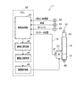
図1は、本発明の実施形態に係る電動サスペンション装置11に共通の全体構成図である。図2は、電動サスペンション装置11の一部を構成する電磁アクチュエータ13の部分断面図である。
[Basic configuration common to the
First, a basic configuration common to the
FIG. 1 is an overall configuration diagram common to the
本発明の実施形態に係る電動サスペンション装置11は、図1に示すように、車両10の各車輪毎に備わる複数の電磁アクチュエータ13と、ひとつの電子制御装置(以下、「ECU」という。)15とを備えて構成されている。複数の電磁アクチュエータ13とECU15との間は、ECU15から複数の電磁アクチュエータ13への駆動制御電力を供給するための電力供給線14(図1の実線参照)、及び、複数の電磁アクチュエータ13からECU15に電動モータ31(図2参照)の回転角信号を送るための信号線16(図1の破線参照)をそれぞれ介して相互に接続されている。
本実施形態では、電磁アクチュエータ13は、前輪(左前輪・右前輪)、及び後輪(左後輪・右後輪)を含む各車輪毎に、都合4つ配設されている。各車輪毎に備わる電磁アクチュエータ13は、各車輪毎の伸縮動作に併せて相互に独立して駆動制御される。
As shown in FIG. 1, the
In the present embodiment, four
複数の電磁アクチュエータ13の各々は、本発明の実施形態では、特に断らない限り、それぞれが共通の構成を備えている。そこで、ひとつの電磁アクチュエータ13の構成について説明することで、複数の電磁アクチュエータ13の説明に代えることとする。
In the embodiment of the present invention, each of the plurality of
電磁アクチュエータ13は、図2に示すように、ベースハウジング17、アウタチューブ19、ボールベアリング21、ボールねじ軸23、複数のボール25、ナット27、及びインナチューブ29を備えて構成されている。
As shown in FIG. 2, the
ベースハウジング17は、ボールベアリング21を介してボールねじ軸23の基端側を軸周りに回転自在に支持する。アウタチューブ19は、ベースハウジング17に設けられ、ボールねじ軸23、複数のボール25、ナット27を含むボールねじ機構18を収容する。複数のボール25は、ボールねじ軸23のねじ溝に沿って転動する。ナット27は、複数のボール25を介してボールねじ軸23に係合し、ボールねじ軸23の回転運動を直線運動に変換する。ナット27に連結されたインナチューブ29は、ナット27と一体になりアウタチューブ19の軸方向に沿って変位する。
The
ボールねじ軸23に回転駆動力を伝えるために、電磁アクチュエータ13には、図2に示すように、電動モータ31、一対のプーリ33、及びベルト部材35が備わっている。電動モータ31は、アウタチューブ19に並列するようにベースハウジング17に設けられている。電動モータ31のモータ軸31a及びボールねじ軸23には、それぞれにプーリ33が装着されている。これら一対のプーリ33には、電動モータ31の回転駆動力をボールねじ軸23に伝達するための歯付ベルト(コグドベルト:不図示)等のベルト部材35が懸架されている。
In order to transmit the rotational driving force to the
電動モータ31には、電動モータ31の回転角信号を検出するレゾルバ37が設けられている。レゾルバ37で検出された電動モータ31の回転角信号は、信号線16を介してECU15へ送られる。電動モータ31は、ECU15が複数の電磁アクチュエータ13のそれぞれに電力供給線14を介して供給する駆動制御電力に応じて回転駆動が制御される。
The
なお、本実施形態では、図2に示すように、電動モータ31のモータ軸31aとボールねじ軸23とを略平行に配置して両者間を連結するレイアウトを採用することで、電磁アクチュエータ13における軸方向の寸法を短縮している。ただし、電動モータ31のモータ軸31aとボールねじ軸23とを同軸に配置して両者間を連結するレイアウトを採用してもよい。
In the present embodiment, as shown in FIG. 2, the
本実施形態に係る電磁アクチュエータ13では、図2に示すように、ベースハウジング17の下端部に連結部39が設けられている。この連結部39は、不図示のばね下部材(車輪側のロアアーム、ナックル等)に連結固定される。一方、インナチューブ29の上端部29aは、不図示のばね上部材(車体側のストラットタワー部等)に連結固定されている。要するに、電磁アクチュエータ13は、車両10の車体と車輪の間に備わる不図示のばね部材に並設されている。
In the
前記のように構成された電磁アクチュエータ13は、次のように動作する。すなわち、例えば、車両10の車輪側から連結部39に対して上向きの振動に係る推進力が入力されたケースを考える。このケースでは、上向きの振動に係る推進力が加わったアウタチューブ19に対し、インナチューブ29及びナット27が一体に下降しようとする。これを受けて、ボールねじ軸23は、ナット27の下降に従う向きに回転しようとする。この際において、ナット27の下降を妨げる向きの電動モータ31の回転駆動力を生じさせる。この電動モータ31の回転駆動力は、ベルト部材35を介してボールねじ軸23に伝達される。
このように、上向きの振動に係る推進力に対抗する反力(減衰力)をボールねじ軸23に作用させることにより、車輪側から車体側へと伝えられようとする振動を減衰させる。
The
In this way, by applying a reaction force (damping force) that opposes the propulsive force related to the upward vibration to the
〔ECU15の内部構成〕
次に、本発明の実施形態に係る電動サスペンション装置11に備わるECU15の内部及び周辺部の構成について、図3、及び図4A〜図4Cを参照して説明する。
図3は、本発明の実施形態に係る電動サスペンション装置11に備わるECU15の内部及び周辺部の構成図である。図4Aは、電動サスペンション装置11に備わる第1実施例に係る減衰力算出部の内部構成を概念的に表す図である。図4Bは、ストローク速度SVに対応する基準減衰力の関係を表す基準減衰力マップ51の説明図である。図4Cは、第1実施例に係る減衰力算出部45A1に備わるローパスフィルタ53のゲイン及び位相の周波数特性を表す説明図である。
[Internal configuration of ECU 15]
Next, the configurations of the internal and peripheral portions of the
FIG. 3 is a configuration diagram of the inside and the periphery of the
ECU15は、各種の演算処理を行うマイクロコンピュータを含んで構成される。ECU15は、レゾルバ37で検出された電動モータ31の回転角信号等に基づいて、複数の電磁アクチュエータ13のそれぞれを駆動制御することにより、減衰動作に係る駆動力(減衰力)を発生させる駆動制御機能を有する。
こうした駆動制御機能を実現するために、ECU15は、図3に示すように、情報取得部43、減衰力算出部45、駆動力演算部47、及び駆動制御部49を備えて構成されている。
The
In order to realize such a drive control function, as shown in FIG. 3, the
情報取得部43は、図3に示すように、レゾルバ37で検出された電動モータ31の回転角信号をストローク位置に係る時系列情報として取得すると共に、ストローク位置に係る時系列情報を時間微分することでストローク速度SVの情報を取得する。
As shown in FIG. 3, the
また、情報取得部43は、図3に示すように、ばね上加速度センサ40で検出されたばね上加速度に係る時系列情報を取得すると共に、ばね上加速度に係る時系列情報を時間積分することでばね上速度の情報を取得する。さらに、情報取得部43は、図3に示すように、車速センサ41で検出した車速の情報、ヨーレイトセンサ42で検出したヨーレイトの情報をそれぞれ取得する。
Further, as shown in FIG. 3, the
情報取得部43で取得したストローク速度SVの情報、ばね上速度の情報、車速及びヨーレイトの情報は、減衰力算出部45へそれぞれ送られる。
The stroke speed SV information, the spring speed information, the vehicle speed and the yaw rate information acquired by the
減衰力算出部45は、基本的には、情報取得部43で取得したストローク速度SVの情報に応じて変化する基準減衰力の関係情報である基準減衰力マップ51を参照して、電磁アクチュエータ13に係る減衰動作の目標値である目標減衰力の候補と目される基準減衰力を算出する機能を有する。なお、基準減衰力の値は、実際には、基準減衰力制御電流の値として記憶されている。
The damping
また、減衰力算出部45は、ストローク速度SVのうちの高周波成分の減衰力を十分に確保しつつ、車両10の乗り心地を損なわせてしまう低周波成分の減衰力を低く抑制する目的で、目標減衰力を適切に補正するための補正減衰力を算出する機能を有する。
Further, the damping
ECU15に備わる減衰力算出部45の実施態様としては、ローパスフィルタ53を用いる第1実施例に係る減衰力算出部45A1(図4A参照)と、ハイパスフィルタ56を用いる第2実施例に係る減衰力算出部45B1(図4D参照)と、がある。なお、第1及び第2実施例に係る減衰力算出部45A1、45B1を総称する場合、単に「減衰力算出部45」と呼ぶ。
As an embodiment of the damping
〔第1実施例に係る減衰力算出部45A1の内部構成〕
第1実施例に係る減衰力算出部45A1は、図4Aに示すように、基準減衰力マップ51、ローパスフィルタ(LPF)53、減算部55、補正減衰力算出部57、及び加算部59を備えて構成されている。
[Internal configuration of damping force calculation unit 45A1 according to the first embodiment]
As shown in FIG. 4A, the damping force calculation unit 45A1 according to the first embodiment includes a reference damping
基準減衰力マップ51には、図4A及び図4Bに示すように、情報取得部43で取得したストローク速度SVの変化に対応付けて大きさが変化する基準減衰力の値が記憶されている。基準減衰力の値は、実際には、基準減衰力制御電流の値として記憶されている。
As shown in FIGS. 4A and 4B, the reference damping
第1実施例に係る減衰力算出部45A1は、情報取得部43で取得したストローク速度SV、及び基準減衰力マップ51の記憶内容に基づいて、基準減衰力を算出する。
減衰力算出部45で算出された基準減衰力は加算部59へ送られる。
The damping force calculation unit 45A1 according to the first embodiment calculates the reference damping force based on the stroke speed SV acquired by the
The reference damping force calculated by the damping
基準減衰力とは、ストローク速度SVの変化に対応するように予め設定された基準となる減衰力である。
本発明では、ストローク速度SVのうちの低周波成分を抑制(除去)する周波数整形を行い、当該周波数整形後のストローク速度SVの情報(高周波成分)に基づいて補正減衰力を算出し、算出した補正減衰力を用いて基準減衰力に対する補正が行われる。
これにより、システム共振点付近の振動抑制に有利な、ストローク速度SVのうちの高周波成分の減衰力を十分に確保しつつ、車両10の乗り心地を損なわせてしまう低周波成分の減衰力を低く抑制可能な目標減衰力が得られる。
The reference damping force is a reference damping force preset so as to correspond to a change in the stroke speed SV.
In the present invention, frequency shaping is performed to suppress (remove) the low frequency component of the stroke speed SV, and the correction damping force is calculated and calculated based on the stroke speed SV information (high frequency component) after the frequency shaping. The correction damping force is used to correct the reference damping force.
As a result, the damping force of the high-frequency component of the stroke speed SV, which is advantageous for suppressing vibration near the system resonance point, is sufficiently secured, and the damping force of the low-frequency component that impairs the riding comfort of the
基準減衰力マップ51に係るストローク速度SVの変化領域は、図4Bに示すように、常用領域SV1、及び非常用領域SV2から構成されている。常用領域SV1は、ストローク速度SVが常用速度閾値SVTh以下(|SV−SVTh|=<0)の速度領域である。通常の走行シーンにおいて、ストローク速度SVのほとんどが常用領域SV1に収束する。
As shown in FIG. 4B, the change region of the stroke speed SV according to the reference damping
なお、常用速度閾値SVThとしては、ストローク速度SVの確率密度関数を実験・シミュレーション等を通じて評価し、当該評価結果を参照すると共に、常用領域SV1及び非常用領域SV2のそれぞれに出現するストローク速度SVの分配比率が、予め定められる分配比率を充足することを考慮して、適宜の値を設定すればよい。 As the normal speed threshold value SVTh, the probability density function of the stroke speed SV is evaluated through experiments, simulations, etc., and the evaluation results are referred to, and the stroke speed SVs appearing in the normal area SV1 and the emergency area SV2, respectively. An appropriate value may be set in consideration of the fact that the distribution ratio satisfies a predetermined distribution ratio.
常用領域SV1における基準減衰力マップ51に係る基準減衰力特性は、図4Bに示すように、ストローク速度SVが伸び側を指向して大きくなるほど縮み側を指向する基準減衰力が略線形に大きくなる一方、ストローク速度SVが縮み側を指向して大きくなるほど伸び側を指向する基準減衰力が略線形に大きくなる特性を有する。この特性は、従来用いられてきた油圧ダンパの減衰特性にならっている。なお、ストローク速度SVがゼロの場合、それに対応する基準減衰力もゼロとなる。
As shown in FIG. 4B, the reference damping force characteristic related to the reference damping
また、非常用領域SV2における基準減衰力マップ51に係る基準減衰力特性は、図4Bに示すように、常用領域SV1における基準減衰力マップ51に係る基準減衰力特性と同様に、ストローク速度SVが伸び側を指向して大きくなるほど縮み側を指向する基準減衰力が略線形に大きくなる一方、ストローク速度SVが縮み側を指向して大きくなるほど伸び側を指向する基準減衰力が略線形に大きくなる特性を有する。
Further, as shown in FIG. 4B, the reference damping force characteristic related to the reference damping
ただし、非常用領域SV2における基準減衰力マップ51に係る基準減衰力特性の傾きは、図4Bに示すように、常用領域SV1における基準減衰力マップ51に係る基準減衰力特性の傾きと比べて、緩やかに傾く特性に設定されている。
なお、基準減衰力マップ51は、第1及び第2実施例に係る減衰力算出部45A1、45B1において共通に適用される。
However, as shown in FIG. 4B, the inclination of the reference damping force characteristic related to the reference damping
The reference damping
ここで、電動サスペンション装置11では、同システムに備わる電磁アクチュエータ13の駆動に伴って生じる慣性モーメント(イナーシャ)と剛性に由来する、システム共振点(共振周波数frsはおよそ40〜100Hz程度:図4C参照)付近の共振振動が強く現れる。
Here, in the
仮に、システム共振点付近の振動抑制効果を狙って減衰力に係る制御量を全ての周波数帯域にわたって増やすと、システム共振点に係る共振周波数frsと比べて低い周波数帯域では、減衰力に係る制御量の増大に伴ってダンピング特性が硬くなる側に振れてしまう。その結果、車両10の乗り心地が損なわれるという問題を生じる。
If the control amount related to the damping force is increased over all frequency bands aiming at the vibration suppression effect near the system resonance point, the control amount related to the damping force is increased in the frequency band lower than the resonance frequency frs related to the system resonance point. As the damping characteristic increases, the damping characteristics tend to become harder. As a result, there arises a problem that the riding comfort of the
そこで、本発明に係る電動サスペンション装置11では、車両の乗り心地を良好に保ちながら、システム共振点付近の振動抑制効果を十分に得るために、LPF53、減算部55、及び補正減衰力算出部57を備えることによって、目標減衰力の大きさを補正するための補正減衰力を算出する。
Therefore, in the
すなわち、ローパスフィルタ(LPF)53は、情報取得部43で取得したストローク速度SVのうちの低周波成分を抽出するローパスフィルタ処理機能を有する。LPF53は、例えばデジタルフィルタによって構成される。LPF53のカットオフ周波数fc としては、図4Cに示すように、電動サスペンション装置11のシステム共振点に係る周波数frsと比べて低い周波数(図4Cに示す例では30Hz)が設定される。
That is, the low-pass filter (LPF) 53 has a low-pass filter processing function for extracting a low-frequency component of the stroke speed SV acquired by the
減算部55は、情報取得部43で取得したストローク速度SVから、LPF53で抽出された低周波成分を減算する。これにより、ストローク速度SVのうち低周波成分が除去されて高周波成分が残留するように、ストローク速度SVに対する周波数整形が行われる。減算部55が出力する周波数整形後のストローク速度SV_afsの情報は、補正減衰力算出部57に入力される。
The
補正減衰力算出部57は、電動サスペンション装置11に係るシステム共振を抑制するための補正減衰力を、周波数整形後のストローク速度SV_afsを引数とする補正減衰力マップFmpに基づいて算出する。補正減衰力マップFmpには、周波数整形後のストローク速度SV_afsの変化に応じて変化する補正減衰力の関係情報が記憶されている。補正減衰力マップFmpは、本発明の「補正減衰力関数」に相当する。
補正減衰力算出部57で算出された補正減衰力は加算部59へ送られる。
The correction damping
The correction damping force calculated by the correction damping
〔第2実施例に係る減衰力算出部45B1の内部構成〕
次に、第2実施例に係る減衰力算出部45B1について、第1実施例に係る減衰力算出部45A1との相違点に注目し、図4D〜図4Eを参照して説明する。
図4Dは、第2実施例に係る減衰力算出部45B1の内部構成を概念的に表す図である。図4Eは、第2実施例に係る減衰力算出部45B1に備わるハイパスフィルタ56のゲイン及び位相の周波数特性を表す説明図である。
[Internal configuration of damping force calculation unit 45B1 according to the second embodiment]
Next, the damping force calculation unit 45B1 according to the second embodiment will be described with reference to FIGS. 4D to 4E, paying attention to the difference from the damping force calculation unit 45A1 according to the first embodiment.
FIG. 4D is a diagram conceptually showing the internal configuration of the damping force calculation unit 45B1 according to the second embodiment. FIG. 4E is an explanatory diagram showing the gain and phase frequency characteristics of the high-
第2実施例に係る減衰力算出部45B1は、図4Dに示すように、基準減衰力マップ51、ハイパスフィルタ(HPF)56、補正減衰力算出部57、及び加算部59を備えて構成されている。
As shown in FIG. 4D, the damping force calculation unit 45B1 according to the second embodiment includes a reference damping
ハイパスフィルタ(HPF)56は、情報取得部43で取得したストローク速度SVのうちの高周波成分を抽出するハイパスフィルタ処理機能を有する。このハイパスフィルタ処理により、ストローク速度SVのうち低周波成分が除去されて高周波成分が残留するように、ストローク速度SVに対する周波数整形が行われる。
HPF56は、例えばデジタルフィルタによって構成される。HPF56のカットオフ周波数fc としては、図4Eに示すように、電動サスペンション装置11のシステム共振点に係る周波数frsと比べて低い周波数(図4Eに示す例では30Hz)が設定される。
The high-pass filter (HPF) 56 has a high-pass filter processing function for extracting a high-frequency component of the stroke speed SV acquired by the
The
なお、第1実施例に係る減衰力算出部45A1における減算部55が出力する周波数整形後のストローク速度SV_afsの情報と、第2実施例に係る減衰力算出部45B1におけるハイパスフィルタ処理による周波数整形後のストローク速度SVの情報とは、実質的に同一又は類似している。
これは、ストローク速度SVのうちの高周波成分の減衰力を十分に確保しつつ、車両10の乗り心地を損なわせてしまう低周波成分の減衰力を低く抑制する本発明の目的を、ローパスフィルタ53を用いる第1実施例に係る減衰力算出部45A1、又はハイパスフィルタ56を用いる第2実施例に係る減衰力算出部45B1(図4D参照)のいずれかで達成できることを意味する。
The information of the stroke speed SV_afs after the frequency shaping output by the subtracting
The purpose of the low-
補正減衰力算出部57は、ハイパスフィルタ処理による周波数整形後のストローク速度SVの情報に基づいて補正減衰力を算出する機能を有する。
なお、補正減衰力算出部57及び加算部59は、第1及び第2実施例に係る減衰力算出部45A1、45B1において共通の役割を果たす。
補正減衰力算出部57で算出された補正減衰力は加算部59へ送られる。
The correction damping
The correction damping
The correction damping force calculated by the correction damping
〔実施例1〜3に係る補正減衰力マップFmp1〜3〕
ここで、第1及び第2実施例に係る減衰力算出部45A1、45B1において周波数整形後のストローク速度SV_afsに適用される、実施例1〜3に係る補正減衰力マップFmp1〜3について、図5A〜図5Cを参照して説明する。図5A〜図5Cは、目標減衰力を補正するための補正減衰力を算出する際に参照される実施例1〜3に係る補正減衰力マップFmp1〜3の説明図である。
なお、実施例1〜3に係る補正減衰力マップFmp1〜3は、第1及び第2実施例に係る減衰力算出部45A1、45B1において共通に適用される。
[Correction damping force map Fmp1 to 3 according to Examples 1 to 3]
Here, FIG. 5A shows the corrected damping force maps Fmp1 to 3 according to Examples 1 to 3 applied to the stroke speed SV_afs after frequency shaping in the damping force calculation units 45A1 and 45B1 according to the first and second embodiments. It will be described with reference to FIG. 5C. 5A to 5C are explanatory views of the correction damping force maps Fmp1 to 3 according to the first to third embodiments referred to when calculating the correction damping force for correcting the target damping force.
The corrected damping force maps Fmp1 to 3 according to the first to third embodiments are commonly applied to the damping force calculation units 45A1 and 45B1 according to the first and second embodiments.
実施例1に係る補正減衰力マップFmp1としては、例えば図5Aに示すように、周波数整形後のストローク速度SV_afsが伸び側を指向して大きくなるほど縮み側を指向する補正減衰力が線形に大きくなる一方、周波数整形後のストローク速度SV_afsが縮み側を指向して大きくなるほど伸び側を指向する補正減衰力が線形に大きくなる特性を有する構成を採用してもよい。
これは、周波数整形後のストローク速度SV_afsに対し、所定の共振抑制ゲイン(固定値)を乗算することにより、補正減衰力を得ることと同義である。
As for the corrected damping force map Fmp1 according to the first embodiment, for example, as shown in FIG. 5A, the corrected damping force directed to the contraction side increases linearly as the stroke speed SV_afs after frequency shaping increases toward the extension side. On the other hand, a configuration having a characteristic that the correction damping force directed to the expansion side increases linearly as the stroke speed SV_afs after frequency shaping increases toward the contraction side may be adopted.
This is synonymous with obtaining a correction damping force by multiplying the stroke speed SV_afs after frequency shaping by a predetermined resonance suppression gain (fixed value).
また、実施例2に係る補正減衰力マップFmp2として、図5Bに示すように、基準減衰力マップ51に係るストローク速度SV−基準減衰力特性に類似した、周波数整形後のストローク速度SV_afs−補正減衰力特性を有する構成を採用してもよい。
Further, as the corrected damping force map Fmp2 according to the second embodiment, as shown in FIG. 5B, the stroke speed SV-reference damping force characteristic according to the reference damping
また、実施例3に係る補正減衰力マップFmp3として、図5Cに示すように、周波数整形後のストローク速度SV_afsの常用領域では、ストローク速度SV_afsが伸び側を指向して大きくなるほど縮み側を指向する補正減衰力が線形に大きくなる一方、ストローク速度SV_afsが縮み側を指向して大きくなるほど伸び側を指向する補正減衰力が線形に大きくなる特性を有する構成を採用してもよい。 Further, as the correction damping force map Fmp3 according to the third embodiment, as shown in FIG. 5C, in the regular region of the stroke speed SV_afs after frequency shaping, the stroke speed SV_afs is directed toward the extension side and the contraction side is directed as it becomes larger. A configuration may be adopted in which the corrected damping force increases linearly, while the corrected damping force directed toward the extension side increases linearly as the stroke speed SV_afs increases toward the contraction side.
この場合、周波数整形後のストローク速度SV_afsの非常用領域では、ストローク速度SV_afsが伸び側を指向して大きくなっても、縮み側を指向する補正減衰力が固定値(制限閾値)を呈する一方、ストローク速度SV_afsが縮み側を指向して大きくなっても、伸び側を指向する補正減衰力が固定値(制限閾値)を呈する特性を有する。
なお、本明細書において、実施例1〜3に係る補正減衰力マップFmp1〜Fmp3を総称する場合、補正減衰力マップFmpと呼ぶ場合がある。
In this case, in the emergency region of the stroke speed SV_afs after frequency shaping, even if the stroke speed SV_afs increases in the direction of the extension side, the correction damping force in the direction of the contraction side exhibits a fixed value (limit threshold value). Even if the stroke speed SV_afs increases in the direction of the contraction side, the correction damping force in the direction of the extension side exhibits a fixed value (limit threshold value).
In addition, in this specification, when the correction damping force maps Fmp1 to Fmp3 according to Examples 1 to 3 are generically referred to, they may be referred to as correction damping force maps Fmp.
図4Aに戻って第1実施例に係る減衰力算出部45の説明を続けると、加算部59は、第1実施例に係る減衰力算出部45で算出した基準減衰力と、補正減衰力算出部57で算出した補正減衰力とを加算することにより、目標減衰力を求める。すなわち、補正減衰力算出部57で算出した補正減衰力を用いて目標減衰力の補正を行う。
Returning to FIG. 4A and continuing the description of the damping
一方、図4Dに戻って第2実施例に係る減衰力算出部45の説明を続けると、加算部59は、第2実施例に係る減衰力算出部45で算出した基準減衰力と、補正減衰力算出部57で算出した補正減衰力とを加算することにより、目標減衰力を求める。すなわち、補正減衰力算出部57で算出した補正減衰力を用いて目標減衰力の補正を行う。
On the other hand, returning to FIG. 4D and continuing the description of the damping
駆動力演算部47は、減衰力算出部45で算出された目標減衰力に基づく目標駆動力を求めると共に、目標駆動力を実現するための駆動制御信号を演算により求める。駆動力演算部47の演算結果である駆動制御信号は、駆動制御部49へ送られる。
The driving
駆動制御部49は、駆動力演算部47から送られてきた駆動制御信号に従って、複数の電磁アクチュエータ13のそれぞれに備わる電動モータ31に駆動制御電力を供給することにより、複数の電磁アクチュエータ13の駆動制御をそれぞれ独立して行う。
なお、電動モータ31に供給される駆動制御電力を生成するに際し、例えば、インバータ制御回路を好適に用いることができる。
The
When generating the drive control power supplied to the
〔本発明の実施形態に係る電動サスペンション装置11の動作〕
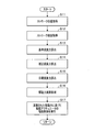
次に、本発明の実施形態に係る電動サスペンション装置11の動作について、図6を参照して説明する。図6は、本発明の実施形態に係る電動サスペンション装置11の動作説明に供するフローチャート図である。
[Operation of
Next, the operation of the
図6に示すステップS11(ストローク位置取得)において、ECU15の情報取得部43は、レゾルバ37で検出された電動モータ31の回転角信号をストローク位置に係る時系列情報として取得する。
In step S11 (stroke position acquisition) shown in FIG. 6, the
ステップS12(ストローク速度取得)において、ECU15の情報取得部43は、ステップS11で取得したストローク位置に係る時系列情報を時間微分することでストローク速度SVの情報を取得する。こうして取得したストローク速度SVの情報は、減衰力算出部45へ送られる。
In step S12 (stroke speed acquisition), the
ステップS13(基準減衰力算出)において、ECU15の減衰力算出部45は、ステップS12で取得したストローク速度SVの情報、及び基準減衰力マップ51を参照して、目標減衰力の候補と目される基準減衰力を算出する。こうして算出した基準減衰力の情報は、減衰力算出部45の加算部59へ送られる。
In step S13 (reference damping force calculation), the damping
ステップS14(補正減衰力算出)において、ECU15に備わる第1実施例に係る減衰力算出部45A1に属するLPF53は、ステップS12で取得したストローク速度SVのうちの低周波成分を抽出する。
次いで、第1実施例に係る減衰力算出部45A1に属する減算部55は、ステップS12で取得したストローク速度SVから、LPF53で抽出された低周波成分を減算する。これにより、ストローク速度SVのうち低周波成分が除去され高周波成分が残留するように、ストローク速度SVに対する周波数整形が行われる。
次いで、第1実施例に係る減衰力算出部45A1に属する補正減衰力算出部57は、周波数整形後のストローク速度SV_afsを引数とする補正減衰力マップFmp電動サスペンション装置11に係るシステム共振を抑制するための補正減衰力を算出する。
In step S14 (correction damping force calculation), the LPF53 belonging to the damping force calculation unit 45A1 according to the first embodiment provided in the
Next, the
Next, the correction damping
また、ステップS14(補正減衰力算出)において、ECU15に備わる第2実施例に係る減衰力算出部45B1に属するHPF56は、ステップS12で取得したストローク速度SVのうちの高周波成分を抽出するハイパスフィルタ処理を実行する。これにより、ストローク速度SVのうち低周波成分が除去されて高周波成分が残留するように、ストローク速度SVに対する周波数整形が行われる。
次いで、第2実施例に係る減衰力算出部45B1に属する補正減衰力算出部57は、周波数整形後のストローク速度SV_afsを引数とする補正減衰力マップFmpを参照して、電動サスペンション装置11に係るシステム共振を抑制するための補正減衰力を算出する。
Further, in step S14 (correction damping force calculation), the
Next, the correction damping
ステップS15(目標減衰力算出処理)において、ECU15の減衰力算出部45に備わる加算部59は、ステップS13で算出した基準減衰力と、ステップS14で算出した補正減衰力とを加算することにより、目標減衰力を算出する。すなわち、減衰力算出部45は、補正減衰力を用いて目標減衰力の補正を行うことによって、目標減衰力を算出する。
In step S15 (target damping force calculation process), the
ステップS16(駆動力演算処理)において、ECU15の駆動力演算部47は、ステップS15で算出した目標減衰力に基づく目標駆動力を求めると共に、目標駆動力を実現するための駆動制御信号を演算により求める。
In step S16 (driving force calculation processing), the driving
ステップS17において、ECU15の駆動制御部49は、ステップS16の演算により求められた駆動制御信号に従って、複数の電磁アクチュエータ13のそれぞれに備わる電動モータ31に駆動制御電力を供給することにより、複数の電磁アクチュエータ13の駆動制御を行う。
In step S17, the
〔ECU15に備わる第1実施例の変形例に係る減衰力算出部45A2の内部構成〕
次に、本発明の電動サスペンション装置11のECU15に備わる第1実施例の変形例に係る減衰力算出部45A2の内部構成について、図7Aを参照して説明する。図7Aは、ECU15に備わる第1実施例の変形例に係る減衰力算出部45A2の内部構成を概念的に表す図である。
[Internal configuration of damping force calculation unit 45A2 according to a modified example of the first embodiment provided in the ECU 15]
Next, the internal configuration of the damping force calculation unit 45A2 according to the modification of the first embodiment provided in the
図4Aに示す第1実施例に係る減衰力算出部45A1と、図7Aに示す第1実施例の変形例に係る減衰力算出部45A2とは、共通の構成部分が多く存在する。 The damping force calculation unit 45A1 according to the first embodiment shown in FIG. 4A and the damping force calculation unit 45A2 according to the modified example of the first embodiment shown in FIG. 7A have many common components.
そこで、第1実施例に係る減衰力算出部45A1と、第1実施例の変形例に係る減衰力算出部45A2との相違部分に注目し、主として当該相違部分について説明することで、第1実施例の変形例に係る減衰力算出部45A2を備える電動サスペンション装置11の構成の説明に代えることとする。
Therefore, by paying attention to the difference between the damping force calculation unit 45A1 according to the first embodiment and the damping force calculation unit 45A2 according to the modified example of the first embodiment, and mainly explaining the difference portion, the first embodiment The description of the configuration of the
第1実施例の変形例に係る減衰力算出部45A2を備える電動サスペンション装置11は、情報取得部43が車速の情報、及び車両10の駆動力を発生する駆動力発生装置(不図示)の状態の情報をさらに取得する点、並びに、ECU15に備わる第1実施例の変形例に係る減衰力算出部45A2に属する補正減衰力算出部57は、情報取得部43で取得した車速の情報、及び駆動力発生装置の状態の情報をそれぞれ入力し、当該入力した情報のうち少なくともいずれか一の情報に基づいて補正減衰力マップFmpの特性を調整(特性の変更を含む)する点で、第1実施例に係る減衰力算出部45A1を備える電動サスペンション装置11と相違している。
The
なお、第1実施例の変形例に係る減衰力算出部45A2を備える電動サスペンション装置11の作用効果については後記する。
The effects of the
〔ECU15に備わる第2実施例の変形例に係る減衰力算出部45B2の内部構成〕
次に、本発明の電動サスペンション装置11のECU15に備わる第2実施例の変形例に係る減衰力算出部45B2の内部構成について、図8Aを参照して説明する。図8Aは、ECU15に備わる第2実施例の変形例に係る減衰力算出部45B2の内部構成を概念的に表す図である。
[Internal configuration of damping force calculation unit 45B2 according to a modified example of the second embodiment provided in the ECU 15]
Next, the internal configuration of the damping force calculation unit 45B2 according to the modified example of the second embodiment provided in the
図4Dに示す第2実施例に係る減衰力算出部45B1と、図8Aに示す第2実施例の変形例に係る減衰力算出部45B2とは、共通の構成部分が多く存在する。 The damping force calculation unit 45B1 according to the second embodiment shown in FIG. 4D and the damping force calculation unit 45B2 according to the modified example of the second embodiment shown in FIG. 8A have many common components.
そこで、第2実施例に係る減衰力算出部45B1と、第2実施例の変形例に係る減衰力算出部45B2との相違部分に注目し、主として当該相違部分について説明することで、第2実施例の変形例に係る減衰力算出部45B2を備える電動サスペンション装置11の構成の説明に代えることとする。
Therefore, by paying attention to the difference between the damping force calculation unit 45B1 according to the second embodiment and the damping force calculation unit 45B2 according to the modified example of the second embodiment, and mainly explaining the difference portion, the second embodiment The description of the configuration of the
第2実施例の変形例に係る減衰力算出部45B2を備える電動サスペンション装置11は、情報取得部43が車速の情報、及び車両10の駆動力を発生する駆動力発生装置(不図示)の状態の情報をさらに取得する点、並びに、ECU15に備わる第2実施例の変形例に係る減衰力算出部45B2に属する補正減衰力算出部57は、情報取得部43で取得した車速の情報、及び駆動力発生装置の状態の情報の少なくともいずれか一方を入力し、当該入力した情報に基づいて補正減衰力マップFmpの特性を調整(特性の変更を含む)する点で、第2実施例に係る減衰力算出部45B1を備える電動サスペンション装置11と相違している。
In the
なお、第2実施例の変形例に係る減衰力算出部45B2を備える電動サスペンション装置11の作用効果については後記する。
The effects of the
〔本発明の実施形態に係る電動サスペンション装置11の作用効果〕
前提として、本発明の実施形態に係る電動サスペンション装置11では、同システムに備わる電磁アクチュエータ13の駆動に伴って生じる慣性モーメント(イナーシャ)等に由来する、システム共振点(共振周波数frsはおよそ40〜100Hz程度)付近の共振振動が強く現れる。
仮に、システム共振点付近の振動抑制効果を狙って減衰力に係る制御量を全ての周波数帯域にわたって増やすと、システム共振点に係る共振周波数frsと比べて低い周波数帯域(f<frs)では、減衰力に係る制御量の増大に伴ってダンピング特性が硬くなる側に振れてしまう。その結果、車両10の乗り心地が損なわれるという問題を生じる。
[Action and effect of the
As a premise, in the
If the control amount related to the damping force is increased over all frequency bands aiming at the vibration suppression effect near the system resonance point, it will be attenuated in the frequency band (f <frs) lower than the resonance frequency frs related to the system resonance point. As the control amount related to the force increases, the damping characteristic swings to the side where it becomes harder. As a result, there arises a problem that the riding comfort of the
そこで、第1の観点に基づく電動サスペンション装置11は、車両10の車体と車輪の間に設けられ、車体の減衰動作に係る駆動力を発生させる電磁アクチュエータ13と、電磁アクチュエータ13のストローク速度SVの情報を取得する情報取得部43と、情報取得部43で取得したストローク速度SVの情報に基づいて電磁アクチュエータ13の減衰動作の目標値である目標減衰力を算出する減衰力算出部45と、減衰力算出部45で算出した目標減衰力に基づく目標駆動力を用いて電磁アクチュエータ13の駆動制御を行う駆動制御部49と、を備える。
減衰力算出部45は、ストローク速度SVのうちの低周波成分を抑制する周波数整形を行い、当該周波数整形後のストローク速度SV_afsの情報に基づいて補正減衰力を算出し、算出した補正減衰力を用いて目標減衰力の補正を行う。
第1の観点に基づく電動サスペンション装置11は、第1実施例に係る減衰力算出部45A1(図4A参照)を備える電動サスペンション装置11に相当する。
Therefore, the
The damping
The
第1の観点に基づく電動サスペンション装置11では、減衰力算出部45は、ストローク速度SVのうちの低周波成分を抑制する周波数整形を行い、当該周波数整形後のストローク速度SV_afsの情報に基づいて補正減衰力を算出し、算出した補正減衰力を用いて目標減衰力の補正を行う。
これにより、システム共振点付近の振動抑制に有利な高周波成分の減衰力を十分に確保しつつ、車両10の乗り心地を損なわせてしまう低周波成分の減衰力を低く抑制可能な目標減衰力が得られる。
In the
As a result, the target damping force that can suppress the damping force of the low frequency component that impairs the riding comfort of the
第1の観点に基づく電動サスペンション装置11によれば、車両10の乗り心地を良好に保ちながら、システム共振点付近の振動を適切に抑制することができる。その結果、共振振動に由来する騒音を抑制して車室内の静音性を保つことができる。
According to the
また、第2の観点に基づく電動サスペンション装置11は、第1の観点に基づく電動サスペンション装置11と同様に、電磁アクチュエータ13と、情報取得部43と、減衰力算出部45と、駆動制御部49と、を備える。
減衰力算出部45は、ストローク速度SVのうちの低周波成分を抽出するローパスフィルタ53と、前記抽出された低周波成分をストローク速度SVから減算する減算部55と、前記減算による周波数整形後のストローク速度SV_afsに基づいて補正減衰力を算出する補正減衰力算出部57と、を備え、当該算出した補正減衰力を用いて目標減衰力の補正を行う。
第2の観点に基づく電動サスペンション装置11は、第1の観点に基づく電動サスペンション装置11と同様に、第1実施例に係る減衰力算出部45A1(図4A参照)を備える電動サスペンション装置11に相当する。
Further, the
The damping
The
第2の観点に基づく電動サスペンション装置11では、減衰力算出部45の具体的な構成として、減衰力算出部45は、ローパスフィルタ53と、減算部55と、補正減衰力算出部57と、を備える旨に言及している点が、第1の観点に基づく電動サスペンション装置11と比べて相違している。
In the
すなわち、第2の観点に基づく電動サスペンション装置11では、減衰力算出部45において、ローパスフィルタ53は、ストローク速度SVのうちの低周波成分を抽出する。減算部55は、前記抽出された低周波成分をストローク速度SVから減算する。補正減衰力算出部57は、前記減算による周波数整形後のストローク速度SV_afsに基づいて補正減衰力を算出する。そして、減衰力算出部45は、前記算出した補正減衰力を用いて目標減衰力の補正を行う。
That is, in the
第2の観点に基づく電動サスペンション装置11によれば、第1の観点に基づく電動サスペンション装置11と同様に、車両10の乗り心地を良好に保ちながら、システム共振点付近の振動を適切に抑制することができる。その結果、共振振動に由来する騒音を抑制して車室内の静音性を保つことができる。
According to the
また、第3の観点に基づく電動サスペンション装置11は、第1又は第2の観点に基づく電動サスペンション装置11と同様に、電磁アクチュエータ13と、情報取得部43と、減衰力算出部45と、駆動制御部49と、を備える。
減衰力算出部45は、ストローク速度SVのうちの高周波成分を抽出する処理を行うハイパスフィルタ56と、前記処理による周波数整形後のストローク速度SV_afsに基づいて補正減衰力を算出する補正減衰力算出部57と、を備え、当該算出した補正減衰力を用いて目標減衰力の補正を行う。
第3の観点に基づく電動サスペンション装置11は、第2実施例に係る減衰力算出部45B1(図4D参照)を備える電動サスペンション装置11に相当する。
Further, the
The damping
The
第3の観点に基づく電動サスペンション装置11では、減衰力算出部45の具体的な構成として、減衰力算出部45は、ハイパスフィルタ56と、補正減衰力算出部57と、を備える旨に言及している点が、第1の観点に基づく電動サスペンション装置11と比べて相違している。
In the
すなわち、第3の観点に基づく電動サスペンション装置11では、減衰力算出部45において、ハイパスフィルタ56は、ストローク速度SVのうちの高周波成分を抽出する処理を行う。補正減衰力算出部57は、前記処理による周波数整形後のストローク速度SV_afsに基づいて補正減衰力を算出する。そして、減衰力算出部45は、前記算出した補正減衰力を用いて目標減衰力の補正を行う。
That is, in the
第3の観点に基づく電動サスペンション装置11によれば、第2の観点に基づく電動サスペンション装置11と同様に、車両10の乗り心地を良好に保ちながら、システム共振点付近の振動を適切に抑制することができる。その結果、共振振動に由来する騒音を抑制して車室内の静音性を保つことができる。
According to the
また、第4の観点に基づく電動サスペンション装置11は、第2の観点に基づく電動サスペンション装置11であって、ローパスフィルタ53のカットオフ周波数fc は、図4Cに示すように、電動サスペンション装置11のシステム共振点に係る共振周波数frsと比べて低い周波数が設定される。
第4の観点に基づく電動サスペンション装置11は、第1実施例に係る減衰力算出部45A1(図4A参照)を備える電動サスペンション装置11に相当する。
Further, the
The
つまり、システム共振点に係る共振周波数frsと比べて低いカットオフ周波数fc が設定されたローパスフィルタ53の働きによって、ストローク速度SVのうちシステム共振点に係る共振周波数frsと比べて低い周波数成分が抽出される。当該抽出された低周波成分は、減算部55においてストローク速度SVから減算される。当該減算による周波数整形後のストローク速度SV_afsに基づいて、補正減衰力算出部57において、電動サスペンション装置11に係るシステム共振を抑制するための補正減衰力が算出される。そして、減衰力算出部45は、前記算出した補正減衰力を用いて目標減衰力の補正を行う。
That is, by the action of the low-
第4の観点に基づく電動サスペンション装置11によれば、ローパスフィルタ53のカットオフ周波数fc は、電動サスペンション装置11のシステム共振点に係る共振周波数frsと比べて低い周波数が設定されるため、第2の観点に基づく電動サスペンション装置11と同様に、車両10の乗り心地を良好に保ちながら、システム共振点付近の振動を適切に抑制することができる。その結果、共振振動に由来する騒音を抑制して車室内の静音性を保つことができる。
According to the
また、第5の観点に基づく電動サスペンション装置11は、第2の観点に基づく電動サスペンション装置11であって、補正減衰力算出部57は、ローパスフィルタ53及び減算部55を用いた周波数整形後のストローク速度SV_afsを引数とする補正減衰力マップ(補正減衰力関数)Fmpに基づいて算出する構成を採用してもよい。
第5の観点に基づく電動サスペンション装置11は、第1実施例に係る減衰力算出部45A1(図4A参照)を備える電動サスペンション装置11に相当する。
Further, the
The
第5の観点に基づく電動サスペンション装置11によれば、補正減衰力算出部57は、ローパスフィルタ53及び減算部55を用いた周波数整形後のストローク速度SV_afsを引数とする補正減衰力マップ(補正減衰力関数)Fmpに基づいて補正減衰力を算出するため、算出された補正減衰力を用いて目標減衰力の補正を行うことによって、システム共振点付近の振動抑制に有利な、ストローク速度SVのうちの高周波成分の減衰力を十分に確保しつつ、車両10の乗り心地を損なわせてしまう低周波成分の減衰力を低く抑制可能な目標減衰力を適確に得ることができる。
According to the
一方、第6の観点に基づく電動サスペンション装置11は、第3の観点に基づく電動サスペンション装置11であって、ハイパスフィルタ56のカットオフ周波数fc は、電動サスペンション装置11のシステム共振点に係る共振周波数frsと比べて低い周波数が設定される。
第6の観点に基づく電動サスペンション装置11は、第2実施例に係る減衰力算出部45B1(図4D参照)を備える電動サスペンション装置11に相当する。
On the other hand, the
The
つまり、システム共振点に係る共振周波数frsと比べて低いカットオフ周波数fc が設定されたハイパスフィルタ56の働きによって、ストローク速度SVのうちシステム共振点に係る共振周波数frsと比べて高い周波数成分を抽出する処理が行われる。当該処理による周波数整形後のストローク速度SV_afsに基づいて、補正減衰力算出部57において、電動サスペンション装置11に係るシステム共振を抑制するための補正減衰力が算出される。そして、減衰力算出部45は、前記算出した補正減衰力を用いて目標減衰力の補正を行う。
That is, by the action of the high-
第6の観点に基づく電動サスペンション装置11によれば、ハイパスフィルタ56のカットオフ周波数fc は、電動サスペンション装置11のシステム共振点に係る共振周波数frsと比べて低い周波数が設定されるため、第3の観点に基づく電動サスペンション装置11と同様に、車両10の乗り心地を良好に保ちながら、システム共振点付近の振動を適切に抑制することができる。その結果、共振振動に由来する騒音を抑制して車室内の静音性を保つことができる。
According to the
また、第7の観点に基づく電動サスペンション装置11は、第6の観点に基づく電動サスペンション装置11であって、補正減衰力算出部57は、ハイパスフィルタ56を用いた周波数整形後のストローク速度SV_afsを引数とする補正減衰力マップ(補正減衰力関数)Fmpに基づいて算出する構成を採用してもよい。
Further, the
第7の観点に基づく電動サスペンション装置11によれば、補正減衰力算出部57は、ハイパスフィルタ56を用いた周波数整形後のストローク速度SV_afsを引数とする補正減衰力マップ(補正減衰力関数)Fmpに基づいて補正減衰力を算出するため、算出された補正減衰力を用いて目標減衰力の補正を行うことによって、システム共振点付近の振動抑制に有利な、ストローク速度SVのうちの高周波成分の減衰力を十分に確保しつつ、車両10の乗り心地を損なわせてしまう低周波成分の減衰力を低く抑制可能な目標減衰力を適確に得ることができる。
According to the
また、第8の観点に基づく電動サスペンション装置11は、第5の観点に基づく電動サスペンション装置11であって、情報取得部43は、車速の情報をさらに取得し、補正減衰力算出部57は、情報取得部43で取得した車速に基づいて補正減衰力マップ(補正減衰力関数)Fmpの特性を調整する構成を採用してもよい。
第8の観点に基づく電動サスペンション装置11は、第1実施例の変形例に係る減衰力算出部45A2(図7A参照)を備える電動サスペンション装置11に相当する。
Further, the
The
第8の観点に基づく電動サスペンション装置11では、補正減衰力算出部57は、情報取得部43で取得した車速に基づいて補正減衰力マップ(補正減衰力関数)Fmp2の特性を調整する。
具体的には、例えば、車速が低車速領域(停止を含む)に存するケースでの車両10の走行音は、車速が(高車速)領域に存するケースでの車両10の走行音と比べて小さい。そのため、車速が(低車速)領域に存するケースでは、車速が(高車速)領域に存するケースと比べて、電動サスペンション装置11の減衰制御を行う際において、より一層の静音性が求められる。
In the
Specifically, for example, the running noise of the
一方、車速が(高車速)領域に存するケースでの車両10の走行音は、車速が(低車速)領域に存するケースでの車両10の走行音と比べて大きい。そのため、車速が(高車速)領域に存するケースでは、車速が(低車速)領域に存するケースと比べて、電動サスペンション装置11の減衰制御を行う際において、静音性に対して、車両10の乗り心地向上効果及びシステム共振点付近の振動抑制効果の両立を高い水準で実現することが求められる。
On the other hand, the running noise of the
そこで、第8の観点に基づく電動サスペンション装置11では、補正減衰力算出部57は、図7Bに示すように、車速が(低車速)領域に存するケース(車両10の走行音が小さいため、電動サスペンション装置11の減衰制御を行う際において、より一層の静音性が求められる)での補正減衰力マップFmp2の特性を、車速が(高車速)領域に存するケースでの補正減衰力マップFmp2の特性と比べて補正減衰力が大きくなるように調整する。
すると、車速が(低車速)領域に存するケースにおいて、車速が(高車速)領域に存するケースと比べて電動サスペンション装置11の減衰制御量が増大する。
その結果、車速が(低車速)領域に存するケースにおいて、車速が(高車速)領域に存するケースと比べて共振振動に由来する騒音が十分に抑制されるため、車室内の静音性を高めることができる。
Therefore, in the
Then, in the case where the vehicle speed is in the (low vehicle speed) region, the damping control amount of the
As a result, in the case where the vehicle speed is in the (low vehicle speed) region, the noise caused by the resonance vibration is sufficiently suppressed as compared with the case where the vehicle speed is in the (high vehicle speed) region, so that the quietness in the vehicle interior is improved. Can be done.
一方、第8の観点に基づく電動サスペンション装置11では、補正減衰力算出部57は、図7Bに示すように、車速が(高車速)領域に存するケース(静音性に対して、車両10の乗り心地向上効果及びシステム共振点付近の振動抑制効果の両立を高い水準で実現することが求められる)での補正減衰力マップFmp2の特性を、車速が(低車速)領域に存するケースでの補正減衰力マップFmp2の特性と比べて補正減衰力が小さくなるように調整する。
すると、車速が(高車速)領域に存するケースにおいて、車速が(低車速)領域に存するケースと比べて電動サスペンション装置11の減衰制御量が低減する。
その結果、車速が(高車速)領域に存するケースにおいて、車速が(低車速)領域に存するケースと比べて、車両10の乗り心地向上効果及びシステム共振点付近の振動抑制効果の両立を高い水準で実現することができる。
On the other hand, in the
Then, in the case where the vehicle speed is in the (high vehicle speed) region, the damping control amount of the
As a result, in the case where the vehicle speed is in the (high vehicle speed) region, both the ride comfort improving effect of the
第8の観点に基づく電動サスペンション装置11によれば、補正減衰力算出部57は、情報取得部43で取得した車速に基づいて補正減衰力マップFmp2の特性を適宜調整するため、第5の観点に基づく電動サスペンション装置11の作用効果に加えて、車速に応じて、電動サスペンション装置11の減衰制御量の増減を調整することによって、車室内の静音性を高める効果、又は、車両10の乗り心地向上効果及びシステム共振点付近の振動抑制効果の両立を高い水準で実現する効果を期待することができる。
According to the
また、第9の観点に基づく電動サスペンション装置11は、第5の観点に基づく電動サスペンション装置11であって、情報取得部43は、車両10の駆動力を発生する駆動力発生装置の状態の情報をさらに取得し、補正減衰力算出部57は、情報取得部43で取得した駆動力発生装置の状態に基づいて補正減衰力マップ(補正減衰力関数)Fmp2の特性を調整する構成を採用してもよい。
第9の観点に基づく電動サスペンション装置11は、第1実施例の変形例に係る減衰力算出部45A2(図7A参照)を備える電動サスペンション装置11に相当する。
Further, the
The
第9の観点に基づく電動サスペンション装置11では、補正減衰力算出部57は、情報取得部43で取得した駆動力発生装置の状態に基づいて補正減衰力マップFmp2の特性を適宜調整する。
具体的には、例えば、車両10がハイブリッド(HV)車両である場合において、駆動力発生装置の状態が、電動機を用いて駆動力を発生(エンジン駆動なし)するEV駆動モード(主として低速側)であるケースでの車両10の走行音は、駆動力発生装置の状態が、内燃機関エンジンを用いて駆動力を発生(エンジン駆動あり)するHV駆動モード(主として高速側)であるケースでの車両10の走行音と比べて小さい。そのため、駆動力発生装置の状態がEV駆動モードであるケースでは、駆動力発生装置の状態がHV駆動モードであるケースと比べて、電動サスペンション装置11の減衰制御を行う際において、より一層の静音性が求められる。
In the
Specifically, for example, when the
一方、駆動力発生装置の状態がHV駆動モードであるケースでの車両10の走行音は、駆動力発生装置の状態がEV駆動モードであるケースでの車両10の走行音と比べて大きい。そのため、駆動力発生装置の状態がHV駆動モードであるケースでは、駆動力発生装置の状態がEV駆動モードであるケースと比べて、電動サスペンション装置11の減衰制御を行う際において、静音性に対して、車両10の乗り心地向上効果及びシステム共振点付近の振動抑制効果の両立を高い水準で実現することが求められる。
On the other hand, the running noise of the
そこで、第9の観点に基づく電動サスペンション装置11では、補正減衰力算出部57は、図7Cに示すように、駆動力発生装置の状態がEV駆動モードであるケース(車両10の走行音が小さいため、電動サスペンション装置11の減衰制御を行う際において、より一層の静音性が求められる)での補正減衰力マップFmp2の特性を、駆動力発生装置の状態がHV駆動モードであるケースでの補正減衰力マップFmp2の特性と比べて補正減衰力が大きくなるように調整する。
すると、駆動力発生装置の状態がEV駆動モードであるケースにおいて、駆動力発生装置の状態がHV駆動モードであるケースと比べて電動サスペンション装置11の減衰制御量が増大する。
その結果、駆動力発生装置の状態がEV駆動モードであるケースにおいて、駆動力発生装置の状態がHV駆動モードであるケースと比べて共振振動に由来する騒音が十分に抑制されるため、車室内の静音性を高めることができる。
Therefore, in the
Then, in the case where the state of the driving force generator is the EV drive mode, the damping control amount of the
As a result, in the case where the driving force generator is in the EV drive mode, the noise caused by the resonance vibration is sufficiently suppressed as compared with the case where the driving force generator is in the HV drive mode. Can enhance the quietness of.
一方、第9の観点に基づく電動サスペンション装置11では、補正減衰力算出部57は、図7Cに示すように、駆動力発生装置の状態がHV駆動モードであるケース(静音性に対して、車両10の乗り心地向上効果及びシステム共振点付近の振動抑制効果の両立を高い水準で実現することが求められる)での補正減衰力マップFmp2の特性を、駆動力発生装置の状態がEV駆動モードであるケースでの補正減衰力マップFmp2の特性と比べて補正減衰力が小さくなるように調整する。
すると、駆動力発生装置の状態がHV駆動モードであるケースにおいて、駆動力発生装置の状態がEV駆動モードであるケースと比べて電動サスペンション装置11の減衰制御量が低減する。
その結果、駆動力発生装置の状態がHV駆動モードであるケースにおいて、駆動力発生装置の状態がEV駆動モードであるケースと比べて、車両10の乗り心地向上効果及びシステム共振点付近の振動抑制効果の両立を高い水準で実現することができる。
On the other hand, in the
Then, in the case where the state of the driving force generator is the HV drive mode, the damping control amount of the
As a result, in the case where the state of the driving force generator is the HV drive mode, the effect of improving the riding comfort of the
第9の観点に基づく電動サスペンション装置11によれば、補正減衰力算出部57は、情報取得部43で取得した駆動力発生装置の状態に基づいて補正減衰力マップFmp2の特性を適宜調整するため、第5の観点に基づく電動サスペンション装置11の作用効果に加えて、駆動力発生装置の状態に応じて、電動サスペンション装置11の減衰制御量の増減を調整することによって、車室内の静音性を高める効果、又は、車両10の乗り心地向上効果及びシステム共振点付近の振動抑制効果の両立を高い水準で実現する効果を期待することができる。
According to the
また、第10の観点に基づく電動サスペンション装置11は、第7の観点に基づく電動サスペンション装置11であって、情報取得部43は、車速の情報をさらに取得し、補正減衰力算出部57は、情報取得部43で取得した車速に基づいて補正減衰力マップ(補正減衰力関数)Fmp2の特性を調整する構成を採用してもよい。
第10の観点に基づく電動サスペンション装置11は、第2実施例の変形例に係る減衰力算出部45B2(図8A参照)を備える電動サスペンション装置11に相当する。
Further, the
The
第10の観点に基づく電動サスペンション装置11によれば、補正減衰力算出部57は、第8の観点に基づく電動サスペンション装置11と同様に、情報取得部43で取得した車速に基づいて補正減衰力マップFmp2の特性を適宜調整(図7B参照)するため、第7の観点に基づく電動サスペンション装置11の作用効果に加えて、車速に応じて、電動サスペンション装置11の減衰制御量の増減を調整することによって、車室内の静音性を高める効果、又は、車両10の乗り心地向上効果及びシステム共振点付近の振動抑制効果の両立を高い水準で実現する効果を期待することができる。
According to the
また、第11の観点に基づく電動サスペンション装置11は、第7の観点に基づく電動サスペンション装置11であって、情報取得部43は、車両10の駆動力を発生する駆動力発生装置の状態の情報をさらに取得し、補正減衰力算出部57は、情報取得部43で取得した駆動力発生装置の状態に基づいて補正減衰力マップ(補正減衰力関数)Fmp2の特性を調整する構成を採用してもよい。
第11の観点に基づく電動サスペンション装置11は、第2実施例の変形例に係る減衰力算出部45B2(図8A参照)を備える電動サスペンション装置11に相当する。
Further, the
The
第11の観点に基づく電動サスペンション装置11によれば、補正減衰力算出部57は、第9の観点に基づく電動サスペンション装置11と同様に、情報取得部43で取得した駆動力発生装置の状態に基づいて補正減衰力マップFmp2の特性を適宜調整(図7C参照)するため、第7の観点に基づく電動サスペンション装置11の作用効果に加えて、駆動力発生装置の状態に応じて、電動サスペンション装置11の減衰制御量の増減を調整することによって、車室内の静音性を高める効果、又は、車両10の乗り心地向上効果及びシステム共振点付近の振動抑制効果の両立を高い水準で実現する効果を期待することができる。
According to the
また、第12の観点に基づく電動サスペンション装置11は、第4の観点に基づく電動サスペンション装置11であって、情報取得部43は、車速の情報をさらに取得し、補正減衰力算出部57は、情報取得部43で取得した車速に基づいてローパスフィルタ53のカットオフ周波数fc を調整する構成を採用してもよい。
第12の観点に基づく電動サスペンション装置11は、第1実施例の変形例に係る減衰力算出部45A2(図7A参照)を備える電動サスペンション装置11に相当する。
Further, the
The
第12の観点に基づく電動サスペンション装置11では、補正減衰力算出部57は、情報取得部43で取得した車速に基づいてローパスフィルタ53のカットオフ周波数fc を適宜調整する。
具体的には、前記したとおり、車速が(低車速)領域に存するケースでは、車速が(高車速)領域に存するケースと比べて、電動サスペンション装置11の減衰制御を行う際において、より一層の静音性が求められる。
In the
Specifically, as described above, in the case where the vehicle speed is in the (low vehicle speed) region, the damping control of the
一方、前記したとおり、車速が(高車速)領域に存するケースでは、車速が(低車速)領域に存するケースと比べて、電動サスペンション装置11の減衰制御を行う際において、静音性に対して、車両10の乗り心地向上効果及びシステム共振点付近の振動抑制効果の両立を高い水準で実現することが求められる。
On the other hand, as described above, in the case where the vehicle speed is in the (high vehicle speed) region, as compared with the case where the vehicle speed is in the (low vehicle speed) region, when the damping control of the
そこで、第12の観点に基づく電動サスペンション装置11では、補正減衰力算出部57は、図7Dに示すように、車速が(低車速)領域に存するケース(車両10の走行音が小さいため、電動サスペンション装置11の減衰制御を行う際において、より一層の静音性が求められる)でのカットオフ周波数fc1(図7Dの例ではfc1=15Hz)を、車速が(高車速)領域に存するケースでのカットオフ周波数fc2(図7Dの例ではfc2=30Hz)と比べて低くなるように調整する。
すると、振動減衰制御対象となる周波数帯域が広がる結果として、車速が(低車速)領域に存するケースにおいて、車速が(高車速)領域に存するケースと比べて電動サスペンション装置11の減衰制御量が増大する。
その結果、車速が(低車速)領域に存するケースにおいて、車速が(高車速)領域に存するケースと比べて共振振動に由来する騒音が十分に抑制されるため、車室内の静音性を高めることができる。
Therefore, in the
Then, as a result of expanding the frequency band to be controlled by vibration damping, the damping control amount of the
As a result, in the case where the vehicle speed is in the (low vehicle speed) region, the noise caused by the resonance vibration is sufficiently suppressed as compared with the case where the vehicle speed is in the (high vehicle speed) region, so that the quietness in the vehicle interior is improved. Can be done.
一方、第12の観点に基づく電動サスペンション装置11では、補正減衰力算出部57は、図7Dに示すように、車速が(高車速)領域に存するケース(静音性に対して、車両10の乗り心地向上効果及びシステム共振点付近の振動抑制効果の両立を高い水準で実現することが求められる)でのカットオフ周波数fc2を、車速が(低車速)領域に存するケースでのカットオフ周波数fc1と比べて高くなるように調整する。
すると、車速が(高車速)領域に存するケースにおいて、車速が(低車速)領域に存するケースと比べて電動サスペンション装置11の減衰制御量が低減する。
その結果、車速が(高車速)領域に存するケースにおいて、車速が(低車速)領域に存するケースと比べて、車両10の乗り心地向上効果及びシステム共振点付近の振動抑制効果の両立を高い水準で実現することができる。
On the other hand, in the
Then, in the case where the vehicle speed is in the (high vehicle speed) region, the damping control amount of the
As a result, in the case where the vehicle speed is in the (high vehicle speed) region, both the ride comfort improving effect of the
第12の観点に基づく電動サスペンション装置11によれば、補正減衰力算出部57は、情報取得部43で取得した車速に基づいてカットオフ周波数fc を適宜調整(図7D参照)するため、第4の観点に基づく電動サスペンション装置11の作用効果に加えて、車速に応じて、電動サスペンション装置11の減衰制御量の増減を調整することによって、車室内の静音性を高める効果、又は、車両10の乗り心地向上効果及びシステム共振点付近の振動抑制効果の両立を高い水準で実現する効果を期待することができる。
According to the
また、第13の観点に基づく電動サスペンション装置11は、第4の観点に基づく電動サスペンション装置11であって、情報取得部43は、車両10の駆動力を発生する駆動力発生装置の状態の情報をさらに取得し、補正減衰力算出部57は、情報取得部43で取得した駆動力発生装置の状態に基づいてカットオフ周波数fc を調整する構成を採用してもよい。
第13の観点に基づく電動サスペンション装置11は、第1実施例の変形例に係る減衰力算出部45A2(図7A参照)を備える電動サスペンション装置11に相当する。
Further, the
The
第13の観点に基づく電動サスペンション装置11では、補正減衰力算出部57は、情報取得部43で取得した駆動力発生装置の状態に基づいてカットオフ周波数fc を適宜調整する。
具体的には、前記したとおり、駆動力発生装置の状態がEV駆動モードであるケースでは、駆動力発生装置の状態がHV駆動モードであるケースと比べて、電動サスペンション装置11の減衰制御を行う際において、より一層の静音性が求められる。
In the
Specifically, as described above, in the case where the state of the driving force generator is the EV drive mode, the damping control of the
一方、駆動力発生装置の状態がHV駆動モードであるケースでは、駆動力発生装置の状態がEV駆動モードであるケースと比べて、電動サスペンション装置11の減衰制御を行う際において、静音性に対して、車両10の乗り心地向上効果及びシステム共振点付近の振動抑制効果の両立を高い水準で実現することが求められる。
On the other hand, in the case where the state of the driving force generator is the HV drive mode, as compared with the case where the state of the driving force generator is the EV drive mode, when the damping control of the
そこで、第13の観点に基づく電動サスペンション装置11では、補正減衰力算出部57は、図7Eに示すように、駆動力発生装置の状態がEV駆動モードであるケース(車両10の走行音が小さいため、電動サスペンション装置11の減衰制御を行う際において、より一層の静音性が求められる)でのカットオフ周波数fc1(図7Eの例ではfc1=15Hz)を、駆動力発生装置の状態がHV駆動モードであるケースでのカットオフ周波数fc2(図7Eの例ではfc2=30Hz)と比べて低くなるように調整する。
すると、振動減衰制御対象となる周波数帯域が広まる結果として、駆動力発生装置の状態がEV駆動モードであるケースにおいて、駆動力発生装置の状態がHV駆動モードであるケースと比べて電動サスペンション装置11の減衰制御量が増大する。
その結果、駆動力発生装置の状態がEV駆動モードであるケースにおいて、駆動力発生装置の状態がHV駆動モードであるケースと比べて共振振動に由来する騒音が十分に抑制されるため、車室内の静音性を高めることができる。
Therefore, in the
Then, as a result of widening the frequency band to be controlled by vibration damping, the
As a result, in the case where the driving force generator is in the EV drive mode, the noise caused by the resonance vibration is sufficiently suppressed as compared with the case where the driving force generator is in the HV drive mode. Can enhance the quietness of.
一方、第13の観点に基づく電動サスペンション装置11では、補正減衰力算出部57は、図7Eに示すように、駆動力発生装置の状態がHV駆動モードであるケース(静音性に対して、車両10の乗り心地向上効果及びシステム共振点付近の振動抑制効果の両立を高い水準で実現することが求められる)でのカットオフ周波数fc2を、駆動力発生装置の状態がEV駆動モードであるケースでのカットオフ周波数fc1と比べて高くなるように調整する。
すると、駆動力発生装置の状態がHV駆動モードであるケースにおいて、振動減衰制御対象となる周波数帯域が狭まる結果として、駆動力発生装置の状態がEV駆動モードであるケースと比べて電動サスペンション装置11の減衰制御量が低減する。
その結果、駆動力発生装置の状態がHV駆動モードであるケースにおいて、駆動力発生装置の状態がEV駆動モードであるケースと比べて、車両10の乗り心地向上効果及びシステム共振点付近の振動抑制効果の両立を高い水準で実現することができる。
On the other hand, in the
Then, in the case where the state of the driving force generator is the HV drive mode, the frequency band to be controlled by the vibration damping is narrowed, and as a result, the
As a result, in the case where the state of the driving force generator is the HV drive mode, the effect of improving the riding comfort of the
第13の観点に基づく電動サスペンション装置11によれば、補正減衰力算出部57は、情報取得部43で取得した駆動力発生装置の状態に基づいてカットオフ周波数fc を適宜調整(図7E参照)するため、第4の観点に基づく電動サスペンション装置11の作用効果に加えて、駆動力発生装置の状態に応じて、電動サスペンション装置11の減衰制御量の増減を調整することによって、車室内の静音性を高める効果、又は、車両10の乗り心地向上効果及びシステム共振点付近の振動抑制効果の両立を高い水準で実現する効果を期待することができる。
According to the
また、第14の観点に基づく電動サスペンション装置11は、第6の観点に基づく電動サスペンション装置11であって、情報取得部43は、車速の情報をさらに取得し、補正減衰力算出部57は、情報取得部43で取得した車速に基づいてハイパスフィルタ56のカットオフ周波数fc を調整する構成を採用してもよい。
第14の観点に基づく電動サスペンション装置11は、第2実施例の変形例に係る減衰力算出部45B2(図8A参照)を備える電動サスペンション装置11に相当する。
Further, the
The
第14の観点に基づく電動サスペンション装置11によれば、補正減衰力算出部57は、第12の観点に基づく電動サスペンション装置11と同様に、情報取得部43で取得した車速に基づいてカットオフ周波数fc を適宜調整(図8A参照)するため、第6の観点に基づく電動サスペンション装置11の作用効果に加えて、車速に応じて、電動サスペンション装置11の減衰制御量の増減を調整することによって、車室内の静音性を高める効果、又は、車両10の乗り心地向上効果及びシステム共振点付近の振動抑制効果の両立を高い水準で実現する効果を期待することができる。
According to the
また、第15の観点に基づく電動サスペンション装置11は、第6の観点に基づく電動サスペンション装置11であって、情報取得部43は、車両10の駆動力を発生する駆動力発生装置の状態の情報をさらに取得し、補正減衰力算出部57は、情報取得部43で取得した駆動力発生装置の状態に基づいてカットオフ周波数fc を調整する構成を採用してもよい。
第15の観点に基づく電動サスペンション装置11は、第2実施例の変形例に係る減衰力算出部45B2(図8A参照)を備える電動サスペンション装置11に相当する。
Further, the
The
第15の観点に基づく電動サスペンション装置11によれば、補正減衰力算出部57は、第13の観点に基づく電動サスペンション装置11と同様に、情報取得部43で取得した駆動力発生装置の状態に基づいてカットオフ周波数fc を適宜調整(図8C参照)するため、第6の観点に基づく電動サスペンション装置11の作用効果に加えて、駆動力発生装置の状態に応じて、電動サスペンション装置11の減衰制御量の増減を調整することによって、車室内の静音性を高める効果、又は、車両10の乗り心地向上効果及びシステム共振点付近の振動抑制効果の両立を高い水準で実現する効果を期待することができる。
According to the
また、第16の観点に基づく電動サスペンション装置11は、第5又は第7の観点に基づく電動サスペンション装置11であって、補正減衰力算出部57は、電動サスペンション装置11に係るシステム共振を抑制するための補正減衰力を、補正減衰力マップ(補正減衰力関数)Fmp2に基づいて算出した後、当該算出した補正減衰力の値のうち所定の制限閾値を超える部分を当該制限閾値に制限する構成を採用してもよい。
第16の観点に基づく電動サスペンション装置11は、第1実施例に係る減衰力算出部45A1(図4A参照)、又は第2実施例に係る減衰力算出部45B1(図4D参照)のいずれか一方を備える電動サスペンション装置11に相当する。
Further, the
The
第16の観点に基づく電動サスペンション装置11によれば、補正減衰力算出部57は、算出した補正減衰力の値のうち所定の制限閾値を超える部分を当該制限閾値に制限する(図5C参照)ため、補正減衰力の値が際限なく増大することはない。そのため、補正減衰力を用いて補正が行われた目標減衰力の値も、過大になることはない。その結果、補正減衰力及び基準減衰力の各値が相互に干渉することで引き起こされ得る車両10の乗り心地の低下を未然に回避することができる。
According to the
〔その他の実施形態〕
以上説明した複数の実施形態は、本発明の具現化の例を示したものである。したがって、これらによって本発明の技術的範囲が限定的に解釈されることがあってはならない。本発明はその要旨またはその主要な特徴から逸脱することなく、様々な形態で実施することができるからである。
[Other Embodiments]
The plurality of embodiments described above show examples of embodying the present invention. Therefore, these should not limit the technical scope of the invention. This is because the present invention can be carried out in various forms without departing from its gist or its main features.
例えば、本発明の第1又は第2実施例の変形例に係る電動サスペンション装置11の説明において、周波数整形後のストローク速度SV_afsの情報、及び補正減衰力マップFmpの記憶内容に基づいて補正減衰力を算出するに際し、情報取得部43で取得した車速の情報、及び駆動力発生装置の状態の情報をそれぞれ入力し、当該入力した情報のうち少なくともいずれか一の情報に基づいて補正減衰力マップFmpの特性を調整する例をあげて説明した。
For example, in the description of the
ここで、補正減衰力マップFmpの特性を調整するとは、例えば、実施例1に係る補正減衰力マップFmp1では、線形の補正減衰力特性線図の傾きを変更することが含まれる。さらには、補正減衰力マップFmpの参照先を、例えば、実施例1に係る補正減衰力マップFmp1から実施例2に係る補正減衰力マップFmp2に変更することも、補正減衰力マップFmpの特性を調整する概念に包含される。 Here, adjusting the characteristics of the corrected damping force map Fmp includes, for example, changing the inclination of the linear corrected damping force characteristic diagram in the corrected damping force map Fmp1 according to the first embodiment. Furthermore, changing the reference destination of the correction damping force map Fmp from, for example, the correction damping force map Fmp1 according to the first embodiment to the correction damping force map Fmp2 according to the second embodiment can also change the characteristics of the correction damping force map Fmp. Included in the concept of coordination.
また、本発明の実施形態に係る電動サスペンション装置11の説明において、電磁アクチュエータ13を、前輪(左前輪・右前輪)及び後輪(左後輪・右後輪)の両方で都合4つ配置する例をあげて説明したが、本発明はこの例に限定されない。電磁アクチュエータ13を、前輪又は後輪のいずれか一方に都合2つ配置する構成を採用しても構わない。
Further, in the description of the
最後に、本発明の実施形態に係る電動サスペンション装置11の説明において、複数の電磁アクチュエータ13の駆動制御をそれぞれ独立して行う駆動制御部49に言及した。
具体的には、駆動制御部49は、四輪のそれぞれに備わる電磁アクチュエータ13の駆動制御を、各輪毎にそれぞれ独立して行ってもよい。
また、四輪のそれぞれに備わる電磁アクチュエータ13の駆動制御を、前輪側及び後輪側毎にそれぞれ独立して行ってもよいし、左輪側及び右輪側毎にそれぞれ独立して行っても構わない。
Finally, in the description of the
Specifically, the
Further, the drive control of the
10 車両
11 電動サスペンション装置
13 電磁アクチュエータ
43 情報取得部
45 減衰力算出部
47 駆動力演算部
49 駆動制御部
51 基準減衰力マップ
53 ローパスフィルタ
55 減算部
56 ハイパスフィルタ
57 補正減衰力算出部
Fmp 補正減衰力マップ(補正減衰力関数)
10
Claims (16)
前記電磁アクチュエータのストローク速度の情報を取得する情報取得部と、
前記情報取得部で取得したストローク速度の情報に基づいて前記電磁アクチュエータの減衰動作の目標値である目標減衰力を算出する減衰力算出部と、
前記減衰力算出部で算出した目標減衰力に基づく目標駆動力を用いて前記電磁アクチュエータの駆動制御を行う駆動制御部と、を備え、
前記減衰力算出部は、前記ストローク速度のうちの低周波成分を抑制する周波数整形を行い、当該周波数整形後のストローク速度の情報に基づいて補正減衰力を算出し、当該算出した補正減衰力を用いて前記目標減衰力の補正を行う
ことを特徴とする電動サスペンション装置。 An electromagnetic actuator provided between the vehicle body and wheels to generate a driving force related to vibration damping of the vehicle, and
An information acquisition unit that acquires information on the stroke speed of the electromagnetic actuator, and
A damping force calculation unit that calculates a target damping force, which is a target value of the damping operation of the electromagnetic actuator, based on the stroke speed information acquired by the information acquisition unit.
A drive control unit that controls the drive of the electromagnetic actuator by using a target driving force based on the target damping force calculated by the damping force calculation unit is provided.
The damping force calculation unit performs frequency shaping that suppresses the low frequency component of the stroke speed, calculates the correction damping force based on the stroke speed information after the frequency shaping, and calculates the corrected damping force. An electric suspension device characterized by being used to correct the target damping force.
前記電磁アクチュエータのストローク速度の情報を取得する情報取得部と、
前記情報取得部で取得したストローク速度の情報に基づいて前記電磁アクチュエータの減衰動作の目標値である目標減衰力を算出する減衰力算出部と、
前記減衰力算出部で算出した目標減衰力に基づく目標駆動力を用いて前記電磁アクチュエータの駆動制御を行う駆動制御部と、を備え、
前記減衰力算出部は、前記ストローク速度のうちの低周波成分を抽出するローパスフィルタと、前記ストローク速度から前記抽出された低周波成分を減算する減算部と、前記減算による周波数整形後のストローク速度に基づいて補正減衰力を算出する補正減衰力算出部と、を備え、当該算出した補正減衰力を用いて前記目標減衰力の補正を行う
ことを特徴とする電動サスペンション装置。 An electromagnetic actuator provided between the vehicle body and wheels to generate a driving force related to vibration damping of the vehicle, and
An information acquisition unit that acquires information on the stroke speed of the electromagnetic actuator, and
A damping force calculation unit that calculates a target damping force, which is a target value of the damping operation of the electromagnetic actuator, based on the stroke speed information acquired by the information acquisition unit.
A drive control unit that controls the drive of the electromagnetic actuator by using a target driving force based on the target damping force calculated by the damping force calculation unit is provided.
The damping force calculation unit includes a low-pass filter that extracts a low frequency component of the stroke speed, a subtraction unit that subtracts the extracted low frequency component from the stroke speed, and a stroke speed after frequency shaping by the subtraction. An electric suspension device comprising a correction damping force calculation unit that calculates a correction damping force based on the above, and correcting the target damping force using the calculated correction damping force.
前記電磁アクチュエータのストローク速度の情報を取得する情報取得部と、
前記情報取得部で取得したストローク速度の情報に基づいて前記電磁アクチュエータの減衰動作の目標値である目標減衰力を算出する減衰力算出部と、
前記減衰力算出部で算出した目標減衰力に基づく目標駆動力を用いて前記電磁アクチュエータの駆動制御を行う駆動制御部と、を備え、
前記減衰力算出部は、前記ストローク速度のうちの高周波成分を抽出する処理を行うハイパスフィルタと、前記処理による周波数整形後のストローク速度に基づいて補正減衰力を算出する補正減衰力算出部と、を備え、当該算出した補正減衰力を用いて前記目標減衰力の補正を行う
ことを特徴とする電動サスペンション装置。 An electromagnetic actuator provided between the vehicle body and wheels to generate a driving force related to vibration damping of the vehicle, and
An information acquisition unit that acquires information on the stroke speed of the electromagnetic actuator, and
A damping force calculation unit that calculates a target damping force, which is a target value of the damping operation of the electromagnetic actuator, based on the stroke speed information acquired by the information acquisition unit.
A drive control unit that controls the drive of the electromagnetic actuator by using a target driving force based on the target damping force calculated by the damping force calculation unit is provided.
The damping force calculation unit includes a high-pass filter that performs a process of extracting a high-frequency component of the stroke speed, and a correction damping force calculation unit that calculates a correction damping force based on the stroke speed after frequency shaping by the process. An electric suspension device comprising the above, and using the calculated correction damping force to correct the target damping force.
前記ローパスフィルタのカットオフ周波数は、電動サスペンション装置のシステム共振点に係る共振周波数と比べて低い周波数が設定される
ことを特徴とする電動サスペンション装置。 The electric suspension device according to claim 2.
An electric suspension device characterized in that the cutoff frequency of the low-pass filter is set to a frequency lower than the resonance frequency related to the system resonance point of the electric suspension device.
前記補正減衰力算出部は、前記補正減衰力を、前記周波数整形後のストローク速度を引数とする補正減衰力関数に基づいて算出する
ことを特徴とする電動サスペンション装置。 The electric suspension device according to claim 4.
The electric suspension device is characterized in that the corrected damping force calculation unit calculates the corrected damping force based on a corrected damping force function having a stroke speed after frequency shaping as an argument.
前記ハイパスフィルタのカットオフ周波数は、電動サスペンション装置のシステム共振点に係る共振周波数と比べて低い周波数が設定される
ことを特徴とする電動サスペンション装置。 The electric suspension device according to claim 3.
An electric suspension device characterized in that the cutoff frequency of the high-pass filter is set to a frequency lower than the resonance frequency related to the system resonance point of the electric suspension device.
前記補正減衰力算出部は、前記補正減衰力を、前記周波数整形後のストローク速度を引数とする補正減衰力関数に基づいて算出する
ことを特徴とする電動サスペンション装置。 The electric suspension device according to claim 6.
The electric suspension device is characterized in that the corrected damping force calculation unit calculates the corrected damping force based on a corrected damping force function having a stroke speed after frequency shaping as an argument.
前記情報取得部は、車速の情報をさらに取得し、
前記補正減衰力算出部は、前記情報取得部で取得した車速に基づいて前記補正減衰力関数の特性を調整する
ことを特徴とする電動サスペンション装置。 The electric suspension device according to claim 5.
The information acquisition unit further acquires vehicle speed information and obtains information on the vehicle speed.
The corrected damping force calculation unit is an electric suspension device characterized in that the characteristics of the corrected damping force function are adjusted based on the vehicle speed acquired by the information acquisition unit.
前記情報取得部は、前記車両の駆動力を発生する駆動力発生装置の状態の情報をさらに取得し、
前記補正減衰力算出部は、前記情報取得部で取得した前記駆動力発生装置の状態に基づいて前記補正減衰力関数の特性を調整する
ことを特徴とする電動サスペンション装置。 The electric suspension device according to claim 5.
The information acquisition unit further acquires information on the state of the driving force generator that generates the driving force of the vehicle.
The electric suspension device is characterized in that the correction damping force calculation unit adjusts the characteristics of the correction damping force function based on the state of the driving force generator acquired by the information acquisition unit.
前記情報取得部は、車速の情報をさらに取得し、
前記補正減衰力算出部は、前記情報取得部で取得した車速に基づいて前記補正減衰力関数の特性を調整する
ことを特徴とする電動サスペンション装置。 The electric suspension device according to claim 7.
The information acquisition unit further acquires vehicle speed information and obtains information on the vehicle speed.
The corrected damping force calculation unit is an electric suspension device characterized in that the characteristics of the corrected damping force function are adjusted based on the vehicle speed acquired by the information acquisition unit.
前記情報取得部は、前記車両の駆動力を発生する駆動力発生装置の状態の情報をさらに取得し、
前記補正減衰力算出部は、前記情報取得部で取得した前記駆動力発生装置の状態に基づいて前記補正減衰力関数の特性を調整する
ことを特徴とする電動サスペンション装置。 The electric suspension device according to claim 7.
The information acquisition unit further acquires information on the state of the driving force generator that generates the driving force of the vehicle.
The electric suspension device is characterized in that the correction damping force calculation unit adjusts the characteristics of the correction damping force function based on the state of the driving force generator acquired by the information acquisition unit.
前記情報取得部は、車速の情報をさらに取得し、
前記補正減衰力算出部は、前記情報取得部で取得した車速に基づいて前記カットオフ周波数を調整する
ことを特徴とする電動サスペンション装置。 The electric suspension device according to claim 4.
The information acquisition unit further acquires vehicle speed information and obtains information on the vehicle speed.
The correction damping force calculation unit is an electric suspension device characterized in that the cutoff frequency is adjusted based on the vehicle speed acquired by the information acquisition unit.
前記情報取得部は、前記車両の駆動力を発生する駆動力発生装置の状態の情報をさらに取得し、
前記補正減衰力算出部は、前記情報取得部で取得した前記駆動力発生装置の状態に基づいて前記カットオフ周波数を調整する
ことを特徴とする電動サスペンション装置。 The electric suspension device according to claim 4.
The information acquisition unit further acquires information on the state of the driving force generator that generates the driving force of the vehicle.
The correction damping force calculation unit is an electric suspension device that adjusts the cutoff frequency based on the state of the driving force generator acquired by the information acquisition unit.
前記情報取得部は、車速の情報をさらに取得し、
前記補正減衰力算出部は、前記情報取得部で取得した車速に基づいて前記カットオフ周波数を調整する
ことを特徴とする電動サスペンション装置。 The electric suspension device according to claim 6.
The information acquisition unit further acquires vehicle speed information and obtains information on the vehicle speed.
The correction damping force calculation unit is an electric suspension device characterized in that the cutoff frequency is adjusted based on the vehicle speed acquired by the information acquisition unit.
前記情報取得部は、前記車両の駆動力を発生する駆動力発生装置の状態の情報をさらに取得し、
前記補正減衰力算出部は、前記情報取得部で取得した前記駆動力発生装置の状態に基づいて前記カットオフ周波数を調整する
ことを特徴とする電動サスペンション装置。 The electric suspension device according to claim 6.
The information acquisition unit further acquires information on the state of the driving force generator that generates the driving force of the vehicle.
The correction damping force calculation unit is an electric suspension device that adjusts the cutoff frequency based on the state of the driving force generator acquired by the information acquisition unit.
前記補正減衰力算出部は、前記補正減衰力を、前記補正減衰力関数に基づいて算出した後、当該算出した補正減衰力の値のうち所定の制限閾値を超える部分を当該制限閾値に制限する
ことを特徴とする電動サスペンション装置。 The electric suspension device according to claim 5 or 7.
The corrected damping force calculation unit calculates the corrected damping force based on the corrected damping force function, and then limits the portion of the calculated corrected damping force value exceeding a predetermined limiting threshold value to the limiting threshold value. An electric suspension device characterized by this.
Priority Applications (3)
| Application Number | Priority Date | Filing Date | Title |
|---|---|---|---|
| JP2019076546A JP6840184B2 (en) | 2019-04-12 | 2019-04-12 | Electric suspension device |
| US16/845,219 US11186134B2 (en) | 2019-04-12 | 2020-04-10 | Electrically powered suspension system |
| CN202010287383.0A CN111806185B (en) | 2019-04-12 | 2020-04-13 | Electric suspension device |
Applications Claiming Priority (1)
| Application Number | Priority Date | Filing Date | Title |
|---|---|---|---|
| JP2019076546A JP6840184B2 (en) | 2019-04-12 | 2019-04-12 | Electric suspension device |
Publications (2)
| Publication Number | Publication Date |
|---|---|
| JP2020172226A true JP2020172226A (en) | 2020-10-22 |
| JP6840184B2 JP6840184B2 (en) | 2021-03-10 |
Family
ID=72748666
Family Applications (1)
| Application Number | Title | Priority Date | Filing Date |
|---|---|---|---|
| JP2019076546A Active JP6840184B2 (en) | 2019-04-12 | 2019-04-12 | Electric suspension device |
Country Status (3)
| Country | Link |
|---|---|
| US (1) | US11186134B2 (en) |
| JP (1) | JP6840184B2 (en) |
| CN (1) | CN111806185B (en) |
Families Citing this family (4)
| Publication number | Priority date | Publication date | Assignee | Title |
|---|---|---|---|---|
| JP6840180B2 (en) * | 2019-03-27 | 2021-03-10 | 本田技研工業株式会社 | Electric suspension device |
| JP6807975B2 (en) * | 2019-04-12 | 2021-01-06 | 本田技研工業株式会社 | Electric suspension device |
| GB2597455B (en) * | 2020-07-21 | 2023-04-26 | Jaguar Land Rover Ltd | Active suspension system |
| WO2024059521A1 (en) * | 2022-09-12 | 2024-03-21 | ClearMotion, Inc. | Ride control tuning for mode differentiation in active suspension systems |
Family Cites Families (18)
| Publication number | Priority date | Publication date | Assignee | Title |
|---|---|---|---|---|
| JPS538181B2 (en) | 1972-06-20 | 1978-03-25 | ||
| US3846579A (en) | 1972-06-03 | 1974-11-05 | Victor Company Of Japan | Color television signal generating apparatus |
| JPS59165614A (en) | 1983-03-10 | 1984-09-18 | 富士不燃建材工業株式会社 | Method of molding raw pottery board |
| JP3131049B2 (en) * | 1992-09-30 | 2001-01-31 | マツダ株式会社 | Vehicle suspension device |
| EP0659598A1 (en) * | 1993-12-21 | 1995-06-28 | Unisia Jecs Corporation | Apparatus and method for controlling damping force characteristic of vehicular shock absorber |
| JP4836601B2 (en) * | 2006-02-20 | 2011-12-14 | 本田技研工業株式会社 | Active suspension system and vehicle state quantity detection device |
| US8793052B2 (en) * | 2008-12-01 | 2014-07-29 | Toyota Jidosha Kabushiki Kaisha | Electromagnetic suspension system |
| JP5488832B2 (en) | 2010-11-25 | 2014-05-14 | トヨタ自動車株式会社 | Suspension device |
| WO2014142268A1 (en) * | 2013-03-13 | 2014-09-18 | カヤバ工業株式会社 | Damper control device |
| JP6278995B2 (en) | 2016-03-16 | 2018-02-14 | 本田技研工業株式会社 | Electromagnetic damper system |
| JP6417443B1 (en) | 2017-04-17 | 2018-11-07 | 本田技研工業株式会社 | Electromagnetic suspension device |
| JP6426785B2 (en) | 2017-04-17 | 2018-11-21 | 本田技研工業株式会社 | Electromagnetic suspension device |
| JP6486414B2 (en) * | 2017-06-16 | 2019-03-20 | 本田技研工業株式会社 | Electromagnetic suspension device |
| JP6426794B1 (en) | 2017-06-16 | 2018-11-21 | 本田技研工業株式会社 | Electromagnetic suspension device |
| CN111132856A (en) * | 2017-06-30 | 2020-05-08 | 超级高铁技术公司 | Active control system |
| KR102304144B1 (en) * | 2017-10-27 | 2021-09-23 | 히다치 아스테모 가부시키가이샤 | Control of Damper Friction Effects in Suspension |
| JP7172414B2 (en) * | 2018-10-12 | 2022-11-16 | トヨタ自動車株式会社 | Vehicle roll vibration damping control device |
| JP7153620B2 (en) * | 2019-08-01 | 2022-10-14 | 本田技研工業株式会社 | electric suspension device |
-
2019
- 2019-04-12 JP JP2019076546A patent/JP6840184B2/en active Active
-
2020
- 2020-04-10 US US16/845,219 patent/US11186134B2/en active Active
- 2020-04-13 CN CN202010287383.0A patent/CN111806185B/en active Active
Also Published As
| Publication number | Publication date |
|---|---|
| US20200324603A1 (en) | 2020-10-15 |
| CN111806185B (en) | 2023-08-15 |
| CN111806185A (en) | 2020-10-23 |
| US11186134B2 (en) | 2021-11-30 |
| JP6840184B2 (en) | 2021-03-10 |
Similar Documents
| Publication | Publication Date | Title |
|---|---|---|
| JP6840184B2 (en) | Electric suspension device | |
| JP6486414B2 (en) | Electromagnetic suspension device | |
| JP6417443B1 (en) | Electromagnetic suspension device | |
| JP7153620B2 (en) | electric suspension device | |
| JP6840185B2 (en) | Electric suspension device | |
| US10647172B2 (en) | Electromagnetic suspension apparatus | |
| CN110549808B (en) | Electromagnetic suspension device | |
| US20200023704A1 (en) | Vehicle suspension system | |
| JP2017165243A (en) | Electromagnetic damper system | |
| JP6923591B2 (en) | Electric suspension device | |
| JP6345724B2 (en) | Vehicle suspension system | |
| CN108725122B (en) | Electromagnetic suspension device | |
| JP7153615B2 (en) | electric suspension device | |
| JP2000264205A (en) | Vibration control device for vehicle | |
| JP6840181B2 (en) | Electric suspension device | |
| JP2022149935A (en) | electric suspension device | |
| JP2000071982A (en) | Oscillation control device for railway rolling stock |
Legal Events
| Date | Code | Title | Description |
|---|---|---|---|
| A621 | Written request for application examination |
Free format text: JAPANESE INTERMEDIATE CODE: A621 Effective date: 20191210 |
|
| A131 | Notification of reasons for refusal |
Free format text: JAPANESE INTERMEDIATE CODE: A131 Effective date: 20201110 |
|
| A521 | Request for written amendment filed |
Free format text: JAPANESE INTERMEDIATE CODE: A523 Effective date: 20201228 |
|
| TRDD | Decision of grant or rejection written | ||
| A01 | Written decision to grant a patent or to grant a registration (utility model) |
Free format text: JAPANESE INTERMEDIATE CODE: A01 Effective date: 20210119 |
|
| A61 | First payment of annual fees (during grant procedure) |
Free format text: JAPANESE INTERMEDIATE CODE: A61 Effective date: 20210216 |
|
| R150 | Certificate of patent or registration of utility model |
Ref document number: 6840184 Country of ref document: JP Free format text: JAPANESE INTERMEDIATE CODE: R150 |