JP2020158047A - Vehicle control system - Google Patents
Vehicle control system Download PDFInfo
- Publication number
- JP2020158047A JP2020158047A JP2019062169A JP2019062169A JP2020158047A JP 2020158047 A JP2020158047 A JP 2020158047A JP 2019062169 A JP2019062169 A JP 2019062169A JP 2019062169 A JP2019062169 A JP 2019062169A JP 2020158047 A JP2020158047 A JP 2020158047A
- Authority
- JP
- Japan
- Prior art keywords
- vehicle
- stop
- area
- lane
- control device
- Prior art date
- Legal status (The legal status is an assumption and is not a legal conclusion. Google has not performed a legal analysis and makes no representation as to the accuracy of the status listed.)
- Pending
Links
- 238000012545 processing Methods 0.000 claims abstract description 39
- 230000004044 response Effects 0.000 claims abstract description 5
- 238000000034 method Methods 0.000 claims description 61
- 230000008569 process Effects 0.000 claims description 57
- 230000002093 peripheral effect Effects 0.000 claims description 14
- 230000001133 acceleration Effects 0.000 claims description 11
- 238000012544 monitoring process Methods 0.000 claims description 11
- 230000010391 action planning Effects 0.000 description 48
- 230000002159 abnormal effect Effects 0.000 description 16
- 238000007726 management method Methods 0.000 description 15
- 238000004891 communication Methods 0.000 description 13
- 230000008859 change Effects 0.000 description 9
- 239000000284 extract Substances 0.000 description 9
- 238000012806 monitoring device Methods 0.000 description 9
- 238000001514 detection method Methods 0.000 description 7
- 235000002673 Dioscorea communis Nutrition 0.000 description 6
- 241000544230 Dioscorea communis Species 0.000 description 6
- 208000035753 Periorbital contusion Diseases 0.000 description 6
- 230000005856 abnormality Effects 0.000 description 6
- 101000911772 Homo sapiens Hsc70-interacting protein Proteins 0.000 description 3
- 230000033228 biological regulation Effects 0.000 description 3
- 210000000744 eyelid Anatomy 0.000 description 3
- 230000006870 function Effects 0.000 description 3
- 210000003128 head Anatomy 0.000 description 3
- 238000012423 maintenance Methods 0.000 description 3
- 208000010496 Heart Arrest Diseases 0.000 description 2
- 208000003443 Unconsciousness Diseases 0.000 description 2
- 208000027418 Wounds and injury Diseases 0.000 description 2
- 230000006378 damage Effects 0.000 description 2
- 238000010191 image analysis Methods 0.000 description 2
- 208000014674 injury Diseases 0.000 description 2
- 230000007246 mechanism Effects 0.000 description 2
- 210000001747 pupil Anatomy 0.000 description 2
- 206010041349 Somnolence Diseases 0.000 description 1
- 230000009471 action Effects 0.000 description 1
- 230000003044 adaptive effect Effects 0.000 description 1
- 230000006399 behavior Effects 0.000 description 1
- 230000005540 biological transmission Effects 0.000 description 1
- 230000036772 blood pressure Effects 0.000 description 1
- 238000002485 combustion reaction Methods 0.000 description 1
- 238000010276 construction Methods 0.000 description 1
- 230000007423 decrease Effects 0.000 description 1
- 230000007850 degeneration Effects 0.000 description 1
- 238000010586 diagram Methods 0.000 description 1
- 230000000694 effects Effects 0.000 description 1
- 230000005484 gravity Effects 0.000 description 1
- 239000004973 liquid crystal related substance Substances 0.000 description 1
- 230000005012 migration Effects 0.000 description 1
- 238000013508 migration Methods 0.000 description 1
- 230000007958 sleep Effects 0.000 description 1
- 230000007704 transition Effects 0.000 description 1
Images


Classifications
-
- B—PERFORMING OPERATIONS; TRANSPORTING
- B60—VEHICLES IN GENERAL
- B60W—CONJOINT CONTROL OF VEHICLE SUB-UNITS OF DIFFERENT TYPE OR DIFFERENT FUNCTION; CONTROL SYSTEMS SPECIALLY ADAPTED FOR HYBRID VEHICLES; ROAD VEHICLE DRIVE CONTROL SYSTEMS FOR PURPOSES NOT RELATED TO THE CONTROL OF A PARTICULAR SUB-UNIT
- B60W30/00—Purposes of road vehicle drive control systems not related to the control of a particular sub-unit, e.g. of systems using conjoint control of vehicle sub-units, or advanced driver assistance systems for ensuring comfort, stability and safety or drive control systems for propelling or retarding the vehicle
- B60W30/08—Active safety systems predicting or avoiding probable or impending collision or attempting to minimise its consequences
- B60W30/095—Predicting travel path or likelihood of collision
- B60W30/0956—Predicting travel path or likelihood of collision the prediction being responsive to traffic or environmental parameters
-
- B—PERFORMING OPERATIONS; TRANSPORTING
- B60—VEHICLES IN GENERAL
- B60W—CONJOINT CONTROL OF VEHICLE SUB-UNITS OF DIFFERENT TYPE OR DIFFERENT FUNCTION; CONTROL SYSTEMS SPECIALLY ADAPTED FOR HYBRID VEHICLES; ROAD VEHICLE DRIVE CONTROL SYSTEMS FOR PURPOSES NOT RELATED TO THE CONTROL OF A PARTICULAR SUB-UNIT
- B60W30/00—Purposes of road vehicle drive control systems not related to the control of a particular sub-unit, e.g. of systems using conjoint control of vehicle sub-units, or advanced driver assistance systems for ensuring comfort, stability and safety or drive control systems for propelling or retarding the vehicle
- B60W30/06—Automatic manoeuvring for parking
-
- B—PERFORMING OPERATIONS; TRANSPORTING
- B60—VEHICLES IN GENERAL
- B60W—CONJOINT CONTROL OF VEHICLE SUB-UNITS OF DIFFERENT TYPE OR DIFFERENT FUNCTION; CONTROL SYSTEMS SPECIALLY ADAPTED FOR HYBRID VEHICLES; ROAD VEHICLE DRIVE CONTROL SYSTEMS FOR PURPOSES NOT RELATED TO THE CONTROL OF A PARTICULAR SUB-UNIT
- B60W10/00—Conjoint control of vehicle sub-units of different type or different function
- B60W10/20—Conjoint control of vehicle sub-units of different type or different function including control of steering systems
-
- B—PERFORMING OPERATIONS; TRANSPORTING
- B60—VEHICLES IN GENERAL
- B60W—CONJOINT CONTROL OF VEHICLE SUB-UNITS OF DIFFERENT TYPE OR DIFFERENT FUNCTION; CONTROL SYSTEMS SPECIALLY ADAPTED FOR HYBRID VEHICLES; ROAD VEHICLE DRIVE CONTROL SYSTEMS FOR PURPOSES NOT RELATED TO THE CONTROL OF A PARTICULAR SUB-UNIT
- B60W30/00—Purposes of road vehicle drive control systems not related to the control of a particular sub-unit, e.g. of systems using conjoint control of vehicle sub-units, or advanced driver assistance systems for ensuring comfort, stability and safety or drive control systems for propelling or retarding the vehicle
- B60W30/08—Active safety systems predicting or avoiding probable or impending collision or attempting to minimise its consequences
- B60W30/09—Taking automatic action to avoid collision, e.g. braking and steering
-
- B—PERFORMING OPERATIONS; TRANSPORTING
- B60—VEHICLES IN GENERAL
- B60W—CONJOINT CONTROL OF VEHICLE SUB-UNITS OF DIFFERENT TYPE OR DIFFERENT FUNCTION; CONTROL SYSTEMS SPECIALLY ADAPTED FOR HYBRID VEHICLES; ROAD VEHICLE DRIVE CONTROL SYSTEMS FOR PURPOSES NOT RELATED TO THE CONTROL OF A PARTICULAR SUB-UNIT
- B60W30/00—Purposes of road vehicle drive control systems not related to the control of a particular sub-unit, e.g. of systems using conjoint control of vehicle sub-units, or advanced driver assistance systems for ensuring comfort, stability and safety or drive control systems for propelling or retarding the vehicle
- B60W30/18—Propelling the vehicle
- B60W30/18009—Propelling the vehicle related to particular drive situations
- B60W30/181—Preparing for stopping
-
- B—PERFORMING OPERATIONS; TRANSPORTING
- B60—VEHICLES IN GENERAL
- B60W—CONJOINT CONTROL OF VEHICLE SUB-UNITS OF DIFFERENT TYPE OR DIFFERENT FUNCTION; CONTROL SYSTEMS SPECIALLY ADAPTED FOR HYBRID VEHICLES; ROAD VEHICLE DRIVE CONTROL SYSTEMS FOR PURPOSES NOT RELATED TO THE CONTROL OF A PARTICULAR SUB-UNIT
- B60W50/00—Details of control systems for road vehicle drive control not related to the control of a particular sub-unit, e.g. process diagnostic or vehicle driver interfaces
- B60W50/08—Interaction between the driver and the control system
- B60W50/14—Means for informing the driver, warning the driver or prompting a driver intervention
-
- B—PERFORMING OPERATIONS; TRANSPORTING
- B60—VEHICLES IN GENERAL
- B60W—CONJOINT CONTROL OF VEHICLE SUB-UNITS OF DIFFERENT TYPE OR DIFFERENT FUNCTION; CONTROL SYSTEMS SPECIALLY ADAPTED FOR HYBRID VEHICLES; ROAD VEHICLE DRIVE CONTROL SYSTEMS FOR PURPOSES NOT RELATED TO THE CONTROL OF A PARTICULAR SUB-UNIT
- B60W60/00—Drive control systems specially adapted for autonomous road vehicles
- B60W60/001—Planning or execution of driving tasks
- B60W60/0015—Planning or execution of driving tasks specially adapted for safety
- B60W60/0016—Planning or execution of driving tasks specially adapted for safety of the vehicle or its occupants
-
- B—PERFORMING OPERATIONS; TRANSPORTING
- B60—VEHICLES IN GENERAL
- B60W—CONJOINT CONTROL OF VEHICLE SUB-UNITS OF DIFFERENT TYPE OR DIFFERENT FUNCTION; CONTROL SYSTEMS SPECIALLY ADAPTED FOR HYBRID VEHICLES; ROAD VEHICLE DRIVE CONTROL SYSTEMS FOR PURPOSES NOT RELATED TO THE CONTROL OF A PARTICULAR SUB-UNIT
- B60W60/00—Drive control systems specially adapted for autonomous road vehicles
- B60W60/001—Planning or execution of driving tasks
- B60W60/0027—Planning or execution of driving tasks using trajectory prediction for other traffic participants
-
- G—PHYSICS
- G05—CONTROLLING; REGULATING
- G05D—SYSTEMS FOR CONTROLLING OR REGULATING NON-ELECTRIC VARIABLES
- G05D1/00—Control of position, course or altitude of land, water, air, or space vehicles, e.g. automatic pilot
- G05D1/02—Control of position or course in two dimensions
- G05D1/021—Control of position or course in two dimensions specially adapted to land vehicles
- G05D1/0212—Control of position or course in two dimensions specially adapted to land vehicles with means for defining a desired trajectory
- G05D1/0214—Control of position or course in two dimensions specially adapted to land vehicles with means for defining a desired trajectory in accordance with safety or protection criteria, e.g. avoiding hazardous areas
-
- B—PERFORMING OPERATIONS; TRANSPORTING
- B60—VEHICLES IN GENERAL
- B60W—CONJOINT CONTROL OF VEHICLE SUB-UNITS OF DIFFERENT TYPE OR DIFFERENT FUNCTION; CONTROL SYSTEMS SPECIALLY ADAPTED FOR HYBRID VEHICLES; ROAD VEHICLE DRIVE CONTROL SYSTEMS FOR PURPOSES NOT RELATED TO THE CONTROL OF A PARTICULAR SUB-UNIT
- B60W2540/00—Input parameters relating to occupants
- B60W2540/10—Accelerator pedal position
-
- B—PERFORMING OPERATIONS; TRANSPORTING
- B60—VEHICLES IN GENERAL
- B60W—CONJOINT CONTROL OF VEHICLE SUB-UNITS OF DIFFERENT TYPE OR DIFFERENT FUNCTION; CONTROL SYSTEMS SPECIALLY ADAPTED FOR HYBRID VEHICLES; ROAD VEHICLE DRIVE CONTROL SYSTEMS FOR PURPOSES NOT RELATED TO THE CONTROL OF A PARTICULAR SUB-UNIT
- B60W2540/00—Input parameters relating to occupants
- B60W2540/12—Brake pedal position
-
- B—PERFORMING OPERATIONS; TRANSPORTING
- B60—VEHICLES IN GENERAL
- B60W—CONJOINT CONTROL OF VEHICLE SUB-UNITS OF DIFFERENT TYPE OR DIFFERENT FUNCTION; CONTROL SYSTEMS SPECIALLY ADAPTED FOR HYBRID VEHICLES; ROAD VEHICLE DRIVE CONTROL SYSTEMS FOR PURPOSES NOT RELATED TO THE CONTROL OF A PARTICULAR SUB-UNIT
- B60W2540/00—Input parameters relating to occupants
- B60W2540/18—Steering angle
-
- B—PERFORMING OPERATIONS; TRANSPORTING
- B60—VEHICLES IN GENERAL
- B60W—CONJOINT CONTROL OF VEHICLE SUB-UNITS OF DIFFERENT TYPE OR DIFFERENT FUNCTION; CONTROL SYSTEMS SPECIALLY ADAPTED FOR HYBRID VEHICLES; ROAD VEHICLE DRIVE CONTROL SYSTEMS FOR PURPOSES NOT RELATED TO THE CONTROL OF A PARTICULAR SUB-UNIT
- B60W2540/00—Input parameters relating to occupants
- B60W2540/26—Incapacity
-
- B—PERFORMING OPERATIONS; TRANSPORTING
- B60—VEHICLES IN GENERAL
- B60W—CONJOINT CONTROL OF VEHICLE SUB-UNITS OF DIFFERENT TYPE OR DIFFERENT FUNCTION; CONTROL SYSTEMS SPECIALLY ADAPTED FOR HYBRID VEHICLES; ROAD VEHICLE DRIVE CONTROL SYSTEMS FOR PURPOSES NOT RELATED TO THE CONTROL OF A PARTICULAR SUB-UNIT
- B60W2554/00—Input parameters relating to objects
- B60W2554/40—Dynamic objects, e.g. animals, windblown objects
- B60W2554/404—Characteristics
- B60W2554/4041—Position
-
- B—PERFORMING OPERATIONS; TRANSPORTING
- B60—VEHICLES IN GENERAL
- B60W—CONJOINT CONTROL OF VEHICLE SUB-UNITS OF DIFFERENT TYPE OR DIFFERENT FUNCTION; CONTROL SYSTEMS SPECIALLY ADAPTED FOR HYBRID VEHICLES; ROAD VEHICLE DRIVE CONTROL SYSTEMS FOR PURPOSES NOT RELATED TO THE CONTROL OF A PARTICULAR SUB-UNIT
- B60W2554/00—Input parameters relating to objects
- B60W2554/40—Dynamic objects, e.g. animals, windblown objects
- B60W2554/404—Characteristics
- B60W2554/4042—Longitudinal speed
Abstract
Description
本発明は、自動運転を行う車両制御システムに関する。 The present invention relates to a vehicle control system that performs automatic driving.
運転者の意識低下を検出したときに、他の車両の通行の妨げにならない場所に車両を強制停止する車両停止装置が公知である(例えば、特許文献1)。特許文献1に係る車両停止装置は、道路状況に基づいて交差点や踏切等の手前で車両が停止したときに、その場所を停車位置として停車状態を継続する。
A vehicle stopping device that forcibly stops a vehicle at a place that does not obstruct the passage of another vehicle when a driver's consciousness decline is detected is known (for example, Patent Document 1). When a vehicle stops in front of an intersection, a railroad crossing, or the like based on a road condition, the vehicle stop device according to
しかし、左側通行の国において右折専用車線に車両を停止させると、後続車の通行に与える影響が大きく、渋滞の要因になる。一方で、運転者が運転に介入することができない場合において、自動運転により右折等の走行車線を横断する運転を行なう場合には、走行の安全性を十分に高めることが必要なる。 However, in a country with left-hand traffic, stopping the vehicle in the right-turn lane has a large effect on the traffic of the following vehicle, which causes traffic congestion. On the other hand, when the driver cannot intervene in driving and the driver crosses the driving lane such as turning right by automatic driving, it is necessary to sufficiently enhance the driving safety.
本発明は、以上の背景を鑑み、自動運転を行う車両制御システムにおいて、運転者の運転への介入が期待できない場合に、車両を停止位置まで安全に走行させることを課題とする。 In view of the above background, it is an object of the present invention to safely drive a vehicle to a stop position when a driver's intervention in driving cannot be expected in a vehicle control system for automatic driving.
上記課題を解決するために本発明のある態様は、車両制御システム(1)であって、車両の操舵、加速、減速、及び周辺監視を含む運転者の運転への介入の度合いに応じて前記車両を制御する制御装置(15)と、前記車両の周囲に存在する障害物を取得可能な外界認識装置(6)とを有し、前記制御装置は、前記外界認識装置からの信号に基づいて前記障害物の位置及び速度を取得し、前記障害物の将来の各時刻における位置及び前記各時刻における位置に安全マージンを設けた障害物存在領域を演算し、前記障害物存在領域と重ならない範囲に前記車両の目標軌道を設定し、前記運転者に対する前記運転への介入要求に応じた前記運転者からの入力が検出されない場合には、前記車両を停車領域に停止させる停車処理を実行し、前記停車処理の実行中は、前記停車処理の非実行中よりも前記安全マージンを大きくするとよい。 In order to solve the above problems, one aspect of the present invention is a vehicle control system (1), which is described according to the degree of driver's intervention in driving, including steering, acceleration, deceleration, and peripheral monitoring of the vehicle. The control device (15) for controlling the vehicle and the outside world recognition device (6) capable of acquiring obstacles existing around the vehicle are provided, and the control device is based on a signal from the outside world recognition device. The position and speed of the obstacle are acquired, the position of the obstacle at each future time and the obstacle existence area having a safety margin at each time are calculated, and the range does not overlap with the obstacle existence area. The target trajectory of the vehicle is set in the vehicle, and when the input from the driver in response to the driver's request for intervention in the driving is not detected, a stop process for stopping the vehicle in the stop area is executed. It is preferable that the safety margin is made larger during the execution of the vehicle stop process than during the non-execution of the vehicle stop process.
この態様によれば、制御装置は、停車処理の実行時に、停車処理の非実行時よりも安全マージンを大きくするため、障害物との衝突の可能性を一層低減させることができる。これにより、車両は、より安全に停車領域に向けて走行することができる。 According to this aspect, since the control device has a larger safety margin when the vehicle stop processing is executed than when the vehicle stop processing is not executed, the possibility of collision with an obstacle can be further reduced. As a result, the vehicle can travel more safely toward the stopped area.
上記の態様において、前記制御装置は、前記停車処理において、予め設定した目的地へのルート上であり、かつ対向車線を横断する回数が1回以下となる範囲に前記停車領域を設定するとよい。 In the above aspect, the control device may set the stop area within a range in which the stop process is on the route to the destination set in advance and the number of times of crossing the oncoming lane is one or less.
この態様によれば、対向車線を横断する回数が制限されるため、事故の発生確率を一層低下させることができる。 According to this aspect, since the number of times of crossing the oncoming lane is limited, the probability of accident occurrence can be further reduced.
上記の態様において、前記制御装置は、前記停車領域を設定する際に、前記車両が前記対向車線を横断するための車線領域内にある場合に、前記対向車線を横断した後の道路上に前記停車領域を設定するとよい。ここで、車両が対向車線を横断するための車線領域とは、車両が対向車線を横断するために走行すべき車線であって、交差点から所定の距離内の領域をいう。 In the above aspect, when the control device sets the stop area, when the vehicle is in the lane area for crossing the oncoming lane, the control device is on the road after crossing the oncoming lane. It is advisable to set a stop area. Here, the lane area for the vehicle to cross the oncoming lane is the lane in which the vehicle should travel to cross the oncoming lane, and is an area within a predetermined distance from the intersection.
この態様によれば、車両は停車処理において対向車線を横断するための車線領域内から離脱した後に停車するため、他の車両の通行を妨げることを避けることができる。 According to this aspect, since the vehicle stops after leaving the lane area for crossing the oncoming lane in the stop processing, it is possible to avoid obstructing the passage of other vehicles.
上記の態様において、前記制御装置は、前記停車処理において前記車両が前記対向車線を横断するときの車速を、前記停車処理を実行していないときに前記車両が前記対向車線を横断するときの車速よりも小さくするとよい。 In the above aspect, the control device determines the vehicle speed when the vehicle crosses the oncoming lane in the stop processing, and the vehicle speed when the vehicle crosses the oncoming lane when the stop processing is not executed. Should be smaller than.
この態様によれば、他の車両が自車両を避け易くなるため、事故が発生する可能性を更に低下させることができる。 According to this aspect, it becomes easier for other vehicles to avoid the own vehicle, so that the possibility of an accident can be further reduced.
上記の態様において、前記制御装置は、前記停車処理において前記停車領域を設定する際に、前記車両が前記対向車線を横断するための車線領域内にない場合に、前記対向車線を横断しないルート上に前記停車領域を設定するとよい。 In the above aspect, when the control device sets the stop area in the stop process, if the vehicle is not in the lane area for crossing the oncoming lane, the control device is on a route that does not cross the oncoming lane. It is advisable to set the stop area in.
この態様によれば、車両が対向車線を横断する進路を取らないため、事故の発生確率を一層低下させることができる。 According to this aspect, since the vehicle does not take a course across the oncoming lane, the probability of an accident can be further reduced.
上記の態様において、前記制御装置は、前記停車処理において、前記対向車線を横断するための車線を除く範囲に前記停車領域を設定するとよい。 In the above aspect, the control device may set the stop area in a range excluding the lane for crossing the oncoming lane in the stop process.
この態様によれば、車両が対向車線を横断するための車線領域内に停車することが避けられ、後続車の通行を妨げることを防止することができる。 According to this aspect, it is possible to prevent the vehicle from stopping in the lane area for crossing the oncoming lane, and to prevent the following vehicle from being obstructed.
上記の態様において、前記制御装置は、前記停車処理において予め設定した目的地へのルート上であり、かつ右折又は左折する回数が1回以下となる範囲に前記停車領域を設定するとよい。 In the above aspect, the control device may set the stop area within a range on the route to the destination preset in the stop process and the number of times of turning right or left is one or less.
この態様によれば、車両が右折又は左折する回数が制限されるため、事故の発生確率を一層低下させることができる。 According to this aspect, since the number of times the vehicle turns right or left is limited, the probability of an accident can be further reduced.
上記の態様において、前記制御装置は、前記停車領域を設定する際に、前記車両が右折又は左折するための車線領域内にある場合に、右折又は左折した後の道路上に前記停車領域を設定するとよい。 In the above aspect, when setting the stop area, the control device sets the stop area on the road after turning right or left when the vehicle is in the lane area for turning right or left. It is good to do.
この態様によれば、車両は停車処理において右折又は左折するための車線から離脱した後に停車するため、他の車両の通行を妨げることを避けることができる。 According to this aspect, since the vehicle stops after leaving the lane for turning right or left in the stop processing, it is possible to avoid obstructing the passage of other vehicles.
上記の態様において、前記制御装置は、前記停車領域を設定する際に、前記車両が右折又は左折するための車線領域内にない場合に、現在走行する道路上に前記停車領域を設定するとよい。 In the above aspect, when setting the stop area, the control device may set the stop area on the road currently traveling when the vehicle is not in the lane area for turning right or left.
この態様によれば、車両が右折又は左折を行わないため、事故の発生確率を一層低下させることができる。 According to this aspect, since the vehicle does not make a right turn or a left turn, the probability of an accident can be further reduced.
上記の態様において、前記制御装置は、前記停車処理において、前記車両が右折又は左折するための車線領域内を除く範囲に前記停車領域を設定するとよい。 In the above aspect, the control device may set the stop area in a range other than the lane area for the vehicle to turn right or left in the stop process.
この態様によれば、他の右折車や左折車の車両の通行を妨げない位置に、車両を停車させることができる。 According to this aspect, the vehicle can be stopped at a position that does not obstruct the passage of other right-turning or left-turning vehicles.
以上の構成によれば、自動運転を行う車両制御システムにおいて、運転者の運転への介入が期待できない場合に、車両を停止位置まで安全に走行させることができる。 According to the above configuration, in the vehicle control system for automatic driving, the vehicle can be safely driven to the stop position when the driver's intervention in the driving cannot be expected.
以下、図面を参照して、本発明に係る車両制御システムの実施形態について説明する。以下では、本発明に係る車両制御システムを、左側走行を採用する国又は地域において走行している車両を制御するシステムに適用した例について説明を行う。 Hereinafter, embodiments of the vehicle control system according to the present invention will be described with reference to the drawings. Hereinafter, an example in which the vehicle control system according to the present invention is applied to a system for controlling a vehicle traveling in a country or region where left-side driving is adopted will be described.
図1に示すように、車両制御システム1は、車両に搭載された車両システム2に含まれている。車両システム2は、推進装置3、ブレーキ装置4、ステアリング装置5、外界認識装置6、車両センサ7、通信装置8、ナビゲーション装置9(地図装置)、運転操作装置10、乗員監視装置11、HMI12(Human Machine Interface)、自動運転レベル切替スイッチ13、車外報知装置14、及び制御装置15を有している。車両システム2の各構成は、CAN16(Controller Area Network)等の通信手段によって信号伝達可能に互いに接続されている。
As shown in FIG. 1, the
推進装置3は車両に駆動力を付与する装置であり、例えば動力源及び変速機を含む。動力源はガソリンエンジンやディーゼルエンジン等の内燃機関及び電動機の少なくとも一方を有する。ブレーキ装置4は車両に制動力を付与する装置であり、例えばブレーキロータにパッドを押し付けるブレーキキャリパと、ブレーキキャリパに油圧を供給する電動シリンダとを含む。ブレーキ装置4はワイヤケーブルによって車輪の回転を規制するパーキングブレーキ装置を含んでもよい。ステアリング装置5は車輪の舵角を変えるための装置であり、例えば車輪を転舵するラックアンドピニオン機構と、ラックアンドピニオン機構を駆動する電動モータとを有する。推進装置3、ブレーキ装置4、及びステアリング装置5は、制御装置15によって制御される。
The propulsion device 3 is a device that applies a driving force to the vehicle, and includes, for example, a power source and a transmission. The power source has at least one of an internal combustion engine such as a gasoline engine and a diesel engine and an electric motor. The brake device 4 is a device that applies a braking force to a vehicle, and includes, for example, a brake caliper that presses a pad against a brake rotor and an electric cylinder that supplies hydraulic pressure to the brake caliper. The brake device 4 may include a parking brake device that regulates the rotation of the wheels by a wire cable. The
外界認識装置6は車外の物体等を検出する装置である。外界認識装置6は、車両の周辺からの電磁波や光を捉えて車外の物体等を検出するセンサ、例えば、レーダ17、ライダ18(LIDAR)、及び車外カメラ19を含む。外界認識装置6は、その他、車外からの信号を受信して、車外の物体等を検出する装置であってもよい。外界認識装置6は検出結果を制御装置15に出力する。
The outside
レーダ17はミリ波等の電波を車両の周囲に発射し、その反射波を捉えることにより、物体の位置(距離及び方向)を検出する。レーダ17は車両の任意の箇所に少なくとも1つ取り付けられている。レーダ17は、少なくとも車両の前方に向けて電波を照射する前方レーダ、車両の後方に向けて電波を照射する後方レーダ、車両の側方に向けて電波を照射する左右一対の側方レーダを含むことが好ましい。
The
ライダ18は赤外線等の光を車両の周囲に照射し、その反射光を捉えることにより、物体の位置(距離及び方向)を検出する。ライダ18は車両の任意の箇所に少なくとも1つ設けられている。
The
車外カメラ19は車両の周囲に存在する物体(例えば、周辺車両や歩行者)や、ガードレール、縁石、壁、中央分離帯、道路の形状や道路に描かれた道路標示等を含む車両の周囲を撮像する。車外カメラ19は、例えば、CCDやCMOS等の固体撮像素子を利用したデジタルカメラであってよい。車外カメラ19は、車両の任意の箇所に少なくとも1つ設けられる。車外カメラ19は少なくとも車両の前方を撮像する前方カメラを含み、更に車両の後方を撮像する後方カメラ及び車両の左右側方を撮像する一対の側方カメラを含んでいるとよい。車外カメラ19は、例えばステレオカメラであってもよい。
The
車両センサ7は、車両の速度を検出する車速センサ、加速度を検出する加速度センサ、鉛直軸回りの角速度を検出するヨーレートセンサ、車両の向きを検出する方位センサ等を含む。ヨーレートセンサは、例えばジャイロセンサである。
The
通信装置8は制御装置15及びナビゲーション装置9と車外に位置する周辺車両やサーバとの間の通信を媒介する。制御装置15は通信装置8を介して周辺車両との間で無線通信を行うことができる。また、制御装置15は通信装置8を介して、交通規制情報の提供を行うサーバと通信を行うことができる。更に、制御装置15は通信装置8を介して車両の外部に存在する人が所持する携帯端末との通信することができる。また、制御装置15は通信装置8を介して車両からの緊急通報を受け付ける緊急通報センタとの通信することができる。
The
ナビゲーション装置9は車両の現在位置を取得し、目的地への経路案内等を行う装置であり、GNSS受信部21、地図記憶部22、ナビインタフェース23、経路決定部24を有する。GNSS受信部21は人工衛星(測位衛星)から受信した信号に基づいて車両の位置(緯度や経度)を特定する。地図記憶部22は、フラッシュメモリやハードディスク等の公知の記憶装置によって構成され、地図情報を記憶している。ナビインタフェース23は乗員からの目的地などの入力を受け付けると共に、乗員に表示や音声によって各種情報を提示する。ナビインタフェース23は例えばタッチパネルディスプレイや、スピーカ等を含むとよい。他の実施形態では、GNSS受信部21は通信装置8の一部として構成されていてもよい。また、地図記憶部22は制御装置15の一部として構成されてもよく、通信装置8を介して通信可能なサーバ装置の一部として構成されてもよい。
The
地図情報は、高速道路、有料道路、国道、都道府県道といった道路の種別、道路の車線数、各車線の中央位置(経度、緯度、高さを含む3次元座標)、道路区画線や車線の境界等の道路標示の形状、歩道や縁石、さく等の有無、交差点の位置、車線の合流及び分岐ポイントの位置、非常駐車帯の領域、各車線の幅員、道路に設けられた標識等の道路情報を含む。また、地図情報は、交通規制情報、住所情報(住所・郵便番号)、施設情報、電話番号情報等を含んでもよい。 Map information includes road types such as highways, toll roads, national roads, and prefectural roads, the number of lanes on the road, the central position of each lane (three-dimensional coordinates including longitude, latitude, and height), and road lane markings and lanes. The shape of road markings such as boundaries, the presence or absence of sidewalks, edge stones, fences, etc., the position of intersections, the position of lane confluences and branch points, the area of emergency parking zones, the width of each lane, roads such as signs provided on the road Contains information. Further, the map information may include traffic regulation information, address information (address / zip code), facility information, telephone number information, and the like.
経路決定部24は、GNSS受信部21により特定された車両の位置と、ナビインタフェース23から入力された目的地と、地図情報とに基づいて目的地までの経路を決定する。また、経路決定部24は、経路を決定するときに、地図情報の車線の合流及び分岐ポイントの位置を参照して、車両が走行すべき車線である目標車線も含めて決定するとよい。
The
運転操作装置10は、運転者が車両を制御するために行う入力操作を受け付ける。運転操作装置10は、例えば、ステアリングホイール、アクセルペダル、及びブレーキペダルを含む。また、運転操作装置10は、シフトレバーやパーキングブレーキレバー等を含んでもよい。各運転操作装置10には、操作量を検出するセンサが取り付けられている。運転操作装置10は操作量を示す信号を制御装置15に出力する。
The driving
乗員監視装置11は車室内の乗員の状態を監視する。乗員監視装置11は例えば、車室内のシートに着座する乗員を撮像する室内カメラ26、及びステアリングホイールに設けられた把持センサ27を有する。室内カメラ26は例えばCCDやCMOS等の固体撮像素子を利用したデジタルカメラである。把持センサ27は運転者がステアリングホイールを把持しているか否かを検出し、把持の有無を検出信号として出力するセンサである。把持センサ27は例えば、ステアリングホイールに設けられた静電容量センサや圧電素子によって形成されているとよい。乗員監視装置11はステアリングホイール又はシートに設けられた心拍センサやシートに設けられた着座センサを含んでもよい。乗員監視装置11はその他、乗員に着用され、着用した乗員の心拍数及び血圧の少なくとも一方を含むバイタル情報を検出可能なウェアラブルデバイスであってもよい。このとき、乗員監視装置11は公知の無線による通信手段によって、制御装置15と通信可能に構成されているとよい。乗員監視装置11は撮像された画像及び検出信号を制御装置15に出力する。
The
車外報知装置14は車外に音や光によって報知する装置であり、例えば、警告灯やホーンを含む。前照灯(フロントライト)や尾灯(テールライト)、ブレーキランプ、ハザードランプ、車内灯が警告灯として機能してもよい。また、車両の前進や後進等の車両挙動や、操舵輪の動き等によって車外に報知を行なってもよい。
The vehicle outside
HMI12は、乗員に対して表示や音声によって各種情報を報知すると共に、乗員による入力操作を受け付ける。HMI12は、例えば、液晶や有機ELを含むタッチパネルや表示灯等の表示装置31、ブザーやスピーカ等の音発生装置32、及びタッチパネル上のGUIスイッチや機械スイッチ等の入力インタフェース33の少なくとも1つを含む。ナビインタフェース23がHMI12として機能するように構成されていてもよい。
The
自動運転レベル切替スイッチ13は、自動運転の実行開始の指示を乗員から受け付けるスイッチである。自動運転レベル切替スイッチ13は機械スイッチやタッチパネル上に表示されるGUIスイッチであってよく、車室内の適所に配置される。自動運転レベル切替スイッチ13は、HMI12の入力インタフェース33によって構成されてもよく、ナビインタフェース23によって構成されていてもよい。
The automatic operation
制御装置15は、CPU、ROM、及びRAM等から構成される電子制御装置(ECU)である。制御装置15はCPUでプログラムに沿った演算処理を実行することで、各種の車両制御を実行する。制御装置15は1つのハードウェアとして構成されていてもよく、複数のハードウェアからなるユニットとして構成されていてもよい。また、制御装置15の各機能部の少なくとも一部は、LSIやASIC、FPGA等のハードウェアによって実現されてもよく、ソフトウェア及びハードウェアの組み合わせによって実現されてもよい。
The
制御装置15は各種の車両制御を組み合わせて、少なくともレベル0〜レベル3の自動運転制御(以下、自動運転)を行う。レベルはSAE J3016の定義に基づくものであって、運転者の運転操作及び車両周辺監視への介入の度合いに関連して定められている。
The
レベル0の自動運転では制御装置15は車両の制御を行わず、運転者が全ての運転操作を行う。すなわち、レベル0の自動運転はいわゆる手動運転を意味する。
In level 0 automatic driving, the
レベル1の自動運転では制御装置15は一部の運転操作を行い、運転者が残りの運転操作を行う。例えば、レベル1の自動運転には定速走行及び車間距離制御(ACC;Adaptive Cruise Control)や車線維持支援制御(LKAS;Lane Keeping Assistance System)が含まれる。レベル1の自動運転は、レベル1の自動運転の実行に要する各種装置(例えば、外界認識装置6や車両センサ7)に異常がないという条件を満たすときに実行される。
In the
レベル2の自動運転では制御装置15が全ての運転操作を行う。レベル2の自動運転は、運転者が車両周辺監視を行い、車両が予め定められた領域内にあり、且つ、レベル2の自動運転の実行に要する各種装置に異常がないという条件を満たすときに実行される。
In
レベル3の自動運転では制御装置15が全ての運転操作を行う。レベル3の自動運転は、運転者が必要に応じて車両周辺監視を行うことのできる姿勢であり、車両が予め定められた領域内にあり、且つ、レベル3の自動運転の実行に要する各種装置に異常がないという条件を満たすときに実行される。レベル3の自動運転が実行される条件には、例えば、車両が渋滞中の道路を走行しているときが含まれている。車両が渋滞中の道路上を走行しているか否かは車外のサーバから提供される交通規制情報に基づいて判定されてもよく、また、車速センサによって取得される車速が所定の時間に渡って、所定の徐行判定値(例えば、30km/h)以下であることに基づいて判定されてもよい。
In level 3 automatic operation, the
このように、レベル1〜レベル3の自動運転では、制御装置15が操舵、加速、減速、及び周辺監視の少なくとも1つを実行する。制御装置15は自動運転モードにあるときに、レベル1〜レベル3の自動運転を実行する。以下では、必要に応じて、操舵、加速及び減速を運転操作と記載し、運転操作及び周辺監視を運転と記載する。
As described above, in the
本実施形態では、自動運転レベル切替スイッチ13において、制御装置15は自動運転の実行指示を受け付けると、外界認識装置6の検出結果、及びナビゲーション装置9によって取得された車両の位置に基づいて、車両の走行する環境に応じたレベルの自動運転を選択し、レベルの変更を行う。但し、制御装置15は、自動運転レベル切替スイッチ13への入力に応じて、レベルの変更を行ってもよい。
In the present embodiment, when the
図1に示すように、制御装置15は自動運転制御部35、異常状態判定部36、状態管理部37、走行制御部38、及び記憶部39を有する。
As shown in FIG. 1, the
自動運転制御部35は、外界認識部40、自車位置認識部41、及び行動計画部42を含む。外界認識部40は、外界認識装置6の検出結果に基づいて、車両の周辺に位置する障害物や、道路の形状、歩道の有無、道路標示を認識する。障害物は、例えば、ガードレールや電柱、周辺車両、歩行者等の人物を含む。外界認識部40は外界認識装置6の検出結果から、周辺車両の位置、速度及び加速度等の状態を取得することができる。周辺車両の位置は、周辺車両の重心位置やコーナー位置等の代表点、又は周辺車両の輪郭で表現された領域として認識されるとよい。
The automatic
自車位置認識部41は、車両が走行している車線である走行車線、及び走行車線に対する車両の相対位置及び角度を認識する。自車位置認識部41は、例えば、地図記憶部22が保持する地図情報とGNSS受信部21が取得する車両の位置とに基づいて、走行車線を認識するとよい。また、路面に描かれた車両の周辺の区画線を地図情報から抽出し、車外カメラ19によって撮像された区画線の形状と比較して、走行車線に対する車両の相対位置、及び角度を認識するとよい。
The own vehicle
行動計画部42は、経路に沿って車両を走行させるための行動計画を順次作成する。より具体的には、行動計画部42はまず車両が障害物と接触することなく、経路決定部24により決定された目標車線を走行するためのイベントを決定する。イベントには定速度で同じ走行車線を走行する定速走行イベント、乗員によって設定された設定速度又は車両の走行する環境に基づいて定められる速度以下の速度で、同じ走行車線を走行する前走車両に追従する追従イベント、車両の走行車線を変更する車線変更イベント、前走車両を追い越す追い越しイベント、道路の合流地点で車両を合流させる合流イベント、道路の分岐地点で車両を目的の方向に走行させる分岐イベント、自動運転を終了して手動運転にする自動運転終了イベント、及び、車両の走行中に制御装置15又は運転者による運転の継続が困難であることを示す所定の条件が満たされたときに車両を停止する停車イベントが含まれる。
The
行動計画部42が停車イベントを決定する条件には、自動運転での走行中に、運転者に対する運転への介入要求(ハンドオーバ要求)に応じた運転者からの室内カメラ26、把持センサ27、又は自動運転レベル切替スイッチ13への入力が検出されない場合が含まれる。介入要求とは、運転者に運転権限の一部が委譲されることを通知して、委譲される運転権限に対応する運転操作及び車両周辺監視の少なくとも一方の実行を運転者に要求する警告である。行動計画部42が停車イベントを決定する条件には、車両の走行中に、運転者が担うべき運転権限に対応する運転操作及び車両周辺監視を実行していないと行動計画部42が判定した場合が含まれているとよい。また、行動計画部42が停車イベントを決定する条件には、車両の走行中に、行動計画部42が、例えば心拍センサや室内カメラ26からの信号に基づいて、運転者が心拍停止状態などの運転操作を実行することができない異常にあると判定した場合が含まれているとよい。
The conditions for the
行動計画部42は、これらのイベントの実行中に、車両の周辺状況(周辺車両や歩行者の存在、道路工事による車線狭窄等)に基づいて、障害物等を回避するための回避イベントを決定してもよい。
During the execution of these events, the
行動計画部42は、更に決定したイベントに基づいて、車両が将来走行すべき目標軌道を生成する。目標軌道は、車両が各時刻において到達すべき地点である軌道点を順に並べたものである。行動計画部42は、イベントごとに設定された目標速度、及び目標加速度に基づいて目標軌道を生成するとよい。このとき、目標速度及び目標加速度の情報は軌道点の間隔で表現される。
The
走行制御部38は、行動計画部42によって生成された目標軌道を、予定の時刻通りに車両が通過するように、推進装置3、ブレーキ装置4、及びステアリング装置5を制御する。
The
記憶部39はROMやRAM等によって構成され、自動運転制御部35、異常状態判定部36、状態管理部37、及び走行制御部38の処理に要する情報が記憶される。
The
異常状態判定部36は、車両状態判定部51と、乗員状態判定部52とを含む。車両状態判定部51は、実行中のレベルの自動運転に影響を与える各種装置(例えば、外界認識装置6や車両センサ7)の信号を解析し、各種装置に実行中の自動運転の維持に困難な異常が発生したか否かを判定する。
The abnormal
乗員状態判定部52は、乗員監視装置11からの信号に基づいて、運転者の状態が異常状態にあるか否かを判定する。異常状態とは、レベル1以下の運転者が操舵を行う義務がある自動運転においては、運転者が操舵を行うことが困難である状態を含む。運転者が操舵を行うことが困難な状態とは、具体的には運転者がステアリングホイールを把持していない状態、又は運転者が寝ている状態、運転者が病気や怪我により動けない状態又は意識不明な状態、運転者が心停止している状態等を含む。乗員状態判定部52は、レベル1以下の運転者が操舵を行う義務がある自動運転において、把持センサ27への乗員からの入力がないときに、運転者の状態が異常状態にあると判定してもよい。また、乗員状態判定部52は抽出された顔画像から運転者のまぶたの開閉状態を判定する。乗員状態判定部52は運転者のまぶたが閉じられた状態が所定時間継続している場合や単位時間当たりのまぶたが閉じられる回数が所定の閾値以上である場合には、運転者が寝ている、強い眠気を感じている、意識不明である、又は心停止状態にあるとして、運転者が運転操作を行うことが困難な状態であり、運転者の状態が異常状態であると判定してもよい。乗員状態判定部52は更に撮像された画像から運転者の姿勢を取得し、運転者の姿勢が運転操作に適さず、且つ、姿勢が変化しない状態が所定時間に渡って維持されているときには運転者が病気や怪我により動けない状態であり、運転者の状態が異常状態であると判定してもよい。
The occupant state determination unit 52 determines whether or not the driver's condition is in an abnormal state based on the signal from the
また、周辺監視義務があるレベルの自動運転、すなわち、レベル2以下の自動運転においては、異常状態とは、運転者が車両周辺監視の義務を怠っている状態を含む。運転者が車両周辺監視の義務を怠っている状態とは、運転者の視線が車両の前方を向いていない状態のいずれか1つを含む。乗員状態判定部52は、室内カメラ26によって撮像された画像に基づいて、運転者の状態が異常状態にあるか否かを判定する。例えば、乗員状態判定部52は撮像された画像から公知の画像解析手段を用いて運転者の顔領域を抽出する。乗員状態判定部52は更に、抽出された顔領域から目頭、目尻、及び瞳孔を含む虹彩部分(以下、黒目)を抽出する。乗員状態判定部52は抽出された目頭、目尻、及び黒目の位置や、黒目の輪郭形状等に基づいて、運転者の視線方向を取得し、運転者の視線が車両の前方を向いていないときに運転者が車両周辺監視の義務を怠っている状態にあると判定する。また、乗員状態判定部52は、例えば、把持センサ27からの信号に基づいて、運転者がステアリングホイールを把持しているか否かを検出し、運転者がステアリングホイールを把持していない場合に運転者が運転操作を行うことが困難な状態であると判定する。
Further, in automatic driving at a level where there is an obligation to monitor the surroundings, that is, in automatic driving at
また、周辺監視義務がないレベルの自動運転、すなわち、レベル3の自動運転においては、異常状態とは、運転者に対して、運転交代要求が発生した際に、速やかに運転交代ができない状態を意味する。運転交代ができない状態とはシステム監視ができない状態を含み、システム監視ができない状況とは、運転者が警報表示を行う画面表示等を監視することができない状況であり、運転者が寝ている状況、及び後方を見ているという状況を含む。本実施形態では、レベル3の自動運転においては、異常状態には、運転者が車両周辺監視を行うように報知された場合に、車両周辺監視の義務を果たすことができない状態が含まれる。本実施形態では、乗員状態判定部52はHMI12の表示装置31に所定の画面を表示させ、運転者に表示装置31を見るように指示を行う。その後、乗員状態判定部52は室内カメラ26によって運転者の視線を検知し、運転者の視線がHMI12の表示装置31に向かっていないと判定したときに、車両周辺監視の義務を果たすことができない状態にあると判定する。
In addition, in automatic driving at a level where there is no obligation to monitor the surroundings, that is, in level 3 automatic driving, an abnormal state is a state in which a driver cannot change driving promptly when a request for changing driving occurs. means. The state in which the driver cannot change the driving includes the state in which the system cannot be monitored, and the situation in which the system cannot be monitored is the situation in which the driver cannot monitor the screen display for displaying the alarm, and the driver is sleeping. , And the situation of looking backwards. In the present embodiment, in the level 3 automatic driving, the abnormal state includes a state in which the duty of vehicle peripheral monitoring cannot be fulfilled when the driver is notified to perform vehicle peripheral monitoring. In the present embodiment, the occupant state determination unit 52 causes the
乗員状態判定部52は、例えば、把持センサ27からの信号に基づいて、運転者がステアリングホイールを把持しているか否かを検出し、運転者がステアリングホイールを把持していない場合に運転者が車両周辺監視の義務を怠っている異常状態であると判定する。また、乗員状態判定部52は、室内カメラ26によって撮像された画像に基づいて、運転者の状態が異常状態にあるか否かを判定する。例えば、乗員状態判定部52は撮像された画像から公知の画像解析手段を用いて運転者の顔領域を抽出する。乗員状態判定部52は更に、抽出された顔領域から目頭、目尻、及び瞳孔を含む虹彩部分(以下、黒目)を抽出する。乗員状態判定部52は抽出された目頭、目尻、及び黒目の位置や、黒目の輪郭形状等に基づいて、運転者の視線方向を取得し、運転者の視線が車両の前方を向いていないときに運転者が車両周辺監視の義務を怠っている状態にあると判定する。
The occupant state determination unit 52 detects whether or not the driver is gripping the steering wheel based on, for example, a signal from the
状態管理部37は自車位置、自動運転レベル切替スイッチ13の操作、及び異常状態判定部36の判定結果の少なくとも1つに基づいて、自動運転のレベルを決定する。更に、状態管理部37は決定したレベルに基づいて行動計画部42を制御することによって、各レベルに応じた自動運転を行う。例えば、状態管理部37はレベル1の自動運転であって定速走行制御を実行するときには、行動計画部42において決定されるイベントを定速走行イベントのみに制限する。
The
状態管理部37は設定されたレベルに応じた自動運転の実行に加えて、レベルの上昇及び下降を行う。
The
より具体的には、状態管理部37は移行後のレベルの自動運転を行う条件が満たされ、且つ、自動運転レベル切替スイッチ13に自動運転のレベルの上昇を指示する入力が行われたときに、レベルを上昇させる。
More specifically, when the condition for performing automatic operation of the level after the transition is satisfied, and the automatic operation
実行中のレベルの自動運転を行う条件が満たされないとき、又は自動運転レベル切替スイッチ13にレベルの下降を指示する入力が行われたときに、状態管理部37は介入要求処理を行う。介入要求処理において、状態管理部37は最初にハンドオーバ要求を運転者に通知する。運転者への通知は表示装置31へのメッセージや画像の表示や、音発生装置32からの音声や警告音の発生によって行われるとよい。運転者への通知は介入要求処理が開始された後、所定時間に渡って継続するように構成してもよい。また、運転者への通知は入力が乗員監視装置11によって検出されるまで継続されるように構成してもよい。
When the condition for performing automatic operation of the level being executed is not satisfied, or when an input instructing the level to be lowered is made to the automatic operation
実行中のレベルの自動運転を行う条件が満たされないときには、車両が現在実行中のレベルよりも低いレベルの自動運転のみが実行可能な領域に移動したときや、異常状態判定部36が運転者又は車両に自動運転を継続するために困難な異常が発生したと判定したときが含まれる。
When the conditions for performing autonomous driving at the running level are not met, when the vehicle moves to an area where only autonomous driving at a level lower than the level currently running is feasible, or when the abnormal
運転者への通知の後、状態管理部37は室内カメラ26又は把持センサ27に運転者から運転への介入を示す入力があったかを検出する。入力の有無の検出方法は移行後のレベルに依存して定められる。レベル2に移行するときには、状態管理部37は室内カメラ26によって取得された画像から運転者の視線方向を抽出し、運転者の視線が車両の前方を向いている場合に、運転者から運転への介入を示す入力があったと判定する。レベル1又はレベル0に移行するときには、状態管理部37は把持センサ27によって運転者のステアリングホイールの把持を検出したときに運転への介入を示す入力があったと判定する。すなわち、室内カメラ26及び把持センサ27は運転者からの運転への介入を検知する介入検知装置として機能する。また、状態管理部37は自動運転レベル切替スイッチ13への入力に基づいて、運転への介入を示す入力があったかを検出してもよい。
After notifying the driver, the
状態管理部37は介入要求処理の開始から所定の時間内に、運転への介入を示す入力が検出された場合に、レベルを下降させる。このとき、下降後の自動運転のレベルはレベル0であってもよく、実行可能な範囲で最も高いレベルであってもよい。
The
状態管理部37は、介入要求処理の実行から所定の時間内に運転者の運転への介入に応じた入力が検出されなかった場合に、行動計画部42に停車イベントを生成させる。停車イベントは、車両制御を縮退させつつ、車両を安全な位置(例えば、非常駐車帯、路側帯、路肩、パーキングエリア等)に停車させるイベントである。ここでは、この停車イベントにおいて実行される一連の手順をMRM(Minimal Risk Maneuver)という。
The
停車イベントが生成されると、制御装置15は自動運転モードから自動停車モードに移行し、行動計画部42が停車処理を実行する。以下、図2を参照して、停車処理の概要を説明する。
When the stop event is generated, the
停車処理では最初に報知処理が実行される(ST1)。報知処理では、行動計画部42は車外報知装置14を作動させて車外への報知を行なう。例えば、行動計画部42は車外報知装置14に含まれるホーンを作動させ、周期的に警告音を発生させる。報知処理は停車処理が終了するまで継続する。行動計画部42は報知処理が終了した後、状況に応じてホーンを作動させ、警告音を発生させ続けてもよい。
In the stop processing, the notification processing is first executed (ST1). In the notification process, the
次に、縮退処理が実行される(ST2)。縮退処理は、行動計画部42が生成可能なイベントを制限する処理である。縮退処理は、例えば、追い越し車線への車線変更イベントや、追い越しイベント、合流イベント等の生成を禁止する。また、縮退処理は、各種イベントにおいて、停車処理を実行していない場合に比べて車両の上限速度及び上限加速度を制限してもよい。
Next, the degeneracy process is executed (ST2). The degeneracy process is a process of limiting the events that can be generated by the
次に、停車領域決定処理が実行される(ST3)。停車領域決定処理は、自車位置に基づいて地図情報を参照し、自車の走行方向における路肩や退避スペース等の停車に適した領域である停車領域を複数抽出する。そして、停車領域の大きさや停車領域と自車位置との距離等に基づいて、複数の停車領域から1つの停車領域を選択する。 Next, the stop area determination process is executed (ST3). The stop area determination process refers to map information based on the position of the own vehicle, and extracts a plurality of stop areas that are suitable for stopping, such as a road shoulder and an evacuation space in the traveling direction of the own vehicle. Then, one stop area is selected from the plurality of stop areas based on the size of the stop area, the distance between the stop area and the own vehicle position, and the like.
次に、移動処理が実行される(ST4)。移動処理では、停車領域に到達するための経路を決定し、経路を走行するための各種イベントを生成すると共に、目標軌道を決定する。走行制御部38は行動計画部42によって決定された目標軌道に基づいて推進装置3、ブレーキ装置4、及びステアリング装置5を制御する。これにより、車両は経路に沿って走行して停車領域に達する。
Next, the move process is executed (ST4). In the movement process, a route for reaching the stop area is determined, various events for traveling on the route are generated, and a target trajectory is determined. The
次に、停車位置決定処理が実行される(ST5)。停車位置決定処理では外界認識部40によって認識された車両の周辺に位置する障害物や、道路標示等に基づいて、停車位置を決定する。なお、停車位置決定処理では周辺車両や障害物の存在によって、停車領域内に停車位置を決定できない場合がある。停車位置決定処理において停車位置を決定することができない場合(ST6の判定がNo)には、停車領域決定処理(ST3)、移動処理(ST4)、及び停車位置決定処理(ST5)を順に繰り返す。
Next, the stop position determination process is executed (ST5). In the stop position determination process, the stop position is determined based on obstacles located around the vehicle recognized by the outside
停車位置決定処理において停車位置を決定することができた場合(ST6の判定がYes)には、停車実行処理が実行される(ST7)。行動計画部42は、停車実行処理において、車両の現在地と、停車位置とに基づいて、目標軌道を生成する。走行制御部38は行動計画部42によって決定された目標軌道に基づいて推進装置3、ブレーキ装置4、及びステアリング装置5を制御する。これにより、車両は停車位置に向かって移動し、停車位置に停止する。
When the stop position can be determined in the stop position determination process (the determination in ST6 is Yes), the stop execution process is executed (ST7). The
停車実行処理が実行された後に停車維持処理が実行される(ST8)。停車維持処理において、走行制御部38は行動計画部42からの指令に応じてパーキングブレーキ装置を駆動させ、車両を停車位置に維持させる。その後、行動計画部42は、通信装置8によって緊急通報を緊急通報センタに送信してもよい。停車維持処理が完了すると、停車処理が終了する。
The stop maintenance process is executed after the stop execution process is executed (ST8). In the vehicle stop maintenance process, the
本実施形態に係る車両制御システム1は、自動運転時に、障害物を取得可能な外界認識装置6からの信号に基づいて障害物の位置及び車両との相対速度を取得し、障害物の将来の各時刻における位置及び各時刻における障害物の位置に安全マージンを設けた障害物存在領域を演算し、障害物存在領域と重ならない範囲に車両の目標軌道を設定する。以下、安全マージンの設定方法及び目標軌道の作成方法について説明する。
The
外界認識部40は、外界認識装置6からの信号に基づいて自車両の周囲に存在する障害物の位置と、障害物の速度とを検出する。障害物には、車両や人、道路上の落下物が含まれる。また、車両には、自車両と同じ車線を走行する前走車及び後続車、自車両が走行する車線に隣接し、進行方向が同じ車線である隣接車線を走行する車両、対向車線を走行する車両が含まれる。人には、道路を横断する人が含まれる。
The outside
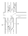
行動計画部42は、外界認識部40が取得した障害物の位置及び速度に基づいて、障害物の将来の各時刻における位置を演算する。また、行動計画部42は、各時刻における前記障害物に安全マージンを設けた障害物存在領域を演算する。安全マージンは、将来の各時刻において障害物と自車両との間に確保すべき距離をいう。安全マージンは、障害物の各時刻における位置の車線に沿った自車両側に設けられるとよい。将来の各時刻における障害物の障害物存在領域は、障害物の現在の位置と速度から推定される各時刻後の障害物の位置よりも安全マージン分、自車両に近い位置まで拡張されている。例えば、図3に示すように、自車両Aより前側を自車両Aと同方向に走行する車両Bには、車線に沿って自車側である後側に安全マージンMBが設定される。また、自車両より後側を自車両と同方向に走行する車両Cには、車線に沿って自車側である前側に安全マージンMCが設定される。また、自車両Aの前側に位置し、対向車線を走行する車両Dには、車線に沿って自車側である前側に安全マージンMDが設定される。車線を横断する人には、自車両が走行する車線に沿って自車側に安全マージンが設定される。
The
行動計画部42は、自車両の状態や、障害物の種別、障害物の状態、自車両が走行する車線の種別等に基づいて安全マージンを設定してもよい。自車両の状態は、車両センサ7によって検出された車速や加速度、停止処理の実行中か否か等を含む。障害物の種別は、障害物が車両、人、落下物、構造物のいずれであるか否かを含む。また、障害物が車両の場合、同方向に走行する車両か、走行する方向が逆の対向車に基づいて安全マージンを変更させてもよい。車線の種別は、一般道か高速道路か、一般道の場合には右折車線、左折車線、直進車線のいずれであるかを含む。すなわち、行動計画部42は、各障害物に対して安全マージンを変更してもよい。
The
行動計画部42は、衝突余裕時間(Time To Collision、TTC)や車頭時間(Time-Head-Way、THW)に基づいて安全マージンを設定してもよい。衝突余裕時間は、自車両の進行方向における自車両と障害物(周辺車両)との間の距離を、自車両と障害物との相対速度で除算することで得られる値である。車頭時間は、自車両の進行方向における自車両と前走車両との間の車間距離を、自車両の速度で除算することで得られる値である。行動計画部42は、例えば、衝突余裕時間又は車頭時間が大きくなるほど、安全マージンを小さくするとよい。
The
行動計画部42は、特に、停車処理の実行中において、停車処理の非実行中よりも安全マージンを大きくする。行動計画部42は、例えば、停車処理の実行中には1以上の所定の係数を安全マージンに掛けることによって、停車処理を実行していないときよりも安全マージンを大きくするとよい。また、行動計画部42は、例えば、停車処理の実行中には所定の値を安全マージンに加算することによって、停車処理を実行していないときよりも安全マージンを大きくするとよい。
The
行動計画部42は、周辺車両を含む各障害物の障害物存在領域と重ならないように、自車両の目標軌道を作成する。そのため、安全マージンが大きいほど、自車両は各障害物からより離れた位置を走行するように目標軌道が作成される。これにより、自車両と各障害物との間により大きな距離が確保され、自車両と障害物との衝突の可能性が低下する。その結果、自車両がより安全に走行することができる。
The
行動計画部42は、例えば交差点において右折する場合、自車両の前方において同じく右折予定の前走車の将来の各時刻における存在領域、及び対向車線を走行する対向車のそれぞれの将来の各時刻における存在領域を演算し、将来の各時刻において各車両の存在領域と重ならないように右折の目標軌道を作成する。
For example, when the
次に、上述した停車領域決定処理(ST3)の詳細を、図3及び図4を参照して説明する。以下の説明では、左側通行を採用する国を基準として説明する。すなわち、対向車線を横断するための車線は右折車線のことをいう。なお、右側通行を採用する国では、対向車線を横断するための車線は左折車線になる。対向車線を横断するための車線領域とは、車両が対向車線を横断するために走行すべき車線であって、交差点から所定の距離内の領域をいう。対向車線を横断するための車線領域は、例えば右折車線において交差点から50m以内の領域であるとよい。 Next, the details of the above-mentioned stop area determination process (ST3) will be described with reference to FIGS. 3 and 4. In the following explanation, the country that adopts left-hand traffic will be used as a reference. That is, the lane for crossing the oncoming lane is the right turn lane. In countries that adopt right-hand traffic, the lane for crossing the oncoming lane is the left turn lane. The lane area for crossing the oncoming lane is the lane in which the vehicle should travel to cross the oncoming lane, and is an area within a predetermined distance from the intersection. The lane area for crossing the oncoming lane may be, for example, an area within 50 m from the intersection in the right turn lane.
図4に示すように、行動計画部42は、最初に、現在の自車両の位置が対向車線を横断するための車線領域内、すなわち右折車線領域101内にあるか否かを判定する(ST11)。右折車線領域101は、交差点から所定の長さを有する車線であり(図3参照)、地図情報として地図記憶部22に記憶されている。自車両が右折車線領域101にある場合、右折車線領域101は予め設定された目的地へのルート上にある。行動計画部42は、ナビゲーション装置9を利用して自車位置が右折車線領域101内にあるか否かを判定する。
As shown in FIG. 4, the
自車両が右折車線領域101にある場合(ST11の判定がYes)、行動計画部42は地図情報を参照し、交差点を右折した後の道路上において路肩や退避スペース等の停車領域を複数抽出し、停車領域の大きさや停車領域と自車位置との距離等に基づいて複数の停車領域から1つの停車領域を決定する(ST12)。
When the own vehicle is in the right turn lane area 101 (the judgment of ST11 is Yes), the
自車両が右折車線領域101にない場合(ST11の判定がNo)、現在の自車両の位置が左折するための車線領域内、すなわち左折車線領域102内にあるか否かを判定する(ST13)。左折車線領域102は、交差点から所定の長さを有する車線であり(図3参照)、地図情報として地図記憶部22に記憶されている。自車両が左折車線領域102にある場合、左折車線領域102は予め設定された目的地へのルート上にある。行動計画部42は、ナビゲーション装置9を利用して自車位置が左折車線領域102内にあるか否かを判定する。
When the own vehicle is not in the right turn lane area 101 (the determination in ST11 is No), it is determined whether or not the current position of the own vehicle is in the lane area for turning left, that is, in the left turn lane area 102 (ST13). .. The left
自車両が左折車線領域102にある場合(ST13の判定がYes)、行動計画部42は地図情報を参照し、交差点を左折した後の道路上において路肩や退避スペース等の停車領域を複数抽出し、停車領域の大きさや停車領域と自車位置との距離等に基づいて複数の停車領域から1つの停車領域を決定する(ST14)。
When the own vehicle is in the left turn lane area 102 (the determination of ST13 is Yes), the
自車両が左折車線領域102にない場合(ST13の判定がNo)、行動計画部42は地図情報を参照し、自車両が現在走行する道路上において路肩や退避スペース等の停車領域を複数抽出し、停車領域の大きさや停車領域と自車位置との距離等に基づいて複数の停車領域から1つの停車領域を決定する(ST15)。このとき、行動計画部42は車両が右折又は左折するための車線領域101、102を除く範囲に停車領域を設定する。ステップST12、ST14、ST15のいずれかにおいて停車領域が決定された後、停車領域決定処理は終了する。
When the own vehicle is not in the left turn lane area 102 (determination of ST13 is No), the
以上の停車領域決定処理によれば、行動計画部42は、停車処理において、予め設定した目的地へのルート上であり、かつ対向車線を横断する(右折する)回数が1回以下となる範囲に停車領域を設定する。また、行動計画部42は、停車処理において、予め設定した目的地へのルート上であり、かつ右折又は左折する回数が1回以下となる範囲に停車領域を設定する。
According to the above stop area determination process, the
停車処理において、右折が発生する場合は停車領域決定処理を実行するときに車両が右折車線領域101にある場合であるため、右折の回数は多くても1回に制限される。同様に、停車処理において、左折が発生する場合は停車領域決定処理を実行するときに車両が左折車線領域102にある場合であるため、左折の回数は多くても1回に制限される。そのため、停車処理において事故の発生確率を一層低下させることができる。
In the stop process, when a right turn occurs, the vehicle is in the right
停車領域決定処理を実行するときに車両が右折車線領域101にある場合、停車領域は右折後の道路上に設定される。すなわち、車両は右折車線領域101から離脱した後に停車する。同様に、停車領域決定処理を実行するときに車両が左折車線領域102にある場合、停車領域は左折後の道路上に設定される。すなわち、車両は左折車線領域102から離脱した後に停車する。これらにより、停車処理により停車した車両が、右折車線領域101又は左折車線領域102を利用する他の車両の通行を妨げることを避けることができる。
If the vehicle is in the right
停車領域決定処理を実行するときに車両が右折車線領域101又は左折車線領域102にない場合、停車領域は車両がそのとき走行する道路上に設定される。これによれば、車両が右折又は左折を行わないため、事故の発生確率を一層低下させることができる。また、このとき、右折車線領域101又は左折車線領域102を除く範囲に停車領域が設定されることによって、他の右折車や左折車の車両の通行を妨げない位置に、車両を停車させることができる。他の右折車や左折車の車両の通行を妨げない位置に、車両を停車させることができる。
If the vehicle is not in the right
行動計画部42は、停車処理の実行時に、停車処理を実行していないときよりも安全マージンを大きくするため、障害物との衝突の可能性を一層低減させることができる。行動計画部42が停車処理を実行する状況では、運転者による運転や周辺監視への介入は期待することができない。安全マージンが大きくなると、自車両は周辺車両を含む障害物との間により大きな距離を確保して走行する。そのため、停車処理を実行する状況において、安全マージンを大きくすることによって、自動運転により車両より安全に走行させることができる。これにより、右折や左折等も比較的安全に行うことができる。
Since the
また、停車処理において右折するときの車速を、停車処理を実行していないときに車両が右折するときの車速よりも小さくするとよい。これによれば、他の車両が自車両を避け易くなるため、事故が発生する可能性を更に低下させることができる。 Further, it is preferable that the vehicle speed when turning right in the stop processing is smaller than the vehicle speed when the vehicle turns right when the stop processing is not executed. According to this, it becomes easier for other vehicles to avoid the own vehicle, so that the possibility of an accident can be further reduced.
以上で具体的実施形態の説明を終えるが、本発明は上記実施形態に限定されることなく幅広く変形実施することができる。 Although the description of the specific embodiment is completed above, the present invention can be widely modified without being limited to the above embodiment.
1 :車両制御システム
2 :車両システム
6 :外界センサ
17 :レーダ
18 :ライダ
19 :車外カメラ
35 :自動運転制御部
38 :走行制御部
40 :外界認識部
42 :行動計画部
1: Vehicle control system 2: Vehicle system 6: External world sensor 17: Radar 18: Rider 19: External camera 35: Automatic driving control unit 38: Driving control unit 40: External world recognition unit 42: Action planning unit
Claims (10)
車両の操舵、加速、減速、及び周辺監視を含む運転者の運転への介入の度合いに応じて前記車両を制御する制御装置と、
前記車両の周囲に存在する障害物を取得可能な外界認識装置とを有し、
前記制御装置は、
前記外界認識装置からの信号に基づいて前記障害物の位置及び速度を取得し、
前記障害物の将来の各時刻における位置及び前記各時刻における位置に安全マージンを設けた障害物存在領域を演算し、
前記障害物存在領域と重ならない範囲に前記車両の目標軌道を設定し、
前記運転者に対する前記運転への介入要求に応じた前記運転者からの入力が検出されない場合には、前記車両を停車領域に停止させる停車処理を実行し、
前記停車処理の実行中は、前記停車処理の非実行中よりも前記安全マージンを大きくする車両制御システム。 It ’s a vehicle control system.
A control device that controls the vehicle according to the degree of the driver's intervention in driving, including steering, acceleration, deceleration, and peripheral monitoring of the vehicle.
It has an outside world recognition device capable of acquiring obstacles existing around the vehicle.
The control device is
The position and speed of the obstacle are acquired based on the signal from the outside world recognition device.
Calculate the position of the obstacle at each time in the future and the area where the obstacle exists with a safety margin at the position at each time.
Set the target track of the vehicle in a range that does not overlap with the obstacle existing area,
When the input from the driver in response to the driver's request for intervention in the driving is not detected, a stop process for stopping the vehicle in the stop area is executed.
A vehicle control system in which the safety margin is made larger during the execution of the stop processing than during the non-execution of the stop processing.
Priority Applications (3)
| Application Number | Priority Date | Filing Date | Title |
|---|---|---|---|
| JP2019062169A JP2020158047A (en) | 2019-03-28 | 2019-03-28 | Vehicle control system |
| CN202010229282.8A CN111746516A (en) | 2019-03-28 | 2020-03-27 | Vehicle control system |
| US16/832,849 US20200307573A1 (en) | 2019-03-28 | 2020-03-27 | Vehicle control system |
Applications Claiming Priority (1)
| Application Number | Priority Date | Filing Date | Title |
|---|---|---|---|
| JP2019062169A JP2020158047A (en) | 2019-03-28 | 2019-03-28 | Vehicle control system |
Publications (1)
| Publication Number | Publication Date |
|---|---|
| JP2020158047A true JP2020158047A (en) | 2020-10-01 |
Family
ID=72607777
Family Applications (1)
| Application Number | Title | Priority Date | Filing Date |
|---|---|---|---|
| JP2019062169A Pending JP2020158047A (en) | 2019-03-28 | 2019-03-28 | Vehicle control system |
Country Status (3)
| Country | Link |
|---|---|
| US (1) | US20200307573A1 (en) |
| JP (1) | JP2020158047A (en) |
| CN (1) | CN111746516A (en) |
Cited By (1)
| Publication number | Priority date | Publication date | Assignee | Title |
|---|---|---|---|---|
| DE112020007365T5 (en) | 2020-12-28 | 2023-05-17 | Honda Motor Co., Ltd. | VEHICLE CONTROL DEVICE, VEHICLE CONTROL METHOD AND PROGRAM |
Families Citing this family (9)
| Publication number | Priority date | Publication date | Assignee | Title |
|---|---|---|---|---|
| JP7313434B2 (en) * | 2019-04-11 | 2023-07-24 | 株式会社小糸製作所 | Vehicle lamp and its lighting circuit |
| WO2020213105A1 (en) * | 2019-04-17 | 2020-10-22 | 日本電気株式会社 | Image presentation device, image presentation method, and non-transitory computer-readable medium having program stored thereon |
| JP7140092B2 (en) * | 2019-11-07 | 2022-09-21 | トヨタ自動車株式会社 | Driving support device |
| CN112389392B (en) * | 2020-12-01 | 2022-02-25 | 安徽江淮汽车集团股份有限公司 | Vehicle active braking method, device, equipment and storage medium |
| US20210309221A1 (en) * | 2021-06-15 | 2021-10-07 | Nauto, Inc. | Devices and methods for determining region of interest for object detection in camera images |
| JP2023023824A (en) * | 2021-08-06 | 2023-02-16 | トヨタ自動車株式会社 | Notification control device for vehicle |
| CN114030482A (en) * | 2021-11-09 | 2022-02-11 | 英博超算(南京)科技有限公司 | Method and system for screening obstacles in automatic driving assistance process |
| JP2023139857A (en) * | 2022-03-22 | 2023-10-04 | スズキ株式会社 | Running control device for vehicle |
| CN117227714A (en) * | 2023-11-15 | 2023-12-15 | 成都西谌科技有限公司 | Control method and system for turning avoidance of automatic driving vehicle |
Citations (8)
| Publication number | Priority date | Publication date | Assignee | Title |
|---|---|---|---|---|
| JP2009101733A (en) * | 2007-10-19 | 2009-05-14 | Toyota Motor Corp | Vehicle traveling controller |
| US20100033333A1 (en) * | 2006-06-11 | 2010-02-11 | Volva Technology Corp | Method and apparatus for determining and analyzing a location of visual interest |
| JP2017001596A (en) * | 2015-06-15 | 2017-01-05 | 日産自動車株式会社 | Stop position setting device and method |
| JP2017077823A (en) * | 2015-10-21 | 2017-04-27 | 本田技研工業株式会社 | Stop control device |
| JP2017140993A (en) * | 2016-02-12 | 2017-08-17 | マツダ株式会社 | Control device for vehicle |
| JP2017165158A (en) * | 2016-03-14 | 2017-09-21 | 本田技研工業株式会社 | Vehicle control device, vehicle control method and vehicle control program |
| JP2017222317A (en) * | 2016-06-17 | 2017-12-21 | 株式会社Subaru | Travel control device for vehicle |
| JP2019043364A (en) * | 2017-09-01 | 2019-03-22 | 本田技研工業株式会社 | Vehicle control device, vehicle control method and program |
Family Cites Families (5)
| Publication number | Priority date | Publication date | Assignee | Title |
|---|---|---|---|---|
| US8977435B2 (en) * | 2011-02-03 | 2015-03-10 | Toyota Jidosha Kabushiki Kaisha | Vehicle control apparatus |
| US9493157B2 (en) * | 2015-01-29 | 2016-11-15 | Toyota Motor Engineering & Manufacturing North America, Inc. | Autonomous vehicle operation in obstructed occupant view and sensor detection environments |
| CN106708040B (en) * | 2016-12-09 | 2019-10-08 | 重庆长安汽车股份有限公司 | Sensor module, automated driving system and the method for automated driving system |
| JP6465319B2 (en) * | 2017-03-31 | 2019-02-06 | 株式会社Subaru | Vehicle travel control device |
| JP6558393B2 (en) * | 2017-04-06 | 2019-08-14 | トヨタ自動車株式会社 | Course setting device and course setting method |
-
2019
- 2019-03-28 JP JP2019062169A patent/JP2020158047A/en active Pending
-
2020
- 2020-03-27 CN CN202010229282.8A patent/CN111746516A/en active Pending
- 2020-03-27 US US16/832,849 patent/US20200307573A1/en not_active Abandoned
Patent Citations (8)
| Publication number | Priority date | Publication date | Assignee | Title |
|---|---|---|---|---|
| US20100033333A1 (en) * | 2006-06-11 | 2010-02-11 | Volva Technology Corp | Method and apparatus for determining and analyzing a location of visual interest |
| JP2009101733A (en) * | 2007-10-19 | 2009-05-14 | Toyota Motor Corp | Vehicle traveling controller |
| JP2017001596A (en) * | 2015-06-15 | 2017-01-05 | 日産自動車株式会社 | Stop position setting device and method |
| JP2017077823A (en) * | 2015-10-21 | 2017-04-27 | 本田技研工業株式会社 | Stop control device |
| JP2017140993A (en) * | 2016-02-12 | 2017-08-17 | マツダ株式会社 | Control device for vehicle |
| JP2017165158A (en) * | 2016-03-14 | 2017-09-21 | 本田技研工業株式会社 | Vehicle control device, vehicle control method and vehicle control program |
| JP2017222317A (en) * | 2016-06-17 | 2017-12-21 | 株式会社Subaru | Travel control device for vehicle |
| JP2019043364A (en) * | 2017-09-01 | 2019-03-22 | 本田技研工業株式会社 | Vehicle control device, vehicle control method and program |
Cited By (2)
| Publication number | Priority date | Publication date | Assignee | Title |
|---|---|---|---|---|
| DE112020007365T5 (en) | 2020-12-28 | 2023-05-17 | Honda Motor Co., Ltd. | VEHICLE CONTROL DEVICE, VEHICLE CONTROL METHOD AND PROGRAM |
| US11919515B2 (en) | 2020-12-28 | 2024-03-05 | Honda Motor Co., Ltd. | Vehicle control device and vehicle control method |
Also Published As
| Publication number | Publication date |
|---|---|
| US20200307573A1 (en) | 2020-10-01 |
| CN111746516A (en) | 2020-10-09 |
Similar Documents
| Publication | Publication Date | Title |
|---|---|---|
| JP2020158047A (en) | Vehicle control system | |
| JP7104651B2 (en) | Vehicle control system | |
| JP7121681B2 (en) | vehicle control system | |
| JP6937335B2 (en) | Vehicle control system | |
| JP7090576B2 (en) | Vehicle control system | |
| JP7168509B2 (en) | vehicle control system | |
| JP7075908B2 (en) | Vehicle control system | |
| JP7165093B2 (en) | vehicle control system | |
| JP6917406B2 (en) | Vehicle control system | |
| US11180163B2 (en) | Vehicle control system | |
| JP7198142B2 (en) | vehicle control system | |
| US20200307638A1 (en) | Vehicle control system | |
| JP2020163986A (en) | Vehicle control system | |
| JP7145805B2 (en) | vehicle control system | |
| US11312396B2 (en) | Vehicle control system | |
| JP7184694B2 (en) | vehicle control system | |
| JP2020158022A (en) | Vehicle control system |
Legal Events
| Date | Code | Title | Description |
|---|---|---|---|
| A621 | Written request for application examination |
Free format text: JAPANESE INTERMEDIATE CODE: A621 Effective date: 20210329 |
|
| A131 | Notification of reasons for refusal |
Free format text: JAPANESE INTERMEDIATE CODE: A131 Effective date: 20220510 |
|
| A02 | Decision of refusal |
Free format text: JAPANESE INTERMEDIATE CODE: A02 Effective date: 20221108 |