JP2020157549A - Cutter device and printer - Google Patents

Cutter device and printer Download PDF

Info

Publication number
JP2020157549A
JP2020157549A JP2019057892A JP2019057892A JP2020157549A JP 2020157549 A JP2020157549 A JP 2020157549A JP 2019057892 A JP2019057892 A JP 2019057892A JP 2019057892 A JP2019057892 A JP 2019057892A JP 2020157549 A JP2020157549 A JP 2020157549A
Authority
JP
Japan
Prior art keywords
movable blade
recording medium
blade
cutting edge
guide
Prior art date
Legal status (The legal status is an assumption and is not a legal conclusion. Google has not performed a legal analysis and makes no representation as to the accuracy of the status listed.)
Withdrawn
Application number
JP2019057892A
Other languages
Japanese (ja)
Other versions
JP2020157549A5 (en
Inventor
大介 ▲柳▼町
大介 ▲柳▼町
Daisuke Yanagimachi
Current Assignee (The listed assignees may be inaccurate. Google has not performed a legal analysis and makes no representation or warranty as to the accuracy of the list.)
Seiko Epson Corp
Original Assignee
Seiko Epson Corp
Priority date (The priority date is an assumption and is not a legal conclusion. Google has not performed a legal analysis and makes no representation as to the accuracy of the date listed.)
Filing date
Publication date
Application filed by Seiko Epson Corp filed Critical Seiko Epson Corp
Priority to JP2019057892A priority Critical patent/JP2020157549A/en
Publication of JP2020157549A publication Critical patent/JP2020157549A/en
Publication of JP2020157549A5 publication Critical patent/JP2020157549A5/ja
Withdrawn legal-status Critical Current

Links

Images

Abstract

To provide a cutter device capable of preventing an end part of a record medium generated by a partial cut from contacting a fixed blade.SOLUTION: A cutter device comprises: a fixed blade with a first blade edge facing a first direction crossing a transfer direction of a record medium; a movable blade with a second blade edge facing a second direction being an opposite direction to the first direction, which can move to the first direction and the second direction, and which moves to the second direction to cut the record medium positioned between the first blade edge and the second blade edge, leaving a part of the record medium uncut; and a guide part. When the movable blade is positioned behind a position where the record medium is cut in the second direction, at least a part of the guide part is positioned at a guide position being a position protruding than the first blade edge in the first direction, or being at the same position as the first blade edge. The guide part moves in the second direction from the guide position by being pushed by the movable blade moving in the second direction. The movable blade and the guide part are positioned upstream of the fixed blade in the transfer direction.SELECTED DRAWING: Figure 3

Description

本発明は、記録媒体を切断するカッター装置および、カッター装置を備えるプリンターに関する。 The present invention relates to a cutter device for cutting a recording medium and a printer including the cutter device.

インクジェットヘッドに対して記録紙搬送方向に隣接した位置に配置されたオートカッターを備える、オートカッター付きインクジェットプリンターが開示されている(特許文献1参照)。 An inkjet printer with an auto-cutter is disclosed, which includes an auto-cutter arranged at a position adjacent to the inkjet head in the recording paper transport direction (see Patent Document 1).

前記文献1によれば、オートカッターは、記録紙搬送路を挟んで配置された、固定刃と、固定刃より搬送方向の下流に在る可動刃とを備え、可動刃が固定刃に向かって移動すると、これらの間に位置している記録紙の部分が幅方向に切断される。 According to the above document 1, the auto cutter includes a fixed blade arranged across a recording paper transport path and a movable blade located downstream of the fixed blade in the transport direction, and the movable blade is directed toward the fixed blade. When moved, the portion of the chart paper located between them is cut in the width direction.

特開2011‐143601号公報Japanese Unexamined Patent Publication No. 2011-143601

上述の構成においては、可動刃の移動により、記録媒体を、その一部を切り残して切断し、その後、搬送方向の下流から上流に向けた搬送であるバックフィードをする場合に、前記切断により固定刃の下流に発生した記録媒体の端部が、固定刃に当たるおそれがあった。 In the above-described configuration, the recording medium is cut by moving the movable blade, leaving a part thereof uncut, and then backfeeding, which is a transfer from the downstream to the upstream in the transfer direction, is performed by the above-mentioned cutting. There was a risk that the end of the recording medium generated downstream of the fixed blade would hit the fixed blade.

カッター装置は、記録媒体の搬送方向と交差する第1方向へ第1の刃先を向けた固定刃と、前記第1方向の逆方向である第2方向へ第2の刃先を向けて、前記第1方向への移動と前記第2方向への移動とが可能であり、前記第2方向へ移動することにより、前記第1の刃先と前記第2の刃先との間に位置する前記記録媒体を、一部を切り残して切断する可動刃と、前記可動刃が、前記記録媒体を切断する位置よりも前記第2方向において後方に位置する場合に、少なくとも一部が前記第1の刃先よりも前記第1方向へ突出する位置、もしくは、前記第1の刃先と同じ位置、であるガイド位置に在り、前記第2方向へ移動する前記可動刃に押されることにより前記ガイド位置から前記第2方向へ移動するガイド部と、を備え、前記可動刃および前記ガイド部は、前記固定刃よりも前記搬送方向の上流に位置する。 The cutter device has a fixed blade whose first cutting edge is directed to a first direction intersecting the conveying direction of the recording medium, and a second cutting edge which is directed to a second direction opposite to the first direction. It is possible to move in one direction and the second direction, and by moving in the second direction, the recording medium located between the first cutting edge and the second cutting edge can be moved. When the movable blade that cuts with a part left uncut and the movable blade is located rearward in the second direction from the position where the recording medium is cut, at least a part of the movable blade is located behind the first cutting edge. The guide position is located at the position protruding in the first direction or the same position as the first cutting edge, and is pushed by the movable blade moving in the second direction to move from the guide position to the second direction. A guide portion that moves to is provided, and the movable blade and the guide portion are located upstream of the fixed blade in the transport direction.

蓋が閉じた状態のプリンターの構成を簡易的に示す図。The figure which shows the structure of the printer with the lid closed simply. 蓋が開いた状態のプリンターの構成を簡易的に示す図。The figure which shows the structure of the printer with the lid open simply. 第1実施例にかかるカッター装置の動作を説明するための図。The figure for demonstrating the operation of the cutter apparatus which concerns on 1st Example. パーシャルカットされた記録媒体を上方からの視点により示す図。The figure which shows the partially cut recording medium from the viewpoint from above. 記録処理を示すフローチャート。A flowchart showing the recording process. 第2実施例にかかるカッター装置を説明するための図。The figure for demonstrating the cutter apparatus which concerns on 2nd Embodiment.

以下、各図を参照しながら本発明の実施形態を説明する。各図は、本実施形態を説明するための例示に過ぎない。各図は例示であるため、形状や比率が正確でなかったり、互いに整合していなかったり、一部が省略されていたりする場合がある。 Hereinafter, embodiments of the present invention will be described with reference to each figure. Each figure is merely an example for explaining the present embodiment. Since each figure is an example, the shape and ratio may not be accurate, they may not be consistent with each other, or some parts may be omitted.

1.プリンターの概略構成:
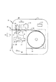
図1は、本実施形態にかかるプリンター10の内部構成を簡易的に示している。
プリンター10は、カッター装置26を備える。プリンター10を、印刷装置、記録装置、液体吐出装置、等と記載してもよい。プリンター10は、概略、プリンター本体11と、プリンター本体11の内側の一部を外部に対して開閉可能な蓋12と、を有する。図1は、蓋12が閉じた状態を示している。図1では、プリンター本体11と蓋12との境界を、破線で例示している。
1. 1. Outline configuration of printer:
FIG. 1 simply shows the internal configuration of the printer 10 according to the present embodiment.
The printer 10 includes a cutter device 26. The printer 10 may be described as a printing device, a recording device, a liquid ejection device, and the like. The printer 10 generally has a printer main body 11 and a lid 12 that can open and close a part of the inside of the printer main body 11 with respect to the outside. FIG. 1 shows a state in which the lid 12 is closed. In FIG. 1, the boundary between the printer main body 11 and the lid 12 is illustrated by a broken line.

図2は、プリンター10の内部構成を図1と同様に示している。ただし図2は、蓋12が開いた状態を示している。また、図2では、図1に示した蓋12の内部の構成を省略している。蓋12がプリンター本体11に対して開閉するための具体的な機構は、特に問わない。図1,2の例では、蓋12は、プリンター本体11に支持された軸28を介してプリンター本体11と繋がっており、軸28を中心に回動することにより、プリンター本体11に対して開閉する構成である。あるいは、蓋12は、プリンター本体11から一定方向へ引き出されることで開き、前記一定方向と逆方向へ押し戻されることで閉じる構成であってもよい。プリンター本体11は、第1構造体の具体例に該当する。また、蓋12は、第1構造体とは別の第2構造体であって、第1構造体に対する姿勢を変更可能な第2構造体の具体例に該当する。 FIG. 2 shows the internal configuration of the printer 10 in the same manner as in FIG. However, FIG. 2 shows a state in which the lid 12 is open. Further, in FIG. 2, the internal configuration of the lid 12 shown in FIG. 1 is omitted. The specific mechanism for opening and closing the lid 12 with respect to the printer main body 11 is not particularly limited. In the examples of FIGS. 1 and 2, the lid 12 is connected to the printer main body 11 via a shaft 28 supported by the printer main body 11, and opens and closes with respect to the printer main body 11 by rotating around the shaft 28. It is a configuration to do. Alternatively, the lid 12 may be configured to be opened by being pulled out from the printer main body 11 in a certain direction and closed by being pushed back in the direction opposite to the certain direction. The printer main body 11 corresponds to a specific example of the first structure. Further, the lid 12 is a second structure different from the first structure, and corresponds to a specific example of the second structure whose posture with respect to the first structure can be changed.

プリンター本体11は、制御部13、収容部14、記録ヘッド15、キャリッジ16、固定刃19、ローラー24等を備える。制御部13は、例えば、プロセッサーとしてのCPUや、メモリー等を備える。制御部13では、メモリーに記憶されたプログラムに従った演算処理をプロセッサーが実行することにより、プリンター10を制御する。プロセッサーは、一つのCPUに限られることなく、複数のCPUや、ASIC(Application Specific Integrated Circuit)等のハードウェア回路により処理を行う構成であってもよいし、CPUとハードウェア回路とが協働して処理を行う構成であってもよい。 The printer main body 11 includes a control unit 13, an accommodating unit 14, a recording head 15, a carriage 16, a fixed blade 19, a roller 24, and the like. The control unit 13 includes, for example, a CPU as a processor, a memory, and the like. The control unit 13 controls the printer 10 by the processor executing arithmetic processing according to the program stored in the memory. The processor is not limited to one CPU, but may be configured to perform processing by a plurality of CPUs or a hardware circuit such as an ASIC (Application Specific Integrated Circuit), or the CPU and the hardware circuit cooperate with each other. It may be configured to perform the processing.

収容部14は、記録媒体30を収容するための空間を形成している。本実施形態では、記録媒体30として、長尺な記録媒体を想定する。長尺な記録媒体を、連続紙とも言う。長尺な紙である記録媒体30がロール状に巻かれたロール紙本体31が、収容部14に収容される。ユーザーは、蓋12を開けることにより収容部14へロール紙本体31を収容して、蓋12を閉じる。ただし、記録媒体30は、インクやトナー等の記録剤により記録可能であり、かつ、カッター装置26により切断可能な媒体であれば、紙以外の素材であってもよい。 The accommodating portion 14 forms a space for accommodating the recording medium 30. In the present embodiment, a long recording medium is assumed as the recording medium 30. A long recording medium is also called continuous paper. The roll paper main body 31 in which the recording medium 30 which is a long paper is wound in a roll shape is accommodated in the accommodating portion 14. The user accommodates the roll paper main body 31 in the accommodating portion 14 by opening the lid 12, and closes the lid 12. However, the recording medium 30 may be a material other than paper as long as it can be recorded by a recording agent such as ink or toner and can be cut by the cutter device 26.

図1によれば、蓋12は、ローラー17、プラテン18、可動刃21、可動刃駆動部22等を備える。蓋12が閉じられたとき、プリンター本体11と蓋12との間に、記録媒体30の搬送経路としての隙間が生じる。符号D3による矢印は、このような搬送経路の方向、つまり、搬送方向D3を示している。搬送方向D3は、水平であったり、水平に対して傾いていたりする。ここでは、搬送方向D3は水平であると仮定する。搬送経路の最も下流は排出口25となっており、記録媒体30は、排出口25からプリンター10の外部へ排出される。プラテン18は、搬送経路の一部を形成する。プラテン18は、ロール紙本体31から搬送経路へ引き出された部分に該当する記録媒体30を、下方から支持する。 According to FIG. 1, the lid 12 includes a roller 17, a platen 18, a movable blade 21, a movable blade driving unit 22, and the like. When the lid 12 is closed, a gap is created between the printer main body 11 and the lid 12 as a transport path for the recording medium 30. The arrow with reference numeral D3 indicates the direction of such a transport path, that is, the transport direction D3. The transport direction D3 is horizontal or tilted with respect to the horizontal. Here, it is assumed that the transport direction D3 is horizontal. The most downstream of the transport path is the discharge port 25, and the recording medium 30 is discharged from the discharge port 25 to the outside of the printer 10. The platen 18 forms part of the transport path. The platen 18 supports the recording medium 30 corresponding to the portion drawn out from the roll paper main body 31 to the transport path from below.

プラテン18よりも搬送方向D3の下流の位置に、搬送経路を挟んで相対するローラー17,24によるローラー対が配置される。搬送方向D3の上流、下流を、以下では単に、上流、下流と記載する。ローラー17,24は、互いの間に記録媒体30を挟持しながら回転することにより、記録媒体30を搬送する。例えば、ローラー17,24のうち、蓋12に配置されたローラー17は、搬送モーター27による動力を受けて回転する能動ローラーである。一方、ローラー17,24のうち、プリンター本体11に配置されたローラー24は、能動ローラーの回転に応じて回転する従動ローラーである。 A roller pair of rollers 17 and 24 facing each other across the transport path is arranged at a position downstream of the platen 18 in the transport direction D3. The upstream and downstream of the transport direction D3 are hereinafter simply referred to as upstream and downstream. The rollers 17 and 24 convey the recording medium 30 by rotating while sandwiching the recording medium 30 between them. For example, of the rollers 17 and 24, the roller 17 arranged on the lid 12 is an active roller that rotates under the power of the transfer motor 27. On the other hand, of the rollers 17 and 24, the roller 24 arranged on the printer main body 11 is a driven roller that rotates according to the rotation of the active roller.

図1の例では、ローラー17を回転させる搬送モーター27は、蓋12の内部に配置されている。ただし、搬送モーター27はプリンター本体11に配置されていてもよい。
搬送モーター27や、ローラー17,24を含む構成を、搬送部と呼ぶ。つまり、搬送部が記録媒体30を搬送する。図示は省略しているが、搬送部は、ローラー17,24以外にも、記録媒体30を搬送するためのローラーを、例えば、記録ヘッド15よりも上流の位置等に、幾つか有するとしてもよい。
In the example of FIG. 1, the transport motor 27 that rotates the roller 17 is arranged inside the lid 12. However, the transfer motor 27 may be arranged in the printer main body 11.
A configuration including a transfer motor 27 and rollers 17 and 24 is called a transfer unit. That is, the transport unit transports the recording medium 30. Although not shown, the transport unit may have some rollers for transporting the recording medium 30 in addition to the rollers 17 and 24, for example, at a position upstream of the recording head 15. ..

プラテン18の上方には、記録ヘッド15が配置されている。記録ヘッド15は、インクを吐出可能なノズルを複数有し、インクジェット方式により記録を行う。記録ヘッド15を、印刷ヘッド、印字ヘッド、液体吐出ヘッド、等と記載してもよい。記録ヘッド15は、不図示のインクカートリッジからインクの供給を受ける。記録ヘッド15は、キャリッジ16に搭載されている。キャリッジ16は、搬送方向D3と交差する主走査方向と平行に往復移動可能である。図1,2においては、図1,2の面に垂直な方向が主走査方向である。後述の図3等では、主走査方向を符号D4による矢印で示している。記録ヘッド15は、キャリッジ16の移動に伴ってノズルからインクを吐出することにより、プラテン18に支持されている記録媒体30に対する記録を行う。 A recording head 15 is arranged above the platen 18. The recording head 15 has a plurality of nozzles capable of ejecting ink, and records by an inkjet method. The recording head 15 may be described as a print head, a print head, a liquid discharge head, or the like. The recording head 15 receives ink from an ink cartridge (not shown). The recording head 15 is mounted on the carriage 16. The carriage 16 can reciprocate in parallel with the main scanning direction intersecting the transport direction D3. In FIGS. 1 and 2, the direction perpendicular to the planes of FIGS. 1 and 2 is the main scanning direction. In FIG. 3 and the like described later, the main scanning direction is indicated by an arrow with reference numeral D4. The recording head 15 records on the recording medium 30 supported by the platen 18 by ejecting ink from the nozzles as the carriage 16 moves.

記録ヘッド15は、キャリッジ16に搭載されずに、プリンター本体11内に固定された、いわゆるラインヘッドであってもよい。つまり、記録ヘッド15は、上述の主走査方向における記録媒体30の幅に相当する範囲に亘って複数のノズルが並ぶノズル列を有し、移動することなく、記録媒体30への記録を行うものであってもよい。記録ヘッド15がラインヘッドである構成においては、キャリッジ16は不要である。 The recording head 15 may be a so-called line head fixed in the printer main body 11 without being mounted on the carriage 16. That is, the recording head 15 has a nozzle array in which a plurality of nozzles are lined up over a range corresponding to the width of the recording medium 30 in the above-mentioned main scanning direction, and records on the recording medium 30 without moving. It may be. The carriage 16 is not required in the configuration in which the recording head 15 is a line head.

ローラー17,24よりも下流の位置に、固定刃19、可動刃21およびガイド部20が配置されている。固定刃19、可動刃21およびガイド部20を少なくとも含む構成が、カッター装置26である。例えば、可動刃駆動部22も、カッター装置26の一部と解してもよい。固定刃19は、プリンター10内で固定されている。具体的には、固定刃19は、搬送方向D3と交差する第1方向D1へ刃先を向けた状態でプリンター本体11に配置されている。固定刃19の刃先は、第1の刃先である。 The fixed blade 19, the movable blade 21, and the guide portion 20 are arranged at positions downstream of the rollers 17 and 24. The cutter device 26 includes at least a fixed blade 19, a movable blade 21, and a guide portion 20. For example, the movable blade driving unit 22 may also be understood as a part of the cutter device 26. The fixed blade 19 is fixed in the printer 10. Specifically, the fixed blade 19 is arranged on the printer main body 11 in a state where the blade edge is directed to the first direction D1 intersecting the transport direction D3. The cutting edge of the fixed blade 19 is the first cutting edge.

可動刃21は、第1方向D1の逆方向である第2方向D2へ刃先を向けた状態で、蓋12に配置されている。可動刃21の刃先は、第2の刃先である。また、可動刃21は、固定刃19よりも上流に配置されている。可動刃21は、第1方向D1への移動と第2方向D2への移動とが可能である。可動刃21は、第2方向D2へ移動することにより、固定刃19の刃先と可動刃21の刃先との間に位置する記録媒体30を、一部を切り残して切断する。一部を切り残して記録媒体30を切断することを、パーシャルカットと呼ぶ。 The movable blade 21 is arranged on the lid 12 with the cutting edge facing the second direction D2, which is the opposite direction of the first direction D1. The cutting edge of the movable blade 21 is a second cutting edge. Further, the movable blade 21 is arranged upstream of the fixed blade 19. The movable blade 21 can move in the first direction D1 and move in the second direction D2. By moving in the second direction D2, the movable blade 21 cuts the recording medium 30 located between the cutting edge of the fixed blade 19 and the cutting edge of the movable blade 21 with a part left uncut. Cutting the recording medium 30 with a part left uncut is called a partial cut.

図1の例では、第1方向D1は下方向であり、第2方向D2は上方向である。よって、図1の例によれば、可動刃21の移動は上下移動である。ただし、下方向は厳密な鉛直下方向でなくてもよく、同様に、上方向は厳密な鉛直上方向でなくてもよい。可動刃21は、可動刃駆動部22によって移動させられる。可動刃駆動部22は、可動刃21の移動用のモーター23や、不図示の歯車等を有し、モーター23による動力を可動刃21に与えて可動刃21を第1方向D1や第2方向D2へ移動させる。可動刃駆動部22は、可動刃21を移動させることが可能な機構であればよい。可動刃駆動部22として、例えば、前記文献1のクランク機構を採用してもよい。 In the example of FIG. 1, the first direction D1 is the downward direction, and the second direction D2 is the upward direction. Therefore, according to the example of FIG. 1, the movement of the movable blade 21 is a vertical movement. However, the downward direction does not have to be a strict vertical downward direction, and similarly, the upward direction does not have to be a strict vertical upward direction. The movable blade 21 is moved by the movable blade driving unit 22. The movable blade driving unit 22 has a motor 23 for moving the movable blade 21, a gear (not shown), and the like, and applies power from the motor 23 to the movable blade 21 to move the movable blade 21 in the first direction D1 or the second direction. Move to D2. The movable blade driving unit 22 may be any mechanism capable of moving the movable blade 21. As the movable blade driving unit 22, for example, the crank mechanism of Document 1 may be adopted.

ガイド部20は、パーシャルカットされた記録媒体30をガイドするための構成であり、プリンター本体11に配置されている。ガイド部20は、第2方向D2において可動刃21よりも前方に位置する。ガイド部20は、固定刃19よりも上流に配置されている。図1では、特に可動刃21およびガイド部20の形状を簡単に記載している。これら可動刃21やガイド部20を含むカッター装置26の詳細については、後述の各実施例により説明する。 The guide unit 20 has a configuration for guiding the partially cut recording medium 30, and is arranged in the printer main body 11. The guide portion 20 is located in front of the movable blade 21 in the second direction D2. The guide portion 20 is arranged upstream of the fixed blade 19. In FIG. 1, the shapes of the movable blade 21 and the guide portion 20 are particularly briefly described. Details of the cutter device 26 including the movable blade 21 and the guide portion 20 will be described with reference to each embodiment described later.

言うまでもなく、プリンター10は、コンピューター等の外部機器と通信するための通信インターフェイスや、ユーザーに対して視覚的情報を示すための画面やインジケーターや、ユーザーからの操作を受け付けるためのボタンやスイッチといった操作受付部等、公知の構成を適宜有する。 Needless to say, the printer 10 has operations such as a communication interface for communicating with an external device such as a computer, screens and indicators for showing visual information to the user, and buttons and switches for accepting operations from the user. It has a known configuration such as a reception unit as appropriate.

2.実施例:
2‐1.第1実施例:
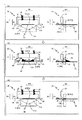
図3は、第1実施例のカッター装置26の動作が状態A1,A2,A3と遷移してく様子を示している。図3では、状態A1,A2,A3の夫々について、カッター装置26の背面図を左に示し、カッター装置26の側面図を右に示している。背面図は、上流から下流を向く視線による図である。側面図は、搬送方向D3に直交し、かつ、第1方向D1および第2方向D2に直交する視線による図である。以下では、簡単に、第1方向D1における前方および第2方向D2における後方を下、第2方向D2における前方および第1方向D1における後方を上、とそれぞれ表現することがある。
2. 2. Example:
2-1. First Example:
FIG. 3 shows how the operation of the cutter device 26 of the first embodiment transitions to the states A1, A2, and A3. In FIG. 3, the rear view of the cutter device 26 is shown on the left and the side view of the cutter device 26 is shown on the right for each of the states A1, A2, and A3. The rear view is a view from the line of sight facing from the upstream to the downstream. The side view is a view taken along the line of sight orthogonal to the transport direction D3 and orthogonal to the first direction D1 and the second direction D2. In the following, the front in the first direction D1 and the rear in the second direction D2 may be simply expressed as the lower, and the front in the second direction D2 and the rear in the first direction D1 may be expressed as the upper.

状態A1は、カッター装置26が記録媒体30のパーシャルカットを実行する前の状態である。可動刃21は、V字形状の刃先21aを有する。V字形状の刃先21aの最も下の部位、つまりV字形状の底に当たる部位を、刃先21aの最深部21bと呼ぶ。記録媒体30は、可動刃21とガイド部20との間を通過する。 The state A1 is a state before the cutter device 26 executes a partial cut of the recording medium 30. The movable blade 21 has a V-shaped cutting edge 21a. The lowermost portion of the V-shaped cutting edge 21a, that is, the portion corresponding to the bottom of the V-shaped cutting edge is referred to as the deepest portion 21b of the V-shaped cutting edge 21a. The recording medium 30 passes between the movable blade 21 and the guide portion 20.

ガイド部20は、記録媒体30を、記録媒体30と相対する端部によりガイドする。記録媒体30をガイドするとは、記録媒体30の位置や姿勢を規制することである。そのため、図3や後述の図6においてガイド部20を指し示す場合に、ガイド部20における記録媒体30と相対する端部を指し示す。ガイド部20における記録媒体30と相対する端部は、水平である。 The guide unit 20 guides the recording medium 30 by an end portion facing the recording medium 30. To guide the recording medium 30 is to regulate the position and orientation of the recording medium 30. Therefore, when the guide unit 20 is pointed to in FIG. 3 or FIG. 6 described later, the end portion of the guide unit 20 facing the recording medium 30 is pointed to. The end of the guide portion 20 facing the recording medium 30 is horizontal.

状態A1では、ガイド部20は、ガイド位置P1に在る。ガイド位置P1とは、ガイド部20の少なくとも一部が固定刃19の刃先19aよりも第1方向D1へ突出する位置である。あるいは、ガイド位置P1は、刃先19aと同じ位置であってもよい。より詳細には、ガイド位置P1は、ガイド部20における記録媒体30と相対する端部が刃先19aよりも第1方向D1へ突出しているときのガイド部20の位置、あるいは、当該端部が第1方向D1において刃先19aと同位置となるガイド部20の位置、である。 In the state A1, the guide unit 20 is at the guide position P1. The guide position P1 is a position where at least a part of the guide portion 20 projects from the cutting edge 19a of the fixed blade 19 in the first direction D1. Alternatively, the guide position P1 may be the same position as the cutting edge 19a. More specifically, the guide position P1 is the position of the guide portion 20 when the end portion of the guide portion 20 facing the recording medium 30 protrudes from the cutting edge 19a in the first direction D1, or the end portion is the first. This is the position of the guide portion 20 that is at the same position as the cutting edge 19a in the one direction D1.

ガイド部20は、プリンター本体11内において、第2方向D2への力を受けたときに反発力を生じさせる支持部29により支持されている。図3の例では、支持部29はバネであり、ガイド部20は、支持部29によってプリンター本体11内に吊り下げられている。つまり、支持部29は、ガイド部20を吊り下げたときのガイド部20の位置がガイド位置P1となるように長さや強度等が設定されている。なお、状態A1,A2,A3の各側面図においては、支持部29の記載を省略している。ガイド部20がガイド位置P1よりも第1方向D1へ移動することを禁止するためのストッパー40が、更に設けられていてもよい。ストッパー40は、プリンター本体11または蓋12のいずれかの内部に固定されている。ストッパー40は、可動刃21および記録媒体30のいずれとも干渉しない位置に設けられており、ガイド位置P1に在るガイド部20に対して、下から当接してガイド部20の第1方向D1への移動を禁止する。なお、状態A1,A2,A3の各側面図においては、ストッパー40の記載を省略している。 The guide portion 20 is supported in the printer main body 11 by a support portion 29 that generates a repulsive force when a force is applied to the second direction D2. In the example of FIG. 3, the support portion 29 is a spring, and the guide portion 20 is suspended in the printer main body 11 by the support portion 29. That is, the length, strength, and the like of the support portion 29 are set so that the position of the guide portion 20 when the guide portion 20 is suspended is the guide position P1. In each side view of the states A1, A2, and A3, the description of the support portion 29 is omitted. A stopper 40 for prohibiting the guide portion 20 from moving from the guide position P1 to the first direction D1 may be further provided. The stopper 40 is fixed inside either the printer main body 11 or the lid 12. The stopper 40 is provided at a position where it does not interfere with either the movable blade 21 or the recording medium 30, and comes into contact with the guide portion 20 at the guide position P1 from below to the first direction D1 of the guide portion 20. Prohibit the movement of. In each side view of the states A1, A2, and A3, the description of the stopper 40 is omitted.

状態A1では、可動刃21は非接触位置P3に在る。非接触位置P3とは、ガイド部20に接触しない位置である。可動刃21は、幅の両端近傍における、記録媒体30と干渉しない各位置から第2方向D2へ延出する延出部21cを有する。本実施形態において、幅とは、主走査方向D4と平行な向きにおける長さや範囲を言う。延出部21cは、刃先21aよりも第2方向D2に延出している。従って、非接触位置P3とは、可動刃21の延出部21cがガイド部20に接触していないときの可動刃21の位置である。 In the state A1, the movable blade 21 is in the non-contact position P3. The non-contact position P3 is a position that does not come into contact with the guide portion 20. The movable blade 21 has an extension portion 21c extending in the second direction D2 from each position that does not interfere with the recording medium 30 in the vicinity of both ends of the width. In the present embodiment, the width means a length or a range in a direction parallel to the main scanning direction D4. The extending portion 21c extends in the second direction D2 from the cutting edge 21a. Therefore, the non-contact position P3 is the position of the movable blade 21 when the extending portion 21c of the movable blade 21 is not in contact with the guide portion 20.

また、非接触位置P3は、可動刃21が記録媒体30を切断する位置よりも第2方向D2において後方である。可動刃21が記録媒体30を切断する位置とは、刃先21aが記録媒体30と接触する位置である。記録媒体30を切断する位置よりも第2方向D2において後方の位置を、可動刃21の非切断位置とも呼ぶ。非接触位置P3は、非切断位置の一つである。 Further, the non-contact position P3 is behind the position where the movable blade 21 cuts the recording medium 30 in the second direction D2. The position where the movable blade 21 cuts the recording medium 30 is the position where the cutting edge 21a comes into contact with the recording medium 30. The position behind the position where the recording medium 30 is cut in the second direction D2 is also referred to as the non-cutting position of the movable blade 21. The non-contact position P3 is one of the non-cutting positions.

状態A1における可動刃21を第2方向D2へ移動させた状態が、状態A2である。非接触位置P3に在った可動刃21が第2方向D2へ移動することにより、先ず、延出部21cがガイド部20に当接する。そして、ガイド部20に当接した状態で可動刃21が更に第2方向D2へ移動すると、ガイド部20は可動刃21に押され、可動刃21とガイド部20とが共に第2方向D2へ移動する。また、可動刃21が第2方向D2へ移動することにより、固定刃19の刃先19aと可動刃21の刃先21aとの間に位置する記録媒体30が切断される。 The state in which the movable blade 21 in the state A1 is moved in the second direction D2 is the state A2. The movable blade 21 located at the non-contact position P3 moves in the second direction D2, so that the extending portion 21c first comes into contact with the guide portion 20. Then, when the movable blade 21 further moves in the second direction D2 while in contact with the guide portion 20, the guide portion 20 is pushed by the movable blade 21, and both the movable blade 21 and the guide portion 20 move to the second direction D2. Moving. Further, when the movable blade 21 moves in the second direction D2, the recording medium 30 located between the cutting edge 19a of the fixed blade 19 and the cutting edge 21a of the movable blade 21 is cut.

可動刃21の移動は、刃先21aの最深部21bが記録媒体30へ到達するよりも早いタイミングで停止する。従って、記録媒体30は幅の一部が切り残される。つまり、状態A2は、カッター装置26が記録媒体30をパーシャルカットした状態である。パーシャルカットによって切り残された部分を、切り残し部34と呼ぶ。パーシャルカットを終えた状態A2においては、ガイド部20は、退避位置P2に在り、可動刃21は、切断終了位置P4に在る。 The movement of the movable blade 21 is stopped at a timing earlier than when the deepest portion 21b of the cutting edge 21a reaches the recording medium 30. Therefore, a part of the width of the recording medium 30 is left uncut. That is, the state A2 is a state in which the cutter device 26 partially cuts the recording medium 30. The portion left uncut by the partial cut is called the uncut portion 34. In the state A2 in which the partial cut is completed, the guide portion 20 is in the retracted position P2, and the movable blade 21 is in the cutting end position P4.

なお、最深部21bを含む刃先21aの形状は、図示したようなV字形状に限定されず、切り残し部34が発生するように記録媒体30をパーシャルカットする形状であればよい。例えば、最深部21bを含む刃先21aの形状は、一部あるいは全部がカーブしていてもよい。 The shape of the cutting edge 21a including the deepest portion 21b is not limited to the V-shape as shown in the drawing, and may be a shape in which the recording medium 30 is partially cut so that the uncut portion 34 is generated. For example, the shape of the cutting edge 21a including the deepest portion 21b may be partially or completely curved.

記録媒体30がパーシャルカットされることにより、固定刃19より上流に、記録媒体30の端部35が新たに生じる。端部35は下流を向いている。可動刃21の第2方向D2への移動による記録媒体30の切断で発生した端部35は、可動刃21の移動に引きずられて第2方向D2へ移動する。状態A2では、このように端部35が第2方向D2へ移動したことにより端部35を含む記録媒体30の一部領域が上方へ押し上げられた様子を例示している。可動刃21を非接触位置P3へ戻した後、端部35を含む記録媒体30の一部領域が上方へ押し上げられたままの記録媒体30を下流へ搬送すると、端部35が固定刃19に接触してしまう。そこで、本実施形態では、カッター装置26は、ガイド部20を端部35に作用させる。 By partially cutting the recording medium 30, an end portion 35 of the recording medium 30 is newly generated upstream of the fixed blade 19. The end 35 faces downstream. The end 35 generated by cutting the recording medium 30 by moving the movable blade 21 in the second direction D2 is dragged by the movement of the movable blade 21 and moves in the second direction D2. In the state A2, a state in which a part of the recording medium 30 including the end 35 is pushed upward by moving the end 35 in the second direction D2 is illustrated. After returning the movable blade 21 to the non-contact position P3, when the recording medium 30 in which a part of the recording medium 30 including the end portion 35 is pushed upward is conveyed downstream, the end portion 35 becomes the fixed blade 19. It will come into contact. Therefore, in the present embodiment, the cutter device 26 causes the guide portion 20 to act on the end portion 35.

状態A2における可動刃21を第1方向D1へ移動させて、ガイド部20の位置を再びガイド位置P1とし、可動刃21の位置を再び非接触位置P3とした状態が、状態A3である。ガイド部20は、退避位置P2において、支持部29から第1方向D1への力を受けているため、パーシャルカット後の可動刃21が第1方向D1へ移動すると、ガイド部20も第1方向D1へ移動する。ガイド部20は、退避位置P2から第1方向D1へ移動する過程で、端部35を第1方向D1へ押し戻す。この結果、ガイド部20がガイド位置P1に到達したとき、端部35を含む記録媒体30の一部領域は、固定刃19の刃先19aと可動刃21の刃先21aとの間の元の位置に戻り、上述したような接触が起きなくなる。このように、可動刃21は、非接触位置P3から切断終了位置P4へ移動し、また、切断終了位置P4から非接触位置P3へ移動する。 The state in which the movable blade 21 in the state A2 is moved to the first direction D1, the position of the guide portion 20 is set to the guide position P1 again, and the position of the movable blade 21 is set to the non-contact position P3 again is the state A3. Since the guide portion 20 receives a force from the support portion 29 to the first direction D1 at the retracted position P2, when the movable blade 21 after the partial cut moves to the first direction D1, the guide portion 20 also receives the force in the first direction D1. Move to D1. The guide portion 20 pushes the end portion 35 back to the first direction D1 in the process of moving from the retracted position P2 to the first direction D1. As a result, when the guide portion 20 reaches the guide position P1, a part of the recording medium 30 including the end portion 35 is returned to the original position between the cutting edge 19a of the fixed blade 19 and the cutting edge 21a of the movable blade 21. It returns and the contact as described above does not occur. In this way, the movable blade 21 moves from the non-contact position P3 to the cutting end position P4, and also moves from the cutting end position P4 to the non-contact position P3.

図4および図5を参照して、第1実施例をさらに説明する。
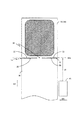
図4は、パーシャルカットされた記録媒体30を上方からの視点により示す図である。
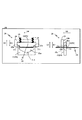
図5は、制御部13が実行する記録処理をフローチャートにより示している。制御部13は、記録ヘッド15、キャリッジ16、搬送部、カッター装置26のそれぞれを制御することにより、記録媒体30に対する記録処理を実行する。図5のフローチャートは、ステップS100,S110,S120,S130,S140のサイクルにより実現されるが、ここでは、ステップS100から説明する。
The first embodiment will be further described with reference to FIGS. 4 and 5.
FIG. 4 is a diagram showing a partially cut recording medium 30 from a viewpoint from above.
FIG. 5 shows a flowchart of the recording process executed by the control unit 13. The control unit 13 executes recording processing on the recording medium 30 by controlling each of the recording head 15, the carriage 16, the transport unit, and the cutter device 26. The flowchart of FIG. 5 is realized by the cycle of steps S100, S110, S120, S130, and S140, but here, it will be described from step S100.

制御部13は、記録データに基づく記録媒体30への記録を実行する(ステップS100)。この場合、制御部13は、キャリッジ16を移動させるともに、記録データに基づくインク吐出を、記録ヘッド15に実行させる。この結果、プラテン18に支持されている記録媒体30の領域に対して記録が実行される。記録データは、例えば、文書やイラストや写真等の何らかのオブジェクトを表現した画像データであり、画素毎にインクのドットの吐出または非吐出を規定している。制御部13は、記録データを、外部のコンピューター等との通信により入力したり、ユーザーの指示に従って生成したりして、取得すればよい。 The control unit 13 executes recording on the recording medium 30 based on the recorded data (step S100). In this case, the control unit 13 moves the carriage 16 and causes the recording head 15 to eject ink based on the recorded data. As a result, recording is performed on the region of the recording medium 30 supported by the platen 18. The recorded data is, for example, image data representing some object such as a document, an illustration, or a photograph, and defines whether or not ink dots are ejected for each pixel. The control unit 13 may acquire the recorded data by inputting it by communication with an external computer or the like or by generating it according to a user's instruction.

ステップS100の後、制御部13は、搬送部つまり搬送モーター27の駆動を制御することにより、記録媒体30の正方向搬送を実行する(ステップS110)。正方向搬送とは、搬送方向D3への搬送、つまり上流から下流への搬送である。ステップS140の逆方向搬送と区別するために、便宜的に正方向という表現を用いている。ステップS110では、制御部13は、ステップS100で記録した記録媒体30の領域が固定刃19よりも下流へ到達する位置へ、記録媒体30を搬送させる。 After step S100, the control unit 13 executes the forward transfer of the recording medium 30 by controlling the drive of the transfer unit, that is, the transfer motor 27 (step S110). The forward transport is transport in the transport direction D3, that is, transport from upstream to downstream. In order to distinguish it from the reverse transport in step S140, the expression forward is used for convenience. In step S110, the control unit 13 conveys the recording medium 30 to a position where the region of the recording medium 30 recorded in step S100 reaches downstream from the fixed blade 19.

ステップS110の後、制御部13は、可動刃駆動部22つまりモーター23の駆動を制御することにより、可動刃21を移動させて、図3で説明した状態A1から状態A2への動作を実行させる(ステップS120)。これにより、パーシャルカットが実行される。 After step S110, the control unit 13 moves the movable blade 21 by controlling the drive of the movable blade drive unit 22, that is, the motor 23, to execute the operation from the state A1 to the state A2 described in FIG. (Step S120). As a result, a partial cut is executed.

ステップS120の後、制御部13は、可動刃駆動部22つまりモーター23の駆動を制御することにより、可動刃21を移動させて、図3で説明した状態A2から状態A3への動作を実行させる(ステップS130)。ステップS130を戻し処理と呼ぶ。パーシャルカットにより第2方向D2へ押し上げられた、端部35を含む記録媒体30の一部領域が、戻し処理により第1方向D1へ押し戻される。 After step S120, the control unit 13 moves the movable blade 21 by controlling the drive of the movable blade drive unit 22, that is, the motor 23, to execute the operation from the state A2 to the state A3 described with reference to FIG. (Step S130). Step S130 is called a return process. A part of the recording medium 30 including the end portion 35, which has been pushed up in the second direction D2 by the partial cut, is pushed back to the first direction D1 by the return process.

図4では、パーシャルカットされた記録媒体30の切れ目を、符号CLにより示している。図4では記載を省略しているが、切れ目CLの近傍には、当然、固定刃19や可動刃21やガイド部20が存在している。図4では、固定刃19の刃先19aの搬送方向D3における位置を、2点鎖線で示している。記録媒体30の幅において、切れ目CLと切れ目CLとの間には、切り残し部34が存在している。記録媒体30の切れ目CLよりも下流の領域が、ステップS100において記録データに基づいてオブジェクトが記録された記録済み領域33である。記録済み領域33内に施されたハッチングは、記録された何らかのオブジェクトを表している。 In FIG. 4, the cuts of the partially cut recording medium 30 are indicated by reference numerals CL. Although the description is omitted in FIG. 4, the fixed blade 19, the movable blade 21, and the guide portion 20 naturally exist in the vicinity of the cut CL. In FIG. 4, the position of the cutting edge 19a of the fixed blade 19 in the transport direction D3 is indicated by a two-dot chain line. In the width of the recording medium 30, there is an uncut portion 34 between the cut CL and the cut CL. The area downstream of the cut CL of the recording medium 30 is the recorded area 33 in which the object is recorded based on the recorded data in step S100. The hatches made within the recorded area 33 represent some recorded object.

切れ目CLを挟んで、記録媒体30の端部32および端部35が発生している。端部32は、記録済み領域33の終端である。端部35は、次に記録される記録媒体30の先端である。パーシャルカットが行われた時点では、搬送方向D3において、記録ヘッド15と端部35との間に距離L1が発生している。記録媒体30における距離L1に対応する領域は白紙領域である。制御部13は、このような白紙領域を次の記録に利用するために、ステップS130の後、搬送部を制御することにより記録媒体30の逆方向搬送を実行する(ステップS140)。逆方向搬送は、下流から上流への搬送、つまりバックフィードである。ステップS140では、制御部13は、例えば、距離L1あるいは距離L1から所定のマージンを引いた距離のバックフィードをさせる。 The end 32 and the end 35 of the recording medium 30 are generated with the cut CL interposed therebetween. The end 32 is the end of the recorded area 33. The end 35 is the tip of the recording medium 30 to be recorded next. At the time when the partial cut is performed, a distance L1 is generated between the recording head 15 and the end portion 35 in the transport direction D3. The area corresponding to the distance L1 in the recording medium 30 is a blank area. In order to utilize such a blank area for the next recording, the control unit 13 executes the reverse transfer of the recording medium 30 by controlling the transfer unit after step S130 (step S140). Reverse transport is transport from downstream to upstream, that is, back feed. In step S140, the control unit 13 causes, for example, backfeed the distance L1 or the distance L1 minus a predetermined margin.

本実施形態では、可動刃21は固定刃19よりも上流に配置されている。そのため、可動刃21を第2方向D2へ移動させて行うパーシャルカットの結果発生した、記録媒体30の端部であって、第2方向D2へ押し上げられた端部は、固定刃19の下流ではなく上流に位置する。従って、記録媒体30のバックフィードに際して、このような押し上げられた端部が、固定刃19と接触してバックフィードを阻害する事態は、生じない。 In the present embodiment, the movable blade 21 is arranged upstream of the fixed blade 19. Therefore, the end portion of the recording medium 30 generated as a result of the partial cut performed by moving the movable blade 21 in the second direction D2, and the end portion pushed up in the second direction D2, is located downstream of the fixed blade 19. It is located upstream. Therefore, during the back feed of the recording medium 30, such a situation in which the pushed-up end portion comes into contact with the fixed blade 19 and hinders the back feed does not occur.

ステップS140の後、制御部13は、ステップS100以下を実行する。このように繰り返されるステップS100以下において、ステップS110では、記録媒体30が下流へ搬送される。このとき、ステップS110よりも前に実行されたステップ130にて、記録媒体30の端部35が、固定刃19と接触しない位置へ戻されている。そのため、ステップS110の搬送において、記録媒体30の端部35は固定刃19と接触することなく固定刃19の下を下流へ通過することができる。 After step S140, the control unit 13 executes steps S100 and below. In step S100 or lower, which is repeated in this way, the recording medium 30 is conveyed downstream in step S110. At this time, in step 130 executed before step S110, the end portion 35 of the recording medium 30 is returned to a position where it does not come into contact with the fixed blade 19. Therefore, in the transfer in step S110, the end portion 35 of the recording medium 30 can pass under the fixed blade 19 downstream without coming into contact with the fixed blade 19.

また、ステップS130の後、制御部13は、ステップS140のバックフィードをせず、記録媒体30をそのまま下流へ搬送することも可能である。この場合も、記録媒体30の端部35は、固定刃19と接触しない位置へ戻されているため、端部35は固定刃19と接触することなく固定刃19の下を下流へ通過することができる。 Further, after step S130, the control unit 13 can convey the recording medium 30 as it is downstream without back-feeding in step S140. Also in this case, since the end portion 35 of the recording medium 30 is returned to a position where it does not come into contact with the fixed blade 19, the end portion 35 passes under the fixed blade 19 downstream without coming into contact with the fixed blade 19. Can be done.

2‐2.第2実施例:
図6は、第2実施例のカッター装置26についての状態A1を、図3と同様に、背面図および側面図により示している。状態A1は第1実施例で説明した通りである。第2実施例に関しては、第1実施例と異なる点を説明する。図6を図3と比較すると判るように、第2実施例の可動刃21の延出部21cは、第1実施例の可動刃21の延出部21cよりも長い。具体的には、第2実施例の可動刃21の延出部21cは、可動刃21が非接触位置P3に在り、ガイド部20がガイド位置P1に在る場合に、固定刃19の刃先19aよりも第2方向D2へ突出するほどの長さを有する。
2-2. Second Example:
FIG. 6 shows a state A1 of the cutter device 26 of the second embodiment by a rear view and a side view as in FIG. The state A1 is as described in the first embodiment. The second embodiment will be described which is different from the first embodiment. As can be seen by comparing FIG. 6 with FIG. 3, the extending portion 21c of the movable blade 21 of the second embodiment is longer than the extending portion 21c of the movable blade 21 of the first embodiment. Specifically, in the extension portion 21c of the movable blade 21 of the second embodiment, when the movable blade 21 is in the non-contact position P3 and the guide portion 20 is in the guide position P1, the cutting edge 19a of the fixed blade 19 is present. It has a length so as to protrude in the second direction D2.

上述したように、状態A1および状態A3では、可動刃21とガイド部20とは接触しない。そのため、第2実施例のガイド部20は、可動刃21の延出部21cと相対する部分が段部20aとなっている。段部20aは、ガイド部20の記録媒体30と相対する端部よりも第2方向D2へ窪んでおり、切り欠き形状となっている。つまり、可動刃21が非接触位置P3に在り、ガイド部20がガイド位置P1に在る場合、ガイド部20における段部20aを形成する第1方向D1を向く面と、可動刃21の延出部21cとは、接触しない。 As described above, in the states A1 and A3, the movable blade 21 and the guide portion 20 do not come into contact with each other. Therefore, in the guide portion 20 of the second embodiment, the portion of the movable blade 21 facing the extending portion 21c is the step portion 20a. The step portion 20a is recessed in the second direction D2 from the end portion of the guide portion 20 facing the recording medium 30, and has a notched shape. That is, when the movable blade 21 is in the non-contact position P3 and the guide portion 20 is in the guide position P1, the surface of the guide portion 20 facing the first direction D1 forming the step portion 20a and the extension of the movable blade 21. It does not come into contact with the portion 21c.

第2実施例では、ガイド部20がガイド位置P1から退避位置P2へ移動する期間、および、ガイド部20が退避位置P2からガイド位置P1へ移動する期間に、ガイド部20の段部20aと可動刃21の延出部21cとが接触する。
このような第2実施例の可動刃21の延出部21cは、可動刃21が移動範囲のいずれに在っても、つまり、可動刃21が非接触位置P3〜切断終了位置P4のいずれに在っても、固定刃19の上流を向く面19bと相対する面21d、を有する。第2実施例の延出部21cを、可動刃21の係合部とも称する。
In the second embodiment, the guide unit 20 is movable with the step portion 20a of the guide unit 20 during the period when the guide unit 20 moves from the guide position P1 to the retracted position P2 and the period when the guide unit 20 moves from the retracted position P2 to the guide position P1. The extension portion 21c of the blade 21 comes into contact with the extension portion 21c.
In the extending portion 21c of the movable blade 21 of the second embodiment, the movable blade 21 is located in any of the moving ranges, that is, in any of the non-contact position P3 to the cutting end position P4. Even if it exists, it has a surface 21d, which faces the surface 19b facing upstream of the fixed blade 19. The extending portion 21c of the second embodiment is also referred to as an engaging portion of the movable blade 21.

3.まとめ:
本実施形態によれば、カッター装置26は、記録媒体30の搬送方向D3と交差する第1方向D1へ第1の刃先(刃先19a)を向けた固定刃19と、第1方向D1の逆方向である第2方向D2へ第2の刃先(刃先21a)を向けて、第1方向D1への移動と第2方向D2への移動とが可能であり、第2方向D2へ移動することにより、刃先19aと刃先21aとの間に位置する記録媒体30を、一部を切り残して切断する可動刃21と、を備える。さらに、カッター装置26は、可動刃21が、記録媒体30を切断する位置よりも第2方向D2において後方に位置する場合に、少なくとも一部が刃先19aよりも第1方向D1へ突出する位置、もしくは、刃先19aと同じ位置、であるガイド位置P1に在り、第2方向D2へ移動する可動刃21に押されることによりガイド位置P1から第2方向D2へ移動するガイド部20、を備える。そして、可動刃21およびガイド部20は、固定刃19よりも搬送方向D3の上流に位置する。
3. 3. Summary:
According to the present embodiment, the cutter device 26 has a fixed blade 19 having a first cutting edge (cutting edge 19a) directed toward a first direction D1 intersecting the conveying direction D3 of the recording medium 30, and a direction opposite to the first direction D1. The second cutting edge (cutting edge 21a) is directed to the second direction D2, and the movement to the first direction D1 and the movement to the second direction D2 is possible. By moving to the second direction D2, A movable blade 21 that cuts a recording medium 30 located between the cutting edge 19a and the cutting edge 21a with a part left uncut is provided. Further, in the cutter device 26, when the movable blade 21 is located rearward in the second direction D2 from the position where the recording medium 30 is cut, at least a part of the movable blade 21 protrudes from the cutting edge 19a in the first direction D1. Alternatively, the guide portion 20 is provided at the guide position P1 which is the same position as the cutting edge 19a and moves from the guide position P1 to the second direction D2 by being pushed by the movable blade 21 which moves in the second direction D2. The movable blade 21 and the guide portion 20 are located upstream of the fixed blade 19 in the transport direction D3.

前記構成によれば、可動刃21は固定刃19よりも上流に位置する。従って、パーシャルカットにより固定刃の下流に発生した記録媒体の端部が、バックフィードに際して固定刃と接触してバックフィードを阻害する、という従来の問題が生じない。また、前記構成によれば、可動刃21が非切断位置に在るとき、ガイド部20はガイド位置P1に在る。従って、パーシャルカットにより固定刃19の上流に発生した、記録媒体30の端部35に、可動刃21を非切断位置に移動させる過程でガイド部20を作用させ、端部35を固定刃19と接触しない位置へ戻すことができる。これにより、パーシャルカット後に記録媒体30を下流へ搬送するときに、記録媒体30と固定刃19との接触が生じず、記録媒体30の搬送を円滑に実行することができる。 According to the above configuration, the movable blade 21 is located upstream of the fixed blade 19. Therefore, the conventional problem that the end portion of the recording medium generated downstream of the fixed blade due to the partial cut comes into contact with the fixed blade during back feed and hinders the back feed does not occur. Further, according to the above configuration, when the movable blade 21 is in the non-cutting position, the guide portion 20 is in the guide position P1. Therefore, the guide portion 20 is made to act on the end portion 35 of the recording medium 30 generated upstream of the fixed blade 19 by the partial cut in the process of moving the movable blade 21 to the non-cutting position, and the end portion 35 is referred to as the fixed blade 19. It can be returned to a position where it does not touch. As a result, when the recording medium 30 is conveyed downstream after the partial cut, the recording medium 30 does not come into contact with the fixed blade 19, and the recording medium 30 can be smoothly conveyed.

また、第2実施例によれば、可動刃21は、可動刃21が移動範囲内のいずれの位置に在っても、記録媒体30から離れた位置で、固定刃19の上流を向く面19bと相対する面21d、を有する係合部(延出部21c)を備える。
前記構成によれば、可動刃21の移動中に、可動刃21の刃先21aが固定刃19の刃先19aよりも下流へ入り込むことが、係合部により禁止される。これにより、固定刃19と可動刃21とによる記録媒体30の切断が確実に実行される。
Further, according to the second embodiment, the movable blade 21 has a surface 19b facing upstream of the fixed blade 19 at a position away from the recording medium 30 regardless of the position of the movable blade 21 within the moving range. An engaging portion (extending portion 21c) having a surface 21d facing the surface 21d is provided.
According to the above configuration, the engaging portion prohibits the cutting edge 21a of the movable blade 21 from entering downstream of the cutting edge 19a of the fixed blade 19 while the movable blade 21 is moving. As a result, the recording medium 30 is surely cut by the fixed blade 19 and the movable blade 21.

また、本実施形態によれば、固定刃19およびガイド部20は第1構造体に配置され、可動刃21は第1構造体とは別の第2構造体に配置され、第2構造体は第1構造体に対する姿勢を変更可能である。
前記構成によれば、第1構造体と第2構造体との間に記録媒体30を通すことにより、固定刃19およびガイド部20と、可動刃21と、の間に記録媒体30をセットすることができる。
Further, according to the present embodiment, the fixed blade 19 and the guide portion 20 are arranged in the first structure, the movable blade 21 is arranged in the second structure different from the first structure, and the second structure is The posture with respect to the first structure can be changed.
According to the above configuration, the recording medium 30 is set between the fixed blade 19, the guide portion 20, and the movable blade 21 by passing the recording medium 30 between the first structure and the second structure. be able to.

また、可動刃21は固定刃19の上流に位置するため、可動刃21が移動中に固定刃19と面接触した場合、可動刃21は固定刃19から、上流を向く力を受ける。図1,2に示したように、第1構造体をプリンター本体11とし、第2構造体を、下流の方に開く蓋12とした場合、可動刃21が移動中に固定刃19から受ける、前記上流に向かう力は、蓋12を閉じる方向に作用する。これにより、カッター装置26の動作中に蓋12が誤って開くといった弊害が生じない。 Further, since the movable blade 21 is located upstream of the fixed blade 19, when the movable blade 21 comes into surface contact with the fixed blade 19 during movement, the movable blade 21 receives a force facing upstream from the fixed blade 19. As shown in FIGS. 1 and 2, when the first structure is the printer main body 11 and the second structure is the lid 12 which opens downstream, the movable blade 21 receives from the fixed blade 19 during movement. The upstream force acts in the direction of closing the lid 12. As a result, there is no adverse effect that the lid 12 is accidentally opened during the operation of the cutter device 26.

第2実施例について説明を補足する。
図6では記載を省略しているが、第2実施例においてもストッパー40を設けることが可能である。第2実施例では、ストッパー40は、可動刃21および記録媒体30のいずれとも干渉しない位置において、ガイド位置P1に在るガイド部20に対して、下から例えば段部20aに当接することにより、ガイド部20がガイド位置P1よりも第1方向D1へ移動することを禁止する。
The description of the second embodiment will be supplemented.
Although the description is omitted in FIG. 6, the stopper 40 can be provided in the second embodiment as well. In the second embodiment, the stopper 40 abuts on the guide portion 20 at the guide position P1 from below at a position where it does not interfere with either the movable blade 21 or the recording medium 30, for example, the step portion 20a. It is prohibited that the guide unit 20 moves from the guide position P1 to the first direction D1.

また、第2実施例では、蓋12を開けるときに、可動刃21の延出部21cが固定刃19と衝突しないようにする必要がある。そのため、第2実施例においては、蓋12の開動作は、可動刃駆動部22が可動刃21を非接触位置P3よりも更に第1方向D1へ移動させる可動刃退避動作と、可動刃退避動作の後に蓋12がプリンター本体11に対する姿勢を変更して開状態となる蓋変位動作と、からなる。可動刃退避動作では、可動刃21の延出部21cが固定刃19の刃先19aよりも第1方向D1の前方へ位置するまで、可動刃21を第1方向D1へ移動させる。また、第2実施例において、蓋12の閉動作は、蓋12がプリンター本体11に対する姿勢を変更して閉状態となる蓋変位動作と、この蓋変位動作の後に可動刃駆動部22が可動刃21を第2方向D2へ移動させて、可動刃21の位置を非接触位置P3とする可動刃進出動作と、からなる。可動刃退避動作は、閉状態である蓋12のロックを解除する動作となり、可動刃進出動作は、蓋12の閉状態をロックする動作となる。
あるいは、第2実施例においては、固定刃19および可動刃21が蓋12に配置されていてもよい。固定刃19および可動刃21が蓋12に配置されていれば、上述の可動刃退避動作や可動刃進出動作は不要である。
Further, in the second embodiment, it is necessary to prevent the extending portion 21c of the movable blade 21 from colliding with the fixed blade 19 when the lid 12 is opened. Therefore, in the second embodiment, the opening operation of the lid 12 includes a movable blade retracting operation in which the movable blade driving unit 22 moves the movable blade 21 further to the first direction D1 than the non-contact position P3, and a movable blade retracting operation. After that, the lid 12 changes its posture with respect to the printer main body 11 to open the lid. In the movable blade retracting operation, the movable blade 21 is moved in the first direction D1 until the extending portion 21c of the movable blade 21 is located in front of the cutting edge 19a of the fixed blade 19 in the first direction D1. Further, in the second embodiment, the closing operation of the lid 12 is a lid displacement operation in which the lid 12 changes its posture with respect to the printer body 11 to be in a closed state, and after this lid displacement operation, the movable blade driving unit 22 moves the movable blade. This consists of a movable blade advance operation in which the movable blade 21 is moved to the second direction D2 and the position of the movable blade 21 is set to the non-contact position P3. The movable blade retracting operation is an operation of unlocking the lid 12 in the closed state, and the movable blade advance operation is an operation of locking the closed state of the lid 12.
Alternatively, in the second embodiment, the fixed blade 19 and the movable blade 21 may be arranged on the lid 12. If the fixed blade 19 and the movable blade 21 are arranged on the lid 12, the above-mentioned movable blade retracting operation and movable blade advancing operation are unnecessary.

本実施形態によれば、カッター装置26だけでなく、カッター装置26を備えるプリンター10も発明として捉えることができる。また、カッター装置26の動作や、カッター装置26を備えるプリンター10の動作を、方法として捉えることも可能である。
プリンター10は、インクジェット方式ではない方式により記録を行う装置であってもよい。例えば、プリンター10は、記録ヘッド15の替わりに、電子写真方式によりトナーを記録媒体30に付着させて記録を行うプリンターエンジンを備えるとしてもよい。また、プリンター10は、サーマルプリンターであってもよい。
According to the present embodiment, not only the cutter device 26 but also the printer 10 provided with the cutter device 26 can be regarded as an invention. It is also possible to grasp the operation of the cutter device 26 and the operation of the printer 10 including the cutter device 26 as a method.
The printer 10 may be a device that records by a method other than the inkjet method. For example, the printer 10 may include a printer engine for recording by adhering toner to the recording medium 30 by an electrophotographic method instead of the recording head 15. Further, the printer 10 may be a thermal printer.

10…プリンター、11…プリンター本体、12…蓋、13…制御部、14…収容部、15…記録ヘッド、16…キャリッジ、17…ローラー、18…プラテン、19…固定刃、19a…刃先、19b…面、20…ガイド部、20a…段部、21…可動刃、21a…刃先、21c…延出部、21d…面、22…可動刃駆動部、23…モーター、24…ローラー、26…カッター装置、27…搬送モーター、29…支持部、30…記録媒体、34…切り残し部、35…端部 10 ... printer, 11 ... printer body, 12 ... lid, 13 ... control unit, 14 ... accommodating unit, 15 ... recording head, 16 ... carriage, 17 ... roller, 18 ... platen, 19 ... fixed blade, 19a ... cutting edge, 19b ... surface, 20 ... guide part, 20a ... step part, 21 ... movable blade, 21a ... cutting edge, 21c ... extension part, 21d ... surface, 22 ... movable blade drive part, 23 ... motor, 24 ... roller, 26 ... cutter Device, 27 ... Conveyor motor, 29 ... Support part, 30 ... Recording medium, 34 ... Uncut part, 35 ... End part

Claims (4)

記録媒体の搬送方向と交差する第1方向へ第1の刃先を向けた固定刃と、
前記第1方向の逆方向である第2方向へ第2の刃先を向けて、前記第1方向への移動と前記第2方向への移動とが可能であり、前記第2方向へ移動することにより、前記第1の刃先と前記第2の刃先との間に位置する前記記録媒体を、一部を切り残して切断する可動刃と、
前記可動刃が、前記記録媒体を切断する位置よりも前記第2方向において後方に位置する場合に、少なくとも一部が前記第1の刃先よりも前記第1方向へ突出する位置、もしくは、前記第1の刃先と同じ位置、であるガイド位置に在り、前記第2方向へ移動する前記可動刃に押されることにより前記ガイド位置から前記第2方向へ移動するガイド部と、を備え、
前記可動刃および前記ガイド部は、前記固定刃よりも前記搬送方向の上流に位置する、ことを特徴とするカッター装置。
A fixed blade with the first cutting edge oriented in the first direction intersecting the transport direction of the recording medium,
The second cutting edge is directed to the second direction, which is the opposite direction of the first direction, and the movement in the first direction and the movement in the second direction are possible, and the movement in the second direction is possible. With a movable blade that cuts the recording medium located between the first cutting edge and the second cutting edge with a part left uncut.
When the movable blade is located rearward in the second direction from the position where the recording medium is cut, at least a part of the movable blade protrudes in the first direction from the first cutting edge, or the first position. It is provided with a guide portion that is located at the same position as the cutting edge of No. 1 and that moves from the guide position to the second direction by being pushed by the movable blade that moves in the second direction.
A cutter device characterized in that the movable blade and the guide portion are located upstream of the fixed blade in the transport direction.
前記可動刃は、前記可動刃が前記移動の範囲内のいずれの位置に在っても、前記記録媒体から離れた位置で、前記固定刃の前記上流を向く面と相対する面、を有する係合部を備える、ことを特徴とする請求項1に記載のカッター装置。 The movable blade has a surface facing the upstream side of the fixed blade at a position away from the recording medium regardless of the position of the movable blade within the range of the movement. The cutter device according to claim 1, further comprising a joint portion. 前記固定刃および前記ガイド部は第1構造体に配置され、前記可動刃は第1構造体とは別の第2構造体に配置され、前記第2構造体は前記第1構造体に対する姿勢を変更可能である、ことを特徴とする請求項1または請求項2に記載のカッター装置。 The fixed blade and the guide portion are arranged in the first structure, the movable blade is arranged in a second structure different from the first structure, and the second structure has a posture with respect to the first structure. The cutter device according to claim 1 or 2, characterized in that it is modifiable. 請求項1〜請求項3のいずれかに記載のカッター装置を備えることを特徴とするプリンター。 A printer comprising the cutter device according to any one of claims 1 to 3.
JP2019057892A 2019-03-26 2019-03-26 Cutter device and printer Withdrawn JP2020157549A (en)

Priority Applications (1)

Application Number Priority Date Filing Date Title
JP2019057892A JP2020157549A (en) 2019-03-26 2019-03-26 Cutter device and printer

Applications Claiming Priority (1)

Application Number Priority Date Filing Date Title
JP2019057892A JP2020157549A (en) 2019-03-26 2019-03-26 Cutter device and printer

Publications (2)

Publication Number Publication Date
JP2020157549A true JP2020157549A (en) 2020-10-01
JP2020157549A5 JP2020157549A5 (en) 2022-03-07

Family

ID=72641187

Family Applications (1)

Application Number Title Priority Date Filing Date
JP2019057892A Withdrawn JP2020157549A (en) 2019-03-26 2019-03-26 Cutter device and printer

Country Status (1)

Country Link
JP (1) JP2020157549A (en)

Citations (4)

* Cited by examiner, † Cited by third party
Publication number Priority date Publication date Assignee Title
JP2011020270A (en) * 2009-07-13 2011-02-03 Seiko Epson Corp Cutting apparatus and printer with cutting apparatus
JP2011136472A (en) * 2009-12-28 2011-07-14 Star Micronics Co Ltd Printing apparatus with cutter mechanism
JP2011143601A (en) * 2010-01-14 2011-07-28 Seiko Epson Corp Inkjet printer with auto cutter and method for controlling the same
JP3187814U (en) * 2013-10-01 2013-12-19 株式会社イシダ Label issuing device

Patent Citations (4)

* Cited by examiner, † Cited by third party
Publication number Priority date Publication date Assignee Title
JP2011020270A (en) * 2009-07-13 2011-02-03 Seiko Epson Corp Cutting apparatus and printer with cutting apparatus
JP2011136472A (en) * 2009-12-28 2011-07-14 Star Micronics Co Ltd Printing apparatus with cutter mechanism
JP2011143601A (en) * 2010-01-14 2011-07-28 Seiko Epson Corp Inkjet printer with auto cutter and method for controlling the same
JP3187814U (en) * 2013-10-01 2013-12-19 株式会社イシダ Label issuing device

Similar Documents

Publication Publication Date Title
JP2010208718A (en) Image recording apparatus
JP5454087B2 (en) Printer with cutter
JP5617576B2 (en) Image forming apparatus
JP5987448B2 (en) Inkjet recording device
JP6896502B2 (en) Inkjet recording device and processing liquid holding unit
US20220203710A1 (en) Image Forming Apparatus
JP2007069556A (en) Printer
JP2006334810A (en) Inkjet recorder
JP2020157549A (en) Cutter device and printer
JP2011143601A (en) Inkjet printer with auto cutter and method for controlling the same
JP7034749B2 (en) Recording device
JP6551654B2 (en) Recording device
JP7459456B2 (en) Cutter device and printer
JP2020157550A (en) Cutter device and printer
US20210300087A1 (en) Image recording apparatus
JP2004168534A (en) Recording apparatus
JP2022117341A (en) Printing apparatus
JP2009113329A (en) Inkjet recording apparatus
JP2007119232A (en) Image reader and image forming device
JP2020183071A (en) Cutter device and printer
JPH09286150A (en) Recording device
JP7115024B2 (en) Liquid ejector
JP2011093084A (en) Printer with cutter, and method of controlling the same
US20240092100A1 (en) Printing apparatus
US20230348218A1 (en) Image recording apparatus, control method of image recording apparatus, and non-transitory computer-readable storage medium

Legal Events

Date Code Title Description
RD07 Notification of extinguishment of power of attorney

Free format text: JAPANESE INTERMEDIATE CODE: A7427

Effective date: 20200811

RD04 Notification of resignation of power of attorney

Free format text: JAPANESE INTERMEDIATE CODE: A7424

Effective date: 20210915

RD03 Notification of appointment of power of attorney

Free format text: JAPANESE INTERMEDIATE CODE: A7423

Effective date: 20211101

A521 Request for written amendment filed

Free format text: JAPANESE INTERMEDIATE CODE: A523

Effective date: 20220225

A621 Written request for application examination

Free format text: JAPANESE INTERMEDIATE CODE: A621

Effective date: 20220225

A977 Report on retrieval

Free format text: JAPANESE INTERMEDIATE CODE: A971007

Effective date: 20221208

A131 Notification of reasons for refusal

Free format text: JAPANESE INTERMEDIATE CODE: A131

Effective date: 20221213

A761 Written withdrawal of application

Free format text: JAPANESE INTERMEDIATE CODE: A761

Effective date: 20230213