JP2020151402A - Medical control device and endoscope system - Google Patents
Medical control device and endoscope system Download PDFInfo
- Publication number
- JP2020151402A JP2020151402A JP2019055705A JP2019055705A JP2020151402A JP 2020151402 A JP2020151402 A JP 2020151402A JP 2019055705 A JP2019055705 A JP 2019055705A JP 2019055705 A JP2019055705 A JP 2019055705A JP 2020151402 A JP2020151402 A JP 2020151402A
- Authority
- JP
- Japan
- Prior art keywords
- pixel signal
- frame
- pulsed light
- specific
- pulsed
- Prior art date
- Legal status (The legal status is an assumption and is not a legal conclusion. Google has not performed a legal analysis and makes no representation as to the accuracy of the status listed.)
- Pending
Links
Images


Classifications
-
- A—HUMAN NECESSITIES
- A61—MEDICAL OR VETERINARY SCIENCE; HYGIENE
- A61B—DIAGNOSIS; SURGERY; IDENTIFICATION
- A61B1/00—Instruments for performing medical examinations of the interior of cavities or tubes of the body by visual or photographical inspection, e.g. endoscopes; Illuminating arrangements therefor
- A61B1/267—Instruments for performing medical examinations of the interior of cavities or tubes of the body by visual or photographical inspection, e.g. endoscopes; Illuminating arrangements therefor for the respiratory tract, e.g. laryngoscopes, bronchoscopes
- A61B1/2673—Instruments for performing medical examinations of the interior of cavities or tubes of the body by visual or photographical inspection, e.g. endoscopes; Illuminating arrangements therefor for the respiratory tract, e.g. laryngoscopes, bronchoscopes for monitoring movements of vocal chords
-
- A—HUMAN NECESSITIES
- A61—MEDICAL OR VETERINARY SCIENCE; HYGIENE
- A61B—DIAGNOSIS; SURGERY; IDENTIFICATION
- A61B1/00—Instruments for performing medical examinations of the interior of cavities or tubes of the body by visual or photographical inspection, e.g. endoscopes; Illuminating arrangements therefor
- A61B1/00002—Operational features of endoscopes
- A61B1/00004—Operational features of endoscopes characterised by electronic signal processing
- A61B1/00006—Operational features of endoscopes characterised by electronic signal processing of control signals
-
- A—HUMAN NECESSITIES
- A61—MEDICAL OR VETERINARY SCIENCE; HYGIENE
- A61B—DIAGNOSIS; SURGERY; IDENTIFICATION
- A61B1/00—Instruments for performing medical examinations of the interior of cavities or tubes of the body by visual or photographical inspection, e.g. endoscopes; Illuminating arrangements therefor
- A61B1/00002—Operational features of endoscopes
- A61B1/00004—Operational features of endoscopes characterised by electronic signal processing
- A61B1/00009—Operational features of endoscopes characterised by electronic signal processing of image signals during a use of endoscope
-
- A—HUMAN NECESSITIES
- A61—MEDICAL OR VETERINARY SCIENCE; HYGIENE
- A61B—DIAGNOSIS; SURGERY; IDENTIFICATION
- A61B1/00—Instruments for performing medical examinations of the interior of cavities or tubes of the body by visual or photographical inspection, e.g. endoscopes; Illuminating arrangements therefor
- A61B1/00002—Operational features of endoscopes
- A61B1/00011—Operational features of endoscopes characterised by signal transmission
- A61B1/00013—Operational features of endoscopes characterised by signal transmission using optical means
-
- A—HUMAN NECESSITIES
- A61—MEDICAL OR VETERINARY SCIENCE; HYGIENE
- A61B—DIAGNOSIS; SURGERY; IDENTIFICATION
- A61B1/00—Instruments for performing medical examinations of the interior of cavities or tubes of the body by visual or photographical inspection, e.g. endoscopes; Illuminating arrangements therefor
- A61B1/04—Instruments for performing medical examinations of the interior of cavities or tubes of the body by visual or photographical inspection, e.g. endoscopes; Illuminating arrangements therefor combined with photographic or television appliances
- A61B1/045—Control thereof
-
- A—HUMAN NECESSITIES
- A61—MEDICAL OR VETERINARY SCIENCE; HYGIENE
- A61B—DIAGNOSIS; SURGERY; IDENTIFICATION
- A61B1/00—Instruments for performing medical examinations of the interior of cavities or tubes of the body by visual or photographical inspection, e.g. endoscopes; Illuminating arrangements therefor
- A61B1/04—Instruments for performing medical examinations of the interior of cavities or tubes of the body by visual or photographical inspection, e.g. endoscopes; Illuminating arrangements therefor combined with photographic or television appliances
- A61B1/05—Instruments for performing medical examinations of the interior of cavities or tubes of the body by visual or photographical inspection, e.g. endoscopes; Illuminating arrangements therefor combined with photographic or television appliances characterised by the image sensor, e.g. camera, being in the distal end portion
- A61B1/051—Details of CCD assembly
-
- A—HUMAN NECESSITIES
- A61—MEDICAL OR VETERINARY SCIENCE; HYGIENE
- A61B—DIAGNOSIS; SURGERY; IDENTIFICATION
- A61B1/00—Instruments for performing medical examinations of the interior of cavities or tubes of the body by visual or photographical inspection, e.g. endoscopes; Illuminating arrangements therefor
- A61B1/06—Instruments for performing medical examinations of the interior of cavities or tubes of the body by visual or photographical inspection, e.g. endoscopes; Illuminating arrangements therefor with illuminating arrangements
- A61B1/0655—Control therefor
-
- A—HUMAN NECESSITIES
- A61—MEDICAL OR VETERINARY SCIENCE; HYGIENE
- A61B—DIAGNOSIS; SURGERY; IDENTIFICATION
- A61B1/00—Instruments for performing medical examinations of the interior of cavities or tubes of the body by visual or photographical inspection, e.g. endoscopes; Illuminating arrangements therefor
- A61B1/06—Instruments for performing medical examinations of the interior of cavities or tubes of the body by visual or photographical inspection, e.g. endoscopes; Illuminating arrangements therefor with illuminating arrangements
- A61B1/0661—Endoscope light sources
Abstract
Description
本開示は、医療用制御装置及び内視鏡システムに関する。 The present disclosure relates to medical controls and endoscopic systems.
従来、医療分野において、声帯の振動周波数に同期させて当該声帯に向けてパルス光を順次、出射し、当該声帯から反射されたパルス光を撮像素子にて撮像することで当該声帯を観察する内視鏡システムが知られている(例えば、特許文献1参照)。
特許文献1に記載の内視鏡システムでは、撮像素子のフレーム周期とパルス光の発光周期とが異なることに伴う1フレーム内での明るさのバラつきや連続するフレーム間での明るさのバラつきを低減させ、観察に適した画像を生成するために、以下に示す処理を実行している。
具体的に、当該内視鏡システムでは、撮像素子から出力される画素信号から、特定の演算式によって演算を行うことで、パルス光の照明期間で当該撮像素子の全ての画素が露光した場合の画素信号に相当する擬似画素信号(照明時画素信号)を生成している。
Conventionally, in the medical field, pulsed light is sequentially emitted toward the vocal cord in synchronization with the vibration frequency of the vocal cord, and the pulsed light reflected from the vocal cord is imaged by an image sensor to observe the vocal cord. An endoscopic system is known (see, for example, Patent Document 1).
In the endoscope system described in
Specifically, in the endoscope system, when all the pixels of the image sensor are exposed during the illumination period of the pulsed light by performing a calculation from the pixel signal output from the image sensor by a specific calculation formula. A pseudo pixel signal (pixel signal during illumination) corresponding to a pixel signal is generated.
しかしながら、特許文献1に記載の内視鏡システムでは、供給されたパルス電流に応じてパルス光を出射する光源に供給する当該パルス電流の波高値(電流値)を変更することで当該パルス光を調光する場合には、上述した特定の演算式によって演算を行うと、適切な擬似画素信号を生成することができない。すなわち、調光で狙った明るさの変動以外の明るさの変動が出てきてしまうため、1フレーム内での明るさのバラつきや連続するフレーム間での明るさのバラつきを低減することができず、観察に適した画像を生成することができない、という問題がある。
However, in the endoscopic system described in
本発明は、上記に鑑みてなされたものであって、観察に適した画像を生成することができる医療用制御装置及び内視鏡システムを提供することを目的とする。 The present invention has been made in view of the above, and an object of the present invention is to provide a medical control device and an endoscopic system capable of generating an image suitable for observation.
上述した課題を解決し、目的を達成するために、本発明に係る医療用制御装置は、パルス電流に応じてパルス光を出射する光源の動作を制御する光源制御部と、前記パルス光で照明された被写体からの光を受光して画素信号を生成する複数の画素を有する撮像素子の動作を制御し、特定のフレームレートで前記撮像素子に前記画素信号を順次、生成させる撮像制御部と、前記画素信号から、特定の前記パルス光の照明期間で前記複数の画素が露光された場合の画素信号に相当する擬似画素信号を生成する画像処理部とを備え、前記光源制御部は、前記パルス電流の波高値を変更することで前記パルス光を調光するとともに、1フレーム内に前記光源から前記パルス光を複数回、出射させ、前記画像処理部は、前記擬似画素信号を生成する際、前記複数の画素の水平ラインのうち特定の水平ラインについては、前記特定の水平ラインが前記特定のパルス光の照明期間を含む特定の1フレーム内に露光した全ての前記パルス光の各露光量を合算した総露光量に対する前記特定の1フレーム内に露光した前記特定のパルス光の露光量の比率を前記特定の水平ラインの各画素からの前記特定の1フレーム分の前記画素信号に乗算した画素信号を用い、前記露光量は、前記パルス電流のパルス幅及び前記波高値にて規定される値である。 In order to solve the above-mentioned problems and achieve the object, the medical control device according to the present invention includes a light source control unit that controls the operation of a light source that emits pulsed light in response to a pulse current, and illumination with the pulsed light. An imaging control unit that controls the operation of an image pickup device having a plurality of pixels that receives light from a subject and generates a pixel signal, and causes the image pickup device to sequentially generate the pixel signal at a specific frame rate. The light source control unit includes an image processing unit that generates a pseudo pixel signal corresponding to a pixel signal when the plurality of pixels are exposed in a specific illumination period of the pulsed light from the pixel signal, and the light source control unit has the pulse. When the pulsed light is dimmed by changing the peak value of the current and the pulsed light is emitted from the light source a plurality of times within one frame, the image processing unit generates the pseudo pixel signal. For a specific horizontal line among the horizontal lines of the plurality of pixels, each exposure amount of all the pulsed light exposed by the specific horizontal line in a specific frame including the illumination period of the specific pulsed light is used. A pixel obtained by multiplying the pixel signal for the specific frame from each pixel of the specific horizontal line by the ratio of the exposure amount of the specific pulsed light exposed in the specific frame to the total total exposure. Using a signal, the exposure amount is a value defined by the pulse width of the pulse current and the peak value.
また、本発明に係る医療用制御装置では、上記発明において、前記特定の水平ラインは、前記特定のパルス光の照明期間と前記画素信号の読み出しタイミングである第1の読み出しタイミングとが重複する重複ラインを除く非重複ラインである。 Further, in the medical control device according to the present invention, in the above invention, the specific horizontal line overlaps the illumination period of the specific pulsed light and the first read timing which is the read timing of the pixel signal. It is a non-overlapping line excluding the line.
また、本発明に係る医療用制御装置では、上記発明において、前記画像処理部は、前記擬似画素信号を生成する際、前記水平ラインのうち前記重複ラインについては、前記第1の読み出しタイミングで前記重複ラインから読み出される第1のフレームの1フレーム分の前記画素信号である第1の画素信号から算出した第1の対応画素信号と、前記第1の読み出しタイミングの1フレーム後の第2の読み出しタイミングで前記重複ラインから読み出される第2のフレームの1フレーム分の前記画素信号である第2の画素信号から算出した第2の対応画素信号とを合成した画素信号を用い、前記第1の対応画素信号は、前記重複ラインが前記第1のフレーム内に露光した全ての前記パルス光の各前記露光量を合算した総露光量に対する前記第1のフレーム内に露光した前記特定のパルス光の前記露光量の比率を前記第1の画素信号に乗算した画素信号であり、前記第2の対応画素信号は、前記重複ラインが前記第2のフレーム内に露光した全ての前記パルス光の各前記露光量を合算した総露光量に対する前記第2のフレーム内に露光した前記特定のパルス光の前記露光量の比率を前記第2の画素信号に乗算した画素信号である。 Further, in the medical control device according to the present invention, in the above invention, when the image processing unit generates the pseudo pixel signal, the overlapping line among the horizontal lines is said to be said at the first read timing. The first corresponding pixel signal calculated from the first pixel signal which is the pixel signal for one frame of the first frame read from the overlapping line, and the second read one frame after the first read timing. The first correspondence is used by using a pixel signal obtained by synthesizing a second corresponding pixel signal calculated from the second pixel signal which is the pixel signal for one frame of the second frame read from the overlapping line at the timing. The pixel signal is the said of the specific pulsed light exposed in the first frame with respect to the total exposure amount of the sum of the exposure amounts of all the pulsed lights exposed in the first frame by the overlapping line. It is a pixel signal obtained by multiplying the first pixel signal by the ratio of the exposure amount, and the second corresponding pixel signal is each of the exposures of all the pulsed lights exposed by the overlapping line in the second frame. It is a pixel signal obtained by multiplying the second pixel signal by the ratio of the exposure amount of the specific pulsed light exposed in the second frame to the total exposure amount obtained by multiplying the total exposure amount.
また、本発明に係る医療用制御装置では、上記発明において、前記光源制御部は、前記パルス電流の前記パルス幅を変更せずに前記波高値のみを変更することで前記パルス光を調光する。 Further, in the medical control device according to the present invention, in the above invention, the light source control unit dimmes the pulsed light by changing only the peak value without changing the pulse width of the pulse current. ..
本発明に係る内視鏡システムは、パルス電流に応じてパルス光を出射する光源と、前記パルス光で照明された被写体からの光を受光して画素信号を生成する複数の画素を有する撮像素子と、上述した医療用制御装置とを備える。 The endoscope system according to the present invention is an image pickup device having a light source that emits pulsed light in response to a pulsed current and a plurality of pixels that receive light from a subject illuminated by the pulsed light and generate a pixel signal. And the above-mentioned medical control device.
また、本発明に係る内視鏡システムでは、上記発明において、前記撮像素子は、CMOS(Complementary Metal Oxide Semiconductor)撮像素子で構成されている。 Further, in the endoscope system according to the present invention, in the above invention, the image pickup device is composed of a CMOS (Complementary Metal Oxide Semiconductor) image pickup device.
また、本発明に係る内視鏡システムでは、上記発明において、前記撮像素子は、CCD(Charge Coupled Device)撮像素子で構成されている。 Further, in the endoscope system according to the present invention, in the above invention, the image pickup device is composed of a CCD (Charge Coupled Device) image pickup device.
本発明に係る医療用制御装置及び内視鏡システムによれば、観察に適した画像を生成することができる。 According to the medical control device and the endoscopic system according to the present invention, an image suitable for observation can be generated.
以下に、図面を参照して、本発明を実施するための形態(以下、実施の形態)について説明する。なお、以下に説明する実施の形態によって本発明が限定されるものではない。さらに、図面の記載において、同一の部分には同一の符号を付している。 Hereinafter, embodiments for carrying out the present invention (hereinafter referred to as embodiments) will be described with reference to the drawings. The present invention is not limited to the embodiments described below. Further, in the description of the drawings, the same parts are designated by the same reference numerals.
(実施の形態1)
〔内視鏡システムの概略構成〕
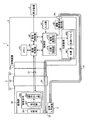
図1は、本実施の形態1に係る内視鏡システム1を示すブロック図である。
内視鏡システム1は、医療分野において用いられ、被写体となる声帯を観察するストロボ内視鏡システムである。この内視鏡システム1は、図1に示すように、内視鏡2と、音声入力装置3と、制御装置4と、表示装置5とを備える。
(Embodiment 1)
[Outline configuration of endoscopic system]
FIG. 1 is a block diagram showing an
The
内視鏡2は、声帯からの被写体像を取り込む。この内視鏡2は、図1に示すように、挿入部21と、操作部22と、ユニバーサルコード23とを備える。
挿入部21は、細長形状をなす。この挿入部21には、図1に示すように、照明ファイバであるライトガイド24が挿通されている。また、挿入部21の先端部分には、ライトガイド24の出射端に対向するように照明レンズ25が設けられている。そして、ライトガイド24から出射されたパルス光は、照明レンズ25を介して声帯に照射される。
The
The
また、挿入部21の先端部分には、図1に示すように、撮像部26が設けられている。
撮像部26は、照明レンズ25を介して声帯に照射され、当該声帯にて反射された光(被写体像)を挿入部21内に取り込むとともに、当該被写体像を撮像する部分である。この撮像部26は、図1に示すように、光学系261と、撮像素子262とを備える。
光学系261は、1または複数のレンズで構成され、声帯からの被写体像を挿入部21内に取り込んで撮像素子262(受光部263)の受光面に結像する。
撮像素子262は、制御装置4による制御の下、特定のフレームレートで光学系261が結像した被写体像を順次、撮像する。この撮像素子262は、図1に示すように、受光部263と、読み出し部264とを備える。
Further, as shown in FIG. 1, an
The
The
The
受光部263の受光面には、光学系261が結像した被写体像を受光し、受光した被写体像を光電変換して画素信号を生成する複数の画素が配置されている。当該複数の画素は、水平方向に沿って配置される2以上の画素からなる画素行(水平ライン)が垂直方向に複数並ぶように行列状に配置されている。そして、受光部263は、受光面に結像した被写体像から声帯を表す画素信号を生成する。
On the light receiving surface of the
読み出し部264は、受光部263における複数の画素に対する露光と複数の画素からの画素信号の読み出しとを行う。
本実施の形態1では、撮像素子262(受光部263及び読み出し部264)は、CMOS撮像素子で構成され、水平ライン毎の露光、かつ、読み出しが可能である。そして、読み出し部264は、露光及び読み出しを行う撮像動作を先頭の水平ラインから実行し、水平ライン毎にタイミングをずらして、電荷リセット、露光及び読み出しを行うローリングシャッタ方式によって画素信号を生成する。したがって、撮像部26においては、1つの撮像期間(フレーム)であっても、水平ライン毎に露光タイミング及び読み出しタイミングがそれぞれ異なる。
The
In the first embodiment, the image sensor 262 (
また、挿入部21には、図1に示すように、画素信号の伝送及び制御信号の伝送のための電気ケーブル27が挿通されている。すなわち、撮像部26は、電気ケーブル27を介した制御装置4からの制御信号に応じてローリングシャッタ方式によって画素信号を生成するとともに、電気ケーブル27を介して当該画素信号を制御装置4に出力する。
Further, as shown in FIG. 1, an
操作部22は、挿入部21の基端側に接続され、医師等のユーザによるユーザ操作を受け付ける各種のスイッチ(図示略)が設けられている。そして、操作部22は、電気ケーブル27を介して当該操作に応じた操作信号を制御装置4に出力する。
ユニバーサルコード23は、操作部22から延在し、ライトガイド24及び電気ケーブル27等が配設されたコードである。そして、ユニバーサルコード23は、基端において、コネクタ23aによって制御装置4と接続する。
The operation unit 22 is connected to the base end side of the
The
音声入力装置3は、図1に示すように、コード31を介して制御装置4の音声入力端子4aに接続する。この音声入力装置3は、声帯から発せされる音声を入力し、音声信号を出力する。そして、当該音声信号は、コード31を介して制御装置4に出力される。
As shown in FIG. 1, the
制御装置4は、本発明に係る医療用制御装置に相当する。この制御装置4は、CPU(Central Processing Unit)やFPGA(Field-Programmable Gate Array)等を含んで構成され、撮像部26及び表示装置5の動作を統括的に制御する。
なお、制御装置4の詳細な構成については、後述する「制御装置の構成」において説明する。
表示装置5は、液晶または有機EL(Electro Luminescence)等を用いた表示ディスプレイで構成され、制御装置4による制御の下、当該制御装置4からの表示用画像信号に基づく画像を表示する。
The control device 4 corresponds to the medical control device according to the present invention. The control device 4 includes a CPU (Central Processing Unit), an FPGA (Field-Programmable Gate Array), and the like, and comprehensively controls the operations of the
The detailed configuration of the control device 4 will be described in "Configuration of control device" described later.
The
〔制御装置の構成〕
次に、制御装置4の構成について説明する。
制御装置4は、図1に示すように、入力部41と、振動周波数検出部42と、メモリ43と、画像処理部44と、表示制御部45と、光源装置46と、制御部47とを備える。
入力部41は、マウス、キーボード、及びタッチパネル等の操作デバイスを用いて構成され、医師等のユーザによるユーザ操作を受け付ける。そして、入力部41は、当該ユーザ操作に応じた操作信号を制御部47に出力する。
振動周波数検出部42は、音声入力装置3から出力された音声信号に基づいて、当該音声入力装置3に入力された音声の周波数(声帯の振動周波数)を検出する。そして、振動周波数検出部42は、検出した音声の周波数を制御部47に出力する。
[Control device configuration]
Next, the configuration of the control device 4 will be described.
As shown in FIG. 1, the control device 4 includes an
The
The vibration
メモリ43は、例えば、DRAM(Dynamic Random Access Memory)等で構成されている。このメモリ43は、読み出し部264から順次、読み出される画素信号を複数フレーム分、一時的に記憶する。また、メモリ43は、画像処理部44にて生成された後述する擬似画素信号を複数フレーム分、一時的に記憶する。
The
画像処理部44は、メモリ43に記憶された連続する複数フレームの画素信号から、光源装置46によるパルス光の照明期間で受光部263の全ての画素が露光された場合の画素信号に相当する擬似画素信号を生成する。本実施の形態1では、画像処理部44は、全てのパルス光に対してそれぞれ擬似画素信号を生成する。なお、画像処理部44としては、全てのパルス光に対してそれぞれ擬似画素信号を生成しない構成を採用してもよい。
なお、擬似画素信号の生成方法の詳細については、後述する「制御装置の動作」において説明する。
また、画像処理部44は、読み出し部264によって読み出された複数の画素の画素信号に対し、所定の画像処理を行う。例えば、画像処理部44は、画素信号に対して、オプティカルブラック減算処理、ホワイトバランス(WB)調整処理、デモザイク処理(撮像素子262がベイヤー配列のカラーフィルタ(図示略)を備えた構成である場合)、カラーマトリクス演算処理、ガンマ補正処理、色再現処理、及びエッジ強調処理等を含む画像処理を行う。
The
The details of the method of generating the pseudo pixel signal will be described in "Operation of the control device" described later.
In addition, the
表示制御部45は、特許文献1に記載の表示用画像信号の生成方法と同様に、表示装置5の表示周期に含まれる各パルス光での各擬似画素信号から、表示装置5に表示させるための表示用画像信号を生成する。
Similar to the method for generating a display image signal described in
光源装置46は、図1に示すように、光源461と、光源ドライバ462とを備える。なお、本実施の形態1では、光源装置46は、制御装置4に内蔵された構成としているが、これに限らず、制御装置4とは独立した構成としても構わない。
光源461は、例えば、白色LED(Light Emitting Diode)等で構成され、供給されたパルス電流に応じてパルス光を出射する。そして、光源461から出射されたパルス光は、ライトガイド24及び照明レンズ25を介して声帯に照射される。
光源ドライバ462は、制御部47による制御の下、光源461に対してパルス電流を供給する。
As shown in FIG. 1, the light source device 46 includes a
The
The
制御部47は、例えば、CPUやFPGA等で構成され、撮像部26及び表示装置5の動作を制御するとともに、制御装置4全体の動作を制御する。この制御部47は、図1に示すように、光源制御部471と、撮像制御部472とを備える。
なお、光源制御部471及び撮像制御部472の機能については、後述する「制御装置の動作」において説明する。
The control unit 47 is composed of, for example, a CPU, an FPGA, or the like, and controls the operations of the
The functions of the light
〔制御装置の動作〕
次に、上述した制御装置4の動作について説明する。
光源制御部471は、振動周波数検出部42にて検出された被写体である声帯から発せされる音声の周波数と同期するように、光源461からパルス光を出射させる。
撮像制御部472は、撮像素子262の1フレーム周期における露光を水平ライン毎に順次、開始させ、露光開始から所定の期間(所謂、シャッタ速度)が経過した水平ライン毎に順次、読み出しを行わせるローリングシャッタ方式による露光制御を特定のフレームレートで行う。
[Operation of control device]
Next, the operation of the control device 4 described above will be described.
The light
The image
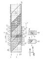
図2は、パルス光の発光タイミングと撮像部26における理想出画タイミングとの関係を示すタイムチャートである。
ここで、図2に示すように、光源461における光源461のパルス光の各発光タイミング(図2(a))と、撮像素子262の露光タイミング(図2(b))とが一致している場合には、出力される複数の画像間で明るさのバラつきは生じない。
本実施の形態1では、光源制御部471は、撮像素子262のフレーム周期よりも光源461の発光周期が短くなるように当該光源461の動作を制御する。
以下、図3を参照しつつ、光源461によるパルス光の発光タイミングと読み出し部264による露光及び読み出しタイミングとを説明する。
FIG. 2 is a time chart showing the relationship between the emission timing of the pulsed light and the ideal image output timing in the
Here, as shown in FIG. 2, each emission timing of the pulsed light of the
In the first embodiment, the light
Hereinafter, with reference to FIG. 3, the emission timing of the pulsed light by the
図3は、パルス光の発光タイミングと読み出し部264による露光及び読み出しタイミングとを説明する図である。具体的に、図3(a)は、光源461から発せられるパルス光の発光タイミングを示すタイミングチャートである。図3(b)は、読み出し部264による複数の画素に対する露光及び読み出しタイミングを示すタイムチャートである。なお、図3(b)では、XYZ直交座標系を用い、X軸で時間を示し、Y軸で複数の画素における水平ラインV(Vは整数。V=1,・・・,n,・・・,t,・・・,j)の位置を示し、Z軸で光源461に供給するパルス電流の波高値(画素に対するパルス光の露光強度(電流値))を示している。
FIG. 3 is a diagram for explaining the emission timing of the pulsed light and the exposure and readout timing by the
光源461は、光源制御部471による制御の下、図3(a)に示すように、撮像素子242のフレーム周期Cfよりも短い発光周期Cp毎にパルス光を発光する。
また、撮像部26は、撮像制御部472による制御の下、水平ラインV毎に露光及び読み出しのタイミングを変えるローリングシャッタ方式によって画素信号を生成する。したがって、同一フレームの画素信号であっても、水平ラインV毎に露光期間及び読み出しタイミングは異なる。例えば、図3(b)に示すように、フレーム(N−1)の先頭の水平ライン1の画素に対しては、読み出し部264は、期間A1に露光を行った後に時間R1で画素信号を読み出す。また、読み出し部264は、以降の水平ラインVの画素に対しては、水平ラインV毎にタイミングを時間方向にシフトさせながら、露光及び読み出しを行う。そして、最終の水平ラインjの画素に対しては、期間Ajにおいて露光を行い、時間Rjで画素信号を読み出す。このため、フレーム(N−1)の画素信号D(N−1)は、先頭の水平ライン1から最終の水平ラインjの各水平ラインVに対する露光が順次、実行されるとともに、時間R1から時間Rjまでの期間に水平ラインVの画素信号が先頭から順に読み出されることによって生成される。なお、フレーム(N−2)の画素信号D(N−2)、フレーム(N)の画素信号D(N)、及びフレーム(N+1)の画素信号D(N+1)も同様に読み出されることによって生成される。
Under the control of the light
Further, the
以上のことから、本実施の形態1では、いずれの水平ラインVの露光期間においても、複数回のパルス光が照明されており、各水平ラインVの画素は、多重露光されることとなる。そして、画像処理部44は、読み出しタイミングとパルス光の照明期間とが重複している水平ラインVがあることに加え、各水平ラインVの画素が多重露光されていることを考慮して、擬似画素信号を生成する。
以下では、光源制御部471が光源461から出射されるパルス光の調光制御を実行していない場合と、当該調光制御を実行している場合とを順に説明する。
From the above, in the first embodiment, the pulsed light is illuminated a plurality of times during the exposure period of any horizontal line V, and the pixels of each horizontal line V are subjected to multiple exposure. Then, the
Hereinafter, a case where the light
〔調光制御を実行していない場合〕
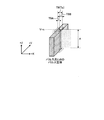
図4及び図5は、調光制御を実行していない場合での露光量を説明する図である。具体的に、図4は、図3(b)を−Y軸方向から見た図である。図5は、図3(b)に示したパルス光Lb9の部分(以下、パルス立体と記載)のみを抽出し、当該パルス光Lb9のパルス立体を−Y軸側から見た斜視図である。
先ず、光源制御部471が調光制御を実行していない場合について説明する。すなわち、光源461に供給されるパルス電流の波高値は、図4に示すように、一律「A」である。また、光源461に供給されるパルス電流のパルス幅(照明期間)は、一律「Tp」である。
[When dimming control is not executed]
4 and 5 are diagrams for explaining the exposure amount when the dimming control is not executed. Specifically, FIG. 4 is a view of FIG. 3B as viewed from the −Y axis direction. FIG. 5 is a perspective view of the pulsed solid of the pulsed light Lb9 as viewed from the −Y axis side by extracting only the portion of the pulsed light Lb9 shown in FIG. 3 (b) (hereinafter referred to as a pulsed solid).
First, a case where the light
以下、擬似画素信号を構成する重複ラインの画素信号の生成方法、及び擬似画素信号を構成する非重複ラインの画素信号の生成方法を順に説明する。
なお、重複ラインは、擬似画素信号の生成対象の照明期間(以下、対象照明期間と記載)に読み出しタイミング(以下、第1の読み出しタイミングと記載)が重複した水平ラインV(図3(b)の例では、重複ラインの一つは水平ラインn)を意味する。一方、非重複ラインは、水平ラインVのうち、重複ライン以外の水平ラインV(図3(b)の例では、非重複ラインの一つは水平ラインt)を意味する。なお、非重複ラインは、本発明に係る特定の水平ラインに相当する。
Hereinafter, a method of generating a pixel signal of overlapping lines constituting a pseudo pixel signal and a method of generating a pixel signal of a non-overlapping line constituting a pseudo pixel signal will be described in order.
The overlapping line is a horizontal line V in which the read timing (hereinafter referred to as the first read timing) overlaps with the illumination period (hereinafter referred to as the target illumination period) of the pseudo pixel signal generation target (FIG. 3B). In the example of, one of the overlapping lines means a horizontal line n). On the other hand, the non-overlapping line means a horizontal line V other than the overlapping line among the horizontal lines V (in the example of FIG. 3B, one of the non-overlapping lines is the horizontal line t). The non-overlapping line corresponds to a specific horizontal line according to the present invention.
先ず、擬似画素信号を構成する重複ラインの画素信号の生成方法について説明する。
画像処理部44は、擬似画素信号を生成する際、重複ラインについては、第1の読み出しタイミングで当該重複ラインから読み出される第1のフレームの1フレーム分の画素信号である第1の画素信号から算出した第1の対応画素信号と、当該第1の読み出しタイミングの1フレーム後の第2の読み出しタイミングで当該重複ラインから読み出される第2のフレームの1フレーム分の画素信号である第2の画素信号から算出した第2の対応画素信号とを合成した画素信号を用いる。
ここで、第1の対応画素信号は、重複ラインが第1のフレーム内に露光した全てのパルス光の各露光量を合算した総露光量に対する第1のフレーム内で対象照明期間に露光した露光量の比率を第1の画素信号に乗算した画素信号である。
また、第2の対応画素信号は、重複ラインが第2のフレーム内に露光した全てのパルス光の各露光量を合算した総露光量に対する第2のフレーム内で対象照明期間に露光した露光量の比率を第2の画素信号に乗算した画素信号である。
また、上述した露光量は、パルス電流のパルス幅(照明期間)及び波高値で規定される。より具体的に、当該露光量は、照明期間×波高値の積分値(図5に示したパルス立体をXZ平面(図5ではドットで表現)にて切断した断面積に相当)となる。
First, a method of generating a pixel signal of overlapping lines constituting a pseudo pixel signal will be described.
When the
Here, the first corresponding pixel signal is the exposure exposed in the first frame during the target illumination period with respect to the total exposure amount of the sum of the exposure amounts of all the pulsed lights exposed in the first frame by the overlapping line. It is a pixel signal obtained by multiplying the amount ratio by the first pixel signal.
Further, the second corresponding pixel signal is the exposure amount exposed in the target illumination period in the second frame with respect to the total exposure amount obtained by adding up the exposure amounts of all the pulsed light exposed in the second frame by the overlapping line. Is a pixel signal obtained by multiplying the second pixel signal by the ratio of.
Further, the above-mentioned exposure amount is defined by the pulse width (illumination period) and the peak value of the pulse current. More specifically, the exposure amount is the integral value of the illumination period × the peak value (corresponding to the cross-sectional area obtained by cutting the pulse solid shown in FIG. 5 in the XZ plane (represented by dots in FIG. 5)).
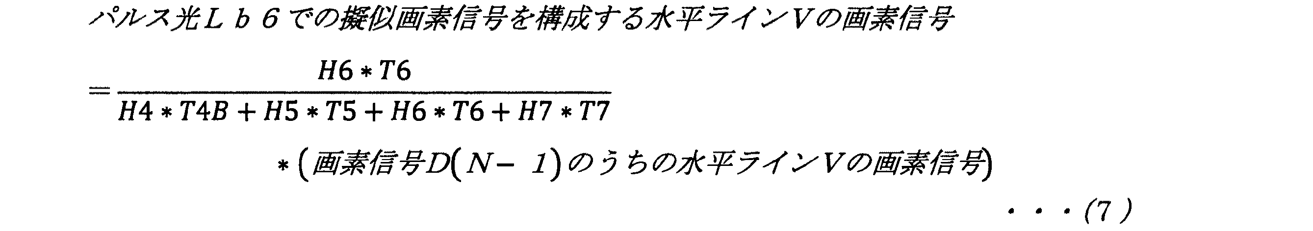
より具体的に、パルス光Lb9で受光部263の全ての画素が露光された場合の画素信号に相当する擬似画素信号を生成する場合であって、重複ラインとして水平ラインnを例に説明する。
画像処理部44は、重複ラインである水平ラインnについては、パルス光Lb9の照明期間(対象照明期間)と重複した読み出しタイミング(第1の読み出しタイミング)で読み出されたフレーム(N−2)(第1のフレーム)の画素信号D(N−2)における水平ラインnの画素信号(第1の画素信号)から算出した第1の対応画素信号と、第1の読み出しタイミングの1フレーム後の第2の読み出しタイミングで読み出されたフレーム(N−1)(第2のフレーム)の画素信号D(N−1)における水平ラインnの画素信号(第2の画素信号)から算出した第2の対応画素信号とを合成した画素信号を用いる。
More specifically, this is a case where a pseudo pixel signal corresponding to a pixel signal when all the pixels of the
The
ここで、フレーム(N−2)の水平ラインnの露光期間には、パルス光Lb9の照明期間T9(対象照明期間)の前半に加えて、パルス光Lb4〜Lb8の各照明期間T4〜T9も含まれている。
このため、第1の対応画素信号は、以下の式(1)で算出される。なお、式(1)において、H4〜H9は、パルス光Lb4〜Lb9をそれぞれ出射させるためのパルス電流の波高値である。また、期間T9Aは、フレーム(N−2)において、パルス光Lb9の照明期間T9が水平ラインnの露光期間に含まれる期間である。
Here, in the exposure period of the horizontal line n of the frame (N-2), in addition to the first half of the illumination period T9 (target illumination period) of the pulsed light Lb9, each illumination period T4 to T9 of the pulsed light Lb4 to Lb8 is also included. include.
Therefore, the first corresponding pixel signal is calculated by the following equation (1). In the equation (1), H4 to H9 are the peak values of the pulse currents for emitting the pulsed lights Lb4 to Lb9, respectively. Further, the period T9A is a period in which the illumination period T9 of the pulsed light Lb9 is included in the exposure period of the horizontal line n in the frame (N-2).
また、フレーム(N−1)の水平ラインnの露光期間には、パルス光Lb9の照明期間T9の後半に加えて、パルス光Lb10〜Lb14の各照明期間T10〜T14も含まれている。
このため、第2の対応画素信号は、以下の式(2)で算出される。なお、式(2)において、H10〜H14は、パルス光Lb10〜Lb14をそれぞれ出射させるためのパルス電流の波高値である。また、期間T9Bは、フレーム(N−1)において、パルス光Lb9の照明期間T9が水平ラインnの露光期間に含まれる期間である。
Further, the exposure period of the horizontal line n of the frame (N-1) includes the respective illumination periods T10 to T14 of the pulsed lights Lb10 to Lb14 in addition to the latter half of the illumination period T9 of the pulsed light Lb9.
Therefore, the second corresponding pixel signal is calculated by the following equation (2). In the equation (2), H10 to H14 are the peak values of the pulse currents for emitting the pulsed lights Lb10 to Lb14, respectively. Further, the period T9B is a period in which the illumination period T9 of the pulsed light Lb9 is included in the exposure period of the horizontal line n in the frame (N-1).
そして、画像処理部44は、パルス光Lb9での擬似画素信号を構成する重複ラインである水平ラインnの画素信号を式(1)で算出した第1の対応画素信号と式(2)で算出した第2の対応画素信号とを合成した画素信号とする。
Then, the
ここで、光源制御部471が調光制御を実行していない場合には、各波高値H4〜H14は、一律「A」である。また、各照明期間T4〜T14は、一律「Tp」である。すなわち、パルス光Lb4〜Lb14の露光量(パルス光Lb4〜Lb14の各パルス立体をXZ平面(図5ではドットで表現)にて切断した各断面積(図5参照))は、全て同一である。
このため、光源制御部471が調光制御を実行していない場合には、式(1)は、以下の式(3)のように展開される。同様に、式(2)は、以下の式(4)のように展開される。
Here, when the light
Therefore, when the light
![]()
![]()
![]()
![]()
すなわち、光源制御部471が調光制御を実行していない場合には、式(3),(4)に示すように、第1,第2の対応画素信号を算出する際には、波高値を考慮することなく、時間(照明期間)のパラメータのみを考慮すればよい。
That is, when the light
次に、擬似画素信号を構成する非重複ラインの画素信号の生成方法について説明する。
画像処理部44は、擬似画素信号を生成する際、非重複ラインについては、当該非重複ラインが対象照明期間を含む特定の1フレーム内に露光した全てのパルス光の各露光量を合算した総露光量に対する当該特定の1フレーム内で当該対象照明期間に露光した露光量の比率を当該非重複ラインの各画素からの当該特定の1フレーム分の画素信号に乗算した画素信号を用いる。
より具体的に、パルス光Lb9で受光部263の全ての画素が露光された場合の1フレーム分の画素信号に相当する擬似画素信号を生成する場合であって、非重複ラインとして水平ラインtを例に説明する。
Next, a method of generating a pixel signal of a non-overlapping line constituting a pseudo pixel signal will be described.
When the
More specifically, in the case of generating a pseudo pixel signal corresponding to a pixel signal for one frame when all the pixels of the
画像処理部44は、非重複ラインである水平ラインtについては、パルス光Lb9の照明期間(対象照明期間)の次の読み出しタイミングで読み出されたフレーム(N−2)の画素信号D(N−2)のうちの水平ラインtの画素信号に基づいて、擬似画素信号を生成する。
ここで、フレーム(N−2)の水平ラインtの露光期間には、パルス光Lb9の照明期間T9(対象照明期間)に加えて、パルス光Lb5の照明期間T5の後半、及びパルス光Lb7〜Lb8,Lb10の各照明期間T7〜T8,T10も含まれている。
このため、パルス光Lb9での擬似画素信号を構成する水平ラインtの画素信号は、以下の式(5)で算出される。なお、式(5)において、期間T5Bは、フレーム(N−2)において、パルス光Lb5の照明期間T5が水平ラインtの露光期間に含まれる期間である。
The
Here, during the exposure period of the horizontal line t of the frame (N-2), in addition to the illumination period T9 (target illumination period) of the pulsed light Lb9, the latter half of the illumination period T5 of the pulsed light Lb5 and the pulsed light Lb7 to The lighting periods T7 to T8 and T10 of Lb8 and Lb10 are also included.
Therefore, the pixel signal of the horizontal line t constituting the pseudo pixel signal in the pulsed light Lb9 is calculated by the following equation (5). In the formula (5), the period T5B is a period in which the illumination period T5 of the pulsed light Lb5 is included in the exposure period of the horizontal line t in the frame (N-2).
ここで、光源制御部471が調光制御を実行していない場合には、各波高値H5〜H10は、一律「A」である。また、各照明期間T6〜T10は、一律「Tp」である。すなわち、パルス光Lb6〜Lb10の露光量(パルス光Lb6〜Lb10の各パルス立体をXZ平面(図5ではドットで表現)にて切断した各断面積(図5参照))は、全て同一である。
このため、光源制御部471が調光制御を実行していない場合には、式(5)は、以下の式(6)のように展開される。
Here, when the light
Therefore, when the light
すなわち、光源制御部471が調光制御を実行していない場合には、式(6)に示すように、擬似画素信号を構成する非重複ラインの画素信号を算出する際には、波高値を考慮することなく、時間(照明期間)のパラメータのみを考慮すればよい。
That is, when the light
〔調光制御を実行している場合〕
図6及び図7は、調光制御を実行している場合での露光量を説明する図である。具体的に、図6は、図3(b)を−Y軸方向から見た図である。図7は、図3(b)に示したパルス光Lb9,Lb10の各パルス立体を抽出し、当該パルス光Lb9,Lb10のパルス立体を−Y軸側から見た斜視図である。
次に、光源制御部471が調光制御を実行している場合について説明する。本実施の形態1では、光源制御部471は、図3(b)、図6及び図7に示すように、光源461に供給するパルス電流のパルス幅(照明期間)を変更せずに全て同一の照明期間Tpとしつつ、当該パルス電流の波高値を変更することによって、パルス光の調光制御を実行する。なお、当該調光制御は、例えば、表示制御部45にて生成された表示用画像信号に基づく画像中の特定の領域の輝度平均値に基づいて、当該画像の明るさが基準となる明るさとなるようにパルス電流の波高値を変更する制御である。
[When dimming control is executed]
6 and 7 are diagrams for explaining the exposure amount when the dimming control is executed. Specifically, FIG. 6 is a view of FIG. 3B as viewed from the −Y axis direction. FIG. 7 is a perspective view of the pulsed solids of the pulsed light Lb9 and Lb10 shown in FIG. 3B extracted and the pulsed solids of the pulsed light Lb9 and Lb10 viewed from the −Y axis side.
Next, a case where the light
以下、擬似画素信号を構成する重複ラインの画素信号の生成方法、及び擬似画素信号を構成する非重複ラインの画素信号の生成方法を順に説明する。
先ず、擬似画素信号を構成する重複ラインの画素信号の生成方法について説明する。
画像処理部44は、擬似画素信号を生成する際、重複ラインについては、上述した「調光制御を実行していない場合」で説明したように、第1,第2の対応画素信号を合成した画素信号を用いる。
すなわち、画像処理部44は、パルス光Lb9での擬似画素信号を構成する重複ラインである水平ラインnの画素信号を式(1)で算出した第1の対応画素信号と式(2)で算出した第2の対応画素信号とを合成した画素信号とする。
Hereinafter, a method of generating a pixel signal of overlapping lines constituting a pseudo pixel signal and a method of generating a pixel signal of a non-overlapping line constituting a pseudo pixel signal will be described in order.
First, a method of generating a pixel signal of overlapping lines constituting a pseudo pixel signal will be described.
When generating the pseudo pixel signal, the
That is, the
ここで、光源制御部471が調光制御を実行している場合には、各照明期間T4〜T14は一律「Tp」であるが、各波高値H4〜H14は異なる値となる。すなわち、パルス光Lb4〜Lb14の露光量(パルス光Lb4〜Lb14の各パルス立体をXZ平面(図7ではドットで表現)にて切断した各断面積(図7参照))は、異なるものとなる。
このため、光源制御部471が調光制御を実行している場合には、式(1)を式(3)のように展開することができない。同様に、式(2)を式(4)のように展開することができない。
Here, when the light
Therefore, when the light
すなわち、光源制御部471が調光制御を実行している場合には、式(1),(2)に示すように、第1,第2の対応画素信号を算出する際には、波高値及び時間(照明期間)の双方のパラメータを考慮する必要がある。
That is, when the light
次に、擬似画素信号を構成する非重複ラインの画素信号の生成方法について説明する。
画像処理部44は、擬似画素信号を生成する際、非重複ラインについては、上述した「調光制御を実行していない場合」で説明したように、当該非重複ラインが対象照明期間を含む特定の1フレーム内に露光した全てのパルス光の各露光量を合算した総露光量に対する当該特定の1フレーム内で当該対象照明期間に露光した露光量の比率を当該非重複ラインの各画素からの当該特定の1フレーム分の画素信号に乗算した画素信号を用いる。
すなわち、画像処理部44は、パルス光Lb9での擬似画素信号を構成する非重複ラインである水平ラインtの画素信号を式(5)によって算出する。
Next, a method of generating a pixel signal of a non-overlapping line constituting a pseudo pixel signal will be described.
When the
That is, the
ここで、光源制御部471が調光制御を実行している場合には、各照明期間T6〜T10は一律「Tp」であるが、各波高値H5〜H10は異なる値となる。すなわち、パルス光Lb6〜Lb10の露光量(パルス光Lb6〜Lb10の各パルス立体をXZ平面(図7ではドットで表現)にて切断した各断面積(図7参照))は、異なるものとなる。
このため、光源制御部471が調光制御を実行している場合には、式(5)を式(6)のように展開することができない。
Here, when the light
Therefore, when the light
すなわち、光源制御部471が調光制御を実行している場合には、式(5)に示すように、擬似画素信号を構成する非重複ラインの画素信号を算出する際には、波高値及び時間(照明期間)の双方のパラメータを考慮する必要がある。
That is, when the light
以上説明した実施の形態1によれば、以下の効果を奏する。
本実施の形態1に係る制御装置4では、波高値及び時間(照明期間)の双方のパラメータを考慮して(式(1),(2),(5)参照)、擬似画素信号を生成する。このため、調光制御を実行している場合であっても、適切な擬似画素信号を生成することができる。すなわち、調光で狙った明るさの変動以外の明るさの変動が出てきてしまうことを抑制することができるため、1フレーム内での明るさのバラつきや連続するフレーム間での明るさのバラつきを低減することができ、観察に適した画像を生成することができる。
According to the first embodiment described above, the following effects are obtained.
In the control device 4 according to the first embodiment, a pseudo pixel signal is generated in consideration of both the peak value and the time (illumination period) parameters (see equations (1), (2), and (5)). .. Therefore, an appropriate pseudo pixel signal can be generated even when the dimming control is executed. That is, since it is possible to suppress fluctuations in brightness other than the fluctuations in brightness aimed at by dimming, variations in brightness within one frame and brightness between consecutive frames can be suppressed. The variation can be reduced, and an image suitable for observation can be generated.
また、本実施の形態1に係る制御装置4では、パルス電流のパルス幅を変更せずに波高値のみを変更することでパルス光を調光する。
このため、パルス電流のパルス幅が非常に短い状態でパルス光を出射させる必要があり、当該パルス幅の変更ではパルス光の調光を行うことが難しい場合であっても、波高値のみを変更することでパルス光を良好に調光することができる。
Further, in the control device 4 according to the first embodiment, the pulsed light is dimmed by changing only the peak value without changing the pulse width of the pulse current.
Therefore, it is necessary to emit the pulsed light in a state where the pulse width of the pulse current is very short, and even if it is difficult to adjust the pulsed light by changing the pulse width, only the peak value is changed. By doing so, the pulsed light can be satisfactorily dimmed.
(実施の形態2)
次に、本実施の形態2について説明する。
以下の説明では、上述した実施の形態1と同様の構成には同一符号を付し、その詳細な説明は省略または簡略化する。
上述した実施の形態1では、撮像素子262は、ローリングシャッタ方式によって画素信号を生成するCMOS撮像素子で構成されていた。
これに対して、本実施の形態2では、撮像素子262は、グローバルシャッタ方式によって画素信号を生成するCCD撮像素子で構成されている。
(Embodiment 2)
Next, the second embodiment will be described.
In the following description, the same components as those in the first embodiment will be designated by the same reference numerals, and detailed description thereof will be omitted or simplified.
In the first embodiment described above, the
On the other hand, in the second embodiment, the
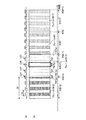
図8は、本実施の形態2におけるパルス光の発光タイミングと読み出し部264による露光及び読み出しタイミングとを示すタイムチャートである。具体的に、図8(a)は、光源461から発せられるパルス光の発光タイミングを示すタイミングチャートである。図8(b)は、読み出し部264による複数の画素に対する露光及び読み出しタイミングを示すタイムチャートである。
撮像部26は、撮像制御部472による制御の下、同一フレームであれば、全ての画素が同じ期間で露光され、同じタイミングで読み出される。すなわち、フレーム(N−2)であれば、露光期間A(N−2)で露光された後に、時間R(N−2)において、全画素の画素信号に対応する画素信号D(N−2)が読み出される。同様に、フレーム(N+1)、フレーム(N)、及びフレーム(N+1)については、それぞれ、露光期間A(N−1),AN,A(N+1)で露光された後に、時間R(N−1),R(N),R(N+1)において、全画素の画素信号に対応する画素信号D(N−1),D(N),D(N+1)が読み出される。
光源461は、光源制御部471による制御の下、図8(a)に示すように、撮像素子242のフレーム周期Cfよりも短い発光周期Cp毎にパルス光を発光する。
FIG. 8 is a time chart showing the emission timing of the pulsed light in the second embodiment and the exposure and readout timing by the
Under the control of the image
Under the control of the light
本実施の形態2では、画像処理部44は、各パルス光のうち全ての水平ラインVが非重複ラインとなるパルス光での擬似画素信号のみを生成する。また、画像処理部44は、当該擬似画素信号を生成する際、水平ラインVが対象照明期間を含む特定の1フレーム内に露光した全てのパルス光の各露光量を合算した総露光量に対する当該特定の1フレーム内で当該対象照明期間に露光した露光量の比率を当該水平ラインVの各画素からの当該特定の1フレーム分の画素信号に乗算した画素信号を用いる。
より具体的に、パルス光Lb6での擬似画素信号を生成する場合を例に説明する。
In the second embodiment, the
More specifically, a case of generating a pseudo pixel signal with pulsed light Lb6 will be described as an example.
画像処理部44は、パルス光Ld6の照明期間(対象照明期間)の次の読み出しタイミングで読み出されたフレーム(N−1)の画素信号D(N−1)を構成する各水平ラインVの画素信号に基づいて、擬似画素信号を生成する。
ここで、フレーム(N−1)の露光期間には、パルス光Ld6の照明期間T6に加えて、パルス光Ld4の照明期間T4の後半、及びパルス光Ld5,Ld7の各照明期間T5,T7も含まれている。
このため、パルス光Lb6での擬似画素信号を構成する水平ラインVの画素信号は、上述した実施の形態1で説明した非重複ラインの場合と同様に、以下の式(7)で算出される。なお、式(7)において、H4〜H7は、パルス光Lb4〜Lb7をそれぞれ出射させるためのパルス電流の波高値である。また、期間T4Bは、フレーム(N−1)において、パルス光Lb4の照明期間T4が含まれる期間である。
The
Here, during the exposure period of the frame (N-1), in addition to the illumination period T6 of the pulsed light Ld6, the latter half of the illumination period T4 of the pulsed light Ld4 and the illumination periods T5 and T7 of the pulsed light Ld5 and Ld7 are also included. include.
Therefore, the pixel signal of the horizontal line V constituting the pseudo pixel signal in the pulsed light Lb6 is calculated by the following equation (7) as in the case of the non-overlapping line described in the first embodiment described above. .. In the equation (7), H4 to H7 are the peak values of the pulse currents for emitting the pulsed lights Lb4 to Lb7, respectively. Further, the period T4B is a period in which the illumination period T4 of the pulsed light Lb4 is included in the frame (N-1).
本実施の形態2では、画像処理部44は、表示装置5の表示周期毎に、当該表示周期に含まれる各パルス光のうち、全ての水平ラインVが非重複ラインとなる1つのパルス光での1つの擬似画素信号を生成する。そして、表示制御部45は、当該表示周期毎に、当該1つの擬似画素信号から1つの表示用画像信号を生成する。
なお、画像処理部44は、表示装置5の表示周期毎に、当該表示周期に含まれる各パルス光のうち、複数のパルス光での擬似画素信号をそれぞれ生成しても構わない。この際には、表示制御部45は、当該表示周期毎に、当該複数の擬似画素信号から1つの表示用画像信号を生成する。
In the second embodiment, the
The
以上説明した本実施の形態2のように撮像素子262をCCD撮像素子で構成した場合であっても、上述した実施の形態1と同様の効果を奏する。
Even when the
(その他の実施の形態)
ここまで、本発明を実施するための形態を説明してきたが、本発明は上述した実施の形態によってのみ限定されるべきものではない。
上述した実施の形態1,2では、内視鏡2を軟性内視鏡で構成していたが、これに限らず、当該内視鏡2を硬性内視鏡で構成しても構わない。
上述した実施の形態1,2では、調光制御において、パルス電流のパルス幅を変更せずに波高値のみを変更していたが、これに限らず、パルス幅及び波高値の双方を変更することでパルス光を調光する構成を採用しても構わない。
(Other embodiments)
Although the embodiments for carrying out the present invention have been described so far, the present invention should not be limited only to the above-described embodiments.
In the above-described first and second embodiments, the
In the above-described first and second embodiments, in the dimming control, only the crest value is changed without changing the pulse width of the pulse current, but the present invention is not limited to this, and both the pulse width and the crest value are changed. Therefore, a configuration for dimming the pulsed light may be adopted.
1 内視鏡システム
2 内視鏡
3 音声入力装置
4 制御装置
4a 音声入力端子
5 表示装置
21 挿入部
22 操作部
23 ユニバーサルコード
23a コネクタ
24 ライトガイド
25 照明レンズ
26 撮像部
27 電気ケーブル
31 コード
41 入力部
42 振動周波数検出部
43 メモリ
44 画像処理部
45 表示制御部
46 光源装置
47 制御部
261 光学系
262 撮像素子
263 受光部
264 読み出し部
461 光源
462 光源ドライバ
471 光源制御部
472 撮像制御部
1
Claims (7)
前記パルス光で照明された被写体からの光を受光して画素信号を生成する複数の画素を有する撮像素子の動作を制御し、特定のフレームレートで前記撮像素子に前記画素信号を順次、生成させる撮像制御部と、
前記画素信号から、特定の前記パルス光の照明期間で前記複数の画素が露光された場合の画素信号に相当する擬似画素信号を生成する画像処理部とを備え、
前記光源制御部は、
前記パルス電流の波高値を変更することで前記パルス光を調光するとともに、1フレーム内に前記光源から前記パルス光を複数回、出射させ、
前記画像処理部は、
前記擬似画素信号を生成する際、前記複数の画素の水平ラインのうち特定の水平ラインについては、前記特定の水平ラインが前記特定のパルス光の照明期間を含む特定の1フレーム内に露光した全ての前記パルス光の各露光量を合算した総露光量に対する前記特定の1フレーム内に露光した前記特定のパルス光の露光量の比率を前記特定の水平ラインの各画素からの前記特定の1フレーム分の前記画素信号に乗算した画素信号を用い、
前記露光量は、
前記パルス電流のパルス幅及び前記波高値にて規定される値である医療用制御装置。 A light source control unit that controls the operation of a light source that emits pulsed light according to the pulse current,
The operation of an image pickup device having a plurality of pixels that receives light from a subject illuminated by the pulsed light and generates a pixel signal is controlled, and the image pickup device sequentially generates the pixel signal at a specific frame rate. Image sensor and
An image processing unit that generates a pseudo pixel signal corresponding to a pixel signal when the plurality of pixels are exposed in a specific illumination period of the pulsed light from the pixel signal is provided.
The light source control unit
The pulsed light is dimmed by changing the peak value of the pulse current, and the pulsed light is emitted from the light source a plurality of times within one frame.
The image processing unit
When generating the pseudo pixel signal, for a specific horizontal line among the horizontal lines of the plurality of pixels, all the specific horizontal lines exposed within a specific frame including the illumination period of the specific pulsed light. The ratio of the exposure amount of the specific pulsed light exposed in the specific frame to the total exposure amount obtained by adding the exposure amounts of the pulsed light is the specific one frame from each pixel of the specific horizontal line. Using the pixel signal multiplied by the pixel signal of the minute,
The exposure amount is
A medical control device that is a value defined by the pulse width of the pulse current and the peak value.
前記特定のパルス光の照明期間と前記画素信号の読み出しタイミングである第1の読み出しタイミングとが重複する重複ラインを除く非重複ラインである請求項1に記載の医療用制御装置。 The particular horizontal line
The medical control device according to claim 1, wherein the medical control device is a non-overlapping line excluding an overlapping line in which the illumination period of the specific pulsed light and the first reading timing which is the reading timing of the pixel signal overlap.
前記擬似画素信号を生成する際、前記水平ラインのうち前記重複ラインについては、前記第1の読み出しタイミングで前記重複ラインから読み出される第1のフレームの1フレーム分の前記画素信号である第1の画素信号から算出した第1の対応画素信号と、前記第1の読み出しタイミングの1フレーム後の第2の読み出しタイミングで前記重複ラインから読み出される第2のフレームの1フレーム分の前記画素信号である第2の画素信号から算出した第2の対応画素信号とを合成した画素信号を用い、
前記第1の対応画素信号は、
前記重複ラインが前記第1のフレーム内に露光した全ての前記パルス光の各前記露光量を合算した総露光量に対する前記第1のフレーム内に露光した前記特定のパルス光の前記露光量の比率を前記第1の画素信号に乗算した画素信号であり、
前記第2の対応画素信号は、
前記重複ラインが前記第2のフレーム内に露光した全ての前記パルス光の各前記露光量を合算した総露光量に対する前記第2のフレーム内に露光した前記特定のパルス光の前記露光量の比率を前記第2の画素信号に乗算した画素信号である請求項2に記載の医療用制御装置。 The image processing unit
When generating the pseudo pixel signal, the overlapping line among the horizontal lines is the first pixel signal for one frame of the first frame read from the overlapping line at the first reading timing. The first corresponding pixel signal calculated from the pixel signal and one frame of the second frame read from the overlapping line at the second read timing one frame after the first read timing. Using a pixel signal synthesized from the second corresponding pixel signal calculated from the second pixel signal,
The first corresponding pixel signal is
The ratio of the exposure amount of the specific pulsed light exposed in the first frame to the total exposure amount obtained by adding up the exposure amounts of all the pulsed lights exposed in the first frame by the overlapping line. Is a pixel signal obtained by multiplying the first pixel signal by
The second corresponding pixel signal is
The ratio of the exposure amount of the specific pulsed light exposed in the second frame to the total exposure amount obtained by adding each of the exposure amounts of all the pulsed lights exposed in the second frame by the overlapping line. The medical control device according to claim 2, which is a pixel signal obtained by multiplying the second pixel signal by.
前記パルス電流の前記パルス幅を変更せずに前記波高値のみを変更することで前記パルス光を調光する請求項1〜3のいずれか一つに記載の医療用制御装置。 The light source control unit
The medical control device according to any one of claims 1 to 3, wherein the pulsed light is dimmed by changing only the peak value without changing the pulse width of the pulse current.
前記パルス光で照明された被写体からの光を受光して画素信号を生成する複数の画素を有する撮像素子と、
請求項1〜4のいずれか一つに記載の医療用制御装置とを備える内視鏡システム。 A light source that emits pulsed light according to the pulse current,
An image sensor having a plurality of pixels that receives light from a subject illuminated by the pulsed light and generates a pixel signal.
An endoscope system including the medical control device according to any one of claims 1 to 4.
CMOS撮像素子で構成されている請求項5に記載の内視鏡システム。 The image sensor is
The endoscope system according to claim 5, which is composed of a CMOS image sensor.
CCD撮像素子で構成されている請求項5に記載の内視鏡システム。 The image sensor is
The endoscope system according to claim 5, which is composed of a CCD image sensor.
Priority Applications (2)
| Application Number | Priority Date | Filing Date | Title |
|---|---|---|---|
| JP2019055705A JP2020151402A (en) | 2019-03-22 | 2019-03-22 | Medical control device and endoscope system |
| US16/729,524 US11559193B2 (en) | 2019-03-22 | 2019-12-30 | Medical control device and endoscope system |
Applications Claiming Priority (1)
| Application Number | Priority Date | Filing Date | Title |
|---|---|---|---|
| JP2019055705A JP2020151402A (en) | 2019-03-22 | 2019-03-22 | Medical control device and endoscope system |
Publications (1)
| Publication Number | Publication Date |
|---|---|
| JP2020151402A true JP2020151402A (en) | 2020-09-24 |
Family
ID=72515883
Family Applications (1)
| Application Number | Title | Priority Date | Filing Date |
|---|---|---|---|
| JP2019055705A Pending JP2020151402A (en) | 2019-03-22 | 2019-03-22 | Medical control device and endoscope system |
Country Status (2)
| Country | Link |
|---|---|
| US (1) | US11559193B2 (en) |
| JP (1) | JP2020151402A (en) |
Families Citing this family (2)
| Publication number | Priority date | Publication date | Assignee | Title |
|---|---|---|---|---|
| JP2020151402A (en) * | 2019-03-22 | 2020-09-24 | ソニー・オリンパスメディカルソリューションズ株式会社 | Medical control device and endoscope system |
| US11154188B2 (en) * | 2019-06-20 | 2021-10-26 | Cilag Gmbh International | Laser mapping imaging and videostroboscopy of vocal cords |
Citations (2)
| Publication number | Priority date | Publication date | Assignee | Title |
|---|---|---|---|---|
| WO2015194415A1 (en) * | 2014-06-18 | 2015-12-23 | オリンパス株式会社 | Processing device, image pickup device, and endoscope system |
| WO2017047166A1 (en) * | 2015-09-15 | 2017-03-23 | オリンパス株式会社 | Endoscope device and video processor |
Family Cites Families (20)
| Publication number | Priority date | Publication date | Assignee | Title |
|---|---|---|---|---|
| JP5634901B2 (en) * | 2010-05-10 | 2014-12-03 | パナソニック株式会社 | Imaging apparatus, external flash correction method, program, and integrated circuit |
| EP2664268B1 (en) * | 2011-06-21 | 2016-04-27 | Olympus Corporation | Medical instrument |
| CN103781398B (en) * | 2011-11-07 | 2016-08-17 | 奥林巴斯株式会社 | Camera head |
| CN103732119B (en) * | 2011-12-27 | 2016-08-24 | 奥林巴斯株式会社 | Camera head |
| WO2013146311A1 (en) * | 2012-03-28 | 2013-10-03 | 富士フイルム株式会社 | Imaging device, and endoscope device provided therewith |
| CN103583038B (en) * | 2012-04-16 | 2017-03-22 | 奥林巴斯株式会社 | Imaging system and imaging method |
| CN103841881B (en) * | 2012-05-25 | 2016-03-23 | 奥林巴斯株式会社 | Camera system |
| CN104168815B (en) * | 2012-07-24 | 2016-08-24 | 奥林巴斯株式会社 | control device and camera system |
| AU2014223163A1 (en) * | 2013-02-28 | 2015-08-20 | Olive Medical Corporation | Videostroboscopy of vocal chords with CMOS sensors |
| EP3000380A4 (en) * | 2013-05-20 | 2017-04-05 | Olympus Corporation | Imaging device |
| JP6311868B2 (en) * | 2013-11-07 | 2018-04-18 | 株式会社Joled | Image processing circuit, image processing method, and display device |
| CN106031158A (en) * | 2014-07-07 | 2016-10-12 | 奥林巴斯株式会社 | Imaging device |
| WO2016035829A1 (en) * | 2014-09-05 | 2016-03-10 | オリンパス株式会社 | Imaging device and processing device |
| JP6355527B2 (en) * | 2014-10-31 | 2018-07-11 | 富士フイルム株式会社 | Endoscope system and operating method thereof |
| WO2016114231A1 (en) * | 2015-01-16 | 2016-07-21 | オリンパス株式会社 | Endoscope system and processing device |
| WO2017013780A1 (en) * | 2015-07-23 | 2017-01-26 | オリンパス株式会社 | Imaging system and endoscope system |
| WO2017158906A1 (en) * | 2016-03-17 | 2017-09-21 | オリンパス株式会社 | Endoscope device and video processor |
| JP2020151402A (en) * | 2019-03-22 | 2020-09-24 | ソニー・オリンパスメディカルソリューションズ株式会社 | Medical control device and endoscope system |
| US11154188B2 (en) * | 2019-06-20 | 2021-10-26 | Cilag Gmbh International | Laser mapping imaging and videostroboscopy of vocal cords |
| JP7394547B2 (en) * | 2019-06-28 | 2023-12-08 | ソニー・オリンパスメディカルソリューションズ株式会社 | Control device, medical observation system, control method and program |
-
2019
- 2019-03-22 JP JP2019055705A patent/JP2020151402A/en active Pending
- 2019-12-30 US US16/729,524 patent/US11559193B2/en active Active
Patent Citations (2)
| Publication number | Priority date | Publication date | Assignee | Title |
|---|---|---|---|---|
| WO2015194415A1 (en) * | 2014-06-18 | 2015-12-23 | オリンパス株式会社 | Processing device, image pickup device, and endoscope system |
| WO2017047166A1 (en) * | 2015-09-15 | 2017-03-23 | オリンパス株式会社 | Endoscope device and video processor |
Also Published As
| Publication number | Publication date |
|---|---|
| US11559193B2 (en) | 2023-01-24 |
| US20200297199A1 (en) | 2020-09-24 |
Similar Documents
| Publication | Publication Date | Title |
|---|---|---|
| US8785833B2 (en) | Image pickup system and image pickup method | |
| CN106256123B (en) | Processing device, imaging device, and endoscope system | |
| JP6239220B1 (en) | Endoscope apparatus and video processor | |
| JP7265823B2 (en) | Imaging device and program | |
| JP2020151402A (en) | Medical control device and endoscope system | |
| JP2020151403A (en) | Medical image processing apparatus and medical observation system | |
| JP6360988B1 (en) | Endoscope and endoscope system | |
| JP2006314504A (en) | Endoscope processor | |
| JP7394547B2 (en) | Control device, medical observation system, control method and program | |
| JP7116580B2 (en) | IMAGING DEVICE, METHOD AND PROGRAM FOR CONTROLLING IMAGING DEVICE | |
| JP6945660B2 (en) | Imaging system and processing equipment | |
| JP6517573B2 (en) | Image processing apparatus and endoscope apparatus | |
| JP2011024885A (en) | Light source system for endoscope, and endoscope unit | |
| JP2020151090A (en) | Medical light source device and medical observation system | |
| JP6137892B2 (en) | Imaging system | |
| JP7235608B2 (en) | Light source control device, medical observation system, light source control method and program | |
| JP7224963B2 (en) | Medical controller and medical observation system | |
| US11744436B2 (en) | Subject observation system, light source apparatus for endoscope, method of operating subject observation system, and recording medium | |
| US11321814B2 (en) | Image processing device, image processing method, and computer readable recording medium | |
| US20210290037A1 (en) | Medical image processing apparatus and medical observation system | |
| JP6735586B2 (en) | Electronic endoscope system and method of operating electronic endoscope system | |
| JP4415162B2 (en) | Electronic endoscope device | |
| JP2021146198A (en) | Medical image processing device and medical observation system | |
| JP2022080732A (en) | Medical image processing device and medical observation system | |
| JP2014004103A (en) | Endoscope apparatus |
Legal Events
| Date | Code | Title | Description |
|---|---|---|---|
| A621 | Written request for application examination |
Free format text: JAPANESE INTERMEDIATE CODE: A621 Effective date: 20220117 |
|
| A977 | Report on retrieval |
Free format text: JAPANESE INTERMEDIATE CODE: A971007 Effective date: 20221110 |
|
| A131 | Notification of reasons for refusal |
Free format text: JAPANESE INTERMEDIATE CODE: A131 Effective date: 20221122 |
|
| A521 | Request for written amendment filed |
Free format text: JAPANESE INTERMEDIATE CODE: A523 Effective date: 20230118 |
|
| A02 | Decision of refusal |
Free format text: JAPANESE INTERMEDIATE CODE: A02 Effective date: 20230425 |