JP2020150340A - Image encoder, image encoding method, and program - Google Patents
Image encoder, image encoding method, and program Download PDFInfo
- Publication number
- JP2020150340A JP2020150340A JP2019044276A JP2019044276A JP2020150340A JP 2020150340 A JP2020150340 A JP 2020150340A JP 2019044276 A JP2019044276 A JP 2019044276A JP 2019044276 A JP2019044276 A JP 2019044276A JP 2020150340 A JP2020150340 A JP 2020150340A
- Authority
- JP
- Japan
- Prior art keywords
- quantization
- quantization matrix
- matrix
- orthogonal conversion
- image
- Prior art date
- Legal status (The legal status is an assumption and is not a legal conclusion. Google has not performed a legal analysis and makes no representation as to the accuracy of the status listed.)
- Pending
Links
- 238000000034 method Methods 0.000 title claims abstract description 94
- 238000013139 quantization Methods 0.000 claims abstract description 419
- 239000011159 matrix material Substances 0.000 claims abstract description 320
- 238000006243 chemical reaction Methods 0.000 claims abstract description 158
- 230000009466 transformation Effects 0.000 claims description 42
- 230000008569 process Effects 0.000 claims description 34
- 230000006870 function Effects 0.000 description 16
- 238000004590 computer program Methods 0.000 description 12
- 238000000926 separation method Methods 0.000 description 7
- 238000010586 diagram Methods 0.000 description 6
- 238000004364 calculation method Methods 0.000 description 5
- 230000000694 effects Effects 0.000 description 5
- 230000009467 reduction Effects 0.000 description 2
- 230000003044 adaptive effect Effects 0.000 description 1
- 230000008859 change Effects 0.000 description 1
- 230000006835 compression Effects 0.000 description 1
- 238000007906 compression Methods 0.000 description 1
- 239000004973 liquid crystal related substance Substances 0.000 description 1
- 230000000717 retained effect Effects 0.000 description 1
- 230000000007 visual effect Effects 0.000 description 1
Images


Classifications
-
- H—ELECTRICITY
- H04—ELECTRIC COMMUNICATION TECHNIQUE
- H04N—PICTORIAL COMMUNICATION, e.g. TELEVISION
- H04N19/00—Methods or arrangements for coding, decoding, compressing or decompressing digital video signals
- H04N19/60—Methods or arrangements for coding, decoding, compressing or decompressing digital video signals using transform coding
- H04N19/61—Methods or arrangements for coding, decoding, compressing or decompressing digital video signals using transform coding in combination with predictive coding
-
- H—ELECTRICITY
- H04—ELECTRIC COMMUNICATION TECHNIQUE
- H04N—PICTORIAL COMMUNICATION, e.g. TELEVISION
- H04N19/00—Methods or arrangements for coding, decoding, compressing or decompressing digital video signals
- H04N19/10—Methods or arrangements for coding, decoding, compressing or decompressing digital video signals using adaptive coding
- H04N19/169—Methods or arrangements for coding, decoding, compressing or decompressing digital video signals using adaptive coding characterised by the coding unit, i.e. the structural portion or semantic portion of the video signal being the object or the subject of the adaptive coding
- H04N19/17—Methods or arrangements for coding, decoding, compressing or decompressing digital video signals using adaptive coding characterised by the coding unit, i.e. the structural portion or semantic portion of the video signal being the object or the subject of the adaptive coding the unit being an image region, e.g. an object
- H04N19/176—Methods or arrangements for coding, decoding, compressing or decompressing digital video signals using adaptive coding characterised by the coding unit, i.e. the structural portion or semantic portion of the video signal being the object or the subject of the adaptive coding the unit being an image region, e.g. an object the region being a block, e.g. a macroblock
-
- H—ELECTRICITY
- H04—ELECTRIC COMMUNICATION TECHNIQUE
- H04N—PICTORIAL COMMUNICATION, e.g. TELEVISION
- H04N19/00—Methods or arrangements for coding, decoding, compressing or decompressing digital video signals
- H04N19/10—Methods or arrangements for coding, decoding, compressing or decompressing digital video signals using adaptive coding
- H04N19/102—Methods or arrangements for coding, decoding, compressing or decompressing digital video signals using adaptive coding characterised by the element, parameter or selection affected or controlled by the adaptive coding
- H04N19/119—Adaptive subdivision aspects, e.g. subdivision of a picture into rectangular or non-rectangular coding blocks
-
- H—ELECTRICITY
- H04—ELECTRIC COMMUNICATION TECHNIQUE
- H04N—PICTORIAL COMMUNICATION, e.g. TELEVISION
- H04N19/00—Methods or arrangements for coding, decoding, compressing or decompressing digital video signals
- H04N19/10—Methods or arrangements for coding, decoding, compressing or decompressing digital video signals using adaptive coding
- H04N19/102—Methods or arrangements for coding, decoding, compressing or decompressing digital video signals using adaptive coding characterised by the element, parameter or selection affected or controlled by the adaptive coding
- H04N19/12—Selection from among a plurality of transforms or standards, e.g. selection between discrete cosine transform [DCT] and sub-band transform or selection between H.263 and H.264
-
- H—ELECTRICITY
- H04—ELECTRIC COMMUNICATION TECHNIQUE
- H04N—PICTORIAL COMMUNICATION, e.g. TELEVISION
- H04N19/00—Methods or arrangements for coding, decoding, compressing or decompressing digital video signals
- H04N19/10—Methods or arrangements for coding, decoding, compressing or decompressing digital video signals using adaptive coding
- H04N19/102—Methods or arrangements for coding, decoding, compressing or decompressing digital video signals using adaptive coding characterised by the element, parameter or selection affected or controlled by the adaptive coding
- H04N19/124—Quantisation
- H04N19/126—Details of normalisation or weighting functions, e.g. normalisation matrices or variable uniform quantisers
-
- H—ELECTRICITY
- H04—ELECTRIC COMMUNICATION TECHNIQUE
- H04N—PICTORIAL COMMUNICATION, e.g. TELEVISION
- H04N19/00—Methods or arrangements for coding, decoding, compressing or decompressing digital video signals
- H04N19/10—Methods or arrangements for coding, decoding, compressing or decompressing digital video signals using adaptive coding
- H04N19/134—Methods or arrangements for coding, decoding, compressing or decompressing digital video signals using adaptive coding characterised by the element, parameter or criterion affecting or controlling the adaptive coding
- H04N19/136—Incoming video signal characteristics or properties
- H04N19/14—Coding unit complexity, e.g. amount of activity or edge presence estimation
-
- H—ELECTRICITY
- H04—ELECTRIC COMMUNICATION TECHNIQUE
- H04N—PICTORIAL COMMUNICATION, e.g. TELEVISION
- H04N19/00—Methods or arrangements for coding, decoding, compressing or decompressing digital video signals
- H04N19/10—Methods or arrangements for coding, decoding, compressing or decompressing digital video signals using adaptive coding
- H04N19/134—Methods or arrangements for coding, decoding, compressing or decompressing digital video signals using adaptive coding characterised by the element, parameter or criterion affecting or controlling the adaptive coding
- H04N19/157—Assigned coding mode, i.e. the coding mode being predefined or preselected to be further used for selection of another element or parameter
- H04N19/159—Prediction type, e.g. intra-frame, inter-frame or bidirectional frame prediction
-
- H—ELECTRICITY
- H04—ELECTRIC COMMUNICATION TECHNIQUE
- H04N—PICTORIAL COMMUNICATION, e.g. TELEVISION
- H04N19/00—Methods or arrangements for coding, decoding, compressing or decompressing digital video signals
- H04N19/10—Methods or arrangements for coding, decoding, compressing or decompressing digital video signals using adaptive coding
- H04N19/169—Methods or arrangements for coding, decoding, compressing or decompressing digital video signals using adaptive coding characterised by the coding unit, i.e. the structural portion or semantic portion of the video signal being the object or the subject of the adaptive coding
- H04N19/177—Methods or arrangements for coding, decoding, compressing or decompressing digital video signals using adaptive coding characterised by the coding unit, i.e. the structural portion or semantic portion of the video signal being the object or the subject of the adaptive coding the unit being a group of pictures [GOP]
-
- H—ELECTRICITY
- H04—ELECTRIC COMMUNICATION TECHNIQUE
- H04N—PICTORIAL COMMUNICATION, e.g. TELEVISION
- H04N19/00—Methods or arrangements for coding, decoding, compressing or decompressing digital video signals
- H04N19/10—Methods or arrangements for coding, decoding, compressing or decompressing digital video signals using adaptive coding
- H04N19/169—Methods or arrangements for coding, decoding, compressing or decompressing digital video signals using adaptive coding characterised by the coding unit, i.e. the structural portion or semantic portion of the video signal being the object or the subject of the adaptive coding
- H04N19/18—Methods or arrangements for coding, decoding, compressing or decompressing digital video signals using adaptive coding characterised by the coding unit, i.e. the structural portion or semantic portion of the video signal being the object or the subject of the adaptive coding the unit being a set of transform coefficients
-
- H—ELECTRICITY
- H04—ELECTRIC COMMUNICATION TECHNIQUE
- H04N—PICTORIAL COMMUNICATION, e.g. TELEVISION
- H04N19/00—Methods or arrangements for coding, decoding, compressing or decompressing digital video signals
- H04N19/44—Decoders specially adapted therefor, e.g. video decoders which are asymmetric with respect to the encoder
-
- H—ELECTRICITY
- H04—ELECTRIC COMMUNICATION TECHNIQUE
- H04N—PICTORIAL COMMUNICATION, e.g. TELEVISION
- H04N19/00—Methods or arrangements for coding, decoding, compressing or decompressing digital video signals
- H04N19/46—Embedding additional information in the video signal during the compression process
-
- H—ELECTRICITY
- H04—ELECTRIC COMMUNICATION TECHNIQUE
- H04N—PICTORIAL COMMUNICATION, e.g. TELEVISION
- H04N19/00—Methods or arrangements for coding, decoding, compressing or decompressing digital video signals
- H04N19/60—Methods or arrangements for coding, decoding, compressing or decompressing digital video signals using transform coding
Abstract
Description
本発明は画像符号化技術に関する。 The present invention relates to an image coding technique.
動画像を圧縮する符号化方式として、HEVC(High Efficiency Video Coding)符号化方式(以下、HEVCと記す)が知られている。HEVCでは符号化効率の向上のため、従来のマクロブロック(16×16画素)より大きなサイズの基本ブロックが採用された。この大きなサイズの基本ブロックはCTU(Coding Tree Unit)と呼ばれ、そのサイズは最大64×64画素である。CTUはさらに予測や変換を行う単位となるサブブロックに分割される。 As a coding method for compressing a moving image, a HEVC (High Efficiency Video Coding) coding method (hereinafter referred to as HEVC) is known. In HEVC, in order to improve the coding efficiency, a basic block having a size larger than that of the conventional macroblock (16 × 16 pixels) has been adopted. This large size basic block is called a CTU (Coding Tree Unit), and its size is a maximum of 64 × 64 pixels. The CTU is further divided into sub-blocks that serve as units for prediction and conversion.
また、HEVCにおいては、直交変換を施した後の係数(以下、直交変換係数と記す)を、周波数成分に応じて重み付けをするために量子化マトリクスが用いられている。量子化マトリクスが用いることで、人間の視覚において劣化が目立ちにくい高周波成分のデータを、低周波成分のデータよりも削減することで、画質を維持しながら圧縮効率を高めることが可能となっている。特開2013−38758(特許文献1)では、このような量子化マトリクスを示す情報を符号化する技術が開示されている。 Further, in HEVC, a quantization matrix is used to weight the coefficient after orthogonal conversion (hereinafter, referred to as orthogonal conversion coefficient) according to the frequency component. By using the quantization matrix, it is possible to improve the compression efficiency while maintaining the image quality by reducing the data of high frequency components, which are less noticeable in human vision, than the data of low frequency components. .. Japanese Patent Application Laid-Open No. 2013-38758 (Patent Document 1) discloses a technique for encoding information indicating such a quantization matrix.
また、近年、HEVCの後継としてさらに高効率な符号化方式の国際標準化を行う活動が開始されている。具体的には、ISO/IECとITU−Tとによって設立されたJVET(Joint Video Experts Team)によって、VVC(Versatile Video Coding)符号化方式(以下、VVC)の標準化が進められている。この標準化において、符号化効率の向上のため、直交変換を行う際のブロックサイズが大きい場合に、高周波成分の直交変換係数を強制的に0とすることで符号量を削減する新たな手法(以下、ゼロアウトと呼称する)が検討されている。 Further, in recent years, as a successor to HEVC, activities to carry out international standardization of a more efficient coding method have been started. Specifically, the VVC (Versatile Video Coding) coding method (hereinafter referred to as VVC) is being standardized by JVET (Joint Video Experts Team) established by ISO / IEC and ITU-T. In this standardization, in order to improve the coding efficiency, when the block size when performing orthogonal conversion is large, a new method to reduce the code amount by forcibly setting the orthogonal conversion coefficient of the high frequency component to 0 (hereinafter referred to as , Called zero-out) is being considered.
そこで、本発明の目的は、一部の直交変換係数を強制的に0とする手法をより効率的に実行することを目的としている。 Therefore, an object of the present invention is to more efficiently execute a method of forcibly setting a part of the orthogonal conversion coefficients to 0.
前述の問題点を解決するため、本発明の画像符号化装置は以下の構成を有する。すなわち、P×Q画素(P及びQは整数)の長方形のブロックを含む複数のブロック単位で画像を符号化してビットストリームを生成することが可能な画像符号化装置において、前記P×Q画素の長方形のブロックの予測誤差に対して直交変換を実行することによって、N×M個(NはN<Pを満たす整数、かつ、MはM<Qを満たす整数)の直交変換係数を生成する直交変換手段と、N×M個の要素を有する量子化マトリクスを少なくとも用いて前記N×M個の直交変換係数を量子化して、N×M個の量子化係数を生成する量子化手段とを有する。 In order to solve the above-mentioned problems, the image coding apparatus of the present invention has the following configuration. That is, in an image coding device capable of generating a bit stream by encoding an image in units of a plurality of blocks including a rectangular block of P × Q pixels (P and Q are integers), the P × Q pixels By performing an orthogonal transformation on the prediction error of a rectangular block, N × M (N is an integer satisfying N <P and M is an integer satisfying M <Q) are generated. It has a conversion means and a quantization means for generating N × M quantization coefficients by quantizing the N × M orthogonal conversion coefficients using at least a quantization matrix having N × M elements. ..
本発明によれば、一部の直交変換係数を強制的に0とする手法をより効率的に実行することを目的としている。 According to the present invention, it is an object of the present invention to more efficiently execute a method of forcibly setting a part of the orthogonal conversion coefficients to 0.
本発明の実施の形態を、添付の図面に基づいて説明する。なお、以下の実施形態において示す構成は一例であり、本発明は以下の実施形態で説明する構成に限定されるものではない。なお、基本ブロックや、サブブロック、量子化マトリクス、ベース量子化マトリクスといった呼称は、各実施形態において便宜的に用いている呼称であり、その意味が変わらない範囲で、適宜、他の呼称を用いてもよい。例えば、基本ブロックやサブブロックは、基本ユニットやサブユニットと称されてもよいし、単にブロックやユニットと称されてもよい。また、以下の説明において、長方形とは、一般的な定義の通り、4つの内角が直角であり、2本の対角線が等しい長さを持つ四角形であるものとする。また、正方形とは、一般的な定義の通り、長方形の内、4つの角がすべて等しく4つの辺がすべて等しい四角形であるものとする。つまり、正方形は長方形の一種であるものとする。 Embodiments of the present invention will be described with reference to the accompanying drawings. The configuration shown in the following embodiments is an example, and the present invention is not limited to the configurations described in the following embodiments. The names such as the basic block, the sub-block, the quantization matrix, and the base quantization matrix are the names used for convenience in each embodiment, and other names may be used as appropriate within the range in which the meaning does not change. You may. For example, a basic block or subunit may be referred to as a basic unit or subunit, or may simply be referred to as a block or unit. Further, in the following description, a rectangle is a quadrangle in which four internal angles are right angles and two diagonal lines have the same length, as is generally defined. Further, as a general definition, a square is a rectangle in which all four corners are equal and all four sides are equal. That is, a square is a kind of rectangle.
<実施形態1>
以下、本発明の実施形態を、図面を用いて説明する。
<
Hereinafter, embodiments of the present invention will be described with reference to the drawings.
まず、ゼロアウト(zeroing out)について、より詳細に説明する。ゼロアウトとは、前述のように、符号化対象のブロックの直交変換係数の一部を強制的に0とする処理である。例えば、入力画像(ピクチャ)における64×64画素のブロックが符号化対象のブロックであるとする。このとき、直交変換係数についても64×64のサイズとなる。ゼロアウトとは、例えば、この64×64の直交変換係数の一部について、仮に、直交変換の結果、0ではない値を有する場合であっても、0であると見做して符号化を行う処理である。例えば、2次元の直交変換係数におけるDC成分を含む左上の所定の範囲に対応する低周波成分については強制的に0とする対象とはせずに、それら低周波成分よりも高い周波数成分に対応する直交変換係数については、常に0とする。 First, zeroing out will be described in more detail. As described above, the zero-out is a process of forcibly setting a part of the orthogonal conversion coefficients of the block to be encoded to 0. For example, it is assumed that a block of 64 × 64 pixels in an input image (picture) is a block to be encoded. At this time, the orthogonal conversion coefficient also has a size of 64 × 64. The zero-out means, for example, that a part of the 64 × 64 orthogonal conversion coefficient is encoded by assuming that it is 0 even if the result of the orthogonal conversion has a value other than 0. It is a process. For example, the low frequency components corresponding to the predetermined range on the upper left including the DC component in the two-dimensional orthogonal conversion coefficient are not forcibly set to 0, but correspond to the frequency components higher than those low frequency components. The orthogonal conversion coefficient to be used is always set to 0.
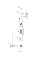
次に、本実施形態の画像符号化装置について説明する。図1は本実施形態の画像符号化装置を示すブロック図である。図1において、101は画像データを入力する端子である。 Next, the image coding apparatus of this embodiment will be described. FIG. 1 is a block diagram showing an image coding apparatus of this embodiment. In FIG. 1, 101 is a terminal for inputting image data.
102はブロック分割部であり、入力画像を複数の基本ブロックに分割し、基本ブロック単位の画像を後段に出力する。
103は、量子化マトリクスを生成し、格納する量子化マトリクス保持部である。ここで、量子化マトリクスとは、周波数成分に応じて、直交変換係数に対する量子化処理を重み付けするためのものである。後述する量子化処理における、各直交変換係数のための量子化ステップは、一例として、基準となるパラメータ値(量子化パラメータ)に基づくスケール値(量子化スケール)に、量子化マトリクスにおける各要素の値を乗算することで重み付けされる。
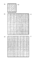
量子化マトリクス保持部110によって格納される量子化マトリクスの生成方法については特に限定しない。例えば、ユーザが量子化マトリクスを示す情報を入力してもよいし、入力画像の特性から画像符号化装置が算出してもよい。また、初期値として予め指定されたものを使用してもよい。本実施形態では、図8(a)に示される8×8のベース量子化マトリクスに加え、ベース量子化マトリクスを拡大して生成された、図8(b)、(c)に示される2種類の32×32の二次元の量子化マトリクスが生成され、格納されるものとする。図8(b)の量子化マトリクスは、図8(a)の8×8のベース量子化マトリクスの各要素を、垂直・水平方向に4回繰り返すことで4倍に拡大した32×32の量子化マトリクスである。一方、図8(c)の量子化マトリクスは、図8(a)のベース量子化マトリクスの左上4×4部分の各要素を、垂直・水平方向に8回繰り返すことで拡大した32×32の量子化マトリクスである。
The method of generating the quantization matrix stored by the quantization
以上のように、ベース量子化マトリクスは、8×8画素のサブブロックにおける量子化だけではなく、ベース量子化マトリクスよりも大きなサイズの量子化マトリクスを作成するためにも使用される量子化マトリクスである。なお、ベース量子化マトリクスのサイズは8×8であるものとするが、このサイズに限られない。また、サブブロックのサイズに応じて別のベース量子化マトリクスを用いてもよい。例えば、8×8、16×16、32×32の3種類のサブブロックが用いられる場合、それぞれに対応する3種類のベース量子化マトリクスを用いることもできる。 As described above, the base quantization matrix is a quantization matrix used not only for quantization in a subblock of 8 × 8 pixels but also for creating a quantization matrix having a size larger than that of the base quantization matrix. is there. The size of the base quantization matrix is assumed to be 8 × 8, but is not limited to this size. Further, another base quantization matrix may be used depending on the size of the subblock. For example, when three types of subblocks of 8 × 8, 16 × 16, and 32 × 32 are used, three types of base quantization matrices corresponding to each can be used.
104は予測部であり、基本ブロック単位の画像データに対し、サブブロック分割を決定する。つまり、基本ブロックをサブブロックへと分割するか否かを決定し、分割するとすればどのように分割するか決定する。サブブロックへ分割しない場合、サブブロックは基本ブロックと同じサイズとなる。サブブロックは正方形でもよいし、正方形以外の長方形であってもよい。
そして、予測部104は、サブブロック単位でフレーム内予測であるイントラ予測や、フレーム間予測であるインター予測などを行い、予測画像データを生成する。
Then, the
例えば、予測部104は、1つのサブブロックに対して行う予測方法を、イントラ予測及びインター予測の中から選択し、選択した予測を行って、当該サブブロックのための予測画像データを生成する。ただし、用いられる予測方法はこれらに限定されず、イントラ予測とインター予測とを組み合わせた予測などを用いてもよい。
For example, the
さらに、予測部104は、入力された画像データと前記予測画像データから予測誤差を算出し、出力する。例えば、予測部104は、サブブロックの各画素値と、当該サブブロックに対する予測によって生成された予測画像データの各画素値との差分を算出し、それを予測誤差として算出する。
Further, the
また、予測部104は、予測に必要な情報、例えばサブブロックの分割状態を示す情報、当該サブブロックの予測方法を示す予測モードや、動きベクトル等の情報も予測誤差と併せて出力する。以下ではこの予測に必要な情報を予測情報と総称する。
Further, the
105は変換・量子化部である。変換・量子化部105は、予測部104によって算出された予測誤差をサブブロック単位で直交変換して、予測誤差の各周波数成分を表す直交変換係数を獲得する。そして、変換・量子化部105は、さらに量子化マトリクス保持部103に格納されている量子化マトリクスと、量子化パラメータとを用いて量子化を行い、量子化された直交変換係数である量子化係数を獲得する。なお、直交変換を行う機能と、量子化を行う機能とは別々の構成にしてもよい。
106は逆量子化・逆変換部である。逆量子化・逆変換部106は、変換・量子化部105から出力された量子化係数を量子化マトリクス保持部103に格納されている量子化マトリクスと、量子化パラメータとを用いて逆量子化して直交変換係数を再生する。そして、逆量子化・逆変換部106は、さらに逆直交変換して予測誤差を再生する。このように、量子化マトリクスと量子化パラメータとを用いて、直交変換係数を再生(導出)する処理を逆量子化と称するものとする。なお、逆量子化を行う機能と、逆量子化を行う機能とは別々の構成にしてもよい。また、画像復号装置が量子化パラメータを導出するための情報も符号化部110によってビットストリームに符号化される。
Reference numeral 106 denotes an inverse quantization / inverse conversion unit. The inverse quantization / inverse conversion unit 106 dequantizes the quantization coefficient output from the conversion /
108は、再生された画像データを格納しておくフレームメモリである。
107は、画像再生部である。予測部104から出力された予測情報に基づいて、フレームメモリ108を適宜参照して予測画像データを生成し、これと入力された予測誤差から再生画像データを生成し、出力する。
109は、インループフィルタ部である。再生画像に対し、デブロッキングフィルタやサンプルアダプティブオフセットなどのインループフィルタ処理を行い、フィルタ処理された画像を出力する。
110は、符号化部である。変換・量子化部105から出力された量子化係数および予測部104から出力された予測情報を符号化して、符号データを生成し出力する。
113は、量子化マトリクス符号化部である。量子化マトリクス保持部103から出力されたベース量子化マトリクスを符号化して、画像復号装置がベース量子化マトリクスを導出するための量子化マトリクス符号データを生成し出力する。
111は、統合符号化部である。量子化マトリクス符号化部113からの出力である量子化マトリクス符号データを用いて、ヘッダ符号データを生成する。さらに符号化部110から出力された符号データと合わせて、ビットストリームを形成して出力する。
112は、端子であり、統合符号化部111で生成されたビットストリームを外部に出力する。
上記画像符号化装置における画像の符号化動作を以下に説明する。本実施形態では動画像データをフレーム単位に入力する構成とする。さらに本実施形態では説明のため、ブロック分割部101においては64×64画素の基本ブロックに分割するものとして説明するが、これに限定されない。例えば、128×128画素のブロックを基本ブロックとしてもよいし、32×32画素のブロックを基本ブロックとしてもよい。
The image coding operation in the image coding apparatus will be described below. In this embodiment, moving image data is input in frame units. Further, in the present embodiment, for the sake of explanation, the
画像符号化装置は、画像の符号化に先立ち、量子化マトリクスの生成および符号化を行う。なお、以下の説明において、一例として、量子化マトリクス800や各ブロックにおける水平方向をx座標、垂直方向をy座標とし、それぞれ、右方向を正、下方向を正とする。また、量子化マトリクス800における左上端の要素の座標を(0,0)とする。つまり、8×8のベース量子化マトリクスの右下端の要素の座標は、(7,7)となる。32×32の量子化マトリクスの右下端の要素の座標は(31,31)となる。
The image coding apparatus generates and encodes a quantization matrix prior to coding the image. In the following description, as an example, the horizontal direction in the
最初に、量子化マトリクス保持部103は量子化マトリクスを生成する。サブブロックのサイズや量子化される直交変換係数のサイズ、予測方法の種類に応じて、量子化マトリクスが生成される。本実施形態では、まず図8(a)に示された後述の量子化マトリクスの生成に用いられる8×8のベース量子化マトリクスが生成される。次に、このベース量子化マトリクスを拡大し、図8(b)および図8(c)に示される2種類の32×32の量子化マトリクスを生成する。図8(b)の量子化マトリクスは、図8(a)の8×8のベース量子化マトリクスの各要素を、垂直・水平方向に4回繰り返すことで4倍に拡大した32×32の量子化マトリクスである。
First, the quantization
つまり、図8(b)に示す例では、32×32の量子化マトリクスにおけるx座標が0〜3及びy座標が0〜3の範囲内の各要素には、ベース量子化マトリクスの左上端の要素の値である1が割り当てられることとなる。また、32×32の量子化マトリクスにおけるx座標が28〜31及びy座標が28〜31の範囲内の各要素には、ベース量子化マトリクスの右下端の要素の値である15が割り当てられることとなる。図8(b)の例では、ベース量子化マトリクスにおける各要素の値の全てが、32×32の量子化マトリクスの各要素の内のいずれかに割り当てられている。 That is, in the example shown in FIG. 8B, each element in the range of 0 to 3 for the x coordinate and 0 to 3 for the y coordinate in the 32 × 32 quantization matrix is at the upper left end of the base quantization matrix. The element value of 1 will be assigned. Further, 15 which is the value of the lower right element of the base quantization matrix is assigned to each element in the range of the x-coordinate of 28 to 31 and the y-coordinate of 28 to 31 in the 32 × 32 quantization matrix. It becomes. In the example of FIG. 8B, all the values of each element in the base quantization matrix are assigned to any of the elements of the 32 × 32 quantization matrix.
一方、図8(c)の量子化マトリクスは、図8(a)のベース量子化マトリクスの左上4×4部分の各要素を、垂直・水平方向に8回繰り返すことで拡大した32×32の量子化マトリクスである。 On the other hand, the quantization matrix of FIG. 8 (c) is a 32 × 32 enlarged by repeating each element of the upper left 4 × 4 portion of the base quantization matrix of FIG. 8 (a) eight times in the vertical and horizontal directions. It is a quantization matrix.
つまり、図8(c)に示す例では、32×32の量子化マトリクスにおけるx座標が0〜7及びy座標が0〜7の範囲内の各要素には、ベース量子化マトリクスの左上4×4部分の左上端の要素の値である1が割り当てられることとなる。また、32×32の量子化マトリクスにおけるx座標が24〜31及びy座標が24〜31の範囲内の各要素には、ベース量子化マトリクスの左上4×4部分の右下端の要素の値である7が割り当てられることとなる。図8(c)の例では、ベース量子化マトリクスにおける各要素の値の左上4×4部分(x座標が0〜3及びy座標が0〜3の範囲)に対応する要素の値だけが、32×32の量子化マトリクスの各要素に割り当てられている。
That is, in the example shown in FIG. 8C, each element in the range of 0 to 7 for the x-coordinate and 0 to 7 for the y-coordinate in the 32 × 32 quantization matrix has the upper left 4 × of the base quantization matrix. 1 which is the value of the element at the upper left end of the four parts is assigned. Further, for each element in the range of the x coordinate of 24 to 31 and the y coordinate of 24 to 31 in the 32 × 32 quantization matrix, the value of the lower right element of the upper left 4 × 4 portion of the base quantization matrix is used. A certain 7 will be assigned. In the example of FIG. 8C, only the element values corresponding to the upper left 4 × 4 portion (the range of
ただし、生成される量子化マトリクスはこれに限定されず、量子化される直交変換係数のサイズが32×32以外にも存在する場合は、16×16や8×8、4×4など、量子化される直交変換係数のサイズに対応した量子化マトリクスが生成されてもよい。ベース量子化マトリクスや量子化マトリクスを構成する各要素の決定方法は特に限定されない。例えば、所定の初期値を用いてもよいし、個別に設定してもよい。また、画像の特性に応じて生成されても構わない。 However, the generated quantization matrix is not limited to this, and if the size of the quantized orthogonal conversion coefficient exists other than 32 × 32, the quantum such as 16 × 16 or 8 × 8, 4 × 4 is obtained. A quantization matrix corresponding to the size of the orthogonal conversion coefficient to be converted may be generated. The method for determining the base quantization matrix and each element constituting the quantization matrix is not particularly limited. For example, a predetermined initial value may be used, or may be set individually. Further, it may be generated according to the characteristics of the image.
量子化マトリクス保持部103には、このようにして生成されたベース量子化マトリクスや量子化マトリクスが保持される。図8(b)は後述の32×32のサブブロック、図8(c)は64×64のサブブロックに対応する直交変換係数の量子化に用いられる量子化マトリクスの一例である。太枠の800は、量子化マトリクスを表している。説明を簡易にするため、それぞれ32×32の1024画素分の構成とし、太枠内の各正方形は量子化マトリクスを構成している各要素を表しているものとする。本実施形態では、図8(b)、(c)に示された三種の量子化マトリクスが二次元の形状で保持されているものとするが、量子化マトリクス内の各要素はもちろんこれに限定されない。また、量子化される直交変換係数のサイズによって、あるいは符号化対象が輝度ブロックか色差ブロックかによって、同じ予測方法に対して複数の量子化マトリクスを保持することも可能である。一般的に、量子化マトリクスは人間の視覚特性に応じた量子化処理を実現するため、図8(b)、(c)に示すように量子化マトリクスの左上部分に相当する低周波部分の要素は小さく、右下部分に相当する高周波部分の要素は大きくなっている。
The quantization
量子化マトリクス符号化部113は、二次元形状で格納されているベース量子化マトリクスの各要素を量子化マトリクス保持部106から順に読み出し、各要素を走査して差分を計算し、その各差分を一次元の行列に配置する。本実施形態では、図8(a)に示されたベース量子化マトリクスは図9に示された走査方法を用い、要素ごとに走査順に直前の要素との差分を計算するものとする。例えば図8(a)で示された8×8のベース量子化マトリクスは図9で示された走査方法によって走査されるが、左上に位置する最初の要素1の次はそのすぐ下に位置する要素2が走査され、差分である+1が計算される。また、量子化マトリクスの最初の要素(本実施形態では1)の符号化には、所定の初期値(例えば8)との差分を計算するものとするが、もちろんこれに限定されず、任意の値との差分や、最初の要素の値そのものを用いてもよい。
The quantization
このようにして、本実施形態では、図8(a)のベース量子化マトリクスは、図9の走査方法を用い、図10に示される差分行列が生成される。量子化マトリクス符号化部113はさらに前記差分行列を符号化して量子化マトリクス符号データを生成する。本実施形態では図11(a)に示される符号化テーブルを用いて符号化するものとするが、符号化テーブルはこれに限定されず、例えば図11(b)に示される符号化テーブルを用いてもよい。このようにして生成された量子化マトリクス符号データは後段の統合符号化部111に出力される。
In this way, in the present embodiment, the base quantization matrix of FIG. 8A uses the scanning method of FIG. 9 to generate the difference matrix shown in FIG. The quantization
図1に戻り、統合符号化部111では画像データの符号化に必要なヘッダ情報を符号化し、量子化マトリクスの符号データを統合する。
Returning to FIG. 1, the
続いて、画像データの符号化が行われる。端子101から入力された1フレーム分の画像データはブロック分割部102に入力される。
Subsequently, the image data is encoded. The image data for one frame input from the terminal 101 is input to the
ブロック分割部102では、入力された画像データを複数の基本ブロックに分割し、基本ブロック単位の画像を予測部104に出力する。本実施形態では64×64画素の基本ブロック単位の画像を出力するものとする。
The
予測部104では、ブロック分割部102から入力された基本ブロック単位の画像データに対し予測処理を実行する。具体的には、基本ブロックをさらに細かいサブブロックに分割するサブブロック分割を決定し、さらにサブブロック単位でイントラ予測やインター予測などの予測モードを決定する。
The
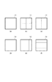
図7にサブブロック分割方法の一例を示す。太枠の700は基本ブロックを表しており、説明を簡易にするため、64×64画素の構成とし、太枠内の各四角形はサブブロックを表すものとする。図7(b)は四分木の正方形サブブロック分割の一例を表しており、648×64画素の基本ブロックは32×32画素のサブブロックに分割されている。一方、図7(c)〜(f)は長方形サブブロック分割の一例を表しており、図7(c)では基本ブロックは32×64画素の縦長、図7(d)では64×32画素の横長の長方形のサブブロックに分割されている。また、図7(e)、(f)では、1:2:1の比で長方形サブブロックに分割されている。このように正方形だけではなく、正方形以外の長方形のサブブロックも用いて符号化処理を行っている。また、基本ブロックを更に複数の正方形のブロックに分割し、その分割した正方形のブロックを基準としてサブブロック分割を行ってもよい。言い換えると、基本ブロックのサイズは64×64画素に限定されず、また、複数のサイズの基本ブロックを用いてもよい。 FIG. 7 shows an example of the sub-block division method. The 700 in the thick frame represents a basic block, and for the sake of simplicity, a 64 × 64 pixel configuration is used, and each quadrangle in the thick frame represents a subblock. FIG. 7B shows an example of quadtree square subblock division, in which a 648 × 64 pixel basic block is divided into 32 × 32 pixel subblocks. On the other hand, FIGS. 7 (c) to 7 (f) show an example of rectangular sub-block division. In FIG. 7 (c), the basic block is vertically long with 32 × 64 pixels, and in FIG. 7 (d), it is 64 × 32 pixels. It is divided into horizontally long rectangular sub-blocks. Further, in FIGS. 7 (e) and 7 (f), it is divided into rectangular subblocks at a ratio of 1: 2: 1. In this way, not only squares but also rectangular subblocks other than squares are used for encoding processing. Further, the basic block may be further divided into a plurality of square blocks, and sub-block division may be performed based on the divided square blocks. In other words, the size of the basic block is not limited to 64 × 64 pixels, and basic blocks of a plurality of sizes may be used.
また、本実施形態では、64×64画素の基本ブロックを分割しない図7(a)、および、図7(b)のような四分木分割のみが用いられるものとするが、サブブロック分割方法はこれに限定されない。図7(e)、(f)のような三分木分割または図7(c)や図7(d)のような二分木分割を用いても構わない。図7(a)や図7(b)以外のサブブロック分割も用いられる場合には、量子化マトリクス保持部103にて使用されるサブブロックに対応する量子化マトリクスが生成される。また、生成された量子化マトリクスに対応する新たなベース量子化マトリクスも生成される場合は量子化マトリクス符号化部113にて新たなベース量子化マトリクスも符号化されることとなる。
Further, in the present embodiment, only the quadtree division as shown in FIGS. 7 (a) and 7 (b) in which the basic block of 64 × 64 pixels is not divided is used, but the sub-block division method Is not limited to this. A ternary tree division as shown in FIGS. 7 (e) and 7 (f) or a binary tree division as shown in FIGS. 7 (c) and 7 (d) may be used. When the sub-block division other than those in FIGS. 7 (a) and 7 (b) is also used, the quantization matrix corresponding to the sub-block used in the quantization
また、本実施形態で用いられる予測部194による予測方法について、更に詳細に説明する。本実施形態では、一例として、イントラ予測、インター予測の2種類の予測方法が用いられるものとする。イントラ予測は符号化対象ブロックの空間的に周辺に位置する符号化済画素を用いて符号化対象ブロックの予測画素を生成し、水平予測や垂直予測、DC予測などのイントラ予測方法の内、使用したイントラ予測方法を示すイントラ予測モードの情報も生成する。インター予測は符号化対象ブロックとは時間的に異なるフレームの符号化済画素を用いて符号化対象ブロックの予測画素を生成し、参照するフレームや動きベクトルなどを示す動き情報も生成する。なお、前述のように、予測部194は、イントラ予測とインター予測とを組み合わせた予測方法を用いてもよい。 Moreover, the prediction method by the prediction unit 194 used in this embodiment will be described in more detail. In this embodiment, as an example, two types of prediction methods, intra prediction and inter prediction, are used. Intra-prediction uses coded pixels located in the spatial periphery of the block to be encoded to generate prediction pixels of the block to be encoded, and is used among intra-prediction methods such as horizontal prediction, vertical prediction, and DC prediction. It also generates information on the intra-prediction mode that indicates the intra-prediction method. In the inter-prediction, the predicted pixels of the coded target block are generated using the encoded pixels of the frame which is different in time from the coded target block, and the motion information indicating the frame to be referred to, the motion vector, and the like is also generated. As described above, the prediction unit 194 may use a prediction method that combines intra-prediction and inter-prediction.
決定した予測モードおよび符号化済の画素から予測画像データを生成し、さらに入力された画像データと前記予測画像データから予測誤差が生成され、変換・量子化部105に出力される。また、サブブロック分割や予測モードなどの情報は予測情報として、符号化部110、画像再生部107に出力される。
Predicted image data is generated from the determined prediction mode and encoded pixels, and a prediction error is generated from the input image data and the predicted image data, and is output to the conversion /
変換・量子化部105では、入力された予測誤差に直交変換・量子化を行い、量子化係数を生成する。まずはサブブロックのサイズに対応した直交変換処理が施されて直交変換係数が生成され、次に直交変換係数を予測モードに応じて量子化マトリクス保持部103に格納されている量子化マトリクスを用いて量子化し、量子化係数を生成する。より具体的な直交変換・量子化処理について、以下で説明する。
The conversion /
図7(b)で示された32×32のサブブロック分割が選択された場合には、32×32の予測誤差に対し、32×32の直交変換行列を用いた直交変換を施し、32×32の直交変換係数を生成する。具体的には、離散コサイン変換(DCT)に代表される32×32の直交変換行列と32×32の予測誤差の乗算を行い32×32の行列状の中間係数を算出する。この32×32の行列状の中間係数に対し、さらに、前述の32×32の直交変換行列の転置行列との乗算を行い、32×32の直交変換係数を生成する。こうして生成された32×32の直交変換係数に対し、図8(b)で示された32×32の量子化マトリクスと、量子化パラメータとを用いて量子化し、32×32の量子化係数を生成する。64×64の基本ブロックの中には32×32のサブブロックが4つ存在しているため、上述の処理を4回繰り返す。 When the 32 × 32 subblock division shown in FIG. 7 (b) is selected, the prediction error of 32 × 32 is subjected to orthogonal transformation using an orthogonal transformation matrix of 32 × 32, and 32 × 32. Generate 32 orthogonal transformation coefficients. Specifically, the 32 × 32 orthogonal transform matrix represented by the discrete cosine transform (DCT) is multiplied by the 32 × 32 prediction error to calculate the intermediate coefficient of the 32 × 32 matrix. The 32 × 32 matrix-like intermediate coefficient is further multiplied by the transposed matrix of the 32 × 32 orthogonal conversion matrix described above to generate a 32 × 32 orthogonal conversion coefficient. The 32 × 32 orthogonal conversion coefficient thus generated is quantized using the 32 × 32 quantization matrix and the quantization parameters shown in FIG. 8 (b), and the 32 × 32 quantization coefficient is obtained. Generate. Since there are four 32 × 32 subblocks in the 64 × 64 basic block, the above process is repeated four times.
一方、図7(a)で示す64×64の分割状態(分割無し)が選択された場合には、64×64の予測誤差に対し、64×64の直交変換行列における奇数番目の行(以下、奇数行と称する)を間引いて生成された32×64の直交変換行列が用いられる。つまり、この奇数行を間引いて生成された32×64の直交変換行列を用いた直交変換を施すことによって、32×32の直交変換係数を生成する。 On the other hand, when the 64 × 64 division state (no division) shown in FIG. 7A is selected, the odd-numbered rows in the 64 × 64 orthogonal transformation matrix with respect to the prediction error of 64 × 64 (hereinafter). , Called odd rows), a 32 × 64 orthogonal transformation matrix generated by thinning out is used. That is, a 32 × 32 orthogonal transformation coefficient is generated by performing an orthogonal transformation using the 32 × 64 orthogonal transformation matrix generated by thinning out the odd-numbered rows.
具体的には、まず64×64の直交変換行列から奇数行を間引いて64×32の直交変換行列を生成する。そしてこの64×32の直交変換行列と64×64の予測誤差の乗算を行い、64×32の行列状の中間係数を生成する。この64×32の行列状の中間係数に対し、前述の64×32の直交変換行列を転置させた32×64の転置行列との乗算を行い、32×32の直交変換係数を生成する。そして、変換・量子化部105は、生成した32×32の直交変換係数を64×64の直交変換係数の左上部分(x座標が0〜31及びy座標が0〜31の範囲)の係数とし、その他を0とすることで、ゼロアウトを実行する。
Specifically, first, an odd number of rows is thinned out from the 64 × 64 orthogonal transformation matrix to generate a 64 × 32 orthogonal transformation matrix. Then, the 64 × 32 orthogonal transformation matrix is multiplied by the 64 × 64 prediction error to generate a 64 × 32 matrix intermediate coefficient. The 64 × 32 matrix-like intermediate coefficient is multiplied by the 32 × 64 transposed matrix obtained by transposing the 64 × 32 orthogonal transformation matrix described above to generate a 32 × 32 orthogonal transformation coefficient. Then, the conversion /
本実施形態では、このように、64×64の予測誤差に対して、64×32の直交変換行列と、この64×32の直交変換行列を転置させた32×64の転置行列とを用いて直交変換を行う。このように32×32の直交変換係数を生成することでゼロアウトを実行する。これにより、64×64の直交変換を行って生成された64×64の直交変換係数の一部を、その値が0でない場合であっても強制的に0とする手法よりも少ない演算量で32×32の直交変換係数を生成できる。つまり、64×64の直交変換行列を用いて直交変換を行って、その結果、ゼロアウトの対象となる直交変換係数が、0であるか否かに関わらずに0と見做して符号化する場合と比較して、直交変換における演算量を低減することができる。なお、64×64の予測誤差から直交変換係数によって32×32の直交変換係数を算出する方法を用いれば演算量を低減させることができるが、ゼロアウトする方法はこの方法に限られず種々の方法を用いることもできる。 In this embodiment, the 64 × 32 orthogonal transformation matrix and the 32 × 64 transposed matrix obtained by transposing the 64 × 32 orthogonal transformation matrix are used with respect to the 64 × 64 prediction error. Perform orthogonal transformation. Zero-out is executed by generating the orthogonal conversion coefficient of 32 × 32 in this way. As a result, a part of the 64 × 64 orthogonal conversion coefficient generated by performing the 64 × 64 orthogonal conversion is forcibly set to 0 even if the value is not 0, with a smaller amount of calculation. A 32 × 32 orthogonal conversion coefficient can be generated. That is, the orthogonal transformation is performed using the orthogonal transformation matrix of 64 × 64, and as a result, the orthogonal transformation coefficient to be zeroed out is regarded as 0 and encoded regardless of whether or not it is 0. Compared with the case, the amount of calculation in the orthogonal transformation can be reduced. The amount of calculation can be reduced by using a method of calculating the orthogonal conversion coefficient of 32 × 32 from the prediction error of 64 × 64 by the orthogonal conversion coefficient, but the zero-out method is not limited to this method, and various methods can be used. It can also be used.
また、ゼロアウトを実行する場合、ゼロアウトの対象となった範囲の直交変換係数が0であることを示す情報を符号化してもよいし、単に、ゼロアウトが行われたことを示す情報(フラグ等)を符号化してもよい。画像復号装置はそれらの情報を復号することで、ゼロアウトの対象を0と見做して、各ブロックを復号することができる。 Further, when executing zero-out, information indicating that the orthogonal conversion coefficient of the range targeted for zero-out is 0 may be encoded, or simply information indicating that zero-out has been performed (flag, etc.). May be encoded. By decoding such information, the image decoding device can regard each block as 0 as the target of zero out and decode each block.
次に、このように生成された32×32の直交変換係数に対し、変換・量子化部105は、図8(c)で示された32×32の量子化マトリクスと、量子化パラメータとを用いて量子化し、32×32の量子化係数を生成する。
Next, with respect to the 32 × 32 orthogonal conversion coefficient generated in this way, the conversion /
本実施形態では、32×32のサブブロックに対応した32×32の直交変換係数には図8(b)の量子化マトリクスが用いられ、64×64のサブブロックに対応した32×32の直交変換係数には図8(c)の量子化マトリクスが用いられるものとする。つまり、ゼロアウトが実行されていない32×32の直交変換係数には図8(b)を用い、ゼロアウトが実行された64×64のサブブロックに対応した32×32の直交変換係数には図8(c)の量子化マトリクスが用いられるものとする。ただし、使用される量子化マトリクスはこれに限定されない。生成された量子化係数は符号化部110および逆量子化・逆変換部106に出力される。
In the present embodiment, the quantization matrix of FIG. 8B is used for the 32 × 32 orthogonal conversion coefficient corresponding to the 32 × 32 subblock, and the 32 × 32 orthogonality corresponding to the 64 × 64 subblock. It is assumed that the quantization matrix of FIG. 8C is used for the conversion coefficient. That is, FIG. 8B is used for the 32 × 32 orthogonal conversion coefficient in which zero out is not executed, and FIG. 8 is used for the 32 × 32 orthogonal conversion coefficient corresponding to the 64 × 64 subblock in which zero out is executed. It is assumed that the quantization matrix of (c) is used. However, the quantization matrix used is not limited to this. The generated quantization coefficient is output to the
逆量子化・逆変換部106では、入力された量子化係数を量子化マトリクス保持部103に格納されている量子化マトリクスと、量子化パラメータとを用いて逆量子化して直交変換係数を再生する。そして、逆量子化・逆変換部106は、さらに再生された直交変換係数を逆直交変換して予測誤差を再生する。逆量子化処理には、変換・量子化部105同様、符号化対象のサブブロックの大きさに対応した量子化マトリクスが用いられる。より具体的な逆量子化・逆変換部106による逆量子化・逆直交変換処理について、以下に説明する。
In the inverse quantization / inverse conversion unit 106, the input quantization coefficient is inversely quantized using the quantization matrix stored in the quantization
図7(b)の32×32のサブブロック分割が選択されている場合、逆量子化・逆変換部106は、変換・量子化部105で生成された32×32の量子化係数は図8(b)の量子化マトリクスを用いて逆量子化し、32×32の直交変換係数を再生する。そして、逆量子化・逆変換部106は、前述の32×32の転置行列と32×32の直交変換との乗算を行い、32×32の行列状の中間係数を算出する。そして、逆量子化・逆変換部106は、この32×32の行列状の中間係数と前述の32×32の直交変換行列との乗算を行い32×32の予測誤差を再生する。各32×32サブブロックに対して同様の処理を行う。一方、図7(a)のように、分割無しが選択されている場合、変換・量子化部105で生成された32×32の量子化係数は図8(c)の量子化マトリクスを用いて逆量子化され、32×32の直交変換係数を再生する。そして、前述の32×64の転置行列と32×32の直交変換との乗算を行い、32×64の行列状の中間係数を算出する。この32×64の行列状の中間係数と前述の64×32の直交変換行列との乗算を行い、64×64の予測誤差を再生する。本実施形態では、サブブロックの大きさに応じて、変換・量子化部105で用いられた量子化マトリクスと同一のものが用いられ逆量子化処理が実行される。再生された予測誤差は画像再生部107に出力される。
When the 32 × 32 sub-block division of FIG. 7B is selected, the inverse quantization / inverse conversion unit 106 has a 32 × 32 quantization coefficient generated by the conversion /
画像再生部107では、予測部104から入力される予測情報に基づいて、フレームメモリ108に記憶された予測画像の再生に必要なデータを適宜参照して、予測画像を再生する。そして再生された予測画像と逆量子化・逆変換部106から入力された再生された予測誤差から画像データを再生し、フレームメモリ108に入力し、格納する。
The
インループフィルタ部109では、フレームメモリ108から再生画像を読み出し、デブロッキングフィルタなどのインループフィルタ処理を行う。そして、フィルタ処理された画像を再びフレームメモリ108に入力し、再格納する。
The in-
符号化部110では、ブロック単位で、変換・量子化部105で生成された量子化係数、予測部104から入力された予測情報をエントロピー符号化し、符号データを生成する。エントロピー符号化の方法は特に指定しないが、ゴロム符号化、算術符号化、ハフマン符号化などを用いることができる。生成された符号データは統合符号化部111に出力される。
The
統合符号化部111では、前述のヘッダの符号データとともに符号化部110から入力された符号データなどを多重化してビットストリームを形成する。最終的には、ビットストリームは端子112から外部に出力される。
In the
図6(a)は実施形態1で出力されるビットストリームの一例である。シーケンスヘッダにはベース量子化マトリクスの符号データが含まれ、各要素の符号化結果で構成されている。ただし、ベース量子化マトリクスの符号データ等が符号化される位置はこれに限定されず、ピクチャヘッダ部やその他のヘッダ部に符号化される構成をとってももちろん構わない。また、1つのシーケンスの中で量子化マトリクスの変更を行う場合、ベース量子化マトリクスを新たに符号化することで更新することも可能である。この際、全ての量子化マトリクスを書き換えてもよいし、書き換える量子化マトリクスに対応する量子化マトリクスのサブブロックの大きさを指定することでその一部を変更するようにすることも可能である。 FIG. 6A is an example of the bit stream output in the first embodiment. The sequence header contains the code data of the base quantization matrix and is composed of the coded results of each element. However, the position where the code data of the base quantization matrix is encoded is not limited to this, and of course, a configuration in which the code data is encoded in the picture header portion or other header portions may be adopted. Further, when the quantization matrix is changed in one sequence, it can be updated by newly encoding the base quantization matrix. At this time, all the quantization matrices may be rewritten, or a part of the quantization matrix may be changed by specifying the size of the subblock of the quantization matrix corresponding to the rewritten quantization matrix. ..
図3は、実施形態1に係る画像符号化装置における符号化処理を示すフローチャートである。 FIG. 3 is a flowchart showing a coding process in the image coding apparatus according to the first embodiment.
まず、画像の符号化に先立ち、ステップS301にて、量子化マトリクス保持部103は二次元の量子化マトリクスを生成し、保持する。本実施形態では、図8(a)に示されたベース量子化マトリクスおよびベース量子化マトリクスから生成された図8(b)、(c)に示された量子化マトリクスを生成し、保持するものとする。
First, prior to image coding, in step S301, the quantization
ステップS302にて、量子化マトリクス符号化部113は、ステップS301にて量子化マトリクスの生成に用いられたベース量子化マトリクスを走査して、走査順で前後する各要素間の差分を算出し、一次元の差分行列を生成する。本実施形態では、図8(a)に示されたベース量子化マトリクスは図9の走査方法を用い、図10に示される差分行列が生成されるものとする。量子化マトリクス符号化部113はさらに生成された差分行列を符号化し、量子化マトリクス符号データを生成する。
In step S302, the quantization
ステップS303にて、統合符号化部111は、生成された量子化マトリクス符号データとともに、画像データの符号化に必要なヘッダ情報を符号化し、出力する。
In step S303, the
ステップS304にて、ブロック分割部102はフレーム単位の入力画像を64×64画素の基本ブロック単位に分割する。
In step S304, the
ステップS305にて、予測部104はステップS304にて生成された基本ブロック単位の画像データに対して、前述した予測方法を用いて予測処理を実行し、サブブロック分割情報や予測モードなどの予測情報および予測画像データを生成する。本実施形態では、図7(b)に示された32×32画素のサブブロック分割および図7(a)に示される64×64画素のサブブロックの2種類のサブブロックサイズが用いられる。さらに入力された画像データと前記予測画像データから予測誤差を算出する。
In step S305, the
ステップS306にて、変換・量子化部105はステップS305で算出された予測誤差を直交変換して直交変換係数を生成する。そして、変換・量子化部105は、さらにステップS301にて生成・保持された量子化マトリクスと、量子化パラメータとを用いて量子化を行い、量子化係数を生成する。具体的には、図7(b)の32×32画素のサブブロックの予測誤差には32×32の直交変換行列およびその転置行列を用いた乗算を行い、32×32の直交変換係数を生成する。一方、図7(a)の64×64画素のサブブロックの予測誤差には64×32の直交変換行列およびその転置行列を用いた乗算を行い、32×32の直交変換係数を生成する。本実施形態では、図7(b)の32×32のサブブロックの直交変換係数には図8(b)、図7(a)の64×64のサブブロックに対応する直交変換係数には図8(c)の量子化マトリクスを用い32×32の直交変換係数を量子化するものとする。
In step S306, the conversion /
ステップS307にて、逆量子化・逆変換部106はステップS306で生成された量子化係数を、ステップS301にて生成・保持された量子化マトリクスと、量子化パラメータとを用いて逆量子化を行い、直交変換係数を再生する。さらに、直交変換係数に対して逆直交変換し、予測誤差を再生する。本ステップでは、それぞれ、ステップS306で用いられた量子化マトリクスと同一のものが用いられ、逆量子化処理が行われる。具体的には、図7(b)の32×32画素のサブブロックに対応した32×32の量子化係数に対しては、図8(b)の量子化マトリクスを用いた逆量子化処理を行い、32×32の直交変換係数を再生する。そしてこの32×32の直交変換係数を32×32の直交変換行列およびその転置行列を用いた乗算を行い、32×32画素の予測誤差を再生する。一方、図7(a)の64×64画素のサブブロックに対応した32×32の量子化係数に対しては、図8(c)の量子化マトリクスを用いた逆量子化処理を行い、32×32の直交変換係数を再生する。そしてこの32×32の直交変換係数を64×32の直交変換行列およびその転置行列を用いた乗算を行い、64×64画素の予測誤差を再生する。 In step S307, the inverse quantization / inverse conversion unit 106 dequantizes the quantization coefficient generated in step S306 by using the quantization matrix generated / held in step S301 and the quantization parameters. And reproduce the orthogonal transformation coefficient. Further, the inverse orthogonal conversion is performed with respect to the orthogonal conversion coefficient, and the prediction error is reproduced. In this step, the same quantization matrix used in step S306 is used, and the inverse quantization process is performed. Specifically, for the 32 × 32 quantization coefficient corresponding to the 32 × 32 pixel subblock of FIG. 7 (b), the inverse quantization process using the quantization matrix of FIG. 8 (b) is performed. This is performed, and a 32 × 32 orthogonal conversion coefficient is reproduced. Then, the 32 × 32 orthogonal conversion coefficient is multiplied by using the 32 × 32 orthogonal transformation matrix and its transposed matrix to reproduce the prediction error of 32 × 32 pixels. On the other hand, the 32 × 32 quantization coefficient corresponding to the 64 × 64 pixel subblock of FIG. 7 (a) is subjected to inverse quantization processing using the quantization matrix of FIG. 8 (c), and 32. The orthogonal conversion coefficient of × 32 is reproduced. Then, the 32 × 32 orthogonal transformation coefficient is multiplied using the 64 × 32 orthogonal transformation matrix and its transposed matrix to reproduce the prediction error of 64 × 64 pixels.
ステップS308にて、画像再生部107はステップS305で生成された予測情報に基づいて予測画像を再生する。さらに再生された予測画像とステップS307で生成された予測誤差から画像データを再生する。
In step S308, the
ステップS309にて、符号化部110は、ステップS305で生成された予測情報およびステップS306で生成された量子化係数を符号化し、符号データを生成する。また、他の符号データも含め、ビットストリームを生成する。
In step S309, the
ステップS310にて、画像符号化装置は、フレーム内の全ての基本ブロックの符号化が終了したか否かの判定を行い、終了していればステップS311に進み、そうでなければ次の基本ブロックを対象として、ステップS304に戻る。 In step S310, the image encoding device determines whether or not the coding of all the basic blocks in the frame is completed, and if so, proceeds to step S311. If not, the next basic block Return to step S304.
ステップS311にて、インループフィルタ部109はステップS308で再生された画像データに対し、インループフィルタ処理を行い、フィルタ処理された画像を生成し、処理を終了する。
In step S311, the in-
以上の構成と動作により、演算量を減らしつつ周波数成分ごとに量子化を制御し主観画質を向上させることができる。特にステップS305において、直交変換係数の数を減らし、減少した直交変換係数に対応する量子化マトリクスを用いた量子化処理をすることで、演算量を減らしつつ周波数成分ごとに量子化を制御し主観画質を向上させることができる。さらには、直交変換係数の数を減らし低周波部分のみを量子化・符号化する場合には、図8(c)のようなベース量子化マトリクスの低周波部分のみを拡大する量子化マトリクスを用いることで、低周波部分に最適な量子化制御を実現することができる。なお、ここでいう低周波部分とは、図8(c)の例では、x座標が0〜3及びy座標が0〜3の範囲である。 With the above configuration and operation, it is possible to improve the subjective image quality by controlling the quantization for each frequency component while reducing the amount of calculation. In particular, in step S305, by reducing the number of orthogonal conversion coefficients and performing quantization processing using a quantization matrix corresponding to the reduced orthogonal conversion coefficients, the quantization is controlled for each frequency component while reducing the amount of calculation and subjective. The image quality can be improved. Furthermore, when reducing the number of orthogonal conversion coefficients and quantizing / encoding only the low-frequency portion, a quantization matrix that enlarges only the low-frequency portion of the base quantization matrix as shown in FIG. 8C is used. Therefore, the optimum quantization control can be realized in the low frequency part. The low frequency portion referred to here is in the range of 0 to 3 for the x coordinate and 0 to 3 for the y coordinate in the example of FIG. 8C.
なお、本実施形態では、符号量削減のため、図8(b)、(c)の量子化マトリクスの生成に共通して用いられる図8(a)のベース量子化マトリクスのみを符号化する構成としたが、図8(b)、(c)の量子化マトリクス自体を符号化する構成としてもよい。その場合、各量子化マトリクスの周波数成分ごとに独自の値を設定することができるため、周波数成分ごとにより細かな量子化制御を実現することができる。また、図8(b)、図8(c)のそれぞれに対し個別のベース量子化マトリクスを設定し、それぞれのベース量子化マトリクスを符号化する構成とすることも可能である。その場合、32×32の直交変換係数と64×64の直交変換係数に対し、それぞれ異なる量子化制御を実施し、より綿密な主観画質の制御を実現することもできる。さらにその場合、64×64の直交変換係数に対応する量子化マトリクスは、8×8のベース量子化マトリクスの左上の4×4部分を8倍に拡大する代わりに、8×8のベース量子化マトリクス全体を4倍に拡大してもよい。こうして64×64の直交変換係数に対しても、より細かな量子化制御を実現することができる。 In this embodiment, in order to reduce the amount of code, only the base quantization matrix of FIG. 8 (a), which is commonly used for the generation of the quantization matrix of FIGS. 8 (b) and 8 (c), is encoded. However, the quantization matrix itself of FIGS. 8 (b) and 8 (c) may be encoded. In that case, since a unique value can be set for each frequency component of each quantization matrix, finer quantization control can be realized for each frequency component. Further, it is also possible to set individual base quantization matrices for each of FIGS. 8 (b) and 8 (c) and encode each base quantization matrix. In that case, it is possible to carry out different quantization controls for the 32 × 32 orthogonal conversion coefficient and the 64 × 64 orthogonal conversion coefficient, and to realize more detailed control of the subjective image quality. Further, in that case, the quantization matrix corresponding to the orthogonal conversion coefficient of 64 × 64 expands the upper left 4 × 4 portion of the 8 × 8 base quantization matrix by 8 times, but instead performs the 8 × 8 base quantization. The entire matrix may be magnified four times. In this way, finer quantization control can be realized even for an orthogonal conversion coefficient of 64 × 64.
さらには、本実施形態では、ゼロアウトを用いた64×64のサブブロックに対する量子化マトリクスが一意に決まる構成としたが、識別子を導入することで選択可能とする構成としても構わない。例えば図6(b)は、量子化マトリクス符号化方法情報符号を新たに導入することで、ゼロアウトを用いた64×64のサブブロックに対する量子化マトリクス符号化を選択的にしたものである。例えば、量子化マトリクス符号化方法情報符号が0を示している場合には、ゼロアウトを用いた64×64画素のサブブロックに対応する直交変換係数に対し、独立した量子化マトリクスである図8(c)が用いられる。また、符号化方法情報符号が1を示している場合には、ゼロアウトを用いた64×64画素のサブブロックに対し、通常のゼロアウトされないサブブロックに対する量子化マトリクスである図8(b)が用いられる。一方、符号化方法情報符号が2を示している場合には、8×8のベース量子化マトリクスではなく、ゼロアウトを用いた64×64画素のサブブロックに対して用いられる量子化マトリクスの要素全てを符号化するといった具合である。これにより、量子化マトリクス符号量削減とゼロアウトを用いたサブブロックに対する独自の量子化制御とを選択的に実現することが可能となる。 Further, in the present embodiment, the quantization matrix for the 64 × 64 subblock using zero out is uniquely determined, but it may be configured to be selectable by introducing an identifier. For example, FIG. 6B shows the quantization matrix coding for 64 × 64 sub-blocks using zero-out selectively by newly introducing the quantization matrix coding method information code. For example, when the quantization matrix coding method information code indicates 0, it is a quantization matrix independent of the orthogonal conversion coefficient corresponding to the subblock of 64 × 64 pixels using zero out (FIG. 8). c) is used. Further, when the coding method information code indicates 1, FIG. 8 (b), which is a quantization matrix for a normal non-zero-out sub-block, is used for a 64 × 64 pixel sub-block using zero-out. Be done. On the other hand, when the coding method information code indicates 2, all the elements of the quantization matrix used for the 64 × 64 pixel subblock using zero out, not the 8 × 8 base quantization matrix. Is encoded, and so on. This makes it possible to selectively realize the reduction of the quantization matrix code amount and the original quantization control for the subblock using zero out.
また、本実施形態ではゼロアウトを用いて処理をしたサブブロックは64×64のみとしているが、ゼロアウトを用いて処理をするサブブロックはこれに限定されない。例えば、図7(c)や図7(b)に示された32×64や64×32サブブロックに対応する直交変換係数のうち、下半分や右半分の32×32の直交変換係数を強制的に0としても構わない。この場合、上半分や左半分の32×32の直交変換係数のみを量子化・符号化の対象とすることとなり、上半分や左半分の32×32の直交変換係数に対して図8(b)とは異なる量子化マトリクスを用いて量子化処理を行うこととなる。 Further, in the present embodiment, the number of subblocks processed using zero out is only 64 × 64, but the subblock processed using zero out is not limited to this. For example, of the orthogonal conversion coefficients corresponding to the 32 × 64 and 64 × 32 subblocks shown in FIGS. 7 (c) and 7 (b), the lower half and the right half of the orthogonal conversion coefficient of 32 × 32 are forced. It may be set to 0. In this case, only the 32 × 32 orthogonal conversion coefficient of the upper half or the left half is targeted for quantization / coding, and FIG. 8 (b) is applied to the 32 × 32 orthogonal conversion coefficient of the upper half or the left half. ), The quantization process will be performed using a different quantization matrix.
さらには、生成された直交変換係数のうち、画質への影響が最も大きいと考えられる左上端に位置するDC係数に対応する量子化マトリクスの値を、8×8のベースマトリクスの各要素の値とは別に設定・符号化する構成としてもよい。図12(b)および図12(c)は、図8(b)および図8(c)と比較してDC成分にあたる左上端に位置する要素の値を変更した例を示している。この場合、図8(a)のベース量子化マトリクスの情報に加えて、DC部分に位置する「2」を示す情報を別途符号化することにより、図12(b)および図12(c)に示される量子化マトリクスを設定することができる。これにより、画質への影響が最も大きい直交変換係数のDC成分に対してより細かい量子化制御を施すことができる。 Furthermore, among the generated orthogonal conversion coefficients, the value of the quantization matrix corresponding to the DC coefficient located at the upper left end, which is considered to have the greatest effect on the image quality, is the value of each element of the 8 × 8 base matrix. It may be configured to be set and encoded separately from the above. 12 (b) and 12 (c) show an example in which the value of the element located at the upper left end corresponding to the DC component is changed as compared with FIGS. 8 (b) and 8 (c). In this case, in addition to the information of the base quantization matrix of FIG. 8 (a), the information indicating “2” located in the DC portion is separately encoded to be shown in FIGS. 12 (b) and 12 (c). The indicated quantization matrix can be set. As a result, finer quantization control can be applied to the DC component of the orthogonal conversion coefficient, which has the greatest effect on image quality.
<実施形態2>
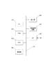
図2は、本発明の実施形態2に係る画像復号装置の構成を示すブロック図である。本実施形態では、実施形態1で生成された符号化データを復号する画像復号装置を例にして説明する。
<
FIG. 2 is a block diagram showing a configuration of an image decoding device according to a second embodiment of the present invention. In the present embodiment, an image decoding device that decodes the coded data generated in the first embodiment will be described as an example.
201は符号化されたビットストリームが入力される端子である。
202は分離復号部であり、ビットストリームから復号処理に関する情報や係数に関する符号データに分離し、またビットストリームのヘッダ部に存在する符号データを復号する。本実施形態では、量子化マトリクス符号を分離し、後段に出力する。分離復号部202は図1の統合符号化部111と逆の動作を行う。
209は量子化マトリクス復号部であり、量子化マトリクス符号をビットストリームから復号してベース量子化マトリクスを再生し、さらにベース量子化マトリクスから各量子化マトリクスを生成する処理を実行する。
203は復号部であり、分離復号部202から出力された符号データを復号し、量子化係数および予測情報を再生(導出)する。
204は逆量子化・逆変換部であり、図1の逆量子化・逆変換部106と同様に、再生された量子化マトリクスと、量子化パラメータとを用いて量子化係数に逆量子化を行って直交変換係数を獲得し、さらに逆直交変換を行って、予測誤差を再生する。なお、量子化パラメータを導出するための情報も復号部203によってビットストリームから復号される。また、逆量子化を行う機能と、逆量子化を行う機能とは別々の構成にしてもよい。
206はフレームメモリである。再生されたピクチャの画像データを格納しておく。 206 is a frame memory. Stores the image data of the reproduced picture.
205は画像再生部である。入力された予測情報に基づいてフレームメモリ206を適宜参照して予測画像データを生成する。そして、この予測画像データと逆量子化・逆変換部204で再生された予測誤差から再生画像データを生成し、出力する。
207はインループフィルタ部である。図1の109同様、再生画像に対し、デブロッキングフィルタなどのインループフィルタ処理を行い、フィルタ処理された画像を出力する。
208は端子であり、再生された画像データを外部に出力する。
上記画像復号装置における画像の復号動作を以下に説明する。本実施形態では、実施形態1で生成されたビットストリームをフレーム単位(ピクチャ単位)で入力する構成となっている。 The image decoding operation in the image decoding device will be described below. In the present embodiment, the bit stream generated in the first embodiment is input in frame units (picture units).
図2において、端子201から入力された1フレーム分のビットストリームは分離復号部202に入力される。分離復号部202では、ビットストリームから復号処理に関する情報や係数に関する符号データに分離し、ビットストリームのヘッダ部に存在する符号データを復号する。より具体的には、量子化マトリクス符号データを再生する。本実施形態では、まず、図6(a)に示されるビットストリームのシーケンスヘッダから量子化マトリクス符号データを抽出し、量子化マトリクス復号部209に出力される。本実施形態では、図8(a)に示されるベース量子化マトリクスに対応する量子化マトリクス符号データが抽出、出力される。続いて、ピクチャデータの基本ブロック単位の符号データを再生し、復号部203に出力する。
In FIG. 2, the bit stream for one frame input from the terminal 201 is input to the separation /
量子化マトリクス復号部209では、まず入力された量子化マトリクス符号データを復号し、図10に示される一次元の差分行列を再生する。本実施形態では、実施形態1同様、図11(a)に示される符号化テーブルを用いて復号するものとするが、符号化テーブルはこれに限定されず、実施形態1と同じものを用いる限りは他の符号化テーブルを用いてもよい。さらに量子化マトリクス復号部209は再生された一次元の差分行列から二次元の量子化マトリクスを再生する。ここでは実施形態1の量子化マトリクス符号化部113の動作とは逆の動作を行う。すなわち、本実施形態では、図10に示される差分行列は、図9に示される走査方法を用いて、それぞれ図8(a)に示されるベース量子化マトリクスを再生し、保持するものとする。具体的には、量子化マトリクス復号部209は、差分行列における各差分値を、前述の初期値から順次加算することによって、量子化マトリクスにおける各要素を再生する。そして、量子化マトリクス復号部209は、その再生した一次元の各要素を図9に示される走査方法に従って、順番に2次元の量子化マトリクスの各要素に対応付けることで、2次元の量子化マトリクスを再生する。
The quantization
さらに量子化マトリクス復号部209では、この再生されたベース量子化マトリクスを、第1実施形態と同様に拡大し、図8(b)および図8(c)に示される2種類の32×32の量子化マトリクスを生成する。図8(b)の量子化マトリクスは、図8(a)の8×8のベース量子化マトリクスの各要素を、垂直・水平方向に4回繰り返すことで4倍に拡大した32×32の量子化マトリクスである。
Further, in the quantization
一方、図8(c)の量子化マトリクスは、図8(a)のベース量子化マトリクスの左上4×4部分の各要素を、垂直・水平方向に8回繰り返すことで拡大した32×32の量子化マトリクスである。ただし、生成される量子化マトリクスはこれに限定されず、後段で逆量子化される量子化係数のサイズが32×32以外にも存在する場合は、16×16、8×8、4×4など逆量子化される量子化係数のサイズに対応した量子化マトリクスが生成されてもよい。生成されたこれらの量子化マトリクスは保持され、後段の逆量子化処理に用いられる。 On the other hand, the quantization matrix of FIG. 8 (c) is a 32 × 32 enlarged by repeating each element of the upper left 4 × 4 portion of the base quantization matrix of FIG. 8 (a) eight times in the vertical and horizontal directions. It is a quantization matrix. However, the generated quantization matrix is not limited to this, and if the size of the quantization coefficient to be dequantized in the subsequent stage exists other than 32 × 32, 16 × 16, 8 × 8, 4 × 4 A quantization matrix corresponding to the size of the quantization coefficient to be dequantized may be generated. These generated quantization matrices are retained and used for the subsequent inverse quantization process.
復号部203では、符号データをビットストリームから復号し、量子化係数および予測情報を再生する。復号された予測情報に基づいて復号対象のサブブロックのサイズを決定し、さらに再生された量子化係数は逆量子化・逆変換部204に出力され、再生された予測情報は画像再生部205に出力される。本実施形態では復号対象のサブブロックの大きさ、すなわち図7(a)の64×64であるか、図7(b)の32×32であるかに関わらず、各サブブロックに対して32×32の量子化係数が再生されるものとする。
The
逆量子化・逆変換部204では、入力された量子化係数に対し、量子化マトリクス復号部209で再生された量子化マトリクスと、量子化パラメータとを用いて逆量子化を行って直交変換係数を生成し、さらに逆直交変換を施して予測誤差を再生する。より具体的な逆量子化・逆直交変換処理について、以下に記す。
In the inverse quantization /
図7(b)の32×32のサブブロック分割が選択されている場合、復号部203で再生された32×3の量子化係数は図8(b)の量子化マトリクスを用いて逆量子化され、32×32の直交変換係数を再生する。そして、前述の32×32の転置行列と32×32の直交変換との乗算を行い、32×32の行列状の中間係数を算出する。この32×32の行列状の中間係数と前述の32×32の直交変換行列との乗算を行い32×32の予測誤差を再生する。各32×32サブブロックに対して同様の処理を行う。
When the 32 × 32 subblock division of FIG. 7 (b) is selected, the 32 × 3 quantization coefficient reproduced by the
一方、図7(a)のように分割無しが選択されている場合、復号部203で再生された32×32の量子化係数は図8(c)の量子化マトリクスを用いて逆量子化され、32×32の直交変換係数を再生する。そして、前述の32×64の転置行列と32×32の直交変換との乗算を行い、32×64の行列状の中間係数を算出する。この32×64の行列状の中間係数と前述の64×32の直交変換行列との乗算を行い、64×64の予測誤差を再生する。
On the other hand, when no division is selected as shown in FIG. 7A, the 32 × 32 quantization coefficient reproduced by the
再生された予測誤差は画像再生部205に出力される。本実施形態では、復号部203で再生された予測情報によって定まった復号対象のサブブロックの大きさに応じて、逆量子化処理において使用される量子化マトリクスを決定する。すなわち、図7(b)の32×32の各サブブロックには、図8(b)の量子化マトリクスが逆量子化処理に用いられ、図7(a)の64×64のサブブロックには図8(c)の量子化マトリクスが用いられる。ただし、使用される量子化マトリクスはこれに限定されず、実施形態1の変換・量子化部105および逆量子化・逆変換部106で用いられた量子化マトリクスと同一のものであればよい。
The reproduced prediction error is output to the
画像再生部205では、復号部203から入力された予測情報に基づいて、フレームメモリ206を適宜参照し、予測画像の再生に必要なデータを取得して、予測画像を再生する。本実施形態では、実施形態1の予測部104同様、イントラ予測およびインター予測の2種類の予測方法が用いられる。また、前述のようにイントラ予測とインター予測とを組み合わせた予測方法が用いられてもよい。また、実施形態1と同様に予測処理はサブブロック単位に行われる。
The
具体的な予測処理については、実施形態1の予測部104と同様であるため、説明を省略する。画像再生部205は、予測処理によって生成された予測画像と、逆量子化・逆変換部204から入力された予測誤差から画像データを再生する。具体的には、画像再生部205は、予測画像と予測誤差とを加算することによって画像データを再生する。再生された画像データは、適宜、フレームメモリ206に格納される。格納された画像データは、他のサブブロックの予測の際に、適宜、参照される。
Since the specific prediction process is the same as that of the
インループフィルタ部207では、図1のインループフィルタ部109と同様、フレームメモリ206から再生画像を読み出し、デブロッキングフィルタなどのインループフィルタ処理を行う。そして、フィルタ処理された画像は再びフレームメモリ206に入力される。
Similar to the in-
フレームメモリ206に格納された再生画像は、最終的には端子208から外部に出力される。再生画像は、例えば、外部の表示装置等に出力される。
The reproduced image stored in the
図4は、実施形態2に係る画像復号装置における画像の復号処理を示すフローチャートである。 FIG. 4 is a flowchart showing an image decoding process in the image decoding apparatus according to the second embodiment.
まず、ステップS401にて、分離復号部202はビットストリームから復号処理に関する情報や係数に関する符号データに分離して、ヘッダ部分の符号データを復号する。より具体的には、量子化マトリクス符号データを再生する。
First, in step S401, the separation /
ステップS402にて、量子化マトリクス復号部209は、まずステップS401で再生された量子化マトリクス符号データを復号し、図10で示される一次元の差分行列を再生する。次に、量子化マトリクス復号部209は再生された一次元の差分行列から二次元のベース量子化マトリクスを再生する。さらに、量子化マトリクス復号部209は、再生した二次元のベース量子化マトリクスを拡大し、量子化マトリクスを生成する。
In step S402, the quantization
すなわち、本実施形態では、量子化マトリクス復号部209は、図10に示される差分行列を、図9に示される走査方法を用いて、図8(a)に示されるベース量子化マトリクスを再生する。さらに、量子化マトリクス復号部209は再生されたベース量子化マトリクスを拡大し、図8(b)および図8(c)に示される量子化マトリクスを生成し、保持するものとする。
That is, in the present embodiment, the quantization
ステップS403にて、復号部203はステップS401で分離された符号データを復号し、量子化係数および予測情報を再生する。さらに、復号された予測情報に基づいて復号対象のサブブロックのサイズを決定する。本実施形態では復号対象のサブブロックの大きさ、すなわち図7(a)の64×64か図7(b)の32×32かに関わらず、各サブブロックに対して32×32の量子化係数が再生されるものとする。
In step S403, the
ステップS404にて、逆量子化・逆変換部204は量子化係数に対しステップS402で再生された量子化マトリクスを用いて逆量子化を行って直交変換係数を獲得し、さらに逆直交変換を行い、予測誤差を再生する。本実施形態では、ステップS403で再生された予測情報によって定まった復号対象のサブブロックの大きさに応じて、逆量子化処理において使用される量子化マトリクスを決定する。すなわち、図7(b)の32×32の各サブブロックには、図8(b)の量子化マトリクスが逆量子化処理に用いられ、図7(a)の64×64のサブブロックには図8(c)の量子化マトリクスが用いられる。ただし、使用される量子化マトリクスはこれに限定されず、実施形態1のステップS306およびステップS307で用いられた量子化マトリクスと同一のものであればよい。
In step S404, the inverse quantization /
ステップS405にて、画像再生部205はステップS403で生成された予測情報から予測画像を再生する。本実施形態では、実施形態1のステップS305同様、イントラ予測およびインター予測の2種類の予測方法が用いられる。さらに再生された予測画像とステップS404で生成された予測誤差から画像データを再生する。
In step S405, the
ステップS406にて、画像復号装置はフレーム内の全ての基本ブロックの復号が終了したか否かの判定を行い、終了していればステップS407に進み、そうでなければ次の基本ブロックを対象としてステップS403に戻る。 In step S406, the image decoding apparatus determines whether or not all the basic blocks in the frame have been decoded, and if so, proceeds to step S407, otherwise the next basic block is targeted. Return to step S403.
ステップS407にて、インループフィルタ部207はステップS405で再生された画像データに対し、インループフィルタ処理を行い、フィルタ処理された画像を生成し、処理を終了する。
In step S407, the in-
以上の構成と動作により、実施形態1で生成された、低周波の直交変換係数のみを量子化・符号化したサブブロックに対しても、量子化マトリクスを用いて周波数成分ごとに量子化を制御し主観画質を向上したビットストリームを復号することができる。また、低周波の直交変換係数のみを量子化・符号化したサブブロックには、図8(c)のようなベース量子化マトリクスの低周波部分のみを拡大した量子化マトリクスを用い、低周波部分に最適な量子化制御を施したビットストリームを復号することができる。 With the above configuration and operation, the quantization is controlled for each frequency component using the quantization matrix even for the subblock generated in the first embodiment in which only the low-frequency orthogonal conversion coefficient is quantized and encoded. It is possible to decode a bit stream with improved subjective image quality. Further, for the subblock in which only the low-frequency orthogonal conversion coefficient is quantized and encoded, a quantization matrix obtained by enlarging only the low-frequency portion of the base quantization matrix as shown in FIG. 8C is used, and the low-frequency portion is used. It is possible to decode a bit stream that has been subjected to optimum quantization control.
なお、本実施形態では、符号量削減のため、図8(b)、(c)の量子化マトリクスの生成に共通して用いられる図8(a)のベース量子化マトリクスのみを復号する構成としたが、図8(b)、(c)の量子化マトリクス自体を復号する構成としてもよい。その場合、各量子化マトリクスの周波数成分ごとに独自の値を設定することができるため、周波数成分ごとにより細かな量子化制御を実現したビットストリームを復号することができる。 In this embodiment, in order to reduce the amount of code, only the base quantization matrix of FIG. 8 (a), which is commonly used for the generation of the quantization matrix of FIGS. 8 (b) and 8 (c), is decoded. However, the quantization matrix itself of FIGS. 8 (b) and 8 (c) may be decoded. In that case, since a unique value can be set for each frequency component of each quantization matrix, it is possible to decode a bit stream that realizes finer quantization control for each frequency component.
また、図8(b)、図8(c)のそれぞれに対し個別のベース量子化マトリクスを設定し、それぞれのベース量子化マトリクスを符号化する構成とすることも可能である。その場合、32×32の直交変換係数と64×64の直交変換係数に対し、それぞれ異なる量子化制御を実施し、より綿密な主観画質の制御を実現したビットストリームを復号することもできる。さらにその場合、64×64の直交変換係数に対応する量子化マトリクスは、8×8のベース量子化マトリクスの左上4×4部分を8倍に拡大する代わりに、8×8のベース量子化マトリクス全体を4倍に拡大してもよい。こうして64×64の直交変換係数に対しても、より細かな量子化制御を実現することができる。 Further, it is also possible to set individual base quantization matrices for each of FIGS. 8 (b) and 8 (c) and encode each base quantization matrix. In that case, it is also possible to perform different quantization control for the 32 × 32 orthogonal conversion coefficient and the 64 × 64 orthogonal conversion coefficient, and to decode the bit stream that realizes more detailed control of the subjective image quality. Further, in that case, the quantization matrix corresponding to the orthogonal conversion coefficient of 64 × 64 is an 8 × 8 base quantization matrix instead of enlarging the upper left 4 × 4 portion of the 8 × 8 base quantization matrix by 8 times. The whole may be magnified four times. In this way, finer quantization control can be realized even for an orthogonal conversion coefficient of 64 × 64.
さらには、本実施形態では、ゼロアウトを用いた64×64のサブブロックに対する量子化マトリクスが一意に決まる構成としたが、識別子を導入することで選択可能とする構成としても構わない。例えば図6(b)は、量子化マトリクス符号化方法情報符号を新たに導入することで、ゼロアウトを用いた64×64のサブブロックに対する量子化マトリクス符号化を選択的にしたものである。例えば、量子化マトリクス符号化方法情報符号が0を示している場合には、ゼロアウトを用いた64×64のサブブロックに対応する量子化係数に対し、独立した量子化マトリクスである図8(c)が用いられる。また、符号化方法情報符号が1を示している場合には、ゼロアウトを用いた64×64のサブブロックに対し、通常のゼロアウトされないサブブロックに対する量子化マトリクスである図8(b)が用いられる。一方、符号化方法情報符号が2を示している場合には、8×8のベース量子化マトリクスではなく、ゼロアウトを用いた64×64のサブブロックに対して用いられる量子化マトリクスの要素全てを符号化するといった具合である。これにより、量子化マトリクス符号量削減とゼロアウトを用いたサブブロックに対する独自の量子化制御とを選択的に実現したビットストリームを復号することが可能となる。 Further, in the present embodiment, the quantization matrix for the 64 × 64 subblock using zero out is uniquely determined, but it may be configured to be selectable by introducing an identifier. For example, FIG. 6B shows the quantization matrix coding for 64 × 64 sub-blocks using zero-out selectively by newly introducing the quantization matrix coding method information code. For example, when the quantization matrix coding method information code indicates 0, it is a quantization matrix independent of the quantization coefficient corresponding to the 64 × 64 subblock using zero out (c). ) Is used. Further, when the coding method information code indicates 1, FIG. 8 (b), which is a quantization matrix for a normal non-zero-out sub-block, is used for a 64 × 64 sub-block using zero-out. .. On the other hand, when the coding method information code indicates 2, all the elements of the quantization matrix used for the 64 × 64 subblock using zero out are used instead of the 8 × 8 base quantization matrix. It's like encoding. This makes it possible to decode a bitstream that selectively realizes reduction of the quantization matrix code amount and original quantization control for subblocks using zero out.
また、本実施形態ではゼロアウトを用いて処理をされたサブブロックは64×64のみとしているが、ゼロアウトを用いた処理を施されたサブブロックはこれに限定されない。例えば、図7(c)や図7(b)に示された32×64や64×32サブブロックに対応する直交変換係数のうち、下半分や右半分の32×32の直交変換係数を復号せず、上半分や左半分の量子化係数のみを復号する構成としても構わない。この場合、上半分や左半分の32×32の直交変換係数のみを復号・逆量子化の対象とすることとなり、上半分や左半分の32×32の直交変換係数に対して図8(b)とは異なる量子化マトリクスを用いて量子化処理を行うこととなる。 Further, in the present embodiment, the number of subblocks processed using zero out is only 64 × 64, but the subblock processed using zero out is not limited to this. For example, among the orthogonal conversion coefficients corresponding to the 32 × 64 and 64 × 32 subblocks shown in FIGS. 7 (c) and 7 (b), the lower half and the right half of the orthogonal conversion coefficients of 32 × 32 are decoded. Instead, it may be configured to decode only the quantization coefficient of the upper half or the left half. In this case, only the 32 × 32 orthogonal conversion coefficients in the upper half and the left half are subject to decoding / dequantization, and FIG. 8 (b) with respect to the 32 × 32 orthogonal conversion coefficients in the upper half and the left half. ), The quantization process will be performed using a different quantization matrix.
さらには、生成された直交変換係数のうち、画質への影響が最も大きいと考えられる左上端に位置するDC係数に対応する量子化マトリクスの値を、8×8のベースマトリクスの各要素の値とは別に復号・設定する構成としてもよい。図12(b)および図12(c)は、図8(b)および図8(c)と比較してDC成分にあたる左上端に位置する要素の値を変更した例を示している。この場合、図8(a)のベース量子化マトリクスの情報に加えて、DC部分に位置する「2」を示す情報を別途復号することにより、図12(b)および図12(c)に示される量子化マトリクスを設定することができる。これにより、画質への影響が最も大きい直交変換係数のDC成分に対してより細かい量子化制御を施したビットストリームを復号することができる。 Furthermore, among the generated orthogonal conversion coefficients, the value of the quantization matrix corresponding to the DC coefficient located at the upper left end, which is considered to have the greatest effect on the image quality, is the value of each element of the 8 × 8 base matrix. It may be configured to be decoded and set separately. 12 (b) and 12 (c) show an example in which the value of the element located at the upper left end corresponding to the DC component is changed as compared with FIGS. 8 (b) and 8 (c). In this case, in addition to the information of the base quantization matrix of FIG. 8 (a), the information indicating “2” located in the DC portion is separately decoded to be shown in FIGS. 12 (b) and 12 (c). Quantization matrix can be set. As a result, it is possible to decode a bit stream in which finer quantization control is applied to the DC component of the orthogonal conversion coefficient, which has the greatest effect on image quality.
<実施形態3>
図1、図2に示した各処理部はハードウェアでもって構成しているものとして上記実施形態では説明した。しかし、これらの図に示した各処理部で行う処理をコンピュータプログラムでもって構成してもよい。
<
Each processing unit shown in FIGS. 1 and 2 has been described in the above embodiment as being configured by hardware. However, the processing performed by each processing unit shown in these figures may be configured by a computer program.
図5は、上記各実施形態に係る画像表示装置に適用可能なコンピュータのハードウェアの構成例を示すブロック図である。 FIG. 5 is a block diagram showing a configuration example of computer hardware applicable to the image display device according to each of the above embodiments.
CPU501は、RAM502やROM503に格納されているコンピュータプログラムやデータを用いてコンピュータ全体の制御を行うと共に、上記各実施形態に係る画像処理装置が行うものとして上述した各処理を実行する。即ち、CPU501は、図1、図2に示した各処理部として機能することになる。
The
RAM502は、外部記憶装置506からロードされたコンピュータプログラムやデータ、I/F(インターフェース)507を介して外部から取得したデータなどを一時的に記憶するためのエリアを有する。更に、RAM502は、CPU501が各種の処理を実行する際に用いるワークエリアを有する。即ち、RAM502は、例えば、フレームメモリとして割り当てたり、その他の各種のエリアを適宜提供したりすることができる。
The
ROM503には、本コンピュータの設定データや、ブートプログラムなどが格納されている。操作部504は、キーボードやマウスなどにより構成されており、本コンピュータのユーザが操作することで、各種の指示をCPU501に対して入力することができる。表示部505は、CPU501による処理結果を表示する。また表示部505は例えば液晶ディスプレイで構成される。
The
外部記憶装置506は、ハードディスクドライブ装置に代表される、大容量情報記憶装置である。外部記憶装置506には、OS(オペレーティングシステム)や、図1、図2に示した各部の機能をCPU501に実現させるためのコンピュータプログラムが保存されている。更には、外部記憶装置506には、処理対象としての各画像データが保存されていてもよい。
The
外部記憶装置506に保存されているコンピュータプログラムやデータは、CPU501による制御に従って適宜、RAM502にロードされ、CPU501による処理対象となる。I/F507には、LANやインターネット等のネットワーク、投影装置や表示装置などの他の機器を接続することができ、本コンピュータはこのI/F507を介して様々な情報を取得したり、送出したりすることができる。508は上述の各部を繋ぐバスである。
The computer programs and data stored in the
上述の構成からなる作動は前述のフローチャートで説明した作動をCPU501が中心となってその制御を行う。
In the operation having the above configuration, the
(その他の実施例)
各実施形態は、前述した機能を実現するコンピュータプログラムのコードを記録した記憶媒体を、システムに供給し、そのシステムがコンピュータプログラムのコードを読み出し実行することによっても達成することができる。この場合、記憶媒体から読み出されたコンピュータプログラムのコード自体が前述した実施形態の機能を実現し、そのコンピュータプログラムのコードを記憶した記憶媒体は本発明を構成する。また、そのプログラムのコードの指示に基づき、コンピュータ上で稼働しているオペレーティングシステム(OS)などが実際の処理の一部または全部を行い、その処理によって前述した機能が実現される場合も含まれる。
(Other Examples)
Each embodiment can also be achieved by supplying a storage medium in which the code of the computer program that realizes the above-mentioned functions is recorded to the system, and the system reads and executes the code of the computer program. In this case, the computer program code itself read from the storage medium realizes the function of the above-described embodiment, and the storage medium storing the computer program code constitutes the present invention. It also includes cases where the operating system (OS) running on the computer performs part or all of the actual processing based on the instructions in the code of the program, and the processing realizes the above-mentioned functions. ..
さらに、以下の形態で実現しても構わない。すなわち、記憶媒体から読み出されたコンピュータプログラムコードを、コンピュータに挿入された機能拡張カードやコンピュータに接続された機能拡張ユニットに備わるメモリに書込む。そして、そのコンピュータプログラムのコードの指示に基づき、その機能拡張カードや機能拡張ユニットに備わるCPUなどが実際の処理の一部または全部を行って、前述した機能が実現される場合も含まれる。 Further, it may be realized in the following form. That is, the computer program code read from the storage medium is written to the memory provided in the function expansion card inserted in the computer or the function expansion unit connected to the computer. Then, based on the instruction of the code of the computer program, the function expansion card, the CPU provided in the function expansion unit, or the like performs a part or all of the actual processing to realize the above-mentioned function.
本発明を上記記憶媒体に適用する場合、その記憶媒体には、先に説明したフローチャートに対応するコンピュータプログラムのコードが格納されることになる。 When the present invention is applied to the storage medium, the storage medium stores the code of the computer program corresponding to the flowchart described above.
101、112、201、208 端子
102 ブロック分割部
103 量子化マトリクス保持部
104 予測部
105 変換・量子化部
106、204 逆量子化・逆変換部
107、205 画像再生部
108、206 フレームメモリ
109、207 インループフィルタ部
110 符号化部
111 統合符号化部
113 量子化マトリクス符号化部
202 分離復号部
203 復号部
209 量子化マトリクス復号部
101, 112, 201, 208
Claims (19)
前記P×Q画素の長方形のブロックの予測誤差に対して直交変換を実行することによって、N×M個(NはN<Pを満たす整数、かつ、MはM<Qを満たす整数)の直交変換係数を生成する直交変換手段と、
N×M個の要素を有する量子化マトリクスを少なくとも用いて前記N×M個の直交変換係数を量子化して、N×M個の量子化係数を生成する量子化手段と
を有することを特徴とする画像符号化装置。 In an image coding device capable of generating a bit stream by encoding an image in units of a plurality of blocks including a rectangular block of P × Q pixels (P and Q are integers).
By performing orthogonal transformation on the prediction error of the rectangular block of P × Q pixels, N × M (N is an integer satisfying N <P and M is an integer satisfying M <Q) are orthogonal. Orthogonal conversion means to generate conversion coefficients and
It is characterized by having a quantization means for generating N × M quantization coefficients by quantizing the N × M orthogonal conversion coefficients using at least a quantization matrix having N × M elements. Image encoder.
ことを特徴とする請求項1記載の画像符号化装置。 The image coding apparatus according to claim 1, wherein the rectangular block is a square block.
ことを特徴とする請求項2記載の画像符号化装置。 The image coding apparatus according to claim 2, wherein P and Q are 64, and N and M are 32.
ことを特徴とする請求項2記載の画像符号化装置。 The image coding apparatus according to claim 2, wherein P and Q are 128, and N and M are 32.
ことを特徴とする請求項3記載の画像符号化装置。 3. The orthogonal conversion means is characterized in that N × M orthogonal conversion coefficients are generated by executing the orthogonal conversion using a 64 × 32 matrix and a 32 × 64 matrix. The image encoding device described.
を更に有することを特徴とする請求項1〜5のいずれか1項に記載の画像符号化装置。 A claim comprising further a generation means for generating the bitstream indicating that the quantization coefficient corresponding to the rectangular block of P × Q pixels other than the N × M quantization coefficient is zero. Item 6. The image coding apparatus according to any one of Items 1 to 5.
ことを特徴とする請求項1〜6のいずれか1項に記載の画像符号化装置。 Claims 1 to 1, wherein the N × M quantization coefficients correspond to orthogonal conversion coefficients in a predetermined range including a DC component in the quantization coefficients corresponding to the rectangular blocks of the P × Q pixels. The image coding apparatus according to any one of 6.
ことを特徴とする請求項7記載の画像符号化装置。 The seventh aspect of claim 7, wherein the quantization coefficient corresponding to the rectangular block of P × Q pixels other than the N × M quantization coefficient corresponds to a frequency component higher than the predetermined range. Image encoder.
ことを特徴とする請求項7又は8に記載の画像符号化装置。 The image coding apparatus according to claim 7 or 8, wherein the predetermined range corresponds to N × M orthogonal conversion coefficients including a DC component in the P × Q orthogonal conversion coefficients.
前記P×Q画素の長方形のブロックの予測誤差に対して直交変換を実行することによって、N×M個(NはN<Pを満たす整数、かつ、MはM<Qを満たす整数)の直交変換係数を生成する直交変換工程と、
N×M個の要素を有する量子化マトリクスを少なくとも用いて前記N×M個の直交変換係数を量子化して、N×M個の量子化係数を生成する量子化工程と
を有することを特徴とする画像符号化方法。 In an image coding method capable of generating a bit stream by encoding an image in units of a plurality of blocks including a rectangular block of P × Q pixels (P and Q are integers).
By performing orthogonal transformation on the prediction error of the rectangular block of P × Q pixels, N × M (N is an integer satisfying N <P and M is an integer satisfying M <Q) are orthogonal. Orthogonal conversion process to generate conversion coefficient and
It is characterized by having a quantization step of generating N × M quantization coefficients by quantizing the N × M orthogonal conversion coefficients using at least a quantization matrix having N × M elements. Image coding method to be performed.
ことを特徴とする請求項10記載の画像符号化方法。 The image coding method according to claim 10, wherein the rectangular block is a square block.
ことを特徴とする請求項11記載の画像符号化方法。 The image coding method according to claim 11, wherein P and Q are 64, and N and M are 32.
ことを特徴とする請求項11記載の画像符号化方法。 The image coding method according to claim 11, wherein P and Q are 128, and N and M are 32.
ことを特徴とする請求項12記載の画像符号化方法。 12. The orthogonal conversion step is characterized in that N × M orthogonal conversion coefficients are generated by executing the orthogonal conversion using a 64 × 32 matrix and a 32 × 64 matrix. The image coding method described.
を更に有することを特徴とする請求項10〜14のいずれか1項に記載の画像符号化方法。 A claim characterized by further comprising a generation step of generating the bitstream indicating that the quantization coefficient corresponding to the rectangular block of P × Q pixels other than the N × M quantization coefficients is zero. Item 2. The image coding method according to any one of Items 10 to 14.
ことを特徴とする請求項10〜15のいずれか1項に記載の画像符号化方法。 Claims 10 to 10, wherein the N × M quantization coefficients correspond to orthogonal conversion coefficients in a predetermined range including a DC component in the quantization coefficients corresponding to the rectangular blocks of the P × Q pixels. The image coding method according to any one of 15.
ことを特徴とする請求項16記載の画像符号化方法。 16. The 16th claim, wherein the quantization coefficient corresponding to the rectangular block of P × Q pixels other than the N × M quantization coefficient corresponds to a frequency component higher than the predetermined range. Image coding method.
ことを特徴とする請求項16又は17に記載の画像符号化方法。 The image coding method according to claim 16 or 17, wherein the predetermined range corresponds to N × M orthogonal conversion coefficients including a DC component in the P × Q orthogonal conversion coefficients.
Priority Applications (9)
| Application Number | Priority Date | Filing Date | Title |
|---|---|---|---|
| JP2019044276A JP2020150340A (en) | 2019-03-11 | 2019-03-11 | Image encoder, image encoding method, and program |
| PCT/JP2020/008439 WO2020184229A1 (en) | 2019-03-11 | 2020-02-28 | Image encoding device, image encoding method, and program |
| EP20769936.4A EP3941053A4 (en) | 2019-03-11 | 2020-02-28 | Image encoding device, image encoding method, and program |
| CN202080020387.0A CN113574881B (en) | 2019-03-11 | 2020-02-28 | Image encoding apparatus and method, image decoding apparatus and method, and storage medium |
| KR1020217031424A KR20210125095A (en) | 2019-03-11 | 2020-02-28 | Image encoding apparatus, image encoding method and storage medium |
| TW112111515A TW202332273A (en) | 2019-03-11 | 2020-03-09 | Image coding apparatus, image coding method, and storage media |
| TW109107590A TWI800712B (en) | 2019-03-11 | 2020-03-09 | Image encoding device, image encoding method and program |
| US17/468,371 US20210409772A1 (en) | 2019-03-11 | 2021-09-07 | Image coding apparatus, image coding method, and storage media |
| JP2023093895A JP2023105156A (en) | 2019-03-11 | 2023-06-07 | Image encoder, image encoding method, and program |
Applications Claiming Priority (1)
| Application Number | Priority Date | Filing Date | Title |
|---|---|---|---|
| JP2019044276A JP2020150340A (en) | 2019-03-11 | 2019-03-11 | Image encoder, image encoding method, and program |
Related Child Applications (1)
| Application Number | Title | Priority Date | Filing Date |
|---|---|---|---|
| JP2023093895A Division JP2023105156A (en) | 2019-03-11 | 2023-06-07 | Image encoder, image encoding method, and program |
Publications (2)
| Publication Number | Publication Date |
|---|---|
| JP2020150340A true JP2020150340A (en) | 2020-09-17 |
| JP2020150340A5 JP2020150340A5 (en) | 2022-03-09 |
Family
ID=72427977
Family Applications (2)
| Application Number | Title | Priority Date | Filing Date |
|---|---|---|---|
| JP2019044276A Pending JP2020150340A (en) | 2019-03-11 | 2019-03-11 | Image encoder, image encoding method, and program |
| JP2023093895A Pending JP2023105156A (en) | 2019-03-11 | 2023-06-07 | Image encoder, image encoding method, and program |
Family Applications After (1)
| Application Number | Title | Priority Date | Filing Date |
|---|---|---|---|
| JP2023093895A Pending JP2023105156A (en) | 2019-03-11 | 2023-06-07 | Image encoder, image encoding method, and program |
Country Status (7)
| Country | Link |
|---|---|
| US (1) | US20210409772A1 (en) |
| EP (1) | EP3941053A4 (en) |
| JP (2) | JP2020150340A (en) |
| KR (1) | KR20210125095A (en) |
| CN (1) | CN113574881B (en) |
| TW (2) | TW202332273A (en) |
| WO (1) | WO2020184229A1 (en) |
Families Citing this family (2)
| Publication number | Priority date | Publication date | Assignee | Title |
|---|---|---|---|---|
| WO2022063040A1 (en) * | 2020-09-27 | 2022-03-31 | 腾讯科技(深圳)有限公司 | Video coding/decoding method, apparatus, and device |
| CN117519887B (en) * | 2023-12-13 | 2024-03-12 | 南京云玑信息科技有限公司 | Method and system for improving cloud computer remote operation experience |
Citations (4)
| Publication number | Priority date | Publication date | Assignee | Title |
|---|---|---|---|---|
| JPS61294585A (en) * | 1985-06-21 | 1986-12-25 | Nec Corp | Convertion coding system for picture signal |
| JPH04100379A (en) * | 1990-08-20 | 1992-04-02 | Toshiba Corp | Image reproduction system |
| JP2007503777A (en) * | 2003-08-26 | 2007-02-22 | トムソン ライセンシング | Method and apparatus for encoding hybrid intra-inter coded blocks |
| WO2018008387A1 (en) * | 2016-07-04 | 2018-01-11 | ソニー株式会社 | Image processing device and method |
Family Cites Families (17)
| Publication number | Priority date | Publication date | Assignee | Title |
|---|---|---|---|---|
| JP2001136527A (en) * | 1999-11-08 | 2001-05-18 | Matsushita Electric Ind Co Ltd | Device and method for resolution conversion of orthogonal image |
| KR100999221B1 (en) * | 2003-02-21 | 2010-12-07 | 파나소닉 주식회사 | Picture coding method and picture decoding method |
| JP2009021802A (en) * | 2007-07-11 | 2009-01-29 | Toshiba Corp | Moving image encoder and method |
| JP4902553B2 (en) * | 2008-01-08 | 2012-03-21 | 日本電信電話株式会社 | Image encoding method, image decoding method, image encoding device, image decoding device, image encoding program, image decoding program, and computer-readable recording medium recording these programs |
| US8902988B2 (en) * | 2010-10-01 | 2014-12-02 | Qualcomm Incorporated | Zero-out of high frequency coefficients and entropy coding retained coefficients using a joint context model |
| US9641846B2 (en) * | 2010-10-22 | 2017-05-02 | Qualcomm Incorporated | Adaptive scanning of transform coefficients for video coding |
| US9288496B2 (en) * | 2010-12-03 | 2016-03-15 | Qualcomm Incorporated | Video coding using function-based scan order for transform coefficients |
| JP2013038758A (en) | 2011-07-13 | 2013-02-21 | Canon Inc | Image encoder, image encoding method, program, image decoder, image decoding method and program |
| JP6120490B2 (en) * | 2011-11-07 | 2017-04-26 | キヤノン株式会社 | Image encoding device, image encoding method and program, image decoding device, image decoding method and program |
| RU2647705C1 (en) * | 2011-11-08 | 2018-03-16 | Кт Корпорейшен | Method of video signal decoding |
| CN108924564B (en) * | 2011-12-19 | 2022-12-16 | 索尼公司 | Image processing apparatus and method |
| JP2015035660A (en) * | 2013-08-07 | 2015-02-19 | 株式会社Jvcケンウッド | Image encoder, image encoding method, and image encoding program |
| US9432696B2 (en) * | 2014-03-17 | 2016-08-30 | Qualcomm Incorporated | Systems and methods for low complexity forward transforms using zeroed-out coefficients |
| GB2573443B (en) * | 2016-12-28 | 2020-04-01 | Arris Entpr Llc | Adaptive unequal weight planar prediction |
| US10855997B2 (en) * | 2017-04-14 | 2020-12-01 | Mediatek Inc. | Secondary transform kernel size selection |
| SG11202009041WA (en) * | 2018-03-28 | 2020-10-29 | Sony Corp | Image processing device and image processing method |
| CN113302942B (en) * | 2019-02-01 | 2024-02-13 | Lg电子株式会社 | Image coding method and device based on secondary transformation |
-
2019
- 2019-03-11 JP JP2019044276A patent/JP2020150340A/en active Pending
-
2020
- 2020-02-28 WO PCT/JP2020/008439 patent/WO2020184229A1/en active Application Filing
- 2020-02-28 EP EP20769936.4A patent/EP3941053A4/en active Pending
- 2020-02-28 CN CN202080020387.0A patent/CN113574881B/en active Active
- 2020-02-28 KR KR1020217031424A patent/KR20210125095A/en active Search and Examination
- 2020-03-09 TW TW112111515A patent/TW202332273A/en unknown
- 2020-03-09 TW TW109107590A patent/TWI800712B/en active
-
2021
- 2021-09-07 US US17/468,371 patent/US20210409772A1/en active Pending
-
2023
- 2023-06-07 JP JP2023093895A patent/JP2023105156A/en active Pending
Patent Citations (4)
| Publication number | Priority date | Publication date | Assignee | Title |
|---|---|---|---|---|
| JPS61294585A (en) * | 1985-06-21 | 1986-12-25 | Nec Corp | Convertion coding system for picture signal |
| JPH04100379A (en) * | 1990-08-20 | 1992-04-02 | Toshiba Corp | Image reproduction system |
| JP2007503777A (en) * | 2003-08-26 | 2007-02-22 | トムソン ライセンシング | Method and apparatus for encoding hybrid intra-inter coded blocks |
| WO2018008387A1 (en) * | 2016-07-04 | 2018-01-11 | ソニー株式会社 | Image processing device and method |
Also Published As
| Publication number | Publication date |
|---|---|
| JP2023105156A (en) | 2023-07-28 |
| TW202332273A (en) | 2023-08-01 |
| EP3941053A4 (en) | 2022-12-21 |
| CN113574881A (en) | 2021-10-29 |
| KR20210125095A (en) | 2021-10-15 |
| US20210409772A1 (en) | 2021-12-30 |
| EP3941053A1 (en) | 2022-01-19 |
| WO2020184229A1 (en) | 2020-09-17 |
| TW202034691A (en) | 2020-09-16 |
| TWI800712B (en) | 2023-05-01 |
| CN113574881B (en) | 2024-03-19 |
Similar Documents
| Publication | Publication Date | Title |
|---|---|---|
| JP2023105156A (en) | Image encoder, image encoding method, and program | |
| WO2020184227A1 (en) | Image decoder, image decoding method, and program | |
| WO2020184223A1 (en) | Image decoder, image decoding method, and program | |
| CN113994677A (en) | Image encoding device, image decoding device, method, and program | |
| JP2020010320A (en) | Image encoding device, image decoding device, control method of them, and program | |
| TWI833620B (en) | Image encoding device, image encoding method, image decoding device and image decoding method | |
| WO2020183859A1 (en) | Image coding device, image decoding device, image coding method, image decoding method, and program | |
| WO2020129498A1 (en) | Image encoding device, image encoding method, image decoding device, and image decoding method | |
| JP2021150723A (en) | Image encoding device, image encoding method and program, and image decoding device, image decoding method and program | |
| WO2020129489A1 (en) | Image encoding device, image decoding device, and method and program for controlling same | |
| JP2023181542A (en) | Image encoding device, image decoding device, control method thereof, and program |
Legal Events
| Date | Code | Title | Description |
|---|---|---|---|
| A521 | Request for written amendment filed |
Free format text: JAPANESE INTERMEDIATE CODE: A523 Effective date: 20220228 |
|
| A621 | Written request for application examination |
Free format text: JAPANESE INTERMEDIATE CODE: A621 Effective date: 20220228 |
|
| A131 | Notification of reasons for refusal |
Free format text: JAPANESE INTERMEDIATE CODE: A131 Effective date: 20221101 |
|
| A521 | Request for written amendment filed |
Free format text: JAPANESE INTERMEDIATE CODE: A523 Effective date: 20221202 |
|
| A02 | Decision of refusal |
Free format text: JAPANESE INTERMEDIATE CODE: A02 Effective date: 20230322 |
|
| A521 | Request for written amendment filed |
Free format text: JAPANESE INTERMEDIATE CODE: A523 Effective date: 20230621 |
|
| A911 | Transfer to examiner for re-examination before appeal (zenchi) |
Free format text: JAPANESE INTERMEDIATE CODE: A911 Effective date: 20230629 |
|
| A912 | Re-examination (zenchi) completed and case transferred to appeal board |
Free format text: JAPANESE INTERMEDIATE CODE: A912 Effective date: 20230810 |
|
| RD01 | Notification of change of attorney |
Free format text: JAPANESE INTERMEDIATE CODE: A7421 Effective date: 20231213 |