JP2020148480A - Pressure sensor - Google Patents
Pressure sensor Download PDFInfo
- Publication number
- JP2020148480A JP2020148480A JP2019043798A JP2019043798A JP2020148480A JP 2020148480 A JP2020148480 A JP 2020148480A JP 2019043798 A JP2019043798 A JP 2019043798A JP 2019043798 A JP2019043798 A JP 2019043798A JP 2020148480 A JP2020148480 A JP 2020148480A
- Authority
- JP
- Japan
- Prior art keywords
- outer bottom
- stem
- pressure sensor
- insulating film
- boundary
- Prior art date
- Legal status (The legal status is an assumption and is not a legal conclusion. Google has not performed a legal analysis and makes no representation as to the accuracy of the status listed.)
- Granted
Links
Images


Classifications
-
- G—PHYSICS
- G01—MEASURING; TESTING
- G01L—MEASURING FORCE, STRESS, TORQUE, WORK, MECHANICAL POWER, MECHANICAL EFFICIENCY, OR FLUID PRESSURE
- G01L9/00—Measuring steady of quasi-steady pressure of fluid or fluent solid material by electric or magnetic pressure-sensitive elements; Transmitting or indicating the displacement of mechanical pressure-sensitive elements, used to measure the steady or quasi-steady pressure of a fluid or fluent solid material, by electric or magnetic means
- G01L9/0041—Transmitting or indicating the displacement of flexible diaphragms
- G01L9/0051—Transmitting or indicating the displacement of flexible diaphragms using variations in ohmic resistance
- G01L9/0052—Transmitting or indicating the displacement of flexible diaphragms using variations in ohmic resistance of piezoresistive elements
-
- G—PHYSICS
- G01—MEASURING; TESTING
- G01L—MEASURING FORCE, STRESS, TORQUE, WORK, MECHANICAL POWER, MECHANICAL EFFICIENCY, OR FLUID PRESSURE
- G01L9/00—Measuring steady of quasi-steady pressure of fluid or fluent solid material by electric or magnetic pressure-sensitive elements; Transmitting or indicating the displacement of mechanical pressure-sensitive elements, used to measure the steady or quasi-steady pressure of a fluid or fluent solid material, by electric or magnetic means
- G01L9/0041—Transmitting or indicating the displacement of flexible diaphragms
- G01L9/0042—Constructional details associated with semiconductive diaphragm sensors, e.g. etching, or constructional details of non-semiconductive diaphragms
-
- G—PHYSICS
- G01—MEASURING; TESTING
- G01L—MEASURING FORCE, STRESS, TORQUE, WORK, MECHANICAL POWER, MECHANICAL EFFICIENCY, OR FLUID PRESSURE
- G01L19/00—Details of, or accessories for, apparatus for measuring steady or quasi-steady pressure of a fluent medium insofar as such details or accessories are not special to particular types of pressure gauges
- G01L19/06—Means for preventing overload or deleterious influence of the measured medium on the measuring device or vice versa
-
- G—PHYSICS
- G01—MEASURING; TESTING
- G01L—MEASURING FORCE, STRESS, TORQUE, WORK, MECHANICAL POWER, MECHANICAL EFFICIENCY, OR FLUID PRESSURE
- G01L19/00—Details of, or accessories for, apparatus for measuring steady or quasi-steady pressure of a fluent medium insofar as such details or accessories are not special to particular types of pressure gauges
- G01L19/14—Housings
- G01L19/145—Housings with stress relieving means
-
- G—PHYSICS
- G01—MEASURING; TESTING
- G01L—MEASURING FORCE, STRESS, TORQUE, WORK, MECHANICAL POWER, MECHANICAL EFFICIENCY, OR FLUID PRESSURE
- G01L9/00—Measuring steady of quasi-steady pressure of fluid or fluent solid material by electric or magnetic pressure-sensitive elements; Transmitting or indicating the displacement of mechanical pressure-sensitive elements, used to measure the steady or quasi-steady pressure of a fluid or fluent solid material, by electric or magnetic means
- G01L9/0041—Transmitting or indicating the displacement of flexible diaphragms
- G01L9/0051—Transmitting or indicating the displacement of flexible diaphragms using variations in ohmic resistance
- G01L9/0052—Transmitting or indicating the displacement of flexible diaphragms using variations in ohmic resistance of piezoresistive elements
- G01L9/0055—Transmitting or indicating the displacement of flexible diaphragms using variations in ohmic resistance of piezoresistive elements bonded on a diaphragm
Abstract
Description
本発明は、ステムの外底面に絶縁膜を挟んで検出回路を設ける圧力センサに関する。 The present invention relates to a pressure sensor in which a detection circuit is provided with an insulating film sandwiched between the outer bottom surfaces of the stem.
圧力センサとして、金属などで形成されるステムの外底面に、絶縁膜を挟んで検出回路を設けるものが知られている。検出回路としては、たとえば圧抵抗効果(ピエゾ抵抗効果ともいう)を利用して、ステムの底壁部(メンブレン、またはダイアフラムともいう)の歪を抵抗変化により検出するものがある。このような圧力センサでは、絶縁膜が、ステムと検出回路との間の絶縁性を確保することにより、検出回路による適切な圧力検出を実現する。 As a pressure sensor, a pressure sensor is known in which a detection circuit is provided on the outer bottom surface of a stem made of metal or the like with an insulating film interposed therebetween. As a detection circuit, for example, a pressure resistance effect (also referred to as a piezoresistive effect) may be used to detect distortion of the bottom wall portion (also referred to as a membrane or diaphragm) of a stem by a resistance change. In such a pressure sensor, the insulating film ensures the insulation between the stem and the detection circuit, thereby realizing appropriate pressure detection by the detection circuit.
しかしながら、このような圧力センサの絶縁膜は、圧力による変形を生じるステムの底壁部に形成されるため、また、測定対象の流体によっては高温環境に曝されるため、膜剥がれやクラックなどを生じる問題がある。絶縁膜に生じる膜剥がれやクラックは、圧力センサの性能低下および耐久寿命の低下につながるおそれがあるため、課題となっている。 However, since the insulating film of such a pressure sensor is formed on the bottom wall of the stem that is deformed by pressure and is exposed to a high temperature environment depending on the fluid to be measured, the film may peel off or crack. There is a problem that arises. Film peeling and cracks that occur in the insulating film have become a problem because they may lead to a decrease in the performance of the pressure sensor and a decrease in the durable life.
本発明は、このような実情に鑑みてなされ、ステムと検出回路とを絶縁する絶縁膜の膜剥がれやクラックの問題を防止する圧力センサを提供する。 The present invention has been made in view of such circumstances, and provides a pressure sensor that prevents the problem of peeling or cracking of the insulating film that insulates the stem and the detection circuit.
上記目的を達成するために、本発明に係る圧力センサは、
平面状の外底面と、前記外底面に対して交差する方向に伸びる外側面と、前記外底面の反対面であって測定対象である流体からの圧力を受ける受圧内面と、を有するステムと、
前記外底面に対して、絶縁膜を挟んで設けられる検出回路と、を有し、
前記ステムは、
前記外底面を取り囲むように形成され、前記外底面に垂直な方向から見て前記外底面および前記外側面とは異なる方向を向く面で構成され、前記外底面と前記外側面とを接続する裾野部を有し、
前記絶縁膜は、前記裾野部の少なくとも一部を覆う。
In order to achieve the above object, the pressure sensor according to the present invention
A stem having a flat outer bottom surface, an outer surface extending in a direction intersecting the outer bottom surface, and an inner surface that is opposite to the outer bottom surface and receives pressure from a fluid to be measured.
It has a detection circuit provided with an insulating film interposed therebetween with respect to the outer bottom surface.
The stem
A skirt that is formed so as to surround the outer bottom surface, is composed of a surface that faces a direction different from the outer bottom surface and the outer surface when viewed from a direction perpendicular to the outer bottom surface, and connects the outer bottom surface and the outer surface. Has a part
The insulating film covers at least a part of the foot portion.
本発明に係る圧力センサでは、絶縁膜が密着するステムの表面に、裾野部が形成されている。従来のステムでは、外底面と外側面とが略垂直に接続しているため、絶縁膜においてこの部分を覆う部分およびその周辺に応力集中が生じ、膜剥がれやクラックの起点になっていたと考えられる。これに対して、本発明に係る圧力センサのステムでは、外底面と外側面とが直接接続されるのではなく、外底面と外側面とが裾野部を介して接続されている。したがって、裾野部の存在が、外底面と外側面との間の急激な面の向きの変化を緩和し、ステムの表面を覆う絶縁膜での応力集中を低減することにより、本発明に係る圧力センサは、絶縁膜の膜剥がれやクラックなどの発生を防止できる。 In the pressure sensor according to the present invention, a base portion is formed on the surface of the stem to which the insulating film is in close contact. In the conventional stem, since the outer bottom surface and the outer surface are connected substantially vertically, it is considered that stress concentration occurs in the portion of the insulating film covering this portion and its periphery, which is the starting point of film peeling and cracking. .. On the other hand, in the stem of the pressure sensor according to the present invention, the outer bottom surface and the outer surface are not directly connected, but the outer bottom surface and the outer surface are connected via the skirt portion. Therefore, the presence of the skirt alleviates abrupt changes in surface orientation between the outer and outer surfaces and reduces stress concentration in the insulating film covering the surface of the stem, thereby reducing the pressure according to the invention. The sensor can prevent the insulating film from peeling off or cracking.
また、たとえば、前記外底面に垂直な方向から見て、前記外底面と前記裾野部との境界である第1境界から、前記裾野部と前記外側面との境界である第2境界までの長さは、10μm以上1mm以下であってもよい。 Further, for example, the length from the first boundary, which is the boundary between the outer bottom surface and the skirt portion, to the second boundary, which is the boundary between the skirt portion and the outer surface, when viewed from a direction perpendicular to the outer bottom surface. The size may be 10 μm or more and 1 mm or less.
裾野部の長さを10μm以上とすることにより、裾野部およびその周辺を覆う絶縁膜での応力集中を、より効果的に低減できるため、このような裾野部を有する圧力センサは、耐久性や信頼性のさらなる改善効果が得られる。また、裾野部の長さを1mm以下とすることにより、圧力センサの小型化に資する。 By setting the length of the skirt to 10 μm or more, stress concentration in the insulating film covering the skirt and its surroundings can be reduced more effectively. Therefore, a pressure sensor having such a skirt has durability and durability. A further improvement effect of reliability can be obtained. In addition, the length of the base portion is set to 1 mm or less, which contributes to the miniaturization of the pressure sensor.
また、たとえば、前記裾野部は、前記外底面を取り囲むように形成され、前記外底面に直交する断面でみて前記外底面に対して30度から60度の角度をなす傾斜面を有してもよい。 Further, for example, the skirt portion may be formed so as to surround the outer bottom surface and may have an inclined surface at an angle of 30 to 60 degrees with respect to the outer bottom surface when viewed in a cross section orthogonal to the outer bottom surface. Good.
このような傾斜面を有する裾野部を設けることにより、外底面と裾野部の境界と、裾野部と外側面の境界のいずれの境界においても、これらの部分を覆う絶縁膜における応力集中を低減することができる。したがって、このような圧力センサは、絶縁膜の膜剥がれやクラックなどの発生を効果的に防止できる。 By providing the skirt portion having such an inclined surface, stress concentration in the insulating film covering these portions is reduced at both the boundary between the outer bottom surface and the skirt portion and the boundary between the skirt portion and the outer surface. be able to. Therefore, such a pressure sensor can effectively prevent the occurrence of peeling and cracking of the insulating film.
また、たとえば、前記傾斜面は、前記外底面に対して直接接続するか、又は前記外底面に対して前記傾斜面より小さい角度をなす接続面を介して接続してもよい。 Further, for example, the inclined surface may be directly connected to the outer bottom surface or may be connected to the outer bottom surface via a connecting surface having an angle smaller than that of the inclined surface.
このような傾斜面を有する裾野部は、特に外底面と裾野部の境界を覆う絶縁膜への応力集中を、効果的に低減し、外底面およびその近くでの絶縁膜の膜剥がれやクラックなどの発生を、効果的に防止できる。 The skirt having such an inclined surface effectively reduces stress concentration on the insulating film covering the boundary between the outer bottom surface and the skirt, and the insulating film is peeled off or cracked in or near the outer bottom surface. Can be effectively prevented.
また、たとえば、前記傾斜面は、前記外底面に直交する断面でみて、前記外底面に対して一定の角度をなしてもよい。 Further, for example, the inclined surface may have a constant angle with respect to the outer bottom surface when viewed in a cross section orthogonal to the outer bottom surface.
このような傾斜面は、機械加工などにより容易に精度よく形成でき、寸法ばらつきを低減することが可能であるため、このようなステムを有する圧力センサは生産性が良好である。 Since such an inclined surface can be easily and accurately formed by machining or the like and dimensional variation can be reduced, the pressure sensor having such a stem has good productivity.
また、たとえば、前記傾斜面は、前記外底面に直交する断面でみて、前記外底面から離れるに従って前記外底面に対してなす角度が大きくなるように変化してもよい。 Further, for example, the inclined surface may be changed so that the angle formed with respect to the outer bottom surface increases as the distance from the outer bottom surface increases when viewed in a cross section orthogonal to the outer bottom surface.
傾斜面の角度が変化することにより、傾斜面を含む裾野部と、外底面および外側面との境界部分での面方向の変化を、より効果的に低減することができる。したがって、このような圧力センサは、絶縁膜の膜剥がれやクラックなどの発生を効果的に防止できる。 By changing the angle of the inclined surface, it is possible to more effectively reduce the change in the surface direction at the boundary portion between the skirt portion including the inclined surface and the outer bottom surface and the outer surface. Therefore, such a pressure sensor can effectively prevent the occurrence of peeling and cracking of the insulating film.
また、たとえば、前記裾野部は、前記外底面に直交する断面でみて、前記外底面と前記裾野部との境界である第1境界から離れるに従って、前記外底面に対してなす角度が遷移的に大きくなる曲面形状を有してもよい。 Further, for example, when the skirt portion is viewed in a cross section orthogonal to the outer bottom surface, the angle formed with respect to the outer bottom surface changes as the distance from the first boundary, which is the boundary between the outer bottom surface and the skirt portion, increases. It may have a curved surface shape that becomes large.
裾野部の角度が変化することにより、裾野部と外底面および外側面との境界部分での面方向の変化を、より効果的に低減できる。また、これに加えて、裾野部と外底面とのなす角度が、境界から遷移的に大きくなるため、このような圧力センサは、絶縁膜の局所的な応力集中を効果的に防止し、膜剥がれやクラックなどの発生を効果的に防止できる。 By changing the angle of the skirt portion, it is possible to more effectively reduce the change in the surface direction at the boundary portion between the skirt portion and the outer bottom surface and the outer surface. In addition to this, the angle formed by the skirt and the outer bottom surface increases transitionally from the boundary, so that such a pressure sensor effectively prevents local stress concentration of the insulating film, and the film. It is possible to effectively prevent the occurrence of peeling and cracks.
以下、本発明を、図面に示す実施形態に基づき説明する。
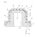
図1は、本発明の第1実施形態に係る圧力センサ10の概略断面図である。圧力センサ10は、ステム20などを含むセンサ本体部18、ステム20へ圧力を伝える流路12bが形成されている接続部材12、接続部材12に対してセンサ本体部18を固定する抑え部材14、ステム20に設けられる検出回路50などに対して配線される基板部70などを有する。
Hereinafter, the present invention will be described based on the embodiments shown in the drawings.
FIG. 1 is a schematic cross-sectional view of the
図1に示すように、接続部材12の外周には、圧力センサ10を測定対象に対して固定するためのねじ溝12aが形成されている。ねじ溝12aを介して圧力センサ10を固定することにより、接続部材12の内部に形成されている流路12bは、測定対象である流体で満たされる圧力室に対して、気密に連通する。
As shown in FIG. 1, a
図1に示すように、センサ本体部18およびセンサ本体部18に含まれるステム20は、有底(上底)筒状の外形状を有しており、接続部材12における流路12bの一方の端部に設けられる。ステム20は、開口側(Z軸負方向側)にフランジ部21が設けられており、抑え部材14と接続部材12との間にフランジ部21が挟み込まれることにより、センサ本体部18が、接続部材12に対して固定される。ステム20の開口と接続部材12の流路12bとは、抑え部材14を用いて気密に連結されており、測定対象の流体の圧力が、ステム20の底壁部22(図2参照)に伝えられる。
As shown in FIG. 1, the sensor
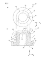
図2は、図1に示すセンサ本体部18の拡大断面図である。センサ本体部18は、ステム20と絶縁膜40と検出回路50とを有する。ステム20は、XY平面方向に延びる略円形板状の底壁部22(図3(a)参照)と、底壁部22の外周縁に接続してZ軸負方向に延びる略円筒状の側壁部25とを有する。
FIG. 2 is an enlarged cross-sectional view of the sensor
また、ステム20は、側壁部25におけるZ軸負方向端部において外径方向に突出するフランジ部21を有するが、ステム20の形状としては、実施形態に示すもののみには限定されず、たとえば、ステムは、フランジ部を有しない有底円筒形状であってもよい。ステム20の材料としては、たとえばステンレスなどの金属材料や、炭化ケイ素のようなセラミックス、シリコンなどの半導体材料などが挙げられるが、特に限定されない。
Further, the
図2に示すように、絶縁膜40は、ステム20の外表面全体を覆うように形成されている。絶縁膜40は、ステム20と検出回路50との絶縁性を確保する。検出回路50が形成される機能膜は、絶縁膜40を介してステム20の外表面に形成される。なお、説明を容易にするために、図2では、絶縁膜40および検出回路50が形成される機能膜の厚みを、実際より厚く記載している。
As shown in FIG. 2, the insulating
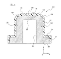
図3は、図2に示すセンサ本体部18におけるステム20の形状を表す概念図である。図3(a)はステム20をZ軸正方向側から見た上面図であり、図3(b)は、Z軸に平行な断面によるステム20の断面図である。なお、図3(b)では、図2に示す検出回路50が形成される機能膜と、絶縁膜40とを、点線で示している。図3(a)および図3(b)に示すように、ステム20の外表面は、外底面24と、裾野部28と、外側面27と、段差面34と、開口縁面36を有する。
FIG. 3 is a conceptual diagram showing the shape of the
外底面24は、ステム20の上方(Z軸正方向)側の端面であり、円形の平面状である。外側面27は、外底面24に対して交差する方向に延びている。図3に示す外側面27は、外底面24の延びる方向(X軸およびY軸方向)に対して略垂直な方向(Z軸方向)に延びており、円筒側面形状である。
The
図3(a)に示すように、裾野部28は、外底面24を取り囲むように形成されている。図3(b)に示すように、裾野部28は、外底面24に平行な方向であるY方向又はX方向から見て外底面24および外側面27とは異なる方向を向く面で構成され、外底面24と外側面27とを接続する。
As shown in FIG. 3A, the
図3(a)に示すように、外底面24に垂直な方向(Z軸方向)から見て、外底面24と裾野部28との境界である第1境界31から、裾野部28と外側面27まとの境界である第2境界32までの長さL1は、10μm以上1mm以下であることが好ましく、40μm以上500μm以下であることがさらに好ましい。長さL1を所定の値以上とすることにより、裾野部28の上に形成される絶縁膜40での応力集中を低減することができる。また、裾野部28の長さL1を所定の値以下とすることにより、ステム20の小型化に資する。
As shown in FIG. 3A, when viewed from the direction perpendicular to the outer bottom surface 24 (Z-axis direction), the
図3(b)に示すように、裾野部28は、外底面24に直交する断面で見て外底面24に対して所定の角度θをなす傾斜面で構成される。裾野部28を構成する傾斜面が外底面24に対してなす角度θは、特に限定されないが、たとえば30度から60度とすることが好ましい。角度θをこのような範囲とすることにより、外底面24と裾野部28の境界である第1境界31と、裾野部28と外側面27の境界である第2境界32の、いずれの境界31、32の近傍においても、ステム20の外表面を覆う絶縁膜40における応力集中を低減することができる。
As shown in FIG. 3B, the
裾野部28は、図3に示すように連続する1つの面で構成されていてもよいが、向きや角度が異なる複数の面を有していてもよい。図3に示す裾野部28を構成する傾斜面は、図3(b)に示すように、外底面24に直交する断面で見て、外底面24に対して一定の角度θをなす。このような傾斜面は、機械加工などにより容易に精度よく形成でき、ステム20の寸法ばらつきを低減することが可能である。
The
図3に示すステム20の段差面34は、フランジ部21の外表面であり、X軸およびY軸方向に延びておりリング形状をなす部分と、Z軸方向に延びており円筒側面形状をなす部分とを有する。開口縁面36は、ステム20の内部に形成される空洞の開口の周りを囲むリング状の平面であり、ステム20の下方(Z軸負方向)側の端面を構成する。
The stepped
図3(b)に示すように、ステム20の内表面は、受圧内面23と、内側面26とを有する。受圧内面23は、底壁部22における外底面24の反対面であって、測定対象である流体からの圧力を受ける。受圧内面23も、外底面24と同様に平面状であるが、外底面24がZ軸正方向側を向く面であるのに対して、受圧内面23はZ軸負方向側を向く面である。
As shown in FIG. 3B, the inner surface of the
ステム20の底壁部22は、受圧内面23が流体からの圧力を受けることにより変形し、底壁部22の少なくとも一部がメンブレン(またはダイアフラム)として機能する。内側面26は、側壁部25における外側面27の反対面である。ステム20の底壁部22の厚みは、測定対象である流体の圧力を受けて適切な変形を生じるように定められ、たとえば側壁部25の厚みに比べて、薄くすることができる。
The
図2および図3(b)に示されるように、圧力センサ10では、受圧内面23とは反対面である外底面24に、絶縁膜40を介して検出回路50が設けられ、検出回路50により、底壁部22の変形および流体の圧力を検出する。図1および図2に示す検出回路50としては、たとえば、圧抵抗効果(ピエゾ抵抗効果ともいう)を利用して、底壁部22の変形および流体の圧力を検出する回路が挙げられるが、これのみには限定されない。
As shown in FIGS. 2 and 3B, in the
検出回路50は、絶縁膜40を介して外底面24の上に設けられている。図2に示すように、検出回路50は、機能膜の一部に対して、レーザー加工や、スクリーン印刷のような半導体加工技術による微細加工を行うことにより形成される。機能膜は、図2に示すように、ステム20の外表面である外底面24、裾野部28および外側面27などの上に、絶縁膜40を介してこれらを間接的に覆うように形成されてもよい。また、機能膜は、これとは異なり、検出回路50が設けられる外底面24の上にのみ、形成されていてもよい。
The
図2に示すように、絶縁膜40は、ステム20の外表面である外底面24、裾野部28および外側面27などを直接接触して、これらを覆うように設けられる。絶縁膜40は、ステム20の外表面と、検出回路50および機能膜との間に形成されている。検出回路50および機能膜は、絶縁膜40によって隔てられており、ステム20に対しては接触しない。
As shown in FIG. 2, the insulating
絶縁膜40は、ステム20の外表面のうち、外底面24の全体を覆い、かつ、外底面24と外側面27とを接続する裾野部28の少なくとも一部を覆うように設けられる。ただし、絶縁膜40は、外底面24および裾野部28の全体を覆っていてもよく、図2に示すように、外底面24および裾野部28に加えて、外側面27や段差面34の少なくとも一部を覆っていてもよい。
The insulating
絶縁膜40は、ステム20と検出回路50との絶縁性を確保する。なお、図2では、絶縁膜40は薄膜などで構成され、絶縁膜40の厚みは、ステム20の肉厚などに比べて薄い。
The insulating
図1に示す圧力センサ10は、たとえば以下のような製造工程により製造される。まず、圧力センサ10の製造では、図3に示すようなステム20を製造する。ステム20は、たとえば所定の金属材料に対してプレス、切削、研磨などの機械加工を行うことにより、製造される。図3に示す裾野部28は、たとえば、外底面24に対して外側面27が垂直に接続された中間製造物を製造したのち、中間製造物において外底面24と外側面27が接続するコーナーの部分に対して、研磨などの機械加工を施すことにより形成することができる。
The
次に、ステム20の外表面に絶縁膜40と機能膜とを多層形成し、形成した多層膜に対して半導体加工技術による微細加工を行うことにより多層膜に検出回路50を形成する。これらの工程により、図2に示すようなセンサ本体部18を得る。さらに、図1に示すように、センサ本体部18を接続部材12などに固定するとともに、基板70と検出回路50とをワイヤボンディングなどにより配線することにより、図1に示すような圧力センサ10を製造することができる。
Next, the insulating
検出回路50を有する機能膜と絶縁膜40の、ステム20に対する形成方法は特に限定されないが、たとえば、スパッタリング法、真空蒸着法、CVD法、ゾル・ゲル法などにより製造することができる。絶縁膜40の材質としては、酸化ケイ素、窒化ケイ素、アルミナなどがあげられるが、特に限定されない。機能膜の材質としては、シリコンなどの半導体や、良導体の金属などが挙げられるが、特に限定されない。
The method for forming the functional film and the insulating
また、検出回路50を有する機能膜や絶縁膜40のパターニング法として、半導体加工技術であるフォトパターニング法などを用いることができる。なお、ステム20が図2に示すような裾野部28を有していることにより、機能膜や絶縁膜40のパターニング・形成工程において、レジストや薄膜が、垂直なエッジ部分において不均一となる問題を、効果的に防止することができる。
Further, as a patterning method for the functional film or the insulating
圧力センサ10に含まれるステム20の大きさは特に限定されないが、たとえば、図3に示す外側面27の直径は、3mm〜20mmである。また、ステム20に形成される絶縁膜40の厚みも特に限定されないが、たとえば500nm〜100μmである。また、ステム20に形成される機能膜の厚みは特に限定されないが、たとえば50nm〜1μmである。
The size of the
以上のように、圧力センサ10は、図3に示すように、外底面24と外側面27とが直接接続されるのではなく、外底面24と外側面27とが裾野部28を介して接続されており、絶縁膜40がその上に設けられている。ここで、実施形態のような圧力センサでは、金属やセラミクスのようなステムの材料と、高誘電材料である絶縁膜との線膨張係数の違いに起因する熱応力が生じる。従来の圧力センサでは、絶縁膜においてステムの垂直なエッジ近傍を覆う部分に応力集中が生じ、絶縁膜にクラックが生じたり、絶縁膜がステム表面から剥がれたりする問題が生じていた。
As described above, in the
しかし、上述した圧力センサ10では、図2に示すように、ステム20が裾野部28を有するため、外底面24と外側面27との間における急激な面方向の変化を緩和し、ステム20の外表面に沿って形成される絶縁膜40での応力集中を低減することができる。したがって、このような圧力センサ10は、絶縁膜40にクラックが生じたり、絶縁膜40がステム20表面から剥がれたりする問題を防止することができ、高い耐久性と信頼性を有する。
However, in the
また、図3(a)に示すように、圧力センサ10は、裾野部28の長さL1を10μm以上とすることにより、裾野部28および第1境界31および第2境界32の周辺に位置する絶縁膜40での応力集中を、より効果的に低減できる。そのため、このような裾野部28を有する圧力センサ10は、耐久性や信頼性のさらなる改善効果が得られる。また、裾野部28の長さL1を1mm以下とすることにより、圧力センサ10の小型化に資する。
Further, as shown in FIG. 3A, the
また、図3(b)に示すように、裾野部28が、外底面24に対して30度から60度の角度θをなす傾斜面を有するため、第1境界31と第2境界32の両方の境界における面方向の変化を小さくすることができる。このため、圧力センサ10は、第1境界31と第2境界32に沿って形成される絶縁膜40における応力集中を低減することができる。
Further, as shown in FIG. 3B, since the
また、圧力センサ10のステム20では、従来の形状のステムとは異なり、検出回路50が設けられる外底面24の周りに垂直に面方向が変化するコーナーが無い。そのため、このようなステム20を用いる圧力センサ10は、パターニング不良や成膜不良など、製造工程で生じる不良発生を低減できるため、生産性が良好である。
Further, unlike the stem having a conventional shape, the
以上のように、実施形態を示して本発明に係る圧力センサを説明したが、本発明は上述した実施形態のみに限定されるものではなく、他の多くの実施形態および変形例を有することは言うまでもない。図4は、本発明の第2実施形態に係る圧力センサのセンサ本体部118を示す模式断面図である。
As described above, the pressure sensor according to the present invention has been described by showing the embodiment, but the present invention is not limited to the above-described embodiment, and may have many other embodiments and modifications. Needless to say. FIG. 4 is a schematic cross-sectional view showing a sensor
図4に示すように、第2実施形態に係る圧力センサは、ステム120における裾野部128の形状と、絶縁膜140の形状と、検出回路150が形成される機能膜の形状が異なることを除き、第1実施形態に係る圧力センサ10と同様である。第2実施形態に係る圧力センサの説明では、第1実施形態に係る圧力センサ10との相違点のみ説明し、圧力センサ10との共通点については説明を省略する。
As shown in FIG. 4, the pressure sensor according to the second embodiment is different from the shape of the
図4に示すように、センサ本体部118は、ステム120と、絶縁膜140と、検出回路150が形成される機能膜とを有する。ステム120は、底壁部122の外周部に配置される裾野部128の形状が、図2に示すステム20とは異なるが、その他の部分はステム20と同様である。
As shown in FIG. 4, the sensor
図5は、図4に示すセンサ本体部118におけるステム120の形状を表す概念図である。図5(a)はステム120をZ軸正方向側から見た上面図であり、図5(b)は、Z軸に平行な断面によるステム120の断面図である。図5(b)に示すように、裾野部128は、外底面24に直交する断面でみて、第1境界31から離れるにしたがって、外底面24に対してなす角度が遷移的に大きくなる曲面形状を有する。たとえば、裾野部128は、裾野部128の長さL1とおなじ曲率半径を有してもよい。
FIG. 5 is a conceptual diagram showing the shape of the
図5に示すように、絶縁膜140の形状は、ステム120の外表面の形状に追従する。したがって、絶縁膜140においてステム120の裾野部128の上に位置する部分は、裾野部128と同様に曲面状になっている。また、検出回路150が形成される機能膜は、絶縁膜140を挟んで外底面24の上のみに形成されている。なお、絶縁膜140は、外底面24については全体を覆っている必要があるが、裾野部128については全体を覆う必要はなく、少なくとも裾野部128の一部を覆っていればよい。
As shown in FIG. 5, the shape of the insulating
図4および図5に示すステム120では、裾野部128が曲面形状を有しており、裾野部128と外底面24とのなす角度θが、第1境界31から離れるにしたがって大きくなる。このような形状の裾野部128を有するステム120は、第1境界31および第2境界32周辺での面方向の変化を小さくできるため、これを覆う絶縁膜140での応力集中を、より効果的に防止できる。また、第2実施形態に係る圧力センサは、第1実施形態に係る圧力センサ10と同様の効果を奏する。
In the
図6は、本発明の第3実施形態に係る圧力センサにおけるステム220の形状を表す概念図である。図6(a)はステム220をZ軸正方向側から見た上面図であり、図6(b)は、Z軸に平行な断面によるステム120の断面図である。図6に示すように、第3実施形態に係る圧力センサは、ステム220における裾野部228の形状が異なり、絶縁膜および機能膜の形状が裾野部228に沿う形状に変わることを除き、第1実施形態に係る圧力センサ10と同様である。第3実施形態に係る圧力センサの説明では、第1実施形態に係る圧力センサ10との相違点のみ説明し、圧力センサ10との共通点については説明を省略する。
FIG. 6 is a conceptual diagram showing the shape of the
図6(b)に示すように、ステム220の裾野部228は、外底面24に直交する断面で見て、外底面24に対して30度から60度の角度をなす傾斜面228aと、外底面24に対して傾斜面228aより小さい角度をなす接続面228bを有する。図6(a)に示すように、外底面24、接続面228bおよび傾斜面228aは同心円状に形成されており、接続面228bおよび傾斜面228aは、外底面24を取り囲むように形成されている。
As shown in FIG. 6B, the
図3と図6の比較から理解されるように、傾斜面は、図3に示す裾野部28を構成する傾斜面のように外底面24に対して直接接続してもよく、図6に示す傾斜面228aのように、接続面228bを介して外底面24に接続してもよい。図6に示すように、裾野部28に含まれる面は、外底面24に直交する断面で見て、第1境界31で接続する外底面24の向きと、第2境界32で接続する外側面27の向きとの間の方向を向く面で構成されることが好ましい。
As can be understood from the comparison between FIGS. 3 and 6, the inclined surface may be directly connected to the
図6に示すような裾野部228を有するステム220を用いる圧力センサは、裾野部28が接続面228bと傾斜面228aを有することにより、第1境界31を覆う絶縁膜への応力集中を、効果的に低減し、外底面24およびその近くでの絶縁膜の膜剥がれやクラックなどの発生を、効果的に防止できる。また、第3実施形態に係る圧力センサは、第1実施形態に係る圧力センサ10と同様の効果を奏する。なお、図6に示す傾斜面228aは、外底面24に対してなす角度θが一定である面に限定されない。ステム220の傾斜面は、図5に示すステム120の裾野部128のように、外底面24に直交する断面で見て、外底面24から離れるにしたがって外底面24に対してなす角度が大きくなるように変化する曲面であってもよい。
The pressure sensor using the
以上のように、複数の実施形態を挙げて本発明にかかる圧力センサを説明したが、本発明は上述した実施形態のみに限定されるものではなく、他の多くの実施形態および変形例を有することは言うまでもない。本発明には、これらの他にも多くの実施形態が含まれる。たとえば、図1に示すステム20の形状および固定構造は一例にすぎず、本発明の圧力センサは、ステム20が圧力に応じて適切に変形する、他の任意の形状および固定構造を採用できる。
As described above, the pressure sensor according to the present invention has been described with reference to a plurality of embodiments, but the present invention is not limited to the above-described embodiments, and has many other embodiments and modifications. Needless to say. The present invention includes many other embodiments. For example, the shape and fixed structure of the
以下に、実施例を挙げて本発明をさらに詳細に説明するが、本発明はこれらの実施例のみに限定されない。 Hereinafter, the present invention will be described in more detail with reference to examples, but the present invention is not limited to these examples.
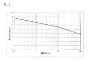
第1実施例
図7は、図5に示すように、裾野部128の長さL1に対応する曲面を有する裾野部128を備えるステム120において、ステム120の受圧内面23に所定の変形が生じた際に、裾野部128の上に形成された絶縁膜140に加えられる最大主応力と、ステム120の裾野部128の長さL1の関係を計算した結果を表すグラフである。その他の主な計算の条件は以下の通りである。
絶縁膜の材質:SiO2
絶縁膜の厚み:1000μm
絶縁膜の成膜方法:TEOS−CVD
裾野部の長さL1:0.1μm、1μm、10μm、100μm
ステムの材質:オーステナイト系ステンレス
温度:25℃
In FIG. 7, as shown in FIG. 5, in the
Insulating film material: SiO 2
Insulation film thickness: 1000 μm
Insulating film film formation method: TEOS-CVD
Length of skirt L1: 0.1 μm, 1 μm, 10 μm, 100 μm
Stem material: Austenitic stainless steel Temperature: 25 ° C
図7からは、裾野部128の長さL1が長くなることにより、絶縁膜140に加えられる最大主応力が低減することが理解できる。最大主応力の値は、裾野部128の長さが1μm以上の範囲において絶縁膜140がクラックを生じない許容範囲となり、裾野部128の長さが10μm以上の範囲では、さらに大きな安全率が確保される。
From FIG. 7, it can be understood that the maximum principal stress applied to the insulating
第2実施例
図8は、裾野部128の長さL1を固定し、絶縁膜140の厚みを変化させたことを除き、第1実施例と同様にして、絶縁膜140に加えられる最大主応力を算出した。第1実施例と異なる主な計算の条件は以下の通りである。
絶縁膜の厚み:1μm、10μm、100μm、1000μm
裾野部の長さL1:1μm
FIG. 8 of the second embodiment shows the maximum principal stress applied to the insulating
Insulating film thickness: 1 μm, 10 μm, 100 μm, 1000 μm
Base length L1: 1 μm
図8からは、絶縁膜140の厚みが薄くなることにより、絶縁膜140に加えられる最大主応力が低減することが理解できる。最大主応力の値は、絶縁膜140の厚みが100μm以下の範囲では、さらに大きな安全率が確保される。なお、絶縁膜140の厚みは、第2実施例のいずれの条件でも、十分な絶縁性が確保される。
From FIG. 8, it can be understood that the maximum principal stress applied to the insulating
10…圧力センサ
12…接続部材
12a…ねじ溝
12b…流路
14…抑え部材
18、118…センサ本体部
20、120、220…ステム
21…フランジ部
22、122…底壁部(メンブレン)
23…受圧内面
24…外底面
25…側壁部
26…内側面
27…外側面
28、128、228…裾野部
228a…傾斜面
228b…接続面
31…第1境界
32…第2境界
34…段差面
36…開口縁面
40、140…絶縁膜
50、150…検出回路
70…基板部
82…接続配線
10 ...
23 ... Pressure receiving
Claims (7)
前記外底面に対して、絶縁膜を挟んで設けられる検出回路と、を有し、
前記ステムは、
前記外底面を取り囲むように形成され、前記外底面に平行な方向から見て前記外底面および前記外側面とは異なる方向を向く面で構成され、前記外底面と前記外側面とを接続する裾野部を有し、
前記絶縁膜は、前記裾野部の少なくとも一部を覆う圧力センサ。 A stem having a flat outer bottom surface, an outer surface extending in a direction intersecting the outer bottom surface, and an inner surface that is opposite to the outer bottom surface and receives pressure from a fluid to be measured.
It has a detection circuit provided with an insulating film interposed therebetween with respect to the outer bottom surface.
The stem
A skirt that is formed so as to surround the outer bottom surface, is composed of a surface that faces a direction different from the outer bottom surface and the outer surface when viewed from a direction parallel to the outer bottom surface, and connects the outer bottom surface and the outer surface. Has a part
The insulating film is a pressure sensor that covers at least a part of the foot portion.
Priority Applications (5)
| Application Number | Priority Date | Filing Date | Title |
|---|---|---|---|
| JP2019043798A JP7164835B2 (en) | 2019-03-11 | 2019-03-11 | pressure sensor |
| EP20769048.8A EP3940359A4 (en) | 2019-03-11 | 2020-03-06 | Pressure sensor |
| CN202080019007.1A CN113574356B (en) | 2019-03-11 | 2020-03-06 | Pressure sensor |
| US17/437,736 US20220155166A1 (en) | 2019-03-11 | 2020-03-06 | Pressure sensor |
| PCT/JP2020/009673 WO2020184434A1 (en) | 2019-03-11 | 2020-03-06 | Pressure sensor |
Applications Claiming Priority (1)
| Application Number | Priority Date | Filing Date | Title |
|---|---|---|---|
| JP2019043798A JP7164835B2 (en) | 2019-03-11 | 2019-03-11 | pressure sensor |
Publications (2)
| Publication Number | Publication Date |
|---|---|
| JP2020148480A true JP2020148480A (en) | 2020-09-17 |
| JP7164835B2 JP7164835B2 (en) | 2022-11-02 |
Family
ID=72426364
Family Applications (1)
| Application Number | Title | Priority Date | Filing Date |
|---|---|---|---|
| JP2019043798A Active JP7164835B2 (en) | 2019-03-11 | 2019-03-11 | pressure sensor |
Country Status (5)
| Country | Link |
|---|---|
| US (1) | US20220155166A1 (en) |
| EP (1) | EP3940359A4 (en) |
| JP (1) | JP7164835B2 (en) |
| CN (1) | CN113574356B (en) |
| WO (1) | WO2020184434A1 (en) |
Cited By (1)
| Publication number | Priority date | Publication date | Assignee | Title |
|---|---|---|---|---|
| WO2022049921A1 (en) | 2020-09-03 | 2022-03-10 | パナソニックIpマネジメント株式会社 | Food management system |
Families Citing this family (3)
| Publication number | Priority date | Publication date | Assignee | Title |
|---|---|---|---|---|
| JP7451907B2 (en) * | 2019-09-09 | 2024-03-19 | Tdk株式会社 | pressure sensor element |
| JP7164837B2 (en) * | 2020-02-21 | 2022-11-02 | Tdk株式会社 | pressure sensor |
| JP2023124671A (en) * | 2022-02-25 | 2023-09-06 | Tdk株式会社 | Metal member with insulation film, physical quantity sensor, and pressure sensor |
Citations (6)
| Publication number | Priority date | Publication date | Assignee | Title |
|---|---|---|---|---|
| JPH05129636A (en) * | 1991-11-01 | 1993-05-25 | Citizen Watch Co Ltd | Element with diaphragm, and manufacture thereof |
| JP2000180283A (en) * | 1998-12-21 | 2000-06-30 | Matsushita Electric Works Ltd | Semiconductor pressure sensor |
| JP2006010623A (en) * | 2004-06-29 | 2006-01-12 | Denso Corp | Pressure sensor |
| JP2008070190A (en) * | 2006-09-13 | 2008-03-27 | Denso Corp | Pressure sensor |
| JP2011164072A (en) * | 2010-02-15 | 2011-08-25 | Seiko Instruments Inc | Diaphragm, pressure sensor, and manufacturing method of diaphragm |
| US20180080844A1 (en) * | 2016-09-22 | 2018-03-22 | Robert Bosch Gmbh | Pressure sensor for detecting a pressure of a fluid medium in a measuring chamber |
Family Cites Families (6)
| Publication number | Priority date | Publication date | Assignee | Title |
|---|---|---|---|---|
| JP3084304B2 (en) | 1991-07-04 | 2000-09-04 | 長野計器株式会社 | Metal diaphragm for pressure sensor |
| JP2005258625A (en) * | 2004-03-10 | 2005-09-22 | Sanyo Electric Co Ltd | Pressure sensor |
| JP2005283255A (en) * | 2004-03-29 | 2005-10-13 | Sanyo Electric Co Ltd | Pressure sensor |
| JP4742577B2 (en) * | 2004-12-14 | 2011-08-10 | 日産自動車株式会社 | Pressure sensor and manufacturing method thereof |
| DE102008000128B4 (en) * | 2007-01-30 | 2013-01-03 | Denso Corporation | Semiconductor sensor device and its manufacturing method |
| JP6115935B2 (en) * | 2013-01-25 | 2017-04-19 | セイコーインスツル株式会社 | Aging heat treated material made of duplex stainless steel, diaphragm, pressure sensor, diaphragm valve using the same, and method for producing duplex stainless steel |
-
2019
- 2019-03-11 JP JP2019043798A patent/JP7164835B2/en active Active
-
2020
- 2020-03-06 EP EP20769048.8A patent/EP3940359A4/en active Pending
- 2020-03-06 CN CN202080019007.1A patent/CN113574356B/en active Active
- 2020-03-06 US US17/437,736 patent/US20220155166A1/en active Pending
- 2020-03-06 WO PCT/JP2020/009673 patent/WO2020184434A1/en unknown
Patent Citations (6)
| Publication number | Priority date | Publication date | Assignee | Title |
|---|---|---|---|---|
| JPH05129636A (en) * | 1991-11-01 | 1993-05-25 | Citizen Watch Co Ltd | Element with diaphragm, and manufacture thereof |
| JP2000180283A (en) * | 1998-12-21 | 2000-06-30 | Matsushita Electric Works Ltd | Semiconductor pressure sensor |
| JP2006010623A (en) * | 2004-06-29 | 2006-01-12 | Denso Corp | Pressure sensor |
| JP2008070190A (en) * | 2006-09-13 | 2008-03-27 | Denso Corp | Pressure sensor |
| JP2011164072A (en) * | 2010-02-15 | 2011-08-25 | Seiko Instruments Inc | Diaphragm, pressure sensor, and manufacturing method of diaphragm |
| US20180080844A1 (en) * | 2016-09-22 | 2018-03-22 | Robert Bosch Gmbh | Pressure sensor for detecting a pressure of a fluid medium in a measuring chamber |
Cited By (1)
| Publication number | Priority date | Publication date | Assignee | Title |
|---|---|---|---|---|
| WO2022049921A1 (en) | 2020-09-03 | 2022-03-10 | パナソニックIpマネジメント株式会社 | Food management system |
Also Published As
| Publication number | Publication date |
|---|---|
| CN113574356A (en) | 2021-10-29 |
| CN113574356B (en) | 2024-03-08 |
| EP3940359A1 (en) | 2022-01-19 |
| US20220155166A1 (en) | 2022-05-19 |
| WO2020184434A1 (en) | 2020-09-17 |
| JP7164835B2 (en) | 2022-11-02 |
| EP3940359A4 (en) | 2022-12-14 |
Similar Documents
| Publication | Publication Date | Title |
|---|---|---|
| WO2020184434A1 (en) | Pressure sensor | |
| JP5033421B2 (en) | Sensor usable in ultrapure environment and highly corrosive environment, and its manufacturing method | |
| KR100523970B1 (en) | Sensor usable in ultra pure and highly corrosive environments | |
| JP4925306B2 (en) | Pressure sensor | |
| US9835507B2 (en) | Dynamic quantity sensor | |
| JP2012047725A (en) | Capacitive pressure sensor | |
| KR102245526B1 (en) | Pressure sensor | |
| EP2873958B1 (en) | Capacitive pressure sensors for high temperature applications | |
| JP5889540B2 (en) | Pressure sensor | |
| WO2020192660A1 (en) | Pressure sensor and manufacturing method therefor | |
| JP2007101222A (en) | Pressure sensor | |
| JP2018115944A (en) | Oilless pressure sensor | |
| WO2020184435A1 (en) | Insulating film-equipped metal material and pressure sensor | |
| JP2009250874A (en) | Physical quantity sensor and method for manufacturing the same | |
| JP6248009B2 (en) | Pressure sensor | |
| US7367234B2 (en) | Pressure sensor | |
| US11054326B2 (en) | Physical quantity sensor | |
| US20220291068A1 (en) | Pressure sensor device | |
| JP5718140B2 (en) | Pressure sensor | |
| JP4250387B2 (en) | Converter and manufacturing method thereof | |
| JP2007047100A (en) | Electrostatic capacitive pressure sensor and its manufacturing method | |
| JP2001215160A (en) | Dynamic physical quantity converter | |
| JPH11241968A (en) | Electrical capacitance pressure sensor and its manufacture | |
| JP2024031316A (en) | pressure sensor | |
| JPH11241966A (en) | Electrical capacitance pressure detector |
Legal Events
| Date | Code | Title | Description |
|---|---|---|---|
| A621 | Written request for application examination |
Free format text: JAPANESE INTERMEDIATE CODE: A621 Effective date: 20211105 |
|
| A131 | Notification of reasons for refusal |
Free format text: JAPANESE INTERMEDIATE CODE: A131 Effective date: 20220531 |
|
| A521 | Request for written amendment filed |
Free format text: JAPANESE INTERMEDIATE CODE: A523 Effective date: 20220729 |
|
| TRDD | Decision of grant or rejection written | ||
| A01 | Written decision to grant a patent or to grant a registration (utility model) |
Free format text: JAPANESE INTERMEDIATE CODE: A01 Effective date: 20220921 |
|
| A61 | First payment of annual fees (during grant procedure) |
Free format text: JAPANESE INTERMEDIATE CODE: A61 Effective date: 20221004 |
|
| R150 | Certificate of patent or registration of utility model |
Ref document number: 7164835 Country of ref document: JP Free format text: JAPANESE INTERMEDIATE CODE: R150 |