JP2020127269A - Power receiving apparatus - Google Patents
Power receiving apparatus Download PDFInfo
- Publication number
- JP2020127269A JP2020127269A JP2019017424A JP2019017424A JP2020127269A JP 2020127269 A JP2020127269 A JP 2020127269A JP 2019017424 A JP2019017424 A JP 2019017424A JP 2019017424 A JP2019017424 A JP 2019017424A JP 2020127269 A JP2020127269 A JP 2020127269A
- Authority
- JP
- Japan
- Prior art keywords
- power
- switch
- secondary coil
- time
- receiving device
- Prior art date
- Legal status (The legal status is an assumption and is not a legal conclusion. Google has not performed a legal analysis and makes no representation as to the accuracy of the status listed.)
- Pending
Links
Images


Classifications
-
- B—PERFORMING OPERATIONS; TRANSPORTING
- B60—VEHICLES IN GENERAL
- B60L—PROPULSION OF ELECTRICALLY-PROPELLED VEHICLES; SUPPLYING ELECTRIC POWER FOR AUXILIARY EQUIPMENT OF ELECTRICALLY-PROPELLED VEHICLES; ELECTRODYNAMIC BRAKE SYSTEMS FOR VEHICLES IN GENERAL; MAGNETIC SUSPENSION OR LEVITATION FOR VEHICLES; MONITORING OPERATING VARIABLES OF ELECTRICALLY-PROPELLED VEHICLES; ELECTRIC SAFETY DEVICES FOR ELECTRICALLY-PROPELLED VEHICLES
- B60L5/00—Current collectors for power supply lines of electrically-propelled vehicles
-
- B—PERFORMING OPERATIONS; TRANSPORTING
- B60—VEHICLES IN GENERAL
- B60L—PROPULSION OF ELECTRICALLY-PROPELLED VEHICLES; SUPPLYING ELECTRIC POWER FOR AUXILIARY EQUIPMENT OF ELECTRICALLY-PROPELLED VEHICLES; ELECTRODYNAMIC BRAKE SYSTEMS FOR VEHICLES IN GENERAL; MAGNETIC SUSPENSION OR LEVITATION FOR VEHICLES; MONITORING OPERATING VARIABLES OF ELECTRICALLY-PROPELLED VEHICLES; ELECTRIC SAFETY DEVICES FOR ELECTRICALLY-PROPELLED VEHICLES
- B60L53/00—Methods of charging batteries, specially adapted for electric vehicles; Charging stations or on-board charging equipment therefor; Exchange of energy storage elements in electric vehicles
- B60L53/10—Methods of charging batteries, specially adapted for electric vehicles; Charging stations or on-board charging equipment therefor; Exchange of energy storage elements in electric vehicles characterised by the energy transfer between the charging station and the vehicle
- B60L53/12—Inductive energy transfer
- B60L53/122—Circuits or methods for driving the primary coil, e.g. supplying electric power to the coil
-
- B—PERFORMING OPERATIONS; TRANSPORTING
- B60—VEHICLES IN GENERAL
- B60M—POWER SUPPLY LINES, AND DEVICES ALONG RAILS, FOR ELECTRICALLY- PROPELLED VEHICLES
- B60M7/00—Power lines or rails specially adapted for electrically-propelled vehicles of special types, e.g. suspension tramway, ropeway, underground railway
-
- H—ELECTRICITY
- H02—GENERATION; CONVERSION OR DISTRIBUTION OF ELECTRIC POWER
- H02J—CIRCUIT ARRANGEMENTS OR SYSTEMS FOR SUPPLYING OR DISTRIBUTING ELECTRIC POWER; SYSTEMS FOR STORING ELECTRIC ENERGY
- H02J50/00—Circuit arrangements or systems for wireless supply or distribution of electric power
- H02J50/10—Circuit arrangements or systems for wireless supply or distribution of electric power using inductive coupling
- H02J50/12—Circuit arrangements or systems for wireless supply or distribution of electric power using inductive coupling of the resonant type
-
- H—ELECTRICITY
- H02—GENERATION; CONVERSION OR DISTRIBUTION OF ELECTRIC POWER
- H02J—CIRCUIT ARRANGEMENTS OR SYSTEMS FOR SUPPLYING OR DISTRIBUTING ELECTRIC POWER; SYSTEMS FOR STORING ELECTRIC ENERGY
- H02J50/00—Circuit arrangements or systems for wireless supply or distribution of electric power
- H02J50/90—Circuit arrangements or systems for wireless supply or distribution of electric power involving detection or optimisation of position, e.g. alignment
-
- H—ELECTRICITY
- H02—GENERATION; CONVERSION OR DISTRIBUTION OF ELECTRIC POWER
- H02J—CIRCUIT ARRANGEMENTS OR SYSTEMS FOR SUPPLYING OR DISTRIBUTING ELECTRIC POWER; SYSTEMS FOR STORING ELECTRIC ENERGY
- H02J7/00—Circuit arrangements for charging or depolarising batteries or for supplying loads from batteries
-
- Y—GENERAL TAGGING OF NEW TECHNOLOGICAL DEVELOPMENTS; GENERAL TAGGING OF CROSS-SECTIONAL TECHNOLOGIES SPANNING OVER SEVERAL SECTIONS OF THE IPC; TECHNICAL SUBJECTS COVERED BY FORMER USPC CROSS-REFERENCE ART COLLECTIONS [XRACs] AND DIGESTS
- Y02—TECHNOLOGIES OR APPLICATIONS FOR MITIGATION OR ADAPTATION AGAINST CLIMATE CHANGE
- Y02T—CLIMATE CHANGE MITIGATION TECHNOLOGIES RELATED TO TRANSPORTATION
- Y02T10/00—Road transport of goods or passengers
- Y02T10/60—Other road transportation technologies with climate change mitigation effect
- Y02T10/70—Energy storage systems for electromobility, e.g. batteries
-
- Y—GENERAL TAGGING OF NEW TECHNOLOGICAL DEVELOPMENTS; GENERAL TAGGING OF CROSS-SECTIONAL TECHNOLOGIES SPANNING OVER SEVERAL SECTIONS OF THE IPC; TECHNICAL SUBJECTS COVERED BY FORMER USPC CROSS-REFERENCE ART COLLECTIONS [XRACs] AND DIGESTS
- Y02—TECHNOLOGIES OR APPLICATIONS FOR MITIGATION OR ADAPTATION AGAINST CLIMATE CHANGE
- Y02T—CLIMATE CHANGE MITIGATION TECHNOLOGIES RELATED TO TRANSPORTATION
- Y02T10/00—Road transport of goods or passengers
- Y02T10/60—Other road transportation technologies with climate change mitigation effect
- Y02T10/7072—Electromobility specific charging systems or methods for batteries, ultracapacitors, supercapacitors or double-layer capacitors
-
- Y—GENERAL TAGGING OF NEW TECHNOLOGICAL DEVELOPMENTS; GENERAL TAGGING OF CROSS-SECTIONAL TECHNOLOGIES SPANNING OVER SEVERAL SECTIONS OF THE IPC; TECHNICAL SUBJECTS COVERED BY FORMER USPC CROSS-REFERENCE ART COLLECTIONS [XRACs] AND DIGESTS
- Y02—TECHNOLOGIES OR APPLICATIONS FOR MITIGATION OR ADAPTATION AGAINST CLIMATE CHANGE
- Y02T—CLIMATE CHANGE MITIGATION TECHNOLOGIES RELATED TO TRANSPORTATION
- Y02T90/00—Enabling technologies or technologies with a potential or indirect contribution to GHG emissions mitigation
- Y02T90/10—Technologies relating to charging of electric vehicles
- Y02T90/14—Plug-in electric vehicles
Abstract
Description
本発明は、送電機器から非接触で交流電力を受電する受電機器に関するものである。 The present invention relates to a power receiving device that receives AC power from a power transmitting device in a contactless manner.
従来、電源コードや送電ケーブルを用いずに、非接触で相手側に電力伝送する非接触電力伝送装置として、磁界共振や電磁誘導を用いたものが知られている。例えば、特許文献1は、工場内等の軌道上を走行する搬送車に受電機器を設け、この受電機器に対して搬送車の移動経路に沿って配設された1次給電線から給電される構成を開示している。この受電機器では、受電機器に接続された負荷に応じて、給電された電力が変化する。そこで、この受電機器は、給電された電力を定電圧にする電圧制御手段を備えている。 2. Description of the Related Art Conventionally, as a non-contact power transmission device that non-contactly transmits power to a partner without using a power cord or a power transmission cable, a device using magnetic field resonance or electromagnetic induction is known. For example, in Patent Document 1, a power receiving device is provided on a carrier vehicle that travels on a track in a factory, and power is supplied to the power receiving device from a primary power supply line that is arranged along a moving route of the carrier vehicle. The configuration is disclosed. In this power receiving device, the supplied power changes according to the load connected to the power receiving device. Therefore, this power receiving device is provided with a voltage control means for making the supplied power a constant voltage.
ところで、道路に送電機器を埋設するとともに、道路を走行する自動車に受電機器を設け、走行中の車両において非接触で電力供給を行う技術が開発されている。道路上を走行する車両では、工場内等の軌道を走行する搬送車と異なり、道路状況や車両状況等で受電機器と送電機器との間の離間距離が変化する。受電機器と送電機器との間の離間距離が変化すると、電力伝送効率等が変化するため、受電機器から負荷に入力される電力が変動する。この変動に対応するためには、負荷側の容量を大きくしたり、部品を追加したりする必要がある。したがって、負荷への入力電力に変動が生じることは望ましくない。 By the way, a technique has been developed in which a power transmission device is embedded in a road and a power receiving device is provided in an automobile running on the road to supply electric power to a running vehicle in a non-contact manner. In a vehicle traveling on a road, unlike a carrier vehicle traveling on a track in a factory or the like, the separation distance between a power receiving device and a power transmitting device changes depending on road conditions, vehicle conditions, and the like. When the separation distance between the power receiving device and the power transmitting device changes, the power transmission efficiency and the like change, so the power input from the power receiving device to the load fluctuates. In order to cope with this variation, it is necessary to increase the load side capacitance or add components. Therefore, it is not desirable that the input power to the load fluctuates.
本発明は、上記課題に鑑みてなされたものであり、その主たる目的は、受電電力の変動に対して適切に対応できる受電装置を提供することにある。 The present invention has been made in view of the above problems, and a main object of the present invention is to provide a power receiving device that can appropriately cope with variations in received power.
本手段は、交流電力が入力される1次コイル(21)を有する送電機器(20)から前記交流電力を受電して負荷(17)に電力を供給する車載の受電機器(30)であって、前記1次コイルから非接触で受電可能な2次コイル(31)と、前記2次コイルに接続され、該2次コイルとともに共振回路(33)を構成するコンデンサ(32)と、前記負荷と前記共振回路との間に設けられ、前記負荷への入力電力を調整する電力調整回路(40)と、前記電力調整回路を制御する制御装置(50)と、を備え、前記電力調整回路は、所定周期でオンオフされるスイッチ(42)を有しており、前記所定周期内における前記スイッチのオン時間が調整されることで、前記負荷への入力電力が調整されており、前記2次コイルと前記1次コイルとの離間距離を算出する距離算出部と、前記離間距離に基づいて、前記スイッチの前記オン時間を設定する時間設定部と、を有する。 This means is an in-vehicle power receiving device (30) for receiving the AC power from a power transmitting device (20) having a primary coil (21) to which the AC power is input and supplying the load (17) with the power. A secondary coil (31) capable of contactlessly receiving power from the primary coil; a capacitor (32) connected to the secondary coil to form a resonance circuit (33) together with the secondary coil; A power adjusting circuit (40) provided between the resonant circuit and adjusting the input power to the load, and a control device (50) controlling the power adjusting circuit, the power adjusting circuit comprising: It has a switch (42) which is turned on and off in a predetermined cycle, and the input power to the load is adjusted by adjusting the on time of the switch in the predetermined cycle, and the secondary coil and A distance calculation unit that calculates a separation distance from the primary coil and a time setting unit that sets the ON time of the switch based on the separation distance.
1次コイルと2次コイルとの間で、例えば磁界共振が成立することで、送電機器から受電機器に交流電力が伝送される。1次コイルと2次コイルとの間の磁界共振が成立するように、コンデンサや2次コイルが調整されている。そして、2次コイルで受電した電力が負荷に供給される。 For example, magnetic field resonance is established between the primary coil and the secondary coil, so that AC power is transmitted from the power transmitting device to the power receiving device. The capacitor and the secondary coil are adjusted so that the magnetic field resonance is established between the primary coil and the secondary coil. Then, the electric power received by the secondary coil is supplied to the load.
ところで、1次コイルと2次コイルとの離間距離の変化により、送電機器から受電機器に電力を伝送する効率が変化し、受電電力が変動する。例えば、車両の走行時においては、道路状況や車両状態によって、1次コイルと2次コイルとの離間距離の変化が生じやすくなると考えられる。受電電力が変動すると、負荷への入力電力が不安定となるため、受電電力の変動に対応する必要がある。また、道路上に送電機器を設ける場合には、道路上には種々の車両が通行するため、送電機器側ではなく、受電機器側で受電電力の変動に対応する必要がある。 By the way, a change in the separation distance between the primary coil and the secondary coil changes the efficiency of transmitting power from the power transmitting device to the power receiving device, and the received power fluctuates. For example, when the vehicle is running, it is considered that the distance between the primary coil and the secondary coil is likely to change depending on road conditions and vehicle conditions. When the received power fluctuates, the input power to the load becomes unstable, so it is necessary to deal with the fluctuation of the received power. Further, when a power transmission device is provided on the road, various vehicles pass on the road, and therefore it is necessary to deal with fluctuations in the received power on the power receiving device side rather than on the power transmitting device side.
そこで、受電機器側で、1次コイルと2次コイルとの離間距離を算出し、この離間距離に基づいて、電力調整回路のスイッチのオン時間を算出し、負荷への入力電力を調整する。このように、受電機器側で、1次コイルと2次コイルとの離間距離の変化に基づいて、負荷への入力電力を調整することで、仮に走行中であっても、負荷への入力電力が不安定となることを抑制できる。 Therefore, on the power receiving device side, the separation distance between the primary coil and the secondary coil is calculated, and the on time of the switch of the power adjustment circuit is calculated based on this separation distance to adjust the input power to the load. As described above, by adjusting the input power to the load on the power receiving device side based on the change in the separation distance between the primary coil and the secondary coil, the input power to the load can be reduced even during traveling. Can be suppressed from becoming unstable.
<実施形態>
本実施形態は、車両に搭載された受電機器を対象にしている。図1は、本実施形態における非接触電力伝送装置10の概略構成図である。車両15は、例えば、EV(電気自動車)やPEV(プラグインハイブリッド自動車)といった電動の車両駆動装置(駆動モータ等)で走行する自動車である。
<Embodiment>
The present embodiment is intended for a power receiving device mounted on a vehicle. FIG. 1 is a schematic configuration diagram of a contactless
送電機器20は、車両15に搭載された受電機器30に対して非接触の状態で、送電(給電)を行う。送電機器20は、地面Gに埋設又は地面Gから露出するように地面G上に設置される。送電機器20は、例えば車両15の走行道路に設けられ、車両15の進行方向に沿って複数並んで埋設されている。また、送電機器20は、車両15の走行中に送電する。
The power transmitting
送電機器20は、1次コイル21を備えている。1次コイル21は、フェライトコア等の心材に巻線(例えばリッツ線)が例えば平面状に巻かれることで形成されている。1次コイル21は、その軸線が地面Gに直交する、つまり平面状に巻かれた平面が地面Gと平行になるように配されている。
The
受電機器30は、2次コイル31を備えており、2次コイル31は、車体に取り付けられている。より具体的には、2次コイル31は、車両底部15aに設けられている。車両底部15aは、車両15の車室を形成する床部やアンダーカバー等、車両15の下面を形成する部分を示している。なお、車体とは、車両15において、車両底部15aや車体フレーム等を含む部分を示している。
The
2次コイル31は、フェライトコア等の心材に巻線(例えばリッツ線)が例えば平面状に巻かれることで形成されている。2次コイル31は、その軸線が地面Gに直交する、つまり平面状に巻かれた平面が地面Gと平行で、1次コイル21に平行に対向するように配される。
The
また、前端側の車両底部15aには、車両15の地面G(走行路面)と車両底部15aとの間の検出距離h1を検出する距離センサ16が設けられている。距離センサ16は、例えばレーザ式や超音波式の測距センサである。なお、距離センサ16は、「検出部」に相当する。距離センサ16は、車両15の前端部ではなく、受電機器30の近傍に設けられていてもよい。
Further, the vehicle bottom portion 15a on the front end side is provided with a
受電機器30で受電した電力は、蓄電池17に供給される。蓄電池17は、例えば二次電池(リチウムイオン電池又はニッケル水素電池等)である。蓄電池17は、受電機器30から供給される電力を蓄えて、車両駆動装置へ電力を供給する。
The power received by the
車両15には、受電機器30を制御するための制御装置であるECU50が設けられている。ECU50は、CPU,ROM,RAM等を有するマイコンとその周辺回路とを具備する電子制御装置である。ECU50には、距離センサ16の検出した値が入力され、蓄電池17のSOC等の監視状況が入力される。なお、ECU50は、2次コイル31等と同じ位置に設けられていてもよいし、ECU50は別の位置に設けられていてもよい。
The
図2は、非接触電力伝送装置10の電気回路図である。非接触電力伝送装置10は、送電機器20と受電機器30とを備えている。送電機器20は、1次側共振部23と、1次側フィルタ回路24と、インバータ25と、コンバータ26と、1次側駆動回路27とを備えている。
FIG. 2 is an electric circuit diagram of the contactless
送電機器20には、電源装置28から電力が供給されている。電源装置28は、電力会社等によって提供される電力網から電力供給を受ける交流電源である。電源装置28は、例えば、3相200Vや400Vで50kHz程度の交流電力を供給する。
Power is supplied from the
コンバータ26は、AC/DCコンバータであって、電源装置28から供給された交流電力を所定の電圧の直流電力に変換しており、例えばスイッチング方式で交流電力を直流電力に変換している。コンバータ26のスイッチング素子は1次側駆動回路27によって駆動される。
The
インバータ25は、コンバータ26から供給された直流電力を所定の周波数の交流電力に変換する。インバータ25は、スイッチング素子のスイッチングにより、直流電流を所定の周波数の交流電流に変換する。インバータ25のスイッチング素子は、1次側駆動回路27により駆動される。
The
インバータ25と1次側共振部23との間には、1次側フィルタ回路24が設けられているのが望ましい。1次側フィルタ回路24は、高周波成分がカットされるローパスフィルタの一種である。具体的には、1次側フィルタ回路24は、コイルと、コンデンサと、コイルとがT字状に接続されたイミタンスフィルタである。
A
1次側共振部23は、1次コイル21と1次側コンデンサ22が直列に接続された共振回路となっている。1次側共振部23は、所定の周波数の交流電力が入力されると共振し、2次側共振部33に送電する。
The primary
受電機器30は、2次側共振部33と、2次側フィルタ回路34と、整流器35と、電力調整回路40とを備える。受電機器30は、蓄電池17に電力を供給する。
The
2次側共振部33は、2次コイル31と2次側コンデンサ32が直列に接続された共振回路となっている。1次側共振部23と2次側共振部33とは、S−S方式で構成されていることが望ましい。2次側共振部33は、1次側共振部23との間の磁界共振が成立するように、調整されている。具体的には、2次側共振部33の共振周波数は、1次側共振部23の共振周波数と一致することが望ましい。
The secondary
そして、送電機器20と受電機器30との相対位置が、磁界共振が成立する位置にある状況において、インバータ25から所定の周波数の交流電力が入力されると、1次側共振部23(1次コイル21)と2次側共振部33(2次コイル31)とが磁界共振する。これにより、2次側共振部33は1次側共振部23から交流電力を受電する。なお、インバータ25から入力される交流電力の所定の周波数は、1次側共振部23と2次側共振部33間にて電力伝送が可能な周波数となっているとよい。具体的には、インバータ25で生成される交流電力の所定の周波数は、1次側共振部23と2次側共振部33の共振周波数に設定されていることが望ましい。
Then, when the relative position between the
2次側共振部33と整流器35との間には、2次側フィルタ回路34が設けられている。2次側フィルタ回路34は、1次側フィルタ回路24と同様の構成を有している。2次側フィルタ回路34は、高周波成分がカットされるローパスフィルタの一種である。具体的には、2次側フィルタ回路34は、コイルと、コンデンサと、コイルとがT字状に接続されたイミタンスフィルタである。イミタンスフィルタ(2次側フィルタ回路34)は、インピーダンス・アドミタンス変換器であり、イミタンスフィルタの入力端から見たインピーダンスが、出力端に接続された負荷のアドミタンスに比例するように構成されたフィルタである。
A
整流器35は、交流電力を直流電力に変換する周知の構成である。整流器35は、例えば、4つのダイオードからなるダイオードブリッジ回路によって構成される。整流器35から出力される電力は、交流電力を全波整流した直流電力になる。
The
整流器35で直流電力に変換された電力は、蓄電池17への入力電力Wを調整する電力調整回路40に入力される。電力調整回路40は、コイル41と、スイッチ42と、ダイオード43と、コンデンサ44とを備えている。電力調整回路40は、スイッチ42がオフになることで、2次コイル31側から蓄電池17への通電を可能とするチョッパ回路である。スイッチ42は、例えばMOSFET等の半導体スイッチング素子であって、2次側駆動回路45によって駆動される。スイッチ42をオンオフすることで、蓄電池17側に流す電力量を調整する。なお、スイッチ42は、半導体スイッチング素子ではなく、機械的なスイッチであってもよい。なお、電力調整回路40は、いわゆる昇圧チョッパ回路と同じ回路構成となっているが、出力される電圧は、蓄電池17の電池電圧に依存する。
The power converted into DC power by the
2次側駆動回路45は、ECU50からの指令に基づいて、スイッチ42を所定の周波数でオンオフ制御する。スイッチ42は、所定周期内でオン状態にする時間が制御されるPWM制御によって制御されており、一定周期におけるオン時間(オンデューティ)を調整することで、出力する電力を制御する。
The secondary
ところで、送電機器20を道路に埋設し、車両15の走行中に送受電を行う場合には、道路上には種々の車両が通行するため、道路内の送電機器20側ではなく、車載の受電機器30側で電力伝送効率の変化に対応することが望ましい。また、車両15の走行時において、1次コイル21と2次コイル31との離間距離h2等が変化すると、送電機器20から受電機器30に電力を伝送する効率が低下して、受電電力W0が変動する。
By the way, when the
具体的には、車両15の走行時においては、道路状況や車両状態によって、1次コイル21と2次コイル31との間の離間距離h2の変化が生じやすくなると考えられる。具体的には、車両15の車速が上がると、走行風によって車両15の姿勢の変化や浮き上がりや沈み込みが発生し、それに起因して離間距離h2が変化する。車両15にかかるダウンフォースによって、車両15がその車両形状等に応じて浮き上がったり、押し下げられたりする。また、車両15の走行によって、タイヤの温度が上昇し、タイヤのガス圧が変化し、タイヤ径が大きくなることで、離間距離h2が大きくなることもある。さらに、燃料タンクを有する車両15の場合には、燃料の重量の増減により、車高が変化し、離間距離h2が変化する。
Specifically, when the
1次コイル21と2次コイル31との離間距離h2の変化により、送電機器20から受電機器30へ送受電する電力伝送効率が変化し、受電電力W0が変動する。受電電力W0が変動すると、蓄電池17への入力電力Wが不安定となる。また、蓄電池17の使用状況及び充電状況によって、電池電圧は変化する。車両15の走行中は、蓄電池17から電力が供給されたり充電されたりするため、電池電圧が変化する。そして、電池電圧が変化すると、受電電力W0が変化する。受電電力W0が変動すると、蓄電池17への入力電力Wが不安定となる。
Due to the change in the separation distance h2 between the
そこで、本実施形態のECU50は、蓄電池17への入力電力Wが所定の範囲内に調整されるように、電力調整回路40のスイッチ42のオン時間を制御する。送電機器20側ではなく、受電機器30側に設けられたECU50で、1次コイル21と2次コイル31との離間距離h2を算出し、この離間距離h2に基づいて、電力調整回路40のスイッチ42のオン時間を算出し、蓄電池17への入力電力Wを調整する。また、蓄電池17の電池電圧に応じて変動する受電電力W0に対して、蓄電池17への入力電力Wが一定となるように、電力調整回路40でのスイッチ42のオン時間を調整する。
Therefore, the
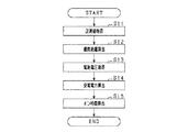
図3は、電力調整回路40のオン時間を制御するためのフローチャートである。この処理は、ECU50によって、所定周期で実施される。
FIG. 3 is a flowchart for controlling the on time of the
S11で、距離センサ16で検出した車両底部15aと地面Gとの間の検出距離h1を取得する。S11で取得した検出距離h1に基づいて、S12で、1次コイル21と2次コイル31との間の離間距離h2を算出する。具体的には、予め定められた地面Gと送電機器20との間の距離及び距離センサ16と受電機器30との取付け高さの差により、検出距離h1を修正して、離間距離h2を算出する。離間距離h2は、瞬時値ではなく、例えば数秒〜数十秒の間の所定時間の検出距離h1の平均値に基づいて算出することが望ましい。このようにすることで、検出誤差や地面G上の小さい段差等の影響を排除することができる。なお、瞬時値に対してフィルタ等で瞬間的な変化を排除して離間距離h2を算出するようにしてもよい。なお、S12が「距離算出部」に相当する。
In S11, the detection distance h1 between the vehicle bottom 15a and the ground G detected by the
S13で、蓄電池17の電池電圧を取得する。蓄電池17のSOC等に基づいて算出された蓄電池17の電池電圧を取得する。なお、S13が「電圧取得部」に相当する。
In S13, the battery voltage of the
S14で、離間距離h2及び電池電圧に基づいて、受電機器30にて受電される受電電力W0を算出する。具体的には、図4に示すような予め実験等により設定したマップに基づいて、離間距離h2及び電池電圧から受電電力W0を算出する。例えば、離間距離h2が150mmで、電池電圧が低いときの受電電力W0は、α[W]になる。
In S14, the received power W0 received by the
なお、離間距離h2が大きくなるほど、受電電力W0は小さくなる。また、電池電圧が高いほど、受電電力W0は大きくなる。2次側共振部33がSS方式で受電し、2次側フィルタ回路34から出力された電力は、定電流となっている。一方、蓄電池17に入力される電圧は、電池電圧が大きくなるほど大きくなる。そのため、電池電圧が大きくなると、受電電力W0は大きくなる。なお、図5に示すように、受電電力W0は、蓄電池17に入力される入力電力Wの目標電力Wtよりも大きくなっている。
The received power W0 decreases as the distance h2 increases. Further, the higher the battery voltage, the larger the received power W0. The secondary
S15で、スイッチ42のオン時間を算出する。蓄電池17に入力される入力電力Wが所定の範囲になるように設定された目標電力Wtと受電電力W0とに基づいて、オン時間(オンデューティ)を算出する。具体的には、オンデューティは、1−(Wt/W0)の式で算出される。算出したオンデューティに基づいて、2次側駆動回路45を制御して、スイッチ42のオン時間を制御し、処理を終了する。なお、S15が「時間設定部」に相当する。
In S15, the on time of the
図6は、離間距離h2の変化による受電電力W0及び蓄電池17への入力電力Wの変動を示す図である。破線で示す線は、走行時間による離間距離h2の変化を示す。離間距離h2及び電池電圧に基づいて、オン時間を設定することで、蓄電池17に入力される電力が所定の範囲内に調整される。車両15の走行時に、タイヤ圧の変化等によって受電機器30と送電機器20との離間距離h2が大きくなると、受電機器30が送電機器20から受電する受電電力W0が小さくなる。この場合には、スイッチ42のオン時間を減少させ、入力電力Wが受電電力W0に対して占める割合が大きくなるように制御する。一方、車速の上昇等により、車高が低くなることで、離間距離h2が小さくなった場合には、電力伝送効率がよくなり、受電電力W0が大きくなる。この場合には、入力電力Wが所定の範囲内になるように、スイッチ42のオン時間を増加させ、入力電力Wが受電電力W0に対して占める割合が小さくなるように制御する。
FIG. 6 is a diagram showing changes in the received power W0 and the input power W to the
また、電池電圧が大きい場合には、受電電力W0が大きくなる。この場合には、入力電力Wが所定の範囲内になるように、スイッチ42のオン時間を増加させ、入力電力Wが受電電力W0に対して占める割合が小さくなるように制御する。一方、電池電圧が小さい場合には、スイッチ42のオン時間を減少させ、入力電力Wが受電電力W0に対して占める割合が大きくなるように制御する。
Further, when the battery voltage is high, the received power W0 is high. In this case, the ON time of the
このようにして、離間距離h2や電池電圧に変動があっても、蓄電池17への入力電力Wが所定の範囲になるように、スイッチ42のオン時間を調整する。これにより、受電電力W0が変動しても、蓄電池17への入力電力Wが安定し、蓄電池17の劣化を抑制することができる。また、受電機器30及び蓄電池17を有する充電システムとして、余裕をみた蓄電池17の容量を準備する必要がないため、充電システムの体格や重量を小さくすることができるとともに、コストを低減できる。
In this way, the ON time of the
以上説明した本実施形態では以下の効果を奏する。 The present embodiment described above has the following effects.
受電機器30側で、1次コイル21と2次コイル31との離間距離h2を算出し、この離間距離h2に基づいて、電力調整回路40のスイッチ42のオン時間を算出し、蓄電池17への入力電力Wを調整する構成としている。このように、受電機器30側で、受電機器30と送電機器20との離間距離h2の変化に基づいて、蓄電池17への入力電力Wを調整することで、仮に走行中であっても、蓄電池17への入力電力Wが不安定となることを抑制できる。
On the
離間距離h2が大きいほど、蓄電池17側への通電時間が長くなるように、スイッチ42のオン時間を設定する。離間距離h2が大きくなり電力伝送効率が悪化すると、蓄電池17側への通電時間を長くして、蓄電池17への入力電力Wが所定の範囲となるように、電力調整回路40でのスイッチ42のオン時間が調整される。これにより、蓄電池17への入力電力Wの変動を抑制できる。
The ON time of the
車両15の車両底部15aに設けられた1次コイル21と2次コイル31との離間距離h2は、車両15の走行中に変化する。例えば、車両15においては、連続走行することに伴うタイヤの温度変化によりタイヤ圧が上昇しタイヤ径が変化することが考えられる。タイヤ径の変化に伴い、1次コイル21と2次コイル31との離間距離h2が走行中に変化する。この点、車両底部15aと走行路面(地面G)の検出距離h1を検出し、検出距離h1に基づいて、1次コイル21と2次コイル31との離間距離h2を算出する。そして、離間距離h2に基づいて、スイッチ42のオン時間を調整することで、このような走行中の離間距離h2の変化に伴う受電電力W0の変化に対応することができる。
The separation distance h2 between the
蓄電池17の使用状況及び充電状況によって、電池電圧は変動する。蓄電池17の電池電圧が変化すると、受電電力W0が変化する。そこで、受電電力W0が変動しても蓄電池17への入力電力Wが所定の範囲内となるように、電力調整回路40でのスイッチ42のオン時間を調整する。電池電圧及び離間距離h2に基づいてスイッチ42のオン時間を調整することで、蓄電池17への入力電力Wを所定の範囲にすることができ、変動を抑制できる。
The battery voltage varies depending on the usage status and the charging status of the
<他の実施形態>
本発明は、上記実施形態に限定されず、例えば以下のように実施してもよい。
<Other Embodiments>
The present invention is not limited to the above embodiment and may be implemented as follows, for example.
・電力調整回路140として、図7に示すように、スイッチ42がオフになることで、2次コイル31側から蓄電池17への通電を可能とするチョッパ回路を用いてもよい。電力調整回路140は、降圧コイル141と、スイッチ142と、ダイオード143と、コンデンサ144とを備えている。スイッチ142は、例えばMOSFET等の半導体スイッチング素子であり、2次側駆動回路45によって駆動される。スイッチ42をオンオフすることで、蓄電池17側に流す電力量を調整する。なお、電力調整回路140は、いわゆる降圧チョッパ回路と同じ回路構成となっているが、出力される電圧は、蓄電池17の電池電圧に依存する。
As the electric
電力調整回路140で電力調整を実施し、例えば、離間距離h2が小さくなった場合には、入力電力Wが所定の範囲内になるように、スイッチ142のオン時間を減少させ、入力電力Wが受電電力W0に対して占める割合が小さくなるように制御する。一方、離間距離h2が大きくなった場合には、スイッチ142のオン時間を増加させ、入力電力Wが受電電力W0に対して占める割合が大きくなるように制御する。
When the
また、電池電圧が大きい場合には、入力電力Wが所定の範囲内になるように、スイッチ142のオン時間を減少させ、入力電力Wが受電電力W0に対して占める割合が小さくなるように制御する。一方、電池電圧が小さい場合には、スイッチ142のオン時間を増加させ、入力電力Wが受電電力W0に対して占める割合が大きくなるように制御する。 When the battery voltage is high, the on-time of the switch 142 is reduced so that the input power W falls within a predetermined range, and the input power W is controlled so that the ratio of the input power W to the received power W0 becomes small. To do. On the other hand, when the battery voltage is low, the on-time of the switch 142 is increased so that the ratio of the input power W to the received power W0 is increased.
・上記実施形態では、電池電圧と離間距離h2に基づいて、受電電力W0を算出したが、離間距離h2のみに基づいて受電電力W0を算出してもよい。この場合には、離間距離h2と受電電力W0の関係を予めマップや式で算出しておき、S12で算出した離間距離h2に基づいて、受電電力W0を算出するとよい。 In the above embodiment, the received power W0 is calculated based on the battery voltage and the distance h2, but the received power W0 may be calculated based only on the distance h2. In this case, the relationship between the separation distance h2 and the received power W0 may be calculated in advance by a map or a formula, and the received power W0 may be calculated based on the separation distance h2 calculated in S12.
・受電機器30に接続される負荷は、蓄電池17ではなく、駆動装置(例えば、駆動モータ)等であってもよい。
The load connected to the
・受電機器は、車両の側部に設けられていてもよい。この場合には、送電機器が道路の側方に配されたガードレール等に埋め込まれていてもよい。 -The power receiving device may be provided on a side portion of the vehicle. In this case, the power transmission device may be embedded in a guardrail or the like arranged on the side of the road.
15…車両、17…蓄電池、20…送電機器、21…1次コイル、30…受電機器、31…2次コイル、32…2次側コンデンサ、33…2次側共振部、40…電力調整回路、42…スイッチ。
15... Vehicle, 17... Storage battery, 20... Power transmission device, 21... Primary coil, 30... Power receiving device, 31... Secondary coil, 32... Secondary side capacitor, 33... Secondary side resonance part, 40...
Claims (6)
前記1次コイルから非接触で受電可能な2次コイル(31)と、
前記2次コイルに接続され、該2次コイルとともに共振回路(33)を構成するコンデンサ(32)と、
前記負荷と前記共振回路との間に設けられ、前記負荷への入力電力を調整する電力調整回路(40)と、
前記電力調整回路を制御する制御装置(50)と、を備え、
前記電力調整回路は、所定周期でオンオフされるスイッチ(42)を有しており、前記所定周期内における前記スイッチのオン時間が調整されることで、前記負荷への入力電力が調整されており、
前記制御装置は、
前記2次コイルと前記1次コイルとの離間距離を算出する距離算出部と、
前記離間距離に基づいて、前記スイッチのオン時間を設定する時間設定部と、
を有する受電機器。 An in-vehicle power receiving device (30) for receiving the AC power from a power transmitting device (20) having a primary coil (21) to which AC power is input and supplying the power to a load (17),
A secondary coil (31) capable of contactlessly receiving power from the primary coil;
A capacitor (32) connected to the secondary coil and forming a resonance circuit (33) together with the secondary coil;
A power adjustment circuit (40) provided between the load and the resonance circuit, for adjusting input power to the load,
A control device (50) for controlling the power adjustment circuit,
The power adjustment circuit has a switch (42) that is turned on and off in a predetermined cycle, and the input power to the load is adjusted by adjusting the on time of the switch within the predetermined cycle. ,
The control device is
A distance calculation unit that calculates a separation distance between the secondary coil and the primary coil;
A time setting unit that sets the ON time of the switch based on the separation distance;
Power receiving device having.
前記時間設定部は、前記離間距離が大きいほど、前記負荷側への通電時間が長くなるように、前記スイッチのオン時間を設定する請求項1に記載の受電機器。 The power adjustment circuit enables energization of the load from the secondary coil side by turning on/off the switch,
The power receiving device according to claim 1, wherein the time setting unit sets the ON time of the switch such that the energization time to the load side becomes longer as the separation distance is larger.
前記2次コイルは、前記車体に設けられており、
前記距離算出部は、前記検出部による検出距離に基づいて、前記2次コイルと前記1次コイルとの離間距離を算出する請求項1又は請求項2に記載の受電機器。 It is applied to a vehicle (15) provided with a detection unit (16) for detecting the distance between the road surface of the vehicle 15 and the vehicle body,
The secondary coil is provided on the vehicle body,
The power receiving device according to claim 1, wherein the distance calculation unit calculates a separation distance between the secondary coil and the primary coil based on a distance detected by the detection unit.
前記時間設定部は、前記離間距離が大きいほど、前記スイッチのオン時間を減少させる請求項1から請求項3のいずれか1項に記載の受電機器。 When the switch is turned off, the power adjustment circuit allows the secondary coil to energize the load,
The power receiving device according to any one of claims 1 to 3, wherein the time setting unit decreases the on-time of the switch as the separation distance increases.
前記蓄電池の電池電圧を取得する電圧取得部を備えており、
前記時間設定部は、前記電池電圧を加味して、前記スイッチのオン時間を設定する請求項1から請求項4のいずれか一項に記載の受電機器。 The load is a rechargeable storage battery,
It comprises a voltage acquisition unit for acquiring the battery voltage of the storage battery,
The power receiving device according to any one of claims 1 to 4, wherein the time setting unit sets the ON time of the switch in consideration of the battery voltage.
前記時間設定部は、前記電池電圧が大きいほど、前記スイッチのオン時間を増加させる請求項5に記載の受電機器。 When the switch is turned off, the power adjustment circuit allows the secondary coil to energize the load,
The power receiving device according to claim 5, wherein the time setting unit increases the ON time of the switch as the battery voltage increases.
Priority Applications (2)
| Application Number | Priority Date | Filing Date | Title |
|---|---|---|---|
| JP2019017424A JP2020127269A (en) | 2019-02-01 | 2019-02-01 | Power receiving apparatus |
| PCT/JP2020/002266 WO2020158559A1 (en) | 2019-02-01 | 2020-01-23 | Power receiving device |
Applications Claiming Priority (1)
| Application Number | Priority Date | Filing Date | Title |
|---|---|---|---|
| JP2019017424A JP2020127269A (en) | 2019-02-01 | 2019-02-01 | Power receiving apparatus |
Publications (2)
| Publication Number | Publication Date |
|---|---|
| JP2020127269A true JP2020127269A (en) | 2020-08-20 |
| JP2020127269A5 JP2020127269A5 (en) | 2021-03-04 |
Family
ID=71840971
Family Applications (1)
| Application Number | Title | Priority Date | Filing Date |
|---|---|---|---|
| JP2019017424A Pending JP2020127269A (en) | 2019-02-01 | 2019-02-01 | Power receiving apparatus |
Country Status (2)
| Country | Link |
|---|---|
| JP (1) | JP2020127269A (en) |
| WO (1) | WO2020158559A1 (en) |
Citations (2)
| Publication number | Priority date | Publication date | Assignee | Title |
|---|---|---|---|---|
| WO2015159560A1 (en) * | 2014-04-16 | 2015-10-22 | 三菱電機株式会社 | Vehicular charging device |
| WO2019021655A1 (en) * | 2017-07-25 | 2019-01-31 | 日本電産株式会社 | Power transmission device and non-contact power supply system |
Family Cites Families (1)
| Publication number | Priority date | Publication date | Assignee | Title |
|---|---|---|---|---|
| EP3444924A4 (en) * | 2016-04-20 | 2019-04-24 | Yamaha Hatsudoki Kabushiki Kaisha | Wireless power supply device |
-
2019
- 2019-02-01 JP JP2019017424A patent/JP2020127269A/en active Pending
-
2020
- 2020-01-23 WO PCT/JP2020/002266 patent/WO2020158559A1/en active Application Filing
Patent Citations (2)
| Publication number | Priority date | Publication date | Assignee | Title |
|---|---|---|---|---|
| WO2015159560A1 (en) * | 2014-04-16 | 2015-10-22 | 三菱電機株式会社 | Vehicular charging device |
| WO2019021655A1 (en) * | 2017-07-25 | 2019-01-31 | 日本電産株式会社 | Power transmission device and non-contact power supply system |
Also Published As
| Publication number | Publication date |
|---|---|
| WO2020158559A1 (en) | 2020-08-06 |
Similar Documents
| Publication | Publication Date | Title |
|---|---|---|
| US8994326B2 (en) | Resonance-type non-contact power supply system | |
| US9537323B2 (en) | Contactless power supplying system with power limiting control | |
| US9270138B2 (en) | Electric power transmission system | |
| US9067497B2 (en) | Power transmitting device and power transfer system | |
| JP6201388B2 (en) | Contactless power supply system | |
| US20150224883A1 (en) | Vehicle and contactless power supply system | |
| JP5508637B2 (en) | Non-contact power transfer device abnormality detection device, non-contact power transmission device including the same, non-contact power reception device, and vehicle | |
| WO2012165242A1 (en) | Contactless electricity supply device | |
| JP5988191B2 (en) | Power transmission system | |
| US20150054456A1 (en) | Electric power transmission system | |
| US20150048688A1 (en) | Electric power transmission system | |
| US20190393728A1 (en) | Multi-Mode Wireless Power Receiver Control | |
| EP2719054A2 (en) | Contactless power receiving device, vehicle equipped with the same, contactless power transmitting device, and contactless power transfer system | |
| US20160197487A1 (en) | Wireless power receiving device | |
| JP2013211933A (en) | Power transmission system | |
| JP6547554B2 (en) | Power transmission device and noncontact power feeding system | |
| CN105052008A (en) | Power supply apparatus and non-contact power supply system | |
| JP2013158188A (en) | Power transmission system | |
| US20210384774A1 (en) | Power receiving device | |
| JP7243450B2 (en) | Power supply system while driving | |
| JP5850248B2 (en) | Non-contact power feeding device | |
| JP2013212033A (en) | Power transmission system | |
| JP2013212034A (en) | Power transmission system | |
| WO2020158559A1 (en) | Power receiving device | |
| JP7021007B2 (en) | Non-contact power receiving device |
Legal Events
| Date | Code | Title | Description |
|---|---|---|---|
| A521 | Request for written amendment filed |
Free format text: JAPANESE INTERMEDIATE CODE: A523 Effective date: 20210125 |
|
| A621 | Written request for application examination |
Free format text: JAPANESE INTERMEDIATE CODE: A621 Effective date: 20210125 |
|
| A131 | Notification of reasons for refusal |
Free format text: JAPANESE INTERMEDIATE CODE: A131 Effective date: 20211124 |
|
| A02 | Decision of refusal |
Free format text: JAPANESE INTERMEDIATE CODE: A02 Effective date: 20220524 |