JP2020125206A - Brake release device - Google Patents
Brake release device Download PDFInfo
- Publication number
- JP2020125206A JP2020125206A JP2019020030A JP2019020030A JP2020125206A JP 2020125206 A JP2020125206 A JP 2020125206A JP 2019020030 A JP2019020030 A JP 2019020030A JP 2019020030 A JP2019020030 A JP 2019020030A JP 2020125206 A JP2020125206 A JP 2020125206A
- Authority
- JP
- Japan
- Prior art keywords
- arm
- brake
- release device
- brake release
- bolt
- Prior art date
- Legal status (The legal status is an assumption and is not a legal conclusion. Google has not performed a legal analysis and makes no representation as to the accuracy of the status listed.)
- Pending
Links
Images


Abstract
Description
本発明は、エレベーター用巻上機を制動する電磁ブレーキを解放するブレーキ解放装置に関する。 The present invention relates to a brake release device that releases an electromagnetic brake that brakes an elevator hoisting machine.
エレベーター用巻上機の電磁ブレーキを手動で解放するブレーキ解放装置が特許文献1に記載されている。特許文献1に記載のブレーキ解放装置は、可動鉄心を摺動可能に貫通して固定鉄心にねじ込まれるブレーキ解放用締結具と、解放レバーとの接触部が前記可動鉄心を前記固定鉄心側に押し込む時の支点となるブレーキ解放用特殊座金とを備えている。 Patent Document 1 discloses a brake release device that manually releases an electromagnetic brake of an elevator hoisting machine. In the brake release device described in Patent Document 1, a contact portion between a brake release fastener slidably penetrating the movable iron core and screwed into the fixed iron core and a release lever pushes the movable iron core toward the fixed iron core side. It is equipped with a special washer for releasing the brake that serves as a fulcrum at the time.
特許文献1のブレーキ解放装置は、同時に1つの電磁ブレーキを解放することしかできない。そのため、このブレーキ解放装置を片手で操作するとしても、1人の作業員が同時に解放できる電磁ブレーキは、2個までとなる。そのため、電磁ブレーキを3個以上搭載したエレベーター巻上機の制動を解除するためには、複数人で作業をしなければならないと言う課題がある。 The brake release device of Patent Document 1 can only release one electromagnetic brake at the same time. Therefore, even if this brake releasing device is operated with one hand, the number of electromagnetic brakes that one worker can release at the same time is two. Therefore, there is a problem that a plurality of people must work in order to release the braking of the elevator hoisting machine equipped with three or more electromagnetic brakes.
本発明は、上記事情に鑑みてなされたもので、その目的は、複数の電磁ブレーキを纏めて解放可能なブレーキ解放装置を提供することにある。 The present invention has been made in view of the above circumstances, and an object thereof is to provide a brake release device that can release a plurality of electromagnetic brakes collectively.
本発明は、非通電時に制動ばねの付勢力で可動部材を回転体に当接させて制動状態となり、通電時に前記制動ばねの付勢力に抗して前記可動部材を前記回転体から離間させて解放状態となる複数の電磁ブレーキを、前記制動状態から前記解放状態に状態変化させるブレーキ解放装置であって、前記複数の電磁ブレーキそれぞれの前記可動部材に装着される複数の解放部材と、前記複数の解放部材を連結するアームと、前記複数の解放部材と異なる位置において前記アームに装着される係止部材と、前記係止部材に係止されて、前記複数の可動部材を前記回転体から離間させる向きの力を、前記アームに伝達する伝達部材とを備えることを特徴とする。 According to the present invention, a biasing force of a braking spring brings a movable member into contact with a rotating body when not energized to bring about a braking state, and when energizing, the movable member is separated from the rotating body against the biasing force of the braking spring. A brake release device for changing the state of a plurality of electromagnetic brakes in a released state from the braking state to the released state, wherein a plurality of release members attached to the movable members of the plurality of electromagnetic brakes, and a plurality of the plurality of release members An arm that connects the release members, a locking member that is mounted on the arm at a position different from the plurality of release members, and a plurality of movable members that are locked by the locking member and are separated from the rotating body. And a transmission member for transmitting the force in the direction to the arm.
本発明のブレーキ解放装置によれば、複数の電磁ブレーキを纏めて解放することができる。なお、上述した以外の課題、構成および効果は、以下の実施形態の説明により明らかにされる。 According to the brake release device of the present invention, a plurality of electromagnetic brakes can be released collectively. The problems, configurations, and effects other than those described above will be clarified by the following description of the embodiments.
以下、図面を参照しながら本発明の実施形態について説明する。以下、本明細書において、同一機能を有するものは、特に断らない限り、同一の符号を付し、繰り返しの説明は省略する。 Embodiments of the present invention will be described below with reference to the drawings. Hereinafter, in the present specification, components having the same function are designated by the same reference numeral unless otherwise specified, and repeated description is omitted.
まず、図1を参照して、本実施形態に係るエレベーターの構成を説明する。図1は、エレベーターの概略構成図である。図1に示すように、エレベーターは、乗りかご2と、釣合い錘4と、エレベーター用巻上機6とを主に備える。
First, the configuration of the elevator according to the present embodiment will be described with reference to FIG. FIG. 1 is a schematic configuration diagram of an elevator. As shown in FIG. 1, the elevator mainly includes a
乗りかご2は、建物に設けられた昇降路1内を上下方向に移動し、各階床に設けられた乗り場で停止するように制御される。乗りかご2は、乗客を収容する内部空間を有する箱型の乗り物である。そして、乗りかご2が乗り場で停止した状態で、乗りかご2のドアが開放されると、乗りかご2に対して乗客が乗降可能となる。
The
釣合い錘4は、乗りかご2との重量バランスをとって、乗りかご2を昇降させるエレベーター用巻上機6の負荷を軽減させるためのウエイトである。なお、本実施形態では、釣合い錘4を乗りかご2と同等の重量としたが、前記の関係に限らず、釣合い錘4の重量と乗りかご2の重量に差があってもよい。
The
昇降路1の頂部に形成された機械室5には、エレベーター用巻上機6が配設されている。エレベーター用巻上機6は、一端が乗りかご2に接続され、他端が釣合い錘4に接続されたロープ3を巻き上げることによって、乗りかご2を昇降させる。すなわち、エレベーター用巻上機6が一方に回転すると、乗りかご2が上昇し、釣合い錘4が降下する。一方、エレベーター用巻上機6が他方に回転すると、乗りかご2が降下し、釣合い錘4が上昇する。
An
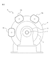
次に、図2及び図3を参照して、エレベーター用巻上機6の構造を説明する。図2は、エレベーター用巻上機6の正面図である。図3は、エレベーター用巻上機6の側面図である。エレベーター用巻上機6は、ロープ3が装架されるシーブ8と、ブレーキディスク9(回転体)と、複数(この例では、3個)の電磁ブレーキ12a、12b、12cとを主に備える。
Next, the structure of the
シーブ8及びブレーキディスク9は、モータフレーム10及びペデスタル13に回転自在に支持された軸7に固定されている。そして、シーブ8及びブレーキディスク9は、モータフレーム10に内蔵されたモータの駆動力が軸7に伝達されることにより、時計回り及び反時計回りに同期して回転する。
The
電磁ブレーキ12a、12b、12cは、モータフレーム10の外周面に設けられたブレーキ支持部11に支持されている。複数のブレーキ支持部11は、モータフレーム10の外周面の周方向に離間した位置に配置されている。電磁ブレーキ12a、12b、12cは、ブレーキディスク9の回転を制動する制動状態と、ブレーキディスク9の回転を許容する解放状態とに切り替え可能に構成されている。
The
なお、エレベーター用巻上機6に搭載される電磁ブレーキの数は特に限定されないが、例えば、3つ以上であるのが望ましい。但し、複数の電磁ブレーキ12a、12b、12cは、それぞれが1つでブレーキディスク9を制動可能な程度の制動力を有するものとする。すなわち、図2に示す3つの電磁ブレーキ12a、12b、12cのうち、電磁ブレーキ12a、12bが解放状態で、電磁ブレーキ12cが制動状態であれば、シーブ8及びブレーキディスク9は回転せず、乗りかご2は昇降しない。
The number of electromagnetic brakes mounted on the
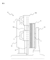
次に、図4を参照して、電磁ブレーキ12aの構造を説明する。図4は、電磁ブレーキ12aの側面図である。なお、電磁ブレーキ12b、12cの構造は、電磁ブレーキ12aと共通する。電磁ブレーキ12aは、コイル14及び複数の制動ばね15を内蔵した固定鉄心16と、一対のブレーキシュー17が連結された可動鉄心18とを主に備える。
Next, the structure of the
固定鉄心16は、磁性材料で形成された円柱形状の部材である。固定鉄心16には、中央を軸方向に貫通する貫通孔16aと、貫通孔16aの周りを囲むように円周方向に連続する円周溝16bと、円周溝16bの周りに周方向に離間して配置された複数の凹部16cとが形成されている。円周溝16bには、コイル14が巻回される。複数の凹部16cそれぞれには、制動ばね15が収容される。
The fixed
可動鉄心18は、凹部16cが開口する側において、固定鉄心16に対面して配置されている。可動鉄心18は、磁性材料で形成された円板部18aと、円板部18aの中央から固定鉄心16側に延設されるロッド18bとを有する。ロッド18bは、固定鉄心16の貫通孔16aに挿入される。また、ロッド18bの先端には、ボルト穴18cが形成されている。
The
さらに、可動鉄心18には、固定鉄心16と反対側において、一対のブレーキシュー17が連結されている。一対のブレーキシュー17は、ブレーキディスク9を挟んで反対側に配置されている。そして、一対のブレーキディスク9は、可動鉄心18の動きに連動して、ブレーキディスク9を挟持し、或いはブレーキディスク9から離間する。
Further, a pair of
コントローラ(図示省略)からコイル14に電力が供給されていないとき(非通電時)、可動鉄心18は、制動ばね15の付勢力によって固定鉄心16から離間する向きに移動し、一対のブレーキシュー17にブレーキディスク9を挟持させる。これにより、シーブ8及びブレーキディスク9の回転が制動されて、乗りかご2が停止する。以下、このときの電磁ブレーキ12aの状態を「制動状態」と表記する。
When electric power is not supplied to the
一方、コントローラからコイル14に電力が供給されているとき(通電時)、可動鉄心18は、固定鉄心16に生じる電磁力によって吸着されて、一対のブレーキシュー17をブレーキディスク9から離間させる。これにより、シーブ8及びブレーキディスク9の制動が解除されて、乗りかご2が昇降可能になる。以下、このときの電磁ブレーキ12aの状態を「解放状態」と表記する。
On the other hand, when electric power is being supplied from the controller to the coil 14 (during energization), the
すなわち、電磁ブレーキ12a、12b、12cは、非通電時に制動状態となり、通電時に解放状態となる、所謂「ネガティブブレーキ」である。そのため、エレベーターが設置された建物が停電すると、電磁ブレーキ12a、12b、12cが自動的に制動状態になって、隣接する階床の間で乗りかご2が停止する可能性がある。そこで、このような電磁ブレーキ12a、12b、12cを制動状態から解放状態に手動で状態変化させるために、ブレーキ解放装置23が必要になる。
That is, the
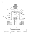
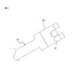
次に、図5〜図10を参照して、本実施形態に係るブレーキ解放装置23の構造を説明する。図5は、ブレーキ解放装置23を装着したエレベーター用巻上機6の正面図である。図6は、図5のVI−VIにおける断面図である。図7は、図6のVII−VIIにおける断面図である。図8は、2つの解放用ボルト20a、20bにアーム24を装着する手順を説明するための図である。図9は、解放用レバー22の先端の拡大図である。図10は、解放用ボルト20cに解放用レバー22を直接装着した例を示す図である。
Next, the structure of the
本実施形態に係るブレーキ解放装置23は、2つの電磁ブレーキ12a、12bを、作業員の片手操作で同時に解放状態にできる装置である。但し、ブレーキ解放装置23が同時に解放状態にできる電磁ブレーキの数は2個に限定されず、3個以上であってもよい。ブレーキ解放装置23は、複数(この例では、3個)の解放用ボルト20a、20b、20c(解放部材)と、アーム24と、ガイド部材25と、引き上げ用ボルト26(係止部材)と、解放用レバー22(伝達部材)とを主に備える。
The
解放用ボルト20a、20b、20cは、ボルト穴18cに螺合されることによって、可動鉄心18に装着される。このとき、解放用ボルト20a、20b、20cの頭部と、貫通孔16aを囲む固定鉄心16の壁面との間に、解放用レバー22の先端が挿入可能な隙間が形成されるように、ボルト穴18cの深さ及び解放用ボルト20a、20b、20cの軸部の長さが調整される。
The
アーム24は、同一平面上において、可動鉄心18に締結された解放用ボルト20a、20bを連結する部材である。アーム24は、例えば、鋼板を折り曲げ加工して形成される。アーム24は、上壁24aと、一対の側壁24bとを主に備える。
The
上壁24aは、長手方向及び短手方向を有する平板である。上壁24aの長手方向の中央部には、引き上げ用ボルト26が挿通される貫通孔24cが形成されている。一対の側壁24bは、上壁24aの短手方向の両端部から、上壁24aと交差(直交)する方向に延設されている。すなわち、一対の側壁24bは、上壁24aの短手方向の寸法だけ離間して、平行に配置されている。
The
一対の側壁24bの先端(上壁24aと反対側の端部)には、複数(この例では、2個)の二股爪24d、24eが取り付けられている。2個の二股爪24d、24eは、上壁24aの長手方向に離間して配置されている。また、上壁24aの長手方向において、貫通孔24cは、2個の二股爪24d、24eから等距離の位置に形成されている。
A plurality of (two in this example) bifurcated
二股爪24d、24eは、解放用ボルト20a、20bの軸部の直径より僅かに大きく、且つ解放用ボルト20a、20bの頭部の直径より小さい間隔を隔てて配置される一対の爪を備える。そして、二股爪24d、24eの先端は、切り欠かれている。
The
そのため、固定鉄心16と解放用ボルト20a、20bの頭部との間に、切り欠かれた先端側から二股爪24d、24eを挿入すると、解放用ボルト20a、20bの軸部を一対の爪で挟む状態になる。この状態で、アーム24を引き上げると、二股爪24d、24eが解放用ボルト20a、20bの頭部に係止されて、可動鉄心18の円板部18aが固定鉄心に近づく方向(以下、「引張り方向」と表記する。)に移動する。すなわち、引張り方向は、一対のブレーキシュー17をブレーキディスク9から離間させる方向と言い換えることができる。
Therefore, when the forked
なお、図8に示すように、2個の二股爪24d、24eは、互いに異なる向きに切り欠かれている。二股爪24d(第1の二股爪)は、上壁24aの長手方向のうち、二股爪24eと反対側の端部が切り欠かれている。一方、二股爪24e(第2の二股爪)は、上壁24aの短手方向に開口している。換言すれば、二股爪24eは、二股爪24dの切り欠き方向と直交する方向を向く端部が切り欠かれている。
As shown in FIG. 8, the two
上記構成のアーム24は、例えば以下の手順で2つの解放用ボルト20a、20bに連結される。まず、解放用ボルト20a、20bを結ぶ仮想線と交差する方向(図8の直線矢印の方向)から、二股爪24dを固定鉄心16と解放用ボルト20aの頭部との間に挿入する。次に、解放用ボルト20aを回転中心として、二股爪24eを解放用ボルト20bに近づける方向(図8の曲線矢印の方向)に、アーム24を回転させる。これにより、二股爪24eが固定鉄心16と解放用ボルト20bの頭部との間に挿入される。
The
ガイド部材25は、アーム24の外側に配置されて、解放用レバー22から付与される力を、可動鉄心18の円板部18aが傾かずに固定鉄心16に近づくように、アーム24に伝達する部材である。ガイド部材25は、例えば、鋼板を折り曲げ加工して形成される。ガイド部材25は、上壁25aと、一対の第1側壁25bと、一対の第2側壁25cとを主に備える。
The
上壁25aは、長手方向及び短手方向を有する平板である。上壁25aの長手方向の中央部には、引き上げ用ボルト26が挿通される貫通孔25dが形成されている。一対の第1側壁25bは、上壁25aの短手方向の両端部から、上壁25aと交差(直交)する方向に延設されている。一対の第2側壁25cは、一対の第1側壁25bの長手方向の端部を相互に接続する。
The
上記構成のガイド部材25は、解放用ボルト20a、20bを連結したアーム24を囲むように配置される。このとき、一対の第1側壁25bの先端は、電磁ブレーキ12a、12bそれぞれの固定鉄心16に当接する。一方、一対の第2側壁25cの先端は、電磁ブレーキ12a、12bそれぞれの固定鉄心16に当接してもよいし、固定鉄心16から離間していてもよい。
The
ここで、一対の第1側壁25bの間隔は、アーム24の短手方向の寸法より僅かに大きい。そのため、一対の第1側壁25bは、アーム24が短手方向(引張り方向と直交する方向)にスライドするのを規制する規制部として機能する。また、一対の第2側壁25cの間隔は、アーム24の長手方向の寸法より僅かに大きい。そのため、一対の第2側壁25cは、アーム24が長手方向(引張り方向と直交する方向)にスライドするのを規制する規制部として機能する。
Here, the distance between the pair of
また、上壁25aの外面には、補強板27(補強部材)が取り付けられていてもよい。補強板27は、上壁25aの板厚より厚い鋼板である。また、補強板27は、上壁25aより剛性の高い部材であるのが好ましい。さらに、補強板27には、貫通孔25dに連通する貫通孔27aが形成されている。
A reinforcing plate 27 (reinforcing member) may be attached to the outer surface of the
引き上げ用ボルト26は、補強板27の貫通孔27aと、ガイド部材25の貫通孔25dと、アーム24の貫通孔24cとに挿通されて、先端にナット28が螺合される。なお、引き上げ用ボルト26の頭部及び軸部の直径は、解放用ボルト20a、20bと同一であるのが好ましい。
The pull-up
そして、引き上げ用ボルト26の頭部は、ガイド部材25より外側に位置して、解放用レバー22の二股爪22aを係止する係止部として機能する。一方、引き上げ用ボルト26の先端に螺合されたナット28は、アーム24の内側に位置して、解放用レバー22を通じて伝達された力でアーム24を引き上げる引き上げ部として機能する。
The head of the pull-up
解放用レバー22は、長尺棒状の部材である。解放用レバー22は、引き上げ用ボルト26及びアーム24を通じて、解放用ボルト20a、20bに連結された可動鉄心18に、引張り方向の力を伝達する伝達部材である。解放用レバー22は、先端に設けられた二股爪22aと、基端側に設けられた把持部22bとを主に備える。
The
図9に示すように、二股爪22aは、引き上げ用ボルト26の軸部の直径より僅かに大きく、且つ引き上げ用ボルト26の頭部の直径より小さい間隔を隔てて配置される一対の爪を備える。そして、二股爪22aの先端は、切り欠かれている。二股爪22aの形状は、アーム24の二股爪24d、24eと同一であるのが望ましい。把持部22bは、解放用レバー22を用いて電磁ブレーキ12a、12bを解放する作業員が把持する部分である。
As shown in FIG. 9, the
図6に示すように、引き上げ用ボルト26の軸部を挟むように、引き上げ用ボルト26の頭部と補強板27との間に二股爪22aを挿入すると、二股爪22aの先端の上面(被係止部)が引き上げ用ボルト26の頭部に係止され、二股爪22aの基端の下面(当接部)が補強板27(ガイド部材25)に当接する。
As shown in FIG. 6, when the
なお、補強板27(ガイド部材25)は、貫通孔27a(貫通孔25d)の全周において、二股爪22aの基端の下面が当接可能な広さの壁面を有する。すなわち、引き上げ用ボルト26に対して、360°どの方向からでも解放用レバー22を挿入することができる。
The reinforcing plate 27 (guide member 25) has a wall surface that is wide enough to contact the lower surface of the proximal end of the
この状態で把持部22bを押し下げると、てこの原理によって、作業員が把持部22bに付与した力が引き上げ用ボルト26に伝達される。すなわち、二股爪22aの基端の下面が支点となり、二股爪22aの先端の上面が作用点となり、把持部22bが力点となって、作業員が把持部22bに付与した力が引き上げ用ボルト26に伝達される。そして、引き上げ用ボルト26に伝達された力は、ナット28を通じてアーム24に伝達される。
When the
ここで、引き上げ用ボルト26に作用する力の向きは、二股爪22aの先端を中心とする円弧を描く。すなわち、引き上げ用ボルト26に作用する力は、引張り方向の分力と、引張り方向に直交(この例では、アーム24の長手方向)する分力とに分解することができる。
Here, the direction of the force acting on the lifting
そのため、アーム24に作用する引張り方向の分力は、解放用ボルト20a、20bを通じて、電磁ブレーキ12a、12bそれぞれの可動鉄心18に伝達される。これにより、可動鉄心18の円板部18aが固定鉄心16に近づいて、ブレーキシュー17がブレーキディスク9から離間する。すなわち、コントローラからコイル14に電力が供給されなくても、電磁ブレーキ12a、12bを制動状態から解放状態に状態変化させることができる。
Therefore, the component force in the pulling direction that acts on the
一方、引張り方向に直交する分力は、固定鉄心16上でアーム24をスライドさせようとする。しかしながら、このアーム24のスライドは、第1側壁25b及び第2側壁25cによって規制される。その結果、てこの原理を利用して引き上げ用ボルト26を引き上げたとしても、円板部18aを傾けずに、可動鉄心18を固定鉄心16に近づけることができる。
On the other hand, the component force orthogonal to the pulling direction tends to slide the
なお、図10に示すように、解放用レバー22の二股爪22aは、解放用ボルト20cの軸部を挟むように、電磁ブレーキ12cの固定鉄心16と解放用ボルト20cの頭部との間に挿入可能である。このとき、二股爪22aの基端の下面が固定鉄心16に当接し、二股爪22aの先端の上面が解放用ボルト20cの頭部に係止される。この状態で把持部22bを押し下げると、二股爪22aの基端の下面が支点となり、二股爪22aの先端の上面が作用点となり、把持部22bが力点となって、引張り方向の力が解放用ボルト20cに伝達される。その結果、電磁ブレーキ12cが制動状態から解放状態に状態変化する。
As shown in FIG. 10, the forked
上記の実施形態によれば、例えば以下の作用効果を奏する。 According to the above-mentioned embodiment, the following operation effects are produced, for example.
上記の実施形態によれば、片手で解放用レバー22を操作してアーム24を押し下げれば、複数の電磁ブレーキ12a、12bを制動状態から解放状態に状態変化させることができる。そのため、図2に示す3つの電磁ブレーキ12a、12b、12cのうち、2つの電磁ブレーキ12a、12bをブレーキ解放装置23で解放し、残りの1つの電磁ブレーキ12cを解放用レバー22で直接解放すれば、1人の作業員で3つの電磁ブレーキ12a、12b、12cを同時に解放できるので、作業の効率が向上する。
According to the above-described embodiment, by operating the
また、てこの原理を利用する解放用レバー22は、可動鉄心18の移動方向に真っ直ぐアーム24を引っ張るのではなく、円弧を描くようにアーム24を引っ張る。そのため、アーム24は、可動鉄心18の移動方向と直交する向きの分力を受けることになる。そこで上記の実施形態のように、ガイド部材25の第1側壁25b及び第2側壁25cを規制部として機能させることにより、可動鉄心18の移動方向と直交する向きのアーム24の移動を規制することができる。
Further, the lever for
また、上記の実施形態によれば、アーム24、ガイド部材25、及び補強板27の貫通孔24c、25d、27aの内面で、引き上げ用ボルト26を引き上げ方向にガイドするので、可動鉄心18の移動方向と直交する向きのアーム24の移動をさらに規制することができる。
Further, according to the above-described embodiment, since the pull-up
また、上記の実施形態によれば、解放用レバー22の二股爪24eを当接させるのに必要な広さの壁面を、貫通孔25d、27aの全周に設けたので、引き上げ用ボルト26に対して360°どの方向からでも解放用レバー22を挿入することができる。そのため、作業員が作業しやすい体勢で電磁ブレーキ12a、12bを解放することができる。
In addition, according to the above-described embodiment, since the wall surface having the width necessary for abutting the
また、上記の実施形態によれば、ガイド部材25の上壁25aに補強板27を取り付けたので、てこの原理を利用して電磁ブレーキ12a、12b、12cを解放する際に、解放用レバー22に当接されたガイド部材25が変形することを防止できる。
Further, according to the above-described embodiment, since the reinforcing
また、上記の実施形態によれば、引き上げ用ボルト26に対して二股爪22aを挿抜するだけで、引き上げ用ボルト26に対して解放用レバー22を簡単に着脱することができる。その結果、複数のエレベーターが設置された施設において、エレベーター用巻上6の制動を順番に解放する作業を、1つのブレーキ解放装置23で行うことができる。
Further, according to the above-described embodiment, the
また、上記構成によれば、解放用ボルト20a、20bに対して二股爪24d、24eを挿抜するだけで、解放用ボルト20a、20bに対してアーム24を簡単に着脱することができる。その結果、電磁ブレーキ12a、12bを手動で解放する作業の効率がさらに向上する。
Moreover, according to the said structure, the
また、上記構成のアーム24は、2つの制動ばね15の付勢力に対抗する力を受けるので、高い剛性を得るためにある程度の重量が必要になる。そのため、アーム24を正確に位置決めして、2つの解放用ボルト20a、20bに二股爪24d、24eを同時に挿入するのは容易ではない。そこで上記の実施形態のように、二股爪24d、24eの切り欠きの向きを図8のようにすることで、一方の解放用ボルト20aに二股爪24dを挿入し、その状態でアーム24を回転させれば、他方の解放用ボルト20bに二股爪24eを挿入することができる。すなわち、複数の電磁ブレーキ12a、12bへのアーム24の取付作業が容易になる。
Further, since the
また、上記の実施形態によれば、解放用ボルト20a、20b、20c及び引き上げ用ボルト26の軸部の太さと、解放用レバー22及びアーム24の二股爪22a、24d、24eの形状とが共通化されているので、解放用レバー22は、図6に示すように、アーム24を介して複数の電磁ブレーキ12a、12bを解放するのにも利用できるし、図10に示すように、1つの電磁ブレーキ12cを直接解放するのにも利用できる。
Further, according to the above-described embodiment, the thicknesses of the shaft portions of the
また、上記の実施形態によれば、解放用ボルト20a、20bから等距離の位置において、引き上げ用ボルト26がアーム24に装着されるので、解放用レバー22を通じてアーム24に伝達される力が、2つの可動鉄心18に均等に分配される。作業員が片手で解放用レバー22を操作する場合でも、複数の電磁ブレーキ12a、12bを適切に解放することができる。
Further, according to the above-described embodiment, since the pull-up
なお、解放用レバー22の具体的な形状は図6の例に限定されない。解放用レバー22の他の例として、二股爪22aと把持部22bとの間で屈曲した略L字型であってもよい。この場合の解放用レバーは、屈曲した部分を補強板27に当接させた状態で把持部22bを押し下げればよい。また、伝達部材の具体例は、解放用レバー22に限定されない。伝達部材の他の例として、引き上げ用ボルト26の頭部と補強板27(ガイド部材25)との間に挿入されて、油圧(空気圧)で広がるジャッキであってもよい。
The specific shape of the
また、引き上げ用ボルト26をアーム24に装着する方法は、ナット28に限定されない。例えば、アーム24の内側に位置する引き上げ用ボルト26の先端に割ピンを挿入して、引き上げ用ボルト26をアーム24に係止してもよい。この場合、引き上げ用ボルト26にはねじ溝が切られていなくてもよい。すなわち、係止部材はボルトでなくてもよい。
Further, the method of attaching the pulling
さらに、解放部材の具体例は、解放用ボルト20a、20b、20cに限定されない。他の例として、ロッド18bの先端は、貫通孔16aから突出していてもよい。そして、貫通孔16aから突出するロッド18bの先端に、ねじ溝が切られていてもよい。この場合の解放部材は、ロッド18bの先端に螺合されるナットであってもよい。
Furthermore, the specific example of the release member is not limited to the
尚、本発明は、上述した実施例に限定するものではなく、様々な変形例が含まれる。例えば、上述した実施例は本発明を分かり易く説明するために詳細に説明したものであり、必ずしも説明した全ての構成を備えるものに限定するものではない。またある実施例の構成の一部を他の実施例の構成に置き換えることが可能であり、また、ある実施例の構成に他の実施例の構成を加えることも可能である。また、各実施例の構成の一部について、他の構成の追加、削除、置換をすることが可能である。 It should be noted that the present invention is not limited to the above-described embodiments, but includes various modifications. For example, the above-described embodiments have been described in detail in order to explain the present invention in an easy-to-understand manner, and are not necessarily limited to those having all the configurations described. Further, it is possible to replace part of the configuration of one embodiment with the configuration of another embodiment, and it is also possible to add the configuration of another embodiment to the configuration of one embodiment. Further, it is possible to add, delete, or replace other configurations with respect to a part of the configurations of the respective embodiments.
1:昇降路、2:乗りかご、3:ロープ、4:釣合い錘、5:機械室、6:エレベーター用巻上機、7:軸、8:シーブ、9:ブレーキディスク(回転体)、10:モータフレーム、11:ブレーキ支持部、12a,12b,12c:電磁ブレーキ、13:ペデスタル、14:コイル、15:制動ばね、16:固定鉄心、16a,24c,25d,27a:貫通孔、16b:円周溝、16c:凹部、17:ブレーキシュー、18:可動鉄心、18a:円板部、18b:ロッド、18c:ボルト穴、20a、20b、20c:解放用ボルト(解放部材)、22:解放用レバー22(伝達部材)、22a,24d,24e:二股爪、22b:把持部、23:ブレーキ解放装置、24:アーム、24a,25a:上壁、24b:側壁、25:ガイド部材、25b:第1側壁、25c:第2側壁、26:引き上げ用ボルト(係止部材)、27:補強板(補強部材)、28:ナット 1: hoistway, 2: car, 3: rope, 4: counterweight, 5: machine room, 6: elevator hoist, 7: shaft, 8: sheave, 9: brake disc (rotating body), 10 : Motor frame, 11: Brake support, 12a, 12b, 12c: Electromagnetic brake, 13: Pedestal, 14: Coil, 15: Braking spring, 16: Fixed iron core, 16a, 24c, 25d, 27a: Through hole, 16b: Circumferential groove, 16c: concave portion, 17: brake shoe, 18: movable iron core, 18a: disc portion, 18b: rod, 18c: bolt hole, 20a, 20b, 20c: release bolt (release member), 22: release Lever 22 (transmission member), 22a, 24d, 24e: bifurcated claw, 22b: gripping part, 23: brake release device, 24: arm, 24a, 25a: upper wall, 24b: side wall, 25: guide member, 25b: First side wall, 25c: Second side wall, 26: Lifting bolt (locking member), 27: Reinforcing plate (reinforcing member), 28: Nut
Claims (10)
前記複数の電磁ブレーキそれぞれの前記可動部材に装着される複数の解放部材と、
前記複数の解放部材を連結するアームと、
前記複数の解放部材と異なる位置において前記アームに装着される係止部材と、
前記係止部材に係止されて、前記複数の可動部材を前記回転体から離間させる向きの力を、前記アームに伝達する伝達部材とを備えることを特徴とするブレーキ解放装置。 When not energized, the urging force of the braking spring brings the movable member into contact with the rotating body to bring it into a braking state. A brake releasing device for changing a plurality of electromagnetic brakes from the braking state to the releasing state,
A plurality of release members mounted on the movable member of each of the plurality of electromagnetic brakes,
An arm connecting the plurality of release members,
A locking member attached to the arm at a position different from the plurality of release members,
A brake release device, comprising: a transmission member that is engaged with the engagement member and that transmits a force in a direction that separates the plurality of movable members from the rotating body to the arm.
前記アームの外側に配置されるガイド部材を備え、
前記伝達部材は、前記係止部材に係止されて作用点となる被係止部と、前記ガイド部材の外面に当接されて支点となる当接部と、作業員に把持されて力点となる把持部とを有し、てこの原理を利用して前記アームに力を伝達するレバーであり、
前記ガイド部材は、前記回転体から離間する前記可動部材の移動方向と直交する向きの前記アームの移動を規制する規制部を有することを特徴とするブレーキ解放装置。 The brake release device according to claim 1,
A guide member arranged outside the arm,
The transmission member includes a locked portion that is locked to the locking member and serves as an action point, an abutting portion that contacts the outer surface of the guide member and serves as a fulcrum, and a force point that is gripped by an operator. A lever for transmitting a force to the arm by utilizing the principle of leverage.
The brake releasing device, wherein the guide member includes a restricting portion that restricts movement of the arm in a direction orthogonal to a moving direction of the movable member that is separated from the rotating body.
前記係止部材は、前記ガイド部材及び前記アームを貫通すると共に、
前記ガイド部材の外側に位置して、前記被係止部を係止する係止部と、
前記アームの内側に位置して、前記伝達部材を通じて伝達された力で前記アームを引き上げる引き上げ部とを有するブレーキ解放装置。 The brake release device according to claim 2,
The locking member penetrates the guide member and the arm,
A locking portion positioned outside the guide member for locking the locked portion,
A brake releasing device having a pulling-up portion located inside the arm and pulling up the arm by a force transmitted through the transmitting member.
前記ガイド部材は、前記係止部材が挿入される貫通孔の全周において、前記当接部が当接可能な広さの壁面を有することを特徴とするブレーキ解放装置。 The brake release device according to claim 3,
The brake release device according to claim 1, wherein the guide member has a wall surface that is wide enough to contact the contact portion along the entire circumference of the through hole into which the locking member is inserted.
前記ガイド部材の外面には、前記ガイド部材より板厚が厚い補強部材が取り付けられ、
前記係止部材は、前記補強部材、前記ガイド部材、及び前記アームを貫通し、
前記当接部は、前記ガイド部材の外面に当接されることを特徴とするブレーキ解放装置。 The brake release device according to claim 3 or 4,
A reinforcing member having a plate thickness larger than that of the guide member is attached to an outer surface of the guide member,
The locking member penetrates the reinforcing member, the guide member, and the arm,
The brake release device, wherein the contact portion is in contact with the outer surface of the guide member.
前記伝達部材は、前記係止部材に対して着脱可能であることを特徴とするブレーキ解放装置。 The brake release device according to claim 1,
The brake release device, wherein the transmission member is attachable to and detachable from the locking member.
前記解放部材は、前記可動部材に螺合される解放用ボルトであり、
前記アームは、前記解放用ボルトの軸部を挟むように、前記解放用ボルトの頭部と前記可動部材との間に挿入される複数の二股爪を有することを特徴とするブレーキ解放装置。 The brake release device according to claim 1,
The release member is a release bolt screwed to the movable member,
The brake releasing device, wherein the arm has a plurality of bifurcated claws that are inserted between the head of the releasing bolt and the movable member so as to sandwich the shaft of the releasing bolt.
前記アームが有する前記複数の二股爪のうち、
第1の二股爪は、第2の二股爪と反対側を向く端部が切り欠かれ、
前記第2の二股爪は、前記第1の二股爪の切り欠き方向と直交する方向を向く端部が切り欠かれていることを特徴とするブレーキ解放装置。 The brake release device according to claim 7,
Of the plurality of bifurcated claws included in the arm,
The first bifurcated claw is notched at the end facing the opposite side of the second bifurcated claw,
The brake releasing device, wherein the second bifurcated claw has a notch in an end portion that faces a direction orthogonal to the notch direction of the first bifurcated claw.
前記係止部材は、軸部の太さが前記解放用ボルトと同じ引き上げ用ボルトであり、
前記伝達部材は、前記引き上げ用ボルトの軸部を挟むように、前記引き上げ用ボルトの頭部と前記アームとの間に挿入される二股爪を有することを特徴とするブレーキ解放装置。 The brake release device according to claim 7 or 8,
The locking member is a pulling bolt whose shaft portion has the same thickness as the releasing bolt,
The brake release device, wherein the transmission member has a bifurcated claw inserted between the head of the pulling bolt and the arm so as to sandwich the shaft portion of the pulling bolt.
前記係止部材は、前記アームに装着された前記複数の解放部材から等距離の位置において、前記アームに装着されることを特徴とするブレーキ解放装置。 The brake release device according to claim 1,
The brake releasing device, wherein the locking member is attached to the arm at a position equidistant from the plurality of releasing members attached to the arm.
Priority Applications (1)
| Application Number | Priority Date | Filing Date | Title |
|---|---|---|---|
| JP2019020030A JP2020125206A (en) | 2019-02-06 | 2019-02-06 | Brake release device |
Applications Claiming Priority (1)
| Application Number | Priority Date | Filing Date | Title |
|---|---|---|---|
| JP2019020030A JP2020125206A (en) | 2019-02-06 | 2019-02-06 | Brake release device |
Publications (1)
| Publication Number | Publication Date |
|---|---|
| JP2020125206A true JP2020125206A (en) | 2020-08-20 |
Family
ID=72083510
Family Applications (1)
| Application Number | Title | Priority Date | Filing Date |
|---|---|---|---|
| JP2019020030A Pending JP2020125206A (en) | 2019-02-06 | 2019-02-06 | Brake release device |
Country Status (1)
| Country | Link |
|---|---|
| JP (1) | JP2020125206A (en) |
Cited By (2)
| Publication number | Priority date | Publication date | Assignee | Title |
|---|---|---|---|---|
| JP6984776B1 (en) * | 2021-03-02 | 2021-12-22 | 三菱電機株式会社 | Brake release device |
| CN114906764A (en) * | 2021-02-10 | 2022-08-16 | 三菱电机株式会社 | Brake release device |
-
2019
- 2019-02-06 JP JP2019020030A patent/JP2020125206A/en active Pending
Cited By (5)
| Publication number | Priority date | Publication date | Assignee | Title |
|---|---|---|---|---|
| CN114906764A (en) * | 2021-02-10 | 2022-08-16 | 三菱电机株式会社 | Brake release device |
| CN114906764B (en) * | 2021-02-10 | 2024-01-16 | 三菱电机株式会社 | brake release device |
| JP6984776B1 (en) * | 2021-03-02 | 2021-12-22 | 三菱電機株式会社 | Brake release device |
| CN114988312A (en) * | 2021-03-02 | 2022-09-02 | 三菱电机株式会社 | Brake release device |
| CN114988312B (en) * | 2021-03-02 | 2023-12-22 | 三菱电机株式会社 | brake release device |
Similar Documents
| Publication | Publication Date | Title |
|---|---|---|
| JP2020125206A (en) | Brake release device | |
| JPH07149487A (en) | Rail brake gear for linear motor type elevator | |
| US6021872A (en) | Remote brake release mechanism for an elevator machine | |
| JP5911042B2 (en) | Brake device and elevator hoisting machine using the same | |
| CN111377339B (en) | Elevator car parking brake and elevator | |
| JP5409788B2 (en) | Elevator direct-acting drum brake device | |
| EP0641950B1 (en) | Disc brake for elevator | |
| JP4952296B2 (en) | Release device for brake for elevator hoist and method for releasing the brake | |
| CN110621606B (en) | Brake release device for elevator | |
| JP6732695B2 (en) | Electromagnetic brake release device and elevator | |
| JP4899472B2 (en) | Elevator rope brake device | |
| JP6162552B2 (en) | Brake device and elevator device using the brake device | |
| JP2000219464A (en) | Elevator electromagnetic brake opening device | |
| JP2008094606A (en) | Emergency stop device for elevator and elevator using it | |
| EP3626669B1 (en) | Brake disc releasing device, turning device, elevator rescue kit and method | |
| CN110831883B (en) | Traction machine for elevator | |
| KR102341995B1 (en) | Apparatus for braking sheave for elevator | |
| KR102341994B1 (en) | Apparatus for braking sheave for elevator | |
| EP1897835A1 (en) | Brake device for elevator | |
| JPH05147855A (en) | Elevator brake releaser | |
| JP2001294386A (en) | Braking force setting device for elevator, hoisting machine | |
| JP2014126138A (en) | Brake device and elevator apparatus using the blake device | |
| JPH05319731A (en) | Braking device for linear motor drive elevator | |
| JP2024019787A (en) | Hoisting machine and elevator | |
| EP4157777A1 (en) | Landing lever assembly of a pneumatic vacuum elevator and method to operate the same |