JP2020122590A - refrigerator - Google Patents
refrigerator Download PDFInfo
- Publication number
- JP2020122590A JP2020122590A JP2019013045A JP2019013045A JP2020122590A JP 2020122590 A JP2020122590 A JP 2020122590A JP 2019013045 A JP2019013045 A JP 2019013045A JP 2019013045 A JP2019013045 A JP 2019013045A JP 2020122590 A JP2020122590 A JP 2020122590A
- Authority
- JP
- Japan
- Prior art keywords
- temperature
- special
- mode
- chilled
- cooling
- Prior art date
- Legal status (The legal status is an assumption and is not a legal conclusion. Google has not performed a legal analysis and makes no representation as to the accuracy of the status listed.)
- Granted
Links
- 238000001816 cooling Methods 0.000 claims abstract description 187
- 238000001514 detection method Methods 0.000 claims description 8
- 238000005057 refrigeration Methods 0.000 claims description 6
- 239000003507 refrigerant Substances 0.000 claims description 2
- 238000010257 thawing Methods 0.000 claims description 2
- 238000007710 freezing Methods 0.000 description 13
- 230000008014 freezing Effects 0.000 description 13
- 230000001419 dependent effect Effects 0.000 description 8
- 230000002093 peripheral effect Effects 0.000 description 3
- 235000013311 vegetables Nutrition 0.000 description 3
- JOYRKODLDBILNP-UHFFFAOYSA-N Ethyl urethane Chemical compound CCOC(N)=O JOYRKODLDBILNP-UHFFFAOYSA-N 0.000 description 2
- 238000007664 blowing Methods 0.000 description 2
- 239000006260 foam Substances 0.000 description 2
- 239000011810 insulating material Substances 0.000 description 2
- 238000012986 modification Methods 0.000 description 2
- 230000004048 modification Effects 0.000 description 2
- 239000000470 constituent Substances 0.000 description 1
- 238000007796 conventional method Methods 0.000 description 1
- 238000010586 diagram Methods 0.000 description 1
- 238000005259 measurement Methods 0.000 description 1
Images


Abstract
Description
本実施形態は、冷蔵庫に関する。 This embodiment relates to a refrigerator.
従来より、冷蔵室の内部にチルド室を設けた冷蔵庫が提供されている(例えば、特許文献1参照)。この種の冷蔵庫においては、チルド室内の温度を、設定された目標温度帯に維持することが求められる。そのため、従来では、例えば、チルド室を密閉構造にしたり、温度センサをチルド室内に設けて当該チルド室内の温度の検知精度を高めたり、チルド室内への冷気の送風口に設けたダンパの開閉制御を調整したりすることによって、チルド室内の温度を制御するようにしている。 Conventionally, there has been provided a refrigerator having a chilled chamber inside a refrigerating chamber (see, for example, Patent Document 1). In this type of refrigerator, it is required to maintain the temperature inside the chilled room within a set target temperature range. Therefore, in the related art, for example, the chilled chamber has a closed structure, a temperature sensor is provided in the chilled chamber to improve the detection accuracy of the temperature in the chilled chamber, and the opening/closing control of a damper provided in the blower for the cool air into the chilled chamber is performed. The temperature inside the chilled room is controlled by adjusting the temperature.
しかしながら、従来の技術では、構造の複雑化や部品点数の増加を招いてしまい、また、多くの構成要素を制御する必要があることから、その制御が複雑化してしまう。 However, in the conventional technique, the structure is complicated and the number of parts is increased, and it is necessary to control many constituent elements, which makes the control complicated.
そこで、本実施形態は、構造の複雑化、部品点数の増加、制御の複雑化を招くことなく、例えばチルド室などのような特別冷却室の内部を目標温度帯に精度良く冷却できるようにした冷蔵庫を提供する。 Therefore, in the present embodiment, it is possible to accurately cool the inside of a special cooling chamber such as a chilled chamber to a target temperature zone without inviting a complicated structure, an increased number of parts, and a complicated control. Provide a refrigerator.
本実施形態に係る冷蔵庫は、冷蔵室内に設けられる特別冷却室と、前記特別冷却室内の冷却を制御する制御手段と、を備え、前記制御手段は、前記特別冷却室内を冷却する冷却モードとして、前記特別冷却室内を通常温度帯に冷却する通常冷却モードと、前記特別冷却室内を前記通常冷却モードにおける通常温度帯よりも低い特別温度帯に冷却する特別冷却モードと、を実行可能であり、前記特別温度帯は、前記特別冷却モードにおける目標温度を基準として所定の調整値内となる温度帯であって、前記調整値として、前記特別冷却モード用に規定された特別冷却モード用調整値が設定される。 The refrigerator according to the present embodiment includes a special cooling chamber provided in a refrigerating chamber, and control means for controlling cooling of the special cooling chamber, and the control means is a cooling mode for cooling the special cooling chamber, It is possible to execute a normal cooling mode for cooling the special cooling chamber to a normal temperature zone, and a special cooling mode for cooling the special cooling chamber to a special temperature zone lower than the normal temperature zone in the normal cooling mode, The special temperature zone is a temperature zone within a predetermined adjustment value based on the target temperature in the special cooling mode, and the adjustment value for the special cooling mode defined for the special cooling mode is set as the adjustment value. To be done.
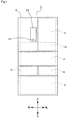
以下、冷蔵庫に係る一実施形態について図面を参照しながら説明する。図1に例示する冷蔵庫1は、その外郭を構成する矩形箱状の断熱箱体2の内部に複数の貯蔵室、この場合、冷蔵室3、野菜室4、製氷室5、小冷凍室6、大冷凍室7を備えている。この場合、冷蔵室3は、断熱箱体2の最上部に設けられている。野菜室4は、冷蔵室3の下部に設けられている。製氷室5および小冷凍室6は、野菜室4の下部において左右に並べて設けられている。大冷凍室7は、製氷室5および小冷凍室6の下部、換言すれば、断熱箱体2の最下部に設けられている。断熱箱体2は、内箱および外箱の間に真空断熱パネルや発泡ウレタンなどの断熱材を備えた構成である。また、複数の貯蔵室3,4,5,6,7は、それぞれ貯蔵室扉によって開閉されるようになっている。
An embodiment of a refrigerator will be described below with reference to the drawings. The refrigerator 1 illustrated in FIG. 1 has a plurality of storage chambers inside a rectangular box-shaped heat-
また、冷蔵室3の内部、この場合、底部には特別冷却室の一例であるチルド室10が設けられている。次に、このチルド室10およびその周辺部分の構成例について説明する。図2に例示するように、冷蔵室3内の後部には上下方向に延びる冷気ダクト11が設けられている。冷気ダクト11の上部には、複数の冷蔵室用冷気吹出口11aが設けられている。また、冷気ダクト11の下部には、冷蔵庫1の前方側である冷蔵室3内側に膨出した冷却室12が設けられている。チルド室10は、冷蔵室3内において、この冷却室12の前方に位置して設けられている。
A
冷却室12の前面の上部には、チルド室用冷気吹出口12aが設けられている。また、冷却室12の前面の下部には、チルド室用冷気吸込口12bが設けられている。チルド室用冷気吹出口12aには、冷蔵庫1の前方側であるチルド室10内側に突出する案内部12cが設けられている。案内部12cは、案内手段の一例であり、この場合、チルド室10内の底面に向かって下降傾斜する板状に設けられている。また、冷蔵庫1は、チルド室用冷気吹出口12aおよびチルド室用冷気吸込口12bにダンパを備えていない構成となっている。なお、冷蔵庫1は、チルド室用冷気吹出口12aおよびチルド室用冷気吸込口12bにダンパを備える構成としてもよい。
A chilled room
冷却室12の内面には、例えば発泡ウレタンなどにより構成される断熱材12dが取り付けられている。また、冷却室12内には、冷気を生成するための冷凍サイクルを構成する冷却器13、および、この冷却器13が生成する冷気を送風するファン14が備えられている。このファン14が駆動することにより、冷却器13が生成する冷気は、冷気ダクト11の冷蔵室用冷気吹出口11aから冷蔵室3内に供給され、また、冷却室12のチルド室用冷気吹出口12aからチルド室10内に供給される。このとき、ファン14が送風する冷気は、チルド室用冷気吹出口12aから案内板12cによって案内されて、チルド室10の底面に向かうように流れるようになる。また、チルド室10内に供給された冷気は、ファン14の送風作用により、冷却室12のチルド室用冷気吸込口12bから冷却室12内に吸い込まれるようになっている。
A
本開示に係る冷蔵庫1においては、チルド室10内には、複数、この場合、2つの収容容器21,22が上下に配置されている。これら収容容器21,22は、それぞれ別個にチルド室10内から冷蔵庫1の前後方向に沿って出し入れ可能となっている。また、冷蔵庫1は、収容容器21,22がチルド室10内に収容された状態において当該チルド室10が密閉状態とならないように構成されている。なお、冷蔵庫1は、収容容器21,22がチルド室10内に収容された状態において当該チルド室10が密閉状態となる構成としてもよい。
In the refrigerator 1 according to the present disclosure, in the
次に、冷蔵庫1の制御系の構成例について説明する。図3に例示する制御装置30は、制御手段の一例である。制御装置30は、例えばマイクロコンピュータを主体として構成されており、制御プログラムや各種の設定内容に基づき冷蔵庫1の動作全般を制御する。制御装置30には、上述したファン14が接続されている。また、制御装置30には、外気温度センサ31、チルド室用温度センサ32、表示パネル33、冷凍サイクルを構成するコンプレッサ34などが接続されている。
Next, a configuration example of the control system of the refrigerator 1 will be described. The
外気温度センサ31は、温度検知手段および外気温度検知手段の一例であり、冷蔵庫1に関わる所定領域の温度を検知するものである。本開示に係る冷蔵庫1では、外気温度センサ31は、冷蔵庫1に関わる所定領域として、この場合、冷蔵庫1の外気の温度、つまり、冷蔵庫1の周辺の温度を検知するようになっている。外気温度センサ31は、冷蔵庫1の外気の温度を検知可能な部位に設けるとよく、例えば、断熱箱体2の外面などに設けるとよい。図1に例示するように、本開示に係る冷蔵庫1においては、外気温度センサ31は、冷蔵室3を開閉する冷蔵室扉の前面に設けられている。
The outside
チルド室用温度センサ32は、温度検知手段および特別冷却室内温度検知手段の一例であり、冷蔵庫1に関わる所定領域の温度を検知するものである。本開示に係る冷蔵庫1では、チルド室用温度センサ32は、冷蔵庫1に関わる所定領域として、この場合、特別冷却室の一例であるチルド室10内の温度を検知するようになっている。なお、チルド室10およびその周辺部分の構造の複雑化を回避するべく、チルド室用温度センサ32は、チルド室10の外部に設けるようにするとよい。
The chilled
図2に例示するように、本開示に係る冷蔵庫1においては、チルド室用温度センサ32は、チルド室10の外部の一例である冷却室12の内部に設けられている。冷却室12の内部には、冷蔵室3内に供給される冷気のほか、チルド室10内に供給される冷気も流れる。よって、冷却室12内に設けられたチルド室用温度センサ32によれば、チルド室10内の温度を間接的に検知することができる。なお、チルド室用温度センサ32は、冷却室12以外の部分、例えば、冷気ダクト11の内部などに設けてもよい。
As illustrated in FIG. 2, in the refrigerator 1 according to the present disclosure, the chilled
表示パネル33は、報知手段の一例であり、例えば、冷蔵室3を開閉する冷蔵室扉の前面に設けられている。表示パネル33は、選択されている制御モードを例えば文字情報やアイコン情報などにより表示可能に構成されている。また、表示パネル33は、例えば静電容量式のタッチスイッチを備えており、使用者の操作を受け付ける操作部としても機能するようになっている。本開示に係る冷蔵庫1によれば、上述した外気温度センサ31は、この表示パネル33に組み込まれている。なお、外気温度センサ31は、表示パネル33とは別の部位に設けてもよい。
The
コンプレッサ34は、上述した冷却器13や図示しない凝縮器とともに、冷気を生成するための周知の冷凍サイクルを構成している。コンプレッサ34は、冷凍サイクルにおいて、冷却器13に冷媒を送ることにより、当該冷却器13を冷却させる。
The
制御装置30は、制御プログラムや表示パネル33を介して入力された各種の設定内容に基づいて、ファン14やコンプレッサ34などの駆動を制御することにより、冷蔵室3などの各種の貯蔵室の内部をそれぞれ設定温度に冷却する。そして、本開示に係る冷蔵庫1は、特に、チルド室10内の冷却制御について創意工夫が施されている。次に、そのチルド室10内の冷却制御例について詳細に説明する。
The
制御装置30は、冷蔵室3内およびチルド室10内を冷却する冷却モードとして、複数種類の冷却モード、この場合、少なくとも、通常冷却モード、特別チルドモードを実行可能に構成されている。
The
通常冷却モードは、チルド室10内を所定の通常温度帯に冷却する冷却モードである。なお、通常冷却モードにおける通常温度帯は、適宜変更して設定することができる。
The normal cooling mode is a cooling mode for cooling the inside of the
特別チルドモードは、特別冷却モードの一例であり、チルド室10内を通常冷却モードにおける通常温度帯よりもさらに低い特別温度帯に冷却する冷却モードである。なお、特別チルドモードにおける特別温度帯は、通常冷却モードにおける通常温度帯よりも低い温度帯において適宜変更して設定することができる。
The special chilled mode is an example of a special cooling mode, and is a cooling mode in which the inside of the
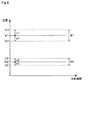
図4に例示するように、通常温度帯B1は、通常冷却モードにおける目標温度K1を基準として所定の調整値u1,d1内となる温度帯となっている。この場合、通常冷却モードにおける目標温度K1は、例えば8.0℃で設定されており、通常温度帯B1は、この通常冷却モードにおける目標温度K1に所定の通常冷却モード用上限温度調整値u1を加算した通常冷却モード用上限温度U1と、通常冷却モードにおける目標温度K1から所定の通常冷却モード用下限温度調整値d1を減算した通常冷却モード用下限温度D1との間の温度帯となっている。 As illustrated in FIG. 4, the normal temperature band B1 is a temperature band within predetermined adjustment values u1 and d1 with reference to the target temperature K1 in the normal cooling mode. In this case, the target temperature K1 in the normal cooling mode is set to, for example, 8.0° C., and the normal temperature band B1 has a predetermined normal cooling mode upper limit temperature adjustment value u1 for the target temperature K1 in the normal cooling mode. The temperature band is between the added upper limit temperature U1 for normal cooling mode and the lower limit temperature D1 for normal cooling mode obtained by subtracting the predetermined lower limit temperature adjustment value d1 for normal cooling mode from the target temperature K1 in the normal cooling mode. ..
通常冷却モード用上限温度調整値u1および通常冷却モード用下限温度調整値d1は、通常冷却モード用に規定された通常冷却モード用の調整値であり、適宜変更して設定することができる。本開示に係る冷蔵庫1では、通常冷却モード用上限温度調整値u1および通常冷却モード用下限温度調整値d1は、何れも、例えば1.0℃で設定されている。なお、通常冷却モード用上限温度調整値u1および通常冷却モード用下限温度調整値d1は、それぞれ異なる値を設定してもよい。 The upper limit temperature adjustment value u1 for the normal cooling mode and the lower limit temperature adjustment value d1 for the normal cooling mode are adjustment values for the normal cooling mode defined for the normal cooling mode, and can be appropriately changed and set. In the refrigerator 1 according to the present disclosure, the normal cooling mode upper limit temperature adjustment value u1 and the normal cooling mode lower limit temperature adjustment value d1 are both set to 1.0° C., for example. The normal cooling mode upper limit temperature adjustment value u1 and the normal cooling mode lower limit temperature adjustment value d1 may be set to different values.
一方、特別温度帯B2は、特別チルドモードにおける目標温度K2を基準として所定の調整値u2,d2内となる温度帯となっている。この場合、特別チルドモードにおける目標温度K2は、例えば2.0℃で設定されており、特別温度帯B2は、この特別チルドモードにおける目標温度K2に所定の特別チルドモード用上限温度調整値u2を加算した特別チルドモード用上限温度U2と、特別チルドモードにおける目標温度K2から所定の特別チルドモード用下限温度調整値d2を減算した特別チルドモード用下限温度D2との間の温度帯となっている。 On the other hand, the special temperature zone B2 is a temperature zone within a predetermined adjustment value u2, d2 with reference to the target temperature K2 in the special chilled mode. In this case, the target temperature K2 in the special chilled mode is set to, for example, 2.0° C., and the special temperature zone B2 has a predetermined special chilled mode upper limit temperature adjustment value u2 for the target temperature K2 in the special chilled mode. The temperature band is between the added special chilled mode upper limit temperature U2 and the special chilled mode lower limit temperature D2 obtained by subtracting the predetermined special chilled mode lower limit temperature adjustment value d2 from the target temperature K2 in the special chilled mode. ..
特別チルドモード用上限温度調整値u2および特別チルドモード用下限温度調整値d2は、特別冷却モード用に規定された特別冷却モード用の調整値であり、適宜変更して設定することができる。本開示に係る冷蔵庫1では、特別チルドモード用上限温度調整値u2および特別チルドモード用下限温度調整値d2は、何れも、例えば0.5℃で設定されている。 The special chilled mode upper limit temperature adjustment value u2 and the special chilled mode lower limit temperature adjustment value d2 are adjustment values for the special cooling mode specified for the special cooling mode, and can be appropriately changed and set. In the refrigerator 1 according to the present disclosure, both the special chilled mode upper limit temperature adjustment value u2 and the special chilled mode lower limit temperature adjustment value d2 are set to, for example, 0.5°C.
つまり、本開示に係る冷蔵庫1によれば、特別チルドモード用上限温度調整値u2として、通常冷却モード用上限温度調整値u1よりも小さい値が設定されている。また、本開示に係る冷蔵庫1によれば、特別チルドモード用下限温度調整値d2として、通常冷却モード用上限温度調整値d1よりも小さい値が設定されている。なお、特別チルドモード用上限温度調整値u2および特別チルドモード用下限温度調整値d2は、それぞれ異なる値を設定してもよい。 That is, according to the refrigerator 1 of the present disclosure, a value smaller than the upper limit temperature adjustment value u1 for the normal cooling mode is set as the upper limit temperature adjustment value u2 for the special chilled mode. Further, according to the refrigerator 1 of the present disclosure, a value smaller than the upper limit temperature adjustment value d1 for the normal cooling mode is set as the lower limit temperature adjustment value d2 for the special chilled mode. The special chilled mode upper limit temperature adjustment value u2 and the special chilled mode lower limit temperature adjustment value d2 may be set to different values.
制御装置30は、通常冷却モードの実行中においては、チルド室用温度センサ32によって検知されるチルド室10内の温度が通常冷却モード用上限温度U1以上になると、コンプレッサ34の駆動をオンする。これにより、チルド室10内の冷却が開始され、当該チルド室10内の温度が通常冷却モード用上限温度U1よりも低くなっていく。また、制御装置30は、通常冷却モードの実行中においては、チルド室用温度センサ32によって検知されるチルド室10内の温度が通常冷却モード用下限温度D1以下になると、コンプレッサ34の駆動をオフする。これにより、チルド室10内の冷却が停止され、当該チルド室10内の温度が通常冷却モード用下限温度D1よりも高くなっていく。制御装置30は、このように、チルド室10内の温度の高低に基づきコンプレッサ34の駆動を制御することにより、チルド室10内の温度を所定の通常温度帯B1内に維持する。
During execution of the normal cooling mode, the
なお、制御装置30は、通常冷却モードの実行中においては、ファン14の駆動のオン/オフをコンプレッサ34の駆動のオン/オフに連動させるようにしてもよいし、連動させないようにしてもよい。
Note that the
一方、制御装置30は、特別冷却モードの実行中においては、チルド室用温度センサ32によって検知されるチルド室10内の温度が特別チルドモード用上限温度U2以上になると、コンプレッサ34の駆動をオンする。これにより、チルド室10内の冷却が開始され、当該チルド室10内の温度が特別チルドモード用上限温度U2よりも低くなっていく。また、制御装置30は、特別冷却モードの実行中においては、チルド室用温度センサ32によって検知されるチルド室10内の温度が特別チルドモード用下限温度D2以下になると、コンプレッサ34の駆動をオフする。これにより、チルド室10内の冷却が停止され、当該チルド室10内の温度が特別チルドモード用下限温度D2よりも高くなっていく。制御装置30は、このように、チルド室10内の温度の高低に基づきコンプレッサ34の駆動を制御することにより、チルド室10内の温度を所定の特別温度帯B2内に維持する。
On the other hand, during execution of the special cooling mode, the
また、制御装置30は、特別冷却モードの実行中においては、例えば下記のようにファン14の駆動を制御する。即ち、制御装置30は、特別冷却モードの実行中において、チルド室用温度センサ32によって検知されるチルド室10内の温度が特別チルドモード用上限温度U2以上になると、コンプレッサ34の運転周波数に基づいてファン14の回転速度を制御する。つまり、制御装置30は、ファン14の回転速度をコンプレッサ依存制御により制御する。
Further, the
本開示に係る冷蔵庫1では、制御装置30は、チルド室10内の温度が特別チルドモード用上限温度U2から高いほど、コンプレッサ34の運転周波数を高くするように設定されている。そのため、制御装置30は、チルド室10内の温度が特別チルドモード用上限温度U2から高いほど、つまり、コンプレッサ34の運転周波数が高いほど、ファン14の回転速度を高くする。この場合、制御装置30は、コンプレッサ34の運転周波数に応じて、換言すれば、チルド室10内の温度に応じて、複数段階、例えば、2000rpm、1500rpm、1000rpmの3段階でファン14の回転速度を切り換えるように構成されている。
In the refrigerator 1 according to the present disclosure, the
なお、チルド室10内の温度が特別チルドモード用上限温度U2以上である場合におけるファン14の回転速度は、コンプレッサ34の運転周波数に関わらず一定の回転速度、例えば、1500rpmで一定としてもよい。
When the temperature in the
また、制御装置30は、特別冷却モードの実行中において、チルド室用温度センサ32によって検知されるチルド室10内の温度が特別温度帯B2内に維持されている場合には、外気温度センサ31によって検知される冷蔵庫1の外気の温度に基づいてファン14の回転速度を制御する。つまり、制御装置30は、ファン14の回転速度を外気温度依存制御により制御する。
Further, when the temperature in the
チルド室10内の温度が特別温度帯B2内に維持されている場合とは、つまり、チルド室10内の温度が、特別チルドモードにおける目標温度K2に特別チルドモード用上限温度調整値u2を加算した特別チルドモード用上限温度U2と特別チルドモードにおける目標温度K2から特別チルドモード用下限温度調整値d2を減算した特別チルドモード用下限温度D2との間の温度帯に維持されている場合、ということである。
When the temperature in the
本開示に係る冷蔵庫1では、制御装置30は、冷蔵庫1の外気の温度が高いほど、ファン14の回転速度を高くする。この場合、制御装置30は、冷蔵庫1の外気の温度に応じて、複数段階、例えば、900rpm、850rpm、800rpmの3段階でファン14の回転速度を切り換えるように構成されている。
In the refrigerator 1 according to the present disclosure, the
なお、チルド室10内の温度が特別温度帯B2内に維持されている場合におけるファン14の回転速度は、チルド室10内の温度が特別チルドモード用上限温度U2以上である場合におけるファン14の回転速度よりも低い回転速度で設定するとよい。また、チルド室10内の温度が特別温度帯B2内に維持されている場合におけるファン14の回転速度は、冷蔵庫1の外気の温度に関わらず一定の回転速度、例えば、900rpmで一定としてもよい。
The rotation speed of the
また、制御装置30は、さらに、うるおいモードを実行可能に構成されている。うるおいモードは、チルド室10内に湿気を供給するための制御モードであり、この場合、冷却器13に付着した霜をファン14の送風作用によって吹き飛ばしてチルド室10内に供給する制御モードとなっている。つまり、うるおいモードは、冷却器13から霜を取り除く除霜モードの一例でもある。そして、制御装置30は、このうるおいモードにおけるファン14の回転速度を、特別チルドモードにおけるファン14の回転速度よりも高くする。この場合、制御装置30は、うるおいモードにおけるファン14の回転速度を、例えば2200rpmで設定している。
Further, the
なお、うるおいモードの動作を開始する開始条件および動作を終了する終了条件は、適宜変更して設定することができる。例えば、うるおいモードの動作を開始する開始条件は、冷蔵庫1の外気の温度が所定温度以上になった場合、図示しない湿度センサにより検知される湿度が所定湿度以下になった場合、ユーザによりうるおいモードの開始が入力された場合などを設定することができる。また、うるおいモードの動作を終了する終了条件は、冷蔵庫1の外気の温度が所定温度以下になった場合、図示しない湿度センサにより検知される湿度が所定湿度以上になった場合、ユーザによりうるおいモードの終了が入力された場合などを設定することができる。 The start condition for starting the operation in the moisture mode and the end condition for ending the operation can be appropriately changed and set. For example, the start condition for starting the operation in the moisture mode is that the user selects the moisture mode when the temperature of the outside air of the refrigerator 1 is equal to or higher than a predetermined temperature, or when the humidity detected by a humidity sensor (not shown) is equal to or lower than the predetermined humidity. It can be set when the start of is input. In addition, the end condition for ending the operation in the moisture mode is that the moisture mode by the user is set when the temperature of the outside air of the refrigerator 1 becomes a predetermined temperature or lower, or when the humidity detected by a humidity sensor (not shown) becomes the predetermined humidity or higher. It is possible to set the case where the end of is input.
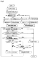
次に、制御装置30による冷蔵庫1の制御例について説明する。なお、ここでは、上述した通常冷却モードおよび特別チルドモードの何れか一方のモードを選択的に実行する場合の制御例について説明する。図5に例示するように、制御装置30は、冷蔵室3内およびチルド室10内の冷却動作を開始すると、つまり、ファン14やコンプレッサ34などの駆動を開始すると(S1)、図示しないタイマにより、冷却動作を開始してからの経過時間つまり冷却時間の計測を開始する(S2)。また、制御装置30は、設定されている冷却モードが特別チルドモードであるか否かを確認する(S3)。
Next, an example of control of the refrigerator 1 by the
制御装置30は、設定されている冷却モードが特別チルドモードでない場合(S3:NO)には、チルド室10内の目標温度として通常冷却モードにおける目標温度K1を設定する(S4)。そして、制御装置30は、通常冷却モード用上限温度調整値u1および通常冷却モード用下限温度調整値d1を設定する(S5)。この場合、制御装置30は、通常冷却モード用上限温度調整値u1および通常冷却モード用下限温度調整値d1として、何れも1.0℃を設定する。
If the set cooling mode is not the special chilled mode (S3: NO),
そして、制御装置30は、通常冷却モードにおける通常温度帯B1を設定する(S6)。即ち、制御装置30は、通常冷却モードにおける目標温度K1に通常冷却モード用上限温度調整値u1を加算した通常冷却モード用上限温度U1と、通常冷却モードにおける目標温度K1から通常冷却モード用下限温度調整値d1を減算した通常冷却モード用下限温度D1との間の温度帯を、通常温度帯B1として決定する。そして、制御装置30は、ステップS10に移行する。
Then, the
一方、制御装置30は、特別チルドモードの実行が設定されている場合(S3:YES)には、チルド室10内の目標温度として特別チルドモードにおける目標温度K2を設定する(S7)。そして、制御装置30は、特別チルドモード用上限温度調整値u2および特別チルドモード用下限温度調整値d2を設定する(S8)。この場合、制御装置30は、特別チルドモード用上限温度調整値u2および特別チルドモード用下限温度調整値d2として、何れも0.5℃を設定する。つまり、制御装置30は、特別チルドモード用上限温度調整値u2として通常冷却モード用上限温度調整値u1よりも小さい値を設定し、特別チルドモード用下限温度調整値d2として通常冷却モード用上限温度調整値d1よりも小さい値を設定する。
On the other hand, when execution of the special chilled mode is set (S3: YES), the
そして、制御装置30は、特別チルドモードにおける特別温度帯B2を設定する(S9)。即ち、制御装置30は、特別チルドモードにおける目標温度K2に特別チルドモード用上限温度調整値u2を加算した特別チルドモード用上限温度U2と、特別チルドモードにおける目標温度K2から特別チルドモード用下限温度調整値d2を減算した特別チルドモード用下限温度D2との間の温度帯を、特別温度帯B2として決定する。そして、制御装置30は、ステップS10に移行する。
Then, the
制御装置30は、ステップS10に移行すると、冷却動作を開始してからの経過時間、つまり、冷却時間が所定の最大冷却時間を超えているか否かを確認する。最大冷却時間は、適宜変更して設定することができ、この場合、例えば60分が設定されている。制御装置30は、冷却時間が最大冷却時間を超えている場合(S10:YES)には、冷蔵室3内およびチルド室10内の冷却動作を終了、つまり、ファン14やコンプレッサ34などの駆動を停止する(S17)。
When the
一方、制御装置30は、冷却時間が最大冷却時間を超えていない場合(S10:NO)には、冷却時間が最低冷却時間を超えているか否か、および、冷凍室の温度が所定の冷凍開始温度を超えているか否か、を確認する(S11)。最低冷却時間は、適宜変更して設定することができ、この場合、例えば20分が設定されている。また、冷凍室の温度は、例えば、冷凍室7内、あるいは、冷凍室7内に冷気を供給する冷気ダクト内に設けられている図示しない冷凍室用の温度センサによって検知することができる。また、冷凍室の冷凍開始温度は、適宜変更して設定することができる。
On the other hand, when the cooling time does not exceed the maximum cooling time (S10: NO), the
制御装置30は、冷却時間が最低冷却時間を超えており、且つ、冷凍室の温度が所定の冷凍開始温度を超えている場合(S11:YES)には、冷蔵室3内およびチルド室10内の冷却動作を終了、つまり、ファン14やコンプレッサ34などの駆動を停止する(S17)。つまり、制御装置30は、冷蔵室3内およびチルド室10内を少なくとも最低冷却時間を超えて冷却している状況において、冷凍室7の温度が冷却を要するほど高くなっている状況となっている場合には、冷蔵室3内およびチルド室10内の冷却動作を終了して、冷凍サイクルが発生する冷気を冷凍室7に提供するようになっている。
When the cooling time exceeds the minimum cooling time and the temperature of the freezing compartment exceeds the predetermined freezing start temperature (S11: YES), the
一方、制御装置30は、冷却時間が最低冷却時間を超えていない場合、または、冷凍室の温度が所定の冷凍開始温度を超えていない場合(S11:NO)には、チルド室用温度センサ32によって検知される温度、つまり、チルド室10内の温度が特別温度帯B2の下限温度、つまり、特別チルドモード用下限温度D2よりも低くなっているか否かを確認する(S12)。
On the other hand, if the cooling time does not exceed the minimum cooling time, or if the temperature of the freezing compartment does not exceed the predetermined freezing start temperature (S11: NO), the
制御装置30は、チルド室10内の温度が特別チルドモード用下限温度D2よりも低くなっている場合(S12:YES)には、冷蔵室3内およびチルド室10内の冷却動作を終了、つまり、ファン14やコンプレッサ34などの駆動を停止する(S17)。これにより、チルド室10内の温度が上昇して特別チルドモード用下限温度D2以上となり、チルド室10内の温度が特別温度帯B2内に収まるようになる。
When the temperature inside the
一方、制御装置30は、チルド室10内の温度が特別チルドモード用下限温度D2よりも低くなっていない場合(S12:NO)には、念のため、設定されている冷却モードが特別チルドモードであるか否かを改めて確認する(S13)。
On the other hand, when the temperature inside the
制御装置30は、設定されている冷却モードが特別チルドモードでない場合(S13:NO)には、ファン14の回転速度をコンプレッサ依存制御により制御する(S14)。このコンプレッサ依存制御は、ファン14の回転速度を、コンプレッサ34の運転周波数に基づいて制御するものである。そして、制御装置30は、コンプレッサ依存制御を開始すると、ステップS10に移行する。なお、このとき、制御装置30は、ステップS3に移行するようにしてもよい。
When the set cooling mode is not the special chilled mode (S13: NO), the
一方、制御装置30は、設定されている冷却モードが特別チルドモードである場合(S13:YES)には、チルド室用温度センサ32によって検知される温度、つまり、チルド室10内の温度が特別温度帯B2の上限温度、つまり、特別チルドモード用上限温度U2よりも高くなっているか否かを確認する(S15)。
On the other hand, when the set cooling mode is the special chilled mode (S13: YES), the
そして、制御装置30は、チルド室10内の温度が特別チルドモード用上限温度U2よりも高くなっている場合(S15:YES)には、コンプレッサ34の運転周波数に基づいてファン14の回転速度を制御する(S14)。
Then, when the temperature in the
一方、制御装置30は、チルド室10内の温度が特別チルドモード用上限温度U2よりも高くなっていない場合(S15:NO)には、ファン14の回転速度を外気温度依存制御により制御する(S16)。この外気温度依存制御は、ファン14の回転速度を、冷蔵庫1の外気の温度に基づいて制御するものである。そして、制御装置30は、外気温度依存制御を開始すると、ステップS10に移行する。なお、このとき、制御装置30は、ステップS3に移行するようにしてもよい。
On the other hand, when the temperature inside the
本開示に係る冷蔵庫1によれば、特別チルドモードにおける特別温度帯B2を規定する調整値として、特別チルドモード用に規定された特別チルドモード用調整値u2,d2を設定するようにした。この場合、特別チルドモード用調整値u2,d2として、通常冷却モードにおける調整値u1,d1よりも小さい値が設定される。そのため、特別チルドモードにおける特別温度帯B2は、通常冷却モードにおける通常温度帯B1よりも狭い温度帯となり、従って、特別チルドモードにおいては、通常冷却モードに比べ、コンプレッサ34のオン/オフがきめ細かく制御されるようになる。
According to the refrigerator 1 according to the present disclosure, the special chilled mode adjustment values u2 and d2 defined for the special chilled mode are set as the adjustment values that define the special temperature zone B2 in the special chilled mode. In this case, the adjustment values u2 and d2 for the special chilled mode are set to values smaller than the adjustment values u1 and d1 in the normal cooling mode. Therefore, the special temperature zone B2 in the special chilled mode is a narrower temperature zone than the normal temperature zone B1 in the normal cooling mode. Therefore, in the special chilled mode, the on/off of the
よって、チルド室10の内部を、特別チルドモードにおける目標温度帯である特別温度帯B2内に精度良く冷却することができる。さらに、本開示に係る冷蔵庫1によれば、このような特別温度帯B2の調整によってチルド室10の内部を目標温度帯に精度良く冷却できるようにした。そのため、例えば、チルド室10を密閉構造にしたり、温度センサをチルド室10内に設けたり、チルド室10内への冷気の送風口にダンパを設けたりする必要がなく、従って、構造の複雑化、部品点数の増加、制御の複雑化を招くことなく、チルド室10の内部を目標温度帯に精度良く冷却することができる。
Therefore, the inside of the
また、冷蔵庫1によれば、制御装置30は、特別チルドモードの実行中において、チルド室10内の温度が特別温度帯B2の上限温度U2以上になると、コンプレッサ34の運転周波数に基づいてファン14の回転速度を制御する。そのため、チルド室10内の温度が特別温度帯B2の上限温度U2以上である場合に、チルド室10内に冷気を迅速に供給することができ、チルド室10内の温度を特別温度帯B2の上限温度U2以下、つまり、特別温度帯B2の範囲内に迅速に収めることができる。
Further, according to the refrigerator 1, when the temperature in the
また、冷蔵庫1によれば、制御装置30は、特別冷却モードの実行中において、チルド室10内の温度が特別温度帯B2の範囲内に維持されている場合には、冷蔵庫1の外気の温度に基づいてファン14の回転速度を制御する。これにより、冷蔵庫1の外気の温度に応じて、チルド室10内に供給される冷気の量をきめ細かく調整することができ、チルド室10内の温度が特別温度帯B2の範囲内に収められた状態を長期にわたって安定的に維持することができる。
Further, according to the refrigerator 1, when the temperature inside the
また、冷蔵庫1によれば、うるおいモードにおけるファン14の回転速度を、特別チルドモードにおけるファン14の回転速度よりも高くする。つまり、うるおいモードにおけるファン14の回転速度を、ある程度の高い回転速度とすることにより、冷却器13に付着した霜を効率良く吹き飛ばしてチルド室10内に供給することができ、チルド室10内の湿気を十分に維持することができる。
Further, according to the refrigerator 1, the rotation speed of the
なお、本実施形態は、上述した一実施形態に限定されるものではなく、その要旨を逸脱しない範囲で種々の変形または拡張を行うことができる。例えば、冷蔵庫1は、当該冷蔵庫1に関わる所定領域の温度として外気の温度を検知するものに限られるものではなく、例えば、貯蔵室内の温度、制御装置30やコンプレッサ34が備えられる図示しない機械室の温度、冷却室12内の温度などの温度を検知するように構成してもよい。
The present embodiment is not limited to the above-described embodiment, and various modifications or expansions can be made without departing from the spirit of the present invention. For example, the refrigerator 1 is not limited to one that detects the temperature of the outside air as the temperature of the predetermined region related to the refrigerator 1, and for example, the temperature in the storage room, a machine room (not shown) in which the
また、特別冷却室は、チルド室10に限定されるものではなく、他の冷却室であってもよい。また、特別冷却室が設けられる位置は、冷蔵室3内の底部に限定されるものではなく、例えば、冷蔵室3内の上部や側部、あるいは、他の貯蔵室の内部など、適宜変更して実施することができる。
Further, the special cooling chamber is not limited to the
以上、本発明の複数の実施形態を説明したが、本実施形態は、例として提示したものであり、発明の範囲を限定することは意図していない。この新規な実施形態は、その他の様々な形態で実施されることが可能であり、発明の要旨を逸脱しない範囲で、種々の省略、置き換え、変更を行うことができる。本実施形態やその変形は、発明の範囲や要旨に含まれるとともに、特許請求の範囲に記載された発明とその均等の範囲に含まれる。 Although a plurality of embodiments of the present invention have been described above, the present embodiments are presented as examples and are not intended to limit the scope of the invention. The novel embodiment can be implemented in various other forms, and various omissions, replacements, and changes can be made without departing from the spirit of the invention. The present embodiment and its modifications are included in the scope and gist of the invention, and are also included in the invention described in the claims and the scope equivalent thereto.
図面中、1は冷蔵庫、3は冷蔵室、10はチルド室(特別冷却室)、13は冷却器、14はファン、30は制御装置(制御手段)、31は外気温度センサ(温度検知手段、外気温度検知手段)、32はチルド室用温度センサ(温度検知手段、特別冷却室内温度検知手段)、34はコンプレッサを示す。
In the drawings, 1 is a refrigerator, 3 is a refrigerating room, 10 is a chilled room (special cooling room), 13 is a cooler, 14 is a fan, 30 is a control device (control means), 31 is an outside air temperature sensor (temperature detection means, Outside temperature detecting means), 32 is a temperature sensor for chilled chamber (temperature detecting means, special cooling room temperature detecting means), and 34 is a compressor.
Claims (5)
前記特別冷却室内の冷却を制御する制御手段と、
を備え、
前記制御手段は、
前記特別冷却室内を冷却する冷却モードとして、
前記特別冷却室内を通常温度帯に冷却する通常冷却モードと、
前記特別冷却室内を前記通常冷却モードにおける通常温度帯よりも低い特別温度帯に冷却する特別冷却モードと、
を実行可能であり、
前記特別温度帯は、前記特別冷却モードにおける目標温度を基準として所定の調整値内となる温度帯であって、
前記調整値として、前記特別冷却モード用に規定された特別冷却モード用調整値が設定される冷蔵庫。 A special cooling room provided in the refrigeration room,
Control means for controlling the cooling of the special cooling chamber,
Equipped with
The control means is
As a cooling mode for cooling the special cooling chamber,
A normal cooling mode for cooling the special cooling chamber to a normal temperature zone,
A special cooling mode for cooling the special cooling chamber to a special temperature zone lower than the normal temperature zone in the normal cooling mode,
Is feasible,
The special temperature zone is a temperature zone within a predetermined adjustment value with reference to the target temperature in the special cooling mode,
The refrigerator in which the adjustment value for the special cooling mode defined for the special cooling mode is set as the adjustment value.
前記特別冷却モード用調整値として、前記通常冷却モードにおける前記調整値よりも小さい値が設定される請求項1に記載の冷蔵庫。 The normal temperature zone is a temperature zone within a predetermined adjustment value with reference to the target temperature in the normal cooling mode,
The refrigerator according to claim 1, wherein a value smaller than the adjustment value in the normal cooling mode is set as the adjustment value for the special cooling mode.
冷気を生成する冷却器と、
前記冷却器に冷媒を送るコンプレッサと、
前記冷却器が生成する冷気を前記特別冷却室内に送風するファンと、
を備え、
前記制御手段は、前記特別冷却モードの実行中において、前記温度検知手段が検知する温度が、前記特別冷却モードにおける目標温度に前記特別冷却モード用調整値を加算した温度以上になると、前記コンプレッサの運転周波数に基づいて前記ファンの回転速度を制御する請求項1または2に記載の冷蔵庫。 Temperature detection means for detecting the temperature of a predetermined region,
A cooler that produces cold air,
A compressor that sends refrigerant to the cooler,
A fan that blows cool air generated by the cooler into the special cooling chamber;
Equipped with
During the execution of the special cooling mode, the control means, when the temperature detected by the temperature detection means is equal to or higher than the temperature obtained by adding the special cooling mode adjustment value to the target temperature in the special cooling mode, The refrigerator according to claim 1, wherein the rotation speed of the fan is controlled based on an operating frequency.
前記特別冷却室内の温度を検知する特別冷却室内温度検知手段と、
外気の温度を検知する外気温度検知手段と、
を備え、
前記制御手段は、前記特別冷却モードの実行中において、前記特別冷却室内温度検知手段が検知する温度が、前記特別冷却モードにおける目標温度に前記特別冷却モード用調整値を加算した温度と前記特別冷却モードにおける目標温度から前記特別冷却モード用調整値を減算した温度との間の温度である場合には、前記外気温度検知手段が検知する温度に基づいて前記ファンの回転速度を制御する請求項3に記載の冷蔵庫。 As the temperature detecting means,
A special cooling chamber temperature detecting means for detecting the temperature in the special cooling chamber,
An outside air temperature detecting means for detecting the temperature of the outside air,
Equipped with
During the execution of the special cooling mode, the control unit detects the temperature detected by the special cooling chamber temperature detection unit by adding the special cooling mode adjustment value to the target temperature in the special cooling mode and the special cooling. The rotation speed of the fan is controlled based on the temperature detected by the outside air temperature detection means when the temperature is between the target temperature in the mode and the temperature obtained by subtracting the adjustment value for the special cooling mode. Refrigerator described in.
前記除霜モードにおける前記ファンの回転速度を、前記特別冷却モードにおける前記ファンの回転速度よりも高くする請求項3または4に記載の冷蔵庫。
The control means is capable of executing a defrost mode in which frost attached to the cooler is blown off by the fan,
The refrigerator according to claim 3 or 4, wherein a rotation speed of the fan in the defrosting mode is set higher than a rotation speed of the fan in the special cooling mode.
Priority Applications (1)
| Application Number | Priority Date | Filing Date | Title |
|---|---|---|---|
| JP2019013045A JP7391515B2 (en) | 2019-01-29 | 2019-01-29 | refrigerator |
Applications Claiming Priority (1)
| Application Number | Priority Date | Filing Date | Title |
|---|---|---|---|
| JP2019013045A JP7391515B2 (en) | 2019-01-29 | 2019-01-29 | refrigerator |
Publications (2)
| Publication Number | Publication Date |
|---|---|
| JP2020122590A true JP2020122590A (en) | 2020-08-13 |
| JP7391515B2 JP7391515B2 (en) | 2023-12-05 |
Family
ID=71993530
Family Applications (1)
| Application Number | Title | Priority Date | Filing Date |
|---|---|---|---|
| JP2019013045A Active JP7391515B2 (en) | 2019-01-29 | 2019-01-29 | refrigerator |
Country Status (1)
| Country | Link |
|---|---|
| JP (1) | JP7391515B2 (en) |
Citations (8)
| Publication number | Priority date | Publication date | Assignee | Title |
|---|---|---|---|---|
| JPS61243268A (en) * | 1985-04-18 | 1986-10-29 | 三洋電機株式会社 | Controller for refrigerator, etc. |
| JPS61282772A (en) * | 1985-06-10 | 1986-12-12 | 三洋電機株式会社 | Temperature controller for refrigerator |
| JPH1047827A (en) * | 1996-08-06 | 1998-02-20 | Matsushita Refrig Co Ltd | Freezing refrigerator |
| JP2004286393A (en) * | 2003-03-25 | 2004-10-14 | Toshiba Corp | Refrigerator |
| JP2007127361A (en) * | 2005-11-07 | 2007-05-24 | Fukushima Industries Corp | Temperature controller of showcase |
| KR20070075674A (en) * | 2006-01-14 | 2007-07-24 | 삼성전자주식회사 | Refrigerator and temperature control method thereof |
| JP2008107068A (en) * | 2006-09-27 | 2008-05-08 | Sanyo Electric Co Ltd | Cooling storage |
| JP2012220047A (en) * | 2011-04-05 | 2012-11-12 | Panasonic Corp | Refrigerator |
-
2019
- 2019-01-29 JP JP2019013045A patent/JP7391515B2/en active Active
Patent Citations (8)
| Publication number | Priority date | Publication date | Assignee | Title |
|---|---|---|---|---|
| JPS61243268A (en) * | 1985-04-18 | 1986-10-29 | 三洋電機株式会社 | Controller for refrigerator, etc. |
| JPS61282772A (en) * | 1985-06-10 | 1986-12-12 | 三洋電機株式会社 | Temperature controller for refrigerator |
| JPH1047827A (en) * | 1996-08-06 | 1998-02-20 | Matsushita Refrig Co Ltd | Freezing refrigerator |
| JP2004286393A (en) * | 2003-03-25 | 2004-10-14 | Toshiba Corp | Refrigerator |
| JP2007127361A (en) * | 2005-11-07 | 2007-05-24 | Fukushima Industries Corp | Temperature controller of showcase |
| KR20070075674A (en) * | 2006-01-14 | 2007-07-24 | 삼성전자주식회사 | Refrigerator and temperature control method thereof |
| JP2008107068A (en) * | 2006-09-27 | 2008-05-08 | Sanyo Electric Co Ltd | Cooling storage |
| JP2012220047A (en) * | 2011-04-05 | 2012-11-12 | Panasonic Corp | Refrigerator |
Also Published As
| Publication number | Publication date |
|---|---|
| JP7391515B2 (en) | 2023-12-05 |
Similar Documents
| Publication | Publication Date | Title |
|---|---|---|
| KR20190049080A (en) | Refrigerator and method for controlling the same | |
| JP6925514B2 (en) | refrigerator | |
| KR101721771B1 (en) | Colntrol method for refrigerator | |
| CN111426123B (en) | Refrigerator with a door | |
| KR100235441B1 (en) | Cool air circulation method and device of a refrigerator | |
| JP2005172298A (en) | Control method of refrigerator | |
| JP6812386B2 (en) | refrigerator | |
| JP7391515B2 (en) | refrigerator | |
| JP6211872B2 (en) | refrigerator | |
| JP5835992B2 (en) | refrigerator | |
| JP7086663B2 (en) | refrigerator | |
| JP7391511B2 (en) | refrigerator | |
| JP7112338B2 (en) | refrigerator | |
| JP7148416B2 (en) | refrigerator | |
| JP3813457B2 (en) | refrigerator | |
| JP5766000B2 (en) | Cooling storage | |
| WO2019193861A1 (en) | Refrigerator | |
| JPH11223447A (en) | Method for controlling refrigerator | |
| JPWO2016135812A1 (en) | refrigerator | |
| JP6495017B2 (en) | refrigerator | |
| JP3332801B2 (en) | refrigerator | |
| JP2990108B2 (en) | Refrigerator having air curtain generation device and air curtain generation operation control method for refrigerator | |
| CN112262289B (en) | Refrigerator with a door | |
| KR100595438B1 (en) | Refrigerator and Control Method Thereof | |
| JP6325273B2 (en) | refrigerator |
Legal Events
| Date | Code | Title | Description |
|---|---|---|---|
| A621 | Written request for application examination |
Free format text: JAPANESE INTERMEDIATE CODE: A621 Effective date: 20210908 |
|
| A131 | Notification of reasons for refusal |
Free format text: JAPANESE INTERMEDIATE CODE: A131 Effective date: 20220621 |
|
| A977 | Report on retrieval |
Free format text: JAPANESE INTERMEDIATE CODE: A971007 Effective date: 20220622 |
|
| A521 | Request for written amendment filed |
Free format text: JAPANESE INTERMEDIATE CODE: A523 Effective date: 20220817 |
|
| A131 | Notification of reasons for refusal |
Free format text: JAPANESE INTERMEDIATE CODE: A131 Effective date: 20221213 |
|
| A521 | Request for written amendment filed |
Free format text: JAPANESE INTERMEDIATE CODE: A523 Effective date: 20230202 |
|
| A131 | Notification of reasons for refusal |
Free format text: JAPANESE INTERMEDIATE CODE: A131 Effective date: 20230221 |
|
| A521 | Request for written amendment filed |
Free format text: JAPANESE INTERMEDIATE CODE: A523 Effective date: 20230413 |
|
| A02 | Decision of refusal |
Free format text: JAPANESE INTERMEDIATE CODE: A02 Effective date: 20230613 |
|
| A521 | Request for written amendment filed |
Free format text: JAPANESE INTERMEDIATE CODE: A523 Effective date: 20230905 |
|
| A911 | Transfer to examiner for re-examination before appeal (zenchi) |
Free format text: JAPANESE INTERMEDIATE CODE: A911 Effective date: 20230921 |
|
| TRDD | Decision of grant or rejection written | ||
| A01 | Written decision to grant a patent or to grant a registration (utility model) |
Free format text: JAPANESE INTERMEDIATE CODE: A01 Effective date: 20231114 |
|
| A61 | First payment of annual fees (during grant procedure) |
Free format text: JAPANESE INTERMEDIATE CODE: A61 Effective date: 20231122 |
|
| R150 | Certificate of patent or registration of utility model |
Ref document number: 7391515 Country of ref document: JP Free format text: JAPANESE INTERMEDIATE CODE: R150 |