JP2020121179A - System for treating urinary retention of mammal patient - Google Patents
System for treating urinary retention of mammal patient Download PDFInfo
- Publication number
- JP2020121179A JP2020121179A JP2020080188A JP2020080188A JP2020121179A JP 2020121179 A JP2020121179 A JP 2020121179A JP 2020080188 A JP2020080188 A JP 2020080188A JP 2020080188 A JP2020080188 A JP 2020080188A JP 2020121179 A JP2020121179 A JP 2020121179A
- Authority
- JP
- Japan
- Prior art keywords
- energy
- bladder
- appendix
- patient
- reservoir
- Prior art date
- Legal status (The legal status is an assumption and is not a legal conclusion. Google has not performed a legal analysis and makes no representation as to the accuracy of the status listed.)
- Pending
Links
- 0 CC(*)C(CCC1)CC1(C)O Chemical compound CC(*)C(CCC1)CC1(C)O 0.000 description 3
Images


Classifications
-
- A—HUMAN NECESSITIES
- A61—MEDICAL OR VETERINARY SCIENCE; HYGIENE
- A61N—ELECTROTHERAPY; MAGNETOTHERAPY; RADIATION THERAPY; ULTRASOUND THERAPY
- A61N1/00—Electrotherapy; Circuits therefor
- A61N1/18—Applying electric currents by contact electrodes
- A61N1/32—Applying electric currents by contact electrodes alternating or intermittent currents
- A61N1/36—Applying electric currents by contact electrodes alternating or intermittent currents for stimulation
- A61N1/372—Arrangements in connection with the implantation of stimulators
- A61N1/37211—Means for communicating with stimulators
- A61N1/37252—Details of algorithms or data aspects of communication system, e.g. handshaking, transmitting specific data or segmenting data
-
- A—HUMAN NECESSITIES
- A61—MEDICAL OR VETERINARY SCIENCE; HYGIENE
- A61B—DIAGNOSIS; SURGERY; IDENTIFICATION
- A61B17/00—Surgical instruments, devices or methods, e.g. tourniquets
- A61B17/12—Surgical instruments, devices or methods, e.g. tourniquets for ligaturing or otherwise compressing tubular parts of the body, e.g. blood vessels, umbilical cord
- A61B17/12009—Implements for ligaturing other than by clamps or clips, e.g. using a loop with a slip knot
-
- A—HUMAN NECESSITIES
- A61—MEDICAL OR VETERINARY SCIENCE; HYGIENE
- A61B—DIAGNOSIS; SURGERY; IDENTIFICATION
- A61B17/00—Surgical instruments, devices or methods, e.g. tourniquets
- A61B17/12—Surgical instruments, devices or methods, e.g. tourniquets for ligaturing or otherwise compressing tubular parts of the body, e.g. blood vessels, umbilical cord
- A61B17/132—Tourniquets
- A61B17/135—Tourniquets inflatable
- A61B17/1355—Automated control means therefor
-
- A—HUMAN NECESSITIES
- A61—MEDICAL OR VETERINARY SCIENCE; HYGIENE
- A61B—DIAGNOSIS; SURGERY; IDENTIFICATION
- A61B5/00—Measuring for diagnostic purposes; Identification of persons
- A61B5/02—Detecting, measuring or recording pulse, heart rate, blood pressure or blood flow; Combined pulse/heart-rate/blood pressure determination; Evaluating a cardiovascular condition not otherwise provided for, e.g. using combinations of techniques provided for in this group with electrocardiography or electroauscultation; Heart catheters for measuring blood pressure
- A61B5/02007—Evaluating blood vessel condition, e.g. elasticity, compliance
-
- A—HUMAN NECESSITIES
- A61—MEDICAL OR VETERINARY SCIENCE; HYGIENE
- A61B—DIAGNOSIS; SURGERY; IDENTIFICATION
- A61B5/00—Measuring for diagnostic purposes; Identification of persons
- A61B5/07—Endoradiosondes
- A61B5/076—Permanent implantations
-
- A—HUMAN NECESSITIES
- A61—MEDICAL OR VETERINARY SCIENCE; HYGIENE
- A61B—DIAGNOSIS; SURGERY; IDENTIFICATION
- A61B5/00—Measuring for diagnostic purposes; Identification of persons
- A61B5/43—Detecting, measuring or recording for evaluating the reproductive systems
- A61B5/4375—Detecting, measuring or recording for evaluating the reproductive systems for evaluating the male reproductive system
- A61B5/4393—Sexual arousal or erectile dysfunction evaluation, e.g. tumescence evaluation
-
- A—HUMAN NECESSITIES
- A61—MEDICAL OR VETERINARY SCIENCE; HYGIENE
- A61B—DIAGNOSIS; SURGERY; IDENTIFICATION
- A61B5/00—Measuring for diagnostic purposes; Identification of persons
- A61B5/68—Arrangements of detecting, measuring or recording means, e.g. sensors, in relation to patient
- A61B5/6846—Arrangements of detecting, measuring or recording means, e.g. sensors, in relation to patient specially adapted to be brought in contact with an internal body part, i.e. invasive
- A61B5/6847—Arrangements of detecting, measuring or recording means, e.g. sensors, in relation to patient specially adapted to be brought in contact with an internal body part, i.e. invasive mounted on an invasive device
- A61B5/6862—Stents
-
- A—HUMAN NECESSITIES
- A61—MEDICAL OR VETERINARY SCIENCE; HYGIENE
- A61B—DIAGNOSIS; SURGERY; IDENTIFICATION
- A61B5/00—Measuring for diagnostic purposes; Identification of persons
- A61B5/68—Arrangements of detecting, measuring or recording means, e.g. sensors, in relation to patient
- A61B5/6846—Arrangements of detecting, measuring or recording means, e.g. sensors, in relation to patient specially adapted to be brought in contact with an internal body part, i.e. invasive
- A61B5/6867—Arrangements of detecting, measuring or recording means, e.g. sensors, in relation to patient specially adapted to be brought in contact with an internal body part, i.e. invasive specially adapted to be attached or implanted in a specific body part
- A61B5/6876—Blood vessel
-
- A—HUMAN NECESSITIES
- A61—MEDICAL OR VETERINARY SCIENCE; HYGIENE
- A61B—DIAGNOSIS; SURGERY; IDENTIFICATION
- A61B5/00—Measuring for diagnostic purposes; Identification of persons
- A61B5/68—Arrangements of detecting, measuring or recording means, e.g. sensors, in relation to patient
- A61B5/6846—Arrangements of detecting, measuring or recording means, e.g. sensors, in relation to patient specially adapted to be brought in contact with an internal body part, i.e. invasive
- A61B5/6885—Monitoring or controlling sensor contact pressure
-
- A—HUMAN NECESSITIES
- A61—MEDICAL OR VETERINARY SCIENCE; HYGIENE
- A61H—PHYSICAL THERAPY APPARATUS, e.g. DEVICES FOR LOCATING OR STIMULATING REFLEX POINTS IN THE BODY; ARTIFICIAL RESPIRATION; MASSAGE; BATHING DEVICES FOR SPECIAL THERAPEUTIC OR HYGIENIC PURPOSES OR SPECIFIC PARTS OF THE BODY
- A61H9/00—Pneumatic or hydraulic massage
-
- A—HUMAN NECESSITIES
- A61—MEDICAL OR VETERINARY SCIENCE; HYGIENE
- A61N—ELECTROTHERAPY; MAGNETOTHERAPY; RADIATION THERAPY; ULTRASOUND THERAPY
- A61N1/00—Electrotherapy; Circuits therefor
- A61N1/02—Details
- A61N1/04—Electrodes
- A61N1/05—Electrodes for implantation or insertion into the body, e.g. heart electrode
- A61N1/0551—Spinal or peripheral nerve electrodes
- A61N1/0556—Cuff electrodes
-
- A—HUMAN NECESSITIES
- A61—MEDICAL OR VETERINARY SCIENCE; HYGIENE
- A61N—ELECTROTHERAPY; MAGNETOTHERAPY; RADIATION THERAPY; ULTRASOUND THERAPY
- A61N1/00—Electrotherapy; Circuits therefor
- A61N1/18—Applying electric currents by contact electrodes
- A61N1/32—Applying electric currents by contact electrodes alternating or intermittent currents
- A61N1/36—Applying electric currents by contact electrodes alternating or intermittent currents for stimulation
- A61N1/372—Arrangements in connection with the implantation of stimulators
- A61N1/378—Electrical supply
- A61N1/3787—Electrical supply from an external energy source
-
- A—HUMAN NECESSITIES
- A61—MEDICAL OR VETERINARY SCIENCE; HYGIENE
- A61B—DIAGNOSIS; SURGERY; IDENTIFICATION
- A61B17/00—Surgical instruments, devices or methods, e.g. tourniquets
- A61B2017/00017—Electrical control of surgical instruments
- A61B2017/00221—Electrical control of surgical instruments with wireless transmission of data, e.g. by infrared radiation or radiowaves
-
- A—HUMAN NECESSITIES
- A61—MEDICAL OR VETERINARY SCIENCE; HYGIENE
- A61B—DIAGNOSIS; SURGERY; IDENTIFICATION
- A61B17/00—Surgical instruments, devices or methods, e.g. tourniquets
- A61B2017/00367—Details of actuation of instruments, e.g. relations between pushing buttons, or the like, and activation of the tool, working tip, or the like
- A61B2017/00411—Details of actuation of instruments, e.g. relations between pushing buttons, or the like, and activation of the tool, working tip, or the like actuated by application of energy from an energy source outside the body
-
- A—HUMAN NECESSITIES
- A61—MEDICAL OR VETERINARY SCIENCE; HYGIENE
- A61B—DIAGNOSIS; SURGERY; IDENTIFICATION
- A61B17/00—Surgical instruments, devices or methods, e.g. tourniquets
- A61B2017/00535—Surgical instruments, devices or methods, e.g. tourniquets pneumatically or hydraulically operated
- A61B2017/00557—Surgical instruments, devices or methods, e.g. tourniquets pneumatically or hydraulically operated inflatable
-
- A—HUMAN NECESSITIES
- A61—MEDICAL OR VETERINARY SCIENCE; HYGIENE
- A61B—DIAGNOSIS; SURGERY; IDENTIFICATION
- A61B17/00—Surgical instruments, devices or methods, e.g. tourniquets
- A61B2017/00681—Aspects not otherwise provided for
- A61B2017/00694—Aspects not otherwise provided for with means correcting for movement of or for synchronisation with the body
- A61B2017/00703—Aspects not otherwise provided for with means correcting for movement of or for synchronisation with the body correcting for movement of heart, e.g. ECG-triggered
-
- A—HUMAN NECESSITIES
- A61—MEDICAL OR VETERINARY SCIENCE; HYGIENE
- A61B—DIAGNOSIS; SURGERY; IDENTIFICATION
- A61B17/00—Surgical instruments, devices or methods, e.g. tourniquets
- A61B2017/00681—Aspects not otherwise provided for
- A61B2017/00734—Aspects not otherwise provided for battery operated
-
- A—HUMAN NECESSITIES
- A61—MEDICAL OR VETERINARY SCIENCE; HYGIENE
- A61B—DIAGNOSIS; SURGERY; IDENTIFICATION
- A61B90/00—Instruments, implements or accessories specially adapted for surgery or diagnosis and not covered by any of the groups A61B1/00 - A61B50/00, e.g. for luxation treatment or for protecting wound edges
- A61B90/06—Measuring instruments not otherwise provided for
- A61B2090/064—Measuring instruments not otherwise provided for for measuring force, pressure or mechanical tension
- A61B2090/065—Measuring instruments not otherwise provided for for measuring force, pressure or mechanical tension for measuring contact or contact pressure
-
- A—HUMAN NECESSITIES
- A61—MEDICAL OR VETERINARY SCIENCE; HYGIENE
- A61B—DIAGNOSIS; SURGERY; IDENTIFICATION
- A61B2562/00—Details of sensors; Constructional details of sensor housings or probes; Accessories for sensors
- A61B2562/02—Details of sensors specially adapted for in-vivo measurements
- A61B2562/0247—Pressure sensors
-
- A—HUMAN NECESSITIES
- A61—MEDICAL OR VETERINARY SCIENCE; HYGIENE
- A61B—DIAGNOSIS; SURGERY; IDENTIFICATION
- A61B2562/00—Details of sensors; Constructional details of sensor housings or probes; Accessories for sensors
- A61B2562/02—Details of sensors specially adapted for in-vivo measurements
- A61B2562/0261—Strain gauges
-
- A—HUMAN NECESSITIES
- A61—MEDICAL OR VETERINARY SCIENCE; HYGIENE
- A61F—FILTERS IMPLANTABLE INTO BLOOD VESSELS; PROSTHESES; DEVICES PROVIDING PATENCY TO, OR PREVENTING COLLAPSING OF, TUBULAR STRUCTURES OF THE BODY, e.g. STENTS; ORTHOPAEDIC, NURSING OR CONTRACEPTIVE DEVICES; FOMENTATION; TREATMENT OR PROTECTION OF EYES OR EARS; BANDAGES, DRESSINGS OR ABSORBENT PADS; FIRST-AID KITS
- A61F2/00—Filters implantable into blood vessels; Prostheses, i.e. artificial substitutes or replacements for parts of the body; Appliances for connecting them with the body; Devices providing patency to, or preventing collapsing of, tubular structures of the body, e.g. stents
- A61F2/02—Prostheses implantable into the body
- A61F2/30—Joints
- A61F2002/30001—Additional features of subject-matter classified in A61F2/28, A61F2/30 and subgroups thereof
- A61F2002/30667—Features concerning an interaction with the environment or a particular use of the prosthesis
- A61F2002/30668—Means for transferring electromagnetic energy to implants
- A61F2002/3067—Means for transferring electromagnetic energy to implants for data transfer
-
- A—HUMAN NECESSITIES
- A61—MEDICAL OR VETERINARY SCIENCE; HYGIENE
- A61F—FILTERS IMPLANTABLE INTO BLOOD VESSELS; PROSTHESES; DEVICES PROVIDING PATENCY TO, OR PREVENTING COLLAPSING OF, TUBULAR STRUCTURES OF THE BODY, e.g. STENTS; ORTHOPAEDIC, NURSING OR CONTRACEPTIVE DEVICES; FOMENTATION; TREATMENT OR PROTECTION OF EYES OR EARS; BANDAGES, DRESSINGS OR ABSORBENT PADS; FIRST-AID KITS
- A61F2250/00—Special features of prostheses classified in groups A61F2/00 - A61F2/26 or A61F2/82 or A61F9/00 or A61F11/00 or subgroups thereof
- A61F2250/0001—Means for transferring electromagnetic energy to implants
- A61F2250/0002—Means for transferring electromagnetic energy to implants for data transfer
-
- A—HUMAN NECESSITIES
- A61—MEDICAL OR VETERINARY SCIENCE; HYGIENE
- A61H—PHYSICAL THERAPY APPARATUS, e.g. DEVICES FOR LOCATING OR STIMULATING REFLEX POINTS IN THE BODY; ARTIFICIAL RESPIRATION; MASSAGE; BATHING DEVICES FOR SPECIAL THERAPEUTIC OR HYGIENIC PURPOSES OR SPECIFIC PARTS OF THE BODY
- A61H2201/00—Characteristics of apparatus not provided for in the preceding codes
- A61H2201/12—Driving means
- A61H2201/1207—Driving means with electric or magnetic drive
-
- A—HUMAN NECESSITIES
- A61—MEDICAL OR VETERINARY SCIENCE; HYGIENE
- A61H—PHYSICAL THERAPY APPARATUS, e.g. DEVICES FOR LOCATING OR STIMULATING REFLEX POINTS IN THE BODY; ARTIFICIAL RESPIRATION; MASSAGE; BATHING DEVICES FOR SPECIAL THERAPEUTIC OR HYGIENIC PURPOSES OR SPECIFIC PARTS OF THE BODY
- A61H2201/00—Characteristics of apparatus not provided for in the preceding codes
- A61H2201/12—Driving means
- A61H2201/1238—Driving means with hydraulic or pneumatic drive
Abstract
Description
本発明は、排尿制御を実現し、膀胱を空にし、それにより不随意による尿閉を防ぐまたは治療するための、移植可能な装置に関する。より詳細には、本発明は、支持構造体により補助された膀胱の外側から動力部材が作用することによって、膀胱から尿を排出させるための移植可能な装置に関する。 The present invention relates to implantable devices for achieving micturition control and emptying the bladder, thereby preventing or treating involuntary urinary retention. More particularly, the invention relates to an implantable device for draining urine from the bladder by the action of a power member from outside the bladder assisted by a support structure.
通常は脊髄損傷により引き起こされる排尿機能障害は、不随意による尿閉を伴い、この状態は、尿路感染、腎障害、または尿路障害に繋がる。尿閉の一般的な治療は、継続的なまたは断続的なカテーテル留置である。カテーテルは、患者にとって不便である上に、感染症への罹患の危険性を常に呈する。代替的に示唆される療法には、筋肉の収縮を生じさせ、膀胱を空にするための、膀胱の電気刺激が含まれる(米国特許第6,393,323号を参照)。膀胱の電気刺激は、尿道括約筋が電気によって刺激されて収縮するため、パルス刺激が必要となるが、これが、尿道を通る尿の噴出を制御不能にしてしまう場合がある点について、熟考を要する。効率的であり、確実であり、患者の高レベルの同意を得られる膀胱排尿を補助するデバイスが必要であることは、明らかである。 Urinary dysfunction, usually caused by spinal cord injury, is accompanied by involuntary retention of the urine, which leads to urinary tract infections, renal disorders, or urinary tract disorders. A common treatment for urinary retention is continuous or intermittent catheterization. In addition to being inconvenient for the patient, catheters always present a risk of infection. Alternately suggested therapies include electrical stimulation of the bladder to produce muscle contractions and empty the bladder (see US Pat. No. 6,393,323). Electrical stimulation of the bladder requires pulse stimulation because the urethral sphincter is electrically stimulated to contract, which requires careful consideration that this can lead to uncontrolled ejection of urine through the urethra. Clearly, there is a need for a device that assists bladder voiding that is efficient, reliable, and allows the patient's high level of consent.
概して、本発明は、哺乳類患者の尿閉を治療するための装置であって、膀胱から尿を排出させるために、膀胱の選択された部分に対して外部から力を加えるように適合化された移植可能な動力部材を備える装置に関する。さらに、この装置は、動力部材の動作を制御するための制御デバイスを備える。動力部材の力は、寛骨、恥骨、もしくは仙骨などの骨、または脊髄、または腹膜、腹壁、もしくは骨盤壁などの他のヒト組織、または膀胱自体の中の少なくとも1つに対接して支持するように適合化された支持構造体に対して少なくとも部分的にかけられる。 Generally, the present invention is a device for treating urinary retention in a mammalian patient, adapted to apply external force to a selected portion of the bladder to expel urine from the bladder. A device with an implantable power member. Furthermore, the apparatus comprises a control device for controlling the movement of the power member. The force of the power member bears against at least one of the bones, such as the hipbone, pubis, or sacrum, or the spinal cord, or other human tissue such as the peritoneum, abdominal wall, or pelvic wall, or the bladder itself. At least partially applied to the support structure so adapted.
制御デバイスは、好ましくは、動力部材および装置の他のエネルギー消費部分を作動させるためのエネルギー源を備える。次に、この装置を備えるシステムのコンテクストにおいてこの装置を通電させ制御するための構成を説明する。制御デバイスは、好ましくは、少なくとも部分的に皮下に、または腹部内に、または骨盤領域内に移植されるように適合化される。この制御デバイスは、皮下に、および/または腹腔内に移植されるように適合化された制御アセンブリを備え、前記制御アセンブリは、移植された際に連結されるようになされた少なくとも2つの部分を備える。 The control device preferably comprises an energy source for operating the power member and other energy consuming parts of the device. Next, a configuration for energizing and controlling this device in the context of a system including this device will be described. The control device is preferably adapted to be implanted at least partially subcutaneously, or in the abdomen, or in the pelvic region. The control device comprises a control assembly adapted to be implanted subcutaneously and/or intraperitoneally, said control assembly comprising at least two parts adapted to be coupled when implanted. Prepare
外部から膀胱を作動させるために、動力部材は、膀胱の表面部分に接触するように適合化された接触部分を備える。動力部材は、一構成において、接触部材に連結される少なくとも1つの作動可能な加圧器を備え、加圧器を作動させることにより、膀胱の圧縮または解放が達成される。このために、動力部材は、膀胱の圧縮または解放を実施するように液圧式にまたは機械式に作動され得る。 To actuate the bladder externally, the power member comprises a contact portion adapted to contact a surface portion of the bladder. The power member, in one configuration, comprises at least one actuatable pressurizer coupled to the contact member, wherein actuation of the pressurizer achieves compression or release of the bladder. To this end, the power member can be hydraulically or mechanically actuated to effect compression or release of the bladder.
一実施形態においては、加圧器は、作動デバイスから動力部材の接触部分まで延在する少なくとも1つの可動アームを備える。作動デバイスは、膀胱から尿を排出させるために、可動アームを膀胱の方に変位させるように適合化される。作動デバイスは、ヒトの組織
に、好ましくはこの実施形態においては恥骨に固定される。さらに、この実施形態においては、作動デバイスは、モータを備え、好ましくは、可動アームを変位させるように適合化された電気モータを備える。接触部分は、膀胱の上方部分に固定されるように適合化され、接触部分は、好ましくは、膀胱尖と実質的に一致するポイントからラジアル方向に延在するように設計される。
In one embodiment, the pressurizer comprises at least one moveable arm extending from the actuation device to the contact portion of the power member. The actuating device is adapted to displace the moveable arm towards the bladder to expel urine from the bladder. The actuation device is fixed to human tissue, preferably the pubis in this embodiment. Furthermore, in this embodiment the actuation device comprises a motor, preferably an electric motor adapted to displace the movable arm. The contact portion is adapted to be secured to the upper portion of the bladder, and the contact portion is preferably designed to extend radially from a point substantially coincident with the bladder apex.
別の実施形態においては、加圧器は、作動流体のためのリザーバを備え、接触部分は、リザーバに液圧式に連結された膨張可能な空洞部を備える。加圧器は、膨張可能な空洞部を膨張させることにより膀胱を圧縮するために、リザーバから作動流体を輸送するためのポンプを備える。さらに、加圧器は、ポンプが作動されない際に、膀胱内の尿圧によって膨張可能な空洞部からリザーバに作動流体を輸送させるように適合化される。空洞部からリザーバへの戻り輸送を達成するためには、ポンプが作動されない場合に、膨張可能な空洞部とリザーバとの間の第2の連結部が、膀胱内の尿圧によって膨張可能な空洞部からリザーバへの作動流体の輸送が可能となるように構成される、一構成を提供することが可能である。好ましくは、第2の連結部の流れ能力が、ポンプ流よりも小さく、それにより、前記第2の連結部を開口状態に留めることが可能となる。この構成の代替としては、ポンプは、膀胱を解放するために、膨張可能な空洞部からリザーバに作動流体を輸送することが可能である。 In another embodiment, the pressurizer comprises a reservoir for the working fluid and the contact portion comprises an inflatable cavity hydraulically coupled to the reservoir. The pressurizer comprises a pump for delivering working fluid from the reservoir to compress the bladder by expanding the inflatable cavity. Furthermore, the pressurizer is adapted to transport working fluid from the cavity expandable by the urine pressure in the bladder to the reservoir when the pump is not activated. To achieve return transport from the cavity to the reservoir, a second connection between the inflatable cavity and the reservoir is provided by the inflatable cavity in the bladder when the pump is not activated. It is possible to provide a configuration that is arranged to allow the transport of working fluid from the part to the reservoir. Preferably, the flow capacity of the second connection is smaller than that of the pump flow, which makes it possible to keep said second connection open. As an alternative to this configuration, the pump can deliver working fluid from the inflatable cavity to the reservoir to release the bladder.
さらに別の実施形態においては、作動加圧器は、膀胱壁に固定されるように適合化された支持デバイスに装着される作動デバイスを備える。作動可能な加圧器は、膀胱を圧縮するように接触部分を作動させるための作動運動を実施するモータを備える作動デバイスに作動的に連結されたアクチュエータを備える。好ましくは、作動デバイスは、アクチュエータの枢動運動を達成するための枢軸を備える。支持デバイスは、概してリング形状であり、または断続的なリング形状を有し、膀胱の外周部に沿って延在する。 In yet another embodiment, the actuating pressurizer comprises an actuating device mounted on a support device adapted to be secured to the bladder wall. The actuatable pressurizer comprises an actuator operatively coupled to an actuation device that includes a motor that performs an actuation movement to actuate the contact portion to compress the bladder. Preferably, the actuating device comprises a pivot for achieving a pivoting movement of the actuator. The support device is generally ring-shaped or has an intermittent ring shape and extends along the outer circumference of the bladder.
先述のセクション内の実施形態の装置は、さらに、膀胱の筋肉を電気的に刺激して収縮させるためのデバイスを備えることが可能である。かかる刺激デバイスは、膀胱の筋肉に装着された複数の電極ストリップを備えることが可能である。 The apparatus of the embodiments in the previous section may further comprise a device for electrically stimulating and contracting the muscles of the bladder. Such a stimulation device can include a plurality of electrode strips attached to the muscles of the bladder.
先述のセクション内の実施形態の装置は、さらに、移植可能な一対の制限デバイスを備えることが可能であり、制御デバイスは、膀胱から尿を排出させる際に尿管を閉じるように適合化された制限デバイスを制御する。 The apparatus of the embodiments in the previous section may further comprise a pair of implantable restriction devices, the control device adapted to close the ureter when draining urine from the bladder. Control the limiting device.
先述のセクション内の実施形態の装置は、さらに、人工尿道括約筋を備えることが可能であり、制御デバイスにより制御される制限デバイスが、尿道括約筋として作動する。 The apparatus of the embodiments in the previous section may further comprise an artificial urethral sphincter, wherein the restriction device controlled by the control device acts as the urethral sphincter.
先述のセクション内の実施形態の装置は、さらに、膀胱の尿圧および体積に関連付けされる任意のパラメータを測定するためのセンサを備えることが可能である。このセンサは、制御デバイスに信号を送ることが可能であり、それにより、制御デバイスは、動力部材を作動および作動停止させる。 The device of the embodiments in the previous section may further comprise a sensor for measuring any parameters associated with urinary pressure and volume of the bladder. The sensor can send a signal to the control device, which causes the power member to be activated and deactivated.
本発明は、さらに、開示される装置を実装する方法であって、患者の腹部内に針様チューブを挿入するステップと、前記チューブを介して腹部をガスで充填し、それにより腹腔を膨張させるステップと、少なくとも2つの腹腔鏡トロカールを患者の身体内に配置し、前記トロカールの一方を介してカメラを腹部内に挿入するステップと、トロカールを介して少なくとも1つの解剖器具を挿入し、患者の膀胱の少なくとも一部分の一区域を解剖するステップと、動力部材の第1の部分を膀胱に固定するステップと、動力部材の別の異なる部分をヒト組織に固定し、動力部材に連結された制御デバイスを移植するステップとを含む方法に関する。この方法においては、動力部材の第1の部分は、膀胱の表面部分に接
触する接触部分であり、動力部材の別の部分は、恥骨、または腹壁、または膀胱壁に固定される。この別の部分を膀胱壁に固定する場合には、膀胱壁が腹膜を含みつつまたは含まずに、この別の部分を不動化するために膀胱壁をそれ自体に縫合することによりトンネル化することが好ましい。好ましくは、この別の部分が、好ましくは膀胱の外周部に沿って延在する概してリング形状の支持デバイスを備える。
The present invention is further a method of implementing the disclosed device, comprising inserting a needle-like tube into a patient's abdomen and filling the abdomen with gas through the tube, thereby expanding the abdominal cavity. Placing at least two laparoscopic trocars in the patient's body and inserting the camera into the abdomen through one of the trocars; inserting at least one dissecting instrument through the trocars Dissecting an area of at least a portion of the bladder, securing a first portion of the power member to the bladder, securing another different portion of the power member to human tissue, and a control device coupled to the power member And the step of transplanting. In this method, a first portion of the power member is a contact portion that contacts a surface portion of the bladder and another portion of the power member is secured to the pubis, or the abdominal wall, or the bladder wall. When securing this other part to the bladder wall, tunneling by suturing the bladder wall to itself to immobilize the other part with or without the peritoneum. Is preferred. Preferably, this further part comprises a generally ring-shaped support device, which preferably extends along the outer circumference of the bladder.
さらに、本発明は、この装置を移植するための代替の方法であって、皮膚を切断するステップと、患者の膀胱の少なくとも一部分の一区域を解剖するステップと、動力部材の第1の部分を膀胱に固定するステップと、動力部材の別の異なる部分をヒト組織に固定するステップと、動力部材に連結された制御デバイスを移植するステップとを含む方法に関する。この方法においては、動力部材の第1の部分は、膀胱の表面部分に接触する接触部分であり、動力部材の別の部分は、恥骨、または腹壁、または膀胱壁に固定されて、膀胱の外部に制御デバイスが配置される。さらに、この方法は、以下のステップ、すなわち、制御デバイスを作動させるために体内に電源を配置するステップ、液圧式リザーバを配置するステップ、および膀胱から尿を排出させるためにリザーバと膨張可能部材との間にて流体をポンピングするために身体内にポンプを配置するステップの中の少なくとも1つを含んでよい。 Further, the present invention is an alternative method for implanting the device, comprising cutting the skin, dissecting an area of at least a portion of the patient's bladder, and removing the first portion of the power member. The method comprises securing to the bladder, securing another different portion of the power member to human tissue, and implanting a control device coupled to the power member. In this method, the first portion of the power member is a contact portion that contacts a surface portion of the bladder, and the other portion of the power member is fixed to the pubis, or the abdominal wall, or the bladder wall, and is external to the bladder. A control device is placed in the. In addition, the method includes the following steps: placing a power source in the body to activate the control device, placing a hydraulic reservoir, and a reservoir and an inflatable member to drain urine from the bladder. It may include at least one of the steps of placing a pump in the body to pump fluid between.
さらに、本発明は、請求項のいずれかに記載の先述の実施形態の装置を備えるシステムに関する。 Furthermore, the invention relates to a system comprising the device of the previous embodiments according to any of the claims.
好ましい一実施形態においては、このシステムは、この装置を手動により、および非侵襲的に制御するために、患者内に移植されることが可能な少なくとも1つのスイッチを備える。 In a preferred embodiment, the system comprises at least one switch that can be implanted in the patient to control the device manually and non-invasively.
別の好ましい実施形態においては、このシステムは、この装置を非侵襲的に制御するための無線リモート・コントロールを備える。 In another preferred embodiment, the system comprises a wireless remote control for non-invasive control of the device.
好ましい一実施形態においては、このシステムは、この装置を作動させるための液圧式作動デバイスを備える。 In a preferred embodiment, the system comprises a hydraulic actuation device for actuating the device.
一実施形態においては、このシステムは、この装置を作動させるためのモータまたはポンプを備える。 In one embodiment, the system comprises a motor or pump to operate the device.
以下では、本明細書において概略的に説明された装置と共に適応可能なシステムのさらなる詳細を、詳細な説明内において概説する。 In the following, further details of the system adaptable with the devices schematically described herein will be outlined in the detailed description.
以下、非限定的な例として、および添付の図面を参照として、本発明をさらに詳細に説明する。 The invention will now be described in more detail by way of non-limiting example and with reference to the accompanying drawings.
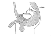
図1は、ヒト患者内に移植された場合の装置の概略断面図である。図2を参照すると、膀胱300に対して作動している際の、移植されたこの装置の一実施形態が、図示されている。この装置は、動力部材100および制御デバイス200を備える。制御デバイス200は、動力部材の動作を制御し、膀胱の壁に関連付けされる圧力センサまたは任意のセンサなど、膀胱内の体積に関連付けされるセンサ150(図示せず、および、警告信号を身体から外部に通信するための)から信号を受信することが可能である。センサは、制御デバイス200のセンサ制御ユニット205に接続される。複数の異なるタイプの入力センサを使用して、例えば、膀胱壁の伸展もしくは屈曲もしくは圧力を判定することができ、または例えば膀胱内部の体積もしくは圧力を感知することができる。大概は、これらのセンサは、患者に警告を与え、膀胱を空にする時であることを知らせることによって、間接的に膀胱を空にさせるに過ぎない。このような警告は、聴覚的または視覚的に発せられてよい。内部制御ユニット203または少なくとも1つの移植されたスイッチ204と通信する無線リモート・コントロールなど、リモート・コントロール300が、動力部材を作動させるために患者の身体の外部から制御される。さらに、制御デバイス200は、動力部材のエネルギー消費部分にエネルギーを供給するためのエネルギー源201を備える。このエネルギー源は、付勢(エナジャイザ)ユニット400から外部から無線により供給され得る。このために、制御デバイスは、エネルギー変換デバイス202を備える。制御デバイスは、外方部分200Aを備え、この外方部分200Aは、手動操作スイッチ201A、および、内方リザーバ206と連通する作動流体用の注入ポート201Bを備える。さらに、制御デバイスは、モータ/ポンプ機能を備える。作動流体に関連付けされる構成部が、図4の液圧式実施形態に関連するものであり、動力部材100が、加圧器140、および膀胱に固定させることができる膀胱接触部120を備えることが、予期される。加圧器は、ヒト組織に、この場合には恥骨に固定される作動デバイス144を備え、接触部に連結される可動アーム142に作動的に連結される。膀胱に対して圧力を加え、それにより尿道を介して尿を排出させるための動作においては、作動デバイス144が、制御デバイスによって作動されて、アームを膀胱の方向に移動させ、これにより、膀胱を収縮させる。さらに、図2は、尿管を一時的に制限するための制限デバイス59Bを図示する(この実施形態は、制限デバイスで両尿管を閉じる)。結局、この装置は、尿が膀胱から腎臓に流れるのを防ぐために、尿を排出するように動力部材を作動させる際に尿管を閉じるために制御デバイス200によって制御される、尿管のためのかかる制御デバイスを備えてよい。作動の際に、この制御デバイス200は、作動され、動力部材にエネルギーを供給する。次いで、加圧器が、膀胱を圧縮させるように作動し、それにより、膀胱内の尿圧が上昇され、それにより尿が尿道を介して排出される。尿の排出が終了すると、加圧器は、膀胱を緩め、その初期位置に戻り、尿管のための制限デバイスは、解放され、膀胱は、腎臓から尿を受けることが可能となる。図3は、尿道を介して尿が排出される際の、図2の装置と同一の装置を図示する。このために、尿道括約筋装置59Cは、作動されず、開口および制限デバイス59B。この装置は、膀胱から尿を押し出すために、かなりの圧力(約60〜80cm水圧)をかける必要があり、尿は、これにより、腎臓に障害をも
たらす潜在的リスクを伴いつつ、尿管32A、32Bを介して逆流するおそれがある。任意のかかる問題を防ぐために、制御デバイスは、制限デバイス59A、59Bを備え、これら制限デバイス59A、59Bは、尿管を一時的に収縮させ、尿を排出させる作動の際に尿管を閉じるように構成される。尿管内の尿圧は、普通は約50cm水圧であるが、短期間の圧力上昇が、腎臓に障害を与える可能性は殆どなく、したがって、制限デバイス59Aおよび59Bは、省かれてもよい。
FIG. 1 is a schematic cross-sectional view of the device when implanted in a human patient. Referring to FIG. 2, one embodiment of this implanted device is shown when operating against
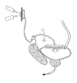
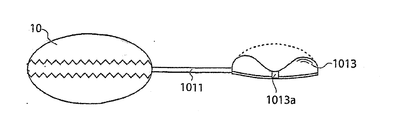
図4は、接触部の空洞部420に液圧式に連結されるリザーバ440を備えている加圧器の一変形形態の概略図である。制御デバイス200は、図2と共に説明されるものと同様の様式において、加圧器の作動を制御する。尿を排出させるようにこの装置を作動させる場合には、制御デバイスは、リザーバ440から接触部の空洞部420への流体の輸送を始動させ、これにより空洞部420の体積が膨張し、それにより、膀胱は圧縮され、膀胱内の尿圧の上昇の結果として尿道を介して尿が排出される。膀胱を解放するためには、流体は、空洞部からリザーバに輸送して戻される。この戻り輸送は、動力による動作(すなわちリザーバに作動的に連結されたポンプ)によってか、または、膀胱内の尿圧の上昇の結果として、達成され得る。空洞部とリザーバとの間の第2の連結部444は、後の輸送用のために使用される。ポンプのポンピング能力が、前記第2の連結部の流れ能力よりも大きな場合には、第2の連結部は、常に開かれていてよい。さらに、図4は、制御デバイス・センサ制御ユニットと通信するセンサ445を図示する。図5は、膀胱壁に固定された支持デバイス510に装着された作動デバイス544を備える、加圧器540の別の変形形態を概略的に示す。この加圧器は、液圧式または機械式に作動され得る。この場合には、機械的構築部が、アクチュエータ542を有し、このアクチュエータ542は、作動デバイスに作動可能に接続されて、接触部520を作動させて膀胱を圧縮させるように、作動動作を実施する。尿を排出させるための動作において、この作動デバイスは、アクチュエータの枢動運動を実施させ、それにより、作動デバイスは、接触部520に接触して、膀胱を圧縮し、それにより尿道を介して尿を排出させる。膀胱を解放する際には、作動デバイスは、アクチュエータ542を、接触部520から初期位置まで移動させ、膀胱は、尿管を介して尿を受けることが可能となる。
FIG. 4 is a schematic view of a variation of a pressurizer including a
図5aは、作動デバイス544Aが、代替の支持機能部としての腹壁の上に配置される、図2の装置の一実施形態を示す。図5bは、作動デバイスが別の骨構造部状に支持された状態の、図2の装置の別の代替形態を図示する。図5cは、尿管のための制限デバイスを伴わず、尿道括約筋機能を伴わない、図2の装置の一代替形態を図示する。尿閉を患う患者のある者は、尿失禁をも伴う。かかる場合においては、別の尿道括約筋装置59Cが、システム内に含まれ、制限デバイスが、患者が排尿を欲するまで尿道を閉じる。かかる場合においては、膀胱内圧力によって括約筋を開くための力は不要となるため、膀胱を空にするためには比較的低い圧力が必要である。この場合には、尿管制限デバイスは、省かれてよい。リザーバは、身体内の任意の位置に配置されてよいが、好ましくは腹腔内に配置され、膀胱の上にまたは骨盤領域に配置されてよい。ある特殊な注入ポート針から届く範囲内において身体内部に配置された注入ポートを利用することにより、リザーバ内の液体の量を流体で調整することができる。リザーバは、やはり省かれてよく、注入ポートのみが、膨張可能部材を充填および空にするために使用されてよい。
FIG. 5a shows one embodiment of the apparatus of FIG. 2 in which the
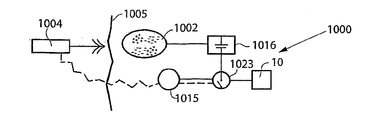
図6は、患者の腹部内に配置されて概略的に図示される、本発明の装置10によって尿閉を治療するためのシステムを図示する。この装置10は、図1〜図5のコンテクストにおいて説明され、本明細書の前セクションにおいて概略的に説明されたもののいずれかであることが可能である。移植エネルギー変換デバイス1002が、電力供給ライン1003を経由して装置のエネルギー消費構成要素にエネルギーを供給するように適合化される。装置10を非侵襲的に通電させるための外部のエネルギー伝送デバイス1004が、少なくとも1つのワイヤレス・エネルギー信号により、エネルギーを伝送する。移植エネル
ギー変換デバイス1002は、エネルギーを、無線エネルギー信号から、電気供給ライン1003を介して供給される電気エネルギーへと変換する。
FIG. 6 illustrates a system for treating urinary retention by the
無線エネルギー信号は、以下のもの、すなわち、音波信号、超音波信号、電磁波信号、赤外光信号、可視光信号、紫外線光信号、レーザ光信号、マイクロ波信号、高周波信号、x線放射信号、およびガンマ放射信号から選択された、波形信号を含んでよい。代替としては、無線エネルギー信号は、電場、または磁場、または電場および磁場の組合せを含んでよい。 Wireless energy signals include the following: sound wave signals, ultrasonic wave signals, electromagnetic wave signals, infrared light signals, visible light signals, ultraviolet light signals, laser light signals, microwave signals, high frequency signals, x-ray emission signals, And a waveform signal selected from the gamma emission signal. Alternatively, the wireless energy signal may include an electric field, or magnetic field, or a combination of electric and magnetic fields.
無線エネルギー伝送デバイス1004は、無線エネルギー信号を搬送するための搬送信号を伝送することができる。かかる搬送信号は、デジタル信号、アナログ信号、または、デジタル信号およびアナログ信号の組合せを含んでよい。この場合、無線エネルギー信号は、アナログ信号、または、デジタル信号、または、アナログ信号およびデジタル信号の組合せを含む。
The wireless
一般的には、エネルギー変換デバイス1002は、エネルギー伝送デバイス1004により伝送された第1の形態の無線エネルギーを、通常は第1の形態のエネルギーとは異なる第2の形態のエネルギーへと変換するために、設けられる。移植装置10は、第2の形態のエネルギーに応答して作動可能である。エネルギー変換デバイス1002は、第2の形態のエネルギーによってこの装置を直接的に作動させることができる。これは、エネルギー変換デバイス1002が、エネルギー伝送デバイス1004により伝送された第1の形態のエネルギーを第2の形態のエネルギーへと変換することによるものである。さらに、このシステムは、移植可能な蓄電池を含んでよく、第2の形態のエネルギーは、この蓄電池を充電するために少なくとも部分的に使用される。
In general, the
代替としては、エネルギー伝送デバイス1004によって伝送される無線エネルギーは、無線エネルギーが、エネルギー伝送デバイス1004によって伝送されつつある際に、この装置を直接的に作動させるために使用されてもよい。システムが、以下において説明されるように、この装置を作動させるための作動デバイスを備える場合には、エネルギー伝送デバイス1004によって伝送される無線エネルギーは、作動デバイスを作動させるために直接的に使用されて、この装置を作動させるための運動エネルギーを生成することができる。
Alternatively, the wireless energy transmitted by the
第1の形態の無線エネルギーは、音波を含んでよく、エネルギー変換デバイス1002は、この音波を電気エネルギーに変換させるための圧電素子を備えてよい。第2の形態のエネルギーは、直流または脈動直流の形態の電気エネルギー、または直流および脈動直流の組合せの形態の電気エネルギー、または、交流電流の形態の電気エネルギー、または直流および交流電流の組合せの形態の電気エネルギーを含んでよい。通常は、この装置は、電気エネルギーにより通電される電気構成要素を備える。このシステムの他の移植可能な電気構成要素は、この装置の電気構成要素に接続された、少なくとも1つの電圧レベル・ガードまたは少なくとも1つの定電流ガードであってよい。
The first form of wireless energy may include sound waves and the
任意には、第1の形態のエネルギーおよび第2の形態のエネルギーの一方が、磁気エネルギー、運動エネルギー、音響エネルギー、化学エネルギー、電波エネルギー、電磁エネルギー、光エネルギー、核エネルギー、または熱エネルギーを含んでよい。好ましくは、第1の形態のエネルギーおよび第2の形態のエネルギーの一方が、非磁気、非運動、非化学、非音響、非核、または非熱である。 Optionally, one of the first form of energy and the second form of energy comprises magnetic energy, kinetic energy, acoustic energy, chemical energy, radio energy, electromagnetic energy, light energy, nuclear energy, or thermal energy. Good. Preferably, one of the first form of energy and the second form of energy is non-magnetic, non-kinetic, non-chemical, non-acoustic, non-nuclear, or non-thermal.
エネルギー伝送デバイスは、患者の身体の外部から制御されて、電磁無線エネルギーを放出させることができ、放出された電磁無線エネルギーは、この装置を作動させるために
使用される。代替としては、エネルギー伝送デバイスは、患者の身体の外部から制御されて、非磁気無線エネルギーを放出することができ、放出された非磁気無線エネルギーは、この装置を作動させるために使用される。
The energy transfer device can be controlled from outside the patient's body to emit electromagnetic radio energy, which is used to operate the device. Alternatively, the energy transfer device may be controlled from outside the patient's body to emit non-magnetic radio energy, which is used to activate the device.
外部のエネルギー伝送デバイス1004は、装置を非侵襲的に制御するために無線制御信号を伝送するための外部信号送信器を有する無線リモート・コントロールをさらに備える。この制御信号は、移植エネルギー変換デバイス1002内に組み込まれてもよく、または移植エネルギー変換デバイス1002から独立したものであってもよい、移植信号受信器によって受信される。
The external
無線制御信号は、周波数変調信号、振幅変調信号、または位相変調信号、またはそれらの組合せを含んでよい。代替としては、無線制御信号は、アナログ信号、またはデジタル信号、またはアナログ信号およびデジタル信号の組合せを含む。代替としては、無線制御信号は、電場または磁場、または電場および磁場の組合せを含む。 The radio control signal may include a frequency modulated signal, an amplitude modulated signal, or a phase modulated signal, or a combination thereof. Alternatively, the radio control signal comprises an analog signal, or a digital signal, or a combination of analog and digital signals. Alternatively, the wireless control signal comprises an electric or magnetic field, or a combination of electric and magnetic fields.
無線リモート・コントロールは、無線制御信号を搬送するための搬送信号を伝送することができる。かかる搬送信号は、デジタル信号、アナログ信号、またはデジタル信号およびアナログ信号の組合せを含んでよい。制御信号が、アナログ信号、またはデジタル信号、またはアナログ信号およびデジタル信号の組合せを含む場合には、無線リモート・コントロールは、好ましくは、デジタル制御信号またはアナログ制御信号を搬送するための電磁搬送波信号を伝送する。 The wireless remote control can carry a carrier signal for carrying a wireless control signal. Such carrier signals may include digital signals, analog signals, or a combination of digital and analog signals. When the control signal comprises an analog signal, or a digital signal, or a combination of analog and digital signals, the wireless remote control preferably comprises an electromagnetic carrier signal for carrying the digital control signal or the analog control signal. To transmit.
図7は、図6のシステムをさらに概略的なブロック図の形態で図示し、装置10、電力供給ライン1003を介して装置10を作動させるエネルギー変換デバイス1002、および外部のエネルギー伝送デバイス1004を図示する。垂線によって概略的に示される患者の皮膚1005が、この線の左側の外部から、この線の右側の患者の内部を隔てる。
FIG. 7 illustrates the system of FIG. 6 in a more schematic block diagram form and illustrates
図8は、例えば分極エネルギーにより作動可能な電気スイッチ1006の形態の逆転デバイスが、装置10を逆転させるために患者内にやはり移植される点を除いては、図7のものと同一である、本発明の一実施形態を図示する。スイッチが、分極エネルギーにより作動されると、外部のエネルギー伝送デバイス1004の無線リモート・コントロールが、分極エネルギーを搬送する無線信号を伝送し、移植エネルギー変換デバイス1002は、この無線分極エネルギーを、電気スイッチ1006を作動させるための分極電流に変換する。電流の極性が、移植エネルギー変換デバイス1002によって変えられると、電気スイッチ1006は、装置10により実施される機能を逆転させる。
8 is identical to that of FIG. 7 except that a reversing device, eg in the form of an
図9は、装置10を作動させるために患者内に移植される作動デバイス1007が、移植エネルギー変換デバイス1002と装置10との間に設けられる点を除いては、図7のものと同一である、本発明の一実施形態を図示する。この作動デバイスは、電気サーボモータなどのモータ1007の形態のものであることが可能である。モータ1007は、外部のエネルギー伝送デバイス1004のリモート・コントロールが、無線信号を、移植エネルギー変換デバイス1002の受信器に伝送すると、移植エネルギー変換デバイス1002からのエネルギーによって作動される。
FIG. 9 is the same as that of FIG. 7 except that an
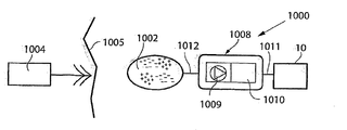
図10は、モータ/ポンプ・ユニット1009を含むアセンブリ1008の形態の作動デバイスを備え、流体リザーバ1010が、患者内に移植される点を除いては、図7のものと同一である、本発明の一実施形態を図示する。この場合には、装置10は、液圧式に作動され、すなわち作動流体が、モータ/ポンプ・ユニット1009によって、流体リザーバ1010から導管1011を通り装置10まで汲み上げられて、装置を作動させ、作動流体が、モータ/ポンプ・ユニット1009によって、装置10から流体リザーバ10
10まで汲み戻されて、装置を開始位置に復帰させる。移植エネルギー変換デバイス1002は、電力供給ライン1012を介してモータ/ポンプ・ユニット1009を作動させるために、無線エネルギーを例えば分極電流などの電流に変換する。
FIG. 10 includes an actuation device in the form of an
Pumped back to 10, returning the device to the starting position. The implantable
液圧式に作動される装置10の代わりに、作動デバイスが、空圧式作動デバイスを備えることが、さらに予期される。この場合には、作動流体は、調整のために使用されることとなる圧縮空気が可能であり、流体リザーバは、空気チャンバによって置換される。
It is further envisioned that, instead of the hydraulically actuated
これらの実施形態の全てにおいて、エネルギー変換デバイス1002は、無線エネルギーによって充電されることとなる電池またはコンデンサなどの再充電式蓄電池を含んでよく、システムのエネルギー消費部分のためにエネルギーを供給する。
In all of these embodiments, the
一代替形態としては、上述の無線リモート・コントロールは、例えば押圧ボタンが皮膚の下に配置されるなど、殆どの場合には間接的に患者の手によって接触がなされる任意の移植部からなる手動制御部によって置換されてよい。 As an alternative, the wireless remote control described above may be a manual implant consisting of any implant that is most often indirectly contacted by the patient's hand, for example a push button placed under the skin. It may be replaced by the controller.
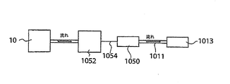
図11は、無線制御部を備える外部のエネルギー伝送デバイス1004、装置10(この場合は液圧式に作動される)、および移植エネルギー変換デバイス1002を備え、さらに、液圧流体リザーバ1013、モータ/ポンプ・ユニット1009、および液圧制御弁シフト・デバイス1014の形態の逆転デバイスを備える、本発明の一実施形態を図示し、これらは全て、患者内に移植される。当然ながら、液圧式作動は、ポンピング方向を変えるだけで容易に実施することができ、したがって、液圧制御弁は、省略されてよい。リモート・コントロールは、外部のエネルギー伝送デバイスから独立したデバイスであってよく、または外部のエネルギー伝送デバイス内に含まれてよい。モータ/ポンプ・ユニット1009のモータは、電気モータである。外部のエネルギー伝送デバイス1004の無線リモート・コントロールからの制御信号に応答して、移植エネルギー変換デバイス1002は、この制御信号により搬送されるエネルギーからのエネルギーによって、モータ/ポンプ・ユニット1009を作動させ、それにより、モータ/ポンプ・ユニット1009は、液圧流体リザーバ1013と装置10との間において作動流体を分配する。外部のエネルギー伝送デバイス1004のリモート・コントロールは、液圧制御弁シフト・デバイス1014を制御して、流体がモータ/ポンプ・ユニット1009により液圧流体リザーバ1013から装置10まで汲み上げられて装置を作動させる一方向と、流体がモータ/ポンプ・ユニット1009により装置10から液圧流体リザーバ1013まで汲み戻されて装置を開始位置に復帰させるもう1つの逆方向との間において、作動流体流方向をシフトさせる。
FIG. 11 shows an external
図12は、無線リモート・コントロールを備える外部のエネルギー伝送デバイス1004、装置10、移植エネルギー変換デバイス1002、外部のエネルギー伝送デバイス1004の無線リモート・コントロールにより制御される移植内部制御ユニット1015、移植蓄電池1016、および移植コンデンサ1017を備える、本発明の一実施形態を図示する。内部制御ユニット1015は、移植エネルギー変換デバイス1002から受けた電気エネルギーを蓄電池1016内に蓄積するように設定し、この蓄電池1016が、装置10にエネルギーを供給する。外部のエネルギー伝送デバイス1004の無線リモート・コントロールからの制御信号に応答して、内部制御ユニット1015は、蓄電池1016から電気エネルギーを放出し、電線1018および1019を介して放出エネルギーを伝達するか、または、電線1020、電流を安定化させるコンデンサ1017、電線1021、および電線1019を介して、移植エネルギー変換デバイス1002から電気エネルギーを直接的に伝達して、装置10を作動させる。
FIG. 12 shows an external
内部制御ユニットは、好ましくは、患者の身体の外部からプログラム可能である。好ま
しい一実施形態においては、内部制御ユニットは、事前プログラムされた時間スケジュールに従って装置10を調整するようにプログラムされるか、または、患者の任意の可能な物理的パラメータもしくはシステムの任意の機能的パラメータを感知する任意のセンサから入力するようにプログラムされる。
The internal control unit is preferably programmable from outside the patient's body. In a preferred embodiment, the internal control unit is programmed to adjust the
一代替形態によれば、図12の実施形態におけるコンデンサ1017は、省かれてよい。別の代替形態によれば、この実施形態中の蓄電池1016が、省かれてよい。
According to one alternative, the
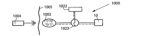
図13は、装置10を作動させるためのエネルギーを供給するための電池1022、および、装置10の作動を切り替えるための電気スイッチ1023が、患者内にさらに移植される点を除いては、図7のものと同一である、本発明の一実施形態を図示する。電気スイッチ1023は、リモート・コントロールによって制御されてよく、さらに移植エネルギー変換デバイス1002により供給されるエネルギーによって制御されて、電池1022の不使用時のオフ・モードから、電池1022が装置10を作動させるためにエネルギーを供給するオン・モードへと、切替えを行ってもよい。
FIG. 13 is similar to FIG. 7 except that a
図14は、外部のエネルギー伝送デバイス1004の無線リモート・コントロールによって制御可能である内部の制御ユニット1015が、患者内にさらに移植される点を除いては、図13のものと同一である、本発明の一実施形態を図示する。この場合には、電気スイッチ1023は、移植エネルギー変換デバイス1002により供給されるエネルギーによって作動されて、無線リモート・コントロールが内部制御ユニット1015を制御することが回避され、電池が不使用となるオフ・モードから、リモート・コントロールが内部制御ユニット1015を制御することが可能となり、装置10を作動させるために電池1022から電気エネルギーを放出させるスタンバイ・モードへと、切替えを行う。
14 is identical to that of FIG. 13 except that an
図15は、蓄電池1016が電池1022の代替とされ、移植構成要素が異なって相互接続される点を除いては、図14のものと同一である、本発明の一実施形態を図示する。この場合には、蓄電池1016は、移植エネルギー変換デバイス1002からのエネルギーを蓄積する。外部のエネルギー伝送デバイス1004の無線リモート・コントロールからの制御信号に応答して、内部制御ユニット1015は、電気スイッチ1023を制御して、蓄電池1016の不使用時であるオフ・モードから、蓄電池1016が装置10を作動させるためにエネルギーを供給するオン・モードへと切替えを行う。蓄電池は、コンデンサと組み合わされてよく、または、コンデンサによって置換されてよい。
FIG. 15 illustrates an embodiment of the invention that is the same as that of FIG. 14 except that the
図16は、電池1022が患者内にやはり移植され、移植構成要素が異なって相互接続される点を除いては、図15のものと同一である、本発明の一実施形態を図示する。外部のエネルギー伝送デバイス1004の無線リモート・コントロールからの制御信号に応答して、内部制御ユニット1015は、電気スイッチ1023を作動させるためにエネルギーを送給するように蓄電池1016を制御して、電池1022の不使用時であるオフ・モードから、電池1022が装置10を作動させるために電気エネルギーを供給するオン・モードへと切替えを行う。
FIG. 16 illustrates an embodiment of the invention that is the same as that of FIG. 15 except that the
代替としては、電気スイッチ1023は、蓄電池1016により供給されるエネルギーによって作動されて、無線リモート・コントロールが電気エネルギーを供給するように電池1022を制御することが回避され、不使用となるオフ・モードから、無線リモート・コントロールが装置10を作動させるために電気エネルギーを供給するように電池1022を制御することが可能となるスタンバイ・モードへと切替えを行うことができる。
Alternatively, the
スイッチ1023およびこのアプリケーションにおける全ての他のスイッチは、その最も広い実施形態において解釈されるべきであることを理解されたい。これは、電源をオン
またはオフに切り替えることのできる、トランジスタ、MCU、MCPU、ASIC、FPGA、またはDAコンバータ、または任意の他の電子構成要素または電子回路を意味する。好ましくは、このスイッチは、身体の外部から制御されるか、代替としては、移植内部制御ユニットによって制御される。
It should be appreciated that
図17は、モータ1007、ギア・ボックス1024の形態の機械逆転デバイス、および、ギア・ボックス1024を制御するための内部制御ユニット1015が、患者内にやはり移植される点を除いては、図13のものと同一である、本発明の一実施形態を図示する。内部制御ユニット1015は、(機械的に作動される)装置10により実施される機能を逆転させるように、ギア・ボックス1024を制御する。さらに簡単であるのは、電子的にモータの方向を切り替えることである。最も広い実施形態において解釈されるギア・ボックスは、比較的長いストロークに有利な作動デバイスが作動するように力を節減するサーボ構成体を意味する。
17 shows a
図18は、移植構成要素が異なって相互接続される点を除いては、図24のものと同一である、本発明の一実施形態を図示する。したがって、この場合には、内部制御ユニット1015は、蓄電池1016、適切にはコンデンサが、電気スイッチ1023を作動させてオン・モードに切り替える際に、電池1022によって作動される。電気スイッチ1023が、オン・モードである場合には、内部制御ユニット1015は、装置10を作動させるためのエネルギーを供給する、または供給しないように、電池1022を作動させることが可能となる。
FIG. 18 illustrates an embodiment of the invention that is the same as that of FIG. 24 except that the implant components are differently interconnected. Thus, in this case, the
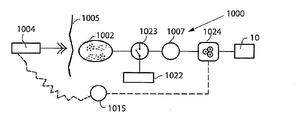
図19は、種々の通信オプションを達成するための装置の移植構成要素の予期される組合せを、概略的に図示する。基本的には、装置10、内部制御ユニット1015、モータまたはポンプ・ユニット1009、および、外部ワイヤレス・リモート・コントロールを含む外部のエネルギー伝送デバイス1004が存在する。既に上述したように、無線リモート・コントロールは、内部制御ユニット1015によって受信される制御信号を伝送し、次いで、内部制御ユニット1015が、この装置の種々の移植構成要素を制御する。
FIG. 19 schematically illustrates possible combinations of implant components of the device to achieve various communication options. Basically, there is an
好ましくはセンサまたは測定デバイス1025を含むフィードバック・デバイスが、患者の物理的パラメータを感知するために、患者内に移植されてよい。物理的パラメータは、圧力、体積、直径、伸展、延伸、拡張、移動、屈曲、弾性、筋肉収縮、神経衝撃、体温、血圧、血流、心拍、および呼吸からなる群より選択される少なくとも1つであってよい。センサは、上述の物理的パラメータのいずれかを感知するものであってよい。例えば、センサは、圧力センサまたは運動性センサであってよい。代替としては、センサ1025は、機能的パラメータを感知するように構成されてよい。機能的パラメータは、移植エネルギー源を充電するためのエネルギーの伝達に相関されてよく、電気、任意の電気パラメータ、圧力、体積、直径、伸展、延伸、拡張、移動、屈曲、弾性、温度、および流れからなるパラメータの群より選択される少なくとも1つをさらに含んでよい。
A feedback device, preferably including a sensor or
フィードバックは、内部制御ユニットに送信されるか、または好ましくは内部制御ユニットを介して外部制御ユニットに送出される。フィードバックは、エネルギー伝達システム、または、受信器および送信器を備える別個の通信システムを介して、身体から送出されてよい。 The feedback is sent to the internal control unit or is preferably sent to the external control unit via the internal control unit. Feedback may be delivered from the body via an energy transfer system or a separate communication system that comprises a receiver and a transmitter.
内部制御ユニット1015、または代替的には、外部のエネルギー伝送デバイス1004の外部ワイヤレス・リモート・コントロールは、センサ1025からの信号に応答して装置10を制御することができる。トランシーバが、感知された物理的パラメータに関する情報を外部無線リモート・コントロールに送信するために、センサ1025と組み合わされてよい。無線リモート・コントロールは、信号送信器またはトランシーバを備えてよ
く、内部制御ユニット1015は、信号受信器またはトランシーバを備えてよい。代替としては、無線リモート・コントロールが、信号送信器またはトランシーバを備えてよく、内部制御ユニット1015が、信号送信器またはトランシーバを備えてよい。上述のトランシーバ、送信器、および受信器は、装置10に関する情報またはデータを患者の身体の内部から患者の身体の外部に送信するために、使用されてよい。
An
モータ/ポンプ・ユニット1009およびモータ/ポンプ・ユニット1009を作動させるための電池1022が、移植される場合には、電池1022の充電に関する情報が、フィードバックされ得る。さらに正確には、電池または蓄電池をエネルギーで充電する場合には、前記充電プロセスに関するフィードバック情報が、送信され、エネルギー供給が、それに応じて変更される。
If the motor/
図20は、代替の一実施形態を図示し、装置10は、患者の身体の外部から調整される。システム1000は、皮下電気スイッチ1026を介して装置10に接続された電池1022を備える。したがって、装置10の調整は、皮下スイッチを手動により押圧することによって非侵襲的に行われ、これにより、装置10の作動が、オンおよびオフに切り替えられる。図示される実施形態は単純なものであり、内部制御ユニットまたは本出願中に開示される任意の他の部分など、追加の構成要素を、システムに追加することができる点が理解されよう。2つの皮下スイッチが使用されてもよい。好ましい実施形態においては、1つの移植スイッチが、内部制御ユニットに情報を送信して、ある所定の動作を行い、患者がスイッチを再び押圧すると、この動作が逆転される。
FIG. 20 illustrates an alternative embodiment in which the
図21は、代替の一実施形態を示し、システム1000は、装置に液圧式に連結された作動流体リザーバ1013を備える。非侵襲的な調整は、この装置に連結される液圧式リザーバを手動により押圧することによって行われる。
FIG. 21 illustrates an alternative embodiment,
このシステムは、外部データ伝送機、および外部データ伝送機と通信する移植可能な内部データ伝送機を備えてよい。内部伝送機は、装置または患者に関連するデータを外部データ伝送機に送り、および/または、外部データ伝送機は、データを内部データ伝送機に送る。 The system may include an external data transmitter and a portable internal data transmitter in communication with the external data transmitter. The internal transmitter sends data associated with the device or patient to the external data transmitter, and/or the external data transmitter sends data to the internal data transmitter.
図22は、装置10の移植エネルギー消費構成要素に接続された、移植された内部のエネルギー受信器1002に対して正確な量のエネルギーを供給するために、装置もしくはシステムの少なくとも1つの機能的パラメータに関する、または患者の物理的パラメータに関するフィードバック情報を与えるように、患者の身体の内部から患者の身体の外部に情報を送信することが可能なシステムの装置を概略的に図示する。かかるエネルギー受信器1002は、エネルギー源および/またはエネルギー変換デバイスを備えてよい。簡単に述べると、無線エネルギーは、患者の外部に位置する外部のエネルギー源1004aから伝送され、患者の内部に位置する内部のエネルギー受信器1002によって受けられる。内部のエネルギー受信器は、スイッチ1026を介して装置10のエネルギー消費構成要素に、受けたエネルギーを直接的にまたは間接的に供給するように適合化される。エネルギー・バランスが、内部のエネルギー受信器1002によって受けられたエネルギーと、装置10に対して使用されるエネルギーとの間で決定され、無線エネルギーの伝送が、次いで、決定されたエネルギー・バランスに基づいて制御される。したがって、このエネルギー・バランスは、必要となるエネルギーの正確な量の正確な示唆を与える。この必要となるエネルギーの正確な量は、装置10を適切に作動させるのに十分なものであるが、不当な温度上昇を引き起こさない。
FIG. 22 illustrates at least one functional parameter of a device or system for delivering an accurate amount of energy to an implanted
図22においては、患者の皮膚は、垂線1005によって示される。この場合には、エネルギー受信器は、患者の内部に、好ましくは患者の皮膚1005の直下に配置される、
エネルギー変換デバイス1002を備える。一般的に述べると、移植エネルギー変換デバイス1002は、腹、胸郭、筋膜(例えば腹壁)、皮下中に、または任意の他の適切な位置に配置されてよい。移植エネルギー変換デバイス1002は、移植エネルギー変換デバイス1002の近傍の患者の皮膚1005の外部に配置された外部のエネルギー伝送デバイス1004中に設けられる外部のエネルギー源1004aから伝送された無線エネルギーEを受けるように適合化される。
In FIG. 22, the patient's skin is indicated by
An
当技術においてよく知られているように、無線エネルギーEは、外部のエネルギー源1004a内に配置された一次コイルと、移植エネルギー変換デバイス1002内に配置された隣接する二次コイルとを備えるデバイスなど、任意の適切な経皮エネルギー伝達(TET: Transcutaneous Energy Transfer)デバイスにより概して伝達され得る。電流が、一次コイルを介して送られると、電圧の形態のエネルギーが、例えば再充電式電池またはコンデンサなどの移植エネルギー源内に流入エネルギーを蓄積した後などに、装置の移植エネルギー消費構成要素を作動させるために使用され得る二次コイル中に誘導される。しかし、本発明は、任意の特定のエネルギー伝達技術に概して限定されず、TETデバイスまたはエネルギー源、および任意の種類の無線エネルギーを使用することができる。
As is well known in the art, wireless energy E is a device that comprises a primary coil located within an
移植されるエネルギー受信器により受けられるエネルギーの量が、この装置の移植構成要素によって使用されるエネルギーと比較されてよい。ここで、「使用されるエネルギー」という語は、装置の移植構成要素によって蓄積されるエネルギーをも含むこととして理解される。制御デバイスが、伝達エネルギーの量を調整するように、決定されたエネルギー・バランスに基づいて外部のエネルギー源1004aを制御する外部制御ユニット1004bを備える。正確な量のエネルギーを伝達するために、エネルギー・バランスおよび必要な量のエネルギーが、スイッチ1026と装置10との間に接続される移植内部制御ユニット1015を備える決定デバイスによって、決定される。したがって、内部制御ユニット1015は、装置10の適切な作動のために必要となるエネルギーの所要量を幾分か反映する、装置10のある特徴を測定する適切なセンサまたは同様のもの(図示せず)によって得られる種々の測定値を受領するように構成され得る。さらに、患者の現在の状態が、患者の状況を反映するパラメータを供給するために、適切な測定デバイスまたはセンサによって検出されてもよい。したがって、かかる特徴および/またはパラメータは、電力消費量、作動モード、および温度などの装置10の現在の状態、ならびに、体温、血圧、心拍、および呼吸などのパラメータにより反映される患者の状態に、関連付けされてよい。他の種類の患者の物理的パラメータおよびデバイスの機能的パラメータは、他所で説明される。
The amount of energy received by the implanted energy receiver may be compared to the energy used by the implant components of the device. The term "energy used" is understood here to also include the energy stored by the implantable components of the device. The control device comprises an
さらに、任意に、蓄電池1016の形態のエネルギー源が、装置10により後の使用のために受け取ったエネルギーを蓄積するために、制御ユニット1015を介して移植エネルギー変換デバイス1002に接続されてもよい。代替としては、または追加的には、エネルギーの所要量をやはり反映するかかる蓄電池の特徴を測定してもよい。蓄電池は、再充電式電池と置換されてよく、測定された特徴は、電池の現在の状態、すなわちエネルギー消費量、電圧、温度、等々の任意の電気的パラメータに関連付けされてよい。装置10に十分な電圧および電流を供給し、さらに、過度の加熱を回避するために、電池が、移植エネルギー変換デバイス1002から正確な量の、すなわち、少なすぎず、多すぎぬ量のエネルギーを受けることによって最適に充電されるべきであることが、明らかに理解される。また、蓄電池は、対応する特徴を有するコンデンサであってもよい。
Further, optionally, an energy source in the form of
例えば、電池の特徴は、電池の現在の状態を判定するために定期的に測定されてよく、次いで、この特徴は、内部制御ユニット1015内の適切な記憶手段内に状態情報として保存され得る。したがって、新たな測定がなされる際にはいつでも、保存された電池状態
情報は、それに応じて更新され得る。このようにして、最適な条件において電池を維持するために、正確な量のエネルギーを伝達することにより電池の状態を「調整」することが可能となる。
For example, battery characteristics may be periodically measured to determine the current status of the battery, which characteristics may then be stored as status information in suitable storage means within
したがって、決定デバイスの内部制御ユニット1015は、装置10の上述のセンサまたは測定デバイスにより行われた測定値、または患者、または使用される場合には移植エネルギー源、またはそれらの任意の組合せに基づいて、エネルギー・バランスおよび/または現在必要な量のエネルギー(単位時間当たりのエネルギーまたは累積エネルギー)を決定するように適合化される。内部制御ユニット1015は、さらに、判定された所要量のエネルギーを反映する制御信号を、外部制御ユニット1004bに接続された外部信号受信器1004cに伝送するように構成された、内部信号送信器1027に接続される。外部のエネルギー源1004aから伝送されたエネルギーの量は、次いで、受信した制御信号に応答して調整され得る。
Therefore, the
代替としては、決定デバイスは、外部制御ユニット1004bを含んでよい。この代替形態においては、外部制御ユニット1004bに直接的にセンサ測定値を伝送することが可能であり、外部制御ユニット1004bによってエネルギー・バランスおよび/または現在必要な量のエネルギーを決定することが可能であり、したがって、内部制御ユニット1015の上述の機能が、外部制御ユニット1004bに組み込まれる。この場合には、内部制御ユニット1015を省くことが可能であり、センサ測定値は、内部信号送信器1027に直接的に供給され、この内部信号送信器1027が、外部信号受信器1004cおよび外部制御ユニット1004bに対してこれらの測定値を送信する。次いで、これらのセンサ測定値に基づいて、外部制御ユニット1004bは、エネルギー・バランスおよび現在必要な量のエネルギーを決定することが可能となる。
Alternatively, the decision device may include an
したがって、図22の構成による本解決策は、所要のエネルギーを示唆する情報のフィードバックを採用し、これは、例えばエネルギー量、エネルギー差、または、この装置の移植エネルギー消費構成要素により使用されるエネルギーの割合と比較した場合のエネルギー受取率に対してなど、受け取ったエネルギーと比較される実際のエネルギー使用量に基づくため、先述の解決策よりもより効率的である。この装置は、移植エネルギー源または同様のものにおけるエネルギーの消費または蓄積のいずれかのために受け取ったエネルギーを使用してよい。したがって、上述の種々のパラメータは、関連があり必要な場合には、実際のエネルギー・バランスを決定するためのツールとして使用される。しかし、かかるパラメータは、装置を特定の態様で作動させるために内部的に行われる任意の動作のために、それ自体として必要とされてもよい。 Therefore, the present solution with the configuration of FIG. 22 employs feedback of information suggesting the required energy, which may be, for example, the amount of energy, the energy difference, or the energy used by the implanted energy consuming components of the device. It is more efficient than the previous solution because it is based on the actual amount of energy used compared to the energy received, such as the rate of energy receipt when compared to the percentage of. This device may use the received energy for either the consumption or storage of energy in an implanted energy source or the like. Therefore, the various parameters described above are used as tools to determine the actual energy balance, if relevant and necessary. However, such parameters may themselves be required for any operation performed internally to operate the device in a particular manner.
内部信号送信器1027および外部信号受信器1004cは、電波信号、赤外(IR)信号、または超音波信号などの、適切な信号伝達手段を用いて、独立したユニットとして実装されてもよい。代替としては、内部信号送信器1027および外部信号受信器1004cは、基本的には同一の伝送技術を用いて、エネルギー伝達に関して逆方向に制御信号を搬送するために、移植エネルギー変換デバイス1002および外部のエネルギー源1004aにそれぞれ組み込まれてよい。制御信号は、周波数、位相、または振幅について変調されてよい。
The
したがって、フィードバック情報は、受信器および送信器を含む独立した通信システムによって伝達され得るか、または、エネルギー・システムに組み込まれ得る。本発明によれば、かかる一体化される情報フィードバックおよびエネルギー・システムは、無線エネルギーを受信するための移植可能な内部のエネルギー受信器を備え、このエネルギー受信器は、内部の第1のコイルおよびこの第1のコイルに接続される第1の電子回路を有し、さらに、かかる一体化される情報フィードバックおよびエネルギー・システムは、無線エ
ネルギーを伝送するための外部のエネルギー送信器を備え、このエネルギー送信器は、外部の第2のコイルおよびこの第2のコイルに接続される第2の電子回路を有する。エネルギー送信器の外部の第2のコイルは、エネルギー受信器の第1のコイルにより受け取られる無線エネルギーを伝送する。さらに、このシステムは、内部の第1のコイルの第1の電子回路への接続をオンおよびオフに切り替えるための、電源スイッチをさらに備え、それにより、電源スイッチが、第1の電子回路への内部の第1のコイルの接続をオンおよびオフに切り替える際に、第1のコイルの充電に関するフィードバック情報が、外部の第2のコイルのロードにおけるインピーダンスの変動の形態において、外部のエネルギー送信器によって受信される。図17の構成におけるこのシステムの実装においては、スイッチ1026は、独立し、内部制御ユニット1015により制御されるか、内部制御ユニット1015に組み込まれる。スイッチ1026は、その最も広い実施形態において解釈されるべきであることを理解されたい。これは、電気をオンまたはオフに切り替えることのできる、トランジスタ、MCU、MCPU、ASIC、FPGA、またはDAコンバータ、または任意の他の電子構成要素または電子回路を意味する。
Therefore, the feedback information may be conveyed by an independent communication system including a receiver and a transmitter, or may be incorporated into the energy system. According to the invention, such an integrated information feedback and energy system comprises an implantable internal energy receiver for receiving wireless energy, the energy receiver comprising an internal first coil and The integrated information feedback and energy system having a first electronic circuit connected to the first coil further comprises an external energy transmitter for transmitting wireless energy, The transmitter has an external second coil and a second electronic circuit connected to the second coil. A second coil external to the energy transmitter carries the wireless energy received by the first coil of the energy receiver. Further, the system further comprises a power switch for switching the connection of the internal first coil to the first electronic circuit on and off, whereby the power switch is connected to the first electronic circuit. When switching the connection of the internal first coil on and off, feedback information on the charging of the first coil is provided by an external energy transmitter in the form of impedance variations in the load of the external second coil. Be received. In the implementation of this system in the configuration of FIG. 17,
結論としては、図22に図示されるエネルギー供給構成は、基本的に以下の態様において作動することができる。エネルギー・バランスが、初めに、決定デバイスの内部制御ユニット1015により決定される。所要量のエネルギーを反映する制御信号が、さらに、内部制御ユニット1015において生成され、この制御信号が、内部信号送信器1027から外部信号受信器1004cに伝送される。代替としては、エネルギー・バランスは、上述のような実施による代わりに、外部制御ユニット1004bにより決定され得る。この場合には、制御信号は、種々のセンサからの測定結果を搬送することができる。次いで、外部のエネルギー源1004aから発せられるエネルギーの量は、例えば受信された制御信号に応答してなど、決定されたエネルギー・バランスに基づいて外部制御ユニット1004bにより調整され得る。このプロセスは、継続中のエネルギー伝達の最中にある間隔で断続的に反復されてよく、または、エネルギー伝達の最中にほぼ継続的に実行されてもよい。
In conclusion, the energy supply arrangement illustrated in Figure 22 can basically operate in the following manner. The energy balance is first determined by the
伝達されるエネルギーの量は、電圧特徴、電流特徴、振幅特徴、周波数特徴、およびパルス特徴など、外部のエネルギー源1004aにおいて種々の伝送パラメータを調節することによって、概して調整され得る。
The amount of energy transferred can be generally adjusted by adjusting various transmission parameters at the
さらに、このシステムは、内部コイルに対する外部コイルの最適な位置を見出すために、およびエネルギー伝達を最適化するために、このシステムを調整するためにも、TETシステム内のコイル間における結合要素に関する情報を得るために使用されてもよい。この場合に、伝達されたエネルギー量を、受け取られたエネルギー量と単純に比較する。例えば、外部コイルが、移動されると、結合要素は、変動する可能性があり、正確に表示された移動量により、外部コイルは、エネルギー伝達のための最適な位置を見出すことが可能となる。好ましくは、外部コイルは、結合要素が最大化される前に、決定デバイスにおけるフィードバック情報を実現するように、伝達されるエネルギーの量を調整するように適合化される。 In addition, the system also provides information about the coupling elements between the coils in the TET system in order to find the optimum position of the outer coil relative to the inner coil and to adjust the system to optimize energy transfer. May be used to obtain In this case, the amount of energy delivered is simply compared with the amount of energy received. For example, when the outer coil is moved, the coupling element may fluctuate, and the accurately displayed amount of movement allows the outer coil to find an optimal position for energy transfer. .. Preferably, the outer coil is adapted to adjust the amount of energy transferred to achieve feedback information in the decision device before the coupling element is maximized.
この結合要素情報は、さらに、エネルギー伝達の際にフィードバックとして使用されてもよい。かかる場合においては、本発明のエネルギー・システムは、無線エネルギーを受け取る移植可能な内部のエネルギー受信器を備え、このエネルギー受信器は、内部の第1のコイルおよびこの第1のコイルに接続される第1の電子回路を有し、さらに、本発明のエネルギー・システムは、無線エネルギーを伝送するための外部のエネルギー送信器を備え、このエネルギー送信器は、外部の第2のコイルおよびこの第2のコイルに接続される第2の電子回路を有する。エネルギー送信器の外部の第2のコイルは、無線エネルギーを伝送し、この無線エネルギーは、エネルギー受信器の第1のコイルによって受け取られる
。さらに、このシステムは、フィードバック情報として第1のコイルにおいて受け取ったエネルギー量を発信するためのフィードバック・デバイスを備え、第2の電子回路は、フィードバック情報を受信するための、および、第1のコイルと第2のコイルとの間の結合要素を求めるために第2のコイルにより伝達されたエネルギーの量を第1のコイルにおいて受け取ったエネルギーの量に関連するフィードバック情報と比較するための、決定デバイスを備える。エネルギー送信器は、得られた結合要素に応答して伝送されたエネルギーを調整することができる。
This coupling element information may also be used as feedback during energy transfer. In such a case, the energy system of the present invention comprises an implantable internal energy receiver for receiving wireless energy, the energy receiver being connected to the internal first coil and the first coil. Having a first electronic circuit, the energy system of the invention further comprises an external energy transmitter for transmitting wireless energy, the energy transmitter comprising an external second coil and the second coil. Has a second electronic circuit connected to the coil. A second coil external to the energy transmitter transmits wireless energy, which is received by the first coil of the energy receiver. Further, the system comprises a feedback device for transmitting the amount of energy received at the first coil as feedback information, the second electronic circuit for receiving the feedback information and the first coil. Device for comparing the amount of energy transferred by the second coil with feedback information related to the amount of energy received at the first coil to determine a coupling element between the first coil and the second coil Equipped with. The energy transmitter can condition the energy transmitted in response to the resulting coupling element.
この装置を作動させるためのエネルギーの無線伝達が、非侵襲的動作を可能にするように上述されたが、図23を参照として、この装置は、有線エネルギーによっても作動され得ることが理解されよう。そのような一例が、図18に図示され、外部スイッチ1026が、外部のエネルギー源1004aと、装置10を作動させる電気モータ1007などの作動デバイスとの間で相互接続される。外部制御ユニット1004bが、装置10の適切な作動を達成するために、外部スイッチ1026の動作を制御する。
Although wireless transfer of energy to operate the device was described above to allow non-invasive operation, it will be appreciated that with reference to FIG. 23, the device may also be operated by wired energy. .. One such example is illustrated in FIG. 18, where an
図24は、受け取られたエネルギーが、装置10によってどのように供給され、使用され得るかについての種々の実施形態を図示する。図17の例と同様に、内部のエネルギー受信器1002は、伝送制御ユニット1004bにより制御される外部のエネルギー源1004aから無線エネルギーEを受け取る。内部のエネルギー受信器1002は、定電圧のエネルギーを装置10に供給するために、図中において「定V」の破線ボックスで示される定電圧回路を備えてよい。さらに、内部のエネルギー受信器1002は、定電流のエネルギーを装置10に供給するために、図中において「定C」の破線ボックスで示される定電流回路を備えてよい。
FIG. 24 illustrates various embodiments of how the received energy may be supplied and used by
装置10は、エネルギー消費部分10aを備え、このエネルギー消費部分10aは、モータ、ポンプ、制限デバイス、または、電気的作動のためにエネルギーを要する任意の他の医療器具であってよい。さらに、装置10は、内部のエネルギー受信器1002から供給されるエネルギーを蓄積するためのエネルギー蓄積デバイス10bを備えてよい。したがって、供給されたエネルギーは、エネルギー消費部分10aによって直接的に消費される場合があり、または、エネルギー蓄積デバイス10bにより蓄積される場合があり、または、供給されたエネルギーは、一部が消費され、一部が蓄積される場合がある。さらに、装置10は、内部のエネルギー受信器1002から供給されたエネルギーを安定化させるためのエネルギー安定化ユニット10cを備えてよい。したがって、エネルギーは、消費または蓄積される前にエネルギーを安定化させることが必要となり得るような変動的な態様で供給されてもよい。
The
さらに、内部のエネルギー受信器1002から供給されたエネルギーは、蓄積されてよく、および/または、装置10によって消費および/または蓄積される前に、装置10の外部に配置される独立したエネルギー安定化ユニット1028によって安定化されてよい。代替としては、エネルギー安定化ユニット1028は、内部のエネルギー受信器1002内に組み込まれてもよい。いずれの場合でも、エネルギー安定化ユニット1028は、定電圧回路および/または定電流回路を備えてよい。
Further, the energy provided by the
図22および図24は、図示される種々の機能構成要素および機能要素が、互いに対してどのように配置され接続され得るかに関して、いくつかの考えられる、しかし非限定的な、実装オプションを図示することに留意されたい。しかし、本発明の範囲内において多数の変形および修正を行い得ることが、当業者には容易に理解されよう。 22 and 24 illustrate some possible but non-limiting implementation options as to how the various functional components illustrated and how the functional components may be arranged and connected to each other. Please note. However, one of ordinary skill in the art will readily appreciate that numerous variations and modifications may be made within the scope of the invention.
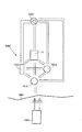
図25は、無線エネルギーの伝送を制御するためのシステム、すなわちエネルギー・バランス制御システムの提案される設計の中の1つのエネルギー・バランス測定回路を概略
的に図示する。この回路は、2.5Vを中心とし、エネルギー・バランスの不均衡に比例的に関連付けされる、出力信号を有する。この信号の微分係数が、この値の上下を、および、その変化の行われる速度を示す。受け取られたエネルギーの量が、この装置の移植構成要素によって使用されるエネルギーよりも低い場合には、より多くのエネルギーが、伝達され、したがって、エネルギー源内に充電される。回路からの出力信号は、典型的には、A/Dコンバータに送られ、デジタル形式に変換される。次いで、デジタル情報が、外部のエネルギー伝送デバイスに送られることが可能となり、これにより外部のエネルギー伝送デバイスは、伝送されたエネルギーのレベルを調節することが可能となる。別の可能性は、エネルギー・バランス・レベルを特定の最大しきい値または最小しきい値と比較する比較器を使用して、バランスが最大/最小ウィンドウから逸脱するか否かの情報を外部のエネルギー伝送デバイスに送信する、完全なアナログ・システムを有することである。
Figure 25 schematically illustrates a system for controlling the transmission of wireless energy, i.e. one of the energy balance measuring circuits in the proposed design of the energy balance control system. This circuit has an output signal centered on 2.5V and proportionally related to the energy balance imbalance. The derivative of this signal indicates above and below this value, and the rate at which the change occurs. If the amount of energy received is less than the energy used by the implant components of the device, more energy will be transferred and thus charged into the energy source. The output signal from the circuit is typically sent to an A/D converter and converted to digital form. The digital information can then be sent to an external energy transfer device, which allows the external energy transfer device to adjust the level of energy transferred. Another possibility is to use a comparator that compares the energy balance level to a certain maximum or minimum threshold to provide information on whether the balance deviates from the maximum/minimum window to the outside world. Having a fully analog system that transmits to an energy transfer device.
概略図25は、誘導エネルギー伝達を利用して患者の身体の外部から本発明の装置の移植エネルギー構成要素にエネルギーを伝達するシステムのための回路実装形態を図示する。誘導エネルギー伝達システムは、典型的には、外部伝送コイルおよび内部受信コイルを使用する。受信コイルL1が、概略図3に含まれるが、このシステムの伝送部分は、省かれている。 Schematic Figure 25 illustrates a circuit implementation for a system that utilizes inductive energy transfer to transfer energy from outside the patient's body to the implant energy component of the device of the present invention. Inductive energy transfer systems typically use external transmission coils and internal reception coils. The receiving coil L1 is included in the schematic diagram 3, but the transmitting part of the system is omitted.
エネルギー・バランスの一般的コンセプトの実現、および情報が外部のエネルギー送信器に伝送される様式は、当然ながら、無数のさまざまな様式において実現され得る。概略図25、ならびに情報を評価および伝送する上述の方法は、制御システムをどのように実装するかの例に過ぎないものとして見なされるべきである。 The implementation of the general concept of energy balance and the manner in which information is transmitted to external energy transmitters can, of course, be implemented in a myriad of different ways. The schematic diagram 25, and the methods described above for evaluating and transmitting information, should be considered as merely examples of how to implement a control system.
回路の詳細
図25においては、記号Y1、Y2、Y3等々が、回路内の試験ポイントを示す。図の構成要素およびそれらの各値は、当然ながら無数の考えられる設計の解決策の中の1つに過ぎないこの特定の実装形態において作用する値である。
Circuit Details In FIG. 25, the symbols Y1, Y2, Y3, etc. indicate test points within the circuit. The components in the figure and their respective values are of course the values that work in this particular implementation, which is only one of a myriad of possible design solutions.
回路を作動させるエネルギーは、エネルギー受取りコイルL1によって受け取られる。移植構成要素へのエネルギーは、この特定の場合においては、25kHzの周波数で伝送される。エネルギー・バランス出力信号は、試験ポイントY1にある。 Energy to operate the circuit is received by the energy receiving coil L1. Energy to the implant component is transmitted at a frequency of 25 kHz in this particular case. The energy balance output signal is at test point Y1.
上述の種々の実施形態のシステムが、多数のさまざまな様式で組み合わされ得ることが、当業者には理解されよう。例えば、図8の電気スイッチ1006は、図11〜図17の実施形態のいずれにおいて組み込まれてもよく、図11の液圧制御弁シフト・デバイス1014は、図10の実施形態において組み込まれてもよく、ギア・ボックス1024は、図9の実施形態において組み込まれてもよい。このスイッチは、任意の電子回路または電子構成要素を単に指すことが可能であるに過ぎないことに留意されたい。
Those skilled in the art will appreciate that the systems of the various embodiments described above can be combined in many different ways. For example, the
図22、図24、および図25に関連して説明される実施形態は、電気的に作動可能な装置の移植エネルギー消費構成要素への無線エネルギーの伝送を制御するための方法およびシステムを特定する。かかる方法およびシステムは、以下において概略的に規定される。 The embodiments described in connection with FIGS. 22, 24, and 25 identify methods and systems for controlling the transfer of wireless energy to an implantable energy consuming component of an electrically actuatable device. .. Such methods and systems are generally defined below.
したがって、上述の装置の移植エネルギー消費構成要素に供給される無線エネルギーの伝送を制御するための方法が提供される。無線エネルギーEは、患者の外部に位置する外部のエネルギー源から伝送され、患者の内部に位置する内部のエネルギー受信器によって受け取られ、内部のエネルギー受信器は、装置の移植エネルギー消費構成要素に接続されて、受け取ったエネルギーをこの移植エネルギー消費構成要素に直接的にまたは間接的に供給する。エネルギー・バランスが、内部のエネルギー受信器により受け取られたエネル
ギーと、装置のために使用されるエネルギーとの間で決定される。次いで、外部のエネルギー源からの無線エネルギーEの伝送が、決定されたエネルギー・バランスに基づいて制御される。
Thus, a method is provided for controlling the transfer of wireless energy delivered to the implantable energy consuming component of the device described above. The wireless energy E is transmitted from an external energy source located external to the patient and received by an internal energy receiver located internal to the patient, the internal energy receiver connected to an implant energy consuming component of the device. And receives the received energy directly or indirectly to the implant energy consuming component. An energy balance is determined between the energy received by the internal energy receiver and the energy used for the device. The transmission of the wireless energy E from the external energy source is then controlled based on the determined energy balance.
無線エネルギーは、外部のエネルギー源内の一次コイルから内部のエネルギー受信器内の二次コイルに誘導的に伝送され得る。エネルギー・バランスにおける変化を検出して、検出されたエネルギー・バランスの変化に基づいて無線エネルギーの伝送を制御することができる。内部のエネルギー受信器によって受け取られたエネルギーと、医療デバイスのために使用されたエネルギーとの間の差が、さらに検出されてもよく、それにより、検出されたエネルギー差に基づいて無線エネルギーの伝送が制御され得る。 Wireless energy may be inductively transferred from a primary coil in an external energy source to a secondary coil in an internal energy receiver. Changes in energy balance can be detected and wireless energy transmission can be controlled based on the detected changes in energy balance. The difference between the energy received by the internal energy receiver and the energy used for the medical device may be further detected, whereby the transmission of wireless energy based on the detected energy difference. Can be controlled.
エネルギーの伝送を制御する際には、検出されたエネルギー・バランスの変化がエネルギー・バランスの上昇を示唆する場合には、伝送される無線エネルギーの量は、低減されてよく、または、逆の場合には、その逆であってよい。エネルギーの伝送の減少/上昇は、検出された変化の割合にさらに対応し得る。 When controlling the transfer of energy, the amount of wireless energy transferred may be reduced if the detected change in energy balance indicates an increase in energy balance, or vice versa. The opposite may be true. The decrease/increase in energy transfer may further correspond to the rate of change detected.
さらに、検出されたエネルギー差が、受け取られたエネルギーが使用されたエネルギーを上回ることを示唆する場合には、伝送される無線エネルギーの量は、低減されてよく、または、逆の場合には、その逆であってよい。この場合、エネルギーの伝送の減少/上昇は、検出されたエネルギー差の大きさに対応し得る。 Further, the amount of wireless energy transmitted may be reduced if the detected energy difference suggests that the energy received exceeds the energy used, or vice versa. The opposite may be true. In this case, the decrease/increase in energy transfer may correspond to the magnitude of the detected energy difference.
上述のように、医療デバイスのために使用されるエネルギーは、医療デバイスを作動させるために消費されるか、または、医療デバイスの少なくとも1つのエネルギー蓄積デバイス内に蓄積され得る。 As mentioned above, the energy used for the medical device may be consumed to operate the medical device or stored in at least one energy storage device of the medical device.
医療デバイスの電気的パラメータおよび/または物理的パラメータ、および/または患者の物理的パラメータが、決定されると、エネルギーは、前記パラメータに基づいて決定される単位時間当たりの伝送率に応じて消費および蓄積のために伝送され得る。伝送されるエネルギーの総量もまた、前記パラメータに基づいて決定され得る。 Once the electrical and/or physical parameters of the medical device and/or the physical parameters of the patient have been determined, the energy consumption and the transmission rate per unit time determined based on said parameters and It can be transmitted for storage. The total amount of energy transmitted can also be determined based on said parameters.
内部のエネルギー受信器によって受け取られるエネルギーの総量と、消費および/または蓄積されるエネルギーの総量との差が、判定されると、検出された差は、前記エネルギー・バランスに関連付けされる少なくとも1つの測定された電気パラメータの時間にわたる積分に関連付けされ、この積分は、エネルギー・バランスに関連付けされるモニタリングされた電圧および/または電流に対して決定され得る。 When the difference between the total amount of energy received by the internal energy receiver and the total amount of energy consumed and/or stored is determined, the detected difference is at least one associated with said energy balance. Associated with the integral of the measured electrical parameter over time, this integral may be determined for the monitored voltage and/or current associated with the energy balance.
消費および/または蓄積されるエネルギーの量に関して測定された電気パラメータの時間にわたって微分係数が決定されると、この微分係数は、エネルギー・バランスに関連付けされるモニタリングされた電圧および/または電流に対して決定され得る。 Once the derivative of the measured electrical parameter with respect to the amount of energy consumed and/or stored is determined over time, this derivative is relative to the monitored voltage and/or current associated with the energy balance. Can be determined.
外部のエネルギー源からの無線エネルギーの伝送は、立ち上がり区間および立ち下がり区間を有する第1の電気回路からの外部のエネルギー源電気パルスを印加して、無線エネルギーに伝送すること、この電気パルスの連続する立ち上がり区間と立ち下がり区間との間の第1の時間間隔の長さを、および/または電気パルスの連続する立ち下がり区間と立ち上がり区間との間の第2の時間間隔の長さを変更すること、ならびに、第1および/または第2の時間間隔の長さに応じて変動される電力を有する電気パルスから生成される無線エネルギーを伝送することによって、制御され得る。 The transmission of wireless energy from an external energy source is performed by applying an external energy source electric pulse from a first electric circuit having a rising section and a falling section and transmitting it to wireless energy. Changing the length of the first time interval between the rising and falling sections and/or the length of the second time interval between successive falling and rising sections of the electrical pulse. And transmitting radio energy generated from electrical pulses having powers that are varied depending on the length of the first and/or second time intervals.
この場合には、電気パルスの周波数は、第1および/または第2の時間間隔が変動する場合に、実質的に一定であってよい。電気パルスを印加すると、電気パルスは、第1およ
び/または第2の時間間隔を変動させることを除いては、変化しないままであり得る。電気パルスの振幅は、第1および/または第2の時間間隔を変動させる際には、実質的に一定であり得る。さらに、電気パルスは、電気パルスの連続する立ち上がり区間と立ち下がり区間との間の第1の時間間隔の長さを変動させることのみにより変動され得る。
In this case, the frequency of the electrical pulse may be substantially constant when the first and/or second time intervals vary. Upon application of the electrical pulse, the electrical pulse may remain unchanged except for varying the first and/or second time intervals. The amplitude of the electrical pulse may be substantially constant when varying the first and/or second time intervals. Furthermore, the electrical pulse may be varied only by varying the length of the first time interval between successive rising and falling edges of the electrical pulse.
一連の2つ以上の電気パルスが、一列にて供給されてよいが、この一連のパルスを供給する際には、この一連のパルスは、そのパルス列の始点に第1の電気パルスを有し、そのパルス列の終点に第2の電気パルスを有する。2つ以上のパルス列が、一列にて供給されてよいが、連続する、第1のパルス列中の第2の電気パルスの立ち下がり区間と、第2のパルス列の第1の電気パルスの立ち上がり区間との間の第2の時間間隔の長さが、変動される。 The series of two or more electrical pulses may be delivered in a train, but when delivering the train of pulses, the train of pulses has a first electrical pulse at the beginning of the train of pulses, It has a second electrical pulse at the end of its pulse train. Although two or more pulse trains may be supplied in one train, there are consecutive falling periods of the second electric pulse in the first pulse train and rising periods of the first electric pulse in the second pulse train. The length of the second time interval between is varied.
電気パルスを印加する際には、電気パルスは、実質的に一定の電流と実質的に一定の電圧とを有してよい。さらに、この電気パルスは、実質的に一定の電流と実質的に一定の電圧とを有してよい。さらに、電気パルスは、実質的に一定の周波数を有してもよい。パルス列内の電気パルスは、同様に、実質的に一定の周波数を有してよい。 When applying the electrical pulse, the electrical pulse may have a substantially constant current and a substantially constant voltage. Further, the electrical pulse may have a substantially constant current and a substantially constant voltage. Further, the electrical pulse may have a substantially constant frequency. The electrical pulses in the pulse train may also have a substantially constant frequency.
第1の電気回路および外部のエネルギー源によって形成される回路は、第1の特徴を有する時間間隔または第1の時間定数を有してよく、伝送されるエネルギーを効果的に変動させる場合には、このような周波数の時間間隔は、第1の特徴を有する時間間隔または時間定数の範囲内であってよく、またはさらに短くてもよい。 The circuit formed by the first electrical circuit and the external energy source may have a time interval having a first characteristic or a first time constant, and when effectively varying the transmitted energy. , Such frequency intervals may be within the time interval or time constant having the first characteristic, or may be even shorter.
したがって、上述の装置を備えるシステムは、この装置の移植エネルギー消費構成要素に供給される無線エネルギーの伝送を制御するためにも提供される。このシステムは、その最も広い意味において、エネルギー伝送デバイスからの無線エネルギーの伝送の制御をするための制御デバイスと、伝送される無線エネルギーを受信するための移植可能な内部のエネルギー受信器とを備え、この内部のエネルギー受信器は、受けたエネルギーを装置に直接的にまたは間接的に供給するための装置の移植可能なエネルギー消費構成要素に接続される。このシステムは、さらに、内部エネルギー受信器により受信されるエネルギーと、装置の移植可能なエネルギー消費構成要素のために使用されるエネルギーとの間のエネルギー・バランスを決定するように適合化された決定デバイスを備え、この制御デバイスは、決定デバイスにより決定されるエネルギー・バランスに基づいて外部のエネルギー伝送デバイスからの無線エネルギーの伝送を制御する。 Therefore, a system comprising the device described above is also provided for controlling the transmission of wireless energy delivered to the implantable energy consuming component of the device. This system comprises, in its broadest sense, a control device for controlling the transmission of wireless energy from an energy transmission device and an implantable internal energy receiver for receiving the transmitted wireless energy. The internal energy receiver is connected to the implantable energy consuming component of the device for directly or indirectly supplying the received energy to the device. The system is further adapted to determine an energy balance between energy received by an internal energy receiver and energy used for implantable energy consuming components of the device. The control device controls the transmission of wireless energy from an external energy transfer device based on the energy balance determined by the determination device.
さらに、このシステムは、以下のいずれかを備えてよい。
− 内部エネルギー受信器内の二次コイルに対して誘導的に無線エネルギーを伝送するように適合化された外部のエネルギー源内の一次コイル。
− 決定デバイスは、エネルギー・バランスにおける変化を検出するように適合化され、制御デバイスは、検出されたエネルギー・バランスの変化に基づいて無線エネルギーの伝送を制御する。
− 決定デバイスは、内部エネルギー受信器によって受け取られるエネルギーと、装置の移植可能なエネルギー消費構成要素のために使用されるエネルギーとの間の差を検出するように適合化され、制御デバイスは、検出されたエネルギー差に基づいて、無線エネルギーの伝送を制御する。
− 検出されたエネルギー・バランスの変化が、エネルギー・バランスが上昇していることを示唆する場合には、制御デバイスは、伝送される無線エネルギーの量を低減させるように、外部のエネルギー伝送デバイスを制御し、逆の場合には、その逆となる。エネルギー伝送の増減は、検出された変化の割合に対応する。
− 検出されるエネルギー差が、受け取られたエネルギーが使用されたエネルギーよりも多いことを示唆する場合には、制御デバイスは、伝送される無線エネルギーの量を低減
させるように、外部のエネルギー伝送デバイスを制御し、逆の場合には、その逆となる。エネルギー伝送の増減は、前記検出されたエネルギー差の大きさに対応する。
− この装置のために使用されるエネルギーは、装置を作動させるために消費され、および/または、この装置の少なくとも1つのエネルギー蓄積デバイス内に蓄積される。
− この装置の電気的パラメータおよび/または物理的パラメータ、および/または、患者の物理的パラメータが、決定されると、エネルギー伝送デバイスは、前記パラメータに基づいて決定デバイスにより決定される単位時間当たりの伝送率に応じて、消費および蓄積のためのエネルギーを伝送する。さらに、決定デバイスは、前記パラメータに基づいて、伝送されたエネルギーの総量を決定する。
− 内部のエネルギー受信器によって受け取られたエネルギーの総量と、消費および/または蓄積されたエネルギーの総量との間の差が検出され、検出された差が、エネルギー・バランスに関連付けされる少なくとも1つの測定される電気パラメータの時間にわたる積分に関連付けされると、決定デバイスは、エネルギー・バランスに関連付けされるモニタリングされた電圧および/または電流に対する積分を決定する。
− 微分係数が、消費および/または蓄積されるエネルギーの総量に関連付けされる測定された電気パラメータの時間にわたって決定されると、決定デバイスは、エネルギー・バランスに関連付けされるモニタリングされた電圧および/または電流に対する微分係数を決定する。
− エネルギー伝送デバイスは、人体の外部に配置されるコイルを備え、電気回路が、電気パルスにより外部のコイルを作動させて無線エネルギーを伝送させるために設けられる。電気パルスは、立ち上がり区間および立ち下がり区間を有し、電気回路は、連続する立ち上がり区間と立ち下がり区間との間の第1の時間間隔、および/または、電気パルスの連続する立ち下がり区間と立ち上がり区間との間の第2の時間間隔を変動させて、伝送される無線エネルギーの電力を変動させるように適合化される。結果として、伝送された無線エネルギーを受け取るエネルギー受信器は、さまざまな電力を有する。
− 電気回路は、第1および/または第2の時間間隔を変動させることを除いては変更されない状態に留めて電気パルスを送給するように適合化される。
− 電気回路は、時間定数を有し、第1の時間定数の範囲内のみにおいて第1の時間間隔および第2の時間間隔を変動させるように適合化されるため、第1の時間間隔および/または第2の時間間隔の長さが変動される場合には、コイルへの伝送される電力は、変動される。
− 電気回路は、電気パルスの連続する立ち上がり区間と立ち下がり区間との間の第1の時間間隔の長さを変動させることのみにより変動されることとなる電気パルスを送給するように適合化される。
− 電気回路は、一連の2つ以上の電気パルスを一列にて供給するように適合化され、前記一連の電気パルスは、パルス列の始点に第1の電気パルスを有し、パルス列の終点に第2の電気パルスを有する。
− 連続する、第1のパルス列中の第2の電気パルスの立ち下がり区間と、第2のパルス列の第1の電気パルスの立ち上がり区間との間の第2の時間間隔の長さは、第1の電子回路によって変動される。
− 電気回路は、実質的に一定の高さおよび/または振幅および/または強度および/または電圧および/または電流および/または周波数を有するパルスとして電気パルスを供給するように適合化される。
− 電気回路は、時間定数を有し、第1の時間定数の範囲内のみにおいて第1および第2の時間間隔を変動させるように適合化されるため、第1の時間間隔および/または第2の時間間隔が変動される場合には、第1のコイルへ伝送される電力は、変動される。
− 電気回路は、第1の時間定数を含む範囲、または、第1の時間定数の大きさと比較した場合に第1の時間定数に比較的近い位置の範囲内においてのみ、第1の時間間隔および/または第2の時間間隔の長さを変動させる電気パルスを供給するように適合化される。
Further, the system may include any of the following:
A primary coil in an external energy source adapted to inductively transfer wireless energy to a secondary coil in the internal energy receiver.
The decision device is adapted to detect a change in energy balance and the control device controls the transmission of wireless energy based on the detected change in energy balance.
The determining device is adapted to detect the difference between the energy received by the internal energy receiver and the energy used for the implantable energy consuming components of the device, the control device being adapted to detect the difference. The wireless energy transmission is controlled based on the energy difference.
-If the detected change in the energy balance indicates that the energy balance is rising, the control device causes the external energy transfer device to reduce the amount of wireless energy transmitted. Control and vice versa. An increase or decrease in energy transfer corresponds to the rate of change detected.
-If the detected energy difference indicates that the received energy is more than the used energy, the control device controls the external energy transfer device to reduce the amount of wireless energy transferred. Control and vice versa. An increase or decrease in energy transfer corresponds to the magnitude of the detected energy difference.
The energy used for this device is consumed for operating the device and/or stored in at least one energy storage device of this device.
Once the electrical and/or physical parameters of the device and/or the physical parameters of the patient have been determined, the energy transfer device may determine the per unit time determined by the determination device based on said parameters. Delivers energy for consumption and storage, depending on the transmission rate. Furthermore, the determining device determines the total amount of energy transferred based on the parameters.
A difference between the total amount of energy received by the internal energy receiver and the total amount of energy consumed and/or stored is detected, the detected difference being associated with at least one energy balance; Once associated with the integral of the measured electrical parameter over time, the determining device determines an integral for the monitored voltage and/or current associated with the energy balance.
-When the derivative is determined over time of the measured electrical parameter associated with the total amount of energy consumed and/or stored, the determining device causes the monitored voltage and/or the associated energy balance and/or Determine the derivative for the current.
The energy transfer device comprises a coil arranged outside the human body and an electric circuit is provided for actuating the external coil by electric pulses to transmit wireless energy. The electric pulse has a rising section and a falling section, and the electric circuit has a first time interval between continuous rising sections and/or falling sections and/or continuous falling sections and rising sections of the electric pulse. It is adapted to vary the second time interval to and from the leg to vary the power of the transmitted wireless energy. As a result, energy receivers that receive the transmitted wireless energy have different powers.
The electrical circuit is adapted to deliver the electrical pulse while remaining unchanged except for varying the first and/or second time intervals.
The electrical circuit has a time constant and is adapted to vary the first time interval and the second time interval only within the range of the first time constant, and thus the first time interval and/or Or, if the length of the second time interval is varied, the power transferred to the coil is varied.
The electrical circuit is adapted to deliver an electrical pulse that will be varied only by varying the length of the first time interval between successive rising and falling edges of the electrical pulse. To be done.
The electrical circuit is adapted to provide a series of two or more electrical pulses in a train, the series of electrical pulses having a first electrical pulse at the beginning of the pulse train and a second at the end of the pulse train. It has 2 electric pulses.
The length of the second time interval between successive falling edges of the second electrical pulse in the first pulse train and rising edges of the first electrical pulse in the second pulse train is the first Fluctuated by the electronic circuit of.
The electrical circuit is adapted to supply the electrical pulse as a pulse having a substantially constant height and/or amplitude and/or intensity and/or voltage and/or current and/or frequency.
The electrical circuit has a time constant and is adapted to vary the first and second time intervals only within the range of the first time constant, and thus the first time interval and/or the second time interval. If the time interval of is varied, the power delivered to the first coil is varied.
The electrical circuit has a first time interval and a first time interval only within a range including the first time constant or within a range relatively close to the first time constant when compared to the magnitude of the first time constant. And/or adapted to provide an electrical pulse varying the length of the second time interval.
図26〜図29は、本発明による移植装置を液圧式にまたは空圧式に作動させる4つの異なる方法のより詳細なブロック図を示す。 26-29 show more detailed block diagrams of four different methods of hydraulically or pneumatically actuating an implantation device according to the present invention.
図26は、上述のようなシステムを図示する。このシステムは、移植装置10を備え、さらに、独立した調整リザーバ1013、一方向ポンプ1009、および交番弁1014を備える。
FIG. 26 illustrates a system as described above. The system comprises an
図27は、装置10および流体リザーバ1013を図示する。調整リザーバの壁部を動かす、または、調整リザーバのサイズを任意の他の異なる様式で変化させることにより、いかなる弁も用いずに、装置の調節を実施することができ、流体の自由な通行が、リザーバの壁部の移動によりいつでも可能となる。
FIG. 27 illustrates
図28は、装置10、2方向ポンプ1009、および調整リザーバ1013を図示する。
FIG. 28 illustrates the
図29は、第2の閉鎖系を制御する第1の閉鎖系を有する反転サーボ・システムのブロック図を示す。このサーボ・システムは、調整リザーバ1013およびサーボ・リザーバ1050を備える。サーボ・リザーバ1050は、機械的相互連結部1054を介して移植装置10を機械的に制御する。この装置は、拡張可能/接触可能な空洞部を有する。この空洞部は、好ましくは、装置10と流体連通状態にある調節可能なリザーバ1052から作動流体を供給することにより、膨張または収縮される。代替としては、この空洞部は圧縮可能なガスを含み、このガスは、サーボ・リザーバ1050の制御下において圧縮および膨張され得る。
FIG. 29 shows a block diagram of a reversing servo system having a first closed system that controls a second closed system. The servo system comprises a
サーボ・リザーバ1050は、さらに、この装置自体の一部であることが可能である。
The
一実施形態においては、調整リザーバは、患者の皮膚の下方の皮下に配置され、指によりその外側面を押すことによって作動される。このシステムは、図30a〜図30cに図示される。図30aにおいては、可撓性皮下調整リザーバ1013が、導管1011によりバルジ形状サーボ・リザーバ1050に連結されて、図示される。このベロー形状サーボ・リザーバ1050は、可撓性装置10内に含まれる。図30aに図示される状態においては、サーボ・リザーバ1050は、最小限の流体を収容し、殆どの流体は、調整リザーバ1013中に見られる。サーボ・リザーバ1050と装置10との間の機械的相互連結により、装置10の外方形状が、収縮され、すなわち、その最大体積を下回った状態を呈する。この最大体積は、図においては破線により図示される。
In one embodiment, the conditioning reservoir is placed subcutaneously below the patient's skin and is activated by pushing its outer surface with a finger. This system is illustrated in Figures 30a-30c. In FIG. 30a, a flexible
図30bは、一状態を図示し、装置が中に移植された患者などのユーザが調整リザーバ1013を押すことにより、中に収容される流体が、導管1011を通りサーボ・リザーバ1050内へと流され、サーボ・リザーバ1050は、サーボ・リザーバ1050がベロー形状であることによって、長手方向に膨張する。この膨張により、次いで、装置10が膨張され、それにより、装置10は、その最大体積状態を呈し、それにより、装置10が接触する胃壁(図示せず)が伸展される。
FIG. 30 b illustrates one condition in which a user, such as a patient with the device implanted therein, pushes the
調整リザーバ1013は、好ましくは、圧縮後にその形状を維持するための手段1013aを備える。したがって、図中において概略的に示されるこの手段は、ユーザが調整リザーバを放した場合でも、装置10を伸展位置に保持することになる。このようにして、調整リザーバは、システムのオン/オフ・スイッチとして実質的に作動する。
次に、図31および図32a〜図32cを参照として、液圧式作動または空圧式作動の
代替的な実施形態を説明する。図31に図示されるブロック図は、第2の閉鎖系を制御する第1の閉鎖系を備える。第1のシステムは、調整リザーバ1013およびサーボ・リザーバ1050を備える。サーボ・リザーバ1050は、機械相互連結部1054を介して比較的大きな調節可能なリザーバ1052を機械的に制御する。次いで、膨張可能/収縮可能な空洞部を有する移植装置10が、この比較的大きな調節可能なリザーバ1052により、装置10と流体連通状態にある比較的大きな調節可能なリザーバ1052から作動流体を供給することによって制御される。
An alternative embodiment of hydraulic or pneumatic actuation will now be described with reference to FIGS. 31 and 32a-32c. The block diagram illustrated in FIG. 31 comprises a first closed system controlling a second closed system. The first system comprises a
次に、図32a〜図32cを参照として、この実施形態の一例を説明する。先述の実施形態と同様に、調節リザーバが、患者の皮膚の下方に皮下に配置され、指によりその外側面を押すことによって作動される。調整リザーバ1013は、導管1011によりベロー形状サーボ・リザーバ1050と流体連通状態にある。図31aに図示される第1の閉鎖系1013、1011、1050においては、サーボ・リザーバ1050は、最小の流体を収容し、殆どの流体は、調整リザーバ1013内に見られる。
Next, an example of this embodiment will be described with reference to FIGS. 32a to 32c. Similar to the previous embodiment, the conditioned reservoir is placed subcutaneously below the patient's skin and is activated by pushing its outer surface with a finger.
サーボ・リザーバ1050は、この例においては、ベロー形状をやはり有するが、サーボ・リザーバ1050よりも大きな直径を有する、比較的に大きな調節可能なリザーバ1052に機械的に連結される。比較的大きな調節可能なリザーバ1052は、装置10と流体連通状態にある。これは、ユーザが調整リザーバ1013を押し、それにより流体を調整リザーバ1013からサーボ・リザーバ1050へと変位させる場合に、サーボ・リザーバ1050の膨張が、比較的大きな調節可能なリザーバ1052から装置10に比較的大きな体積の流体を変位させることとなる。換言すれば、この反転されたサーボにおいては、調整リザーバ中の小さな体積が、比較的高い力により押圧され、これにより、単位面積あたり比較的小さな力により、比較的大きな総面積の動きが引き起こされる。
図30a〜図30cを参照として上述された先述の実施形態におけるのと同様に、好ましくは、調整リザーバ1013は、圧縮後にその形状を維持するための手段1013aを備える。したがって、図中において概略的に示されるこの手段は、ユーザが調整リザーバを放した場合でも、装置10を伸展位置に保持することになる。このようにして、調整リザーバは、システムのオン/オフ・スイッチとして基本的に作動する。
<付記1>
哺乳類患者の尿閉を膀胱からの尿を排出によって処理する装置であって:
膀胱から尿を排出させるために、膀胱の選択部分に外側から力を付与する植込み型動力部材(00)と、
前記動力部材の動作を制御する制御デバイス(200)とを備える、尿閉を処理する装置。<付記2>
前記力が支持構造に対して部分的に少なくとも動作する、付記1に記載の装置。
<付記3>
前記支持構造が、骨盤、陰部骨または仙骨または脊髄などの骨、または、腹膜、腹部であるか骨盤壁または尿膀胱自体などの人間の組織に対しての支持となる、付記2に記載の装置。
<付記4>
制御デバイスが、装置の動力部材および他のエネルギーを消費している部分を作動するためのエネルギー源を含む、付記1に記載の装置。
<付記5>
前記制御デバイスが、腹部または骨盤領域の少なくとも部分的に皮下あって、植設されるのに適している、付記4に記載の装置。
<付記6>
前記制御デバイスが、少なくとも2つのパーツから成り、両方とも皮下に挿入されるの
に適した制御組立体から成っており、前記制御組立体は、腹腔に植設されるときに、相互
接続される、付記4または5に記載の装置。
<付記7>
動力部材が膀胱の表層一部に接触するのに適した接触部(120)を含む、付記1に記載の
装置。
<付記8>
動力部材が、接触部に結合している少なくとも一つの操作可能な加圧器(140)を含み、加圧器が膀胱の圧縮および拡張に寄与するよう動作する、付記7に記載の装置。
<付記9>
動力部材が圧縮または膀胱の発散を提供するために油圧で作動される付記7に記載の装置。
<付記10>
動力部材が圧縮または膀胱の発散を提供するために機械的に作動される、に付記7に記載の装置。
<付記11>
加圧器(140)が動作装置(144)から動力部材の接触部分まで伸びている少なくとも一つの可動腕(142)から成る、付記8に記載の装置。
<付記12>
動作装置(144)が膀胱から尿を排出するために膀胱の方へ可動腕を移動させるのに適
している、付記11に記載の装置。
<付記13>
動作装置が人間の組織に固定する(144)である付記11に記載の装置。
<付記14>
動作装置が恥骨に固定に適している付記111記載の装置。
<付記15>
動作装置(144)が、可動腕を動かすのに適しているモータを含む、付記11または1
2に記載の装置。
<付記16>
加圧器が作動液のための貯蔵部から成り、接触部が油圧で貯蔵部に接続している拡張可能な空腔から成る、付記9に記載の装置。
<付記17>
加圧器がこのことにより膀胱を圧縮している拡張可能な空腔を拡大するために貯蔵部から作動液を輸送するためのポンプから成る、付記16に記載の装置。
<付記18>
ポンプが作動中でないときに、加圧器が膀胱の尿圧力によって拡張可能な空腔から貯蔵部まで輸送される作動液を有するのに適している、付記17に記載の装置。
<付記19>
ポンプが作動中でないときに、膀胱の尿圧力によって拡張可能な空腔から貯蔵部まで輸送作動液を認めるのに適している拡張可能な空腔および貯蔵部間の第2の接続から成る、
付記12に記載の装置。
<付記20>
第2の接続の流れ収容力がポンプ・フローより小さく、前記第2の接続が開いているままであり得る、付記19に記載の装置。
<付記21>
ポンプが膀胱をリリースするために拡張可能な空腔から貯蔵部まで作動液を輸送する、付記17に記載の装置。
<付記22>
操作可能な加圧器が尿膀胱壁に固定するのに適している支持装置に取り付けられる動作装置から成る、付記8に記載の装置。
<付記23>
操作可能な加圧器が接触部分を動かして膀胱を圧縮する作動運動を実行するために使用
可能な状態で動作装置に接続しているアクチュエータから成る、付記22に記載の装置。<付記24>
動作装置がアクチュエータの回動移動を達成するための枢軸から成る22(前記操作可能な加圧器を作動するために動作装置から成ること)を請求するために一致している装置。<付記25>
支持装置が通常、リング形であるかまたは断続的なリング-形状を有し、前記支持装置
が膀胱の周辺に沿って伸びている、付記22に記載の装置。
<付記26>
動作装置がモーターから成る、付記23または24に記載の装置。
<付記27>
制御デバイスが電気的に収縮させる膀胱の筋肉を刺激する装置から更に成る付記1に記載の装置。
<付記28>
電気的に刺激的な装置が膀胱の筋肉に取り付けられる複数の電極細片から成る、付記27に記載の装置。
<付記29>
膀胱から尿を排出するときに、制御デバイスが尿管を閉じるのに適している規制装置を制御する1対の植込み型規制装置から成る、付記1に記載の装置。
<付記30>
制限装置が尿括約筋として制御される、付記1に記載の装置。
<付記31>
尿圧力に関連したいかなるパラメータもまたは膀胱のボリュームを計量するためのセンサを含み、当該センサは、動力部材を活性化することの要請として本体からアラーム情報を発送するのに適している信号を送ることができる、付記1〜30の何れかに記載の装置。
<付記32>
接触部が、適している膀胱の上部に固定させる付記8に記載の置。
<付記33>
接触部分が放射状に膀胱頂点に基本的に整列する位置から伸びる)付記32(に記載の装置。
<付記34>
付記1の装置を埋め込む方法であって、
針のような管を患者の腹部に嵌入すること、
腹部を前記管を介してガスで満たし、それによって腹腔を拡大すること
患者身体に少なくとも2つの腹腔鏡トロカールを配置し、前記トロカールの1つを介してカメラを腹部に嵌入すること、
トロカールによる少なくとも一つの詳細に吟味しているツールを嵌入して、患者の膀胱の少なくとも一つの部分の領域を解剖すること、
膀胱に動力部材で初めての一部を固定させること、
一部分は人間の組織に対する動力部材で異なって、もう一方を固定させること、
動力部材に接続している制御デバイスを挿入すること、を備えて成る、方法。
<付記35>
動力部材の第1の部分が膀胱の表層一部を接触させている接触部分である、付記34記
載の方法。
<付記36>
恥骨または骨盤または脊椎骨柱に動力部材の異なる部分を固定させる、付記34に記載の方法。
<付記37>
腹壁に動力部材の異なる部分を固定させる、付記34に記載の方法。
<付記38>
尿膀胱壁に動力部材の異なる部分を固定させる、付記34に記載の方法。
<付記39>
異なる一部を固定するためにそれ自体に尿膀胱壁を縫合することによるトンネル効果から成る、そこにおいて、尿壁は、含む腹膜を含む、付記38に記載の方法。
<付記40>
異なる一部が一般にリング形のサポート装置から成る、付記38に記載の方法
<付記41>
付記1〜35のいずれかに記載の装置から成るシステム。
<付記42>
手動で、そして、非侵襲的に装置を制御すること間の患者において植込み型少なくとも一つのスイッチから更に成っている付記41に記載のシステム。
<付記43>
装置が手動で流体貯蔵部を押圧することによって非侵襲的に調整されるのに適しており、油圧で接続している植込み型流体貯蔵部を有する油圧装置を更に含む、付記41記載のシステム。
<付記44>
観血的に装置を制御しているための無線遠隔制御から更に成っている付記41に従ってシステム。
<付記45>
外部信号送信機または送信信号によって外部信号受信器に送られる信号を受信するための患者において植込み型内部信号受信器および/または送信機から更に成り、無線遠隔制御が少なくとも一つの外部信号送信機および/またはレシーバを含む、付記44記載のシステム。
<付記46>
無線遠隔制御が装置を制御するための少なくとも一つの無線制御信号を送信する、付記44に記載のシステム。
<付記47>
無線制御信号が頻度から成り、振幅または位相を一致させている、信号またはそれらの組み合わせを調整した、付記46に記載のシステム。
<付記48>
無線遠隔制御が制御信号を担持するための電磁気の搬送波信号を送る、付記46に記載のシステム。
<付記49>
無線エネルギーを有する装置の非侵襲的にエネルギーを与えている移植可能なエネルギーを消費している構成要素の無線エネルギー-トランスミッション装置から更に成ってい
る、付記41に記載のシステム。
<付記50>
無線エネルギーが以下から選択される波信号、すなわち、音波信号、超音波信号、電磁波信号、赤外線の光信号、可視光信号、紫外光信号、レーザー光信号、ミクロ波信号、電波信号、X線放射線信号およびガンマ放射線から成る、付記49に記載のシステム
<付記51>
無線エネルギーが以下の1つ、すなわち、電界、磁場、混合性の電気装置、そして、磁
場の1つから成る、付記49に記載のシステム:。
<付記52>
制御信号が以下の1つ、すなわち、電界、磁場、混合性の電気装置、そして、磁場の1
つから成る、付記44に記載のシステム:。
<付記53>
信号が、アナログの信号、デジタル信号または類似体およびデジタル信号の組合せから成る、付記44または48に記載のシステム
<付記54>
装置の移植可能なエネルギーを消費している構成要素に電力を供給するための移植可能な内部エネルギー源から更に成っている付記41に記載のシステム。
<付記55>
無線モード(内部エネルギー源が無線モードで移されるエネルギーによって請求可能である)のエネルギーを移すための外部のエネルギー源から更に成っている付記54に記載のシステム。
<付記56>
内部エネルギー源に託すためのエネルギーの転送と相関している機能的なパラメータを検出しているかまたは測定しているセンサまたは測定装置から更に成って、および患者内部でからの送信フィードバック情報のフィードバック装置によるシステムが有するは、その外側(センサによって検出されるかまたは測定装置で測定される機能的なパラメータに関連があるフィードバック情報)に、具体化する、付記55に記載のシステム。
<付記57>
外側、患者の物理的なパラメータの少なくとも1つに関連があるフィードバック情報お
よび装置に関連した機能的なパラメータに患者の体内部でからフィードバックに情報を送信するフィードバック装置から更に成っている付記41に記載のシステム。
<付記58>
センサによって検出される患者の物理的なパラメータの少なくとも1つに関連がある情
報に応答して装置を制御するためのセンサおよび/または測定装置および植込み型内蔵制御装置から更に成っているか、またはセンサによって検出されるかまたは測定装置で測定される装置に関連した測定装置および機能的なパラメータで測定される付記41に記載のシステム。
<付記59>
物理的なパラメータが圧力または運動性運動である、付記58に記載のシステム。
<付記60>
外部データ・コミュニケータ(内部コミュニケータが外部データ・コミュニケータに装置または患者に関連したデータを供給するおよび/または外部データ・コミュニケータが内部データ・コミュニケータにデータを供給する)と通信している外部データ・コミュニケータおよび移植可能な内部データ・コミュニケータから更に成っている付記41に記載のシステム。
<付記61>
モーターまたは装置を作動するためのポンプから更に成っている付記41に記載のシステム。
<付記62>
装置を作動する油圧動作装置から更に成っている付記41に記載のシステム。
<付記63>
装置を作動する動作装置から更に成って、動作装置が、動作装置がその代わりに装置を作動するために必要とされる力を減少させるように設計されたサーボモータから成るより長い道を行っていて、決定された動きのための時間を増加させている付記41に記載のシステム。
<付記64>
無線エネルギーとして装置(無線エネルギーが装置の動作のための運動エネルギーをつくるために直接動作装置を駆動するためにその無線状態において使われる)を作動する動作装置から更に成っている、エネルギー-トランスミッション装置によって送信されてい
る付記49に記載のシステム。
<付記65>
第2の形エネルギーに初めての形からエネルギー-トランスミッション装置によって伝動される無線エネルギーを変換するエネルギーを変換している装置から更に成っている付記49に記載のシステム。
<付記66>
エネルギーを変換している装置として(エネルギーを変換している装置が直接第2の形
エネルギーを有する装置の移植可能なエネルギーを消費している構成要素に電力を供給する)に記載のシステムは、第2の形エネルギーにエネルギー-トランスミッション装置によって伝動される第1の形エネルギーを変換する付記65に記載のシステム。
<付記67>
第2の形エネルギーが直流、脈動している直流および交流のうちの少なくとも1つから成る、付記65に記載のシステム。
<付記68>
植込み型アキュムレータ(第2の形エネルギーがアキュムレータに充電するために部分
的に少なくとも使われる)から更に成っている、付記65に記載のシステム。
<付記69>
第一のエネルギーまたは第2の形によるシステムが磁気エネルギー、運動エネルギー、
しっかりしたエネルギー、化学エネルギー、放射エネルギー、電磁気エネルギ、写真エネルギー、原子力エネルギー熱エネルギー、磁性がないエネルギー、非運動エネルギー、非化学エネルギー、非音のエネルギー、非核エネルギーおよび非熱エネルギーの最少の一つで含む、付記65に記載のシステム。
<付記70>
少なくとも一つの電圧レベル・ガードおよび/または少なくとも一つの定電流源を含む植込み型電気的コンポーネントから更に成っている付記41に記載のシステム。
<付記71>
エネルギー-トランスミッション装置からの無線エネルギーおよびそれに対して送信さ
れた無線エネルギー、直接装置の消費する構成要素を移植可能なエネルギーに接続している内部エネルギー・レシーバまたは間接的に供給受信エネルギを受信するための植込み型内部エネルギー・レシーバの伝送を制御するための制御デバイスから更に成っている、内部エネルギー・レシーバによって受け取られるエネルギーおよび判定装置で測定されるエネルギー・バランスに基づいて装置(制御デバイスが外部エネルギー-トランスミッショ
ン装置から無線エネルギーの伝達を制御する)の構成要素を消費している移植可能なエネルギーのために使用するエネルギーの間のエネルギー釣合いを決定するのに適している判定装置から更に成っている付記49に記載のシステム。
<付記72>
および制御デバイスによるシステムが制御する、検出エネルギーに基づく無線エネルギーの伝達は、変化のバランスをとり、判定装置がエネルギー・バランスの変化を検出するのに適している、付記71に記載のシステム。
<付記73>
装置が内部エネルギー・レシーバによって受け取られるエネルギーの違いを検出するのに適しているという判定およびエネルギーによるシステムが装置の移植可能なエネルギーを消費している構成要素のために使用したおよび無線エネルギーの伝達が検出エネルギー差に基礎をおいた制御デバイス規制、付記72に記載のシステム。
<付記74>
内部的に、無線エネルギー、リードすることを有する電気的パルスおよび後縁部を送信するために電気的パルスを有する外部コイルを駆動するために接続される人体および電気回路に置かれるために植込み型エネルギー・レシーバから更に成る(エネルギー-トラン
スミッション装置が人体に外部的に配置されるコイルから成る)システム、電気回路は送信された無線エネルギーの力を変化させるために連続して引くことおよび電気的パルスのリーディング・エッジとの間に連続してリードすることおよび後縁部間の第1の時間間隔
および/または第2の時間間隔を変化させるために適応した。そして、エネルギー・レシ
ーバが様々な力を有する送信された無線エネルギーを受信した付記49に記載のシステム。
<付記75>
電気回路が第1のおよび/または第2の時間間隔を変化させることを除いて不変のままで
あるために電気的パルスを分配するのに適している)付記74に記載のシステム。
<付記76>
第1のおよび/または第2の時間間隔の長さが多彩なときに、電気回路が時定数を有して、第1の時定数だけの範囲の第1および第2の時間間隔、それで、それを変化させるのに
適している)にコイルの上の送信パワーを一致させているシステムは、多彩である付記74に記載のシステム。
<付記77>
無線エネルギーを受信するための植込み型内部エネルギー・レシーバ、内部第1のコイ
ルを有するエネルギー・レシーバおよび第1のコイルに接続している第1の電子回路から更に成って、付記57および送信無線エネルギー、外部第2のコイルを有するエネルギー送信
機および第2の電子回路用の外部エネルギー送信機によるシステムが第2に接続した77.は
丸くなる。そこにおいて、エネルギー送信機の外部第2のコイルはエネルギー・レシーバ
の第1のコイルによって受け取られる無線エネルギーを伝動する、第1のコイルに託すことに関連したフィードバック情報が外部第2のコイル(電源スイッチが第1の電子回路に内部第1のコイルの接続のスイッチを入れる)の積荷におけるインピーダンス変化の形で外部
エネルギー送信機によって受け取られるように、オン/オフに内部第1のコイルの接続を
第1の電子回路に移すための電動スイッチから更に成っている付記77に記載のシステム
。
<付記78>
無線エネルギーを受信するための植込み型内部エネルギー・レシーバ、内部第1のコイ
ルを有するエネルギー・レシーバおよび第1のコイルに接続している第1の電子回路から更に成って、付記57および送信無線エネルギー、外部第2のコイルを有するエネルギー送信
機および第2の電子回路用の外部エネルギー送信機によるシステムが第2に接続した、は丸くなる。そこにおいて、エネルギー送信機の外部第2のコイルはエネルギー・レシーバの
第1のコイルによって受け取られる無線エネルギーを伝動する、エネルギー量を外へ伝達
するフィードバック装置から更に成っているシステムはフィードバック情報として初めてのコイルにおいて受けた、そして、第2の電子回路はフィードバック情報を受信するため
の、そして、カップリング要因を得るために第1のコイルにおいて受け取られるエネルギ
ー量に関連したフィードバック情報を有する第2のコイルによって転送されたエネルギー
の量を比較するための判定装置を含む第1および第2のコイルとの間の付記57に記載のシステム。
<付記79>
エネルギー送信機が得られたカップリング要因に応答して送信されたエネルギーを制御する、付記78に記載のシステム。
<付記80>
カップリング要因がいずれであるかという(外部第2のコイルが第2のコイルの最適設置を確立するために内部第1のコイルに関して移動するのに最大に適している)付記78に
記載のシステム。
<付記81>
カップリング要因の前の(外部第2のコイルがフィードバック情報を判定装置において
成し遂げるために転送されたエネルギーの量を調整するのに最大に適している付記80に記載のシステム。
<付記82>
皮膚を切っている次のステップから成る、装置を挿入するために方法;患者の膀胱の少
なくとも一つの部分の領域を解剖する;膀胱に対する動力部材で初めての一部を固定させ
る;、もう一方を固定させて、別に、人間の組織に動力部材の中で分かれる;制御デバイスを挿入することは動力部材につながった付記1に記載の方法。
<付記83>
接触させることによって、(動力部材で初めての一部が接触一部である)に次のステップから成る方法に接触ものを与えている方法は、膀胱の表層一部を分ける;恥骨(または
腹壁)または尿膀胱壁に対する動力部材を固定させる;、そして、膀胱の外側の制御デバ
イスを配置する付記82に記載の方法。
<付記84>
本体の範囲内に制御デバイスを駆動する電力源を配置する;流体貯蔵部を配置し、本体
の範囲内のポンプを、貯蔵部および膨張可能部材間のポンピング流体が尿膀胱から尿を排出するために配置する付記82に記載の方法。
As in the previous embodiments described above with reference to Figures 30a to 30c, preferably the
<
A device for treating urinary retention in a mammalian patient by draining urine from the bladder:
An implantable power member (00) that externally applies force to a selected portion of the bladder to expel urine from the bladder,
An apparatus for treating urinary retention, comprising a control device (200) for controlling the operation of the power member. <Appendix 2>
The device of
<Appendix 3>
The device of claim 2 wherein the support structure provides support for the pelvis, pubic bones or bones such as the sacrum or spinal cord, or human tissue such as the peritoneum, the abdomen or the pelvic wall or the urinary bladder itself. ..
<Appendix 4>
The apparatus of
<Appendix 5>
The apparatus of claim 4 wherein the control device is subcutaneously at least partially in the abdominal or pelvic region and is suitable for implantation.
<Appendix 6>
The control device comprises at least two parts, both of which comprise a control assembly suitable for subcutaneous insertion, wherein the control assembly is interconnected when implanted in the abdominal cavity. The device according to Appendix 4 or 5.
<
The device of
<Appendix 8>
The device of
<Appendix 9>
The device of
<
The device of
<Appendix 11>
The device of claim 8 wherein the pressurizer (140) comprises at least one moveable arm (142) extending from the operating device (144) to the contact portion of the power member.
<Appendix 12>
The device of claim 11, wherein the movement device (144) is suitable for moving the movable arm toward the bladder to expel urine from the bladder.
<Appendix 13>
The device of claim 11 wherein the motion device is secured to human tissue (144).
<Appendix 14>
120. The device as in appendix 111, wherein the motion device is suitable for fixation to the pubis.
<Appendix 15>
2. The device according to 2.
<Appendix 16>
The apparatus of claim 9 wherein the pressurizer comprises a reservoir for hydraulic fluid and the contact comprises an expandable cavity hydraulically connected to the reservoir.
<Appendix 17>
The device of claim 16 wherein the pressurizer comprises a pump for delivering hydraulic fluid from the reservoir to expand the expandable cavity thereby compressing the bladder.
<Appendix 18>
The apparatus of claim 17, wherein the pressurizer is suitable for having hydraulic fluid delivered from the expandable cavity to the reservoir by the urine pressure of the bladder when the pump is not in operation.
<Appendix 19>
A second connection between the expandable cavity and the reservoir that is suitable for allowing transport hydraulic fluid from the expandable cavity to the reservoir by the bladder urine pressure when the pump is not in operation,
The apparatus according to Appendix 12.
<Appendix 20>
20. The device of clause 19, wherein the flow capacity of the second connection is less than the pump flow and the second connection may remain open.
<Appendix 21>
The device of claim 17, wherein the pump transports hydraulic fluid from the expandable cavity to the reservoir to release the bladder.
<Appendix 22>
The apparatus of claim 8 wherein the operable pressurizer comprises an actuating device attached to a support device suitable for securing to the urinary bladder wall.
<Appendix 23>
23. The device of clause 22, wherein the actuatable pressurizer comprises an actuator operably connected to the actuating device to perform an actuating movement to move the contact portion to compress the bladder. <Appendix 24>
Consistent apparatus for claiming 22 wherein the actuating device comprises a pivot for effecting pivotal movement of the actuator, the actuating device comprising the actuating device for actuating the operable pressurizer. <Appendix 25>
23. The device of clause 22, wherein the support device is typically ring-shaped or has an intermittent ring-shape, the support device extending along the periphery of the bladder.
<Appendix 26>
25. The device according to appendix 23 or 24, wherein the operating device comprises a motor.
<Appendix 27>
The apparatus of
<Appendix 28>
28. The device of clause 27, wherein the electrically stimulator device comprises a plurality of electrode strips attached to the muscles of the bladder.
<Appendix 29>
The apparatus of
<Appendix 30>
The device of
<Appendix 31>
It includes a sensor for metering any parameter related to urine pressure or bladder volume, which sensor sends a signal suitable for sending alarm information from the body as a request to activate a power member. The device according to any one of
<Appendix 32>
The device of claim 8 wherein the contact portion is secured to the top of the bladder where appropriate.
<Appendix 33>
The device of claim 32 (wherein the contact portion extends from a location that is essentially radially aligned with the apex of the bladder).
<Appendix 34>
A method of embedding the device of
Inserting a needle-like tube into the patient's abdomen,
Filling the abdomen with gas through the tube and thereby expanding the abdominal cavity Placing at least two laparoscopic trocars on the patient's body and inserting the camera into the abdomen via one of the trocars,
Dissecting an area of at least one portion of a patient's bladder by inserting at least one scrutiny tool by a trocar,
Fixing a part of the bladder for the first time with a power member,
One part is a power member for human tissue, the other is different, fixing the other,
Inserting a control device connected to the power member.
<Appendix 35>
35. The method according to appendix 34, wherein the first portion of the power member is a contact portion in contact with a part of the surface layer of the bladder.
<Appendix 36>
35. The method of claim 34, wherein different portions of the power member are secured to the pubis or pelvis or spinal column.
<Appendix 37>
35. The method according to appendix 34, wherein different parts of the power member are fixed to the abdominal wall.
<Appendix 38>
The method of claim 34, wherein different parts of the power member are fixed to the urinary bladder wall.
<Appendix 39>
39. The method of clause 38, consisting of a tunnel effect by suturing the urinary bladder wall to itself to secure a different portion, wherein the urine wall comprises the peritoneum containing.
<Appendix 40>
The method of claim 38, wherein the different parts generally consist of a ring-shaped support device <appendix 41>.
A system comprising the device according to any one of
<Appendix 42>
42. The system of claim 41 further comprising at least one implantable switch in the patient during manual and non-invasive control of the device.
<Appendix 43>
42. The system of claim 41, wherein the device is adapted to be non-invasively adjusted by manually pressing the fluid reservoir and further comprises a hydraulic device having a hydraulically connected implantable fluid reservoir.
<Appendix 44>
The system according to claim 41, further comprising a wireless remote control for invasively controlling the device.
<Appendix 45>
The device further comprises an implantable internal signal receiver and/or transmitter at the patient for receiving an external signal transmitter or a signal sent by the transmitted signal to the external signal receiver, the wireless remote control being at least one external signal transmitter and 45. The system of clause 44, including a/or receiver.
<Appendix 46>
The system of claim 44, wherein the wireless remote control sends at least one wireless control signal for controlling the device.
<Appendix 47>
47. The system of claim 46, wherein the radio control signals consist of frequencies and are matched in amplitude or phase, adjusted signals or combinations thereof.
<Appendix 48>
The system of claim 46, wherein the wireless remote control sends an electromagnetic carrier signal to carry the control signal.
<Appendix 49>
The system of claim 41 further comprising a non-invasively energizing implantable energy consuming component wireless energy-transmission device of the wireless energy carrying device.
<Appendix 50>
Wave signals whose wireless energy is selected from the following: sound wave signal, ultrasonic wave signal, electromagnetic wave signal, infrared light signal, visible light signal, ultraviolet light signal, laser light signal, microwave signal, radio wave signal, X-ray radiation System according to attachment 49, consisting of signal and gamma radiation <Appendix 51>
The system of claim 49, wherein the wireless energy consists of one of the following: an electric field, a magnetic field, a mixed electrical device, and a magnetic field.
<Appendix 52>
The control signal is one of the following: an electric field, a magnetic field, a mixed electric device, and one of the magnetic fields.
The system of claim 44, which comprises:.
<Appendix 53>
System according to appendix 44 or 48, wherein the signal comprises an analog signal, a digital signal or a combination of analogues and digital signals <Appendix 54>
The system of claim 41 further comprising an implantable internal energy source for powering the implantable energy consuming components of the device.
<Appendix 55>
The system of claim 54 further comprising an external energy source for transferring energy in a wireless mode (internal energy source is chargeable by energy transferred in the wireless mode).
<Appendix 56>
A feedback device for transmitting feedback information, further comprising a sensor or measuring device detecting or measuring a functional parameter correlated with the transfer of energy for entrusting to an internal energy source, and from within the patient. 56. The system according to annex 55, wherein the system according to embodies on its outside (feedback information related to the functional parameter detected by the sensor or measured by the measuring device).
<Appendix 57>
Annex 41 further comprising a feedback device externally transmitting feedback information relating to at least one of the patient's physical parameters and functional parameters associated with the device to the feedback from within the patient's body. The system described.
<Appendix 58>
Or further comprises a sensor and/or a measuring device and an implantable embedded controller for controlling the device in response to information related to at least one of the physical parameters of the patient detected by the sensor 42. The system according to clause 41, which is measured with a measuring device and functional parameters related to the device detected by or measured with the measuring device.
<Appendix 59>
59. The system of clause 58, wherein the physical parameter is pressure or motor activity.
<Appendix 60>
Communicating with an external data communicator (where the internal communicator provides the external data communicator with device or patient-related data and/or the external data communicator provides the internal data communicator with data) 42. The system of claim 41 further comprising an external data communicator and a portable internal data communicator.
<Appendix 61>
The system of claim 41 further comprising a pump for operating the motor or device.
<Appendix 62>
The system of claim 41 further comprising a hydraulically operated device for actuating the device.
<Appendix 63>
Further comprising an actuating device for actuating the device, the actuating device having a longer path comprising a servomotor designed to reduce the force required for the actuating device to actuate the device instead. The system of claim 41, increasing the time for the determined movement.
<Appendix 64>
An energy-transmission device further comprising an operating device for operating the device as wireless energy, the wireless energy being used in its wireless state to drive the operating device directly to create kinetic energy for the operation of the device. The system of claim 49 transmitted by.
<Appendix 65>
The system of claim 49 further comprising an energy converting device that converts the energy from the first form to the second form energy-radio energy transmitted by the transmission device.
<Appendix 66>
The system according to
<Appendix 67>
The system of claim 65, wherein the second form energy comprises at least one of direct current, pulsating direct current, and alternating current.
<Appendix 68>
The system of claim 65 further comprising an implantable accumulator, wherein the second form energy is at least partially used to charge the accumulator.
<Appendix 69>
The system of the first energy or the second form is magnetic energy, kinetic energy,
One of the least of solid energy, chemical energy, radiant energy, electromagnetic energy, photographic energy, nuclear energy thermal energy, non-magnetic energy, non-kinetic energy, non-chemical energy, non-sound energy, non-nuclear energy and non-thermal energy The system according to appendix 65, comprising:
<Appendix 70>
The system of claim 41 further comprising an implantable electrical component including at least one voltage level guard and/or at least one constant current source.
<Appendix 71>
Energy-to receive wireless energy from and transmitted to the transmission device, an internal energy receiver directly connecting components consumed by the device to implantable energy or indirectly supplied received energy. Apparatus based on the energy received by the internal energy receiver and the energy balance measured by the decision device, which further comprises a control device for controlling the transmission of the implantable internal energy receiver of -Controlling the transmission of wireless energy from the transmission device) further comprises a determination device suitable for determining the energy balance between the energy used for the implantable energy consuming components The system according to attachment 49.
<Appendix 72>
72. The system according to clause 71, wherein the transfer of wireless energy based on the detected energy, controlled by the system by the control device, is suitable for balancing the changes and for the determining device to detect the changes in the energy balance.
<Appendix 73>
Determining that a device is suitable for detecting differences in energy received by an internal energy receiver and energy-based system used for portable energy-consuming components of the device and wireless energy transfer The system of Appendix 72, Control Device Regulations Based on Detected Energy Differences.
<Appendix 74>
Internally implantable to be placed in the human body and electrical circuits connected to drive an external coil with wireless energy, electrical pulses with lead and electrical pulses to transmit the trailing edge A system further comprising an energy receiver (energy-consisting of a coil in which the transmission device is arranged externally to the human body), an electrical circuit being a continuous pull and electrical pulse to change the power of the transmitted wireless energy. Adapted to continuously lead to and from the leading edge and vary the first time interval and/or the second time interval between the trailing edges. The system of claim 49, wherein the energy receiver has received transmitted wireless energy having different powers.
<Appendix 75>
The system of claim 74, wherein the electrical circuit is suitable for delivering electrical pulses because it remains unchanged except for varying the first and/or second time intervals).
<Appendix 76>
When the length of the first and/or the second time interval is variable, the electric circuit has a time constant and the first and second time intervals are in the range of only the first time constant, so The system according to appendix 74, wherein the system matching the transmit power on the coil is suitable for varying it).
<Appendix 77>
Appendix 57 and transmit wireless energy, further comprising an implantable internal energy receiver for receiving wireless energy, an energy receiver having an internal first coil and a first electronic circuit connected to the first coil. 77. A system with an energy transmitter having an external second coil and an external energy transmitter for the second electronic circuit second connected 77. There, an external second coil of the energy transmitter carries the wireless energy received by the first coil of the energy receiver, feedback information related to committing to the first coil is supplied to the external second coil (power supply). The internal first coil connection is turned on/off so that the switch is received by the external energy transmitter in the form of an impedance change in the load (switching on the internal first coil connection to the first electronic circuit). The system of claim 77 further comprising an electric switch for transfer to the first electronic circuit.
<Appendix 78>
Appendix 57 and transmit wireless energy, further comprising an implantable internal energy receiver for receiving wireless energy, an energy receiver having an internal first coil and a first electronic circuit connected to the first coil. , A system with an energy transmitter having an external second coil and an external energy transmitter for a second electronic circuit second connected, rounded. There, the external second coil of the energy transmitter carries the wireless energy received by the first coil of the energy receiver, the system further comprising a feedback device for transmitting the amount of energy to the outside for the first time as feedback information. A second electronic circuit that receives feedback information in the first coil and receives feedback information and that has feedback information related to the amount of energy received in the first coil to obtain a coupling factor. The system of claim 57 between a first and second coil that includes a determining device for comparing the amount of energy transferred by the coil.
<Appendix 79>
The system of claim 78, wherein the energy transmitter controls the energy transmitted in response to the resulting coupling factor.
<Appendix 80>
The system of claim 78 in which the coupling factors are (the outer second coil is best suited to move with respect to the inner first coil to establish optimum placement of the second coil). ..
<Appendix 81>
81. The system according to clause 80, in front of the coupling factor (the external second coil being most suitable for adjusting the amount of energy transferred to achieve feedback information in the decision device.
<Appendix 82>
A method for inserting the device comprising the following steps of cutting the skin; dissecting the area of at least one part of the patient's bladder; fixing the first part with a power member to the bladder; and the other. The method of
<Appendix 83>
By contacting, the contacting method (which is the first part of the power member being the contacting part) consists of the following steps separating the superficial part of the bladder; the pubis (or abdominal wall). Or the method of claim 82, wherein the power member is secured to the urinary bladder wall; and the control device is located outside the bladder.
<Appendix 84>
Placing a power source driving a control device within the body; arranging a fluid reservoir and pump within the body, for pumping fluid between the reservoir and the inflatable member to drain urine from the urinary bladder The method according to appendix 82, wherein
59B、59C 制限デバイス; 100 動力部材; 120 膀胱接触部; 140
加圧器; 142 可動アーム; 144 作動デバイス; 200 制御デバイス;
201 エネルギー源; 201A 手動操作スイッチ; 201B 注入ポート; 202 エネルギー変換デバイス; 203 内部制御ユニット; 204 スイッチ204; 205 センサ制御ユニット; 206 内方リザーバ; 300 リモート・コントロール; 付勢ユニット400。
59B, 59C Restriction device; 100 Power member; 120 Bladder contact part; 140
Pressurizer; 142 movable arm; 144 actuating device; 200 control device;
201 energy source; 201A manually operated switch; 201B injection port; 202 energy conversion device; 203 internal control unit; 203
Claims (9)
前記膀胱から尿を排出するために前記膀胱の選択された部分の前記膀胱の外側部分から力を働かせるように適合した移植可能な動力部材と、
前記動力部材の作動を制御する制御装置を備え、
前記動力部材は、前記膀胱の圧縮または解放を提供するために機械的に作動され、前記膀胱の表面部分に接触するように適合した接触部分を備え、
前記動力部材は、前記膀胱の圧縮または開放を提供するための配置において前記接触部分に接続される少なくとも1つの動作可能な加圧器を備え、前記加圧器は、動作装置から前記動力部材の前記接触部分に延びる少なくとも1つの可動腕を備え、前記動作装置は、前記膀胱から尿を排出するために前記膀胱にむかって前記可動腕を移動するよう適合された、
装置。 A device for treating urinary retention in a mammalian patient to empty the bladder by draining urine from the bladder:
An implantable power member adapted to exert force from an outer portion of the bladder of a selected portion of the bladder to drain urine from the bladder;
A control device for controlling the operation of the power member,
The power member is mechanically actuated to provide compression or release of the bladder and comprises a contact portion adapted to contact a surface portion of the bladder,
The power member comprises at least one operable pressurizer connected to the contact portion in an arrangement for providing compression or opening of the bladder, the pressurizer from the operating device to contact the power member. At least one movable arm extending in a portion, wherein the movement device is adapted to move the movable arm toward the bladder to expel urine from the bladder;
apparatus.
Priority Applications (2)
| Application Number | Priority Date | Filing Date | Title |
|---|---|---|---|
| JP2022066731A JP7454009B2 (en) | 2007-10-11 | 2022-04-14 | System for treating urinary retention in mammalian patients |
| JP2023211934A JP2024023687A (en) | 2007-10-11 | 2023-12-15 | System for treating urinary retention in mammalian patients |
Applications Claiming Priority (4)
| Application Number | Priority Date | Filing Date | Title |
|---|---|---|---|
| US96071507P | 2007-10-11 | 2007-10-11 | |
| US96071607P | 2007-10-11 | 2007-10-11 | |
| US60/960,716 | 2007-10-11 | ||
| US60/960,715 | 2007-10-11 |
Related Parent Applications (1)
| Application Number | Title | Priority Date | Filing Date |
|---|---|---|---|
| JP2018179048A Division JP6700357B2 (en) | 2007-10-11 | 2018-09-25 | System for treating urinary retention in mammalian patients |
Related Child Applications (1)
| Application Number | Title | Priority Date | Filing Date |
|---|---|---|---|
| JP2022066731A Division JP7454009B2 (en) | 2007-10-11 | 2022-04-14 | System for treating urinary retention in mammalian patients |
Publications (1)
| Publication Number | Publication Date |
|---|---|
| JP2020121179A true JP2020121179A (en) | 2020-08-13 |
Family
ID=40549391
Family Applications (6)
| Application Number | Title | Priority Date | Filing Date |
|---|---|---|---|
| JP2013209371A Active JP5848303B2 (en) | 2007-10-11 | 2013-10-04 | Devices and systems for treating and monitoring an aneurysm in a patient |
| JP2016119626A Active JP6457438B2 (en) | 2007-10-11 | 2016-06-16 | Implantable device for external urination control |
| JP2018179048A Active JP6700357B2 (en) | 2007-10-11 | 2018-09-25 | System for treating urinary retention in mammalian patients |
| JP2020080188A Pending JP2020121179A (en) | 2007-10-11 | 2020-04-30 | System for treating urinary retention of mammal patient |
| JP2022066731A Active JP7454009B2 (en) | 2007-10-11 | 2022-04-14 | System for treating urinary retention in mammalian patients |
| JP2023211934A Pending JP2024023687A (en) | 2007-10-11 | 2023-12-15 | System for treating urinary retention in mammalian patients |
Family Applications Before (3)
| Application Number | Title | Priority Date | Filing Date |
|---|---|---|---|
| JP2013209371A Active JP5848303B2 (en) | 2007-10-11 | 2013-10-04 | Devices and systems for treating and monitoring an aneurysm in a patient |
| JP2016119626A Active JP6457438B2 (en) | 2007-10-11 | 2016-06-16 | Implantable device for external urination control |
| JP2018179048A Active JP6700357B2 (en) | 2007-10-11 | 2018-09-25 | System for treating urinary retention in mammalian patients |
Family Applications After (2)
| Application Number | Title | Priority Date | Filing Date |
|---|---|---|---|
| JP2022066731A Active JP7454009B2 (en) | 2007-10-11 | 2022-04-14 | System for treating urinary retention in mammalian patients |
| JP2023211934A Pending JP2024023687A (en) | 2007-10-11 | 2023-12-15 | System for treating urinary retention in mammalian patients |
Country Status (11)
| Country | Link |
|---|---|
| US (3) | US9913774B2 (en) |
| JP (6) | JP5848303B2 (en) |
| CN (1) | CN104548338B (en) |
| CA (2) | CA3107442A1 (en) |
| CY (1) | CY1124524T1 (en) |
| ES (4) | ES2951194T3 (en) |
| HR (1) | HRP20211213T1 (en) |
| HU (1) | HUE055437T2 (en) |
| PL (1) | PL2214606T3 (en) |
| PT (1) | PT2214606T (en) |
| WO (1) | WO2009048384A2 (en) |
Families Citing this family (15)
| Publication number | Priority date | Publication date | Assignee | Title |
|---|---|---|---|---|
| BRPI0817871B8 (en) | 2007-10-11 | 2021-06-22 | Implantica Patent Ltd | device for controlling the flow in an organ of the body |
| US8992409B2 (en) | 2007-10-11 | 2015-03-31 | Peter Forsell | Method for controlling flow in a bodily organ |
| US8874215B2 (en) | 2008-10-10 | 2014-10-28 | Peter Forsell | System, an apparatus, and a method for treating a sexual dysfunctional female patient |
| CA2994509A1 (en) * | 2015-08-03 | 2017-02-09 | Galvani Bioelectronics Limited | Neuromodulation device |
| US10806522B2 (en) * | 2016-02-10 | 2020-10-20 | Covidien Lp | Colpotomy system for total laparoscopic hysterectomy |
| KR102194468B1 (en) * | 2017-01-26 | 2020-12-23 | 가톨릭대학교 산학협력단 | Biomimetic artficial bladder |
| FR3074039B1 (en) * | 2017-11-28 | 2022-05-27 | Uromems | OCCLUSIVE CUFF AND IMPLANTABLE OCCLUSIVE SYSTEM COMPRISING SUCH A CUFF |
| CN108742948A (en) * | 2018-06-13 | 2018-11-06 | 上海交通大学 | The bionical real-time active opening/closing system of artificial sphincter ani prosthese |
| KR102271744B1 (en) * | 2018-07-25 | 2021-07-01 | 가톨릭대학교 산학협력단 | Biomimetic artficial bladder and control method thereof |
| CA3108692A1 (en) * | 2018-08-08 | 2020-02-13 | Incube Labs, Llc | Apparatus, systems and methods for sensing bladder fullness |
| CN110840507B (en) * | 2019-11-22 | 2021-08-20 | 北京泌康医疗科技有限公司 | Urinary incontinence automatic control system with multipoint alternate switching function and internal machine thereof |
| CN110974482A (en) * | 2019-11-22 | 2020-04-10 | 北京泌康医疗科技有限公司 | Urinary incontinence automatic control system with wireless transmission function and internal machine thereof |
| KR102597890B1 (en) * | 2021-02-18 | 2023-11-02 | 인제대학교 산학협력단 | Smart Artificial Bladder Using FSR Sensor |
| EP4324515A1 (en) * | 2021-11-11 | 2024-02-21 | Korea University Research and Business Foundation | Bio-implantable bladder treatment device, and method for manufacturing electronic web and electronic thread included therein |
| WO2023156574A1 (en) * | 2022-02-18 | 2023-08-24 | Implantica Patent Ltd | Apparatus and method for obtaining urinary control |
Citations (2)
| Publication number | Priority date | Publication date | Assignee | Title |
|---|---|---|---|---|
| JP2002287613A (en) * | 2001-03-28 | 2002-10-04 | Toshiba Corp | Device for operation training |
| JP2006136416A (en) * | 2004-11-10 | 2006-06-01 | Saga Univ | Urination support device |
Family Cites Families (25)
| Publication number | Priority date | Publication date | Assignee | Title |
|---|---|---|---|---|
| FR2347030A1 (en) | 1975-08-04 | 1977-11-04 | Guiset Jacques | PROTHETIC BLADDER |
| JPS5847183B2 (en) * | 1976-03-27 | 1983-10-20 | 日機装株式会社 | urinary pacemaker |
| US4969474A (en) * | 1988-10-11 | 1990-11-13 | Schwarz Gerald R | Incontinence bladder control method and apparatus |
| US5370690A (en) * | 1992-02-28 | 1994-12-06 | Mayo Foundation For Medical Education And Research | Artificial bladder |
| US6074341A (en) | 1998-06-09 | 2000-06-13 | Timm Medical Technologies, Inc. | Vessel occlusive apparatus and method |
| US6090098A (en) * | 1998-12-21 | 2000-07-18 | Kimberly-Clark Worldwide, Inc. | Method for alleviating female urinary incontinence |
| MXPA01011316A (en) * | 1999-05-04 | 2003-07-14 | Simon Marcus Horner | Cardiac assist method and apparatus. |
| BR0013004B1 (en) * | 1999-08-12 | 2009-01-13 | medical implant apparatus with wireless power transmission. | |
| AU2001236522A1 (en) * | 2000-01-25 | 2001-08-07 | Harridan Medical | Device for preventing fecal incontinence |
| US6454700B1 (en) * | 2000-02-09 | 2002-09-24 | Obtech Medical Ag | Heartburn and reflux disease treatment apparatus with wireless energy supply |
| ES2249407T3 (en) * | 2000-02-10 | 2006-04-01 | Potencia Medical Ag | CONTROLLED URINARY INCONTINENCE TREATMENT. |
| ATE416743T1 (en) * | 2000-02-11 | 2008-12-15 | Potentica Ag | DEVICE WITH ENERGY CONVERSION MEANS FOR TREATING IMPOTENCY |
| US7011621B2 (en) | 2000-09-29 | 2006-03-14 | Precision Medical Devices, Inc. | Body fluid flow control method and device |
| EP1343112A1 (en) * | 2002-03-08 | 2003-09-10 | EndoArt S.A. | Implantable device |
| US20040242956A1 (en) * | 2002-07-29 | 2004-12-02 | Scorvo Sean K. | System for controlling fluid in a body |
| US6772011B2 (en) | 2002-08-20 | 2004-08-03 | Thoratec Corporation | Transmission of information from an implanted medical device |
| CA2499297A1 (en) * | 2002-09-17 | 2004-04-01 | Tricardia, Llc | Vascular compliance device and method of use |
| US20040064110A1 (en) | 2002-10-01 | 2004-04-01 | Peter Forsell | Injection port |
| CN2574706Y (en) * | 2002-10-08 | 2003-09-24 | 蔡永军 | Planter |
| US7273448B2 (en) * | 2003-04-24 | 2007-09-25 | Ams Research Corporation | Male urethral prosthesis |
| AU2005218677B2 (en) * | 2004-03-02 | 2011-11-03 | Peter William Walsh | A vessel or sac wall treatment and a cardiac assist device |
| US20050266042A1 (en) * | 2004-05-27 | 2005-12-01 | Medtronic Vascular, Inc. | Methods and apparatus for treatment of aneurysmal tissue |
| US7274960B2 (en) * | 2004-08-05 | 2007-09-25 | Medtronic Vascular, Inc. | Method and apparatus for treating aneurysms by electrostimulation |
| US8442639B2 (en) * | 2007-02-13 | 2013-05-14 | Cardiac Pacemakers, Inc. | Systems and methods for electrical stimulation of blood vessels |
| JP4351709B2 (en) | 2007-04-03 | 2009-10-28 | メタキュアー エヌブイ | Smooth muscle control device |
-
2008
- 2008-10-10 ES ES18190019T patent/ES2951194T3/en active Active
- 2008-10-10 CN CN201410652830.2A patent/CN104548338B/en active Active
- 2008-10-10 PL PL08838257T patent/PL2214606T3/en unknown
- 2008-10-10 ES ES08837114T patent/ES2894287T3/en active Active
- 2008-10-10 PT PT88382577T patent/PT2214606T/en unknown
- 2008-10-10 CA CA3107442A patent/CA3107442A1/en active Pending
- 2008-10-10 CA CA3119280A patent/CA3119280A1/en active Pending
- 2008-10-10 HU HUE08838257A patent/HUE055437T2/en unknown
- 2008-10-10 ES ES08837993T patent/ES2896276T3/en active Active
- 2008-10-10 HR HRP20211213TT patent/HRP20211213T1/en unknown
- 2008-10-10 ES ES18211392T patent/ES2949529T3/en active Active
- 2008-10-10 WO PCT/SE2008/000573 patent/WO2009048384A2/en active Application Filing
-
2013
- 2013-10-04 JP JP2013209371A patent/JP5848303B2/en active Active
-
2016
- 2016-05-30 US US15/168,117 patent/US9913774B2/en active Active
- 2016-06-16 JP JP2016119626A patent/JP6457438B2/en active Active
-
2018
- 2018-03-12 US US15/917,978 patent/US10821289B2/en active Active
- 2018-09-25 JP JP2018179048A patent/JP6700357B2/en active Active
-
2020
- 2020-04-30 JP JP2020080188A patent/JP2020121179A/en active Pending
- 2020-11-02 US US17/086,556 patent/US20210205627A1/en active Pending
-
2021
- 2021-08-10 CY CY20211100712T patent/CY1124524T1/en unknown
-
2022
- 2022-04-14 JP JP2022066731A patent/JP7454009B2/en active Active
-
2023
- 2023-12-15 JP JP2023211934A patent/JP2024023687A/en active Pending
Patent Citations (2)
| Publication number | Priority date | Publication date | Assignee | Title |
|---|---|---|---|---|
| JP2002287613A (en) * | 2001-03-28 | 2002-10-04 | Toshiba Corp | Device for operation training |
| JP2006136416A (en) * | 2004-11-10 | 2006-06-01 | Saga Univ | Urination support device |
Also Published As
| Publication number | Publication date |
|---|---|
| US20210205627A1 (en) | 2021-07-08 |
| HRP20211213T1 (en) | 2022-02-04 |
| JP6457438B2 (en) | 2019-01-23 |
| ES2894287T3 (en) | 2022-02-14 |
| CY1124524T1 (en) | 2022-07-22 |
| WO2009048384A2 (en) | 2009-04-16 |
| US20180263840A1 (en) | 2018-09-20 |
| US9913774B2 (en) | 2018-03-13 |
| JP5848303B2 (en) | 2016-01-27 |
| CA3107442A1 (en) | 2009-04-16 |
| CN104548338B (en) | 2018-09-18 |
| JP6700357B2 (en) | 2020-05-27 |
| US10821289B2 (en) | 2020-11-03 |
| ES2949529T3 (en) | 2023-09-29 |
| CN104548338A (en) | 2015-04-29 |
| PT2214606T (en) | 2021-08-16 |
| ES2951194T3 (en) | 2023-10-18 |
| HUE055437T2 (en) | 2021-11-29 |
| US20160346160A1 (en) | 2016-12-01 |
| JP2024023687A (en) | 2024-02-21 |
| ES2896276T3 (en) | 2022-02-24 |
| JP2019030683A (en) | 2019-02-28 |
| PL2214606T3 (en) | 2021-12-06 |
| JP2022087266A (en) | 2022-06-09 |
| CA3119280A1 (en) | 2009-04-16 |
| JP2014039854A (en) | 2014-03-06 |
| WO2009048384A3 (en) | 2012-11-08 |
| JP7454009B2 (en) | 2024-03-21 |
| JP2016179228A (en) | 2016-10-13 |
Similar Documents
| Publication | Publication Date | Title |
|---|---|---|
| JP6700357B2 (en) | System for treating urinary retention in mammalian patients | |
| JP6546222B2 (en) | Implantable device for controlling the urinary tract in the body | |
| US9351664B2 (en) | Implantable device for external urinary control | |
| JP7248742B2 (en) | Implantable device for controlling urology within the body | |
| CA3225412A1 (en) | Implantable device for external urinary control |
Legal Events
| Date | Code | Title | Description |
|---|---|---|---|
| A621 | Written request for application examination |
Free format text: JAPANESE INTERMEDIATE CODE: A621 Effective date: 20200430 |
|
| A131 | Notification of reasons for refusal |
Free format text: JAPANESE INTERMEDIATE CODE: A131 Effective date: 20210420 |
|
| A521 | Request for written amendment filed |
Free format text: JAPANESE INTERMEDIATE CODE: A523 Effective date: 20210715 |
|
| A02 | Decision of refusal |
Free format text: JAPANESE INTERMEDIATE CODE: A02 Effective date: 20211214 |